simodrive 611 universal / e - adegis
TRANSCRIPT

Function Manual
Control Components for Closed-Loop Speed Control and Positioning
Digital Drive Technology
10/2014Edition
SIMODRIVE 611 universal / E
Answers for industry.
Bufferzone
8 mm
8 mm
Wird ein Textbereich im oberen Bereich (big bar) 2-Spaltig, so erweitert sich der Text nach oben! Passen Sie dann den transparenten Balken entsprechend an und halten dabei die 8 mm Abstand zum Text(oben und unten) ein.
Der untere Bereich (smal bar, Dokuklasse) darf nur Einspaltig sein!
Ho
rizo
nt
imm
er a
uf
60
mm
Natural Blue dark CoolGray 100%
Das Bild darf mit der Bufferzone nicht berühren.
Hintergrund coolgray 20%, ohne Verlauf
Bild soll hinter den Balken laufen damit dieTransparenz zur Geltung kommt.Transparenz des Balkens nicht verändern!
Titelseite OHNE Beschnittin RGB
60
mm
Siemens Serif OT, Semibold, 36/30/26 PT, weissAbsatzformat: 01 System 36/30/26 pt
Siemens Sans OT, Bold, 18/15/13 PT, weissAbsatzformat: 02 Produkt 18/15/13 pt
Siemens Sans OT, Bold, 13/11 PT, weissAbsatzformat: 03 Titel 13/11 pt
Siemens Sans OT, Bold, 13 PT, weissAbsatzformat: 04 Dokuklasse 13 pt
Siemens Sans OT, Bold, 11/7,5 pt, weissAbsatzformat: 05 Ausgabe 11/7,5 pt
Siemens Sans OT, Bold, 13 PT, schwarzAbsatzformat: 06 SectorClaim 13 pt
Mögliche Schriftgrößen für die Textbereiche finden Sie im Bedienfeld "Absatzformate"!
Valid for
Control Software versionSIMODRIVE 611 universal 2.xSIMODRIVE 611 universal 3.xSIMODRIVE 611 universal/E 4.xSIMODRIVE 611 universal/E 5.xSIMODRIVE 611 universal/E 6.xSIMODRIVE 611 universal/E 7.xSIMODRIVE 611 universal/E 8.xSIMODRIVE 611 universal/E 9.xSIMODRIVE 611 universal/E 10.xSIMODRIVE 611 universal/E 11.xSIMODRIVE 611 universal/E 12.xSIMODRIVE 611 universal/E 13.xSIMODRIVE 611 universal/E 14.x
10/2014 Edition
Control Components forClosed–Loop Speed Control and Positioning
SIMODRIVE 611 universalSIMODRIVE 611 universal E
Function ManualFunction ManualFunction ManualFunction ManualFunction ManualFunction ManualFunction ManualFunction ManualFunction ManualFunction ManualFunction ManualFunction Manual
Product Overview 1
Installing and Connecting–Up 2
Parameterizing the Board 3
Commissioning 4
Communications via PROFIBUS–DP 5
Description of the Functions 6
Fault Handling/Diagnostics 7
Lists A
Abbreviations B
References C
Certificates D
Index E
SIMODRIVE® documentation
Printing historyBrief details of this edition and previous editions are listed below.
The status of each edition is shown by the code in the ”Remarks” column.
Status code in the ”Remarks” column:
A.... New documentation
B.... Unrevised reprint with new Order No.
C.... Revised edition with new status
Edition Order No. Remarks
01.99 6SN1197–0AB20–0BP0 A
04.99 6SN1197–0AB20–0BP1 C
10.99 6SN1197–0AB20–0BP2 C
05.00 6SN1197–0AB20–0BP3 C
08.01 6SN1197–0AB20–0BP4 C
02.02 6SN1197–0AB20–0BP5 C
08.02 6SN1197–0AB20–0BP6 C
02.03 6SN1197–0AB20–0BP7 C
07.03 6SN1197–0AB20–0BP8 C
06.04 6SN1197–0AB20–1BP0 C
10.04 6SN1197–0AB20–1BP1 C
04.05 6SN1197–0AB20–1BP2 C
09.05 6SN1197–0AB20–1BP3 C
04.06 6SN1197–0AB20–1BP4 C
08.06 6SN1197–0AB20–1BP5 C
12.06 6SN1197–0AB20–1BP6 C
07.07 6SN1197–0AB20–1BP7 C
02.08 6SN1197–0AB20–1BP8 C
09.08 6SN1197–0AB20–2BP0 C
06.09 6SN1197–0AB20–2BP1 C
05.10 6SN1197–0AB20–2BP2 C
06.11 6SN1197–0AB20–2BP3 C
10.14 6SN1197–0AB20–2BP4 C
TrademarksAll names identified by � are registered trademarks of Siemens AG. The remaining trademarks in thispublication may be trademarks whose use by third parties for their own purposes could violate the rights ofthe owner.
Copyright �Siemens AG 1999–2014All rights reserved.
We have reviewed the contents of this publication to ensure consistencywith the hardware and software described.Since variance cannot be precluded entirely, we cannot guarantee fullconsistency. However, the information inthis publication is reviewed regularly and any necessary corrections areincluded in subsequent editions.
10/2014 Subject to change
Siemens–AktiengesellschaftPrinted in the Federal Republic of Germany
3ls

iii� Siemens AG 2014 All Rights ReservedSIMODRIVE 611 universal Function Manual (FBU) – 10/2014 Edition
Foreword
The SINUMERIK 611 documentation is organized in the following cate-gories:� General documentation� Manufacturer/service documentation
You can find information on the following topics under the following link:� Ordering documentation/overview of documentation� Additional links to download documents� Using documentation online (finding and searching in manuals/infor-
mation)
http://www.siemens.com/motioncontrol/docu
Please send any questions about the technical documentation (e.g.suggestions for improvement, corrections) to the following e-mail address:
The following link provides information on how to create your own indi-vidual documentation based on Siemens content and adapt it for yourown machine documentation:
http://www.siemens.com/mdm
The following link provides information on SITRAIN – training fromSiemens for products, systems and automation engineering solutions:
http://www.siemens.com/sitrain
You can find Frequently Asked Questions in the Service&Supportpages under Product Support:
http://support.automation.siemens.com
You can find information on SIMODRIVE 611 under the following link:
http://www.siemens.com/simodrive
This document addresses machine manufacturers, commissioningengineers and programmers using the SIMODRIVE 611 drive system.
SIMODRIVE 611 documentation
Additionalinformation
My DocumentationManager
Training
FAQs
SIMODRIVE 611
Target group
iv� Siemens AG 2014 All Rights Reserved
SIMODRIVE 611 universal Function Manual (FBU) – 10/2014 Edition
This publication describes the functions so that the target group under-stands these functions and can appropriately select them. It providesthe target group with the information required to implement the ap-propriate functions.
Should you wish for additional information or should exceptional prob-lems arise that are not addressed in sufficient detail in this manual, youcan request the required information from your local Siemens office.
The scope of the functionality described in this document can differfrom the scope of the functionality of the drive system that is actuallysupplied.
� It may be possible for other functions not described in this docu-mentation to be executed in the drive system. However, no claimcan be made regarding the availability of these functions when theequipment is first supplied or in the event of servicing.
� Functions can be described in the documentation that are not avail-able in a particular product version of the drive system. The func-tionality of the supplied drive system should only be taken from theordering documentation.
� Extensions or changes made by the machine manufacturer are doc-umented by the machine manufacturer.
� Further, for the sake of simplicity, this documentation does not con-tain all detailed information about all types of the product and cannotcover every conceivable case of installation, operation or mainte-nance.
� The contents of this documentation are neither part of an earlier orexisting agreement, commitment or contractual relationship, nor dothey change this. Siemens is obliged to fulfill all requirements speci-fied in the applicable sales contract, which also contains all the validterms of warranty. Any statements contained herein neither createnew warranties nor modify the existing warranty.
Country–specific telephone numbers for technical support are providedin the Internet under:http://www.siemens.com/automation/service&support
You will find the certificates for the products described in this documen-tation in the Internet:http://www.support.automation.siemens.com
There – as a search term – enter the number 15257461 or contact yourlocal Siemens office.
The EC Declaration of Conformity for the Low–Voltage Directive can befound on the Internet under:http://www.support.automation.siemens.com
There – as a search term – enter the number 22383669.
Benefits
Standard scope
Technical Support
Certificates
Foreword
v� Siemens AG 2014 All Rights ReservedSIMODRIVE 611 universal Function Manual (FBU) – 10/2014 Edition
Note
The function manual describes a reference state, which ensures reli-able operation and compliance with EMC limit values when main-tained.
For deviations from the requirements listed in the function manual,suitable measures, for example, measurements, should be applied tosecure and/or verify the required reliable operation and ensure com-pliance with EMC limit values.
Spare parts can be found on the Internet under:
http://support.automation.siemens.com/WW/view/en/16612315
Spare parts
Foreword
vi� Siemens AG 2014 All Rights Reserved
SIMODRIVE 611 universal Function Manual (FBU) – 10/2014 Edition
The following should be observed when using this manual:
Notice
From Edition 10.99, this documentation includes information for”SIMODRIVE 611 universal” and ”SIMODRIVE 611 universal E”.From Edition 02.02, this documentation includes information for”SIMODRIVE 611 universal HR” and ”SIMODRIVE 611 universal EHR”.From Edition 09.05, this documentation includes information for”SIMODRIVE 611 universal HRS” and ”SIMODRIVE 611 universal EHRS”.From Edition 10.14, this documentation includes information for”SIMODRIVE 611 universal HRS” and ”SIMODRIVE 611 universal EHRS”. ”SIMODRIVE 611 universal HRS2”.� Information for users of ”SIMODRIVE 611 universal” and
”SIMODRIVE 611 universal HR/HRS”:––> For you, all of the Chapters are applicable with the exception ofChapter 1.4.
� Information for users of ”SIMODRIVE 611 universal E” and ”SIMODRIVE 611 universal E HR/HRS”:––> It is important that you read Chapter 1.4.5 first.
The Chapter and pages are coded for the reader as follows in theheader line:
Designation Significance� none Information is valid for 611u and 611ue� ! not 611u ! Information is not valid for 611u� ! not 611ue ! Information is not valid for 611ue� ! 611ue diff ! Information differs between
611u and 611ue.In addition, the list of differences in Chapter 1.4.5 must be carefully observed.
Board Abbreviation (only for this purpose)� SIMODRIVE 611 universal 611u� SIMODRIVE 611 universal E 611ue
Information forusing this Manual
Foreword
vii� Siemens AG 2014 All Rights ReservedSIMODRIVE 611 universal Function Manual (FBU) – 10/2014 Edition
The following should also be observed when using this manual:
1. Help: The following help is available for the reader:
� Complete table of contents
� Header line (as orientation): the main chapter is in the upper header linethe sub–chapter is in the lower header line
� Chapter list of contents is provided at the beginning of each Chapter
� Appendix with
– Abbreviations and List of References
– Index
If you require information regarding a specific term, then look forthis in the Appendix under the Chapter ”Index”. The Chapter number as well as the page number is specifiedwhere information on this term can be found.
2. Parameter displays
In this description, for the parameters, the following displays andsignificances are available:
� P0660 Parameter 0660 without sub–parameter
� P1451:8 P1451 with sub–parameters (P1451:0 to P1451:7):8 Sub–parameters that are dependent on the parameter set
� P0080:64 P0080 with sub–parameters (P0080:0 to P0080:63):64 sub–parameters that are dependent on the traversing block
The following applies: Colon (:) the parameter has the sub–parameter Number: these sub–parameters are available (from :0)
� P1650.15 Parameter 1650 bit 15
3. List of faults and warnings, parameter list
The lists are completely updated at each edition, and a new editioncan be entered in the header lines on all of the pages. For the individual faults and warnings, there is no software release–dependent coding regarding the parameters.
Foreword
viii� Siemens AG 2014 All Rights Reserved
SIMODRIVE 611 universal Function Manual (FBU) – 10/2014 Edition
There is a fixed relationship between the edition of the documentationand the software release of the control board.
The first edition 01.99 describes the functionality of SW 2.1.
Edition 04.99 describes the functionality of SW 2.x.
What are the essential new functions that have been added for SW 2.xin comparison to SW 2.1?
� Rotary axis with modulo correction
� Motor changeover for induction motors
� Optional TERMINAL modules can now be used independent of theoperating mode.
� Communications via the RS485 interface (HW dependent)
� SimoCom U Comparing parameter sets
� Example: Drive operated via PROFIBUS Reading/writing parameters via PROFIBUS
Edition 10.99 describes the functionality of SW 2.x and SW 3.x.
What are the essential new functions that have been added for SW 3.xin comparison to SW 2.x?
� Jerk limitation
� External block change
� Input signal ”Suppress fault 608” (speed controller output limited)
� Optional PROFIBUS–DP module: PROFIBUS–DP2, Order No. (MLFB): 6SN1114–0NB00–0AA1PROFIBUS–DP3, Order No. (MLFB): 6SN1114–0NB01–0AA0
� PROFIBUS Process data configuringMotion Control with PROFIBUS–DP (clock synchronous operation)New control signals: NSOLL_B, DIG_OUT, Gx_STWNew status signals: NIST_B, DIG_IN, XistP, IqGl,
Gx_ZSW, Gx_XIST1, Gx_XIST2Override evaluation can be set (P0883)S7 blocks to read/write parameters
� Fixed speed setpoints for closed–loop speed controlled operation
� i2t power module limitation
� SimoCom U Online operation via PROFIBUS possibleOnline operation via MPI interface possiblePROFIBUS diagnostics screenHelp topics for each parameter of the expert list
� Faults and warnings: The stop response (STOP I to STOP VII) is specified for each one
Edition of thedocumentation?
Software release ofthe board?
What is new?
Foreword
ix� Siemens AG 2014 All Rights ReservedSIMODRIVE 611 universal Function Manual (FBU) – 10/2014 Edition
� List of motors 1FE1 motors (PE spindle) new in the list 1FT6xxx–xWxxx–xxxx motors new in the list(water–cooled synchronous motors)
� ”SIMODRIVE 611 universal E” control board
� First common software release for the ”SIMODRIVE 611 universal”and ”SIMODRIVE 611 universal E”
Edition 05.00 describes the functionality of SW 2.x and SW 3.x.
What are the essential new functions that have been added for SW 3.3in comparison to SW 3.1/3.2?
� ”External position reference value” operating mode
� Axis couplings
� Angular incremental encoder interface as input
� Direct measuring system (DM, encoder 2)
� Process data
– Encoder interface (encoder 1, 2 and 3) is written into bitwise
– Standard telegrams 4 and 103 have been supplemented
� The encoder interface is independent of clock–synchronous operation
� Traversing to fixed stop
� In order to execute traversing blocks, it is no longer necessary tosupply the input signals ”Operating condition/reject traversing task”and ”Operating condition/intermediate stop”.
� SimoCom U ”Boot board” function”User parameter list” function
� Permanent–magnet synchronous motors with field weakening(1FE1 motors, PE spindle)
– List of 1FE1 motors, expanded
– Reluctance torque constant introduced
� Bandstop filter with bilinear transformation or Z transformation
Edition 08.01 describes the functionality of SW 2.x, SW 3.x andSW 4.x.
What are the essential new functions that have been added for SW 4.xin comparison to SW 2.x/3.x?
� ”External position reference value” is now available in the ”Positioning”mode
� Teach–in and incremental jogging
� Slave–to–slave communications, PROFIBUS–DP
� Dynamic Servo Control (DSC)
Foreword
x� Siemens AG 2014 All Rights Reserved
SIMODRIVE 611 universal Function Manual (FBU) – 10/2014 Edition
Edition 02.02 describes the functionality of SW 2.x, SW 3.x,SW 4.x and SW 5.1.
What are the essential new functions that have been added for SW 5.1?
� Spindle positioning
� Possibility of integrating into an external safety concept ”Safe standstill”
� Expanded functionality of the ”SimoCom U” start–up tool
– Support, motor data optimization
– Bit masking for the ”Trace” function
� Passive homing
� Filter parameterization (current, speed setpoint)
� ”SIMODRIVE 611 universal HR” control board (HR stands for high resolution)
� The functionality for ”SIMODRIVE 611 universal” described in theDescription of Functions, also applies to ”SIMODRIVE 611 universal HR”
Edition 08.02 describes the functionality of SW 2.x, SW 3.x,SW 4.x, SW 5.x and SW 6.1.
What are the essential new functions that have been added for SW 6.1?
� PROFIdrive conformance
Edition 02.03 describes the functionality of SW 2.x, SW 3.x, SW 4.x, SW 5.x, SW 6.x and SW 7.1.
What are the essential new functions that have been added for SW 7.1?� MDI (external block processing)
Edition 07.03 describes the functionality of SW 2.x, SW 3.x,SW 4.x, SW 5.x, SW 6.x and SW 7.
The 06.04 Edition describes the functionality of SW 3.6, SW 4.1,SW 5.x, SW 6.x, SW 7.x and SW 8.1
What are the essential new functions that have been added for SW 8.1?� Electronic handwheel� Password protection� Any gearbox ratio� Changes/modifications for the CAN bus� Direction–dependent fast–stop using a hardware switch
The 10.04 Edition describes the functionality of SW 3.6, SW 4.1,SW 5.x, SW 6.x, SW 7.x and SW 8.x
Foreword
xi� Siemens AG 2014 All Rights ReservedSIMODRIVE 611 universal Function Manual (FBU) – 10/2014 Edition
The 04.05 Edition describes the functionality of SW 3.6, SW 4.1,SW 5.x, SW 6.x, SW 7.x and SW 8.x
What are the essential new functions that have been added for SW 8.3?� Input signal ”ON/OFF 1” at a digital input terminal� Reading the DC link voltage via PROFIBUS–DP� Referencing (homing) with distance–coded measuring system
The 09.05 Edition describes the functionality of SW 3.6, SW 4.1,SW 5.x, SW 6.x, SW 7.x, SW 8.x and SW 9.x
What are the essential new functions that have been added for SW 9.1?� Control board ”SIMODRIVE 611 universal HRS” to compatibly replace the
control board ”SIMODRIVE 611 universal HR”� Additional torque/force limiting at zero setpoint (P1096/P1097)� Parameter P0900 (angular incremental encoder handwheel evalua-
tion) is replaced by P0889� Supplement to activate the function generator and the measuring
function for ”SimoCom U” with– PROFIBUS control signal in the pos mode (PosStw.15)– Digital input terminal function No. 41
The 04.06 Edition describes the functionality of SW 3.6, SW 4.1,SW 5.x, SW 6.x, SW 7.x, SW 8.x and SW 9.x
What are the essential new functions that have been added for SW 9.2?� New type, optional PROFIBUS–DP module:
PROFIBUS–DP2, Order No. (MLFB): 6SN1114–0NB00–0AA2PROFIBUS–DP3, Order No. (MLFB): 6SN1114–0NB01–0AA1
� Active oscillation damping (APC, in preparation)� Extension of positioning data sets (64 to 256, in preparation)� Start–up Tool ”SimoCom U” can run under WIN Server 2003
The 08.06 Edition describes the functionality of SW 3.6, SW 4.1,SW 5.x, SW 6.x, SW 7.x, SW 8.x and SW 9.x
What are the essential new functions that have been added for SW 10.1?� Active oscillation damping (APC)� Extension of positioning data sets (64 to 256)� Encoder plausibility monitoring
The 12.06 Edition describes the functionality of SW 3.6, SW 4.1,SW 5.x, SW 6.x, SW 7.x, SW 8.x, SW 9.x and SW 10.x
What are the essential new functions that have been added for SW 10.2?� Troubleshooting
Foreword
xii� Siemens AG 2014 All Rights Reserved
SIMODRIVE 611 universal Function Manual (FBU) – 10/2014 Edition
The 07.07 Edition describes the functionality of SW 3.6, SW 4.1,SW 5.x, SW 6.x, SW 7.x, SW 8.x, SW 9.x, SW 10.x and SW 11.x
What are the essential new functions that have been added for SW 11.1?� Stationary minimum speed speed range exclusion
(taken over from SIMODRIVE 611 analog)� Improvement of the distance of the measuring probe edges (to 65 ms)� PTC evaluation for ASM
(taken over from SIMODRIVE 611 analog)� Signal: Programmed velocity reached� Monitoring of the direction of the axis motion� Oscillation (taken over from SIMODRIVE 611 analog)� Thermal motor model
The 02.08 Edition describes the functionality of SW 3.6, SW 4.1,SW 5.x, SW 6.x, SW 7.x, SW 8.x, SW 9.x, SW 10.x and SW 11.x
What are the essential new functions that have been added for SW 11.2?� PROFIBUS-DP expansion and optional module interfaces for parame-
ters > 2000� Oscillation function enabled via P 0878.6 = 1� Troubleshooting
The 09.08 Edition describes the functionality of SW 3.6, SW 4.1,SW 5.x, SW 6.x, SW 7.x., SW 8.x, SW 9.x, SW 10.x SW 11.x and SW 12.1.x
What are the essential new functions that have been added for SW 12.1?� Speed monitoring using a BERO for IM operation� Adaptations for PROFIDRIVE Version 4� Travel to fixed stop with velocity limiting� P1172 “FD operation with field weakening” have been introduced� Troubleshooting
The 06.09 Edition describes the functionality of SW 3.6, SW 4.1,SW 5.x, SW 6.x, SW 7.x., SW 8.x, SW 9.x, SW 10.x SW 11.x and SW 12.1.x
What are the essential new functions that have been added for SW 12.2?� Pre–alarm threshold, thermal motor protection� TroubleshootingThe 05.10 Edition describes the functionality of SW 3.6, SW 4.1,SW 5.x, SW 6.x, SW 7.x, SW 8.x, SW 9.x, SW 10.x SW 11.x, SW 12.1.x and SW 13.1.xWhat are the essential new functions that have been added for SW 13.1?� Equalization controller via Profibus� Expansion of the power section derating� Motor diagnostics, ground–fault test� Dynamic energy management� Online help “SimuComU start–up tool” changeover to HTML
Foreword
xiii� Siemens AG 2014 All Rights ReservedSIMODRIVE 611 universal Function Manual (FBU) – 10/2014 Edition
The 06.11 Edition describes the functionality of SW 3.6, SW 4.1,SW5.x, SW 6.x, SW 7.x., SW 8.x, SW9.x, SW10.x SW 11.x, SW 12.x, SW 13.1 and SW 13.2What are the essential new functions that have been added for SW 13.2?� Application with Windows 7, 32 bits� TroubleshootingThe 10.14 Edition describes the functionality of SW 3.6, SW 4.1,SW5.x, SW 6.x, SW 7.x., SW 8.x, SW9.x, SW10.x SW 11.x, SW 12.x, SW 13.x, SW 14.1 and SW 14.2What are the essential new functions that have been added for SW 14.1?� Vdc_min-Regler� Alarmtrigger� TroubleshootingWhat are the essential new functions that have been added for SW 14.2?� Module HRS2� Application with Windows 7, 64 bits
Setup and operation of the device/equipment/system in question mustonly be performed using this documentation. Only qualified personnelshould be allowed to commission and operate the device/system.Qualified personnel as referred to in the safety instructions in thisdocumentation are persons authorized to start up, ground, and labeldevices, systems, and circuits in accordance with the relevant safetystandards.
Definition:Who arequalifiedpersonnel?
Foreword
xiv� Siemens AG 2014 All Rights Reserved
SIMODRIVE 611 universal Function Manual (FBU) – 10/2014 Edition
This documentation contains information that must be observed to en-sure your personal safety and to prevent material damage. The instruc-tions for your personal safety are marked by a warning triangle. Instruc-tions relating solely to material damage are not marked by a warningtriangle. Depending on the degree of hazard, the warning information isshown as follows in decreasing sequence:
!Danger
Indicates that death or severe personal injury will result if properprecautions are not taken.
!Warning
Indicates that death or severe personal injury may result if properprecautions are not taken.
!Caution
With a warning triangle indicates that minor personal injury can result ifproper precautions are not taken.
Caution
Without warning triangle indicates that material damage can result ifproper precautions are not taken.
Notice
Indicates that an undesirable result or state may arise if the relevantnote is not observed.
Note the following:
!Warning
Siemens products must only be used for the applications specified inthe catalog and in the technical documentation. If third–party productsand components are used, they must be recommended or approvedby Siemens. To ensure trouble–free and safe operation of theproducts, they must be appropriately transported, stored, assembled,installed, commissioned, operated and maintained. The permissibleambient conditions must be adhered to. The notes in the associateddocumentation must be complied with.
Safety information/instructions
Proper use
Foreword
xv� Siemens AG 2014 All Rights ReservedSIMODRIVE 611 universal Function Manual (FBU) – 10/2014 Edition
Note
This symbol indicates important information about the product or partof the document, where the reader should take special note.
Reader’s note
This symbol is shown, if it relates to important information which thereader must observe.
Technical information
!Warning
When electrical equipment is operated, certain parts of this equipmentare inevitably under dangerous voltage.
Incorrect handling of these units, i.e. not observing the warninginformation, can therefore lead to death, severe bodily injury orsignificant material damage.
Only appropriately qualified personnel may commission/start up thisequipment.
This personnel must have in–depth knowledge regarding all of thewarning information and service measures according to this operatinginstructions.
Professional transport, storage, mounting, and installation, as well ascareful operation and service, are essential for the error–free, safe andreliable operation of the equipment.
Hazardous axis motion can occur when working with the equipment.
!Danger
”Protective separation” (PELV/SELV) in the drive can only beguaranteed when the following points are taken into consideration:� Certified components are used.� The degree of protection for all components is ensured.� With the exception of the DC link and motor terminals, all of the
circuits (e.g. digital inputs) must fulfill the requirements of PELV orSELV circuits.
� The braking cable shield must be connected to PE through thelargest possible surface area.
� For unlisted motors, ”protective separation” is required between thetemperature sensor and motor winding.
Further notes
Foreword
xvi� Siemens AG 2014 All Rights Reserved
SIMODRIVE 611 universal Function Manual (FBU) – 10/2014 Edition
Note
When handling cables, observe the following:� They are not damaged,� they may not be stressed,� they may not come into contact with rotating components.
!Warning
All of the SIMODRIVE unit connections must be withdrawn ordisconnected when the electrical equipment on the machines is subjectto a voltage test (EN 60204–1 (VDE 0113–1), Point 20.4). This is necessary, as the SIMODRIVE insulation has already beentested, and should not be subject to a new test (additional voltagestressing).
!Warning
Start–up/commissioning is absolutely prohibited until it has beenensured that the machine in which the components described here areto be installed, fulfills the regulations/specifications of the Directive89/392/EEC.
!Warning
The information and instructions in all of the documentation suppliedand any other instructions must always be observed to eliminatehazardous situations and damage.� For special versions of the machines and equipment, the
information in the associated catalogs and quotations applies.� Further, all of the relevant national, local land plant/system–specific
regulations and specifications must be taken into account.� All work should be undertaken with the system in a no–voltage
condition!
Caution
When using mobile radios (e.g. cellular phones, mobile phones, 2–wayradios) with a transmission power of > 1 W close to the equipment(< 1.5 m) the function of the equipment can be disturbed.
Foreword
xvii� Siemens AG 2014 All Rights ReservedSIMODRIVE 611 universal Function Manual (FBU) – 10/2014 Edition
ElectroStatic Discharge Sensitive Devices
Note
Components, which can be destroyed by electrostatic discharge areindividual components, integrated circuits, or boards, which whenhandled, tested, or transported, could be destroyed by electrostaticfields or electrostatic discharge. These components are referred to as ESDS (ElectroStatic Discharge Sensitive Devices).
Handling ESDS modules:� When handling devices which can be damaged by electrostatic
discharge, personnel, workstations and packaging must be wellgrounded!
� Electronic components should only be touched when absolutelynecessary.
� Personnel may only come into contact with the components, if– they are continuously grounded through ESDS wristlets,– they wear ESDS shoes, ESDS shoe grounding strips in
conjunction with an ESDS floor surface.� Boards/modules must only be placed on conductive surfaces (table
with ESDS surface, conductive ESDS foam, ESDS packaging,ESDS transport container).
� Boards may not be brought close to data terminals, monitors ortelevision sets (minimum clearance to the screen > 10 cm).
� Boards may not be brought into contact with highly insulatingmaterials which can be statically charged, e.g. plastic foils,insulating desktops, clothing manufactured from man–made fibers.
� Measuring work may only be carried out on the components if– the measuring unit is grounded (e.g. via protective conductor),
or– for floating measuring equipment, the probe is briefly discharged
before making measurements (e.g. a bare–metal controlhousing is touched).
� Only touch control components, option modules and memorymodules at the front panel or at the edge of the PC boards.
�
ESDS informationand instructions
Foreword

xviii� Siemens AG 2014 All Rights Reserved
SIMODRIVE 611 universal Function Manual (FBU) – 10/2014 Edition
Foreword
Space for your notes
xix� Siemens AG 2014 All Rights ReservedSIMODRIVE 611 universal Function Manual (FBU) – 10/2014 Edition
Table of Contents
1 Product Overview 1-23. . . . . . . . . . . . . . . . . . . . . . . . . . . . . . . . . . . . . . . . . . . . . . . . . . . . . .
1.1 What can ”SIMODRIVE 611 universal” do? 1-24. . . . . . . . . . . . . . . . . . . . . . . . .
1.2 ”SIMODRIVE 611 universal” in the SIMODRIVE 611 system 1-28. . . . . . . . . .
1.3 ”SIMODRIVE 611 universal” control board 1-32. . . . . . . . . . . . . . . . . . . . . . . . . . 1.3.1 Control board for 2 or 1 axis 1-35. . . . . . . . . . . . . . . . . . . . . . . . . . . . . . . . . . . . . . 1.3.2 Elements on the control board front panel 1-37. . . . . . . . . . . . . . . . . . . . . . . . . . 1.3.3 Optional modules 1-40. . . . . . . . . . . . . . . . . . . . . . . . . . . . . . . . . . . . . . . . . . . . . . . .
1.4 ”SIMODRIVE 611 universal E” control board 1-43. . . . . . . . . . . . . . . . . . . . . . . . 1.4.1 Diagram of the board and optional module 1-44. . . . . . . . . . . . . . . . . . . . . . . . . . 1.4.2 Elements on the control board front panel 1-45. . . . . . . . . . . . . . . . . . . . . . . . . . 1.4.3 Description of the terminals, interfaces and operator
control elements 1-46. . . . . . . . . . . . . . . . . . . . . . . . . . . . . . . . . . . . . . . . . . . . . . . . 1.4.4 Commissioning the board with ”SimoCom U” 1-53. . . . . . . . . . . . . . . . . . . . . . . . 1.4.5 What are the differences with respect to
”SIMODRIVE 611 universal”? 1-55. . . . . . . . . . . . . . . . . . . . . . . . . . . . . . . . . . . . .
2 Installing and Connecting–Up 2-59. . . . . . . . . . . . . . . . . . . . . . . . . . . . . . . . . . . . . . . . . . .
2.1 Installing/removing control boards and modules 2-60. . . . . . . . . . . . . . . . . . . . . 2.1.1 Installing the control board 2-60. . . . . . . . . . . . . . . . . . . . . . . . . . . . . . . . . . . . . . . . 2.1.2 Installing/removing an option module 2-61. . . . . . . . . . . . . . . . . . . . . . . . . . . . . . . 2.1.3 Installing/removing the memory module 2-62. . . . . . . . . . . . . . . . . . . . . . . . . . . . 2.1.4 Replacing a defective HR control board by a new one 2-64. . . . . . . . . . . . . . . . 2.1.5 Replacing a defective HRS / HRS2 control board by a new one 2-67. . . . . . . .
2.2 Wiring 2-70. . . . . . . . . . . . . . . . . . . . . . . . . . . . . . . . . . . . . . . . . . . . . . . . . . . . . . . . . 2.2.1 General information on connecting–up 2-70. . . . . . . . . . . . . . . . . . . . . . . . . . . . . 2.2.2 Connecting–up and setting the line supply infeed module 2-73. . . . . . . . . . . . . 2.2.3 Connecting–up the power module 2-74. . . . . . . . . . . . . . . . . . . . . . . . . . . . . . . . .
2.3 Connection diagram and wiring 2-75. . . . . . . . . . . . . . . . . . . . . . . . . . . . . . . . . . . . 2.3.1 Connection diagram for the ”SIMODRIVE 611 universal” board 2-75. . . . . . . . 2.3.2 Connecting–up the control board 2-76. . . . . . . . . . . . . . . . . . . . . . . . . . . . . . . . . . 2.3.3 Connection diagram, connecting–up the optional
TERMINAL module 2-82. . . . . . . . . . . . . . . . . . . . . . . . . . . . . . . . . . . . . . . . . . . . . . 2.3.4 Connection diagram, connecting–up the optional
PROFIBUS–DP module 2-84. . . . . . . . . . . . . . . . . . . . . . . . . . . . . . . . . . . . . . . . . .
2.4 Pin assignment of the interfaces 2-86. . . . . . . . . . . . . . . . . . . . . . . . . . . . . . . . . . .
2.5 Cable diagrams 2-89. . . . . . . . . . . . . . . . . . . . . . . . . . . . . . . . . . . . . . . . . . . . . . . . .
xx� Siemens AG 2014 All Rights Reserved
SIMODRIVE 611 universal Function Manual (FBU) – 10/2014 Edition
3 Parameterizing the Board 3-91. . . . . . . . . . . . . . . . . . . . . . . . . . . . . . . . . . . . . . . . . . . . . . .
3.1 Overview when parameterizing 3-92. . . . . . . . . . . . . . . . . . . . . . . . . . . . . . . . . . . .
3.2 Parameterizing using the display and operator unit 3-93. . . . . . . . . . . . . . . . . . . 3.2.1 Parameterizing mode 3-94. . . . . . . . . . . . . . . . . . . . . . . . . . . . . . . . . . . . . . . . . . . . 3.2.2 Example: Changing a parameter value 3-99. . . . . . . . . . . . . . . . . . . . . . . . . . . . .
3.3 Parameterizing using the parameterizing and start–up tool SimoCom U 3-100. . . . . . . . . . . . . . . . . . . . . . . . . . . . . . . . . . . . . . . . . . . . . . . . . . . .
3.3.1 Installing SimoCom U 3-100. . . . . . . . . . . . . . . . . . . . . . . . . . . . . . . . . . . . . . . . . . . . 3.3.2 Entry into SimoCom U 3-103. . . . . . . . . . . . . . . . . . . . . . . . . . . . . . . . . . . . . . . . . . . 3.3.3 Online operation: SimoCom U via a serial interface 3-109. . . . . . . . . . . . . . . . . . 3.3.4 Online operation: SimoCom U via PROFIBUS–DP (from SW 3.1) 3-115. . . . . .
4 Commissioning 4-121. . . . . . . . . . . . . . . . . . . . . . . . . . . . . . . . . . . . . . . . . . . . . . . . . . . . . . . .
4.1 General commissioning information 4-122. . . . . . . . . . . . . . . . . . . . . . . . . . . . . . . .
4.2 Booting ”SIMODRIVE 611 universal” 4-125. . . . . . . . . . . . . . . . . . . . . . . . . . . . . . .
4.3 Commissioning via SimoCom U 4-126. . . . . . . . . . . . . . . . . . . . . . . . . . . . . . . . . . . 4.3.1 First commissioning with SimoCom U 4-127. . . . . . . . . . . . . . . . . . . . . . . . . . . . . . 4.3.2 Series commissioning with SimoCom U 4-128. . . . . . . . . . . . . . . . . . . . . . . . . . . . 4.3.3 Password protection with SimoCom U (from SW 8.1) 4-129. . . . . . . . . . . . . . . . . 4.3.4 Upgrading the firmware 4-132. . . . . . . . . . . . . . . . . . . . . . . . . . . . . . . . . . . . . . . . . . 4.3.5 Firmware download 4-132. . . . . . . . . . . . . . . . . . . . . . . . . . . . . . . . . . . . . . . . . . . . . . 4.3.6 Automated firmware download (from SW 8.1) 4-133. . . . . . . . . . . . . . . . . . . . . . .
4.4 Commissioning using the display and operator unit 4-135. . . . . . . . . . . . . . . . . . .
4.5 Function–initiating and diagnostic parameters 4-138. . . . . . . . . . . . . . . . . . . . . . .
4.6 Parameters for hardware, operating mode and clock cycles 4-144. . . . . . . . . . .
4.7 Induction motor operation with induction motor 4-148. . . . . . . . . . . . . . . . . . . . . . 4.7.1 Description 4-148. . . . . . . . . . . . . . . . . . . . . . . . . . . . . . . . . . . . . . . . . . . . . . . . . . . . . 4.7.2 Commissioning induction motors (ARM) without encoder 4-151. . . . . . . . . . . . . 4.7.3 Motor data optimization, steps 1 to 4 4-155. . . . . . . . . . . . . . . . . . . . . . . . . . . . . . . 4.7.4 Speed monitoring using a BERO (from SW 12.1) 4-160. . . . . . . . . . . . . . . . . . . .
4.8 Permanent–magnet synchronous motor with and without field–weakening (PE spindle) 4-163. . . . . . . . . . . . . . . . . . . . . . . . . . . . . . . . . . . . .
4.8.1 Description 4-163. . . . . . . . . . . . . . . . . . . . . . . . . . . . . . . . . . . . . . . . . . . . . . . . . . . . . 4.8.2 Commissioning synchronous motors 4-165. . . . . . . . . . . . . . . . . . . . . . . . . . . . . . . 4.8.3 Current controller adaptation 4-169. . . . . . . . . . . . . . . . . . . . . . . . . . . . . . . . . . . . . . 4.8.4 Parameters for PE spindles 4-172. . . . . . . . . . . . . . . . . . . . . . . . . . . . . . . . . . . . . . .
4.9 1FW6 built–in torque motors (from SW 6.1) 4-174. . . . . . . . . . . . . . . . . . . . . . . . . 4.9.1 Description 4-174. . . . . . . . . . . . . . . . . . . . . . . . . . . . . . . . . . . . . . . . . . . . . . . . . . . . . 4.9.2 Commissioning 1FW6 motors 4-176. . . . . . . . . . . . . . . . . . . . . . . . . . . . . . . . . . . . . 4.9.3 Thermal motor protection 4-177. . . . . . . . . . . . . . . . . . . . . . . . . . . . . . . . . . . . . . . . .
4.10 Linear motors (1FN1, 1FN3 motors) 4-178. . . . . . . . . . . . . . . . . . . . . . . . . . . . . . . 4.10.1 General information on commissioning linear motors 4-178. . . . . . . . . . . . . . . . . 4.10.2 Commissioning: Linear motor with one primary section 4-181. . . . . . . . . . . . . . . 4.10.3 Commissioning: Linear motor with two identical primary sections 4-188. . . . . . . 4.10.4 Mechanical system 4-191. . . . . . . . . . . . . . . . . . . . . . . . . . . . . . . . . . . . . . . . . . . . . . 4.10.5 Thermal motor protection 4-193. . . . . . . . . . . . . . . . . . . . . . . . . . . . . . . . . . . . . . . . . 4.10.6 Measuring system 4-197. . . . . . . . . . . . . . . . . . . . . . . . . . . . . . . . . . . . . . . . . . . . . . .
Table of Contents
xxi� Siemens AG 2014 All Rights ReservedSIMODRIVE 611 universal Function Manual (FBU) – 10/2014 Edition
4.10.7 Parallel and double–cam arrangement of linear motors 4-200. . . . . . . . . . . . . . . 4.10.8 Checking the linear motor by making measurements 4-201. . . . . . . . . . . . . . . . .
4.11 Direct measuring system for position control (from SW 3.3) 4-202. . . . . . . . . . .
4.12 Connecting induction motors with TTL encoder (from SW 8.1) 4-206. . . . . . . . .
4.13 FD operation with field weakening (from SW 12.1) 4-207. . . . . . . . . . . . . . . . . . .
5 Communications via PROFIBUS DP 5-209. . . . . . . . . . . . . . . . . . . . . . . . . . . . . . . . . . . . . .
5.1 General information about PROFIBUS–DP for ”SIMODRIVE 611 universal” 5-210. . . . . . . . . . . . . . . . . . . . . . . . . . . . . . . . . . . . . .
5.2 Basic functions of the cyclic data transfer 5-216. . . . . . . . . . . . . . . . . . . . . . . . . . .
5.3 Basic functions of the non–cyclic data transfer 5-218. . . . . . . . . . . . . . . . . . . . . .
5.4 Terminal signals and PROFIBUS signals 5-222. . . . . . . . . . . . . . . . . . . . . . . . . . .
5.5 Internal effect of PROFIBUS signal and hardware terminals 5-223. . . . . . . . . . .
5.6 Net data (PKW and PZD area) 5-226. . . . . . . . . . . . . . . . . . . . . . . . . . . . . . . . . . . . 5.6.1 Overview of the process data (PZD area) 5-226. . . . . . . . . . . . . . . . . . . . . . . . . . . 5.6.2 Description of the control words (setpoints) 5-230. . . . . . . . . . . . . . . . . . . . . . . . . 5.6.3 Description of the status words (actual values) 5-243. . . . . . . . . . . . . . . . . . . . . . 5.6.4 Encoder interface (n–set mode, from SW 3.1) 5-253. . . . . . . . . . . . . . . . . . . . . . . 5.6.5 Configuring process data (from SW 3.1) 5-265. . . . . . . . . . . . . . . . . . . . . . . . . . . . 5.6.6 Defining the process data according to the PPO type 5-280. . . . . . . . . . . . . . . . . 5.6.7 Parameter area (PKW area) 5-283. . . . . . . . . . . . . . . . . . . . . . . . . . . . . . . . . . . . . .
5.7 Settings at the PROFIBUS–DP master 5-291. . . . . . . . . . . . . . . . . . . . . . . . . . . . . 5.7.1 Master device file and configuring 5-291. . . . . . . . . . . . . . . . . . . . . . . . . . . . . . . . . 5.7.2 Commissioning 5-295. . . . . . . . . . . . . . . . . . . . . . . . . . . . . . . . . . . . . . . . . . . . . . . . . 5.7.3 Diagnostics and troubleshooting 5-299. . . . . . . . . . . . . . . . . . . . . . . . . . . . . . . . . . .
5.8 Motion Control with PROFIBUS–DP (from SW 3.1) 5-303. . . . . . . . . . . . . . . . . . 5.8.1 Equidistant DP cycle operation in the n–set mode 5-305. . . . . . . . . . . . . . . . . . . . 5.8.2 Equidistant DP cycle operation in the positioning mode 5-307. . . . . . . . . . . . . . . 5.8.3 Times in the equidistant DP cycle 5-310. . . . . . . . . . . . . . . . . . . . . . . . . . . . . . . . . . 5.8.4 Bus run–up, synchronization and net data save 5-312. . . . . . . . . . . . . . . . . . . . . . 5.8.5 Parameterization using the parameterizing telegram 5-314. . . . . . . . . . . . . . . . .
5.9 Parameter overview of PROFIBUS–DP 5-315. . . . . . . . . . . . . . . . . . . . . . . . . . . .
5.10 Slave–to–slave communications (from SW 4.1) 5-324. . . . . . . . . . . . . . . . . . . . . . 5.10.1 General information 5-324. . . . . . . . . . . . . . . . . . . . . . . . . . . . . . . . . . . . . . . . . . . . . . 5.10.2 Setpoint assignment in the subscriber 5-327. . . . . . . . . . . . . . . . . . . . . . . . . . . . . . 5.10.3 Activating/parameterizing slave–to–slave communications 5-328. . . . . . . . . . . . 5.10.4 Message format 5-330. . . . . . . . . . . . . . . . . . . . . . . . . . . . . . . . . . . . . . . . . . . . . . . . . 5.10.5 Example: Coupling two drives (master, slave drive) 5-333. . . . . . . . . . . . . . . . . .
Table of Contents
xxii� Siemens AG 2014 All Rights Reserved
SIMODRIVE 611 universal Function Manual (FBU) – 10/2014 Edition
6 Description of the Functions 6-339. . . . . . . . . . . . . . . . . . . . . . . . . . . . . . . . . . . . . . . . . . . .
6.1 Operating mode, speed/torque setpoint (P0700 = 1) 6-341. . . . . . . . . . . . . . . . . 6.1.1 Application examples 6-341. . . . . . . . . . . . . . . . . . . . . . . . . . . . . . . . . . . . . . . . . . . . 6.1.2 Current and speed control 6-342. . . . . . . . . . . . . . . . . . . . . . . . . . . . . . . . . . . . . . . . 6.1.3 Ramp–function generator 6-344. . . . . . . . . . . . . . . . . . . . . . . . . . . . . . . . . . . . . . . . . 6.1.4 Optimizing the closed–loop current and speed controller 6-346. . . . . . . . . . . . . . 6.1.5 Speed controller adaptation 6-348. . . . . . . . . . . . . . . . . . . . . . . . . . . . . . . . . . . . . . . 6.1.6 Fixed speed setpoint (from SW 3.1) 6-350. . . . . . . . . . . . . . . . . . . . . . . . . . . . . . . . 6.1.7 Monitoring functions 6-351. . . . . . . . . . . . . . . . . . . . . . . . . . . . . . . . . . . . . . . . . . . . . 6.1.8 Limits 6-359. . . . . . . . . . . . . . . . . . . . . . . . . . . . . . . . . . . . . . . . . . . . . . . . . . . . . . . . . . 6.1.9 Position measuring system with distance–coded reference marks
(from SW 4.1) 6-367. . . . . . . . . . . . . . . . . . . . . . . . . . . . . . . . . . . . . . . . . . . . . . . . . .
6.2 Positioning mode (P0700 = 3, from SW 2.1) 6-368. . . . . . . . . . . . . . . . . . . . . . . . 6.2.1 Encoder adaptation 6-369. . . . . . . . . . . . . . . . . . . . . . . . . . . . . . . . . . . . . . . . . . . . . . 6.2.2 Units for travel, velocity and acceleration 6-376. . . . . . . . . . . . . . . . . . . . . . . . . . . 6.2.3 Closed–loop position control components 6-379. . . . . . . . . . . . . . . . . . . . . . . . . . . 6.2.4 Referencing and adjusting 6-404. . . . . . . . . . . . . . . . . . . . . . . . . . . . . . . . . . . . . . . . 6.2.5 Referencing for incremental measuring systems 6-404. . . . . . . . . . . . . . . . . . . . . 6.2.6 Referencing with a distance–coded measuring system
(from SW 8.3) 6-410. . . . . . . . . . . . . . . . . . . . . . . . . . . . . . . . . . . . . . . . . . . . . . . . . . 6.2.7 Adjusting absolute measuring systems 6-414. . . . . . . . . . . . . . . . . . . . . . . . . . . . . 6.2.8 Parameter overview when referencing/adjusting 6-416. . . . . . . . . . . . . . . . . . . . . 6.2.9 Jogging operation 6-421. . . . . . . . . . . . . . . . . . . . . . . . . . . . . . . . . . . . . . . . . . . . . . . 6.2.10 Programming traversing blocks 6-423. . . . . . . . . . . . . . . . . . . . . . . . . . . . . . . . . . . . 6.2.11 Starting, interrupting and exiting traversing blocks 6-436. . . . . . . . . . . . . . . . . . . 6.2.12 MDI operation (from SW 7.1) 6-441. . . . . . . . . . . . . . . . . . . . . . . . . . . . . . . . . . . . .
6.3 Axis couplings (from SW 3.3) 6-446. . . . . . . . . . . . . . . . . . . . . . . . . . . . . . . . . . . . . 6.3.1 Position reference value and position actual value coupling 6-447. . . . . . . . . . . 6.3.2 Handling faults in the master and slave drives 6-476. . . . . . . . . . . . . . . . . . . . . . . 6.3.3 Torque setpoint coupling (from SW 4.1) 6-478. . . . . . . . . . . . . . . . . . . . . . . . . . . . 6.3.4 Equalization controller (from SW 7.1) 6-484. . . . . . . . . . . . . . . . . . . . . . . . . . . . . .
6.4 Input/output terminals of the control board 6-495. . . . . . . . . . . . . . . . . . . . . . . . . . 6.4.1 Permanently–connected input terminals 6-495. . . . . . . . . . . . . . . . . . . . . . . . . . . . 6.4.2 Freely–parameterizable digital input terminals 6-496. . . . . . . . . . . . . . . . . . . . . . . 6.4.3 List of input signals 6-497. . . . . . . . . . . . . . . . . . . . . . . . . . . . . . . . . . . . . . . . . . . . . . 6.4.4 Permanently–connected output terminals 6-521. . . . . . . . . . . . . . . . . . . . . . . . . . . 6.4.5 Freely–parameterizable digital output terminals 6-521. . . . . . . . . . . . . . . . . . . . . . 6.4.6 List of output signals 6-523. . . . . . . . . . . . . . . . . . . . . . . . . . . . . . . . . . . . . . . . . . . . .
6.5 Input/output terminals for the optional TERMINAL module 6-549. . . . . . . . . . . .
6.6 Analog inputs 6-551. . . . . . . . . . . . . . . . . . . . . . . . . . . . . . . . . . . . . . . . . . . . . . . . . . . 6.6.1 Basic setting of the analog inputs 6-552. . . . . . . . . . . . . . . . . . . . . . . . . . . . . . . . . . 6.6.2 nset mode or nset with Mred mode 6-553. . . . . . . . . . . . . . . . . . . . . . . . . . . . . . . . 6.6.3 Mset mode or Mset with Mred mode 6-557. . . . . . . . . . . . . . . . . . . . . . . . . . . . . . . 6.6.4 Torque/power reduction via terminal 24.x/20.x 6-560. . . . . . . . . . . . . . . . . . . . . . . 6.6.5 Application example master/slave 6-563. . . . . . . . . . . . . . . . . . . . . . . . . . . . . . . . .
6.7 Analog outputs 6-565. . . . . . . . . . . . . . . . . . . . . . . . . . . . . . . . . . . . . . . . . . . . . . . . . .
6.8 Angular incremental encoder interface (X461, X462) 6-579. . . . . . . . . . . . . . . . . 6.8.1 Angular incremental encoder interface as output (P0890 = 1) 6-581. . . . . . . . . .
Table of Contents
xxiii� Siemens AG 2014 All Rights ReservedSIMODRIVE 611 universal Function Manual (FBU) – 10/2014 Edition
6.8.2 Angular incremental encoder interface as input (P0890 = 2, from SW 3.3) 6-586. . . . . . . . . . . . . . . . . . . . . . . . . . . . . . . . . . . . . . . .
6.8.3 Electronic handwheel (from SW 8.1) 6-590. . . . . . . . . . . . . . . . . . . . . . . . . . . . . . .
6.9 Motor holding brake 6-594. . . . . . . . . . . . . . . . . . . . . . . . . . . . . . . . . . . . . . . . . . . . .
6.10 Parameter set changeover 6-600. . . . . . . . . . . . . . . . . . . . . . . . . . . . . . . . . . . . . . . .
6.11 Motor changeover for induction motors (from SW 2.4) 6-604. . . . . . . . . . . . . . . . 6.11.1 General information on motor changeover 6-604. . . . . . . . . . . . . . . . . . . . . . . . . . 6.11.2 Changeover, max. 4 motors each with 1 data set (P1013 = 1) 6-610. . . . . . . . . 6.11.3 Changeover, 1 motor with max. 4 data sets (P1013 = 2) 6-612. . . . . . . . . . . . . . 6.11.4 Changeover, max. 2 motors each with 2 data sets (P1013 = 3) 6-613. . . . . . . . 6.11.5 Parameters for motor changeover 6-616. . . . . . . . . . . . . . . . . . . . . . . . . . . . . . . . .
6.12 Travel to fixed stop (positioning mode) (from SW 3.3) 6-618. . . . . . . . . . . . . . . .
6.13 Teach–in (from SW 4.1) 6-625. . . . . . . . . . . . . . . . . . . . . . . . . . . . . . . . . . . . . . . . . .
6.14 Dynamic Servo Control (DSC, from SW 4.1) 6-627. . . . . . . . . . . . . . . . . . . . . . . .
6.15 Spindle positioning (from SW 5.1) 6-629. . . . . . . . . . . . . . . . . . . . . . . . . . . . . . . . .
6.16 Rotor position identification/pole position identification 6-639. . . . . . . . . . . . . . . .
6.17 Electrical braking when the encoder fails (from SW 9.1) 6-646. . . . . . . . . . . . . .
6.18 Active oscillation damping (APC, from SW 10.1) 6-648. . . . . . . . . . . . . . . . . . . . .
6.19 Activate function generator immediately (from SW 11.2) 6-653. . . . . . . . . . . . . .
6.20 Monitoring of the direction of the axis motion (from SW 11.1) 6-654. . . . . . . . . .
6.21 Power section derating (from SW 13.1) 6-655. . . . . . . . . . . . . . . . . . . . . . . . . . . . .
6.22 Dynamic energy management (from SW 13.1) 6-657. . . . . . . . . . . . . . . . . . . . . .
6.23 Motor diagnostics, ground fault test (from SW 13.1) 6-660. . . . . . . . . . . . . . . . . .
7 Fault Handling/Diagnostics 7-663. . . . . . . . . . . . . . . . . . . . . . . . . . . . . . . . . . . . . . . . . . . . .
7.1 Overview of faults and warnings 7-664. . . . . . . . . . . . . . . . . . . . . . . . . . . . . . . . . . .
7.2 Displaying and handling faults and warnings 7-669. . . . . . . . . . . . . . . . . . . . . . . . 7.2.1 Display and operator control via the display and operator unit 7-669. . . . . . . . . 7.2.2 FAULT LED on the front panel 7-672. . . . . . . . . . . . . . . . . . . . . . . . . . . . . . . . . . . .
7.3 List of faults and alarms 7-673. . . . . . . . . . . . . . . . . . . . . . . . . . . . . . . . . . . . . . . . . . 7.3.1 Fault without a number being displayed 7-673. . . . . . . . . . . . . . . . . . . . . . . . . . . . 7.3.2 Error with fault/warning number 7-674. . . . . . . . . . . . . . . . . . . . . . . . . . . . . . . . . . .
7.4 Commissioning functions 7-762. . . . . . . . . . . . . . . . . . . . . . . . . . . . . . . . . . . . . . . . . 7.4.1 Function generator (FG) 7-763. . . . . . . . . . . . . . . . . . . . . . . . . . . . . . . . . . . . . . . . . . 7.4.2 Trace function 7-771. . . . . . . . . . . . . . . . . . . . . . . . . . . . . . . . . . . . . . . . . . . . . . . . . . 7.4.3 Test sockets, DAC1, DAC2 7-773. . . . . . . . . . . . . . . . . . . . . . . . . . . . . . . . . . . . . . . 7.4.4 Measurement function 7-776. . . . . . . . . . . . . . . . . . . . . . . . . . . . . . . . . . . . . . . . . . .
7.5 V/Hz operation (diagnostics function) 7-777. . . . . . . . . . . . . . . . . . . . . . . . . . . . . . 7.5.1 V/Hz operation with induction motors (ARM) 7-777. . . . . . . . . . . . . . . . . . . . . . . . 7.5.2 V/Hz operation with synchronous motors (SRM) 7-778. . . . . . . . . . . . . . . . . . . . . 7.5.3 Parameters for V/Hz operation 7-780. . . . . . . . . . . . . . . . . . . . . . . . . . . . . . . . . . . .
7.6 Spare parts 7-780. . . . . . . . . . . . . . . . . . . . . . . . . . . . . . . . . . . . . . . . . . . . . . . . . . . . .
Table of Contents
xxiv� Siemens AG 2014 All Rights Reserved
SIMODRIVE 611 universal Function Manual (FBU) – 10/2014 Edition
A Lists A-781. . . . . . . . . . . . . . . . . . . . . . . . . . . . . . . . . . . . . . . . . . . . . . . . . . . . . . . . . . . . . . . . . . .
A.1 Parameter list A-782. . . . . . . . . . . . . . . . . . . . . . . . . . . . . . . . . . . . . . . . . . . . . . . . . . .
A.2 Power module list A-924. . . . . . . . . . . . . . . . . . . . . . . . . . . . . . . . . . . . . . . . . . . . . . .
A.3 List of motors A-927. . . . . . . . . . . . . . . . . . . . . . . . . . . . . . . . . . . . . . . . . . . . . . . . . . . A.3.1 List of the rotating synchronous motors A-927. . . . . . . . . . . . . . . . . . . . . . . . . . . . . A.3.2 List of permanent–magnet synchronous motors with
field weakening (1FE1, 2SP1, PE spindle) A-939. . . . . . . . . . . . . . . . . . . . . . . . . . A.3.3 List of permanent–magnet synchronous motors without
field weakening, built–in torque motors (1FW6, from SW 6.1) A-946. . . . . . . . . . A.3.4 List of linear synchronous motors A-951. . . . . . . . . . . . . . . . . . . . . . . . . . . . . . . . . . A.3.5 List of induction motors A-957. . . . . . . . . . . . . . . . . . . . . . . . . . . . . . . . . . . . . . . . . .
A.4 Encoder list A-969. . . . . . . . . . . . . . . . . . . . . . . . . . . . . . . . . . . . . . . . . . . . . . . . . . . . . A.4.1 Encoder code A-969. . . . . . . . . . . . . . . . . . . . . . . . . . . . . . . . . . . . . . . . . . . . . . . . . . . A.4.2 Encoder adaptation A-972. . . . . . . . . . . . . . . . . . . . . . . . . . . . . . . . . . . . . . . . . . . . . .
B List of Abbreviations B-977. . . . . . . . . . . . . . . . . . . . . . . . . . . . . . . . . . . . . . . . . . . . . . . . . . .
C References C-983. . . . . . . . . . . . . . . . . . . . . . . . . . . . . . . . . . . . . . . . . . . . . . . . . . . . . . . . . . . . .
D Certificates D-987. . . . . . . . . . . . . . . . . . . . . . . . . . . . . . . . . . . . . . . . . . . . . . . . . . . . . . . . . . . . .
E Index E-997. . . . . . . . . . . . . . . . . . . . . . . . . . . . . . . . . . . . . . . . . . . . . . . . . . . . . . . . . . . . . . . . . .
Table of Contents
1
1-23� Siemens AG 2014 All Rights ReservedSIMODRIVE 611 universal Function Manual (FBU) – 10/2014 Edition
Product Overview
1.1 What can ”SIMODRIVE 611 universal” do? 1-24. . . . . . . . . . . . . . . . . . . . . . . . .
1.2 ”SIMODRIVE 611 universal” in the SIMODRIVE 611 system 1-28. . . . . . . . . .
1.3 ”SIMODRIVE 611 universal” control board 1-32. . . . . . . . . . . . . . . . . . . . . . . . . . 1.3.1 Control board for 2 or 1 axis 1-35. . . . . . . . . . . . . . . . . . . . . . . . . . . . . . . . . . . . . . 1.3.2 Elements on the control board front panel 1-37. . . . . . . . . . . . . . . . . . . . . . . . . . 1.3.3 Optional modules 1-40. . . . . . . . . . . . . . . . . . . . . . . . . . . . . . . . . . . . . . . . . . . . . . . .
1.4 ”SIMODRIVE 611 universal E” control board 1-43. . . . . . . . . . . . . . . . . . . . . . . . 1.4.1 Diagram of the board and optional module 1-44. . . . . . . . . . . . . . . . . . . . . . . . . . 1.4.2 Elements on the control board front panel 1-45. . . . . . . . . . . . . . . . . . . . . . . . . . 1.4.3 Description of the terminals, interfaces and operator
control elements 1-46. . . . . . . . . . . . . . . . . . . . . . . . . . . . . . . . . . . . . . . . . . . . . . . . 1.4.4 Commissioning the board with ”SimoCom U” 1-53. . . . . . . . . . . . . . . . . . . . . . . . 1.4.5 What are the differences with respect to
”SIMODRIVE 611 universal”? 1-55. . . . . . . . . . . . . . . . . . . . . . . . . . . . . . . . . . . . .
1
1
1.1 What can ”SIMODRIVE 611 universal” do?
1-24� Siemens AG 2014 All Rights Reserved
SIMODRIVE 611 universal Function Manual (FBU) – 10/2014 Edition
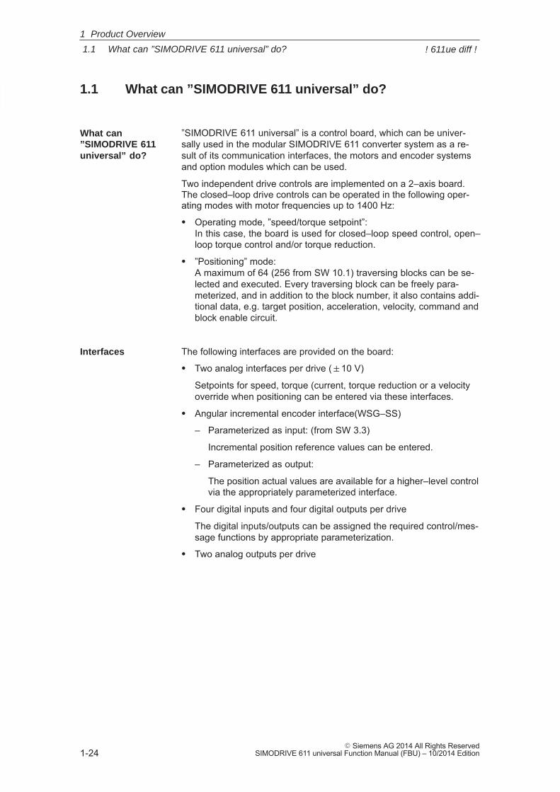
1.1 What can ”SIMODRIVE 611 universal” do?
”SIMODRIVE 611 universal” is a control board, which can be univer-sally used in the modular SIMODRIVE 611 converter system as a re-sult of its communication interfaces, the motors and encoder systemsand option modules which can be used.
Two independent drive controls are implemented on a 2–axis board. The closed–loop drive controls can be operated in the following oper-ating modes with motor frequencies up to 1400 Hz:
� Operating mode, ”speed/torque setpoint”: In this case, the board is used for closed–loop speed control, open–loop torque control and/or torque reduction.
� ”Positioning” mode: A maximum of 64 (256 from SW 10.1) traversing blocks can be se-lected and executed. Every traversing block can be freely para-meterized, and in addition to the block number, it also contains addi-tional data, e.g. target position, acceleration, velocity, command andblock enable circuit.
The following interfaces are provided on the board:
� Two analog interfaces per drive (�10 V)
Setpoints for speed, torque (current, torque reduction or a velocityoverride when positioning can be entered via these interfaces.
� Angular incremental encoder interface(WSG–SS)
– Parameterized as input: (from SW 3.3)
Incremental position reference values can be entered.
– Parameterized as output:
The position actual values are available for a higher–level controlvia the appropriately parameterized interface.
� Four digital inputs and four digital outputs per drive
The digital inputs/outputs can be assigned the required control/mes-sage functions by appropriate parameterization.
� Two analog outputs per drive
What can”SIMODRIVE 611universal” do?
Interfaces
1 Product Overview
! 611ue diff !
1
1.1 What can ”SIMODRIVE 611 universal” do?
1-25� Siemens AG 2014 All Rights ReservedSIMODRIVE 611 universal Function Manual (FBU) – 10/2014 Edition
The ”SIMODRIVE 611 universal” control board can be expanded byone of the following option modules:
� Optional TERMINAL moduleThis module provides an additional 8 digital inputs and 8 digital out-puts (e.g. necessary to select and start a traversing block in the”positioning” mode).
Note
The input/output terminals of the optional TERMINAL module are:� Before SW 4.1: permanently assigned to drive A or axis A
� From SW 4.1: can be freely assigned axes
� Optional PROFIBUS–DP module To integrate the system into distributed concepts, ”SIMODRIVE 611universal” can be operated as slave on PROFIBUS–DP using thisoption module (refer to Table 1-3).
The following motors can be used with ”SIMODRIVE 611 universal”:
� 1FK6, 1FK7, 1FT6, 1FT7 servomotors up to 140 Nm
� 1FE1 permanent–magnet synchronous motors
� 1PH induction motors up to 100 kW (1PH6, 1PH4, 1PH2, 1PH7,1PH8)
� Induction motors without encoder
� Standard 1LA induction motors up to 100 kW
� 1FN linear motors
� 1FW6 built–in torque motors
Note
� Two different motor types can be operated with a control board(e.g. 1FK6 synchronous motor and 1PH7 induction motor).
� Unlisted motors can also be connected.� The motors which can be connected are listed in Chapter A.3.
Optional modules
Which motors canbe used?
1 Product Overview
! 611ue diff !
1
1.1 What can ”SIMODRIVE 611 universal” do?
1-26� Siemens AG 2014 All Rights Reserved
SIMODRIVE 611 universal Function Manual (FBU) – 10/2014 Edition
The following encoders can be connected when using ”SIMODRIVE611 universal”:
– Resolver with pole pair numbers 1, 2, 3, 4, 5 and 6– Incremental encoder with sin/cos 1Vpp up to 65535 pulses,
e.g. ERN 1387 from Heidenhain– Absolute encoder with
sin/cos 1Vpp and interface with EnDat protocol,e.g. EQN 1325 from Heidenhain (EnDat protocol)
– from SW 8.1incremental encoders with TTL signals with control board, OrderNo. 6SN1118–�NH01–0AA�, only for induction motors
Note
� For a 2–axis control board, it is not possible to mix encoders withsin/cos 1Vpp and resolvers.
� Unlisted encoders can also be connected.� The encoders which can be connected are listed in Chapter A.4.� The following is valid for resolvers:
The selected resolver must match the motor. For resolvers, pole pair number = 1 (P1018) or the pole pairnumber of the motor (P1112) is permissible.
The equipment is integrated and adapted to the machine/system byappropriately parameterizing it. The following possibilities are availablefor start–up and for service:� ”SimoCom U” parameterizing and start–up tool
(SimoCom U under Windows, refer to Chapter 3.3)� Display and operator unit
(on the control board front panel)
The control board has an interchangeable memory module with a non–volatile data memory (FEPROM) to save the following data:� Firmware (system software)� User data
The ”SIMODRIVE 611 universal” control board can be flexibly used inmany applications as a result of its design.Typical applications for this control board are, e.g.:� Textile machines� Packaging machines� Machine tools� Handling equipment� Conveyor and transport equipment� Machines to machine/handle wood, glass or ceramics, etc.
Which encoderscan beconnected?
Parameterassignment
Data save
Where can”SIMODRIVE 611universal” be used?
1 Product Overview
! 611ue diff !
1
1.1 What can ”SIMODRIVE 611 universal” do?
1-27� Siemens AG 2014 All Rights ReservedSIMODRIVE 611 universal Function Manual (FBU) – 10/2014 Edition
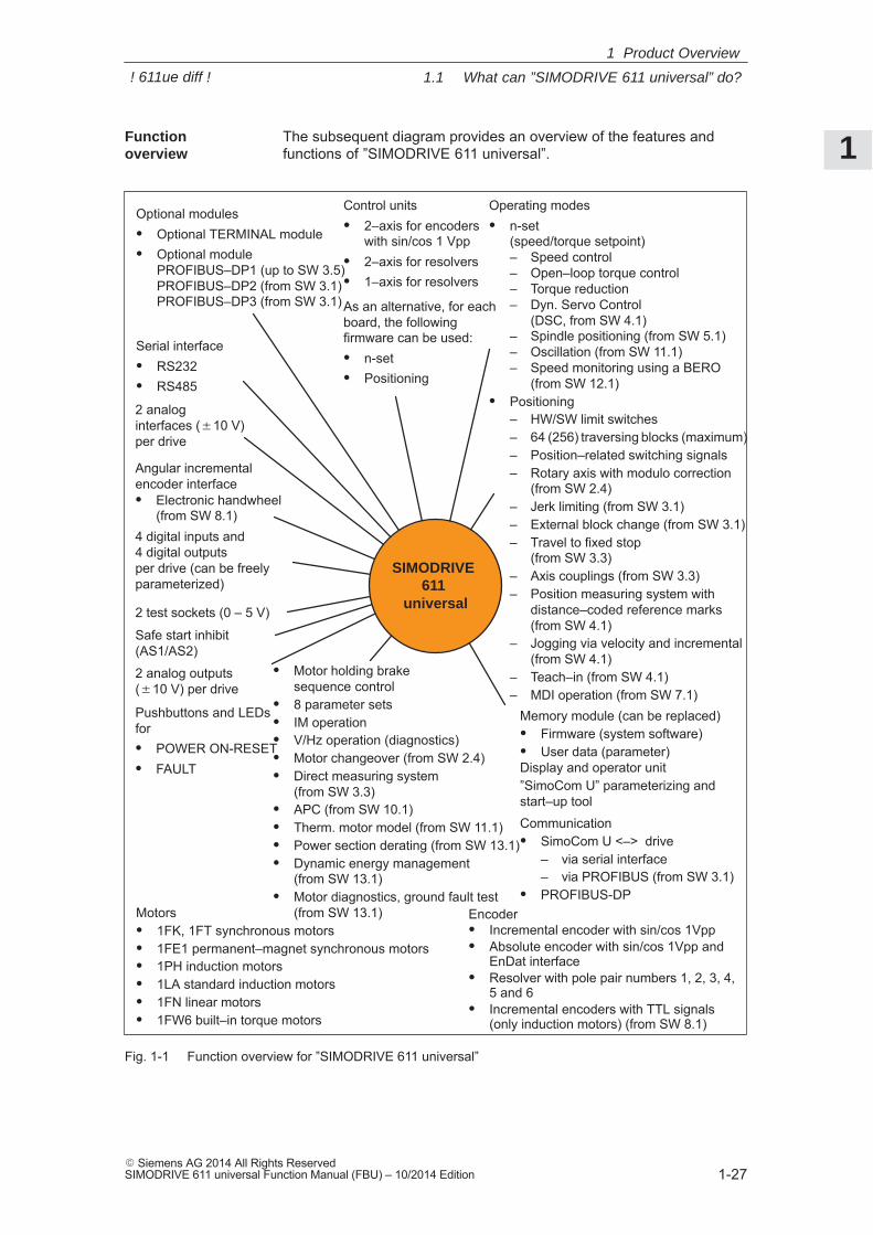
The subsequent diagram provides an overview of the features andfunctions of ”SIMODRIVE 611 universal”.
� Motor holding brake sequence control
� 8 parameter sets� IM operation� V/Hz operation (diagnostics)� Motor changeover (from SW 2.4)� Direct measuring system
(from SW 3.3)� APC (from SW 10.1)� Therm. motor model (from SW 11.1)� Power section derating (from SW 13.1)� Dynamic energy management
(from SW 13.1)� Motor diagnostics, ground fault test
(from SW 13.1)
4 digital inputs and 4 digital outputsper drive (can be freelyparameterized)
Display and operator unit
Control units� 2–axis for encoders
with sin/cos 1 Vpp� 2–axis for resolvers� 1–axis for resolvers
As an alternative, for eachboard, the followingfirmware can be used:� n-set� Positioning
Optional modules� Optional TERMINAL module� Optional module
PROFIBUS–DP1 (up to SW 3.5)PROFIBUS–DP2 (from SW 3.1)PROFIBUS–DP3 (from SW 3.1)
Pushbuttons and LEDsfor� POWER ON-RESET� FAULT
Operating modes� n-set
(speed/torque setpoint)– Speed control– Open–loop torque control– Torque reduction– Dyn. Servo Control
(DSC, from SW 4.1)– Spindle positioning (from SW 5.1)– Oscillation (from SW 11.1)– Speed monitoring using a BERO
(from SW 12.1)� Positioning
– HW/SW limit switches– 64 (256) traversing blocks (maximum)– Position–related switching signals– Rotary axis with modulo correction
(from SW 2.4)– Jerk limiting (from SW 3.1)– External block change (from SW 3.1)– Travel to fixed stop
(from SW 3.3)– Axis couplings (from SW 3.3)– Position measuring system with
distance–coded reference marks(from SW 4.1)
– Jogging via velocity and incremental(from SW 4.1)
– Teach–in (from SW 4.1)– MDI operation (from SW 7.1)
”SimoCom U” parameterizing andstart–up tool
Serial interface� RS232� RS485
Communication� SimoCom U <–> drive
– via serial interface– via PROFIBUS (from SW 3.1)
� PROFIBUS-DP
2 analoginterfaces (�10 V) per drive
Motors� 1FK, 1FT synchronous motors� 1FE1 permanent–magnet synchronous motors� 1PH induction motors� 1LA standard induction motors� 1FN linear motors� 1FW6 built–in torque motors
Memory module (can be replaced)� Firmware (system software)� User data (parameter)
Encoder� Incremental encoder with sin/cos 1Vpp� Absolute encoder with sin/cos 1Vpp and
EnDat interface� Resolver with pole pair numbers 1, 2, 3, 4,
5 and 6� Incremental encoders with TTL signals
(only induction motors) (from SW 8.1)
Angular incrementalencoder interface� Electronic handwheel
(from SW 8.1)
SIMODRIVE 611
universal2 test sockets (0 – 5 V)
2 analog outputs (�10 V) per drive
Safe start inhibit (AS1/AS2)
Fig. 1-1 Function overview for ”SIMODRIVE 611 universal”
Function overview
1 Product Overview
! 611ue diff !
1
1.2 ”SIMODRIVE 611 universal” in the SIMODRIVE 611 system
1-28� Siemens AG 2014 All Rights Reserved
SIMODRIVE 611 universal Function Manual (FBU) – 10/2014 Edition
1.2 ”SIMODRIVE 611 universal” in the SIMODRIVE 611 system
”SIMODRIVE 611 universal” is implemented as digital control modulefor two drives for operation in the SIMODRIVE 611 system.
A SIMODRIVE drive group is modular and comprises the followingmodules and boards:
� Commutating reactor(s)
� Supply infeed module (NE module)
� Power module(s) with control board
– ”SIMODRIVE 611 universal” or
– ”SIMODRIVE 611 universal HR” (from the middle of 2002 withSW 5.1)
– ”SIMODRIVE 611 universal HRS” (from the middle of 2005 withSW 9.1)
– ”SIMODRIVE 611 universal HRS / HRS2” (from 2014 with SW14.2)
Note
In the following chapters of the Description of Functions, adifferentiation is not made between ”SIMODRIVE 611 universal” and”SIMODRIVE 611 universal HR/HRS/HRS2”.
The functionality, specified under ”SIMODRIVE 611 universal” alsoapplies for ”SIMODRIVE 611 universal HR/HRS/HRS2”.
and, when required
� Line filter
� Monitoring and pulsed resistor module
� Transformer
Reference: /PJU/, SIMODRIVE 611, Configuration Manual, Drive Converters
Engineering a SIMODRIVE drive group is subdivided into the followingphases as follows:
� Phase 1 (engineering)– The motor is selected– The power module and the supply infeed are selected
� Phase 2 (integration)– Create circuit diagrams
How is the SIMODRIVE 611universal integrated into the SIMODRIVE 611system?
Configuration
1 Product Overview
! 611ue diff !
1
1.2 ”SIMODRIVE 611 universal” in the SIMODRIVE 611 system
1-29� Siemens AG 2014 All Rights ReservedSIMODRIVE 611 universal Function Manual (FBU) – 10/2014 Edition
Note
The following documentation, SW Tools and Catalogs are availablewhen engineering the system:� Reference: /PJU/, SIMODRIVE 611,
Configuration Manual, Drive Converters� Reference: /PJM/, SIMODRIVE 611,
Configuration Manual, Motors AC Motors for Feed and Main Spindle Drives
� PC Tool: /SP/, SIMOPRO, Program to engineer SIMODRIVE drives http://www.ad.siemens.de/mc/html_00/info/projektier_tools/index.htm
� Reference: /BU/, Catalog NC 60, Ordering Documentation� CD: Interactive Catalog CA01� CD: /CD1/, DOC ON CD with all SINUMERIK
840D/810D/FM–NC and SIMODRIVE 611D documentation
1 Product Overview
! 611ue diff !
1
1.2 ”SIMODRIVE 611 universal” in the SIMODRIVE 611 system
1-30� Siemens AG 2014 All Rights Reserved
SIMODRIVE 611 universal Function Manual (FBU) – 10/2014 Edition
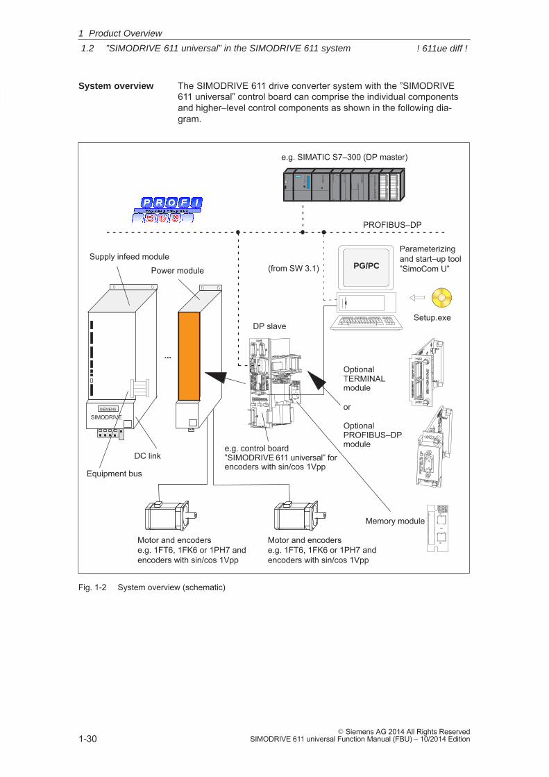
The SIMODRIVE 611 drive converter system with the ”SIMODRIVE611 universal” control board can comprise the individual componentsand higher–level control components as shown in the following dia-gram.
Equipment bus
DC link
SIMODRIVESIEMENS
Supply infeed module
Power module
e.g. control board ”SIMODRIVE 611 universal” forencoders with sin/cos 1Vpp
PROFIBUS–DP
OptionalTERMINALmodule
or
OptionalPROFIBUS–DPmodule
e.g. SIMATIC S7–300 (DP master)
DP slave
Motor and encoderse.g. 1FT6, 1FK6 or 1PH7 andencoders with sin/cos 1Vpp
...
Motor and encoderse.g. 1FT6, 1FK6 or 1PH7 andencoders with sin/cos 1Vpp
Memory module
Parameterizingand start–up tool”SimoCom U”PG/PC
Setup.exe
(from SW 3.1)
Fig. 1-2 System overview (schematic)
System overview
1 Product Overview
! 611ue diff !
1
1.2 ”SIMODRIVE 611 universal” in the SIMODRIVE 611 system
1-31� Siemens AG 2014 All Rights ReservedSIMODRIVE 611 universal Function Manual (FBU) – 10/2014 Edition
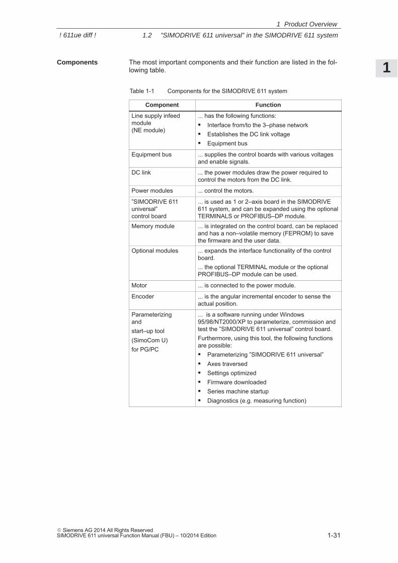
The most important components and their function are listed in the fol-lowing table.
Table 1-1 Components for the SIMODRIVE 611 system
Component Function
Line supply infeedmodule (NE module)
... has the following functions:� Interface from/to the 3–phase network� Establishes the DC link voltage� Equipment bus
Equipment bus ... supplies the control boards with various voltagesand enable signals.
DC link ... the power modules draw the power required tocontrol the motors from the DC link.
Power modules ... control the motors.
”SIMODRIVE 611 universal” control board
... is used as 1 or 2–axis board in the SIMODRIVE611 system, and can be expanded using the optionalTERMINALS or PROFIBUS–DP module.
Memory module ... is integrated on the control board, can be replacedand has a non–volatile memory (FEPROM) to savethe firmware and the user data.
Optional modules ... expands the interface functionality of the controlboard.... the optional TERMINAL module or the optionalPROFIBUS–DP module can be used.
Motor ... is connected to the power module.
Encoder ... is the angular incremental encoder to sense theactual position.
Parameterizing andstart–up tool(SimoCom U)for PG/PC
... is a software running under Windows95/98/NT2000/XP to parameterize, commission andtest the ”SIMODRIVE 611 universal” control board.Furthermore, using this tool, the following functionsare possible:� Parameterizing ”SIMODRIVE 611 universal”� Axes traversed� Settings optimized� Firmware downloaded� Series machine startup� Diagnostics (e.g. measuring function)
Components
1 Product Overview
! 611ue diff !
1
1.3 ”SIMODRIVE 611 universal” control board
1-32� Siemens AG 2014 All Rights Reserved
SIMODRIVE 611 universal Function Manual (FBU) – 10/2014 Edition
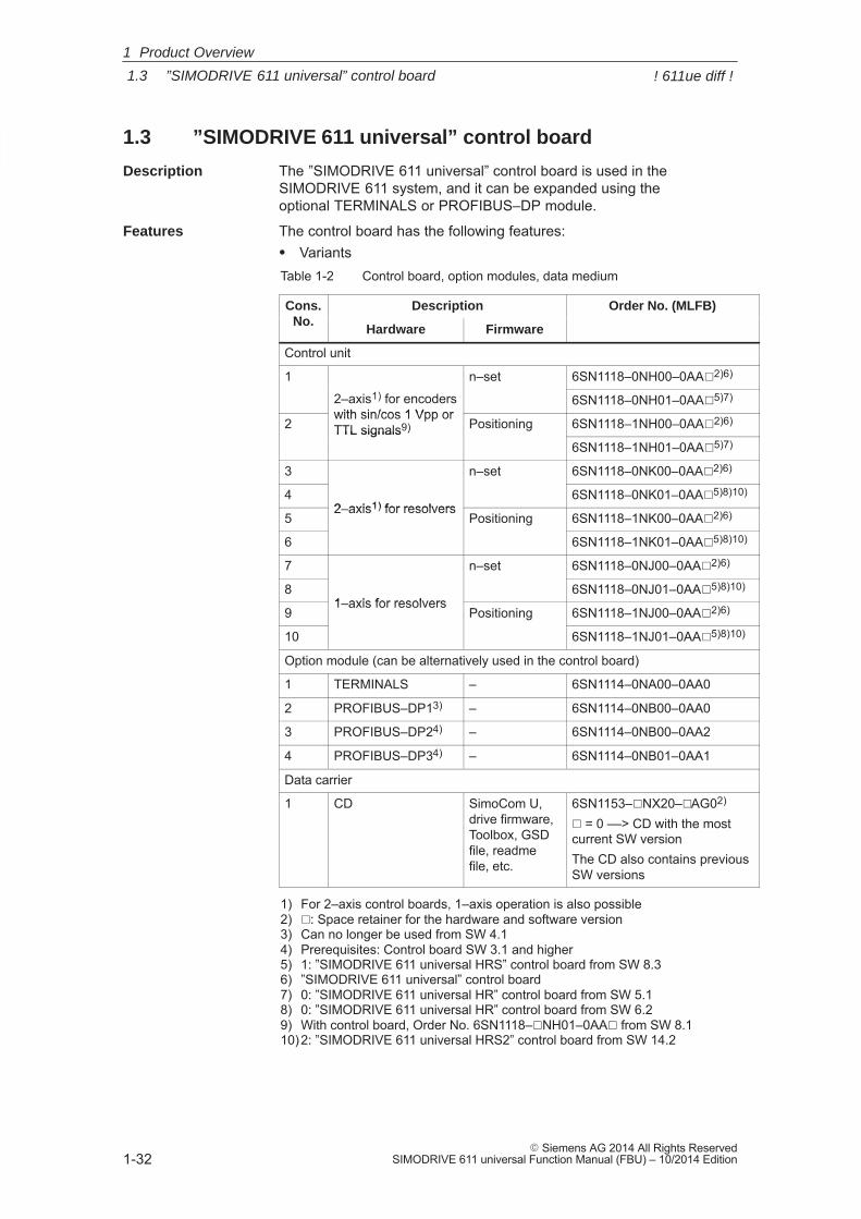
1.3 ”SIMODRIVE 611 universal” control board
The ”SIMODRIVE 611 universal” control board is used in theSIMODRIVE 611 system, and it can be expanded using the optional TERMINALS or PROFIBUS–DP module.
The control board has the following features:� VariantsTable 1-2 Control board, option modules, data medium
Cons.No.
Description Order No. (MLFB)No.
Hardware Firmware
Control unit
1 n–set 6SN1118–0NH00–0AA�2)6)
2–axis1) for encoderswith sin/cos 1 Vpp or
6SN1118–0NH01–0AA�5)7)
2with sin/cos 1 Vpp orTTL signals9) Positioning 6SN1118–1NH00–0AA�2)6)TTL signals9)
6SN1118–1NH01–0AA�5)7)
3 n–set 6SN1118–0NK00–0AA�2)6)
42–axis1) for resolvers
6SN1118–0NK01–0AA�5)8)10)
52–axis1) for resolvers
Positioning 6SN1118–1NK00–0AA�2)6)
6 6SN1118–1NK01–0AA�5)8)10)
7 n–set 6SN1118–0NJ00–0AA�2)6)
81–axis for resolvers
6SN1118–0NJ01–0AA�5)8)10)
91–axis for resolvers
Positioning 6SN1118–1NJ00–0AA�2)6)
10 6SN1118–1NJ01–0AA�5)8)10)
Option module (can be alternatively used in the control board)
1 TERMINALS – 6SN1114–0NA00–0AA0
2 PROFIBUS–DP13) – 6SN1114–0NB00–0AA0
3 PROFIBUS–DP24) – 6SN1114–0NB00–0AA2
4 PROFIBUS–DP34) – 6SN1114–0NB01–0AA1
Data carrier
1 CD SimoCom U, drive firmware,Toolbox, GSDfile, readmefile, etc.
6SN1153–�NX20–�AG02)
� = 0 ––> CD with the mostcurrent SW versionThe CD also contains previousSW versions
1) For 2–axis control boards, 1–axis operation is also possible2) �: Space retainer for the hardware and software version3) Can no longer be used from SW 4.14) Prerequisites: Control board SW 3.1 and higher5) 1: ”SIMODRIVE 611 universal HRS” control board from SW 8.36) ”SIMODRIVE 611 universal” control board7) 0: ”SIMODRIVE 611 universal HR” control board from SW 5.18) 0: ”SIMODRIVE 611 universal HR” control board from SW 6.29) With control board, Order No. 6SN1118–�NH01–0AA� from SW 8.110)2: ”SIMODRIVE 611 universal HRS2” control board from SW 14.2
Description
Features
1 Product Overview
! 611ue diff !
1
1.3 ”SIMODRIVE 611 universal” control board
1-33� Siemens AG 2014 All Rights ReservedSIMODRIVE 611 universal Function Manual (FBU) – 10/2014 Edition
Reader’s note
Please observe the information in the ”readme.txt” file on the CD for ”SIMODRIVE 611 universal”.
� Settings
All drive–related settings of the control board can be made as follows:
– using the parameterizing and start–up tool SimoCom U on anexternal PG/PC (refer to Chapter 3.3)
– using the display and operator unit on the front panel (refer to Chapter 3.2)
– using PROFIBUS–DP (parameter area, PKW area, refer to Chapter 5.6.7)
� Software and data
The firmware and the user data are saved on a memory modulewhich can be replaced.
� Terminals and operator control elements
– 2 analog inputs, 2 analog outputs per drive
– 4 digital inputs, 4 digital outputs per drive
– 2 test sockets
– POWER–ON RESET pushbutton with LED
– Display and operator unit
� Safe start inhibit
The start inhibit is addressed via terminal 663 and is signaled backusing a relay with positively–driven signaling contacts (AS1/AS2).Using the start inhibit, the energy feed from the drive to the motor isinterrupted.When the ”safe start inhibit” function is correctly used, the signalingcontacts AS1/AS2 must be included in the line contactor circuit orthe EMERGENCY OFF circuit.
Caution
When using the ”safe start inhibit” function, it must be ensured that thevelocity goes to zero.
The control board supports the ”Safe standstill” function.
Detailed information about the ”Safe Standstill” function is providedin
Reference: /PJU/, SIMODRIVE 611, Configuration Manual, Drive Converters
1 Product Overview
! 611ue diff !

1
1.3 ”SIMODRIVE 611 universal” control board
1-34� Siemens AG 2014 All Rights Reserved
SIMODRIVE 611 universal Function Manual (FBU) – 10/2014 Edition
� Serial interface (RS232/RS485)
� Optional modules
– Optional TERMINAL module, 8 digital inputs and 8 digital outputs for drive A
– Optional PROFIBUS–DP module
� Expanded functions SW 5.1 and higher
The following expanded functionality is provided with the ”SIMODRIVE611 universal control board for sin/cos 1Vpp encoders:
– Higher internal resolution, interpolation factor 2048 (previously 128)
– Pulse multiplication is possible (doubling) at the angular incre-mental encoder interface for absolute value encoders
– Pulse multiplication (doubling) and division (1:2, 1:4, 1:8) arepossible at the angular incremental encoder interface, also forincremental encoders
– From SW 8.1It is possible to connect standard square–wave encoders (TTL)with differential signals according to RS422 and 5 V powersupply voltage as pulse encoder for induction motors at theSIMODRIVE 611 universal HR” control board (Order No.6SN1118–�NH01–0AA�).
� Expanded functions from SW 9.1
”SIMODRIVE 611 universal HR” or ”SIMODRIVE 611 universal”control boards can be replaced by the ”SIMODRIVE 611 universalHRS” control board (higher computational performance” and thisreplacement is compatible.
The ”SIMODRIVE 611 universal HRS” control board is, at all inter-faces, electrically compatible to its predecessor and as far as all ofthe functions are concerned.
The mechanical dimensions, mounting/installation dimensions andconnection interfaces of the ”SIMODRIVE 611 universal HRS” con-trol board are compatible to the previous types and are compatiblefrom an installation perspective to the the SIMODRIVE 611 digitalpower modules. Exception: Connectors X461/X462.
– 10–pin for ”SIMODRIVE 611 universal”.
– 11–pin for ”SIMODRIVE 611 universal HR” and ”SIMODRIVE611 universal HRS” as terminal 15 has been added. When the board has to be replaced, please refer to the attachedinstallation instructions regarding the wiring changes that have tobe made.
� Expanded functions from SW 14.2
The “SIMODRIVE 611 universal HRS2“ control board is, at all inter-faces, electrically compatible to its predecessor and as far as all ofthe functions are concerned.
1 Product Overview
! 611ue diff !
1
1.3 ”SIMODRIVE 611 universal” control board
1-35� Siemens AG 2014 All Rights ReservedSIMODRIVE 611 universal Function Manual (FBU) – 10/2014 Edition
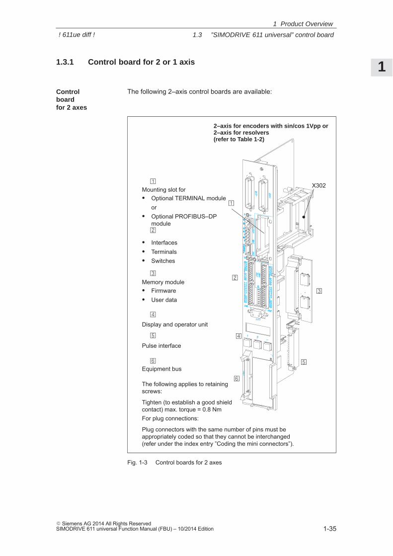
1.3.1 Control board for 2 or 1 axis
The following 2–axis control boards are available:
Mounting slot for� Optional TERMINAL module
or� Optional PROFIBUS–DP
module
Memory module� Firmware� User data
Pulse interface
The following applies to retainingscrews:
Tighten (to establish a good shieldcontact) max. torque = 0.8 Nm
2–axis for encoders with sin/cos 1Vpp or 2–axis for resolvers (refer to Table 1-2)
�
�
�
�
�
Equipment bus
Display and operator unit
�
� Interfaces� Terminals� Switches
�
�
For plug connections:
Plug connectors with the same number of pins must beappropriately coded so that they cannot be interchanged(refer under the index entry ”Coding the mini connectors”).
X302
Fig. 1-3 Control boards for 2 axes
Control board for 2 axes
1 Product Overview
! 611ue diff !
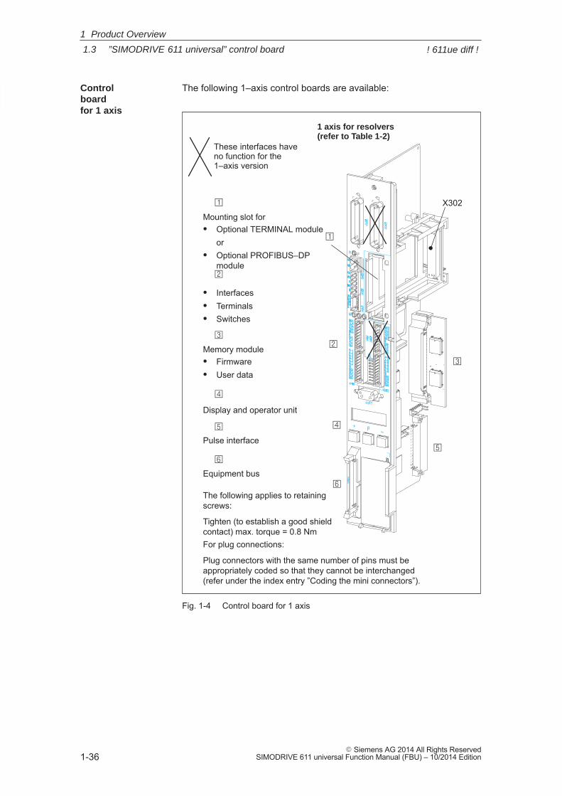
1
1.3 ”SIMODRIVE 611 universal” control board
1-36� Siemens AG 2014 All Rights Reserved
SIMODRIVE 611 universal Function Manual (FBU) – 10/2014 Edition
The following 1–axis control boards are available:
These interfaces haveno function for the1–axis version
Mounting slot for� Optional TERMINAL module
or� Optional PROFIBUS–DP
module
Memory module� Firmware� User data
Pulse interface
The following applies to retainingscrews:
Tighten (to establish a good shieldcontact) max. torque = 0.8 Nm
1 axis for resolvers (refer to Table 1-2)
�
�
�
�
�
Equipment bus
Display and operator unit
�
� Interfaces� Terminals� Switches
�
�
For plug connections:
Plug connectors with the same number of pins must beappropriately coded so that they cannot be interchanged(refer under the index entry ”Coding the mini connectors”).
X302
Fig. 1-4 Control board for 1 axis
Control board for 1 axis
1 Product Overview
! 611ue diff !
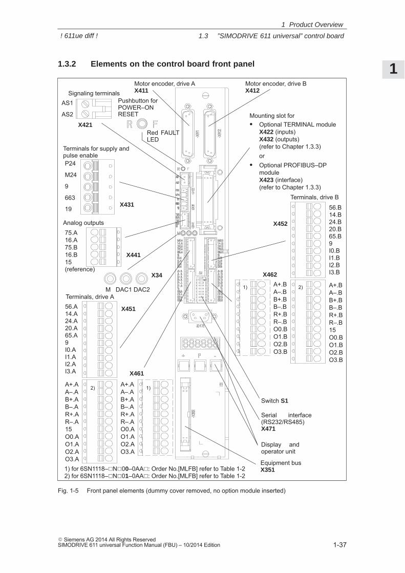
1
1.3 ”SIMODRIVE 611 universal” control board
1-37� Siemens AG 2014 All Rights ReservedSIMODRIVE 611 universal Function Manual (FBU) – 10/2014 Edition
1.3.2 Elements on the control board front panel
Motor encoder, drive AX411
Motor encoder, drive B X412
56.B14.B24.B20.B65.B9I0.BI1.BI2.BI3.B
Terminals, drive B
A+.BA–.BB+.BB–.BR+.BR–.BO0.BO1.BO2.BO3.B
Serial interface(RS232/RS485) X471
Display andoperator unit
Switch S1
Equipment bus X351
AS1
AS2
Signaling terminals
P24
M24
9
663
19
Terminals for supply andpulse enable
75.A16.A75.B16.B15 (reference)
Analog outputs
Pushbutton forPOWER–ONRESET
Red FAULTLED
M DAC1 DAC2
X34
56.A14.A24.A20.A65.A9I0.AI1.AI2.AI3.A
Terminals, drive A
A+.AA–.AB+.AB–.AR+.AR–.AO0.AO1.AO2.AO3.A
X451
X461
Mounting slot for� Optional TERMINAL module
X422 (inputs)X432 (outputs)(refer to Chapter 1.3.3)or
� Optional PROFIBUS–DPmodule X423 (interface)(refer to Chapter 1.3.3)
X452
X462
X441
X431
X421
A+.BA–.BB+.BB–.BR+.BR–.B15O0.BO1.BO2.BO3.B
1) 2)
1) for 6SN1118–�N�00–0AA�: Order No.[MLFB] refer to Table 1-22) for 6SN1118–�N�01–0AA�: Order No.[MLFB] refer to Table 1-2
A+.AA–.AB+.AB–.AR+.AR–.A15O0.AO1.AO2.AO3.A
1)2)
Fig. 1-5 Front panel elements (dummy cover removed, no option module inserted)
1 Product Overview
! 611ue diff !
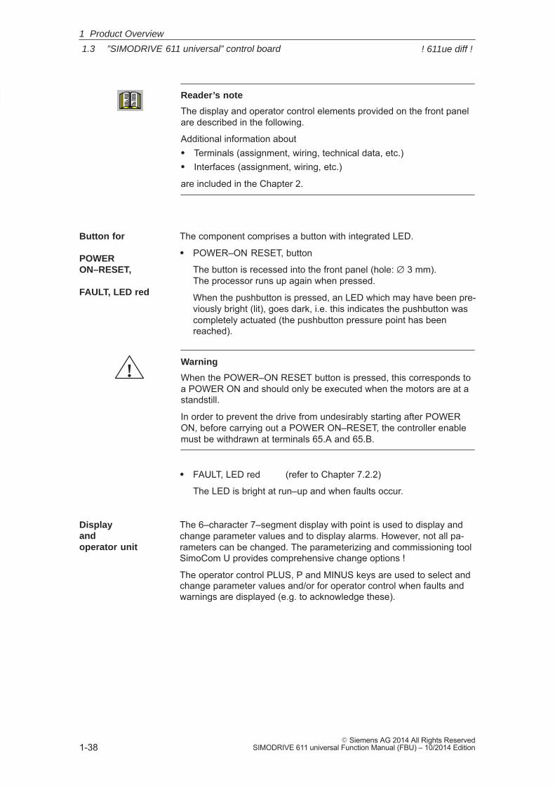
1
1.3 ”SIMODRIVE 611 universal” control board
1-38� Siemens AG 2014 All Rights Reserved
SIMODRIVE 611 universal Function Manual (FBU) – 10/2014 Edition
Reader’s note
The display and operator control elements provided on the front panelare described in the following.
Additional information about� Terminals (assignment, wiring, technical data, etc.)� Interfaces (assignment, wiring, etc.)
are included in the Chapter 2.
The component comprises a button with integrated LED.
� POWER–ON RESET, button
The button is recessed into the front panel (hole: ∅ 3 mm). The processor runs up again when pressed.
When the pushbutton is pressed, an LED which may have been pre-viously bright (lit), goes dark, i.e. this indicates the pushbutton wascompletely actuated (the pushbutton pressure point has beenreached).
!Warning
When the POWER–ON RESET button is pressed, this corresponds toa POWER ON and should only be executed when the motors are at astandstill.
In order to prevent the drive from undesirably starting after POWERON, before carrying out a POWER ON–RESET, the controller enablemust be withdrawn at terminals 65.A and 65.B.
� FAULT, LED red (refer to Chapter 7.2.2)
The LED is bright at run–up and when faults occur.
The 6–character 7–segment display with point is used to display andchange parameter values and to display alarms. However, not all pa-rameters can be changed. The parameterizing and commissioning toolSimoCom U provides comprehensive change options !
The operator control PLUS, P and MINUS keys are used to select andchange parameter values and/or for operator control when faults andwarnings are displayed (e.g. to acknowledge these).
Button for
POWER ON–RESET,
FAULT, LED red
Display and operator unit
1 Product Overview
! 611ue diff !
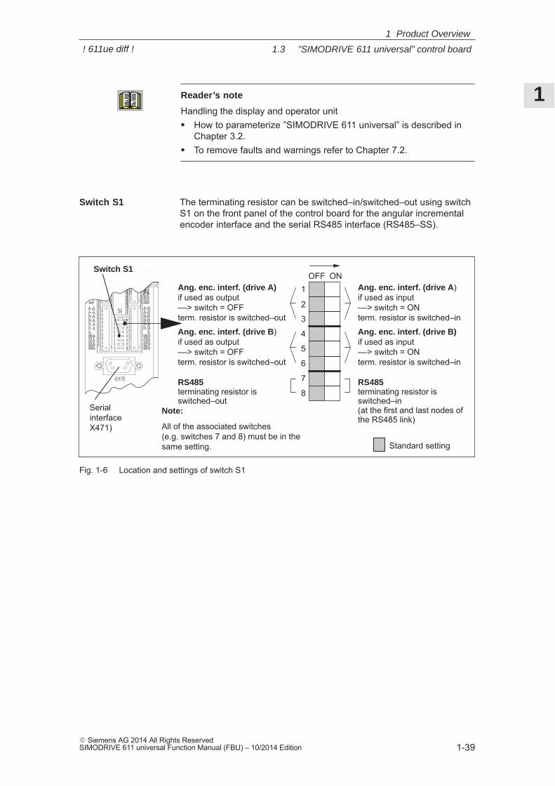
1
1.3 ”SIMODRIVE 611 universal” control board
1-39� Siemens AG 2014 All Rights ReservedSIMODRIVE 611 universal Function Manual (FBU) – 10/2014 Edition
Reader’s note
Handling the display and operator unit� How to parameterize ”SIMODRIVE 611 universal” is described in
Chapter 3.2.� To remove faults and warnings refer to Chapter 7.2.
The terminating resistor can be switched–in/switched–out using switchS1 on the front panel of the control board for the angular incrementalencoder interface and the serial RS485 interface (RS485–SS).
Switch S1OFF ON
1
2
8
3
4
5
6
7 RS485terminating resistor isswitched–in(at the first and last nodes ofthe RS485 link)
Standard setting
RS485terminating resistor isswitched–out
Note:
All of the associated switches (e.g. switches 7 and 8) must be in thesame setting.
Serial interfaceX471)
Switch S1
Ang. enc. interf. (drive A)if used as output––> switch = OFF term. resistor is switched–out
Ang. enc. interf. (drive B)if used as output––> switch = OFFterm. resistor is switched–out
Ang. enc. interf. (drive A)if used as input––> switch = ONterm. resistor is switched–in
Ang. enc. interf. (drive B)if used as input––> switch = ONterm. resistor is switched–in
Fig. 1-6 Location and settings of switch S1
Switch S1
1 Product Overview
! 611ue diff !
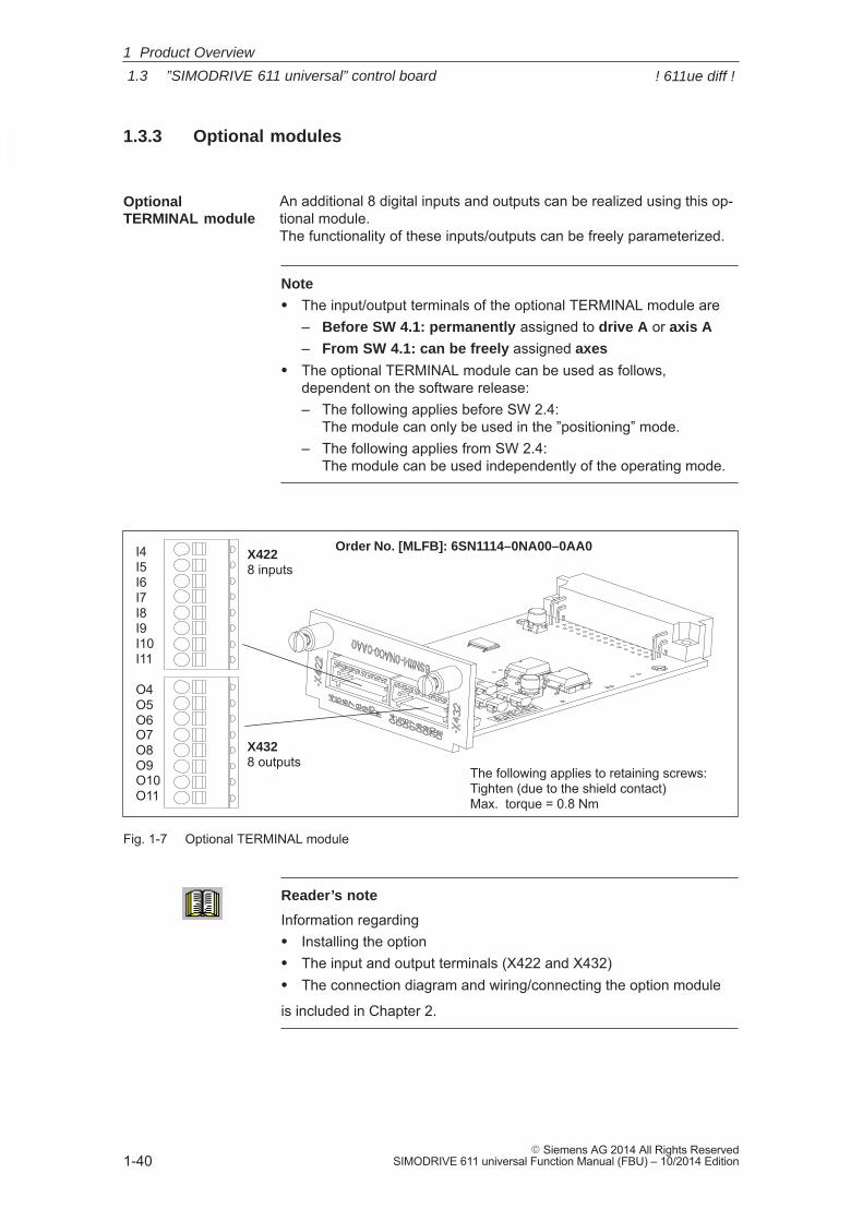
1
1.3 ”SIMODRIVE 611 universal” control board
1-40� Siemens AG 2014 All Rights Reserved
SIMODRIVE 611 universal Function Manual (FBU) – 10/2014 Edition
1.3.3 Optional modules
An additional 8 digital inputs and outputs can be realized using this op-tional module. The functionality of these inputs/outputs can be freely parameterized.
Note
� The input/output terminals of the optional TERMINAL module are– Before SW 4.1: permanently assigned to drive A or axis A
– From SW 4.1: can be freely assigned axes
� The optional TERMINAL module can be used as follows,dependent on the software release:– The following applies before SW 2.4:
The module can only be used in the ”positioning” mode.– The following applies from SW 2.4:
The module can be used independently of the operating mode.
Order No. [MLFB]: 6SN1114–0NA00–0AA0I4I5I6I7I8I9I10I11
O4O5O6O7O8O9O10O11
X4228 inputs
X4328 outputs
The following applies to retaining screws:Tighten (due to the shield contact)Max. torque = 0.8 Nm
Fig. 1-7 Optional TERMINAL module
Reader’s note
Information regarding� Installing the option� The input and output terminals (X422 and X432)� The connection diagram and wiring/connecting the option module
is included in Chapter 2.
OptionalTERMINAL module
1 Product Overview
! 611ue diff !
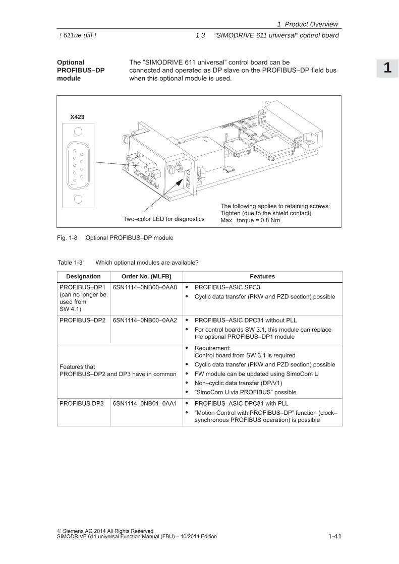
1
1.3 ”SIMODRIVE 611 universal” control board
1-41� Siemens AG 2014 All Rights ReservedSIMODRIVE 611 universal Function Manual (FBU) – 10/2014 Edition
The ”SIMODRIVE 611 universal” control board can be connected and operated as DP slave on the PROFIBUS–DP field buswhen this optional module is used.
X423
Two–color LED for diagnostics
The following applies to retaining screws:Tighten (due to the shield contact)Max. torque = 0.8 Nm
Fig. 1-8 Optional PROFIBUS–DP module
Table 1-3 Which optional modules are available?
Designation Order No. (MLFB) Features
PROFIBUS–DP1(can no longer beused fromSW 4.1)
6SN1114–0NB00–0AA0 � PROFIBUS–ASIC SPC3� Cyclic data transfer (PKW and PZD section) possible
PROFIBUS–DP2 6SN1114–0NB00–0AA2 � PROFIBUS–ASIC DPC31 without PLL� For control boards SW 3.1, this module can replace
the optional PROFIBUS–DP1 module
Features that PROFIBUS–DP2 and DP3 have in common
� Requirement: Control board from SW 3.1 is required
� Cyclic data transfer (PKW and PZD section) possible� FW module can be updated using SimoCom U� Non–cyclic data transfer (DP/V1)� ”SimoCom U via PROFIBUS” possible
PROFIBUS DP3 6SN1114–0NB01–0AA1 � PROFIBUS–ASIC DPC31 with PLL� ”Motion Control with PROFIBUS–DP” function (clock–
synchronous PROFIBUS operation) is possible
OptionalPROFIBUS–DP module
1 Product Overview
! 611ue diff !
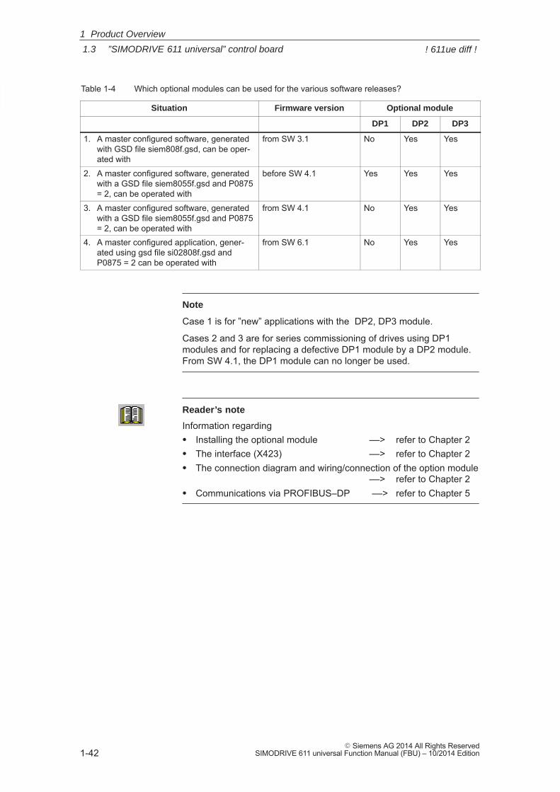
1
1.3 ”SIMODRIVE 611 universal” control board
1-42� Siemens AG 2014 All Rights Reserved
SIMODRIVE 611 universal Function Manual (FBU) – 10/2014 Edition
Table 1-4 Which optional modules can be used for the various software releases?
Situation Firmware version Optional module
DP1 DP2 DP3
1. A master configured software, generatedwith GSD file siem808f.gsd, can be oper-ated with
from SW 3.1 No Yes Yes
2. A master configured software, generatedwith a GSD file siem8055f.gsd and P0875= 2, can be operated with
before SW 4.1 Yes Yes Yes
3. A master configured software, generatedwith a GSD file siem8055f.gsd and P0875= 2, can be operated with
from SW 4.1 No Yes Yes
4. A master configured application, gener-ated using gsd file si02808f.gsd andP0875 = 2 can be operated with
from SW 6.1 No Yes Yes
Note
Case 1 is for ”new” applications with the DP2, DP3 module.
Cases 2 and 3 are for series commissioning of drives using DP1modules and for replacing a defective DP1 module by a DP2 module.From SW 4.1, the DP1 module can no longer be used.
Reader’s note
Information regarding� Installing the optional module ––> refer to Chapter 2� The interface (X423) ––> refer to Chapter 2� The connection diagram and wiring/connection of the option module
––> refer to Chapter 2� Communications via PROFIBUS–DP ––> refer to Chapter 5
1 Product Overview
! 611ue diff !
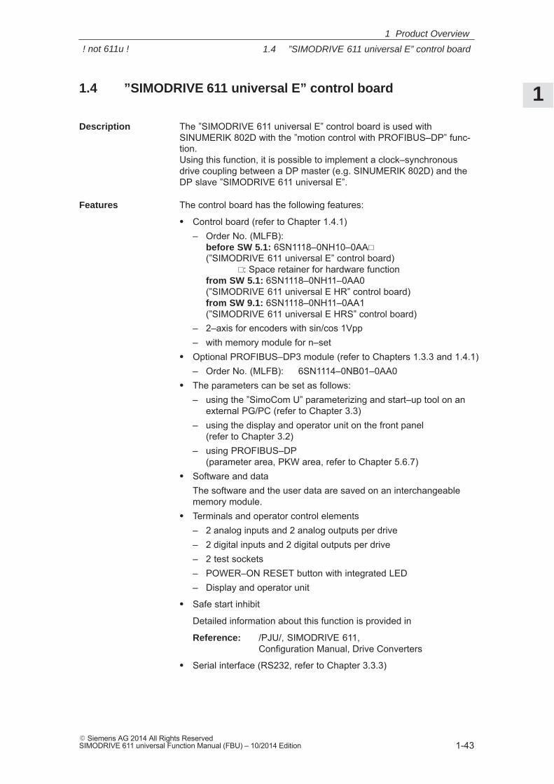
1
1.4 ”SIMODRIVE 611 universal E” control board
1-43� Siemens AG 2014 All Rights ReservedSIMODRIVE 611 universal Function Manual (FBU) – 10/2014 Edition
1.4 ”SIMODRIVE 611 universal E” control board
The ”SIMODRIVE 611 universal E” control board is used withSINUMERIK 802D with the ”motion control with PROFIBUS–DP” func-tion.Using this function, it is possible to implement a clock–synchronousdrive coupling between a DP master (e.g. SINUMERIK 802D) and theDP slave ”SIMODRIVE 611 universal E”.
The control board has the following features:
� Control board (refer to Chapter 1.4.1)– Order No. (MLFB):
before SW 5.1: 6SN1118–0NH10–0AA�
(”SIMODRIVE 611 universal E” control board)�: Space retainer for hardware function
from SW 5.1: 6SN1118–0NH11–0AA0(”SIMODRIVE 611 universal E HR” control board)from SW 9.1: 6SN1118–0NH11–0AA1(”SIMODRIVE 611 universal E HRS” control board)
– 2–axis for encoders with sin/cos 1Vpp– with memory module for n–set
� Optional PROFIBUS–DP3 module (refer to Chapters 1.3.3 and 1.4.1)– Order No. (MLFB): 6SN1114–0NB01–0AA0
� The parameters can be set as follows:– using the ”SimoCom U” parameterizing and start–up tool on an
external PG/PC (refer to Chapter 3.3)– using the display and operator unit on the front panel
(refer to Chapter 3.2)– using PROFIBUS–DP
(parameter area, PKW area, refer to Chapter 5.6.7)� Software and data
The software and the user data are saved on an interchangeablememory module.
� Terminals and operator control elements– 2 analog inputs and 2 analog outputs per drive– 2 digital inputs and 2 digital outputs per drive– 2 test sockets– POWER–ON RESET button with integrated LED– Display and operator unit
� Safe start inhibit
Detailed information about this function is provided in
Reference: /PJU/, SIMODRIVE 611, Configuration Manual, Drive Converters
� Serial interface (RS232, refer to Chapter 3.3.3)
Description
Features
1 Product Overview
! not 611u !
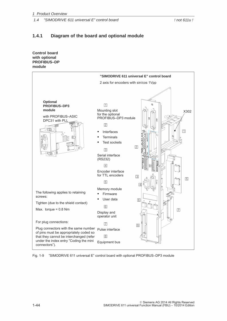
1
1.4 ”SIMODRIVE 611 universal E” control board
1-44� Siemens AG 2014 All Rights Reserved
SIMODRIVE 611 universal Function Manual (FBU) – 10/2014 Edition
1.4.1 Diagram of the board and optional module
Mounting slot for the optional PROFIBUS–DP3 module
Memory module� Firmware� User data
Pulse interface
The following applies to retainingscrews:
Tighten (due to the shield contact)
Max. torque = 0.8 Nm
”SIMODRIVE 611 universal E” control board
2 axis for encoders with sin/cos 1Vpp
�
�
�
�
Equipment bus
Display and operator unit
�
� Interfaces� Terminals� Test sockets
�
�
�
Serial interface(RS232)
Optional PROFIBUS–DP3module
with PROFIBUS–ASICDPC31 with PLL
Encoder interfacefor TTL encoders
�
�
�
�
For plug connections:
Plug connectors with the same numberof pins must be appropriately coded sothat they cannot be interchanged (referunder the index entry ”Coding the miniconnectors”).
X302
Fig. 1-9 ”SIMODRIVE 611 universal E” control board with optional PROFIBUS–DP3 module
Control board with optional PROFIBUS–DPmodule
1 Product Overview
! not 611u !
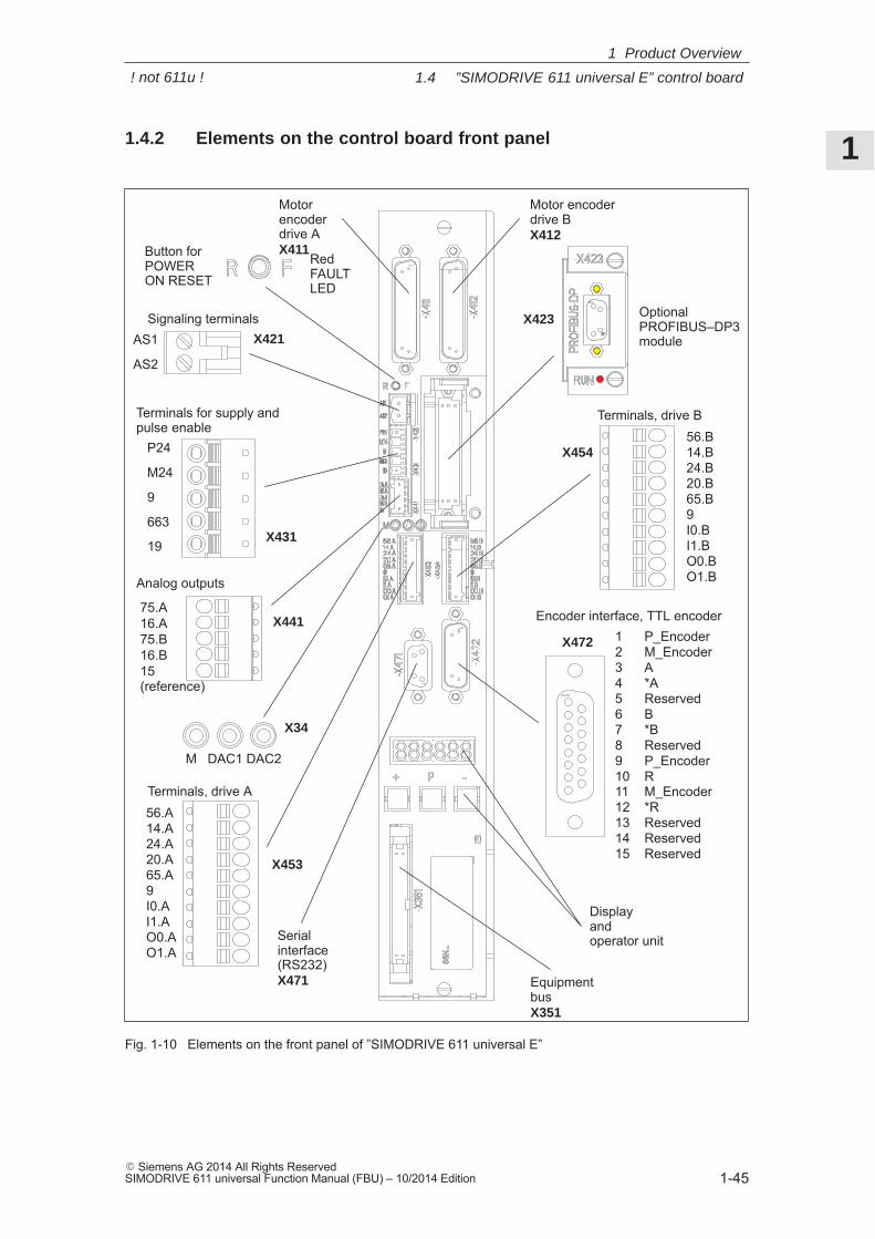
1
1.4 ”SIMODRIVE 611 universal E” control board
1-45� Siemens AG 2014 All Rights ReservedSIMODRIVE 611 universal Function Manual (FBU) – 10/2014 Edition
1.4.2 Elements on the control board front panel
Motorencoder drive AX411
Motor encoderdrive BX412
Serial interface(RS232)X471
Display and operator unit
EquipmentbusX351
AS1
AS2
Signaling terminals
P24
M24
9
663
19
Terminals for supply andpulse enable
75.A16.A75.B16.B15 (reference)
Analog outputs
Button forPOWER ON RESET
RedFAULTLED
M DAC1 DAC2
X34
X453
X454
X472
X441
X431
X421
56.B14.B24.B20.B65.B9I0.BI1.BO0.BO1.B
Terminals, drive B
Terminals, drive A56.A14.A24.A20.A65.A9I0.AI1.AO0.AO1.A
1 P_Encoder2 M_Encoder3 A4 *A5 Reserved6 B7 *B8 Reserved9 P_Encoder10 R11 M_Encoder12 *R13 Reserved14 Reserved15 Reserved
Optional PROFIBUS–DP3module
Encoder interface, TTL encoder
X423
Fig. 1-10 Elements on the front panel of ”SIMODRIVE 611 universal E”
1 Product Overview
! not 611u !
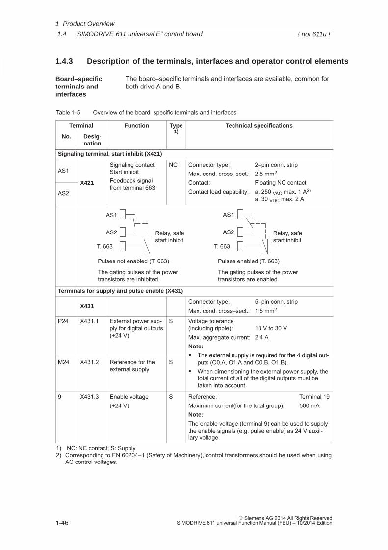
1
1.4 ”SIMODRIVE 611 universal E” control board
1-46� Siemens AG 2014 All Rights Reserved
SIMODRIVE 611 universal Function Manual (FBU) – 10/2014 Edition
1.4.3 Description of the terminals, interfaces and operator control elements
The board–specific terminals and interfaces are available, common forboth drive A and B.
Table 1-5 Overview of the board–specific terminals and interfaces
Terminal Function Type1)
Technical specifications
No. Desig-nation
1)
Signaling terminal, start inhibit (X421)
AS1
X421
Signaling contact Start inhibitFeedback signal
NC Connector type: 2–pin conn. stripMax. cond. cross–sect.: 2.5 mm2
Contact: Floating NC contact
AS2
X421 Feedback signalfrom terminal 663
Contact: Floating NC contactContact load capability: at 250 VAC max. 1 A2)
at 30 VDC max. 2 A
Relay, safestart inhibit
AS2
AS1
T. 663 T. 663
Pulses not enabled (T. 663)
The gating pulses of the powertransistors are inhibited.
Pulses enabled (T. 663)
The gating pulses of the powertransistors are enabled.
Relay, safestart inhibit
AS2
AS1
Terminals for supply and pulse enable (X431)
X431Connector type: 5–pin conn. stripMax. cond. cross–sect.: 1.5 mm2
P24 X431.1 External power sup-ply for digital outputs(+24 V)
S Voltage tolerance(including ripple): 10 V to 30 VMax. aggregate current: 2.4 ANote:
� The external supply is required for the 4 digital out-M24 X431.2 Reference for the
external supplyS
� The external supply is required for the 4 digital out-puts (O0.A, O1.A and O0.B, O1.B).
� When dimensioning the external power supply, thetotal current of all of the digital outputs must betaken into account.
9 X431.3 Enable voltage(+24 V)
S Reference: Terminal 19Maximum current(for the total group): 500 mANote:
The enable voltage (terminal 9) can be used to supplythe enable signals (e.g. pulse enable) as 24 V auxil-iary voltage.
1) NC: NC contact; S: Supply2) Corresponding to EN 60204–1 (Safety of Machinery), control transformers should be used when using
AC control voltages.
Board–specificterminals and interfaces
1 Product Overview
! not 611u !
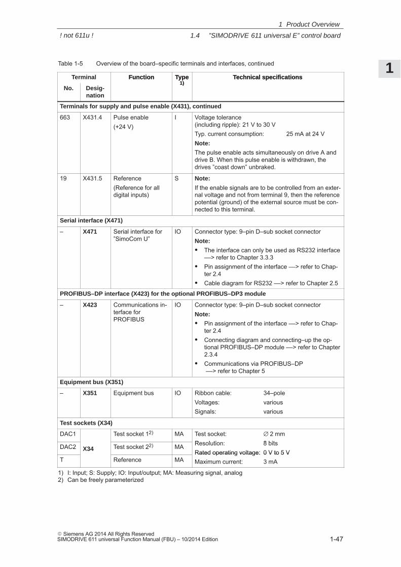
1
1.4 ”SIMODRIVE 611 universal E” control board
1-47� Siemens AG 2014 All Rights ReservedSIMODRIVE 611 universal Function Manual (FBU) – 10/2014 Edition
Table 1-5 Overview of the board–specific terminals and interfaces, continued
Terminal Technical specificationsType1)
Function
No.
Technical specificationsType1)
Function
Desig-nation
Terminals for supply and pulse enable (X431), continued
663 X431.4 Pulse enable(+24 V)
I Voltage tolerance(including ripple): 21 V to 30 VTyp. current consumption: 25 mA at 24 VNote:
The pulse enable acts simultaneously on drive A anddrive B. When this pulse enable is withdrawn, thedrives ”coast down” unbraked.
19 X431.5 Reference(Reference for alldigital inputs)
S Note:
If the enable signals are to be controlled from an exter-nal voltage and not from terminal 9, then the referencepotential (ground) of the external source must be con-nected to this terminal.
Serial interface (X471)
– X471 Serial interface for”SimoCom U”
IO Connector type: 9–pin D–sub socket connectorNote:
� The interface can only be used as RS232 interface––> refer to Chapter 3.3.3
� Pin assignment of the interface ––> refer to Chap-ter 2.4
� Cable diagram for RS232 ––> refer to Chapter 2.5
PROFIBUS–DP interface (X423) for the optional PROFIBUS–DP3 module
– X423 Communications in-terface forPROFIBUS
IO Connector type: 9–pin D–sub socket connectorNote:
� Pin assignment of the interface ––> refer to Chap-ter 2.4
� Connecting diagram and connecting–up the op-tional PROFIBUS–DP module ––> refer to Chapter2.3.4
� Communications via PROFIBUS–DP ––> refer to Chapter 5
Equipment bus (X351)
– X351 Equipment bus IO Ribbon cable: 34–poleVoltages: variousSignals: various
Test sockets (X34)
DAC1 Test socket 12) MA Test socket: ∅ 2 mmResolution: 8 bitsDAC2 X34 Test socket 22) MA Resolution: 8 bitsRated operating voltage: 0 V to 5 V
T Reference MARated operating voltage: 0 V to 5 VMaximum current: 3 mA
1) I: Input; S: Supply; IO: Input/output; MA: Measuring signal, analog2) Can be freely parameterized
1 Product Overview
! not 611u !
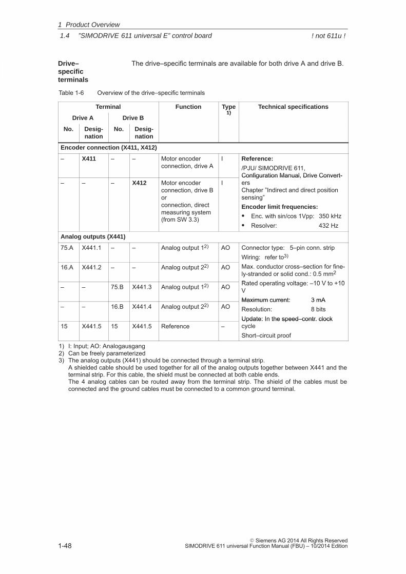
1
1.4 ”SIMODRIVE 611 universal E” control board
1-48� Siemens AG 2014 All Rights Reserved
SIMODRIVE 611 universal Function Manual (FBU) – 10/2014 Edition
The drive–specific terminals are available for both drive A and drive B.
Table 1-6 Overview of the drive–specific terminals
Terminal Function Type1)
Technical specifications
Drive A Drive B1)
No. Desig-nation
No. Desig-nation
Encoder connection (X411, X412)
– X411 – – Motor encoderconnection, drive A
I Reference:
/PJU/ SIMODRIVE 611, Configuration Manual, Drive Convert-
– – – X412 Motor encoder connection, drive Borconnection, directmeasuring system (from SW 3.3)
IConfiguration Manual, Drive Convert-ersChapter ”Indirect and direct positionsensing”Encoder limit frequencies:
� Enc. with sin/cos 1Vpp: 350 kHz� Resolver: 432 Hz
Analog outputs (X441)
75.A X441.1 – – Analog output 12) AO Connector type: 5–pin conn. stripWiring: refer to3)
16.A X441.2 – – Analog output 22) AOWiring: refer toMax. conductor cross–section for fine-ly-stranded or solid cond.: 0.5 mm2
Rated operating voltage: –10 V to +10– – 75.B X441.3 Analog output 12) AO Rated operating voltage: –10 V to +10VMaximum current: 3 mA
– – 16.B X441.4 Analog output 22) AOMaximum current: 3 mAResolution: 8 bitsUpdate: In the speed–contr. clock
15 X441.5 15 X441.5 Reference –Update: In the speed–contr. clockcycleShort–circuit proof
1) I: Input; AO: Analogausgang2) Can be freely parameterized3) The analog outputs (X441) should be connected through a terminal strip.
A shielded cable should be used together for all of the analog outputs together between X441 and theterminal strip. For this cable, the shield must be connected at both cable ends. The 4 analog cables can be routed away from the terminal strip. The shield of the cables must beconnected and the ground cables must be connected to a common ground terminal.
Drive–specific terminals
1 Product Overview
! not 611u !
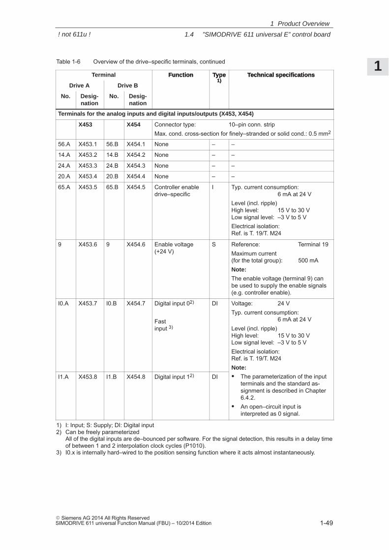
1
1.4 ”SIMODRIVE 611 universal E” control board
1-49� Siemens AG 2014 All Rights ReservedSIMODRIVE 611 universal Function Manual (FBU) – 10/2014 Edition
Table 1-6 Overview of the drive–specific terminals, continued
Terminal Technical specificationsType1)
Function
Drive A
Technical specificationsType1)
Function
Drive B
No.
Technical specificationsType1)
Function
Desig-nation
No.Desig-nation
Terminals for the analog inputs and digital inputs/outputs (X453, X454)
X453 X454 Connector type: 10–pin conn. stripMax. cond. cross-section for finely–stranded or solid cond.: 0.5 mm2
56.A X453.1 56.B X454.1 None – –
14.A X453.2 14.B X454.2 None – –
24.A X453.3 24.B X454.3 None – –
20.A X453.4 20.B X454.4 None – –
65.A X453.5 65.B X454.5 Controller enable drive–specific
I Typ. current consumption: 6 mA at 24 V
Level (incl. ripple)High level: 15 V to 30 VLow signal level: –3 V to 5 VElectrical isolation: Ref. is T. 19/T. M24
9 X453.6 9 X454.6 Enable voltage(+24 V)
S Reference: Terminal 19Maximum current (for the total group): 500 mANote:
The enable voltage (terminal 9) canbe used to supply the enable signals(e.g. controller enable).
I0.A X453.7 I0.B X454.7 Digital input 02)
Fastinput 3)
DI Voltage: 24 VTyp. current consumption:
6 mA at 24 VLevel (incl. ripple)High level: 15 V to 30 VLow signal level: –3 V to 5 VElectrical isolation: Ref. is T. 19/T. M24Note:
I1.A X453.8 I1.B X454.8 Digital input 12) DINote:
� The parameterization of the inputterminals and the standard as-signment is described in Chapter6.4.2.
� An open–circuit input is interpreted as 0 signal.
1) I: Input; S: Supply; DI: Digital input2) Can be freely parameterized
All of the digital inputs are de–bounced per software. For the signal detection, this results in a delay timeof between 1 and 2 interpolation clock cycles (P1010).
3) I0.x is internally hard–wired to the position sensing function where it acts almost instantaneously.
1 Product Overview
! not 611u !
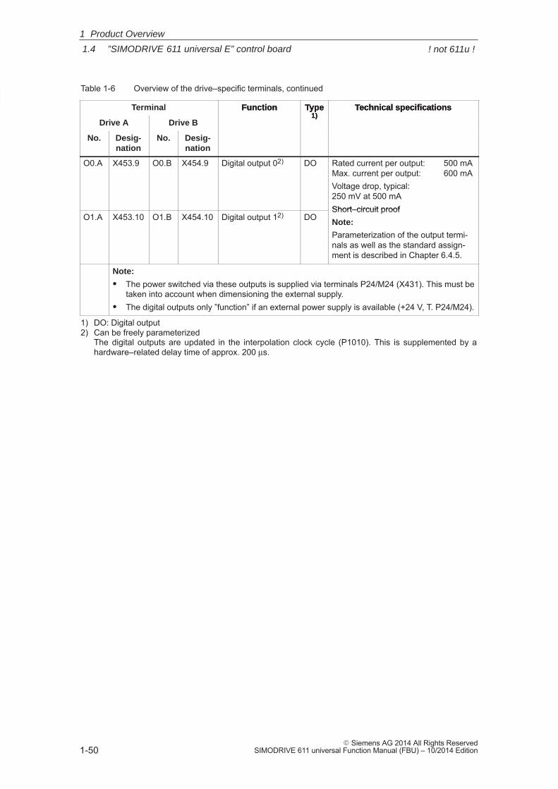
1
1.4 ”SIMODRIVE 611 universal E” control board
1-50� Siemens AG 2014 All Rights Reserved
SIMODRIVE 611 universal Function Manual (FBU) – 10/2014 Edition
Table 1-6 Overview of the drive–specific terminals, continued
Terminal Technical specificationsType1)
Function
Drive A
Technical specificationsType1)
Function
Drive B
No.
Technical specificationsType1)
Function
Desig-nation
No.Desig-nation
O0.A X453.9 O0.B X454.9 Digital output 02) DO Rated current per output: 500 mAMax. current per output: 600 mAVoltage drop, typical: 250 mV at 500 mAShort–circuit proof
O1.A X453.10 O1.B X454.10 Digital output 12) DOShort–circuit proofNote:
Parameterization of the output termi-nals as well as the standard assign-ment is described in Chapter 6.4.5.
Note:
� The power switched via these outputs is supplied via terminals P24/M24 (X431). This must betaken into account when dimensioning the external supply.
� The digital outputs only ”function” if an external power supply is available (+24 V, T. P24/M24).
1) DO: Digital output2) Can be freely parameterized
The digital outputs are updated in the interpolation clock cycle (P1010). This is supplemented by ahardware–related delay time of approx. 200 μs.
1 Product Overview
! not 611u !
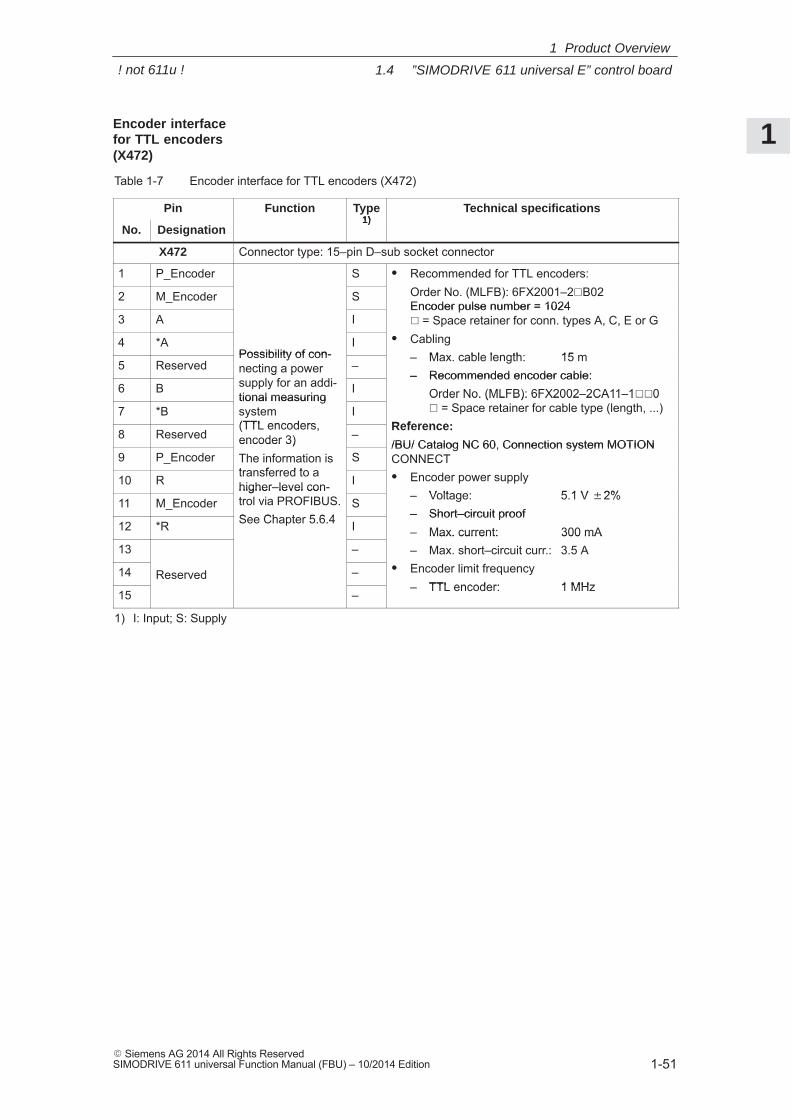
1
1.4 ”SIMODRIVE 611 universal E” control board
1-51� Siemens AG 2014 All Rights ReservedSIMODRIVE 611 universal Function Manual (FBU) – 10/2014 Edition
Table 1-7 Encoder interface for TTL encoders (X472)
Pin Function Type1)
Technical specifications
No. Designation1)
X472 Connector type: 15–pin D–sub socket connector
1 P_Encoder S � Recommended for TTL encoders:Order No. (MLFB): 6FX2001–2 B022 M_Encoder S Order No. (MLFB): 6FX2001–2�B02Encoder pulse number = 1024
3 A IEncoder pulse number = 1024� = Space retainer for conn. types A, C, E or GCabling4 *A
Possibility of con-I � Cabling
– Max. cable length: 15 m5 Reserved
Possibility of con-necting a powersupply for an addi-
–– Max. cable length: 15 m– Recommended encoder cable:
6 B
necting a powersupply for an addi-tional measuring
I– Recommended encoder cable:
Order No. (MLFB): 6FX2002–2CA11–1��0 = Space retainer for cable type (length, ...)7 *B
tional measuringsystem(TTL encoders,
IOrder No. (MLFB): 6FX2002–2CA11–1��0� = Space retainer for cable type (length, ...)
Reference:8 Reserved
(TTL encoders, encoder 3) –
Reference:
/BU/ Catalog NC 60, Connection system MOTION9 P_Encoder
encoder 3)The information istransferred to a
S/BU/ Catalog NC 60, Connection system MOTIONCONNECT
Encoder power supply10 Rtransferred to ahigher–level con- I � Encoder power supply
– Voltage: 5.1 V �2%11 M_Encoder
higher–level con-trol via PROFIBUS.See Chapter 5.6.4
S– Voltage: 5.1 V �2%– Short–circuit proof
12 *R See Chapter 5.6.4 I– Short–circuit proof– Max. current: 300 mA
13 –– Max. current: 300 mA– Max. short–circuit curr.: 3.5 AEncoder limit frequency14 Reserved – � Encoder limit frequency– TTL encoder: 1 MHz
15
Reserved
–– TTL encoder: 1 MHz
1) I: Input; S: Supply
Encoder interfacefor TTL encoders(X472)
1 Product Overview
! not 611u !
1
1.4 ”SIMODRIVE 611 universal E” control board
1-52� Siemens AG 2014 All Rights Reserved
SIMODRIVE 611 universal Function Manual (FBU) – 10/2014 Edition
The component comprises a button with integrated LED.
� POWER–ON RESET, button
The button is recessed into the front panel (hole: ∅ 3 mm). The processor runs up again when pressed.
When the pushbutton is pressed, an LED which may have been pre-viously bright (lit), goes dark, i.e. this indicates the pushbutton wascompletely actuated (the pushbutton pressure point has beenreached).
!Warning
When the POWER–ON RESET button is pressed, this corresponds toa POWER ON and should only be executed when the motors are at astandstill.
In order to prevent the drive from undesirably starting after POWERON, before carrying out a POWER ON–RESET, the controller enablemust be withdrawn at terminals 65.A and 65.B.
� FAULT, LED red (refer to Chapter 7.2.2)
The LED is bright at run–up and when faults occur.
The 6–character 7–segment display with point is used to display andchange parameter values and to display alarms.
The operator control PLUS, P and MINUS keys are used to select andchange parameter values and/or for operator control when faults andwarnings are displayed (e.g. to acknowledge these).
Reader’s note
Handling the display and operator unit� To parameterize the drive, refer to Chapter 3.2� To remove faults and warnings, refer to Chapter 7.2.1
Button for
POWER ON–RESET,
FAULT, LED red
Display and operator unit
1 Product Overview
! not 611u !
1
1.4 ”SIMODRIVE 611 universal E” control board
1-53� Siemens AG 2014 All Rights ReservedSIMODRIVE 611 universal Function Manual (FBU) – 10/2014 Edition
1.4.4 Commissioning the board with ”SimoCom U”
The following prerequisites must be fulfilled in order to be able to com-mission a drive using the ”SimoCom U” parameterizing and start–uptool:
1. All of the prerequisites for commissioning are fulfilled, according toChapter 4.1 this means that the system with ”SIMODRIVE 611 uni-versal E” can be commissioned.
2. The checklist for commissioning according to Chapter 4.1 has beenchecked.
3. The optional PROFIBUS–DP3 module is inserted into the controlboard (refer to Chapter 1.3.3).
4. The ”SimoCom U” tool is installed on the PC/PG, which is to beused to commission the drive.
5. There is a connecting cable between the PG/PC and control board(RS232 connecting cable, refer to Chapter 2.5).
6. The PC/PG with ”SimoCom U” is connected to the control board(X471).
Reader’s note� Cable diagrams for the connecting cable refer to Chapter 2.5� Everything about ”SimoCom U” refer to Chapter 3.3
Requirements
1 Product Overview
! not 611u !
1
1.4 ”SIMODRIVE 611 universal E” control board
1-54� Siemens AG 2014 All Rights Reserved
SIMODRIVE 611 universal Function Manual (FBU) – 10/2014 Edition
Please proceed as follows when commissioning ”SIMODRIVE 611 uni-versal E” using the ”SimoCom U” parameterizing and start–up tool forthe first time:
1. Power–up the drive group
2. Start SimoCom U
3. Request online operation for drive A
Operator action: Execute the ”Search for online drives” function in the ”Start–up”menu, and select drive A in the ”Drive and dialog browser”.
Is the ”start–up required” window displayed?
– Yes: ––> Start the drive configuration assistant
––>This means you signal the drive the existing configuration(PROFIBUS node address, power module, motor, etc.).
– No: ––> Press ”re–configure drive” button
––> This means that you change the configuration on the controlboard (PROFIBUS node address, power module, motor, etc.).
4. Execute the drive configuration, and at the end, press the ”Calculatecontroller data, save, reset” button.
Note
If drive B is to be commissioned, then the points must be executed fordrive B from point 3 onwards.
Procedure when commissioning thedrive for the firsttime
1 Product Overview
! not 611u !
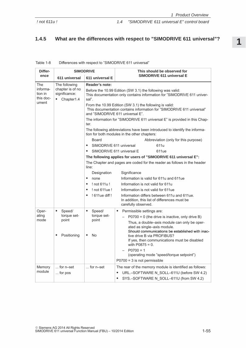
1
1.4 ”SIMODRIVE 611 universal E” control board
1-55� Siemens AG 2014 All Rights ReservedSIMODRIVE 611 universal Function Manual (FBU) – 10/2014 Edition
1.4.5 What are the differences with respect to ”SIMODRIVE 611 universal”?
Table 1-8 Differences with respect to ”SIMODRIVE 611 universal”
Differ-ence
SIMODRIVE This should be observed for SIMODRIVE 611 universal Eence
611 universal 611 universal ESIMODRIVE 611 universal E
Theinforma-tion inthis doc-ument
The followingchapter is of nosignificance:� Chapter1.4
Reader’s note:
Before the 10.99 Edition (SW 3.1) the following was valid:This documentation only contains information for ”SIMODRIVE 611 univer-sal”.From the 10.99 Edition (SW 3.1) the following is valid: This documentation contains information for ”SIMODRIVE 611 universal”and ”SIMODRIVE 611 universal E”.The information for ”SIMODRIVE 611 universal E” is provided in this Chap-ter.The following abbreviations have been introduced to identify the informa-tion for both modules in the other chapters:
Board Abbreviation (only for this purpose)� SIMODRIVE 611 universal 611u� SIMODRIVE 611 universal E 611ueThe following applies for users of ”SIMODRIVE 611 universal E”:
The Chapter and pages are coded for the reader as follows in the headerline:
Designation Significance� none Information is valid for 611u and 611ue� ! not 611u ! Information is not valid for 611u� ! not 611ue ! Information is not valid for 611ue� ! 611ue diff ! Information differs between 611u and 611ue.
In addition, this list of differences must be carefully observed.
Oper-atingmode
� Speed/torque set-point
� Speed/torque set-point
� Permissible settings are:– P0700 = 0 (the drive is inactive, only drive B)
Thus, a double–axis module can only be oper-ated as single–axis module. Should communications be established with inac-
� Positioning � NoShould communications be established with inac-tive drive B via PROFIBUS? If yes, then communications must be disabledwith P0875 = 0.with P0875 = 0.
– P0700 = 1 (operating mode ”speed/torque setpoint”)
P0700 = 3 is not permissible
Memorymodule
... for n–set
... for pos... for n–set The rear of the memory module is identified as follows:
� URL.–SOFTWARE N_SOLL–611U (before SW 4.2)� SYS.–SOFTWARE N_SOLL–611U (from SW 4.2)
1 Product Overview
! not 611u !
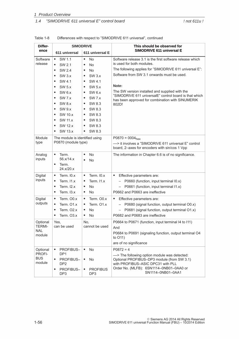
1
1.4 ”SIMODRIVE 611 universal E” control board
1-56� Siemens AG 2014 All Rights Reserved
SIMODRIVE 611 universal Function Manual (FBU) – 10/2014 Edition
Table 1-8 Differences with respect to ”SIMODRIVE 611 universal”, continued
Differ-ence
This should be observed for SIMODRIVE 611 universal E
SIMODRIVEDiffer-ence
This should be observed for SIMODRIVE 611 universal E
611 universal E611 universal
Softwarerelease
� SW 1.1� SW 2.1� SW 2.4� SW 3.x� SW 4.1� SW 5.x� SW 6.x� SW 7.x� SW 8.x� SW 9.x� SW 10.x� SW 11.x� SW 12.x� SW 13.x
� No� No� No� SW 3.x� SW 4.1� SW 5.x� SW 6.x� SW 7.x� SW 8.3� SW 8.3� SW 8.3� SW 8.3� SW 8.3� SW 8.3
Software release 3.1 is the first software release whichis used for both modules.The following applies for ”SIMODRIVE 611 universal E”:Software from SW 3.1 onwards must be used.
Note:
The SW version installed and supplied with the”SIMODRIVE 611 universalE” control board is that whichhas been approved for combination with SINUMERIK802D!
Moduletype
The module is identified usingP0870 (module type)
P0870 = 0004hex
––> it involves a ”SIMODRIVE 611 universal E” controlboard, 2–axes for encoders with sin/cos 1 Vpp
Analoginputs
� Term.56.x/14.x
� Term.24.x/20.x
� No� No
The information in Chapter 6.6 is of no significance.
Digitalinputs
� Term. I0.x� Term. I1.x� Term. I2.x� Term. I3.x
� Term. I0.x� Term. I1.x� No� No
� Effective parameters are:– P0660 (function, input terminal I0.x)– P0661 (function, input terminal I1.x)
P0662 and P0663 are ineffective
Digitaloutputs
� Term. O0.x� Term. O1.x� Term. O2.x� Term. O3.x
� Term. O0.x� Term. O1.x� No� No
� Effective parameters are:– P0680 (signal function, output terminal O0.x)– P0681 (signal function, output terminal O1.x)
P0682 and P0683 are ineffective
OptionalTERMI-NALmodule
Yes, can be used
No, cannot be used
P0664 to P0671 (function, input terminal I4 to I11)AndP0684 to P0691 (signaling function, output terminal O4to O11)are of no significance
OptionalPROFI-BUSmodule
� PROFIBUS–DP1
� PROFIBUS–DP2
� PROFIBUS–DP3
� No
� No
� PROFIBUSDP3
P0872 = 4––> The following option module was detected:Optional PROFIBUS–DP3 module (from SW 3.1) with PROFIBUS–ASIC DPC31 with PLL Order No. (MLFB): 6SN1114–0NB01–0AA0 or
SN1114–0NB01–0AA1
1 Product Overview
! not 611u !
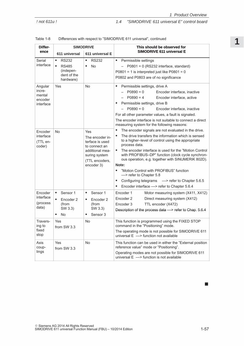
1
1.4 ”SIMODRIVE 611 universal E” control board
1-57� Siemens AG 2014 All Rights ReservedSIMODRIVE 611 universal Function Manual (FBU) – 10/2014 Edition
Table 1-8 Differences with respect to ”SIMODRIVE 611 universal”, continued
Differ-ence
This should be observed for SIMODRIVE 611 universal E
SIMODRIVEDiffer-ence
This should be observed for SIMODRIVE 611 universal E
611 universal E611 universal
Serialinterface
� RS232� RS485
(indepen-dent of thehardware)
� RS232� No
� Permissible settings– P0801 = 0 (RS232 interface, standard)
P0801 = 1 is interpreted just like P0801 = 0P0802 and P0803 are of no significance
Angularincre-mentalencoderinterface
Yes No � Permissible settings, drive A– P0890 = 0 Encoder interface, inactive– P0890 = 4 Encoder interface, active
� Permissible settings, drive B– P0890 = 0 Encoder interface, inactive
For all other parameter values, a fault is signaled.The encoder interface is not suitable to connect a directmeasuring system for the following reasons:
The encoder signals are not evaluated in the drive.Encoderinterface(TTL en-coder)
No YesThe encoder in-terface is usedto connect anadditional mea-suring system(TTL encoders, encoder 3)
� The encoder signals are not evaluated in the drive.� The drive transfers the information which is sensed
to a higher–level of control using the appropriateprocess data.
� The encoder interface is used for the ”Motion Controlwith PROFIBUS–DP” function (clock cycle synchron-ous operation, e.g. together with SINUMERIK 802D).
Note:
� ”Motion Control with PROFIBUS” function––> refer to Chapter 5.8
� Configuring telegrams ––> refer to Chapter 5.6.5� Encoder interface ––> refer to Chapter 5.6.4
Encoderinterface
� Sensor 1 � Sensor 1 Encoder 1 Motor measuring system (X411, X412)interface(processdata)
� Encoder 2(fromSW 3.3)
� Encoder 2(fromSW 3.3)
Encoder 2 Direct measuring system (X412)Encoder 3 TTL encoder (X472)Description of the process data ––> refer to Chap. 5.6.4
� No � Sensor 3Description of the process data ––> refer to Chap. 5.6.4
Travers-ing tofixedstop
Yesfrom SW 3.3
No This function is programmed using the FIXED STOPcommand in the ”Positioning” mode.The operating mode is not possible for SIMODRIVE 611universal E ––> function not available
Axiscoup-lings
Yesfrom SW 3.3
No This function can be used in either the ”External positionreference value” mode or ”Positioning”.Operating modes are not possible for SIMODRIVE 611universal E ––> function is not available
1 Product Overview
! not 611u !

1
1.4 ”SIMODRIVE 611 universal E” control board
1-58� Siemens AG 2014 All Rights Reserved
SIMODRIVE 611 universal Function Manual (FBU) – 10/2014 Edition
1 Product Overview
Space for your notes
2
2-59� Siemens AG 2014 All Rights ReservedSIMODRIVE 611 universal Function Manual (FBU) – 10/2014 Edition
Installing and Connecting–Up
2.1 Installing/removing control boards and modules 2-60. . . . . . . . . . . . . . . . . . . . . 2.1.1 Installing the control board 2-60. . . . . . . . . . . . . . . . . . . . . . . . . . . . . . . . . . . . . . . . 2.1.2 Installing/removing an option module 2-61. . . . . . . . . . . . . . . . . . . . . . . . . . . . . . . 2.1.3 Installing/removing the memory module 2-62. . . . . . . . . . . . . . . . . . . . . . . . . . . . 2.1.4 Replacing a defective HR control board by a new one 2-64. . . . . . . . . . . . . . . . 2.1.5 Replacing a defective HRS / HRS2 control board by a new one 2-67. . . . . . . .
2.2 Wiring 2-70. . . . . . . . . . . . . . . . . . . . . . . . . . . . . . . . . . . . . . . . . . . . . . . . . . . . . . . . . 2.2.1 General information on connecting–up 2-70. . . . . . . . . . . . . . . . . . . . . . . . . . . . . 2.2.2 Connecting–up and setting the line supply infeed module 2-73. . . . . . . . . . . . . 2.2.3 Connecting–up the power module 2-74. . . . . . . . . . . . . . . . . . . . . . . . . . . . . . . . .
2.3 Connection diagram and wiring 2-75. . . . . . . . . . . . . . . . . . . . . . . . . . . . . . . . . . . . 2.3.1 Connection diagram for the ”SIMODRIVE 611 universal” board 2-75. . . . . . . . 2.3.2 Connecting–up the control board 2-76. . . . . . . . . . . . . . . . . . . . . . . . . . . . . . . . . . 2.3.3 Connection diagram, connecting–up the optional
TERMINAL module 2-82. . . . . . . . . . . . . . . . . . . . . . . . . . . . . . . . . . . . . . . . . . . . . . 2.3.4 Connection diagram, connecting–up the optional
PROFIBUS–DP module 2-84. . . . . . . . . . . . . . . . . . . . . . . . . . . . . . . . . . . . . . . . . .
2.4 Pin assignment of the interfaces 2-86. . . . . . . . . . . . . . . . . . . . . . . . . . . . . . . . . . .
2.5 Cable diagrams 2-89. . . . . . . . . . . . . . . . . . . . . . . . . . . . . . . . . . . . . . . . . . . . . . . . .
2
2
2.1 Installing/removing control boards and modules
2-60� Siemens AG 2014 All Rights Reserved
SIMODRIVE 611 universal Function Manual (FBU) – 10/2014 Edition
2.1 Installing/removing control boards and modules
!Warning
It is only permissible to install/remove a control board or an optionmodule when the system is in a no–voltage condition (powered down).
If boards or option modules are inserted or withdrawn under voltage,this can result in data loss or destruction of components.
Note
The screws retaining electrical connections at the modules must betightened with the following torque:Screw size ––> tightening torqueM3 ––> 0.5 Nm (for electrical connections)M3 ––> 0.8 Nm (for mechanical connections)M4 ––> 1.8 NmM5 ––> 3.0 NmTolerance ––> 0/+30 %After transport, the screws should be tightened!
2.1.1 Installing the control board
The following points must be observed when installing the”SIMODRIVE 611 universal” control board into the power module (refer to Fig. 2-1):
!Warning
The ESDS measures must be observed when installing/removing thecontrol board.
1. Ensure that the power module is in a no–voltage condition.2. Check that the memory module is inserted and locked into place in
the control board. If it is not inserted, then refer to the point ”installing/removing thememory module”.
3. Insert the control board in the power module.4. Tighten up the screws retaining the board
(2 screws on the front panel, max. torque= 0.8 Nm).5. Connect–up the front panel of the board corresponding to the con-
nection diagram (refer to Chapter 2.3.1).The mating connectors are inserted at the appropriate interface.
2 Installing and Connecting–Up
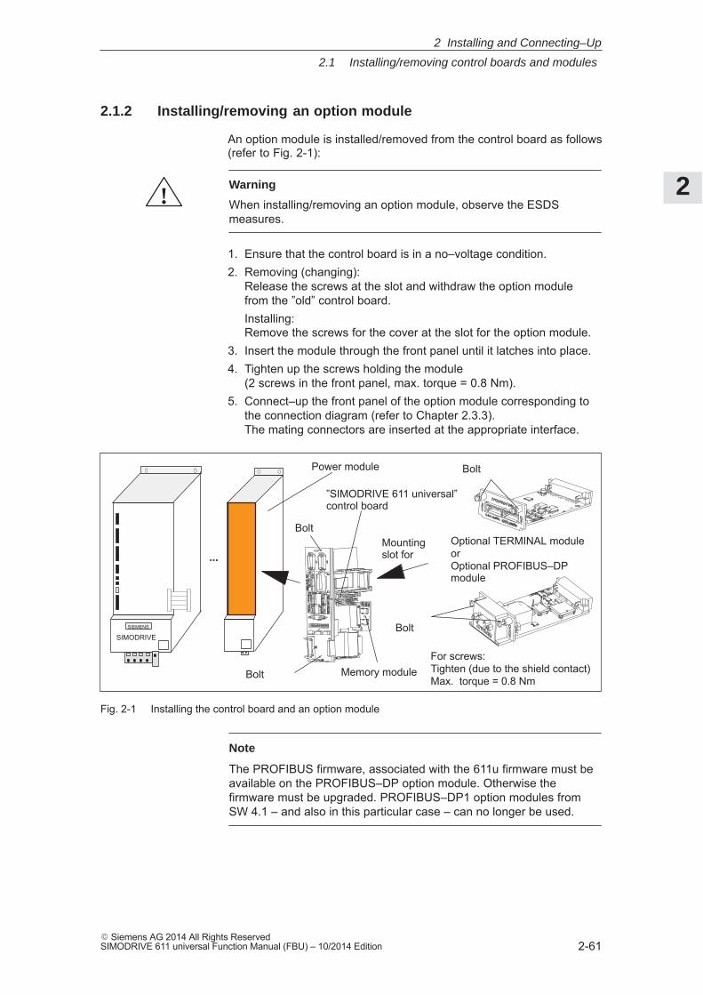
2
2.1 Installing/removing control boards and modules
2-61� Siemens AG 2014 All Rights ReservedSIMODRIVE 611 universal Function Manual (FBU) – 10/2014 Edition
2.1.2 Installing/removing an option module
An option module is installed/removed from the control board as follows(refer to Fig. 2-1):
!Warning
When installing/removing an option module, observe the ESDSmeasures.
1. Ensure that the control board is in a no–voltage condition.2. Removing (changing):
Release the screws at the slot and withdraw the option module from the ”old” control board.Installing:Remove the screws for the cover at the slot for the option module.
3. Insert the module through the front panel until it latches into place.4. Tighten up the screws holding the module
(2 screws in the front panel, max. torque = 0.8 Nm).5. Connect–up the front panel of the option module corresponding to
the connection diagram (refer to Chapter 2.3.3).The mating connectors are inserted at the appropriate interface.
Power module
”SIMODRIVE 611 universal” control board
Optional TERMINAL moduleorOptional PROFIBUS–DPmodule
...
Bolt
Bolt
Bolt
For screws:Tighten (due to the shield contact)Max. torque = 0.8 Nm
Mounting slot for
Memory module
Bolt
SIMODRIVESIEMENS
Fig. 2-1 Installing the control board and an option module
Note
The PROFIBUS firmware, associated with the 611u firmware must beavailable on the PROFIBUS–DP option module. Otherwise thefirmware must be upgraded. PROFIBUS–DP1 option modules fromSW 4.1 – and also in this particular case – can no longer be used.
2 Installing and Connecting–Up
2
2.1 Installing/removing control boards and modules
2-62� Siemens AG 2014 All Rights Reserved
SIMODRIVE 611 universal Function Manual (FBU) – 10/2014 Edition
2.1.3 Installing/removing the memory module
The memory module can be replaced, and when supplied from the fac-tory, a new control board is already installed.
When replacing the control board (service) with an identical one, afunctioning memory module can be taken from the old control boardand inserted in the new control board. This means that the system soft-ware can be transferred over with the user files without requiring anyother resources.
When replacing with a type HR or HRS control board, Chapter 2.1.4or2.1.5 or the mounting instructions provided with the spare part mustbe carefully observed.
There are memory modules for n–set or positioning. This is labeled at the rear of the memory module:Designation can be inserted in control boardbefore SW 4.2URL.–SOFTWARE POS.–611U for positioning (refer to Chap. 1.3)URL.–SOFTWARE N_SOLL–611U for n–set (refer to Chapter 1.3)from SW 4.2SYS.–SOFTWARE POS.–611U for positioning (refer to Chap. 1.3)SYS.–SOFTWARE N_SOLL–611U for n–set (refer to Chapter 1.3)The software designation refers to the system software including the initial program loader.
A memory module is inserted/replaced as follows:
!Warning
The ESDS measures must be observed when installing/removing thememory module.
1. Place the old and new control boards on an ESDS–compatible sur-face (to the left of the front panel).
2. Press the memory module latches downwards and outwards untilthey release (refer to Fig. 2-2).
3. Remove the memory from its connections (upwards).
4. Insert the old memory module into the new control board and the new memory module into the old control board. The latches must automatically engage.
5. Check that the latches are correctly engaged.
General
What types ofmemory modulesare available?
How is the memory module replaced?
2 Installing and Connecting–Up
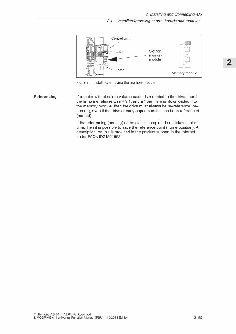
2
2.1 Installing/removing control boards and modules
2-63� Siemens AG 2014 All Rights ReservedSIMODRIVE 611 universal Function Manual (FBU) – 10/2014 Edition
Memory module
Control unit
Latch
Latch
Slot formemorymodule
Fig. 2-2 Installing/removing the memory module
If a motor with absolute value encoder is mounted to the drive, then ifthe firmware release was < 9.1, and a *.par file was downloaded intothe memory module, then the drive must always be re–reference (re–homed), even if the drive already appears as if it has been referenced(homed).
If the referencing (homing) of the axis is completed and takes a lot oftime, then it is possible to save the reference point (home position). Adescription on this is provided in the product support in the Internetunder FAQs ID21821692.
Referencing
2 Installing and Connecting–Up
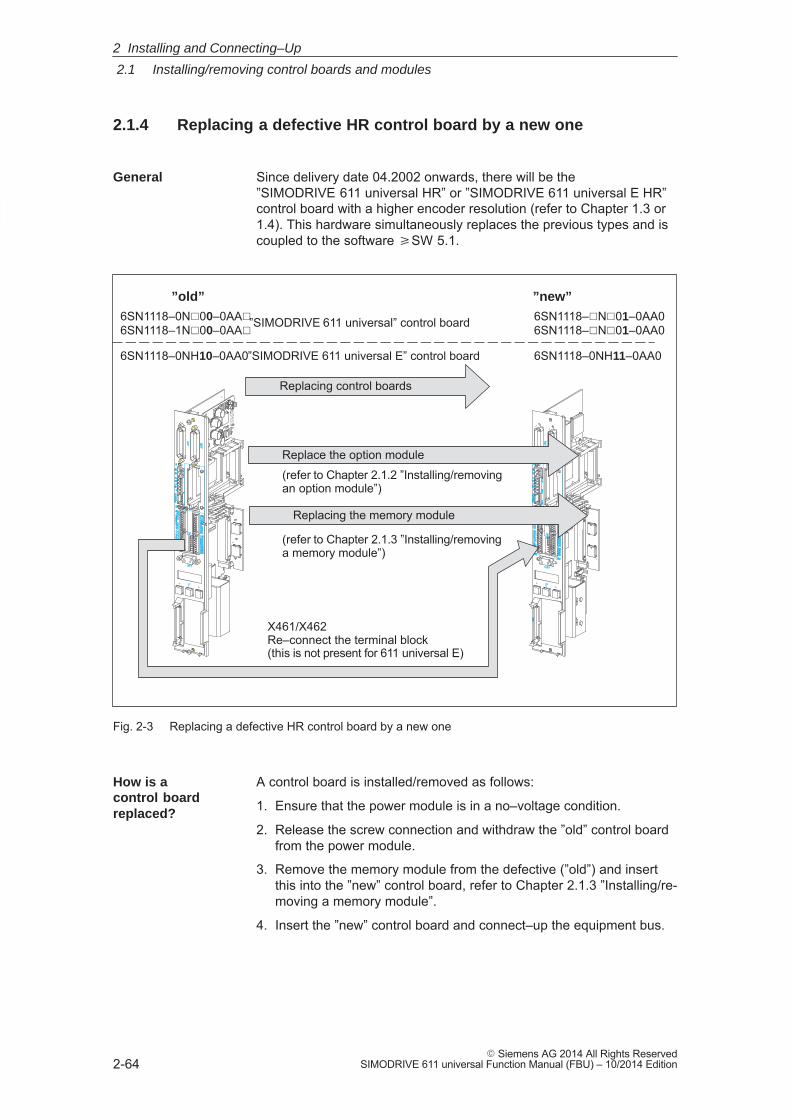
2
2.1 Installing/removing control boards and modules
2-64� Siemens AG 2014 All Rights Reserved
SIMODRIVE 611 universal Function Manual (FBU) – 10/2014 Edition
2.1.4 Replacing a defective HR control board by a new one
Since delivery date 04.2002 onwards, there will be the ”SIMODRIVE 611 universal HR” or ”SIMODRIVE 611 universal E HR”control board with a higher encoder resolution (refer to Chapter 1.3 or1.4). This hardware simultaneously replaces the previous types and iscoupled to the software �SW 5.1.
6SN1118–0N�00–0AA�6SN1118–1N�00–0AA�”SIMODRIVE 611 universal” control board
”old” ”new”
Replacing the memory module
Replace the option module
6SN1118–0NH10–0AA0”SIMODRIVE 611 universal E” control board
Replacing control boards
6SN1118–�N�01–0AA06SN1118–�N�01–0AA0
6SN1118–0NH11–0AA0
(refer to Chapter 2.1.2 ”Installing/removingan option module”)
(refer to Chapter 2.1.3 ”Installing/removinga memory module”)
X461/X462 Re–connect the terminal block(this is not present for 611 universal E)
Fig. 2-3 Replacing a defective HR control board by a new one
A control board is installed/removed as follows:
1. Ensure that the power module is in a no–voltage condition.
2. Release the screw connection and withdraw the ”old” control boardfrom the power module.
3. Remove the memory module from the defective (”old”) and insert this into the ”new” control board, refer to Chapter 2.1.3 ”Installing/re-moving a memory module”.
4. Insert the ”new” control board and connect–up the equipment bus.
General
How is a control boardreplaced?
2 Installing and Connecting–Up
2
2.1 Installing/removing control boards and modules
2-65� Siemens AG 2014 All Rights ReservedSIMODRIVE 611 universal Function Manual (FBU) – 10/2014 Edition
5. Install the ”SimoCom U” start–up tool with version 5.1 (or higher)or, when using an ”older” version, observe the following information:
– Exit SimoCom U.
– Make a back–up copy of the test file ”...\siemens\lists\control.txt”in the main SimoCom U directory (generally under ”C:\ProgramFiles\Siemens\SimoComU”).
– Then open this file with Microsoft Wordpad (not with a text editor!).
– Search for the following line under the Section ”611U” or the lastline of this section:
– 6SN1118–1NJ00–0AAx 259 0x00000000 1 1 2 1 ;611Uresolver 1–axis X_SOLL
– Insert the following lines directly below:
– 6SN1118–0NH01–0AA0 5 0x00000000 2 2 1 7 ;611Uencoder HR 2–axis N_SOLL
– 6SN1118–0NK01–0AA0 7 0x00000000 1 2 1 8 ;611Uresolver HR 2–axis N_SOLL
– 6SN1118–0NJ01–0AA0 8 0x00000000 1 1 1 8 ;611Uresolver HR 1–axis N_SOLL
– 6SN1118–1NH01–0AA0 261 0x00000000 2 2 2 7 ;611Uencoder HR 2–axis X_SOLL
– 6SN1118–1NK01–0AA0 263 0x00000000 1 2 2 8 ;611Uresolver HR 2–axis X_SOLL
– 6SN1118–1NJ01–0AA0 264 0x00000000 1 1 2 8 ;611Uresolver HR 1–axis X_SOLL
– As last line, insert under the Section ”611UE”:
– 6SN1118–0NH11–0AA0 9 0x00000000 2 2 1 9 ;611UEencoder HR 2–axis N_SOLL
– Save the ”control.txt” file.
– Restart SimoCom U and continue with Point 6.
6. Save your machine data from the ”old” memory module (File: ”*.par”) using the ”SimoCom U” start–up tool.
7. Again remove the ”new” control board and replace the ”old” memorymodule by the ”new” memory module. Software release � SW 5.1is already installed on the ”new” memory module.
8. Insert the ”new” control board back into the power module andtighten the retaining screws (2 screws at the front panel, torque =0.8 Nm).
2 Installing and Connecting–Up
2
2.1 Installing/removing control boards and modules
2-66� Siemens AG 2014 All Rights Reserved
SIMODRIVE 611 universal Function Manual (FBU) – 10/2014 Edition
9. Re–connect the front panel of the module corresponding to the con-nection diagram.
Insert the mating connector at the appropriate interface.
Notice
For ”SIMODRIVE 611 universal”, connectors X461 and X462 have been extended to an 11–pole version. This means that the signalconductors connected to this terminal block must be re–connected to the new (11–pole) terminal block (terminal blockassignment, refer to Fig. 1-5).
10.Download your machine data, saved under 6., into the ”new” controlboard using the ”SimoCom U” start–up tool.
!Warning
It is only permissible to install/remove a control board when the systemis in a no–voltage condition (i.e. powered–down).
If a control board is inserted or removed under voltage (with thesystem powered–up), this can result in data being lost or componentsbeing destroyed.
The ESDS measures must be observed when installing/removing thecontrol board.
Note
For spare control boards, a set of installation instructions are providedwhich describes how the control board is replaced.
2 Installing and Connecting–Up
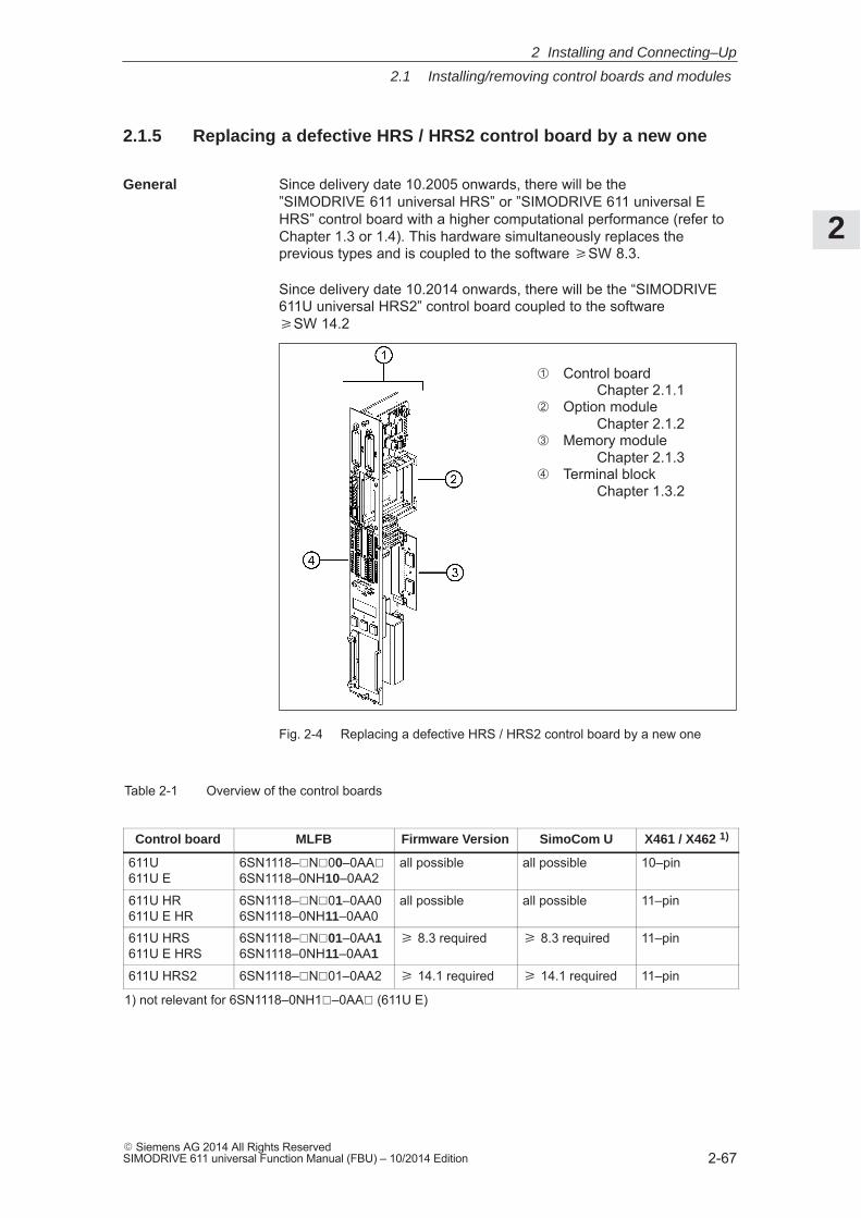
2
2.1 Installing/removing control boards and modules
2-67� Siemens AG 2014 All Rights ReservedSIMODRIVE 611 universal Function Manual (FBU) – 10/2014 Edition
2.1.5 Replacing a defective HRS / HRS2 control board by a new one
Since delivery date 10.2005 onwards, there will be the ”SIMODRIVE 611 universal HRS” or ”SIMODRIVE 611 universal EHRS” control board with a higher computational performance (refer toChapter 1.3 or 1.4). This hardware simultaneously replaces the previous types and is coupled to the software �SW 8.3.
Since delivery date 10.2014 onwards, there will be the “SIMODRIVE611U universal HRS2” control board coupled to the software �SW 14.2
� Control boardChapter 2.1.1
� Option module Chapter 2.1.2
� Memory moduleChapter 2.1.3
� Terminal blockChapter 1.3.2
Fig. 2-4 Replacing a defective HRS / HRS2 control board by a new one
Table 2-1 Overview of the control boards
Control board MLFB Firmware Version SimoCom U X461 / X462 1)
611U611U E
6SN1118–�N�00–0AA�6SN1118–0NH10–0AA2
all possible all possible 10–pin
611U HR611U E HR
6SN1118–�N�01–0AA06SN1118–0NH11–0AA0
all possible all possible 11–pin
611U HRS611U E HRS
6SN1118–�N�01–0AA16SN1118–0NH11–0AA1
� 8.3 required � 8.3 required 11–pin
611U HRS2 6SN1118–�N�01–0AA2 � 14.1 required � 14.1 required 11–pin
1) not relevant for 6SN1118–0NH1�–0AA� (611U E)
General
2 Installing and Connecting–Up
2
2.1 Installing/removing control boards and modules
2-68� Siemens AG 2014 All Rights Reserved
SIMODRIVE 611 universal Function Manual (FBU) – 10/2014 Edition
A control board is installed/removed as follows:
1. User data should be available on a protected file as the ”old”memory module cannot be run on the ”new” control board in allcases.
!Warning
The control module may only be inserted/withdrawn when it is in a no–voltage condition. If a control module is withdrawn or inserted undervoltage, this can result in data being lost or the components destroyed.
The ESDS measures must be observed when inserting/withdrawingthe control module.
2. Power–down the power module and ensure that it is in a no–voltagecondition.
3. Release the screw connection and withdraw the ”old” control modulefrom the power module.
4. Withdraw the memory module from the defective (”old”) controlmodule and insert it in the ”new” one, refer to Chapter 2.1.3 ”Installing/removing a memory module”.
5. Install the ”new” control unit, screw it tight (2 bolts on the frontpanel, max. torque = 0.8 Nm) and connect the device bus.
6. Energize the drive. If it runs up correctly the board replacement isfinished and you can proceed with point 11. Otherwise carry out thefollowing steps 7. to 10.
7. Install the ”SimoCom U” start–up tool in version 8.3 for HRS (orhigher) and 14.2 for HRS2 ––>Internet: http://support.automation.siemens.com/WW/view/de/10804940/133100
8. De–energize/re–energize the drive and start SimoCom U.
9. When SimoCom U requests you to upgrade the firmware, do so byinstalling firmware version � 8.3 for HRS and �14.2 for HRS2.
10.If communications cannot be built up or if after upgrading theramp–up has not been executed, then the old memory module isdefective or cannot be used and must be replaced by the memorymodule of the new control board. Load the corresponding user datafrom the saved file.
!Warning
In addition, the axes have to be newly referenced for a control boardwith motors with absolute encoders and a firmware version < 9.1, evenif they appear to have been referenced. If referencing of the axes iscomplicated and time–consuming it is possible to rescue the referencepoints. This possibility is described under Product Support in the Inter-net under FAQs ID21821692.
How is a control boardreplaced?
2 Installing and Connecting–Up
2
2.1 Installing/removing control boards and modules
2-69� Siemens AG 2014 All Rights ReservedSIMODRIVE 611 universal Function Manual (FBU) – 10/2014 Edition
11.Re–connect the front panel of the module according to your connec-tion diagram. Insert the mating connector into the appropriate inter-face.
Notice
”HR”, ”HRS” and ”HRS2” connectors X461 and X462 have now beenchanged to an 11–pin design. This is why the assigned signal cables ofthe (10–pin) terminal block of SIMODRIVE 611 universal have to berewired to the new (11–pin) terminal block. Terminal 15 remains free(terminal block assignment see figure 1-5) .
Note
For spare control boards, a set of installation instructions are providedwhich describes how the control board is replaced.
2 Installing and Connecting–Up
2
2.2 Wiring
2-70� Siemens AG 2014 All Rights Reserved
SIMODRIVE 611 universal Function Manual (FBU) – 10/2014 Edition
2.2 Wiring
2.2.1 General information on connecting–up
Reader’s note
Information on the subjects� Cabinet design� Basic rules regarding electromagnetic compatibility (basic EMC
rules)� Equipotential bonding� Wiring and cabling� EMC–compliant wiring� Shielding and shield connections� Handling modules that can be damaged by electrostatic discharge
(ESDS measures), etc.
are included in
Reference: /EMC/ EMC Guidelines, Configuration Manual
!Warning
Cable shields and cores/conductors of power cables which are notused (e.g. brake conductors) must be connected to PE potential inorder to discharge charges arising from capacitive coupling.
Non–observance can cause lethal shock voltages.
2 Installing and Connecting–Up
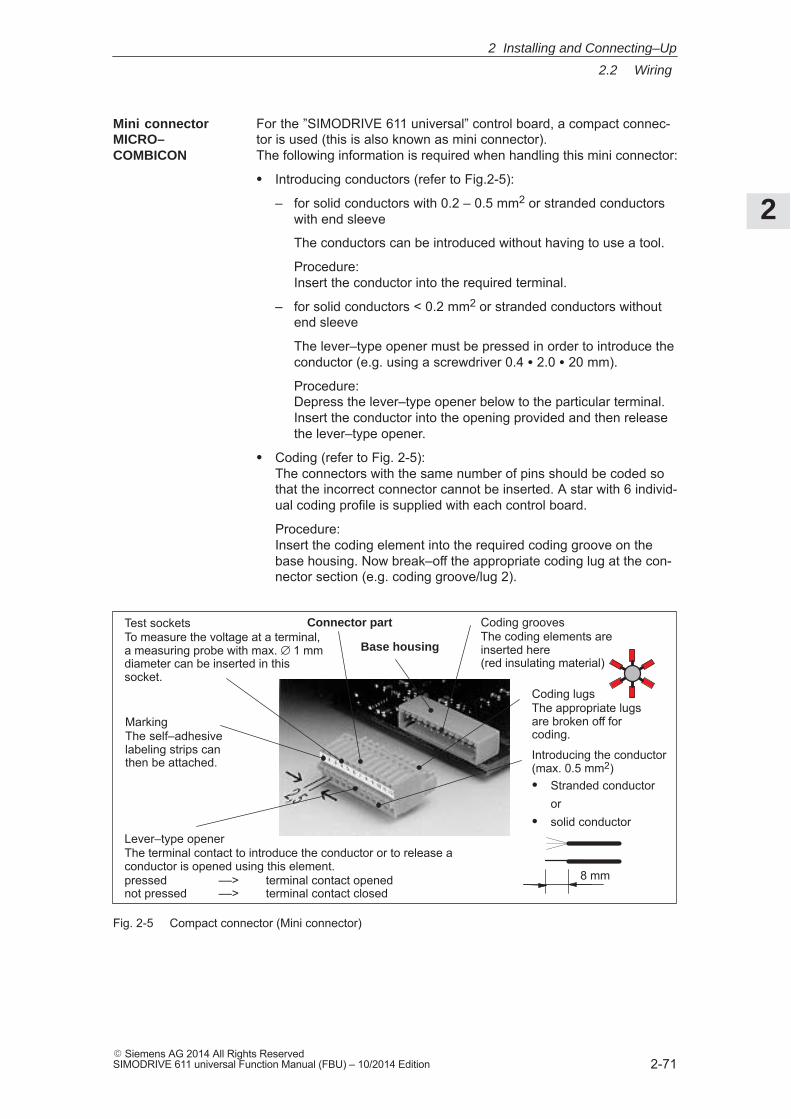
2
2.2 Wiring
2-71� Siemens AG 2014 All Rights ReservedSIMODRIVE 611 universal Function Manual (FBU) – 10/2014 Edition
For the ”SIMODRIVE 611 universal” control board, a compact connec-tor is used (this is also known as mini connector). The following information is required when handling this mini connector:
� Introducing conductors (refer to Fig.2-5):
– for solid conductors with 0.2 – 0.5 mm2 or stranded conductorswith end sleeve
The conductors can be introduced without having to use a tool.
Procedure: Insert the conductor into the required terminal.
– for solid conductors < 0.2 mm2 or stranded conductors withoutend sleeve
The lever–type opener must be pressed in order to introduce the conductor (e.g. using a screwdriver 0.4 � 2.0 � 20 mm).
Procedure: Depress the lever–type opener below to the particular terminal. Insert the conductor into the opening provided and then releasethe lever–type opener.
� Coding (refer to Fig. 2-5):The connectors with the same number of pins should be coded sothat the incorrect connector cannot be inserted. A star with 6 individ-ual coding profile is supplied with each control board.
Procedure: Insert the coding element into the required coding groove on thebase housing. Now break–off the appropriate coding lug at the con-nector section (e.g. coding groove/lug 2).
MarkingThe self–adhesivelabeling strips canthen be attached. Introducing the conductor
(max. 0.5 mm2)� Stranded conductor
or� solid conductor
Lever–type openerThe terminal contact to introduce the conductor or to release aconductor is opened using this element.pressed ––> terminal contact opened not pressed ––> terminal contact closed
Test socketsTo measure the voltage at a terminal,a measuring probe with max. ∅ 1 mmdiameter can be inserted in thissocket.
Base housing
Connector part Coding groovesThe coding elements areinserted here (red insulating material)
Coding lugsThe appropriate lugsare broken off forcoding.
8 mm
Fig. 2-5 Compact connector (Mini connector)
Mini connectorMICRO–COMBICON
2 Installing and Connecting–Up
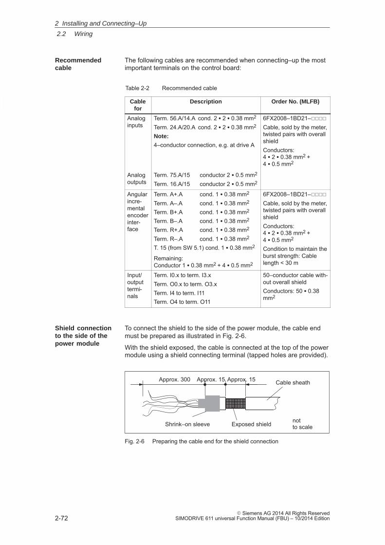
2
2.2 Wiring
2-72� Siemens AG 2014 All Rights Reserved
SIMODRIVE 611 universal Function Manual (FBU) – 10/2014 Edition
The following cables are recommended when connecting–up the mostimportant terminals on the control board:
Table 2-2 Recommended cable
Cablefor
Description Order No. (MLFB)
Analoginputs
Term. 56.A/14.A cond. 2 � 2 � 0.38 mm2
Term. 24.A/20.A cond. 2 � 2 � 0.38 mm2
Note:
4–conductor connection, e.g. at drive A
6FX2008–1BD21–����Cable, sold by the meter,twisted pairs with overallshieldConductors: 4 � 2 � 0.38 mm2 + 4 � 0.5 mm2
Analogoutputs
Term. 75.A/15 conductor 2 � 0.5 mm2
Term. 16.A/15 conductor 2 � 0.5 mm2
Angularincre-mentalencoderinter-face
Term. A+.A cond. 1 � 0.38 mm2
Term. A–.A cond. 1 � 0.38 mm2
Term. B+.A cond. 1 � 0.38 mm2
Term. B–.A cond. 1 � 0.38 mm2
Term. R+.A cond. 1 � 0.38 mm2
Term. R–.A cond. 1 � 0.38 mm2
T. 15 (from SW 5.1) cond. 1 � 0.38 mm2
6FX2008–1BD21–����Cable, sold by the meter,twisted pairs with overallshieldConductors: 4 � 2 � 0.38 mm2 + 4 � 0.5 mm2
Condition to maintain theburst strength: CableRemaining:
Conductor 1 � 0.38 mm2 + 4 � 0.5 mm2
Condition to maintain theburst strength: Cablelength < 30 m
Input/outputtermi-nals
Term. I0.x to term. I3.xTerm. O0.x to term. O3.xTerm. I4 to term. I11Term. O4 to term. O11
50–conductor cable with-out overall shieldConductors: 50 � 0.38mm2
To connect the shield to the side of the power module, the cable endmust be prepared as illustrated in Fig. 2-6.
With the shield exposed, the cable is connected at the top of the powermodule using a shield connecting terminal (tapped holes are provided).
ÉÉÉÉÉÉ
Exposed shield
Cable sheath
Shrink–on sleeve
Approx. 300 Approx. 15 Approx. 15
not to scale
Fig. 2-6 Preparing the cable end for the shield connection
Recommendedcable
Shield connectionto the side of the power module
2 Installing and Connecting–Up
2
2.2 Wiring
2-73� Siemens AG 2014 All Rights ReservedSIMODRIVE 611 universal Function Manual (FBU) – 10/2014 Edition
Note
� The cable shield should be connected at both cable ends throughthe largest possible surface area.
� Recommendation for the end of the conductor:Remove 5 mm of insulation from the end of the conductor andattach the specified cable lug using the manual crimping tool.– Pin–type cable lug from the AMP company
Type A, yellow, DIN cable cross–section range 0.14 –0.35 mm2, max. insulation diameter 2.1 mm, Order No.:165514–1
– Manual crimping tool from AMP CERTI–CRIMP, Order No.: 169485–0
2.2.2 Connecting–up and setting the line supply infeed module
Connecting–up the line supply infeed module will not be described inany more detail in this documentation. The following applies:
Reader’s note
Information on connecting–up the supply infeed modules, technicaldata as well as an interface overview are included in:
Reference: /PJU/ SIMODRIVE 611, Configuration Manual, Drive ConvertersChapter ”Line infeed (NE)”
There is a 6–position switch S1 on the top or front of the line supplyinfeed module. The setting of this switch is not described in any more detail in this doc-umentation. The following applies:
Reader’s note
Information on setting switch S1 at the line supply infeed module isincluded in:
Reference: /PJU/ SIMODRIVE 611, Configuration Manual, Drive ConvertersChapter ”Line infeed (NE)”
Wiring
Setting switch S1
2 Installing and Connecting–Up
2
2.2 Wiring
2-74� Siemens AG 2014 All Rights Reserved
SIMODRIVE 611 universal Function Manual (FBU) – 10/2014 Edition
2.2.3 Connecting–up the power module
Table 2-3 Overview of the interfaces
Terminal Function Type1)
Technical specifications
No. Desig-nation
1)
Motor connections
U2V2W2
A1 Motor connection for drive A
O Note:
Additional information on connecting–up the powermodule, technical data as well as interface over-view are included in:
U2V2W2
A2 Motor connection for drive B (only for 2–axis power modules)
Oview are included in:Reference: /PJU/ SIMODRIVE 611
Configuration Manual,Drive ConvertersChapter ”Power module”
PE Protective conductor I 0 VBolt
DC link
P600M600
– DC link IO Conductor bar
Equipment bus
– X151 Equipment bus IO Ribbon cable: 34–poleVoltages: variousSignals: various
1) O: Output; I: Input; IO: Input/output
!Warning
If a contactor is used between the motor and the power module, then itmust be ensured that this contactor is only switched in a no–currentcondition (power circuit).
Switch–off When terminal 663 (pulse cancellation) is simultaneously de–energizedand the coil of the power contactor, this condition is maintained. Thepulses are almost instantaneously canceled, the contactor contacts arethen in a no–current condition, and switch somewhat later due to thecontact delay.
Switching on: Terminal 663 may only be energized if all of the main contacts of thepower contactor are closed (e.g. terminal 663 is switched through anauxiliary contact of the power contactor).
2 Installing and Connecting–Up
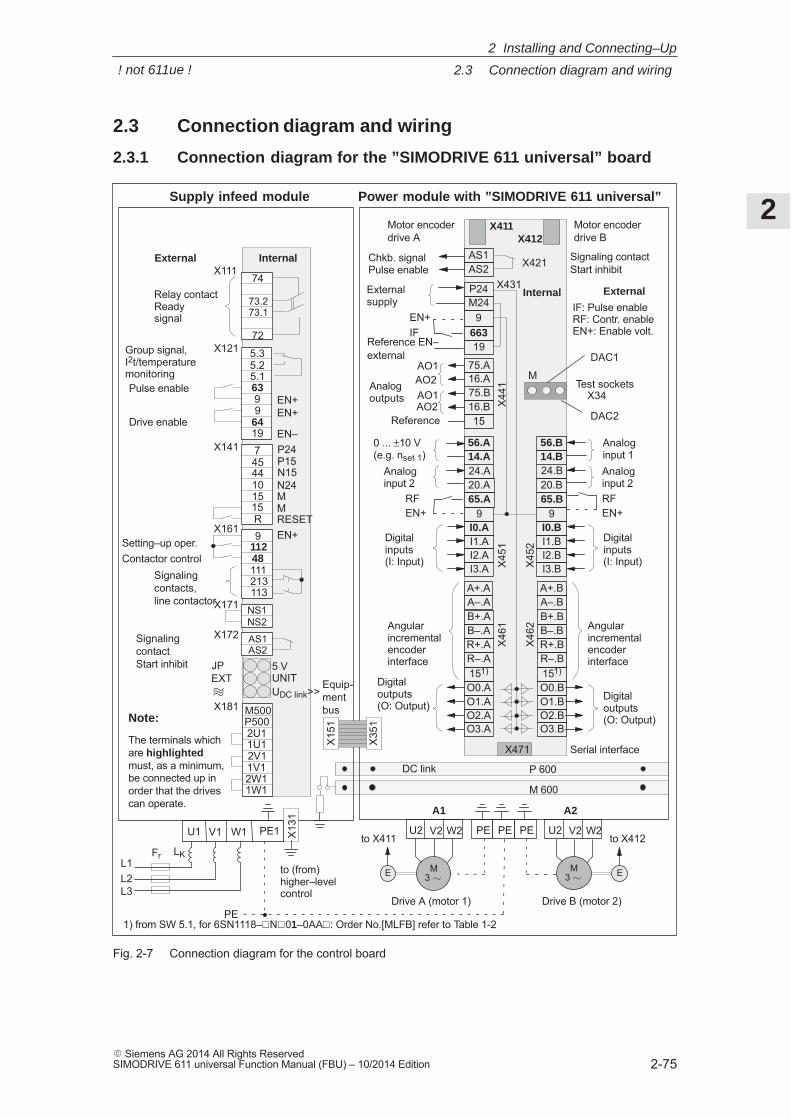
2
2.3 Connection diagram and wiring
2-75� Siemens AG 2014 All Rights ReservedSIMODRIVE 611 universal Function Manual (FBU) – 10/2014 Edition
2.3 Connection diagram and wiring
2.3.1 Connection diagram for the ”SIMODRIVE 611 universal” board
M3 �
W2V2U2
P 600
M 600
DC link
Equip-mentbus
X412Motor encoder drive A
X471 Serial interface
RF
Signaling contact Start inhibit
Power module with ”SIMODRIVE 611 universal”Supply infeed module
X111
X121
P5002U11U12V11V12W11W1
74
73.273.1
72
5.35.25.1639
6419
9
74544101515R9
11248111
113
AS1AS2
NS1NS2
X13
1
X141
X161
X171
X172
X181
Relay contact Ready signal
Group signal, I2t/temperaturemonitoringPulse enable
Drive enableEN+
EN–P24P15N15N24MMRESETEN+
Contactor control
JPEXT
5 VUNITUDC link>>
M500
M3 �E
PE
FrL1L2L3
LK
External Internal
Setting–up oper.
213
���
Signalingcontact Start inhibit
EN+
Signalingcontacts,line contactor
Motor encoderdrive B
9
19
M24P24
AS1AS2
EN+
IF
75.B16.B
16.A75.AAO1
Reference
AO2
X411
AO1AO2
B+.AB–.AR+.A
A–.AA+.A
R–.A
O0.AO1.AO2.AO3.A
to X411 to X412
663EN+
15
X421
X431
X34
M
DAC1
DAC2
Digital outputs(O: Output)
Test sockets
Digital inputs(I: Input)
Digital outputs(O: Output)
Digital inputs(I: Input)
Analog outputs
External supply
Chkb. signal Pulse enable
Angularincremental encoderinterface
Angularincremental encoderinterface
0 ... ±10 V(e.g. nset 1)
Analoginput 2
Analoginput 1Analoginput 2RFEN+
Reference EN–external
Internal
PE PE PE W2V2U2
A1 A2
X45
1X
461
X45
2X
462
X44
1
to (from) higher–level control
External
E
X15
1
X35
1
PE1 W1V1U1
Drive A (motor 1) Drive B (motor 2)
Note:
The terminals whichare highlightedmust, as a minimum,be connected up inorder that the drivescan operate.
B+.BB–.BR+.B
A–.BA+.B
R–.B
O0.BO1.BO2.BO3.B
24.A20.A65.A
14.A56.A
9I0.AI1.AI2.AI3.A
24.B20.B65.B
14.B56.B
9I0.BI1.BI2.BI3.B
IF: Pulse enable RF: Contr. enableEN+: Enable volt.
1) from SW 5.1, for 6SN1118–�N�01–0AA�: Order No.[MLFB] refer to Table 1-2
151) 151)
Fig. 2-7 Connection diagram for the control board
2 Installing and Connecting–Up
! not 611ue !
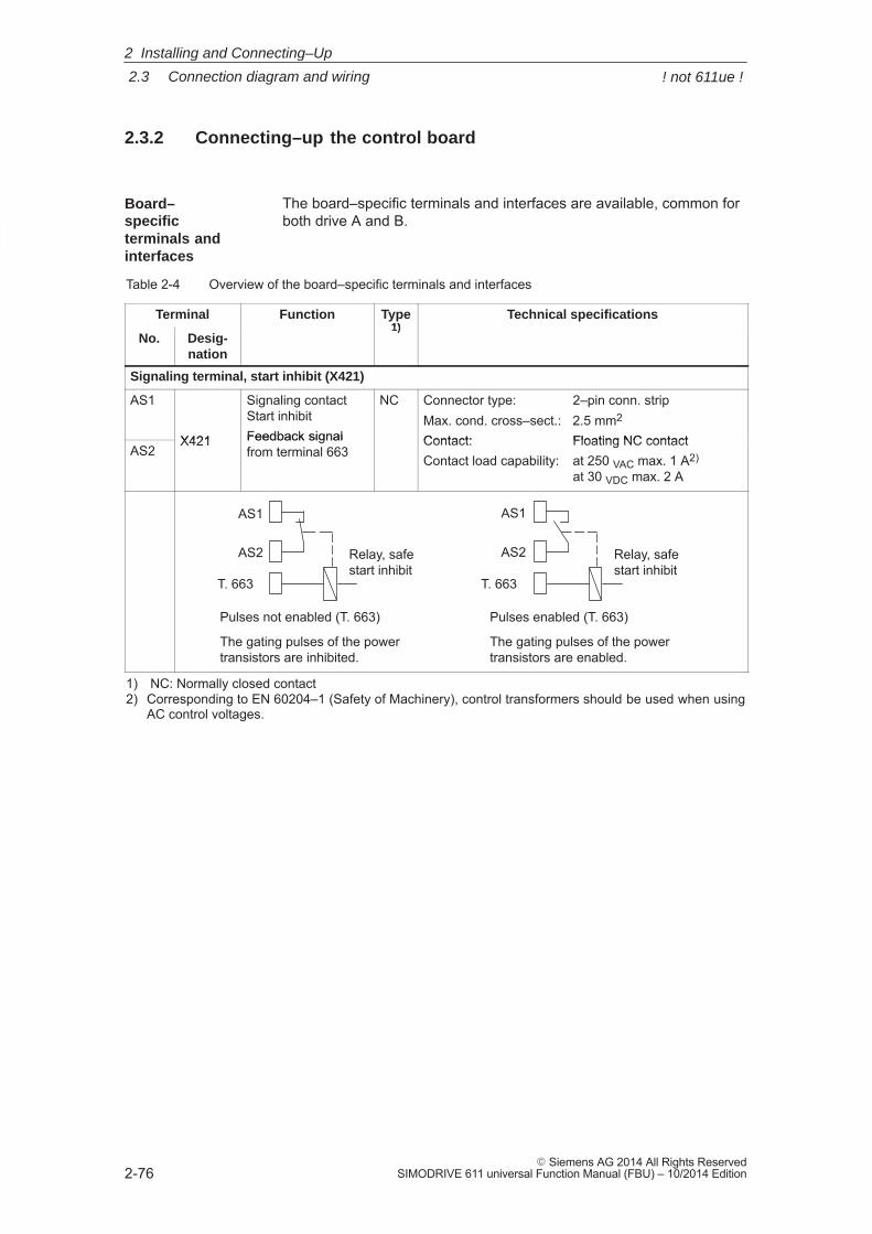
2
2.3 Connection diagram and wiring
2-76� Siemens AG 2014 All Rights Reserved
SIMODRIVE 611 universal Function Manual (FBU) – 10/2014 Edition
2.3.2 Connecting–up the control board
The board–specific terminals and interfaces are available, common forboth drive A and B.
Table 2-4 Overview of the board–specific terminals and interfaces
Terminal Function Type1)
Technical specifications
No. Desig-nation
1)
Signaling terminal, start inhibit (X421)
AS1
X421
Signaling contact Start inhibitFeedback signal
NC Connector type: 2–pin conn. stripMax. cond. cross–sect.: 2.5 mm2
Contact: Floating NC contactAS2
X421 Feedback signalfrom terminal 663
Contact: Floating NC contactContact load capability: at 250 VAC max. 1 A2)
at 30 VDC max. 2 A
Relay, safestart inhibit
AS2
AS1
T. 663 T. 663
Pulses not enabled (T. 663)
The gating pulses of the powertransistors are inhibited.
Pulses enabled (T. 663)
The gating pulses of the powertransistors are enabled.
Relay, safestart inhibit
AS2
AS1
1) NC: Normally closed contact2) Corresponding to EN 60204–1 (Safety of Machinery), control transformers should be used when using
AC control voltages.
Board–specific terminals andinterfaces
2 Installing and Connecting–Up
! not 611ue !
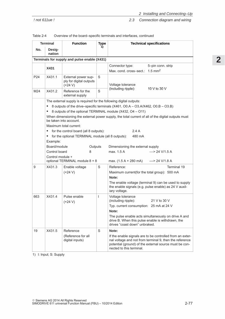
2
2.3 Connection diagram and wiring
2-77� Siemens AG 2014 All Rights ReservedSIMODRIVE 611 universal Function Manual (FBU) – 10/2014 Edition
Table 2-4 Overview of the board–specific terminals and interfaces, continued
Terminal Technical specificationsType1)
Function
No.
Technical specificationsType1)
Function
Desig-nation
Terminals for supply and pulse enable (X431)
X431Connector type: 5–pin conn. stripMax. cond. cross–sect.: 1.5 mm2
P24 X431.1 External power sup-ply for digital outputs(+24 V)
S
Voltage tolerance(including ripple): 10 V to 30 V
M24 X431.2 Reference for theexternal supply
S(including ripple): 10 V to 30 V
The external supply is required for the following digital outputs:� 8 outputs of the drive–specific terminals (X461, O0.A – O3.A/X462, O0.B – O3.B)� 8 outputs of the optional TERMINAL module (X432, O4 – O11)When dimensioning the external power supply, the total current of all of the digital outputs mustbe taken into account.Maximum total current:� for the control board (all 8 outputs): 2.4 A� for the optional TERMINAL module (all 8 outputs): 480 mAExample:Board/module Outputs Dimensioning the external supplyControl board 8 max. 1.5 A ––> 24 V/1.5 AControl module + optional TERMINAL module 8 + 8 max. (1.5 A + 280 mA) ––> 24 V/1.8 A
9 X431.3 Enable voltage(+24 V)
S Reference: Terminal 19Maximum current(for the total group): 500 mANote:
The enable voltage (terminal 9) can be used to supplythe enable signals (e.g. pulse enable) as 24 V auxil-iary voltage.
663 X431.4 Pulse enable(+24 V)
I Voltage tolerance(including ripple): 21 V to 30 VTyp. current consumption: 25 mA at 24 VNote:
The pulse enable acts simultaneously on drive A anddrive B. When this pulse enable is withdrawn, thedrives ”coast down” unbraked.
19 X431.5 Reference(Reference for alldigital inputs)
S Note:
If the enable signals are to be controlled from an exter-nal voltage and not from terminal 9, then the referencepotential (ground) of the external source must be con-nected to this terminal.
1) I: Input; S: Supply
2 Installing and Connecting–Up
! not 611ue !
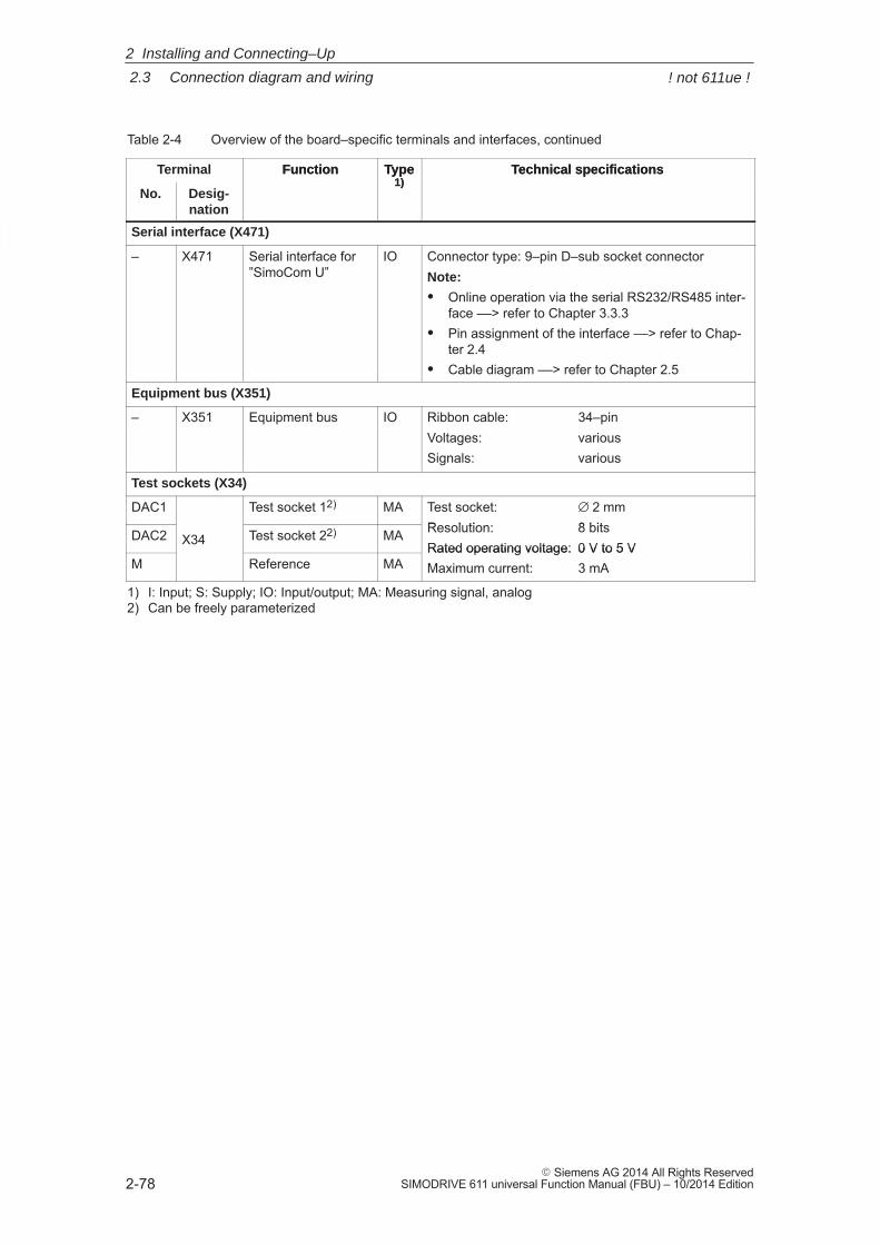
2
2.3 Connection diagram and wiring
2-78� Siemens AG 2014 All Rights Reserved
SIMODRIVE 611 universal Function Manual (FBU) – 10/2014 Edition
Table 2-4 Overview of the board–specific terminals and interfaces, continued
Terminal Technical specificationsType1)
Function
No.
Technical specificationsType1)
Function
Desig-nation
Serial interface (X471)
– X471 Serial interface for”SimoCom U”
IO Connector type: 9–pin D–sub socket connectorNote:
� Online operation via the serial RS232/RS485 inter-face ––> refer to Chapter 3.3.3
� Pin assignment of the interface ––> refer to Chap-ter 2.4
� Cable diagram ––> refer to Chapter 2.5
Equipment bus (X351)
– X351 Equipment bus IO Ribbon cable: 34–pinVoltages: variousSignals: various
Test sockets (X34)
DAC1 Test socket 12) MA Test socket: ∅ 2 mmResolution: 8 bitsDAC2 X34 Test socket 22) MA Resolution: 8 bitsRated operating voltage: 0 V to 5 V
M Reference MARated operating voltage: 0 V to 5 VMaximum current: 3 mA
1) I: Input; S: Supply; IO: Input/output; MA: Measuring signal, analog2) Can be freely parameterized
2 Installing and Connecting–Up
! not 611ue !
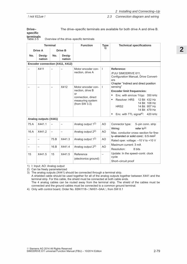
2
2.3 Connection diagram and wiring
2-79� Siemens AG 2014 All Rights ReservedSIMODRIVE 611 universal Function Manual (FBU) – 10/2014 Edition
The drive–specific terminals are available for both drive A and drive B.
Table 2-5 Overview of the drive–specific terminals
Terminal Function Type1)
Technical specifications
Drive A Drive B1)
No. Desig-nation
No. Desig-nation
Encoder connection (X411, X412)
– X411 – – Motor encoder con-nection, drive A
I Reference:
/PJU/ SIMODRIVE 611, Configuration Manual, Drive Convert-ersChapter ”Indirect and direct position
– – – X412 Motor encoder con-nection, drive Bor connection, directmeasuring system (from SW 3.3)
IChapter ”Indirect and direct positionsensing”Encoder limit frequencies:
� Enc. with sin/cos 1Vpp: 350 kHz� Resolver: HRS 12 Bit 432 Hz
14 Bit 108 HzHRS2 14 Bit 957 Hz
14 Bit 479 Hz� Enc. with TTL signal4): 420 kHz
Analog outputs (X441)
75.A X441.1 – – Analog output 12) AO Connector type: 5–pin conn. stripWiring: refer to3)
16.A X441.2 – – Analog output 22) AOWiring: refer to3)
Max. conductor cross–section for fine-ly–stranded or solid cond.: 0.5 mm2
– – 75.B X441.3 Analog output 12) AOly–stranded or solid cond.: 0.5 mm2
Rated oper. voltage: –10 V to +10 VMaximum current: 3 mA
– – 16.B X441.4 Analog output 22) AOMaximum current: 3 mAResolution: 8 bitsUpdate: In the speed–contr. clock15 X441.5 15 X441.5 Reference
(electronics ground)– Update: In the speed–contr. clock
cycleShort–circuit proof
1) I: Input; AO: Analog output2) Can be freely parameterized3) The analog outputs (X441) should be connected through a terminal strip.
A shielded cable should be used together for all of the analog outputs together between X441 and theterminal strip. For this cable, the shield must be connected at both cable ends. The 4 analog cables can be routed away from the terminal strip. The shield of the cables must beconnected and the ground cables must be connected to a common ground terminal.
4) Only with control board, Order No. 6SN1118–�NH01–0AA�, from SW 8.1
Drive–specific terminals
2 Installing and Connecting–Up
! not 611ue !
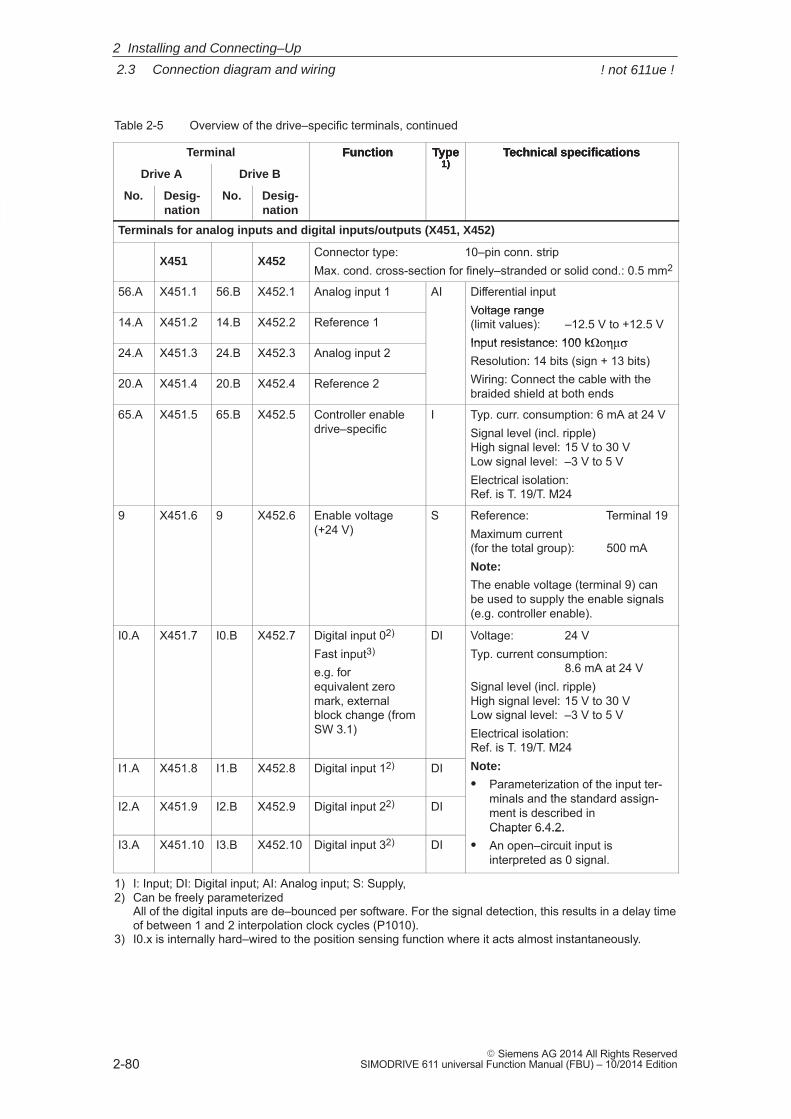
2
2.3 Connection diagram and wiring
2-80� Siemens AG 2014 All Rights Reserved
SIMODRIVE 611 universal Function Manual (FBU) – 10/2014 Edition
Table 2-5 Overview of the drive–specific terminals, continued
Terminal Technical specificationsType1)
Function
Drive A
Technical specificationsType1)
Function
Drive B
No.
Technical specificationsType1)
Function
Desig-nation
No.Desig-nation
Terminals for analog inputs and digital inputs/outputs (X451, X452)
X451 X452Connector type: 10–pin conn. stripMax. cond. cross-section for finely–stranded or solid cond.: 0.5 mm2
56.A X451.1 56.B X452.1 Analog input 1 AI Differential inputVoltage range
14.A X451.2 14.B X452.2 Reference 1Voltage range(limit values): –12.5 V to +12.5 VInput resistance: 100 kΩοημσ
24.A X451.3 24.B X452.3 Analog input 2Input resistance: 100 kΩοημσResolution: 14 bits (sign + 13 bits)Wiring: Connect the cable with the20.A X451.4 20.B X452.4 Reference 2 Wiring: Connect the cable with thebraided shield at both ends
65.A X451.5 65.B X452.5 Controller enable drive–specific
I Typ. curr. consumption: 6 mA at 24 VSignal level (incl. ripple)High signal level: 15 V to 30 VLow signal level: –3 V to 5 VElectrical isolation: Ref. is T. 19/T. M24
9 X451.6 9 X452.6 Enable voltage(+24 V)
S Reference: Terminal 19Maximum current (for the total group): 500 mANote:
The enable voltage (terminal 9) canbe used to supply the enable signals(e.g. controller enable).
I0.A X451.7 I0.B X452.7 Digital input 02)
Fast input3)
e.g. for equivalent zeromark, externalblock change (fromSW 3.1)
DI Voltage: 24 VTyp. current consumption:
8.6 mA at 24 VSignal level (incl. ripple)High signal level: 15 V to 30 VLow signal level: –3 V to 5 VElectrical isolation: Ref. is T. 19/T. M24
I1.A X451.8 I1.B X452.8 Digital input 12) DI
Ref. is T. 19/T. M24Note:
� Parameterization of the input ter-minals and the standard assign-
I2.A X451.9 I2.B X452.9 Digital input 22) DIminals and the standard assign-ment is described in Chapter 6.4.2.
I3.A X451.10 I3.B X452.10 Digital input 32) DIChapter 6.4.2.
� An open–circuit input is interpreted as 0 signal.
1) I: Input; DI: Digital input; AI: Analog input; S: Supply,2) Can be freely parameterized
All of the digital inputs are de–bounced per software. For the signal detection, this results in a delay timeof between 1 and 2 interpolation clock cycles (P1010).
3) I0.x is internally hard–wired to the position sensing function where it acts almost instantaneously.
2 Installing and Connecting–Up
! not 611ue !
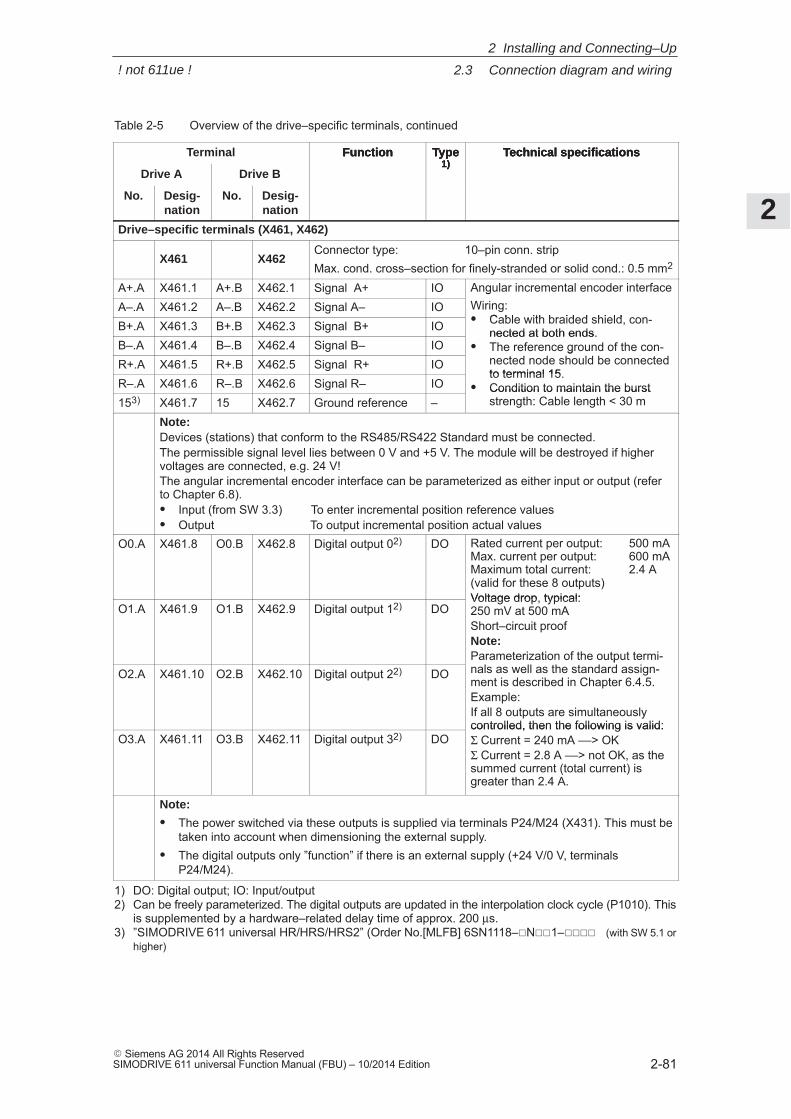
2
2.3 Connection diagram and wiring
2-81� Siemens AG 2014 All Rights ReservedSIMODRIVE 611 universal Function Manual (FBU) – 10/2014 Edition
Table 2-5 Overview of the drive–specific terminals, continued
Terminal Technical specificationsType1)
Function
Drive A
Technical specificationsType1)
Function
Drive B
No.
Technical specificationsType1)
Function
Desig-nation
No.Desig-nation
Drive–specific terminals (X461, X462)
X461 X462Connector type: 10–pin conn. stripMax. cond. cross–section for finely-stranded or solid cond.: 0.5 mm2
A+.A X461.1 A+.B X462.1 Signal A+ IO Angular incremental encoder interfaceA–.A X461.2 A–.B X462.2 Signal A– IO
Angular incremental encoder interfaceWiring:� Cable with braided shield, con-B+.A X461.3 B+.B X462.3 Signal B+ IO � Cable with braided shield, con-
nected at both ends.B–.A X461.4 B–.B X462.4 Signal B– IO
nected at both ends.� The reference ground of the con-
nected node should be connectedR+.A X461.5 R+.B X462.5 Signal R+ IOThe reference ground of the con-nected node should be connectedto terminal 15.
R–.A X461.6 R–.B X462.6 Signal R– IOto terminal 15.
� Condition to maintain the burst153) X461.7 15 X462.7 Ground reference –
Condition to maintain the burststrength: Cable length < 30 m
Note:Devices (stations) that conform to the RS485/RS422 Standard must be connected.The permissible signal level lies between 0 V and +5 V. The module will be destroyed if highervoltages are connected, e.g. 24 V!The angular incremental encoder interface can be parameterized as either input or output (referto Chapter 6.8).� Input (from SW 3.3) To enter incremental position reference values� Output To output incremental position actual values
O0.A X461.8 O0.B X462.8 Digital output 02) DO Rated current per output: 500 mAMax. current per output: 600 mAMaximum total current: 2.4 A(valid for these 8 outputs)Voltage drop, typical:
O1.A X461.9 O1.B X462.9 Digital output 12) DOVoltage drop, typical: 250 mV at 500 mAShort–circuit proofNote:Parameterization of the output termi-nals as well as the standard assign-O2.A X461.10 O2.B X462.10 Digital output 22) DOParameterization of the output termi-nals as well as the standard assign-ment is described in Chapter 6.4.5.Example:If all 8 outputs are simultaneouslycontrolled, then the following is valid:
O3.A X461.11 O3.B X462.11 Digital output 32) DOcontrolled, then the following is valid:Σ Current = 240 mA ––> OKΣ Current = 2.8 A ––> not OK, as thesummed current (total current) isgreater than 2.4 A.
Note:
� The power switched via these outputs is supplied via terminals P24/M24 (X431). This must betaken into account when dimensioning the external supply.
� The digital outputs only ”function” if there is an external supply (+24 V/0 V, terminalsP24/M24).
1) DO: Digital output; IO: Input/output2) Can be freely parameterized. The digital outputs are updated in the interpolation clock cycle (P1010). This
is supplemented by a hardware–related delay time of approx. 200 μs.3) ”SIMODRIVE 611 universal HR/HRS/HRS2” (Order No.[MLFB] 6SN1118–�N��1–���� (with SW 5.1 or
higher)
2 Installing and Connecting–Up
! not 611ue !
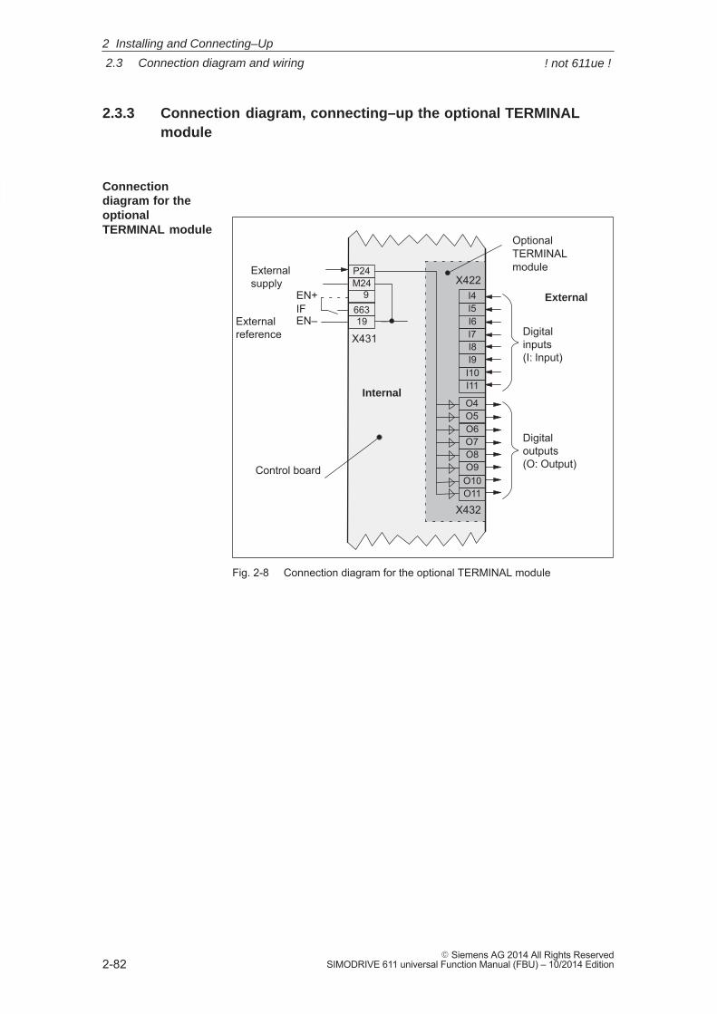
2
2.3 Connection diagram and wiring
2-82� Siemens AG 2014 All Rights Reserved
SIMODRIVE 611 universal Function Manual (FBU) – 10/2014 Edition
2.3.3 Connection diagram, connecting–up the optional TERMINALmodule
IFEN+
Digitalinputs(I: Input)
Digitaloutputs(O: Output)
External supply
Externalreference
EN–
Control board
OptionalTERMINALmodule
External
I6I7I8
I5I4
I9I10I11
X422
X432
9
19
M24P24
663
X431
O6O7O8
O5O4
O9O10O11
Internal
Fig. 2-8 Connection diagram for the optional TERMINAL module
Connectiondiagram for theoptionalTERMINAL module
2 Installing and Connecting–Up
! not 611ue !
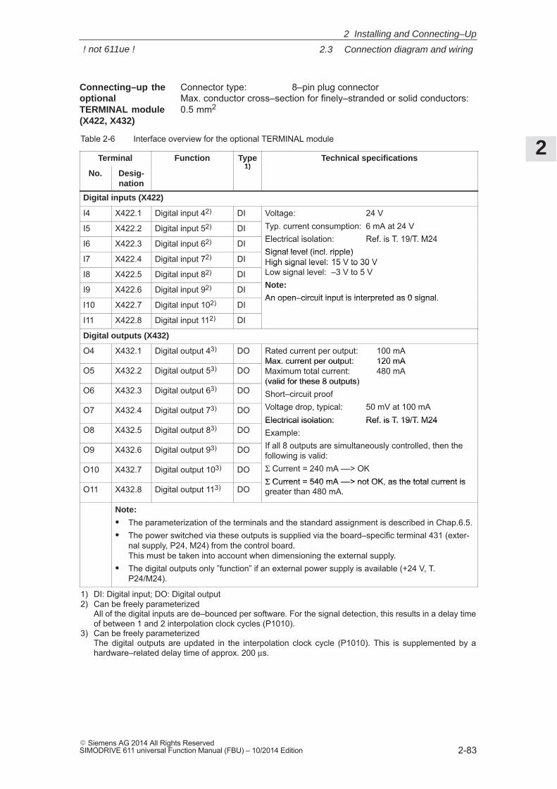
2
2.3 Connection diagram and wiring
2-83� Siemens AG 2014 All Rights ReservedSIMODRIVE 611 universal Function Manual (FBU) – 10/2014 Edition
Connector type: 8–pin plug connectorMax. conductor cross–section for finely–stranded or solid conductors:0.5 mm2
Table 2-6 Interface overview for the optional TERMINAL module
Terminal Function Type1)
Technical specifications
No. Desig-nation
1)
Digital inputs (X422)
I4 X422.1 Digital input 42) DI Voltage: 24 V
I5 X422.2 Digital input 52) DI Typ. current consumption: 6 mA at 24 VElectrical isolation: Ref. is T. 19/T. M24I6 X422.3 Digital input 62) DI Electrical isolation: Ref. is T. 19/T. M24Signal level (incl. ripple)
I7 X422.4 Digital input 72) DISignal level (incl. ripple)High signal level: 15 V to 30 V
I8 X422.5 Digital input 82) DIHigh signal level: 15 V to 30 VLow signal level: –3 V to 5 VNote:I9 X422.6 Digital input 92) DI Note:
An open–circuit input is interpreted as 0 signal.I10 X422.7 Digital input 102) DI
An open–circuit input is interpreted as 0 signal.
I11 X422.8 Digital input 112) DI
Digital outputs (X432)
O4 X432.1 Digital output 43) DO Rated current per output: 100 mAMax. current per output: 120 mA
O5 X432.2 Digital output 53) DOMax. current per output: 120 mAMaximum total current: 480 mA (valid for these 8 outputs)
O6 X432.3 Digital output 63) DO(valid for these 8 outputs)Short–circuit proofVoltage drop, typical: 50 mV at 100 mAO7 X432.4 Digital output 73) DO Voltage drop, typical: 50 mV at 100 mAElectrical isolation: Ref. is T. 19/T. M24
O8 X432.5 Digital output 83) DOElectrical isolation: Ref. is T. 19/T. M24Example:If all 8 outputs are simultaneously controlled, then theO9 X432.6 Digital output 93) DO If all 8 outputs are simultaneously controlled, then thefollowing is valid:
O10 X432.7 Digital output 103) DOfollowing is valid:Σ Current = 240 mA ––> OKΣ Current = 540 mA ––> not OK, as the total current is
O11 X432.8 Digital output 113) DOΣ Current = 540 mA ––> not OK, as the total current isgreater than 480 mA.
Note:
� The parameterization of the terminals and the standard assignment is described in Chap.6.5.� The power switched via these outputs is supplied via the board–specific terminal 431 (exter-
nal supply, P24, M24) from the control board. This must be taken into account when dimensioning the external supply.
� The digital outputs only ”function” if an external power supply is available (+24 V, T.P24/M24).
1) DI: Digital input; DO: Digital output2) Can be freely parameterized
All of the digital inputs are de–bounced per software. For the signal detection, this results in a delay timeof between 1 and 2 interpolation clock cycles (P1010).
3) Can be freely parameterized The digital outputs are updated in the interpolation clock cycle (P1010). This is supplemented by ahardware–related delay time of approx. 200 μs.
Connecting–up theoptionalTERMINAL module(X422, X432)
2 Installing and Connecting–Up
! not 611ue !
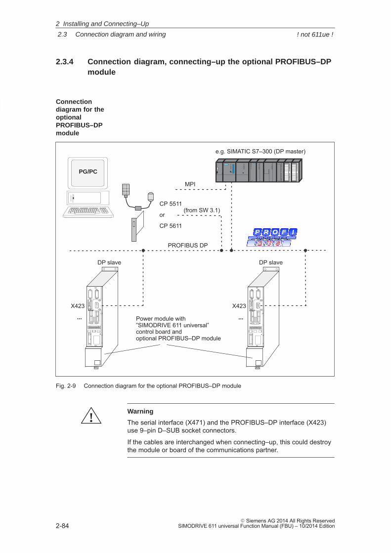
2
2.3 Connection diagram and wiring
2-84� Siemens AG 2014 All Rights Reserved
SIMODRIVE 611 universal Function Manual (FBU) – 10/2014 Edition
2.3.4 Connection diagram, connecting–up the optional PROFIBUS–DPmodule
Power module with ”SIMODRIVE 611 universal” control board and optional PROFIBUS–DP module
PROFIBUS DP
e.g. SIMATIC S7–300 (DP master)
DP slave
... ...
DP slave
MPI
X423 X423
PG/PC
CP 5511
or
CP 5611
(from SW 3.1)
ÄÄ
Fig. 2-9 Connection diagram for the optional PROFIBUS–DP module
!Warning
The serial interface (X471) and the PROFIBUS–DP interface (X423)use 9–pin D–SUB socket connectors.
If the cables are interchanged when connecting–up, this could destroythe module or board of the communications partner.
Connectiondiagram for theoptional PROFIBUS–DPmodule
2 Installing and Connecting–Up
! not 611ue !
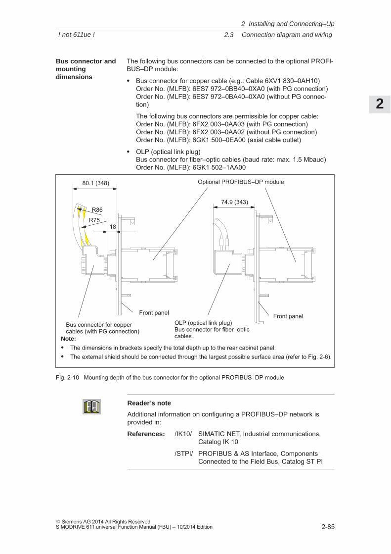
2
2.3 Connection diagram and wiring
2-85� Siemens AG 2014 All Rights ReservedSIMODRIVE 611 universal Function Manual (FBU) – 10/2014 Edition
The following bus connectors can be connected to the optional PROFI-BUS–DP module:
� Bus connector for copper cable (e.g.: Cable 6XV1 830–0AH10)Order No. (MLFB): 6ES7 972–0BB40–0XA0 (with PG connection)Order No. (MLFB): 6ES7 972–0BA40–0XA0 (without PG connec-tion)
The following bus connectors are permissible for copper cable:Order No. (MLFB): 6FX2 003–0AA03 (with PG connection)Order No. (MLFB): 6FX2 003–0AA02 (without PG connection)Order No. (MLFB): 6GK1 500–0EA00 (axial cable outlet)
� OLP (optical link plug)Bus connector for fiber–optic cables (baud rate: max. 1.5 Mbaud)Order No. (MLFB): 6GK1 502–1AA00
80.1 (348)
74.9 (343)R86
R7518
Optional PROFIBUS–DP module
Bus connector for coppercables (with PG connection)
OLP (optical link plug)Bus connector for fiber–opticcablesNote:
� The dimensions in brackets specify the total depth up to the rear cabinet panel.� The external shield should be connected through the largest possible surface area (refer to Fig. 2-6).
Front panel Front panel
Fig. 2-10 Mounting depth of the bus connector for the optional PROFIBUS–DP module
Reader’s note
Additional information on configuring a PROFIBUS–DP network isprovided in:
References: /IK10/ SIMATIC NET, Industrial communications, Catalog IK 10
/STPI/ PROFIBUS & AS Interface, ComponentsConnected to the Field Bus, Catalog ST PI
Bus connector andmountingdimensions
2 Installing and Connecting–Up
! not 611ue !
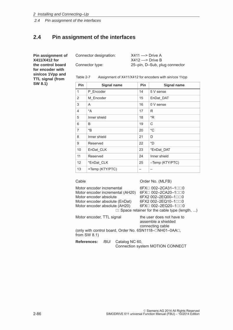
2
2.4 Pin assignment of the interfaces
2-86� Siemens AG 2014 All Rights Reserved
SIMODRIVE 611 universal Function Manual (FBU) – 10/2014 Edition
2.4 Pin assignment of the interfaces
Connector designation: X411 ––> Drive AX412 ––> Drive B
Connector type: 25–pin, D–Sub, plug connector
Table 2-7 Assignment of X411/X412 for encoders with sin/cos 1Vpp
Pin Signal name Pin Signal name
1 P_Encoder 14 5 V sense
2 M_Encoder 15 EnDat_DAT
3 A 16 0 V sense
4 *A 17 R
5 Inner shield 18 *R
6 B 19 C
7 *B 20 *C
8 Inner shield 21 D
9 Reserved 22 *D
10 EnDat_CLK 23 *EnDat_DAT
11 Reserved 24 Inner shield
12 *EnDat_CLK 25 –Temp (KTY/PTC)
13 +Temp (KTY/PTC) – –
Cable Order No. (MLFB)
Motor encoder incremental 6FX� 002–2CA31–1��0Motor encoder incremental (AH20) 6FX� 002–2CA20–1��0Motor encoder absolute 6FX2 002–2EQ00–1��0Motor encoder absolute (EnDat) 6FX2 002–2EQ10–1��0Motor encoder absolute (AH20) 6FX� 002–2EQ20–1��0
�: Space retainer for the cable type (length, ...)
Motor encoder, TTL signal the user does not have toassemble a shielded connecting cable
(only with control board, Order No. 6SN1118–�NH01–0AA�, from SW 8.1)
References: /BU/ Catalog NC 60,Connection system MOTION CONNECT
Pin assignment ofX411/X412 for the control boardfor encoder withsin/cos 1Vpp andTTL signal (fromSW 8.1)
2 Installing and Connecting–Up
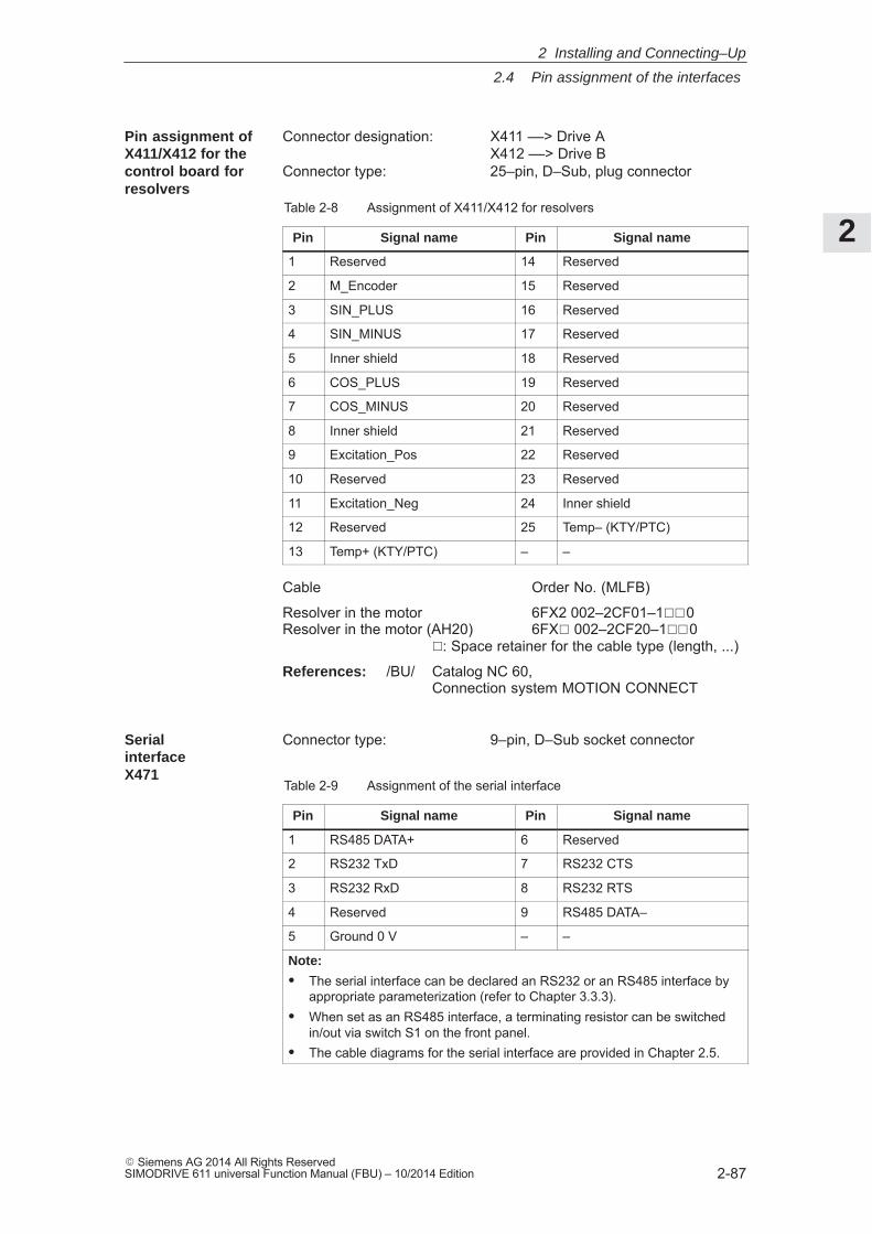
2
2.4 Pin assignment of the interfaces
2-87� Siemens AG 2014 All Rights ReservedSIMODRIVE 611 universal Function Manual (FBU) – 10/2014 Edition
Connector designation: X411 ––> Drive AX412 ––> Drive B
Connector type: 25–pin, D–Sub, plug connector
Table 2-8 Assignment of X411/X412 for resolvers
Pin Signal name Pin Signal name
1 Reserved 14 Reserved
2 M_Encoder 15 Reserved
3 SIN_PLUS 16 Reserved
4 SIN_MINUS 17 Reserved
5 Inner shield 18 Reserved
6 COS_PLUS 19 Reserved
7 COS_MINUS 20 Reserved
8 Inner shield 21 Reserved
9 Excitation_Pos 22 Reserved
10 Reserved 23 Reserved
11 Excitation_Neg 24 Inner shield
12 Reserved 25 Temp– (KTY/PTC)
13 Temp+ (KTY/PTC) – –
Cable Order No. (MLFB)
Resolver in the motor 6FX2 002–2CF01–1��0 Resolver in the motor (AH20) 6FX� 002–2CF20–1��0
�: Space retainer for the cable type (length, ...)
References: /BU/ Catalog NC 60,Connection system MOTION CONNECT
Connector type: 9–pin, D–Sub socket connector
Table 2-9 Assignment of the serial interface
Pin Signal name Pin Signal name
1 RS485 DATA+ 6 Reserved
2 RS232 TxD 7 RS232 CTS
3 RS232 RxD 8 RS232 RTS
4 Reserved 9 RS485 DATA–
5 Ground 0 V – –
Note:
� The serial interface can be declared an RS232 or an RS485 interface byappropriate parameterization (refer to Chapter 3.3.3).
� When set as an RS485 interface, a terminating resistor can be switchedin/out via switch S1 on the front panel.
� The cable diagrams for the serial interface are provided in Chapter 2.5.
Pin assignment ofX411/X412 for the control board for resolvers
Serial interfaceX471
2 Installing and Connecting–Up
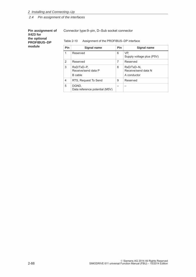
2
2.4 Pin assignment of the interfaces
2-88� Siemens AG 2014 All Rights Reserved
SIMODRIVE 611 universal Function Manual (FBU) – 10/2014 Edition
Connector type:9–pin, D–Sub socket connector
Table 2-10 Assignment of the PROFIBUS–DP interface
Pin Signal name Pin Signal name
1 Reserved 6 VP, Supply voltage plus (P5V)
2 Reserved 7 Reserved
3 RxD/TxD–P, Receive/send data PB cable
8 RxD/TxD–N, Receive/send data NA conductor
4 RTS, Request To Send 9 Reserved
5 DGND, Data reference potential (M5V)
– –
Pin assignment ofX423 for the optional PROFIBUS–DPmodule
2 Installing and Connecting–Up
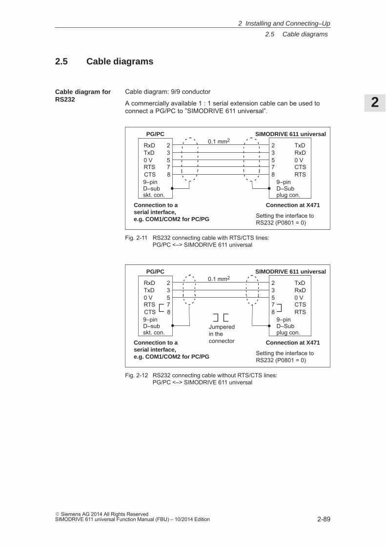
2
2.5 Cable diagrams
2-89� Siemens AG 2014 All Rights ReservedSIMODRIVE 611 universal Function Manual (FBU) – 10/2014 Edition
2.5 Cable diagrams
Cable diagram: 9/9 conductor
A commercially available 1 : 1 serial extension cable can be used toconnect a PG/PC to ”SIMODRIVE 611 universal”.
SIMODRIVE 611 universalPG/PC
RxD 2TxD 30 V 5RTS 7CTS 8
2 TxD3 RxD5 0 V7 CTS8 RTS
Connection at X471Connection to aserial interface, e.g. COM1/COM2 for PC/PG
9–pinD–sub skt. con.
9–pin D–Sub plug con.
0.1 mm2
Setting the interface toRS232 (P0801 = 0)
Fig. 2-11 RS232 connecting cable with RTS/CTS lines: PG/PC <–> SIMODRIVE 611 universal
SIMODRIVE 611 universalPG/PC
RxD 2TxD 30 V 5RTS 7CTS 8
2 TxD3 RxD5 0 V7 CTS8 RTS
Connection at X471Connection to aserial interface, e.g. COM1/COM2 for PC/PG
9–pinD–sub skt. con.
9–pin D–Sub plug con.
0.1 mm2
Setting the interface toRS232 (P0801 = 0)
Jumperedin the connector
Fig. 2-12 RS232 connecting cable without RTS/CTS lines: PG/PC <–> SIMODRIVE 611 universal
Cable diagram forRS232
2 Installing and Connecting–Up
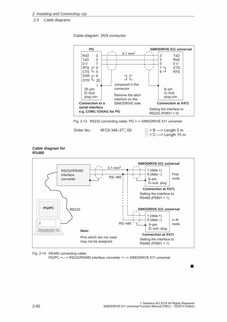
2
2.5 Cable diagrams
2-90� Siemens AG 2014 All Rights Reserved
SIMODRIVE 611 universal Function Manual (FBU) – 10/2014 Edition
Cable diagram: 25/9 conductor
SIMODRIVE 611 universalPG
RxD 3TxD 20 V 7RTS 4CTS 5DSR 6DTR 20
1
2 TxD3 RxD5 0 V7 CTS8 RTS
Connection at X471Connection to aserial interface e.g. COM1 V24/AG for PG
25–pin D–Sub plug con.
9–pin D–Sub plug con.
0.1 mm2
Setting the interface toRS232 (P0801 = 0)
Jumpered in theconnector
Remove the latchinterlock on theSIMODRIVE side
Fig. 2-13 RS232 connecting cable: PG <–> SIMODRIVE 611 universal
Order No.: 6FC9 348–2T�00 � = B ––> Length 5 m� = C ––> Length 10 m
SIMODRIVE 611 universal
Note:
Pins which are not usedmay not be assigned.
Connection at X471
9–pin D–sub, plug
0.1 mm21 (data +)9 (data –)
RS232/RS485interfaceconverter
First node
SIMODRIVE 611 universal
Connection at X471
9–pin D–sub, plug
1 (data +)9 (data –) n–th
node
RS232
RS–485
PG/PC
RS–485
Setting the interface toRS485 (P0801 = 1)
Setting the interface toRS485 (P0801 = 1)
Fig. 2-14 RS485 connecting cable: PG/PC <––> RS232/RS485 interface converter <––> SIMODRIVE 611 universal
�
Cable diagram forRS485
2 Installing and Connecting–Up
3
3-91� Siemens AG 2014 All Rights ReservedSIMODRIVE 611 universal Function Manual (FBU) – 10/2014 Edition
Parameterizing the Board
3.1 Overview when parameterizing 3-92. . . . . . . . . . . . . . . . . . . . . . . . . . . . . . . . . . . .
3.2 Parameterizing using the display and operator unit 3-93. . . . . . . . . . . . . . . . . . . 3.2.1 Parameterizing mode 3-94. . . . . . . . . . . . . . . . . . . . . . . . . . . . . . . . . . . . . . . . . . . . 3.2.2 Example: Changing a parameter value 3-99. . . . . . . . . . . . . . . . . . . . . . . . . . . . .
3.3 Parameterizing using the parameterizing and start–up tool SimoCom U 3-100. . . . . . . . . . . . . . . . . . . . . . . . . . . . . . . . . . . . . . . . . . . . . . . . . . . .
3.3.1 Installing SimoCom U 3-100. . . . . . . . . . . . . . . . . . . . . . . . . . . . . . . . . . . . . . . . . . . . 3.3.2 Entry into SimoCom U 3-103. . . . . . . . . . . . . . . . . . . . . . . . . . . . . . . . . . . . . . . . . . . 3.3.3 Online operation: SimoCom U via a serial interface 3-109. . . . . . . . . . . . . . . . . . 3.3.4 Online operation: SimoCom U via PROFIBUS–DP
(from SW 3.1) 3-115. . . . . . . . . . . . . . . . . . . . . . . . . . . . . . . . . . . . . . . . . . . . . . . . . .
3
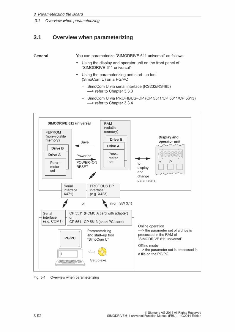
3
3.1 Overview when parameterizing
3-92� Siemens AG 2014 All Rights Reserved
SIMODRIVE 611 universal Function Manual (FBU) – 10/2014 Edition
3.1 Overview when parameterizing
You can parameterize ”SIMODRIVE 611 universal” as follows:
� Using the display and operator unit on the front panel of”SIMODRIVE 611 universal”
� Using the parameterizing and start–up tool (SimoCom U) on a PG/PC
– SimoCom U via serial interface (RS232/RS485) ––> refer to Chapter 3.3.3
– SimoCom U via PROFIBUS–DP (CP 5511/CP 5611/CP 5613) ––> refer to Chapter 3.3.4
Online operation ––> the parameter set of a drive isprocessed in the RAM of”SIMODRIVE 611 universal”
Offline mode ––> the parameter set is processed ina file on the PG/PC
SIMODRIVE 611 universal
FEPROM(non–volatilememory)
Display and operator unit
Drive B
Para–meter set
Drive A
Para–meter set
RAM(volatilememory)
Drive B
Para–meter set
Drive A
Para–meter set
Save
Power on
POWER–ONRESET
Serial interfaceX471)
Serial interface (e.g. COM1)
+ P –to display and change parameters
PROFIBUS DP interface(e.g. X423)
CP 5511 (PCMCIA card with adapter)orCP 5611 CP 5613 (short PCI card)
or (from SW 3.1)
Parameterizingand start–up tool”SimoCom U”PG/PC
Setup.exe
Fig. 3-1 Overview when parameterizing
General
3 Parameterizing the Board
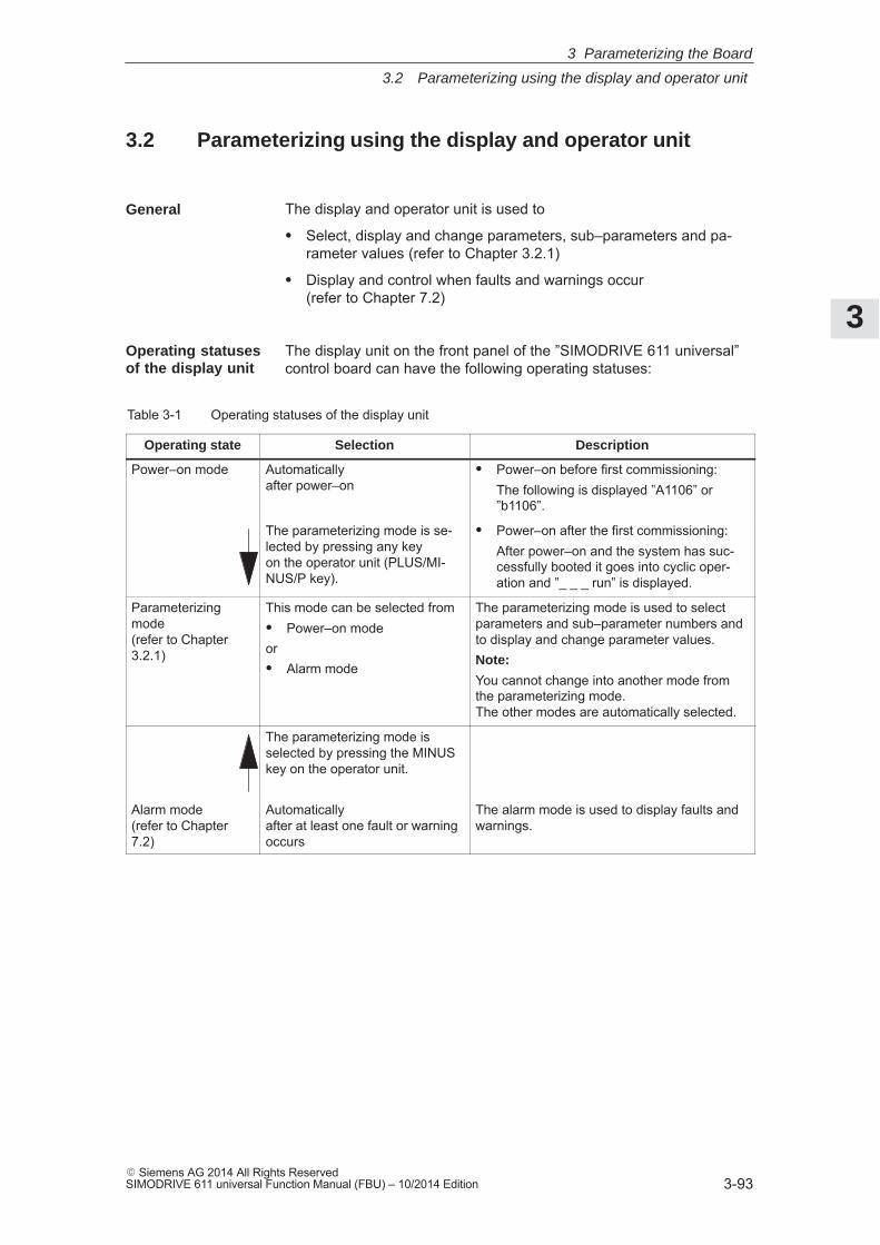
3
3.2 Parameterizing using the display and operator unit
3-93� Siemens AG 2014 All Rights ReservedSIMODRIVE 611 universal Function Manual (FBU) – 10/2014 Edition
3.2 Parameterizing using the display and operator unit
The display and operator unit is used to
� Select, display and change parameters, sub–parameters and pa-rameter values (refer to Chapter 3.2.1)
� Display and control when faults and warnings occur (refer to Chapter 7.2)
The display unit on the front panel of the ”SIMODRIVE 611 universal”control board can have the following operating statuses:
Table 3-1 Operating statuses of the display unit
Operating state Selection Description
Power–on mode Automatically after power–on
� Power–on before first commissioning:The following is displayed ”A1106” or”b1106”.
The parameterizing mode is se-lected by pressing any key on the operator unit (PLUS/MI-NUS/P key).
� Power–on after the first commissioning:After power–on and the system has suc-cessfully booted it goes into cyclic oper-ation and ”_ _ _ run” is displayed.
Parameterizingmode(refer to Chapter3.2.1)
This mode can be selected from� Power–on modeor� Alarm mode
The parameterizing mode is used to selectparameters and sub–parameter numbers andto display and change parameter values.Note:
You cannot change into another mode fromthe parameterizing mode. The other modes are automatically selected.
The parameterizing mode is selected by pressing the MINUSkey on the operator unit.
Alarm mode(refer to Chapter7.2)
Automatically after at least one fault or warningoccurs
The alarm mode is used to display faults andwarnings.
General
Operating statusesof the display unit
3 Parameterizing the Board
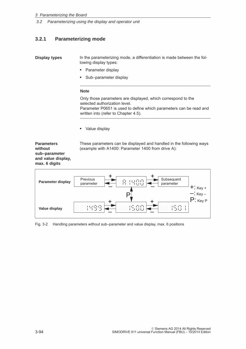
3
3.2 Parameterizing using the display and operator unit
3-94� Siemens AG 2014 All Rights Reserved
SIMODRIVE 611 universal Function Manual (FBU) – 10/2014 Edition
3.2.1 Parameterizing mode
In the parameterizing mode, a differentiation is made between the fol-lowing display types:
� Parameter display
� Sub–parameter display
Note
Only those parameters are displayed, which correspond to theselected authorization level. Parameter P0651 is used to define which parameters can be read andwritten into (refer to Chapter 4.5).
� Value display
These parameters can be displayed and handled in the following ways(example with A1400: Parameter 1400 from drive A):
Parameter display
Value display
P
+–
+–
+–
Previousparameter
Subsequentparameter
+– +: Key +
–: Key –
P: Key P
Fig. 3-2 Handling parameters without sub–parameter and value display, max. 6 positions
Display types
Parameterswithout sub–parameterand value display, max. 6 digits
3 Parameterizing the Board
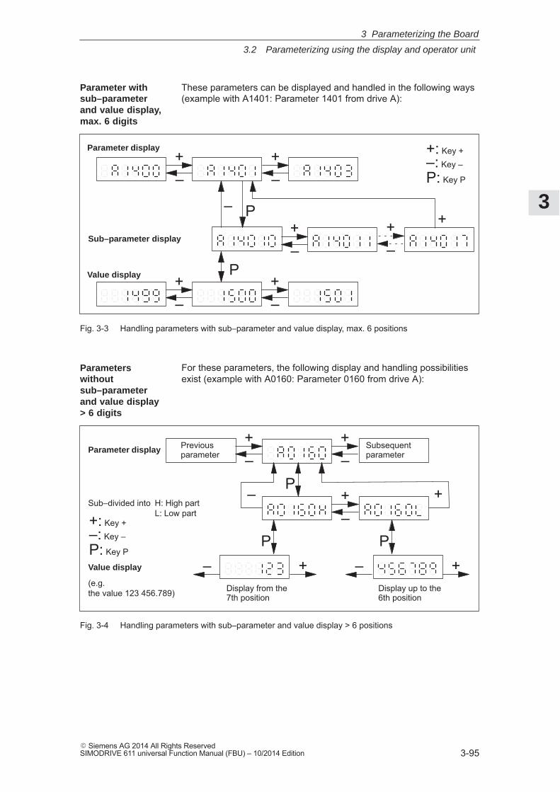
3
3.2 Parameterizing using the display and operator unit
3-95� Siemens AG 2014 All Rights ReservedSIMODRIVE 611 universal Function Manual (FBU) – 10/2014 Edition
These parameters can be displayed and handled in the following ways(example with A1401: Parameter 1401 from drive A):
Parameter display
Sub–parameter display
Value display P
P
+–
+–
+–
+–
+–
+–
+–
+: Key +–: Key –
P: Key P
Fig. 3-3 Handling parameters with sub–parameter and value display, max. 6 positions
For these parameters, the following display and handling possibilitiesexist (example with A0160: Parameter 0160 from drive A):
Parameter display
P
+–
+–
Previousparameter
Subsequentparameter
+–
P PValue display
(e.g. the value 123 456.789)
Sub–divided into H: High part L: Low part
– +
+– +–Display from the7th position
Display up to the6th position
+: Key +–: Key –
P: Key P
Fig. 3-4 Handling parameters with sub–parameter and value display > 6 positions
Parameter with sub–parameterand value display, max. 6 digits
Parameterswithout sub–parameterand value display > 6 digits
3 Parameterizing the Board
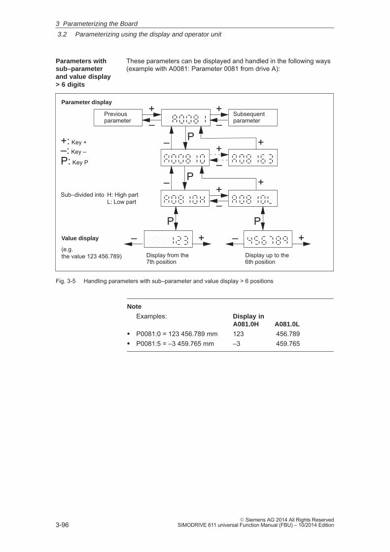
3
3.2 Parameterizing using the display and operator unit
3-96� Siemens AG 2014 All Rights Reserved
SIMODRIVE 611 universal Function Manual (FBU) – 10/2014 Edition
These parameters can be displayed and handled in the following ways(example with A0081: Parameter 0081 from drive A):
Parameter display+–
+–
Previousparameter
Subsequentparameter
+–
PValue display
(e.g. the value 123 456.789)
+
+–
+– –
P– +
P
P
– +Sub–divided into H: High part
L: Low part
Display from the7th position
Display up to the6th position
+: Key +–: Key –
P: Key P
Fig. 3-5 Handling parameters with sub–parameter and value display > 6 positions
Note
Examples: Display inA081.0H A081.0L
� P0081:0 = 123 456.789 mm 123 456.789� P0081:5 = –3 459.765 mm –3 459.765
Parameters with sub–parameterand value display > 6 digits
3 Parameterizing the Board
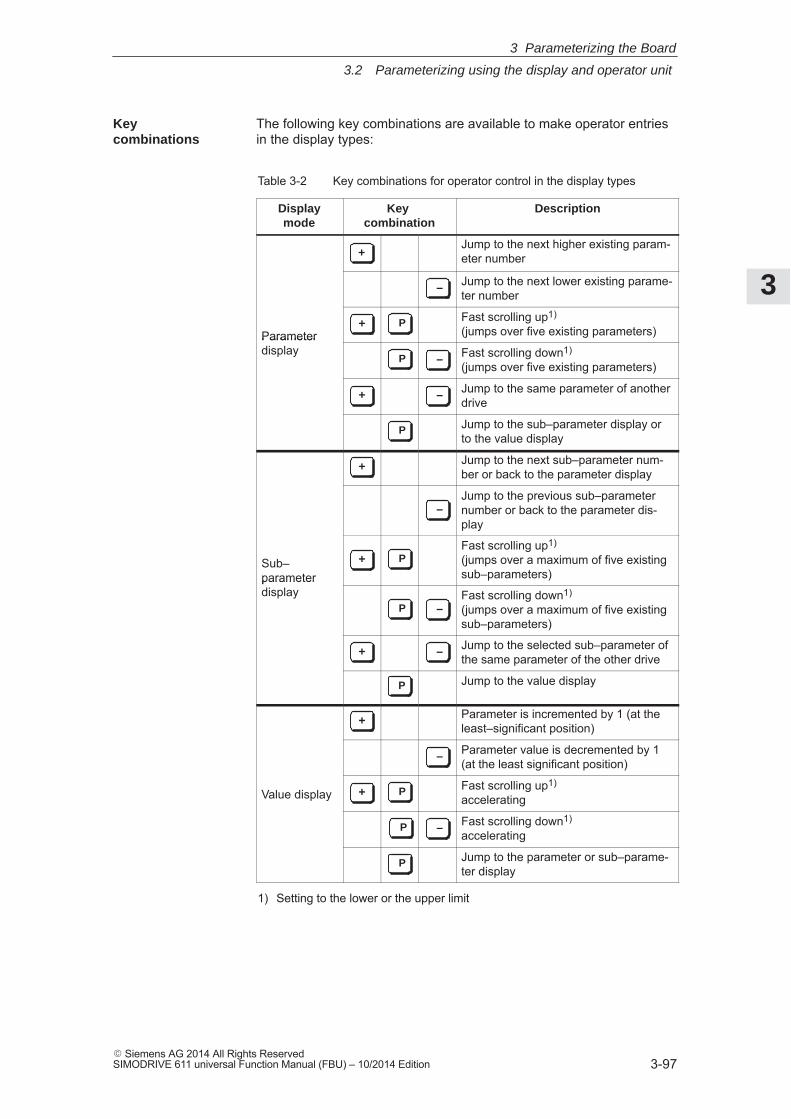
3
3.2 Parameterizing using the display and operator unit
3-97� Siemens AG 2014 All Rights ReservedSIMODRIVE 611 universal Function Manual (FBU) – 10/2014 Edition
The following key combinations are available to make operator entriesin the display types:
Table 3-2 Key combinations for operator control in the display types
Displaymode
Key combination
Description
+Jump to the next higher existing param-eter number
– Jump to the next lower existing parame-ter number
Parameter + P Fast scrolling up1)
(jumps over five existing parameters)Parameter display
P – Fast scrolling down1) (jumps over five existing parameters)
+ – Jump to the same parameter of anotherdrive
P Jump to the sub–parameter display orto the value display
+ Jump to the next sub–parameter num-ber or back to the parameter display
–Jump to the previous sub–parameternumber or back to the parameter dis-play
Sub–parameterdisplay
+ PFast scrolling up1) (jumps over a maximum of five existingsub–parameters)parameter
displayP –
Fast scrolling down1) (jumps over a maximum of five existingsub–parameters)
+ – Jump to the selected sub–parameter ofthe same parameter of the other drive
P Jump to the value display
+ Parameter is incremented by 1 (at theleast–significant position)
– Parameter value is decremented by 1(at the least significant position)
Value display + P Fast scrolling up1) accelerating
P – Fast scrolling down1) accelerating
P Jump to the parameter or sub–parame-ter display
1) Setting to the lower or the upper limit
Key combinations
3 Parameterizing the Board
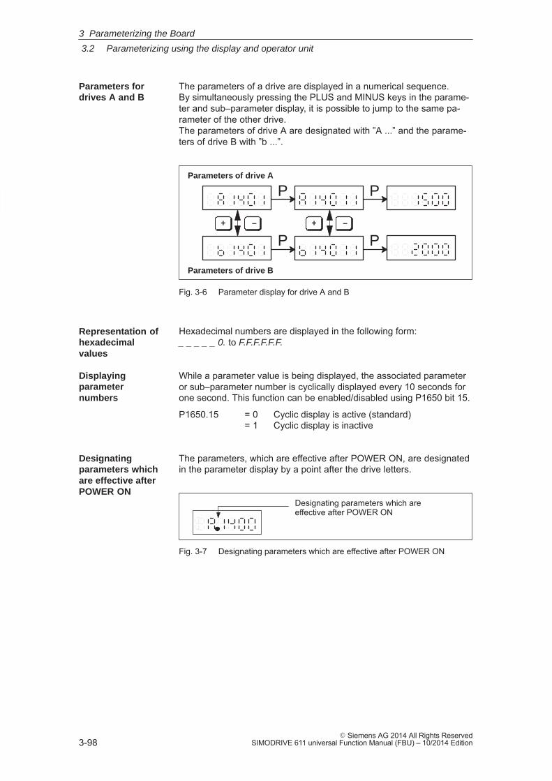
3
3.2 Parameterizing using the display and operator unit
3-98� Siemens AG 2014 All Rights Reserved
SIMODRIVE 611 universal Function Manual (FBU) – 10/2014 Edition
The parameters of a drive are displayed in a numerical sequence. By simultaneously pressing the PLUS and MINUS keys in the parame-ter and sub–parameter display, it is possible to jump to the same pa-rameter of the other drive.The parameters of drive A are designated with ”A ...” and the parame-ters of drive B with ”b ...”.
Parameters of drive A
Parameters of drive B
+ – + –
P P
P P
Fig. 3-6 Parameter display for drive A and B
Hexadecimal numbers are displayed in the following form:_ _ _ _ _ 0. to F.F.F.F.F.F.
While a parameter value is being displayed, the associated parameteror sub–parameter number is cyclically displayed every 10 seconds forone second. This function can be enabled/disabled using P1650 bit 15.
P1650.15 = 0 Cyclic display is active (standard)= 1 Cyclic display is inactive
The parameters, which are effective after POWER ON, are designatedin the parameter display by a point after the drive letters.
Designating parameters which are effective after POWER ON
Fig. 3-7 Designating parameters which are effective after POWER ON
Parameters for drives A and B
Representation ofhexadecimal values
Displaying parameternumbers
Designatingparameters which are effective after POWER ON
3 Parameterizing the Board
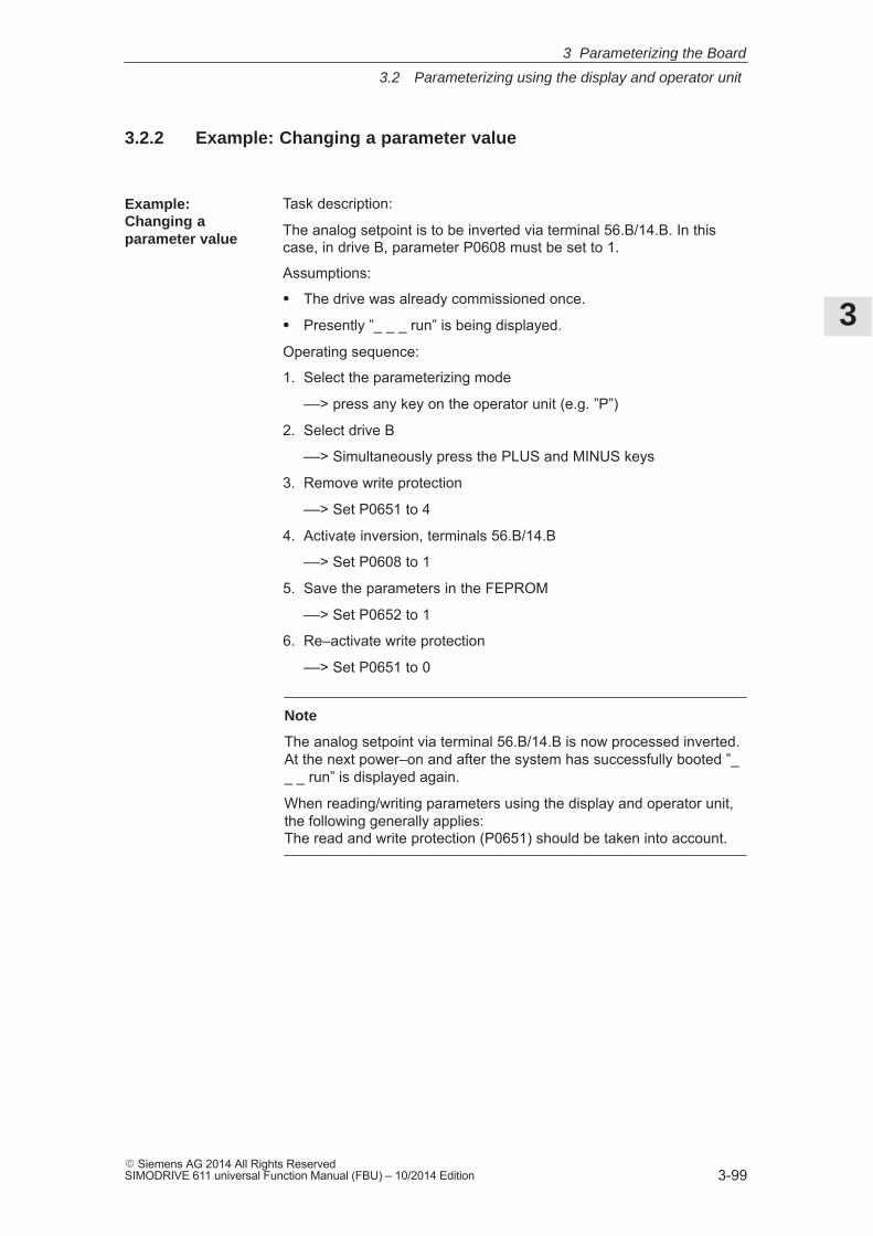
3
3.2 Parameterizing using the display and operator unit
3-99� Siemens AG 2014 All Rights ReservedSIMODRIVE 611 universal Function Manual (FBU) – 10/2014 Edition
3.2.2 Example: Changing a parameter value
Task description:
The analog setpoint is to be inverted via terminal 56.B/14.B. In thiscase, in drive B, parameter P0608 must be set to 1.
Assumptions:
� The drive was already commissioned once.
� Presently ”_ _ _ run” is being displayed.
Operating sequence:
1. Select the parameterizing mode
––> press any key on the operator unit (e.g. ”P”)
2. Select drive B
––> Simultaneously press the PLUS and MINUS keys
3. Remove write protection
––> Set P0651 to 4
4. Activate inversion, terminals 56.B/14.B
––> Set P0608 to 1
5. Save the parameters in the FEPROM
––> Set P0652 to 1
6. Re–activate write protection
––> Set P0651 to 0
Note
The analog setpoint via terminal 56.B/14.B is now processed inverted.At the next power–on and after the system has successfully booted ”__ _ run” is displayed again.
When reading/writing parameters using the display and operator unit,the following generally applies:The read and write protection (P0651) should be taken into account.
Example: Changing a parameter value
3 Parameterizing the Board
3
3.3 Parameterizing using the parameterizing and start–up tool SimoCom U
3-100� Siemens AG 2014 All Rights Reserved
SIMODRIVE 611 universal Function Manual (FBU) – 10/2014 Edition
3.3 Parameterizing using the parameterizing and start–uptool SimoCom U
3.3.1 Installing SimoCom U
Note
”SimoCom U” is a tool that is used for commissioning, diagnostics andparameterization. It is not permissible to use this tool as operatorinterface for continuous operation of drives!
A PG/PC is required to install the tool; it must fulfill the following mini-mum requirements:� Operating system:
Windows 98® or Windows NT® or
from SW 4.1 also Windows ME® or Windows 2000® or
from SW 6.1, also Window XP®
from SW 9.1, also WIN Server 2003®
from SW 9.2, only Windows XP®, WIN Server 2003®
from SW 12.1, only Windows XP®, WIN Server 2003® or Windows Vista®
from SW 13.2, only Windows XP®, WIN Server 2003®
Windows Vista® or Windows 7®
� 32 MB RAM memory
� Free memory required on the hard disk
– Installing with one language ––> 30 MB
– Installing each additional language ––> plus approx. 10 MB
� 1 free serial interface (RS232 interface)
Note
Note: If the PG/PC does not have a serial interface, then acommercially available USB/RS232 interface adapter can beconnected!
The various software versions are supplied on a CD–ROM.Further, the software is available in the Internet under the following address:http://www.ad.siemens.de/ ––> Products & Solutions ––> Drive systems ––> Drive converters ––>SIMODRIVE 611 ––> 611 universal ––> Downloads
Prerequisite
Software supply
3 Parameterizing the Board
3
3.3 Parameterizing using the parameterizing and start–up tool SimoCom U
3-101� Siemens AG 2014 All Rights ReservedSIMODRIVE 611 universal Function Manual (FBU) – 10/2014 Edition
The ”SimoCom U” parameterizing and start–up tool can be used forvarious drives.The functional scope of ”SimoCom U” tool will be continually adapted tothe functional expansion of these drives.In order to parameterize and handle all of the functions of a drive using”SimoCom U”, the optimum matching ”SimoCom U” must be used, de-pending on the drive software release.
Reader’s noteWhich version of SimoCom U optimally matches which drive and whichdrive software release?refer to SimoCom U as follows:Help ––> Info about ”SimoCom U” ... ––> Versions
This is how you install the ”SimoCom U” tool on your PG/PC:
Reader’s note
The ”readme.txt” file is provided on the software CD. Please observe the information, tips and tricks provided in this file.
1. Insert the software CD into the appropriate drive of your PG/PC.
2. Run the ”setup.exe” file in the ”disk1” directory of the required ver-sion of ”SimoCom U”.–> START –> RUB –> OPEN SETUP.EXE –> OK
3. Follow the instructions which the installation program displays step–by–step.
Result:
– The ”SimoCom U” tool has now been installed in the target direc-tory which you selected.
– The tool can e.g. be started as follows: –> START –> PROGRAMS –> SIMOCOMU –> SimoComU –> click on selection
Note
The firmware on the CD can be loaded into the appropriate moduleusing the ”SimoCom U” tool.
Which SimoCom Uversion is theoptimum one?
Installing”SimoCom U”
3 Parameterizing the Board
3
3.3 Parameterizing using the parameterizing and start–up tool SimoCom U
3-102� Siemens AG 2014 All Rights Reserved
SIMODRIVE 611 universal Function Manual (FBU) – 10/2014 Edition
You can un–install the ”SimoCom U” parameterizing and start–up toolfrom your PG/PC:
� Using the SimoCom U program
The ”SimoCom U” tool can, e.g. be uninstalled as follows:
–> START –> PROGRAMS –> SIMOCOMU –> Un–install SimoComU –> click
� Using the Control Panel just like any other Windows program
– Select the ”control panel”–> START –> SETTINGS –> CONTROL PANEL
– Double–click on the ”Software” symbol
– Select the ”SimoCom U” program in the selection field
– Press the ”add/remove...” button and then follow the instructions
Un–installing SimoCom U
3 Parameterizing the Board
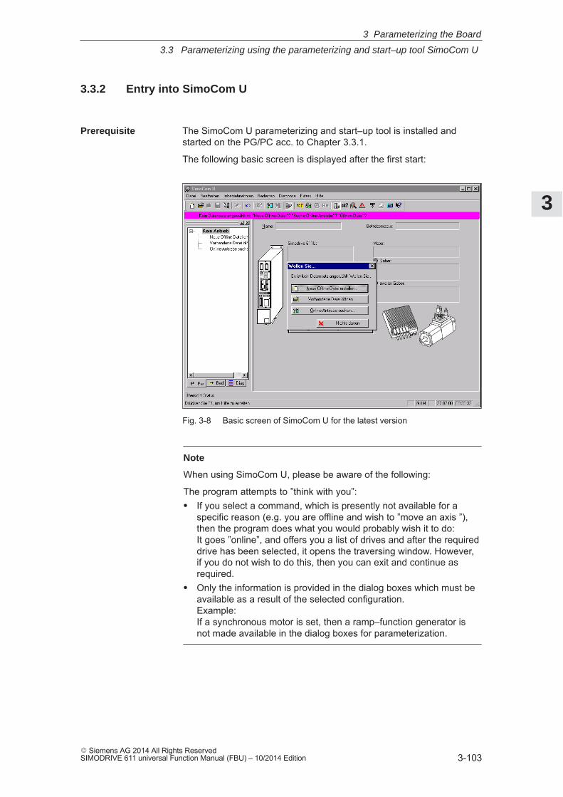
3
3.3 Parameterizing using the parameterizing and start–up tool SimoCom U
3-103� Siemens AG 2014 All Rights ReservedSIMODRIVE 611 universal Function Manual (FBU) – 10/2014 Edition
3.3.2 Entry into SimoCom U
The SimoCom U parameterizing and start–up tool is installed andstarted on the PG/PC acc. to Chapter 3.3.1.
The following basic screen is displayed after the first start:
Fig. 3-8 Basic screen of SimoCom U for the latest version
Note
When using SimoCom U, please be aware of the following:
The program attempts to ”think with you”:� If you select a command, which is presently not available for a
specific reason (e.g. you are offline and wish to ”move an axis ”),then the program does what you would probably wish it to do: It goes ”online”, and offers you a list of drives and after the requireddrive has been selected, it opens the traversing window. However,if you do not wish to do this, then you can exit and continue asrequired.
� Only the information is provided in the dialog boxes which must beavailable as a result of the selected configuration. Example: If a synchronous motor is set, then a ramp–function generator isnot made available in the dialog boxes for parameterization.
Prerequisite
3 Parameterizing the Board
3
3.3 Parameterizing using the parameterizing and start–up tool SimoCom U
3-104� Siemens AG 2014 All Rights Reserved
SIMODRIVE 611 universal Function Manual (FBU) – 10/2014 Edition
The information listed in Table 3-3 provides basic information and in-structions on how to handle the SimoCom U parameterizing andstart–up tool.
Table 3-3 Information on SimoCom U
Function Description
Tasks, which can beexecuted usingSimoCom U
� Check the wiring (go into the Online Help: connection diagrams)� Establish a connection to the drive to be parameterized� Change the parameters
– The essential parameters are changed in interactive dialog– All of the parameters can be changed using the list parameterization
� Upgrade firmware� Optimize the controller parameters� Traverse the axis� Diagnose the drive status
– Obtain an overview of all of the connected drives and their status– Identify the connected hardware – Obtain a display of the terminal status– Obtain a display of the alarms and information on how they can be
removed� Carry–out diagnostics
– Parameterize the test sockets (DAC1, DAC2) This means that selected signals in the drive can be routed to the testsockets for measurement with an oscilloscope.
– Execute the measuring function It is possible to measure the most important quantities in the closed–loopcurrent and speed control loop in the time and frequency domains with-out having to use external measuring equipment; these can then also begraphically displayed.
– Execute the trace functionSelected measuring quantities in the drive can be measured correspond-ing to the specified measuring parameters, and graphically displayedusing SimoCom U.
� Simulate terminal signals� Save the results
– Save the parameters in the drive FEPROM– Save the parameters in a file/open a file– Print the parameters
� Comparing parameter sets (from version 02.04)This allows the differences between 2 parameter sets to be identified.
� Boot the board (from version 03.03)The board status when originally shipped can be re–established using thisfunction.
� User–parameter list (from version 03.03)The user can include a parameter in this list. This list has the same function-ality as the expert list.
� Password protection (from version 08.01)Using this function, access protection can be provided for SimoCom U andthe drive firmware so that the drive configuration cannot be changed. To setthe password protection, refer to Chapter 4.3.3.
Information onSimoCom U
3 Parameterizing the Board
3
3.3 Parameterizing using the parameterizing and start–up tool SimoCom U
3-105� Siemens AG 2014 All Rights ReservedSIMODRIVE 611 universal Function Manual (FBU) – 10/2014 Edition
Table 3-3 Information on SimoCom U, continued
Function Description
Working offline ... this means that you are only working at the computer and you do not have aconnection to a ”SIMODRIVE 611 universal” drive. The opened files are now included in the drive selection box of the toolbar.
Working online ... this means that you are connected with one or several SIMODRIVE 611universal drives and SimoCom U also knows these drives. This is the case, if SimoCom U has already searched for the interface.You go online, if � You default setting in the menu ”Options/Settings/Communications” is set to
”connect via COMx” (this is realized when starting SimoCom U)
� You make the selection with the operator action ”Search for online drives”In the online mode, the toolbars of the opened files are included in the driveselection box together with all of the drives available at the interface.Recommended interface setting:If you are starting SimoCom U for the first time, then you will be prompted aboutthe default setting of the interface: � If you predominantly work in the office, then select ”work offline”. � If you predominantly work at the machine, then select ”connect via” and the
serial interface at your computer.
Note:
The parameters, displayed via SimoCom U, are not cyclically read.Examples:� If a parameter of an open dialog box is changed in online operation using
the display and operator unit, then this parameter remains ”frozen” in theopen dialog box.
� If a first commissioning is executed using the display and operator unit whileSimoCom U is in the online mode with the drive, then SimoCom U cannotidentify that the drive has been started up (commissioned).
Remedy:After changing parameters using the display and operator unit or via PROFI-BUS–DP, you should first go offline with SimoCom U, in order to go back onlinewith updated data.
Working in the driveorin the file
You can work in a file directly in the drive or only at the PC – however, only withone data set at any one time.For instance, you can be connected with a double axis module (and thereforehave access to the parameter sets in the two drives A and B) and at the sametime, have several files open. All of these parameter sets are then displayed inthe selection box in the toolbar, and also in the ”file” menu.When you select ”Drive A”, you will see the status and the parameters which areactive directly in Drive A – otherwise none. When changing over to a ”my.par”file, then you will only see the parameters of this file.Opened parameter files can also be re–closed: Menu ”File/Close file”.
3 Parameterizing the Board
3
3.3 Parameterizing using the parameterizing and start–up tool SimoCom U
3-106� Siemens AG 2014 All Rights Reserved
SIMODRIVE 611 universal Function Manual (FBU) – 10/2014 Edition
Table 3-3 Information on SimoCom U, continued
Function Description
Expert list ... displays all of the ”SIMODRIVE 611 universal” parameters.You can individually change any parameter via the expert list. The operator hasno additional support here. This list parameterization should only be used inexceptional cases.� Operating Instructions
– Call: Menu ”Start–up/Additional parameters/Expert list”– If you open the list, you will additionally obtain the menu, which can also
be reached using the right–hand mouse key. – It is especially interesting that the standard value and value limits for the
actual parameters are displayed in the status line.– Modified values only become effective after pressing the Enter key or if
another parameter was selected. Values which are inactive have a redbackground.
– In the ”List” menu, you can select which data should appear in the list:All, or only the controller data, or only the sub–parameter set 0 or ....Furthermore, you can search for specific terms with F3 (or list/searchmenu), e.g. you can search for ”temp” if you wish to change thetemperature warning threshold value.
– Bit–coded values: Go with the cursor to the line and press F4 (or menu,List/bit values). You then obtain a plain text display of the individual bitsand can select these at a click of the mouse.
Assign the PC themaster control
... means that the terminal signals are ignored at the terminals and instead, thedrive evaluates signals set by the PC.This means that the enable signals to traverse the drive can be output from thePC.Exceptions:� The pulse enable (terminal 663) and the controller enable (terminal 65.x)
must be provided, as before, via the input terminals.This is for safety: You can withdraw these enable signals at any time, usinga switch in order to switch the drive into a no–current condition or shut itdown.
� During PC–control, digital input 10 with the ”external block exchange” pa-rameter assignment is not active even if set via the PC (Diagnostics > Diagnostics Views > CTRL L).
Transfer the mastercontrol from the PCback to the terminals
... you then obtain a display of the voltage level available at the terminalscompared to the signals set by the PC. The master control is only transferred back to the terminals afteracknowledgement.
3 Parameterizing the Board
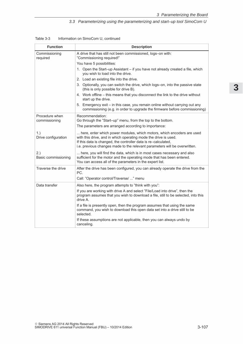
3
3.3 Parameterizing using the parameterizing and start–up tool SimoCom U
3-107� Siemens AG 2014 All Rights ReservedSIMODRIVE 611 universal Function Manual (FBU) – 10/2014 Edition
Table 3-3 Information on SimoCom U, continued
Function Description
Commissioning required
A drive that has still not been commissioned, logs–on with: ”Commissioning required!”You have 5 possibilities:1. Open the Start–up Assistant – if you have not already created a file, which
you wish to load into the drive.2. Load an existing file into the drive.3. Optionally, you can switch the drive, which logs–on, into the passive state
(this is only possible for drive B).4. Work offline – this means that you disconnect the link to the drive without
start up the drive.5. Emergency exit – in this case, you remain online without carrying out any
commissioning (e.g. in order to upgrade the firmware before commissioning)
Procedure when commissioning
Recommendation:Go through the ”Start–up” menu, from the top to the bottom.The parameters are arranged according to importance:
1.) Drive configuration
... here, enter which power modules, which motors, which encoders are usedwith this drive, and in which operating mode the drive is used. If this data is changed, the controller data is re–calculated, i.e. previous changes made to the relevant parameters will be overwritten.
2.)Basic commissioning
... here, you will find the data, which is in most cases necessary and alsosufficient for the motor and the operating mode that has been entered. You can access all of the parameters in the expert list.
Traverse the drive After the drive has been configured, you can already operate the drive from thePC.Call: ”Operator control/Traverse/ ...” menu
Data transfer Also here, the program attempts to ”think with you”:If you are working with drive A and select ”File/Load into drive”, then theprogram assumes that you wish to download a file, still to be selected, into thisdrive A.If a file is presently open, then the program assumes that using the samecommand, you wish to download this open data set into a drive still to beselected.If these assumptions are not applicable, then you can always undo bycanceling.
3 Parameterizing the Board
3
3.3 Parameterizing using the parameterizing and start–up tool SimoCom U
3-108� Siemens AG 2014 All Rights Reserved
SIMODRIVE 611 universal Function Manual (FBU) – 10/2014 Edition
The ”SimoCom U” tool has an integrated Help function, which helpsyou to use the tool and the ”SIMODRIVE 611 universal” drive. This is how you call up the integrated help function:
� Using the menu command Help � Help contents...
or
� By pressing the Help button
or
� By pressing key F1
Data for the following dialog boxes can be printed using the print sym-bol in the symbol bar:
� Traversing blocks
� Teach In
� User parameter list
� Operating conditions
� Status parameters
� Trace function
� Measurement function
� Expert List
Integrated help
Printing
3 Parameterizing the Board
3
3.3 Parameterizing using the parameterizing and start–up tool SimoCom U
3-109� Siemens AG 2014 All Rights ReservedSIMODRIVE 611 universal Function Manual (FBU) – 10/2014 Edition
3.3.3 Online operation: SimoCom U via a serial interface
The serial interface (X471) can be used as RS232 interface or asRS485 interface.
� Used as RS232 interface––> refer under the index entry, ”Communications via RS232”
� Used as RS485 interface––> refer under the index entry ”Communications via RS485”
Note
When working with the interface, it is imperative to observe the follo-wing points:� The data cables should not be removed when the SimoCom U is in
the online mode. Should you have nevertheless removed the datacable, close and restart SimoCom U, and then you may continueworking.
� Before removing the data cable, cancel pulse enable of the I/RFand all drive modules. Thus. you avoid damage to the serial inter-face in closed–loop control or if a PC / notebook is connected.
� When uploading measurement data from the drive, note that thecancellation of servo enable using the <F8> key or spacebar is notaccepted. The hardware terminal, however, remains effective.
General
3 Parameterizing the Board
! 611ue diff !
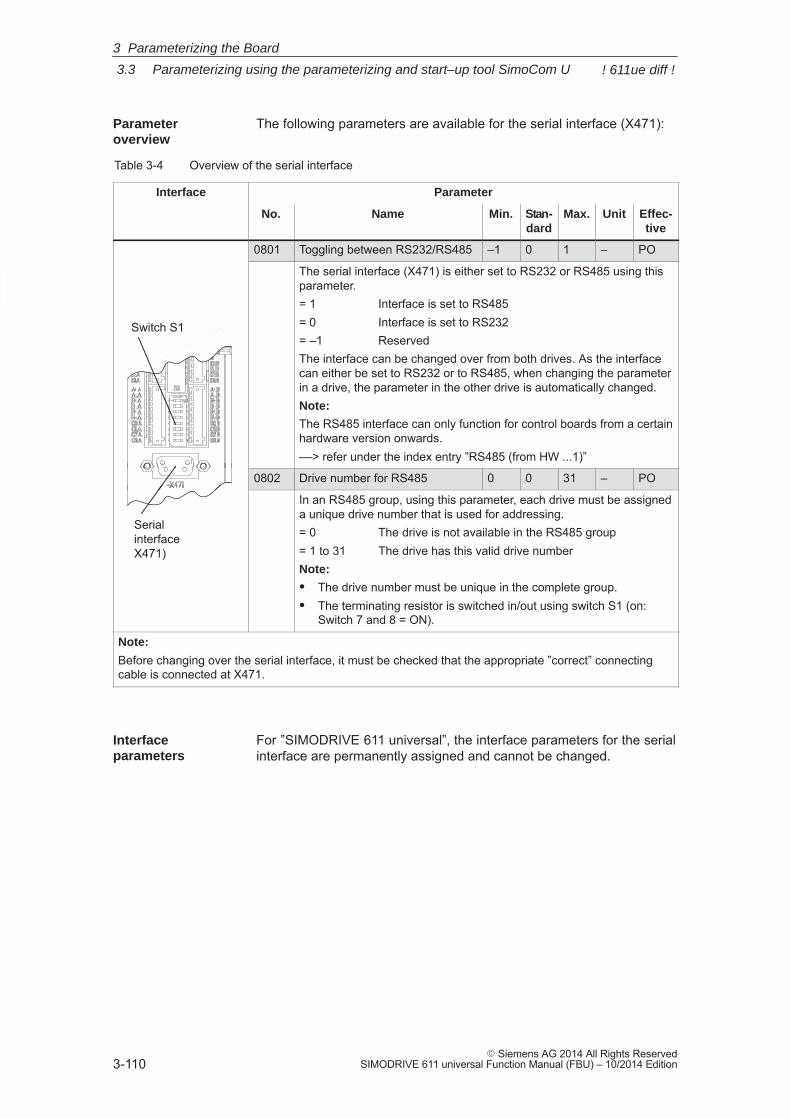
3
3.3 Parameterizing using the parameterizing and start–up tool SimoCom U
3-110� Siemens AG 2014 All Rights Reserved
SIMODRIVE 611 universal Function Manual (FBU) – 10/2014 Edition
The following parameters are available for the serial interface (X471):
Table 3-4 Overview of the serial interface
Interface Parameter
No. Name Min. Stan-dard
Max. Unit Effec-tive
0801 Toggling between RS232/RS485 –1 0 1 – PO
Switch S1
The serial interface (X471) is either set to RS232 or RS485 using thisparameter.= 1 Interface is set to RS485= 0 Interface is set to RS232= –1 ReservedThe interface can be changed over from both drives. As the interfacecan either be set to RS232 or to RS485, when changing the parameterin a drive, the parameter in the other drive is automatically changed.Note:
The RS485 interface can only function for control boards from a certainhardware version onwards.––> refer under the index entry ”RS485 (from HW ...1)”
0802 Drive number for RS485 0 0 31 – PO
Serial interfaceX471)
In an RS485 group, using this parameter, each drive must be assigneda unique drive number that is used for addressing.= 0 The drive is not available in the RS485 group= 1 to 31 The drive has this valid drive numberNote:
� The drive number must be unique in the complete group.� The terminating resistor is switched in/out using switch S1 (on:
Switch 7 and 8 = ON).
Note:
Before changing over the serial interface, it must be checked that the appropriate ”correct” connectingcable is connected at X471.
For ”SIMODRIVE 611 universal”, the interface parameters for the serialinterface are permanently assigned and cannot be changed.
Parameter overview
Interface parameters
3 Parameterizing the Board
! 611ue diff !
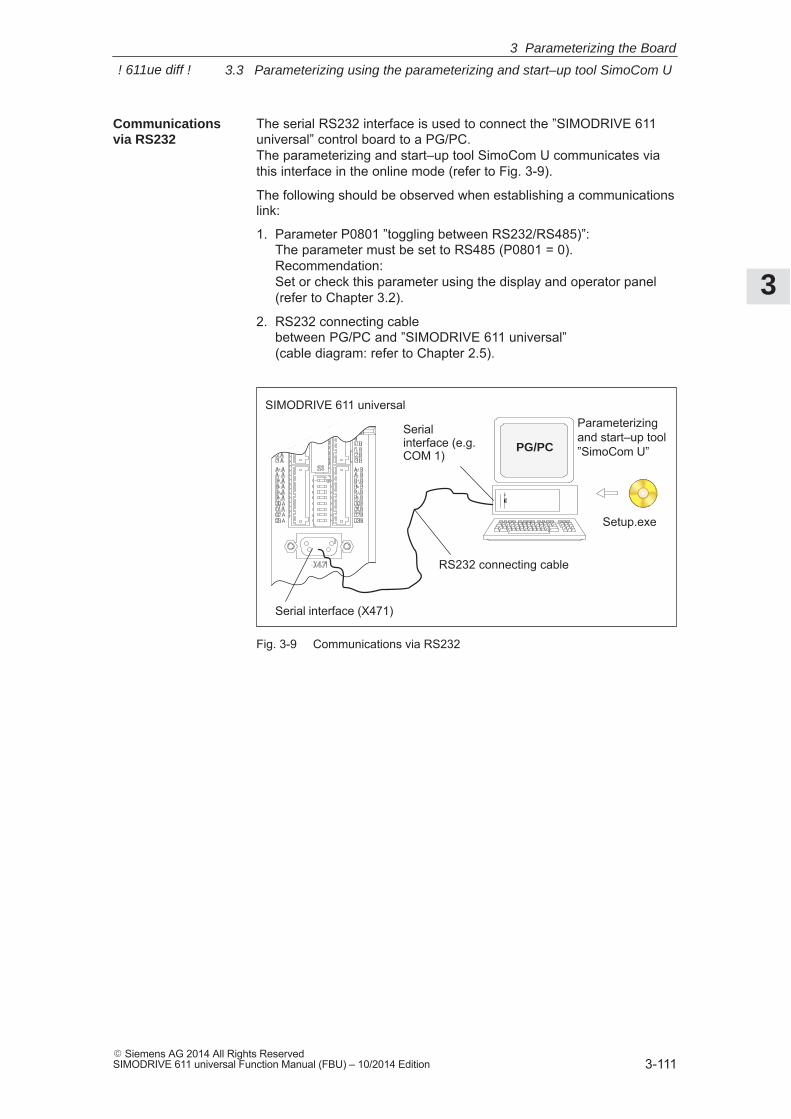
3
3.3 Parameterizing using the parameterizing and start–up tool SimoCom U
3-111� Siemens AG 2014 All Rights ReservedSIMODRIVE 611 universal Function Manual (FBU) – 10/2014 Edition
The serial RS232 interface is used to connect the ”SIMODRIVE 611universal” control board to a PG/PC. The parameterizing and start–up tool SimoCom U communicates viathis interface in the online mode (refer to Fig. 3-9).
The following should be observed when establishing a communicationslink:
1. Parameter P0801 ”toggling between RS232/RS485)”:The parameter must be set to RS485 (P0801 = 0).Recommendation: Set or check this parameter using the display and operator panel(refer to Chapter 3.2).
2. RS232 connecting cablebetween PG/PC and ”SIMODRIVE 611 universal” (cable diagram: refer to Chapter 2.5).
Serial interface (X471)
RS232 connecting cable
SIMODRIVE 611 universal
Serial interface (e.g.COM 1)
Parameterizingand start–up tool”SimoCom U”PG/PC
Setup.exe
Fig. 3-9 Communications via RS232
Communicationsvia RS232
3 Parameterizing the Board
! 611ue diff !
3
3.3 Parameterizing using the parameterizing and start–up tool SimoCom U
3-112� Siemens AG 2014 All Rights Reserved
SIMODRIVE 611 universal Function Manual (FBU) – 10/2014 Edition
The serial RS485 interface is used to connect several ”SIMODRIVE611 universal” control boards in an RS485 group. The SimoCom U parameterizing and start–up tool communicates, inthe online mode, via an RS232/RS485 interface converter and the se-lected drive in the RS485 group (refer to Fig. 3-10).
Notice
The RS485 interface can only function with control boards from theappropriate hardware version (refer to Order No., MLFB).
Control board (Order No.) RS485?� 6SN1118–�N�00–0AA0 RS485 cannot be used� from 6SN1118–�N�00–0AA1 RS485 can be used
�: Space retainer for the Order No.
For communications via RS485, the following should be observed:
1. Parameter
– P0801 (toggling between RS232/RS485)The parameter must be set to RS485 (P0801 = 1).
Recommendation:Set or check this parameter using the display and operator panel(refer to Chapter 3.2).
– P0802 (drive number for RS485)The drive number for each drive is selected via this parameter.
2. Interface converter RS232/RS485For operation via RS485, a commercially available RS232/RS485converter is required between the PC and RS485 bus.
The interface converter must have the following features:
– The converter itself must automatically change over the data flowdirection.
– It is not permissible that the converter sends an ”echo” back tothe PC.
Recommended RS232/RS485 interface converter name:
– Name: PC/PPI cable (RS232/RS485 converter)
– Order No.: 6ES7 901–3BF20–0XA0
– Cable length: 5 m
– Connector: on the RS232 side: 9–pin socket connectoron the RS485 side: 9–pin plug connector
– Power supply: via the connector on the RS485 sideRS485 side (+24 V/0.5 W)
– Data transfer rate: set to 38.4 kbaud
Communicationsvia RS485
(the function is dependent on thehardware)
3 Parameterizing the Board
! 611ue diff !
3
3.3 Parameterizing using the parameterizing and start–up tool SimoCom U
3-113� Siemens AG 2014 All Rights ReservedSIMODRIVE 611 universal Function Manual (FBU) – 10/2014 Edition
3. Cable
– RS232 connecting cableCable between the PG/PC and interface converter(cable diagram: refer to Chapter 2.5)
– RS485 connecting cableCable between the RS232/RS485 interface converter and thenodes to establish an RS485 link(cable diagram: refer to Chapter 2.5 or Fig. 3-10)
4. Terminating resistor for the RS485 bus
Generally applies:First and last node ––> terminating resistor switched–in Other nodes on the bus ––> terminating resistor switched–out (switch S1, refer to Chapter 1.3.2)
Communications from a PG/PC to 3 ”SIMODRIVE 611 universal” con-trol boards (2–axis versions) should be possible via the serial interface. Online operation between a PG/PC and the individual control boardsmust be realized via an RS232/RS485 converter and the appropriatecabling on the RS485 side, so that the drive can go online at any time.
Assumptions for the example:
� The recommended RS232/RS485 converter is used (PC/PPI cable).Set all of the switches at the converter to ”0”.
� The serial interface must be set to RS485 for all drives (P0801 = 1).
� Setting the drive number (P0802)
– 1st board Drive A: Drive number for RS485 = 4Drive B: Drive number for RS485 = 2
– 2nd board Drive A: Drive number for RS485 = 7Drive B: Drive number for RS485 = 8
– 3rd board Drive A: Drive number for RS485 = 5Drive B: Drive number for RS485 = 3
� Terminating resistor for the RS485 bus
– Interface converter: First node ––> Switch–in the terminating resistor
or solder into the socket (refer to Fig. 3-10)
– 1st and 2nd board: No first or last node––> Switch–out the terminating resistor
– 3rd board: Last node––> Switch–in the terminating resistor
Example: Communications between the PG/PCand 6 drives via RS485
3 Parameterizing the Board
! 611ue diff !
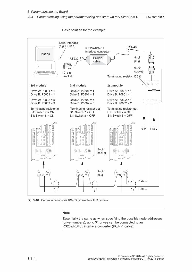
3
3.3 Parameterizing using the parameterizing and start–up tool SimoCom U
3-114� Siemens AG 2014 All Rights Reserved
SIMODRIVE 611 universal Function Manual (FBU) – 10/2014 Edition
Basic solution for the example:
Serial interface (e.g. COM 1) RS–48
5
RS232
RS232/RS485interface converter
1st module
Drive A: P0801 = 1Drive B: P0801 = 1
Drive A: P0802 = 4Drive B: P0802 = 2
Terminating resistor out S1: Switch 7 = OFFS1: Switch 8 = OFF
2nd module
Drive A: P0801 = 1Drive B: P0801 = 1
Drive A: P0802 = 7Drive B: P0802 = 8
Terminating resistor out S1: Switch 7 = OFFS1: Switch 8 = OFF
3rd module
Drive A: P0801 = 1Drive B: P0801 = 1
Drive A: P0802 = 5Drive B: P0802 = 3
Terminating resistor in S1: Switch 7 = ONS1: Switch 8 = ON
ÇÇÇÇÇÇ
9–pin plug
9–pin socket
19
9–pin plug
19
19
ÇÇÇÇÇÇ
3 872
9–pin socket
9–pin socket
Data +
Data –
ÇÇÇPC/PPI cable
PG/PC
0 V +24 V
Terminating resistor 120 Ω
Fig. 3-10 Communications via RS485 (example with 3 nodes)
Note
Essentially the same as when specifying the possible node addresses(drive numbers), up to 31 drives can be connected to anRS232/RS485 interface converter (PC/PPI cable).
3 Parameterizing the Board
! 611ue diff !
3
3.3 Parameterizing using the parameterizing and start–up tool SimoCom U
3-115� Siemens AG 2014 All Rights ReservedSIMODRIVE 611 universal Function Manual (FBU) – 10/2014 Edition
3.3.4 Online operation: SimoCom U via PROFIBUS–DP (from SW 3.1)
The ”SimoCom U” parameterizing and start–up tool can communicatewith the drives via the serial interfaces and also via the PROFIBUS–DPfield bus.
The following online modes are possible:
� Online operation via the CP 5511/CP 5611/CP 5613 directly with thefield bus
PG/PC <––> CP 5511 / CP 5611 / CP 5613 <––> PROFIBUS <––>drives
� Online operation via the MPI interface of SIMATIC S7
PG/PC <––> MPI <––> PROFIBUS <––> drives
If the subsequently listed prerequisites are fulfilled, then online oper-ation can be established between SimoCom U, and all of the drivesconnected to the bus (”DP slaves 611U”).
Note
When displaying drive–internal values (e.g. position setpoint...) devi-ations can occur at the last position of the value. This is due to the dif-ferent rounding–off techniques employed by the conversion programsin the drive and in the “SimoCom U” parameterizing and commission-ing tool. However, this has no effect on the computational accuracy inthe drive.
Note
The data cables should not be removed when SimoCom U is in theonline mode. If this case occurs, close and restart SimoCom U, andthen you may continue working.
Before removing the data cable, cancel pulse enable of the I/RF andall drive modules to avoid damage to the serial interface in closed–loopcontrol or if a PC / notebook is connected.
Description
3 Parameterizing the Board
3
3.3 Parameterizing using the parameterizing and start–up tool SimoCom U
3-116� Siemens AG 2014 All Rights Reserved
SIMODRIVE 611 universal Function Manual (FBU) – 10/2014 Edition
For SimoCom U, communications via PROFIBUS–DP can be set asfollows:
� Options – Settings – Communications ––> ”Interface” dialog”
� For ”For ”Go online” connect via” set the following:––> ”PROFIBUS” and
––> ”Direct connection” ––> if the coupling is directly with the field bus or
––> ”MPI –> PROFIBUS Routing” ––> if the coupling is via the MPI interfaceor
––> ”Communication via OPC server” (from SW 6.1)––> if the coupling is via OPC server
Then, online operation can be established directly to the drive via thefield bus using the ”Search for online drives” function.
Settings forSimoCom U
3 Parameterizing the Board
3
3.3 Parameterizing using the parameterizing and start–up tool SimoCom U
3-117� Siemens AG 2014 All Rights ReservedSIMODRIVE 611 universal Function Manual (FBU) – 10/2014 Edition
In order to go online with a drive via the PROFIBUS–DP field bus using”SimoCom U”, the following prerequisites must be fulfilled:
1. ”SIMODRIVE 611 universal” control board from SW 3.1 with the fol-lowing option module:
– Optional PROFIBUS–DP2 module (with ASIC DPC31 withoutPLL) Order No. (MLFB): 6SN1114–0NB00–0AAx
or
– Optional PROFIBUS–DP3 module (with ASIC DPC31 with PLL) Order No. (MLFB): 6SN1114–0NB01–0AAx
2. ”SimoCom U” parameterizing and start–up tool from version 3.1
3. Communication boards, if connected via PROFIBUS
– CP 5511 (PROFIBUS connection via PCMCIA card)
Setup: PCMCIA card, type 2 + adapter with 9–pin SUB–D socket con-nector to connect to PROFIBUS.
Order No. (MLFB): 6GK1551–1AA00
or
– CP 5611 (PROFIBUS connection through a short PCI card)
Setup: Short PCI card with 9–pin SUB–D socket to connect toPROFIBUS.
Order No. (MLFB): 6GK1561–1AA00
– CP 5613 (PROFIBUS coupling via short PCI card) (from SW 4.1)
Setup: Short PCI card with 9–pin SUB–D socket to connect toPROFIBUS.Diagnostic LEDs, PROFIBUS controller ASPC2 StepE
Order No. (MLFB): 6GK1561–3AA00
4. SIMATIC–CPU, if connected via an MPI interface
A routing–capable SIMATIC–CPU is required for a coupling via MPIinterface.
5. S7–DOS from V5.0
This software is supplied on the CD for ”SIMODRIVE 611 universal”(refer to Chapter 1.3).
6. Cables
– between CP 5511 or CP 5611 and the PROFIBUS field bus
or
– between the MPI interface from the PG and SIMATIC CPU
Conditions
3 Parameterizing the Board
3
3.3 Parameterizing using the parameterizing and start–up tool SimoCom U
3-118� Siemens AG 2014 All Rights Reserved
SIMODRIVE 611 universal Function Manual (FBU) – 10/2014 Edition
Note
Going online/offline in cyclic operation via PROFIBUS:
While PROFIBUS is in cyclic operation, SimoCom U with CPxx can be attached or disconnected from the field bus via the followingplug–in cable without creating a fault
Order No. (MLFB): 6ES7901–4BD00–0XA0 (plug–in cable)
In order to go online with a drive using ”SimoCom U” via an OPC server PROFIBUS–DP, the OPC server must first be installed accord-ing to the manufacturers instructions and the following prerequisitesmust be fulfilled:
� Hardware
– PROFIBUS card must be installed in the PC – cards from third–party manufacturers can also be used
– Connecting cable
� Software
– Driver software and the associated OPC server for the installedProfibus card
– Configuring software for the OPC server Most OPC server/Profibus cards require a bus setting (e.g. baudrate, protocol) – several also require that the existing drives areconfigured on the bus.
Reader’s note
Please refer to the documentation of the appropriate manufacturer regarding information on how to configure a PROFIBUS card and OPserver. These procedures depend on the particular manufacturer.
– The OPC server, provided by the manufacturer, offers a possibil-ity of accessing MSAC2 services according to DPV1 (EN50170)including the DataTransport service.OPC servers that have registered themselves with the systemunder the Category ”Profibus–DPV1–OPC server Version 1.0”fulfill this requirement. When selecting the interface, SimoCom U offers this OPC serverin a separate selection box.
Prerequisites withthe OPC server(from SW 6.1)
3 Parameterizing the Board
3
3.3 Parameterizing using the parameterizing and start–up tool SimoCom U
3-119� Siemens AG 2014 All Rights ReservedSIMODRIVE 611 universal Function Manual (FBU) – 10/2014 Edition
� SimoCom U from Version 6.1
After this configuration of the OPC server has been activated, theaccess route to ”Communications via OPC server” can be set inSimoCom U under ”Options/Settings/Communication”.
The OPC server to be used should then be selected using the ”OPCConfiguration” button:– We recommend that the option ”Display all DPV1–OPC–Server”
is selected and an OPC server selected from the selection boxlocated below. The OPC servers, which are displayed for thisparticular selection, guarantee that the utilities (services), required by SimComU, as described in the software prerequi-sites, are provided.
– If the required OPC server is not listed, but the required utilities(services) are however available, then the button ”Display allOPC servers” should be selected, whereby, all of the utilities,installed in the PC which support the OPC, are listed.
– Alternatively, the so–called ClassID of the OPC server can bedirectly entered under the ”Specify OPC server name (only forexperts!).
3 Parameterizing the Board
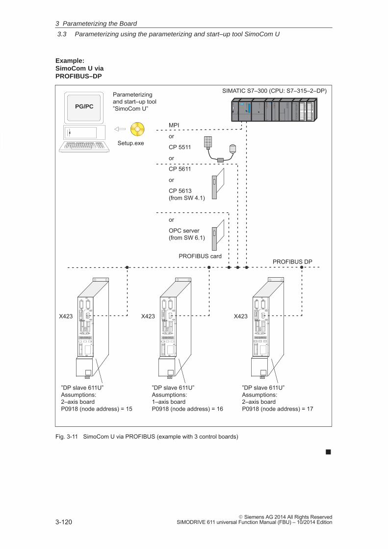
3
3.3 Parameterizing using the parameterizing and start–up tool SimoCom U
3-120� Siemens AG 2014 All Rights Reserved
SIMODRIVE 611 universal Function Manual (FBU) – 10/2014 Edition
MPI
or
CP 5511
or
CP 5611
or
CP 5613 (from SW 4.1)
or
OPC server(from SW 6.1)
”DP slave 611U”Assumptions:2–axis boardP0918 (node address) = 15
PROFIBUS DP
SIMATIC S7–300 (CPU: S7–315–2–DP)
”DP slave 611U”Assumptions:1–axis boardP0918 (node address) = 16
”DP slave 611U”Assumptions:2–axis boardP0918 (node address) = 17
ÄÄÄÄ
X423 X423 X423
Parameterizingand start–up tool”SimoCom U”PG/PC
Setup.exe
PROFIBUS card
Fig. 3-11 SimoCom U via PROFIBUS (example with 3 control boards)
�
Example: SimoCom U viaPROFIBUS–DP
3 Parameterizing the Board
4
4-121� Siemens AG 2014 All Rights ReservedSIMODRIVE 611 universal Function Manual (FBU) – 10/2014 Edition
Commissioning
4.1 General commissioning information 4-122. . . . . . . . . . . . . . . . . . . . . . . . . . . . . . . .
4.2 Booting ”SIMODRIVE 611 universal” 4-125. . . . . . . . . . . . . . . . . . . . . . . . . . . . . . .
4.3 Commissioning via SimoCom U 4-126. . . . . . . . . . . . . . . . . . . . . . . . . . . . . . . . . . . 4.3.1 First commissioning with SimoCom U 4-127. . . . . . . . . . . . . . . . . . . . . . . . . . . . . . 4.3.2 Series commissioning with SimoCom U 4-128. . . . . . . . . . . . . . . . . . . . . . . . . . . . 4.3.3 Password protection with SimoCom U (from SW 8.1) 4-129. . . . . . . . . . . . . . . . . 4.3.4 Upgrading the firmware 4-132. . . . . . . . . . . . . . . . . . . . . . . . . . . . . . . . . . . . . . . . . . 4.3.5 Firmware download 4-132. . . . . . . . . . . . . . . . . . . . . . . . . . . . . . . . . . . . . . . . . . . . . . 4.3.6 Automated firmware download (from SW 8.1) 4-133. . . . . . . . . . . . . . . . . . . . . . .
4.4 Commissioning using the display and operator unit 4-135. . . . . . . . . . . . . . . . . . .
4.5 Function–initiating and diagnostic parameters 4-138. . . . . . . . . . . . . . . . . . . . . . .
4.6 Parameters for hardware, operating mode and clock cycles 4-144. . . . . . . . . . .
4.7 Induction motor operation with induction motor 4-148. . . . . . . . . . . . . . . . . . . . . . 4.7.1 Description 4-148. . . . . . . . . . . . . . . . . . . . . . . . . . . . . . . . . . . . . . . . . . . . . . . . . . . . . 4.7.2 Commissioning induction motors (ARM) without encoder 4-151. . . . . . . . . . . . . 4.7.3 Motor data optimization, steps 1 to 4 4-155. . . . . . . . . . . . . . . . . . . . . . . . . . . . . . . 4.7.4 Speed monitoring using a BERO (from SW 12.1) 4-160. . . . . . . . . . . . . . . . . . . .
4.8 Permanent–magnet synchronous motor with and without field–weakening (PE spindle) 4-163. . . . . . . . . . . . . . . . . . . . . . . . . . . . . . . . . . . . .
4.8.1 Description 4-163. . . . . . . . . . . . . . . . . . . . . . . . . . . . . . . . . . . . . . . . . . . . . . . . . . . . . 4.8.2 Commissioning synchronous motors 4-165. . . . . . . . . . . . . . . . . . . . . . . . . . . . . . . 4.8.3 Current controller adaptation 4-169. . . . . . . . . . . . . . . . . . . . . . . . . . . . . . . . . . . . . . 4.8.4 Parameters for PE spindles 4-172. . . . . . . . . . . . . . . . . . . . . . . . . . . . . . . . . . . . . . .
4.9 1FW6 built–in torque motors (from SW 6.1) 4-174. . . . . . . . . . . . . . . . . . . . . . . . . 4.9.1 Description 4-174. . . . . . . . . . . . . . . . . . . . . . . . . . . . . . . . . . . . . . . . . . . . . . . . . . . . . 4.9.2 Commissioning 1FW6 motors 4-176. . . . . . . . . . . . . . . . . . . . . . . . . . . . . . . . . . . . . 4.9.3 Thermal motor protection 4-177. . . . . . . . . . . . . . . . . . . . . . . . . . . . . . . . . . . . . . . . .
4.10 Linear motors (1FN1, 1FN3 motors) 4-178. . . . . . . . . . . . . . . . . . . . . . . . . . . . . . . 4.10.1 General information on commissioning linear motors 4-178. . . . . . . . . . . . . . . . . 4.10.2 Commissioning: Linear motor with one primary section 4-181. . . . . . . . . . . . . . . 4.10.3 Commissioning: Linear motor with two identical primary sections 4-188. . . . . . . 4.10.4 Mechanical system 4-191. . . . . . . . . . . . . . . . . . . . . . . . . . . . . . . . . . . . . . . . . . . . . . 4.10.5 Thermal motor protection 4-193. . . . . . . . . . . . . . . . . . . . . . . . . . . . . . . . . . . . . . . . . 4.10.6 Measuring system 4-197. . . . . . . . . . . . . . . . . . . . . . . . . . . . . . . . . . . . . . . . . . . . . . . 4.10.7 Parallel and double–cam arrangement of linear motors 4-200. . . . . . . . . . . . . . . 4.10.8 Checking the linear motor by making measurements 4-201. . . . . . . . . . . . . . . . .
4.11 Direct measuring system for position control (from SW 3.3) 4-202. . . . . . . . . . .
4.12 Connecting induction motors with TTL encoder (from SW 8.1) 4-206. . . . . . . . .
4.13 FD operation with field weakening (from SW 12.1) 4-207. . . . . . . . . . . . . . . . . . .
4
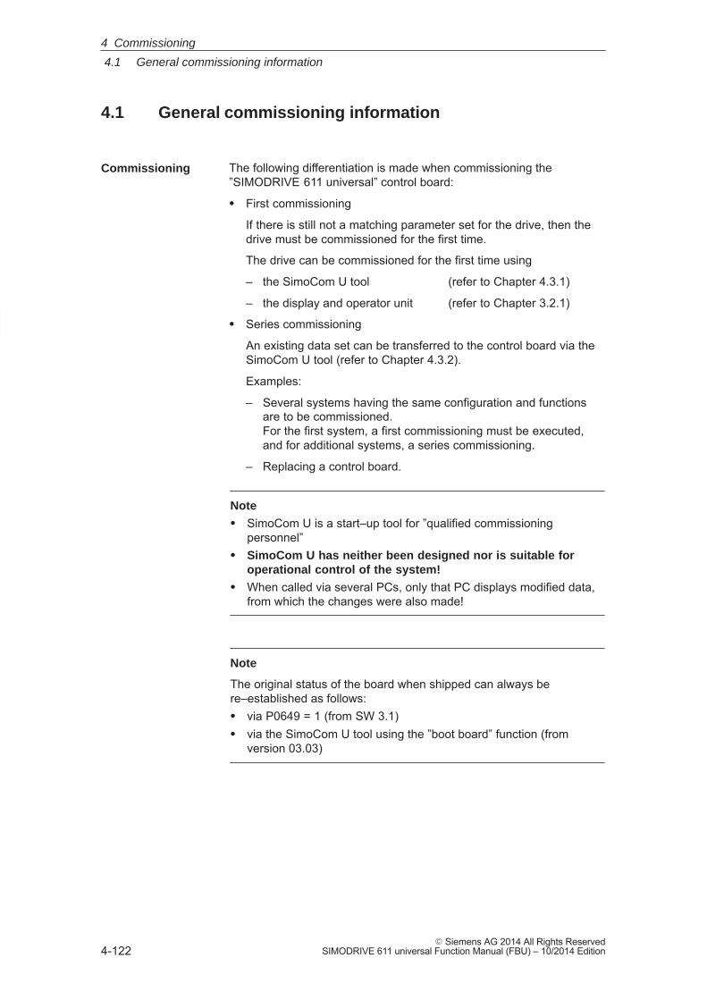
4
4.1 General commissioning information
4-122� Siemens AG 2014 All Rights Reserved
SIMODRIVE 611 universal Function Manual (FBU) – 10/2014 Edition
4.1 General commissioning information
The following differentiation is made when commissioning the”SIMODRIVE 611 universal” control board:
� First commissioning
If there is still not a matching parameter set for the drive, then thedrive must be commissioned for the first time.
The drive can be commissioned for the first time using
– the SimoCom U tool (refer to Chapter 4.3.1)
– the display and operator unit (refer to Chapter 3.2.1)
� Series commissioning
An existing data set can be transferred to the control board via theSimoCom U tool (refer to Chapter 4.3.2).
Examples:
– Several systems having the same configuration and functionsare to be commissioned. For the first system, a first commissioning must be executed,and for additional systems, a series commissioning.
– Replacing a control board.
Note
� SimoCom U is a start–up tool for ”qualified commissioningpersonnel”
� SimoCom U has neither been designed nor is suitable foroperational control of the system!
� When called via several PCs, only that PC displays modified data,from which the changes were also made!
Note
The original status of the board when shipped can always bere–established as follows:� via P0649 = 1 (from SW 3.1)� via the SimoCom U tool using the ”boot board” function (from
version 03.03)
Commissioning
4 Commissioning
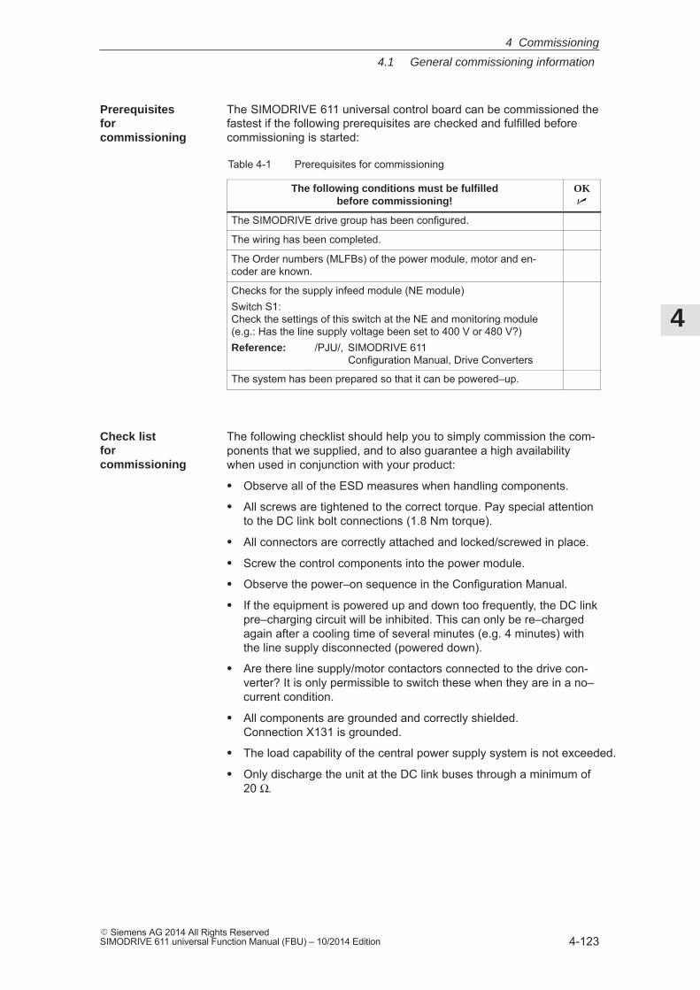
4
4.1 General commissioning information
4-123� Siemens AG 2014 All Rights ReservedSIMODRIVE 611 universal Function Manual (FBU) – 10/2014 Edition
The SIMODRIVE 611 universal control board can be commissioned thefastest if the following prerequisites are checked and fulfilled beforecommissioning is started:
Table 4-1 Prerequisites for commissioning
The following conditions must be fulfilledbefore commissioning!
OK�
The SIMODRIVE drive group has been configured.
The wiring has been completed.
The Order numbers (MLFBs) of the power module, motor and en-coder are known.
Checks for the supply infeed module (NE module)Switch S1: Check the settings of this switch at the NE and monitoring module (e.g.: Has the line supply voltage been set to 400 V or 480 V?)Reference: /PJU/, SIMODRIVE 611
Configuration Manual, Drive Converters
The system has been prepared so that it can be powered–up.
The following checklist should help you to simply commission the com-ponents that we supplied, and to also guarantee a high availabilitywhen used in conjunction with your product:
� Observe all of the ESD measures when handling components.
� All screws are tightened to the correct torque. Pay special attentionto the DC link bolt connections (1.8 Nm torque).
� All connectors are correctly attached and locked/screwed in place.
� Screw the control components into the power module.
� Observe the power–on sequence in the Configuration Manual.
� If the equipment is powered up and down too frequently, the DC linkpre–charging circuit will be inhibited. This can only be re–chargedagain after a cooling time of several minutes (e.g. 4 minutes) withthe line supply disconnected (powered down).
� Are there line supply/motor contactors connected to the drive con-verter? It is only permissible to switch these when they are in a no–current condition.
� All components are grounded and correctly shielded. Connection X131 is grounded.
� The load capability of the central power supply system is not exceeded.
� Only discharge the unit at the DC link buses through a minimum of20 Ω.
Prerequisites for commissioning
Check list for commissioning
4 Commissioning
4
4.1 General commissioning information
4-124� Siemens AG 2014 All Rights Reserved
SIMODRIVE 611 universal Function Manual (FBU) – 10/2014 Edition
� The units are designed for the specified mechanical, climatic andelectrical ambient conditions. None of the limit values may be ex-ceeded in operation nor during transport. Please pay special atten-tion to the following:
– Line supply conditions
– Pollutants
– Damaging gases
– Ambient climatic conditions
– Storage/transport
– Shock load
– Vibratory load
– Ambient temperature
– Total (summed) current of the digital outputs (refer to Chapter 2.3)
Reader’s note
More detailed information on the drive group and the ambientconditions is provided in:
Reference: /PJU/ SIMODRIVE 611Configuration Manual, Drive Converters
!Caution
General rule: Before powering–up or down using the main switch or aline contactor, terminal 63 (pulse enable) and/or terminal 48 (startterminal, contactor control) must be de–energized or disconnected atthe supply infeed module (NE module!
Otherwise, there is a danger that the line supply infeed modulewill be destroyed.
In order that the optional PROFIBUS module can be upgraded error–free, the cyclic PROFIBUS connection must interrupted. In this case,the physical connection must also be interrupted, i.e. the PROFIBUSconnector must be withdrawn.
The firmware cannot be upgraded while data is being transferred viathe PROFIBUS.
Note
If the firmware is updated via PROFIBUS–DP and is then interrupted,the firmware can only be downloaded via the serial link. This is thecase for the existing software releases � SW 4.1 or �SW 7.2.
Upgrading thefirmware of the optionalPROFIBUS module
4 Commissioning
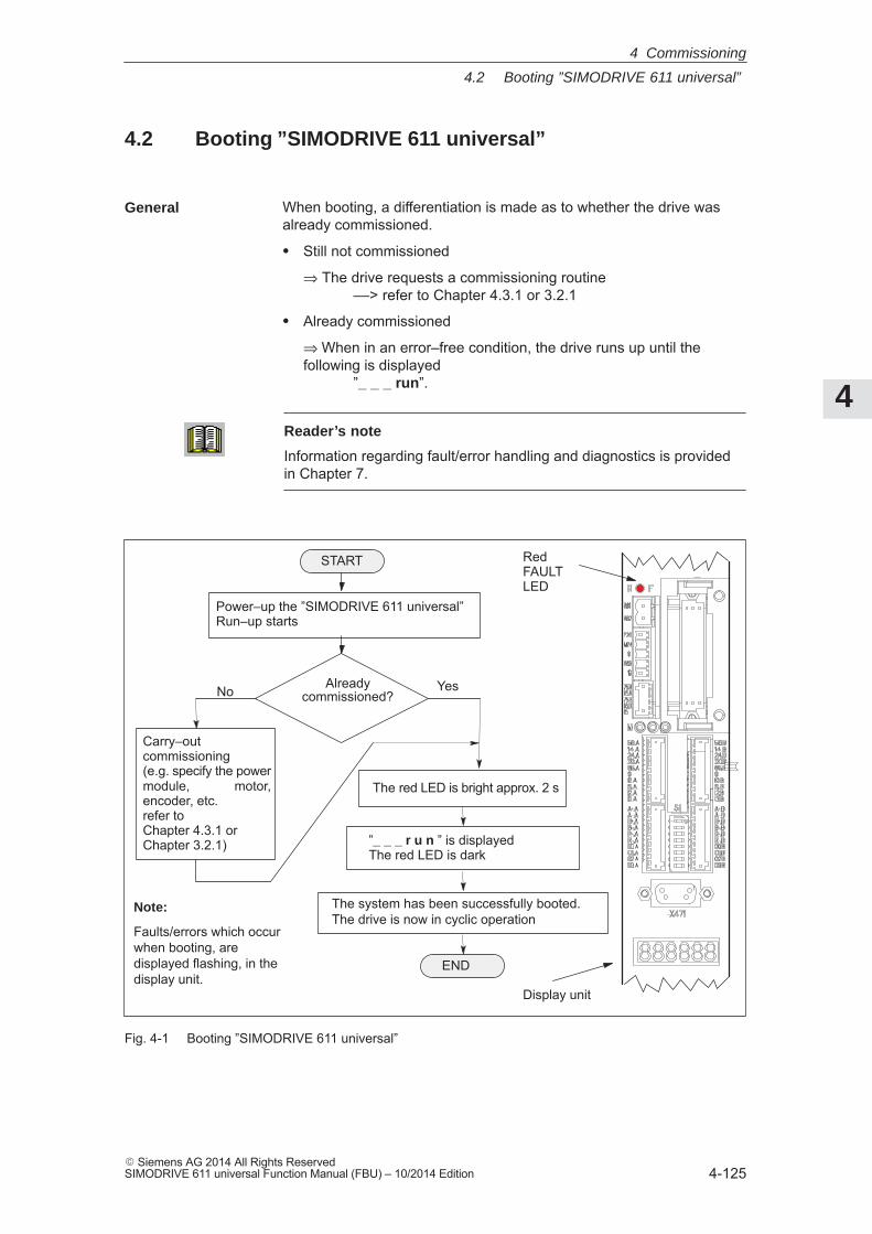
4
4.2 Booting ”SIMODRIVE 611 universal”
4-125� Siemens AG 2014 All Rights ReservedSIMODRIVE 611 universal Function Manual (FBU) – 10/2014 Edition
4.2 Booting ”SIMODRIVE 611 universal”
When booting, a differentiation is made as to whether the drive wasalready commissioned.
� Still not commissioned
⇒ The drive requests a commissioning routine ––> refer to Chapter 4.3.1 or 3.2.1
� Already commissioned
⇒ When in an error–free condition, the drive runs up until the following is displayed
”_ _ _ run”.
Reader’s note
Information regarding fault/error handling and diagnostics is providedin Chapter 7.
The red LED is bright approx. 2 s
Alreadycommissioned?No Yes
Power–up the ”SIMODRIVE 611 universal” Run–up starts
Carry–outcommissioning(e.g. specify the powermodule, motor,encoder, etc. refer toChapter 4.3.1 or Chapter 3.2.1) ”_ _ _ r u n ” is displayed
The red LED is dark
The system has been successfully booted.The drive is now in cyclic operation
RedFAULTLED
Display unit
Note:
Faults/errors which occurwhen booting, aredisplayed flashing, in thedisplay unit.
START
END
Fig. 4-1 Booting ”SIMODRIVE 611 universal”
General
4 Commissioning
4
4.3 Commissioning via SimoCom U
4-126� Siemens AG 2014 All Rights Reserved
SIMODRIVE 611 universal Function Manual (FBU) – 10/2014 Edition
4.3 Commissioning via SimoCom U
The following prerequisites must be fulfilled in order to be able to com-mission a drive using the ”SimoCom U” parameterizing and start–uptool:
1. All of the prerequisites for commissioning, according to Chapter 4.1,have been fulfilled, i.e. the system with ”SIMODRIVE 611 universal”can be commissioned.
2. The checklist for commissioning according to Chapter 4.1 has beenchecked.
3. The ”SimoCom U” tool is installed on the PC/PG, which is to beused to commission the drive.
4. There is a connecting cable between the PG/PC and the controlboard (e.g. RS232 connecting cable, refer to Chapter 2.5).
5. The PC/PG with ”SimoCom U” is connected to the control board(X471).
Reader’s note� Cable diagrams for the connecting cable refer to Chapter 2.5� Installing ”SimoCom U”,
Introduction to ”SimoCom U” and establishing online operation refer to Chapter 3.3
Offline Commissioning The software version is not taken into account in offline commissioning.In other words: SimoCom U cannot recognize which firmware versionmatches which drive.
Requirements
4 Commissioning
4
4.3 Commissioning via SimoCom U
4-127� Siemens AG 2014 All Rights ReservedSIMODRIVE 611 universal Function Manual (FBU) – 10/2014 Edition
4.3.1 First commissioning with SimoCom U
When ”SIMODRIVE 611 universal” is first commissioned using the”SimoCom U” parameterizing and start–up tool, proceed as follows:
1. Power–up the drive group
2. Start SimoCom U
3. Request online operation for drive A
Operator action: Execute the ”Search for online drives” function in the ”Start–up”menu, and select drive A in the ”Drive and dialog browser”.
Is the ”start–up required” window displayed?
– Yes: ––> Start the drive configuration assistant
––> This signals the drive the existing configuration (power mo-dule, motor, etc.).
– No: ––> Press ”re–configure drive” button
––> This adapts the control board to the present configuration(power module, motor, etc.).
4. Execute the drive configuration, and at the end, press the ”Calculatecontroller data, save, reset” button.
5. Carry–out basic commissioning
Set the ”Drive and dialog browser” (left–hand window) to ”Parameter”. To do this, press the ”P Par” button below the browser.
The commissioning is now executed by working through the remain-ing dialog boxes for this drive in the ”Drive and dialog browser” fromthe top to the bottom. The required settings are made in the se-lected dialog boxes.
Note
If drive B is to be commissioned, then the points must be executed fordrive B from point 3 onwards.
Procedure when commissioning thedrive for the firsttime
4 Commissioning
4
4.3 Commissioning via SimoCom U
4-128� Siemens AG 2014 All Rights Reserved
SIMODRIVE 611 universal Function Manual (FBU) – 10/2014 Edition
4.3.2 Series commissioning with SimoCom U
For series commissioning of ”SIMODRIVE 611 universal” with the”SimoCom U” parameterizing and start–up tool, proceed as follows:
1. Power–up the drive group
2. Start SimoCom U
3. Request online operation for drive A
Operator action: Click–on the ”Search for online drives” in the ”Start–up” menu, andselect ”Drive A” in the selection box.
Is the ”start–up required” window displayed?
– Yes: ––> Click on the ”Load parameter file into the drive...” button
––> After you have selected the required parameter file for driveA and have pressed ”open”, the file is downloaded into drive A.
– No: ––> Click on the menu ”File ––> Load into drive ––> Load andsave in the drive”
––> After you have selected the required parameter file for driveA and have pressed ”open”, the file is downloaded into drive A.
Note
If drive B is to be commissioned, then the points must be executed fordrive B from point 3 onwards.
Procedure for seriescommissioning
4 Commissioning
4
4.3 Commissioning via SimoCom U
4-129� Siemens AG 2014 All Rights ReservedSIMODRIVE 611 universal Function Manual (FBU) – 10/2014 Edition
4.3.3 Password protection with SimoCom U (from SW 8.1)
Access protection using a password is possible in order to ensure thatwhen service is carried–out the drive configuration is not changed.
The ”SimoCom U” parameterizing and start–up tool has a passwordinput and change view in order to carry–out the following on a con-nected drive:� Activate/de–activate the password protection� Define the password� Define the functions that are to be protected using the password
For a series commissioning, the password and the password configura-tion are transferred to the drive just like any other parameter assign-ment.
The password is not necessary to do the following:� Open files� Downloading files into a drive
The password must only be entered if the protected functions are to beaccessed in the file or in the drive.
SimoCom U allows the password function to be copied between sev-eral drives.
Note
The function ”Password protection” only functions with a ”SimoCom U”parameterizing and start–up tool version �8.1.
Proceed as follows when setting–up a password using the ”SimoComU” parameterizing and start–up tool:1. Power–up the drive group2. Start SimoCom U3. Request that the required drive either goes into the offline or online
mode4. In the ”drive and dialog browser” (left–hand window), select the
”password” folder5. Access to enter a PIN and browser to enter the functions to be pro-
tected is activated by a ”check” in the ”Activate password protection”field (right–hand window)
6. Enter a PIN (4–digit number from 1000...9999) and acknowledge
Generalinformation
Procedure whensetting–up thepassword
4 Commissioning
4
4.3 Commissioning via SimoCom U
4-130� Siemens AG 2014 All Rights Reserved
SIMODRIVE 611 universal Function Manual (FBU) – 10/2014 Edition
7. Define the functions to be protected––> The safety–relevant functions are displayed in
the ”right–hand” display window (browser) with a ”check” in the particular field (default setting).
––> Further, additional functions can be assigned password protection by activating the button ”Activate all functions”or by entering a ”check” in the field of the function to be protected.
8. Press the ”Accept password configuration” button
9. Save the changes
Note
The ”Activate safety–relevant functions” and ”Activate all functions”buttons should only be pressed when actually required.
Individual functions (operator masks, menu items, ...) can be protectedor enabled.
The following safety–relevant functions are set as default values:
� Expert List
� Load to drive
� Reconfigure drive
� Establish the standard values of the current drive configuration
� Upgrade firmware
� User parameter list
The drive inhibits write access operations via SimoCom U <Version 8.1and outputs a warning.
In order to be able to change the drive in any way, a SimoCom U �Version SW 8.1 must be used.
The drive inhibits all access operations via the 7–segment display. The7–segment display is then only used to display ”_ _ _run” or warningsand alarms that are present.
Access operations via PROFIBUS–DP, CAN bus and other unlistedmodules are not prevented, as in the normal operating state of the ma-chine, these channels cannot be manipulated by the operator.
Access protection
Access with SimoCom U <Version 8.1
Access via the7–segment display
Access via databus
4 Commissioning
4
4.3 Commissioning via SimoCom U
4-131� Siemens AG 2014 All Rights ReservedSIMODRIVE 611 universal Function Manual (FBU) – 10/2014 Edition
You can access a password–protected function via SimoCom U as fol-lows:
1. In the online mode, SimoCom U prompts for the password.––> Enter password
2. All of the protected functions in the ”right–hand” browser of themenu screen can now be changed.
3. After entry, the password remains valid up to the next time thatSimoCom U goes online.
4. The protected functions cannot be accessed if the password wasnot entered.
5. If the password was incorrectly entered five times in a row, then SimoCom U must be re–started before the password can bere–entered.
The drive must be deleted using ”delete drive configuration” or ”bootboard”. This deletes the complete parameterization.
Note
Before activating password protection using SimoCom U, werecommend that the functioning configuration of the drive is saved in afile.
There is no generally–valid password!
When using A&D Data Management (ADDM) and other programs, thatSimoCom U uses, then password protection may not be activated.
Enable the access
Passwordforgotten?
Passwordprotection andother programswith SimoCom U
4 Commissioning
4
4.3 Commissioning via SimoCom U
4-132� Siemens AG 2014 All Rights Reserved
SIMODRIVE 611 universal Function Manual (FBU) – 10/2014 Edition
4.3.4 Upgrading the firmware
In order to take into account technical advances, the drive firmware iscontinually being further developed with each software release.
In spite of the fact that the firmware is optimized regarding its runtimebehavior, it cannot be excluded that more recent firmware releases willhave a different runtime behavior. This must be especially taken intoaccount if functions are used that require a high level of runtime.
When upgrading control boards to a new firmware release, it musttherefore be carefully checked as to whether the runtime behavior issatisfactory. If required, re–optimize the drive parameterization or donot upgrade the firmware!
In order to be able to optimally use new firmware releases with respectto the runtime behavior, we recommend that the latest hardware is al-ways used.
4.3.5 Firmware download
Firmware can be downloaded using the “SimoCom U” parameterizingand commissioning tool.
Procedure:
Under the menu item: Options / Service / .... select required firmwareupgrade item...., then follow the user prompting.
For a connection via PROFIBUS–DP, e.g. PC as Master Class 2 on thebus, only an update or download is possible to any status of the drivefirmware (e.g. SW 7.2).
For a connection via the RS 232 interface, it is also possible to down-load the firmware of the Profibus module.
Notice
Under no circumstances interrupt or exit the update as otherwise it ispossible that the module will no longer be able to be identified andaddressed!
Runtime behavior
4 Commissioning
4
4.3 Commissioning via SimoCom U
4-133� Siemens AG 2014 All Rights ReservedSIMODRIVE 611 universal Function Manual (FBU) – 10/2014 Edition
4.3.6 Automated firmware download (from SW 8.1)
Automated firmware download is possible using the ”SimoCom U”parameterizing and start–up tool.
This means that both the actual firmware as well as also the previousversion releases (e.g. SW 7.2) can be downloaded.
”SimoCom U” is configured for the appropriate drive using registry files.
Data can be downloaded via the data bus (e.g. PROFIBUS–DP) or the serial interface.
� When downloading via PROFIBUS–DP, the correct PROFIBUSnode address must be parameterized for the appropriate drive.
� The registry files must be edited so that they match a specified driveconfiguration.
� It is necessary that ”SimoCom U” was installed – however, the ap-plication may not run while changing or running the registry file.
1. Edit the .reg file and carry–out the settings (refer to Fig. 4-2).
If you wish to only change the file names, the path or thePROFIBUS address, then the settings are also possible viaSimoCom U without using the .reg files.
––> Using the dialog menu ”Service” ––> ”Automated firmware download” ––> ”Define file” or ”Options” ––> ”Settings” ––> ”Communications”
2. Run the .reg file if you have not carried–out the settings viaSimoCom U.
––> The Windows registry editor prompts after the settings have been transferred into the registry.
––> Acknowledge with ”Enter”.
––> The Windows registry editor signals that the settings have been successfully transferred into the registry
––> Again acknowledge this message with ”Enter”.
General
Condition
Proceed as follows
4 Commissioning
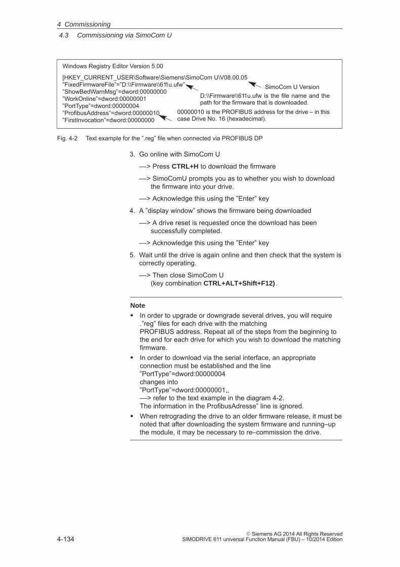
4
4.3 Commissioning via SimoCom U
4-134� Siemens AG 2014 All Rights Reserved
SIMODRIVE 611 universal Function Manual (FBU) – 10/2014 Edition
Windows Registry Editor Version 5.00
[HKEY_CURRENT_USER\Software\Siemens\SimoCom U\V08.00.05”FixedFirmwareFile”=”D:\\Firmware\\611u.ufw””ShowBedWarnMsg”=dword:00000000”WorkOnline”=dword:00000001”PortType”=dword:00000004”ProfibusAddress”=dword:00000010”FirstInvocation”=dword:00000000
SimoCom U VersionD:\\Firmware\\611u.ufw is the file name and thepath for the firmware that is downloaded.
00000010 is the PROFIBUS address for the drive – in thiscase Drive No. 16 (hexadecimal).
Fig. 4-2 Text example for the ”.reg” file when connected via PROFIBUS DP
3. Go online with SimoCom U
––> Press CTRL+H to download the firmware
––> SimoComU prompts you as to whether you wish to download the firmware into your drive.
––> Acknowledge this using the ”Enter” key
4. A ”display window” shows the firmware being downloaded
––> A drive reset is requested once the download has been successfully completed.
––> Acknowledge this using the ”Enter” key
5. Wait until the drive is again online and then check that the system iscorrectly operating.
––> Then close SimoCom U (key combination CTRL+ALT+Shift+F12) .
Note
� In order to upgrade or downgrade several drives, you will require.”reg” files for each drive with the matching PROFIBUS address. Repeat all of the steps from the beginning tothe end for each drive for which you wish to download the matchingfirmware.
� In order to download via the serial interface, an appropriateconnection must be established and the line ”PortType”=dword:00000004 changes into ”PortType”=dword:00000001,, ––> refer to the text example in the diagram 4-2. The information in the ProfibusAdresse” line is ignored.
� When retrograding the drive to an older firmware release, it must benoted that after downloading the system firmware and running–upthe module, it may be necessary to re–commission the drive.
4 Commissioning
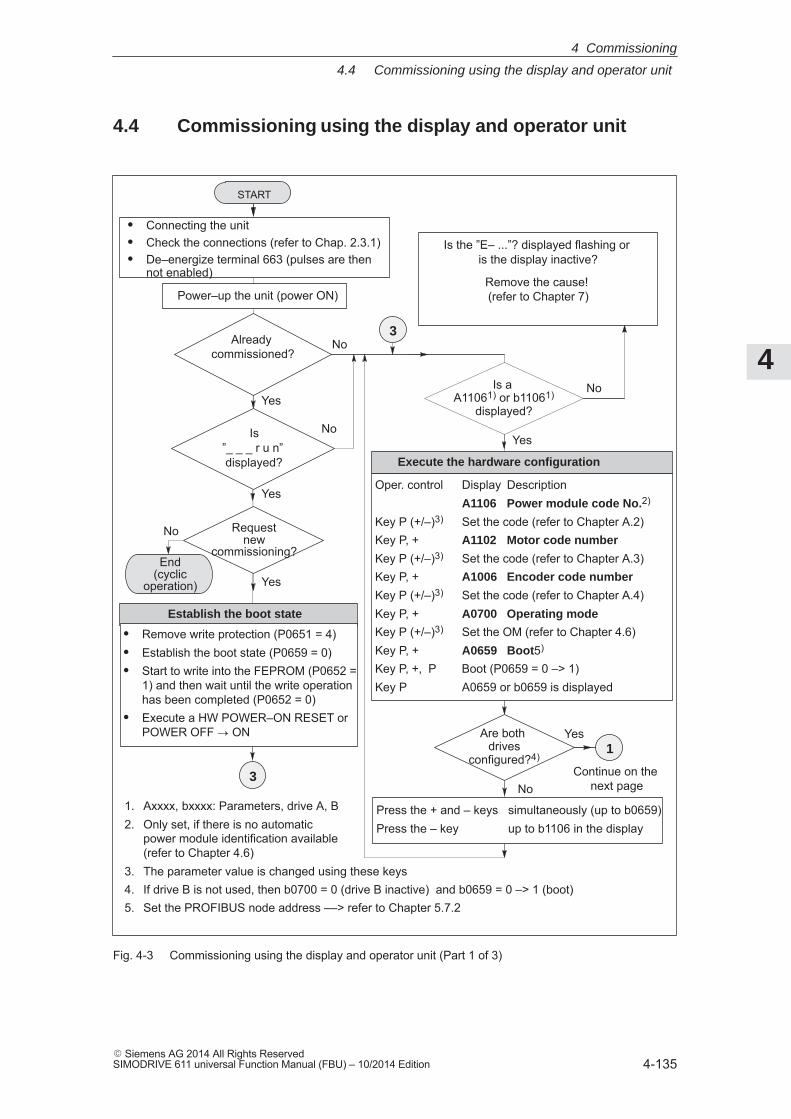
4
4.4 Commissioning using the display and operator unit
4-135� Siemens AG 2014 All Rights ReservedSIMODRIVE 611 universal Function Manual (FBU) – 10/2014 Edition
4.4 Commissioning using the display and operator unit
1. Axxxx, bxxxx: Parameters, drive A, B2. Only set, if there is no automatic
power module identification available (refer to Chapter 4.6)
3. The parameter value is changed using these keys4. If drive B is not used, then b0700 = 0 (drive B inactive) and b0659 = 0 –> 1 (boot)5. Set the PROFIBUS node address ––> refer to Chapter 5.7.2
START
Power–up the unit (power ON)
Is the ”E– ...”? displayed flashing or is the display inactive?
Remove the cause! (refer to Chapter 7)
Is”_ _ _ r u n” displayed?
� Connecting the unit� Check the connections (refer to Chap. 2.3.1)� De–energize terminal 663 (pulses are then
not enabled)
Requestnew
commissioning?
No
Is a A11061) or b11061)
displayed?
No
Yes
Yes
Yes
No
Yes
No
� Remove write protection (P0651 = 4)� Establish the boot state (P0659 = 0)� Start to write into the FEPROM (P0652 =
1) and then wait until the write operationhas been completed (P0652 = 0)
� Execute a HW POWER–ON RESET orPOWER OFF � ON Are both
drivesconfigured?4)
No
Yes
Press the + and – keys simultaneously (up to b0659)Press the – key up to b1106 in the display
Execute the hardware configuration
3 Continue on the next page
End(cyclic
operation)
Establish the boot state
Oper. control Display DescriptionA1106 Power module code No.2)
Key P (+/–)3) Set the code (refer to Chapter A.2)Key P, + A1102 Motor code number
Key P (+/–)3) Set the code (refer to Chapter A.3)Key P, + A1006 Encoder code number
Key P (+/–)3) Set the code (refer to Chapter A.4)Key P, + A0700 Operating mode
Key P (+/–)3) Set the OM (refer to Chapter 4.6)Key P, + A0659 Boot5)
Key P, +, P Boot (P0659 = 0 –> 1)Key P A0659 or b0659 is displayed
3
1
Already commissioned?
Fig. 4-3 Commissioning using the display and operator unit (Part 1 of 3)
4 Commissioning
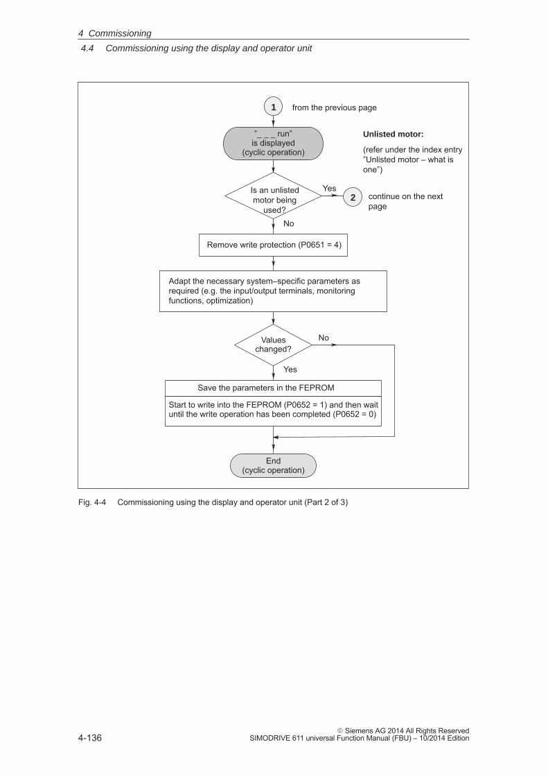
4
4.4 Commissioning using the display and operator unit
4-136� Siemens AG 2014 All Rights Reserved
SIMODRIVE 611 universal Function Manual (FBU) – 10/2014 Edition
Yes
Adapt the necessary system–specific parameters asrequired (e.g. the input/output terminals, monitoringfunctions, optimization)
Valueschanged?
No
Yes
Remove write protection (P0651 = 4)
1
2
”_ _ _ run”is displayed
(cyclic operation)
No
End(cyclic operation)
continue on the nextpage
from the previous page
Start to write into the FEPROM (P0652 = 1) and then waituntil the write operation has been completed (P0652 = 0)
Save the parameters in the FEPROM
Is an unlistedmotor being
used?
Unlisted motor:
(refer under the index entry”Unlisted motor – what isone”)
Fig. 4-4 Commissioning using the display and operator unit (Part 2 of 3)
4 Commissioning
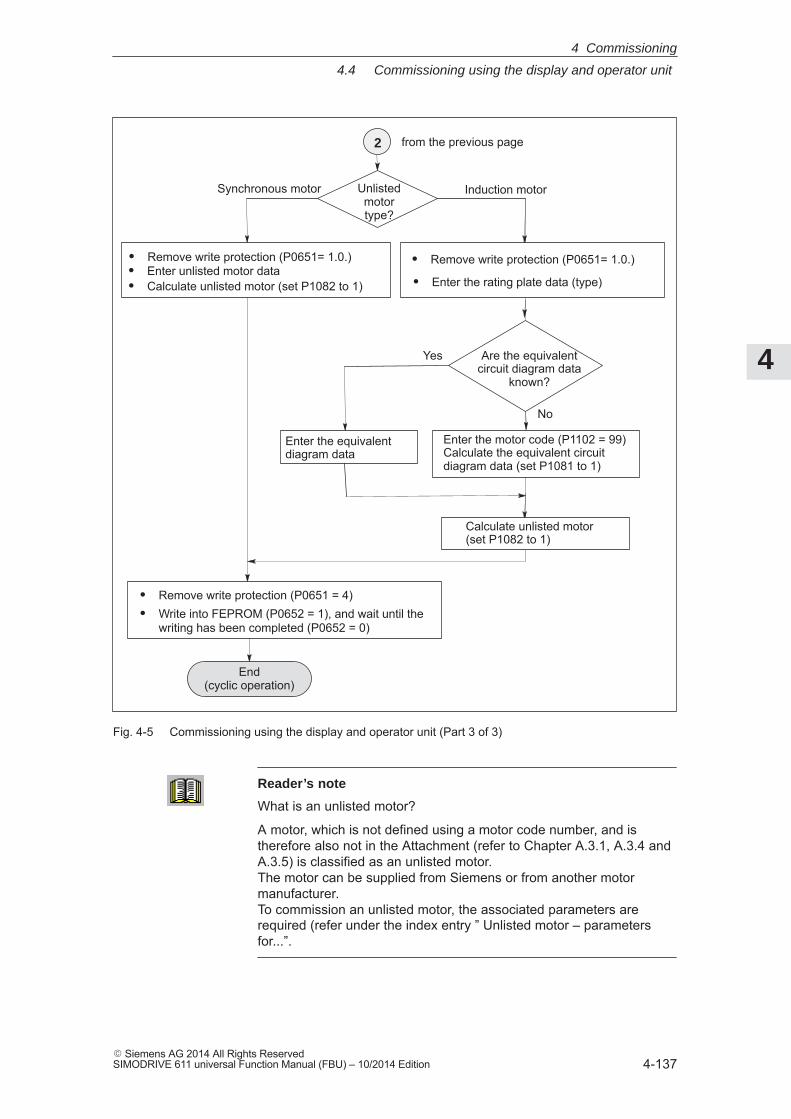
4
4.4 Commissioning using the display and operator unit
4-137� Siemens AG 2014 All Rights ReservedSIMODRIVE 611 universal Function Manual (FBU) – 10/2014 Edition
No
Yes
� Remove write protection (P0651 = 4)� Write into FEPROM (P0652 = 1), and wait until the
writing has been completed (P0652 = 0)
� Remove write protection (P0651= 1.0.)
Synchronous motor Induction motor
� Enter unlisted motor data� Calculate unlisted motor (set P1082 to 1)
Enter the equivalentdiagram data
End(cyclic operation)
2
Unlistedmotortype?
from the previous page
� Remove write protection (P0651= 1.0.)
� Enter the rating plate data (type)
Calculate unlisted motor (set P1082 to 1)
Enter the motor code (P1102 = 99)Calculate the equivalent circuit diagram data (set P1081 to 1)
Are the equivalentcircuit diagram data
known?
Fig. 4-5 Commissioning using the display and operator unit (Part 3 of 3)
Reader’s note
What is an unlisted motor?
A motor, which is not defined using a motor code number, and istherefore also not in the Attachment (refer to Chapter A.3.1, A.3.4 andA.3.5) is classified as an unlisted motor. The motor can be supplied from Siemens or from another motormanufacturer. To commission an unlisted motor, the associated parameters arerequired (refer under the index entry ” Unlisted motor – parametersfor...”.
4 Commissioning
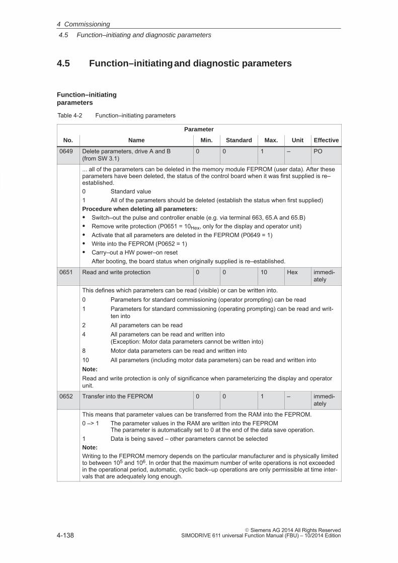
4
4.5 Function–initiating and diagnostic parameters
4-138� Siemens AG 2014 All Rights Reserved
SIMODRIVE 611 universal Function Manual (FBU) – 10/2014 Edition
4.5 Function–initiating and diagnostic parameters
Table 4-2 Function–initiating parameters
Parameter
No. Name Min. Standard Max. Unit Effective
0649 Delete parameters, drive A and B (from SW 3.1)
0 0 1 – PO
... all of the parameters can be deleted in the memory module FEPROM (user data). After theseparameters have been deleted, the status of the control board when it was first supplied is re–established.0 Standard value1 All of the parameters should be deleted (establish the status when first supplied)Procedure when deleting all parameters:� Switch–out the pulse and controller enable (e.g. via terminal 663, 65.A and 65.B)� Remove write protection (P0651 = 10Hex, only for the display and operator unit)� Activate that all parameters are deleted in the FEPROM (P0649 = 1)� Write into the FEPROM (P0652 = 1)� Carry–out a HW power–on reset
After booting, the board status when originally supplied is re–established.
0651 Read and write protection 0 0 10 Hex immedi-ately
This defines which parameters can be read (visible) or can be written into.0 Parameters for standard commissioning (operator prompting) can be read1 Parameters for standard commissioning (operating prompting) can be read and writ-
ten into2 All parameters can be read4 All parameters can be read and written into
(Exception: Motor data parameters cannot be written into)8 Motor data parameters can be read and written into10 All parameters (including motor data parameters) can be read and written intoNote:
Read and write protection is only of significance when parameterizing the display and operatorunit.
0652 Transfer into the FEPROM 0 0 1 – immedi-ately
This means that parameter values can be transferred from the RAM into the FEPROM.0 –> 1 The parameter values in the RAM are written into the FEPROM
The parameter is automatically set to 0 at the end of the data save operation.1 Data is being saved – other parameters cannot be selectedNote:Writing to the FEPROM memory depends on the particular manufacturer and is physically limitedto between 105 and 106. In order that the maximum number of write operations is not exceededin the operational period, automatic, cyclic back–up operations are only permissible at time inter-vals that are adequately long enough.
Function–initiatingparameters
4 Commissioning
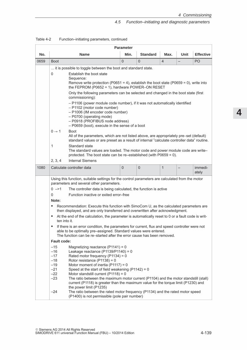
4
4.5 Function–initiating and diagnostic parameters
4-139� Siemens AG 2014 All Rights ReservedSIMODRIVE 611 universal Function Manual (FBU) – 10/2014 Edition
Table 4-2 Function–initiating parameters, continued
Parameter
No. EffectiveUnitMax.StandardMin.Name
0659 Boot 0 0 4 – PO
... it is possible to toggle between the boot and standard state.0 Establish the boot state
Sequence: Remove write protection (P0651 = 4), establish the boot state (P0659 = 0), write intothe FEPROM (P0652 = 1), hardware POWER–ON RESETOnly the following parameters can be selected and changed in the boot state (firstcommissioning):– P1106 (power module code number), if it was not automatically identified– P1102 (motor code number) – P1006 (IM encoder code number) – P0700 (operating mode) – P0918 (PROFIBUS node address) – P0659 (boot), execute in the sense of a boot
0 � 1 BootAll of the parameters, which are not listed above, are appropriately pre–set (default)standard values or are preset as a result of internal ”calculate controller data” routine.
1 Standard state The standard values are loaded. The motor code and power module code are write–protected. The boot state can be re–established (with P0659 = 0).
2, 3, 4 Internal Siemens
1080 Calculate controller data 0 0 1 – immedi-ately
Using this function, suitable settings for the control parameters are calculated from the motorparameters and several other parameters.0 –>1 The controller data is being calculated, the function is active0 Function inactive or exited error–freeNote:
� Recommendation: Execute this function with SimoCom U, as the calculated parameters arethen displayed, and are only transferred and overwritten after acknowledgment.
� At the end of the calculation, the parameter is automatically reset to 0 or a fault code is writ-ten into it.
� If there is an error condition, the parameters for current, flux and speed controller were notable to be optimally pre–assigned. Standard values were entered.The function can be re–started after the error cause has been removed.
Fault code:
–15 Magnetizing reactance (P1141) = 0 –16 Leakage reactance (P1139/P1140) = 0 –17 Rated motor frequency (P1134) = 0 –18 Rotor resistance (P1138) = 0 –19 Motor moment of inertia (P1117) = 0 –21 Speed at the start of field weakening (P1142) = 0–22 Motor standstill current (P1118) = 0 –23 The ratio between the maximum motor current (P1104) and the motor standstill (stall)
current (P1118) is greater than the maximum value for the torque limit (P1230) andthe power limit (P1235)
–24 The ratio between the rated motor frequency (P1134) and the rated motor speed (P1400) is not permissible (pole pair number)
4 Commissioning
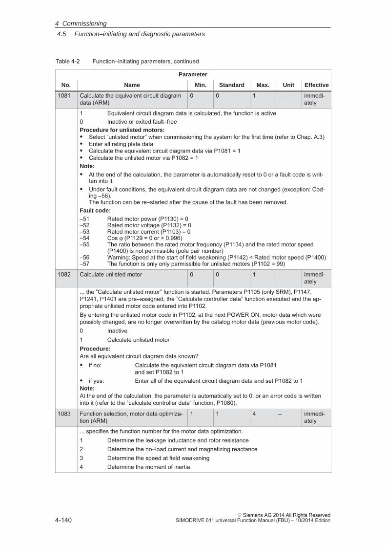
4
4.5 Function–initiating and diagnostic parameters
4-140� Siemens AG 2014 All Rights Reserved
SIMODRIVE 611 universal Function Manual (FBU) – 10/2014 Edition
Table 4-2 Function–initiating parameters, continued
Parameter
No. EffectiveUnitMax.StandardMin.Name
1081 Calculate the equivalent circuit diagramdata (ARM)
0 0 1 – immedi-ately
1 Equivalent circuit diagram data is calculated, the function is active0 Inactive or exited fault–freeProcedure for unlisted motors:� Select ”unlisted motor” when commissioning the system for the first time (refer to Chap. A.3)� Enter all rating plate data� Calculate the equivalent circuit diagram data via P1081 = 1� Calculate the unlisted motor via P1082 = 1Note:� At the end of the calculation, the parameter is automatically reset to 0 or a fault code is writ-
ten into it.� Under fault conditions, the equivalent circuit diagram data are not changed (exception: Cod-
ing –56).The function can be re–started after the cause of the fault has been removed.
Fault code:–51 Rated motor power (P1130) = 0 –52 Rated motor voltage (P1132) = 0 –53 Rated motor current (P1103) = 0 –54 Cos ϕ (P1129 = 0 or > 0.996) –55 The ratio between the rated motor frequency (P1134) and the rated motor speed
(P1400) is not permissible (pole pair number) –56 Warning: Speed at the start of field weakening (P1142) < Rated motor speed (P1400)–57 The function is only only permissible for unlisted motors (P1102 = 99)
1082 Calculate unlisted motor 0 0 1 – immedi-ately
... the ”Calculate unlisted motor” function is started. Parameters P1105 (only SRM), P1147,P1241, P1401 are pre–assigned, the ”Calculate controller data” function executed and the ap-propriate unlisted motor code entered into P1102.By entering the unlisted motor code in P1102, at the next POWER ON, motor data which werepossibly changed, are no longer overwritten by the catalog motor data (previous motor code).0 Inactive1 Calculate unlisted motorProcedure:Are all equivalent circuit diagram data known?� if no: Calculate the equivalent circuit diagram data via P1081
and set P1082 to 1� if yes: Enter all of the equivalent circuit diagram data and set P1082 to 1Note:At the end of the calculation, the parameter is automatically set to 0, or an error code is writteninto it (refer to the ”calculate controller data” function, P1080).
1083 Function selection, motor data optimiza-tion (ARM)
1 1 4 – immedi-ately
... specifies the function number for the motor data optimization.1 Determine the leakage inductance and rotor resistance2 Determine the no–load current and magnetizing reactance3 Determine the speed at field weakening4 Determine the moment of inertia
4 Commissioning
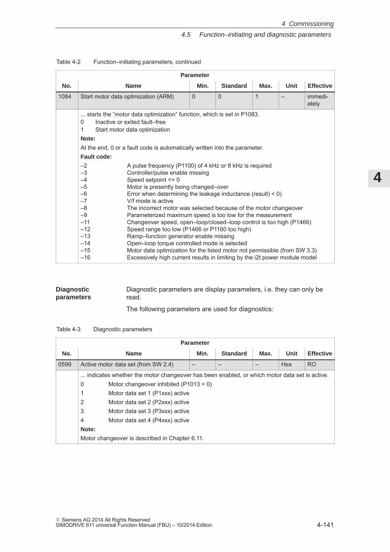
4
4.5 Function–initiating and diagnostic parameters
4-141� Siemens AG 2014 All Rights ReservedSIMODRIVE 611 universal Function Manual (FBU) – 10/2014 Edition
Table 4-2 Function–initiating parameters, continued
Parameter
No. EffectiveUnitMax.StandardMin.Name
1084 Start motor data optimization (ARM) 0 0 1 – immedi-ately
... starts the ”motor data optimization” function, which is set in P1083.0 Inactive or exited fault–free1 Start motor data optimizationNote:
At the end, 0 or a fault code is automatically written into the parameter.Fault code:
–2 A pulse frequency (P1100) of 4 kHz or 8 kHz is required–3 Controller/pulse enable missing–4 Speed setpoint <> 0–5 Motor is presently being changed–over–6 Error when determining the leakage inductance (result) < 0) –7 V/f mode is active–8 The incorrect motor was selected because of the motor changeover–9 Parameterized maximum speed is too low for the measurement–11 Changeover speed, open–loop/closed–loop control is too high (P1466)–12 Speed range too low (P1466 or P1160 too high)–13 Ramp–function generator enable missing–14 Open–loop torque controlled mode is selected–15 Motor data optimization for the listed motor not permissible (from SW 3.3)–16 Excessively high current results in limiting by the i2t power module model
Diagnostic parameters are display parameters, i.e. they can only beread.
The following parameters are used for diagnostics:
Table 4-3 Diagnostic parameters
Parameter
No. Name Min. Standard Max. Unit Effective
0599 Active motor data set (from SW 2.4) – – – Hex RO
... indicates whether the motor changeover has been enabled, or which motor data set is active.0 Motor changeover inhibited (P1013 = 0)1 Motor data set 1 (P1xxx) active2 Motor data set 2 (P2xxx) active3 Motor data set 3 (P3xxx) active4 Motor data set 4 (P4xxx) activeNote:
Motor changeover is described in Chapter 6.11.
Diagnostic parameters
4 Commissioning
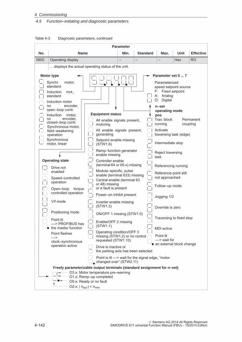
4
4.5 Function–initiating and diagnostic parameters
4-142� Siemens AG 2014 All Rights Reserved
SIMODRIVE 611 universal Function Manual (FBU) – 10/2014 Edition
Table 4-3 Diagnostic parameters, continued
Parameter
No. EffectiveUnitMax.StandardMin.Name
0600 Operating display – – – Hex RO
... displays the actual operating status of the unit.
Traversing to fixed stop
Motor type
Equipment status
Central enable (terminal 63 or 48) missing or a fault is present
Operating state
Drive notenabled
Parameter set 0 ... 7
Synchr. motor,standardInduction mot.,standardInduction motorno encoder,open–loop contr.Induction motor,no encoder,closed–loop contr.Synchronous motor,field–weakeningoperation
Speed–controlledoperation
Open–loop torquecontrolled operation
Module–specific, pulseenable (terminal 633) missing
Controller enable(terminal 64 or 65.x) missing
Ramp–function generator enable missing
All enable signals present,motoringAll enable signals present,generating
O1.x: Ramp–up completed
O2.x: | nact | < nmin
O0.x: Ready or no fault
O3.x: Motor temperature pre–warningFreely parameterizable output terminals (standard assignment for n–set)
V/f mode
Positioning mode
Setpoint enable missing(STW1.6)
Power–on inhibit present
Inverter enable missing(STW1.3)
ON/OFF 1 missing (STW1.0)
Enable/OFF 2 missing(STW1.1)
Operating condition/OFF 3 missing (STW1.2) or no control requested (STW1.10)
Point lit––> PROFIBUS has the master functionPoint flashes––>clock–synchronousoperation active Drive is inactive or
the parking axis has been selected
Override is zero
Jogging 1/2
Follow–up mode
Reference point stillnot approached
Referencing running
Reject traversingtask
Intermediate stop
Activatetraversing task (edge)
Trav. block running
Parameterizedspeed setpoint sourceF: Fixed setpointA: AnalogO: Digital
n–setoperating modepos
Point is lit ––> wait for the signal edge, ”motorchanged over” (STW2.11)
Synchronousmotor, linear
Permanentcoupling
Point lit––> wait for an external block change
MDI active
4 Commissioning
4
4.5 Function–initiating and diagnostic parameters
4-143� Siemens AG 2014 All Rights ReservedSIMODRIVE 611 universal Function Manual (FBU) – 10/2014 Edition
The following additional parameters are available for diagnostics:
� P0653 Image, input signals, Part 1
� P0654 Image, input signals, Part 2
� P0655 Image, input signals, Part 3 (from SW 3.3)
� P0656 Image, output signals, Part 1
� P0657 Image, output signals, Part 2
� P0658 Image, output signals, Part 3
� P0678 Image of the input terminals
� P0698 Image of the output terminals
Additionalparameters fordiagnostics (referto Chapter A.1)
4 Commissioning
4
4.6 Parameters for hardware, operating mode and clock cycles
4-144� Siemens AG 2014 All Rights Reserved
SIMODRIVE 611 universal Function Manual (FBU) – 10/2014 Edition
4.6 Parameters for hardware, operating mode and clockcycles
The drive must identify the hardware used (motor, power module andencoder) so that it can behave appropriately. The hardware can only beidentified when the drive is in the booted state.
� Specifying the hardware with the display and operator unit
In order to specify the motor, power module and encoder used, theappropriate code must be determined from the tables, using the Or-der No. (MLFB) and entered in the parameter.
� Specifying the hardware with SimoCom U
The motor, power module and encoder are selected from a list usingthe relevant Order numbers (MLFB). The appropriate code is thenautomatically entered.
!Caution
A power module could be destroyed for the following reasons:� Incorrect power module code or motor code� Incorrect motor data� Inverter clock frequency or current controller gain too high
Procedure when first commissioning an unlisted motor(also refer to Chapter 3.2.1):
� Select ”unlisted motor”, e.g. synchronous or induction motor
� Enter all of the rating plate data, and if known, all of the equivalentcircuit diagram data. The equivalent circuit diagram data can also becalculated using parameter P1081.
� Set parameter P1082 ”Calculate unlisted motor”. This means that the controller data is internally calculated and themotor code number corresponding to the motor type is saved.
The ”SIMODRIVE 611 universal” control board has an automatic powermodule detection function, i.e. the control board automatically detectsand identifies power modules with this function.
Which power modules have an automatic identification function?
Only power modules from a specific hardware version have the auto-matic power module identification function (refer to Order No.).
Hardware parameters
Calculate equivalentcircuit diagram data,calculate unlistedmotor
Automatic power module identification
4 Commissioning
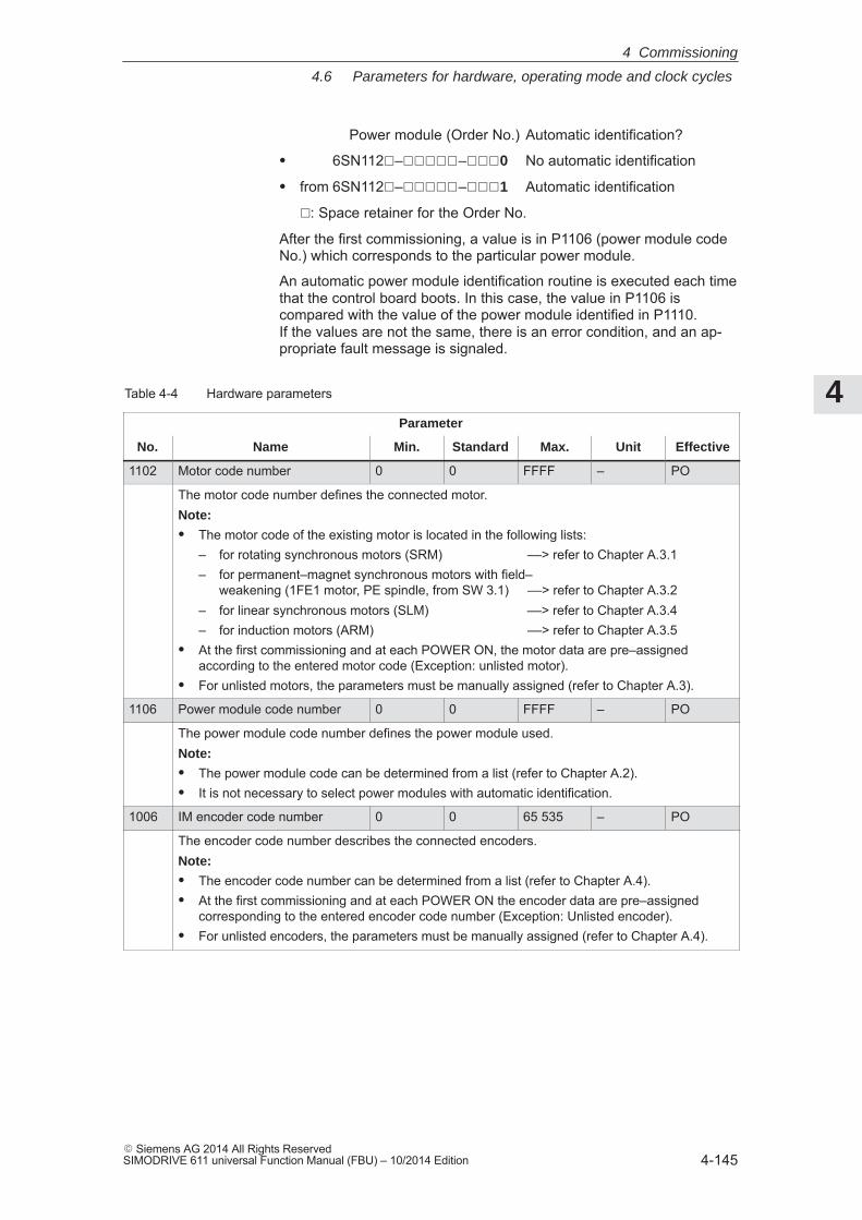
4
4.6 Parameters for hardware, operating mode and clock cycles
4-145� Siemens AG 2014 All Rights ReservedSIMODRIVE 611 universal Function Manual (FBU) – 10/2014 Edition
Power module (Order No.) Automatic identification?
� 6SN112�–�����–���0 No automatic identification
� from 6SN112�–�����–���1 Automatic identification
�: Space retainer for the Order No.
After the first commissioning, a value is in P1106 (power module codeNo.) which corresponds to the particular power module.
An automatic power module identification routine is executed each timethat the control board boots. In this case, the value in P1106 iscompared with the value of the power module identified in P1110. If the values are not the same, there is an error condition, and an ap-propriate fault message is signaled.
Table 4-4 Hardware parameters
Parameter
No. Name Min. Standard Max. Unit Effective
1102 Motor code number 0 0 FFFF – PO
The motor code number defines the connected motor.Note:
� The motor code of the existing motor is located in the following lists:– for rotating synchronous motors (SRM) ––> refer to Chapter A.3.1– for permanent–magnet synchronous motors with field–
weakening (1FE1 motor, PE spindle, from SW 3.1) ––> refer to Chapter A.3.2– for linear synchronous motors (SLM) ––> refer to Chapter A.3.4– for induction motors (ARM) ––> refer to Chapter A.3.5
� At the first commissioning and at each POWER ON, the motor data are pre–assignedaccording to the entered motor code (Exception: unlisted motor).
� For unlisted motors, the parameters must be manually assigned (refer to Chapter A.3).
1106 Power module code number 0 0 FFFF – PO
The power module code number defines the power module used.Note:
� The power module code can be determined from a list (refer to Chapter A.2).� It is not necessary to select power modules with automatic identification.
1006 IM encoder code number 0 0 65 535 – PO
The encoder code number describes the connected encoders.Note:
� The encoder code number can be determined from a list (refer to Chapter A.4).� At the first commissioning and at each POWER ON the encoder data are pre–assigned
corresponding to the entered encoder code number (Exception: Unlisted encoder).� For unlisted encoders, the parameters must be manually assigned (refer to Chapter A.4).
4 Commissioning
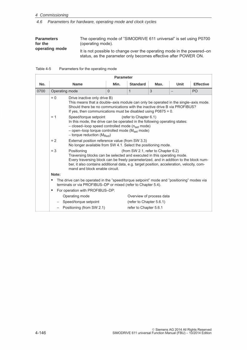
4
4.6 Parameters for hardware, operating mode and clock cycles
4-146� Siemens AG 2014 All Rights Reserved
SIMODRIVE 611 universal Function Manual (FBU) – 10/2014 Edition
The operating mode of ”SIMODRIVE 611 universal” is set using P0700(operating mode).
It is not possible to change over the operating mode in the powered–onstatus, as the parameter only becomes effective after POWER ON.
Table 4-5 Parameters for the operating mode
Parameter
No. Name Min. Standard Max. Unit Effective
0700 Operating mode 0 1 3 – PO
= 0 Drive inactive only drive B)This means that a double–axis module can only be operated in the single–axis mode.Should there be no communications with the inactive drive B via PROFIBUS?If yes, then communications must be disabled using P0875 = 0.
= 1 Speed/torque setpoint (refer to Chapter 6.1)In this mode, the drive can be operated in the following operating states:– closed–loop speed controlled mode (nset mode)– open–loop torque controlled mode (Mset mode)– torque reduction (MRed)
= 2 External position reference value (from SW 3.3)No longer available from SW 4.1. Select the positioning mode.
= 3 Positioning (from SW 2.1, refer to Chapter 6.2)Traversing blocks can be selected and executed in this operating mode. Every traversing block can be freely parameterized, and in addition to the block num-ber, it also contains additional data, e.g. target position, acceleration, velocity, com-mand and block enable circuit.
Note:
� The drive can be operated in the ”speed/torque setpoint” mode and ”positioning” modes viaterminals or via PROFIBUS–DP or mixed (refer to Chapter 5.4).
� For operation with PROFIBUS–DP:Operating mode Overview of process data
– Speed/torque setpoint (refer to Chapter 5.6.1)– Positioning (from SW 2.1) refer to Chapter 5.6.1
Parameters for the operating mode
4 Commissioning
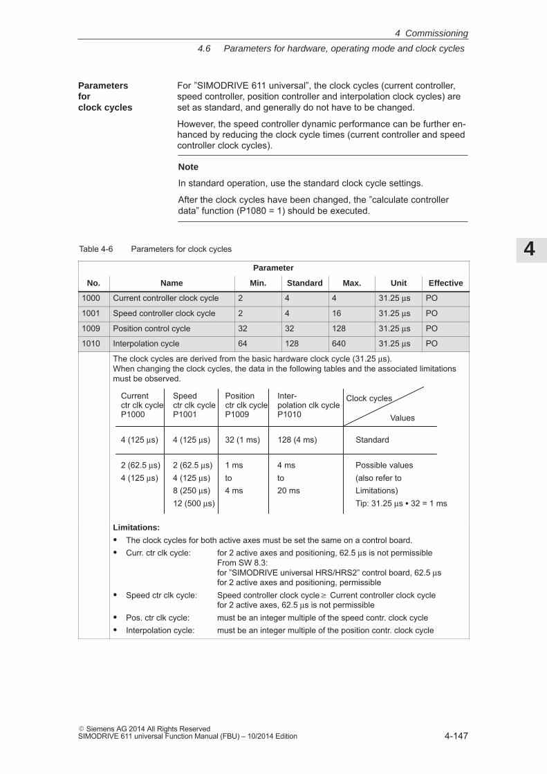
4
4.6 Parameters for hardware, operating mode and clock cycles
4-147� Siemens AG 2014 All Rights ReservedSIMODRIVE 611 universal Function Manual (FBU) – 10/2014 Edition
For ”SIMODRIVE 611 universal”, the clock cycles (current controller,speed controller, position controller and interpolation clock cycles) areset as standard, and generally do not have to be changed.
However, the speed controller dynamic performance can be further en-hanced by reducing the clock cycle times (current controller and speedcontroller clock cycles).
Note
In standard operation, use the standard clock cycle settings.
After the clock cycles have been changed, the ”calculate controllerdata” function (P1080 = 1) should be executed.
Table 4-6 Parameters for clock cycles
Parameter
No. Name Min. Standard Max. Unit Effective
1000 Current controller clock cycle 2 4 4 31.25 μs PO
1001 Speed controller clock cycle 2 4 16 31.25 μs PO
1009 Position control cycle 32 32 128 31.25 μs PO
1010 Interpolation cycle 64 128 640 31.25 μs PO
The clock cycles are derived from the basic hardware clock cycle (31.25 μs).When changing the clock cycles, the data in the following tables and the associated limitationsmust be observed.
Current Speed Position Inter-ctr clk cycle ctr clk cycle ctr clk cycle polation clk cycleP1000 P1001 P1009 P1010
4 (125 μs) 4 (125 μs) 32 (1 ms) 128 (4 ms) Standard
2 (62.5 μs) 2 (62.5 μs) 1 ms 4 ms Possible values4 (125 μs) 4 (125 μs) to to (also refer to
8 (250 μs) 4 ms 20 ms Limitations)12 (500 μs) Tip: 31.25 μs � 32 = 1 ms
Clock cycles
Values
Limitations:
� The clock cycles for both active axes must be set the same on a control board.� Curr. ctr clk cycle: for 2 active axes and positioning, 62.5 μs is not permissible
From SW 8.3:for ”SIMODRIVE universal HRS/HRS2” control board, 62.5 μs for 2 active axes and positioning, permissible
� Speed ctr clk cycle: Speed controller clock cycle� Current controller clock cyclefor 2 active axes, 62.5 μs is not permissible
� Pos. ctr clk cycle: must be an integer multiple of the speed contr. clock cycle� Interpolation cycle: must be an integer multiple of the position contr. clock cycle
Parametersfor clock cycles
4 Commissioning
4
4.7 Induction motor operation with induction motor
4-148� Siemens AG 2014 All Rights Reserved
SIMODRIVE 611 universal Function Manual (FBU) – 10/2014 Edition
4.7 Induction motor operation with induction motor
4.7.1 Description
The IM function permits pure encoderless operation (IM operation) or mixedoperation (encoderless operation/operation with encoder), P1465 = 0.
The induction motor operation for a ”SIMODRIVE 611 universal” drive is used for 4–quadrant closed–loop speed control of induction motorswithout speed or rotor position encoder.
Induction motor operation permits higher demands to be fulfilled re-garding the dynamic control performance and the stall immunity of con-ventional converter drives with V/Hz characteristic control. Comparedto drives with rotor position encoder, the speed accuracy is somewhatlower and therefore it must be taken into account, that in the lowerspeed range, the dynamic response and smooth running characteristicswill deteriorate.
IM (Induction Motor) operation is used, e.g. in the area of special high–speed motors, for grinding applications and for drives for punches andpresses.
MSD mode:MSD mode with encoder is for high speed accuracy, dynamics andpositioning, P1465 > nmax.Application: Spindles, spindle positioning
As the dynamic performance in IM operation is less than MSD oper-ation with encoder, a speed–torque–frequency pre–control is imple-mented to improve the control dynamic performance. This pre–control is only active in induction motor operation. It pre–con-trols, with information about the drive torque, taking into account theexisting torque and current limits and the load (motor – P1117 + load –P1123:8 (from SW 2.4)), the torque required for a particular speedchange, in the fastest possible time. This means, that when correctly parameterized, overshoot is preventedand the controlled dynamic performance is enhanced.
For the torque pre–control, a smoothing time can be parameterized viaP1459. The speed controller is parameterized for induction motor operationusing P1451 and P1453 due to the low dynamic performance.
In the low speed range, for pure induction motor operation, the actualspeed, the orientation and the actual flux can no longer be calculated.This is due to the accuracy of the measured values and the parametersensitivity of the technique. Thus, an open–loop current/frequency con-trol is selected. The changeover threshold is parameterized using P1466 , whereby a5 % hysteresis is implemented. In order to be able to accept a high load torque, even in the open–loopcontrolled range, the motor current can be increased via P1458.
IM operation
Applications
Closed–loopcontrol
4 Commissioning
4
4.7 Induction motor operation with induction motor
4-149� Siemens AG 2014 All Rights ReservedSIMODRIVE 611 universal Function Manual (FBU) – 10/2014 Edition
Note
The value in MD 1458 should be taken into account whendimensioning the power section, particularly in those cases where thecontrolled operational state lasts for a long time. The maximum currentspecified with MD 1458 is also used with low speeds and torques; thiscan lead to long–term damage or to a power section whosedimensions are too small being destroyed.
When the pulses are canceled and in pure induction motor operation,the drive converter has no information about the actual motor speed. When the pulses are re–enabled, the speed actual value must first besearched for.
Parameter P1012.7 can be used to define whether the search shouldstart at the setpoint speed or at speed = 0.
P1012.7 = 0 Search starts at the setpoint speed= 1 Search starts at speed = 0
When the motor is stationary and P1012.7 = 0, you should avoid apply-ing a high setpoint before the pulses have been enabled.
!Warning
When deleting the gating pulses for the motor (terminal 663, terminal63 or internally canceling the pulses when faults are present), there isno motor speed data. The computed actual speed value is then set tozero, Thus, all of the speed actual value signals, speed actual valuemessages and output signals (| nact | < nmin, ramp–function generatorended, | nact | < nx, nset = nact) are no longer reliable.
The MSD/AM function enables the control response to be switched dur-ing operation from MSD to AM control for high speeds, depending onthe speed. Parameter P1465 > 0, < nmax.The switchover takes place automatically, depending on the setting ofthe speed threshold in P1465. A switchover via a digital input, for example, is not possible.
Behavior after pulse cancellation
MSD/IM operation
4 Commissioning
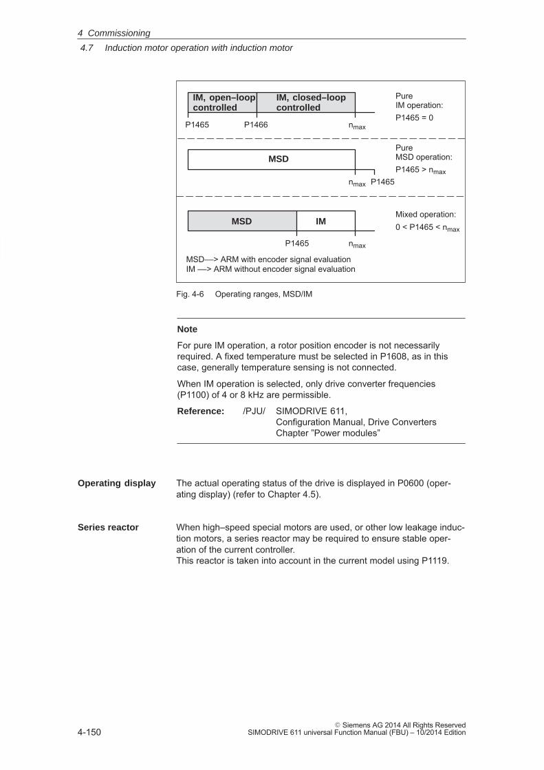
4
4.7 Induction motor operation with induction motor
4-150� Siemens AG 2014 All Rights Reserved
SIMODRIVE 611 universal Function Manual (FBU) – 10/2014 Edition
nmax
nmax
nmax
P1466P1465
P1465
P1465
Pure IM operation:P1465 = 0
Pure MSD operation:P1465 > nmax
Mixed operation:0 < P1465 < nmax
MSD
MSD––> ARM with encoder signal evaluation IM ––> ARM without encoder signal evaluation
IM
MSD
IM, open–loopcontrolled
IM, closed–loopcontrolled
Fig. 4-6 Operating ranges, MSD/IM
Note
For pure IM operation, a rotor position encoder is not necessarilyrequired. A fixed temperature must be selected in P1608, as in thiscase, generally temperature sensing is not connected.
When IM operation is selected, only drive converter frequencies(P1100) of 4 or 8 kHz are permissible.
Reference: /PJU/ SIMODRIVE 611, Configuration Manual, Drive ConvertersChapter ”Power modules”
The actual operating status of the drive is displayed in P0600 (oper-ating display) (refer to Chapter 4.5).
When high–speed special motors are used, or other low leakage induc-tion motors, a series reactor may be required to ensure stable oper-ation of the current controller. This reactor is taken into account in the current model using P1119.
Operating display
Series reactor
4 Commissioning
4
4.7 Induction motor operation with induction motor
4-151� Siemens AG 2014 All Rights ReservedSIMODRIVE 611 universal Function Manual (FBU) – 10/2014 Edition
4.7.2 Commissioning induction motors (ARM) without encoder
!Danger
The EMERGENCY STOP functions must always be functioning whencommissioning the drive. The relevant safety regulations must beobserved to exclude danger for man and machine.
When optimizing the motor data, motor movements are initiated, whichcan reach the maximum motor speed.
The use of unlisted induction motors with ”SIMODRIVE 611 universal”is supported with the motor data optimization.
Often, the commissioning engineer only knows the rating plate data(manufacturer’s data according to DIN VDE 0530, Part 1) of the motor.
The “Calculate equivalent circuit diagram data” function can be used tocalculate other motor data.The result of the calculation is merely an approximate estimate. Themotor data optimization is used to improve the result.
When optimizing the motor data, voltage, current and speed setpointpatterns are output to the motor, and information regarding the equiva-lent circuit diagram data is taken from the motor response.
The following prerequisites are necessary when commissioning thedrive system:
� Pulses, controller, and ramp–function generator must be enabled.
� Motor data optimization is possible in the MSD and IM modes.
� For MSD operation, it is not necessary to determine the moment ofinertia.
Note
As a result of the many motors available in the market, it cannotalways be guaranteed that the motor data optimization routine suppliesresults for all motor types. This is especially true for motors with a lowpower rating.
In this case, in addition to using the data on the motor rating plate, anattempt can also be made to only execute those steps 1...4 for motordata optimization (Chapter 4.7.3) that can be executed without anyproblems being encountered. If step 2 results in problems, then onlythe data on the motor rating plate should be used. So, after the motordata optimization has been completed, an attempt can be made toincrease the flux gain (P1150). If this is also not successful, thenunfortunately, the motor cannot be used together with SIMODRIVE611 universal!
Motor data optimization
Prerequisites forcommissioning
4 Commissioning
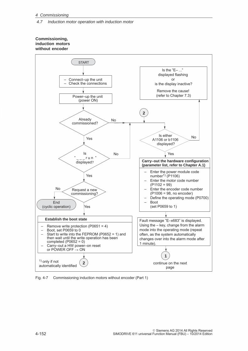
4
4.7 Induction motor operation with induction motor
4-152� Siemens AG 2014 All Rights Reserved
SIMODRIVE 611 universal Function Manual (FBU) – 10/2014 Edition
START
Power–up the unit (power ON)
Is ” _ _ _ r u n ”
displayed?
– Connect–up the unit– Check the connections
Request a newcommissioning?
Alreadycommissioned?
No
Is either A1106 or b1106
displayed?
No
Yes
Yes
Yes
No
Yes
No
– Remove write protection (P0651 = 4)– Boot, set P0659 to 0– Start to write into the FEPROM (P0652 = 1) and
then wait until the write operation has beencompleted (P0652 = 0)
– Carry–out a HW power–on resetor POWER OFF � ON
Establish the boot state
Carry–out the hardware configuration(parameter list, refer to Chapter A.1)
1) only if notautomatically identified
1
– Enter the power module codenumber1) (P1106)
– Enter the motor code number (P1102 = 99)
– Enter the encoder code number (P1006 = 98, no encoder)
– Define the operating mode (P0700)– Boot
(set P0659 to 1)
continue on the nextpage
End(cyclic operation)
2
2
Is the ”E– ...” displayed flashing
or is the display inactive?
Remove the cause! (refer to Chapter 7.3)
Fault message ”E–x683” is displayed.Using the – key, change from the alarmmode into the operating mode (repeatoften, as the system automaticallychanges over into the alarm mode after1 minute).
Fig. 4-7 Commissioning induction motors without encoder (Part 1)
Commissioning,induction motorswithout encoder
4 Commissioning
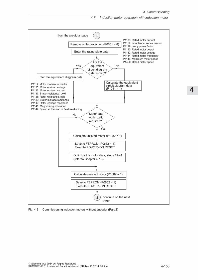
4
4.7 Induction motor operation with induction motor
4-153� Siemens AG 2014 All Rights ReservedSIMODRIVE 611 universal Function Manual (FBU) – 10/2014 Edition
Enter the rating plate data
P1117: Motor moment of inertiaP1135: Motor no–load voltageP1136: Motor no–load currentP1137: Stator resistance, coldP1138: Rotor resistance, coldP1139: Stator leakage reactanceP1140: Rotor leakage reactanceP1141: Magnetizing reactanceP1142: Speed at the start of field weakening
Save to FEPROM (P0652 = 1)Execute POWER–ON RESET
Yes No
Yes
No
Are theequivalent
circuit diagramdata known?
Calculate unlisted motor (P1082 = 1)
Optimize the motor data, steps 1 to 4(refer to Chapter 4.7.3)
Calculate unlisted motor (P1082 = 1)
Save to FEPROM (P0652 = 1)Execute POWER–ON RESET
1from the previous pageP1103: Rated motor currentP1119: Inductance, series reactorP1129: cos ϕ power factorP1130: Rated motor outputP1132: Rated motor voltageP1134: Rated motor frequencyP1146: Maximum motor speedP1400: Rated motor speed
Enter the equivalent diagram data
3 continue on the nextpage
Remove write protection (P0651 = 8)
Calculate the equivalentcircuit diagram data(P1081 = 1)
Motor dataoptimizationrequired?
Fig. 4-8 Commissioning induction motors without encoder (Part 2)
4 Commissioning
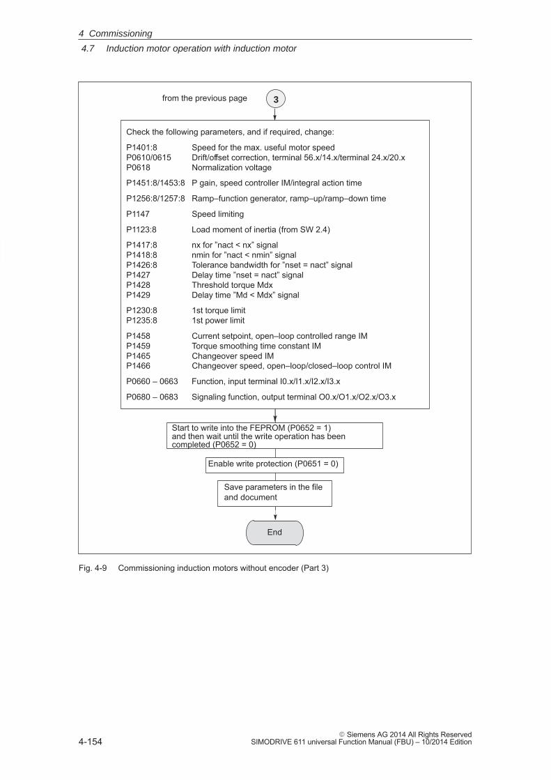
4
4.7 Induction motor operation with induction motor
4-154� Siemens AG 2014 All Rights Reserved
SIMODRIVE 611 universal Function Manual (FBU) – 10/2014 Edition
End
from the previous page 3
Check the following parameters, and if required, change:
P1401:8 Speed for the max. useful motor speedP0610/0615 Drift/offset correction, terminal 56.x/14.x/terminal 24.x/20.xP0618 Normalization voltage
P1451:8/1453:8 P gain, speed controller IM/integral action time
P1256:8/1257:8 Ramp–function generator, ramp–up/ramp–down time
P1147 Speed limiting
P1123:8 Load moment of inertia (from SW 2.4)
P1417:8 nx for ”nact < nx” signal P1418:8 nmin for ”nact < nmin” signal P1426:8 Tolerance bandwidth for ”nset = nact” signal P1427 Delay time ”nset = nact” signalP1428 Threshold torque MdxP1429 Delay time ”Md < Mdx” signal
P1230:8 1st torque limitP1235:8 1st power limit
P1458 Current setpoint, open–loop controlled range IMP1459 Torque smoothing time constant IMP1465 Changeover speed IMP1466 Changeover speed, open–loop/closed–loop control IM
P0660 – 0663 Function, input terminal I0.x/I1.x/I2.x/I3.x
P0680 – 0683 Signaling function, output terminal O0.x/O1.x/O2.x/O3.x
Start to write into the FEPROM (P0652 = 1)and then wait until the write operation has beencompleted (P0652 = 0)
Enable write protection (P0651 = 0)
Save parameters in the file and document
Fig. 4-9 Commissioning induction motors without encoder (Part 3)
4 Commissioning
4
4.7 Induction motor operation with induction motor
4-155� Siemens AG 2014 All Rights ReservedSIMODRIVE 611 universal Function Manual (FBU) – 10/2014 Edition
4.7.3 Motor data optimization, steps 1 to 4
Reader’s note
What happens to the faults occurring during motor data optimization?
Faults, which occur during the commissioning steps, are written intoP1084 as fault code (refer to the parameter list in Chapter A.1).
Prerequisites for the commissioning steps 1 to 4:� Switch in the pulse, controller and ramp–function generator enable
signal� Remove write protection (P0651 = 8)� Set the converter switching frequency (P1100) to 4 or 8 kHz
Note
The motor is immediately braked if a motor data optimization routine isinterrupted while it is running.
From SW 5.1, the ”SimoCom U” start–up tool supports motor data opti-mization.
After ”motor data optimization” has been selected, a menu is displayedin which, the following optimization steps can be selected one afteranother from the ”Settings” selection box. These optimizing steps canbe started using the ”Start” button:
1. Step 1: Determining the resistances and reactances
2. Step 2: Finely defining the no–load current, magnetizing field reactance
3. Step 3: Determining the speed at the start of field weakening
4. Step 4: Determining the moment of inertia
For the listed parameters, the results of the optimization steps are dis-played, up–to–date, in the menu screen.
The motor can also be optimized as follows using parameter settings.
Determine the resistance and reactance values of the motor and animproved no–load current value.
Note
� The motor does not move and may not move during thismeasurement.
� Monitoring is not possible, as the induction motor does not have anencoder.
Optimizing using”SimoCom U”
Optimizing withthe parametersettings
Commissioningstep 1
4 Commissioning
4
4.7 Induction motor operation with induction motor
4-156� Siemens AG 2014 All Rights Reserved
SIMODRIVE 611 universal Function Manual (FBU) – 10/2014 Edition
The step is executed as follows:
1. Select the step: P1083 = 1
2. Start the step: P1084 = 1
– P1084 = 1 The step was started and is running – it can be exited with P1084 = 0.
– P1084 = 1/0 The step was successfully completed
– P1084 = –x The step was cancelled with fault–x(refer to P1084 in Chapter A.1)Start again after the fault has been removed.
The following parameters are calculated/written into:
� P1136, P1137, P1138, P1139, P1140, P1141
Determine the no–load current and magnetizing reactance.
The no–load current is set, so that at rated speed, the no–load voltageis present at the motor terminals.
!Danger
The motor is accelerated, with a positive rotating field, up to the ratedspeed.
Note
If the speed actual value is not steady (resolver, toothed–wheelencoder), it cannot be guaranteed that this commissioning step iscorrectly executed (the setting takes too long).
Remedy: Set the speed actual value smoothing (P1522) to min. 1 ms.
The step is executed as follows:
1. Select the step: P1083 = 2
2. Start the step: P1084 = 1
– P1084 = 1 The step was started and is running – it can be exited with P1084 = 0.
– P1084 = 1/0 The step was successfully completed
– P1084 = –x The step was cancelled with fault–x(refer to P1084 in Chapter A.1)Start again after the fault has been removed.
The following parameters are calculated/written into:
� P1136, P1141
Carrying–out step 1
Changed parameters
Commissioningstep 2
Carrying–out step 2
Changed parameters
4 Commissioning
4
4.7 Induction motor operation with induction motor
4-157� Siemens AG 2014 All Rights ReservedSIMODRIVE 611 universal Function Manual (FBU) – 10/2014 Edition
Determine the speed at the start of field weakening.
When traveling at the threshold speed for the start of field weakening anda DC link voltage VDC link, the converter output voltage is set to 380 V.If VDC link < 600 V, the converter output voltage is reduced by the factorVDC link/ 600 V.
!Danger
The motor is accelerated up to the speed at the start of fieldweakening with a positive rotating field; the speed is limited to thecurrently effective limit.
Note
If the speed actual value is not steady (resolver, toothed–wheelencoder), it cannot be guaranteed that this commissioning step iscorrectly executed (the setting takes too long).
Remedy: Set the speed actual value smoothing (P1522) to min. 1 ms.
The step is executed as follows:
1. Select the step: P1083 = 3
2. Start the step: P1084 = 1
– P1084 = 1 The step was started and is running – it can be exited with P1084 = 0.
– P1084 = 1/0 The step was successfully completed
– P1084 = –x The step was cancelled with fault–x(refer to P1084 in Chapter A.1)Start again after the fault has been removed.
The following parameters are calculated/written into:
� P1142
Note
If an asynchronous motor with a rated voltage � 400 V is configured,the message is displayed that the speed at the start of field weakeninglies under the rated speed. This configured rated voltage cannot beprovided by the DC link voltage UZK!
Commissioningstep 3
Carrying out step 3
Changed parameters
4 Commissioning
4
4.7 Induction motor operation with induction motor
4-158� Siemens AG 2014 All Rights Reserved
SIMODRIVE 611 universal Function Manual (FBU) – 10/2014 Edition
Determine the moment of inertia.
The moment of inertia is set, so that when the motor accelerates to themaximum speed, no I component is set in the speed controller.
Note
If there is a significant load moment of inertia in actual operation, thisstep should be executed with a coupled load.
For identification runs, the total moment of inertia (P1117 + P1123:8(from SW 2.4)) is taken into account and corrected in P1117. Thecommissioning engineer must make the appropriate distributionbetween P1117 and P1123:8 (parameter set independent anddependent).
!Danger
The motor is accelerated with a positive field direction of rotation up tothe maximum speed along the torque limit.
The step is executed as follows:
1. Select the step: P1083 = 4
2. Start the step: P1084 = 1
– P1084 = 1 The step was started and is running – it can be exited with P1084 = 0.
– P1084 = 1/0 The step was successfully completed
– P1084 = –x The step was cancelled with fault–x(refer to P1084 in Chapter A.1)Start again after the fault has been removed.
The following parameters are calculated/written into:
� P1117
For IM operation (encoderless operation), the following parameters areavailable:
Commissioningstep 4
(not required whencarrying–out self–commissioning inthe MSD mode)
Carrying–out step 4
Changed parameters
Parameter overview
4 Commissioning
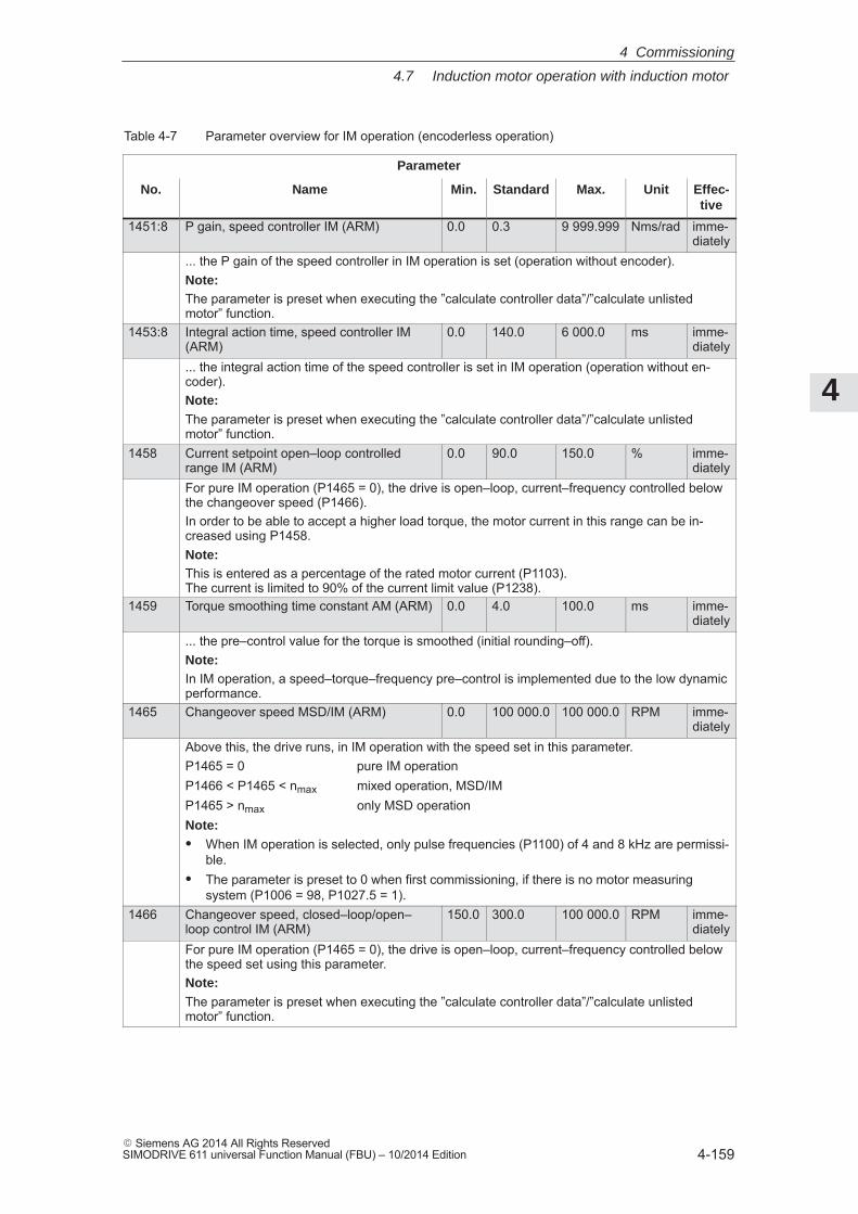
4
4.7 Induction motor operation with induction motor
4-159� Siemens AG 2014 All Rights ReservedSIMODRIVE 611 universal Function Manual (FBU) – 10/2014 Edition
Table 4-7 Parameter overview for IM operation (encoderless operation)
Parameter
No. Name Min. Standard Max. Unit Effec-tive
1451:8 P gain, speed controller IM (ARM) 0.0 0.3 9 999.999 Nms/rad imme-diately
... the P gain of the speed controller in IM operation is set (operation without encoder).Note:The parameter is preset when executing the ”calculate controller data”/”calculate unlistedmotor” function.
1453:8 Integral action time, speed controller IM(ARM)
0.0 140.0 6 000.0 ms imme-diately
... the integral action time of the speed controller is set in IM operation (operation without en-coder).Note:The parameter is preset when executing the ”calculate controller data”/”calculate unlistedmotor” function.
1458 Current setpoint open–loop controlledrange IM (ARM)
0.0 90.0 150.0 % imme-diately
For pure IM operation (P1465 = 0), the drive is open–loop, current–frequency controlled belowthe changeover speed (P1466).In order to be able to accept a higher load torque, the motor current in this range can be in-creased using P1458.Note:This is entered as a percentage of the rated motor current (P1103). The current is limited to 90% of the current limit value (P1238).
1459 Torque smoothing time constant AM (ARM) 0.0 4.0 100.0 ms imme-diately
... the pre–control value for the torque is smoothed (initial rounding–off).Note:In IM operation, a speed–torque–frequency pre–control is implemented due to the low dynamicperformance.
1465 Changeover speed MSD/IM (ARM) 0.0 100 000.0 100 000.0 RPM imme-diately
Above this, the drive runs, in IM operation with the speed set in this parameter.P1465 = 0 pure IM operationP1466 < P1465 < nmax mixed operation, MSD/IMP1465 > nmax only MSD operationNote:� When IM operation is selected, only pulse frequencies (P1100) of 4 and 8 kHz are permissi-
ble.� The parameter is preset to 0 when first commissioning, if there is no motor measuring
system (P1006 = 98, P1027.5 = 1).1466 Changeover speed, closed–loop/open–
loop control IM (ARM)150.0 300.0 100 000.0 RPM imme-
diatelyFor pure IM operation (P1465 = 0), the drive is open–loop, current–frequency controlled belowthe speed set using this parameter.Note:The parameter is preset when executing the ”calculate controller data”/”calculate unlistedmotor” function.
4 Commissioning
4
4.7 Induction motor operation with induction motor
4-160� Siemens AG 2014 All Rights Reserved
SIMODRIVE 611 universal Function Manual (FBU) – 10/2014 Edition
4.7.4 Speed monitoring using a BERO (from SW 12.1)
With the ”Speed monitoring using a BERO“ function, this function canbe emulated for IM operation the same as for the “SIMODRIVE 611analog” drive that has already be implemented for all configuredinduction motors.
An adapter for the BERO is required to use this function.
The angular incremental encoder interface must be used as input forthe “Speed monitoring using BERO” for “SIMODRIVE 611 universal”(refer to Chapter 6.8.2). This means that in the speed/torque setpointmode, the angular incremental encoder interface can no longer be usedas output if a BERO is connected.
The angular incremental encoder interface is correctly configured withP0890 = 2, the angular incremental encoder interface switched–in asinput and P0894 = 1, pulse/direction signal.
Commercially available BEROs function with a 24 V output. This is thereason that the signal level must be adapted to the angular incrementalencoder interface (5 V input). This can be realized by connecting a DTI(Digital Tacho Interface, Order No. [MLFB] 6SE7090-0XX84-3DB0) atthe existing angular incremental encoder interface input.
Note
If the angular incremental encoder interface has already been definedas an output for another function, when a BERO is connected, faultmessage 750 (from SW 12.1 and higher) is output – “Angular incre-mental encoder interface incorrectly configured”.
Description
Commissioning
4 Commissioning
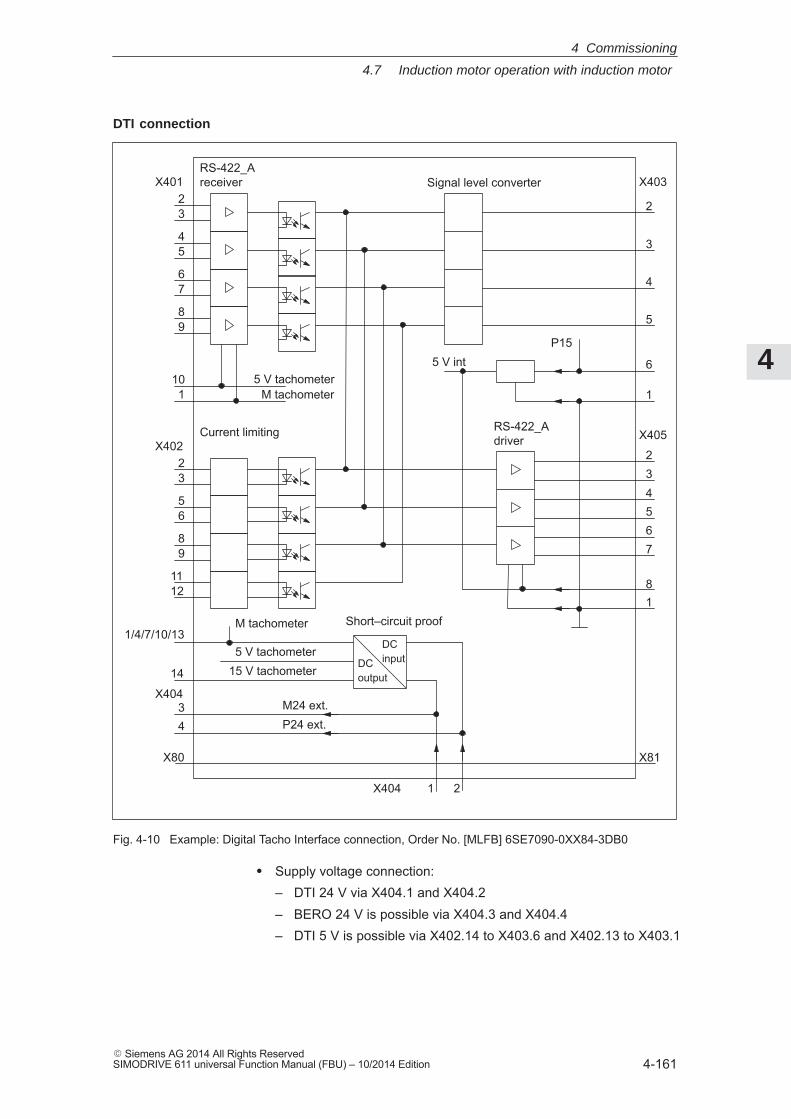
4
4.7 Induction motor operation with induction motor
4-161� Siemens AG 2014 All Rights ReservedSIMODRIVE 611 universal Function Manual (FBU) – 10/2014 Edition
5 V tachometer
Signal level converter2
RS-422_Areceiver
3
45
67
89
X401
101 M tachometer
2
Current limiting
3
56
89
1112
X402
5 V int
2
3
4
5
6
1
X403
X405
234567
81
P15
1/4/7/10/13Short–circuit proof
DCinputDC
output14
34
X404
M tachometer
5 V tachometer15 V tachometer
M24 ext.P24 ext.
X81
X404 1 2
X80
RS-422_Adriver
Fig. 4-10 Example: Digital Tacho Interface connection, Order No. [MLFB] 6SE7090-0XX84-3DB0
� Supply voltage connection:– DTI 24 V via X404.1 and X404.2– BERO 24 V is possible via X404.3 and X404.4– DTI 5 V is possible via X402.14 to X403.6 and X402.13 to X403.1
DTI connection
4 Commissioning
4
4.7 Induction motor operation with induction motor
4-162� Siemens AG 2014 All Rights Reserved
SIMODRIVE 611 universal Function Manual (FBU) – 10/2014 Edition
� Connection, BERO output signal:
– BERO at X402.2 and M24 via X404.3 to X402.3
� Connection, DTI output signal:
– DTI pulse track A from X405.2 to SIMODRIVE 611 universalX461/X462 A+
– DTI inverse pulse track A from X405.3 to SIMODRIVE 611universal X461/X462 A–
– DTI pulse track B from X405.4 to SIMODRIVE 611 universalX461/X462 B+
– DTI inverse pulse track B from X405.5 to SIMODRIVE 611universal X461/X462 B–
– DTI ground reference from X405.1 to SIMODRIVE 611 universalX461/X462.7 (15)
The “Speed monitoring using a BERO” function is activated with P1467 � 1.
P1467 = 1 allows a BERO signal to be transferred to the angular incre-mental encoder interface.
P1467 is set > 1 if the BERO detects the number of fan blades.
The following parameters are used for the “Speed monitoring using a BERO”:
� P1467 BERO pulse number
� P1468 BERO shutdown threshold, speed monitoring
� P1469 BERO speed actual value
Fault message 718 “BERO shutdown threshold exceeded” is output, if,
� The speed threshold parameterized in P1468 was exceeded or
� BERO pulses are no longer being received for a calculated speedof > 1200 RPM.
Activation
Parameteroverview(refer to Chap. A.1)
Fault case
4 Commissioning
4
4.8 Permanent–magnet synchronous motor with and without field–weakening (PE spindle)
4-163� Siemens AG 2014 All Rights ReservedSIMODRIVE 611 universal Function Manual (FBU) – 10/2014 Edition
4.8 Permanent–magnet synchronous motor with and withoutfield–weakening (PE spindle)
4.8.1 Description
The permanent–magnet synchronous motors with field weakening(1FE1 motor series) are liquid–cooled synchronous motors, which aresupplied as components. After the components have been assembledon the spindle, a complete motor spindle unit is formed.
The rotors of 1FE1 motors are equipped with permanent magnets. Thehigh speeds for spindle operation are achieved by a current which op-poses the field. This is similar to field weakening for induction motors.
The advantages of permanent–magnet spindles in comparison to in-duction motors are:
� Extremely low power loss in the rotor––> low bearing temperature
� Higher torque for the same active part dimensions––> more compact machine design
� Shorter accelerating times with the same moment of inertia
� Improved efficiency
� Favorable Cos ϕ ––> it may be possible to use a smaller power module
� More favorable speed/power characteristic––> no power reduction in the upper speed range
Reader’s note
Detailed information on 1FE1 motors, configuring and mountingbuilt–in motors are provided in:
Reference: /PJFE/ AC Motors for Main Spindle DrivesSynchronous Built–in Motors 1FE1Configuration ManualManufacturer Documentation
What is apermanent–magnetsynchronousmotor with fieldweakening?
Advantages
4 Commissioning
4
4.8 Permanent–magnet synchronous motor with and without field–weakening (PE spindle)
4-164� Siemens AG 2014 All Rights Reserved
SIMODRIVE 611 universal Function Manual (FBU) – 10/2014 Edition
A motor spindle generally consists of the following components:
� Spindle box
� Spindle with bearings
� Cooling system
The spindle manufacturer is responsible for designing the bearings,lubrication and cooling.
� Built–in motor
– 4–pole series (especially suitable for high speeds)
– 6–pole series (especially suitable for high torque)
– A VP module (VPM) is required, depending on the EMF (rotorvoltage) (VPM: Voltage Protection Module)
– Maximum speed: up to 16 000 RPM Maximum torque: up to 310 Nm
(depending on the frame size)
� Encoder system (integrated encoder)
– Hollow shaft measuring systems with sin/cos 1 Vpp (e.g. SIZAG 2 or SIMAG H)
The prerequisites are as follows:
� Control board SIMODRIVE 611 universal for encoders with sin/cos 1Vpp
� Maximum motor cable length = 50 m
Motor spindle components
System prerequisites
4 Commissioning
4
4.8 Permanent–magnet synchronous motor with and without field–weakening (PE spindle)
4-165� Siemens AG 2014 All Rights ReservedSIMODRIVE 611 universal Function Manual (FBU) – 10/2014 Edition
4.8.2 Commissioning synchronous motors
The following questions must be positively answered before commis-sioning synchronous motors:
� Are all of the prerequisites for commissioning checked and were the points in the checklist for commissioning checked (refer toChapter 4.1)?
� Is the motor used a standard or an unlisted motor?
– Standard motor?
In the Catalog, the motor is listed as a permanent–magnetsynchronous motor and has an assigned motor code (refer toChapter A.3.2)?
When commissioning, the motor used is selected from a list.
– Unlisted motor?
The motor is not included in the list of permanent–magnetsynchronous motor without field weakening and also does nothave a motor code (refer to Chapter A.3.2)?
When commissioning, the data of the motor used must be avail-able and must be manually entered.
The data required with field weakening can be found in the tableunder the index entry ”Unlisted motor – parameters for PEspindle”.
� Are the motor and encoder already mounted and ready to be powered up?
The synchronous motors are commissioned as follows using theSimoCom U parameterizing and start–up tool:
1. Establish online operation
Operation: e.g. with ”Commissioning – search for online drives”
2. Configure the drive
General rule: You can reach the next or the previous dialog box by pressing”next” or ”back”.
– ”Drive name” dialog box
– ”Power module” dialog box (only if it is not automatically identified)
– ”Motor selection” dialog box for standard motors:
”Motor” field ”Motor type” field–> Standard motor –> 1FT6, 1FK6, 1FE1, 1FW6 (synchronous)
––> select the motor used––> continue with the ”measuring system/encoder” dialog box
Generalinformation oncommissioningsynchronousmotors
Commissioningsynchronousmotors withSimoCom U
4 Commissioning
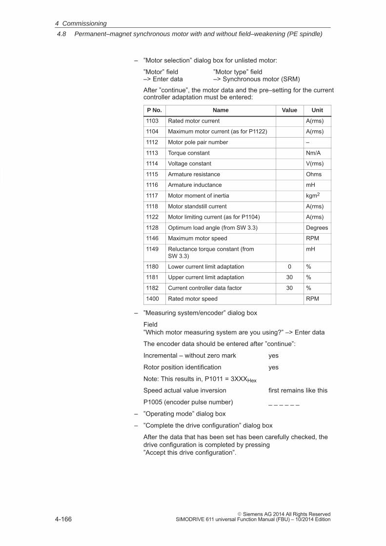
4
4.8 Permanent–magnet synchronous motor with and without field–weakening (PE spindle)
4-166� Siemens AG 2014 All Rights Reserved
SIMODRIVE 611 universal Function Manual (FBU) – 10/2014 Edition
– ”Motor selection” dialog box for unlisted motor:
”Motor” field ”Motor type” field –> Enter data –> Synchronous motor (SRM)
After ”continue”, the motor data and the pre–setting for the currentcontroller adaptation must be entered:
P No. Name Value Unit
1103 Rated motor current A(rms)
1104 Maximum motor current (as for P1122) A(rms)
1112 Motor pole pair number –
1113 Torque constant Nm/A
1114 Voltage constant V(rms)
1115 Armature resistance Ohms
1116 Armature inductance mH
1117 Motor moment of inertia kgm2
1118 Motor standstill current A(rms)
1122 Motor limiting current (as for P1104) A(rms)
1128 Optimum load angle (from SW 3.3) Degrees
1146 Maximum motor speed RPM
1149 Reluctance torque constant (fromSW 3.3)
mH
1180 Lower current limit adaptation 0 %
1181 Upper current limit adaptation 30 %
1182 Current controller data factor 30 %
1400 Rated motor speed RPM
– ”Measuring system/encoder” dialog box
Field”Which motor measuring system are you using?” –> Enter data
The encoder data should be entered after ”continue”:
Incremental – without zero mark yes
Rotor position identification yes
Note: This results in, P1011 = 3XXXHex
Speed actual value inversion first remains like this
P1005 (encoder pulse number) _ _ _ _ _ _
– ”Operating mode” dialog box
– ”Complete the drive configuration” dialog box
After the data that has been set has been carefully checked, thedrive configuration is completed by pressing ”Accept this drive configuration”.
4 Commissioning
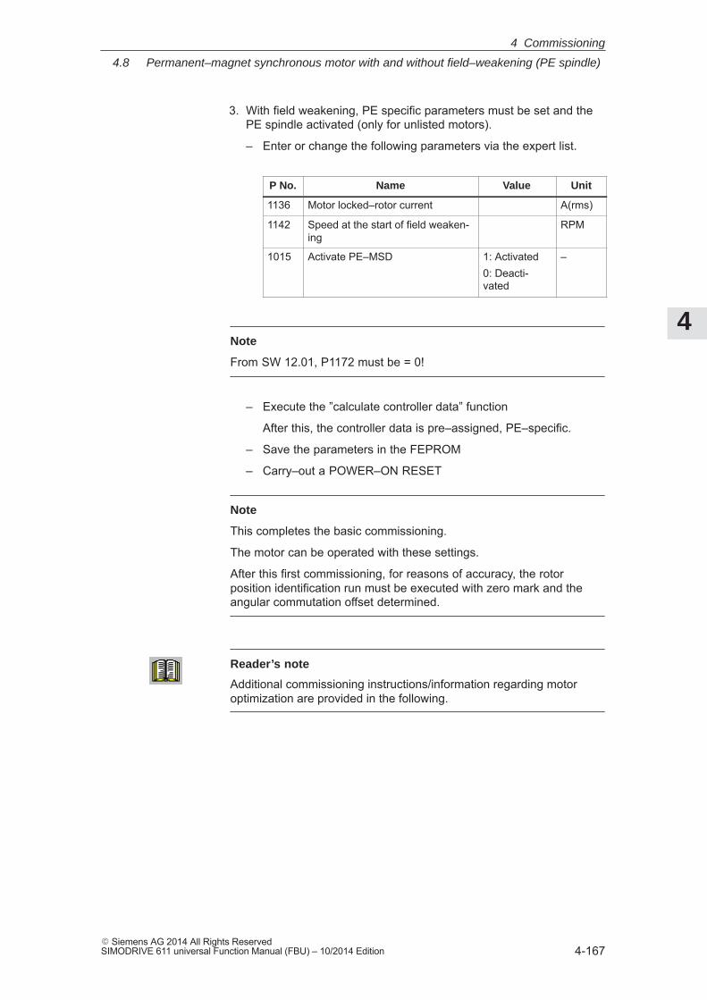
4
4.8 Permanent–magnet synchronous motor with and without field–weakening (PE spindle)
4-167� Siemens AG 2014 All Rights ReservedSIMODRIVE 611 universal Function Manual (FBU) – 10/2014 Edition
3. With field weakening, PE specific parameters must be set and thePE spindle activated (only for unlisted motors).
– Enter or change the following parameters via the expert list.
P No. Name Value Unit
1136 Motor locked–rotor current A(rms)
1142 Speed at the start of field weaken-ing
RPM
1015 Activate PE–MSD 1: Activated0: Deacti-vated
–
Note
From SW 12.01, P1172 must be = 0!
– Execute the ”calculate controller data” function
After this, the controller data is pre–assigned, PE–specific.
– Save the parameters in the FEPROM
– Carry–out a POWER–ON RESET
Note
This completes the basic commissioning.
The motor can be operated with these settings.
After this first commissioning, for reasons of accuracy, the rotorposition identification run must be executed with zero mark and theangular commutation offset determined.
Reader’s note
Additional commissioning instructions/information regarding motoroptimization are provided in the following.
4 Commissioning
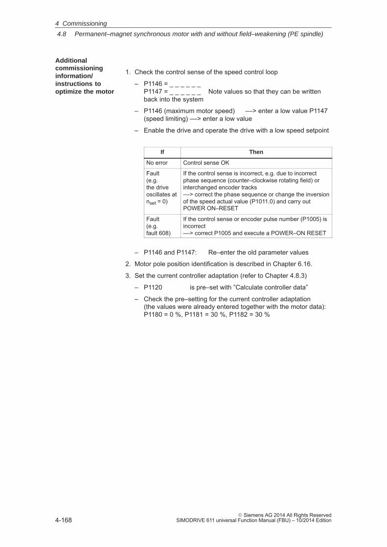
4
4.8 Permanent–magnet synchronous motor with and without field–weakening (PE spindle)
4-168� Siemens AG 2014 All Rights Reserved
SIMODRIVE 611 universal Function Manual (FBU) – 10/2014 Edition
1. Check the control sense of the speed control loop
– P1146 = _ _ _ _ _ _ P1147 = _ _ _ _ _ _ Note values so that they can be writtenback into the system
– P1146 (maximum motor speed) ––> enter a low value P1147 (speed limiting) ––> enter a low value
– Enable the drive and operate the drive with a low speed setpoint
If Then
No error Control sense OK
Fault(e.g. the driveoscillates atnset = 0)
If the control sense is incorrect, e.g. due to incorrectphase sequence (counter–clockwise rotating field) orinterchanged encoder tracks ––> correct the phase sequence or change the inversionof the speed actual value (P1011.0) and carry outPOWER ON–RESET
Fault(e.g. fault 608)
If the control sense or encoder pulse number (P1005) isincorrect ––> correct P1005 and execute a POWER–ON RESET
– P1146 and P1147: Re–enter the old parameter values
2. Motor pole position identification is described in Chapter 6.16.
3. Set the current controller adaptation (refer to Chapter 4.8.3)
– P1120 is pre–set with ”Calculate controller data”
– Check the pre–setting for the current controller adaptation (the values were already entered together with the motor data):P1180 = 0 %, P1181 = 30 %, P1182 = 30 %
Additionalcommissioninginformation/instructions tooptimize the motor
4 Commissioning
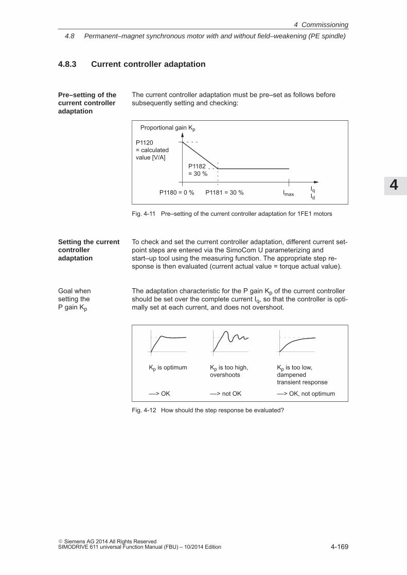
4
4.8 Permanent–magnet synchronous motor with and without field–weakening (PE spindle)
4-169� Siemens AG 2014 All Rights ReservedSIMODRIVE 611 universal Function Manual (FBU) – 10/2014 Edition
4.8.3 Current controller adaptation
The current controller adaptation must be pre–set as follows beforesubsequently setting and checking:
P1182= 30 %
P1120 = calculatedvalue [V/A]
P1180 = 0 % P1181 = 30 % IqId
Proportional gain Kp
Imax
Fig. 4-11 Pre–setting of the current controller adaptation for 1FE1 motors
To check and set the current controller adaptation, different current set-point steps are entered via the SimoCom U parameterizing andstart–up tool using the measuring function. The appropriate step re-sponse is then evaluated (current actual value = torque actual value).
The adaptation characteristic for the P gain Kp of the current controllershould be set over the complete current Iq, so that the controller is opti-mally set at each current, and does not overshoot.
Kp is optimum
––> OK
Kp is too high,overshoots
––> not OK
Kp is too low, dampened transient response
––> OK, not optimum
Fig. 4-12 How should the step response be evaluated?
Pre–setting of the current controller adaptation
Setting the currentcontrolleradaptation
Goal when setting the P gain Kp
4 Commissioning
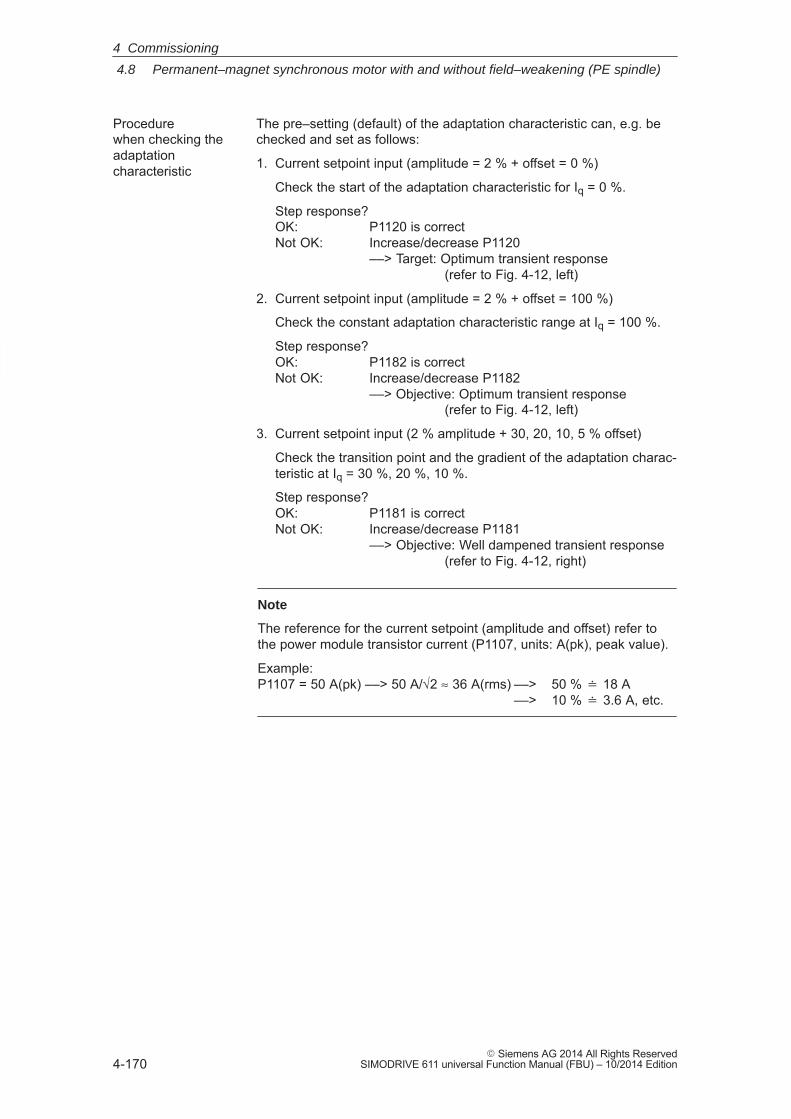
4
4.8 Permanent–magnet synchronous motor with and without field–weakening (PE spindle)
4-170� Siemens AG 2014 All Rights Reserved
SIMODRIVE 611 universal Function Manual (FBU) – 10/2014 Edition
The pre–setting (default) of the adaptation characteristic can, e.g. bechecked and set as follows:
1. Current setpoint input (amplitude = 2 % + offset = 0 %)
Check the start of the adaptation characteristic for Iq = 0 %.
Step response? OK: P1120 is correctNot OK: Increase/decrease P1120
––> Target: Optimum transient response (refer to Fig. 4-12, left)
2. Current setpoint input (amplitude = 2 % + offset = 100 %)
Check the constant adaptation characteristic range at Iq = 100 %.
Step response? OK: P1182 is correctNot OK: Increase/decrease P1182
––> Objective: Optimum transient response (refer to Fig. 4-12, left)
3. Current setpoint input (2 % amplitude + 30, 20, 10, 5 % offset)
Check the transition point and the gradient of the adaptation charac-teristic at Iq = 30 %, 20 %, 10 %.
Step response? OK: P1181 is correctNot OK: Increase/decrease P1181
––> Objective: Well dampened transient response (refer to Fig. 4-12, right)
Note
The reference for the current setpoint (amplitude and offset) refer tothe power module transistor current (P1107, units: A(pk), peak value).
Example: P1107 = 50 A(pk) ––> 50 A/√2 ≈ 36 A(rms) ––> 50 % � 18 A
––> 10 % � 3.6 A, etc.
Procedure when checking theadaptationcharacteristic
4 Commissioning
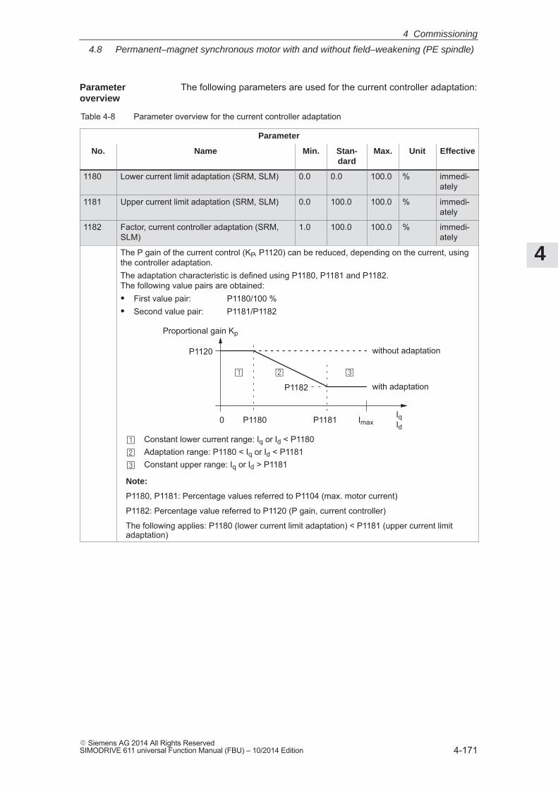
4
4.8 Permanent–magnet synchronous motor with and without field–weakening (PE spindle)
4-171� Siemens AG 2014 All Rights ReservedSIMODRIVE 611 universal Function Manual (FBU) – 10/2014 Edition
The following parameters are used for the current controller adaptation:
Table 4-8 Parameter overview for the current controller adaptation
Parameter
No. Name Min. Stan-dard
Max. Unit Effective
1180 Lower current limit adaptation (SRM, SLM) 0.0 0.0 100.0 % immedi-ately
1181 Upper current limit adaptation (SRM, SLM) 0.0 100.0 100.0 % immedi-ately
1182 Factor, current controller adaptation (SRM,SLM)
1.0 100.0 100.0 % immedi-ately
The P gain of the current control (KP, P1120) can be reduced, depending on the current, usingthe controller adaptation.The adaptation characteristic is defined using P1180, P1181 and P1182. The following value pairs are obtained:� First value pair: P1180/100 %� Second value pair: P1181/P1182
P1182
P1120
P1180 P1181 IqId
Proportional gain Kp
without adaptation
with adaptation
�
�
�
� � �
Constant lower current range: Iq or Id < P1180Adaptation range: P1180 < Iq or Id < P1181Constant upper range: Iq or Id > P1181
Note:
P1180, P1181: Percentage values referred to P1104 (max. motor current)
P1182: Percentage value referred to P1120 (P gain, current controller)
The following applies: P1180 (lower current limit adaptation) < P1181 (upper current limitadaptation)
0 Imax
Parameter overview
4 Commissioning
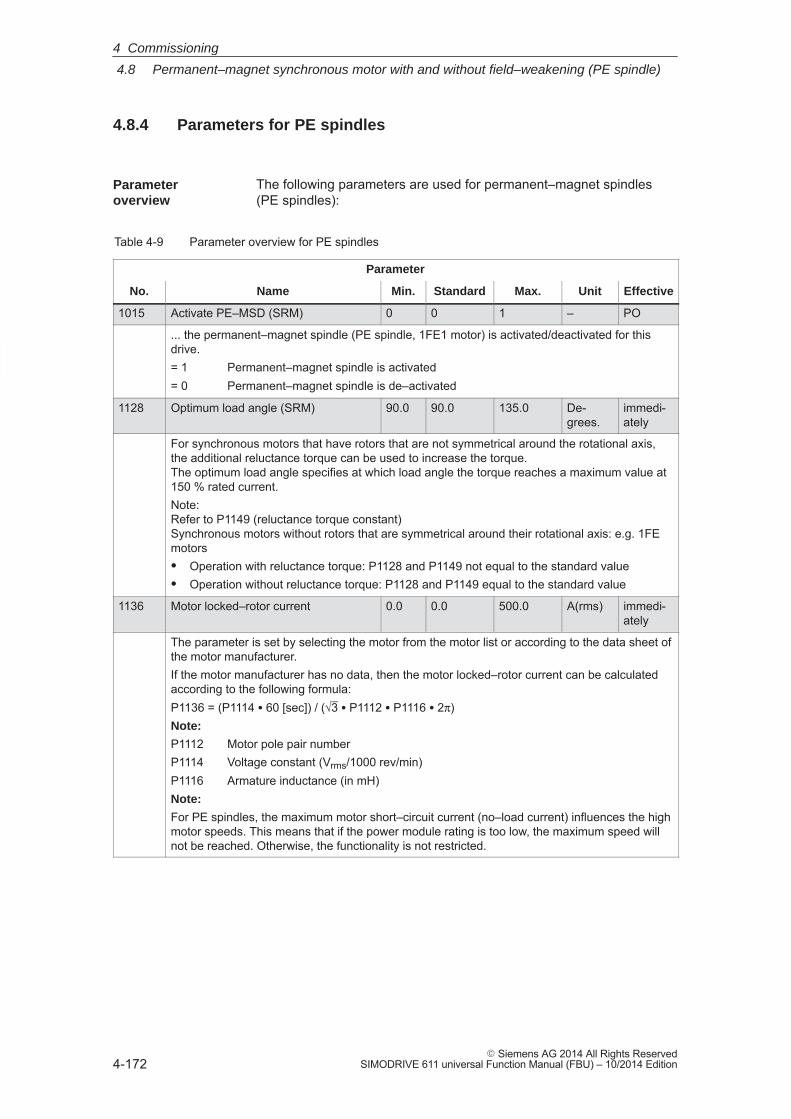
4
4.8 Permanent–magnet synchronous motor with and without field–weakening (PE spindle)
4-172� Siemens AG 2014 All Rights Reserved
SIMODRIVE 611 universal Function Manual (FBU) – 10/2014 Edition
4.8.4 Parameters for PE spindles
The following parameters are used for permanent–magnet spindles(PE spindles):
Table 4-9 Parameter overview for PE spindles
Parameter
No. Name Min. Standard Max. Unit Effective
1015 Activate PE–MSD (SRM) 0 0 1 – PO
... the permanent–magnet spindle (PE spindle, 1FE1 motor) is activated/deactivated for thisdrive.= 1 Permanent–magnet spindle is activated= 0 Permanent–magnet spindle is de–activated
1128 Optimum load angle (SRM) 90.0 90.0 135.0 De-grees.
immedi-ately
For synchronous motors that have rotors that are not symmetrical around the rotational axis,the additional reluctance torque can be used to increase the torque.The optimum load angle specifies at which load angle the torque reaches a maximum value at150 % rated current.Note:Refer to P1149 (reluctance torque constant)Synchronous motors without rotors that are symmetrical around their rotational axis: e.g. 1FEmotors� Operation with reluctance torque: P1128 and P1149 not equal to the standard value� Operation without reluctance torque: P1128 and P1149 equal to the standard value
1136 Motor locked–rotor current 0.0 0.0 500.0 A(rms) immedi-ately
The parameter is set by selecting the motor from the motor list or according to the data sheet ofthe motor manufacturer.If the motor manufacturer has no data, then the motor locked–rotor current can be calculatedaccording to the following formula:P1136 = (P1114 � 60 [sec]) / (√3 � P1112 � P1116 � 2π)Note:
P1112 Motor pole pair numberP1114 Voltage constant (Vrms/1000 rev/min)P1116 Armature inductance (in mH)Note:
For PE spindles, the maximum motor short–circuit current (no–load current) influences the highmotor speeds. This means that if the power module rating is too low, the maximum speed willnot be reached. Otherwise, the functionality is not restricted.
Parameter overview
4 Commissioning
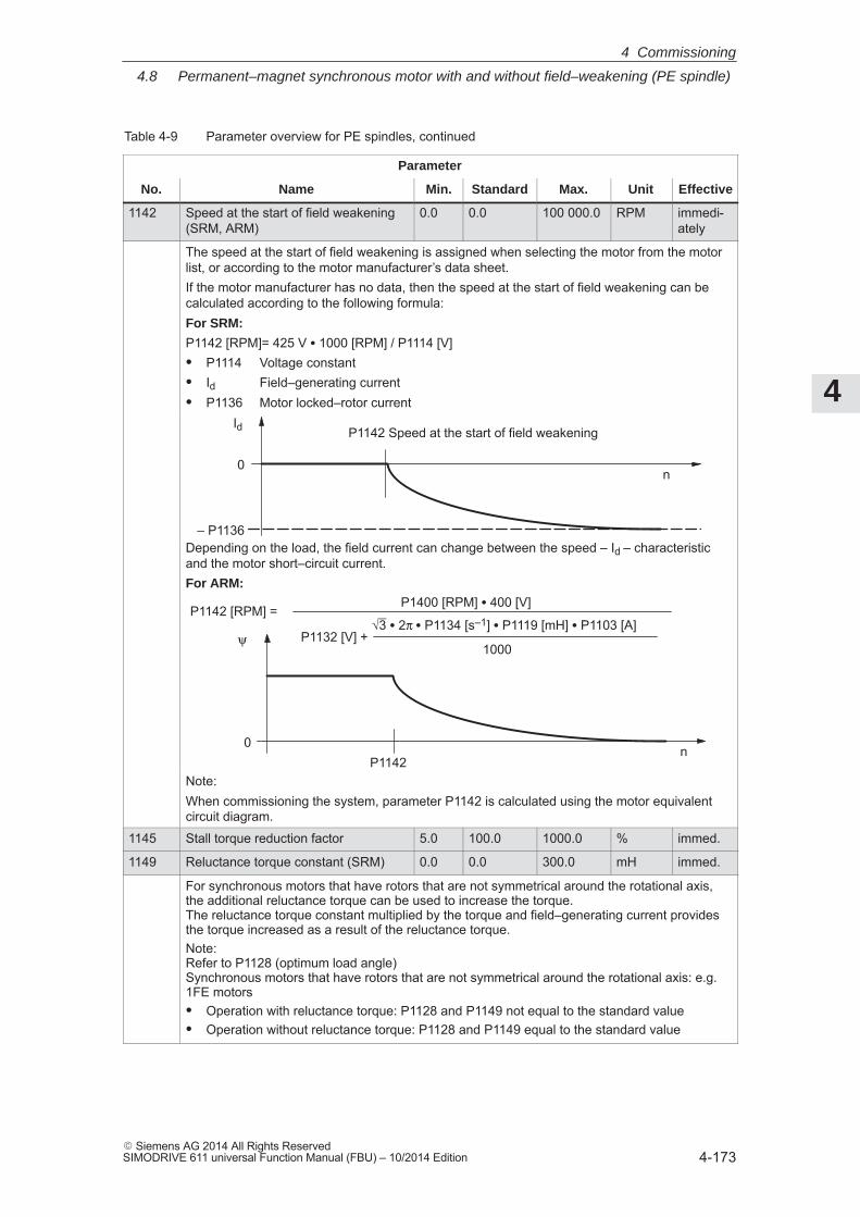
4
4.8 Permanent–magnet synchronous motor with and without field–weakening (PE spindle)
4-173� Siemens AG 2014 All Rights ReservedSIMODRIVE 611 universal Function Manual (FBU) – 10/2014 Edition
Table 4-9 Parameter overview for PE spindles, continued
Parameter
No. EffectiveUnitMax.StandardMin.Name
1142 Speed at the start of field weakening(SRM, ARM)
0.0 0.0 100 000.0 RPM immedi-ately
The speed at the start of field weakening is assigned when selecting the motor from the motorlist, or according to the motor manufacturer’s data sheet.If the motor manufacturer has no data, then the speed at the start of field weakening can becalculated according to the following formula:For SRM:
P1142 [RPM]= 425 V � 1000 [RPM] / P1114 [V]� P1114 Voltage constant� Id Field–generating current� P1136 Motor locked–rotor current
n
P1142 Speed at the start of field weakeningId
– P1136
0
Depending on the load, the field current can change between the speed – Id – characteristicand the motor short–circuit current.For ARM:
nP1142
ψ
0
P1142 [RPM] =P1400 [RPM] � 400 [V]
P1132 [V] +1000
√3 � 2π � P1134 [s–1] � P1119 [mH] � P1103 [A]
Note:When commissioning the system, parameter P1142 is calculated using the motor equivalentcircuit diagram.
1145 Stall torque reduction factor 5.0 100.0 1000.0 % immed.
1149 Reluctance torque constant (SRM) 0.0 0.0 300.0 mH immed.
For synchronous motors that have rotors that are not symmetrical around the rotational axis,the additional reluctance torque can be used to increase the torque.The reluctance torque constant multiplied by the torque and field–generating current providesthe torque increased as a result of the reluctance torque.Note:Refer to P1128 (optimum load angle)Synchronous motors that have rotors that are not symmetrical around the rotational axis: e.g.1FE motors� Operation with reluctance torque: P1128 and P1149 not equal to the standard value� Operation without reluctance torque: P1128 and P1149 equal to the standard value
4 Commissioning
4
4.9 1FW6 built–in torque motors (from SW 6.1)
4-174� Siemens AG 2014 All Rights Reserved
SIMODRIVE 611 universal Function Manual (FBU) – 10/2014 Edition
4.9 1FW6 built–in torque motors (from SW 6.1)
4.9.1 Description
Built–in torque motors are liquid–cooled, slow–speed (high pole num-ber), permanent–magnet three–phase synchronous motors with hol-low–shaft rotors. The motors are supplied as built–in componentswhich are kept together, when shipped, using an assembly unit. Inaddition, a bearing and a rotary encoder are required for a completedrive unit.
The stator and the rotor have flanges at both ends with centering sur-faces and tapped holes which allow them to be integrated into a ma-chine.
The motors distinguish themselves as follows:
� Extremely high power density
� High torque with a compact design and low envelope dimensions
� Wide range of types
� High overload capability (factor 1.8 ... 2.0)
� Low moment of inertia
� High degree of availability as there are no gearbox components inthe mechanical drive transmission line which are subject to wear
� Cable and cooling connections, either radial or axial
� Water cooling to increase the rated power
� Directly flanged to the machine
Reader’s note
Detailed information on 1FW6 motors and to engineer and mountbuilt–in torque motors is provided in:
Reference: /PJTM/ Configuration Manual 1FW6 Built–in Torque MotorsManufacturer Documentation
What is apermanent–magnetsynchronousmotor with fieldweakening?
Advantages
4 Commissioning
4
4.9 1FW6 built–in torque motors (from SW 6.1)
4-175� Siemens AG 2014 All Rights ReservedSIMODRIVE 611 universal Function Manual (FBU) – 10/2014 Edition
Generally, a built–in torque motor comprises the following components:
� StatorThis comprises an iron core and a three–phase winding. The wind-ing is cast in polyurethane in order to better dissipate the powerlosses. The motor can be force–cooled using a liquid heat ex-changer (main heat exchanger) around its circumference.
� RotorThis is the reaction part of the motor. It comprises a cylindrical hol-low steel shaft which has permanent magnets around its circumfer-ence.
� CoolingThe cooling version depends on the outer diameter.
� Encoder system
– Absolute incremental encoder with EnDat (e.g. RCN 723, Heidenhain)
– Incremental encoder (1Vpp) (e.g. RON 786, Heidenhain)
– Min. encoder pulse number zmin = 2048
– Max. encoder pulse number zmax = 65535
The prerequisites are as follows:
� Control board SIMODRIVE 611 universal (encoder interpolation depends on thenumber of pulses of the incremental encoder)
� Built–in torque motors should be set–up as feed motors
� Maximum motor cable length = 50 m
Note
When built–in torque motors (direct drives) are connected to controlledinfeeds, an HFD commutating reactor with the appropriate resistancemust be used as otherwise electrical system oscillations could occur.
When engineering the HFD commutating reactor with resistor, refer to:
Reference: /PJU/ SIMODRIVE 611Configuration ManualManufacturer Documentation
Components of built–in torquemotors
System prerequisites
4 Commissioning
4
4.9 1FW6 built–in torque motors (from SW 6.1)
4-176� Siemens AG 2014 All Rights Reserved
SIMODRIVE 611 universal Function Manual (FBU) – 10/2014 Edition
4.9.2 Commissioning 1FW6 motors
The following questions must be positively answered before commis-sioning 1FE1 motors:
� Are all of the prerequisites for commissioning checked and were the points in the checklist for commissioning checked (refer toChapter 4.1)?
� Is the motor used a standard or an unlisted motor?
– Standard motor?
In the Catalog, the motor is listed as a permanent–magnetsynchronous motor without field weakening and has an assignedmotor code (refer to Chapter A.3.3)?
When commissioning, the motor used is selected from a list.
– Unlisted motor?
The motor is not included in the list of permanent–magnetsynchronous motor without field weakening and also does nothave a motor code (refer to Chapter A.3.3)?
When commissioning, the data of the motor used must be avail-able and must be manually entered.
The necessary data is listed in the table under the index entry”Unlisted motor – parameters for 1FW6 motor”.
� Are the motor and encoder already mounted and ready to bepowered up?
1FW6 motors are commissioned as follows using the SimoCom Uparameterizing and start–up tool:
Reader’s note
Also refer to commissioning 1FE1 motors with SimoCom U in Chapter4.8.2.
Generalinformation oncommissioning1FW6 motors
Commissioning1FW6 motors withSimoCom U
4 Commissioning
4
4.9 1FW6 built–in torque motors (from SW 6.1)
4-177� Siemens AG 2014 All Rights ReservedSIMODRIVE 611 universal Function Manual (FBU) – 10/2014 Edition
For 1FW6 torque motors, the commutation required for synchronousmotors can be automatically set using the software–based rotor posi-tion identification technique.
The following two techniques can be applied for all frame sizes of1FW6 torque motors:
� Saturation–based technique (from SW 5.1)
– This technique can also be used to determine the angular com-mutation offset once in conjunction with an absolute measuringsystem (e.g. RCN 723 from Heidenhain).
– This technique does not cause the rotor to move which meansthat it can also be used for axes which are locked (e.g. using abrake).
– Depending on the actual mechanical design, this can result in ahigher noise level when the axis is powered–up during the identi-fication routine.
� Motion–based technique (from SW 6.1)
– This technique may only be used for horizontal axes that are freeto move and are not braked (static friction < 10 % of the ratedmotor torque).
– When this technique is applied, under worst case condition, therotor can move in the range of ± 5 degrees.
– The measuring system must be very stiffly mounted if this tech-nique is used.
4.9.3 Thermal motor protection
1FW6 stators are equipped with the two following temperature monitor-ing circuits to protect the stator against inadmissibly high thermalstressing as well as to monitor the temperature during the commission-ing phase and in operation:
� 2 x Temp–S (one switching threshold at 130°C and another at 150°C)
� 1 x Temp–F
Reader’s note
Detailed information on how to connect and evaluate the temperaturemonitoring circuits is provided in:
Reference: /PJTM/ Configuration Manual 1FW6 Built–in Torque MotorsManufacturer Documentation
Additionalcommissioninginformation/instructions tooptimize the motor
4 Commissioning
4
4.10 Linear motors (1FN1, 1FN3 motors)
4-178� Siemens AG 2014 All Rights Reserved
SIMODRIVE 611 universal Function Manual (FBU) – 10/2014 Edition
4.10 Linear motors (1FN1, 1FN3 motors)
4.10.1 General information on commissioning linear motors
Before commissioning motors, the following questions must be an-swered:
� Are all of the prerequisites for commissioning checked and were thepoints in the checklist for commissioning checked (refer to Chapter4.1)?
� Is there a control board with sin/cos 1 Vpp (refer to Chapter 1.3)?
Reader’s note
Detailed information on linear motors, encoders and power connection,configuring and mounting are provided in:
Reference: Configuration ManualLinear Motors of the Product Family 1FN1 or Linear Motors 1FN Peak-Load Motors of theProduct Family 1FN3
The following checks can be made:
1. Linear motor
– Which linear motor is being used?
– Is the motor in the list (refer to Chapter A.3.4)?
Yes Which? 1FN _ _ _ _ – _ _ _ _ _ – _ _ _ _
No Is the data of the ”unlisted” linear motor available?(refer under the index entry”Unlisted motor – Parameters for SLM”)
– Is the motor already mounted and ready to be powered up?
– If a cooling circuit is being used, is it functional?
Generalinformation oncommissioninglinear motors
Checks in the no–current state
4 Commissioning
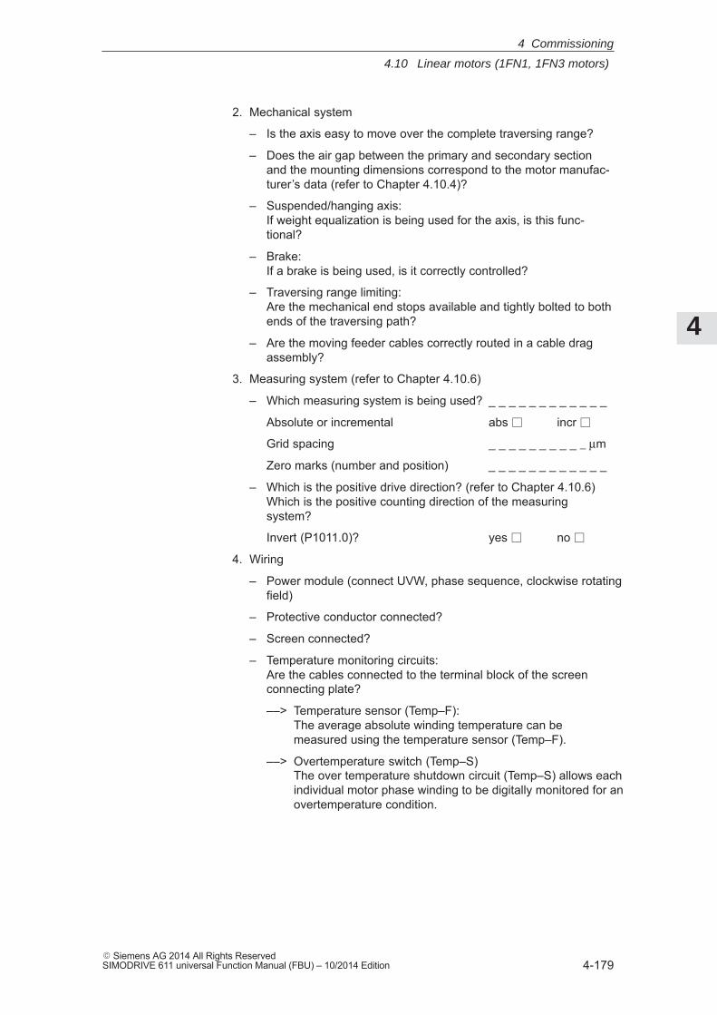
4
4.10 Linear motors (1FN1, 1FN3 motors)
4-179� Siemens AG 2014 All Rights ReservedSIMODRIVE 611 universal Function Manual (FBU) – 10/2014 Edition
2. Mechanical system
– Is the axis easy to move over the complete traversing range?
– Does the air gap between the primary and secondary sectionand the mounting dimensions correspond to the motor manufac-turer’s data (refer to Chapter 4.10.4)?
– Suspended/hanging axis:If weight equalization is being used for the axis, is this func-tional?
– Brake:If a brake is being used, is it correctly controlled?
– Traversing range limiting:Are the mechanical end stops available and tightly bolted to bothends of the traversing path?
– Are the moving feeder cables correctly routed in a cable dragassembly?
3. Measuring system (refer to Chapter 4.10.6)
– Which measuring system is being used? _ _ _ _ _ _ _ _ _ _ _ _
Absolute or incremental abs incr
Grid spacing _ _ _ _ _ _ _ _ _ _ μm
Zero marks (number and position) _ _ _ _ _ _ _ _ _ _ _ _
– Which is the positive drive direction? (refer to Chapter 4.10.6)Which is the positive counting direction of the measuringsystem?
Invert (P1011.0)? yes no
4. Wiring
– Power module (connect UVW, phase sequence, clockwise rotatingfield)
– Protective conductor connected?
– Screen connected?
– Temperature monitoring circuits: Are the cables connected to the terminal block of the screenconnecting plate?
––> Temperature sensor (Temp–F):The average absolute winding temperature can be measured using the temperature sensor (Temp–F).
––> Overtemperature switch (Temp–S)The over temperature shutdown circuit (Temp–S) allows eachindividual motor phase winding to be digitally monitored for an overtemperature condition.
4 Commissioning
4
4.10 Linear motors (1FN1, 1FN3 motors)
4-180� Siemens AG 2014 All Rights Reserved
SIMODRIVE 611 universal Function Manual (FBU) – 10/2014 Edition
!Danger
The circuits of Temp–F and Temp–S neither have ”protectiveseparation” between each other nor to the power circuits inaccordance with VDE 0160/EN 50178 (EN 61800–5–1).
Thus, they may not be used as SELV/PELV circuits, or connected withthese. Also refer to
Reference: Configuration ManualLinear Motors of the Product Family 1FN1 or Peak-Load Motors of the Product Family 1FN3
– Temperature sensor evaluation (refer to Chapter 4.10.5)
5. Measuring system cable Is the measuring system cable inserted at X411/X412 or at theadapter connector of the temperature sensor coupling cable?
!Danger
Presently, the connection does not correspond to ”protectiveseparation” according to VDE 0160/EN 50178 (EN 61800–5–1).
Thus, they may not be used as SELV/PELV circuits, or connected withthese. Also refer to
Reference: Configuration ManualLinear Motors of the Product Family 1FN1 or Peak-Load Motors of the Product Family 1FN3
4 Commissioning
4
4.10 Linear motors (1FN1, 1FN3 motors)
4-181� Siemens AG 2014 All Rights ReservedSIMODRIVE 611 universal Function Manual (FBU) – 10/2014 Edition
4.10.2 Commissioning: Linear motor with one primary section
Linear motors with a primary section (single motor) should be commis-sioned as follows using the parameterizing and start–up tool:
!Warning
The pulse enable (terminal 663) must be switched–out (de–energized)for safety reasons before the drive is powered–up.
1. Establish online operation
Operation: e.g. with ”Commissioning – search for online drives”
2. Configure the drive
General rule: You can reach the next or the previous dialog box by pressing”next” or ”back”.
– ”Drive name” dialog box
– ”Power module” dialog box (only if it is not automatically identified)
– ”Motor selection” dialog box:
Is the linear motor included in the list of linear motors?
”Motor” field ”Motor type” field–> Standard motor –> 1FNx (linear)
The linear motor is not included in the list of linear motors?––>Unlisted motor
”Motor” field ”Motor type” field –> Enter data –> Linear motor (SLM)
The motor data should be entered after ”continue”.
Procedure whencommissioningusing SimoCom U
4 Commissioning
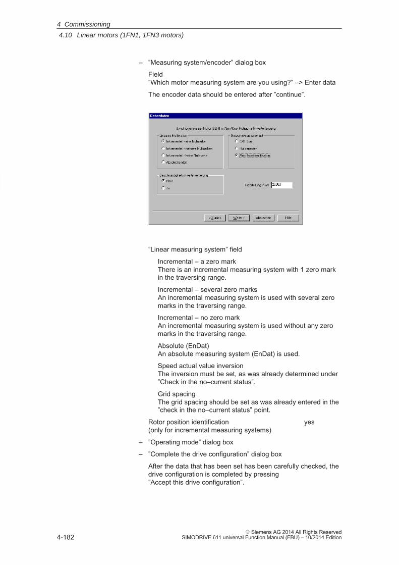
4
4.10 Linear motors (1FN1, 1FN3 motors)
4-182� Siemens AG 2014 All Rights Reserved
SIMODRIVE 611 universal Function Manual (FBU) – 10/2014 Edition
– ”Measuring system/encoder” dialog box
Field”Which motor measuring system are you using?” –> Enter data
The encoder data should be entered after ”continue”.
”Linear measuring system” field
Incremental – a zero markThere is an incremental measuring system with 1 zero markin the traversing range.
Incremental – several zero marks An incremental measuring system is used with several zeromarks in the traversing range.
Incremental – no zero markAn incremental measuring system is used without any zeromarks in the traversing range.
Absolute (EnDat)An absolute measuring system (EnDat) is used.
Speed actual value inversionThe inversion must be set, as was already determined under”Check in the no–current status”.
Grid spacingThe grid spacing should be set as was already entered in the”check in the no–current status” point.
Rotor position identification yes(only for incremental measuring systems)
– ”Operating mode” dialog box
– ”Complete the drive configuration” dialog box
After the data that has been set has been carefully checked, thedrive configuration is completed by pressing ”Accept this drive configuration”.
4 Commissioning
4
4.10 Linear motors (1FN1, 1FN3 motors)
4-183� Siemens AG 2014 All Rights ReservedSIMODRIVE 611 universal Function Manual (FBU) – 10/2014 Edition
3. Fixed temperature?
If the temperature monitoring is realized through a PLC and notthrough the drive (refer to case c), then for the temperature sensorevaluation, refer to Chapter 4.10.5), the monitoring function must bedisabled by specifying a fixed temperature > 0.
– P1608 (fixed temperature) = e.g. 80 C Monitoring off
– P1608 (fixed temperature) = 0 C Monitoring on
4. Reduce the maximum motor current for safety reasons
– P1105 (maximum motor current) = e.g. enter 20 %
!Danger
Linear drives can achieve significantly higher rates of acceleration andvelocities than conventional drives.
The traversing range must always be kept clear in order to avoid anypotential danger for man or machine.
5. Determine the angular commutation offset
The angular commutation offset is determined as follows:
a) Select the identification technique using P1075. Possibly adapt other machine data for the rotor position identification routine.
b) Save the parameters and carry–out a POWER ON RESET.
c) Depending on the measuring system used, proceed as follows:
4 Commissioning
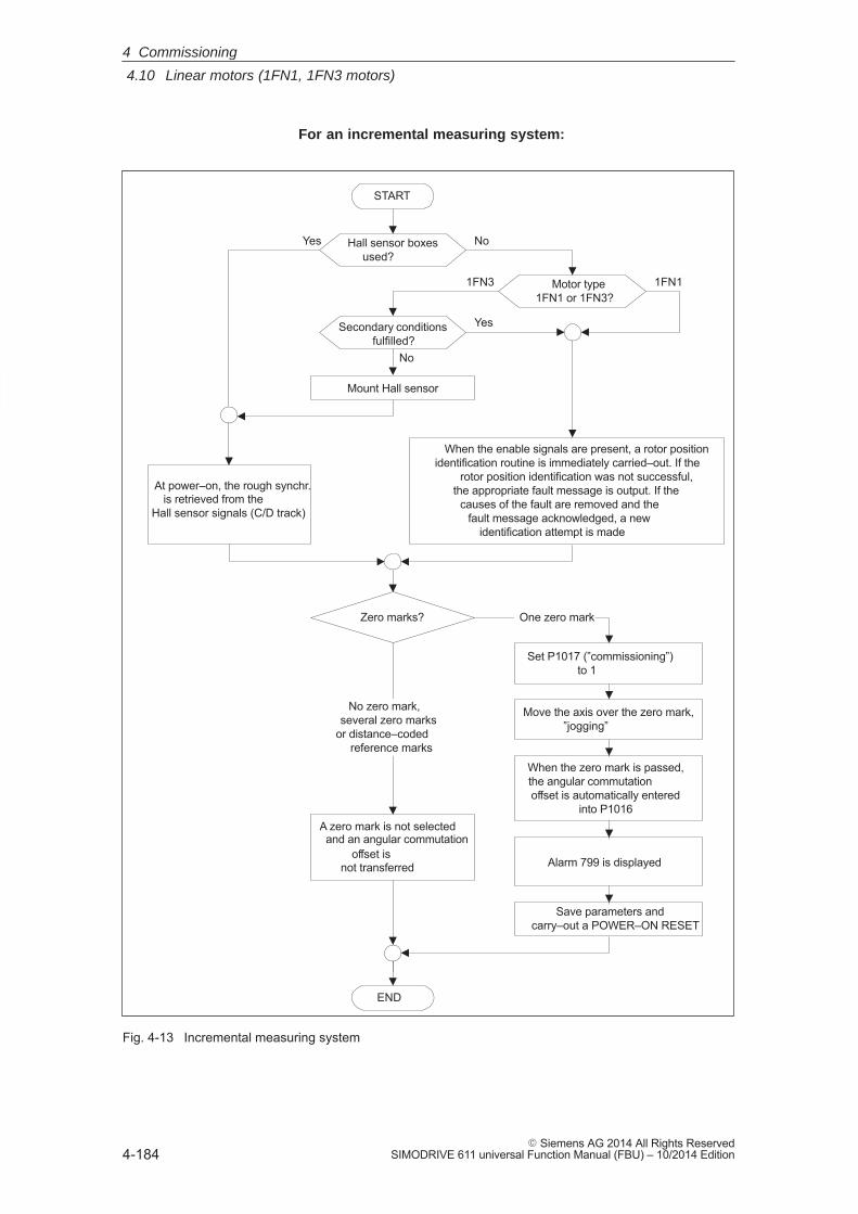
4
4.10 Linear motors (1FN1, 1FN3 motors)
4-184� Siemens AG 2014 All Rights Reserved
SIMODRIVE 611 universal Function Manual (FBU) – 10/2014 Edition
For an incremental measuring system:
When the enable signals are present, a rotor positionidentification routine is immediately carried–out. If the
rotor position identification was not successful,the appropriate fault message is output. If the
causes of the fault are removed and thefault message acknowledged, a new
identification attempt is made
Zero marks?
No zero mark,several zero marks
or distance–codedreference marks
END
A zero mark is not selectedand an angular commutation
offset isnot transferred
One zero mark
Set P1017 (”commissioning”)to 1
Move the axis over the zero mark,”jogging”
When the zero mark is passed,the angular commutationoffset is automatically entered
into P1016
Alarm 799 is displayed
Save parameters andcarry–out a POWER–ON RESET
START
Hall sensor boxesused?
NoYes
At power–on, the rough synchr.is retrieved from the
Hall sensor signals (C/D track)
Motor type1FN1 or 1FN3?
1FN3 1FN1
Secondary conditionsfulfilled?
Yes
Mount Hall sensor
No
Fig. 4-13 Incremental measuring system
4 Commissioning
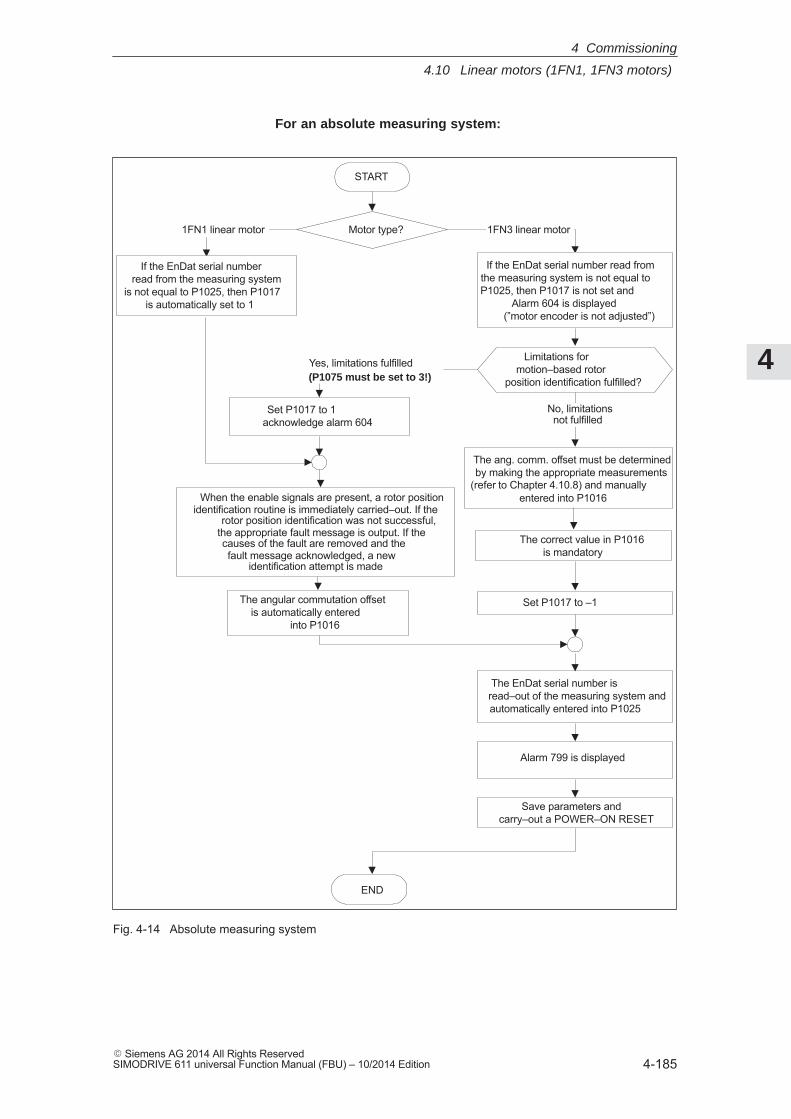
4
4.10 Linear motors (1FN1, 1FN3 motors)
4-185� Siemens AG 2014 All Rights ReservedSIMODRIVE 611 universal Function Manual (FBU) – 10/2014 Edition
For an absolute measuring system:
When the enable signals are present, a rotor positionidentification routine is immediately carried–out. If the
rotor position identification was not successful,the appropriate fault message is output. If thecauses of the fault are removed and thefault message acknowledged, a new
identification attempt is made
Motor type?1FN1 linear motor
END
If the EnDat serial number read from the measuring system
is not equal to P1025, then P1017is automatically set to 1
1FN3 linear motor
Set P1017 to 1acknowledge alarm 604
The angular commutation offsetis automatically entered
into P1016
Alarm 799 is displayed
START
If the EnDat serial number read fromthe measuring system is not equal toP1025, then P1017 is not set and
Alarm 604 is displayed(”motor encoder is not adjusted”)
Limitations formotion–based rotor
position identification fulfilled?
Yes, limitations fulfilled(P1075 must be set to 3!)
No, limitationsnot fulfilled
The ang. comm. offset must be determinedby making the appropriate measurements
entered into P1016
Set P1017 to –1
The EnDat serial number isread–out of the measuring system andautomatically entered into P1025
(refer to Chapter 4.10.8) and manually
Save parameters andcarry–out a POWER–ON RESET
The correct value in P1016is mandatory
Fig. 4-14 Absolute measuring system
4 Commissioning
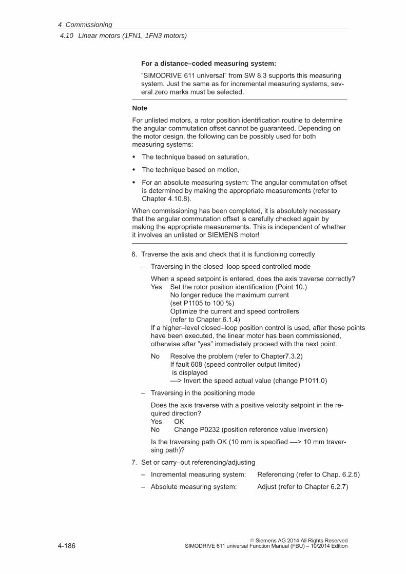
4
4.10 Linear motors (1FN1, 1FN3 motors)
4-186� Siemens AG 2014 All Rights Reserved
SIMODRIVE 611 universal Function Manual (FBU) – 10/2014 Edition
For a distance–coded measuring system:
”SIMODRIVE 611 universal” from SW 8.3 supports this measuringsystem. Just the same as for incremental measuring systems, sev-eral zero marks must be selected.
Note
For unlisted motors, a rotor position identification routine to determinethe angular commutation offset cannot be guaranteed. Depending onthe motor design, the following can be possibly used for bothmeasuring systems:
� The technique based on saturation,
� The technique based on motion,
� For an absolute measuring system: The angular commutation offsetis determined by making the appropriate measurements (refer toChapter 4.10.8).
When commissioning has been completed, it is absolutely necessarythat the angular commutation offset is carefully checked again bymaking the appropriate measurements. This is independent of whetherit involves an unlisted or SIEMENS motor!
6. Traverse the axis and check that it is functioning correctly
– Traversing in the closed–loop speed controlled mode
When a speed setpoint is entered, does the axis traverse correctly?Yes Set the rotor position identification (Point 10.)
No longer reduce the maximum current(set P1105 to 100 %)Optimize the current and speed controllers(refer to Chapter 6.1.4)
If a higher–level closed–loop position control is used, after these pointshave been executed, the linear motor has been commissioned, otherwise after ”yes” immediately proceed with the next point.
No Resolve the problem (refer to Chapter7.3.2)If fault 608 (speed controller output limited) is displayed––> Invert the speed actual value (change P1011.0)
– Traversing in the positioning mode
Does the axis traverse with a positive velocity setpoint in the re-quired direction?Yes OKNo Change P0232 (position reference value inversion)
Is the traversing path OK (10 mm is specified ––> 10 mm traver-sing path)?
7. Set or carry–out referencing/adjusting
– Incremental measuring system: Referencing (refer to Chap. 6.2.5)
– Absolute measuring system: Adjust (refer to Chapter 6.2.7)
4 Commissioning
4
4.10 Linear motors (1FN1, 1FN3 motors)
4-187� Siemens AG 2014 All Rights ReservedSIMODRIVE 611 universal Function Manual (FBU) – 10/2014 Edition
8. Set the setpoint limit switch
– P0314, P0315 and P0316(refer under the index entry ”Software limit switch”)
9. Optimizing the axis controller settings
Note:Generally, the automatic controller setting for linear motors does notprovide adequate results, as the measuring system mounting playsa significant role in the closed–loop control characteristics.
– Current and speed controllers (refer to Chapter 6.1.4)
– Position controller (refer under the index entry”Kv factor”)
10.Check and set the rotor position identification
To check the rotor position identification, using a test function,you can determine the difference between the calculated rotorangle position and that actually used by the closed–loop control.Proceed as follows:
– Start the test function several times and evaluate the differenceStart Set P1736 (test rotor position identification) to 1 Difference P1737 (difference, rotor position identification)
= _ _ _ _ , _ _ _ _ , _ _ _ _ , _ _ _ _ , _ _ _ _
– Is the spread of the measured values less than 10 degrees electrical?Yes: OKNo: Increase P1019 (e.g. by 10 %)
and repeat the measurements
If OK after having repeated the measurements, then theangular commutation offset can be re–determined:
For an incremental measuring system(incremental – one zero mark):as for Point 5. (determining the angular commutation off-set)
For an absolute measuring system:Power–down the drive (POWER ON–RESET)Power–up the drive with the pulse or controller enablesignals switched–outSet P1017.0 to 1Switch–in the pulse and enable signals––> The angular offset is automatically
entered into P1016––> Fault 799
(Save to FEPROM and HW–RESET required) is displayed
Save to FEPROM and carry–out a HW–RESET
For incremental measuring system (incremental – no or several zero marks):Save to FEPROM and carry–out a HW RESET
4 Commissioning
4
4.10 Linear motors (1FN1, 1FN3 motors)
4-188� Siemens AG 2014 All Rights Reserved
SIMODRIVE 611 universal Function Manual (FBU) – 10/2014 Edition
4.10.3 Commissioning: Linear motor with two identical primary sections
If it is certain that the EMF of both motors have the same relativephase position to one another, the connecting cables can be connectedin parallel and operated from one drive.
Linear motors, which are connected in parallel, are commissioned,based on the commissioning of a single linear motor.
First, only one linear motor (motor 1) is connected to the drive, and iscommissioned as individual motor (1FNx ...). The angular commutationoffset is automatically determined and noted.
Instead of motor 1, motor 2 is connected and is commissioned as indi-vidual motor. Also here, the angular commutation offset is automaticallydetermined and noted.
If the difference between the angular commutation offset of motor 1and motor 2 is less than 10 degrees electrical, both motors can be con-nected in parallel to the drive and commissioned as a parallel circuitconfiguration of 2 linear motors (e.g. 2 � 1FN1xxx).
Linear motors connected in parallel are commissioned as follows:
1. Disconnect the parallel circuit
Only connect motor 1 to the power module.
2. Commission motor 1 as a single motor
––> Observe the information/data in Chapter 4.10.1
––> Commission as described in Chapter 4.10.2 (up to and including Point 5.)
––> Check and set the rotor position identification (refer to Chapter 4.10.2, Point 10.)
3. Traverse the axis and check that it is functioning correctly
4. Note the angular commutation offset of motor 1
– P1016 (motor 1) = _ _ _ _ _ _ _ _ degrees electrical
5. Power–down and wait until the DC link has been discharged
6. Instead of motor 1, connect motor 2 to the power module
Caution: For a Janus configuration (refer to Chapter 4.10.7) interchangephases U and V.
7. Power–up with the pulse and controller enable signals switched out
Generalinformation
Procedure forcommissioning linear motorsconnected inparallel
4 Commissioning
4
4.10 Linear motors (1FN1, 1FN3 motors)
4-189� Siemens AG 2014 All Rights ReservedSIMODRIVE 611 universal Function Manual (FBU) – 10/2014 Edition
8. Determine the angular commutation offset of motor 2
For an incremental measuring system:as for Chapter 4.10.2, Point 5. (determining the angular commuta-tion offset)
For an absolute measuring system:Power–down the drive (POWER ON–RESET)Power–up the drive with the pulse or controller enable signalsswitched–outSet P1017.0 to 1Switch–in the pulse and enable signals––> The angular offset is automatically entered into P1016––> Fault 799
(Save to FEPROM and HW–RESET required) is displayed
Save to FEPROM and carry–out a HW–RESET
9. Traverse the axis and check that it is functioning correctly
10.Note the angular commutation offset of motor 2
– P1016 (motor 2) = _ _ _ _ _ _ _ _ degrees electrical
11.Deviation between Point 4. (motor 1) and Point 10. (motor 2)
if � 10 degrees––> OK
If > 10 degrees ––> Check and correct the mechanical arrangement
(refer to Chapter 4.10.4 and 4.10.7)or
––> Carry–out a check by making the appropriate measurements(refer to Chapter 4.10.8)
12.Delete the drive configuration
Operator action: ”Options – Service – Delete drive configuration”
13.Power–down and wait until the DC link has been discharged
14.Connect the 2 linear motors in parallel again
Connect both of the motors back to the power module.
15.Power–up with the pulse and controller enable signals switched out
16.Commission the linear motors connected in parallel
– Work completely through Chapter 4.10.2
– In the ”motor selection” dialog box, select the motor connected inparallel (2 � 1FNx ...) or enter the data of the unlisted motor connected in parallel (referunder the index entry ”unlisted motor – parameters for SLM”)
4 Commissioning
4
4.10 Linear motors (1FN1, 1FN3 motors)
4-190� Siemens AG 2014 All Rights Reserved
SIMODRIVE 611 universal Function Manual (FBU) – 10/2014 Edition
17.Compare the angular commutation offset between motors 1 and 2
P1016 (motor 1, refer to Point 4.) = _ _ _ _ _P1016 (motor 2, refer to Point 10.) = _ _ _ _ _
if the difference � 10 degrees OK
if the difference � 10 degrees not OK
Check and correct the motor cable connection at the powermodule and determine the angular commutation offset.
For an incremental measuring system:as for Chapter 4.10.2, Point 5. (determining the angular com-mutation offset)
For an absolute measuring system:Power–down the drive (POWER ON–RESET)Power–up the drive with the pulse or controller enable signalsswitched–outSet P1017.0 to 1Switch–in the pulse and enable signals––> The angular offset is automatically
entered into P1016––> Fault 799
(Save to FEPROM and HW–RESET required) is displayed
Save to FEPROM and carry–out a HW–RESET
4 Commissioning
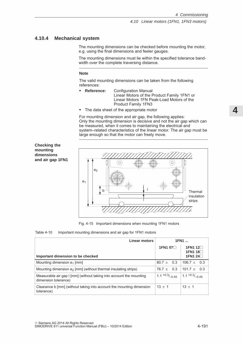
4
4.10 Linear motors (1FN1, 1FN3 motors)
4-191� Siemens AG 2014 All Rights ReservedSIMODRIVE 611 universal Function Manual (FBU) – 10/2014 Edition
4.10.4 Mechanical system
The mounting dimensions can be checked before mounting the motor,e.g. using the final dimensions and feeler gauges.
The mounting dimensions must lie within the specified tolerance band-width over the complete traversing distance.
Note
The valid mounting dimensions can be taken from the followingreferences:� Reference: Configuration Manual
Linear Motors of the Product Family 1FN1 or Linear Motors 1FN Peak-Load Motors of theProduct Family 1FN3
� The data sheet of the appropriate motor
For mounting dimension and air gap, the following applies:Only the mounting dimension is decisive and not the air gap which canbe measured, when it comes to maintaining the electrical andsystem–related characteristics of the linear motor. The air gap must belarge enough so that the motor can freely move.
Thermalinsulationstrips
e1
e2
l
ÖÖÖÖÖÖÖÖÖÖÖÖÖÖÖÖÖÖÖÖÖÖÖÖÖÖÖÖÖÖ
ÖÖÖÖÖÖÖÖÖÖÖÖÖÖÖÖÖÖÖÖÖÖÖÖÖÖÖÖÖÖ
b
Fig. 4-15 Important dimensions when mounting 1FN1 motors
Table 4-10 Important mounting dimensions and air gap for 1FN1 motors
Linear motors 1FN1 ...
Important dimension to be checked
1FN1 07 1FN1 121FN1 181FN1 24
Mounting dimension e1 [mm] 80.7 � 0.3 106.7 � 0.3
Mounting dimension e2 [mm] (without thermal insulating strips) 76.7 � 0.3 101.7 � 0.3
Measurable air gap l [mm] (without taking into account the mountingdimension tolerance)
1.1 +0.3/–0.45 1.1 +0.3/–0.45
Clearance b [mm] (without taking into account the mounting dimensiontolerance)
13 � 1 13 � 1
Checking the mountingdimensions and air gap 1FN1
4 Commissioning
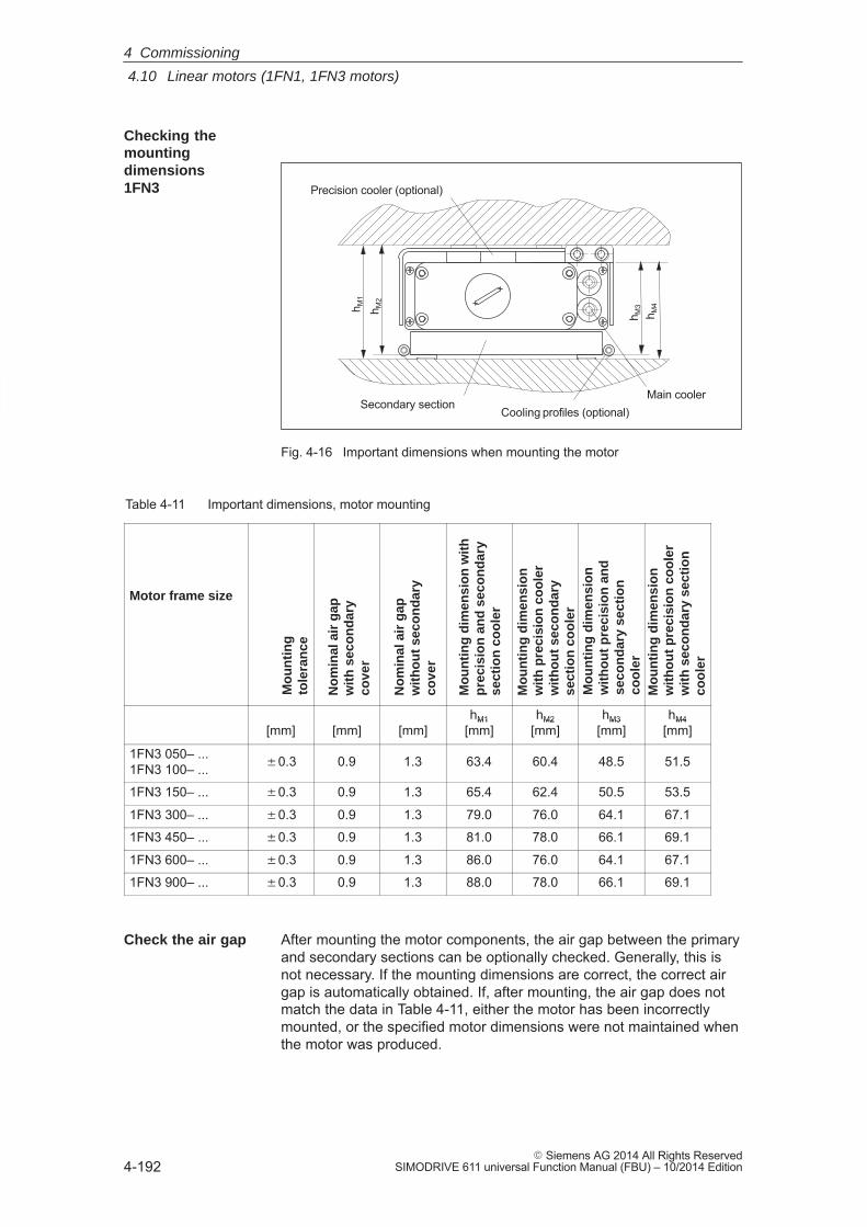
4
4.10 Linear motors (1FN1, 1FN3 motors)
4-192� Siemens AG 2014 All Rights Reserved
SIMODRIVE 611 universal Function Manual (FBU) – 10/2014 Edition
h M1
h M2
h M3
h M4
Secondary section
Precision cooler (optional)
Main coolerCooling profiles (optional)
Fig. 4-16 Important dimensions when mounting the motor
Table 4-11 Important dimensions, motor mounting
Motor frame size
Mo
un
tin
gto
lera
nce
No
min
al a
ir g
apw
ith
sec
on
dar
yco
ver
No
min
al a
ir g
apw
ith
ou
t se
con
dar
yco
ver
Mo
un
tin
g d
imen
sio
n w
ith
pre
cisi
on
an
d s
eco
nd
ary
sect
ion
co
ole
r
Mo
un
tin
g d
imen
sio
n
wit
h p
reci
sio
n c
oo
ler
wit
ho
ut
seco
nd
ary
sect
ion
co
ole
rM
ou
nti
ng
dim
ensi
on
wit
ho
ut
pre
cisi
on
an
dse
con
dar
y se
ctio
nco
ole
rM
ou
nti
ng
dim
ensi
on
wit
ho
ut
pre
cisi
on
co
ole
rw
ith
sec
on
dar
y se
ctio
nco
ole
r
[mm] [mm] [mm]hM1
[mm]hM2
[mm]hM3
[mm]hM4
[mm][mm] [mm] [mm]hM1
[mm]hM2
[mm]hM3
[mm]hM4
[mm]
1FN3 050– ...1FN3 100– ... �0.3 0.9 1.3 63.4 60.4 48.5 51.5
1FN3 150– ... �0.3 0.9 1.3 65.4 62.4 50.5 53.5
1FN3 300– ... �0.3 0.9 1.3 79.0 76.0 64.1 67.1
1FN3 450– ... �0.3 0.9 1.3 81.0 78.0 66.1 69.1
1FN3 600– ... �0.3 0.9 1.3 86.0 76.0 64.1 67.1
1FN3 900– ... �0.3 0.9 1.3 88.0 78.0 66.1 69.1
After mounting the motor components, the air gap between the primaryand secondary sections can be optionally checked. Generally, this isnot necessary. If the mounting dimensions are correct, the correct airgap is automatically obtained. If, after mounting, the air gap does notmatch the data in Table 4-11, either the motor has been incorrectlymounted, or the specified motor dimensions were not maintained whenthe motor was produced.
Checking themountingdimensions 1FN3
Check the air gap
4 Commissioning
4
4.10 Linear motors (1FN1, 1FN3 motors)
4-193� Siemens AG 2014 All Rights ReservedSIMODRIVE 611 universal Function Manual (FBU) – 10/2014 Edition
4.10.5 Thermal motor protection
Two independent monitoring circuits are available for the 1FN1, 1FN3primary sections for thermal motor protection.
The absolute, average winding temperature can be measured using thetemperature sensor (Temp–F) comprising a temperature sensor (KTY 84).
The overtemperature shutdown circuit (Temp–S) allows each individualmotor phase winding to be digitally monitored for an overtemperaturecondition.
The two independent temperature circuits Temp–F and Temp–S can beused for motor protection, either individually or together. At least oneTemp–S must be used for the motor overtemperature protection.
The circuit and connection system for Temp–F and Temp–S are de-scribed in detail in:
Reader’s note
Reference: Configuration Manual of the Product Family 1FN1 or 1FN3
!Danger
The circuits of Temp–F and Temp–S neither have ”protectiveseparation” between each other nor to the power circuits inaccordance with VDE 0160/EN 50178.
Thus, they may not be used as SELV/PELV circuits, or connected withthese. Also refer to the literature reference mentioned above!
Note
Temp–S must be connected for thermal motor protection; it is notpermissible not to connect Temp–S!
Temp–F can be optionally connected to a measuring device forcommissioning and testing.
For regular operation, the Temp–F connections should beshort–circuited and connected to PE.
Description
4 Commissioning
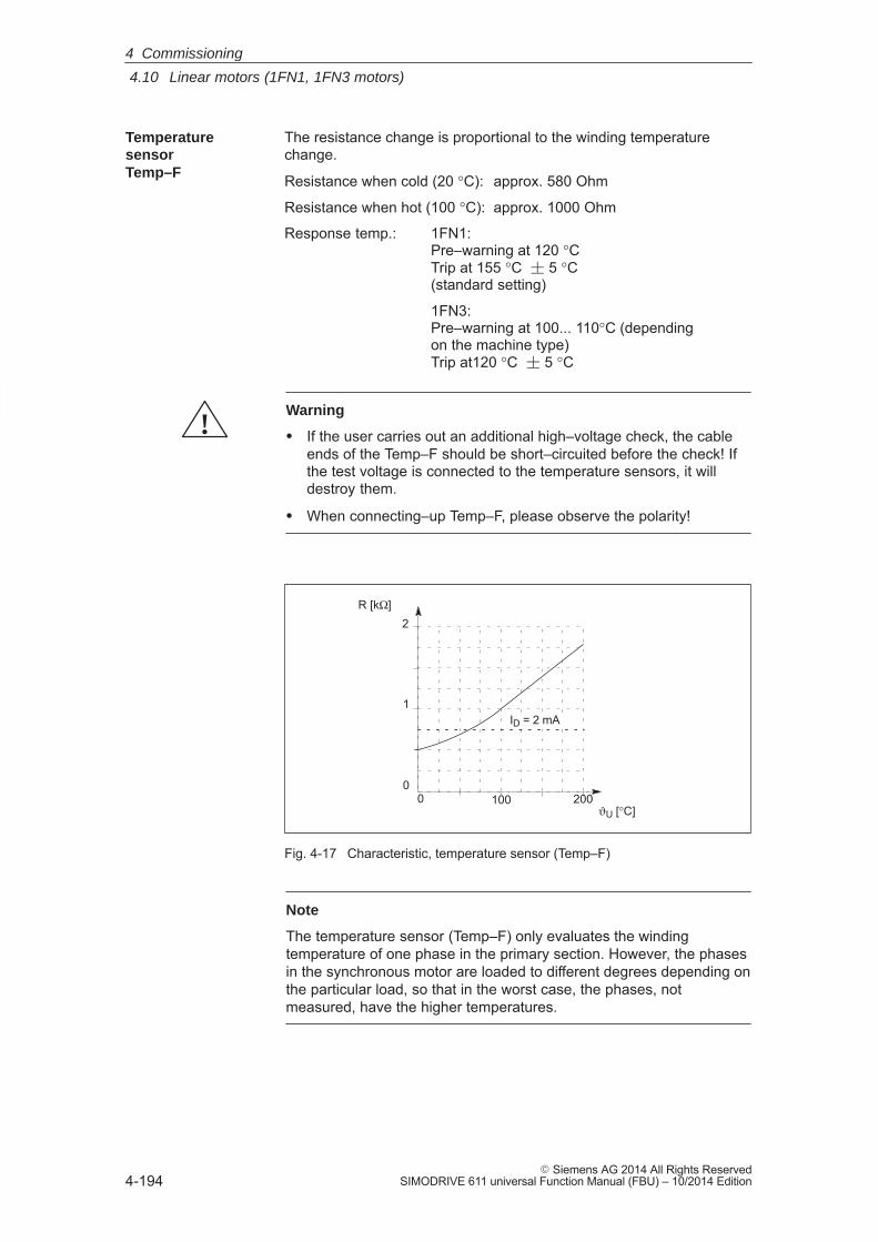
4
4.10 Linear motors (1FN1, 1FN3 motors)
4-194� Siemens AG 2014 All Rights Reserved
SIMODRIVE 611 universal Function Manual (FBU) – 10/2014 Edition
The resistance change is proportional to the winding temperaturechange.
Resistance when cold (20 °C): approx. 580 Ohm
Resistance when hot (100 °C): approx. 1000 Ohm
Response temp.: 1FN1:Pre–warning at 120 °C Trip at 155 °C � 5 °C(standard setting)
1FN3:Pre–warning at 100... 110°C (dependingon the machine type)Trip at120 °C � 5 °C
!Warning
� If the user carries out an additional high–voltage check, the cableends of the Temp–F should be short–circuited before the check! Ifthe test voltage is connected to the temperature sensors, it willdestroy them.
� When connecting–up Temp–F, please observe the polarity!
2
0
1
0200100
ϑU [°C]
ID = 2 mA
R [kΩ]
Fig. 4-17 Characteristic, temperature sensor (Temp–F)
Note
The temperature sensor (Temp–F) only evaluates the windingtemperature of one phase in the primary section. However, the phasesin the synchronous motor are loaded to different degrees depending onthe particular load, so that in the worst case, the phases, notmeasured, have the higher temperatures.
Temperaturesensor Temp–F
4 Commissioning
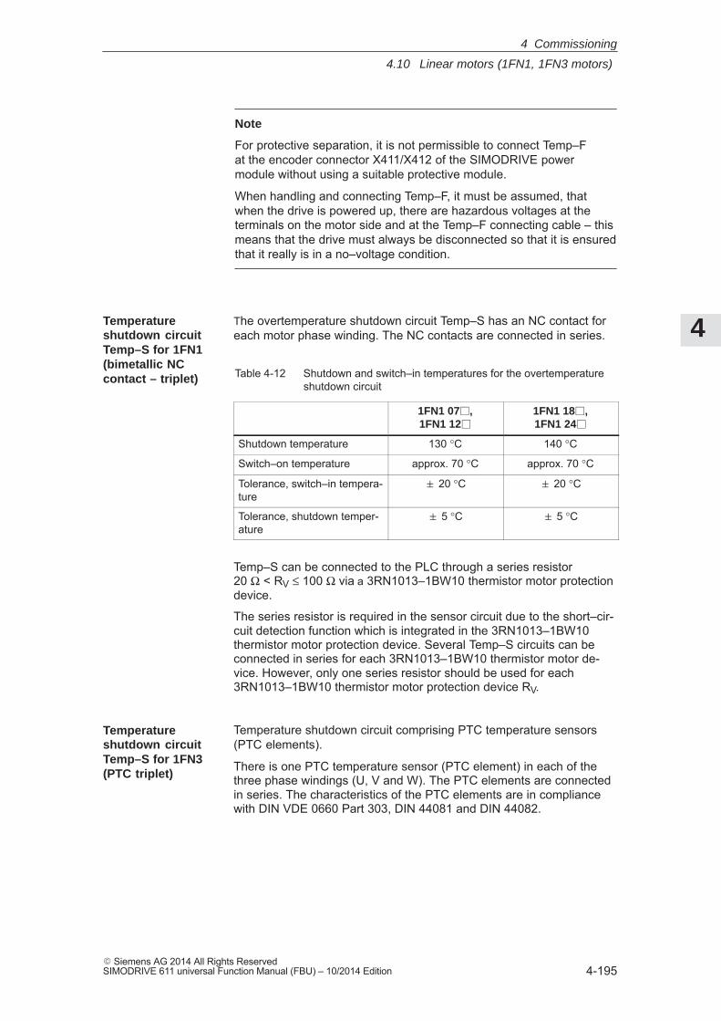
4
4.10 Linear motors (1FN1, 1FN3 motors)
4-195� Siemens AG 2014 All Rights ReservedSIMODRIVE 611 universal Function Manual (FBU) – 10/2014 Edition
Note
For protective separation, it is not permissible to connect Temp–Fat the encoder connector X411/X412 of the SIMODRIVE powermodule without using a suitable protective module.
When handling and connecting Temp–F, it must be assumed, thatwhen the drive is powered up, there are hazardous voltages at theterminals on the motor side and at the Temp–F connecting cable – thismeans that the drive must always be disconnected so that it is ensuredthat it really is in a no–voltage condition.
The overtemperature shutdown circuit Temp–S has an NC contact foreach motor phase winding. The NC contacts are connected in series.
Table 4-12 Shutdown and switch–in temperatures for the overtemperatureshutdown circuit
1FN1 07,1FN1 12
1FN1 18,1FN1 24
Shutdown temperature 130 °C 140 °C
Switch–on temperature approx. 70 °C approx. 70 °C
Tolerance, switch–in tempera-ture
20 °C 20 °C
Tolerance, shutdown temper-ature
5 °C 5 °C
Temp–S can be connected to the PLC through a series resistor 20 Ω < RV ≤ 100 Ω via a 3RN1013–1BW10 thermistor motor protectiondevice.
The series resistor is required in the sensor circuit due to the short–cir-cuit detection function which is integrated in the 3RN1013–1BW10thermistor motor protection device. Several Temp–S circuits can beconnected in series for each 3RN1013–1BW10 thermistor motor de-vice. However, only one series resistor should be used for each3RN1013–1BW10 thermistor motor protection device RV.
Temperature shutdown circuit comprising PTC temperature sensors(PTC elements).
There is one PTC temperature sensor (PTC element) in each of thethree phase windings (U, V and W). The PTC elements are connectedin series. The characteristics of the PTC elements are in compliancewith DIN VDE 0660 Part 303, DIN 44081 and DIN 44082.
Temperatureshutdown circuitTemp–S for 1FN1(bimetallic NCcontact – triplet)
Temperatureshutdown circuitTemp–S for 1FN3(PTC triplet)
4 Commissioning
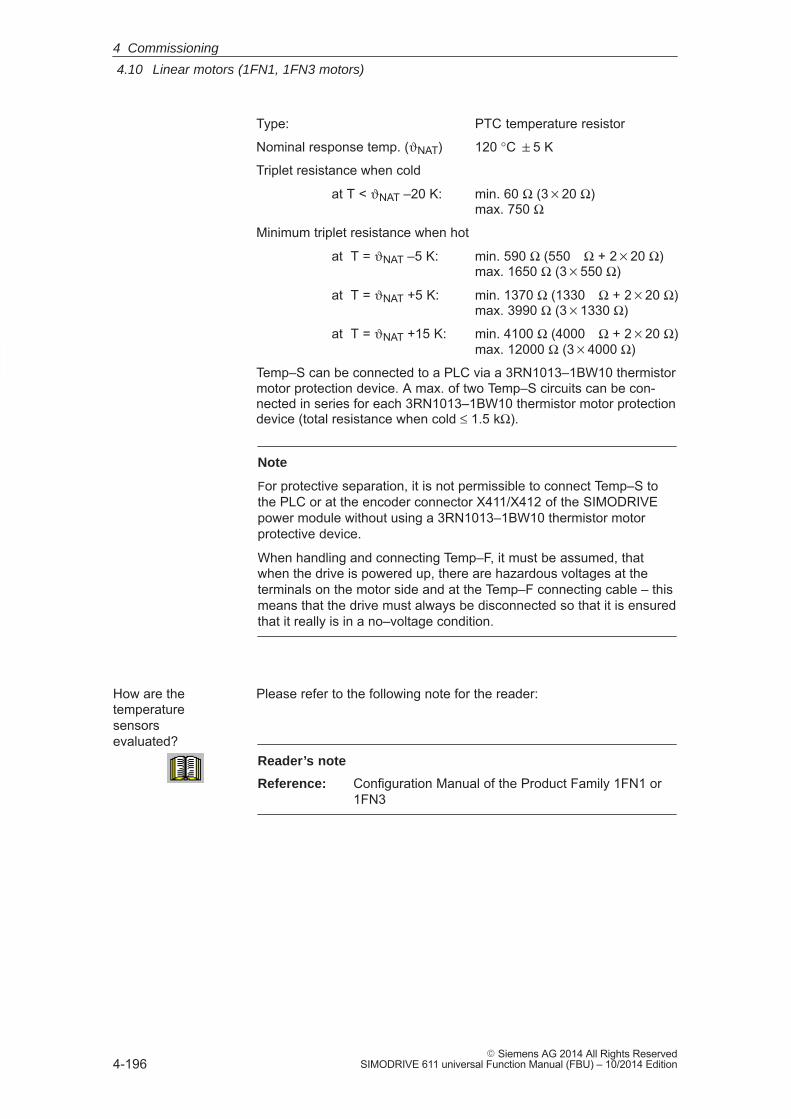
4
4.10 Linear motors (1FN1, 1FN3 motors)
4-196� Siemens AG 2014 All Rights Reserved
SIMODRIVE 611 universal Function Manual (FBU) – 10/2014 Edition
Type: PTC temperature resistor
Nominal response temp. (ϑNAT) 120 °C 5 K
Triplet resistance when cold
at T < ϑNAT –20 K: min. 60 Ω (320 Ω)max. 750 Ω
Minimum triplet resistance when hot
at T = ϑNAT –5 K: min. 590 Ω (550 Ω + 220 Ω)max. 1650 Ω (3550 Ω)
at T = ϑNAT +5 K: min. 1370 Ω (1330 Ω + 220 Ω)max. 3990 Ω (31330 Ω)
at T = ϑNAT +15 K: min. 4100 Ω (4000 Ω + 220 Ω)max. 12000 Ω (34000 Ω)
Temp–S can be connected to a PLC via a 3RN1013–1BW10 thermistormotor protection device. A max. of two Temp–S circuits can be con-nected in series for each 3RN1013–1BW10 thermistor motor protectiondevice (total resistance when cold ≤ 1.5 kΩ).
Note
For protective separation, it is not permissible to connect Temp–S tothe PLC or at the encoder connector X411/X412 of the SIMODRIVEpower module without using a 3RN1013–1BW10 thermistor motorprotective device.
When handling and connecting Temp–F, it must be assumed, thatwhen the drive is powered up, there are hazardous voltages at theterminals on the motor side and at the Temp–F connecting cable – thismeans that the drive must always be disconnected so that it is ensuredthat it really is in a no–voltage condition.
Please refer to the following note for the reader:
Reader’s note
Reference: Configuration Manual of the Product Family 1FN1 or 1FN3
How are thetemperature sensors evaluated?
4 Commissioning
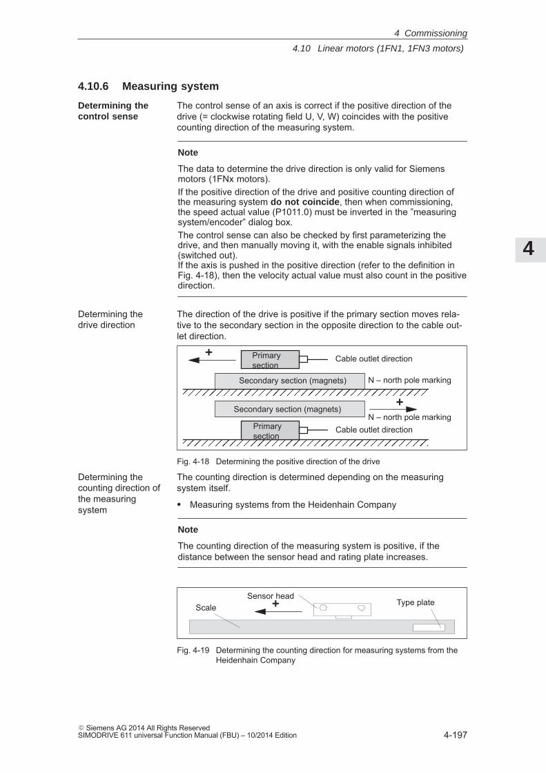
4
4.10 Linear motors (1FN1, 1FN3 motors)
4-197� Siemens AG 2014 All Rights ReservedSIMODRIVE 611 universal Function Manual (FBU) – 10/2014 Edition
4.10.6 Measuring system
The control sense of an axis is correct if the positive direction of thedrive (= clockwise rotating field U, V, W) coincides with the positivecounting direction of the measuring system.
Note
The data to determine the drive direction is only valid for Siemensmotors (1FNx motors).If the positive direction of the drive and positive counting direction ofthe measuring system do not coincide, then when commissioning,the speed actual value (P1011.0) must be inverted in the ”measuringsystem/encoder” dialog box.The control sense can also be checked by first parameterizing thedrive, and then manually moving it, with the enable signals inhibited(switched out). If the axis is pushed in the positive direction (refer to the definition inFig. 4-18), then the velocity actual value must also count in the positivedirection.
The direction of the drive is positive if the primary section moves rela-tive to the secondary section in the opposite direction to the cable out-let direction.
ÖÖÖÖÖÖÖÖÖÖÖÖÖÖÖÖÖÖÖÖÖÖÖÖÖÖÖÖÖÖÖÖÖÖÖÖÖÖ
Secondary section (magnets)
+
ÖÖÖÖÖÖÖÖÖÖÖÖÖÖÖÖÖÖÖ
Secondary section (magnets)+
Primarysection
Cable outlet direction
Primarysection
Cable outlet direction
N – north pole marking
N – north pole marking
Fig. 4-18 Determining the positive direction of the drive
The counting direction is determined depending on the measuringsystem itself.
� Measuring systems from the Heidenhain Company
Note
The counting direction of the measuring system is positive, if thedistance between the sensor head and rating plate increases.
Sensor headType plateScale +
Fig. 4-19 Determining the counting direction for measuring systems from theHeidenhain Company
Determining the control sense
Determining the drive direction
Determining the counting direction ofthe measuringsystem
4 Commissioning
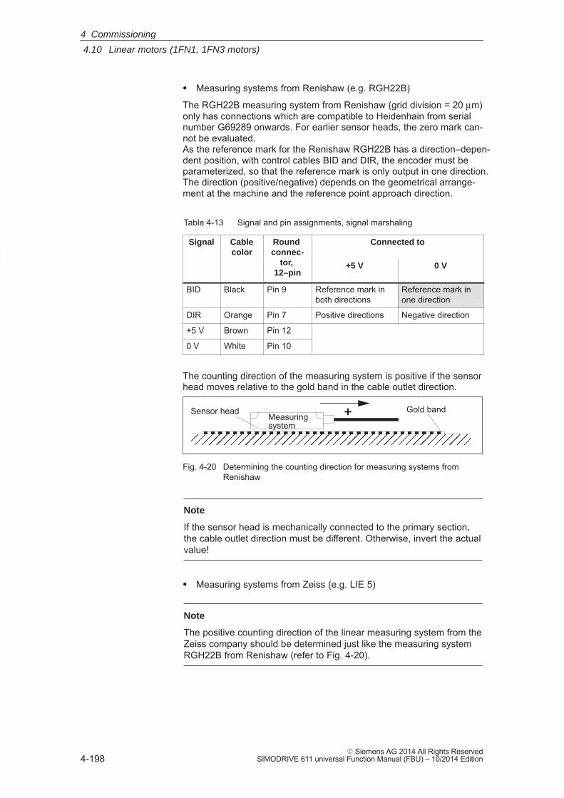
4
4.10 Linear motors (1FN1, 1FN3 motors)
4-198� Siemens AG 2014 All Rights Reserved
SIMODRIVE 611 universal Function Manual (FBU) – 10/2014 Edition
� Measuring systems from Renishaw (e.g. RGH22B)
The RGH22B measuring system from Renishaw (grid division = 20 μm)only has connections which are compatible to Heidenhain from serialnumber G69289 onwards. For earlier sensor heads, the zero mark can-not be evaluated. As the reference mark for the Renishaw RGH22B has a direction–depen-dent position, with control cables BID and DIR, the encoder must beparameterized, so that the reference mark is only output in one direction. The direction (positive/negative) depends on the geometrical arrange-ment at the machine and the reference point approach direction.
Table 4-13 Signal and pin assignments, signal marshaling
Signal Cablecolor
Round connec-
tor,
Connected tocolor connec-
tor, 12–pin
+5 V 0 V
BID Black Pin 9 Reference mark inboth directions
Reference mark inone direction
DIR Orange Pin 7 Positive directions Negative direction
+5 V Brown Pin 12
0 V White Pin 10
The counting direction of the measuring system is positive if the sensorhead moves relative to the gold band in the cable outlet direction.
ËËËËËËËËËËËËËËËËËËÖÖÖÖÖÖÖÖÖÖÖÖÖÖÖÖÖÖÖÖÖÖÖÖÖÖÖÖÖÖÖÖÖÖÖÖÖÖÖÖ
Gold bandSensor headMeasuringsystem
+
Fig. 4-20 Determining the counting direction for measuring systems fromRenishaw
Note
If the sensor head is mechanically connected to the primary section,the cable outlet direction must be different. Otherwise, invert the actualvalue!
� Measuring systems from Zeiss (e.g. LIE 5)
Note
The positive counting direction of the linear measuring system from theZeiss company should be determined just like the measuring systemRGH22B from Renishaw (refer to Fig. 4-20).
4 Commissioning
4
4.10 Linear motors (1FN1, 1FN3 motors)
4-199� Siemens AG 2014 All Rights ReservedSIMODRIVE 611 universal Function Manual (FBU) – 10/2014 Edition
The temperature sensor coupling cable is used to couple the tempera-ture sensor circuit Temp–F into the encoder cable using connectorboxes. The transition from the power cable to encoder cable can berealized at the machine as well as in the cabinet.
Please refer to the following note for the reader:
Reader’s note
Section ”General information on the connection system (CON)” in:
Reference: /PJLM/ Configuration Manual, 1FN1, 1FN3 Linear Motors
If an incremental measuring system is used, the drive is roughly syn-chronized using the rotor position identification.
!Warning
When connecting–up the temperature monitoring circuits, carefullyobserve the specifications relating to protective separation DIN EN 50178.
Information on protective separation can be taken from:
Reference: /PJLM/ Configuration Manual, 1FN1, 1FN3 Linear Motors
Temperaturesensor couplingcable
How are thetemperature sensorcoupling cable andlength measuringsystem connected?
4 Commissioning
4
4.10 Linear motors (1FN1, 1FN3 motors)
4-200� Siemens AG 2014 All Rights Reserved
SIMODRIVE 611 universal Function Manual (FBU) – 10/2014 Edition
4.10.7 Parallel and double–cam arrangement of linear motors
Note
Only identical linear motors (the same forces, winding types,secondary section types and air gap) may be connected in parallel.(Order designation or Order No. [[MLFB] of the primary sections to beconnected in parallel must be identical up to the winding sense and/orprimary section length.)
If linear motors in an axis are connected in parallel, the position of theprimary sections with respect to one another and to the secondarysections must exhibit a specific grid, in order to achieve a matchingelectrical phase position.
Additional data, refer to:
References: PJLM/ SIMODRIVEConfiguration Manual, 1FN1, 1FN3Linear Motors
The temperature sensors can be evaluated, for example, as follows:
� Temperature sensor
– Motor 1: Evaluated by the drive
– Motor 2: Not connected (short–circuited and connected with PE)
� Temperature switch
– Motor 1 and 2: Evaluated by a PLC
Reader’s note
Section ”General information on the connection system (CON)” in:
Reference: /PJLM/ Configuration Manual, 1FN1, 1FN3 Linear Motors
!Warning
When connecting–up the temperature monitoring circuits, carefullyobserve the specifications relating to protective separation DIN EN 50178.
Information on protective separation can be taken from:
Reference: /PJLM/ Configuration Manual, 1FN1, 1FN3Linear Motors
Temperaturesensor andelectrical wiring (refer to Chapter 4.10.5)
4 Commissioning
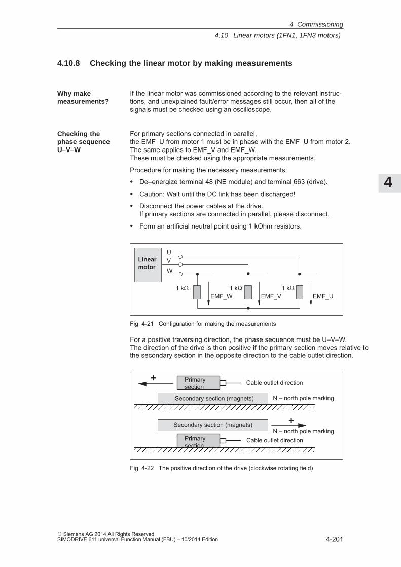
4
4.10 Linear motors (1FN1, 1FN3 motors)
4-201� Siemens AG 2014 All Rights ReservedSIMODRIVE 611 universal Function Manual (FBU) – 10/2014 Edition
4.10.8 Checking the linear motor by making measurements
If the linear motor was commissioned according to the relevant instruc-tions, and unexplained fault/error messages still occur, then all of thesignals must be checked using an oscilloscope.
For primary sections connected in parallel, the EMF_U from motor 1 must be in phase with the EMF_U from motor 2. The same applies to EMF_V and EMF_W. These must be checked using the appropriate measurements.
Procedure for making the necessary measurements:
� De–energize terminal 48 (NE module) and terminal 663 (drive).
� Caution: Wait until the DC link has been discharged!
� Disconnect the power cables at the drive.If primary sections are connected in parallel, please disconnect.
� Form an artificial neutral point using 1 kOhm resistors.
UVW
1 kΩ
Linearmotor
EMF_U1 kΩ 1 kΩ
EMF_W EMF_V
Fig. 4-21 Configuration for making the measurements
For a positive traversing direction, the phase sequence must be U–V–W. The direction of the drive is then positive if the primary section moves relative tothe secondary section in the opposite direction to the cable outlet direction.
ÖÖÖÖÖÖÖÖÖÖÖÖÖÖÖÖÖÖÖSecondary section (magnets)
+
ÖÖÖÖÖÖÖÖÖÖÖÖÖÖÖÖÖÖÖ
Secondary section (magnets)
+
Primarysection
Cable outlet direction
Primarysection
Cable outlet direction
N – north pole marking
N – north pole marking
Fig. 4-22 The positive direction of the drive (clockwise rotating field)
Why makemeasurements?
Checking thephase sequence U–V–W
4 Commissioning
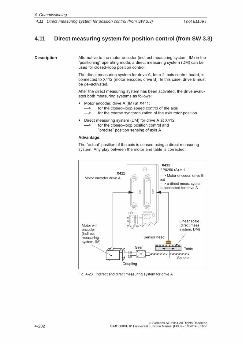
4
4.11 Direct measuring system for position control (from SW 3.3)
4-202� Siemens AG 2014 All Rights Reserved
SIMODRIVE 611 universal Function Manual (FBU) – 10/2014 Edition
4.11 Direct measuring system for position control (from SW 3.3)
Alternative to the motor encoder (indirect measuring system, IM) in the”positioning” operating mode, a direct measuring system (DM) can beused for closed–loop position control.
The direct measuring system for drive A, for a 2–axis control board, isconnected to X412 (motor encoder, drive B). In this case, drive B mustbe de–activated.
After the direct measuring system has been activated, the drive evalu-ates both measuring systems as follows:
� Motor encoder, drive A (IM) at X411: ––> for the closed–loop speed control of the axis––> for the coarse synchronization of the axis rotor position
� Direct measuring system (DM) for drive A at X412:––> for the closed–loop position control and
”precise” position sensing of axis A
Advantage:
The ”actual” position of the axis is sensed using a direct measuringsystem. Any play between the motor and table is corrected.
ÍÍÍÍÍÍÍÍTableGear
Spindle
ËËËËË
Linear scale(direct meas. system, DM)
Sensor head
Coupling
Motor withencoder (indirect measuringsystem, IM)
ÄÄ
Motor encoder drive AX411
X412if P0250 (A) = 1––> Motor encoder, drive Bbut––> a direct meas. systemis connected for drive A
ÄÄÄÄ
Fig. 4-23 Indirect and direct measuring system for drive A
Description
4 Commissioning
! not 611ue !
4
4.11 Direct measuring system for position control (from SW 3.3)
4-203� Siemens AG 2014 All Rights ReservedSIMODRIVE 611 universal Function Manual (FBU) – 10/2014 Edition
The following limitations and rules apply:
1. The direct measuring system may only be directly connected at theload side without measuring gearbox.
2. Which combinations of power module and control board are pos-sible for a direct measuring system?
– 1–axis power module with 2–axis control board
In this case, drive B is not available.
– 2–axis power module with 2–axis control board
Drive B is available.
The following applies: Switch drive B into a passive state (P0700(B) = 0)
3. Which encoder systems are available for the direct measuringsystem?
Dependent on the 2–axis board with encoder for sin/cos 1 Vpp or forresolver, the following rotary or linear measuring systems can beconnected at X412:
– Incremental encoder with sin/cos 1 Vpp
– Absolute value encoder with EnDat protocol
– Resolver with any pole pair number
4. Process data for the direct measuring system
The actual values of the position controller can be read via statusword XistP.
5. The ”direct measuring system” function is activated with P0250 (A)= 1.
The following applies:
– This activation becomes effective after POWER ON
– The direct measuring system must have been commissioned––> refer to ”commissioning the direct measuring system”
– It is not permissible to operate drive A without a motor measuringsystem.
––> The following must be valid: P1027.5 (A) = 0
– The input terminal I0.B (fast input from drive B) can be assigneda function for the direct measuring system from drive A viaP0672.
e.g. the ”Equivalent zero mark” function (P0672=79) or ”flying measurement” (P0672=80)
Limitations andrules for a directmeasuring system
4 Commissioning
! not 611ue !
4
4.11 Direct measuring system for position control (from SW 3.3)
4-204� Siemens AG 2014 All Rights Reserved
SIMODRIVE 611 universal Function Manual (FBU) – 10/2014 Edition
6. Output the direct measuring system via the angular incrementalencoder interface
– Before SW 4.1 the following applies:
The direct measuring system signals cannot be output via theangular incremental encoder interface.
If the angular incremental encoder interface is switched as out-put (P0890 = 1), then the following is valid, independent of acti-vating the direct measuring system (P0250 (A) = 0 or 1):
Interface Output signalsAng. incr. enc. interf. (A) Signals of the motor meas. systemAng. incr. enc. interf. (B) No signals
– From SW 4.1, the following applies:
The direct measuring system signals can be output via the angu-lar incremental encoder interface. The angular incremental enco-der interface as output becomes automatically active if P0890 isset to 1 for the motor measuring system AND the direct measu-ring system is activated (P0250 = 1). However, parametersP0892 and P0893 are not effective for the angular incrementalencoder interface (B).
Interface Output signalsAng. incr. enc. interf. (A) Signals of the motor meas. systemAng. incr. enc. interf. (B) Signals of the direct
7. Direction adaptation for direct measuring systems– P0231 Position act. value inversion– P0232 Position ref. value inversion
8. You can toggle between the indirect measuring system (IM) and thedirect measuring system (DM) by changing P0250 and executing aPOWER–ON RESET.
– The parameters for the closed–loop position control are onlyavailable once and must also be appropriately adapted, e.g.:P0231 Position act. value inversionP0332 Position ref. value inversionP0201 Backlash compensation
– The parameters for the gearbox and spindle pitch are only avail-able once and must be set for the indirect measuring system,e.g.:P0236 Spindle pitchP0237:8 Encoder revolutionsP0238:8 Load revolutions
– The adjustment status for absolute value encoders is changedafter changeover, i.e. P0175 is set to 0. A re–adjustment is re-quired.
9. Which measuring system does the drive control use?
––> refer to P1792 (active measuring system)
4 Commissioning
! not 611ue !
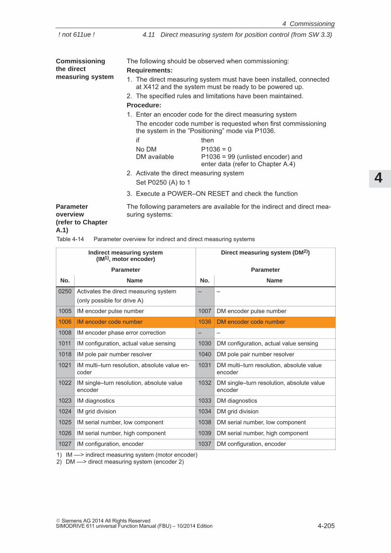
4
4.11 Direct measuring system for position control (from SW 3.3)
4-205� Siemens AG 2014 All Rights ReservedSIMODRIVE 611 universal Function Manual (FBU) – 10/2014 Edition
The following should be observed when commissioning:Requirements:1. The direct measuring system must have been installed, connected
at X412 and the system must be ready to be powered up.2. The specified rules and limitations have been maintained.Procedure:1. Enter an encoder code for the direct measuring system
The encoder code number is requested when first commissioningthe system in the ”Positioning” mode via P1036.if thenNo DM P1036 = 0DM available P1036 = 99 (unlisted encoder) and
enter data (refer to Chapter A.4)2. Activate the direct measuring system
Set P0250 (A) to 1
3. Execute a POWER–ON RESET and check the function
The following parameters are available for the indirect and direct mea-suring systems:
Table 4-14 Parameter overview for indirect and direct measuring systems
Indirect measuring system(IM1), motor encoder)
Direct measuring system (DM2))
Parameter Parameter
No. Name No. Name
0250 Activates the direct measuring system(only possible for drive A)
– –
1005 IM encoder pulse number 1007 DM encoder pulse number
1006 IM encoder code number 1036 DM encoder code number
1008 IM encoder phase error correction – –
1011 IM configuration, actual value sensing 1030 DM configuration, actual value sensing
1018 IM pole pair number resolver 1040 DM pole pair number resolver
1021 IM multi–turn resolution, absolute value en-coder
1031 DM multi–turn resolution, absolute valueencoder
1022 IM single–turn resolution, absolute valueencoder
1032 DM single–turn resolution, absolute valueencoder
1023 IM diagnostics 1033 DM diagnostics
1024 IM grid division 1034 DM grid division
1025 IM serial number, low component 1038 DM serial number, low component
1026 IM serial number, high component 1039 DM serial number, high component
1027 IM configuration, encoder 1037 DM configuration, encoder
1) IM ––> indirect measuring system (motor encoder)2) DM ––> direct measuring system (encoder 2)
Commissioningthe directmeasuring system
Parameteroverview(refer to ChapterA.1)
4 Commissioning
! not 611ue !
4
4.12 Connecting induction motors with TTL encoder (from SW 8.1)
4-206� Siemens AG 2014 All Rights Reserved
SIMODRIVE 611 universal Function Manual (FBU) – 10/2014 Edition
4.12 Connecting induction motors with TTL encoder (from SW 8.1)
Standard square–wave encoders (TTL) with differential signals accord-ing to RS422 and 5 V power supply voltage can be connected as pulseencoder for induction motors to the control board ”SIMODRIVE 611universal HR/HRS” (Order No. 6SN1118–�NH01–0AA�).
The maximum encoder limiting frequency is 420 kHz.
Encoder connection: X411/X412
Pin assignment of the interface: refer to Chapter 2.4
Encoder cable: Users must assemble these themselves
Max. cable length: 50 m
Note
If an induction motor with TTL encoder is connected to ”SIMODRIVE611 universal HR/HRS”, then it is not permissible that the angularincremental encoder interface is used as output.
!Warning
If individual or several signals of the encoder are short–circuited orinterrupted – under certain circumstances – it is possible that theencoder signal monitoring does not respond and the motor can movein an uncontrolled fashion.
The following parameters are available for connecting an inductionmotor with TTL encoder:� P1011 IM configuration, actual value sensing� P1005 IM encoder pulse number� P1027 IM configuration, encoder
Description
Connection
Parameteroverview (refer to ChapterA.1)
4 Commissioning
4
4.13 FD operation with field weakening (from SW 12.1)
4-207� Siemens AG 2014 All Rights ReservedSIMODRIVE 611 universal Function Manual (FBU) – 10/2014 Edition
4.13 FD operation with field weakening (from SW 12.1)
In order to be able to use field weakening – also with the FD machinedata assignments, e.g. for 1FT7 motors, then this can be activated bysetting P1172 = 1 in addition to P1015 = 1.
If P1015 and P1172 were enabled and a motor selected using the listdiagram, then the following machine data are additionally pre–assignedusing the “Calculate controller data” function:
� P1121: Current controller reset time
� P1147: Speed limitation (ARM SRM)
� P1401: Velocity for max. useful motor velocity (ARM SRM)
� P1403: Creep speed, pulse suppression (ARM SRM)
� P1404: Timer pulse suppression
� P1405: Monitoring speed, motor (ARM SRM)
� P1606: Threshold n controller at stop
� P1610: Diagnostic functions
� P1612: Shutdown response, faults 1
� P1613: Shutdown response, faults 2
Note
For synchronous motors, field–weakening operation can beswitched–in using P1015.
“Calculate controller data” must be initiated after changing the machinedata setting!
The speed at the start of field weakening is assigned by selecting themotor from the motor list or set according to the data sheet of themotor manufacturer.
If the motor manufacturer does not specify any data, then the speed atthe start of field weakening can be calculated using the following formula:
P1142 = 380 V � 1000 [RPM] / P1114
P1114: EMF_VOLTAGE
Description
Closed–loopcontrol parameters
4 Commissioning
4
4.13 FD operation with field weakening (from SW 12.1)
4-208� Siemens AG 2014 All Rights Reserved
SIMODRIVE 611 universal Function Manual (FBU) – 10/2014 Edition
Note
P1172 is only effective, if P1015 = 1 was set – “Activate PE–MSD”.
“Calculate controller data” must be initiated after changing the machinedata setting!
The following parameters are used for FD operation with field weakening:� P1015 Activate PE–MSD (SRM)� P1114 Voltage constant (SRM SLM)� P1142 Threshold speed field weakening (ARM SRM)� P1172 FD operation with field weakening (SRM) (–> 12.1)
�
Parameteroverview(refer to ChapterA.1)
4 Commissioning
5
5-209� Siemens AG 2014 All Rights ReservedSIMODRIVE 611 universal Function Manual (FBU) – 10/2014 Edition
Communications via PROFIBUS DP
5.1 General information about PROFIBUS–DP for ”SIMODRIVE 611 universal” 5-210. . . . . . . . . . . . . . . . . . . . . . . . . . . . . . . . . . . . . .
5.2 Basic functions of the cyclic data transfer 5-216. . . . . . . . . . . . . . . . . . . . . . . . . . .
5.3 Basic functions of the non–cyclic data transfer 5-218. . . . . . . . . . . . . . . . . . . . . .
5.4 Terminal signals and PROFIBUS signals 5-222. . . . . . . . . . . . . . . . . . . . . . . . . . .
5.5 Internal effect of PROFIBUS signal and hardware terminals 5-223. . . . . . . . . . .
5.6 Net data (PKW and PZD area) 5-226. . . . . . . . . . . . . . . . . . . . . . . . . . . . . . . . . . . . 5.6.1 Overview of the process data (PZD area) 5-226. . . . . . . . . . . . . . . . . . . . . . . . . . . 5.6.2 Description of the control words (setpoints) 5-230. . . . . . . . . . . . . . . . . . . . . . . . . 5.6.3 Description of the status words (actual values) 5-243. . . . . . . . . . . . . . . . . . . . . . 5.6.4 Encoder interface (n–set mode, from SW 3.1) 5-253. . . . . . . . . . . . . . . . . . . . . . . 5.6.5 Configuring process data (from SW 3.1) 5-265. . . . . . . . . . . . . . . . . . . . . . . . . . . . 5.6.6 Defining the process data according to the PPO type 5-280. . . . . . . . . . . . . . . . . 5.6.7 Parameter area (PKW area) 5-283. . . . . . . . . . . . . . . . . . . . . . . . . . . . . . . . . . . . . .
5.7 Settings at the PROFIBUS–DP master 5-291. . . . . . . . . . . . . . . . . . . . . . . . . . . . . 5.7.1 Master device file and configuring 5-291. . . . . . . . . . . . . . . . . . . . . . . . . . . . . . . . . 5.7.2 Commissioning 5-295. . . . . . . . . . . . . . . . . . . . . . . . . . . . . . . . . . . . . . . . . . . . . . . . . 5.7.3 Diagnostics and troubleshooting 5-299. . . . . . . . . . . . . . . . . . . . . . . . . . . . . . . . . . .
5.8 Motion Control with PROFIBUS–DP (from SW 3.1) 5-303. . . . . . . . . . . . . . . . . . 5.8.1 Equidistant DP cycle operation in the n–set mode 5-305. . . . . . . . . . . . . . . . . . . . 5.8.2 Equidistant DP cycle operation in the positioning mode 5-307. . . . . . . . . . . . . . . 5.8.3 Times in the equidistant DP cycle 5-310. . . . . . . . . . . . . . . . . . . . . . . . . . . . . . . . . . 5.8.4 Bus run–up, synchronization and net data save 5-312. . . . . . . . . . . . . . . . . . . . . . 5.8.5 Parameterization using the parameterizing telegram 5-314. . . . . . . . . . . . . . . . .
5.9 Parameter overview of PROFIBUS–DP 5-315. . . . . . . . . . . . . . . . . . . . . . . . . . . .
5.10 Slave–to–slave communications (from SW 4.1) 5-324. . . . . . . . . . . . . . . . . . . . . . 5.10.1 General information 5-324. . . . . . . . . . . . . . . . . . . . . . . . . . . . . . . . . . . . . . . . . . . . . . 5.10.2 Setpoint assignment in the subscriber 5-327. . . . . . . . . . . . . . . . . . . . . . . . . . . . . . 5.10.3 Activating/parameterizing slave–to–slave communications 5-328. . . . . . . . . . . . 5.10.4 Message format 5-330. . . . . . . . . . . . . . . . . . . . . . . . . . . . . . . . . . . . . . . . . . . . . . . . . 5.10.5 Example: Coupling two drives (master, slave drive) 5-333. . . . . . . . . . . . . . . . . .
5
5
5.1 General information about PROFIBUS–DP for ”SIMODRIVE 611 universal”
5-210� Siemens AG 2014 All Rights Reserved
SIMODRIVE 611 universal Function Manual (FBU) – 10/2014 Edition
5.1 General information about PROFIBUS–DP for”SIMODRIVE 611 universal”
PROFIBUS DP is an international, open fieldbus standard, which isspecified in the European Fieldbus Standard EN 50170 Part 2.PROFIBUS DP is optimized for fast, data transmission at the field levelfor time–critical applications.The fieldbus is used for cyclic and non–cyclic data transfer between amaster and the slaves assigned to this master.
The following communication possibilities are available:� Cyclic communication
––> Setpoint, actual value transfer using process data (PZD communications)
– According to the DP standard functionalityFor standard DP operation, a new cycle is started after the oldcycle has been completed.––> refer to Chapter 5.2
– Clock–cycle synchronous functionalityFor clock–cycle synchronous operation a new cycle is startedwith the set Tp clock cycle.––> refer to Chapter 5.2
– Slave–to–slave communicationsFast, distributed data transfer between drives (slaves) is possibleusing the ”slave–to–slave” communications function without in-volving the master.––> refer to Chapter 5.10
� Noncyclic communication
––> Access to the drive parameters– Parameterization using the ”SimoCom U” tool
––> refer to Chapter 3.3– Data transfer using the SIMATIC Operation Panel (SIMATIC OP)
––> refer to Chapter 5.3– PKW area in the net data structure according to PPOs
––> refer to Chapter 5.6.7– Data exchange with the master (e.g. SIMATIC S7) and other
control devices, utilizing the DPV1 utility (service) ”read data set/write data set” corresponding to the PROFIdrive Profile––> refer to Chapter 5.3
� Configuration
––> Configuring defines the data, which the master transfers to the ”DP slaves” at every bus run–up via the parameterizing telegram and the configuration telegram.
The system can be configured in the following ways (refer to Chapter 5.7):– using the GSD file (SIEM808F.GSD/SI02808F.GSD)– using the ”Slave object manager” (Drive ES)
General
5 Communications via PROFIBUS DP
5
5.1 General information about PROFIBUS–DP for ”SIMODRIVE 611 universal”
5-211� Siemens AG 2014 All Rights ReservedSIMODRIVE 611 universal Function Manual (FBU) – 10/2014 Edition
The profile defines, among other things, how setpoints and actual val-ues are transferred and how drive parameters can be accessed.
� The profile includes the necessary definitions for the operatingmode ”Speed setpoint” and ”Positioning”.
� It defines the basic drive functions and leaves sufficient freedom forapplication–specific expanded functionality and ongoing develop-ments.
� The profile includes an image of the application functions on PROFIBUS–DP.
� The PROFIdrive Profile provides a total of 6 different applicationclasses.
� ”SIMODRIVE 611 universal” is in conformance with the profile forapplication Class 1 and from SW 6.1, application Class 4.
The following functional scope has been implemented corresponding tothe directive PROFIdrive V3.1 – 2002. From SW 12.1, operationaccording to the PROFIdrive profile version V4.1 – 2006 is possible:
� Isochronous mode
� Configuring a telegram
� Encoder interface
� Non–cyclic parameter access using DPV1 utilities
� Profile parameters
The following parameters should be set in order, for this functionality, toachieve the precise compatibility to profile version 3.1:
� P0878 bit 0 =1, bit 1 = 1, bit 2 = 1 (from SW 8.2)
� P0879 bit 0 = 1, bit 1 = 0, bit 2 = 0, bit 9 =1
� P1012 bit 12 = 1, bit 13 = 1, bit 14 = 0, bit 15 = 1 (from SW 9.1)
In order to achieve compatibility to profile version 4.1, the followingparameters must also be set:
� P0878 bit 3 =1 (from SW 12.1)
Reader’s note
Standard telegrams are defined to simplify configuring PROFIBUS–DP.
Telegrams 1, 2 ..., 6 are designated as standard telegramscorresponding to PROFIdrive definitions and telegrams 102...110 fromSiemens are designated as standard telegram.
PROFIdrive conformance
5 Communications via PROFIBUS DP
5
5.1 General information about PROFIBUS–DP for ”SIMODRIVE 611 universal”
5-212� Siemens AG 2014 All Rights Reserved
SIMODRIVE 611 universal Function Manual (FBU) – 10/2014 Edition
For PROFIBUS, a differentiation is made between master and slave units.
� Master (active bus device)
Devices, which represent a master on the bus, define data transferalong the bus, and are therefore known as active bus nodes. A differentiation is made between two classes of master:
– DP Master class 1 (DPMC1):These are central master systems that exchange data with theslaves in defined message cycles.Examples: SIMATIC S5, SIMATIC S7, etc.
– DP Master class 2 (DPMC2):These are devices for configuring, commissioning, operator con-trol and monitoring in bus operations.Examples: Programming units, operator control and visualizationdevices
� Slaves (passive bus nodes)
These devices may only receive, acknowledge and transfer mes-sages to a master when so requested.
Reader’s note
The ”SIMODRIVE 611 universal” control board with the optionalPROFIBUS–DP module is a slave on the fieldbus. In the following text, this slave is designated the ”DP slave 611U” .
PROFIBUS supports data transfer according to RS485 and also datatransfer using fiber–optic cable.
The ”DP–Slave 611U” automatically detects the baud rate set at thebus at power–on.The following baud rates are possible:9.6 kbaud, 19.2 kbaud, 93.75 kbaud, 187.5 kbaud, 500 kbaud, 1.5 Mbaud, 3.0 Mbaud, 6.0 Mbaud and 12 Mbaud
Note
� When using Optical Link Plugs (OLPs), the baud rate is limited to1.5 Mbaud.
� When several slaves are connected to a master, for practical andsensible operation with SimoCom U, a baud rate �187.5 kbaudshould be set.
When commissioning the fieldbus, the baud rate is defined the samefor all devices starting from the master.
Master and slaves
Data transfer technology, baud rate
5 Communications via PROFIBUS DP
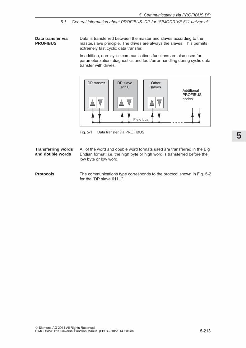
5
5.1 General information about PROFIBUS–DP for ”SIMODRIVE 611 universal”
5-213� Siemens AG 2014 All Rights ReservedSIMODRIVE 611 universal Function Manual (FBU) – 10/2014 Edition
Data is transferred between the master and slaves according to themaster/slave principle. The drives are always the slaves. This permitsextremely fast cyclic data transfer.
In addition, non–cyclic communications functions are also used forparameterization, diagnostics and fault/error handling during cyclic datatransfer with drives.
AdditionalPROFIBUSnodes
Field bus
DP slave 611U
DP master Otherslaves
Fig. 5-1 Data transfer via PROFIBUS
All of the word and double word formats used are transferred in the BigEndian format, i.e. the high byte or high word is transferred before thelow byte or low word.
The communications type corresponds to the protocol shown in Fig. 5-2for the ”DP slave 611U”.
Data transfer viaPROFIBUS
Transferring wordsand double words
Protocols
5 Communications via PROFIBUS DP
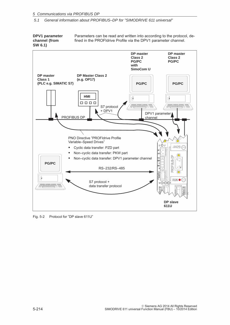
5
5.1 General information about PROFIBUS–DP for ”SIMODRIVE 611 universal”
5-214� Siemens AG 2014 All Rights Reserved
SIMODRIVE 611 universal Function Manual (FBU) – 10/2014 Edition
Parameters can be read and written into according to the protocol, de-fined in the PROFIdrive Profile via the DPV1 parameter channel.
DPV1 parameterchannel
PNO Directive ”PROFIdrive Profile Variable–Speed Drives”� Cyclic data transfer: PZD part� Non–cyclic data transfer: PKW part� Non–cyclic data transfer: DPV1 parameter channel
S7 protocol +data transfer protocol
DP master Class 1(PLC e.g. SIMATIC S7)
DP Master Class 2(e.g. OP17)
HMI
DP slave 611U
PROFIBUS DP
RS–232/RS–485PG/PC
PG/PC
DP master Class 2PG/PC with SimoCom U
S7 protocol + DPV1
PG/PC
DP master Class 2PG/PC
Fig. 5-2 Protocol for ”DP slave 611U”
DPV1 parameterchannel (fromSW 6.1)
5 Communications via PROFIBUS DP
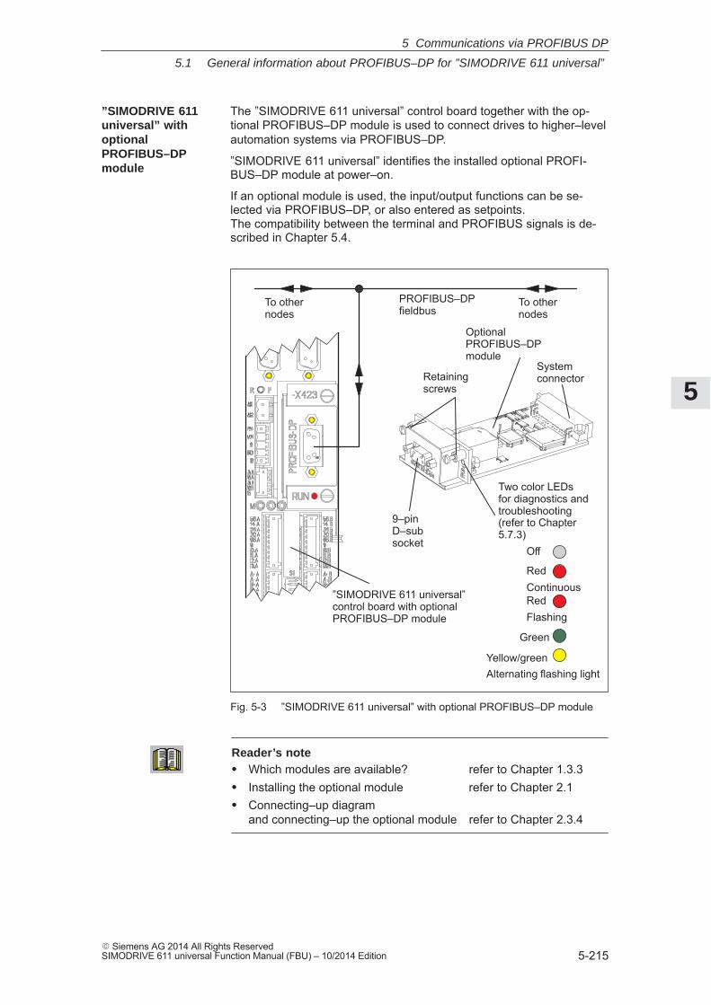
5
5.1 General information about PROFIBUS–DP for ”SIMODRIVE 611 universal”
5-215� Siemens AG 2014 All Rights ReservedSIMODRIVE 611 universal Function Manual (FBU) – 10/2014 Edition
The ”SIMODRIVE 611 universal” control board together with the op-tional PROFIBUS–DP module is used to connect drives to higher–levelautomation systems via PROFIBUS–DP.
”SIMODRIVE 611 universal” identifies the installed optional PROFI-BUS–DP module at power–on.
If an optional module is used, the input/output functions can be se-lected via PROFIBUS–DP, or also entered as setpoints. The compatibility between the terminal and PROFIBUS signals is de-scribed in Chapter 5.4.
Yellow/greenAlternating flashing light
PROFIBUS–DPfieldbus
To other nodes
To other nodes
OptionalPROFIBUS–DP module
”SIMODRIVE 611 universal”control board with optional PROFIBUS–DP module
9–pin D–subsocket
Retaining screws
Two color LEDs for diagnostics andtroubleshooting(refer to Chapter5.7.3)
Systemconnector
Off
RedContinuous
Green
RedFlashing
Fig. 5-3 ”SIMODRIVE 611 universal” with optional PROFIBUS–DP module
Reader’s note� Which modules are available? refer to Chapter 1.3.3� Installing the optional module refer to Chapter 2.1� Connecting–up diagram
and connecting–up the optional module refer to Chapter 2.3.4
”SIMODRIVE 611universal” with optionalPROFIBUS–DPmodule
5 Communications via PROFIBUS DP
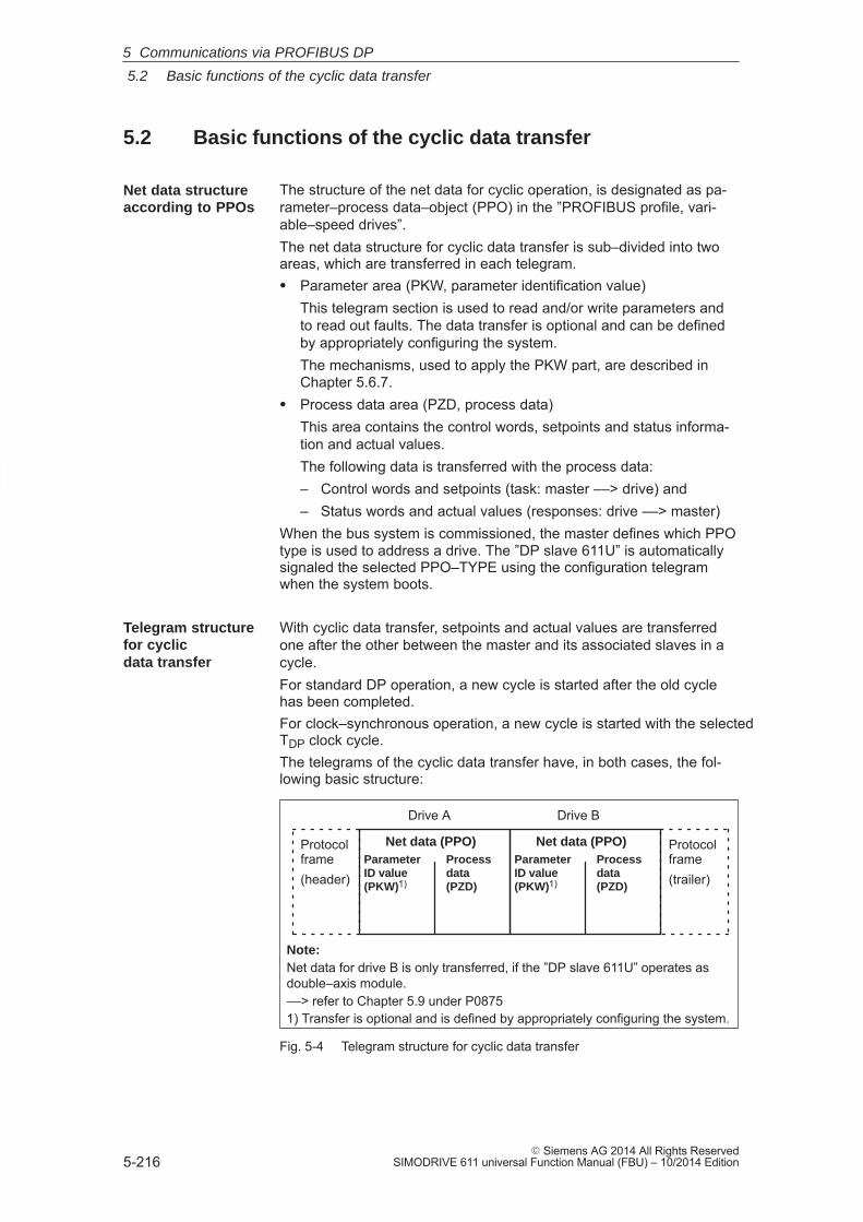
5
5.2 Basic functions of the cyclic data transfer
5-216� Siemens AG 2014 All Rights Reserved
SIMODRIVE 611 universal Function Manual (FBU) – 10/2014 Edition
5.2 Basic functions of the cyclic data transfer
The structure of the net data for cyclic operation, is designated as pa-rameter–process data–object (PPO) in the ”PROFIBUS profile, vari-able–speed drives”.The net data structure for cyclic data transfer is sub–divided into twoareas, which are transferred in each telegram.� Parameter area (PKW, parameter identification value)
This telegram section is used to read and/or write parameters andto read out faults. The data transfer is optional and can be definedby appropriately configuring the system.The mechanisms, used to apply the PKW part, are described inChapter 5.6.7.
� Process data area (PZD, process data)This area contains the control words, setpoints and status informa-tion and actual values.The following data is transferred with the process data:– Control words and setpoints (task: master ––> drive) and– Status words and actual values (responses: drive ––> master)
When the bus system is commissioned, the master defines which PPOtype is used to address a drive. The ”DP slave 611U” is automaticallysignaled the selected PPO–TYPE using the configuration telegramwhen the system boots.
With cyclic data transfer, setpoints and actual values are transferredone after the other between the master and its associated slaves in acycle.For standard DP operation, a new cycle is started after the old cyclehas been completed.For clock–synchronous operation, a new cycle is started with the selectedTDP clock cycle.The telegrams of the cyclic data transfer have, in both cases, the fol-lowing basic structure:
Net data (PPO)ParameterID value(PKW)1)
Processdata (PZD)
Net data (PPO)ParameterID value(PKW)1)
Processdata (PZD)
Protocolframe(trailer)
Drive A Drive B
Note:Net data for drive B is only transferred, if the ”DP slave 611U” operates asdouble–axis module.––> refer to Chapter 5.9 under P08751) Transfer is optional and is defined by appropriately configuring the system.
Protocolframe(header)
Fig. 5-4 Telegram structure for cyclic data transfer
Net data structureaccording to PPOs
Telegram structurefor cyclicdata transfer
5 Communications via PROFIBUS DP
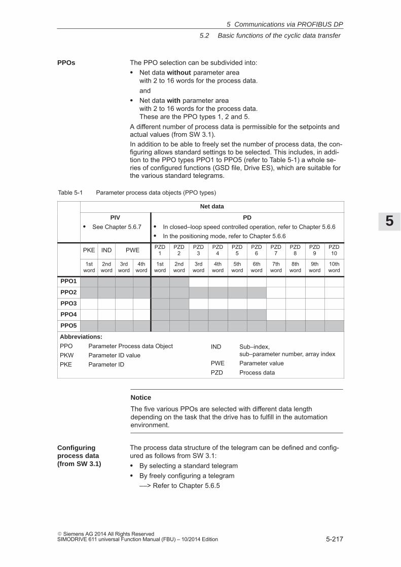
5
5.2 Basic functions of the cyclic data transfer
5-217� Siemens AG 2014 All Rights ReservedSIMODRIVE 611 universal Function Manual (FBU) – 10/2014 Edition
The PPO selection can be subdivided into:� Net data without parameter area
with 2 to 16 words for the process data.and
� Net data with parameter areawith 2 to 16 words for the process data. These are the PPO types 1, 2 and 5.
A different number of process data is permissible for the setpoints andactual values (from SW 3.1).In addition to be able to freely set the number of process data, the con-figuring allows standard settings to be selected. This includes, in addi-tion to the PPO types PPO1 to PPO5 (refer to Table 5-1) a whole se-ries of configured functions (GSD file, Drive ES), which are suitable forthe various standard telegrams.
Table 5-1 Parameter process data objects (PPO types)
Net data
PIV
� See Chapter 5.6.7PD
� In closed–loop speed controlled operation, refer to Chapter 5.6.6� In the positioning mode, refer to Chapter 5.6.6
PKE IND PWE PZD1
PZD2
PZD3
PZD4
PZD5
PZD6
PZD7
PZD8
PZD9
PZD10
1stword
2ndword
3rdword
4thword
1stword
2ndword
3rdword
4thword
5thword
6thword
7thword
8thword
9thword
10thword
PPO1
PPO2
PPO3
PPO4
PPO5
Abbreviations:
PPO Parameter Process data ObjectPKW Parameter ID valuePKE Parameter ID
IND Sub–index, sub–parameter number, array index
PWE Parameter valuePZD Process data
Notice
The five various PPOs are selected with different data lengthdepending on the task that the drive has to fulfill in the automationenvironment.
The process data structure of the telegram can be defined and config-ured as follows from SW 3.1:� By selecting a standard telegram� By freely configuring a telegram
––> Refer to Chapter 5.6.5
PPOs
Configuringprocess data(from SW 3.1)
5 Communications via PROFIBUS DP
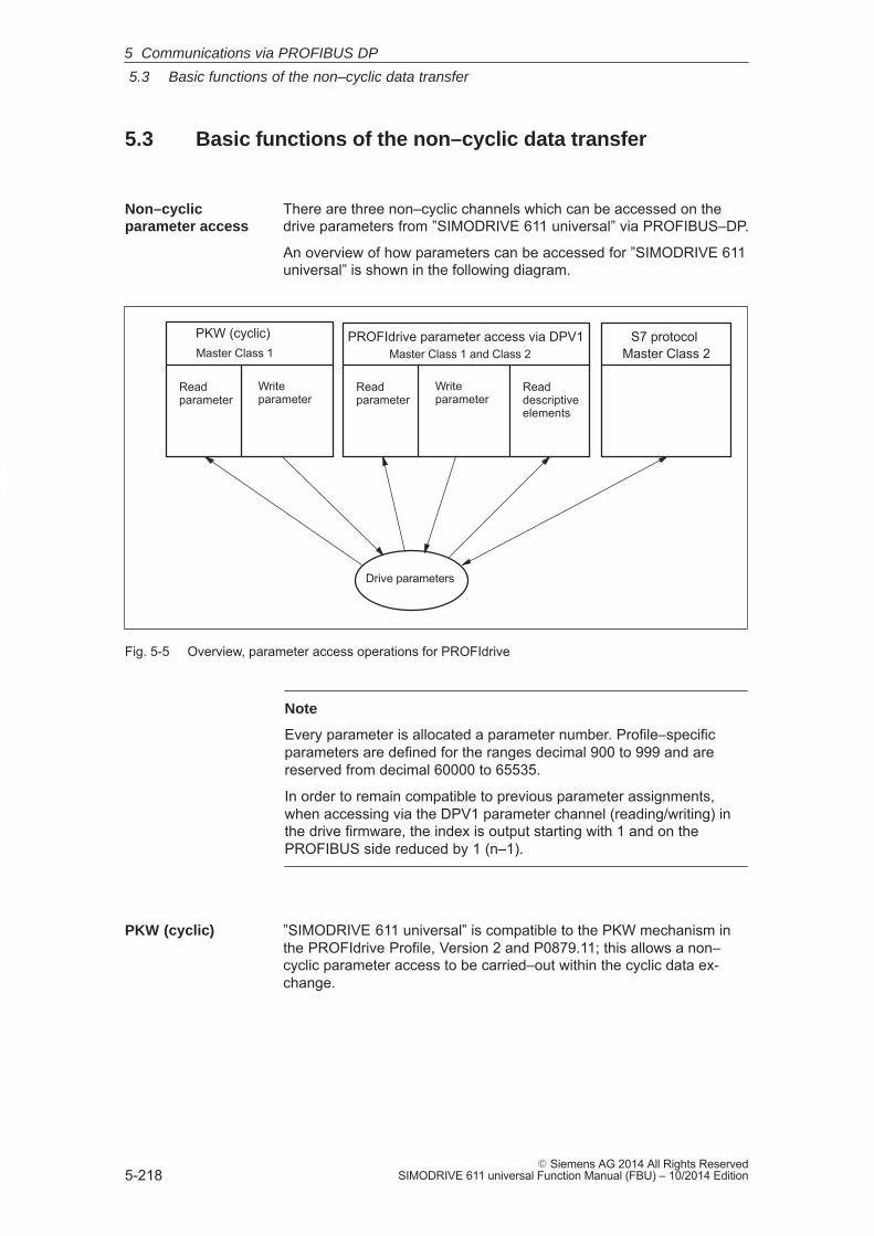
5
5.3 Basic functions of the non–cyclic data transfer
5-218� Siemens AG 2014 All Rights Reserved
SIMODRIVE 611 universal Function Manual (FBU) – 10/2014 Edition
5.3 Basic functions of the non–cyclic data transfer
There are three non–cyclic channels which can be accessed on thedrive parameters from ”SIMODRIVE 611 universal” via PROFIBUS–DP.
An overview of how parameters can be accessed for ”SIMODRIVE 611universal” is shown in the following diagram.
Drive parameters
PROFIdrive parameter access via DPV1
Readparameter
Writeparameter
Readdescriptiveelements
S7 protocol PKW (cyclic)Master Class 2 Master Class 1 and Class 2
Readparameter
Writeparameter
Master Class 1
Fig. 5-5 Overview, parameter access operations for PROFIdrive
Note
Every parameter is allocated a parameter number. Profile–specificparameters are defined for the ranges decimal 900 to 999 and arereserved from decimal 60000 to 65535.
In order to remain compatible to previous parameter assignments,when accessing via the DPV1 parameter channel (reading/writing) inthe drive firmware, the index is output starting with 1 and on thePROFIBUS side reduced by 1 (n–1).
”SIMODRIVE 611 universal” is compatible to the PKW mechanism inthe PROFIdrive Profile, Version 2 and P0879.11; this allows a non–cyclic parameter access to be carried–out within the cyclic data ex-change.
Non–cyclicparameter access
PKW (cyclic)
5 Communications via PROFIBUS DP
5
5.3 Basic functions of the non–cyclic data transfer
5-219� Siemens AG 2014 All Rights ReservedSIMODRIVE 611 universal Function Manual (FBU) – 10/2014 Edition
Using PROFIdrive, it is possible to transfer parameters via DPV1 usingnon–cyclic communications. The parameter definition and parameteraccess via the DPV1 mechanism is defined in the PROFIdrive parame-ter model, which is part of the PROFIdrive Profile Version 3 and 4 (fromSW 12.1).
The function blocks and project examples for SIMATIC S7 can be usedto transfer drive parameters in a non–cyclic fashion:
Product Order No. (MLFB):Drive ES SIMATIC 6SW1700–5JC00–2AA0
Reader’s note
Reference: /PPA/, PROFIdrive–Profile Drive Technology, Version 3.1.2 Sept. 2004 (Chapter 3.4)
From SW 12.1:Version 4.1 May 2006 (Chapter 6.2)
A protocol has been defined for accessing parameters which comprisestasks and the associated responses. The tasks are non–cyclicallytransferred using the DPV1 utility ”write data” and the responses with”read data”. Several drive parameters (e.g. traversing block) can besimultaneously accessed using a task/response.
A DPV1 parameter task and a DPV1 parameter response with individ-ual fields is defined and documented in the PROFIdrive profile.
When reading and writing parameters, that, depending on the currentconfiguring of the drive, are not valid – e.g. P1083 is only valid for in-duction motors, however, a synchronous motor is configured – then theSiemens–specific DPV1 error code 0x65 (parameter presently de–acti-vated) is output.
Values of signal parameters (50000–type parameters) can only be readif this was configured in the PROFIBUS telegram (P0915, P0916). Anegative acknowledgement (DPV1 error code 0x65) is output whenreading signal parameters using non–cyclic data transfer that were notconfigured in the Profibus Telegram.
The parameters, defined by the profile, are documented in a list formin the PROFIdrive profile.
This includes both parameters with the implementation rule ”manda-tory”, i.e. parameters that are absolutely necessary in order to be inconformance with the profile as well as parameters with the imple-mentation rule ”optional” .
Parameter descriptions can be read so that now a master knows whichparameters a drive knows and the properties which each of these pa-rameters has.
Parameter accessvia DPV1
Parameters,reading/writingDPV1 (fromSW 6.1)
Read theparameterdescription DPV1(from SW 6.1)
5 Communications via PROFIBUS DP
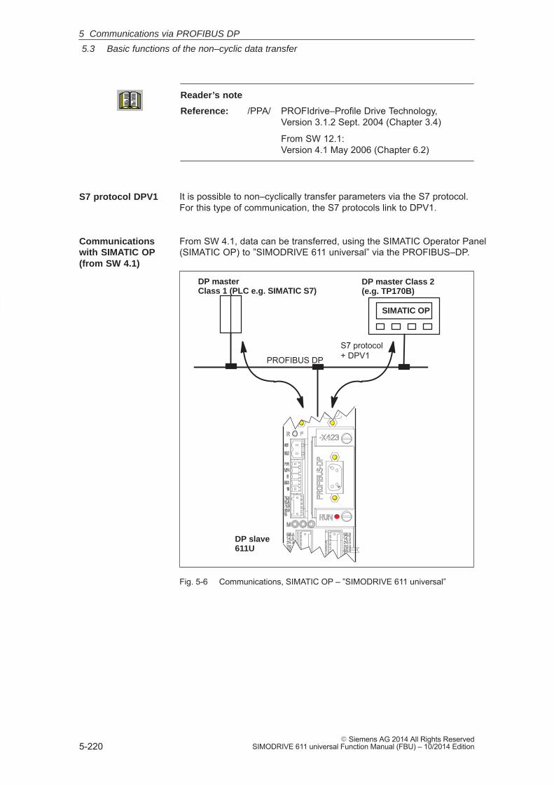
5
5.3 Basic functions of the non–cyclic data transfer
5-220� Siemens AG 2014 All Rights Reserved
SIMODRIVE 611 universal Function Manual (FBU) – 10/2014 Edition
Reader’s note
Reference: /PPA/ PROFIdrive–Profile Drive Technology, Version 3.1.2 Sept. 2004 (Chapter 3.4)
From SW 12.1:Version 4.1 May 2006 (Chapter 6.2)
It is possible to non–cyclically transfer parameters via the S7 protocol.For this type of communication, the S7 protocols link to DPV1.
From SW 4.1, data can be transferred, using the SIMATIC Operator Panel(SIMATIC OP) to ”SIMODRIVE 611 universal” via the PROFIBUS–DP.
DP slave 611U
DP master Class 1 (PLC e.g. SIMATIC S7)
DP master Class 2(e.g. TP170B)
PROFIBUS DP
S7 protocol + DPV1
SIMATIC OP
Fig. 5-6 Communications, SIMATIC OP – ”SIMODRIVE 611 universal”
S7 protocol DPV1
Communicationswith SIMATIC OP(from SW 4.1)
5 Communications via PROFIBUS DP
5
5.3 Basic functions of the non–cyclic data transfer
5-221� Siemens AG 2014 All Rights ReservedSIMODRIVE 611 universal Function Manual (FBU) – 10/2014 Edition
� Technical details
– Communications are established directly between the SIMATIC OP (e.g. TP170B) as Master Class 2 and the ”SIMODRIVE 611 universal”as slave using the S7 protocol and the non–cyclic DPV1 utilities.
– SIMATIC OP can read and write into drive parameters.
– A Class 1 master is not required.
� Configured in SIMATIC OP
– The drive parameters are addressed using the data block anddata word.––> Axis A:Data block number_OP = parameter number_611UData word_OP = sub–parameter_611U––> Axis B:Data block number_OP = parameter number_611U + 10000Data word_OP = sub–parameter_611U
� Parameterization in the ”SIMODRIVE 611 universal”
– A DP2 or DP3 module with a correctly entered DP address(P0918) must be inserted.
– Parameterize from where the drive is to be operated
––> PROFIBUS–DP Master Class 1:Set P0875 = P872
––> HW terminals Set P0875 to 0
� Setpoint input
– it is not possible to directly enter setpoints from the SIMATIC OP.
– Setpoints can be indirectly entered using the SIMATIC OP bychanging parameters, e.g. P0641 (fixed setpoint)
––> Enter the setpoint via HW terminals (P0875 = 0)
!Danger
For applications where the setpoint is entered using the SIMATIC OP,in addition, an enable or EMERGENCY STOP signal should beconnected to SIMATIC OP, as an interrupted connection betweenSIMATIC OP and ”SIMODRIVE universal” does not result in a drivefault.
5 Communications via PROFIBUS DP
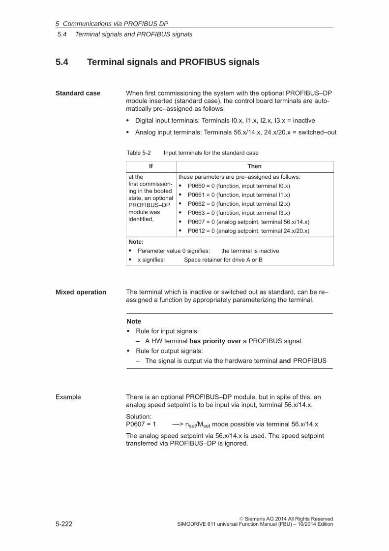
5
5.4 Terminal signals and PROFIBUS signals
5-222� Siemens AG 2014 All Rights Reserved
SIMODRIVE 611 universal Function Manual (FBU) – 10/2014 Edition
5.4 Terminal signals and PROFIBUS signals
When first commissioning the system with the optional PROFIBUS–DPmodule inserted (standard case), the control board terminals are auto-matically pre–assigned as follows:
� Digital input terminals: Terminals I0.x, I1.x, I2.x, I3.x = inactive
� Analog input terminals: Terminals 56.x/14.x, 24.x/20.x = switched–out
Table 5-2 Input terminals for the standard case
If Then
at the first commission-ing in the bootedstate, an optionalPROFIBUS–DPmodule wasidentified,
these parameters are pre–assigned as follows:� P0660 = 0 (function, input terminal I0.x)� P0661 = 0 (function, input terminal I1.x)� P0662 = 0 (function, input terminal I2.x)� P0663 = 0 (function, input terminal I3.x)� P0607 = 0 (analog setpoint, terminal 56.x/14.x)� P0612 = 0 (analog setpoint, terminal 24.x/20.x)
Note:
� Parameter value 0 signifies: the terminal is inactive� x signifies: Space retainer for drive A or B
The terminal which is inactive or switched out as standard, can be re–assigned a function by appropriately parameterizing the terminal.
Note
� Rule for input signals:– A HW terminal has priority over a PROFIBUS signal.
� Rule for output signals:– The signal is output via the hardware terminal and PROFIBUS
There is an optional PROFIBUS–DP module, but in spite of this, ananalog speed setpoint is to be input via input, terminal 56.x/14.x.
Solution: P0607 = 1 ––> nset/Mset mode possible via terminal 56.x/14.x
The analog speed setpoint via 56.x/14.x is used. The speed setpointtransferred via PROFIBUS–DP is ignored.
Standard case
Mixed operation
Example
5 Communications via PROFIBUS DP
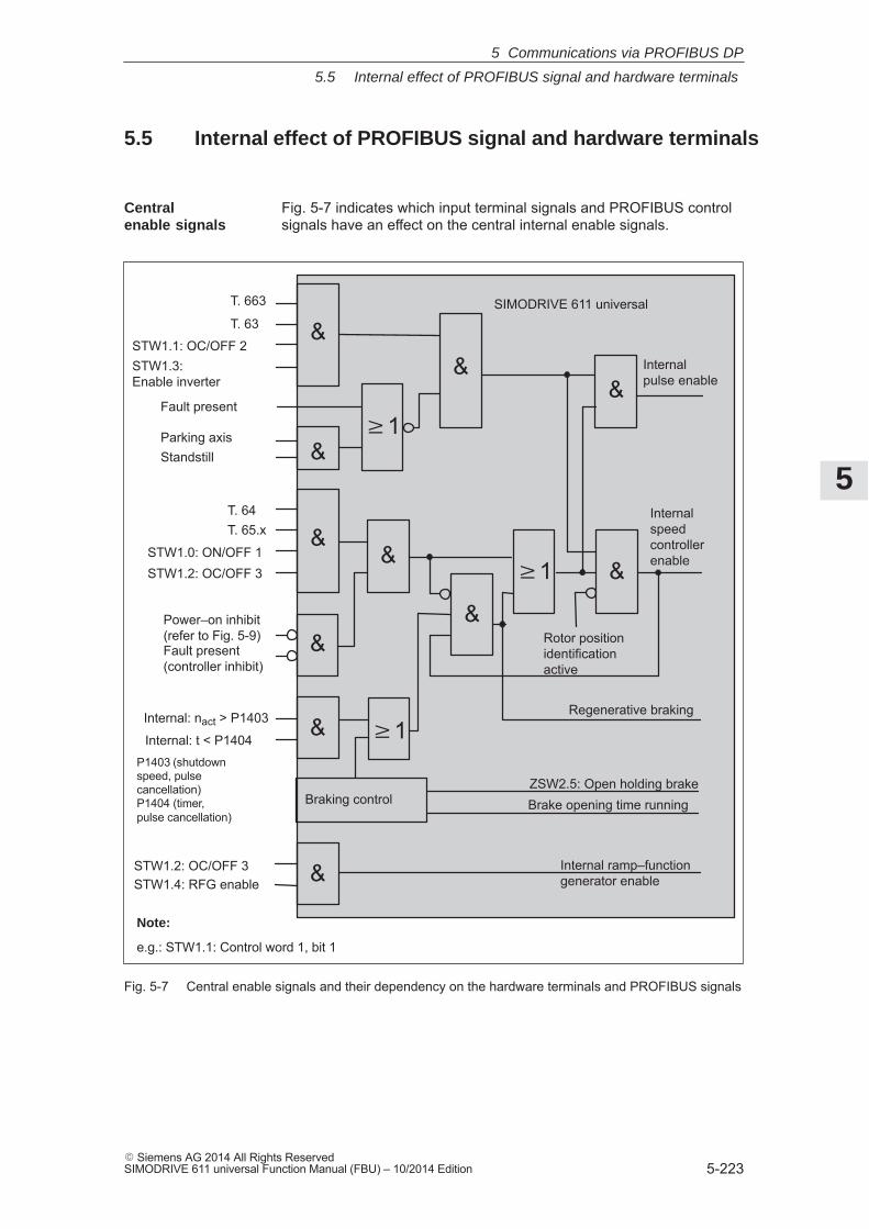
5
5.5 Internal effect of PROFIBUS signal and hardware terminals
5-223� Siemens AG 2014 All Rights ReservedSIMODRIVE 611 universal Function Manual (FBU) – 10/2014 Edition
5.5 Internal effect of PROFIBUS signal and hardware terminals
Fig. 5-7 indicates which input terminal signals and PROFIBUS controlsignals have an effect on the central internal enable signals.
�1
&&
&&
�1 &
&
&
T. 663
T. 63
STW1.1: OC/OFF 2
T. 64T. 65.x
STW1.0: ON/OFF 1STW1.2: OC/OFF 3
STW1.2: OC/OFF 3STW1.4: RFG enable
SIMODRIVE 611 universal
& �1
Braking control
&
Internal pulse enable
Internal ramp–functiongenerator enable
Internal speed controllerenable
Rotor position identificationactive
Regenerative braking
ZSW2.5: Open holding brakeBrake opening time running
Fault present (controller inhibit)
Power–on inhibit(refer to Fig. 5-9)
STW1.3: Enable inverter
Fault present
Parking axis
Internal: nact > P1403
Internal: t < P1404
&Standstill
&
P1403 (shutdownspeed, pulsecancellation) P1404 (timer, pulse cancellation)
Note:
e.g.: STW1.1: Control word 1, bit 1
Fig. 5-7 Central enable signals and their dependency on the hardware terminals and PROFIBUS signals
Centralenable signals
5 Communications via PROFIBUS DP

5
5.5 Internal effect of PROFIBUS signal and hardware terminals
5-224� Siemens AG 2014 All Rights Reserved
SIMODRIVE 611 universal Function Manual (FBU) – 10/2014 Edition
Fig. 5-8 shows which input terminal signals and PROFIBUS control sig-nals have a significant effect on the most important status signals andhow they are formed.
&
&
&
&
&
&
&
T. 663T. 63
STW1.1: OC/OFF 2
STW1.2: OC/OFF 3 ZSW1.0: Ready to bepowered–up/notready to bepowered–up
SIMODRIVE 611 universal
T. 663T. 63T. 64T. 65.x
T. 663T. 63
STW1.1: OC/OFF 2
STW1.1: OC/OFF 2
STW1.2: OC/OFF 3
STW1.0: ON/OFF 1
STW1.2: OC/OFF 3
ZSW1.2: Status, controllerenable
ZSW1.4:No OFF 2 present
ZSW1.5:No OFF 3 present
&
ZSW1.1: P1012.2 = 1 ––> Ready
or = 0 ––> No fault
Internal speed controller enable
Regenerative brakingBrake opening time running
Fault present(pulse enable)
Fault present (pulse enable)
Power–on inhibit(refer to Fig. 5-9)
Power–on inhibit(refer to Fig. 5-9)
Fig. 5-8 Statuses dependent on the hardware terminals and PROFIBUS signals
Statuses from the terminal andcontrol signals
5 Communications via PROFIBUS DP
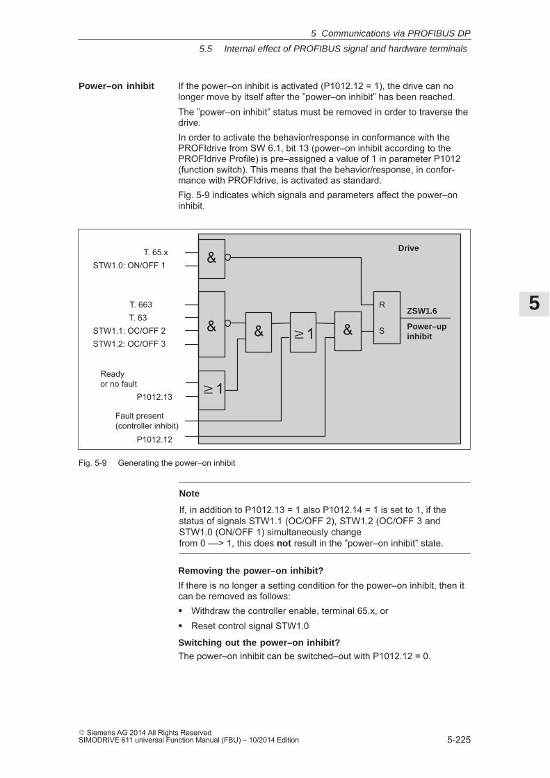
5
5.5 Internal effect of PROFIBUS signal and hardware terminals
5-225� Siemens AG 2014 All Rights ReservedSIMODRIVE 611 universal Function Manual (FBU) – 10/2014 Edition
If the power–on inhibit is activated (P1012.12 = 1), the drive can nolonger move by itself after the ”power–on inhibit” has been reached.The ”power–on inhibit” status must be removed in order to traverse thedrive.In order to activate the behavior/response in conformance with thePROFIdrive from SW 6.1, bit 13 (power–on inhibit according to thePROFIdrive Profile) is pre–assigned a value of 1 in parameter P1012(function switch). This means that the behavior/response, in confor-mance with PROFIdrive, is activated as standard.Fig. 5-9 indicates which signals and parameters affect the power–oninhibit.
P1012.13
&
&�1
T. 65.xSTW1.0: ON/OFF 1
T. 663T. 63
STW1.1: OC/OFF 2STW1.2: OC/OFF 3
& &
R
S
Drive
ZSW1.6
Power–up inhibit
Ready or no fault
Fault present (controller inhibit)
P1012.12
�1
Fig. 5-9 Generating the power–on inhibit
Note
If, in addition to P1012.13 = 1 also P1012.14 = 1 is set to 1, if thestatus of signals STW1.1 (OC/OFF 2), STW1.2 (OC/OFF 3 andSTW1.0 (ON/OFF 1) simultaneously change from 0 ––> 1, this does not result in the ”power–on inhibit” state.
Removing the power–on inhibit?
If there is no longer a setting condition for the power–on inhibit, then itcan be removed as follows:� Withdraw the controller enable, terminal 65.x, or� Reset control signal STW1.0
Switching out the power–on inhibit?The power–on inhibit can be switched–out with P1012.12 = 0.
Power–on inhibit
5 Communications via PROFIBUS DP

5
5.6 Net data (PKW and PZD area)
5-226� Siemens AG 2014 All Rights Reserved
SIMODRIVE 611 universal Function Manual (FBU) – 10/2014 Edition
5.6 Net data (PKW and PZD area)
5.6.1 Overview of the process data (PZD area)
Reader’s note
In the index, for each process data (control/status word), it is specifiedon which page information can be found on this word.� refer to ”Process data in the n–set mode – control words ...”
refer to ”Process data in the n–set mode – status words ...”� refer to ”Process data in the pos mode control words ...”
refer to the ”Process data in the pos mode – status words – ...”
5 Communications via PROFIBUS DP
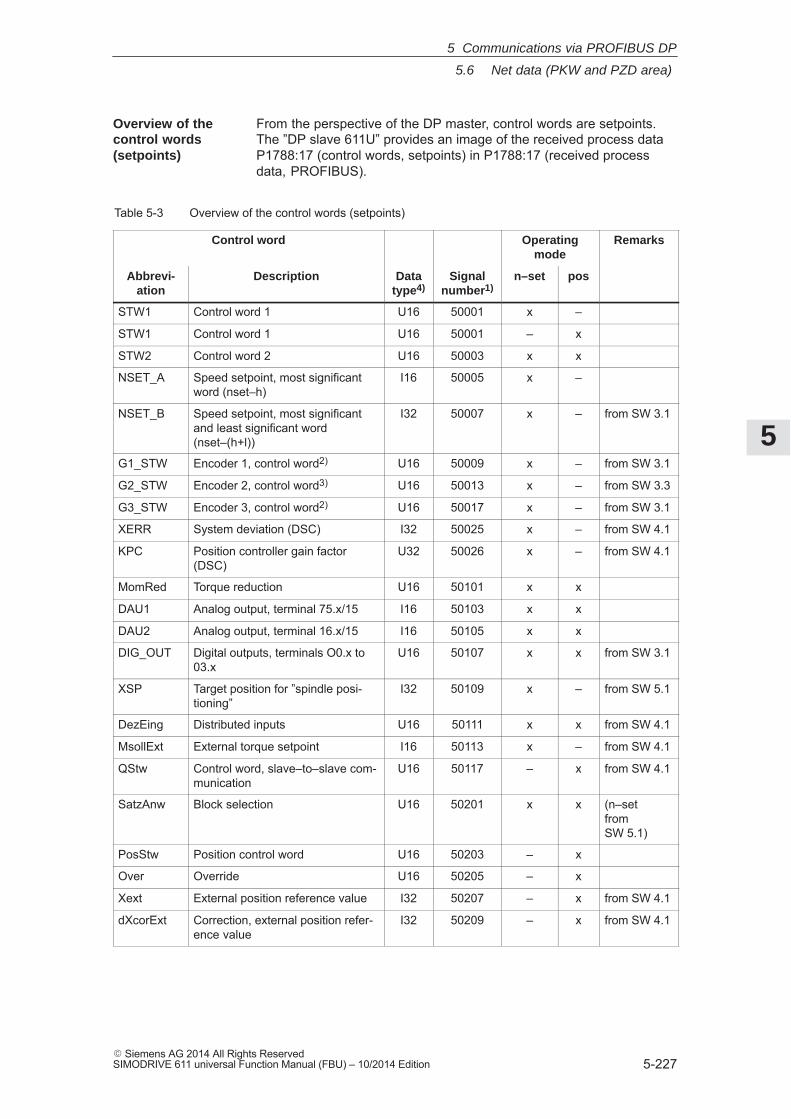
5
5.6 Net data (PKW and PZD area)
5-227� Siemens AG 2014 All Rights ReservedSIMODRIVE 611 universal Function Manual (FBU) – 10/2014 Edition
From the perspective of the DP master, control words are setpoints.The ”DP slave 611U” provides an image of the received process dataP1788:17 (control words, setpoints) in P1788:17 (received processdata, PROFIBUS).
Table 5-3 Overview of the control words (setpoints)
Control word Operatingmode
Remarks
Abbrevi-ation
Description Datatype4)
Signalnumber1)
n–set pos
STW1 Control word 1 U16 50001 x –
STW1 Control word 1 U16 50001 – x
STW2 Control word 2 U16 50003 x x
NSET_A Speed setpoint, most significantword (nset–h)
I16 50005 x –
NSET_B Speed setpoint, most significantand least significant word(nset–(h+l))
I32 50007 x – from SW 3.1
G1_STW Encoder 1, control word2) U16 50009 x – from SW 3.1
G2_STW Encoder 2, control word3) U16 50013 x – from SW 3.3
G3_STW Encoder 3, control word2) U16 50017 x – from SW 3.1
XERR System deviation (DSC) I32 50025 x – from SW 4.1
KPC Position controller gain factor(DSC)
U32 50026 x – from SW 4.1
MomRed Torque reduction U16 50101 x x
DAU1 Analog output, terminal 75.x/15 I16 50103 x x
DAU2 Analog output, terminal 16.x/15 I16 50105 x x
DIG_OUT Digital outputs, terminals O0.x to03.x
U16 50107 x x from SW 3.1
XSP Target position for ”spindle posi-tioning”
I32 50109 x – from SW 5.1
DezEing Distributed inputs U16 50111 x x from SW 4.1
MsollExt External torque setpoint I16 50113 x – from SW 4.1
QStw Control word, slave–to–slave com-munication
U16 50117 – x from SW 4.1
SatzAnw Block selection U16 50201 x x (n–set fromSW 5.1)
PosStw Position control word U16 50203 – x
Over Override U16 50205 – x
Xext External position reference value I32 50207 – x from SW 4.1
dXcorExt Correction, external position refer-ence value
I32 50209 – x from SW 4.1
Overview of thecontrol words (setpoints)
5 Communications via PROFIBUS DP
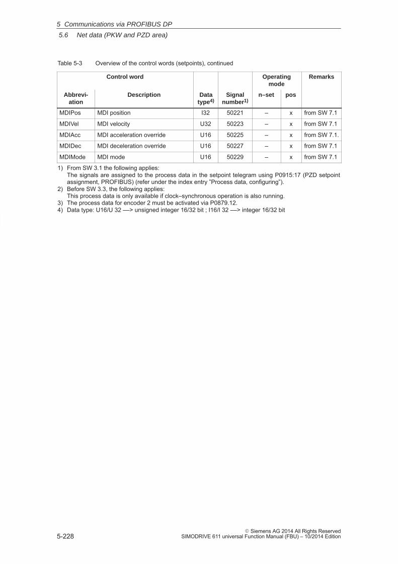
5
5.6 Net data (PKW and PZD area)
5-228� Siemens AG 2014 All Rights Reserved
SIMODRIVE 611 universal Function Manual (FBU) – 10/2014 Edition
Table 5-3 Overview of the control words (setpoints), continued
Control word RemarksOperatingmode
Abbrevi-ation
posn–setSignalnumber1)
Datatype4)
Description
MDIPos MDI position I32 50221 – x from SW 7.1
MDIVel MDI velocity U32 50223 – x from SW 7.1
MDIAcc MDI acceleration override U16 50225 – x from SW 7.1.
MDIDec MDI deceleration override U16 50227 – x from SW 7.1
MDIMode MDI mode U16 50229 – x from SW 7.1
1) From SW 3.1 the following applies:The signals are assigned to the process data in the setpoint telegram using P0915:17 (PZD setpointassignment, PROFIBUS) (refer under the index entry ”Process data, configuring”).
2) Before SW 3.3, the following applies:This process data is only available if clock–synchronous operation is also running.
3) The process data for encoder 2 must be activated via P0879.12.4) Data type: U16/U 32 ––> unsigned integer 16/32 bit ; I16/I 32 ––> integer 16/32 bit
5 Communications via PROFIBUS DP
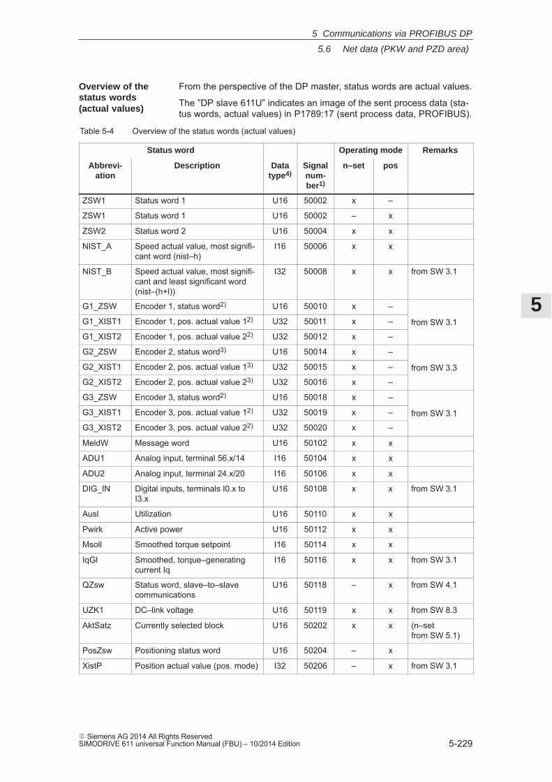
5
5.6 Net data (PKW and PZD area)
5-229� Siemens AG 2014 All Rights ReservedSIMODRIVE 611 universal Function Manual (FBU) – 10/2014 Edition
From the perspective of the DP master, status words are actual values.
The ”DP slave 611U” indicates an image of the sent process data (sta-tus words, actual values) in P1789:17 (sent process data, PROFIBUS).
Table 5-4 Overview of the status words (actual values)
Status word Operating mode Remarks
Abbrevi-ation
Description Datatype4)
Signalnum-ber1)
n–set pos
ZSW1 Status word 1 U16 50002 x –
ZSW1 Status word 1 U16 50002 – x
ZSW2 Status word 2 U16 50004 x x
NIST_A Speed actual value, most signifi-cant word (nist–h)
I16 50006 x x
NIST_B Speed actual value, most signifi-cant and least significant word(nist–(h+l))
I32 50008 x x from SW 3.1
G1_ZSW Encoder 1, status word2) U16 50010 x –
G1_XIST1 Encoder 1, pos. actual value 12) U32 50011 x – from SW 3.1
G1_XIST2 Encoder 1, pos. actual value 22) U32 50012 x –
from SW 3.1
G2_ZSW Encoder 2, status word3) U16 50014 x –
G2_XIST1 Encoder 2, pos. actual value 13) U32 50015 x – from SW 3.3
G2_XIST2 Encoder 2, pos. actual value 23) U32 50016 x –
from SW 3.3
G3_ZSW Encoder 3, status word2) U16 50018 x –
G3_XIST1 Encoder 3, pos. actual value 12) U32 50019 x – from SW 3.1
G3_XIST2 Encoder 3, pos. actual value 22) U32 50020 x –
from SW 3.1
MeldW Message word U16 50102 x x
ADU1 Analog input, terminal 56.x/14 I16 50104 x x
ADU2 Analog input, terminal 24.x/20 I16 50106 x x
DIG_IN Digital inputs, terminals I0.x toI3.x
U16 50108 x x from SW 3.1
Ausl Utilization U16 50110 x x
Pwirk Active power U16 50112 x x
Msoll Smoothed torque setpoint I16 50114 x x
IqGl Smoothed, torque–generatingcurrent Iq
I16 50116 x x from SW 3.1
QZsw Status word, slave–to–slavecommunications
U16 50118 – x from SW 4.1
UZK1 DC–link voltage U16 50119 x x from SW 8.3
AktSatz Currently selected block U16 50202 x x (n–set from SW 5.1)
PosZsw Positioning status word U16 50204 – x
XistP Position actual value (pos. mode) I32 50206 – x from SW 3.1
Overview of the status words(actual values)
5 Communications via PROFIBUS DP
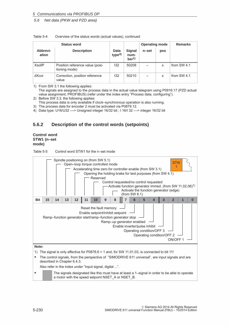
5
5.6 Net data (PKW and PZD area)
5-230� Siemens AG 2014 All Rights Reserved
SIMODRIVE 611 universal Function Manual (FBU) – 10/2014 Edition
Table 5-4 Overview of the status words (actual values), continued
Status word RemarksOperating mode
Abbrevi-ation
posn–setSignalnum-ber1)
Datatype4)
Description
XsollP Position reference value (posi-tioning mode)
I32 50208 – x from SW 4.1
dXcor Correction, position referencevalue
I32 50210 – x from SW 4.1
1) From SW 3.1 the following applies:The signals are assigned to the process data in the actual value telegram using P0916:17 (PZD actualvalue assignment, PROFIBUS) (refer under the index entry ”Process data, configuring”).
2) Before SW 3.3, the following applies:This process data is only available if clock–synchronous operation is also running.
3) The process data for encoder 2 must be activated via P0879.12.4) Data type: U16/U32 ––> Unsigned integer 16/32 bit ; I 16/I 32 ––> integer 16/32 bit
5.6.2 Description of the control words (setpoints)
Table 5-5 Control word STW1 for the n–set mode
Open–loop torque controlled mode
Control requested/no control requestedReserved
STW1
Activate function generator immed. (from SW 11.02.06)1)
Accelerating time zero for controller enable (from SW 3.1)
Spindle positioning on (from SW 5.1)
Opening the holding brake for test purposes (from SW 4.1)
Activate the function generator (edge)(from SW 8.1)
Bit 15 14 13 12 11 10 9 8 7 6 5 4 3 2 1 0
Reset the fault memoryEnable setpoint/inhibit setpoint
Ramp–function generator start/ramp–function generator stopRamp–up generator enabled
Enable inverter/pulse inhibitOperating condition/OFF 3
Operating condition/OFF 2ON/OFF 1
Note:
1) The signal is only effective for P0878.6 = 1 and, for SW 11.01.03, is connected to bit 11!� The control signals, from the perspective of ”SIMODRIVE 611 universal”, are input signals and are
described in Chapter 6.4.3.Also refer in the index under ”Input signal, digital ...”.
� The signals designated like this must have at least a 1–signal in order to be able to operatea motor with the speed setpoint NSET_A or NSET_B.
Control wordSTW1 (n–setmode)
5 Communications via PROFIBUS DP
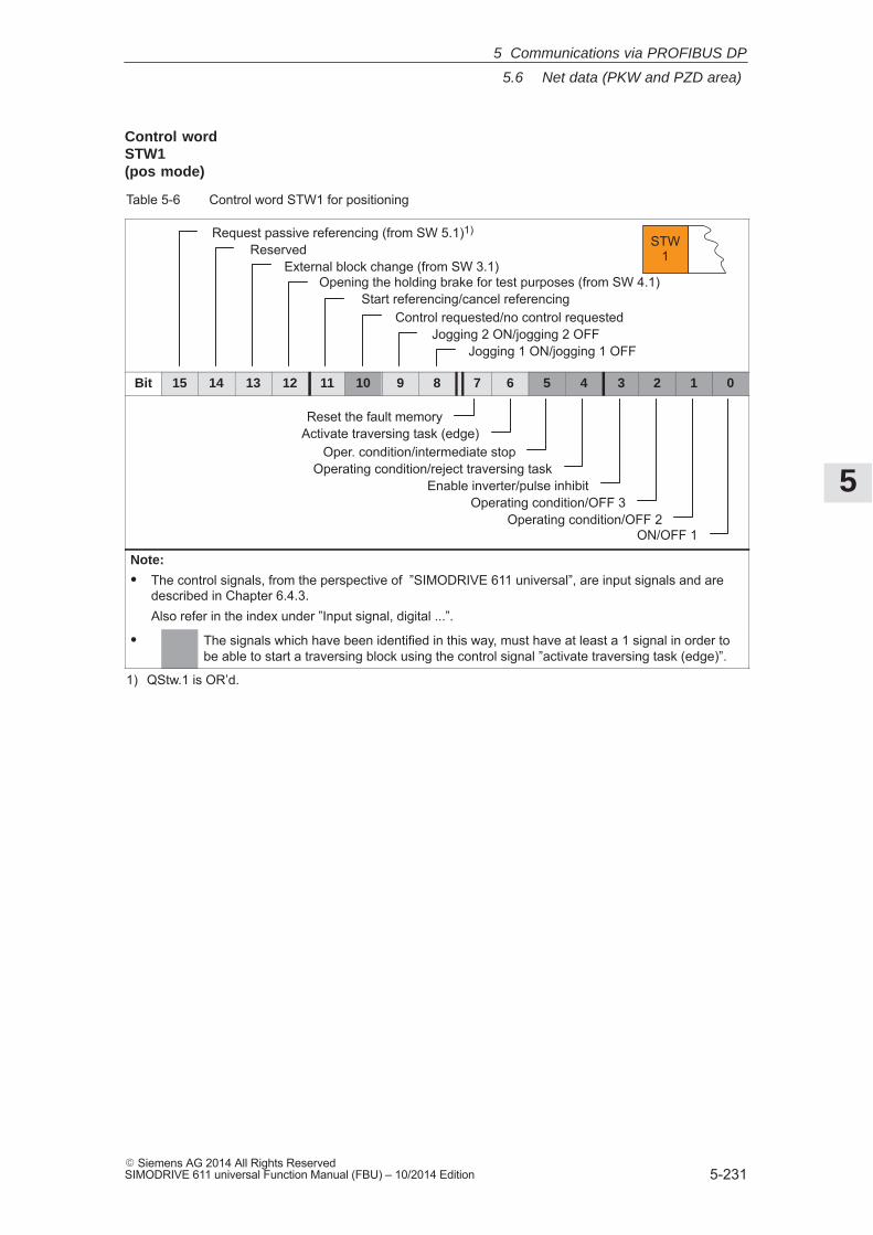
5
5.6 Net data (PKW and PZD area)
5-231� Siemens AG 2014 All Rights ReservedSIMODRIVE 611 universal Function Manual (FBU) – 10/2014 Edition
Table 5-6 Control word STW1 for positioning
External block change (from SW 3.1)Opening the holding brake for test purposes (from SW 4.1)
Start referencing/cancel referencingControl requested/no control requested
Jogging 2 ON/jogging 2 OFFJogging 1 ON/jogging 1 OFF
STW1Reserved
Request passive referencing (from SW 5.1)1)
Bit 15 14 13 12 11 10 9 8 7 6 5 4 3 2 1 0
Reset the fault memoryActivate traversing task (edge)
Oper. condition/intermediate stopOperating condition/reject traversing task
Enable inverter/pulse inhibitOperating condition/OFF 3
Operating condition/OFF 2ON/OFF 1
Note:
� The control signals, from the perspective of ”SIMODRIVE 611 universal”, are input signals and aredescribed in Chapter 6.4.3.Also refer in the index under ”Input signal, digital ...”.
� The signals which have been identified in this way, must have at least a 1 signal in order tobe able to start a traversing block using the control signal ”activate traversing task (edge)”.
1) QStw.1 is OR’d.
Control wordSTW1 (pos mode)
5 Communications via PROFIBUS DP
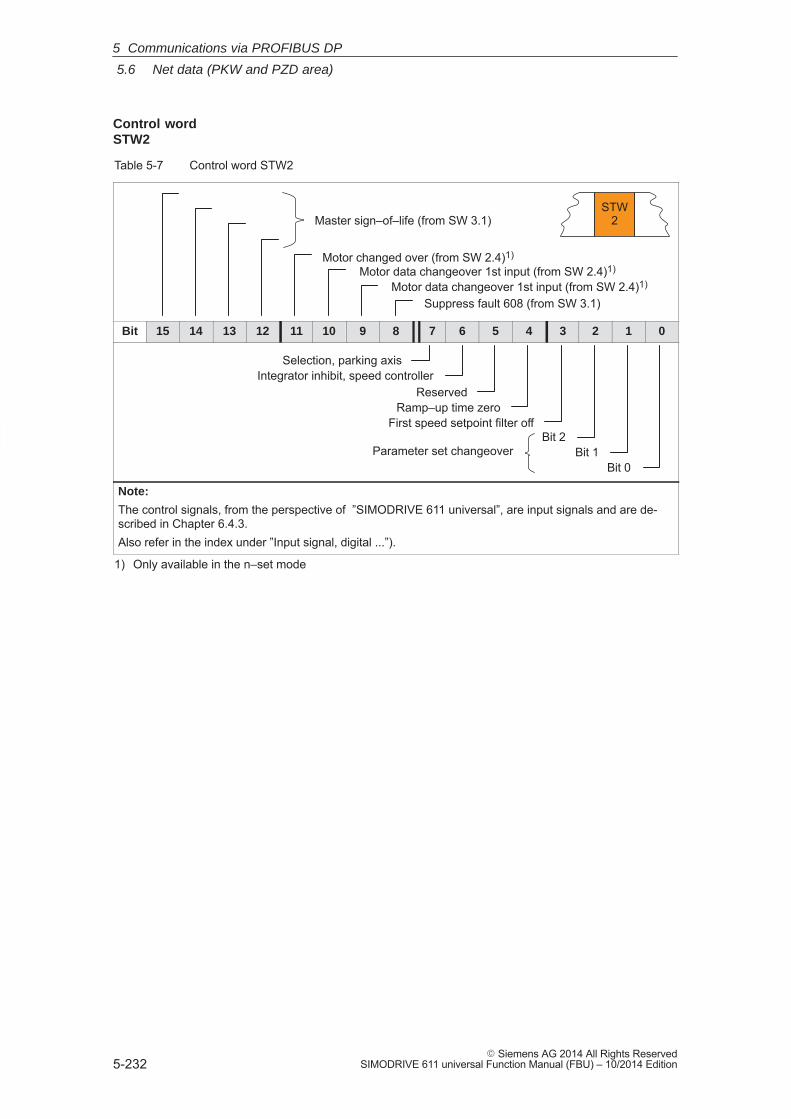
5
5.6 Net data (PKW and PZD area)
5-232� Siemens AG 2014 All Rights Reserved
SIMODRIVE 611 universal Function Manual (FBU) – 10/2014 Edition
Table 5-7 Control word STW2
STW2
Motor data changeover 1st input (from SW 2.4)1)
Motor data changeover 1st input (from SW 2.4)1)
Motor changed over (from SW 2.4)1)
Suppress fault 608 (from SW 3.1)
Master sign–of–life (from SW 3.1)
Bit 15 14 13 12 11 10 9 8 7 6 5 4 3 2 1 0
Selection, parking axisIntegrator inhibit, speed controller
Bit 2Bit 1
Bit 0Parameter set changeover
ReservedRamp–up time zero
First speed setpoint filter off
Note:
The control signals, from the perspective of ”SIMODRIVE 611 universal”, are input signals and are de-scribed in Chapter 6.4.3.Also refer in the index under ”Input signal, digital ...”).
1) Only available in the n–set mode
Control word STW2
5 Communications via PROFIBUS DP
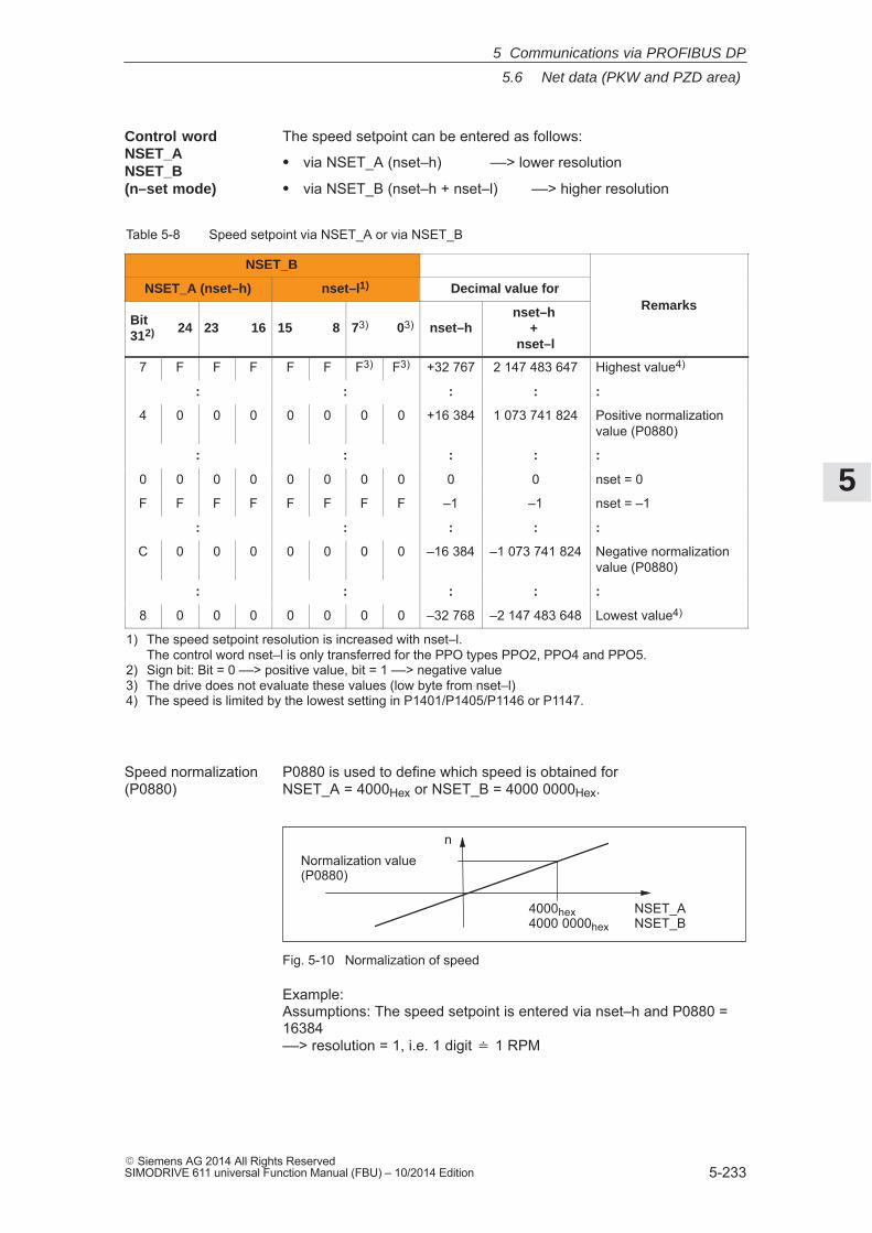
5
5.6 Net data (PKW and PZD area)
5-233� Siemens AG 2014 All Rights ReservedSIMODRIVE 611 universal Function Manual (FBU) – 10/2014 Edition
The speed setpoint can be entered as follows:
� via NSET_A (nset–h) ––> lower resolution
� via NSET_B (nset–h + nset–l) ––> higher resolution
Table 5-8 Speed setpoint via NSET_A or via NSET_B
NSET_B
NSET_A (nset–h) nset–l1) Decimal value forRemarks
Bit312) 24 23 16 15 8 73) 03) nset–h
nset–h +
nset–l
Remarks
7 F F F F F F3) F3) +32 767 2 147 483 647 Highest value4)
: : : : :
4 0 0 0 0 0 0 0 +16 384 1 073 741 824 Positive normalizationvalue (P0880)
: : : : :
0 0 0 0 0 0 0 0 0 0 nset = 0
F F F F F F F F –1 –1 nset = –1
: : : : :
C 0 0 0 0 0 0 0 –16 384 –1 073 741 824 Negative normalizationvalue (P0880)
: : : : :
8 0 0 0 0 0 0 0 –32 768 –2 147 483 648 Lowest value4)
1) The speed setpoint resolution is increased with nset–l. The control word nset–l is only transferred for the PPO types PPO2, PPO4 and PPO5.
2) Sign bit: Bit = 0 ––> positive value, bit = 1 ––> negative value3) The drive does not evaluate these values (low byte from nset–l)4) The speed is limited by the lowest setting in P1401/P1405/P1146 or P1147.
P0880 is used to define which speed is obtained for NSET_A = 4000Hex or NSET_B = 4000 0000Hex.
nNormalization value(P0880)
NSET_ANSET_B
4000hex4000 0000hex
Fig. 5-10 Normalization of speed
Example: Assumptions: The speed setpoint is entered via nset–h and P0880 =16384 ––> resolution = 1, i.e. 1 digit � 1 RPM
Control wordNSET_A NSET_B (n–set mode)
Speed normalization(P0880)
5 Communications via PROFIBUS DP
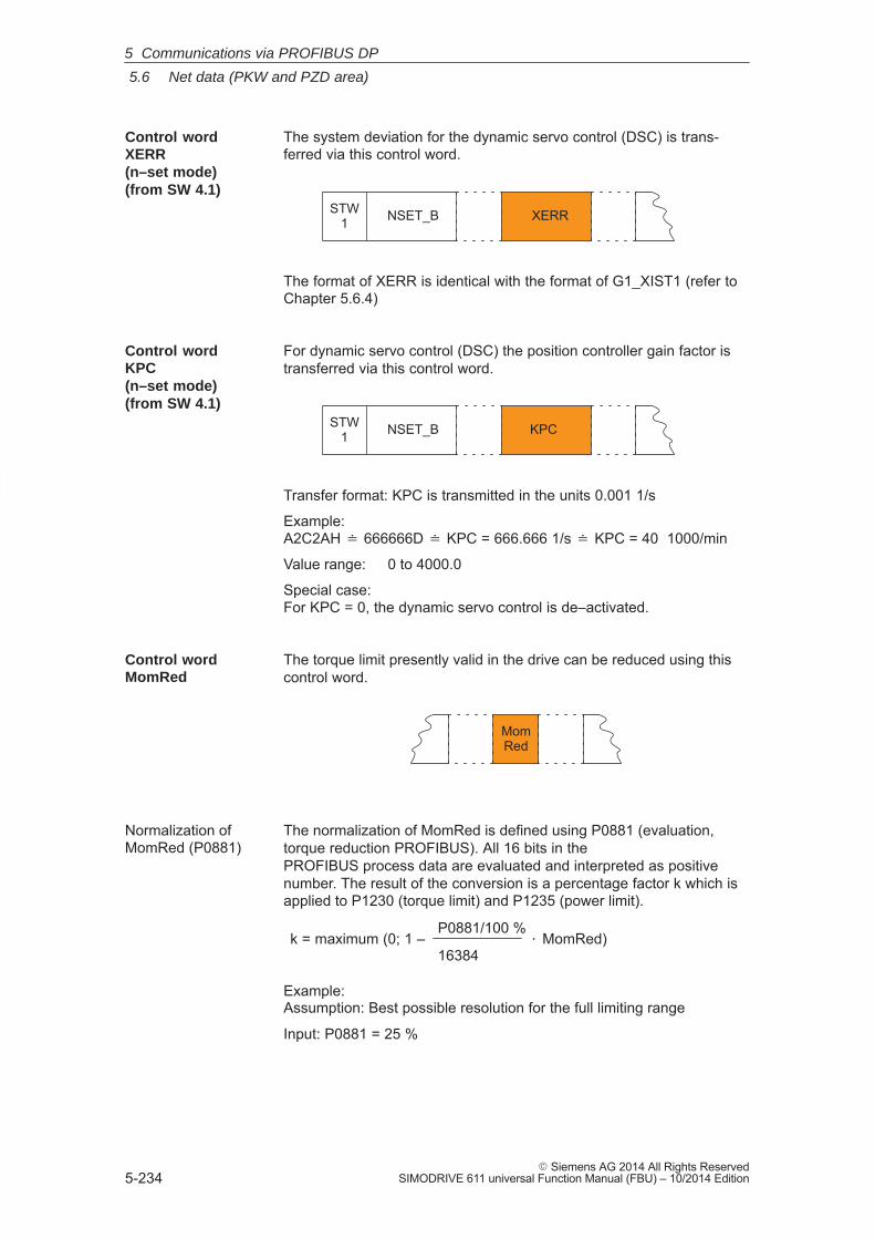
5
5.6 Net data (PKW and PZD area)
5-234� Siemens AG 2014 All Rights Reserved
SIMODRIVE 611 universal Function Manual (FBU) – 10/2014 Edition
The system deviation for the dynamic servo control (DSC) is trans-ferred via this control word.
XERRSTW1 NSET_B
The format of XERR is identical with the format of G1_XIST1 (refer toChapter 5.6.4)
For dynamic servo control (DSC) the position controller gain factor istransferred via this control word.
KPCSTW1 NSET_B
Transfer format: KPC is transmitted in the units 0.001 1/s
Example:A2C2AH � 666666D � KPC = 666.666 1/s � KPC = 40 1000/min
Value range: 0 to 4000.0
Special case:For KPC = 0, the dynamic servo control is de–activated.
The torque limit presently valid in the drive can be reduced using thiscontrol word.
MomRed
The normalization of MomRed is defined using P0881 (evaluation,torque reduction PROFIBUS). All 16 bits in the PROFIBUS process data are evaluated and interpreted as positivenumber. The result of the conversion is a percentage factor k which isapplied to P1230 (torque limit) and P1235 (power limit).
k = maximum (0; 1 –P0881/100 %
16384� MomRed)
Example: Assumption: Best possible resolution for the full limiting range
Input: P0881 = 25 %
Control wordXERR (n–set mode) (from SW 4.1)
Control wordKPC (n–set mode)(from SW 4.1)
Control word MomRed
Normalization ofMomRed (P0881)
5 Communications via PROFIBUS DP
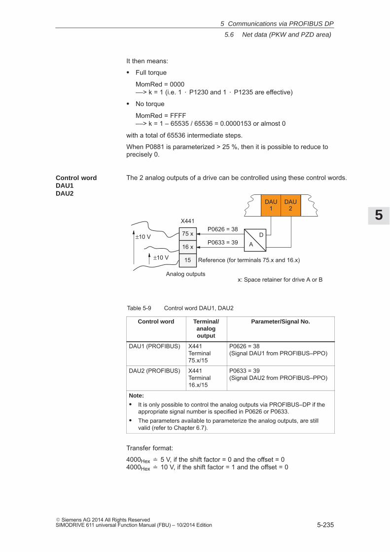
5
5.6 Net data (PKW and PZD area)
5-235� Siemens AG 2014 All Rights ReservedSIMODRIVE 611 universal Function Manual (FBU) – 10/2014 Edition
It then means:
� Full torque
MomRed = 0000 ––> k = 1 (i.e. 1 � P1230 and 1 � P1235 are effective)
� No torque
MomRed = FFFF ––> k = 1 – 65535 / 65536 = 0.0000153 or almost 0
with a total of 65536 intermediate steps.
When P0881 is parameterized > 25 %, then it is possible to reduce toprecisely 0.
The 2 analog outputs of a drive can be controlled using these control words.
DAU1
DAU2
DA
Reference (for terminals 75.x and 16.x)
P0626 = 38
P0633 = 39
x: Space retainer for drive A or B
75 x
16 x
15
X441
±10 V
±10 V
Analog outputs
Table 5-9 Control word DAU1, DAU2
Control word Terminal/analogoutput
Parameter/Signal No.
DAU1 (PROFIBUS) X441Terminal75.x/15
P0626 = 38 (Signal DAU1 from PROFIBUS–PPO)
DAU2 (PROFIBUS) X441Terminal16.x/15
P0633 = 39(Signal DAU2 from PROFIBUS–PPO)
Note:
� It is only possible to control the analog outputs via PROFIBUS–DP if theappropriate signal number is specified in P0626 or P0633.
� The parameters available to parameterize the analog outputs, are stillvalid (refer to Chapter 6.7).
Transfer format:
4000Hex � 5 V, if the shift factor = 0 and the offset = 0 4000Hex � 10 V, if the shift factor = 1 and the offset = 0
Control word DAU1 DAU2
5 Communications via PROFIBUS DP
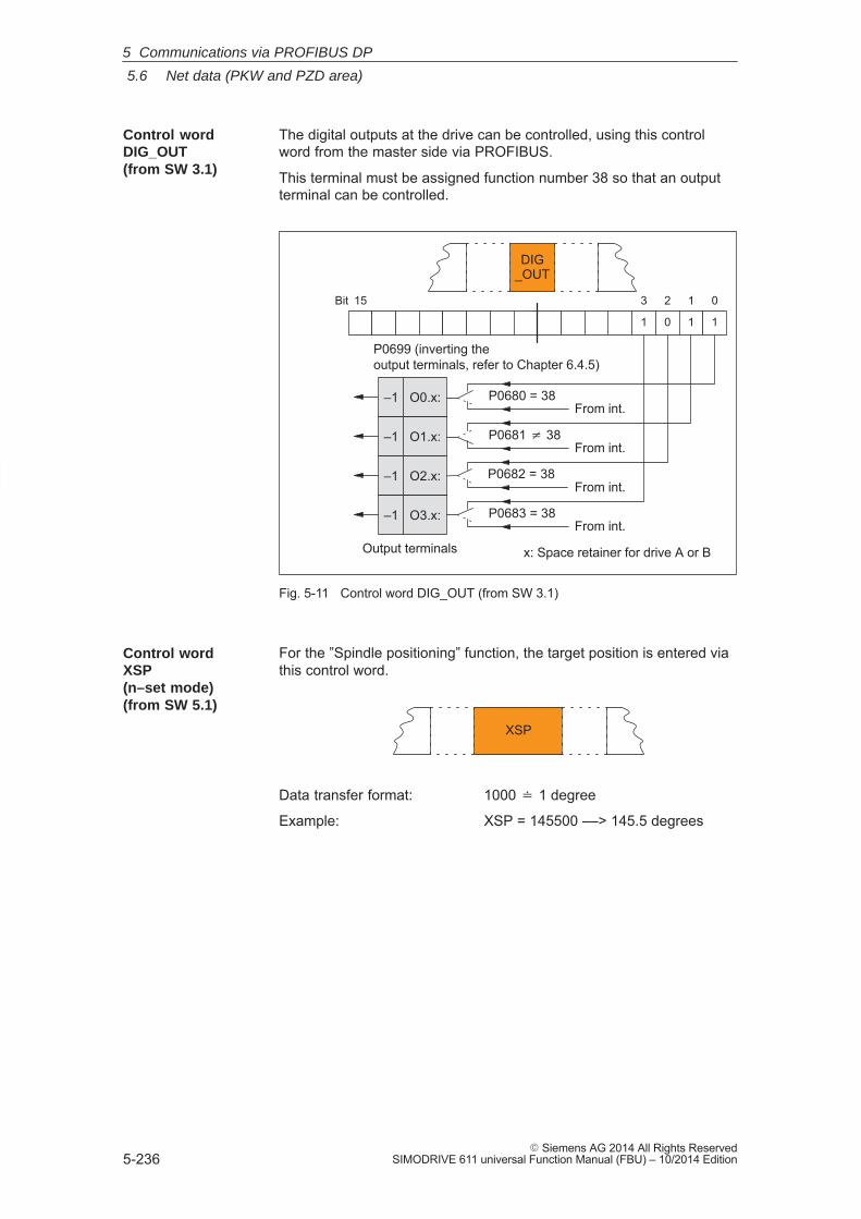
5
5.6 Net data (PKW and PZD area)
5-236� Siemens AG 2014 All Rights Reserved
SIMODRIVE 611 universal Function Manual (FBU) – 10/2014 Edition
The digital outputs at the drive can be controlled, using this controlword from the master side via PROFIBUS.
This terminal must be assigned function number 38 so that an outputterminal can be controlled.
15 0123Bit
1 0 1 1
From int.
P0699 (inverting the output terminals, refer to Chapter 6.4.5)
Output terminals
P0681 � 38
P0682 = 38
P0683 = 38
From int.
From int.
From int.
x: Space retainer for drive A or B
DIG_OUT
P0680 = 38O0.x:
O1.x:
O2.x:
O3.x:
–1
–1
–1
–1
Fig. 5-11 Control word DIG_OUT (from SW 3.1)
For the ”Spindle positioning” function, the target position is entered viathis control word.
XSP
Data transfer format: 1000 � 1 degree
Example: XSP = 145500 ––> 145.5 degrees
Control wordDIG_OUT (from SW 3.1)
Control word XSP(n–set mode)(from SW 5.1)
5 Communications via PROFIBUS DP
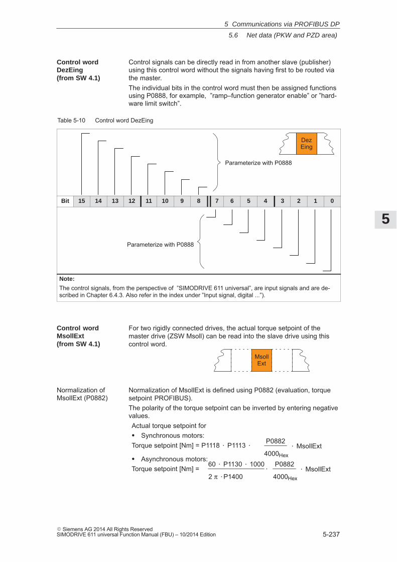
5
5.6 Net data (PKW and PZD area)
5-237� Siemens AG 2014 All Rights ReservedSIMODRIVE 611 universal Function Manual (FBU) – 10/2014 Edition
Control signals can be directly read in from another slave (publisher)using this control word without the signals having first to be routed viathe master.The individual bits in the control word must then be assigned functionsusing P0888, for example, ”ramp–function generator enable” or ”hard-ware limit switch”.
Table 5-10 Control word DezEing
DezEing
Parameterize with P0888
Bit 15 14 13 12 11 10 9 8 7 6 5 4 3 2 1 0
Parameterize with P0888
Note:
The control signals, from the perspective of ”SIMODRIVE 611 universal”, are input signals and are de-scribed in Chapter 6.4.3. Also refer in the index under ”Input signal, digital ...”).
For two rigidly connected drives, the actual torque setpoint of themaster drive (ZSW Msoll) can be read into the slave drive using thiscontrol word.
MsollExt
Normalization of MsollExt is defined using P0882 (evaluation, torquesetpoint PROFIBUS).The polarity of the torque setpoint can be inverted by entering negativevalues.Actual torque setpoint for� Synchronous motors:Torque setpoint [Nm] = P1118 � P1113 � P0882
4000Hex� MsollExt
� Asynchronous motors:Torque setpoint [Nm] = �
P0882
4000Hex� MsollExt
60 � P1130 � 1000
2 π �P1400
Control word DezEing (from SW 4.1)
Control wordMsollExt (from SW 4.1)
Normalization ofMsollExt (P0882)
5 Communications via PROFIBUS DP
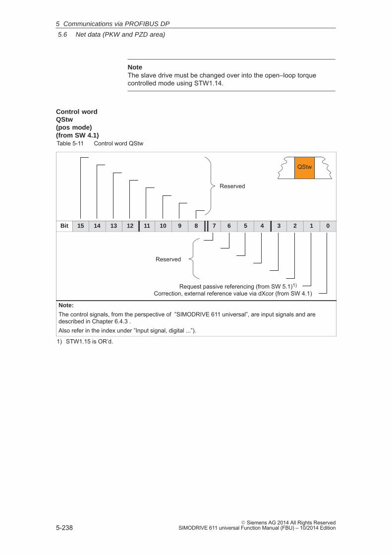
5
5.6 Net data (PKW and PZD area)
5-238� Siemens AG 2014 All Rights Reserved
SIMODRIVE 611 universal Function Manual (FBU) – 10/2014 Edition
NoteThe slave drive must be changed over into the open–loop torquecontrolled mode using STW1.14.
Table 5-11 Control word QStw
QStw
Reserved
Bit 15 14 13 12 11 10 9 8 7 6 5 4 3 2 1 0
Reserved
Correction, external reference value via dXcor (from SW 4.1)Request passive referencing (from SW 5.1)1)
Note:
The control signals, from the perspective of ”SIMODRIVE 611 universal”, are input signals and are described in Chapter 6.4.3 .Also refer in the index under ”Input signal, digital ...”).
1) STW1.15 is OR’d.
Control word QStw (pos mode)(from SW 4.1)
5 Communications via PROFIBUS DP
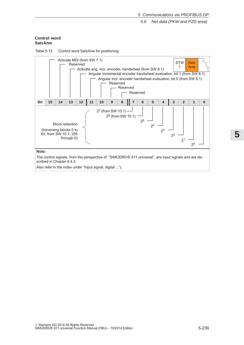
5
5.6 Net data (PKW and PZD area)
5-239� Siemens AG 2014 All Rights ReservedSIMODRIVE 611 universal Function Manual (FBU) – 10/2014 Edition
Table 5-12 Control word SatzAnw for positioning
STW1
SatzAnw
Reserved
Activate MDI (from SW 7.1)Reserved
Activate ang. incr. encoder, handwheel (from SW 8.1)Angular incremental encoder handwheel evaluation, bit 1 (from SW 8.1)
Angular incr. encoder handwheel evaluation, bit 0 (from SW 8.1)
ReservedReserved
Bit 15 14 13 12 11 10 9 8 7 6 5 4 3 2 1 0
25
24
23
22
21
20
26 (from SW 10.1)
Block selection(traversing blocks 0 to63; from SW 10.1: 255
through 0)
27 (from SW 10.1)
Note:
The control signals, from the perspective of ”SIMODRIVE 611 universal”, are input signals and are de-scribed in Chapter 6.4.3.Also refer in the index under ”Input signal, digital ...”).
Control wordSatzAnw
5 Communications via PROFIBUS DP
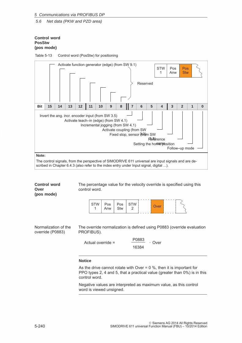
5
5.6 Net data (PKW and PZD area)
5-240� Siemens AG 2014 All Rights Reserved
SIMODRIVE 611 universal Function Manual (FBU) – 10/2014 Edition
Table 5-13 Control word (PosStw) for positioning
STW1
PosAnw
PosStw
Reserved
Activate function generator (edge) (from SW 9.1)
Bit 15 14 13 12 11 10 9 8 7 6 5 4 3 2 1 0
Activate teach–in (edge) (from SW 4.1)
Setting the home positionFollow–up mode
Referencecams
Activate coupling (from SW3.3)Fixed stop, sensor (from SW
3.3)
Invert the ang. incr. encoder input (from SW 3.5)
Incremental jogging (from SW 4.1)
Note:
The control signals, from the perspective of SIMODRIVE 611 universal are input signals and are de-scribed in Chapter 6.4.3 (also refer to the index entry under Input signal, digital ...).
The percentage value for the velocity override is specified using thiscontrol word.
OverSTW1
PosAnw
PosStw
STW2
The override normalization is defined using P0883 (override evaluationPROFIBUS).
Actual override =P0883
16384� Over
Notice
As the drive cannot rotate with Over = 0 %, then it is important forPPO types 2, 4 and 5, that a practical value (greater than 0%) is in thiscontrol word.
Negative values are interpreted as maximum value, as this controlword is viewed unsigned.
Control wordPosStw (pos mode)
Control wordOver (pos mode)
Normalization of theoverride (P0883)
5 Communications via PROFIBUS DP
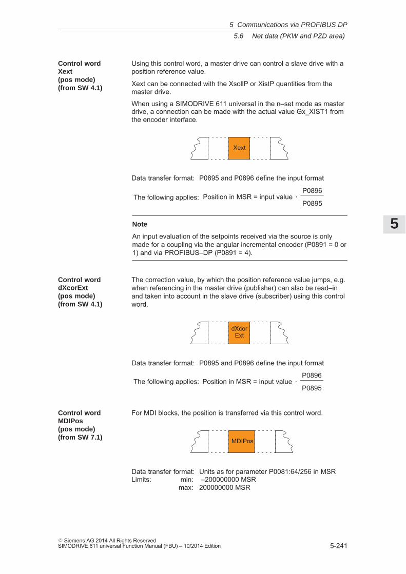
5
5.6 Net data (PKW and PZD area)
5-241� Siemens AG 2014 All Rights ReservedSIMODRIVE 611 universal Function Manual (FBU) – 10/2014 Edition
Using this control word, a master drive can control a slave drive with aposition reference value.
Xext can be connected with the XsollP or XistP quantities from themaster drive.
When using a SIMODRIVE 611 universal in the n–set mode as masterdrive, a connection can be made with the actual value Gx_XIST1 fromthe encoder interface.
Xext
Data transfer format: P0895 and P0896 define the input format
Position in MSR = input value �P0896
P0895The following applies:
Note
An input evaluation of the setpoints received via the source is onlymade for a coupling via the angular incremental encoder (P0891 = 0 or1) and via PROFIBUS–DP (P0891 = 4).
The correction value, by which the position reference value jumps, e.g.when referencing in the master drive (publisher) can also be read–inand taken into account in the slave drive (subscriber) using this controlword.
dXcorExt
Data transfer format: P0895 and P0896 define the input format
Position in MSR = input value �P0896
P0895The following applies:
For MDI blocks, the position is transferred via this control word.
MDIPos
Data transfer format: Units as for parameter P0081:64/256 in MSRLimits: min: –200000000 MSR
max: 200000000 MSR
Control word Xext (pos mode)(from SW 4.1)
Control word dXcorExt (pos mode)(from SW 4.1)
Control word MDIPos (pos mode)(from SW 7.1)
5 Communications via PROFIBUS DP
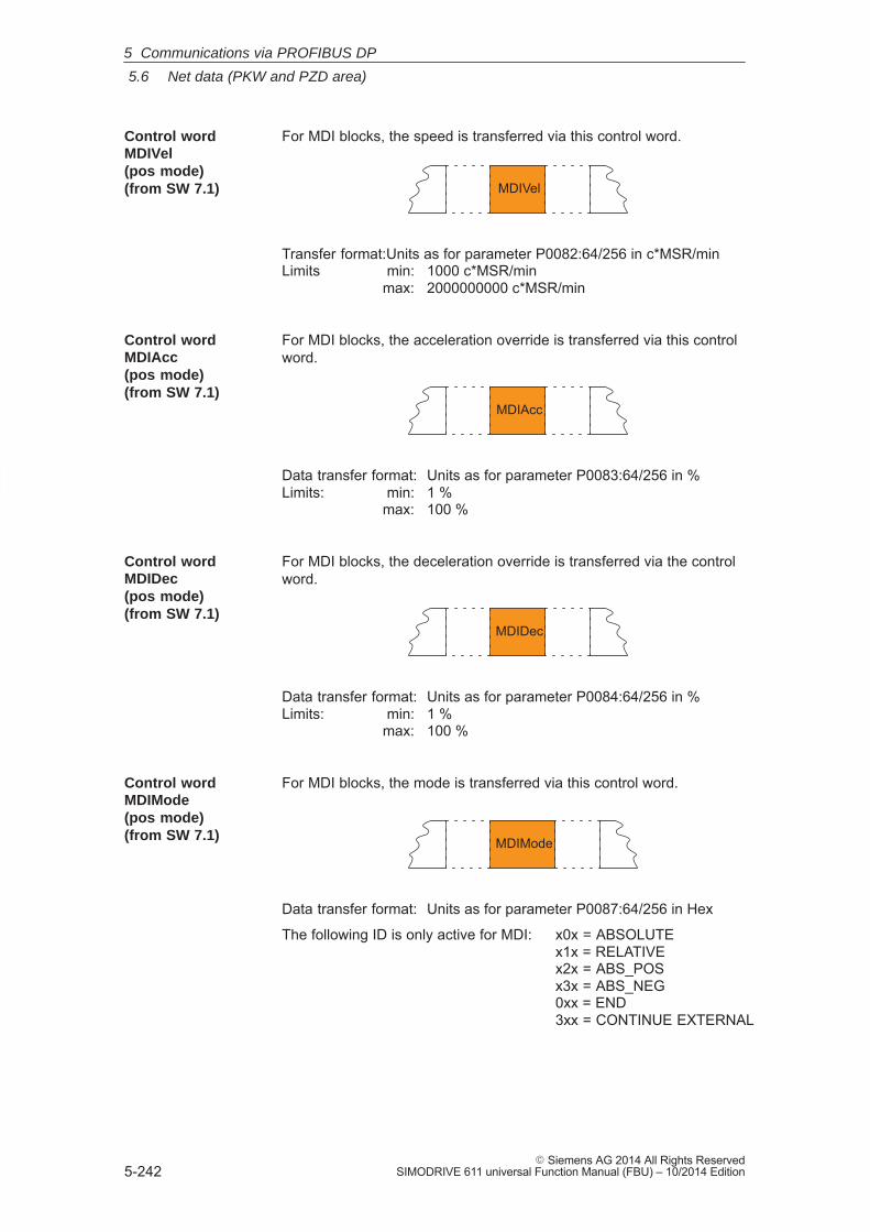
5
5.6 Net data (PKW and PZD area)
5-242� Siemens AG 2014 All Rights Reserved
SIMODRIVE 611 universal Function Manual (FBU) – 10/2014 Edition
For MDI blocks, the speed is transferred via this control word.
MDIVel
Transfer format:Units as for parameter P0082:64/256 in c*MSR/minLimits min: 1000 c*MSR/min
max: 2000000000 c*MSR/min
For MDI blocks, the acceleration override is transferred via this controlword.
MDIAcc
Data transfer format: Units as for parameter P0083:64/256 in %Limits: min: 1 %
max: 100 %
For MDI blocks, the deceleration override is transferred via the controlword.
MDIDec
Data transfer format: Units as for parameter P0084:64/256 in %Limits: min: 1 %
max: 100 %
For MDI blocks, the mode is transferred via this control word.
MDIMode
Data transfer format: Units as for parameter P0087:64/256 in Hex
The following ID is only active for MDI: x0x = ABSOLUTEx1x = RELATIVEx2x = ABS_POSx3x = ABS_NEG0xx = END3xx = CONTINUE EXTERNAL
Control word MDIVel (pos mode)(from SW 7.1)
Control word MDIAcc (pos mode)(from SW 7.1)
Control word MDIDec (pos mode)(from SW 7.1)
Control word MDIMode (pos mode)(from SW 7.1)
5 Communications via PROFIBUS DP
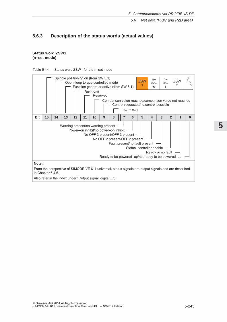
5
5.6 Net data (PKW and PZD area)
5-243� Siemens AG 2014 All Rights ReservedSIMODRIVE 611 universal Function Manual (FBU) – 10/2014 Edition
5.6.3 Description of the status words (actual values)
Table 5-14 Status word ZSW1 for the n–set mode
Spindle positioning on (from SW 5.1)Open–loop torque controlled mode
Comparison value reached/comparison value not reachedControl requested/no control possible
nset = nact
ZSW1
n–ist–h
n–ist–
lZSW
2
Reserved
Function generator active (from SW 6.1)Reserved
Bit 15 14 13 12 11 10 9 8 7 6 5 4 3 2 1 0
Warning present/no warning presentPower–on inhibit/no power–on inhibit
No OFF 3 present/OFF 3 presentNo OFF 2 present/OFF 2 present
Fault present/no fault presentStatus, controller enable
Ready or no faultReady to be powered–up/not ready to be powered–up
Note:
From the perspective of SIMODRIVE 611 universal, status signals are output signals and are describedin Chapter 6.4.6.Also refer in the index under ”Output signal, digital ...”).
Status word ZSW1 (n–set mode)
5 Communications via PROFIBUS DP
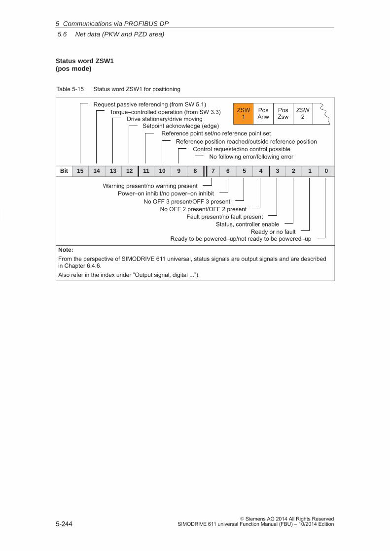
5
5.6 Net data (PKW and PZD area)
5-244� Siemens AG 2014 All Rights Reserved
SIMODRIVE 611 universal Function Manual (FBU) – 10/2014 Edition
Table 5-15 Status word ZSW1 for positioning
Torque–controlled operation (from SW 3.3)Drive stationary/drive moving
Setpoint acknowledge (edge)Reference point set/no reference point set
Reference position reached/outside reference positionControl requested/no control possible
No following error/following error
ZSW1
PosAnw
PosZsw
ZSW2
Request passive referencing (from SW 5.1)
Bit 15 14 13 12 11 10 9 8 7 6 5 4 3 2 1 0
Warning present/no warning presentPower–on inhibit/no power–on inhibit
No OFF 3 present/OFF 3 presentNo OFF 2 present/OFF 2 present
Fault present/no fault presentStatus, controller enable
Ready or no faultReady to be powered–up/not ready to be powered–up
Note:
From the perspective of SIMODRIVE 611 universal, status signals are output signals and are describedin Chapter 6.4.6.Also refer in the index under ”Output signal, digital ...”).
Status word ZSW1 (pos mode)
5 Communications via PROFIBUS DP
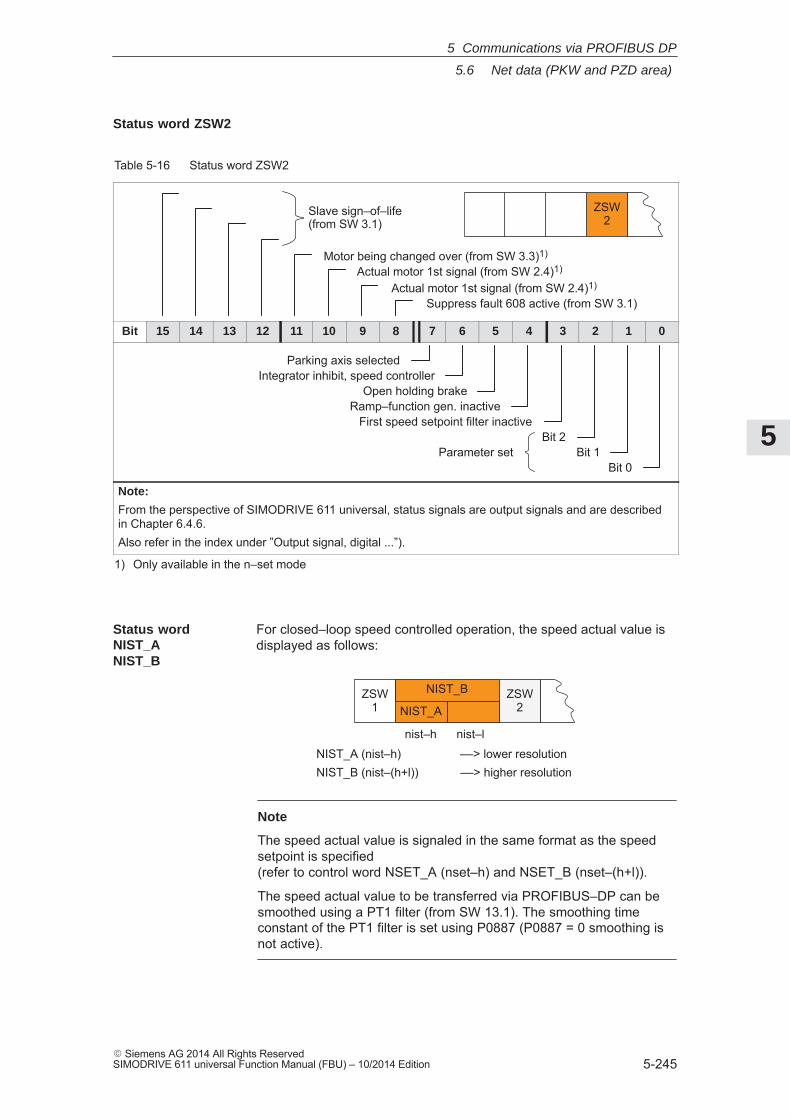
5
5.6 Net data (PKW and PZD area)
5-245� Siemens AG 2014 All Rights ReservedSIMODRIVE 611 universal Function Manual (FBU) – 10/2014 Edition
Table 5-16 Status word ZSW2
ZSW2
Suppress fault 608 active (from SW 3.1)Actual motor 1st signal (from SW 2.4)1)
Actual motor 1st signal (from SW 2.4)1)
Slave sign–of–life(from SW 3.1)
Motor being changed over (from SW 3.3)1)
Bit 15 14 13 12 11 10 9 8 7 6 5 4 3 2 1 0
Parking axis selectedIntegrator inhibit, speed controller
Open holding brakeRamp–function gen. inactive
First speed setpoint filter inactiveBit 2
Bit 1Bit 0
Parameter set
Note:
From the perspective of SIMODRIVE 611 universal, status signals are output signals and are describedin Chapter 6.4.6.Also refer in the index under ”Output signal, digital ...”).
1) Only available in the n–set mode
For closed–loop speed controlled operation, the speed actual value isdisplayed as follows:
NIST_A (nist–h) ––> lower resolutionNIST_B (nist–(h+l)) ––> higher resolution
nist–l
ZSW1
ZSW2
NIST_B
NIST_A
nist–h
Note
The speed actual value is signaled in the same format as the speedsetpoint is specified (refer to control word NSET_A (nset–h) and NSET_B (nset–(h+l)).
The speed actual value to be transferred via PROFIBUS–DP can besmoothed using a PT1 filter (from SW 13.1). The smoothing timeconstant of the PT1 filter is set using P0887 (P0887 = 0 smoothing isnot active).
Status word ZSW2
Status wordNIST_A NIST_B
5 Communications via PROFIBUS DP
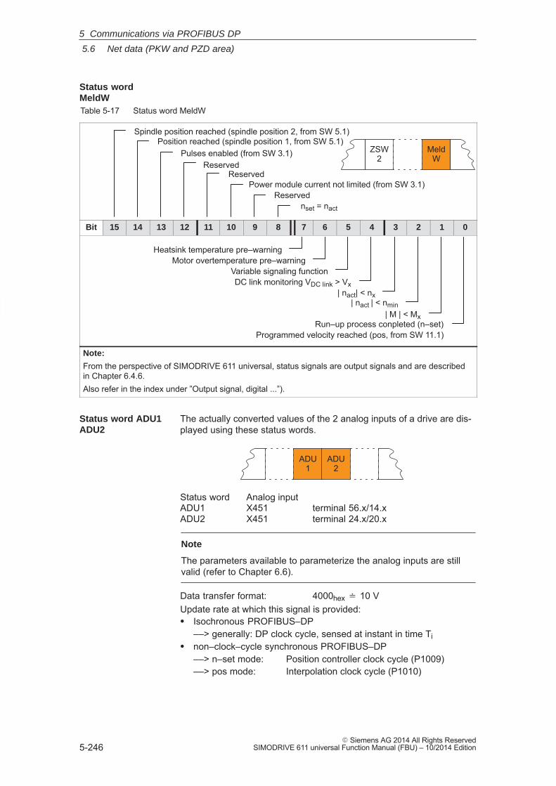
5
5.6 Net data (PKW and PZD area)
5-246� Siemens AG 2014 All Rights Reserved
SIMODRIVE 611 universal Function Manual (FBU) – 10/2014 Edition
Table 5-17 Status word MeldW
Reserved
MeldW
ZSW2
nset = nact
Pulses enabled (from SW 3.1)
Spindle position reached (spindle position 2, from SW 5.1)
Power module current not limited (from SW 3.1)Reserved
Position reached (spindle position 1, from SW 5.1)
Reserved
Bit 15 14 13 12 11 10 9 8 7 6 5 4 3 2 1 0
| M | < MxRun–up process conpleted (n–set)
| nact | < nmin
| nact| < nx
DC link monitoring VDC link > Vx
Variable signaling function
Heatsink temperature pre–warningMotor overtemperature pre–warning
Programmed velocity reached (pos, from SW 11.1)
Note:
From the perspective of SIMODRIVE 611 universal, status signals are output signals and are describedin Chapter 6.4.6.Also refer in the index under ”Output signal, digital ...”).
The actually converted values of the 2 analog inputs of a drive are dis-played using these status words.
ADU1
ADU2
Status word Analog inputADU1 X451 terminal 56.x/14.xADU2 X451 terminal 24.x/20.x
Note
The parameters available to parameterize the analog inputs are stillvalid (refer to Chapter 6.6).
Data transfer format: 4000hex � 10 VUpdate rate at which this signal is provided:� Isochronous PROFIBUS–DP
––> generally: DP clock cycle, sensed at instant in time Ti� non–clock–cycle synchronous PROFIBUS–DP
––> n–set mode: Position controller clock cycle (P1009)––> pos mode: Interpolation clock cycle (P1010)
Status wordMeldW
Status word ADU1ADU2
5 Communications via PROFIBUS DP
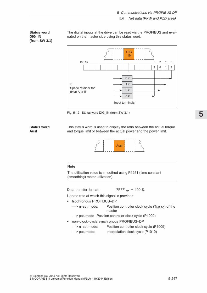
5
5.6 Net data (PKW and PZD area)
5-247� Siemens AG 2014 All Rights ReservedSIMODRIVE 611 universal Function Manual (FBU) – 10/2014 Edition
The digital inputs at the drive can be read via the PROFIBUS and eval-uated on the master side using this status word.
15 0123Bit
1 0 1 1
I0.x
I1.x
I2.x
I3.x
Input terminals
x: Space retainer for drive A or B
DIG_IN
Fig. 5-12 Status word DIG_IN (from SW 3.1)
This status word is used to display the ratio between the actual torqueand torque limit or between the actual power and the power limit.
Ausl
Note
The utilization value is smoothed using P1251 (time constant(smoothing) motor utilization).
Data transfer format: 7FFFhex � 100 %
Update rate at which this signal is provided:� Isochronous PROFIBUS–DP
––> n–set mode: Position controller clock cycle (TMAPC) of themaster
––> pos mode Position controller clock cycle (P1009)� non–clock–cycle synchronous PROFIBUS–DP
––> n–set mode: Position controller clock cycle (P1009)––> pos mode: Interpolation clock cycle (P1010)
Status wordDIG_IN (from SW 3.1)
Status word Ausl
5 Communications via PROFIBUS DP
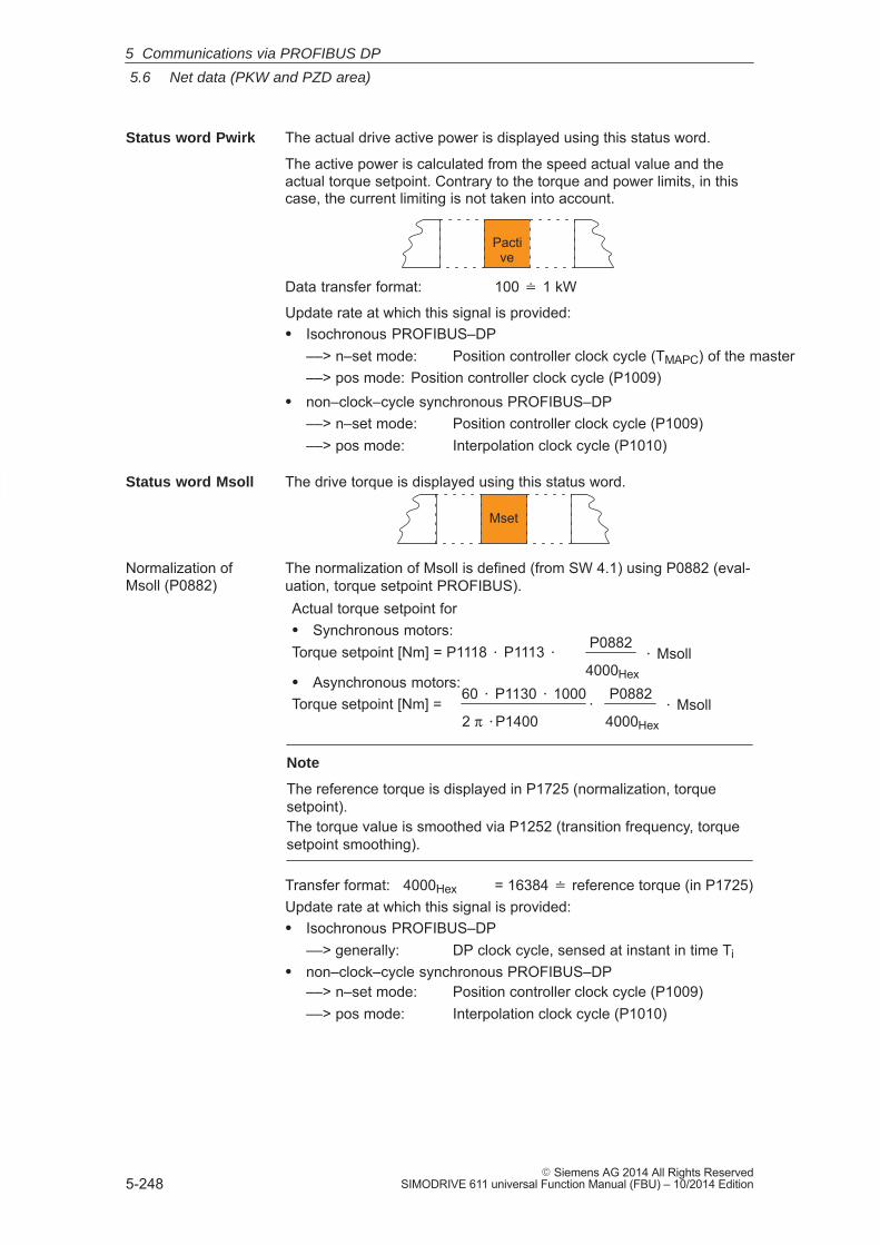
5
5.6 Net data (PKW and PZD area)
5-248� Siemens AG 2014 All Rights Reserved
SIMODRIVE 611 universal Function Manual (FBU) – 10/2014 Edition
The actual drive active power is displayed using this status word.
The active power is calculated from the speed actual value and theactual torque setpoint. Contrary to the torque and power limits, in thiscase, the current limiting is not taken into account.
Pactive
Data transfer format: 100 � 1 kW
Update rate at which this signal is provided:� Isochronous PROFIBUS–DP
––> n–set mode: Position controller clock cycle (TMAPC) of the master––> pos mode: Position controller clock cycle (P1009)
� non–clock–cycle synchronous PROFIBUS–DP––> n–set mode: Position controller clock cycle (P1009)––> pos mode: Interpolation clock cycle (P1010)
The drive torque is displayed using this status word.
Mset
The normalization of Msoll is defined (from SW 4.1) using P0882 (eval-uation, torque setpoint PROFIBUS).Actual torque setpoint for� Synchronous motors:Torque setpoint [Nm] = P1118 � P1113 � P0882
4000Hex� Msoll
� Asynchronous motors:Torque setpoint [Nm] = �
P0882
4000Hex� Msoll
60 � P1130 � 1000
2 π �P1400
Note
The reference torque is displayed in P1725 (normalization, torquesetpoint).The torque value is smoothed via P1252 (transition frequency, torquesetpoint smoothing).
Transfer format: 4000Hex = 16384 � reference torque (in P1725)Update rate at which this signal is provided:� Isochronous PROFIBUS–DP
––> generally: DP clock cycle, sensed at instant in time Ti� non–clock–cycle synchronous PROFIBUS–DP
––> n–set mode: Position controller clock cycle (P1009)––> pos mode: Interpolation clock cycle (P1010)
Status word Pwirk
Status word Msoll
Normalization ofMsoll (P0882)
5 Communications via PROFIBUS DP
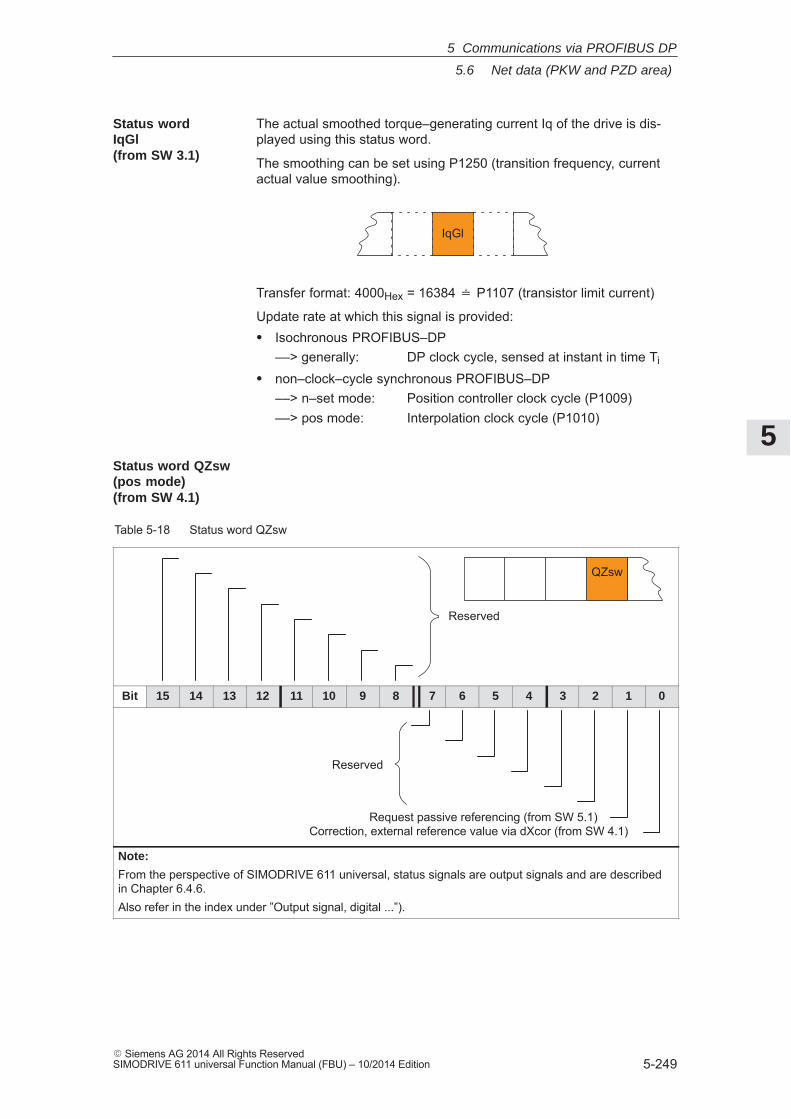
5
5.6 Net data (PKW and PZD area)
5-249� Siemens AG 2014 All Rights ReservedSIMODRIVE 611 universal Function Manual (FBU) – 10/2014 Edition
The actual smoothed torque–generating current Iq of the drive is dis-played using this status word.
The smoothing can be set using P1250 (transition frequency, currentactual value smoothing).
IqGl
Transfer format: 4000Hex = 16384 � P1107 (transistor limit current)
Update rate at which this signal is provided:� Isochronous PROFIBUS–DP
––> generally: DP clock cycle, sensed at instant in time Ti
� non–clock–cycle synchronous PROFIBUS–DP––> n–set mode: Position controller clock cycle (P1009)––> pos mode: Interpolation clock cycle (P1010)
Table 5-18 Status word QZsw
QZsw
Reserved
Bit 15 14 13 12 11 10 9 8 7 6 5 4 3 2 1 0
Reserved
Correction, external reference value via dXcor (from SW 4.1)Request passive referencing (from SW 5.1)
Note:
From the perspective of SIMODRIVE 611 universal, status signals are output signals and are describedin Chapter 6.4.6.Also refer in the index under ”Output signal, digital ...”).
Status wordIqGl (from SW 3.1)
Status word QZsw (pos mode)(from SW 4.1)
5 Communications via PROFIBUS DP
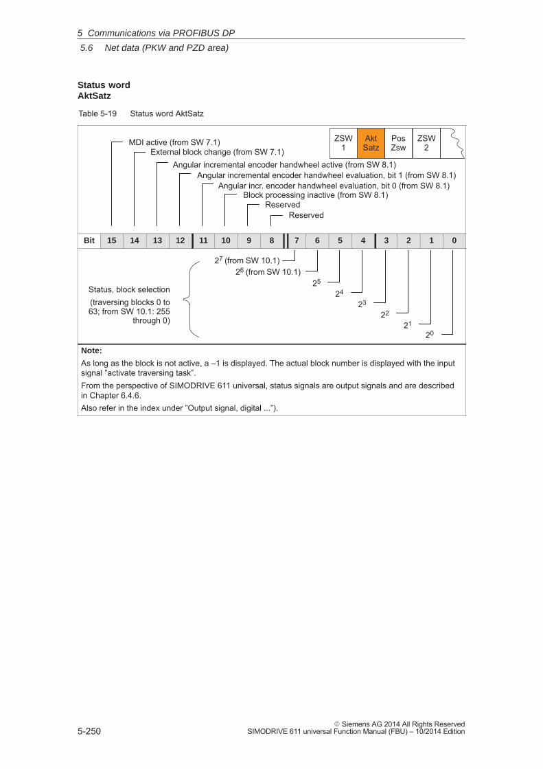
5
5.6 Net data (PKW and PZD area)
5-250� Siemens AG 2014 All Rights Reserved
SIMODRIVE 611 universal Function Manual (FBU) – 10/2014 Edition
Table 5-19 Status word AktSatz
ZSW1
AktSatz
PosZsw
ZSW2
Angular incr. encoder handwheel evaluation, bit 0 (from SW 8.1)Block processing inactive (from SW 8.1)
MDI active (from SW 7.1)External block change (from SW 7.1)
Angular incremental encoder handwheel evaluation, bit 1 (from SW 8.1)
ReservedReserved
Angular incremental encoder handwheel active (from SW 8.1)
Bit 15 14 13 12 11 10 9 8 7 6 5 4 3 2 1 0
26 (from SW 10.1)25
24
23
22
21
20
Status, block selection(traversing blocks 0 to63; from SW 10.1: 255
through 0)
27 (from SW 10.1)
Note:
As long as the block is not active, a –1 is displayed. The actual block number is displayed with the inputsignal ”activate traversing task”.From the perspective of SIMODRIVE 611 universal, status signals are output signals and are describedin Chapter 6.4.6.Also refer in the index under ”Output signal, digital ...”).
Status wordAktSatz
5 Communications via PROFIBUS DP
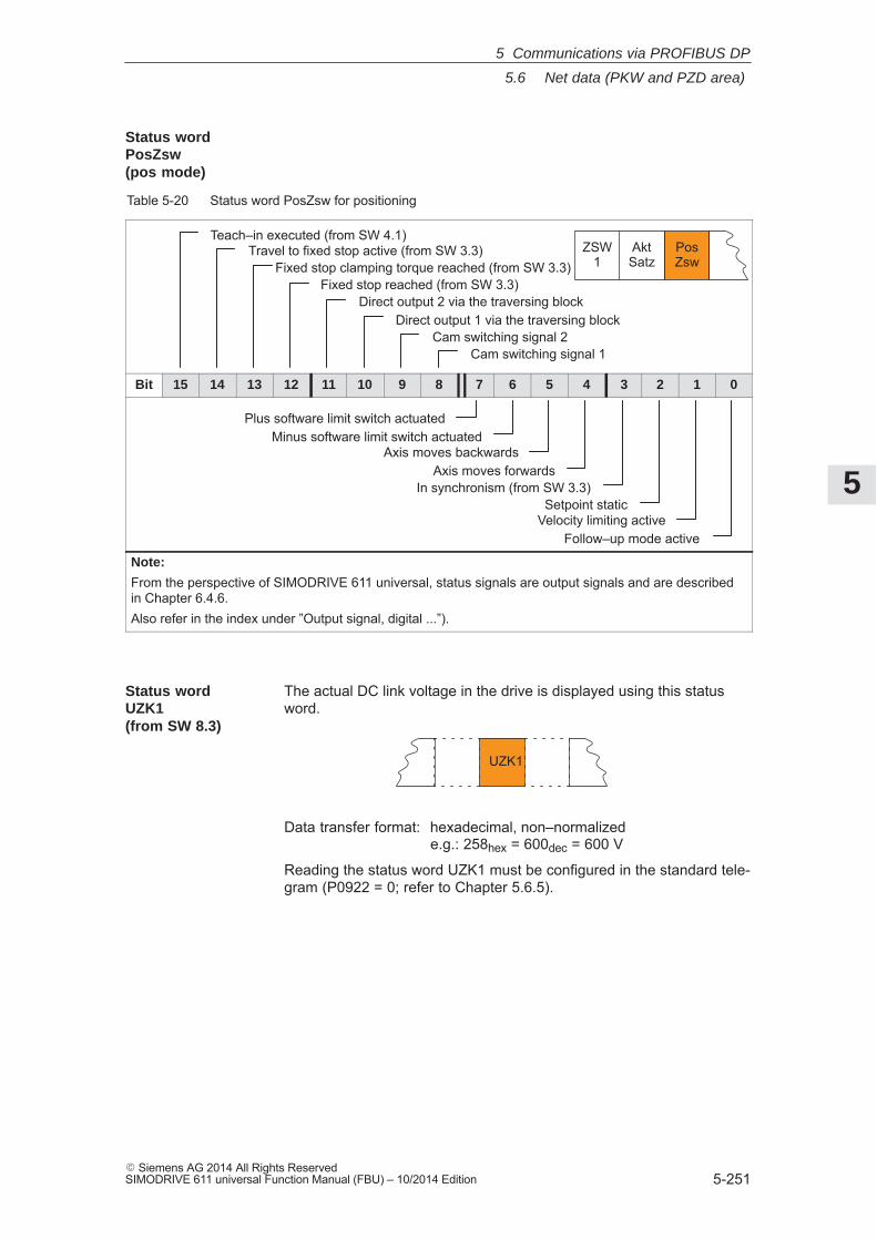
5
5.6 Net data (PKW and PZD area)
5-251� Siemens AG 2014 All Rights ReservedSIMODRIVE 611 universal Function Manual (FBU) – 10/2014 Edition
Table 5-20 Status word PosZsw for positioning
Cam switching signal 1Cam switching signal 2
ZSW1
AktSatz
PosZsw
Direct output 1 via the traversing blockDirect output 2 via the traversing block
Fixed stop reached (from SW 3.3)Fixed stop clamping torque reached (from SW 3.3)
Teach–in executed (from SW 4.1)Travel to fixed stop active (from SW 3.3)
Bit 15 14 13 12 11 10 9 8 7 6 5 4 3 2 1 0
Axis moves backwards
Follow–up mode active
Setpoint static
Axis moves forwards
Minus software limit switch actuatedPlus software limit switch actuated
In synchronism (from SW 3.3)
Velocity limiting active
Note:
From the perspective of SIMODRIVE 611 universal, status signals are output signals and are describedin Chapter 6.4.6.Also refer in the index under ”Output signal, digital ...”).
The actual DC link voltage in the drive is displayed using this statusword.
UZK1
Data transfer format: hexadecimal, non–normalizede.g.: 258hex = 600dec = 600 V
Reading the status word UZK1 must be configured in the standard tele-gram (P0922 = 0; refer to Chapter 5.6.5).
Status wordPosZsw (pos mode)
Status wordUZK1 (from SW 8.3)
5 Communications via PROFIBUS DP
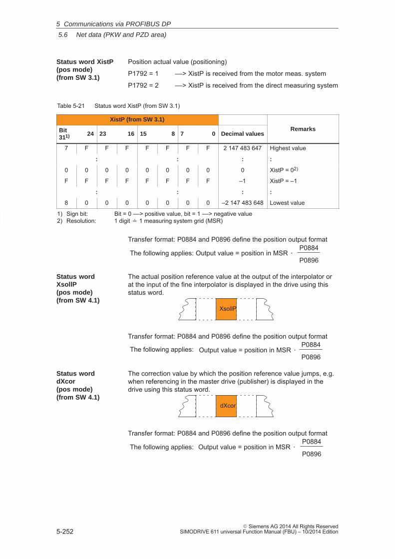
5
5.6 Net data (PKW and PZD area)
5-252� Siemens AG 2014 All Rights Reserved
SIMODRIVE 611 universal Function Manual (FBU) – 10/2014 Edition
Position actual value (positioning)
P1792 = 1 ––> XistP is received from the motor meas. system
P1792 = 2 ––> XistP is received from the direct measuring system
Table 5-21 Status word XistP (from SW 3.1)
XistP (from SW 3.1)
RemarksBit311) 24 23 16 15 8 7 0 Decimal values
Remarks
7 F F F F F F F 2 147 483 647 Highest value
: : : :
0 0 0 0 0 0 0 0 0 XistP = 02)
F F F F F F F F –1 XistP = –1
: : : :
8 0 0 0 0 0 0 0 –2 147 483 648 Lowest value
1) Sign bit: Bit = 0 ––> positive value, bit = 1 ––> negative value2) Resolution: 1 digit � 1 measuring system grid (MSR)
Transfer format: P0884 and P0896 define the position output format
Output value = position in MSR �P0884
P0896The following applies:
The actual position reference value at the output of the interpolator orat the input of the fine interpolator is displayed in the drive using thisstatus word.
XsollP
Transfer format: P0884 and P0896 define the position output format
Output value = position in MSR �P0884
P0896The following applies:
The correction value by which the position reference value jumps, e.g.when referencing in the master drive (publisher) is displayed in thedrive using this status word.
dXcor
Transfer format: P0884 and P0896 define the position output format
Output value = position in MSR �P0884
P0896The following applies:
Status word XistP(pos mode) (from SW 3.1)
Status wordXsollP (pos mode)(from SW 4.1)
Status worddXcor (pos mode)(from SW 4.1)
5 Communications via PROFIBUS DP
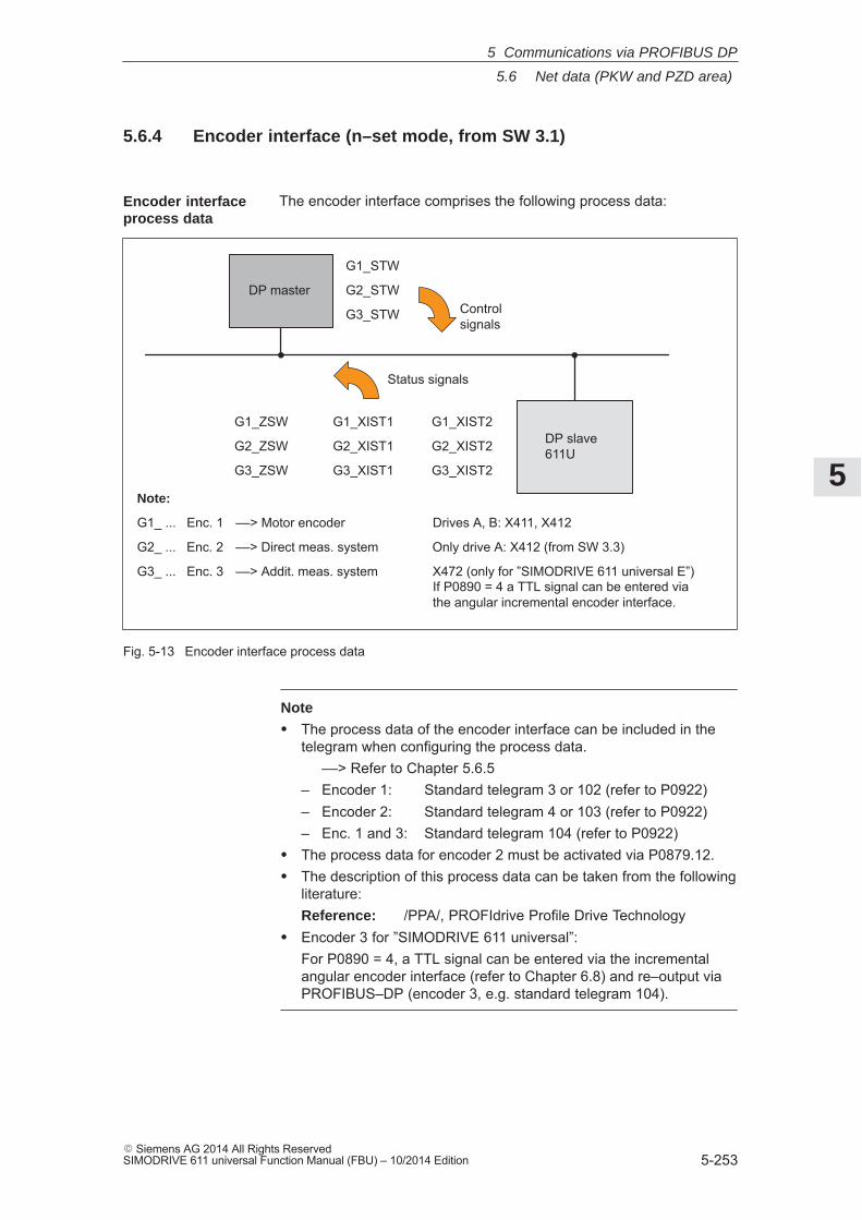
5
5.6 Net data (PKW and PZD area)
5-253� Siemens AG 2014 All Rights ReservedSIMODRIVE 611 universal Function Manual (FBU) – 10/2014 Edition
5.6.4 Encoder interface (n–set mode, from SW 3.1)
The encoder interface comprises the following process data:
DP master
DP slave611U
G1_STW
G2_STW
G3_STW
G1_ZSW G1_XIST1 G1_XIST2
G2_ZSW G2_XIST1 G2_XIST2
G3_ZSW G3_XIST1 G3_XIST2
Note:
G1_ ... Enc. 1 ––> Motor encoder Drives A, B: X411, X412
G2_ ... Enc. 2 ––> Direct meas. system Only drive A: X412 (from SW 3.3)
G3_ ... Enc. 3 ––> Addit. meas. system X472 (only for ”SIMODRIVE 611 universal E”)If P0890 = 4 a TTL signal can be entered viathe angular incremental encoder interface.
Controlsignals
Status signals
Fig. 5-13 Encoder interface process data
Note
� The process data of the encoder interface can be included in thetelegram when configuring the process data.
––> Refer to Chapter 5.6.5– Encoder 1: Standard telegram 3 or 102 (refer to P0922)– Encoder 2: Standard telegram 4 or 103 (refer to P0922)– Enc. 1 and 3: Standard telegram 104 (refer to P0922)
� The process data for encoder 2 must be activated via P0879.12.� The description of this process data can be taken from the following
literature:Reference: /PPA/, PROFIdrive Profile Drive Technology
� Encoder 3 for ”SIMODRIVE 611 universal”:For P0890 = 4, a TTL signal can be entered via the incrementalangular encoder interface (refer to Chapter 6.8) and re–output viaPROFIBUS–DP (encoder 3, e.g. standard telegram 104).
Encoder interfaceprocess data
5 Communications via PROFIBUS DP
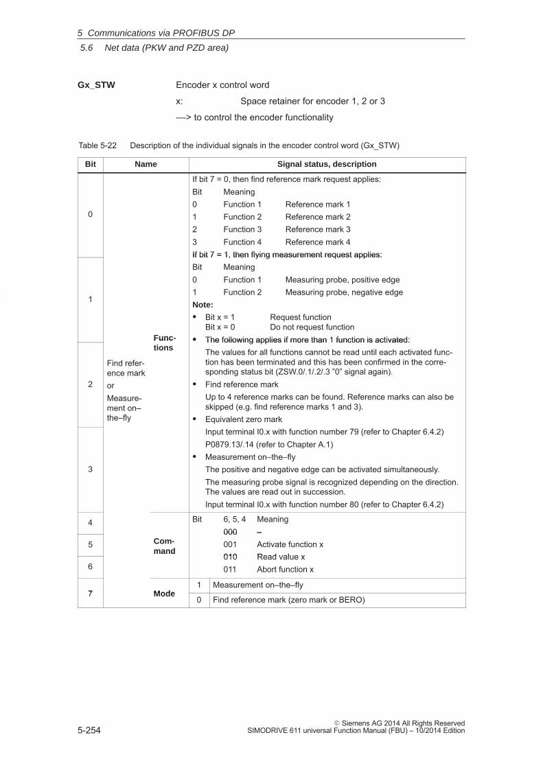
5
5.6 Net data (PKW and PZD area)
5-254� Siemens AG 2014 All Rights Reserved
SIMODRIVE 611 universal Function Manual (FBU) – 10/2014 Edition
Encoder x control word
x: Space retainer for encoder 1, 2 or 3
––> to control the encoder functionality
Table 5-22 Description of the individual signals in the encoder control word (Gx_STW)
Bit Name Signal status, description
0
If bit 7 = 0, then find reference mark request applies:Bit Meaning0 Function 1 Reference mark 11 Function 2 Reference mark 22 Function 3 Reference mark 33 Function 4 Reference mark 4If bit 7 = 1, then flying measurement request applies:
1
Func-
If bit 7 = 1, then flying measurement request applies:Bit Meaning0 Function 1 Measuring probe, positive edge1 Function 2 Measuring probe, negative edgeNote:
� Bit x = 1 Request functionBit x = 0 Do not request function
� The following applies if more than 1 function is activated:
2
Find refer-ence markorMeasure-ment on–the–fly
Func-tions
� The following applies if more than 1 function is activated:The values for all functions cannot be read until each activated func-tion has been terminated and this has been confirmed in the corre-sponding status bit (ZSW.0/.1/.2/.3 ”0” signal again).
� Find reference markUp to 4 reference marks can be found. Reference marks can also beskipped (e.g. find reference marks 1 and 3).
� Equivalent zero markInput terminal I0.x with function number 79 (refer to Chapter 6.4.2)
3
Input terminal I0.x with function number 79 (refer to Chapter 6.4.2)P0879.13/.14 (refer to Chapter A.1)
� Measurement on–the–flyThe positive and negative edge can be activated simultaneously.The measuring probe signal is recognized depending on the direction.The values are read out in succession.Input terminal I0.x with function number 80 (refer to Chapter 6.4.2)
4 Bit 6, 5, 4 Meaning000 –
5 Com-mand
000 –001 Activate function x010 Read value x
6
mand010 Read value x011 Abort function x
7 Mode1 Measurement on–the–fly
7 Mode0 Find reference mark (zero mark or BERO)
Gx_STW
5 Communications via PROFIBUS DP
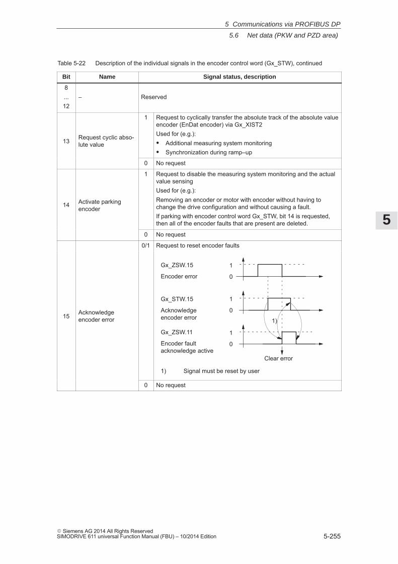
5
5.6 Net data (PKW and PZD area)
5-255� Siemens AG 2014 All Rights ReservedSIMODRIVE 611 universal Function Manual (FBU) – 10/2014 Edition
Table 5-22 Description of the individual signals in the encoder control word (Gx_STW), continued
Bit Signal status, descriptionName
8...12
– Reserved
13 Request cyclic abso-lute value
1 Request to cyclically transfer the absolute track of the absolute valueencoder (EnDat encoder) via Gx_XIST2Used for (e.g.):� Additional measuring system monitoring� Synchronization during ramp–up
0 No request
14 Activate parkingencoder
1 Request to disable the measuring system monitoring and the actualvalue sensingUsed for (e.g.):Removing an encoder or motor with encoder without having tochange the drive configuration and without causing a fault.If parking with encoder control word Gx_STW, bit 14 is requested,then all of the encoder faults that are present are deleted.
0 No request
0/1 Request to reset encoder faults
15 Acknowledgeencoder error
1
0
Gx_ZSW.15
Encoder error
1
0
1
0
Gx_STW.15
Acknowledgeencoder error
Gx_ZSW.11
Encoder faultacknowledge active
Clear error
1)
1) Signal must be reset by user
0 No request
5 Communications via PROFIBUS DP
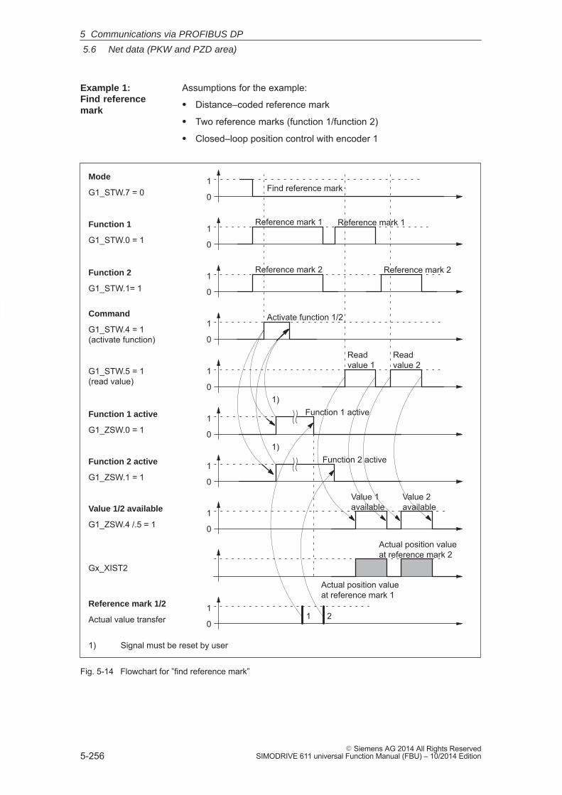
5
5.6 Net data (PKW and PZD area)
5-256� Siemens AG 2014 All Rights Reserved
SIMODRIVE 611 universal Function Manual (FBU) – 10/2014 Edition
Assumptions for the example:
� Distance–coded reference mark
� Two reference marks (function 1/function 2)
� Closed–loop position control with encoder 1
Mode
G1_STW.7 = 0
Function 1
G1_STW.0 = 1
Command
G1_STW.4 = 1(activate function)
G1_STW.5 = 1(read value)
Function 1 active
G1_ZSW.0 = 1
Value 1/2 available
G1_ZSW.4 /.5 = 1
Gx_XIST2
Reference mark 1/2
Actual value transfer1
0
1
0
1
0
1
0
1
0
1
0Find reference mark
Reference mark 1
Activate function 1/2
Function 1 active
Value 1available
Function 2
G1_STW.1= 11
0
Function 2 active
G1_ZSW.1 = 11
0
Function 2 active
Reference mark 2
Value 2available
Actual position valueat reference mark 1
Actual position valueat reference mark 2
Reference mark 1
Reference mark 2
1 2
1)
1) Signal must be reset by user
1
0
Read value 1
Read value 2
1)
Fig. 5-14 Flowchart for ”find reference mark”
Example 1: Find referencemark
5 Communications via PROFIBUS DP
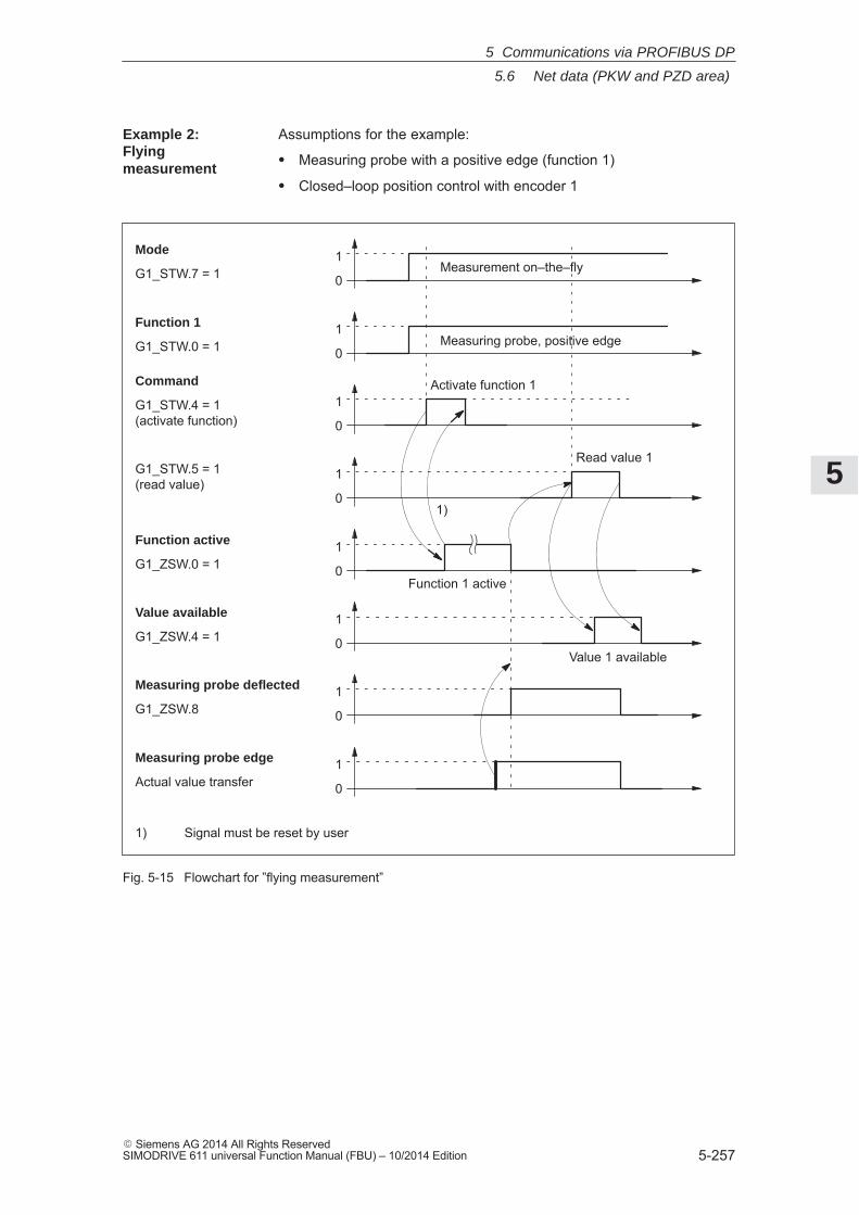
5
5.6 Net data (PKW and PZD area)
5-257� Siemens AG 2014 All Rights ReservedSIMODRIVE 611 universal Function Manual (FBU) – 10/2014 Edition
Assumptions for the example:
� Measuring probe with a positive edge (function 1)
� Closed–loop position control with encoder 1
Mode
G1_STW.7 = 1
Function 1
G1_STW.0 = 1
Command
G1_STW.4 = 1(activate function)
G1_STW.5 = 1(read value)
Function active
G1_ZSW.0 = 1
Value available
G1_ZSW.4 = 1
Measuring probe deflected
G1_ZSW.8
Measuring probe edge
Actual value transfer1
0
1
0
1
0
1
0
1
0
1
0
1
0Measurement on–the–fly
Measuring probe, positive edge
Activate function 1
Function 1 active
Value 1 available
1)
1) Signal must be reset by user
1
0
Read value 1
Fig. 5-15 Flowchart for ”flying measurement”
Example 2: Flying measurement
5 Communications via PROFIBUS DP
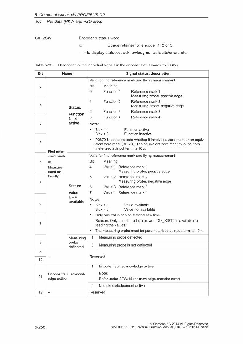
5
5.6 Net data (PKW and PZD area)
5-258� Siemens AG 2014 All Rights Reserved
SIMODRIVE 611 universal Function Manual (FBU) – 10/2014 Edition
Encoder x status word
x: Space retainer for encoder 1, 2 or 3
––> to display statuses, acknowledgments, faults/errors etc.
Table 5-23 Description of the individual signals in the encoder status word (Gx_ZSW)
Bit Name Signal status, description
0Valid for find reference mark and flying measurementBit Meaning0 Function 1 Reference mark 1
Measuring probe, positive edge
1 Status:
Function
Measuring probe, positive edge1 Function 2 Reference mark 2
Measuring probe, negative edge2 Function 3 Reference mark 3
2
Function1 – 4active
2 Function 3 Reference mark 33 Function 4 Reference mark 4
Note:
� Bit x = 1 Function activeBit x = 0 Function inactive
3
Find refer-
Bit x = 0 Function inactive� P0879 is set to indicate whether it involves a zero mark or an equiv-
alent zero mark (BERO). The equivalent zero mark must be para-meterized at input terminal I0.x.
4
Find refer-ence markorMeasure-ment on–
Valid for find reference mark and flying measurementBit Meaning4 Value 1 Reference mark 1
Measuring probe, positive edge
5
ment on–the–fly
Status:
Value
Measuring probe, positive edge5 Value 2 Reference mark 2
Measuring probe, negative edge6 Value 3 Reference mark 37 Value 4 Reference mark 4
6
Value 1 – 4available
7 Value 4 Reference mark 4
Note:
� Bit x = 1 Value availableBit x = 0 Value not availableOnly one value can be fetched at a time.
7
� Only one value can be fetched at a time.Reason: Only one shared status word Gx_XIST2 is available forreading the values.
� The measuring probe must be parameterized at input terminal I0.x.
8Measuringprobe
1 Measuring probe deflected8 probe
deflected 0 Measuring probe is not deflected
9– Reserved
10– Reserved
11 Encoder fault acknowl-edge active
1 Encoder fault acknowledge active
Note:
Refer under STW.15 (acknowledge encoder error)
0 No acknowledgement active
12 – Reserved
Gx_ZSW
5 Communications via PROFIBUS DP
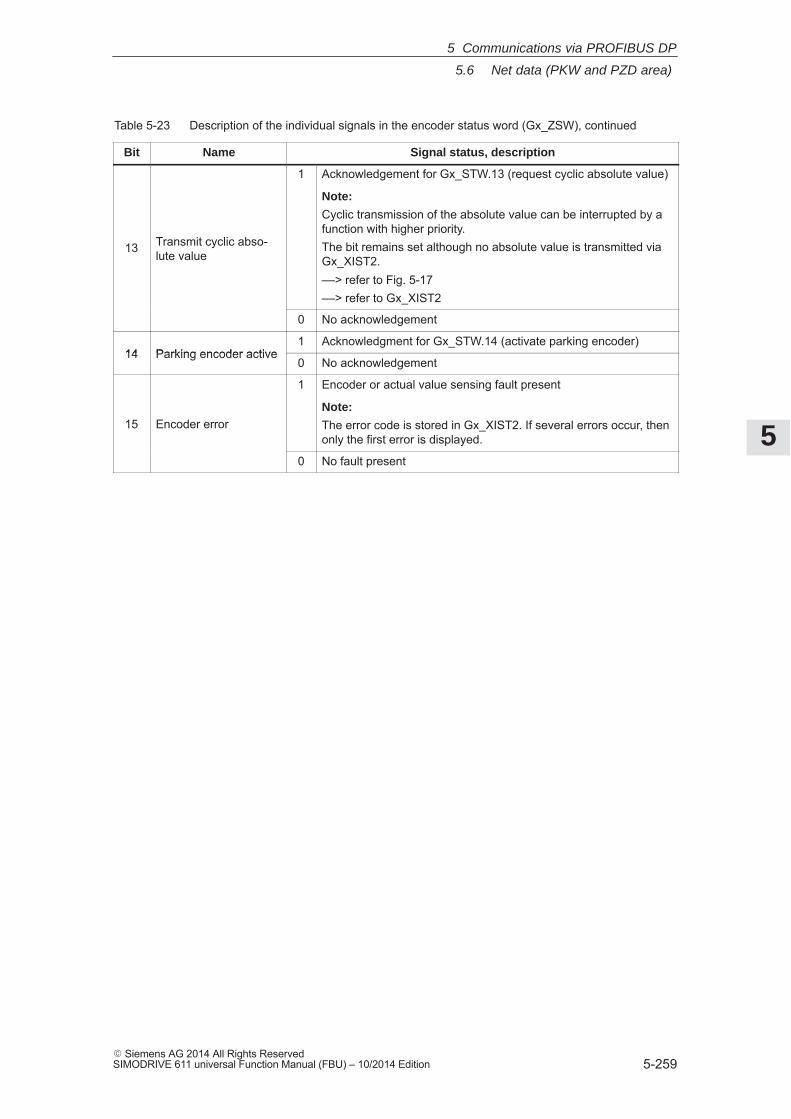
5
5.6 Net data (PKW and PZD area)
5-259� Siemens AG 2014 All Rights ReservedSIMODRIVE 611 universal Function Manual (FBU) – 10/2014 Edition
Table 5-23 Description of the individual signals in the encoder status word (Gx_ZSW), continued
Bit Signal status, descriptionName
13 Transmit cyclic abso-lute value
1 Acknowledgement for Gx_STW.13 (request cyclic absolute value)
Note:
Cyclic transmission of the absolute value can be interrupted by afunction with higher priority.The bit remains set although no absolute value is transmitted viaGx_XIST2.––> refer to Fig. 5-17––> refer to Gx_XIST2
0 No acknowledgement
14 Parking encoder active1 Acknowledgment for Gx_STW.14 (activate parking encoder)
14 Parking encoder active0 No acknowledgement
15 Encoder error
1 Encoder or actual value sensing fault present
Note:
The error code is stored in Gx_XIST2. If several errors occur, thenonly the first error is displayed.
0 No fault present
5 Communications via PROFIBUS DP
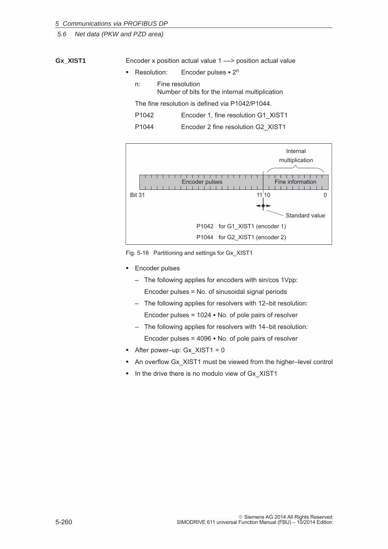
5
5.6 Net data (PKW and PZD area)
5-260� Siemens AG 2014 All Rights Reserved
SIMODRIVE 611 universal Function Manual (FBU) – 10/2014 Edition
Encoder x position actual value 1 ––> position actual value
� Resolution: Encoder pulses � 2n
n: Fine resolution Number of bits for the internal multiplication
The fine resolution is defined via P1042/P1044.
P1042 Encoder 1, fine resolution G1_XIST1
P1044 Encoder 2 fine resolution G2_XIST1
Bit 31
Encoder pulses Fine information
11 10 0
Internalmultiplication
P1042 for G1_XIST1 (encoder 1)
P1044 for G2_XIST1 (encoder 2)
Standard value
Fig. 5-16 Partitioning and settings for Gx_XIST1
� Encoder pulses
– The following applies for encoders with sin/cos 1Vpp:
Encoder pulses = No. of sinusoidal signal periods
– The following applies for resolvers with 12–bit resolution:
Encoder pulses = 1024 � No. of pole pairs of resolver
– The following applies for resolvers with 14–bit resolution:
Encoder pulses = 4096 � No. of pole pairs of resolver
� After power–up: Gx_XIST1 = 0
� An overflow Gx_XIST1 must be viewed from the higher–level control
� In the drive there is no modulo view of Gx_XIST1
Gx_XIST1
5 Communications via PROFIBUS DP
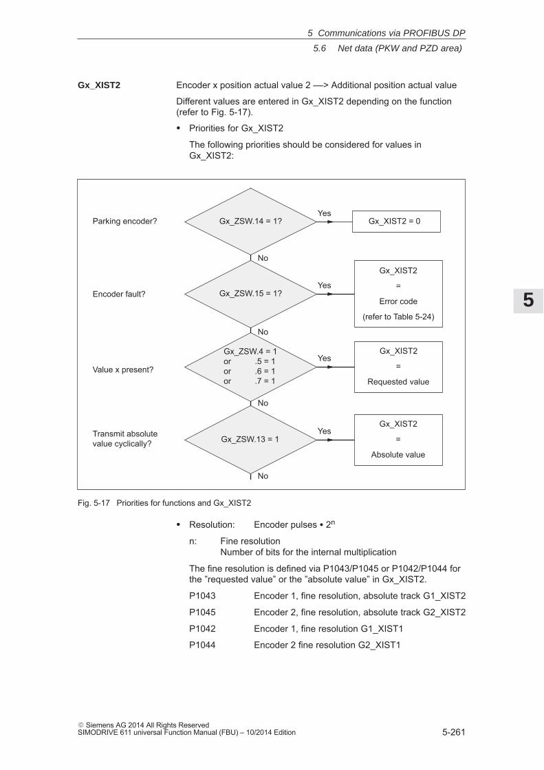
5
5.6 Net data (PKW and PZD area)
5-261� Siemens AG 2014 All Rights ReservedSIMODRIVE 611 universal Function Manual (FBU) – 10/2014 Edition
Encoder x position actual value 2 ––> Additional position actual value
Different values are entered in Gx_XIST2 depending on the function(refer to Fig. 5-17).
� Priorities for Gx_XIST2
The following priorities should be considered for values inGx_XIST2:
Gx_ZSW.14 = 1?
Gx_XIST2
=
Error code
(refer to Table 5-24)
Gx_XIST2
=
Requested value
Gx_XIST2
=
Absolute value
Yes
No
Yes
No
Yes
No
Yes
No
Gx_XIST2 = 0
Gx_ZSW.13 = 1
Gx_ZSW.4 = 1or .5 = 1or .6 = 1or .7 = 1
Gx_ZSW.15 = 1?
Parking encoder?
Encoder fault?
Value x present?
Transmit absolutevalue cyclically?
Fig. 5-17 Priorities for functions and Gx_XIST2
� Resolution: Encoder pulses � 2n
n: Fine resolution Number of bits for the internal multiplication
The fine resolution is defined via P1043/P1045 or P1042/P1044 forthe ”requested value” or the ”absolute value” in Gx_XIST2.
P1043 Encoder 1, fine resolution, absolute track G1_XIST2
P1045 Encoder 2, fine resolution, absolute track G2_XIST2
P1042 Encoder 1, fine resolution G1_XIST1
P1044 Encoder 2 fine resolution G2_XIST1
Gx_XIST2
5 Communications via PROFIBUS DP
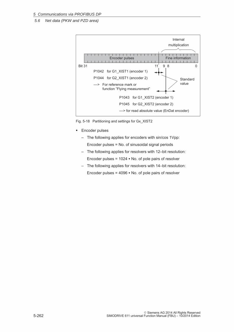
5
5.6 Net data (PKW and PZD area)
5-262� Siemens AG 2014 All Rights Reserved
SIMODRIVE 611 universal Function Manual (FBU) – 10/2014 Edition
Bit 31
Encoder pulses Fine information
11 0
Internalmultiplication
P1042 for G1_XIST1 (encoder 1)
P1044 for G2_XIST1 (encoder 2)
––> For reference mark or function ”Flying measurement”
P1043 for G1_XIST2 (encoder 1)
P1045 for G2_XIST2 (encoder 2)
––> for read absolute value (EnDat encoder)
8
Standardvalue
9
Fig. 5-18 Partitioning and settings for Gx_XIST2
� Encoder pulses
– The following applies for encoders with sin/cos 1Vpp:
Encoder pulses = No. of sinusoidal signal periods
– The following applies for resolvers with 12–bit resolution:
Encoder pulses = 1024 � No. of pole pairs of resolver
– The following applies for resolvers with 14–bit resolution:
Encoder pulses = 4096 � No. of pole pairs of resolver
5 Communications via PROFIBUS DP
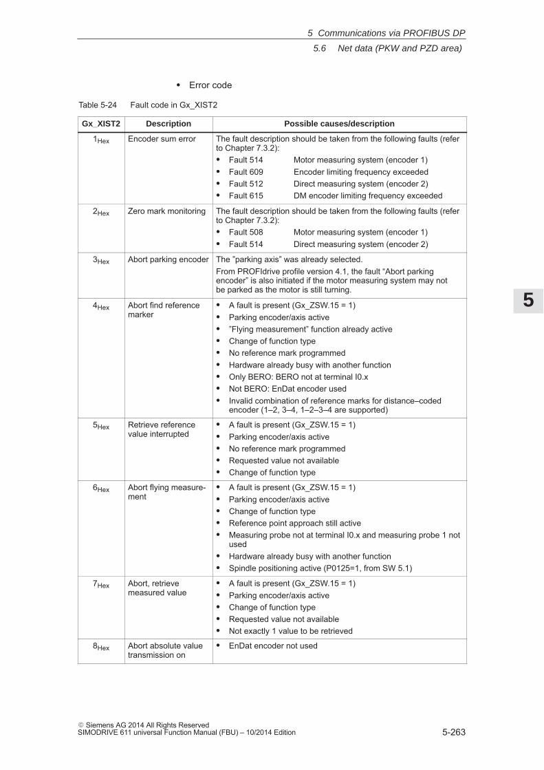
5
5.6 Net data (PKW and PZD area)
5-263� Siemens AG 2014 All Rights ReservedSIMODRIVE 611 universal Function Manual (FBU) – 10/2014 Edition
� Error code
Table 5-24 Fault code in Gx_XIST2
Gx_XIST2 Description Possible causes/description
1Hex Encoder sum error The fault description should be taken from the following faults (referto Chapter 7.3.2):� Fault 514 Motor measuring system (encoder 1)� Fault 609 Encoder limiting frequency exceeded� Fault 512 Direct measuring system (encoder 2)� Fault 615 DM encoder limiting frequency exceeded
2Hex Zero mark monitoring The fault description should be taken from the following faults (referto Chapter 7.3.2):� Fault 508 Motor measuring system (encoder 1)� Fault 514 Direct measuring system (encoder 2)
3Hex Abort parking encoder The ”parking axis” was already selected.From PROFIdrive profile version 4.1, the fault “Abort parkingencoder” is also initiated if the motor measuring system may notbe parked as the motor is still turning.
4Hex Abort find referencemarker
� A fault is present (Gx_ZSW.15 = 1)� Parking encoder/axis active� ”Flying measurement” function already active� Change of function type� No reference mark programmed� Hardware already busy with another function� Only BERO: BERO not at terminal I0.x� Not BERO: EnDat encoder used� Invalid combination of reference marks for distance–coded
encoder (1–2, 3–4, 1–2–3–4 are supported)
5Hex Retrieve referencevalue interrupted
� A fault is present (Gx_ZSW.15 = 1)� Parking encoder/axis active� No reference mark programmed� Requested value not available� Change of function type
6Hex Abort flying measure-ment
� A fault is present (Gx_ZSW.15 = 1)� Parking encoder/axis active� Change of function type� Reference point approach still active� Measuring probe not at terminal I0.x and measuring probe 1 not
used� Hardware already busy with another function� Spindle positioning active (P0125=1, from SW 5.1)
7Hex Abort, retrievemeasured value
� A fault is present (Gx_ZSW.15 = 1)� Parking encoder/axis active� Change of function type� Requested value not available� Not exactly 1 value to be retrieved
8Hex Abort absolute valuetransmission on
� EnDat encoder not used
5 Communications via PROFIBUS DP
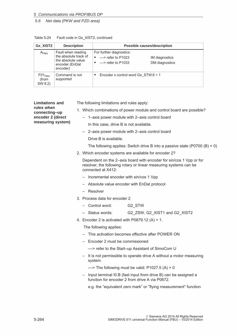
5
5.6 Net data (PKW and PZD area)
5-264� Siemens AG 2014 All Rights Reserved
SIMODRIVE 611 universal Function Manual (FBU) – 10/2014 Edition
Table 5-24 Fault code in Gx_XIST2, continued
Gx_XIST2 Possible causes/descriptionDescription
AHex Fault when readingthe absolute track ofthe absolute valueencoder (EnDatencoder)
For further diagnostics:� ––> refer to P1023 IM diagnostics� ––> refer to P1033 DM diagnostics
F01Hex(from
SW 8.2)
Command is notsupported
� Encoder x control word Gx_STW.6 = 1
The following limitations and rules apply:
1. Which combinations of power module and control board are possible?
– 1–axis power module with 2–axis control board
In this case, drive B is not available.
– 2–axis power module with 2–axis control board
Drive B is available.
The following applies: Switch drive B into a passive state (P0700 (B) = 0)
2. Which encoder systems are available for encoder 2?
Dependent on the 2–axis board with encoder for sin/cos 1 Vpp or forresolver, the following rotary or linear measuring systems can beconnected at X412:
– Incremental encoder with sin/cos 1 Vpp
– Absolute value encoder with EnDat protocol
– Resolver
3. Process data for encoder 2
– Control word: G2_STW
– Status words: G2_ZSW, G2_XIST1 and G2_XIST2
4. Encoder 2 is activated with P0879.12 (A) = 1.
The following applies:
– This activation becomes effective after POWER ON
– Encoder 2 must be commissioned
––> refer to the Start–up Assistant of SimoCom U
– It is not permissible to operate drive A without a motor measuringsystem.
––> The following must be valid: P1027.5 (A) = 0
– Input terminal I0.B (fast input from drive B) can be assigned afunction for encoder 2 from drive A via P0672.
e.g. the ”equivalent zero mark” or ”flying measurement” function
Limitations andrules whenconnecting–upencoder 2 (directmeasuring system)
5 Communications via PROFIBUS DP
5
5.6 Net data (PKW and PZD area)
5-265� Siemens AG 2014 All Rights ReservedSIMODRIVE 611 universal Function Manual (FBU) – 10/2014 Edition
5.6.5 Configuring process data (from SW 3.1)
The process data structure of the telegram can be defined and config-ured as follows:
1. By selecting a standard telegram (P0922 > 0)
Examples:
– P0922 = 1 standard telegram for nset interface 16 bit
– P0922 = 101 telegram is as for SW 2.4(dependent on the operating mode)
2. By freely–configuring the telegram (P0922 = 0)
Example:
– P0922 = 0 Before SW 4.1:
PZD1 to PZD4 are defined as standard PZD5 to PZD16 can be freely configured
From SW 4.1:PZD1 remains defined as standardPZD2 to PZD16 can be freely configured
Setpoint direction (refer to the parameter overview for P0915:17) e.g.: P0915:5 = xxxx (required signal ID) P0915:6 = yyyy ...
or Actual value direction (refer to the parameter overview for P0916:17) e.g.: P0916:5 = uuuu (requested signal ID) P0916:6 = vvvv ...
Note
Standard signals, defined in the PROFIdrive Profile as well as specialsignals only defined for the ”DP slave 611U” can be configured assetpoints/actual values.
For double–word signals (32 bits) the appropriate signal ID must beconfigured twice on adjacent process data.Example: P0916:7 = 50011 ––> G1_XIST1 is assigned to PZD7 P0916:8 = 50011 ––> G1_XIST1 is assigned to PZD8 ––> as G1_XIST1 is a double word (32 bits), it must be assigned twoPZDs.
Description
5 Communications via PROFIBUS DP
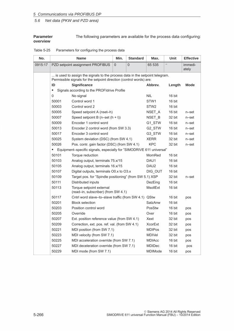
5
5.6 Net data (PKW and PZD area)
5-266� Siemens AG 2014 All Rights Reserved
SIMODRIVE 611 universal Function Manual (FBU) – 10/2014 Edition
The following parameters are available for the process data configuring:
Table 5-25 Parameters for configuring the process data
No. Name Min. Standard Max. Unit Effective
0915:17 PZD setpoint assignment PROFIBUS 0 0 65 535 – immedi-ately
... is used to assign the signals to the process data in the setpoint telegram.Permissible signals for the setpoint direction (control words) are:ID Significance Abbrev. Length Mode
� Signals according to the PROFIdrive Profile0 No signal NIL 16 bit50001 Control word 1 STW1 16 bit50003 Control word 2 STW2 16 bit50005 Speed setpoint A (nset–h) NSET_A 16 bit n–set50007 Speed setpoint B (n–set (h + l)) NSET_B 32 bit n–set50009 Encoder 1 control word G1_STW 16 bit n–set50013 Encoder 2 control word (from SW 3.3) G2_STW 16 bit n–set50017 Encoder 3 control word G3_STW 16 bit n–set50025 System deviation (DSC) (from SW 4.1) XERR 32 bit n–set50026 Pos. contr. gain factor (DSC) (from SW 4.1) KPC 32 bit n–set� Equipment–specific signals, especially for ”SIMODRIVE 611 universal”50101 Torque reduction MomRed 16 bit50103 Analog output, terminals 75.x/15 DAU1 16 bit50105 Analog output, terminals 16.x/15 DAU2 16 bit50107 Digital outputs, terminals O0.x to O3.x DIG_OUT 16 bit50109 Target pos. for ”Spindle positioning” (from SW 5.1) XSP 32 bit n–set50111 Distributed inputs DezEing 16 bit50113 Torque setpoint external MsollExt 16 bit
(read–in, subscriber) (from SW 4.1)50117 Cntrl word slave–to–slave traffic (from SW 4.1) QStw 16 bit pos50201 Block selection SatzAnw 16 bit50203 Position control word PosStw 16 bit pos50205 Override Over 16 bit pos50207 Ext. position reference value (from SW 4.1) Xext 32 bit pos50209 Correction, ext. pos. ref. val. (from SW 4.1) XcorExt 32 bit pos50221 MDI position (from SW 7.1) MDIPos 32 bit pos50223 MDI velocity (from SW 7.1) MDIVel 32 bit pos50225 MDI acceleration override (from SW 7.1) MDIAcc 16 bit pos50227 MDI deceleration override (from SW 7.1) MDIDec 16 bit pos50229 MDI mode (from SW 7.1) MDIMode 16 bit pos
Parameter overview
5 Communications via PROFIBUS DP
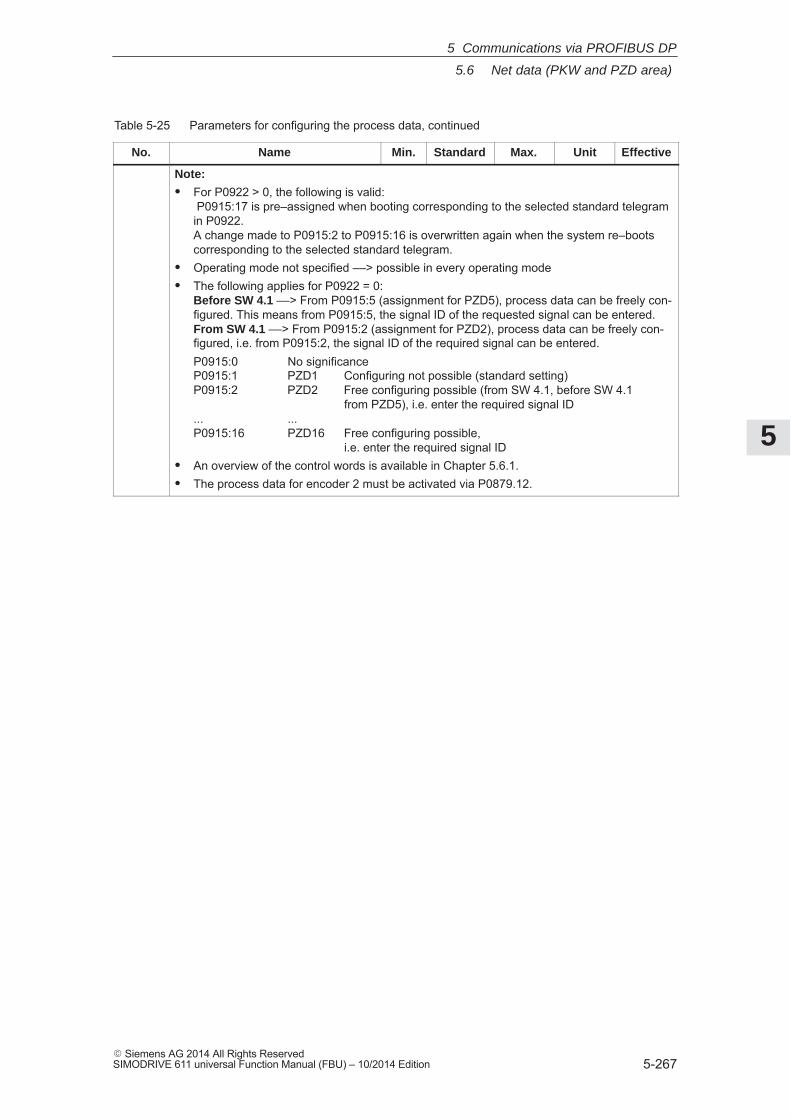
5
5.6 Net data (PKW and PZD area)
5-267� Siemens AG 2014 All Rights ReservedSIMODRIVE 611 universal Function Manual (FBU) – 10/2014 Edition
Table 5-25 Parameters for configuring the process data, continued
No. EffectiveUnitMax.StandardMin.Name
Note:
� For P0922 > 0, the following is valid: P0915:17 is pre–assigned when booting corresponding to the selected standard telegramin P0922. A change made to P0915:2 to P0915:16 is overwritten again when the system re–bootscorresponding to the selected standard telegram.
� Operating mode not specified ––> possible in every operating mode� The following applies for P0922 = 0:
Before SW 4.1 ––> From P0915:5 (assignment for PZD5), process data can be freely con-figured. This means from P0915:5, the signal ID of the requested signal can be entered.From SW 4.1 ––> From P0915:2 (assignment for PZD2), process data can be freely con-figured, i.e. from P0915:2, the signal ID of the required signal can be entered.P0915:0 No significanceP0915:1 PZD1 Configuring not possible (standard setting)P0915:2 PZD2 Free configuring possible (from SW 4.1, before SW 4.1
from PZD5), i.e. enter the required signal ID... ... P0915:16 PZD16 Free configuring possible,
i.e. enter the required signal ID� An overview of the control words is available in Chapter 5.6.1.� The process data for encoder 2 must be activated via P0879.12.
5 Communications via PROFIBUS DP
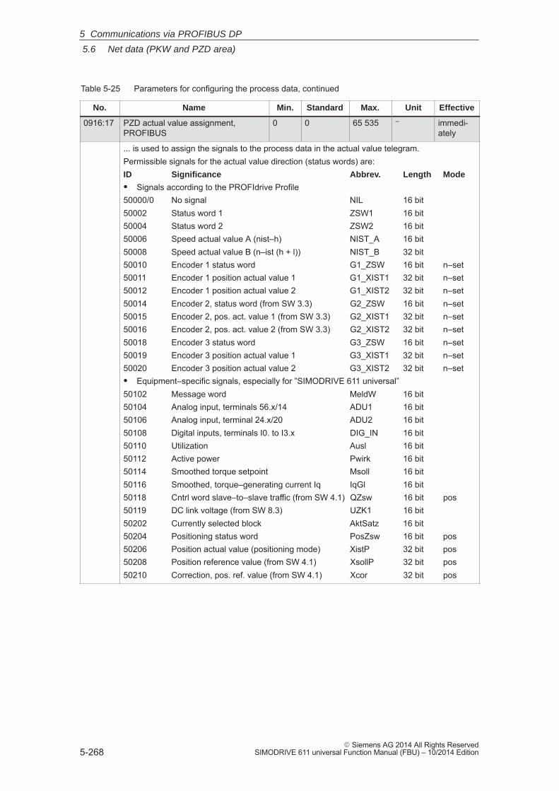
5
5.6 Net data (PKW and PZD area)
5-268� Siemens AG 2014 All Rights Reserved
SIMODRIVE 611 universal Function Manual (FBU) – 10/2014 Edition
Table 5-25 Parameters for configuring the process data, continued
No. EffectiveUnitMax.StandardMin.Name
0916:17 PZD actual value assignment,PROFIBUS
0 0 65 535 – immedi-ately
... is used to assign the signals to the process data in the actual value telegram.Permissible signals for the actual value direction (status words) are:ID Significance Abbrev. Length Mode
� Signals according to the PROFIdrive Profile50000/0 No signal NIL 16 bit50002 Status word 1 ZSW1 16 bit50004 Status word 2 ZSW2 16 bit50006 Speed actual value A (nist–h) NIST_A 16 bit50008 Speed actual value B (n–ist (h + l)) NIST_B 32 bit50010 Encoder 1 status word G1_ZSW 16 bit n–set50011 Encoder 1 position actual value 1 G1_XIST1 32 bit n–set50012 Encoder 1 position actual value 2 G1_XIST2 32 bit n–set50014 Encoder 2, status word (from SW 3.3) G2_ZSW 16 bit n–set50015 Encoder 2, pos. act. value 1 (from SW 3.3) G2_XIST1 32 bit n–set50016 Encoder 2, pos. act. value 2 (from SW 3.3) G2_XIST2 32 bit n–set50018 Encoder 3 status word G3_ZSW 16 bit n–set50019 Encoder 3 position actual value 1 G3_XIST1 32 bit n–set50020 Encoder 3 position actual value 2 G3_XIST2 32 bit n–set� Equipment–specific signals, especially for ”SIMODRIVE 611 universal”50102 Message word MeldW 16 bit50104 Analog input, terminals 56.x/14 ADU1 16 bit50106 Analog input, terminal 24.x/20 ADU2 16 bit50108 Digital inputs, terminals I0. to I3.x DIG_IN 16 bit50110 Utilization Ausl 16 bit50112 Active power Pwirk 16 bit50114 Smoothed torque setpoint Msoll 16 bit50116 Smoothed, torque–generating current Iq IqGl 16 bit50118 Cntrl word slave–to–slave traffic (from SW 4.1) QZsw 16 bit pos50119 DC link voltage (from SW 8.3) UZK1 16 bit50202 Currently selected block AktSatz 16 bit50204 Positioning status word PosZsw 16 bit pos50206 Position actual value (positioning mode) XistP 32 bit pos50208 Position reference value (from SW 4.1) XsollP 32 bit pos50210 Correction, pos. ref. value (from SW 4.1) Xcor 32 bit pos
5 Communications via PROFIBUS DP
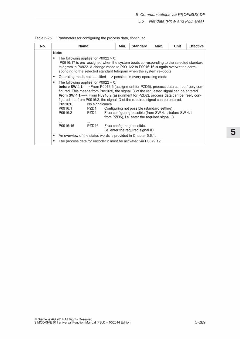
5
5.6 Net data (PKW and PZD area)
5-269� Siemens AG 2014 All Rights ReservedSIMODRIVE 611 universal Function Manual (FBU) – 10/2014 Edition
Table 5-25 Parameters for configuring the process data, continued
No. EffectiveUnitMax.StandardMin.Name
Note:
� The following applies for P0922 > 0: P0916:17 is pre–assigned when the system boots corresponding to the selected standardtelegram in P0922. A change made to P0916:2 to P0916:16 is again overwritten corre-sponding to the selected standard telegram when the system re–boots.
� Operating mode not specified ––> possible in every operating mode� The following applies for P0922 = 0:
before SW 4.1 ––> From P0916:5 (assignment for PZD5), process data can be freely con-figured. This means from P0916:5, the signal ID of the requested signal can be entered.From SW 4.1 ––> From P0916:2 (assignment for PZD2), process data can be freely con-figured, i.e. from P0916:2, the signal ID of the required signal can be entered.P0916:0 No significanceP0916:1 PZD1 Configuring not possible (standard setting)P0916:2 PZD2 Free configuring possible (from SW 4.1, before SW 4.1
from PZD5), i.e. enter the required signal ID... ... P0916:16 PZD16 Free configuring possible,
i.e. enter the required signal ID� An overview of the status words is provided in Chapter 5.6.1.� The process data for encoder 2 must be activated via P0879.12.
5 Communications via PROFIBUS DP
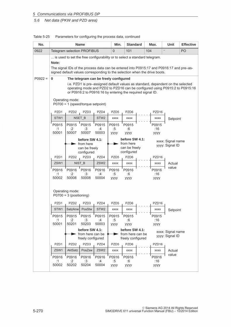
5
5.6 Net data (PKW and PZD area)
5-270� Siemens AG 2014 All Rights Reserved
SIMODRIVE 611 universal Function Manual (FBU) – 10/2014 Edition
Table 5-25 Parameters for configuring the process data, continued
No. EffectiveUnitMax.StandardMin.Name
0922 Telegram selection PROFIBUS 0 101 104 – PO
... is used to set the free configurability or to select a standard telegram.Note:
The signal IDs of the process data can be entered into P0915:17 and P0916:17 and pre–as-signed default values corresponding to the selection when the drive boots.
P0922 = 0 The telegram can be freely configured
i.e. PZD1 is pre–assigned default values as standard, dependent on the selectedoperating mode and PZD2 to PZD16 can be configured using P0915:2 to P0915:16or P0916:2 to P0916:16 by entering the required signal ID.
PZD1
STW1
ZSW2
PZD1
ZSW1
PZD4
Setpoint
Actualvalue
PZD4
STW2
PZD5
xxxx
PZD5
xxxx
P0915:1
50001
P0915:4
50003
P0915:5
yyyy
PZD6
xxxx
P0916:1
50002
PZD6
xxxx
P0915:6
yyyy
PZD16
xxxx
P0915:16
yyyy
PZD16
xxxx
P0916:16
yyyy
P0916:4
50004
P0916:5
yyyy
P0916:6
yyyy
Operating mode: P0700 = 1 (speed/torque setpoint)
xxxx: Signal nameyyyy: Signal ID
before SW 4.1:from herecan be freelyconfigured
PZD2 PZD3
NSET_B
P0915:2
50007
P0915:3
50007
PZD2 PZD3
NIST_B
P0916:2
50008
P0916:3
50008
before SW 4.1:from herecan be freelyconfigured
PZD1
STW1
ZSW2
PZD1
ZSW1
PZD4
Setpoint
Actualvalue
PZD4
STW2
PZD5
xxxx
PZD5
xxxx
P0915:1
50001
P0915:2
50201
P0915:3
50203
P0915:4
50003
P0915:5
yyyy
PZD6
xxxx
P0916:1
50002
P0916:2
50202
PZD6
xxxx
P0915:6
yyyy
PZD16
xxxx
P0915:16
yyyy
PZD16
xxxx
P0916:16
yyyy
P0916:3
50204
P0916:4
50004
P0916:5
yyyy
P0916:6
yyyy
PZD2
SatzAnw
PZD3
PosStw
AktSatz
PZD2
PosZsw
PZD3
Operating mode: P0700 = 3 (positioning)
xxxx: Signal nameyyyy: Signal ID
before SW 4.1:from here can befreely configured
before SW 4.1:from here can befreely configured
5 Communications via PROFIBUS DP
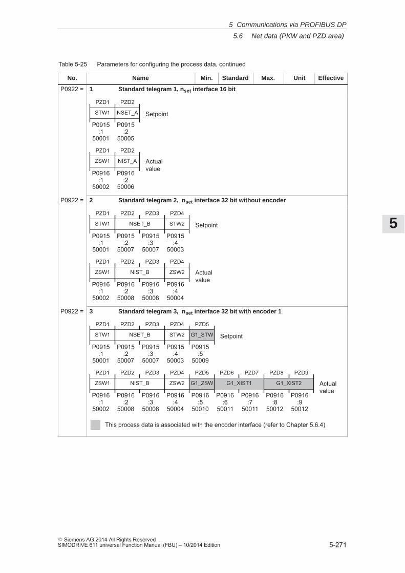
5
5.6 Net data (PKW and PZD area)
5-271� Siemens AG 2014 All Rights ReservedSIMODRIVE 611 universal Function Manual (FBU) – 10/2014 Edition
Table 5-25 Parameters for configuring the process data, continued
No. EffectiveUnitMax.StandardMin.Name
P0922 = 1 Standard telegram 1, nset interface 16 bit
NSET_A
PZD1
STW1
PZD2
NIST_A
PZD1
ZSW1
PZD2
Setpoint
Actualvalue
P0915:1
50001
P0915:2
50005
P0916:1
50002
P0916:2
50006
P0922 = 2 Standard telegram 2, nset interface 32 bit without encoder
PZD1
STW1
ZSW2
PZD1
ZSW1
PZD4
Setpoint
Actualvalue
PZD4
STW2
P0915:1
50001
P0915:4
50003
P0916:1
50002
P0916:4
50004
PZD2 PZD3
NSET_B
P0915:2
50007
P0915:3
50007
PZD2 PZD3
NIST_B
P0916:2
50008
P0916:3
50008
P0922 = 3 Standard telegram 3, nset interface 32 bit with encoder 1
PZD1
STW1
ZSW2
PZD1
ZSW1
PZD4
Setpoint
Actualvalue
PZD4
STW2
PZD5
G1_STW
PZD5
G1_ZSW
PZD6 PZD7 PZD8 PZD9
G1_XIST2
P0915:1
50001
P0915:4
50003
P0915:5
50009
P0916:1
50002
P0916:4
50004
P0916:5
50010
P0916:6
50011
P0916:7
50011
P0916:8
50012
P0916:9
50012
PZD2 PZD3
NSET_B
P0915:2
50007
P0915:3
50007
PZD2 PZD3
NIST_B
P0916:2
50008
P0916:3
50008
G1_XIST1
This process data is associated with the encoder interface (refer to Chapter 5.6.4)
5 Communications via PROFIBUS DP
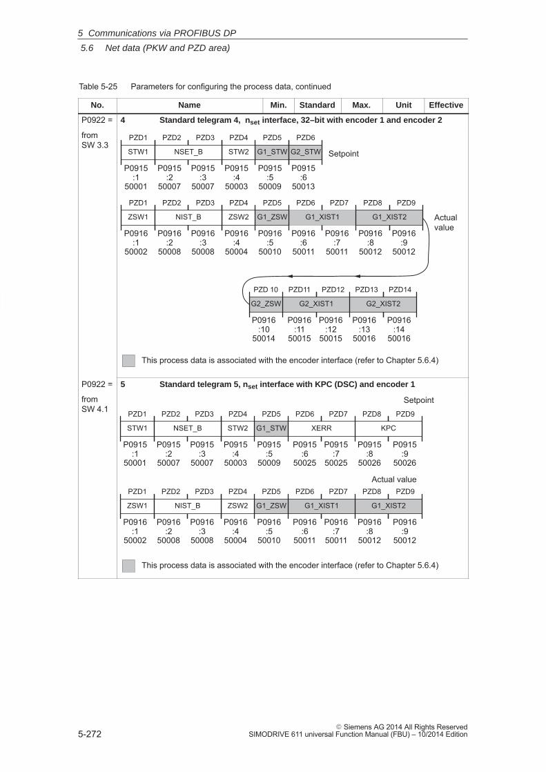
5
5.6 Net data (PKW and PZD area)
5-272� Siemens AG 2014 All Rights Reserved
SIMODRIVE 611 universal Function Manual (FBU) – 10/2014 Edition
Table 5-25 Parameters for configuring the process data, continued
No. EffectiveUnitMax.StandardMin.Name
P0922 = 4 Standard telegram 4, nset interface, 32–bit with encoder 1 and encoder 2
from SW 3.3
PZD1
STW1
ZSW2
PZD1
ZSW1
PZD4
Setpoint
Actualvalue
PZD4
STW2
PZD5
G1_STW
PZD5
G1_ZSW
PZD6 PZD7 PZD8 PZD9
G1_XIST2
P0915:1
50001
P0915:4
50003
P0915:5
50009
P0916:1
50002
P0916:4
50004
P0916:5
50010
P0916:6
50011
P0916:7
50011
P0916:8
50012
P0916:9
50012
PZD2 PZD3
NSET_B
P0915:2
50007
P0915:3
50007
PZD2 PZD3
NIST_B
P0916:2
50008
P0916:3
50008
G1_XIST1
PZD6
G2_STW
P0915:6
50013
PZD 10
G2_ZSW
PZD11 PZD12
G2_XIST1
PZD13 PZD14
G2_XIST2
P0916:10
50014
P0916:11
50015
P0916:12
50015
P0916:13
50016
P0916:14
50016
This process data is associated with the encoder interface (refer to Chapter 5.6.4)
P0922 = 5 Standard telegram 5, nset interface with KPC (DSC) and encoder 1
from SW 4.1
ZSW2
PZD1
ZSW1
PZD4
Setpoint
Actual valuePZD5
G1_ZSW
PZD6 PZD7
G1_XIST1
PZD8 PZD9
G1_XIST2
P0916:1
50002
P0916:4
50004
P0916:5
50010
P0916:6
50011
P0916:7
50011
P0916:8
50012
P0916:9
50012
PZD2 PZD3
NIST_B
P0916:2
50008
P0916:3
50008
STW2
PZD1
STW1
PZD4 PZD5
G1_STW
PZD6 PZD7
XERR
PZD8 PZD9
KPC
P0915:1
50001
P0915:4
50003
P0915:5
50009
P0915:6
50025
P0915:7
50025
P0915:8
50026
P0915:9
50026
PZD2 PZD3
NSET_B
P0915:2
50007
P0915:3
50007
This process data is associated with the encoder interface (refer to Chapter 5.6.4)
5 Communications via PROFIBUS DP
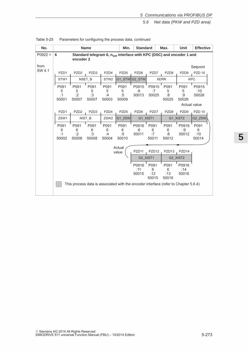
5
5.6 Net data (PKW and PZD area)
5-273� Siemens AG 2014 All Rights ReservedSIMODRIVE 611 universal Function Manual (FBU) – 10/2014 Edition
Table 5-25 Parameters for configuring the process data, continued
No. EffectiveUnitMax.StandardMin.Name
P0922 = 6 Standard telegram 6, nset interface with KPC (DSC) and encoder 1 andencoder 2
from SW 4.1 PZD1
STW1
ZSW2
PZD1
ZSW1
PZD4
Setpoint
Actual value
PZD4
STW2
PZD5
G1_ZSW
PZD6 PZD7
G1_XIST1
PZD8 PZD9
G1_XIST2
PZD5
G1_STW
P0915:1
50001
P0915:4
50003
P0916:1
50002
P0916:4
50004
P0915:5
50009
P0916:5
50010
P0916:6
50011
P0916:7
50011
P0916:8
50012
P0916:9
50012
PZD6
G2_STW
P0915:6
50013
PZD 10
G2_ZSW
PZD11 PZD12
G2_XIST1
PZD13 PZD14
G2_XIST2
P0916
:1050014
P0916:11
50015
P0916
:1250015
P0916
:1350016
P0916:14
50016
Actualvalue
PZD2 PZD3
NSET_B
P0915:2
50007
P0915:3
50007
PZD2 PZD3
NIST_B
P0916:2
50008
P0916:3
50008
This process data is associated with the encoder interface (refer to Chapter 5.6.4)
PZD7 PZD8
XERR
P0915:7
50025
P0915:8
50025
PZD9 PZD 10
KPC
P0915:9
50026
P0915:10
50026
5 Communications via PROFIBUS DP
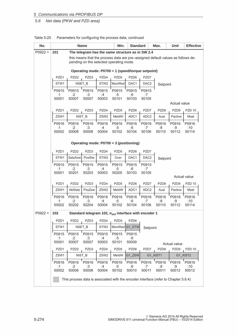
5
5.6 Net data (PKW and PZD area)
5-274� Siemens AG 2014 All Rights Reserved
SIMODRIVE 611 universal Function Manual (FBU) – 10/2014 Edition
Table 5-25 Parameters for configuring the process data, continued
No. EffectiveUnitMax.StandardMin.Name
P0922 = 101 The telegram has the same structure as in SW 2.4
this means that the process data are pre–assigned default values as follows de-pending on the selected operating mode.
PZD1
STW1
ZSW2
PZD1
ZSW1
PZD4
Setpoint
Actual value
PZD4
STW2
PZD5
MomRed
PZD5
MeldW
P0915:1
50001
P0915:4
50003
P0915:5
50101
PZD6
ADC1
P0916:1
50002
PZD6
DAC1
P0915:6
50103
PZD7
DAC2
P0915:7
50105
PZD7
ADC2
P0916:7
50106
P0916:4
50004
P0916:5
50102
P0916:6
50104
Operating mode: P0700 = 1 (speed/torque setpoint)
PZD8
Ausl
P0916:8
50110
PZD9
Pactive
P0916:9
50112
PZD 10
Mset
P0916:10
50114
PZD2 PZD3
NSET_B
P0915:2
50007
P0915:3
50007
PZD2 PZD3
NIST_B
P0916:2
50008
P0916:3
50008
PZD1
STW1
ZSW2
PZD1
ZSW1
PZD4
Setpoint
Actual value
PZD4
STW2
PZD5
Over
PZD5
MeldW
P0915:1
50001
P0915:2
50201
P0915:3
50203
P0915:4
50003
P0915:5
50205
PZD6
ADC1
P0916:1
50002
P0916:2
50202
PZD6
DAC1
P0915:6
50103
PZD7
DAC2
P0915:7
50105
P0916:3
50204
P0916:4
50004
P0916:5
50102
P0916:6
50104
PZD2
SatzAnw
PZD3
PosStw
AktSatz
PZD2
PosZsw
PZD3
Operating mode: P0700 = 3 (positioning)
PZD8
Ausl
P0916:8
50110
PZD9
Pactive
P0916:9
50112
PZD 10
Mset
P0916:10
50114
PZD7
ADC2
P0916:7
50106
P0922 = 102 Standard telegram 102, nset interface with encoder 1
PZD1
STW1
ZSW2
PZD1
ZSW1
PZD4
Setpoint
Actual value
PZD4
STW2
PZD5
MomRed
PZD6
G1_ZSW
PZD7 PZD8
G1_XIST1
PZD9 PZD 10
G1_XIST2
PZD6
G1_STW
MeldW
PZD5
P0915:1
50001
P0915:4
50003
P0916:1
50002
P0916:4
50004
P0916:5
50102
P0915:5
50101
P0915:6
50009
P0916:6
50010
P0916:7
50011
P0916:8
50011
P0916:9
50012
P0916:10
50012
PZD2 PZD3
NSET_B
P0915:2
50007
P0915:3
50007
PZD2 PZD3
NIST_B
P0916:2
50008
P0916:3
50008
This process data is associated with the encoder interface (refer to Chapter 5.6.4)
5 Communications via PROFIBUS DP
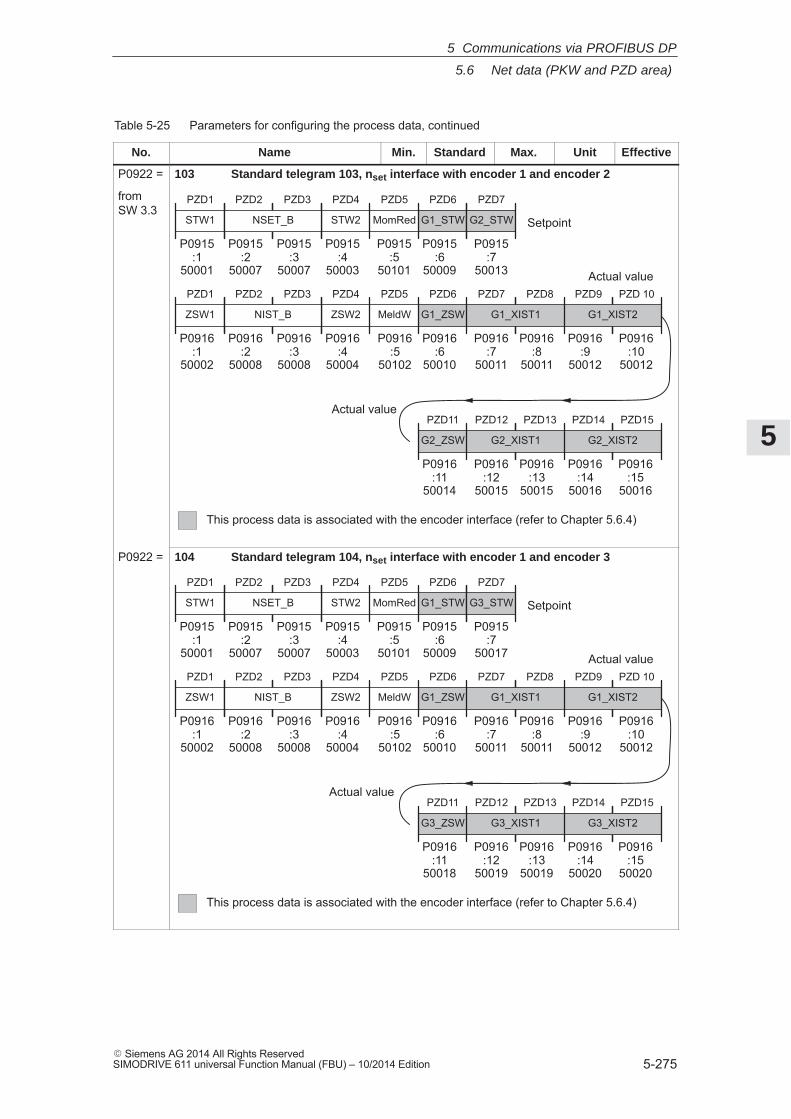
5
5.6 Net data (PKW and PZD area)
5-275� Siemens AG 2014 All Rights ReservedSIMODRIVE 611 universal Function Manual (FBU) – 10/2014 Edition
Table 5-25 Parameters for configuring the process data, continued
No. EffectiveUnitMax.StandardMin.Name
P0922 = 103 Standard telegram 103, nset interface with encoder 1 and encoder 2
from SW 3.3
PZD1
STW1
ZSW2
PZD1
ZSW1
PZD4
Setpoint
Actual value
PZD4
STW2
PZD5
MomRed
PZD6
G1_ZSW
PZD7 PZD8
G1_XIST1
PZD9 PZD 10
G1_XIST2
PZD6
G1_STW
MeldW
PZD5
P0915:1
50001
P0915:4
50003
P0916:1
50002
P0916:4
50004
P0916:5
50102
P0915:5
50101
P0915:6
50009
P0916:6
50010
P0916:7
50011
P0916:8
50011
P0916:9
50012
P0916:10
50012
PZD7
G2_STW
P0915:7
50013
PZD11
G2_ZSW
PZD12 PZD13
G2_XIST1
PZD14 PZD15
G2_XIST2
P0916:11
50014
P0916:12
50015
P0916:13
50015
P0916:14
50016
P0916:15
50016
Actual value
PZD2 PZD3
NSET_B
P0915:2
50007
P0915:3
50007
PZD2 PZD3
NIST_B
P0916:2
50008
P0916:3
50008
This process data is associated with the encoder interface (refer to Chapter 5.6.4)
P0922 = 104 Standard telegram 104, nset interface with encoder 1 and encoder 3
PZD1
STW1
ZSW2
PZD1
ZSW1
PZD4
Setpoint
Actual value
PZD4
STW2
PZD5
MomRed
PZD6
G1_ZSW
PZD7 PZD8
G1_XIST1
PZD9 PZD 10
G1_XIST2
PZD6
G1_STW
MeldW
PZD5
P0915:1
50001
P0915:4
50003
P0916:1
50002
P0916:4
50004
P0916:5
50102
P0915:5
50101
P0915:6
50009
P0916:6
50010
P0916:7
50011
P0916:8
50011
P0916:9
50012
P0916:10
50012
PZD7
G3_STW
P0915:7
50017
PZD11
G3_ZSW
PZD12 PZD13
G3_XIST1
PZD14 PZD15
G3_XIST2
P0916:11
50018
P0916:12
50019
P0916:13
50019
P0916:14
50020
P0916:15
50020
Actual value
PZD2 PZD3
NSET_B
P0915:2
50007
P0915:3
50007
PZD2 PZD3
NIST_B
P0916:2
50008
P0916:3
50008
This process data is associated with the encoder interface (refer to Chapter 5.6.4)
5 Communications via PROFIBUS DP
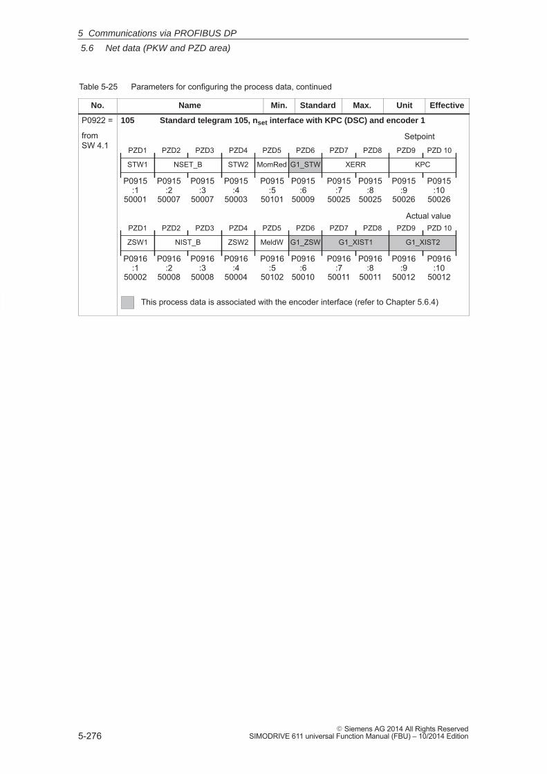
5
5.6 Net data (PKW and PZD area)
5-276� Siemens AG 2014 All Rights Reserved
SIMODRIVE 611 universal Function Manual (FBU) – 10/2014 Edition
Table 5-25 Parameters for configuring the process data, continued
No. EffectiveUnitMax.StandardMin.Name
P0922 = 105 Standard telegram 105, nset interface with KPC (DSC) and encoder 1
from SW 4.1
ZSW2
PZD1
ZSW1
PZD4
Setpoint
Actual valuePZD6
G1_ZSW
PZD7 PZD8
G1_XIST1
PZD9 PZD 10
G1_XIST2MeldW
PZD5
P0916:1
50002
P0916:4
50004
P0916:5
50102
P0916:6
50010
P0916:7
50011
P0916:8
50011
P0916:9
50012
P0916:10
50012
PZD2 PZD3
NIST_B
P0916:2
50008
P0916:3
50008
STW2
PZD1
STW1
PZD4 PZD6
G1_STW
PZD7 PZD8
XERR
PZD9 PZD 10
KPCMomRed
PZD5
P0915:1
50001
P0915:4
50003
P0915:5
50101
P0915:6
50009
P0915:7
50025
P0915:8
50025
P0915:9
50026
P0915:10
50026
PZD2 PZD3
NSET_B
P0915:2
50007
P0915:3
50007
This process data is associated with the encoder interface (refer to Chapter 5.6.4)
5 Communications via PROFIBUS DP
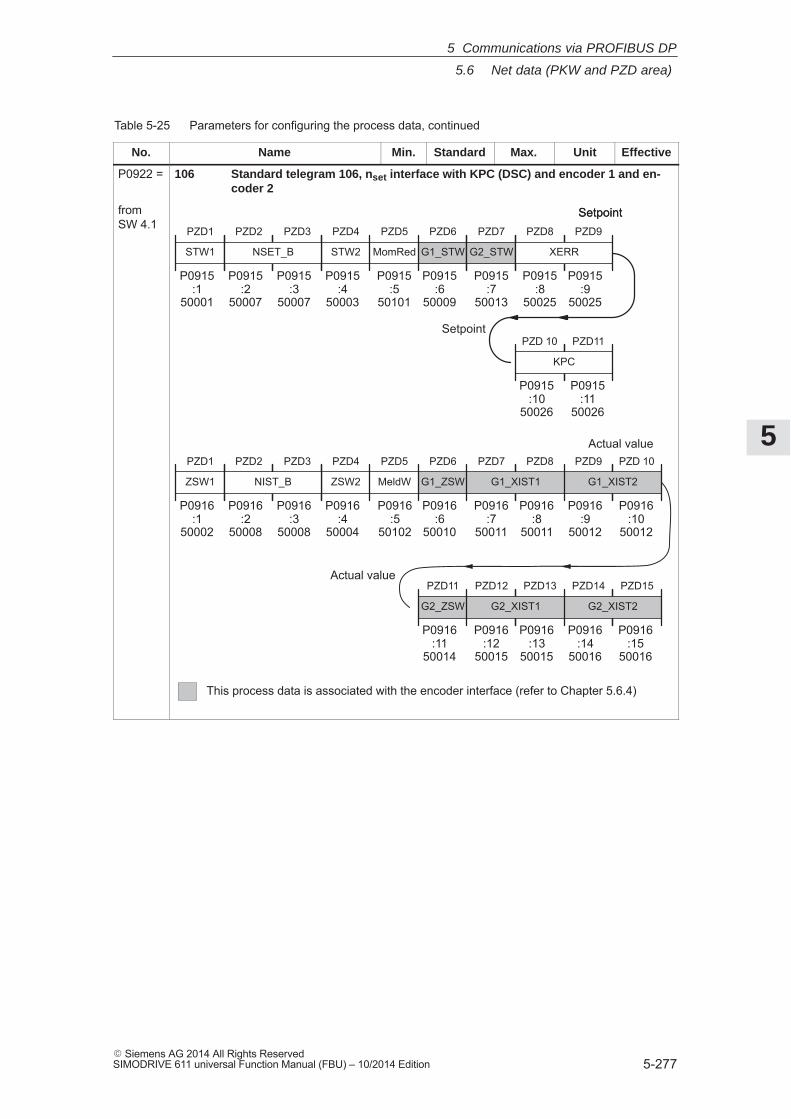
5
5.6 Net data (PKW and PZD area)
5-277� Siemens AG 2014 All Rights ReservedSIMODRIVE 611 universal Function Manual (FBU) – 10/2014 Edition
Table 5-25 Parameters for configuring the process data, continued
No. EffectiveUnitMax.StandardMin.Name
P0922 = 106 Standard telegram 106, nset interface with KPC (DSC) and encoder 1 and en-coder 2
from SW 4.1 PZD1
STW1
ZSW2
PZD1
ZSW1
PZD4
Setpoint
Actual value
PZD4
STW2
PZD5
MomRed
PZD6
G1_ZSW
PZD7 PZD8
G1_XIST1
PZD9 PZD 10
G1_XIST2
PZD6
G1_STW
MeldW
PZD5
P0915:1
50001
P0915:4
50003
P0916:1
50002
P0916:4
50004
P0916:5
50102
P0915:5
50101
P0915:6
50009
P0916:6
50010
P0916:7
50011
P0916:8
50011
P0916:9
50012
P0916:10
50012
PZD7
G2_STW
P0915:7
50013
PZD11
G2_ZSW
PZD12 PZD13
G2_XIST1
PZD14 PZD15
G2_XIST2
P0916:11
50014
P0916:12
50015
P0916:13
50015
P0916:14
50016
P0916:15
50016
Actual value
PZD2 PZD3
NSET_B
P0915:2
50007
P0915:3
50007
PZD2 PZD3
NIST_B
P0916:2
50008
P0916:3
50008
This process data is associated with the encoder interface (refer to Chapter 5.6.4)
PZD8 PZD9
XERR
P0915:8
50025
P0915:9
50025
PZD 10 PZD11
KPC
P0915:10
50026
P0915:11
50026
Setpoint
Setpoint
5 Communications via PROFIBUS DP
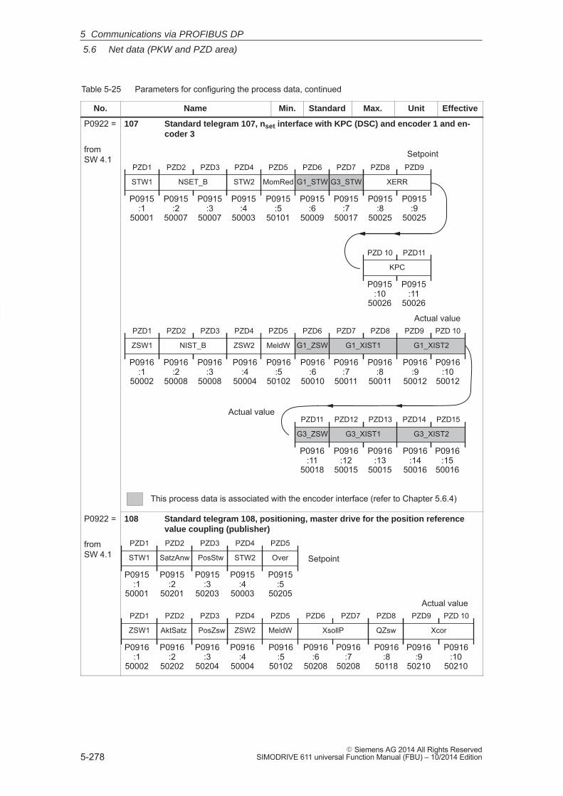
5
5.6 Net data (PKW and PZD area)
5-278� Siemens AG 2014 All Rights Reserved
SIMODRIVE 611 universal Function Manual (FBU) – 10/2014 Edition
Table 5-25 Parameters for configuring the process data, continued
No. EffectiveUnitMax.StandardMin.Name
P0922 = 107 Standard telegram 107, nset interface with KPC (DSC) and encoder 1 and en-coder 3
from SW 4.1
This process data is associated with the encoder interface (refer to Chapter 5.6.4)
PZD1
STW1
ZSW2
PZD1
ZSW1
PZD4
Setpoint
Actual value
PZD4
STW2
PZD5
MomRed
PZD6
G1_ZSW
PZD7 PZD8
G1_XIST1
PZD9 PZD 10
G1_XIST2
PZD6
G1_STW
MeldW
PZD5
P0915:1
50001
P0915:4
50003
P0916:1
50002
P0916:4
50004
P0916:5
50102
P0915:5
50101
P0915:6
50009
P0916:6
50010
P0916:7
50011
P0916:8
50011
P0916:9
50012
P0916:10
50012
PZD7
G3_STW
P0915:7
50017
PZD11
G3_ZSW
PZD12 PZD13
G3_XIST1
PZD14 PZD15
G3_XIST2
P0916:11
50018
P0916:12
50015
P0916:13
50015
P0916:14
50016
P0916:15
50016
Actual value
PZD2 PZD3
NSET_B
P0915:2
50007
P0915:3
50007
PZD2 PZD3
NIST_B
P0916:2
50008
P0916:3
50008
PZD8 PZD9
XERR
P0915:8
50025
P0915:9
50025
PZD 10 PZD11
KPC
P0915:10
50026
P0915:11
50026
P0922 = 108 Standard telegram 108, positioning, master drive for the position referencevalue coupling (publisher)
from SW 4.1
PZD1
STW1
ZSW2
PZD1
ZSW1
PZD4Actual value
PZD4
STW2
PZD5
Over
PZD6 PZD7
XsollP
PZD9 PZD 10
XcorMeldW
PZD5
P0915:1
50001
P0915:4
50003
P0916:1
50002
P0916:4
50004
P0916:5
50102
P0915:5
50205
P0916:6
50208
P0916:7
50208
P0916:9
50210
P0916:10
50210
PZD2 PZD3
SatzAnw
P0915:2
50201
P0915:3
50203
PZD2 PZD3
AktSatz
P0916:2
50202
P0916:3
50204
SetpointPosStw
PosZsw QZsw
PZD8
P0916:8
50118
5 Communications via PROFIBUS DP
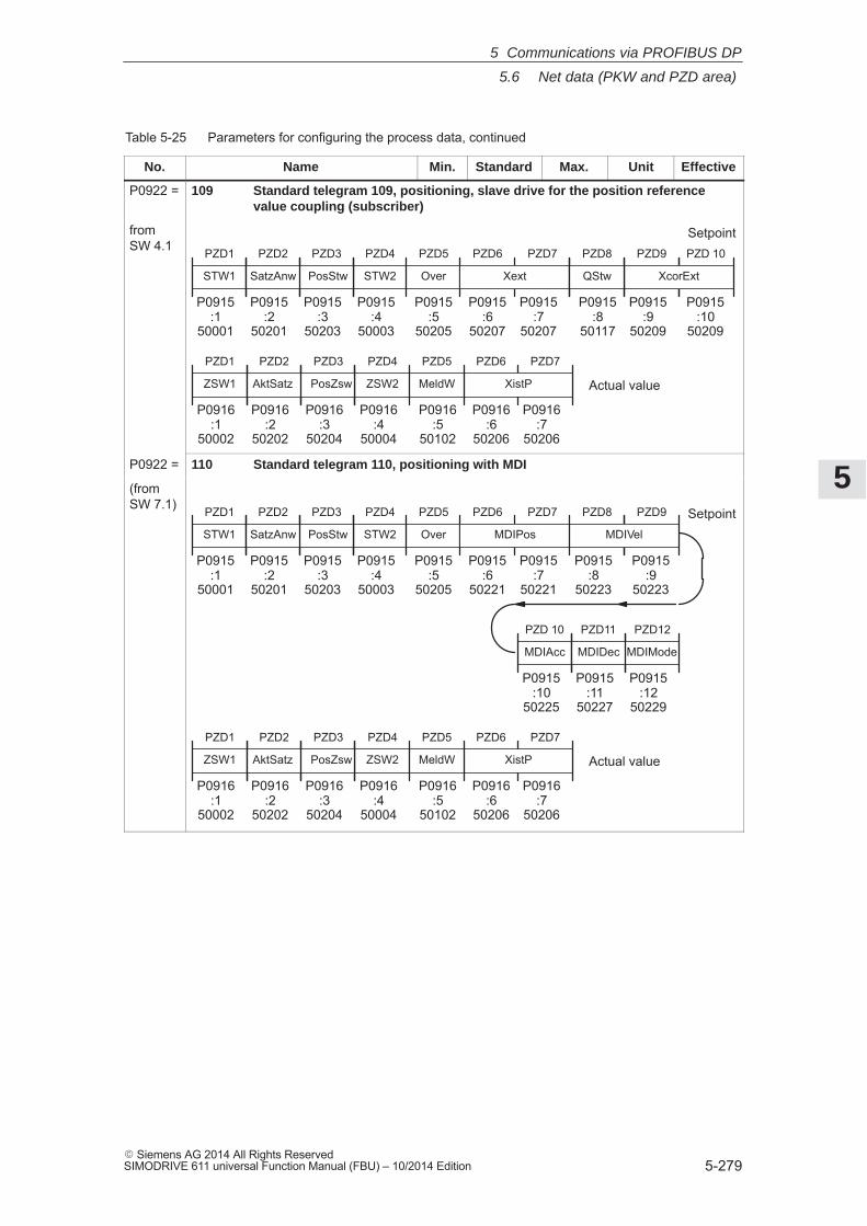
5
5.6 Net data (PKW and PZD area)
5-279� Siemens AG 2014 All Rights ReservedSIMODRIVE 611 universal Function Manual (FBU) – 10/2014 Edition
Table 5-25 Parameters for configuring the process data, continued
No. EffectiveUnitMax.StandardMin.Name
P0922 = 109 Standard telegram 109, positioning, slave drive for the position referencevalue coupling (subscriber)
from SW 4.1 PZD1
STW1
PZD4
STW2
PZD5
Over
P0915:1
50001
P0915:4
50003
P0915:5
50205
PZD2 PZD3
SatzAnw
P0915:2
50201
P0915:3
50203
PosStw
SetpointPZD6 PZD7
Xext
PZD9 PZD 10
XcorExt
P0915:6
50207
P0915:7
50207
P0915:9
50209
P0915:10
50209
QStw
PZD8
P0915:8
50117
ZSW2
PZD1
ZSW1
PZD4
Actual value
PZD6 PZD7
XistPMeldW
PZD5
P0916:1
50002
P0916:4
50004
P0916:5
50102
P0916:6
50206
P0916:7
50206
PZD2 PZD3
AktSatz
P0916:2
50202
P0916:3
50204
PosZsw
P0922 = 110 Standard telegram 110, positioning with MDI
(from SW 7.1) PZD1
STW1
PZD4
STW2
PZD5
Over
P0915:1
50001
P0915:4
50003
P0915:5
50205
PZD2 PZD3
SatzAnw
P0915:2
50201
P0915:3
50203
PosStw
SetpointPZD6 PZD7
MDIPos
PZD8 PZD9
MDIVel
P0915:6
50221
P0915:7
50221
P0915:8
50223
P0915:9
50223
ZSW2
PZD1
ZSW1
PZD4
Actual value
PZD6 PZD7
XistPMeldW
PZD5
P0916:1
50002
P0916:4
50004
P0916:5
50102
P0916:6
50206
P0916:7
50206
PZD2 PZD3
AktSatz
P0916:2
50202
P0916:3
50204
PosZsw
PZD 10
MDIAcc
P0915:10
50225
PZD11 PZD12
MDIDec
P0915:11
50227
P0915:12
50229
MDIMode
5 Communications via PROFIBUS DP
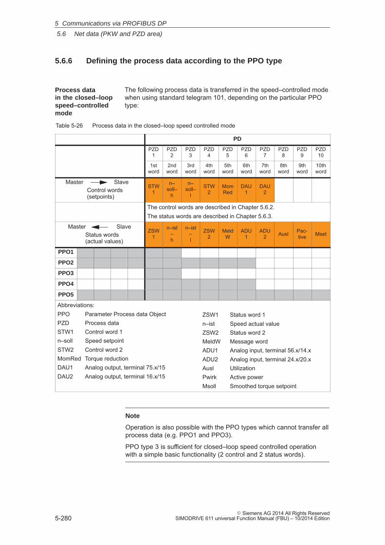
5
5.6 Net data (PKW and PZD area)
5-280� Siemens AG 2014 All Rights Reserved
SIMODRIVE 611 universal Function Manual (FBU) – 10/2014 Edition
5.6.6 Defining the process data according to the PPO type
The following process data is transferred in the speed–controlled modewhen using standard telegram 101, depending on the particular PPOtype:
Table 5-26 Process data in the closed–loop speed controlled mode
PD
PZD1
PZD2
PZD3
PZD4
PZD5
PZD6
PZD7
PZD8
PZD9
PZD10
1stword
2ndword
3rdword
4thword
5thword
6thword
7thword
8thword
9thword
10thword
Control words(setpoints)
Master SlaveSTW
1
n–soll–
h
n–soll–
l
STW2
MomRed
DAU1
DAU2
The control words are described in Chapter 5.6.2.The status words are described in Chapter 5.6.3.
Master SlaveStatus words(actual values)
ZSW1
n–ist–h
n–ist–l
ZSW2
MeldW
ADU1
ADU2 Ausl Pac-
tive Mset
PPO1
PPO2
PPO3
PPO4
PPO5
Abbreviations:PPO Parameter Process data ObjectPZD Process dataSTW1 Control word 1n–soll Speed setpointSTW2 Control word 2MomRed Torque reductionDAU1 Analog output, terminal 75.x/15DAU2 Analog output, terminal 16.x/15
ZSW1 Status word 1n–ist Speed actual valueZSW2 Status word 2MeldW Message wordADU1 Analog input, terminal 56.x/14.xADU2 Analog input, terminal 24.x/20.xAusl UtilizationPwirk Active powerMsoll Smoothed torque setpoint
Note
Operation is also possible with the PPO types which cannot transfer allprocess data (e.g. PPO1 and PPO3).
PPO type 3 is sufficient for closed–loop speed controlled operationwith a simple basic functionality (2 control and 2 status words).
Process data in the closed–loopspeed–controlledmode
5 Communications via PROFIBUS DP
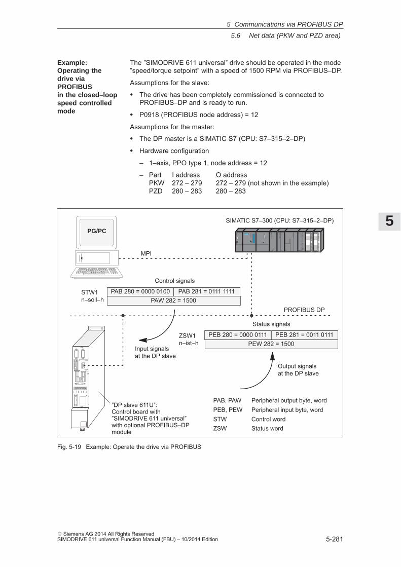
5
5.6 Net data (PKW and PZD area)
5-281� Siemens AG 2014 All Rights ReservedSIMODRIVE 611 universal Function Manual (FBU) – 10/2014 Edition
The ”SIMODRIVE 611 universal” drive should be operated in the mode”speed/torque setpoint” with a speed of 1500 RPM via PROFIBUS–DP.
Assumptions for the slave:
� The drive has been completely commissioned is connected toPROFIBUS–DP and is ready to run.
� P0918 (PROFIBUS node address) = 12
Assumptions for the master:
� The DP master is a SIMATIC S7 (CPU: S7–315–2–DP)
� Hardware configuration
– 1–axis, PPO type 1, node address = 12
– Part I address O addressPKW 272 – 279 272 – 279 (not shown in the example)PZD 280 – 283 280 – 283
”DP slave 611U”:Control board with”SIMODRIVE 611 universal” with optional PROFIBUS–DPmodule
PROFIBUS DP
SIMATIC S7–300 (CPU: S7–315–2–DP)
MPI
Output signalsat the DP slave
Input signalsat the DP slave
Control signals
STW1n–soll–h
PAB 280 = 0000 0100 PAB 281 = 0111 1111PAW 282 = 1500
Status signals
ZSW1n–ist–h
PEB 280 = 0000 0111 PEB 281 = 0011 0111PEW 282 = 1500
PAB, PAW Peripheral output byte, wordPEB, PEW Peripheral input byte, wordSTW Control wordZSW Status word
PG/PC
Fig. 5-19 Example: Operate the drive via PROFIBUS
Example:Operating thedrive viaPROFIBUS in the closed–loopspeed controlledmode
5 Communications via PROFIBUS DP
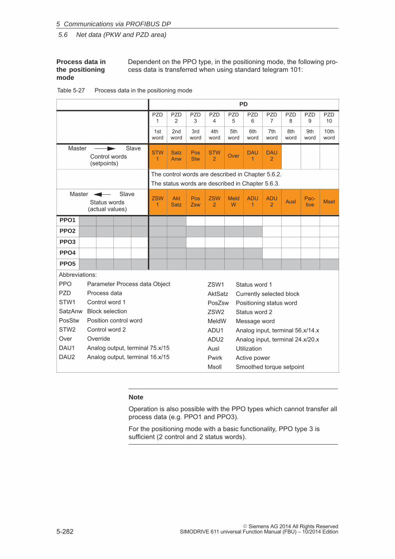
5
5.6 Net data (PKW and PZD area)
5-282� Siemens AG 2014 All Rights Reserved
SIMODRIVE 611 universal Function Manual (FBU) – 10/2014 Edition
Dependent on the PPO type, in the positioning mode, the following pro-cess data is transferred when using standard telegram 101:
Table 5-27 Process data in the positioning mode
PD
PZD1
PZD2
PZD3
PZD4
PZD5
PZD6
PZD7
PZD8
PZD9
PZD10
1stword
2ndword
3rdword
4thword
5thword
6thword
7thword
8thword
9thword
10thword
Master SlaveControl words(setpoints)
STW1
SatzAnw
PosStw
STW2 Over DAU
1DAU
2
The control words are described in Chapter 5.6.2.The status words are described in Chapter 5.6.3.
Master SlaveStatus words
(actual values)
ZSW1
AktSatz
PosZsw
ZSW2
MeldW
ADU1
ADU2 Ausl Pac-
tive Mset
PPO1
PPO2
PPO3
PPO4
PPO5
Abbreviations:PPO Parameter Process data ObjectPZD Process dataSTW1 Control word 1SatzAnw Block selectionPosStw Position control wordSTW2 Control word 2Over OverrideDAU1 Analog output, terminal 75.x/15DAU2 Analog output, terminal 16.x/15
ZSW1 Status word 1AktSatz Currently selected blockPosZsw Positioning status wordZSW2 Status word 2MeldW Message wordADU1 Analog input, terminal 56.x/14.xADU2 Analog input, terminal 24.x/20.xAusl UtilizationPwirk Active powerMsoll Smoothed torque setpoint
Note
Operation is also possible with the PPO types which cannot transfer allprocess data (e.g. PPO1 and PPO3).
For the positioning mode with a basic functionality, PPO type 3 issufficient (2 control and 2 status words).
Process data in the positioningmode
5 Communications via PROFIBUS DP
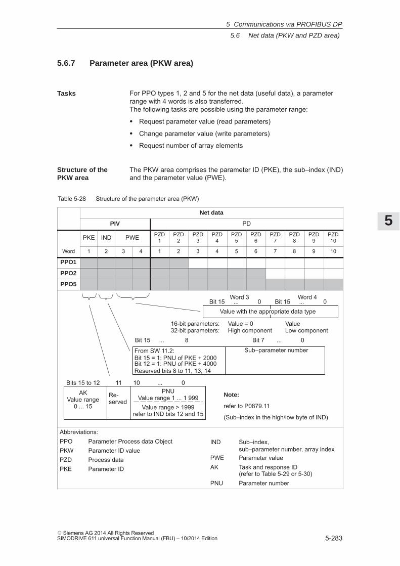
5
5.6 Net data (PKW and PZD area)
5-283� Siemens AG 2014 All Rights ReservedSIMODRIVE 611 universal Function Manual (FBU) – 10/2014 Edition
5.6.7 Parameter area (PKW area)
For PPO types 1, 2 and 5 for the net data (useful data), a parameterrange with 4 words is also transferred. The following tasks are possible using the parameter range:
� Request parameter value (read parameters)
� Change parameter value (write parameters)
� Request number of array elements
The PKW area comprises the parameter ID (PKE), the sub–index (IND)and the parameter value (PWE).
Table 5-28 Structure of the parameter area (PKW)
Net data
PIV PD
PKE IND PWE PZD1
PZD2
PZD3
PZD4
PZD5
PZD6
PZD7
PZD8
PZD9
PZD10
Word 1 2 3 4 1 2 3 4 5 6 7 8 9 10
PPO1
PPO2
PPO5
From SW 11.2:
Reserved bits 8 to 11, 13, 14Bit 12 = 1: PNU of PKE + 4000Bit 15 = 1: PNU of PKE + 2000
PNUValue range 1 ... 1 999
Value range > 1999refer to IND bits 12 and 15
Sub–parameter number
AKValue range
0 ... 15
Re-served
Bits 15 to 12 11 10 ... 0
Bit 15 ... 8 Bit 7 ... 0
Bit 15 ... 0 Bit 15 ... 0Word 3 Word 4
Value with the appropriate data type
16-bit parameters: Value = 0 Value32-bit parameters: High component Low component
Note:
refer to P0879.11
(Sub–index in the high/low byte of IND)
Abbreviations:PPO Parameter Process data ObjectPKW Parameter ID valuePZD Process dataPKE Parameter ID
IND Sub–index, sub–parameter number, array index
PWE Parameter valueAK Task and response ID
(refer to Table 5-29 or 5-30)PNU Parameter number
Tasks
Structure of the PKW area
5 Communications via PROFIBUS DP
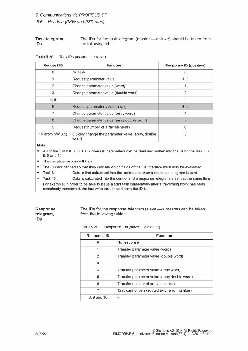
5
5.6 Net data (PKW and PZD area)
5-284� Siemens AG 2014 All Rights Reserved
SIMODRIVE 611 universal Function Manual (FBU) – 10/2014 Edition
The IDs for the task telegram (master ––> slave) should be taken fromthe following table:
Table 5-29 Task IDs (master ––> slave)
Request ID Function Response ID (positive)
0 No task 0
1 Request parameter value 1, 2
2 Change parameter value (word) 1
3 Change parameter value (double word) 2
4, 5 – –
6 Request parameter value (array) 4, 5
7 Change parameter value (array word) 4
8 Change parameter value (array double word) 5
9 Request number of array elements 6
10 (from SW 3.5) Quickly change the parameter value (array, doubleword)
5
Note:
� All of the ”SIMODRIVE 611 universal” parameters can be read and written into the using the task IDs6, 8 and 10.
� The negative response ID is 7.� The IDs are defined so that they indicate which fields of the PK interface must also be evaluated.� Task 8 Data is first calculated into the control and then a response telegram is sent� Task 10 Data is calculated into the control and a response telegram is sent at the same time
For example, in order to be able to issue a start task immediately after a traversing block has beencompletely transferred, the last write task should have the ID 8.
The IDs for the response telegram (slave ––> master) can be takenfrom the following table:
Table 5-30 Response IDs (slave ––> master)
Response ID Function
0 No response
1 Transfer parameter value (word)
2 Transfer parameter value (double word)
3 –
4 Transfer parameter value (array word)
5 Transfer parameter value (array double word)
6 Transfer number of array elements
7 Task cannot be executed (with error number)
8, 9 and 10 –
Task telegram, IDs
Responsetelegram, IDs
5 Communications via PROFIBUS DP
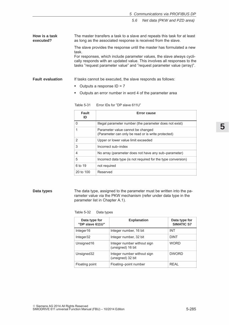
5
5.6 Net data (PKW and PZD area)
5-285� Siemens AG 2014 All Rights ReservedSIMODRIVE 611 universal Function Manual (FBU) – 10/2014 Edition
The master transfers a task to a slave and repeats this task for at leastas long as the associated response is received from the slave.
The slave provides the response until the master has formulated a newtask. For responses, which include parameter values, the slave always cycli-cally responds with an updated value. This involves all responses to thetasks ”request parameter value” and ”request parameter value (array)”.
If tasks cannot be executed, the slave responds as follows:
� Outputs a response ID = 7
� Outputs an error number in word 4 of the parameter area
Table 5-31 Error IDs for ”DP slave 611U”
FaultID
Error cause
0 Illegal parameter number (the parameter does not exist)
1 Parameter value cannot be changed (Parameter can only be read or is write protected)
2 Upper or lower value limit exceeded
3 Incorrect sub–index
4 No array (parameter does not have any sub–parameter)
5 Incorrect data type (is not required for the type conversion)
6 to 19 not required
20 to 100 Reserved
The data type, assigned to the parameter must be written into the pa-rameter value via the PKW mechanism (refer under data type in theparameter list in Chapter A.1).
Table 5-32 Data types
Data type for”DP slave 611U”
Explanation Data type for SIMATIC S7
Integer16 Integer number, 16 bit INT
Integer32 Integer number, 32 bit DINT
Unsigned16 Integer number without sign(unsigned) 16 bit
WORD
Unsigned32 Integer number without sign(unsigned) 32 bit
DWORD
Floating point Floating–point number REAL
How is a task executed?
Fault evaluation
Data types
5 Communications via PROFIBUS DP
5
5.6 Net data (PKW and PZD area)
5-286� Siemens AG 2014 All Rights Reserved
SIMODRIVE 611 universal Function Manual (FBU) – 10/2014 Edition
For ”SIMODRIVE 611 universal”, the traversing blocks in the ”position-ing” operating mode are saved in parameters, and can therefore beread and changed using the PKW mechanism.
Reader’s note
The parameters for the traversing blocks are described in Chapter6.2.10.
When mapping the traversing blocks to the parameters, the parameternumber defines the block components (position, velocity, etc.) and thesub–parameter number of the traversing block number.
Example: P0081:17 Position for traversing block 17
Addressing in the PKW mechanism:
� The parameter ID (PKE) addresses the block components.
� The sub–index (IND) addresses the traversing block number
This means that a complete set can only be read or changed one afterthe other via the individual components.
From SW 7.1, during positioning, a new position or a new traversingblock can be accepted and executed (flying block change) using thefunction ”MDI” (refer to Chapter 6.2.12).
1. A task or a response can always only be referred to one parameter.
2. The master must repeat a task until it has received the appropriateresponse from the slave.
3. The slave provides the response until the master has formulated anew task.
4. The master recognize the response to a task which it issued:
– by evaluating the response ID
– by evaluating the parameter number (PNU)
– also, if required, by evaluating the parameter index (IND)
5. For response telegrams, which include parameter values, the slavealways cyclically responds with an updated value. This involves all responses to the tasks ”request parameter value”and ”request parameter value (array)”.
Transferringtraversing blocks
Rules forprocessing tasks/responses
5 Communications via PROFIBUS DP
5
5.6 Net data (PKW and PZD area)
5-287� Siemens AG 2014 All Rights ReservedSIMODRIVE 611 universal Function Manual (FBU) – 10/2014 Edition
When there is at least one fault, the drive fault buffer (P0945:1 toP0945:8) should be read out via PROFIBUS, and buffered on themaster side.
Assumptions for the slave:
� The drive has been completely commissioned is connected toPROFIBUS–DP and is ready to run.
� P0918 = 12 (PROFIBUS node address) has been set
Assumptions for the master:
� The DP master is a SIMATIC S7 (CPU: S7–315–2–DP)
� Hardware configuration
– 1–axis, PPO type 1, node address = 12
– Part I address O addressPKW 272 – 279 272 – 279 PZD 280 – 283 280 – 283 (not shown in the example)
If the input signal from the peripheral (I/O) area E281.3 (ZSW1.3, faultpresent/no fault present) = ”1” signal, then the following must be exe-cuted on the master side (refer to Fig. 5-20):
1. Programming SFC14 and SFC15
The standard functions SFC14 ”Read slave data” and SFC15 ”writeslave data” are required in order to consistently transfer more than4 bytes.
2. Request parameter value
– Write into the PKW output signals (PAB 272 –279) withAK = 6, PNU = 945, IND = 1, PWE = no significance
3. Read parameter value and save
– Evaluate the PKW input signals (PEB 272 –279)
– If AK = 4 or 5, PNU = 945, IND = 1 and PWE = xx then OK
– Read and save P945:1 = xx
– If AK = 7, then evaluate the fault number in PEW 278 (refer to Table 5-31)
4. Repeat points 1 and 2 to read the other sub–parameters of the faultcondition
P945:2 ––> PNU = 945, IND = 2to toP945:8 ––> PNU = 945, IND = 8
This repetitive procedure can be exited if a ”0” is in one of the sub–parameters. All of the faults of the last fault situation are then detected.
Example: Readingparameters viaPROFIBUS
What has to be programmedon the master side?
5 Communications via PROFIBUS DP
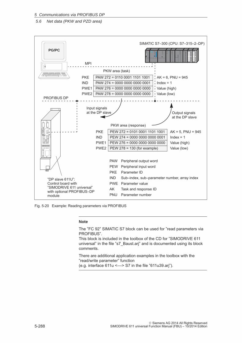
5
5.6 Net data (PKW and PZD area)
5-288� Siemens AG 2014 All Rights Reserved
SIMODRIVE 611 universal Function Manual (FBU) – 10/2014 Edition
PROFIBUS DP
SIMATIC S7–300 (CPU: S7–315–2–DP)
MPI
Output signalsat the DP slave
Input signalsat the DP slave
PKW area (task)
PAW 272 = 0110 0001 1101 1001PAW 274 = 0000 0000 0000 0001PAW 276 = 0000 0000 0000 0000PAW 278 = 0000 0000 0000 0000
INDPKE
PWE1PWE2
AK = 6, PNU = 945Index = 1Value (high)Value (low)
PKW area (response)
PEW 272 = 0101 0001 1101 1001PEW 274 = 0000 0000 0000 0001PEW 276 = 0000 0000 0000 0000PEW 278 = 130 (for example)
INDPKE
PWE1PWE2
AK = 5, PNU = 945Index = 1Value (high)Value (low)
”DP slave 611U”:Control board with”SIMODRIVE 611 universal” with optional PROFIBUS–DPmodule
PAW Peripheral output wordPEW Peripheral input wordPKE Parameter IDIND Sub–index, sub–parameter number, array indexPWE Parameter valueAK Task and response IDPNU Parameter number
PG/PC
Fig. 5-20 Example: Reading parameters via PROFIBUS
Note
The ”FC 92” SIMATIC S7 block can be used for ”read parameters viaPROFIBUS”.This block is included in the toolbox of the CD for ”SIMODRIVE 611universal” in the file ”s7_Baust.arj” and is documented using its blockcomments.
There are additional application examples in the toolbox with the”read/write parameter” function (e.g. interface 611u <––> S7 in the file ”611u39.arj”).
5 Communications via PROFIBUS DP
5
5.6 Net data (PKW and PZD area)
5-289� Siemens AG 2014 All Rights ReservedSIMODRIVE 611 universal Function Manual (FBU) – 10/2014 Edition
Depending on a condition, the position in traversing block 4 (P0081:3)should be adapted as required via PROFIBUS. In this particular example, P0081:3 = 14 586 is written.
Assumptions for the slave:
� The drive has been completely commissioned is connected toPROFIBUS–DP and is ready to run.
� P0700 = 3 (”positioning” mode) has been set
� P0918 = 12 (PROFIBUS node address) has been set
Assumptions for the master:
� The DP master is a SIMATIC S7 (CPU: S7–315–2–DP)
� Hardware configuration
– 1–axis, PPO type 1, node address = 12
– Part I address O addressPKW 272 – 279 272 – 279 PZD 280 – 283 280 – 283 (not shown in the example)
If the condition to write the position in traversing block 4 is available,then the following must occur on the master side(refer to Fig. 5-21):
1. Write the parameter value (define task)
– PKW output signals (PAB 272 – 279) written intowith AK = 8, PNU = 81, IND = 3, PWE2 = 14586
2. Check the task
– Evaluate the PKW input signals (PEB 272 –279)
– If AK = 5, PNU = 81, IND = 3 and PWE2 = 14586 then OK
– If AK = 7, then evaluate the fault number in PEW 278 (refer to Table 5-31)
Example:Reading parameters via PROFIBUS
What has to be programmedon the master side?
5 Communications via PROFIBUS DP
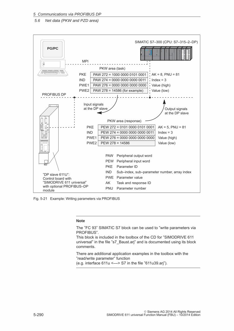
5
5.6 Net data (PKW and PZD area)
5-290� Siemens AG 2014 All Rights Reserved
SIMODRIVE 611 universal Function Manual (FBU) – 10/2014 Edition
PROFIBUS DP
SIMATIC S7–300 (CPU: S7–315–2–DP)
MPI
Output signalsat the DP slave
Input signalsat the DP slave
PKW area (task)
PAW 272 = 1000 0000 0101 0001PAW 274 = 0000 0000 0000 0011PAW 276 = 0000 0000 0000 0000PAW 278 = 14586 (for example)
INDPKE
PWE1PWE2
AK = 8, PNU = 81Index = 3Value (high)Value (low)
”DP slave 611U”:Control board with”SIMODRIVE 611 universal” with optional PROFIBUS–DPmodule
PKW area (response)
PEW 272 = 0101 0000 0101 0001PEW 274 = 0000 0000 0000 0011PEW 276 = 0000 0000 0000 0000PEW 278 = 14586
INDPKE
PWE1PWE2
AK = 5, PNU = 81Index = 3Value (high)Value (low)
PAW Peripheral output wordPEW Peripheral input wordPKE Parameter IDIND Sub–index, sub–parameter number, array indexPWE Parameter valueAK Task and response IDPNU Parameter number
PG/PC
Fig. 5-21 Example: Writing parameters via PROFIBUS
Note
The ”FC 93” SIMATIC S7 block can be used to ”write parameters viaPROFIBUS”.This block is included in the toolbox of the CD for ”SIMODRIVE 611universal” in the file ”s7_Baust.arj” and is documented using its blockcomments.
There are additional application examples in the toolbox with the”read/write parameter” function (e.g. interface 611u <––> S7 in the file ”611u39.arj”).
5 Communications via PROFIBUS DP
5
5.7 Settings at the PROFIBUS–DP master
5-291� Siemens AG 2014 All Rights ReservedSIMODRIVE 611 universal Function Manual (FBU) – 10/2014 Edition
5.7 Settings at the PROFIBUS–DP master
5.7.1 Master device file and configuring
PROFIBUS devices have different performance features. In order that all of the master systems can correctly address the ”DPslave 611U”, the characteristic features of the slave are combined in astandardized master device file (GSD).
The ”DP slave 611U” is exclusively operated as DP slave.
The following master device files (GSDs) are available for the ”DPslave 611U”:
Before SW 4.1:
� SIEM8055.GSD for the optional PROFIBUS–DP1 module
� SIEM808F.GSD for the optional PROFIBUS–DP2 and DP3 modules
From SW 4.1:
� SIEM808F.GSD for the optional PROFIBUS–DP2 and DP3 modules
From SW 6.1:
� SIEM808F.GSD for the optional PROFIBUS DP2 and DP3 modules(PROFIdrive application Class 1)
� SI02808F.GSD for the optional PROFIBUS DP2 and DP3 modules(PROFIdrive application Class 4)
Using the GSD file SI02808F.GSD, it is no longer necessary to enterthe block for clock–cycle synchronism into the parameterizing tele-gram manually byte–for–byte.
In order to use the GSD file SI02808F.GSD, a configuring tool isrequired which supports the GSD Revision 4 (e.g. Step7 HW–ConfigVersion x.xx)
Reader’s note
From SW 4.1, the optional PROFIBUS–DP1 module can no longer beused.
Compatibility conditions, GSD file and optional modules are describedin Chapter 1.3.3 in Table 1-4.
The GSDs are available as ASCII files on the data medium (e.g. CD)for ”SIMODRIVE 611 universal”.
These files uniquely describe the features and properties of the ”DPslave 611U” in a precisely defined format.The GSD file must be inserted into the configuring tool of the master.
Performancefeatures of the PROFIBUSdevices
Master device file for ”DP slave 611U”
5 Communications via PROFIBUS DP
5
5.7 Settings at the PROFIBUS–DP master
5-292� Siemens AG 2014 All Rights Reserved
SIMODRIVE 611 universal Function Manual (FBU) – 10/2014 Edition
If this is not possible, then the appropriate information must be derivedfor the ”DP slave 611U” from the GSD file.
Reader’s note
Information on the PROFIBUS–DP master settings should be takenfrom the literature of the master used.
Configuring defines the data, which the master transfers to the ”DPslaves” at every bus run–up via the parameterizing telegram and theconfiguration telegram.
Configuring can be realized in the following ways:1. Using the GSD ”SIEM808F.GSD” or ”SI02808F.GSD”2. Using the ”Slave Object Manager (Drive ES Slave–OM)”,
which is included in the following products:Product Order No. (MLFB):Drive ES Basic V5.1 SP2 6SW1700–5JA00–1AA0 (single license)
6SW1700–5JA00–1AA1 (company license)6SW1700–5JA00–1AA4 (upgrade)
Drive ES SIMATIC V5.2 6SW1700–5JC00–2AA06SW1700–5JC00–2AA4 (upgrade)
The products, require as basis, the basic SIMATIC–STEP 7 software.Compared to the GSD file, Drive ES offers a higher degree of userfriendliness regarding the telegram structure and clock cycle–synchro-nous operation.Slave–to–slave communications does not function without Drive ES.The following is valid from SW 3.1: The parameterizing and configuration data, received from the ”DPslave 611U” are displayed in the following parameters:� P1783:64 Received PROFIBUS parameterizing data� P1784:64 Received PROFIBUS configuration data
Configuration
5 Communications via PROFIBUS DP
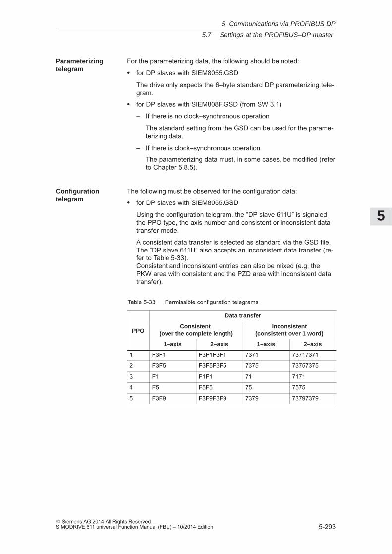
5
5.7 Settings at the PROFIBUS–DP master
5-293� Siemens AG 2014 All Rights ReservedSIMODRIVE 611 universal Function Manual (FBU) – 10/2014 Edition
For the parameterizing data, the following should be noted:
� for DP slaves with SIEM8055.GSD
The drive only expects the 6–byte standard DP parameterizing tele-gram.
� for DP slaves with SIEM808F.GSD (from SW 3.1)
– If there is no clock–synchronous operation
The standard setting from the GSD can be used for the parame-terizing data.
– If there is clock–synchronous operation
The parameterizing data must, in some cases, be modified (referto Chapter 5.8.5).
The following must be observed for the configuration data:
� for DP slaves with SIEM8055.GSD
Using the configuration telegram, the ”DP slave 611U” is signaledthe PPO type, the axis number and consistent or inconsistent datatransfer mode.
A consistent data transfer is selected as standard via the GSD file.The ”DP slave 611U” also accepts an inconsistent data transfer (re-fer to Table 5-33). Consistent and inconsistent entries can also be mixed (e.g. thePKW area with consistent and the PZD area with inconsistent datatransfer).
Table 5-33 Permissible configuration telegrams
Data transfer
PPOConsistent
(over the complete length)Inconsistent
(consistent over 1 word)
1–axis 2–axis 1–axis 2–axis
1 F3F1 F3F1F3F1 7371 73717371
2 F3F5 F3F5F3F5 7375 73757375
3 F1 F1F1 71 7171
4 F5 F5F5 75 7575
5 F3F9 F3F9F3F9 7379 73797379
Parameterizingtelegram
Configuration telegram
5 Communications via PROFIBUS DP
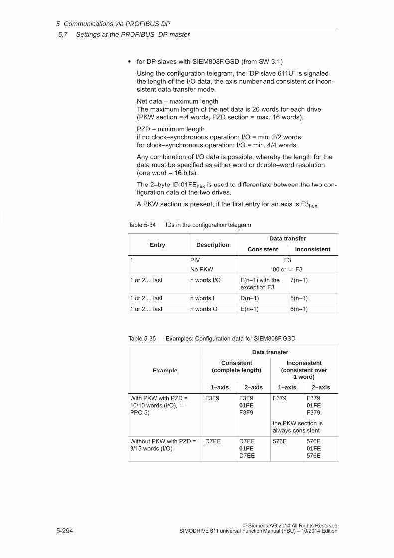
5
5.7 Settings at the PROFIBUS–DP master
5-294� Siemens AG 2014 All Rights Reserved
SIMODRIVE 611 universal Function Manual (FBU) – 10/2014 Edition
� for DP slaves with SIEM808F.GSD (from SW 3.1)
Using the configuration telegram, the ”DP slave 611U” is signaledthe length of the I/O data, the axis number and consistent or incon-sistent data transfer mode.
Net data – maximum lengthThe maximum length of the net data is 20 words for each drive(PKW section = 4 words, PZD section = max. 16 words).
PZD – minimum lengthif no clock–synchronous operation: I/O = min. 2/2 wordsfor clock–synchronous operation: I/O = min. 4/4 words
Any combination of I/O data is possible, whereby the length for thedata must be specified as either word or double–word resolution(one word = 16 bits).
The 2–byte ID 01FEhex is used to differentiate between the two con-figuration data of the two drives.
A PKW section is present, if the first entry for an axis is F3hex.
Table 5-34 IDs in the configuration telegram
Entry DescriptionData transfer
Entry DescriptionConsistent Inconsistent
1 PIVNo PKW
F300 or � F3
1 or 2 ... last n words I/O F(n–1) with theexception F3
7(n–1)
1 or 2 ... last n words I D(n–1) 5(n–1)
1 or 2 ... last n words O E(n–1) 6(n–1)
Table 5-35 Examples: Configuration data for SIEM808F.GSD
Data transfer
ExampleConsistent
(complete length)Inconsistent
(consistent over1 word)
1–axis 2–axis 1–axis 2–axis
With PKW with PZD =10/10 words (I/O), �PPO 5)
F3F9 F3F901FEF3F9
F379 F37901FEF379
the PKW section isalways consistent
Without PKW with PZD =8/15 words (I/O)
D7EE D7EE01FED7EE
576E 576E01FE576E
5 Communications via PROFIBUS DP
5
5.7 Settings at the PROFIBUS–DP master
5-295� Siemens AG 2014 All Rights ReservedSIMODRIVE 611 universal Function Manual (FBU) – 10/2014 Edition
5.7.2 Commissioning
In order to commission the ”DP slave 611U” the slave must fulfill thefollowing prerequisites or these prerequisites must be clarified:
� What is the node address of the DP slave?
The node address must be set in P0918.
� In which mode is the DP slave operated?
This mode is set in P0700.
The selected mode is significant when defining the functional scopeof the DP slave and the function of the control and status signals.
– ”Speed/torque setpoint” modeThe closed–loop speed controlled mode represents a functionalsubset of the positioning mode. The functional scope is defined by the control and status wordsspecified in Chapter 5.6.1.
– ”Positioning” modeIn the positioning mode, the functional scope is defined by thecontrol and status words, specified in Chapter 5.6.1.
Note
In order to commission all of the nodes connected to PROFIBUS, itnow may be necessary to temporarily disable the ”disturbing” DPslaves (also refer to the Chapter 5.9 under P0875).
!Caution
With the ”DP slave 611U” powered–up, the enable terminals andPROFIBUS enable signals are required in order to enable the driveand to operate it. If the ”DP slave 611U” is switched out via P0875 = 0, then the drive isalready enabled using the local enable terminals (e.g. terminal 663,65.x). Thus, the enable signals via the PROFIBUS control word are nolonger necessary.
Prerequisites for aslave
5 Communications via PROFIBUS DP
5
5.7 Settings at the PROFIBUS–DP master
5-296� Siemens AG 2014 All Rights Reserved
SIMODRIVE 611 universal Function Manual (FBU) – 10/2014 Edition
When starting–up the ”DP slave 611U” the following must be taken intoconsideration on the master side:
� Node address (station address)What is the node address (P0918) of the ”DP slave 611U” which isto be commissioned?
� Master device file (GSD file)Is there a GSD file for the ”DP–Slave 611U” for the master?If not, then the GSD file must be inserted into the configuring tool ofthe master for the ”DP–Slave 611U”.
� Data transfer (consistent/non–consistent)
The following applies when programming the data transfer (consis-tent/inconsistent) in the user program of the master:(e.g. for the SIMATIC S7, CPU 315–2DP)
– PKW part
––> with SFC 14/15
– PZD part
consistent data transfer (consistent over the complete length):
––> with SFC 14/15
non–consistent data transfer (consistent over 1 word):
––> An SFC14/15 cannot be used. Instead, a direct peripheralaccess must be used (PAW/PEW).
Prerequisites and information aboutor to the master
5 Communications via PROFIBUS DP
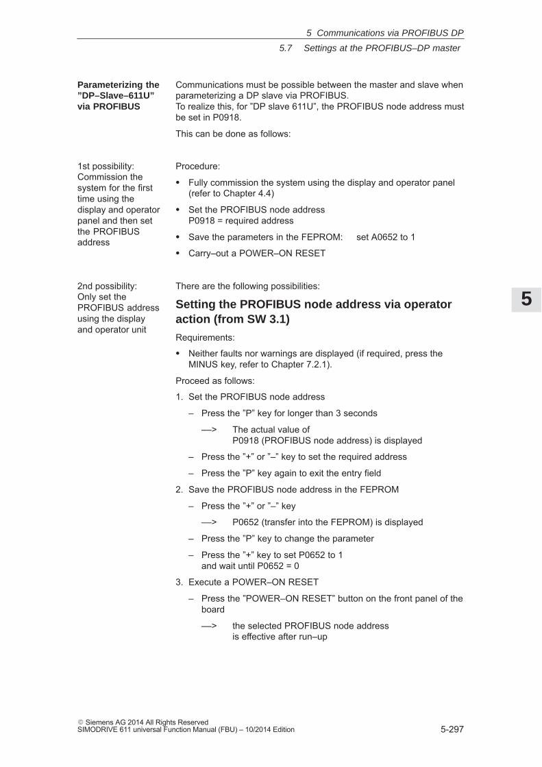
5
5.7 Settings at the PROFIBUS–DP master
5-297� Siemens AG 2014 All Rights ReservedSIMODRIVE 611 universal Function Manual (FBU) – 10/2014 Edition
Communications must be possible between the master and slave whenparameterizing a DP slave via PROFIBUS. To realize this, for ”DP slave 611U”, the PROFIBUS node address mustbe set in P0918.
This can be done as follows:
Procedure:
� Fully commission the system using the display and operator panel(refer to Chapter 4.4)
� Set the PROFIBUS node addressP0918 = required address
� Save the parameters in the FEPROM: set A0652 to 1
� Carry–out a POWER–ON RESET
There are the following possibilities:
Setting the PROFIBUS node address via operatoraction (from SW 3.1)Requirements:
� Neither faults nor warnings are displayed (if required, press theMINUS key, refer to Chapter 7.2.1).
Proceed as follows:
1. Set the PROFIBUS node address
– Press the ”P” key for longer than 3 seconds
––> The actual value of P0918 (PROFIBUS node address) is displayed
– Press the ”+” or ”–” key to set the required address
– Press the ”P” key again to exit the entry field
2. Save the PROFIBUS node address in the FEPROM
– Press the ”+” or ”–” key
––> P0652 (transfer into the FEPROM) is displayed
– Press the ”P” key to change the parameter
– Press the ”+” key to set P0652 to 1 and wait until P0652 = 0
3. Execute a POWER–ON RESET
– Press the ”POWER–ON RESET” button on the front panel of theboard
––> the selected PROFIBUS node address is effective after run–up
Parameterizing the”DP–Slave–611U”via PROFIBUS
1st possibility:Commission thesystem for the firsttime using thedisplay and operatorpanel and then setthe PROFIBUSaddress
2nd possibility:Only set thePROFIBUS addressusing the displayand operator unit
5 Communications via PROFIBUS DP
5
5.7 Settings at the PROFIBUS–DP master
5-298� Siemens AG 2014 All Rights Reserved
SIMODRIVE 611 universal Function Manual (FBU) – 10/2014 Edition
Setting the PROFIBUS node address using the dialogbox for the first start–up1. Carry out the first commissioning (start–up) using the display and
operator unit and for the hardware configuration, do not enter theconfiguration data up to the node address (refer to Chapter 4.4).
A1106 (power module code number) do not set
... (other parameters) do not set
A0918 (PROFIBUS node address) set
A0652 (write into the FEPROM) = 1 set
2. Carry–out a POWER–ON RESET
3. ––> cyclic operation between ”DP slave 611U” <–––> PROFIBUS–DP master is possible
Note
The system can be commissioned and parameterized as follows:� With ”SimoCom U via PROFIBUS–DP” (from SW 3.1)
– Establish online operation (refer to Chapter 3.3.4)– Carry–out the first or series commissioning (start–up) using
SimoCom U (refer to Chapter 4.3.1 or 4.3.2, P0918 (PROFIBUSnode address) may not be overwritten).
� Using ”read/write parameter ” via PKW sectionThe parameters of the ”DP slaves 611U” can be read/written intovia the PKW section from the PROFIBUS–DP master.
5 Communications via PROFIBUS DP
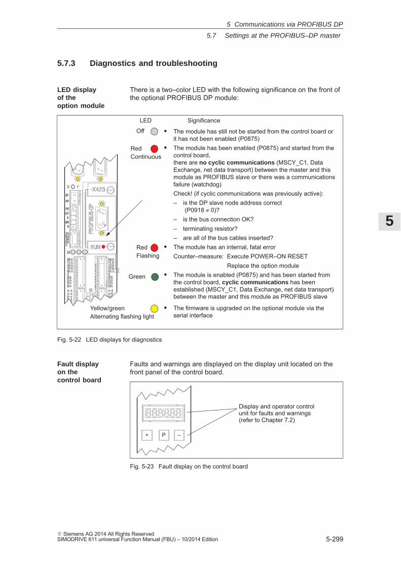
5
5.7 Settings at the PROFIBUS–DP master
5-299� Siemens AG 2014 All Rights ReservedSIMODRIVE 611 universal Function Manual (FBU) – 10/2014 Edition
5.7.3 Diagnostics and troubleshooting
There is a two–color LED with the following significance on the front ofthe optional PROFIBUS DP module:
RedContinuous
RedFlashing
� The module has still not be started from the control board or it has not been enabled (P0875)
� The module has been enabled (P0875) and started from thecontrol board, there are no cyclic communications (MSCY_C1, DataExchange, net data transport) between the master and thismodule as PROFIBUS slave or there was a communicationsfailure (watchdog)Check! (if cyclic communications was previously active):– is the DP slave node address correct
(P0918 ≠ 0)?– is the bus connection OK?– terminating resistor?– are all of the bus cables inserted?
� The module has an internal, fatal errorCounter–measure: Execute POWER–ON RESET
Replace the option module� The module is enabled (P0875) and has been started from
the control board, cyclic communications has beenestablished (MSCY_C1, Data Exchange, net data transport)between the master and this module as PROFIBUS slave
LED Significance
Off
Green
� The firmware is upgraded on the optional module via theserial interface
Yellow/greenAlternating flashing light
Fig. 5-22 LED displays for diagnostics
Faults and warnings are displayed on the display unit located on thefront panel of the control board.
+ P –
Display and operator controlunit for faults and warnings(refer to Chapter 7.2)
Fig. 5-23 Fault display on the control board
LED displayof the option module
Fault display on the control board
5 Communications via PROFIBUS DP
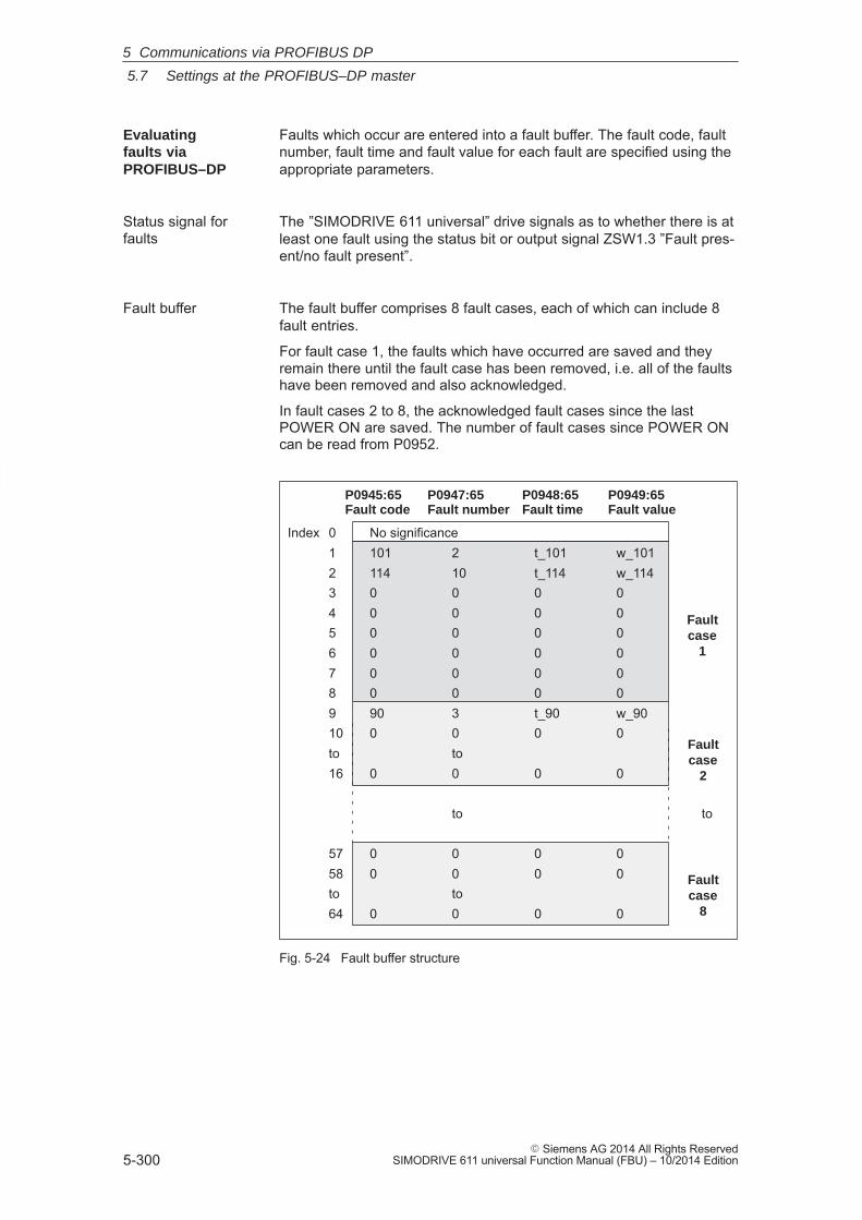
5
5.7 Settings at the PROFIBUS–DP master
5-300� Siemens AG 2014 All Rights Reserved
SIMODRIVE 611 universal Function Manual (FBU) – 10/2014 Edition
Faults which occur are entered into a fault buffer. The fault code, faultnumber, fault time and fault value for each fault are specified using theappropriate parameters.
The ”SIMODRIVE 611 universal” drive signals as to whether there is atleast one fault using the status bit or output signal ZSW1.3 ”Fault pres-ent/no fault present”.
The fault buffer comprises 8 fault cases, each of which can include 8fault entries.
For fault case 1, the faults which have occurred are saved and theyremain there until the fault case has been removed, i.e. all of the faultshave been removed and also acknowledged.
In fault cases 2 to 8, the acknowledged fault cases since the lastPOWER ON are saved. The number of fault cases since POWER ONcan be read from P0952.
Index 0 No significance1 101 2 t_101 w_1012 114 10 t_114 w_1143 0 0 0 04 0 0 0 05 0 0 0 06 0 0 0 07 0 0 0 08 0 0 0 09 90 3 t_90 w_9010 0 0 0 0to to16 0 0 0 0
to
57 0 0 0 058 0 0 0 0to to64 0 0 0 0
P0947:65Fault number
P0945:65Fault code
P0948:65Fault time
P0949:65Fault value
Faultcase
1
Faultcase
2
Faultcase
8
to
Fig. 5-24 Fault buffer structure
Evaluatingfaults viaPROFIBUS–DP
Status signal forfaults
Fault buffer
5 Communications via PROFIBUS DP
5
5.7 Settings at the PROFIBUS–DP master
5-301� Siemens AG 2014 All Rights ReservedSIMODRIVE 611 universal Function Manual (FBU) – 10/2014 Edition
The following rules apply to the fault buffer:
� At POWER ON, the complete fault buffer is deleted.
� The faults are entered in the sequence that they occur, in the pa-rameter of fault case 1, i.e.
– 1. fault that has occurred ––> parameter with index 1
– 2. fault that has occurred ––> parameter with index 2, etc.
If more than 8 faults occur, then these are not displayed.
� Fault case 1 is considered to have been resolved, if, the following isvalid for all of the entered faults:
– the cause has been removed and
– the fault has been acknowledged
The fault buffer is then re–arranged so that the faults of fault case 1go into fault case 2 and those from fault case 2 into fault case 3 etc.This means that the parameters of fault case 1 are again free foradditional entries.
If more than 8 fault cases have occurred since the last POWER ON,then fault case 8 is overwritten, the oldest fault case is eliminated.
� If, in fault case 1, there is at least one fault, which must be acknowl-edged with POWER ON, then this is valid for the complete faultcase.
Reader’s note
A description of the faults, the way in which they can be acknowledgedas well as a list of all the faults, is provided in Chapter 7.
The warnings which occurred, are displayed, bit–coded in P0953 toP0960.
The ”SIMODRIVE 611 universal” drive signals as to whether there is atleast one message present via the status bit or output signal ZSW1.7”Warning present/no warning present”.
Reader’s note
A description of the warnings as well as a list of all of the warnings isprovided in Chapter 7.
Rules regardingthe fault buffer
Evaluatingwarnings viaPROFIBUS–DP
Status signal forwarnings
5 Communications via PROFIBUS DP
5
5.7 Settings at the PROFIBUS–DP master
5-302� Siemens AG 2014 All Rights Reserved
SIMODRIVE 611 universal Function Manual (FBU) – 10/2014 Edition
The sent and received process data of the ”DP slaves 611U” are dis-played using the following parameters:
� P1788:17 Received process data PROFIBUS
� P1789:17 Sent process data PROFIBUS
The sent and received PKW data of the ”DP slave 611U” are displayedusing the following parameters:
� P1786:5 Received PKW data PROFIBUS
� P1787:5 Sent PKW data PROFIBUS
The parameterizing and configuration data, received from the DPmaster, are displayed using the following parameters:
� P1783:64 Received PROFIBUS parameterizing data
� P1784:64 Received PROFIBUS configuration data
Diagnostics of theprocess data
Diagnostics of the PKW data(from SW 2.4)
Diagnostics of the parameterizing and configurationdata (from SW 3.1)
5 Communications via PROFIBUS DP
5
5.8 Motion Control with PROFIBUS–DP (from SW 3.1)
5-303� Siemens AG 2014 All Rights ReservedSIMODRIVE 611 universal Function Manual (FBU) – 10/2014 Edition
5.8 Motion Control with PROFIBUS–DP (from SW 3.1)
Using the ”Motion Control with PROFIBUS DP” function, a clock–cyclesynchronous drive coupling can be established between a DP masterand one or several slaves via the PROFIBUS fieldbus.
Reader’s note
The clock–synchronous drive coupling is defined in the followingdocumentation:
Reference: /PPA/, PROFIdrive Profile Drive Technology, Version 3.1.2 Sept. 2004 (Chapter 3.4)
From SW 12.1:Version 4.1 May 2006 (Chapter 6.2)
Clock–synchronous operation can be implemented using the followingDP masters:
Table 5-36 Examples for clock–synchronous masters
DP–MASTER DP slave 611U
SINUMERIK 802D
SINUMERIK 840Di In the ”speed/torque setpoint” mode(n–set mode)Positioning and path control board
FM 357–2(n–set mode)
SIMATIC S7–3006ES7315–2AF03–xxxx
In the ”positioning” operating mode(pos mode)
The clock–cycle synchronous drive coupling can be activated if all ofthe prerequisites of the DP master and DP slave have been fulfilledand the function has been selected in the DP master by appropriatelyparameterizing/configuring it.
The parameters for equidistant operation are included in the slave–spe-cific master device file SIEM808F.GSD. Parameterization is also pos-sible via Drive ES.
The master configuring ensures, that all of the DP slaves in the applica-tion use the same clock cycle times and processing instants.
When PROFIBUS boots, the information required by the DP slaves, istransferred from the master to all of the slaves via the parameterizingtelegram.
General
Which clock–synchronousmasters are there?
Activating
Parameterizingequidistantoperation
5 Communications via PROFIBUS DP
5
5.8 Motion Control with PROFIBUS–DP (from SW 3.1)
5-304� Siemens AG 2014 All Rights Reserved
SIMODRIVE 611 universal Function Manual (FBU) – 10/2014 Edition
Every DP cycle starts with a Global Control Telegram (GC), which isthen followed, one after the other, with the data transfer with the indi-vidual slaves (S1, S2, ...).
The GC telegram is a broadcast telegram, sent from the master, andwhich is received simultaneously by all slaves.
The internal clock cycles of the ”DP slave 611U” are synchronized tothe DP clock cycle using this GC telegram and the PLL used for theoptional PROFIBUS–DP3 module.
The clock–synchronous coupling has the following prerequisites andfeatures:
� Prerequisites for the DP slave (refer to Chapter 1.3.3)
– ”SIMODRIVE 611 universal” control board from SW 3.1
– Optional PROFIBUS–DP3 module with ASIC DPC31 and PLL(Order No.: 6SN1114–0NB01–0AA0)
� Prerequisites for the DP master
– ”Motion Control with PROFIBUS–DP” function
– Using a DP interface in the DP master, which can realize clock–cycle synchronous operation
– Transmission rate: Can be set between 1.5 and 12 Mbaud
� Telegram data transfer between a DP master and slave in equidis-tant cycles.
� Post synchronization of the slave clock cycles to the equidistant DPcycle via the Global Control Telegram at the start of a DP cycle.
� The maximum permissible fluctuations when recognizing a GlobalControl Telegram (Jitter) via the optional PROFIBUS DP module isdependent on the data transfer rate as follows:
Data transfer rate Max. permissible jitter
12 Mbaud 1.0 μs3 or 6 Mbaud 0.9 μs1.5 Mbaud 0.8 μs
Clock–synchronous operation with the ”DP slave 611U” is only guar-anteed when the maximum permissible jitter is maintained.
When configuring the bus system, it should be ensured, that espe-cially when, e.g. repeaters or optical bus components are used, themaximum permissible jitter is not exceeded.
DP cycle
Prerequisites and features
5 Communications via PROFIBUS DP
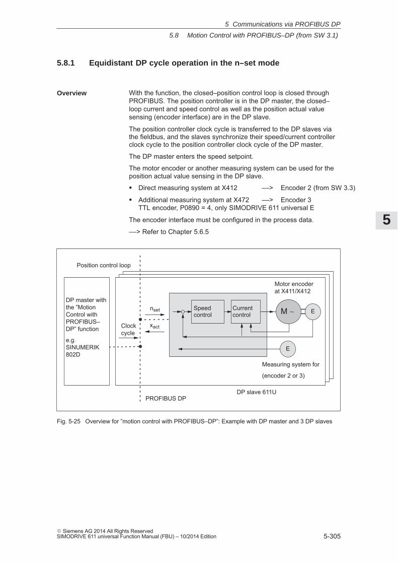
5
5.8 Motion Control with PROFIBUS–DP (from SW 3.1)
5-305� Siemens AG 2014 All Rights ReservedSIMODRIVE 611 universal Function Manual (FBU) – 10/2014 Edition
5.8.1 Equidistant DP cycle operation in the n–set mode
With the function, the closed–position control loop is closed throughPROFIBUS. The position controller is in the DP master, the closed–loop current and speed control as well as the position actual valuesensing (encoder interface) are in the DP slave.
The position controller clock cycle is transferred to the DP slaves viathe fieldbus, and the slaves synchronize their speed/current controllerclock cycle to the position controller clock cycle of the DP master.
The DP master enters the speed setpoint.
The motor encoder or another measuring system can be used for theposition actual value sensing in the DP slave.
� Direct measuring system at X412 ––> Encoder 2 (from SW 3.3)
� Additional measuring system at X472 ––> Encoder 3TTL encoder, P0890 = 4, only SIMODRIVE 611 universal E
The encoder interface must be configured in the process data.
––> Refer to Chapter 5.6.5
nset
Clockcycle
xact
Currentcontrol
Speed control M ∼ E
E
Motorencoderat X411/X412
nset
Clockcycle
xact
Currentcontrol
Speed control M ∼ E
E
Motorencoderat X411/X412
nset
DP master withthe ”MotionControl withPROFIBUS–DP” function
e.g. SINUMERIK802D
Clockcycle
xact
PROFIBUS DP
Currentcontrol
Speed control M ∼ E
Position control loop
E
Measuring system for
(encoder 2 or 3)
Motor encoderat X411/X412
DP slave 611U
Fig. 5-25 Overview for ”motion control with PROFIBUS–DP”: Example with DP master and 3 DP slaves
Overview
5 Communications via PROFIBUS DP
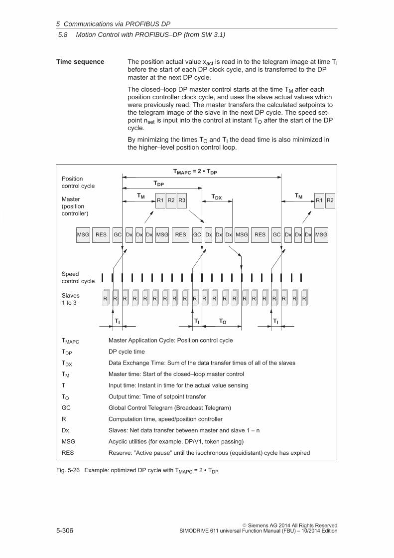
5
5.8 Motion Control with PROFIBUS–DP (from SW 3.1)
5-306� Siemens AG 2014 All Rights Reserved
SIMODRIVE 611 universal Function Manual (FBU) – 10/2014 Edition
The position actual value xact is read in to the telegram image at time TIbefore the start of each DP clock cycle, and is transferred to the DPmaster at the next DP cycle.
The closed–loop DP master control starts at the time TM after eachposition controller clock cycle, and uses the slave actual values whichwere previously read. The master transfers the calculated setpoints tothe telegram image of the slave in the next DP cycle. The speed set-point nset is input into the control at instant TO after the start of the DPcycle.
By minimizing the times TO and TI the dead time is also minimized inthe higher–level position control loop.
R
TMAPC Master Application Cycle: Position control cycle
TDP DP cycle time
TDX Data Exchange Time: Sum of the data transfer times of all of the slaves
TM Master time: Start of the closed–loop master control
TI Input time: Instant in time for the actual value sensing
TO Output time: Time of setpoint transfer
GC Global Control Telegram (Broadcast Telegram)
R Computation time, speed/position controller
Dx Slaves: Net data transfer between master and slave 1 – n
MSG Acyclic utilities (for example, DP/V1, token passing)
RES Reserve: ”Active pause” until the isochronous (equidistant) cycle has expired
DxDxDxGCMSG RES MSG DxDxDx MSG DxDxDx MSG
RR RRR RRR RRR RRR RRR RRR RRR RRR RRR RRR RRR RRR RRR RRR RRR RRR RRR RRRRRR RRR
Speedcontrol cycle
Slaves 1 to 3
Master(positioncontroller)
R1 R2 R3
Positioncontrol cycle
TI
TM
TO
TMAPC = 2 � TDP
TM
TDP
TI
RES GC RES GC
TI
R1 R2TDX
Fig. 5-26 Example: optimized DP cycle with TMAPC = 2 � TDP
Time sequence
5 Communications via PROFIBUS DP
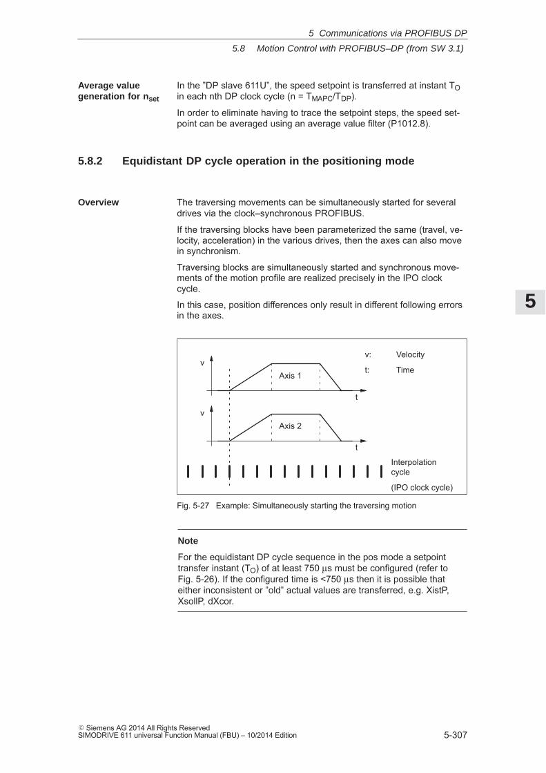
5
5.8 Motion Control with PROFIBUS–DP (from SW 3.1)
5-307� Siemens AG 2014 All Rights ReservedSIMODRIVE 611 universal Function Manual (FBU) – 10/2014 Edition
In the ”DP slave 611U”, the speed setpoint is transferred at instant TOin each nth DP clock cycle (n = TMAPC/TDP).
In order to eliminate having to trace the setpoint steps, the speed set-point can be averaged using an average value filter (P1012.8).
5.8.2 Equidistant DP cycle operation in the positioning mode
The traversing movements can be simultaneously started for severaldrives via the clock–synchronous PROFIBUS.
If the traversing blocks have been parameterized the same (travel, ve-locity, acceleration) in the various drives, then the axes can also movein synchronism.
Traversing blocks are simultaneously started and synchronous move-ments of the motion profile are realized precisely in the IPO clockcycle.
In this case, position differences only result in different following errorsin the axes.
v: Velocity
t: Time
v
t
Axis 2
Interpolationcycle
(IPO clock cycle)
v
t
Axis 1
Fig. 5-27 Example: Simultaneously starting the traversing motion
Note
For the equidistant DP cycle sequence in the pos mode a setpointtransfer instant (TO) of at least 750 μs must be configured (refer toFig. 5-26). If the configured time is <750 μs then it is possible thateither inconsistent or ”old” actual values are transferred, e.g. XistP,XsollP, dXcor.
Average valuegeneration for nset
Overview
5 Communications via PROFIBUS DP
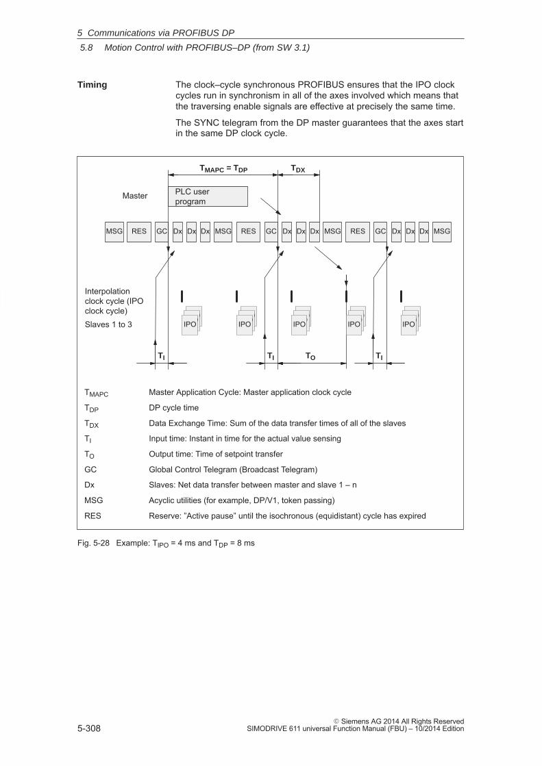
5
5.8 Motion Control with PROFIBUS–DP (from SW 3.1)
5-308� Siemens AG 2014 All Rights Reserved
SIMODRIVE 611 universal Function Manual (FBU) – 10/2014 Edition
The clock–cycle synchronous PROFIBUS ensures that the IPO clockcycles run in synchronism in all of the axes involved which means thatthe traversing enable signals are effective at precisely the same time.
The SYNC telegram from the DP master guarantees that the axes startin the same DP clock cycle.
DxDxDxGCMSG RES MSG DxDxDx MSG DxDxDx MSG
Interpolationclock cycle (IPOclock cycle)Slaves 1 to 3
Master
TI TO
TMAPC = TDP
TI
RES GC RES GC
TI
TDX
PLC userprogram
IPOIPOIPOIPOIPOIPO
IPOIPOIPOIPOIPOIPO
IPOIPOIPO
TMAPC Master Application Cycle: Master application clock cycle
TDP DP cycle time
TDX Data Exchange Time: Sum of the data transfer times of all of the slaves
TI Input time: Instant in time for the actual value sensing
TO Output time: Time of setpoint transfer
GC Global Control Telegram (Broadcast Telegram)
Dx Slaves: Net data transfer between master and slave 1 – n
MSG Acyclic utilities (for example, DP/V1, token passing)
RES Reserve: ”Active pause” until the isochronous (equidistant) cycle has expired
Fig. 5-28 Example: TIPO = 4 ms and TDP = 8 ms
Timing
5 Communications via PROFIBUS DP
5
5.8 Motion Control with PROFIBUS–DP (from SW 3.1)
5-309� Siemens AG 2014 All Rights ReservedSIMODRIVE 611 universal Function Manual (FBU) – 10/2014 Edition
General prerequisites:
� The interpolation clock cycle (P1010) must be parameterized thesame for all axes.
� The master application clock cycle TMAPC must be an integer multi-ple of the interpolation clock cycle.
� TI and TO must be the same for all axes.
� TDP must be less than or equal to 16 ms.
� For masters, which cannot generate a master sign of life (e.g.SIMATIC S7), TMAPC must be = to TDP and the sign–of–life monitor-ing in operation must be disabled using P0879.8 = 1.
Additional prerequisites for SIMATIC S7:
� Presently, there is no run level that is in synchronism with DP cyclein S7 user programs. This means, that if axes are to be simulta-neously started, in addition to the clock–synchronous PROFIBUSoperation, the ”classic” SYNC mechanism must be used.
SYNC mechanism
––> refer to the documentation of the DP master SIMATIC S7 (SFC 11 ”DPSYNC_FR”)
The SYNC mechanism may only be activated after the drive has setthe status bit ZSW1.9 ”control requested”.
Conditions
5 Communications via PROFIBUS DP
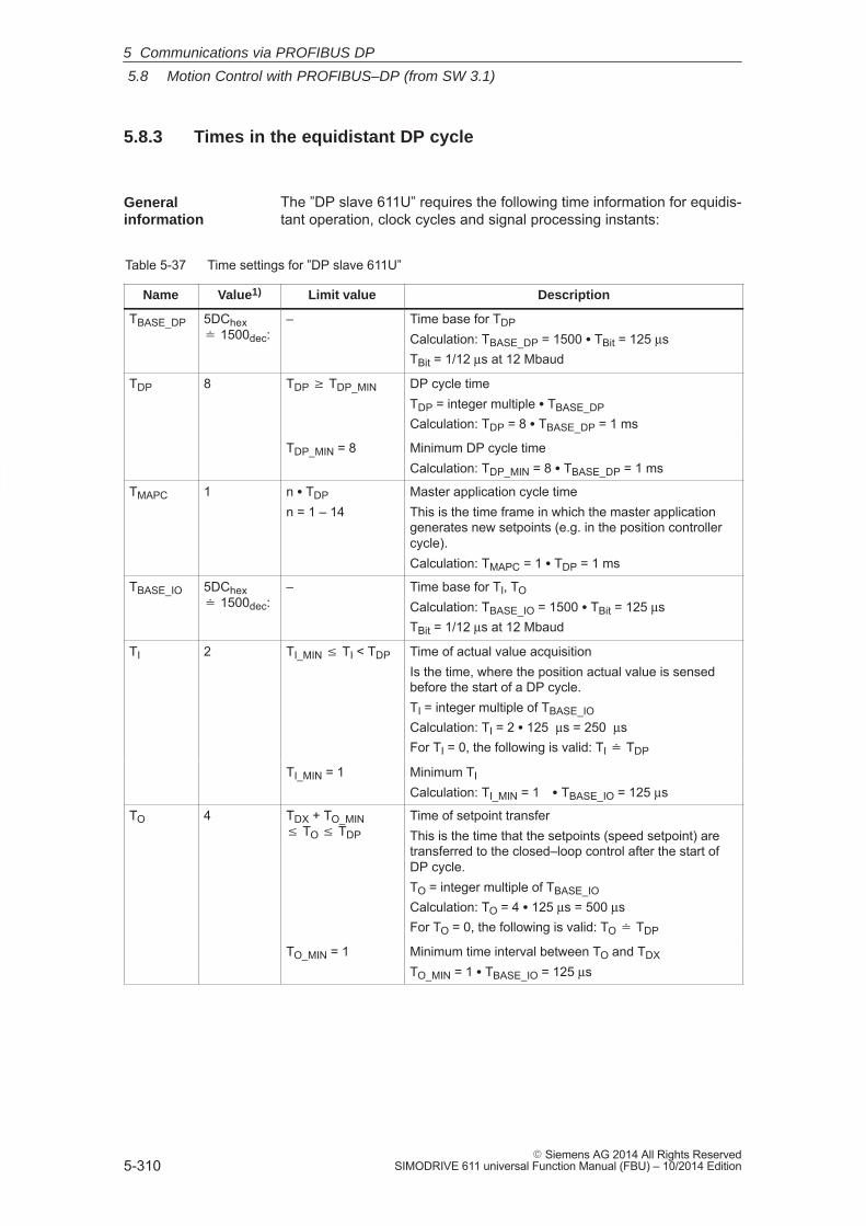
5
5.8 Motion Control with PROFIBUS–DP (from SW 3.1)
5-310� Siemens AG 2014 All Rights Reserved
SIMODRIVE 611 universal Function Manual (FBU) – 10/2014 Edition
5.8.3 Times in the equidistant DP cycle
The ”DP slave 611U” requires the following time information for equidis-tant operation, clock cycles and signal processing instants:
Table 5-37 Time settings for ”DP slave 611U”
Name Value1) Limit value Description
TBASE_DP 5DChex � 1500dec:
– Time base for TDP
Calculation: TBASE_DP = 1500 � TBit = 125 μsTBit = 1/12 μs at 12 Mbaud
TDP 8 TDP � TDP_MIN DP cycle timeTDP = integer multiple � TBASE_DPCalculation: TDP = 8 � TBASE_DP = 1 ms
TDP_MIN = 8 Minimum DP cycle timeCalculation: TDP_MIN = 8 � TBASE_DP = 1 ms
TMAPC 1 n � TDP
n = 1 – 14Master application cycle timeThis is the time frame in which the master applicationgenerates new setpoints (e.g. in the position controllercycle).Calculation: TMAPC = 1 � TDP = 1 ms
TBASE_IO 5DChex � 1500dec:
– Time base for TI, TO
Calculation: TBASE_IO = 1500 � TBit = 125 μsTBit = 1/12 μs at 12 Mbaud
TI 2 TI_MIN � TI < TDP Time of actual value acquisitionIs the time, where the position actual value is sensedbefore the start of a DP cycle.TI = integer multiple of TBASE_IOCalculation: TI = 2 � 125 μs = 250 μsFor TI = 0, the following is valid: TI � TDP
TI_MIN = 1 Minimum TI
Calculation: TI_MIN = 1 � TBASE_IO = 125 μs
TO 4 TDX + TO_MIN � TO � TDP
Time of setpoint transferThis is the time that the setpoints (speed setpoint) aretransferred to the closed–loop control after the start ofDP cycle.TO = integer multiple of TBASE_IOCalculation: TO = 4 � 125 μs = 500 μsFor TO = 0, the following is valid: TO � TDP
TO_MIN = 1 Minimum time interval between TO and TDX
TO_MIN = 1 � TBASE_IO = 125 μs
Generalinformation
5 Communications via PROFIBUS DP
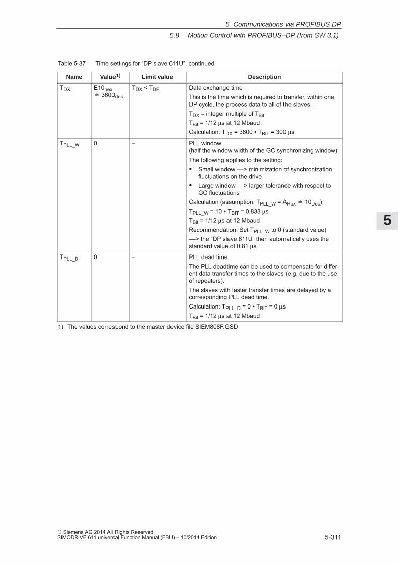
5
5.8 Motion Control with PROFIBUS–DP (from SW 3.1)
5-311� Siemens AG 2014 All Rights ReservedSIMODRIVE 611 universal Function Manual (FBU) – 10/2014 Edition
Table 5-37 Time settings for ”DP slave 611U”, continued
Name DescriptionLimit valueValue1)
TDX E10hex� 3600dec
TDX < TDP Data exchange timeThis is the time which is required to transfer, within oneDP cycle, the process data to all of the slaves.TDX = integer multiple of TBitTBit = 1/12 μs at 12 MbaudCalculation: TDX = 3600 � TBIT = 300 μs
TPLL_W 0 – PLL window(half the window width of the GC synchronizing window)The following applies to the setting:� Small window ––> minimization of synchronization
fluctuations on the drive� Large window ––> larger tolerance with respect to
GC fluctuationsCalculation (assumption: TPLL_W = AHex � 10Dec)TPLL_W = 10 � TBIT = 0.833 μsTBit = 1/12 μs at 12 MbaudRecommendation: Set TPLL_W to 0 (standard value)––> the ”DP slave 611U” then automatically uses thestandard value of 0.81 μs
TPLL_D 0 – PLL dead timeThe PLL deadtime can be used to compensate for differ-ent data transfer times to the slaves (e.g. due to the useof repeaters).The slaves with faster transfer times are delayed by acorresponding PLL dead time.Calculation: TPLL_D = 0 � TBIT = 0 μsTBit = 1/12 μs at 12 Mbaud
1) The values correspond to the master device file SIEM808F.GSD
5 Communications via PROFIBUS DP

5
5.8 Motion Control with PROFIBUS–DP (from SW 3.1)
5-312� Siemens AG 2014 All Rights Reserved
SIMODRIVE 611 universal Function Manual (FBU) – 10/2014 Edition
The following criteria must be taken into account when setting the times:
� DP cycle (TDP)
– Time TDP must be set the same for all bus nodes.
– The following must be valid: TDP > TDX and TDP � TO
Time TDP is therefore long enough to permit communicationswith all of the bus nodes.
– Specific reserves must be available
This means that additional masters can be connected and non–cyclic communications can be realized.
� TI and TO
– n–set mode: Setting the times in TI and TO as short as possiblereduces the dead time in the position control loop.
– The following must be valid: TO > TDX + TOmin
� The following is valid for interpolating axes:
– TI of the interpolating axes should be the same
– TO of the interpolating axes should be the same
5.8.4 Bus run–up, synchronization and net data save
When running–up, the DP master checks the DP slave by requestingdiagnostic information. The following faults/errors are identified:
� Parameterizing and configuring errors
� The DP slave has been assigned to another master
� Static user diagnostics
� Operational readiness of the DP slave
If a fault has not been detected, then the DP master, with this DPslave, goes into cyclic net data operation, i.e. input and output data areexchanged.
With the transition into cyclic net data transfer, the DP slave is syn-chronized to the master sign–of–life.
The DP slave runs in synchronism with the master, if
� The status signal ZSW1.9 (control requested/no control possible) = ”1”
and
� The slave sign–of–life (ZSW2.12 to ZSW2.15, value = 1 to 15) iscounted
Setting criteria
Bus run–up andsynchronization
5 Communications via PROFIBUS DP
5
5.8 Motion Control with PROFIBUS–DP (from SW 3.1)
5-313� Siemens AG 2014 All Rights ReservedSIMODRIVE 611 universal Function Manual (FBU) – 10/2014 Edition
The net data save is realized in both data transfer directions (master<––> slave) using a sign–of–life that comprises a 4–bit counter.
The sign–of–life counter is always incremented from 1 to 15, and thenstarts again with the value 1.
� Master sign–of–life (M–SoL)
– The control signals STW2.12 to STW2.15 are used as mastersign–of–life.
– The master sign–of–life counter is incremented in each masterapplication cycle (TMAPC).
– P0879. 2 to .0 Permissible sign–of–life error
– P0879. 8 Operation with/without Master sign–of–life monitoring
– Monitoring
The master sign–of–life is monitored in the DP slave. If themaster sign–of–life does not consecutively correspond to theexpected value or more often than is permitted in P0879 bit 2 tobit 0, then the following occurs:
––> fault 597 (PROFIBUS: synchronization error) is output
––> zero is output as slave sign–of–life
––> the status signal ZSW1.9 (control requested/control notpossible) is set to ”0”
––> the system re–synchronizes to the master sign–of–life
� Slave sign–of–life (S–SoL)
– The status signals ZSW2.12 to ZSW2.15 are used as slavesign–of–life.
– The slave sign–of–life counter is incremented in every DP cycle (TDP).
Net datasave
5 Communications via PROFIBUS DP
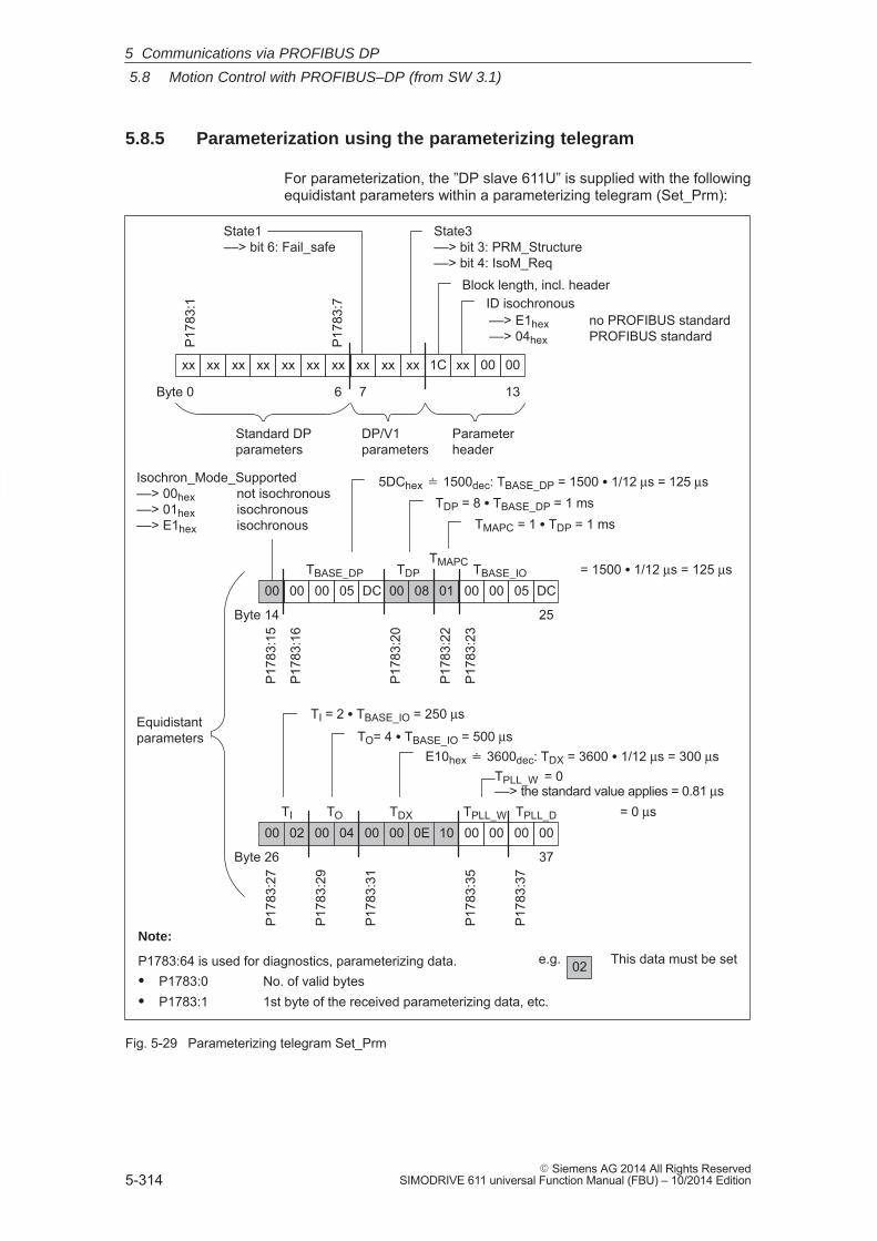
5
5.8 Motion Control with PROFIBUS–DP (from SW 3.1)
5-314� Siemens AG 2014 All Rights Reserved
SIMODRIVE 611 universal Function Manual (FBU) – 10/2014 Edition
5.8.5 Parameterization using the parameterizing telegram
For parameterization, the ”DP slave 611U” is supplied with the followingequidistant parameters within a parameterizing telegram (Set_Prm):
State1––> bit 6: Fail_safe
ID isochronous
Isochron_Mode_Supported––> 00hex not isochronous––> 01hex isochronous––> E1hex isochronous
TBASE_DP TDPTMAPC TBASE_IO = 1500 � 1/12 μs = 125 μs
TI TDX TPLL_W TPLL_D = 0 μsTO
xx xx xx
7Byte 0
1C xx 00 00
DP/V1parameters
Parameterheader
00 00 00 05 DC 00 08 01 00 00 05 DC
00 02 00 04 00 00 0E 10 00 00 00 00
13
Equidistantparameters
Block length, incl. header
37
xxxxxxxxxxxxxx
6
Standard DPparameters
02 This data must be set
Note:
P1783:64 is used for diagnostics, parameterizing data.� P1783:0 No. of valid bytes� P1783:1 1st byte of the received parameterizing data, etc.
P17
83:1
P17
83:7
Byte 14
Byte 26
25
P17
83:1
5
P17
83:1
6
P17
83:2
0
P17
83:2
2
P17
83:2
3
P17
83:2
7
P17
83:2
9
P17
83:3
1
P17
83:3
5
P17
83:3
7
5DChex � 1500dec: TBASE_DP = 1500 � 1/12 μs = 125 μsTDP = 8 � TBASE_DP = 1 ms
TMAPC = 1 � TDP = 1 ms
TI = 2 � TBASE_IO = 250 μs
TO= 4 � TBASE_IO = 500 μsE10hex � 3600dec: TDX = 3600 � 1/12 μs = 300 μs
TPLL_W = 0 ––> the standard value applies = 0.81 μs
––> E1hex no PROFIBUS standard––> 04hex PROFIBUS standard
State3––> bit 3: PRM_Structure––> bit 4: IsoM_Req
e.g.
Fig. 5-29 Parameterizing telegram Set_Prm
5 Communications via PROFIBUS DP
5
5.9 Parameter overview of PROFIBUS–DP
5-315� Siemens AG 2014 All Rights ReservedSIMODRIVE 611 universal Function Manual (FBU) – 10/2014 Edition
5.9 Parameter overview of PROFIBUS–DP
The following parameters are available for PROFIBUS–DP:
Table 5-38 Parameters for PROFIBUS–DP
Parameter
No. Description Min. Stan-dard
Max. Unit Effec-tive
0872 Optional module type – – – – RO
... indicates which optional module was identified when the control board was powered–up.0 No option module1 Optional TERMINAL module, Order No. (MLFB): 6SN1114–0NA00–0AA02 Optional PROFIBUS–DP1 module
with PROFIBUS–ASIC SPC3, Order No. (MLFB): 6SN1114–0NB00–0AA03 Optional PROFIBUS–DP2 module (from SW 3.1)
with PROFIBUS–ASIC DPC31 without PLL, Order No. (MLFB): 6SN1114–0NB00–0AA1/–0AA2
4 Optional PROFIBUS–DP3 module (from SW 3.1) with PROFIBUS–ASIC DPC31 with PLL Order No. (MLFB): 6SN1114–0NB01–0AA0/–0AA1
0873 Option module version – – – Hex RO
... displays the version of the particular option module.
0875 Expected optional module type 0 0 4 – PO
... indicates which option module was expected as a result of the parameterization.The parameters are automatically set at the first start–up corresponding to P0872 (option mod-ule type).Examples:
� P0875 = P0872 ––> normal situation after first commissioning––> no error is signaled when booting
� P0875 = 3 and P0872 = 0 ––> the optional PROFIBUS–DP2 module has been parameterized but was not detected––> a fault was signaled when the system ran up
Note:
Switch–out the communications or the ”DP slaves 611U” when the module is inserted:� 1–axis module
––> the ”DP slave 611U” is switched–out from drive A with P0875 = 0� 2–axis module
––> with P0875 = 0, the communications with drive B is switched–out from drive B––> with P0875 = 0 in both drives, the ”DP slave 611U” is switched–out
This means, that e.g. ”disturbing” slaves can be temporarily disabled when commissioning theother nodes (refer under the index entry ”Start–up PROFIBUS–DP”).After disabling the communications or the module, P0875 must be again set to P0872.
Parameter overview
5 Communications via PROFIBUS DP
5
5.9 Parameter overview of PROFIBUS–DP
5-316� Siemens AG 2014 All Rights Reserved
SIMODRIVE 611 universal Function Manual (FBU) – 10/2014 Edition
Table 5-38 Parameters for PROFIBUS–DP, continued
Parameter
No. Effec-tive
UnitMax.Stan-dard
Min.Description
0879 PROFIBUS configuration (from SW 3.1) 0 1 FFFF Hex PO
Bit 2, 1, 0 Permissible sign–of–life errorBit 8 Operation with/without master sign–of–life monitoringBit 11 PKW area: Sub–index in the high/low byte of IND (from SW 3.3)Bit 12 Activates the direct measuring system (encoder 2) for the encoder interface (from
SW 3.3)Bit 13 Incremental motor measuring system with/without equivalent zero markBit 14 Incremental, direct meas. system with/without equivalent zero mark (from SW 3.3)
0880 Speed evaluation PROFIBUS (SRM,ARM)Motor velocity evaluation PROFIBUS(SLM)
0.0 16 384.0 100 000.0
RPM
m/min
imme-diately
... defines the normalization of the speed or velocity when using PROFIBUS–DP.4000Hex or 16384Dec � of the speed or velocity in P0880
0881(from SW 4.1)
Evaluation, torque/power reductionPROFIBUS (SRM, ARM)Evaluation, force/power reduction PROFIBUS (SLM)
0.0 16 384.0 16 384.0
%
%
imme-diately
... defines the normalization of the torque/power reduction or force/power reduction when us-ing PROFIBUS–DP.Note:
4000 hex or 16384 dec in the control word MomRed corresponds to a reduction by the per-centage specified in P0881.
0882(from SW 4.1)
Torque setpoint evaluationPROFIBUS (SRM, ARM)Force setpoint evaluationPROFIBUS (SLM)
–16384.0 800.0 16 384.0
%
%
imme-diately
... defines the normalization of the torque or force setpoint when entered via PROFIBUS–DP.Note:
P0882 is a percentage value referred to the rated motor torque. The parameter acts on theprocess data MsollExt (torque setpoint external in the input direction) and Msoll (torque set-point in the output direction).4000 hex or 16384 dec in the control word corresponds to the percentage entered into P0882.
0883 Override evaluation, PROFIBUS (from SW 3.1)
0.0 16 384.0 16 384.0 % imme-diately
... defines the normalization of the override when entered via PROFIBUS DP.4000hex or 16384dec � the override in P0883
0884(from SW 4.1)
PROFIBUS position output evaluationnumber of increments
1 2048 8388607 – PO
... defines the normalization of the override when entered via PROFIBUS.4000hex or 16384dec � the override in P0883
5 Communications via PROFIBUS DP
5
5.9 Parameter overview of PROFIBUS–DP
5-317� Siemens AG 2014 All Rights ReservedSIMODRIVE 611 universal Function Manual (FBU) – 10/2014 Edition
Table 5-38 Parameters for PROFIBUS–DP, continued
Parameter
No. Effec-tive
UnitMax.Stan-dard
Min.Description
0888:16(from SW 4.1)
Function, distributed input (PROFIBUS)
0 0 82 – imme-diately
... defines which function a signal has which was read in via the PROFIBUS–PZD for distrib-uted inputs (DezEing).The function number from the ”list of input signals” is entered. The following applies for theindividual indices of P0888::0 Function DezEing bit 0:1 Function DezEing bit 1:2 etc.
0891(from SW 3.3)
Source, external position referencevalue
–1 –1 4 – PO
... defines the source for the external position reference value.–1 No external position reference value0 Angular incremental encoder interface1 Motor encoder, drive A (only drive B in double–axis modules)
(only for compatibility, recommended value = 2)2 Pos. act. value drive A (only drive B in double–axis modules, from SW 4.1)3 Pos. ref. value, drive A (only drive B in double–axis modules, from SW 4.1)4 PROFIBUS–DP (from SW 4.1)
0895(from SW 3.3)
External position reference value – num-ber of increments
1 2048 8388607 – PO
... defines, together with P0896 for couplings, the ratio between input increments and the di-mension system grids.Note:
––> P0895 input pulses at the angular incremental encoder correspond to P0896 MSR––> Setpoint input from P0895 corresponds to P0896 MSRrefer to P0896
0896(from SW 3.3)
External position reference value – num-ber of dimension system grids
1 10000 8388607 MSC PO
... defines, together with P0895, for couplings, the ratio between the input pulse periods (orinput bit) and the dimension system grids.
0915 PZD setpoint assignment, PROFIBUS (from SW 3.1)
0 0 65 535 – imme-diately
... is used to assign the signals to the process data in the setpoint telegram.––> Refer to Chapter 5.6.5
0916 PZD actual value assignment,PROFIBUS (from SW 3.1)
0 0 65 535 – imme-diately
... is used to assign the signals to the process data in the actual value telegram.––> Refer to Chapter 5.6.5
5 Communications via PROFIBUS DP
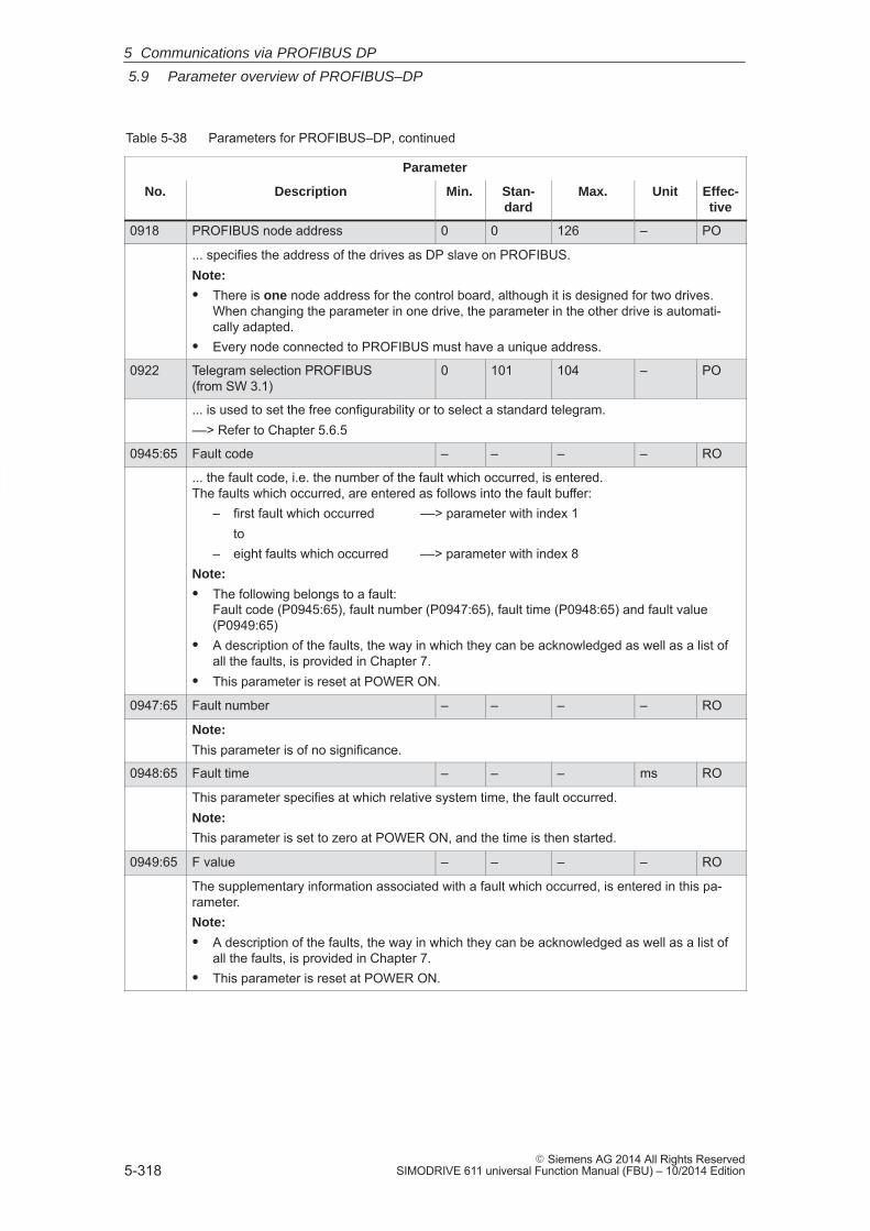
5
5.9 Parameter overview of PROFIBUS–DP
5-318� Siemens AG 2014 All Rights Reserved
SIMODRIVE 611 universal Function Manual (FBU) – 10/2014 Edition
Table 5-38 Parameters for PROFIBUS–DP, continued
Parameter
No. Effec-tive
UnitMax.Stan-dard
Min.Description
0918 PROFIBUS node address 0 0 126 – PO
... specifies the address of the drives as DP slave on PROFIBUS.Note:
� There is one node address for the control board, although it is designed for two drives.When changing the parameter in one drive, the parameter in the other drive is automati-cally adapted.
� Every node connected to PROFIBUS must have a unique address.
0922 Telegram selection PROFIBUS (from SW 3.1)
0 101 104 – PO
... is used to set the free configurability or to select a standard telegram.––> Refer to Chapter 5.6.5
0945:65 Fault code – – – – RO
... the fault code, i.e. the number of the fault which occurred, is entered. The faults which occurred, are entered as follows into the fault buffer:
– first fault which occurred ––> parameter with index 1to
– eight faults which occurred ––> parameter with index 8Note:
� The following belongs to a fault: Fault code (P0945:65), fault number (P0947:65), fault time (P0948:65) and fault value(P0949:65)
� A description of the faults, the way in which they can be acknowledged as well as a list ofall the faults, is provided in Chapter 7.
� This parameter is reset at POWER ON.
0947:65 Fault number – – – – RO
Note:
This parameter is of no significance.
0948:65 Fault time – – – ms RO
This parameter specifies at which relative system time, the fault occurred.Note:
This parameter is set to zero at POWER ON, and the time is then started.
0949:65 F value – – – – RO
The supplementary information associated with a fault which occurred, is entered in this pa-rameter.Note:
� A description of the faults, the way in which they can be acknowledged as well as a list ofall the faults, is provided in Chapter 7.
� This parameter is reset at POWER ON.
5 Communications via PROFIBUS DP
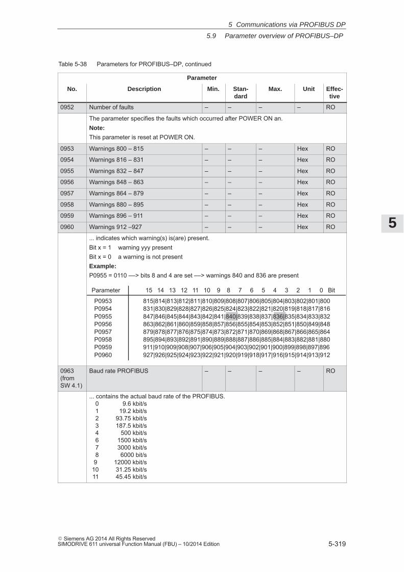
5
5.9 Parameter overview of PROFIBUS–DP
5-319� Siemens AG 2014 All Rights ReservedSIMODRIVE 611 universal Function Manual (FBU) – 10/2014 Edition
Table 5-38 Parameters for PROFIBUS–DP, continued
Parameter
No. Effec-tive
UnitMax.Stan-dard
Min.Description
0952 Number of faults – – – – RO
The parameter specifies the faults which occurred after POWER ON an.Note:
This parameter is reset at POWER ON.
0953 Warnings 800 – 815 – – – Hex RO
0954 Warnings 816 – 831 – – – Hex RO
0955 Warnings 832 – 847 – – – Hex RO
0956 Warnings 848 – 863 – – – Hex RO
0957 Warnings 864 – 879 – – – Hex RO
0958 Warnings 880 – 895 – – – Hex RO
0959 Warnings 896 – 911 – – – Hex RO
0960 Warnings 912 –927 – – – Hex RO
... indicates which warning(s) is(are) present.Bit x = 1 warning yyy presentBit x = 0 a warning is not presentExample:
P0955 = 0110 ––> bits 8 and 4 are set ––> warnings 840 and 836 are present
Parameter 15 14 13 12 11 10 9 8 7 6 5 4 3 2 1 0 Bit
P0953 815|814|813|812|811|810|809|808|807|806|805|804|803|802|801|800P0954 831|830|829|828|827|826|825|824|823|822|821|820|819|818|817|816P0955 847|846|845|844|843|842|841|840|839|838|837|836|835|834|833|832P0956 863|862|861|860|859|858|857|856|855|854|853|852|851|850|849|848P0957 879|878|877|876|875|874|873|872|871|870|869|868|867|866|865|864P0958 895|894|893|892|891|890|889|888|887|886|885|884|883|882|881|880P0959 911|910|909|908|907|906|905|904|903|902|901|900|899|898|897|896P0960 927|926|925|924|923|922|921|920|919|918|917|916|915|914|913|912
0963(from SW 4.1)
Baud rate PROFIBUS – – – – RO
... contains the actual baud rate of the PROFIBUS.0 9.6 kbit/s1 19.2 kbit/s2 93.75 kbit/s3 187.5 kbit/s4 500 kbit/s6 1500 kbit/s7 3000 kbit/s8 6000 bit/s9 12000 kbit/s
10 31.25 kbit/s11 45.45 kbit/s
5 Communications via PROFIBUS DP
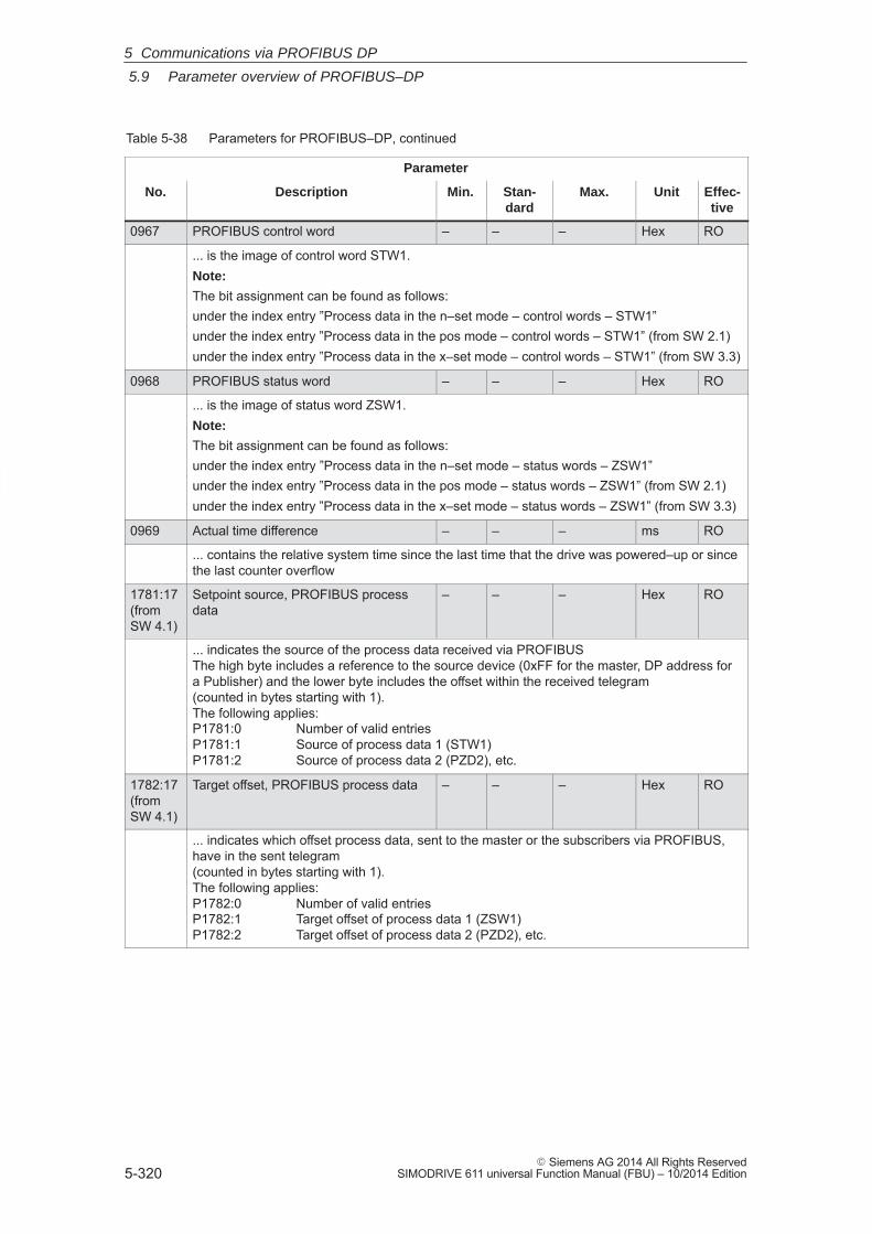
5
5.9 Parameter overview of PROFIBUS–DP
5-320� Siemens AG 2014 All Rights Reserved
SIMODRIVE 611 universal Function Manual (FBU) – 10/2014 Edition
Table 5-38 Parameters for PROFIBUS–DP, continued
Parameter
No. Effec-tive
UnitMax.Stan-dard
Min.Description
0967 PROFIBUS control word – – – Hex RO
... is the image of control word STW1.Note:
The bit assignment can be found as follows:under the index entry ”Process data in the n–set mode – control words – STW1”under the index entry ”Process data in the pos mode – control words – STW1” (from SW 2.1)under the index entry ”Process data in the x–set mode – control words – STW1” (from SW 3.3)
0968 PROFIBUS status word – – – Hex RO
... is the image of status word ZSW1.Note:
The bit assignment can be found as follows:under the index entry ”Process data in the n–set mode – status words – ZSW1”under the index entry ”Process data in the pos mode – status words – ZSW1” (from SW 2.1)under the index entry ”Process data in the x–set mode – status words – ZSW1” (from SW 3.3)
0969 Actual time difference – – – ms RO
... contains the relative system time since the last time that the drive was powered–up or sincethe last counter overflow
1781:17(from SW 4.1)
Setpoint source, PROFIBUS processdata
– – – Hex RO
... indicates the source of the process data received via PROFIBUSThe high byte includes a reference to the source device (0xFF for the master, DP address fora Publisher) and the lower byte includes the offset within the received telegram (counted in bytes starting with 1). The following applies: P1781:0 Number of valid entriesP1781:1 Source of process data 1 (STW1)P1781:2 Source of process data 2 (PZD2), etc.
1782:17(from SW 4.1)
Target offset, PROFIBUS process data – – – Hex RO
... indicates which offset process data, sent to the master or the subscribers via PROFIBUS,have in the sent telegram (counted in bytes starting with 1).The following applies: P1782:0 Number of valid entriesP1782:1 Target offset of process data 1 (ZSW1)P1782:2 Target offset of process data 2 (PZD2), etc.
5 Communications via PROFIBUS DP
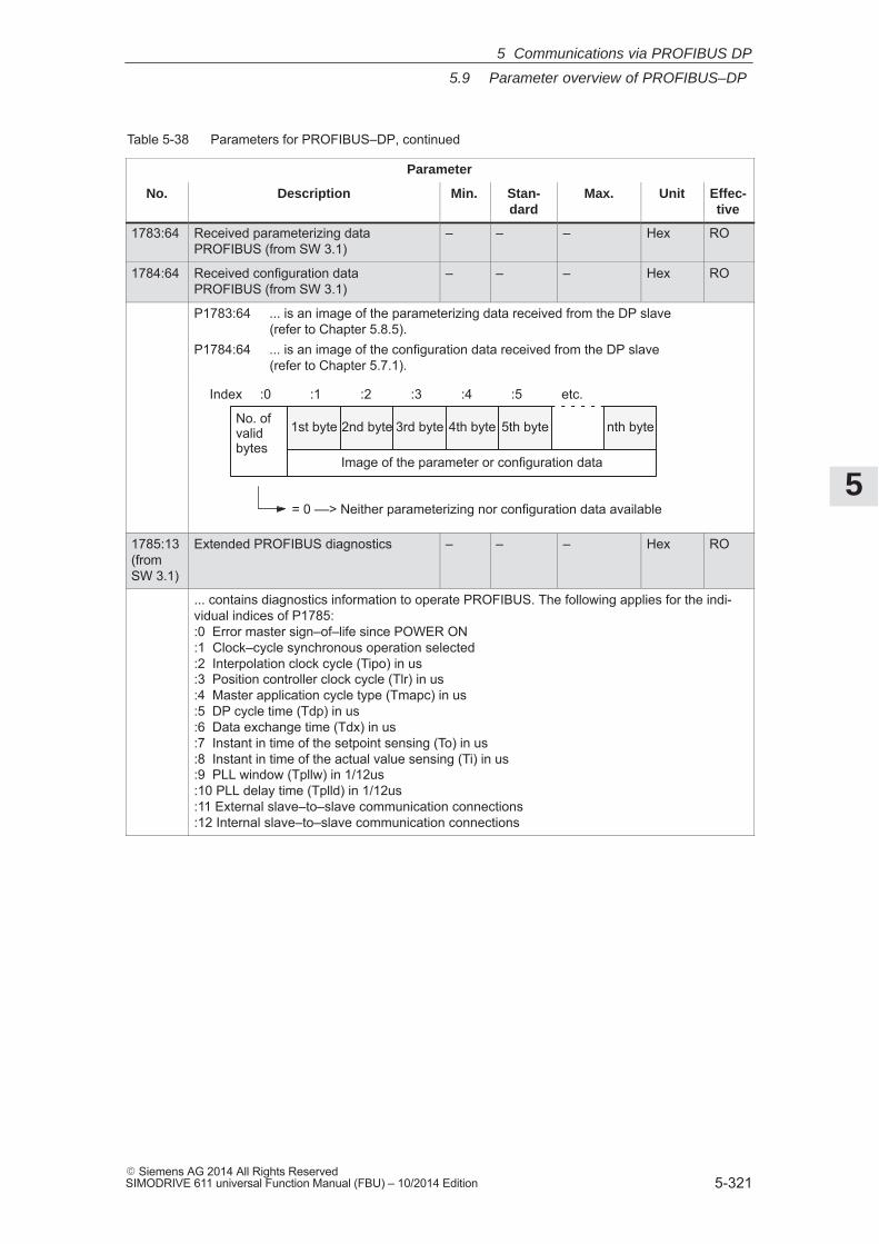
5
5.9 Parameter overview of PROFIBUS–DP
5-321� Siemens AG 2014 All Rights ReservedSIMODRIVE 611 universal Function Manual (FBU) – 10/2014 Edition
Table 5-38 Parameters for PROFIBUS–DP, continued
Parameter
No. Effec-tive
UnitMax.Stan-dard
Min.Description
1783:64 Received parameterizing dataPROFIBUS (from SW 3.1)
– – – Hex RO
1784:64 Received configuration dataPROFIBUS (from SW 3.1)
– – – Hex RO
P1783:64 ... is an image of the parameterizing data received from the DP slave(refer to Chapter 5.8.5).
P1784:64 ... is an image of the configuration data received from the DP slave(refer to Chapter 5.7.1).
Index :0 :1 :2 :3 :4 :5 etc.
No. of valid bytes
Image of the parameter or configuration data
= 0 ––> Neither parameterizing nor configuration data available
1st byte 2nd byte 3rd byte 4th byte 5th byte nth byte
1785:13(from SW 3.1)
Extended PROFIBUS diagnostics – – – Hex RO
... contains diagnostics information to operate PROFIBUS. The following applies for the indi-vidual indices of P1785::0 Error master sign–of–life since POWER ON:1 Clock–cycle synchronous operation selected:2 Interpolation clock cycle (Tipo) in us:3 Position controller clock cycle (Tlr) in us :4 Master application cycle type (Tmapc) in us :5 DP cycle time (Tdp) in us :6 Data exchange time (Tdx) in us :7 Instant in time of the setpoint sensing (To) in us :8 Instant in time of the actual value sensing (Ti) in us :9 PLL window (Tpllw) in 1/12us:10 PLL delay time (Tplld) in 1/12us:11 External slave–to–slave communication connections:12 Internal slave–to–slave communication connections
5 Communications via PROFIBUS DP
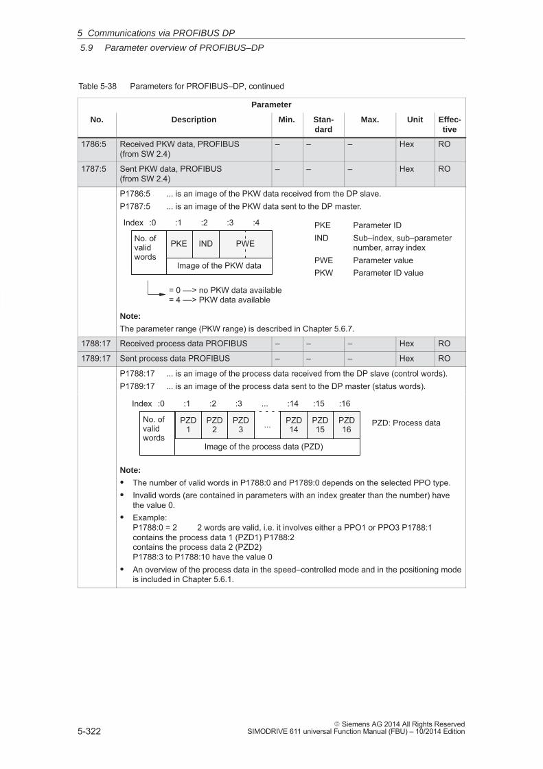
5
5.9 Parameter overview of PROFIBUS–DP
5-322� Siemens AG 2014 All Rights Reserved
SIMODRIVE 611 universal Function Manual (FBU) – 10/2014 Edition
Table 5-38 Parameters for PROFIBUS–DP, continued
Parameter
No. Effec-tive
UnitMax.Stan-dard
Min.Description
1786:5 Received PKW data, PROFIBUS (from SW 2.4)
– – – Hex RO
1787:5 Sent PKW data, PROFIBUS (from SW 2.4)
– – – Hex RO
P1786:5 ... is an image of the PKW data received from the DP slave.P1787:5 ... is an image of the PKW data sent to the DP master.
PWE
Index :0 :1 :2 :3 :4
No. ofvalidwords
Image of the PKW data
INDPKE
= 0 ––> no PKW data available= 4 ––> PKW data available
PKE Parameter IDIND Sub–index, sub–parameter
number, array indexPWE Parameter valuePKW Parameter ID value
Note:
The parameter range (PKW range) is described in Chapter 5.6.7.
1788:17 Received process data PROFIBUS – – – Hex RO
1789:17 Sent process data PROFIBUS – – – Hex RO
P1788:17 ... is an image of the process data received from the DP slave (control words).P1789:17 ... is an image of the process data sent to the DP master (status words).
Index :0 :1 :2 :3 ... :14 :15 :16
No. ofvalidwords
Image of the process data (PZD)
PZD1
PZD2
PZD14
PZD3
PZD15
PZD16... PZD: Process data
Note:
� The number of valid words in P1788:0 and P1789:0 depends on the selected PPO type.� Invalid words (are contained in parameters with an index greater than the number) have
the value 0.� Example:
P1788:0 = 2 2 words are valid, i.e. it involves either a PPO1 or PPO3 P1788:1 contains the process data 1 (PZD1) P1788:2 contains the process data 2 (PZD2) P1788:3 to P1788:10 have the value 0
� An overview of the process data in the speed–controlled mode and in the positioning modeis included in Chapter 5.6.1.
5 Communications via PROFIBUS DP
5
5.9 Parameter overview of PROFIBUS–DP
5-323� Siemens AG 2014 All Rights ReservedSIMODRIVE 611 universal Function Manual (FBU) – 10/2014 Edition
� P0600 Operating display
� P0607 Analog setpoint, terminal 56.x/14.x
� P0612 Analog setpoint, terminal 24.x/20.x
� P0653 Image, input signals, Part 1
� P0654 Image, input signals, Part 2
� P0656 Image, output signals, Part 1
� P0657 Image, output signals, Part 2
� P0658 Image, output signals, Part 3
� P0660 Function, input terminal I0.x
� P0661 Function, input terminal I1.x
� P0662 Function, input terminal I2.x
� P0663 Function, input terminal I3.x
� P0680 Function, output terminal O0.x
� P0681 Function, output terminal O1.x
� P0682 Function, output terminal O2.x
� P0683 Function, output terminal O3.x
� P0972 Request POWER–ON RESET (from SW 3.3)
� P1012.2 Function switchBit 2 ”Ready or no fault”
� P1012.12 Function switchBit 12 ”power–on inhibit”
� P1795 Optional module (PROFIBUS): Firmware version
Additional parametersrelevant forPROFIBUS–DP (refer to ChapterA.1)
5 Communications via PROFIBUS DP
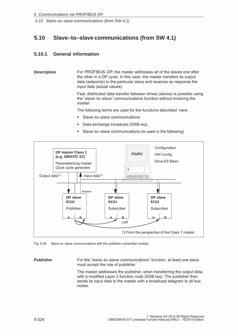
5
5.10 Slave–to–slave communications (from SW 4.1)
5-324� Siemens AG 2014 All Rights Reserved
SIMODRIVE 611 universal Function Manual (FBU) – 10/2014 Edition
5.10 Slave–to–slave communications (from SW 4.1)
5.10.1 General information
For PROFIBUS–DP, the master addresses all of the slaves one afterthe other in a DP cycle. In this case, the master transfers its outputdata (setpoints) to the particular slave and receives as response theinput data (actual values).
Fast, distributed data transfer between drives (slaves) is possible usingthe ”slave–to–slave” communications function without involving themaster.
The following terms are used for the functions described here:
� Slave–to–slave communications
� Data exchange broadcast (DXB.req)
� Slave–to–slave communications (is used in the following)
A
DP master Class 1(e.g. SIMATIC S7)
Parameterizing masterClock cycle generator
B
Answer
Input data1)Output data1)
1) From the perspective of the Class 1 master
DP slave611U
Publisher
A B
DP slave611U
Subscriber
A B
DP slave611U
Subscriber
Left
PG/PC
Configuration
HW Config
Drive ES Basic
Fig. 5-30 Slave–to–slave communications with the publisher–subscriber module
For the ”slave–to–slave communications” function, at least one slavemust accept the role of publisher.
The master addresses the publisher, when transferring the output data,with a modified Layer 2 function code (DXB.req). The publisher thensends its input data to the master with a broadcast telegram to all busnodes.
Description
Publisher
5 Communications via PROFIBUS DP
5
5.10 Slave–to–slave communications (from SW 4.1)
5-325� Siemens AG 2014 All Rights ReservedSIMODRIVE 611 universal Function Manual (FBU) – 10/2014 Edition
The subscribers evaluate the broadcast telegrams, sent from the pub-lishers, and use the data which has been received as setpoints.
The setpoints are used, in addition to the setpoints received from themaster, corresponding to the configured telegram structure (P0915:17).
The links configured in the subscriber (connection to publisher) containthe following information:
� From which publishers may input data be received?
� Which input data is there?
� A which location should the input data be used as setpoints?
Several taps are possible within a link. Several input data or input dataareas, which are not associated with one another, can be used as set-point via a tap.
Links are possible to the device itself. This means, e.g. that for a two–axis module, data can be transferred from drive A to B. This internallink corresponds, as far as the timing is concerned, to a link viaPROFIBUS.
The following limitations should be observed for the ”slave–to–slave”communications function:
� Drive ES Basic V5.1 SP1
� Optional PROFIBUS–DP2 module � SW 4.1
� Optional PROFIBUS–DP3 module � SW 4.1
� SIMODRIVE 611 universal � SW 4.1
� Number of process data max. of 16 per drive
� Number of links to publishers max. 3 and 1 internal
� Number of taps per link max. 8
For example, the following applications can be implemented using the”slave–to–slave communications” function:
� Axis couplings (this is practical for clock cycle synchronous operation) (refer to Chapter 6.3)
– Angular synchronism where the position reference value or posi-tion actual value is entered
– Torque setpoint coupling (master/slave operation)
Master drive <––> Slave driveClosed–loop speed controlled Open–loop torque controlled
� Entering digital input signals from another slave (refer to Chapter5.10.4)
Subscriber
Links and taps
Requirements andboundaryconditions
Applications
5 Communications via PROFIBUS DP
5
5.10 Slave–to–slave communications (from SW 4.1)
5-326� Siemens AG 2014 All Rights Reserved
SIMODRIVE 611 universal Function Manual (FBU) – 10/2014 Edition
The following parameters are available for the ”slave–to–slave commu-nications” function:
� P0032 External position reference value
� P0400 Reference point coordinate, master drive
� P0401 Coupling factor, revolutions master drive
� P0402 Coupling factor, revolutions slave drive
� P0410 Configuration, coupling that can be switched–in
� P0412 Synchronous offset position
� P0413 Offset, synchronous velocity
� P0420 Position difference, measuring probe to the zeropoint, slave drive
� P0425:16 Coupling positions
� P0879 PROFIBUS configuration
� P0882 Evaluation, torque setpoint PROFIBUS
� P0884 PROFIBUS position output evaluation Number of increments
� P0888 Function, distributed inputs (PROFIBUS)
� P0891 Source, external position reference value
� P0895 External position reference value – No. of increments
� P0896 Ext. position reference value – No. of dimensionsystem grids
� P0897 Inversion, external position reference value
� P0898 Modulo range, master drive
� P1781:17 Setpoint source, PROFIBUS process data
� P1782:17 Target offset, PROFIBUS process data
� P1785:13 Extended PROFIBUS diagnosticsThe following signals are available for the ”slave–to–slave communica-tions” function:
� Input signals
– ”Correction, external position reference value via dXcor (fromSW 4.1)”
––> via the PROFIBUS control signal ”QStw.0”
– ”Request passive referencing (from SW 5.1)”
––> via the PROFIBUS control signal QStw.1 or STW1.15”
� Output signals
– ”Correction, external position reference value via dXcor (fromSW 4.1)”
––> via PROFIBUS control signal ”QZsw.0”
– ”Request passive referencing (from SW 5.1)”
––> via the PROFIBUS control signal QZsw.1 or ZSW1.15”
Parameteroverview(refer to ChapterA.1)
Input/outputsignals (refer toChapter 5.6)
5 Communications via PROFIBUS DP
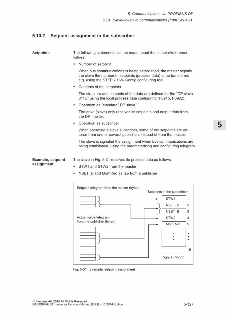
5
5.10 Slave–to–slave communications (from SW 4.1)
5-327� Siemens AG 2014 All Rights ReservedSIMODRIVE 611 universal Function Manual (FBU) – 10/2014 Edition
5.10.2 Setpoint assignment in the subscriber
The following statements can be made about the setpoint/referencevalues:
� Number of setpoint
When bus communications is being established, the master signalsthe slave the number of setpoints (process data) to be transferrede.g. using the STEP 7 HW–Config configuring tool.
� Contents of the setpoints
The structure and contents of the data are defined for the ”DP slave611U” using the local process data configuring (P0915, P0922).
� Operation as ”standard” DP slave
The drive (slave) only receives its setpoints and output data fromthe DP master.
� Operation as subscriber
When operating a slave subscriber, some of the setpoints are en-tered from one or several publishers instead of from the master.
The slave is signaled the assignment when bus communications arebeing established, using the parameterizing and configuring telegram.
The slave in Fig. 5-31 receives its process data as follows:
� STW1 and STW2 from the master
� NSET_B and MomRed as tap from a publisher
STW1
NSET_B
NSET_B
STW2
MomRed
Setpoints in the subscriberSetpoint telegram from the master (bytes)
Actual value telegramfrom the publisher (bytes)
1
2
3
4
5
16
P0915, P0922
Fig. 5-31 Example, setpoint assignment
Setpoints
Example, setpointassignment
5 Communications via PROFIBUS DP
5
5.10 Slave–to–slave communications (from SW 4.1)
5-328� Siemens AG 2014 All Rights Reserved
SIMODRIVE 611 universal Function Manual (FBU) – 10/2014 Edition
5.10.3 Activating/parameterizing slave–to–slave communications
The activation of the function ”slave–to–slave communication” must beactivated in the subscribers.
By configuring the links with Drive ES Basic, the master can identifywhich slaves are to be addressed as publisher with a modified layer 2function code (DDB–Distributed Data Base).
The publisher then does not send its input data to the master, but to allbus nodes as broadcast telegram.
The slave, which is to be used as subscriber, requires a filter table.The slave must know which setpoints are received from the master andwhich are received from a publisher.
The filter table contains the following information:
� From which publisher is data to be retrieved?
� The length of the publisher input data (test purposes)?
� From which position (offset) in the input data is data to be taken?
� How much data is to be taken?
� To which position in the setpoints is the data, which has been taken,to be copied?
Parameterizing telegram (SetPrm)
The filter table is transferred, as dedicated block from the master to theslave with the parameterizing telegram when bus communications areestablished.
If: The block for the filter table is not availableorelement ”number of links” = 0
Then: ––> no subscriber functionality
The precise structure of this block, together with the permissible settingvalues is shown in Fig. 5-32.
Configuration telegram (ChkCfg)
Using the configuration telegram, a slave knows how may setpoints areto be received from the master and how many actual values are to besent to the master.
For slave–to–slave communications, a special empty ID is required foreach data access, which is then transferred with the ChkCfg.
Structure of the empty ID for Drive ES Basic (S7 ID format):
0x04 0x00 0x00 0xD3 0x40
Activation in thepublisher
Activation in thesubscriber
5 Communications via PROFIBUS DP
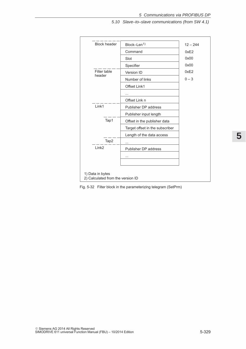
5
5.10 Slave–to–slave communications (from SW 4.1)
5-329� Siemens AG 2014 All Rights ReservedSIMODRIVE 611 universal Function Manual (FBU) – 10/2014 Edition
Block–Len1)
Command
Slot
Specifier
Version ID
Number of links
Offset Link1
...
Offset Link n
Publisher DP address
Publisher input length
Offset in the publisher data
Target offset in the subscriber
Length of the data access
...
Publisher DP address
...
Block header
Filter tableheader
Link2
Tap1
Tap2
Link1
12 – 244
0xE2
0x00
0x00
0xE2
0 – 3
1) Data in bytes2) Calculated from the version ID
Fig. 5-32 Filter block in the parameterizing telegram (SetPrm)
5 Communications via PROFIBUS DP
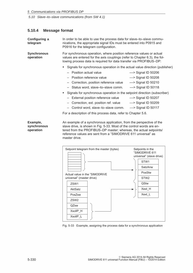
5
5.10 Slave–to–slave communications (from SW 4.1)
5-330� Siemens AG 2014 All Rights Reserved
SIMODRIVE 611 universal Function Manual (FBU) – 10/2014 Edition
5.10.4 Message format
In order to be able to use the process data for slave–to–slave commu-nications, the appropriate signal IDs must be entered into P0915 andP0916 for the telegram configuration.
For synchronous operation, where position reference values or actualvalues are entered for the axis couplings (refer to Chapter 6.3), the fol-lowing process data is required for data transfer via PROFIBUS–DP:
� Signals for synchronous operation in the actual value direction (publisher)
– Position actual value ––> Signal ID 50206– Position reference value ––> Signal ID 50208– Correction, position reference value ––> Signal ID 50210– Status word, slave–to–slave comm. ––> Signal ID 50118
� Signals for synchronous operation in the setpoint direction (subscriber)– External position reference value ––> Signal ID 50207– Correction, ext. position ref. value ––> Signal ID 50209– Control word, slave–to–slave comm. ––> Signal ID 50117
For a description of this process data, refer to Chapter 5.6.
An example of a synchronous application, from the perspective of theslave drive, is shown in Fig. 5-33. Most of the control words are en-tered from the PROFIBUS–DP master; whereas, the actual setpoints/reference values are sent from a ”SIMODRIVE 611 universal” asmaster drive.
ZSW1
AktSatz
PosZsw
ZSW2
QZsw
XsollP_H
XsollP_L
STW1
SatzAnw
PosStw
STW2
QStw
Xext_H
Xext_L
Setpoints in the ”SIMODRIVE 611universal” (slave drive)
Setpoint telegram from the master (bytes)
Actual value in the ”SIMODRIVEuniversal” (master drive)
Fig. 5-33 Example, assigning the process data for a synchronous application
Configuring atelegram
Synchronousoperation
Example,synchronousoperation
5 Communications via PROFIBUS DP
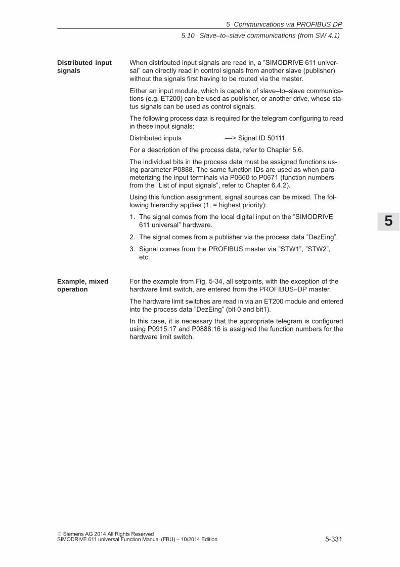
5
5.10 Slave–to–slave communications (from SW 4.1)
5-331� Siemens AG 2014 All Rights ReservedSIMODRIVE 611 universal Function Manual (FBU) – 10/2014 Edition
When distributed input signals are read in, a ”SIMODRIVE 611 univer-sal” can directly read in control signals from another slave (publisher)without the signals first having to be routed via the master.
Either an input module, which is capable of slave–to–slave communica-tions (e.g. ET200) can be used as publisher, or another drive, whose sta-tus signals can be used as control signals.
The following process data is required for the telegram configuring to readin these input signals:
Distributed inputs ––> Signal ID 50111
For a description of the process data, refer to Chapter 5.6.
The individual bits in the process data must be assigned functions us-ing parameter P0888. The same function IDs are used as when para-meterizing the input terminals via P0660 to P0671 (function numbersfrom the ”List of input signals”, refer to Chapter 6.4.2).
Using this function assignment, signal sources can be mixed. The fol-lowing hierarchy applies (1. = highest priority):
1. The signal comes from the local digital input on the ”SIMODRIVE611 universal” hardware.
2. The signal comes from a publisher via the process data ”DezEing”.
3. Signal comes from the PROFIBUS master via ”STW1”, ”STW2”,etc.
For the example from Fig. 5-34, all setpoints, with the exception of thehardware limit switch, are entered from the PROFIBUS–DP master.
The hardware limit switches are read in via an ET200 module and enteredinto the process data ”DezEing” (bit 0 and bit1).
In this case, it is necessary that the appropriate telegram is configuredusing P0915:17 and P0888:16 is assigned the function numbers for thehardware limit switch.
Distributed inputsignals
Example, mixedoperation
5 Communications via PROFIBUS DP
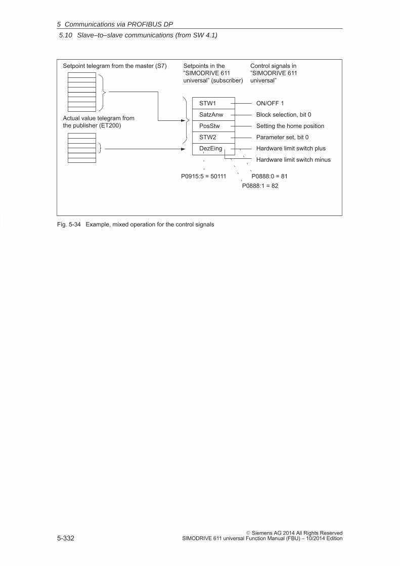
5
5.10 Slave–to–slave communications (from SW 4.1)
5-332� Siemens AG 2014 All Rights Reserved
SIMODRIVE 611 universal Function Manual (FBU) – 10/2014 Edition
STW1
SatzAnw
PosStw
STW2
DezEing
Setpoints in the ”SIMODRIVE 611universal” (subscriber)
Setpoint telegram from the master (S7)
Actual value telegram fromthe publisher (ET200)
Control signals in ”SIMODRIVE 611universal”
ON/OFF 1
Block selection, bit 0
Setting the home position
Parameter set, bit 0
Hardware limit switch plus
Hardware limit switch minus
P0888:0 = 81P0888:1 = 82
P0915:5 = 50111
Fig. 5-34 Example, mixed operation for the control signals
5 Communications via PROFIBUS DP
5
5.10 Slave–to–slave communications (from SW 4.1)
5-333� Siemens AG 2014 All Rights ReservedSIMODRIVE 611 universal Function Manual (FBU) – 10/2014 Edition
5.10.5 Example: Coupling two drives (master, slave drive)
The following example is based on the functionality of slave–to–slavecommunications via PROFIBUS–DP. It shows the steps which are nec-essary, using SimoCom U, to parameterize the master and slave drive.We recommend the following sequence when parameterizing:1. Parameterizing the master, e.g. SIMATIC S72. Parameterizing the master drive3. Parameterizing the slave drive
� Standard telegram 108 for the master drive (publisher)� Standard telegram 109 for the slave drive (subscriber)� Default 5 m, sufficient for the traversing range� An SFC14/15 cannot be used� P1009 = 4 ms
The steps when configuring an S7 are shown in the following Figs.:
The following data should be parameterized in the DP master (S7):
� Configuration, master drive matching telegram 108 ––> number of process data– 4 words, PKW– 10 words, actual values to the DP master (inconsistent)– 10 words, setpoints from the DP master (inconsistent)
Fig. 5-35 Example, configuring the master drive for S7
Generalinformation
Assumptions forthe example
Parameterizing DPmaster
5 Communications via PROFIBUS DP
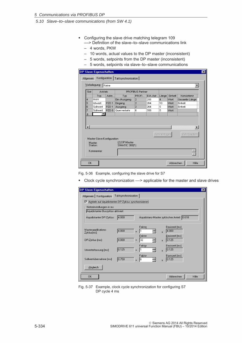
5
5.10 Slave–to–slave communications (from SW 4.1)
5-334� Siemens AG 2014 All Rights Reserved
SIMODRIVE 611 universal Function Manual (FBU) – 10/2014 Edition
� Configuring the slave drive matching telegram 109––> Definition of the slave–to–slave communications link– 4 words, PKW– 10 words, actual values to the DP master (inconsistent)– 5 words, setpoints from the DP master (inconsistent)– 5 words, setpoints via slave–to–slave communications
Fig. 5-36 Example, configuring the slave drive for S7
� Clock cycle synchronization ––> applicable for the master and slave drives
Fig. 5-37 Example, clock cycle synchronization for configuring S7 DP cycle 4 ms
5 Communications via PROFIBUS DP
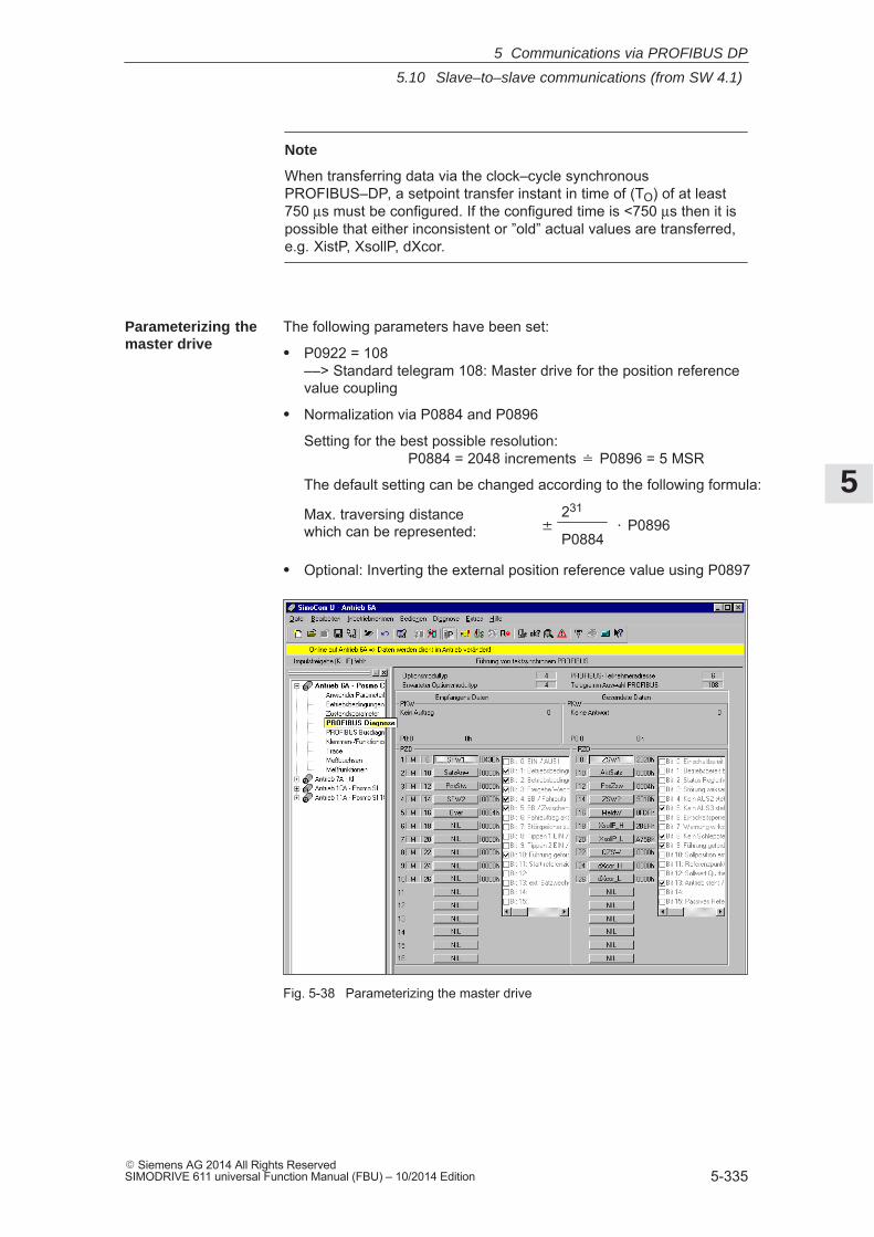
5
5.10 Slave–to–slave communications (from SW 4.1)
5-335� Siemens AG 2014 All Rights ReservedSIMODRIVE 611 universal Function Manual (FBU) – 10/2014 Edition
Note
When transferring data via the clock–cycle synchronousPROFIBUS–DP, a setpoint transfer instant in time of (TO) of at least750 μs must be configured. If the configured time is <750 μs then it ispossible that either inconsistent or ”old” actual values are transferred,e.g. XistP, XsollP, dXcor.
The following parameters have been set:
� P0922 = 108 ––> Standard telegram 108: Master drive for the position referencevalue coupling
� Normalization via P0884 and P0896
Setting for the best possible resolution: P0884 = 2048 increments � P0896 = 5 MSR
The default setting can be changed according to the following formula:
� P0896231
P0884
Max. traversing distancewhich can be represented:
� Optional: Inverting the external position reference value using P0897
Fig. 5-38 Parameterizing the master drive
Parameterizing themaster drive
5 Communications via PROFIBUS DP
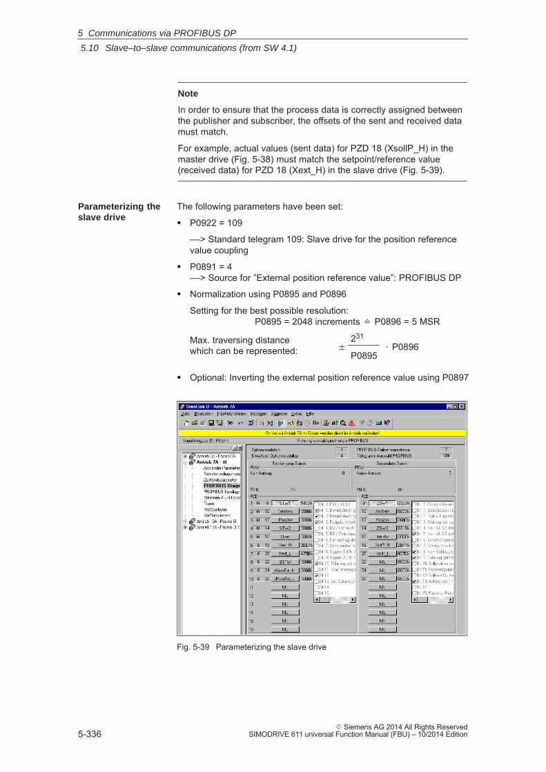
5
5.10 Slave–to–slave communications (from SW 4.1)
5-336� Siemens AG 2014 All Rights Reserved
SIMODRIVE 611 universal Function Manual (FBU) – 10/2014 Edition
Note
In order to ensure that the process data is correctly assigned betweenthe publisher and subscriber, the offsets of the sent and received datamust match.
For example, actual values (sent data) for PZD 18 (XsollP_H) in themaster drive (Fig. 5-38) must match the setpoint/reference value(received data) for PZD 18 (Xext_H) in the slave drive (Fig. 5-39).
The following parameters have been set:
� P0922 = 109
––> Standard telegram 109: Slave drive for the position referencevalue coupling
� P0891 = 4––> Source for ”External position reference value”: PROFIBUS DP
� Normalization using P0895 and P0896
Setting for the best possible resolution: P0895 = 2048 increments � P0896 = 5 MSR
� P0896231
P0895
Max. traversing distancewhich can be represented:
� Optional: Inverting the external position reference value using P0897
Fig. 5-39 Parameterizing the slave drive
Parameterizing theslave drive
5 Communications via PROFIBUS DP
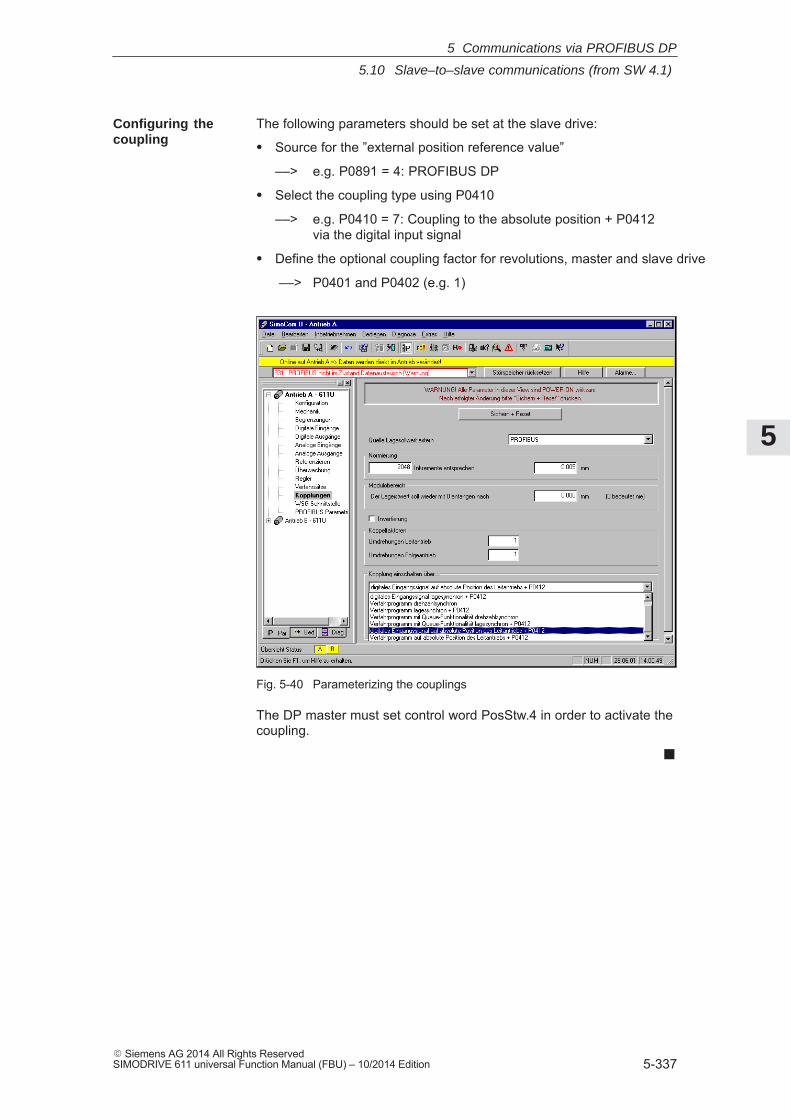
5
5.10 Slave–to–slave communications (from SW 4.1)
5-337� Siemens AG 2014 All Rights ReservedSIMODRIVE 611 universal Function Manual (FBU) – 10/2014 Edition
The following parameters should be set at the slave drive:
� Source for the ”external position reference value”
––> e.g. P0891 = 4: PROFIBUS DP
� Select the coupling type using P0410
––> e.g. P0410 = 7: Coupling to the absolute position + P0412 via the digital input signal
� Define the optional coupling factor for revolutions, master and slave drive
––> P0401 and P0402 (e.g. 1)
Fig. 5-40 Parameterizing the couplings
The DP master must set control word PosStw.4 in order to activate thecoupling.
�
Configuring thecoupling
5 Communications via PROFIBUS DP

5
5.10 Slave–to–slave communications (from SW 4.1)
5-338� Siemens AG 2014 All Rights Reserved
SIMODRIVE 611 universal Function Manual (FBU) – 10/2014 Edition
5 Communications via PROFIBUS DP
Space for your notes
6
6-339� Siemens AG 2014 All Rights ReservedSIMODRIVE 611 universal Function Manual (FBU) – 10/2014 Edition
Description of the Functions
6.1 Operating mode, speed/torque setpoint (P0700 = 1) 6-341. . . . . . . . . . . . . . . . . 6.1.1 Application examples 6-341. . . . . . . . . . . . . . . . . . . . . . . . . . . . . . . . . . . . . . . . . . . . 6.1.2 Current and speed control 6-342. . . . . . . . . . . . . . . . . . . . . . . . . . . . . . . . . . . . . . . . 6.1.3 Ramp–function generator 6-344. . . . . . . . . . . . . . . . . . . . . . . . . . . . . . . . . . . . . . . . . 6.1.4 Optimizing the closed–loop current and speed controller 6-346. . . . . . . . . . . . . . 6.1.5 Speed controller adaptation 6-348. . . . . . . . . . . . . . . . . . . . . . . . . . . . . . . . . . . . . . . 6.1.6 Fixed speed setpoint (from SW 3.1) 6-350. . . . . . . . . . . . . . . . . . . . . . . . . . . . . . . . 6.1.7 Monitoring functions 6-351. . . . . . . . . . . . . . . . . . . . . . . . . . . . . . . . . . . . . . . . . . . . . 6.1.8 Limits 6-359. . . . . . . . . . . . . . . . . . . . . . . . . . . . . . . . . . . . . . . . . . . . . . . . . . . . . . . . . . 6.1.9 Position measuring system with distance–coded reference marks
(from SW 4.1) 6-367. . . . . . . . . . . . . . . . . . . . . . . . . . . . . . . . . . . . . . . . . . . . . . . . . .
6.2 Positioning mode (P0700 = 3, from SW 2.1) 6-368. . . . . . . . . . . . . . . . . . . . . . . . 6.2.1 Encoder adaptation 6-369. . . . . . . . . . . . . . . . . . . . . . . . . . . . . . . . . . . . . . . . . . . . . . 6.2.2 Units for travel, velocity and acceleration 6-376. . . . . . . . . . . . . . . . . . . . . . . . . . . 6.2.3 Closed–loop position control components 6-379. . . . . . . . . . . . . . . . . . . . . . . . . . . 6.2.4 Referencing and adjusting 6-404. . . . . . . . . . . . . . . . . . . . . . . . . . . . . . . . . . . . . . . . 6.2.5 Referencing for incremental measuring systems 6-404. . . . . . . . . . . . . . . . . . . . . 6.2.6 Referencing with a distance–coded measuring system
(from SW 8.3) 6-410. . . . . . . . . . . . . . . . . . . . . . . . . . . . . . . . . . . . . . . . . . . . . . . . . . 6.2.7 Adjusting absolute measuring systems 6-414. . . . . . . . . . . . . . . . . . . . . . . . . . . . . 6.2.8 Parameter overview when referencing/adjusting 6-416. . . . . . . . . . . . . . . . . . . . . 6.2.9 Jogging operation 6-421. . . . . . . . . . . . . . . . . . . . . . . . . . . . . . . . . . . . . . . . . . . . . . . 6.2.10 Programming traversing blocks 6-423. . . . . . . . . . . . . . . . . . . . . . . . . . . . . . . . . . . . 6.2.11 Starting, interrupting and exiting traversing blocks 6-436. . . . . . . . . . . . . . . . . . . 6.2.12 MDI operation (from SW 7.1) 6-441. . . . . . . . . . . . . . . . . . . . . . . . . . . . . . . . . . . . .
6.3 Axis couplings (from SW 3.3) 6-446. . . . . . . . . . . . . . . . . . . . . . . . . . . . . . . . . . . . . 6.3.1 Position reference value and position actual value coupling 6-447. . . . . . . . . . . 6.3.2 Handling faults in the master and slave drives 6-476. . . . . . . . . . . . . . . . . . . . . . . 6.3.3 Torque setpoint coupling (from SW 4.1) 6-478. . . . . . . . . . . . . . . . . . . . . . . . . . . . 6.3.4 Equalization controller (from SW 7.1) 6-484. . . . . . . . . . . . . . . . . . . . . . . . . . . . . .
General information 6-484. . . . . . . . . . . . . . . . . . . . . . . . . . . . . . . . . . . . . . . . . . . . . .
Equalization controller via PROFIBUS-DP (from SW 13.1) 6-490. . . . . . . . . . . .
6.4 Input/output terminals of the control board 6-495. . . . . . . . . . . . . . . . . . . . . . . . . . 6.4.1 Permanently–connected input terminals 6-495. . . . . . . . . . . . . . . . . . . . . . . . . . . . 6.4.2 Freely–parameterizable digital input terminals 6-496. . . . . . . . . . . . . . . . . . . . . . . 6.4.3 List of input signals 6-497. . . . . . . . . . . . . . . . . . . . . . . . . . . . . . . . . . . . . . . . . . . . . . 6.4.4 Permanently–connected output terminals 6-521. . . . . . . . . . . . . . . . . . . . . . . . . . . 6.4.5 Freely–parameterizable digital output terminals 6-521. . . . . . . . . . . . . . . . . . . . . . 6.4.6 List of output signals 6-523. . . . . . . . . . . . . . . . . . . . . . . . . . . . . . . . . . . . . . . . . . . . .
6.5 Input/output terminals for the optional TERMINAL module 6-549. . . . . . . . . . . .
6.6 Analog inputs 6-551. . . . . . . . . . . . . . . . . . . . . . . . . . . . . . . . . . . . . . . . . . . . . . . . . . . 6.6.1 Basic setting of the analog inputs 6-552. . . . . . . . . . . . . . . . . . . . . . . . . . . . . . . . . .
6
6
6-340� Siemens AG 2014 All Rights Reserved
SIMODRIVE 611 universal Function Manual (FBU) – 10/2014 Edition
6.6.2 nset mode or nset with Mred mode 6-553. . . . . . . . . . . . . . . . . . . . . . . . . . . . . . . . 6.6.3 Mset mode or Mset with Mred mode 6-557. . . . . . . . . . . . . . . . . . . . . . . . . . . . . . . 6.6.4 Torque/power reduction via terminal 24.x/20.x 6-560. . . . . . . . . . . . . . . . . . . . . . . 6.6.5 Application example master/slave 6-563. . . . . . . . . . . . . . . . . . . . . . . . . . . . . . . . .
6.7 Analog outputs 6-565. . . . . . . . . . . . . . . . . . . . . . . . . . . . . . . . . . . . . . . . . . . . . . . . . .
6.8 Angular incremental encoder interface (X461, X462) 6-579. . . . . . . . . . . . . . . . . 6.8.1 Angular incremental encoder interface as output (P0890 = 1) 6-581. . . . . . . . . . 6.8.2 Angular incremental encoder interface as input (P0890 = 2,
from SW 3.3) 6-586. . . . . . . . . . . . . . . . . . . . . . . . . . . . . . . . . . . . . . . . . . . . . . . . . . . 6.8.3 Electronic handwheel (from SW 8.1) 6-590. . . . . . . . . . . . . . . . . . . . . . . . . . . . . . .
6.9 Motor holding brake 6-594. . . . . . . . . . . . . . . . . . . . . . . . . . . . . . . . . . . . . . . . . . . . .
6.10 Parameter set changeover 6-600. . . . . . . . . . . . . . . . . . . . . . . . . . . . . . . . . . . . . . . .
6.11 Motor changeover for induction motors (from SW 2.4) 6-604. . . . . . . . . . . . . . . . 6.11.1 General information on motor changeover 6-604. . . . . . . . . . . . . . . . . . . . . . . . . . 6.11.2 Changeover, max. 4 motors each with 1 data set (P1013 = 1) 6-610. . . . . . . . . 6.11.3 Changeover, 1 motor with max. 4 data sets (P1013 = 2) 6-612. . . . . . . . . . . . . . 6.11.4 Changeover, max. 2 motors each with 2 data sets (P1013 = 3) 6-613. . . . . . . . 6.11.5 Parameters for motor changeover 6-616. . . . . . . . . . . . . . . . . . . . . . . . . . . . . . . . .
6.12 Travel to fixed stop (positioning mode) (from SW 3.3) 6-618. . . . . . . . . . . . . . . .
6.13 Teach–in (from SW 4.1) 6-625. . . . . . . . . . . . . . . . . . . . . . . . . . . . . . . . . . . . . . . . . .
6.14 Dynamic Servo Control (DSC, from SW 4.1) 6-627. . . . . . . . . . . . . . . . . . . . . . . .
6.15 Spindle positioning (from SW 5.1) 6-629. . . . . . . . . . . . . . . . . . . . . . . . . . . . . . . . .
6.16 Rotor position identification/pole position identification 6-639. . . . . . . . . . . . . . . .
6.17 Electrical braking when the encoder fails (from SW 9.1) 6-646. . . . . . . . . . . . . .
6.18 Active oscillation damping (APC, from SW 10.1) 6-648. . . . . . . . . . . . . . . . . . . . .
6.19 Activate function generator immediately (from SW 11.2) 6-653. . . . . . . . . . . . . .
6.20 Monitoring of the direction of the axis motion (from SW 11.1) 6-654. . . . . . . . . .
6.21 Power section derating (from SW 13.1) 6-655. . . . . . . . . . . . . . . . . . . . . . . . . . . . .
6.22 Dynamic energy management (from SW 13.1) 6-657. . . . . . . . . . . . . . . . . . . . . .
6.23 Motor diagnostics, ground fault test (from SW 13.1) 6-660. . . . . . . . . . . . . . . . . .
6 Description of the Functions
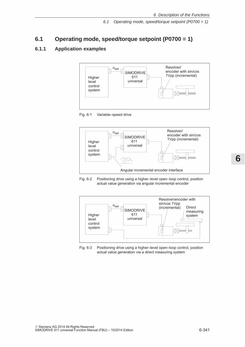
6
6.1 Operating mode, speed/torque setpoint (P0700 = 1)
6-341� Siemens AG 2014 All Rights ReservedSIMODRIVE 611 universal Function Manual (FBU) – 10/2014 Edition
6.1 Operating mode, speed/torque setpoint (P0700 = 1)
6.1.1 Application examples
Higherlevelcontrolsystem
SIMODRIVE611
universal
nset Resolver/encoder with sin/cos1Vpp (incremental)
Fig. 6-1 Variable–speed drive
Higherlevelcontrolsystem
SIMODRIVE611
universal
Angular incremental encoder interface
nsetResolver/encoder with sin/cos1Vpp (incremental)
Fig. 6-2 Positioning drive using a higher–level open–loop control, positionactual value generation via angular incremental encoder
Higherlevelcontrolsystem
SIMODRIVE611
universal
nset Directmeasuringsystem
Resolver/encoder withsin/cos 1Vpp(incremental)
Fig. 6-3 Positioning drive using a higher–level open–loop control, positionactual value generation via a direct measuring system
6 Description of the Functions
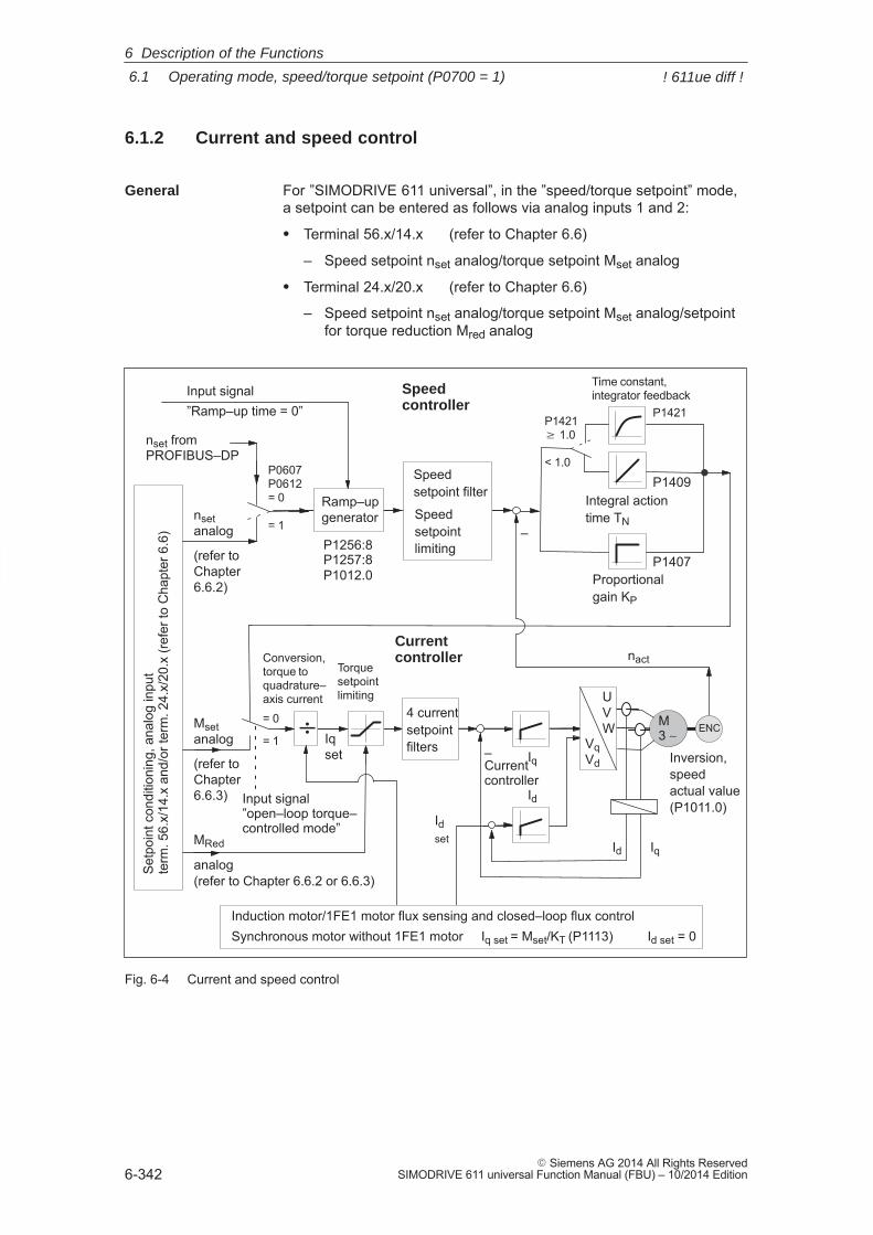
6
6.1 Operating mode, speed/torque setpoint (P0700 = 1)
6-342� Siemens AG 2014 All Rights Reserved
SIMODRIVE 611 universal Function Manual (FBU) – 10/2014 Edition
6.1.2 Current and speed control
For ”SIMODRIVE 611 universal”, in the ”speed/torque setpoint” mode,a setpoint can be entered as follows via analog inputs 1 and 2:
� Terminal 56.x/14.x (refer to Chapter 6.6)
– Speed setpoint nset analog/torque setpoint Mset analog
� Terminal 24.x/20.x (refer to Chapter 6.6)
– Speed setpoint nset analog/torque setpoint Mset analog/setpointfor torque reduction Mred analog
Torquesetpointlimiting
Proportionalgain KP
Integral actiontime TN
Currentcontroller
MRed
analog (refer to Chapter 6.6.2 or 6.6.3)
Speedcontroller
Input signal ”Ramp–up time = 0”
Input signal ”open–loop torque–controlled mode”
P1256:8P1257:8P1012.0
P1409
P1407
Currentcontroller
–
IqId
–
Setp
oint
con
ditio
ning
, ana
log
inpu
t te
rm. 5
6.x/
14.x
and
/or t
erm
. 24.
x/20
.x (r
efer
to C
hapt
er 6
.6)
Msetanalog
(refer toChapter6.6.3)
nsetanalog
(refer toChapter6.6.2)
Time constant, integrator feedback
P1421P1421 � 1.0
< 1.0
Inversion,speedactual value(P1011.0)
P0607P0612= 0
= 1
nset fromPROFIBUS–DP
Ramp–upgenerator
4 currentsetpointfilters
= 0
= 1ENC
Speedsetpoint filter
Speedsetpointlimiting
Id
Iq
Induction motor/1FE1 motor flux sensing and closed–loop flux controlSynchronous motor without 1FE1 motor Iq set = Mset/KT (P1113) Id set = 0
Idset
Iqset
Conversion,torque toquadrature–axis current
÷
nact
VqVd
UVW M
3 ∼
Fig. 6-4 Current and speed control
General
6 Description of the Functions
! 611ue diff !
6
6.1 Operating mode, speed/torque setpoint (P0700 = 1)
6-343� Siemens AG 2014 All Rights ReservedSIMODRIVE 611 universal Function Manual (FBU) – 10/2014 Edition
Reader’s note
Described in the following:� Ramp–function Generator� Optimizing the closed–loop current and speed controller� Speed controller adaptation
All additional parameters to optimize the current and speed controlloop can be adapted using the expert list.
Detailed information regarding the current and speed control loop areincluded in:
Reference: /FBA/ SIMODRIVE 611D/SINUMERIK 840D/810DDescription of Functions, Drive Functions
6 Description of the Functions
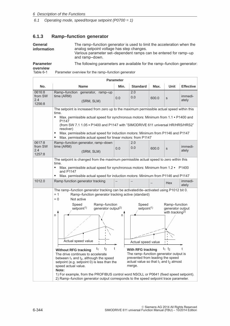
6
6.1 Operating mode, speed/torque setpoint (P0700 = 1)
6-344� Siemens AG 2014 All Rights Reserved
SIMODRIVE 611 universal Function Manual (FBU) – 10/2014 Edition
6.1.3 Ramp–function generator
The ramp–function generator is used to limit the acceleration when theanalog setpoint voltage has step changes. Various parameter set–dependent ramps can be entered for ramp–upand ramp–down.The following parameters are available for the ramp–function generator:
Table 6-1 Parameter overview for the ramp–function generator
Parameter
No. Name Min. Standard Max. Unit Effective
0616:8from SW2.41256:8
Ramp–function generator, ramp–uptime (ARM)
(SRM, SLM)0.0
2.00.0 600.0 s immedi-
ately
The setpoint is increased from zero up to the maximum permissible actual speed within thistime.� Max. permissible actual speed for synchronous motors: Minimum from 1.1 � P1400 and
P1147 (from SW 7.1 1.05 � P1400 and P1147 with ”SIMODRIVE 611 universal HR/HRS/HRS2”resolver)
� Max. permissible actual speed for induction motors: Minimum from P1146 and P1147� Max. permissible actual speed for linear motors: from P1147
0617:8from SW2.41257:8
Ramp–function generator, ramp–downtime (ARM)
(SRM, SLM)0.0
2.00.0 600.0 s immedi-
ately
The setpoint is changed from the maximum permissible actual speed to zero within thistime.� Max. permissible actual speed for synchronous motors: Minimum from 1.2 � P1400
and P1147� Max. permissible actual speed for induction motors: Minimum from P1146 and P1147
1012.0 Ramp function generator tracking – – – Hex immedi-ately
The ramp–function generator tracking can be activated/de–activated using P1012 bit 0.= 1 Ramp–function generator tracking active (standard)= 0 Not active
t
Ramp–functiongenerator output2)
Actual speed value
Without RFG tracking
Speedsetpoint1)
With RFG tracking
Actual speed value
Ramp–functiongenerator outputwith tracking2)
tt1 t2 t1 t2The drive continues to acceleratebetween t1 and t2, although the speedsetpoint (e.g. setpoint 0) is less than thespeed actual value.
The ramp–function generator output isprevented from leading the speedactual value so that t1 and t2 almostmerge.
n n
Note:1) For example, from the PROFIBUS control word NSOLL or P0641 (fixed speed setpoint).2) Ramp–function generator output corresponds to the speed setpoint trace parameter.
Speedsetpoint1)
Generalinformation
Parameter overview
6 Description of the Functions
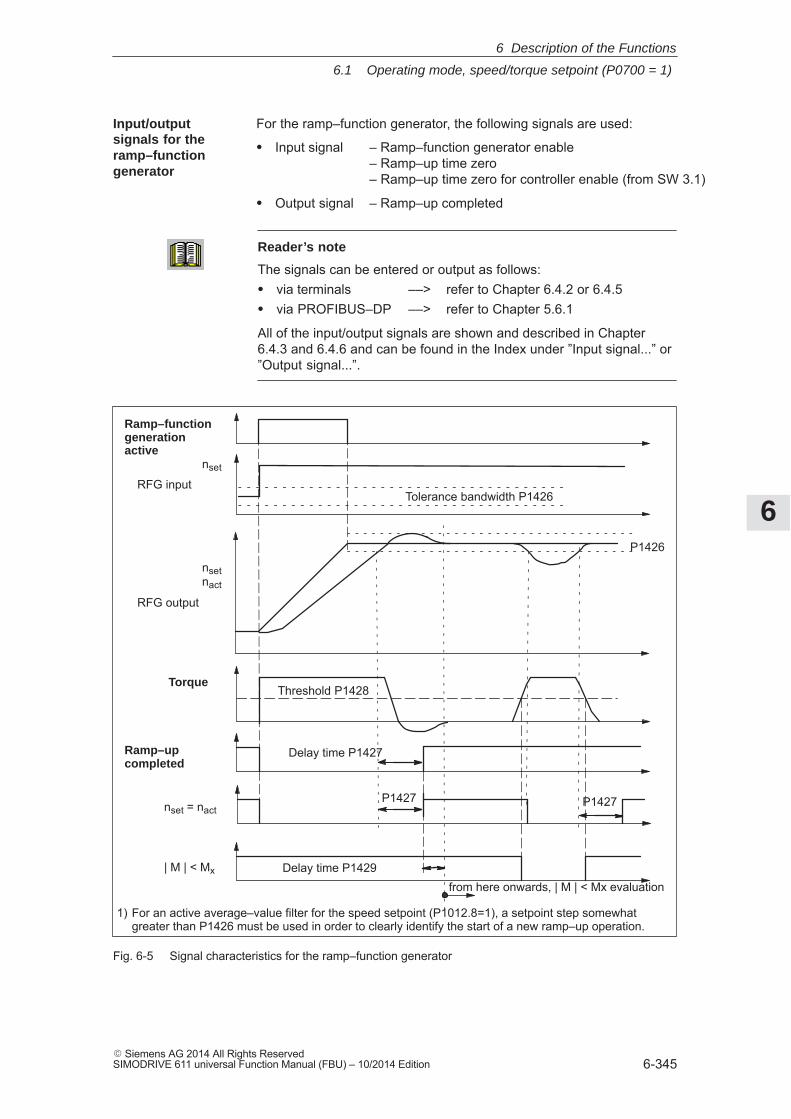
6
6.1 Operating mode, speed/torque setpoint (P0700 = 1)
6-345� Siemens AG 2014 All Rights ReservedSIMODRIVE 611 universal Function Manual (FBU) – 10/2014 Edition
For the ramp–function generator, the following signals are used:
� Input signal – Ramp–function generator enable– Ramp–up time zero– Ramp–up time zero for controller enable (from SW 3.1)
� Output signal – Ramp–up completed
Reader’s note
The signals can be entered or output as follows:� via terminals ––> refer to Chapter 6.4.2 or 6.4.5� via PROFIBUS–DP ––> refer to Chapter 5.6.1
All of the input/output signals are shown and described in Chapter6.4.3 and 6.4.6 and can be found in the Index under ”Input signal...” or”Output signal...”.
Ramp–functiongenerationactive
nset
Tolerance bandwidth P1426
Ramp–upcompleted
| M | < Mx
nsetnact
Threshold P1428Torque
Delay time P1427
Delay time P1429
P1427 P1427nset = nact
RFG input
RFG output
P1426
from here onwards, | M | < Mx evaluation
1) For an active average–value filter for the speed setpoint (P1012.8=1), a setpoint step somewhat greater than P1426 must be used in order to clearly identify the start of a new ramp–up operation.
Fig. 6-5 Signal characteristics for the ramp–function generator
Input/outputsignals for the ramp–functiongenerator
6 Description of the Functions
6
6.1 Operating mode, speed/torque setpoint (P0700 = 1)
6-346� Siemens AG 2014 All Rights Reserved
SIMODRIVE 611 universal Function Manual (FBU) – 10/2014 Edition
6.1.4 Optimizing the closed–loop current and speed controller
When optimizing the cascaded control structure (current, speed con-troller), you generally proceed from the inside to the outside.
At the first commissioning or later, the current controller is pre–set us-ing the ”Calculate controller data” function, and generally no longer hasto be optimized.
However, all parameters for the current control loop can be adapted viathe expert list of the ”SimoCom U” tool.
At the first start–up (first commissioning) or later, the speed controller ispre–set using the ”Calculate controller data”.
This speed controller setting is calculated for a motor operating underno–load conditions, and corresponds to a ”safe” setting.
In order to be able to fully utilize the dynamic performance of the driveincluding the mechanical system, some post–optimization will be nec-essary.
� Optimizing using the ”SimoCom U” tool
The controller setting for ”SIMODRIVE 611 universal” can be auto-matically executed using the ”SimoCom U” tool (only in online oper-ation).
Call: Press the ”Execute automatic controller setting” button under ”Con-troller” and execute the steps offered.
Reader’s note
Recommendation when optimizing the controller:
Optimize the control loop with ”SimoCom U” and the ”Executeautomatic controller setting” function.
� Optimization using the display and operator control unit:
– Remove write protection ––> set P0651 to 4
– Increase the proportional gain Kp (P1407:8) until the motormakes a whistling sound
– Reduce the proportional gain Kp (P1407:8) until this whistlingsound disappears
– The integral action time TN (P1409:8) can be retained
Optimizing thecurrent controller
Optimizationspeed controller
6 Description of the Functions
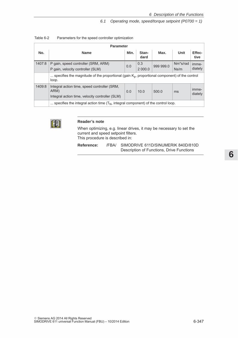
6
6.1 Operating mode, speed/torque setpoint (P0700 = 1)
6-347� Siemens AG 2014 All Rights ReservedSIMODRIVE 611 universal Function Manual (FBU) – 10/2014 Edition
Table 6-2 Parameters for the speed controller optimization
Parameter
No. Name Min. Stan-dard
Max. Unit Effec-tive
1407:8 P gain, speed controller (SRM, ARM)P gain, velocity controller (SLM)
0.00.32 000.0
999 999.0Nm*s/radNs/m
imme-diately
... specifies the magnitude of the proportional (gain Kp, proportional component) of the controlloop.
1409:8 Integral action time, speed controller (SRM,ARM)Integral action time, velocity controller (SLM)
0.0 10.0 500.0 ms imme-diately
... specifies the integral action time (TN, integral component) of the control loop.
Reader’s note
When optimizing, e.g. linear drives, it may be necessary to set thecurrent and speed setpoint filters. This procedure is described in:
Reference: /FBA/ SIMODRIVE 611D/SINUMERIK 840D/810DDescription of Functions, Drive Functions
6 Description of the Functions
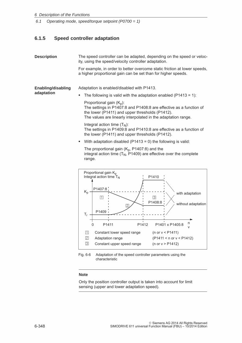
6
6.1 Operating mode, speed/torque setpoint (P0700 = 1)
6-348� Siemens AG 2014 All Rights Reserved
SIMODRIVE 611 universal Function Manual (FBU) – 10/2014 Edition
6.1.5 Speed controller adaptation
The speed controller can be adapted, depending on the speed or veloc-ity, using the speed/velocity controller adaptation.
For example, in order to better overcome static friction at lower speeds,a higher proportional gain can be set than for higher speeds.
Adaptation is enabled/disabled with P1413.
� The following is valid with the adaptation enabled (P1413 = 1):
Proportional gain (Kp): The settings in P1407:8 and P1408:8 are effective as a function ofthe lower (P1411) and upper thresholds (P1412). The values are linearly interpolated in the adaptation range.
Integral action time (TN):The settings in P1409:8 and P1410:8 are effective as a function ofthe lower (P1411) and upper thresholds (P1412).
� With adaptation disabled (P1413 = 0) the following is valid:
The proportional gain (Kp, P1407:8) and theintegral action time (TN, P1409) are effective over the completerange.
Kp
Tr
n
P1409
P1407:8
P1410
P1408:8
0 P1411 P1412 P1401 x P1405:8
Constant lower speed range (n or v < P1411)Adaptation range (P1411 < n or v < P1412)Constant upper speed range (n or v > P1412)
�
�
�
without adaptation
with adaptation
Proportional gain Kp Integral action time TN
v�
�
�
Fig. 6-6 Adaptation of the speed controller parameters using thecharacteristic
Note
Only the position controller output is taken into account for limitsensing (upper and lower adaptation speed).
Description
Enabling/disablingadaptation
6 Description of the Functions
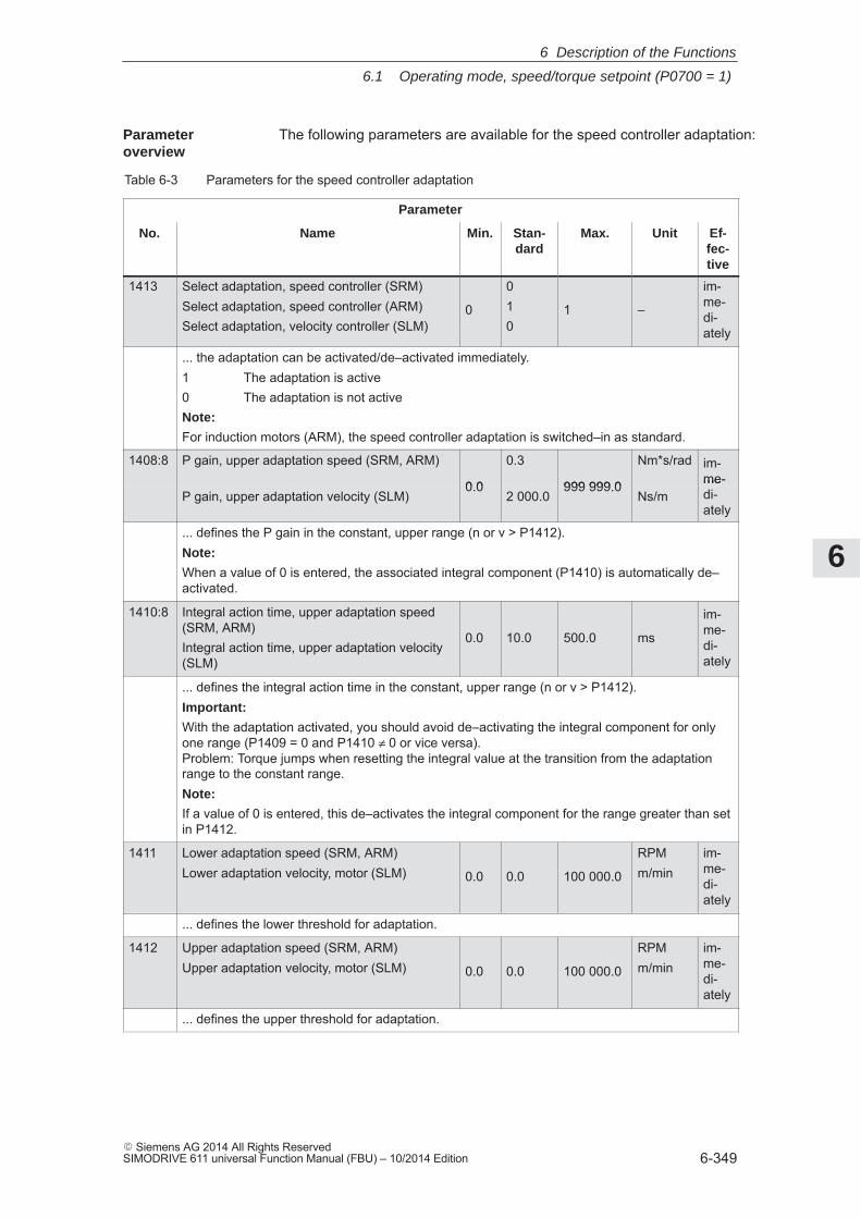
6
6.1 Operating mode, speed/torque setpoint (P0700 = 1)
6-349� Siemens AG 2014 All Rights ReservedSIMODRIVE 611 universal Function Manual (FBU) – 10/2014 Edition
The following parameters are available for the speed controller adaptation:
Table 6-3 Parameters for the speed controller adaptation
Parameter
No. Name Min. Stan-dard
Max. Unit Ef-fec-tive
1413 Select adaptation, speed controller (SRM)Select adaptation, speed controller (ARM)Select adaptation, velocity controller (SLM)
0
010
1 –
im-me-di-ately
... the adaptation can be activated/de–activated immediately.1 The adaptation is active0 The adaptation is not activeNote:
For induction motors (ARM), the speed controller adaptation is switched–in as standard.
1408:8 P gain, upper adaptation speed (SRM, ARM)
0.0
0.3
999 999.0
Nm*s/rad im-me-
P gain, upper adaptation velocity (SLM)0.0
2 000.0999 999.0
Ns/mme-di-ately
... defines the P gain in the constant, upper range (n or v > P1412).Note:
When a value of 0 is entered, the associated integral component (P1410) is automatically de–activated.
1410:8 Integral action time, upper adaptation speed(SRM, ARM)Integral action time, upper adaptation velocity(SLM)
0.0 10.0 500.0 ms
im-me-di-ately
... defines the integral action time in the constant, upper range (n or v > P1412).Important:
With the adaptation activated, you should avoid de–activating the integral component for onlyone range (P1409 = 0 and P1410 ≠ 0 or vice versa). Problem: Torque jumps when resetting the integral value at the transition from the adaptationrange to the constant range.Note:
If a value of 0 is entered, this de–activates the integral component for the range greater than setin P1412.
1411 Lower adaptation speed (SRM, ARM)Lower adaptation velocity, motor (SLM) 0.0 0.0 100 000.0
RPMm/min
im-me-di-ately
... defines the lower threshold for adaptation.
1412 Upper adaptation speed (SRM, ARM)Upper adaptation velocity, motor (SLM) 0.0 0.0 100 000.0
RPMm/min
im-me-di-ately
... defines the upper threshold for adaptation.
Parameter overview
6 Description of the Functions
6
6.1 Operating mode, speed/torque setpoint (P0700 = 1)
6-350� Siemens AG 2014 All Rights Reserved
SIMODRIVE 611 universal Function Manual (FBU) – 10/2014 Edition
6.1.6 Fixed speed setpoint (from SW 3.1)
Speed setpoints can be defined in parameters using this function. Therequired fixed setpoint for the speed setpoint input is selected via inputsignals. The currently selected fixed setpoint can be displayed via out-put signals.
Advantage:
An analog voltage is not required for the speed setpoint input, and thesetpoint can be precisely set.
The following signals are used for the ”fixed speed setpoint” function:
� Input signals(refer under index entry ”Input signal, digital – ...”)
– Fixed speed setpoint 1st input (function number = 15)
– Fixed speed setpoint 2nd input (function number = 16)
– Fixed speed setpoint 3rd input (function number = 17)
– Fixed speed setpoint 4th input (function number = 18)
� Output signals(refer under the index entry, ”Output signal, digital – ...”)
– Status, fixed speed setpoint 1st output (function number = 15)
– Status, fixed speed setpoint 2nd output (function number = 16)
– Status, fixed speed setpoint 3rd output (function number = 17)
– Status, fixed speed setpoint 4th output (function number = 18)
The following parameters are available for the ”fixed speed setpoint”function:
� P0641:16 Fixed speed setpoint (SRM, ARM)Fixed velocity setpoint (SLM)
The following sequence is practical when commissioning:
1. Enter the required fixed speed setpoints (refer to Chapter A.1) P0641:0 = no significanceP0641:1 = required fixed setpoint 1P0641:2 = required fixed setpoint 2, etc.
2. Parameterize the input terminals (refer to Chapters 6.4.2 and 6.4.3)
3. Parameterize the output terminals (refer to Chapters 6.4.5 and 6.4.6)
4. Check the function
Description
Input/outputsignals
Parameteroverview(refer to ChapterA.1)
Commissioningthe function
6 Description of the Functions
! not 611ue !
6
6.1 Operating mode, speed/torque setpoint (P0700 = 1)
6-351� Siemens AG 2014 All Rights ReservedSIMODRIVE 611 universal Function Manual (FBU) – 10/2014 Edition
6.1.7 Monitoring functions
The temperature limit values are pre–assigned, corresponding to theselected motor when the motor code is specified; the user should notchange these.
The following motor temperature monitoring functions are available:
� Temperature monitoring with pre–warning (P1602 + P1603)
If the temperature warning threshold (P1602) is exceeded, the resultis as follows:
– Warning 814 is output
– Timer (P1603) is started
– Motor overtemperature is signaled via terminal 5.x at the NEmodule
Note: This signal is saved, if it is still present after the time in P1603has expired.
– The ”motor temperature pre–warning” (MeldW.6) output signal isset
If the overtemperature condition still remains after the time set inP1603, then this results in fault 614 and the drive is powered down.
The monitoring function can be enabled/disabled using P1601.14.
� Temperature monitoring without pre–warning (P1607)
If the temperature threshold in P1607 is exceeded, this immediatelyresults in fault 613 and the drive is powered down.
The monitoring function can be enabled/disabled using P1601.13.
Note
The temperature monitoring functions (warning P1602 + timer P1603or P1607) are not subject to any mutual restrictions, i.e. it is permissible that P1607 < P1602.
� Specifying a fixed temperature (P1608)
When a fixed temperature is specified, the temperature–dependentadaptation of the rotor resistance is executed with this fixed temper-ature.
Note
The temperature monitoring functions of the motor, set using P1602 orP1607, are then no longer effective.
Motor temperaturemonitoring
6 Description of the Functions
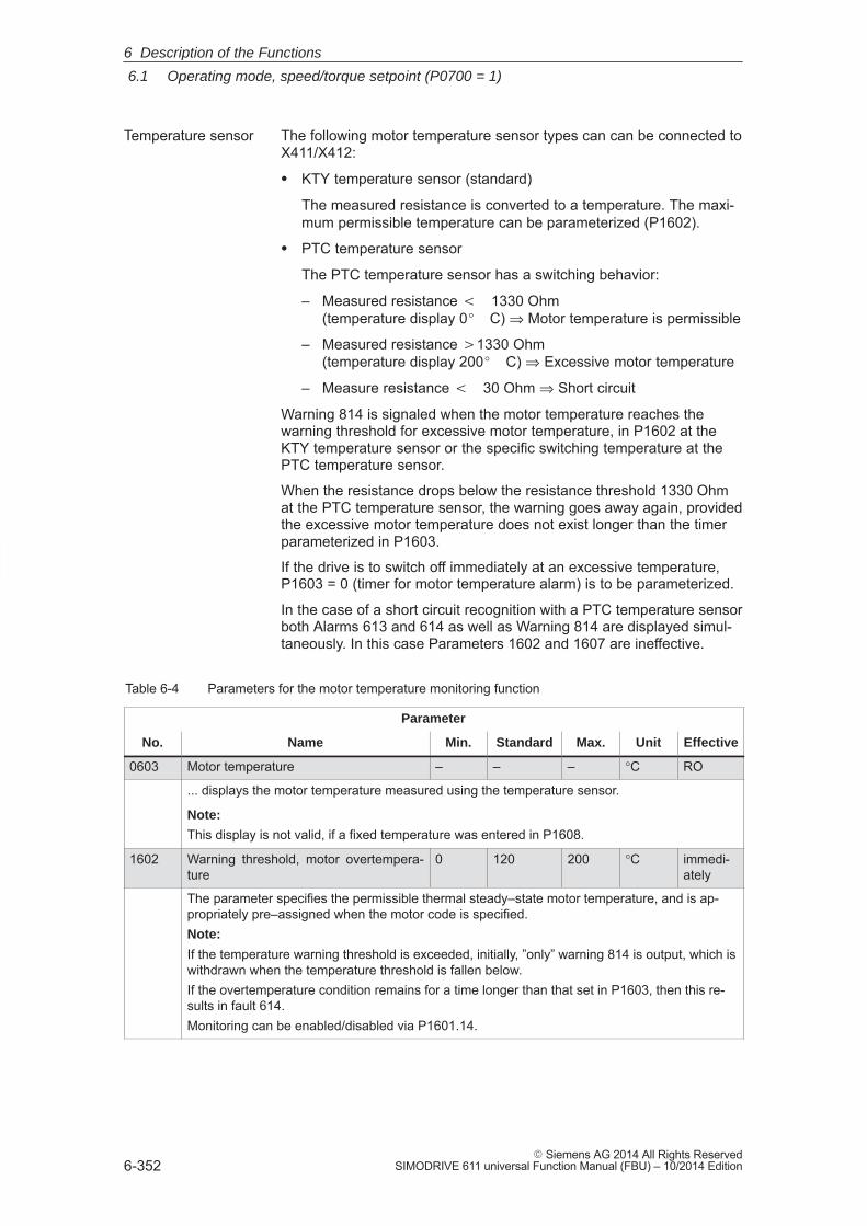
6
6.1 Operating mode, speed/torque setpoint (P0700 = 1)
6-352� Siemens AG 2014 All Rights Reserved
SIMODRIVE 611 universal Function Manual (FBU) – 10/2014 Edition
The following motor temperature sensor types can can be connected toX411/X412:
� KTY temperature sensor (standard)
The measured resistance is converted to a temperature. The maxi-mum permissible temperature can be parameterized (P1602).
� PTC temperature sensor
The PTC temperature sensor has a switching behavior:
– Measured resistance � 1330 Ohm (temperature display 0� C) ⇒ Motor temperature is permissible
– Measured resistance �1330 Ohm (temperature display 200� C) ⇒ Excessive motor temperature
– Measure resistance � 30 Ohm ⇒ Short circuit
Warning 814 is signaled when the motor temperature reaches thewarning threshold for excessive motor temperature, in P1602 at theKTY temperature sensor or the specific switching temperature at thePTC temperature sensor.
When the resistance drops below the resistance threshold 1330 Ohmat the PTC temperature sensor, the warning goes away again, providedthe excessive motor temperature does not exist longer than the timerparameterized in P1603.
If the drive is to switch off immediately at an excessive temperature,P1603 = 0 (timer for motor temperature alarm) is to be parameterized.
In the case of a short circuit recognition with a PTC temperature sensorboth Alarms 613 and 614 as well as Warning 814 are displayed simul-taneously. In this case Parameters 1602 and 1607 are ineffective.
Table 6-4 Parameters for the motor temperature monitoring function
Parameter
No. Name Min. Standard Max. Unit Effective
0603 Motor temperature – – – °C RO
... displays the motor temperature measured using the temperature sensor.
Note:
This display is not valid, if a fixed temperature was entered in P1608.
1602 Warning threshold, motor overtempera-ture
0 120 200 °C immedi-ately
The parameter specifies the permissible thermal steady–state motor temperature, and is ap-propriately pre–assigned when the motor code is specified.Note:
If the temperature warning threshold is exceeded, initially, ”only” warning 814 is output, which iswithdrawn when the temperature threshold is fallen below.If the overtemperature condition remains for a time longer than that set in P1603, then this re-sults in fault 614.Monitoring can be enabled/disabled via P1601.14.
Temperature sensor
6 Description of the Functions
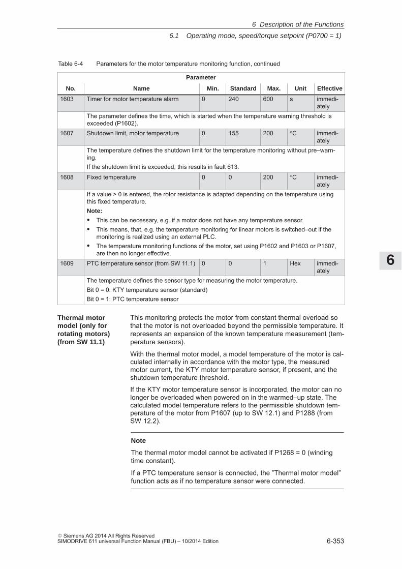
6
6.1 Operating mode, speed/torque setpoint (P0700 = 1)
6-353� Siemens AG 2014 All Rights ReservedSIMODRIVE 611 universal Function Manual (FBU) – 10/2014 Edition
Table 6-4 Parameters for the motor temperature monitoring function, continued
Parameter
No. EffectiveUnitMax.StandardMin.Name
1603 Timer for motor temperature alarm 0 240 600 s immedi-ately
The parameter defines the time, which is started when the temperature warning threshold isexceeded (P1602).
1607 Shutdown limit, motor temperature 0 155 200 °C immedi-ately
The temperature defines the shutdown limit for the temperature monitoring without pre–warn-ing.If the shutdown limit is exceeded, this results in fault 613.
1608 Fixed temperature 0 0 200 °C immedi-ately
If a value > 0 is entered, the rotor resistance is adapted depending on the temperature usingthis fixed temperature.Note:
� This can be necessary, e.g. if a motor does not have any temperature sensor.� This means, that, e.g. the temperature monitoring for linear motors is switched–out if the
monitoring is realized using an external PLC.� The temperature monitoring functions of the motor, set using P1602 and P1603 or P1607,
are then no longer effective.1609 PTC temperature sensor (from SW 11.1) 0 0 1 Hex immedi-
atelyThe temperature defines the sensor type for measuring the motor temperature.Bit 0 = 0: KTY temperature sensor (standard)Bit 0 = 1: PTC temperature sensor
This monitoring protects the motor from constant thermal overload sothat the motor is not overloaded beyond the permissible temperature. Itrepresents an expansion of the known temperature measurement (tem-perature sensors).
With the thermal motor model, a model temperature of the motor is cal-culated internally in accordance with the motor type, the measuredmotor current, the KTY motor temperature sensor, if present, and theshutdown temperature threshold.
If the KTY motor temperature sensor is incorporated, the motor can nolonger be overloaded when powered on in the warmed–up state. Thecalculated model temperature refers to the permissible shutdown tem-perature of the motor from P1607 (up to SW 12.1) and P1288 (fromSW 12.2).
Note
The thermal motor model cannot be activated if P1268 = 0 (windingtime constant).
If a PTC temperature sensor is connected, the ”Thermal motor model”function acts as if no temperature sensor were connected.
Thermal motormodel (only forrotating motors) (from SW 11.1)
6 Description of the Functions
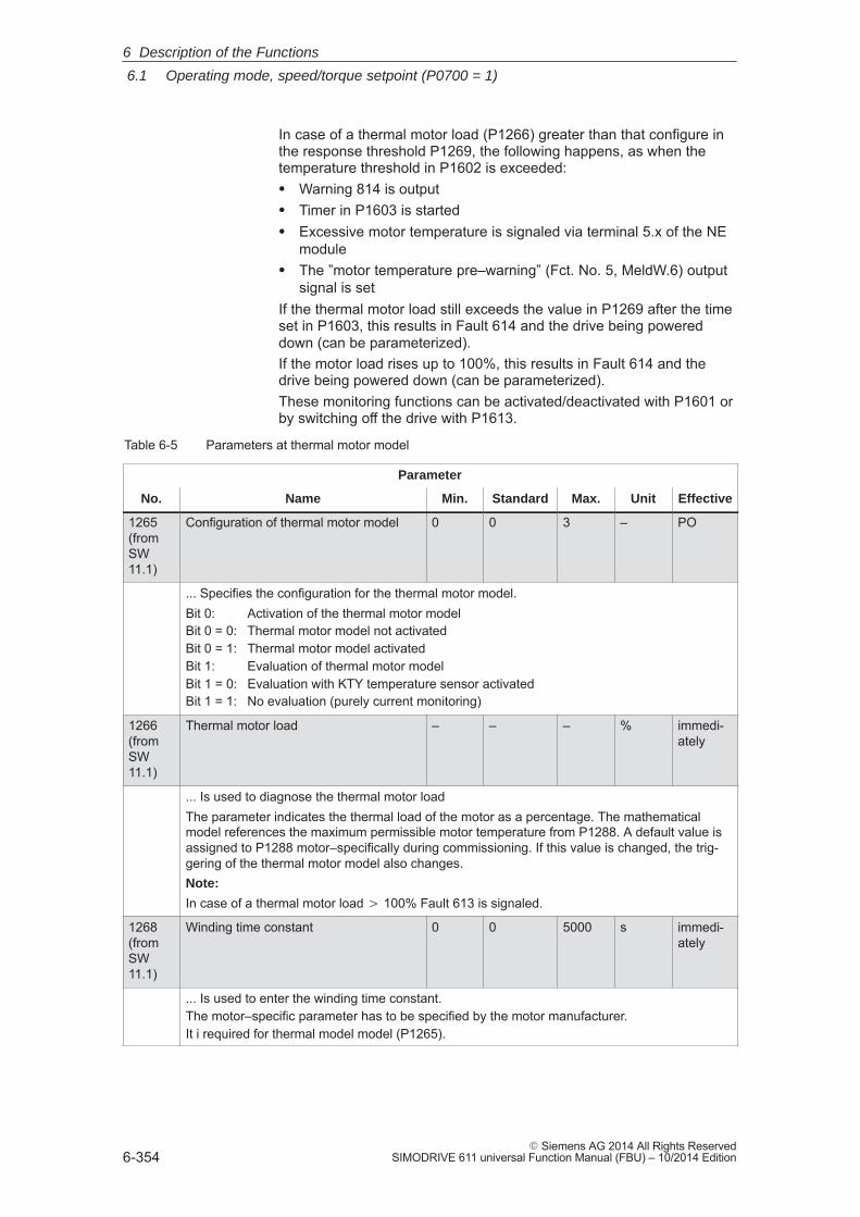
6
6.1 Operating mode, speed/torque setpoint (P0700 = 1)
6-354� Siemens AG 2014 All Rights Reserved
SIMODRIVE 611 universal Function Manual (FBU) – 10/2014 Edition
In case of a thermal motor load (P1266) greater than that configure inthe response threshold P1269, the following happens, as when thetemperature threshold in P1602 is exceeded:� Warning 814 is output� Timer in P1603 is started� Excessive motor temperature is signaled via terminal 5.x of the NE
module� The ”motor temperature pre–warning” (Fct. No. 5, MeldW.6) output
signal is setIf the thermal motor load still exceeds the value in P1269 after the timeset in P1603, this results in Fault 614 and the drive being powereddown (can be parameterized).If the motor load rises up to 100%, this results in Fault 614 and thedrive being powered down (can be parameterized).These monitoring functions can be activated/deactivated with P1601 orby switching off the drive with P1613.
Table 6-5 Parameters at thermal motor model
Parameter
No. Name Min. Standard Max. Unit Effective
1265(fromSW11.1)
Configuration of thermal motor model 0 0 3 – PO
... Specifies the configuration for the thermal motor model.Bit 0: Activation of the thermal motor modelBit 0 = 0: Thermal motor model not activatedBit 0 = 1: Thermal motor model activatedBit 1: Evaluation of thermal motor modelBit 1 = 0: Evaluation with KTY temperature sensor activatedBit 1 = 1: No evaluation (purely current monitoring)
1266(fromSW11.1)
Thermal motor load – – – % immedi-ately
... Is used to diagnose the thermal motor loadThe parameter indicates the thermal load of the motor as a percentage. The mathematicalmodel references the maximum permissible motor temperature from P1288. A default value isassigned to P1288 motor–specifically during commissioning. If this value is changed, the trig-gering of the thermal motor model also changes.Note:
In case of a thermal motor load � 100% Fault 613 is signaled.
1268(fromSW11.1)
Winding time constant 0 0 5000 s immedi-ately
... Is used to enter the winding time constant.The motor–specific parameter has to be specified by the motor manufacturer.It i required for thermal model model (P1265).
6 Description of the Functions
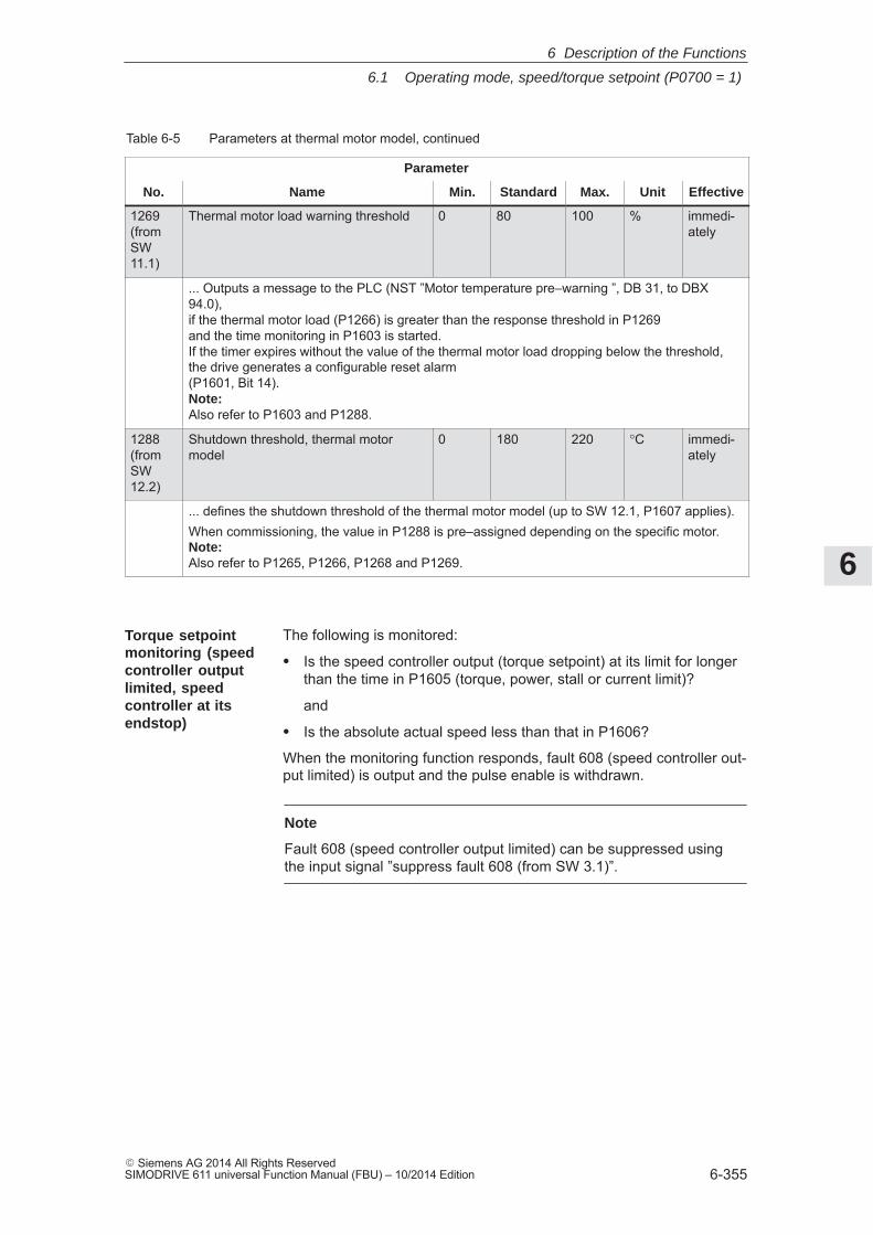
6
6.1 Operating mode, speed/torque setpoint (P0700 = 1)
6-355� Siemens AG 2014 All Rights ReservedSIMODRIVE 611 universal Function Manual (FBU) – 10/2014 Edition
Table 6-5 Parameters at thermal motor model, continued
Parameter
No. EffectiveUnitMax.StandardMin.Name
1269(fromSW11.1)
Thermal motor load warning threshold 0 80 100 % immedi-ately
... Outputs a message to the PLC (NST ”Motor temperature pre–warning ”, DB 31, to DBX94.0),if the thermal motor load (P1266) is greater than the response threshold in P1269and the time monitoring in P1603 is started.If the timer expires without the value of the thermal motor load dropping below the threshold,the drive generates a configurable reset alarm (P1601, Bit 14).Note:Also refer to P1603 and P1288.
1288(fromSW12.2)
Shutdown threshold, thermal motormodel
0 180 220 °C immedi-ately
... defines the shutdown threshold of the thermal motor model (up to SW 12.1, P1607 applies).When commissioning, the value in P1288 is pre–assigned depending on the specific motor.Note:Also refer to P1265, P1266, P1268 and P1269.
The following is monitored:
� Is the speed controller output (torque setpoint) at its limit for longerthan the time in P1605 (torque, power, stall or current limit)?
and
� Is the absolute actual speed less than that in P1606?
When the monitoring function responds, fault 608 (speed controller out-put limited) is output and the pulse enable is withdrawn.
Note
Fault 608 (speed controller output limited) can be suppressed usingthe input signal ”suppress fault 608 (from SW 3.1)”.
Torque setpointmonitoring (speedcontroller outputlimited, speedcontroller at itsendstop)
6 Description of the Functions
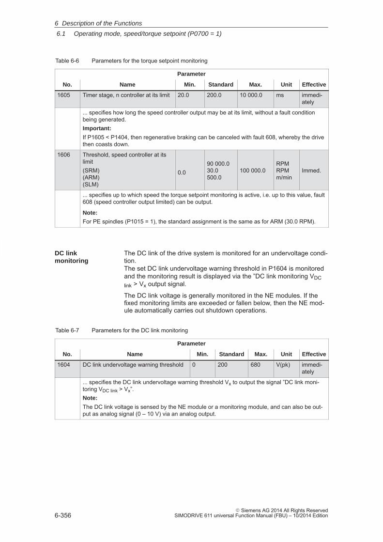
6
6.1 Operating mode, speed/torque setpoint (P0700 = 1)
6-356� Siemens AG 2014 All Rights Reserved
SIMODRIVE 611 universal Function Manual (FBU) – 10/2014 Edition
Table 6-6 Parameters for the torque setpoint monitoring
Parameter
No. Name Min. Standard Max. Unit Effective
1605 Timer stage, n controller at its limit 20.0 200.0 10 000.0 ms immedi-ately
... specifies how long the speed controller output may be at its limit, without a fault conditionbeing generated.Important:
If P1605 < P1404, then regenerative braking can be canceled with fault 608, whereby the drivethen coasts down.
1606 Threshold, speed controller at itslimit(SRM)(ARM)(SLM)
0.090 000.030.0500.0
100 000.0RPMRPMm/min
Immed.
... specifies up to which speed the torque setpoint monitoring is active, i.e. up to this value, fault608 (speed controller output limited) can be output.
Note:
For PE spindles (P1015 = 1), the standard assignment is the same as for ARM (30.0 RPM).
The DC link of the drive system is monitored for an undervoltage condi-tion. The set DC link undervoltage warning threshold in P1604 is monitoredand the monitoring result is displayed via the ”DC link monitoring VDClink > Vx output signal.
The DC link voltage is generally monitored in the NE modules. If thefixed monitoring limits are exceeded or fallen below, then the NE mod-ule automatically carries out shutdown operations.
Table 6-7 Parameters for the DC link monitoring
Parameter
No. Name Min. Standard Max. Unit Effective
1604 DC link undervoltage warning threshold 0 200 680 V(pk) immedi-ately
... specifies the DC link undervoltage warning threshold Vx to output the signal ”DC link moni-toring VDC link > Vx”.Note:
The DC link voltage is sensed by the NE module or a monitoring module, and can also be out-put as analog signal (0 – 10 V) via an analog output.
DC link monitoring
6 Description of the Functions
6
6.1 Operating mode, speed/torque setpoint (P0700 = 1)
6-357� Siemens AG 2014 All Rights ReservedSIMODRIVE 611 universal Function Manual (FBU) – 10/2014 Edition
From SW 4.1, the following monitoring functions/warnings are availablefor the DC link voltage, which result in the drive being powered down(tripped):
� Monitoring the DC link for an overvoltage condition
Threshold: P1163 ”Max. DC link voltage”
Fault 617, if the DC link voltage, when the pulses are enabled, isgreater than the threshold. The shutdown response can be config-ured using P1613 bit 16 or 17.
� Monitoring for a DC link undervoltage condition
Threshold: P1162 ”Minimum DC link voltage”
Defines the permissible lower limit for the DC link voltage.
Fault 616 is generated if the DC link voltage when setting the enablesignals is less than the threshold. The monitoring only becomes ac-tive if VDC link (P1701) has fallen below the value in P1162 at leastonce and the drive is ready to be moved. The shutdown response to fault 616 can be configured using P1613bit 16 or 17.
If the standard value is entered in P1162/P1163, then the appropriatemonitoring is inactive.
6 Description of the Functions
6
6.1 Operating mode, speed/torque setpoint (P0700 = 1)
6-358� Siemens AG 2014 All Rights Reserved
SIMODRIVE 611 universal Function Manual (FBU) – 10/2014 Edition
When using ”SIMODRIVE 611 universal” with a higher–level control, itcan occur that for coordinate transformation, e.g. shifting and rotatingthe tool, that the software limit switches cannot be activated/evaluatedin the higher–level control.
An axis fast stop is possible using a hardware limit switch monitoringfunction.
The HW limit switches must be connected to an input terminal with thefollowing function numbers:
� ”Plus hardware limit switch” function ––> function number 81
� ”Minus hardware limit switch” function ––> function number 82
––> Refer to Chapter 6.4.2
When traversing to a hardware limit switch, the associated input signalis set to ”0” and the following response is automatically initiated:
� A setpoint of zero is entered in the selecting speed direction – theaxis is braked and comes to a standstill. The drive remains in theclosed–loop controlled mode.
If it is switched–in, the ramp–function generator remains active. Thebraking that is initiated runs with or without braking ramp.
� One of the following warnings is output:
– Warning 800 Minus hardware limit switch
– Warning 801 Plus hardware limit switch
The hardware limit switch signal must always remain at a ”0 signal” out-side the permitted traversing range. A brief change from ”0 signal” to ”1signal” is not permitted.
As a result of the zero speed input when reaching the hardware limitswitch, alarms, e.g. ”following error too high” or similar faults must bedetected in the higher–level control.
If an axis is at a hardware limit switch, then it can be moved away asfollows:
� Enter a setpoint in the opposite direction to the approach direction
or
� Withdraw the controller enable and move the drive away manually
After moving away from the hardware limit switch, warning 800 or 801is automatically deleted.
Hardware limit switch (HW limit switch)(from SW 8.1)
Traverse to ahardware limitswitch?
How do you moveaway from ahardware limitswitch?
6 Description of the Functions
6
6.1 Operating mode, speed/torque setpoint (P0700 = 1)
6-359� Siemens AG 2014 All Rights ReservedSIMODRIVE 611 universal Function Manual (FBU) – 10/2014 Edition
Reader’s note
For ”SIMODRIVE 611 universal”, additional monitoring functions canbe parameterized, and processed via output signals (terminals,PROFIBUS) (refer to Chapter 6.4.6 and 6.20).
6.1.8 Limits
The speed setpoint is limited to the maximum value which is set.
How is the speed setpoint limiting calculated?
Motor type Interdependencies
� SRM, SLM: P1405:8 � P1401:8
� ARM: Minimum (P1405:8 � P1401:8, 1.02 � P1147, 1.02 � P1146)
Note
The maximum useful motor speed, set via P1401:8, is taken intoaccount when calculating the speed setpoint, i.e. P1401:8 acts asspeed limiting. This is valid, independent of whether the setpoint is entered via a terminal or PROFIBUS–DP.
If the speed actual value exceeds the selected limit value by more than2%, then the torque, when motoring, is set to 0. Thus, further acceleration is not possible. If the speed actual value drops below the limit value, the torque limitingis withdrawn again.
How is the speed limiting calculated?
Motor type Interdependencies
� SRM: Minimum (P1147, 1.2 � P1400)
� ARM, SLM, PE spindle: Minimum (P1147, P1146)
Other monitoringfunctions
Limiting the speedsetpoint
Speed limiting
6 Description of the Functions
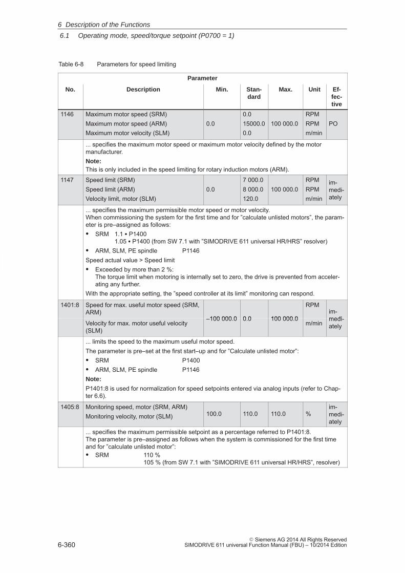
6
6.1 Operating mode, speed/torque setpoint (P0700 = 1)
6-360� Siemens AG 2014 All Rights Reserved
SIMODRIVE 611 universal Function Manual (FBU) – 10/2014 Edition
Table 6-8 Parameters for speed limiting
Parameter
No. Description Min. Stan-dard
Max. Unit Ef-fec-tive
1146 Maximum motor speed (SRM)Maximum motor speed (ARM)Maximum motor velocity (SLM)
0.00.015000.00.0
100 000.0RPMRPMm/min
PO
... specifies the maximum motor speed or maximum motor velocity defined by the motormanufacturer.Note:This is only included in the speed limiting for rotary induction motors (ARM).
1147 Speed limit (SRM)Speed limit (ARM)Velocity limit, motor (SLM)
0.07 000.08 000.0120.0
100 000.0RPMRPMm/min
im-medi-ately
... specifies the maximum permissible motor speed or motor velocity.When commissioning the system for the first time and for ”calculate unlisted motors”, the param-eter is pre–assigned as follows:� SRM 1.1 � P1400
1.05 � P1400 (from SW 7.1 with ”SIMODRIVE 611 universal HR/HRS” resolver)� ARM, SLM, PE spindle P1146Speed actual value > Speed limit� Exceeded by more than 2 %:
The torque limit when motoring is internally set to zero, the drive is prevented from acceler-ating any further.
With the appropriate setting, the ”speed controller at its limit” monitoring can respond.
1401:8 Speed for max. useful motor speed (SRM,ARM)
–100 000.0 0.0 100 000.0
RPMim-medi-
Velocity for max. motor useful velocity(SLM)
–100 000.0 0.0 100 000.0m/min
medi-ately
... limits the speed to the maximum useful motor speed.The parameter is pre–set at the first start–up and for ”Calculate unlisted motor”:� SRM P1400� ARM, SLM, PE spindle P1146Note:
P1401:8 is used for normalization for speed setpoints entered via analog inputs (refer to Chap-ter 6.6).
1405:8 Monitoring speed, motor (SRM, ARM)Monitoring velocity, motor (SLM) 100.0 110.0 110.0 %
im-medi-ately
... specifies the maximum permissible setpoint as a percentage referred to P1401:8.The parameter is pre–assigned as follows when the system is commissioned for the first timeand for ”calculate unlisted motor”:� SRM 110 %
105 % (from SW 7.1 with ”SIMODRIVE 611 universal HR/HRS”, resolver)
6 Description of the Functions
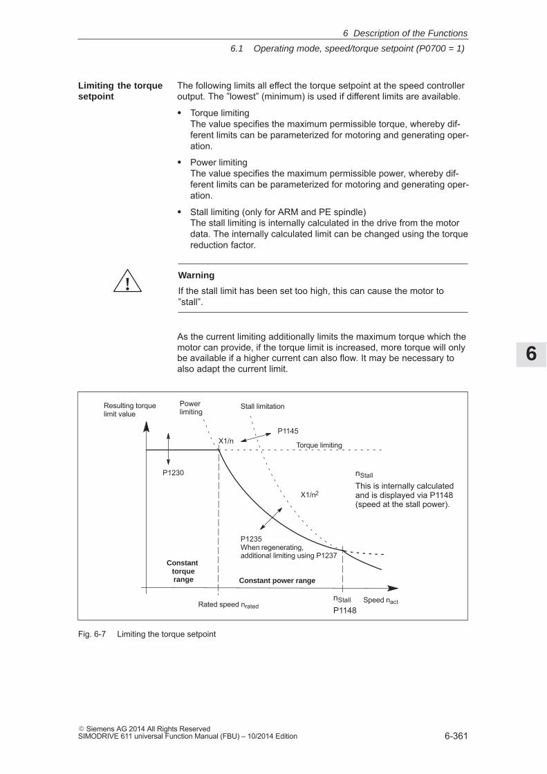
6
6.1 Operating mode, speed/torque setpoint (P0700 = 1)
6-361� Siemens AG 2014 All Rights ReservedSIMODRIVE 611 universal Function Manual (FBU) – 10/2014 Edition
The following limits all effect the torque setpoint at the speed controlleroutput. The ”lowest” (minimum) is used if different limits are available.
� Torque limitingThe value specifies the maximum permissible torque, whereby dif-ferent limits can be parameterized for motoring and generating oper-ation.
� Power limitingThe value specifies the maximum permissible power, whereby dif-ferent limits can be parameterized for motoring and generating oper-ation.
� Stall limiting (only for ARM and PE spindle)The stall limiting is internally calculated in the drive from the motordata. The internally calculated limit can be changed using the torquereduction factor.
!Warning
If the stall limit has been set too high, this can cause the motor to”stall”.
As the current limiting additionally limits the maximum torque which themotor can provide, if the torque limit is increased, more torque will onlybe available if a higher current can also flow. It may be necessary toalso adapt the current limit.
P1230
P1235When regenerating, additional limiting using P1237
Constant torquerange Constant power range
Torque limiting
Powerlimiting
Stall limitation
P1145
Speed nact
Resulting torquelimit value
X1/n2
X1/n
Rated speed nratednStall
P1148
nStall
This is internally calculatedand is displayed via P1148(speed at the stall power).
Fig. 6-7 Limiting the torque setpoint
Limiting the torquesetpoint
6 Description of the Functions
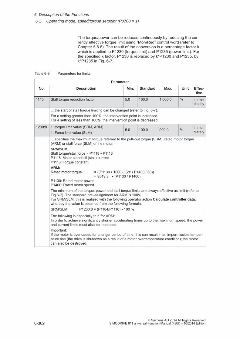
6
6.1 Operating mode, speed/torque setpoint (P0700 = 1)
6-362� Siemens AG 2014 All Rights Reserved
SIMODRIVE 611 universal Function Manual (FBU) – 10/2014 Edition
The torque/power can be reduced continuously by reducing the cur-rently effective torque limit using ”MomRed” control word (refer toChapter 5.6.6). The result of the conversion is a percentage factor kwhich is applied to P1230 (torque limit) and P1235 (power limit). Forthe specified k factor, P1230 is replaced by k*P1230 and P1235, byk*P1235 in Fig. 6-7.
Table 6-9 Parameters for limits
Parameter
No. Description Min. Standard Max. Unit Effec-tive
1145 Stall torque reduction factor 5.0 100.0 1 000.0 % imme-diately
... the start of stall torque limiting can be changed (refer to Fig. 6-7).For a setting greater than 100%, the intervention point is increased.For a setting of less than 100%, the intervention point is decreased.
1230:8 1. torque limit value (SRM, ARM)1. Force limit value (SLM)
5.0 100.0 900.0 % imme-diately
... specifies the maximum torque referred to the pull–out torque (SRM), rated motor torque(ARM) or stall force (SLM) of the motor.SRM/SLM: Stall torque/stall force = P1118 � P1113P1118: Motor standstill (stall) currentP1113: Torque constantARM: Rated motor torque = ((P1130 � 1000) / (2π � P1400 / 60))
= 9549.3 � (P1130 / P1400)P1130: Rated motor powerP1400: Rated motor speedThe minimum of the torque, power and stall torque limits are always effective as limit (refer toFig.6-7). The standard pre–assignment for ARM is 100%. For SRM/SLM, this is realized with the following operator action Calculate controller data,whereby the value is obtained from the following formula:SRM/SLM: P1230:8 = (P1104/P1118) � 100 %
The following is especially true for ARM: In order to achieve significantly shorter accelerating times up to the maximum speed, the powerand current limits must also be increased.Important: If the motor is overloaded for a longer period of time, this can result in an impermissible temper-ature rise (the drive is shutdown as a result of a motor overtemperature condition); the motorcan also be destroyed.
6 Description of the Functions
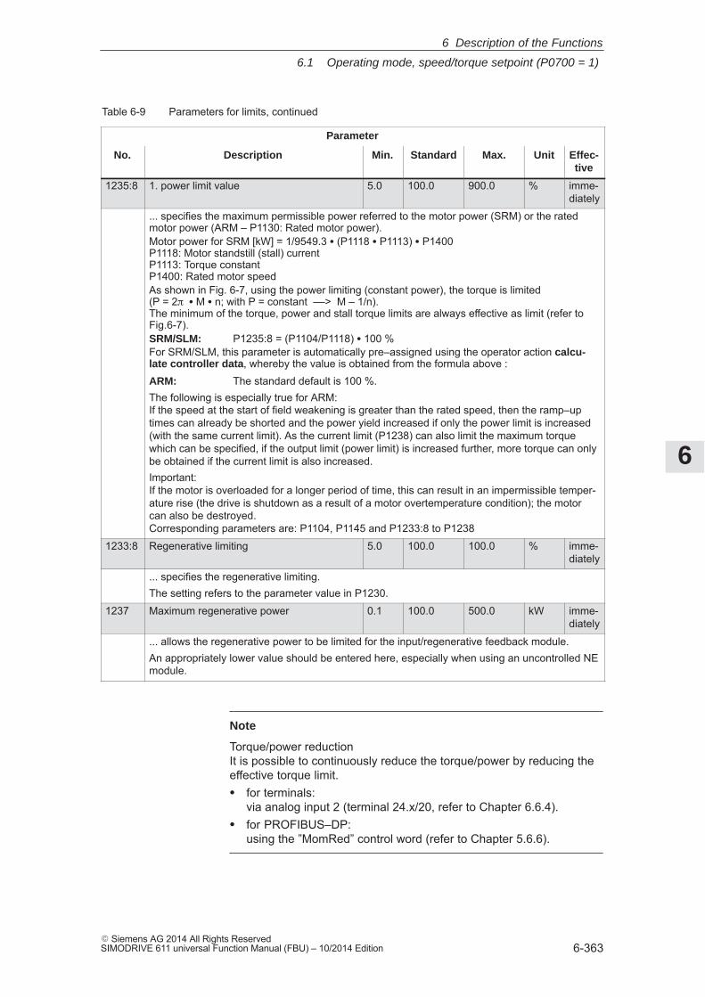
6
6.1 Operating mode, speed/torque setpoint (P0700 = 1)
6-363� Siemens AG 2014 All Rights ReservedSIMODRIVE 611 universal Function Manual (FBU) – 10/2014 Edition
Table 6-9 Parameters for limits, continued
Parameter
No. Effec-tive
UnitMax.StandardMin.Description
1235:8 1. power limit value 5.0 100.0 900.0 % imme-diately
... specifies the maximum permissible power referred to the motor power (SRM) or the ratedmotor power (ARM – P1130: Rated motor power).Motor power for SRM [kW] = 1/9549.3 � (P1118 � P1113) � P1400P1118: Motor standstill (stall) currentP1113: Torque constantP1400: Rated motor speedAs shown in Fig. 6-7, using the power limiting (constant power), the torque is limited (P = 2� � M � n; with P = constant ––> M – 1/n). The minimum of the torque, power and stall torque limits are always effective as limit (refer toFig.6-7).SRM/SLM: P1235:8 = (P1104/P1118) � 100 %For SRM/SLM, this parameter is automatically pre–assigned using the operator action calcu-late controller data, whereby the value is obtained from the formula above :ARM: The standard default is 100 %.The following is especially true for ARM: If the speed at the start of field weakening is greater than the rated speed, then the ramp–uptimes can already be shorted and the power yield increased if only the power limit is increased(with the same current limit). As the current limit (P1238) can also limit the maximum torquewhich can be specified, if the output limit (power limit) is increased further, more torque can onlybe obtained if the current limit is also increased.Important: If the motor is overloaded for a longer period of time, this can result in an impermissible temper-ature rise (the drive is shutdown as a result of a motor overtemperature condition); the motorcan also be destroyed. Corresponding parameters are: P1104, P1145 and P1233:8 to P1238
1233:8 Regenerative limiting 5.0 100.0 100.0 % imme-diately
... specifies the regenerative limiting.The setting refers to the parameter value in P1230.
1237 Maximum regenerative power 0.1 100.0 500.0 kW imme-diately
... allows the regenerative power to be limited for the input/regenerative feedback module.An appropriately lower value should be entered here, especially when using an uncontrolled NEmodule.
Note
Torque/power reduction It is possible to continuously reduce the torque/power by reducing theeffective torque limit.� for terminals:
via analog input 2 (terminal 24.x/20, refer to Chapter 6.6.4).� for PROFIBUS–DP:
using the ”MomRed” control word (refer to Chapter 5.6.6).
6 Description of the Functions
6
6.1 Operating mode, speed/torque setpoint (P0700 = 1)
6-364� Siemens AG 2014 All Rights Reserved
SIMODRIVE 611 universal Function Manual (FBU) – 10/2014 Edition
Drives, for which a stop was initiated as a result of one of the followingmeasures, are braked with the maximum possible motor current(P1104) taking into account the reduction in P1105:
� Terminal 64 de–energized at the SIMODRIVE line infeed module.
� Generating an alarm, which initiates a Stop II, and therefore with-draws the internal controller enable.
� Controller enable (ON/OFF1) withdrawn or terminal 65 de–ener-gized (X451.5/X452.5).
This may possible cause the plant/machine to be mechanically damaged.
For this case, a torque reduction can be parameterized for a setpoint ofzero.
The following definitions apply:� P1096: Used to configured the torque reduction at nset = 0.
Bit 0 = 1: Reduces the torque limit for a regenerativestop with a speed setpoint of zero.
Bit 1 = 0 Monitors the speed controller at its endstop for torque reduction
If the motor brakes with a low torque, then fault 608 can be initiated.If it is not desirable that this fault is initiated, then the fault can besuppressed using bit 1 = 1.
� P1097: Specifies the torque reduction at nset = 0.
Note
The percentage value from P1097 only refers to the torque obtained atthe maximum motor current if P1105 = 100%.
� The braking behavior is influenced by:– P1403: Shutdown speed/velocity, pulse cancellation
If the absolute speed actual value or velocity actual value fallsbelow the specified shutdown speed in P1403 while braking, thenthe pulse enable is withdrawn and the drive coasts down.
– P1404: Timer for pulse suppressionThe pulses are cancelled before this if the timer set in P1404 hasexpired.
– P1605: Timer stage, n controller at its limitAfter the set time has expired, then drive coasts down after braking.
– P1613: Shutdown response, faultsIf the torque reduction is to be initiated by a fault at nset = 0,then this must be parameterized using the shutdown response STOP II.
Torque reductionat nset = 0 (fromSW 9.1)
6 Description of the Functions
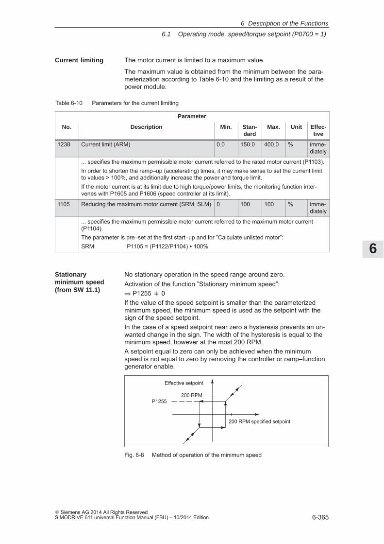
6
6.1 Operating mode, speed/torque setpoint (P0700 = 1)
6-365� Siemens AG 2014 All Rights ReservedSIMODRIVE 611 universal Function Manual (FBU) – 10/2014 Edition
The motor current is limited to a maximum value.
The maximum value is obtained from the minimum between the para-meterization according to Table 6-10 and the limiting as a result of thepower module.
Table 6-10 Parameters for the current limiting
Parameter
No. Description Min. Stan-dard
Max. Unit Effec-tive
1238 Current limit (ARM) 0.0 150.0 400.0 % imme-diately
... specifies the maximum permissible motor current referred to the rated motor current (P1103).In order to shorten the ramp–up (accelerating) times, it may make sense to set the current limitto values > 100%, and additionally increase the power and torque limit.If the motor current is at its limit due to high torque/power limits, the monitoring function inter-venes with P1605 and P1606 (speed controller at its limit).
1105 Reducing the maximum motor current (SRM, SLM) 0 100 100 % imme-diately
... specifies the maximum permissible motor current referred to the maximum motor current(P1104).The parameter is pre–set at the first start–up and for ”Calculate unlisted motor”:SRM: P1105 = (P1122/P1104) � 100%
No stationary operation in the speed range around zero.Activation of the function ”Stationary minimum speed”:⇒ P1255 � 0If the value of the speed setpoint is smaller than the parameterizedminimum speed, the minimum speed is used as the setpoint with thesign of the speed setpoint.In the case of a speed setpoint near zero a hysteresis prevents an un-wanted change in the sign. The width of the hysteresis is equal to theminimum speed, however at the most 200 RPM.A setpoint equal to zero can only be achieved when the minimumspeed is not equal to zero by removing the controller or ramp–functiongenerator enable.
Effective setpoint
200 RPM specified setpoint
P1255200 RPM
Fig. 6-8 Method of operation of the minimum speed
Current limiting
Stationaryminimum speed (from SW 11.1)
6 Description of the Functions
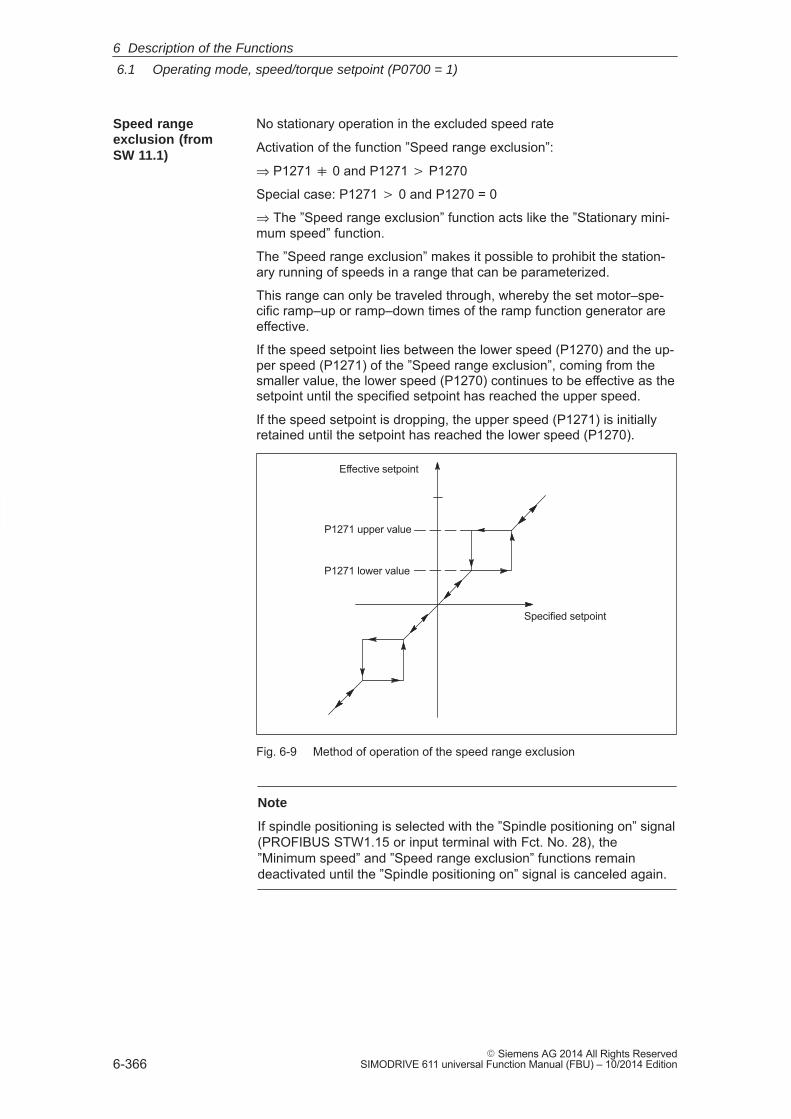
6
6.1 Operating mode, speed/torque setpoint (P0700 = 1)
6-366� Siemens AG 2014 All Rights Reserved
SIMODRIVE 611 universal Function Manual (FBU) – 10/2014 Edition
No stationary operation in the excluded speed rate
Activation of the function ”Speed range exclusion”:
⇒ P1271 � 0 and P1271 � P1270
Special case: P1271 � 0 and P1270 = 0
⇒ The ”Speed range exclusion” function acts like the ”Stationary mini-mum speed” function.
The ”Speed range exclusion” makes it possible to prohibit the station-ary running of speeds in a range that can be parameterized.
This range can only be traveled through, whereby the set motor–spe-cific ramp–up or ramp–down times of the ramp function generator areeffective.
If the speed setpoint lies between the lower speed (P1270) and the up-per speed (P1271) of the ”Speed range exclusion”, coming from thesmaller value, the lower speed (P1270) continues to be effective as thesetpoint until the specified setpoint has reached the upper speed.
If the speed setpoint is dropping, the upper speed (P1271) is initiallyretained until the setpoint has reached the lower speed (P1270).
Effective setpoint
Specified setpoint
P1271 upper value
P1271 lower value
Fig. 6-9 Method of operation of the speed range exclusion
Note
If spindle positioning is selected with the ”Spindle positioning on” signal(PROFIBUS STW1.15 or input terminal with Fct. No. 28), the”Minimum speed” and ”Speed range exclusion” functions remaindeactivated until the ”Spindle positioning on” signal is canceled again.
Speed rangeexclusion (fromSW 11.1)
6 Description of the Functions
6
6.1 Operating mode, speed/torque setpoint (P0700 = 1)
6-367� Siemens AG 2014 All Rights ReservedSIMODRIVE 611 universal Function Manual (FBU) – 10/2014 Edition
6.1.9 Position measuring system with distance–coded reference marks(from SW 4.1)
In order that large distances do not have to be traversed for referencepoint approach, for indirect and direct measuring systems, it is possibleto use a position measuring system with distance–coded referencemarks.
This guarantees that the measuring system has already been refer-enced after a short traversing distance (e.g. 20 mm).
Note
Referencing with distance–coded reference marks is only possibleusing PROFIBUS–DP in an external control (refer to Chapter 5.6.4). Itis not possible to evaluate the coding in the board itself!
From SW 8.3 for rotary encoder systems and from SW 9.2 for linearencoder systems:The SIMODRIVE module is, in the pos mode, in the position toautonomously reference (home) without an external control.
The procedure is the same as when referencing with normal incremen-tal measuring systems.
The following conditions are to be observed:
� Indirect measuring system (motor measuring system, IM)
– P1027.7 = 1 (IM configuration, encoder) ––> distance–coded reference scale
– P1050 or P1051 ––> basic distance between two fixed reference marks
� Direct measuring system (DM)
– P1037.7 = 1 (DM configuration, encoder)––> distance–coded reference scale
– P1052 or P1053 ––> distance–coded reference scale
� Modulo operation (from SW 10.2)
Distance–coded referencing in modulo operation is only possible ifthe following practical, integer number modulo range values apply: n � 360 degrees with n = 1, 2, ...
Any modulo range values are not permitted and would result in fault139 being output.
General
Proceed as follows
6 Description of the Functions
6
6.2 Positioning mode (P0700 = 3, from SW 2.1)
6-368� Siemens AG 2014 All Rights Reserved
SIMODRIVE 611 universal Function Manual (FBU) – 10/2014 Edition
6.2 Positioning mode (P0700 = 3, from SW 2.1)
The following functions are available in the ”positioning” mode:
� Referencing or adjusting– Referencing for incremental positioning measuring systems– Adjusting absolute position measuring systems– Setting the home position
� Programming and selecting traversing blocksThe max. 64 (256, from SW 10.1) traversing blocks per drive can befreely programmed and are saved in the parameters.
– How many blocks can be individually selected via terminals? Drive A + optional TERMINAL module: all 64/256 blocks Drive B: Block 0 or 1 can be selected (1 input terminal)
– How many blocks can be individually selected via PROFIBUS–DP? Drives A and B: all 64/256 blocks
A block contains the following information:– Block number
– Position
– Velocity
– Acceleration override
– Deceleration override
– Command
– Command parameters
– Mode: Block change enable – positioning mode – IDs
When programming a traversing block, the block enable condition isspecified. This means that when starting a block, precisely one blockcan be executed (for a block enable condition END) or automatic, evenfor several blocks (if the block enable condition CONTINUE FLYING,CONTINUE WITH STOP, CONTINUE EXTERNAL).The blocks are executed according to the consecutive block numberup to the block with the block enable condition END.
� Position–related switching signals (cams)Signals are generated and output as a function of the actual positionactual value and parameter setting.
� JoggingThis operating mode allows speed–controlled traversing in the ”posi-tioning” mode. From SW 4.1, the drive can be jogged in the closed–loop position controlled mode (incremental) (refer to Chapter 6.2.9).
� Monitoring functionsDynamic following error monitoring, positioning monitoring, standstillmonitoring, hardware/software limit switches
Generalinformation onpositioning for”SIMODRIVE 611 universal”
6 Description of the Functions
! not 611ue !
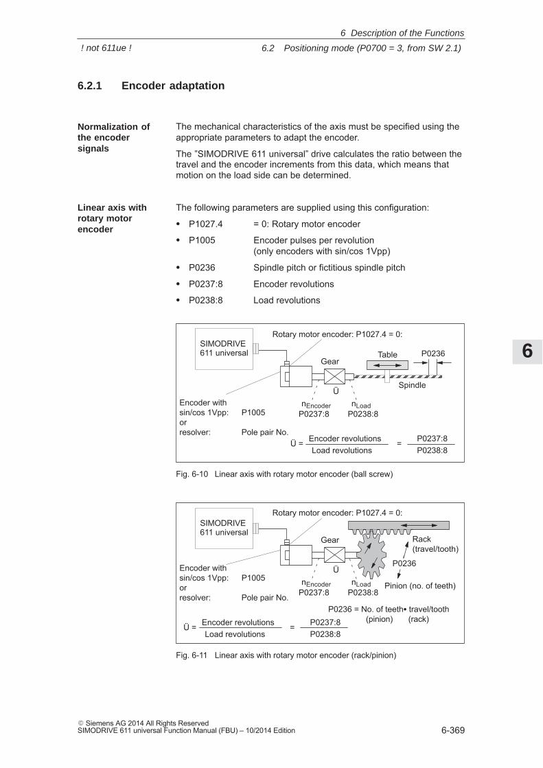
6
6.2 Positioning mode (P0700 = 3, from SW 2.1)
6-369� Siemens AG 2014 All Rights ReservedSIMODRIVE 611 universal Function Manual (FBU) – 10/2014 Edition
6.2.1 Encoder adaptation
The mechanical characteristics of the axis must be specified using theappropriate parameters to adapt the encoder.
The ”SIMODRIVE 611 universal” drive calculates the ratio between thetravel and the encoder increments from this data, which means thatmotion on the load side can be determined.
The following parameters are supplied using this configuration:
� P1027.4 = 0: Rotary motor encoder
� P1005 Encoder pulses per revolution (only encoders with sin/cos 1Vpp)
� P0236 Spindle pitch or fictitious spindle pitch
� P0237:8 Encoder revolutions
� P0238:8 Load revolutions
ÍÍÍÍÍÍÍÍÍÍÍÍÍÍ
Encoder with sin/cos 1Vpp: P1005orresolver: Pole pair No.
Table
Encoder revolutions Ü =Load revolutions
P0237:8P0238:8
=
Gear
nEncoder nLoad
ÜSpindle
P0236
P0237:8 P0238:8
Rotary motor encoder: P1027.4 = 0:SIMODRIVE 611 universal
Fig. 6-10 Linear axis with rotary motor encoder (ball screw)
Encoder with sin/cos 1Vpp: P1005orresolver: Pole pair No.
Encoder revolutions Ü =Load revolutions
P0237:8P0238:8
=
Gear
nEncoder nLoad
Ü
P0237:8 P0238:8
Rotary motor encoder: P1027.4 = 0:
Pinion (no. of teeth)
P0236 = No. of teeth� travel/tooth (pinion) (rack)
P0236
Rack(travel/tooth)
SIMODRIVE 611 universal
Fig. 6-11 Linear axis with rotary motor encoder (rack/pinion)
Normalization ofthe encodersignals
Linear axis withrotary motorencoder
6 Description of the Functions
! not 611ue !
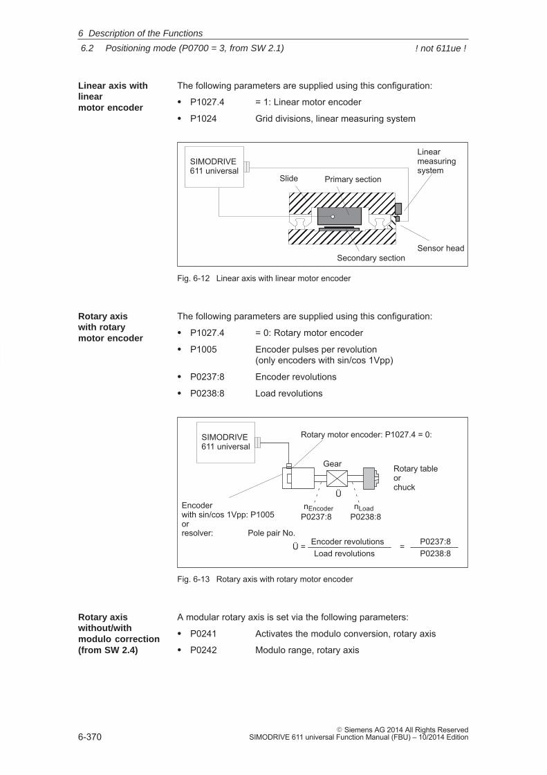
6
6.2 Positioning mode (P0700 = 3, from SW 2.1)
6-370� Siemens AG 2014 All Rights Reserved
SIMODRIVE 611 universal Function Manual (FBU) – 10/2014 Edition
The following parameters are supplied using this configuration:
� P1027.4 = 1: Linear motor encoder
� P1024 Grid divisions, linear measuring system
SIMODRIVE 611 universal
ÏÏÏÏÏÏÏÏÏÏÏÏÏÏÏÏÏÏÏÏÏÏÏÏÏÏÏÏÏÏÏÏÏÏÏÏÏÏÏÏ
ÎÎ
Slide Primary section
Secondary section
Linearmeasuringsystem
Sensor head
Fig. 6-12 Linear axis with linear motor encoder
The following parameters are supplied using this configuration:
� P1027.4 = 0: Rotary motor encoder
� P1005 Encoder pulses per revolution (only encoders with sin/cos 1Vpp)
� P0237:8 Encoder revolutions
� P0238:8 Load revolutions
SIMODRIVE 611 universal
Encoderwith sin/cos 1Vpp: P1005orresolver: Pole pair No.
Encoder revolutions Ü =Load revolutions
P0237:8P0238:8
=
Gear
nEncoder nLoad
Ü
P0237:8 P0238:8
Rotary tableor chuck
Rotary motor encoder: P1027.4 = 0:
Fig. 6-13 Rotary axis with rotary motor encoder
A modular rotary axis is set via the following parameters:
� P0241 Activates the modulo conversion, rotary axis
� P0242 Modulo range, rotary axis
Linear axis withlinearmotor encoder
Rotary axis with rotary motor encoder
Rotary axiswithout/withmodulo correction(from SW 2.4)
6 Description of the Functions
! not 611ue !
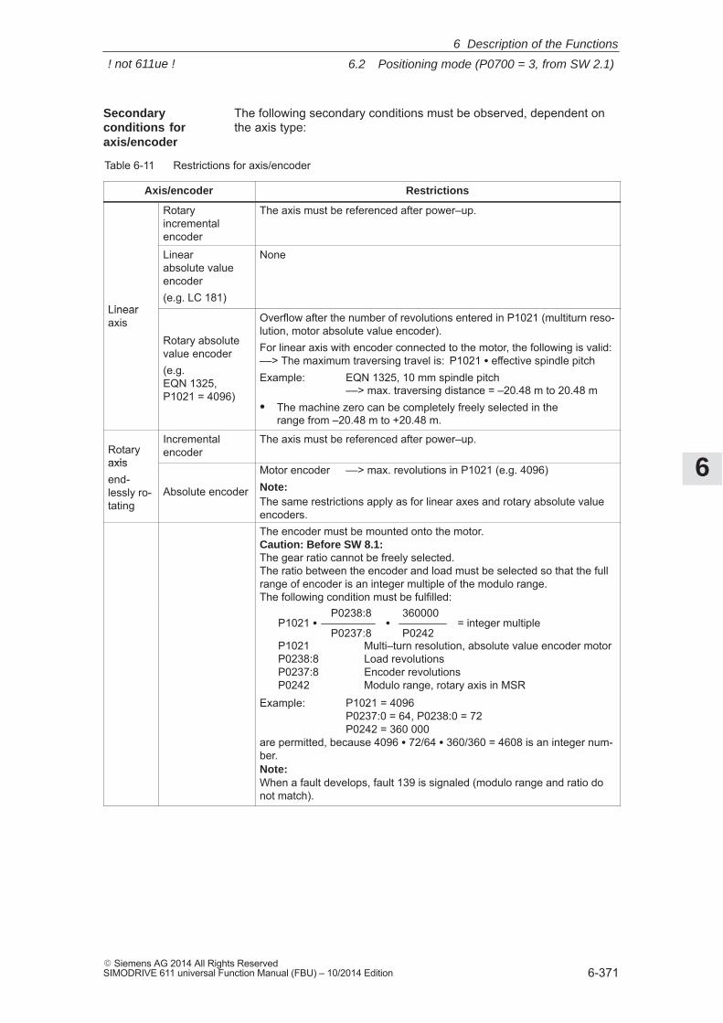
6
6.2 Positioning mode (P0700 = 3, from SW 2.1)
6-371� Siemens AG 2014 All Rights ReservedSIMODRIVE 611 universal Function Manual (FBU) – 10/2014 Edition
The following secondary conditions must be observed, dependent onthe axis type:
Table 6-11 Restrictions for axis/encoder
Axis/encoder Restrictions
Rotary incrementalencoder
The axis must be referenced after power–up.
Linear
Linear absolute valueencoder(e.g. LC 181)
None
Linearaxis
Rotary absolutevalue encoder(e.g. EQN 1325, P1021 = 4096)
Overflow after the number of revolutions entered in P1021 (multiturn reso-lution, motor absolute value encoder).For linear axis with encoder connected to the motor, the following is valid:––> The maximum traversing travel is: P1021 � effective spindle pitchExample: EQN 1325, 10 mm spindle pitch ––> max. traversing distance = –20.48 m to 20.48 m� The machine zero can be completely freely selected in the
range from –20.48 m to +20.48 m.
Rotaryaxis
Incrementalencoder
The axis must be referenced after power–up.
axisend-lessly ro-tating
Absolute encoder
Motor encoder ––> max. revolutions in P1021 (e.g. 4096)Note:The same restrictions apply as for linear axes and rotary absolute valueencoders.The encoder must be mounted onto the motor.Caution: Before SW 8.1:The gear ratio cannot be freely selected.The ratio between the encoder and load must be selected so that the fullrange of encoder is an integer multiple of the modulo range.The following condition must be fulfilled:
P1021 �P0238:8
P0237:8
360000
P0242�
P1021 Multi–turn resolution, absolute value encoder motorP0238:8 Load revolutionsP0237:8 Encoder revolutionsP0242 Modulo range, rotary axis in MSR
= integer multiple
Example: P1021 = 4096P0237:0 = 64, P0238:0 = 72 P0242 = 360 000
are permitted, because 4096 � 72/64 � 360/360 = 4608 is an integer num-ber.Note:When a fault develops, fault 139 is signaled (modulo range and ratio donot match).
Secondaryconditions foraxis/encoder
6 Description of the Functions
! not 611ue !
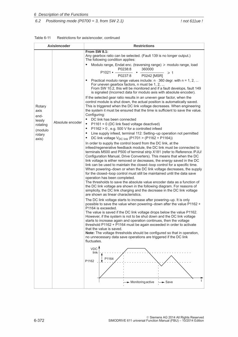
6
6.2 Positioning mode (P0700 = 3, from SW 2.1)
6-372� Siemens AG 2014 All Rights Reserved
SIMODRIVE 611 universal Function Manual (FBU) – 10/2014 Edition
Table 6-11 Restrictions for axis/encoder, continued
Axis/encoder Restrictions
Rotaryaxisend-lesslyrotating(modulorotaryaxis)
Absolute encoder
From SW 8.1:Any gearbox ratio can be selected. (Fault 139 is no longer output.)The following condition applies:� Modulo range, Endat enc. (traversing range) � modulo range, load
� Practical modulo range values include: n � 360 degr. with n = 1, 2, ...For uneven gearbox factors, n must be 1, 2, ...From SW 10.2, this will be monitored and if a fault develops, fault 149is signaled (Incorrect data for modulo axis with absolute encoder).
If the selected gear ratio results in an uneven gear factor, when thecontrol module is shut down, the actual position is automatically saved.This is triggered when the DC link voltage decreases. When engineeringthe system it must be ensured that the time is sufficient to save the value.Configuring:� DC link has been connected� P1161 = 0 (DC link fixed voltage deactived)� P1162 > 0 , e.g. 500 V for a controlled infeed� Line supply infeed, terminal 112: Setting–up operation not permitted� DC link voltage VDC link (P1701 > (P1162 + P1164))In order to supply the control board from the DC link, at theinfeed/regenerative feedback module, the DC link must be connected toterminals M500 and P500 of terminal strip X181 (refer to Reference /PJU/Configuration Manual, Drive Converters). This means that when the DClink voltage is either removed or decreases, the energy saved in the DClink can be used to maintain the closed–loop control for a specific time.When powering–down or when the DC link voltage decreases, the supply
P1021 �P0238:8
P0237:8
360000
P0242 [MSR]� � 1
t
P1164
VDClink
P1162
Monitoring active Save
When powering–down or when the DC link voltage decreases, the supplyfor the closed–loop control must still be maintained until the data saveoperation has been completed.The thresholds to save the absolute value encoder data as a function ofthe DC link voltage are shown in the following diagram. For reasons ofsimplicity, the DC link charging and the decrease in the DC link voltageare shown as linear characteristics.The DC link voltage starts to increase after powering–up. It is onlypossible to save the value when powering–down after the value P1162 +P1164 is exceeded.The value is saved if the DC link voltage drops below the value P1162.However, if the system is not to be shut down and the DC link voltagestarts to increase again and operation continues, then the voltagethreshold P1162 + P1164 must be again exceeded in order to activatethat the value is saved.Note: The voltage thresholds should be configured so that in operation,no unnecessary data save operations are triggered if the DC linkfluctuates.
6 Description of the Functions
! not 611ue !
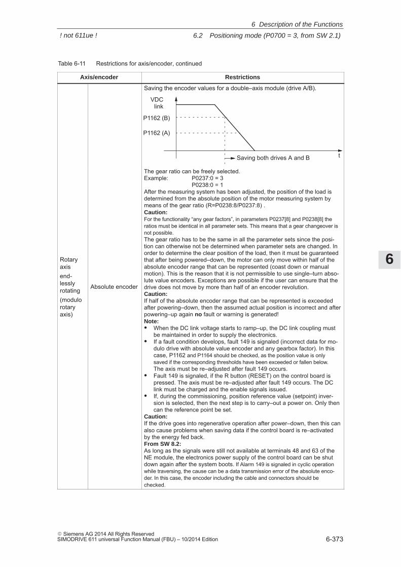
6
6.2 Positioning mode (P0700 = 3, from SW 2.1)
6-373� Siemens AG 2014 All Rights ReservedSIMODRIVE 611 universal Function Manual (FBU) – 10/2014 Edition
Table 6-11 Restrictions for axis/encoder, continued
Axis/encoder Restrictions
t
VDClink
P1162 (B)
Saving both drives A and B
Saving the encoder values for a double–axis module (drive A/B).
P1162 (A)
Rotaryaxisend-lesslyrotating(modulorotaryaxis)
Absolute encoder
The gear ratio can be freely selected.Example: P0237:0 = 3
P0238:0 = 1After the measuring system has been adjusted, the position of the load isdetermined from the absolute position of the motor measuring system bymeans of the gear ratio (R=P0238:8/P0237:8) .Caution:For the functionality “any gear factors”, in parameters P0237[8] and P0238[8] theratios must be identical in all parameter sets. This means that a gear changeover isnot possible. The gear ratio has to be the same in all the parameter sets since the posi-tion can otherwise not be determined when parameter sets are changed. Inorder to determine the clear position of the load, then it must be guaranteedthat after being powered–down, the motor can only move within half of theabsolute encoder range that can be represented (coast down or manualmotion). This is the reason that it is not permissible to use single–turn abso-lute value encoders. Exceptions are possible if the user can ensure that thedrive does not move by more than half of an encoder revolution.Caution:If half of the absolute encoder range that can be represented is exceededafter powering–down, then the assumed actual position is incorrect and afterpowering–up again no fault or warning is generated!Note:� When the DC link voltage starts to ramp–up, the DC link coupling must
be maintained in order to supply the electronics.� If a fault condition develops, fault 149 is signaled (incorrect data for mo-
dulo drive with absolute value encoder and any gearbox factor). In thiscase, P1162 and P1164 should be checked, as the position value is onlysaved if the corresponding thresholds have been exceeded or fallen below.The axis must be re–adjusted after fault 149 occurs.
� Fault 149 is signaled, if the R button (RESET) on the control board ispressed. The axis must be re–adjusted after fault 149 occurs. The DClink must be charged and the enable signals issued.
� If, during the commissioning, position reference value (setpoint) inver-sion is selected, then the next step is to carry–out a power on. Only thencan the reference point be set.
Caution:If the drive goes into regenerative operation after power–down, then this canalso cause problems when saving data if the control board is re–activatedby the energy fed back.From SW 8.2:As long as the signals were still not available at terminals 48 and 63 of theNE module, the electronics power supply of the control board can be shutdown again after the system boots. If Alarm 149 is signaled in cyclic operationwhile traversing, the cause can be a data transmission error of the absolute enco-der. In this case, the encoder including the cable and connectors should bechecked.
6 Description of the Functions
! not 611ue !
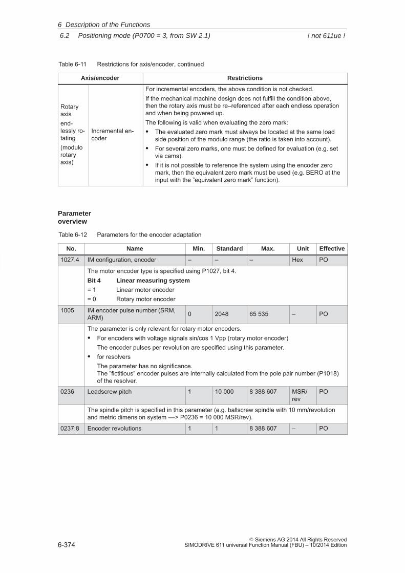
6
6.2 Positioning mode (P0700 = 3, from SW 2.1)
6-374� Siemens AG 2014 All Rights Reserved
SIMODRIVE 611 universal Function Manual (FBU) – 10/2014 Edition
Table 6-11 Restrictions for axis/encoder, continued
Axis/encoder Restrictions
Rotaryaxisend-lessly ro-tating(modulorotaryaxis)
Incremental en-coder
For incremental encoders, the above condition is not checked.If the mechanical machine design does not fulfill the condition above,then the rotary axis must be re–referenced after each endless operationand when being powered up.The following is valid when evaluating the zero mark:� The evaluated zero mark must always be located at the same load
side position of the modulo range (the ratio is taken into account).� For several zero marks, one must be defined for evaluation (e.g. set
via cams).� If it is not possible to reference the system using the encoder zero
mark, then the equivalent zero mark must be used (e.g. BERO at theinput with the ”equivalent zero mark” function).
Table 6-12 Parameters for the encoder adaptation
No. Name Min. Standard Max. Unit Effective
1027.4 IM configuration, encoder – – – Hex PO
The motor encoder type is specified using P1027, bit 4.Bit 4 Linear measuring system
= 1 Linear motor encoder= 0 Rotary motor encoder
1005 IM encoder pulse number (SRM,ARM) 0 2048 65 535 – PO
The parameter is only relevant for rotary motor encoders.� For encoders with voltage signals sin/cos 1 Vpp (rotary motor encoder)
The encoder pulses per revolution are specified using this parameter.� for resolvers
The parameter has no significance. The ”fictitious” encoder pulses are internally calculated from the pole pair number (P1018)of the resolver.
0236 Leadscrew pitch 1 10 000 8 388 607 MSR/rev
PO
The spindle pitch is specified in this parameter (e.g. ballscrew spindle with 10 mm/revolutionand metric dimension system ––> P0236 = 10 000 MSR/rev).
0237:8 Encoder revolutions 1 1 8 388 607 – PO
Parameter overview
6 Description of the Functions
! not 611ue !
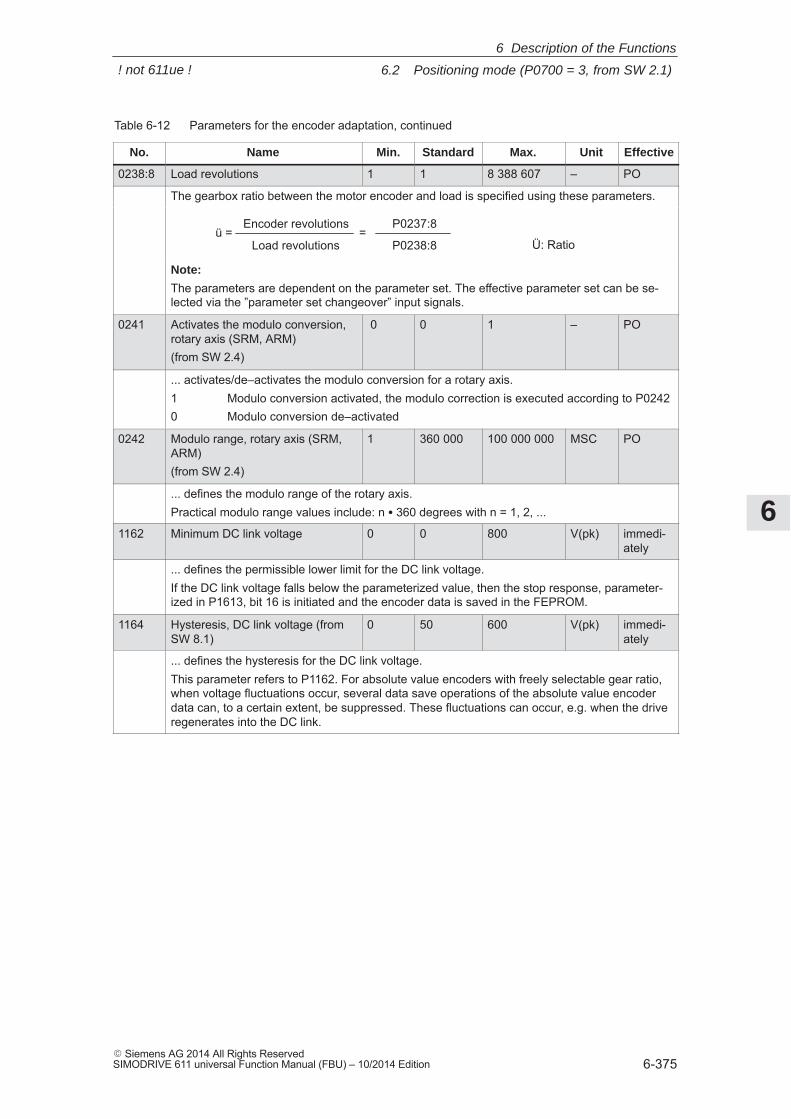
6
6.2 Positioning mode (P0700 = 3, from SW 2.1)
6-375� Siemens AG 2014 All Rights ReservedSIMODRIVE 611 universal Function Manual (FBU) – 10/2014 Edition
Table 6-12 Parameters for the encoder adaptation, continued
No. EffectiveUnitMax.StandardMin.Name
0238:8 Load revolutions 1 1 8 388 607 – PO
The gearbox ratio between the motor encoder and load is specified using these parameters.
ü = =Encoder revolutions
Load revolutions
P0237:8
P0238:8 Ü: Ratio
Note:
The parameters are dependent on the parameter set. The effective parameter set can be se-lected via the ”parameter set changeover” input signals.
0241 Activates the modulo conversion,rotary axis (SRM, ARM)(from SW 2.4)
0 0 1 – PO
... activates/de–activates the modulo conversion for a rotary axis.1 Modulo conversion activated, the modulo correction is executed according to P02420 Modulo conversion de–activated
0242 Modulo range, rotary axis (SRM,ARM)(from SW 2.4)
1 360 000 100 000 000 MSC PO
... defines the modulo range of the rotary axis.Practical modulo range values include: n � 360 degrees with n = 1, 2, ...
1162 Minimum DC link voltage 0 0 800 V(pk) immedi-ately
... defines the permissible lower limit for the DC link voltage.If the DC link voltage falls below the parameterized value, then the stop response, parameter-ized in P1613, bit 16 is initiated and the encoder data is saved in the FEPROM.
1164 Hysteresis, DC link voltage (fromSW 8.1)
0 50 600 V(pk) immedi-ately
... defines the hysteresis for the DC link voltage.This parameter refers to P1162. For absolute value encoders with freely selectable gear ratio,when voltage fluctuations occur, several data save operations of the absolute value encoderdata can, to a certain extent, be suppressed. These fluctuations can occur, e.g. when the driveregenerates into the DC link.
6 Description of the Functions
! not 611ue !
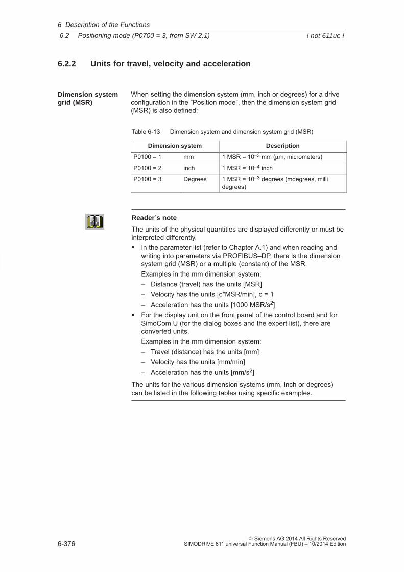
6
6.2 Positioning mode (P0700 = 3, from SW 2.1)
6-376� Siemens AG 2014 All Rights Reserved
SIMODRIVE 611 universal Function Manual (FBU) – 10/2014 Edition
6.2.2 Units for travel, velocity and acceleration
When setting the dimension system (mm, inch or degrees) for a driveconfiguration in the ”Position mode”, then the dimension system grid(MSR) is also defined:
Table 6-13 Dimension system and dimension system grid (MSR)
Dimension system Description
P0100 = 1 mm 1 MSR = 10–3 mm (μm, micrometers)
P0100 = 2 inch 1 MSR = 10–4 inch
P0100 = 3 Degrees 1 MSR = 10–3 degrees (mdegrees, millidegrees)
Reader’s note
The units of the physical quantities are displayed differently or must beinterpreted differently.� In the parameter list (refer to Chapter A.1) and when reading and
writing into parameters via PROFIBUS–DP, there is the dimensionsystem grid (MSR) or a multiple (constant) of the MSR.Examples in the mm dimension system:– Distance (travel) has the units [MSR]– Velocity has the units [c*MSR/min], c = 1– Acceleration has the units [1000 MSR/s2]
� For the display unit on the front panel of the control board and forSimoCom U (for the dialog boxes and the expert list), there areconverted units.Examples in the mm dimension system:– Travel (distance) has the units [mm]– Velocity has the units [mm/min]– Acceleration has the units [mm/s2]
The units for the various dimension systems (mm, inch or degrees)can be listed in the following tables using specific examples.
Dimension systemgrid (MSR)
6 Description of the Functions
! not 611ue !
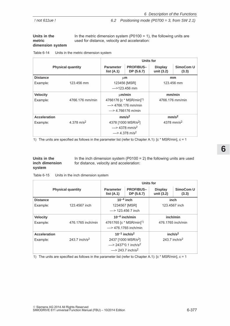
6
6.2 Positioning mode (P0700 = 3, from SW 2.1)
6-377� Siemens AG 2014 All Rights ReservedSIMODRIVE 611 universal Function Manual (FBU) – 10/2014 Edition
In the metric dimension system (P0100 = 1), the following units areused for distance, velocity and acceleration:
Table 6-14 Units in the metric dimension system
Units for
Physical quantity Parameterlist (A.1)
PROFIBUS–DP (5.6.7)
Displayunit (3.2)
SimoCom U(3.3)
Distance
Example: 123.456 mmμm
123456 [MSR]––>123.456 mm
mm
123.456 mm
Velocity
Example: 4766.176 mm/minμm/min
4766176 [c * MSR/min]1)
––> 4766.176 mm/min––> 4.766176 m/min
mm/min
4766.176 mm/min
Acceleration
Example: 4.378 m/s2mm/s2
4378 [1000 MSR/s2]––> 4378 mm/s2
––> 4.378 m/s2
mm/s2
4378 mm/s2
1) The units are specified as follows in the parameter list (refer to Chapter A.1): [c * MSR/min], c = 1
In the inch dimension system (P0100 = 2) the following units are usedfor distance, velocity and acceleration:
Table 6-15 Units in the inch dimension system
Units for
Physical quantity Parameterlist (A.1)
PROFIBUS–DP (5.6.7)
Displayunit (3.2)
SimoCom U(3.3)
Distance
Example: 123.4567 inch10–4 inch
1234567 [MSR]––> 123.456 7 inch
inch
123.4567 inch
Velocity
Example: 476.1765 inch/min10–4 inch/min
4761765 [c * MSR/min]1)
––> 476.1765 inch/min
inch/min
476.1765 inch/min
Acceleration
Example: 243.7 inch/s210–1 inch/s2
2437 [1000 MSR/s2]––> 2437*0.1 inch/s2
––> 243.7 inch/s2
inch/s2
243.7 inch/s2
1) The units are specified as follows in the parameter list (refer to Chapter A.1): [c * MSR/min], c = 1
Units in themetricdimension system
Units in theinch dimensionsystem
6 Description of the Functions
! not 611ue !
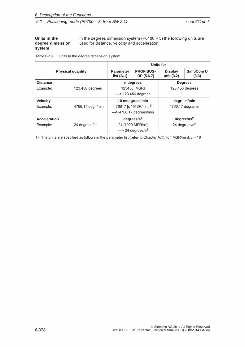
6
6.2 Positioning mode (P0700 = 3, from SW 2.1)
6-378� Siemens AG 2014 All Rights Reserved
SIMODRIVE 611 universal Function Manual (FBU) – 10/2014 Edition
In the degrees dimension system (P0100 = 3) the following units areused for distance, velocity and acceleration:
Table 6-16 Units in the degree dimension system
Units for
Physical quantity Parameterlist (A.1)
PROFIBUS–DP (5.6.7)
Displayunit (3.2)
SimoCom U(3.3)
Distance
Example: 123.456 degreesmdegrees
123456 [MSR]––> 123.456 degrees
Degrees
123.456 degrees
Velocity
Example: 4766.17 degr./min10 mdegrees/min
476617 [c * MSR/min]1)
––> 4766.17 degrees/min
degrees/min
4766.17 degr./min
Acceleration
Example: 24 degrees/s2degrees/s2
24 [1000 MSR/s2]––> 24 degrees/s2
degrees/s2
24 degrees/s2
1) The units are specified as follows in the parameter list (refer to Chapter A.1): [c * MSR/min], c = 10
Units in thedegree dimensionsystem
6 Description of the Functions
! not 611ue !
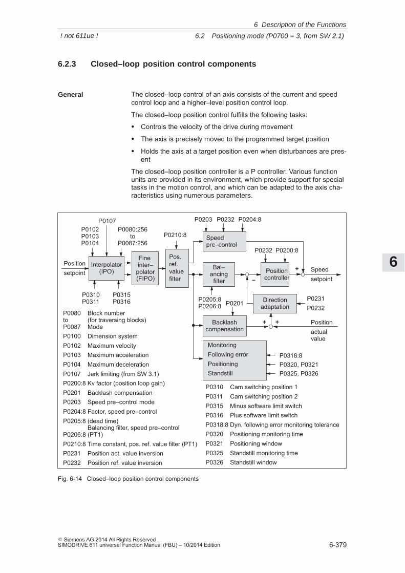
6
6.2 Positioning mode (P0700 = 3, from SW 2.1)
6-379� Siemens AG 2014 All Rights ReservedSIMODRIVE 611 universal Function Manual (FBU) – 10/2014 Edition
6.2.3 Closed–loop position control components
The closed–loop control of an axis consists of the current and speedcontrol loop and a higher–level position control loop.
The closed–loop position control fulfills the following tasks:
� Controls the velocity of the drive during movement
� The axis is precisely moved to the programmed target position
� Holds the axis at a target position even when disturbances are pres-ent
The closed–loop position controller is a P controller. Various functionunits are provided in its environment, which provide support for specialtasks in the motion control, and which can be adapted to the axis cha-racteristics using numerous parameters.
Positionsetpoint
MonitoringFollowing errorPositioningStandstill
Speedsetpoint
Positionactualvalue
P0080 Block numberto (for traversing blocks)P0087 ModeP0100 Dimension systemP0102 Maximum velocityP0103 Maximum accelerationP0104 Maximum decelerationP0107 Jerk limiting (from SW 3.1)P0200:8 Kv factor (position loop gain)P0201 Backlash compensationP0203 Speed pre–control modeP0204:8 Factor, speed pre–controlP0205:8 (dead time)
Balancing filter, speed pre–controlP0206:8 (PT1)P0210:8 Time constant, pos. ref. value filter (PT1)P0231 Position act. value inversionP0232 Position ref. value inversion
P0203 P0204:8
P0200:8
P0310 Cam switching position 1P0311 Cam switching position 2P0315 Minus software limit switchP0316 Plus software limit switchP0318:8 Dyn. following error monitoring toleranceP0320 Positioning monitoring timeP0321 Positioning windowP0325 Standstill monitoring timeP0326 Standstill window
P0310P0311
P0102P0103P0104
P0315P0316
P0080:256to
P0087:256
Fine inter–
polator(FIPO)
Positioncontroller
Backlashcompensation
Directionadaptation
P0231P0232
P0201
+ +
+
–
P0320, P0321P0325, P0326
P0318:8
P0232
P0232
P0205:8P0206:8
Interpolator(IPO)
Pos.ref.valuefilter
P0210:8 Speedpre–control
Bal–ancing
filter
P0107
Fig. 6-14 Closed–loop position control components
General
6 Description of the Functions
! not 611ue !
6
6.2 Positioning mode (P0700 = 3, from SW 2.1)
6-380� Siemens AG 2014 All Rights Reserved
SIMODRIVE 611 universal Function Manual (FBU) – 10/2014 Edition
The units of an axis are defined using the dimension system setting.
Note
� In the following text, the dimension system grid (MSR) term is usedas unit of the selected dimension system.– The following is valid depending on P0100:
1 MSR = 10–3 mm or 10–4 inch or 10–3 degrees– Example: Assumption P0100 = 1 ––> 103 MSR = 1 mm
� The dimension system is selected depending on the axis type(linear axis, rotary axis), i.e. for a rotary axis, the dimension system10–3 degrees must be parameterized.
� The dimension system setting must be specified when”SIMODRIVE 611 universal” is commissioned for the first time.
Recommendation: Carry–out the first start–up using the ”correct” dimension system, sothat it isn’t necessary to later changeover (refer to the following warninginformation).
If, after ”SIMODRIVE 611 universal” has been first commissioned, it isstill necessary to changeover the dimension system setting from mm toinch, then the following steps must be executed:
1. Enter the required dimension system into P0100
2. Carry out a POWER ON
During run–up, it is identified, that P0100 � P0101 and automati-cally, all of the parameters, dependent on the dimension system (re-fer to Chapter A.1) are converted corresponding to the setting inP0100.
Parameters that are dependent on the dimension system have thefollowing units:
– MSC
– k * MSR/min
– 1 000 MSR/s
– 1 000 MSR/s2
– 1 000 MSR/s3
– MSR/rev
Example:If 254 [mm] is located in P0081:4 and a changeover is made frommetric to inch (imperial units), then afterwards, 10 [inch] is located inP0081:4.
Dimension systemsettingP0100
Dimension systemchangeovermm <–> inch
6 Description of the Functions
! not 611ue !
6
6.2 Positioning mode (P0700 = 3, from SW 2.1)
6-381� Siemens AG 2014 All Rights ReservedSIMODRIVE 611 universal Function Manual (FBU) – 10/2014 Edition
!Warning
Although it is possible to subsequently change over the dimensionsystem, we recommend that you do not do this:
When subsequently changing–over the dimension system from mm toinch, data, dependent on the dimension system, is converted, wherebyrounding–off errors can occur and value limits can be violated.
The conversion is not made when changing between a rotary axis(degrees) and linear axis (mm/inch).
Table 6-17 Parameters for the dimension system setting and changeover
No. Name Min. Standard Max. Unit Effective
0100 Dimension system 1 1 3 – PO
... specifies the dimension system grid (MSR) which is being used.= 1 ––> 1 MSR = 10–3 mm used for linear axes in the metric system= 2 ––> 1 MSR = 10–4 mm used for linear axes in the inch (imperial) system= 3 ––> 1 MSR = 10–3 degrees used for rotary axesExample:
P0100 = 1 ––> 345 123 MSR = 345.123 mm
0101 Actual dimension system – – – – RO
... indicates the currently active dimension system.Note:
If it is identified at POWER ON that P0100 � is P0101, then a dimension system changeover isautomatically made.
6 Description of the Functions
! not 611ue !
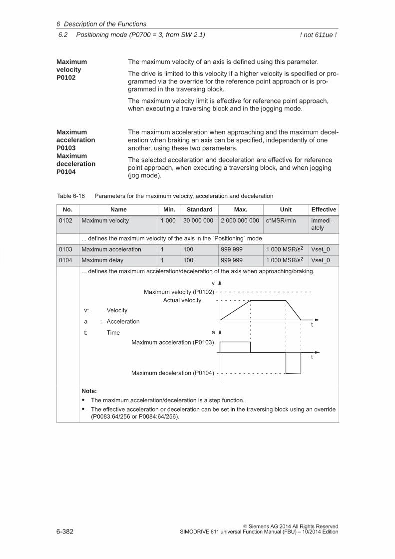
6
6.2 Positioning mode (P0700 = 3, from SW 2.1)
6-382� Siemens AG 2014 All Rights Reserved
SIMODRIVE 611 universal Function Manual (FBU) – 10/2014 Edition
The maximum velocity of an axis is defined using this parameter.
The drive is limited to this velocity if a higher velocity is specified or pro-grammed via the override for the reference point approach or is pro-grammed in the traversing block.
The maximum velocity limit is effective for reference point approach,when executing a traversing block and in the jogging mode.
The maximum acceleration when approaching and the maximum decel-eration when braking an axis can be specified, independently of oneanother, using these two parameters.
The selected acceleration and deceleration are effective for referencepoint approach, when executing a traversing block, and when jogging(jog mode).
Table 6-18 Parameters for the maximum velocity, acceleration and deceleration
No. Name Min. Standard Max. Unit Effective
0102 Maximum velocity 1 000 30 000 000 2 000 000 000 c*MSR/min immedi-ately
... defines the maximum velocity of the axis in the ”Positioning” mode.
0103 Maximum acceleration 1 100 999 999 1 000 MSR/s2 Vset_0
0104 Maximum delay 1 100 999 999 1 000 MSR/s2 Vset_0
... defines the maximum acceleration/deceleration of the axis when approaching/braking.
v
a
Maximum acceleration (P0103)
t
t
Maximum deceleration (P0104)
Actual velocityMaximum velocity (P0102)
v: Velocity
a : Acceleration
t: Time
Note:
� The maximum acceleration/deceleration is a step function.� The effective acceleration or deceleration can be set in the traversing block using an override
(P0083:64/256 or P0084:64/256).
MaximumvelocityP0102
MaximumaccelerationP0103 MaximumdecelerationP0104
6 Description of the Functions
! not 611ue !
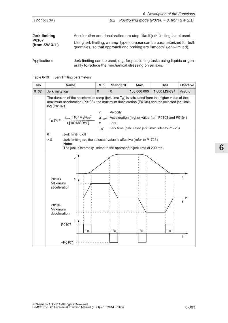
6
6.2 Positioning mode (P0700 = 3, from SW 2.1)
6-383� Siemens AG 2014 All Rights ReservedSIMODRIVE 611 universal Function Manual (FBU) – 10/2014 Edition
Acceleration and deceleration are step–like if jerk limiting is not used.
Using jerk limiting, a ramp–type increase can be parameterized for bothquantities, so that approach and braking are ”smooth” (jerk–limited).
Jerk limiting can be used, e.g. for positioning tasks using liquids or gen-erally to reduce the mechanical stressing on an axis.
Table 6-19 Jerk limiting parameters
No. Name Min. Standard Max. Unit Effective
0107 Jerk limitation 0 0 100 000 000 1 000 MSR/s3 Vset_0
The duration of the acceleration ramp (jerk time TR) is calculated from the higher value of themaximum acceleration (P0103), the maximum deceleration (P0104) and the selected jerk limit-ing (P0107).
v: Velocityamax: Acceleration (higher value from P0103 and P0104)r: JerkTR: Jerk time (calculated jerk time: refer to P1726)
TR [s] =amax [103 MSR/s2]
r [103 MSR/s3]
0 Jerk limiting off> 0 Jerk limiting on, the selected value is effective (refer to P1726)
Note: The jerk is internally limited to the appropriate jerk time of 200 ms.
t
P0107
–P0107
P0103Maximumacceleration
P0104Maximumdeceleration
v
a
r
t
t
TR TR TR TR
Jerk limitingP0107 (from SW 3.1 )
Applications
6 Description of the Functions
! not 611ue !
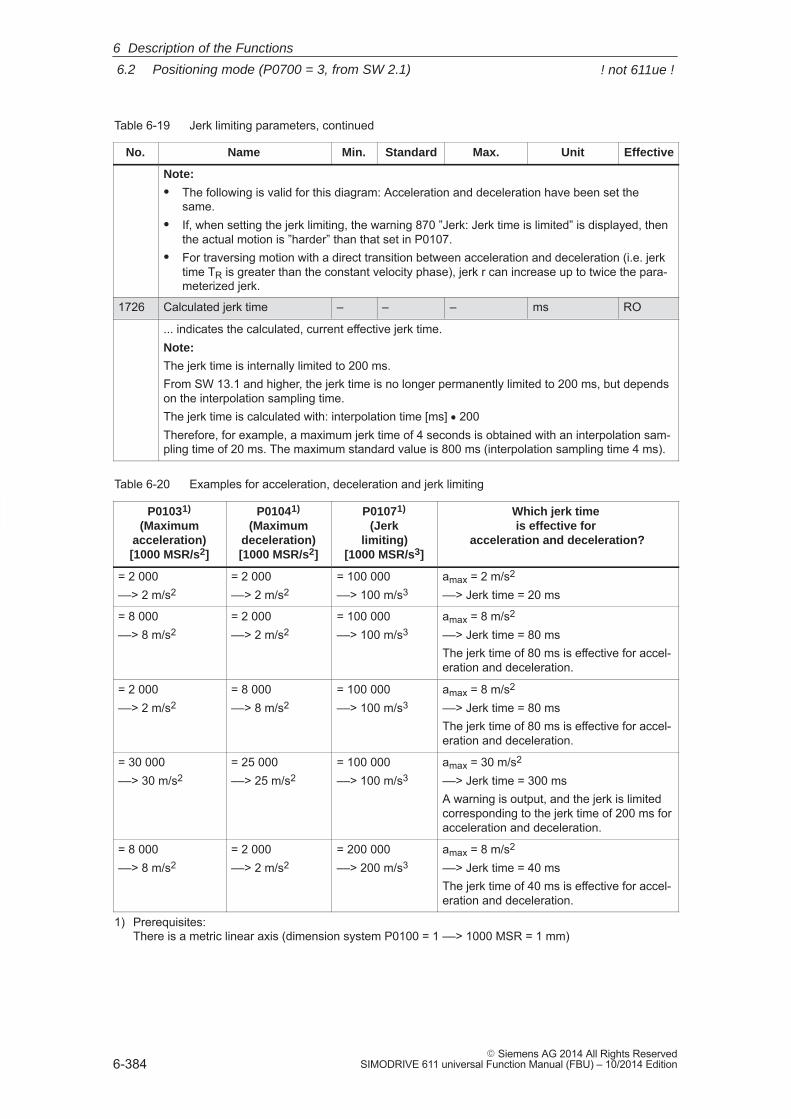
6
6.2 Positioning mode (P0700 = 3, from SW 2.1)
6-384� Siemens AG 2014 All Rights Reserved
SIMODRIVE 611 universal Function Manual (FBU) – 10/2014 Edition
Table 6-19 Jerk limiting parameters, continued
No. EffectiveUnitMax.StandardMin.Name
Note:
� The following is valid for this diagram: Acceleration and deceleration have been set thesame.
� If, when setting the jerk limiting, the warning 870 ”Jerk: Jerk time is limited” is displayed, thenthe actual motion is ”harder” than that set in P0107.
� For traversing motion with a direct transition between acceleration and deceleration (i.e. jerktime TR is greater than the constant velocity phase), jerk r can increase up to twice the para-meterized jerk.
1726 Calculated jerk time – – – ms RO
... indicates the calculated, current effective jerk time.Note:
The jerk time is internally limited to 200 ms.From SW 13.1 and higher, the jerk time is no longer permanently limited to 200 ms, but dependson the interpolation sampling time.The jerk time is calculated with: interpolation time [ms] � 200Therefore, for example, a maximum jerk time of 4 seconds is obtained with an interpolation sam-pling time of 20 ms. The maximum standard value is 800 ms (interpolation sampling time 4 ms).
Table 6-20 Examples for acceleration, deceleration and jerk limiting
P01031)
(Maximumacceleration)[1000 MSR/s2]
P01041)
(Maximumdeceleration)[1000 MSR/s2]
P01071)
(Jerklimiting)
[1000 MSR/s3]
Which jerk time is effective for
acceleration and deceleration?
= 2 000––> 2 m/s2
= 2 000––> 2 m/s2
= 100 000––> 100 m/s3
amax = 2 m/s2
––> Jerk time = 20 ms
= 8 000––> 8 m/s2
= 2 000––> 2 m/s2
= 100 000––> 100 m/s3
amax = 8 m/s2
––> Jerk time = 80 msThe jerk time of 80 ms is effective for accel-eration and deceleration.
= 2 000––> 2 m/s2
= 8 000––> 8 m/s2
= 100 000––> 100 m/s3
amax = 8 m/s2
––> Jerk time = 80 msThe jerk time of 80 ms is effective for accel-eration and deceleration.
= 30 000––> 30 m/s2
= 25 000––> 25 m/s2
= 100 000––> 100 m/s3
amax = 30 m/s2
––> Jerk time = 300 msA warning is output, and the jerk is limitedcorresponding to the jerk time of 200 ms foracceleration and deceleration.
= 8 000––> 8 m/s2
= 2 000––> 2 m/s2
= 200 000––> 200 m/s3
amax = 8 m/s2
––> Jerk time = 40 msThe jerk time of 40 ms is effective for accel-eration and deceleration.
1) Prerequisites: There is a metric linear axis (dimension system P0100 = 1 ––> 1000 MSR = 1 mm)
6 Description of the Functions
! not 611ue !
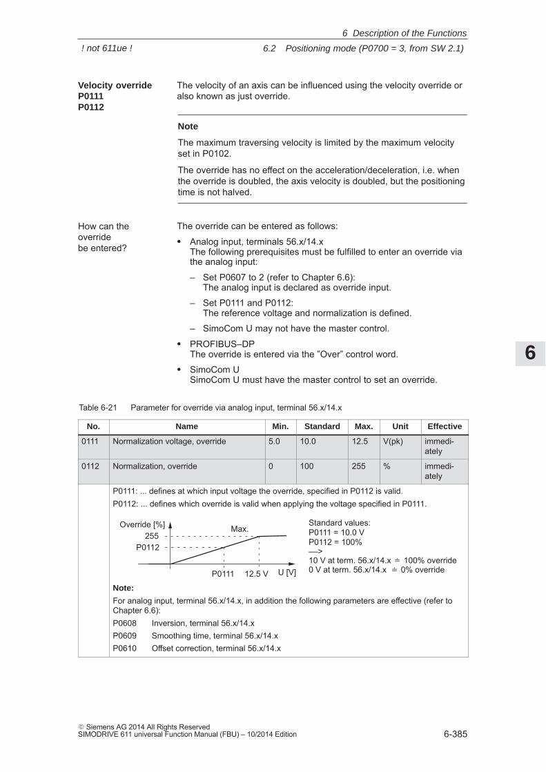
6
6.2 Positioning mode (P0700 = 3, from SW 2.1)
6-385� Siemens AG 2014 All Rights ReservedSIMODRIVE 611 universal Function Manual (FBU) – 10/2014 Edition
The velocity of an axis can be influenced using the velocity override oralso known as just override.
Note
The maximum traversing velocity is limited by the maximum velocityset in P0102.
The override has no effect on the acceleration/deceleration, i.e. whenthe override is doubled, the axis velocity is doubled, but the positioningtime is not halved.
The override can be entered as follows:
� Analog input, terminals 56.x/14.xThe following prerequisites must be fulfilled to enter an override viathe analog input:
– Set P0607 to 2 (refer to Chapter 6.6): The analog input is declared as override input.
– Set P0111 and P0112: The reference voltage and normalization is defined.
– SimoCom U may not have the master control.
� PROFIBUS–DPThe override is entered via the ”Over” control word.
� SimoCom USimoCom U must have the master control to set an override.
Table 6-21 Parameter for override via analog input, terminal 56.x/14.x
No. Name Min. Standard Max. Unit Effective
0111 Normalization voltage, override 5.0 10.0 12.5 V(pk) immedi-ately
0112 Normalization, override 0 100 255 % immedi-ately
P0111: ... defines at which input voltage the override, specified in P0112 is valid.P0112: ... defines which override is valid when applying the voltage specified in P0111.
P0111
Standard values:P0111 = 10.0 VP0112 = 100% ––>10 V at term. 56.x/14.x � 100% override0 V at term. 56.x/14.x � 0% overrideU [V]
Override [%]
P0112255
12.5 V
Max.
Note:
For analog input, terminal 56.x/14.x, in addition the following parameters are effective (refer toChapter 6.6):P0608 Inversion, terminal 56.x/14.xP0609 Smoothing time, terminal 56.x/14.xP0610 Offset correction, terminal 56.x/14.x
Velocity overrideP0111P0112
How can theoverride be entered?
6 Description of the Functions
! not 611ue !
6
6.2 Positioning mode (P0700 = 3, from SW 2.1)
6-386� Siemens AG 2014 All Rights Reserved
SIMODRIVE 611 universal Function Manual (FBU) – 10/2014 Edition
For ”SIMODRIVE 611 universal”, the following limit switch monitoringfunctions can be used:
� Hardware limit switches (HW limit switch)
� Software limit switches (SW limit switches)
The limit switch monitoring functions can be used to limit the operatingrange or to protect the machine.
ÏÏÏÏÏÏÏÏÏÏÏÏMechanical
end oftraversingrange
Mechanical end oftraversingrange
Minus hardwarelimit switch(NC contact)
Plus hardwarelimit switch(NC contact)
Minus softwarelimit switch
P0315
Plus softwarelimit switch
P0316
Input terminal withthe ”minus hardwarelimit switch” function
Input terminal withthe ”plus hardwarelimit switch” function
Output signal ”minussoftwarelimit switch actuated”
Output signal ”plus softwarelimit switch actuated”
P0314ÏÏÏÏÏÏÏÏÏÏÏÏ
Fig. 6-15 Overview of the limit switch monitoring functions
There is a hardware limit switch for every axis and every approachdirection.
The HW limit switches must be connected to an input terminal with thefollowing function numbers:
� ”Plus hardware limit switch” function ––> function number 81
� ”Minus hardware limit switch” function ––> function number 82
––> Refer to Chapter 6.4.2
When traversing to a hardware limit switch, the associated input signalis set and the following response is automatically initiated:
� The axis is braked with the deceleration level set in P0104 (maxi-mum deceleration) and therefore comes to a standstill after the limitswitch. The drive remains in the closed–loop controlled mode.
� One of the following faults is signaled:
– Fault 140 Minus hardware limit switch
– Fault 141 Plus hardware limit switch
� The jogging key is inhibited in the direction of motion
� The traversing block is exited
Limit switchmonitoringfunctions
Hardwarelimit switch(HW limit switch)
Traverse to ahardware limitswitch?
6 Description of the Functions
! not 611ue !
6
6.2 Positioning mode (P0700 = 3, from SW 2.1)
6-387� Siemens AG 2014 All Rights ReservedSIMODRIVE 611 universal Function Manual (FBU) – 10/2014 Edition
If an axis is located at a hardware limit switch, then it can be movedaway again as follows:
� Return the axis to the valid traversing range
– Move away jogging in the opposite direction to the approach direction
or
– Withdraw the controller enable and move the drive away manually
� Withdraw controller enable (terminal 65.x)
� Acknowledge the fault
The minus software limit switch (P0315) and the plus software limitswitch (P0316) must be appropriately set to limit the working range orto protect the machine.
Notice
The software limit switches only become active if the followingconditions exist:� The function is activated via P0314� The axis is referenced (”reference point set” output signal)
Only then is it certain that the axis will be immediately stopped if itattempts to move out of the permissible range.
Note
The SW limit switch monitoring is dependent on the axis type asfollows:� For a linear axis or rotary axis with modulo correction, the following
is valid:The software limit switches can be activated via P0314 and set viaP0315 and P0316.
� For rotary axis with modulo correction (from SW 2.4), the followingis valid:The software limit switches are automatically de–activated. Ifmonitoring is parameterized, it has no effect.
The status of a software limit switch is displayed using the followingsignals (refer to Chapter 6.4.5):
� ”Minus software limit switch actuated” output signal
or
� ”Plus software limit switch actuated” output signal
How do you moveaway from ahardware limitswitch?
Softwarelimit switches(SW limit switches)P0314P0315P0316
Output signals
6 Description of the Functions
! not 611ue !
6
6.2 Positioning mode (P0700 = 3, from SW 2.1)
6-388� Siemens AG 2014 All Rights Reserved
SIMODRIVE 611 universal Function Manual (FBU) – 10/2014 Edition
When traversing to a software limit switch, the following response isautomatically initiated:
� Behavior in the jog mode (via velocity)– When the axis reaches the software limit switch, it is braked with
the deceleration level set in P0104 (maximum deceleration) andtherefore comes to a standstill after the limit switch.
– One of the following faults is signaled:Fault 132 (drive is located after the minus software limit switch)Fault 133 (drive is located after the plus software limit switch)
– The jog button is inhibited in the approach direction.� Behavior in the positioning mode (traversing blocks) and for incre-
mental jogging operation (from SW 4.1)– The axis comes to a standstill directly at the software limit
switch.– The traversing block or jogging operation is interrupted.– One of the following faults/warnings is signaled:
P0118.0 = 0 (standard, before SW 4.1)Fault 119 (PLUS software limit switch actuated)Fault 120 (MINUS software limit switch actuated)P0118.0 = 1 (from SW 4.1)Warning 849 (PLUS software limit switch actuated)Warning 850 (MINUS software limit switch actuated)
– When a target position is parameterized after a software limit switch, the traversing block is not started and fault 101 or102 is output.
If an axis is at a software limit switch, then it can be returned to thevalid traversing range as follows:
� P0118.0 = 0 (standard, before SW 4.1)
– Return the axis to the valid traversing range
In the jogging mode (via velocity), move away in the directionopposite to the approach direction
or
Withdraw the controller enable and move the drive away ma-nually
– Withdraw controller enable (terminal 65.x)
– Acknowledge the fault
� P0118.0 = 1 (from SW 4.1)
– In the jogging mode (incremental or via velocity), move away inthe direction opposite to the approach direction
or
– Move away, with the traversing block in the opposite direction tothe approach direction
Traverse to asoftware limitswitch?
How do you moveaway from asoftware limitswitch?
6 Description of the Functions
! not 611ue !
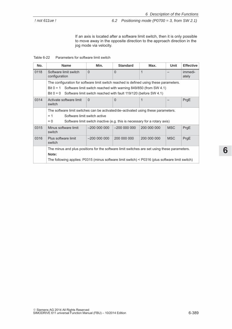
6
6.2 Positioning mode (P0700 = 3, from SW 2.1)
6-389� Siemens AG 2014 All Rights ReservedSIMODRIVE 611 universal Function Manual (FBU) – 10/2014 Edition
If an axis is located after a software limit switch, then it is only possibleto move away in the opposite direction to the approach direction in thejog mode via velocity.
Table 6-22 Parameters for software limit switch
No. Name Min. Standard Max. Unit Effective
0118 Software limit switchconfiguration
0 0 1 – immedi-ately
The configuration for software limit switch reached is defined using these parameters.Bit 0 = 1 Software limit switch reached with warning 849/850 (from SW 4.1)Bit 0 = 0 Software limit switch reached with fault 119/120 (before SW 4.1)
0314 Activate software limitswitch
0 0 1 – PrgE
The software limit switches can be activated/de–activated using these parameters.= 1 Software limit switch active= 0 Software limit switch inactive (e.g. this is necessary for a rotary axis)
0315 Minus software limitswitch
–200 000 000 –200 000 000 200 000 000 MSC PrgE
0316 Plus software limitswitch
–200 000 000 200 000 000 200 000 000 MSC PrgE
The minus and plus positions for the software limit switches are set using these parameters.Note:
The following applies: P0315 (minus software limit switch) < P0316 (plus software limit switch)
6 Description of the Functions
! not 611ue !
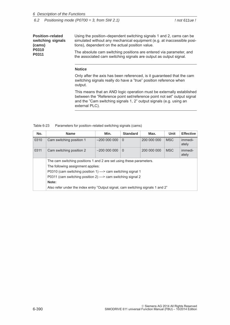
6
6.2 Positioning mode (P0700 = 3, from SW 2.1)
6-390� Siemens AG 2014 All Rights Reserved
SIMODRIVE 611 universal Function Manual (FBU) – 10/2014 Edition
Using the position–dependent switching signals 1 and 2, cams can besimulated without any mechanical equipment (e.g. at inaccessible posi-tions), dependent on the actual position value.
The absolute cam switching positions are entered via parameter, andthe associated cam switching signals are output as output signal.
Notice
Only after the axis has been referenced, is it guaranteed that the camswitching signals really do have a ”true” position reference whenoutput.
This means that an AND logic operation must be externally establishedbetween the ”Reference point set/reference point not set” output signaland the ”Cam switching signals 1, 2” output signals (e.g. using anexternal PLC).
Table 6-23 Parameters for position–related switching signals (cams)
No. Name Min. Standard Max. Unit Effective
0310 Cam switching position 1 –200 000 000 0 200 000 000 MSC immedi-ately
0311 Cam switching position 2 –200 000 000 0 200 000 000 MSC immedi-ately
The cam switching positions 1 and 2 are set using these parameters.The following assignment applies:P0310 (cam switching position 1) ––> cam switching signal 1P0311 (cam switching position 2) ––> cam switching signal 2Note:
Also refer under the index entry ”Output signal, cam switching signals 1 and 2”
Position–relatedswitching signals(cams)P0310P0311
6 Description of the Functions
! not 611ue !
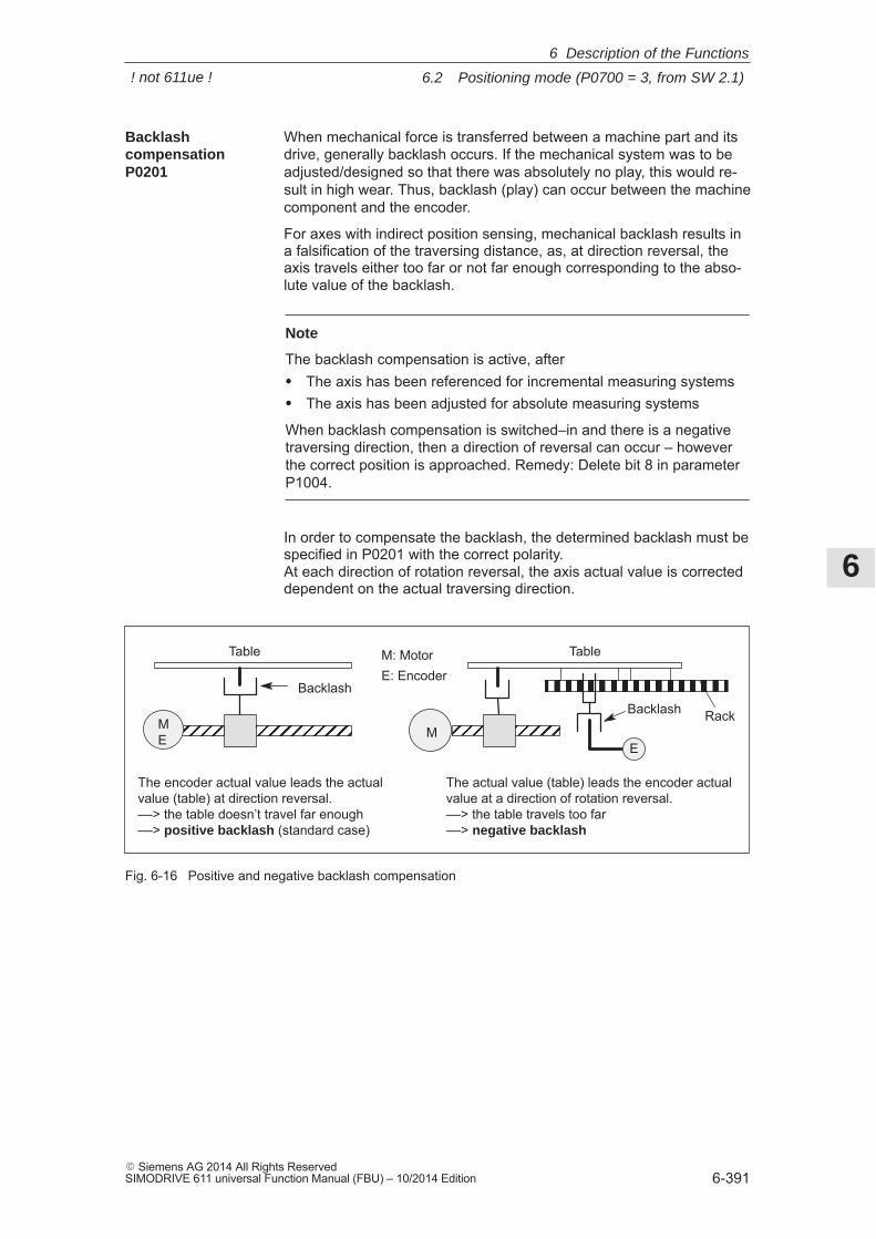
6
6.2 Positioning mode (P0700 = 3, from SW 2.1)
6-391� Siemens AG 2014 All Rights ReservedSIMODRIVE 611 universal Function Manual (FBU) – 10/2014 Edition
When mechanical force is transferred between a machine part and itsdrive, generally backlash occurs. If the mechanical system was to beadjusted/designed so that there was absolutely no play, this would re-sult in high wear. Thus, backlash (play) can occur between the machinecomponent and the encoder.
For axes with indirect position sensing, mechanical backlash results ina falsification of the traversing distance, as, at direction reversal, theaxis travels either too far or not far enough corresponding to the abso-lute value of the backlash.
Note
The backlash compensation is active, after� The axis has been referenced for incremental measuring systems� The axis has been adjusted for absolute measuring systems
When backlash compensation is switched–in and there is a negativetraversing direction, then a direction of reversal can occur – howeverthe correct position is approached. Remedy: Delete bit 8 in parameterP1004.
In order to compensate the backlash, the determined backlash must bespecified in P0201 with the correct polarity. At each direction of rotation reversal, the axis actual value is correcteddependent on the actual traversing direction.
Backlash
Table
ÏÏ ÏÏÏÏÏ
The encoder actual value leads the actualvalue (table) at direction reversal. ––> the table doesn’t travel far enough––> positive backlash (standard case)
BacklashËËËËËËËËË
The actual value (table) leads the encoder actualvalue at a direction of rotation reversal. ––> the table travels too far––> negative backlash
MÏÏÏÏÏÏ
Table
Rack
M: MotorE: Encoder
ME E
Fig. 6-16 Positive and negative backlash compensation
Backlash compensationP0201
6 Description of the Functions
! not 611ue !
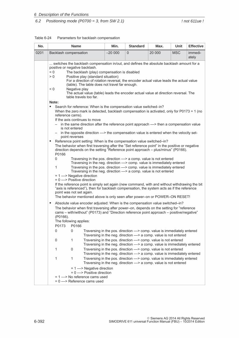
6
6.2 Positioning mode (P0700 = 3, from SW 2.1)
6-392� Siemens AG 2014 All Rights Reserved
SIMODRIVE 611 universal Function Manual (FBU) – 10/2014 Edition
Table 6-24 Parameters for backlash compensation
No. Name Min. Standard Max. Unit Effective
0201 Backlash compensation –20 000 0 20 000 MSC immedi-ately
... switches the backlash compensation in/out, and defines the absolute backlash amount for apositive or negative backlash.= 0 The backlash (play) compensation is disabled> 0 Positive play (standard situation)
For a direction of rotation reversal, the encoder actual value leads the actual value(table). The table does not travel far enough.
< 0 Negative play The actual value (table) leads the encoder actual value at direction reversal. Thetable travels too far.
Note:� Search for reference: When is the compensation value switched–in?
When the zero mark is detected, backlash compensation is activated, only for P0173 = 1 (noreference cams).If the axis continues to move– in the same direction after the reference point approach ––> then a compensation value
is not entered– in the opposite direction ––> the compensation value is entered when the velocity set-
point reverses� Reference point setting: When is the compensation value switched–in?
The behavior when first traversing after the ”Set reference point” in the positive or negativedirection depends on the setting ”Reference point approach – plus/minus” (P0166).P01660 Traversing in the pos. direction ––> a comp. value is not entered
Traversing in the neg. direction ––> comp. value is immediately entered1 Traversing in the pos. direction ––> comp. value is immediately entered
Traversing in the neg. direction ––> a comp. value is not entered= 1 ––> Negative direction= 0 ––> Positive directionIf the reference point is simply set again (new command, with and without withdrawing the bit”axis is referenced”), then for backlash compensation, the system acts as if the referencepoint was not set again.The behavior mentioned above is only seen after power–on or POWER–ON RESET!
� Absolute value encoder adjusted: When is the compensation value switched–in?The behavior when first traversing after power–on, depends on the setting for ”referencecams – with/without” (P0173) and ”Direction reference point approach – positive/negative”(P0166). The following applies:P0173 P01660 0 Traversing in the pos. direction ––> comp. value is immediately entered
Traversing in the neg. direction ––> a comp. value is not entered0 1 Traversing in the pos. direction ––> comp. value is not entered
Traversing in the neg. direction ––> a comp. value is immediately entered1 0 Traversing in the pos. direction ––> comp. value is not entered
Traversing in the neg. direction ––> a comp. value is immediately entered1 1 Traversing in the pos. direction ––> comp. value is immediately entered
Traversing in the neg. direction ––> a comp. value is not entered= 1 ––> Negative direction= 0 ––> Positive direction
= 1 ––> No reference cams used= 0 ––> Reference cams used
6 Description of the Functions
! not 611ue !
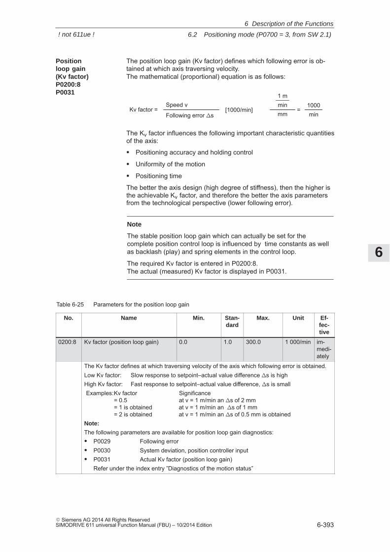
6
6.2 Positioning mode (P0700 = 3, from SW 2.1)
6-393� Siemens AG 2014 All Rights ReservedSIMODRIVE 611 universal Function Manual (FBU) – 10/2014 Edition
The position loop gain (Kv factor) defines which following error is ob-tained at which axis traversing velocity. The mathematical (proportional) equation is as follows:
Kv factor =Speed v
Following error �s[1000/min]
1 mminmm
=1000min
The Kv factor influences the following important characteristic quantitiesof the axis:
� Positioning accuracy and holding control
� Uniformity of the motion
� Positioning time
The better the axis design (high degree of stiffness), then the higher isthe achievable Kv factor, and therefore the better the axis parametersfrom the technological perspective (lower following error).
Note
The stable position loop gain which can actually be set for thecomplete position control loop is influenced by time constants as wellas backlash (play) and spring elements in the control loop.
The required Kv factor is entered in P0200:8. The actual (measured) Kv factor is displayed in P0031.
Table 6-25 Parameters for the position loop gain
No. Name Min. Stan-dard
Max. Unit Ef-fec-tive
0200:8 Kv factor (position loop gain) 0.0 1.0 300.0 1 000/min im-medi-ately
The Kv factor defines at which traversing velocity of the axis which following error is obtained.Low Kv factor: Slow response to setpoint–actual value difference �s is highHigh Kv factor: Fast response to setpoint–actual value difference, �s is smallExamples:Kv factor Significance
= 0.5 at v = 1 m/min an �s of 2 mm= 1 is obtained at v = 1 m/min an �s of 1 mm= 2 is obtained at v = 1 m/min an �s of 0.5 mm is obtained
Note:
The following parameters are available for position loop gain diagnostics:� P0029 Following error� P0030 System deviation, position controller input� P0031 Actual Kv factor (position loop gain)
Refer under the index entry ”Diagnostics of the motion status”
Position loop gain(Kv factor)P0200:8 P0031
6 Description of the Functions
! not 611ue !
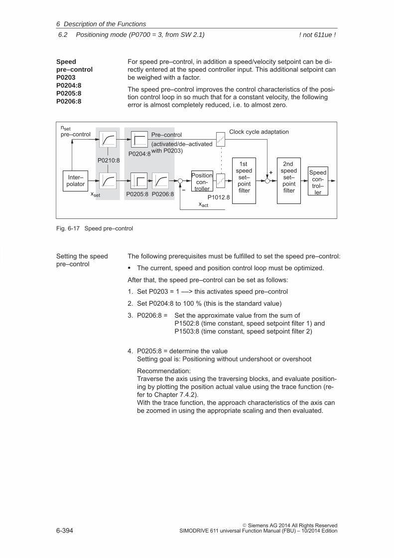
6
6.2 Positioning mode (P0700 = 3, from SW 2.1)
6-394� Siemens AG 2014 All Rights Reserved
SIMODRIVE 611 universal Function Manual (FBU) – 10/2014 Edition
For speed pre–control, in addition a speed/velocity setpoint can be di-rectly entered at the speed controller input. This additional setpoint canbe weighed with a factor.
The speed pre–control improves the control characteristics of the posi-tion control loop in so much that for a constant velocity, the followingerror is almost completely reduced, i.e. to almost zero.
+
P0204:8
P0205:8 P0206:8
nset pre–control Pre–control
(activated/de–activated with P0203)
–
Speedcon-trol–ler
Positioncon-troller
2nd speedset–pointfilter
1st speedset–pointfilter
Inter–polator
xact
xset
P0210:8
Clock cycle adaptation
P1012.8
Fig. 6-17 Speed pre–control
The following prerequisites must be fulfilled to set the speed pre–control:
� The current, speed and position control loop must be optimized.
After that, the speed pre–control can be set as follows:
1. Set P0203 = 1 ––> this activates speed pre–control
2. Set P0204:8 to 100 % (this is the standard value)
3. P0206:8 = Set the approximate value from the sum of P1502:8 (time constant, speed setpoint filter 1) and P1503:8 (time constant, speed setpoint filter 2)
4. P0205:8 = determine the valueSetting goal is: Positioning without undershoot or overshoot
Recommendation:Traverse the axis using the traversing blocks, and evaluate position-ing by plotting the position actual value using the trace function (re-fer to Chapter 7.4.2). With the trace function, the approach characteristics of the axis canbe zoomed in using the appropriate scaling and then evaluated.
Speed pre–controlP0203P0204:8P0205:8P0206:8
Setting the speedpre–control
6 Description of the Functions
! not 611ue !
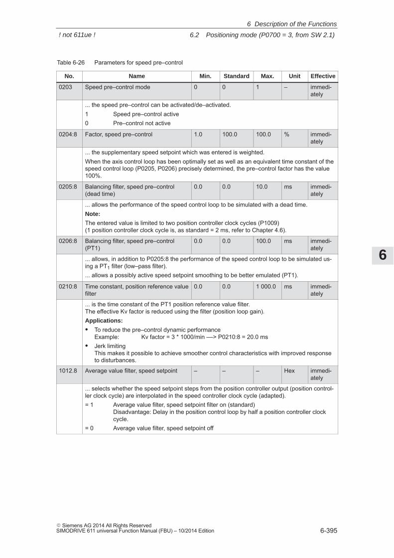
6
6.2 Positioning mode (P0700 = 3, from SW 2.1)
6-395� Siemens AG 2014 All Rights ReservedSIMODRIVE 611 universal Function Manual (FBU) – 10/2014 Edition
Table 6-26 Parameters for speed pre–control
No. Name Min. Standard Max. Unit Effective
0203 Speed pre–control mode 0 0 1 – immedi-ately
... the speed pre–control can be activated/de–activated.1 Speed pre–control active0 Pre–control not active
0204:8 Factor, speed pre–control 1.0 100.0 100.0 % immedi-ately
... the supplementary speed setpoint which was entered is weighted.When the axis control loop has been optimally set as well as an equivalent time constant of thespeed control loop (P0205, P0206) precisely determined, the pre–control factor has the value100%.
0205:8 Balancing filter, speed pre–control(dead time)
0.0 0.0 10.0 ms immedi-ately
... allows the performance of the speed control loop to be simulated with a dead time.Note:
The entered value is limited to two position controller clock cycles (P1009) (1 position controller clock cycle is, as standard = 2 ms, refer to Chapter 4.6).
0206:8 Balancing filter, speed pre–control(PT1)
0.0 0.0 100.0 ms immedi-ately
... allows, in addition to P0205:8 the performance of the speed control loop to be simulated us-ing a PT1 filter (low–pass filter).... allows a possibly active speed setpoint smoothing to be better emulated (PT1).
0210:8 Time constant, position reference valuefilter
0.0 0.0 1 000.0 ms immedi-ately
... is the time constant of the PT1 position reference value filter. The effective Kv factor is reduced using the filter (position loop gain).Applications:
� To reduce the pre–control dynamic performance Example: Kv factor = 3 * 1000/min ––> P0210:8 = 20.0 ms
� Jerk limitingThis makes it possible to achieve smoother control characteristics with improved responseto disturbances.
1012.8 Average value filter, speed setpoint – – – Hex immedi-ately
... selects whether the speed setpoint steps from the position controller output (position control-ler clock cycle) are interpolated in the speed controller clock cycle (adapted).= 1 Average value filter, speed setpoint filter on (standard)
Disadvantage: Delay in the position control loop by half a position controller clockcycle.
= 0 Average value filter, speed setpoint off
6 Description of the Functions
! not 611ue !
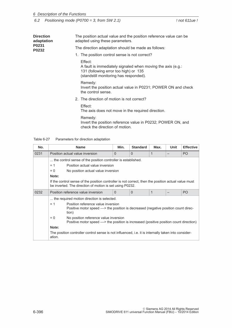
6
6.2 Positioning mode (P0700 = 3, from SW 2.1)
6-396� Siemens AG 2014 All Rights Reserved
SIMODRIVE 611 universal Function Manual (FBU) – 10/2014 Edition
The position actual value and the position reference value can beadapted using these parameters.
The direction adaptation should be made as follows:
1. The position control sense is not correct?
Effect: A fault is immediately signaled when moving the axis (e.g.: 131 (following error too high) or 135 (standstill monitoring has responded).
Remedy: Invert the position actual value in P0231; POWER ON and checkthe control sense.
2. The direction of motion is not correct?
Effect: The axis does not move in the required direction.
Remedy: Invert the position reference value in P0232; POWER ON, andcheck the direction of motion.
Table 6-27 Parameters for direction adaptation
No. Name Min. Standard Max. Unit Effective
0231 Position actual value inversion 0 0 1 – PO
... the control sense of the position controller is established.= 1 Position actual value inversion= 0 No position actual value inversionNote:
If the control sense of the position controller is not correct, then the position actual value mustbe inverted. The direction of motion is set using P0232.
0232 Position reference value inversion 0 0 1 – PO
... the required motion direction is selected.= 1 Position reference value inversion
Positive motor speed ––> the position is decreased (negative position count direc-tion)
= 0 No position reference value inversion Positive motor speed ––> the position is increased (positive position count direction)
Note:
The position controller control sense is not influenced, i.e. it is internally taken into consider-ation.
DirectionadaptationP0231P0232
6 Description of the Functions
! not 611ue !
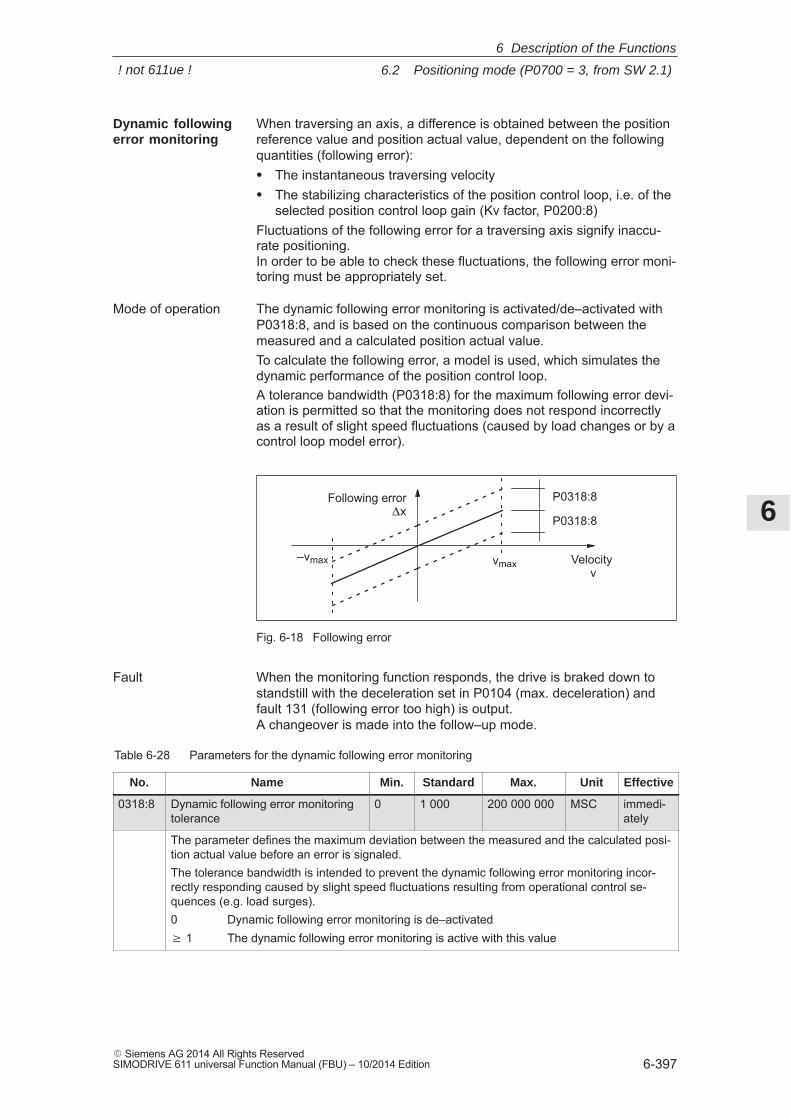
6
6.2 Positioning mode (P0700 = 3, from SW 2.1)
6-397� Siemens AG 2014 All Rights ReservedSIMODRIVE 611 universal Function Manual (FBU) – 10/2014 Edition
When traversing an axis, a difference is obtained between the positionreference value and position actual value, dependent on the followingquantities (following error):� The instantaneous traversing velocity� The stabilizing characteristics of the position control loop, i.e. of the
selected position control loop gain (Kv factor, P0200:8)Fluctuations of the following error for a traversing axis signify inaccu-rate positioning. In order to be able to check these fluctuations, the following error moni-toring must be appropriately set.
The dynamic following error monitoring is activated/de–activated withP0318:8, and is based on the continuous comparison between themeasured and a calculated position actual value.To calculate the following error, a model is used, which simulates thedynamic performance of the position control loop.A tolerance bandwidth (P0318:8) for the maximum following error devi-ation is permitted so that the monitoring does not respond incorrectlyas a result of slight speed fluctuations (caused by load changes or by acontrol loop model error).
Following error�x
vmax–vmax Velocity
v
P0318:8
P0318:8
Fig. 6-18 Following error
When the monitoring function responds, the drive is braked down tostandstill with the deceleration set in P0104 (max. deceleration) andfault 131 (following error too high) is output. A changeover is made into the follow–up mode.
Table 6-28 Parameters for the dynamic following error monitoring
No. Name Min. Standard Max. Unit Effective
0318:8 Dynamic following error monitoringtolerance
0 1 000 200 000 000 MSC immedi-ately
The parameter defines the maximum deviation between the measured and the calculated posi-tion actual value before an error is signaled.The tolerance bandwidth is intended to prevent the dynamic following error monitoring incor-rectly responding caused by slight speed fluctuations resulting from operational control se-quences (e.g. load surges).0 Dynamic following error monitoring is de–activated� 1 The dynamic following error monitoring is active with this value
Dynamic followingerror monitoring
Mode of operation
Fault
6 Description of the Functions
! not 611ue !
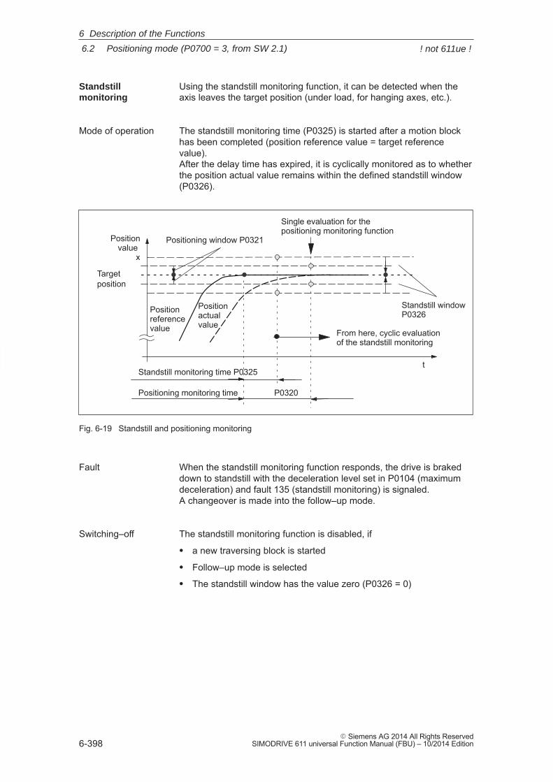
6
6.2 Positioning mode (P0700 = 3, from SW 2.1)
6-398� Siemens AG 2014 All Rights Reserved
SIMODRIVE 611 universal Function Manual (FBU) – 10/2014 Edition
Using the standstill monitoring function, it can be detected when theaxis leaves the target position (under load, for hanging axes, etc.).
The standstill monitoring time (P0325) is started after a motion blockhas been completed (position reference value = target referencevalue). After the delay time has expired, it is cyclically monitored as to whetherthe position actual value remains within the defined standstill window(P0326).
t
Positioning monitoring time P0320
Targetposition
Positionvalue
x
Positioning window P0321
Positionreferencevalue
Positionactualvalue
Standstill window P0326
Standstill monitoring time P0325
Single evaluation for the positioning monitoring function
From here, cyclic evaluation of the standstill monitoring
Fig. 6-19 Standstill and positioning monitoring
When the standstill monitoring function responds, the drive is brakeddown to standstill with the deceleration level set in P0104 (maximumdeceleration) and fault 135 (standstill monitoring) is signaled. A changeover is made into the follow–up mode.
The standstill monitoring function is disabled, if
� a new traversing block is started
� Follow–up mode is selected
� The standstill window has the value zero (P0326 = 0)
Standstillmonitoring
Mode of operation
Fault
Switching–off
6 Description of the Functions
! not 611ue !
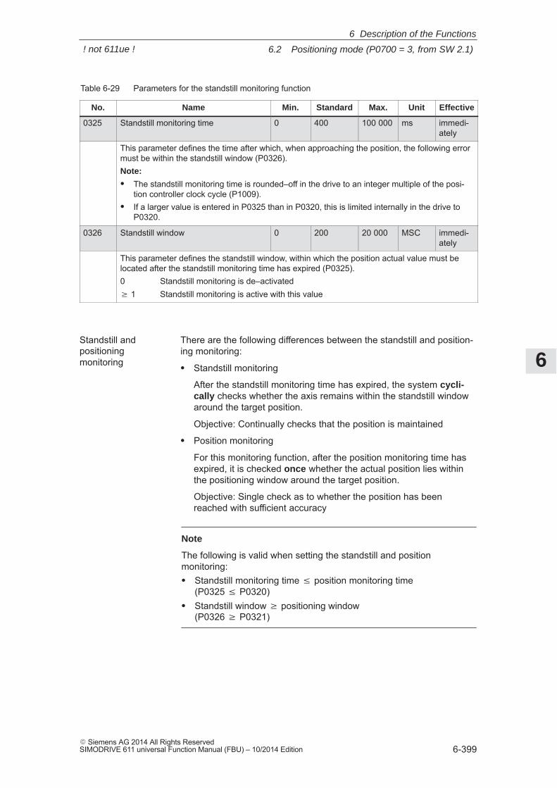
6
6.2 Positioning mode (P0700 = 3, from SW 2.1)
6-399� Siemens AG 2014 All Rights ReservedSIMODRIVE 611 universal Function Manual (FBU) – 10/2014 Edition
Table 6-29 Parameters for the standstill monitoring function
No. Name Min. Standard Max. Unit Effective
0325 Standstill monitoring time 0 400 100 000 ms immedi-ately
This parameter defines the time after which, when approaching the position, the following errormust be within the standstill window (P0326).Note:
� The standstill monitoring time is rounded–off in the drive to an integer multiple of the posi-tion controller clock cycle (P1009).
� If a larger value is entered in P0325 than in P0320, this is limited internally in the drive toP0320.
0326 Standstill window 0 200 20 000 MSC immedi-ately
This parameter defines the standstill window, within which the position actual value must belocated after the standstill monitoring time has expired (P0325).0 Standstill monitoring is de–activated� 1 Standstill monitoring is active with this value
There are the following differences between the standstill and position-ing monitoring:
� Standstill monitoring
After the standstill monitoring time has expired, the system cycli-cally checks whether the axis remains within the standstill windowaround the target position.
Objective: Continually checks that the position is maintained
� Position monitoring
For this monitoring function, after the position monitoring time hasexpired, it is checked once whether the actual position lies withinthe positioning window around the target position.
Objective: Single check as to whether the position has beenreached with sufficient accuracy
Note
The following is valid when setting the standstill and positionmonitoring:� Standstill monitoring time position monitoring time
(P0325 P0320)� Standstill window � positioning window
(P0326 � P0321)
Standstill and positioningmonitoring
6 Description of the Functions
! not 611ue !
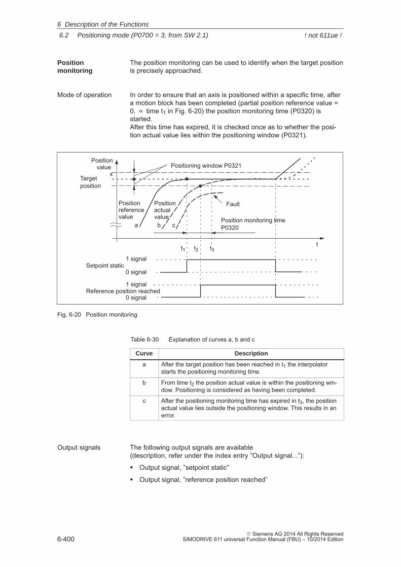
6
6.2 Positioning mode (P0700 = 3, from SW 2.1)
6-400� Siemens AG 2014 All Rights Reserved
SIMODRIVE 611 universal Function Manual (FBU) – 10/2014 Edition
The position monitoring can be used to identify when the target positionis precisely approached.
In order to ensure that an axis is positioned within a specific time, aftera motion block has been completed (partial position reference value =0, � time t1 in Fig. 6-20) the position monitoring time (P0320) isstarted. After this time has expired, it is checked once as to whether the posi-tion actual value lies within the positioning window (P0321).
t
Position monitoring timeP0320
t1 t2 t3
Targetposition
a b c
Setpoint static1 signal
0 signal
Reference position reached1 signal
0 signal
Positionvalue
xPositioning window P0321
Positionreferencevalue
Positionactualvalue
Fault
Fig. 6-20 Position monitoring
Table 6-30 Explanation of curves a, b and c
Curve Description
a After the target position has been reached in t1 the interpolatorstarts the positioning monitoring time.
b From time t2 the position actual value is within the positioning win-dow. Positioning is considered as having been completed.
c After the positioning monitoring time has expired in t3, the positionactual value lies outside the positioning window. This results in anerror.
The following output signals are available(description, refer under the index entry ”Output signal...”):
� Output signal, ”setpoint static”
� Output signal, ”reference position reached”
Positionmonitoring
Mode of operation
Output signals
6 Description of the Functions
! not 611ue !
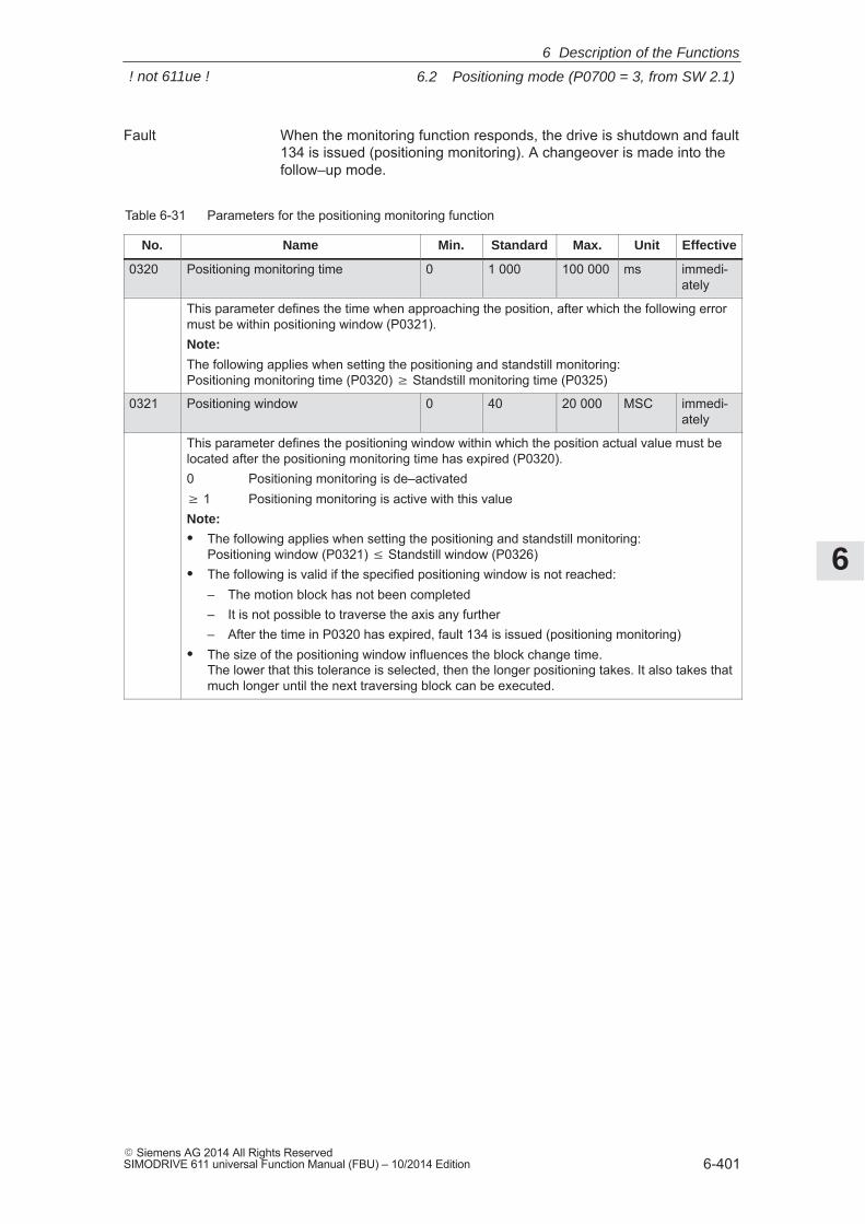
6
6.2 Positioning mode (P0700 = 3, from SW 2.1)
6-401� Siemens AG 2014 All Rights ReservedSIMODRIVE 611 universal Function Manual (FBU) – 10/2014 Edition
When the monitoring function responds, the drive is shutdown and fault134 is issued (positioning monitoring). A changeover is made into thefollow–up mode.
Table 6-31 Parameters for the positioning monitoring function
No. Name Min. Standard Max. Unit Effective
0320 Positioning monitoring time 0 1 000 100 000 ms immedi-ately
This parameter defines the time when approaching the position, after which the following errormust be within positioning window (P0321).Note:
The following applies when setting the positioning and standstill monitoring:Positioning monitoring time (P0320) � Standstill monitoring time (P0325)
0321 Positioning window 0 40 20 000 MSC immedi-ately
This parameter defines the positioning window within which the position actual value must belocated after the positioning monitoring time has expired (P0320).0 Positioning monitoring is de–activated� 1 Positioning monitoring is active with this valueNote:
� The following applies when setting the positioning and standstill monitoring:Positioning window (P0321) Standstill window (P0326)
� The following is valid if the specified positioning window is not reached:– The motion block has not been completed– It is not possible to traverse the axis any further– After the time in P0320 has expired, fault 134 is issued (positioning monitoring)
� The size of the positioning window influences the block change time. The lower that this tolerance is selected, then the longer positioning takes. It also takes thatmuch longer until the next traversing block can be executed.
Fault
6 Description of the Functions
! not 611ue !
6
6.2 Positioning mode (P0700 = 3, from SW 2.1)
6-402� Siemens AG 2014 All Rights Reserved
SIMODRIVE 611 universal Function Manual (FBU) – 10/2014 Edition
If an axis is in the follow–up mode, then the control is disabled and itsposition reference value tracks the actual position actual value.
The actual position of the axis is still being sensed – this means that itis not necessary to re–home (re–reference) the axis when the fol-low–up mode (correcting mode) is cancelled.
In the follow–up mode, there are various selection possibilities and sig-nals:
� The follow–up mode is selected, if
– controller enable terminal 65.x is withdrawn and the ”follow–up mode” input signal is set to ”1”
– Jogging operation (jogging 1, 2) is active (when jogging via thevelocity, not for incremental jogging)
– When a fault develops, automatically using ”SIMODRIVE 611universal” (only for a STOP 0, I or II stop response)
� In all cases, the checkback signal is realized using the output signal”follow–up mode active”.
The ”follow–up mode” input signal is only relevant if the controllerenable (terminal 65.x) of the drive is withdrawn or if the controller isre–enabled.
� Follow–up mode = 1 (so–called tracking)
When the axis–specific controller enable is withdrawn (terminal65.x), the position reference value of the associated axis continuallytracks the position actual value. In this status, the ”follow–up modeactive” output signal = ”1”.
If the controller is re–enabled, all additional axis movements start atthe actual position which may have changed.
� Follow–up mode = 0 (stopping)
No follow–up operation is activated when the controller enable iswithdrawn and the following error, positioning and standstill monitor-ing are disabled. This means that the old position reference value iskept. If the axis is pushed out of its position, a following error occursbetween the position reference value and the position actual value,which is compensated when the controller enable is set. In this sta-tus, the ”follow–up mode active” output signal = ”0”. However, whenthe monitoring function is enabled, follow–up mode is activated andthe position reference value follows the position actual value.
All additional axis movements start at the reference position, whichwas available before the controller enable was withdrawn.
Follow–up mode
Selection, signals
Effect
6 Description of the Functions
! not 611ue !
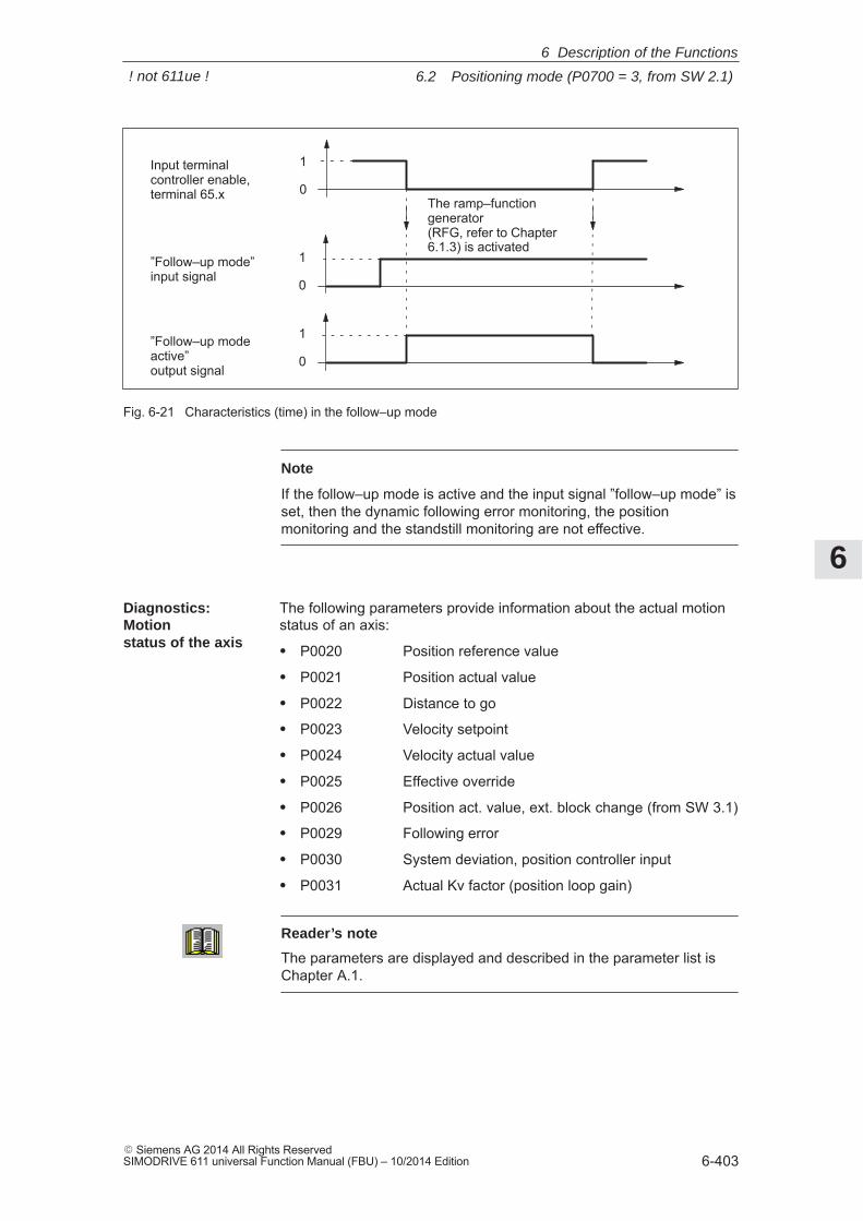
6
6.2 Positioning mode (P0700 = 3, from SW 2.1)
6-403� Siemens AG 2014 All Rights ReservedSIMODRIVE 611 universal Function Manual (FBU) – 10/2014 Edition
”Follow–up mode”input signal
”Follow–up modeactive”output signal
Input terminal controller enable,terminal 65.x
The ramp–functiongenerator(RFG, refer to Chapter6.1.3) is activated
1
0
1
0
1
0
Fig. 6-21 Characteristics (time) in the follow–up mode
Note
If the follow–up mode is active and the input signal ”follow–up mode” isset, then the dynamic following error monitoring, the positionmonitoring and the standstill monitoring are not effective.
The following parameters provide information about the actual motionstatus of an axis:
� P0020 Position reference value
� P0021 Position actual value
� P0022 Distance to go
� P0023 Velocity setpoint
� P0024 Velocity actual value
� P0025 Effective override
� P0026 Position act. value, ext. block change (from SW 3.1)
� P0029 Following error
� P0030 System deviation, position controller input
� P0031 Actual Kv factor (position loop gain)
Reader’s note
The parameters are displayed and described in the parameter list isChapter A.1.
Diagnostics:Motionstatus of the axis
6 Description of the Functions
! not 611ue !
6
6.2 Positioning mode (P0700 = 3, from SW 2.1)
6-404� Siemens AG 2014 All Rights Reserved
SIMODRIVE 611 universal Function Manual (FBU) – 10/2014 Edition
6.2.4 Referencing and adjusting
In order that the ”SIMODRIVE 611 universal” drive precisely identifiesthe machine zero point after power–on, the axis measuring systemmust be synchronized with the machine.
This synchronization is realized when referencing incremental measur-ing systems or adjusting absolute measuring systems.
Notice
The following functions are ineffective for axes which are either notreferenced not adjusted:� Software limit switches� Backlash compensation� Start the traversing blocks
6.2.5 Referencing for incremental measuring systems
For axes with incremental measuring systems, each time the system ispowered–up, the position reference to the machine zero point must beestablished.
Synchronization is realized for a reference point approach by acceptinga specific position value at a known point of the axis.
Note
� Before SW 4.1:
The encoder must be re–referenced if, for a referenced incrementalmeasuring system, a parameter set was changed over.
� From SW 4.1:
Using P0239, the behavior for a parameter set changeover can beset for a motor measuring system.
P0239 = 0: Behavior as before SW 4.1 (standard)
P0239 = 1: For a parameter set changeover, it is only necessary to re–reference the encoder, if the ratio P0237/P0238 has changed.
Definitions
General
6 Description of the Functions
! not 611ue !
6
6.2 Positioning mode (P0700 = 3, from SW 2.1)
6-405� Siemens AG 2014 All Rights ReservedSIMODRIVE 611 universal Function Manual (FBU) – 10/2014 Edition
The reference point approach can be started in the ”positioning” modevia the ”start referencing” input signal.
The signal can be entered via an input terminal or via PROFIBUS–DP,and must remain set until the end of the reference point approachtravel via the ”reference point set” output signal. If the ”start referencing” signal is reset during referencing, then refer-encing is exited and the drive stops.
For a 2–axis control board, the reference point approach for both axescan be started and executed, either one after the other or simulta-neously.
The approach direction for reference point approach is defined usingP0166.
Axes, which have several zero marks over their complete traversingrange (e.g. incremental, rotary measuring system), require a referencecam to select the ”correct” zero mark when referencing.
The reference point approach for these axes is executed in 3 phases:
When starting the reference point approach, the following statuses areavailable:
� Axis is located in front of the reference camAfter the reference point approach is started, the axis moves withthe reference point approach velocity (P0163) in the direction speci-fied by P0166. The drive detects the reference cam using the input signal ”refer-ence cam” and for a ”1” signal brakes down to standstill. It continues with the ”synchronization with the zero pulse”.
Note
The maximum permissible distance from the starting position up to thereference cams can be monitored using P0170 (maximum distance tothe reference cams).
The override influences the reference point approach velocity.
� The axis is located at the reference camAfter the reference point approach has started, it is considered ashaving been completed with ”travel to the reference cam”. It continues with the ”synchronization with the zero pulse”.
Starting thereference pointapproach
Axis with reference cams(P0173 = 0)
Phase 1:Traverse to the reference cams
6 Description of the Functions
! not 611ue !
6
6.2 Positioning mode (P0700 = 3, from SW 2.1)
6-406� Siemens AG 2014 All Rights Reserved
SIMODRIVE 611 universal Function Manual (FBU) – 10/2014 Edition
The axis traverses with the reference point shutdown velocity (P0164)in the opposite direction to that specified in P0166. After the reference cam has been left (input signal, ”reference cam” =”0” signal), the axis synchronizes with the first zero pulse. The axisbrakes down to standstill. The system continues with ”traverse to reference point”.
Note
The maximum permissible travel from the reference cams to the zeropulse can be monitored using P0171 (max. distance between thereference cam/zero pulse).
The override is not effective.
The axis traverses with the reference point approach velocity (P0165),the reference point offset (P0162) in a positive or negative directionreferred to the zero pulse. The following is achieved when the axis reaches the reference point:� The reference point coordinate (P0160 = 0) is transferred as the
new reference position.� The ”reference point set” output signal is set to a ”1” signal.� From SW 8.3, the reference point approach (homing) can be termi-
nated after the zero mark has been detected, refer to Table 6-34(P0160 = 1).
Note
If the reference point offset is less than the braking travel of the axisfrom the reference point shutdown velocity to standstill, then thereference point is approached from the other direction.
The override is not effective.
The reference cam signal must be connected to an input terminal withfunction number 78 (reference cam). Parameter P0167 can be used to adapt the signal characteristics of thereference cam (NO/NC characteristics).
Table 6-32 Adapting the reference cam signal
If then, when approaching/exiting
the reference cam
P0167
Normallyopen con-tact
a 0/1 edgeor 1/0 edge ––>
P0167 = 0 (no inversion) (standard)
Normallyclosed con-tact
a 0/1 edgeor 1/0 edge ––>
P0167 = 1 (inversion)
Phase 2:Synchronization using the zero pulse
Phase 3:Traversing to the reference point
Mounting a reference cam
6 Description of the Functions
! not 611ue !
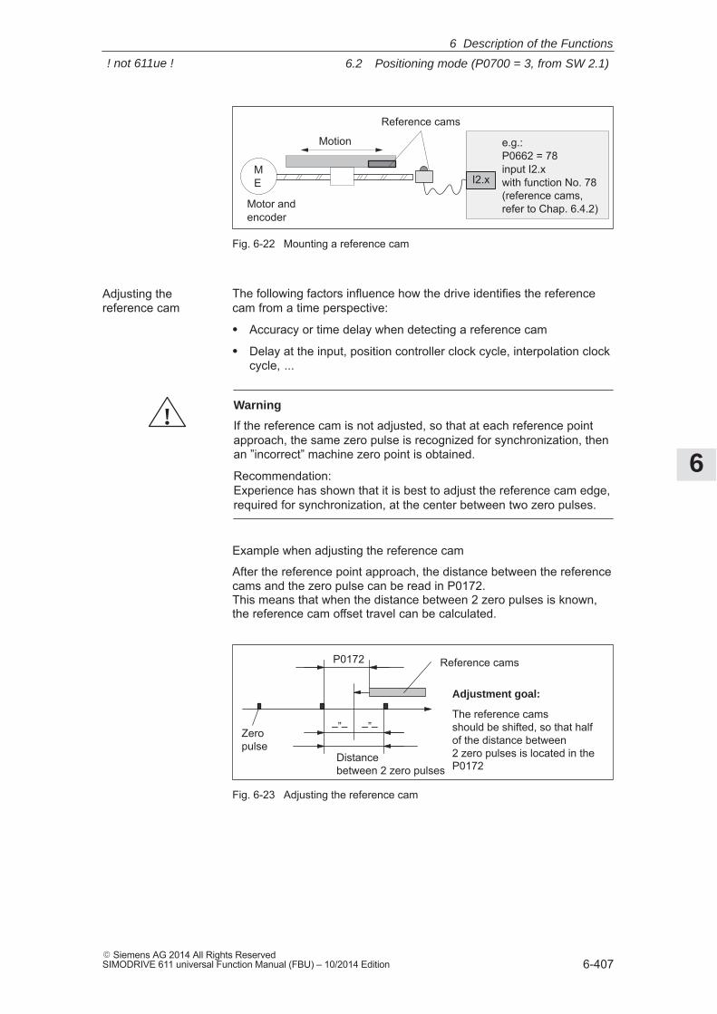
6
6.2 Positioning mode (P0700 = 3, from SW 2.1)
6-407� Siemens AG 2014 All Rights ReservedSIMODRIVE 611 universal Function Manual (FBU) – 10/2014 Edition
Reference cams
Motion
ÎÎÎÎÎÎMotor and
encoder
e.g.: P0662 = 78 input I2.x with function No. 78(reference cams, refer to Chap. 6.4.2)
I2.xME
Fig. 6-22 Mounting a reference cam
The following factors influence how the drive identifies the referencecam from a time perspective:
� Accuracy or time delay when detecting a reference cam
� Delay at the input, position controller clock cycle, interpolation clockcycle, ...
!Warning
If the reference cam is not adjusted, so that at each reference pointapproach, the same zero pulse is recognized for synchronization, thenan ”incorrect” machine zero point is obtained.
Recommendation:Experience has shown that it is best to adjust the reference cam edge,required for synchronization, at the center between two zero pulses.
Example when adjusting the reference cam
After the reference point approach, the distance between the referencecams and the zero pulse can be read in P0172. This means that when the distance between 2 zero pulses is known,the reference cam offset travel can be calculated.
Reference camsP0172
Distance between 2 zero pulses
–”––”–
Adjustment goal:
The reference cams should be shifted, so that halfof the distance between 2 zero pulses is located in theP0172
Zeropulse
Fig. 6-23 Adjusting the reference cam
Adjusting thereference cam
6 Description of the Functions
! not 611ue !
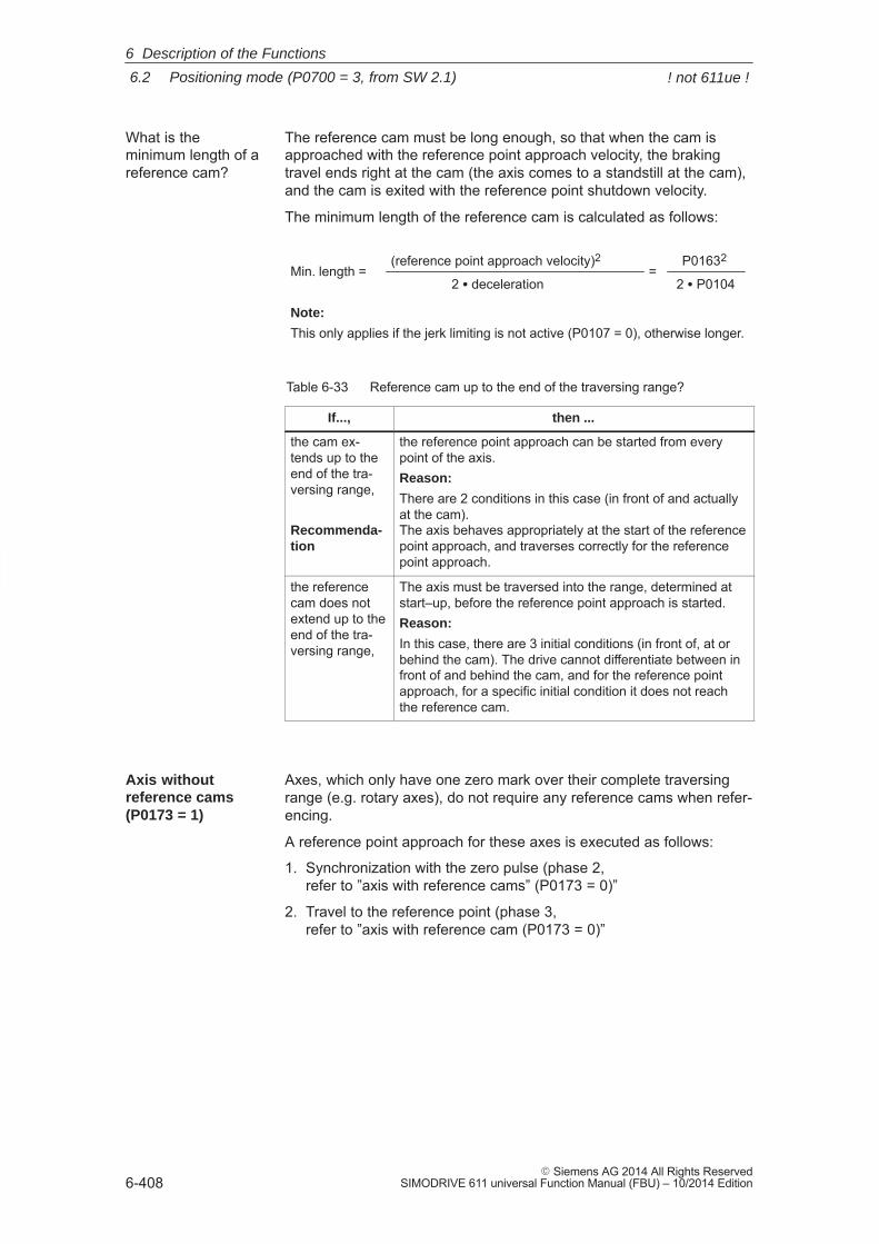
6
6.2 Positioning mode (P0700 = 3, from SW 2.1)
6-408� Siemens AG 2014 All Rights Reserved
SIMODRIVE 611 universal Function Manual (FBU) – 10/2014 Edition
The reference cam must be long enough, so that when the cam isapproached with the reference point approach velocity, the brakingtravel ends right at the cam (the axis comes to a standstill at the cam),and the cam is exited with the reference point shutdown velocity.
The minimum length of the reference cam is calculated as follows:
Min. length = (reference point approach velocity)2
2 � deceleration=
P01632
2 � P0104
Note:
This only applies if the jerk limiting is not active (P0107 = 0), otherwise longer.
Table 6-33 Reference cam up to the end of the traversing range?
If..., then ...
the cam ex-tends up to theend of the tra-versing range,
Recommenda-tion
the reference point approach can be started from everypoint of the axis.Reason:
There are 2 conditions in this case (in front of and actuallyat the cam). The axis behaves appropriately at the start of the referencepoint approach, and traverses correctly for the referencepoint approach.
the referencecam does notextend up to theend of the tra-versing range,
The axis must be traversed into the range, determined atstart–up, before the reference point approach is started.Reason:
In this case, there are 3 initial conditions (in front of, at orbehind the cam). The drive cannot differentiate between infront of and behind the cam, and for the reference pointapproach, for a specific initial condition it does not reachthe reference cam.
Axes, which only have one zero mark over their complete traversingrange (e.g. rotary axes), do not require any reference cams when refer-encing.
A reference point approach for these axes is executed as follows:
1. Synchronization with the zero pulse (phase 2, refer to ”axis with reference cams” (P0173 = 0)”
2. Travel to the reference point (phase 3, refer to ”axis with reference cam (P0173 = 0)”
What is theminimum length of areference cam?
Axis without reference cams(P0173 = 1)
6 Description of the Functions
! not 611ue !
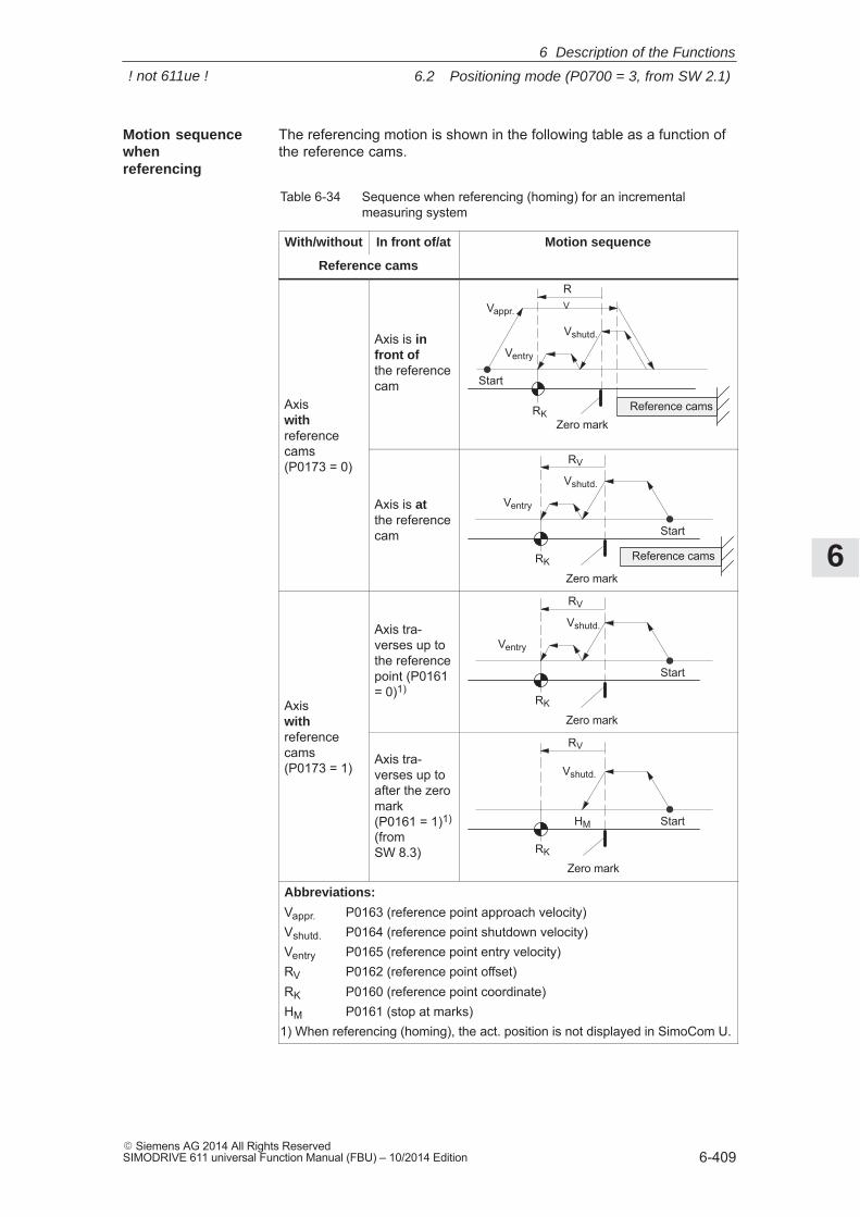
6
6.2 Positioning mode (P0700 = 3, from SW 2.1)
6-409� Siemens AG 2014 All Rights ReservedSIMODRIVE 611 universal Function Manual (FBU) – 10/2014 Edition
The referencing motion is shown in the following table as a function ofthe reference cams.
Table 6-34 Sequence when referencing (homing) for an incrementalmeasuring system
With/without In front of/at Motion sequence
Reference cams
Axis with referencecams
Axis is infront of the referencecam
Vappr.
Reference cams
Ventry
Vshutd.
RV
Start
RKZero mark
cams (P0173 = 0)
Axis is at the referencecam
Reference cams
Ventry
Vshutd.
RV
Start
RK
Zero mark
Axis with reference
Axis tra-verses up tothe referencepoint (P0161= 0)1)
Ventry
Vshutd.
RV
Start
RK
Zero markwith referencecams (P0173 = 1)
Axis tra-verses up toafter the zeromark (P0161 = 1)1)
(fromSW 8.3)
Vshutd.
RV
Start
RK
HM
Zero mark
Abbreviations:
Vappr. P0163 (reference point approach velocity)Vshutd. P0164 (reference point shutdown velocity)Ventry P0165 (reference point entry velocity)RV P0162 (reference point offset)RK P0160 (reference point coordinate)HM P0161 (stop at marks)
1) When referencing (homing), the act. position is not displayed in SimoCom U.
Motion sequencewhen referencing
6 Description of the Functions
! not 611ue !
6
6.2 Positioning mode (P0700 = 3, from SW 2.1)
6-410� Siemens AG 2014 All Rights Reserved
SIMODRIVE 611 universal Function Manual (FBU) – 10/2014 Edition
6.2.6 Referencing with a distance–coded measuring system (from SW 8.3)
In the case of measurement systems with distancecoded referencemarks, it is not necessary to evaluate a reference cam or approach adefined reference point in order to reference the machine axis.
Measuring systems of this type consist of a line grid and a referencemark track running parallel to this. The distance between twoconsecutive reference marks is defined variably, so that the absoluteposition of the machine axis can be determined from the distance.
For axes with incremental measuring systems, each time the system ispowered–up, the position reference to the machine zero point must beestablished.
Synchronization is realized at reference point approach by accepting aspecific position value at a known point of the axis.
Note
The distance between the zero marks is continually monitored.
Only encoders are monitored whose pulse number can be divide byeither 16 or 10!
The reference point approach can be started in the ”positioning” modevia the ”start referencing” input signal.
The input signal is entered using an input terminal with function number65, and must remain set until the end of the reference point approach issignaled using the output signal ”reference point set” (function number61).
If the ”start referencing” signal is reset during referencing, then refer-encing is exited and the drive stops.
During the reference point approach (homing), at least two referencemarks (zero marks) are passed. The reference point approach (hom-ing) is completed when these zero marks have been passed and thedrive has been braked.
For a 2–axis control board, the reference point approach for both axescan be started and executed, either one after the other or simulta-neously.
The approach direction for reference point approach is defined usingP0166.
The reference point approach (homing) is executed in 2 phases (referto Table 6-35):
General
Starting thereference pointapproach
6 Description of the Functions
! not 611ue !
6
6.2 Positioning mode (P0700 = 3, from SW 2.1)
6-411� Siemens AG 2014 All Rights ReservedSIMODRIVE 611 universal Function Manual (FBU) – 10/2014 Edition
The axis traverses with the reference point shutdown velocity (P0164)in the direction specified in P0166.
The system is synchronized when passing two zero pulses (position oftwo zero marks). The axis brakes down to standstill after the secondzero pulse.
The system continues with ”traverse to reference point”.
Note
The maximum permissible distance from the start up to the secondzero pulse is monitored using P0171 (max. distance between thereference cams or start/zero pulse). For distance–coded measuringsystems, it is practical to set the basic distance.
The override is not effective.
The axis traverses with the reference point approach velocity (P0165),the reference point offset (P0162) in a positive or negative directionreferred to the zero pulse of the encoder.
The following is achieved when the axis reaches the reference point:
� The reference point coordinate (P0160) is transferred as the newreference position.
� The ”reference point set” output signal is set to a ”1” signal.
Note
If, after the second zero point, a reference point approach is notrequired (P0161 = 1), then the absolute position of the current positionis calculated and accepted in the drive.
The ”reference point set” output signal is then set to a ”1”. ParameterP0162 and P0160 act the same as for a reference point approach withone zero mark. The reference point offset does not refer to the zeromark passed, but to the encoder zero.
For a machine with distance–coded reference marks, there is no re-quirement to reference using cams.
Standard setting when referencing with distance–coded measuring sys-tems:
––> P0173 = 1: ”Referencing without cams”
Phase 1:Synchronizing usingtwo zero pulses
Phase 2:Traversing to thereference point(home position)
Parameter changefor a newcommissioning
6 Description of the Functions
! not 611ue !
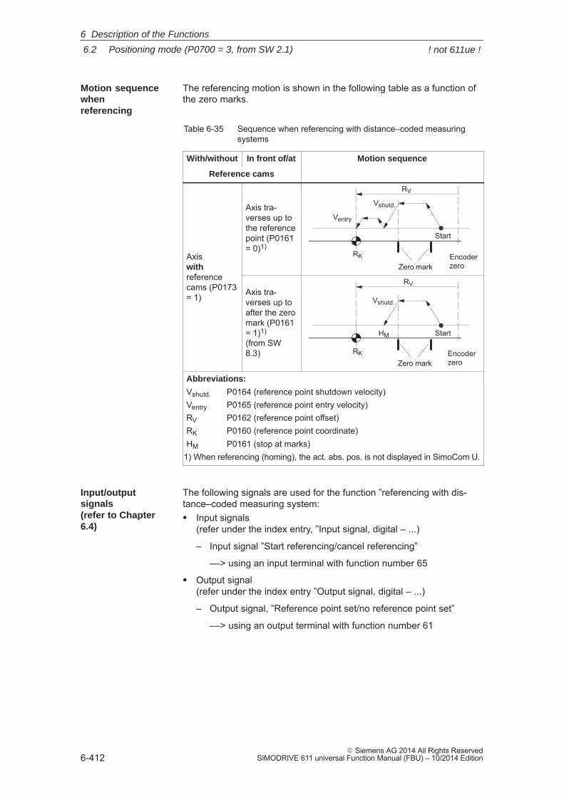
6
6.2 Positioning mode (P0700 = 3, from SW 2.1)
6-412� Siemens AG 2014 All Rights Reserved
SIMODRIVE 611 universal Function Manual (FBU) – 10/2014 Edition
The referencing motion is shown in the following table as a function ofthe zero marks.
Table 6-35 Sequence when referencing with distance–coded measuringsystems
With/without In front of/at Motion sequence
Reference cams
Axis with reference
Axis tra-verses up tothe referencepoint (P0161= 0)1)
Ventry
Vshutd.
RV
Start
RK
Zero markEncoderzero
referencecams (P0173= 1) Axis tra-
verses up toafter the zeromark (P0161= 1)1)
(from SW8.3)
Vshutd.
RV
Start
RK
Zero mark
HM
Encoderzero
Abbreviations:
Vshutd. P0164 (reference point shutdown velocity)Ventry P0165 (reference point entry velocity)RV P0162 (reference point offset)RK P0160 (reference point coordinate)HM P0161 (stop at marks)
1) When referencing (homing), the act. abs. pos. is not displayed in SimoCom U.
The following signals are used for the function ”referencing with dis-tance–coded measuring system:� Input signals
(refer under the index entry, ”Input signal, digital – ...)
– Input signal ”Start referencing/cancel referencing”
––> using an input terminal with function number 65
� Output signal(refer under the index entry ”Output signal, digital – ...)
– Output signal, ”Reference point set/no reference point set”
––> using an output terminal with function number 61
Motion sequencewhen referencing
Input/outputsignals(refer to Chapter6.4)
6 Description of the Functions
! not 611ue !
6
6.2 Positioning mode (P0700 = 3, from SW 2.1)
6-413� Siemens AG 2014 All Rights ReservedSIMODRIVE 611 universal Function Manual (FBU) – 10/2014 Edition
The following parameters are used for referencing with distance–codedmeasuring systems:� P0161 Stopping at marks (from SW 8.3)� P0173 Reference point approach (homing) without reference cams� P1027 IM configuration, encoder� P1037 DM configuration, encoder� P1050 IM reference mark distance for distance–coded
scales� P1051 IM reference mark distance for distance–coded
rotary encoders� P1052 DM reference mark distance for distance–coded
scales� P1053 DM reference mark distance for distance–coded
rotary encoders� P1054 IM difference for distance–coded rotary encoders
(from SW 8.3)� P1055 DM difference for distance–coded rotary encoders
(from SW 8.3)
� Modulo operation (from SW 10.2)
Distance–coded referencing in modulo operation is only possible ifthe following practical, integer number modulo range values apply: n � 360 degrees with n = 1, 2, ...
Any modulo range values are not permitted and would result in fault139 being output.
Parameteroverview (refer to 6.2.8 andA.1)
Supplementarycondition
6 Description of the Functions
! not 611ue !
6
6.2 Positioning mode (P0700 = 3, from SW 2.1)
6-414� Siemens AG 2014 All Rights Reserved
SIMODRIVE 611 universal Function Manual (FBU) – 10/2014 Edition
6.2.7 Adjusting absolute measuring systems
Axes with absolute value encoders automatically obtain their referenceposition without any axis motion after power–on.
Requirements:
� There is an absolute value encoder (single–turn/multi–turn absolutevalue encoder) (P0175 = 0)
� Absolute value encoder is considered to have been adjusted (P0175 = 3 for indirect measuring system P0175 = 4 for direct measuring system)
An absolute value encoder should be adjusted once when commission-ing the axis or after opening the mechanical coupling between the mea-suring system and mechanical system, for example, after:
� Replacing the measuring system and/or motor
� Changing the gearbox ratio (when changing the gearbox factors)
� Selection, ”parking axis” (if another EnDat encoder was connected)
Note
� ”SIMODRIVE 611 universal” can only identify if the mechanicalcoupling between the measuring system and mechanical system isreleased, if it is powered up.
� When a parameter set is changed–over in operation (e.g. a gearratio is changed), the ”not adjusted” information is lost atpower–down if ”save to Feprom” is not explicitly initiated.
� Before SW 4.1:
If a parameter set changeover was carried out with an adjustedabsolute encoder for a particular motor measuring system, then theencoder must be re–adjusted.
� From SW 4.1:
Using P0239, the behavior for a parameter set changeover can beset for a motor measuring system.
P0239 = 0: Behavior as before SW 4.1 (standard)
P0239 = 1: For a parameter set changeover, it is only necessary to adjust the encoder if the mechanical ratio of P0237/P0238 has been changed.
� The following must be observed for linear axes:
Amount of the position value / spindle pitch x transmission ratio differentiable encoder rotations /2.If this is not observed, an incorrect actual position is displayed afterswitching the drive off / on!
Generalinformation
Adjusting the absolute valueencoder
6 Description of the Functions
! not 611ue !
6
6.2 Positioning mode (P0700 = 3, from SW 2.1)
6-415� Siemens AG 2014 All Rights ReservedSIMODRIVE 611 universal Function Manual (FBU) – 10/2014 Edition
The following sequence is practical when adjusting absolute value en-coders:
1. Traverse the axis to a known or measured position (this is therequired actual value). The axis can be traversed, e.g. using ”Jogging 1” or ”Jogging 2”.
2. Set P0160 to ”required actual value”
3. Set P0175 = 1 The ”SIMODRIVE 611 universal” drive determines the differencebetween the required actual value in P0160 and the encoder actualvalue and enters it into an internal parameter.If a fault occurs, then P0175 is set to –1. If the operation was error–free, then P0175 is set to 2, 3 or 4 (referto Chapter 6.2.8) and Fault 799 (save to FEPROM and HW RESETrequired) is signaled.
– Save parameters in the FEPROM (P0652 = 1)
– Carry–out a HW–RESET (press the POWER–ON RESET buttonon the front panel of the control board)
4. Check: Is the actual value correctly displayed after power–on?
The absolute value encoder is adjusted, supported by the operator. The following sequence is practical:
1. Establish online operation between SimoCom U and the drive
2. Traverse the axis to a known or measured position (this is the re-quired actual value). The axis can be traversed, e.g. using ”Jogging 1” or ”Jogging 2”.
3. Select the ”referencing” dialog box
– Enter the ”required actual value” into the appropriate field.
– Press the ”Set absolute value” button.The ”SIMODRIVE 611 universal” drive determines the differencebetween the required actual value in P0160 and the encoder ac-tual value and enters it into an internal parameter.If this operation is error–free, fault 799 is then signaled (save toFEPROM and HW RESET) and the operator is prompted to:
Save parameters by carrying out a ”save to FEPROM”
and
carry out a ”HW–RESET”
4. Check: Is the actual value correctly displayed after power–on?
Procedureto adjust anabsolute valueencoderusing the displayand operatorcontrol unit
Procedure whenadjusting anabsolute valueencoderusing SimoCom U
6 Description of the Functions
! not 611ue !
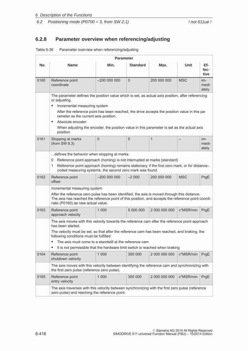
6
6.2 Positioning mode (P0700 = 3, from SW 2.1)
6-416� Siemens AG 2014 All Rights Reserved
SIMODRIVE 611 universal Function Manual (FBU) – 10/2014 Edition
6.2.8 Parameter overview when referencing/adjusting
Table 6-36 Parameter overview when referencing/adjusting
Parameter
No. Name Min. Standard Max. Unit Ef-fec-tive
0160 Reference point coordinate
–200 000 000 0 200 000 000 MSC im-medi-ately
The parameter defines the position value which is set, as actual axis position, after referencingor adjusting.� Incremental measuring system
After the reference point has been reached, the drive accepts the position value in this pa-rameter as the current axis position.
� Absolute encoderWhen adjusting the encoder, the position value in this parameter is set as the actual axisposition.
0161 Stopping at marks (from SW 8.3)
0 0 1 – im-medi-ately
...defines the behavior when stopping at marks.0 Reference point approach (homing) is not interrupted at marks (standard)1 Reference point approach (homing) remains stationary, if the first zero mark, or for distance–
coded measuring systems, the second zero mark was found.
0162 Reference point offset
–200 000 000 –2 000 200 000 000 MSC PrgE
Incremental measuring systemAfter the reference zero pulse has been identified, the axis is moved through this distance. The axis has reached the reference point of this position, and accepts the reference point coordi-nate (P0160) as new actual value.
0163 Reference point approach velocity
1 000 5 000 000 2 000 000 000 c*MSR/min PrgE
The axis moves with this velocity towards the reference cam after the reference point approachhas been started.The velocity must be set, so that after the reference cam has been reached, and braking, thefollowing conditions must be fulfilled:� The axis must come to a standstill at the reference cam� It is not permissible that the hardware limit switch is reached when braking
0164 Reference pointshutdown velocity
1 000 300 000 2 000 000 000 c*MSR/min PrgE
The axis moves with this velocity between identifying the reference cam and synchronizing withthe first zero pulse (reference zero pulse).
0165 Reference pointentry velocity
1 000 300 000 2 000 000 000 c*MSR/min PrgE
The axis traverses with this velocity between synchronizing with the first zero pulse (referencezero pulse) and reaching the reference point.
6 Description of the Functions
! not 611ue !
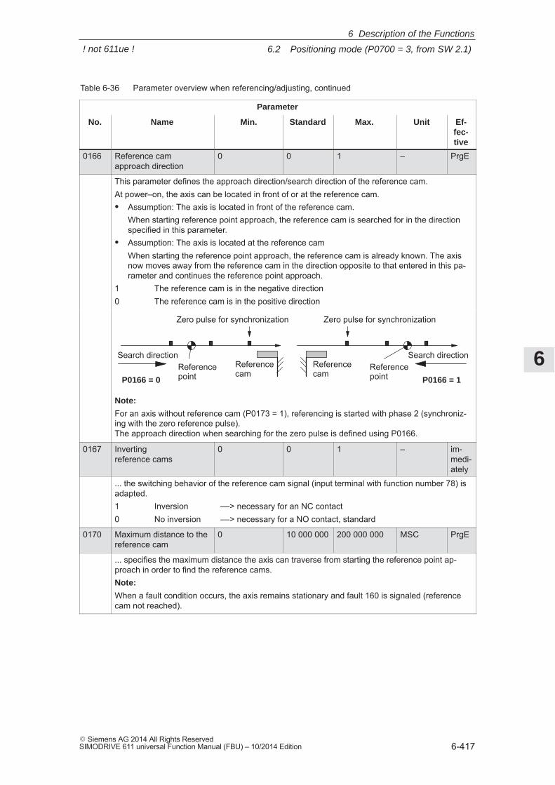
6
6.2 Positioning mode (P0700 = 3, from SW 2.1)
6-417� Siemens AG 2014 All Rights ReservedSIMODRIVE 611 universal Function Manual (FBU) – 10/2014 Edition
Table 6-36 Parameter overview when referencing/adjusting, continued
Parameter
No. Ef-fec-tive
UnitMax.StandardMin.Name
0166 Reference cam approach direction
0 0 1 – PrgE
This parameter defines the approach direction/search direction of the reference cam.At power–on, the axis can be located in front of or at the reference cam.� Assumption: The axis is located in front of the reference cam.
When starting reference point approach, the reference cam is searched for in the directionspecified in this parameter.
� Assumption: The axis is located at the reference camWhen starting the reference point approach, the reference cam is already known. The axisnow moves away from the reference cam in the direction opposite to that entered in this pa-rameter and continues the reference point approach.
1 The reference cam is in the negative direction0 The reference cam is in the positive direction
P0166 = 0
Referencecam
Zero pulse for synchronization
P0166 = 1
Referencecam
Zero pulse for synchronization
Referencepoint
Referencepoint
Search direction Search direction
Note:
For an axis without reference cam (P0173 = 1), referencing is started with phase 2 (synchroniz-ing with the zero reference pulse). The approach direction when searching for the zero pulse is defined using P0166.
0167 Invertingreference cams
0 0 1 – im-medi-ately
... the switching behavior of the reference cam signal (input terminal with function number 78) isadapted.1 Inversion ––> necessary for an NC contact0 No inversion ––> necessary for a NO contact, standard
0170 Maximum distance to thereference cam
0 10 000 000 200 000 000 MSC PrgE
... specifies the maximum distance the axis can traverse from starting the reference point ap-proach in order to find the reference cams.Note:
When a fault condition occurs, the axis remains stationary and fault 160 is signaled (referencecam not reached).
6 Description of the Functions
! not 611ue !
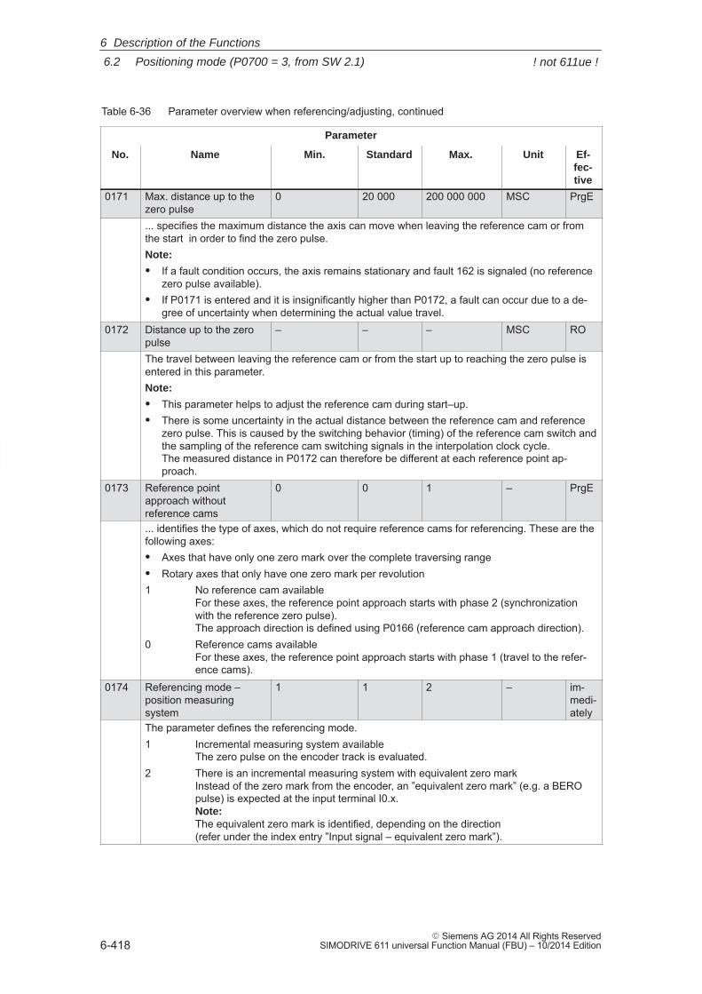
6
6.2 Positioning mode (P0700 = 3, from SW 2.1)
6-418� Siemens AG 2014 All Rights Reserved
SIMODRIVE 611 universal Function Manual (FBU) – 10/2014 Edition
Table 6-36 Parameter overview when referencing/adjusting, continued
Parameter
No. Ef-fec-tive
UnitMax.StandardMin.Name
0171 Max. distance up to thezero pulse
0 20 000 200 000 000 MSC PrgE
... specifies the maximum distance the axis can move when leaving the reference cam or fromthe start in order to find the zero pulse.Note:
� If a fault condition occurs, the axis remains stationary and fault 162 is signaled (no referencezero pulse available).
� If P0171 is entered and it is insignificantly higher than P0172, a fault can occur due to a de-gree of uncertainty when determining the actual value travel.
0172 Distance up to the zeropulse
– – – MSC RO
The travel between leaving the reference cam or from the start up to reaching the zero pulse isentered in this parameter.Note:
� This parameter helps to adjust the reference cam during start–up.� There is some uncertainty in the actual distance between the reference cam and reference
zero pulse. This is caused by the switching behavior (timing) of the reference cam switch andthe sampling of the reference cam switching signals in the interpolation clock cycle. The measured distance in P0172 can therefore be different at each reference point ap-proach.
0173 Reference pointapproach withoutreference cams
0 0 1 – PrgE
... identifies the type of axes, which do not require reference cams for referencing. These are thefollowing axes:� Axes that have only one zero mark over the complete traversing range� Rotary axes that only have one zero mark per revolution1 No reference cam available
For these axes, the reference point approach starts with phase 2 (synchronizationwith the reference zero pulse). The approach direction is defined using P0166 (reference cam approach direction).
0 Reference cams availableFor these axes, the reference point approach starts with phase 1 (travel to the refer-ence cams).
0174 Referencing mode – position measuringsystem
1 1 2 – im-medi-ately
The parameter defines the referencing mode.1 Incremental measuring system available
The zero pulse on the encoder track is evaluated.2 There is an incremental measuring system with equivalent zero mark
Instead of the zero mark from the encoder, an ”equivalent zero mark” (e.g. a BEROpulse) is expected at the input terminal I0.x. Note: The equivalent zero mark is identified, depending on the direction(refer under the index entry ”Input signal – equivalent zero mark”).
6 Description of the Functions
! not 611ue !
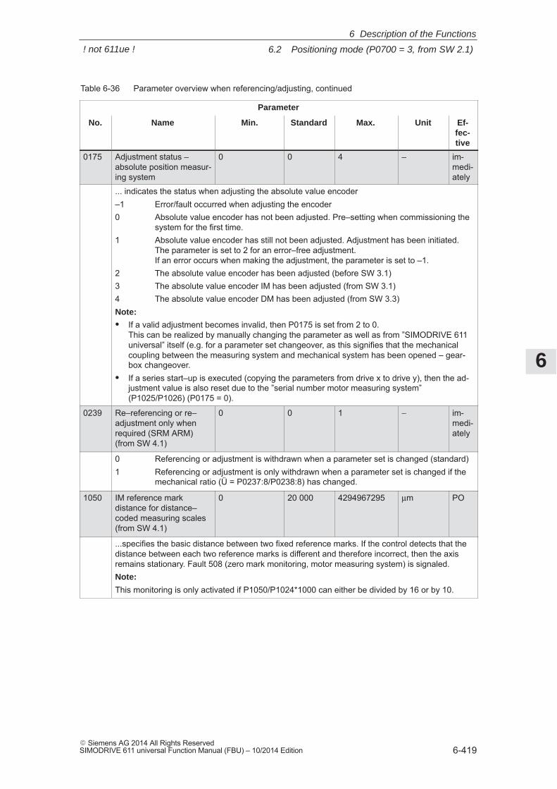
6
6.2 Positioning mode (P0700 = 3, from SW 2.1)
6-419� Siemens AG 2014 All Rights ReservedSIMODRIVE 611 universal Function Manual (FBU) – 10/2014 Edition
Table 6-36 Parameter overview when referencing/adjusting, continued
Parameter
No. Ef-fec-tive
UnitMax.StandardMin.Name
0175 Adjustment status – absolute position measur-ing system
0 0 4 – im-medi-ately
... indicates the status when adjusting the absolute value encoder–1 Error/fault occurred when adjusting the encoder0 Absolute value encoder has not been adjusted. Pre–setting when commissioning the
system for the first time.1 Absolute value encoder has still not been adjusted. Adjustment has been initiated.
The parameter is set to 2 for an error–free adjustment.If an error occurs when making the adjustment, the parameter is set to –1.
2 The absolute value encoder has been adjusted (before SW 3.1)3 The absolute value encoder IM has been adjusted (from SW 3.1)4 The absolute value encoder DM has been adjusted (from SW 3.3)Note:
� If a valid adjustment becomes invalid, then P0175 is set from 2 to 0. This can be realized by manually changing the parameter as well as from ”SIMODRIVE 611universal” itself (e.g. for a parameter set changeover, as this signifies that the mechanicalcoupling between the measuring system and mechanical system has been opened – gear-box changeover.
� If a series start–up is executed (copying the parameters from drive x to drive y), then the ad-justment value is also reset due to the ”serial number motor measuring system”(P1025/P1026) (P0175 = 0).
0239 Re–referencing or re–adjustment only whenrequired (SRM ARM) (from SW 4.1)
0 0 1 − im-medi-ately
0 Referencing or adjustment is withdrawn when a parameter set is changed (standard)1 Referencing or adjustment is only withdrawn when a parameter set is changed if the
mechanical ratio (Ü = P0237:8/P0238:8) has changed.
1050 IM reference markdistance for distance–coded measuring scales (from SW 4.1)
0 20 000 4294967295 μm PO
...specifies the basic distance between two fixed reference marks. If the control detects that thedistance between each two reference marks is different and therefore incorrect, then the axisremains stationary. Fault 508 (zero mark monitoring, motor measuring system) is signaled.Note:
This monitoring is only activated if P1050/P1024*1000 can either be divided by 16 or by 10.
6 Description of the Functions
! not 611ue !
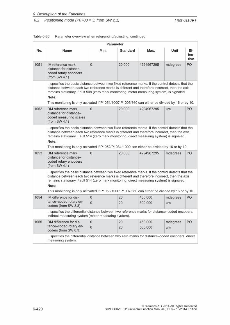
6
6.2 Positioning mode (P0700 = 3, from SW 2.1)
6-420� Siemens AG 2014 All Rights Reserved
SIMODRIVE 611 universal Function Manual (FBU) – 10/2014 Edition
Table 6-36 Parameter overview when referencing/adjusting, continued
Parameter
No. Ef-fec-tive
UnitMax.StandardMin.Name
1051 IM reference markdistance for distance–coded rotary encoders (from SW 4.1)
0 20 000 4294967295 mdegrees PO
...specifies the basic distance between two fixed reference marks. If the control detects that thedistance between each two reference marks is different and therefore incorrect, then the axisremains stationary. Fault 508 (zero mark monitoring, motor measuring system) is signaled.Note:
This monitoring is only activated if P1051/1000*P1005/360 can either be divided by 16 or by 10.
1052 DM reference markdistance for distance–coded measuring scales (from SW 4.1)
0 20 000 4294967295 μm PO
...specifies the basic distance between two fixed reference marks. If the control detects that thedistance between each two reference marks is different and therefore incorrect, then the axisremains stationary. Fault 514 (zero mark monitoring, direct measuring system) is signaled.Note:
This monitoring is only activated if P1052/P1034*1000 can either be divided by 16 or by 10.
1053 DM reference markdistance for distance–coded rotary encoders (from SW 4.1)
0 20 000 4294967295 mdegrees PO
...specifies the basic distance between two fixed reference marks. If the control detects that thedistance between each two reference marks is different and therefore incorrect, then the axisremains stationary. Fault 514 (zero mark monitoring, direct measuring system) is signaled.Note:
This monitoring is only activated if P1053/1000*P1007/360 can either be divided by 16 or by 10.
1054 IM difference for dis-tance–coded rotary en-coders (from SW 8.3)
00
2020
450 000500 000
mdegreesμm
PO
...specifies the differential distance between two reference marks for distance–coded encoders,indirect measuring system (motor measuring system).
1055 DM difference for dis-tance–coded rotary en-coders (from SW 8.3)
00
2020
450 000500 000
mdegreesμm
PO
...specifies the differential distance between two zero marks for distance–coded encoders, directmeasuring system.
6 Description of the Functions
! not 611ue !
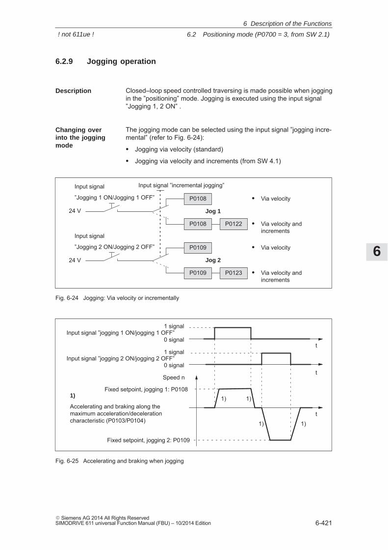
6
6.2 Positioning mode (P0700 = 3, from SW 2.1)
6-421� Siemens AG 2014 All Rights ReservedSIMODRIVE 611 universal Function Manual (FBU) – 10/2014 Edition
6.2.9 Jogging operation
Closed–loop speed controlled traversing is made possible when joggingin the ”positioning” mode. Jogging is executed using the input signal”Jogging 1, 2 ON” .
The jogging mode can be selected using the input signal ”jogging incre-mental” (refer to Fig. 6-24):
� Jogging via velocity (standard)
� Jogging via velocity and increments (from SW 4.1)
Input signal
”Jogging 1 ON/Jogging 1 OFF”
Input signal
”Jogging 2 ON/Jogging 2 OFF”
Input signal ”incremental jogging”
24 V
24 V
P0109 P0123
P0108 P0122
Jog 1
P0108
P0109
� Via velocity andincrements
� Via velocity
� Via velocity andincrements
� Via velocity
Jog 2
Fig. 6-24 Jogging: Via velocity or incrementally
Fixed setpoint, jogging 1: P0108
t
t
t
Speed n
1 signal
0 signalInput signal ”jogging 1 ON/jogging 1 OFF”
Fixed setpoint, jogging 2: P0109
1 signal
0 signalInput signal ”jogging 2 ON/jogging 2 OFF”
1)
Accelerating and braking along themaximum acceleration/decelerationcharacteristic (P0103/P0104)
1) 1)
1) 1)
Fig. 6-25 Accelerating and braking when jogging
Description
Changing overinto the joggingmode
6 Description of the Functions
! not 611ue !
6
6.2 Positioning mode (P0700 = 3, from SW 2.1)
6-422� Siemens AG 2014 All Rights Reserved
SIMODRIVE 611 universal Function Manual (FBU) – 10/2014 Edition
Note
The following is valid when jogging:� The traversing direction is defined by the sign of P0108 or P0109.� When the jogging signal is withdrawn, the axis comes to an
immediate stop and, at the next ”1” signal is re–started with thesame task.
� It is not possible to continue after incremental jogging has beeninterrupted.
� The software limit switches are effective if they have been activatedand set for this axis, and the axis has been referenced. Contrary tooperation in the positioning mode, the axis only starts to brakewhen the software limit switch is reached. The travel beyond thesoftware limit switch depends on the active velocity setpoint forjogging 1/2 (P0108/P0109, override) and the selected maximumdeceleration (P0104).
� The override is effective.� If input signals for jogging 1 and 2 are simultaneously available,
then an appropriate fault is signaled.� If the position reference value is inverted (P0231, P0232), then the
direction of rotation also changes in the jogging mode.� For speed–controlled jogging, the drive is in the follow–up status. In
this case, the velocity setpoint and actual value are formed from the speed controller.
The following parameters are available for the ”jogging mode” function:� P0108 Velocity setpoint, jogging 1� P0109 Velocity setpoint, jogging 2� P0122 Jogging 1, increments (from SW 4.1)� P0123 Jogging 2, increments (from SW 4.1)
The following signals are available for the ”jogging mode” function:
� Input signals(refer under index entry ”Input signal, digital – ...”)– Input signal ”jogging 1 ON/jogging 1 OFF”
––> using an input terminal with function number 62––> via PROFIBUS control signal ”STW1.8”
– Input signal ”jogging 2 ON/jogging 2 OFF”––> using an input terminal with function number 63––> via PROFIBUS control signal ”STW1.9”
– Input signal, ”incremental jogging ” (from SW 4.1)––> using an input terminal with function number 61––> via the PROFIBUS control signal ”PosStw.5”
Parameteroverview(refer to ChapterA.1)
Input signals (referto Chapter 6.4)
6 Description of the Functions
! not 611ue !
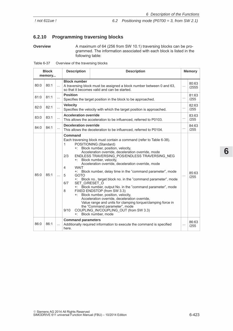
6
6.2 Positioning mode (P0700 = 3, from SW 2.1)
6-423� Siemens AG 2014 All Rights ReservedSIMODRIVE 611 universal Function Manual (FBU) – 10/2014 Edition
6.2.10 Programming traversing blocks
A maximum of 64 (256 from SW 10.1) traversing blocks can be pro-grammed. The information associated with each block is listed in thefollowing table:
Table 6-37 Overview of the traversing blocks
Blockmemory...
Description Description Memory
80:0 80:1 ...Block numberA traversing block must be assigned a block number between 0 and 63,so that it becomes valid and can be started.
... 80:63/2555
81:0 81:1 ... PositionSpecifies the target position in the block to be approached. ... 81:63
/255
82:0 82:1 ... VelocitySpecifies the velocity with which the target position is approached. ... 82:63
/255
83:0 83:1 ... Acceleration overrideThis allows the acceleration to be influenced, referred to P0103. ... 83:63
/255
84:0 84:1 ... Deceleration overrideThis allows the deceleration to be influenced, referred to P0104. ... 84:63
/255
85:0 85:1 ...
CommandEach traversing block must contain a command (refer to Table 6-38).1 POSITIONING (Standard)
+: Block number, position, velocity, Acceleration override, deceleration override, mode
2/3 ENDLESS TRAVERSING_POS/ENDLESS TRAVERSING_NEG+: Block number, velocity,
Acceleration override, deceleration override, mode4 WAIT
+: Block number, delay time in the ”command parameter”, mode5 GOTO
+: Block no., target block no. in the ”command parameter”, mode 6/7 SET_O/RESET_O
+: Block number, output No. in the ”command parameter”, mode8 FIXED ENDSTOP (from SW 3.3)
+: Block number, position, velocity, Acceleration override, deceleration override, Value range and units for clamping torque/clamping force inthe ”Command parameter”, mode
9/10 COUPLING_IN/COUPLING_OUT (from SW 3.3)+: Block number, mode
... 85:63/255
86:0 86:1 ...Command parametersAdditionally required information to execute the command is specifiedhere.
... 86:63/255
Overview
6 Description of the Functions
! not 611ue !
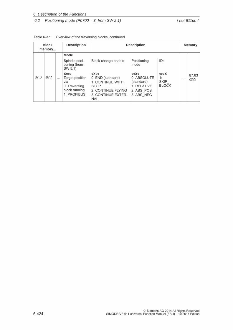
6
6.2 Positioning mode (P0700 = 3, from SW 2.1)
6-424� Siemens AG 2014 All Rights Reserved
SIMODRIVE 611 universal Function Manual (FBU) – 10/2014 Edition
Table 6-37 Overview of the traversing blocks, continued
Blockmemory...
MemoryDescriptionDescription
Mode
Spindle posi-tioning (fromSW 5.1)
Block change enable Positioningmode
IDs
87:0 87:1 ...XxxxTarget positionvia0: Traversingblock running1: PROFIBUS
xXxx0: END (standard)1: CONTINUE WITHSTOP2: CONTINUE FLYING3: CONTINUE EXTER-NAL
xxXx0: ABSOLUTE(standard)1: RELATIVE2: ABS_POS3: ABS_NEG
xxxX1: SKIP_BLOCK
... 87:63/255
6 Description of the Functions
! not 611ue !
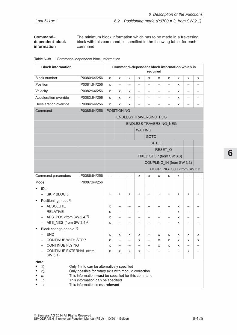
6
6.2 Positioning mode (P0700 = 3, from SW 2.1)
6-425� Siemens AG 2014 All Rights ReservedSIMODRIVE 611 universal Function Manual (FBU) – 10/2014 Edition
The minimum block information which has to be made in a traversingblock with this command, is specified in the following table, for eachcommand.
Table 6-38 Command–dependent block information
Block information Command–dependent block information which isrequired
Block number P0080:64/256 x x x x x x x x x x
Position P0081:64/256 x – – – – – – x – –
Velocity P0082:64/256 x x x – – – – x – –
Acceleration override P0083:64/256 x x x – – – – x – –
Deceleration override P0084:64/256 x x x – – – – x – –
Command P0085:64/256 POSITIONING
ENDLESS TRAVERSING_POS
ENDLESS TRAVERSING_NEG
WAITING
GOTO
SET_O
RESET_O
FIXED STOP (from SW 3.3)
COUPLING_IN (from SW 3.3)
COUPLING_OUT (from SW 3.3)
Command parameters P0086:64/256 – – – x x x x x – –
Mode P0087:64/256
� IDs– SKIP BLOCK + + + + + + + + + +
� Positioning mode1)
– ABSOLUTE– RELATIVE– ABS_POS (from SW 2.4)2)
– ABS_NEG (from SW 2.4)2)
xxxx
––––
––––
––––
––––
––––
––––
xxxx
––––
––––
� Block change enable 1)
– END– CONTINUE WITH STOP– CONTINUE FLYING– CONTINUE EXTERNAL (from
SW 3.1)
xxxx
x––x
x––x
xx–x
––––
xxx–
xxx–
xxx–
xx–x
xx––
Note:� 1) Only 1 info can be alternatively specified� 2) Only possible for rotary axis with modulo correction� x: This information must be specified for this command� +: This information can be specified� –: This information is not relevant
Command–dependent blockinformation
6 Description of the Functions
! not 611ue !
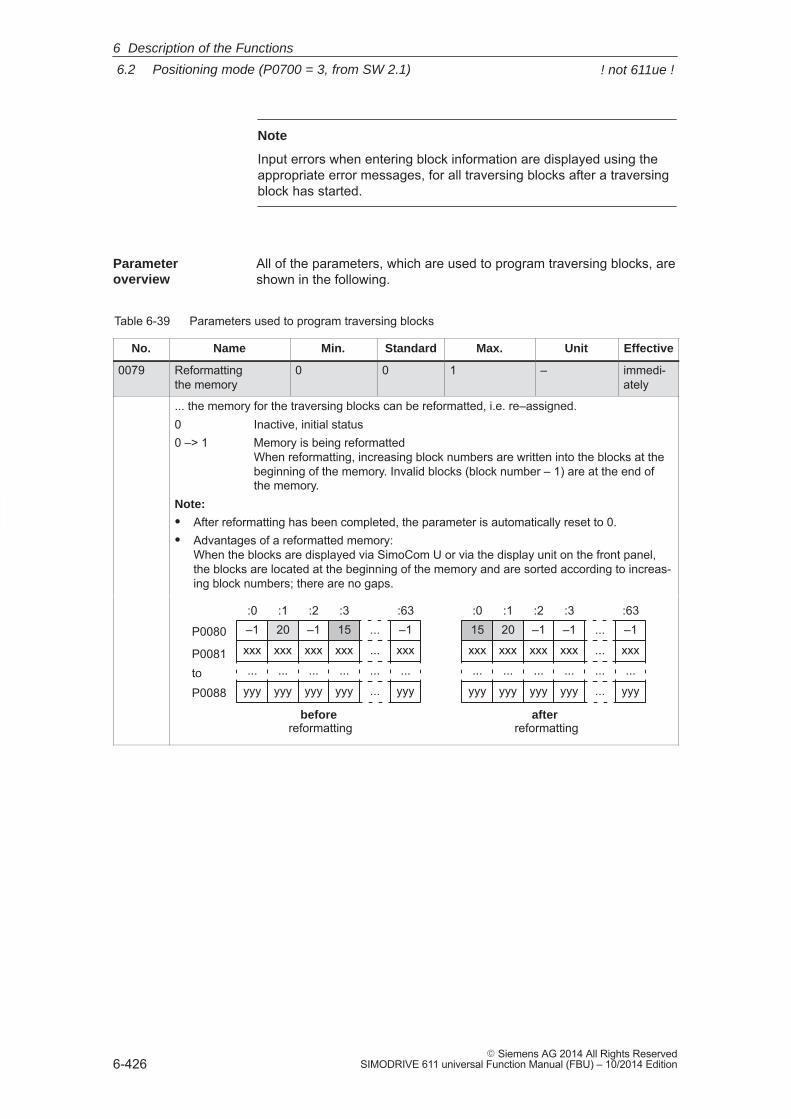
6
6.2 Positioning mode (P0700 = 3, from SW 2.1)
6-426� Siemens AG 2014 All Rights Reserved
SIMODRIVE 611 universal Function Manual (FBU) – 10/2014 Edition
Note
Input errors when entering block information are displayed using theappropriate error messages, for all traversing blocks after a traversingblock has started.
All of the parameters, which are used to program traversing blocks, areshown in the following.
Table 6-39 Parameters used to program traversing blocks
No. Name Min. Standard Max. Unit Effective
0079 Reformatting the memory
0 0 1 – immedi-ately
... the memory for the traversing blocks can be reformatted, i.e. re–assigned.0 Inactive, initial status0 –> 1 Memory is being reformatted
When reformatting, increasing block numbers are written into the blocks at thebeginning of the memory. Invalid blocks (block number – 1) are at the end ofthe memory.
Note:
� After reformatting has been completed, the parameter is automatically reset to 0.� Advantages of a reformatted memory:
When the blocks are displayed via SimoCom U or via the display unit on the front panel,the blocks are located at the beginning of the memory and are sorted according to increas-ing block numbers; there are no gaps.
P0080
P0081
P0088
before reformatting
to
after reformatting
–1
xxx
...
yyy
:020
xxx
...
yyy
:115
xxx
...
yyy
:3–1
xxx
...
yyy
:2–1
xxx
...
yyy
:63
...
...
...
...
–1
xxx
...
yyy
:220
xxx
...
yyy
:115
xxx
...
yyy
:0–1
xxx
...
yyy
:3–1
xxx
...
yyy
:63
...
...
...
...
Parameter overview
6 Description of the Functions
! not 611ue !
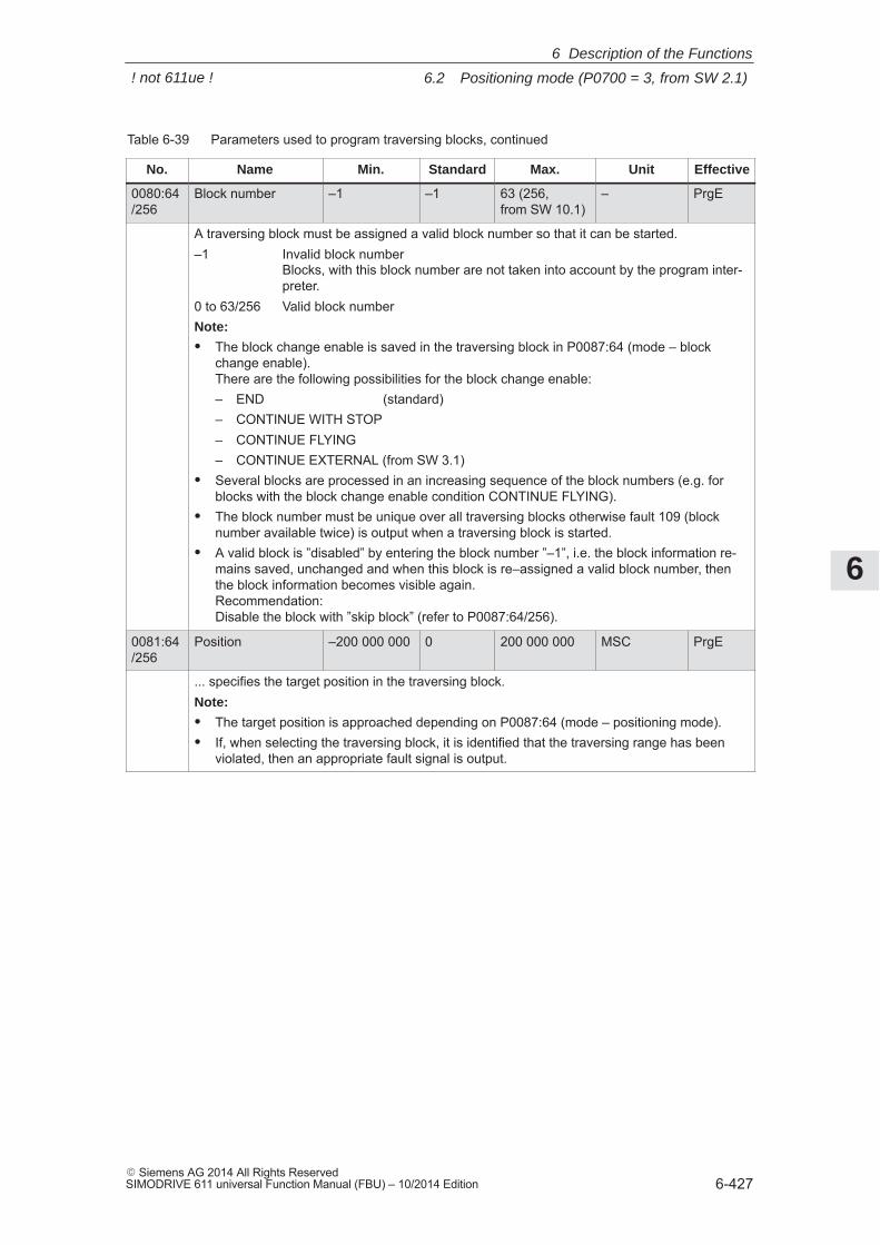
6
6.2 Positioning mode (P0700 = 3, from SW 2.1)
6-427� Siemens AG 2014 All Rights ReservedSIMODRIVE 611 universal Function Manual (FBU) – 10/2014 Edition
Table 6-39 Parameters used to program traversing blocks, continued
No. EffectiveUnitMax.StandardMin.Name
0080:64/256
Block number –1 –1 63 (256, from SW 10.1)
– PrgE
A traversing block must be assigned a valid block number so that it can be started.–1 Invalid block number
Blocks, with this block number are not taken into account by the program inter-preter.
0 to 63/256 Valid block numberNote:
� The block change enable is saved in the traversing block in P0087:64 (mode – blockchange enable). There are the following possibilities for the block change enable:– END (standard)– CONTINUE WITH STOP– CONTINUE FLYING– CONTINUE EXTERNAL (from SW 3.1)
� Several blocks are processed in an increasing sequence of the block numbers (e.g. forblocks with the block change enable condition CONTINUE FLYING).
� The block number must be unique over all traversing blocks otherwise fault 109 (blocknumber available twice) is output when a traversing block is started.
� A valid block is ”disabled” by entering the block number ”–1”, i.e. the block information re-mains saved, unchanged and when this block is re–assigned a valid block number, thenthe block information becomes visible again.Recommendation: Disable the block with ”skip block” (refer to P0087:64/256).
0081:64/256
Position –200 000 000 0 200 000 000 MSC PrgE
... specifies the target position in the traversing block.Note:
� The target position is approached depending on P0087:64 (mode – positioning mode).� If, when selecting the traversing block, it is identified that the traversing range has been
violated, then an appropriate fault signal is output.
6 Description of the Functions
! not 611ue !
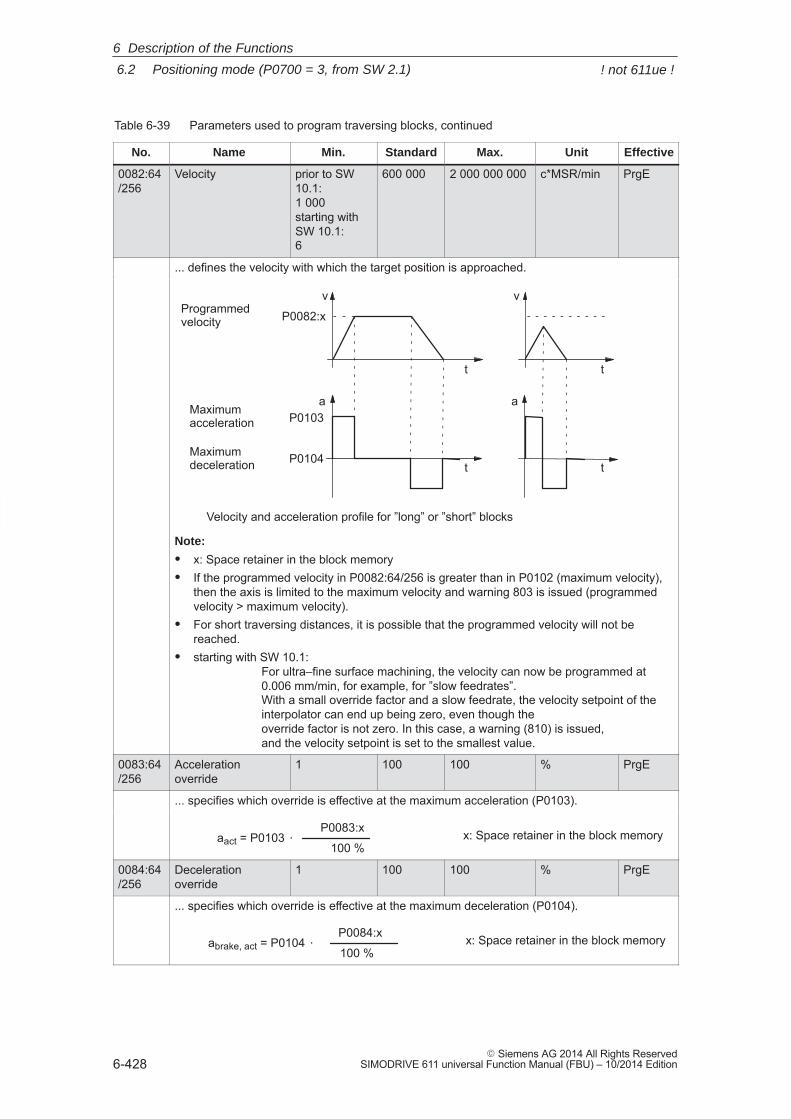
6
6.2 Positioning mode (P0700 = 3, from SW 2.1)
6-428� Siemens AG 2014 All Rights Reserved
SIMODRIVE 611 universal Function Manual (FBU) – 10/2014 Edition
Table 6-39 Parameters used to program traversing blocks, continued
No. EffectiveUnitMax.StandardMin.Name
0082:64/256
Velocity prior to SW10.1:1 000starting withSW 10.1:6
600 000 2 000 000 000 c*MSR/min PrgE
... defines the velocity with which the target position is approached.
v
t
aP0103
P0104
P0082:xProgrammed velocity
Maximum acceleration
Maximum deceleration
v
a
Velocity and acceleration profile for ”long” or ”short” blocks
t
t
t
Note:
� x: Space retainer in the block memory� If the programmed velocity in P0082:64/256 is greater than in P0102 (maximum velocity),
then the axis is limited to the maximum velocity and warning 803 is issued (programmedvelocity > maximum velocity).
� For short traversing distances, it is possible that the programmed velocity will not bereached.
� starting with SW 10.1:For ultra–fine surface machining, the velocity can now be programmed at 0.006 mm/min, for example, for ”slow feedrates”.With a small override factor and a slow feedrate, the velocity setpoint of theinterpolator can end up being zero, even though the override factor is not zero. In this case, a warning (810) is issued, and the velocity setpoint is set to the smallest value.
0083:64/256
Accelerationoverride
1 100 100 % PrgE
... specifies which override is effective at the maximum acceleration (P0103).
aact = P0103 P0083:x
100 %x: Space retainer in the block memory
0084:64/256
Deceleration override
1 100 100 % PrgE
... specifies which override is effective at the maximum deceleration (P0104).
abrake, act = P0104 P0084:x
100 %x: Space retainer in the block memory
6 Description of the Functions
! not 611ue !
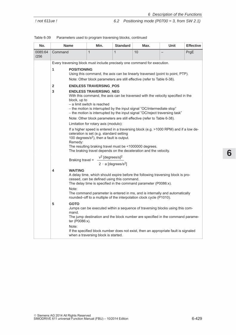
6
6.2 Positioning mode (P0700 = 3, from SW 2.1)
6-429� Siemens AG 2014 All Rights ReservedSIMODRIVE 611 universal Function Manual (FBU) – 10/2014 Edition
Table 6-39 Parameters used to program traversing blocks, continued
No. EffectiveUnitMax.StandardMin.Name
0085:64/256
Command 1 1 10 – PrgE
Every traversing block must include precisely one command for execution.
1 POSITIONINGUsing this command, the axis can be linearly traversed (point to point, PTP).Note: Other block parameters are still effective (refer to Table 6-38).
2 ENDLESS TRAVERSING_POS
3 ENDLESS TRAVERSING_NEGWith this command, the axis can be traversed with the velocity specified in theblock, up to– a limit switch is reached– the motion is interrupted by the input signal ”OC/intermediate stop” – the motion is interrupted by the input signal ”OC/reject traversing task”Note: Other block parameters are still effective (refer to Table 6-38).Limitation for rotary axis (modulo):If a higher speed is entered in a traversing block (e.g. >1000 RPM) and if a low de-celeration is set (e.g. standard setting 100 degrees/s2), then a fault is output.Remedy:The resulting braking travel must be <1000000 degrees. The braking travel depends on the deceleration and the velocity.
Braking travel =v2 [degrees/s]2
2 a [degrees/s2]
4 WAITINGA delay time, which should expire before the following traversing block is pro-cessed, can be defined using this command. The delay time is specified in the command parameter (P0086:x).Note: The command parameter is entered in ms, and is internally and automaticallyrounded–off to a multiple of the interpolation clock cycle (P1010).
5 GOTOJumps can be executed within a sequence of traversing blocks using this com-mand. The jump destination and the block number are specified in the command parame-ter (P0086:x).Note:If the specified block number does not exist, then an appropriate fault is signaledwhen a traversing block is started.
6 Description of the Functions
! not 611ue !
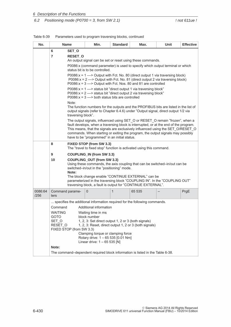
6
6.2 Positioning mode (P0700 = 3, from SW 2.1)
6-430� Siemens AG 2014 All Rights Reserved
SIMODRIVE 611 universal Function Manual (FBU) – 10/2014 Edition
Table 6-39 Parameters used to program traversing blocks, continued
No. EffectiveUnitMax.StandardMin.Name
6 SET_O
7 RESET_OAn output signal can be set or reset using these commands.P0086:x (command parameter) is used to specify which output terminal or whichstatus bit is to be controlled.P0086:x = 1 ––> Output with Fct. No. 80 (direct output 1 via traversing block) P0086:x = 2 ––> Output with Fct. No. 81 (direct output 2 via traversing block)P0086:x = 3 ––> Output with Fct. Nos. 80 and 81 are controlledP0086:x = 1 ––> status bit ”direct output 1 via traversing block” P0086:x = 2 ––> status bit ”direct output 2 via traversing block”P0086:x = 3 ––> both status bits are controlledNote:The function numbers for the outputs and the PROFIBUS bits are listed in the list ofoutput signals (refer to Chapter 6.4.6) under ”Output signal, direct output 1/2 viatraversing block”.The output signals, influenced using SET_O or RESET_O remain ”frozen”, when afault develops, when a traversing block is interrupted, or at the end of the program.This means, that the signals are exclusively influenced using the SET_O/RESET_Ocommands. When starting or exiting the program, the output signals may possiblyhave to be ”programmed” in an initial status.
8 FIXED STOP (from SW 3.3)The ”travel to fixed stop” function is activated using this command.
9 COUPLING_IN (from SW 3.3)
10 COUPLING_OUT (from SW 3.3)Using these commands, the axis coupling that can be switched–in/out can beswitched–in/out in the ”positioning” mode.Note:The block change enable ”CONTINUE EXTERNAL” can be parameterized in the traversing block ”COUPLING IN”. In the ”COUPLING OUT”traversing block, a fault is output for ”CONTINUE EXTERNAL”.
0086:64/256
Command parame-ters
0 1 65 535 – PrgE
... specifies the additional information required for the following commands.Command Additional informationWAITING Waiting time in msGOTO block numberSET_O 1, 2, 3: Set direct output 1, 2 or 3 (both signals)RESET_O 1, 2, 3: Reset, direct output 1, 2 or 3 (both signals) FIXED STOP (from SW 3.3)
Clamping torque or clamping force Rotary drive: 1 – 65 535 [0.01 Nm]Linear drive: 1 – 65 535 [N]
Note:
The command–dependent required block information is listed in the Table 6-38.
6 Description of the Functions
! not 611ue !
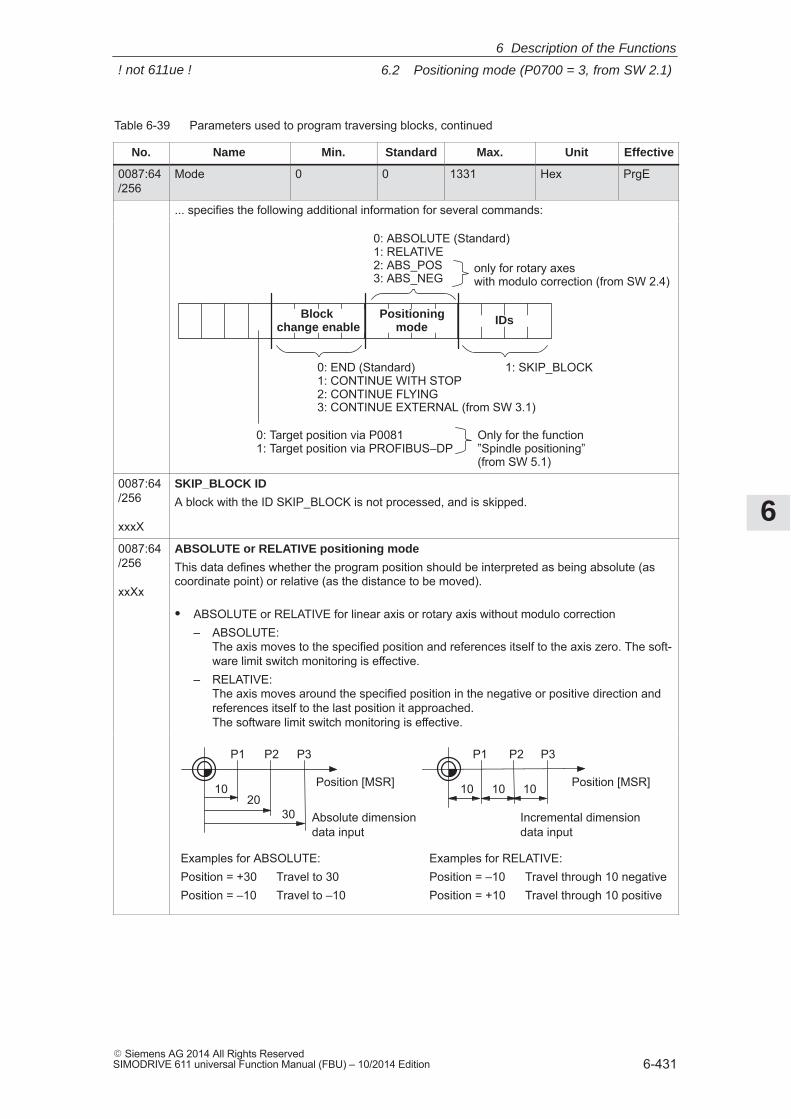
6
6.2 Positioning mode (P0700 = 3, from SW 2.1)
6-431� Siemens AG 2014 All Rights ReservedSIMODRIVE 611 universal Function Manual (FBU) – 10/2014 Edition
Table 6-39 Parameters used to program traversing blocks, continued
No. EffectiveUnitMax.StandardMin.Name
0087:64/256
Mode 0 0 1331 Hex PrgE
... specifies the following additional information for several commands:
0: Target position via P00811: Target position via PROFIBUS–DP
0: ABSOLUTE (Standard)1: RELATIVE2: ABS_POS3: ABS_NEG
0: END (Standard)1: CONTINUE WITH STOP2: CONTINUE FLYING3: CONTINUE EXTERNAL (from SW 3.1)
1: SKIP_BLOCK
Block change enable
Positioningmode IDs
only for rotary axeswith modulo correction (from SW 2.4)
Only for the function ”Spindle positioning” (from SW 5.1)
0087:64/256
xxxX
SKIP_BLOCK ID
A block with the ID SKIP_BLOCK is not processed, and is skipped.
0087:64/256
xxXx
ABSOLUTE or RELATIVE positioning mode
This data defines whether the program position should be interpreted as being absolute (ascoordinate point) or relative (as the distance to be moved).
� ABSOLUTE or RELATIVE for linear axis or rotary axis without modulo correction– ABSOLUTE:
The axis moves to the specified position and references itself to the axis zero. The soft-ware limit switch monitoring is effective.
– RELATIVE: The axis moves around the specified position in the negative or positive direction andreferences itself to the last position it approached. The software limit switch monitoring is effective.
10 Position [MSR]
P1 P3P2
Incremental dimensiondata input
10
30
Position [MSR]
P1 P3P2
20Absolute dimensiondata input
Examples for ABSOLUTE:Position = +30 Travel to 30Position = –10 Travel to –10
Examples for RELATIVE:Position = –10 Travel through 10 negativePosition = +10 Travel through 10 positive
10 10
6 Description of the Functions
! not 611ue !
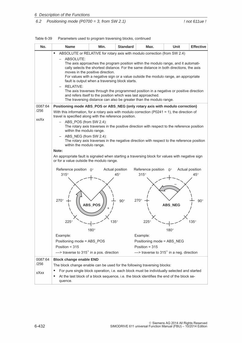
6
6.2 Positioning mode (P0700 = 3, from SW 2.1)
6-432� Siemens AG 2014 All Rights Reserved
SIMODRIVE 611 universal Function Manual (FBU) – 10/2014 Edition
Table 6-39 Parameters used to program traversing blocks, continued
No. EffectiveUnitMax.StandardMin.Name
� ABSOLUTE or RELATIVE for rotary axis with modulo correction (from SW 2.4)– ABSOLUTE:
The axis approaches the program position within the modulo range, and it automati-cally selects the shortest distance. For the same distance in both directions, the axismoves in the positive direction.For values with a negative sign or a value outside the modulo range, an appropriatefault is output when a traversing block starts.
– RELATIVE: The axis traverses through the programmed position in a negative or positive directionand refers itself to the position which was last approached.The traversing distance can also be greater than the modulo range.
0087:64/256
xxXx
Positioning mode ABS_POS or ABS_NEG (only rotary axis with modulo correction)
With this information, for a rotary axis with modulo correction (P0241 = 1), the direction oftravel is specified along with the reference position.
– ABS_POS (from SW 2.4):The rotary axis traverses in the positive direction with respect to the reference positionwithin the modulo range.
– ABS_NEG (from SW 2.4):The rotary axis traverses in the negative direction with respect to the reference positionwithin the modulo range.
Note:
An appropriate fault is signaled when starting a traversing block for values with negative signor for a value outside the modulo range.
–
+
Example:Positioning mode = ABS_POSPosition = 315––> traverse to 315� in a pos. direction
Example:Positioning mode = ABS_NEGPosition = 315––> traverse to 315� in a neg. direction
ABS_POS ABS_NEG
Reference position45°
90°
135°
180°
225°
270°
315°0° Actual position Actual positionReference position
45°
90°
135°
180°
225°
270°
315°0°
0087:64/256
xXxx
Block change enable END
The block change enable can be used for the following traversing blocks:� For pure single block operation, i.e. each block must be individually selected and started� At the last block of a block sequence, i.e. the block identifies the end of the block se-
quence.
6 Description of the Functions
! not 611ue !
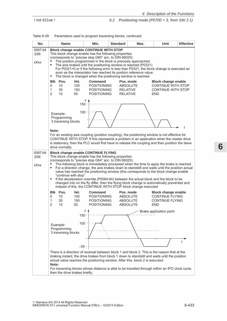
6
6.2 Positioning mode (P0700 = 3, from SW 2.1)
6-433� Siemens AG 2014 All Rights ReservedSIMODRIVE 611 universal Function Manual (FBU) – 10/2014 Edition
Table 6-39 Parameters used to program traversing blocks, continued
No. EffectiveUnitMax.StandardMin.Name
0087:64/256
xXxx
Block change enable CONTINUE WITH STOPThis block change enable has the following properties(corresponds to ”precise stop G60” acc. to DIN 66025):� The position programmed in the block is precisely approached� The axis braked until the positioning window is reached (P0321)
For P0321=0 or if the following error is less than P0321, the block change is executed assoon as the interpolator has reached its position reference value.
� The block is changed when the positioning window is reached.Blk Pos. Vel. Command Pos. mode Block change enable0 10 100 POSITIONING ABSOLUTE CONTINUE WITH STOP1 30 150 POSITIONING RELATIVE CONTINUE WITH STOP2 10 50 POSITIONING RELATIVE END
100
v
t
Example:Programming 3 traversing blocks
150
Note:For an existing axis coupling (position coupling), the positioning window is not effective forCONTINUE WITH STOP. If this represents a problem in an application when the master driveis stationary, then the PLC would first have to release the coupling and then position the slavedrive normally.
0087:64/256
xXxx
Block change enable CONTINUE FLYINGThis block change enable has the following properties(corresponds to ”precise stop G64” acc. to DIN 66025):� The following block is immediately processed when the time to apply the brake is reached� For a direction change, the axis brakes down to standstill and waits until the position actual
value has reached the positioning window (this corresponds to the block change enable”continue with stop”
� If the deceleration override (P0084:64) between the actual block and the block to bechanged into on the fly differ, then the flying block change is automatically prevented andinstead of this, the CONTINUE WITH STOP block change executed
Blk Pos. Vel. Command Pos. mode Block change enable0 10 100 POSITIONING ABSOLUTE CONTINUE FLYING1 30 150 POSITIONING ABSOLUTE CONTINUE FLYING2 10 50 POSITIONING ABSOLUTE END
100
v
t
Example:Programming 3 traversing blocks
150
–50
Brake application point
There is a direction of reversal between block 1 and block 2. This is the reason that at thebraking instant, the drive brakes from block 1 down to standstill and waits until the positionactual value reaches the positioning window. After this, block 2 is executed.Note:For traversing blocks whose distance is able to be travelled through within an IPO clock cycle,then the drive brakes briefly.
6 Description of the Functions
! not 611ue !
6
6.2 Positioning mode (P0700 = 3, from SW 2.1)
6-434� Siemens AG 2014 All Rights Reserved
SIMODRIVE 611 universal Function Manual (FBU) – 10/2014 Edition
Table 6-39 Parameters used to program traversing blocks, continued
No. EffectiveUnitMax.StandardMin.Name
0087:64/256
xXxx
Block change enable CONTINUE EXTERNAL (from SW 3.1)This block change enable has the following properties:� For a traversing block with the block change enable CONTINUE EXTERNAL, a flying
block change is made if an edge of the input signal ”external block change” is identified. Ifthe deceleration override (P0084:64/256) differs between the current and the block whichis to be changed into flying, then a flying block change is made.
� When using the commands SET_O and RESET_O, it is not possible to use the block change enable CONTINUE EXTERNAL!
� What happens, if...?– The following traversing block is programmed in the RELATIVE positioning mode
––> The programmed position refers to the actual value at the instant that the external block change is requested
– The braking travel is greater than the distance programmed in the following block––> The axis is held at the parameterized deceleration ramp and then traverses
to the target position in the opposite direction.– A different behavior is necessary for ”external block change”?
Then the required behavior must be set in P0110:P0110 = 0 (standard) ––> If the signal is not available up to the start of braking, then the axis
is stopped in front of the target position (dependent on: Acceleration, deceleration,positioning
velocity) and fault 109 (external block change not requested in the block) is output.
= 1 ––> If the signal is not present up to the start of braking, then a flying block change is made (refer to block change enable CONTINUE FLYING).
= 2 ––> The block is traversed, independent of the signal, to the end. The system only waits for the signal at the end of the block; when the signal is detected, a block
change is executed.= 3 (from SW 5.1) ––> if the signal is not present up to the end of the block, then the
axis waits for the signal and when the signal is identified, a block change is made.Note: When P0110 is changed, the change is not accepted after v_set = 0, butinstead,
only after the end of the program when the traversing block is re–started.– The subsequent traversing block is programmed with the WAIT command?
After the signal edge has been detected, the position actual value is written into P0026,and the axis is braked down to standstill with the programmed deceleration (P0104 +deceleration override in P0084:64/256) and then the system waits. The other positiondata refer to the block change position.
– Does the acceleration override (P0083:64/256) or deceleration override(P0084:64/256) differ between the actual (current) block and the following block to bechanged into?When the ”external block change” input signal is detected, the acceleration or decel-eration override of the block, which is now current, becomes valid and is immediatelyeffective.
– Was the deceleration changed during the braking ramp when positioning in absoluteterms?––> a change is not accepted. Positioning is realized with the previously set
braking ramp (P0084 or P0094).– The subsequent traversing block in the positioning mode ABS_POS/ABS_NEG (only
rotary axis with modulo correction) and the deceleration override (P0084:64/256) be-tween the actual block and the block to be changed into on the fly differ––> A block change enable ”CONTINUE FLYING” or ”CONTINUE WITH STOP”
is executed depending on the block change position and the braking travel , i.e. the programmed position is reached by the shortest distance.
Note:� For the block change configuration P0110 = 2 or 3, it is not permissible that fast inputs I0.x
are used, as, for these, the block change can be initiated from different signal edges.
6 Description of the Functions
! not 611ue !
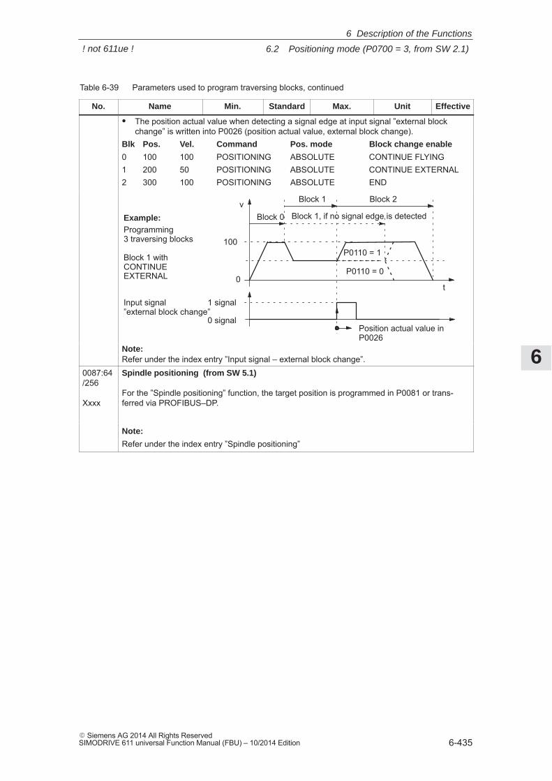
6
6.2 Positioning mode (P0700 = 3, from SW 2.1)
6-435� Siemens AG 2014 All Rights ReservedSIMODRIVE 611 universal Function Manual (FBU) – 10/2014 Edition
Table 6-39 Parameters used to program traversing blocks, continued
No. EffectiveUnitMax.StandardMin.Name
� The position actual value when detecting a signal edge at input signal ”external blockchange” is written into P0026 (position actual value, external block change).
Blk Pos. Vel. Command Pos. mode Block change enable
0 100 100 POSITIONING ABSOLUTE CONTINUE FLYING1 200 50 POSITIONING ABSOLUTE CONTINUE EXTERNAL2 300 100 POSITIONING ABSOLUTE END
100
v
t
Example:Programming 3 traversing blocks
Block 1 with CONTINUEEXTERNAL 0
1 signal
0 signal
Input signal ”external block change”
Block 0
Block 1 Block 2
Block 1, if no signal edge is detected
P0110 = 0
P0110 = 1
Position actual value inP0026
Note:Refer under the index entry ”Input signal – external block change”.
0087:64/256
Xxxx
Spindle positioning (from SW 5.1)
For the ”Spindle positioning” function, the target position is programmed in P0081 or trans-ferred via PROFIBUS–DP.
Note:
Refer under the index entry ”Spindle positioning”
6 Description of the Functions
! not 611ue !
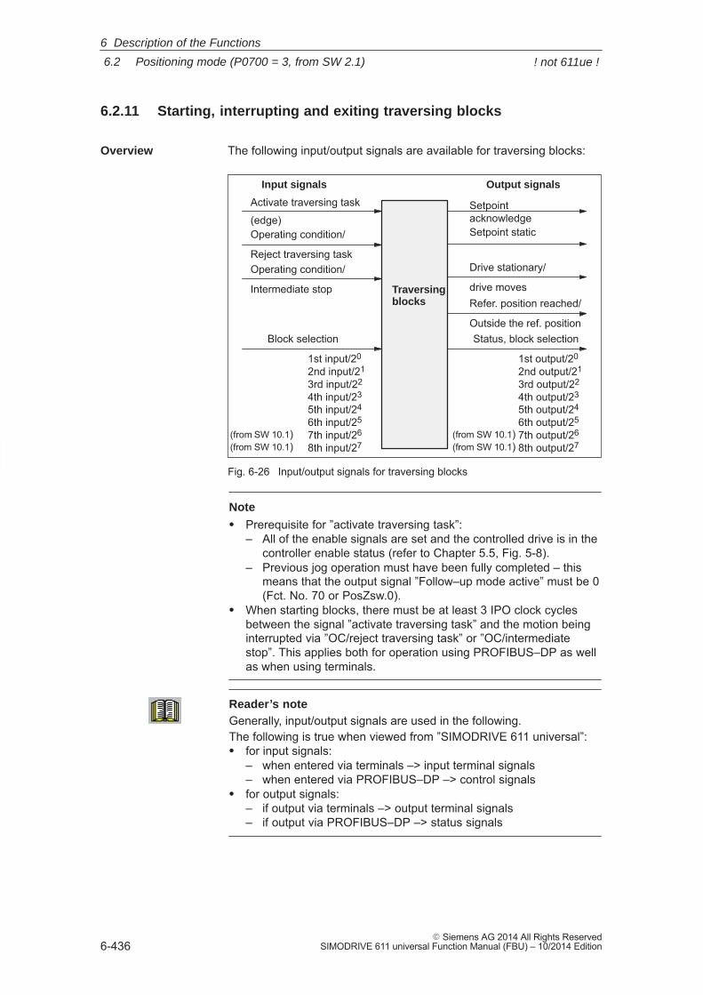
6
6.2 Positioning mode (P0700 = 3, from SW 2.1)
6-436� Siemens AG 2014 All Rights Reserved
SIMODRIVE 611 universal Function Manual (FBU) – 10/2014 Edition
6.2.11 Starting, interrupting and exiting traversing blocks
The following input/output signals are available for traversing blocks:
Block selection
1st input/20
2nd input/21
3rd input/22
4th input/23
5th input/24
6th input/25
7th input/26
8th input/27
Activate traversing task
(edge)
Traversing blocks
Operating condition/
Reject traversing taskOperating condition/
Intermediate stop
SetpointacknowledgeSetpoint static
Drive stationary/
drive movesRefer. position reached/
Outside the ref. position
Input signals Output signals
Status, block selection
1st output/20
2nd output/21
3rd output/22
4th output/23
5th output/24
6th output/25
7th output/26
8th output/27(from SW 10.1)(from SW 10.1)
(from SW 10.1)(from SW 10.1)
Fig. 6-26 Input/output signals for traversing blocks
Note
� Prerequisite for ”activate traversing task”:– All of the enable signals are set and the controlled drive is in the
controller enable status (refer to Chapter 5.5, Fig. 5-8).– Previous jog operation must have been fully completed – this
means that the output signal ”Follow–up mode active” must be 0(Fct. No. 70 or PosZsw.0).
� When starting blocks, there must be at least 3 IPO clock cyclesbetween the signal ”activate traversing task” and the motion beinginterrupted via ”OC/reject traversing task” or ”OC/intermediatestop”. This applies both for operation using PROFIBUS–DP as wellas when using terminals.
Reader’s noteGenerally, input/output signals are used in the following.The following is true when viewed from ”SIMODRIVE 611 universal”:� for input signals:
– when entered via terminals –> input terminal signals– when entered via PROFIBUS–DP –> control signals
� for output signals:– if output via terminals –> output terminal signals– if output via PROFIBUS–DP –> status signals
Overview
6 Description of the Functions
! not 611ue !
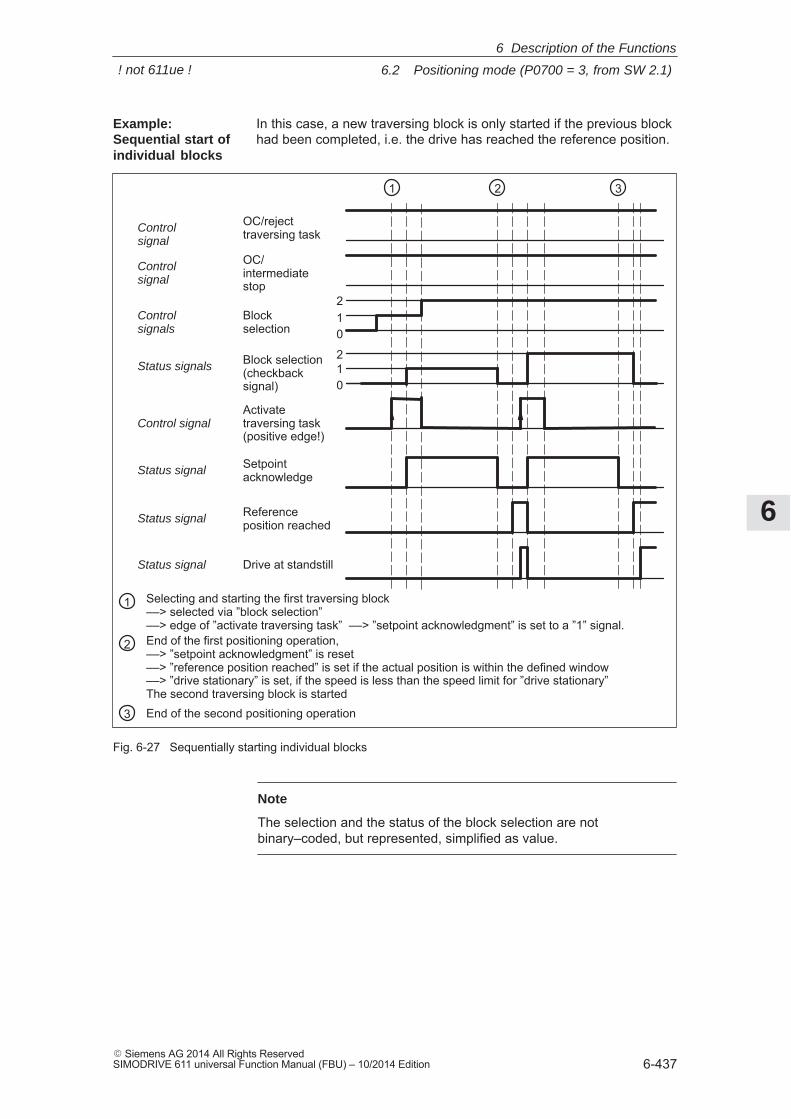
6
6.2 Positioning mode (P0700 = 3, from SW 2.1)
6-437� Siemens AG 2014 All Rights ReservedSIMODRIVE 611 universal Function Manual (FBU) – 10/2014 Edition
In this case, a new traversing block is only started if the previous blockhad been completed, i.e. the drive has reached the reference position.
Activatetraversing task(positive edge!)
Setpointacknowledge
Referenceposition reached
Drive at standstill
1 2 3
012
Blockselection
012Block selection
(checkbacksignal)
OC/rejecttraversing task
OC/intermediatestop
Controlsignal
Controlsignal
Controlsignals
Status signals
Control signal
Status signal
Status signal
Status signal
1 Selecting and starting the first traversing block––> selected via ”block selection”––> edge of ”activate traversing task” ––> ”setpoint acknowledgment” is set to a ”1” signal.
2 End of the first positioning operation, ––> ”setpoint acknowledgment” is reset ––> ”reference position reached” is set if the actual position is within the defined window––> ”drive stationary” is set, if the speed is less than the speed limit for ”drive stationary”The second traversing block is started
3 End of the second positioning operation
Fig. 6-27 Sequentially starting individual blocks
Note
The selection and the status of the block selection are notbinary–coded, but represented, simplified as value.
Example: Sequential start ofindividual blocks
6 Description of the Functions
! not 611ue !
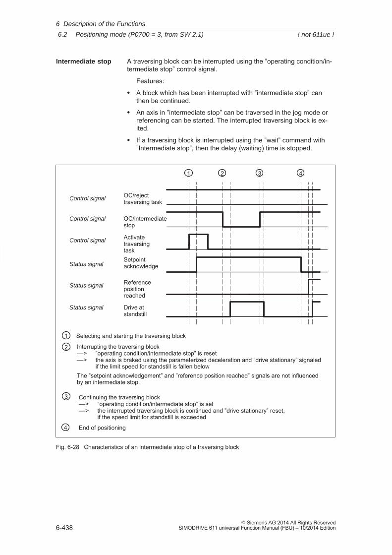
6
6.2 Positioning mode (P0700 = 3, from SW 2.1)
6-438� Siemens AG 2014 All Rights Reserved
SIMODRIVE 611 universal Function Manual (FBU) – 10/2014 Edition
A traversing block can be interrupted using the ”operating condition/in-termediate stop” control signal.
Features:
� A block which has been interrupted with ”intermediate stop” canthen be continued.
� An axis in ”intermediate stop” can be traversed in the jog mode orreferencing can be started. The interrupted traversing block is ex-ited.
� If a traversing block is interrupted using the ”wait” command with”Intermediate stop”, then the delay (waiting) time is stopped.
ActivatetraversingtaskSetpointacknowledge
Referencepositionreached
Drive atstandstill
1 2 3
OC/intermediatestop
4
OC/rejecttraversing taskControl signal
Control signal
Control signal
Status signal
Status signal
Status signal
1 Selecting and starting the traversing block
2 Interrupting the traversing block ––> ”operating condition/intermediate stop” is reset––> the axis is braked using the parameterized deceleration and ”drive stationary” signaled
if the limit speed for standstill is fallen belowThe ”setpoint acknowledgement” and ”reference position reached” signals are not influencedby an intermediate stop.
3 Continuing the traversing block––> ”operating condition/intermediate stop” is set––> the interrupted traversing block is continued and ”drive stationary” reset,
if the speed limit for standstill is exceeded
4 End of positioning
Fig. 6-28 Characteristics of an intermediate stop of a traversing block
Intermediate stop
6 Description of the Functions
! not 611ue !
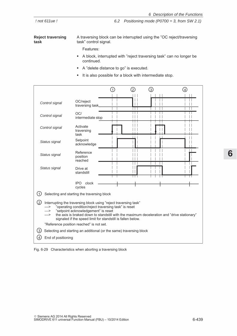
6
6.2 Positioning mode (P0700 = 3, from SW 2.1)
6-439� Siemens AG 2014 All Rights ReservedSIMODRIVE 611 universal Function Manual (FBU) – 10/2014 Edition
A traversing block can be interrupted using the ”OC reject/traversingtask” control signal.
Features:
� A block, interrupted with ”reject traversing task” can no longer becontinued.
� A ”delete distance to go” is executed.
� It is also possible for a block with intermediate stop.
ActivatetraversingtaskSetpointacknowledge
Referencepositionreached
Drive atstandstill
1 2 3
OC/rejecttraversing task
4
OC/intermediate stopControl signal
Control signal
Control signal
Status signal
Status signal
Status signal
IPO clockcycles
1 Selecting and starting the traversing block
2 Interrupting the traversing block using ”reject traversing task”––> ”operating condition/reject traversing task” is reset ––> ”setpoint acknowledgement” is reset––> the axis is braked down to standstill with the maximum deceleration and ”drive stationary”
signaled if the speed limit for standstill is fallen below.”Reference position reached” is not set.
3 Selecting and starting an additional (or the same) traversing block
4 End of positioning
Fig. 6-29 Characteristics when aborting a traversing block
Reject traversingtask
6 Description of the Functions
! not 611ue !
6
6.2 Positioning mode (P0700 = 3, from SW 2.1)
6-440� Siemens AG 2014 All Rights Reserved
SIMODRIVE 611 universal Function Manual (FBU) – 10/2014 Edition
Information about the traversing block presently being processed canbe read from the following parameters:
� P0001 Actual traversing block – block number
� P0002 Actual traversing block – position
� P0003 Actual traversing block – velocity
� P0004 Actual traversing block – acceleration override
� P0005 Actual traversing block – deceleration override
� P0006 Actual traversing block – command
� P0007 Actual traversing block – command parameter
� P0008 Actual traversing block – mode
Diagnostics:Image of the actual traversing block(refer to ChapterA.1)
6 Description of the Functions
! not 611ue !
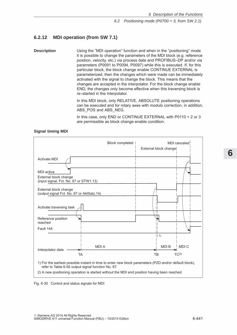
6
6.2 Positioning mode (P0700 = 3, from SW 2.1)
6-441� Siemens AG 2014 All Rights ReservedSIMODRIVE 611 universal Function Manual (FBU) – 10/2014 Edition
6.2.12 MDI operation (from SW 7.1)
Using the ”MDI operation” function and when in the ”positioning” modeit is possible to change the parameters of the MDI block (e.g. referenceposition, velocity, etc.) via process data and PROFIBUS–DP and/or viaparameters (P0091 to P0094, P0097) while this is executed. If, for thisparticular block, the block change enable CONTINUE EXTERNAL isparameterized, then the changes which were made can be immediatelyactivated with the signal to change the block. This means that thechanges are accepted in the interpolator. For the block change enableEND, the changes only become effective when this traversing block isre–started in the interpolator.
In this MDI block, only RELATIVE, ABSOLUTE positioning operationscan be executed and for rotary axes with modulo correction, in addition,ABS_POS and ABS_NEG.
In this case, only END or CONTINUE EXTERNAL with P0110 = 2 or 3are permissible as block change enable condition.
Activate MDI
Activate traversing task
Reference positionreached
MDI activeExternal block change (input signal, Fct. No. 67 or STW1.13)
Fault 144
Block completedExternal block change
MDI canceled
MDI A MDI B MDI C
TA TB TC2)
1) For the earliest possible instant in time to enter new block parameters (PZD and/or default block), refer to Table 6-50 output signal function No. 67.2) A new positioning operation is started without the MDI end position having been reached.
Interpolator data
External block change (output signal Fct. No. 67 or AktSatz.14)
1)
Fig. 6-30 Control and status signals for MDI
Description
Signal timing MDI
6 Description of the Functions
6
6.2 Positioning mode (P0700 = 3, from SW 2.1)
6-442� Siemens AG 2014 All Rights Reserved
SIMODRIVE 611 universal Function Manual (FBU) – 10/2014 Edition
The data available in the block parameters (PZD and/or default block)at instant in time TA is transferred into the interpolator and processed.This data (MDI A) remains valid up to instant in time TB when new datais transferred into the interpolator. In turn, these (MDI B) remain validuntil new data is transferred (TC/MDI C).
Note
The following applies for the MDI mode:� MDI is switched–in using the ”activate MDI” signal via terminal
(Fct.No. 83) or PROFIBUS (SatzAnw.15). The ”MDI active” signalis used for the feedback signal which is either transferred viaterminal (Fct. No. 83) or PROFIBUS (AktSatz.15). A traversingblock can be entered using process data (MDIPos, MDIVel,MDIAcc, MDIDec, MDIMode) via PROFIBUS–DP and started usingthe signal ”activate traversing task”.
� If either no MDI block or only individual block parameters areentered via PROFIBUS–DP, then the missing parameters are takenfrom the MDI default block (P0091 to P0094, P0097). However, ifMDI process data are parameterized in P0915:17 and these arealso transferred via PROFIBUS–DP, then the values in parametersP0091 to P0094 and P0097 are not taken into account.
� If CONTINUE EXTERNAL is parameterized as block changeenable, then actual block parameters of the MDI block (entered viaPZDs and/or MDI default block) are immediately transferred intothe interpolator with the signal ”external block change”.
� For an MDI block, the block change enable signals CONTINUEWITH STOP and CONTINUE FLYING, are not possible. The blockchange enable CONTINUE EXTERNAL is only permissible withP0110 = 2 or 3 (configuration of an external block change).
� If the signal ”Activate MDI” is set to 0 while an MDI block is stillrunning, then fault 144 is initiated. This means that MDI operationcan only be disabled after the target position has been reached.
� The signals ”operating condition/reject traversing task” and ”operating condition/intermediate stop” are effective just the sameas in the normal ”positioning” operating mode. The monitoring functions, e.g. software and hardware switches arealso active.
6 Description of the Functions
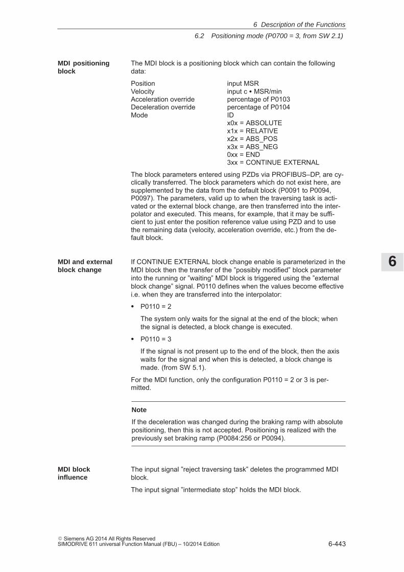
6
6.2 Positioning mode (P0700 = 3, from SW 2.1)
6-443� Siemens AG 2014 All Rights ReservedSIMODRIVE 611 universal Function Manual (FBU) – 10/2014 Edition
The MDI block is a positioning block which can contain the followingdata:
Position input MSRVelocity input c � MSR/minAcceleration override percentage of P0103Deceleration override percentage of P0104Mode ID
x0x = ABSOLUTEx1x = RELATIVEx2x = ABS_POSx3x = ABS_NEG0xx = END3xx = CONTINUE EXTERNAL
The block parameters entered using PZDs via PROFIBUS–DP, are cy-clically transferred. The block parameters which do not exist here, aresupplemented by the data from the default block (P0091 to P0094,P0097). The parameters, valid up to when the traversing task is acti-vated or the external block change, are then transferred into the inter-polator and executed. This means, for example, that it may be suffi-cient to just enter the position reference value using PZD and to usethe remaining data (velocity, acceleration override, etc.) from the de-fault block.
If CONTINUE EXTERNAL block change enable is parameterized in theMDI block then the transfer of the ”possibly modified” block parameterinto the running or ”waiting” MDI block is triggered using the ”externalblock change” signal. P0110 defines when the values become effectivei.e. when they are transferred into the interpolator:
� P0110 = 2
The system only waits for the signal at the end of the block; whenthe signal is detected, a block change is executed.
� P0110 = 3
If the signal is not present up to the end of the block, then the axiswaits for the signal and when this is detected, a block change ismade. (from SW 5.1).
For the MDI function, only the configuration P0110 = 2 or 3 is per-mitted.
Note
If the deceleration was changed during the braking ramp with absolutepositioning, then this is not accepted. Positioning is realized with thepreviously set braking ramp (P0084:256 or P0094).
The input signal ”reject traversing task” deletes the programmed MDIblock.
The input signal ”intermediate stop” holds the MDI block.
MDI positioningblock
MDI and externalblock change
MDI blockinfluence
6 Description of the Functions
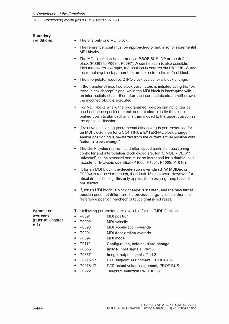
6
6.2 Positioning mode (P0700 = 3, from SW 2.1)
6-444� Siemens AG 2014 All Rights Reserved
SIMODRIVE 611 universal Function Manual (FBU) – 10/2014 Edition
� There is only one MDI block.
� The reference point must be approached or set, also for incrementalMDI blocks.
� The MDI block can be entered via PROFIBUS–DP or the defaultblock (P0091 to P0094, P0097). A combination is also possible.This means, for example, the position is entered via PROFIBUS andthe remaining block parameters are taken from the default block.
� The interpolator requires 2 IPO clock cycles for a block change.
� If the transfer of modified block parameters is initiated using the ”ex-ternal block change” signal while the MDI block is interrupted withan intermediate stop – then after the intermediate stop is withdrawn,the modified block is executed.
� For MDI blocks where the programmed position can no longer bereached in the specified direction of rotation, initially the axis isbraked down to standstill and is then moved to the target position inthe opposite direction.
� If relative positioning (incremental dimension) is parameterized foran MDI block, then for a CONTINUE EXTERNAL block changeenable positioning is re–started from the current actual position with”external block change”.
� The clock cycles (current controller, speed controller, positioningcontroller and interpolation clock cycle) are, for ”SIMODRIVE 611universal” set as standard and must be increased for a double–axismodule for two–axis operation (P1000, P1001, P1009, P1010).
� If, for an MDI block, the deceleration override (STW MDIDec orP0094) is reduced too much, then fault 131 is output. However, forabsolute positioning, this only applies if the braking ramp has stillnot started.
� If, for an MDI block, a block change is initiated, and the new targetposition does not differ from the previous target position, then the”reference position reached” output signal is not reset.
The following parameters are available for the ”MDI” function:� P0091 MDI position� P0092 MDI velocity� P0093 MDI acceleration override� P0094 MDI deceleration override� P0097 MDI mode� P0110 Configuration, external block change� P0655 Image, input signals, Part 3� P0657 Image, output signals, Part 2� P0915:17 PZD setpoint assignment, PROFIBUS� P0916:17 PZD actual value assignment, PROFIBUS� P0922 Telegram selection PROFIBUS
Boundaryconditions
Parameteroverview (refer to ChapterA.1)
6 Description of the Functions
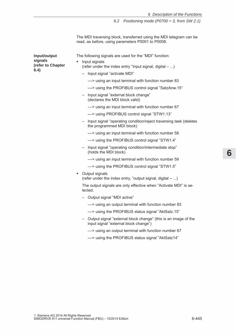
6
6.2 Positioning mode (P0700 = 3, from SW 2.1)
6-445� Siemens AG 2014 All Rights ReservedSIMODRIVE 611 universal Function Manual (FBU) – 10/2014 Edition
The MDI traversing block, transferred using the MDI telegram can beread, as before, using parameters P0001 to P0008.
The following signals are used for the ”MDI” function:� Input signals
(refer under the index entry ”Input signal, digital – ...)
– Input signal ”activate MDI”
––> using an input terminal with function number 83
––> using the PROFIBUS control signal ”SatzAnw.15”
– Input signal ”external block change” (declares the MDI block valid)
––> using an input terminal with function number 67
––> using PROFIBUS control signal ”STW1.13”
– Input signal ”operating condition/reject traversing task (deletesthe programmed MDI block)
––> using an input terminal with function number 58
––> using the PROFIBUS control signal ”STW1.4”
– Input signal ”operating condition/intermediate stop” (holds the MDI block)
––> using an input terminal with function number 59
––> using the PROFIBUS control signal ”STW1.5”
� Output signals(refer under the index entry, ”output signal, digital – ...)
The output signals are only effective when ”Activate MDI” is se-lected.
– Output signal ”MDI active”
––> using an output terminal with function number 83
––> using the PROFIBUS status signal ”AktSatz.15”
– Output signal ”external block change” (this is an image of theinput signal ”external block change”)
––> using an output terminal with function number 67
––> using the PROFIBUS status signal ”AktSatz14”
Input/outputsignals(refer to Chapter6.4)
6 Description of the Functions
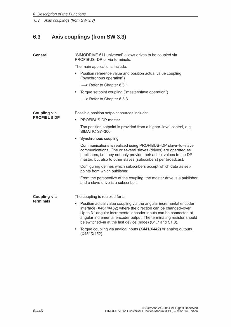
6
6.3 Axis couplings (from SW 3.3)
6-446� Siemens AG 2014 All Rights Reserved
SIMODRIVE 611 universal Function Manual (FBU) – 10/2014 Edition
6.3 Axis couplings (from SW 3.3)
”SIMODRIVE 611 universal” allows drives to be coupled viaPROFIBUS–DP or via terminals.
The main applications include:
� Position reference value and position actual value coupling(”synchronous operation”)
––> Refer to Chapter 6.3.1
� Torque setpoint coupling (”master/slave operation”)
––> Refer to Chapter 6.3.3
Possible position setpoint sources include:
� PROFIBUS DP master
The position setpoint is provided from a higher–level control, e.g.SIMATIC S7–300.
� Synchronous coupling
Communications is realized using PROFIBUS–DP slave–to–slavecommunications. One or several slaves (drives) are operated aspublishers, i.e. they not only provide their actual values to the DPmaster, but also to other slaves (subscribers) per broadcast.
Configuring defines which subscribers accept which data as set-points from which publisher.
From the perspective of the coupling, the master drive is a publisherand a slave drive is a subscriber.
The coupling is realized for a
� Position actual value coupling via the angular incremental encoderinterface (X461/X462) where the direction can be changed–over.Up to 31 angular incremental encoder inputs can be connected atangular incremental encoder output. The terminating resistor shouldbe switched–in at the last device (node) (S1.7 and S1.8).
� Torque coupling via analog inputs (X441/X442) or analog outputs(X451/X452).
General
Coupling viaPROFIBUS DP
Coupling viaterminals
6 Description of the Functions
6
6.3 Axis couplings (from SW 3.3)
6-447� Siemens AG 2014 All Rights ReservedSIMODRIVE 611 universal Function Manual (FBU) – 10/2014 Edition
6.3.1 Position reference value and position actual value coupling
The master drive must output process data via PROFIBUS–DP whichthe slave drive can use as position reference value. The following pro-cess data is available:
� XsollP (position reference value, number 50208)
� XistP (position actual value, number 50206)
Depending on the actual requirements, it is possible/necessary to out-put additional process data.
Beyond the output of these signals, the master drive is parameterizedas a conventional positioning drive (”Positioning” mode, P0700 = 3).
”SIMODRIVE 611 universal” assumes that when the position referencevalue XsollP is output via PROFIBUS–DP, that it is being used asmaster drive. In order that the master and slave drive simultaneouslyprocess the position reference values, the master drive correspondinglydelays transferring data to its own position controller. If the positionreference value is only to be output for diagnostic purposes, then thedelay can be disabled using P1004.9 = 0.
The angular incremental encoder interface (X461/X462) is set as out-put with P0890 = 1. This means that the incremental position actualvalue of the motor encoder or a direct measuring system is output (re-fer to Chapter 6.8.1).
An interface for an external position reference value is available in the”positioning” mode (P0700 = 3).Possible signal sources include:� PROFIBUS DP� Angular incremental encoder interface (X461/X462, switched as
input)� Internal coupling in the double axis moduleThe external position reference value is entered via PROFIBUS–DPwith the following process data� Xext (external position reference value, number 50207)Depending on the actual requirements, it is possible/necessary to out-put additional process data.The normalization of the process data XsollP, XistP (master drive) orXext (slave drive) can be parameterized using a numerator/denomina-tor pair This means that not only is a coupling possible between”SIMODRIVE 611 universal” drives, but also with other bus nodes (DPmaster or DP slave).
When the interface is switched–in, the drive responds to absolute posi-tion reference values which are entered via the angular incrementalencoder interface, switched as input, or PROFIBUS–DP. In addition,traversing blocks can be executed, which result in superimposed mo-tion.
”SIMODRIVE 611universal” as master drive
”SIMODRIVE 611universal” as master drive,angular increm.encoder interface
”SIMODRIVE 611universal” as slavedrive
6 Description of the Functions

6
6.3 Axis couplings (from SW 3.3)
6-448� Siemens AG 2014 All Rights Reserved
SIMODRIVE 611 universal Function Manual (FBU) – 10/2014 Edition
When the interface is switched–out, the drive can execute, as usual,autonomous movements via traversing blocks.
The position reference value interface can be switched–in/switched–outvia an input signal (PROFIBUS–DP or terminal) or via a traversingblock.
The following possibilities are available to reference incremental posi-tion measuring systems:
� When the interface is switched–out, the drive can be individuallyreferenced as usual (refer to Chapter 6.2.4).
� When the interface is switched–in, the drive follows the referencemotion of the master drive via the ”passive referencing” function(from SW 5.1).
6 Description of the Functions
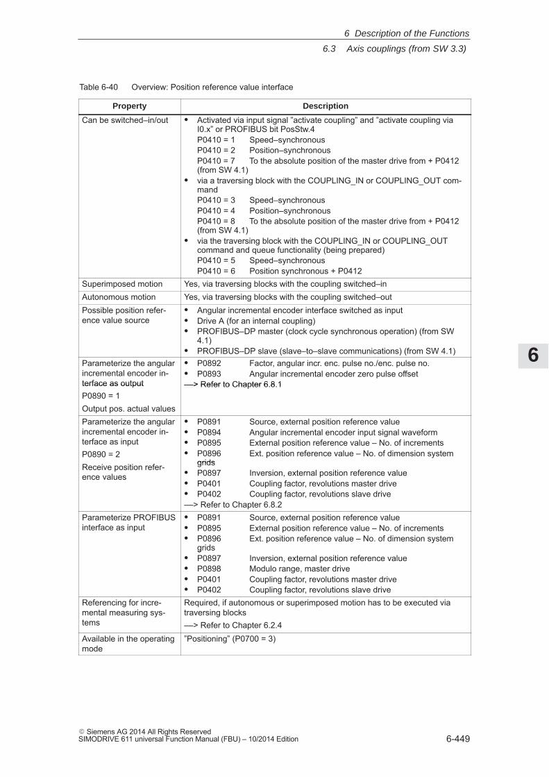
6
6.3 Axis couplings (from SW 3.3)
6-449� Siemens AG 2014 All Rights ReservedSIMODRIVE 611 universal Function Manual (FBU) – 10/2014 Edition
Table 6-40 Overview: Position reference value interface
Property Description
Can be switched–in/out � Activated via input signal ”activate coupling” and ”activate coupling viaI0.x” or PROFIBUS bit PosStw.4P0410 = 1 Speed–synchronousP0410 = 2 Position–synchronousP0410 = 7 To the absolute position of the master drive from + P0412(from SW 4.1)
� via a traversing block with the COUPLING_IN or COUPLING_OUT com-mandP0410 = 3 Speed–synchronousP0410 = 4 Position–synchronousP0410 = 8 To the absolute position of the master drive from + P0412(from SW 4.1)
� via the traversing block with the COUPLING_IN or COUPLING_OUTcommand and queue functionality (being prepared)P0410 = 5 Speed–synchronousP0410 = 6 Position synchronous + P0412
Superimposed motion Yes, via traversing blocks with the coupling switched–inAutonomous motion Yes, via traversing blocks with the coupling switched–outPossible position refer-ence value source
� Angular incremental encoder interface switched as input� Drive A (for an internal coupling)� PROFIBUS–DP master (clock cycle synchronous operation) (from SW
4.1)� PROFIBUS–DP slave (slave–to–slave communications) (from SW 4.1)
Parameterize the angularincremental encoder in-terface as output
� P0892 Factor, angular incr. enc. pulse no./enc. pulse no.� P0893 Angular incremental encoder zero pulse offset––> Refer to Chapter 6.8.1terface as output
P0890 = 1Output pos. actual values
––> Refer to Chapter 6.8.1
Parameterize the angularincremental encoder in-terface as inputP0890 = 2Receive position refer-
� P0891 Source, external position reference value� P0894 Angular incremental encoder input signal waveform� P0895 External position reference value – No. of increments� P0896 Ext. position reference value – No. of dimension system
gridsReceive position refer-ence values
grids� P0897 Inversion, external position reference value� P0401 Coupling factor, revolutions master drive� P0402 Coupling factor, revolutions slave drive––> Refer to Chapter 6.8.2
Parameterize PROFIBUSinterface as input
� P0891 Source, external position reference value� P0895 External position reference value – No. of increments� P0896 Ext. position reference value – No. of dimension system
gridsP0897 Inversion, external position reference valuegrids
� P0897 Inversion, external position reference value� P0898 Modulo range, master drive� P0401 Coupling factor, revolutions master drive� P0402 Coupling factor, revolutions slave drive
Referencing for incre-mental measuring sys-tems
Required, if autonomous or superimposed motion has to be executed viatraversing blocks––> Refer to Chapter 6.2.4
Available in the operatingmode
”Positioning” (P0700 = 3)
6 Description of the Functions
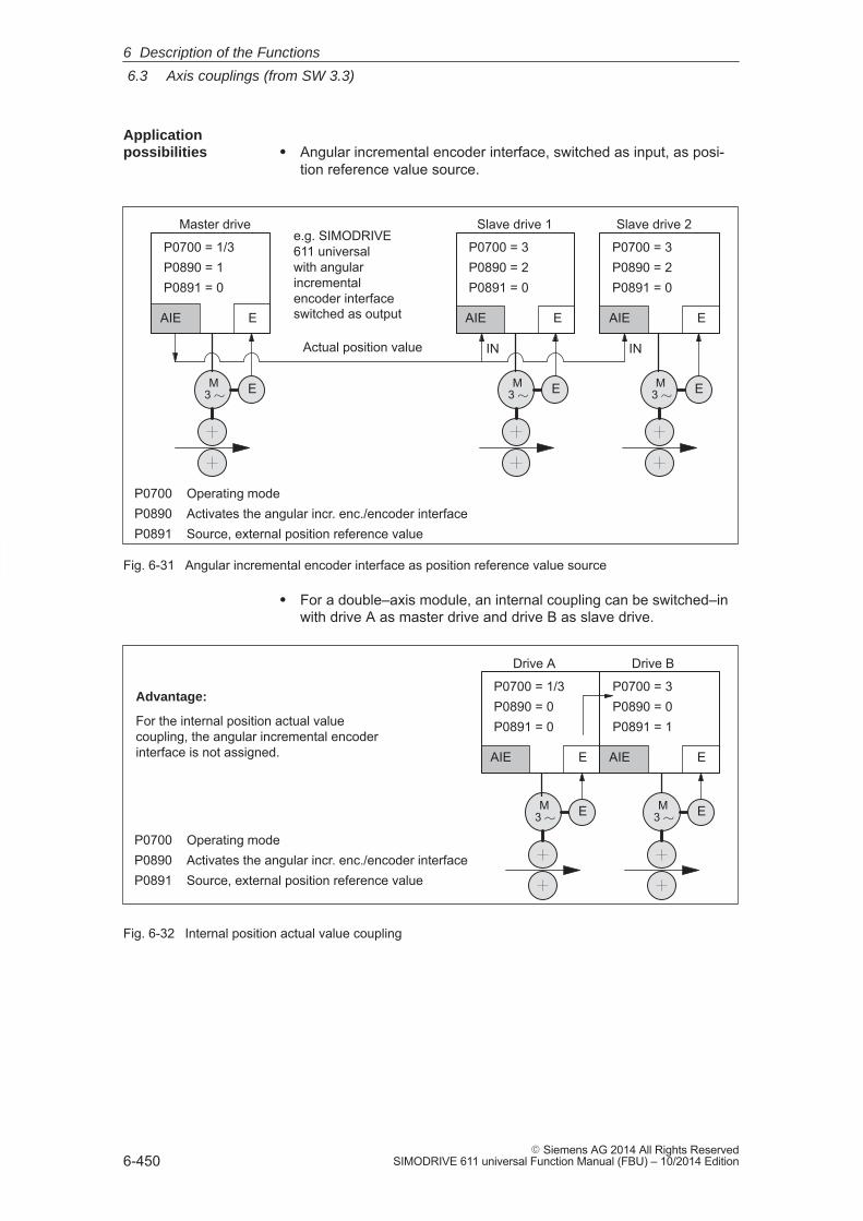
6
6.3 Axis couplings (from SW 3.3)
6-450� Siemens AG 2014 All Rights Reserved
SIMODRIVE 611 universal Function Manual (FBU) – 10/2014 Edition
� Angular incremental encoder interface, switched as input, as posi-tion reference value source.
EAIE
P0700 Operating modeP0890 Activates the angular incr. enc./encoder interfaceP0891 Source, external position reference value
P0700 = 3P0890 = 2P0891 = 0
P0700 = 3P0890 = 2P0891 = 0
EAIE
Slave drive 1 Slave drive 2
ININ
e.g. SIMODRIVE 611 universal with angularincrementalencoder interfaceswitched as outputEAIE
P0700 = 1/3P0890 = 1P0891 = 0
M3 � E M
3 � E
Actual position value
Master drive
M3 � E
Fig. 6-31 Angular incremental encoder interface as position reference value source
� For a double–axis module, an internal coupling can be switched–inwith drive A as master drive and drive B as slave drive.
P0700 Operating modeP0890 Activates the angular incr. enc./encoder interfaceP0891 Source, external position reference value
Drive A Drive B
EAIE
P0700 = 1/3P0890 = 0P0891 = 0
EAIE
P0700 = 3P0890 = 0P0891 = 1
M3 � EM
3 � E
Advantage:
For the internal position actual valuecoupling, the angular incremental encoderinterface is not assigned.
Fig. 6-32 Internal position actual value coupling
Applicationpossibilities
6 Description of the Functions
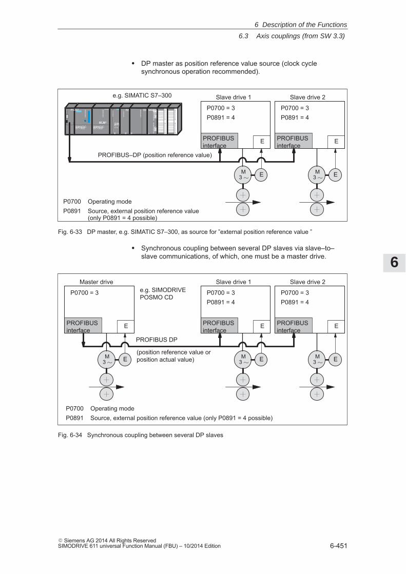
6
6.3 Axis couplings (from SW 3.3)
6-451� Siemens AG 2014 All Rights ReservedSIMODRIVE 611 universal Function Manual (FBU) – 10/2014 Edition
� DP master as position reference value source (clock cyclesynchronous operation recommended).
EPROFIBUSinterface
P0700 Operating modeP0891 Source, external position reference value
(only P0891 = 4 possible)
P0700 = 3P0891 = 4
Slave drive 1
M3 � E
PROFIBUS–DP (position reference value)
SIMATICS7–300 SIMATICS7–300
CP342–5
RUNSTOP SIMATICET 200MIM 153
IM 360 IM 361MOBYASM47024VANWCommandErrorSLG1RxD
ErrorSLG2RxD
PS307
e.g. SIMATIC S7–300
EPROFIBUSinterface
P0700 = 3P0891 = 4
Slave drive 2
M3 � E
Fig. 6-33 DP master, e.g. SIMATIC S7–300, as source for ”external position reference value ”
� Synchronous coupling between several DP slaves via slave–to–slave communications, of which, one must be a master drive.
M3 � E
EPROFIBUSinterface
P0700 Operating modeP0891 Source, external position reference value (only P0891 = 4 possible)
P0700 = 3P0891 = 4
Slave drive 1
PROFIBUS DP
EPROFIBUSinterface
P0700 = 3P0891 = 4
Slave drive 2
M3 � E
EPROFIBUSinterface
P0700 = 3
Master drivee.g. SIMODRIVE POSMO CD
(position reference value orposition actual value)M
3 � E
Fig. 6-34 Synchronous coupling between several DP slaves
6 Description of the Functions
6
6.3 Axis couplings (from SW 3.3)
6-452� Siemens AG 2014 All Rights Reserved
SIMODRIVE 611 universal Function Manual (FBU) – 10/2014 Edition
The external position reference value source is selected using P0891.
� P0891 = 0 Angular incremental encoder interface (X461/X462)
� P0891 = 1 Motor encoder Drive A (only for compatibility, recommended P0891 = 2)
� P0891 = 2 Position actual value, drive A
� P0891 = 3 Position reference value, drive A
� P0891 = 4 Coupling via PROFIBUS–DP (the telegram must be appropriately parameterized for the master and slave drive sides)
P0891 = 1, 2 or 3 is only possible on drive B for a double–axis module.
In case of resolvers and changeover of the resolution 12 bits → 14 bitsin Drive A, a four–fold value is to be parameterized using SimoCom Uas follows in Drive B:
� In the display of the information of the selected ”Couplings” dialog box
→ ”Position input evaluation” entry field
� In the ”Expert list”
→ Changing Parameter P0895
The following process data is available for the master drive:
� XsollP (position reference value, number 50208)
� XistP (position actual value, number 50206)
� QZsw (status word, slave–to–slave communications, number50118)
� dXcor (correction, position reference/actual value, number 50210)
The process data XsollP, QZsw and dXcor are included in standardtelegram 108.
The following process data are available for the slave drive:
� Xext (external position reference value, number 50207)
� QStw (status word, slave–to–slave communications, number 50117)
� dXcorExt (correction, external position reference value, number 50209)
The process data Xext, QStw and dXcorExt are included in standardtelegram 109.
For a position reference value coupling between ”SIMODRIVE 611 uni-versal” drives, we recommend that standard telegram 108 is used forthe master drive and standard telegram 109 for the slave drive.
Parameterizing thesetpoint source
PROFIBUS–DPprocess data andstandardtelegrams
6 Description of the Functions
6
6.3 Axis couplings (from SW 3.3)
6-453� Siemens AG 2014 All Rights ReservedSIMODRIVE 611 universal Function Manual (FBU) – 10/2014 Edition
Note
� It is not necessary to transfer dXcor or dXcorExt if, with thecoupling switched–in, no external jumps/steps can occur in theexternal position reference value.
� It is not necessary to transfer QZsw or QStw if, when the couplingis switched–in, no external jumps/steps can occur in the positionreference value and the ”passive referencing” function is notrequired.
� In the example in Chapter 5.10.5 for coupling 2 drives (master,slave drive) a description is provided how the hardwareconfiguration can be parameterized for the necessaryslave–to–slave data transfer and with SimoCom U, the telegrams.
6 Description of the Functions
6
6.3 Axis couplings (from SW 3.3)
6-454� Siemens AG 2014 All Rights Reserved
SIMODRIVE 611 universal Function Manual (FBU) – 10/2014 Edition
Setpoints, entered via the source, are evaluated at the input for the fol-lowing couplings:––> via the angular incremental encoder (P0891 = 0 or 1)––> via PROFIBUS–DP (P0891 = 4)� Input format (slave drive):
– Xext (external position reference value, number 50207)– dXcorExt (correction, external position reference value, number
50209)
Position in MSR = input value P0896
P0895The following applies:
� The output is evaluated ––> PROFIBUS–DPOutput format (master drive):– XsollP (position reference value, number 50208)– XistP (position actual value, number 50206)– dXcor (correction, position reference/actual value, 50210)
Output value = position in MSR P0884
P0896The following applies:
The output value must be able to be represented using 32 bits. Thismeans that the maximum traversing distance that can be repre-sented is:
P0896
P0895 (P0884) (231–1)–231 P0896
P0895 (P0884)
� The standard settings for PROFIBUS–DP are:– P0884 = 10000– P0895 = 10000– P0896 = 10000 MSR (�m)
Recommendation: Modify the standard setting as follows to achievethe best possible resolution:– P0884 = 2048– P0895 = 2048– P0896 = 5 MSR (�m)
�m 5
2048For this setting, the resolution is
and the traversing distance that can be represented is � 5.24 m.
Note
Changes to P0884, P0895 and P0896 are incorporated in P0032(external position reference value).
The external position reference value can be inverted using P0897.
Note
Changes to P0897 are incorporated in P0032 (external positionreference value).
Input/outputevaluation
Position referencevalue inversion
6 Description of the Functions
6
6.3 Axis couplings (from SW 3.3)
6-455� Siemens AG 2014 All Rights ReservedSIMODRIVE 611 universal Function Manual (FBU) – 10/2014 Edition
A coupling factor for all setpoint sources can be defined using P0401 andP0402. Revolutions of the master drive (P0401) correspond to revolutionsof the slave drive (P0402).
If steps (jumps) occur in the external position reference value, e.g. afterreferencing the master drive, this must be signaled to the slave drive sothat this does not execute this step� Coupling via PROFIBUS DP
––> QZsw.0 = 1 (publisher) or QStw.0 = 1 (subscriber)The amplitude of the step is transferred in dXcor and is received inthe dXcorExt.
� Coupling via the angular incremental encoder––> not necessary, as it involves an incremental setpoint input
Exception:For P0891 = 7 or 8, it may be necessary to use the signal ”setpoint, master drive” on the slave drive side.
Note
� A ”SIMODRIVE 611 universal” as slave drive also operates withPROFIBUS master drives together which do not support theconcept of multiple correction value transfer. The only thing that isnecessary, is that, for a setpoint step, the control bit and thecorrection value are correctly set. In this case, there is a danger,that after the telegram has been lost, a setpoint step occurs.
� The slave drive corrects the setpoint when the 0/1 edge of thecontrol bit is detected.
� If it can be ensured that at the instant that the setpoint step occurs,there is no coupling, then it is not necessary to transfer the steplocation Xcor.
The coupling type is configured in the slave drive using P0410.The following is defined for a coupling via P0410:� Can be switched–in/switched–out via an input signal or traversing
block� Speed synchronism, position synchronism or to the absolute
position of the master drive
––> refer to the following information.
For PROFIBUS–DP, P0410 = 7, i.e. can be switched–in/out via the in-put signal, coupling is preset to the absolute position.
Coupling factor
Setpoint steps
Couplingconfiguration(P0410)
6 Description of the Functions
6
6.3 Axis couplings (from SW 3.3)
6-456� Siemens AG 2014 All Rights Reserved
SIMODRIVE 611 universal Function Manual (FBU) – 10/2014 Edition
For P0410 = 1, 2 or 7, the coupling can be switched–in/out via an inputsignal.The following applies:� When switching–in/switching–out the coupling, the drive to be
coupled must remain stationary and a traversing program may notrun.
� The coupling is switched–in/switched–out using the ”activate cou-pling” input signal.The input signal can be entered via input terminal or via PROFIBUS DP.– via an input terminal with function number 72 and 73– Via PROFIBUS signal ”PosStw.4”
What can be programmed for the coupling that is switched–in?After the ”activate traversing task” input signal, traversing blockscan be programmed with the commands: Relative position input, WAIT, GOTO, SET_O, RESET_O,ENDLESS TRAVERSING_POS, ENDLESS TRAVERSING_NEG
� Additional block change enable circuits are:
Block change enable END, CONTINUE WITH STOP, CONTINUEFLYING and CONTINUE EXTERNAL (only for P0110 = 2)
� The coupling can be configured for speed synchronism, positionsynchronism or an absolute position.
– P0410 = 1 Speed synchronism via input signal
––> refer to Fig. 6-35
– P0410 = 2 Position synchronism via input signal
––> refer to Fig. 6-36
– P0410 = 7 Absolute position (from SW 4.1)
Note
If a traversing block is parameterized with COUPLING_IN and/orCOUPLING_OUT and if the coupling is to be controlled using a digitalsignal, then when any traversing block is started, fault 166 is alwaysoutput (not that traversing block with COUPLING_IN or withCOUPLING_OUT).
Coupling–in/outvia the input signal (P0410 = 1, 2 or 7)
6 Description of the Functions
6
6.3 Axis couplings (from SW 3.3)
6-457� Siemens AG 2014 All Rights ReservedSIMODRIVE 611 universal Function Manual (FBU) – 10/2014 Edition
For P0410 = 3, 4 or 8, the coupling can be switched–in/switched–out via a traversing block.
The following applies:
� The coupling is switched–in/switched–out using the following commands:– COUPLING_IN
What happens after COUPLING_IN?The drive waits until synchronism is achieved, and then executesthe appropriate block change enable.When programmed with CONTINUE FLYING, the command al-ways results in the block change enable CONTINUE WITHSTOP.What can be programmed for the coupling that is switched–in?Traversing blocks can be programmed with the commands: Relative position data, WAIT, GOTO, SET_O, RESET_O. For ENDLESS TRAVERSING_POS, ENDLESS TRAVER-SING_NEG, fault 105 is output.For a coupling that is kept closed, the programmed value isswitched to the position reference value, received via the angularincremental encoder interface, so that a superimposed motion isobtained.
– COUPLING_OUTWhat happens after COUPLING_OUT?
The drive switches–out the coupling, brakes down to standstill,and then executes the programmed block change enable.
� Additional block change enable circuits are:
Block change enable END, CONTINUE WITH STOP, CONTINUEFLYING and CONTINUE EXTERNAL (only for P0110 = 2)
Note
� For blocks with COUPLING_IN/COUPLING_OUT, a block changeenable with CONTINUE FLYING is not possible.
� For blocks with COUPLING_OUT, a block change enable withCONTINUE EXTERNAL is not possible.
� The coupling can be configured for speed synchronism, positionsynchronism or an absolute position.
– P0410 = 3 Speed synchronism via traversing block
––> refer to Fig. 6-35
– P0410 = 4 Position synchronism via traversing block
––> refer to Fig. 6-36
– P0410 = 8 Absolute position (from SW 4.1)
––> refer to Fig. 6-37
Coupling–in/outvia traversingblock (P0410 = 3, 4or 8)
6 Description of the Functions
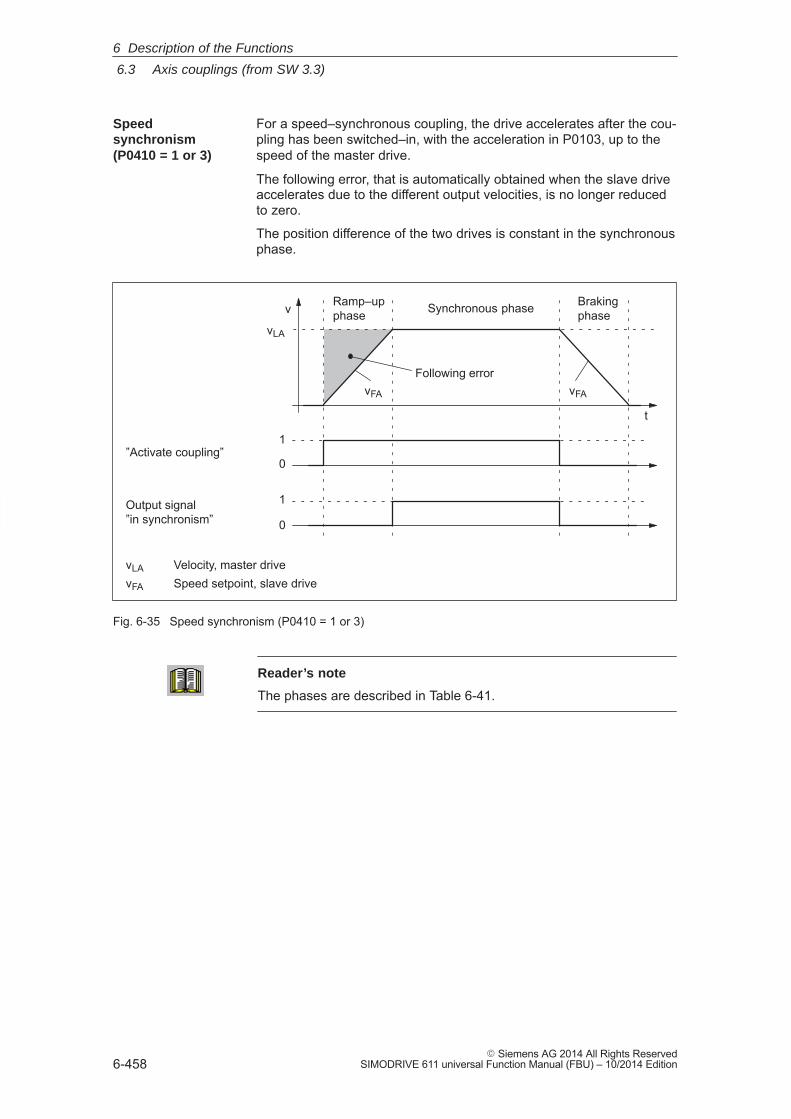
6
6.3 Axis couplings (from SW 3.3)
6-458� Siemens AG 2014 All Rights Reserved
SIMODRIVE 611 universal Function Manual (FBU) – 10/2014 Edition
For a speed–synchronous coupling, the drive accelerates after the cou-pling has been switched–in, with the acceleration in P0103, up to thespeed of the master drive.
The following error, that is automatically obtained when the slave driveaccelerates due to the different output velocities, is no longer reducedto zero.
The position difference of the two drives is constant in the synchronousphase.
t
v
vLA
vFA
Following errorvFA
vLA Velocity, master drivevFA Speed setpoint, slave drive
Ramp–upphase Synchronous phase Braking
phase
”Activate coupling”
Output signal ”in synchronism”
1
0
1
0
Fig. 6-35 Speed synchronism (P0410 = 1 or 3)
Reader’s note
The phases are described in Table 6-41.
Speedsynchronism(P0410 = 1 or 3)
6 Description of the Functions
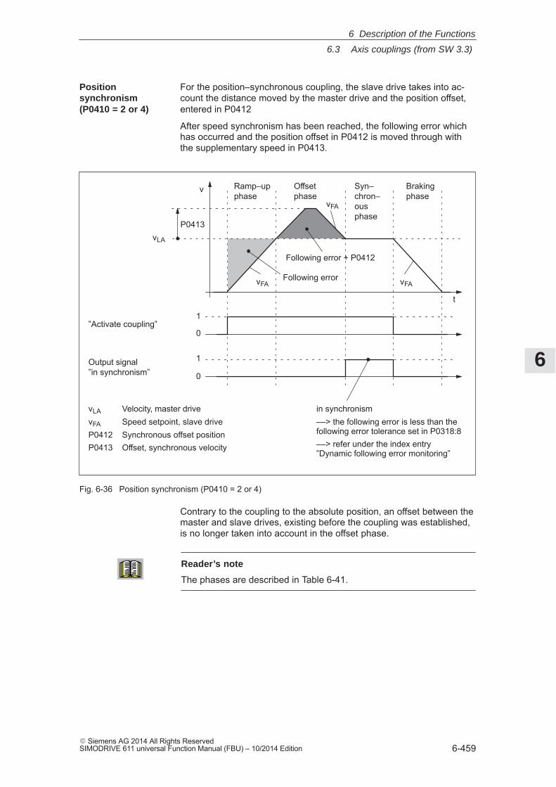
6
6.3 Axis couplings (from SW 3.3)
6-459� Siemens AG 2014 All Rights ReservedSIMODRIVE 611 universal Function Manual (FBU) – 10/2014 Edition
For the position–synchronous coupling, the slave drive takes into ac-count the distance moved by the master drive and the position offset,entered in P0412
After speed synchronism has been reached, the following error whichhas occurred and the position offset in P0412 is moved through withthe supplementary speed in P0413.
t
v
vLA
vFAFollowing error vFA
vLA Velocity, master drivevFA Speed setpoint, slave driveP0412 Synchronous offset positionP0413 Offset, synchronous velocity
Ramp–upphase
Syn–chron–ousphase
Brakingphase
”Activate coupling”
Output signal ”in synchronism”
1
0
1
0
Offsetphase
vFA
Following error + P0412
P0413
in synchronism––> the following error is less than thefollowing error tolerance set in P0318:8––> refer under the index entry”Dynamic following error monitoring”
Fig. 6-36 Position synchronism (P0410 = 2 or 4)
Contrary to the coupling to the absolute position, an offset between themaster and slave drives, existing before the coupling was established,is no longer taken into account in the offset phase.
Reader’s note
The phases are described in Table 6-41.
Positionsynchronism(P0410 = 2 or 4)
6 Description of the Functions
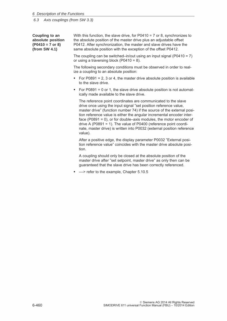
6
6.3 Axis couplings (from SW 3.3)
6-460� Siemens AG 2014 All Rights Reserved
SIMODRIVE 611 universal Function Manual (FBU) – 10/2014 Edition
With this function, the slave drive, for P0410 = 7 or 8, synchronizes tothe absolute position of the master drive plus an adjustable offsetP0412. After synchronization, the master and slave drives have thesame absolute position with the exception of the offset P0412.
The coupling can be switched–in/out using an input signal (P0410 = 7)or using a traversing block (P0410 = 8).
The following secondary conditions must be observed in order to real-ize a coupling to an absolute position:
� For P0891 = 2, 3 or 4, the master drive absolute position is availableto the slave drive.
� For P0891 = 0 or 1, the slave drive absolute position is not automat-ically made available to the slave drive.
The reference point coordinates are communicated to the slavedrive once using the input signal ”set position reference value,master drive” (function number 74) if the source of the external posi-tion reference value is either the angular incremental encoder inter-face (P0891 = 0), or for double–axis modules, the motor encoder ofdrive A (P0891 = 1). The value of P0400 (reference point coordi-nate, master drive) is written into P0032 (external position referencevalue).
After a positive edge, the display parameter P0032 ”External posi-tion reference value” coincides with the master drive absolute posi-tion.
A coupling should only be closed at the absolute position of themaster drive after ”set setpoint, master drive” as only then can beguaranteed that the slave drive has been correctly referenced.
� ––> refer to the example, Chapter 5.10.5
Coupling to anabsolute position(P0410 = 7 or 8)(from SW 4.1)
6 Description of the Functions
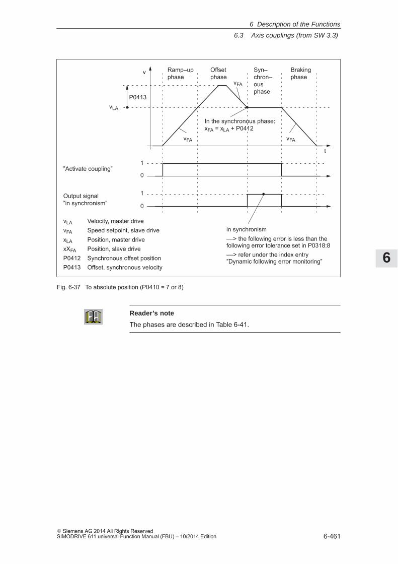
6
6.3 Axis couplings (from SW 3.3)
6-461� Siemens AG 2014 All Rights ReservedSIMODRIVE 611 universal Function Manual (FBU) – 10/2014 Edition
t
v
vLA
vFA vFA
vLA Velocity, master drivevFA Speed setpoint, slave drivexLA Position, master drivexXFA Position, slave driveP0412 Synchronous offset positionP0413 Offset, synchronous velocity
Ramp–upphase
Syn–chron–ousphase
Brakingphase
”Activate coupling”
Output signal ”in synchronism”
1
0
1
0
Offsetphase
vFA
In the synchronous phase:xFA = xLA + P0412
P0413
in synchronism––> the following error is less than thefollowing error tolerance set in P0318:8––> refer under the index entry”Dynamic following error monitoring”
Fig. 6-37 To absolute position (P0410 = 7 or 8)
Reader’s note
The phases are described in Table 6-41.
6 Description of the Functions
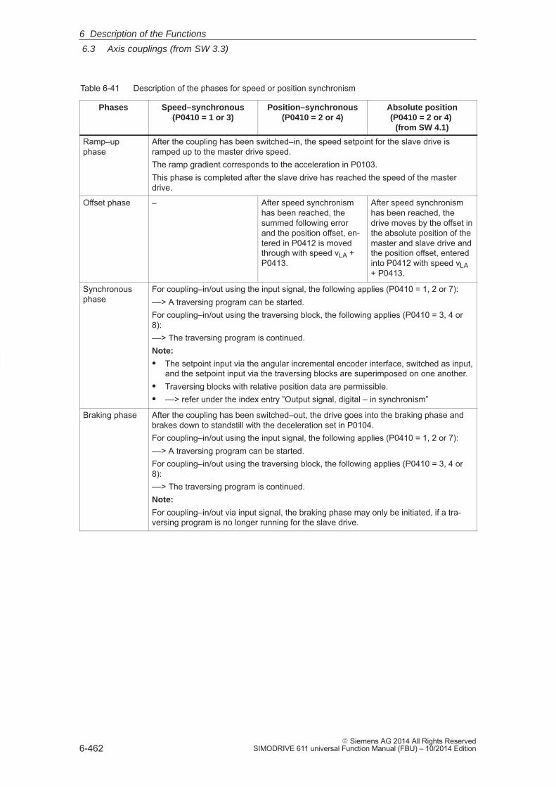
6
6.3 Axis couplings (from SW 3.3)
6-462� Siemens AG 2014 All Rights Reserved
SIMODRIVE 611 universal Function Manual (FBU) – 10/2014 Edition
Table 6-41 Description of the phases for speed or position synchronism
Phases Speed–synchronous(P0410 = 1 or 3)
Position–synchronous(P0410 = 2 or 4)
Absolute position(P0410 = 2 or 4)
(from SW 4.1)
Ramp–upphase
After the coupling has been switched–in, the speed setpoint for the slave drive isramped up to the master drive speed.The ramp gradient corresponds to the acceleration in P0103.This phase is completed after the slave drive has reached the speed of the masterdrive.
Offset phase – After speed synchronismhas been reached, thesummed following errorand the position offset, en-tered in P0412 is movedthrough with speed vLA +P0413.
After speed synchronismhas been reached, thedrive moves by the offset inthe absolute position of themaster and slave drive andthe position offset, enteredinto P0412 with speed vLA+ P0413.
Synchronousphase
For coupling–in/out using the input signal, the following applies (P0410 = 1, 2 or 7):––> A traversing program can be started.For coupling–in/out using the traversing block, the following applies (P0410 = 3, 4 or8):––> The traversing program is continued.Note:
� The setpoint input via the angular incremental encoder interface, switched as input,and the setpoint input via the traversing blocks are superimposed on one another.
� Traversing blocks with relative position data are permissible.� ––> refer under the index entry ”Output signal, digital – in synchronism”
Braking phase After the coupling has been switched–out, the drive goes into the braking phase andbrakes down to standstill with the deceleration set in P0104.For coupling–in/out using the input signal, the following applies (P0410 = 1, 2 or 7):––> A traversing program can be started.For coupling–in/out using the traversing block, the following applies (P0410 = 3, 4 or8):––> The traversing program is continued.Note:
For coupling–in/out via input signal, the braking phase may only be initiated, if a tra-versing program is no longer running for the slave drive.
6 Description of the Functions
6
6.3 Axis couplings (from SW 3.3)
6-463� Siemens AG 2014 All Rights ReservedSIMODRIVE 611 universal Function Manual (FBU) – 10/2014 Edition
With this function, a coupling is established between the master andslave drives depending on a position memory (queue) being processed.
� Coupling always switched–in/out always via the traversing program
� P0410 = 5: Speed–synchronous
� P0410 = 6: Position–synchronous
The master drive drives a conveyor belt. The position of the workpiecesis detected using a measuring probe and saved in the slave drive inP0425:16. If a workpiece approaches its waiting position, the slavedrive must accelerate in plenty of time so that it can move insynchronism with the workpiece in the machinery range.
Requirements:
If a workpiece is detected, the distance, measured to the actual slavedrive position is continuously entered into P0425:16. The first work-piece is entered under P0425:0 and the last under P0425:15.
A maximum of 16 positions can be saved ––> otherwise, fault 168 isoutput (overflow, buffer memory).
For slave drives, a traversing program cyclically runs with coupling andmachining commands.
Sequence:
1. The COUPLING IN command is executed, i.e. the slave drive waitsto be synchronized to the master drive.
2. When will synchronization start, i.e. when will the coupling beswitched–in?
Synchronization is started when the next workpiece has reached theslave drive, i.e. if the distance between the workpiece and the slavedrive in the next interpolation clock cycle k is
v2LA
2aFAless than .
vLA Velocity, master drive
aFA Acceleration, slave drive
3. To start, speed synchronism is established. After this, the oldestposition is deleted from the position memory and for P0410 = 6,position synchronism established.
The equalization motion is extremely short, as synchronization ispredictive.
After synchronism has been established, additional commands canbe executed (e.g. to machine the workpiece).
For the commands, the same conditions apply as for the program-mable couplings.
Coupling using thequeuefunctionality(P0410 = 5 or 6) (being prepared)
Applicationexample, queuefunctionality(refer to Fig. 6-38)
6 Description of the Functions
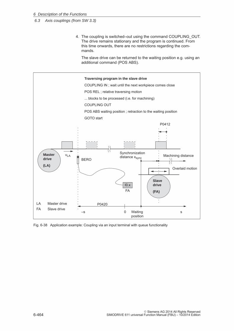
6
6.3 Axis couplings (from SW 3.3)
6-464� Siemens AG 2014 All Rights Reserved
SIMODRIVE 611 universal Function Manual (FBU) – 10/2014 Edition
4. The coupling is switched–out using the command COUPLING_OUT.The drive remains stationary and the program is continued. Fromthis time onwards, there are no restrictions regarding the com-mands.
The slave drive can be returned to the waiting position e.g. using anadditional command (POS ABS).
BEROvLAMaster
drive
(LA)
Slave drive
(FA)
P0420
P0412
Traversing program in the slave drive
COUPLING IN ; wait until the next workpiece comes close
POS REL ; relative traversing motion
... blocks to be processed (i.e. for machining)
COUPLING OUT
POS ABS waiting position ; retraction to the waiting position
GOTO start
I0.xFA
Synchronizationdistance xsync
Waitingposition
0
Machining distance
s
LA Master driveFA Slave drive
Overlaid motion
–s
Fig. 6-38 Application example: Coupling via an input terminal with queue functionality
6 Description of the Functions
6
6.3 Axis couplings (from SW 3.3)
6-465� Siemens AG 2014 All Rights ReservedSIMODRIVE 611 universal Function Manual (FBU) – 10/2014 Edition
In order to implement an axis coupling for modulo rotary axes, the fol-lowing settings must be made:
� Which settings have to be made for the master axis?
– ”Positioning” mode (P0700 = 3)
– Set the modulo rotary axis (P0241, P0242)
� Which settings have to be made for the slave axis?
– ”Positioning” mode (P0700 = 3)
– Set the modulo rotary axis (P0241, P0242)
– For the slave axis, the modulo range of the master axis must bespecified in P0898.
i.e.: P0242 (master axis) � P0898 (slave axis)
Note
The modulo range of the master axis can be the same or not equal tothe modulo range of the slave axis.
i.e.: P0242 (master axis) � or � P0242 (slave axis)
Position reference value steps as a result of modulo correction are de-tected by the slave drive itself, i.e. it is not permissible that control bitQStw.0 or the correction value dXcorExt are set.
The following is required:
� P0898 must be correctly parameterized for the slave drive.
� The traversing difference between two position reference values isthe maximum of half the modulo range (so that the direction of mo-tion is clear)
Telegrams may be lost when transferring data via Profibus–DP. In thiscase, the slave drive must extrapolate a new reference value positionfrom the previous acceleration and velocity.
The correct position is only approached with the next valid telegram. Ifmore telegrams are lost than are parameterized in P0879 , Fault 595 or597 is output and the drive comes to a standstill.
The following secondary conditions must be observed for position refer-ence value and actual value coupling:
� Resolution of the angular incremental encoder interfaceIt should be carefully observed that the coupling must be configuredwith a high resolution (encoder), e.g. for––> a good resolution: 2048 pulses correspond to 10 mm––> a poor resolution: 1250 pulses correspond to 1500 mm
Axis coupling formodulorotary axes(from SW 4.1)
Modulo correction
Telegram loss
Boundaryconditions
6 Description of the Functions
6
6.3 Axis couplings (from SW 3.3)
6-466� Siemens AG 2014 All Rights Reserved
SIMODRIVE 611 universal Function Manual (FBU) – 10/2014 Edition
� Travel to fixed stop and axis coupling– It is not permissible to activate the ”travel to fixed stop” function
when in the coupled mode (Fault 173).– The axis coupling cannot be switched–in during the ”travel to
fixed stop” function (Fault 173).
� If it is predicted that a software limit switch will be passed, forcoupled axes, one of the following faults/warnings will be signaled:– Fault 132 or 133 after a software limit switch has been passed
(minus or plus)– Warning 891
(software limit switch PLUS actuated, coupled)– Warning 892
(software limit switch MINUS actuated, coupled)For a coupled drive, there is no response to warning 891 or 892.This can be signaled to the master drive using the output signal”warning present”; this then allows the master drive to respond.
� Only relative position data is permissible for traversing blocks whenin the coupled mode (Fault 165).
� During an active coupling, a block change enable CONTINUE EXTERNAL is only possible with P0110 = 2 (Fault 172).
� The position of the master drive, at which the coupling was re-quested, is in P0425:0.
� The following applies for P0410 = 1, 2 or 7:– It is not possible to program the commands COUPLING_IN
or COUPLING_OUT (Fault 166).– The coupling can be switched–in/switched–out via input terminal
as follows:1.)Assign function 72 to any input terminal––> Input signal ”activate coupling”or2.) (recommendation, as it is a fast input)Assign function number 73 to input terminal I0.x ––> Assign the input signal ”Activate coupling via I0.x”andfunction number 72 to any other input terminal––> Input signal ”Activate coupling”(refer to Chapter 6.4.3 Function numbers 72 and 73)
� The following applies for P0410 = 3, 4 or 8:
The coupling cannot be switched–in/switched–out via an input signal.
6 Description of the Functions
6
6.3 Axis couplings (from SW 3.3)
6-467� Siemens AG 2014 All Rights ReservedSIMODRIVE 611 universal Function Manual (FBU) – 10/2014 Edition
� Rotary axis with modulo correction and basic coupling
The following applies for SW 3.3:The coupling mode for rotary axes with modulo correction is not per-missible for the master and slave drive.
The following applies from SW 3.5:The coupling mode is permissible for rotary axes with modulocorrection.
� Direct measuring system and axis coupling
For a drive with direct measuring system, the actual values of themotor measuring system are always output via the angular incre-mental encoder interface switched as output.
This means that an actual value coupling cannot be realized usingthe direct measuring system.
� The following applies for P0410 = 5 or 6 (from SW 3.5):
– It is only possible to precisely determine the position using thefast input I0.x.
––> refer under the index entry ”Input signal, digital – flying mea-surement/length measurement”
– The standstill time of the slave drive up to the next workpiecemust be at least 1 IPO clock cycle (P1010).
– After COUPLING OUT for the slave drive, the drive should re-tract to its waiting position as otherwise it will continue to be posi-tioned away from the target position.
� The following secondary conditions have to be taken into consider-ation when parameterizing P0891:
– The following applies for P0891 = 1:
––> only exists for drive B;
––> for drive A, P0891 must be 0
– The following applies for P0891 = 2 or 3:
––> Selectable for drive A or B
––> The other drive is then the master drive where P0891 must be set to 0.
––> Coupling via the input signal ”Activate coupling via I0.x” (fast input) is not possible
� If a setpoint source is selected, which is not available for the drive,e.g. there is no optional PROFIBUS–DP module, then Fault 788 isoutput.
6 Description of the Functions
6
6.3 Axis couplings (from SW 3.3)
6-468� Siemens AG 2014 All Rights Reserved
SIMODRIVE 611 universal Function Manual (FBU) – 10/2014 Edition
� It is possible to have mixed operation of position reference valuesources within a drive group. For instance, drive A can receive itssetpoint via the angular incremental encoder and transfer this toother drives via PROFIBUS–DP. The following secondary conditionsmust be observed:
– The synchronous operation of the drive group is poor as a resultof the different data propagation times.
– There are differences in the position resolution between the indi-vidual sources.
� Limitations for a slave axis
!Warning
When superimposing the speed of the master and slave drives, aresulting slave drive speed can be obtained which is greater than themaximum speed P0102. For slave axes, the speed monitoring inP1147, P1401:8 and P1405:8 applies.
Note
For coupled operation via PROFIBUS–DP, we recommend that internalcouplings are not used. Instead, the second drive should beparameterized as subscriber (refer to Chapter 5.10).
� Display of position actual value XisP/position actual value Xset fordouble–axis modules with ”SimoCom U commissioning tool”:
The displayed value of XistP/XsollP in the information display of theselected ”PROFIBUS parameterization” dialog box can vary slightlyas compared to the displayed actual values/setpoints at the positionof the position displays of the SimoCom U (approx. 1 μ).
� Coupling via angular incremental encoder interface with ”coarse en-coder resolution”:
Prior to SW 10.1:For axis couplings, the angular incremental encoder interface canbe configured as documented previously.
Starting with SW 10.1:For an axis coupling with the ”Source, external position referencevalue” function, ”Angular incremental encoder interface X461/X642(coarse)” must be selected. This results in P0891 = 5.
6 Description of the Functions
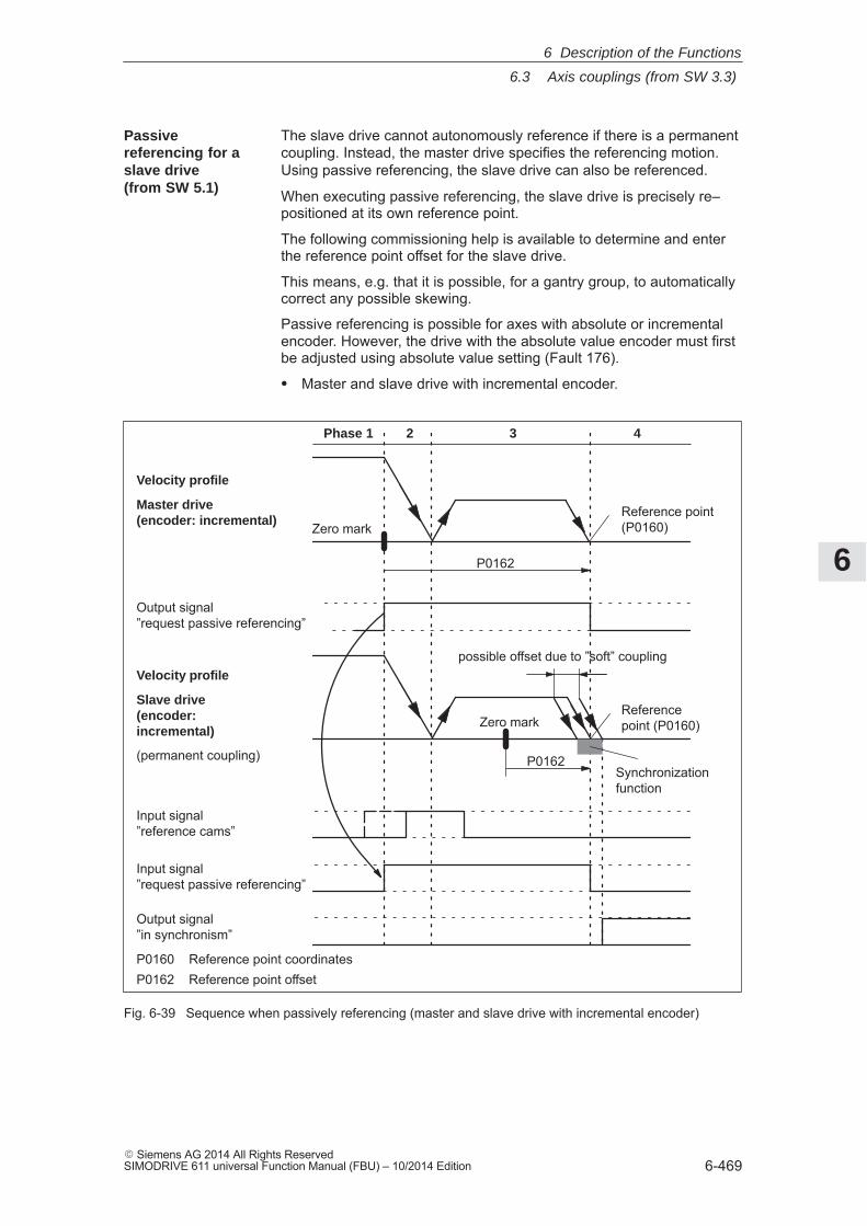
6
6.3 Axis couplings (from SW 3.3)
6-469� Siemens AG 2014 All Rights ReservedSIMODRIVE 611 universal Function Manual (FBU) – 10/2014 Edition
The slave drive cannot autonomously reference if there is a permanentcoupling. Instead, the master drive specifies the referencing motion.Using passive referencing, the slave drive can also be referenced.
When executing passive referencing, the slave drive is precisely re–positioned at its own reference point.
The following commissioning help is available to determine and enterthe reference point offset for the slave drive.
This means, e.g. that it is possible, for a gantry group, to automaticallycorrect any possible skewing.
Passive referencing is possible for axes with absolute or incrementalencoder. However, the drive with the absolute value encoder must firstbe adjusted using absolute value setting (Fault 176).
� Master and slave drive with incremental encoder.
Velocity profile
Slave drive(encoder:incremental)
(permanent coupling)
possible offset due to ”soft” coupling
Phase 1 2 3 4
Zero markReference point(P0160)
Output signal ”in synchronism”
Input signal ”request passive referencing”
Synchronizationfunction
Zero mark
P0162
Referencepoint (P0160)
P0162
Velocity profile
Master drive(encoder: incremental)
Output signal ”request passive referencing”
P0160 Reference point coordinatesP0162 Reference point offset
Input signal ”reference cams”
Fig. 6-39 Sequence when passively referencing (master and slave drive with incremental encoder)
Passivereferencing for aslave drive (from SW 5.1)
6 Description of the Functions
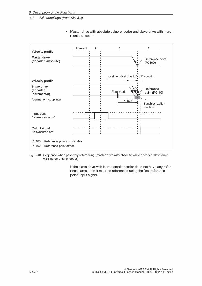
6
6.3 Axis couplings (from SW 3.3)
6-470� Siemens AG 2014 All Rights Reserved
SIMODRIVE 611 universal Function Manual (FBU) – 10/2014 Edition
� Master drive with absolute value encoder and slave drive with incre-mental encoder.
Velocity profile
Slave drive(encoder:incremental)
(permanent coupling)
possible offset due to ”soft” coupling
Phase 1 2 3 4
Reference point(P0160)
Output signal ”in synchronism”
Synchronizationfunction
Zero markReferencepoint (P0160)
P0162
Velocity profile
Master drive(encoder: absolute)
P0160 Reference point coordinatesP0162 Reference point offset
Input signal ”reference cams”
Fig. 6-40 Sequence when passively referencing (master drive with absolute value encoder, slave drivewith incremental encoder)
If the slave drive with incremental encoder does not have any refer-ence cams, then it must be referenced using the ”set referencepoint” input signal.
6 Description of the Functions
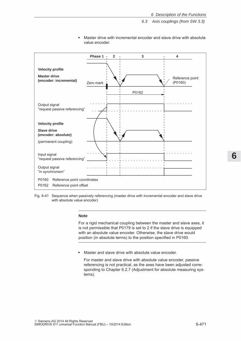
6
6.3 Axis couplings (from SW 3.3)
6-471� Siemens AG 2014 All Rights ReservedSIMODRIVE 611 universal Function Manual (FBU) – 10/2014 Edition
� Master drive with incremental encoder and slave drive with absolutevalue encoder.
Velocity profile
Slave drive(encoder: absolute)
(permanent coupling)
Phase 1 2 3 4
Zero markReference point(P0160)
Output signal ”in synchronism”
Input signal ”request passive referencing”
P0162
Velocity profile
Master drive(encoder: incremental)
Output signal ”request passive referencing”
P0160 Reference point coordinatesP0162 Reference point offset
Fig. 6-41 Sequence when passively referencing (master drive with incremental encoder and slave drivewith absolute value encoder)
Note
For a rigid mechanical coupling between the master and slave axes, itis not permissible that P0179 is set to 2 if the slave drive is equippedwith an absolute value encoder. Otherwise, the slave drive wouldposition (in absolute terms) to the position specified in P0160.
� Master and slave drive with absolute value encoder.
For master and slave drive with absolute value encoder, passivereferencing is not practical, as the axes have been adjusted corre-sponding to Chapter 6.2.7 (Adjustment for absolute measuring sys-tems).
6 Description of the Functions
6
6.3 Axis couplings (from SW 3.3)
6-472� Siemens AG 2014 All Rights Reserved
SIMODRIVE 611 universal Function Manual (FBU) – 10/2014 Edition
The following timing for passive referencing applies when using incre-mental encoders for the master and slave drives. When referencing themaster drive, after its zero mark is reached, passive referencing for theslave drive is requested. The master drive then traverses through thereference point offset up to the reference point.
During this travel, the slave drive must detect a 1/0 edge at the ”refer-ence cam” input signal and then its own zero mark.
After the master drive has reached its reference point, the slave drive ismoved to its reference point.
� Phase 1 Master drive searches for its zero markThe master drive has moved away from the reference cam andsearches for the next zero mark.After the zero mark has been found, the following is initiated:– The drive is braked down to standstill– Master drive:
Set the ”request passive referencing” output signal– Slave drive:
When the ”request passive referencing” input signal has beendetected, the slave drive starts to search for the 1/0 edge of theinput signal ”reference cams” after which it searches for the zeromark
� Phase 2 The master drive starts to its reference pointThe master drive moves to traverse to its reference point. Duringthis traversing operation, the slave drive continues to search for itszero mark.
� Phase 3 The master drive approaches its reference pointWhen the reference point is reached, the following is initiated:– The ”request passive referencing” output signal is reset
If the slave drive, up to this instant in time, has not found a zeromark, fault 175 is signaled.
� Phase 4 Slave drive referenced– For P0179 = 0
After the reference point is reached, the value from P0160 is ac-cepted as new actual value (set reference point).
– For P0179 = 2
After the axis has reached its standstill position, the axis is tra-versed, corresponding to P0162, to its own reference point withthe velocity defined in P0413. The value from P0160 is then ac-cepted as new actual value.
––> Refer under the commissioning help for passive referencing of the slave drive
Timing whenpassivelyreferencing (from SW 5.1)
6 Description of the Functions
6
6.3 Axis couplings (from SW 3.3)
6-473� Siemens AG 2014 All Rights ReservedSIMODRIVE 611 universal Function Manual (FBU) – 10/2014 Edition
The commissioning help is used to determine the reference point offsetin P0162 for the slave drive.Requirements: Set P0179 = 01. Carry–out passive referencing as usual (Fig.6-39).
Note
To execute the following points, the master drive must beprecisely positioned at its reference point!
2. Slave drive:– In the jogging mode, the axis moves to its measured reference
point
Note
Before ”jogging”, the coupling must be switched–out, otherwise”jogging” is not possible. Switch–in the coupling again afterwards.
3. Slave drive:
– Set P0179 = 1––> the distance between the zero mark and approached refer-ence point is saved as offset in P0162
– P0179 is internally set to 2
4. Save the parameters in the FEPROM
5. Carry–out a power on
This means that for future referencing, the reference point of the slavedrive is ”correctly” approached.
The following secondary conditions apply:
� The slave drive must find its own zero mark during phases 2 and 3.
� Passive referencing between the master and slave drive is con-trolled using the following signals:
– Master drive: Output signal ”request passive referencing”
––> using the output terminal with function number 69 (refer to Chapter 6.4)
––> using the PROFIBUS status signal QZsw.1 (refer to Chapter 5.6.3)
– Slave drive: Input signal ”request passive referencing”
––> using an input terminal with function number 69 (refer to Chapter 6.4)
––> using the PROFIBUS control signal QStw.1 (refer to Chapter 5.6.2)
Commissioninghelp to passivelyreference the slavedrive (from SW 5.1)
Secondaryconditions andlimitations whenpassivelyreferencing (from SW 5.1)
6 Description of the Functions
6
6.3 Axis couplings (from SW 3.3)
6-474� Siemens AG 2014 All Rights Reserved
SIMODRIVE 611 universal Function Manual (FBU) – 10/2014 Edition
The master drive output signal should be connected to the inputsignal of the slave drive.Exception:If, for a double–axis module, P0891 (B) = 1, i.e. the position ac-tual value of drive A is internally connected to the position refer-ence value from drive B, then the following applies:The ”request passive referencing” output signal from drive A(master drive A) is internally and automatically recognized bydrive B (slave drive). In this case, external wiring is not required.
� The permanent coupling can be switched–in via an input signal orwith the traversing block. Additional traversing blocks are not per-mitted.
Example, switching–in with a traversing block using the ”Start–upTool SimoCom U”:Command: COUPLING INBlock change enable: End
� If reference point approach is started at the master drive, and theslave drive is coupled–out and coupled–in again, then the slavedrive outputs faults 131 and 605 if the master drive has reached itsreference point. This means that after a reference point approachhas been started, it is no longer possible to de–couple the axes.
The following parameters are used for the ”axis coupling” function:
� P0179 Mode, passive referencing (from SW 5.1)
� P0400 Ref. point coordinate, master drive (from SW 4.1)
� P0401 Coupling factor, revolutions master drive
� P0402 Coupling factor, revolutions slave drive
� P0410 Configuration, coupling that can be switched–in
� P0412 Synchronous offset position
� P0413 Offset, synchronous velocity
� P0420 Position difference, measuring probe to the zero point, slave drive (from SW 3.5)
� P0425:16 Coupling positions
� P0884 Position output value PROFIBUS – No. of increments
� P0891 Source, external position reference value
� P0895 External position reference value – No. of increments
� P0896 Ext. position reference value – No. of dimensionsystem grids
� P0897 Inversion, external position reference value
� P0898 Modulo range, master drive (from SW 3.5)
Parameteroverview(refer to ChapterA.1)
6 Description of the Functions
6
6.3 Axis couplings (from SW 3.3)
6-475� Siemens AG 2014 All Rights ReservedSIMODRIVE 611 universal Function Manual (FBU) – 10/2014 Edition
The following signals are used for the function ”axis coupling”:
� Input signals(refer under index entry ”Input signal, digital – ...”)
– Input signal, ”activate coupling”
––> using an input terminal with function number 72
––> using the PROFIBUS control signal ”PosStw.4”
– Input signal, ”activate coupling via I0.x”
––> using an input terminal with function number 73
– Input signal ”set setpoint, master drive” (from SW 4.1)
––> using an input terminal with function number 74
– Input signal ”request passive referencing” (from SW 5.1)
––> using an input terminal with function number 69
––> using the PROFIBUS control signal ”STW1.15” or alternatively ”QStw.1”
� Output signals(refer under the index entry, ”Output signal, digital – ...”)
– Output signal ”in synchronism”
––> using an output terminal with function number 71
––> using the PROFIBUS status signal ”PosZsw.3”
– Output signal ”Request passive referencing” (from SW 5.1)
––> using an output terminal with function number 69
––> using the PROFIBUS control signal ”ZSW1.15” or alternatively ”QZsw.1”
Additional input/output signals
� Input signals(refer under index entry ”Input signal, digital – ...”)
– Input signal, ”set reference point”
– Input signal ”reference cams”
� Output signals(refer under the index entry, ”Output signal, digital – ...”)
– Output signal, ”controller enable status”
– Output signal ”fault present”
– Output signal, ”warning present”
Input/outputsignals (refer toChapter 6.4, 5.6.2,5.6.3)
6 Description of the Functions
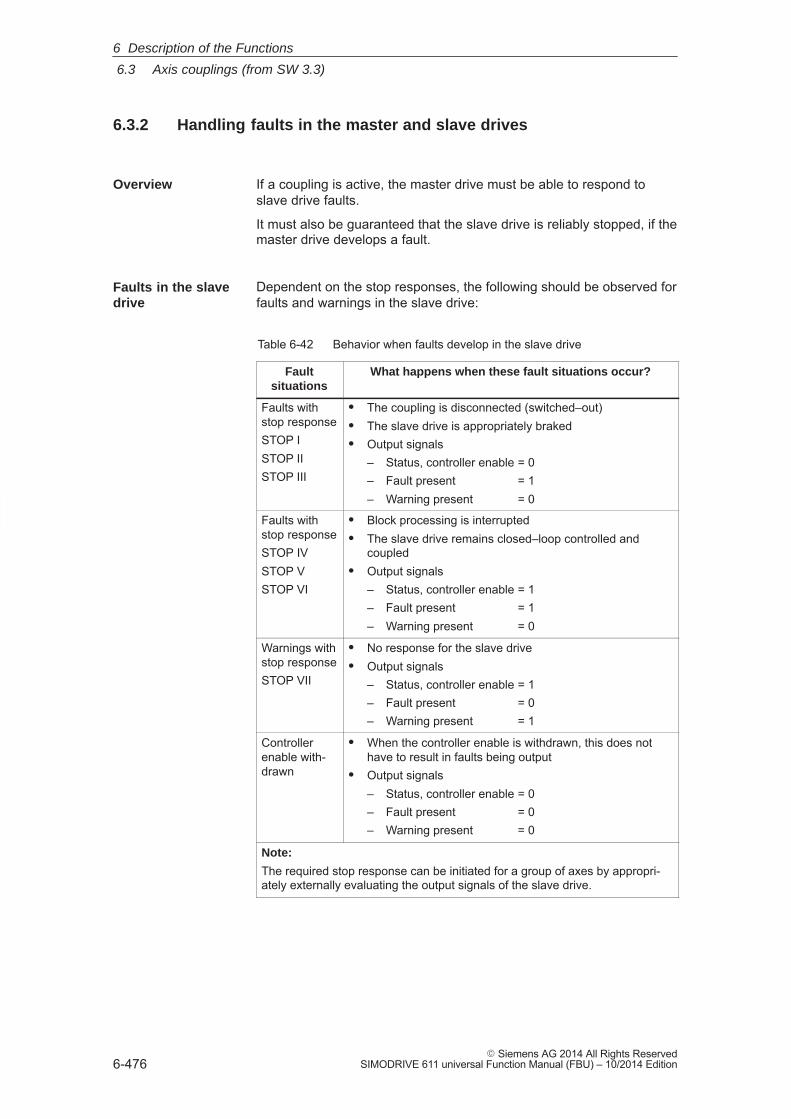
6
6.3 Axis couplings (from SW 3.3)
6-476� Siemens AG 2014 All Rights Reserved
SIMODRIVE 611 universal Function Manual (FBU) – 10/2014 Edition
6.3.2 Handling faults in the master and slave drives
Overview If a coupling is active, the master drive must be able to respond toslave drive faults.
It must also be guaranteed that the slave drive is reliably stopped, if themaster drive develops a fault.
Dependent on the stop responses, the following should be observed forfaults and warnings in the slave drive:
Table 6-42 Behavior when faults develop in the slave drive
Faultsituations
What happens when these fault situations occur?
Faults withstop responseSTOP ISTOP IISTOP III
� The coupling is disconnected (switched–out)� The slave drive is appropriately braked� Output signals
– Status, controller enable = 0– Fault present = 1– Warning present = 0
Faults withstop responseSTOP IVSTOP VSTOP VI
� Block processing is interrupted� The slave drive remains closed–loop controlled and
coupled� Output signals
– Status, controller enable = 1– Fault present = 1– Warning present = 0
Warnings withstop responseSTOP VII
� No response for the slave drive� Output signals
– Status, controller enable = 1– Fault present = 0– Warning present = 1
Controllerenable with-drawn
� When the controller enable is withdrawn, this does nothave to result in faults being output
� Output signals– Status, controller enable = 0– Fault present = 0– Warning present = 0
Note:
The required stop response can be initiated for a group of axes by appropri-ately externally evaluating the output signals of the slave drive.
Faults in the slavedrive
6 Description of the Functions
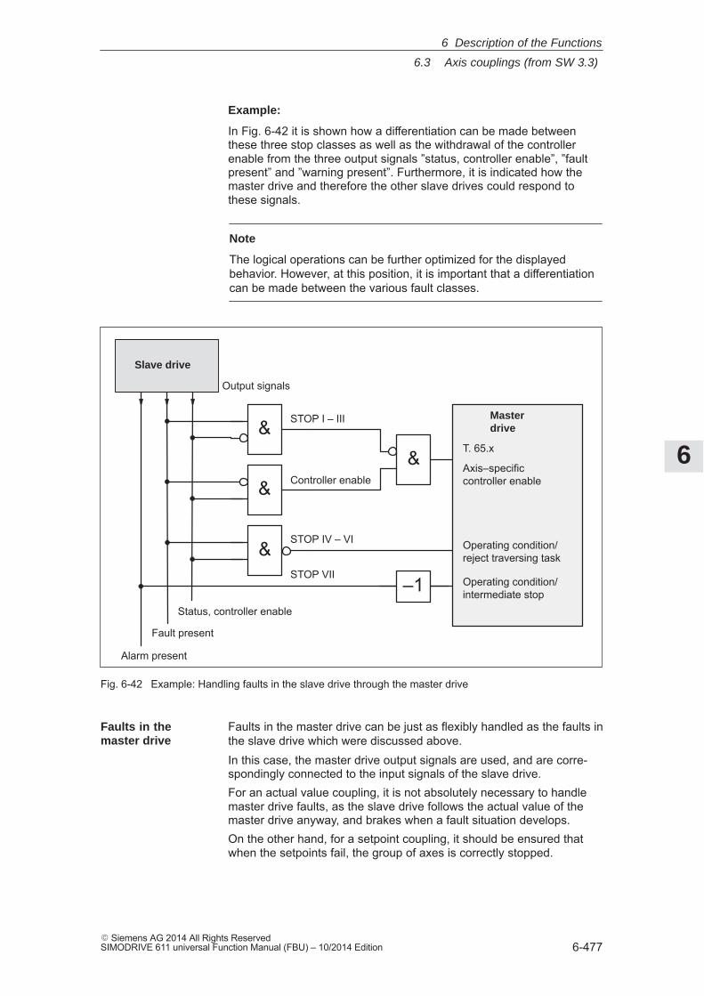
6
6.3 Axis couplings (from SW 3.3)
6-477� Siemens AG 2014 All Rights ReservedSIMODRIVE 611 universal Function Manual (FBU) – 10/2014 Edition
Example:
In Fig. 6-42 it is shown how a differentiation can be made betweenthese three stop classes as well as the withdrawal of the controllerenable from the three output signals ”status, controller enable”, ”faultpresent” and ”warning present”. Furthermore, it is indicated how themaster drive and therefore the other slave drives could respond tothese signals.
Note
The logical operations can be further optimized for the displayedbehavior. However, at this position, it is important that a differentiationcan be made between the various fault classes.
Slave drive
Alarm present
Fault present
Status, controller enable
&&
&
&
–1
STOP I – III Masterdrive
T. 65.x
Axis–specificcontroller enable
Operating condition/reject traversing task
Operating condition/intermediate stop
Controller enable
STOP IV – VI
STOP VII
Output signals
Fig. 6-42 Example: Handling faults in the slave drive through the master drive
Faults in the master drive can be just as flexibly handled as the faults inthe slave drive which were discussed above.In this case, the master drive output signals are used, and are corre-spondingly connected to the input signals of the slave drive.For an actual value coupling, it is not absolutely necessary to handlemaster drive faults, as the slave drive follows the actual value of themaster drive anyway, and brakes when a fault situation develops.On the other hand, for a setpoint coupling, it should be ensured thatwhen the setpoints fail, the group of axes is correctly stopped.
Faults in themaster drive
6 Description of the Functions
6
6.3 Axis couplings (from SW 3.3)
6-478� Siemens AG 2014 All Rights Reserved
SIMODRIVE 611 universal Function Manual (FBU) – 10/2014 Edition
6.3.3 Torque setpoint coupling (from SW 4.1)
A torque setpoint coupling (master/slave operation) between two rigidlyconnected drives can be established via analog signals or PROFI-BUS–DP.
How is this function activated?
� The master drive is changed–over into the closed–loop speed con-trolled mode.
� The torque setpoint at the speed controller output of the masterdrive is provided via the process data ”Msoll” (number 50114).
� The slave drive must be changed–over into the open–loop torquecontrolled mode using process data ”STW1.14”.
� The torque setpoint of the master drive should be read into theslave drive using process data ”MsollExt” (number 50113).
P0882 determines the normalization of process data ”Msoll” and”MsollExt”. The percentage value of the rated motor torque, enteredinto P0882, corresponds to value 16384 in the PROFIBUS interface.
The polarity of the torque setpoint can be inverted by entering negativevalues.
The torque, corresponding to 16384, is displayed in Nm in P1725(P0882 rated motor torque).
The ”Msoll” process data is smoothed using the transition frequency setin P1252. The pre–setting P1252 = 100 Hz can result in problems for me-chanical couplings. If required, the smoothing (dead time) should be dis-abled using P1252 = 0.
Note
For torque setpoint couplings via PROFIBUS–DP, when compared tocoupling via analog signals (refer to Chapter 6.6), there is a longerdead time (� 1 ms instead of the speed controller clock cycle).
Description
Normalization
Smoothing andclock cycle
6 Description of the Functions
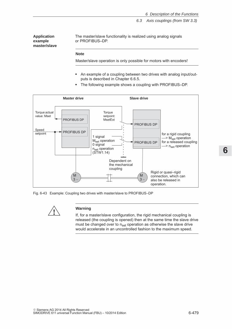
6
6.3 Axis couplings (from SW 3.3)
6-479� Siemens AG 2014 All Rights ReservedSIMODRIVE 611 universal Function Manual (FBU) – 10/2014 Edition
The master/slave functionality is realized using analog signals or PROFIBUS–DP.
Note
Master/slave operation is only possible for motors with encoders!
� An example of a coupling between two drives with analog input/out-puts is described in Chapter 6.6.5.
� The following example shows a coupling with PROFIBUS–DP.
Speedsetpoint
1 signalMset operation0 signalnset operation(STW1.14)
Master drive
Torque actualvalue: Mset
M3 ∼
M3 ∼
for a rigid coupling––> Mset operationfor a released coupling––> nset operation
Dependent onthe mechanicalcoupling
Rigid or quasi–rigidconnection, which canalso be released inoperation.
PROFIBUS DP
PROFIBUS DP
Slave drive
Torquesetpoint:MsetExt
PROFIBUS DP
PROFIBUS DP
Fig. 6-43 Example: Coupling two drives with master/slave to PROFIBUS–DP
!Warning
If, for a master/slave configuration, the rigid mechanical coupling isreleased (the coupling is opened) then at the same time the slave drivemust be changed over to nset operation as otherwise the slave drivewould accelerate in an uncontrolled fashion to the maximum speed.
Applicationexamplemaster/slave
6 Description of the Functions
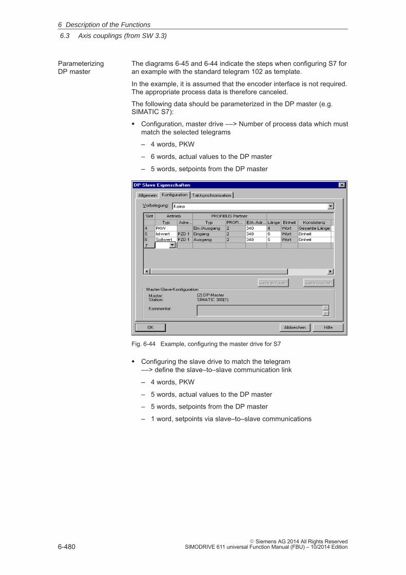
6
6.3 Axis couplings (from SW 3.3)
6-480� Siemens AG 2014 All Rights Reserved
SIMODRIVE 611 universal Function Manual (FBU) – 10/2014 Edition
The diagrams 6-45 and 6-44 indicate the steps when configuring S7 foran example with the standard telegram 102 as template.
In the example, it is assumed that the encoder interface is not required.The appropriate process data is therefore canceled.
The following data should be parameterized in the DP master (e.g.SIMATIC S7):
� Configuration, master drive ––> Number of process data which mustmatch the selected telegrams
– 4 words, PKW
– 6 words, actual values to the DP master
– 5 words, setpoints from the DP master
Fig. 6-44 Example, configuring the master drive for S7
� Configuring the slave drive to match the telegram ––> define the slave–to–slave communication link
– 4 words, PKW
– 5 words, actual values to the DP master
– 5 words, setpoints from the DP master
– 1 word, setpoints via slave–to–slave communications
Parameterizing DP master
6 Description of the Functions
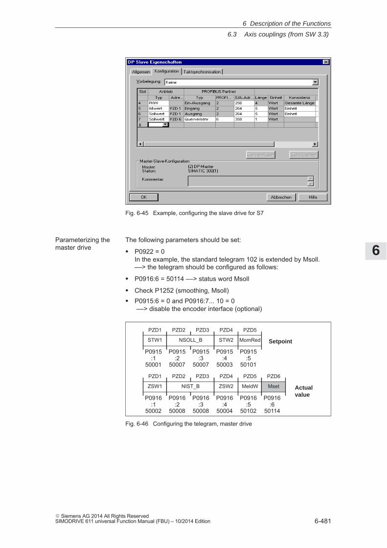
6
6.3 Axis couplings (from SW 3.3)
6-481� Siemens AG 2014 All Rights ReservedSIMODRIVE 611 universal Function Manual (FBU) – 10/2014 Edition
Fig. 6-45 Example, configuring the slave drive for S7
The following parameters should be set:
� P0922 = 0In the example, the standard telegram 102 is extended by Msoll.––> the telegram should be configured as follows:
� P0916:6 = 50114 ––> status word Msoll
� Check P1252 (smoothing, Msoll)� P0915:6 = 0 and P0916:7... 10 = 0
––> disable the encoder interface (optional)
PZD1
STW1
ZSW2
PZD1
ZSW1
PZD4
Setpoint
Actualvalue
PZD4
STW2
PZD5
MomRed
MeldW
PZD5
P0915:1
50001
P0915:4
50003
P0916:1
50002
P0916:4
50004
P0916:5
50102
P0915:5
50101
PZD2 PZD3
NSOLL_B
P0915:2
50007
P0915:3
50007
PZD2 PZD3
NIST_B
P0916:2
50008
P0916:3
50008
PZD6
Mset
P0916:6
50114
Fig. 6-46 Configuring the telegram, master drive
Parameterizing the master drive
6 Description of the Functions
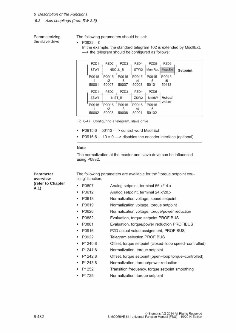
6
6.3 Axis couplings (from SW 3.3)
6-482� Siemens AG 2014 All Rights Reserved
SIMODRIVE 611 universal Function Manual (FBU) – 10/2014 Edition
The following parameters should be set:� P0922 = 0
In the example, the standard telegram 102 is extended by MsollExt.––> the telegram should be configured as follows:
PZD1
STW1
ZSW2
PZD1
ZSW1
PZD4
Setpoint
Actualvalue
PZD4
STW2
PZD5
MomRed
MeldW
PZD5
P0915:1
50001
P0915:4
50003
P0916:1
50002
P0916:4
50004
P0916:5
50102
P0915:5
50101
PZD2 PZD3
NSOLL_B
P0915:2
50007
P0915:3
50007
PZD2 PZD3
NIST_B
P0916:2
50008
P0916:3
50008
PZD6
MsetExt
P0915:6
50113
Fig. 6-47 Configuring a telegram, slave drive
� P0915:6 = 50113 ––> control word MsollExt� P0916:6 ... 10 = 0 ––> disables the encoder interface (optional)
Note
The normalization at the master and slave drive can be influencedusing P0882.
The following parameters are available for the ”torque setpoint cou-pling” function:
� P0607 Analog setpoint, terminal 56.x/14.x� P0612 Analog setpoint, terminal 24.x/20.x� P0618 Normalization voltage, speed setpoint� P0619 Normalization voltage, torque setpoint� P0620 Normalization voltage, torque/power reduction� P0882 Evaluation, torque setpoint PROFIBUS� P0881 Evaluation, torque/power reduction PROFIBUS� P0916 PZD actual value assignment, PROFIBUS� P0922 Telegram selection PROFIBUS� P1240:8 Offset, torque setpoint (closed–loop speed–controlled)� P1241:8 Normalization, torque setpoint� P1242:8 Offset, torque setpoint (open–loop torque–controlled)� P1243:8 Normalization, torque/power reduction� P1252 Transition frequency, torque setpoint smoothing� P1725 Normalization, torque setpoint
Parameterizing the slave drive
Parameteroverview(refer to ChapterA.1)
6 Description of the Functions
6
6.3 Axis couplings (from SW 3.3)
6-483� Siemens AG 2014 All Rights ReservedSIMODRIVE 611 universal Function Manual (FBU) – 10/2014 Edition
The following signals are used for the function ”torque setpoint coupling”:
� Input signals(refer under index entry ”Input signal, digital – ...”)
– Input signal ”open–loop torque controlled operation”
––> using an input terminal with function number 4
––> using the PROFIBUS control signal ”STW1.14”
– Input signal ”external torque setpoint”
––> using the PROFIBUS control signal ”MsollExt”
– Input signal ”torque limit reduction”
––> using the PROFIBUS control signal ”MomRed”
� Output signals(refer under the index entry, ”Output signal, digital – ...”)
– Output signal ”in synchronism”
––> using an output terminal with function number 71
––> using the PROFIBUS status signal ”PosZsw.3”
– Output signal ”open–loop torque controlled operation”
––> using the PROFIBUS status signal ”ZSW1.14”
– Output signal ”smoothed torque setpoint”
––> using the PROFIBUS status signal ”Msoll”
– Output signal ”smoothed torque–generating current Iq”
––> using the PROFIBUS status signal ”IqGl”
Input/outputsignals (refer toChapter 6.4)
6 Description of the Functions
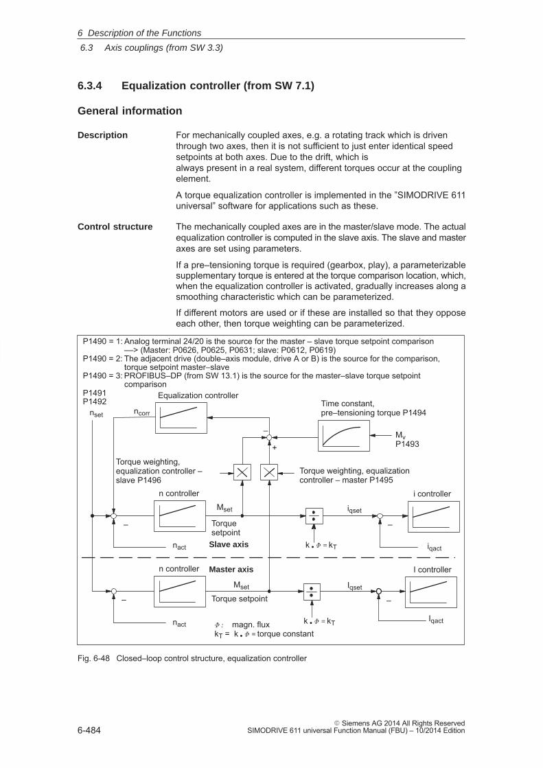
6
6.3 Axis couplings (from SW 3.3)
6-484� Siemens AG 2014 All Rights Reserved
SIMODRIVE 611 universal Function Manual (FBU) – 10/2014 Edition
6.3.4 Equalization controller (from SW 7.1)
General information
For mechanically coupled axes, e.g. a rotating track which is driven through two axes, then it is not sufficient to just enter identical speedsetpoints at both axes. Due to the drift, which is always present in a real system, different torques occur at the couplingelement.
A torque equalization controller is implemented in the ”SIMODRIVE 611universal” software for applications such as these.
The mechanically coupled axes are in the master/slave mode. The actualequalization controller is computed in the slave axis. The slave and masteraxes are set using parameters.
If a pre–tensioning torque is required (gearbox, play), a parameterizablesupplementary torque is entered at the torque comparison location, which,when the equalization controller is activated, gradually increases along asmoothing characteristic which can be parameterized.
If different motors are used or if these are installed so that they opposeeach other, then torque weighting can be parameterized.
P1490 = 1: Analog terminal 24/20 is the source for the master – slave torque setpoint comparison ––> (Master: P0626, P0625, P0631; slave: P0612, P0619)
P1490 = 2: The adjacent drive (double–axis module, drive A or B) is the source for the comparison,torque setpoint master–slave
P1490 = 3: PROFIBUS–DP (from SW 13.1) is the source for the master–slave torque setpointcomparison
P1491P1492
nact
Torque weighting,equalization controller –slave P1496
i controller
I controllern controller
n controller
nset
+
–
–
–
–
Master axis
Slave axis
Equalization controller
ncorr
Mset
Mset
Iqset
iqset
iqact
Iqact
nact
k � � � kT
k � � � kT
� � magn. fluxkT = k � � � torque constant
Time constant,pre–tensioning torque P1494
Mv P1493
Torque weighting, equalizationcontroller – master P1495
–
Torque setpoint
Torquesetpoint
Fig. 6-48 Closed–loop control structure, equalization controller
Description
Control structure
6 Description of the Functions
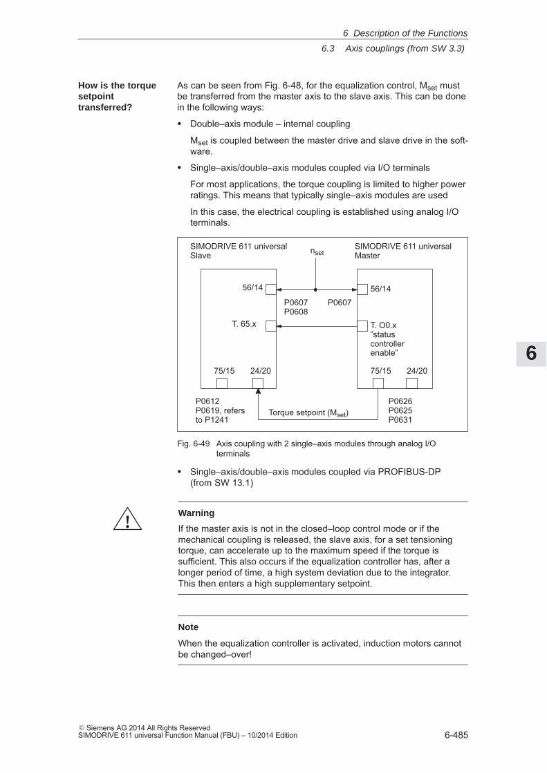
6
6.3 Axis couplings (from SW 3.3)
6-485� Siemens AG 2014 All Rights ReservedSIMODRIVE 611 universal Function Manual (FBU) – 10/2014 Edition
As can be seen from Fig. 6-48, for the equalization control, Mset mustbe transferred from the master axis to the slave axis. This can be donein the following ways:
� Double–axis module – internal coupling
Mset is coupled between the master drive and slave drive in the soft-ware.
� Single–axis/double–axis modules coupled via I/O terminals
For most applications, the torque coupling is limited to higher powerratings. This means that typically single–axis modules are used
In this case, the electrical coupling is established using analog I/Oterminals.
56/14
24/20
nset
Torque setpoint (Mset)
SIMODRIVE 611 universalSlave
56/14
75/15 24/20 75/15
SIMODRIVE 611 universalMaster
P0607P0608
P0607
P0626P0625P0631
P0612P0619, refersto P1241
T. O0.x”statuscontrollerenable”
T. 65.x
Fig. 6-49 Axis coupling with 2 single–axis modules through analog I/Oterminals
� Single–axis/double–axis modules coupled via PROFIBUS-DP(from SW 13.1)
!Warning
If the master axis is not in the closed–loop control mode or if themechanical coupling is released, the slave axis, for a set tensioningtorque, can accelerate up to the maximum speed if the torque issufficient. This also occurs if the equalization controller has, after alonger period of time, a high system deviation due to the integrator.This then enters a high supplementary setpoint.
Note
When the equalization controller is activated, induction motors cannotbe changed–over!
How is the torquesetpointtransferred?
6 Description of the Functions
6
6.3 Axis couplings (from SW 3.3)
6-486� Siemens AG 2014 All Rights Reserved
SIMODRIVE 611 universal Function Manual (FBU) – 10/2014 Edition
The following parameters should be set for the ”equalization controller”function, if the coupling is realized via analog I/O terminals:
� P0607 Analog setpoint, terminal 56.x/14.x
Parameterize the speed setpoint at both axes:
Master axis: P0607 = 1
Slave axis: P0607 = 1P0608 = 1, if the direction of rotation is to be inverted
� P0626 Signal number, analog output terminals 75.x/15 (only for an analog setpoint coupling)
Master axis: P0626 = 36 (torque setpoint, finely normalized)
P0625 = 50
P0631 = 1
� P0612 Signal number, analog setpoint terminals 24.x/20.x(only for an analog setpoint coupling)
Slave axis: P0612 = 3, is automatically set if, when using theparameterizing and start–up tool ”SimoCom U”, ”slave axis with analog coupling” is selected in the parameterizing screen form ”equalizationcontroller” for activate equalization controller.
P0619 = 5 (P0619 refers to P1241)
P1241 – pre–assigned the rated torque
Note
If P1490 = 1 and P0612 3, then fault 738 is output.
� P1490 Activates the equalization controller
Master axis: P1490 = 0
Slave axis: P1490 = 0 ––> No source or no equalization controller
P1490 = 1––> Equalization controller is active,
Source is terminal 24/20Parameterization of P0626, P0625, P0612, P0619
P1490 = 2––> Equalization controller is active
The source is the adjacent drive (drive A or B)
P1490 = 3 (from SW 13.1)––> Equalization controller is active
Source is PROFIBUS-DP (P0922, P0915)
Parameteroverview(refer to ChapterA.1)
6 Description of the Functions
6
6.3 Axis couplings (from SW 3.3)
6-487� Siemens AG 2014 All Rights ReservedSIMODRIVE 611 universal Function Manual (FBU) – 10/2014 Edition
Settings for the slave axis:
� P1491 P gain, equalization controller
Recommended setting:Vp equalization controller (P1491) = 0.5 / Vp speed controller (P1407)
The sign of the torque weighting must be taken into considerationwhen inverting the speed!
� P1492 Integral action time, equalization controller
Recommended setting:TN equalization controller (P1492) = 10 � TN speed controller (P1409)
� P1493 Pre–tensioning torque (pre–tensioning force) equalization controller
If a pre–tensioning torque is required (e.g. gearbox, play), a supple-mentary torque can be added at the torque comparison point usingP1493. When the equalization controller is activated, this supple-mentary torque gradually increases. This delay is achieved using aPT1 element which can be set using P1494.
� P1494 Pre–tensioning torque (pre–tensioning force) equalization controller
P1494 is used to enter the time constant for the PT1 element whichensures that the pre–tensioning torque gradually increases (pre–tensioning force) when the equalization controller is activated.
� P1495 Torque weighting, equalization controller – master
If different motors are involved in the closed–loop equalization con-trol, then a torque weighting of the torque setpoint (or force weight-ing of the force setpoint (SLM)) of the master axis can be set usingP1495.
� P1496 Torque weighting, equalization controller – slave
If various motors are involved in the closed–loop equalization con-trol, then a torque weighting of the torque setpoint or force weightingof the force setpoint (SLM) of the slave axis can be set.
The equalization controller is computed in the 1 ms clock cycle timeand the speed controller is computed in the speed controller clockcycle. In order to achieve a softer transition between these times slices,the setpoint steps (jumps) can be smoothed using a speed setpointfilter as PT1 system (1 ms time constant).
6 Description of the Functions
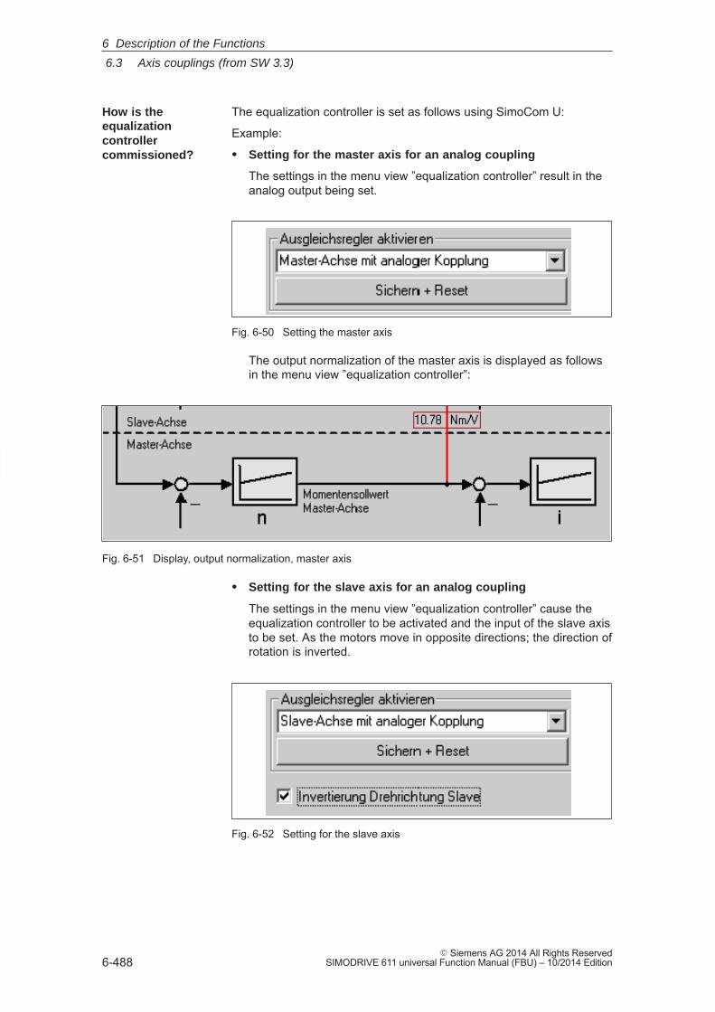
6
6.3 Axis couplings (from SW 3.3)
6-488� Siemens AG 2014 All Rights Reserved
SIMODRIVE 611 universal Function Manual (FBU) – 10/2014 Edition
The equalization controller is set as follows using SimoCom U:
Example:
� Setting for the master axis for an analog coupling
The settings in the menu view ”equalization controller” result in theanalog output being set.
Fig. 6-50 Setting the master axis
The output normalization of the master axis is displayed as followsin the menu view ”equalization controller”:
Fig. 6-51 Display, output normalization, master axis
� Setting for the slave axis for an analog coupling
The settings in the menu view ”equalization controller” cause theequalization controller to be activated and the input of the slave axisto be set. As the motors move in opposite directions; the direction ofrotation is inverted.
Fig. 6-52 Setting for the slave axis
How is theequalizationcontrollercommissioned?
6 Description of the Functions
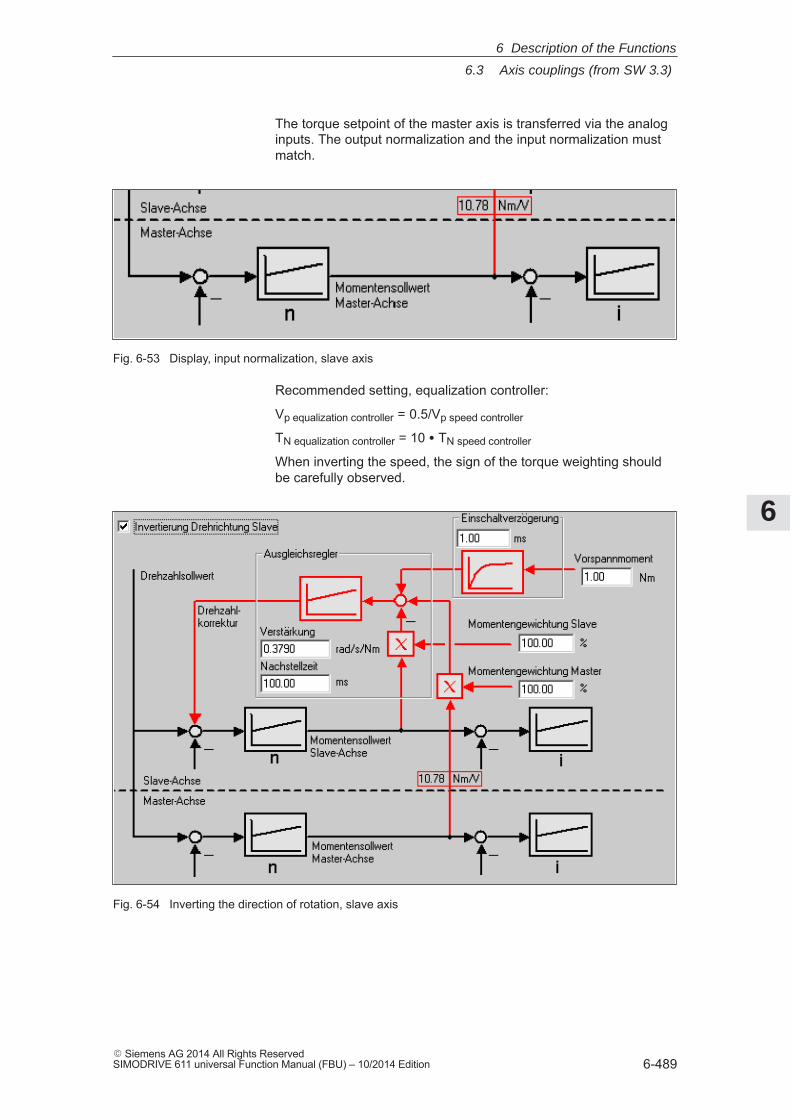
6
6.3 Axis couplings (from SW 3.3)
6-489� Siemens AG 2014 All Rights ReservedSIMODRIVE 611 universal Function Manual (FBU) – 10/2014 Edition
The torque setpoint of the master axis is transferred via the analoginputs. The output normalization and the input normalization mustmatch.
Fig. 6-53 Display, input normalization, slave axis
Recommended setting, equalization controller:
Vp equalization controller = 0.5/Vp speed controller
TN equalization controller = 10 � TN speed controller
When inverting the speed, the sign of the torque weighting shouldbe carefully observed.
Fig. 6-54 Inverting the direction of rotation, slave axis
6 Description of the Functions
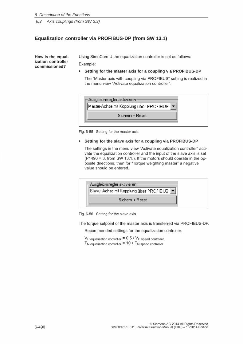
6
6.3 Axis couplings (from SW 3.3)
6-490� Siemens AG 2014 All Rights Reserved
SIMODRIVE 611 universal Function Manual (FBU) – 10/2014 Edition
Equalization controller via PROFIBUS-DP (from SW 13.1)
Using SimoCom U the equalization controller is set as follows:
Example:
� Setting for the master axis for a coupling via PROFIBUS-DP
The “Master axis with coupling via PROFIBUS“ setting is realized inthe menu view ”Activate equalization controller”.
Fig. 6-55 Setting for the master axis
� Setting for the slave axis for a coupling via PROFIBUS-DP
The settings in the menu view “Activate equalization controller“ acti-vate the equalization controller and the input of the slave axis is set(P1490 = 3, from SW 13.1.). If the motors should operate in the op-posite directions, then for “Torque weighting master” a negativevalue should be entered.
Fig. 6-56 Setting for the slave axis
The torque setpoint of the master axis is transferred via PROFIBUS-DP.
Recommended settings for the equalization controller:
VP equalization controller = 0.5 / VP speed controllerTN equalization controller = 10 � TN speed controller
How is the equal-ization controllercommissioned?
6 Description of the Functions
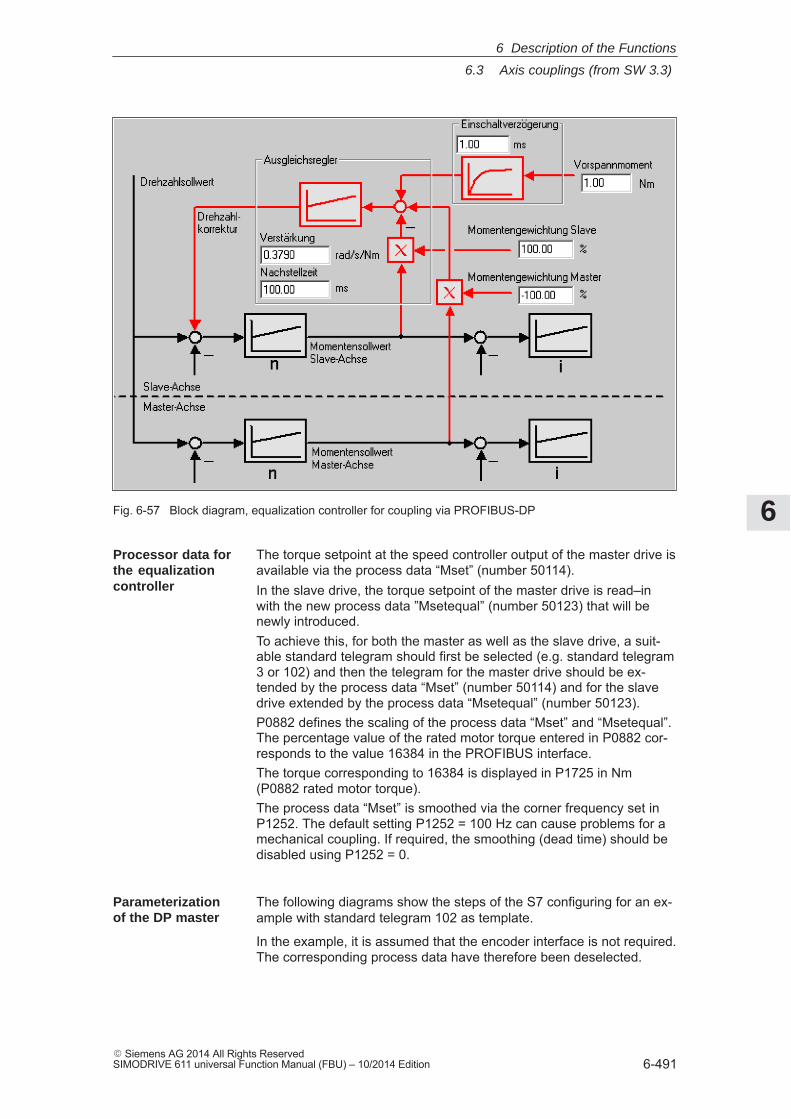
6
6.3 Axis couplings (from SW 3.3)
6-491� Siemens AG 2014 All Rights ReservedSIMODRIVE 611 universal Function Manual (FBU) – 10/2014 Edition
Fig. 6-57 Block diagram, equalization controller for coupling via PROFIBUS-DP
The torque setpoint at the speed controller output of the master drive isavailable via the process data “Mset” (number 50114).In the slave drive, the torque setpoint of the master drive is read–inwith the new process data ”Msetequal” (number 50123) that will benewly introduced.To achieve this, for both the master as well as the slave drive, a suit-able standard telegram should first be selected (e.g. standard telegram3 or 102) and then the telegram for the master drive should be ex-tended by the process data “Mset” (number 50114) and for the slavedrive extended by the process data “Msetequal” (number 50123).P0882 defines the scaling of the process data “Mset” and “Msetequal”.The percentage value of the rated motor torque entered in P0882 cor-responds to the value 16384 in the PROFIBUS interface.The torque corresponding to 16384 is displayed in P1725 in Nm(P0882 rated motor torque).The process data “Mset” is smoothed via the corner frequency set inP1252. The default setting P1252 = 100 Hz can cause problems for amechanical coupling. If required, the smoothing (dead time) should bedisabled using P1252 = 0.
The following diagrams show the steps of the S7 configuring for an ex-ample with standard telegram 102 as template.
In the example, it is assumed that the encoder interface is not required.The corresponding process data have therefore been deselected.
Processor data forthe equalizationcontroller
Parameterizationof the DP master
6 Description of the Functions
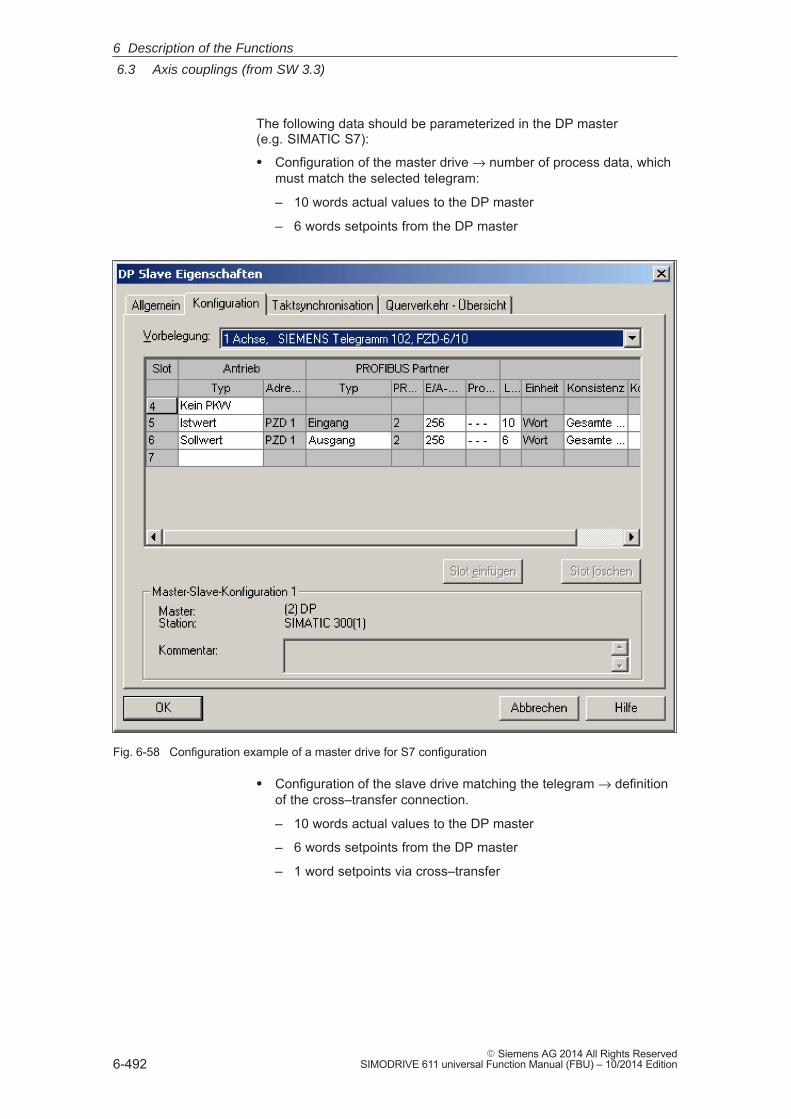
6
6.3 Axis couplings (from SW 3.3)
6-492� Siemens AG 2014 All Rights Reserved
SIMODRIVE 611 universal Function Manual (FBU) – 10/2014 Edition
The following data should be parameterized in the DP master (e.g. SIMATIC S7):
� Configuration of the master drive → number of process data, whichmust match the selected telegram:
– 10 words actual values to the DP master
– 6 words setpoints from the DP master
Fig. 6-58 Configuration example of a master drive for S7 configuration
� Configuration of the slave drive matching the telegram → definitionof the cross–transfer connection.
– 10 words actual values to the DP master
– 6 words setpoints from the DP master
– 1 word setpoints via cross–transfer
6 Description of the Functions
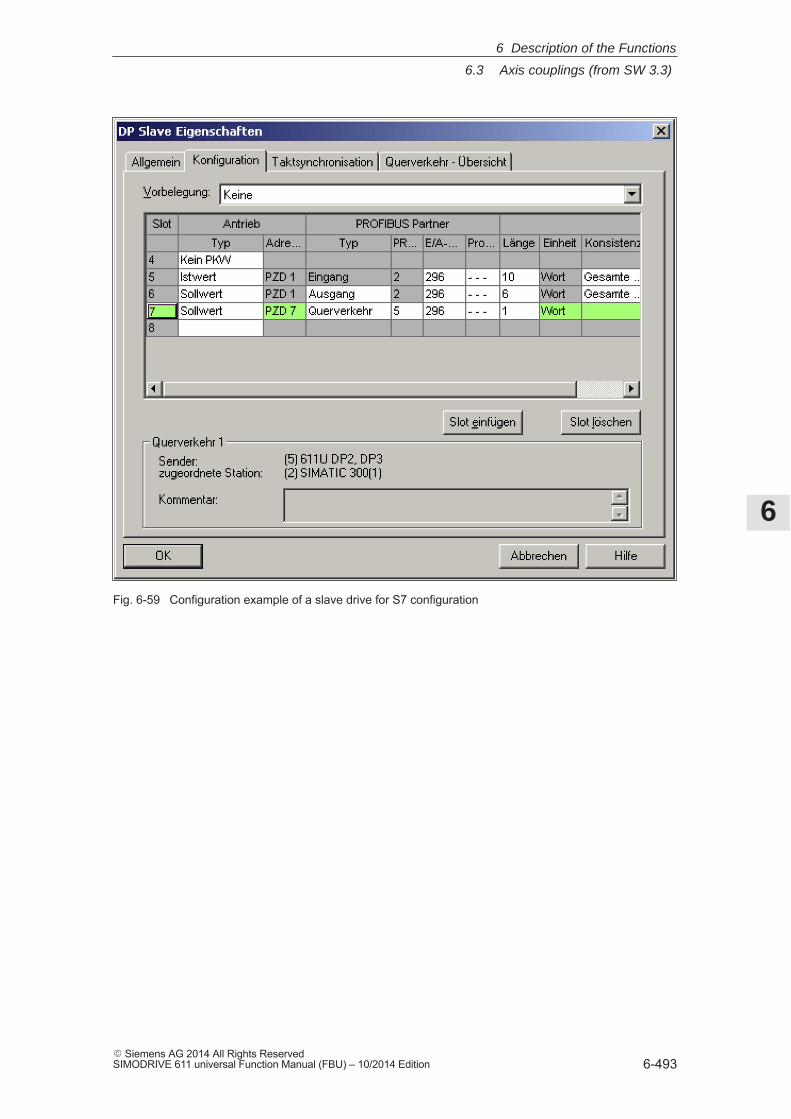
6
6.3 Axis couplings (from SW 3.3)
6-493� Siemens AG 2014 All Rights ReservedSIMODRIVE 611 universal Function Manual (FBU) – 10/2014 Edition
Fig. 6-59 Configuration example of a slave drive for S7 configuration
6 Description of the Functions
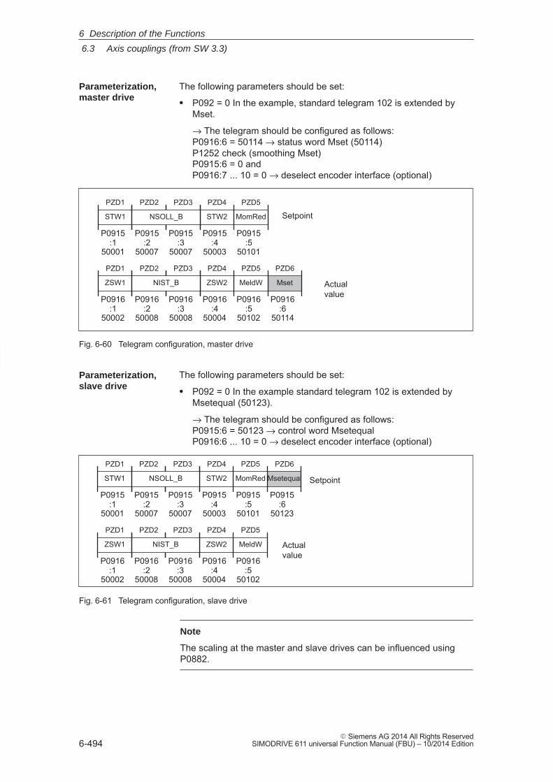
6
6.3 Axis couplings (from SW 3.3)
6-494� Siemens AG 2014 All Rights Reserved
SIMODRIVE 611 universal Function Manual (FBU) – 10/2014 Edition
The following parameters should be set:
� P092 = 0 In the example, standard telegram 102 is extended byMset.
→ The telegram should be configured as follows:P0916:6 = 50114 → status word Mset (50114)P1252 check (smoothing Mset)P0915:6 = 0 and P0916:7 ... 10 = 0 → deselect encoder interface (optional)
PZD1
STW1
ZSW2
PZD1
ZSW1
PZD4
Setpoint
Actualvalue
PZD4
STW2
PZD5
MomRed
PZD6
MsetMeldW
PZD5
P0915:1
50001
P0915:4
50003
P0916:1
50002
P0916:4
50004
P0916:5
50102
P0915:5
50101
P0916:6
50114
PZD2 PZD3
NSOLL_B
P0915:2
50007
P0915:3
50007
PZD2 PZD3
NIST_B
P0916:2
50008
P0916:3
50008
Fig. 6-60 Telegram configuration, master drive
The following parameters should be set:
� P092 = 0 In the example standard telegram 102 is extended byMsetequal (50123).
→ The telegram should be configured as follows:P0915:6 = 50123 → control word MsetequalP0916:6 ... 10 = 0 → deselect encoder interface (optional)
Actualvalue
PZD1
STW1
ZSW2
PZD1
ZSW1
PZD4
Setpoint
PZD4
STW2
PZD5
MomRed
PZD6
Msetequal
MeldW
PZD5
P0915:1
50001
P0915:4
50003
P0916:1
50002
P0916:4
50004
P0916:5
50102
P0915:5
50101
P0915:6
50123
PZD2 PZD3
NSOLL_B
P0915:2
50007
P0915:3
50007
PZD2 PZD3
NIST_B
P0916:2
50008
P0916:3
50008
Fig. 6-61 Telegram configuration, slave drive
Note
The scaling at the master and slave drives can be influenced usingP0882.
Parameterization,master drive
Parameterization,slave drive
6 Description of the Functions
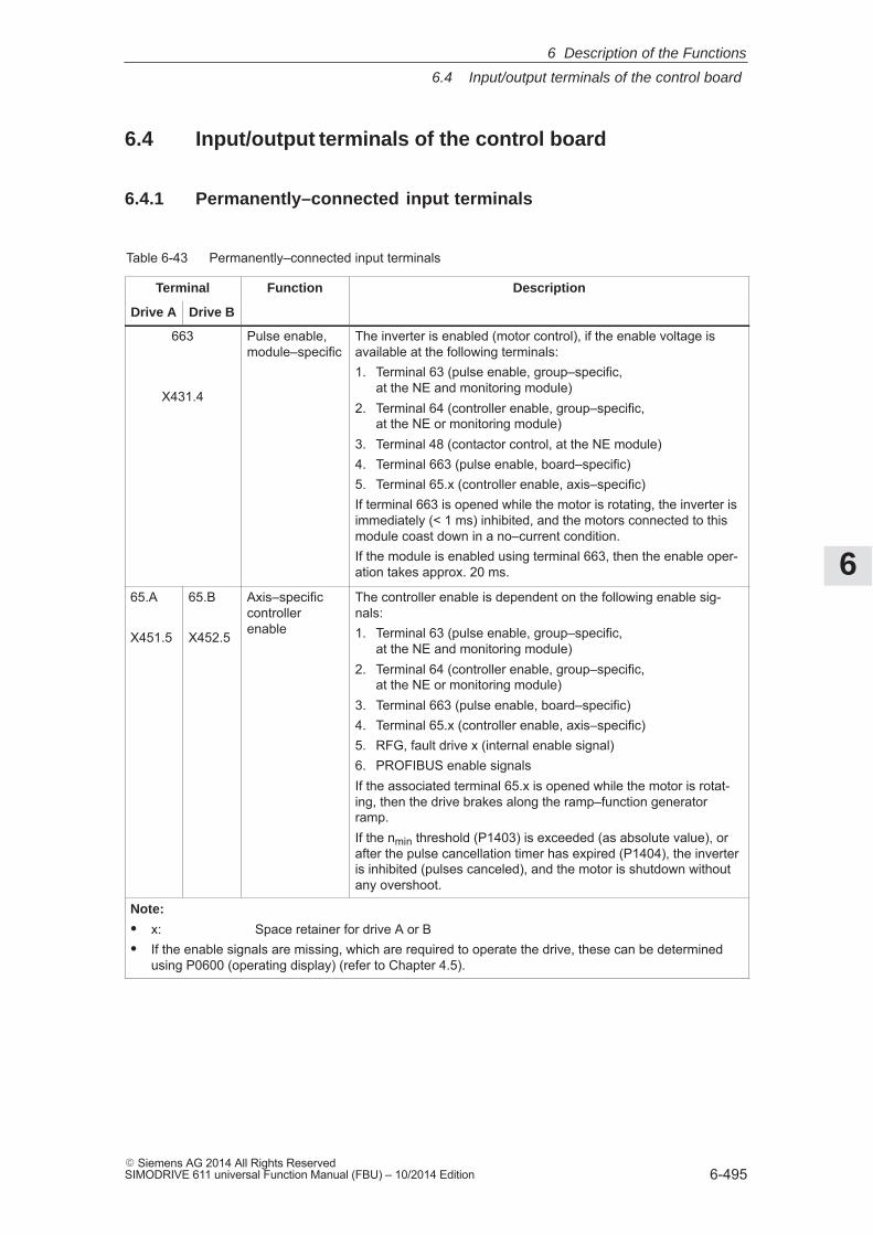
6
6.4 Input/output terminals of the control board
6-495� Siemens AG 2014 All Rights ReservedSIMODRIVE 611 universal Function Manual (FBU) – 10/2014 Edition
6.4 Input/output terminals of the control board
6.4.1 Permanently–connected input terminals
Table 6-43 Permanently–connected input terminals
Terminal Function Description
Drive A Drive B
663
X431.4
Pulse enable,module–specific
The inverter is enabled (motor control), if the enable voltage isavailable at the following terminals:1. Terminal 63 (pulse enable, group–specific,
at the NE and monitoring module)2. Terminal 64 (controller enable, group–specific,
at the NE or monitoring module)3. Terminal 48 (contactor control, at the NE module)4. Terminal 663 (pulse enable, board–specific)5. Terminal 65.x (controller enable, axis–specific)If terminal 663 is opened while the motor is rotating, the inverter isimmediately (< 1 ms) inhibited, and the motors connected to thismodule coast down in a no–current condition.If the module is enabled using terminal 663, then the enable oper-ation takes approx. 20 ms.
65.A
X451.5
65.B
X452.5
Axis–specificcontrollerenable
The controller enable is dependent on the following enable sig-nals:1. Terminal 63 (pulse enable, group–specific,
at the NE and monitoring module)2. Terminal 64 (controller enable, group–specific,
at the NE or monitoring module)3. Terminal 663 (pulse enable, board–specific)4. Terminal 65.x (controller enable, axis–specific)5. RFG, fault drive x (internal enable signal)6. PROFIBUS enable signalsIf the associated terminal 65.x is opened while the motor is rotat-ing, then the drive brakes along the ramp–function generatorramp.If the nmin threshold (P1403) is exceeded (as absolute value), orafter the pulse cancellation timer has expired (P1404), the inverteris inhibited (pulses canceled), and the motor is shutdown withoutany overshoot.
Note:
� x: Space retainer for drive A or B� If the enable signals are missing, which are required to operate the drive, these can be determined
using P0600 (operating display) (refer to Chapter 4.5).
6 Description of the Functions
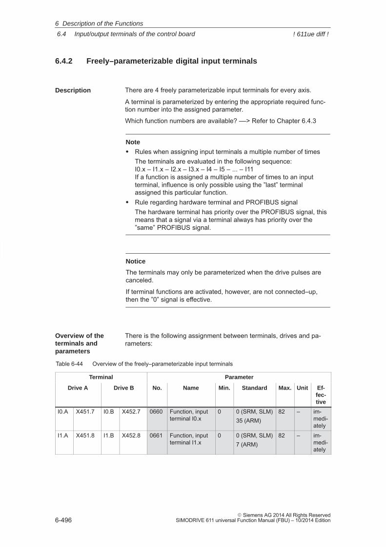
6
6.4 Input/output terminals of the control board
6-496� Siemens AG 2014 All Rights Reserved
SIMODRIVE 611 universal Function Manual (FBU) – 10/2014 Edition
6.4.2 Freely–parameterizable digital input terminals
There are 4 freely parameterizable input terminals for every axis.
A terminal is parameterized by entering the appropriate required func-tion number into the assigned parameter.
Which function numbers are available? ––> Refer to Chapter 6.4.3
Note
� Rules when assigning input terminals a multiple number of timesThe terminals are evaluated in the following sequence:I0.x – I1.x – I2.x – I3.x – I4 – I5 – ... – I11 If a function is assigned a multiple number of times to an inputterminal, influence is only possible using the ”last” terminalassigned this particular function.
� Rule regarding hardware terminal and PROFIBUS signalThe hardware terminal has priority over the PROFIBUS signal, thismeans that a signal via a terminal always has priority over the”same” PROFIBUS signal.
Notice
The terminals may only be parameterized when the drive pulses arecanceled.
If terminal functions are activated, however, are not connected–up,then the ”0” signal is effective.
There is the following assignment between terminals, drives and pa-rameters:
Table 6-44 Overview of the freely–parameterizable input terminals
Terminal Parameter
Drive A Drive B No. Name Min. Standard Max. Unit Ef-fec-tive
I0.A X451.7 I0.B X452.7 0660 Function, inputterminal I0.x
0 0 (SRM, SLM)35 (ARM)
82 – im-medi-ately
I1.A X451.8 I1.B X452.8 0661 Function, inputterminal I1.x
0 0 (SRM, SLM)7 (ARM)
82 – im-medi-ately
Description
Overview of theterminals and parameters
6 Description of the Functions
! 611ue diff !
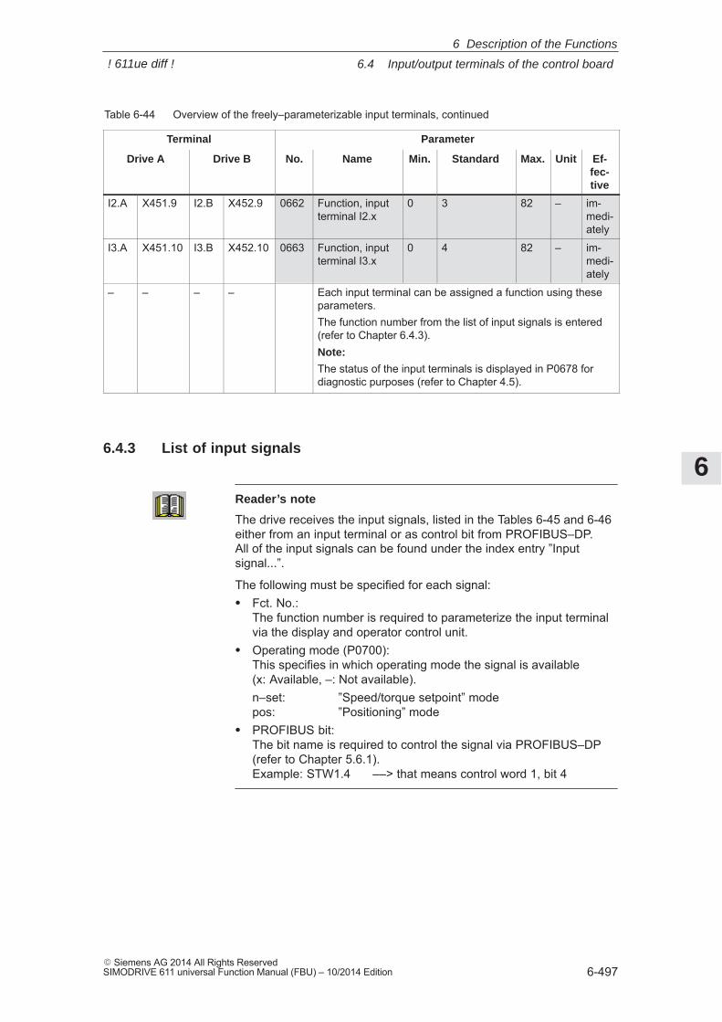
6
6.4 Input/output terminals of the control board
6-497� Siemens AG 2014 All Rights ReservedSIMODRIVE 611 universal Function Manual (FBU) – 10/2014 Edition
Table 6-44 Overview of the freely–parameterizable input terminals, continued
Terminal Parameter
Drive A Ef-fec-tive
UnitMax.StandardMin.NameNo.Drive B
I2.A X451.9 I2.B X452.9 0662 Function, inputterminal I2.x
0 3 82 – im-medi-ately
I3.A X451.10 I3.B X452.10 0663 Function, inputterminal I3.x
0 4 82 – im-medi-ately
– – – – Each input terminal can be assigned a function using theseparameters.The function number from the list of input signals is entered(refer to Chapter 6.4.3).Note:
The status of the input terminals is displayed in P0678 fordiagnostic purposes (refer to Chapter 4.5).
6.4.3 List of input signals
Reader’s note
The drive receives the input signals, listed in the Tables 6-45 and 6-46either from an input terminal or as control bit from PROFIBUS–DP. All of the input signals can be found under the index entry ”Inputsignal...”.
The following must be specified for each signal:� Fct. No.:
The function number is required to parameterize the input terminalvia the display and operator control unit.
� Operating mode (P0700): This specifies in which operating mode the signal is available(x: Available, –: Not available).n–set: ”Speed/torque setpoint” mode pos: ”Positioning” mode
� PROFIBUS bit: The bit name is required to control the signal via PROFIBUS–DP(refer to Chapter 5.6.1).Example: STW1.4 ––> that means control word 1, bit 4
6 Description of the Functions
! 611ue diff !
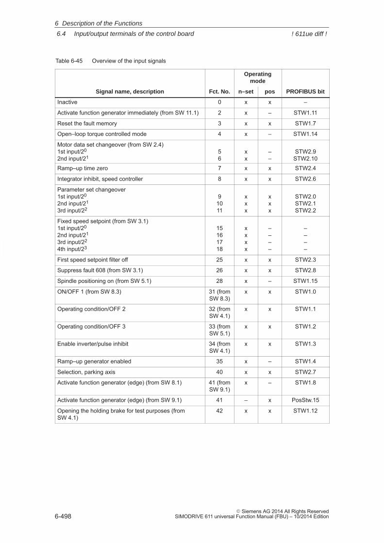
6
6.4 Input/output terminals of the control board
6-498� Siemens AG 2014 All Rights Reserved
SIMODRIVE 611 universal Function Manual (FBU) – 10/2014 Edition
Table 6-45 Overview of the input signals
Operatingmode
Signal name, description Fct. No. n–set pos PROFIBUS bit
Inactive 0 x x –
Activate function generator immediately (from SW 11.1) 2 x – STW1.11
Reset the fault memory 3 x x STW1.7
Open–loop torque controlled mode 4 x – STW1.14
Motor data set changeover (from SW 2.4)1st input/20
2nd input/2156
xx
––
STW2.9STW2.10
Ramp–up time zero 7 x x STW2.4
Integrator inhibit, speed controller 8 x x STW2.6
Parameter set changeover1st input/20
2nd input/21
3rd input/22
91011
xxx
xxx
STW2.0STW2.1STW2.2
Fixed speed setpoint (from SW 3.1)1st input/20
2nd input/21
3rd input/22
4th input/23
15161718
xxxx
––––
––––
First speed setpoint filter off 25 x x STW2.3
Suppress fault 608 (from SW 3.1) 26 x x STW2.8
Spindle positioning on (from SW 5.1) 28 x – STW1.15
ON/OFF 1 (from SW 8.3) 31 (fromSW 8.3)
x x STW1.0
Operating condition/OFF 2 32 (fromSW 4.1)
x x STW1.1
Operating condition/OFF 3 33 (fromSW 5.1)
x x STW1.2
Enable inverter/pulse inhibit 34 (fromSW 4.1)
x x STW1.3
Ramp–up generator enabled 35 x – STW1.4
Selection, parking axis 40 x x STW2.7
Activate function generator (edge) (from SW 8.1) 41 (fromSW 9.1)
x – STW1.8
Activate function generator (edge) (from SW 9.1) 41 – x PosStw.15
Opening the holding brake for test purposes (fromSW 4.1)
42 x x STW1.12
6 Description of the Functions
! 611ue diff !
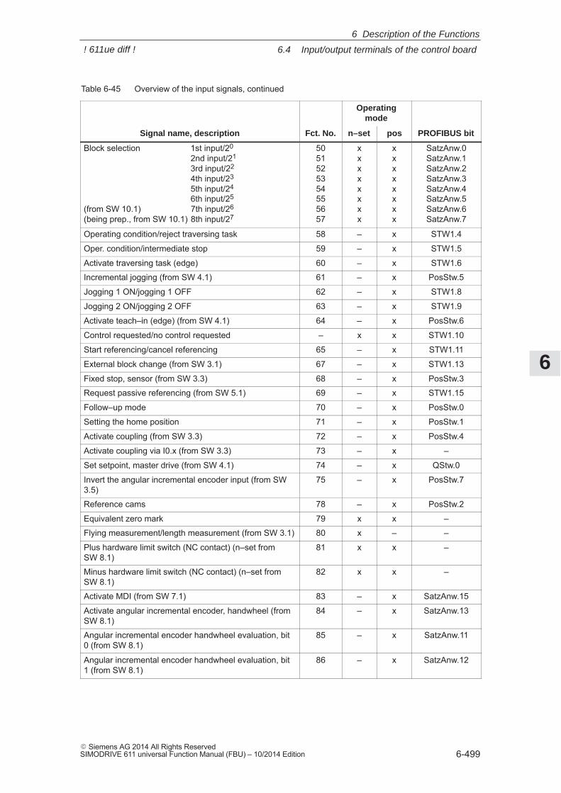
6
6.4 Input/output terminals of the control board
6-499� Siemens AG 2014 All Rights ReservedSIMODRIVE 611 universal Function Manual (FBU) – 10/2014 Edition
Table 6-45 Overview of the input signals, continued
Operatingmode
Signal name, description PROFIBUS bitposn–setFct. No.
Block selection 1st input/20
2nd input/21
3rd input/22
4th input/23
5th input/24
6th input/25
(from SW 10.1) 7th input/26 (being prep., from SW 10.1) 8th input/27
5051525354555657
xxxxxxxx
xxxxxxxx
SatzAnw.0SatzAnw.1SatzAnw.2SatzAnw.3SatzAnw.4SatzAnw.5SatzAnw.6SatzAnw.7
Operating condition/reject traversing task 58 – x STW1.4
Oper. condition/intermediate stop 59 – x STW1.5
Activate traversing task (edge) 60 – x STW1.6
Incremental jogging (from SW 4.1) 61 – x PosStw.5
Jogging 1 ON/jogging 1 OFF 62 – x STW1.8
Jogging 2 ON/jogging 2 OFF 63 – x STW1.9
Activate teach–in (edge) (from SW 4.1) 64 – x PosStw.6
Control requested/no control requested – x x STW1.10
Start referencing/cancel referencing 65 – x STW1.11
External block change (from SW 3.1) 67 – x STW1.13
Fixed stop, sensor (from SW 3.3) 68 – x PosStw.3
Request passive referencing (from SW 5.1) 69 – x STW1.15
Follow–up mode 70 – x PosStw.0
Setting the home position 71 – x PosStw.1
Activate coupling (from SW 3.3) 72 – x PosStw.4
Activate coupling via I0.x (from SW 3.3) 73 – x –
Set setpoint, master drive (from SW 4.1) 74 – x QStw.0
Invert the angular incremental encoder input (from SW3.5)
75 – x PosStw.7
Reference cams 78 – x PosStw.2
Equivalent zero mark 79 x x –
Flying measurement/length measurement (from SW 3.1) 80 x – –
Plus hardware limit switch (NC contact) (n–set fromSW 8.1)
81 x x –
Minus hardware limit switch (NC contact) (n–set fromSW 8.1)
82 x x –
Activate MDI (from SW 7.1) 83 – x SatzAnw.15
Activate angular incremental encoder, handwheel (fromSW 8.1)
84 – x SatzAnw.13
Angular incremental encoder handwheel evaluation, bit0 (from SW 8.1)
85 – x SatzAnw.11
Angular incremental encoder handwheel evaluation, bit1 (from SW 8.1)
86 – x SatzAnw.12
6 Description of the Functions
! 611ue diff !
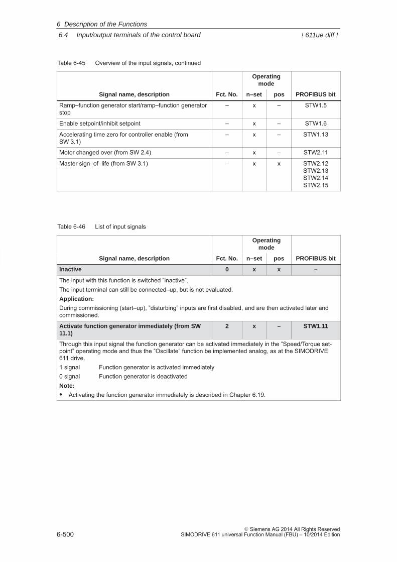
6
6.4 Input/output terminals of the control board
6-500� Siemens AG 2014 All Rights Reserved
SIMODRIVE 611 universal Function Manual (FBU) – 10/2014 Edition
Table 6-45 Overview of the input signals, continued
Operatingmode
Signal name, description PROFIBUS bitposn–setFct. No.
Ramp–function generator start/ramp–function generatorstop
– x – STW1.5
Enable setpoint/inhibit setpoint – x – STW1.6
Accelerating time zero for controller enable (fromSW 3.1)
– x – STW1.13
Motor changed over (from SW 2.4) – x – STW2.11
Master sign–of–life (from SW 3.1) – x x STW2.12STW2.13STW2.14STW2.15
Table 6-46 List of input signals
Operatingmode
Signal name, description Fct. No. n–set pos PROFIBUS bit
Inactive 0 x x –
The input with this function is switched ”inactive”.The input terminal can still be connected–up, but is not evaluated.Application:
During commissioning (start–up), ”disturbing” inputs are first disabled, and are then activated later andcommissioned.
Activate function generator immediately (from SW11.1)
2 x – STW1.11
Through this input signal the function generator can be activated immediately in the ”Speed/Torque set-point” operating mode and thus the ”Oscillate” function be implemented analog, as at the SIMODRIVE611 drive.1 signal Function generator is activated immediately0 signal Function generator is deactivatedNote:
� Activating the function generator immediately is described in Chapter 6.19.
6 Description of the Functions
! 611ue diff !
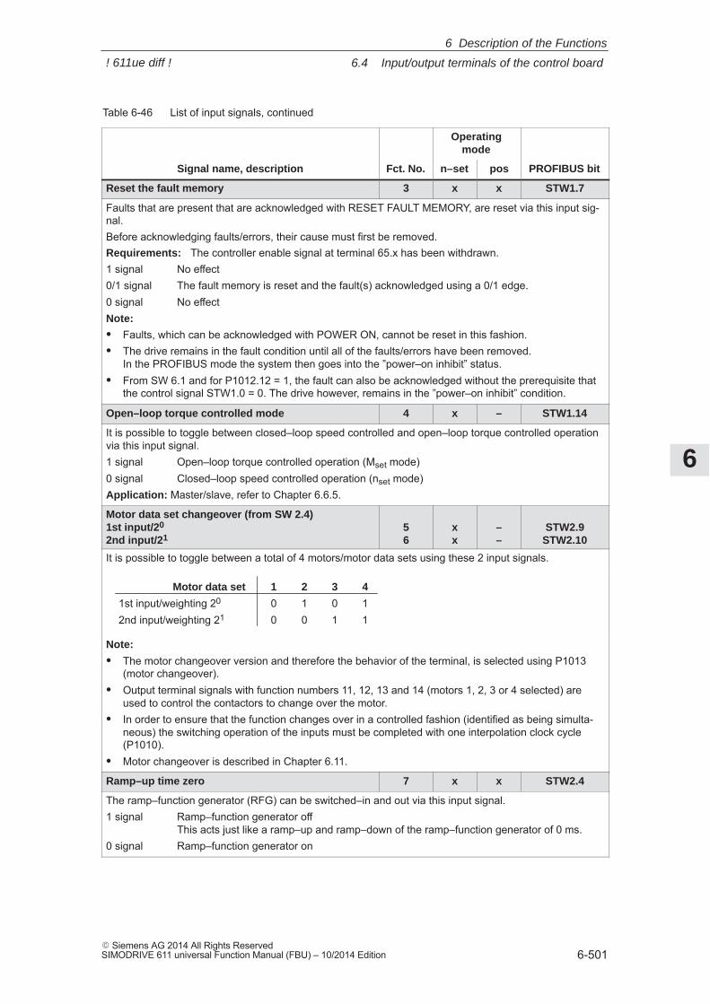
6
6.4 Input/output terminals of the control board
6-501� Siemens AG 2014 All Rights ReservedSIMODRIVE 611 universal Function Manual (FBU) – 10/2014 Edition
Table 6-46 List of input signals, continued
Operatingmode
Signal name, description PROFIBUS bitposn–setFct. No.
Reset the fault memory 3 x x STW1.7
Faults that are present that are acknowledged with RESET FAULT MEMORY, are reset via this input sig-nal.Before acknowledging faults/errors, their cause must first be removed.Requirements: The controller enable signal at terminal 65.x has been withdrawn.1 signal No effect0/1 signal The fault memory is reset and the fault(s) acknowledged using a 0/1 edge.0 signal No effectNote:
� Faults, which can be acknowledged with POWER ON, cannot be reset in this fashion.� The drive remains in the fault condition until all of the faults/errors have been removed.
In the PROFIBUS mode the system then goes into the ”power–on inhibit” status.� From SW 6.1 and for P1012.12 = 1, the fault can also be acknowledged without the prerequisite that
the control signal STW1.0 = 0. The drive however, remains in the ”power–on inhibit” condition.
Open–loop torque controlled mode 4 x – STW1.14
It is possible to toggle between closed–loop speed controlled and open–loop torque controlled operationvia this input signal.1 signal Open–loop torque controlled operation (Mset mode)0 signal Closed–loop speed controlled operation (nset mode)Application: Master/slave, refer to Chapter 6.6.5.
Motor data set changeover (from SW 2.4)1st input/20
2nd input/2156
xx
––
STW2.9STW2.10
It is possible to toggle between a total of 4 motors/motor data sets using these 2 input signals.
Motor data set 1 2 3 4
1st input/weighting 20 0 1 0 12nd input/weighting 21 0 0 1 1
Note:
� The motor changeover version and therefore the behavior of the terminal, is selected using P1013(motor changeover).
� Output terminal signals with function numbers 11, 12, 13 and 14 (motors 1, 2, 3 or 4 selected) areused to control the contactors to change over the motor.
� In order to ensure that the function changes over in a controlled fashion (identified as being simulta-neous) the switching operation of the inputs must be completed with one interpolation clock cycle(P1010).
� Motor changeover is described in Chapter 6.11.
Ramp–up time zero 7 x x STW2.4
The ramp–function generator (RFG) can be switched–in and out via this input signal.1 signal Ramp–function generator off
This acts just like a ramp–up and ramp–down of the ramp–function generator of 0 ms.0 signal Ramp–function generator on
6 Description of the Functions
! 611ue diff !
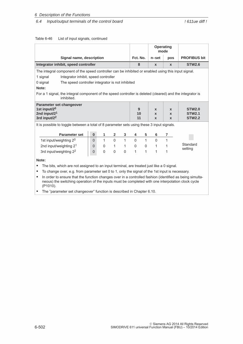
6
6.4 Input/output terminals of the control board
6-502� Siemens AG 2014 All Rights Reserved
SIMODRIVE 611 universal Function Manual (FBU) – 10/2014 Edition
Table 6-46 List of input signals, continued
Operatingmode
Signal name, description PROFIBUS bitposn–setFct. No.
Integrator inhibit, speed controller 8 x x STW2.6
The integral component of the speed controller can be inhibited or enabled using this input signal.1 signal Integrator inhibit, speed controller0 signal The speed controller integrator is not inhibitedNote:
For a 1 signal, the integral component of the speed controller is deleted (cleared) and the integrator isinhibited.
Parameter set changeover1st input/20
2nd input/21
3rd input/22
91011
xxx
xxx
STW2.0STW2.1STW2.2
It is possible to toggle between a total of 8 parameter sets using these 3 input signals.
Parameter set 0 1 2 3 4 5 6 7
1st input/weighting 20 0 1 0 1 0 1 0 12nd input/weighting 21 0 0 1 1 0 0 1 13rd input/weighting 22 0 0 0 0 1 1 1 1
Standardsetting
Note:
� The bits, which are not assigned to an input terminal, are treated just like a 0 signal.� To change over, e.g. from parameter set 0 to 1, only the signal of the 1st input is necessary.� In order to ensure that the function changes over in a controlled fashion (identified as being simulta-
neous) the switching operation of the inputs must be completed with one interpolation clock cycle(P1010).
� The ”parameter set changeover” function is described in Chapter 6.10.
6 Description of the Functions
! 611ue diff !
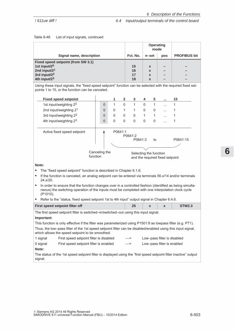
6
6.4 Input/output terminals of the control board
6-503� Siemens AG 2014 All Rights ReservedSIMODRIVE 611 universal Function Manual (FBU) – 10/2014 Edition
Table 6-46 List of input signals, continued
Operatingmode
Signal name, description PROFIBUS bitposn–setFct. No.
Fixed speed setpoint (from SW 3.1)1st input/20
2nd input/21
3rd input/22
4th input/23
15161718
xxxx
––––
––––
Using these input signals, the ”fixed speed setpoint” function can be selected with the required fixed set-points 1 to 15, or the function can be canceled.
Fixed speed setpoint 1 2 3 4 5 ... 15
1st input/weighting 20 0 1 0 1 0 1 ... 12nd input/weighting 21 0 0 1 1 0 0 ... 13rd input/weighting 22 0 0 0 0 1 1 ... 14th input/weighting 23 0 0 0 0 0 0 ... 1
Active fixed speed setpoint P0641:1P0641:2
P0641:3 to P0641:15
Canceling thefunction
Selecting the functionand the required fixed setpoint
Note:
� The ”fixed speed setpoint” function is described in Chapter 6.1.6.� If the function is canceled, an analog setpoint can be entered via terminals 56.x/14 and/or terminals
24.x/20.� In order to ensure that the function changes over in a controlled fashion (identified as being simulta-
neous) the switching operation of the inputs must be completed with one interpolation clock cycle(P1010).
� Refer to the ”status, fixed speed setpoint 1st to 4th input” output signal in Chapter 6.4.6.
First speed setpoint filter off 25 x x STW2.3
The first speed setpoint filter is switched–in/switched–out using this input signal.Important:
This function is only effective if the filter was parameterized using P1501:8 as lowpass filter (e.g. PT1).Thus, the low–pass filter of the 1st speed setpoint filter can be disabled/enabled using this input signal,which allows the speed setpoint to be smoothed.1 signal First speed setpoint filter is disabled ––> Low–pass filter is disabled0 signal First speed setpoint filter is enabled ––> Low–pass filter is enabledNote:
The status of the 1st speed setpoint filter is displayed using the ”first speed setpoint filter inactive” outputsignal.
6 Description of the Functions
! 611ue diff !
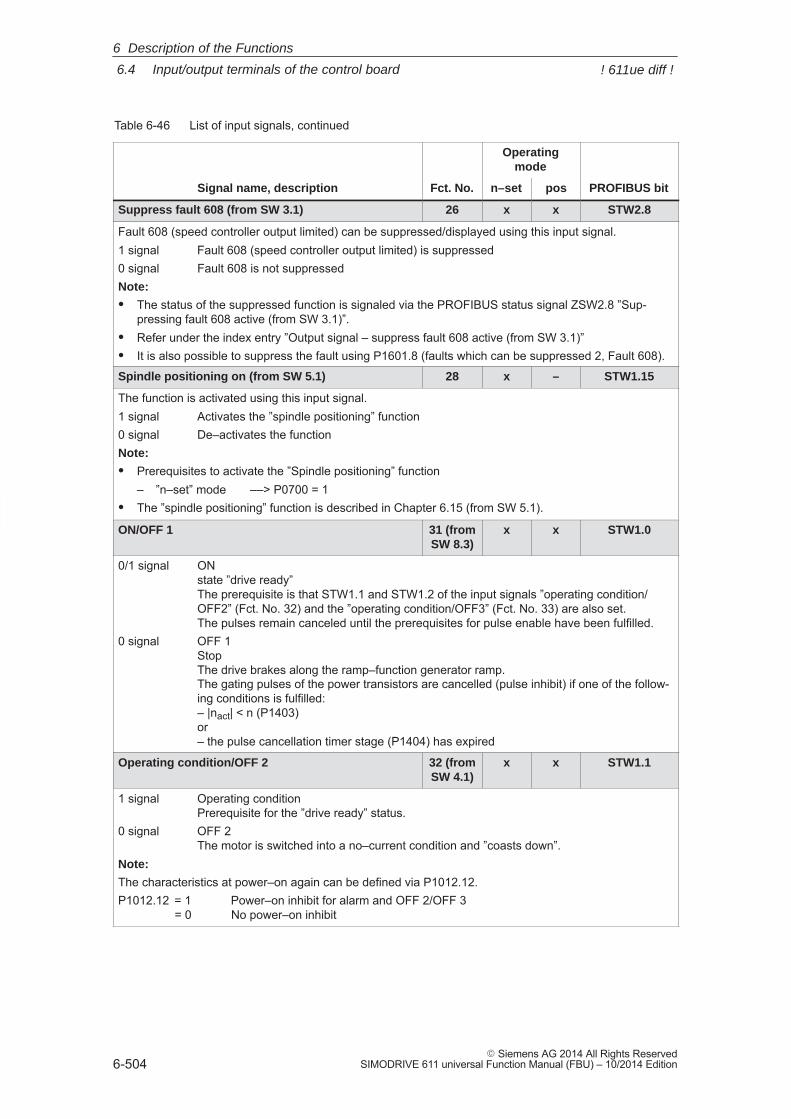
6
6.4 Input/output terminals of the control board
6-504� Siemens AG 2014 All Rights Reserved
SIMODRIVE 611 universal Function Manual (FBU) – 10/2014 Edition
Table 6-46 List of input signals, continued
Operatingmode
Signal name, description PROFIBUS bitposn–setFct. No.
Suppress fault 608 (from SW 3.1) 26 x x STW2.8
Fault 608 (speed controller output limited) can be suppressed/displayed using this input signal.1 signal Fault 608 (speed controller output limited) is suppressed0 signal Fault 608 is not suppressedNote:
� The status of the suppressed function is signaled via the PROFIBUS status signal ZSW2.8 ”Sup-pressing fault 608 active (from SW 3.1)”.
� Refer under the index entry ”Output signal – suppress fault 608 active (from SW 3.1)”� It is also possible to suppress the fault using P1601.8 (faults which can be suppressed 2, Fault 608).
Spindle positioning on (from SW 5.1) 28 x – STW1.15
The function is activated using this input signal.1 signal Activates the ”spindle positioning” function0 signal De–activates the functionNote:
� Prerequisites to activate the ”Spindle positioning” function– ”n–set” mode ––> P0700 = 1
� The ”spindle positioning” function is described in Chapter 6.15 (from SW 5.1).
ON/OFF 1 31 (fromSW 8.3)
x x STW1.0
0/1 signal ONstate ”drive ready”The prerequisite is that STW1.1 and STW1.2 of the input signals ”operating condition/OFF2” (Fct. No. 32) and the ”operating condition/OFF3” (Fct. No. 33) are also set. The pulses remain canceled until the prerequisites for pulse enable have been fulfilled.
0 signal OFF 1 Stop The drive brakes along the ramp–function generator ramp. The gating pulses of the power transistors are cancelled (pulse inhibit) if one of the follow-ing conditions is fulfilled:– |nact| < n (P1403) or– the pulse cancellation timer stage (P1404) has expired
Operating condition/OFF 2 32 (fromSW 4.1)
x x STW1.1
1 signal Operating conditionPrerequisite for the ”drive ready” status.
0 signal OFF 2 The motor is switched into a no–current condition and ”coasts down”.
Note:
The characteristics at power–on again can be defined via P1012.12.P1012.12 = 1 Power–on inhibit for alarm and OFF 2/OFF 3
= 0 No power–on inhibit
6 Description of the Functions
! 611ue diff !
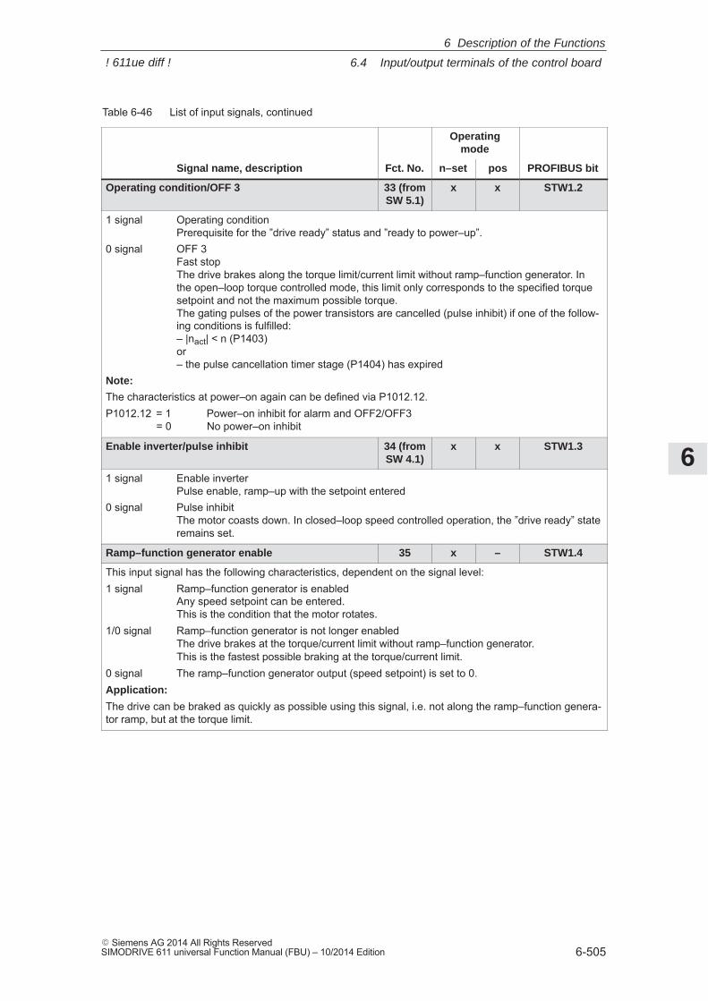
6
6.4 Input/output terminals of the control board
6-505� Siemens AG 2014 All Rights ReservedSIMODRIVE 611 universal Function Manual (FBU) – 10/2014 Edition
Table 6-46 List of input signals, continued
Operatingmode
Signal name, description PROFIBUS bitposn–setFct. No.
Operating condition/OFF 3 33 (fromSW 5.1)
x x STW1.2
1 signal Operating conditionPrerequisite for the ”drive ready” status and ”ready to power–up”.
0 signal OFF 3 Fast stop The drive brakes along the torque limit/current limit without ramp–function generator. Inthe open–loop torque controlled mode, this limit only corresponds to the specified torquesetpoint and not the maximum possible torque.The gating pulses of the power transistors are cancelled (pulse inhibit) if one of the follow-ing conditions is fulfilled:– |nact| < n (P1403) or– the pulse cancellation timer stage (P1404) has expired
Note:
The characteristics at power–on again can be defined via P1012.12.P1012.12 = 1 Power–on inhibit for alarm and OFF2/OFF3
= 0 No power–on inhibit
Enable inverter/pulse inhibit 34 (fromSW 4.1)
x x STW1.3
1 signal Enable inverterPulse enable, ramp–up with the setpoint entered
0 signal Pulse inhibitThe motor coasts down. In closed–loop speed controlled operation, the ”drive ready” stateremains set.
Ramp–function generator enable 35 x – STW1.4
This input signal has the following characteristics, dependent on the signal level:1 signal Ramp–function generator is enabled
Any speed setpoint can be entered.This is the condition that the motor rotates.
1/0 signal Ramp–function generator is not longer enabledThe drive brakes at the torque/current limit without ramp–function generator.This is the fastest possible braking at the torque/current limit.
0 signal The ramp–function generator output (speed setpoint) is set to 0.Application:
The drive can be braked as quickly as possible using this signal, i.e. not along the ramp–function genera-tor ramp, but at the torque limit.
6 Description of the Functions
! 611ue diff !
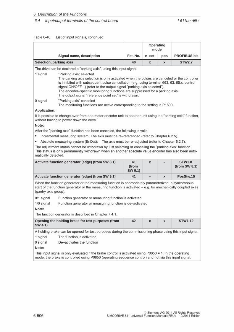
6
6.4 Input/output terminals of the control board
6-506� Siemens AG 2014 All Rights Reserved
SIMODRIVE 611 universal Function Manual (FBU) – 10/2014 Edition
Table 6-46 List of input signals, continued
Operatingmode
Signal name, description PROFIBUS bitposn–setFct. No.
Selection, parking axis 40 x x STW2.7
The drive can be declared a ”parking axis”, using this input signal.1 signal ”Parking axis” selected
The parking axis selection is only activated when the pulses are canceled or the controlleris inhibited with subsequent pulse cancellation (e.g. using terminal 663, 63, 65.x, controlsignal ON/OFF 1) (refer to the output signal ”parking axis selected”).The encoder–specific monitoring functions are suppressed for a parking axis.The output signal ”reference point set” is withdrawn.
0 signal ”Parking axis” canceledThe monitoring functions are active corresponding to the setting in P1600.
Application:
It is possible to change over from one motor encoder unit to another unit using the ”parking axis” function,without having to power down the drive.Note:
After the ”parking axis” function has been canceled, the following is valid:� Incremental measuring system: The axis must be re–referenced (refer to Chapter 6.2.5).� Absolute measuring system (EnDat): The axis must be re–adjusted (refer to Chapter 6.2.7).The adjustment status cannot be withdrawn by just selecting or canceling the ”parking axis” function.This status is only permanently withdrawn when an another absolute value encoder has also been auto-matically detected.
Activate function generator (edge) (from SW 8.1) 41(from
SW 9.1)
x – STW1.8 (from SW 8.1)
Activate function generator (edge) (from SW 9.1) 41 – x PosStw.15
When the function generator or the measuring function is appropriately parameterized, a synchronousstart of the function generator or the measuring function is activated – e.g. for mechanically coupled axes(gantry axis group).
0/1 signal Function generator or measuring function is activated1/0 signal Function generator or measuring function is de–activatedNote:
The function generator is described in Chapter 7.4.1.
Opening the holding brake for test purposes (fromSW 4.1)
42 x x STW1.12
A holding brake can be opened for test purposes during the commissioning phase using this input signal.1 signal The function is activated0 signal De–activates the functionNote:
This input signal is only evaluated if the brake control is activated using P0850 = 1. In the operatingmode, the brake is controlled using P0850 (operating sequence control) and not via this input signal.
6 Description of the Functions
! 611ue diff !
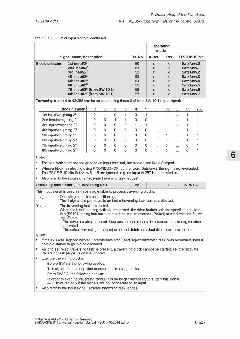
6
6.4 Input/output terminals of the control board
6-507� Siemens AG 2014 All Rights ReservedSIMODRIVE 611 universal Function Manual (FBU) – 10/2014 Edition
Table 6-46 List of input signals, continued
Operatingmode
Signal name, description PROFIBUS bitposn–setFct. No.
Block selection 1st input/20
2nd input/21
3rd input/22
4th input/23
5th input/24
6th input/25
7th input/26 (from SW 10.1)8th input/27 (from SW 10.1)
5051525354555657
xxxxxxxx
xxxxxxxx
SatzAnw.0SatzAnw.1SatzAnw.2SatzAnw.3SatzAnw.4SatzAnw.5SatzAnw.6SatzAnw.7
Traversing blocks 0 to 63/255 can be selected using these 6 (8 from SW 10.1) input signals.
Block number 0 1 2 3 4 5 ... 31 ... 63 255
1st input/weighting 20 0 1 0 1 0 1 ... 1 ... 1 12nd input/weighting 21 0 0 1 1 0 0 ... 1 ... 1 13rd input/weighting 22 0 0 0 0 1 1 ... 1 ... 1 14th input/weighting 23 0 0 0 0 0 0 ... 1 ... 1 15th input/weighting 24 0 0 0 0 0 0 ... 1 ... 1 16th input/weighting 25 0 0 0 0 0 0 ... 0 ... 1 17th input/weighting 26 0 0 0 0 0 0 ... 0 ... 0 18th input/weighting 27 0 0 0 0 0 0 ... 0 ... 0 1
Note:
� The bits, which are not assigned to an input terminal, are treated just like a 0 signal.� When a block is selecting using PROFIBUS–DP (control word SatzAnw), the sign is not evaluated.
The PROFIBUS bits SatzAnw.8...15 are ignored, e.g. an input of 257 is interpreted as 1.� Also refer to the input signal ”activate traversing task (edge)”
Operating condition/reject traversing task 58 – x STW1.4
This input signal is used as traversing enable to process traversing blocks.1 signal Operating condition for positioning
The 1 signal is a prerequisite so that a traversing task can be activated.0 signal The traversing task is rejected
When the block is being actively processed, the drive brakes with the specified decelera-tion (P0104) taking into account the deceleration override (P0084) to n = 0 with the follow-ing effects:– The drive remains in closed–loop position control and the standstill monitoring functionis activated– The actual traversing task is rejected and delete residual distance is carried–out.
Note:� If the axis was stopped with an ”intermediate stop”, and ”reject traversing task” was requested, then a
delete distance to go is also executed.� As long as ”reject traversing task” is present, a traversing block cannot be started, i.e. the ”activate
traversing task (edge)” signal is ignored� Execute traversing blocks:
– Before SW 3.3 the following applies:This signal must be supplied to execute traversing blocks.
– From SW 3.3, the following applies:In order to execute traversing blocks, it is no longer necessary to supply this signal.––> However, only if the signals are not connected to an input.
� Also refer to the input signal ”activate traversing task (edge)”
6 Description of the Functions
! 611ue diff !
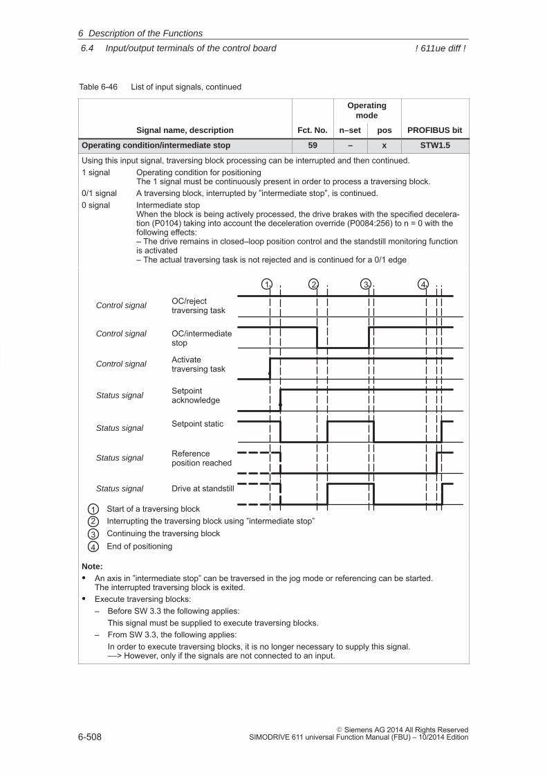
6
6.4 Input/output terminals of the control board
6-508� Siemens AG 2014 All Rights Reserved
SIMODRIVE 611 universal Function Manual (FBU) – 10/2014 Edition
Table 6-46 List of input signals, continued
Operatingmode
Signal name, description PROFIBUS bitposn–setFct. No.
Operating condition/intermediate stop 59 – x STW1.5
Using this input signal, traversing block processing can be interrupted and then continued.1 signal Operating condition for positioning
The 1 signal must be continuously present in order to process a traversing block.0/1 signal A traversing block, interrupted by ”intermediate stop”, is continued.0 signal Intermediate stop
When the block is being actively processed, the drive brakes with the specified decelera-tion (P0104) taking into account the deceleration override (P0084:256) to n = 0 with thefollowing effects:– The drive remains in closed–loop position control and the standstill monitoring functionis activated– The actual traversing task is not rejected and is continued for a 0/1 edge
Activatetraversing task
Setpointacknowledge
Setpoint static
Referenceposition reached
Drive at standstill
OC/intermediatestop
OC/rejecttraversing taskControl signal
Control signal
Status signal
Control signal
Status signal
Status signal
Status signal
1 Start of a traversing block2 Interrupting the traversing block using ”intermediate stop”
Continuing the traversing blockEnd of positioning
34
1 2 3 4
Note:� An axis in ”intermediate stop” can be traversed in the jog mode or referencing can be started.
The interrupted traversing block is exited.� Execute traversing blocks:
– Before SW 3.3 the following applies:This signal must be supplied to execute traversing blocks.
– From SW 3.3, the following applies:In order to execute traversing blocks, it is no longer necessary to supply this signal.––> However, only if the signals are not connected to an input.
6 Description of the Functions
! 611ue diff !
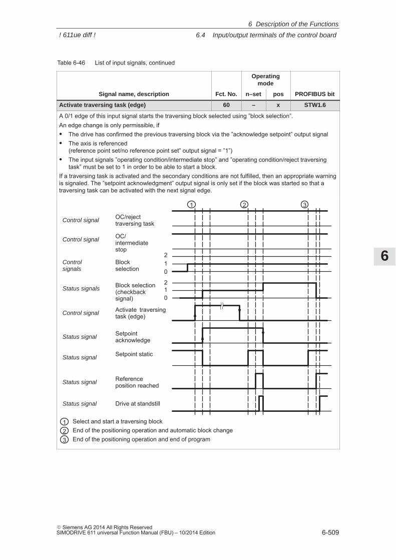
6
6.4 Input/output terminals of the control board
6-509� Siemens AG 2014 All Rights ReservedSIMODRIVE 611 universal Function Manual (FBU) – 10/2014 Edition
Table 6-46 List of input signals, continued
Operatingmode
Signal name, description PROFIBUS bitposn–setFct. No.
Activate traversing task (edge) 60 – x STW1.6
A 0/1 edge of this input signal starts the traversing block selected using ”block selection”.An edge change is only permissible, if� The drive has confirmed the previous traversing block via the ”acknowledge setpoint” output signal� The axis is referenced
(reference point set/no reference point set” output signal = ”1”)� The input signals ”operating condition/intermediate stop” and ”operating condition/reject traversing
task” must be set to 1 in order to be able to start a block.If a traversing task is activated and the secondary conditions are not fulfilled, then an appropriate warningis signaled. The ”setpoint acknowledgment” output signal is only set if the block was started so that atraversing task can be activated with the next signal edge.
Activate traversingtask (edge)
Setpointacknowledge
Setpoint static
Referenceposition reached
Drive at standstill
1 2 3
012
Blockselection
012Block selection
(checkbacksignal)
OC/rejecttraversing task
OC/intermediatestop
Control signal
Control signal
Controlsignals
Status signals
Control signal
Status signal
Status signal
Status signal
Status signal
123
Select and start a traversing blockEnd of the positioning operation and automatic block changeEnd of the positioning operation and end of program
6 Description of the Functions
! 611ue diff !
6
6.4 Input/output terminals of the control board
6-510� Siemens AG 2014 All Rights Reserved
SIMODRIVE 611 universal Function Manual (FBU) – 10/2014 Edition
Table 6-46 List of input signals, continued
Operatingmode
Signal name, description PROFIBUS bitposn–setFct. No.
Incremental jogging (from SW 4.1) 61 – x PosStw.5
This input signal is used to define whether jogging is executed via velocity or via velocity and increments.1 signal Jogging via velocity and increments is effective0 signal Jogging via velocity is effectiveNote:
This input signal is effective for jogging 1 and jogging 2.The ”jogging mode” function is described in Chapter 6.2.9.
Jogging 1 ON/jogging 1 OFF 62 – x STW1.8
Jogging 2 ON/jogging 2 OFF 63 – x STW1.9
Using these input signals closed–loop speed controlled traversing is possible in the ”positioning” mode,without changing the mode.� For jogging 1, the drive traverses with the speed/velocity in P0108.� For jogging 2, the drive traverses with the speed/velocity P0109.1 signal The drive traverses with the parameterized speed/velocity1/0 signal The drive brakes down to standstill with the deceleration set in P0104 (maximum decel-
eration). The closed–loop position control is re–activated after the braking operation hasbeen completed.
0 signal Output status for jogging0/1 signal The drive accelerates to the speed/velocity, parameterized in P0108/P0109 with the ac-
celeration set in P0103 (maximum acceleration)Note:
For jogging, the software limit switch and the override are effective.
6 Description of the Functions
! 611ue diff !
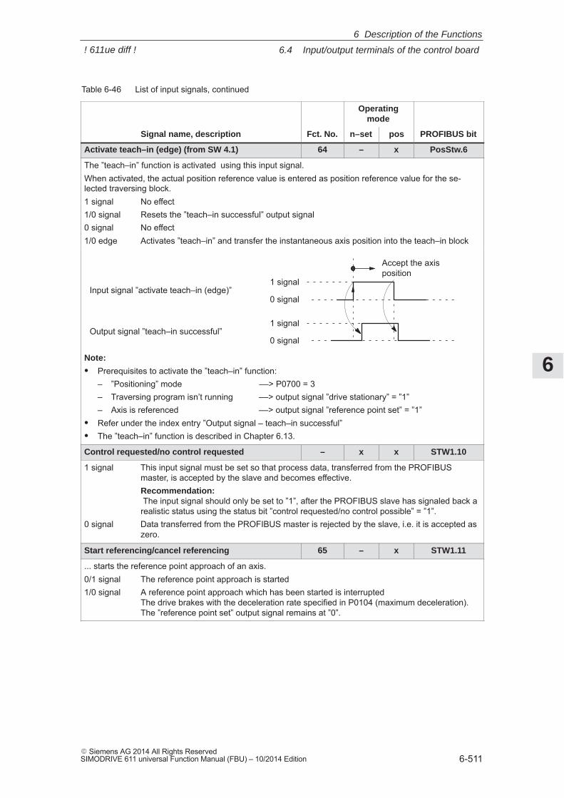
6
6.4 Input/output terminals of the control board
6-511� Siemens AG 2014 All Rights ReservedSIMODRIVE 611 universal Function Manual (FBU) – 10/2014 Edition
Table 6-46 List of input signals, continued
Operatingmode
Signal name, description PROFIBUS bitposn–setFct. No.
Activate teach–in (edge) (from SW 4.1) 64 – x PosStw.6
The ”teach–in” function is activated using this input signal.When activated, the actual position reference value is entered as position reference value for the se-lected traversing block.1 signal No effect1/0 signal Resets the ”teach–in successful” output signal0 signal No effect1/0 edge Activates ”teach–in” and transfer the instantaneous axis position into the teach–in block
1 signal
0 signalInput signal ”activate teach–in (edge)”
1 signal
0 signalOutput signal ”teach–in successful”
Accept the axisposition
Note:
� Prerequisites to activate the ”teach–in” function:– ”Positioning” mode ––> P0700 = 3– Traversing program isn’t running ––> output signal ”drive stationary” = ”1”– Axis is referenced ––> output signal ”reference point set” = ”1”
� Refer under the index entry ”Output signal – teach–in successful”� The ”teach–in” function is described in Chapter 6.13.
Control requested/no control requested – x x STW1.10
1 signal This input signal must be set so that process data, transferred from the PROFIBUSmaster, is accepted by the slave and becomes effective.Recommendation: The input signal should only be set to ”1”, after the PROFIBUS slave has signaled back arealistic status using the status bit ”control requested/no control possible” = ”1”.
0 signal Data transferred from the PROFIBUS master is rejected by the slave, i.e. it is accepted aszero.
Start referencing/cancel referencing 65 – x STW1.11
... starts the reference point approach of an axis.0/1 signal The reference point approach is started1/0 signal A reference point approach which has been started is interrupted
The drive brakes with the deceleration rate specified in P0104 (maximum deceleration).The ”reference point set” output signal remains at ”0”.
6 Description of the Functions
! 611ue diff !
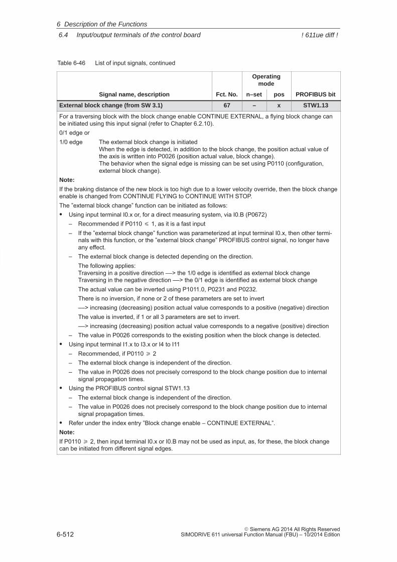
6
6.4 Input/output terminals of the control board
6-512� Siemens AG 2014 All Rights Reserved
SIMODRIVE 611 universal Function Manual (FBU) – 10/2014 Edition
Table 6-46 List of input signals, continued
Operatingmode
Signal name, description PROFIBUS bitposn–setFct. No.
External block change (from SW 3.1) 67 – x STW1.13
For a traversing block with the block change enable CONTINUE EXTERNAL, a flying block change canbe initiated using this input signal (refer to Chapter 6.2.10).0/1 edge or1/0 edge The external block change is initiated
When the edge is detected, in addition to the block change, the position actual value ofthe axis is written into P0026 (position actual value, block change).The behavior when the signal edge is missing can be set using P0110 (configuration,external block change).
Note:
If the braking distance of the new block is too high due to a lower velocity override, then the block changeenable is changed from CONTINUE FLYING to CONTINUE WITH STOP.The ”external block change” function can be initiated as follows:� Using input terminal I0.x or, for a direct measuring system, via I0.B (P0672)
– Recommended if P0110 � 1, as it is a fast input– If the ”external block change” function was parameterized at input terminal I0.x, then other termi-
nals with this function, or the ”external block change” PROFIBUS control signal, no longer haveany effect.
– The external block change is detected depending on the direction.The following applies: Traversing in a positive direction ––> the 1/0 edge is identified as external block changeTraversing in the negative direction ––> the 0/1 edge is identified as external block changeThe actual value can be inverted using P1011.0, P0231 and P0232.There is no inversion, if none or 2 of these parameters are set to invert––> increasing (decreasing) position actual value corresponds to a positive (negative) directionThe value is inverted, if 1 or all 3 parameters are set to invert.––> increasing (decreasing) position actual value corresponds to a negative (positive) direction
– The value in P0026 corresponds to the existing position when the block change is detected.� Using input terminal I1.x to I3.x or I4 to I11
– Recommended, if P0110 � 2– The external block change is independent of the direction.– The value in P0026 does not precisely correspond to the block change position due to internal
signal propagation times.� Using the PROFIBUS control signal STW1.13
– The external block change is independent of the direction.– The value in P0026 does not precisely correspond to the block change position due to internal
signal propagation times.� Refer under the index entry ”Block change enable – CONTINUE EXTERNAL”.Note:
If P0110 � 2, then input terminal I0.x or I0.B may not be used as input, as, for these, the block changecan be initiated from different signal edges.
6 Description of the Functions
! 611ue diff !
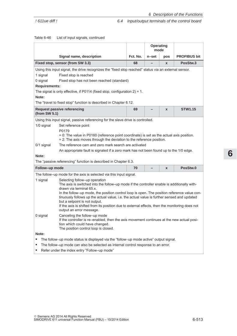
6
6.4 Input/output terminals of the control board
6-513� Siemens AG 2014 All Rights ReservedSIMODRIVE 611 universal Function Manual (FBU) – 10/2014 Edition
Table 6-46 List of input signals, continued
Operatingmode
Signal name, description PROFIBUS bitposn–setFct. No.
Fixed stop, sensor (from SW 3.3) 68 – x PosStw.3
Using this input signal, the drive recognizes the ”fixed stop reached” status via an external sensor.1 signal Fixed stop is reached0 signal Fixed stop has not been reached (standard)Requirements:
The signal is only effective, if P0114 (fixed stop, configuration 2) = 1.Note:
The ”travel to fixed stop” function is described in Chapter 6.12.
Request passive referencing (from SW 5.1)
69 – x STW1.15
Using this input signal, passive referencing for the slave drive is controlled.1/0 signal Set reference point
P0179 = 0: The value in P0160 (reference point coordinate) is set as the actual axis position.= 2: The axis moves through the deviation to the reference position.
0/1 signal The reference cam and zero mark search are activatedAn appropriate fault is signaled if a zero mark has not been found up to the 1/0 edge.
Note:
The ”passive referencing” function is described in Chapter 6.3.
Follow–up mode 70 – x PosStw.0
The follow–up mode for the axis is selected via this input signal.1 signal Selecting follow–up operation
The axis is switched into the follow–up mode if the controller enable is additionally with-drawn via terminal 65.x. In the follow–up mode, the position control loop is open. The position reference value con-tinuously follows up the actual value, i.e. the actual value is further sensed and updatedbut a setpoint is not output. If the axis is shifted from its position due to external effects, then the monitoring does notoutput an error message.
0 signal Canceling the follow–up modeIf the controller is re–enabled, then the axis movement continues at the new actual posi-tion which could have changed.The position control loop is closed.
Note:
� The follow–up mode status is displayed via the ”follow–up mode active” output signal.� The follow–up mode can also be selected as internal control response to an error.� Refer under the index entry ”Follow–up mode”
6 Description of the Functions
! 611ue diff !
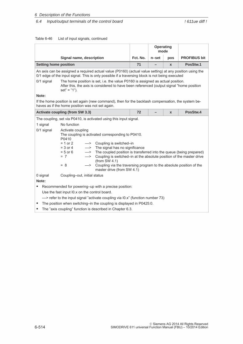
6
6.4 Input/output terminals of the control board
6-514� Siemens AG 2014 All Rights Reserved
SIMODRIVE 611 universal Function Manual (FBU) – 10/2014 Edition
Table 6-46 List of input signals, continued
Operatingmode
Signal name, description PROFIBUS bitposn–setFct. No.
Setting home position 71 – x PosStw.1
An axis can be assigned a required actual value (P0160) (actual value setting) at any position using the0/1 edge of the input signal. This is only possible if a traversing block is not being executed0/1 signal The home position is set, i.e. the value P0160 is assigned as actual position.
After this, the axis is considered to have been referenced (output signal ”home positionset” = ”1”).
Note:
If the home position is set again (new command), then for the backlash compensation, the system be-haves as if the home position was not set again.
Activate coupling (from SW 3.3) 72 – x PosStw.4
The coupling, set via P0410, is activated using this input signal.1 signal No function0/1 signal Activate coupling
The coupling is activated corresponding to P0410.P0410 = 1 or 2 ––> Coupling is switched–in= 3 or 4 ––> The signal has no significance= 5 or 6 ––> The coupled position is transferred into the queue (being prepared)= 7 ––> Coupling is switched–in at the absolute position of the master drive
(from SW 4.1)= 8 ––> Coupling via the traversing program to the absolute position of the
master drive (from SW 4.1)0 signal Coupling–out, initial statusNote:
� Recommended for powering–up with a precise position:Use the fast input I0.x on the control board.––> refer to the input signal ”activate coupling via I0.x” (function number 73)
� The position when switching–in the coupling is displayed in P0425:0.� The ”axis coupling” function is described in Chapter 6.3.
6 Description of the Functions
! 611ue diff !
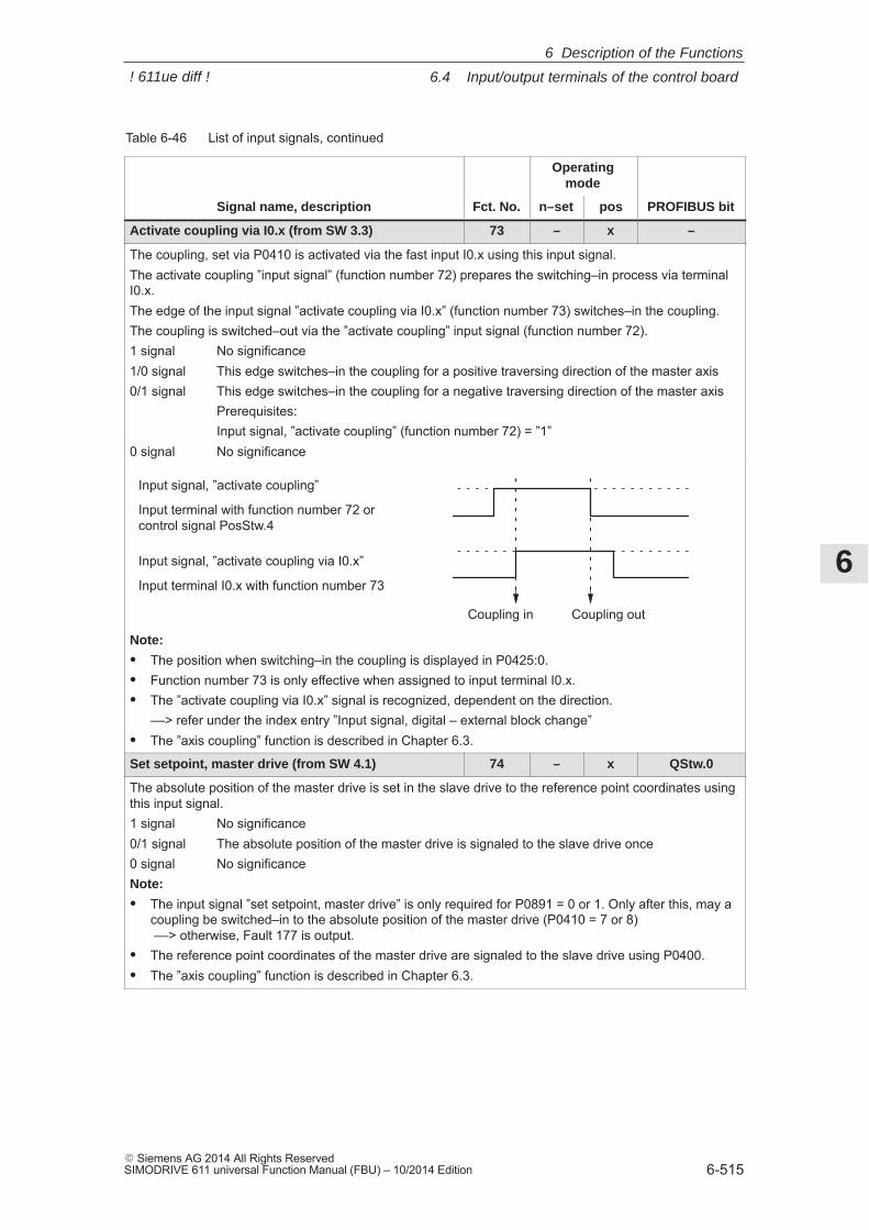
6
6.4 Input/output terminals of the control board
6-515� Siemens AG 2014 All Rights ReservedSIMODRIVE 611 universal Function Manual (FBU) – 10/2014 Edition
Table 6-46 List of input signals, continued
Operatingmode
Signal name, description PROFIBUS bitposn–setFct. No.
Activate coupling via I0.x (from SW 3.3) 73 – x –
The coupling, set via P0410 is activated via the fast input I0.x using this input signal.The activate coupling ”input signal” (function number 72) prepares the switching–in process via terminalI0.x.The edge of the input signal ”activate coupling via I0.x” (function number 73) switches–in the coupling.The coupling is switched–out via the ”activate coupling” input signal (function number 72).1 signal No significance1/0 signal This edge switches–in the coupling for a positive traversing direction of the master axis0/1 signal This edge switches–in the coupling for a negative traversing direction of the master axis
Prerequisites:Input signal, ”activate coupling” (function number 72) = ”1”
0 signal No significance
Input signal, ”activate coupling”
Input terminal with function number 72 orcontrol signal PosStw.4
Input signal, ”activate coupling via I0.x”
Input terminal I0.x with function number 73
Coupling in Coupling out
Note:
� The position when switching–in the coupling is displayed in P0425:0.� Function number 73 is only effective when assigned to input terminal I0.x.� The ”activate coupling via I0.x” signal is recognized, dependent on the direction.
––> refer under the index entry ”Input signal, digital – external block change”� The ”axis coupling” function is described in Chapter 6.3.
Set setpoint, master drive (from SW 4.1) 74 – x QStw.0
The absolute position of the master drive is set in the slave drive to the reference point coordinates usingthis input signal.1 signal No significance0/1 signal The absolute position of the master drive is signaled to the slave drive once0 signal No significanceNote:
� The input signal ”set setpoint, master drive” is only required for P0891 = 0 or 1. Only after this, may acoupling be switched–in to the absolute position of the master drive (P0410 = 7 or 8) ––> otherwise, Fault 177 is output.
� The reference point coordinates of the master drive are signaled to the slave drive using P0400.� The ”axis coupling” function is described in Chapter 6.3.
6 Description of the Functions
! 611ue diff !
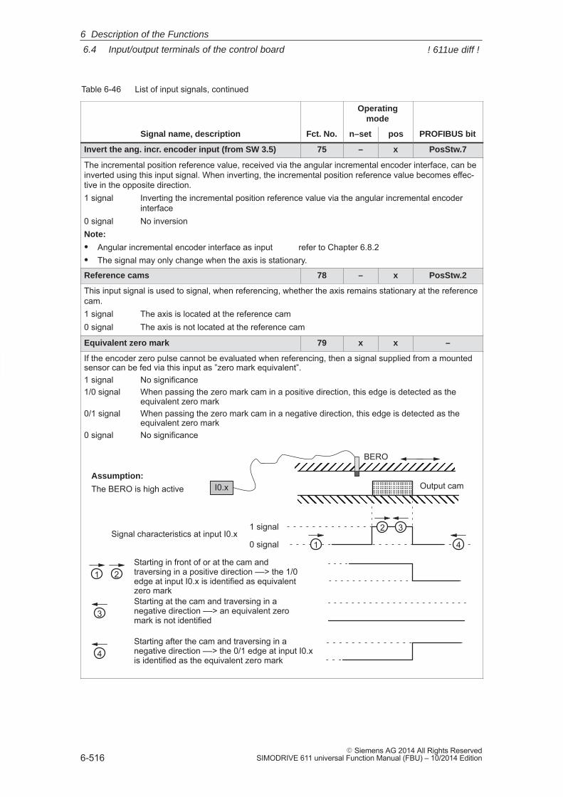
6
6.4 Input/output terminals of the control board
6-516� Siemens AG 2014 All Rights Reserved
SIMODRIVE 611 universal Function Manual (FBU) – 10/2014 Edition
Table 6-46 List of input signals, continued
Operatingmode
Signal name, description PROFIBUS bitposn–setFct. No.
Invert the ang. incr. encoder input (from SW 3.5) 75 – x PosStw.7
The incremental position reference value, received via the angular incremental encoder interface, can beinverted using this input signal. When inverting, the incremental position reference value becomes effec-tive in the opposite direction.1 signal Inverting the incremental position reference value via the angular incremental encoder
interface0 signal No inversionNote:
� Angular incremental encoder interface as input refer to Chapter 6.8.2� The signal may only change when the axis is stationary.
Reference cams 78 – x PosStw.2
This input signal is used to signal, when referencing, whether the axis remains stationary at the referencecam.1 signal The axis is located at the reference cam0 signal The axis is not located at the reference cam
Equivalent zero mark 79 x x –
If the encoder zero pulse cannot be evaluated when referencing, then a signal supplied from a mountedsensor can be fed via this input as ”zero mark equivalent”.1 signal No significance1/0 signal When passing the zero mark cam in a positive direction, this edge is detected as the
equivalent zero mark0/1 signal When passing the zero mark cam in a negative direction, this edge is detected as the
equivalent zero mark0 signal No significance
ÎÎÎÎÎÎÎÎÎÎÎÎ
ÏÏÏÏÏÏÏÏÏÏÏÏÏÏÏÏÏÏÏÏÏÏÏÏ
ÄÄÄÄÄÄÄÄ
Starting in front of or at the cam andtraversing in a positive direction ––> the 1/0edge at input I0.x is identified as equivalentzero mark
Starting after the cam and traversing in anegative direction ––> the 0/1 edge at input I0.xis identified as the equivalent zero mark
BERO
Output camAssumption:
The BERO is high active
1
1
4
32
3
4
Starting at the cam and traversing in anegative direction ––> an equivalent zeromark is not identified
1 signal
0 signalSignal characteristics at input I0.x
I0.x
2
6 Description of the Functions
! 611ue diff !
6
6.4 Input/output terminals of the control board
6-517� Siemens AG 2014 All Rights ReservedSIMODRIVE 611 universal Function Manual (FBU) – 10/2014 Edition
Table 6-46 List of input signals, continued
Operatingmode
Signal name, description PROFIBUS bitposn–setFct. No.
Note:� This function must be executed via input terminal I0.x (fast input).� Activate the ”equivalent zero mark” function for an incremental measuring system:
– refer to P0174– refer to P0879.13 or P0879.14
� The equivalent zero mark is identified as a function of the direction.� The actual value can be inverted using P1011.0, P0231 and P0232.
– There is no inversion, if none or 2 of these parameters are set to invert––> increasing (decreasing) position actual value corresponds to a positive (negative) direction
– The value is inverted, if 1 or all 3 parameters are set to invert.––> increasing (decreasing) position actual value corresponds to a negative (positive) direction
Flying measurement/length measurement (from SW 3.1)
80 x – –
The encoder actual value can be retrieved via an input with this function.0/1 signal or1/0 signal The actual encoder value is retrievedNote:� This function must be executed via the fast I0.x input.� The function is only available for ”Motion Control with PROFIBUS–DP”.
––> refer under the index entry ”Encoder interface (from SW 3.1)”� The function is only available for the control board ”SIMODRIVE 611 universal” from Order No.
6SN1118–xxxxx–0AA2 and control board ”SIMODRIVE 611 universal HR/HRS”.� This function cannot be executed for spindle positioning active (P0125 = 1).� The measuring probe signal is defined depending on the parameterized edge in control word
Gx_STW.0/1 (refer to Chapter 5.6.4).� The edge clearance must be at least 150 ms. Measuring probe edges that are received faster (low
clearance between signals) cannot be evaluated.� If the measuring probe signal is to be transferred via PROFIBUS in Gx_ZSW.8 then it must be pres-
ent at input I0.x �4 ms.
Plus hardware limit switch (NC contact) 81 x1) x –
Minus hardware limit switch (NC contact) 82 x1) x –
A hardware limit switch can be connected at an input with this function in order to limit the traversingrange in either the positive or negative direction.1/0 signal The plus or minus hardware limit switch has been actuated
The axis is braked. The drive remains in closed–loop control.In the pos mode:The axis can be moved away from the limit switch in the jog mode.In the n–set mode (from SW 8.1):The axis can be moved away from the limit switch using a setpoint that is opposite to theapproach direction.
1 signal No significance
Note:
1) from SW 8.1––> refer under the index entry ”hardware limit switch”
6 Description of the Functions
! 611ue diff !
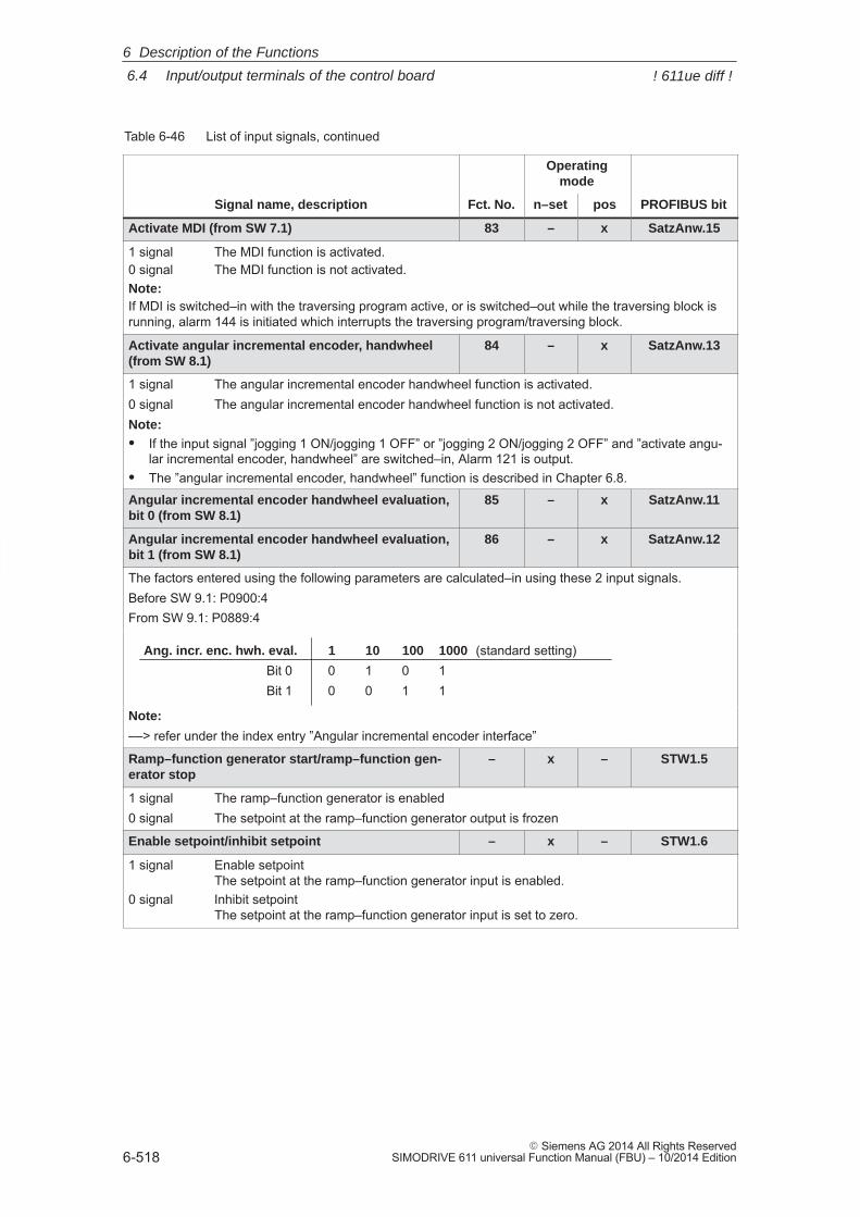
6
6.4 Input/output terminals of the control board
6-518� Siemens AG 2014 All Rights Reserved
SIMODRIVE 611 universal Function Manual (FBU) – 10/2014 Edition
Table 6-46 List of input signals, continued
Operatingmode
Signal name, description PROFIBUS bitposn–setFct. No.
Activate MDI (from SW 7.1) 83 – x SatzAnw.15
1 signal The MDI function is activated.0 signal The MDI function is not activated.Note:If MDI is switched–in with the traversing program active, or is switched–out while the traversing block isrunning, alarm 144 is initiated which interrupts the traversing program/traversing block.
Activate angular incremental encoder, handwheel(from SW 8.1)
84 – x SatzAnw.13
1 signal The angular incremental encoder handwheel function is activated.0 signal The angular incremental encoder handwheel function is not activated.Note:� If the input signal ”jogging 1 ON/jogging 1 OFF” or ”jogging 2 ON/jogging 2 OFF” and ”activate angu-
lar incremental encoder, handwheel” are switched–in, Alarm 121 is output.� The ”angular incremental encoder, handwheel” function is described in Chapter 6.8.
Angular incremental encoder handwheel evaluation,bit 0 (from SW 8.1)
85 – x SatzAnw.11
Angular incremental encoder handwheel evaluation,bit 1 (from SW 8.1)
86 – x SatzAnw.12
The factors entered using the following parameters are calculated–in using these 2 input signals.Before SW 9.1: P0900:4From SW 9.1: P0889:4
Ang. incr. enc. hwh. eval. 1 10 100 1000 (standard setting)Bit 0 0 1 0 1Bit 1 0 0 1 1
Note:
––> refer under the index entry ”Angular incremental encoder interface”
Ramp–function generator start/ramp–function gen-erator stop
– x – STW1.5
1 signal The ramp–function generator is enabled0 signal The setpoint at the ramp–function generator output is frozen
Enable setpoint/inhibit setpoint – x – STW1.6
1 signal Enable setpointThe setpoint at the ramp–function generator input is enabled.
0 signal Inhibit setpoint The setpoint at the ramp–function generator input is set to zero.
6 Description of the Functions
! 611ue diff !
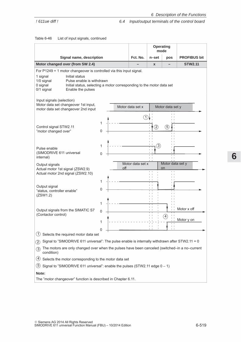
6
6.4 Input/output terminals of the control board
6-519� Siemens AG 2014 All Rights ReservedSIMODRIVE 611 universal Function Manual (FBU) – 10/2014 Edition
Table 6-46 List of input signals, continued
Operatingmode
Signal name, description PROFIBUS bitposn–setFct. No.
Motor changed over (from SW 2.4) – x – STW2.11
For P1249 = 1 motor changeover is controlled via this input signal.1 signal Initial status1/0 signal Pulse enable is withdrawn0 signal Initial status, selecting a motor corresponding to the motor data set0/1 signal Enable the pulses
Motor data set yon
Motor data set xoff
Pulse enable(SIMODRIVE 611 universalinternal)
Input signals (selection)Motor data set changeover 1st input,motor data set changeover 2nd input
1
0
Control signal STW2.11”motor changed over”
1
0
Output signals from the SIMATIC S7(Contactor control)
Motor data set x Motor data set y
Output signalsActual motor 1st signal (ZSW2.9)Actual motor 2nd signal (ZSW2.10)
Selects the required motor data set
Signal to ”SIMODRIVE 611 universal”: The pulse enable is internally withdrawn after STW2.11 = 0
The motors are only changed over when the pulses have been canceled (switched–in a no–currentcondition)
Selects the motor corresponding to the motor data set
Signal to ”SIMODRIVE 611 universal”: enable the pulses (STW2.11 edge 0 – 1)
1
0Output signal”status, controller enable”(ZSW1.2)
3
1
52
4
1
2
3
4
5
1
0
1
0
Motor x off
Motor y on
Note:
The ”motor changeover” function is described in Chapter 6.11.
6 Description of the Functions
! 611ue diff !
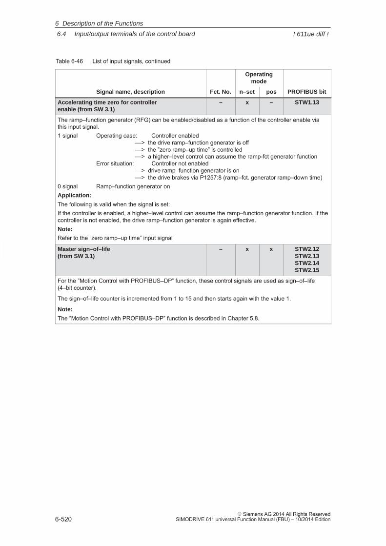
6
6.4 Input/output terminals of the control board
6-520� Siemens AG 2014 All Rights Reserved
SIMODRIVE 611 universal Function Manual (FBU) – 10/2014 Edition
Table 6-46 List of input signals, continued
Operatingmode
Signal name, description PROFIBUS bitposn–setFct. No.
Accelerating time zero for controller enable (from SW 3.1)
– x – STW1.13
The ramp–function generator (RFG) can be enabled/disabled as a function of the controller enable viathis input signal.1 signal Operating case: Controller enabled
––> the drive ramp–function generator is off––> the ”zero ramp–up time” is controlled––> a higher–level control can assume the ramp-fct generator function
Error situation: Controller not enabled––> drive ramp–function generator is on––> the drive brakes via P1257:8 (ramp–fct. generator ramp–down time)
0 signal Ramp–function generator onApplication:
The following is valid when the signal is set:If the controller is enabled, a higher–level control can assume the ramp–function generator function. If thecontroller is not enabled, the drive ramp–function generator is again effective.Note:
Refer to the ”zero ramp–up time” input signal
Master sign–of–life (from SW 3.1)
– x x STW2.12STW2.13STW2.14STW2.15
For the ”Motion Control with PROFIBUS–DP” function, these control signals are used as sign–of–life(4–bit counter).
The sign–of–life counter is incremented from 1 to 15 and then starts again with the value 1.
Note:
The ”Motion Control with PROFIBUS–DP” function is described in Chapter 5.8.
6 Description of the Functions
! 611ue diff !
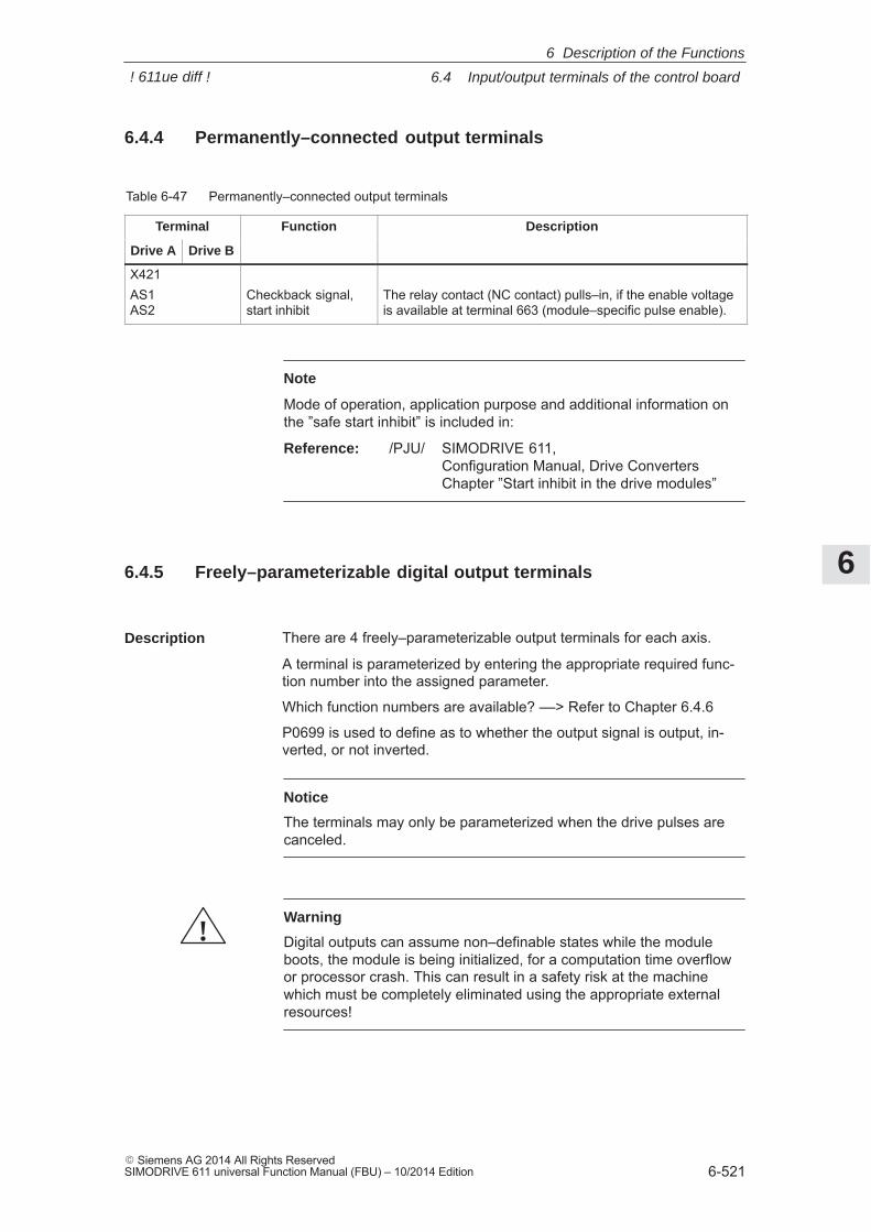
6
6.4 Input/output terminals of the control board
6-521� Siemens AG 2014 All Rights ReservedSIMODRIVE 611 universal Function Manual (FBU) – 10/2014 Edition
6.4.4 Permanently–connected output terminals
Table 6-47 Permanently–connected output terminals
Terminal Function Description
Drive A Drive B
X421AS1AS2
Checkback signal,start inhibit
The relay contact (NC contact) pulls–in, if the enable voltageis available at terminal 663 (module–specific pulse enable).
Note
Mode of operation, application purpose and additional information onthe ”safe start inhibit” is included in:
Reference: /PJU/ SIMODRIVE 611, Configuration Manual, Drive ConvertersChapter ”Start inhibit in the drive modules”
6.4.5 Freely–parameterizable digital output terminals
There are 4 freely–parameterizable output terminals for each axis.
A terminal is parameterized by entering the appropriate required func-tion number into the assigned parameter.
Which function numbers are available? ––> Refer to Chapter 6.4.6
P0699 is used to define as to whether the output signal is output, in-verted, or not inverted.
Notice
The terminals may only be parameterized when the drive pulses arecanceled.
!Warning
Digital outputs can assume non–definable states while the moduleboots, the module is being initialized, for a computation time overflowor processor crash. This can result in a safety risk at the machinewhich must be completely eliminated using the appropriate externalresources!
Description
6 Description of the Functions
! 611ue diff !
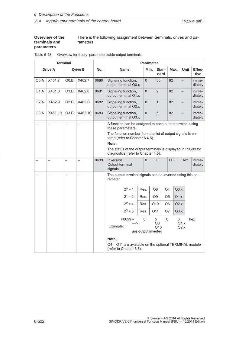
6
6.4 Input/output terminals of the control board
6-522� Siemens AG 2014 All Rights Reserved
SIMODRIVE 611 universal Function Manual (FBU) – 10/2014 Edition
There is the following assignment between terminals, drives and pa-rameters:
Table 6-48 Overview for freely–parameterizable output terminals
Terminal Parameter
Drive A Drive B No. Name Min. Stan-dard
Max. Unit Effec-tive
O0.A X461.7 O0.B X462.7 0680 Signaling function,output terminal O0.x
0 33 82 – imme-diately
O1.A X461.8 O1.B X462.8 0681 Signaling function,output terminal O1.x
0 2 82 – imme-diately
O2.A X462.9 O2.B X462.B 0682 Signaling function,output terminal O2.x
0 1 82 – imme-diately
O3.A X461.10 O3.B X462.10 0683 Signaling function,output terminal O3.x
0 5 82 – imme-diately
– – – – A function can be assigned to each output terminal usingthese parameters.The function number from the list of output signals is en-tered (refer to Chapter 6.4.6).Note:
The status of the output terminals is displayed in P0698 fordiagnostics (refer to Chapter 4.5).
– – – – 0699 InversionOutput terminalsignals
0 0 FFF Hex imme-diately
– – – – The output terminal signals can be inverted using this pa-rameter.
20 = 1
21 = 2
22 = 4
23 = 8
P0699 = 0 5 0 6 hex––> O8 O1.x
O10 O2.xare output inverted
O0.x:
O1.x:
O2.x:
O3.x:
O4
O5
O6
O7
O8
O9
O10
O11
Res.
Res.
Res.
Res.
Example:
Note:
O4 – O11 are available on the optional TERMINAL module(refer to Chapter 6.5).
Overview of theterminals and parameters
6 Description of the Functions
! 611ue diff !
6
6.4 Input/output terminals of the control board
6-523� Siemens AG 2014 All Rights ReservedSIMODRIVE 611 universal Function Manual (FBU) – 10/2014 Edition
6.4.6 List of output signals
Reader’s note
The drive ”signals” the output signals, listed in the Tables 6-49 and6-50 either through an output terminal or as status bit toPROFIBUS–DP. All of the output signals can be found in the Index under Outputsignal... .
For output signals, which are assigned to terminals, an inversion canbe parameterized. In this list, these output signals are represented asnot inverted. If an output signal inversion has been parameterized, then this must beappropriately taken into account when representing the signal.
The following must be specified for each signal:� Fct. No.:
The function number is required to parameterize the output terminalvia the display and operator control unit.
� Operating mode (P0700): This specifies in which operating mode the signal is available(x: Available, –: Not available).n–set: ”Speed/torque setpoint” mode pos: ”Positioning” mode
� PROFIBUS bit: The bit name is required to read the signal via PROFIBUS–DP(refer to Chapter 5.6.1).Example: ZSW2.10 ––> that means, status 2 bit 10
6 Description of the Functions
! 611ue diff !
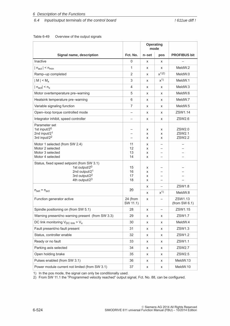
6
6.4 Input/output terminals of the control board
6-524� Siemens AG 2014 All Rights Reserved
SIMODRIVE 611 universal Function Manual (FBU) – 10/2014 Edition
Table 6-49 Overview of the output signals
Operatingmode
Signal name, description Fct. No. n–set pos PROFIBUS bit
Inactive 0 x x –
| nact | < nmin 1 x x MeldW.2
Ramp–up completed 2 x x1)2) MeldW.0
| M | < Mx 3 x x1) MeldW.1
| nact| < nx 4 x x MeldW.3
Motor overtemperature pre–warning 5 x x MeldW.6
Heatsink temperature pre–warning 6 x x MeldW.7
Variable signaling function 7 x x MeldW.5
Open–loop torque controlled mode – x x ZSW1.14
Integrator inhibit, speed controller – x x ZSW2.6
Parameter set1st input/20
2nd input/21
3rd input/22
–––
xxx
xxx
ZSW2.0ZSW2.1ZSW2.2
Motor 1 selected (from SW 2.4)Motor 2 selected Motor 3 selected Motor 4 selected
11121314
xxxx
––––
––––
Status, fixed speed setpoint (from SW 3.1)1st output/20
2nd output/21
3rd output/22
4th output/23
15161718
xxxx
––––
––––
nset = nact 20x – ZSW1.8
nset = nact 20x x1) MeldW.8
Function generator active 24 (fromSW 11.1)
x – ZSW1.13 (from SW 6.1)
Spindle positioning on (from SW 5.1) 28 x – ZSW1.15
Warning present/no warning present (from SW 3.3) 29 x x ZSW1.7
DC link monitoring VDC link > Vx 30 x x MeldW.4
Fault present/no fault present 31 x x ZSW1.3
Status, controller enable 32 x x ZSW1.2
Ready or no fault 33 x x ZSW1.1
Parking axis selected 34 x x ZSW2.7
Open holding brake 35 x x ZSW2.5
Pulses enabled (from SW 3.1) 36 x x MeldW.13
Power module current not limited (from SW 3.1) 37 x x MeldW.10
1) In the pos mode, the signal can only be conditionally used.2) From SW 11.1 the ”Programmed velocity reached” output signal, Fct. No. 88, can be configured.
6 Description of the Functions
! 611ue diff !
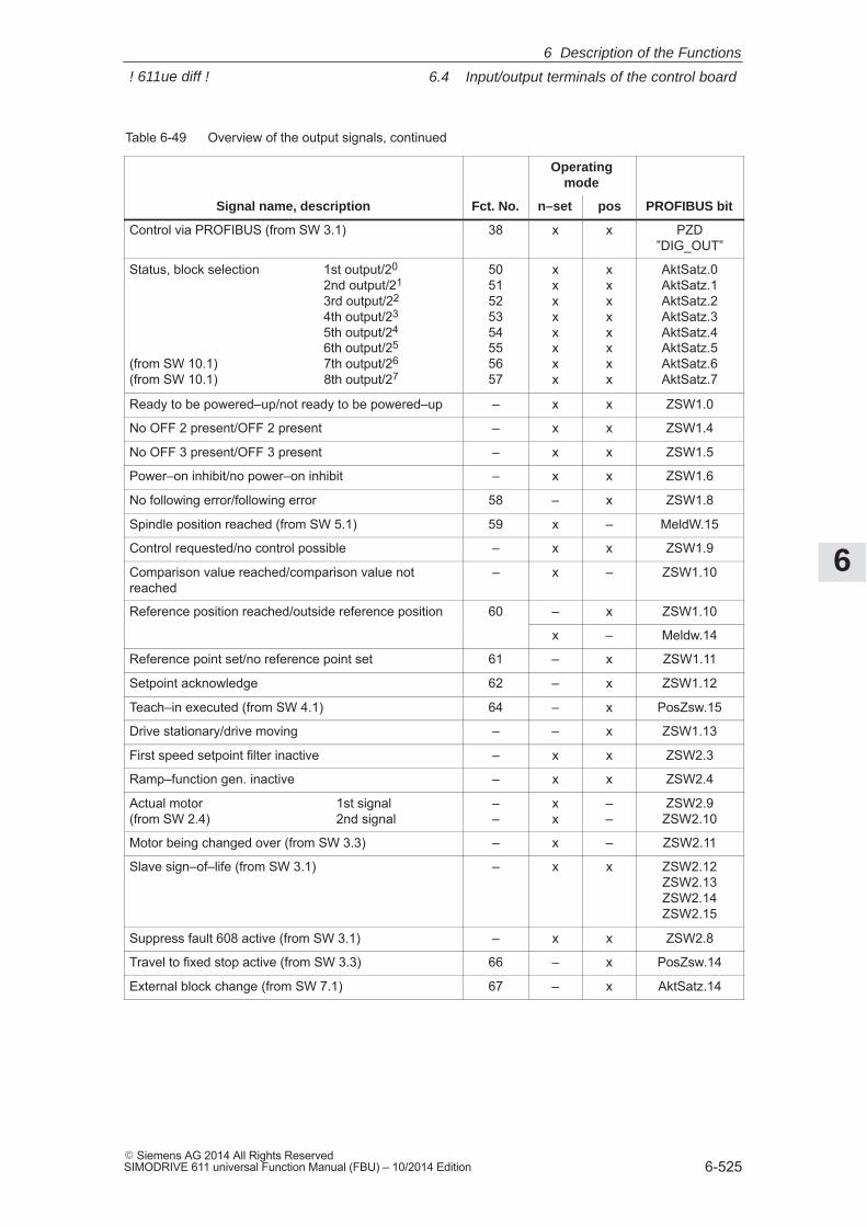
6
6.4 Input/output terminals of the control board
6-525� Siemens AG 2014 All Rights ReservedSIMODRIVE 611 universal Function Manual (FBU) – 10/2014 Edition
Table 6-49 Overview of the output signals, continued
Operatingmode
Signal name, description PROFIBUS bitposn–setFct. No.
Control via PROFIBUS (from SW 3.1) 38 x x PZD”DIG_OUT”
Status, block selection 1st output/20
2nd output/21
3rd output/22
4th output/23
5th output/24
6th output/25
(from SW 10.1) 7th output/26
(from SW 10.1) 8th output/27
5051525354555657
xxxxxxxx
xxxxxxxx
AktSatz.0AktSatz.1AktSatz.2AktSatz.3AktSatz.4AktSatz.5AktSatz.6AktSatz.7
Ready to be powered–up/not ready to be powered–up – x x ZSW1.0
No OFF 2 present/OFF 2 present – x x ZSW1.4
No OFF 3 present/OFF 3 present – x x ZSW1.5
Power–on inhibit/no power–on inhibit – x x ZSW1.6
No following error/following error 58 – x ZSW1.8
Spindle position reached (from SW 5.1) 59 x – MeldW.15
Control requested/no control possible – x x ZSW1.9
Comparison value reached/comparison value notreached
– x – ZSW1.10
Reference position reached/outside reference position 60 – x ZSW1.10
x – Meldw.14
Reference point set/no reference point set 61 – x ZSW1.11
Setpoint acknowledge 62 – x ZSW1.12
Teach–in executed (from SW 4.1) 64 – x PosZsw.15
Drive stationary/drive moving – – x ZSW1.13
First speed setpoint filter inactive – x x ZSW2.3
Ramp–function gen. inactive – x x ZSW2.4
Actual motor 1st signal (from SW 2.4) 2nd signal
––
xx
––
ZSW2.9ZSW2.10
Motor being changed over (from SW 3.3) – x – ZSW2.11
Slave sign–of–life (from SW 3.1) – x x ZSW2.12ZSW2.13ZSW2.14ZSW2.15
Suppress fault 608 active (from SW 3.1) – x x ZSW2.8
Travel to fixed stop active (from SW 3.3) 66 – x PosZsw.14
External block change (from SW 7.1) 67 – x AktSatz.14
6 Description of the Functions
! 611ue diff !
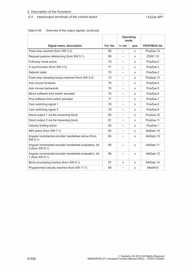
6
6.4 Input/output terminals of the control board
6-526� Siemens AG 2014 All Rights Reserved
SIMODRIVE 611 universal Function Manual (FBU) – 10/2014 Edition
Table 6-49 Overview of the output signals, continued
Operatingmode
Signal name, description PROFIBUS bitposn–setFct. No.
Fixed stop reached (from SW 3.3) 68 – x PosZsw.12
Request passive referencing (from SW 5.1) 69 – x ZSW1.15
Followup mode active 70 – x PosZsw.0
In synchronism (from SW 3.3) 71 – x PosZsw.3
Setpoint static 72 – x PosZsw.2
Fixed stop clamping torque reached (from SW 3.3) 73 – x PosZsw.13
Axis moves forwards 74 – x PosZsw.4
Axis moves backwards 75 – x PosZsw.5
Minus software limit switch actuated 76 – x PosZsw.6
Plus software limit switch actuated 77 – x PosZsw.7
Cam switching signal 1 78 – x PosZsw.8
Cam switching signal 2 79 – x PosZsw.9
Direct output 1 via the traversing block 80 – x PosZsw.10
Direct output 2 via the traversing block 81 – x PosZsw.11
Velocity limiting active 82 – x PosZsw.1
MDI active (from SW 7.1) 83 – x AktSatz.15
Angular incremental encoder handwheel active (fromSW 8.1)
84 – x AktSatz.13
Angular incremental encoder handwheel evaluation, bit0 (from SW 8.1)
85 – x AktSatz.11
Angular incremental encoder handwheel evaluation, bit1 (from SW 8.1)
86 – x AktSatz.12
Block processing inactive (from SW 8.1) 87 x x AktSatz.10
Programmed velocity reached (from SW 11.1) 88 – x MeldW.0
6 Description of the Functions
! 611ue diff !
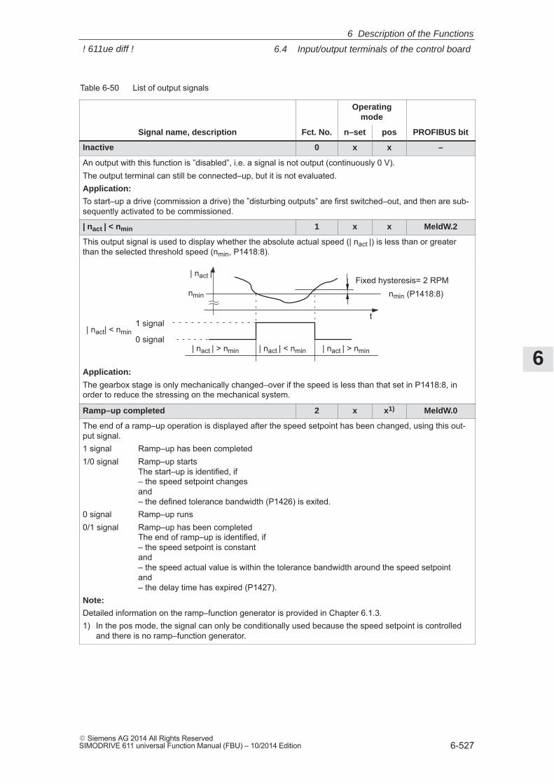
6
6.4 Input/output terminals of the control board
6-527� Siemens AG 2014 All Rights ReservedSIMODRIVE 611 universal Function Manual (FBU) – 10/2014 Edition
Table 6-50 List of output signals
Operatingmode
Signal name, description Fct. No. n–set pos PROFIBUS bit
Inactive 0 x x –
An output with this function is ”disabled”, i.e. a signal is not output (continuously 0 V).The output terminal can still be connected–up, but it is not evaluated.Application:
To start–up a drive (commission a drive) the ”disturbing outputs” are first switched–out, and then are sub-sequently activated to be commissioned.
| nact | < nmin 1 x x MeldW.2
This output signal is used to display whether the absolute actual speed (| nact |) is less than or greaterthan the selected threshold speed (nmin, P1418:8).
nmin nmin (P1418:8)
t1 signal
0 signal
| nact |
| nact | < nmin| nact | > nmin | nact | > nmin
| nact| < nmin
Fixed hysteresis= 2 RPM
Application:
The gearbox stage is only mechanically changed–over if the speed is less than that set in P1418:8, inorder to reduce the stressing on the mechanical system.
Ramp–up completed 2 x x1) MeldW.0
The end of a ramp–up operation is displayed after the speed setpoint has been changed, using this out-put signal.1 signal Ramp–up has been completed1/0 signal Ramp–up starts
The start–up is identified, if – the speed setpoint changesand– the defined tolerance bandwidth (P1426) is exited.
0 signal Ramp–up runs0/1 signal Ramp–up has been completed
The end of ramp–up is identified, if– the speed setpoint is constantand– the speed actual value is within the tolerance bandwidth around the speed setpointand – the delay time has expired (P1427).
Note:
Detailed information on the ramp–function generator is provided in Chapter 6.1.3.1) In the pos mode, the signal can only be conditionally used because the speed setpoint is controlled
and there is no ramp–function generator.
6 Description of the Functions
! 611ue diff !
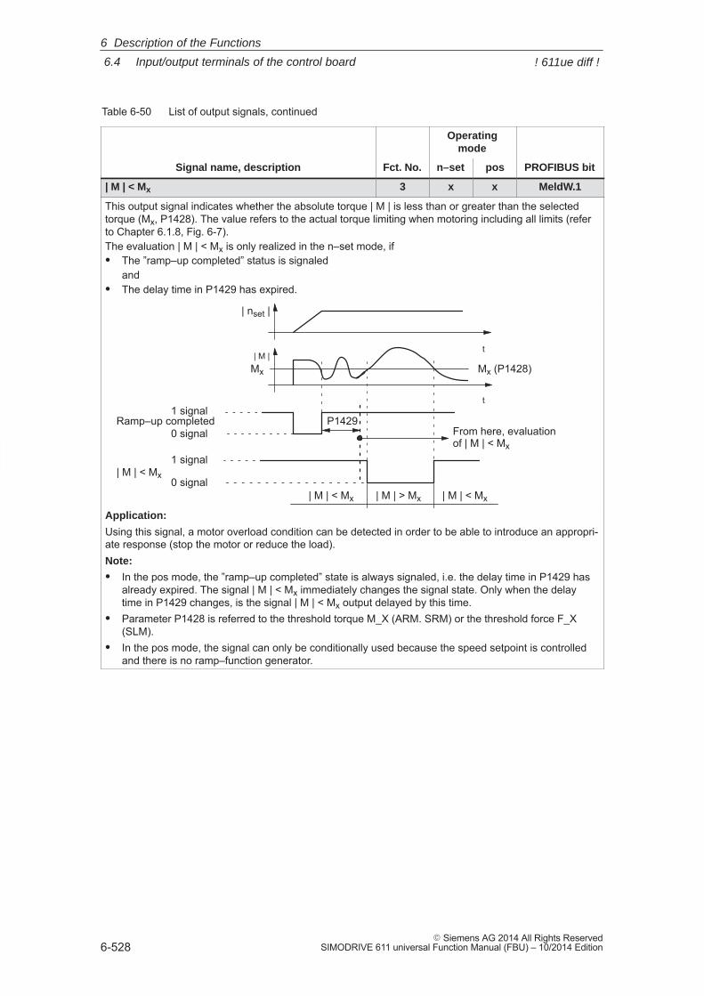
6
6.4 Input/output terminals of the control board
6-528� Siemens AG 2014 All Rights Reserved
SIMODRIVE 611 universal Function Manual (FBU) – 10/2014 Edition
Table 6-50 List of output signals, continued
Operatingmode
Signal name, description PROFIBUS bitposn–setFct. No.
| M | < Mx 3 x x MeldW.1
This output signal indicates whether the absolute torque | M | is less than or greater than the selectedtorque (Mx, P1428). The value refers to the actual torque limiting when motoring including all limits (referto Chapter 6.1.8, Fig. 6-7).The evaluation | M | < Mx is only realized in the n–set mode, if� The ”ramp–up completed” status is signaled
and� The delay time in P1429 has expired.
1 signal
0 signal| M | > Mx| M | < Mx
| nset |
| M |t
t
Mx
1 signal
0 signal
| M | < Mx
P1429Ramp–up completed
| M | < Mx
Mx (P1428)
From here, evaluation of | M | < Mx
Application:
Using this signal, a motor overload condition can be detected in order to be able to introduce an appropri-ate response (stop the motor or reduce the load).Note:
� In the pos mode, the ”ramp–up completed” state is always signaled, i.e. the delay time in P1429 hasalready expired. The signal | M | < Mx immediately changes the signal state. Only when the delaytime in P1429 changes, is the signal | M | < Mx output delayed by this time.
� Parameter P1428 is referred to the threshold torque M_X (ARM. SRM) or the threshold force F_X(SLM).
� In the pos mode, the signal can only be conditionally used because the speed setpoint is controlledand there is no ramp–function generator.
6 Description of the Functions
! 611ue diff !
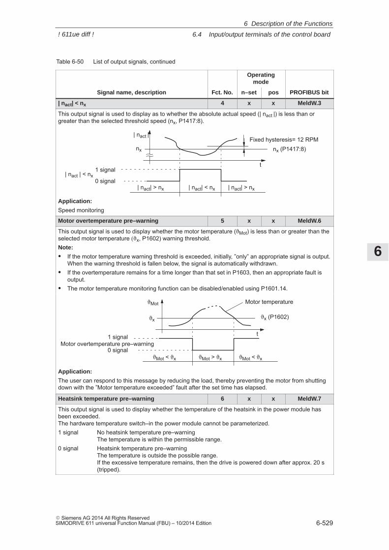
6
6.4 Input/output terminals of the control board
6-529� Siemens AG 2014 All Rights ReservedSIMODRIVE 611 universal Function Manual (FBU) – 10/2014 Edition
Table 6-50 List of output signals, continued
Operatingmode
Signal name, description PROFIBUS bitposn–setFct. No.
| nact| < nx 4 x x MeldW.3
This output signal is used to display as to whether the absolute actual speed (| nact |) is less than orgreater than the selected threshold speed (nx, P1417:8).
nx nx (P1417:8)
t1 signal
0 signal
| nact |
| nact| < nx| nact| > nx | nact| > nx
| nact | < nx
Fixed hysteresis= 12 RPM
Application:
Speed monitoring
Motor overtemperature pre–warning 5 x x MeldW.6
This output signal is used to display whether the motor temperature (�Mot) is less than or greater than theselected motor temperature ��x, P1602) warning threshold.Note:
� If the motor temperature warning threshold is exceeded, initially, ”only” an appropriate signal is output.When the warning threshold is fallen below, the signal is automatically withdrawn.
� If the overtemperature remains for a time longer than that set in P1603, then an appropriate fault isoutput.
� The motor temperature monitoring function can be disabled/enabled using P1601.14.
�x �x (P1602)
t1 signal
0 signal�Mot < �x
�Mot
�Mot > �x �Mot < �x
Motor temperature
Motor overtemperature pre–warning
Application:
The user can respond to this message by reducing the load, thereby preventing the motor from shuttingdown with the ”Motor temperature exceeded” fault after the set time has elapsed.
Heatsink temperature pre–warning 6 x x MeldW.7
This output signal is used to display whether the temperature of the heatsink in the power module hasbeen exceeded. The hardware temperature switch–in the power module cannot be parameterized.1 signal No heatsink temperature pre–warning
The temperature is within the permissible range.0 signal Heatsink temperature pre–warning
The temperature is outside the possible range. If the excessive temperature remains, then the drive is powered down after approx. 20 s(tripped).
6 Description of the Functions
! 611ue diff !
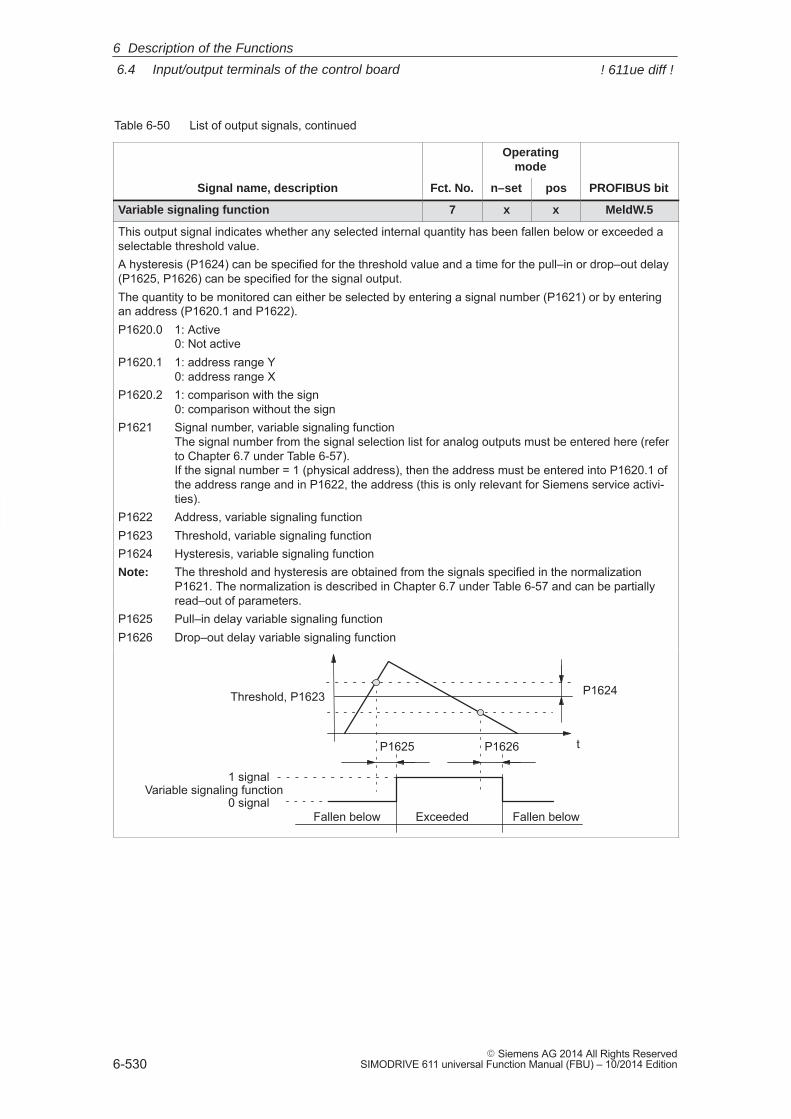
6
6.4 Input/output terminals of the control board
6-530� Siemens AG 2014 All Rights Reserved
SIMODRIVE 611 universal Function Manual (FBU) – 10/2014 Edition
Table 6-50 List of output signals, continued
Operatingmode
Signal name, description PROFIBUS bitposn–setFct. No.
Variable signaling function 7 x x MeldW.5
This output signal indicates whether any selected internal quantity has been fallen below or exceeded aselectable threshold value.A hysteresis (P1624) can be specified for the threshold value and a time for the pull–in or drop–out delay(P1625, P1626) can be specified for the signal output.The quantity to be monitored can either be selected by entering a signal number (P1621) or by enteringan address (P1620.1 and P1622).P1620.0 1: Active
0: Not activeP1620.1 1: address range Y
0: address range XP1620.2 1: comparison with the sign
0: comparison without the signP1621 Signal number, variable signaling function
The signal number from the signal selection list for analog outputs must be entered here (referto Chapter 6.7 under Table 6-57). If the signal number = 1 (physical address), then the address must be entered into P1620.1 ofthe address range and in P1622, the address (this is only relevant for Siemens service activi-ties).
P1622 Address, variable signaling functionP1623 Threshold, variable signaling functionP1624 Hysteresis, variable signaling functionNote: The threshold and hysteresis are obtained from the signals specified in the normalization
P1621. The normalization is described in Chapter 6.7 under Table 6-57 and can be partiallyread–out of parameters.
P1625 Pull–in delay variable signaling functionP1626 Drop–out delay variable signaling function
t
Fallen below Exceeded
Threshold, P1623
1 signal
P1624
0 signalFallen below
P1625 P1626
Variable signaling function
6 Description of the Functions
! 611ue diff !
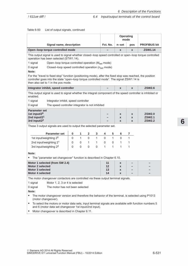
6
6.4 Input/output terminals of the control board
6-531� Siemens AG 2014 All Rights ReservedSIMODRIVE 611 universal Function Manual (FBU) – 10/2014 Edition
Table 6-50 List of output signals, continued
Operatingmode
Signal name, description PROFIBUS bitposn–setFct. No.
Open–loop torque controlled mode – x x ZSW1.14
This output signal is used to signal whether closed–loop speed controlled or open–loop torque controlledoperation has been selected (STW1.14).1 signal Open–loop torque controlled operation (Mset mode)0 signal Closed–loop speed controlled operation (nset mode)Note:
For the ”travel to fixed stop” function (positioning mode), after the fixed stop was reached, the positioncontroller goes into the state ”open–loop torque controlled mode”. The signal ZSW1.14 is then also set to 1 in the pos mode.
Integrator inhibit, speed controller – x x ZSW2.6
This output signal is used to signal whether the integral component of the speed controller is inhibited orenabled.1 signal Integrator inhibit, speed controller0 signal The speed controller integrator is not inhibited
Parameter set1st input/20
2nd input/21
3rd input/22
–––
xxx
xxx
ZSW2.0ZSW2.1ZSW2.2
These 3 output signals are used to output the selected parameter set.
Parameter set 0 1 2 3 4 5 6 7
1st input/weighting 20 0 1 0 1 0 1 0 12nd input/weighting 21 0 0 1 1 0 0 1 13rd input/weighting 22 0 0 0 0 1 1 1 1
Note:
� The ”parameter set changeover” function is described in Chapter 6.10.
Motor 1 selected (from SW 2.4)Motor 2 selected Motor 3 selected Motor 4 selected
11121314
xxxx
––––
––––
The motor changeover contactors are controlled via these output terminal signals.1 signal Motor 1, 2, 3 or 4 is selected0 signal The motor has not been selectedNote:
� The motor changeover version and therefore the behavior of the terminal, is selected using P1013(motor changeover).
� To select the motors or motor data sets, input terminal signals are available with function numbers 5and 6 (motor data set changeover 1st input/2nd input).
� Motor changeover is described in Chapter 6.11.
6 Description of the Functions
! 611ue diff !
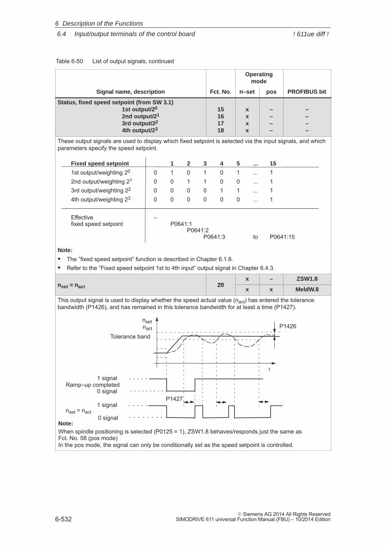
6
6.4 Input/output terminals of the control board
6-532� Siemens AG 2014 All Rights Reserved
SIMODRIVE 611 universal Function Manual (FBU) – 10/2014 Edition
Table 6-50 List of output signals, continued
Operatingmode
Signal name, description PROFIBUS bitposn–setFct. No.
Status, fixed speed setpoint (from SW 3.1)1st output/20
2nd output/21
3rd output/22
4th output/23
15161718
xxxx
––––
––––
These output signals are used to display which fixed setpoint is selected via the input signals, and whichparameters specify the speed setpoint.
Fixed speed setpoint 1 2 3 4 5 ... 15
1st output/weighting 20 0 1 0 1 0 1 ... 12nd output/weighting 21 0 0 1 1 0 0 ... 13rd output/weighting 22 0 0 0 0 1 1 ... 14th output/weighting 23 0 0 0 0 0 0 ... 1
Effective –fixed speed setpoint P0641:1
P0641:2P0641:3 to P0641:15
Note:
� The ”fixed speed setpoint” function is described in Chapter 6.1.6.� Refer to the ”Fixed speed setpoint 1st to 4th input” output signal in Chapter 6.4.3.
nset = nact 20x – ZSW1.8
nset = nact 20x x MeldW.8
This output signal is used to display whether the speed actual value (nact) has entered the tolerancebandwidth (P1426), and has remained in this tolerance bandwidth for at least a time (P1427).
1 signal
0 signal
nset
t
1 signal
0 signalRamp–up completed
nact
nset = nact
P1427
Tolerance band
P1426
Note:When spindle positioning is selected (P0125 = 1), ZSW1.8 behaves/responds just the same as Fct. No. 58 (pos mode)In the pos mode, the signal can only be conditionally set as the speed setpoint is controlled.
6 Description of the Functions
! 611ue diff !
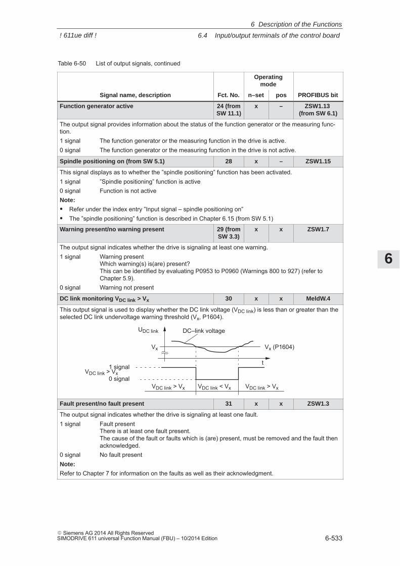
6
6.4 Input/output terminals of the control board
6-533� Siemens AG 2014 All Rights ReservedSIMODRIVE 611 universal Function Manual (FBU) – 10/2014 Edition
Table 6-50 List of output signals, continued
Operatingmode
Signal name, description PROFIBUS bitposn–setFct. No.
Function generator active 24 (fromSW 11.1)
x – ZSW1.13 (from SW 6.1)
The output signal provides information about the status of the function generator or the measuring func-tion.1 signal The function generator or the measuring function in the drive is active.0 signal The function generator or the measuring function in the drive is not active.
Spindle positioning on (from SW 5.1) 28 x – ZSW1.15
This signal displays as to whether the ”spindle positioning” function has been activated.1 signal ”Spindle positioning” function is active0 signal Function is not activeNote:
� Refer under the index entry ”Input signal – spindle positioning on”� The ”spindle positioning” function is described in Chapter 6.15 (from SW 5.1)
Warning present/no warning present 29 (fromSW 3.3)
x x ZSW1.7
The output signal indicates whether the drive is signaling at least one warning.1 signal Warning present
Which warning(s) is(are) present?This can be identified by evaluating P0953 to P0960 (Warnings 800 to 927) (refer toChapter 5.9).
0 signal Warning not present
DC link monitoring VDC link > Vx 30 x x MeldW.4
This output signal is used to display whether the DC link voltage (VDC link) is less than or greater than theselected DC link undervoltage warning threshold (Vx, P1604).
Vx
t1 signal
0 signal
UDC link DC–link voltage
Vx (P1604)
VDC link > Vx VDC link < Vx VDC link > Vx
VDC link > Vx
Fault present/no fault present 31 x x ZSW1.3
The output signal indicates whether the drive is signaling at least one fault.1 signal Fault present
There is at least one fault present. The cause of the fault or faults which is (are) present, must be removed and the fault thenacknowledged.
0 signal No fault presentNote:
Refer to Chapter 7 for information on the faults as well as their acknowledgment.
6 Description of the Functions
! 611ue diff !
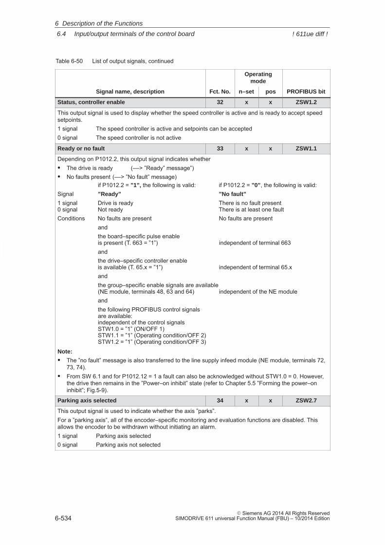
6
6.4 Input/output terminals of the control board
6-534� Siemens AG 2014 All Rights Reserved
SIMODRIVE 611 universal Function Manual (FBU) – 10/2014 Edition
Table 6-50 List of output signals, continued
Operatingmode
Signal name, description PROFIBUS bitposn–setFct. No.
Status, controller enable 32 x x ZSW1.2
This output signal is used to display whether the speed controller is active and is ready to accept speedsetpoints.1 signal The speed controller is active and setpoints can be accepted0 signal The speed controller is not active
Ready or no fault 33 x x ZSW1.1
Depending on P1012.2, this output signal indicates whether� The drive is ready (––> ”Ready” message”)� No faults present (––> ”No fault” message)
if P1012.2 = ”1”, the following is valid: if P1012.2 = ”0”, the following is valid:Signal ”Ready” ”No fault”
1 signal Drive is ready There is no fault present0 signal Not ready There is at least one faultConditions No faults are present No faults are present
andthe board–specific pulse enableis present (T. 663 = ”1”) independent of terminal 663andthe drive–specific controller enableis available (T. 65.x = ”1”) independent of terminal 65.xandthe group–specific enable signals are available(NE module, terminals 48, 63 and 64) independent of the NE moduleandthe following PROFIBUS control signalsare available:independent of the control signalsSTW1.0 = ”1” (ON/OFF 1)STW1.1 = ”1” (Operating condition/OFF 2)STW1.2 = ”1” (Operating condition/OFF 3)
Note:
� The ”no fault” message is also transferred to the line supply infeed module (NE module, terminals 72,73, 74).
� From SW 6.1 and for P1012.12 = 1 a fault can also be acknowledged without STW1.0 = 0. However,the drive then remains in the ”Power–on inhibit” state (refer to Chapter 5.5 ”Forming the power–oninhibit”; Fig.5-9).
Parking axis selected 34 x x ZSW2.7
This output signal is used to indicate whether the axis ”parks”.For a ”parking axis”, all of the encoder–specific monitoring and evaluation functions are disabled. Thisallows the encoder to be withdrawn without initiating an alarm.1 signal Parking axis selected0 signal Parking axis not selected
6 Description of the Functions
! 611ue diff !
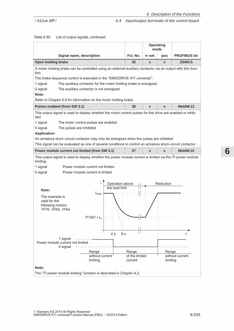
6
6.4 Input/output terminals of the control board
6-535� Siemens AG 2014 All Rights ReservedSIMODRIVE 611 universal Function Manual (FBU) – 10/2014 Edition
Table 6-50 List of output signals, continued
Operatingmode
Signal name, description PROFIBUS bitposn–setFct. No.
Open holding brake 35 x x ZSW2.5
A motor holding brake can be controlled using an external auxiliary contactor via an output with this func-tion.The brake sequence control is executed in the ”SIMODRIVE 611 universal”.1 signal The auxiliary contactor for the motor holding brake is energized0 signal The auxiliary contactor is not energizedNote:
Refer to Chapter 6.9 for information on the motor holding brake.
Pulses enabled (from SW 3.1) 36 x x MeldW.13
This output signal is used to display whether the motor control pulses for this drive are enabled or inhib-ited.1 signal The motor control pulses are enabled0 signal The pulses are inhibitedApplication:
An armature short–circuit contactor may only be energized when the pulses are inhibited.This signal can be evaluated as one of several conditions to control an armature short–circuit contactor.
Power module current not limited (from SW 3.1) 37 x x MeldW.10
This output signal is used to display whether the power module current is limited via the i2t power modulelimiting.1 signal Power module current not limited0 signal Power module current is limited
1 signal
0 signal
t8 s
i
Rangewithout currentlimiting
Range of the limitedcurrent
P1261 � in
imax
4 s
Power module current not limited
Rangewithout currentlimiting
Operation abovethe load limit
Reduction
Note:
The example isvalid for thefollowing motors:1FT6, 1FK6, 1FNx
Note:
The ”i2t power module limiting” function is described in Chapter A.2.
6 Description of the Functions
! 611ue diff !
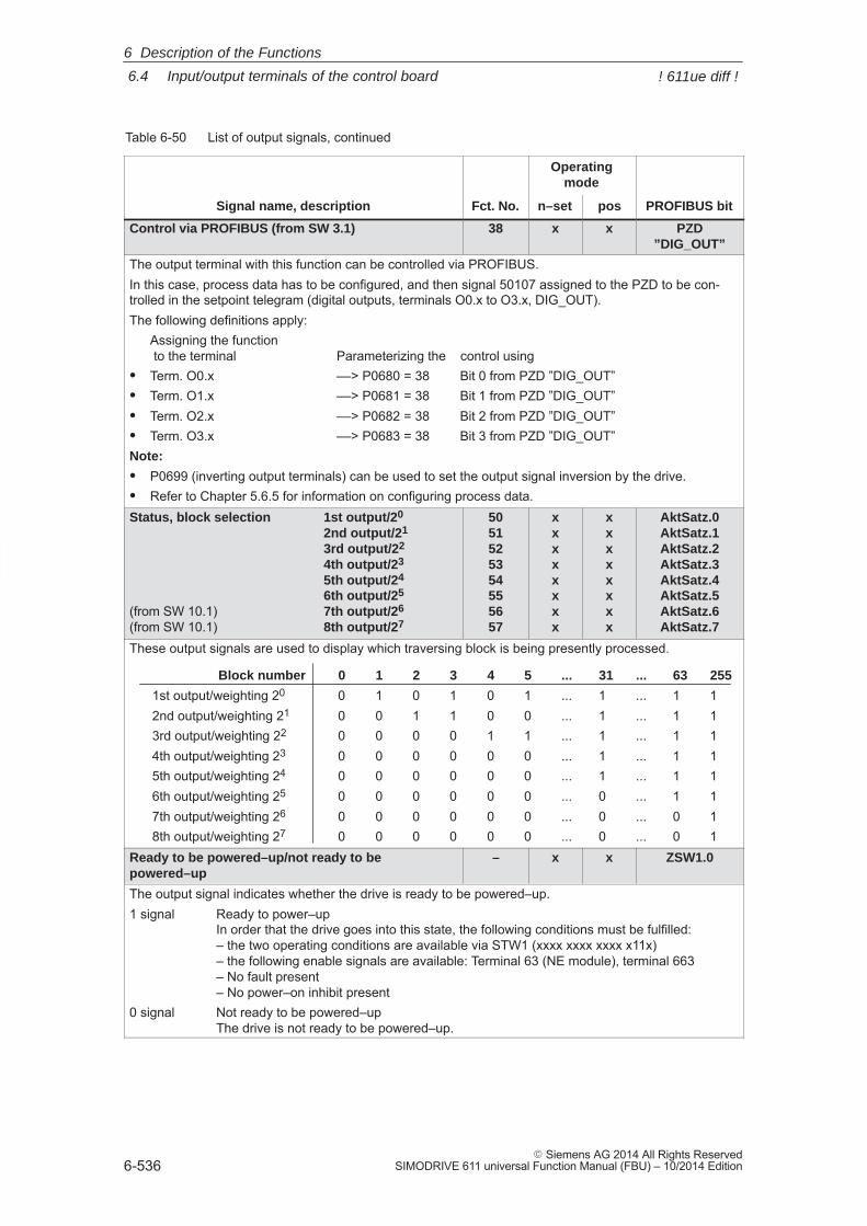
6
6.4 Input/output terminals of the control board
6-536� Siemens AG 2014 All Rights Reserved
SIMODRIVE 611 universal Function Manual (FBU) – 10/2014 Edition
Table 6-50 List of output signals, continued
Operatingmode
Signal name, description PROFIBUS bitposn–setFct. No.
Control via PROFIBUS (from SW 3.1) 38 x x PZD”DIG_OUT”
The output terminal with this function can be controlled via PROFIBUS.In this case, process data has to be configured, and then signal 50107 assigned to the PZD to be con-trolled in the setpoint telegram (digital outputs, terminals O0.x to O3.x, DIG_OUT).The following definitions apply:
Assigning the function to the terminal Parameterizing the control using
� Term. O0.x ––> P0680 = 38 Bit 0 from PZD ”DIG_OUT”� Term. O1.x ––> P0681 = 38 Bit 1 from PZD ”DIG_OUT”� Term. O2.x ––> P0682 = 38 Bit 2 from PZD ”DIG_OUT”� Term. O3.x ––> P0683 = 38 Bit 3 from PZD ”DIG_OUT”Note:
� P0699 (inverting output terminals) can be used to set the output signal inversion by the drive.� Refer to Chapter 5.6.5 for information on configuring process data.Status, block selection 1st output/20
2nd output/21
3rd output/22
4th output/23
5th output/24
6th output/25
(from SW 10.1) 7th output/26
(from SW 10.1) 8th output/27
5051525354555657
xxxxxxxx
xxxxxxxx
AktSatz.0AktSatz.1AktSatz.2AktSatz.3AktSatz.4AktSatz.5AktSatz.6AktSatz.7
These output signals are used to display which traversing block is being presently processed.
Block number 0 1 2 3 4 5 ... 31 ... 63 255
1st output/weighting 20 0 1 0 1 0 1 ... 1 ... 1 12nd output/weighting 21 0 0 1 1 0 0 ... 1 ... 1 13rd output/weighting 22 0 0 0 0 1 1 ... 1 ... 1 14th output/weighting 23 0 0 0 0 0 0 ... 1 ... 1 15th output/weighting 24 0 0 0 0 0 0 ... 1 ... 1 16th output/weighting 25 0 0 0 0 0 0 ... 0 ... 1 17th output/weighting 26 0 0 0 0 0 0 ... 0 ... 0 18th output/weighting 27 0 0 0 0 0 0 ... 0 ... 0 1
Ready to be powered–up/not ready to bepowered–up
– x x ZSW1.0
The output signal indicates whether the drive is ready to be powered–up.1 signal Ready to power–up
In order that the drive goes into this state, the following conditions must be fulfilled:– the two operating conditions are available via STW1 (xxxx xxxx xxxx x11x)– the following enable signals are available: Terminal 63 (NE module), terminal 663– No fault present– No power–on inhibit present
0 signal Not ready to be powered–upThe drive is not ready to be powered–up.
6 Description of the Functions
! 611ue diff !
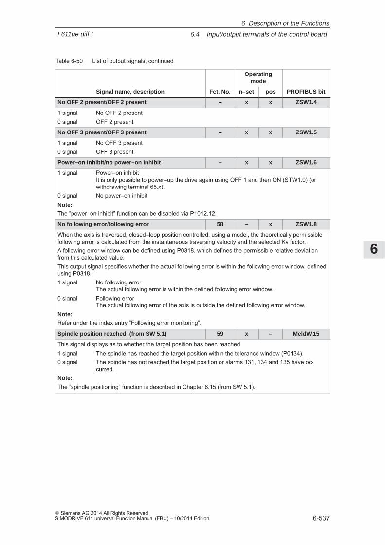
6
6.4 Input/output terminals of the control board
6-537� Siemens AG 2014 All Rights ReservedSIMODRIVE 611 universal Function Manual (FBU) – 10/2014 Edition
Table 6-50 List of output signals, continued
Operatingmode
Signal name, description PROFIBUS bitposn–setFct. No.
No OFF 2 present/OFF 2 present – x x ZSW1.4
1 signal No OFF 2 present0 signal OFF 2 present
No OFF 3 present/OFF 3 present – x x ZSW1.5
1 signal No OFF 3 present0 signal OFF 3 present
Power–on inhibit/no power–on inhibit – x x ZSW1.6
1 signal Power–on inhibitIt is only possible to power–up the drive again using OFF 1 and then ON (STW1.0) (orwithdrawing terminal 65.x).
0 signal No power–on inhibitNote:
The ”power–on inhibit” function can be disabled via P1012.12.
No following error/following error 58 – x ZSW1.8
When the axis is traversed, closed–loop position controlled, using a model, the theoretically permissiblefollowing error is calculated from the instantaneous traversing velocity and the selected Kv factor.A following error window can be defined using P0318, which defines the permissible relative deviationfrom this calculated value.This output signal specifies whether the actual following error is within the following error window, definedusing P0318.1 signal No following error
The actual following error is within the defined following error window.0 signal Following error
The actual following error of the axis is outside the defined following error window.Note:
Refer under the index entry ”Following error monitoring”.
Spindle position reached (from SW 5.1) 59 x – MeldW.15
This signal displays as to whether the target position has been reached.1 signal The spindle has reached the target position within the tolerance window (P0134).0 signal The spindle has not reached the target position or alarms 131, 134 and 135 have oc-
curred.Note:
The ”spindle positioning” function is described in Chapter 6.15 (from SW 5.1).
6 Description of the Functions
! 611ue diff !
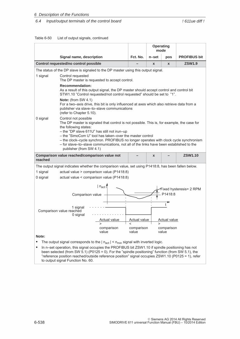
6
6.4 Input/output terminals of the control board
6-538� Siemens AG 2014 All Rights Reserved
SIMODRIVE 611 universal Function Manual (FBU) – 10/2014 Edition
Table 6-50 List of output signals, continued
Operatingmode
Signal name, description PROFIBUS bitposn–setFct. No.
Control requested/no control possible – x x ZSW1.9
The status of the DP slave is signaled to the DP master using this output signal.1 signal Control requested
The DP master is requested to accept control.Recommendation:As a result of this output signal, the DP master should accept control and control bitSTW1.10 ”Control requested/not control requested” should be set to ”1”.Note: (from SW 4.1)For a two–axis drive, this bit is only influenced at axes which also retrieve data from apublisher via slave–to–slave communications(refer to Chapter 5.10).
0 signal Control not possibleThe DP master is signaled that control is not possible. This is, for example, the case forthe following states:– the ”DP slave 611U” has still not irun–up – the ”SimoCom U” tool has taken–over the master control – the clock–cycle synchron. PROFIBUS no longer operates with clock cycle synchronism– for slave–to–slave communications, not all of the links have been established to the publisher (from SW 4.1)
Comparison value reached/comparison value notreached
– x – ZSW1.10
The output signal indicates whether the comparison value, set using P1418:8, has been fallen below.1 signal actual value > comparison value (P1418:8)0 signal actual value < comparison value (P1418:8)
Comparison value P1418:8
t1 signal
0 signal
| nact |
Comparison value reached
Actual value> comparisonvalue
Actual value< comparisonvalue
Actual value> comparisonvalue
Fixed hysteresis= 2 RPM
Note:
� The output signal corresponds to the | nact | < nmin signal with inverted logic.� In n–set operation, this signal occupies the PROFIBUS bit ZSW1.10 if spindle positioning has not
been selected (from SW 5.1) (P0125 = 0). For the ”spindle positioning” function (from SW 5.1), the”reference position reached/outside reference position” signal occupies ZSW1.10 (P0125 = 1), referto output signal Function No. 60.
6 Description of the Functions
! 611ue diff !
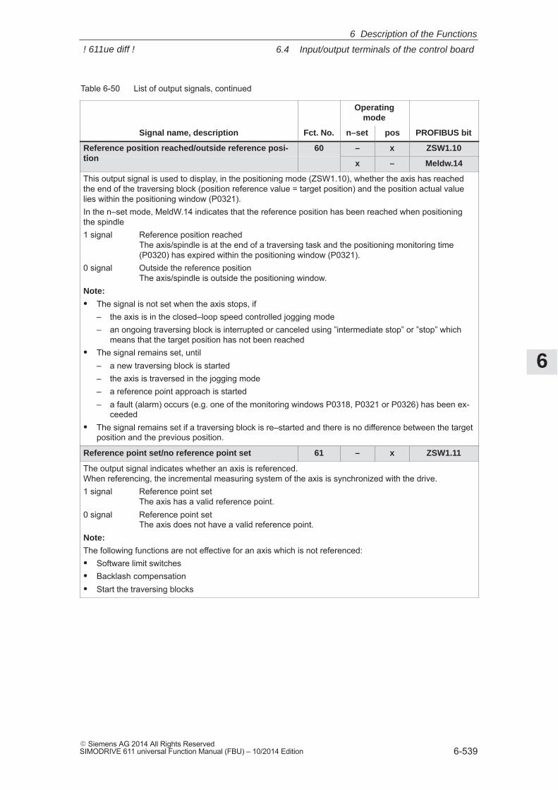
6
6.4 Input/output terminals of the control board
6-539� Siemens AG 2014 All Rights ReservedSIMODRIVE 611 universal Function Manual (FBU) – 10/2014 Edition
Table 6-50 List of output signals, continued
Operatingmode
Signal name, description PROFIBUS bitposn–setFct. No.
Reference position reached/outside reference posi-tion
60 – x ZSW1.10tion
x – Meldw.14
This output signal is used to display, in the positioning mode (ZSW1.10), whether the axis has reachedthe end of the traversing block (position reference value = target position) and the position actual valuelies within the positioning window (P0321).In the n–set mode, MeldW.14 indicates that the reference position has been reached when positioningthe spindle1 signal Reference position reached
The axis/spindle is at the end of a traversing task and the positioning monitoring time(P0320) has expired within the positioning window (P0321).
0 signal Outside the reference positionThe axis/spindle is outside the positioning window.
Note:
� The signal is not set when the axis stops, if– the axis is in the closed–loop speed controlled jogging mode– an ongoing traversing block is interrupted or canceled using ”intermediate stop” or ”stop” which
means that the target position has not been reached� The signal remains set, until
– a new traversing block is started– the axis is traversed in the jogging mode– a reference point approach is started– a fault (alarm) occurs (e.g. one of the monitoring windows P0318, P0321 or P0326) has been ex-
ceeded� The signal remains set if a traversing block is re–started and there is no difference between the target
position and the previous position.
Reference point set/no reference point set 61 – x ZSW1.11
The output signal indicates whether an axis is referenced. When referencing, the incremental measuring system of the axis is synchronized with the drive.1 signal Reference point set
The axis has a valid reference point.0 signal Reference point set
The axis does not have a valid reference point.Note:
The following functions are not effective for an axis which is not referenced:� Software limit switches� Backlash compensation� Start the traversing blocks
6 Description of the Functions
! 611ue diff !
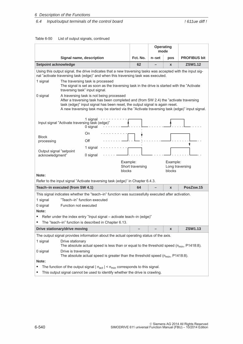
6
6.4 Input/output terminals of the control board
6-540� Siemens AG 2014 All Rights Reserved
SIMODRIVE 611 universal Function Manual (FBU) – 10/2014 Edition
Table 6-50 List of output signals, continued
Operatingmode
Signal name, description PROFIBUS bitposn–setFct. No.
Setpoint acknowledge 62 – x ZSW1.12
Using this output signal, the drive indicates that a new traversing tasks was accepted with the input sig-nal ”activate traversing task (edge)” and when this traversing task was executed.1 signal The traversing task is processed
The signal is set as soon as the traversing task in the drive is started with the ”Activatetraversing task” input signal.
0 signal A traversing task is not being processedAfter a traversing task has been completed and (from SW 2.4) the ”activate traversingtask (edge)” input signal has been reset, the output signal is again reset. A new traversing task may be started via the ”Activate traversing task (edge)” input signal.
1 signal
0 signalInput signal ”Activate traversing task (edge)”
On
OffBlockprocessing
1 signal
0 signalOutput signal ”setpointacknowledgment”
Example: Short traversingblocks
Example: Long traversingblocks
Note:
Refer to the input signal ”Activate traversing task (edge)” in Chapter 6.4.3.
Teach–in executed (from SW 4.1) 64 – x PosZsw.15
This signal indicates whether the ”teach–in” function was successfully executed after activation.1 signal ”Teach–in” function executed0 signal Function not executedNote:
� Refer under the index entry ”Input signal – activate teach–in (edge)”� The ”teach–in” function is described in Chapter 6.13.
Drive stationary/drive moving – – x ZSW1.13
The output signal provides information about the actual operating status of the axis.1 signal Drive stationary
The absolute actual speed is less than or equal to the threshold speed (nmin, P1418:8).0 signal Drive is traversing
The absolute actual speed is greater than the threshold speed (nmin, P1418:8).Note:
� The function of the output signal | nact | < nmin corresponds to this signal.� This output signal cannot be used to identify whether the drive is crawling.
6 Description of the Functions
! 611ue diff !
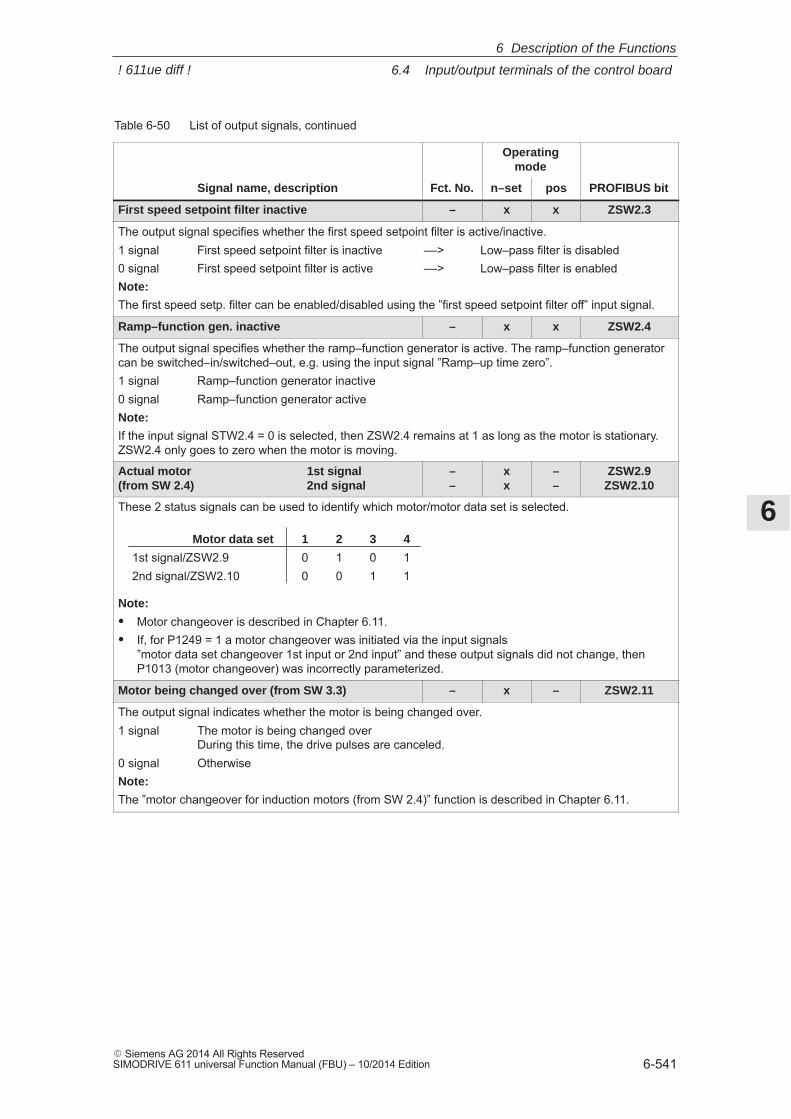
6
6.4 Input/output terminals of the control board
6-541� Siemens AG 2014 All Rights ReservedSIMODRIVE 611 universal Function Manual (FBU) – 10/2014 Edition
Table 6-50 List of output signals, continued
Operatingmode
Signal name, description PROFIBUS bitposn–setFct. No.
First speed setpoint filter inactive – x x ZSW2.3
The output signal specifies whether the first speed setpoint filter is active/inactive.1 signal First speed setpoint filter is inactive ––> Low–pass filter is disabled0 signal First speed setpoint filter is active ––> Low–pass filter is enabledNote:
The first speed setp. filter can be enabled/disabled using the ”first speed setpoint filter off” input signal.
Ramp–function gen. inactive – x x ZSW2.4
The output signal specifies whether the ramp–function generator is active. The ramp–function generatorcan be switched–in/switched–out, e.g. using the input signal ”Ramp–up time zero”.1 signal Ramp–function generator inactive0 signal Ramp–function generator activeNote:
If the input signal STW2.4 = 0 is selected, then ZSW2.4 remains at 1 as long as the motor is stationary.ZSW2.4 only goes to zero when the motor is moving.
Actual motor 1st signal (from SW 2.4) 2nd signal
––
xx
––
ZSW2.9ZSW2.10
These 2 status signals can be used to identify which motor/motor data set is selected.
Motor data set 1 2 3 4
1st signal/ZSW2.9 0 1 0 12nd signal/ZSW2.10 0 0 1 1
Note:
� Motor changeover is described in Chapter 6.11.� If, for P1249 = 1 a motor changeover was initiated via the input signals
”motor data set changeover 1st input or 2nd input” and these output signals did not change, thenP1013 (motor changeover) was incorrectly parameterized.
Motor being changed over (from SW 3.3) – x – ZSW2.11
The output signal indicates whether the motor is being changed over.1 signal The motor is being changed over
During this time, the drive pulses are canceled.0 signal OtherwiseNote:
The ”motor changeover for induction motors (from SW 2.4)” function is described in Chapter 6.11.
6 Description of the Functions
! 611ue diff !
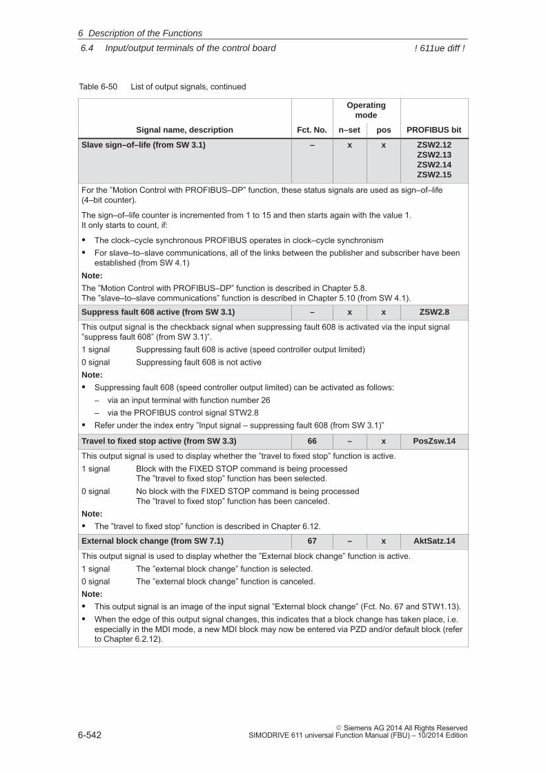
6
6.4 Input/output terminals of the control board
6-542� Siemens AG 2014 All Rights Reserved
SIMODRIVE 611 universal Function Manual (FBU) – 10/2014 Edition
Table 6-50 List of output signals, continued
Operatingmode
Signal name, description PROFIBUS bitposn–setFct. No.
Slave sign–of–life (from SW 3.1) – x x ZSW2.12ZSW2.13ZSW2.14ZSW2.15
For the ”Motion Control with PROFIBUS–DP” function, these status signals are used as sign–of–life(4–bit counter).
The sign–of–life counter is incremented from 1 to 15 and then starts again with the value 1.It only starts to count, if:
� The clock–cycle synchronous PROFIBUS operates in clock–cycle synchronism� For slave–to–slave communications, all of the links between the publisher and subscriber have been
established (from SW 4.1)Note:
The ”Motion Control with PROFIBUS–DP” function is described in Chapter 5.8.The ”slave–to–slave communications” function is described in Chapter 5.10 (from SW 4.1).
Suppress fault 608 active (from SW 3.1) – x x ZSW2.8
This output signal is the checkback signal when suppressing fault 608 is activated via the input signal”suppress fault 608” (from SW 3.1)”.1 signal Suppressing fault 608 is active (speed controller output limited)0 signal Suppressing fault 608 is not activeNote:
� Suppressing fault 608 (speed controller output limited) can be activated as follows:– via an input terminal with function number 26– via the PROFIBUS control signal STW2.8
� Refer under the index entry ”Input signal – suppressing fault 608 (from SW 3.1)”
Travel to fixed stop active (from SW 3.3) 66 – x PosZsw.14
This output signal is used to display whether the ”travel to fixed stop” function is active.1 signal Block with the FIXED STOP command is being processed
The ”travel to fixed stop” function has been selected.0 signal No block with the FIXED STOP command is being processed
The ”travel to fixed stop” function has been canceled.Note:
� The ”travel to fixed stop” function is described in Chapter 6.12.
External block change (from SW 7.1) 67 – x AktSatz.14
This output signal is used to display whether the ”External block change” function is active.1 signal The ”external block change” function is selected.0 signal The ”external block change” function is canceled.Note:
� This output signal is an image of the input signal ”External block change” (Fct. No. 67 and STW1.13).� When the edge of this output signal changes, this indicates that a block change has taken place, i.e.
especially in the MDI mode, a new MDI block may now be entered via PZD and/or default block (referto Chapter 6.2.12).
6 Description of the Functions
! 611ue diff !
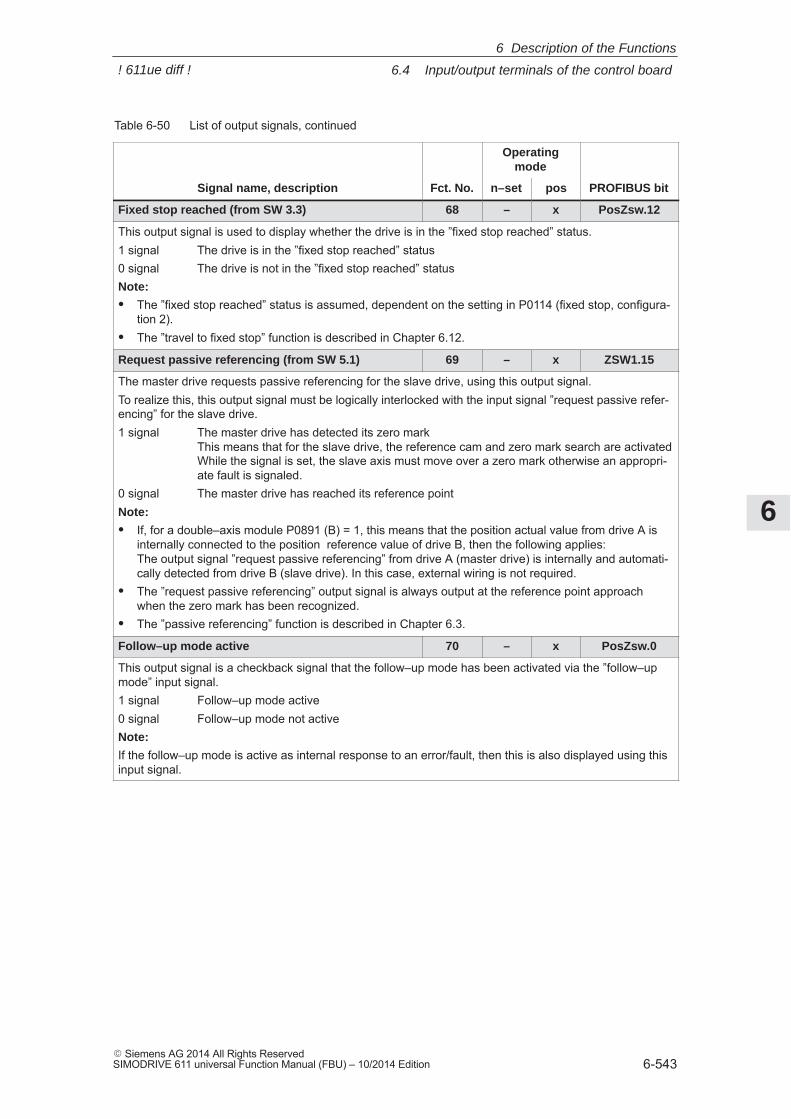
6
6.4 Input/output terminals of the control board
6-543� Siemens AG 2014 All Rights ReservedSIMODRIVE 611 universal Function Manual (FBU) – 10/2014 Edition
Table 6-50 List of output signals, continued
Operatingmode
Signal name, description PROFIBUS bitposn–setFct. No.
Fixed stop reached (from SW 3.3) 68 – x PosZsw.12
This output signal is used to display whether the drive is in the ”fixed stop reached” status.1 signal The drive is in the ”fixed stop reached” status0 signal The drive is not in the ”fixed stop reached” statusNote:
� The ”fixed stop reached” status is assumed, dependent on the setting in P0114 (fixed stop, configura-tion 2).
� The ”travel to fixed stop” function is described in Chapter 6.12.
Request passive referencing (from SW 5.1) 69 – x ZSW1.15
The master drive requests passive referencing for the slave drive, using this output signal.To realize this, this output signal must be logically interlocked with the input signal ”request passive refer-encing” for the slave drive.1 signal The master drive has detected its zero mark
This means that for the slave drive, the reference cam and zero mark search are activatedWhile the signal is set, the slave axis must move over a zero mark otherwise an appropri-ate fault is signaled.
0 signal The master drive has reached its reference pointNote:
� If, for a double–axis module P0891 (B) = 1, this means that the position actual value from drive A isinternally connected to the position reference value of drive B, then the following applies:The output signal ”request passive referencing” from drive A (master drive) is internally and automati-cally detected from drive B (slave drive). In this case, external wiring is not required.
� The ”request passive referencing” output signal is always output at the reference point approachwhen the zero mark has been recognized.
� The ”passive referencing” function is described in Chapter 6.3.
Follow–up mode active 70 – x PosZsw.0
This output signal is a checkback signal that the follow–up mode has been activated via the ”follow–upmode” input signal.1 signal Follow–up mode active0 signal Follow–up mode not activeNote:
If the follow–up mode is active as internal response to an error/fault, then this is also displayed using thisinput signal.
6 Description of the Functions
! 611ue diff !
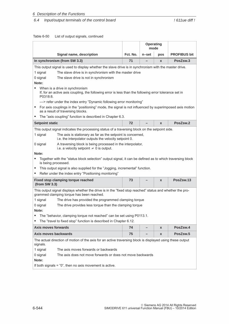
6
6.4 Input/output terminals of the control board
6-544� Siemens AG 2014 All Rights Reserved
SIMODRIVE 611 universal Function Manual (FBU) – 10/2014 Edition
Table 6-50 List of output signals, continued
Operatingmode
Signal name, description PROFIBUS bitposn–setFct. No.
In synchronism (from SW 3.3) 71 – x PosZsw.3
This output signal is used to display whether the slave drive is in synchronism with the master drive.1 signal The slave drive is in synchronism with the master drive0 signal The slave drive is not in synchronismNote:
� When is a drive in synchronismIf, for an active axis coupling, the following error is less than the following error tolerance set inP0318:8.––> refer under the index entry ”Dynamic following error monitoring”
� For axis couplings in the ”positioning” mode, the signal is not influenced by superimposed axis motionas a result of traversing blocks.
� The ”axis coupling” function is described in Chapter 6.3.
Setpoint static 72 – x PosZsw.2
This output signal indicates the processing status of a traversing block on the setpoint side.1 signal The axis is stationary as far as the setpoint is concerned,
i.e. the interpolator outputs the velocity setpoint 0.0 signal A traversing block is being processed in the interpolator,
i.e. a velocity setpoint � 0 is output.Note:
� Together with the ”status block selection” output signal, it can be defined as to which traversing blockis being processed.
� This output signal is also supplied for the ”Jogging, incremental” function.� Refer under the index entry ”Positioning monitoring”
Fixed stop clamping torque reached (from SW 3.3)
73 – x PosZsw.13
This output signal displays whether the drive is in the ”fixed stop reached” status and whether the pro-grammed clamping torque has been reached.1 signal The drive has provided the programmed clamping torque0 signal The drive provides less torque than the clamping torqueNote:
� The ”behavior, clamping torque not reached” can be set using P0113.1.� The ”travel to fixed stop” function is described in Chapter 6.12.
Axis moves forwards 74 – x PosZsw.4
Axis moves backwards 75 – x PosZsw.5
The actual direction of motion of the axis for an active traversing block is displayed using these outputsignals.1 signal The axis moves forwards or backwards0 signal The axis does not move forwards or does not move backwardsNote:
If both signals = ”0”, then no axis movement is active.
6 Description of the Functions
! 611ue diff !
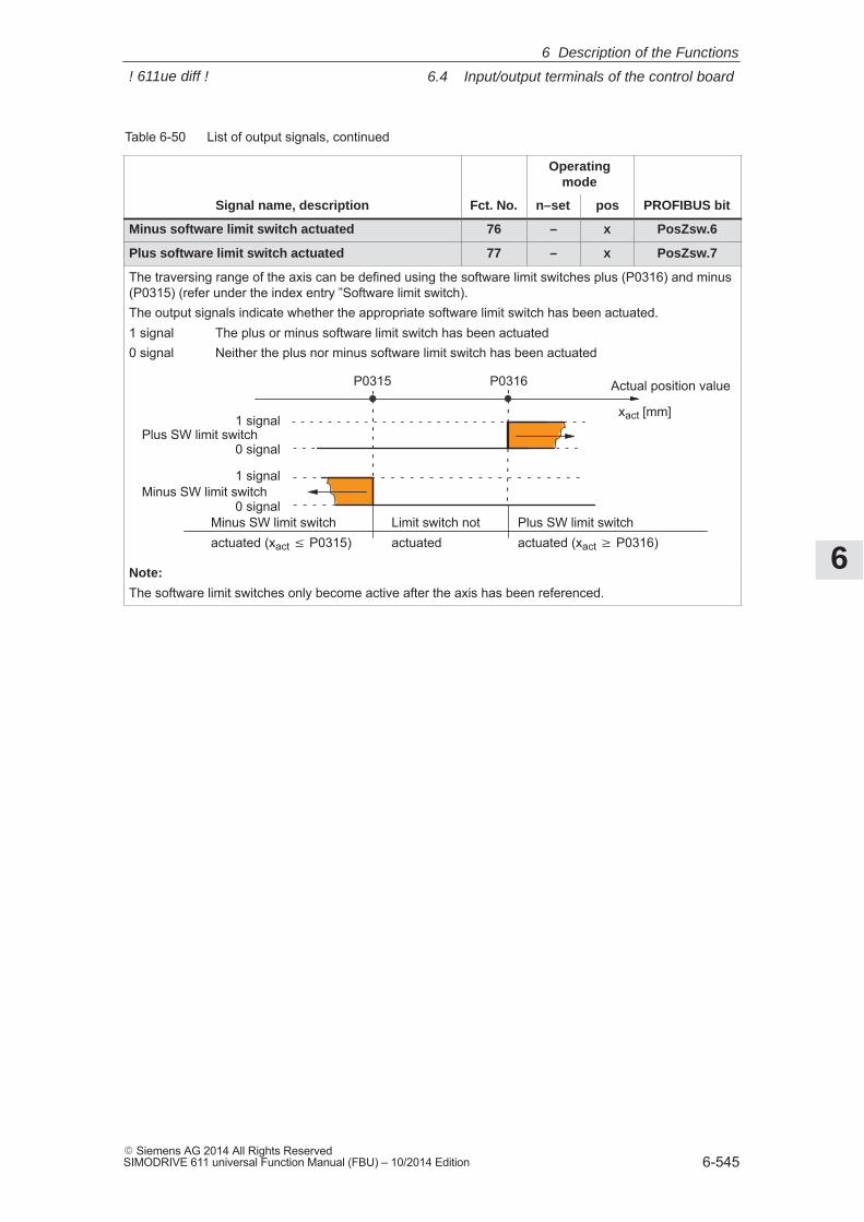
6
6.4 Input/output terminals of the control board
6-545� Siemens AG 2014 All Rights ReservedSIMODRIVE 611 universal Function Manual (FBU) – 10/2014 Edition
Table 6-50 List of output signals, continued
Operatingmode
Signal name, description PROFIBUS bitposn–setFct. No.
Minus software limit switch actuated 76 – x PosZsw.6
Plus software limit switch actuated 77 – x PosZsw.7
The traversing range of the axis can be defined using the software limit switches plus (P0316) and minus(P0315) (refer under the index entry ”Software limit switch).The output signals indicate whether the appropriate software limit switch has been actuated.1 signal The plus or minus software limit switch has been actuated0 signal Neither the plus nor minus software limit switch has been actuated
P0315 P0316
1 signal
0 signal
Plus SW limit switch1 signal
0 signal
Minus SW limit switch
Limit switch notactuated
Actual position value
xact [mm]
Minus SW limit switchactuated (xact P0315)
Plus SW limit switchactuated (xact � P0316)
Note:
The software limit switches only become active after the axis has been referenced.
6 Description of the Functions
! 611ue diff !
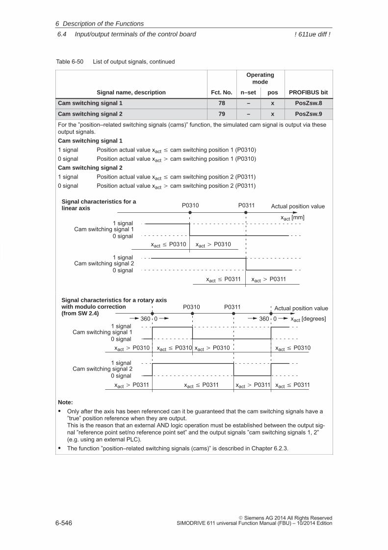
6
6.4 Input/output terminals of the control board
6-546� Siemens AG 2014 All Rights Reserved
SIMODRIVE 611 universal Function Manual (FBU) – 10/2014 Edition
Table 6-50 List of output signals, continued
Operatingmode
Signal name, description PROFIBUS bitposn–setFct. No.
Cam switching signal 1 78 – x PosZsw.8
Cam switching signal 2 79 – x PosZsw.9
For the ”position–related switching signals (cams)” function, the simulated cam signal is output via theseoutput signals.Cam switching signal 1
1 signal Position actual value xact cam switching position 1 (P0310)0 signal Position actual value xact � cam switching position 1 (P0310)Cam switching signal 2
1 signal Position actual value xact cam switching position 2 (P0311)0 signal Position actual value xact � cam switching position 2 (P0311)
P0310
Cam switching signal 11 signal
0 signal
Actual position value
Cam switching signal 21 signal
0 signal
xact P0310 xact � P0310
xact P0311 xact � P0311
Signal characteristics for alinear axis P0311
xact [mm]
P0310
Cam switching signal 11 signal
0 signal
xact [degrees]
Cam switching signal 21 signal
0 signal
xact P0310 xact � P0310
xact P0311 xact � P0311
Signal characteristics for a rotary axiswith modulo correction(from SW 2.4)
P0311
360 0 360 0
xact � P0310 xact P0310
Actual position value
xact � P0311 xact P0311
Note:
� Only after the axis has been referenced can it be guaranteed that the cam switching signals have a”true” position reference when they are output.This is the reason that an external AND logic operation must be established between the output sig-nal ”reference point set/no reference point set” and the output signals ”cam switching signals 1, 2”(e.g. using an external PLC).
� The function ”position–related switching signals (cams)” is described in Chapter 6.2.3.
6 Description of the Functions
! 611ue diff !
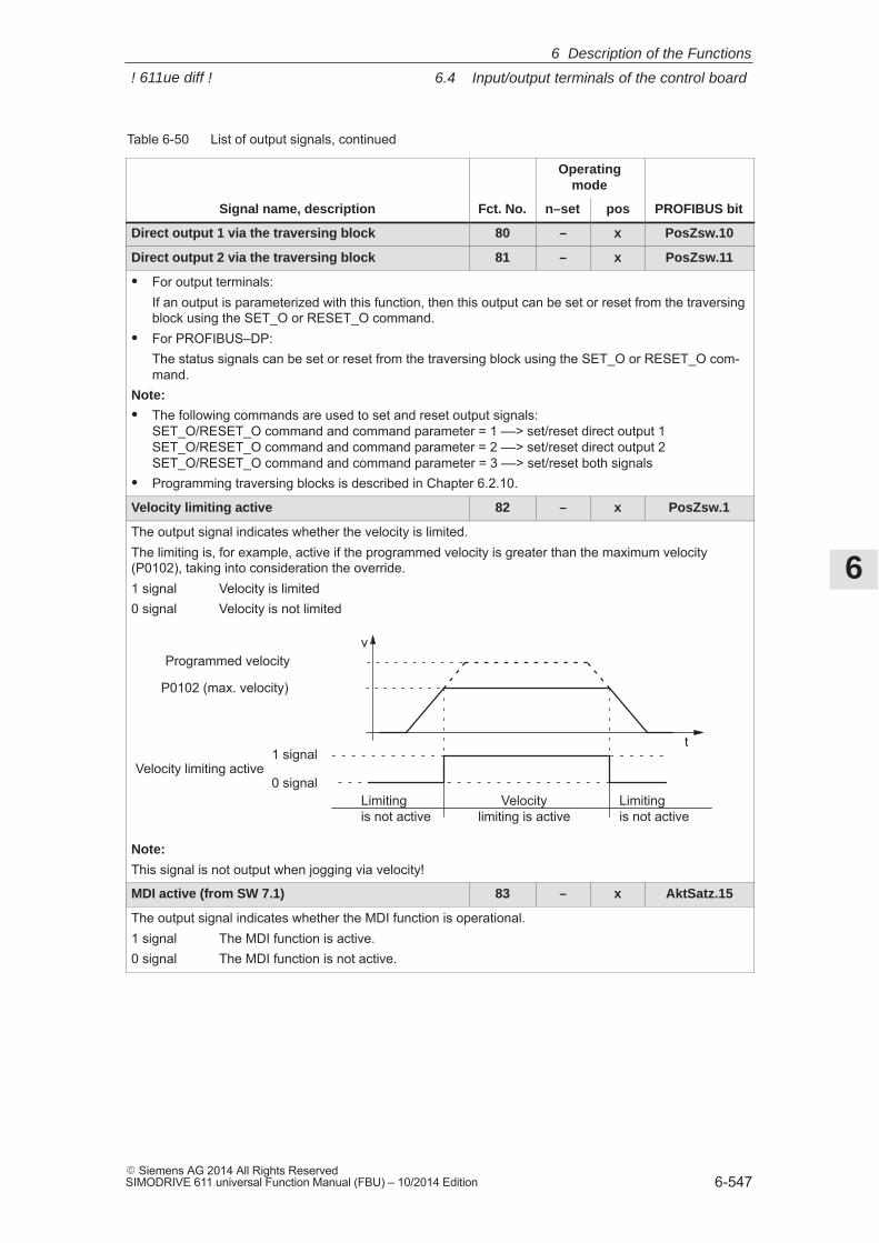
6
6.4 Input/output terminals of the control board
6-547� Siemens AG 2014 All Rights ReservedSIMODRIVE 611 universal Function Manual (FBU) – 10/2014 Edition
Table 6-50 List of output signals, continued
Operatingmode
Signal name, description PROFIBUS bitposn–setFct. No.
Direct output 1 via the traversing block 80 – x PosZsw.10
Direct output 2 via the traversing block 81 – x PosZsw.11
� For output terminals:If an output is parameterized with this function, then this output can be set or reset from the traversingblock using the SET_O or RESET_O command.
� For PROFIBUS–DP:The status signals can be set or reset from the traversing block using the SET_O or RESET_O com-mand.
Note:
� The following commands are used to set and reset output signals:SET_O/RESET_O command and command parameter = 1 ––> set/reset direct output 1SET_O/RESET_O command and command parameter = 2 ––> set/reset direct output 2SET_O/RESET_O command and command parameter = 3 ––> set/reset both signals
� Programming traversing blocks is described in Chapter 6.2.10.
Velocity limiting active 82 – x PosZsw.1
The output signal indicates whether the velocity is limited.The limiting is, for example, active if the programmed velocity is greater than the maximum velocity(P0102), taking into consideration the override.1 signal Velocity is limited0 signal Velocity is not limited
P0102 (max. velocity)
Programmed velocityv
t1 signal
0 signalVelocity
limiting is activeLimitingis not active
Velocity limiting active
Limitingis not active
Note:
This signal is not output when jogging via velocity!
MDI active (from SW 7.1) 83 – x AktSatz.15
The output signal indicates whether the MDI function is operational.1 signal The MDI function is active.0 signal The MDI function is not active.
6 Description of the Functions
! 611ue diff !
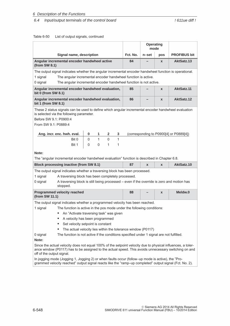
6
6.4 Input/output terminals of the control board
6-548� Siemens AG 2014 All Rights Reserved
SIMODRIVE 611 universal Function Manual (FBU) – 10/2014 Edition
Table 6-50 List of output signals, continued
Operatingmode
Signal name, description PROFIBUS bitposn–setFct. No.
Angular incremental encoder handwheel active(from SW 8.1)
84 – x AktSatz.13
The output signal indicates whether the angular incremental encoder handwheel function is operational.1 signal The angular incremental encoder handwheel function is active.0 signal The angular incremental encoder handwheel function is not active.
Angular incremental encoder handwheel evaluation,bit 0 (from SW 8.1)
85 – x AktSatz.11
Angular incremental encoder handwheel evaluation,bit 1 (from SW 8.1)
86 – x AktSatz.12
These 2 status signals can be used to define which angular incremental encoder handwheel evaluationis selected via the following parameter.Before SW 9.1: P0900:4From SW 9.1: P0889:4
Ang. incr. enc. hwh. eval. 0 1 2 3 (corresponding to P0900[4] or P0889[4])Bit 0 0 1 0 1Bit 1 0 0 1 1
Note:
The ”angular incremental encoder handwheel evaluation” function is described in Chapter 6.8.
Block processing inactive (from SW 8.1) 87 x x AktSatz.10
The output signal indicates whether a traversing block has been processed.1 signal A traversing block has been completely processed.0 signal A traversing block is still being processed – even if the override is zero and motion has
stopped.
Programmed velocity reached (from SW 11.1)
88 – x Meldw.0
The output signal indicates whether a programmed velocity has been reached.1 signal The function is active in the pos mode under the following conditions:
� An ”Activate traversing task” was given� A velocity has been programmed� Set velocity setpoint is constant� The actual velocity lies within the tolerance window (P0117)
0 signal The function is not active if the conditions specified under 1 signal are not fulfilled.Note:
Since the actual velocity does not equal 100% of the setpoint velocity due to physical influences, a toler-ance window (P0117) has to be assigned to the actual speed. This avoids unnecessary switching on andoff of the output signal.In jogging mode (Jogging 1, Jogging 2) or when faults occur (follow–up mode is active), the ”Pro-grammed velocity reached” output signal reacts like the ”ramp–up completed” output signal (Fct. No. 2).
6 Description of the Functions
! 611ue diff !
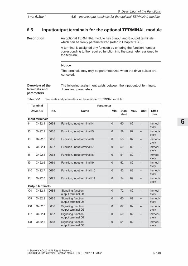
6
6.5 Input/output terminals for the optional TERMINAL module
6-549� Siemens AG 2014 All Rights ReservedSIMODRIVE 611 universal Function Manual (FBU) – 10/2014 Edition
6.5 Input/output terminals for the optional TERMINAL module
An optional TERMINAL module has 8 input and 8 output terminals,which can be freely parameterized (refer to Chapter 1.3.3).
A terminal is assigned any function by entering the function numbercorresponding to the required function into the parameter assigned tothe terminal.
Notice
The terminals may only be parameterized when the drive pulses arecanceled.
The following assignment exists between the input/output terminals,drives and parameters:
Table 6-51 Terminals and parameters for the optional TERMINAL module
Terminal Parameter
Drive A/B No. Name Min. Stan-dard
Max. Unit Effec-tive
Input terminals
I4 X422.1 0664 Function, input terminal I4 0 60 82 – immedi-ately
I5 X422.2 0665 Function, input terminal I5 0 59 82 – immedi-ately
I6 X422.3 0666 Function, input terminal I6 0 58 82 – immedi-ately
I7 X422.4 0667 Function, input terminal I7 0 50 82 – immedi-ately
I8 X422.5 0668 Function, input terminal I8 0 51 82 – immedi-ately
I9 X422.6 0669 Function, input terminal I9 0 52 82 – immedi-ately
I10 X422.7 0670 Function, input terminal I10 0 53 82 – immedi-ately
I11 X422.8 0671 Function, input terminal I11 0 54 82 – immedi-ately
Output terminals
O4 X432.1 0684 Signaling functionoutput terminal O4
0 72 82 – immedi-ately
O5 X432.2 0685 Signaling functionoutput terminal O5
0 60 82 – immedi-ately
O6 X432.3 0686 Signaling function output terminal O6
0 62 82 – immedi-ately
O7 X432.4 0687 Signaling function output terminal O7
0 50 82 – immedi-ately
O8 X432.5 0688 Signaling function output terminal O8
0 51 82 – immedi-ately
Description
Overview of theterminals andparameters
6 Description of the Functions
! not 611ue !
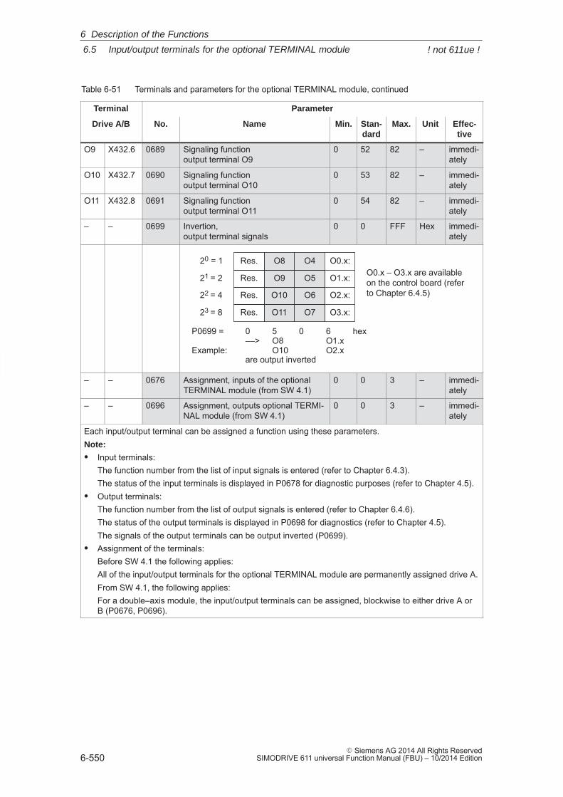
6
6.5 Input/output terminals for the optional TERMINAL module
6-550� Siemens AG 2014 All Rights Reserved
SIMODRIVE 611 universal Function Manual (FBU) – 10/2014 Edition
Table 6-51 Terminals and parameters for the optional TERMINAL module, continued
Terminal Parameter
Drive A/B Effec-tive
UnitMax.Stan-dard
Min.NameNo.
O9 X432.6 0689 Signaling function output terminal O9
0 52 82 – immedi-ately
O10 X432.7 0690 Signaling function output terminal O10
0 53 82 – immedi-ately
O11 X432.8 0691 Signaling function output terminal O11
0 54 82 – immedi-ately
– – 0699 Invertion, output terminal signals
0 0 FFF Hex immedi-ately
20 = 1
21 = 2
22 = 4
23 = 8
P0699 = 0 5 0 6 hex––> O8 O1.x
Example: O10 O2.xare output inverted
O0.x:
O1.x:
O2.x:
O3.x:
O4
O5
O6
O7
O8
O9
O10
O11
Res.
Res.
Res.
Res.
O0.x – O3.x are availableon the control board (referto Chapter 6.4.5)
– – 0676 Assignment, inputs of the optionalTERMINAL module (from SW 4.1)
0 0 3 – immedi-ately
– – 0696 Assignment, outputs optional TERMI-NAL module (from SW 4.1)
0 0 3 – immedi-ately
Each input/output terminal can be assigned a function using these parameters.Note:
� Input terminals:The function number from the list of input signals is entered (refer to Chapter 6.4.3).The status of the input terminals is displayed in P0678 for diagnostic purposes (refer to Chapter 4.5).
� Output terminals:The function number from the list of output signals is entered (refer to Chapter 6.4.6).The status of the output terminals is displayed in P0698 for diagnostics (refer to Chapter 4.5).The signals of the output terminals can be output inverted (P0699).
� Assignment of the terminals:Before SW 4.1 the following applies:All of the input/output terminals for the optional TERMINAL module are permanently assigned drive A.From SW 4.1, the following applies:For a double–axis module, the input/output terminals can be assigned, blockwise to either drive A orB (P0676, P0696).
6 Description of the Functions
! not 611ue !
6
6.6 Analog inputs
6-551� Siemens AG 2014 All Rights ReservedSIMODRIVE 611 universal Function Manual (FBU) – 10/2014 Edition
6.6 Analog inputs
For ”SIMODRIVE 611 universal”, there are two analog inputs for eachdrive.
In the ”speed/torque setpoint” mode, the setpoint can be entered forthe following functions via these analog inputs:
� Speed Speed–controlled operation (nset operation)
For the nset mode, the analog voltage at terminal 56.x/14.x and/orterminal 24.x/20.x is used as speed setpoint.
� Torque: Open–loop torque controlled operation (Mset mode)
For the Mset mode the analog voltage at terminal 56.x/14.x and/orterminal 24.x/20.x is used as torque setpoint.
Open–loop torque control is used, if
– the speed controller is implemented in a higher–level control, or
– the master/slave functionality is used
� Torque/power reduction (Mred mode)
It may be necessary to reduce the maximum drive torque to protectthe machine components. The following possibilities exist:
– Permanent torque limiting This limit function can be set via parameters P1230 or P1235(refer to Chapter 6.1.8).
– Variable torque limitingIn this case, analog input 2 is set to Mred mode and the analogvoltage at terminal 24.x/20.x is used to continuously reduce thetorque.
In the ”positioning” mode, a setpoint can be entered for the velocityoverride via analog input 1.
Description
6 Description of the Functions
! not 611ue !
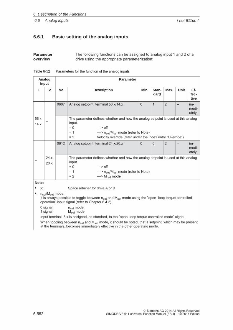
6
6.6 Analog inputs
6-552� Siemens AG 2014 All Rights Reserved
SIMODRIVE 611 universal Function Manual (FBU) – 10/2014 Edition
6.6.1 Basic setting of the analog inputs
The following functions can be assigned to analog input 1 and 2 of adrive using the appropriate parameterization:
Table 6-52 Parameters for the function of the analog inputs
Analoginput
Parameter
1 2 No. Description Min. Stan-dard
Max. Unit Ef-fec-tive
0607 Analog setpoint, terminal 56.x/14.x 0 1 2 – im-medi-ately
56 x14 x
–The parameter defines whether and how the analog setpoint is used at this analoginput.= 0 ––> off= 1 ––> nset/Mset mode (refer to Note)= 2 Velocity override (refer under the index entry ”Override”)
0612 Analog setpoint, terminal 24.x/20.x 0 0 2 – im-medi-ately
–24 x20 x
The parameter defines whether and how the analog setpoint is used at this analoginput.= 0 ––> off= 1 ––> nset/Mset mode (refer to Note)= 2 ––> Mred mode
Note:
� x: Space retainer for drive A or B� nset/Mset mode:
It is always possible to toggle between nset and Mset mode using the ”open–loop torque controlledoperation” input signal (refer to Chapter 6.4.2).0 signal: nset mode1 signal: Mset modeInput terminal I3.x is assigned, as standard, to the ”open–loop torque controlled mode” signal.When toggling between nset and Mset mode, it should be noted, that a setpoint, which may be presentat the terminals, becomes immediately effective in the other operating mode.
Parameteroverview
6 Description of the Functions
! not 611ue !
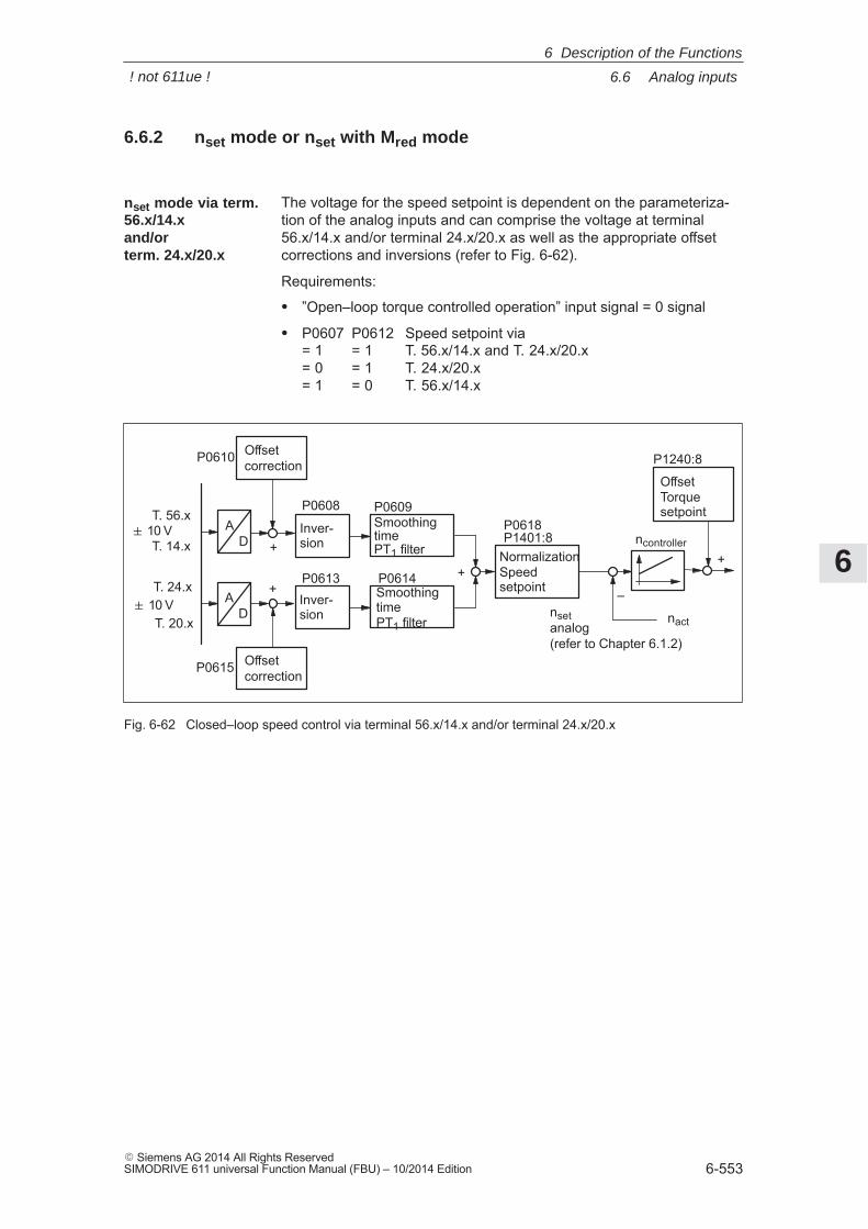
6
6.6 Analog inputs
6-553� Siemens AG 2014 All Rights ReservedSIMODRIVE 611 universal Function Manual (FBU) – 10/2014 Edition
6.6.2 nset mode or nset with Mred mode
The voltage for the speed setpoint is dependent on the parameteriza-tion of the analog inputs and can comprise the voltage at terminal56.x/14.x and/or terminal 24.x/20.x as well as the appropriate offsetcorrections and inversions (refer to Fig. 6-62).
Requirements:
� ”Open–loop torque controlled operation” input signal = 0 signal
� P0607 P0612 Speed setpoint via= 1 = 1 T. 56.x/14.x and T. 24.x/20.x= 0 = 1 T. 24.x/20.x= 1 = 0 T. 56.x/14.x
OffsetTorquesetpointP0609
P0614NormalizationSpeedsetpoint
P0610
P0615
P1401:8SmoothingtimePT1 filter+
+
nset analog (refer to Chapter 6.1.2)
+
P0618
Inver-sion
Inver-sion
P0608
P0613
AD
AD
� 10 V
P1240:8
+
SmoothingtimePT1 filter
T. 56.x
T. 14.x
T. 24.x
T. 20.x� 10 V
ncontroller
Offsetcorrection
Offsetcorrection
nact
–
Fig. 6-62 Closed–loop speed control via terminal 56.x/14.x and/or terminal 24.x/20.x
nset mode via term.56.x/14.xand/orterm. 24.x/20.x
6 Description of the Functions
! not 611ue !
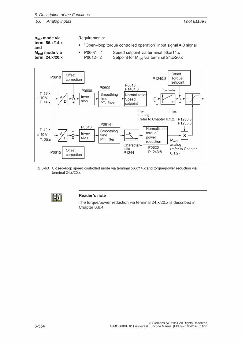
6
6.6 Analog inputs
6-554� Siemens AG 2014 All Rights Reserved
SIMODRIVE 611 universal Function Manual (FBU) – 10/2014 Edition
Requirements:
� ”Open–loop torque controlled operation” input signal = 0 signal
� P0607 = 1 Speed setpoint via terminal 56.x/14.xP0612= 2 Setpoint for Mred via terminal 24.x/20.x
P0609
P0614
P0610
P0615
Offsetcorrection
+
+ Inver-sion
Inver-sion
P0608
P0613
AD
AD
� 10 V
SmoothingtimePT1 filter
T. 56.x
T. 14.x
T. 24.x
T. 20.x� 10 V
P0620
P0618P1401:8
Normalizationtorque/powerreduction
NormalizationSpeedsetpoint
P1244 P1243:8
+
Character–
P1240:8OffsetTorquesetpoint
Mred analog(refer to Chapter6.1.2)
istic
ncontroller
X
P1230:8P1235:8
SmoothingtimePT1 filter
Offsetcorrection
nset analog (refer to Chapter 6.1.2)
nact
–
Fig. 6-63 Closed–loop speed controlled mode via terminal 56.x/14.x and torque/power reduction viaterminal 24.x/20.x
Reader’s note
The torque/power reduction via terminal 24.x/20.x is described inChapter 6.6.4.
nset mode via term. 56.x/14.x and Mred mode viaterm. 24.x/20.x
6 Description of the Functions
! not 611ue !
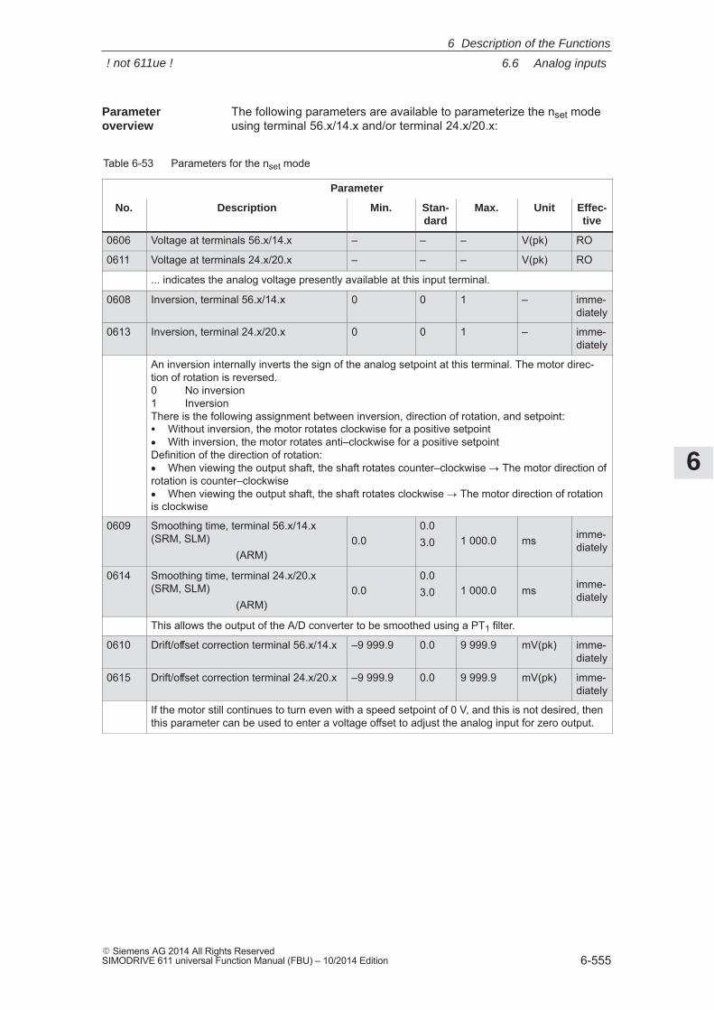
6
6.6 Analog inputs
6-555� Siemens AG 2014 All Rights ReservedSIMODRIVE 611 universal Function Manual (FBU) – 10/2014 Edition
The following parameters are available to parameterize the nset modeusing terminal 56.x/14.x and/or terminal 24.x/20.x:
Table 6-53 Parameters for the nset mode
Parameter
No. Description Min. Stan-dard
Max. Unit Effec-tive
0606 Voltage at terminals 56.x/14.x – – – V(pk) RO
0611 Voltage at terminals 24.x/20.x – – – V(pk) RO
... indicates the analog voltage presently available at this input terminal.
0608 Inversion, terminal 56.x/14.x 0 0 1 – imme-diately
0613 Inversion, terminal 24.x/20.x 0 0 1 – imme-diately
An inversion internally inverts the sign of the analog setpoint at this terminal. The motor direc-tion of rotation is reversed.0 No inversion1 InversionThere is the following assignment between inversion, direction of rotation, and setpoint:� Without inversion, the motor rotates clockwise for a positive setpoint� With inversion, the motor rotates anti–clockwise for a positive setpointDefinition of the direction of rotation:� When viewing the output shaft, the shaft rotates counter–clockwise � The motor direction ofrotation is counter–clockwise� When viewing the output shaft, the shaft rotates clockwise � The motor direction of rotationis clockwise
0609 Smoothing time, terminal 56.x/14.x(SRM, SLM)
(ARM)0.0
0.03.0 1 000.0 ms imme-
diately
0614 Smoothing time, terminal 24.x/20.x(SRM, SLM)
(ARM)0.0
0.03.0 1 000.0 ms imme-
diately
This allows the output of the A/D converter to be smoothed using a PT1 filter.
0610 Drift/offset correction terminal 56.x/14.x –9 999.9 0.0 9 999.9 mV(pk) imme-diately
0615 Drift/offset correction terminal 24.x/20.x –9 999.9 0.0 9 999.9 mV(pk) imme-diately
If the motor still continues to turn even with a speed setpoint of 0 V, and this is not desired, thenthis parameter can be used to enter a voltage offset to adjust the analog input for zero output.
Parameter overview
6 Description of the Functions
! not 611ue !

6
6.6 Analog inputs
6-556� Siemens AG 2014 All Rights Reserved
SIMODRIVE 611 universal Function Manual (FBU) – 10/2014 Edition
Table 6-53 Parameters for the nset mode, continued
Parameter
No. Effec-tive
UnitMax.Stan-dard
Min.Description
0618 Normalization voltagespeed setpoint
5.0 9.0 12.5 V(pk) imme-diately
1401:8 Speed for max. useful motor speed(SRM, ARM)Velocity for max. motor useful velocity(SLM)
–100 000.0 0.0 100 000.0
RPM
m/minimme-diately
P0618: This defines the input voltage at which the maximum useful motor speed is reached.P1401:8: The parameter specifies the maximum motor useful speed, and represents the refer-
ence value for P0618. The standard value is pre–assigned for the hardware configuration depending on themotor used.
P0618
Example:P0618 = 9P1401:8 = 2000––> at 9 V, the motor reaches a speedof 2000 RPMU [V]
n [rev/min]
P1401:8
Note:
The maximum useful motor speed, set using P1401:8 is taken into account when calculatingthe speed setpoint. This means that P1401:8 acts as a speed limit.This is independent of whether the setpoint is entered via a terminal or PROFIBUS.
1240:8 Offset, torque setpoint (closed–loopspeed controlled) (SRM, ARM)Offset, force setpoint (closed–loopspeed controlled) (SLM)
–50 000.0 0.0 50 000.0
Nm
Nimme-diately
This parameter value is added to the torque setpoint or force setpoint (SLM).Note:
This allows a weight equalization to be set.
0620
1243 For the torque/power reduction via terminal 24.x/20.x (refer to Chapter 6.6.4), this parametercan be used to make adjustments.
1244can be used to make adjustments.
6 Description of the Functions
! not 611ue !
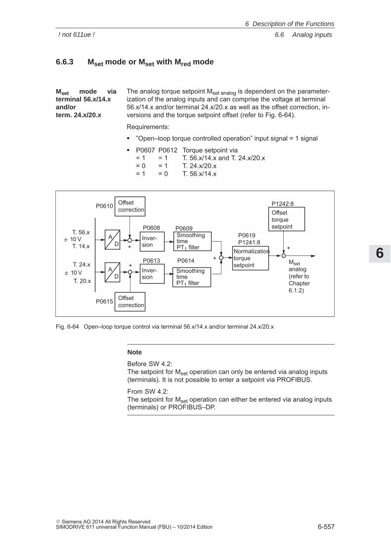
6
6.6 Analog inputs
6-557� Siemens AG 2014 All Rights ReservedSIMODRIVE 611 universal Function Manual (FBU) – 10/2014 Edition
6.6.3 Mset mode or Mset with Mred mode
The analog torque setpoint Mset analog is dependent on the parameter-ization of the analog inputs and can comprise the voltage at terminal56.x/14.x and/or terminal 24.x/20.x as well as the offset correction, in-versions and the torque setpoint offset (refer to Fig. 6-64).
Requirements:
� ”Open–loop torque controlled operation” input signal = 1 signal
� P0607 P0612 Torque setpoint via= 1 = 1 T. 56.x/14.x and T. 24.x/20.x= 0 = 1 T. 24.x/20.x= 1 = 0 T. 56.x/14.x
Normalizationtorquesetpoint
P1241:8
Mset analog(refer to Chapter6.1.2)
P0619
Offsettorquesetpoint
P1242:8
+
P0609
P0614
P0610
P0615
SmoothingtimePT1 filter+
++
Inver-sion
Inver-sion
P0608
P0613
AD
AD
� 10 V
SmoothingtimePT1 filter
T. 56.x
T. 14.x
T. 24.x
T. 20.x� 10 V
Offsetcorrection
Offsetcorrection
Fig. 6-64 Open–loop torque control via terminal 56.x/14.x and/or terminal 24.x/20.x
Note
Before SW 4.2:The setpoint for Mset operation can only be entered via analog inputs(terminals). It is not possible to enter a setpoint via PROFIBUS.
From SW 4.2:The setpoint for Mset operation can either be entered via analog inputs(terminals) or PROFIBUS–DP.
Mset mode viaterminal 56.x/14.xand/orterm. 24.x/20.x
6 Description of the Functions
! not 611ue !
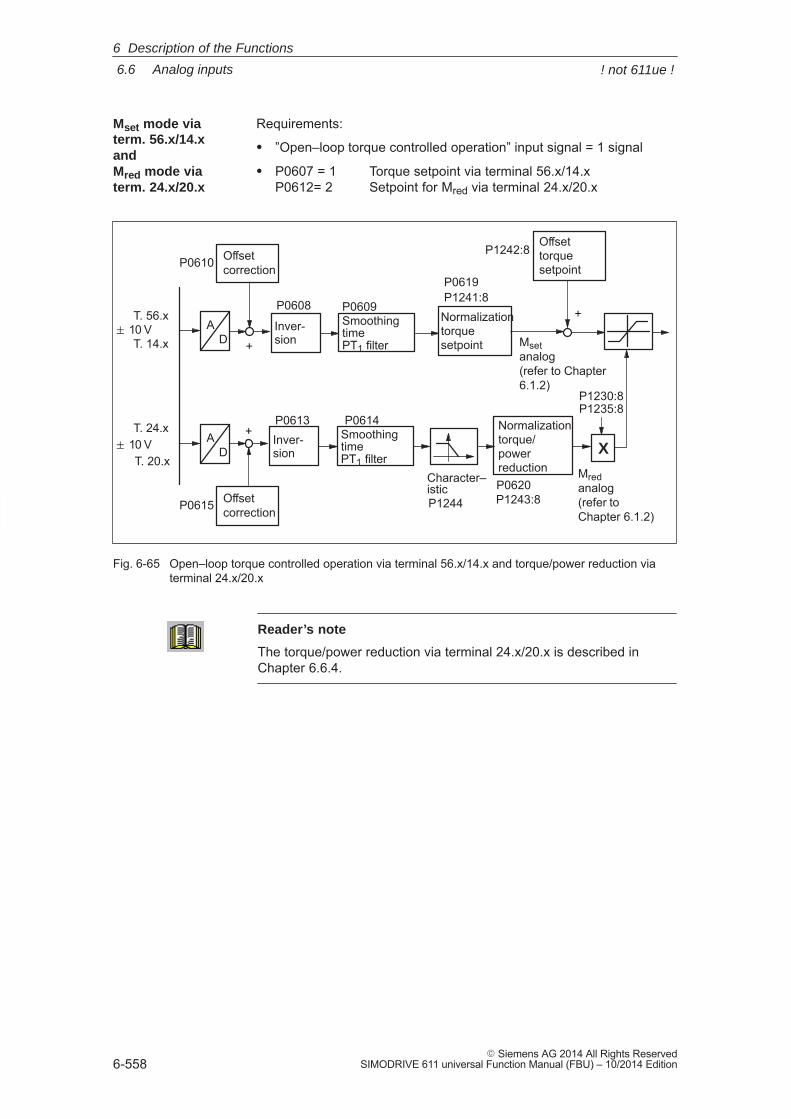
6
6.6 Analog inputs
6-558� Siemens AG 2014 All Rights Reserved
SIMODRIVE 611 universal Function Manual (FBU) – 10/2014 Edition
Requirements:
� ”Open–loop torque controlled operation” input signal = 1 signal
� P0607 = 1 Torque setpoint via terminal 56.x/14.xP0612= 2 Setpoint for Mred via terminal 24.x/20.x
P1241:8
Mred analog(refer to Chapter 6.1.2)
P0620
Mset analog (refer to Chapter6.1.2)
P0619
P1242:8
+
Offsettorquesetpoint
Normalizationtorquesetpoint
P1243:8
Normalizationtorque/powerreduction
Character–
P0609
P0614
P0610
P0615
SmoothingtimePT1 filter+
+Inver-sion
Inver-sion
P0608
P0613
AD
AD
� 10 V
SmoothingtimePT1 filter
T. 56.x
T. 14.x
T. 24.x
T. 20.x� 10 V
P1244istic
X
P1230:8P1235:8
Offsetcorrection
Offsetcorrection
Fig. 6-65 Open–loop torque controlled operation via terminal 56.x/14.x and torque/power reduction viaterminal 24.x/20.x
Reader’s note
The torque/power reduction via terminal 24.x/20.x is described inChapter 6.6.4.
Mset mode viaterm. 56.x/14.x and Mred mode viaterm. 24.x/20.x
6 Description of the Functions
! not 611ue !
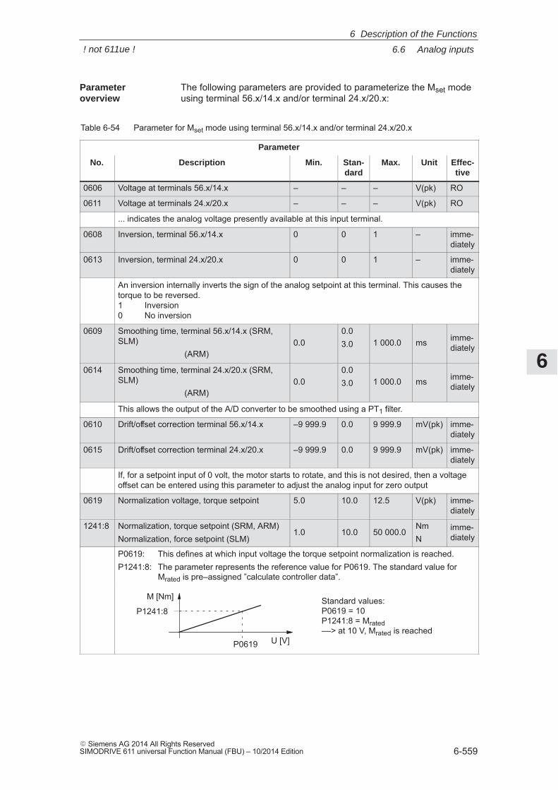
6
6.6 Analog inputs
6-559� Siemens AG 2014 All Rights ReservedSIMODRIVE 611 universal Function Manual (FBU) – 10/2014 Edition
The following parameters are provided to parameterize the Mset modeusing terminal 56.x/14.x and/or terminal 24.x/20.x:
Table 6-54 Parameter for Mset mode using terminal 56.x/14.x and/or terminal 24.x/20.x
Parameter
No. Description Min. Stan-dard
Max. Unit Effec-tive
0606 Voltage at terminals 56.x/14.x – – – V(pk) RO
0611 Voltage at terminals 24.x/20.x – – – V(pk) RO
... indicates the analog voltage presently available at this input terminal.
0608 Inversion, terminal 56.x/14.x 0 0 1 – imme-diately
0613 Inversion, terminal 24.x/20.x 0 0 1 – imme-diately
An inversion internally inverts the sign of the analog setpoint at this terminal. This causes thetorque to be reversed.1 Inversion0 No inversion
0609 Smoothing time, terminal 56.x/14.x (SRM,SLM)
(ARM)0.0
0.03.0 1 000.0 ms imme-
diately
0614 Smoothing time, terminal 24.x/20.x (SRM,SLM)
(ARM)0.0
0.03.0 1 000.0 ms imme-
diately
This allows the output of the A/D converter to be smoothed using a PT1 filter.
0610 Drift/offset correction terminal 56.x/14.x –9 999.9 0.0 9 999.9 mV(pk) imme-diately
0615 Drift/offset correction terminal 24.x/20.x –9 999.9 0.0 9 999.9 mV(pk) imme-diately
If, for a setpoint input of 0 volt, the motor starts to rotate, and this is not desired, then a voltageoffset can be entered using this parameter to adjust the analog input for zero output
0619 Normalization voltage, torque setpoint 5.0 10.0 12.5 V(pk) imme-diately
1241:8 Normalization, torque setpoint (SRM, ARM)Normalization, force setpoint (SLM)
1.0 10.0 50 000.0NmN
imme-diately
P0619: This defines at which input voltage the torque setpoint normalization is reached.P1241:8: The parameter represents the reference value for P0619. The standard value for
Mrated is pre–assigned ”calculate controller data”.
Standard values:P0619 = 10P1241:8 = Mrated––> at 10 V, Mrated is reached
P1241:8
P0619 U [V]
M [Nm]
Parameter overview
6 Description of the Functions
! not 611ue !
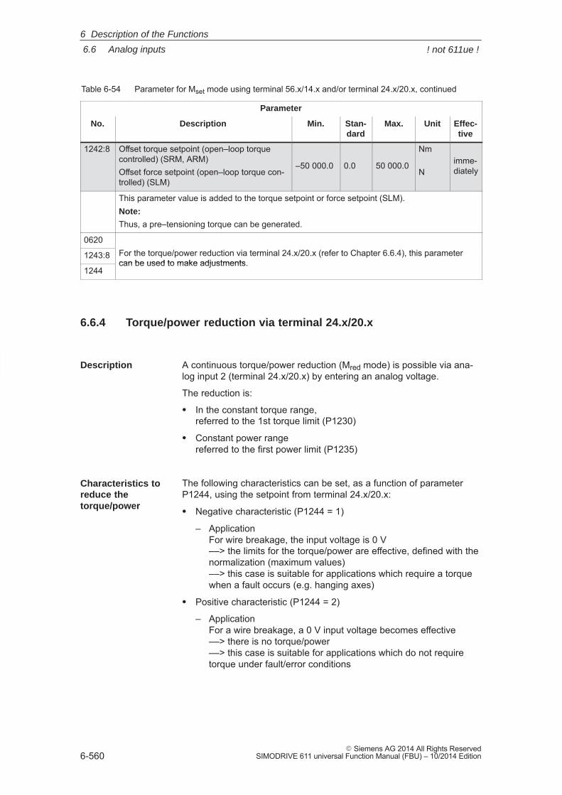
6
6.6 Analog inputs
6-560� Siemens AG 2014 All Rights Reserved
SIMODRIVE 611 universal Function Manual (FBU) – 10/2014 Edition
Table 6-54 Parameter for Mset mode using terminal 56.x/14.x and/or terminal 24.x/20.x, continued
Parameter
No. Effec-tive
UnitMax.Stan-dard
Min.Description
1242:8 Offset torque setpoint (open–loop torquecontrolled) (SRM, ARM)Offset force setpoint (open–loop torque con-trolled) (SLM)
–50 000.0 0.0 50 000.0
Nm
Nimme-diately
This parameter value is added to the torque setpoint or force setpoint (SLM).Note:
Thus, a pre–tensioning torque can be generated.
0620For the torque/power reduction via terminal 24.x/20.x (refer to Chapter 6.6.4), this parameter1243:8 For the torque/power reduction via terminal 24.x/20.x (refer to Chapter 6.6.4), this parametercan be used to make adjustments.
1244can be used to make adjustments.
6.6.4 Torque/power reduction via terminal 24.x/20.x
A continuous torque/power reduction (Mred mode) is possible via ana-log input 2 (terminal 24.x/20.x) by entering an analog voltage.
The reduction is:
� In the constant torque range,referred to the 1st torque limit (P1230)
� Constant power rangereferred to the first power limit (P1235)
The following characteristics can be set, as a function of parameterP1244, using the setpoint from terminal 24.x/20.x:
� Negative characteristic (P1244 = 1)
– ApplicationFor wire breakage, the input voltage is 0 V ––> the limits for the torque/power are effective, defined with thenormalization (maximum values) ––> this case is suitable for applications which require a torquewhen a fault occurs (e.g. hanging axes)
� Positive characteristic (P1244 = 2)
– Application For a wire breakage, a 0 V input voltage becomes effective ––> there is no torque/power––> this case is suitable for applications which do not requiretorque under fault/error conditions
Description
Characteristics toreduce thetorque/power
6 Description of the Functions
! not 611ue !
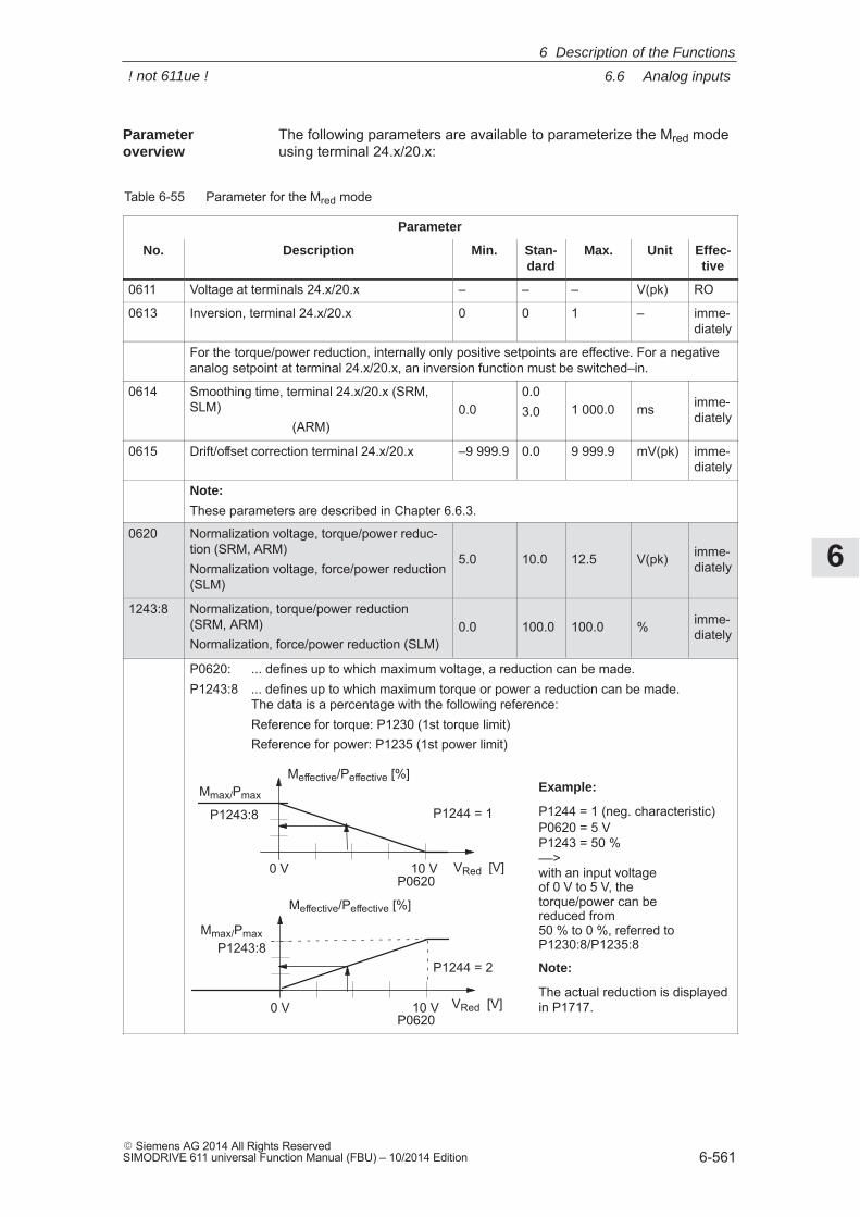
6
6.6 Analog inputs
6-561� Siemens AG 2014 All Rights ReservedSIMODRIVE 611 universal Function Manual (FBU) – 10/2014 Edition
The following parameters are available to parameterize the Mred modeusing terminal 24.x/20.x:
Table 6-55 Parameter for the Mred mode
Parameter
No. Description Min. Stan-dard
Max. Unit Effec-tive
0611 Voltage at terminals 24.x/20.x – – – V(pk) RO
0613 Inversion, terminal 24.x/20.x 0 0 1 – imme-diately
For the torque/power reduction, internally only positive setpoints are effective. For a negativeanalog setpoint at terminal 24.x/20.x, an inversion function must be switched–in.
0614 Smoothing time, terminal 24.x/20.x (SRM,SLM)
(ARM)0.0
0.03.0 1 000.0 ms imme-
diately
0615 Drift/offset correction terminal 24.x/20.x –9 999.9 0.0 9 999.9 mV(pk) imme-diately
Note:
These parameters are described in Chapter 6.6.3.
0620 Normalization voltage, torque/power reduc-tion (SRM, ARM)Normalization voltage, force/power reduction(SLM)
5.0 10.0 12.5 V(pk) imme-diately
1243:8 Normalization, torque/power reduction(SRM, ARM)Normalization, force/power reduction (SLM)
0.0 100.0 100.0 % imme-diately
P0620: ... defines up to which maximum voltage, a reduction can be made.P1243:8 ... defines up to which maximum torque or power a reduction can be made.
The data is a percentage with the following reference:Reference for torque: P1230 (1st torque limit)Reference for power: P1235 (1st power limit)
Meffective/Peffective [%]Mmax/Pmax
10 V VRed [V]
Example:
P1244 = 1 (neg. characteristic)P0620 = 5 VP1243 = 50 %––> with an input voltage of 0 V to 5 V, thetorque/power can be reduced from50 % to 0 %, referred toP1230:8/P1235:8
Note:
The actual reduction is displayedin P1717.
0 V
Meffective/Peffective [%]
Mmax/Pmax
VRed [V]
P1243:8
P1243:8
P0620
P062010 V0 V
P1244 = 1
P1244 = 2
Parameter overview
6 Description of the Functions
! not 611ue !
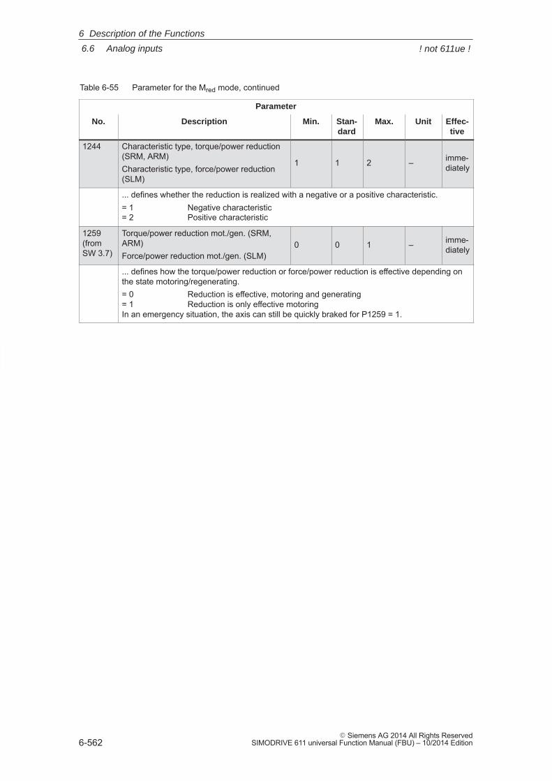
6
6.6 Analog inputs
6-562� Siemens AG 2014 All Rights Reserved
SIMODRIVE 611 universal Function Manual (FBU) – 10/2014 Edition
Table 6-55 Parameter for the Mred mode, continued
Parameter
No. Effec-tive
UnitMax.Stan-dard
Min.Description
1244 Characteristic type, torque/power reduction(SRM, ARM)Characteristic type, force/power reduction(SLM)
1 1 2 – imme-diately
... defines whether the reduction is realized with a negative or a positive characteristic.= 1 Negative characteristic= 2 Positive characteristic
1259(from SW 3.7)
Torque/power reduction mot./gen. (SRM,ARM)Force/power reduction mot./gen. (SLM)
0 0 1 – imme-diately
... defines how the torque/power reduction or force/power reduction is effective depending onthe state motoring/regenerating.= 0 Reduction is effective, motoring and generating= 1 Reduction is only effective motoringIn an emergency situation, the axis can still be quickly braked for P1259 = 1.
6 Description of the Functions
! not 611ue !
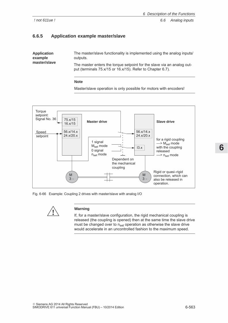
6
6.6 Analog inputs
6-563� Siemens AG 2014 All Rights ReservedSIMODRIVE 611 universal Function Manual (FBU) – 10/2014 Edition
6.6.5 Application example master/slave
The master/slave functionality is implemented using the analog inputs/outputs.
The master enters the torque setpoint for the slave via an analog out-put (terminals 75.x/15 or 16.x/15). Refer to Chapter 6.7).
Note
Master/slave operation is only possible for motors with encoders!
Speedsetpoint
1 signalMset mode0 signalnset mode
Master drive Slave drive
M3 ∼
M3 ∼
Rigid or quasi–rigidconnection, which canalso be released inoperation.
75.x/1516.x/15
56.x/14.x24.x/20.x
56.x/14.x24.x/20.x
I3.x
for a rigid coupling––> Mset modewith the couplingreleased––> nset mode
Dependent on the mechanicalcoupling
Torquesetpoint: Signal No. 36
Fig. 6-66 Example: Coupling 2 drives with master/slave with analog I/O
!Warning
If, for a master/slave configuration, the rigid mechanical coupling isreleased (the coupling is opened) then at the same time the slave drivemust be changed over to nset operation as otherwise the slave drivewould accelerate in an uncontrolled fashion to the maximum speed.
Applicationexamplemaster/slave
6 Description of the Functions
! not 611ue !
6
6.6 Analog inputs
6-564� Siemens AG 2014 All Rights Reserved
SIMODRIVE 611 universal Function Manual (FBU) – 10/2014 Edition
The following settings are necessary for the master drive:
� Setting the analog output
Term. 75.x/15 P0626 = 36 (torque setpoint (finely normalized))
P0627 = 0 (shift factor)
P0631 = 1 (overcontrol protection on)
Term. 16.x/15 P0633 = 36 (torque setpoint (finely normalized))
P0634 = 0 (shift factor)
P0638 = 1 (overcontrol protection on)
� Set DAU (D/A converter) normalization
P0625 = 50 ––> +5 V � twice the rated torque
For the slave drives the following settings are necessary:
� Set the analog input
Terminal 56.x/14.x P0607 = 1 (nset/Mset mode)
Terminal 24.x/20.x P0612 = 1 (nset/Mset mode)
� Set the normalization
P0619 = 5 (normalization voltage, torque setpoint)
P1241 = rated torque, slave–motor (normalization, torque setpoint)
� Set the digital input
Function number = 4 (open–loop torque controlled mode)
Terminal on the control board ––> refer to Chap. 6.4.2
Terminal on the optional TERMINAL module ––> refer to Chap. 6.5
Example: Settings for themaster drive
Example: Settings for theslave drive
6 Description of the Functions
6
6.7 Analog outputs
6-565� Siemens AG 2014 All Rights ReservedSIMODRIVE 611 universal Function Manual (FBU) – 10/2014 Edition
6.7 Analog outputs
There are two freely parameterizable analog outputs with the followingfeatures for each drive:
� Resolution of the DAU (D/A converter): 8 bit
� Rated operating voltage: –10 V to +10 V
� Update: in the speed controller clock cycle (P1001)
Description
6 Description of the Functions
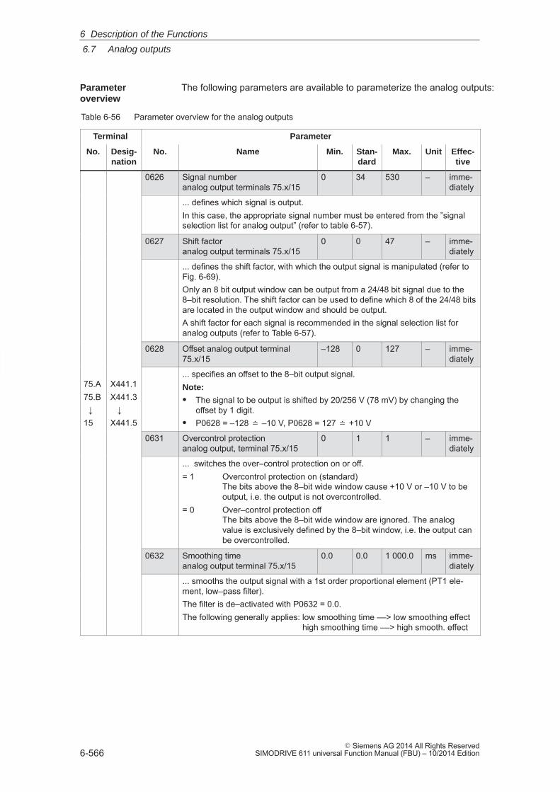
6
6.7 Analog outputs
6-566� Siemens AG 2014 All Rights Reserved
SIMODRIVE 611 universal Function Manual (FBU) – 10/2014 Edition
The following parameters are available to parameterize the analog outputs:
Table 6-56 Parameter overview for the analog outputs
Terminal Parameter
No. Desig-nation
No. Name Min. Stan-dard
Max. Unit Effec-tive
0626 Signal number analog output terminals 75.x/15
0 34 530 – imme-diately
... defines which signal is output.In this case, the appropriate signal number must be entered from the ”signalselection list for analog output” (refer to table 6-57).
0627 Shift factor analog output terminals 75.x/15
0 0 47 – imme-diately
... defines the shift factor, with which the output signal is manipulated (refer toFig. 6-69).Only an 8 bit output window can be output from a 24/48 bit signal due to the8–bit resolution. The shift factor can be used to define which 8 of the 24/48 bitsare located in the output window and should be output.A shift factor for each signal is recommended in the signal selection list foranalog outputs (refer to Table 6-57).
0628 Offset analog output terminal75.x/15
–128 0 127 – imme-diately
75.A75.B �15
X441.1X441.3 �X441.5
... specifies an offset to the 8–bit output signal.Note:
� The signal to be output is shifted by 20/256 V (78 mV) by changing theoffset by 1 digit.
� P0628 = –128 � –10 V, P0628 = 127 � +10 V
0631 Overcontrol protectionanalog output, terminal 75.x/15
0 1 1 – imme-diately
... switches the over–control protection on or off.= 1 Overcontrol protection on (standard)
The bits above the 8–bit wide window cause +10 V or –10 V to beoutput, i.e. the output is not overcontrolled.
= 0 Over–control protection offThe bits above the 8–bit wide window are ignored. The analogvalue is exclusively defined by the 8–bit window, i.e. the output canbe overcontrolled.
0632 Smoothing time analog output terminal 75.x/15
0.0 0.0 1 000.0 ms imme-diately
... smooths the output signal with a 1st order proportional element (PT1 ele-ment, low–pass filter).The filter is de–activated with P0632 = 0.0.The following generally applies: low smoothing time ––> low smoothing effect
high smoothing time ––> high smooth. effect
Parameter overview
6 Description of the Functions
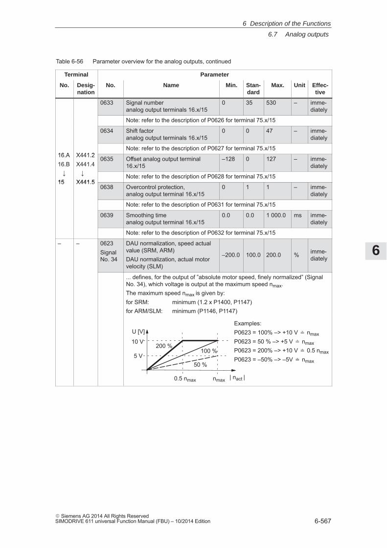
6
6.7 Analog outputs
6-567� Siemens AG 2014 All Rights ReservedSIMODRIVE 611 universal Function Manual (FBU) – 10/2014 Edition
Table 6-56 Parameter overview for the analog outputs, continued
Terminal Parameter
No. Effec-tive
UnitMax.Stan-dard
Min.NameNo.Desig-nation
0633 Signal number analog output terminals 16.x/15
0 35 530 – imme-diately
Note: refer to the description of P0626 for terminal 75.x/15
0634 Shift factor analog output terminals 16.x/15
0 0 47 – imme-diately
16.A X441.2Note: refer to the description of P0627 for terminal 75.x/15
16.A16.B �
X441.2X441.4 �
0635 Offset analog output terminal16.x/15
–128 0 127 – imme-diately
�15
�X441.5
Note: refer to the description of P0628 for terminal 75.x/1515 X441.5
0638 Overcontrol protection,analog output terminal 16.x/15
0 1 1 – imme-diately
Note: refer to the description of P0631 for terminal 75.x/15
0639 Smoothing time analog output terminal 16.x/15
0.0 0.0 1 000.0 ms imme-diately
Note: refer to the description of P0632 for terminal 75.x/15
– – 0623Signal No. 34
DAU normalization, speed actualvalue (SRM, ARM)DAU normalization, actual motorvelocity (SLM)
–200.0 100.0 200.0 % imme-diately
... defines, for the output of ”absolute motor speed, finely normalized” (SignalNo. 34), which voltage is output at the maximum speed nmax.The maximum speed nmax is given by:for SRM: minimum (1.2 x P1400, P1147)for ARM/SLM: minimum (P1146, P1147)
10 V
5 V
0.5 nmax
200 %100 %
50 %
Examples:P0623 = 100% –> +10 V � nmax
P0623 = 50 % –> +5 V � nmaxP0623 = 200% –> +10 V � 0.5 nmax
P0623 = –50% –> –5V � nmax
nmax
U [V]
| nact |
6 Description of the Functions
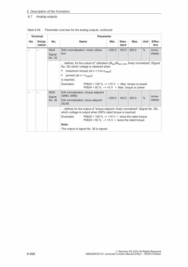
6
6.7 Analog outputs
6-568� Siemens AG 2014 All Rights Reserved
SIMODRIVE 611 universal Function Manual (FBU) – 10/2014 Edition
Table 6-56 Parameter overview for the analog outputs, continued
Terminal Parameter
No. Effec-tive
UnitMax.Stan-dard
Min.NameNo.Desig-nation
– – 0624Signal No. 35
DAU normalization, motor utiliza-tion
–200.0 100.0 200.0 % imme-diately
... defines, for the output of ”utilization (Mset/Mset, limit, finely normalized” (SignalNo. 35) which voltage is obtained when� |maximum torque| (at n = 0 to nrated)� |power| (at n > nrated).is reached.Examples: P0624 = 100 % –> +10 V � Max. torque or power
P0624 = 50 % –> +5 V � Max. torque or power
– – 0625Signal No. 36
D/A normalization, torque setpoint(SRM, ARM)D/A normalization, force setpoint(SLM)
–200.0 100.0 200.0 % imme-diately
... defines for the output of ”torque setpoint, finely normalized” (Signal No. 36),which voltage is output when 200% rated torque is reached.Examples: P0625 = 100 % –> +10 V � twice the rated torque
P0625 = 50 % –> +5 V � twice the rated torqueNote:
The output of signal No. 36 is signed.
6 Description of the Functions
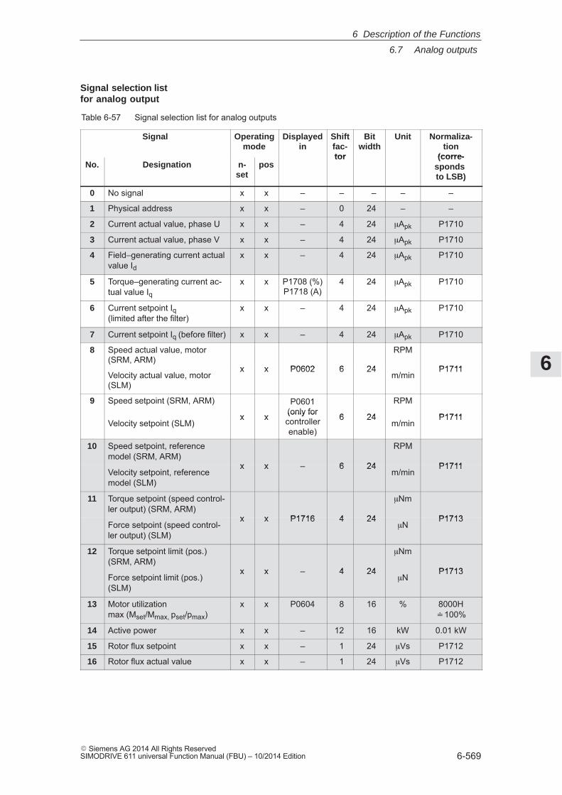
6
6.7 Analog outputs
6-569� Siemens AG 2014 All Rights ReservedSIMODRIVE 611 universal Function Manual (FBU) – 10/2014 Edition
Table 6-57 Signal selection list for analog outputs
Signal Operatingmode
Displayedin
Shiftfac-tor
Bitwidth
Unit Normaliza-tion
(corre-No. Designation n-
setpos
tor (corre-sponds to LSB)
0 No signal x x – – – – –
1 Physical address x x – 0 24 – –
2 Current actual value, phase U x x – 4 24 �Apk P1710
3 Current actual value, phase V x x – 4 24 �Apk P1710
4 Field–generating current actualvalue Id
x x – 4 24 �Apk P1710
5 Torque–generating current ac-tual value Iq
x x P1708 (%)P1718 (A)
4 24 �Apk P1710
6 Current setpoint Iq (limited after the filter)
x x – 4 24 �Apk P1710
7 Current setpoint Iq (before filter) x x – 4 24 �Apk P1710
8 Speed actual value, motor(SRM, ARM)
x x P0602 6 24
RPM
P1711Velocity actual value, motor(SLM)
x x P0602 6 24m/min
P1711
9 Speed setpoint (SRM, ARM)
x x
P0601(only for 6 24
RPM
P1711Velocity setpoint (SLM)
x x (only forcontrollerenable)
6 24m/min
P1711
10 Speed setpoint, referencemodel (SRM, ARM)
x x – 6 24
RPM
P1711Velocity setpoint, referencemodel (SLM)
x x – 6 24m/min
P1711
11 Torque setpoint (speed control-ler output) (SRM, ARM)
x x P1716 4 24
�Nm
P1713Force setpoint (speed control-ler output) (SLM)
x x P1716 4 24�N
P1713
12 Torque setpoint limit (pos.)(SRM, ARM)
x x – 4 24
�Nm
P1713Force setpoint limit (pos.)(SLM)
x x – 4 24�N
P1713
13 Motor utilization max (Mset/Mmax, pset/pmax)
x x P0604 8 16 % 8000H�100%
14 Active power x x – 12 16 kW 0.01 kW
15 Rotor flux setpoint x x – 1 24 �Vs P1712
16 Rotor flux actual value x x – 1 24 �Vs P1712
Signal selection listfor analog output
6 Description of the Functions
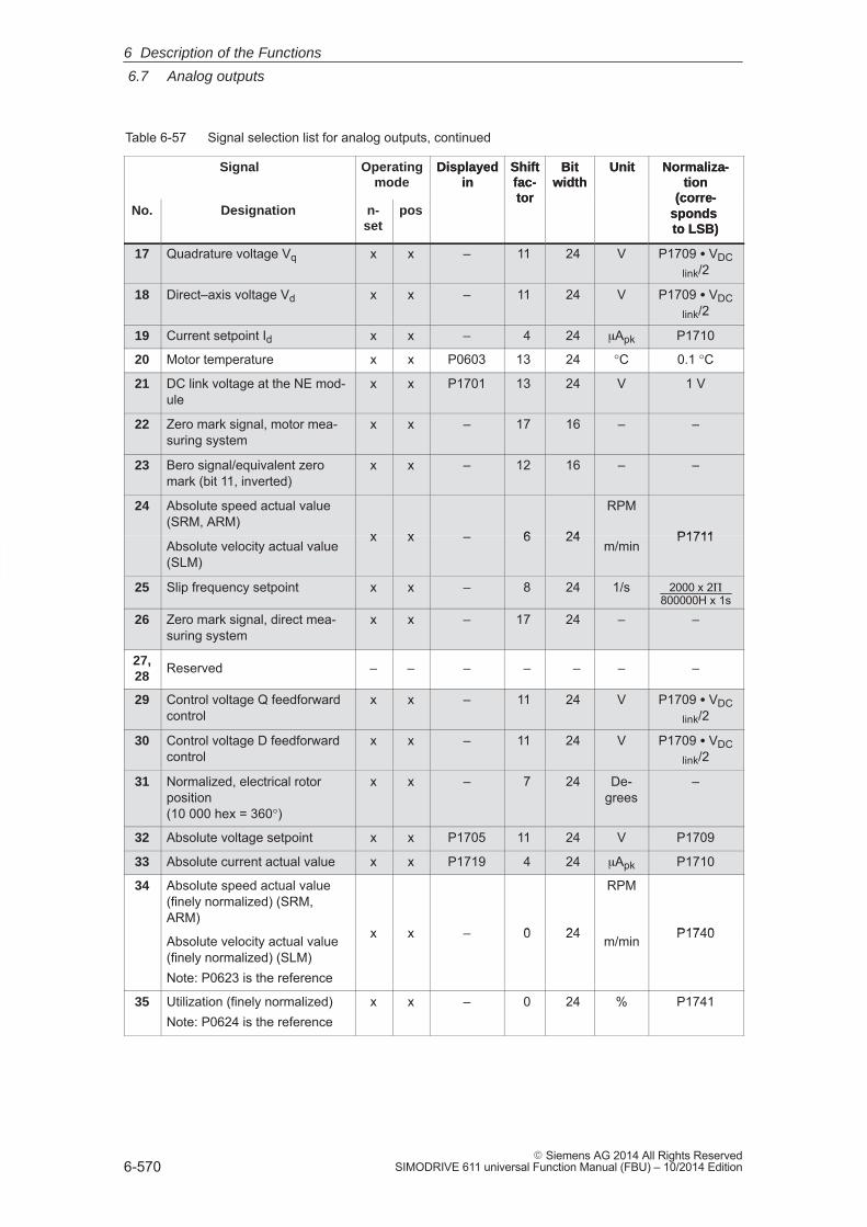
6
6.7 Analog outputs
6-570� Siemens AG 2014 All Rights Reserved
SIMODRIVE 611 universal Function Manual (FBU) – 10/2014 Edition
Table 6-57 Signal selection list for analog outputs, continued
Signal Normaliza-tion
(corre-sponds to LSB)
UnitBitwidth
Shiftfac-tor
Displayedin
Operatingmode
No.
Normaliza-tion
(corre-sponds to LSB)
UnitBitwidth
Shiftfac-tor
Displayedin
posn-set
Designation
17 Quadrature voltage Vq x x – 11 24 V P1709 � VDClink/2
18 Direct–axis voltage Vd x x – 11 24 V P1709 � VDClink/2
19 Current setpoint Id x x – 4 24 �Apk P1710
20 Motor temperature x x P0603 13 24 °C 0.1 °C
21 DC link voltage at the NE mod-ule
x x P1701 13 24 V 1 V
22 Zero mark signal, motor mea-suring system
x x – 17 16 – –
23 Bero signal/equivalent zeromark (bit 11, inverted)
x x – 12 16 – –
24 Absolute speed actual value(SRM, ARM)
x x – 6 24
RPM
P1711Absolute velocity actual value(SLM)
x x – 6 24m/min
P1711
25 Slip frequency setpoint x x – 8 24 1/s 2000 x 2�800000H x 1s
26 Zero mark signal, direct mea-suring system
x x – 17 24 – –
27,28
Reserved – – – – – – –
29 Control voltage Q feedforwardcontrol
x x – 11 24 V P1709 � VDClink/2
30 Control voltage D feedforwardcontrol
x x – 11 24 V P1709 � VDClink/2
31 Normalized, electrical rotorposition(10 000 hex = 360°)
x x – 7 24 De-grees
–
32 Absolute voltage setpoint x x P1705 11 24 V P1709
33 Absolute current actual value x x P1719 4 24 �Apk P1710
34 Absolute speed actual value(finely normalized) (SRM,ARM)
x x – 0 24
RPM
P1740Absolute velocity actual value(finely normalized) (SLM)Note: P0623 is the reference
x x – 0 24 m/min P1740
35 Utilization (finely normalized)Note: P0624 is the reference
x x – 0 24 % P1741
6 Description of the Functions
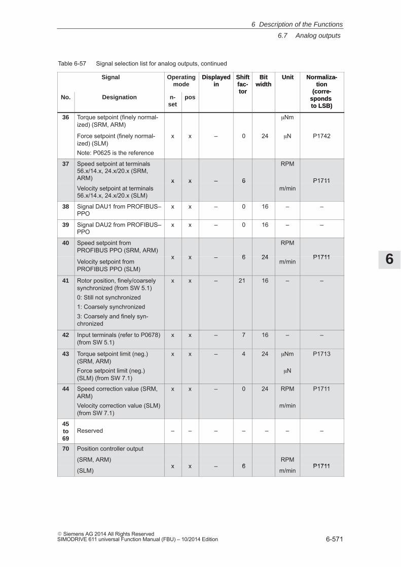
6
6.7 Analog outputs
6-571� Siemens AG 2014 All Rights ReservedSIMODRIVE 611 universal Function Manual (FBU) – 10/2014 Edition
Table 6-57 Signal selection list for analog outputs, continued
Signal Normaliza-tion
(corre-sponds to LSB)
UnitBitwidth
Shiftfac-tor
Displayedin
Operatingmode
No.
Normaliza-tion
(corre-sponds to LSB)
UnitBitwidth
Shiftfac-tor
Displayedin
posn-set
Designation
36 Torque setpoint (finely normal-ized) (SRM, ARM)
�Nm
Force setpoint (finely normal-ized) (SLM)Note: P0625 is the reference
x x – 0 24 �N P1742
37 Speed setpoint at terminals56.x/14.x, 24.x/20.x (SRM,ARM) x x – 6
RPM
P1711Velocity setpoint at terminals56.x/14.x, 24.x/20.x (SLM)
x x – 6m/min
P1711
38 Signal DAU1 from PROFIBUS–PPO
x x – 0 16 – –
39 Signal DAU2 from PROFIBUS–PPO
x x – 0 16 – –
40 Speed setpoint from PROFIBUS PPO (SRM, ARM)
x x – 6 24
RPM
P1711Velocity setpoint fromPROFIBUS PPO (SLM)
x x – 6 24m/min
P1711
41 Rotor position, finely/coarselysynchronized (from SW 5.1)0: Still not synchronized1: Coarsely synchronized3: Coarsely and finely syn-chronized
x x – 21 16 – –
42 Input terminals (refer to P0678)(from SW 5.1)
x x – 7 16 – –
43 Torque setpoint limit (neg.)(SRM, ARM)Force setpoint limit (neg.)(SLM) (from SW 7.1)
x x – 4 24 �Nm
�N
P1713
44 Speed correction value (SRM,ARM)Velocity correction value (SLM)(from SW 7.1)
x x – 0 24 RPM
m/min
P1711
45to69
Reserved – – – – – – –
70 Position controller output
(SRM, ARM)x x – 6
RPMP1711
(SLM)x x – 6
m/minP1711
6 Description of the Functions
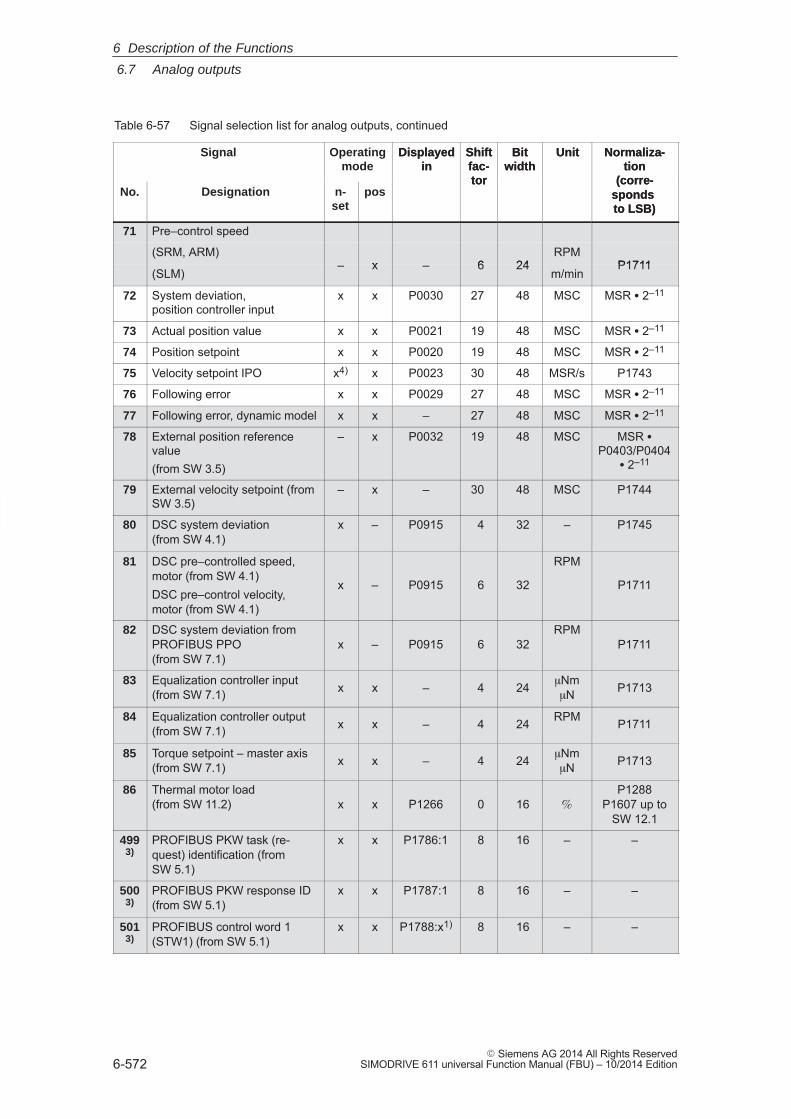
6
6.7 Analog outputs
6-572� Siemens AG 2014 All Rights Reserved
SIMODRIVE 611 universal Function Manual (FBU) – 10/2014 Edition
Table 6-57 Signal selection list for analog outputs, continued
Signal Normaliza-tion
(corre-sponds to LSB)
UnitBitwidth
Shiftfac-tor
Displayedin
Operatingmode
No.
Normaliza-tion
(corre-sponds to LSB)
UnitBitwidth
Shiftfac-tor
Displayedin
posn-set
Designation
71 Pre–control speed
(SRM, ARM)– x – 6 24
RPMP1711
(SLM)– x – 6 24
m/minP1711
72 System deviation, position controller input
x x P0030 27 48 MSC MSR � 2–11
73 Actual position value x x P0021 19 48 MSC MSR � 2–11
74 Position setpoint x x P0020 19 48 MSC MSR � 2–11
75 Velocity setpoint IPO x4) x P0023 30 48 MSR/s P1743
76 Following error x x P0029 27 48 MSC MSR � 2–11
77 Following error, dynamic model x x – 27 48 MSC MSR � 2–11
78 External position referencevalue(from SW 3.5)
– x P0032 19 48 MSC MSR �P0403/P0404
� 2–11
79 External velocity setpoint (fromSW 3.5)
– x – 30 48 MSC P1744
80 DSC system deviation(from SW 4.1)
x – P0915 4 32 – P1745
81 DSC pre–controlled speed,motor (from SW 4.1)DSC pre–control velocity,motor (from SW 4.1)
x – P0915 6 32
RPM
P1711
82 DSC system deviation from PROFIBUS PPO(from SW 7.1)
x – P0915 6 32RPM
P1711
83 Equalization controller input(from SW 7.1) x x – 4 24 �Nm
�N P1713
84 Equalization controller output(from SW 7.1) x x – 4 24 RPM P1711
85 Torque setpoint – master axis(from SW 7.1) x x – 4 24 �Nm
�N P1713
86 Thermal motor load (from SW 11.2) x x P1266 0 16 �
P1288P1607 up to
SW 12.1
4993)
PROFIBUS PKW task (re-quest) identification (fromSW 5.1)
x x P1786:1 8 16 – –
5003)
PROFIBUS PKW response ID(from SW 5.1)
x x P1787:1 8 16 – –
5013)
PROFIBUS control word 1(STW1) (from SW 5.1)
x x P1788:x1) 8 16 – –
6 Description of the Functions
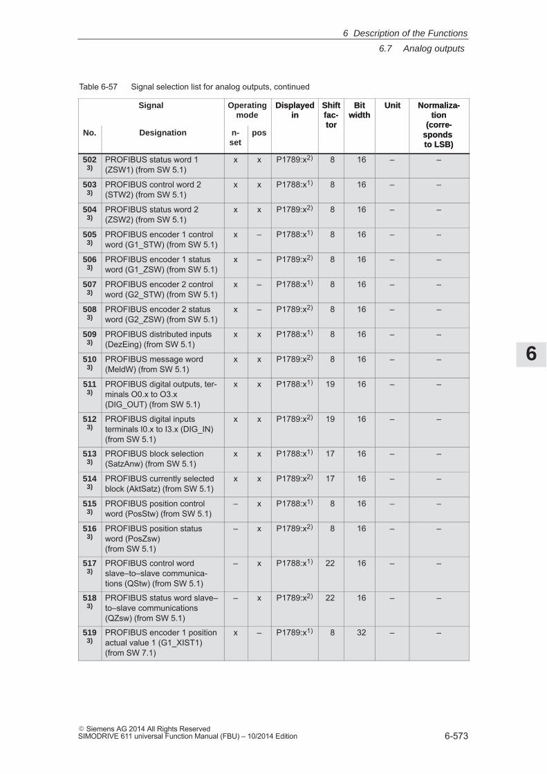
6
6.7 Analog outputs
6-573� Siemens AG 2014 All Rights ReservedSIMODRIVE 611 universal Function Manual (FBU) – 10/2014 Edition
Table 6-57 Signal selection list for analog outputs, continued
Signal Normaliza-tion
(corre-sponds to LSB)
UnitBitwidth
Shiftfac-tor
Displayedin
Operatingmode
No.
Normaliza-tion
(corre-sponds to LSB)
UnitBitwidth
Shiftfac-tor
Displayedin
posn-set
Designation
5023)
PROFIBUS status word 1(ZSW1) (from SW 5.1)
x x P1789:x2) 8 16 – –
5033)
PROFIBUS control word 2(STW2) (from SW 5.1)
x x P1788:x1) 8 16 – –
5043)
PROFIBUS status word 2(ZSW2) (from SW 5.1)
x x P1789:x2) 8 16 – –
5053)
PROFIBUS encoder 1 controlword (G1_STW) (from SW 5.1)
x – P1788:x1) 8 16 – –
5063)
PROFIBUS encoder 1 statusword (G1_ZSW) (from SW 5.1)
x – P1789:x2) 8 16 – –
5073)
PROFIBUS encoder 2 controlword (G2_STW) (from SW 5.1)
x – P1788:x1) 8 16 – –
5083)
PROFIBUS encoder 2 statusword (G2_ZSW) (from SW 5.1)
x – P1789:x2) 8 16 – –
5093)
PROFIBUS distributed inputs(DezEing) (from SW 5.1)
x x P1788:x1) 8 16 – –
5103)
PROFIBUS message word(MeldW) (from SW 5.1)
x x P1789:x2) 8 16 – –
5113)
PROFIBUS digital outputs, ter-minals O0.x to O3.x(DIG_OUT) (from SW 5.1)
x x P1788:x1) 19 16 – –
5123)
PROFIBUS digital inputsterminals I0.x to I3.x (DIG_IN)(from SW 5.1)
x x P1789:x2) 19 16 – –
5133)
PROFIBUS block selection(SatzAnw) (from SW 5.1)
x x P1788:x1) 17 16 – –
5143)
PROFIBUS currently selectedblock (AktSatz) (from SW 5.1)
x x P1789:x2) 17 16 – –
5153)
PROFIBUS position controlword (PosStw) (from SW 5.1)
– x P1788:x1) 8 16 – –
5163)
PROFIBUS position statusword (PosZsw) (from SW 5.1)
– x P1789:x2) 8 16 – –
5173)
PROFIBUS control wordslave–to–slave communica-tions (QStw) (from SW 5.1)
– x P1788:x1) 22 16 – –
5183)
PROFIBUS status word slave–to–slave communications(QZsw) (from SW 5.1)
– x P1789:x2) 22 16 – –
5193)
PROFIBUS encoder 1 positionactual value 1 (G1_XIST1)(from SW 7.1)
x – P1789:x1) 8 32 – –
6 Description of the Functions
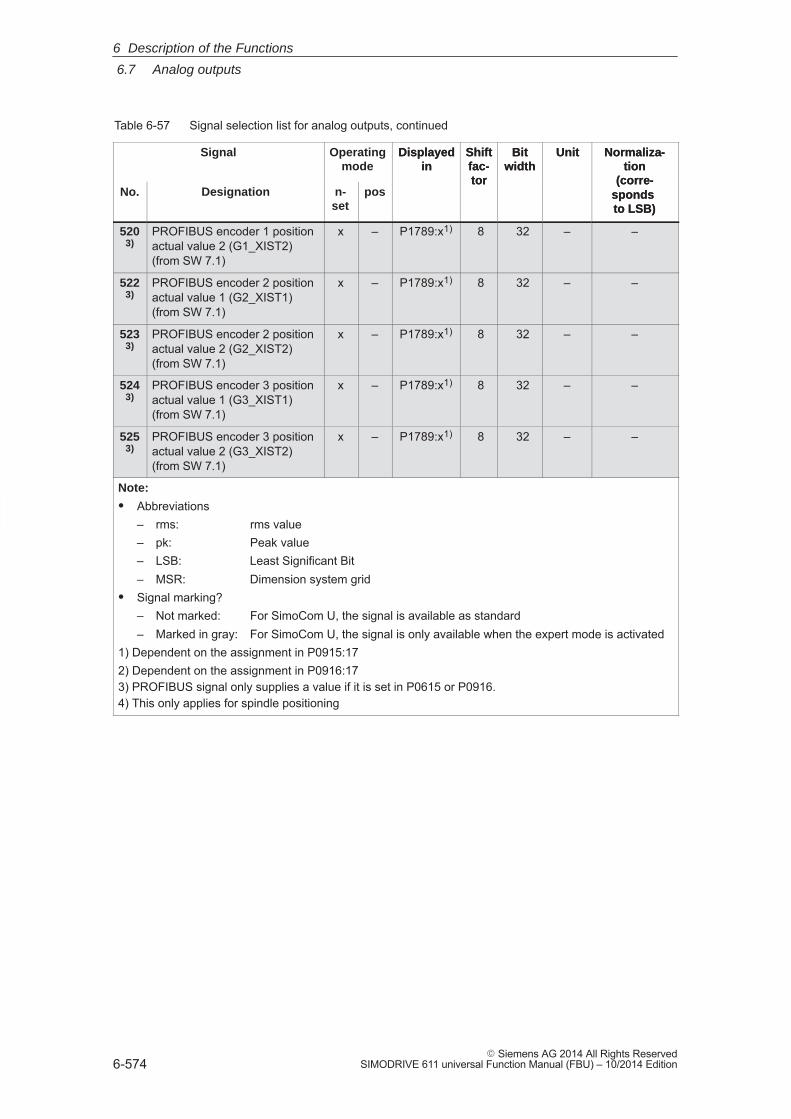
6
6.7 Analog outputs
6-574� Siemens AG 2014 All Rights Reserved
SIMODRIVE 611 universal Function Manual (FBU) – 10/2014 Edition
Table 6-57 Signal selection list for analog outputs, continued
Signal Normaliza-tion
(corre-sponds to LSB)
UnitBitwidth
Shiftfac-tor
Displayedin
Operatingmode
No.
Normaliza-tion
(corre-sponds to LSB)
UnitBitwidth
Shiftfac-tor
Displayedin
posn-set
Designation
5203)
PROFIBUS encoder 1 positionactual value 2 (G1_XIST2)(from SW 7.1)
x – P1789:x1) 8 32 – –
5223)
PROFIBUS encoder 2 positionactual value 1 (G2_XIST1)(from SW 7.1)
x – P1789:x1) 8 32 – –
5233)
PROFIBUS encoder 2 positionactual value 2 (G2_XIST2)(from SW 7.1)
x – P1789:x1) 8 32 – –
5243)
PROFIBUS encoder 3 positionactual value 1 (G3_XIST1)(from SW 7.1)
x – P1789:x1) 8 32 – –
5253)
PROFIBUS encoder 3 positionactual value 2 (G3_XIST2)(from SW 7.1)
x – P1789:x1) 8 32 – –
Note:
� Abbreviations– rms: rms value– pk: Peak value– LSB: Least Significant Bit– MSR: Dimension system grid
� Signal marking?– Not marked: For SimoCom U, the signal is available as standard– Marked in gray: For SimoCom U, the signal is only available when the expert mode is activated
1) Dependent on the assignment in P0915:172) Dependent on the assignment in P0916:173) PROFIBUS signal only supplies a value if it is set in P0615 or P0916.4) This only applies for spindle positioning
6 Description of the Functions
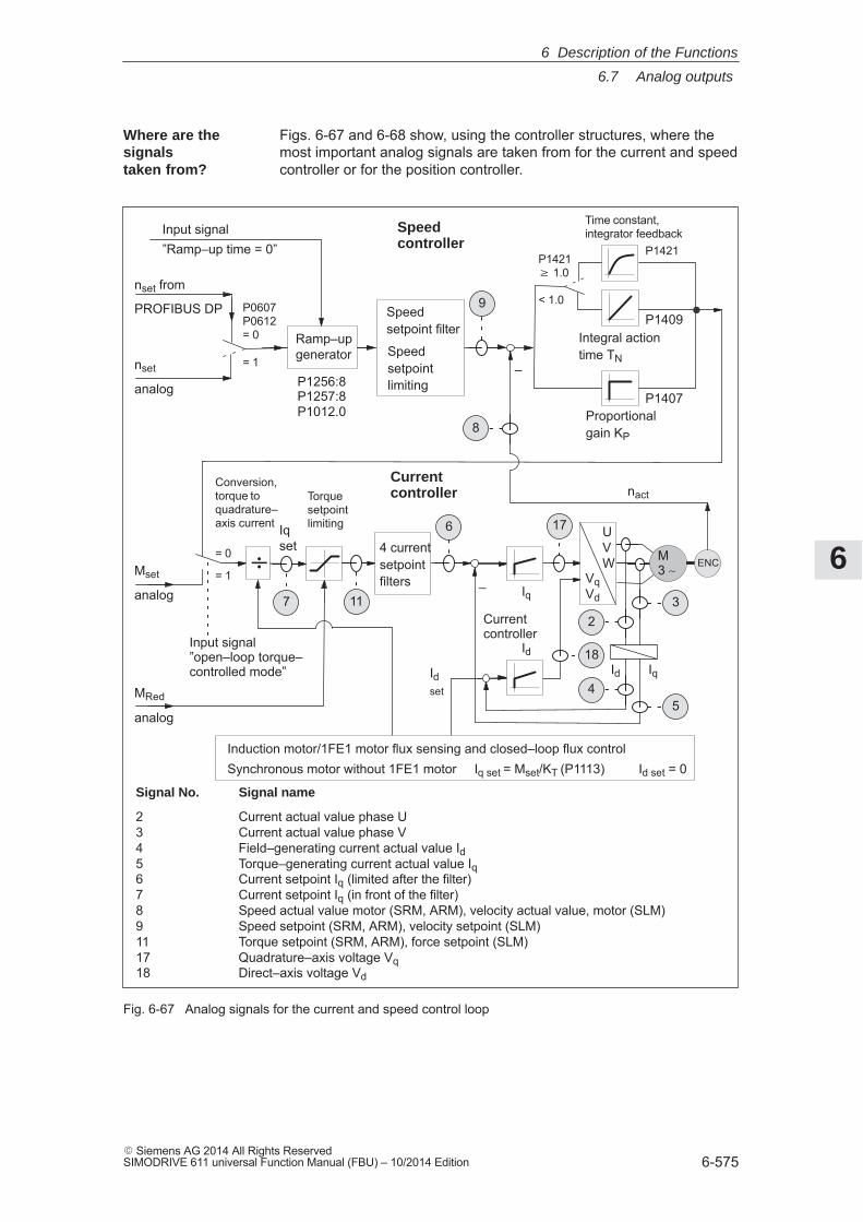
6
6.7 Analog outputs
6-575� Siemens AG 2014 All Rights ReservedSIMODRIVE 611 universal Function Manual (FBU) – 10/2014 Edition
Figs. 6-67 and 6-68 show, using the controller structures, where themost important analog signals are taken from for the current and speedcontroller or for the position controller.
Torquesetpointlimiting
Proportionalgain KP
Integral actiontime TN
Currentcontroller
MRed
analog
Speedcontroller
Input signal ”Ramp–up time = 0”
Input signal ”open–loop torque–controlled mode”
P1256:8P1257:8P1012.0
P1409
P1407
Currentcontroller
–
IqId
–Mset
analog
nset
analog
Time constant, integrator feedback
P1421P1421 � 1.0
< 1.0P0607P0612= 0
= 1
nset from
PROFIBUS DP
Ramp–upgenerator
4 currentsetpointfilters
= 0
= 1ENC
Id
Iq
Induction motor/1FE1 motor flux sensing and closed–loop flux controlSynchronous motor without 1FE1 motor Iq set = Mset/KT (P1113) Id set = 0
Idset
Iqset
Conversion,torque toquadrature–axis current
nact
VqVd
UVW M
3 ∼
Signal No. Signal name
2 Current actual value phase U 3 Current actual value phase V 4 Field–generating current actual value Id 5 Torque–generating current actual value Iq 6 Current setpoint Iq (limited after the filter)7 Current setpoint Iq (in front of the filter) 8 Speed actual value motor (SRM, ARM), velocity actual value, motor (SLM)9 Speed setpoint (SRM, ARM), velocity setpoint (SLM) 11 Torque setpoint (SRM, ARM), force setpoint (SLM) 17 Quadrature–axis voltage Vq 18 Direct–axis voltage Vd
9Speedsetpoint filter
Speedsetpointlimiting
÷
23
4
17
5
8
6
117
18
Fig. 6-67 Analog signals for the current and speed control loop
Where are the signalstaken from?
6 Description of the Functions
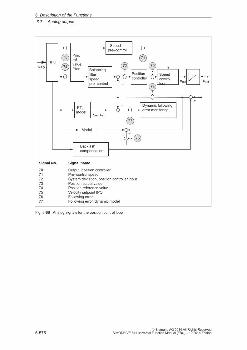
6
6.7 Analog outputs
6-576� Siemens AG 2014 All Rights Reserved
SIMODRIVE 611 universal Function Manual (FBU) – 10/2014 Edition
Dynamic followingerror monitoring
xact
–
–
xset, ber
FIPO
nact
Model
xIPO
–
Speedpre–control
Backlashcompensation
PT1model
+
Speedcontrolloop
Positioncontroller
75 71
74 72 70
73
76
77
Signal No. Signal name
70 Output, position controller 71 Pre–control speed 72 System deviation, position controller input 73 Position actual value 74 Position reference value 75 Velocity setpoint IPO76 Following error 77 Following error, dynamic model
Pos.ref.valuefilter Balancing
filter speedpre–control
Fig. 6-68 Analog signals for the position control loop
6 Description of the Functions
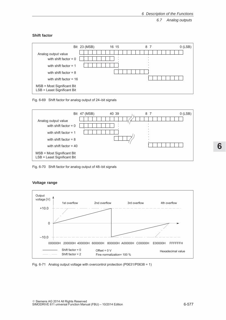
6
6.7 Analog outputs
6-577� Siemens AG 2014 All Rights ReservedSIMODRIVE 611 universal Function Manual (FBU) – 10/2014 Edition
0 (LSB)23 (MSB)Bit 781516
with shift factor = 0
with shift factor = 1
with shift factor = 8
with shift factor = 16
MSB = Most Significant BitLSB = Least Significant Bit
Analog output value
Fig. 6-69 Shift factor for analog output of 24–bit signals
0 (LSB)47 (MSB)Bit 783940
with shift factor = 0
with shift factor = 1
with shift factor = 8
with shift factor = 40
Analog output value
MSB = Most Significant BitLSB = Least Significant Bit
Fig. 6-70 Shift factor for analog output of 48–bit signals
Shift factor = 0Shift factor = 2
200000H
–10.0
0
+10.0
Output voltage [V]
000000H 400000H 600000H 800000H A00000H C00000H E00000H FFFFFFH
1st overflow 2nd overflow 3rd overflow 4th overflow
Offset = 0 VFine normalization= 100 %
Hexadecimal value
Fig. 6-71 Analog output voltage with overcontrol protection (P0631/P0638 = 1)
Shift factor
Voltage range
6 Description of the Functions
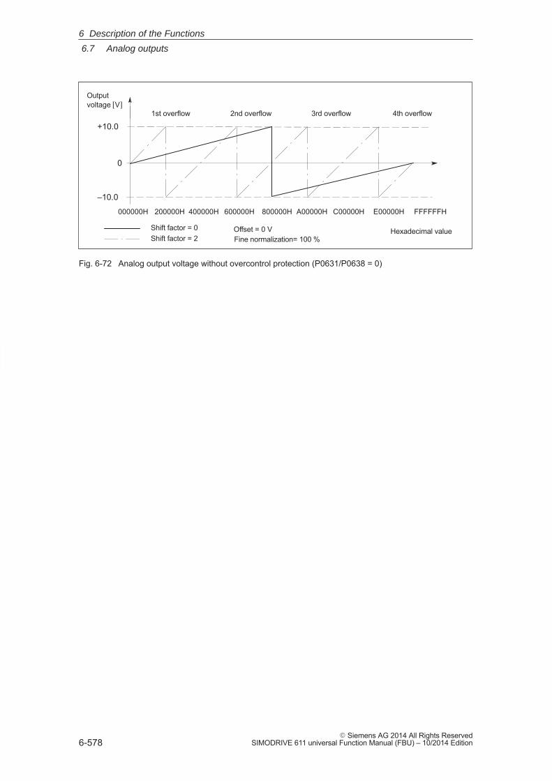
6
6.7 Analog outputs
6-578� Siemens AG 2014 All Rights Reserved
SIMODRIVE 611 universal Function Manual (FBU) – 10/2014 Edition
Shift factor = 0Shift factor = 2
200000H
–10.0
0
+10.0
Output voltage [V]
000000H 400000H 600000H 800000H A00000H C00000H E00000H FFFFFFH
1st overflow 2nd overflow 3rd overflow 4th overflow
Offset = 0 VFine normalization= 100 %
Hexadecimal value
Fig. 6-72 Analog output voltage without overcontrol protection (P0631/P0638 = 0)
6 Description of the Functions
6
6.8 Angular incremental encoder interface (X461, X462)
6-579� Siemens AG 2014 All Rights ReservedSIMODRIVE 611 universal Function Manual (FBU) – 10/2014 Edition
6.8 Angular incremental encoder interface (X461, X462)
Incremental setpoints can be read–in (input, from SW 3.3) and incre-mental actual values output via this interface.
An electronic handwheel can be connected to this interface (from SW 8.1).
� Incremental position actual value is output via the angular incremen-tal encoder interface
––> P0890 = 1––> the interface is switched as output––> refer to Chapter6.8.1
The incremental position actual value of the drive is output via theinterface. The actual value can be used by a high–level control.
Notice
The control board only supplies ”correct” angular incremental encodersignals after it has been completely booted. In order that a higher–level control does not go into a fault condition,the control board must first run up, before the angular incrementalencoder interface signals can be evaluated. The criterion for this is the”ready” signal.
Switch–on sequence (e.g.): ”SIMODRIVE 611 universal” control board ––> higher–level control
� Enter the incremental position setpoint value via the angular incre-mental encoder interface (from SW 3.3)
––> P0890 = 2––> the interface is switched as input ––> refer to Chapter 6.8.2
An incremental position reference value can be entered via the interface.
Description
6 Description of the Functions
! not 611ue !
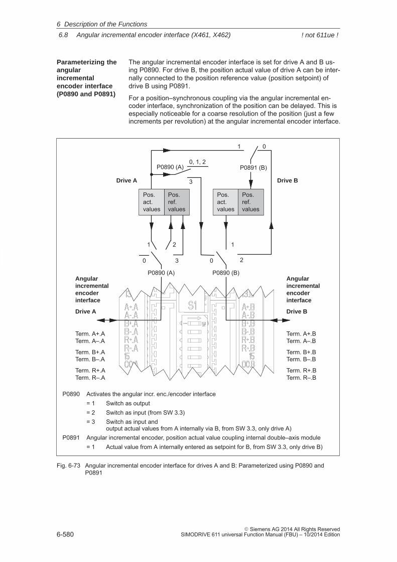
6
6.8 Angular incremental encoder interface (X461, X462)
6-580� Siemens AG 2014 All Rights Reserved
SIMODRIVE 611 universal Function Manual (FBU) – 10/2014 Edition
The angular incremental encoder interface is set for drive A and B us-ing P0890. For drive B, the position actual value of drive A can be inter-nally connected to the position reference value (position setpoint) ofdrive B using P0891.
For a position–synchronous coupling via the angular incremental en-coder interface, synchronization of the position can be delayed. This isespecially noticeable for a coarse resolution of the position (just a fewincrements per revolution) at the angular incremental encoder interface.
P0890 Activates the angular incr. enc./encoder interface= 1 Switch as output= 2 Switch as input (from SW 3.3)= 3 Switch as input and
output actual values from A internally via B, from SW 3.3, only drive A)P0891 Angular incremental encoder, position actual value coupling internal double–axis module = 1 Actual value from A internally entered as setpoint for B, from SW 3.3, only drive B)
0
1 2
P0890 (A)
0
1
2
01
P0891 (B)
3
Angularincremental encoderinterface
Drive A
Term. A+.ATerm. A–.A
Term. B+.ATerm. B–.A
Term. R+.ATerm. R–.A
Pos.act.values
Pos.ref.values
Pos.act.values
Pos.ref.values
0, 1, 2
3
P0890 (A) P0890 (B)Angularincremental encoderinterface
Drive B
Term. A+.BTerm. A–.B
Term. B+.BTerm. B–.B
Term. R+.BTerm. R–.B
Drive A Drive B
Fig. 6-73 Angular incremental encoder interface for drives A and B: Parameterized using P0890 andP0891
Parameterizing theangularincrementalencoder interface(P0890 and P0891)
6 Description of the Functions
! not 611ue !
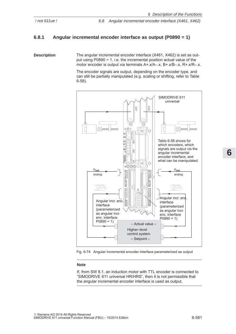
6
6.8 Angular incremental encoder interface (X461, X462)
6-581� Siemens AG 2014 All Rights ReservedSIMODRIVE 611 universal Function Manual (FBU) – 10/2014 Edition
6.8.1 Angular incremental encoder interface as output (P0890 = 1)
The angular incremental encoder interface (X461, X462) is set as out-put using P0890 = 1, i.e. the incremental position actual value of themotor encoder is output via terminals A+.x/A–.x, B+.x/B–.x, R+.x/R–.x.
The encoder signals are output, depending on the encoder type, andcan still be partially manipulated (e.g. scaling or shifting, refer to Table6-58).
Higher–levelcontrol system
SIMODRIVE 611 universal
Angular incr. enc.interface(parameterizedas angular incr.enc. interfaceP0890 = 1)
nsetanalog
– Setpoint –
– Actual value –
Table 6-58 shows for which encoders, whichsignals are output via theangular incrementalencoder interface, andwhat can be manipulated.
nsetanalog
Angular incr. enc.interface(parameterizedas angular incr.enc. interfaceP0890 = 1)
Fig. 6-74 Angular incremental encoder interface parameterized as output
Note
If, from SW 8.1, an induction motor with TTL encoder is connected to”SIMODRIVE 611 universal HR/HRS”, then it is not permissible thatthe angular incremental encoder interface is used as output.
Description
6 Description of the Functions
! not 611ue !
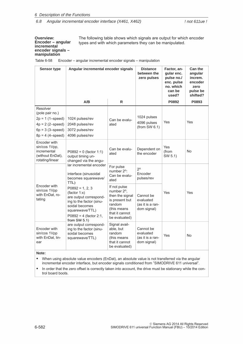
6
6.8 Angular incremental encoder interface (X461, X462)
6-582� Siemens AG 2014 All Rights Reserved
SIMODRIVE 611 universal Function Manual (FBU) – 10/2014 Edition
The following table shows which signals are output for which encodertypes and with which parameters they can be manipulated.
Table 6-58 Encoder – angular incremental encoder signals – manipulation
Sensor type Angular incremental encoder signals Distancebetween the zero pulses
Factor, an-gular enc.pulse no./enc. pulseno. which
can beused?
Can the angular increm. encoder
zero pulse beshifted?
A/B R P0892 P0893
Resolver (pole pair no.)2p = 1 (1–speed)4p = 2 (2–speed)6p = 3 (3–speed)8p = 4 (4–speed)
1024 pulses/rev2048 pulses/rev3072 pulses/rev4096 pulses/rev
Can be evalu-ated
1024 pulses4096 pulses(from SW 6.1)
Yes Yes
Encoder with sin/cos 1Vpp, incremental(without EnDat), rotating/linear
P0892 = 0 (factor 1:1)output timing un-changed via the angu-lar incremental encoder
Can be evalu-ated
Dependent onthe encoder
Yes(fromSW 5.1)
No
changed via the angu-lar incremental encoder
interface (sinusoidalbecomes squarewave/TTL)
For pulsenumber 2n:Can be evalu-ated
2n Encoderpulses/rev
Encoder withsin/cos 1Vppwith EnDat, ro-tating
TTL)P0892 = 1, 2, 3 (factor 1:x)are output correspond-ing to the factor (sinu-soidal becomessquarewave/TTL)P0892 = 4 (factor 2:1,from SW 5.1)
If not pulsenumber 2n,then the signalis present butrandom(this meansthat it cannotbe evaluated)
Cannot beevaluated(as it is a ran-dom signal)
Yes Yes
Encoder withsin/cos 1Vppwith EnDat, lin-ear
from SW 5.1)are output correspond-ing to the factor (sinu-soidal becomessquarewave/TTL)
Signal avail-able, butrandom(this meansthat it cannotbe evaluated)
Cannot beevaluated(as it is a ran-dom signal)
Yes No
Note:
� When using absolute value encoders (EnDat), an absolute value is not transferred via the angularincremental encoder interface, but encoder signals conditioned from ”SIMODRIVE 611 universal”.
� In order that the zero offset is correctly taken into account, the drive must be stationary while the con-trol board boots.
Overview: Encoder – angularincrementalencoder signals –manipulation
6 Description of the Functions
! not 611ue !
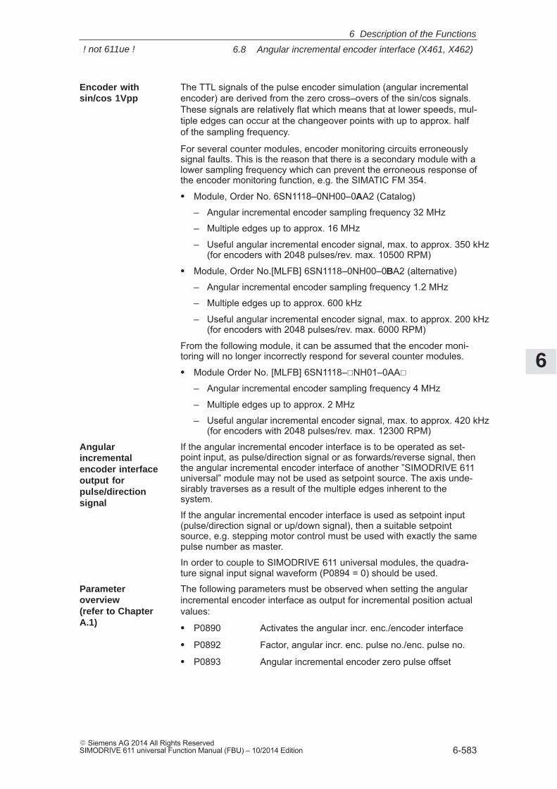
6
6.8 Angular incremental encoder interface (X461, X462)
6-583� Siemens AG 2014 All Rights ReservedSIMODRIVE 611 universal Function Manual (FBU) – 10/2014 Edition
The TTL signals of the pulse encoder simulation (angular incrementalencoder) are derived from the zero cross–overs of the sin/cos signals.These signals are relatively flat which means that at lower speeds, mul-tiple edges can occur at the changeover points with up to approx. halfof the sampling frequency.
For several counter modules, encoder monitoring circuits erroneouslysignal faults. This is the reason that there is a secondary module with alower sampling frequency which can prevent the erroneous response ofthe encoder monitoring function, e.g. the SIMATIC FM 354.
� Module, Order No. 6SN1118–0NH00–0AA2 (Catalog)
– Angular incremental encoder sampling frequency 32 MHz
– Multiple edges up to approx. 16 MHz
– Useful angular incremental encoder signal, max. to approx. 350 kHz(for encoders with 2048 pulses/rev. max. 10500 RPM)
� Module, Order No.[MLFB] 6SN1118–0NH00–0BA2 (alternative)
– Angular incremental encoder sampling frequency 1.2 MHz
– Multiple edges up to approx. 600 kHz
– Useful angular incremental encoder signal, max. to approx. 200 kHz(for encoders with 2048 pulses/rev. max. 6000 RPM)
From the following module, it can be assumed that the encoder moni-toring will no longer incorrectly respond for several counter modules.
� Module Order No. [MLFB] 6SN1118–�NH01–0AA�
– Angular incremental encoder sampling frequency 4 MHz
– Multiple edges up to approx. 2 MHz
– Useful angular incremental encoder signal, max. to approx. 420 kHz(for encoders with 2048 pulses/rev. max. 12300 RPM)
If the angular incremental encoder interface is to be operated as set-point input, as pulse/direction signal or as forwards/reverse signal, thenthe angular incremental encoder interface of another ”SIMODRIVE 611universal” module may not be used as setpoint source. The axis unde-sirably traverses as a result of the multiple edges inherent to thesystem.
If the angular incremental encoder interface is used as setpoint input(pulse/direction signal or up/down signal), then a suitable setpointsource, e.g. stepping motor control must be used with exactly the samepulse number as master.
In order to couple to SIMODRIVE 611 universal modules, the quadra-ture signal input signal waveform (P0894 = 0) should be used.
The following parameters must be observed when setting the angularincremental encoder interface as output for incremental position actualvalues:
� P0890 Activates the angular incr. enc./encoder interface
� P0892 Factor, angular incr. enc. pulse no./enc. pulse no.
� P0893 Angular incremental encoder zero pulse offset
Encoder withsin/cos 1Vpp
Angularincrementalencoder interfaceoutput forpulse/directionsignal
Parameteroverview(refer to ChapterA.1)
6 Description of the Functions
! not 611ue !
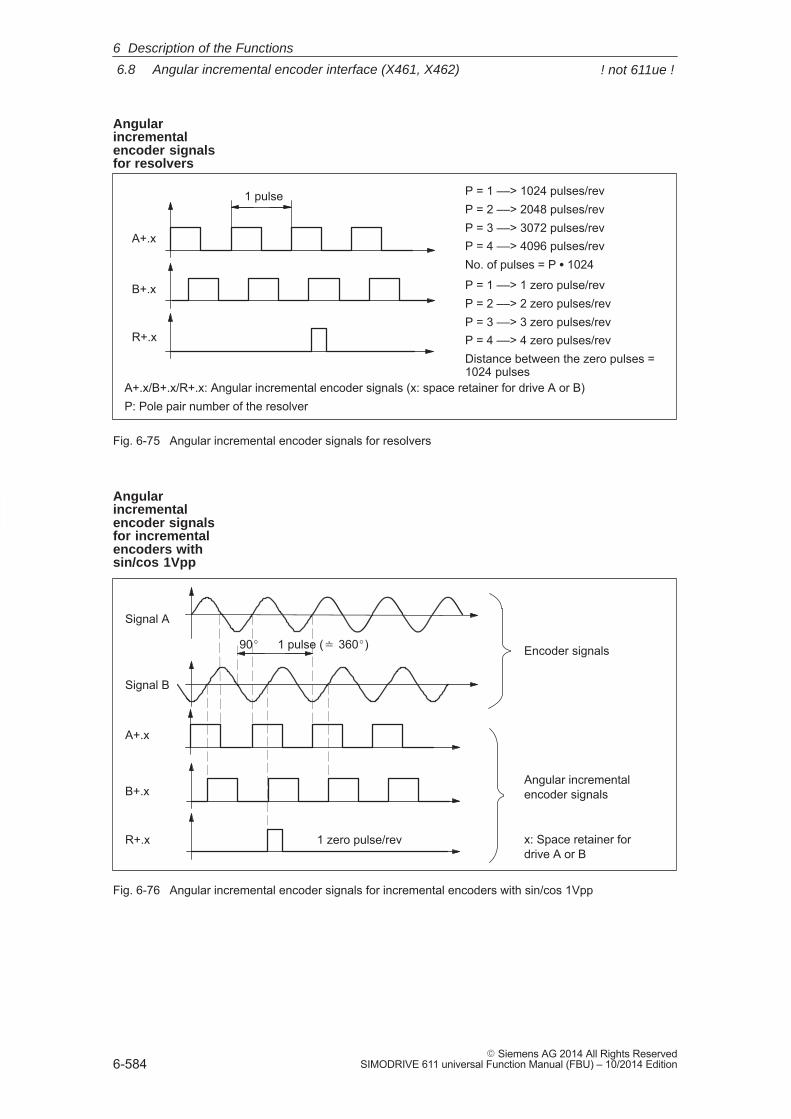
6
6.8 Angular incremental encoder interface (X461, X462)
6-584� Siemens AG 2014 All Rights Reserved
SIMODRIVE 611 universal Function Manual (FBU) – 10/2014 Edition
A+.x
B+.x
R+.x
P = 1 ––> 1024 pulses/revP = 2 ––> 2048 pulses/revP = 3 ––> 3072 pulses/revP = 4 ––> 4096 pulses/revNo. of pulses = P � 1024
P = 1 ––> 1 zero pulse/revP = 2 ––> 2 zero pulses/revP = 3 ––> 3 zero pulses/revP = 4 ––> 4 zero pulses/revDistance between the zero pulses =1024 pulses
1 pulse
A+.x/B+.x/R+.x: Angular incremental encoder signals (x: space retainer for drive A or B)P: Pole pair number of the resolver
Fig. 6-75 Angular incremental encoder signals for resolvers
Signal A
Signal B
A+.x
B+.x
R+.x 1 zero pulse/rev
Encoder signals
Angular incrementalencoder signals
x: Space retainer fordrive A or B
1 pulse (� 360�)90�
Fig. 6-76 Angular incremental encoder signals for incremental encoders with sin/cos 1Vpp
Angularincrementalencoder signalsfor resolvers
Angularincrementalencoder signals for incrementalencoders with sin/cos 1Vpp
6 Description of the Functions
! not 611ue !
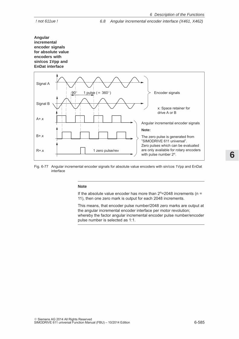
6
6.8 Angular incremental encoder interface (X461, X462)
6-585� Siemens AG 2014 All Rights ReservedSIMODRIVE 611 universal Function Manual (FBU) – 10/2014 Edition
Signal A
Signal B
A+.x
B+.x
R+.x 1 zero pulse/rev
Encoder signals
Angular incremental encoder signals
Note:
The zero pulse is generated from”SIMODRIVE 611 universal”. Zero pulses which can be evaluatedare only available for rotary encoderswith pulse number 2n.
1 pulse (� 360�)90�
x: Space retainer fordrive A or B
Fig. 6-77 Angular incremental encoder signals for absolute value encoders with sin/cos 1Vpp and EnDatinterface
Note
If the absolute value encoder has more than 2n=2048 increments (n =11), then one zero mark is output for each 2048 increments.
This means, that encoder pulse number/2048 zero marks are output atthe angular incremental encoder interface per motor revolution;whereby the factor angular incremental encoder pulse number/encoderpulse number is selected as 1:1.
Angularincrementalencoder signalsfor absolute valueencoders withsin/cos 1Vpp andEnDat interface
6 Description of the Functions
! not 611ue !
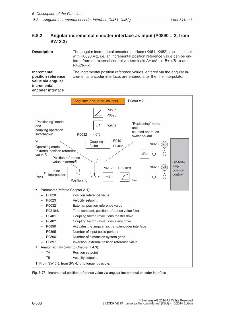
6
6.8 Angular incremental encoder interface (X461, X462)
6-586� Siemens AG 2014 All Rights Reserved
SIMODRIVE 611 universal Function Manual (FBU) – 10/2014 Edition
6.8.2 Angular incremental encoder interface as input (P0890 = 2, fromSW 3.3)
The angular incremental encoder interface (X461, X462) is set as inputwith P0890 = 2, i.e. an incremental position reference value can be en-tered from an external control via terminals A+.x/A–.x, B+.x/B–.x andR+.x/R–.x.
The incremental position reference values, entered via the angular in-cremental encoder interface, are entered after the fine interpolator.
P0897
P0210:8
P0895P0896
P0032
P0401P0402
� Parameter (refer to Chapter A.1):– P0020 Position reference value– P0023 Velocity setpoint– P0032 External position reference value– P0210:8 Time constant, position reference value filter– P0401 Coupling factor, revolutions master drive– P0402 Coupling factor, revolutions slave drive– P0890 Activates the angular incr. enc./encoder interface– P0895 Number of input pulse periods– P0896 Number of dimension system grids– P0897 Inversion, external position reference value
� Analog signals (refer to Chapter 7.4.3):– 74 Position setpoint– 75 Velocity setpoint
P0232 P0020
75
xsetxIPO
Positioning
Position referencevalue, external1)
Fineinterpolator
Couplingfactor
�1
Ang. incr. enc. interf. as input
74Closed–looppositioncontrol
�1
P0890 = 2
”Positioning” modeand coupling operationswitched–in
or
Operating mode”external position referencevalue”1)
”Positioning” modeand coupled operationswitched–out
P0023
d/dt
+
1) From SW 3.3, from SW 4.1, no longer possible.
Fig. 6-78 Incremental position reference value via angular incremental encoder interface
Description
Incrementalposition referencevalue via angularincrementalencoder interface
6 Description of the Functions
! not 611ue !
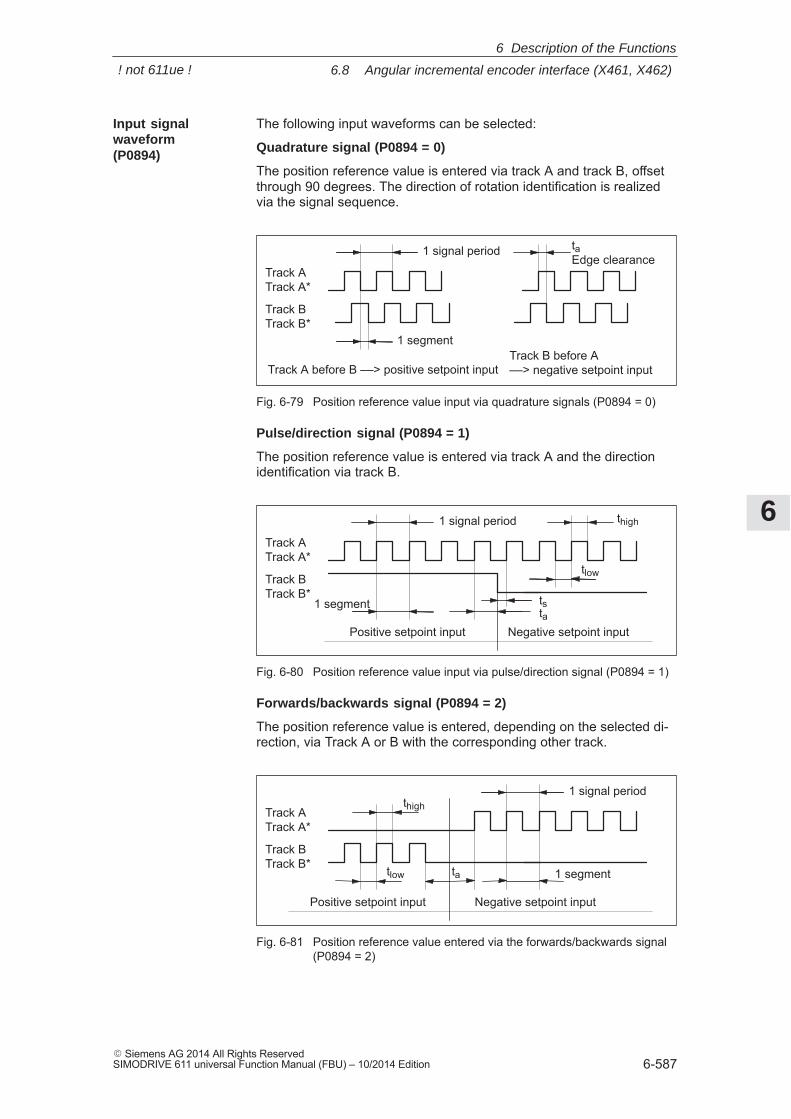
6
6.8 Angular incremental encoder interface (X461, X462)
6-587� Siemens AG 2014 All Rights ReservedSIMODRIVE 611 universal Function Manual (FBU) – 10/2014 Edition
The following input waveforms can be selected:
Quadrature signal (P0894 = 0)
The position reference value is entered via track A and track B, offsetthrough 90 degrees. The direction of rotation identification is realizedvia the signal sequence.
1 signal period
1 segment
Track ATrack A*
Track BTrack B*
Track A before B ––> positive setpoint inputTrack B before A ––> negative setpoint input
ta Edge clearance
Fig. 6-79 Position reference value input via quadrature signals (P0894 = 0)
Pulse/direction signal (P0894 = 1)
The position reference value is entered via track A and the directionidentification via track B.
1 signal period
1 segment
Track ATrack A*
Track BTrack B*
Positive setpoint input Negative setpoint input
thigh
tlow
tsta
Fig. 6-80 Position reference value input via pulse/direction signal (P0894 = 1)
Forwards/backwards signal (P0894 = 2)
The position reference value is entered, depending on the selected di-rection, via Track A or B with the corresponding other track.
1 signal period
1 segment
Track ATrack A*
Track BTrack B*
Positive setpoint input Negative setpoint input
tlow
thigh
ta
Fig. 6-81 Position reference value entered via the forwards/backwards signal(P0894 = 2)
Input signalwaveform(P0894)
6 Description of the Functions
! not 611ue !
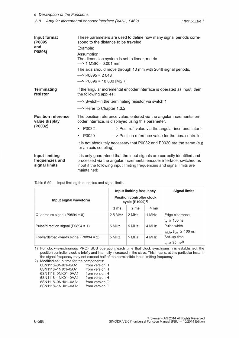
6
6.8 Angular incremental encoder interface (X461, X462)
6-588� Siemens AG 2014 All Rights Reserved
SIMODRIVE 611 universal Function Manual (FBU) – 10/2014 Edition
These parameters are used to define how many signal periods corre-spond to the distance to be traveled.Example:Assumption: The dimension system is set to linear, metric––> 1 MSR = 0.001 mmThe axis should move through 10 mm with 2048 signal periods.––> P0895 = 2 048––> P0896 = 10 000 [MSR]
If the angular incremental encoder interface is operated as input, thenthe following applies:
––> Switch–in the terminating resistor via switch 1
––> Refer to Chapter 1.3.2
The position reference value, entered via the angular incremental en-coder interface, is displayed using this parameter.
� P0032 ––> Pos. ref. value via the angular incr. enc. interf.
� P0020 ––> Position reference value for the pos. controller
It is not absolutely necessary that P0032 and P0020 are the same (e.g.for an axis coupling).
It is only guaranteed that the input signals are correctly identified andprocessed via the angular incremental encoder interface, switched asinput if the following input limiting frequencies and signal limits aremaintained:
Table 6-59 Input limiting frequencies and signal limits
Input limiting frequency Signal limits
Input signal waveformPosition controller clock
cycle (P1009)1)
1 ms 2 ms 4 ms
Quadrature signal (P0894 = 0) 2.5 MHz 2 MHz 1 MHz Edge clearanceta � 100 ns
Pulse/direction signal (P0894 = 1) 5 MHz 5 MHz 4 MHzta 100 nsPulse widththigh, tlow � 100 ns
Forwards/backwards signal (P0894 = 2) 5 MHz 5 MHz 4 MHzthigh, tlow 100 nsSet–up timets � 35 ns2)
1) For clock–synchronous PROFIBUS operation, each time that clock synchronism is established, theposition controller clock is briefly and internally increased in the slave. This means, at this particular instant,the signal frequency may not exceed half of the permissible input limiting frequency.
2) Modified setup time for the components:6SN1118–0NJ01–0AA1 from version H6SN1118–1NJ01–0AA1 from version H6SN1118–0NK01–0AA1 from version H6SN1118–1NK01–0AA1 from version H6SN1118–0NH01–0AA1 from version G6SN1118–1NH01–0AA1 from version G
Input format(P0895 and P0896)
Terminatingresistor
Position referencevalue display(P0032)
Input limiting frequencies and signal limits
6 Description of the Functions
! not 611ue !
6
6.8 Angular incremental encoder interface (X461, X462)
6-589� Siemens AG 2014 All Rights ReservedSIMODRIVE 611 universal Function Manual (FBU) – 10/2014 Edition
When switching–out (releasing) the coupling, it should be noted that theinterpolator controls the velocity to the last value that was present, be-fore it starts to brake. For high fluctuations in the velocity setpoint, thiscan lead to the drive first briefly accelerating before braking.This has to be taken into consideration for coarse resolutions of theposition setpoint (e.g. 1 increment > 0.5 mm), as synchronization dis-tances with different lengths can occur.
From SW 8.3.7 and higher, it is also possible to use an encoder with acoarse resolution (1 increment = approx. 1 mm or 1 degree). FromSW 10.1.1. and higher, P0891 must also be set to 5 (angular encoderinterface X461/X462 coarse).
If the acceleration in P0104 is set too low, then when synchronizing,higher acceleration levels can be reached.
When setting the angular incremental encoder interface as input forincremental position reference values, the following parameters mustbe observed:
� P0032 External position reference value
� P0890 Activates the angular incr. enc./encoder interface
� P0891 Source, external position reference value
� P0894 Angular incremental encoder input signal waveform
� P0895 External position reference value – No. of increments
� P0896 Ext. position reference value – No. of dimensionsystem grids
� P0897 Inversion, external position reference value
For ”angular incremental encoder interface as input”, the following sig-nal is available:
� Input signal ”invert angular increm. encoder input” (from SW 3.5)(refer under the index entry ”Input signal, digital ...”)
––> using an input terminal with function number 75
––> using the PROFIBUS control signal ”PosStw.7”
Input in posoperation
Encoder withcoarse resolution
Parameteroverview(refer to ChapterA.1)
Input signal(refer to Chapter6.4)
6 Description of the Functions
! not 611ue !
6
6.8 Angular incremental encoder interface (X461, X462)
6-590� Siemens AG 2014 All Rights Reserved
SIMODRIVE 611 universal Function Manual (FBU) – 10/2014 Edition
6.8.3 Electronic handwheel (from SW 8.1)
An electronic handwheel can be connected to the angular incrementalencoder interface. Electronic handwheels can be used to traverse theselected axes simultaneously in manual mode. The evaluation of thehandwheel pulses is defined using the indexing dimension evaluation.
Note
If you wish an electronic handwheel to be activated at drive B, parame-ter P0890 for drive A must not be configured with ”3” (internal couplingof the actual value of drive A as the setpoint for drive B will then nolonger be possible).
In this case, only the values 0 ... 2 or 4 in the parameter P0890 arepermissible for drive A.
The electronic handwheel can, in the positioning mode, be activated viaan input terminal function and via PROFIBUS–DP. The signals from theangular incremental encoder interface are velocity signals. The hand-wheel and drive do not move in synchronism.
Acceleration and braking is realized according to P0103 and P0104.The drive speed is limited by P0102.
The increments of the electronic handwheel can be assigned four fac-tors using two input terminals.
The factors should be entered, before SW 9.1 in P0900 and from SW9.1 onwards, in P0889:
Bit 1 Bit 0 Handwheel evaluation (standard)P0900/P0889[0] 0 0 1 MSRP0900/P0889[1] 0 1 10 MSRP0900/P0889[2] 1 0 100 MSRP0900/P0889[3] 1 1 1000 MSR
Before SW 9.1:Sub–parameters P0900[0] up to P0900[3] can be optionally assignedfactors of between 1 and 10000.
From SW 9.1:Sub–parameters P0889[0] to P0889[3] can be optionally assigned fac-tors of between 1 and 10000.
Reader’s note
If the drive is moved using the electronic handwheel, then the drivebehavior corresponds to that of jogging, refer to Chapter 6.2.9.
Description
Angularincrementalencoderhandwheelevaluation
6 Description of the Functions
6
6.8 Angular incremental encoder interface (X461, X462)
6-591� Siemens AG 2014 All Rights ReservedSIMODRIVE 611 universal Function Manual (FBU) – 10/2014 Edition
Example:
The electronic handwheel supplies 100 incr./rev. One handwheel revo-lution corresponds to a value of 1 mm. 200 handwheel revolutions in one minute correspond to a velocity of200 mm/min. The handwheel evaluation is entered using the input sig-nal ”angular incremental encoder handwheel evaluation, bit 0”. The following should be parameterized:
� Spindle pitch 10 mm/rev ––> P0236 = 10.000
� Quadrature signal activated ––> P0894 = 0
� Angular incremental encoder handwheel evaluation 10 ––> P0900/P0889[1] = 10
6 Description of the Functions
6
6.8 Angular incremental encoder interface (X461, X462)
6-592� Siemens AG 2014 All Rights Reserved
SIMODRIVE 611 universal Function Manual (FBU) – 10/2014 Edition
An axis is moved using the ”electronic handwheel” dependent on thedirection.
The direction should be set as follows using parameter P0899:8:
� P0899:8 = 0: positive and negative direction (standard)
� P0899:8 = 1: only in the positive direction
� P0899:8 = 2: only in the negative direction
Note
Angular incremental encoder pulses in the inhibited direction do notresult in the output of faults or warnings.
In the inhibited direction, only the pulses of the velocity setpoint arecancelled. The velocity actual value must not necessarily follow thevelocity setpoint, e.g. as a result of external forces or transientoperations. As a result, motion is also possible in the direction that hasnot been enabled.
The handwheel direction of rotation can be inverted as follows:
� Using the input terminal function No. 75 ”Invert angular incrementalencoder input”, i.e. when the axis is stationary, the incremental posi-tion reference value is immediately inverted with a 1 signal at theinput terminals.
� ”External inversion position reference value”, via parameter P0897 –i.e. the inversion of the incremental position reference value withP0897 = 1 – is only effective after power on.
The following actions are not possible and initiate the appropriatefaults:
� If the input terminals Fct. No. 62 or control signal STW1.8 (jogging 1ON) or Fct. No. 63 or STW1.9 (jogging 2 ON) and Fct. No. 84 orSatzAnw.13 (activate angular incremental encoder, handwheel) aresimultaneously activated, then fault 121 is output.
� If input terminal Fct. No. 72 or control signal PosStw.4 (activate cou-pling) and Fct. No. 84 or SatzAnw.13 (activate angular incrementalencoder handwheel) are simultaneously activated, if a position refer-ence value source is active via Parameter P0891, then fault 167 isoutput.
Angularincrementalencoder –direction-dependent
Angularincrementalencoder inversion
Fault handling
6 Description of the Functions
6
6.8 Angular incremental encoder interface (X461, X462)
6-593� Siemens AG 2014 All Rights ReservedSIMODRIVE 611 universal Function Manual (FBU) – 10/2014 Edition
The following parameters must be observed when connecting a hand-wheel to the angular incremental encoder interface:� P0890 Activates the angular incr. enc./encoder interface� P0899:8 Enters the angular incremental encoder direction� P0900:4 Angular incremental encoder handwheel evaluation
(before SW 9.1)� P0889:4 Angular incremental encoder handwheel evaluation
(from SW 9.1)� P0102 Maximum velocity� P0103 Maximum acceleration� P0104 Maximum deceleration� P0655 Image, input signals, Part 3� P0657 Image, output signals, Part 2
The following signals are used to connect a handwheel to the angularincremental encoder interface:� Input signals
(refer under index entry ”Input signal, digital – ...”)– Input signal, ”activate angular incremental encoder handwheel”
(from SW 8.1)––> using an input terminal with function number 84––> using the PROFIBUS control signal ”SatzAnw.13”
– Input signal, ”angular incremental encoder handwheel evaluation,bit 0” (from SW 8.1)––> using an input terminal with function number 85––> using the PROFIBUS control signal ”SatzAnw.11”
– Input signal, ”angular incremental encoder handwheel evaluation,bit 1” (from SW 8.1)––> using an input terminal with function number 86––> using the PROFIBUS control signal ”SatzAnw.12”
� Output signals(refer under the index entry, ”Output signal, digital – ...”)– Output signal, ”angular incremental encoder handwheel active”
(from SW 8.1)––> using an output terminal with function number 84––> using the PROFIBUS status signal ”AktSatz.13”
– Output signal, ”angular incremental encoder handwheel evalua-tion, bit 0” (from SW 8.1)––> using an output terminal with function number 85––> using the PROFIBUS status signal ”AktSatz.11”
– Output signal, ”angular incremental encoder handwheel evalua-tion, bit 1” (from SW 8.1)––> using an output terminal with function number 86––> using the PROFIBUS status signal ”AktSatz.12”
Note
Compared to the input of control signals via PROFIBUS–DP, the inputterminal functions No. 84 to 86 have a higher priority.
Parameteroverview(refer to ChapterA.1)
Input/outputsignals(refer to Chapter6.4)
6 Description of the Functions
6
6.9 Motor holding brake
6-594� Siemens AG 2014 All Rights Reserved
SIMODRIVE 611 universal Function Manual (FBU) – 10/2014 Edition
6.9 Motor holding brake
For axes, which must be secured against undesirable motion whenpowered down, the brake sequence control of ”SIMODRIVE 611 uni-versal” can be used to control the motor holding brake.
The relay for the motor holding brake is controlled via a freely–parame-terizable output terminal.
SIEMENS motors are optionally available with a motor holding brake.
!Warning
It is not permissible to use the motor holding brake as working brake,as it is generally only designed for a limited number of emergencybraking operations.
The brake sequence control is activated by setting P0850 to 1.
This function is possible either the n–set mode or pos mode.
The brake sequence control operates with the ”open holding brake”output signal. The signal can be output as follows:
� Using a freely–parameterizable output terminal
The required output signal for the control board or the optional TER-MINAL module must therefore be assigned function No. 35 for themotor holding brake by appropriately parameterizing it.
Output terminals on the control board0.x, O1.x, O2.x and O3.x (parameterization, refer to Chap. 6.4.5)
Output terminals for the optional TERMINAL moduleO2, O3 to O11 (parameterization, refer to Chapter 6.5)
P0699 can be used, for each output terminal, to set whether the sig-nal is output inverted.
The relay for the motor holding brake is connected at the para-meterized output terminal.
� Via status signal for PROFIBUS–DP
The DP master must process the ”open holding brake” status signal.The signal must be connected to the digital output of the master, towhich the relay for the motor holding brake is connected.
Description
Activating
Connecting the motor holdingbrake
6 Description of the Functions
6
6.9 Motor holding brake
6-595� Siemens AG 2014 All Rights ReservedSIMODRIVE 611 universal Function Manual (FBU) – 10/2014 Edition
The following parameters are used for the ”motor holding brake” function:
� P0850 Activates the brake control
� P0851 Brake opening time
� P0852 Speed, close holding brake (SRM, ARM) Motor velocity, close holding brake (SLM)
� P0853 Brake delay time
� P0854 Controller inhibit time
Note
For controller enable:Issuing and withdrawing the controller enable is dependent on severalinternal and external enable signals (refer to Chapter 6.4.1).
For pulse enable:Issuing and withdrawing the pulse enable is dependent on severalinternal and external enable signals (refer to Chapter 6.4.1).
Parameteroverview(refer to ChapterA.1)
Information for enabling thecontroller andpulses
6 Description of the Functions
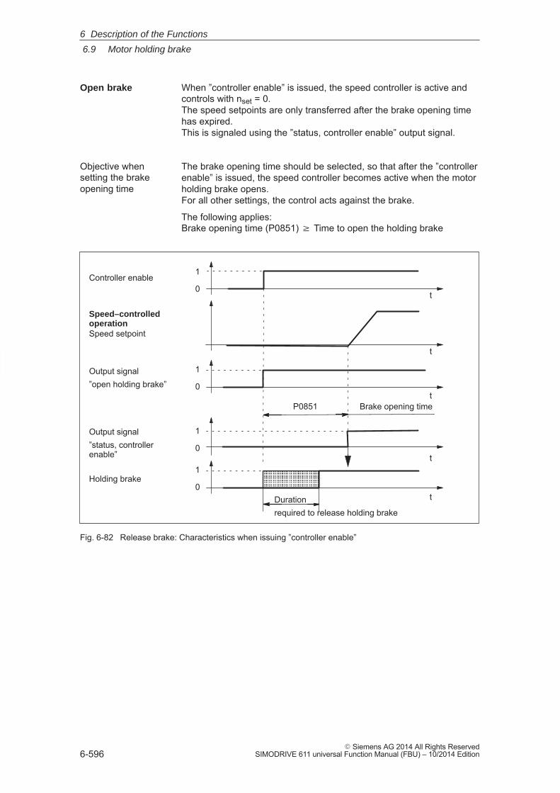
6
6.9 Motor holding brake
6-596� Siemens AG 2014 All Rights Reserved
SIMODRIVE 611 universal Function Manual (FBU) – 10/2014 Edition
When ”controller enable” is issued, the speed controller is active andcontrols with nset = 0. The speed setpoints are only transferred after the brake opening timehas expired. This is signaled using the ”status, controller enable” output signal.
The brake opening time should be selected, so that after the ”controllerenable” is issued, the speed controller becomes active when the motorholding brake opens. For all other settings, the control acts against the brake.
The following applies:Brake opening time (P0851) � Time to open the holding brake
Speed–controlled operationSpeed setpoint
Holding brake
Controller enable
t
ÄÄÄÄÄÄÄÄÄÄ
t
t
t
tP0851 Brake opening time
Durationrequired to release holding brake
Output signal”status, controllerenable”
1
0
1
0
1
0
1
0
Output signal”open holding brake”
Fig. 6-82 Release brake: Characteristics when issuing ”controller enable”
Open brake
Objective whensetting the brakeopening time
6 Description of the Functions
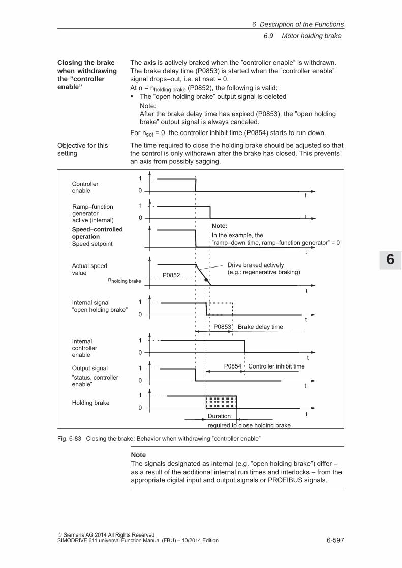
6
6.9 Motor holding brake
6-597� Siemens AG 2014 All Rights ReservedSIMODRIVE 611 universal Function Manual (FBU) – 10/2014 Edition
The axis is actively braked when the ”controller enable” is withdrawn.The brake delay time (P0853) is started when the ”controller enable” signal drops–out, i.e. at nset = 0.At n = nholding brake (P0852), the following is valid:� The ”open holding brake” output signal is deleted
Note:After the brake delay time has expired (P0853), the ”open holdingbrake” output signal is always canceled.
For nset = 0, the controller inhibit time (P0854) starts to run down.
The time required to close the holding brake should be adjusted so thatthe control is only withdrawn after the brake has closed. This preventsan axis from possibly sagging.
Actual speedvalue
Internal signal”open holding brake”
Holding brake
Controllerenable
ÄÄÄÄÄÄÄÄ
P0854 Controller inhibit time
Drive braked actively (e.g.: regenerative braking)
Speed–controlled operationSpeed setpoint
Internal controllerenable
Note:
In the example, the ”ramp–down time, ramp–function generator” = 0
t
t
t
t
t
t
t
nholding brake
P0853 Brake delay time
Output signal”status, controllerenable”
P0852
Durationrequired to close holding brake
1
0
1
0
1
0
1
0
1
0
Ramp–functiongeneratoractive (internal) t
1
0
Fig. 6-83 Closing the brake: Behavior when withdrawing ”controller enable”
NoteThe signals designated as internal (e.g. ”open holding brake”) differ –as a result of the additional internal run times and interlocks – from theappropriate digital input and output signals or PROFIBUS signals.
Closing the brakewhen withdrawingthe ”controllerenable”
Objective for this setting
6 Description of the Functions
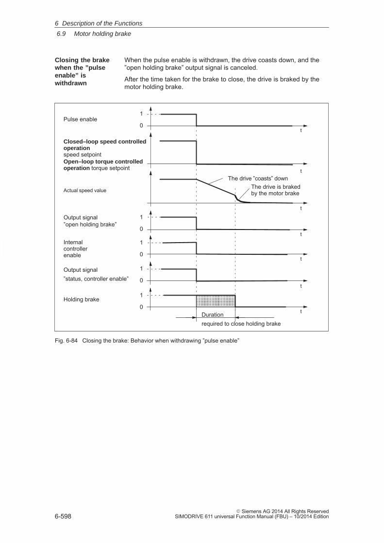
6
6.9 Motor holding brake
6-598� Siemens AG 2014 All Rights Reserved
SIMODRIVE 611 universal Function Manual (FBU) – 10/2014 Edition
When the pulse enable is withdrawn, the drive coasts down, and the”open holding brake” output signal is canceled.
After the time taken for the brake to close, the drive is braked by themotor holding brake.
Actual speed value
Output signal”open holding brake”
Holding brake
Pulse enable
ÄÄÄÄÄÄÄÄÄÄÄÄÄÄÄ
�
�
�
�
�
�
The drive ”coasts” downThe drive is braked by the motor brake
Closed–loop speed controlledoperationspeed setpointOpen–loop torque controlledoperation torque setpoint
Internal controllerenable
�
Output signal”status, controller enable”
Durationrequired to close holding brake
1
0
1
0
1
0
1
0
1
0
Fig. 6-84 Closing the brake: Behavior when withdrawing ”pulse enable”
Closing the brakewhen the ”pulseenable” iswithdrawn
6 Description of the Functions
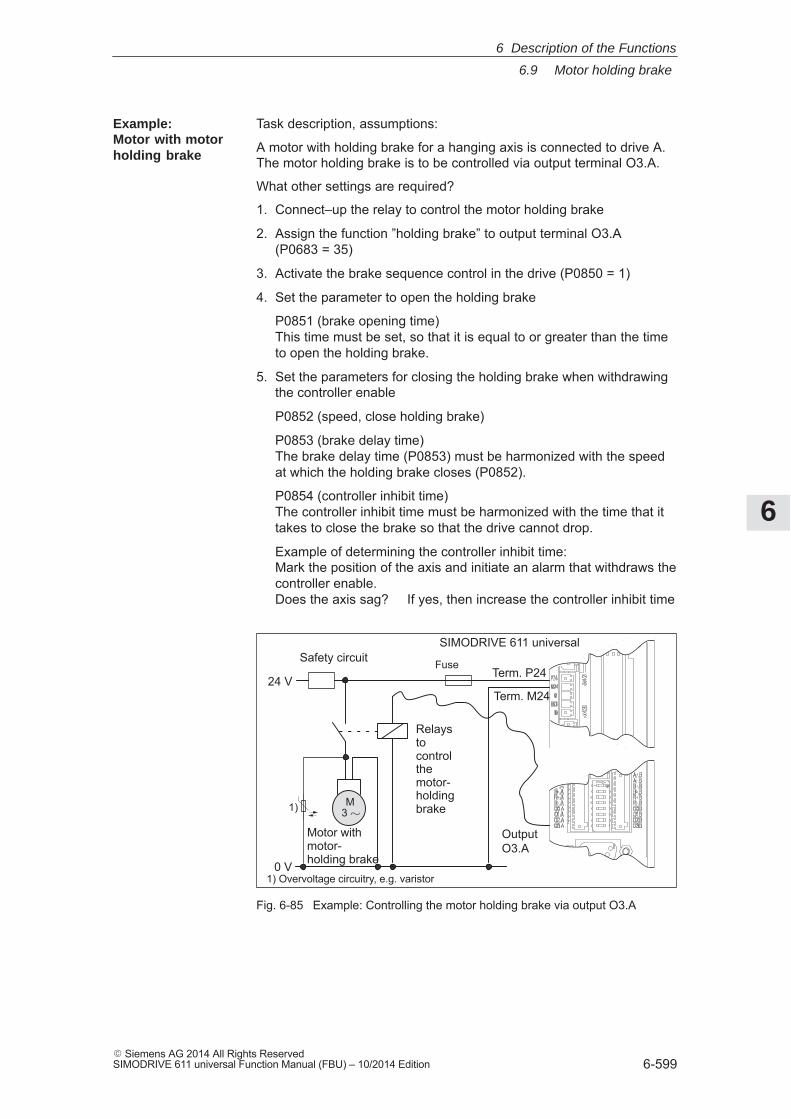
6
6.9 Motor holding brake
6-599� Siemens AG 2014 All Rights ReservedSIMODRIVE 611 universal Function Manual (FBU) – 10/2014 Edition
Task description, assumptions:
A motor with holding brake for a hanging axis is connected to drive A.The motor holding brake is to be controlled via output terminal O3.A.
What other settings are required?
1. Connect–up the relay to control the motor holding brake
2. Assign the function ”holding brake” to output terminal O3.A (P0683 = 35)
3. Activate the brake sequence control in the drive (P0850 = 1)
4. Set the parameter to open the holding brake
P0851 (brake opening time)This time must be set, so that it is equal to or greater than the timeto open the holding brake.
5. Set the parameters for closing the holding brake when withdrawingthe controller enable
P0852 (speed, close holding brake)
P0853 (brake delay time)The brake delay time (P0853) must be harmonized with the speedat which the holding brake closes (P0852).
P0854 (controller inhibit time)The controller inhibit time must be harmonized with the time that ittakes to close the brake so that the drive cannot drop.
Example of determining the controller inhibit time: Mark the position of the axis and initiate an alarm that withdraws thecontroller enable.Does the axis sag? If yes, then increase the controller inhibit time
M3 �
OutputO3.A
24 V
Motor with motor-holding brake0 V
Relaystocontrolthemotor-holdingbrake
SIMODRIVE 611 universal
Term. P24
Term. M24
Safety circuit Fuse
1)
1) Overvoltage circuitry, e.g. varistor
Fig. 6-85 Example: Controlling the motor holding brake via output O3.A
Example:Motor with motorholding brake
6 Description of the Functions
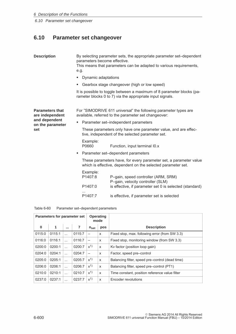
6
6.10 Parameter set changeover
6-600� Siemens AG 2014 All Rights Reserved
SIMODRIVE 611 universal Function Manual (FBU) – 10/2014 Edition
6.10 Parameter set changeover
By selecting parameter sets, the appropriate parameter set–dependentparameters become effective.This means that parameters can be adapted to various requirements,e.g.
� Dynamic adaptations
� Gearbox stage changeover (high or low speed)
It is possible to toggle between a maximum of 8 parameter blocks (pa-rameter blocks 0 to 7) via the appropriate input signals.
For ”SIMODRIVE 611 universal” the following parameter types areavailable, referred to the parameter set changeover:
� Parameter set–independent parameters
These parameters only have one parameter value, and are effec-tive, independent of the selected parameter set.
Example: P0660 Function, input terminal I0.x
� Parameter set–dependent parameters
These parameters have, for every parameter set, a parameter valuewhich is effective, dependent on the selected parameter set.
Example:P1407:8 P–gain, speed controller (ARM, SRM)
P–gain, velocity controller (SLM)P1407:0 is effective, if parameter set 0 is selected (standard)...P1407:7 is effective, if parameter set is selected
Table 6-60 Parameter set–dependent parameters
Parameters for parameter set Operatingmode
0 1 ... 7 nset pos Description
0115:0 0115:1 ... 0115:7 – x Fixed stop, max. following error (from SW 3.3)
0116:0 0116:1 ... 0116:7 – x Fixed stop, monitoring window (from SW 3.3)
0200:0 0200:1 ... 0200:7 x1) x Kv factor (position loop gain)
0204:0 0204:1 ... 0204:7 – x Factor, speed pre–control
0205:0 0205:1 ... 0205:7 x1) x Balancing filter, speed pre–control (dead time)
0206:0 0206:1 ... 0206:7 x1) x Balancing filter, speed pre–control (PT1)
0210:0 0210:1 ... 0210:7 x1) x Time constant, position reference value filter
0237:0 0237:1 ... 0237:7 x1) x Encoder revolutions
Description
Parameters that are independent and dependent on the parameterset
6 Description of the Functions
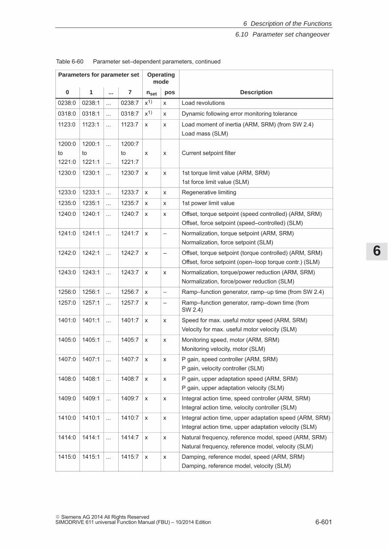
6
6.10 Parameter set changeover
6-601� Siemens AG 2014 All Rights ReservedSIMODRIVE 611 universal Function Manual (FBU) – 10/2014 Edition
Table 6-60 Parameter set–dependent parameters, continued
Parameters for parameter set Operatingmode
0 Descriptionposnset7...1
0238:0 0238:1 ... 0238:7 x1) x Load revolutions
0318:0 0318:1 ... 0318:7 x1) x Dynamic following error monitoring tolerance
1123:0 1123:1 ... 1123:7 x x Load moment of inertia (ARM, SRM) (from SW 2.4)Load mass (SLM)
1200:0to1221:0
1200:1to1221:1
...
...
1200:7to1221:7
x x Current setpoint filter
1230:0 1230:1 ... 1230:7 x x 1st torque limit value (ARM, SRM)1st force limit value (SLM)
1233:0 1233:1 ... 1233:7 x x Regenerative limiting
1235:0 1235:1 ... 1235:7 x x 1st power limit value
1240:0 1240:1 ... 1240:7 x x Offset, torque setpoint (speed controlled) (ARM, SRM)Offset, force setpoint (speed–controlled) (SLM)
1241:0 1241:1 ... 1241:7 x – Normalization, torque setpoint (ARM, SRM)Normalization, force setpoint (SLM)
1242:0 1242:1 ... 1242:7 x – Offset, torque setpoint (torque controlled) (ARM, SRM)Offset, force setpoint (open–loop torque contr.) (SLM)
1243:0 1243:1 ... 1243:7 x x Normalization, torque/power reduction (ARM, SRM)Normalization, force/power reduction (SLM)
1256:0 1256:1 ... 1256:7 x – Ramp–function generator, ramp–up time (from SW 2.4)
1257:0 1257:1 ... 1257:7 x – Ramp–function generator, ramp–down time (fromSW 2.4)
1401:0 1401:1 ... 1401:7 x x Speed for max. useful motor speed (ARM, SRM)Velocity for max. useful motor velocity (SLM)
1405:0 1405:1 ... 1405:7 x x Monitoring speed, motor (ARM, SRM)Monitoring velocity, motor (SLM)
1407:0 1407:1 ... 1407:7 x x P gain, speed controller (ARM, SRM)P gain, velocity controller (SLM)
1408:0 1408:1 ... 1408:7 x x P gain, upper adaptation speed (ARM, SRM)P gain, upper adaptation velocity (SLM)
1409:0 1409:1 ... 1409:7 x x Integral action time, speed controller (ARM, SRM)Integral action time, velocity controller (SLM)
1410:0 1410:1 ... 1410:7 x x Integral action time, upper adaptation speed (ARM, SRM)Integral action time, upper adaptation velocity (SLM)
1414:0 1414:1 ... 1414:7 x x Natural frequency, reference model, speed (ARM, SRM)Natural frequency, reference model, velocity (SLM)
1415:0 1415:1 ... 1415:7 x x Damping, reference model, speed (ARM, SRM)Damping, reference model, velocity (SLM)
6 Description of the Functions
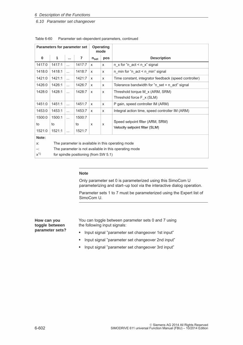
6
6.10 Parameter set changeover
6-602� Siemens AG 2014 All Rights Reserved
SIMODRIVE 611 universal Function Manual (FBU) – 10/2014 Edition
Table 6-60 Parameter set–dependent parameters, continued
Parameters for parameter set Operatingmode
0 Descriptionposnset7...1
1417:0 1417:1 ... 1417:7 x x n_x for ”n_act < n_x” signal
1418:0 1418:1 ... 1418:7 x x n_min for ”n_act < n_min” signal
1421:0 1421:1 ... 1421:7 x x Time constant, integrator feedback (speed controller)
1426:0 1426:1 ... 1426:7 x x Tolerance bandwidth for ”n_set = n_act” signal
1428:0 1428:1 ... 1428:7 x x Threshold torque M_x (ARM, SRM)Threshold force F_x (SLM)
1451:0 1451:1 ... 1451:7 x x P gain, speed controller IM (ARM)
1453:0 1453:1 ... 1453:7 x x Integral action time, speed controller IM (ARM)
1500:0 1500:1 ... 1500:7Speed setpoint filter (ARM, SRM)to to to x x Speed setpoint filter (ARM, SRM)Velocity setpoint filter (SLM)
1521:0 1521:1 ... 1521:7Velocity setpoint filter (SLM)
Note:
x: The parameter is available in this operating mode–: The parameter is not available in this operating modex1) for spindle positioning (from SW 5.1)
Note
Only parameter set 0 is parameterized using this SimoCom Uparameterizing and start–up tool via the interactive dialog operation.
Parameter sets 1 to 7 must be parameterized using the Expert list ofSimoCom U.
You can toggle between parameter sets 0 and 7 using the following input signals:
� Input signal ”parameter set changeover 1st input”
� Input signal ”parameter set changeover 2nd input”
� Input signal ”parameter set changeover 3rd input”
How can you toggle betweenparameter sets?
6 Description of the Functions
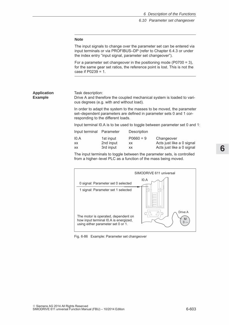
6
6.10 Parameter set changeover
6-603� Siemens AG 2014 All Rights ReservedSIMODRIVE 611 universal Function Manual (FBU) – 10/2014 Edition
Note
The input signals to change over the parameter set can be entered viainput terminals or via PROFIBUS–DP (refer to Chapter 6.4.3 or underthe index entry ”input signal, parameter set changeover”).
For a parameter set changeover in the positioning mode (P0700 = 3),for the same gear set ratios, the reference point is lost. This is not thecase if P0239 = 1.
Task description:Drive A and therefore the coupled mechanical system is loaded to vari-ous degrees (e.g. with and without load).
In order to adapt the system to the masses to be moved, the parameterset–dependent parameters are defined in parameter sets 0 and 1 cor-responding to the different loads.
Input terminal I0.A is to be used to toggle between parameter set 0 and 1:
Input terminal Parameter Description
I0.A 1st input P0660 = 9 Changeoverxx 2nd input xx Acts just like a 0 signalxx 3rd input xx Acts just like a 0 signal
The input terminals to toggle between the parameter sets, is controlledfrom a higher–level PLC as a function of the mass being moved.
SIMODRIVE 611 universal
I0.A
Drive A
0 signal: Parameter set 0 selected
1 signal: Parameter set 1 selected
The motor is operated, dependent onhow input terminal I0.A is energized,using either parameter set 0 or 1.
M3 �
Fig. 6-86 Example: Parameter set changeover
ApplicationExample
6 Description of the Functions
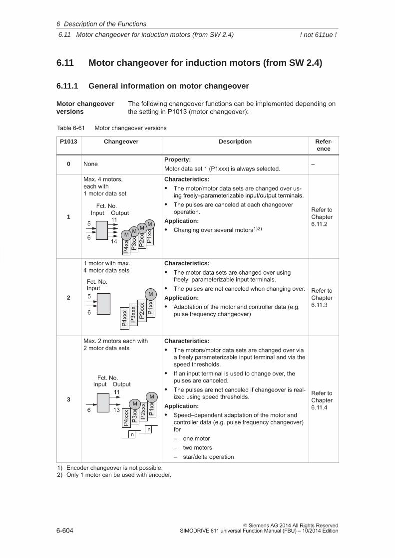
6
6.11 Motor changeover for induction motors (from SW 2.4)
6-604� Siemens AG 2014 All Rights Reserved
SIMODRIVE 611 universal Function Manual (FBU) – 10/2014 Edition
6.11 Motor changeover for induction motors (from SW 2.4)
6.11.1 General information on motor changeover
The following changeover functions can be implemented depending onthe setting in P1013 (motor changeover):
Table 6-61 Motor changeover versions
P1013 Changeover Description Refer-ence
0 NoneProperty:
Motor data set 1 (P1xxx) is always selected.–
Max. 4 motors,each with1 motor data set
Characteristics:
� The motor/motor data sets are changed over us-ing freely–parameterizable input/output terminals.
15
6
11
14 P1x
xx
M
P2x
xx
M
P3x
xx
M
P4x
xx
M
Fct. No.OutputInput
ing freely–parameterizable input/output terminals.� The pulses are canceled at each changeover
operation.Application:
� Changing over several motors1)2)
Refer to Chapter6.11.2
1 motor with max.4 motor data sets
Characteristics:
� The motor data sets are changed over usingfreely–parameterizable input terminals.
2
P1x
xx
M
P2x
xxP
3xxx
P4x
xx
5
6
InputFct. No.
The motor data sets are changed over usingfreely–parameterizable input terminals.
� The pulses are not canceled when changing over.Application:
� Adaptation of the motor and controller data (e.g.pulse frequency changeover)
Refer to Chapter6.11.3
Max. 2 motors each with2 motor data sets
Characteristics:
� The motors/motor data sets are changed over viaa freely parameterizable input terminal and via thespeed thresholds.If an input terminal is used to change over, the
3
nn
P1x
xx
M
P2x
xxP
3xxx
M
P4x
xx6
11
13
Input OutputFct. No.
� If an input terminal is used to change over, thepulses are canceled.
� The pulses are not canceled if changeover is real-ized using speed thresholds.
Application:
� Speed–dependent adaptation of the motor andcontroller data (e.g. pulse frequency changeover)for– one motor– two motors– star/delta operation
Refer to Chapter6.11.4
1) Encoder changeover is not possible.2) Only 1 motor can be used with encoder.
Motor changeover versions
6 Description of the Functions
! not 611ue !
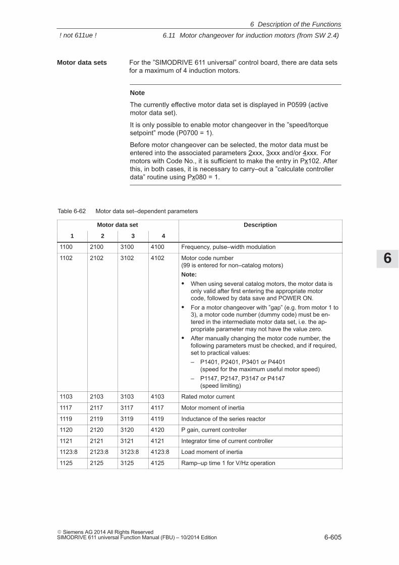
6
6.11 Motor changeover for induction motors (from SW 2.4)
6-605� Siemens AG 2014 All Rights ReservedSIMODRIVE 611 universal Function Manual (FBU) – 10/2014 Edition
For the ”SIMODRIVE 611 universal” control board, there are data setsfor a maximum of 4 induction motors.
Note
The currently effective motor data set is displayed in P0599 (activemotor data set).
It is only possible to enable motor changeover in the ”speed/torquesetpoint” mode (P0700 = 1).
Before motor changeover can be selected, the motor data must beentered into the associated parameters 2xxx, 3xxx and/or 4xxx. Formotors with Code No., it is sufficient to make the entry in Px102. Afterthis, in both cases, it is necessary to carry–out a ”calculate controllerdata” routine using Px080 = 1.
Table 6-62 Motor data set–dependent parameters
Motor data set Description
1 2 3 4
1100 2100 3100 4100 Frequency, pulse–width modulation
1102 2102 3102 4102 Motor code number(99 is entered for non–catalog motors)Note:
� When using several catalog motors, the motor data isonly valid after first entering the appropriate motorcode, followed by data save and POWER ON.
� For a motor changeover with ”gap” (e.g. from motor 1 to3), a motor code number (dummy code) must be en-tered in the intermediate motor data set, i.e. the ap-propriate parameter may not have the value zero.
� After manually changing the motor code number, thefollowing parameters must be checked, and if required,set to practical values:– P1401, P2401, P3401 or P4401
(speed for the maximum useful motor speed)– P1147, P2147, P3147 or P4147
(speed limiting)
1103 2103 3103 4103 Rated motor current
1117 2117 3117 4117 Motor moment of inertia
1119 2119 3119 4119 Inductance of the series reactor
1120 2120 3120 4120 P gain, current controller
1121 2121 3121 4121 Integrator time of current controller
1123:8 2123:8 3123:8 4123:8 Load moment of inertia
1125 2125 3125 4125 Ramp–up time 1 for V/Hz operation
Motor data sets
6 Description of the Functions
! not 611ue !
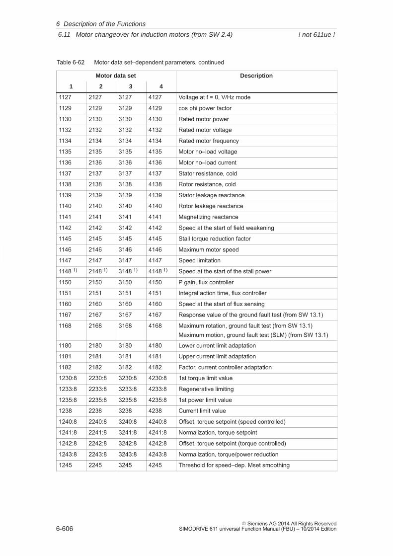
6
6.11 Motor changeover for induction motors (from SW 2.4)
6-606� Siemens AG 2014 All Rights Reserved
SIMODRIVE 611 universal Function Manual (FBU) – 10/2014 Edition
Table 6-62 Motor data set–dependent parameters, continued
Motor data set Description
1 432
1127 2127 3127 4127 Voltage at f = 0, V/Hz mode
1129 2129 3129 4129 cos phi power factor
1130 2130 3130 4130 Rated motor power
1132 2132 3132 4132 Rated motor voltage
1134 2134 3134 4134 Rated motor frequency
1135 2135 3135 4135 Motor no–load voltage
1136 2136 3136 4136 Motor no–load current
1137 2137 3137 4137 Stator resistance, cold
1138 2138 3138 4138 Rotor resistance, cold
1139 2139 3139 4139 Stator leakage reactance
1140 2140 3140 4140 Rotor leakage reactance
1141 2141 3141 4141 Magnetizing reactance
1142 2142 3142 4142 Speed at the start of field weakening
1145 2145 3145 4145 Stall torque reduction factor
1146 2146 3146 4146 Maximum motor speed
1147 2147 3147 4147 Speed limitation
1148 1) 2148 1) 3148 1) 4148 1) Speed at the start of the stall power
1150 2150 3150 4150 P gain, flux controller
1151 2151 3151 4151 Integral action time, flux controller
1160 2160 3160 4160 Speed at the start of flux sensing
1167 2167 3167 4167 Response value of the ground fault test (from SW 13.1)
1168 2168 3168 4168 Maximum rotation, ground fault test (from SW 13.1)Maximum motion, ground fault test (SLM) (from SW 13.1)
1180 2180 3180 4180 Lower current limit adaptation
1181 2181 3181 4181 Upper current limit adaptation
1182 2182 3182 4182 Factor, current controller adaptation
1230:8 2230:8 3230:8 4230:8 1st torque limit value
1233:8 2233:8 3233:8 4233:8 Regenerative limiting
1235:8 2235:8 3235:8 4235:8 1st power limit value
1238 2238 3238 4238 Current limit value
1240:8 2240:8 3240:8 4240:8 Offset, torque setpoint (speed controlled)
1241:8 2241:8 3241:8 4241:8 Normalization, torque setpoint
1242:8 2242:8 3242:8 4242:8 Offset, torque setpoint (torque controlled)
1243:8 2243:8 3243:8 4243:8 Normalization, torque/power reduction
1245 2245 3245 4245 Threshold for speed–dep. Mset smoothing
6 Description of the Functions
! not 611ue !
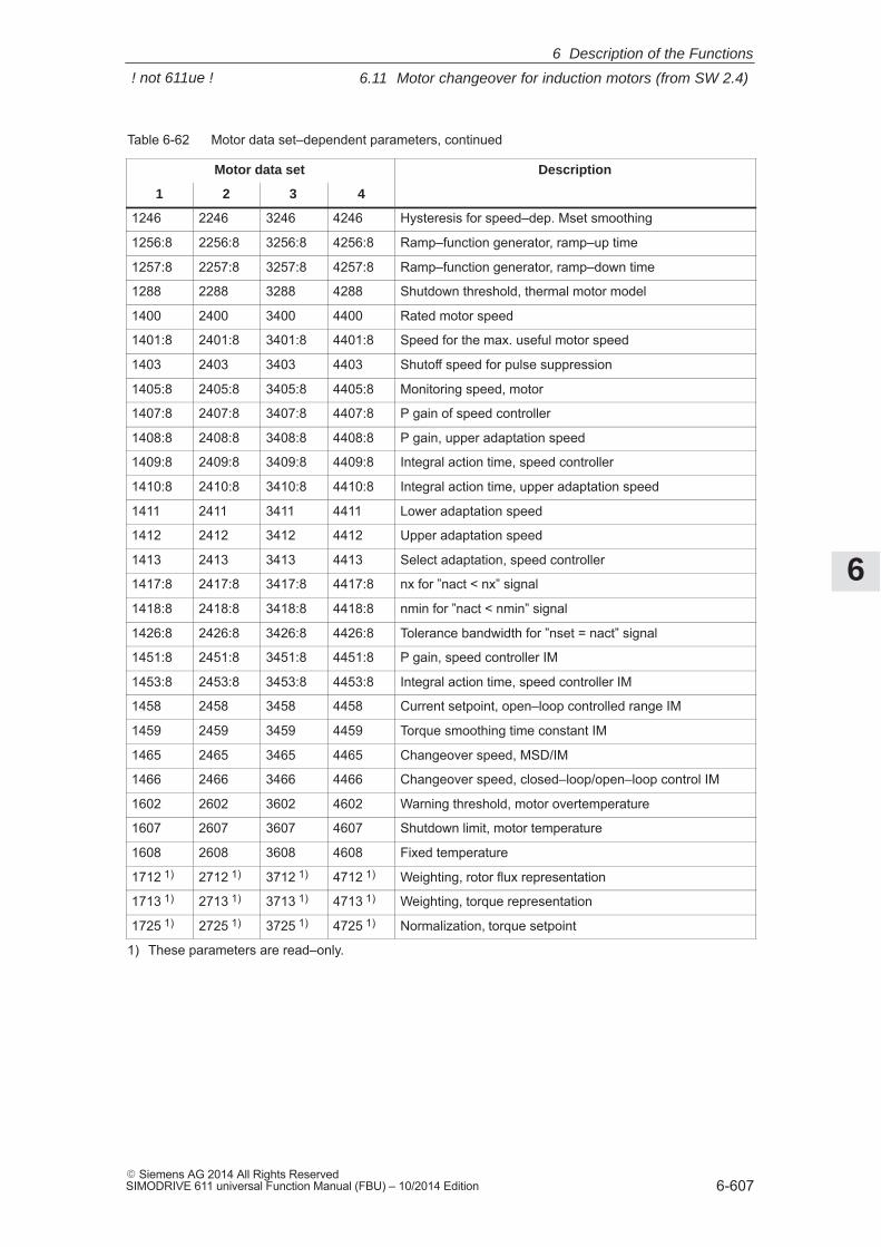
6
6.11 Motor changeover for induction motors (from SW 2.4)
6-607� Siemens AG 2014 All Rights ReservedSIMODRIVE 611 universal Function Manual (FBU) – 10/2014 Edition
Table 6-62 Motor data set–dependent parameters, continued
Motor data set Description
1 432
1246 2246 3246 4246 Hysteresis for speed–dep. Mset smoothing
1256:8 2256:8 3256:8 4256:8 Ramp–function generator, ramp–up time
1257:8 2257:8 3257:8 4257:8 Ramp–function generator, ramp–down time
1288 2288 3288 4288 Shutdown threshold, thermal motor model
1400 2400 3400 4400 Rated motor speed
1401:8 2401:8 3401:8 4401:8 Speed for the max. useful motor speed
1403 2403 3403 4403 Shutoff speed for pulse suppression
1405:8 2405:8 3405:8 4405:8 Monitoring speed, motor
1407:8 2407:8 3407:8 4407:8 P gain of speed controller
1408:8 2408:8 3408:8 4408:8 P gain, upper adaptation speed
1409:8 2409:8 3409:8 4409:8 Integral action time, speed controller
1410:8 2410:8 3410:8 4410:8 Integral action time, upper adaptation speed
1411 2411 3411 4411 Lower adaptation speed
1412 2412 3412 4412 Upper adaptation speed
1413 2413 3413 4413 Select adaptation, speed controller
1417:8 2417:8 3417:8 4417:8 nx for ”nact < nx” signal
1418:8 2418:8 3418:8 4418:8 nmin for ”nact < nmin” signal
1426:8 2426:8 3426:8 4426:8 Tolerance bandwidth for ”nset = nact” signal
1451:8 2451:8 3451:8 4451:8 P gain, speed controller IM
1453:8 2453:8 3453:8 4453:8 Integral action time, speed controller IM
1458 2458 3458 4458 Current setpoint, open–loop controlled range IM
1459 2459 3459 4459 Torque smoothing time constant IM
1465 2465 3465 4465 Changeover speed, MSD/IM
1466 2466 3466 4466 Changeover speed, closed–loop/open–loop control IM
1602 2602 3602 4602 Warning threshold, motor overtemperature
1607 2607 3607 4607 Shutdown limit, motor temperature
1608 2608 3608 4608 Fixed temperature
1712 1) 2712 1) 3712 1) 4712 1) Weighting, rotor flux representation
1713 1) 2713 1) 3713 1) 4713 1) Weighting, torque representation
1725 1) 2725 1) 3725 1) 4725 1) Normalization, torque setpoint
1) These parameters are read–only.
6 Description of the Functions
! not 611ue !
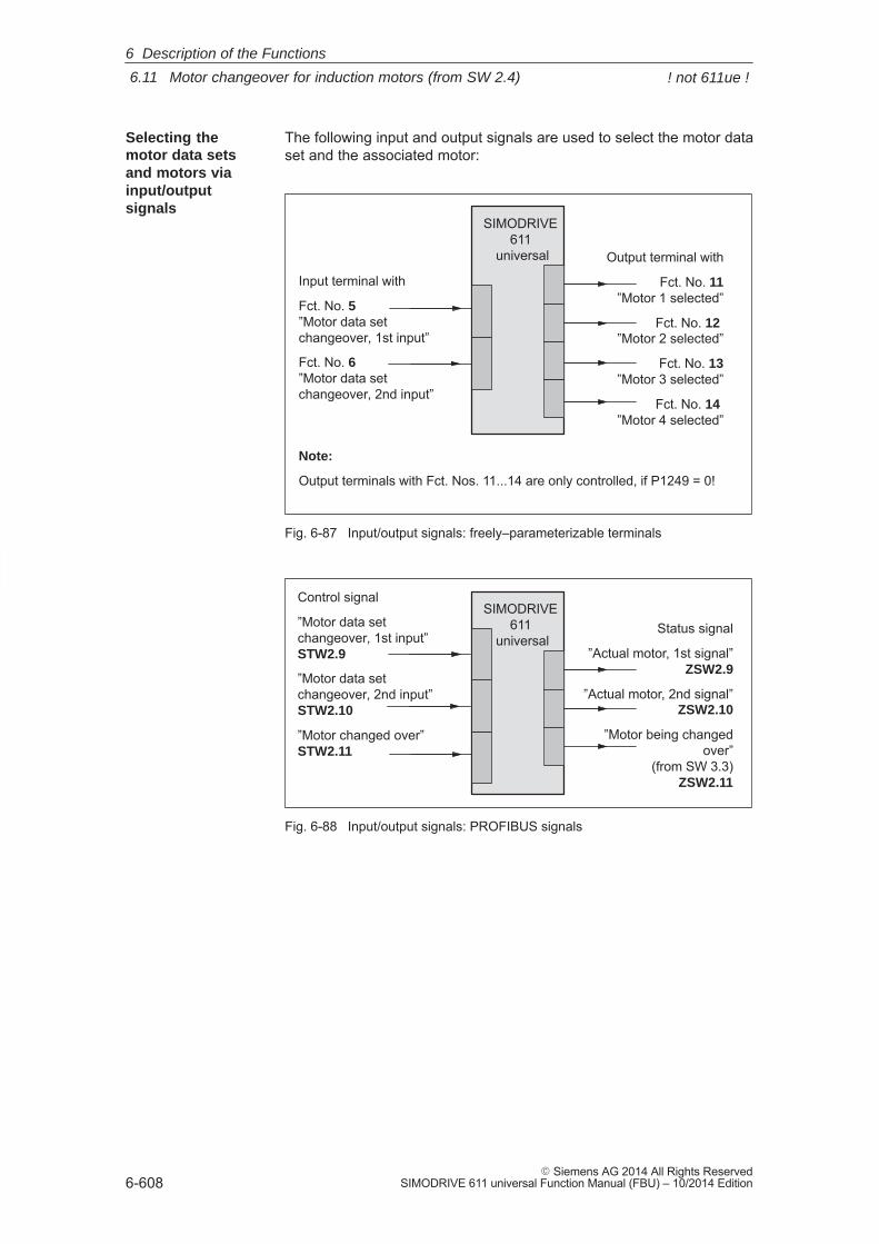
6
6.11 Motor changeover for induction motors (from SW 2.4)
6-608� Siemens AG 2014 All Rights Reserved
SIMODRIVE 611 universal Function Manual (FBU) – 10/2014 Edition
The following input and output signals are used to select the motor dataset and the associated motor:
Input terminal with
Fct. No. 5 ”Motor data set changeover, 1st input”
Fct. No. 6 ”Motor data set changeover, 2nd input”
Output terminal with
Fct. No. 11”Motor 1 selected”
Fct. No. 12 ”Motor 2 selected”
Fct. No. 13”Motor 3 selected”
Fct. No. 14 ”Motor 4 selected”
SIMODRIVE 611
universal
Note:
Output terminals with Fct. Nos. 11...14 are only controlled, if P1249 = 0!
Fig. 6-87 Input/output signals: freely–parameterizable terminals
Status signal
”Actual motor, 1st signal”ZSW2.9
”Actual motor, 2nd signal”ZSW2.10
”Motor being changedover”
(from SW 3.3) ZSW2.11
SIMODRIVE 611
universal
Control signal
”Motor data set changeover, 1st input”STW2.9
”Motor data set changeover, 2nd input”STW2.10
”Motor changed over”STW2.11
Fig. 6-88 Input/output signals: PROFIBUS signals
Selecting the motor data setsand motors viainput/outputsignals
6 Description of the Functions
! not 611ue !
6
6.11 Motor changeover for induction motors (from SW 2.4)
6-609� Siemens AG 2014 All Rights ReservedSIMODRIVE 611 universal Function Manual (FBU) – 10/2014 Edition
Reader’s note� Input signals: refer under the index entry ”Input signal...”
Output signals: refer under the index entry ”Output signal ...”� The wiring of the input/output terminals for the control board and for
the optional TERMINAL module is described in Chapter 2.2.� The following input/output terminals are available:
– for the control board: I0.x to I3.x or O0.x to O3.x x: Space retainer for drive A or B
– for the optional TERMINAL module: I4 to I11 or O4 to O11� The parameterization of the input/output terminals is described as
follows:– for the control board: in Chapter 6.4.2 and 6.4.5– for the optional TERMINAL module: in Chapter 6.5
A dedicated power module pulse frequency (P1100) can be parameter-ized for each motor data set.
The speed requirement of the motor can be better adapted by changingover the pulse frequency. With a higher pulse frequency, higher speedscan be achieved.
The following applies for the pulse frequency, it must have at leastapprox. 6 the frequency of the instantaneous motor frequency.
High pulse frequencies mean high switching losses and therefore poorutilization.At a pulse frequency of 8 kHz, only 40–55% of the possible current thatis available at 3.2 kHz is available.
Pulse frequencychangeover
6 Description of the Functions
! not 611ue !
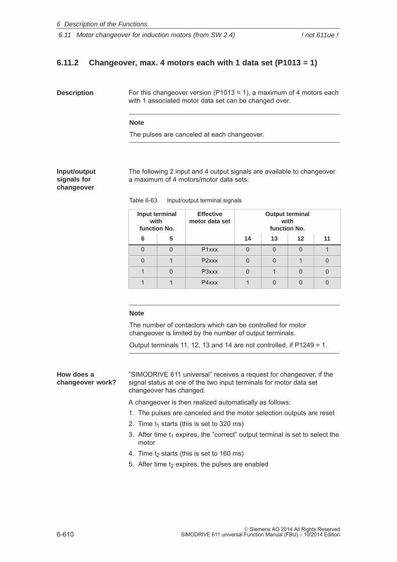
6
6.11 Motor changeover for induction motors (from SW 2.4)
6-610� Siemens AG 2014 All Rights Reserved
SIMODRIVE 611 universal Function Manual (FBU) – 10/2014 Edition
6.11.2 Changeover, max. 4 motors each with 1 data set (P1013 = 1)
For this changeover version (P1013 = 1), a maximum of 4 motors eachwith 1 associated motor data set can be changed over.
Note
The pulses are canceled at each changeover.
The following 2 input and 4 output signals are available to changeovera maximum of 4 motors/motor data sets:
Table 6-63 Input/output terminal signals
Input terminalwith
function No.
Effectivemotor data set
Output terminalwith
function No.
6 5 14 13 12 11
0 0 P1xxx 0 0 0 1
0 1 P2xxx 0 0 1 0
1 0 P3xxx 0 1 0 0
1 1 P4xxx 1 0 0 0
Note
The number of contactors which can be controlled for motorchangeover is limited by the number of output terminals.
Output terminals 11, 12, 13 and 14 are not controlled, if P1249 = 1.
”SIMODRIVE 611 universal” receives a request for changeover, if thesignal status at one of the two input terminals for motor data setchangeover has changed.
A changeover is then realized automatically as follows:1. The pulses are canceled and the motor selection outputs are reset2. Time t1 starts (this is set to 320 ms)3. After time t1 expires, the ”correct” output terminal is set to select the
motor4. Time t2 starts (this is set to 160 ms)5. After time t2 expires, the pulses are enabled
Description
Input/outputsignals forchangeover
How does a changeover work?
6 Description of the Functions
! not 611ue !
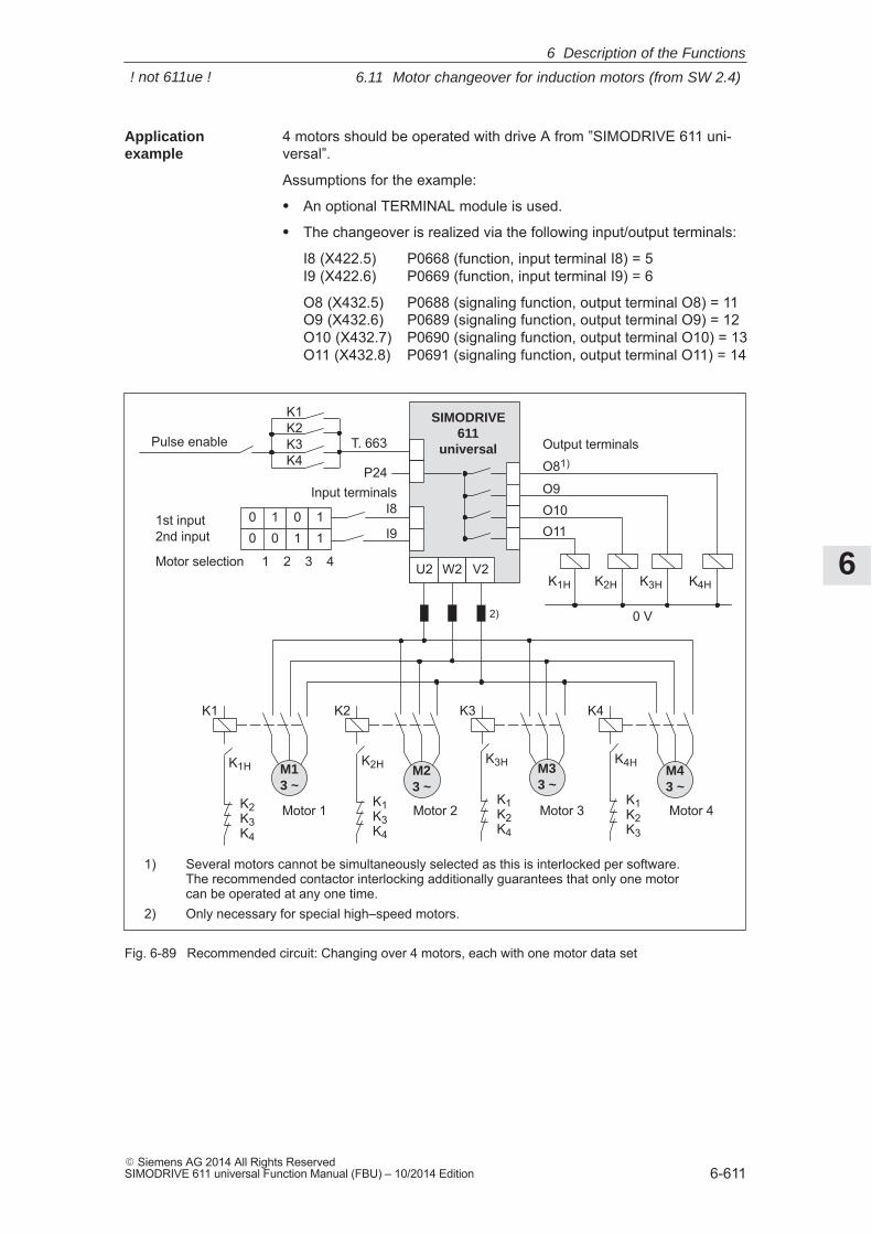
6
6.11 Motor changeover for induction motors (from SW 2.4)
6-611� Siemens AG 2014 All Rights ReservedSIMODRIVE 611 universal Function Manual (FBU) – 10/2014 Edition
4 motors should be operated with drive A from ”SIMODRIVE 611 uni-versal”.
Assumptions for the example:
� An optional TERMINAL module is used.
� The changeover is realized via the following input/output terminals:
I8 (X422.5) P0668 (function, input terminal I8) = 5I9 (X422.6) P0669 (function, input terminal I9) = 6
O8 (X432.5) P0688 (signaling function, output terminal O8) = 11O9 (X432.6) P0689 (signaling function, output terminal O9) = 12O10 (X432.7) P0690 (signaling function, output terminal O10) = 13O11 (X432.8) P0691 (signaling function, output terminal O11) = 14
SIMODRIVE611
universalT. 663
1) Several motors cannot be simultaneously selected as this is interlocked per software. The recommended contactor interlocking additionally guarantees that only one motor can be operated at any one time.
2) Only necessary for special high–speed motors.
Pulse enable
Motor 1 Motor 2 Motor 3 Motor 4
K1
M13 ~
K1K2K3K4
Input terminalsI8
I9
2)
K2
M23 ~
K1H
K2K3K4
K2H
K1K3K4
K3H
K1K2K4
K3
M33 ~
K4
M43 ~
K4H
K1K2K3
Output terminals
P24
U2 W2 V2
O11O10O9
O81)
00
1st input2nd input
Motor selection 1 2 3 4
10
01
11
K1H K2H K3H K4H
0 V
Fig. 6-89 Recommended circuit: Changing over 4 motors, each with one motor data set
Application example
6 Description of the Functions
! not 611ue !
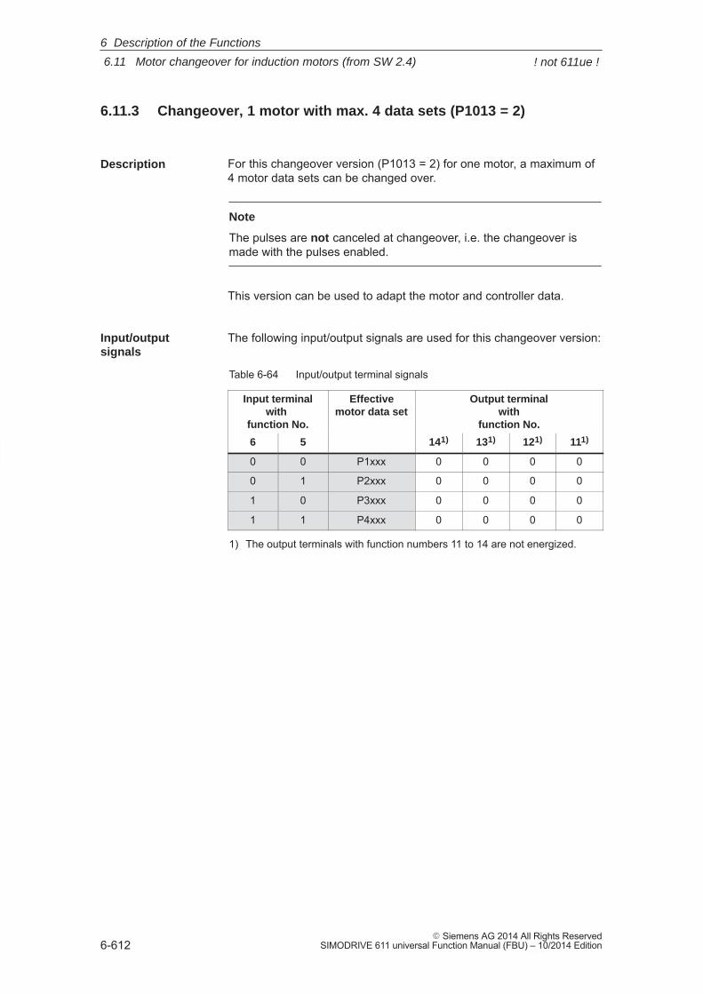
6
6.11 Motor changeover for induction motors (from SW 2.4)
6-612� Siemens AG 2014 All Rights Reserved
SIMODRIVE 611 universal Function Manual (FBU) – 10/2014 Edition
6.11.3 Changeover, 1 motor with max. 4 data sets (P1013 = 2)
For this changeover version (P1013 = 2) for one motor, a maximum of4 motor data sets can be changed over.
Note
The pulses are not canceled at changeover, i.e. the changeover ismade with the pulses enabled.
This version can be used to adapt the motor and controller data.
The following input/output signals are used for this changeover version:
Table 6-64 Input/output terminal signals
Input terminalwith
function No.
Effectivemotor data set
Output terminalwith
function No.
6 5 141) 131) 121) 111)
0 0 P1xxx 0 0 0 0
0 1 P2xxx 0 0 0 0
1 0 P3xxx 0 0 0 0
1 1 P4xxx 0 0 0 0
1) The output terminals with function numbers 11 to 14 are not energized.
Description
Input/output signals
6 Description of the Functions
! not 611ue !
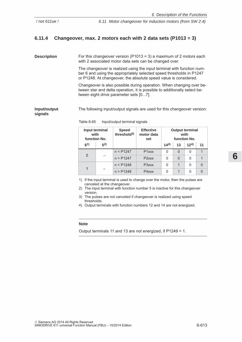
6
6.11 Motor changeover for induction motors (from SW 2.4)
6-613� Siemens AG 2014 All Rights ReservedSIMODRIVE 611 universal Function Manual (FBU) – 10/2014 Edition
6.11.4 Changeover, max. 2 motors each with 2 data sets (P1013 = 3)
For this changeover version (P1013 = 3) a maximum of 2 motors eachwith 2 associated motor data sets can be changed over.
The changeover is realized using the input terminal with function num-ber 6 and using the appropriately selected speed thresholds in P1247or P1248. At changeover, the absolute speed value is considered.
Changeover is also possible during operation. When changing over be-tween star and delta operation, it is possible to additionally select be-tween eight drive parameter sets [0...7].
The following input/output signals are used for this changeover version:
Table 6-65 Input/output terminal signals
Input terminalwith
function No.
Speedthreshold3)
Effectivemotor data
set
Output terminalwith
function No.
61) 52) 144) 13 124) 11
0 –n < P1247 P1xxx 0 0 0 1
0 –n > P1247 P2xxx 0 0 0 1
1 –n < P1248 P3xxx 0 1 0 0
1 –n > P1248 P4xxx 0 1 0 0
1) If the input terminal is used to change over the motor, then the pulses arecanceled at the changeover.
2) The input terminal with function number 5 is inactive for this changeoverversion.
3) The pulses are not canceled if changeover is realized using speedthresholds.
4) Output terminals with function numbers 12 and 14 are not energized.
Note
Output terminals 11 and 13 are not energized, if P1249 = 1.
Description
Input/output signals
6 Description of the Functions
! not 611ue !
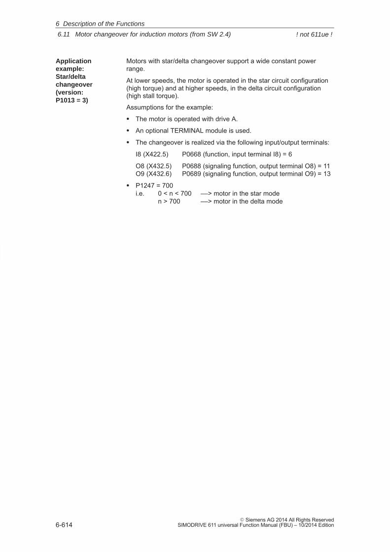
6
6.11 Motor changeover for induction motors (from SW 2.4)
6-614� Siemens AG 2014 All Rights Reserved
SIMODRIVE 611 universal Function Manual (FBU) – 10/2014 Edition
Motors with star/delta changeover support a wide constant powerrange.
At lower speeds, the motor is operated in the star circuit configuration(high torque) and at higher speeds, in the delta circuit configuration(high stall torque).
Assumptions for the example:
� The motor is operated with drive A.
� An optional TERMINAL module is used.
� The changeover is realized via the following input/output terminals:
I8 (X422.5) P0668 (function, input terminal I8) = 6
O8 (X432.5) P0688 (signaling function, output terminal O8) = 11O9 (X432.6) P0689 (signaling function, output terminal O9) = 13
� P1247 = 700i.e. 0 < n < 700 ––> motor in the star mode
n > 700 ––> motor in the delta mode
Applicationexample: Star/deltachangeover(version:P1013 = 3)
6 Description of the Functions
! not 611ue !
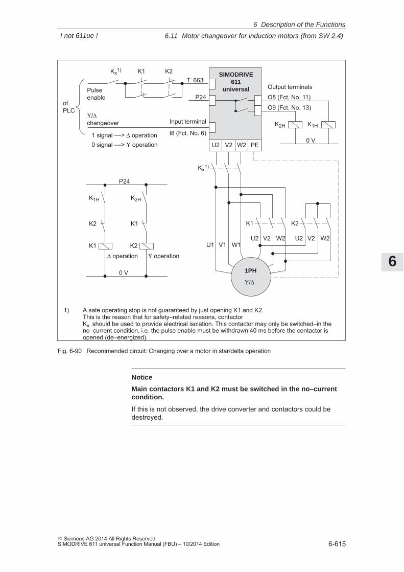
6
6.11 Motor changeover for induction motors (from SW 2.4)
6-615� Siemens AG 2014 All Rights ReservedSIMODRIVE 611 universal Function Manual (FBU) – 10/2014 Edition
SIMODRIVE611
universal
U2 V2 W2
Υ/Δ changeover Input terminal
I8 (Fct. No. 6)
Output terminals
O9 (Fct. No. 13)
O8 (Fct. No. 11)
K2H K1H
P24Pulse enable
PE
K1
K1 K2
1PH
Υ/Δ
U1 V1 W1U2 V2 W2 U2 V2 W2
Kx1)
0 V
K1H K2H
Δ operation
K2
Υ operation
P24
0 V
K1 K2Kx1)
T. 663
ofPLC
1) A safe operating stop is not guaranteed by just opening K1 and K2.This is the reason that for safety–related reasons, contactor Kx should be used to provide electrical isolation. This contactor may only be switched–in theno–current condition, i.e. the pulse enable must be withdrawn 40 ms before the contactor isopened (de–energized).
K2 K1
1 signal ––> Δ operation0 signal ––> Υ operation
Fig. 6-90 Recommended circuit: Changing over a motor in star/delta operation
Notice
Main contactors K1 and K2 must be switched in the no–currentcondition.
If this is not observed, the drive converter and contactors could bedestroyed.
6 Description of the Functions
! not 611ue !

6
6.11 Motor changeover for induction motors (from SW 2.4)
6-616� Siemens AG 2014 All Rights Reserved
SIMODRIVE 611 universal Function Manual (FBU) – 10/2014 Edition
6.11.5 Parameters for motor changeover
The following parameters are available for motor changeover:
Table 6-66 Parameters for motor changeover
Parameter
No. Description Min. Standard Max. Unit Effective
1013 Enable, motor changeover (ARM) 0 0 3 – PO
... the motor changeover is enabled or the motor changeover type is selectedValue Description0 Motor changeover inhibited1 Motor changeover with pulse cancellation2 Motor changeover without pulse cancellation (data set changeover)3 Motor changeover using speed thresholds (P1247, P1248)Note:
It is only possible to enable motor changeover in the ”speed/torque setpoint” mode (P0700 =1).
1247 Speed thresholdmotor changeover 1/2 (ARM)
100.0 100 000.0 100 000.0 RPM immedi-ately
1248 Speed thresholdmotor changeover 3/4 (ARM)
100.0 100 000.0 100 000.0 RPM immedi-ately
... the speed thresholds for the motor changeover are defined with speed threshold (P1013 =3).P1247:Below P1247 minus 5% hysteresis, the first motor data set is selected (P1xxx).Above P1247 plus 5% hysteresis, the second motor data set is selected (P2xxx).P1248:Below P1248 minus 5% hysteresis, the third motor data set is selected (P3xxx).Above P1248 plus 5% hysteresis, the fourth motor data set is selected (P4xxx).
Motor data set Motor data setP1xxx P1247 P2xxxP3xxx P1248 P4xxx
n5 % 5 %
Parameter overview
6 Description of the Functions
! not 611ue !
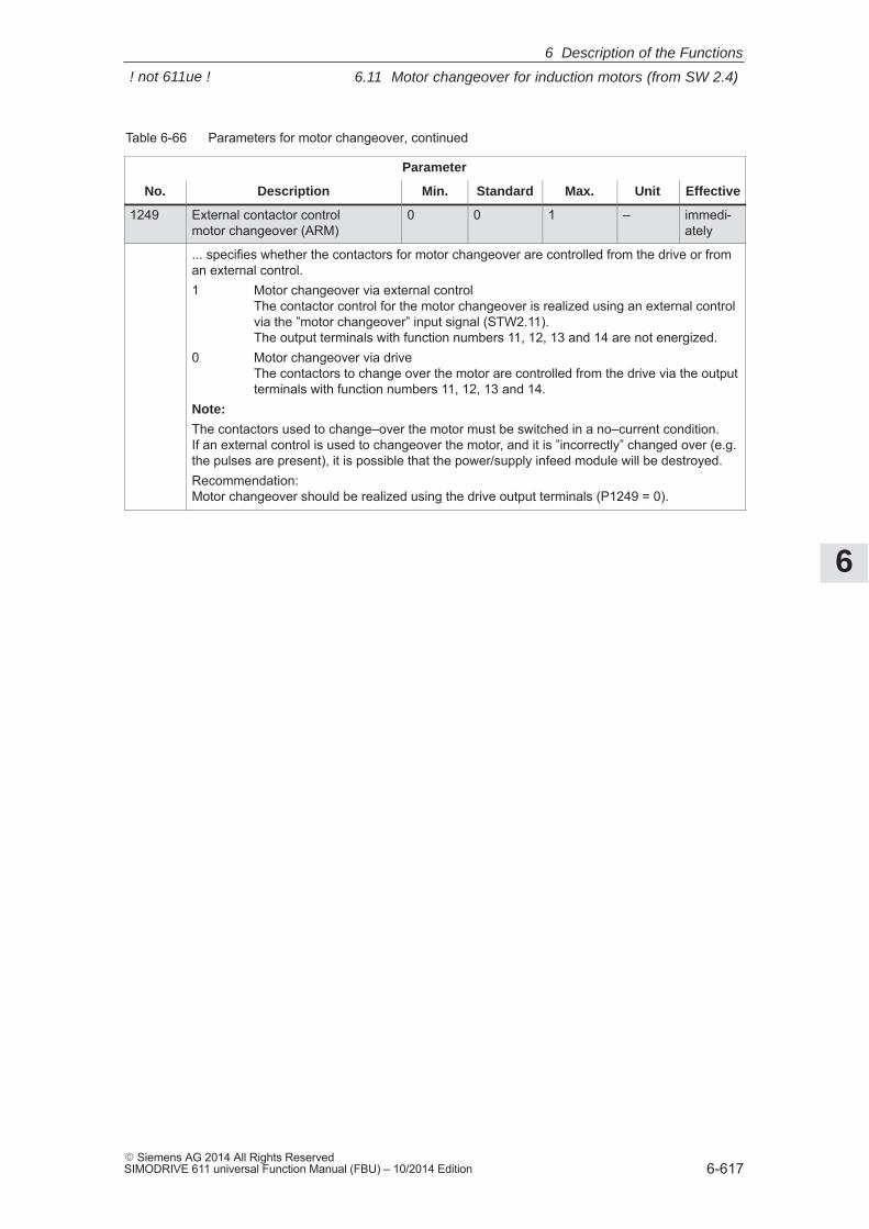
6
6.11 Motor changeover for induction motors (from SW 2.4)
6-617� Siemens AG 2014 All Rights ReservedSIMODRIVE 611 universal Function Manual (FBU) – 10/2014 Edition
Table 6-66 Parameters for motor changeover, continued
Parameter
No. EffectiveUnitMax.StandardMin.Description
1249 External contactor controlmotor changeover (ARM)
0 0 1 – immedi-ately
... specifies whether the contactors for motor changeover are controlled from the drive or froman external control.1 Motor changeover via external control
The contactor control for the motor changeover is realized using an external controlvia the ”motor changeover” input signal (STW2.11). The output terminals with function numbers 11, 12, 13 and 14 are not energized.
0 Motor changeover via driveThe contactors to change over the motor are controlled from the drive via the outputterminals with function numbers 11, 12, 13 and 14.
Note:
The contactors used to change–over the motor must be switched in a no–current condition.If an external control is used to changeover the motor, and it is ”incorrectly” changed over (e.g.the pulses are present), it is possible that the power/supply infeed module will be destroyed.Recommendation:Motor changeover should be realized using the drive output terminals (P1249 = 0).
6 Description of the Functions
! not 611ue !
6
6.12 Travel to fixed stop (positioning mode) (from SW 3.3)
6-618� Siemens AG 2014 All Rights Reserved
SIMODRIVE 611 universal Function Manual (FBU) – 10/2014 Edition
6.12 Travel to fixed stop (positioning mode) (from SW 3.3)
A linear or rotary axis can be traversed in the ”positioning” mode byspecifying a target position and a maximum possible torque using the”travel to fixed endstop” function. When a fixed stop is reached, thenthe defined torque/force is established.
This property can be used, e.g. for the following tasks:
� To clamp workpieces (e.g. to press the spindle sleeve against theworkpiece)
� Approaching the mechanical reference point
� Carry out simple measuring operations (e.g. with a low torque)
The function is programmed using the FIXED STOP command. Theclamping torque must also be specified in this traversing block. Thefollowing applies:
Drive Value range and units for the clamping torque/clamping force
� Rotating 1 – 65 535 [0.01 Nm]
� Linear 1 – 65 535 [0.01 N]
A selectable fixed endstop monitoring window prevents the drive fromcontinuing after the fixed endstop has been reached (e.g. when thefixed endstop breaks–off)
Note
When jogging (closed–loop speed control), travel to fixed stop is alsopossible by suppressing fault 608 (speed controller output limited)using the ”suppress fault 608” input signal.
The ”travel to fixed stop” function may not be used for coupled axes.
The following applies to axes with incremental measuring system:
After a traversing block has been executed with the ”fixed stop” com-mand and the block change enable END, the axis can be re–refer-enced at the fixed stop using the ”set reference point” function.
Description
Application example
6 Description of the Functions
! not 611ue !
6
6.12 Travel to fixed stop (positioning mode) (from SW 3.3)
6-619� Siemens AG 2014 All Rights ReservedSIMODRIVE 611 universal Function Manual (FBU) – 10/2014 Edition
The following sequence applies for the ”travel to fixed stop” function:
� How is this function started?
The function is started when executing a traversing block with theFIXED STOP command.
The same data as for a positioning set should be made in this tra-versing block and, in addition, also the clamping torque in [0.01 Nm]or the clamping force in [N] (refer under the index entry ”Command–dependent block information”).
In order that the fixed endstop (workpiece) can be reached at all, itmust be located between the start and target positions. The targetposition must be selected a considerable distance behind the fixedstop.
� How is the axis moved after start?
– After starting the block, the axis travels in the direction of the tar-get position with the programmed velocity.
– The clamping torque/clamping force, programmed in this block,already becomes effective from the starting position, i.e. the axismoves to the fixed stop with the reduced torque limit/force limit.
– The dynamic following error monitoring is not effective when trav-eling to the fixed stop.
� What happens if ...
– ... the fixed stop is reached before the target position is reached(standard case)?
––> refer to ”What happens if the fixed stop is reached?”
– ... the fixed stop is not reached, but the target position is ap-proached?
––> refer to ”What happens if the fixed stop is not reached?”
– ... the programmed clamping torque is not reached.
––> refer to ”What happens if the fixed stop is reached but theprogrammed clamping torque is not reached?”
– ... the axis is first at the fixed stop and then leaves this position,i.e. has the fixed stop broken off?
––> then the fixed endstop monitoring becomes effective, i.e. theaxis then moves by the distance, set in P0116:8 (fixed endstopmonitoring window) plus the braking ramp.
––> refer to ”fixed endstop” monitoring window
Flowchart
6 Description of the Functions
! not 611ue !
6
6.12 Travel to fixed stop (positioning mode) (from SW 3.3)
6-620� Siemens AG 2014 All Rights Reserved
SIMODRIVE 611 universal Function Manual (FBU) – 10/2014 Edition
If the axis moves to a fixed stop, then the behavior is as follows:
� The closed–loop drive control increases the torque for the axis up tothe programmed clamping torque, and then keeps it constant.
� The ”fixed stop reached” status is reached as follows, depending onP0114 (fixed stop, configuration 2):
Table 6-67 Behavior, if the fixed stop is reached
If the following is valid for the ”fixed stop reached” status:
P0114 = 0(standard)
The status is automatically reached, if the following error ex-ceeds the theoretically calculated following error by the valueentered in P0115:8.Note:
� Refer under the index entry ”Dynamic following error moni-toring”
� The following applies for the target position:Target position > position, fixed stop + P0115:8 + brakingtravel
P0114 = 1 The status is only reached, if it is recognized via the ”sensor,fixed stop” input signal.
� The following applies after the ”fixed stop reached” status has beenrecognized:
– The distance to go is deleted
– The position reference value is tracked
– The fixed endstop monitoring is activated
– The controller enable remains active
– The ”fixed stop reached” output signal is set
– Is the programmed clamping torque reached?
Yes ––> the output signal”fixed stop, clamping torque reached” is set
No ––> the behavior is dependent on P0113.1
Table 6-68 Behavior, if the clamping torque is not reached
If Then the following is valid:
P0113.1 = 0(standard)
Warning 889 is signaledThe block change enable is only realized, as programmed inthe block, only after the clamping torque has been reached.
P0113.1 = 1 Warning 889 is signaled and a block change is madeThe block change enable is realized as programmed in theblock.
Note:
The block change enable CONTINUE FLYING, behaves just like the blockchange enable CONTINUE WITH STOP.
What happens ifthe fixed stop isreached?
6 Description of the Functions
! not 611ue !
6
6.12 Travel to fixed stop (positioning mode) (from SW 3.3)
6-621� Siemens AG 2014 All Rights ReservedSIMODRIVE 611 universal Function Manual (FBU) – 10/2014 Edition
– The clamping torque remains, if ...subsequently, e.g. blocks are processed with the commandsWAIT, GOTO, SET_O or RESET_OThere is no subsequent block, i.e. the traversing program hasbeen completed
– the position can be read in P0002 (actual traversing block – position)
If, for a traversing block, the axis moves to the brake initiation pointwith the FIXED STOP command, without detecting the status ”fixedstop reached”, then the following behavior applies, dependent onP0113.0:
Table 6-69 Behavior, if the fixed stop is not reached
If Then the following is valid:
P0113.0 = 0(standard)
Fault 145 is signaledThe torque limiting is automatically disabled. The axis is brakedand comes to a standstill in front of the programmed target posi-tion. The deviation from the reference position depends on:� Positioning velocity� Acceleration� Deceleration
P0113.0 = 1 A block change is madeThe torque limiting is automatically disabled. The block changeenable is realized as programmed in the block.
The ”travel to fixed stop” function is interrupted, and if warning 889 ispresent it is acknowledged, if one of the following occurs:� The next block is processed with the POSITIONING command� the jogging mode is selected if previously interrupted
––> with the input signal ”reject operating condition/traversing task”� The controller enable is withdrawn (––> fault 147)� Pulse enable is withdrawn (––> fault 147)
The following applies for a traversing block with the FIXED STOP com-mand:
� Interrupt and continue––> using the ”operating condition/intermediate stop” input signal
� Exit––> using the ”operating condition/reject traversing task” input signal
In all of these cases, the drive is correspondingly braked.
Interruption at the fixed stop:The drive remains at the fixed stop, and can be moved away from iteither in the jog mode, or by starting a new traversing block.
What happens ifthe fixed stop isnot reached?
Canceling the”travel to fixedstop” function
Interrupting orexiting the ”travelto fixed stop”function
6 Description of the Functions
! not 611ue !
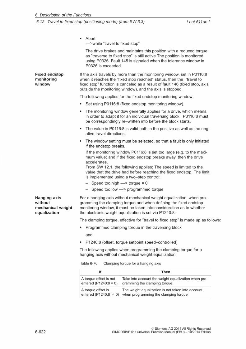
6
6.12 Travel to fixed stop (positioning mode) (from SW 3.3)
6-622� Siemens AG 2014 All Rights Reserved
SIMODRIVE 611 universal Function Manual (FBU) – 10/2014 Edition
� Abort––>while ”travel to fixed stop”
The drive brakes and maintains this position with a reduced torqueas ”traverse to fixed stop” is still active The position is monitoredusing P0326. Fault 145 is signaled when the tolerance window inP0326 is exceeded.
If the axis travels by more than the monitoring window, set in P0116:8when it reaches the ”fixed stop reached” status, then the ”travel tofixed stop” function is canceled as a result of fault 146 (fixed stop, axisoutside the monitoring window), and the axis is stopped.
The following applies for the fixed endstop monitoring window:
� Set using P0116:8 (fixed endstop monitoring window).
� The monitoring window generally applies for a drive, which means,in order to adapt it for an individual traversing block, P0116:8 mustbe correspondingly re–written into before the block starts.
� The value in P0116:8 is valid both in the positive as well as the neg-ative travel directions.
� The window setting must be selected, so that a fault is only initiatedif the endstop breaks.If the monitoring window P0116:8 is set too large (e.g. to the maxi-mum value) and if the fixed endstop breaks away, then the driveaccelerates.From SW 12.1, the following applies: The speed is limited to thevalue that the drive had before reaching the fixed endstop. The limitis implemented using a two–step control:– Speed too high ––> torque = 0– Speed too low ––> programmed torque
For a hanging axis without mechanical weight equalization, when pro-gramming the clamping torque and when defining the fixed endstopmonitoring window, it must be taken into consideration as to whetherthe electronic weight equalization is set via P1240:8.
The clamping torque, effective for ”travel to fixed stop” is made up as follows:
� Programmed clamping torque in the traversing block
and
� P1240:8 (offset, torque setpoint speed–controlled)
The following applies when programming the clamping torque for ahanging axis without mechanical weight equalization:
Table 6-70 Clamping torque for a hanging axis
If Then
A torque offset is notentered (P1240:8 = 0)
Take into account the weight equalization when pro-gramming the clamping torque.
A torque offset isentered (P1240:8 � 0)
The weight equalization is not taken into accountwhen programming the clamping torque
Fixed endstopmonitoringwindow
Hanging axiswithoutmechanical weightequalization
6 Description of the Functions
! not 611ue !
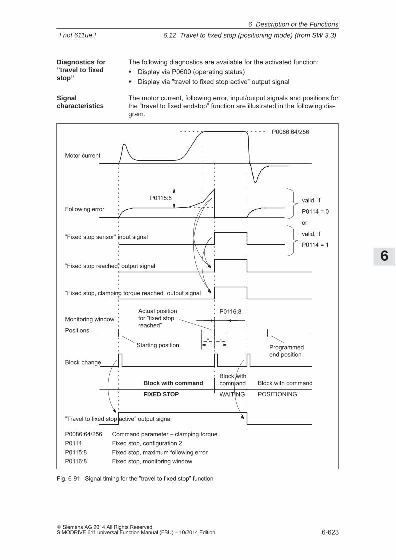
6
6.12 Travel to fixed stop (positioning mode) (from SW 3.3)
6-623� Siemens AG 2014 All Rights ReservedSIMODRIVE 611 universal Function Manual (FBU) – 10/2014 Edition
The following diagnostics are available for the activated function:� Display via P0600 (operating status)� Display via ”travel to fixed stop active” output signal
The motor current, following error, input/output signals and positions forthe ”travel to fixed endstop” function are illustrated in the following dia-gram.
Following error
Motor current
P0115:8
”Fixed stop reached” output signal
Block change
P0086:64/256
”Fixed stop sensor” input signal
Block with command
FIXED STOP
Block with command
POSITIONING
valid, if
P0114 = 0
or
valid, if
P0114 = 1
P0086:64/256 Command parameter – clamping torqueP0114 Fixed stop, configuration 2P0115:8 Fixed stop, maximum following errorP0116:8 Fixed stop, monitoring window
Monitoring window
Positions
Starting position Programmedend position
P0116:8Actual positionfor ”fixed stopreached”
–”––”–
”Fixed stop, clamping torque reached” output signal
”Travel to fixed stop active” output signal
Block withcommand
WAITING
Fig. 6-91 Signal timing for the ”travel to fixed stop” function
Diagnostics for”travel to fixedstop”
Signalcharacteristics
6 Description of the Functions
! not 611ue !
6
6.12 Travel to fixed stop (positioning mode) (from SW 3.3)
6-624� Siemens AG 2014 All Rights Reserved
SIMODRIVE 611 universal Function Manual (FBU) – 10/2014 Edition
!Caution
It must be ensured, that after the ”travel to fixed endstop” function iswithdrawn as a result of EMERGENCY OFF, the machine cannot gointo a potentially hazardous state (e.g. the clamped workpiece dropsout of the clamping mechanism after EMERGENCY OFF).
The following parameters are available for the ”travel to fixed stop”function:
� P0113 Fixed stop, configuration 1
� P0114 Fixed stop, configuration 2
� P0115:8 Fixed stop, maximum following error
� P0116:8 Fixed stop, monitoring window
� P1240:8 Offset, torque setpoint (speed controlled)Offset, force setpoint (speed controlled)
The following signals are used for the function ”traverse to fixed stop”:
� Input signals(refer under index entry ”Input signal, digital – ...”)
– ”Fixed stop sensor” input signal
––> using an input terminal with function number 68
––> using PROFIBUS control signal PosStw.3
� Output signals(refer under the index entry, ”Output signal, digital – ...”)
– ”Fixed stop reached” output signal
––> using an output terminal with function number 68
––> using PROFIBUS status signal PosZsw.12
– ”Fixed stop, clamping torque reached” output signal
––> using an output terminal with function number 73
––> using PROFIBUS status signal PosZsw.13
– ”Travel to fixed stop active” output signal
––> using an output terminal with function number 66
––> using PROFIBUS status signal PosZsw.14
Travel to fixedendstop andEMERGENCY OFF
Parameteroverview(refer to ChapterA.1)
Input/outputsignals
6 Description of the Functions
! not 611ue !
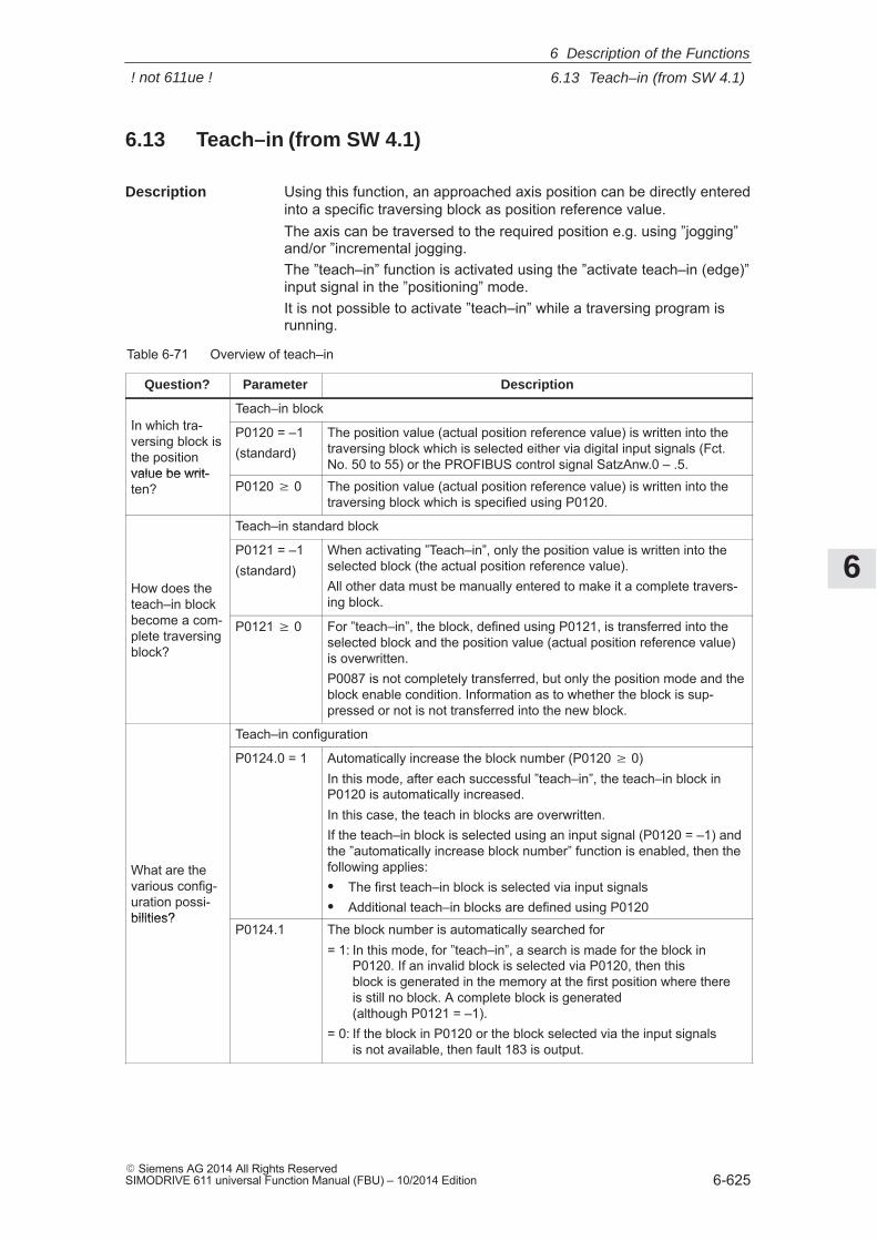
6
6.13 Teach–in (from SW 4.1)
6-625� Siemens AG 2014 All Rights ReservedSIMODRIVE 611 universal Function Manual (FBU) – 10/2014 Edition
6.13 Teach–in (from SW 4.1)
Using this function, an approached axis position can be directly enteredinto a specific traversing block as position reference value.The axis can be traversed to the required position e.g. using ”jogging”and/or ”incremental jogging.The ”teach–in” function is activated using the ”activate teach–in (edge)”input signal in the ”positioning” mode.It is not possible to activate ”teach–in” while a traversing program isrunning.
Table 6-71 Overview of teach–in
Question? Parameter Description
In which tra-Teach–in block
In which tra-versing block isthe positionvalue be writ-
P0120 = –1(standard)
The position value (actual position reference value) is written into thetraversing block which is selected either via digital input signals (Fct.No. 50 to 55) or the PROFIBUS control signal SatzAnw.0 – .5.
value be writ-ten? P0120 � 0 The position value (actual position reference value) is written into the
traversing block which is specified using P0120.
Teach–in standard block
How does theteach–in blockbecome a com-
P0121 = –1(standard)
When activating ”Teach–in”, only the position value is written into theselected block (the actual position reference value).All other data must be manually entered to make it a complete travers-ing block.teach–in block
become a com-plete traversingblock?
P0121 � 0 For ”teach–in”, the block, defined using P0121, is transferred into theselected block and the position value (actual position reference value)is overwritten.P0087 is not completely transferred, but only the position mode and theblock enable condition. Information as to whether the block is sup-pressed or not is not transferred into the new block.
Teach–in configuration
What are thevarious config-uration possi-bilities?
P0124.0 = 1 Automatically increase the block number (P0120 � 0)In this mode, after each successful ”teach–in”, the teach–in block inP0120 is automatically increased.In this case, the teach in blocks are overwritten.If the teach–in block is selected using an input signal (P0120 = –1) andthe ”automatically increase block number” function is enabled, then thefollowing applies:� The first teach–in block is selected via input signals� Additional teach–in blocks are defined using P0120
bilities?P0124.1 The block number is automatically searched for
= 1: In this mode, for ”teach–in”, a search is made for the block in P0120. If an invalid block is selected via P0120, then this block is generated in the memory at the first position where there is still no block. A complete block is generated (although P0121 = –1).
= 0: If the block in P0120 or the block selected via the input signals is not available, then fault 183 is output.
Description
6 Description of the Functions
! not 611ue !
6
6.13 Teach–in (from SW 4.1)
6-626� Siemens AG 2014 All Rights Reserved
SIMODRIVE 611 universal Function Manual (FBU) – 10/2014 Edition
The following parameters are available for the ”teach–in” function:
� P0120 Teach–in block
� P0121 Teach–in standard block
� P0124 Teach–in configuration
The following signals are used for the ”teach–in” function:
� Input signals(refer under index entry ”Input signal, digital – ...”)
– Input signal ”activate teach–in (edge)”
––> using an input terminal with function number 64
––> using the PROFIBUS control signal ”PosStw.6”
– up to SW 9.2Input signal ”block selection 1st to 6th input”
––> using an input terminal with function number 50 – 55
––> using PROFIBUS control signal SatzAnw.0 – .5
– From SW 10.1Input signal ”block selection 1st to 8th input”
––> using an input terminal with function number 50 – 57
––> using PROFIBUS control signal SatzAnw.0 – .7
� Output signals(refer under the index entry, ”Output signal, digital – ...”)
– Output signal ”teach–in successful”
––> using an output terminal with function number 64
––> using the PROFIBUS status signal ”PosZsw.15”
Note
The positions with teach–in are only transferred into the RAM memory.Data is manually saved using the ”SimoCom U” parameterizing andstart–up tool with ”Save in the drive (FEPROM)”.
Parameteroverview(refer to ChapterA.1)
Input/outputsignals (refer toChapter 6.4)
6 Description of the Functions
! not 611ue !
6
6.14 Dynamic Servo Control (DSC, from SW 4.1)
6-627� Siemens AG 2014 All Rights ReservedSIMODRIVE 611 universal Function Manual (FBU) – 10/2014 Edition
6.14 Dynamic Servo Control (DSC, from SW 4.1)
The ”Dynamic Servo Control” ( DSC) is a closed–loop control structurewhich is computed in a fast speed controller clock cycle and is suppliedwith setpoints by the control in the position controller clock cycle.
This allows higher position controller gain factors to be achieved.
The following prerequisites are necessary to use Dynamic Servo Control:
� n–set mode
� Isochronous PROFIBUS–DP
� The position controller gain factor (KPC) and the system deviation(XERR) must be included in the PROFIBUS–DP setpoint telegram(refer to P0915)
� The position actual value must be transferred to the master in theactual value telegram of PROFIBUS–DP via the encoder interfaceGx_XIST1 (refer to Chapter 5.6.4)
� When DSC is activated, the speed setpoint N_SOLL_B from thePROFIBUS telegram is used as speed pre–control value
� The internal quasi–position controller uses the position actual valuefrom the motor measuring system (G1_XIST1)
Description
Condition
6 Description of the Functions
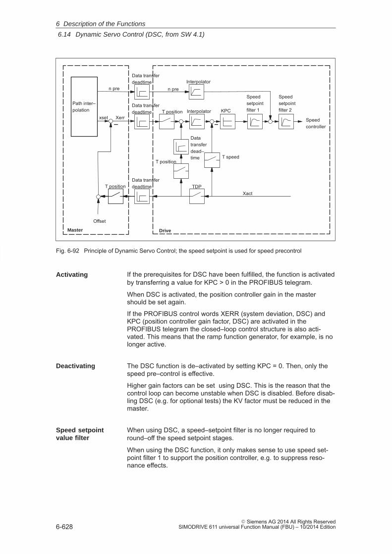
6
6.14 Dynamic Servo Control (DSC, from SW 4.1)
6-628� Siemens AG 2014 All Rights Reserved
SIMODRIVE 611 universal Function Manual (FBU) – 10/2014 Edition
T speed
Data transferdeadtime
Data transferdeadtime
Data transferdeadtime
Speedsetpointfilter 2
Speedsetpointfilter 1
Datatransferdead–time
T position
TDP
Interpolator
Interpolator
Speedcontroller
XerrKPC
n pre
Offset
Master Drive
n pre
xsetT position
T positionXact
Path inter–polation
Fig. 6-92 Principle of Dynamic Servo Control; the speed setpoint is used for speed precontrol
If the prerequisites for DSC have been fulfilled, the function is activatedby transferring a value for KPC > 0 in the PROFIBUS telegram.
When DSC is activated, the position controller gain in the mastershould be set again.
If the PROFIBUS control words XERR (system deviation, DSC) andKPC (position controller gain factor, DSC) are activated in thePROFIBUS telegram the closed–loop control structure is also acti-vated. This means that the ramp function generator, for example, is nolonger active.
The DSC function is de–activated by setting KPC = 0. Then, only thespeed pre–control is effective.
Higher gain factors can be set using DSC. This is the reason that thecontrol loop can become unstable when DSC is disabled. Before disab-ling DSC (e.g. for optional tests) the KV factor must be reduced in themaster.
When using DSC, a speed–setpoint filter is no longer required toround–off the speed setpoint stages.
When using the DSC function, it only makes sense to use speed set-point filter 1 to support the position controller, e.g. to suppress reso-nance effects.
Activating
Deactivating
Speed setpointvalue filter
6 Description of the Functions
6
6.15 Spindle positioning (from SW 5.1)
6-629� Siemens AG 2014 All Rights ReservedSIMODRIVE 611 universal Function Manual (FBU) – 10/2014 Edition
6.15 Spindle positioning (from SW 5.1)
Using the ”spindle positioning” function, in the ”n–set” mode, thespindle can be traversed to a specific position and then held there.
The function is activated in the ”n–set” mode (P0700 = 1) via the inputsignal ”spindle positioning on” or via PROFIBUS–DP (STW1.15), ifP0125 = 1 (spindle positioning active).
Note
If the ”spindle positioning” function is carried–out using NC functionality(e.g. SINUMERIK 802D), then P0125 must be set to 0 (spindlepositioning de–activated).
In addition, a traversing block number must be entered via a terminal orPROFIBUS–DP. If a bit is not selected for the traversing block number,then data in traversing block 0 is used.The following is mainly defined in the traversing block:� The target position (also via PROFIBUS–DP control word XSP is
possible, being prepared)� The search velocity, and� How the axis approaches the target position
The target position can be approached as follows:� With the actual direction of rotation� With a defined direction of rotation (clockwise, counter–clockwise)
� With a motor encoder (sin/cos 1 Vpp)� With a motor encoder (sin/cos 1 Vpp) and external zero (BERO) at
the spindle when the gearbox stage is being changed–over� With direct measuring system (spindle encoder, sin/cos 1 Vpp) via
encoder connection X412 (drive B)
� Spindle positioning only with motor 1.� If spindle positioning has been selected, then the encoder informa-
tion for PROFIBUS–DP (G1_STW, G1_ZSW) is no longer preciselytransferred.
� If ”spindle positioning on” is selected using a terminal or PROFI-BUS–DP (for P0125 = 1), then the ”relative” positioning mode(P0087:64/256) may no longer be programmed in the currently se-lected traversing block.
� When spindle positioning is selected, it is not possible to changeover the motor via PROFIBUS–DP.
� Spindle positioning is not supported in conjunction with the absolutedistance–coded measuring systems.
� Spindle positioning is not permissible in encoderless mode. Thethreshold speed specified may not be exceeded. After exceedingthe threshold speed, the spindle is positioned incorrectly!
Description
Activating
Position actualvalue sensing
Boundaryconditions
6 Description of the Functions
! not 611ue !
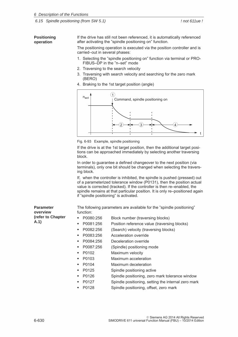
6
6.15 Spindle positioning (from SW 5.1)
6-630� Siemens AG 2014 All Rights Reserved
SIMODRIVE 611 universal Function Manual (FBU) – 10/2014 Edition
If the drive has still not been referenced, it is automatically referencedafter activating the ”spindle positioning on” function.The positioning operation is executed via the position controller and iscarried–out in several phases:1. Selecting the ”spindle positioning on” function via terminal or PRO-
FIBUS–DP in the ”n–set” mode2. Traversing to the search velocity3. Traversing with search velocity and searching for the zero mark
(BERO)4. Braking to the 1st target position (angle)
nact
t
Command, spindle positioning on1
2 3 4
Fig. 6-93 Example, spindle positioning
If the drive is at the 1st target position, then the additional target posi-tions can be approached immediately by selecting another traversingblock.In order to guarantee a defined changeover to the next position (viaterminals), only one bit should be changed when selecting the travers-ing block.If, when the controller is inhibited, the spindle is pushed (pressed) outof a parameterized tolerance window (P0131), then the position actualvalue is corrected (tracked). If the controller is then re–enabled, thespindle remains at that particular position. It is only re–positioned againif ”spindle positioning” is activated.
The following parameters are available for the ”spindle positioning”function:� P0080:256 Block number (traversing blocks)� P0081:256 Position reference value (traversing blocks)� P0082:256 (Search) velocity (traversing blocks)� P0083:256 Acceleration override� P0084:256 Deceleration override� P0087:256 (Spindle) positioning mode� P0102 Maximum velocity� P0103 Maximum acceleration� P0104 Maximum deceleration� P0125 Spindle positioning active� P0126 Spindle positioning, zero mark tolerance window� P0127 Spindle positioning, setting the internal zero mark� P0128 Spindle positioning, offset, zero mark
Positioningoperation
Parameteroverview (refer to ChapterA.1)
6 Description of the Functions
! not 611ue !
6
6.15 Spindle positioning (from SW 5.1)
6-631� Siemens AG 2014 All Rights ReservedSIMODRIVE 611 universal Function Manual (FBU) – 10/2014 Edition
� P0129 Spindle positioning, tolerance, search velocity� P0130 Spindle positioning, lowest search velocity� P0131 Spindle positioning, motion window� P0133 Spindle positioning, max. search velocity� P0174 Referencing mode – position measuring system� P0200:8 Kv factor (position loop gain)� P0231 Position act. value inversion� P0232 Position ref. value inversion� P0237:8 Encoder revolutions� P0238:8 Load revolutions� P0242 Modulo range, rotary axis� P0250 Activating the direct measuring system
The following diagnostic parameters are available for the ”spindle posi-tioning” function:� P0001 Actual traversing block – block number� P0002 Actual traversing block – position� P0003 Actual traversing block – velocity� P0004 Actual traversing block – acceleration override� P0005 Actual traversing block – deceleration override� P0008 Actual traversing block – mode� P0020 Position reference value� P0021 Position actual value� P0024 Velocity actual value� P0132 Spindle positioning, zero mark difference (BERO)� P0136 Spindle positioning, active/inactive� P0137 Spindle positioning, status
Setting values for the position actual value monitoring:� P0134 Spindle positioning, positioning window reached� P0318:8 Dynamic following error monitoring tolerance� P0320 Positioning monitoring time� P0321 Positioning window (reference position reached)� P0326 Standstill window
!Warning
When the monitoring is disabled via parameters P0318:8, P0321 andP0326, it should be noted that under fault conditions, the drive canaccelerate up to the max. speed.
6 Description of the Functions
! not 611ue !
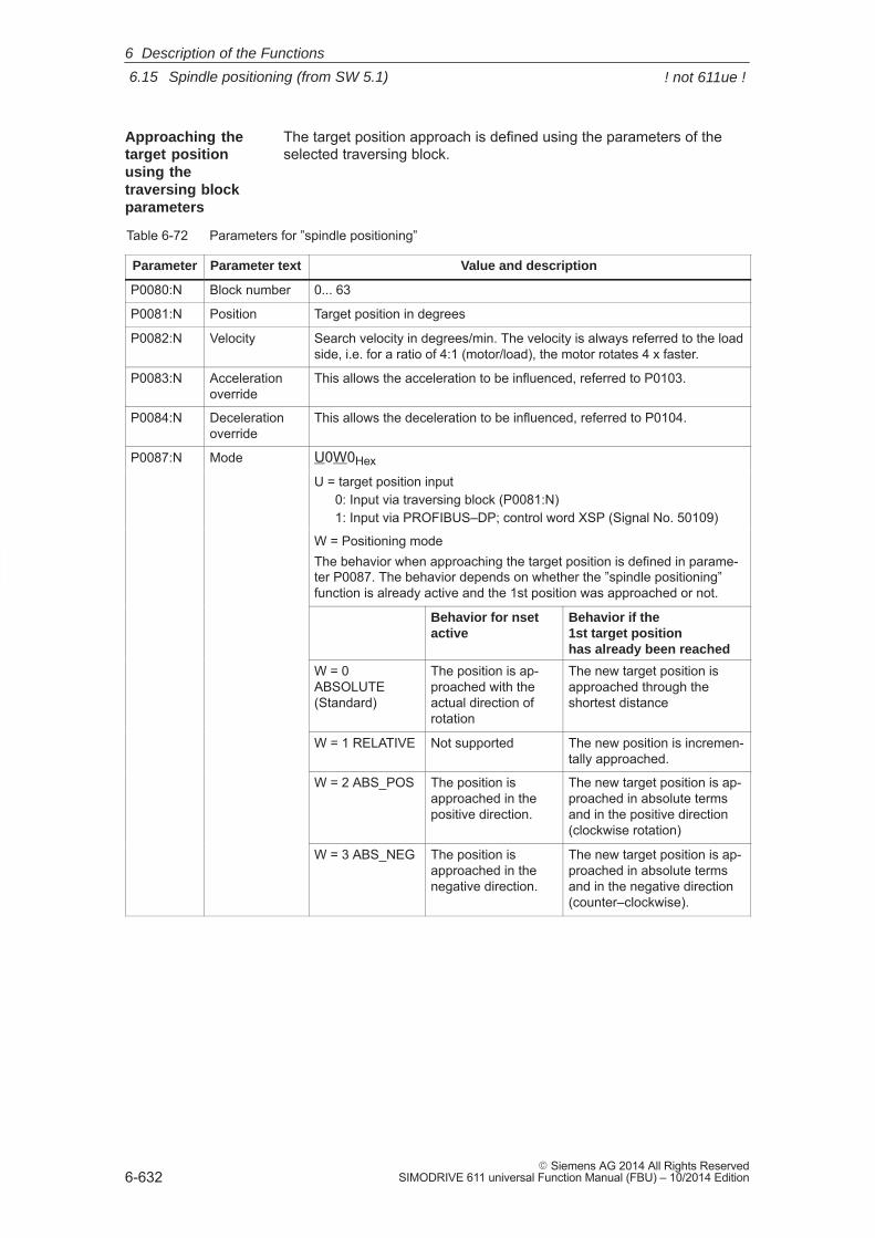
6
6.15 Spindle positioning (from SW 5.1)
6-632� Siemens AG 2014 All Rights Reserved
SIMODRIVE 611 universal Function Manual (FBU) – 10/2014 Edition
The target position approach is defined using the parameters of theselected traversing block.
Table 6-72 Parameters for ”spindle positioning”
Parameter Parameter text Value and description
P0080:N Block number 0... 63
P0081:N Position Target position in degrees
P0082:N Velocity Search velocity in degrees/min. The velocity is always referred to the loadside, i.e. for a ratio of 4:1 (motor/load), the motor rotates 4 x faster.
P0083:N Accelerationoverride
This allows the acceleration to be influenced, referred to P0103.
P0084:N Decelerationoverride
This allows the deceleration to be influenced, referred to P0104.
P0087:N Mode U0W0Hex
U = target position input0: Input via traversing block (P0081:N)1: Input via PROFIBUS–DP; control word XSP (Signal No. 50109)
W = Positioning modeThe behavior when approaching the target position is defined in parame-ter P0087. The behavior depends on whether the ”spindle positioning”function is already active and the 1st position was approached or not.
Behavior for nset active
Behavior if the1st target positionhas already been reached
W = 0ABSOLUTE(Standard)
The position is ap-proached with theactual direction ofrotation
The new target position isapproached through theshortest distance
W = 1 RELATIVE Not supported The new position is incremen-tally approached.
W = 2 ABS_POS The position isapproached in thepositive direction.
The new target position is ap-proached in absolute termsand in the positive direction(clockwise rotation)
W = 3 ABS_NEG The position isapproached in thenegative direction.
The new target position is ap-proached in absolute termsand in the negative direction(counter–clockwise).
Approaching thetarget positionusing thetraversing blockparameters
6 Description of the Functions
! not 611ue !
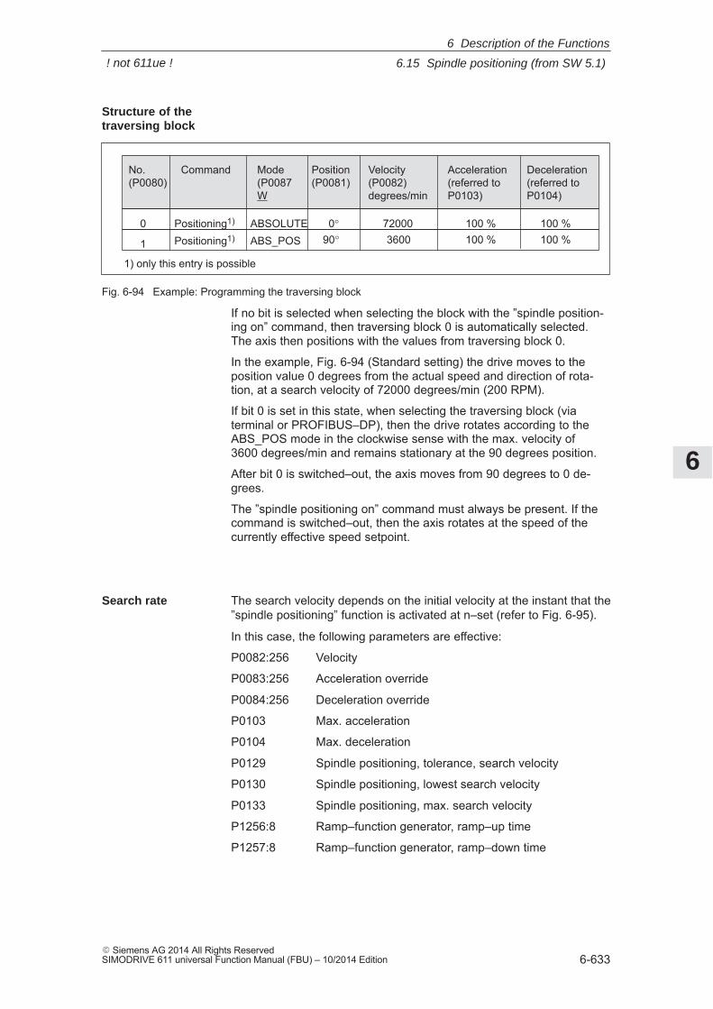
6
6.15 Spindle positioning (from SW 5.1)
6-633� Siemens AG 2014 All Rights ReservedSIMODRIVE 611 universal Function Manual (FBU) – 10/2014 Edition
No.(P0080)
Command Mode(P0087W
Position(P0081)
Velocity(P0082)degrees/min
Acceleration(referred toP0103)
Deceleration(referred toP0104)
0 Positioning1) ABSOLUTE 0° 72000 100 % 100 %
1
1) only this entry is possible
ABS_POS 90°Positioning1) 3600 100 % 100 %
Fig. 6-94 Example: Programming the traversing block
If no bit is selected when selecting the block with the ”spindle position-ing on” command, then traversing block 0 is automatically selected.The axis then positions with the values from traversing block 0.
In the example, Fig. 6-94 (Standard setting) the drive moves to theposition value 0 degrees from the actual speed and direction of rota-tion, at a search velocity of 72000 degrees/min (200 RPM).
If bit 0 is set in this state, when selecting the traversing block (viaterminal or PROFIBUS–DP), then the drive rotates according to theABS_POS mode in the clockwise sense with the max. velocity of 3600 degrees/min and remains stationary at the 90 degrees position.
After bit 0 is switched–out, the axis moves from 90 degrees to 0 de-grees.
The ”spindle positioning on” command must always be present. If thecommand is switched–out, then the axis rotates at the speed of thecurrently effective speed setpoint.
The search velocity depends on the initial velocity at the instant that the”spindle positioning” function is activated at n–set (refer to Fig. 6-95).
In this case, the following parameters are effective:
P0082:256 Velocity
P0083:256 Acceleration override
P0084:256 Deceleration override
P0103 Max. acceleration
P0104 Max. deceleration
P0129 Spindle positioning, tolerance, search velocity
P0130 Spindle positioning, lowest search velocity
P0133 Spindle positioning, max. search velocity
P1256:8 Ramp–function generator, ramp–up time
P1257:8 Ramp–function generator, ramp–down time
Structure of thetraversing block
Search rate
6 Description of the Functions
! not 611ue !
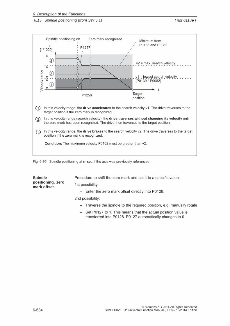
6
6.15 Spindle positioning (from SW 5.1)
6-634� Siemens AG 2014 All Rights Reserved
SIMODRIVE 611 universal Function Manual (FBU) – 10/2014 Edition
Spindle positioning on
v[1/1000]
Zero mark recognizedVe
loci
ty ra
nge
Targetposition
1
2
3
1
2
3
In this velocity range, the drive accelerates to the search velocity v1. The drive traverses to thetarget position if the zero mark is recognized.
v2 = max. search velocity
In this velocity range (search velocity), the drive traverses without changing its velocity untilthe zero mark has been recognized. The drive then traverses to the target position.
In this velocity range, the drive brakes to the search velocity v2. The drive traverses to the targetposition if the zero mark is recognized.
v1 = lowest search velocity(P0130 * P0082)
Minimum fromP0133 and P0082
t
P1257
P1256
Condition: The maximum velocity P0102 must be greater than v2.
Fig. 6-95 Spindle positioning at n–set, if the axis was previously referenced
Procedure to shift the zero mark and set it to a specific value:
1st possibility:
– Enter the zero mark offset directly into P0128.
2nd possibility:
– Traverse the spindle to the required position, e.g. manually rotate
– Set P0127 to 1. This means that the actual position value istransferred into P0128. P0127 automatically changes to 0.
Spindlepositioning, zeromark offset
6 Description of the Functions
! not 611ue !
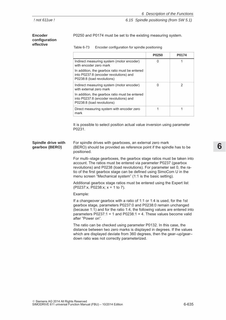
6
6.15 Spindle positioning (from SW 5.1)
6-635� Siemens AG 2014 All Rights ReservedSIMODRIVE 611 universal Function Manual (FBU) – 10/2014 Edition
P0250 and P0174 must be set to the existing measuring system.
Table 6-73 Encoder configuration for spindle positioning
P0250 P0174
Indirect measuring system (motor encoder)with encoder zero markIn addition, the gearbox ratio must be enteredinto P0237:8 (encoder revolutions) andP0238:8 (load revolutions)
0 1
Indirect measuring system (motor encoder)with external zero markIn addition, the gearbox ratio must be enteredinto P0237:8 (encoder revolutions) andP0238:8 (load revolutions)
0 2
Direct measuring system with encoder zeromark
1 1
It is possible to select position actual value inversion using parameterP0231.
For spindle drives with gearboxes, an external zero mark (BERO) should be provided as reference point if the spindle has to bepositioned.
For multi–stage gearboxes, the gearbox stage ratios must be taken intoaccount. The ratios must be entered via parameter P0237 (gearboxrevolutions) and P0238 (load revolutions). For parameter set 0, the ra-tio of the first gearbox stage can be defined using SimoCom U in themenu screen ”Mechanical system” (1:1 is the basic setting).
Additional gearbox stage ratios must be entered using the Expert list(P0237:x, P0238:x; x = 1 to 7).
Example:
If a changeover gearbox with a ratio of 1:1 or 1:4 is used, for the 1stgearbox stage, parameters P0237:0 and P0238:0 remain unchanged(because 1:1) and for the ratio 1:4, the following values are entered intoparameters P0237:1 = 1 and P0238:1 = 4. These values become validafter ”Power on”.
The ratio can be checked using parameter P0132. In this case, thedistance between two zero marks is displayed in degrees. If the valueswhich are displayed deviate from 360 degrees, then the gear–up/gear–down ratio was not correctly parameterized.
Encoderconfigurationeffective
Spindle drive withgearbox (BERO)
6 Description of the Functions
! not 611ue !
6
6.15 Spindle positioning (from SW 5.1)
6-636� Siemens AG 2014 All Rights Reserved
SIMODRIVE 611 universal Function Manual (FBU) – 10/2014 Edition
The following signals are used for the ”spindle positioning” function:� Input signals
(refer under the index entry ”Input signal, digital – ...)
– Input signal, ”spindle positioning on”
––> using an input terminal with function number 28
––> using the PROFIBUS control signal ”STW1.15”
– Input of traversing blocks
––> via an input terminal, or
––> via PROFIBUS–DP
When the traversing block selection is changed (number), theposition is immediately changed to the position specified in thetraversing block.
� Output signals(refer under the index entry, ”output signal, digital – ...)
The output signals are only effective when selecting ”spindle posi-tion on”.
– Output signal, ”spindle positioning on”
––> using an output terminal with function number 28
––> using the PROFIBUS status signal ”ZSW1.14”
– Output signal ”spindle position reached”
––> setting a window with P0134
––> using an output terminal with function number 59
––> using PROFIBUS status signal ”MeldW.15”
– Output signal ”reference position reached/outside reference position”
––> setting values with P0320, P0321
––> using an output terminal with function number 60
––> using PROFIBUS status signal ”MeldW.14”
Input/outputsignals(refer to Chapter6.4)
6 Description of the Functions
! not 611ue !
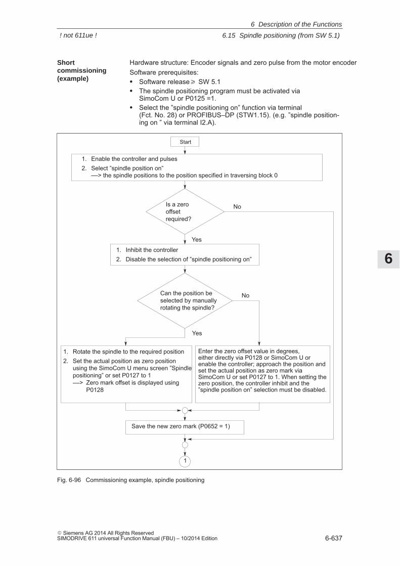
6
6.15 Spindle positioning (from SW 5.1)
6-637� Siemens AG 2014 All Rights ReservedSIMODRIVE 611 universal Function Manual (FBU) – 10/2014 Edition
Hardware structure: Encoder signals and zero pulse from the motor encoderSoftware prerequisites:� Software release� SW 5.1� The spindle positioning program must be activated via
SimoCom U or P0125 =1.� Select the ”spindle positioning on” function via terminal
(Fct. No. 28) or PROFIBUS–DP (STW1.15). (e.g. ”spindle position-ing on ” via terminal I2.A).
1. Enable the controller and pulses2. Select ”spindle position on”
––> the spindle positions to the position specified in traversing block 0
No
Yes
Yes
Can the position beselected by manuallyrotating the spindle?
No
1. Rotate the spindle to the required position2. Set the actual position as zero position
using the SimoCom U menu screen ”Spindlepositioning” or set P0127 to 1––> Zero mark offset is displayed using
P0128
Enter the zero offset value in degrees, either directly via P0128 or SimoCom U orenable the controller; approach the position andset the actual position as zero mark viaSimoCom U or set P0127 to 1. When setting thezero position, the controller inhibit and the”spindle position on” selection must be disabled.
Save the new zero mark (P0652 = 1)
1
Start
1. Inhibit the controller2. Disable the selection of ”spindle positioning on”
Is a zero offsetrequired?
Fig. 6-96 Commissioning example, spindle positioning
Shortcommissioning(example)
6 Description of the Functions
! not 611ue !
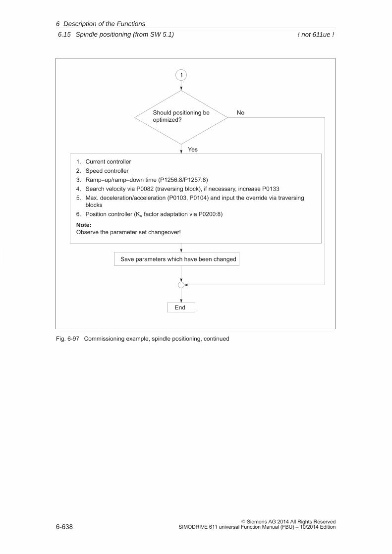
6
6.15 Spindle positioning (from SW 5.1)
6-638� Siemens AG 2014 All Rights Reserved
SIMODRIVE 611 universal Function Manual (FBU) – 10/2014 Edition
1
1. Current controller2. Speed controller3. Ramp–up/ramp–down time (P1256:8/P1257:8)4. Search velocity via P0082 (traversing block), if necessary, increase P01335. Max. deceleration/acceleration (P0103, P0104) and input the override via traversing
blocks6. Position controller (Kv factor adaptation via P0200:8)
Note:Observe the parameter set changeover!
Save parameters which have been changed
Yes
End
Should positioning beoptimized?
No
Fig. 6-97 Commissioning example, spindle positioning, continued
6 Description of the Functions
! not 611ue !
6
6.16 Rotor position identification/pole position identification
6-639� Siemens AG 2014 All Rights ReservedSIMODRIVE 611 universal Function Manual (FBU) – 10/2014 Edition
6.16 Rotor position identification/pole position identification
NoteTerminology change: Rotor position identification (RLI), corresponds to the pole positionidentification (PLI)!
Drive converters with field–orientated closed–loop control impress thecurrent into permanent–magnet synchronous motors to establish themagnetic flux in the motor.At power–on, the rotor position identification (RLI) automatically deter-mines the absolute rotor position using the maximum of the magneticflux.
The rotor position identification is used for:� Determining the rotor position (coarse synchronization and fine syn-
chronization)� Supports commissioning when determining the commutation angle
offset
Two techniques can be used for the rotor position identification routine:� For the technique based on saturation (P1075 = 1)� A technique based on movement (P1075 = 3) (from SW 6.1).
The particular technique can be selected using parameter P1075.
Determining the rotor position
The rotor position identification routine automatically determines themotor rotor position. This means that the motor encoder does not re-quire any additional position information from the encoder (C/D track).For linear motors, Hall sensors are not required if the limitations andsecondary conditions are maintained.
� with zero marks: P1011.13 = 0For the fine synchronization (P1011.13 = 0), the commutation offsetis transferred when passing the zero mark.Advantages:– The fine synchronization with zero mark guarantees a consistent
and optimum and force and torque utilization.– An increase in robustness thanks to renewed encoder monitoring
(absolute information and internal pole position).Parameter P1016 must be appropriately set.
Notice
When replacing the motor/encoder, the commutation angle (P1016)must be re–determined.
� with pole position identification: P1011.13 = 1For P1011.13 = 1, fine synchronization is replaced by the pole posi-tion identification. P1016 is not effective.
Description
Coarsesynchronization
Finesynchronization
6 Description of the Functions
6
6.16 Rotor position identification/pole position identification
6-640� Siemens AG 2014 All Rights Reserved
SIMODRIVE 611 universal Function Manual (FBU) – 10/2014 Edition
Encoder adjustment is not required if the rotor position identificationroutine is used for coarse and fine synchronization.
In P1011, bit 12 (identify coarse position) is set in order that the rotorposition identification technique is initiated when powering–up the drive.If bit 13 is set (fine position identification), a rotor position identificationis executed independently of bit 12.
The following parameters are used for the rotor position synchroniza-tion/rotor position identification:� P1011 IM configuration, actual value sensing� P1016 Angular commutation offset� P1017 Commissioning support� P1019 Current, rotor position identification� P1020 Maximum rotation, rotor position identification (SRM)
Maximum movement, rotor position identification (SLM)� P1075 Technique, rotor position identification� P1076 Load moment of inertia RLI (SRM)
Load mass RLI (SLM)� P1523 Time constant, speed actual value filter (PT1) RLI
(from SW 9.1)The following diagnostics parameters are used rotor position synchro-nization/rotor position identification:� P1734 Diagnostics, rotor position identification� P1736 Test, rotor position identification� P1737 Difference, rotor position identification
� The techniques can only be started when the controller and pulsesare enabled as current must flow through the motor.
� When using an absolute motor measuring system, the rotor positionidentification can only be used to determine the commutation angleoffset (P1016).
� The technique can only be started when the controller and pulsesare enabled as current must flow through the motor.
� This technique can be used for both braked and non–braked mo-tors.
� The technique cannot be used for motors which are moving.
� The current which is entered must be adequate in order to generatea significant measuring signal.
� The measurement and evaluation take approx. 250 ms.
Equivalent of the encoderadjustment
Configuration,actual valuesensing motorencoder
Parameteroverview (refer to ChapterA.1)
Boundaryconditions
For the techniquebased on saturation(P1075 = 1)
6 Description of the Functions
6
6.16 Rotor position identification/pole position identification
6-641� Siemens AG 2014 All Rights ReservedSIMODRIVE 611 universal Function Manual (FBU) – 10/2014 Edition
� Due to the different mechanical designs, for the motion–based rotorposition identification technique, the result must be checked oncewhen the drive system is first commissioned. The deviation of mea-sured rotor position should be < 10° electrical.
� The measuring system must stiffly mounted.
� The axis static friction must be low in comparison to the rated motorforce or rated motor torque. An excessively high static friction canhave a significant negative impact on the accuracy of the rotor posi-tion identification and, under certain circumstances, make it impossi-ble to execute the rotor position identification with motion.
� The technique may only be used for horizontal axes which canfreely move and which do not have a brake.
� During the rotor position identification run, it is not permissible thatexternal forces are applied to the motor.
� If the previous secondary conditions/limitations are not fulfilled, thenlinear motors can only be operated with Hall sensor boxes or withabsolute measuring systems.
� When this technique is used, under worst case condition, movementin the range of ± 10 mm or ±5 degrees can occur.
� In the pos mode, until the identification has been completed, theaxis to be identified must be set in the follow–up mode in order tosuppress fault 135 during the identification routine (standstill moni-toring).
� When starting the rotor position identification routine via P1736 as atest:
– For a test start, fault 135 (standstill monitoring) can be output,which must be acknowledged with RESET.
– For coupled axes, the test start for rotor position identification isnot permitted
!Warning
When the motors are not braked, the motor rotates or moves as aresult of the current impressed during the measurement. Themagnitude of the motion depends on the magnitude of the current andthe moment of inertia of the motor and load.
For the techniquebased on motion(P1075 = 3, from SW 6.1)
6 Description of the Functions
6
6.16 Rotor position identification/pole position identification
6-642� Siemens AG 2014 All Rights Reserved
SIMODRIVE 611 universal Function Manual (FBU) – 10/2014 Edition
For the parameterization of the rotor position identification for the mo-tion–based technique, initially, a rotor position identification run must bemade with a standard parameterization.
The noise which is generated should be heard as a sequence of softsurges.
The following should be done if faults occur:
� Fault 611 (inadmissible motion):––> Increase the parameterized load mass (P1076), check the max-imum permissible motion (P1020) and if required, increase.
� Fault 610 (rotor position identification unsuccessful) and P1734 = –4(current rise too low): ––> The motor is not correctly connected ––> The motor power connections must be checked.
� Fault 610 (rotor position identification unsuccessful) and P1734 = –6(max. permissible duration exceeded): ––> This can be due to the following reasons:
– external forces have faulted the identification routine (e.g.coupled axes have not been opened, surges, etc.),
– if the drive emits an excessive noise (a loud whistling sound) dur-ing the identification routine, then the identification technique hasbecome unstable: ––> P1076 must be reduced,
from SW 9.1 also possible in the negative range
– Extremely low encoder resolution: ––> use an encoder with a higher resolution
– encoder mounting is not stiff enough: ––> improve the mounting.
� Fault 610 (rotor position identification unsuccessful) and P1734 = –7(no clear rotor position has been found: ––> This can be due to the following reasons:
– the axis cannot freely move (e.g. the motor rotor is locked)
– external forces have disturbed the identification routine (referabove)
– the axis has an extremely high friction: ––> the identification current (P1019) must be increased
If the rotor position identification routine was successful, the rotor posi-tion which was found should be checked. This test function can deter-mine the difference between the determined rotor position angle andthe rotor position angle used by the closed–loop control.
The following procedure should be applied several times:
1. Start the test function using P1736 = 1.
2. Evaluate the difference in P1737 – a spread of the measured valuesof less than 10 degrees is acceptable. If this is not the case, then ahigher current must be used for the identification routine (P1019).
Parameterizationfor themotion–basedtechnique (P1075 = 3) (from SW 6.1)
6 Description of the Functions
6
6.16 Rotor position identification/pole position identification
6-643� Siemens AG 2014 All Rights ReservedSIMODRIVE 611 universal Function Manual (FBU) – 10/2014 Edition
1. Step: Determine the pole position
– Incremental measuring system (with zero mark)
Set P1011.12 = 1Set P1011.13 = 0Carry–out a HW–RESETSet P1017.0 = 1 Switch–in the pulse and controller enable signalsMove the axis over the zero mark (e.g. enter low nset)––> The angular offset is automatically entered into P1016––> Fault 799 is displayed
(Save to FEPROM and HW–RESET required)Save to FEPROM and carry–out a HW–RESET
– Absolute measuring system (with CD track)
Power–up with the controller and pulses disabledSet P1017.0 = 1 Switch–in the controller and pulse enable––> The angular offset is automatically entered into P1016––> Fault 799
(Save to FEPROM and HW–RESET required) is displayedSave to FEPROM and carry–out a HW–RESET
2. Step: Check the pole position
To check the rotor position identification, using a test function, youcan determine the difference between the calculated rotor angleposition and that actually used by the closed–loop control. Proceedas follows:
– Start the test function several times and evaluate the differenceStart Set P1736 (test rotor position identification) to 1 Difference P1737 (difference, rotor position identification)
= _ _ _ _ , _ _ _ _ , _ _ _ _ , _ _ _ _ , _ _ _ _– Is the spread of the measured values less than 2 degrees electrical?
Yes: OKNo: Increase P1019 (e.g. by 10 %)
and repeat the measurementsIf OK after having repeated the measurements, then theangular commutation offset can be re–determined:For an incremental measuring system:as for Point 2. (determining the angular commutation offset)
Steps whencommissioning thesystem
6 Description of the Functions
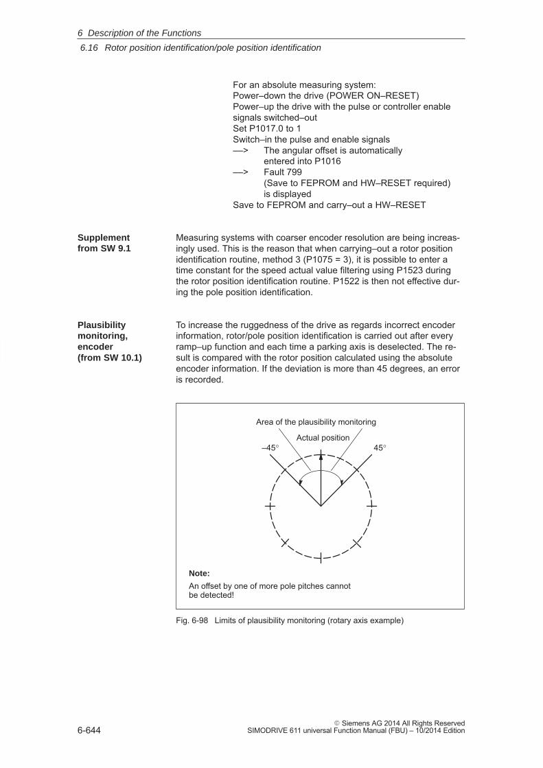
6
6.16 Rotor position identification/pole position identification
6-644� Siemens AG 2014 All Rights Reserved
SIMODRIVE 611 universal Function Manual (FBU) – 10/2014 Edition
For an absolute measuring system:Power–down the drive (POWER ON–RESET)Power–up the drive with the pulse or controller enablesignals switched–outSet P1017.0 to 1Switch–in the pulse and enable signals––> The angular offset is automatically
entered into P1016––> Fault 799
(Save to FEPROM and HW–RESET required) is displayed
Save to FEPROM and carry–out a HW–RESET
Measuring systems with coarser encoder resolution are being increas-ingly used. This is the reason that when carrying–out a rotor positionidentification routine, method 3 (P1075 = 3), it is possible to enter atime constant for the speed actual value filtering using P1523 duringthe rotor position identification routine. P1522 is then not effective dur-ing the pole position identification.
To increase the ruggedness of the drive as regards incorrect encoderinformation, rotor/pole position identification is carried out after everyramp–up function and each time a parking axis is deselected. The re-sult is compared with the rotor position calculated using the absoluteencoder information. If the deviation is more than 45 degrees, an erroris recorded.
Actual position45°–45°
Area of the plausibility monitoring
Note:
An offset by one of more pole pitches cannotbe detected!
Fig. 6-98 Limits of plausibility monitoring (rotary axis example)
Supplementfrom SW 9.1
Plausibilitymonitoring,encoder (from SW 10.1)
6 Description of the Functions
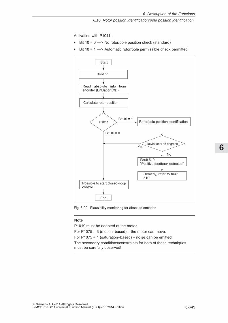
6
6.16 Rotor position identification/pole position identification
6-645� Siemens AG 2014 All Rights ReservedSIMODRIVE 611 universal Function Manual (FBU) – 10/2014 Edition
Activation with P1011:
� Bit 10 = 0 ––> No rotor/pole position check (standard)
� Bit 10 = 1 ––> Automatic rotor/pole permissible check permitted
Read absolute info fromencoder (EnDat or C/D)
Booting
Calculate rotor position
Deviation < 45 degrees
Rotor/pole position identification
Possible to start closed–loopcontrol
Fault 510 ”Positive feedback detected”
P1011Bit 10 = 1
No
Yes
Bit 10 = 0
Start
End
Remedy, refer to fault510!
Fig. 6-99 Plausibility monitoring for absolute encoder
NoteP1019 must be adapted at the motor.For P1075 = 3 (motion–based) – the motor can move.For P1075 = 1 (saturation–based) – noise can be emitted.The secondary conditions/constraints for both of these techniquesmust be carefully observed!
6 Description of the Functions
6
6.17 Electrical braking when the encoder fails (from SW 9.1)
6-646� Siemens AG 2014 All Rights Reserved
SIMODRIVE 611 universal Function Manual (FBU) – 10/2014 Edition
6.17 Electrical braking when the encoder fails (from SW 9.1)
For a feed drive with synchronous motor (SRM, SLM), if the encoderfails without the encoder information, then the drive is braked up to thechangeover speed/velocity parameterized in P1466.
Note
Electrical braking when the encoder fails has not been designed foroperation with coupled axes!
The function ”electrical braking when the encoder fails” is activated withP1049 = 1. The standard setting (default setting) is P1049 = 0.
If P1049 = 1, then braking is carried–out in the following steps:
� Initially, the pulse inhibit is suppressed.
� The speed controller enable to initiate braking is simultaneouslywithdrawn.
� The drive brakes down to the changeover speed/velocity parameter-ized in P1466. The pulses are only inhibited then and the motorcosts down.
� If the motor speed/velocity at the instant that the encoder fails liesbelow the changeover speed/velocity defined in P1466, then thepulse inhibit is directly initiated and the motor coasts down.
� The timer for pulse cancellation in P1404 should be greater than theduration of the braking operation.
� The changeover speed/velocity P1403 should be less than the valueof the changeover speed/velocity in P1466.
� The maximum torque for a regenerative stop is always reduced withP1097.
� The function to monitor whether the speed controller is at its end-stop is always disabled (P1096.1 = 1).
� The following criteria always apply for the use, otherwise fault 722 isoutput:
– Rotating motors (SRM) P1466 > 40000/P1114
– Linear motors (SLM): P1466 > 1386/P1114
When commissioning a motor, P1466 is automatically set to thislimit.
Description
Activating
Braking sequence
Boundaryconditions
6 Description of the Functions
6
6.17 Electrical braking when the encoder fails (from SW 9.1)
6-647� Siemens AG 2014 All Rights ReservedSIMODRIVE 611 universal Function Manual (FBU) – 10/2014 Edition
Note
This braking can withdraw a large proportion of the kinetic energy fromthe system. This means that at the end the motor coasts down with alow amount of energy and depending on the particular application andthe motors selected, the machinery construction OEM should provideadditional protective measure
The following parameters are used for ”electrical braking when the encoderfails”:� P1049 Activate EMF brake (SRM SLM)� P1097 Red. max. torque for regen. stop� P1403 Shutdown speed, pulse cancellation (SRM)
Shutdown speed, pulse cancellation (SLM)� P1404 Timer, pulse cancellation� P1466 Changeover speed, closed–loop control/pulse cancellation (SRM)
Changeover velocity, closed–loop control/pulse cancellation (SLM)
Parameteroverview (refer to ChapterA.1)
6 Description of the Functions
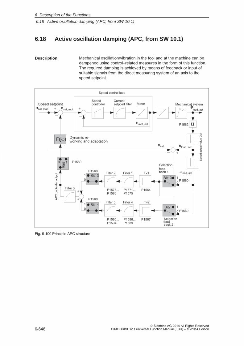
6
6.18 Active oscillation damping (APC, from SW 10.1)
6-648� Siemens AG 2014 All Rights Reserved
SIMODRIVE 611 universal Function Manual (FBU) – 10/2014 Edition
6.18 Active oscillation damping (APC, from SW 10.1)
Mechanical oscillation/vibration in the tool and at the machine can bedampened using control–related measures in the form of this function.The required damping is achieved by means of feedback or input ofsuitable signals from the direct measuring system of an axis to thespeed setpoint.
Dynamic re-working and adaptation
Spee
d ac
tual
val
ue D
M
Speed setpoint
APC
con
trolle
r out
put Filter 1
nload, actnset
aload, act
Selection
nset, motnset, load
Bit7
Bit10Bit13
Bit14
Bit9
0 1
10
01
10
10
nmot, act
Speedcontroller
Currentsetpoint filter
Filter 2
Filter 4Filter 5
Filter 3
Mechanical system
Tv1
Tv2
Selection
Motor
Speed control loop
feed-back 2
feed-back 1
F(j)
load, act
Ü
P1560
P1560
P1560
P1560
P1560
P1562
P1576...P1580
P1571...P1575
P1590...P1594
P1586...P1589
P1564
P1567
Fig. 6-100 Principle APC structure
Description
6 Description of the Functions
6
6.18 Active oscillation damping (APC, from SW 10.1)
6-649� Siemens AG 2014 All Rights ReservedSIMODRIVE 611 universal Function Manual (FBU) – 10/2014 Edition
Activating with P1560 bit 5.
� Bit 5 = 0 ––> APC is de–activated
� Bit 5 = 1 ––> APC is activated
� Bit 6 Reserved
� Bit 7 Selecting the input for 2nd cascade APC
� Bit 8 Filter input APC of the function generator
� Bit 9 Do not connect filter output of APC
� Bit 10 Input 1st cascade APC
� Bit 11 Speed control with direct measuring system (pulse de–coupling)
� Bit 12 Reserved
� Bit 13 APC, disable 1st cascade
� Bit 14 APC, disable 2nd cascade
� Bit 15 Reserved
Additionally:
� The direct measuring system must be activated (P0250 = 1) duringnset mode and the position actual value transferred to the higher–level control.
� P1562 must be pre–assigned.
� An axis must have two measuring systems – i.e. a motor measuringsystem and a direct measuring system. This means that APC canonly be used for 1 axis.
� APC only functions with ”SIMODRIVE 611 universal HR/HRS”.
� The mechanical components to be dampened must be suitable.
Caution
Exercise caution for axes holding workpieces and axes where themass changes!
Activating
Boundaryconditions
6 Description of the Functions
6
6.18 Active oscillation damping (APC, from SW 10.1)
6-650� Siemens AG 2014 All Rights Reserved
SIMODRIVE 611 universal Function Manual (FBU) – 10/2014 Edition
The following sequence is practical when commissioning:
1. Define the APC mode (P1560).
2. Parameterize the ratio between the motor measuring system anddirect measuring system.
The ratio is entered as a factor, by which the direct measuringsystem pulse frequency must be multiplied in order to obtain themotor measuring system pulse frequency – assuming uniform, con-sistent motion. This includes the measuring system resolution differ-ences and any gearbox or measuring gearbox, which are possiblybeing used. If the direction of rotation is different, then this is takeninto account with a negative sign. The sign is included in the ratio.
Example 1:
Rotating motor, 2,048 pulses/rev, with a ball screw pitch of 10 mm/rev, direct measuring system 20 μm.Converted to the motor side: (10 mm/rev)/(20 μm)= 500 pulses permotor revolution on the load side; factor: 2048/500 = 4,096
Example 2:
Rotating motor, 2048 pulses/rev, gearbox to the load with a ratio or 25:1, rotating load with load measuring system 8192 pulses/rev. 8192/25 pulsesper motor revolution on the load side; factor: 2048/8192 25 = 6.25
Example 3:
Rotating motor, 2048 pulses/rev, load directly coupled to the directmeasuring system 1024 pulses/revConverted to the motor side: 1024 pulses per motor revolution onthe load side; factor: 2048/1024 = 2.0
3. Define the acceleration filter type (P1570:8).
4. Parameterize the sub–sampling of the acceleration filter (P1569).
The sub–sampling factor is entered here for filters 1, 2, 4, and 5. 1 means no sub–sampling (standard).
Sub–sampling should be used for filters with a low blocking fre-quency. It is generally recommended that
Blocking frequency Sampling time Sub–sampling factor shouldbe � 1/160.
This can easily be ensured using the sub–sampling factor. It is ef-fective for filters 1, 2, 4, and 5. The 3rd filter is always processed inthe speed controller cycle and can serve to interpolate the filters,which have been sub–sampled. All filters can only be deactivated bybeing suitably parameterized (e.g., using default values); there is noon/off switch.
5. Parameterize the filter characteristics (P1571:8...P1594:8)
Commissioningthe function
6 Description of the Functions
6
6.18 Active oscillation damping (APC, from SW 10.1)
6-651� Siemens AG 2014 All Rights ReservedSIMODRIVE 611 universal Function Manual (FBU) – 10/2014 Edition
Note
Filters 1 and 2 or 4 and 5 can be disabled by selecting PT1 and settingthe time constant to zero.
Filter 3 cannot be configured as PT1 and therefore cannot be disabled.
The ”SimoCom U” start–up tool is used to display the filter frequency characteristics.
The following parameters are used for APC:� P1560 APC mode (ARM SRM)
APC mode (SLM)� P1562 Ratio, motor to DM (ARM SRM)
Ratio, motor to DM (SLM)� P1564:8 Derivative action time, load speed controller (ARM SRM)
Derivative action time, load velocity controller (SLM)� P1567:8 Derivative action time, load speed controller 2 (ARM SRM)
Derivative action time, load velocity controller 2 (SLM)� P1569 Sub–sampling, accel. filter (ARM SRM)
Sub–sampling accel. filter (SLM)� P1570:8 Type, acceleration filter (ARM SRM)
Type, acceleration filter (SLM)� P1571:8 Time constant, accel. filter 1 (ARM SRM)
Time constant, accel. filter 1 (SLM)� P1572:8 Denom., natural freq. Accel. filter 1 (ARM SRM)
Denom. natural freq. Accel. filter 1 (SLM)� P1573:8 Denom. damping accel. filter 1 (ARM SRM)
Denom. damping accel. filter 1 (SLM)� P1574:8 Numerator natural freq. Accel. filter 1 (ARM SRM)
Numerator natural freq. Accel. filter 1 (SLM)� P1575:8 Numerator damp. accel. filter 1 (ARM SRM)
Numerator damp. accel. filter 1 (SLM)� P1576:8 Time constant, accel. filter 2 (ARM SRM)
Time constant, accel. filter 2 (SLM)� P1577:8 Denom., natural freq. Accel. filter 2 (ARM SRM)
Denom. natural freq. Accel. filter 2 (SLM)� P1578:8 Denom. damping accel. filter 2 (ARM SRM)
Denom. damping accel. filter 2 (SLM)� P1579:8 Numerator natural freq. Accel. filter 2 (ARM SRM)
Numerator natural freq. Accel. filter 2 (SLM)� P1580:8 Numerator damp. accel. filter 2 (ARM SRM)
Numerator damp. accel. filter 2 (SLM)
Parameteroverview (refer to ChapterA.1)
6 Description of the Functions
6
6.18 Active oscillation damping (APC, from SW 10.1)
6-652� Siemens AG 2014 All Rights Reserved
SIMODRIVE 611 universal Function Manual (FBU) – 10/2014 Edition
� P1581:8 Denom., natural freq. Accel. filter 3 (ARM SRM)Denom. natural freq. Accel. filter 3 (SLM)
� P1582:8 Denom. damping accel. filter 3 (ARM SRM)Denom. damping accel. filter 3 (SLM)
� P1583:8 Numerator natural freq. Accel. filter 3 (ARM SRM)Numerator natural freq. Accel. filter 3 (SLM)
� P1584:8 Numerator damp. accel. filter 3 (ARM SRM)Numerator damp. accel. filter 3 (SLM)
� P1585:8 Time constant, accel. filter 4 (ARM SRM)Time constant, accel. filter 4 (SLM)
� P1586:8 Denom., natural freq. Accel. filter 4 (ARM SRM)Denom. natural freq. Accel. filter 4 (SLM)
� P1587:8 Denom. damping accel. filter 4 (ARM SRM)Denom. damping accel. filter 4 (SLM)
� P1588:8 Numerator natural freq. Accel. filter 4 (ARM SRM)Numerator natural freq. Accel. filter 4 (SLM)
� P1589:8 Numerator damp. accel. filter 4 (ARM SRM)Numerator damp. accel. filter 4 (SLM)
� P1590:8 Time constant, accel. filter 5 (ARM SRM)Time constant, accel. filter 5 (SLM)
� P1591:8 Denom., natural freq. Accel. filter 5 (ARM SRM)Denom. natural freq. Accel. filter 5 (SLM)
� P1592:8 Denom. damping accel. filter 5 (ARM SRM)Denom. damping accel. filter 5 (SLM)
� P1593:8 Numerator natural freq. Accel. filter 5 (ARM SRM)Numerator natural freq. Accel. filter 5 (SLM)
� P1594:8 Numerator damp. accel. filter 5 (ARM SRM)Numerator damp. accel. filter 5 (SLM)
6 Description of the Functions
6
6.19 Activate function generator immediately (from SW 11.2)
6-653� Siemens AG 2014 All Rights ReservedSIMODRIVE 611 universal Function Manual (FBU) – 10/2014 Edition
6.19 Activate function generator immediately (from SW 11.2)
The function generator can be activated immediately in the ”Speed/torque setpoint” mode by using the ”Activate function generator imme-diately” input signal.
”Activate function generator immediately” activation:
� Using input terminal with function number 2
� Using PROFIBUS control word STW1.9
”Function generator active” message/display:
� Using an output terminal with function number 24
� Using PROFIBUS status word ZSW1.13
The ”Activate function generator immediately” input signal cannot beactivated simultaneously for Drive A and B. If the function generator usactivated for Drive A and B or is parameterized incorrectly, Warning824 ”Faulty function generator” is triggered with additional information.
Note
The ”Oscillate” function of the ”SIMODRIVE 611 analog” can besimulated by using the ”Activate function generator immediately” inputsignal. The parameters of the ”Function generator” function are to beparameterized in a suitable manner (see Chapter 7.4.1).
The ”PRBS white noise” function generator waveform is not suitablefor the oscillating function. This waveform does not have anyinterlocking for ”oscillating”!
Starting via PROFIBUS-DP is only possible if bit 6 is set to 1 in P0878.
If the oscillation function is canceled (controller enable is withdrawn)then the drive brakes along the braking ramp P1813. At zero speed,oscillation is ended and the drive is switched into the ”Positioning”operating mode.
Description
Input/outputsignals
Boundaryconditions
6 Description of the Functions
6
6.20 Monitoring of the direction of the axis motion (from SW 11.1)
6-654� Siemens AG 2014 All Rights Reserved
SIMODRIVE 611 universal Function Manual (FBU) – 10/2014 Edition
6.20 Monitoring of the direction of the axis motion (from SW 11.1)
The ruggedness of the drive system with regard to encoder and poleposition faults can be increased with this function.
It offers a solution for the following faults:� Faulty absolute information from the encoder and thus false pole
position information� Demagnetized synchronous machine with faulty pole position identi-
fication
A check is carried out whether the acceleration/velocity of a machinealways corresponds to the direction of the torque/force, referenced toall the torques/forces existing in the system, In the process, oscillatorysytems, external torques/forces and the energy storage in the systemare taken into account.
If the speed controller is longer at its limit than the period parameter-ized in P1645 and the direction of acceleration/speed and torque/forcediffers, Fault 510 is reported.
Activating with parameter:
� P1645 Missing orientation timer
Parameterization of the duration for which speed controllers mayhave different directions during the acceleration/velocity and torque/force at the same limit.
� P1646 Threshold deactivating of the direction monitoring
Parameterization from which speed/velocity the direction monitoringis to be deactivate.
The direction monitoring is activated by default. It can be deactivatedby setting P1646 = 0. This may be necessary at the following applica-tions:� External torque� Oscillating system� Vertical axes� Axes coupled at HLA� Master slave with bias� Traversing to fixed stop� Extremely fast axis (reversing in 10 ms)
Description
Activating
Boundaryconditions
6 Description of the Functions
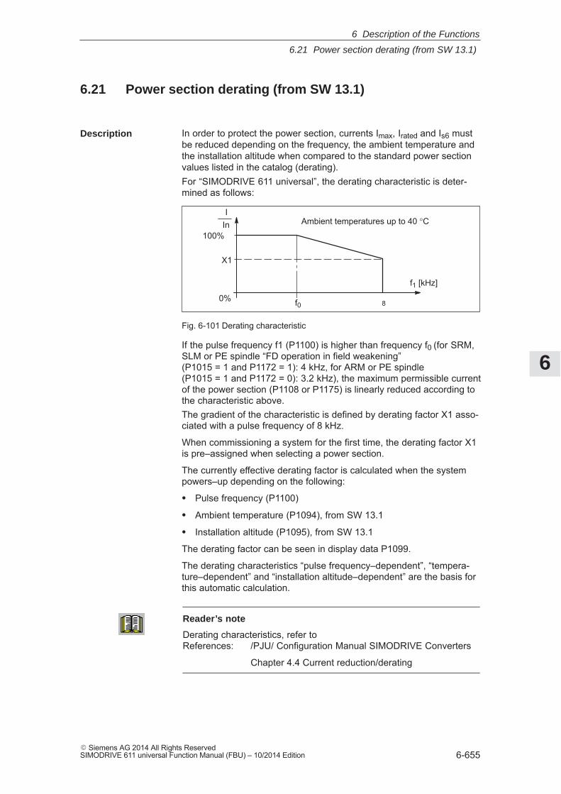
6
6.21 Power section derating (from SW 13.1)
6-655� Siemens AG 2014 All Rights ReservedSIMODRIVE 611 universal Function Manual (FBU) – 10/2014 Edition
6.21 Power section derating (from SW 13.1)
In order to protect the power section, currents Imax, Irated and Is6 mustbe reduced depending on the frequency, the ambient temperature andthe installation altitude when compared to the standard power sectionvalues listed in the catalog (derating).For “SIMODRIVE 611 universal”, the derating characteristic is deter-mined as follows:
f1 [kHz]
f0
IIn
100%
X1
0%
Ambient temperatures up to 40 °C
8
Fig. 6-101 Derating characteristic
If the pulse frequency f1 (P1100) is higher than frequency f0 (for SRM,SLM or PE spindle “FD operation in field weakening” (P1015 = 1 and P1172 = 1): 4 kHz, for ARM or PE spindle (P1015 = 1 and P1172 = 0): 3.2 kHz), the maximum permissible currentof the power section (P1108 or P1175) is linearly reduced according tothe characteristic above.The gradient of the characteristic is defined by derating factor X1 asso-ciated with a pulse frequency of 8 kHz.
When commissioning a system for the first time, the derating factor X1is pre–assigned when selecting a power section.
The currently effective derating factor is calculated when the systempowers–up depending on the following:
� Pulse frequency (P1100)
� Ambient temperature (P1094), from SW 13.1
� Installation altitude (P1095), from SW 13.1
The derating factor can be seen in display data P1099.
The derating characteristics “pulse frequency–dependent”, “tempera-ture–dependent” and “installation altitude–dependent” are the basis forthis automatic calculation.
Reader’s note
Derating characteristics, refer toReferences: /PJU/ Configuration Manual SIMODRIVE Converters
Chapter 4.4 Current reduction/derating
Description
6 Description of the Functions
6
6.21 Power section derating (from SW 13.1)
6-656� Siemens AG 2014 All Rights Reserved
SIMODRIVE 611 universal Function Manual (FBU) – 10/2014 Edition
With this functionality, the following current reduction (derating) isobtained for the power section:
� For SRM, SLM or PE spindle “FD operation in field weakening”(P1015 = 1 and P1172 = 1)
– Imax = P1108 (from power section list) � P1175 (from powersection list) � P1099
– IS6 = P1109 (from power section list) � P1176 (from powersection list) � P1099
– Irated = P1111 (from power section list) � P1177 (from powersection list) � P1099
� For ARM or PE spindle (P1015 = 1 and P1172 = 0)
– Imax = P1108 (from power section list) � P1099
– IS6 = P1109 (from power section list) � P1099
– Irated = P1111 (from power section list) � P1099
The following parameters are used for “Power section derating“:� P1106 Power section code number� P1107 Transistor limit current� P1108 Limiting power section current (rms)� P1109 Limiting power section S6 (rms)� P1111 Rated power section current (rms)� P1175 Synch. reduction factor for P1108� P1176 Synch. reduction factor for P1109� P1177 Synch. reduction factor for P1111� P1178 Synch. current reduction factor� P1179 Asynch. current reduction factor� P1094 Derating, ambient temperature� P1095 Derating, installation altitude� P1099 Limiting factor, power section currents� P1260 i2t limiting, limit current power module S6� P1261 i2t limiting, rated power module current
Parameteroverview(refer toChapter A.1)
6 Description of the Functions
6
6.22 Dynamic energy management (from SW 13.1)
6-657� Siemens AG 2014 All Rights ReservedSIMODRIVE 611 universal Function Manual (FBU) – 10/2014 Edition
6.22 Dynamic energy management (from SW 13.1)
Dynamic energy management allows the infeed/regenerative feedbackunit to be dimensioned in–line with the specific requirements andadapted to the overall system concept.
Regenerative drive braking causes the DC link voltage to increase.While braking (which also means regenerative feedback into the linesupply), for certain drives, the braking torque should be briefly reducedin order that the maximum permissible DC link voltage is not exceeded.
Activated with P1155:
� Bit 0: Dynamic energy management function
– Bit 0 = 0 ––> not active
– Bit 0 = 1 ––> active
� Bit 1: Dynamic energy management function only effective for re-generative braking
– Bit 1 = 0 ––> not active
– Bit 1 = 1 ––> active
With an axis–specific configuring, using P1152 a “Minimum DC linkvoltage dynamic energy management” can be set, and using P1153 a“Maximum DC link voltage dynamic energy management” can be set.
If the DC link voltage increases during operation (P1155 bit 1 = 0) orduring regenerative braking (P1155 bit 1 = 1) via the “Maximum DC linkvoltage dynamic energy management” P1153, Alarm 617 “DC link over-voltage” is output and the torque is reduced to 0%, which opposes avoltage increase.
This torque reduction is only withdrawn if the DC link voltage subse-quently falls below the “Minimum DC link voltage dynamic energy man-agement” P1152.
In this case, the DC link voltage can again increase as a step function ifthe motor is still rotating. This can be reduced using the setting P1096/P1097 “Red. max. torque for regen. stop”.
For regenerative braking, the maximum torque is reduced to the per-centage value specified in P1097 – assuming that P1096 bit 0 is active.This means that briefly occurring voltage spikes in the DC link voltagecan be avoided.
Description
Activation
Boundaryconditions
6 Description of the Functions
6
6.22 Dynamic energy management (from SW 13.1)
6-658� Siemens AG 2014 All Rights Reserved
SIMODRIVE 611 universal Function Manual (FBU) – 10/2014 Edition
The times must lie within the configured times of P1403 “Shutdownspeed pulse cancellation” and P1404 “Timer pulse cancellation” so thatonly a controller inhibit is initiated and not a pulse inhibit.
To achieve this, the controller inhibit must be configured as a shutdownresponse when Alarm 617 is output with P1613 “Shutdown response,fault 2”, bit 17 “DC link voltage“.
Note
When the upper limit for the DC link voltage dynamic energy manage-ment is exceeded (P1701 > P1153), then Alarm 617 “DC link overvol-tage” is output.
The configuration must ensure that the sum of all of the motion axes,which regenerate into the line supply, cannot destroy the infeed/regen-erative feedback unit. Alarm 617 can be influenced using P1613 bit 17.
Note
Speeding up the DC link sensing
The DC link voltage is measured using a multiplexer which is also usedto sense the motor temperature for motor 1 and motor 2 and an inter-nal reference measurement.
These “switchover deadtimes” are also included in the response of theDC link voltage sensing.
In order that the DC link voltage monitoring responds faster, after ex-ceeding a speed threshold that can be entered into P1154 “only V DClink monitoring from motor speed”, the multiplexer can be preventedfrom switching over so that only the DC link voltage is monitored.
A 3% ”Hysteresis” around the speed threshold prevents continuoustoggling between the monitoring functions.
If the response threshold (0.97 P1154) is fallen below again, then thestandard function is re-established.
The motor temperature monitoring and the reference measurement areinhibited for the time that it takes to measure the DC link voltage. Thismeasure means that if the “Maximum DC link voltage dynamic energymanagement” P1153 is exceeded then this is detected with the short-est possible delay time.
Precondition
6 Description of the Functions
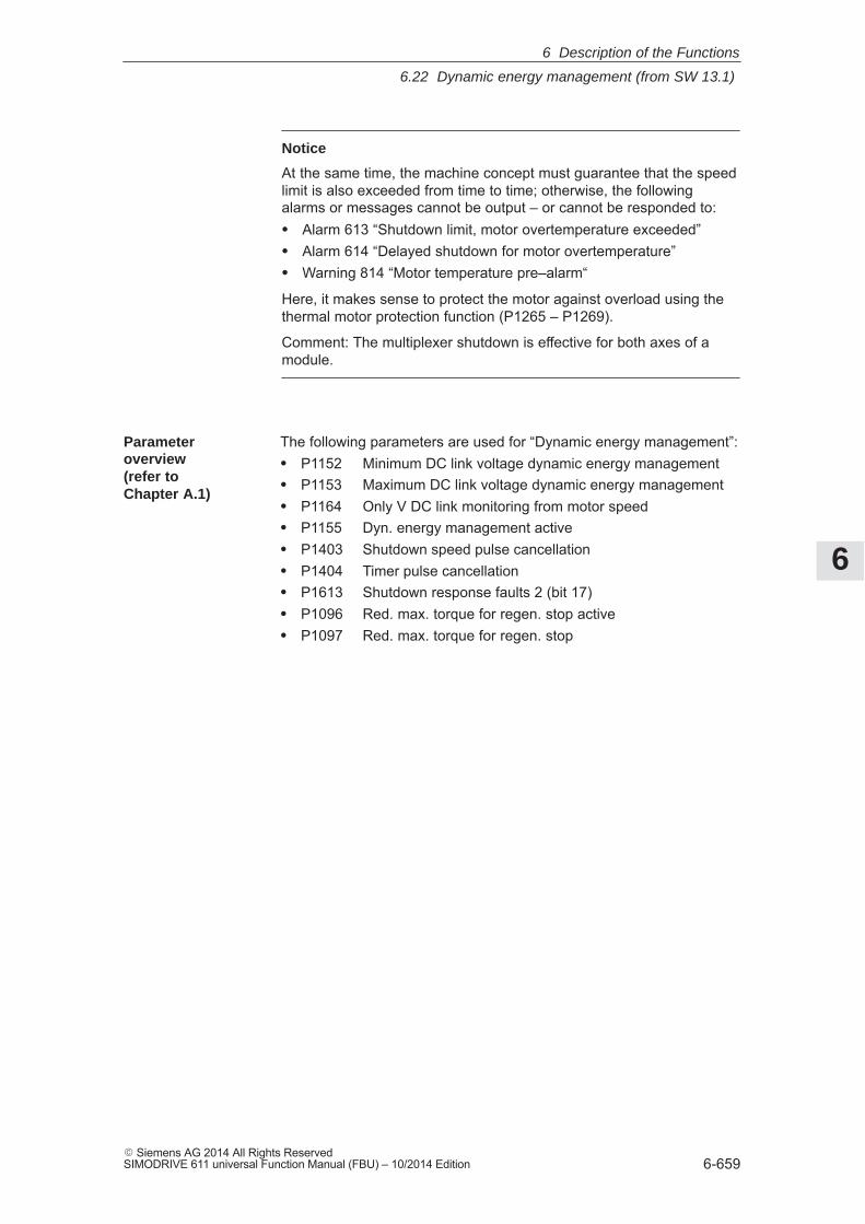
6
6.22 Dynamic energy management (from SW 13.1)
6-659� Siemens AG 2014 All Rights ReservedSIMODRIVE 611 universal Function Manual (FBU) – 10/2014 Edition
Notice
At the same time, the machine concept must guarantee that the speedlimit is also exceeded from time to time; otherwise, the followingalarms or messages cannot be output – or cannot be responded to:� Alarm 613 “Shutdown limit, motor overtemperature exceeded”� Alarm 614 “Delayed shutdown for motor overtemperature”� Warning 814 “Motor temperature pre–alarm“
Here, it makes sense to protect the motor against overload using thethermal motor protection function (P1265 – P1269).
Comment: The multiplexer shutdown is effective for both axes of amodule.
The following parameters are used for “Dynamic energy management”:� P1152 Minimum DC link voltage dynamic energy management� P1153 Maximum DC link voltage dynamic energy management� P1164 Only V DC link monitoring from motor speed� P1155 Dyn. energy management active� P1403 Shutdown speed pulse cancellation� P1404 Timer pulse cancellation� P1613 Shutdown response faults 2 (bit 17)� P1096 Red. max. torque for regen. stop active� P1097 Red. max. torque for regen. stop
Parameteroverview(refer toChapter A.1)
6 Description of the Functions
6
6.23 Motor diagnostics, ground fault test (from SW 13.1)
6-660� Siemens AG 2014 All Rights Reserved
SIMODRIVE 611 universal Function Manual (FBU) – 10/2014 Edition
6.23 Motor diagnostics, ground fault test (from SW 13.1)
This function can be used to detect a ground fault, i.e. a conductiveconnection between one of the motor phases and ground. This motortest takes place when the closed–loop control powers–up; however, itcan also be specifically initiated in operation.
Note
The machine cannot be used for production during the motor diagnos-tics ground fault test.
Activated with P1166 (activate ground fault test):
� Bit 0: Automatic ground fault test after power on
– Bit 0 = 0 ––> automatic motor ground fault test after power–updisabled
– Bit 0 = 1 ––> automatic motor ground fault test after power–upenabled
� Bit 1: start ground fault test using P1166
– Bit 1 = 1 ––> Start: Start: activate motor ground fault test inoperation using the signal edge 0–>1
The bit is automatically reset after the ground fault test has beenperformed.
Note
The ground fault test does not represent a protection function in thesense of the VDE guidelines.
� If, during the ground fault test, the current exceeds the value config-ured in P1167 “Response threshold of the ground fault test”, thenAlarm 511 “Ground fault detected” is output. The cause of the alarm is saved in P1169 = -6.
� Current flows through the motor when the ground fault test is per-formed; this is the reason that the function can only be started afterthe controller and pulses have been enabled.
� If, during the ground fault test, the pulse enable is withdrawn, thenthe ground fault test waits for the next pulse enable – and thenrepeats the complete procedure.
Description
Activation
Boundaryconditions
6 Description of the Functions
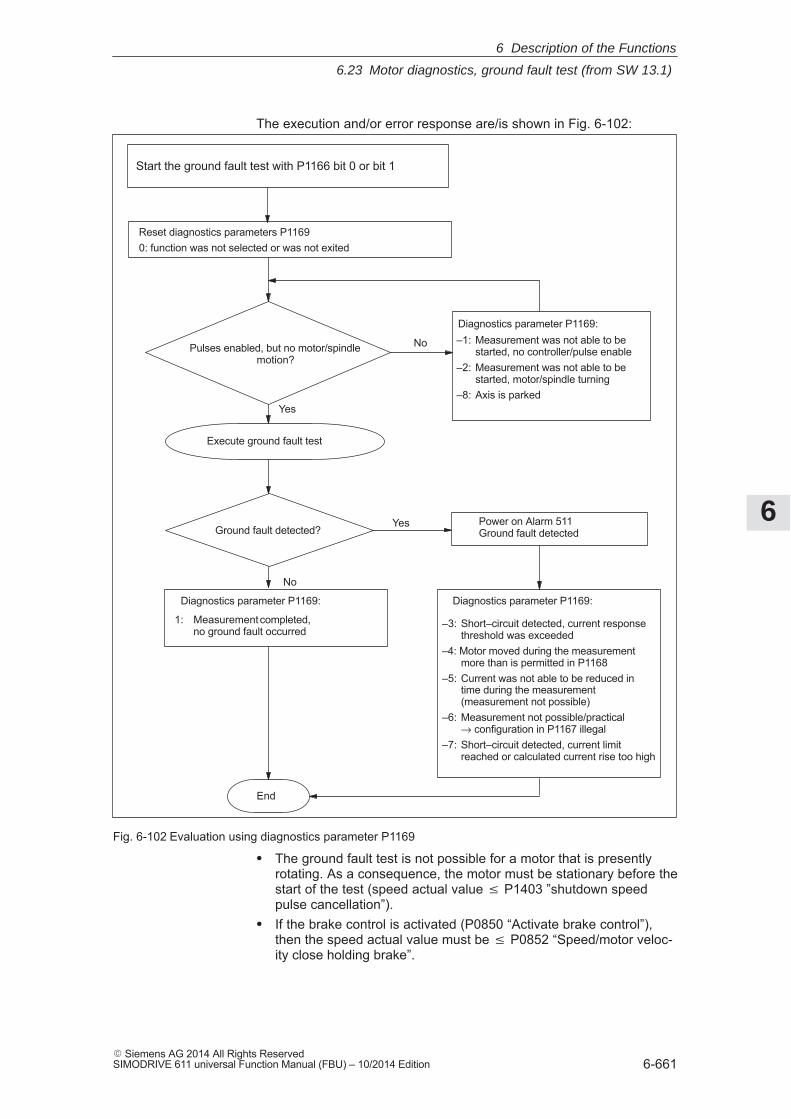
6
6.23 Motor diagnostics, ground fault test (from SW 13.1)
6-661� Siemens AG 2014 All Rights ReservedSIMODRIVE 611 universal Function Manual (FBU) – 10/2014 Edition
The execution and/or error response are/is shown in Fig. 6-102:
1: Measurement completed,no ground fault occurred
–3: Short–circuit detected, current responsethreshold was exceeded
–4: Motor moved during the measurementmore than is permitted in P1168
–5: Current was not able to be reduced intime during the measurement(measurement not possible)
–6: Measurement not possible/practical→ configuration in P1167 illegal
–7: Short–circuit detected, current limitreached or calculated current rise too high
Start the ground fault test with P1166 bit 0 or bit 1
Reset diagnostics parameters P11690: function was not selected or was not exited
Pulses enabled, but no motor/spindlemotion?
Execute ground fault test
Ground fault detected?
Diagnostics parameter P1169:–1: Measurement was not able to be
started, no controller/pulse enable–2: Measurement was not able to be
started, motor/spindle turning–8: Axis is parked
Power on Alarm 511Ground fault detected
Diagnostics parameter P1169:
Yes
Yes
No
No
End
Diagnostics parameter P1169:
Fig. 6-102 Evaluation using diagnostics parameter P1169
� The ground fault test is not possible for a motor that is presentlyrotating. As a consequence, the motor must be stationary before thestart of the test (speed actual value P1403 ”shutdown speedpulse cancellation”).
� If the brake control is activated (P0850 “Activate brake control”),then the speed actual value must be P0852 “Speed/motor veloc-ity close holding brake”.
6 Description of the Functions
6
6.23 Motor diagnostics, ground fault test (from SW 13.1)
6-662� Siemens AG 2014 All Rights Reserved
SIMODRIVE 611 universal Function Manual (FBU) – 10/2014 Edition
� When booting after power on, the automatic ground fault test(P1166 bit 0 = 1) can only be performed for motor 1.If a ground fault test is to be performed for motors 2 to 4 from themotor data set changeover, then this must be explicitly realized us-ing P1166 bit 1 = 1.
� A ground fault test for a hanging/suspended axis is possible, underthe prerequisite that the axis is mechanically locked using the hold-ing brake.
� A ground fault test cannot be performed for induction motors inencoderless operation!
The following parameters are used for the “Motor diagnostics groundfault test”:� P1166 Activate ground fault test� P1167 Response threshold of the ground fault test� P1168 Maximum rotation, ground fault test (ARM SRM)
Maximum motion, ground fault test (SLM)� P1169 Motor diagnostics
Parameteroverview(refer toChapter A.1)
6 Description of the Functions
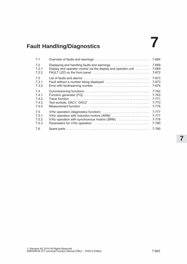
7
7-663� Siemens AG 2014 All Rights ReservedSIMODRIVE 611 universal Function Manual (FBU) – 10/2014 Edition
Fault Handling/Diagnostics
7.1 Overview of faults and warnings 7-664. . . . . . . . . . . . . . . . . . . . . . . . . . . . . . . . . . .
7.2 Displaying and handling faults and warnings 7-669. . . . . . . . . . . . . . . . . . . . . . . . 7.2.1 Display and operator control via the display and operator unit 7-669. . . . . . . . . 7.2.2 FAULT LED on the front panel 7-672. . . . . . . . . . . . . . . . . . . . . . . . . . . . . . . . . . . .
7.3 List of faults and alarms 7-673. . . . . . . . . . . . . . . . . . . . . . . . . . . . . . . . . . . . . . . . . . 7.3.1 Fault without a number being displayed 7-673. . . . . . . . . . . . . . . . . . . . . . . . . . . . 7.3.2 Error with fault/warning number 7-674. . . . . . . . . . . . . . . . . . . . . . . . . . . . . . . . . . .
7.4 Commissioning functions 7-762. . . . . . . . . . . . . . . . . . . . . . . . . . . . . . . . . . . . . . . . . 7.4.1 Function generator (FG) 7-763. . . . . . . . . . . . . . . . . . . . . . . . . . . . . . . . . . . . . . . . . . 7.4.2 Trace function 7-771. . . . . . . . . . . . . . . . . . . . . . . . . . . . . . . . . . . . . . . . . . . . . . . . . . 7.4.3 Test sockets, DAC1, DAC2 7-773. . . . . . . . . . . . . . . . . . . . . . . . . . . . . . . . . . . . . . . 7.4.4 Measurement function 7-776. . . . . . . . . . . . . . . . . . . . . . . . . . . . . . . . . . . . . . . . . . .
7.5 V/Hz operation (diagnostics function) 7-777. . . . . . . . . . . . . . . . . . . . . . . . . . . . . . 7.5.1 V/Hz operation with induction motors (ARM) 7-777. . . . . . . . . . . . . . . . . . . . . . . . 7.5.2 V/Hz operation with synchronous motors (SRM) 7-778. . . . . . . . . . . . . . . . . . . . . 7.5.3 Parameters for V/Hz operation 7-780. . . . . . . . . . . . . . . . . . . . . . . . . . . . . . . . . . . .
7.6 Spare parts 7-780. . . . . . . . . . . . . . . . . . . . . . . . . . . . . . . . . . . . . . . . . . . . . . . . . . . . .
7
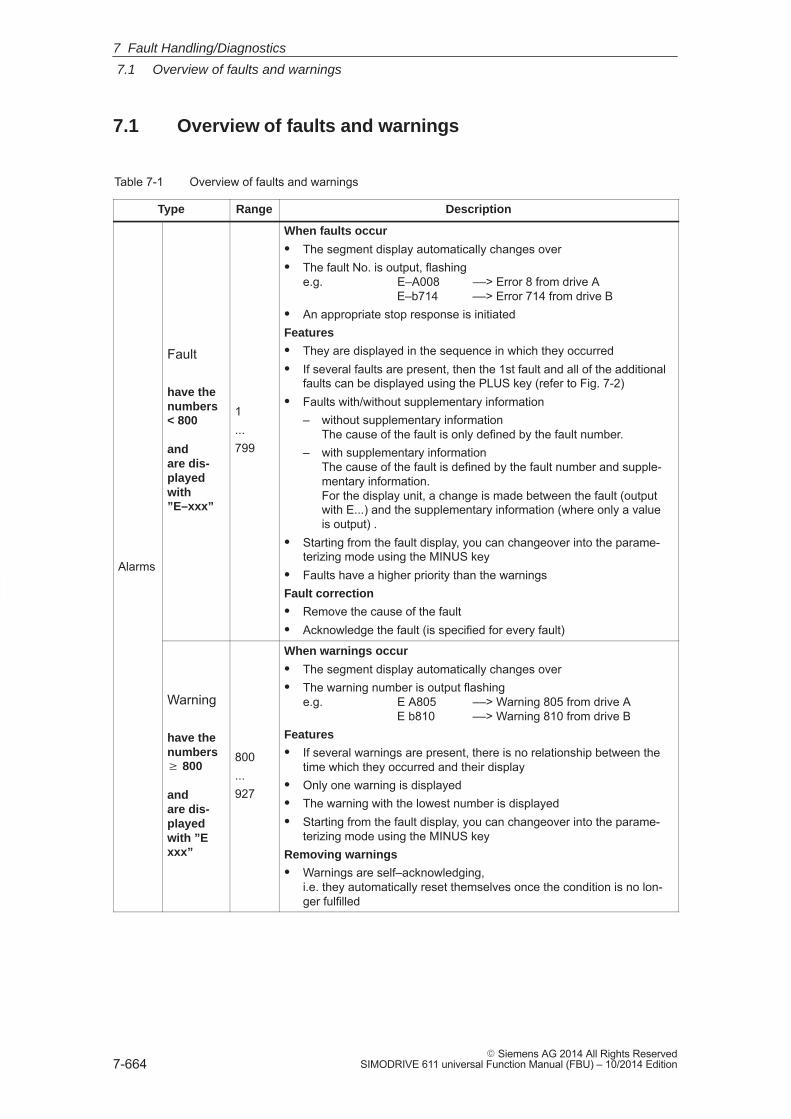
7
7.1 Overview of faults and warnings
7-664� Siemens AG 2014 All Rights Reserved
SIMODRIVE 611 universal Function Manual (FBU) – 10/2014 Edition
7.1 Overview of faults and warnings
Table 7-1 Overview of faults and warnings
Type Range Description
Alarms
Fault
have thenumbers< 800
andare dis-playedwith”E–xxx”
1...799
When faults occur
� The segment display automatically changes over� The fault No. is output, flashing
e.g. E–A008 ––> Error 8 from drive AE–b714 ––> Error 714 from drive B
� An appropriate stop response is initiatedFeatures
� They are displayed in the sequence in which they occurred� If several faults are present, then the 1st fault and all of the additional
faults can be displayed using the PLUS key (refer to Fig. 7-2)� Faults with/without supplementary information
– without supplementary informationThe cause of the fault is only defined by the fault number.
– with supplementary informationThe cause of the fault is defined by the fault number and supple-mentary information.For the display unit, a change is made between the fault (outputwith E...) and the supplementary information (where only a valueis output) .
� Starting from the fault display, you can changeover into the parame-terizing mode using the MINUS key
� Faults have a higher priority than the warningsFault correction
� Remove the cause of the fault� Acknowledge the fault (is specified for every fault)
Warning
have thenumbers� 800
andare dis-playedwith ”Exxx”
800...927
When warnings occur
� The segment display automatically changes over� The warning number is output flashing
e.g. E A805 ––> Warning 805 from drive AE b810 ––> Warning 810 from drive B
Features
� If several warnings are present, there is no relationship between thetime which they occurred and their display
� Only one warning is displayed� The warning with the lowest number is displayed� Starting from the fault display, you can changeover into the parame-
terizing mode using the MINUS keyRemoving warnings
� Warnings are self–acknowledging,i.e. they automatically reset themselves once the condition is no lon-ger fulfilled
7 Fault Handling/Diagnostics
7
7.1 Overview of faults and warnings
7-665� Siemens AG 2014 All Rights ReservedSIMODRIVE 611 universal Function Manual (FBU) – 10/2014 Edition
The parameterizing and commissioning tool ”SimoCom U” enters thealarms and warnngs that have occurred with data time into an alarmprotocol file that is saved in the ”SIMOCOMU installation path” under.../user/AlarmLog.txt.
Note:If ”SimoCom U” is connected to a drive that is already operational, thenfor the warnings that have occurred up until then, neither date nor timeis specified in the log file. If the size of the alarm log file exceeds 50 kb,then after closing the parameterizing and commissioning tool”SimoCom U”, the contents of the log file are transferred into theAlarmLog.bak file and AlarmLog.txt is set–up again.
In the list of faults and warnings (refer to Chapter 7.3), for each faultand warning, an explanation is given under ”Acknowledge”, as to howthey can be acknowledged after the cause has been removed.
Faults, which are to be acknowledged with POWER ON, can be alter-natively acknowledged as follows:1. POWER ON
––> power–off/power–on ”SIMODRIVE 611 universal”2. Press the POWER–ON RESET button on the front panel of the con-
trol board3. POWER–ON RESET with the ”SimoCom U” toolThe processor runs up again, all of the faults are acknowledged, andthe fault buffer is re–initialized.
Faults, which are to be acknowledged with RESET FAULT MEMORY,can be alternatively acknowledged as follows:
Notice
Prerequisites when acknowledging:� Disable the controller enable via terminal 65.x
or� Set the PROFIBUS control signal STW1.0 to ”0”
From SW 6.1 and for P1012.12 = 1, the fault can also beacknowledged without this prerequisite. However, the drive thenremains in the ”Power–on inhibit” state (refer to Chapter 5.5”Forming the power–on inhibit”; Fig.5-9).
� Set the appropriate bus signal (e.g. for the CAN bus, fromSW 8.1)
1. Carry–out POWER ON acknowledgmentIn addition to the POWER ON faults, all of the faults, which can beacknowledged with RESET FAULT MEMORY, are also acknowl-edged.
2. Set the input terminal with the ”reset fault memory” function to ”1”3. Press button P on the display and operator control unit
Alarm log
Acknowledgement
Acknowledgingfaults withPOWER ON
Acknowledgingfaults withRESET FAULTMEMORY
7 Fault Handling/Diagnostics

7
7.1 Overview of faults and warnings
7-666� Siemens AG 2014 All Rights Reserved
SIMODRIVE 611 universal Function Manual (FBU) – 10/2014 Edition
4. Using PROFIBUS–DP: Set STW1.7 (reset fault memory) to ”1”5. Set terminal R on the NE module to ”1”
When this terminal is energized, ”reset fault memory” is effective forall of the control boards of the complete drive group.
6. For the ”SimoCom U” tool in the dialog box ”Alarm report” by press-ing the ”Reset fault memory” button
7. From SW 9.1:The fault buffer is cleared with parameter P0952 = 0 and the faultsare acknowledged if the causes were resolved.
If a fault is acknowledged, before the cause, e.g. overtemperature, DClink undervoltage etc. was removed, then the fault message is subse-quently de–activated at that instant in time when the cause is no longerpresent. The fault memory does not have to be reset again.
7 Fault Handling/Diagnostics
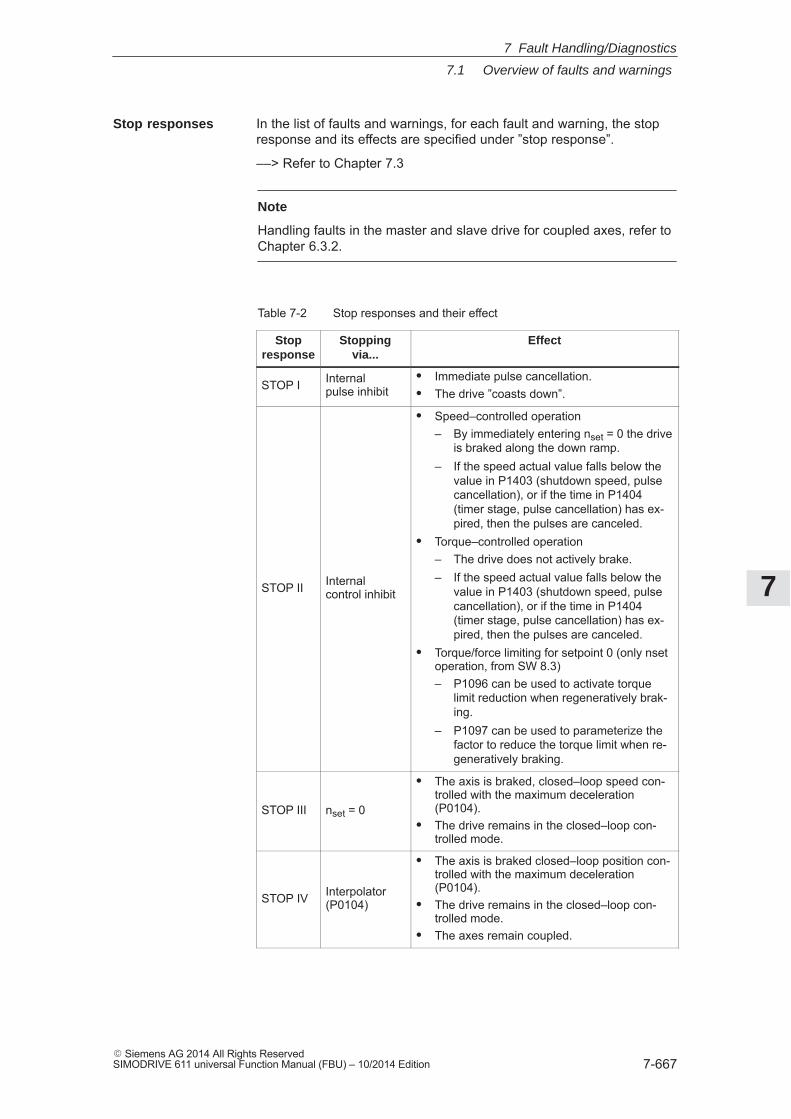
7
7.1 Overview of faults and warnings
7-667� Siemens AG 2014 All Rights ReservedSIMODRIVE 611 universal Function Manual (FBU) – 10/2014 Edition
In the list of faults and warnings, for each fault and warning, the stopresponse and its effects are specified under ”stop response”.
––> Refer to Chapter 7.3
Note
Handling faults in the master and slave drive for coupled axes, refer toChapter 6.3.2.
Table 7-2 Stop responses and their effect
Stopresponse
Stoppingvia...
Effect
STOP I Internalpulse inhibit
� Immediate pulse cancellation.� The drive ”coasts down”.
STOP II Internalcontrol inhibit
� Speed–controlled operation– By immediately entering nset = 0 the drive
is braked along the down ramp.– If the speed actual value falls below the
value in P1403 (shutdown speed, pulsecancellation), or if the time in P1404(timer stage, pulse cancellation) has ex-pired, then the pulses are canceled.
� Torque–controlled operation– The drive does not actively brake.– If the speed actual value falls below the
value in P1403 (shutdown speed, pulsecancellation), or if the time in P1404(timer stage, pulse cancellation) has ex-pired, then the pulses are canceled.
� Torque/force limiting for setpoint 0 (only nsetoperation, from SW 8.3)– P1096 can be used to activate torque
limit reduction when regeneratively brak-ing.
– P1097 can be used to parameterize thefactor to reduce the torque limit when re-generatively braking.
STOP III nset = 0
� The axis is braked, closed–loop speed con-trolled with the maximum deceleration(P0104).
� The drive remains in the closed–loop con-trolled mode.
STOP IV Interpolator(P0104)
� The axis is braked closed–loop position con-trolled with the maximum deceleration(P0104).
� The drive remains in the closed–loop con-trolled mode.
� The axes remain coupled.
Stop responses
7 Fault Handling/Diagnostics
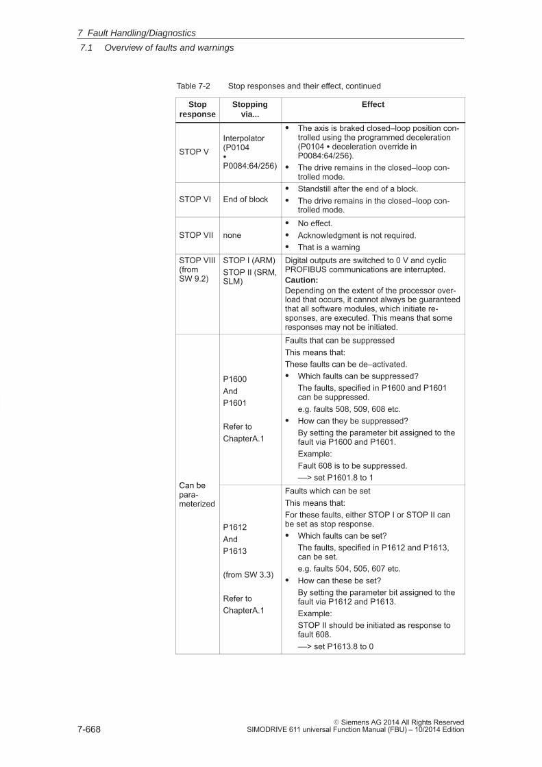
7
7.1 Overview of faults and warnings
7-668� Siemens AG 2014 All Rights Reserved
SIMODRIVE 611 universal Function Manual (FBU) – 10/2014 Edition
Table 7-2 Stop responses and their effect, continued
Stopresponse
EffectStoppingvia...
STOP VInterpolator(P0104�
P0084:64/256)
� The axis is braked closed–loop position con-trolled using the programmed deceleration(P0104 � deceleration override inP0084:64/256).
� The drive remains in the closed–loop con-trolled mode.
STOP VI End of block� Standstill after the end of a block.� The drive remains in the closed–loop con-
trolled mode.
STOP VII none� No effect.� Acknowledgment is not required.� That is a warning
STOP VIII(fromSW 9.2)
STOP I (ARM)STOP II (SRM,SLM)
Digital outputs are switched to 0 V and cyclicPROFIBUS communications are interrupted.Caution:Depending on the extent of the processor over-load that occurs, it cannot always be guaranteedthat all software modules, which initiate re-sponses, are executed. This means that someresponses may not be initiated.
Can be
P1600AndP1601
Refer toChapterA.1
Faults that can be suppressedThis means that:These faults can be de–activated.� Which faults can be suppressed?
The faults, specified in P1600 and P1601can be suppressed.e.g. faults 508, 509, 608 etc.
� How can they be suppressed?By setting the parameter bit assigned to thefault via P1600 and P1601.Example:Fault 608 is to be suppressed.––> set P1601.8 to 1
Can bepara-meterized
P1612AndP1613
(from SW 3.3)
Refer toChapterA.1
Faults which can be set This means that:For these faults, either STOP I or STOP II canbe set as stop response.� Which faults can be set?
The faults, specified in P1612 and P1613,can be set.e.g. faults 504, 505, 607 etc.
� How can these be set?By setting the parameter bit assigned to thefault via P1612 and P1613.Example:STOP II should be initiated as response tofault 608.––> set P1613.8 to 0
7 Fault Handling/Diagnostics
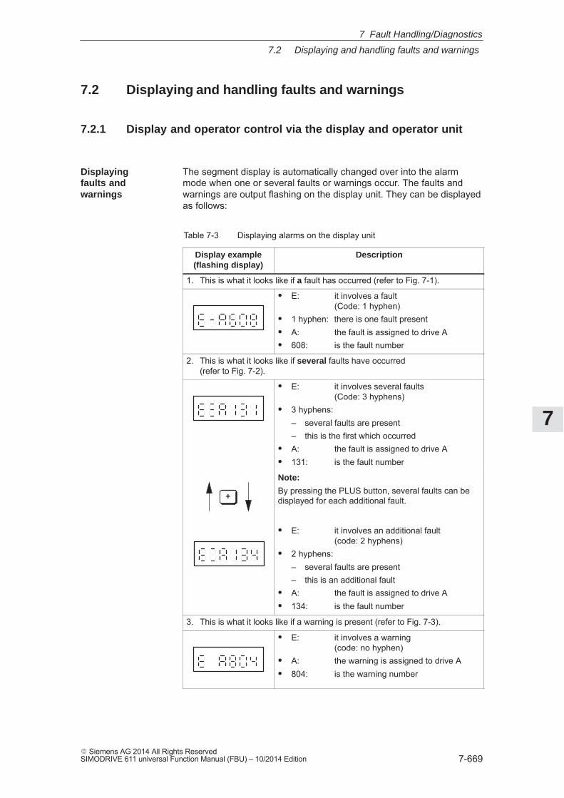
7
7.2 Displaying and handling faults and warnings
7-669� Siemens AG 2014 All Rights ReservedSIMODRIVE 611 universal Function Manual (FBU) – 10/2014 Edition
7.2 Displaying and handling faults and warnings
7.2.1 Display and operator control via the display and operator unit
The segment display is automatically changed over into the alarmmode when one or several faults or warnings occur. The faults andwarnings are output flashing on the display unit. They can be displayedas follows:
Table 7-3 Displaying alarms on the display unit
Display example(flashing display)
Description
1. This is what it looks like if a fault has occurred (refer to Fig. 7-1).
� E: it involves a fault(Code: 1 hyphen)
� 1 hyphen: there is one fault present� A: the fault is assigned to drive A� 608: is the fault number
2. This is what it looks like if several faults have occurred(refer to Fig. 7-2).
� E: it involves several faults(Code: 3 hyphens)
� 3 hyphens:– several faults are present– this is the first which occurred
� A: the fault is assigned to drive A� 131: is the fault number
+
Note:
By pressing the PLUS button, several faults can bedisplayed for each additional fault.
� E: it involves an additional fault(code: 2 hyphens)
� 2 hyphens:– several faults are present– this is an additional fault
� A: the fault is assigned to drive A� 134: is the fault number
3. This is what it looks like if a warning is present (refer to Fig. 7-3).
� E: it involves a warning(code: no hyphen)
� A: the warning is assigned to drive A� 804: is the warning number
Displayingfaults andwarnings
7 Fault Handling/Diagnostics
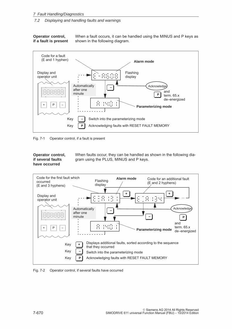
7
7.2 Displaying and handling faults and warnings
7-670� Siemens AG 2014 All Rights Reserved
SIMODRIVE 611 universal Function Manual (FBU) – 10/2014 Edition
When a fault occurs, it can be handled using the MINUS and P keys asshown in the following diagram.
+ P –
Automaticallyafter oneminute
Acknowledge
Parameterizing mode
Switch into the parameterizing mode
Flashingdisplay
Alarm mode
Display andoperator unit
Code for a fault(E and 1 hyphen)
–
P
Acknowledging faults with RESET FAULT MEMORY
–
P
Key
Key
andterm. 65.xde–energized
Fig. 7-1 Operator control, if a fault is present
When faults occur, they can be handled as shown in the following dia-gram using the PLUS, MINUS and P keys.
+ P –
...
Automaticallyafter oneminute
Acknowledge
Parameterizing mode
Switch into the parameterizing mode
Flashingdisplay
Alarm mode
Display andoperator unit
Code for the first fault whichoccurred(E and 3 hyphens)
Code for an additional fault(E and 2 hyphens)
+
–
+
– P
+ Displays additional faults, sorted according to the sequencethat they occurred
Acknowledging faults with RESET FAULT MEMORY
Key
–
P
Key
Key
andterm. 65.xde–energized
Fig. 7-2 Operator control, if several faults have occurred
Operator control,if a fault is present
Operator control,if several faultshave occurred
7 Fault Handling/Diagnostics
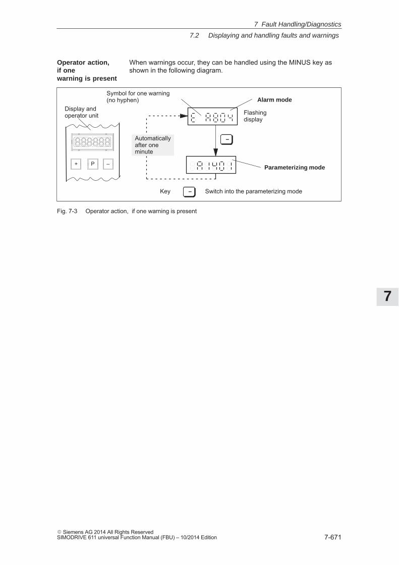
7
7.2 Displaying and handling faults and warnings
7-671� Siemens AG 2014 All Rights ReservedSIMODRIVE 611 universal Function Manual (FBU) – 10/2014 Edition
When warnings occur, they can be handled using the MINUS key asshown in the following diagram.
+ P –Parameterizing mode
Switch into the parameterizing mode
Flashingdisplay
Alarm mode
Display andoperator unit
Symbol for one warning(no hyphen)
–
Key –
Automaticallyafter oneminute
Fig. 7-3 Operator action, if one warning is present
Operator action,if onewarning is present
7 Fault Handling/Diagnostics
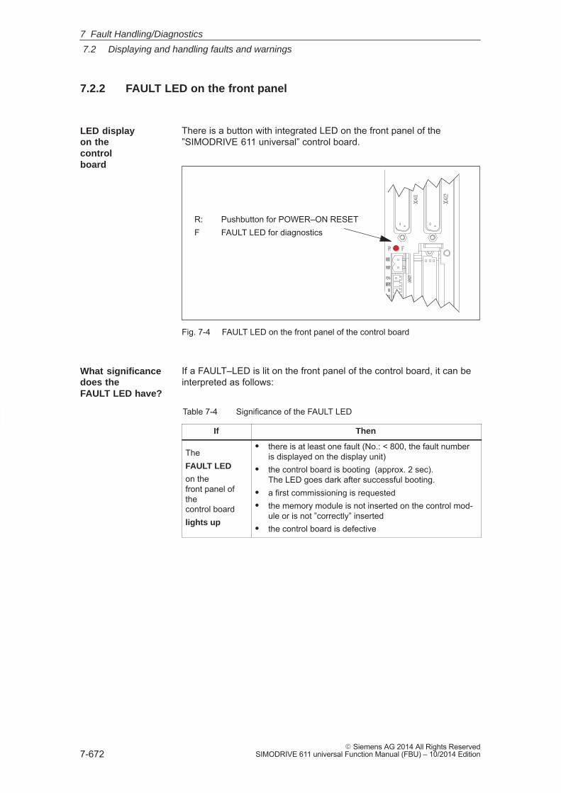
7
7.2 Displaying and handling faults and warnings
7-672� Siemens AG 2014 All Rights Reserved
SIMODRIVE 611 universal Function Manual (FBU) – 10/2014 Edition
7.2.2 FAULT LED on the front panel
There is a button with integrated LED on the front panel of the”SIMODRIVE 611 universal” control board.
R: Pushbutton for POWER–ON RESETF FAULT LED for diagnostics
Fig. 7-4 FAULT LED on the front panel of the control board
If a FAULT–LED is lit on the front panel of the control board, it can beinterpreted as follows:
Table 7-4 Significance of the FAULT LED
If Then
TheFAULT LED
on thefront panel ofthecontrol boardlights up
� there is at least one fault (No.: < 800, the fault numberis displayed on the display unit)
� the control board is booting (approx. 2 sec).The LED goes dark after successful booting.
� a first commissioning is requested� the memory module is not inserted on the control mod-
ule or is not ”correctly” inserted� the control board is defective
LED displayon thecontrolboard
What significancedoes theFAULT LED have?
7 Fault Handling/Diagnostics
7
7.3 List of faults and alarms
7-673� Siemens AG 2014 All Rights ReservedSIMODRIVE 611 universal Function Manual (FBU) – 10/2014 Edition
7.3 List of faults and alarms
7.3.1 Fault without a number being displayed
Fault After power–on, the operating display is inactive
Cause – At least 2 phases are missing (NE module)
– At least 2 input fuses have ruptured (NE module)
– Defective electronics power supply in the NE module
– Equipment bus connection (ribbon cable) fromthe NE module to the ”SIMODRIVE 611 universal”control board is either not inserted or defective
– Defective control board
Fault After the controller enable, the motor is stationary atnset � 0
Cause – P1401:8 is set to zero
– Power–on inhibit is present for PROFIBUS operationRemove the power–on inhibit withA ”high – low – high” signal change at 65.x orthe control bit STW1.0 (ON/OFF 1)orset bit 12 of parameter 1012 to zero
Fault After the controller has been enabled, the motor brieflymoves
Cause – Defective power module
Fault After the controller has been enabled, the motorrotates at max. 50 RPM at nset > 50 RPM or the motoroscillates at nset < 50 RPM
Cause – Motor phase sequence is incorrect (interchange 2 phase connections)
– The entered encoder pulse number was too high
Fault After the controller is enabled, the motor acceleratesto a high speed
Cause – Encoder pulse number too small
– Open–loop torque controlled mode selection?
Fault ”– – – – – –” is output on the display unit
Cause – There is no drive firmware in this memory module. – Remedy, refer to fault 001
7 Fault Handling/Diagnostics
7
7.3 List of faults and alarms
7-674� Siemens AG 2014 All Rights Reserved
SIMODRIVE 611 universal Function Manual (FBU) – 10/2014 Edition
7.3.2 Error with fault/warning number
Version: 13.02.01
Reader’s note
� In some instances, the space retainers (e.g. \%u) are specified forthe texts of the individual faults and warnings. In online operationwith SimoCom U instead of a space retainer, an appropriate valueis displayed.
� The complete list is updated corresponding to the Edition of thisdocumentation and corresponds to the software release of”SIMODRIVE 611 universal” documented here. The individualfaults/warnings are not coded dependent on the software release.
000 Alarm diagnostics not possible
Cause – Communications to the drive have been interrupted.– Different versions of the ”SimoCom U” start-up and parameterizing tool and the drive.
Remedy – Check the communications to the drive (cable, interfaces, ... )– The V_611U<Version>.acc file on the hard disk of the PG/PC should be adapted to the drive as follows: – Exit ”SimoCom U” – Delete the V_611U<Version>.acc file (search and delete the file) – Restart ”SimoCom U” and go online The V_611U<Version>.acc file is now re-generated and is harmonized to the drive version.Never delete the file V000000.acc!
001 The drive does not have firmware
Cause No drive firmware on the memory module.
Remedy – Load the drive firmware via SimoCom U– Insert the memory module with firmware
Acknowledgement POWER ON
Stop response STOP II (SRM, SLM) STOP I (ARM)
7 Fault Handling/Diagnostics
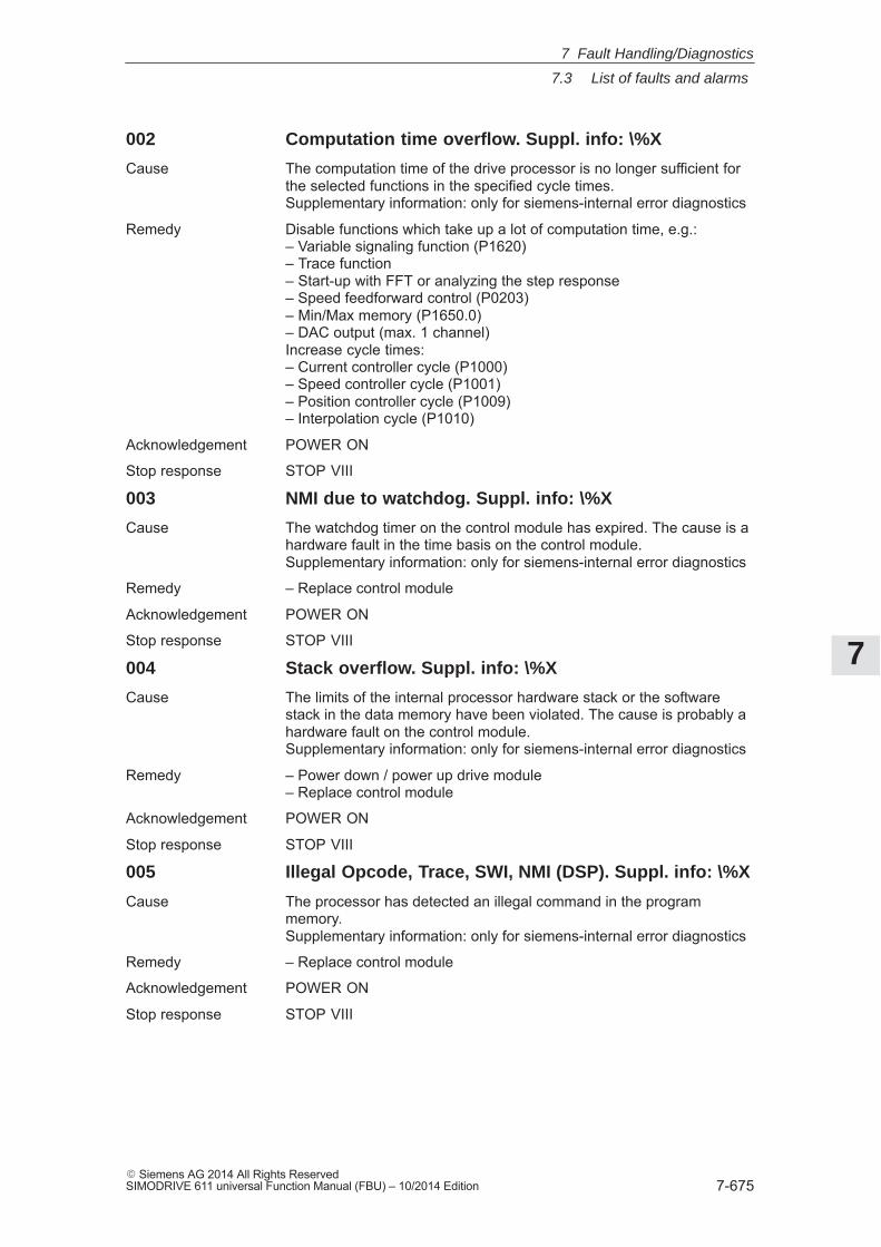
7
7.3 List of faults and alarms
7-675� Siemens AG 2014 All Rights ReservedSIMODRIVE 611 universal Function Manual (FBU) – 10/2014 Edition
002 Computation time overflow. Suppl. info: \%X
Cause The computation time of the drive processor is no longer sufficient forthe selected functions in the specified cycle times.Supplementary information: only for siemens-internal error diagnostics
Remedy Disable functions which take up a lot of computation time, e.g.:– Variable signaling function (P1620)– Trace function– Start-up with FFT or analyzing the step response– Speed feedforward control (P0203)– Min/Max memory (P1650.0)– DAC output (max. 1 channel)Increase cycle times:– Current controller cycle (P1000)– Speed controller cycle (P1001)– Position controller cycle (P1009)– Interpolation cycle (P1010)
Acknowledgement POWER ON
Stop response STOP VIII
003 NMI due to watchdog. Suppl. info: \%X
Cause The watchdog timer on the control module has expired. The cause is ahardware fault in the time basis on the control module.Supplementary information: only for siemens-internal error diagnostics
Remedy – Replace control module
Acknowledgement POWER ON
Stop response STOP VIII
004 Stack overflow. Suppl. info: \%X
Cause The limits of the internal processor hardware stack or the softwarestack in the data memory have been violated. The cause is probably ahardware fault on the control module.Supplementary information: only for siemens-internal error diagnostics
Remedy – Power down / power up drive module– Replace control module
Acknowledgement POWER ON
Stop response STOP VIII
005 Illegal Opcode, Trace, SWI, NMI (DSP). Suppl. info: \%X
Cause The processor has detected an illegal command in the programmemory.Supplementary information: only for siemens-internal error diagnostics
Remedy – Replace control module
Acknowledgement POWER ON
Stop response STOP VIII
7 Fault Handling/Diagnostics
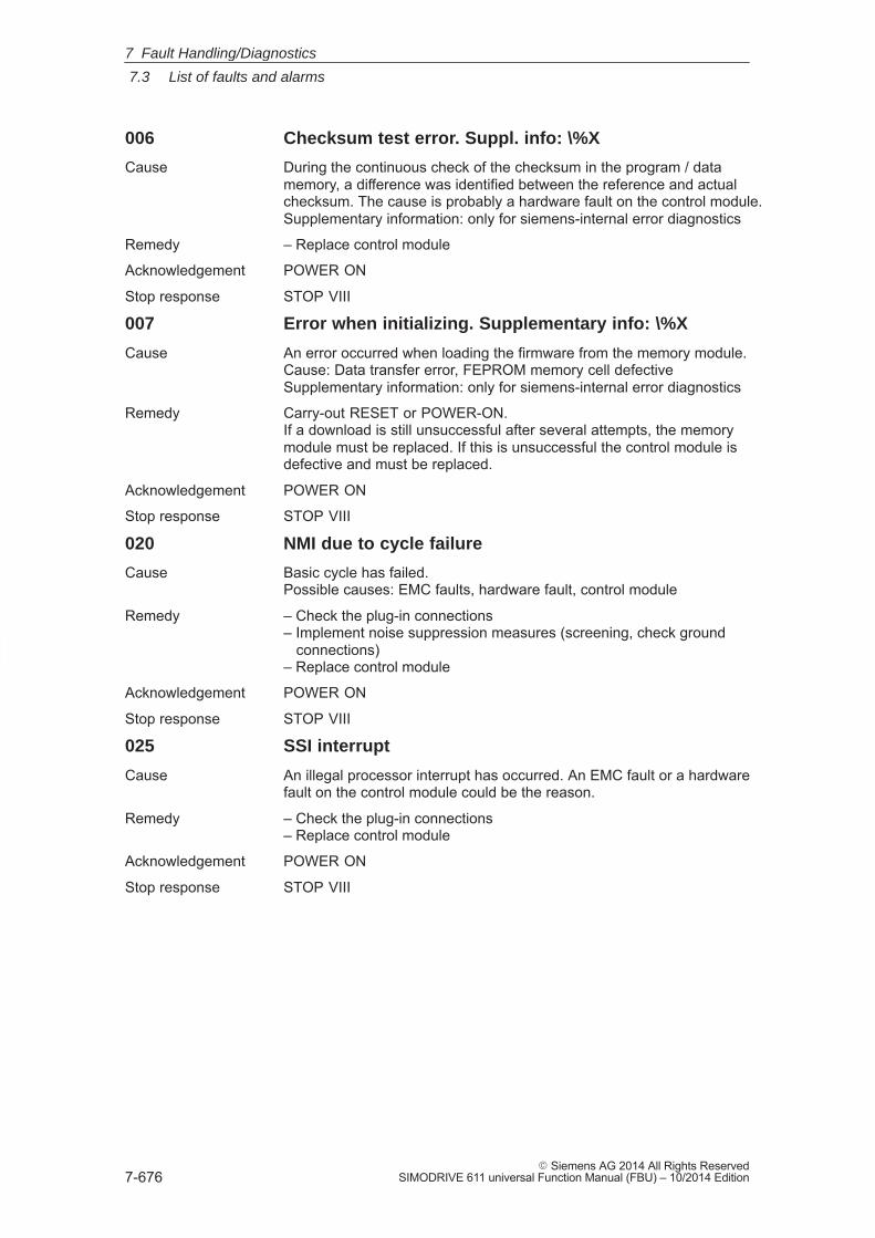
7
7.3 List of faults and alarms
7-676� Siemens AG 2014 All Rights Reserved
SIMODRIVE 611 universal Function Manual (FBU) – 10/2014 Edition
006 Checksum test error. Suppl. info: \%X
Cause During the continuous check of the checksum in the program / datamemory, a difference was identified between the reference and actualchecksum. The cause is probably a hardware fault on the control module.Supplementary information: only for siemens-internal error diagnostics
Remedy – Replace control module
Acknowledgement POWER ON
Stop response STOP VIII
007 Error when initializing. Supplementary info: \%X
Cause An error occurred when loading the firmware from the memory module.Cause: Data transfer error, FEPROM memory cell defectiveSupplementary information: only for siemens-internal error diagnostics
Remedy Carry-out RESET or POWER-ON.If a download is still unsuccessful after several attempts, the memorymodule must be replaced. If this is unsuccessful the control module isdefective and must be replaced.
Acknowledgement POWER ON
Stop response STOP VIII
020 NMI due to cycle failure
Cause Basic cycle has failed.Possible causes: EMC faults, hardware fault, control module
Remedy – Check the plug-in connections– Implement noise suppression measures (screening, check ground connections)– Replace control module
Acknowledgement POWER ON
Stop response STOP VIII
025 SSI interrupt
Cause An illegal processor interrupt has occurred. An EMC fault or a hardwarefault on the control module could be the reason.
Remedy – Check the plug-in connections– Replace control module
Acknowledgement POWER ON
Stop response STOP VIII
7 Fault Handling/Diagnostics
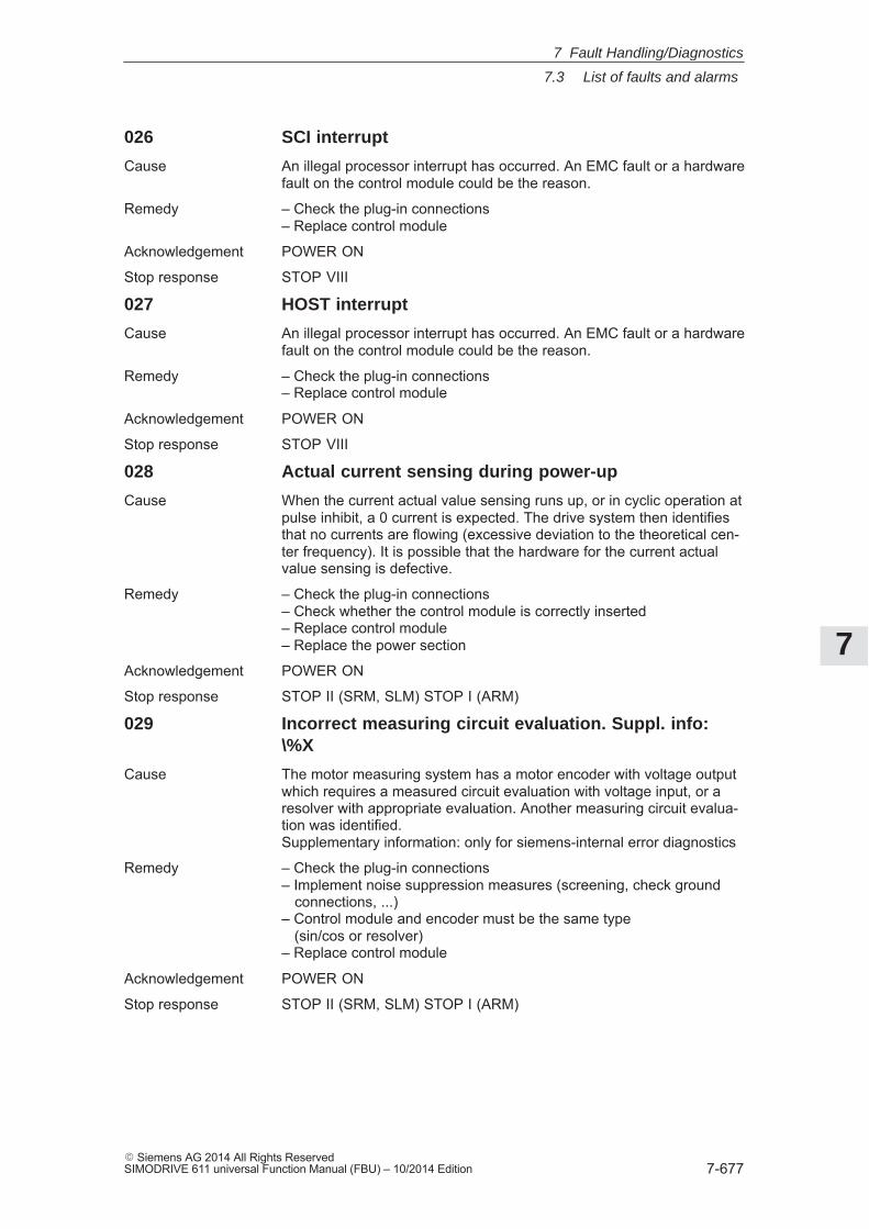
7
7.3 List of faults and alarms
7-677� Siemens AG 2014 All Rights ReservedSIMODRIVE 611 universal Function Manual (FBU) – 10/2014 Edition
026 SCI interrupt
Cause An illegal processor interrupt has occurred. An EMC fault or a hardwarefault on the control module could be the reason.
Remedy – Check the plug-in connections– Replace control module
Acknowledgement POWER ON
Stop response STOP VIII
027 HOST interrupt
Cause An illegal processor interrupt has occurred. An EMC fault or a hardwarefault on the control module could be the reason.
Remedy – Check the plug-in connections– Replace control module
Acknowledgement POWER ON
Stop response STOP VIII
028 Actual current sensing during power-up
Cause When the current actual value sensing runs up, or in cyclic operation atpulse inhibit, a 0 current is expected. The drive system then identifiesthat no currents are flowing (excessive deviation to the theoretical cen-ter frequency). It is possible that the hardware for the current actualvalue sensing is defective.
Remedy – Check the plug-in connections– Check whether the control module is correctly inserted– Replace control module– Replace the power section
Acknowledgement POWER ON
Stop response STOP II (SRM, SLM) STOP I (ARM)
029 Incorrect measuring circuit evaluation. Suppl. info:\%X
Cause The motor measuring system has a motor encoder with voltage outputwhich requires a measured circuit evaluation with voltage input, or aresolver with appropriate evaluation. Another measuring circuit evalua-tion was identified.Supplementary information: only for siemens-internal error diagnostics
Remedy – Check the plug-in connections– Implement noise suppression measures (screening, check ground connections, ...)– Control module and encoder must be the same type (sin/cos or resolver)– Replace control module
Acknowledgement POWER ON
Stop response STOP II (SRM, SLM) STOP I (ARM)
7 Fault Handling/Diagnostics
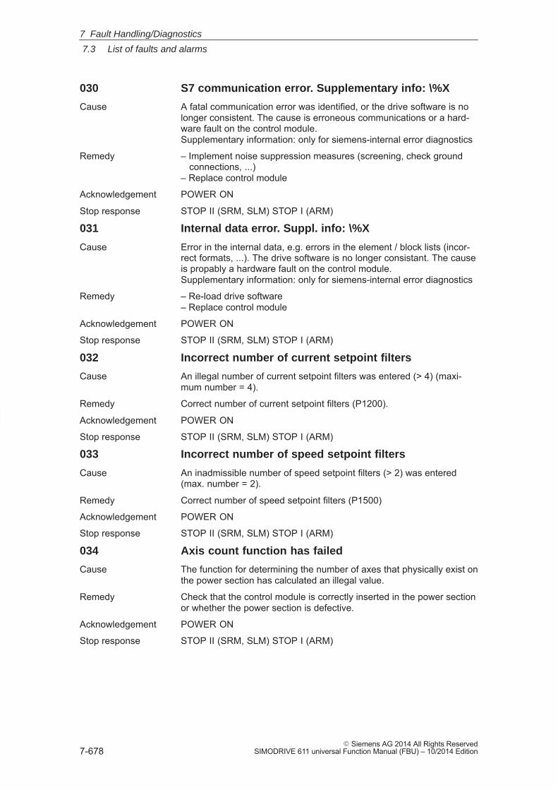
7
7.3 List of faults and alarms
7-678� Siemens AG 2014 All Rights Reserved
SIMODRIVE 611 universal Function Manual (FBU) – 10/2014 Edition
030 S7 communication error. Supplementary info: \%X
Cause A fatal communication error was identified, or the drive software is nolonger consistent. The cause is erroneous communications or a hard-ware fault on the control module.Supplementary information: only for siemens-internal error diagnostics
Remedy – Implement noise suppression measures (screening, check ground connections, ...)– Replace control module
Acknowledgement POWER ON
Stop response STOP II (SRM, SLM) STOP I (ARM)
031 Internal data error. Suppl. info: \%X
Cause Error in the internal data, e.g. errors in the element / block lists (incor-rect formats, ...). The drive software is no longer consistant. The causeis propably a hardware fault on the control module.Supplementary information: only for siemens-internal error diagnostics
Remedy – Re-load drive software– Replace control module
Acknowledgement POWER ON
Stop response STOP II (SRM, SLM) STOP I (ARM)
032 Incorrect number of current setpoint filters
Cause An illegal number of current setpoint filters was entered (> 4) (maxi-mum number = 4).
Remedy Correct number of current setpoint filters (P1200).
Acknowledgement POWER ON
Stop response STOP II (SRM, SLM) STOP I (ARM)
033 Incorrect number of speed setpoint filters
Cause An inadmissible number of speed setpoint filters (> 2) was entered(max. number = 2).
Remedy Correct number of speed setpoint filters (P1500)
Acknowledgement POWER ON
Stop response STOP II (SRM, SLM) STOP I (ARM)
034 Axis count function has failed
Cause The function for determining the number of axes that physically exist onthe power section has calculated an illegal value.
Remedy Check that the control module is correctly inserted in the power sectionor whether the power section is defective.
Acknowledgement POWER ON
Stop response STOP II (SRM, SLM) STOP I (ARM)
7 Fault Handling/Diagnostics
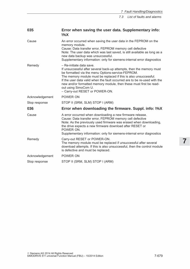
7
7.3 List of faults and alarms
7-679� Siemens AG 2014 All Rights ReservedSIMODRIVE 611 universal Function Manual (FBU) – 10/2014 Edition
035 Error when saving the user data. Supplementary info:\%X
Cause An error occurred when saving the user data in the FEPROM on thememory module.Cause: Data transfer error, FEPROM memory cell defectiveNote: The user data which was last saved, is still available as long as anew data backup was unsuccessful.Supplementary information: only for siemens-internal error diagnostics
Remedy – Re-initiate data save.If unsuccessful after several back-up attempts, then the memory mustbe formatted via the menu Options-service-FEPROM.The memory module must be replaced if this is also unsuccessful.If the user data valid when the fault occurred are to be re-used with thenew and/or formatted memory module, then these must first be read-out using SimoCom U.– Carry-out RESET or POWER-ON.
Acknowledgement POWER ON
Stop response STOP II (SRM, SLM) STOP I (ARM)
036 Error when downloading the firmware. Suppl. info: \%X
Cause A error occurred when downloading a new firmware release.Cause: Data transfer error, FEPROM memory cell defectiveNote: As the previously used firmware was erased when downloading,the drive expects a new firmware download after RESET orPOWER ON.Supplementary information: only for siemens-internal error diagnostics
Remedy Carry-out RESET or POWER-ON.The memory module must be replaced if unsuccessful after severaldownload attempts. If this is also unsuccessful, then the control moduleis defective and must be replaced.
Acknowledgement POWER ON
Stop response STOP II (SRM, SLM) STOP I (ARM)
7 Fault Handling/Diagnostics
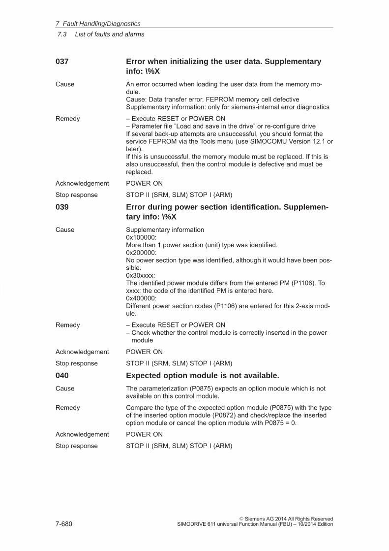
7
7.3 List of faults and alarms
7-680� Siemens AG 2014 All Rights Reserved
SIMODRIVE 611 universal Function Manual (FBU) – 10/2014 Edition
037 Error when initializing the user data. Supplementaryinfo: \%X
Cause An error occurred when loading the user data from the memory mo-dule.Cause: Data transfer error, FEPROM memory cell defectiveSupplementary information: only for siemens-internal error diagnostics
Remedy – Execute RESET or POWER ON– Parameter file ”Load and save in the drive” or re-configure driveIf several back-up attempts are unsuccessful, you should format theservice FEPROM via the Tools menu (use SIMOCOMU Version 12.1 orlater).If this is unsuccessful, the memory module must be replaced. If this isalso unsuccessful, then the control module is defective and must bereplaced.
Acknowledgement POWER ON
Stop response STOP II (SRM, SLM) STOP I (ARM)
039 Error during power section identification. Supplemen-tary info: \%X
Cause Supplementary information0x100000:More than 1 power section (unit) type was identified.0x200000:No power section type was identified, although it would have been pos-sible.0x30xxxx:The identified power module differs from the entered PM (P1106). Toxxxx: the code of the identified PM is entered here.0x400000:Different power section codes (P1106) are entered for this 2-axis mod-ule.
Remedy – Execute RESET or POWER ON– Check whether the control module is correctly inserted in the power module
Acknowledgement POWER ON
Stop response STOP II (SRM, SLM) STOP I (ARM)
040 Expected option module is not available.
Cause The parameterization (P0875) expects an option module which is notavailable on this control module.
Remedy Compare the type of the expected option module (P0875) with the typeof the inserted option module (P0872) and check/replace the insertedoption module or cancel the option module with P0875 = 0.
Acknowledgement POWER ON
Stop response STOP II (SRM, SLM) STOP I (ARM)
7 Fault Handling/Diagnostics
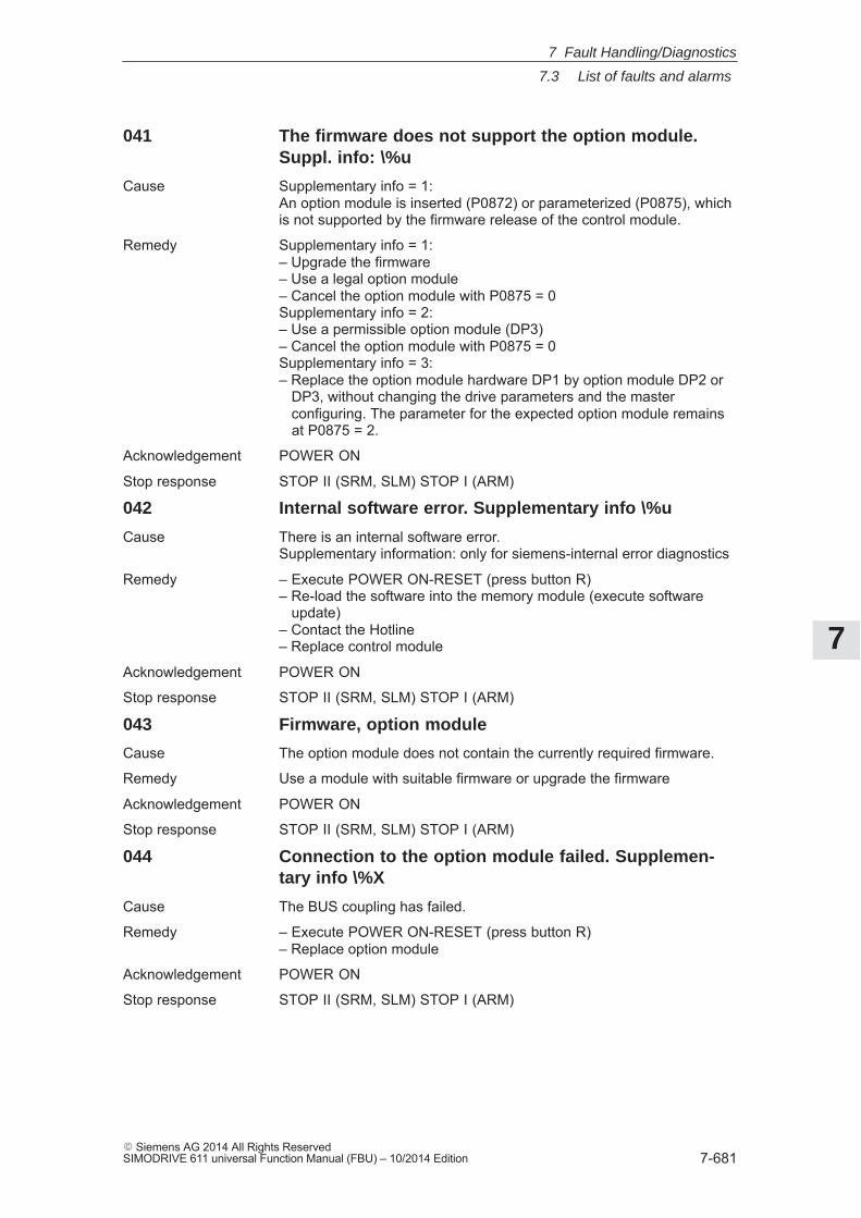
7
7.3 List of faults and alarms
7-681� Siemens AG 2014 All Rights ReservedSIMODRIVE 611 universal Function Manual (FBU) – 10/2014 Edition
041 The firmware does not support the option module.Suppl. info: \%u
Cause Supplementary info = 1:An option module is inserted (P0872) or parameterized (P0875), whichis not supported by the firmware release of the control module.
Remedy Supplementary info = 1:– Upgrade the firmware– Use a legal option module– Cancel the option module with P0875 = 0Supplementary info = 2:– Use a permissible option module (DP3)– Cancel the option module with P0875 = 0Supplementary info = 3:– Replace the option module hardware DP1 by option module DP2 or DP3, without changing the drive parameters and the master configuring. The parameter for the expected option module remains at P0875 = 2.
Acknowledgement POWER ON
Stop response STOP II (SRM, SLM) STOP I (ARM)
042 Internal software error. Supplementary info \%u
Cause There is an internal software error.Supplementary information: only for siemens-internal error diagnostics
Remedy – Execute POWER ON-RESET (press button R)– Re-load the software into the memory module (execute software update)– Contact the Hotline– Replace control module
Acknowledgement POWER ON
Stop response STOP II (SRM, SLM) STOP I (ARM)
043 Firmware, option module
Cause The option module does not contain the currently required firmware.
Remedy Use a module with suitable firmware or upgrade the firmware
Acknowledgement POWER ON
Stop response STOP II (SRM, SLM) STOP I (ARM)
044 Connection to the option module failed. Supplemen-tary info \%X
Cause The BUS coupling has failed.
Remedy – Execute POWER ON-RESET (press button R)– Replace option module
Acknowledgement POWER ON
Stop response STOP II (SRM, SLM) STOP I (ARM)
7 Fault Handling/Diagnostics
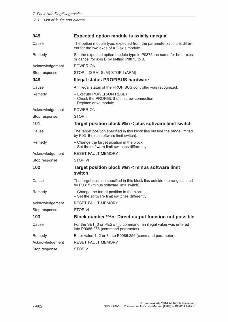
7
7.3 List of faults and alarms
7-682� Siemens AG 2014 All Rights Reserved
SIMODRIVE 611 universal Function Manual (FBU) – 10/2014 Edition
045 Expected option module is axially unequal
Cause The option module type, expected from the parameterization, is differ-ent for the two axes of a 2-axis module.
Remedy Set the expected option module type in P0875 the same for both axes,or cancel for axis B by setting P0875 to 0.
Acknowledgement POWER ON
Stop response STOP II (SRM, SLM) STOP I (ARM)
048 Illegal status PROFIBUS hardware
Cause An illegal status of the PROFIBUS controller was recognized.
Remedy – Execute POWER-ON RESET– Check the PROFIBUS unit screw connection– Replace drive module
Acknowledgement POWER ON
Stop response STOP II
101 Target position block \%n < plus software limit switch
Cause The target position specified in this block lies outside the range limitedby P0316 (plus software limit switch).
Remedy – Change the target position in the block– Set the software limit switches differently
Acknowledgement RESET FAULT MEMORY
Stop response STOP VI
102 Target position block \%n < minus software limitswitch
Cause The target position specified in this block lies outside the range limitedby P0315 (minus software limit switch).
Remedy – Change the target position in the block– Set the software limit switches differently
Acknowledgement RESET FAULT MEMORY
Stop response STOP VI
103 Block number \%n: Direct output function not possible
Cause For the SET_0 or RESET_0 command, an illegal value was enteredinto P0086:256 (command parameter).
Remedy Enter value 1, 2 or 3 into P0086:256 (command parameter).
Acknowledgement RESET FAULT MEMORY
Stop response STOP V
7 Fault Handling/Diagnostics
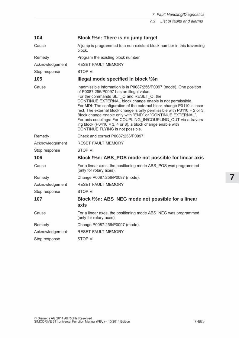
7
7.3 List of faults and alarms
7-683� Siemens AG 2014 All Rights ReservedSIMODRIVE 611 universal Function Manual (FBU) – 10/2014 Edition
104 Block \%n: There is no jump target
Cause A jump is programmed to a non-existent block number in this traversingblock.
Remedy Program the existing block number.
Acknowledgement RESET FAULT MEMORY
Stop response STOP VI
105 Illegal mode specified in block \%n
Cause Inadmissible information is in P0087:256/P0097 (mode). One positionof P0087:256/P0097 has an illegal value.For the commands SET_O and RESET_O, theCONTINUE EXTERNAL block change enable is not permissible.For MDI: The configuration of the external block change P0110 is incor-rect. The external block change is only permissible with P0110 = 2 or 3.Block change enable only with ”END” or ”CONTINUE EXTERNAL”.For axis couplings: For COUPLING_IN/COUPLING_OUT via a travers-ing block (P0410 = 3, 4 or 8), a block change enable withCONTINUE FLYING is not possible.
Remedy Check and correct P0087:256/P0097.
Acknowledgement RESET FAULT MEMORY
Stop response STOP VI
106 Block \%n: ABS_POS mode not possible for linear axis
Cause For a linear axes, the positioning mode ABS_POS was programmed(only for rotary axes).
Remedy Change P0087:256/P0097 (mode).
Acknowledgement RESET FAULT MEMORY
Stop response STOP VI
107 Block \%n: ABS_NEG mode not possible for a linearaxis
Cause For a linear axes, the positioning mode ABS_NEG was programmed(only for rotary axes).
Remedy Change P0087:256/P0097 (mode).
Acknowledgement RESET FAULT MEMORY
Stop response STOP VI
7 Fault Handling/Diagnostics
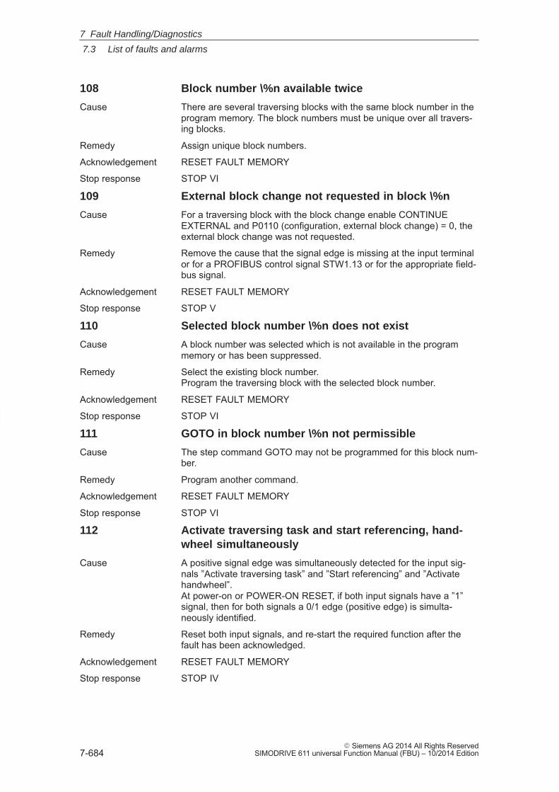
7
7.3 List of faults and alarms
7-684� Siemens AG 2014 All Rights Reserved
SIMODRIVE 611 universal Function Manual (FBU) – 10/2014 Edition
108 Block number \%n available twice
Cause There are several traversing blocks with the same block number in theprogram memory. The block numbers must be unique over all travers-ing blocks.
Remedy Assign unique block numbers.
Acknowledgement RESET FAULT MEMORY
Stop response STOP VI
109 External block change not requested in block \%n
Cause For a traversing block with the block change enable CONTINUEEXTERNAL and P0110 (configuration, external block change) = 0, theexternal block change was not requested.
Remedy Remove the cause that the signal edge is missing at the input terminalor for a PROFIBUS control signal STW1.13 or for the appropriate field-bus signal.
Acknowledgement RESET FAULT MEMORY
Stop response STOP V
110 Selected block number \%n does not exist
Cause A block number was selected which is not available in the programmemory or has been suppressed.
Remedy Select the existing block number.Program the traversing block with the selected block number.
Acknowledgement RESET FAULT MEMORY
Stop response STOP VI
111 GOTO in block number \%n not permissible
Cause The step command GOTO may not be programmed for this block num-ber.
Remedy Program another command.
Acknowledgement RESET FAULT MEMORY
Stop response STOP VI
112 Activate traversing task and start referencing, hand-wheel simultaneously
Cause A positive signal edge was simultaneously detected for the input sig-nals ”Activate traversing task” and ”Start referencing” and ”Activatehandwheel”.At power-on or POWER-ON RESET, if both input signals have a ”1”signal, then for both signals a 0/1 edge (positive edge) is simulta-neously identified.
Remedy Reset both input signals, and re-start the required function after thefault has been acknowledged.
Acknowledgement RESET FAULT MEMORY
Stop response STOP IV
7 Fault Handling/Diagnostics
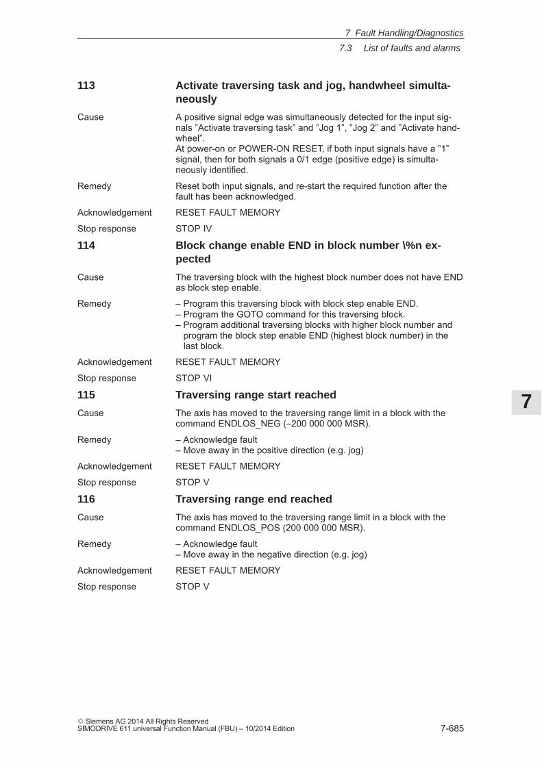
7
7.3 List of faults and alarms
7-685� Siemens AG 2014 All Rights ReservedSIMODRIVE 611 universal Function Manual (FBU) – 10/2014 Edition
113 Activate traversing task and jog, handwheel simulta-neously
Cause A positive signal edge was simultaneously detected for the input sig-nals ”Activate traversing task” and ”Jog 1”, ”Jog 2” and ”Activate hand-wheel”.At power-on or POWER-ON RESET, if both input signals have a ”1”signal, then for both signals a 0/1 edge (positive edge) is simulta-neously identified.
Remedy Reset both input signals, and re-start the required function after thefault has been acknowledged.
Acknowledgement RESET FAULT MEMORY
Stop response STOP IV
114 Block change enable END in block number \%n ex-pected
Cause The traversing block with the highest block number does not have ENDas block step enable.
Remedy – Program this traversing block with block step enable END.– Program the GOTO command for this traversing block.– Program additional traversing blocks with higher block number and program the block step enable END (highest block number) in the last block.
Acknowledgement RESET FAULT MEMORY
Stop response STOP VI
115 Traversing range start reached
Cause The axis has moved to the traversing range limit in a block with thecommand ENDLOS_NEG (–200 000 000 MSR).
Remedy – Acknowledge fault– Move away in the positive direction (e.g. jog)
Acknowledgement RESET FAULT MEMORY
Stop response STOP V
116 Traversing range end reached
Cause The axis has moved to the traversing range limit in a block with thecommand ENDLOS_POS (200 000 000 MSR).
Remedy – Acknowledge fault– Move away in the negative direction (e.g. jog)
Acknowledgement RESET FAULT MEMORY
Stop response STOP V
7 Fault Handling/Diagnostics
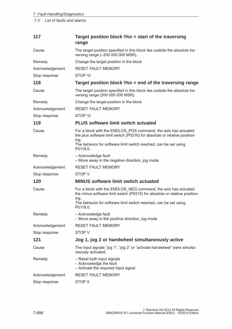
7
7.3 List of faults and alarms
7-686� Siemens AG 2014 All Rights Reserved
SIMODRIVE 611 universal Function Manual (FBU) – 10/2014 Edition
117 Target position block \%n < start of the traversingrange
Cause The target position specified in this block lies outside the absolute tra-versing range (–200 000 000 MSR).
Remedy Change the target position in the block
Acknowledgement RESET FAULT MEMORY
Stop response STOP VI
118 Target position block \%n < end of the traversing range
Cause The target position specified in this block lies outside the absolute tra-versing range (200 000 000 MSR).
Remedy Change the target position in the block
Acknowledgement RESET FAULT MEMORY
Stop response STOP VI
119 PLUS software limit switch actuated
Cause For a block with the ENDLOS_POS command, the axis has actuatedthe plus software limit switch (P0316) for absolute or relative position-ing.The behavior for software limit switch reached, can be set usingP0118.0.
Remedy – Acknowledge fault– Move away in the negative direction, jog mode
Acknowledgement RESET FAULT MEMORY
Stop response STOP V
120 MINUS software limit switch actuated
Cause For a block with the ENDLOS_NEG command, the axis has actuatedthe minus software limit switch (P0315) for absolute or relative position-ing.The behavior for software limit switch reached, can be set usingP0118.0.
Remedy – Acknowledge fault– Move away in the positive direction, jog mode
Acknowledgement RESET FAULT MEMORY
Stop response STOP V
121 Jog 1, jog 2 or handwheel simultaneously active
Cause The input signals ”jog 1”, ”jog 2” or ”activate handwheel” were simulta-neously activated.
Remedy – Reset both input signals– Acknowledge the fault– Activate the required input signal
Acknowledgement RESET FAULT MEMORY
Stop response STOP II
7 Fault Handling/Diagnostics
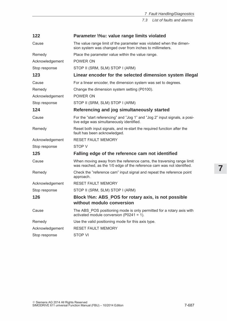
7
7.3 List of faults and alarms
7-687� Siemens AG 2014 All Rights ReservedSIMODRIVE 611 universal Function Manual (FBU) – 10/2014 Edition
122 Parameter \%u: value range limits violated
Cause The value range limit of the parameter was violated when the dimen-sion system was changed over from inches to millimeters.
Remedy Place the parameter value within the value range.
Acknowledgement POWER ON
Stop response STOP II (SRM, SLM) STOP I (ARM)
123 Linear encoder for the selected dimension system illegal
Cause For a linear encoder, the dimension system was set to degrees.
Remedy Change the dimension system setting (P0100).
Acknowledgement POWER ON
Stop response STOP II (SRM, SLM) STOP I (ARM)
124 Referencing and jog simultaneously started
Cause For the ”start referencing” and ”Jog 1” and ”Jog 2” input signals, a posi-tive edge was simultaneously identified.
Remedy Reset both input signals, and re-start the required function after thefault has been acknowledged.
Acknowledgement RESET FAULT MEMORY
Stop response STOP V
125 Falling edge of the reference cam not identified
Cause When moving away from the reference cams, the traversing range limitwas reached, as the 1/0 edge of the reference cam was not identified.
Remedy Check the ”reference cam” input signal and repeat the reference pointapproach.
Acknowledgement RESET FAULT MEMORY
Stop response STOP II (SRM, SLM) STOP I (ARM)
126 Block \%n: ABS_POS for rotary axis, is not possiblewithout modulo conversion
Cause The ABS_POS positioning mode is only permitted for a rotary axis withactivated module conversion (P0241 = 1).
Remedy Use the valid positioning mode for this axis type.
Acknowledgement RESET FAULT MEMORY
Stop response STOP VI
7 Fault Handling/Diagnostics
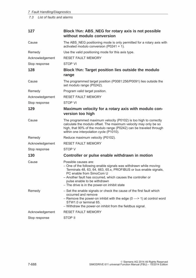
7
7.3 List of faults and alarms
7-688� Siemens AG 2014 All Rights Reserved
SIMODRIVE 611 universal Function Manual (FBU) – 10/2014 Edition
127 Block \%n: ABS_NEG for rotary axis is not possiblewithout modulo conversion
Cause The ABS_NEG positioning mode is only permitted for a rotary axis withactivated modulo conversion (P0241 = 1).
Remedy Use the valid positioning mode for this axis type.
Acknowledgement RESET FAULT MEMORY
Stop response STOP VI
128 Block \%n: Target position lies outside the modulorange
Cause The programmed target position (P0081:256/P0091) lies outside theset modulo range (P0242).
Remedy Program valid target position.
Acknowledgement RESET FAULT MEMORY
Stop response STOP VI
129 Maximum velocity for a rotary axis with modulo con-version too high
Cause The programmed maximum velocity (P0102) is too high to correctlycalculate the modulo offset. The maximum velocity may only be sohigh, that 90% of the modulo range (P0242) can be traveled throughwithin one interpolation cycle (P1010).
Remedy Reduce maximum velocity (P0102).
Acknowledgement RESET FAULT MEMORY
Stop response STOP V
130 Controller or pulse enable withdrawn in motion
Cause Possible causes are:– One of the following enable signals was withdrawn while moving: Terminals 48, 63, 64, 663, 65.x, PROFIBUS or bus enable signals, PC enable from SimoCom U– Another fault has occurred, which causes the controller or pulse enable to be withdrawn– The drive is in the power-on inhibit state
Remedy – Set the enable signals or check the cause of the first fault which occurred and remove– Remove the power-on inhibit with the edge (0 ––> 1) at control word STW1.0 or terminal 65.– Withdraw the power-on inhibit from the fieldbus signal.
Acknowledgement RESET FAULT MEMORY
Stop response STOP II
7 Fault Handling/Diagnostics
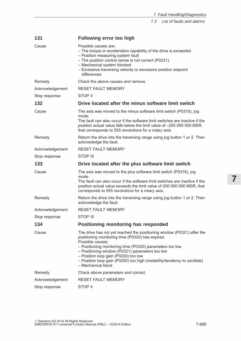
7
7.3 List of faults and alarms
7-689� Siemens AG 2014 All Rights ReservedSIMODRIVE 611 universal Function Manual (FBU) – 10/2014 Edition
131 Following error too high
Cause Possible causes are:– The torque or acceleration capability of the drive is exceeded– Position measuring system fault– The position control sense is not correct (P0231)– Mechanical system blocked– Excessive traversing velocity or excessive position setpoint differences
Remedy Check the above causes and remove.
Acknowledgement RESET FAULT MEMORY
Stop response STOP II
132 Drive located after the minus software limit switch
Cause The axis was moved to the minus software limit switch (P0315), jogmode.The fault can also occur if the software limit switches are inactive if theposition actual value falls below the limit value of –200 000 000 MSR,that corresponds to 555 revolutions for a rotary axis.
Remedy Return the drive into the traversing range using jog button 1 or 2. Thenacknowledge the fault.
Acknowledgement RESET FAULT MEMORY
Stop response STOP III
133 Drive located after the plus software limit switch
Cause The axis was moved to the plus software limit switch (P0316), jogmode.The fault can also occur if the software limit switches are inactive if theposition actual value exceeds the limit value of 200 000 000 MSR, thatcorresponds to 555 revolutions for a rotary axis.
Remedy Return the drive into the traversing range using jog button 1 or 2. Thenacknowledge the fault.
Acknowledgement RESET FAULT MEMORY
Stop response STOP III
134 Positioning monitoring has responded
Cause The drive has not yet reached the positioning window (P0321) after thepositioning monitoring time (P0320) has expired.Possible causes:– Positioning monitoring time (P0320) parameters too low– Positioning window (P0321) parameters too low– Position loop gain (P0200) too low– Position loop gain (P0200) too high (instability/tendency to oscillate)– Mechanical block
Remedy Check above parameters and correct.
Acknowledgement RESET FAULT MEMORY
Stop response STOP II
7 Fault Handling/Diagnostics
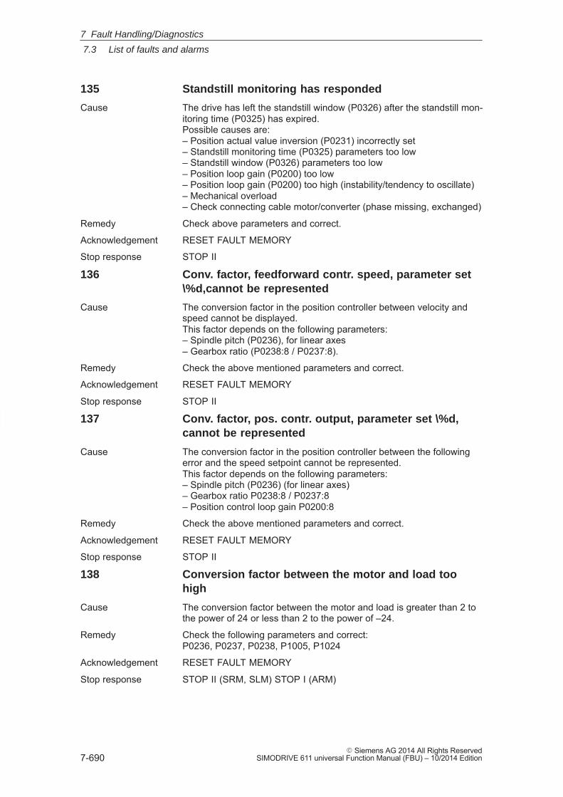
7
7.3 List of faults and alarms
7-690� Siemens AG 2014 All Rights Reserved
SIMODRIVE 611 universal Function Manual (FBU) – 10/2014 Edition
135 Standstill monitoring has responded
Cause The drive has left the standstill window (P0326) after the standstill mon-itoring time (P0325) has expired.Possible causes are:– Position actual value inversion (P0231) incorrectly set– Standstill monitoring time (P0325) parameters too low– Standstill window (P0326) parameters too low– Position loop gain (P0200) too low– Position loop gain (P0200) too high (instability/tendency to oscillate)– Mechanical overload– Check connecting cable motor/converter (phase missing, exchanged)
Remedy Check above parameters and correct.
Acknowledgement RESET FAULT MEMORY
Stop response STOP II
136 Conv. factor, feedforward contr. speed, parameter set\%d,cannot be represented
Cause The conversion factor in the position controller between velocity andspeed cannot be displayed.This factor depends on the following parameters:– Spindle pitch (P0236), for linear axes– Gearbox ratio (P0238:8 / P0237:8).
Remedy Check the above mentioned parameters and correct.
Acknowledgement RESET FAULT MEMORY
Stop response STOP II
137 Conv. factor, pos. contr. output, parameter set \%d,cannot be represented
Cause The conversion factor in the position controller between the followingerror and the speed setpoint cannot be represented.This factor depends on the following parameters:– Spindle pitch (P0236) (for linear axes)– Gearbox ratio P0238:8 / P0237:8– Position control loop gain P0200:8
Remedy Check the above mentioned parameters and correct.
Acknowledgement RESET FAULT MEMORY
Stop response STOP II
138 Conversion factor between the motor and load toohigh
Cause The conversion factor between the motor and load is greater than 2 tothe power of 24 or less than 2 to the power of –24.
Remedy Check the following parameters and correct: P0236, P0237, P0238, P1005, P1024
Acknowledgement RESET FAULT MEMORY
Stop response STOP II (SRM, SLM) STOP I (ARM)
7 Fault Handling/Diagnostics
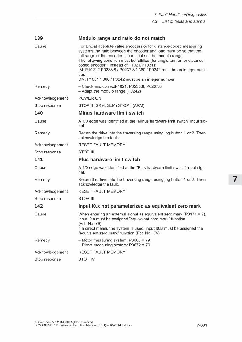
7
7.3 List of faults and alarms
7-691� Siemens AG 2014 All Rights ReservedSIMODRIVE 611 universal Function Manual (FBU) – 10/2014 Edition
139 Modulo range and ratio do not match
Cause For EnDat absolute value encoders or for distance-coded measuringsystems the ratio between the encoder and load must be so that thefull range of the encoder is a multiple of the modulo range.The following condition must be fulfilled (for single turn or for distance-coded encoder 1 instead of P1021/P1031):IM: P1021 * P0238:8 / P0237:8 * 360 / P0242 must be an integer num-ber.DM: P1031 * 360 / P0242 must be an integer number
Remedy – Check and correctP1021, P0238:8, P0237:8– Adapt the modulo range (P0242)
Acknowledgement POWER ON
Stop response STOP II (SRM, SLM) STOP I (ARM)
140 Minus hardware limit switch
Cause A 1/0 edge was identified at the ”Minus hardware limit switch” input sig-nal.
Remedy Return the drive into the traversing range using jog button 1 or 2. Thenacknowledge the fault.
Acknowledgement RESET FAULT MEMORY
Stop response STOP III
141 Plus hardware limit switch
Cause A 1/0 edge was identified at the ”Plus hardware limit switch” input sig-nal.
Remedy Return the drive into the traversing range using jog button 1 or 2. Thenacknowledge the fault.
Acknowledgement RESET FAULT MEMORY
Stop response STOP III
142 Input I0.x not parameterized as equivalent zero mark
Cause When entering an external signal as equivalent zero mark (P0174 = 2),input I0.x must be assigned ”equivalent zero mark” function(Fct. No.:79).if a direct measuring system is used, input I0.B must be assigned the”equivalent zero mark” function (Fct. No.: 79).
Remedy – Motor measuring system: P0660 = 79– Direct measuring system: P0672 = 79
Acknowledgement RESET FAULT MEMORY
Stop response STOP IV
7 Fault Handling/Diagnostics
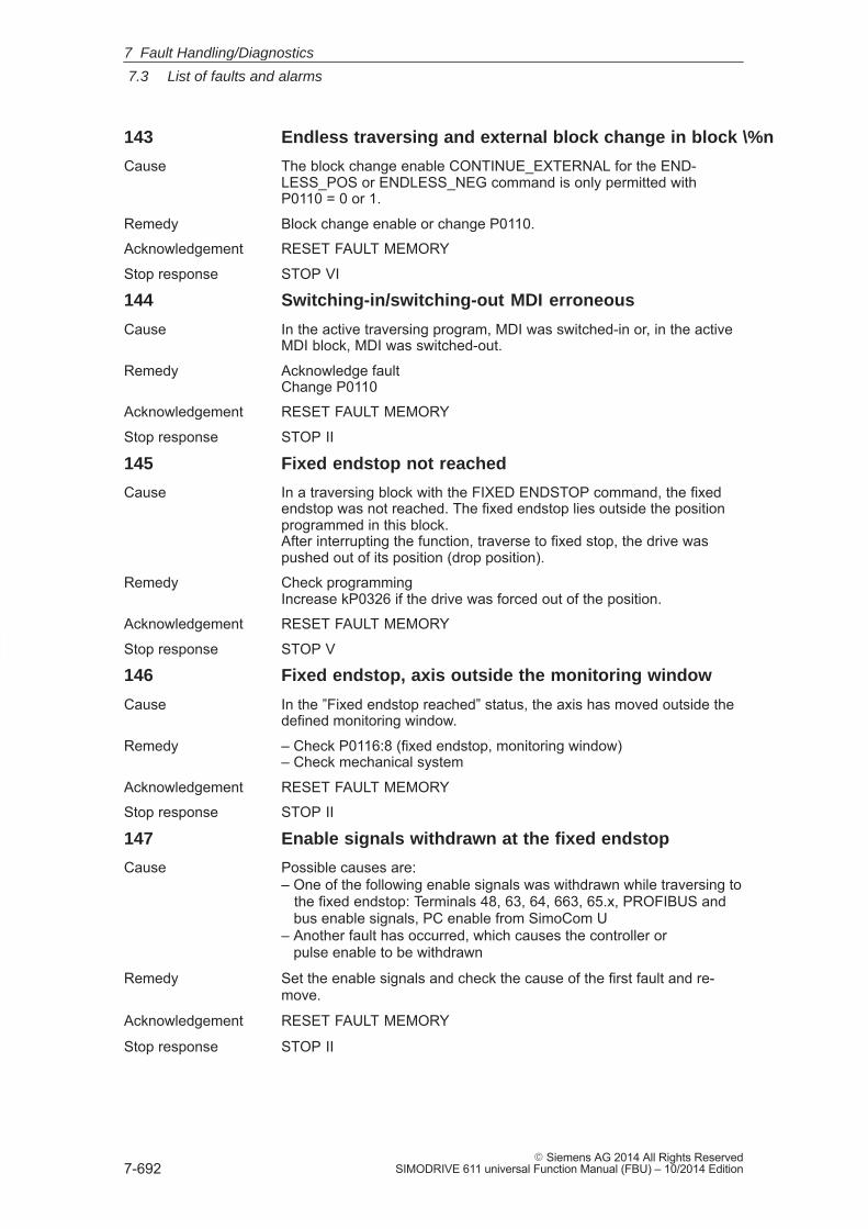
7
7.3 List of faults and alarms
7-692� Siemens AG 2014 All Rights Reserved
SIMODRIVE 611 universal Function Manual (FBU) – 10/2014 Edition
143 Endless traversing and external block change in block \%n
Cause The block change enable CONTINUE_EXTERNAL for the END-LESS_POS or ENDLESS_NEG command is only permitted withP0110 = 0 or 1.
Remedy Block change enable or change P0110.
Acknowledgement RESET FAULT MEMORY
Stop response STOP VI
144 Switching-in/switching-out MDI erroneous
Cause In the active traversing program, MDI was switched-in or, in the activeMDI block, MDI was switched-out.
Remedy Acknowledge faultChange P0110
Acknowledgement RESET FAULT MEMORY
Stop response STOP II
145 Fixed endstop not reached
Cause In a traversing block with the FIXED ENDSTOP command, the fixedendstop was not reached. The fixed endstop lies outside the positionprogrammed in this block.After interrupting the function, traverse to fixed stop, the drive waspushed out of its position (drop position).
Remedy Check programmingIncrease kP0326 if the drive was forced out of the position.
Acknowledgement RESET FAULT MEMORY
Stop response STOP V
146 Fixed endstop, axis outside the monitoring window
Cause In the ”Fixed endstop reached” status, the axis has moved outside thedefined monitoring window.
Remedy – Check P0116:8 (fixed endstop, monitoring window)– Check mechanical system
Acknowledgement RESET FAULT MEMORY
Stop response STOP II
147 Enable signals withdrawn at the fixed endstop
Cause Possible causes are:– One of the following enable signals was withdrawn while traversing to the fixed endstop: Terminals 48, 63, 64, 663, 65.x, PROFIBUS and bus enable signals, PC enable from SimoCom U– Another fault has occurred, which causes the controller or pulse enable to be withdrawn
Remedy Set the enable signals and check the cause of the first fault and re-move.
Acknowledgement RESET FAULT MEMORY
Stop response STOP II
7 Fault Handling/Diagnostics
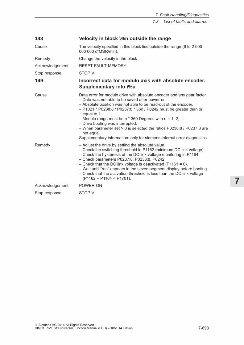
7
7.3 List of faults and alarms
7-693� Siemens AG 2014 All Rights ReservedSIMODRIVE 611 universal Function Manual (FBU) – 10/2014 Edition
148 Velocity in block \%n outside the range
Cause The velocity specified in this block lies outside the range (6 to 2 000000 000 c*MSR/min).
Remedy Change the velocity in the block
Acknowledgement RESET FAULT MEMORY
Stop response STOP VI
149 Incorrect data for modulo axis with absolute encoder.Supplementary info \%u
Cause Data error for modulo drive with absolute encoder and any gear factor.– Data was not able to be saved after power-on.– Absolute position was not able to be read-out of the encoder.– P1021 * P0238:8 / P0237:8 * 360 / P0242 must be greater than or equal to 1.– Modulo range must be n * 360 Degrees with n = 1, 2, ....– Drive booting was interrupted.– When parameter set > 0 is selected the ratios P0238:8 / P0237:8 are not equal.Supplementary information: only for siemens-internal error diagnostics
Remedy – Adjust the drive by setting the absolute value.– Check the switching threshold in P1162 (minimum DC link voltage).– Check the hysteresis of the DC link voltage monitoring in P1164.– Check parameters P0237:8, P0238:8, P0242.– Check that the DC link voltage is deactivated (P1161 = 0).– Wait until ”run” appears in the seven-segment display before booting.– Check that the activation threshold is less than the DC link voltage (P1162 + P1164 < P1701).
Acknowledgement POWER ON
Stop response STOP V
7 Fault Handling/Diagnostics
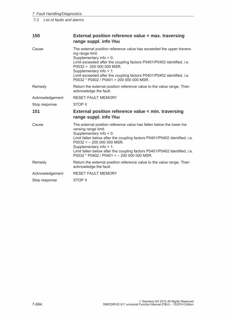
7
7.3 List of faults and alarms
7-694� Siemens AG 2014 All Rights Reserved
SIMODRIVE 611 universal Function Manual (FBU) – 10/2014 Edition
150 External position reference value < max. traversingrange suppl. info \%u
Cause The external position reference value has exceeded the upper travers-ing range limit.Supplementary info = 0:Limit exceeded after the coupling factors P0401/P0402 identified, i.e.P0032 > 200 000 000 MSR.Supplementary info = 1:Limit exceeded after the coupling factors P0401/P0402 identified, i.e.P0032 * P0402 / P0401 > 200 000 000 MSR.
Remedy Return the external position reference value to the value range. Thenacknowledge the fault.
Acknowledgement RESET FAULT MEMORY
Stop response STOP II
151 External position reference value < min. traversingrange suppl. info \%u
Cause The external position reference value has fallen below the lower tra-versing range limit.Supplementary info = 0:Limit fallen below after the coupling factors P0401/P0402 identified, i.e.P0032 < – 200 000 000 MSR.Supplementary info = 1:Limit fallen below after the coupling factors P0401/P0402 identified, i.e.P0032 * P0402 / P0401 < – 200 000 000 MSR.
Remedy Return the external position reference value to the value range. Thenacknowledge the fault.
Acknowledgement RESET FAULT MEMORY
Stop response STOP II
7 Fault Handling/Diagnostics
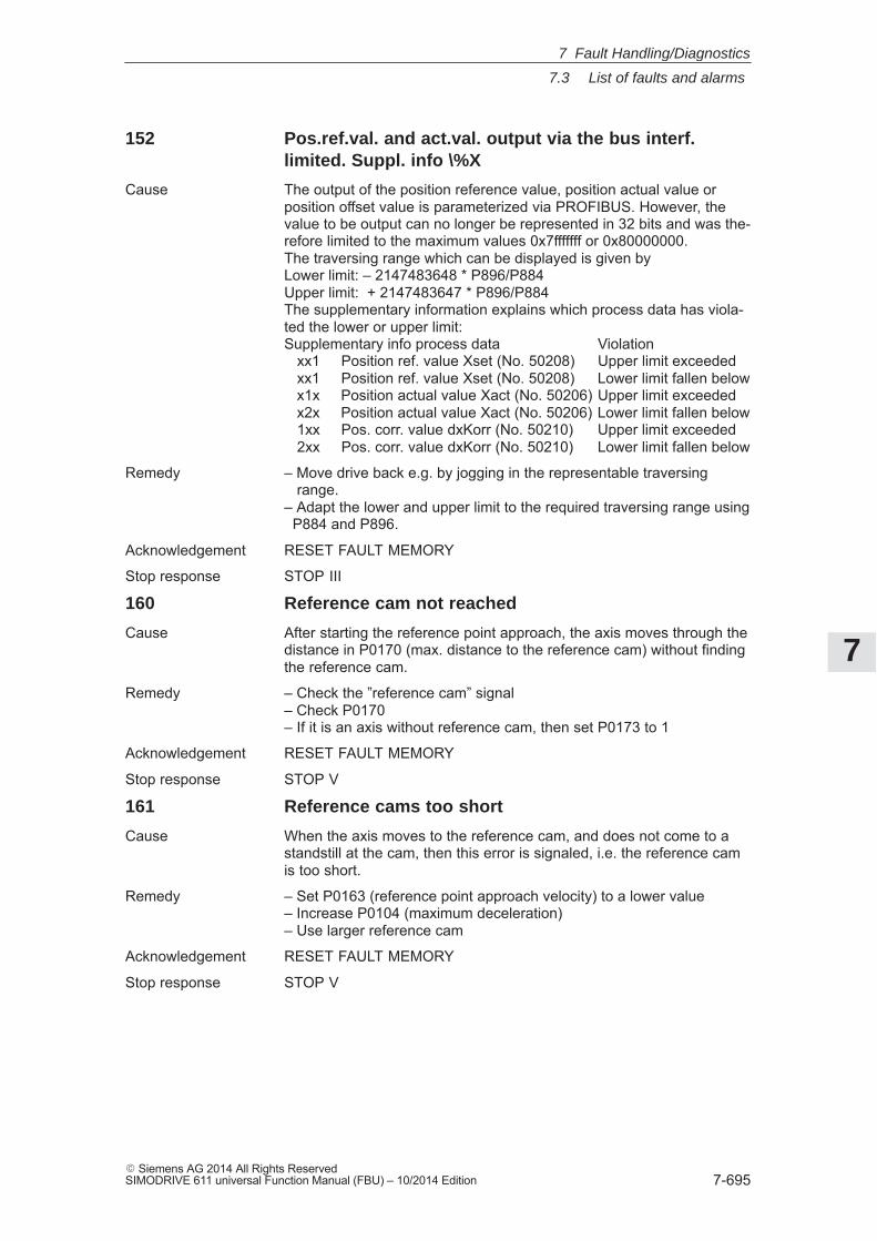
7
7.3 List of faults and alarms
7-695� Siemens AG 2014 All Rights ReservedSIMODRIVE 611 universal Function Manual (FBU) – 10/2014 Edition
152 Pos.ref.val. and act.val. output via the bus interf.limited. Suppl. info \%X
Cause The output of the position reference value, position actual value orposition offset value is parameterized via PROFIBUS. However, thevalue to be output can no longer be represented in 32 bits and was the-refore limited to the maximum values 0x7fffffff or 0x80000000.The traversing range which can be displayed is given byLower limit: – 2147483648 * P896/P884Upper limit: + 2147483647 * P896/P884The supplementary information explains which process data has viola-ted the lower or upper limit:Supplementary info process data Violation xx1 Position ref. value Xset (No. 50208) Upper limit exceeded xx1 Position ref. value Xset (No. 50208) Lower limit fallen below x1x Position actual value Xact (No. 50206) Upper limit exceeded x2x Position actual value Xact (No. 50206) Lower limit fallen below 1xx Pos. corr. value dxKorr (No. 50210) Upper limit exceeded 2xx Pos. corr. value dxKorr (No. 50210) Lower limit fallen below
Remedy – Move drive back e.g. by jogging in the representable traversing range.– Adapt the lower and upper limit to the required traversing range using P884 and P896.
Acknowledgement RESET FAULT MEMORY
Stop response STOP III
160 Reference cam not reached
Cause After starting the reference point approach, the axis moves through thedistance in P0170 (max. distance to the reference cam) without findingthe reference cam.
Remedy – Check the ”reference cam” signal– Check P0170– If it is an axis without reference cam, then set P0173 to 1
Acknowledgement RESET FAULT MEMORY
Stop response STOP V
161 Reference cams too short
Cause When the axis moves to the reference cam, and does not come to astandstill at the cam, then this error is signaled, i.e. the reference camis too short.
Remedy – Set P0163 (reference point approach velocity) to a lower value– Increase P0104 (maximum deceleration)– Use larger reference cam
Acknowledgement RESET FAULT MEMORY
Stop response STOP V
7 Fault Handling/Diagnostics
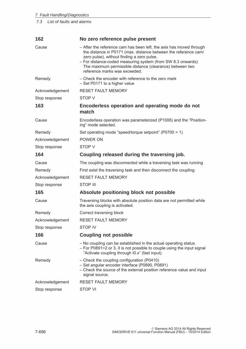
7
7.3 List of faults and alarms
7-696� Siemens AG 2014 All Rights Reserved
SIMODRIVE 611 universal Function Manual (FBU) – 10/2014 Edition
162 No zero reference pulse present
Cause – After the reference cam has been left, the axis has moved through the distance in P0171 (max. distance between the reference cam/ zero pulse), without finding a zero pulse.– For distance-coded measuring system (from SW 8.3 onwards): The maximum permissible distance (clearance) between two reference marks was exceeded.
Remedy – Check the encoder with reference to the zero mark– Set P0171 to a higher value
Acknowledgement RESET FAULT MEMORY
Stop response STOP V
163 Encoderless operation and operating mode do notmatch
Cause Encoderless operation was parameterized (P1006) and the ”Position-ing” mode selected.
Remedy Set operating mode ”speed/torque setpoint” (P0700 = 1)
Acknowledgement POWER ON
Stop response STOP V
164 Coupling released during the traversing job.
Cause The coupling was disconnected while a traversing task was running
Remedy First exist the traversing task and then disconnect the coupling.
Acknowledgement RESET FAULT MEMORY
Stop response STOP III
165 Absolute positioning block not possible
Cause Traversing blocks with absolute position data are not permitted whilethe axis coupling is activated.
Remedy Correct traversing block
Acknowledgement RESET FAULT MEMORY
Stop response STOP IV
166 Coupling not possible
Cause – No coupling can be established in the actual operating status.– For P0891=2 or 3, it is not possible to couple using the input signal ”Activate coupling through I0.x” (fast input).
Remedy – Check the coupling configuration (P0410)– Set angular encoder interface (P0890, P0891)– Check the source of the external position reference value and input signal source.
Acknowledgement RESET FAULT MEMORY
Stop response STOP VI
7 Fault Handling/Diagnostics
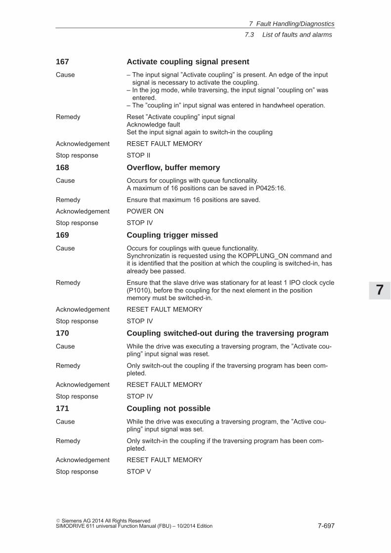
7
7.3 List of faults and alarms
7-697� Siemens AG 2014 All Rights ReservedSIMODRIVE 611 universal Function Manual (FBU) – 10/2014 Edition
167 Activate coupling signal present
Cause – The input signal ”Activate coupling” is present. An edge of the input signal is necessary to activate the coupling.– In the jog mode, while traversing, the input signal ”coupling on” was entered.– The ”coupling in” input signal was entered in handwheel operation.
Remedy Reset ”Activate coupling” input signalAcknowledge faultSet the input signal again to switch-in the coupling
Acknowledgement RESET FAULT MEMORY
Stop response STOP II
168 Overflow, buffer memory
Cause Occurs for couplings with queue functionality.A maximum of 16 positions can be saved in P0425:16.
Remedy Ensure that maximum 16 positions are saved.
Acknowledgement POWER ON
Stop response STOP IV
169 Coupling trigger missed
Cause Occurs for couplings with queue functionality.Synchronizatin is requested using the KOPPLUNG_ON command andit is identified that the position at which the coupling is switched-in, hasalready bee passed.
Remedy Ensure that the slave drive was stationary for at least 1 IPO clock cycle(P1010), before the coupling for the next element in the positionmemory must be switched-in.
Acknowledgement RESET FAULT MEMORY
Stop response STOP IV
170 Coupling switched-out during the traversing program
Cause While the drive was executing a traversing program, the ”Activate cou-pling” input signal was reset.
Remedy Only switch-out the coupling if the traversing program has been com-pleted.
Acknowledgement RESET FAULT MEMORY
Stop response STOP IV
171 Coupling not possible
Cause While the drive was executing a traversing program, the ”Active cou-pling” input signal was set.
Remedy Only switch-in the coupling if the traversing program has been com-pleted.
Acknowledgement RESET FAULT MEMORY
Stop response STOP V
7 Fault Handling/Diagnostics
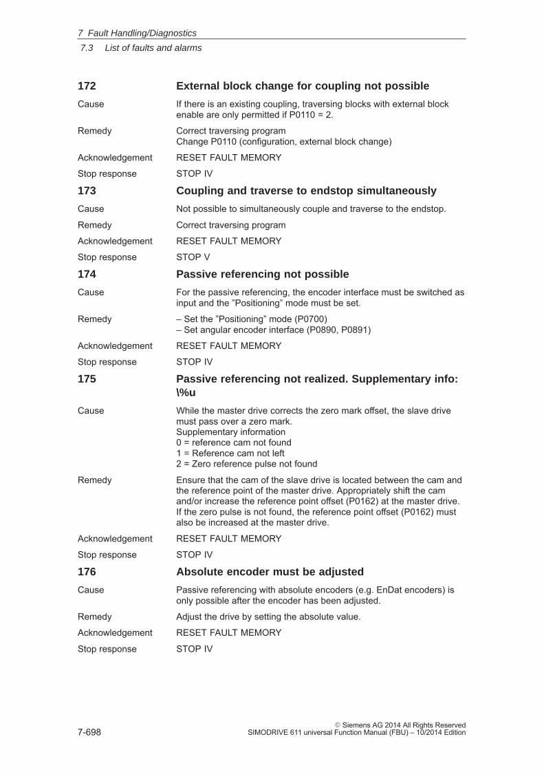
7
7.3 List of faults and alarms
7-698� Siemens AG 2014 All Rights Reserved
SIMODRIVE 611 universal Function Manual (FBU) – 10/2014 Edition
172 External block change for coupling not possible
Cause If there is an existing coupling, traversing blocks with external blockenable are only permitted if P0110 = 2.
Remedy Correct traversing programChange P0110 (configuration, external block change)
Acknowledgement RESET FAULT MEMORY
Stop response STOP IV
173 Coupling and traverse to endstop simultaneously
Cause Not possible to simultaneously couple and traverse to the endstop.
Remedy Correct traversing program
Acknowledgement RESET FAULT MEMORY
Stop response STOP V
174 Passive referencing not possible
Cause For the passive referencing, the encoder interface must be switched asinput and the ”Positioning” mode must be set.
Remedy – Set the ”Positioning” mode (P0700)– Set angular encoder interface (P0890, P0891)
Acknowledgement RESET FAULT MEMORY
Stop response STOP IV
175 Passive referencing not realized. Supplementary info:\%u
Cause While the master drive corrects the zero mark offset, the slave drivemust pass over a zero mark.Supplementary information0 = reference cam not found1 = Reference cam not left2 = Zero reference pulse not found
Remedy Ensure that the cam of the slave drive is located between the cam andthe reference point of the master drive. Appropriately shift the camand/or increase the reference point offset (P0162) at the master drive.If the zero pulse is not found, the reference point offset (P0162) mustalso be increased at the master drive.
Acknowledgement RESET FAULT MEMORY
Stop response STOP IV
176 Absolute encoder must be adjusted
Cause Passive referencing with absolute encoders (e.g. EnDat encoders) isonly possible after the encoder has been adjusted.
Remedy Adjust the drive by setting the absolute value.
Acknowledgement RESET FAULT MEMORY
Stop response STOP IV
7 Fault Handling/Diagnostics
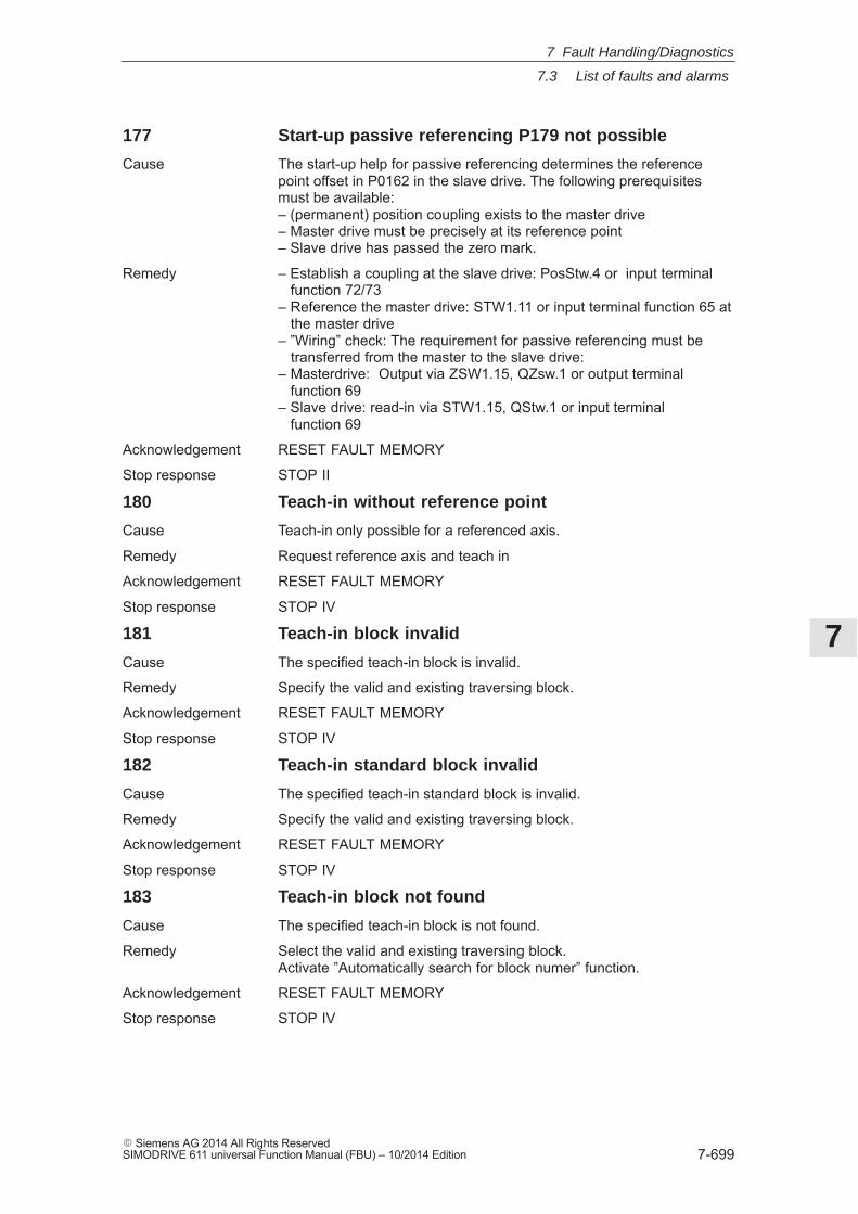
7
7.3 List of faults and alarms
7-699� Siemens AG 2014 All Rights ReservedSIMODRIVE 611 universal Function Manual (FBU) – 10/2014 Edition
177 Start-up passive referencing P179 not possible
Cause The start-up help for passive referencing determines the referencepoint offset in P0162 in the slave drive. The following prerequisitesmust be available:– (permanent) position coupling exists to the master drive– Master drive must be precisely at its reference point– Slave drive has passed the zero mark.
Remedy – Establish a coupling at the slave drive: PosStw.4 or input terminal function 72/73– Reference the master drive: STW1.11 or input terminal function 65 at the master drive– ”Wiring” check: The requirement for passive referencing must be transferred from the master to the slave drive:– Masterdrive: Output via ZSW1.15, QZsw.1 or output terminal function 69– Slave drive: read-in via STW1.15, QStw.1 or input terminal function 69
Acknowledgement RESET FAULT MEMORY
Stop response STOP II
180 Teach-in without reference point
Cause Teach-in only possible for a referenced axis.
Remedy Request reference axis and teach in
Acknowledgement RESET FAULT MEMORY
Stop response STOP IV
181 Teach-in block invalid
Cause The specified teach-in block is invalid.
Remedy Specify the valid and existing traversing block.
Acknowledgement RESET FAULT MEMORY
Stop response STOP IV
182 Teach-in standard block invalid
Cause The specified teach-in standard block is invalid.
Remedy Specify the valid and existing traversing block.
Acknowledgement RESET FAULT MEMORY
Stop response STOP IV
183 Teach-in block not found
Cause The specified teach-in block is not found.
Remedy Select the valid and existing traversing block.Activate ”Automatically search for block numer” function.
Acknowledgement RESET FAULT MEMORY
Stop response STOP IV
7 Fault Handling/Diagnostics
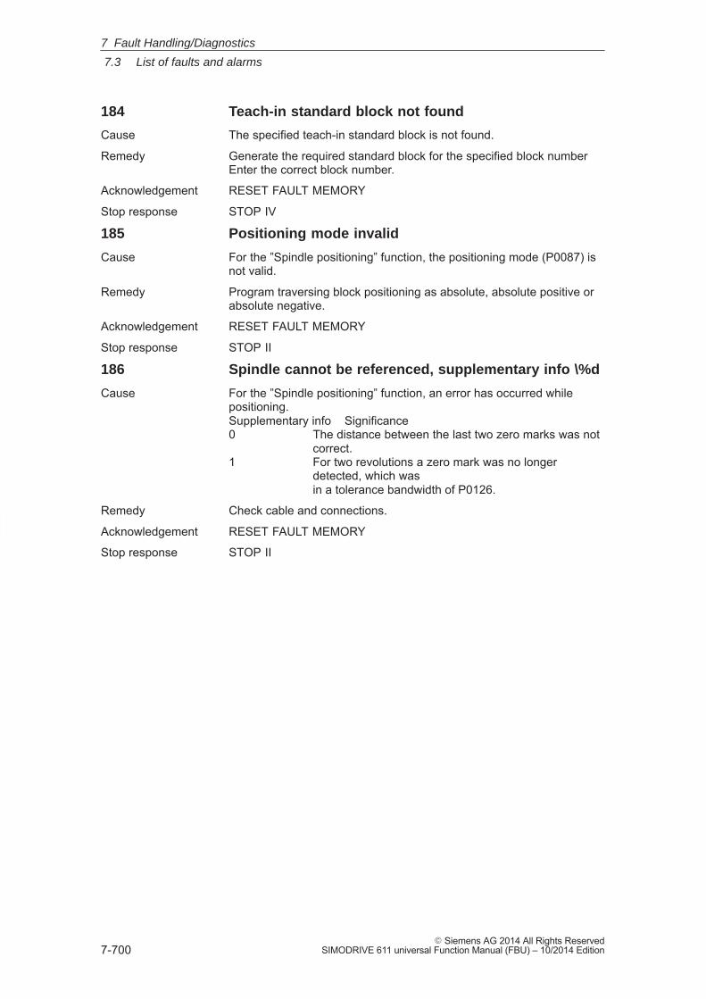
7
7.3 List of faults and alarms
7-700� Siemens AG 2014 All Rights Reserved
SIMODRIVE 611 universal Function Manual (FBU) – 10/2014 Edition
184 Teach-in standard block not found
Cause The specified teach-in standard block is not found.
Remedy Generate the required standard block for the specified block numberEnter the correct block number.
Acknowledgement RESET FAULT MEMORY
Stop response STOP IV
185 Positioning mode invalid
Cause For the ”Spindle positioning” function, the positioning mode (P0087) isnot valid.
Remedy Program traversing block positioning as absolute, absolute positive orabsolute negative.
Acknowledgement RESET FAULT MEMORY
Stop response STOP II
186 Spindle cannot be referenced, supplementary info \%d
Cause For the ”Spindle positioning” function, an error has occurred whilepositioning.Supplementary info Significance0 The distance between the last two zero marks was not
correct.1 For two revolutions a zero mark was no longer
detected, which was in a tolerance bandwidth of P0126.
Remedy Check cable and connections.
Acknowledgement RESET FAULT MEMORY
Stop response STOP II
7 Fault Handling/Diagnostics
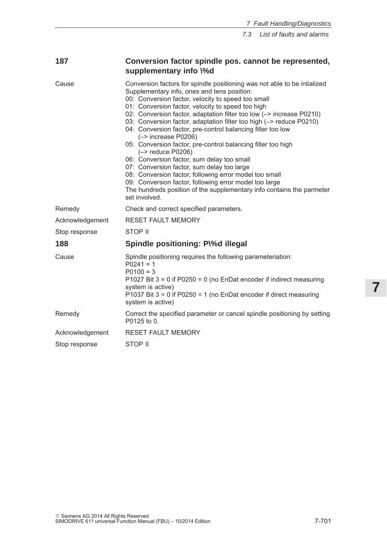
7
7.3 List of faults and alarms
7-701� Siemens AG 2014 All Rights ReservedSIMODRIVE 611 universal Function Manual (FBU) – 10/2014 Edition
187 Conversion factor spindle pos. cannot be represented,supplementary info \%d
Cause Conversion factors for spindle positioning was not able to be intializedSupplementary info, ones and tens position:00: Conversion factor, velocity to speed too small01: Conversion factor, velocity to speed too high02: Conversion factor, adaptation filter too low (–> increase P0210)03: Conversion factor, adaptation filter too high (–> reduce P0210)04: Conversion factor, pre-control balancing filter too low
(–> increase P0206)05: Conversion factor, pre-control balancing filter too high
(–> reduce P0206)06: Conversion factor, sum delay too small07: Conversion factor, sum delay too large08: Conversion factor, following error model too small09: Conversion factor, following error model too largeThe hundreds position of the supplementary info contains the parmeterset involved.
Remedy Check and correct specified parameters.
Acknowledgement RESET FAULT MEMORY
Stop response STOP II
188 Spindle positioning: P\%d illegal
Cause Spindle positioning requires the following parameteriation:P0241 = 1P0100 = 3P1027 Bit 3 = 0 if P0250 = 0 (no EnDat encoder if indirect measuringsystem is active)P1037 Bit 3 = 0 if P0250 = 1 (no EnDat encoder if direct measuringsystem is active)
Remedy Correct the specified parameter or cancel spindle positioning by settingP0125 to 0.
Acknowledgement RESET FAULT MEMORY
Stop response STOP II
7 Fault Handling/Diagnostics
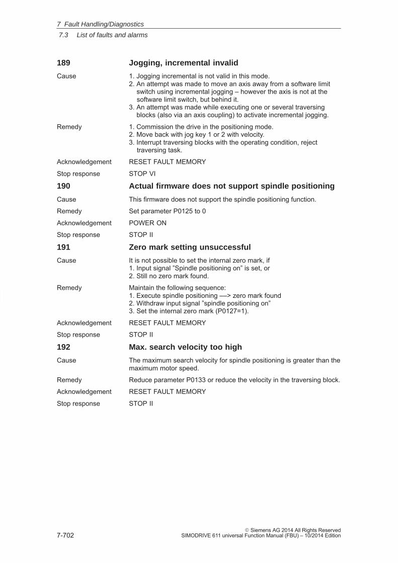
7
7.3 List of faults and alarms
7-702� Siemens AG 2014 All Rights Reserved
SIMODRIVE 611 universal Function Manual (FBU) – 10/2014 Edition
189 Jogging, incremental invalid
Cause 1. Jogging incremental is not valid in this mode.2. An attempt was made to move an axis away from a software limit switch using incremental jogging – however the axis is not at the software limit switch, but behind it.3. An attempt was made while executing one or several traversing blocks (also via an axis coupling) to activate incremental jogging.
Remedy 1. Commission the drive in the positioning mode.2. Move back with jog key 1 or 2 with velocity.3. Interrupt traversing blocks with the operating condition, reject traversing task.
Acknowledgement RESET FAULT MEMORY
Stop response STOP VI
190 Actual firmware does not support spindle positioning
Cause This firmware does not support the spindle positioning function.
Remedy Set parameter P0125 to 0
Acknowledgement POWER ON
Stop response STOP II
191 Zero mark setting unsuccessful
Cause It is not possible to set the internal zero mark, if1. Input signal ”Spindle positioning on” is set, or2. Still no zero mark found.
Remedy Maintain the following sequence:1. Execute spindle positioning ––> zero mark found2. Withdraw input signal ”spindle positioning on”3. Set the internal zero mark (P0127=1).
Acknowledgement RESET FAULT MEMORY
Stop response STOP II
192 Max. search velocity too high
Cause The maximum search velocity for spindle positioning is greater than themaximum motor speed.
Remedy Reduce parameter P0133 or reduce the velocity in the traversing block.
Acknowledgement RESET FAULT MEMORY
Stop response STOP II
7 Fault Handling/Diagnostics
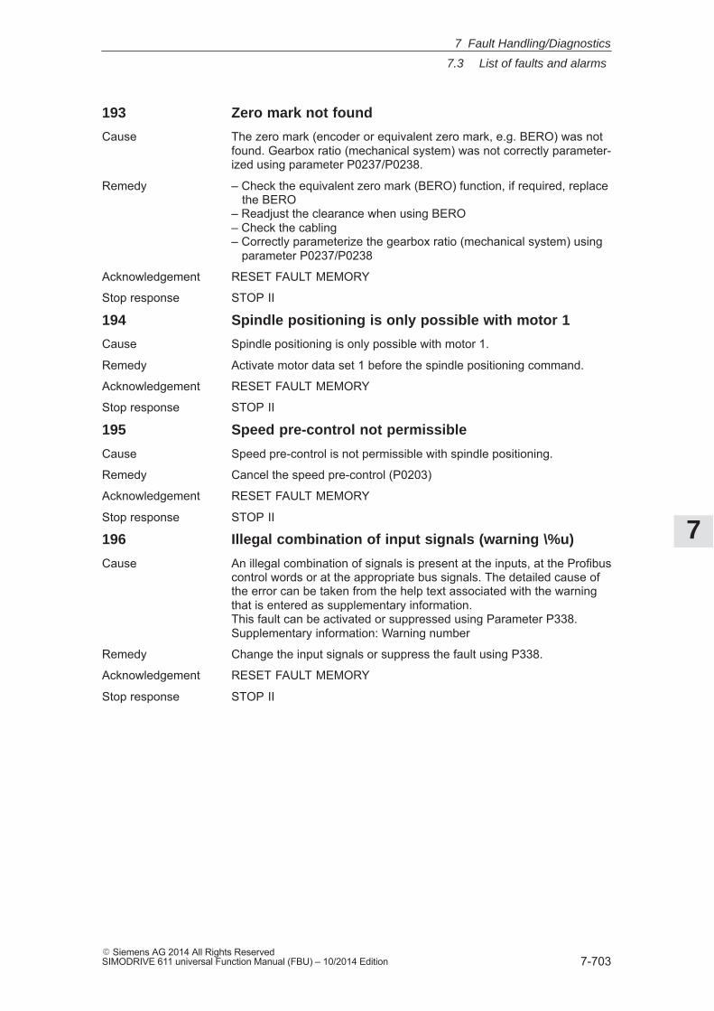
7
7.3 List of faults and alarms
7-703� Siemens AG 2014 All Rights ReservedSIMODRIVE 611 universal Function Manual (FBU) – 10/2014 Edition
193 Zero mark not found
Cause The zero mark (encoder or equivalent zero mark, e.g. BERO) was notfound. Gearbox ratio (mechanical system) was not correctly parameter-ized using parameter P0237/P0238.
Remedy – Check the equivalent zero mark (BERO) function, if required, replace the BERO– Readjust the clearance when using BERO– Check the cabling– Correctly parameterize the gearbox ratio (mechanical system) using parameter P0237/P0238
Acknowledgement RESET FAULT MEMORY
Stop response STOP II
194 Spindle positioning is only possible with motor 1
Cause Spindle positioning is only possible with motor 1.
Remedy Activate motor data set 1 before the spindle positioning command.
Acknowledgement RESET FAULT MEMORY
Stop response STOP II
195 Speed pre-control not permissible
Cause Speed pre-control is not permissible with spindle positioning.
Remedy Cancel the speed pre-control (P0203)
Acknowledgement RESET FAULT MEMORY
Stop response STOP II
196 Illegal combination of input signals (warning \%u)
Cause An illegal combination of signals is present at the inputs, at the Profibuscontrol words or at the appropriate bus signals. The detailed cause ofthe error can be taken from the help text associated with the warningthat is entered as supplementary information.This fault can be activated or suppressed using Parameter P338.Supplementary information: Warning number
Remedy Change the input signals or suppress the fault using P338.
Acknowledgement RESET FAULT MEMORY
Stop response STOP II
7 Fault Handling/Diagnostics
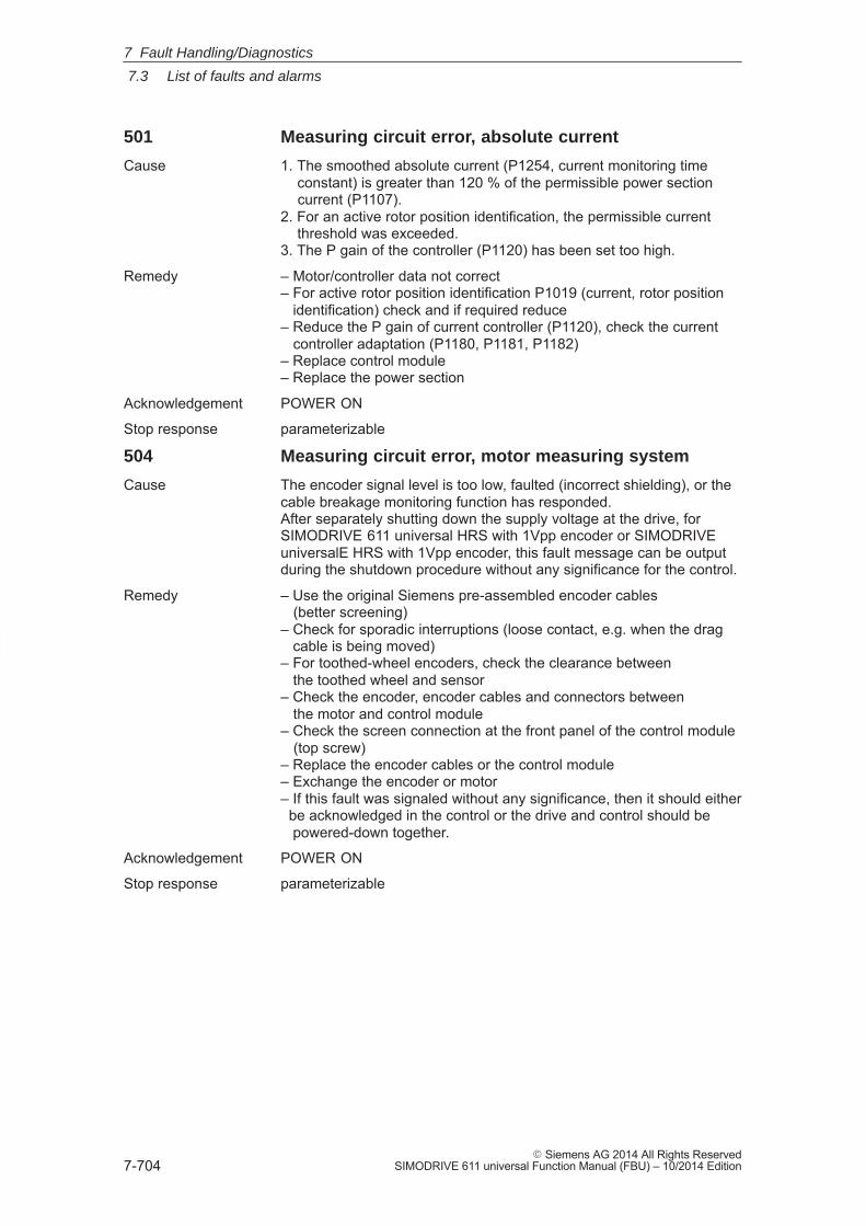
7
7.3 List of faults and alarms
7-704� Siemens AG 2014 All Rights Reserved
SIMODRIVE 611 universal Function Manual (FBU) – 10/2014 Edition
501 Measuring circuit error, absolute current
Cause 1. The smoothed absolute current (P1254, current monitoring time constant) is greater than 120 % of the permissible power section current (P1107).2. For an active rotor position identification, the permissible current threshold was exceeded.3. The P gain of the controller (P1120) has been set too high.
Remedy – Motor/controller data not correct– For active rotor position identification P1019 (current, rotor position identification) check and if required reduce– Reduce the P gain of current controller (P1120), check the current controller adaptation (P1180, P1181, P1182)– Replace control module– Replace the power section
Acknowledgement POWER ON
Stop response parameterizable
504 Measuring circuit error, motor measuring system
Cause The encoder signal level is too low, faulted (incorrect shielding), or thecable breakage monitoring function has responded.After separately shutting down the supply voltage at the drive, forSIMODRIVE 611 universal HRS with 1Vpp encoder or SIMODRIVEuniversalE HRS with 1Vpp encoder, this fault message can be outputduring the shutdown procedure without any significance for the control.
Remedy – Use the original Siemens pre-assembled encoder cables (better screening)– Check for sporadic interruptions (loose contact, e.g. when the drag cable is being moved)– For toothed-wheel encoders, check the clearance between the toothed wheel and sensor– Check the encoder, encoder cables and connectors between the motor and control module– Check the screen connection at the front panel of the control module (top screw)– Replace the encoder cables or the control module– Exchange the encoder or motor– If this fault was signaled without any significance, then it should either be acknowledged in the control or the drive and control should be powered-down together.
Acknowledgement POWER ON
Stop response parameterizable
7 Fault Handling/Diagnostics
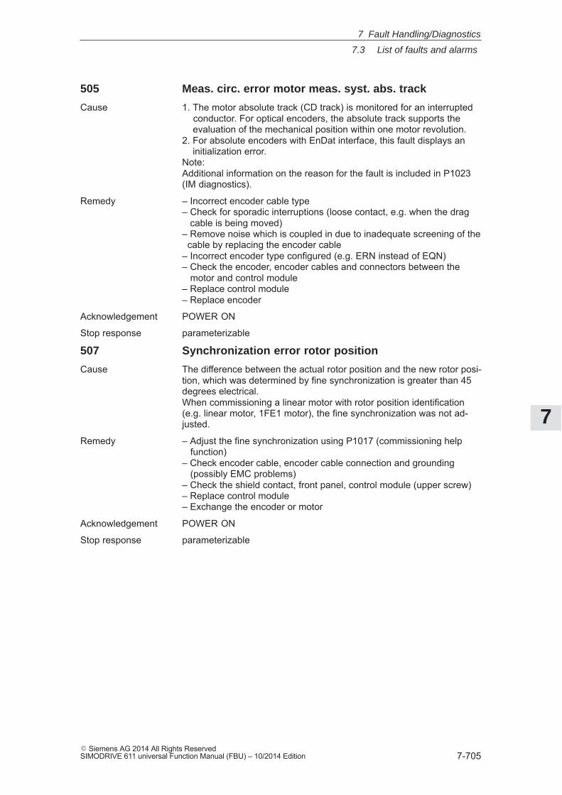
7
7.3 List of faults and alarms
7-705� Siemens AG 2014 All Rights ReservedSIMODRIVE 611 universal Function Manual (FBU) – 10/2014 Edition
505 Meas. circ. error motor meas. syst. abs. track
Cause 1. The motor absolute track (CD track) is monitored for an interrupted conductor. For optical encoders, the absolute track supports the evaluation of the mechanical position within one motor revolution.2. For absolute encoders with EnDat interface, this fault displays an initialization error.Note:Additional information on the reason for the fault is included in P1023(IM diagnostics).
Remedy – Incorrect encoder cable type– Check for sporadic interruptions (loose contact, e.g. when the drag cable is being moved)– Remove noise which is coupled in due to inadequate screening of the cable by replacing the encoder cable– Incorrect encoder type configured (e.g. ERN instead of EQN)– Check the encoder, encoder cables and connectors between the motor and control module– Replace control module– Replace encoder
Acknowledgement POWER ON
Stop response parameterizable
507 Synchronization error rotor position
Cause The difference between the actual rotor position and the new rotor posi-tion, which was determined by fine synchronization is greater than 45degrees electrical.When commissioning a linear motor with rotor position identification(e.g. linear motor, 1FE1 motor), the fine synchronization was not ad-justed.
Remedy – Adjust the fine synchronization using P1017 (commissioning help function)– Check encoder cable, encoder cable connection and grounding (possibly EMC problems)– Check the shield contact, front panel, control module (upper screw)– Replace control module– Exchange the encoder or motor
Acknowledgement POWER ON
Stop response parameterizable
7 Fault Handling/Diagnostics
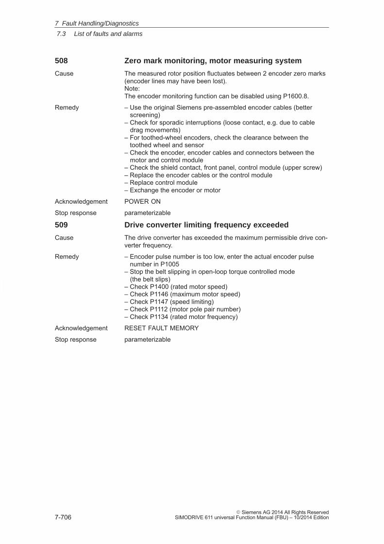
7
7.3 List of faults and alarms
7-706� Siemens AG 2014 All Rights Reserved
SIMODRIVE 611 universal Function Manual (FBU) – 10/2014 Edition
508 Zero mark monitoring, motor measuring system
Cause The measured rotor position fluctuates between 2 encoder zero marks(encoder lines may have been lost).Note:The encoder monitoring function can be disabled using P1600.8.
Remedy – Use the original Siemens pre-assembled encoder cables (better screening)– Check for sporadic interruptions (loose contact, e.g. due to cable drag movements)– For toothed-wheel encoders, check the clearance between the toothed wheel and sensor– Check the encoder, encoder cables and connectors between the motor and control module– Check the shield contact, front panel, control module (upper screw)– Replace the encoder cables or the control module– Replace control module– Exchange the encoder or motor
Acknowledgement POWER ON
Stop response parameterizable
509 Drive converter limiting frequency exceeded
Cause The drive converter has exceeded the maximum permissible drive con-verter frequency.
Remedy – Encoder pulse number is too low, enter the actual encoder pulse number in P1005– Stop the belt slipping in open-loop torque controlled mode (the belt slips)– Check P1400 (rated motor speed)– Check P1146 (maximum motor speed)– Check P1147 (speed limiting)– Check P1112 (motor pole pair number)– Check P1134 (rated motor frequency)
Acknowledgement RESET FAULT MEMORY
Stop response parameterizable
7 Fault Handling/Diagnostics
7
7.3 List of faults and alarms
7-707� Siemens AG 2014 All Rights ReservedSIMODRIVE 611 universal Function Manual (FBU) – 10/2014 Edition
510 Positive feedback identified
Cause Ramp-up:The actual rotor position and the position information read-out of theencoder were compared with one another while booting and a deviationof more than 45 Degrees was identified, P1011[10].Operational:The acceleration/velocity direction is different than the torque/force di-rection.This monitoring function can be set using P1645 and P1646.
Remedy – This alarm can also occur when axes are mechanically blocked. Check the fault cause analog to Alarm 605 ”Speed controller output limited”.– Operation may only be resumed after the fault has been removed otherwise there is a danger of uncontrollable motion.Ramp-up:– The deviation is due to dirt on the encoder or incorrect mounting/installation of the encoder or encoder cable.Operational:– If the load oscillates strongly increase the delay for the monitoring (P1645).– Caution : The value in P1645 influences the duration of the axis motion, triggered by positive feedback until the fault responds.– Check the encoder: Mounting, dirt, absolute track fault, lost pulses, encoder cable
Acknowledgement POWER ON
Stop response parameterizable
511 Ground fault detected
Cause Firmware has detected a ground fault.Measured phase currents are greater than the response value of theground fault test configured in P1167 or the motion is greater than themaximum permitted motion for the ground fault test configured inP1168.
Remedy – Ground fault in the power cables or at the motor.During the ground fault test, at least one phase increases above thethreshold P1167 or P1168.Detailed information can be taken from the diagnostics parameterP1169.
Acknowledgement POWER ON
Stop response parameterizable
7 Fault Handling/Diagnostics
7
7.3 List of faults and alarms
7-708� Siemens AG 2014 All Rights Reserved
SIMODRIVE 611 universal Function Manual (FBU) – 10/2014 Edition
512 Measuring circuit error, direct measuring system
Cause The encoder signal level is too low, faulted (incorrect shielding), or thecable breakage monitoring function has responded.
Remedy – Use the original Siemens pre-assembled encoder cables (better screening)– Check for sporadic interruptions (loose contact, e.g. due to cabledrag movements)– For toothed-wheel encoders, check the clearance between the toothed wheel and sensor– Check the encoder, encoder cables and connectors between the encoder and control module– Check the shield contact, front panel, control module (upper screw)– Replace the encoder cables or the control module– Replace encoder
Acknowledgement POWER ON
Stop response parameterizable
513 Measuring circuit error, direct measuring system abso-lute track
Cause For absolute encoders with EnDat interface, this fault indicates an init-ialization error.Note:Additional information on the reason for the fault is included in P1033(DM diagnostics).
Remedy – Incorrect encoder cable type– Check for sporadic interruptions (loose contact, e.g. when the drag cable is being moved)– Remove noise which is coupled in due to inadequate screening of the cable by replacing the encoder cable– Incorrect encoder type configured (e.g. ERN instead of EQN)– Check the encoder, encoder cables and connectors between the encoder and control module– Replace control module– Replace encoder
Acknowledgement POWER ON
Stop response parameterizable
7 Fault Handling/Diagnostics
7
7.3 List of faults and alarms
7-709� Siemens AG 2014 All Rights ReservedSIMODRIVE 611 universal Function Manual (FBU) – 10/2014 Edition
514 Zero mark monitoring, direct measuring system
Cause A fluctuation in the measured values has occurred between 2 encoderzero marks (encoder pulses may have been lost).Note:The encoder monitoring can be disabled using P1600.14.
Remedy – Use the original Siemens pre-assembled encoder cables (better screening)– Check for sporadic interruptions (loose contact, e.g. due to cable drag movements)– For toothed-wheel encoders, check the clearance between the toothed wheel and sensor– Check the encoder, encoder cables and connectors between the motor and control module– Check the shield contact, front panel, control module (upper screw)– Replace the encoder cables or the control module– Replace encoder
Acknowledgement POWER ON
Stop response parameterizable
515 Power module temperature, exceeded
Cause The power section temperature is sensed using a temperature sensoron the heatsink. The drive is immediately shut down 20 seconds afterthe heatsink temperature alarm in order to prevent the power sectionbeing thermally destroyed (regenerative stop).
Remedy Improve the drive module cooling, e.g. using:– Higher airflow in the switching cabinet, possibly cool the ambient air of the drive modules– Avoid many acceleration and braking operations which follow quickly one after the other– Check that the power section for the axis/spindle is adequate, otherwise use a higher-rating module– Ambient temperature too high (refer to the Planning Guide)– Permissible installation altitude exceeded (refer to the Planning Guide)– Pulse frequency too high (refer to the Planning Guide)– Check fan, if required, replace– Maintain the minimum clearance above and below the power section (refer to the Planning Guide)
Acknowledgement POWER ON
Stop response parameterizable
7 Fault Handling/Diagnostics
7
7.3 List of faults and alarms
7-710� Siemens AG 2014 All Rights Reserved
SIMODRIVE 611 universal Function Manual (FBU) – 10/2014 Edition
591 Pos.contr.clock cycle not equal to DP clock cycle/master applic. clock cycle
Cause For a 2-axis module, one axis is in the n-set mode and one axis in thepositioning mode. For the axis in the n-set mode, a position controllerclock cycle (of the master) is entered via the clock-cycle synchronousPROFIBUS or the bus interface. This position controller clock cyclediffers from the parameterized position controller clock cycle (P1009) ofthe axis in the positioning mode. The position controller clock cycle ofthe master is obtained, in the n-set mode, from the DP clock cycle(Tdp) or the clock cycle of the bus interface multiplied by the time gridTmapc.
Remedy For a clock cycle synchronous PROFIBUS (isochronous) or the businterface, the clock cycles configured for the bus (parameterization) arealigned with the position controller clock cycle P1009 from the position-ing axis and n-set axis.
Acknowledgement POWER ON
Stop response STOP II
592 Spindle positioning: Pos. contr. not equal to masterapplication clock cycle
Cause The function ”spindle positioning” requires, for a clock-cycle synchron-ous PROFIBUS or the bus interface, that the position controller clockcycle of the master matches the parameterized position controller clockcycle (P1009). The position controller clock cycle of the master is ob-tained from the DP clock cycle (Tdp) multiplied by the time grid Tmapc.
Remedy For the clock-cycle synchronous PROFIBUS or the bus interface, theclock cycles configured for the bus (parameterization) are aligned withthe position controller clock cycle P1009.
Acknowledgement POWER ON
Stop response STOP II
7 Fault Handling/Diagnostics
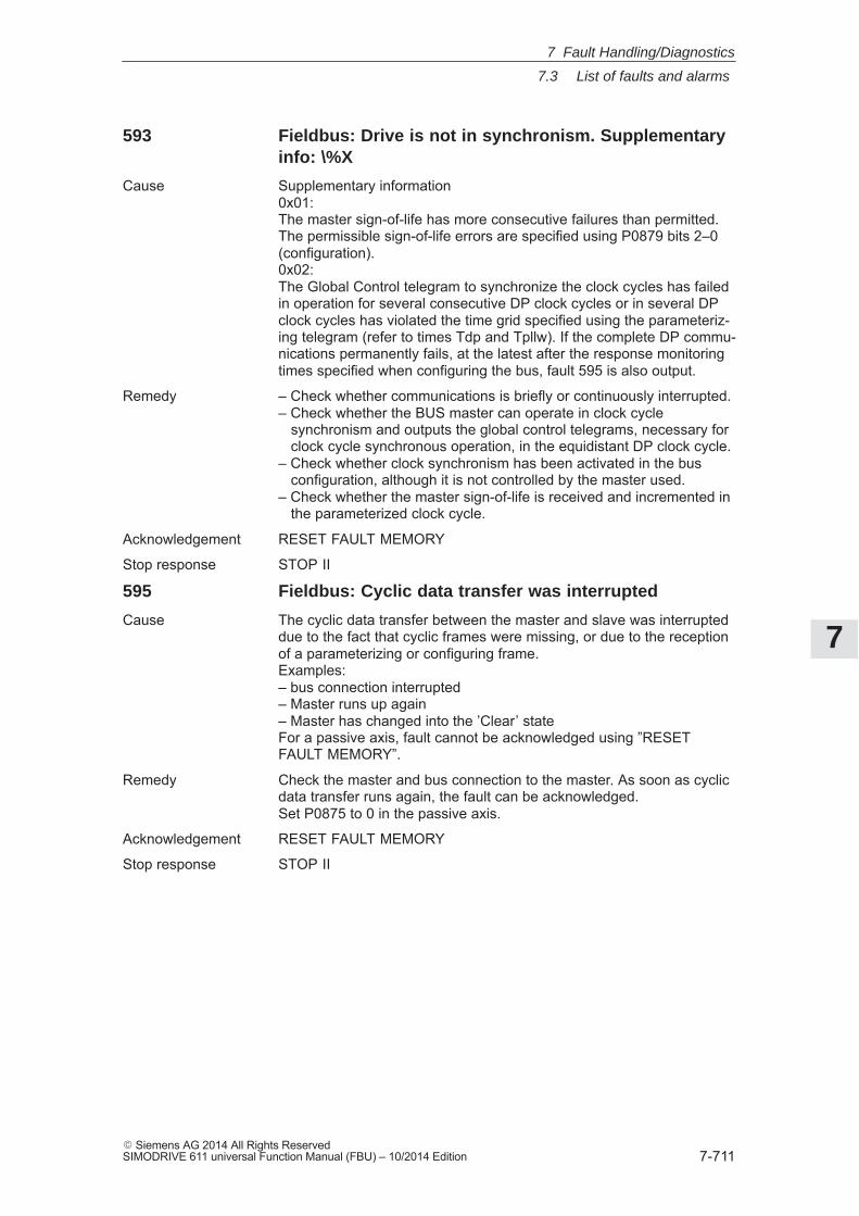
7
7.3 List of faults and alarms
7-711� Siemens AG 2014 All Rights ReservedSIMODRIVE 611 universal Function Manual (FBU) – 10/2014 Edition
593 Fieldbus: Drive is not in synchronism. Supplementaryinfo: \%X
Cause Supplementary information0x01:The master sign-of-life has more consecutive failures than permitted.The permissible sign-of-life errors are specified using P0879 bits 2–0(configuration).0x02:The Global Control telegram to synchronize the clock cycles has failedin operation for several consecutive DP clock cycles or in several DPclock cycles has violated the time grid specified using the parameteriz-ing telegram (refer to times Tdp and Tpllw). If the complete DP commu-nications permanently fails, at the latest after the response monitoringtimes specified when configuring the bus, fault 595 is also output.
Remedy – Check whether communications is briefly or continuously interrupted.– Check whether the BUS master can operate in clock cycle synchronism and outputs the global control telegrams, necessary for clock cycle synchronous operation, in the equidistant DP clock cycle.– Check whether clock synchronism has been activated in the bus configuration, although it is not controlled by the master used.– Check whether the master sign-of-life is received and incremented in the parameterized clock cycle.
Acknowledgement RESET FAULT MEMORY
Stop response STOP II
595 Fieldbus: Cyclic data transfer was interrupted
Cause The cyclic data transfer between the master and slave was interrupteddue to the fact that cyclic frames were missing, or due to the receptionof a parameterizing or configuring frame.Examples:– bus connection interrupted– Master runs up again– Master has changed into the ’Clear’ stateFor a passive axis, fault cannot be acknowledged using ”RESETFAULT MEMORY”.
Remedy Check the master and bus connection to the master. As soon as cyclicdata transfer runs again, the fault can be acknowledged.Set P0875 to 0 in the passive axis.
Acknowledgement RESET FAULT MEMORY
Stop response STOP II
7 Fault Handling/Diagnostics
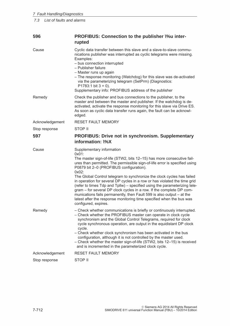
7
7.3 List of faults and alarms
7-712� Siemens AG 2014 All Rights Reserved
SIMODRIVE 611 universal Function Manual (FBU) – 10/2014 Edition
596 PROFIBUS: Connection to the publisher \%u inter-rupted
Cause Cyclic data transfer between this slave and a slave-to-slave commu-nications publisher was interrupted as cyclic telegrams were missing.Examples:– bus connection interrupted– Publisher failure– Master runs up again– The response monitoring (Watchdog) for this slave was de-activated via the parameterizing telegram (SetPrm) (Diagnostics: P1783:1 bit 3 = 0).Supplementary info: PROFIBUS address of the publisher
Remedy Check the publisher and bus connections to the publisher, to themaster and between the master and publisher. If the watchdog is de-activated, activate the response monitoring for this slave via Drive ES.As soon as cyclic data transfer runs again, the fault can be acknowl-edged.
Acknowledgement RESET FAULT MEMORY
Stop response STOP II
597 PROFIBUS: Drive not in synchronism. Supplementaryinformation: \%X
Cause Supplementary information0x01:The master sign-of-life (STW2, bits 12–15) has more consecutive fail-ures than permitted. The permissible sign-of-life error is specified usingP0879 bit 2–0 (PROFIBUS configuration).0x02:The Global Control telegram to synchronize the clock cycles has failedin operation for several DP cycles in a row or has violated the time grid(refer to times Tdp and Tpllw) – specified using the parameterizing tele-gram – for several DP clock cycles in a row. If the complete DP com-munications fails permanently, then Fault 599 is also output – at thelatest after the response monitoring time specified when the bus wasconfigured, expires.
Remedy – Check whether communications is briefly or continuously interrupted.– Check whether the PROFIBUS master can operate in clock cycle synchronism and the Global Control Telegrams, required for clock cycle synchronous operation, are output in the equidistant DP clock cycle.– Check whether clock synchronism has been activated in the bus configuration, although it is not controlled by the master used.– Check whether the master sign-of-life (STW2, bits 12–15) is received and is incremented in the parameterized clock cycle.
Acknowledgement RESET FAULT MEMORY
Stop response STOP II
7 Fault Handling/Diagnostics
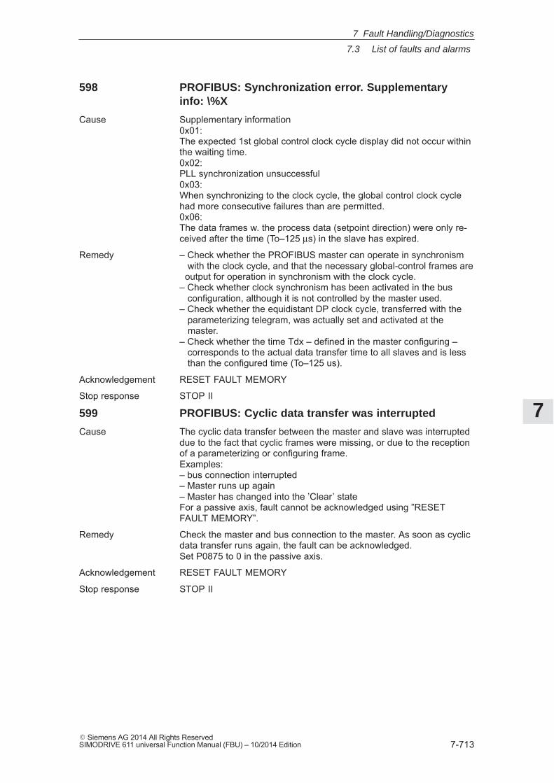
7
7.3 List of faults and alarms
7-713� Siemens AG 2014 All Rights ReservedSIMODRIVE 611 universal Function Manual (FBU) – 10/2014 Edition
598 PROFIBUS: Synchronization error. Supplementaryinfo: \%X
Cause Supplementary information0x01:The expected 1st global control clock cycle display did not occur withinthe waiting time.0x02:PLL synchronization unsuccessful0x03:When synchronizing to the clock cycle, the global control clock cyclehad more consecutive failures than are permitted.0x06:The data frames w. the process data (setpoint direction) were only re-ceived after the time (To–125 μs) in the slave has expired.
Remedy – Check whether the PROFIBUS master can operate in synchronism with the clock cycle, and that the necessary global-control frames are output for operation in synchronism with the clock cycle.– Check whether clock synchronism has been activated in the bus configuration, although it is not controlled by the master used.– Check whether the equidistant DP clock cycle, transferred with the parameterizing telegram, was actually set and activated at the master.– Check whether the time Tdx – defined in the master configuring – corresponds to the actual data transfer time to all slaves and is less than the configured time (To–125 us).
Acknowledgement RESET FAULT MEMORY
Stop response STOP II
599 PROFIBUS: Cyclic data transfer was interrupted
Cause The cyclic data transfer between the master and slave was interrupteddue to the fact that cyclic frames were missing, or due to the receptionof a parameterizing or configuring frame.Examples:– bus connection interrupted– Master runs up again– Master has changed into the ’Clear’ stateFor a passive axis, fault cannot be acknowledged using ”RESETFAULT MEMORY”.
Remedy Check the master and bus connection to the master. As soon as cyclicdata transfer runs again, the fault can be acknowledged.Set P0875 to 0 in the passive axis.
Acknowledgement RESET FAULT MEMORY
Stop response STOP II
7 Fault Handling/Diagnostics
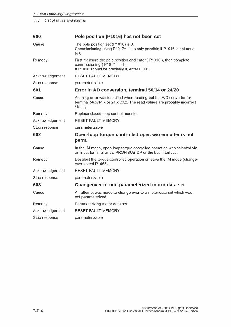
7
7.3 List of faults and alarms
7-714� Siemens AG 2014 All Rights Reserved
SIMODRIVE 611 universal Function Manual (FBU) – 10/2014 Edition
600 Pole position (P1016) has not been set
Cause The pole position set (P1016) is 0.Commissioning using P1017= –1 is only possible if P1016 is not equalto 0.
Remedy First measure the pole position and enter ( P1016 ), then completecommissioning ( P1017 = –1 ).If P1016 should be precisely 0, enter 0.001.
Acknowledgement RESET FAULT MEMORY
Stop response parameterizable
601 Error in AD conversion, terminal 56/14 or 24/20
Cause A timing error was identified when reading-out the A/D converter forterminal 56.x/14.x or 24.x/20.x. The read values are probably incorrect/ faulty.
Remedy Replace closed-loop control module
Acknowledgement RESET FAULT MEMORY
Stop response parameterizable
602 Open-loop torque controlled oper. w/o encoder is notperm.
Cause In the IM mode, open-loop torque controlled operation was selected viaan input terminal or via PROFIBUS-DP or the bus interface.
Remedy Deselect the torque-controlled operation or leave the IM mode (change-over speed P1465).
Acknowledgement RESET FAULT MEMORY
Stop response parameterizable
603 Changeover to non-parameterized motor data set
Cause An attempt was made to change over to a motor data set which wasnot parameterized.
Remedy Parameterizing motor data set
Acknowledgement RESET FAULT MEMORY
Stop response parameterizable
7 Fault Handling/Diagnostics
7
7.3 List of faults and alarms
7-715� Siemens AG 2014 All Rights ReservedSIMODRIVE 611 universal Function Manual (FBU) – 10/2014 Edition
604 Motor encoder is not adjusted
Cause For an EnDat motor measuring system, it was identified that the serialnumber does not match that saved, i.e. the encoder has still not runwith this drive.
Remedy 1FN3 linear motors (if P1075 = 1):Measure the rotor position offset to the EMF of the U_R phase and addto P1016 as the commutation angle offset. Then set P1017 to –1 inorder to save the serial number of the EnDat encoder.otherwise:To determine commutation angle offset in P1016, initiate the rotor posi-tion identification routine via P1017=1. The rotor position identificationroutine is executed by acknowledging the fault and setting the enablesignals.Note:also refer to description of P1017
Acknowledgement RESET FAULT MEMORY
Stop response parameterizable
605 Position controller output limited
Cause The speed setpoint requested from the position controller lies abovethe max. motor speed.Possible causes:– Programmed velocity (P0082:256) too high– Max. acceleration (P0103) or deceleration (P0104) too high– Axis is overloaded or blocked
Remedy – Check and correct the above parameter
Acknowledgement RESET FAULT MEMORY
Stop response parameterizable
606 Flux controller output limited
Cause The specified flux setpoint cannot be realized, although maximum cur-rent is input.– Motor data are incorrect– Motor data and motor connection type (star/delta) do not match– Motor has stalled because motor data are extremely inaccurate– Current limit is too low for the motor (0.9 * P1238 * P1103 < P1136)– Power section is too small
Remedy – Correct the motor data– If required use a larger power section
Acknowledgement RESET FAULT MEMORY
Stop response parameterizable
7 Fault Handling/Diagnostics
7
7.3 List of faults and alarms
7-716� Siemens AG 2014 All Rights Reserved
SIMODRIVE 611 universal Function Manual (FBU) – 10/2014 Edition
607 Current controller output limited
Cause The entered setpoint cannot be impressed in the motor, although themaximum voltage has been entered. The cause could be that the motoris not connected, or a phase is missing.
Remedy – Check the connecting cable, motor/drive converter (phase missing)– Check the motor contactor– DC link voltage present?– Check the DC link busbar (check that the screws are tight)– Uce monitoring function in the power section has responded (RESET by powering off/powering on)– Replace the power section or control module
Acknowledgement RESET FAULT MEMORY
Stop response parameterizable
608 Speed controller output limited
Cause The speed controller is at its limit for an inadmissibly long time (torqueand current limit). The permissible duration is defined in P1605, thespeed upper limit up to when the monitoring responds is defined inP1606.Synchronous motor:In normal operation, the correct, optimized axis drive should neverreach its current limit – not even for extremely large speed changes(changeover sequences from rapid traverse in the positive direction torapid traverse in the negative direction).P1605 = 200 msP1606 = 8000 rev/minInduction motor:Acceleration and braking with the maximum torque/current are usual inoperation, only a stalled drive (0 speed) is monitored.P1605 = 200 msP1606 = 30 rev/min1. At the first commissioning, after the software has been replaced or the software has been upgraded, after the parameters have been entered the ”calculate motor data” or ”calculate controller data” function was not executed. The drive then keeps the default values (for the values to be calculated this is zero) which can, under certain circumstances, result in this fault (P1605 and P1606 should be adapted to the mechanical and dynamic capabilities of the axis).2. An undesirable input of a high torque reduction via the analog inputs or via PROFIBUS and the bus interface. For PROFIBUS and the bus interface, this effect especially occurs when changing from the positioning mode to the speed setpoint input mode (check as to whether a torque reduction is entered. Diagnostics using P1717, 0%: No torque, 100%: Full torque).
Remedy – Check connecting cable motor/converter (phase missing, exchanged)– Check the motor contactor– Check the torque reduction (P1717)– DC link voltage present?– Check the DC link voltage (check that the screws are tight)– Unblock the motor– Is the motor encoder connected?
7 Fault Handling/Diagnostics
7
7.3 List of faults and alarms
7-717� Siemens AG 2014 All Rights ReservedSIMODRIVE 611 universal Function Manual (FBU) – 10/2014 Edition
– Check the motor encoder cable screen– Is the motor grounded (PE connection)?– Check the encoder pulse number (P1005)– Does the encoder cable fit to the encoder type?– Check the direction of rotation of the encoder tracks (e.g. toothed-wheel encoder, P1011)Adapt parameters P1605 and P1606 to the mechanical and dynamiccapabilities of the axis. Check whether a torque reduction has beenentered (diagnostics via P1717, 0%: no torque, 100%: full torque).For linear motors:– Check actual value inversion– Check the reduction in the maximum motor current (P1105) and if required increase the value– Check the power cable connection– For the parallel circuit configuration, are the motors correctly assigned and electrically connected?– Uce monitoring function in the power section has responded (RESET by powering off/powering on)– Replace the power section or control module
Acknowledgement RESET FAULT MEMORY
Stop response parameterizable
609 Encoder limit frequency exceeded
Cause The speed actual value exceeds the encoder frequency.– Incorrect encoder– P1005 does not correspond to the no. of encoder pulses– Encoder defective– Motor cable defective or not properly attached– Shield on motor encoder cable is not connected– Defective control module
Remedy – Enter correct encoder data / replace encoder– Check the encoder pulse number (P1005)– Attach motor cable correctly or replace– Connect the motor encoder cable screen– Reduce the speed setpoint input (P1401)– Replace control module
Acknowledgement RESET FAULT MEMORY
Stop response parameterizable
7 Fault Handling/Diagnostics
7
7.3 List of faults and alarms
7-718� Siemens AG 2014 All Rights Reserved
SIMODRIVE 611 universal Function Manual (FBU) – 10/2014 Edition
610 Rotor position identification has failed
Cause if P1075 = 1 (technique based on saturation)A rotor position could not be determined from the measurement signals(motor current), as no significant saturation effects occurred.Also refer to parameter P1734 for detailed diagnostics.if P1075 = 3 (motion-based technique)1. Current increase too low.2. Maximum permissible duration exceeded.3. No clear rotor position found.
Remedy if P1075 = 1– Increase current via P1019– Check armature inductance (P1116) and if required, increase– Check the connecting cable, motor/drive converter (phase missing)– Check the motor contactor– DC link voltage present?– Check the DC link busbar (check that the screws are tight)– Uce monitoring function in the power section has responded (RESET by powering off/powering on)– Replace the power section or control moduleif P1075 = 3To 1.– The motor is not correctly connected– The motor power connection must be checkedTo 2.– Remove disturbing external forces (e.g. axis couplings which are not released)– Identification technique must remain stable (P1076 must be reduced)– Use an encoder with higher resolution– Improve the encoder mounting (it is not stiff enough)To 3.– Remove disturbing external forces (e.g. axis couplings which are not released)– The axis must be able to freely move (e.g. the motor rotor may not be locked)– Reduce the high axis friction (increase P1019)
Acknowledgement RESET FAULT MEMORY
Stop response parameterizable
7 Fault Handling/Diagnostics
7
7.3 List of faults and alarms
7-719� Siemens AG 2014 All Rights ReservedSIMODRIVE 611 universal Function Manual (FBU) – 10/2014 Edition
611 Illegal motion during rotor position identification
Cause During the rotor position identification (motor current measurement),the motor rotated more than the value entered in P1020. The rotationcould be caused by having powered on with the motor already rotating,or caused by the identification routine itself.
Remedy if P1075 = 1– If the interchange was caused by the identification itself and if the error occurs again, then reduce P1019 or increase P1020.– Lock the motor rotor during the identification routine.if P1075 = 3– Increase the parameterized load mass (P1076)– Check the maximum permissible motion (P1020) and if required, increase– Reduce the current, rotor position identification (P1019) If the current and speed controller clock cycle have low values (62.5 microseconds), then it maybe necessary to increase P1019.
Acknowledgement RESET FAULT MEMORY
Stop response parameterizable
612 Illegal current during rotor position identification
Cause 1. Current was >= 1.2 * 1.05 * P1107 while rotor position identificationwas active2. Current was >= P1104 while rotor position identification was active
Remedy With the rotor position identification (P1011.12 and P1011.13) acti-vated, if required, check and reduce P1019 (current, rotor position iden-tification)
Acknowledgement RESET FAULT MEMORY
Stop response parameterizable
613 Shutdown limit, motor overtemperature exceeded.Supplementary information \%X
Cause .. is specified in the additional information:1. The motor temperature is sensed using a KTY temperature sensor. a) The motor temperature has exceeded the temperature limit in P1607. b) The sensor or the cable is interrupted or has a short-circuit.2. The motor temperature is sensed using a PTC temperature sensor. b) The sensor or the cable has a short-circuit.3. The thermal motor model has tripped because the permitted thermal motor utilization in P1266 was exceeded.
Remedy – Avoid many acceleration and braking operations which follow one another quickly.– Motor overload?– Check whether the motor output is sufficient for the drive, otherwise use a more powerful motor, possibly together with a higher-rating power section.– Check the motor data. The current could be too high due to incorrect motor data.– Temperature sensor monitoring.
7 Fault Handling/Diagnostics
7
7.3 List of faults and alarms
7-720� Siemens AG 2014 All Rights Reserved
SIMODRIVE 611 universal Function Manual (FBU) – 10/2014 Edition
– Check whether the sensor type (KTY or PTC) is correctly set in P1609.– If the alarm occurs with the motor in the cold condition check whether the sensor is short-circuited or the cable is interrupted.– Check the motor fan.– Check the motor encoder cable.– Motor encoder defective?– Check and possibly reduce P1230 or P1235.The motor temperature monitoring can be disabled withP1601 bit 13 = 1.For linear motors:– Check the parameters for the motor temperature monitoring P1602 (alarm threshold, motor overtemperature) = 120 degrees C P1603 (timer, motor temperature alarm) = 240 s P1607 (shutdown limit, motor temperature) = 155 degrees C P1608 (fixed temperature) = 0 degrees C P1608 = 0 ––> Temperature sensing active P1608 > 0 ––> Fixed temperature active– If the temperature monitoring is exclusively realized using an external PLC, a fixed temperature must be entered into P1608 (e. g. 80 degrees C). This disables the drive temperature monitoring.– Check the parameters for the thermal motor model P1265 (thermal motor model configuration) P1268 (winding time constant) P1288 (shutdown threshold, thermal motor model)– Check the power connector at the motor– Check the connection of the temperature sensor coupling cable at the end of the power cable, approx. 580 Ohm (KTY) or 100 Ohm (PTC) must be able to be measured at 20 Degrees C– If the measuring system connector is withdrawn (X411 for 611U or MOT ENCODR for POSMO) is approx. 580 Ohm (KTY) or 100 Ohm (PTC) measured between PIN 13 (611U) or 20 (POSMO) and PIN 25 (611U) or 21 (POSMO)at 20 Degree C?– Check the measuring system connector at the drive (X411 or MOT ENCODR) to ensure that it is correctly inserted– For drives connected in parallel, both KTY temperature sensors may not be directly connected. In this case an appropriate evaluation unit, e.g. SME-92 or SME-94 should be used for 2 drives.– If the temperature switch and temperature sensor are connected in series, the temperature sensor (NC contact) may have responded, or the temperature switch is defective
Acknowledgement RESET FAULT MEMORY
Stop response parameterizable
614 Delayed shutdown for motor overtemp. (P1602 /P1603). Supplementary info. \%X
Cause .. is specified in the additional information:1 The motor temperature is sensed using a KTY temperature sensor. a) The motor temperature has exceeded the temperature limit, motor overtemperature P1602 for a longer period of time than that permitted in P1603. b) The sensor or the cable is interrupted or has a short-circuit.
7 Fault Handling/Diagnostics
7
7.3 List of faults and alarms
7-721� Siemens AG 2014 All Rights ReservedSIMODRIVE 611 universal Function Manual (FBU) – 10/2014 Edition
2. The motor temperature is sensed using a PTC temperature sensor. a) The motor temperature has exceeded the PTC-specific switching temperature for a time longer than that permitted in P1603. b) The sensor or the cable has a short-circuit.3. The thermal motor model has tripped because the permitted thermal motor utilization alarm threshold P1269 was exceeded for a time longer than permitted in P1603.
Remedy – Avoid many acceleration and braking operations which follow one another quickly.– Motor overload?– Check whether the motor output is sufficient for the drive, otherwise use a more powerful motor, possibly together with a higher-rating power section.– Check the motor data. The current could be too high due to incorrect motor data.– Check the thermal motor utilization alarm threshold P1269.– Temperature sensor monitoring.– Check whether the sensor type (KTY or PTC) is correctly set in P1609.– If the alarm occurs with the motor in the cold condition check whether the sensor is short-circuited or the cable is interrupted.– Check the motor fan.– Check the motor encoder cable.– Motor encoder defective?– Check and possibly reduce P1230 or P1235.The motor temperature monitoring can be disabled withP1601 bit 14 = 1.For linear motors:– Check the parameters for the motor temperature monitoring P1602 (alarm threshold, motor overtemperature) = 120 degrees C P1603 (timer, motor temperature alarm) = 240 s P1607 (shutdown limit, motor temperature) = 155 degrees C P1608 (fixed temperature) = 0 degrees C P1608 = 0 temperature sensing active P1608 > 0 fixed temperature active– If the temperature monitoring is exclusively realized using an external PLC, a fixed temperature must be entered into P1608 (e. g. 80 degrees C). This disables the drive temperature monitoring.– Check the parameters for the thermal motor model P1265 (thermal motor model configuration) P1268 (winding time constant) P1288 (shutdown threshold, thermal motor model)– Check the power connector at the motor– Check the connection of the temperature sensor coupling cable at the end of the power cable, approx. 580 Ohm (KTY) or 100 Ohm (PTC) must be able to be measured at 20 Degrees C– If the measuring system connector is withdrawn (X411 for 611U or MOT ENCODR for POSMO) is approx. 580 Ohm (KTY) or 100 Ohm (PTC) measured between PIN 13 (611U) or 20 (POSMO) and PIN 25 (611U) or 21 (POSMO)at 20 Degree C?– Check the measuring system connector at the drive (X411 or MOT ENCODR) to ensure that it is correctly inserted
7 Fault Handling/Diagnostics
7
7.3 List of faults and alarms
7-722� Siemens AG 2014 All Rights Reserved
SIMODRIVE 611 universal Function Manual (FBU) – 10/2014 Edition
– For drives connected in parallel, both KTY temperature sensors may not be directly connected. In this case an appropriate evaluation unit, e.g. SME-92 or SME-94 should be used for 2 drives.– If the temperature switch and temperature sensor are connected in series, the temperature sensor (NC contact) may have responded, or the temperature switch is defective
Acknowledgement RESET FAULT MEMORY
Stop response parameterizable
615 DM encoder limiting frequency exceeded
Cause The speed actual value of the direct measuring system exceeds thepermissible encoder limiting frequency.– Incorrect encoder– P1007 does not coincide with the encoder pulse number– Encoder defective– Defective encoder cable or not correctly retained– Encoder cable shield is not connected– Defective control module
Remedy – Enter correct encoder data / replace encoder– Check encoder pulse number (P1007)– Correctly retain encoder cable / replace– Connect encoder cable shield– Reduce speed setpoint input– Replace control module
Acknowledgement RESET FAULT MEMORY
Stop response parameterizable
616 DC link undervoltage
Cause The infeed has gone into a fault condition and the DC link voltage hasfallen below the permissible lower limit P1162.
Remedy – Check whether the line supply voltage is available– Check whether the pulsed resistor is overloaded– Switch-off/switch-on infeed
Acknowledgement RESET FAULT MEMORY
Stop response parameterizable
7 Fault Handling/Diagnostics
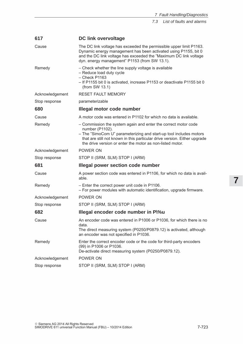
7
7.3 List of faults and alarms
7-723� Siemens AG 2014 All Rights ReservedSIMODRIVE 611 universal Function Manual (FBU) – 10/2014 Edition
617 DC link overvoltage
Cause The DC link voltage has exceeded the permissible upper limit P1163.Dynamic energy management has been activated using P1155, bit 0and the DC link voltage has exceeded the ”Maximum DC link voltagedyn. energy management” P1153 (from SW 13.1).
Remedy – Check whether the line supply voltage is available– Reduce load duty cycle– Check P1163– If P1155 bit 0 is activated, increase P1153 or deactivate P1155 bit 0 (from SW 13.1)
Acknowledgement RESET FAULT MEMORY
Stop response parameterizable
680 Illegal motor code number
Cause A motor code was entered in P1102 for which no data is available.
Remedy – Commission the system again and enter the correct motor code number (P1102).– The ”SimoCom U” parameterizing and start-up tool includes motors that are still not known in this particular drive version. Either upgrade the drive version or enter the motor as non-listed motor.
Acknowledgement POWER ON
Stop response STOP II (SRM, SLM) STOP I (ARM)
681 Illegal power section code number
Cause A power section code was entered in P1106, for which no data is avail-able.
Remedy – Enter the correct power unit code in P1106.– For power modules with automatic identification, upgrade firmware.
Acknowledgement POWER ON
Stop response STOP II (SRM, SLM) STOP I (ARM)
682 Illegal encoder code number in P\%u
Cause An encoder code was entered in P1006 or P1036, for which there is nodata.The direct measuring system (P0250/P0879.12) is activated, althoughan encoder was not specified in P1036.
Remedy Enter the correct encoder code or the code for third-party encoders(99) in P1006 or P1036.De-activate direct measuring system (P0250/P0879.12).
Acknowledgement POWER ON
Stop response STOP II (SRM, SLM) STOP I (ARM)
7 Fault Handling/Diagnostics

7
7.3 List of faults and alarms
7-724� Siemens AG 2014 All Rights Reserved
SIMODRIVE 611 universal Function Manual (FBU) – 10/2014 Edition
683 Calculate controller data was unsuccessful at firststart-up (\%d)
Cause An error occurred at the first start-up with ”calculate controller data”.Under fault conditions, the parameters for the current controller, fluxcontroller and speed controller could not be optimally assigned.
Remedy Read-out the detailed cause of the error from P1080 and remove thecause.Then initiate ”calculate controller data” again with P1080 = 1. Repeatthis operation, until no error is displayed in P1080. Then save in theFEPROM and execute a POWER ON-RESET.Error coding in the supplementary info and P1080:–15 magnetizing reactance (P1141) = 0–16 leakage reactance (P1139 / P1140) = 0–17 rated motor frequency (P1134) = 0–18 rotor resistance (P1138) = 0–19 motor moment of inertia (P1117) = 0–21 threshold speed for field weakening (P1142) = 0–22 motor standstill current (P1118) = 0–23 The ratio between the maximum motor current (P1104) and the motor stall current (P1118) is greater than the maximum value for the torque limit (P1230) and the power limit (P1235).–24 The ratio between the rated motor frequency (P1134) and the rated motor speed (P1400) is inadmissible (pole pair number).
Acknowledgement POWER ON
Stop response STOP II (SRM, SLM) STOP I (ARM)
703 Invalid current controller cycle
Cause An illegal value was entered in P1000.
Remedy Enter a valid value in P1000.Permissible values for P1000 are:2 (62.5 μs) for single-axis positioning or for speed setpoint input4 (125 μs) in each operating mode
Acknowledgement POWER ON
Stop response STOP II (SRM, SLM) STOP I (ARM)
704 Invalid speed controller cycle
Cause An illegal value was entered into P1001.
Remedy Enter a valid value in P1001.Permissible values for P1001 are 2 (62.5 μs, 4 (125 μs), 8 (250 μs),16 (500 μs.Setting 2 (62.5 μs) is only permissible for single-axis operation.Further, P1001 must be >= P1000.
Acknowledgement POWER ON
Stop response STOP II (SRM, SLM) STOP I (ARM)
7 Fault Handling/Diagnostics
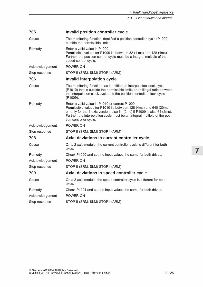
7
7.3 List of faults and alarms
7-725� Siemens AG 2014 All Rights ReservedSIMODRIVE 611 universal Function Manual (FBU) – 10/2014 Edition
705 Invalid position controller cycle
Cause The monitoring function identified a position controller cycle (P1009)outside the permissible limits.
Remedy Enter a valid value in P1009.Permissible values for P1009 lie between 32 (1 ms) and 128 (4ms).Further, the position control cycle must be a integral multiple of thespeed control cycle.
Acknowledgement POWER ON
Stop response STOP II (SRM, SLM) STOP I (ARM)
706 Invalid interpolation cycle
Cause The monitoring function has identified an interpolation clock cycle(P1010) that is outside the permissible limits or an illegal ratio betweenthe interpolation clock cycle and the position controller clock cycle(P1009).
Remedy Enter a valid value in P1010 or correct P1009.Permissible values for P1010 lie between 128 (4ms) and 640 (20ms)or, only for the 1-axis version, also 64 (2ms) if P1009 is also 64 (2ms).Further, the interpolation cycle must be an integral multiple of the posi-tion controller cycle.
Acknowledgement POWER ON
Stop response STOP II (SRM, SLM) STOP I (ARM)
708 Axial deviations in current controller cycle
Cause On a 2-axis module, the current controller cycle is different for bothaxes.
Remedy Check P1000 and set the input values the same for both drives.
Acknowledgement POWER ON
Stop response STOP II (SRM, SLM) STOP I (ARM)
709 Axial deviations in speed controller cycle
Cause On a 2-axis module, the speed controller cycle is different for bothaxes.
Remedy Check P1001 and set the input values the same for both drives.
Acknowledgement POWER ON
Stop response STOP II (SRM, SLM) STOP I (ARM)
7 Fault Handling/Diagnostics
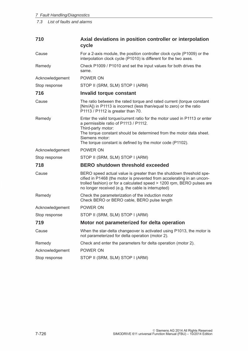
7
7.3 List of faults and alarms
7-726� Siemens AG 2014 All Rights Reserved
SIMODRIVE 611 universal Function Manual (FBU) – 10/2014 Edition
710 Axial deviations in position controller or interpolationcycle
Cause For a 2-axis module, the position controller clock cycle (P1009) or theinterpolation clock cycle (P1010) is different for the two axes.
Remedy Check P1009 / P1010 and set the input values for both drives thesame.
Acknowledgement POWER ON
Stop response STOP II (SRM, SLM) STOP I (ARM)
716 Invalid torque constant
Cause The ratio between the rated torque and rated current (torque constant[Nm/A]) in P1113 is incorrect (less than/equal to zero) or the ratioP1113 / P1112 is greater than 70.
Remedy Enter the valid torque/current ratio for the motor used in P1113 or entera permissible ratio of P1113 / P1112.Third-party motor:The torque constant should be determined from the motor data sheet.Siemens motor:The torque constant is defined by the motor code (P1102).
Acknowledgement POWER ON
Stop response STOP II (SRM, SLM) STOP I (ARM)
718 BERO shutdown threshold exceeded
Cause BERO speed actual value is greater than the shutdown threshold spe-cified in P1468 (the motor is prevented from accelerating in an uncon-trolled fashion) or for a calculated speed > 1200 rpm, BERO pulses areno longer received (e.g. the cable is interrupted)
Remedy Check the parameterization of the induction motorCheck BERO or BERO cable, BERO pulse length
Acknowledgement POWER ON
Stop response STOP II (SRM, SLM) STOP I (ARM)
719 Motor not parameterized for delta operation
Cause When the star-delta changeover is activated using P1013, the motor isnot parameterized for delta operation (motor 2).
Remedy Check and enter the parameters for delta operation (motor 2).
Acknowledgement POWER ON
Stop response STOP II (SRM, SLM) STOP I (ARM)
7 Fault Handling/Diagnostics
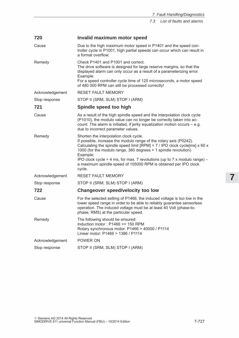
7
7.3 List of faults and alarms
7-727� Siemens AG 2014 All Rights ReservedSIMODRIVE 611 universal Function Manual (FBU) – 10/2014 Edition
720 Invalid maximum motor speed
Cause Due to the high maximum motor speed in P1401 and the speed con-troller cycle in P1001, high partial speeds can occur which can result ina format overflow.
Remedy Check P1401 and P1001 and correct.The drive software is designed for large reserve margins, so that thedisplayed alarm can only occur as a result of a parameterizing error.Example:For a speed controller cycle time of 125 microseconds, a motor speedof 480 000 RPM can still be processed correctly!
Acknowledgement RESET FAULT MEMORY
Stop response STOP II (SRM, SLM) STOP I (ARM)
721 Spindle speed too high
Cause As a result of the high spindle speed and the interpolation clock cycle(P1010), the modulo value can no longer be correctly taken into ac-count. The alarm is initiated, if jerky equalization motion occurs – e.g.due to incorrect parameter values.
Remedy Shorten the interpolation clock cycle.If possible, increase the modulo range of the rotary axis (P0242).Calculating the spindle speed limit [RPM] = 7 / IPO clock cycle[ms] x 60 x1000 (for the modulo range, 360 degrees = 1 spindle revolution)Example:IPO clock cycle = 4 ms, for max. 7 revolutions (up to 7 x modulo range) –a maximum spindle speed of 105000 RPM is obtained per IPO clockcycle.
Acknowledgement RESET FAULT MEMORY
Stop response STOP II (SRM, SLM) STOP I (ARM)
722 Changeover speed/velocity too low
Cause For the selected setting of P1466, the induced voltage is too low in thelower speed range in order to be able to reliably guarantee sensorlessoperation. The induced voltage must be at least 40 Volt (phase-to-phase, RMS) at the particular speed.
Remedy The following should be ensured:Induction motor : P1466 >= 150 RPMRotary synchronous motor: P1466 > 40000 / P1114Linear motor: P1466 > 1386 / P1114
Acknowledgement POWER ON
Stop response STOP II (SRM, SLM) STOP I (ARM)
7 Fault Handling/Diagnostics
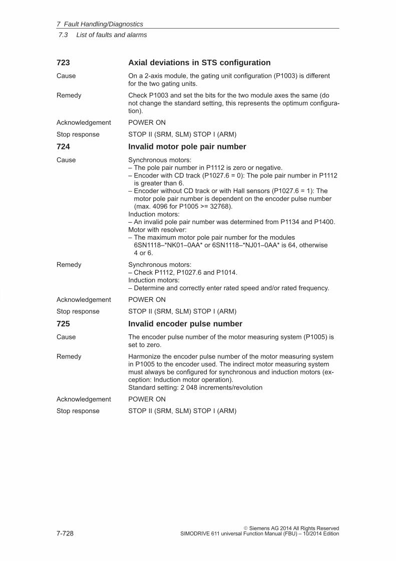
7
7.3 List of faults and alarms
7-728� Siemens AG 2014 All Rights Reserved
SIMODRIVE 611 universal Function Manual (FBU) – 10/2014 Edition
723 Axial deviations in STS configuration
Cause On a 2-axis module, the gating unit configuration (P1003) is differentfor the two gating units.
Remedy Check P1003 and set the bits for the two module axes the same (donot change the standard setting, this represents the optimum configura-tion).
Acknowledgement POWER ON
Stop response STOP II (SRM, SLM) STOP I (ARM)
724 Invalid motor pole pair number
Cause Synchronous motors:– The pole pair number in P1112 is zero or negative.– Encoder with CD track (P1027.6 = 0): The pole pair number in P1112 is greater than 6.– Encoder without CD track or with Hall sensors (P1027.6 = 1): The motor pole pair number is dependent on the encoder pulse number (max. 4096 for P1005 >= 32768).Induction motors:– An invalid pole pair number was determined from P1134 and P1400.Motor with resolver:– The maximum motor pole pair number for the modules 6SN1118–*NK01–0AA* or 6SN1118–*NJ01–0AA* is 64, otherwise 4 or 6.
Remedy Synchronous motors:– Check P1112, P1027.6 and P1014.Induction motors:– Determine and correctly enter rated speed and/or rated frequency.
Acknowledgement POWER ON
Stop response STOP II (SRM, SLM) STOP I (ARM)
725 Invalid encoder pulse number
Cause The encoder pulse number of the motor measuring system (P1005) isset to zero.
Remedy Harmonize the encoder pulse number of the motor measuring systemin P1005 to the encoder used. The indirect motor measuring systemmust always be configured for synchronous and induction motors (ex-ception: Induction motor operation).Standard setting: 2 048 increments/revolution
Acknowledgement POWER ON
Stop response STOP II (SRM, SLM) STOP I (ARM)
7 Fault Handling/Diagnostics
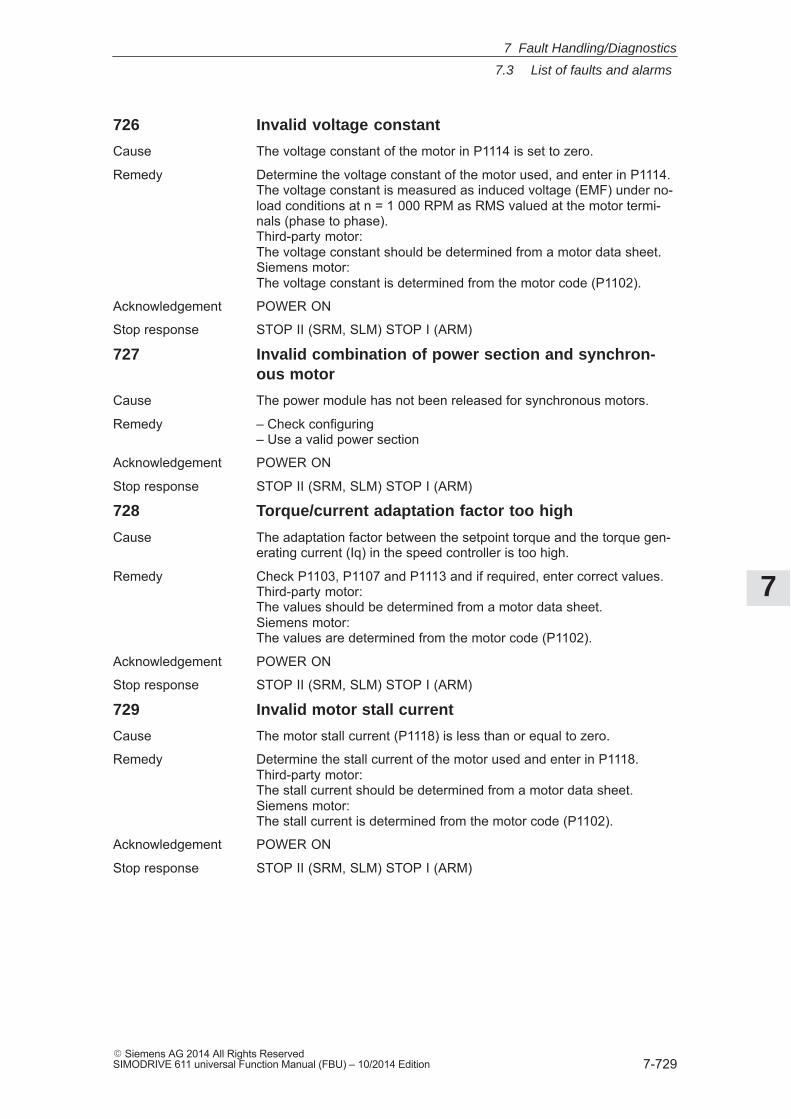
7
7.3 List of faults and alarms
7-729� Siemens AG 2014 All Rights ReservedSIMODRIVE 611 universal Function Manual (FBU) – 10/2014 Edition
726 Invalid voltage constant
Cause The voltage constant of the motor in P1114 is set to zero.
Remedy Determine the voltage constant of the motor used, and enter in P1114.The voltage constant is measured as induced voltage (EMF) under no-load conditions at n = 1 000 RPM as RMS valued at the motor termi-nals (phase to phase).Third-party motor:The voltage constant should be determined from a motor data sheet.Siemens motor:The voltage constant is determined from the motor code (P1102).
Acknowledgement POWER ON
Stop response STOP II (SRM, SLM) STOP I (ARM)
727 Invalid combination of power section and synchron-ous motor
Cause The power module has not been released for synchronous motors.
Remedy – Check configuring– Use a valid power section
Acknowledgement POWER ON
Stop response STOP II (SRM, SLM) STOP I (ARM)
728 Torque/current adaptation factor too high
Cause The adaptation factor between the setpoint torque and the torque gen-erating current (Iq) in the speed controller is too high.
Remedy Check P1103, P1107 and P1113 and if required, enter correct values.Third-party motor:The values should be determined from a motor data sheet.Siemens motor:The values are determined from the motor code (P1102).
Acknowledgement POWER ON
Stop response STOP II (SRM, SLM) STOP I (ARM)
729 Invalid motor stall current
Cause The motor stall current (P1118) is less than or equal to zero.
Remedy Determine the stall current of the motor used and enter in P1118.Third-party motor:The stall current should be determined from a motor data sheet.Siemens motor:The stall current is determined from the motor code (P1102).
Acknowledgement POWER ON
Stop response STOP II (SRM, SLM) STOP I (ARM)
7 Fault Handling/Diagnostics
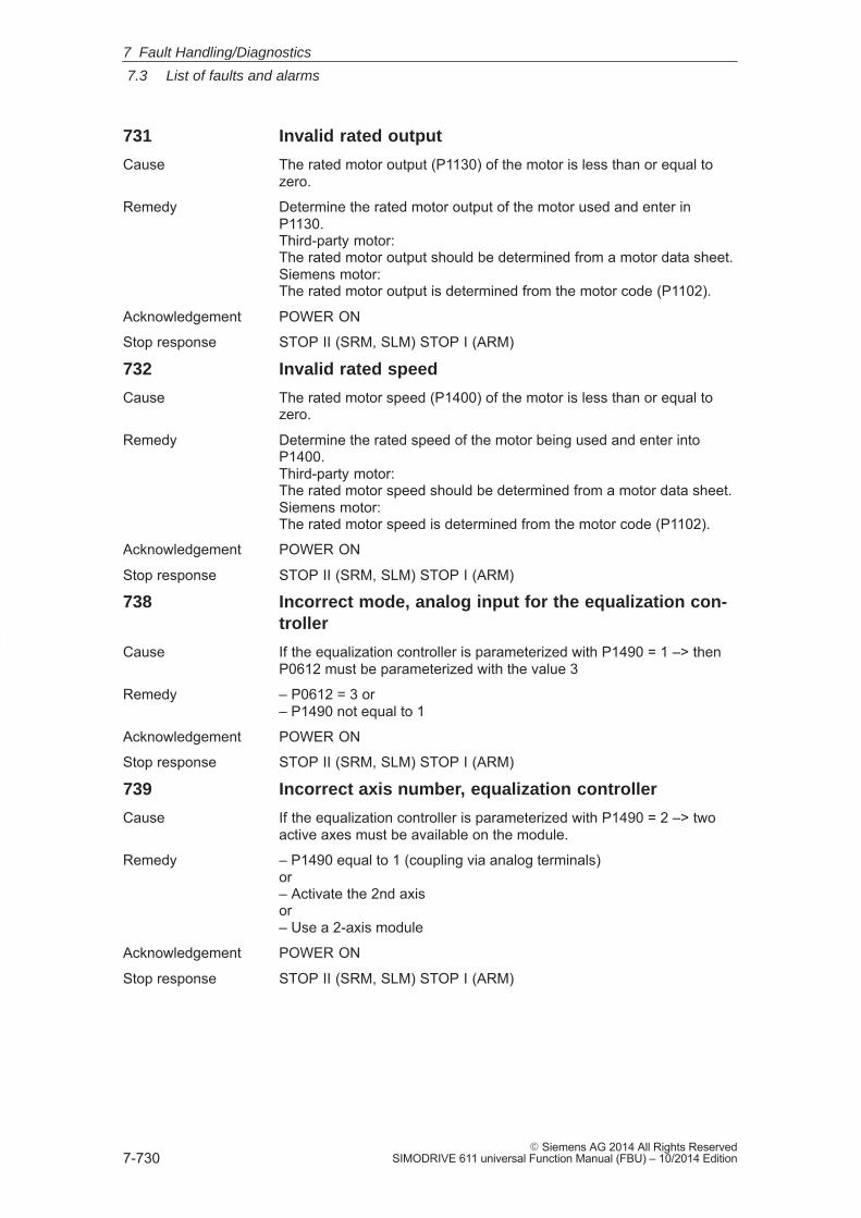
7
7.3 List of faults and alarms
7-730� Siemens AG 2014 All Rights Reserved
SIMODRIVE 611 universal Function Manual (FBU) – 10/2014 Edition
731 Invalid rated output
Cause The rated motor output (P1130) of the motor is less than or equal tozero.
Remedy Determine the rated motor output of the motor used and enter inP1130.Third-party motor:The rated motor output should be determined from a motor data sheet.Siemens motor:The rated motor output is determined from the motor code (P1102).
Acknowledgement POWER ON
Stop response STOP II (SRM, SLM) STOP I (ARM)
732 Invalid rated speed
Cause The rated motor speed (P1400) of the motor is less than or equal tozero.
Remedy Determine the rated speed of the motor being used and enter intoP1400.Third-party motor:The rated motor speed should be determined from a motor data sheet.Siemens motor:The rated motor speed is determined from the motor code (P1102).
Acknowledgement POWER ON
Stop response STOP II (SRM, SLM) STOP I (ARM)
738 Incorrect mode, analog input for the equalization con-troller
Cause If the equalization controller is parameterized with P1490 = 1 –> thenP0612 must be parameterized with the value 3
Remedy – P0612 = 3 or– P1490 not equal to 1
Acknowledgement POWER ON
Stop response STOP II (SRM, SLM) STOP I (ARM)
739 Incorrect axis number, equalization controller
Cause If the equalization controller is parameterized with P1490 = 2 –> twoactive axes must be available on the module.
Remedy – P1490 equal to 1 (coupling via analog terminals)or– Activate the 2nd axisor– Use a 2-axis module
Acknowledgement POWER ON
Stop response STOP II (SRM, SLM) STOP I (ARM)
7 Fault Handling/Diagnostics
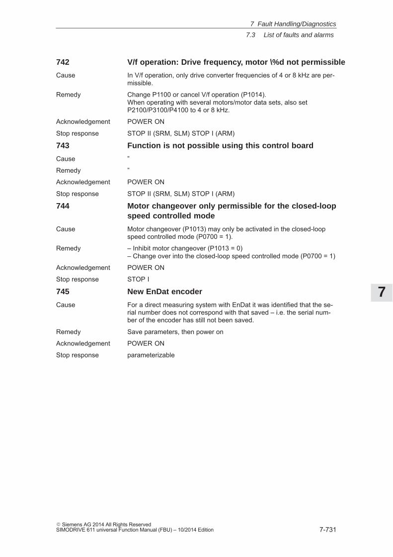
7
7.3 List of faults and alarms
7-731� Siemens AG 2014 All Rights ReservedSIMODRIVE 611 universal Function Manual (FBU) – 10/2014 Edition
742 V/f operation: Drive frequency, motor \%d not permissible
Cause In V/f operation, only drive converter frequencies of 4 or 8 kHz are per-missible.
Remedy Change P1100 or cancel V/f operation (P1014).When operating with several motors/motor data sets, also setP2100/P3100/P4100 to 4 or 8 kHz.
Acknowledgement POWER ON
Stop response STOP II (SRM, SLM) STOP I (ARM)
743 Function is not possible using this control board
Cause ”
Remedy ”
Acknowledgement POWER ON
Stop response STOP II (SRM, SLM) STOP I (ARM)
744 Motor changeover only permissible for the closed-loopspeed controlled mode
Cause Motor changeover (P1013) may only be activated in the closed-loopspeed controlled mode (P0700 = 1).
Remedy – Inhibit motor changeover (P1013 = 0)– Change over into the closed-loop speed controlled mode (P0700 = 1)
Acknowledgement POWER ON
Stop response STOP I
745 New EnDat encoder
Cause For a direct measuring system with EnDat it was identified that the se-rial number does not correspond with that saved – i.e. the serial num-ber of the encoder has still not been saved.
Remedy Save parameters, then power on
Acknowledgement POWER ON
Stop response parameterizable
7 Fault Handling/Diagnostics
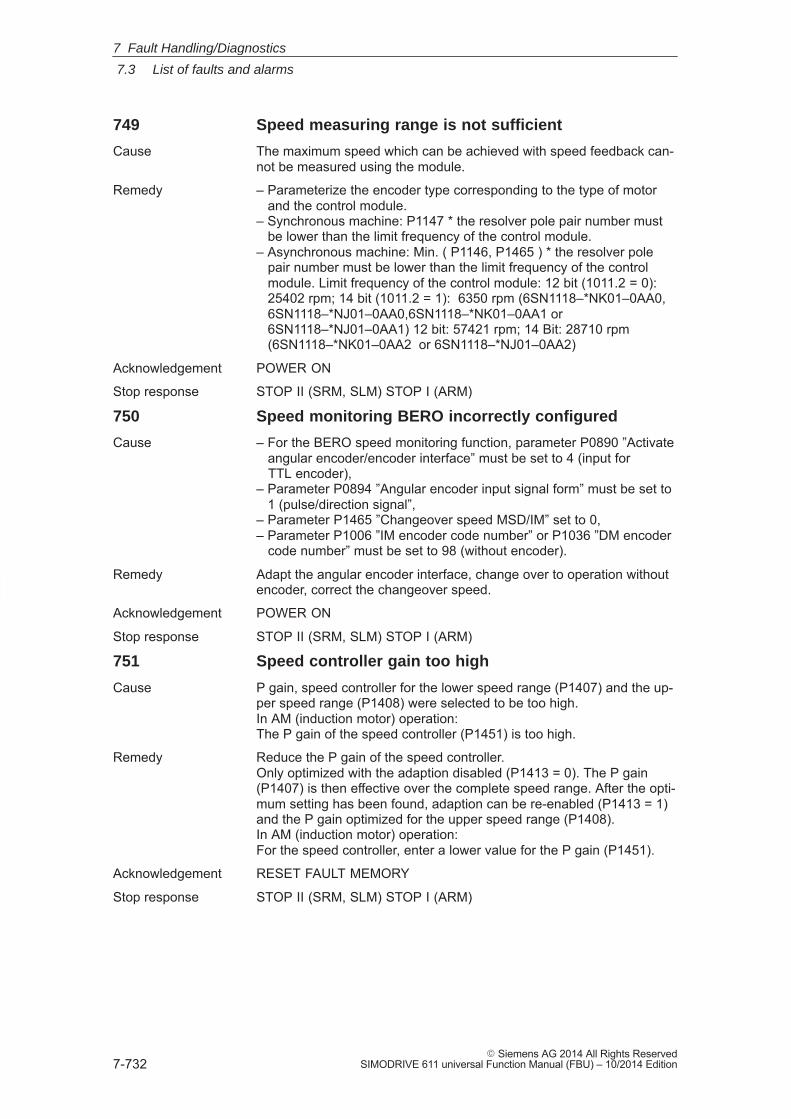
7
7.3 List of faults and alarms
7-732� Siemens AG 2014 All Rights Reserved
SIMODRIVE 611 universal Function Manual (FBU) – 10/2014 Edition
749 Speed measuring range is not sufficient
Cause The maximum speed which can be achieved with speed feedback can-not be measured using the module.
Remedy – Parameterize the encoder type corresponding to the type of motor and the control module.– Synchronous machine: P1147 * the resolver pole pair number must be lower than the limit frequency of the control module.– Asynchronous machine: Min. ( P1146, P1465 ) * the resolver pole pair number must be lower than the limit frequency of the control module. Limit frequency of the control module: 12 bit (1011.2 = 0): 25402 rpm; 14 bit (1011.2 = 1): 6350 rpm (6SN1118–*NK01–0AA0, 6SN1118–*NJ01–0AA0,6SN1118–*NK01–0AA1 or 6SN1118–*NJ01–0AA1) 12 bit: 57421 rpm; 14 Bit: 28710 rpm (6SN1118–*NK01–0AA2 or 6SN1118–*NJ01–0AA2)
Acknowledgement POWER ON
Stop response STOP II (SRM, SLM) STOP I (ARM)
750 Speed monitoring BERO incorrectly configured
Cause – For the BERO speed monitoring function, parameter P0890 ”Activate angular encoder/encoder interface” must be set to 4 (input for TTL encoder),– Parameter P0894 ”Angular encoder input signal form” must be set to 1 (pulse/direction signal”,– Parameter P1465 ”Changeover speed MSD/IM” set to 0,– Parameter P1006 ”IM encoder code number” or P1036 ”DM encoder code number” must be set to 98 (without encoder).
Remedy Adapt the angular encoder interface, change over to operation withoutencoder, correct the changeover speed.
Acknowledgement POWER ON
Stop response STOP II (SRM, SLM) STOP I (ARM)
751 Speed controller gain too high
Cause P gain, speed controller for the lower speed range (P1407) and the up-per speed range (P1408) were selected to be too high.In AM (induction motor) operation:The P gain of the speed controller (P1451) is too high.
Remedy Reduce the P gain of the speed controller.Only optimized with the adaption disabled (P1413 = 0). The P gain(P1407) is then effective over the complete speed range. After the opti-mum setting has been found, adaption can be re-enabled (P1413 = 1)and the P gain optimized for the upper speed range (P1408).In AM (induction motor) operation:For the speed controller, enter a lower value for the P gain (P1451).
Acknowledgement RESET FAULT MEMORY
Stop response STOP II (SRM, SLM) STOP I (ARM)
7 Fault Handling/Diagnostics
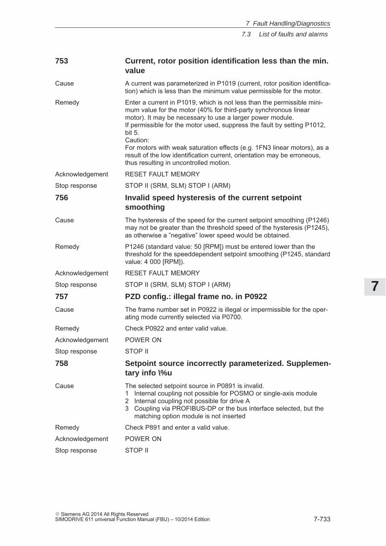
7
7.3 List of faults and alarms
7-733� Siemens AG 2014 All Rights ReservedSIMODRIVE 611 universal Function Manual (FBU) – 10/2014 Edition
753 Current, rotor position identification less than the min.value
Cause A current was parameterized in P1019 (current, rotor position identifica-tion) which is less than the minimum value permissible for the motor.
Remedy Enter a current in P1019, which is not less than the permissible mini-mum value for the motor (40% for third-party synchronous linearmotor). It may be necessary to use a larger power module.If permissible for the motor used, suppress the fault by setting P1012,bit 5.Caution:For motors with weak saturation effects (e.g. 1FN3 linear motors), as aresult of the low identification current, orientation may be erroneous,thus resulting in uncontrolled motion.
Acknowledgement RESET FAULT MEMORY
Stop response STOP II (SRM, SLM) STOP I (ARM)
756 Invalid speed hysteresis of the current setpointsmoothing
Cause The hysteresis of the speed for the current setpoint smoothing (P1246)may not be greater than the threshold speed of the hysteresis (P1245),as otherwise a ”negative” lower speed would be obtained.
Remedy P1246 (standard value: 50 [RPM]) must be entered lower than thethreshold for the speeddependent setpoint smoothing (P1245, standardvalue: 4 000 [RPM]).
Acknowledgement RESET FAULT MEMORY
Stop response STOP II (SRM, SLM) STOP I (ARM)
757 PZD config.: illegal frame no. in P0922
Cause The frame number set in P0922 is illegal or impermissible for the oper-ating mode currently selected via P0700.
Remedy Check P0922 and enter valid value.
Acknowledgement POWER ON
Stop response STOP II
758 Setpoint source incorrectly parameterized. Supplemen-tary info \%u
Cause The selected setpoint source in P0891 is invalid.1 Internal coupling not possible for POSMO or single-axis module2 Internal coupling not possible for drive A3 Coupling via PROFIBUS-DP or the bus interface selected, but the
matching option module is not inserted
Remedy Check P891 and enter a valid value.
Acknowledgement POWER ON
Stop response STOP II
7 Fault Handling/Diagnostics
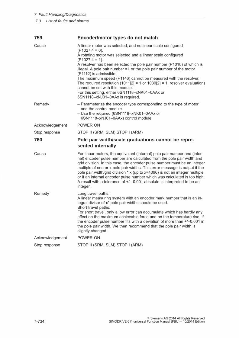
7
7.3 List of faults and alarms
7-734� Siemens AG 2014 All Rights Reserved
SIMODRIVE 611 universal Function Manual (FBU) – 10/2014 Edition
759 Encoder/motor types do not match
Cause A linear motor was selected, and no linear scale configured(P1027.4 = 0).A rotating motor was selected and a linear scale configured(P1027.4 = 1).A resolver has been selected the pole pair number (P1018) of which isillegal. A pole pair number =1 or the pole pair number of the motor(P1112) is admissible.The maximum speed (P1146) cannot be measured with the resolver.The required resolution (1011[2] = 1 or 1030[2] = 1, resolver evaluation)cannot be set with this module.For this setting, either 6SN1118–xNK01–0AAx or6SN1118–xNJ01–0AAx is required.
Remedy – Parameterize the encoder type corresponding to the type of motor and the control module.– Use the required (6SN1118–xNK01–0AAx or 6SN1118–xNJ01–0AAx) control module.
Acknowledgement POWER ON
Stop response STOP II (SRM, SLM) STOP I (ARM)
760 Pole pair width/scale graduations cannot be repre-sented internally
Cause For linear motors, the equivalent (internal) pole pair number and (inter-nal) encoder pulse number are calculated from the pole pair width andgrid division. In this case, the encoder pulse number must be an integermultiple of one or x pole pair widths. This error message is output if thepole pair width/grid division * x (up to x=4096) is not an integer multipleor if an internal encoder pulse number which was calculated is too high.A result with a tolerance of +/– 0.001 absolute is interpreted to be aninteger.
Remedy Long travel paths:A linear measuring system with an encoder mark number that is an in-tegral divisor of x* pole pair widths should be used.Short travel paths:For short travel, only a low error can accumulate which has hardly anyeffect on the maximum achievable force and on the temperature rise, ifthe encoder pulse number fits with a deviation of more than +/–0.001 inthe pole pair width. We then recommend that the pole pair width isslightly changed.
Acknowledgement POWER ON
Stop response STOP II (SRM, SLM) STOP I (ARM)
7 Fault Handling/Diagnostics
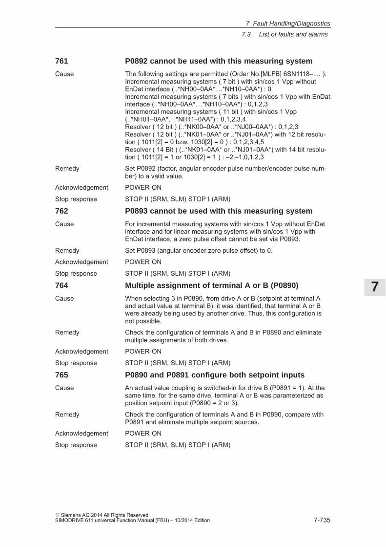
7
7.3 List of faults and alarms
7-735� Siemens AG 2014 All Rights ReservedSIMODRIVE 611 universal Function Manual (FBU) – 10/2014 Edition
761 P0892 cannot be used with this measuring system
Cause The following settings are permitted (Order No.[MLFB] 6SN1118–.... ):Incremental measuring systems ( 7 bit ) with sin/cos 1 Vpp withoutEnDat interface (..*NH00–0AA*, ..*NH10–0AA*) : 0Incremental measuring systems ( 7 bits ) with sin/cos 1 Vpp with EnDatinterface (..*NH00–0AA*, ..*NH10–0AA*) : 0,1,2,3Incremental measuring systems ( 11 bit ) with sin/cos 1 Vpp(..*NH01–0AA*, ..*NH11–0AA*) : 0,1,2,3,4Resolver ( 12 bit ) (..*NK00–0AA* or ..*NJ00–0AA*) : 0,1,2,3Resolver ( 12 bit ) (..*NK01–0AA* or ..*NJ01–0AA*) with 12 bit resolu-tion ( 1011[2] = 0 bzw. 1030[2] = 0 ) : 0,1,2,3,4,5Resolver ( 14 Bit ) (..*NK01–0AA* or ..*NJ01–0AA*) with 14 bit resolu-tion ( 1011[2] = 1 or 1030[2] = 1 ) : –2,–1,0,1,2,3
Remedy Set P0892 (factor, angular encoder pulse number/encoder pulse num-ber) to a valid value.
Acknowledgement POWER ON
Stop response STOP II (SRM, SLM) STOP I (ARM)
762 P0893 cannot be used with this measuring system
Cause For incremental measuring systems with sin/cos 1 Vpp without EnDatinterface and for linear measuring systems with sin/cos 1 Vpp withEnDat interface, a zero pulse offset cannot be set via P0893.
Remedy Set P0893 (angular encoder zero pulse offset) to 0.
Acknowledgement POWER ON
Stop response STOP II (SRM, SLM) STOP I (ARM)
764 Multiple assignment of terminal A or B (P0890)
Cause When selecting 3 in P0890, from drive A or B (setpoint at terminal Aand actual value at terminal B), it was identified, that terminal A or Bwere already being used by another drive. Thus, this configuration isnot possible.
Remedy Check the configuration of terminals A and B in P0890 and eliminatemultiple assignments of both drives.
Acknowledgement POWER ON
Stop response STOP II (SRM, SLM) STOP I (ARM)
765 P0890 and P0891 configure both setpoint inputs
Cause An actual value coupling is switched-in for drive B (P0891 = 1). At thesame time, for the same drive, terminal A or B was parameterized asposition setpoint input (P0890 = 2 or 3).
Remedy Check the configuration of terminals A and B in P0890, compare withP0891 and eliminate multiple setpoint sources.
Acknowledgement POWER ON
Stop response STOP II (SRM, SLM) STOP I (ARM)
7 Fault Handling/Diagnostics
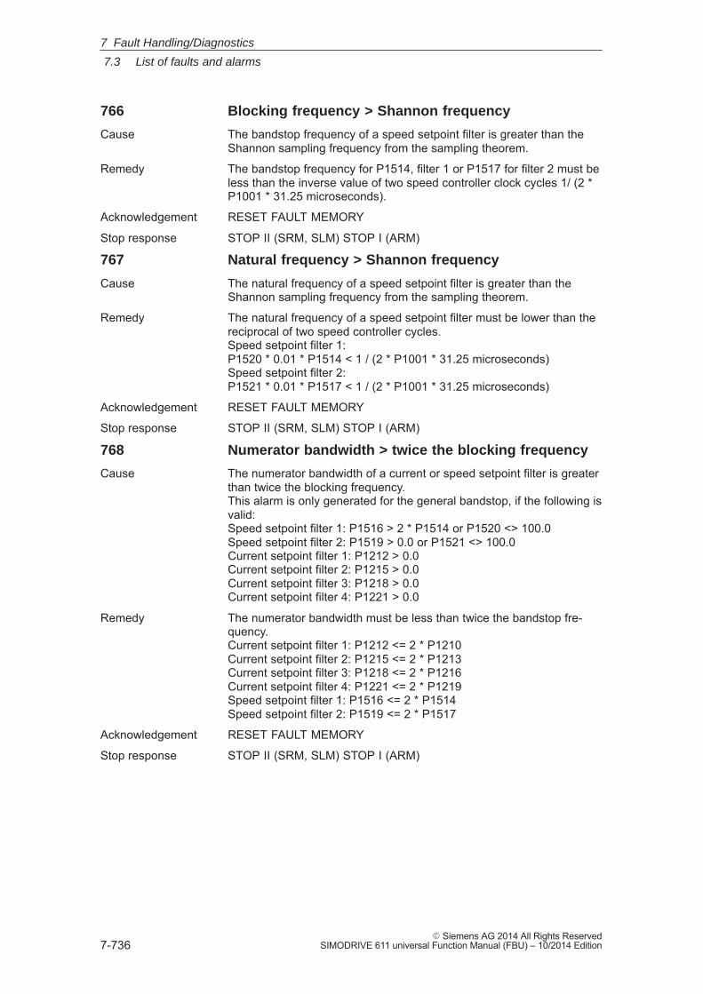
7
7.3 List of faults and alarms
7-736� Siemens AG 2014 All Rights Reserved
SIMODRIVE 611 universal Function Manual (FBU) – 10/2014 Edition
766 Blocking frequency > Shannon frequency
Cause The bandstop frequency of a speed setpoint filter is greater than theShannon sampling frequency from the sampling theorem.
Remedy The bandstop frequency for P1514, filter 1 or P1517 for filter 2 must beless than the inverse value of two speed controller clock cycles 1/ (2 *P1001 * 31.25 microseconds).
Acknowledgement RESET FAULT MEMORY
Stop response STOP II (SRM, SLM) STOP I (ARM)
767 Natural frequency > Shannon frequency
Cause The natural frequency of a speed setpoint filter is greater than theShannon sampling frequency from the sampling theorem.
Remedy The natural frequency of a speed setpoint filter must be lower than thereciprocal of two speed controller cycles.Speed setpoint filter 1:P1520 * 0.01 * P1514 < 1 / (2 * P1001 * 31.25 microseconds)Speed setpoint filter 2:P1521 * 0.01 * P1517 < 1 / (2 * P1001 * 31.25 microseconds)
Acknowledgement RESET FAULT MEMORY
Stop response STOP II (SRM, SLM) STOP I (ARM)
768 Numerator bandwidth > twice the blocking frequency
Cause The numerator bandwidth of a current or speed setpoint filter is greaterthan twice the blocking frequency.This alarm is only generated for the general bandstop, if the following isvalid:Speed setpoint filter 1: P1516 > 2 * P1514 or P1520 <> 100.0Speed setpoint filter 2: P1519 > 0.0 or P1521 <> 100.0Current setpoint filter 1: P1212 > 0.0Current setpoint filter 2: P1215 > 0.0Current setpoint filter 3: P1218 > 0.0Current setpoint filter 4: P1221 > 0.0
Remedy The numerator bandwidth must be less than twice the bandstop fre-quency.Current setpoint filter 1: P1212 <= 2 * P1210Current setpoint filter 2: P1215 <= 2 * P1213Current setpoint filter 3: P1218 <= 2 * P1216Current setpoint filter 4: P1221 <= 2 * P1219Speed setpoint filter 1: P1516 <= 2 * P1514Speed setpoint filter 2: P1519 <= 2 * P1517
Acknowledgement RESET FAULT MEMORY
Stop response STOP II (SRM, SLM) STOP I (ARM)
7 Fault Handling/Diagnostics
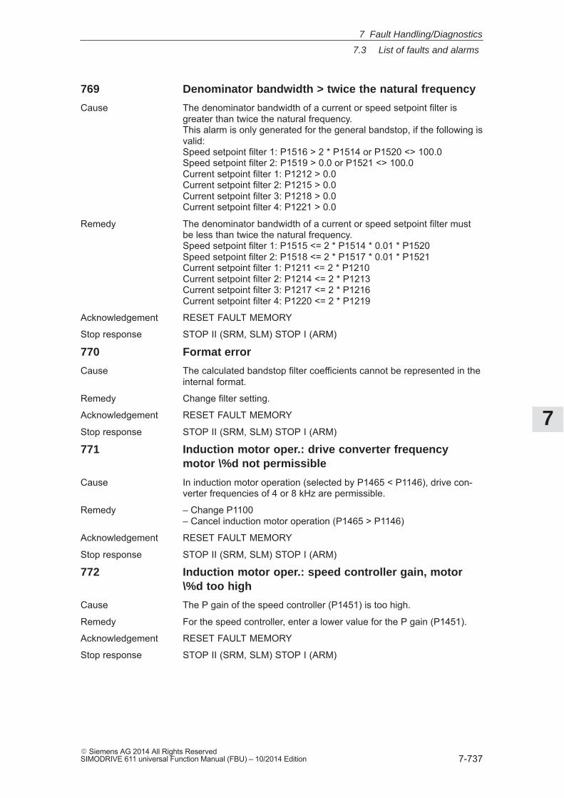
7
7.3 List of faults and alarms
7-737� Siemens AG 2014 All Rights ReservedSIMODRIVE 611 universal Function Manual (FBU) – 10/2014 Edition
769 Denominator bandwidth > twice the natural frequency
Cause The denominator bandwidth of a current or speed setpoint filter isgreater than twice the natural frequency.This alarm is only generated for the general bandstop, if the following isvalid:Speed setpoint filter 1: P1516 > 2 * P1514 or P1520 <> 100.0Speed setpoint filter 2: P1519 > 0.0 or P1521 <> 100.0Current setpoint filter 1: P1212 > 0.0Current setpoint filter 2: P1215 > 0.0Current setpoint filter 3: P1218 > 0.0Current setpoint filter 4: P1221 > 0.0
Remedy The denominator bandwidth of a current or speed setpoint filter mustbe less than twice the natural frequency.Speed setpoint filter 1: P1515 <= 2 * P1514 * 0.01 * P1520Speed setpoint filter 2: P1518 <= 2 * P1517 * 0.01 * P1521Current setpoint filter 1: P1211 <= 2 * P1210Current setpoint filter 2: P1214 <= 2 * P1213Current setpoint filter 3: P1217 <= 2 * P1216Current setpoint filter 4: P1220 <= 2 * P1219
Acknowledgement RESET FAULT MEMORY
Stop response STOP II (SRM, SLM) STOP I (ARM)
770 Format error
Cause The calculated bandstop filter coefficients cannot be represented in theinternal format.
Remedy Change filter setting.
Acknowledgement RESET FAULT MEMORY
Stop response STOP II (SRM, SLM) STOP I (ARM)
771 Induction motor oper.: drive converter frequencymotor \%d not permissible
Cause In induction motor operation (selected by P1465 < P1146), drive con-verter frequencies of 4 or 8 kHz are permissible.
Remedy – Change P1100– Cancel induction motor operation (P1465 > P1146)
Acknowledgement RESET FAULT MEMORY
Stop response STOP II (SRM, SLM) STOP I (ARM)
772 Induction motor oper.: speed controller gain, motor\%d too high
Cause The P gain of the speed controller (P1451) is too high.
Remedy For the speed controller, enter a lower value for the P gain (P1451).
Acknowledgement RESET FAULT MEMORY
Stop response STOP II (SRM, SLM) STOP I (ARM)
7 Fault Handling/Diagnostics
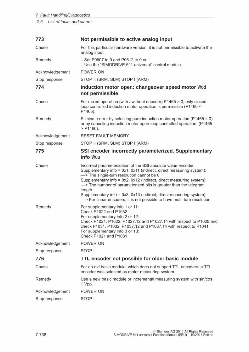
7
7.3 List of faults and alarms
7-738� Siemens AG 2014 All Rights Reserved
SIMODRIVE 611 universal Function Manual (FBU) – 10/2014 Edition
773 Not permissible to active analog input
Cause For this particular hardware version, it is not permissible to activate theanalog input.
Remedy – Set P0607 to 0 and P0612 to 0 or– Use the ”SIMODRIVE 611 universal” control module.
Acknowledgement POWER ON
Stop response STOP II (SRM, SLM) STOP I (ARM)
774 Induction motor oper.: changeover speed motor \%dnot permissible
Cause For mixed operation (with / without encoder) P1465 > 0, only closed-loop controlled induction motor operation is permissible (P1466 <=P1465).
Remedy Eliminate error by selecting pure induction motor operation (P1465 = 0)or by canceling induction motor open-loop controlled operation (P1465> P1466).
Acknowledgement RESET FAULT MEMORY
Stop response STOP II (SRM, SLM) STOP I (ARM)
775 SSI encoder incorrectly parameterized. Supplementaryinfo \%u
Cause Incorrect parameterization of the SSI absolute value encoder.Supplementary info = 0x1, 0x11 (indirect, direct measuring system):––> The single-turn resolution cannot be 0.Supplementary info = 0x2, 0x12 (indirect, direct measuring system):––> The number of parameterized bits is greater than the telegramlength.Supplementary info = 0x3, 0x13 (indirect, direct measuring system):––> For linear encoders, it is not possible to have multi-turn resolution.
Remedy For supplementary info 1 or 11:Check P1022 and P1032For supplementary info 2 or 12:Check P1021, P1022, P1027.12 and P1027.14 with respect to P1028 andcheck P1031, P1032, P1037.12 and P1037.14 with respect to P1041.For supplementary info 3 or 13:Check P1021 and P1031
Acknowledgement POWER ON
Stop response STOP I
776 TTL encoder not possible for older basic module
Cause For an old basic module, which does not support TTL encoders, a TTLencoder was selected as motor measuring system.
Remedy Use a new basic module or incremental measuring system with sin/cos1 Vpp.
Acknowledgement POWER ON
Stop response STOP I
7 Fault Handling/Diagnostics
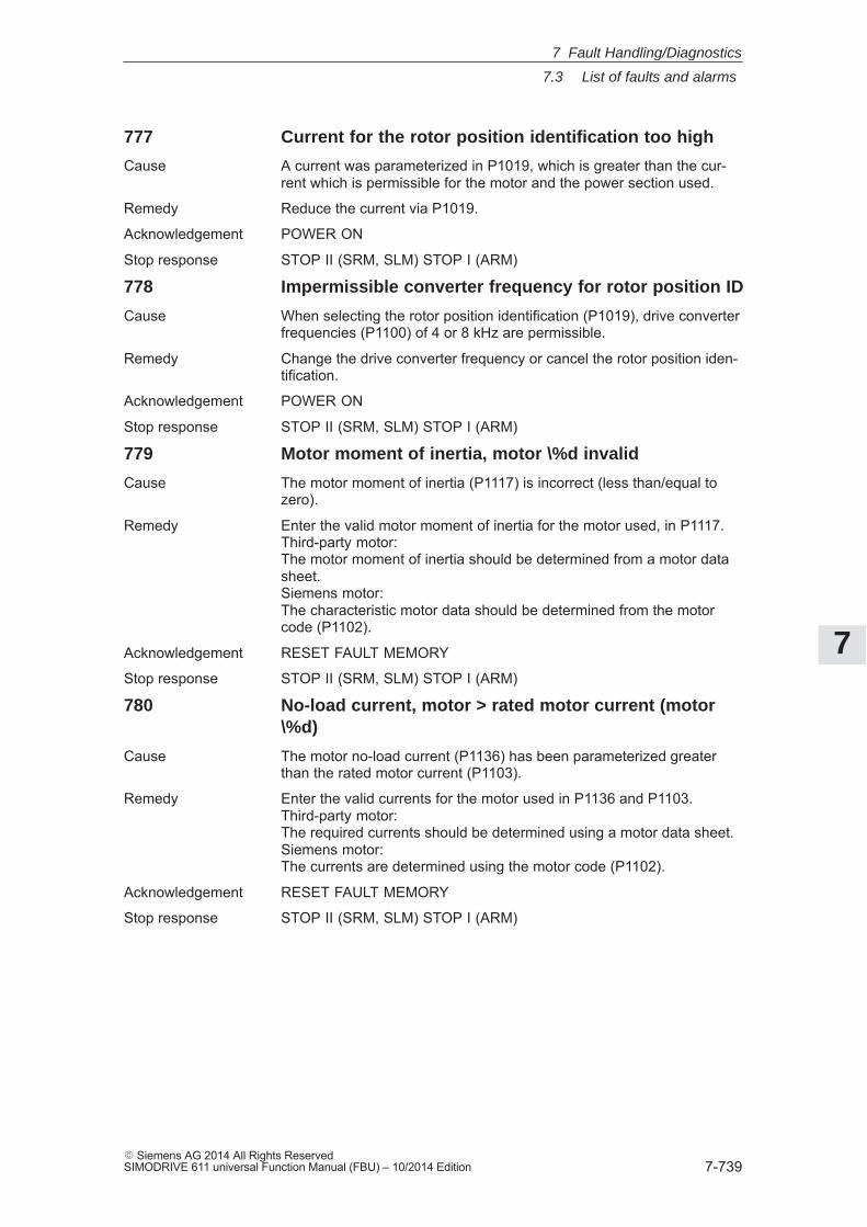
7
7.3 List of faults and alarms
7-739� Siemens AG 2014 All Rights ReservedSIMODRIVE 611 universal Function Manual (FBU) – 10/2014 Edition
777 Current for the rotor position identification too high
Cause A current was parameterized in P1019, which is greater than the cur-rent which is permissible for the motor and the power section used.
Remedy Reduce the current via P1019.
Acknowledgement POWER ON
Stop response STOP II (SRM, SLM) STOP I (ARM)
778 Impermissible converter frequency for rotor position ID
Cause When selecting the rotor position identification (P1019), drive converterfrequencies (P1100) of 4 or 8 kHz are permissible.
Remedy Change the drive converter frequency or cancel the rotor position iden-tification.
Acknowledgement POWER ON
Stop response STOP II (SRM, SLM) STOP I (ARM)
779 Motor moment of inertia, motor \%d invalid
Cause The motor moment of inertia (P1117) is incorrect (less than/equal tozero).
Remedy Enter the valid motor moment of inertia for the motor used, in P1117.Third-party motor:The motor moment of inertia should be determined from a motor datasheet.Siemens motor:The characteristic motor data should be determined from the motorcode (P1102).
Acknowledgement RESET FAULT MEMORY
Stop response STOP II (SRM, SLM) STOP I (ARM)
780 No-load current, motor > rated motor current (motor\%d)
Cause The motor no-load current (P1136) has been parameterized greaterthan the rated motor current (P1103).
Remedy Enter the valid currents for the motor used in P1136 and P1103.Third-party motor:The required currents should be determined using a motor data sheet.Siemens motor:The currents are determined using the motor code (P1102).
Acknowledgement RESET FAULT MEMORY
Stop response STOP II (SRM, SLM) STOP I (ARM)
7 Fault Handling/Diagnostics
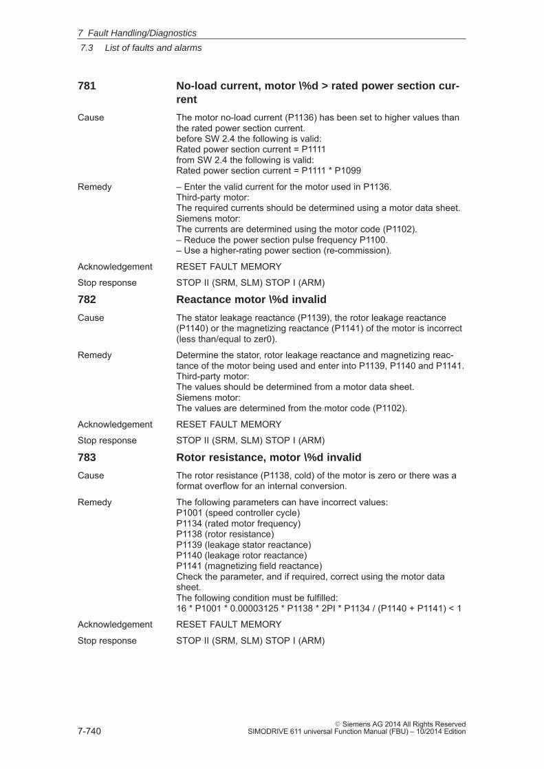
7
7.3 List of faults and alarms
7-740� Siemens AG 2014 All Rights Reserved
SIMODRIVE 611 universal Function Manual (FBU) – 10/2014 Edition
781 No-load current, motor \%d > rated power section cur-rent
Cause The motor no-load current (P1136) has been set to higher values thanthe rated power section current.before SW 2.4 the following is valid:Rated power section current = P1111from SW 2.4 the following is valid:Rated power section current = P1111 * P1099
Remedy – Enter the valid current for the motor used in P1136.Third-party motor:The required currents should be determined using a motor data sheet.Siemens motor:The currents are determined using the motor code (P1102).– Reduce the power section pulse frequency P1100.– Use a higher-rating power section (re-commission).
Acknowledgement RESET FAULT MEMORY
Stop response STOP II (SRM, SLM) STOP I (ARM)
782 Reactance motor \%d invalid
Cause The stator leakage reactance (P1139), the rotor leakage reactance(P1140) or the magnetizing reactance (P1141) of the motor is incorrect(less than/equal to zer0).
Remedy Determine the stator, rotor leakage reactance and magnetizing reac-tance of the motor being used and enter into P1139, P1140 and P1141.Third-party motor:The values should be determined from a motor data sheet.Siemens motor:The values are determined from the motor code (P1102).
Acknowledgement RESET FAULT MEMORY
Stop response STOP II (SRM, SLM) STOP I (ARM)
783 Rotor resistance, motor \%d invalid
Cause The rotor resistance (P1138, cold) of the motor is zero or there was aformat overflow for an internal conversion.
Remedy The following parameters can have incorrect values:P1001 (speed controller cycle)P1134 (rated motor frequency)P1138 (rotor resistance)P1139 (leakage stator reactance)P1140 (leakage rotor reactance)P1141 (magnetizing field reactance)Check the parameter, and if required, correct using the motor datasheet.The following condition must be fulfilled:16 * P1001 * 0.00003125 * P1138 * 2PI * P1134 / (P1140 + P1141) < 1
Acknowledgement RESET FAULT MEMORY
Stop response STOP II (SRM, SLM) STOP I (ARM)
7 Fault Handling/Diagnostics
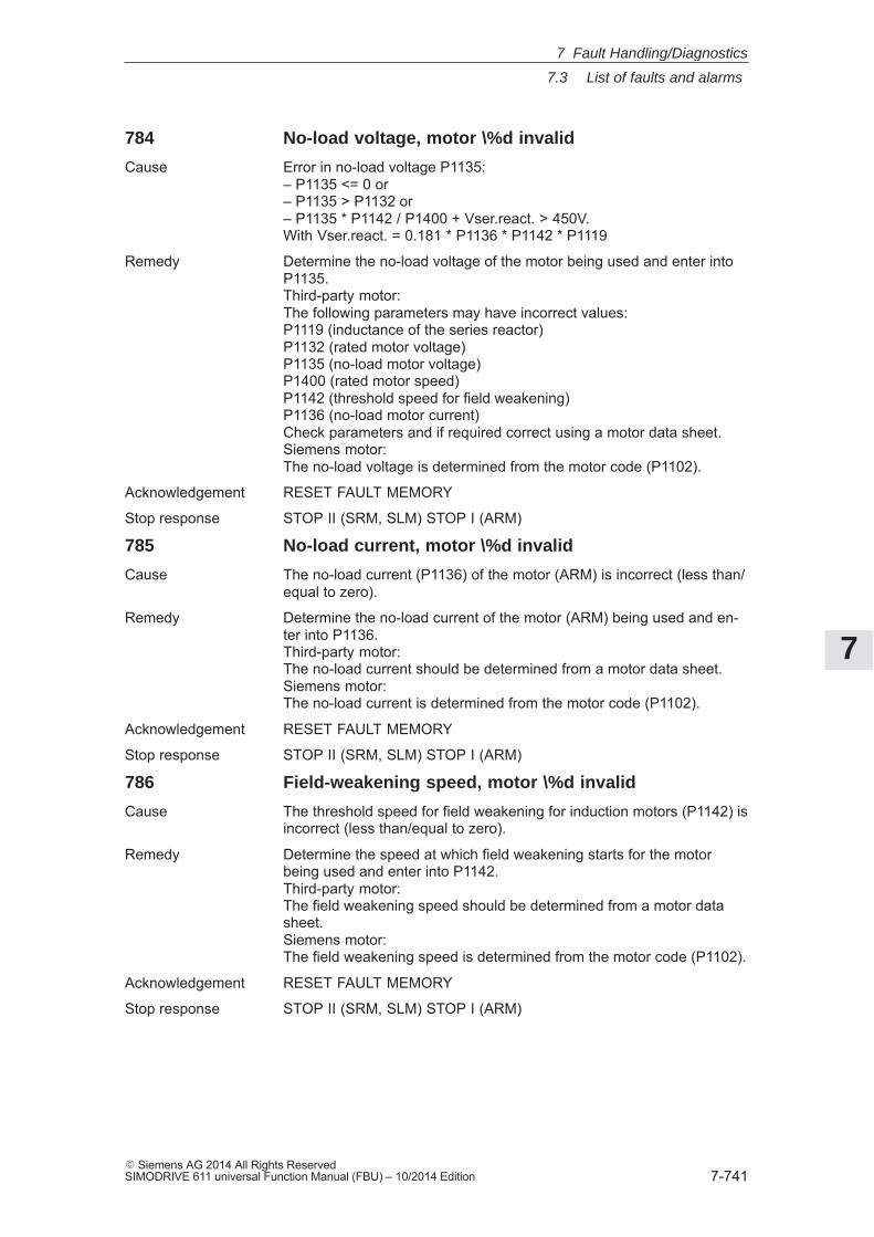
7
7.3 List of faults and alarms
7-741� Siemens AG 2014 All Rights ReservedSIMODRIVE 611 universal Function Manual (FBU) – 10/2014 Edition
784 No-load voltage, motor \%d invalid
Cause Error in no-load voltage P1135:– P1135 <= 0 or– P1135 > P1132 or– P1135 * P1142 / P1400 + Vser.react. > 450V.With Vser.react. = 0.181 * P1136 * P1142 * P1119
Remedy Determine the no-load voltage of the motor being used and enter intoP1135.Third-party motor:The following parameters may have incorrect values:P1119 (inductance of the series reactor)P1132 (rated motor voltage)P1135 (no-load motor voltage)P1400 (rated motor speed)P1142 (threshold speed for field weakening)P1136 (no-load motor current)Check parameters and if required correct using a motor data sheet.Siemens motor:The no-load voltage is determined from the motor code (P1102).
Acknowledgement RESET FAULT MEMORY
Stop response STOP II (SRM, SLM) STOP I (ARM)
785 No-load current, motor \%d invalid
Cause The no-load current (P1136) of the motor (ARM) is incorrect (less than/equal to zero).
Remedy Determine the no-load current of the motor (ARM) being used and en-ter into P1136.Third-party motor:The no-load current should be determined from a motor data sheet.Siemens motor:The no-load current is determined from the motor code (P1102).
Acknowledgement RESET FAULT MEMORY
Stop response STOP II (SRM, SLM) STOP I (ARM)
786 Field-weakening speed, motor \%d invalid
Cause The threshold speed for field weakening for induction motors (P1142) isincorrect (less than/equal to zero).
Remedy Determine the speed at which field weakening starts for the motorbeing used and enter into P1142.Third-party motor:The field weakening speed should be determined from a motor datasheet.Siemens motor:The field weakening speed is determined from the motor code (P1102).
Acknowledgement RESET FAULT MEMORY
Stop response STOP II (SRM, SLM) STOP I (ARM)
7 Fault Handling/Diagnostics
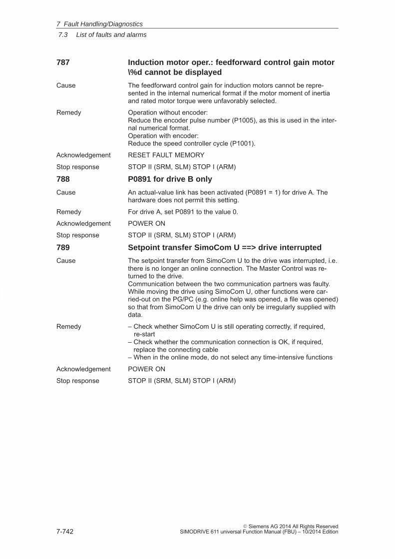
7
7.3 List of faults and alarms
7-742� Siemens AG 2014 All Rights Reserved
SIMODRIVE 611 universal Function Manual (FBU) – 10/2014 Edition
787 Induction motor oper.: feedforward control gain motor\%d cannot be displayed
Cause The feedforward control gain for induction motors cannot be repre-sented in the internal numerical format if the motor moment of inertiaand rated motor torque were unfavorably selected.
Remedy Operation without encoder:Reduce the encoder pulse number (P1005), as this is used in the inter-nal numerical format.Operation with encoder:Reduce the speed controller cycle (P1001).
Acknowledgement RESET FAULT MEMORY
Stop response STOP II (SRM, SLM) STOP I (ARM)
788 P0891 for drive B only
Cause An actual-value link has been activated (P0891 = 1) for drive A. Thehardware does not permit this setting.
Remedy For drive A, set P0891 to the value 0.
Acknowledgement POWER ON
Stop response STOP II (SRM, SLM) STOP I (ARM)
789 Setpoint transfer SimoCom U ==> drive interrupted
Cause The setpoint transfer from SimoCom U to the drive was interrupted, i.e.there is no longer an online connection. The Master Control was re-turned to the drive.Communication between the two communication partners was faulty.While moving the drive using SimoCom U, other functions were car-ried-out on the PG/PC (e.g. online help was opened, a file was opened)so that from SimoCom U the drive can only be irregularly supplied withdata.
Remedy – Check whether SimoCom U is still operating correctly, if required, re-start– Check whether the communication connection is OK, if required, replace the connecting cable– When in the online mode, do not select any time-intensive functions
Acknowledgement POWER ON
Stop response STOP II (SRM, SLM) STOP I (ARM)
7 Fault Handling/Diagnostics
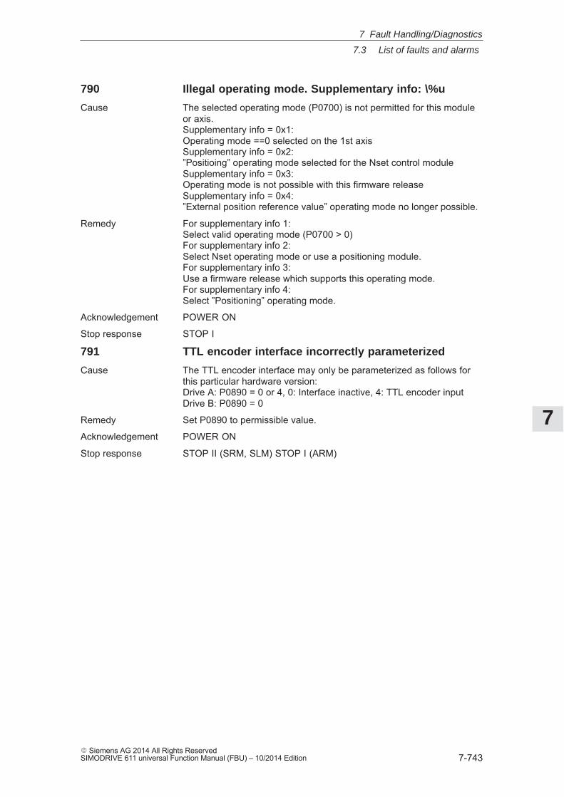
7
7.3 List of faults and alarms
7-743� Siemens AG 2014 All Rights ReservedSIMODRIVE 611 universal Function Manual (FBU) – 10/2014 Edition
790 Illegal operating mode. Supplementary info: \%u
Cause The selected operating mode (P0700) is not permitted for this moduleor axis.Supplementary info = 0x1:Operating mode ==0 selected on the 1st axisSupplementary info = 0x2:”Positioing” operating mode selected for the Nset control moduleSupplementary info = 0x3:Operating mode is not possible with this firmware releaseSupplementary info = 0x4:”External position reference value” operating mode no longer possible.
Remedy For supplementary info 1:Select valid operating mode (P0700 > 0)For supplementary info 2:Select Nset operating mode or use a positioning module.For supplementary info 3:Use a firmware release which supports this operating mode.For supplementary info 4:Select ”Positioning” operating mode.
Acknowledgement POWER ON
Stop response STOP I
791 TTL encoder interface incorrectly parameterized
Cause The TTL encoder interface may only be parameterized as follows forthis particular hardware version:Drive A: P0890 = 0 or 4, 0: Interface inactive, 4: TTL encoder inputDrive B: P0890 = 0
Remedy Set P0890 to permissible value.
Acknowledgement POWER ON
Stop response STOP II (SRM, SLM) STOP I (ARM)
7 Fault Handling/Diagnostics

7
7.3 List of faults and alarms
7-744� Siemens AG 2014 All Rights Reserved
SIMODRIVE 611 universal Function Manual (FBU) – 10/2014 Edition
792 Direct measuring system incorrectly parameterized.Supplementary info: \%u
Cause It is not permitted to parameterize the direct measuring system.Supplementary info = 0x1:A direct measuring system cannot be used using this board.Supplementary info = 0x2:The direct measuring system cannot be simultaneously operated withdrive B.Supplementary info = 0x3:The direct measuring system is active and drive A is set for encoder-less operation (P1027 bit 5 = 1).
Remedy For supplementary info 1:Use the required board.For supplementary info 2:– De-activate the direct measuring system for drive A (P0250/P0879.12 = 0)or– Switch drive B inactive (P0700 = 0)For supplementary info 3:– De-activate the direct measuring system for drive A (P0250/P0879.12 = 0)or– Commission the motor measuring system for drive A
Acknowledgement POWER ON
Stop response STOP I
793 Angular encoder signal waveform different for drive Aand B
Cause The input signal waveform for the angular encoder interface must beset the same for the drives.
Remedy Check P0894 for both drives and set the same
Acknowledgement POWER ON
Stop response STOP II (SRM, SLM) STOP I (ARM)
794 P0890 = 3 not permitted for drive B
Cause This angular encoder interface setting is not permitted for drive B.
Remedy Check P0890 for drive B and set to a permissible value
Acknowledgement POWER ON
Stop response STOP II (SRM, SLM) STOP I (ARM)
7 Fault Handling/Diagnostics
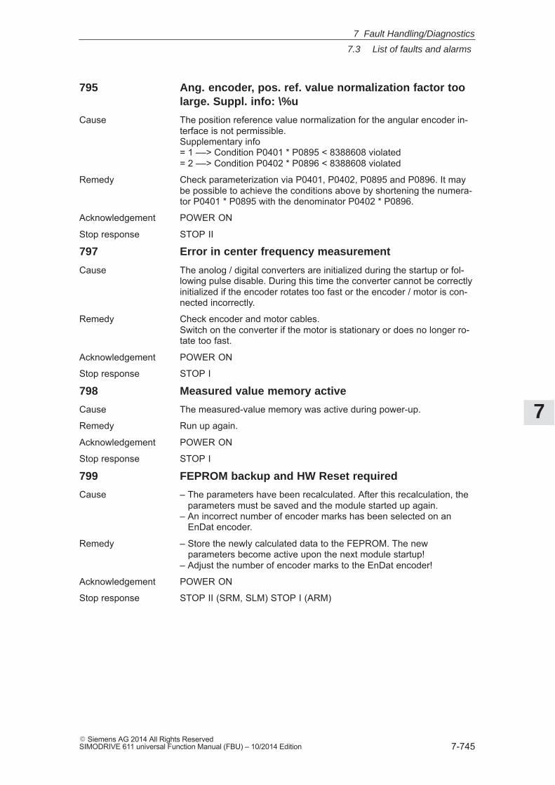
7
7.3 List of faults and alarms
7-745� Siemens AG 2014 All Rights ReservedSIMODRIVE 611 universal Function Manual (FBU) – 10/2014 Edition
795 Ang. encoder, pos. ref. value normalization factor toolarge. Suppl. info: \%u
Cause The position reference value normalization for the angular encoder in-terface is not permissible.Supplementary info= 1 ––> Condition P0401 * P0895 < 8388608 violated= 2 ––> Condition P0402 * P0896 < 8388608 violated
Remedy Check parameterization via P0401, P0402, P0895 and P0896. It maybe possible to achieve the conditions above by shortening the numera-tor P0401 * P0895 with the denominator P0402 * P0896.
Acknowledgement POWER ON
Stop response STOP II
797 Error in center frequency measurement
Cause The anolog / digital converters are initialized during the startup or fol-lowing pulse disable. During this time the converter cannot be correctlyinitialized if the encoder rotates too fast or the encoder / motor is con-nected incorrectly.
Remedy Check encoder and motor cables.Switch on the converter if the motor is stationary or does no longer ro-tate too fast.
Acknowledgement POWER ON
Stop response STOP I
798 Measured value memory active
Cause The measured-value memory was active during power-up.
Remedy Run up again.
Acknowledgement POWER ON
Stop response STOP I
799 FEPROM backup and HW Reset required
Cause – The parameters have been recalculated. After this recalculation, the parameters must be saved and the module started up again.– An incorrect number of encoder marks has been selected on an EnDat encoder.
Remedy – Store the newly calculated data to the FEPROM. The new parameters become active upon the next module startup!– Adjust the number of encoder marks to the EnDat encoder!
Acknowledgement POWER ON
Stop response STOP II (SRM, SLM) STOP I (ARM)
7 Fault Handling/Diagnostics
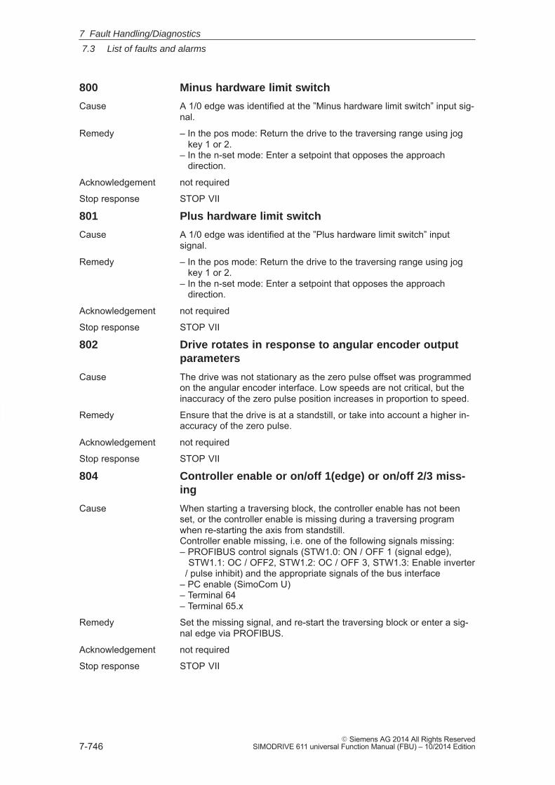
7
7.3 List of faults and alarms
7-746� Siemens AG 2014 All Rights Reserved
SIMODRIVE 611 universal Function Manual (FBU) – 10/2014 Edition
800 Minus hardware limit switch
Cause A 1/0 edge was identified at the ”Minus hardware limit switch” input sig-nal.
Remedy – In the pos mode: Return the drive to the traversing range using jog key 1 or 2.– In the n-set mode: Enter a setpoint that opposes the approach direction.
Acknowledgement not required
Stop response STOP VII
801 Plus hardware limit switch
Cause A 1/0 edge was identified at the ”Plus hardware limit switch” inputsignal.
Remedy – In the pos mode: Return the drive to the traversing range using jog key 1 or 2.– In the n-set mode: Enter a setpoint that opposes the approach direction.
Acknowledgement not required
Stop response STOP VII
802 Drive rotates in response to angular encoder outputparameters
Cause The drive was not stationary as the zero pulse offset was programmedon the angular encoder interface. Low speeds are not critical, but theinaccuracy of the zero pulse position increases in proportion to speed.
Remedy Ensure that the drive is at a standstill, or take into account a higher in-accuracy of the zero pulse.
Acknowledgement not required
Stop response STOP VII
804 Controller enable or on/off 1(edge) or on/off 2/3 miss-ing
Cause When starting a traversing block, the controller enable has not beenset, or the controller enable is missing during a traversing programwhen re-starting the axis from standstill.Controller enable missing, i.e. one of the following signals missing:– PROFIBUS control signals (STW1.0: ON / OFF 1 (signal edge), STW1.1: OC / OFF2, STW1.2: OC / OFF 3, STW1.3: Enable inverter / pulse inhibit) and the appropriate signals of the bus interface– PC enable (SimoCom U)– Terminal 64– Terminal 65.x
Remedy Set the missing signal, and re-start the traversing block or enter a sig-nal edge via PROFIBUS.
Acknowledgement not required
Stop response STOP VII
7 Fault Handling/Diagnostics
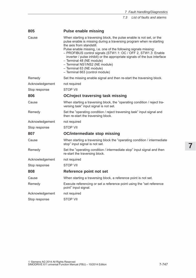
7
7.3 List of faults and alarms
7-747� Siemens AG 2014 All Rights ReservedSIMODRIVE 611 universal Function Manual (FBU) – 10/2014 Edition
805 Pulse enable missing
Cause When starting a traversing block, the pulse enable is not set, or thepulse enable is missing during a traversing program when re-startingthe axis from standstill.Pulse enable missing, i.e. one of the following signals missing:– PROFIBUS control signals (STW1.1: OC / OFF 2, STW1.3: Enable inverter / pulse inhibit) or the appropriate signals of the bus interface– Terminal 48 (NE module)– Terminal NS1/NS2 (NE module)– Terminal 63 (NE module)– Terminal 663 (control module)
Remedy Set the missing enable signal and then re-start the traversing block.
Acknowledgement not required
Stop response STOP VII
806 OC/reject traversing task missing
Cause When starting a traversing block, the ”operating condition / reject tra-versing task” input signal is not set.
Remedy Set the ”operating condition / reject traversing task” input signal andthen re-start the traversing block.
Acknowledgement not required
Stop response STOP VII
807 OC/intermediate stop missing
Cause When starting a traversing block the ”operating condition / intermediatestop” input signal is not set.
Remedy Set the ”operating condition / intermediate stop” input signal and thenre-start the traversing block.
Acknowledgement not required
Stop response STOP VII
808 Reference point not set
Cause When starting a traversing block, a reference point is not set.
Remedy Execute referencing or set a reference point using the ”set referencepoint” input signal.
Acknowledgement not required
Stop response STOP VII
7 Fault Handling/Diagnostics
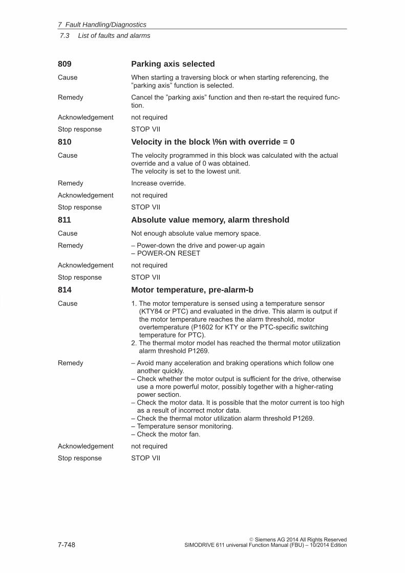
7
7.3 List of faults and alarms
7-748� Siemens AG 2014 All Rights Reserved
SIMODRIVE 611 universal Function Manual (FBU) – 10/2014 Edition
809 Parking axis selected
Cause When starting a traversing block or when starting referencing, the”parking axis” function is selected.
Remedy Cancel the ”parking axis” function and then re-start the required func-tion.
Acknowledgement not required
Stop response STOP VII
810 Velocity in the block \%n with override = 0
Cause The velocity programmed in this block was calculated with the actualoverride and a value of 0 was obtained.The velocity is set to the lowest unit.
Remedy Increase override.
Acknowledgement not required
Stop response STOP VII
811 Absolute value memory, alarm threshold
Cause Not enough absolute value memory space.
Remedy – Power-down the drive and power-up again– POWER-ON RESET
Acknowledgement not required
Stop response STOP VII
814 Motor temperature, pre-alarm-b
Cause 1. The motor temperature is sensed using a temperature sensor (KTY84 or PTC) and evaluated in the drive. This alarm is output if the motor temperature reaches the alarm threshold, motor overtemperature (P1602 for KTY or the PTC-specific switching temperature for PTC).2. The thermal motor model has reached the thermal motor utilization alarm threshold P1269.
Remedy – Avoid many acceleration and braking operations which follow one another quickly.– Check whether the motor output is sufficient for the drive, otherwise use a more powerful motor, possibly together with a higher-rating power section.– Check the motor data. It is possible that the motor current is too high as a result of incorrect motor data.– Check the thermal motor utilization alarm threshold P1269.– Temperature sensor monitoring.– Check the motor fan.
Acknowledgement not required
Stop response STOP VII
7 Fault Handling/Diagnostics
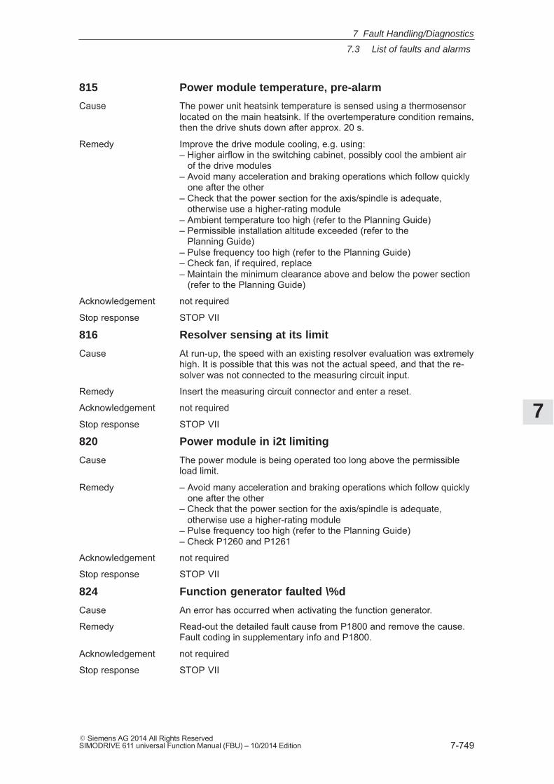
7
7.3 List of faults and alarms
7-749� Siemens AG 2014 All Rights ReservedSIMODRIVE 611 universal Function Manual (FBU) – 10/2014 Edition
815 Power module temperature, pre-alarm
Cause The power unit heatsink temperature is sensed using a thermosensorlocated on the main heatsink. If the overtemperature condition remains,then the drive shuts down after approx. 20 s.
Remedy Improve the drive module cooling, e.g. using:– Higher airflow in the switching cabinet, possibly cool the ambient air of the drive modules– Avoid many acceleration and braking operations which follow quickly one after the other– Check that the power section for the axis/spindle is adequate, otherwise use a higher-rating module– Ambient temperature too high (refer to the Planning Guide)– Permissible installation altitude exceeded (refer to the Planning Guide)– Pulse frequency too high (refer to the Planning Guide)– Check fan, if required, replace– Maintain the minimum clearance above and below the power section (refer to the Planning Guide)
Acknowledgement not required
Stop response STOP VII
816 Resolver sensing at its limit
Cause At run-up, the speed with an existing resolver evaluation was extremelyhigh. It is possible that this was not the actual speed, and that the re-solver was not connected to the measuring circuit input.
Remedy Insert the measuring circuit connector and enter a reset.
Acknowledgement not required
Stop response STOP VII
820 Power module in i2t limiting
Cause The power module is being operated too long above the permissibleload limit.
Remedy – Avoid many acceleration and braking operations which follow quickly one after the other– Check that the power section for the axis/spindle is adequate, otherwise use a higher-rating module– Pulse frequency too high (refer to the Planning Guide)– Check P1260 and P1261
Acknowledgement not required
Stop response STOP VII
824 Function generator faulted \%d
Cause An error has occurred when activating the function generator.
Remedy Read-out the detailed fault cause from P1800 and remove the cause.Fault coding in supplementary info and P1800.
Acknowledgement not required
Stop response STOP VII
7 Fault Handling/Diagnostics
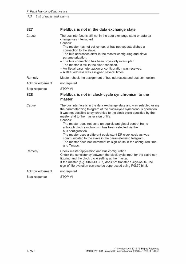
7
7.3 List of faults and alarms
7-750� Siemens AG 2014 All Rights Reserved
SIMODRIVE 611 universal Function Manual (FBU) – 10/2014 Edition
827 Fieldbus is not in the data exchange state
Cause The bus interface is still not in the data exchange state or data ex-change was interrupted.Causes:– The master has not yet run up, or has not yet established a connection to the slave.– The bus addresses differ in the master configuring and slave parameterization.– The bus connection has been physically interrupted.– The master is still in the clear condition.– An illegal parameterization or configuration was received.– A BUS address was assigned several times.
Remedy Master, check the assignment of bus addresses and bus connection.
Acknowledgement not required
Stop response STOP VII
828 Fieldbus is not in clock-cycle synchronism to themaster
Cause The bus interface is in the data exchange state and was selected usingthe parameterizing telegram of the clock-cycle synchronous operation.It was not possible to synchronize to the clock cycle specified by themaster and to the master sign of life.Causes:– The master does not send an equidistant global control frame although clock synchronism has been selected via the bus configuration.– The master uses a different equidistant DP clock cycle as was communicated to the slave in the parameterizing telegram.– The master does not increment its sign-of-life in the configured time grid Tmapc.
Remedy Check master application and bus configurationCheck the consistency between the clock cycle input for the slave con-figuring and the clock cycle setting at the master.If the master (e.g. SIMATIC S7) does not transfer a sign-of-life, thesign-of-life evalution can also be suppressed using P0879 bit 8.
Acknowledgement not required
Stop response STOP VII
7 Fault Handling/Diagnostics
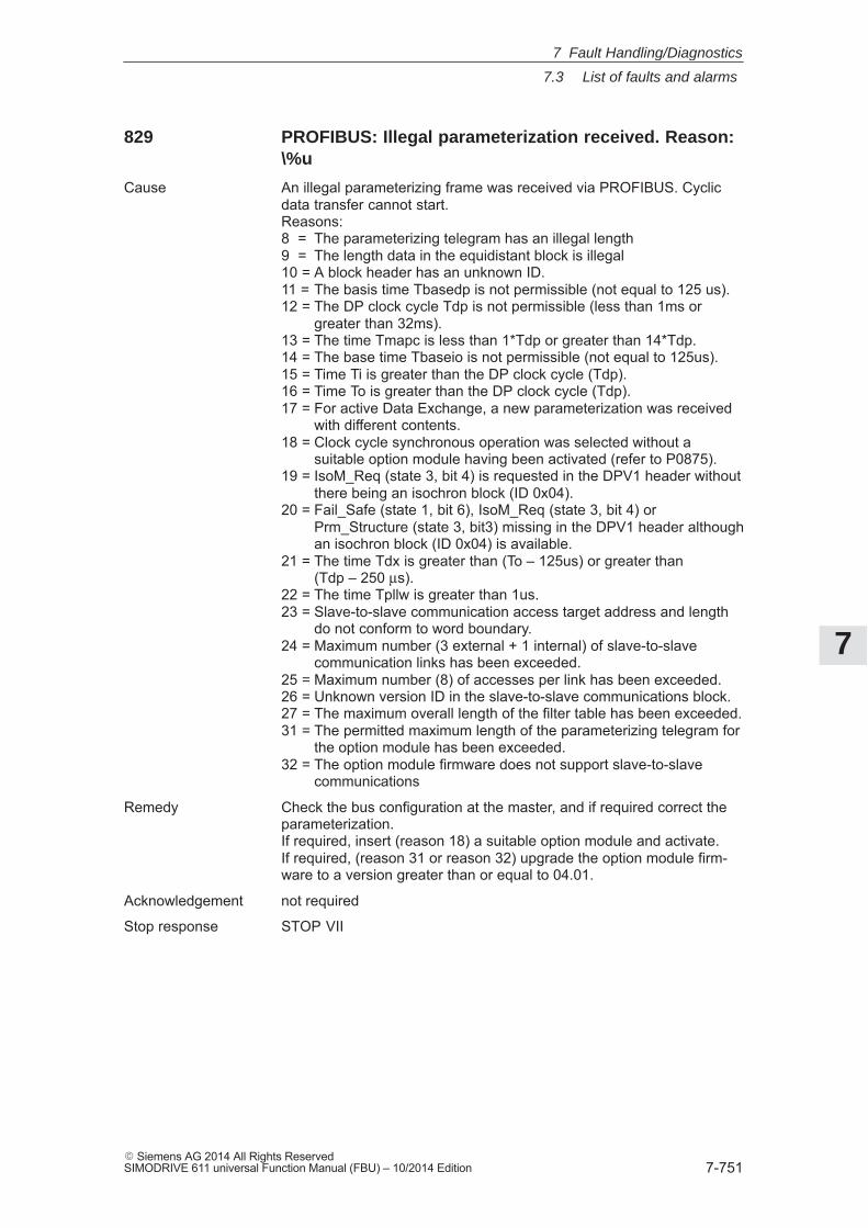
7
7.3 List of faults and alarms
7-751� Siemens AG 2014 All Rights ReservedSIMODRIVE 611 universal Function Manual (FBU) – 10/2014 Edition
829 PROFIBUS: Illegal parameterization received. Reason:\%u
Cause An illegal parameterizing frame was received via PROFIBUS. Cyclicdata transfer cannot start.Reasons:8 = The parameterizing telegram has an illegal length9 = The length data in the equidistant block is illegal10 = A block header has an unknown ID.11 = The basis time Tbasedp is not permissible (not equal to 125 us).12 = The DP clock cycle Tdp is not permissible (less than 1ms or
greater than 32ms).13 = The time Tmapc is less than 1*Tdp or greater than 14*Tdp.14 = The base time Tbaseio is not permissible (not equal to 125us).15 = Time Ti is greater than the DP clock cycle (Tdp).16 = Time To is greater than the DP clock cycle (Tdp).17 = For active Data Exchange, a new parameterization was received
with different contents.18 = Clock cycle synchronous operation was selected without a
suitable option module having been activated (refer to P0875).19 = IsoM_Req (state 3, bit 4) is requested in the DPV1 header without
there being an isochron block (ID 0x04).20 = Fail_Safe (state 1, bit 6), IsoM_Req (state 3, bit 4) or
Prm_Structure (state 3, bit3) missing in the DPV1 header althoughan isochron block (ID 0x04) is available.
21 = The time Tdx is greater than (To – 125us) or greater than(Tdp – 250 μs).
22 = The time Tpllw is greater than 1us.23 = Slave-to-slave communication access target address and length
do not conform to word boundary.24 = Maximum number (3 external + 1 internal) of slave-to-slave
communication links has been exceeded.25 = Maximum number (8) of accesses per link has been exceeded.26 = Unknown version ID in the slave-to-slave communications block.27 = The maximum overall length of the filter table has been exceeded.31 = The permitted maximum length of the parameterizing telegram for
the option module has been exceeded.32 = The option module firmware does not support slave-to-slave
communications
Remedy Check the bus configuration at the master, and if required correct theparameterization.If required, insert (reason 18) a suitable option module and activate.If required, (reason 31 or reason 32) upgrade the option module firm-ware to a version greater than or equal to 04.01.
Acknowledgement not required
Stop response STOP VII
7 Fault Handling/Diagnostics
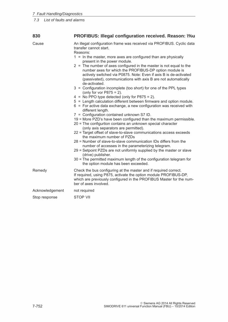
7
7.3 List of faults and alarms
7-752� Siemens AG 2014 All Rights Reserved
SIMODRIVE 611 universal Function Manual (FBU) – 10/2014 Edition
830 PROFIBUS: Illegal configuration received. Reason: \%u
Cause An illegal configuration frame was received via PROFIBUS. Cyclic datatransfer cannot start.Reasons:1 = In the master, more axes are configured than are physically
present in the power module.2 = The number of axes configured in the master is not equal to the
number axes for which the PROFIBUS-DP option module isactively switched via P0875. Note: Even if axis B is de-activated(passivated), communications with axis B are not automaticallyde-activated.
3 = Configuration incomplete (too short) for one of the PPL types(only for vor P875 = 2).
4 = No PPO type detected (only for P875 = 2).5 = Length calculation different between firmware and option module.6 = For active data exchange, a new configuration was received with
different length.7 = Configuration contained unknown S7 ID.19 = More PZD’s have been configured than the maximum permissible.20 = The configurtion contains an unknown special character
(only axis separators are permitted).22 = Target offset of slave-to-slave communications access exceeds
the maximum number of PZDs28 = Number of slave-to-slave communication IDs differs from the
number of accesses in the parameterizing telegram.29 = Setpoint PZDs are not uniformly supplied by the master or slave
(drive) publisher.30 = The permitted maximum length of the configuration telegram for
the option module has been exceeded.
Remedy Check the bus configuring at the master and if required correct.If required, using P875, activate the option module PROFIBUS-DP,which are previously configured in the PROFIBUS Master for the num-ber of axes involved.
Acknowledgement not required
Stop response STOP VII
7 Fault Handling/Diagnostics
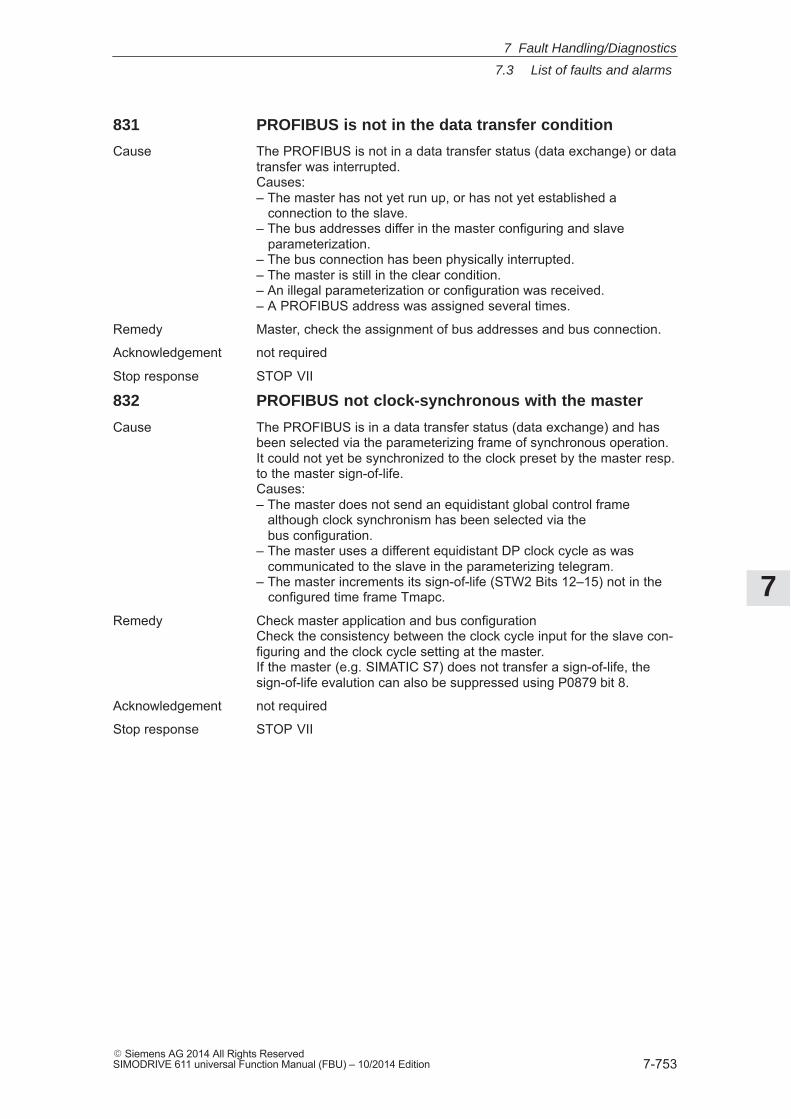
7
7.3 List of faults and alarms
7-753� Siemens AG 2014 All Rights ReservedSIMODRIVE 611 universal Function Manual (FBU) – 10/2014 Edition
831 PROFIBUS is not in the data transfer condition
Cause The PROFIBUS is not in a data transfer status (data exchange) or datatransfer was interrupted.Causes:– The master has not yet run up, or has not yet established a connection to the slave.– The bus addresses differ in the master configuring and slave parameterization.– The bus connection has been physically interrupted.– The master is still in the clear condition.– An illegal parameterization or configuration was received.– A PROFIBUS address was assigned several times.
Remedy Master, check the assignment of bus addresses and bus connection.
Acknowledgement not required
Stop response STOP VII
832 PROFIBUS not clock-synchronous with the master
Cause The PROFIBUS is in a data transfer status (data exchange) and hasbeen selected via the parameterizing frame of synchronous operation.It could not yet be synchronized to the clock preset by the master resp.to the master sign-of-life.Causes:– The master does not send an equidistant global control frame although clock synchronism has been selected via the bus configuration.– The master uses a different equidistant DP clock cycle as was communicated to the slave in the parameterizing telegram.– The master increments its sign-of-life (STW2 Bits 12–15) not in the configured time frame Tmapc.
Remedy Check master application and bus configurationCheck the consistency between the clock cycle input for the slave con-figuring and the clock cycle setting at the master.If the master (e.g. SIMATIC S7) does not transfer a sign-of-life, thesign-of-life evalution can also be suppressed using P0879 bit 8.
Acknowledgement not required
Stop response STOP VII
7 Fault Handling/Diagnostics
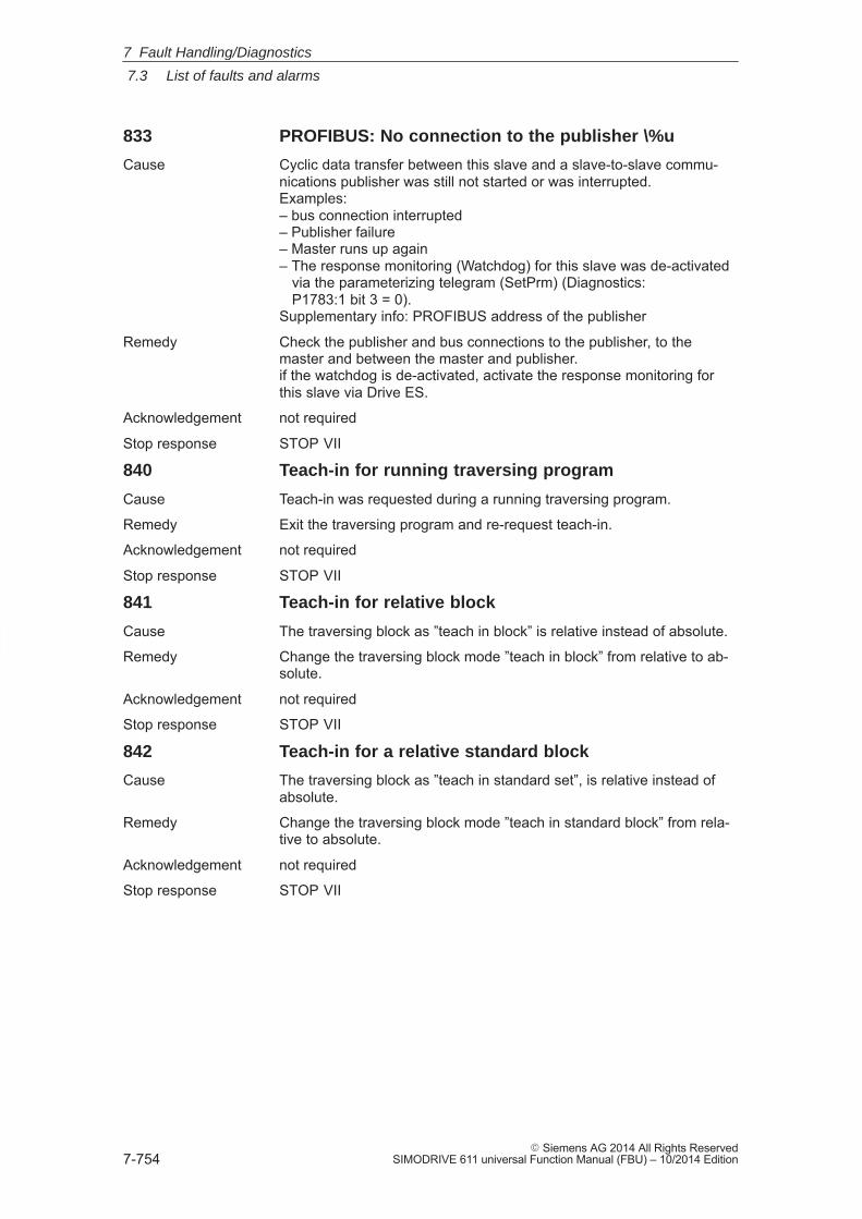
7
7.3 List of faults and alarms
7-754� Siemens AG 2014 All Rights Reserved
SIMODRIVE 611 universal Function Manual (FBU) – 10/2014 Edition
833 PROFIBUS: No connection to the publisher \%u
Cause Cyclic data transfer between this slave and a slave-to-slave commu-nications publisher was still not started or was interrupted.Examples:– bus connection interrupted– Publisher failure– Master runs up again– The response monitoring (Watchdog) for this slave was de-activated via the parameterizing telegram (SetPrm) (Diagnostics: P1783:1 bit 3 = 0).Supplementary info: PROFIBUS address of the publisher
Remedy Check the publisher and bus connections to the publisher, to themaster and between the master and publisher.if the watchdog is de-activated, activate the response monitoring forthis slave via Drive ES.
Acknowledgement not required
Stop response STOP VII
840 Teach-in for running traversing program
Cause Teach-in was requested during a running traversing program.
Remedy Exit the traversing program and re-request teach-in.
Acknowledgement not required
Stop response STOP VII
841 Teach-in for relative block
Cause The traversing block as ”teach in block” is relative instead of absolute.
Remedy Change the traversing block mode ”teach in block” from relative to ab-solute.
Acknowledgement not required
Stop response STOP VII
842 Teach-in for a relative standard block
Cause The traversing block as ”teach in standard set”, is relative instead ofabsolute.
Remedy Change the traversing block mode ”teach in standard block” from rela-tive to absolute.
Acknowledgement not required
Stop response STOP VII
7 Fault Handling/Diagnostics
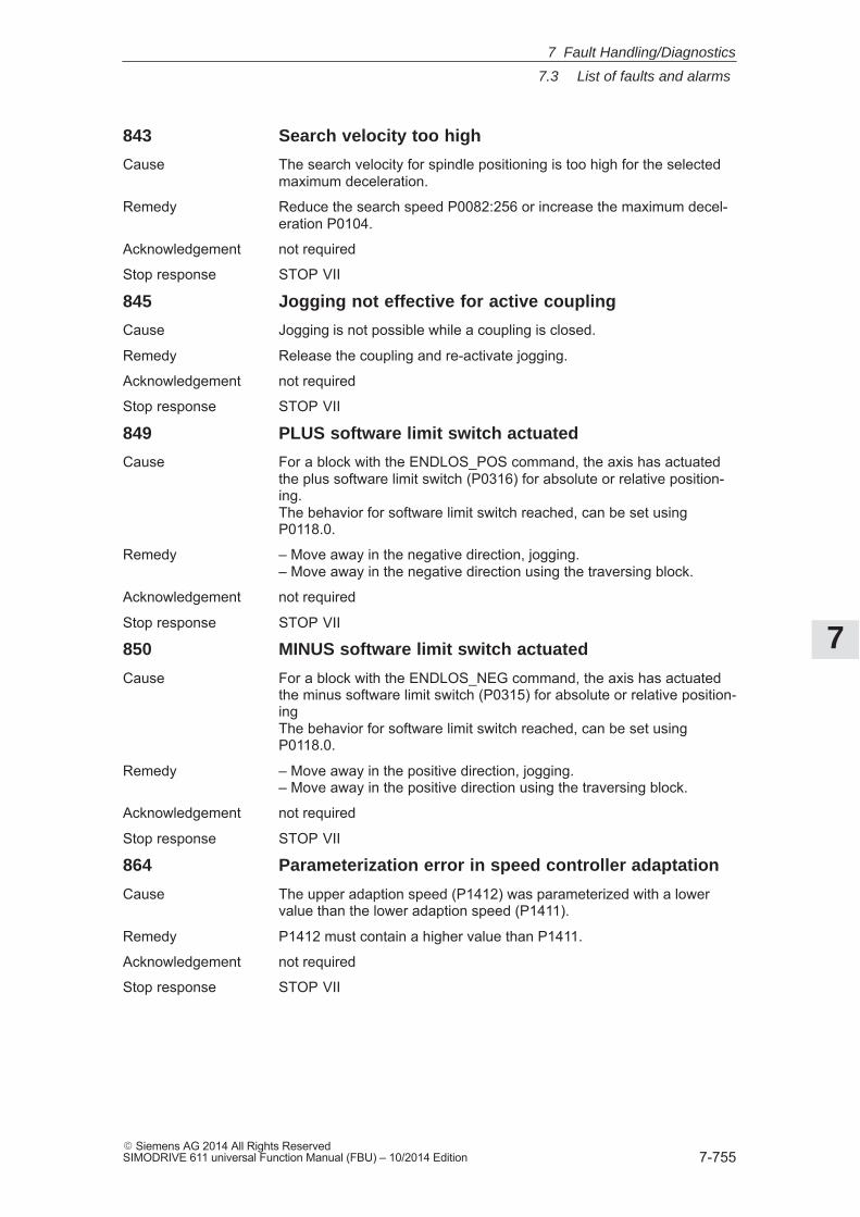
7
7.3 List of faults and alarms
7-755� Siemens AG 2014 All Rights ReservedSIMODRIVE 611 universal Function Manual (FBU) – 10/2014 Edition
843 Search velocity too high
Cause The search velocity for spindle positioning is too high for the selectedmaximum deceleration.
Remedy Reduce the search speed P0082:256 or increase the maximum decel-eration P0104.
Acknowledgement not required
Stop response STOP VII
845 Jogging not effective for active coupling
Cause Jogging is not possible while a coupling is closed.
Remedy Release the coupling and re-activate jogging.
Acknowledgement not required
Stop response STOP VII
849 PLUS software limit switch actuated
Cause For a block with the ENDLOS_POS command, the axis has actuatedthe plus software limit switch (P0316) for absolute or relative position-ing.The behavior for software limit switch reached, can be set usingP0118.0.
Remedy – Move away in the negative direction, jogging.– Move away in the negative direction using the traversing block.
Acknowledgement not required
Stop response STOP VII
850 MINUS software limit switch actuated
Cause For a block with the ENDLOS_NEG command, the axis has actuatedthe minus software limit switch (P0315) for absolute or relative position-ingThe behavior for software limit switch reached, can be set usingP0118.0.
Remedy – Move away in the positive direction, jogging.– Move away in the positive direction using the traversing block.
Acknowledgement not required
Stop response STOP VII
864 Parameterization error in speed controller adaptation
Cause The upper adaption speed (P1412) was parameterized with a lowervalue than the lower adaption speed (P1411).
Remedy P1412 must contain a higher value than P1411.
Acknowledgement not required
Stop response STOP VII
7 Fault Handling/Diagnostics
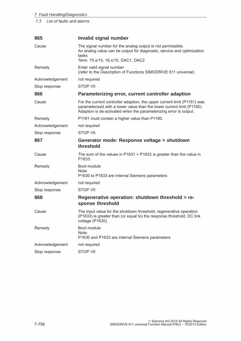
7
7.3 List of faults and alarms
7-756� Siemens AG 2014 All Rights Reserved
SIMODRIVE 611 universal Function Manual (FBU) – 10/2014 Edition
865 Invalid signal number
Cause The signal number for the analog output is not permissible.An analog value can be output for diagnostic, service and optimizationtasksTerm. 75.x/15, 16.x/15, DAC1, DAC2
Remedy Enter valid signal number(refer to the Description of Functions SIMODRIVE 611 universal)
Acknowledgement not required
Stop response STOP VII
866 Parameterizing error, current controller adaption
Cause For the current controller adaption, the upper current limit (P1181) wasparameterized with a lower value than the lower current limit (P1180).Adaption is de-activated when the parameterizing error is output.
Remedy P1181 must contain a higher value than P1180.
Acknowledgement not required
Stop response STOP VII
867 Generator mode: Response voltage > shutdownthreshold
Cause The sum of the values in P1631 + P1632 is greater than the value inP1633.
Remedy Boot moduleNote:P1630 to P1633 are internal Siemens parameters
Acknowledgement not required
Stop response STOP VII
868 Regenerative operation: shutdown threshold > re-sponse threshold
Cause The input value for the shutdown threshold, regenerative operation(P1633) is greater than (or equal to) the response threshold, DC linkvoltage (P1630).
Remedy Boot moduleNote:P1630 and P1633 are internal Siemens parameters
Acknowledgement not required
Stop response STOP VII
7 Fault Handling/Diagnostics
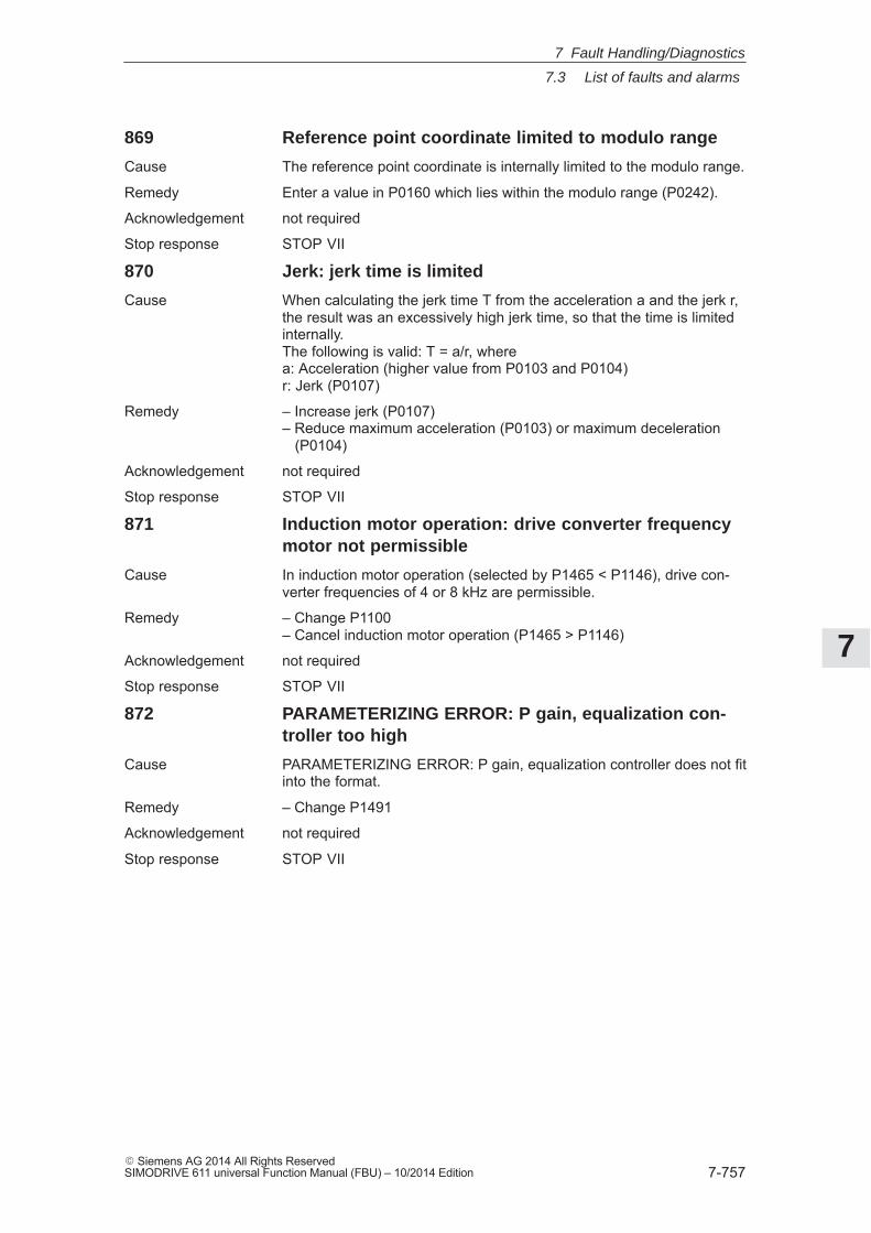
7
7.3 List of faults and alarms
7-757� Siemens AG 2014 All Rights ReservedSIMODRIVE 611 universal Function Manual (FBU) – 10/2014 Edition
869 Reference point coordinate limited to modulo range
Cause The reference point coordinate is internally limited to the modulo range.
Remedy Enter a value in P0160 which lies within the modulo range (P0242).
Acknowledgement not required
Stop response STOP VII
870 Jerk: jerk time is limited
Cause When calculating the jerk time T from the acceleration a and the jerk r,the result was an excessively high jerk time, so that the time is limitedinternally.The following is valid: T = a/r, wherea: Acceleration (higher value from P0103 and P0104)r: Jerk (P0107)
Remedy – Increase jerk (P0107)– Reduce maximum acceleration (P0103) or maximum deceleration (P0104)
Acknowledgement not required
Stop response STOP VII
871 Induction motor operation: drive converter frequencymotor not permissible
Cause In induction motor operation (selected by P1465 < P1146), drive con-verter frequencies of 4 or 8 kHz are permissible.
Remedy – Change P1100– Cancel induction motor operation (P1465 > P1146)
Acknowledgement not required
Stop response STOP VII
872 PARAMETERIZING ERROR: P gain, equalization con-troller too high
Cause PARAMETERIZING ERROR: P gain, equalization controller does not fitinto the format.
Remedy – Change P1491
Acknowledgement not required
Stop response STOP VII
7 Fault Handling/Diagnostics
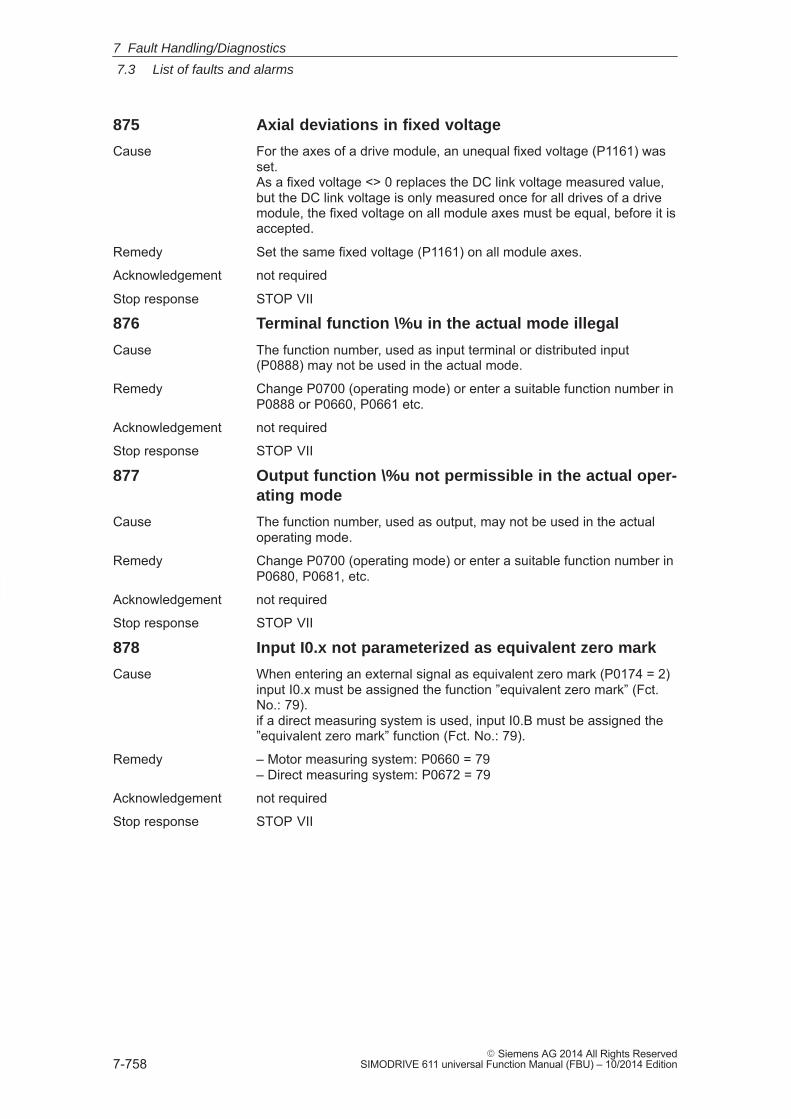
7
7.3 List of faults and alarms
7-758� Siemens AG 2014 All Rights Reserved
SIMODRIVE 611 universal Function Manual (FBU) – 10/2014 Edition
875 Axial deviations in fixed voltage
Cause For the axes of a drive module, an unequal fixed voltage (P1161) wasset.As a fixed voltage <> 0 replaces the DC link voltage measured value,but the DC link voltage is only measured once for all drives of a drivemodule, the fixed voltage on all module axes must be equal, before it isaccepted.
Remedy Set the same fixed voltage (P1161) on all module axes.
Acknowledgement not required
Stop response STOP VII
876 Terminal function \%u in the actual mode illegal
Cause The function number, used as input terminal or distributed input(P0888) may not be used in the actual mode.
Remedy Change P0700 (operating mode) or enter a suitable function number inP0888 or P0660, P0661 etc.
Acknowledgement not required
Stop response STOP VII
877 Output function \%u not permissible in the actual oper-ating mode
Cause The function number, used as output, may not be used in the actualoperating mode.
Remedy Change P0700 (operating mode) or enter a suitable function number inP0680, P0681, etc.
Acknowledgement not required
Stop response STOP VII
878 Input I0.x not parameterized as equivalent zero mark
Cause When entering an external signal as equivalent zero mark (P0174 = 2)input I0.x must be assigned the function ”equivalent zero mark” (Fct.No.: 79).if a direct measuring system is used, input I0.B must be assigned the”equivalent zero mark” function (Fct. No.: 79).
Remedy – Motor measuring system: P0660 = 79– Direct measuring system: P0672 = 79
Acknowledgement not required
Stop response STOP VII
7 Fault Handling/Diagnostics
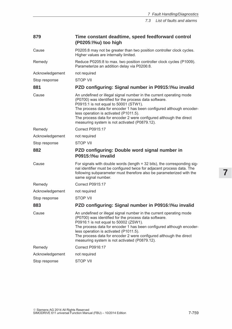
7
7.3 List of faults and alarms
7-759� Siemens AG 2014 All Rights ReservedSIMODRIVE 611 universal Function Manual (FBU) – 10/2014 Edition
879 Time constant deadtime, speed feedforward control(P0205:\%u) too high
Cause P0205:8 may not be greater than two position controller clock cycles.Higher values are internally limited.
Remedy Reduce P0205:8 to max. two position controller clock cycles (P1009).Parameterize an addition delay via P0206:8.
Acknowledgement not required
Stop response STOP VII
881 PZD configuring: Signal number in P0915:\%u invalid
Cause An undefined or illegal signal number in the current operating mode(P0700) was identified for the process data software.P0915:1 is not equal to 50001 (STW1).The process data for encoder 1 has been configured although encoder-less operation is activated (P1011.5).The process data for encoder 2 were configured although the directmeasuring system is not activated (P0879.12).
Remedy Correct P0915:17
Acknowledgement not required
Stop response STOP VII
882 PZD configuring: Double word signal number inP0915:\%u invalid
Cause For signals with double words (length = 32 bits), the corresponding sig-nal identifier must be configured twice for adjacent process data. Thefollowing subparameter must therefore also be parameterized with thesame signal number.
Remedy Correct P0915:17
Acknowledgement not required
Stop response STOP VII
883 PZD configuring: Signal number in P0916:\%u invalid
Cause An undefined or illegal signal number in the current operating mode(P0700) was identified for the process data software.P0916:1 is not equal to 50002 (ZSW1).The process data for encoder 1 has been configured although encoder-less operation is activated (P1011.5).The process data for encoder 2 were configured although the directmeasuring system is not activated (P0879.12).
Remedy Correct P0916:17
Acknowledgement not required
Stop response STOP VII
7 Fault Handling/Diagnostics
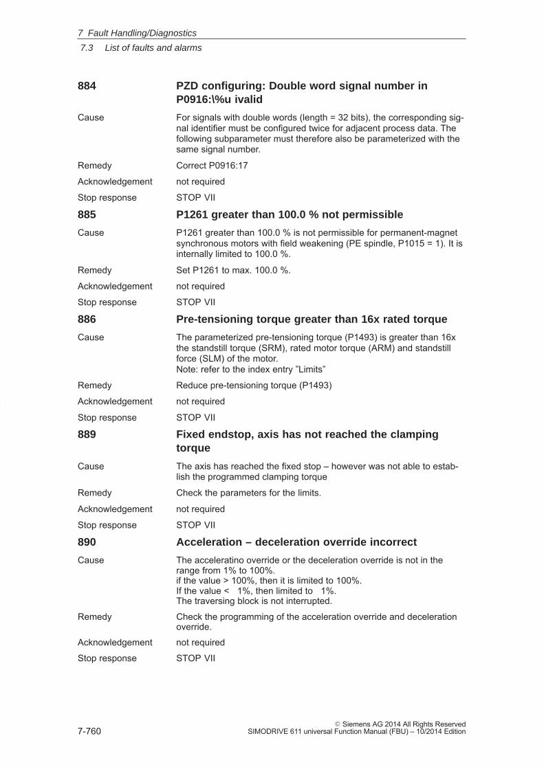
7
7.3 List of faults and alarms
7-760� Siemens AG 2014 All Rights Reserved
SIMODRIVE 611 universal Function Manual (FBU) – 10/2014 Edition
884 PZD configuring: Double word signal number inP0916:\%u ivalid
Cause For signals with double words (length = 32 bits), the corresponding sig-nal identifier must be configured twice for adjacent process data. Thefollowing subparameter must therefore also be parameterized with thesame signal number.
Remedy Correct P0916:17
Acknowledgement not required
Stop response STOP VII
885 P1261 greater than 100.0 % not permissible
Cause P1261 greater than 100.0 % is not permissible for permanent-magnetsynchronous motors with field weakening (PE spindle, P1015 = 1). It isinternally limited to 100.0 %.
Remedy Set P1261 to max. 100.0 %.
Acknowledgement not required
Stop response STOP VII
886 Pre-tensioning torque greater than 16x rated torque
Cause The parameterized pre-tensioning torque (P1493) is greater than 16xthe standstill torque (SRM), rated motor torque (ARM) and standstillforce (SLM) of the motor.Note: refer to the index entry ”Limits”
Remedy Reduce pre-tensioning torque (P1493)
Acknowledgement not required
Stop response STOP VII
889 Fixed endstop, axis has not reached the clampingtorque
Cause The axis has reached the fixed stop – however was not able to estab-lish the programmed clamping torque
Remedy Check the parameters for the limits.
Acknowledgement not required
Stop response STOP VII
890 Acceleration – deceleration override incorrect
Cause The acceleratino override or the deceleration override is not in therange from 1% to 100%.if the value > 100%, then it is limited to 100%.If the value < 1%, then limited to 1%.The traversing block is not interrupted.
Remedy Check the programming of the acceleration override and decelerationoverride.
Acknowledgement not required
Stop response STOP VII
7 Fault Handling/Diagnostics
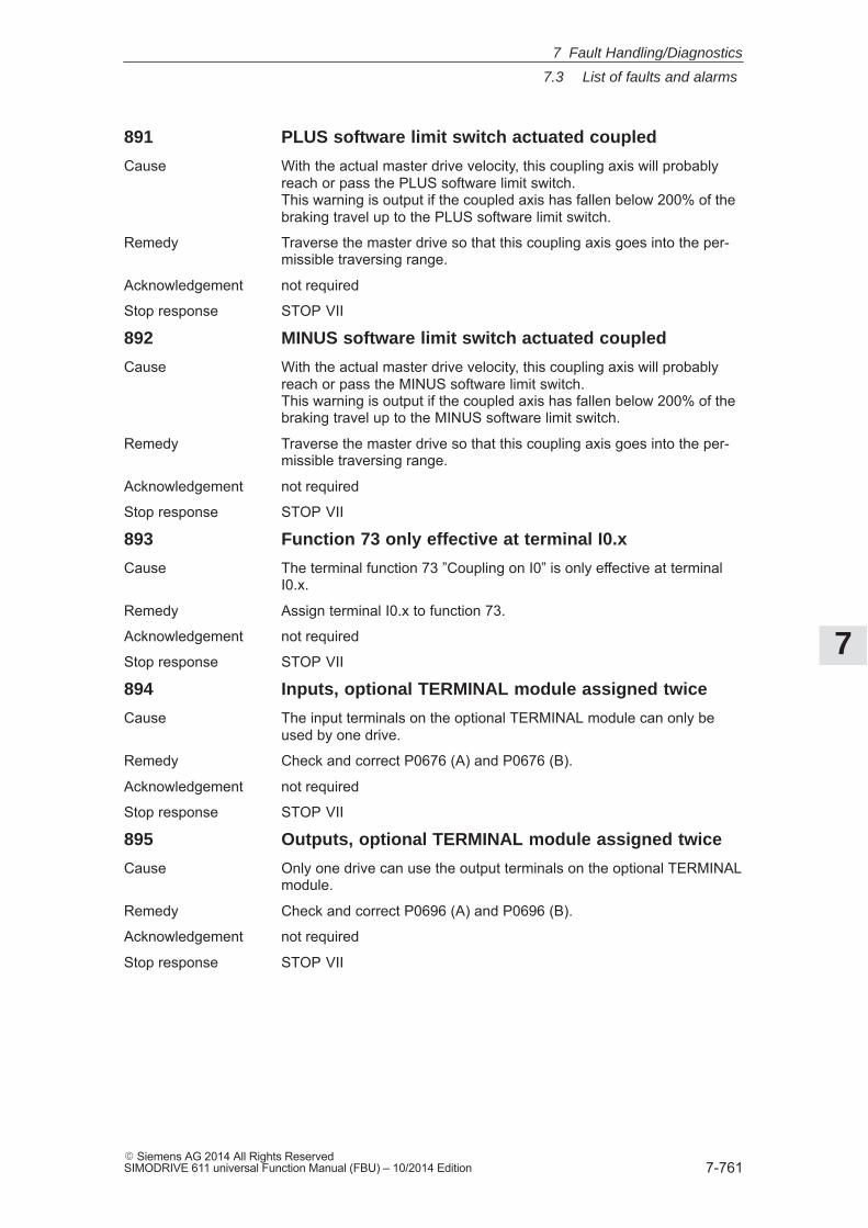
7
7.3 List of faults and alarms
7-761� Siemens AG 2014 All Rights ReservedSIMODRIVE 611 universal Function Manual (FBU) – 10/2014 Edition
891 PLUS software limit switch actuated coupled
Cause With the actual master drive velocity, this coupling axis will probablyreach or pass the PLUS software limit switch.This warning is output if the coupled axis has fallen below 200% of thebraking travel up to the PLUS software limit switch.
Remedy Traverse the master drive so that this coupling axis goes into the per-missible traversing range.
Acknowledgement not required
Stop response STOP VII
892 MINUS software limit switch actuated coupled
Cause With the actual master drive velocity, this coupling axis will probablyreach or pass the MINUS software limit switch.This warning is output if the coupled axis has fallen below 200% of thebraking travel up to the MINUS software limit switch.
Remedy Traverse the master drive so that this coupling axis goes into the per-missible traversing range.
Acknowledgement not required
Stop response STOP VII
893 Function 73 only effective at terminal I0.x
Cause The terminal function 73 ”Coupling on I0” is only effective at terminalI0.x.
Remedy Assign terminal I0.x to function 73.
Acknowledgement not required
Stop response STOP VII
894 Inputs, optional TERMINAL module assigned twice
Cause The input terminals on the optional TERMINAL module can only beused by one drive.
Remedy Check and correct P0676 (A) and P0676 (B).
Acknowledgement not required
Stop response STOP VII
895 Outputs, optional TERMINAL module assigned twice
Cause Only one drive can use the output terminals on the optional TERMINALmodule.
Remedy Check and correct P0696 (A) and P0696 (B).
Acknowledgement not required
Stop response STOP VII
7 Fault Handling/Diagnostics
7
7.4 Commissioning functions
7-762� Siemens AG 2014 All Rights Reserved
SIMODRIVE 611 universal Function Manual (FBU) – 10/2014 Edition
7.4 Commissioning functions
The commissioning functions and support tools help during start–up,during service, when optimizing the drive, and troubleshooting.
The ”SIMODRIVE 611 universal” control board has the following com-missioning and help functions:
� Function generator (FG) refer to Chapter 7.4.1
� Trace function refer to Chapter 7.4.2
� Test sockets (DAC1, DAC2) refer to Chapter 7.4.3
� Measuring function refer to Chapter 7.4.4
!Caution
Setpoints entered via analog inputs (e.g. via terminals 56.x/14.x and/or24.x/20.x) or speeds entered via PROFIBUS–DP are added when thefunction generator starts.
Note:The analog inputs can be disabled via P0607 = 0 (for terminal56.x/14.x) or P0612 = 0 (for terminal 24.x/20.x).
Note
For a ”SIMODRIVE 611 universal” control board, only 1 functiongenerator or 1 measuring function can be started at the same time,i.e. either for drive A or B.
The SimoCom U parameterization and start–up tool can, in the onlinemode, start the commissioning functions ”function generator” and”measuring function” with the control authority for PG/PC.
Note
If online operation between SimoCom U and ”SIMODRIVE 611universal” is interrupted while a start–up function is being executed,then this start–up function is exited, and an appropriate fault isdisplayed on the display unit.
Overview
Start–up(commissioning)functions and”SimoCom U” tool
7 Fault Handling/Diagnostics
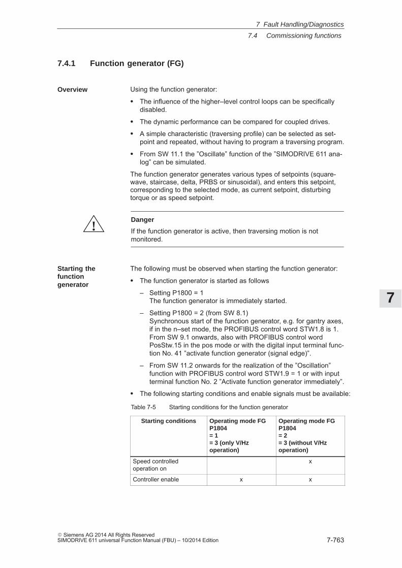
7
7.4 Commissioning functions
7-763� Siemens AG 2014 All Rights ReservedSIMODRIVE 611 universal Function Manual (FBU) – 10/2014 Edition
7.4.1 Function generator (FG)
Using the function generator:
� The influence of the higher–level control loops can be specificallydisabled.
� The dynamic performance can be compared for coupled drives.
� A simple characteristic (traversing profile) can be selected as set-point and repeated, without having to program a traversing program.
� From SW 11.1 the ”Oscillate” function of the ”SIMODRIVE 611 ana-log” can be simulated.
The function generator generates various types of setpoints (square-wave, staircase, delta, PRBS or sinusoidal), and enters this setpoint,corresponding to the selected mode, as current setpoint, disturbingtorque or as speed setpoint.
!Danger
If the function generator is active, then traversing motion is notmonitored.
The following must be observed when starting the function generator:
� The function generator is started as follows
– Setting P1800 = 1The function generator is immediately started.
– Setting P1800 = 2 (from SW 8.1)Synchronous start of the function generator, e.g. for gantry axes,if in the n–set mode, the PROFIBUS control word STW1.8 is 1.From SW 9.1 onwards, also with PROFIBUS control wordPosStw.15 in the pos mode or with the digital input terminal func-tion No. 41 ”activate function generator (signal edge)”.
– From SW 11.2 onwards for the realization of the ”Oscillation”function with PROFIBUS control word STW1.9 = 1 or with inputterminal function No. 2 ”Activate function generator immediately”.
� The following starting conditions and enable signals must be available:
Table 7-5 Starting conditions for the function generator
Starting conditions Operating mode FGP1804= 1= 3 (only V/Hzoperation)
Operating mode FGP1804= 2= 3 (without V/Hzoperation)
Speed controlledoperation on
x
Controller enable x x
Overview
Starting thefunctiongenerator
7 Fault Handling/Diagnostics
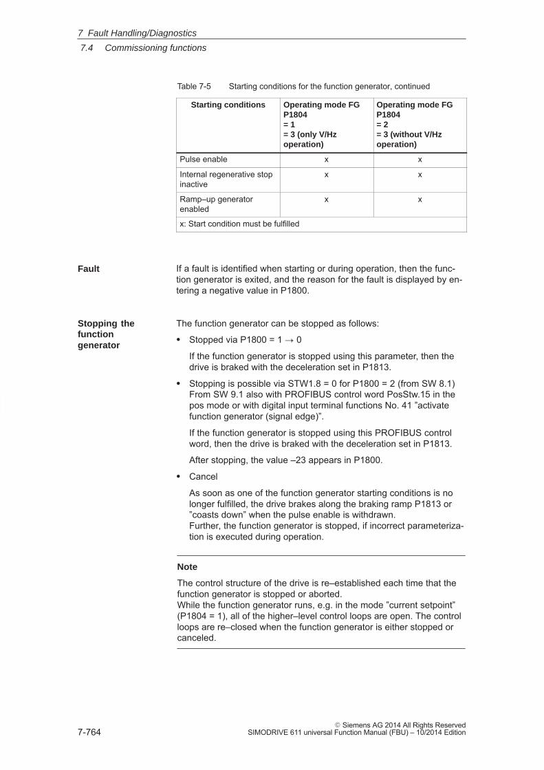
7
7.4 Commissioning functions
7-764� Siemens AG 2014 All Rights Reserved
SIMODRIVE 611 universal Function Manual (FBU) – 10/2014 Edition
Table 7-5 Starting conditions for the function generator, continued
Starting conditions Operating mode FGP1804= 2= 3 (without V/Hzoperation)
Operating mode FGP1804= 1= 3 (only V/Hzoperation)
Pulse enable x x
Internal regenerative stopinactive
x x
Ramp–up generatorenabled
x x
x: Start condition must be fulfilled
If a fault is identified when starting or during operation, then the func-tion generator is exited, and the reason for the fault is displayed by en-tering a negative value in P1800.
The function generator can be stopped as follows:
� Stopped via P1800 = 1 � 0
If the function generator is stopped using this parameter, then thedrive is braked with the deceleration set in P1813.
� Stopping is possible via STW1.8 = 0 for P1800 = 2 (from SW 8.1)From SW 9.1 also with PROFIBUS control word PosStw.15 in thepos mode or with digital input terminal functions No. 41 ”activatefunction generator (signal edge)”.
If the function generator is stopped using this PROFIBUS controlword, then the drive is braked with the deceleration set in P1813.
After stopping, the value –23 appears in P1800.
� Cancel
As soon as one of the function generator starting conditions is nolonger fulfilled, the drive brakes along the braking ramp P1813 or”coasts down” when the pulse enable is withdrawn.Further, the function generator is stopped, if incorrect parameteriza-tion is executed during operation.
Note
The control structure of the drive is re–established each time that thefunction generator is stopped or aborted.While the function generator runs, e.g. in the mode ”current setpoint”(P1804 = 1), all of the higher–level control loops are open. The controlloops are re–closed when the function generator is either stopped orcanceled.
Fault
Stopping thefunctiongenerator
7 Fault Handling/Diagnostics
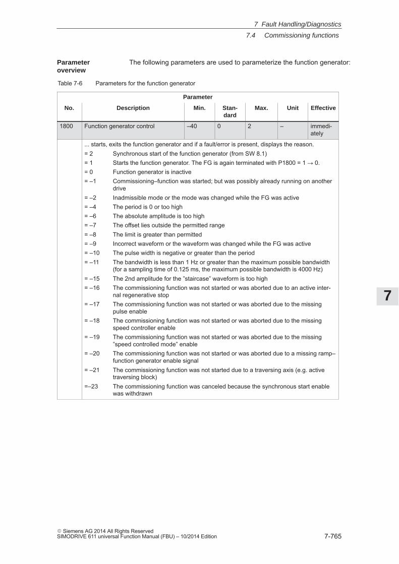
7
7.4 Commissioning functions
7-765� Siemens AG 2014 All Rights ReservedSIMODRIVE 611 universal Function Manual (FBU) – 10/2014 Edition
The following parameters are used to parameterize the function generator:
Table 7-6 Parameters for the function generator
Parameter
No. Description Min. Stan-dard
Max. Unit Effective
1800 Function generator control –40 0 2 – immedi-ately
... starts, exits the function generator and if a fault/error is present, displays the reason.= 2 Synchronous start of the function generator (from SW 8.1)= 1 Starts the function generator. The FG is again terminated with P1800 = 1 � 0.= 0 Function generator is inactive= –1 Commissioning–function was started; but was possibly already running on another
drive= –2 Inadmissible mode or the mode was changed while the FG was active= –4 The period is 0 or too high= –6 The absolute amplitude is too high= –7 The offset lies outside the permitted range= –8 The limit is greater than permitted= –9 Incorrect waveform or the waveform was changed while the FG was active= –10 The pulse width is negative or greater than the period= –11 The bandwidth is less than 1 Hz or greater than the maximum possible bandwidth
(for a sampling time of 0.125 ms, the maximum possible bandwidth is 4000 Hz)= –15 The 2nd amplitude for the ”staircase” waveform is too high= –16 The commissioning function was not started or was aborted due to an active inter-
nal regenerative stop= –17 The commissioning function was not started or was aborted due to the missing
pulse enable= –18 The commissioning function was not started or was aborted due to the missing
speed controller enable= –19 The commissioning function was not started or was aborted due to the missing
”speed controlled mode” enable= –20 The commissioning function was not started or was aborted due to a missing ramp–
function generator enable signal= –21 The commissioning function was not started due to a traversing axis (e.g. active
traversing block)=–23 The commissioning function was canceled because the synchronous start enable
was withdrawn
Parameteroverview
7 Fault Handling/Diagnostics
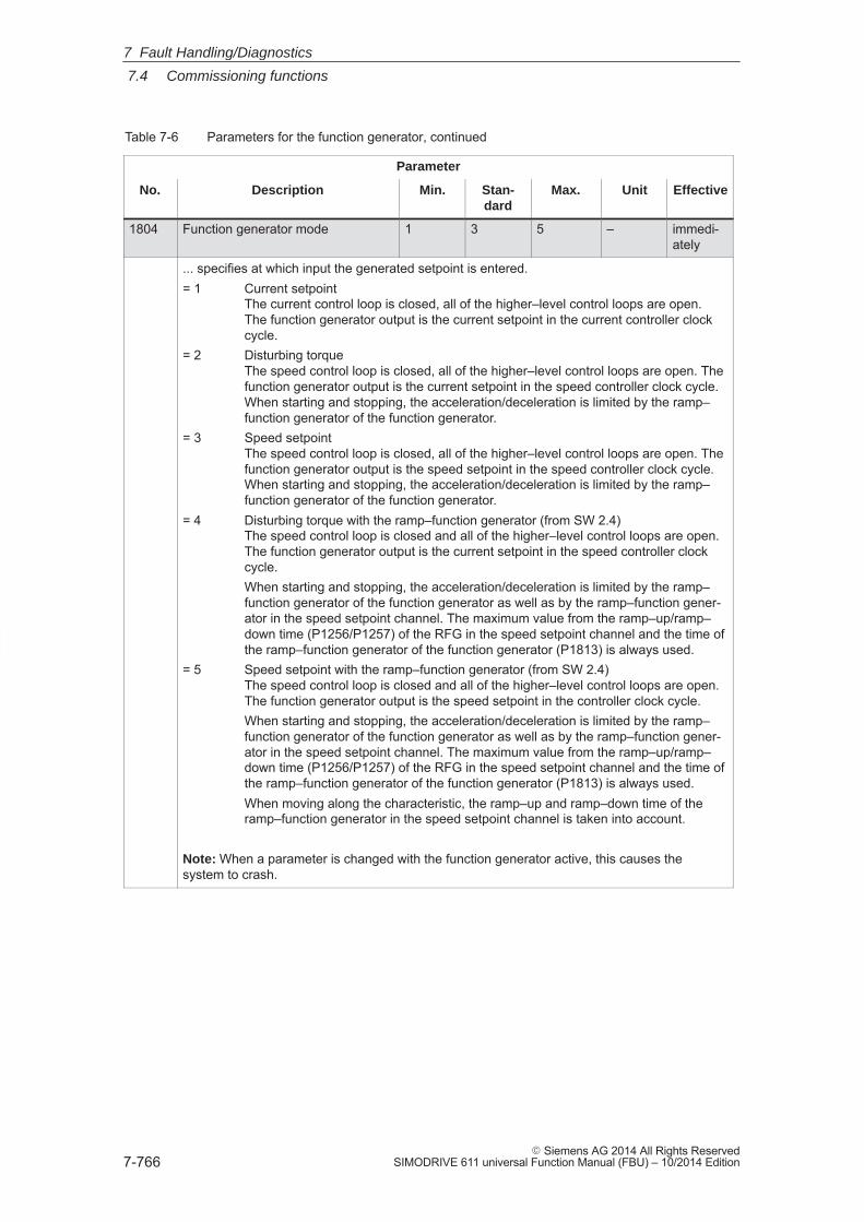
7
7.4 Commissioning functions
7-766� Siemens AG 2014 All Rights Reserved
SIMODRIVE 611 universal Function Manual (FBU) – 10/2014 Edition
Table 7-6 Parameters for the function generator, continued
Parameter
No. EffectiveUnitMax.Stan-dard
Min.Description
1804 Function generator mode 1 3 5 – immedi-ately
... specifies at which input the generated setpoint is entered.= 1 Current setpoint
The current control loop is closed, all of the higher–level control loops are open.The function generator output is the current setpoint in the current controller clockcycle.
= 2 Disturbing torqueThe speed control loop is closed, all of the higher–level control loops are open. Thefunction generator output is the current setpoint in the speed controller clock cycle.When starting and stopping, the acceleration/deceleration is limited by the ramp–function generator of the function generator.
= 3 Speed setpointThe speed control loop is closed, all of the higher–level control loops are open. Thefunction generator output is the speed setpoint in the speed controller clock cycle.When starting and stopping, the acceleration/deceleration is limited by the ramp–function generator of the function generator.
= 4 Disturbing torque with the ramp–function generator (from SW 2.4)The speed control loop is closed and all of the higher–level control loops are open.The function generator output is the current setpoint in the speed controller clockcycle.When starting and stopping, the acceleration/deceleration is limited by the ramp–function generator of the function generator as well as by the ramp–function gener-ator in the speed setpoint channel. The maximum value from the ramp–up/ramp–down time (P1256/P1257) of the RFG in the speed setpoint channel and the time ofthe ramp–function generator of the function generator (P1813) is always used.
= 5 Speed setpoint with the ramp–function generator (from SW 2.4)The speed control loop is closed and all of the higher–level control loops are open.The function generator output is the speed setpoint in the controller clock cycle.When starting and stopping, the acceleration/deceleration is limited by the ramp–function generator of the function generator as well as by the ramp–function gener-ator in the speed setpoint channel. The maximum value from the ramp–up/ramp–down time (P1256/P1257) of the RFG in the speed setpoint channel and the time ofthe ramp–function generator of the function generator (P1813) is always used.When moving along the characteristic, the ramp–up and ramp–down time of theramp–function generator in the speed setpoint channel is taken into account.
Note: When a parameter is changed with the function generator active, this causes thesystem to crash.
7 Fault Handling/Diagnostics
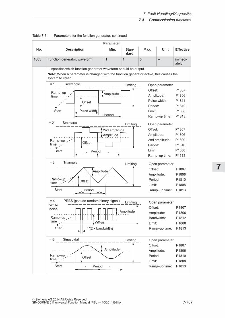
7
7.4 Commissioning functions
7-767� Siemens AG 2014 All Rights ReservedSIMODRIVE 611 universal Function Manual (FBU) – 10/2014 Edition
Table 7-6 Parameters for the function generator, continued
Parameter
No. EffectiveUnitMax.Stan-dard
Min.Description
1805 Function generator, waveform 1 1 5 – immedi-ately
... specifies which function generator waveform should be output.Note: When a parameter is changed with the function generator active, this causes thesystem to crash.
Start
= 1 Rectangle
Offset
Amplitude
Pulse widthPeriod
Limiting Open parameterOffset: P1807Amplitude: P1806Pulse width: P1811Period: P1810Limit: P1808Ramp–up time: P1813
Ramp–uptime
= 2 Staircase
Start
Offset
2nd amplitudeAmplitude
Period
Limiting
Ramp–uptime
Open parameterOffset: P1807Amplitude: P18062nd amplitude: P1809Period: P1810Limit: P1808Ramp–up time: P1813–”– –”–
Start
= 3 Triangular
Offset
Amplitude
Period
Limiting
Ramp–uptime
Open parameterOffset: P1807Amplitude: P1806Period: P1810Limit: P1808Ramp–up time: P1813–”– –”–
Start
= 4 PRBS (pseudo random binary signal)
Offset
Amplitude
Limiting
Ramp–uptime
1/(2 x bandwidth)
Open parameterOffset: P1807Amplitude: P1806Bandwidth: P1812Limit: P1808Ramp–up time: P1813
Whitenoise
Start
= 5 Sinusoidal
Offset
Amplitude
Period
Limiting
Ramp–uptime
Open parameterOffset: P1807Amplitude: P1806Period: P1810Limit: P1808Ramp–up time: P1813–”– –”–
7 Fault Handling/Diagnostics
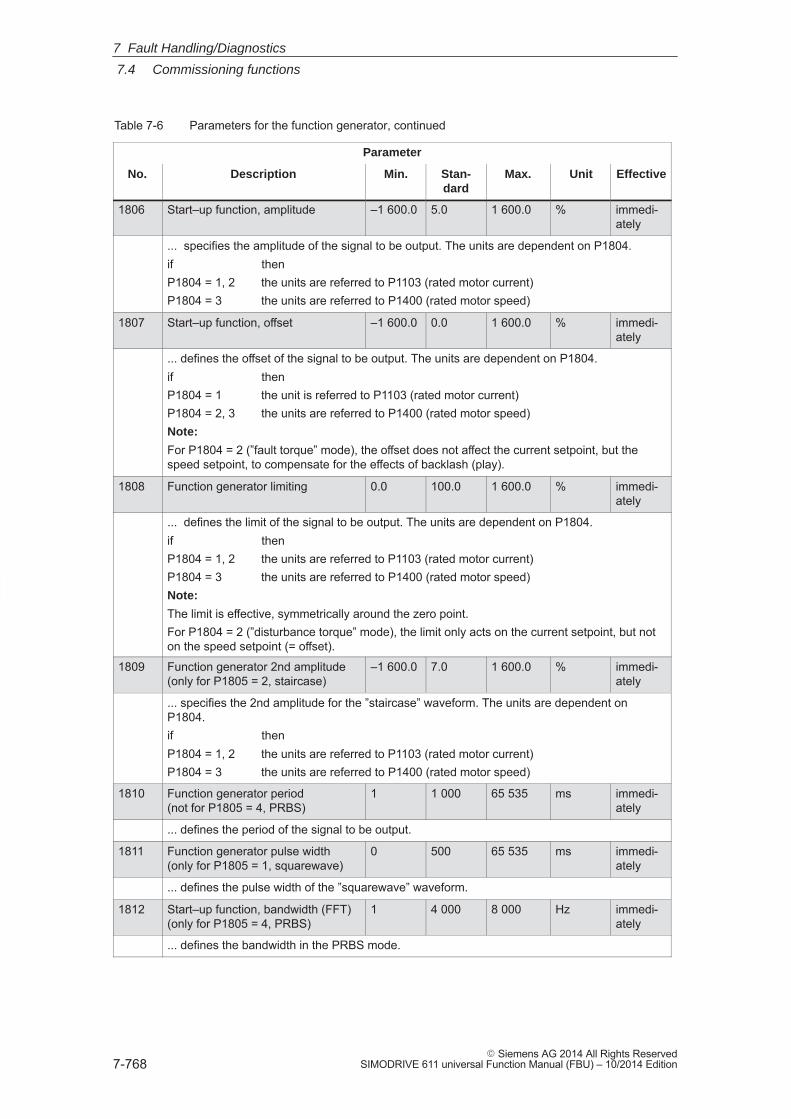
7
7.4 Commissioning functions
7-768� Siemens AG 2014 All Rights Reserved
SIMODRIVE 611 universal Function Manual (FBU) – 10/2014 Edition
Table 7-6 Parameters for the function generator, continued
Parameter
No. EffectiveUnitMax.Stan-dard
Min.Description
1806 Start–up function, amplitude –1 600.0 5.0 1 600.0 % immedi-ately
... specifies the amplitude of the signal to be output. The units are dependent on P1804.if thenP1804 = 1, 2 the units are referred to P1103 (rated motor current)P1804 = 3 the units are referred to P1400 (rated motor speed)
1807 Start–up function, offset –1 600.0 0.0 1 600.0 % immedi-ately
... defines the offset of the signal to be output. The units are dependent on P1804.if thenP1804 = 1 the unit is referred to P1103 (rated motor current)P1804 = 2, 3 the units are referred to P1400 (rated motor speed)Note:
For P1804 = 2 (”fault torque” mode), the offset does not affect the current setpoint, but thespeed setpoint, to compensate for the effects of backlash (play).
1808 Function generator limiting 0.0 100.0 1 600.0 % immedi-ately
... defines the limit of the signal to be output. The units are dependent on P1804.if thenP1804 = 1, 2 the units are referred to P1103 (rated motor current)P1804 = 3 the units are referred to P1400 (rated motor speed)Note:
The limit is effective, symmetrically around the zero point.For P1804 = 2 (”disturbance torque” mode), the limit only acts on the current setpoint, but noton the speed setpoint (= offset).
1809 Function generator 2nd amplitude(only for P1805 = 2, staircase)
–1 600.0 7.0 1 600.0 % immedi-ately
... specifies the 2nd amplitude for the ”staircase” waveform. The units are dependent onP1804.if thenP1804 = 1, 2 the units are referred to P1103 (rated motor current)P1804 = 3 the units are referred to P1400 (rated motor speed)
1810 Function generator period(not for P1805 = 4, PRBS)
1 1 000 65 535 ms immedi-ately
... defines the period of the signal to be output.
1811 Function generator pulse width(only for P1805 = 1, squarewave)
0 500 65 535 ms immedi-ately
... defines the pulse width of the ”squarewave” waveform.
1812 Start–up function, bandwidth (FFT)(only for P1805 = 4, PRBS)
1 4 000 8 000 Hz immedi-ately
... defines the bandwidth in the PRBS mode.
7 Fault Handling/Diagnostics
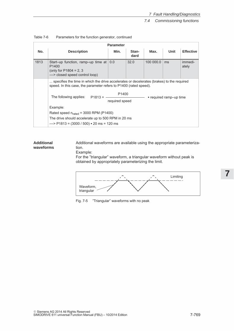
7
7.4 Commissioning functions
7-769� Siemens AG 2014 All Rights ReservedSIMODRIVE 611 universal Function Manual (FBU) – 10/2014 Edition
Table 7-6 Parameters for the function generator, continued
Parameter
No. EffectiveUnitMax.Stan-dard
Min.Description
1813 Start–up function, ramp–up time atP1400(only for P1804 = 2, 3––> closed speed control loop)
0.0 32.0 100 000.0 ms immedi-ately
... specifies the time in which the drive accelerates or decelerates (brakes) to the requiredspeed. In this case, the parameter refers to P1400 (rated speed).
The following applies: P1813 =P1400
required speed� required ramp–up time
Example:Rated speed nrated = 3000 RPM (P1400)The drive should accelerate up to 500 RPM in 20 ms––> P1813 = (3000 / 500) � 20 ms = 120 ms
Additional waveforms are available using the appropriate parameteriza-tion.Example:For the ”triangular” waveform, a triangular waveform without peak isobtained by appropriately parameterizing the limit.
Limiting
Waveform,triangular
Fig. 7-5 ”Triangular” waveforms with no peak
Additionalwaveforms
7 Fault Handling/Diagnostics
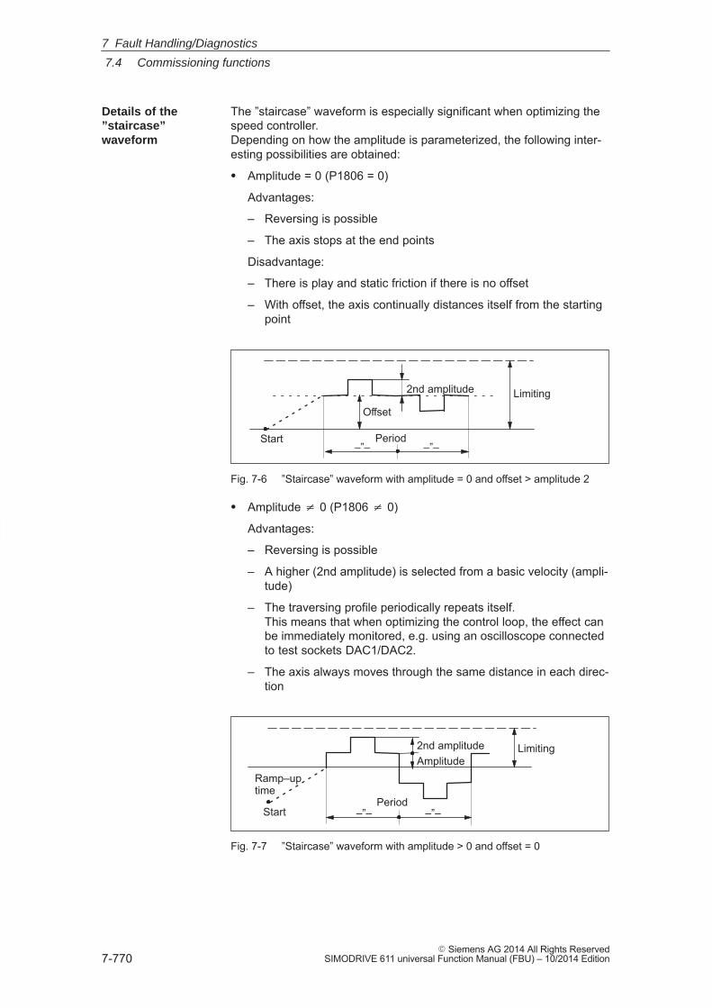
7
7.4 Commissioning functions
7-770� Siemens AG 2014 All Rights Reserved
SIMODRIVE 611 universal Function Manual (FBU) – 10/2014 Edition
The ”staircase” waveform is especially significant when optimizing thespeed controller.Depending on how the amplitude is parameterized, the following inter-esting possibilities are obtained:
� Amplitude = 0 (P1806 = 0)
Advantages:
– Reversing is possible
– The axis stops at the end points
Disadvantage:
– There is play and static friction if there is no offset
– With offset, the axis continually distances itself from the startingpoint
Start
Offset
2nd amplitude Limiting
Period–”– –”–
Fig. 7-6 ”Staircase” waveform with amplitude = 0 and offset > amplitude 2
� Amplitude � 0 (P1806 � 0)
Advantages:
– Reversing is possible
– A higher (2nd amplitude) is selected from a basic velocity (ampli-tude)
– The traversing profile periodically repeats itself.This means that when optimizing the control loop, the effect canbe immediately monitored, e.g. using an oscilloscope connectedto test sockets DAC1/DAC2.
– The axis always moves through the same distance in each direc-tion
Start
2nd amplitudeAmplitude
Period
Limiting
Ramp–uptime
–”– –”–
Fig. 7-7 ”Staircase” waveform with amplitude > 0 and offset = 0
Details of the”staircase”waveform
7 Fault Handling/Diagnostics
7
7.4 Commissioning functions
7-771� Siemens AG 2014 All Rights ReservedSIMODRIVE 611 universal Function Manual (FBU) – 10/2014 Edition
7.4.2 Trace function
Selected measuring quantities in the drive can be measured corre-sponding to the specified measuring parameters, using the tracefunction and graphically displayed using SimoCom U.
The trace function has the following properties and features:
� 4 trace buffers with up to 2048 measured values
The actual number of possible measured values is dependent onwhether the measuring signal is 24 or 48 bit.
� Freely–selectable measuring signals
The required signal is selected from a signal selection box.
� Triggering
– without triggering (the trace starts immediately after START)
– with triggering to an additional trigger signal with signal edge/sig-nal level/bit pattern triggering and trigger delay/pre–trigger
– trigger is initiated by a change in the bit mask (from SW 5.1)A trigger is initiated as soon as one of the bits in the bit maskchanges.
– with triggering to alarm (ab SW 14.1)
� X/Y scaling: Automatic and selectable
Using the scaling, a sub–range can be specified for the abscissa (xaxis) and ordinate (y axis), so that a section can be displayed.It is possible to zoom in using an appropriately set scaling factor.
� Signal measurement via cursor
This means that the signals can be analyzed using the X cursor(time axis) and/or Y cursor.
� From SW 5.1, individual bits of a signal can be evaluated.
One or several bits can be selected in the ”SimoCom U” in the”trace” input mask using the ”bit masking” button. The bit maskingcan be set, independently for each channel and can be recognizedby the units of the associated signal.
Description
Overview offunctions
7 Fault Handling/Diagnostics
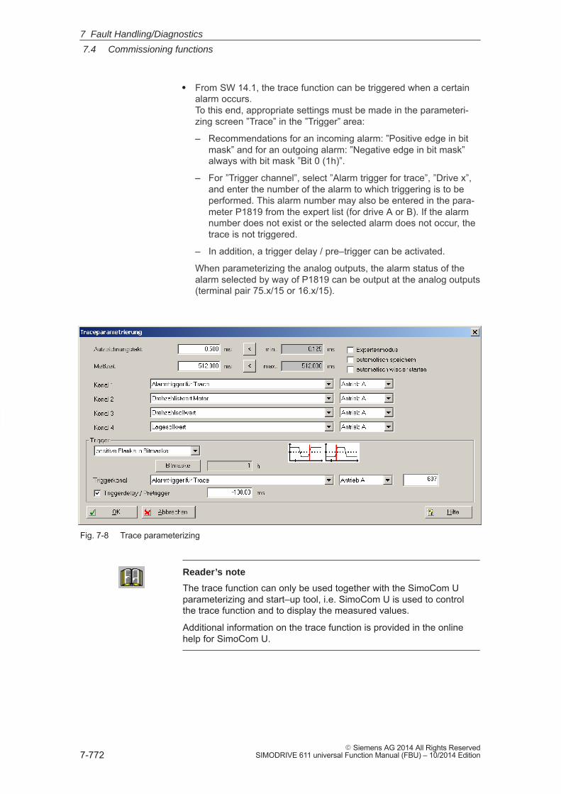
7
7.4 Commissioning functions
7-772� Siemens AG 2014 All Rights Reserved
SIMODRIVE 611 universal Function Manual (FBU) – 10/2014 Edition
� From SW 14.1, the trace function can be triggered when a certainalarm occurs.To this end, appropriate settings must be made in the parameteri-zing screen ”Trace” in the ”Trigger” area:
– Recommendations for an incoming alarm: ”Positive edge in bitmask” and for an outgoing alarm: ”Negative edge in bit mask”always with bit mask ”Bit 0 (1h)”.
– For ”Trigger channel”, select ”Alarm trigger for trace”, ”Drive x”,and enter the number of the alarm to which triggering is to beperformed. This alarm number may also be entered in the para-meter P1819 from the expert list (for drive A or B). If the alarmnumber does not exist or the selected alarm does not occur, thetrace is not triggered.
– In addition, a trigger delay / pre–trigger can be activated.
When parameterizing the analog outputs, the alarm status of thealarm selected by way of P1819 can be output at the analog outputs(terminal pair 75.x/15 or 16.x/15).
Fig. 7-8 Trace parameterizing
Reader’s note
The trace function can only be used together with the SimoCom Uparameterizing and start–up tool, i.e. SimoCom U is used to controlthe trace function and to display the measured values.
Additional information on the trace function is provided in the onlinehelp for SimoCom U.
7 Fault Handling/Diagnostics
7
7.4 Commissioning functions
7-773� Siemens AG 2014 All Rights ReservedSIMODRIVE 611 universal Function Manual (FBU) – 10/2014 Edition
7.4.3 Test sockets, DAC1, DAC2
For ”SIMODRIVE 611 universal”, there are two test sockets to outputanalog signals, with the following features:
� Resolution of the DAC 8 bit
� Voltage range 0 V to +5 V
� Measurement clock cycle Speed controller clock cycle
� Shift factor (refer to Figs. 7-9 and 7-10)
The resolution is 8 bit. Thus, only an 8 bit section can be outputfrom a 24/48 bit signal. The shift factor defines how finely the se-lected signal is quantized.
� Module–specific
The test sockets are provided for each module, i.e. they can be acti-vated and de–activated from each drive.Only one drive can output one value at a test socket.
� Signal selection list
The signals which can be output via the test sockets, can be takenfrom the signal selection list for analog outputs (refer to Chap. 6.7).
Note
The test sockets are only provided for test purposes duringcommissioning or for service.
Description
7 Fault Handling/Diagnostics
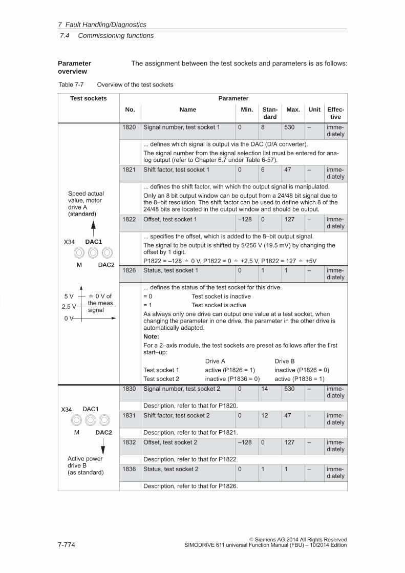
7
7.4 Commissioning functions
7-774� Siemens AG 2014 All Rights Reserved
SIMODRIVE 611 universal Function Manual (FBU) – 10/2014 Edition
The assignment between the test sockets and parameters is as follows:
Table 7-7 Overview of the test sockets
Test sockets Parameter
No. Name Min. Stan-dard
Max. Unit Effec-tive
1820 Signal number, test socket 1 0 8 530 – imme-diately
... defines which signal is output via the DAC (D/A converter).The signal number from the signal selection list must be entered for ana-log output (refer to Chapter 6.7 under Table 6-57).
1821 Shift factor, test socket 1 0 6 47 – imme-diately
Speed actualvalue, motordrive A(standard)
... defines the shift factor, with which the output signal is manipulated.Only an 8 bit output window can be output from a 24/48 bit signal due tothe 8–bit resolution. The shift factor can be used to define which 8 of the24/48 bits are located in the output window and should be output.
(standard)1822 Offset, test socket 1 –128 0 127 – imme-
diately
M
DAC1
DAC2
X34... specifies the offset, which is added to the 8–bit output signal.The signal to be output is shifted by 5/256 V (19.5 mV) by changing theoffset by 1 digit.P1822 = –128 � 0 V, P1822 = 0 � +2.5 V, P1822 = 127 � +5VM DAC2
1826 Status, test socket 1 0 1 1 – imme-diately
5 V
2.5 V
� 0 V ofthe meas.signal
0 V
... defines the status of the test socket for this drive.= 0 Test socket is inactive= 1 Test socket is activeAs always only one drive can output one value at a test socket, whenchanging the parameter in one drive, the parameter in the other drive isautomatically adapted.Note:For a 2–axis module, the test sockets are preset as follows after the firststart–up:
Drive A Drive BTest socket 1 active (P1826 = 1) inactive (P1826 = 0)Test socket 2 inactive (P1836 = 0) active (P1836 = 1)
1830 Signal number, test socket 2 0 14 530 – imme-diately
DAC1X34 Description, refer to that for P1820.DAC1X341831 Shift factor, test socket 2 0 12 47 – imme-
diatelyM DAC2 Description, refer to that for P1821.M DAC2
1832 Offset, test socket 2 –128 0 127 – imme-diately
Active powerdrive B
Description, refer to that for P1822.drive B(as standard) 1836 Status, test socket 2 0 1 1 – imme-
diatelyDescription, refer to that for P1826.
Parameteroverview
7 Fault Handling/Diagnostics
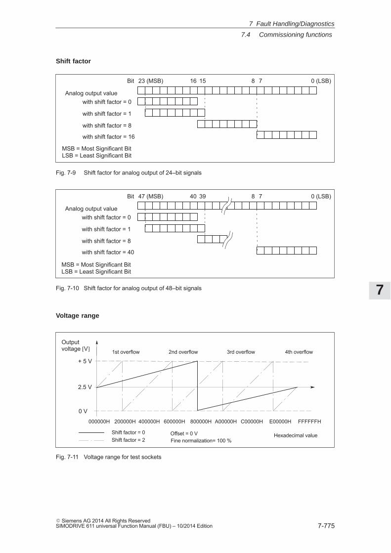
7
7.4 Commissioning functions
7-775� Siemens AG 2014 All Rights ReservedSIMODRIVE 611 universal Function Manual (FBU) – 10/2014 Edition
0 (LSB)23 (MSB)Bit 781516
with shift factor = 0
with shift factor = 1
with shift factor = 8
with shift factor = 16
MSB = Most Significant BitLSB = Least Significant Bit
Analog output value
Fig. 7-9 Shift factor for analog output of 24–bit signals
0 (LSB)47 (MSB)Bit 783940
with shift factor = 0
with shift factor = 1
with shift factor = 8
with shift factor = 40
Analog output value
MSB = Most Significant BitLSB = Least Significant Bit
Fig. 7-10 Shift factor for analog output of 48–bit signals
Shift factor = 0Shift factor = 2
200000H
0 V
2.5 V
+ 5 V
Outputvoltage [V]
000000H 400000H 600000H 800000H A00000H C00000H E00000H FFFFFFH
1st overflow 2nd overflow 3rd overflow 4th overflow
Offset = 0 VFine normalization= 100 %
Hexadecimal value
Fig. 7-11 Voltage range for test sockets
Shift factor
Voltage range
7 Fault Handling/Diagnostics
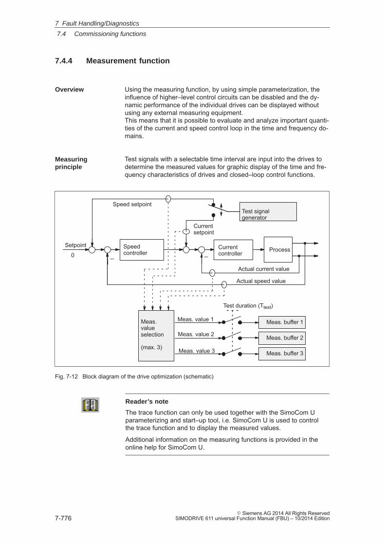
7
7.4 Commissioning functions
7-776� Siemens AG 2014 All Rights Reserved
SIMODRIVE 611 universal Function Manual (FBU) – 10/2014 Edition
7.4.4 Measurement function
Using the measuring function, by using simple parameterization, theinfluence of higher–level control circuits can be disabled and the dy-namic performance of the individual drives can be displayed withoutusing any external measuring equipment.This means that it is possible to evaluate and analyze important quanti-ties of the current and speed control loop in the time and frequency do-mains.
Test signals with a selectable time interval are input into the drives todetermine the measured values for graphic display of the time and fre-quency characteristics of drives and closed–loop control functions.
Test signalgenerator
�
�
Test duration (Ttest)
Meas.valueselection
(max. 3)
Meas. value 1
Meas. value 2
Meas. value 3
Speed setpoint
Currentsetpoint
Actual current value
Actual speed value
Setpoint
0Speedcontroller
Currentcontroller
Process
Meas. buffer 2
Meas. buffer 3
Meas. buffer 1
Fig. 7-12 Block diagram of the drive optimization (schematic)
Reader’s note
The trace function can only be used together with the SimoCom Uparameterizing and start–up tool, i.e. SimoCom U is used to controlthe trace function and to display the measured values.
Additional information on the measuring functions is provided in theonline help for SimoCom U.
Overview
Measuringprinciple
7 Fault Handling/Diagnostics
7
7.5 V/Hz operation (diagnostics function)
7-777� Siemens AG 2014 All Rights ReservedSIMODRIVE 611 universal Function Manual (FBU) – 10/2014 Edition
7.5 V/Hz operation (diagnostics function)
V/Hz operation allows the following motors to be used:
� Induction motors without encoder evaluation
� 1FK6/1FT6 feed motors without encoder evaluation
Note
The V/Hz operation is exclusively provided for diagnostics purposes forsynchronous (SRM) and induction motors (ARM).
V/Hz operation may only be used with converter switching frequencies(P1100) of 4 or 8 kHz. After changing P1100, ”calculate controller data”must be re–executed.
For operation with encoder, the speed actual value from the measuringsystem is displayed, and for operation without encoder, a calculatedspeed actual value.
7.5.1 V/Hz operation with induction motors (ARM)
For V/Hz operation, it is first necessary to carry–out the standard com-missioning for an induction motor with motor selection to obtain practi-cal pre–assignment values (default values) for all of the parameters.If a motor measuring system is not used, then ”no encoder” must beselected as the encoder type.
As ”unlisted motors” are generally used, for simple sensorless (no en-coder) operation, the rating plate data should be entered andthe ”calculate equivalent circuit diagram data” and ”calculate con-troller data” functions executed.
V/Hz operation is then activated using P1014 = 1.
For V/Hz operation with induction motors, the following parameters areavailable:
Table 7-8 Parameters for V/Hz operation with ARM
Parameter Name
P1014 Activates V/f mode
P1125 Ramp–up time 1 for V/Hz operation
P1127 Voltage at f = 0, V/Hz mode
P1132 Rated motor voltage
Description
Commissioning
Parameters forV/Hz operationwith inductionmotors (ARM)
7 Fault Handling/Diagnostics
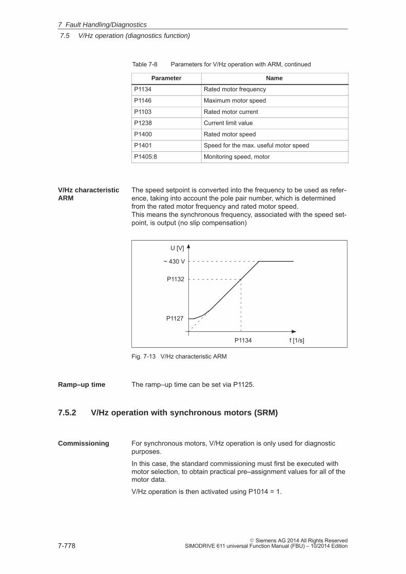
7
7.5 V/Hz operation (diagnostics function)
7-778� Siemens AG 2014 All Rights Reserved
SIMODRIVE 611 universal Function Manual (FBU) – 10/2014 Edition
Table 7-8 Parameters for V/Hz operation with ARM, continued
Parameter Name
P1134 Rated motor frequency
P1146 Maximum motor speed
P1103 Rated motor current
P1238 Current limit value
P1400 Rated motor speed
P1401 Speed for the max. useful motor speed
P1405:8 Monitoring speed, motor
The speed setpoint is converted into the frequency to be used as refer-ence, taking into account the pole pair number, which is determinedfrom the rated motor frequency and rated motor speed.This means the synchronous frequency, associated with the speed set-point, is output (no slip compensation)
~ 430 V
P1134
P1132
P1127
U [V]
f [1/s]
Fig. 7-13 V/Hz characteristic ARM
The ramp–up time can be set via P1125.
7.5.2 V/Hz operation with synchronous motors (SRM)
For synchronous motors, V/Hz operation is only used for diagnosticpurposes.
In this case, the standard commissioning must first be executed withmotor selection, to obtain practical pre–assignment values for all of themotor data.
V/Hz operation is then activated using P1014 = 1.
V/Hz characteristicARM
Ramp–up time
Commissioning
7 Fault Handling/Diagnostics
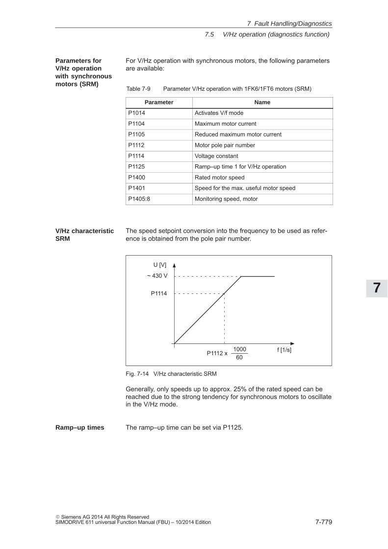
7
7.5 V/Hz operation (diagnostics function)
7-779� Siemens AG 2014 All Rights ReservedSIMODRIVE 611 universal Function Manual (FBU) – 10/2014 Edition
For V/Hz operation with synchronous motors, the following parametersare available:
Table 7-9 Parameter V/Hz operation with 1FK6/1FT6 motors (SRM)
Parameter Name
P1014 Activates V/f mode
P1104 Maximum motor current
P1105 Reduced maximum motor current
P1112 Motor pole pair number
P1114 Voltage constant
P1125 Ramp–up time 1 for V/Hz operation
P1400 Rated motor speed
P1401 Speed for the max. useful motor speed
P1405:8 Monitoring speed, motor
The speed setpoint conversion into the frequency to be used as refer-ence is obtained from the pole pair number.
~ 430 V
P1114
U [V]
P1112 x100060
f [1/s]
Fig. 7-14 V/Hz characteristic SRM
Generally, only speeds up to approx. 25% of the rated speed can bereached due to the strong tendency for synchronous motors to oscillatein the V/Hz mode.
The ramp–up time can be set via P1125.
Parameters forV/Hz operationwith synchronousmotors (SRM)
V/Hz characteristicSRM
Ramp–up times
7 Fault Handling/Diagnostics
7
7.6 Spare parts
7-780� Siemens AG 2014 All Rights Reserved
SIMODRIVE 611 universal Function Manual (FBU) – 10/2014 Edition
7.5.3 Parameters for V/Hz operation
The following parameters are available for V/Hz operation
Table 7-10 Parameter overview for V/Hz operation
Parameter
No. Name Min. Stan-dard
Max. Unit Effec-tive
1014 Activates V/f mode 0 0 1 – PO
... V/Hz operation for this drive is activated/de–activated.= 1 V/Hz operation is activated= 0 V/Hz operation is de–activated
1125 Ramp–up time 1 for V/Hz operation 0.01 5.0 100.0 s imme-diately
When V/Hz operation is activated, this is the time in which the speed setpoint is changed from0 to the maximum motor speed (P1146).
1127 Voltage at f = 0 V/Hz operation (ARM) 0.0 2.0 20.0 V(pk) imme-diately
When V/Hz operation is activated, and at 0 frequency, the voltage which is output is increasedby the value in this parameter.Note:
The parameter is preset when carrying–out the ”calculate controller data” function.
7.6 Spare parts
Table 7-11 Terminals for SIMODRIVE 611 universal
Designation Terminal Item number Order No.[MLFB]
X421 AS1, AS2 GWE–000000590513 6SY9907
X431 P24, M24,9 663,19 GWE–000000588343 6SY9908
X451, X452 56.x, 14.x, 24.x, 20.x, ... GWE–000000588293 6SY9910
X461, X462 (10 pin) A+.x, A–.x, B+.x, B–.x
X461, X462 (11 pin) A+.x, A–.x, B+.x, B–.x A5E0009717 6SY9913
X453, X454 A+.x, A–.x, B+.x, ...0
X441 75.x. 16.x, 15 GWE–000000588277 6SY9911
X422, X432 I4...I11, O4...O11 GWE–000000588285 6SY9912
Power connector, motor connec-tion
6SY9904
Power connector, pulsed resistor 6SY9905s
�
Parameteroverview
7 Fault Handling/Diagnostics
A
A-781� Siemens AG 2014 All Rights ReservedSIMODRIVE 611 universal Function Manual (FBU) – 10/2014 Edition
Lists
A.1 Parameter list A-782. . . . . . . . . . . . . . . . . . . . . . . . . . . . . . . . . . . . . . . . . . . . . . . . . . .
A.2 Power module list A-924. . . . . . . . . . . . . . . . . . . . . . . . . . . . . . . . . . . . . . . . . . . . . . .
A.3 List of motors A-927. . . . . . . . . . . . . . . . . . . . . . . . . . . . . . . . . . . . . . . . . . . . . . . . . . . A.3.1 List of the rotating synchronous motors A-927. . . . . . . . . . . . . . . . . . . . . . . . . . . . . A.3.2 List of permanent–magnet synchronous motors with
field weakening (1FE1, 2SP1, PE spindle) A-939. . . . . . . . . . . . . . . . . . . . . . . . . . A.3.3 List of permanent–magnet synchronous motors without
field weakening, built–in torque motors (1FW6, from SW 6.1) A-946. . . . . . . . . . A.3.4 List of linear synchronous motors A-951. . . . . . . . . . . . . . . . . . . . . . . . . . . . . . . . . . A.3.5 List of induction motors A-957. . . . . . . . . . . . . . . . . . . . . . . . . . . . . . . . . . . . . . . . . .
A.4 Encoder list A-969. . . . . . . . . . . . . . . . . . . . . . . . . . . . . . . . . . . . . . . . . . . . . . . . . . . . . A.4.1 Encoder code A-969. . . . . . . . . . . . . . . . . . . . . . . . . . . . . . . . . . . . . . . . . . . . . . . . . . . A.4.2 Encoder adaptation A-972. . . . . . . . . . . . . . . . . . . . . . . . . . . . . . . . . . . . . . . . . . . . . .
A
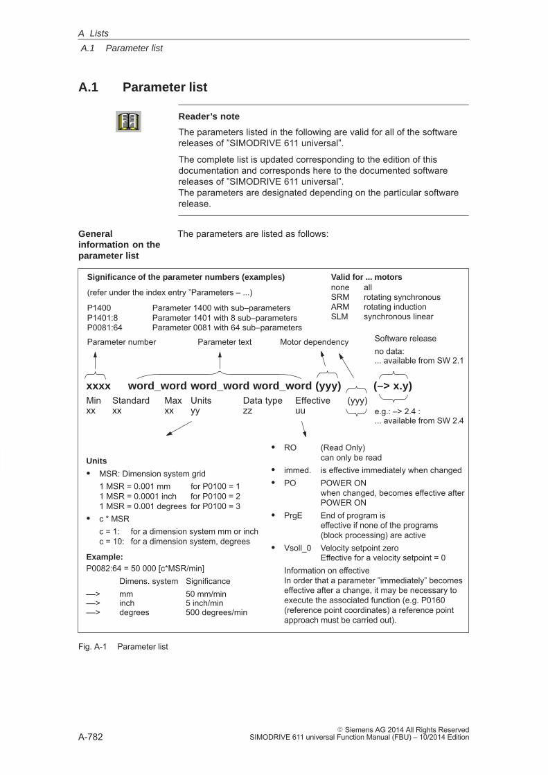
A
A.1 Parameter list
A-782� Siemens AG 2014 All Rights Reserved
SIMODRIVE 611 universal Function Manual (FBU) – 10/2014 Edition
A.1 Parameter list
Reader’s note
The parameters listed in the following are valid for all of the softwarereleases of ”SIMODRIVE 611 universal”.
The complete list is updated corresponding to the edition of thisdocumentation and corresponds here to the documented softwarereleases of ”SIMODRIVE 611 universal”.The parameters are designated depending on the particular softwarerelease.
The parameters are listed as follows:
xxxx word_word word_word word_word (yyy) (–> x.y)Min Standard Max Units Data type Effective (yyy)xx xx xx yy zz uu
Significance of the parameter numbers (examples)
(refer under the index entry ”Parameters – ...)
P1400 Parameter 1400 with sub–parametersP1401:8 Parameter 1401 with 8 sub–parameters P0081:64 Parameter 0081 with 64 sub–parameters
Parameter text
Valid for ... motorsnone allSRM rotating synchronousARM rotating inductionSLM synchronous linear
� RO (Read Only) can only be read
� immed. is effective immediately when changed� PO POWER ON
when changed, becomes effective afterPOWER ON
� PrgE End of program is effective if none of the programs (block processing) are active
� Vsoll_0 Velocity setpoint zero Effective for a velocity setpoint = 0
Information on effectiveIn order that a parameter ”immediately” becomeseffective after a change, it may be necessary toexecute the associated function (e.g. P0160(reference point coordinates) a reference pointapproach must be carried out).
Parameter number Motor dependency
Units
� MSR: Dimension system grid1 MSR = 0.001 mm for P0100 = 11 MSR = 0.0001 inch for P0100 = 21 MSR = 0.001 degrees for P0100 = 3
� c * MSRc = 1: for a dimension system mm or inch c = 10: for a dimension system, degrees
Example:P0082:64 = 50 000 [c*MSR/min]
Dimens. system Significance––> mm 50 mm/min––> inch 5 inch/min––> degrees 500 degrees/min
Software releaseno data: ... available from SW 2.1
e.g.: –> 2.4 : ... available from SW 2.4
Fig. A-1 Parameter list
Generalinformation on theparameter list
A Lists
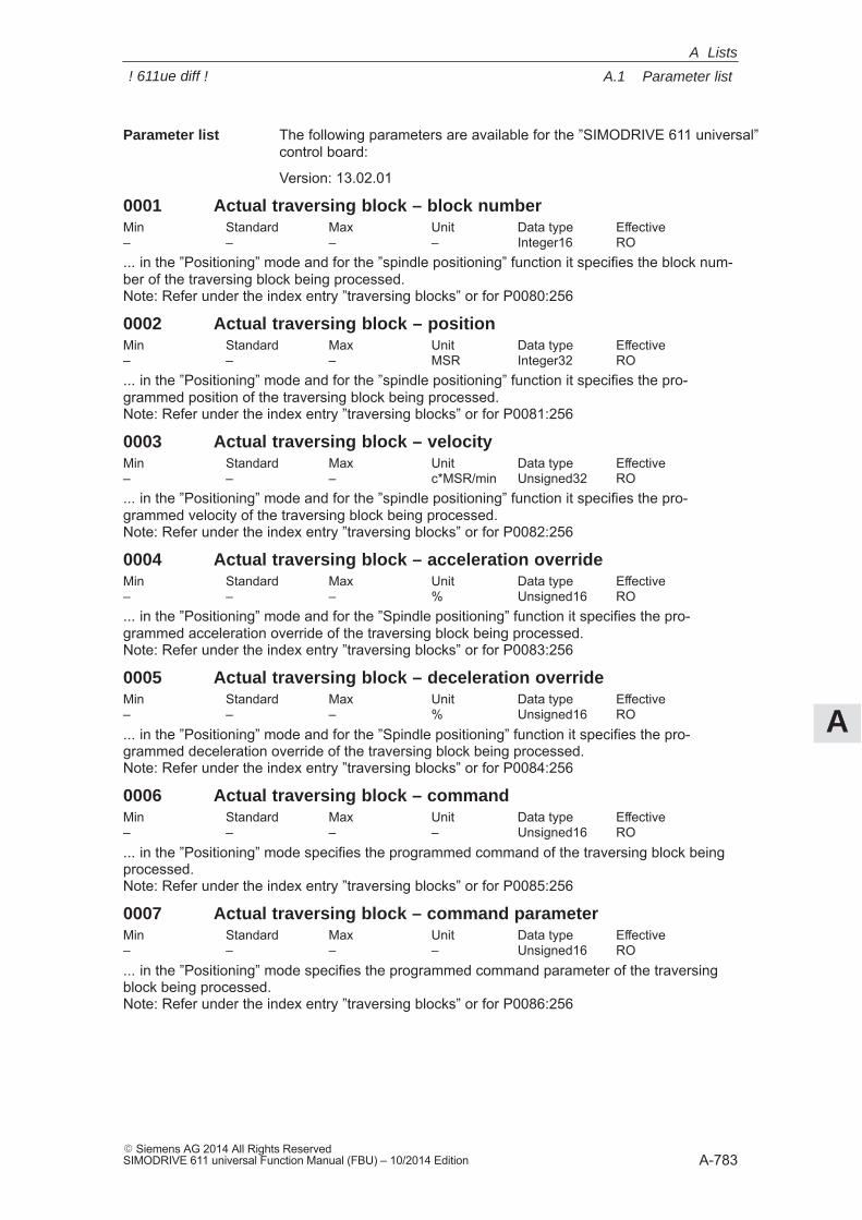
A
A.1 Parameter list
A-783� Siemens AG 2014 All Rights ReservedSIMODRIVE 611 universal Function Manual (FBU) – 10/2014 Edition
The following parameters are available for the ”SIMODRIVE 611 universal”control board:
Version: 13.02.01
0001 Actual traversing block – block numberMin Standard Max Unit Data type Effective– – – – Integer16 RO... in the ”Positioning” mode and for the ”spindle positioning” function it specifies the block num-ber of the traversing block being processed.Note: Refer under the index entry ”traversing blocks” or for P0080:256
0002 Actual traversing block – positionMin Standard Max Unit Data type Effective– – – MSR Integer32 RO... in the ”Positioning” mode and for the ”spindle positioning” function it specifies the pro-grammed position of the traversing block being processed.Note: Refer under the index entry ”traversing blocks” or for P0081:256
0003 Actual traversing block – velocityMin Standard Max Unit Data type Effective– – – c*MSR/min Unsigned32 RO... in the ”Positioning” mode and for the ”spindle positioning” function it specifies the pro-grammed velocity of the traversing block being processed.Note: Refer under the index entry ”traversing blocks” or for P0082:256
0004 Actual traversing block – acceleration overrideMin Standard Max Unit Data type Effective– – – % Unsigned16 RO... in the ”Positioning” mode and for the ”Spindle positioning” function it specifies the pro-grammed acceleration override of the traversing block being processed.Note: Refer under the index entry ”traversing blocks” or for P0083:256
0005 Actual traversing block – deceleration overrideMin Standard Max Unit Data type Effective– – – % Unsigned16 RO... in the ”Positioning” mode and for the ”Spindle positioning” function it specifies the pro-grammed deceleration override of the traversing block being processed.Note: Refer under the index entry ”traversing blocks” or for P0084:256
0006 Actual traversing block – commandMin Standard Max Unit Data type Effective– – – – Unsigned16 RO... in the ”Positioning” mode specifies the programmed command of the traversing block beingprocessed.Note: Refer under the index entry ”traversing blocks” or for P0085:256
0007 Actual traversing block – command parameterMin Standard Max Unit Data type Effective– – – – Unsigned16 RO... in the ”Positioning” mode specifies the programmed command parameter of the traversingblock being processed.Note: Refer under the index entry ”traversing blocks” or for P0086:256
Parameter list
A Lists
! 611ue diff !
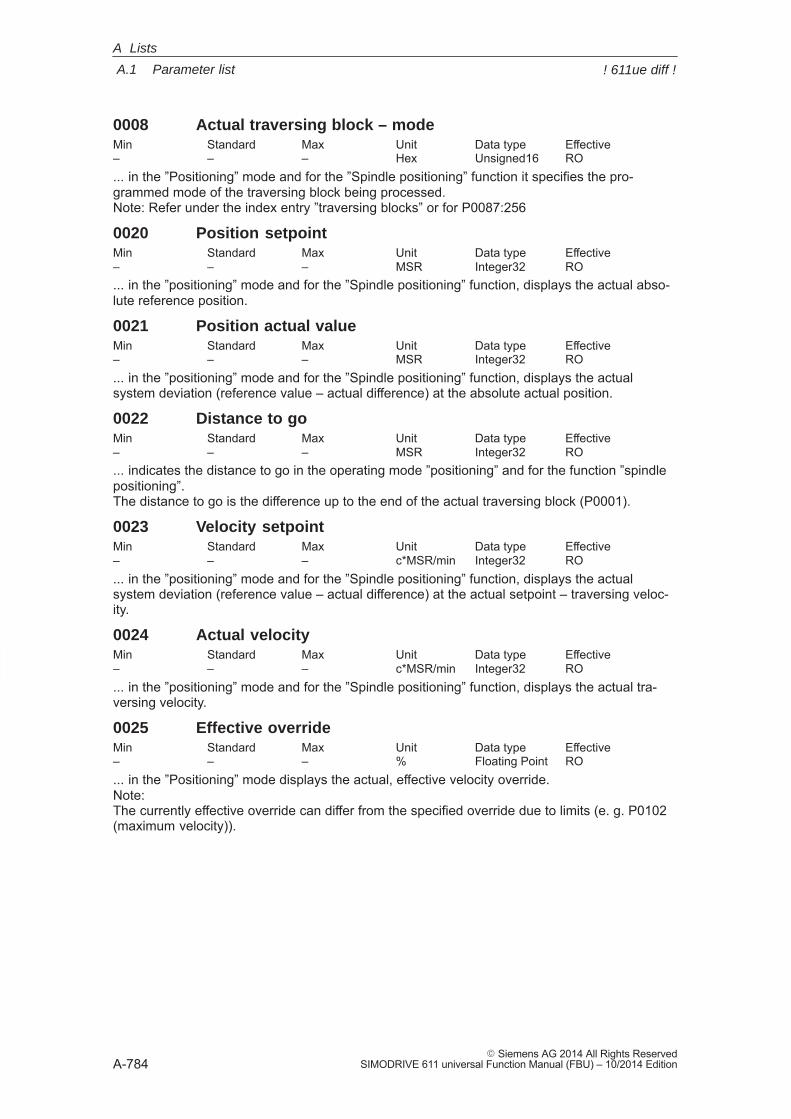
A
A.1 Parameter list
A-784� Siemens AG 2014 All Rights Reserved
SIMODRIVE 611 universal Function Manual (FBU) – 10/2014 Edition
0008 Actual traversing block – modeMin Standard Max Unit Data type Effective– – – Hex Unsigned16 RO... in the ”Positioning” mode and for the ”Spindle positioning” function it specifies the pro-grammed mode of the traversing block being processed.Note: Refer under the index entry ”traversing blocks” or for P0087:256
0020 Position setpointMin Standard Max Unit Data type Effective– – – MSR Integer32 RO... in the ”positioning” mode and for the ”Spindle positioning” function, displays the actual abso-lute reference position.
0021 Position actual valueMin Standard Max Unit Data type Effective– – – MSR Integer32 RO... in the ”positioning” mode and for the ”Spindle positioning” function, displays the actualsystem deviation (reference value – actual difference) at the absolute actual position.
0022 Distance to goMin Standard Max Unit Data type Effective– – – MSR Integer32 RO... indicates the distance to go in the operating mode ”positioning” and for the function ”spindlepositioning”.The distance to go is the difference up to the end of the actual traversing block (P0001).
0023 Velocity setpointMin Standard Max Unit Data type Effective– – – c*MSR/min Integer32 RO... in the ”positioning” mode and for the ”Spindle positioning” function, displays the actualsystem deviation (reference value – actual difference) at the actual setpoint – traversing veloc-ity.
0024 Actual velocityMin Standard Max Unit Data type Effective– – – c*MSR/min Integer32 RO... in the ”positioning” mode and for the ”Spindle positioning” function, displays the actual tra-versing velocity.
0025 Effective overrideMin Standard Max Unit Data type Effective– – – % Floating Point RO... in the ”Positioning” mode displays the actual, effective velocity override.Note:The currently effective override can differ from the specified override due to limits (e. g. P0102(maximum velocity)).
A Lists
! 611ue diff !
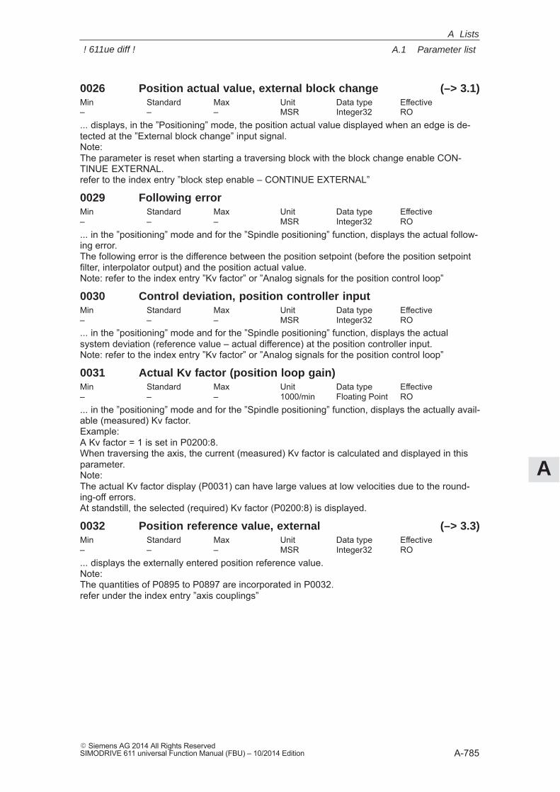
A
A.1 Parameter list
A-785� Siemens AG 2014 All Rights ReservedSIMODRIVE 611 universal Function Manual (FBU) – 10/2014 Edition
0026 Position actual value, external block change (–> 3.1)Min Standard Max Unit Data type Effective– – – MSR Integer32 RO... displays, in the ”Positioning” mode, the position actual value displayed when an edge is de-tected at the ”External block change” input signal.Note:The parameter is reset when starting a traversing block with the block change enable CON-TINUE EXTERNAL.refer to the index entry ”block step enable – CONTINUE EXTERNAL”
0029 Following errorMin Standard Max Unit Data type Effective– – – MSR Integer32 RO... in the ”positioning” mode and for the ”Spindle positioning” function, displays the actual follow-ing error.The following error is the difference between the position setpoint (before the position setpointfilter, interpolator output) and the position actual value.Note: refer to the index entry ”Kv factor” or ”Analog signals for the position control loop”
0030 Control deviation, position controller inputMin Standard Max Unit Data type Effective– – – MSR Integer32 RO... in the ”positioning” mode and for the ”Spindle positioning” function, displays the actualsystem deviation (reference value – actual difference) at the position controller input.Note: refer to the index entry ”Kv factor” or ”Analog signals for the position control loop”
0031 Actual Kv factor (position loop gain)Min Standard Max Unit Data type Effective– – – 1000/min Floating Point RO... in the ”positioning” mode and for the ”Spindle positioning” function, displays the actually avail-able (measured) Kv factor.Example:A Kv factor = 1 is set in P0200:8.When traversing the axis, the current (measured) Kv factor is calculated and displayed in thisparameter.Note:The actual Kv factor display (P0031) can have large values at low velocities due to the round-ing-off errors.At standstill, the selected (required) Kv factor (P0200:8) is displayed.
0032 Position reference value, external (–> 3.3)Min Standard Max Unit Data type Effective– – – MSR Integer32 RO... displays the externally entered position reference value.Note:The quantities of P0895 to P0897 are incorporated in P0032.refer under the index entry ”axis couplings”
A Lists
! 611ue diff !
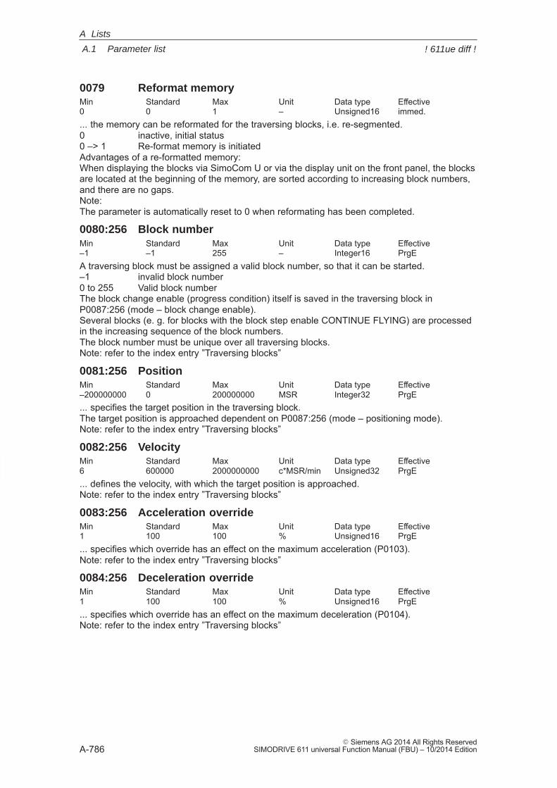
A
A.1 Parameter list
A-786� Siemens AG 2014 All Rights Reserved
SIMODRIVE 611 universal Function Manual (FBU) – 10/2014 Edition
0079 Reformat memoryMin Standard Max Unit Data type Effective0 0 1 – Unsigned16 immed.... the memory can be reformated for the traversing blocks, i.e. re-segmented.0 inactive, initial status0 –> 1 Re-format memory is initiatedAdvantages of a re-formatted memory:When displaying the blocks via SimoCom U or via the display unit on the front panel, the blocksare located at the beginning of the memory, are sorted according to increasing block numbers,and there are no gaps.Note:The parameter is automatically reset to 0 when reformating has been completed.
0080:256 Block numberMin Standard Max Unit Data type Effective–1 –1 255 – Integer16 PrgEA traversing block must be assigned a valid block number, so that it can be started.–1 invalid block number0 to 255 Valid block numberThe block change enable (progress condition) itself is saved in the traversing block inP0087:256 (mode – block change enable).Several blocks (e. g. for blocks with the block step enable CONTINUE FLYING) are processedin the increasing sequence of the block numbers.The block number must be unique over all traversing blocks.Note: refer to the index entry ”Traversing blocks”
0081:256 PositionMin Standard Max Unit Data type Effective–200000000 0 200000000 MSR Integer32 PrgE... specifies the target position in the traversing block.The target position is approached dependent on P0087:256 (mode – positioning mode).Note: refer to the index entry ”Traversing blocks”
0082:256 VelocityMin Standard Max Unit Data type Effective6 600000 2000000000 c*MSR/min Unsigned32 PrgE... defines the velocity, with which the target position is approached.Note: refer to the index entry ”Traversing blocks”
0083:256 Acceleration overrideMin Standard Max Unit Data type Effective1 100 100 % Unsigned16 PrgE... specifies which override has an effect on the maximum acceleration (P0103).Note: refer to the index entry ”Traversing blocks”
0084:256 Deceleration overrideMin Standard Max Unit Data type Effective1 100 100 % Unsigned16 PrgE... specifies which override has an effect on the maximum deceleration (P0104).Note: refer to the index entry ”Traversing blocks”
A Lists
! 611ue diff !
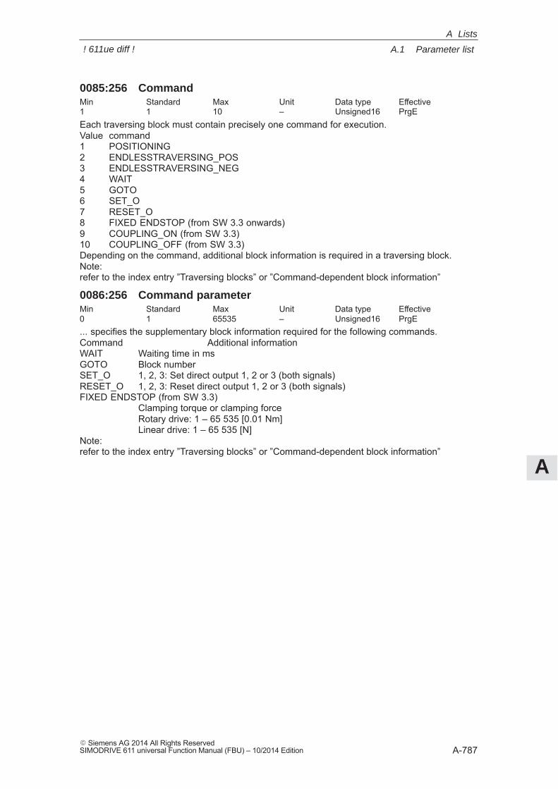
A
A.1 Parameter list
A-787� Siemens AG 2014 All Rights ReservedSIMODRIVE 611 universal Function Manual (FBU) – 10/2014 Edition
0085:256 CommandMin Standard Max Unit Data type Effective1 1 10 – Unsigned16 PrgEEach traversing block must contain precisely one command for execution.Value command1 POSITIONING2 ENDLESSTRAVERSING_POS3 ENDLESSTRAVERSING_NEG4 WAIT5 GOTO6 SET_O7 RESET_O8 FIXED ENDSTOP (from SW 3.3 onwards)9 COUPLING_ON (from SW 3.3)10 COUPLING_OFF (from SW 3.3)Depending on the command, additional block information is required in a traversing block.Note:refer to the index entry ”Traversing blocks” or ”Command-dependent block information”
0086:256 Command parameterMin Standard Max Unit Data type Effective0 1 65535 – Unsigned16 PrgE... specifies the supplementary block information required for the following commands.Command Additional informationWAIT Waiting time in msGOTO Block numberSET_O 1, 2, 3: Set direct output 1, 2 or 3 (both signals)RESET_O 1, 2, 3: Reset direct output 1, 2 or 3 (both signals)FIXED ENDSTOP (from SW 3.3)
Clamping torque or clamping forceRotary drive: 1 – 65 535 [0.01 Nm]Linear drive: 1 – 65 535 [N]
Note:refer to the index entry ”Traversing blocks” or ”Command-dependent block information”
A Lists
! 611ue diff !
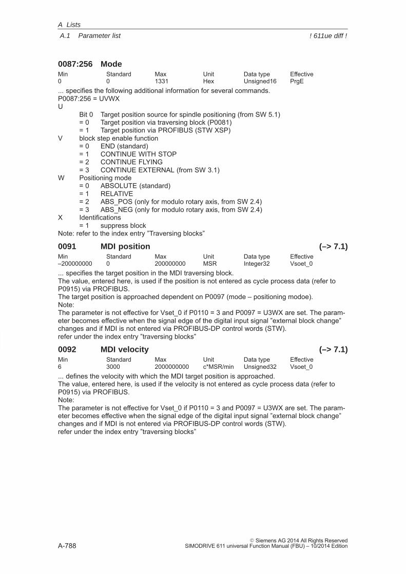
A
A.1 Parameter list
A-788� Siemens AG 2014 All Rights Reserved
SIMODRIVE 611 universal Function Manual (FBU) – 10/2014 Edition
0087:256 ModeMin Standard Max Unit Data type Effective0 0 1331 Hex Unsigned16 PrgE... specifies the following additional information for several commands.P0087:256 = UVWXU
Bit 0 Target position source for spindle positioning (from SW 5.1)= 0 Target position via traversing block (P0081)= 1 Target position via PROFIBUS (STW XSP)
V block step enable function= 0 END (standard)= 1 CONTINUE WITH STOP= 2 CONTINUE FLYING= 3 CONTINUE EXTERNAL (from SW 3.1)
W Positioning mode= 0 ABSOLUTE (standard)= 1 RELATIVE= 2 ABS_POS (only for modulo rotary axis, from SW 2.4)= 3 ABS_NEG (only for modulo rotary axis, from SW 2.4)
X Identifications= 1 suppress block
Note: refer to the index entry ”Traversing blocks”
0091 MDI position (–> 7.1)Min Standard Max Unit Data type Effective–200000000 0 200000000 MSR Integer32 Vsoet_0... specifies the target position in the MDI traversing block.The value, entered here, is used if the position is not entered as cycle process data (refer toP0915) via PROFIBUS.The target position is approached dependent on P0097 (mode – positioning modoe).Note:The parameter is not effective for Vset_0 if P0110 = 3 and P0097 = U3WX are set. The param-eter becomes effective when the signal edge of the digital input signal ”external block change”changes and if MDI is not entered via PROFIBUS-DP control words (STW).refer under the index entry ”traversing blocks”
0092 MDI velocity (–> 7.1)Min Standard Max Unit Data type Effective6 3000 2000000000 c*MSR/min Unsigned32 Vsoet_0... defines the velocity with which the MDI target position is approached.The value, entered here, is used if the velocity is not entered as cycle process data (refer toP0915) via PROFIBUS.Note:The parameter is not effective for Vset_0 if P0110 = 3 and P0097 = U3WX are set. The param-eter becomes effective when the signal edge of the digital input signal ”external block change”changes and if MDI is not entered via PROFIBUS-DP control words (STW).refer under the index entry ”traversing blocks”
A Lists
! 611ue diff !
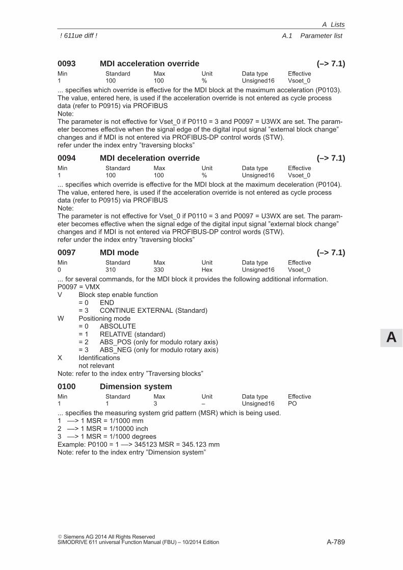
A
A.1 Parameter list
A-789� Siemens AG 2014 All Rights ReservedSIMODRIVE 611 universal Function Manual (FBU) – 10/2014 Edition
0093 MDI acceleration override (–> 7.1)Min Standard Max Unit Data type Effective1 100 100 % Unsigned16 Vsoet_0... specifies which override is effective for the MDI block at the maximum acceleration (P0103).The value, entered here, is used if the acceleration override is not entered as cycle processdata (refer to P0915) via PROFIBUSNote:The parameter is not effective for Vset_0 if P0110 = 3 and P0097 = U3WX are set. The param-eter becomes effective when the signal edge of the digital input signal ”external block change”changes and if MDI is not entered via PROFIBUS-DP control words (STW).refer under the index entry ”traversing blocks”
0094 MDI deceleration override (–> 7.1)Min Standard Max Unit Data type Effective1 100 100 % Unsigned16 Vsoet_0... specifies which override is effective for the MDI block at the maximum deceleration (P0104).The value, entered here, is used if the acceleration override is not entered as cycle processdata (refer to P0915) via PROFIBUSNote:The parameter is not effective for Vset_0 if P0110 = 3 and P0097 = U3WX are set. The param-eter becomes effective when the signal edge of the digital input signal ”external block change”changes and if MDI is not entered via PROFIBUS-DP control words (STW).refer under the index entry ”traversing blocks”
0097 MDI mode (–> 7.1)Min Standard Max Unit Data type Effective0 310 330 Hex Unsigned16 Vsoet_0... for several commands, for the MDI block it provides the following additional information.P0097 = VMXV Block step enable function
= 0 END= 3 CONTINUE EXTERNAL (Standard)
W Positioning mode= 0 ABSOLUTE= 1 RELATIVE (standard)= 2 ABS_POS (only for modulo rotary axis)= 3 ABS_NEG (only for modulo rotary axis)
X Identificationsnot relevant
Note: refer to the index entry ”Traversing blocks”
0100 Dimension systemMin Standard Max Unit Data type Effective1 1 3 – Unsigned16 PO... specifies the measuring system grid pattern (MSR) which is being used.1 ––> 1 MSR = 1/1000 mm2 ––> 1 MSR = 1/10000 inch3 ––> 1 MSR = 1/1000 degreesExample: P0100 = 1 ––> 345123 MSR = 345.123 mmNote: refer to the index entry ”Dimension system”
A Lists
! 611ue diff !
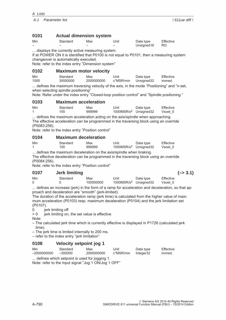
A
A.1 Parameter list
A-790� Siemens AG 2014 All Rights Reserved
SIMODRIVE 611 universal Function Manual (FBU) – 10/2014 Edition
0101 Actual dimension systemMin Standard Max Unit Data type Effective– – – – Unsigned16 RO... displays the currently active measuring system.If at POWER ON it is identified that P0100 is not equal to P0101, then a measuring systemchangeover is automatically executed.Note: refer to the index entry ”Dimension system”
0102 Maximum motor velocityMin Standard Max Unit Data type Effective1000 30000000 2000000000 c*MSR/min Unsigned32 immed.... defines the maximum traversing velocity of the axis, in the mode ”Positioning” and ”n-set,when selecting spindle positioning”Note: Refer under the index entry ”Closed-loop position control” and ”Spindle positioning ”
0103 Maximum accelerationMin Standard Max Unit Data type Effective1 100 999999 1000MSR/s2 Unsigned32 Vsoet_0... defines the maximum acceleration acting on the axis/spindle when approaching.The effective acceleration can be programmed in the traversing block using an override(P0083:256).Note: refer to the index entry ”Position control”
0104 Maximum decelerationMin Standard Max Unit Data type Effective1 100 999999 1000MSR/s2 Unsigned32 Vsoet_0... defines the maximum deceleration on the axis/spindle when braking.The effective deceleration can be programmed in the traversing block using an override(P0084:256).Note: refer to the index entry ”Position control”
0107 Jerk limiting (–> 3.1)Min Standard Max Unit Data type Effective0 0 100000000 1000MSR/s2 Unsigned32 Vsoet_0... defines an increase (jerk) in the form of a ramp for acceleration and deceleration, so that ap-proach and deceleration are ”smooth” (jerk-limited).The duration of the acceleration ramp (jerk time) is calculated from the higher value of maxi-mum acceleration (P0103) resp. maximum deceleration (P0104) and the jerk limitation set(P0107).0 jerk limiting off> 0 jerk limiting on, the set value is effectiveNote:– The calculated jerk time which is currently effective is displayed in P1726 (calculated jerk time).– The jerk time is limited internally to 200 ms.– refer to the index entry ”jerk limitation”
0108 Velocity setpoint jog 1Min Standard Max Unit Data type Effective–2000000000 –300000 2000000000 c*MSR/min Integer32 immed.... defines which setpoint is used for jogging 1.Note: refer to the input signal ”Jog 1 ON/Jog 1 OFF”
A Lists
! 611ue diff !
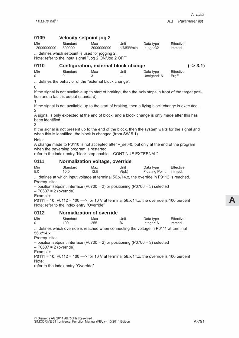
A
A.1 Parameter list
A-791� Siemens AG 2014 All Rights ReservedSIMODRIVE 611 universal Function Manual (FBU) – 10/2014 Edition
0109 Velocity setpoint jog 2Min Standard Max Unit Data type Effective–2000000000 300000 2000000000 c*MSR/min Integer32 immed.... defines which setpoint is used for jogging 2.Note: refer to the input signal ”Jog 2 ON/Jog 2 OFF”
0110 Configuration, external block change (–> 3.1)Min Standard Max Unit Data type Effective0 0 3 – Unsigned16 PrgE... defines the behavior of the ”external block change”.0If the signal is not available up to start of braking, then the axis stops in front of the target posi-tion and a fault is output (standard).1If the signal is not available up to the start of braking, then a flying block change is executed.2A signal is only expected at the end of block, and a block change is only made after this hasbeen identified.3If the signal is not present up to the end of the block, then the system waits for the signal andwhen this is identified, the block is changed (from SW 5.1).Note:A change made to P0110 is not accepted after v_set=0, but only at the end of the programwhen the traversing program is restarted.refer to the index entry ”block step enable – CONTINUE EXTERNAL”
0111 Normalization voltage, overrideMin Standard Max Unit Data type Effective5.0 10.0 12.5 V(pk) Floating Point immed.... defines at which input voltage at terminal 56.x/14.x, the override in P0112 is reached.Prerequisite:– position setpoint interface (P0700 = 2) or positioning (P0700 = 3) selected– P0607 = 2 (override)Example:P0111 = 10, P0112 = 100 ––> for 10 V at terminal 56.x/14.x, the override is 100 percentNote: refer to the index entry ”Override”
0112 Normalization of overrideMin Standard Max Unit Data type Effective0 100 255 % Integer16 immed.... defines which override is reached when connecting the voltage in P0111 at terminal56.x/14.x.Prerequisite:– position setpoint interface (P0700 = 2) or positioning (P0700 = 3) selected– P0607 = 2 (override)Example:P0111 = 10, P0112 = 100 ––> for 10 V at terminal 56.x/14.x, the override is 100 percentNote:refer to the index entry ”Override”
A Lists
! 611ue diff !
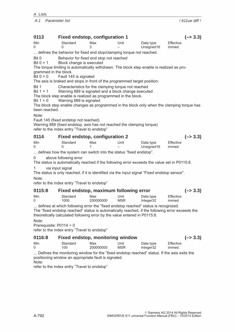
A
A.1 Parameter list
A-792� Siemens AG 2014 All Rights Reserved
SIMODRIVE 611 universal Function Manual (FBU) – 10/2014 Edition
0113 Fixed endstop, configuration 1 (–> 3.3)Min Standard Max Unit Data type Effective0 0 3 – Unsigned16 immed.... defines the behavior for fixed end stop/clamping torque not reached.Bit 0 Behavior for fixed end stop not reachedBit 0 = 1 Block change is executedThe torque limiting is automatically withdrawn. The block step enable is realized as pro-grammed in the block.Bit 0 = 0 Fault 145 is signaledThe axis is braked and stops in front of the programmed target position.Bit 1 Characteristics for the clamping torque not reachedBit 1 = 1 Warning 889 is signaled and a block change executedThe block step enable is realized as programmed in the block.Bit 1 = 0 Warning 889 is signaledThe block step enable changes as programmed in the block only when the clamping torque hasbeen reached.Note:Fault 145 (fixed endstop not reached)Warning 889 (fixed endstop, axis has not reached the clamping torque)refer to the index entry ”Travel to endstop”
0114 Fixed endstop, configuration 2 (–> 3.3)Min Standard Max Unit Data type Effective0 0 1 – Unsigned16 immed.... defines how the system can switch into the status ”fixed endstop”.0 above following errorThe status is automatically reached if the following error exceeds the value set in P0115:8.1 via input signalThe status is only reached, if it is identified via the input signal ”Fixed endstop sensor”.Note:refer to the index entry ”Travel to endstop”
0115:8 Fixed endstop, maximum following error (–> 3.3)Min Standard Max Unit Data type Effective0 1000 200000000 MSR Integer32 immed.... defines at which following error the ”fixed endstop reached” status is recognized.The ”fixed endstop reached” status is automatically reached, if the following error exceeds thetheoretically calculated following error by the value entered in P0115:8.Note:Prerequisite: P0114 = 0refer to the index entry ”Travel to endstop”
0116:8 Fixed endstop, monitoring window (–> 3.3)Min Standard Max Unit Data type Effective0 100 200000000 MSR Integer32 immed.... Defines the monitoring window for the ”fixed endstop reached” status. If the axis exits thepositioning window an appropriate fault is signaled.Note:refer to the index entry ”Travel to endstop”
A Lists
! 611ue diff !
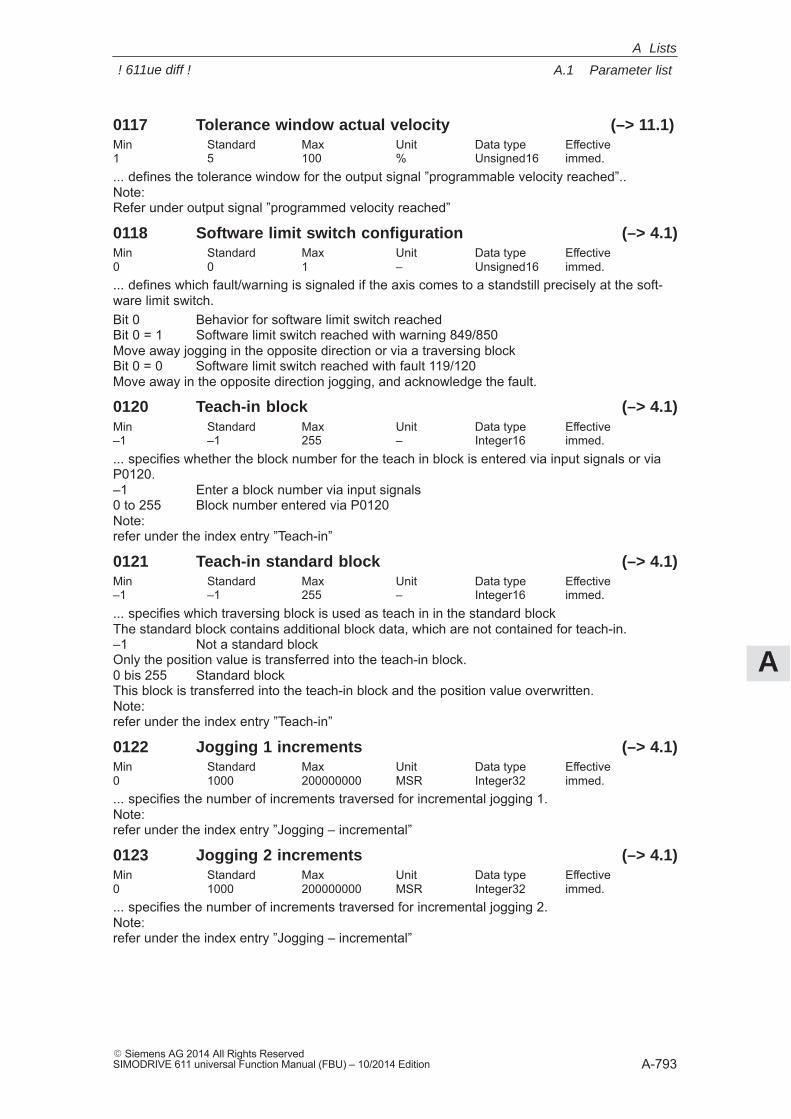
A
A.1 Parameter list
A-793� Siemens AG 2014 All Rights ReservedSIMODRIVE 611 universal Function Manual (FBU) – 10/2014 Edition
0117 Tolerance window actual velocity (–> 11.1)Min Standard Max Unit Data type Effective1 5 100 % Unsigned16 immed.... defines the tolerance window for the output signal ”programmable velocity reached”..Note:Refer under output signal ”programmed velocity reached”
0118 Software limit switch configuration (–> 4.1)Min Standard Max Unit Data type Effective0 0 1 – Unsigned16 immed.... defines which fault/warning is signaled if the axis comes to a standstill precisely at the soft-ware limit switch.Bit 0 Behavior for software limit switch reachedBit 0 = 1 Software limit switch reached with warning 849/850Move away jogging in the opposite direction or via a traversing blockBit 0 = 0 Software limit switch reached with fault 119/120Move away in the opposite direction jogging, and acknowledge the fault.
0120 Teach-in block (–> 4.1)Min Standard Max Unit Data type Effective–1 –1 255 – Integer16 immed.... specifies whether the block number for the teach in block is entered via input signals or viaP0120.–1 Enter a block number via input signals0 to 255 Block number entered via P0120Note:refer under the index entry ”Teach-in”
0121 Teach-in standard block (–> 4.1)Min Standard Max Unit Data type Effective–1 –1 255 – Integer16 immed.... specifies which traversing block is used as teach in in the standard blockThe standard block contains additional block data, which are not contained for teach-in.–1 Not a standard blockOnly the position value is transferred into the teach-in block.0 bis 255 Standard blockThis block is transferred into the teach-in block and the position value overwritten.Note:refer under the index entry ”Teach-in”
0122 Jogging 1 increments (–> 4.1)Min Standard Max Unit Data type Effective0 1000 200000000 MSR Integer32 immed.... specifies the number of increments traversed for incremental jogging 1.Note:refer under the index entry ”Jogging – incremental”
0123 Jogging 2 increments (–> 4.1)Min Standard Max Unit Data type Effective0 1000 200000000 MSR Integer32 immed.... specifies the number of increments traversed for incremental jogging 2.Note:refer under the index entry ”Jogging – incremental”
A Lists
! 611ue diff !
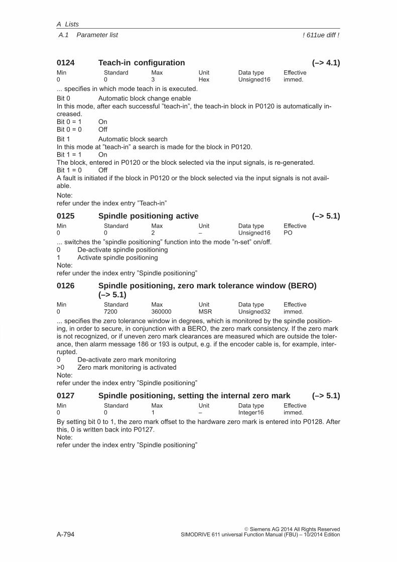
A
A.1 Parameter list
A-794� Siemens AG 2014 All Rights Reserved
SIMODRIVE 611 universal Function Manual (FBU) – 10/2014 Edition
0124 Teach-in configuration (–> 4.1)Min Standard Max Unit Data type Effective0 0 3 Hex Unsigned16 immed.... specifies in which mode teach in is executed.Bit 0 Automatic block change enableIn this mode, after each successful ”teach-in”, the teach-in block in P0120 is automatically in-creased.Bit 0 = 1 OnBit 0 = 0 OffBit 1 Automatic block searchIn this mode at ”teach-in” a search is made for the block in P0120.Bit 1 = 1 OnThe block, entered in P0120 or the block selected via the input signals, is re-generated.Bit 1 = 0 OffA fault is initiated if the block in P0120 or the block selected via the input signals is not avail-able.Note:refer under the index entry ”Teach-in”
0125 Spindle positioning active (–> 5.1)Min Standard Max Unit Data type Effective0 0 2 – Unsigned16 PO... switches the ”spindle positioning” function into the mode ”n-set” on/off.0 De-activate spindle positioning1 Activate spindle positioningNote:refer under the index entry ”Spindle positioning”
0126 Spindle positioning, zero mark tolerance window (BERO)(–> 5.1)
Min Standard Max Unit Data type Effective0 7200 360000 MSR Unsigned32 immed.... specifies the zero tolerance window in degrees, which is monitored by the spindle position-ing, in order to secure, in conjunction with a BERO, the zero mark consistency. If the zero markis not recognized, or if uneven zero mark clearances are measured which are outside the toler-ance, then alarm message 186 or 193 is output, e.g. if the encoder cable is, for example, inter-rupted.0 De-activate zero mark monitoring>0 Zero mark monitoring is activatedNote:refer under the index entry ”Spindle positioning”
0127 Spindle positioning, setting the internal zero mark (–> 5.1)Min Standard Max Unit Data type Effective0 0 1 – Integer16 immed.By setting bit 0 to 1, the zero mark offset to the hardware zero mark is entered into P0128. Afterthis, 0 is written back into P0127.Note:refer under the index entry ”Spindle positioning”
A Lists
! 611ue diff !
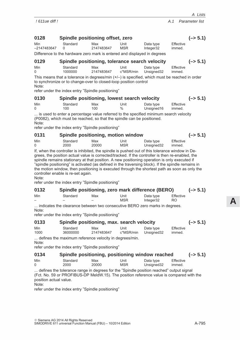
A
A.1 Parameter list
A-795� Siemens AG 2014 All Rights ReservedSIMODRIVE 611 universal Function Manual (FBU) – 10/2014 Edition
0128 Spindle positioning offset, zero (–> 5.1)Min Standard Max Unit Data type Effective–2147483647 0 2147483647 MSR Integer32 immed.Difference to the hardware zero mark is entered and displayed in degrees
0129 Spindle positioning, tolerance search velocity (–> 5.1)Min Standard Max Unit Data type Effective0 1000000 2147483647 c*MSR/min Unsigned32 immed.This means that a tolerance in degrees/min (+/–) is specified, which must be reached in orderto synchronize or to change-over to closed-loop position controlNote:refer under the index entry ”Spindle positioning”
0130 Spindle positioning, lowest search velocity (–> 5.1)Min Standard Max Unit Data type Effective0 100 100 % Unsigned16 immed.... is used to enter a percentage value referred to the specified minimum search velocity(P0082), which must be reached, so that the spindle can be positioned.Note:refer under the index entry ”Spindle positioning”
0131 Spindle positioning, motion window (–> 5.1)Min Standard Max Unit Data type Effective0 2000 20000 MSR Unsigned32 immed.If, when the controller is inhibited, the spindle is pushed out of this tolerance window in De-grees, the position actual value is corrected/tracked. If the controller is then re-enabled, thespindle remains stationary at that position. A new positioning operation is only executed if”spindle positioning” is activated (as defined in the traversing block). If the spindle remains inthe motion window, then positioning is executed through the shortest path as soon as only thecontroller enable is re-set again.Note:refer under the index entry ”Spindle positioning”
0132 Spindle positioning, zero mark difference (BERO) (–> 5.1)Min Standard Max Unit Data type Effective– – – MSR Integer32 RO... indicates the clearance between two consecutive BERO zero marks in degrees.Note:refer under the index entry ”Spindle positioning”
0133 Spindle positioning, max. search velocity (–> 5.1)Min Standard Max Unit Data type Effective1000 36000000 2147483647 c*MSR/min Unsigned32 immed.... defines the maximum reference velocity in degrees/min.Note:refer under the index entry ”Spindle positioning”
0134 Spindle positioning, positioning window reached (–> 5.1)Min Standard Max Unit Data type Effective0 2000 20000 MSR Unsigned32 immed.... defines the tolerance range in degrees for the ”Spindle position reached” output signal (Fct. No. 59 or PROFIBUS-DP MeldW.15). The position reference value is compared with theposition actual value.Note:refer under the index entry ”Spindle positioning”
A Lists
! 611ue diff !
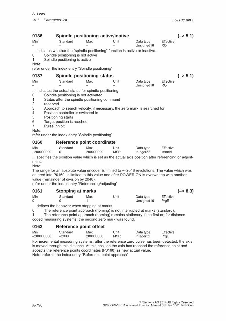
A
A.1 Parameter list
A-796� Siemens AG 2014 All Rights Reserved
SIMODRIVE 611 universal Function Manual (FBU) – 10/2014 Edition
0136 Spindle positioning active/inative (–> 5.1)Min Standard Max Unit Data type Effective– – – – Unsigned16 RO... indicates whether the ”spindle positioning” function is active or inactive.0 Spindle positioning is not active1 Spindle positioning is activeNote:refer under the index entry ”Spindle positioning”
0137 Spindle positioning status (–> 5.1)Min Standard Max Unit Data type Effective– – – – Unsigned16 RO... indicates the actual status for spindle positioning.0 Spindle positioning is not activated1 Status after the spindle positioning command2 reserved3 Approach to search velocity, if necessary, the zero mark is searched for4 Position controller is switched-in5 Positioning starts6 Target position is reached7 Pulse inhibitNote:refer under the index entry ”Spindle positioning”
0160 Reference point coordinateMin Standard Max Unit Data type Effective–200000000 0 200000000 MSR Integer32 immed.... specifies the position value which is set as the actual axis position after referencing or adjust-ment.Note:The range for an absolute value encoder is limited to +–2048 revolutions. The value which wasentered into P0160, is limited to this value and after POWER ON is overwritten with anothervalue (remainder of division by 2048).refer under the index entry ”Referencing/adjusting”
0161 Stopping at marks (–> 8.3)Min Standard Max Unit Data type Effective0 0 1 – Unsigned16 PrgE... defines the behavior when stopping at marks.0 The reference point approach (homing) is not interrupted at marks (standard).1 The reference point approach (homing) remains stationary if the first or, for distance-coded measuring systems, the second zero mark was found.
0162 Reference point offsetMin Standard Max Unit Data type Effective–200000000 –2000 200000000 MSR Integer32 PrgEFor incremental measuring systems, after the reference zero pulse has been detected, the axisis moved through this distance. At this position the axis has reached the reference point andaccepts the reference points coordinates (P0160) as new actual value.Note: refer to the index entry ”Reference point approach”
A Lists
! 611ue diff !
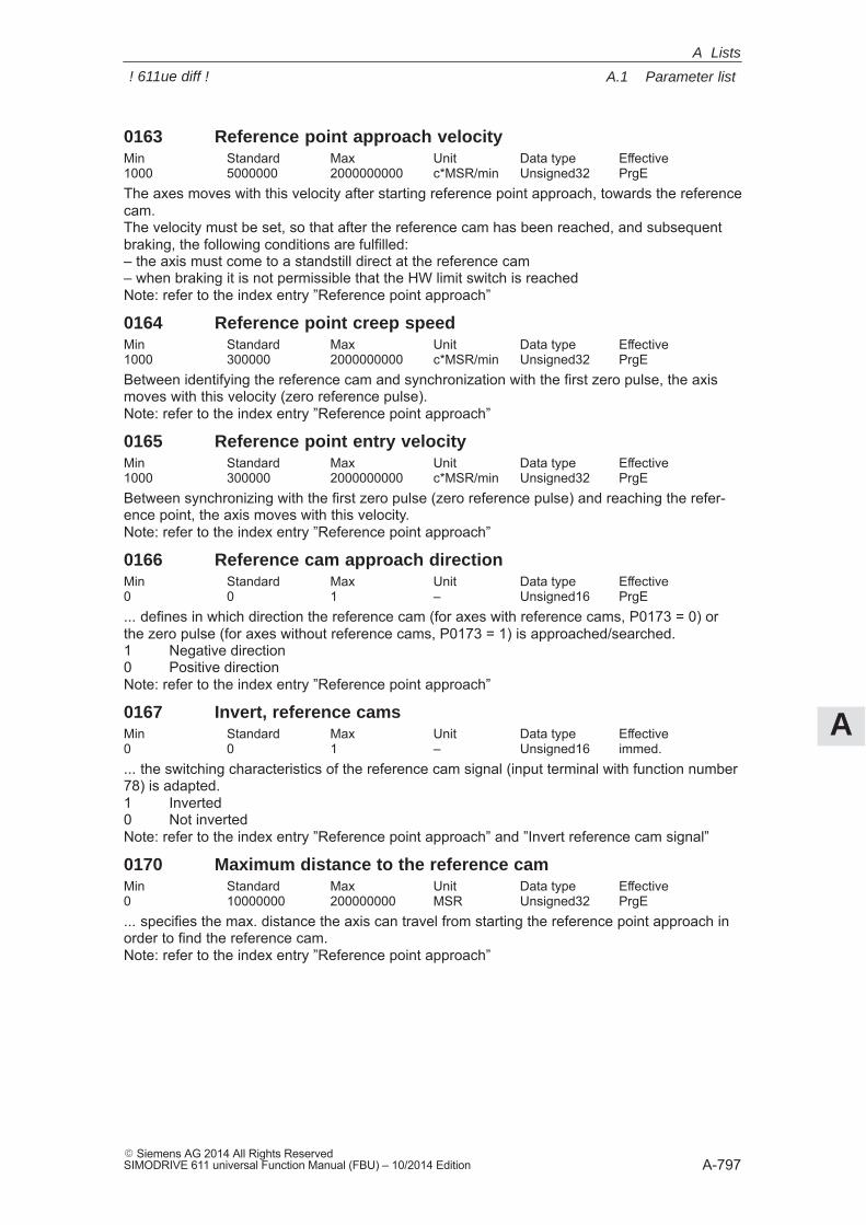
A
A.1 Parameter list
A-797� Siemens AG 2014 All Rights ReservedSIMODRIVE 611 universal Function Manual (FBU) – 10/2014 Edition
0163 Reference point approach velocityMin Standard Max Unit Data type Effective1000 5000000 2000000000 c*MSR/min Unsigned32 PrgEThe axes moves with this velocity after starting reference point approach, towards the referencecam.The velocity must be set, so that after the reference cam has been reached, and subsequentbraking, the following conditions are fulfilled:– the axis must come to a standstill direct at the reference cam– when braking it is not permissible that the HW limit switch is reachedNote: refer to the index entry ”Reference point approach”
0164 Reference point creep speedMin Standard Max Unit Data type Effective1000 300000 2000000000 c*MSR/min Unsigned32 PrgEBetween identifying the reference cam and synchronization with the first zero pulse, the axismoves with this velocity (zero reference pulse).Note: refer to the index entry ”Reference point approach”
0165 Reference point entry velocityMin Standard Max Unit Data type Effective1000 300000 2000000000 c*MSR/min Unsigned32 PrgEBetween synchronizing with the first zero pulse (zero reference pulse) and reaching the refer-ence point, the axis moves with this velocity.Note: refer to the index entry ”Reference point approach”
0166 Reference cam approach directionMin Standard Max Unit Data type Effective0 0 1 – Unsigned16 PrgE... defines in which direction the reference cam (for axes with reference cams, P0173 = 0) orthe zero pulse (for axes without reference cams, P0173 = 1) is approached/searched.1 Negative direction0 Positive directionNote: refer to the index entry ”Reference point approach”
0167 Invert, reference camsMin Standard Max Unit Data type Effective0 0 1 – Unsigned16 immed.... the switching characteristics of the reference cam signal (input terminal with function number78) is adapted.1 Inverted0 Not invertedNote: refer to the index entry ”Reference point approach” and ”Invert reference cam signal”
0170 Maximum distance to the reference camMin Standard Max Unit Data type Effective0 10000000 200000000 MSR Unsigned32 PrgE... specifies the max. distance the axis can travel from starting the reference point approach inorder to find the reference cam.Note: refer to the index entry ”Reference point approach”
A Lists
! 611ue diff !
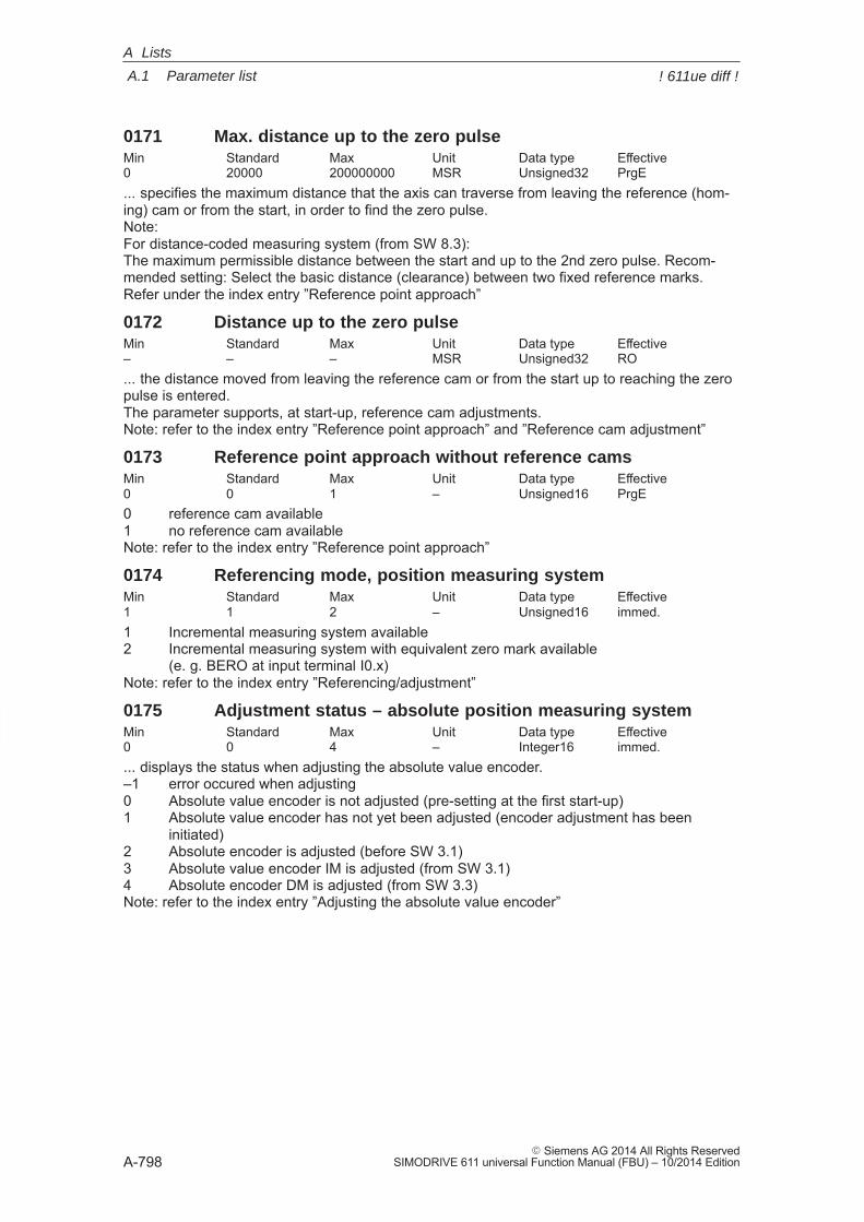
A
A.1 Parameter list
A-798� Siemens AG 2014 All Rights Reserved
SIMODRIVE 611 universal Function Manual (FBU) – 10/2014 Edition
0171 Max. distance up to the zero pulseMin Standard Max Unit Data type Effective0 20000 200000000 MSR Unsigned32 PrgE... specifies the maximum distance that the axis can traverse from leaving the reference (hom-ing) cam or from the start, in order to find the zero pulse.Note: For distance-coded measuring system (from SW 8.3):The maximum permissible distance between the start and up to the 2nd zero pulse. Recom-mended setting: Select the basic distance (clearance) between two fixed reference marks.Refer under the index entry ”Reference point approach”
0172 Distance up to the zero pulseMin Standard Max Unit Data type Effective– – – MSR Unsigned32 RO... the distance moved from leaving the reference cam or from the start up to reaching the zeropulse is entered.The parameter supports, at start-up, reference cam adjustments.Note: refer to the index entry ”Reference point approach” and ”Reference cam adjustment”
0173 Reference point approach without reference camsMin Standard Max Unit Data type Effective0 0 1 – Unsigned16 PrgE0 reference cam available 1 no reference cam availableNote: refer to the index entry ”Reference point approach”
0174 Referencing mode, position measuring systemMin Standard Max Unit Data type Effective1 1 2 – Unsigned16 immed.1 Incremental measuring system available2 Incremental measuring system with equivalent zero mark available
(e. g. BERO at input terminal I0.x)Note: refer to the index entry ”Referencing/adjustment”
0175 Adjustment status – absolute position measuring systemMin Standard Max Unit Data type Effective0 0 4 – Integer16 immed.... displays the status when adjusting the absolute value encoder.–1 error occured when adjusting0 Absolute value encoder is not adjusted (pre-setting at the first start-up)1 Absolute value encoder has not yet been adjusted (encoder adjustment has been
initiated)2 Absolute encoder is adjusted (before SW 3.1)3 Absolute value encoder IM is adjusted (from SW 3.1)4 Absolute encoder DM is adjusted (from SW 3.3)Note: refer to the index entry ”Adjusting the absolute value encoder”
A Lists
! 611ue diff !
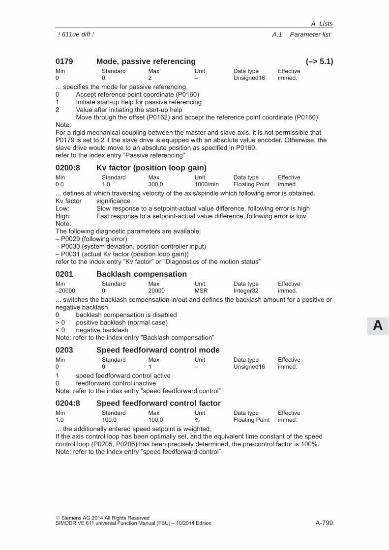
A
A.1 Parameter list
A-799� Siemens AG 2014 All Rights ReservedSIMODRIVE 611 universal Function Manual (FBU) – 10/2014 Edition
0179 Mode, passive referencing (–> 5.1)Min Standard Max Unit Data type Effective0 0 2 – Unsigned16 immed.... specifies the mode for passive referencing.0 Accept reference point coordinate (P0160)1 Initiate start-up help for passive referencing2 Value after initiating the start-up help
Move through the offset (P0162) and accept the reference point coordinate (P0160)Note:For a rigid mechanical coupling between the master and slave axis, it is not permissible thatP0179 is set to 2 if the slave drive is equipped with an absolute value encoder. Otherwise, theslave drive would move to an absolute position as specified in P0160.refer to the index entry ”Passive referencing”
0200:8 Kv factor (position loop gain)Min Standard Max Unit Data type Effective0.0 1.0 300.0 1000/min Floating Point immed.... defines at which traversing velocity of the axis/spindle which following error is obtained.Kv factor significanceLow: Slow response to a setpoint-actual value difference, following error is highHigh: Fast response to a setpoint-actual value difference, following error is lowNote:The following diagnostic parameters are available:– P0029 (following error)– P0030 (system deviation, position controller input)– P0031 (actual Kv factor (position loop gain))refer to the index entry ”Kv factor” or ”Diagnostics of the motion status”
0201 Backlash compensationMin Standard Max Unit Data type Effective–20000 0 20000 MSR Integer32 immed.... switches the backlash compensation in/out and defines the backlash amount for a positive ornegative backlash.0 backlash compensation is disabled> 0 positive backlash (normal case)< 0 negative backlashNote: refer to the index entry ”Backlash compensation”
0203 Speed feedforward control modeMin Standard Max Unit Data type Effective0 0 1 – Unsigned16 immed.1 speed feedforward control active0 feedforward control inactiveNote: refer to the index entry ”speed feedforward control”
0204:8 Speed feedforward control factorMin Standard Max Unit Data type Effective1.0 100.0 100.0 % Floating Point immed.... the additionally entered speed setpoint is weighted.If the axis control loop has been optimally set, and the equivalent time constant of the speedcontrol loop (P0205, P0206) has been precisely determined, the pre-control factor is 100%.Note: refer to the index entry ”speed feedforward control”
A Lists
! 611ue diff !
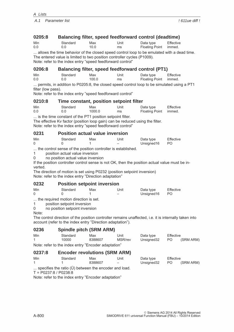
A
A.1 Parameter list
A-800� Siemens AG 2014 All Rights Reserved
SIMODRIVE 611 universal Function Manual (FBU) – 10/2014 Edition
0205:8 Balancing filter, speed feedforward control (deadtime)Min Standard Max Unit Data type Effective0.0 0.0 10.0 ms Floating Point immed.... allows the time behavior of the closed speed control loop to be emulated with a dead time.The entered value is limited to two position controller cycles (P1009).Note: refer to the index entry ”speed feedforward control”
0206:8 Balancing filter, speed feedforward control (PT1)Min Standard Max Unit Data type Effective0.0 0.0 100.0 ms Floating Point immed.... permits, in addition to P0205:8, the closed speed control loop to be simulated using a PT1filter (low pass).Note: refer to the index entry ”speed feedforward control”
0210:8 Time constant, position setpoint filterMin Standard Max Unit Data type Effective0.0 0.0 1000.0 ms Floating Point immed.... is the time constant of the PT1 position setpoint filter.The effective Kv factor (position loop gain) can be reduced using the filter.Note: refer to the index entry ”speed feedforward control”
0231 Position actual value inversionMin Standard Max Unit Data type Effective0 0 1 – Unsigned16 PO... the control sense of the position controller is established.1 position actual value inversion0 no position actual value inversionIf the position controller control sense is not OK, then the position actual value must be in-verted.The direction of motion is set using P0232 (position setpoint inversion)Note: refer to the index entry ”Direction adaptation”
0232 Position setpoint inversionMin Standard Max Unit Data type Effective0 0 1 – Unsigned16 PO... the required motion direction is set.1 position setpoint inversion0 no position setpoint inversionNote:The control direction of the position controller remains unaffected, i.e. it is internally taken intoaccount (refer to the index entry ”Direction adaptation”).
0236 Spindle pitch (SRM ARM)Min Standard Max Unit Data type Effective1 10000 8388607 MSR/rev Unsigned32 PO (SRM ARM)Note: refer to the index entry ”Encoder adaptation”
0237:8 Encoder revolutions (SRM ARM)Min Standard Max Unit Data type Effective1 1 8388607 – Unsigned32 PO (SRM ARM)... specifies the ratio (Ü) between the encoder and load.T = P0237:8 / P0238:8Note: refer to the index entry ”Encoder adaptation”
A Lists
! 611ue diff !
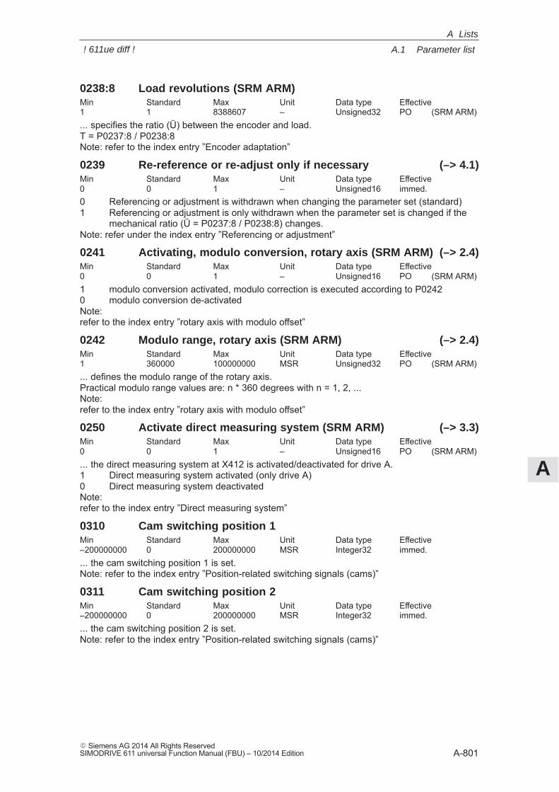
A
A.1 Parameter list
A-801� Siemens AG 2014 All Rights ReservedSIMODRIVE 611 universal Function Manual (FBU) – 10/2014 Edition
0238:8 Load revolutions (SRM ARM)Min Standard Max Unit Data type Effective1 1 8388607 – Unsigned32 PO (SRM ARM)... specifies the ratio (Ü) between the encoder and load.T = P0237:8 / P0238:8Note: refer to the index entry ”Encoder adaptation”
0239 Re-reference or re-adjust only if necessary (–> 4.1)Min Standard Max Unit Data type Effective0 0 1 – Unsigned16 immed.0 Referencing or adjustment is withdrawn when changing the parameter set (standard)1 Referencing or adjustment is only withdrawn when the parameter set is changed if the
mechanical ratio (Ü = P0237:8 / P0238:8) changes.Note: refer under the index entry ”Referencing or adjustment”
0241 Activating, modulo conversion, rotary axis (SRM ARM) (–> 2.4)Min Standard Max Unit Data type Effective0 0 1 – Unsigned16 PO (SRM ARM)1 modulo conversion activated, modulo correction is executed according to P02420 modulo conversion de-activatedNote:refer to the index entry ”rotary axis with modulo offset”
0242 Modulo range, rotary axis (SRM ARM) (–> 2.4)Min Standard Max Unit Data type Effective1 360000 100000000 MSR Unsigned32 PO (SRM ARM)... defines the modulo range of the rotary axis.Practical modulo range values are: n * 360 degrees with n = 1, 2, ...Note:refer to the index entry ”rotary axis with modulo offset”
0250 Activate direct measuring system (SRM ARM) (–> 3.3)Min Standard Max Unit Data type Effective0 0 1 – Unsigned16 PO (SRM ARM)... the direct measuring system at X412 is activated/deactivated for drive A.1 Direct measuring system activated (only drive A)0 Direct measuring system deactivatedNote:refer to the index entry ”Direct measuring system”
0310 Cam switching position 1Min Standard Max Unit Data type Effective–200000000 0 200000000 MSR Integer32 immed.... the cam switching position 1 is set.Note: refer to the index entry ”Position-related switching signals (cams)”
0311 Cam switching position 2Min Standard Max Unit Data type Effective–200000000 0 200000000 MSR Integer32 immed.... the cam switching position 2 is set.Note: refer to the index entry ”Position-related switching signals (cams)”
A Lists
! 611ue diff !
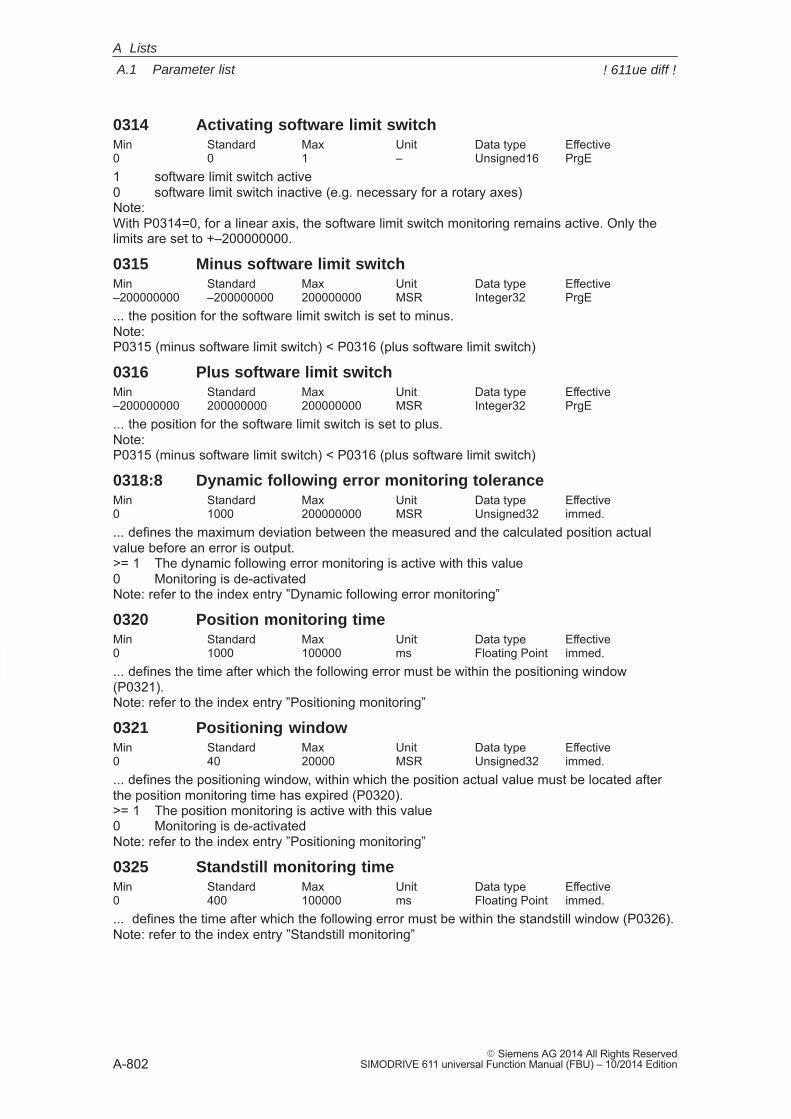
A
A.1 Parameter list
A-802� Siemens AG 2014 All Rights Reserved
SIMODRIVE 611 universal Function Manual (FBU) – 10/2014 Edition
0314 Activating software limit switchMin Standard Max Unit Data type Effective0 0 1 – Unsigned16 PrgE1 software limit switch active0 software limit switch inactive (e.g. necessary for a rotary axes)Note:With P0314=0, for a linear axis, the software limit switch monitoring remains active. Only thelimits are set to +–200000000.
0315 Minus software limit switchMin Standard Max Unit Data type Effective–200000000 –200000000 200000000 MSR Integer32 PrgE... the position for the software limit switch is set to minus.Note: P0315 (minus software limit switch) < P0316 (plus software limit switch)
0316 Plus software limit switchMin Standard Max Unit Data type Effective–200000000 200000000 200000000 MSR Integer32 PrgE... the position for the software limit switch is set to plus.Note:P0315 (minus software limit switch) < P0316 (plus software limit switch)
0318:8 Dynamic following error monitoring toleranceMin Standard Max Unit Data type Effective0 1000 200000000 MSR Unsigned32 immed.... defines the maximum deviation between the measured and the calculated position actualvalue before an error is output.>= 1 The dynamic following error monitoring is active with this value0 Monitoring is de-activatedNote: refer to the index entry ”Dynamic following error monitoring”
0320 Position monitoring timeMin Standard Max Unit Data type Effective0 1000 100000 ms Floating Point immed.... defines the time after which the following error must be within the positioning window(P0321).Note: refer to the index entry ”Positioning monitoring”
0321 Positioning windowMin Standard Max Unit Data type Effective0 40 20000 MSR Unsigned32 immed.... defines the positioning window, within which the position actual value must be located afterthe position monitoring time has expired (P0320).>= 1 The position monitoring is active with this value0 Monitoring is de-activatedNote: refer to the index entry ”Positioning monitoring”
0325 Standstill monitoring timeMin Standard Max Unit Data type Effective0 400 100000 ms Floating Point immed.... defines the time after which the following error must be within the standstill window (P0326).Note: refer to the index entry ”Standstill monitoring”
A Lists
! 611ue diff !
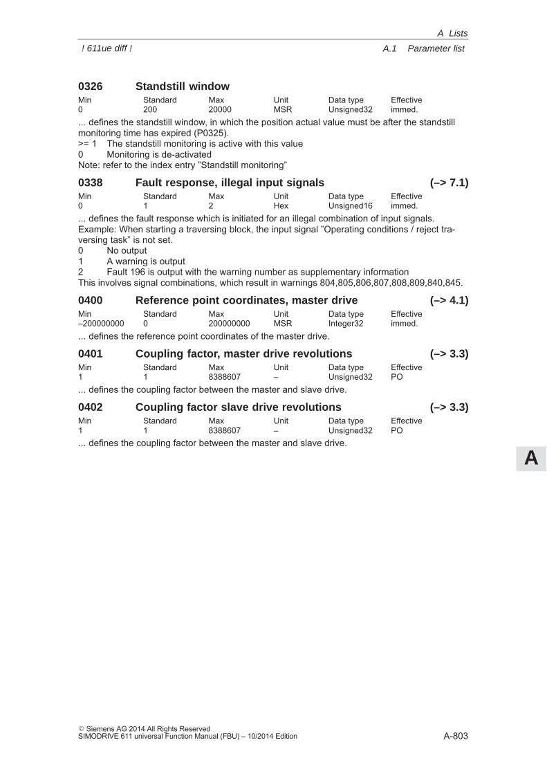
A
A.1 Parameter list
A-803� Siemens AG 2014 All Rights ReservedSIMODRIVE 611 universal Function Manual (FBU) – 10/2014 Edition
0326 Standstill windowMin Standard Max Unit Data type Effective0 200 20000 MSR Unsigned32 immed.... defines the standstill window, in which the position actual value must be after the standstillmonitoring time has expired (P0325).>= 1 The standstill monitoring is active with this value0 Monitoring is de-activatedNote: refer to the index entry ”Standstill monitoring”
0338 Fault response, illegal input signals (–> 7.1)Min Standard Max Unit Data type Effective0 1 2 Hex Unsigned16 immed.... defines the fault response which is initiated for an illegal combination of input signals.Example: When starting a traversing block, the input signal ”Operating conditions / reject tra-versing task” is not set.0 No output1 A warning is output2 Fault 196 is output with the warning number as supplementary informationThis involves signal combinations, which result in warnings 804,805,806,807,808,809,840,845.
0400 Reference point coordinates, master drive (–> 4.1)Min Standard Max Unit Data type Effective–200000000 0 200000000 MSR Integer32 immed.... defines the reference point coordinates of the master drive.
0401 Coupling factor, master drive revolutions (–> 3.3)Min Standard Max Unit Data type Effective1 1 8388607 – Unsigned32 PO... defines the coupling factor between the master and slave drive.
0402 Coupling factor slave drive revolutions (–> 3.3)Min Standard Max Unit Data type Effective1 1 8388607 – Unsigned32 PO... defines the coupling factor between the master and slave drive.
A Lists
! 611ue diff !
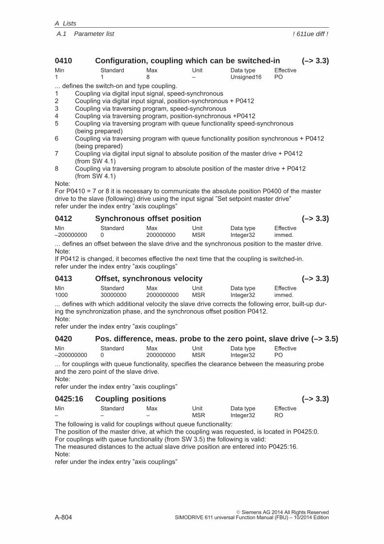
A
A.1 Parameter list
A-804� Siemens AG 2014 All Rights Reserved
SIMODRIVE 611 universal Function Manual (FBU) – 10/2014 Edition
0410 Configuration, coupling which can be switched-in (–> 3.3)Min Standard Max Unit Data type Effective1 1 8 – Unsigned16 PO... defines the switch-on and type coupling.1 Coupling via digital input signal, speed-synchronous2 Coupling via digital input signal, position-synchronous + P04123 Coupling via traversing program, speed-synchronous4 Coupling via traversing program, position-synchronous +P04125 Coupling via traversing program with queue functionality speed-synchronous
(being prepared)6 Coupling via traversing program with queue functionality position synchronous + P0412
(being prepared)7 Coupling via digital input signal to absolute position of the master drive + P0412
(from SW 4.1)8 Coupling via traversing program to absolute position of the master drive + P0412
(from SW 4.1)Note:For P0410 = 7 or 8 it is necessary to communicate the absolute position P0400 of the masterdrive to the slave (following) drive using the input signal ”Set setpoint master drive”refer under the index entry ”axis couplings”
0412 Synchronous offset position (–> 3.3)Min Standard Max Unit Data type Effective–200000000 0 200000000 MSR Integer32 immed.... defines an offset between the slave drive and the synchronous position to the master drive.Note:If P0412 is changed, it becomes effective the next time that the coupling is switched-in.refer under the index entry ”axis couplings”
0413 Offset, synchronous velocity (–> 3.3)Min Standard Max Unit Data type Effective1000 30000000 2000000000 MSR Integer32 immed.... defines with which additional velocity the slave drive corrects the following error, built-up dur-ing the synchronization phase, and the synchronous offset position P0412.Note:refer under the index entry ”axis couplings”
0420 Pos. difference, meas. probe to the zero point, slave drive (–> 3.5)Min Standard Max Unit Data type Effective–200000000 0 200000000 MSR Integer32 PO... for couplings with queue functionality, specifies the clearance between the measuring probeand the zero point of the slave drive.Note:refer under the index entry ”axis couplings”
0425:16 Coupling positions (–> 3.3)Min Standard Max Unit Data type Effective– – – MSR Integer32 ROThe following is valid for couplings without queue functionality:The position of the master drive, at which the coupling was requested, is located in P0425:0.For couplings with queue functionality (from SW 3.5) the following is valid:The measured distances to the actual slave drive position are entered into P0425:16.Note:refer under the index entry ”axis couplings”
A Lists
! 611ue diff !
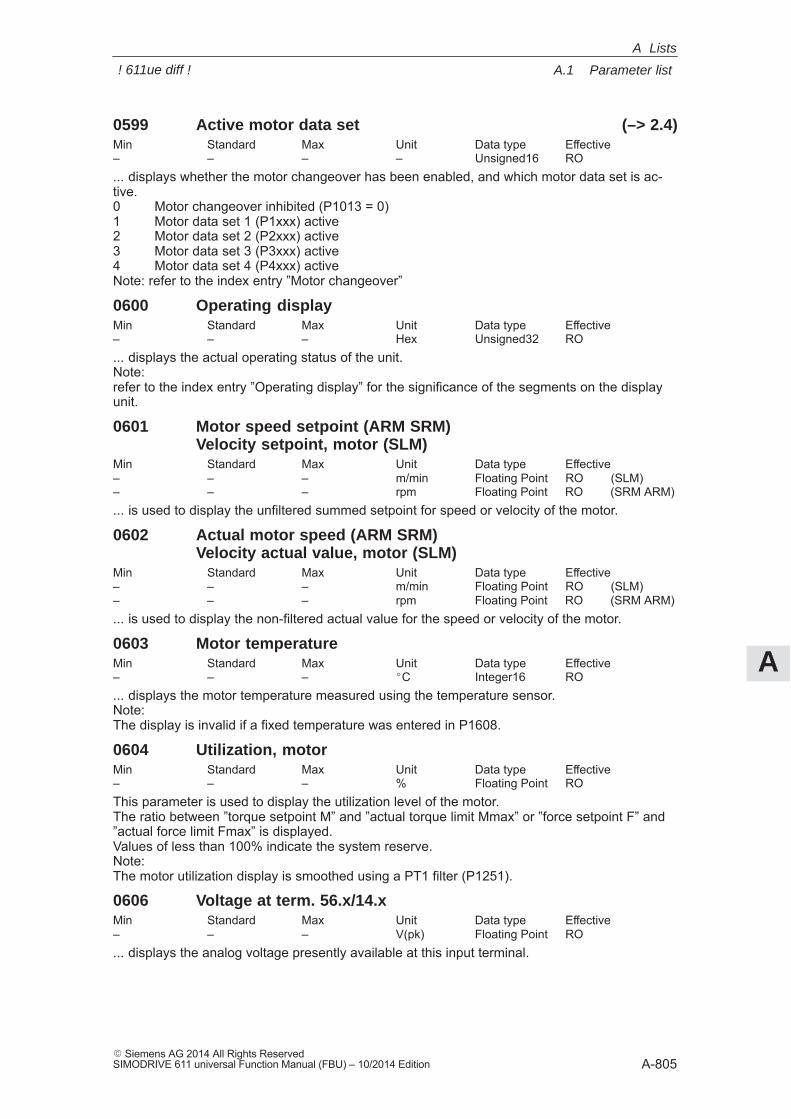
A
A.1 Parameter list
A-805� Siemens AG 2014 All Rights ReservedSIMODRIVE 611 universal Function Manual (FBU) – 10/2014 Edition
0599 Active motor data set (–> 2.4)Min Standard Max Unit Data type Effective– – – – Unsigned16 RO... displays whether the motor changeover has been enabled, and which motor data set is ac-tive.0 Motor changeover inhibited (P1013 = 0)1 Motor data set 1 (P1xxx) active2 Motor data set 2 (P2xxx) active3 Motor data set 3 (P3xxx) active4 Motor data set 4 (P4xxx) activeNote: refer to the index entry ”Motor changeover”
0600 Operating displayMin Standard Max Unit Data type Effective– – – Hex Unsigned32 RO... displays the actual operating status of the unit.Note:refer to the index entry ”Operating display” for the significance of the segments on the displayunit.
0601 Motor speed setpoint (ARM SRM)Velocity setpoint, motor (SLM)
Min Standard Max Unit Data type Effective– – – m/min Floating Point RO (SLM)– – – rpm Floating Point RO (SRM ARM)... is used to display the unfiltered summed setpoint for speed or velocity of the motor.
0602 Actual motor speed (ARM SRM)Velocity actual value, motor (SLM)
Min Standard Max Unit Data type Effective– – – m/min Floating Point RO (SLM)– – – rpm Floating Point RO (SRM ARM)... is used to display the non-filtered actual value for the speed or velocity of the motor.
0603 Motor temperatureMin Standard Max Unit Data type Effective– – – �C Integer16 RO... displays the motor temperature measured using the temperature sensor.Note:The display is invalid if a fixed temperature was entered in P1608.
0604 Utilization, motorMin Standard Max Unit Data type Effective– – – % Floating Point ROThis parameter is used to display the utilization level of the motor.The ratio between ”torque setpoint M” and ”actual torque limit Mmax” or ”force setpoint F” and”actual force limit Fmax” is displayed.Values of less than 100% indicate the system reserve.Note:The motor utilization display is smoothed using a PT1 filter (P1251).
0606 Voltage at term. 56.x/14.xMin Standard Max Unit Data type Effective– – – V(pk) Floating Point RO... displays the analog voltage presently available at this input terminal.
A Lists
! 611ue diff !
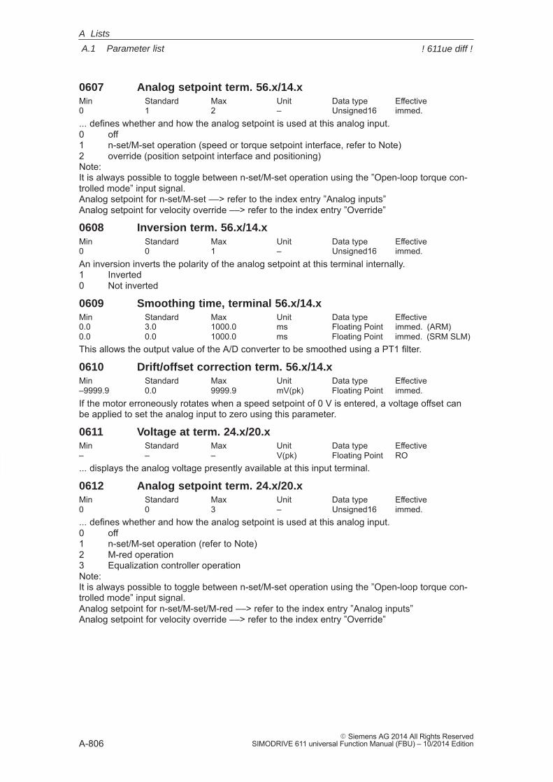
A
A.1 Parameter list
A-806� Siemens AG 2014 All Rights Reserved
SIMODRIVE 611 universal Function Manual (FBU) – 10/2014 Edition
0607 Analog setpoint term. 56.x/14.xMin Standard Max Unit Data type Effective0 1 2 – Unsigned16 immed.... defines whether and how the analog setpoint is used at this analog input.0 off1 n-set/M-set operation (speed or torque setpoint interface, refer to Note)2 override (position setpoint interface and positioning)Note:It is always possible to toggle between n-set/M-set operation using the ”Open-loop torque con-trolled mode” input signal.Analog setpoint for n-set/M-set ––> refer to the index entry ”Analog inputs”Analog setpoint for velocity override ––> refer to the index entry ”Override”
0608 Inversion term. 56.x/14.xMin Standard Max Unit Data type Effective0 0 1 – Unsigned16 immed.An inversion inverts the polarity of the analog setpoint at this terminal internally.1 Inverted0 Not inverted
0609 Smoothing time, terminal 56.x/14.xMin Standard Max Unit Data type Effective0.0 3.0 1000.0 ms Floating Point immed. (ARM)0.0 0.0 1000.0 ms Floating Point immed. (SRM SLM)This allows the output value of the A/D converter to be smoothed using a PT1 filter.
0610 Drift/offset correction term. 56.x/14.xMin Standard Max Unit Data type Effective–9999.9 0.0 9999.9 mV(pk) Floating Point immed.If the motor erroneously rotates when a speed setpoint of 0 V is entered, a voltage offset canbe applied to set the analog input to zero using this parameter.
0611 Voltage at term. 24.x/20.xMin Standard Max Unit Data type Effective– – – V(pk) Floating Point RO... displays the analog voltage presently available at this input terminal.
0612 Analog setpoint term. 24.x/20.xMin Standard Max Unit Data type Effective0 0 3 – Unsigned16 immed.... defines whether and how the analog setpoint is used at this analog input.0 off1 n-set/M-set operation (refer to Note)2 M-red operation3 Equalization controller operationNote:It is always possible to toggle between n-set/M-set operation using the ”Open-loop torque con-trolled mode” input signal.Analog setpoint for n-set/M-set/M-red ––> refer to the index entry ”Analog inputs”Analog setpoint for velocity override ––> refer to the index entry ”Override”
A Lists
! 611ue diff !
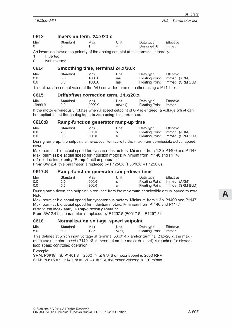
A
A.1 Parameter list
A-807� Siemens AG 2014 All Rights ReservedSIMODRIVE 611 universal Function Manual (FBU) – 10/2014 Edition
0613 Inversion term. 24.x/20.xMin Standard Max Unit Data type Effective0 0 1 – Unsigned16 immed.An inversion inverts the polarity of the analog setpoint at this terminal internally.1 Inverted0 Not inverted
0614 Smoothing time, terminal 24.x/20.xMin Standard Max Unit Data type Effective0.0 3.0 1000.0 ms Floating Point immed. (ARM)0.0 0.0 1000.0 ms Floating Point immed. (SRM SLM)This allows the output value of the A/D converter to be smoothed using a PT1 filter.
0615 Drift/offset correction term. 24.x/20.xMin Standard Max Unit Data type Effective–9999.9 0.0 9999.9 mV(pk) Floating Point immed.If the motor erroneously rotates when a speed setpoint of 0 V is entered, a voltage offset canbe applied to set the analog input to zero using this parameter.
0616:8 Ramp-function generator ramp-up timeMin Standard Max Unit Data type Effective0.0 2.0 600.0 s Floating Point immed. (ARM)0.0 0.0 600.0 s Floating Point immed. (SRM SLM)During ramp-up, the setpoint is increased from zero to the maximum permissible actual speed.Note:Max. permissible actual speed for synchronous motors: Minimum from 1.2 x P1400 and P1147Max. permissible actual speed for induction motors: Minimum from P1146 and P1147refer to the index entry ”Ramp-function generator”From SW 2.4, this parameter is replaced by P1256:8 (P0616:8 = P1256:8).
0617:8 Ramp-function generator ramp-down timeMin Standard Max Unit Data type Effective0.0 2.0 600.0 s Floating Point immed. (ARM)0.0 0.0 600.0 s Floating Point immed. (SRM SLM)During ramp-down, the setpoint is reduced from the maximum permissible actual speed to zero.Note:Max. permissible actual speed for synchronous motors: Minimum from 1.2 x P1400 and P1147Max. permissible actual speed for induction motors: Minimum from P1146 and P1147refer to the index entry ”Ramp-function generator”From SW 2.4 this parameter is replaced by P1257:8 (P0617:8 = P1257:8).
0618 Normalization voltage, speed setpointMin Standard Max Unit Data type Effective5.0 9.0 12.5 V(pk) Floating Point immed.This defines at which input voltage at terminal 56.x/14.x and/or terminal 24.x/20.x, the maxi-mum useful motor speed (P1401:8, dependent on the motor data set) is reached for closed-loop speed controlled operation.Example:SRM: P0618 = 9, P1401:8 = 2000 –> at 9 V, the motor speed is 2000 RPMSLM: P0618 = 9, P1401:8 = 120 –> at 9 V, the motor velocity is 120 m/min
A Lists
! 611ue diff !
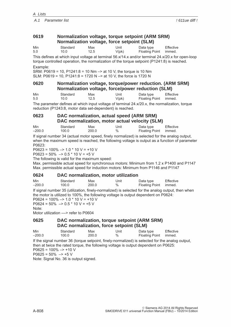
A
A.1 Parameter list
A-808� Siemens AG 2014 All Rights Reserved
SIMODRIVE 611 universal Function Manual (FBU) – 10/2014 Edition
0619 Normalization voltage, torque setpoint (ARM SRM)Normalization voltage, force setpoint (SLM)
Min Standard Max Unit Data type Effective5.0 10.0 12.5 V(pk) Floating Point immed.This defines at which input voltage at terminal 56.x/14.x and/or terminal 24.x/20.x for open-looptorque controlled operation, the normalization of the torque setpoint (P1241:8) is reached.Example:SRM: P0619 = 10, P1241:8 = 10 Nm –> at 10 V, the torque is 10 NmSLM: P0619 = 10, P1241:8 = 1720 N –> at 10 V, the force is 1720 N
0620 Normalization voltage, torque/power reduction. (ARM SRM)Normalization voltage, force/power reduction (SLM)
Min Standard Max Unit Data type Effective5.0 10.0 12.5 V(pk) Floating Point immed.The parameter defines at which input voltage of terminal 24.x/20.x, the normalization, torquereduction (P1243:8, motor data set-dependent) is reached.
0623 DAC normalization, actual speed (ARM SRM)DAC normalization, motor actual velocity (SLM)
Min Standard Max Unit Data type Effective–200.0 100.0 200.0 % Floating Point immed.If signal number 34 (actual motor speed, finely normalized) is selected for the analog output,when the maximum speed is reached, the following voltage is output as a function of parameterP0623:P0623 = 100% –> 1.0 * 10 V = +10 VP0623 = 50% –> 0.5 * 10 V = +5 VThe following is valid for the maximum speed:Max. permissible actual speed for synchronous motors: Minimum from 1.2 x P1400 and P1147Max. permissible actual speed for induction motors: Minimum from P1146 and P1147
0624 DAC normalization, motor utilizationMin Standard Max Unit Data type Effective–200.0 100.0 200.0 % Floating Point immed.If signal number 35 (utilization, finely-normalized) is selected for the analog output, then whenthe motor is utilized to 100%, the following voltage is output dependent on P0624:P0624 = 100% –> 1.0 * 10 V = +10 VP0624 = 50% –> 0.5 * 10 V = +5 VNote:Motor utilization ––> refer to P0604
0625 DAC normalization, torque setpoint (ARM SRM)DAC normalization, force setpoint (SLM)
Min Standard Max Unit Data type Effective–200.0 100.0 200.0 % Floating Point immed.If the signal number 36 (torque setpoint, finely-normalized) is selected for the analog output,then at twice the rated torque, the following voltage is output dependent on P0625:P0625 = 100% –> +10 VP0625 = 50% –> +5 VNote: Signal No. 36 is output signed.
A Lists
! 611ue diff !
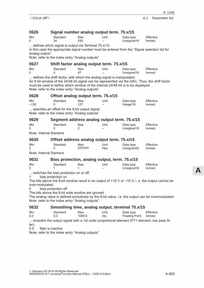
A
A.1 Parameter list
A-809� Siemens AG 2014 All Rights ReservedSIMODRIVE 611 universal Function Manual (FBU) – 10/2014 Edition
0626 Signal number analog output term. 75.x/15Min Standard Max Unit Data type Effective0 34 530 – Unsigned16 immed.... defines which signal is output via Terminal 75.x/15.In this case the appropriate signal number must be entered from the ”Signal selection list foranalog output”.Note: refer to the index entry ”Analog outputs”
0627 Shift factor analog output term. 75.x/15Min Standard Max Unit Data type Effective0 0 47 – Unsigned16 immed.... defines the shift factor, with which the analog signal is manipulated.An 8 bit window of the 24/48 bit signal can be represented via the DAC. Thus, the shift factormust be used to define which window of the internal 24/48 bit is to be displayed.Note: refer to the index entry ”Analog outputs”
0628 Offset analog output term. 75.x/15Min Standard Max Unit Data type Effective–128 0 127 – Integer16 immed.... specifies an offset for the 8-bit output signal.Note: refer to the index entry ”Analog outputs”
0629 Segment address analog output term. 75.x/15Min Standard Max Unit Data type Effective0 0 2 – Unsigned16 immed.Note: Internal Siemens
0630 Offset address analog output term. 75.x/15Min Standard Max Unit Data type Effective0 0 FFFFFF Hex Unsigned32 immed.Note: Internal Siemens
0631 Bias protection, analog output, term. 75.x/15Min Standard Max Unit Data type Effective0 1 1 – Unsigned16 immed.... switches the bias protection on or off.1 bias protection onThe bits above the 8-bit window result in an output of +10 V or –10 V, i. e. the output cannot beover-modulated.0 bias protection offThe bits above the 8-bit wide window are ignored.The analog value is defined exclusively by the 8-bit value, i.e. the output can be overmodulated.Note: refer to the index entry ”Analog outputs”
0632 Smoothing time, analog output, terminal 75.x/15Min Standard Max Unit Data type Effective0.0 0.0 1000.0 ms Floating Point immed.... smooths the output signal with a 1st order proportional element (PT1 element, low pass fil-ter).0.0 filter is inactiveNote: refer to the index entry ”Analog outputs”
A Lists
! 611ue diff !
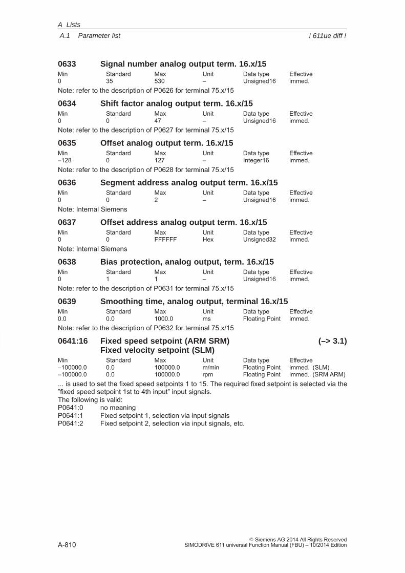
A
A.1 Parameter list
A-810� Siemens AG 2014 All Rights Reserved
SIMODRIVE 611 universal Function Manual (FBU) – 10/2014 Edition
0633 Signal number analog output term. 16.x/15Min Standard Max Unit Data type Effective0 35 530 – Unsigned16 immed.Note: refer to the description of P0626 for terminal 75.x/15
0634 Shift factor analog output term. 16.x/15Min Standard Max Unit Data type Effective0 0 47 – Unsigned16 immed.Note: refer to the description of P0627 for terminal 75.x/15
0635 Offset analog output term. 16.x/15Min Standard Max Unit Data type Effective–128 0 127 – Integer16 immed.Note: refer to the description of P0628 for terminal 75.x/15
0636 Segment address analog output term. 16.x/15Min Standard Max Unit Data type Effective0 0 2 – Unsigned16 immed.Note: Internal Siemens
0637 Offset address analog output term. 16.x/15Min Standard Max Unit Data type Effective0 0 FFFFFF Hex Unsigned32 immed.Note: Internal Siemens
0638 Bias protection, analog output, term. 16.x/15Min Standard Max Unit Data type Effective0 1 1 – Unsigned16 immed.Note: refer to the description of P0631 for terminal 75.x/15
0639 Smoothing time, analog output, terminal 16.x/15Min Standard Max Unit Data type Effective0.0 0.0 1000.0 ms Floating Point immed.Note: refer to the description of P0632 for terminal 75.x/15
0641:16 Fixed speed setpoint (ARM SRM) (–> 3.1)Fixed velocity setpoint (SLM)
Min Standard Max Unit Data type Effective–100000.0 0.0 100000.0 m/min Floating Point immed. (SLM)–100000.0 0.0 100000.0 rpm Floating Point immed. (SRM ARM)... is used to set the fixed speed setpoints 1 to 15. The required fixed setpoint is selected via the”fixed speed setpoint 1st to 4th input” input signals.The following is valid:P0641:0 no meaningP0641:1 Fixed setpoint 1, selection via input signalsP0641:2 Fixed setpoint 2, selection via input signals, etc.
A Lists
! 611ue diff !
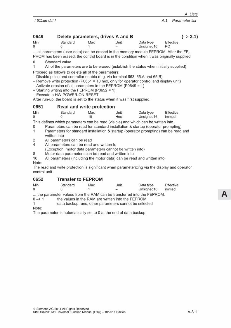
A
A.1 Parameter list
A-811� Siemens AG 2014 All Rights ReservedSIMODRIVE 611 universal Function Manual (FBU) – 10/2014 Edition
0649 Delete parameters, drives A and B (–> 3.1)Min Standard Max Unit Data type Effective0 0 1 – Unsigned16 PO... all parameters (user data) can be erased in the memory module FEPROM. After the FE-PROM has been erased, the control board is in the condition when it was originally supplied.0 Standard value1 All of the parameters are to be erased (establish the status when initially supplied)Proceed as follows to delete all of the parameters:– Disable pulse and controller enable (e.g. via terminal 663, 65.A and 65.B)– Remove write protection (P0651 = 10 hex, only for operator control and display unit)– Activate erasion of all parameters in the FEPROM (P0649 = 1)– Starting writing into the FEPROM (P0652 = 1)– Execute a HW POWER-ON RESETAfter run-up, the board is set to the status when it was first supplied.
0651 Read and write protectionMin Standard Max Unit Data type Effective0 0 10 Hex Unsigned16 immed.This defines which parameters can be read (visible) and which can be written into.0 Parameters can be read for standard installation & startup (operator prompting)1 Parameters for standard installation & startup (operator prompting) can be read and
written into2 All parameters can be read4 All parameters can be read and written to
(Exception: motor data parameters cannot be written into)8 Motor data parameters can be read and written into10 All parameters (including the motor data) can be read and written intoNote:The read and write protection is significant when parameterizing via the display and operatorcontrol unit.
0652 Transfer to FEPROMMin Standard Max Unit Data type Effective0 0 1 – Unsigned16 immed.... the parameter values from the RAM can be transferred into the FEPROM.0 –> 1 the values in the RAM are written into the FEPROM1 data backup runs, other parameters cannot be selectedNote:The parameter is automatically set to 0 at the end of data backup.
A Lists
! 611ue diff !
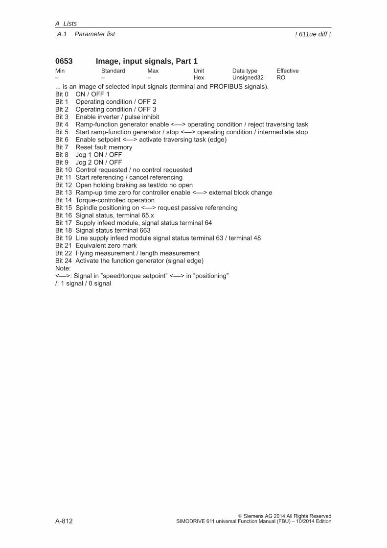
A
A.1 Parameter list
A-812� Siemens AG 2014 All Rights Reserved
SIMODRIVE 611 universal Function Manual (FBU) – 10/2014 Edition
0653 Image, input signals, Part 1Min Standard Max Unit Data type Effective– – – Hex Unsigned32 RO... is an image of selected input signals (terminal and PROFIBUS signals).Bit 0 ON / OFF 1Bit 1 Operating condition / OFF 2Bit 2 Operating condition / OFF 3Bit 3 Enable inverter / pulse inhibitBit 4 Ramp-function generator enable <––> operating condition / reject traversing taskBit 5 Start ramp-function generator / stop <––> operating condition / intermediate stopBit 6 Enable setpoint <––> activate traversing task (edge)Bit 7 Reset fault memoryBit 8 Jog 1 ON / OFFBit 9 Jog 2 ON / OFFBit 10 Control requested / no control requestedBit 11 Start referencing / cancel referencingBit 12 Open holding braking as test/do no openBit 13 Ramp-up time zero for controller enable <––> external block changeBit 14 Torque-controlled operationBit 15 Spindle positioning on <––> request passive referencingBit 16 Signal status, terminal 65.xBit 17 Supply infeed module, signal status terminal 64Bit 18 Signal status terminal 663Bit 19 Line supply infeed module signal status terminal 63 / terminal 48Bit 21 Equivalent zero markBit 22 Flying measurement / length measurementBit 24 Activate the function generator (signal edge)Note:<––>: Signal in ”speed/torque setpoint” <––> in ”positioning”/: 1 signal / 0 signal
A Lists
! 611ue diff !
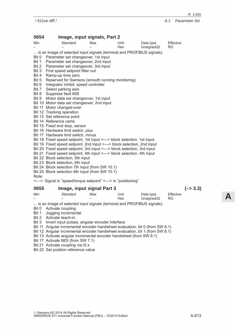
A
A.1 Parameter list
A-813� Siemens AG 2014 All Rights ReservedSIMODRIVE 611 universal Function Manual (FBU) – 10/2014 Edition
0654 Image, input signals, Part 2Min Standard Max Unit Data type Effective– – – Hex Unsigned32 RO... is an image of selected input signals (terminal and PROFIBUS signals).Bit 0 Parameter set changeover, 1st inputBit 1 Parameter set changeover, 2nd inputBit 2 Parameter set changeover, 3rd inputBit 3 First speed setpoint filter outBit 4 Ramp-up time zeroBit 5 Reserved for Siemens (smooth running monitoring)Bit 6 Integrator inhibit, speed controllerBit 7 Select parking axisBit 8 Suppress fault 608Bit 9 Motor data set changeover, 1st inputBit 10 Motor data set changeover, 2nd inputBit 11 Motor changed-overBit 12 Tracking operationBit 13 Set reference pointBit 14 Reference camsBit 15 Fixed end stop, sensorBit 16 Hardware limit switch, plusBit 17 Hardware limit switch, minusBit 18 Fixed speed setpoint, 1st input <––> block selection, 1st inputBit 19 Fixed speed setpoint, 2nd input <––> block selection, 2nd inputBit 20 Fixed speed setpoint, 3rd input <––> block selection, 3rd inputBit 21 Fixed speed setpoint, 4th input <––> block selection, 4th inputBit 22 Block selection, 5th inputBit 23 Block selection, 6th inputBit 24 Block selection 7th input (from SW 10.1)Bit 25 Block selection 8th input (from SW 10.1)Note:<––>: Signal in ”speed/torque setpoint” <––> in ”positioning”
0655 Image, input signal Part 3 (–> 3.3)Min Standard Max Unit Data type Effective– – – Hex Unsigned32 RO... is an image of selected input signals (terminal and PROFIBUS signals).Bit 0 Activate couplingBit 1 Jogging incrementalBit 2 Activate teach-inBit 3 Invert input pulses, angular encoder interfaceBit 11 Angular incremental encoder handwheel evaluation, bit 0 (from SW 8.1)Bit 12 Angular incremental encoder handwheel evaluation, bit 1 (from SW 8.1)Bit 13 Activate angular incremental encoder handwheel (from SW 8.1)Bit 17 Activate MDI (from SW 7.1)Bit 21 Activate coupling via I0.xBit 22 Set position reference value
A Lists
! 611ue diff !
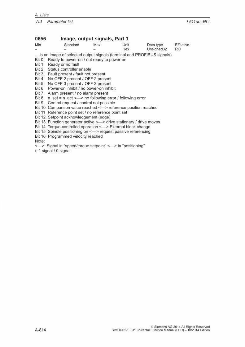
A
A.1 Parameter list
A-814� Siemens AG 2014 All Rights Reserved
SIMODRIVE 611 universal Function Manual (FBU) – 10/2014 Edition
0656 Image, output signals, Part 1Min Standard Max Unit Data type Effective– – – Hex Unsigned32 RO... is an image of selected output signals (terminal and PROFIBUS signals).Bit 0 Ready to power-on / not ready to power-onBit 1 Ready or no faultBit 2 Status controller enableBit 3 Fault present / fault not presentBit 4 No OFF 2 present / OFF 2 presentBit 5 No OFF 3 present / OFF 3 presentBit 6 Power-on inhibit / no power-on inhibitBit 7 Alarm present / no alarm presentBit 8 n_set = n_act <––> no following error / following errorBit 9 Control request / control not possibleBit 10 Comparison value reached <––> reference position reachedBit 11 Reference point set / no reference point setBit 12 Setpoint acknowledgement (edge)Bit 13 Function generator active <––> drive stationary / drive movesBit 14 Torque-controlled operation <––> External block changeBit 15 Spindle positioning on <––> request passive referencingBit 16 Programmed velocity reachedNote:<––>: Signal in ”speed/torque setpoint” <––> in ”positioning”/: 1 signal / 0 signal
A Lists
! 611ue diff !
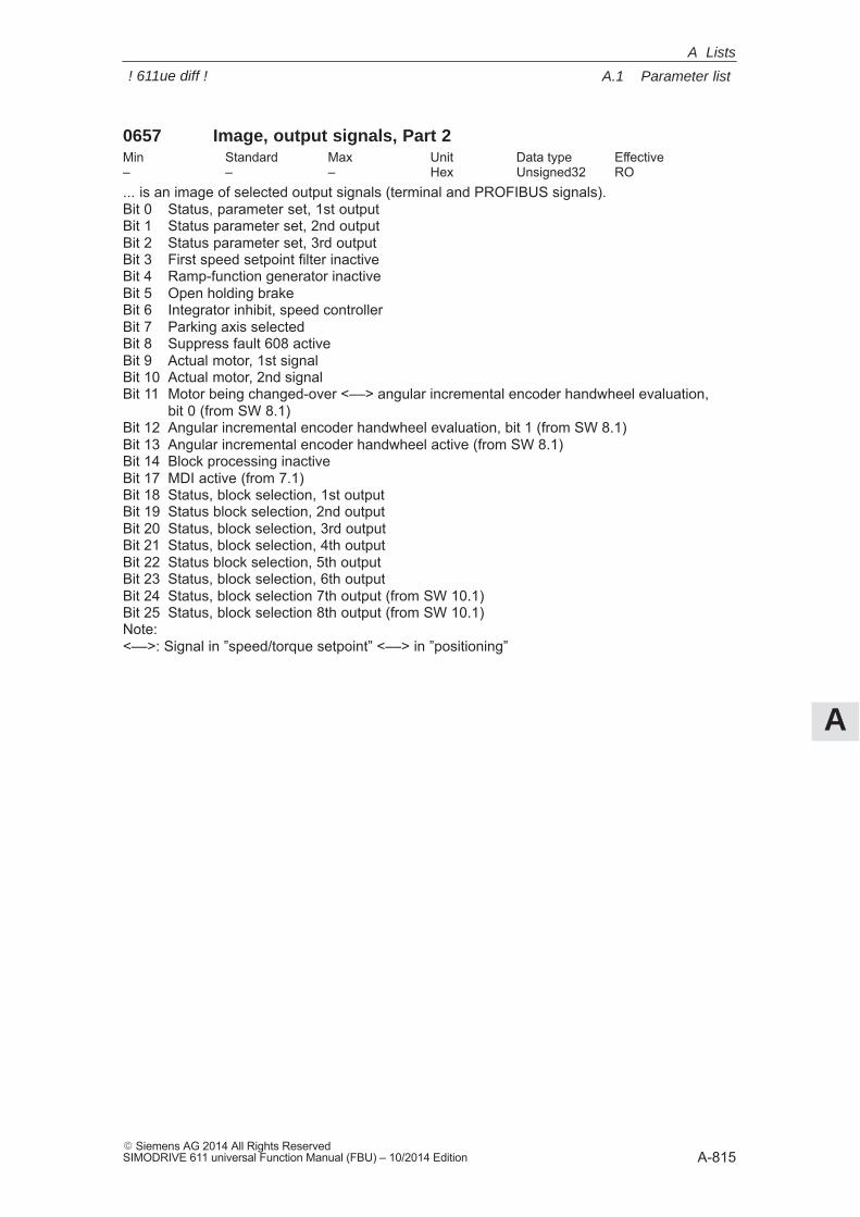
A
A.1 Parameter list
A-815� Siemens AG 2014 All Rights ReservedSIMODRIVE 611 universal Function Manual (FBU) – 10/2014 Edition
0657 Image, output signals, Part 2Min Standard Max Unit Data type Effective– – – Hex Unsigned32 RO... is an image of selected output signals (terminal and PROFIBUS signals).Bit 0 Status, parameter set, 1st outputBit 1 Status parameter set, 2nd outputBit 2 Status parameter set, 3rd outputBit 3 First speed setpoint filter inactiveBit 4 Ramp-function generator inactiveBit 5 Open holding brakeBit 6 Integrator inhibit, speed controllerBit 7 Parking axis selectedBit 8 Suppress fault 608 activeBit 9 Actual motor, 1st signalBit 10 Actual motor, 2nd signalBit 11 Motor being changed-over <––> angular incremental encoder handwheel evaluation,
bit 0 (from SW 8.1)Bit 12 Angular incremental encoder handwheel evaluation, bit 1 (from SW 8.1)Bit 13 Angular incremental encoder handwheel active (from SW 8.1)Bit 14 Block processing inactiveBit 17 MDI active (from 7.1)Bit 18 Status, block selection, 1st outputBit 19 Status block selection, 2nd outputBit 20 Status, block selection, 3rd outputBit 21 Status, block selection, 4th outputBit 22 Status block selection, 5th outputBit 23 Status, block selection, 6th outputBit 24 Status, block selection 7th output (from SW 10.1)Bit 25 Status, block selection 8th output (from SW 10.1)Note:<––>: Signal in ”speed/torque setpoint” <––> in ”positioning”
A Lists
! 611ue diff !
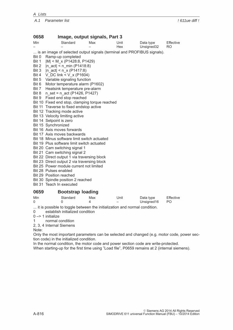
A
A.1 Parameter list
A-816� Siemens AG 2014 All Rights Reserved
SIMODRIVE 611 universal Function Manual (FBU) – 10/2014 Edition
0658 Image, output signals, Part 3Min Standard Max Unit Data type Effective– – – Hex Unsigned32 RO... is an image of selected output signals (terminal and PROFIBUS signals).Bit 0 Ramp-up completedBit 1 |M| < M_x (P1428:8, P1429)Bit 2 |n_act| < n_min (P1418:8)Bit 3 |n_act| < n_x (P1417:8)Bit 4 V_DC link < V_x (P1604)Bit 5 Variable signaling functionBit 6 Motor temperature alarm (P1602)Bit 7 Heatsink temperature pre-alarmBit 8 n_set = n_act (P1426, P1427)Bit 9 Fixed end stop reachedBit 10 Fixed end stop, clamping torque reachedBit 11 Traverse to fixed endstop activeBit 12 Tracking mode activeBit 13 Velocity limiting activeBit 14 Setpoint is zeroBit 15 SynchronizedBit 16 Axis moves forwardsBit 17 Axis moves backwardsBit 18 Minus software limit switch actuatedBit 19 Plus software limit switch actuatedBit 20 Cam switching signal 1Bit 21 Cam switching signal 2Bit 22 Direct output 1 via traversing blockBit 23 Direct output 2 via traversing blockBit 25 Power module current not limitedBit 28 Pulses enabledBit 29 Position reachedBit 30 Spindle position 2 reachedBit 31 Teach In executed
0659 Bootstrap loadingMin Standard Max Unit Data type Effective0 0 4 – Unsigned16 PO... it is possible to toggle between the initialization and normal condition.0 establish initialized condition0 –> 1 initialize1 normal condition2, 3, 4 Internal SiemensNote:Only the most important parameters can be selected and changed (e.g. motor code, power sec-tion code) in the initialized condition. In the normal condition, the motor code and power section code are write-protected.When starting-up for the first time using ”Load file”, P0659 remains at 2 (internal siemens).
A Lists
! 611ue diff !
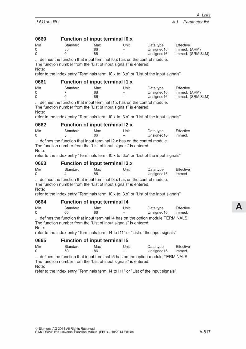
A
A.1 Parameter list
A-817� Siemens AG 2014 All Rights ReservedSIMODRIVE 611 universal Function Manual (FBU) – 10/2014 Edition
0660 Function of input terminal I0.xMin Standard Max Unit Data type Effective0 35 86 – Unsigned16 immed. (ARM)0 0 86 – Unsigned16 immed. (SRM SLM)... defines the function that input terminal I0.x has on the control module.The function number from the ”List of input signals” is entered.Note:refer to the index entry ”Terminals term. I0.x to I3.x” or ”List of the input signals”
0661 Function of input terminal I1.xMin Standard Max Unit Data type Effective0 7 86 – Unsigned16 immed. (ARM)0 0 86 – Unsigned16 immed. (SRM SLM)... defines the function that input terminal I1.x has on the control module.The function number from the ”List of input signals” is entered.Note:refer to the index entry ”Terminals term. I0.x to I3.x” or ”List of the input signals”
0662 Function of input terminal I2.xMin Standard Max Unit Data type Effective0 3 86 – Unsigned16 immed.... defines the function that input terminal I2.x has on the control module.The function number from the ”List of input signals” is entered.Note:refer to the index entry ”Terminals term. I0.x to I3.x” or ”List of the input signals”
0663 Function of input terminal I3.xMin Standard Max Unit Data type Effective0 4 86 – Unsigned16 immed.... defines the function that input terminal I3.x has on the control module.The function number from the ”List of input signals” is entered.Note:refer to the index entry ”Terminals term. I0.x to I3.x” or ”List of the input signals”
0664 Function of input terminal I4Min Standard Max Unit Data type Effective0 60 86 – Unsigned16 immed.... defines the function that input terminal I4 has on the option module TERMINALS.The function number from the ”List of input signals” is entered.Note:refer to the index entry ”Terminals term. I4 to I11” or ”List of the input signals”
0665 Function of input terminal I5Min Standard Max Unit Data type Effective0 59 86 – Unsigned16 immed.... defines the function that input terminal I5 has on the option module TERMINALS.The function number from the ”List of input signals” is entered.Note:refer to the index entry ”Terminals term. I4 to I11” or ”List of the input signals”
A Lists
! 611ue diff !
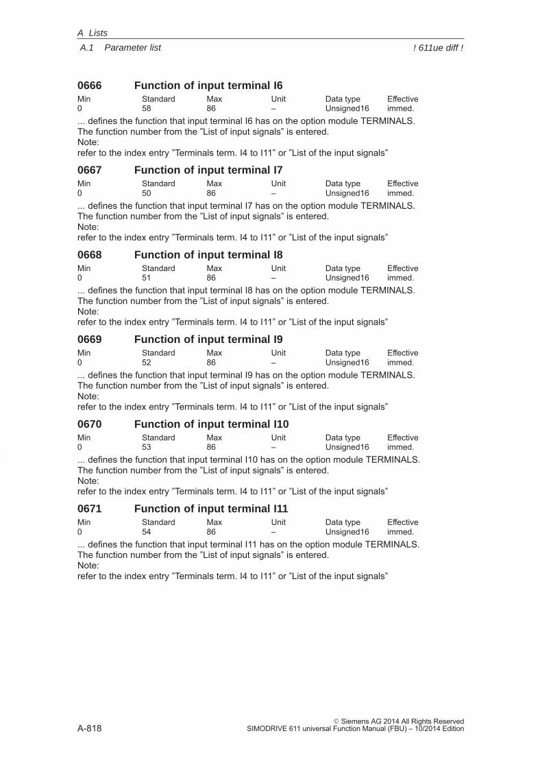
A
A.1 Parameter list
A-818� Siemens AG 2014 All Rights Reserved
SIMODRIVE 611 universal Function Manual (FBU) – 10/2014 Edition
0666 Function of input terminal I6Min Standard Max Unit Data type Effective0 58 86 – Unsigned16 immed.... defines the function that input terminal I6 has on the option module TERMINALS.The function number from the ”List of input signals” is entered.Note:refer to the index entry ”Terminals term. I4 to I11” or ”List of the input signals”
0667 Function of input terminal I7Min Standard Max Unit Data type Effective0 50 86 – Unsigned16 immed.... defines the function that input terminal I7 has on the option module TERMINALS.The function number from the ”List of input signals” is entered.Note:refer to the index entry ”Terminals term. I4 to I11” or ”List of the input signals”
0668 Function of input terminal I8Min Standard Max Unit Data type Effective0 51 86 – Unsigned16 immed.... defines the function that input terminal I8 has on the option module TERMINALS.The function number from the ”List of input signals” is entered.Note:refer to the index entry ”Terminals term. I4 to I11” or ”List of the input signals”
0669 Function of input terminal I9Min Standard Max Unit Data type Effective0 52 86 – Unsigned16 immed.... defines the function that input terminal I9 has on the option module TERMINALS.The function number from the ”List of input signals” is entered.Note:refer to the index entry ”Terminals term. I4 to I11” or ”List of the input signals”
0670 Function of input terminal I10Min Standard Max Unit Data type Effective0 53 86 – Unsigned16 immed.... defines the function that input terminal I10 has on the option module TERMINALS.The function number from the ”List of input signals” is entered.Note:refer to the index entry ”Terminals term. I4 to I11” or ”List of the input signals”
0671 Function of input terminal I11Min Standard Max Unit Data type Effective0 54 86 – Unsigned16 immed.... defines the function that input terminal I11 has on the option module TERMINALS.The function number from the ”List of input signals” is entered.Note:refer to the index entry ”Terminals term. I4 to I11” or ”List of the input signals”
A Lists
! 611ue diff !
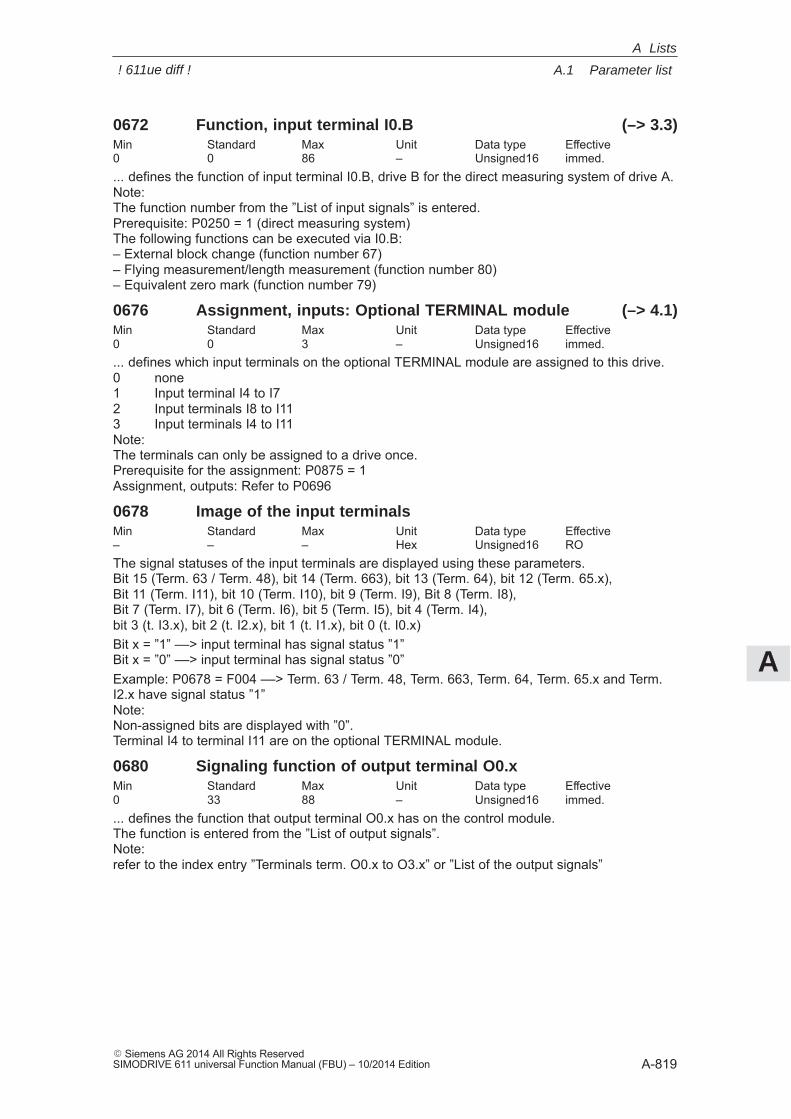
A
A.1 Parameter list
A-819� Siemens AG 2014 All Rights ReservedSIMODRIVE 611 universal Function Manual (FBU) – 10/2014 Edition
0672 Function, input terminal I0.B (–> 3.3)Min Standard Max Unit Data type Effective0 0 86 – Unsigned16 immed.... defines the function of input terminal I0.B, drive B for the direct measuring system of drive A.Note:The function number from the ”List of input signals” is entered.Prerequisite: P0250 = 1 (direct measuring system)The following functions can be executed via I0.B:– External block change (function number 67)– Flying measurement/length measurement (function number 80)– Equivalent zero mark (function number 79)
0676 Assignment, inputs: Optional TERMINAL module (–> 4.1)Min Standard Max Unit Data type Effective0 0 3 – Unsigned16 immed.... defines which input terminals on the optional TERMINAL module are assigned to this drive.0 none1 Input terminal I4 to I72 Input terminals I8 to I113 Input terminals I4 to I11Note:The terminals can only be assigned to a drive once.Prerequisite for the assignment: P0875 = 1Assignment, outputs: Refer to P0696
0678 Image of the input terminalsMin Standard Max Unit Data type Effective– – – Hex Unsigned16 ROThe signal statuses of the input terminals are displayed using these parameters.Bit 15 (Term. 63 / Term. 48), bit 14 (Term. 663), bit 13 (Term. 64), bit 12 (Term. 65.x),Bit 11 (Term. I11), bit 10 (Term. I10), bit 9 (Term. I9), Bit 8 (Term. I8),Bit 7 (Term. I7), bit 6 (Term. I6), bit 5 (Term. I5), bit 4 (Term. I4),bit 3 (t. I3.x), bit 2 (t. I2.x), bit 1 (t. I1.x), bit 0 (t. I0.x)Bit x = ”1” ––> input terminal has signal status ”1”Bit x = ”0” ––> input terminal has signal status ”0”Example: P0678 = F004 ––> Term. 63 / Term. 48, Term. 663, Term. 64, Term. 65.x and Term.I2.x have signal status ”1”Note:Non-assigned bits are displayed with ”0”.Terminal I4 to terminal I11 are on the optional TERMINAL module.
0680 Signaling function of output terminal O0.xMin Standard Max Unit Data type Effective0 33 88 – Unsigned16 immed.... defines the function that output terminal O0.x has on the control module.The function is entered from the ”List of output signals”.Note:refer to the index entry ”Terminals term. O0.x to O3.x” or ”List of the output signals”
A Lists
! 611ue diff !

A
A.1 Parameter list
A-820� Siemens AG 2014 All Rights Reserved
SIMODRIVE 611 universal Function Manual (FBU) – 10/2014 Edition
0681 Signaling function of output terminal O1.xMin Standard Max Unit Data type Effective0 2 88 – Unsigned16 immed.... defines the function that output terminal O1.x has on the control module.The function is entered from the ”List of output signals”.Note:refer to the index entry ”Terminals term. O0.x to O3.x” or ”List of the output signals”
0682 Signaling function of output terminal O2.xMin Standard Max Unit Data type Effective0 1 88 – Unsigned16 immed.... defines the function that output terminal O2.x has on the control module.The function is entered from the ”List of output signals”.Note:refer to the index entry ”Terminals term. O0.x to O3.x” or ”List of the output signals”
0683 Signaling function of output terminal O3.xMin Standard Max Unit Data type Effective0 5 88 – Unsigned16 immed.... defines the function that output terminal O3.x has on the control module.The function is entered from the ”List of output signals”.Note:refer to the index entry ”Terminals term. O0.x to O3.x” or ”List of the output signals”
0684 Signaling function, output terminal O4Min Standard Max Unit Data type Effective0 72 88 – Unsigned16 immed.... defines the function that output terminal O4 has on the option module TERMINALS.The function is entered from the ”List of output signals”.Note:refer to the index entry ”Terminals term. O4 to O11” or ”List of the output signals”
0685 Signaling function, output terminal O5Min Standard Max Unit Data type Effective0 60 88 – Unsigned16 immed.... defines the function that output terminal O5 has on the option module TERMINALS.The function is entered from the ”List of output signals”.Note:refer to the index entry ”Terminals term. O4 to O11” or ”List of the output signals”
0686 Signaling function, output terminal O6Min Standard Max Unit Data type Effective0 62 88 – Unsigned16 immed.... defines the function thatoutput terminal O6 has on the option module TERMINALS.The function is entered from the ”List of output signals”.Note:refer to the index entry ”Terminals term. O4 to O11” or ”List of the output signals”
A Lists
! 611ue diff !
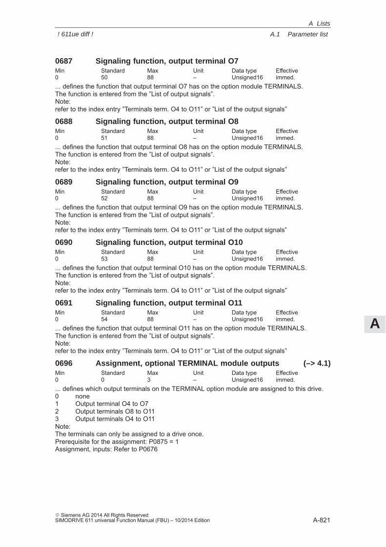
A
A.1 Parameter list
A-821� Siemens AG 2014 All Rights ReservedSIMODRIVE 611 universal Function Manual (FBU) – 10/2014 Edition
0687 Signaling function, output terminal O7Min Standard Max Unit Data type Effective0 50 88 – Unsigned16 immed.... defines the function that output terminal O7 has on the option module TERMINALS.The function is entered from the ”List of output signals”.Note:refer to the index entry ”Terminals term. O4 to O11” or ”List of the output signals”
0688 Signaling function, output terminal O8Min Standard Max Unit Data type Effective0 51 88 – Unsigned16 immed.... defines the function that output terminal O8 has on the option module TERMINALS.The function is entered from the ”List of output signals”.Note:refer to the index entry ”Terminals term. O4 to O11” or ”List of the output signals”
0689 Signaling function, output terminal O9Min Standard Max Unit Data type Effective0 52 88 – Unsigned16 immed.... defines the function that output terminal O9 has on the option module TERMINALS.The function is entered from the ”List of output signals”.Note:refer to the index entry ”Terminals term. O4 to O11” or ”List of the output signals”
0690 Signaling function, output terminal O10Min Standard Max Unit Data type Effective0 53 88 – Unsigned16 immed.... defines the function that output terminal O10 has on the option module TERMINALS.The function is entered from the ”List of output signals”.Note:refer to the index entry ”Terminals term. O4 to O11” or ”List of the output signals”
0691 Signaling function, output terminal O11Min Standard Max Unit Data type Effective0 54 88 – Unsigned16 immed.... defines the function that output terminal O11 has on the option module TERMINALS.The function is entered from the ”List of output signals”.Note:refer to the index entry ”Terminals term. O4 to O11” or ”List of the output signals”
0696 Assignment, optional TERMINAL module outputs (–> 4.1)Min Standard Max Unit Data type Effective0 0 3 – Unsigned16 immed.... defines which output terminals on the TERMINAL option module are assigned to this drive.0 none1 Output terminal O4 to O72 Output terminals O8 to O113 Output terminals O4 to O11Note:The terminals can only be assigned to a drive once.Prerequisite for the assignment: P0875 = 1Assignment, inputs: Refer to P0676
A Lists
! 611ue diff !
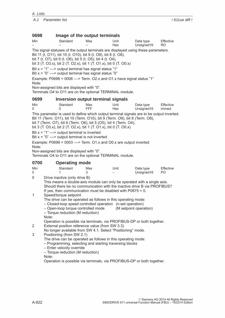
A
A.1 Parameter list
A-822� Siemens AG 2014 All Rights Reserved
SIMODRIVE 611 universal Function Manual (FBU) – 10/2014 Edition
0698 Image of the output terminalsMin Standard Max Unit Data type Effective– – – Hex Unsigned16 ROThe signal statuses of the output terminals are displayed using these parameters.Bit 11 (t. O11), bit 10 (t. O10), bit 9 (t. O9), bit 8 (t. O8), bit 7 (t. O7), bit 6 (t. O6), bit 5 (t. O5), bit 4 (t. O4), bit 3 (T. O3.x), bit 2 (T. O2.x), bit 1 (T. O1.x), bit 0 (T. O0.x)Bit x = ”1” ––> output terminal has signal status ”1”Bit x = ”0” ––> output terminal has signal status ”0”Example: P0698 = 0006 ––> Term. O2.x and O1.x have signal status ”1”Note:Non-assigned bits are displayed with ”0”.Terminals O4 to O11 are on the optional TERMINAL module.
0699 Inversion output terminal signalsMin Standard Max Unit Data type Effective0 0 FFF Hex Unsigned16 immed.This parameter is used to define which output terminal signals are to be output inverted.Bit 11 (Term. O11), bit 10 (Term. O10), bit 9 (Term. O9), bit 8 (Term. O8),bit 7 (Term. O7), bit 6 (Term. O6), bit 5 (O5), bit 4 (Term. O4),bit 3 (T. O3.x), bit 2 (T. O2.x), bit 1 (T. O1.x), bit 0 (T. O0.x)Bit x = ”1” ––> output terminal is invertedBit x = ”0” ––> output terminal is not invertedExample: P0699 = 0003 ––> Term. O1.x and O0.x are output invertedNote:Non-assigned bits are displayed with ”0”.Terminals O4 to O11 are on the optional TERMINAL module.
0700 Operating modeMin Standard Max Unit Data type Effective0 1 3 – Unsigned16 PO0 Drive inactive (only drive B)
This means a double-axis module can only be operated with a single axis.Should there be no communication with the inactive drive B via PROFIBUS?If yes, then communication must be disabled with P0875 = 0.
1 Speed/torque setpointThe drive can be operated as follows in this operating mode:– Closed-loop speed controlled operation (n-set operation)– Open-loop torque controlled mode (M setpoint operation)– Torque reduction (M reduction)Note:Operation is possible via terminals, via PROFIBUS-DP or both together.
2 External position reference value (from SW 3.3)No longer available from SW 4.1. Select ”Positioning” mode.
3 Positioning (from SW 2.1)The drive can be operated as follows in this operating mode:– Programming, selecting and starting traversing blocks– Enter velocity override– Torque reduction (M reduction)Note:Operation is possible via terminals, via PROFIBUS-DP or both together.
A Lists
! 611ue diff !
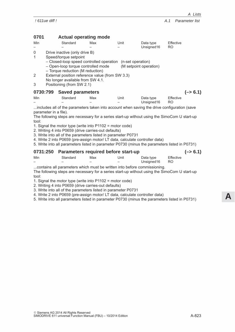
A
A.1 Parameter list
A-823� Siemens AG 2014 All Rights ReservedSIMODRIVE 611 universal Function Manual (FBU) – 10/2014 Edition
0701 Actual operating modeMin Standard Max Unit Data type Effective– – – – Unsigned16 RO0 Drive inactive (only drive B)1 Speed/torque setpoint
– Closed-loop speed controlled operation (n-set operation)– Open-loop torque controlled mode (M setpoint operation)– Torque reduction (M reduction)
2 External position reference value (from SW 3.3)No longer available from SW 4.1.
3 Positioning (from SW 2.1)
0730:799 Saved parameters (–> 6.1)Min Standard Max Unit Data type Effective– – – – Unsigned16 RO...includes all of the parameters taken into account when saving the drive configuration (saveparameter in a file).The following steps are necessary for a series start-up without using the SimoCom U start-uptool:1. Signal the motor type (write into P1102 = motor code)2. Writing 4 into P0659 (drive carries-out defaults)3. Write into all of the parameters listed in parameter P07314. Write 2 into P0659 (pre-assign motor/ LT data, calculate controller data)5. Write into all parameters listed in parameter P0730 (minus the parameters listed in P0731)
0731:250 Parameters required before start-up (–> 6.1)Min Standard Max Unit Data type Effective– – – – Unsigned16 RO...contains all parameters which must be written into before commissioning.The following steps are necessary for a series start-up without using the SimoCom U start-uptool:1. Signal the motor type (write into P1102 = motor code)2. Writing 4 into P0659 (drive carries-out defaults)3. Write into all of the parameters listed in parameter P07314. Write 2 into P0659 (pre-assign motor/ LT data, calculate controller data)5. Write into all parameters listed in parameter P0730 (minus the parameters listed in P0731)
A Lists
! 611ue diff !
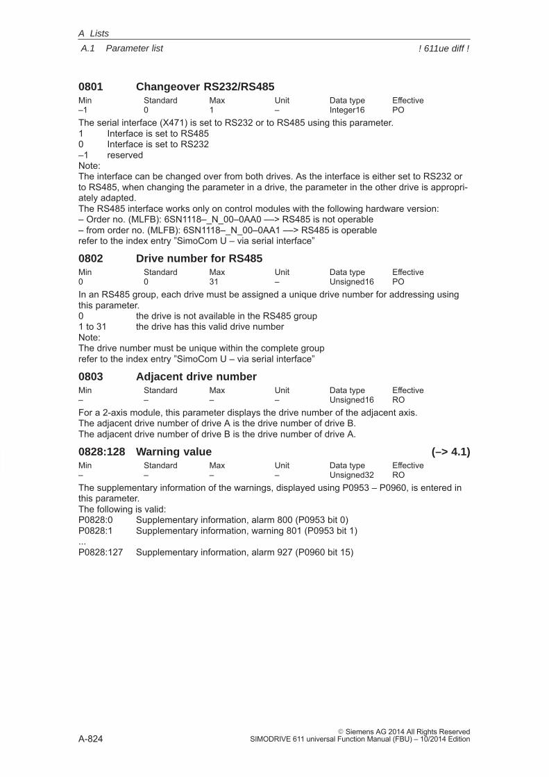
A
A.1 Parameter list
A-824� Siemens AG 2014 All Rights Reserved
SIMODRIVE 611 universal Function Manual (FBU) – 10/2014 Edition
0801 Changeover RS232/RS485Min Standard Max Unit Data type Effective–1 0 1 – Integer16 POThe serial interface (X471) is set to RS232 or to RS485 using this parameter.1 Interface is set to RS4850 Interface is set to RS232–1 reservedNote:The interface can be changed over from both drives. As the interface is either set to RS232 orto RS485, when changing the parameter in a drive, the parameter in the other drive is appropri-ately adapted.The RS485 interface works only on control modules with the following hardware version:– Order no. (MLFB): 6SN1118–_N_00–0AA0 ––> RS485 is not operable– from order no. (MLFB): 6SN1118–_N_00–0AA1 ––> RS485 is operablerefer to the index entry ”SimoCom U – via serial interface”
0802 Drive number for RS485Min Standard Max Unit Data type Effective0 0 31 – Unsigned16 POIn an RS485 group, each drive must be assigned a unique drive number for addressing usingthis parameter.0 the drive is not available in the RS485 group 1 to 31 the drive has this valid drive numberNote:The drive number must be unique within the complete grouprefer to the index entry ”SimoCom U – via serial interface”
0803 Adjacent drive numberMin Standard Max Unit Data type Effective– – – – Unsigned16 ROFor a 2-axis module, this parameter displays the drive number of the adjacent axis.The adjacent drive number of drive A is the drive number of drive B.The adjacent drive number of drive B is the drive number of drive A.
0828:128 Warning value (–> 4.1)Min Standard Max Unit Data type Effective– – – – Unsigned32 ROThe supplementary information of the warnings, displayed using P0953 – P0960, is entered inthis parameter.The following is valid:P0828:0 Supplementary information, alarm 800 (P0953 bit 0)P0828:1 Supplementary information, warning 801 (P0953 bit 1)...P0828:127 Supplementary information, alarm 927 (P0960 bit 15)
A Lists
! 611ue diff !
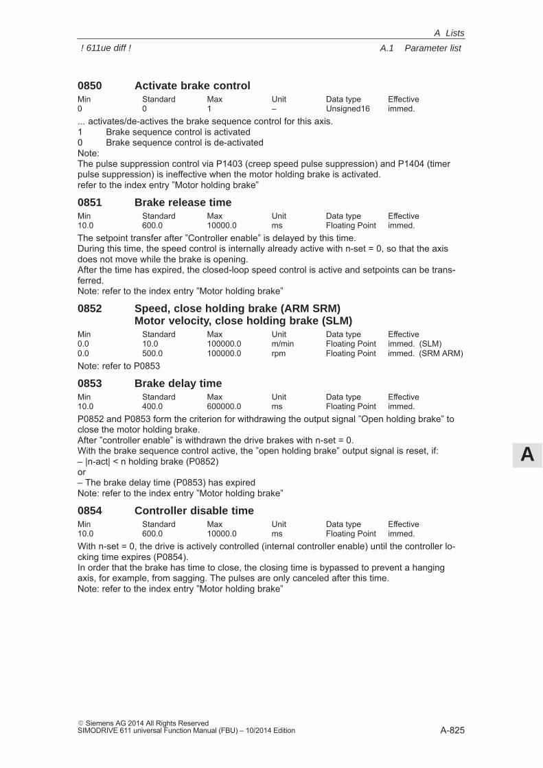
A
A.1 Parameter list
A-825� Siemens AG 2014 All Rights ReservedSIMODRIVE 611 universal Function Manual (FBU) – 10/2014 Edition
0850 Activate brake controlMin Standard Max Unit Data type Effective0 0 1 – Unsigned16 immed.... activates/de-actives the brake sequence control for this axis.1 Brake sequence control is activated0 Brake sequence control is de-activatedNote:The pulse suppression control via P1403 (creep speed pulse suppression) and P1404 (timerpulse suppression) is ineffective when the motor holding brake is activated.refer to the index entry ”Motor holding brake”
0851 Brake release timeMin Standard Max Unit Data type Effective10.0 600.0 10000.0 ms Floating Point immed.The setpoint transfer after ”Controller enable” is delayed by this time.During this time, the speed control is internally already active with n-set = 0, so that the axisdoes not move while the brake is opening.After the time has expired, the closed-loop speed control is active and setpoints can be trans-ferred.Note: refer to the index entry ”Motor holding brake”
0852 Speed, close holding brake (ARM SRM)Motor velocity, close holding brake (SLM)
Min Standard Max Unit Data type Effective0.0 10.0 100000.0 m/min Floating Point immed. (SLM)0.0 500.0 100000.0 rpm Floating Point immed. (SRM ARM)Note: refer to P0853
0853 Brake delay timeMin Standard Max Unit Data type Effective10.0 400.0 600000.0 ms Floating Point immed.P0852 and P0853 form the criterion for withdrawing the output signal ”Open holding brake” toclose the motor holding brake.After ”controller enable” is withdrawn the drive brakes with n-set = 0.With the brake sequence control active, the ”open holding brake” output signal is reset, if:– |n-act| < n holding brake (P0852)or– The brake delay time (P0853) has expiredNote: refer to the index entry ”Motor holding brake”
0854 Controller disable timeMin Standard Max Unit Data type Effective10.0 600.0 10000.0 ms Floating Point immed.With n-set = 0, the drive is actively controlled (internal controller enable) until the controller lo-cking time expires (P0854).In order that the brake has time to close, the closing time is bypassed to prevent a hangingaxis, for example, from sagging. The pulses are only canceled after this time.Note: refer to the index entry ”Motor holding brake”
A Lists
! 611ue diff !
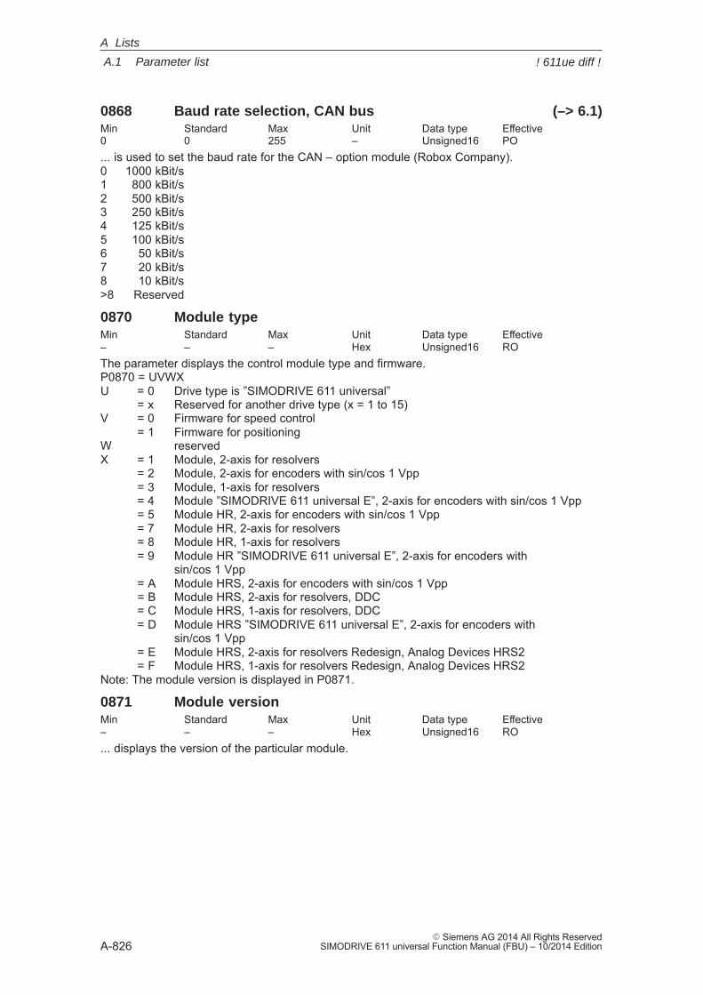
A
A.1 Parameter list
A-826� Siemens AG 2014 All Rights Reserved
SIMODRIVE 611 universal Function Manual (FBU) – 10/2014 Edition
0868 Baud rate selection, CAN bus (–> 6.1)Min Standard Max Unit Data type Effective0 0 255 – Unsigned16 PO... is used to set the baud rate for the CAN – option module (Robox Company).0 1000 kBit/s1 800 kBit/s2 500 kBit/s3 250 kBit/s4 125 kBit/s5 100 kBit/s6 50 kBit/s7 20 kBit/s8 10 kBit/s>8 Reserved
0870 Module typeMin Standard Max Unit Data type Effective– – – Hex Unsigned16 ROThe parameter displays the control module type and firmware.P0870 = UVWXU = 0 Drive type is ”SIMODRIVE 611 universal”
= x Reserved for another drive type (x = 1 to 15)V = 0 Firmware for speed control
= 1 Firmware for positioningW reservedX = 1 Module, 2-axis for resolvers
= 2 Module, 2-axis for encoders with sin/cos 1 Vpp= 3 Module, 1-axis for resolvers= 4 Module ”SIMODRIVE 611 universal E”, 2-axis for encoders with sin/cos 1 Vpp= 5 Module HR, 2-axis for encoders with sin/cos 1 Vpp= 7 Module HR, 2-axis for resolvers= 8 Module HR, 1-axis for resolvers= 9 Module HR ”SIMODRIVE 611 universal E”, 2-axis for encoders with
sin/cos 1 Vpp= A Module HRS, 2-axis for encoders with sin/cos 1 Vpp= B Module HRS, 2-axis for resolvers, DDC= C Module HRS, 1-axis for resolvers, DDC= D Module HRS ”SIMODRIVE 611 universal E”, 2-axis for encoders with
sin/cos 1 Vpp= E Module HRS, 2-axis for resolvers Redesign, Analog Devices HRS2= F Module HRS, 1-axis for resolvers Redesign, Analog Devices HRS2
Note: The module version is displayed in P0871.
0871 Module versionMin Standard Max Unit Data type Effective– – – Hex Unsigned16 RO... displays the version of the particular module.
A Lists
! 611ue diff !
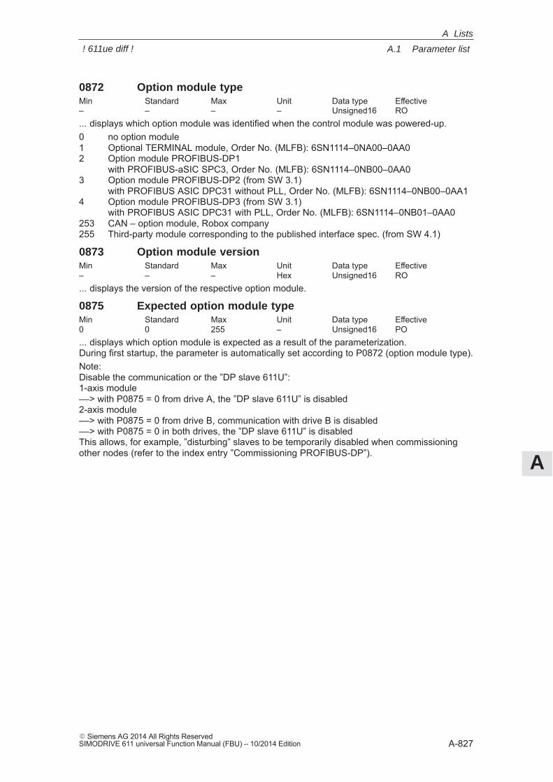
A
A.1 Parameter list
A-827� Siemens AG 2014 All Rights ReservedSIMODRIVE 611 universal Function Manual (FBU) – 10/2014 Edition
0872 Option module typeMin Standard Max Unit Data type Effective– – – – Unsigned16 RO... displays which option module was identified when the control module was powered-up.0 no option module1 Optional TERMINAL module, Order No. (MLFB): 6SN1114–0NA00–0AA02 Option module PROFIBUS-DP1
with PROFIBUS-aSIC SPC3, Order No. (MLFB): 6SN1114–0NB00–0AA03 Option module PROFIBUS-DP2 (from SW 3.1)
with PROFIBUS ASIC DPC31 without PLL, Order No. (MLFB): 6SN1114–0NB00–0AA14 Option module PROFIBUS-DP3 (from SW 3.1)
with PROFIBUS ASIC DPC31 with PLL, Order No. (MLFB): 6SN1114–0NB01–0AA0253 CAN – option module, Robox company255 Third-party module corresponding to the published interface spec. (from SW 4.1)
0873 Option module versionMin Standard Max Unit Data type Effective– – – Hex Unsigned16 RO... displays the version of the respective option module.
0875 Expected option module typeMin Standard Max Unit Data type Effective0 0 255 – Unsigned16 PO... displays which option module is expected as a result of the parameterization.During first startup, the parameter is automatically set according to P0872 (option module type).Note:Disable the communication or the ”DP slave 611U”:1-axis module––> with P0875 = 0 from drive A, the ”DP slave 611U” is disabled2-axis module––> with P0875 = 0 from drive B, communication with drive B is disabled––> with P0875 = 0 in both drives, the ”DP slave 611U” is disabledThis allows, for example, ”disturbing” slaves to be temporarily disabled when commissioningother nodes (refer to the index entry ”Commissioning PROFIBUS-DP”).
A Lists
! 611ue diff !
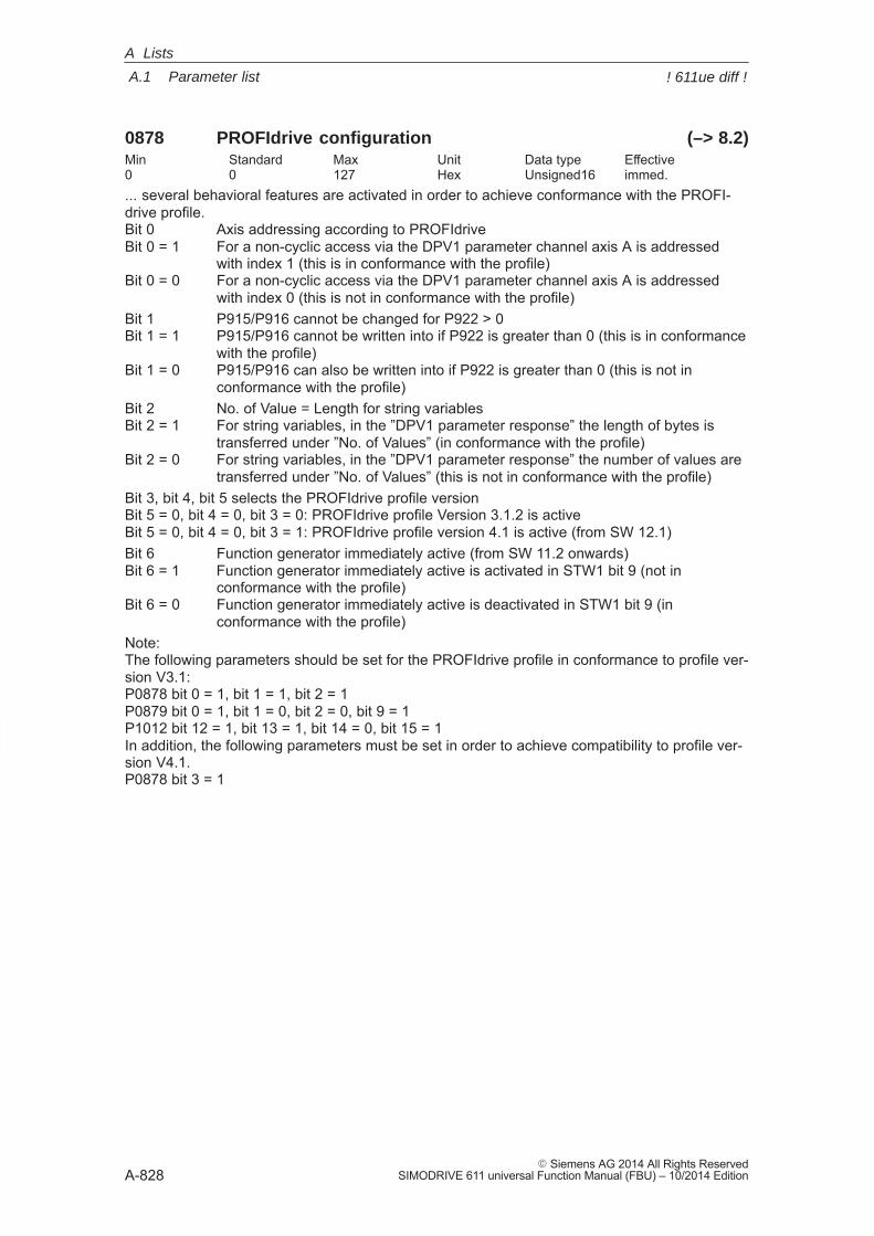
A
A.1 Parameter list
A-828� Siemens AG 2014 All Rights Reserved
SIMODRIVE 611 universal Function Manual (FBU) – 10/2014 Edition
0878 PROFIdrive configuration (–> 8.2)Min Standard Max Unit Data type Effective0 0 127 Hex Unsigned16 immed.... several behavioral features are activated in order to achieve conformance with the PROFI-drive profile.Bit 0 Axis addressing according to PROFIdriveBit 0 = 1 For a non-cyclic access via the DPV1 parameter channel axis A is addressed
with index 1 (this is in conformance with the profile)Bit 0 = 0 For a non-cyclic access via the DPV1 parameter channel axis A is addressed
with index 0 (this is not in conformance with the profile)Bit 1 P915/P916 cannot be changed for P922 > 0Bit 1 = 1 P915/P916 cannot be written into if P922 is greater than 0 (this is in conformance
with the profile)Bit 1 = 0 P915/P916 can also be written into if P922 is greater than 0 (this is not in
conformance with the profile)Bit 2 No. of Value = Length for string variablesBit 2 = 1 For string variables, in the ”DPV1 parameter response” the length of bytes is
transferred under ”No. of Values” (in conformance with the profile)Bit 2 = 0 For string variables, in the ”DPV1 parameter response” the number of values are
transferred under ”No. of Values” (this is not in conformance with the profile)Bit 3, bit 4, bit 5 selects the PROFIdrive profile version Bit 5 = 0, bit 4 = 0, bit 3 = 0: PROFIdrive profile Version 3.1.2 is activeBit 5 = 0, bit 4 = 0, bit 3 = 1: PROFIdrive profile version 4.1 is active (from SW 12.1)Bit 6 Function generator immediately active (from SW 11.2 onwards)Bit 6 = 1 Function generator immediately active is activated in STW1 bit 9 (not in
conformance with the profile)Bit 6 = 0 Function generator immediately active is deactivated in STW1 bit 9 (in
conformance with the profile)Note:The following parameters should be set for the PROFIdrive profile in conformance to profile ver-sion V3.1:P0878 bit 0 = 1, bit 1 = 1, bit 2 = 1P0879 bit 0 = 1, bit 1 = 0, bit 2 = 0, bit 9 = 1P1012 bit 12 = 1, bit 13 = 1, bit 14 = 0, bit 15 = 1In addition, the following parameters must be set in order to achieve compatibility to profile ver-sion V4.1.P0878 bit 3 = 1
A Lists
! 611ue diff !
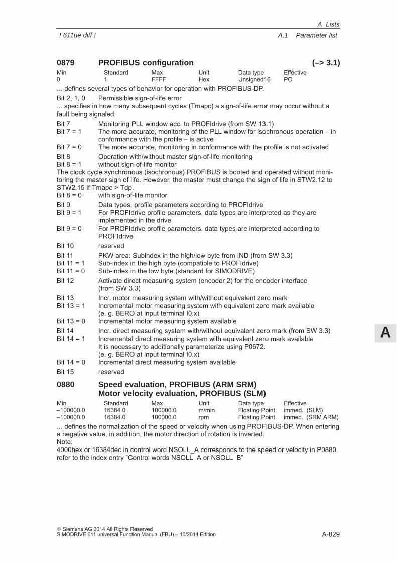
A
A.1 Parameter list
A-829� Siemens AG 2014 All Rights ReservedSIMODRIVE 611 universal Function Manual (FBU) – 10/2014 Edition
0879 PROFIBUS configuration (–> 3.1)Min Standard Max Unit Data type Effective0 1 FFFF Hex Unsigned16 PO... defines several types of behavior for operation with PROFIBUS-DP.Bit 2, 1, 0 Permissible sign-of-life error... specifies in how many subsequent cycles (Tmapc) a sign-of-life error may occur without afault being signaled.Bit 7 Monitoring PLL window acc. to PROFIdrive (from SW 13.1)Bit 7 = 1 The more accurate, monitoring of the PLL window for isochronous operation – in
conformance with the profile – is activeBit 7 = 0 The more accurate, monitoring in conformance with the profile is not activatedBit 8 Operation with/without master sign-of-life monitoringBit 8 = 1 without sign-of-life monitorThe clock cycle synchronous (isochronous) PROFIBUS is booted and operated without moni-toring the master sign of life. However, the master must change the sign of life in STW2.12 toSTW2.15 if Tmapc > Tdp.Bit 8 = 0 with sign-of-life monitorBit 9 Data types, profile parameters according to PROFIdriveBit 9 = 1 For PROFIdrive profile parameters, data types are interpreted as they are
implemented in the driveBit 9 = 0 For PROFIdrive profile parameters, data types are interpreted according to
PROFIdriveBit 10 reservedBit 11 PKW area: Subindex in the high/low byte from IND (from SW 3.3)Bit 11 = 1 Sub-index in the high byte (compatible to PROFIdrive)Bit 11 = 0 Sub-index in the low byte (standard for SIMODRIVE)Bit 12 Activate direct measuring system (encoder 2) for the encoder interface
(from SW 3.3)Bit 13 Incr. motor measuring system with/without equivalent zero markBit 13 = 1 Incremental motor measuring system with equivalent zero mark available
(e. g. BERO at input terminal I0.x)Bit 13 = 0 Incremental motor measuring system availableBit 14 Incr. direct measuring system with/without equivalent zero mark (from SW 3.3)Bit 14 = 1 Incremental direct measuring system with equivalent zero mark available
It is necessary to additionally parameterize using P0672.(e. g. BERO at input terminal I0.x)
Bit 14 = 0 Incremental direct measuring system availableBit 15 reserved
0880 Speed evaluation, PROFIBUS (ARM SRM)Motor velocity evaluation, PROFIBUS (SLM)
Min Standard Max Unit Data type Effective–100000.0 16384.0 100000.0 m/min Floating Point immed. (SLM)–100000.0 16384.0 100000.0 rpm Floating Point immed. (SRM ARM)... defines the normalization of the speed or velocity when using PROFIBUS-DP. When enteringa negative value, in addition, the motor direction of rotation is inverted.Note:4000hex or 16384dec in control word NSOLL_A corresponds to the speed or velocity in P0880.refer to the index entry ”Control words NSOLL_A or NSOLL_B”
A Lists
! 611ue diff !
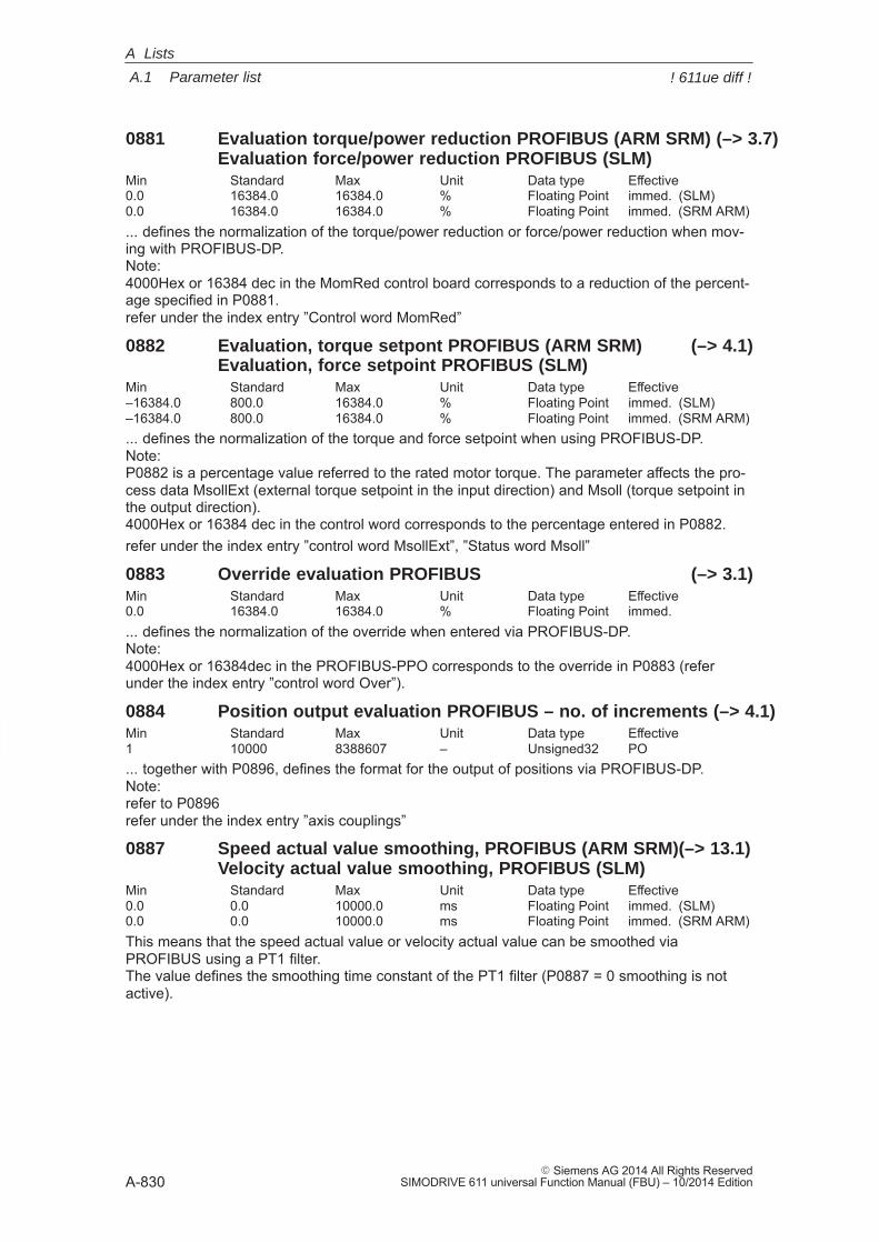
A
A.1 Parameter list
A-830� Siemens AG 2014 All Rights Reserved
SIMODRIVE 611 universal Function Manual (FBU) – 10/2014 Edition
0881 Evaluation torque/power reduction PROFIBUS (ARM SRM) (–> 3.7)Evaluation force/power reduction PROFIBUS (SLM)
Min Standard Max Unit Data type Effective0.0 16384.0 16384.0 % Floating Point immed. (SLM)0.0 16384.0 16384.0 % Floating Point immed. (SRM ARM)... defines the normalization of the torque/power reduction or force/power reduction when mov-ing with PROFIBUS-DP.Note:4000Hex or 16384 dec in the MomRed control board corresponds to a reduction of the percent-age specified in P0881.refer under the index entry ”Control word MomRed”
0882 Evaluation, torque setpont PROFIBUS (ARM SRM) (–> 4.1)Evaluation, force setpoint PROFIBUS (SLM)
Min Standard Max Unit Data type Effective–16384.0 800.0 16384.0 % Floating Point immed. (SLM)–16384.0 800.0 16384.0 % Floating Point immed. (SRM ARM)... defines the normalization of the torque and force setpoint when using PROFIBUS-DP. Note:P0882 is a percentage value referred to the rated motor torque. The parameter affects the pro-cess data MsollExt (external torque setpoint in the input direction) and Msoll (torque setpoint inthe output direction).4000Hex or 16384 dec in the control word corresponds to the percentage entered in P0882.refer under the index entry ”control word MsollExt”, ”Status word Msoll”
0883 Override evaluation PROFIBUS (–> 3.1)Min Standard Max Unit Data type Effective0.0 16384.0 16384.0 % Floating Point immed.... defines the normalization of the override when entered via PROFIBUS-DP. Note:4000Hex or 16384dec in the PROFIBUS-PPO corresponds to the override in P0883 (referunder the index entry ”control word Over”).
0884 Position output evaluation PROFIBUS – no. of increments (–> 4.1)Min Standard Max Unit Data type Effective1 10000 8388607 – Unsigned32 PO... together with P0896, defines the format for the output of positions via PROFIBUS-DP.Note:refer to P0896refer under the index entry ”axis couplings”
0887 Speed actual value smoothing, PROFIBUS (ARM SRM)(–> 13.1)Velocity actual value smoothing, PROFIBUS (SLM)
Min Standard Max Unit Data type Effective0.0 0.0 10000.0 ms Floating Point immed. (SLM)0.0 0.0 10000.0 ms Floating Point immed. (SRM ARM)This means that the speed actual value or velocity actual value can be smoothed viaPROFIBUS using a PT1 filter.The value defines the smoothing time constant of the PT1 filter (P0887 = 0 smoothing is notactive).
A Lists
! 611ue diff !
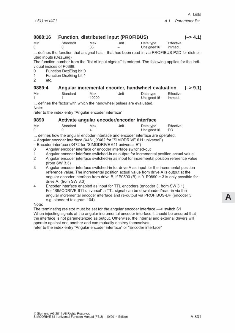
A
A.1 Parameter list
A-831� Siemens AG 2014 All Rights ReservedSIMODRIVE 611 universal Function Manual (FBU) – 10/2014 Edition
0888:16 Function, distributed input (PROFIBUS) (–> 4.1)Min Standard Max Unit Data type Effective0 0 83 – Unsigned16 immed.... defines the function that a signal has – that has been read-in via PROFIBUS-PZD for distrib-uted inputs (DezEing)The function number from the ”list of input signals” is entered. The following applies for the indi-vidual indices of P0888:0 Function DezEing bit 01 Function DezEing bit 12 etc.
0889:4 Angular incremental encoder, handwheel evaluation (–> 9.1)Min Standard Max Unit Data type Effective1 1 10000 – Unsigned16 immed.... defines the factor with which the handwheel pulses are evaluated.Note:refer to the index entry ”Angular encoder interface”
0890 Activate angular encoder/encoder interfaceMin Standard Max Unit Data type Effective0 0 4 – Unsigned16 PO... defines how the angular encoder interface and encoder interface are operated.– Angular encoder interface (X461, X462 for ”SIMODRIVE 611 universal”)– Encoder interface (X472 for ”SIMODRIVE 611 universal E”)0 Angular encoder interface or encoder interface switched-out1 Angular encoder interface switched-in as output for incremental position actual value2 Angular encoder interface switched-in as input for incremental position reference value
(from SW 3.3)3 Angular encoder interface switched-in for drive A as input for the incremental position
reference value. The incremental position actual value from drive A is output at the angular encoder interface from drive B, if P0890 (B) is 0. P0890 = 3 is only possible for drive A. (from SW 3.3)
4 Encoder interface enabled as input for TTL encoders (encoder 3, from SW 3.1)For ”SIMODRIVE 611 universal” a TTL signal can be downloaded/read-in via the angular incremental encoder interface and re-output via PROFIBUS-DP (encoder 3, e.g. standard telegram 104).
Note:The terminating resistor must be set for the angular encoder interface ––> switch S1When injecting signals at the angular incremental encoder interface it should be ensured thatthe interface is not parameterized as output. Otherwise, the internal and external drivers willoperate against one another and can mutually destroy themselves.refer to the index entry ”Angular encoder interface” or ”Encoder interface”
A Lists
! 611ue diff !
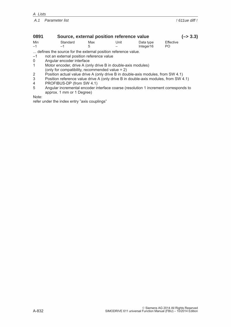
A
A.1 Parameter list
A-832� Siemens AG 2014 All Rights Reserved
SIMODRIVE 611 universal Function Manual (FBU) – 10/2014 Edition
0891 Source, external position reference value (–> 3.3)Min Standard Max Unit Data type Effective–1 –1 5 – Integer16 PO... defines the source for the external position reference value.–1 not an external position reference value0 Angular encoder interface1 Motor encoder, drive A (only drive B in double-axis modules)
(only for compatibility, recommended value = 2)2 Position actual value drive A (only drive B in double-axis modules, from SW 4.1)3 Position reference value drive A (only drive B in double-axis modules, from SW 4.1)4 PROFIBUS-DP (from SW 4.1)5 Angular incremental encoder interface coarse (resolution 1 increment corresponds to
approx. 1 mm or 1 Degree)Note:refer under the index entry ”axis couplings”
A Lists
! 611ue diff !
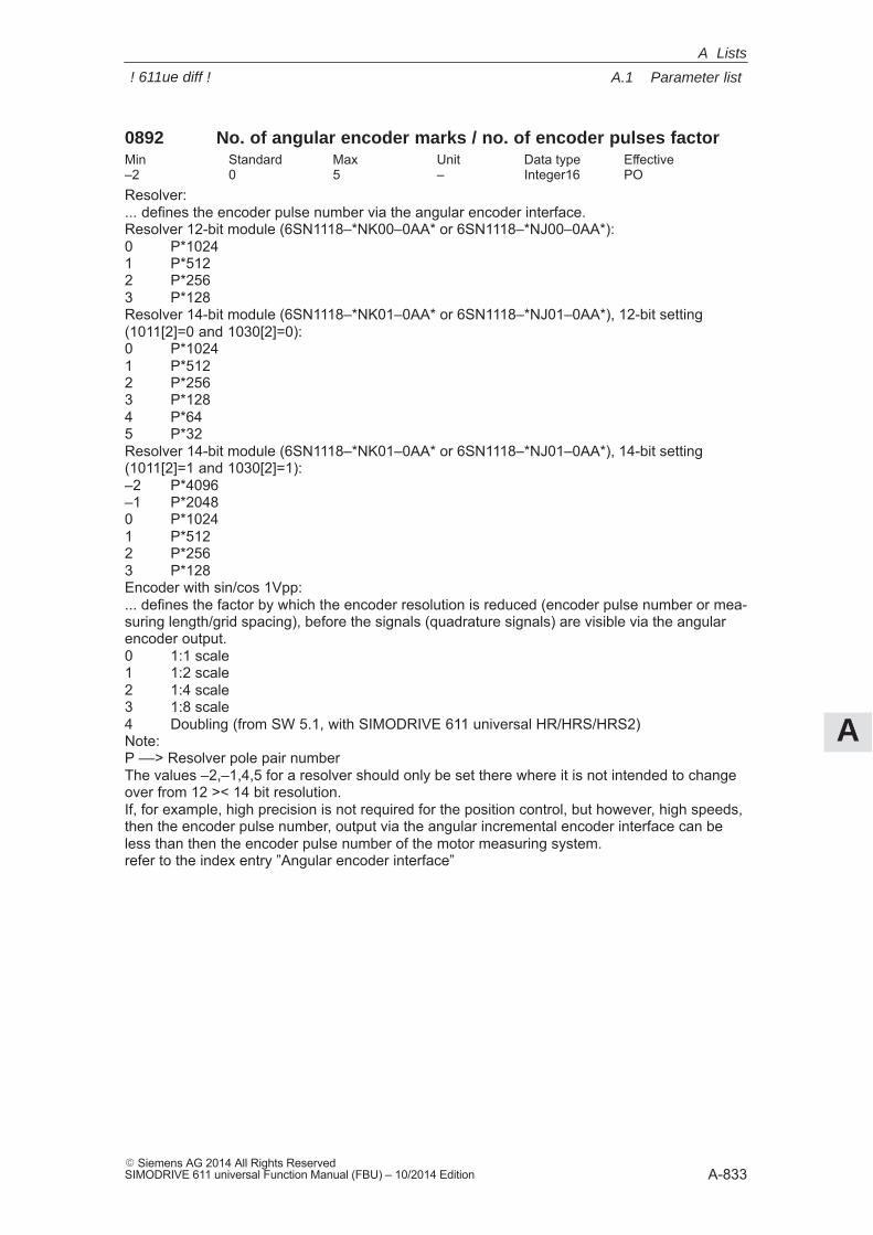
A
A.1 Parameter list
A-833� Siemens AG 2014 All Rights ReservedSIMODRIVE 611 universal Function Manual (FBU) – 10/2014 Edition
0892 No. of angular encoder marks / no. of encoder pulses factorMin Standard Max Unit Data type Effective–2 0 5 – Integer16 POResolver:... defines the encoder pulse number via the angular encoder interface.Resolver 12-bit module (6SN1118–*NK00–0AA* or 6SN1118–*NJ00–0AA*):0 P*10241 P*5122 P*2563 P*128Resolver 14-bit module (6SN1118–*NK01–0AA* or 6SN1118–*NJ01–0AA*), 12-bit setting(1011[2]=0 and 1030[2]=0):0 P*10241 P*5122 P*2563 P*1284 P*645 P*32Resolver 14-bit module (6SN1118–*NK01–0AA* or 6SN1118–*NJ01–0AA*), 14-bit setting(1011[2]=1 and 1030[2]=1):–2 P*4096–1 P*20480 P*10241 P*5122 P*2563 P*128Encoder with sin/cos 1Vpp:... defines the factor by which the encoder resolution is reduced (encoder pulse number or mea-suring length/grid spacing), before the signals (quadrature signals) are visible via the angularencoder output.0 1:1 scale1 1:2 scale2 1:4 scale3 1:8 scale4 Doubling (from SW 5.1, with SIMODRIVE 611 universal HR/HRS/HRS2)Note:P ––> Resolver pole pair numberThe values –2,–1,4,5 for a resolver should only be set there where it is not intended to changeover from 12 >< 14 bit resolution.If, for example, high precision is not required for the position control, but however, high speeds,then the encoder pulse number, output via the angular incremental encoder interface can beless than then the encoder pulse number of the motor measuring system.refer to the index entry ”Angular encoder interface”
A Lists
! 611ue diff !
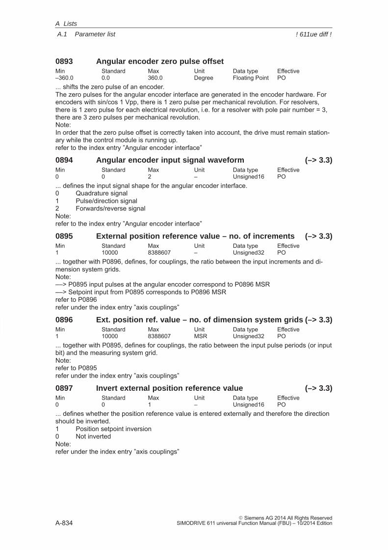
A
A.1 Parameter list
A-834� Siemens AG 2014 All Rights Reserved
SIMODRIVE 611 universal Function Manual (FBU) – 10/2014 Edition
0893 Angular encoder zero pulse offsetMin Standard Max Unit Data type Effective–360.0 0.0 360.0 Degree Floating Point PO... shifts the zero pulse of an encoder.The zero pulses for the angular encoder interface are generated in the encoder hardware. Forencoders with sin/cos 1 Vpp, there is 1 zero pulse per mechanical revolution. For resolvers,there is 1 zero pulse for each electrical revolution, i.e. for a resolver with pole pair number = 3,there are 3 zero pulses per mechanical revolution.Note:In order that the zero pulse offset is correctly taken into account, the drive must remain station-ary while the control module is running up.refer to the index entry ”Angular encoder interface”
0894 Angular encoder input signal waveform (–> 3.3)Min Standard Max Unit Data type Effective0 0 2 – Unsigned16 PO... defines the input signal shape for the angular encoder interface.0 Quadrature signal1 Pulse/direction signal2 Forwards/reverse signalNote:refer to the index entry ”Angular encoder interface”
0895 External position reference value – no. of increments (–> 3.3)Min Standard Max Unit Data type Effective1 10000 8388607 – Unsigned32 PO... together with P0896, defines, for couplings, the ratio between the input increments and di-mension system grids.Note:––> P0895 input pulses at the angular encoder correspond to P0896 MSR––> Setpoint input from P0895 corresponds to P0896 MSRrefer to P0896refer under the index entry ”axis couplings”
0896 Ext. position ref. value – no. of dimension system grids (–> 3.3)Min Standard Max Unit Data type Effective1 10000 8388607 MSR Unsigned32 PO... together with P0895, defines for couplings, the ratio between the input pulse periods (or inputbit) and the measuring system grid.Note:refer to P0895refer under the index entry ”axis couplings”
0897 Invert external position reference value (–> 3.3)Min Standard Max Unit Data type Effective0 0 1 – Unsigned16 PO... defines whether the position reference value is entered externally and therefore the directionshould be inverted.1 Position setpoint inversion0 Not invertedNote:refer under the index entry ”axis couplings”
A Lists
! 611ue diff !
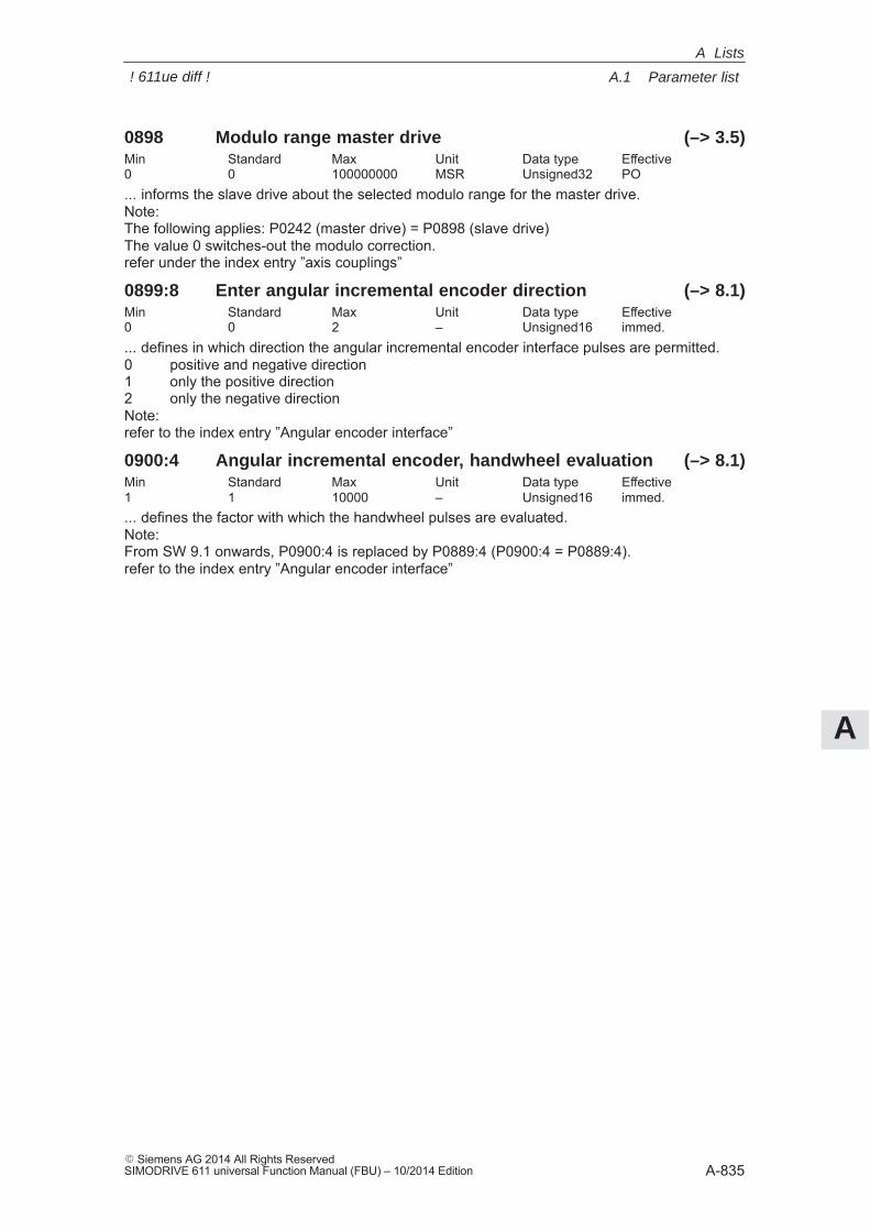
A
A.1 Parameter list
A-835� Siemens AG 2014 All Rights ReservedSIMODRIVE 611 universal Function Manual (FBU) – 10/2014 Edition
0898 Modulo range master drive (–> 3.5)Min Standard Max Unit Data type Effective0 0 100000000 MSR Unsigned32 PO... informs the slave drive about the selected modulo range for the master drive.Note:The following applies: P0242 (master drive) = P0898 (slave drive)The value 0 switches-out the modulo correction.refer under the index entry ”axis couplings”
0899:8 Enter angular incremental encoder direction (–> 8.1)Min Standard Max Unit Data type Effective0 0 2 – Unsigned16 immed.... defines in which direction the angular incremental encoder interface pulses are permitted.0 positive and negative direction1 only the positive direction2 only the negative directionNote:refer to the index entry ”Angular encoder interface”
0900:4 Angular incremental encoder, handwheel evaluation (–> 8.1)Min Standard Max Unit Data type Effective1 1 10000 – Unsigned16 immed.... defines the factor with which the handwheel pulses are evaluated.Note:From SW 9.1 onwards, P0900:4 is replaced by P0889:4 (P0900:4 = P0889:4).refer to the index entry ”Angular encoder interface”
A Lists
! 611ue diff !
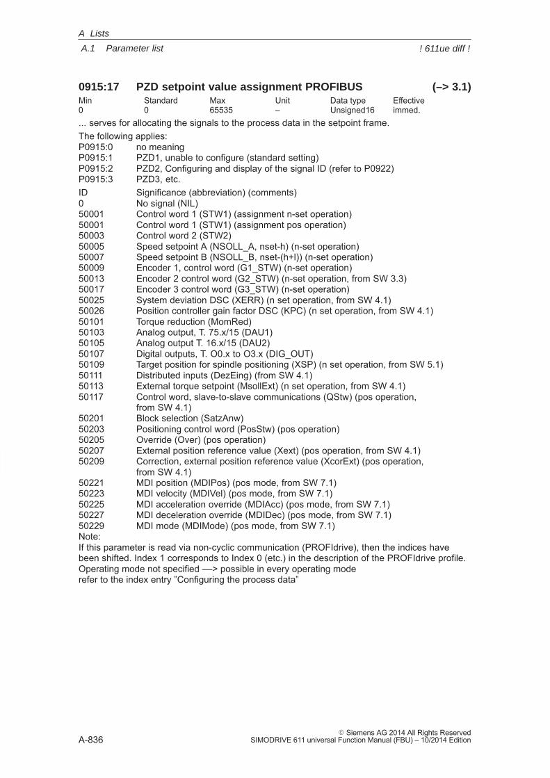
A
A.1 Parameter list
A-836� Siemens AG 2014 All Rights Reserved
SIMODRIVE 611 universal Function Manual (FBU) – 10/2014 Edition
0915:17 PZD setpoint value assignment PROFIBUS (–> 3.1)Min Standard Max Unit Data type Effective0 0 65535 – Unsigned16 immed.... serves for allocating the signals to the process data in the setpoint frame.The following applies:P0915:0 no meaningP0915:1 PZD1, unable to configure (standard setting)P0915:2 PZD2, Configuring and display of the signal ID (refer to P0922)P0915:3 PZD3, etc.ID Significance (abbreviation) (comments)0 No signal (NIL)50001 Control word 1 (STW1) (assignment n-set operation)50001 Control word 1 (STW1) (assignment pos operation)50003 Control word 2 (STW2)50005 Speed setpoint A (NSOLL_A, nset-h) (n-set operation)50007 Speed setpoint B (NSOLL_B, nset-(h+l)) (n-set operation)50009 Encoder 1, control word (G1_STW) (n-set operation)50013 Encoder 2 control word (G2_STW) (n-set operation, from SW 3.3)50017 Encoder 3 control word (G3_STW) (n-set operation)50025 System deviation DSC (XERR) (n set operation, from SW 4.1)50026 Position controller gain factor DSC (KPC) (n set operation, from SW 4.1)50101 Torque reduction (MomRed)50103 Analog output, T. 75.x/15 (DAU1)50105 Analog output T. 16.x/15 (DAU2)50107 Digital outputs, T. O0.x to O3.x (DIG_OUT)50109 Target position for spindle positioning (XSP) (n set operation, from SW 5.1)50111 Distributed inputs (DezEing) (from SW 4.1)50113 External torque setpoint (MsollExt) (n set operation, from SW 4.1)50117 Control word, slave-to-slave communications (QStw) (pos operation,
from SW 4.1)50201 Block selection (SatzAnw)50203 Positioning control word (PosStw) (pos operation)50205 Override (Over) (pos operation)50207 External position reference value (Xext) (pos operation, from SW 4.1)50209 Correction, external position reference value (XcorExt) (pos operation,
from SW 4.1)50221 MDI position (MDIPos) (pos mode, from SW 7.1)50223 MDI velocity (MDIVel) (pos mode, from SW 7.1)50225 MDI acceleration override (MDIAcc) (pos mode, from SW 7.1)50227 MDI deceleration override (MDIDec) (pos mode, from SW 7.1)50229 MDI mode (MDIMode) (pos mode, from SW 7.1)Note:If this parameter is read via non-cyclic communication (PROFIdrive), then the indices havebeen shifted. Index 1 corresponds to Index 0 (etc.) in the description of the PROFIdrive profile.Operating mode not specified ––> possible in every operating moderefer to the index entry ”Configuring the process data”
A Lists
! 611ue diff !
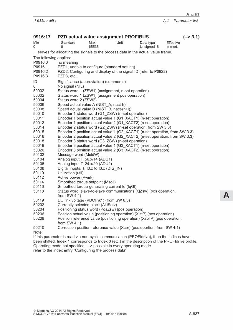
A
A.1 Parameter list
A-837� Siemens AG 2014 All Rights ReservedSIMODRIVE 611 universal Function Manual (FBU) – 10/2014 Edition
0916:17 PZD actual value assignment PROFIBUS (–> 3.1)Min Standard Max Unit Data type Effective0 0 65535 – Unsigned16 immed.... serves for allocating the signals to the process data in the actual value frame.The following applies:P0916:0 no meaningP0916:1 PZD1, unable to configure (standard setting)P0916:2 PZD2, Configuring and display of the signal ID (refer to P0922)P0916:3 PZD3, etc.ID Significance (abbreviation) (comments)0 No signal (NIL)50002 Status word 1 (ZSW1) (assignment, n-set operation)50002 Status word 1 (ZSW1) (assignment pos operation)50004 Status word 2 (ZSW2)50006 Speed actual value A (NIST_A, nact-h)50008 Speed actual value B (NIST_B, nact-(h+l))50010 Encoder 1 status word (G1_ZSW) (n-set operation)50011 Encoder 1 position actual value 1 (G1_XACT1) (n-set operation)50012 Encoder 1 position actual value 2 (G1_XACT2) (n-set operation)50014 Encoder 2 status word (G2_ZSW) (n-set operation, from SW 3.3)50015 Encoder 2 position actual value 1 (G2_XACT1) (n-set operation, from SW 3.3)50016 Encoder 2 position actual value 2 (G2_XACT2) (n-set operation, from SW 3.3)50018 Encoder 3 status word (G3_ZSW) (n-set operation)50019 Encoder 3 position actual value 1 (G3_XACT1) (n-set operation)50020 Encoder 3 position actual value 2 (G3_XACT2) (n-set operation)50102 Message word (MeldW)50104 Analog input T. 56.x/14 (ADU1)50106 Analog input T. 24.x/20 (ADU2)50108 Digital inputs, T. I0.x to I3.x (DIG_IN)50110 Utilization (util)50112 Active power (Pwirk)50114 Smoothed torque setpoint (Msoll)50116 Smoothed torque-generating current Iq (IqGl)50118 Status word, slave-to-slave communications (QZsw) (pos operation,
from SW 4.1)50119 DC link voltage (VDClink1) (from SW 8.3)50202 Currently selected block (AktSatz)50204 Positioning status word (PosZsw) (pos operation)50206 Position actual value (positioning operation) (XistP) (pos operation)50208 Position reference value (positioning operation) (XsollP) (pos operation,
from SW 4.1)50210 Correction position reference value (Xcor) (pos opertion, from SW 4.1)Note:If this parameter is read via non-cyclic communication (PROFIdrive), then the indices havebeen shifted. Index 1 corresponds to Index 0 (etc.) in the description of the PROFIdrive profile.Operating mode not specified ––> possible in every operating moderefer to the index entry ”Configuring the process data”
A Lists
! 611ue diff !
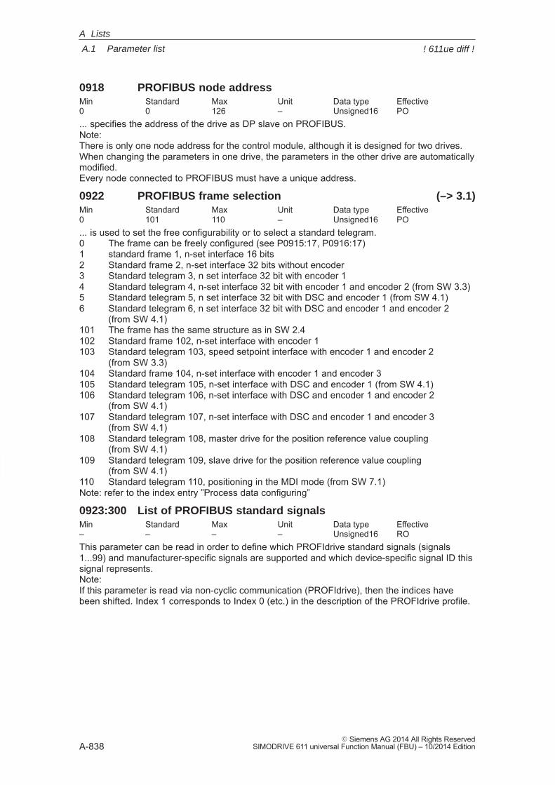
A
A.1 Parameter list
A-838� Siemens AG 2014 All Rights Reserved
SIMODRIVE 611 universal Function Manual (FBU) – 10/2014 Edition
0918 PROFIBUS node addressMin Standard Max Unit Data type Effective0 0 126 – Unsigned16 PO... specifies the address of the drive as DP slave on PROFIBUS.Note:There is only one node address for the control module, although it is designed for two drives.When changing the parameters in one drive, the parameters in the other drive are automaticallymodified.Every node connected to PROFIBUS must have a unique address.
0922 PROFIBUS frame selection (–> 3.1)Min Standard Max Unit Data type Effective0 101 110 – Unsigned16 PO... is used to set the free configurability or to select a standard telegram.0 The frame can be freely configured (see P0915:17, P0916:17)1 standard frame 1, n-set interface 16 bits2 Standard frame 2, n-set interface 32 bits without encoder3 Standard telegram 3, n set interface 32 bit with encoder 14 Standard telegram 4, n-set interface 32 bit with encoder 1 and encoder 2 (from SW 3.3)5 Standard telegram 5, n set interface 32 bit with DSC and encoder 1 (from SW 4.1)6 Standard telegram 6, n set interface 32 bit with DSC and encoder 1 and encoder 2
(from SW 4.1)101 The frame has the same structure as in SW 2.4102 Standard frame 102, n-set interface with encoder 1103 Standard telegram 103, speed setpoint interface with encoder 1 and encoder 2
(from SW 3.3)104 Standard frame 104, n-set interface with encoder 1 and encoder 3105 Standard telegram 105, n-set interface with DSC and encoder 1 (from SW 4.1)106 Standard telegram 106, n-set interface with DSC and encoder 1 and encoder 2
(from SW 4.1)107 Standard telegram 107, n-set interface with DSC and encoder 1 and encoder 3
(from SW 4.1)108 Standard telegram 108, master drive for the position reference value coupling
(from SW 4.1)109 Standard telegram 109, slave drive for the position reference value coupling
(from SW 4.1)110 Standard telegram 110, positioning in the MDI mode (from SW 7.1)Note: refer to the index entry ”Process data configuring”
0923:300 List of PROFIBUS standard signalsMin Standard Max Unit Data type Effective– – – – Unsigned16 ROThis parameter can be read in order to define which PROFIdrive standard signals (signals1...99) and manufacturer-specific signals are supported and which device-specific signal ID thissignal represents.Note:If this parameter is read via non-cyclic communication (PROFIdrive), then the indices havebeen shifted. Index 1 corresponds to Index 0 (etc.) in the description of the PROFIdrive profile.
A Lists
! 611ue diff !
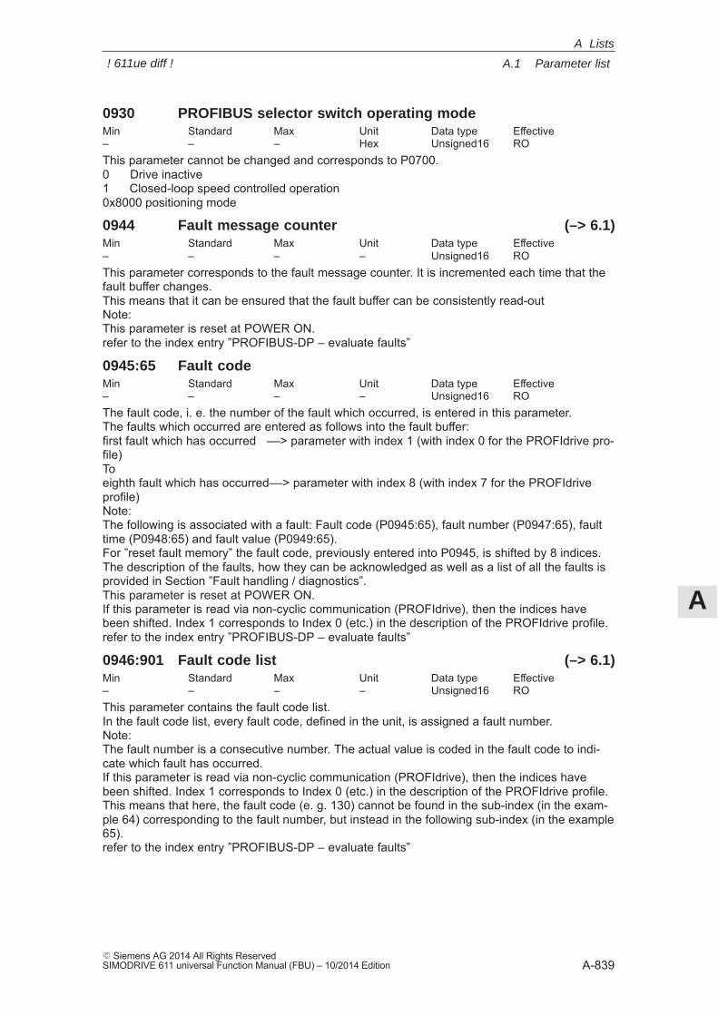
A
A.1 Parameter list
A-839� Siemens AG 2014 All Rights ReservedSIMODRIVE 611 universal Function Manual (FBU) – 10/2014 Edition
0930 PROFIBUS selector switch operating modeMin Standard Max Unit Data type Effective– – – Hex Unsigned16 ROThis parameter cannot be changed and corresponds to P0700.0 Drive inactive1 Closed-loop speed controlled operation0x8000 positioning mode
0944 Fault message counter (–> 6.1)Min Standard Max Unit Data type Effective– – – – Unsigned16 ROThis parameter corresponds to the fault message counter. It is incremented each time that thefault buffer changes.This means that it can be ensured that the fault buffer can be consistently read-outNote:This parameter is reset at POWER ON.refer to the index entry ”PROFIBUS-DP – evaluate faults”
0945:65 Fault codeMin Standard Max Unit Data type Effective– – – – Unsigned16 ROThe fault code, i. e. the number of the fault which occurred, is entered in this parameter.The faults which occurred are entered as follows into the fault buffer:first fault which has occurred ––> parameter with index 1 (with index 0 for the PROFIdrive pro-file)Toeighth fault which has occurred––> parameter with index 8 (with index 7 for the PROFIdriveprofile)Note:The following is associated with a fault: Fault code (P0945:65), fault number (P0947:65), faulttime (P0948:65) and fault value (P0949:65).For ”reset fault memory” the fault code, previously entered into P0945, is shifted by 8 indices.The description of the faults, how they can be acknowledged as well as a list of all the faults isprovided in Section ”Fault handling / diagnostics”.This parameter is reset at POWER ON.If this parameter is read via non-cyclic communication (PROFIdrive), then the indices havebeen shifted. Index 1 corresponds to Index 0 (etc.) in the description of the PROFIdrive profile.refer to the index entry ”PROFIBUS-DP – evaluate faults”
0946:901 Fault code list (–> 6.1)Min Standard Max Unit Data type Effective– – – – Unsigned16 ROThis parameter contains the fault code list.In the fault code list, every fault code, defined in the unit, is assigned a fault number.Note:The fault number is a consecutive number. The actual value is coded in the fault code to indi-cate which fault has occurred.If this parameter is read via non-cyclic communication (PROFIdrive), then the indices havebeen shifted. Index 1 corresponds to Index 0 (etc.) in the description of the PROFIdrive profile.This means that here, the fault code (e. g. 130) cannot be found in the sub-index (in the exam-ple 64) corresponding to the fault number, but instead in the following sub-index (in the example65).refer to the index entry ”PROFIBUS-DP – evaluate faults”
A Lists
! 611ue diff !
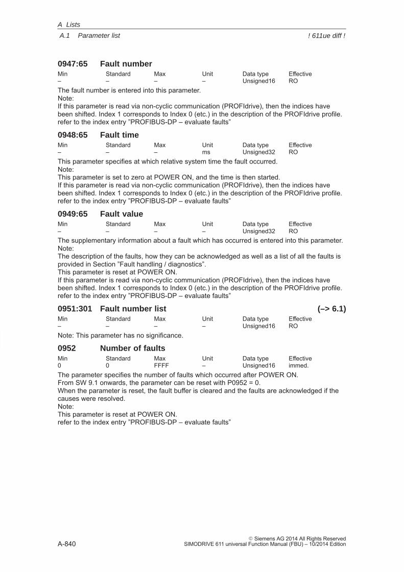
A
A.1 Parameter list
A-840� Siemens AG 2014 All Rights Reserved
SIMODRIVE 611 universal Function Manual (FBU) – 10/2014 Edition
0947:65 Fault numberMin Standard Max Unit Data type Effective– – – – Unsigned16 ROThe fault number is entered into this parameter.Note:If this parameter is read via non-cyclic communication (PROFIdrive), then the indices havebeen shifted. Index 1 corresponds to Index 0 (etc.) in the description of the PROFIdrive profile.refer to the index entry ”PROFIBUS-DP – evaluate faults”
0948:65 Fault timeMin Standard Max Unit Data type Effective– – – ms Unsigned32 ROThis parameter specifies at which relative system time the fault occurred.Note:This parameter is set to zero at POWER ON, and the time is then started.If this parameter is read via non-cyclic communication (PROFIdrive), then the indices havebeen shifted. Index 1 corresponds to Index 0 (etc.) in the description of the PROFIdrive profile.refer to the index entry ”PROFIBUS-DP – evaluate faults”
0949:65 Fault valueMin Standard Max Unit Data type Effective– – – – Unsigned32 ROThe supplementary information about a fault which has occurred is entered into this parameter.Note: The description of the faults, how they can be acknowledged as well as a list of all the faults isprovided in Section ”Fault handling / diagnostics”.This parameter is reset at POWER ON.If this parameter is read via non-cyclic communication (PROFIdrive), then the indices havebeen shifted. Index 1 corresponds to Index 0 (etc.) in the description of the PROFIdrive profile.refer to the index entry ”PROFIBUS-DP – evaluate faults”
0951:301 Fault number list (–> 6.1)Min Standard Max Unit Data type Effective– – – – Unsigned16 RONote: This parameter has no significance.
0952 Number of faultsMin Standard Max Unit Data type Effective0 0 FFFF – Unsigned16 immed.The parameter specifies the number of faults which occurred after POWER ON.From SW 9.1 onwards, the parameter can be reset with P0952 = 0.When the parameter is reset, the fault buffer is cleared and the faults are acknowledged if thecauses were resolved.Note:This parameter is reset at POWER ON.refer to the index entry ”PROFIBUS-DP – evaluate faults”
A Lists
! 611ue diff !
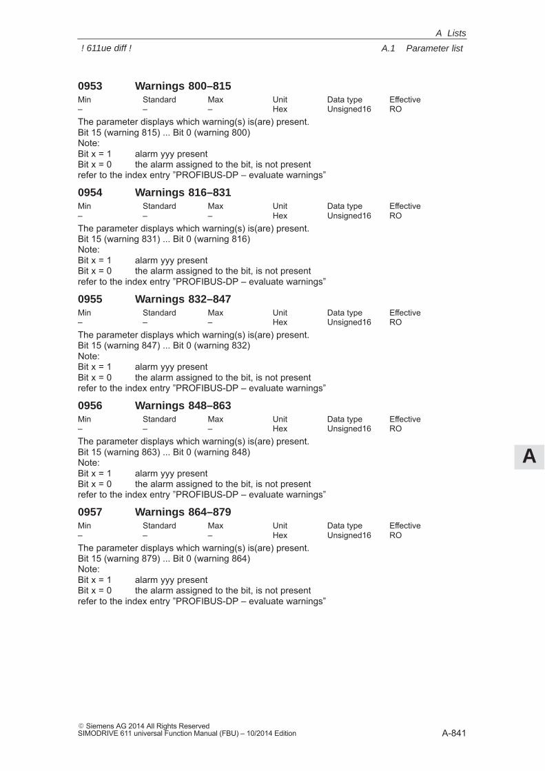
A
A.1 Parameter list
A-841� Siemens AG 2014 All Rights ReservedSIMODRIVE 611 universal Function Manual (FBU) – 10/2014 Edition
0953 Warnings 800–815Min Standard Max Unit Data type Effective– – – Hex Unsigned16 ROThe parameter displays which warning(s) is(are) present.Bit 15 (warning 815) ... Bit 0 (warning 800)Note:Bit x = 1 alarm yyy presentBit x = 0 the alarm assigned to the bit, is not presentrefer to the index entry ”PROFIBUS-DP – evaluate warnings”
0954 Warnings 816–831Min Standard Max Unit Data type Effective– – – Hex Unsigned16 ROThe parameter displays which warning(s) is(are) present.Bit 15 (warning 831) ... Bit 0 (warning 816)Note:Bit x = 1 alarm yyy presentBit x = 0 the alarm assigned to the bit, is not presentrefer to the index entry ”PROFIBUS-DP – evaluate warnings”
0955 Warnings 832–847Min Standard Max Unit Data type Effective– – – Hex Unsigned16 ROThe parameter displays which warning(s) is(are) present.Bit 15 (warning 847) ... Bit 0 (warning 832)Note:Bit x = 1 alarm yyy presentBit x = 0 the alarm assigned to the bit, is not presentrefer to the index entry ”PROFIBUS-DP – evaluate warnings”
0956 Warnings 848–863Min Standard Max Unit Data type Effective– – – Hex Unsigned16 ROThe parameter displays which warning(s) is(are) present.Bit 15 (warning 863) ... Bit 0 (warning 848)Note:Bit x = 1 alarm yyy presentBit x = 0 the alarm assigned to the bit, is not presentrefer to the index entry ”PROFIBUS-DP – evaluate warnings”
0957 Warnings 864–879Min Standard Max Unit Data type Effective– – – Hex Unsigned16 ROThe parameter displays which warning(s) is(are) present.Bit 15 (warning 879) ... Bit 0 (warning 864)Note:Bit x = 1 alarm yyy presentBit x = 0 the alarm assigned to the bit, is not presentrefer to the index entry ”PROFIBUS-DP – evaluate warnings”
A Lists
! 611ue diff !
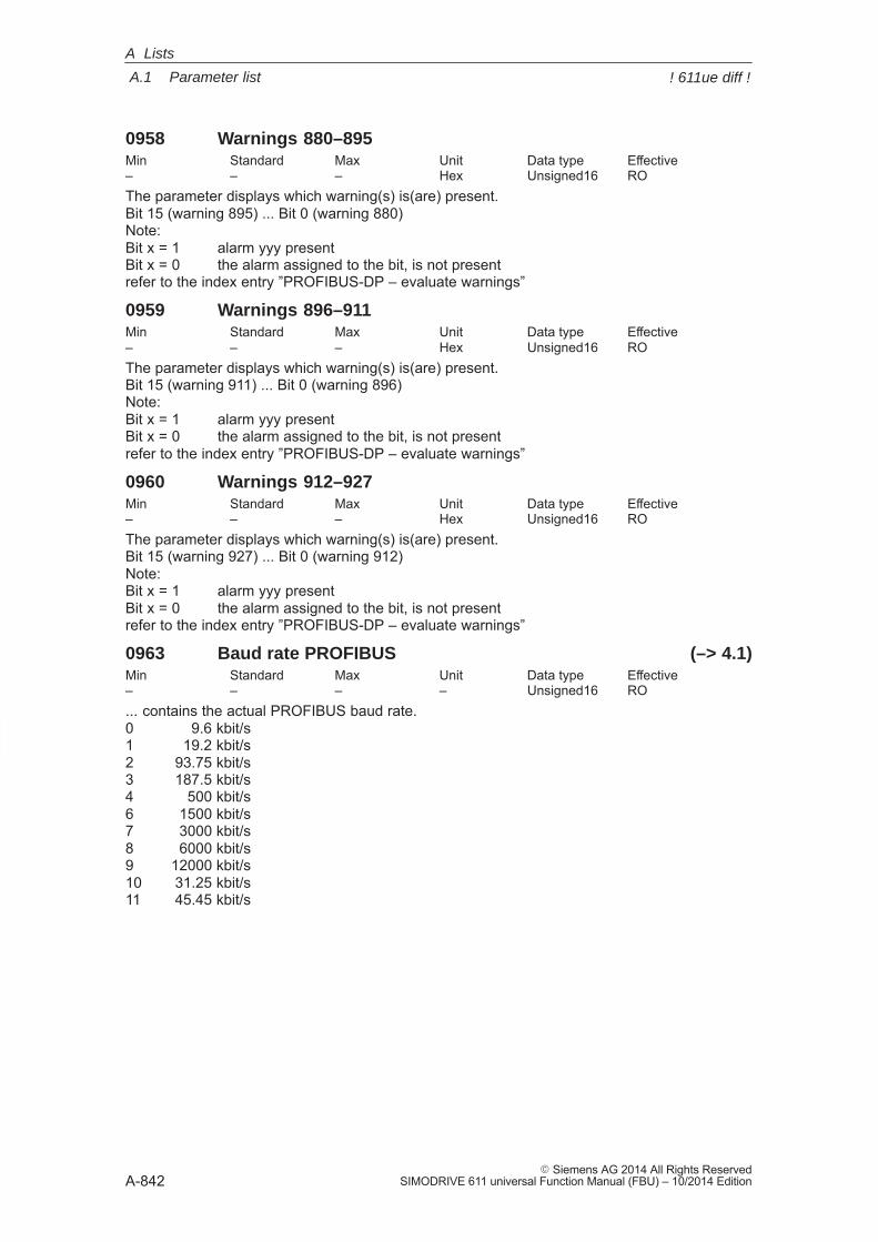
A
A.1 Parameter list
A-842� Siemens AG 2014 All Rights Reserved
SIMODRIVE 611 universal Function Manual (FBU) – 10/2014 Edition
0958 Warnings 880–895Min Standard Max Unit Data type Effective– – – Hex Unsigned16 ROThe parameter displays which warning(s) is(are) present.Bit 15 (warning 895) ... Bit 0 (warning 880)Note:Bit x = 1 alarm yyy presentBit x = 0 the alarm assigned to the bit, is not presentrefer to the index entry ”PROFIBUS-DP – evaluate warnings”
0959 Warnings 896–911Min Standard Max Unit Data type Effective– – – Hex Unsigned16 ROThe parameter displays which warning(s) is(are) present.Bit 15 (warning 911) ... Bit 0 (warning 896)Note:Bit x = 1 alarm yyy presentBit x = 0 the alarm assigned to the bit, is not presentrefer to the index entry ”PROFIBUS-DP – evaluate warnings”
0960 Warnings 912–927Min Standard Max Unit Data type Effective– – – Hex Unsigned16 ROThe parameter displays which warning(s) is(are) present.Bit 15 (warning 927) ... Bit 0 (warning 912)Note:Bit x = 1 alarm yyy presentBit x = 0 the alarm assigned to the bit, is not presentrefer to the index entry ”PROFIBUS-DP – evaluate warnings”
0963 Baud rate PROFIBUS (–> 4.1)Min Standard Max Unit Data type Effective– – – – Unsigned16 RO... contains the actual PROFIBUS baud rate.0 9.6 kbit/s1 19.2 kbit/s2 93.75 kbit/s3 187.5 kbit/s4 500 kbit/s6 1500 kbit/s7 3000 kbit/s8 6000 kbit/s9 12000 kbit/s10 31.25 kbit/s11 45.45 kbit/s
A Lists
! 611ue diff !
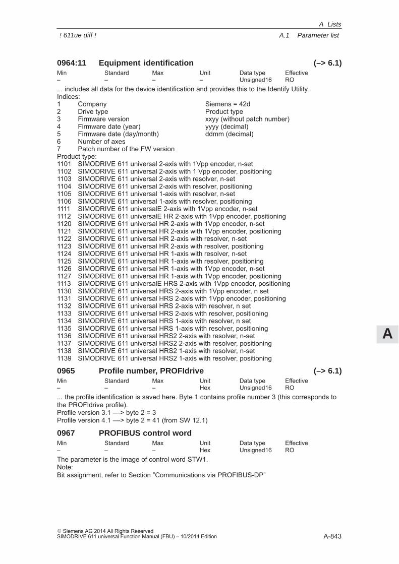
A
A.1 Parameter list
A-843� Siemens AG 2014 All Rights ReservedSIMODRIVE 611 universal Function Manual (FBU) – 10/2014 Edition
0964:11 Equipment identification (–> 6.1)Min Standard Max Unit Data type Effective– – – – Unsigned16 RO... includes all data for the device identification and provides this to the Identify Utility.Indices:1 Company Siemens = 42d2 Drive type Product type3 Firmware version xxyy (without patch number)4 Firmware date (year) yyyy (decimal)5 Firmware date (day/month) ddmm (decimal)6 Number of axes7 Patch number of the FW versionProduct type:1101 SIMODRIVE 611 universal 2-axis with 1Vpp encoder, n-set1102 SIMODRIVE 611 universal 2-axis with 1 Vpp encoder, positioning1103 SIMODRIVE 611 universal 2-axis with resolver, n-set1104 SIMODRIVE 611 universal 2-axis with resolver, positioning1105 SIMODRIVE 611 universal 1-axis with resolver, n-set1106 SIMODRIVE 611 universal 1-axis with resolver, positioning1111 SIMODRIVE 611 universalE 2-axis with 1Vpp encoder, n-set1112 SIMODRIVE 611 universalE HR 2-axis with 1Vpp encoder, positioning1120 SIMODRIVE 611 universal HR 2-axis with 1Vpp encoder, n-set1121 SIMODRIVE 611 universal HR 2-axis with 1Vpp encoder, positioning1122 SIMODRIVE 611 universal HR 2-axis with resolver, n-set1123 SIMODRIVE 611 universal HR 2-axis with resolver, positioning1124 SIMODRIVE 611 universal HR 1-axis with resolver, n-set1125 SIMODRIVE 611 universal HR 1-axis with resolver, positioning1126 SIMODRIVE 611 universal HR 1-axis with 1Vpp encoder, n-set1127 SIMODRIVE 611 universal HR 1-axis with 1Vpp encoder, positioning1113 SIMODRIVE 611 universalE HRS 2-axis with 1Vpp encoder, positioning1130 SIMODRIVE 611 universal HRS 2-axis with 1Vpp encoder, n set1131 SIMODRIVE 611 universal HRS 2-axis with 1Vpp encoder, positioning1132 SIMODRIVE 611 universal HRS 2-axis with resolver, n set1133 SIMODRIVE 611 universal HRS 2-axis with resolver, positioning1134 SIMODRIVE 611 universal HRS 1-axis with resolver, n set1135 SIMODRIVE 611 universal HRS 1-axis with resolver, positioning1136 SIMODRIVE 611 universal HRS2 2-axis with resolver, n-set1137 SIMODRIVE 611 universal HRS2 2-axis with resolver, positioning1138 SIMODRIVE 611 universal HRS2 1-axis with resolver, n-set1139 SIMODRIVE 611 universal HRS2 1-axis with resolver, positioning
0965 Profile number, PROFIdrive (–> 6.1)Min Standard Max Unit Data type Effective– – – Hex Unsigned16 RO... the profile identification is saved here. Byte 1 contains profile number 3 (this corresponds tothe PROFIdrive profile).Profile version 3.1 ––> byte 2 = 3Profile version 4.1 ––> byte 2 = 41 (from SW 12.1)
0967 PROFIBUS control wordMin Standard Max Unit Data type Effective– – – Hex Unsigned16 ROThe parameter is the image of control word STW1.Note:Bit assignment, refer to Section ”Communications via PROFIBUS-DP”
A Lists
! 611ue diff !
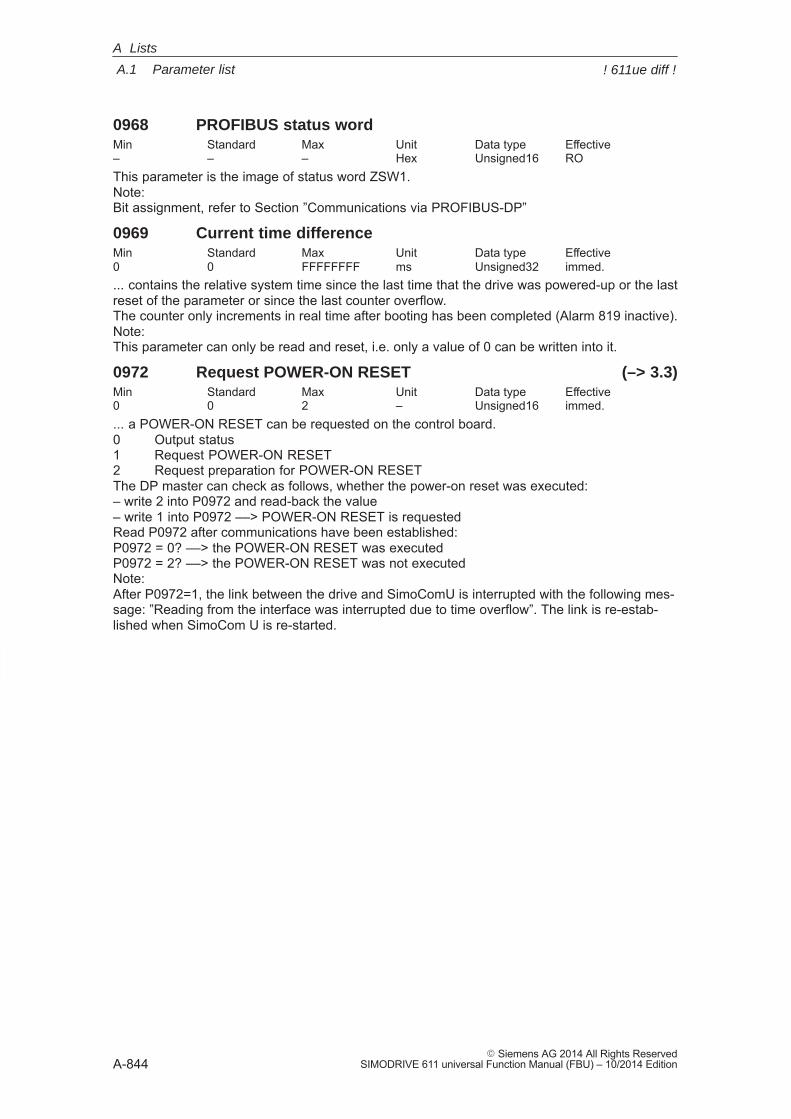
A
A.1 Parameter list
A-844� Siemens AG 2014 All Rights Reserved
SIMODRIVE 611 universal Function Manual (FBU) – 10/2014 Edition
0968 PROFIBUS status wordMin Standard Max Unit Data type Effective– – – Hex Unsigned16 ROThis parameter is the image of status word ZSW1.Note:Bit assignment, refer to Section ”Communications via PROFIBUS-DP”
0969 Current time differenceMin Standard Max Unit Data type Effective0 0 FFFFFFFF ms Unsigned32 immed.... contains the relative system time since the last time that the drive was powered-up or the lastreset of the parameter or since the last counter overflow.The counter only increments in real time after booting has been completed (Alarm 819 inactive).Note:This parameter can only be read and reset, i.e. only a value of 0 can be written into it.
0972 Request POWER-ON RESET (–> 3.3)Min Standard Max Unit Data type Effective0 0 2 – Unsigned16 immed.... a POWER-ON RESET can be requested on the control board.0 Output status1 Request POWER-ON RESET2 Request preparation for POWER-ON RESETThe DP master can check as follows, whether the power-on reset was executed:– write 2 into P0972 and read-back the value– write 1 into P0972 ––> POWER-ON RESET is requestedRead P0972 after communications have been established:P0972 = 0? ––> the POWER-ON RESET was executedP0972 = 2? ––> the POWER-ON RESET was not executedNote:After P0972=1, the link between the drive and SimoComU is interrupted with the following mes-sage: ”Reading from the interface was interrupted due to time overflow”. The link is re-estab-lished when SimoCom U is re-started.
A Lists
! 611ue diff !
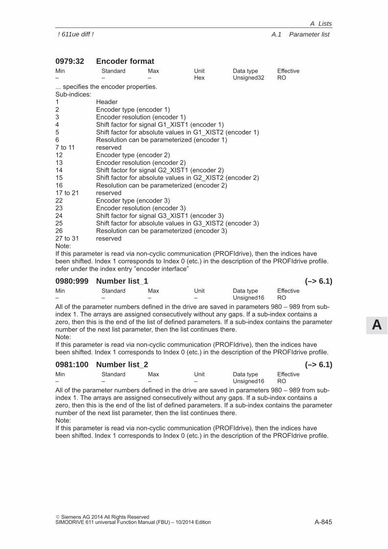
A
A.1 Parameter list
A-845� Siemens AG 2014 All Rights ReservedSIMODRIVE 611 universal Function Manual (FBU) – 10/2014 Edition
0979:32 Encoder formatMin Standard Max Unit Data type Effective– – – Hex Unsigned32 RO... specifies the encoder properties.Sub-indices:1 Header2 Encoder type (encoder 1)3 Encoder resolution (encoder 1)4 Shift factor for signal G1_XIST1 (encoder 1)5 Shift factor for absolute values in G1_XIST2 (encoder 1)6 Resolution can be parameterized (encoder 1)7 to 11 reserved12 Encoder type (encoder 2)13 Encoder resolution (encoder 2)14 Shift factor for signal G2_XIST1 (encoder 2)15 Shift factor for absolute values in G2_XIST2 (encoder 2)16 Resolution can be parameterized (encoder 2)17 to 21 reserved22 Encoder type (encoder 3)23 Encoder resolution (encoder 3)24 Shift factor for signal G3_XIST1 (encoder 3)25 Shift factor for absolute values in G3_XIST2 (encoder 3)26 Resolution can be parameterized (encoder 3)27 to 31 reservedNote:If this parameter is read via non-cyclic communication (PROFIdrive), then the indices havebeen shifted. Index 1 corresponds to Index 0 (etc.) in the description of the PROFIdrive profile.refer under the index entry ”encoder interface”
0980:999 Number list_1 (–> 6.1)Min Standard Max Unit Data type Effective– – – – Unsigned16 ROAll of the parameter numbers defined in the drive are saved in parameters 980 – 989 from sub-index 1. The arrays are assigned consecutively without any gaps. If a sub-index contains azero, then this is the end of the list of defined parameters. If a sub-index contains the parameternumber of the next list parameter, then the list continues there.Note:If this parameter is read via non-cyclic communication (PROFIdrive), then the indices havebeen shifted. Index 1 corresponds to Index 0 (etc.) in the description of the PROFIdrive profile.
0981:100 Number list_2 (–> 6.1)Min Standard Max Unit Data type Effective– – – – Unsigned16 ROAll of the parameter numbers defined in the drive are saved in parameters 980 – 989 from sub-index 1. The arrays are assigned consecutively without any gaps. If a sub-index contains azero, then this is the end of the list of defined parameters. If a sub-index contains the parameternumber of the next list parameter, then the list continues there.Note:If this parameter is read via non-cyclic communication (PROFIdrive), then the indices havebeen shifted. Index 1 corresponds to Index 0 (etc.) in the description of the PROFIdrive profile.
A Lists
! 611ue diff !
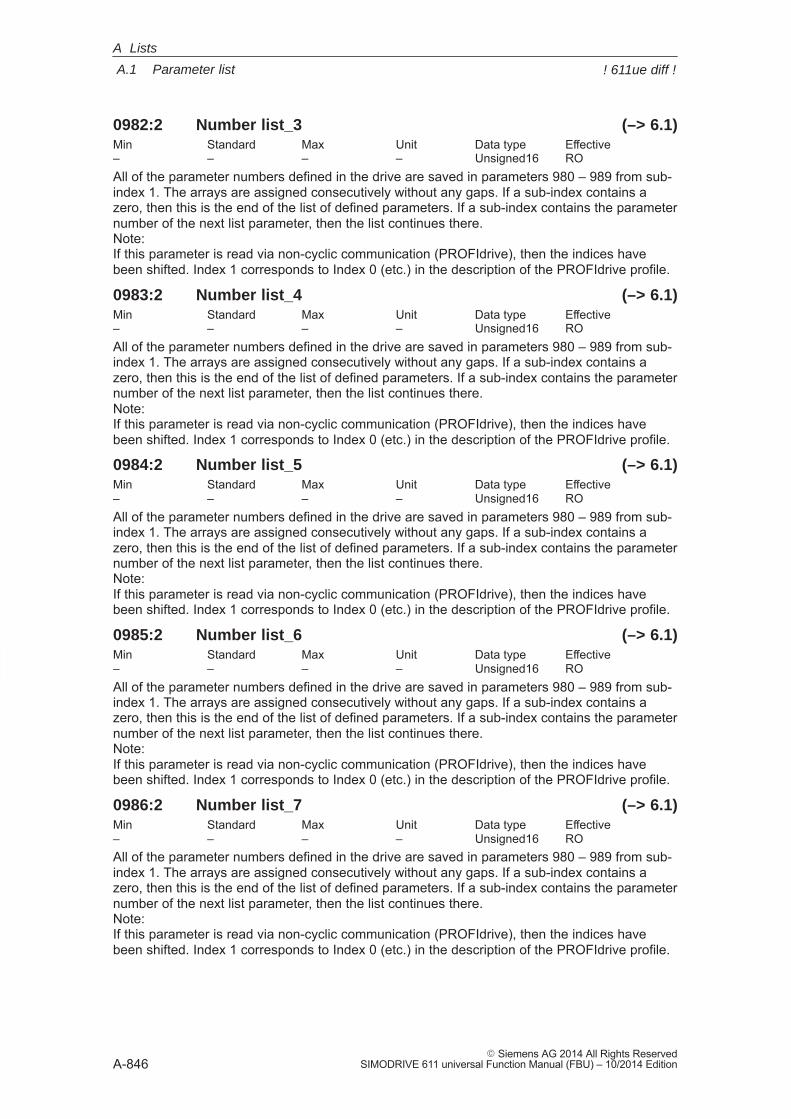
A
A.1 Parameter list
A-846� Siemens AG 2014 All Rights Reserved
SIMODRIVE 611 universal Function Manual (FBU) – 10/2014 Edition
0982:2 Number list_3 (–> 6.1)Min Standard Max Unit Data type Effective– – – – Unsigned16 ROAll of the parameter numbers defined in the drive are saved in parameters 980 – 989 from sub-index 1. The arrays are assigned consecutively without any gaps. If a sub-index contains azero, then this is the end of the list of defined parameters. If a sub-index contains the parameternumber of the next list parameter, then the list continues there.Note:If this parameter is read via non-cyclic communication (PROFIdrive), then the indices havebeen shifted. Index 1 corresponds to Index 0 (etc.) in the description of the PROFIdrive profile.
0983:2 Number list_4 (–> 6.1)Min Standard Max Unit Data type Effective– – – – Unsigned16 ROAll of the parameter numbers defined in the drive are saved in parameters 980 – 989 from sub-index 1. The arrays are assigned consecutively without any gaps. If a sub-index contains azero, then this is the end of the list of defined parameters. If a sub-index contains the parameternumber of the next list parameter, then the list continues there.Note:If this parameter is read via non-cyclic communication (PROFIdrive), then the indices havebeen shifted. Index 1 corresponds to Index 0 (etc.) in the description of the PROFIdrive profile.
0984:2 Number list_5 (–> 6.1)Min Standard Max Unit Data type Effective– – – – Unsigned16 ROAll of the parameter numbers defined in the drive are saved in parameters 980 – 989 from sub-index 1. The arrays are assigned consecutively without any gaps. If a sub-index contains azero, then this is the end of the list of defined parameters. If a sub-index contains the parameternumber of the next list parameter, then the list continues there.Note:If this parameter is read via non-cyclic communication (PROFIdrive), then the indices havebeen shifted. Index 1 corresponds to Index 0 (etc.) in the description of the PROFIdrive profile.
0985:2 Number list_6 (–> 6.1)Min Standard Max Unit Data type Effective– – – – Unsigned16 ROAll of the parameter numbers defined in the drive are saved in parameters 980 – 989 from sub-index 1. The arrays are assigned consecutively without any gaps. If a sub-index contains azero, then this is the end of the list of defined parameters. If a sub-index contains the parameternumber of the next list parameter, then the list continues there.Note:If this parameter is read via non-cyclic communication (PROFIdrive), then the indices havebeen shifted. Index 1 corresponds to Index 0 (etc.) in the description of the PROFIdrive profile.
0986:2 Number list_7 (–> 6.1)Min Standard Max Unit Data type Effective– – – – Unsigned16 ROAll of the parameter numbers defined in the drive are saved in parameters 980 – 989 from sub-index 1. The arrays are assigned consecutively without any gaps. If a sub-index contains azero, then this is the end of the list of defined parameters. If a sub-index contains the parameternumber of the next list parameter, then the list continues there.Note:If this parameter is read via non-cyclic communication (PROFIdrive), then the indices havebeen shifted. Index 1 corresponds to Index 0 (etc.) in the description of the PROFIdrive profile.
A Lists
! 611ue diff !
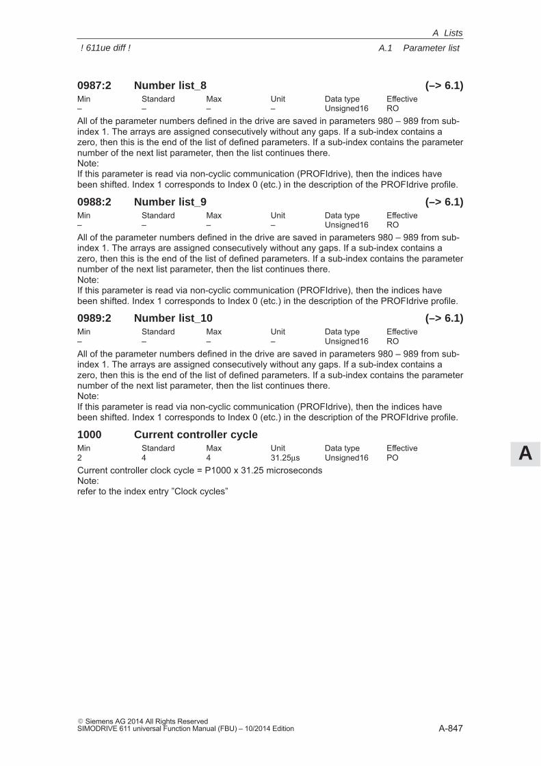
A
A.1 Parameter list
A-847� Siemens AG 2014 All Rights ReservedSIMODRIVE 611 universal Function Manual (FBU) – 10/2014 Edition
0987:2 Number list_8 (–> 6.1)Min Standard Max Unit Data type Effective– – – – Unsigned16 ROAll of the parameter numbers defined in the drive are saved in parameters 980 – 989 from sub-index 1. The arrays are assigned consecutively without any gaps. If a sub-index contains azero, then this is the end of the list of defined parameters. If a sub-index contains the parameternumber of the next list parameter, then the list continues there.Note:If this parameter is read via non-cyclic communication (PROFIdrive), then the indices havebeen shifted. Index 1 corresponds to Index 0 (etc.) in the description of the PROFIdrive profile.
0988:2 Number list_9 (–> 6.1)Min Standard Max Unit Data type Effective– – – – Unsigned16 ROAll of the parameter numbers defined in the drive are saved in parameters 980 – 989 from sub-index 1. The arrays are assigned consecutively without any gaps. If a sub-index contains azero, then this is the end of the list of defined parameters. If a sub-index contains the parameternumber of the next list parameter, then the list continues there.Note:If this parameter is read via non-cyclic communication (PROFIdrive), then the indices havebeen shifted. Index 1 corresponds to Index 0 (etc.) in the description of the PROFIdrive profile.
0989:2 Number list_10 (–> 6.1)Min Standard Max Unit Data type Effective– – – – Unsigned16 ROAll of the parameter numbers defined in the drive are saved in parameters 980 – 989 from sub-index 1. The arrays are assigned consecutively without any gaps. If a sub-index contains azero, then this is the end of the list of defined parameters. If a sub-index contains the parameternumber of the next list parameter, then the list continues there.Note:If this parameter is read via non-cyclic communication (PROFIdrive), then the indices havebeen shifted. Index 1 corresponds to Index 0 (etc.) in the description of the PROFIdrive profile.
1000 Current controller cycleMin Standard Max Unit Data type Effective2 4 4 31.25μs Unsigned16 POCurrent controller clock cycle = P1000 x 31.25 microsecondsNote:refer to the index entry ”Clock cycles”
A Lists
! 611ue diff !
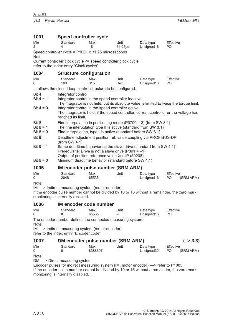
A
A.1 Parameter list
A-848� Siemens AG 2014 All Rights Reserved
SIMODRIVE 611 universal Function Manual (FBU) – 10/2014 Edition
1001 Speed controller cycleMin Standard Max Unit Data type Effective2 4 16 31.25μs Unsigned16 POSpeed controller cycle = P1001 x 31.25 microsecondsNote:Current controller clock cycle <= speed controller clock cyclerefer to the index entry ”Clock cycles”
1004 Structure configurationMin Standard Max Unit Data type Effective0 100 315 Hex Unsigned16 PO... allows the closed-loop control structure to be configured.Bit 4 Integrator controlBit 4 = 1 Integrator control in the speed controller inactive
The integrator is not held, but its absolute value is limited to twice the torque limit.Bit 4 = 0 Integrator control in the speed controller active
The integrator is held, if the speed controller, current controller or the voltage has reached its limit.
Bit 8 Fine interpolation in positioning mode (P0700 = 3) (from SW 3.1)Bit 8 = 1 The fine interpolation type II is active (standard from SW 3.1)Bit 8 = 0 Fine interpolation, type I is active (standard before SW 3.1)Bit 9 Deadtime adjustment position ref. value coupling via PROFIBUS-DP
(from SW 4.1)Bit 9 = 1 Same deadtime behavior as the slave drive (standard from SW 4.1)
Prerequisite: Drive is not a slave drive (P891 = –1)Output of position reference value XsollP (50208).
Bit 9 = 0 Minimum deadtime behavior (standard before SW 4.1)
1005 IM encoder pulse number (SRM ARM)Min Standard Max Unit Data type Effective0 2048 65535 – Unsigned16 PO (SRM ARM)Note:IM ––> Indirect measuring system (motor encoder)If the encoder pulse number cannot be divided by 10 or 16 without a remainder, the zero markmonitoring is internally disabled.
1006 IM encoder code numberMin Standard Max Unit Data type Effective0 0 65535 – Unsigned16 POThe encoder number defines the connected measuring system.Note:IM ––> Indirect measuring system (motor encoder)refer to the index entry ”Encoder code”
1007 DM encoder pulse number (SRM ARM) (–> 3.3)Min Standard Max Unit Data type Effective0 0 8388607 – Unsigned32 PO (SRM ARM)Note:DM ––> Direct measuring systemEncoder pulses for indirect measuring system (IM, motor encoder) ––> refer to P1005If the encoder pulse number cannot be divided by 10 or 16 without a remainder, the zero markmonitoring is internally disabled.
A Lists
! 611ue diff !
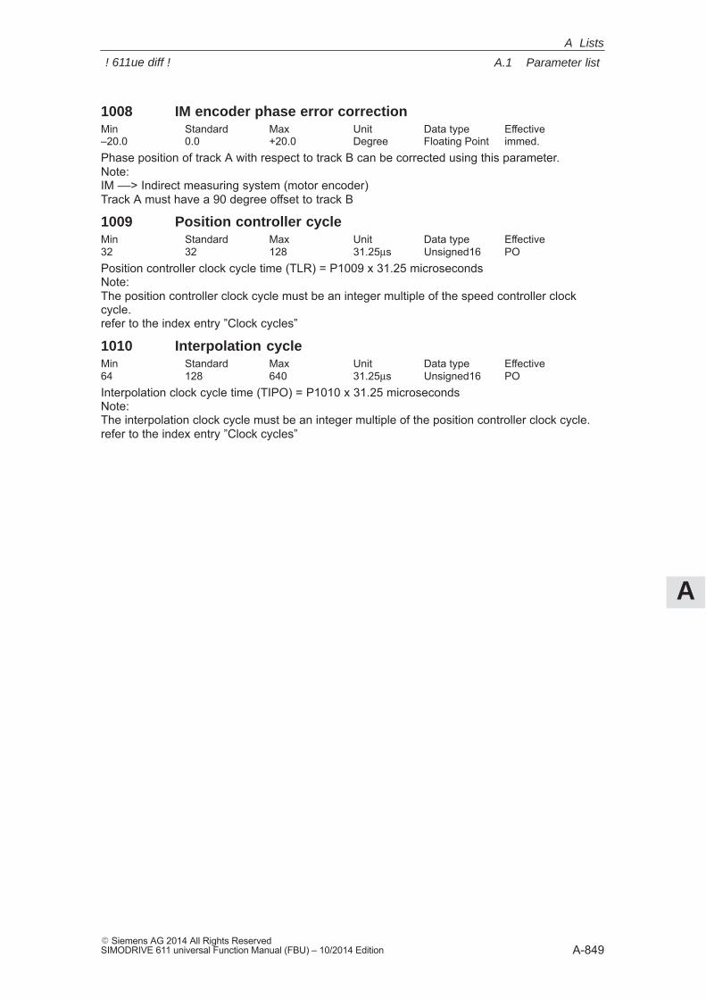
A
A.1 Parameter list
A-849� Siemens AG 2014 All Rights ReservedSIMODRIVE 611 universal Function Manual (FBU) – 10/2014 Edition
1008 IM encoder phase error correctionMin Standard Max Unit Data type Effective–20.0 0.0 +20.0 Degree Floating Point immed.Phase position of track A with respect to track B can be corrected using this parameter.Note:IM ––> Indirect measuring system (motor encoder)Track A must have a 90 degree offset to track B
1009 Position controller cycleMin Standard Max Unit Data type Effective32 32 128 31.25μs Unsigned16 POPosition controller clock cycle time (TLR) = P1009 x 31.25 microsecondsNote:The position controller clock cycle must be an integer multiple of the speed controller clockcycle.refer to the index entry ”Clock cycles”
1010 Interpolation cycleMin Standard Max Unit Data type Effective64 128 640 31.25μs Unsigned16 POInterpolation clock cycle time (TIPO) = P1010 x 31.25 microsecondsNote:The interpolation clock cycle must be an integer multiple of the position controller clock cycle.refer to the index entry ”Clock cycles”
A Lists
! 611ue diff !
A
A.1 Parameter list
A-850� Siemens AG 2014 All Rights Reserved
SIMODRIVE 611 universal Function Manual (FBU) – 10/2014 Edition
1011 IM configuration, actual value sensingMin Standard Max Unit Data type Effective0 0 F003 Hex Unsigned16 PO... allows the actual value sensing to be configured for an indirect measuring system.Bit 0 Invert speed actual valueBit 0 = 1 Inversion, speed actual valueBit 0 = 0 No inversionBit 1 Encoder phase failure correctionBit 1 = 1 Encoder phase failure correctionBit 1 = 0 No encoder phase error compensationBit 2 Resolver resolutionBit 2 = 1 Resolver resolution, 14 bitsBit 2 = 0 Resolver resolution, 12 bitsNote:A resolver resolution of 14 bit can only be set with ”SIMODRIVE 611 universal HR/HRS/HRS2”,otherwise fault 759 is output.After changing the resolver resolution from 12 bits to 14 bits, the resolution of some signals atthe analog output or DAU (D/A converter) changes – refer under the index entry ”Resolver reso-lution”.The resolution displayed in SimoComU is always correct.Bit 10 Plausibility monitoring, encoder (from SW 10.1)Bit 10 = 0 No rotor position check – default (up to SW 10.1)Bit 10 = 1 Automatic rotor position check permitted (from SW 10.1)Bit 12 Coarse position identificationBit 12 = 1 Identify rough positionBit 12 = 0 No coarse position identificationNote:This bit has no significance for EnDat encoders.For encoders without hall sensors and without C/D track (e. g. ERN 1387), the rotor positionidentification replaces the coarse synchronization. The zero mark must still be adjusted (shift orvia P1017).Bit 13 Fine position identificationBit 13 = 1 The fine position is identified ( with pole position identification )Bit 13 = 0 The fine position is not identified ( fine synchronization with zero mark )Note:This bit has no significance for EnDat encoders.The rotor position identification replaces the coarse synchronization using Hall sensors or a C/Dtrack. The zero mark neither has to be present nor does it have to be adjusted.If the rotor position identification does not offer satisfactory results, then the zero mark must beadjusted.Bit 14 Data transfer rate EnDat, bit 0Bit 15 Transmission rate EnDat, Bit 1Note:Bits 14 and 15 are set as follows in the factory:Bit 15, 14 = 00 ––> 100 kHz (standard)Bit 15, 14 = 01 ––> 500 kHz (setting possible)Bit 15, 14 = 10 ––> 1 MHz (setting, Siemens-internal)Bit 15, 14 = 11 ––> 2 MHz (Siemens internal setting)IM ––> Indirect measuring system (motor encoder)refer to the index entry ”List of encoders”
A Lists
! 611ue diff !
A
A.1 Parameter list
A-851� Siemens AG 2014 All Rights ReservedSIMODRIVE 611 universal Function Manual (FBU) – 10/2014 Edition
1012 Function switchMin Standard Max Unit Data type Effective0 A185 F1F5 Hex Unsigned16 immed. (ARM)0 A105 F1F5 Hex Unsigned16 immed. (SRM SLM)... allows the closed-loop control functions to be activated/de-activated.Note:Standard value for an activated PROFIBUS option module:B185 (ARM)B105 (SRM SLM)Bit 0 Ramp-function generator trackingBit 0 = 1 activeBit 0 = 0 inactiveNote: refer to the index entry ”Ramp-function generator”Bit 2 Ready or no fault (at the output signal)Bit 2 = 1 ”Ready” signalBit 2 = 0 ”No fault” messageNote: refer to the index entry ”output signal ready or no fault”Bit 5 Suppress fault 753Bit 7 IM speed actual value after pulse inhibitBit 7 = 1 Speed actual value is zeroThe drive brakes the motor towards 0 speed and accelerates to the setpoint speed present.Bit 7 = 0 Speed actual value is the speed setpointThe drive direct accelerates the motor to the setpoint speed present.Bit 8 Average value filter, speed setpointBit 8 = 1 Average value filter onThe avg.val.filter to adapt the pos.contr.clock cyc. to the sp. contr. clock cyc. is active in thespeedsetpoint branch.Bit 8 = 0 Average value filter offThe avg.val.filter to adapt the pos.contr.clock cyc. to the sp. contr. clock cyc. is inactive in thespeedsetpoint branch.Bit 12 Power-on inhibit for alarm and OFF2/OFF3Bit 12 = 1 Power-on inhibit for alarm or AUS2/AUS3 or terminal 63/663 de-energizedNote: The power-on inhibit is removed again by withdrawing the controller enable via terminal 65.x orPROFIBUS control signal STW1.0 (ON/OFF1).Bit 12 = 0 No power-on inhibitBit 13 Status signals (ZSW1) according to the PROFIdrive profile (only PROFIBUS
operation)Bit 13 = 1 Power-on inhibit signal is formed independently of the status of the ready signal
(PROFIdrive definition)The power-up inhibit signal is only set when the pulses have been cancelled after
the braking phase.The ready signal remains set during OFF1 and OFF3 until the pulses have been cancelled after the braking phase.The ready to power-up signal remains set during OFF3 until the pulses have been cancelled after the braking phase.
Bit 13 = 0 The power-on inhibit signal is only set from 0 to 1 if the ready signal is setThe power-up inhibit signal is also set if the pulses have still not been deleted while the drive is braking.The ready signal is immediately cancelled at OFF1 or OFF3, even if the drive is still braking.The ready to power-up signal is immediately deleted for OFF3, even if the drive is still braking.
Note: The power-up inhibit is only effective for bit 12 = 1.
A Lists
! 611ue diff !
A
A.1 Parameter list
A-852� Siemens AG 2014 All Rights Reserved
SIMODRIVE 611 universal Function Manual (FBU) – 10/2014 Edition
Bit 14 No power-on inhibit with simultaneous enable signalsBit 14 = 1 Deviating from the PROFIdrive profile, a power-on inhibit is not initiated if
AUS2/AUS3 and AUS1 are simultaneously withdrawnBit 14 = 0 The power-on inhibit is generated when OFF2/OFF3 and OFF1 are
simultaneously withdrawnNote: Bit 14 is only effective for bit 13 = 1.Bit 15 ”Reset fault memory” is not saved (no latching effect)Bit 15 = 1 Corresponding to the PROFIdrive profile, a positive edge of the signal ”reset fault
memory” is not saved. It is only possible to acknowledge a fault after the cause ofthe fault has been resolved.
Bit 15 = 0 A positive edge of the signal ”reset fault memory” is saved and results in the fault being acknowledged even if the problem is only then subsequently resolved.
Note: The positive signal edge is only saved as long as a fault is present.
1013 Enable motor changeover (ARM) (–> 2.4)Min Standard Max Unit Data type Effective0 0 3 – Unsigned16 PO (ARM)... the motor changeover is enabled or the motor changeover type is set.0 Motor changeover inhibited1 Motor changeover with pulse suppression2 Motor changeover without pulse suppression (data set changeover)3 Motor changeover with speed thresholds (P1247, P1248)Note: It is only possible to enable motor changeover in the ”Speed/torque setpoint” mode (P0700 = 1)(refer to the index entry ”Motor changeover”).
1014 Activate V/f operationMin Standard Max Unit Data type Effective0 0 1 – Unsigned16 PO... the V/f operation is activated/de-activated for this drive.1 V/f operation is activated0 V/f operation is de-activatedNote: refer to the index entry ”V/f operation”
1015 Activate PE-MSD (SRM)Min Standard Max Unit Data type Effective0 0 1 – Unsigned16 PO (SRM)... the permanently excited spindle (PE spindle, 1FE1 motor) is activated/de-activated for thisdrive.1 permanently excited spindle is activated0 PE spindle is de-activatedNote: For synchronous motors, field-weakening operation can be switched-in using P1015.Refer under the index entry ”Permanent-magnet synchronous motor with and without fieldweakening (PE spindle)” or FD operation with field weakening”.
A Lists
! 611ue diff !
A
A.1 Parameter list
A-853� Siemens AG 2014 All Rights ReservedSIMODRIVE 611 universal Function Manual (FBU) – 10/2014 Edition
1016 Commutation angle offset (SRM SLM)Min Standard Max Unit Data type Effective–360.0 0.0 360.0 Degree Floating Point PO (SRM SLM)... provides information about the rotor position.To electrically commutate a synchronous motor, the closed-loop drive control must have dataregarding the absolute rotor position (position of the magnets with respect to the stator or sec-ondary part). This data (commutation angle) is determined at synchronization.Incremental measuring system:... specifies the offset for a zero mark.Note: If the zero mark to the rotor position was already adjusted in the factory, a 0 is located inP1016.Absolute measuring system (EnDat encoder):... specifies the angular offset to the position actual value of the EnDat encoder.Note: The angular offset is read out each time the drive runs up.
1017 Start-up support (SRM SLM)Min Standard Max Unit Data type Effective–1 0 1 – Integer16 immed. (SRM SLM)1: Determine the commutation angular offset0: Function is de-activated (normal status)–1: EnDat encoder: Serial numbers are read-in in P1025/P1026The angular commutation offset is automatically determined during start-up:Incremental measuring system with a zero mark:– set P1017 to 1– Move the axis over the zero mark (e. g. with inching 1)– –> the angular offset is automatically entered into P1016– –> fault 799 (save parameters in FEPROM and HW-RESET required) is displayed– Save parameters in the FEPROM (P0652 = 1)– Carry-out a HW_RESETAbsolute measuring system (EnDat encoder) (also 1FN3 linear motors, if P1075 = 3)– De-activate controller and pulse enable– Set P1017 to 1 (note: If, for 1FN1, the EnDat serial number, read from the measuring system, is not equal to P0125/P1026, P1017 is automatically set to 1.)– Switch in the controller and pulse enable– –> The angular offset is automatically entered into P1016 and the encoder serial number of the encoder into P1025 and P1026– –> fault 799 (save parameters in FEPROM and HW-RESET required) is displayed– Save to FEPROM and carry-out a HW-RESETAbsolute measuring system (EnDat encoder) with 1FN3 linear motor if a rotor position identifi-cation technique is not used:– Determine the rotor position difference between the normalized electrical rotor position and EMF_V using the appropriate measuring techniques.– Add rotor position difference to P1016– Set P1017 to –1– –> fault 799 (save parameters in FEPROM and HW-RESET required) is displayed– Save to FEPROM and carry-out a HW-RESETNote: refer under the index entry ”Rotor position identification”, ”PE spindle” or ”linear motor”
A Lists
! 611ue diff !
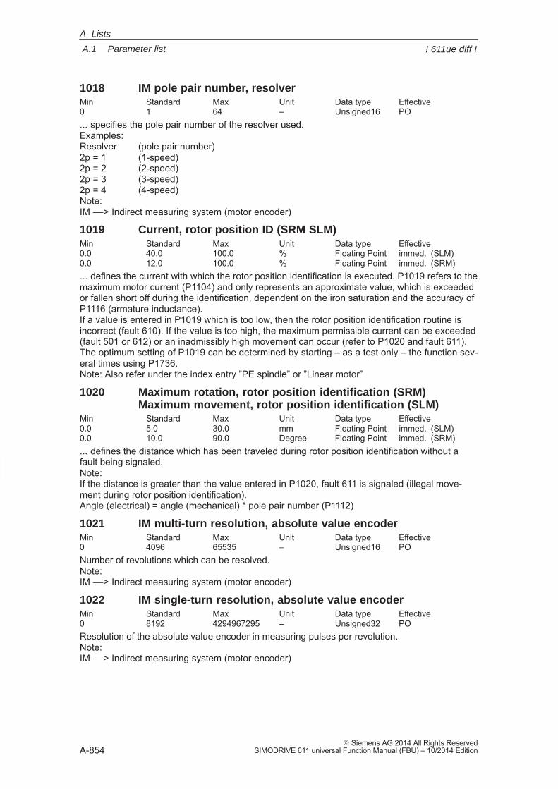
A
A.1 Parameter list
A-854� Siemens AG 2014 All Rights Reserved
SIMODRIVE 611 universal Function Manual (FBU) – 10/2014 Edition
1018 IM pole pair number, resolverMin Standard Max Unit Data type Effective0 1 64 – Unsigned16 PO... specifies the pole pair number of the resolver used.Examples:Resolver (pole pair number)2p = 1 (1-speed)2p = 2 (2-speed)2p = 3 (3-speed)2p = 4 (4-speed)Note:IM ––> Indirect measuring system (motor encoder)
1019 Current, rotor position ID (SRM SLM)Min Standard Max Unit Data type Effective0.0 40.0 100.0 % Floating Point immed. (SLM)0.0 12.0 100.0 % Floating Point immed. (SRM)... defines the current with which the rotor position identification is executed. P1019 refers to themaximum motor current (P1104) and only represents an approximate value, which is exceededor fallen short off during the identification, dependent on the iron saturation and the accuracy ofP1116 (armature inductance).If a value is entered in P1019 which is too low, then the rotor position identification routine isincorrect (fault 610). If the value is too high, the maximum permissible current can be exceeded(fault 501 or 612) or an inadmissibly high movement can occur (refer to P1020 and fault 611).The optimum setting of P1019 can be determined by starting – as a test only – the function sev-eral times using P1736.Note: Also refer under the index entry ”PE spindle” or ”Linear motor”
1020 Maximum rotation, rotor position identification (SRM)Maximum movement, rotor position identification (SLM)
Min Standard Max Unit Data type Effective0.0 5.0 30.0 mm Floating Point immed. (SLM)0.0 10.0 90.0 Degree Floating Point immed. (SRM)... defines the distance which has been traveled during rotor position identification without afault being signaled.Note:If the distance is greater than the value entered in P1020, fault 611 is signaled (illegal move-ment during rotor position identification).Angle (electrical) = angle (mechanical) * pole pair number (P1112)
1021 IM multi-turn resolution, absolute value encoderMin Standard Max Unit Data type Effective0 4096 65535 – Unsigned16 PONumber of revolutions which can be resolved.Note:IM ––> Indirect measuring system (motor encoder)
1022 IM single-turn resolution, absolute value encoderMin Standard Max Unit Data type Effective0 8192 4294967295 – Unsigned32 POResolution of the absolute value encoder in measuring pulses per revolution.Note:IM ––> Indirect measuring system (motor encoder)
A Lists
! 611ue diff !
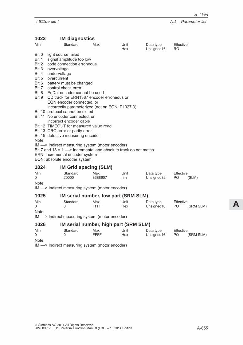
A
A.1 Parameter list
A-855� Siemens AG 2014 All Rights ReservedSIMODRIVE 611 universal Function Manual (FBU) – 10/2014 Edition
1023 IM diagnosticsMin Standard Max Unit Data type Effective– – – Hex Unsigned16 ROBit 0 light source failedBit 1 signal amplitude too lowBit 2 code connection erroneousBit 3 overvoltageBit 4 undervoltageBit 5 overcurrentBit 6 battery must be changedBit 7 control check errorBit 8 EnDat encoder cannot be usedBit 9 CD track for ERN1387 encoder erroneous or
EQN encoder connected, or incorrectly parameterized (not on EQN, P1027.3)
Bit 10 protocol cannot be exitedBit 11 No encoder connected, or
incorrect encoder cableBit 12 TIMEOUT for measured value readBit 13 CRC error or parity errorBit 15 defective measuring encoderNote:IM ––> Indirect measuring system (motor encoder)Bit 7 and 13 = 1 ––> Incremental and absolute track do not matchERN: incremental encoder system EQN: absolute encoder system
1024 IM Grid spacing (SLM)Min Standard Max Unit Data type Effective0 20000 8388607 nm Unsigned32 PO (SLM)Note:IM ––> Indirect measuring system (motor encoder)
1025 IM serial number, low part (SRM SLM)Min Standard Max Unit Data type Effective0 0 FFFF Hex Unsigned16 PO (SRM SLM)Note:IM ––> Indirect measuring system (motor encoder)
1026 IM serial number, high part (SRM SLM)Min Standard Max Unit Data type Effective0 0 FFFF Hex Unsigned16 PO (SRM SLM)Note:IM ––> Indirect measuring system (motor encoder)
A Lists
! 611ue diff !
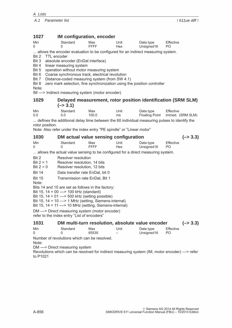
A
A.1 Parameter list
A-856� Siemens AG 2014 All Rights Reserved
SIMODRIVE 611 universal Function Manual (FBU) – 10/2014 Edition
1027 IM configuration, encoderMin Standard Max Unit Data type Effective0 0 FFFF Hex Unsigned16 PO... allows the encoder evaluation to be configured for an indirect measuring system.Bit 2 TTL encoderBit 3 absolute encoder (EnDat interface)Bit 4 linear measuring systemBit 5 operation without motor measuring systemBit 6 Coarse synchronous track, electrical revolutionBit 7 Distance-coded measuring system (from SW 4.1)Bit 8 zero mark selection, fine synchronization using the position controllerNote:IM ––> Indirect measuring system (motor encoder)
1029 Delayed measurement, rotor position identification (SRM SLM)(–> 3.1)
Min Standard Max Unit Data type Effective0.0 0.0 100.0 ms Floating Point immed. (SRM SLM)... defines the additional delay time between the 60 individual measuring pulses to identify therotor position.Note: Also refer under the index entry ”PE spindle” or ”Linear motor”
1030 DM actual value sensing configuration (–> 3.3)Min Standard Max Unit Data type Effective0 0 FFFF Hex Unsigned16 PO... allows the actual value sensing to be configured for a direct measuring system.Bit 2 Resolver resolutionBit 2 = 1 Resolver resolution, 14 bitsBit 2 = 0 Resolver resolution, 12 bitsBit 14 Data transfer rate EnDat, bit 0Bit 15 Transmission rate EnDat, Bit 1Note:Bits 14 and 15 are set as follows in the factory:Bit 15, 14 = 00 ––> 100 kHz (standard)Bit 15, 14 = 01 ––> 500 kHz (setting possible)Bit 15, 14 = 10 ––> 1 MHz (setting, Siemens-internal)Bit 15, 14 = 11 ––> 10 MHz (setting, Siemens-internal)DM ––> Direct measuring system (motor encoder)refer to the index entry ”List of encoders”
1031 DM multi-turn resolution, absolute value encoder (–> 3.3)Min Standard Max Unit Data type Effective0 0 65535 – Unsigned16 PONumber of revolutions which can be resolved.Note:DM ––> Direct measuring systemRevolutions which can be resolved for indirect measuring system (IM, motor encoder) ––> referto P1021
A Lists
! 611ue diff !
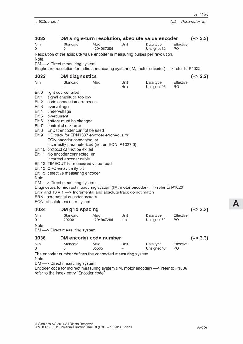
A
A.1 Parameter list
A-857� Siemens AG 2014 All Rights ReservedSIMODRIVE 611 universal Function Manual (FBU) – 10/2014 Edition
1032 DM single-turn resolution, absolute value encoder (–> 3.3)Min Standard Max Unit Data type Effective0 0 4294967295 – Unsigned32 POResolution of the absolute value encoder in measuring pulses per revolution.Note:DM ––> Direct measuring systemSingle-turn resolution for indirect measuring system (IM, motor encoder) ––> refer to P1022
1033 DM diagnostics (–> 3.3)Min Standard Max Unit Data type Effective– – – Hex Unsigned16 ROBit 0 light source failedBit 1 signal amplitude too lowBit 2 code connection erroneousBit 3 overvoltageBit 4 undervoltageBit 5 overcurrentBit 6 battery must be changedBit 7 control check errorBit 8 EnDat encoder cannot be usedBit 9 CD track for ERN1387 encoder erroneous or
EQN encoder connected, orincorrectly parameterized (not on EQN, P1027.3)
Bit 10 protocol cannot be exitedBit 11 No encoder connected, or
incorrect encoder cableBit 12 TIMEOUT for measured value readBit 13 CRC error, parity bitBit 15 defective measuring encoderNote:DM ––> Direct measuring systemDiagnostics for indirect measuring system (IM, motor encoder) ––> refer to P1023Bit 7 and 13 = 1 ––> Incremental and absolute track do not matchERN: incremental encoder systemEQN: absolute encoder system
1034 DM grid spacing (–> 3.3)Min Standard Max Unit Data type Effective0 20000 4294967295 nm Unsigned32 PONote:DM ––> Direct measuring system
1036 DM encoder code number (–> 3.3)Min Standard Max Unit Data type Effective0 0 65535 – Unsigned16 POThe encoder number defines the connected measuring system.Note:DM ––> Direct measuring systemEncoder code for indirect measuring system (IM, motor encoder) ––> refer to P1006refer to the index entry ”Encoder code”
A Lists
! 611ue diff !
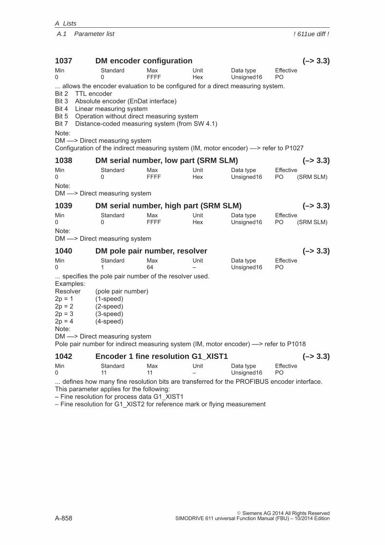
A
A.1 Parameter list
A-858� Siemens AG 2014 All Rights Reserved
SIMODRIVE 611 universal Function Manual (FBU) – 10/2014 Edition
1037 DM encoder configuration (–> 3.3)Min Standard Max Unit Data type Effective0 0 FFFF Hex Unsigned16 PO... allows the encoder evaluation to be configured for a direct measuring system.Bit 2 TTL encoderBit 3 Absolute encoder (EnDat interface)Bit 4 Linear measuring systemBit 5 Operation without direct measuring systemBit 7 Distance-coded measuring system (from SW 4.1)Note:DM ––> Direct measuring systemConfiguration of the indirect measuring system (IM, motor encoder) ––> refer to P1027
1038 DM serial number, low part (SRM SLM) (–> 3.3)Min Standard Max Unit Data type Effective0 0 FFFF Hex Unsigned16 PO (SRM SLM)Note:DM ––> Direct measuring system
1039 DM serial number, high part (SRM SLM) (–> 3.3)Min Standard Max Unit Data type Effective0 0 FFFF Hex Unsigned16 PO (SRM SLM)Note:DM ––> Direct measuring system
1040 DM pole pair number, resolver (–> 3.3)Min Standard Max Unit Data type Effective0 1 64 – Unsigned16 PO... specifies the pole pair number of the resolver used.Examples:Resolver (pole pair number)2p = 1 (1-speed)2p = 2 (2-speed)2p = 3 (3-speed)2p = 4 (4-speed)Note:DM ––> Direct measuring systemPole pair number for indirect measuring system (IM, motor encoder) ––> refer to P1018
1042 Encoder 1 fine resolution G1_XIST1 (–> 3.3)Min Standard Max Unit Data type Effective0 11 11 – Unsigned16 PO... defines how many fine resolution bits are transferred for the PROFIBUS encoder interface.This parameter applies for the following:– Fine resolution for process data G1_XIST1– Fine resolution for G1_XIST2 for reference mark or flying measurement
A Lists
! 611ue diff !
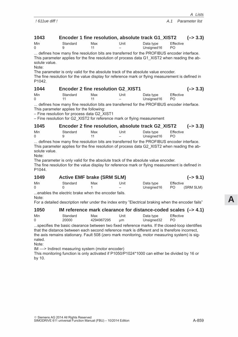
A
A.1 Parameter list
A-859� Siemens AG 2014 All Rights ReservedSIMODRIVE 611 universal Function Manual (FBU) – 10/2014 Edition
1043 Encoder 1 fine resolution, absolute track G1_XIST2 (–> 3.3)Min Standard Max Unit Data type Effective0 9 11 – Unsigned16 PO... defines how many fine resolution bits are transferred for the PROFIBUS encoder interface.This parameter applies for the fine resolution of process data G1_XIST2 when reading the ab-solute value.Note:The parameter is only valid for the absolute track of the absolute value encoder.The fine resolution for the value display for reference mark or flying measurement is defined inP1042.
1044 Encoder 2 fine resolution G2_XIST1 (–> 3.3)Min Standard Max Unit Data type Effective0 11 11 – Unsigned16 PO... defines how many fine resolution bits are transferred for the PROFIBUS encoder interface.This parameter applies for the following:– Fine resolution for process data G2_XIST1– Fine resolution for G2_XIST2 for reference mark or flying measurement
1045 Encoder 2 fine resolution, absolute track G2_XIST2 (–> 3.3)Min Standard Max Unit Data type Effective0 9 11 – Unsigned16 PO... defines how many fine resolution bits are transferred for the PROFIBUS encoder interface.This parameter applies for the fine resolution of process data G2_XIST2 when reading the ab-solute value.Note:The parameter is only valid for the absolute track of the absolute value encoder.The fine resolution for the value display for reference mark or flying measurement is defined inP1044.
1049 Active EMF brake (SRM SLM) (–> 9.1)Min Standard Max Unit Data type Effective0 0 1 – Unsigned16 PO (SRM SLM)...enables the electric brake when the encoder fails.Note:For a detailed description refer under the index entry ”Electrical braking when the encoder fails”
1050 IM reference mark clearance for distance-coded scales (–> 4.1)Min Standard Max Unit Data type Effective0 20000 4294967295 μm Unsigned32 PO...specifies the basic clearance between two fixed reference marks. If the closed-loop identifiesthat the distance between each second reference mark is different and is therefore incorrect,the axis remains stationary. Fault 508 (zero mark monitoring, motor measuring system) is sig-naled.Note:IM ––> Indirect measuring system (motor encoder)This monitoring function is only activated if P1050/P1024*1000 can either be divided by 16 orby 10.
A Lists
! 611ue diff !
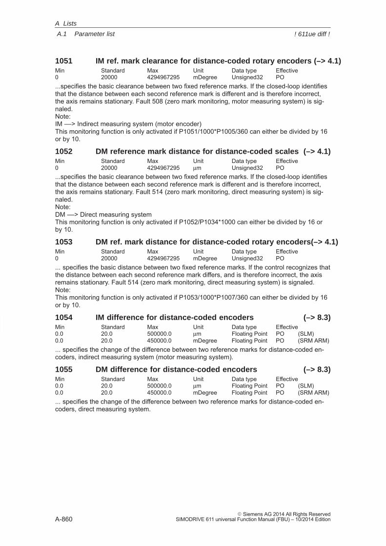
A
A.1 Parameter list
A-860� Siemens AG 2014 All Rights Reserved
SIMODRIVE 611 universal Function Manual (FBU) – 10/2014 Edition
1051 IM ref. mark clearance for distance-coded rotary encoders (–> 4.1)Min Standard Max Unit Data type Effective0 20000 4294967295 mDegree Unsigned32 PO...specifies the basic clearance between two fixed reference marks. If the closed-loop identifiesthat the distance between each second reference mark is different and is therefore incorrect,the axis remains stationary. Fault 508 (zero mark monitoring, motor measuring system) is sig-naled.Note:IM ––> Indirect measuring system (motor encoder)This monitoring function is only activated if P1051/1000*P1005/360 can either be divided by 16or by 10.
1052 DM reference mark distance for distance-coded scales (–> 4.1)Min Standard Max Unit Data type Effective0 20000 4294967295 μm Unsigned32 PO...specifies the basic clearance between two fixed reference marks. If the closed-loop identifiesthat the distance between each second reference mark is different and is therefore incorrect,the axis remains stationary. Fault 514 (zero mark monitoring, direct measuring system) is sig-naled.Note:DM ––> Direct measuring systemThis monitoring function is only activated if P1052/P1034*1000 can either be divided by 16 orby 10.
1053 DM ref. mark distance for distance-coded rotary encoders(–> 4.1)Min Standard Max Unit Data type Effective0 20000 4294967295 mDegree Unsigned32 PO... specifies the basic distance between two fixed reference marks. If the control recognizes thatthe distance between each second reference mark differs, and is therefore incorrect, the axisremains stationary. Fault 514 (zero mark monitoring, direct measuring system) is signaled.Note:This monitoring function is only activated if P1053/1000*P1007/360 can either be divided by 16or by 10.
1054 IM difference for distance-coded encoders (–> 8.3)Min Standard Max Unit Data type Effective0.0 20.0 500000.0 μm Floating Point PO (SLM)0.0 20.0 450000.0 mDegree Floating Point PO (SRM ARM)... specifies the change of the difference between two reference marks for distance-coded en-coders, indirect measuring system (motor measuring system).
1055 DM difference for distance-coded encoders (–> 8.3)Min Standard Max Unit Data type Effective0.0 20.0 500000.0 μm Floating Point PO (SLM)0.0 20.0 450000.0 mDegree Floating Point PO (SRM ARM)... specifies the change of the difference between two reference marks for distance-coded en-coders, direct measuring system.
A Lists
! 611ue diff !
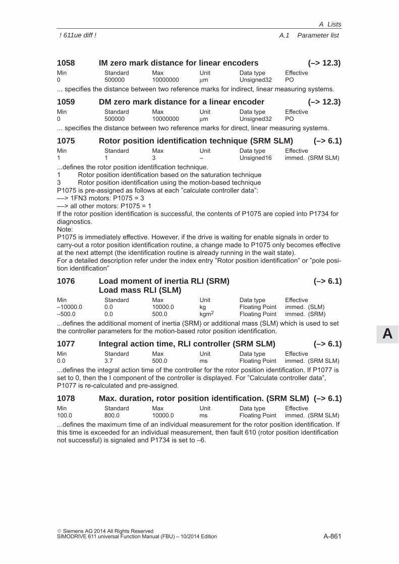
A
A.1 Parameter list
A-861� Siemens AG 2014 All Rights ReservedSIMODRIVE 611 universal Function Manual (FBU) – 10/2014 Edition
1058 IM zero mark distance for linear encoders (–> 12.3)Min Standard Max Unit Data type Effective0 500000 10000000 μm Unsigned32 PO... specifies the distance between two reference marks for indirect, linear measuring systems.
1059 DM zero mark distance for a linear encoder (–> 12.3)Min Standard Max Unit Data type Effective0 500000 10000000 μm Unsigned32 PO... specifies the distance between two reference marks for direct, linear measuring systems.
1075 Rotor position identification technique (SRM SLM) (–> 6.1)Min Standard Max Unit Data type Effective1 1 3 – Unsigned16 immed. (SRM SLM)...defines the rotor position identification technique.1 Rotor position identification based on the saturation technique3 Rotor position identification using the motion-based techniqueP1075 is pre-assigned as follows at each ”calculate controller data”:––> 1FN3 motors: P1075 = 3––> all other motors: P1075 = 1If the rotor position identification is successful, the contents of P1075 are copied into P1734 fordiagnostics.Note:P1075 is immediately effective. However, if the drive is waiting for enable signals in order tocarry-out a rotor position identification routine, a change made to P1075 only becomes effectiveat the next attempt (the identification routine is already running in the wait state).For a detailed description refer under the index entry ”Rotor position identification” or ”pole posi-tion identification”
1076 Load moment of inertia RLI (SRM) (–> 6.1)Load mass RLI (SLM)
Min Standard Max Unit Data type Effective–10000.0 0.0 10000.0 kg Floating Point immed. (SLM)–500.0 0.0 500.0 kgm2 Floating Point immed. (SRM)...defines the additional moment of inertia (SRM) or additional mass (SLM) which is used to setthe controller parameters for the motion-based rotor position identification.
1077 Integral action time, RLI controller (SRM SLM) (–> 6.1)Min Standard Max Unit Data type Effective0.0 3.7 500.0 ms Floating Point immed. (SRM SLM)...defines the integral action time of the controller for the rotor position identification. If P1077 isset to 0, then the I component of the controller is displayed. For ”Calculate controller data”,P1077 is re-calculated and pre-assigned.
1078 Max. duration, rotor position identification. (SRM SLM) (–> 6.1)Min Standard Max Unit Data type Effective100.0 800.0 10000.0 ms Floating Point immed. (SRM SLM)...defines the maximum time of an individual measurement for the rotor position identification. Ifthis time is exceeded for an individual measurement, then fault 610 (rotor position identificationnot successful) is signaled and P1734 is set to –6.
A Lists
! 611ue diff !
A
A.1 Parameter list
A-862� Siemens AG 2014 All Rights Reserved
SIMODRIVE 611 universal Function Manual (FBU) – 10/2014 Edition
1080 Calculate controller dataMin Standard Max Unit Data type Effective0 0 1 – Integer16 immed.Suitable settings for the control parameters are calculated from the motor parameters and sev-eral other parameters using this function.0 –> 1 Controller data are being calculated, function is active0 Function inactive or completed correctlyError codes–15 Magnetizing reactance (P1141) = 0 –16 Leakage reactance (P1139 / P1140) = 0–17 Rated motor frequency (P1134) = 0–18 Rotor resistance (P1138) = 0–19 Moment of inertia (P1117+P1123) <= 0–21 threshold speed for field weakening (P1142) = 0–22 Motor stall current (P1118) = 0–23 The ratio between the maximum motor current (P1104) and the motor stall current
(P1118) is greater than the maximum value for the torque limit (P1230) and the power limit (P1235).
–24 The ratio between the rated motor frequency (P1134) and the rated motor speed (P1400) is inadmissible (pole pair number)
Note:Recommendation: Execute this function using SimoCom U because the calculated parametersare displayed and are only accepted and overwritten after confirmation.At the end of the calculation, the parameters are automatically reset to 0 or an error code iswritten into it.When an error occurs, the parameters for the current controller, flux controller and speed con-troller could not be optimally pre-assigned. The standard values were entered.After the cause of the error is resolved, the function can be re-started.
1081 Calculate equivalent circuit diagram data (ARM)Min Standard Max Unit Data type Effective0 0 1 – Integer16 immed. (ARM)Procedure for third-party motor:– Select ”third-party motor” for the first start-up (refer to the index entry ”Motor code”)– Enter all rating plate data– Calculate the equivalent circuit diagram data via P1081 = 1Note: After the ”Calculate equivalent circuit diagram data”, a ”Calculate third-party motor” should becarried out (P1082).A 0 or another error code is automatically written into the parameter at the end of the calcula-tion.0 –> 1 Equivalent circuit diagram data are being calculated, function is active0 Function inactive or completed correctlyError codes–51 Rated motor output (P1130) = 0–52 Rated motor voltage (P1132) = 0–53 Rated motor current (P1103) = 0–54 Cos phi (P1129) = 0 or > 0.996–55 The ratio between the rated motor frequency (P1134) and the rated motor speed
(P1400) is inadmissible (pole pair number)–56 Warning: The threshold speed for field weakening (P1142) < rated motor speed (P1400)–57 The function is only permissible for third-party motors (P1102 = 99)Note:In the case of an error, no equivalent circuit diagram data were changed (exception: code –56).
A Lists
! 611ue diff !
A
A.1 Parameter list
A-863� Siemens AG 2014 All Rights ReservedSIMODRIVE 611 universal Function Manual (FBU) – 10/2014 Edition
1082 Calculate third-party motorMin Standard Max Unit Data type Effective0 0 1 – Integer16 immed.... the ”Calculate unlisted motor” function is started. Parameters P1105 (only SRM), P1147,P1241, P1401 are pre-assigned, the ”calculate controller data” function executed and the ap-propriate unlisted motor code entered into P1102.By entering the third-party motor code in P1102, at the next POWER ON, possibly changedmotor data will no longer be overwritten by the catalog motor data (previous motor code).0 –> 1 Third-party motor is being calculated, function is active0 Function in inactive Procedure for third-party motor:Are all of the equivalent circuit diagram data known?– if no: Calculate the equivalent circuit diagram data via P1081– if yes: Enter all of the equivalent circuit diagram data and set P1082 to 1Note:At the end of the calculation, the parameter is automatically reset to 0 or an error code is writteninto it (refer to P1080).
1083 Function selection, motor data optimization (ARM)Min Standard Max Unit Data type Effective1 1 4 – Unsigned16 immed. (ARM)... the function number for motor data optimization is entered.1 Calculate leakage inductance and rotor resistance2 Calculate no-load current and magnetizing reactance3 Calculate field-weakening speed4 Calculate moment of inertiaPerform motor data optimization:Step 1P1083 = 1 and start with P1084 = 1 (if not 0, then evaluate the error code)Calculated and written parameters: P1136, P1137, P1138, P1139, P1140, P1141Step 2P1083 = 2 and start with P1084 = 1 (if it is not 0, evaluate error code)Calculated and written parameters: P1136, P1141Step 3P1083 = 3 and start with P1084 = 1 (if it is not 0, evaluate error code)Calculated and written parameters: P1142Step 4P1083 = 4 and start with P1084 = 1 (if it is not 0, evaluate error code)Calculated and written parameters: P1117Note:For a detailed description, please refer to the index entry ”Motor data optimization”.
A Lists
! 611ue diff !
A
A.1 Parameter list
A-864� Siemens AG 2014 All Rights Reserved
SIMODRIVE 611 universal Function Manual (FBU) – 10/2014 Edition
1084 Start motor data optimization (ARM)Min Standard Max Unit Data type Effective0 0 1 – Integer16 immed. (ARM)The function is selected using P1083 and is started by setting P1084 to 1.A 0 or another error code is automatically written into the parameter at the end of the calcula-tion.1 Function is active0 Function inactive or completed correctlyError codes –2 Pulse frequency (P1100) of 4 kHz or 8 kHz required –3 Controller / pulse enable missing –4 Speed setpoint <> 0 –5 Motor changeover is currently active –6 Error when determining the leakage inductance (result < 0) –7 V/f operation is active –8 The incorrect motor was selected by the motor changeover –9 Parameterized maximum speed is too low for the measurement–10 Power-up inhibit–11 Changeover speed open-loop / closed-loop control is too large (P1466)–12 Speed range too low (P1466 or P1160 too large)–13 Ramp-function generator enable missing–14 Open-loop torque-controlled operation is selected–15 Motor data optimization for catalog motor illegal (from SW 3.3)–16 If the current is too high, it is limited by the i2t power module model
1094 Derating, ambient temperature (–> 13.1)Min Standard Max Unit Data type Effective30 40 55 C Unsigned16 PO... specifies the ambient temperature in Degrees Celsius for the power unit derating.When powering up, the currently effective derating factor is calculated as a function of the pulsefrequency, the ambient temperature (P1094), the installation altitude (P1095) and the deratingfactor X1. It can be seen in display data P1099. Note:also refer to P1095, P1178 or P1179
1095 Derating, installation altitude (–> 13.1)Min Standard Max Unit Data type Effective0.000000 1000.000000 5000.000000 m Floating Point PO... specifies the installation altitude in meters for the power unit derating.When powering up, the currently effective derating factor is calculated as a function of the pulsefrequency, the ambient temperature (P1094), the installation altitude (P1095) and the deratingfactor X1. It can be seen in display data P1099. Note:also refer to P1095, P1178 or P1179
A Lists
! 611ue diff !
A
A.1 Parameter list
A-865� Siemens AG 2014 All Rights ReservedSIMODRIVE 611 universal Function Manual (FBU) – 10/2014 Edition
1096 Red. max. torque for regenerative stop active (–> 9.1)Min Standard Max Unit Data type Effective0 0 3 – Unsigned16 immed.... configures the torque reduction for a speed setpoint of zero.Bit 0 The torque limit is reduced for regenerative brakingBit 0 = 1 The limit torque is reduced for a regenerative stop with a speed setpoint of zero. Note:For EMF brakes, the torque is always reduced with P1097.Bit 0 = 0 inactiveBit 1 Disable monitoring for speed controller at its end stop so that the regenerativestop – that takes longer due to the reduced torque – is not interrupted by the monitoring func-tion cancelling the pulsesNote:For EMF brakes, the speed controller at its limit monitoring function is always disabled.Bit 1 = 1 not activeBit 1 = 0 Monitoring, speed controller at its limit for torque reductionBit 2 – 15 ReservedNote: Refer under index entry ”Faults, stop responses”
1097 Red. max. torque for regenerative stop (–> 9.1)Min Standard Max Unit Data type Effective0 80 100 % Integer16 immed.... specifies the torque reduction for a speed setpoint of zero.Note: Refer under index entry ”Faults, stop responses”
1099 Limiting factor, power section currents (–> 2.4)Min Standard Max Unit Data type Effective– – – % Floating Point ROthe following applies before SW 13.1:... displays the limiting factor for the power section currents (P1108, P1109, P1111) as a functionof the pulse frequency (P1100).from SW 13.1, the following applies:... indicates the limit factor for the power unit currents (P1108, P1109, P1111).When booting, the currently effective limit factor is calculated depending on the pulse frequency(P1100), the ambient temperature (P1094), the installation altitude (P1095) and derating factorX1.Note: Refer under the index entry ”Power unit currents”
1100 Pulse width modulation frequencyMin Standard Max Unit Data type Effective2000.0 3200.0 8000.0 Hz Floating Point PO (ARM)2000.0 4000.0 8000.0 Hz Floating Point PO (SRM SLM)... defines the clock frequency of the inverter.We recommend the following frequencies: 2000, 2666, 3200, (4000), 5333, 6400 and (8000)Hz.For low-leakage or high-speed third-party motors (motor frequency > 500 Hz) it makes sense toincrease the switching frequency.Further, it may make sense to change the switching frequency to reduce motor noise.Note:The frequencies specified in brackets are preferred values – intermediate values can also beset.For IM operation (ARM without encoder), only frequencies of 4000 and 8000 Hz are permitted.The current rating of the drive converter is reduced when the frequency is increased. This mustalready be taken into account when dimensioning the power section (refer to the de-rating cha-racteristic).
A Lists
! 611ue diff !
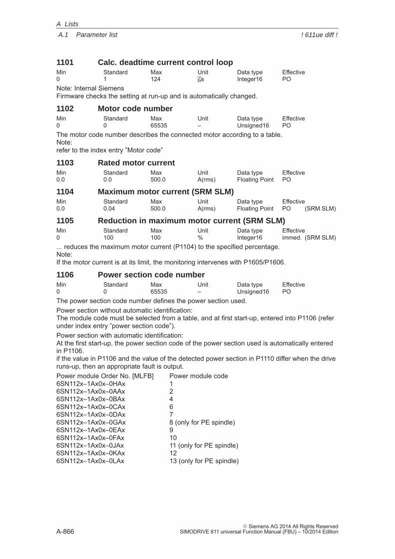
A
A.1 Parameter list
A-866� Siemens AG 2014 All Rights Reserved
SIMODRIVE 611 universal Function Manual (FBU) – 10/2014 Edition
1101 Calc. deadtime current control loopMin Standard Max Unit Data type Effective0 1 124 s Integer16 PONote: Internal SiemensFirmware checks the setting at run-up and is automatically changed.
1102 Motor code numberMin Standard Max Unit Data type Effective0 0 65535 – Unsigned16 POThe motor code number describes the connected motor according to a table.Note:refer to the index entry ”Motor code”
1103 Rated motor currentMin Standard Max Unit Data type Effective0.0 0.0 500.0 A(rms) Floating Point PO
1104 Maximum motor current (SRM SLM)Min Standard Max Unit Data type Effective0.0 0.04 500.0 A(rms) Floating Point PO (SRM SLM)
1105 Reduction in maximum motor current (SRM SLM)Min Standard Max Unit Data type Effective0 100 100 % Integer16 immed. (SRM SLM)... reduces the maximum motor current (P1104) to the specified percentage.Note: If the motor current is at its limit, the monitoring intervenes with P1605/P1606.
1106 Power section code numberMin Standard Max Unit Data type Effective0 0 65535 – Unsigned16 POThe power section code number defines the power section used.Power section without automatic identification:The module code must be selected from a table, and at first start-up, entered into P1106 (referunder index entry ”power section code”).Power section with automatic identification:At the first start-up, the power section code of the power section used is automatically enteredin P1106.if the value in P1106 and the value of the detected power section in P1110 differ when the driveruns-up, then an appropriate fault is output.Power module Order No. [MLFB] Power module code6SN112x–1Ax0x–0HAx 16SN112x–1Ax0x–0AAx 26SN112x–1Ax0x–0BAx 46SN112x–1Ax0x–0CAx 66SN112x–1Ax0x–0DAx 76SN112x–1Ax0x–0GAx 8 (only for PE spindle)6SN112x–1Ax0x–0EAx 96SN112x–1Ax0x–0FAx 106SN112x–1Ax0x–0JAx 11 (only for PE spindle)6SN112x–1Ax0x–0KAx 126SN112x–1Ax0x–0LAx 13 (only for PE spindle)
A Lists
! 611ue diff !
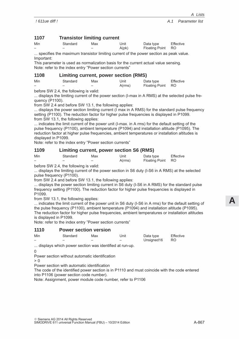
A
A.1 Parameter list
A-867� Siemens AG 2014 All Rights ReservedSIMODRIVE 611 universal Function Manual (FBU) – 10/2014 Edition
1107 Transistor limiting currentMin Standard Max Unit Data type Effective– – – A(pk) Floating Point RO... specifies the maximum transistor limiting current of the power section as peak value.Important:This parameter is used as normalization basis for the current actual value sensing.Note: refer to the index entry ”Power section currents”
1108 Limiting current, power section (RMS)Min Standard Max Unit Data type Effective– – – A(rms) Floating Point RObefore SW 2.4, the following is valid:... displays the limiting current of the power section (I-max in A RMS) at the selected pulse fre-quency (P1100).from SW 2.4 and before SW 13.1, the following applies:... displays the power section limiting current (I max in A RMS) for the standard pulse frequencysetting (P1100). The reduction factor for higher pulse frequencies is displayed in P1099.from SW 13.1, the following applies:... indicates the limit current of the power unit (I-max. in A rms) for the default setting of thepulse frequency (P1100), ambient temperature (P1094) and installation altitude (P1095). Thereduction factor at higher pulse frequencies, ambient temperatures or installation altitudes isdisplayed in P1099.Note: refer to the index entry ”Power section currents”
1109 Limiting current, power section S6 (RMS)Min Standard Max Unit Data type Effective– – – A(rms) Floating Point RObefore SW 2.4, the following is valid:... displays the limiting current of the power section in S6 duty (I-S6 in A RMS) at the selectedpulse frequency (P1100).from SW 2.4 and before SW 13.1, the following applies:... displays the power section limiting current in S6 duty (I-S6 in A RMS) for the standard pulsefrequency setting (P1100). The reduction factor for higher pulse frequencies is displayed inP1099.from SW 13.1, the following applies:... indicates the limit current of the power unit in S6 duty (I-S6 in A rms) for the default setting ofthe pulse frequency (P1100), ambient temperature (P1094) and installation altitude (P1095).The reduction factor for higher pulse frequencies, ambient temperatures or installation altitudesis displayed in P1099.Note: refer to the index entry ”Power section currents”
1110 Power section versionMin Standard Max Unit Data type Effective– – – – Unsigned16 RO... displays which power section was identified at run-up.0Power section without automatic identification> 0Power section with automatic identificationThe code of the identified power section is in P1110 and must coincide with the code enteredinto P1106 (power section code number).Note: Assignment, power module code number, refer to P1106
A Lists
! 611ue diff !
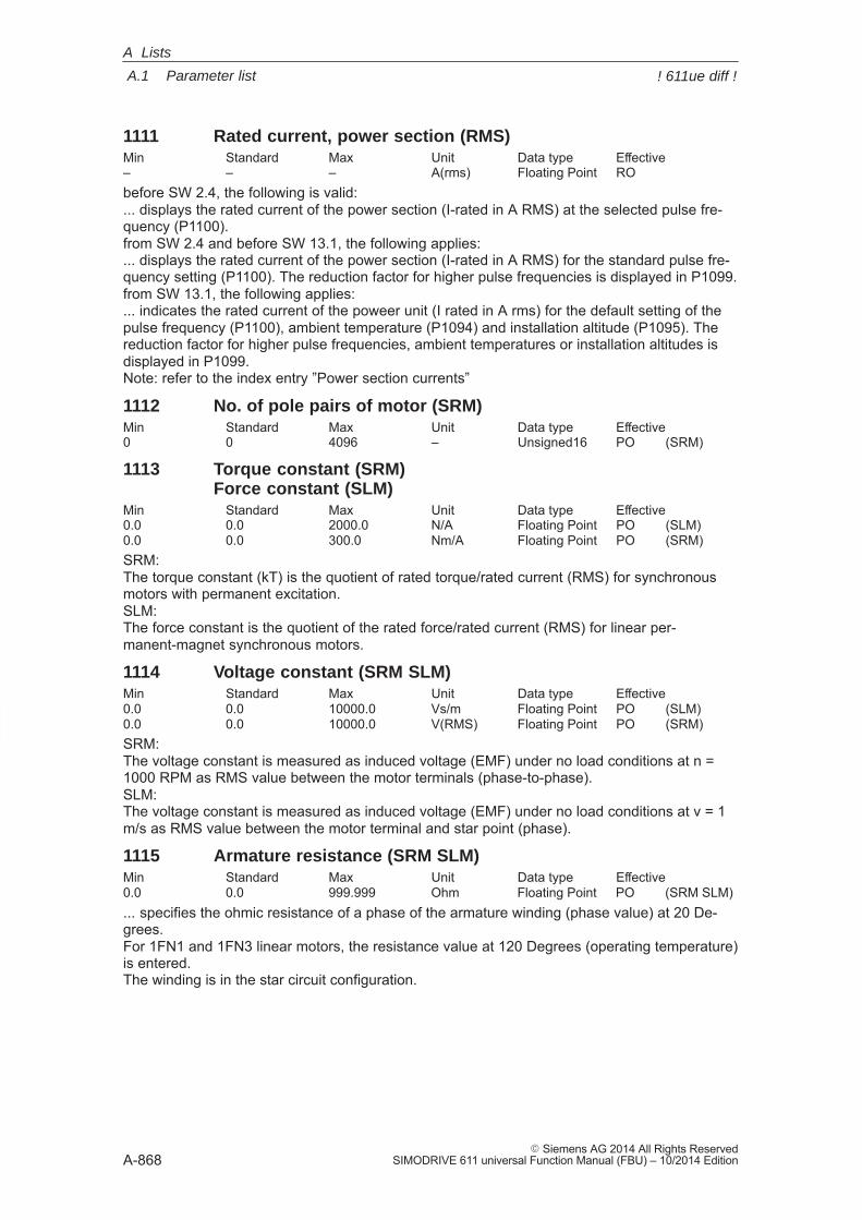
A
A.1 Parameter list
A-868� Siemens AG 2014 All Rights Reserved
SIMODRIVE 611 universal Function Manual (FBU) – 10/2014 Edition
1111 Rated current, power section (RMS)Min Standard Max Unit Data type Effective– – – A(rms) Floating Point RObefore SW 2.4, the following is valid:... displays the rated current of the power section (I-rated in A RMS) at the selected pulse fre-quency (P1100).from SW 2.4 and before SW 13.1, the following applies:... displays the rated current of the power section (I-rated in A RMS) for the standard pulse fre-quency setting (P1100). The reduction factor for higher pulse frequencies is displayed in P1099.from SW 13.1, the following applies:... indicates the rated current of the poweer unit (I rated in A rms) for the default setting of thepulse frequency (P1100), ambient temperature (P1094) and installation altitude (P1095). Thereduction factor for higher pulse frequencies, ambient temperatures or installation altitudes isdisplayed in P1099.Note: refer to the index entry ”Power section currents”
1112 No. of pole pairs of motor (SRM)Min Standard Max Unit Data type Effective0 0 4096 – Unsigned16 PO (SRM)
1113 Torque constant (SRM)Force constant (SLM)
Min Standard Max Unit Data type Effective0.0 0.0 2000.0 N/A Floating Point PO (SLM)0.0 0.0 300.0 Nm/A Floating Point PO (SRM)SRM:The torque constant (kT) is the quotient of rated torque/rated current (RMS) for synchronousmotors with permanent excitation.SLM:The force constant is the quotient of the rated force/rated current (RMS) for linear per-manent-magnet synchronous motors.
1114 Voltage constant (SRM SLM)Min Standard Max Unit Data type Effective0.0 0.0 10000.0 Vs/m Floating Point PO (SLM)0.0 0.0 10000.0 V(RMS) Floating Point PO (SRM)SRM:The voltage constant is measured as induced voltage (EMF) under no load conditions at n =1000 RPM as RMS value between the motor terminals (phase-to-phase).SLM:The voltage constant is measured as induced voltage (EMF) under no load conditions at v = 1m/s as RMS value between the motor terminal and star point (phase).
1115 Armature resistance (SRM SLM)Min Standard Max Unit Data type Effective0.0 0.0 999.999 Ohm Floating Point PO (SRM SLM)... specifies the ohmic resistance of a phase of the armature winding (phase value) at 20 De-grees.For 1FN1 and 1FN3 linear motors, the resistance value at 120 Degrees (operating temperature)is entered.The winding is in the star circuit configuration.
A Lists
! 611ue diff !
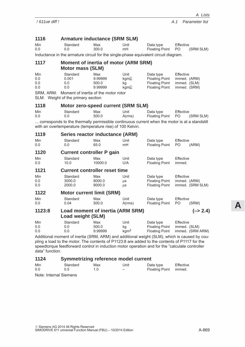
A
A.1 Parameter list
A-869� Siemens AG 2014 All Rights ReservedSIMODRIVE 611 universal Function Manual (FBU) – 10/2014 Edition
1116 Armature inductance (SRM SLM)Min Standard Max Unit Data type Effective0.0 0.0 300.0 mH Floating Point PO (SRM SLM)Inductance in the armature circuit for the single-phase equivalent circuit diagram.
1117 Moment of inertia of motor (ARM SRM)Motor mass (SLM)
Min Standard Max Unit Data type Effective0.0 0.001 9.99999 kgm Floating Point immed. (ARM)0.0 0.0 500.0 kg Floating Point immed. (SLM)0.0 0.0 9.99999 kgm Floating Point immed. (SRM)SRM, ARM: Moment of inertia of the motor rotorSLM: Weight of the primary section
1118 Motor zero-speed current (SRM SLM)Min Standard Max Unit Data type Effective0.0 0.0 500.0 A(rms) Floating Point PO (SRM SLM)... corresponds to the thermally permissible continuous current when the motor is at a standstillwith an overtemperature (temperature rise) of 100 Kelvin.
1119 Series reactor inductance (ARM)Min Standard Max Unit Data type Effective0.0 0.0 65.0 mH Floating Point PO (ARM)
1120 Current controller P gainMin Standard Max Unit Data type Effective0.0 10.0 10000.0 U/A Floating Point immed.
1121 Current controller reset timeMin Standard Max Unit Data type Effective0.0 3000.0 8000.0 μs Floating Point immed. (ARM)0.0 2000.0 8000.0 μs Floating Point immed. (SRM SLM)
1122 Motor current limit (SRM)Min Standard Max Unit Data type Effective0.0 0.04 500.0 A(rms) Floating Point PO (SRM)
1123:8 Load moment of inertia (ARM SRM) (–> 2.4)Load weight (SLM)
Min Standard Max Unit Data type Effective0.0 0.0 500.0 kg Floating Point immed. (SLM)0.0 0.0 9.99999 kgm2 Floating Point immed. (SRM ARM)Additional moment of inertia (SRM, ARM) and additional weight (SLM), which is caused by cou-pling a load to the motor. The contents of P1123:8 are added to the contents of P1117 for thespeedtorque feedforward control in induction motor operation and for the ”calculate controllerdata” function.
1124 Symmetrizing reference model currentMin Standard Max Unit Data type Effective0.0 0.5 1.0 – Floating Point immed.Note: Internal Siemens
A Lists
! 611ue diff !
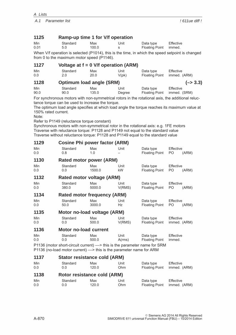
A
A.1 Parameter list
A-870� Siemens AG 2014 All Rights Reserved
SIMODRIVE 611 universal Function Manual (FBU) – 10/2014 Edition
1125 Ramp-up time 1 for V/f operationMin Standard Max Unit Data type Effective0.01 5.0 100.0 s Floating Point immed.When V/f operation is selected (P1014), this is the time, in which the speed setpoint is changedfrom 0 to the maximum motor speed (P1146).
1127 Voltage at f = 0 V/f operation (ARM)Min Standard Max Unit Data type Effective0.0 2.0 20.0 V(pk) Floating Point immed. (ARM)
1128 Optimum load angle (SRM) (–> 3.3)Min Standard Max Unit Data type Effective90.0 90.0 135.0 Degree Floating Point immed. (SRM)For synchronous motors with non-symmetrical rotors in the rotational axis, the additional reluc-tance torque can be used to increase the torque.The optimum load angle specifies at which load angle the torque reaches its maximum value at150% rated current.Note:Refer to P1149 (reluctance torque constant)Synchronous motors with non-symmetrical rotor in the rotational axis: e.g. 1FE motorsTraverse with reluctance torque: P1128 and P1149 not equal to the standard valueTraverse without reluctance torque: P1128 and P1149 equal to the standard value
1129 Cosine Phi power factor (ARM)Min Standard Max Unit Data type Effective0.0 0.8 1.0 – Floating Point PO (ARM)
1130 Rated motor power (ARM)Min Standard Max Unit Data type Effective0.0 0.0 1500.0 kW Floating Point PO (ARM)
1132 Rated motor voltage (ARM)Min Standard Max Unit Data type Effective0.0 380.0 5000.0 V(RMS) Floating Point PO (ARM)
1134 Rated motor frequency (ARM)Min Standard Max Unit Data type Effective0.0 50.0 3000.0 Hz Floating Point PO (ARM)
1135 Motor no-load voltage (ARM)Min Standard Max Unit Data type Effective0.0 0.0 500.0 V(RMS) Floating Point immed. (ARM)
1136 Motor no-load currentMin Standard Max Unit Data type Effective0.0 0.0 500.0 A(rms) Floating Point immed.P1136 (motor short-circuit current) ––> this is the parameter name for SRMP1136 (no-load motor current) ––> this is the parameter name for ARM
1137 Stator resistance cold (ARM)Min Standard Max Unit Data type Effective0.0 0.0 120.0 Ohm Floating Point immed. (ARM)
1138 Rotor resistance cold (ARM)Min Standard Max Unit Data type Effective0.0 0.0 120.0 Ohm Floating Point immed. (ARM)
A Lists
! 611ue diff !
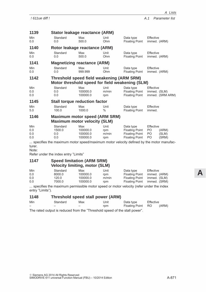
A
A.1 Parameter list
A-871� Siemens AG 2014 All Rights ReservedSIMODRIVE 611 universal Function Manual (FBU) – 10/2014 Edition
1139 Stator leakage reactance (ARM)Min Standard Max Unit Data type Effective0.0 0.0 500.0 Ohm Floating Point immed. (ARM)
1140 Rotor leakage reactance (ARM)Min Standard Max Unit Data type Effective0.0 0.0 500.0 Ohm Floating Point immed. (ARM)
1141 Magnetizing reactance (ARM)Min Standard Max Unit Data type Effective0.0 0.0 999.999 Ohm Floating Point immed. (ARM)
1142 Threshold speed field weakening (ARM SRM)Motor threshold speed for field weakening (SLM)
Min Standard Max Unit Data type Effective0.0 0.0 100000.0 m/min Floating Point immed. (SLM)0.0 0.0 100000.0 rpm Floating Point immed. (SRM ARM)
1145 Stall torque reduction factorMin Standard Max Unit Data type Effective5.0 100.0 1000.0 % Floating Point immed.
1146 Maximum motor speed (ARM SRM)Maximum motor velocity (SLM)
Min Standard Max Unit Data type Effective0.0 1500.0 100000.0 rpm Floating Point PO (ARM)0.0 0.0 100000.0 m/min Floating Point PO (SLM)0.0 0.0 100000.0 rpm Floating Point PO (SRM)... specifies the maximum motor speed/maximum motor velocity defined by the motor manufac-turer.Note:Refer under the index entry ”Limits”
1147 Speed limitation (ARM SRM)Velocity limiting, motor (SLM)
Min Standard Max Unit Data type Effective0.0 8000.0 100000.0 rpm Floating Point immed. (ARM)0.0 120.0 100000.0 m/min Floating Point immed. (SLM)0.0 7000.0 100000.0 rpm Floating Point immed. (SRM)... specifies the maximum permissible motor speed or motor velocity (refer under the indexentry ”Limits”).
1148 Threshold speed stall power (ARM)Min Standard Max Unit Data type Effective– – – rpm Floating Point RO (ARM)The rated output is reduced from the ”Threshold speed of the stall power”.
A Lists
! 611ue diff !
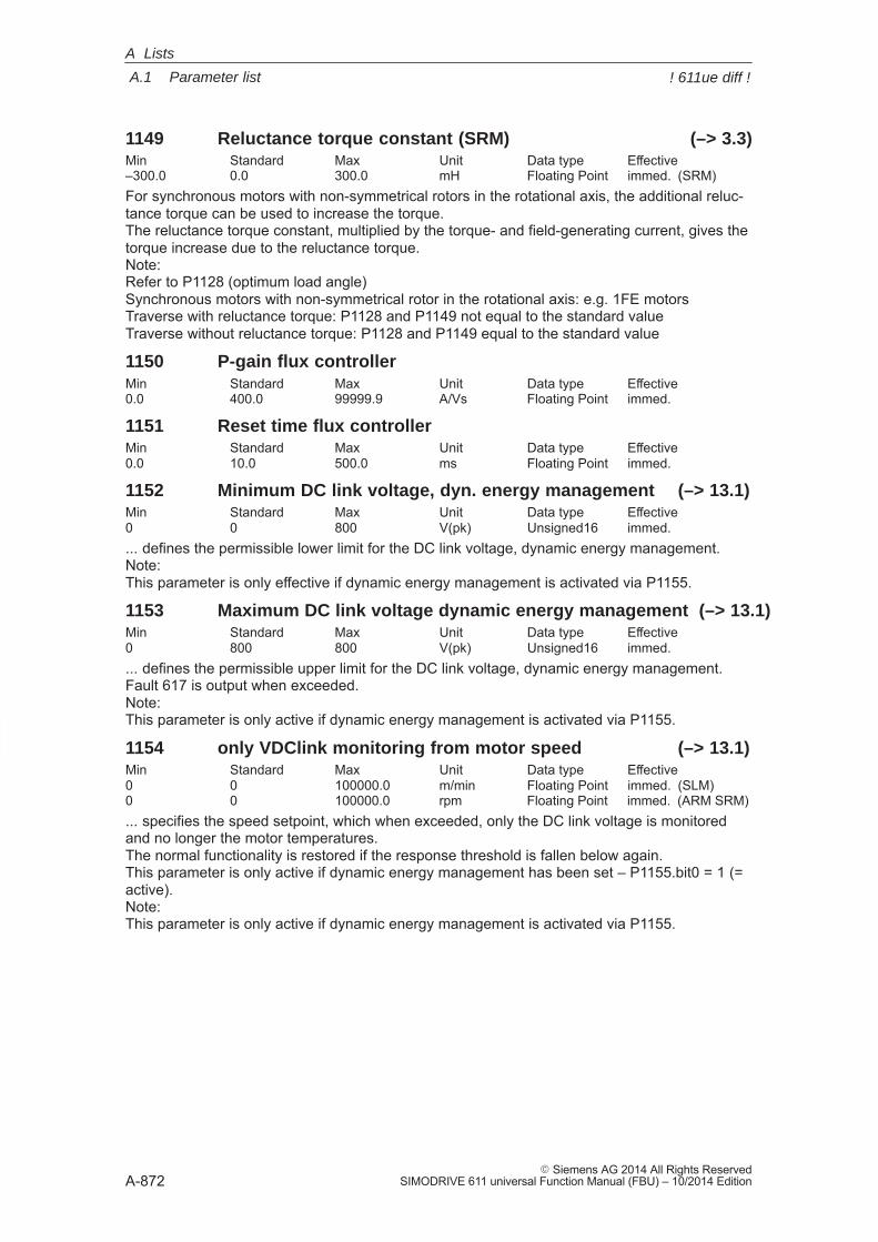
A
A.1 Parameter list
A-872� Siemens AG 2014 All Rights Reserved
SIMODRIVE 611 universal Function Manual (FBU) – 10/2014 Edition
1149 Reluctance torque constant (SRM) (–> 3.3)Min Standard Max Unit Data type Effective–300.0 0.0 300.0 mH Floating Point immed. (SRM)For synchronous motors with non-symmetrical rotors in the rotational axis, the additional reluc-tance torque can be used to increase the torque.The reluctance torque constant, multiplied by the torque- and field-generating current, gives thetorque increase due to the reluctance torque.Note:Refer to P1128 (optimum load angle)Synchronous motors with non-symmetrical rotor in the rotational axis: e.g. 1FE motorsTraverse with reluctance torque: P1128 and P1149 not equal to the standard valueTraverse without reluctance torque: P1128 and P1149 equal to the standard value
1150 P-gain flux controllerMin Standard Max Unit Data type Effective0.0 400.0 99999.9 A/Vs Floating Point immed.
1151 Reset time flux controllerMin Standard Max Unit Data type Effective0.0 10.0 500.0 ms Floating Point immed.
1152 Minimum DC link voltage, dyn. energy management (–> 13.1)Min Standard Max Unit Data type Effective0 0 800 V(pk) Unsigned16 immed.... defines the permissible lower limit for the DC link voltage, dynamic energy management.Note:This parameter is only effective if dynamic energy management is activated via P1155.
1153 Maximum DC link voltage dynamic energy management (–> 13.1)Min Standard Max Unit Data type Effective0 800 800 V(pk) Unsigned16 immed.... defines the permissible upper limit for the DC link voltage, dynamic energy management.Fault 617 is output when exceeded.Note:This parameter is only active if dynamic energy management is activated via P1155.
1154 only VDClink monitoring from motor speed (–> 13.1)Min Standard Max Unit Data type Effective0 0 100000.0 m/min Floating Point immed. (SLM)0 0 100000.0 rpm Floating Point immed. (ARM SRM)... specifies the speed setpoint, which when exceeded, only the DC link voltage is monitoredand no longer the motor temperatures.The normal functionality is restored if the response threshold is fallen below again.This parameter is only active if dynamic energy management has been set – P1155.bit0 = 1 (=active).Note:This parameter is only active if dynamic energy management is activated via P1155.
A Lists
! 611ue diff !
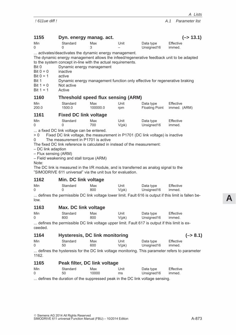
A
A.1 Parameter list
A-873� Siemens AG 2014 All Rights ReservedSIMODRIVE 611 universal Function Manual (FBU) – 10/2014 Edition
1155 Dyn. energy manag. act. (–> 13.1)Min Standard Max Unit Data type Effective0 0 3 – Unsigned16 immed.... activates/deactivates the dynamic energy management.The dynamic energy management allows the infeed/regenerative feedback unit to be adaptedto the system concept in-line with the actual requirements.Bit 0 Dynamic energy managementBit 0 = 0 inactiveBit 0 = 1 activeBit 1 Dynamic energy management function only effective for regenerative brakingBit 1 = 0 Not activeBit 1 = 1 Active
1160 Threshold speed flux sensing (ARM)Min Standard Max Unit Data type Effective200.0 1500.0 100000.0 rpm Floating Point immed. (ARM)
1161 Fixed DC link voltageMin Standard Max Unit Data type Effective0 0 700 V(pk) Unsigned16 immed.... a fixed DC link voltage can be entered.> 0 Fixed DC link voltage, the measurement in P1701 (DC link voltage) is inactive0 The measurement in P1701 is activeThe fixed DC link reference is calculated in instead of the measurement:– DC link adaption– Flux sensing (ARM)– Field weakening and stall torque (ARM)Note:The DC link is measured in the I/R module, and is transferred as analog signal to the”SIMODRIVE 611 universal” via the unit bus for evaluation.
1162 Min. DC link voltageMin Standard Max Unit Data type Effective0 0 800 V(pk) Unsigned16 immed.... defines the permissible DC link voltage lower limit. Fault 616 is output if this limit is fallen be-low.
1163 Max. DC link voltageMin Standard Max Unit Data type Effective0 800 800 V(pk) Unsigned16 immed.... defines the permissible DC link voltage upper limit. Fault 617 is output if this limit is ex-ceeded.
1164 Hysteresis, DC link monitoring (–> 8.1)Min Standard Max Unit Data type Effective0 50 600 V(pk) Unsigned16 immed.... defines the hysteresis for the DC link voltage monitoring. This parameter refers to parameter1162.
1165 Peak filter, DC link voltageMin Standard Max Unit Data type Effective0 50 10000 ms Unsigned16 immed.... defines the duration of the suppressed peak in the DC link voltage sensing.
A Lists
! 611ue diff !
A
A.1 Parameter list
A-874� Siemens AG 2014 All Rights Reserved
SIMODRIVE 611 universal Function Manual (FBU) – 10/2014 Edition
1166 Ground fault test active (–> 13.1)Min Standard Max Unit Data type Effective0 0 3 Hex Unsigned16 immed.... activate the ground fault testBit 0 Automatic ground fault test after POBit 0 = 1 Automatic motor ground fault test enabled after ramp-upBit 0 = 0 Automatic motor ground fault test disabled after ramp-upBit 1 Start ground fault test using P1166Bit 1 = 1 Start: Activate motor ground fault test in operation using signal edge 0–>1
Tuesday_1 June The bit is automatically reset after the ground fault test has beenperformed.Note:In the sense of the VDE Directives, the ground fault test does not represent a protective func-tion.
1167 Response threshold of the ground fault test (–> 13.1)Min Standard Max Unit Data type Effective2.0 4.0 100.0 % Floating Point immed.Response threshold of the ground fault test, referred to the transistor limit current, power unit(P1107).Note:If the threshold exceeds the rated motor current P1103 it is not possible/practical to make ameasurement in this combination of power unit and motor.–6 is entered into P1169.Remedy:Reduce the threshold or adapt the power unit/motor configuration.
1168 Maximum rotation, ground fault test (ARM SRM) (–> 13.1)Maximum motion, ground fault test (SLM)
Min Standard Max Unit Data type Effective0.0 5.0 10.0 mm Floating Point immed. (SLM)0.0 10.0 30.0 Degree Floating Point immed. (SRM ARM)... enter the permitted rotation/motion for the ground fault test.Note:If the distance is greater than that entered in P1168, fault 511 (ground fault detected) is sig-naled.
1169 Diagnostics, motor (–> 13.1)Min Standard Max Unit Data type Effective– – – – Integer16 RO... a positive value means that a ground fault was not detected.0: Function was not selected or still not terminated1: Measurement completed, no ground fault occurred–1: Measurement was not able to be started, controller/pulse enable missing–2: Measurement was not able to be started, motor/spindle rotating–3: Short-circuit identified, current response threshold was exceeded–4: During the measurement, the motor moved more than is permitted in P1168–5: During the measurement, the current was not able to be decreased again in time (measure-ment not possible).–6: Measurement not possible/practical – observe the configuration of P1167–7: Short circuit detected, current limiting reached or calcucated current rise too high.–8: Parking axis selected
A Lists
! 611ue diff !
A
A.1 Parameter list
A-875� Siemens AG 2014 All Rights ReservedSIMODRIVE 611 universal Function Manual (FBU) – 10/2014 Edition
1170 Pole pair width (SLM)Min Standard Max Unit Data type Effective0.0 72.0 1000.0 mm Floating Point PO (SLM)The pole pair width of a linear drive corresponds to the length from a north and south pole ofthe magnet.
1172 FD operation with field weakening (SRM) (–> 12.1)Min Standard Max Unit Data type Effective0 0 1 – Unsigned16 PO (SRM)... defines feed drive operation with field weakening for this drive1 FD operation with field weakening is activated0 FD operation with field weakening is deactivatedNote: This parameter is only active if P1015 has been set to 1 ”Activate PE-MSD”. see under the index entry ”Permanent-magnet synchronous motor with and without field weak-ening (PE spindle)” or ”FD operation with field weakening”.
1175 Synchr. reduction factor for P1108Min Standard Max Unit Data type Effective– – – – Floating Point ROFor SRM, SLM or PE spindle in field weakening (P1015 = 1 and P1172 = 1), the ”limit currentpower unit (rms)” P1108 is multiplied by P1175 ”synchr. reduction factor for P1108”.
1176 Synchr. reduction factor for P1109Min Standard Max Unit Data type Effective– – – – Floating Point ROFor SRM, SLM or PE spindle in field weakening (P1015 = 1 and P1172 = 1), the ”limit currentpower unit S6 (rms)” P1109 is multiplied by P1176 ”synchr. reduction factor for P1109”.
1177 Synchr. reduction factor for P1111Min Standard Max Unit Data type Effective– – – – Floating Point ROFor SRM, SLM or PE spindle in field weakening (P1015 = 1 and P1172 = 1), the ”rated currentpower unit (rms)” P1111 is multiplied by P1177 ”synchr. reduction factor for P1111”.
1178 Synchr. current reduction factorMin Standard Max Unit Data type Effective– – – % Floating Point ROIf, for SRM, SLM or PE spindle in field weakening (P1015 = 1 and P1172 = 1), parameter P1100”Frequency pulse width modulation” is set greater than 4 kHz, then parameters P1108, P1109,P1111 are reduced using ”Current reduction factor” P1178 and the derating characteristic. Thisreduction factor is saved in the power unit data and is automatically taken into account depend-ing on P1100.
1179 Asynchr. current reduction factorMin Standard Max Unit Data type Effective– – – % Floating Point ROIf, for ARM, parameter P1100 ”Frequency pulse width modulation” is set greater than 3.2 kHz,then parameters P1108, P1109, P1111 are reduced using ”Current reduction factor” P1178 andthe derating characteristic. This reduction factor is saved in the power unit data and is automati-cally taken into account depending on P1100.
A Lists
! 611ue diff !
A
A.1 Parameter list
A-876� Siemens AG 2014 All Rights Reserved
SIMODRIVE 611 universal Function Manual (FBU) – 10/2014 Edition
1180 Lower current limit adaption (SRM SLM)Min Standard Max Unit Data type Effective0.0 0.0 100.0 % Floating Point immed. (SRM SLM)Using the current controller adaptation (P1180, P1181, P1182), the P gain of the current control-ler (P1120) can be reduced depending on the current.P1180 defines the lower current value from which the adaptation linearly reduces the P gain upto the upper current value (P1181). In addition to current values P1180 and P1181, P1182 (fac-tor, current controller adaptation) also defines the adaptation straight line (chracteristic).The following value pairs are obtained:First value pair: P1180 / 100%Second value pair: P1181 / P1182Note:P1180, P1181––> Percentage values referred to P1104 (maximum current)P1182 ––> Percentage value, referred to P1120 (P gain, current controller)The following applies: P1180 (lower current limit, adaptation) < P1181 (upper current limitadaptation)(refer under the index entry ”Current controller adaption”)
1181 Upper current limit adaption (SRM SLM)Min Standard Max Unit Data type Effective0.0 100.0 100.0 % Floating Point immed. (SRM SLM)Note: Description, refer to P1180.
1182 Factor, current controller adaption (SRM SLM)Min Standard Max Unit Data type Effective1.0 100.0 100.0 % Floating Point immed. (SRM SLM)Note: Description, refer to P1180.
1185 Start-up factor P_IREG (ARM)Min Standard Max Unit Data type Effective0.0 100.0 10000.0 % Floating Point PO (ARM)P1185 was introduced for 1PM4/1PM6 motors. For ”calculate controller data” the current con-troller P gain is multiplied by the factor in P1185 and entered into P1120.
1200:8 No. of current setpoint filtersMin Standard Max Unit Data type Effective0 1 4 – Unsigned16 immed.... specifies the number of current setpoint filters.The filter type (bandstop or low pass) is set using P1201:8.0 No current setpoint value filter1 Filter 1 active2 Filters 1 and 2 active3 Filters 1, 2 and 3 active4 Filters 1, 2, 3 and 4 activeNote: The current setpoint filters are described in:References: /FBA/, Description of Functions, Drive Functions, Section DD2
A Lists
! 611ue diff !
A
A.1 Parameter list
A-877� Siemens AG 2014 All Rights ReservedSIMODRIVE 611 universal Function Manual (FBU) – 10/2014 Edition
1201:8 Current setpoint filter typeMin Standard Max Unit Data type Effective0 0 800F Hex Unsigned16 immed.... specifies the type of the 4 current setpoint filters.Bit 0 Filter 1
= 1 Bandstop (filter parameters: P1210:8, P1211:8, P1212:8)= 0 Low pass (filter parameters: P1202:8, P1203:8)
Bit 1 Filter 2= 1 Bandstop (filter parameters: P1213:8, P1214:8, P1215:8)= 0 Low pass (filter parameters: P1204:8, P1205:8)
Bit 2 Filter 3= 1 Bandstop (filter parameters: P1216:8, P1217:8, P1218:8)= 0 Low pass (filter parameters: P1206:8, P1207:8)
Bit 3 Filter 4= 1 Bandstop (filter parameters: P1219:8, P1220:8, P1221:8)= 0 Low pass (filter parameters: P1208:8, P1209:8)
Bit 15 Bandstop, transformation type (from SW 3.3)= 1 Z transformation= 0 Bilinear transformation (standard)
Note:Before parameterizing the filter type, the appropriate filter parameters must be assigned.The current setpoint filters are described in:References: /FBA/, Description of Functions, Drive Functions, Section DD2
1202:8 Natural frequency current setp. filter 1Min Standard Max Unit Data type Effective0.0 2000.0 8000.0 Hz Floating Point immed.Note: The current setpoint filters are described in:References: /FBA/, Description of Functions, Drive Functions, Section DD2
1203:8 Damping, current setp. filter 1Min Standard Max Unit Data type Effective0.05 0.7 5.0 – Floating Point immed.Note: The current setpoint filters are described in:References: /FBA/, Description of Functions, Drive Functions, Section DD2
1204:8 Natural frequency current setp. filter 2Min Standard Max Unit Data type Effective0.0 0.0 8000.0 Hz Floating Point immed.Note:The current setpoint filters are described in:References: /FBA/, Description of Functions, Drive Functions, Section DD2
1205:8 Damping, current setp. filter 2Min Standard Max Unit Data type Effective0.05 1.0 5.0 – Floating Point immed.Note:The current setpoint filters are described in:References: /FBA/, Description of Functions, Drive Functions, Section DD2
A Lists
! 611ue diff !
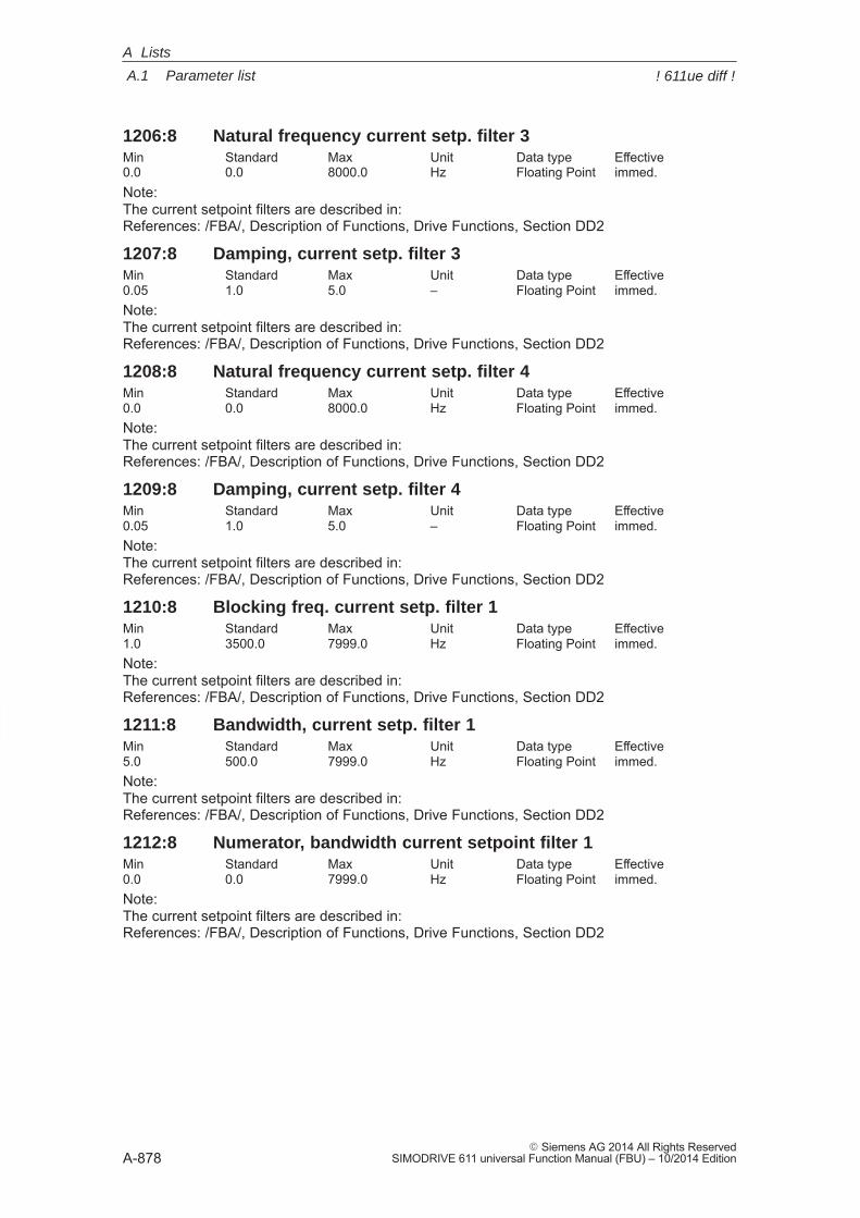
A
A.1 Parameter list
A-878� Siemens AG 2014 All Rights Reserved
SIMODRIVE 611 universal Function Manual (FBU) – 10/2014 Edition
1206:8 Natural frequency current setp. filter 3Min Standard Max Unit Data type Effective0.0 0.0 8000.0 Hz Floating Point immed.Note:The current setpoint filters are described in:References: /FBA/, Description of Functions, Drive Functions, Section DD2
1207:8 Damping, current setp. filter 3Min Standard Max Unit Data type Effective0.05 1.0 5.0 – Floating Point immed.Note:The current setpoint filters are described in:References: /FBA/, Description of Functions, Drive Functions, Section DD2
1208:8 Natural frequency current setp. filter 4Min Standard Max Unit Data type Effective0.0 0.0 8000.0 Hz Floating Point immed.Note:The current setpoint filters are described in:References: /FBA/, Description of Functions, Drive Functions, Section DD2
1209:8 Damping, current setp. filter 4Min Standard Max Unit Data type Effective0.05 1.0 5.0 – Floating Point immed.Note:The current setpoint filters are described in:References: /FBA/, Description of Functions, Drive Functions, Section DD2
1210:8 Blocking freq. current setp. filter 1Min Standard Max Unit Data type Effective1.0 3500.0 7999.0 Hz Floating Point immed.Note:The current setpoint filters are described in:References: /FBA/, Description of Functions, Drive Functions, Section DD2
1211:8 Bandwidth, current setp. filter 1Min Standard Max Unit Data type Effective5.0 500.0 7999.0 Hz Floating Point immed.Note:The current setpoint filters are described in:References: /FBA/, Description of Functions, Drive Functions, Section DD2
1212:8 Numerator, bandwidth current setpoint filter 1Min Standard Max Unit Data type Effective0.0 0.0 7999.0 Hz Floating Point immed.Note:The current setpoint filters are described in:References: /FBA/, Description of Functions, Drive Functions, Section DD2
A Lists
! 611ue diff !
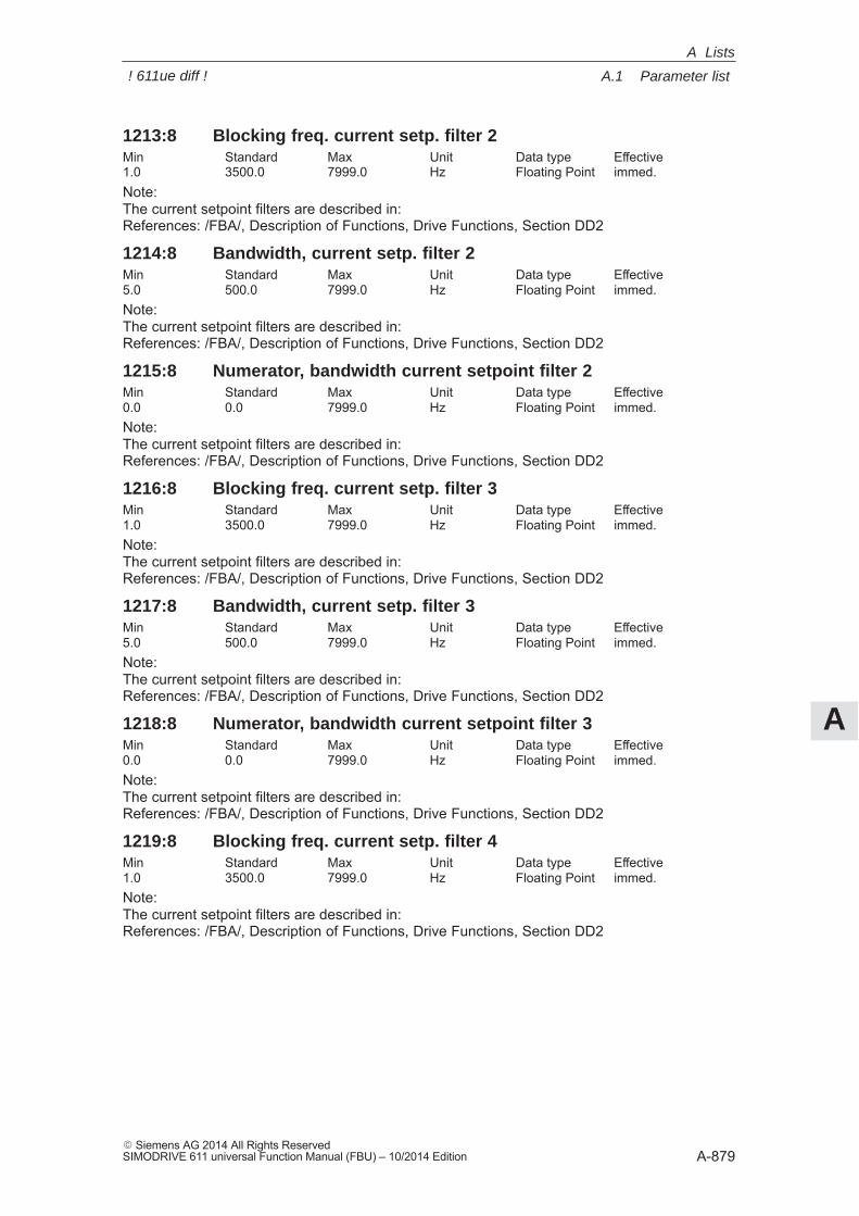
A
A.1 Parameter list
A-879� Siemens AG 2014 All Rights ReservedSIMODRIVE 611 universal Function Manual (FBU) – 10/2014 Edition
1213:8 Blocking freq. current setp. filter 2Min Standard Max Unit Data type Effective1.0 3500.0 7999.0 Hz Floating Point immed.Note:The current setpoint filters are described in:References: /FBA/, Description of Functions, Drive Functions, Section DD2
1214:8 Bandwidth, current setp. filter 2Min Standard Max Unit Data type Effective5.0 500.0 7999.0 Hz Floating Point immed.Note:The current setpoint filters are described in:References: /FBA/, Description of Functions, Drive Functions, Section DD2
1215:8 Numerator, bandwidth current setpoint filter 2Min Standard Max Unit Data type Effective0.0 0.0 7999.0 Hz Floating Point immed.Note:The current setpoint filters are described in:References: /FBA/, Description of Functions, Drive Functions, Section DD2
1216:8 Blocking freq. current setp. filter 3Min Standard Max Unit Data type Effective1.0 3500.0 7999.0 Hz Floating Point immed.Note:The current setpoint filters are described in:References: /FBA/, Description of Functions, Drive Functions, Section DD2
1217:8 Bandwidth, current setp. filter 3Min Standard Max Unit Data type Effective5.0 500.0 7999.0 Hz Floating Point immed.Note:The current setpoint filters are described in:References: /FBA/, Description of Functions, Drive Functions, Section DD2
1218:8 Numerator, bandwidth current setpoint filter 3Min Standard Max Unit Data type Effective0.0 0.0 7999.0 Hz Floating Point immed.Note:The current setpoint filters are described in:References: /FBA/, Description of Functions, Drive Functions, Section DD2
1219:8 Blocking freq. current setp. filter 4Min Standard Max Unit Data type Effective1.0 3500.0 7999.0 Hz Floating Point immed.Note:The current setpoint filters are described in:References: /FBA/, Description of Functions, Drive Functions, Section DD2
A Lists
! 611ue diff !
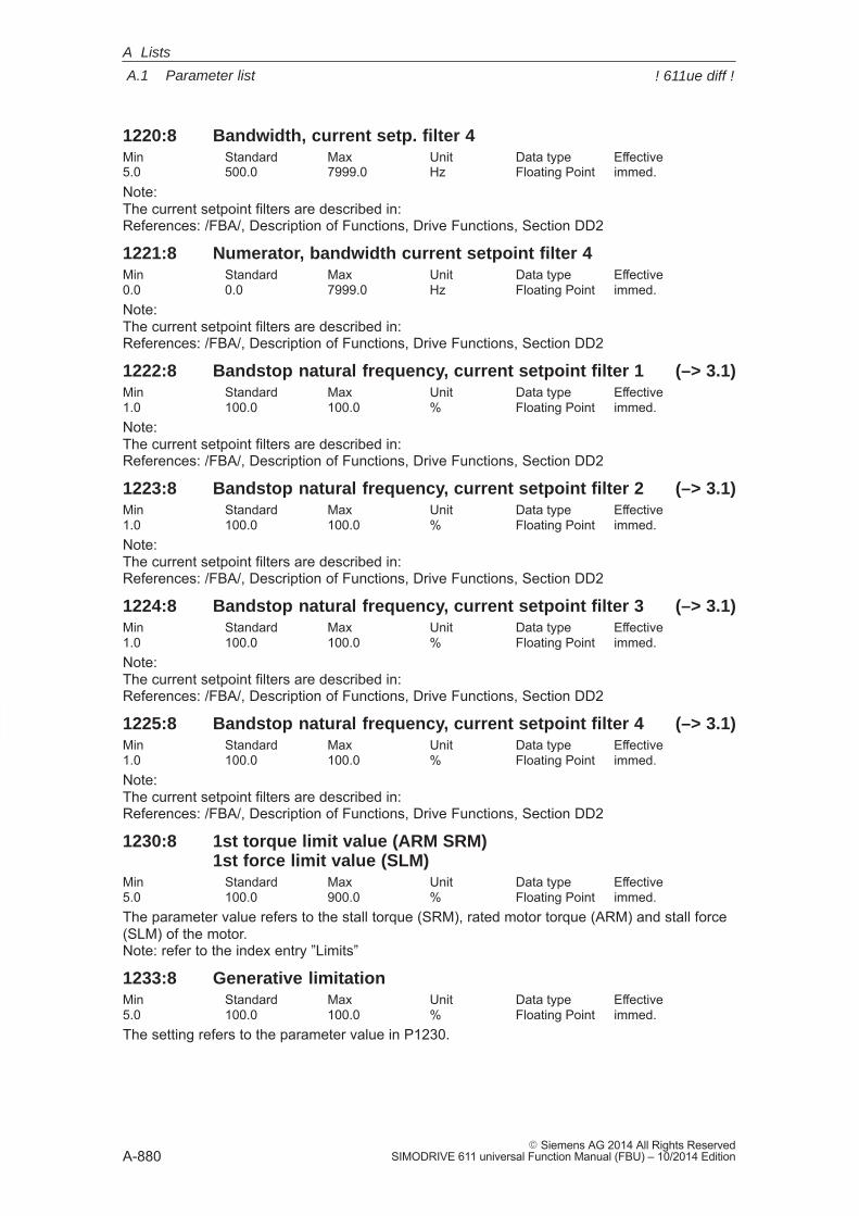
A
A.1 Parameter list
A-880� Siemens AG 2014 All Rights Reserved
SIMODRIVE 611 universal Function Manual (FBU) – 10/2014 Edition
1220:8 Bandwidth, current setp. filter 4Min Standard Max Unit Data type Effective5.0 500.0 7999.0 Hz Floating Point immed.Note:The current setpoint filters are described in:References: /FBA/, Description of Functions, Drive Functions, Section DD2
1221:8 Numerator, bandwidth current setpoint filter 4Min Standard Max Unit Data type Effective0.0 0.0 7999.0 Hz Floating Point immed.Note:The current setpoint filters are described in:References: /FBA/, Description of Functions, Drive Functions, Section DD2
1222:8 Bandstop natural frequency, current setpoint filter 1 (–> 3.1)Min Standard Max Unit Data type Effective1.0 100.0 100.0 % Floating Point immed.Note:The current setpoint filters are described in:References: /FBA/, Description of Functions, Drive Functions, Section DD2
1223:8 Bandstop natural frequency, current setpoint filter 2 (–> 3.1)Min Standard Max Unit Data type Effective1.0 100.0 100.0 % Floating Point immed.Note:The current setpoint filters are described in:References: /FBA/, Description of Functions, Drive Functions, Section DD2
1224:8 Bandstop natural frequency, current setpoint filter 3 (–> 3.1)Min Standard Max Unit Data type Effective1.0 100.0 100.0 % Floating Point immed.Note:The current setpoint filters are described in:References: /FBA/, Description of Functions, Drive Functions, Section DD2
1225:8 Bandstop natural frequency, current setpoint filter 4 (–> 3.1)Min Standard Max Unit Data type Effective1.0 100.0 100.0 % Floating Point immed.Note:The current setpoint filters are described in:References: /FBA/, Description of Functions, Drive Functions, Section DD2
1230:8 1st torque limit value (ARM SRM)1st force limit value (SLM)
Min Standard Max Unit Data type Effective5.0 100.0 900.0 % Floating Point immed.The parameter value refers to the stall torque (SRM), rated motor torque (ARM) and stall force(SLM) of the motor.Note: refer to the index entry ”Limits”
1233:8 Generative limitationMin Standard Max Unit Data type Effective5.0 100.0 100.0 % Floating Point immed.The setting refers to the parameter value in P1230.
A Lists
! 611ue diff !
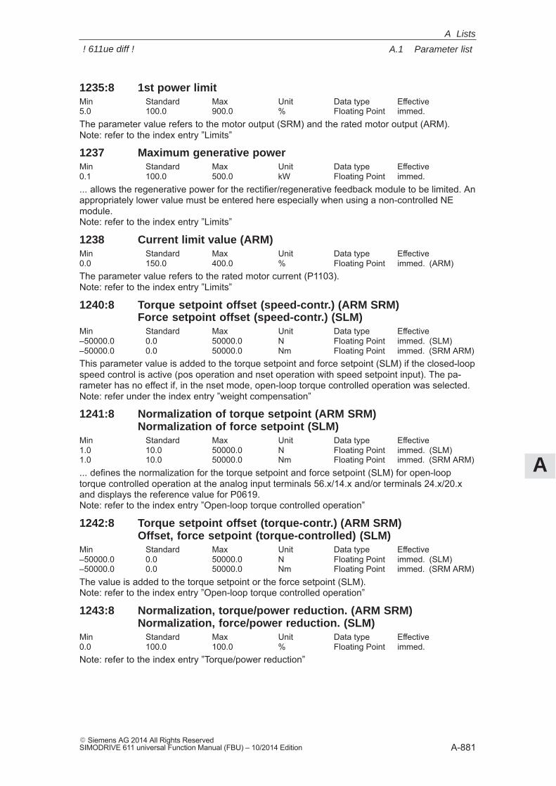
A
A.1 Parameter list
A-881� Siemens AG 2014 All Rights ReservedSIMODRIVE 611 universal Function Manual (FBU) – 10/2014 Edition
1235:8 1st power limitMin Standard Max Unit Data type Effective5.0 100.0 900.0 % Floating Point immed.The parameter value refers to the motor output (SRM) and the rated motor output (ARM).Note: refer to the index entry ”Limits”
1237 Maximum generative powerMin Standard Max Unit Data type Effective0.1 100.0 500.0 kW Floating Point immed.... allows the regenerative power for the rectifier/regenerative feedback module to be limited. Anappropriately lower value must be entered here especially when using a non-controlled NEmodule.Note: refer to the index entry ”Limits”
1238 Current limit value (ARM)Min Standard Max Unit Data type Effective0.0 150.0 400.0 % Floating Point immed. (ARM)The parameter value refers to the rated motor current (P1103).Note: refer to the index entry ”Limits”
1240:8 Torque setpoint offset (speed-contr.) (ARM SRM)Force setpoint offset (speed-contr.) (SLM)
Min Standard Max Unit Data type Effective–50000.0 0.0 50000.0 N Floating Point immed. (SLM)–50000.0 0.0 50000.0 Nm Floating Point immed. (SRM ARM)This parameter value is added to the torque setpoint and force setpoint (SLM) if the closed-loopspeed control is active (pos operation and nset operation with speed setpoint input). The pa-rameter has no effect if, in the nset mode, open-loop torque controlled operation was selected.Note: refer under the index entry ”weight compensation”
1241:8 Normalization of torque setpoint (ARM SRM)Normalization of force setpoint (SLM)
Min Standard Max Unit Data type Effective1.0 10.0 50000.0 N Floating Point immed. (SLM)1.0 10.0 50000.0 Nm Floating Point immed. (SRM ARM)... defines the normalization for the torque setpoint and force setpoint (SLM) for open-looptorque controlled operation at the analog input terminals 56.x/14.x and/or terminals 24.x/20.xand displays the reference value for P0619.Note: refer to the index entry ”Open-loop torque controlled operation”
1242:8 Torque setpoint offset (torque-contr.) (ARM SRM)Offset, force setpoint (torque-controlled) (SLM)
Min Standard Max Unit Data type Effective–50000.0 0.0 50000.0 N Floating Point immed. (SLM)–50000.0 0.0 50000.0 Nm Floating Point immed. (SRM ARM)The value is added to the torque setpoint or the force setpoint (SLM).Note: refer to the index entry ”Open-loop torque controlled operation”
1243:8 Normalization, torque/power reduction. (ARM SRM)Normalization, force/power reduction. (SLM)
Min Standard Max Unit Data type Effective0.0 100.0 100.0 % Floating Point immed.Note: refer to the index entry ”Torque/power reduction”
A Lists
! 611ue diff !
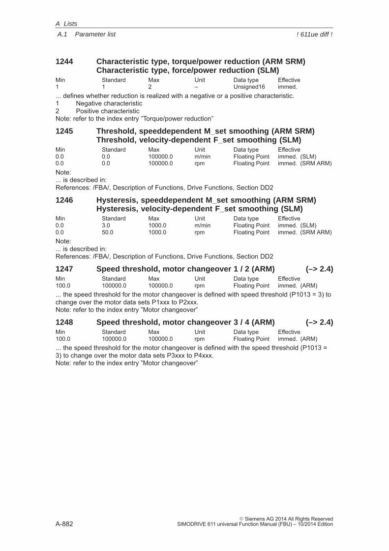
A
A.1 Parameter list
A-882� Siemens AG 2014 All Rights Reserved
SIMODRIVE 611 universal Function Manual (FBU) – 10/2014 Edition
1244 Characteristic type, torque/power reduction (ARM SRM)Characteristic type, force/power reduction (SLM)
Min Standard Max Unit Data type Effective1 1 2 – Unsigned16 immed.... defines whether reduction is realized with a negative or a positive characteristic.1 Negative characteristic2 Positive characteristicNote: refer to the index entry ”Torque/power reduction”
1245 Threshold, speeddependent M_set smoothing (ARM SRM)Threshold, velocity-dependent F_set smoothing (SLM)
Min Standard Max Unit Data type Effective0.0 0.0 100000.0 m/min Floating Point immed. (SLM)0.0 0.0 100000.0 rpm Floating Point immed. (SRM ARM)Note:... is described in:References: /FBA/, Description of Functions, Drive Functions, Section DD2
1246 Hysteresis, speeddependent M_set smoothing (ARM SRM)Hysteresis, velocity-dependent F_set smoothing (SLM)
Min Standard Max Unit Data type Effective0.0 3.0 1000.0 m/min Floating Point immed. (SLM)0.0 50.0 1000.0 rpm Floating Point immed. (SRM ARM)Note:... is described in:References: /FBA/, Description of Functions, Drive Functions, Section DD2
1247 Speed threshold, motor changeover 1 / 2 (ARM) (–> 2.4)Min Standard Max Unit Data type Effective100.0 100000.0 100000.0 rpm Floating Point immed. (ARM)... the speed threshold for the motor changeover is defined with speed threshold (P1013 = 3) tochange over the motor data sets P1xxx to P2xxx.Note: refer to the index entry ”Motor changeover”
1248 Speed threshold, motor changeover 3 / 4 (ARM) (–> 2.4)Min Standard Max Unit Data type Effective100.0 100000.0 100000.0 rpm Floating Point immed. (ARM)... the speed threshold for the motor changeover is defined with the speed threshold (P1013 =3) to change over the motor data sets P3xxx to P4xxx.Note: refer to the index entry ”Motor changeover”
A Lists
! 611ue diff !
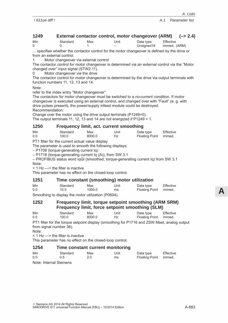
A
A.1 Parameter list
A-883� Siemens AG 2014 All Rights ReservedSIMODRIVE 611 universal Function Manual (FBU) – 10/2014 Edition
1249 External contactor control, motor changeover (ARM) (–> 2.4)Min Standard Max Unit Data type Effective0 0 1 – Unsigned16 immed. (ARM)... specifies whether the contactor control for the motor changeover is defined by the drive orfrom an external control.1 Motor changeover via external controlThe contactor control for motor changeover is determined via an external control via the ”Motorchanged over” input signal (STW2.11).0 Motor changeover via the driveThe contactor control for motor changeover is determined by the drive via output terminals withfunction numbers 11, 12, 13 and 14.Note:refer to the index entry ”Motor changeover” The contactors for motor changeover must be switched to a no-current condition. If motorchangeover is executed using an external control, and changed over with ”Fault” (e. g. withdrive pulses present), the power/supply infeed module could be destroyed.Recommendation: Change over the motor using the drive output terminals (P1249=0).The output terminals 11, 12, 13 and 14 are not energized if P1249 = 1.
1250 Frequency limit, act. current smoothingMin Standard Max Unit Data type Effective0.0 100.0 8000.0 Hz Floating Point immed.PT1 filter for the current actual value displayThe parameter is used to smooth the following displays:– P1708 (torque-generating current Iq)– P1718 (torque-generating current Iq (A)), from SW 3.1– PROFIBUS status word IqGl (smoothed, torque-generating current Iq) from SW 3.1Note:< 1 Hz ––> the filter is inactiveThis parameter has no effect on the closed-loop control.
1251 Time constant (smoothing) motor utilizationMin Standard Max Unit Data type Effective0.0 10.0 1000.0 ms Floating Point immed.Smoothing to display the motor utilization (P0604).
1252 Frequency limit, torque setpoint smoothing (ARM SRM)Frequency limit, force setpoint smoothing (SLM)
Min Standard Max Unit Data type Effective0.0 100.0 8000.0 Hz Floating Point immed.PT1 filter for the torque setpoint display (smoothing for P1716 and ZSW Mset, analog outputfrom signal number 36).Note:< 1 Hz ––> the filter is inactiveThis parameter has no effect on the closed-loop control.
1254 Time constant current monitoringMin Standard Max Unit Data type Effective0.0 0.5 2.0 ms Floating Point immed.Note: Internal Siemens
A Lists
! 611ue diff !

A
A.1 Parameter list
A-884� Siemens AG 2014 All Rights Reserved
SIMODRIVE 611 universal Function Manual (FBU) – 10/2014 Edition
1255 Steady-state minimum speed (–> 11.1)Min Standard Max Unit Data type Effective0.0 0.0 100000.0 rpm Floating Point immed. (ARM)0.0 0.0 100000.0 m/min Floating Point immed. (SLM)0.0 0.0 100000.0 rpm Floating Point immed. (SRM)... defines the steady-state minimum spindle speed in speed setpoint operation.
1256:8 Ramp-function generator ramp-up time (–> 2.4)Min Standard Max Unit Data type Effective0.0 2.0 600.0 s Floating Point immed. (ARM)0.0 0.0 600.0 s Floating Point immed. (SRM SLM)During ramp-up, the setpoint is increased from zero to the maximum permissible actual speed.Note:Max. permissible actual speed for synchronous motors: Minimum from 1.1 (1.05 from SW 7.1onwards with ”SIMODRIVE 611 universal HR/HRS/HRS2”, resolver) x P1400 and P1147Max. permissible actual speed for induction motors: Minimum from P1146 and P1147Max. permissible actual speed for linear motors: From P1147refer to the index entry ”Ramp-function generator”
1257:8 Ramp-function generator ramp-down time (–> 2.4)Min Standard Max Unit Data type Effective0.0 2.0 600.0 s Floating Point immed. (ARM)0.0 0.0 600.0 s Floating Point immed. (SRM SLM)During ramp-down, the setpoint is reduced from the maximum permissible actual speed to zero.Note:Max. permissible actual speed for synchronous motors: Minimum from 1.1 (1.05 from SW 7.1onwards with ”SIMODRIVE 611 universal HR/HRS/HRS2”, resolver) x P1400 and P1147Max. permissible actual speed for induction motors: Minimum from P1146 and P1147Max. permissible actual speed for linear motors: From P1147refer to the index entry ”Ramp-function generator”
1259 Torque/power reduction mot./gen. (ARM SRM) (–> 3.7)Force/power reduction mot./gen. (SLM)
Min Standard Max Unit Data type Effective0 0 3 Hex Unsigned16 immed.... defines if the torque/power de-rating or force/power de-rating depends on whether the driveis motoring/generating.Bit 0 Torque / power reduction, only when motoringBit 0 = 1 Reduction is only effective when motoringBit 0 = 0 Reduction is effective when motoring and regeneratingBit 1 Motoring / regenerating limiting dependent on NsetBit 1 = 1 The torque limits when motoring are used if the product of torque and speed
setpoint is positive and the speed setpoint is not equal to 0Bit 1 = 0 The torque limits when motoring are used if the product of torque and speed
actual value is positive or the absolute speed actual value is less than 10 RPMP1259 valid for input via PROFIBUS and analog input.
Note: refer to the index entry ”Torque/power reduction”
A Lists
! 611ue diff !
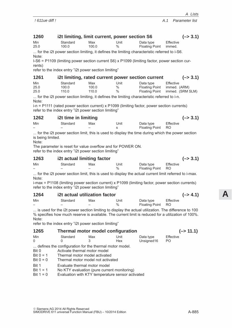
A
A.1 Parameter list
A-885� Siemens AG 2014 All Rights ReservedSIMODRIVE 611 universal Function Manual (FBU) – 10/2014 Edition
1260 i2t limiting, limit current, power section S6 (–> 3.1)Min Standard Max Unit Data type Effective25.0 100.0 100.0 % Floating Point immed.... for the i2t power section limiting, it defines the limiting characteristic referred to i-S6.Note:I-S6 = P1109 (limiting power section current S6) x P1099 (limiting factor, power section cur-rents)refer to the index entry ”i2t power section limiting”
1261 i2t limiting, rated current power section current (–> 3.1)Min Standard Max Unit Data type Effective25.0 100.0 100.0 % Floating Point immed. (ARM)25.0 110.0 110.0 % Floating Point immed. (SRM SLM)... for the i2t power section limiting, it defines the limiting characteristic referred to i-n.Note:i-n = P1111 (rated power section current) x P1099 (limiting factor, power section currents)refer to the index entry ”i2t power section limiting”
1262 i2t time in limiting (–> 3.1)Min Standard Max Unit Data type Effective– – – s Floating Point RO... for the i2t power section limit, this is used to display the time during which the power sectionis being limited.Note:The parameter is reset for value overflow and for POWER ON.refer to the index entry ”i2t power section limiting”
1263 i2t actual limiting factor (–> 3.1)Min Standard Max Unit Data type Effective– – – % Floating Point RO... for the i2t power section limit, this is used to display the actual current limit referred to i-max.Note:i-max = P1108 (limiting power section current) x P1099 (limiting factor, power section currents)refer to the index entry ”i2t power section limiting”
1264 i2t actual utilization factor (–> 4.1)Min Standard Max Unit Data type Effective– – – % Floating Point RO... is used for the i2t power section limiting to display the actual utilization. The difference to 100% specifies how much reserve is available. The current limit is reduced for a utilization of 100%.Note:refer to the index entry ”i2t power section limiting”
1265 Thermal motor model configuration (–> 11.1)Min Standard Max Unit Data type Effective0 0 3 Hex Unsigned16 PO... defines the configuration for the thermal motor model.Bit 0 Activate thermal motor modelBit 0 = 1 Thermal motor model activatedBit 0 = 0 Thermal motor model not activatedBit 1 Evaluate thermal motor modelBit 1 = 1 No KTY evaluation (pure current monitoring)Bit 1 = 0 Evaluation with KTY temperature sensor activated
A Lists
! 611ue diff !
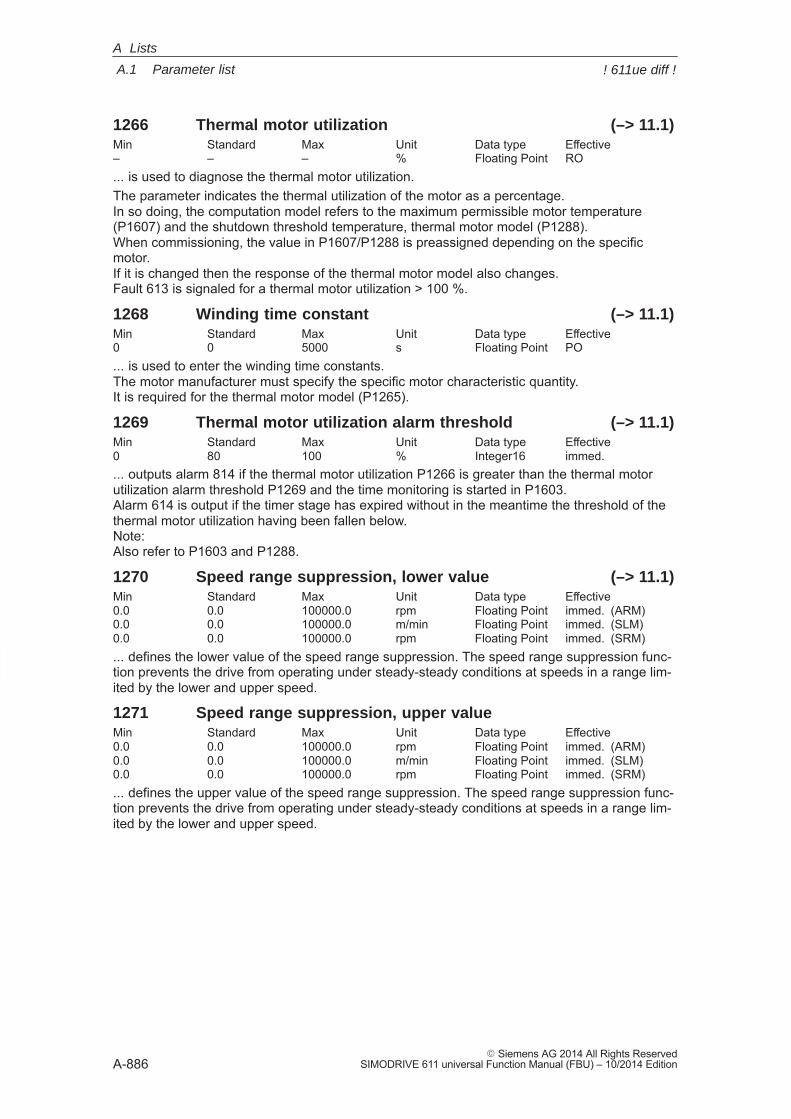
A
A.1 Parameter list
A-886� Siemens AG 2014 All Rights Reserved
SIMODRIVE 611 universal Function Manual (FBU) – 10/2014 Edition
1266 Thermal motor utilization (–> 11.1)Min Standard Max Unit Data type Effective– – – % Floating Point RO... is used to diagnose the thermal motor utilization.The parameter indicates the thermal utilization of the motor as a percentage. In so doing, the computation model refers to the maximum permissible motor temperature(P1607) and the shutdown threshold temperature, thermal motor model (P1288). When commissioning, the value in P1607/P1288 is preassigned depending on the specificmotor. If it is changed then the response of the thermal motor model also changes.Fault 613 is signaled for a thermal motor utilization > 100 %.
1268 Winding time constant (–> 11.1)Min Standard Max Unit Data type Effective0 0 5000 s Floating Point PO... is used to enter the winding time constants. The motor manufacturer must specify the specific motor characteristic quantity.It is required for the thermal motor model (P1265).
1269 Thermal motor utilization alarm threshold (–> 11.1)Min Standard Max Unit Data type Effective0 80 100 % Integer16 immed.... outputs alarm 814 if the thermal motor utilization P1266 is greater than the thermal motorutilization alarm threshold P1269 and the time monitoring is started in P1603.Alarm 614 is output if the timer stage has expired without in the meantime the threshold of thethermal motor utilization having been fallen below.Note:Also refer to P1603 and P1288.
1270 Speed range suppression, lower value (–> 11.1)Min Standard Max Unit Data type Effective0.0 0.0 100000.0 rpm Floating Point immed. (ARM)0.0 0.0 100000.0 m/min Floating Point immed. (SLM)0.0 0.0 100000.0 rpm Floating Point immed. (SRM)... defines the lower value of the speed range suppression. The speed range suppression func-tion prevents the drive from operating under steady-steady conditions at speeds in a range lim-ited by the lower and upper speed.
1271 Speed range suppression, upper valueMin Standard Max Unit Data type Effective0.0 0.0 100000.0 rpm Floating Point immed. (ARM)0.0 0.0 100000.0 m/min Floating Point immed. (SLM)0.0 0.0 100000.0 rpm Floating Point immed. (SRM)... defines the upper value of the speed range suppression. The speed range suppression func-tion prevents the drive from operating under steady-steady conditions at speeds in a range lim-ited by the lower and upper speed.
A Lists
! 611ue diff !
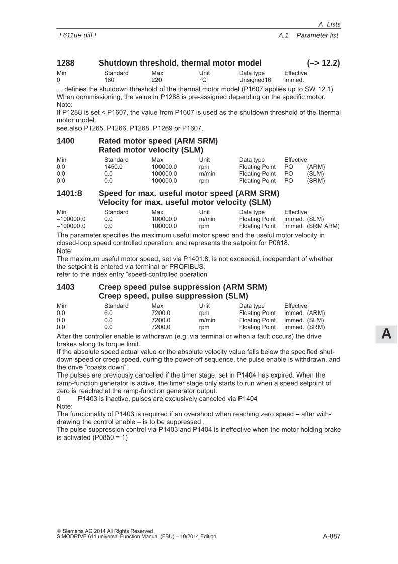
A
A.1 Parameter list
A-887� Siemens AG 2014 All Rights ReservedSIMODRIVE 611 universal Function Manual (FBU) – 10/2014 Edition
1288 Shutdown threshold, thermal motor model (–> 12.2)Min Standard Max Unit Data type Effective0 180 220 �C Unsigned16 immed.... defines the shutdown threshold of the thermal motor model (P1607 applies up to SW 12.1). When commissioning, the value in P1288 is pre-assigned depending on the specific motor.Note:If P1288 is set < P1607, the value from P1607 is used as the shutdown threshold of the thermalmotor model.see also P1265, P1266, P1268, P1269 or P1607.
1400 Rated motor speed (ARM SRM)Rated motor velocity (SLM)
Min Standard Max Unit Data type Effective0.0 1450.0 100000.0 rpm Floating Point PO (ARM)0.0 0.0 100000.0 m/min Floating Point PO (SLM)0.0 0.0 100000.0 rpm Floating Point PO (SRM)
1401:8 Speed for max. useful motor speed (ARM SRM)Velocity for max. useful motor velocity (SLM)
Min Standard Max Unit Data type Effective–100000.0 0.0 100000.0 m/min Floating Point immed. (SLM)–100000.0 0.0 100000.0 rpm Floating Point immed. (SRM ARM)The parameter specifies the maximum useful motor speed and the useful motor velocity inclosed-loop speed controlled operation, and represents the setpoint for P0618.Note:The maximum useful motor speed, set via P1401:8, is not exceeded, independent of whetherthe setpoint is entered via terminal or PROFIBUS.refer to the index entry ”speed-controlled operation”
1403 Creep speed pulse suppression (ARM SRM)Creep speed, pulse suppression (SLM)
Min Standard Max Unit Data type Effective0.0 6.0 7200.0 rpm Floating Point immed. (ARM)0.0 0.0 7200.0 m/min Floating Point immed. (SLM)0.0 0.0 7200.0 rpm Floating Point immed. (SRM)After the controller enable is withdrawn (e.g. via terminal or when a fault occurs) the drivebrakes along its torque limit.If the absolute speed actual value or the absolute velocity value falls below the specified shut-down speed or creep speed, during the power-off sequence, the pulse enable is withdrawn, andthe drive ”coasts down”.The pulses are previously cancelled if the timer stage, set in P1404 has expired. When theramp-function generator is active, the timer stage only starts to run when a speed setpoint ofzero is reached at the ramp-function generator output.0 P1403 is inactive, pulses are exclusively canceled via P1404Note:The functionality of P1403 is required if an overshoot when reaching zero speed – after with-drawing the control enable – is to be suppressed .The pulse suppression control via P1403 and P1404 is ineffective when the motor holding brakeis activated (P0850 = 1)
A Lists
! 611ue diff !
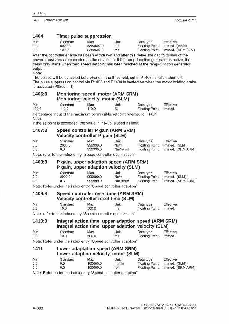
A
A.1 Parameter list
A-888� Siemens AG 2014 All Rights Reserved
SIMODRIVE 611 universal Function Manual (FBU) – 10/2014 Edition
1404 Timer pulse suppressionMin Standard Max Unit Data type Effective0.0 5000.0 8388607.0 ms Floating Point immed. (ARM)0.0 100.0 8388607.0 ms Floating Point immed. (SRM SLM)After the controller enable has been withdrawn and after this delay, the gating pulses of thepower transistors are canceled on the drive side. If the ramp-function generator is active, thedelay only starts when zero speed setpoint has been reached at the ramp-function generatoroutput.Note: The pulses will be canceled beforehand, if the threshold, set in P1403, is fallen short off.The pulse suppression control via P1403 and P1404 is ineffective when the motor holding brakeis activated (P0850 = 1)
1405:8 Monitoring speed, motor (ARM SRM)Monitoring velocity, motor (SLM)
Min Standard Max Unit Data type Effective100.0 110.0 110.0 % Floating Point immed.Percentage input of the maximum permissible setpoint referred to P1401.Note: If the setpoint is exceeded, the value in P1405 is used as limit.
1407:8 Speed controller P gain (ARM SRM)Velocity controller P gain (SLM)
Min Standard Max Unit Data type Effective0.0 2000.0 999999.0 Ns/m Floating Point immed. (SLM)0.0 0.3 999999.0 Nm*s/rad Floating Point immed. (SRM ARM)Note: refer to the index entry ”Speed controller optimization”
1408:8 P gain, upper adaption speed (ARM SRM)P gain, upper adaption velocity (SLM)
Min Standard Max Unit Data type Effective0.0 2000.0 999999.0 Ns/m Floating Point immed. (SLM)0.0 0.3 999999.0 Nm*s/rad Floating Point immed. (SRM ARM)Note: Refer under the index entry ”Speed controller adaption”
1409:8 Speed controller reset time (ARM SRM)Velocity controller reset time (SLM)
Min Standard Max Unit Data type Effective0.0 10.0 500.0 ms Floating Point immed.Note: refer to the index entry ”Speed controller optimization”
1410:8 Integral action time, upper adaption speed (ARM SRM)Integral action time, upper adaption velocity (SLM)
Min Standard Max Unit Data type Effective0.0 10.0 500.0 ms Floating Point immed.Note: Refer under the index entry ”Speed controller adaption”
1411 Lower adaptation speed (ARM SRM)Lower adaption velocity, motor (SLM)
Min Standard Max Unit Data type Effective0.0 0.0 100000.0 m/min Floating Point immed. (SLM)0.0 0.0 100000.0 rpm Floating Point immed. (SRM ARM)Note: Refer under the index entry ”Speed controller adaption”
A Lists
! 611ue diff !
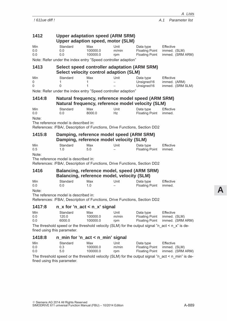
A
A.1 Parameter list
A-889� Siemens AG 2014 All Rights ReservedSIMODRIVE 611 universal Function Manual (FBU) – 10/2014 Edition
1412 Upper adaptation speed (ARM SRM)Upper adaption speed, motor (SLM)
Min Standard Max Unit Data type Effective0.0 0.0 100000.0 m/min Floating Point immed. (SLM)0.0 0.0 100000.0 rpm Floating Point immed. (SRM ARM)Note: Refer under the index entry ”Speed controller adaption”
1413 Select speed controller adaptation (ARM SRM)Select velocity control adaption (SLM)
Min Standard Max Unit Data type Effective0 1 1 – Unsigned16 immed. (ARM)0 0 1 – Unsigned16 immed. (SRM SLM)Note: Refer under the index entry ”Speed controller adaption”
1414:8 Natural frequency, reference model speed (ARM SRM)Natural frequency, reference model velocity (SLM)
Min Standard Max Unit Data type Effective0.0 0.0 8000.0 Hz Floating Point immed.Note:The reference model is described in:References: /FBA/, Description of Functions, Drive Functions, Section DD2
1415:8 Damping, reference model speed (ARM SRM)Damping, reference model velocity (SLM)
Min Standard Max Unit Data type Effective0.5 1.0 5.0 – Floating Point immed.Note:The reference model is described in:References: /FBA/, Description of Functions, Drive Functions, Section DD2
1416 Balancing, reference model, speed (ARM SRM)Balancing, reference model, velocity (SLM)
Min Standard Max Unit Data type Effective0.0 0.0 1.0 – Floating Point immed.Note:The reference model is described in:References: /FBA/, Description of Functions, Drive Functions, Section DD2
1417:8 n_x for ’n_act < n_x’ signalMin Standard Max Unit Data type Effective0.0 120.0 100000.0 m/min Floating Point immed. (SLM)0.0 6000.0 100000.0 rpm Floating Point immed. (SRM ARM)The threshold speed or the threshold velocity (SLM) for the output signal ”n_act < n_x” is de-fined using this parameter.
1418:8 n_min for ’n_act < n_min’ signalMin Standard Max Unit Data type Effective0.0 0.3 100000.0 m/min Floating Point immed. (SLM)0.0 5.0 100000.0 rpm Floating Point immed. (SRM ARM)The threshold speed or the threshold velocity (SLM) for the output signal ”n_act < n_min” is de-fined using this parameter.
A Lists
! 611ue diff !
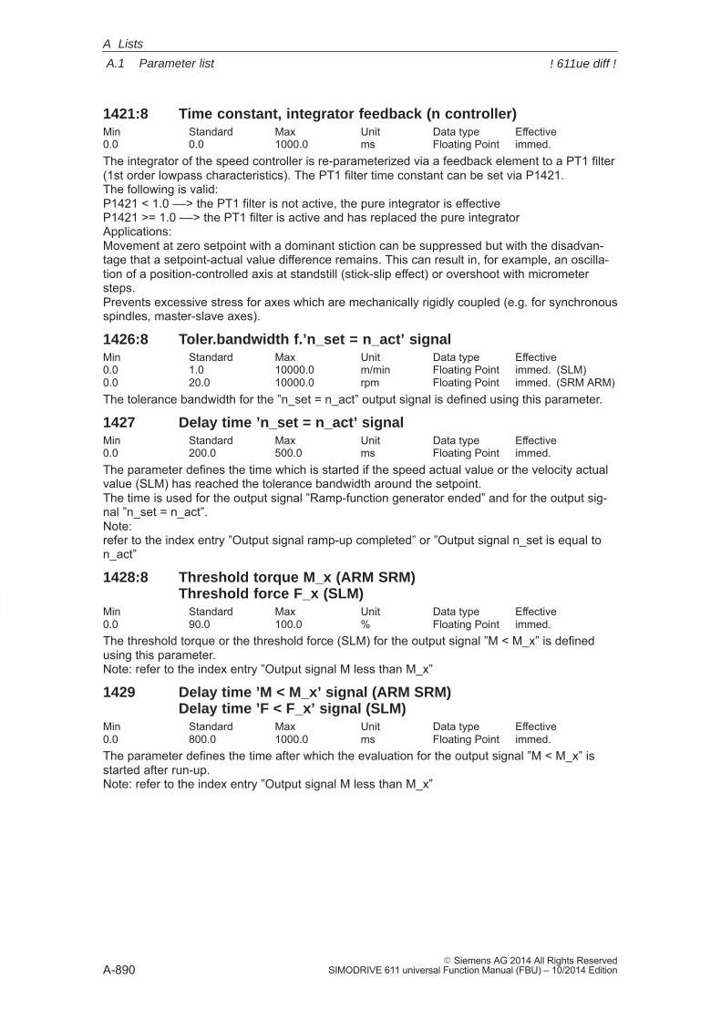
A
A.1 Parameter list
A-890� Siemens AG 2014 All Rights Reserved
SIMODRIVE 611 universal Function Manual (FBU) – 10/2014 Edition
1421:8 Time constant, integrator feedback (n controller)Min Standard Max Unit Data type Effective0.0 0.0 1000.0 ms Floating Point immed.The integrator of the speed controller is re-parameterized via a feedback element to a PT1 filter(1st order lowpass characteristics). The PT1 filter time constant can be set via P1421.The following is valid:P1421 < 1.0 ––> the PT1 filter is not active, the pure integrator is effectiveP1421 >= 1.0 ––> the PT1 filter is active and has replaced the pure integratorApplications:Movement at zero setpoint with a dominant stiction can be suppressed but with the disadvan-tage that a setpoint-actual value difference remains. This can result in, for example, an oscilla-tion of a position-controlled axis at standstill (stick-slip effect) or overshoot with micrometersteps.Prevents excessive stress for axes which are mechanically rigidly coupled (e.g. for synchronousspindles, master-slave axes).
1426:8 Toler.bandwidth f.’n_set = n_act’ signalMin Standard Max Unit Data type Effective0.0 1.0 10000.0 m/min Floating Point immed. (SLM)0.0 20.0 10000.0 rpm Floating Point immed. (SRM ARM)The tolerance bandwidth for the ”n_set = n_act” output signal is defined using this parameter.
1427 Delay time ’n_set = n_act’ signalMin Standard Max Unit Data type Effective0.0 200.0 500.0 ms Floating Point immed.The parameter defines the time which is started if the speed actual value or the velocity actualvalue (SLM) has reached the tolerance bandwidth around the setpoint.The time is used for the output signal ”Ramp-function generator ended” and for the output sig-nal ”n_set = n_act”.Note: refer to the index entry ”Output signal ramp-up completed” or ”Output signal n_set is equal ton_act”
1428:8 Threshold torque M_x (ARM SRM)Threshold force F_x (SLM)
Min Standard Max Unit Data type Effective0.0 90.0 100.0 % Floating Point immed.The threshold torque or the threshold force (SLM) for the output signal ”M < M_x” is definedusing this parameter.Note: refer to the index entry ”Output signal M less than M_x”
1429 Delay time ’M < M_x’ signal (ARM SRM)Delay time ’F < F_x’ signal (SLM)
Min Standard Max Unit Data type Effective0.0 800.0 1000.0 ms Floating Point immed.The parameter defines the time after which the evaluation for the output signal ”M < M_x” isstarted after run-up.Note: refer to the index entry ”Output signal M less than M_x”
A Lists
! 611ue diff !
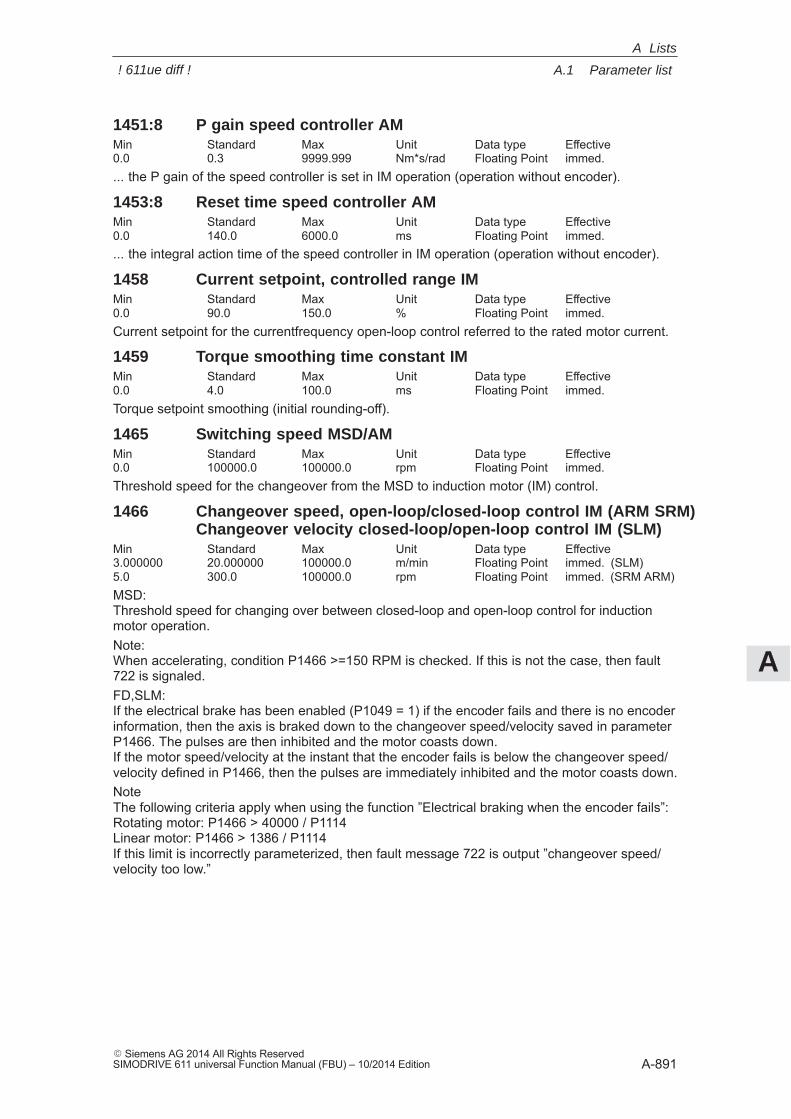
A
A.1 Parameter list
A-891� Siemens AG 2014 All Rights ReservedSIMODRIVE 611 universal Function Manual (FBU) – 10/2014 Edition
1451:8 P gain speed controller AMMin Standard Max Unit Data type Effective0.0 0.3 9999.999 Nm*s/rad Floating Point immed.... the P gain of the speed controller is set in IM operation (operation without encoder).
1453:8 Reset time speed controller AMMin Standard Max Unit Data type Effective0.0 140.0 6000.0 ms Floating Point immed.... the integral action time of the speed controller in IM operation (operation without encoder).
1458 Current setpoint, controlled range IMMin Standard Max Unit Data type Effective0.0 90.0 150.0 % Floating Point immed.Current setpoint for the currentfrequency open-loop control referred to the rated motor current.
1459 Torque smoothing time constant IMMin Standard Max Unit Data type Effective0.0 4.0 100.0 ms Floating Point immed.Torque setpoint smoothing (initial rounding-off).
1465 Switching speed MSD/AMMin Standard Max Unit Data type Effective0.0 100000.0 100000.0 rpm Floating Point immed.Threshold speed for the changeover from the MSD to induction motor (IM) control.
1466 Changeover speed, open-loop/closed-loop control IM (ARM SRM)Changeover velocity closed-loop/open-loop control IM (SLM)
Min Standard Max Unit Data type Effective3.000000 20.000000 100000.0 m/min Floating Point immed. (SLM)5.0 300.0 100000.0 rpm Floating Point immed. (SRM ARM)MSD:Threshold speed for changing over between closed-loop and open-loop control for inductionmotor operation.Note:When accelerating, condition P1466 >=150 RPM is checked. If this is not the case, then fault722 is signaled.FD,SLM:If the electrical brake has been enabled (P1049 = 1) if the encoder fails and there is no encoderinformation, then the axis is braked down to the changeover speed/velocity saved in parameterP1466. The pulses are then inhibited and the motor coasts down.If the motor speed/velocity at the instant that the encoder fails is below the changeover speed/velocity defined in P1466, then the pulses are immediately inhibited and the motor coasts down.NoteThe following criteria apply when using the function ”Electrical braking when the encoder fails”:Rotating motor: P1466 > 40000 / P1114Linear motor: P1466 > 1386 / P1114If this limit is incorrectly parameterized, then fault message 722 is output ”changeover speed/velocity too low.”
A Lists
! 611ue diff !
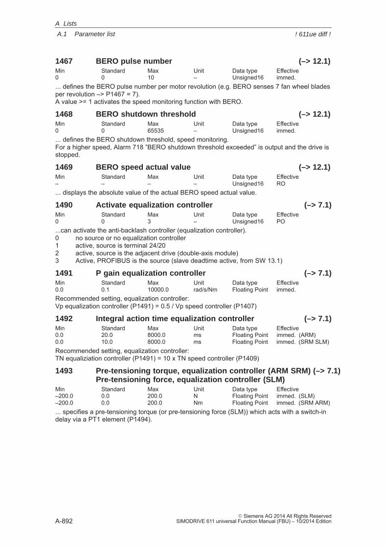
A
A.1 Parameter list
A-892� Siemens AG 2014 All Rights Reserved
SIMODRIVE 611 universal Function Manual (FBU) – 10/2014 Edition
1467 BERO pulse number (–> 12.1)Min Standard Max Unit Data type Effective0 0 10 – Unsigned16 immed.... defines the BERO pulse number per motor revolution (e.g. BERO senses 7 fan wheel bladesper revolution –> P1467 = 7).A value >= 1 activates the speed monitoring function with BERO.
1468 BERO shutdown threshold (–> 12.1)Min Standard Max Unit Data type Effective0 0 65535 – Unsigned16 immed.... defines the BERO shutdown threshold, speed monitoring.For a higher speed, Alarm 718 ”BERO shutdown threshold exceeded” is output and the drive isstopped.
1469 BERO speed actual value (–> 12.1)Min Standard Max Unit Data type Effective– – – – Unsigned16 RO... displays the absolute value of the actual BERO speed actual value.
1490 Activate equalization controller (–> 7.1)Min Standard Max Unit Data type Effective0 0 3 – Unsigned16 PO...can activate the anti-backlash controller (equalization controller).0 no source or no equalization controller1 active, source is terminal 24/202 active, source is the adjacent drive (double-axis module)3 Active, PROFIBUS is the source (slave deadtime active, from SW 13.1)
1491 P gain equalization controller (–> 7.1)Min Standard Max Unit Data type Effective0.0 0.1 10000.0 rad/s/Nm Floating Point immed.Recommended setting, equalization controller:Vp equalization controller (P1491) = 0.5 / Vp speed controller (P1407)
1492 Integral action time equalization controller (–> 7.1)Min Standard Max Unit Data type Effective0.0 20.0 8000.0 ms Floating Point immed. (ARM)0.0 10.0 8000.0 ms Floating Point immed. (SRM SLM)Recommended setting, equalization controller:TN equaliziation controller (P1491) = 10 x TN speed controller (P1409)
1493 Pre-tensioning torque, equalization controller (ARM SRM) (–> 7.1)Pre-tensioning force, equalization controller (SLM)
Min Standard Max Unit Data type Effective–200.0 0.0 200.0 N Floating Point immed. (SLM)–200.0 0.0 200.0 Nm Floating Point immed. (SRM ARM)... specifies a pre-tensioning torque (or pre-tensioning force (SLM)) which acts with a switch-indelay via a PT1 element (P1494).
A Lists
! 611ue diff !
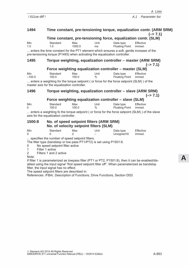
A
A.1 Parameter list
A-893� Siemens AG 2014 All Rights ReservedSIMODRIVE 611 universal Function Manual (FBU) – 10/2014 Edition
1494 Time constant, pre-tensioning torque, equalization contr. (ARM SRM)(–> 7.1)
Time constant, pre-tensioning force, equalization contr. (SLM)Min Standard Max Unit Data type Effective1.0 1.0 1000.0 ms Floating Point immed.... enters the time constant for the PT1 element which ensures a soft, gentle increase of thepre-tensioning torque (P1493) when activating the equalization controller.
1495 Torque weighting, equalization controller – master (ARM SRM)(–> 7.1)
Force weighting equalization controller – master (SLM)Min Standard Max Unit Data type Effective–100.0 100.0 100.0 % Floating Point immed.... enters a weighting for the torque setpoint ( or force for the force setpoint (SLM) ) of themaster axis for the equalization controller.
1496 Torque weighting, equalization controller – slave (ARM SRM)(–> 7.1)
Force weighting equalization controller – slave (SLM)Min Standard Max Unit Data type Effective0 100.0 100.0 % Floating Point immed.... enters a weighting fo the torque setpoint ( or force for the force setpoint (SLM) ) of the slaveaxis for the equalization controller.
1500:8 No. of speed setpoint filters (ARM SRM)No. of velocity setpoint filters (SLM)
Min Standard Max Unit Data type Effective0 0 2 – Unsigned16 immed.... specifies the number of speed setpoint filters.The filter type (bandstop or low pass PT1/PT2) is set using P1501:8.0 No speed setpoint filter active1 Filter 1 active2 Filters 1 and 2 activeNote:If filter 1 is parameterized as lowpass filter (PT1 or PT2, P1501:8), then it can be enabled/dis-abled using the input signal ”first speed setpoint filter off”. When parameterized as bandstopfilter, the input signal has no effect.The speed setpoint filters are described in:References: /FBA/, Description of Functions, Drive Functions, Section DD2
A Lists
! 611ue diff !
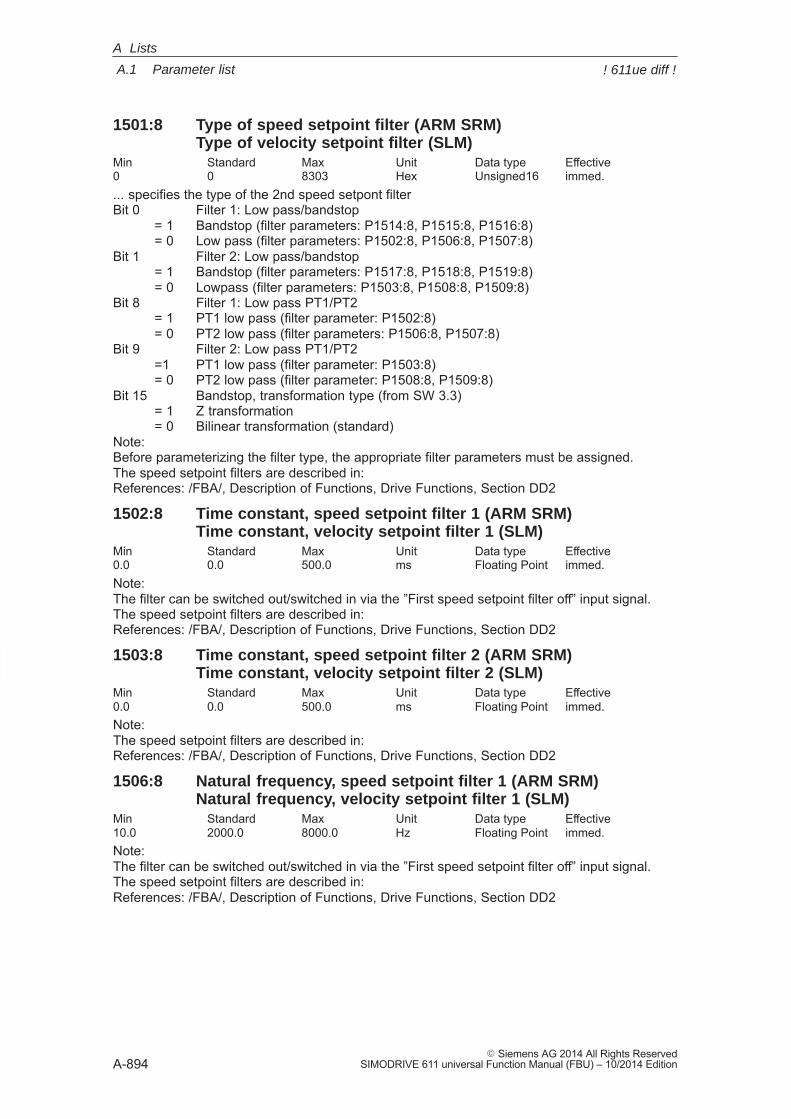
A
A.1 Parameter list
A-894� Siemens AG 2014 All Rights Reserved
SIMODRIVE 611 universal Function Manual (FBU) – 10/2014 Edition
1501:8 Type of speed setpoint filter (ARM SRM)Type of velocity setpoint filter (SLM)
Min Standard Max Unit Data type Effective0 0 8303 Hex Unsigned16 immed.... specifies the type of the 2nd speed setpont filterBit 0 Filter 1: Low pass/bandstop
= 1 Bandstop (filter parameters: P1514:8, P1515:8, P1516:8)= 0 Low pass (filter parameters: P1502:8, P1506:8, P1507:8)
Bit 1 Filter 2: Low pass/bandstop= 1 Bandstop (filter parameters: P1517:8, P1518:8, P1519:8)= 0 Lowpass (filter parameters: P1503:8, P1508:8, P1509:8)
Bit 8 Filter 1: Low pass PT1/PT2= 1 PT1 low pass (filter parameter: P1502:8)= 0 PT2 low pass (filter parameters: P1506:8, P1507:8)
Bit 9 Filter 2: Low pass PT1/PT2=1 PT1 low pass (filter parameter: P1503:8)= 0 PT2 low pass (filter parameter: P1508:8, P1509:8)
Bit 15 Bandstop, transformation type (from SW 3.3)= 1 Z transformation= 0 Bilinear transformation (standard)
Note:Before parameterizing the filter type, the appropriate filter parameters must be assigned.The speed setpoint filters are described in:References: /FBA/, Description of Functions, Drive Functions, Section DD2
1502:8 Time constant, speed setpoint filter 1 (ARM SRM)Time constant, velocity setpoint filter 1 (SLM)
Min Standard Max Unit Data type Effective0.0 0.0 500.0 ms Floating Point immed.Note:The filter can be switched out/switched in via the ”First speed setpoint filter off” input signal.The speed setpoint filters are described in:References: /FBA/, Description of Functions, Drive Functions, Section DD2
1503:8 Time constant, speed setpoint filter 2 (ARM SRM)Time constant, velocity setpoint filter 2 (SLM)
Min Standard Max Unit Data type Effective0.0 0.0 500.0 ms Floating Point immed.Note:The speed setpoint filters are described in:References: /FBA/, Description of Functions, Drive Functions, Section DD2
1506:8 Natural frequency, speed setpoint filter 1 (ARM SRM)Natural frequency, velocity setpoint filter 1 (SLM)
Min Standard Max Unit Data type Effective10.0 2000.0 8000.0 Hz Floating Point immed.Note:The filter can be switched out/switched in via the ”First speed setpoint filter off” input signal.The speed setpoint filters are described in:References: /FBA/, Description of Functions, Drive Functions, Section DD2
A Lists
! 611ue diff !
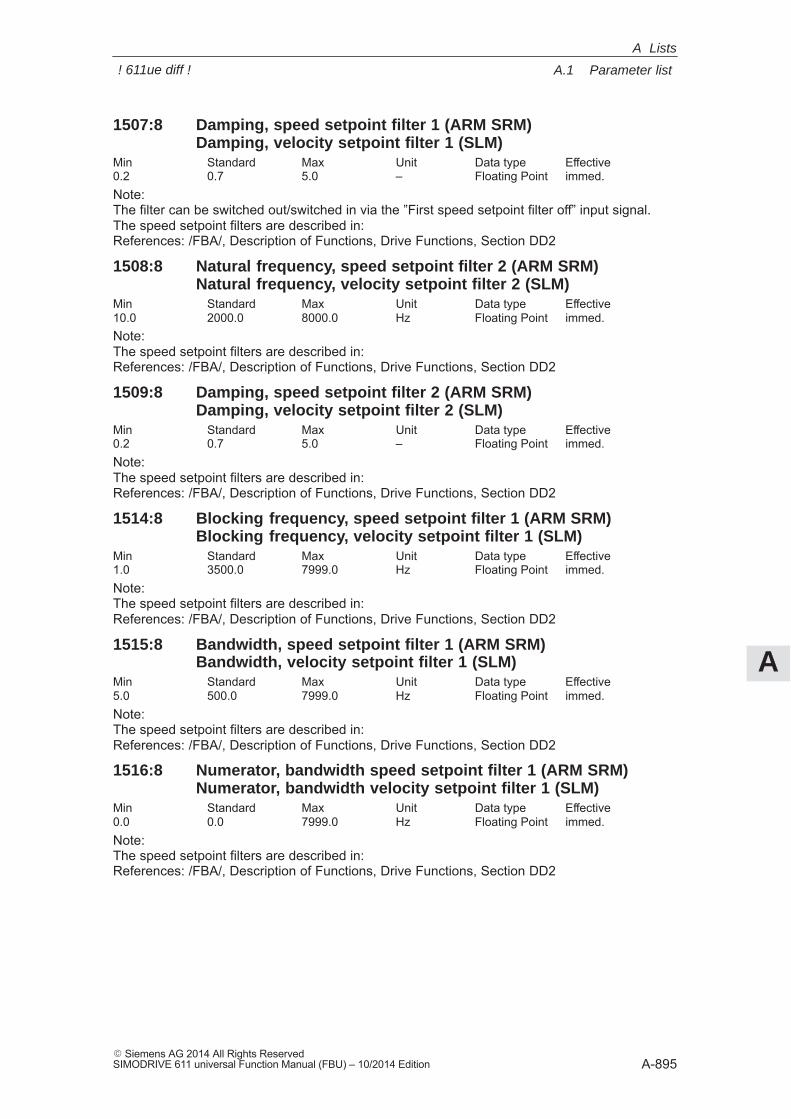
A
A.1 Parameter list
A-895� Siemens AG 2014 All Rights ReservedSIMODRIVE 611 universal Function Manual (FBU) – 10/2014 Edition
1507:8 Damping, speed setpoint filter 1 (ARM SRM)Damping, velocity setpoint filter 1 (SLM)
Min Standard Max Unit Data type Effective0.2 0.7 5.0 – Floating Point immed.Note:The filter can be switched out/switched in via the ”First speed setpoint filter off” input signal.The speed setpoint filters are described in:References: /FBA/, Description of Functions, Drive Functions, Section DD2
1508:8 Natural frequency, speed setpoint filter 2 (ARM SRM)Natural frequency, velocity setpoint filter 2 (SLM)
Min Standard Max Unit Data type Effective10.0 2000.0 8000.0 Hz Floating Point immed.Note:The speed setpoint filters are described in:References: /FBA/, Description of Functions, Drive Functions, Section DD2
1509:8 Damping, speed setpoint filter 2 (ARM SRM)Damping, velocity setpoint filter 2 (SLM)
Min Standard Max Unit Data type Effective0.2 0.7 5.0 – Floating Point immed.Note:The speed setpoint filters are described in:References: /FBA/, Description of Functions, Drive Functions, Section DD2
1514:8 Blocking frequency, speed setpoint filter 1 (ARM SRM)Blocking frequency, velocity setpoint filter 1 (SLM)
Min Standard Max Unit Data type Effective1.0 3500.0 7999.0 Hz Floating Point immed.Note:The speed setpoint filters are described in:References: /FBA/, Description of Functions, Drive Functions, Section DD2
1515:8 Bandwidth, speed setpoint filter 1 (ARM SRM)Bandwidth, velocity setpoint filter 1 (SLM)
Min Standard Max Unit Data type Effective5.0 500.0 7999.0 Hz Floating Point immed.Note:The speed setpoint filters are described in:References: /FBA/, Description of Functions, Drive Functions, Section DD2
1516:8 Numerator, bandwidth speed setpoint filter 1 (ARM SRM)Numerator, bandwidth velocity setpoint filter 1 (SLM)
Min Standard Max Unit Data type Effective0.0 0.0 7999.0 Hz Floating Point immed.Note:The speed setpoint filters are described in:References: /FBA/, Description of Functions, Drive Functions, Section DD2
A Lists
! 611ue diff !
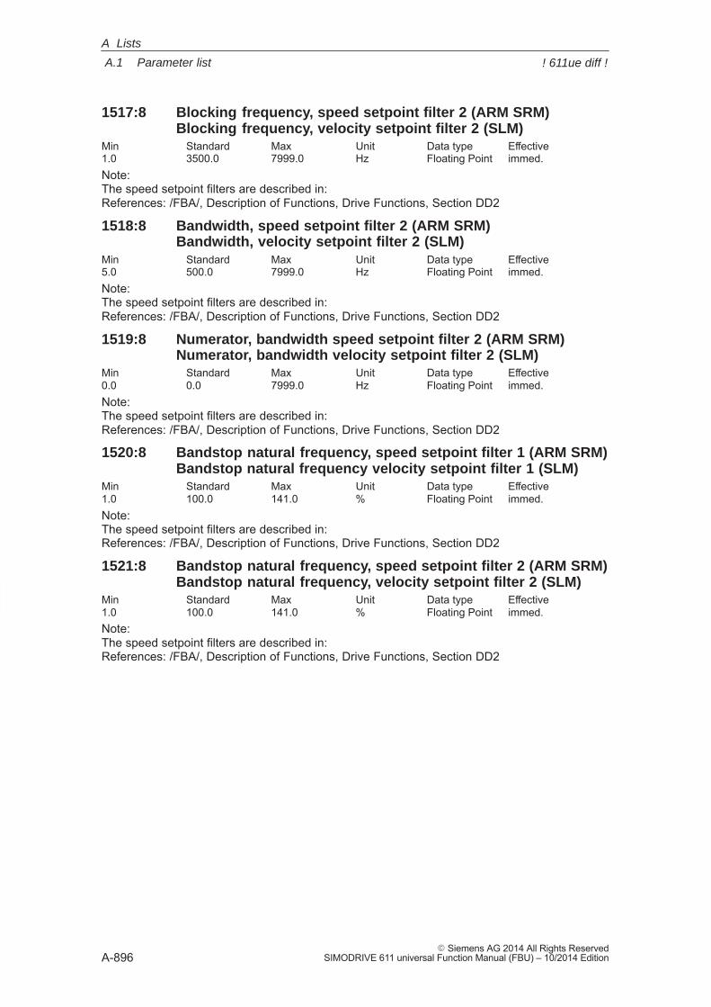
A
A.1 Parameter list
A-896� Siemens AG 2014 All Rights Reserved
SIMODRIVE 611 universal Function Manual (FBU) – 10/2014 Edition
1517:8 Blocking frequency, speed setpoint filter 2 (ARM SRM)Blocking frequency, velocity setpoint filter 2 (SLM)
Min Standard Max Unit Data type Effective1.0 3500.0 7999.0 Hz Floating Point immed.Note:The speed setpoint filters are described in:References: /FBA/, Description of Functions, Drive Functions, Section DD2
1518:8 Bandwidth, speed setpoint filter 2 (ARM SRM)Bandwidth, velocity setpoint filter 2 (SLM)
Min Standard Max Unit Data type Effective5.0 500.0 7999.0 Hz Floating Point immed.Note:The speed setpoint filters are described in:References: /FBA/, Description of Functions, Drive Functions, Section DD2
1519:8 Numerator, bandwidth speed setpoint filter 2 (ARM SRM)Numerator, bandwidth velocity setpoint filter 2 (SLM)
Min Standard Max Unit Data type Effective0.0 0.0 7999.0 Hz Floating Point immed.Note:The speed setpoint filters are described in:References: /FBA/, Description of Functions, Drive Functions, Section DD2
1520:8 Bandstop natural frequency, speed setpoint filter 1 (ARM SRM)Bandstop natural frequency velocity setpoint filter 1 (SLM)
Min Standard Max Unit Data type Effective1.0 100.0 141.0 % Floating Point immed.Note:The speed setpoint filters are described in:References: /FBA/, Description of Functions, Drive Functions, Section DD2
1521:8 Bandstop natural frequency, speed setpoint filter 2 (ARM SRM)Bandstop natural frequency, velocity setpoint filter 2 (SLM)
Min Standard Max Unit Data type Effective1.0 100.0 141.0 % Floating Point immed.Note:The speed setpoint filters are described in:References: /FBA/, Description of Functions, Drive Functions, Section DD2
A Lists
! 611ue diff !
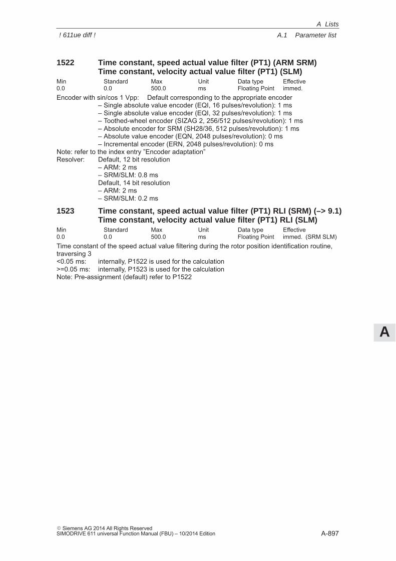
A
A.1 Parameter list
A-897� Siemens AG 2014 All Rights ReservedSIMODRIVE 611 universal Function Manual (FBU) – 10/2014 Edition
1522 Time constant, speed actual value filter (PT1) (ARM SRM)Time constant, velocity actual value filter (PT1) (SLM)
Min Standard Max Unit Data type Effective0.0 0.0 500.0 ms Floating Point immed.Encoder with sin/cos 1 Vpp: Default corresponding to the appropriate encoder
– Single absolute value encoder (EQI, 16 pulses/revolution): 1 ms– Single absolute value encoder (EQI, 32 pulses/revolution): 1 ms– Toothed-wheel encoder (SIZAG 2, 256/512 pulses/revolution): 1 ms – Absolute encoder for SRM (SH28/36, 512 pulses/revolution): 1 ms– Absolute value encoder (EQN, 2048 pulses/revolution): 0 ms– Incremental encoder (ERN, 2048 pulses/revolution): 0 ms
Note: refer to the index entry ”Encoder adaptation”Resolver: Default, 12 bit resolution
– ARM: 2 ms– SRM/SLM: 0.8 msDefault, 14 bit resolution– ARM: 2 ms– SRM/SLM: 0.2 ms
1523 Time constant, speed actual value filter (PT1) RLI (SRM) (–> 9.1)Time constant, velocity actual value filter (PT1) RLI (SLM)
Min Standard Max Unit Data type Effective0.0 0.0 500.0 ms Floating Point immed. (SRM SLM)Time constant of the speed actual value filtering during the rotor position identification routine,traversing 3<0.05 ms: internally, P1522 is used for the calculation>=0.05 ms: internally, P1523 is used for the calculationNote: Pre-assignment (default) refer to P1522
A Lists
! 611ue diff !
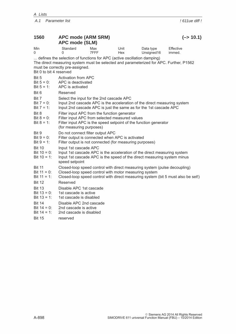
A
A.1 Parameter list
A-898� Siemens AG 2014 All Rights Reserved
SIMODRIVE 611 universal Function Manual (FBU) – 10/2014 Edition
1560 APC mode (ARM SRM) (–> 10.1)APC mode (SLM)
Min Standard Max Unit Data type Effective0 0 7FFF Hex Unsigned16 immed.... defines the selection of functions for APC (active oscillation damping)The direct measuring system must be selected and parameterized for APC. Further, P1562must be correctly pre-assigned.Bit 0 to bit 4 reservedBit 5 Activation from APCBit 5 = 0: APC is deactivatedBit 5 = 1: APC is activatedBit 6 ReservedBit 7 Select the input for the 2nd cascade APCBit 7 = 0: Input 2nd cascade APC is the acceleration of the direct measuring systemBit 7 = 1: Input 2nd cascade APC is just the same as for the 1st cascade APCBit 8 Filter input APC from the function generatorBit 8 = 0: Filter input APC from selected measured valuesBit 8 = 1: Filter input APC is the speed setpoint of the function generator
(for measuring purposes)Bit 9 Do not connect filter output APCBit 9 = 0: Filter output is connected when APC is activatedBit 9 = 1: Filter output is not connected (for measuring purposes)Bit 10 Input 1st cascade APCBit 10 = 0: Input 1st cascade APC is the acceleration of the direct measuring systemBit 10 = 1: Input 1st cascade APC is the speed of the direct measuring system minus
speed setpointBit 11 Closed-loop speed control with direct measuring system (pulse decoupling)Bit 11 = 0: Closed-loop speed control with motor measuring systemBit 11 = 1: Closed-loop speed control with direct measuring system (bit 5 must also be set!)Bit 12 ReservedBit 13 Disable APC 1st cascadeBit 13 = 0: 1st cascade is activeBit 13 = 1: 1st cascade is disabledBit 14 Disable APC 2nd cascadeBit 14 = 0: 2nd cascade is activeBit 14 = 1: 2nd cascade is disabledBit 15 reserved
A Lists
! 611ue diff !
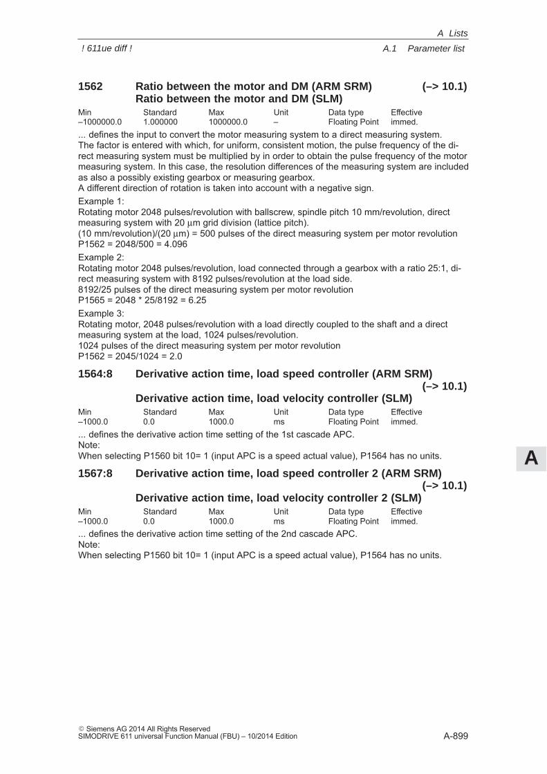
A
A.1 Parameter list
A-899� Siemens AG 2014 All Rights ReservedSIMODRIVE 611 universal Function Manual (FBU) – 10/2014 Edition
1562 Ratio between the motor and DM (ARM SRM) (–> 10.1)Ratio between the motor and DM (SLM)
Min Standard Max Unit Data type Effective–1000000.0 1.000000 1000000.0 – Floating Point immed.... defines the input to convert the motor measuring system to a direct measuring system.The factor is entered with which, for uniform, consistent motion, the pulse frequency of the di-rect measuring system must be multiplied by in order to obtain the pulse frequency of the motormeasuring system. In this case, the resolution differences of the measuring system are includedas also a possibly existing gearbox or measuring gearbox.A different direction of rotation is taken into account with a negative sign.Example 1:Rotating motor 2048 pulses/revolution with ballscrew, spindle pitch 10 mm/revolution, directmeasuring system with 20 μm grid division (lattice pitch).(10 mm/revolution)/(20 μm) = 500 pulses of the direct measuring system per motor revolutionP1562 = 2048/500 = 4.096Example 2:Rotating motor 2048 pulses/revolution, load connected through a gearbox with a ratio 25:1, di-rect measuring system with 8192 pulses/revolution at the load side.8192/25 pulses of the direct measuring system per motor revolutionP1565 = 2048 * 25/8192 = 6.25Example 3:Rotating motor, 2048 pulses/revolution with a load directly coupled to the shaft and a directmeasuring system at the load, 1024 pulses/revolution.1024 pulses of the direct measuring system per motor revolutionP1562 = 2045/1024 = 2.0
1564:8 Derivative action time, load speed controller (ARM SRM)(–> 10.1)
Derivative action time, load velocity controller (SLM)Min Standard Max Unit Data type Effective–1000.0 0.0 1000.0 ms Floating Point immed.... defines the derivative action time setting of the 1st cascade APC.Note:When selecting P1560 bit 10= 1 (input APC is a speed actual value), P1564 has no units.
1567:8 Derivative action time, load speed controller 2 (ARM SRM)(–> 10.1)
Derivative action time, load velocity controller 2 (SLM)Min Standard Max Unit Data type Effective–1000.0 0.0 1000.0 ms Floating Point immed.... defines the derivative action time setting of the 2nd cascade APC.Note:When selecting P1560 bit 10= 1 (input APC is a speed actual value), P1564 has no units.
A Lists
! 611ue diff !
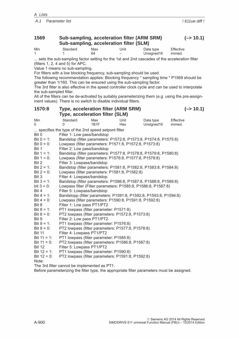
A
A.1 Parameter list
A-900� Siemens AG 2014 All Rights Reserved
SIMODRIVE 611 universal Function Manual (FBU) – 10/2014 Edition
1569 Sub-sampling, acceleration filter (ARM SRM) (–> 10.1)Sub-sampling, acceleration filter (SLM)
Min Standard Max Unit Data type Effective1 1 64 – Unsigned16 immed.... sets the sub-sampling factor setting for the 1st and 2nd cascades of the acceleration filter(filters 1, 2, 4 and 5) for APC.Value 1 means no sub-sampling. For filters with a low blocking frequency, sub-sampling should be used. The following recommendation applies: Blocking frequency * sampling time * P1569 should begreater than 1/160. This can be ensured using the sub-sampling factor. The 3rd filter is also effective in the speed controller clock cycle and can be used to interpolatethe sub-sampled filter. All of the filters can be de-activated by suitably parameterizing them (e.g. using the pre-assign-ment values). There is no switch to disable individual filters.
1570:8 Type, acceleration filter (ARM SRM) (–> 10.1)Type, acceleration filter (SLM)
Min Standard Max Unit Data type Effective0 0 1B1F Hex Unsigned16 immed.... specifies the type of the 2nd speed setpont filterBit 0 Filter 1: Low pass/bandstopBit 0 = 1: Bandstop (filter parameters: P1572:8, P1573:8, P1574:8, P1575:8)Bit 0 = 0: Lowpass (filter parameters: P1571:8, P1572:8, P1573:8)Bit 1 Filter 2: Low pass/bandstopBit 1 = 1: Bandstop (filter parameters: P1577:8, P1578:8, P1579:8, P1580:8)Bit 1 = 0: Lowpass (filter parameters: P1576:8, P1577:8, P1578:8)Bit 2 Filter 3: Lowpass/bandstopBit 2 = 1: Bandstop (filter parameters: P1581:8, P1582:8, P1583:8, P1584:8)Bit 2 = 0: Lowpass (filter parameters: P1581:8, P1582:8)Bit 3 Filter 4: Lowpass/bandstopBit 3 = 1: Bandstop (filter parameters: P1586:8, P1587:8, P1588:8, P1589:8)bit 3 = 0: Lowpass filter (Filter parameters: P1585:8, P1586:8, P1587:8)Bit 4 Filter 5: Lowpass/bandstopBit 4 = 1: Bandstopp (filter parameters: P1591:8, P1592:8, P1593:8, P1594:8)Bit 4 = 0: Lowpass (filter parameters: P1590:8, P1591:8, P1592:8)Bit 8 Filter 1: Low pass PT1/PT2Bit 8 = 1: PT1 lowpass (filter parameter: P1571:8)Bit 8 = 0: PT2 lowpass (filter parameters: P1572:8, P1573:8)Bit 9 Filter 2: Low pass PT1/PT2Bit 9 = 1: PT1 lowpass (filter parameter: P1576:8)Bit 9 = 0: PT2 lowpass (filter parameters: P1577:8, P1578:8)Bit 11 Filter 4: Lowpass PT1/PT2Bit 11 = 1: PT1 lowpass (filter parameter: P1585:8)Bit 11 = 0: PT2 lowpass (filter parameters: P1586:8, P1587:8)Bit 12 Filter 5: Lowpass PT1/PT2Bit 12 = 1: PT1 lowpass (filter parameter: P1590:8)Bit 12 = 0: PT2 lowpass (filter parameters: P1591:8, P1592:8)Note:The 3rd filter cannot be implemented as PT1.Before parameterizing the filter type, the appropriate filter parameters must be assigned.
A Lists
! 611ue diff !
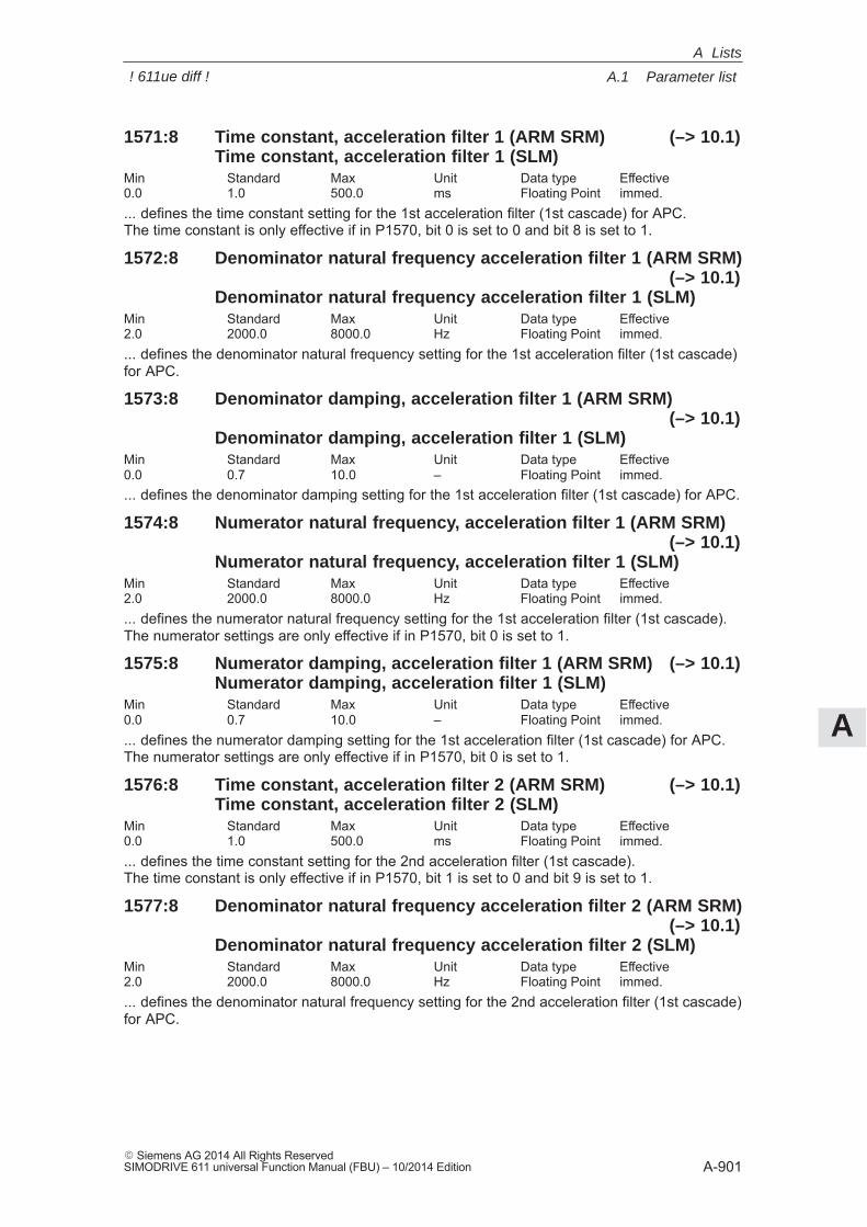
A
A.1 Parameter list
A-901� Siemens AG 2014 All Rights ReservedSIMODRIVE 611 universal Function Manual (FBU) – 10/2014 Edition
1571:8 Time constant, acceleration filter 1 (ARM SRM) (–> 10.1)Time constant, acceleration filter 1 (SLM)
Min Standard Max Unit Data type Effective0.0 1.0 500.0 ms Floating Point immed.... defines the time constant setting for the 1st acceleration filter (1st cascade) for APC. The time constant is only effective if in P1570, bit 0 is set to 0 and bit 8 is set to 1.
1572:8 Denominator natural frequency acceleration filter 1 (ARM SRM)(–> 10.1)
Denominator natural frequency acceleration filter 1 (SLM)Min Standard Max Unit Data type Effective2.0 2000.0 8000.0 Hz Floating Point immed.... defines the denominator natural frequency setting for the 1st acceleration filter (1st cascade)for APC.
1573:8 Denominator damping, acceleration filter 1 (ARM SRM)(–> 10.1)
Denominator damping, acceleration filter 1 (SLM)Min Standard Max Unit Data type Effective0.0 0.7 10.0 – Floating Point immed.... defines the denominator damping setting for the 1st acceleration filter (1st cascade) for APC.
1574:8 Numerator natural frequency, acceleration filter 1 (ARM SRM)(–> 10.1)
Numerator natural frequency, acceleration filter 1 (SLM)Min Standard Max Unit Data type Effective2.0 2000.0 8000.0 Hz Floating Point immed.... defines the numerator natural frequency setting for the 1st acceleration filter (1st cascade). The numerator settings are only effective if in P1570, bit 0 is set to 1.
1575:8 Numerator damping, acceleration filter 1 (ARM SRM) (–> 10.1)Numerator damping, acceleration filter 1 (SLM)
Min Standard Max Unit Data type Effective0.0 0.7 10.0 – Floating Point immed.... defines the numerator damping setting for the 1st acceleration filter (1st cascade) for APC. The numerator settings are only effective if in P1570, bit 0 is set to 1.
1576:8 Time constant, acceleration filter 2 (ARM SRM) (–> 10.1)Time constant, acceleration filter 2 (SLM)
Min Standard Max Unit Data type Effective0.0 1.0 500.0 ms Floating Point immed.... defines the time constant setting for the 2nd acceleration filter (1st cascade). The time constant is only effective if in P1570, bit 1 is set to 0 and bit 9 is set to 1.
1577:8 Denominator natural frequency acceleration filter 2 (ARM SRM)(–> 10.1)
Denominator natural frequency acceleration filter 2 (SLM)Min Standard Max Unit Data type Effective2.0 2000.0 8000.0 Hz Floating Point immed.... defines the denominator natural frequency setting for the 2nd acceleration filter (1st cascade)for APC.
A Lists
! 611ue diff !
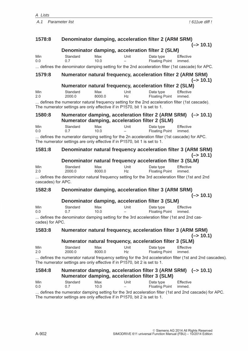
A
A.1 Parameter list
A-902� Siemens AG 2014 All Rights Reserved
SIMODRIVE 611 universal Function Manual (FBU) – 10/2014 Edition
1578:8 Denominator damping, acceleration filter 2 (ARM SRM)(–> 10.1)
Denominator damping, acceleration filter 2 (SLM)Min Standard Max Unit Data type Effective0.0 0.7 10.0 – Floating Point immed.... defines the denominator damping setting for the 2nd acceleration filter (1st cascade) for APC.
1579:8 Numerator natural frequency, acceleration filter 2 (ARM SRM)(–> 10.1)
Numerator natural frequency, acceleration filter 2 (SLM)Min Standard Max Unit Data type Effective2.0 2000.0 8000.0 Hz Floating Point immed.... defines the numerator natural frequency setting for the 2nd acceleration filter (1st cascade).The numerator settings are only effective if in P1570, bit 1 is set to 1.
1580:8 Numerator damping, acceleration filter 2 (ARM SRM) (–> 10.1)Numerator damping, acceleration filter 2 (SLM)
Min Standard Max Unit Data type Effective0.0 0.7 10.0 – Floating Point immed.... defines the numerator damping setting for the 2n acceleration filter (1st cascade) for APC. The numerator settings are only effective if in P1570, bit 1 is set to 1.
1581:8 Denominator natural frequency acceleration filter 3 (ARM SRM)(–> 10.1)
Denominator natural frequency acceleration filter 3 (SLM)Min Standard Max Unit Data type Effective2.0 2000.0 8000.0 Hz Floating Point immed.... defines the denominator natural frequency setting for the 3rd acceleration filter (1st and 2ndcascades) for APC.
1582:8 Denominator damping, acceleration filter 3 (ARM SRM)(–> 10.1)
Denominator damping, acceleration filter 3 (SLM)Min Standard Max Unit Data type Effective0.0 0.7 10.0 – Floating Point immed.... defines the denominator damping setting for the 3rd acceleration filter (1st and 2nd cas-cades) for APC.
1583:8 Numerator natural frequency, acceleration filter 3 (ARM SRM)(–> 10.1)
Numerator natural frequency, acceleration filter 3 (SLM)Min Standard Max Unit Data type Effective2.0 2000.0 8000.0 Hz Floating Point immed.... defines the numerator natural frequency setting for the 3rd acceleration filter (1st and 2nd cascades).The numerator settings are only effective if in P1570, bit 2 is set to 1.
1584:8 Numerator damping, acceleration filter 3 (ARM SRM) (–> 10.1)Numerator damping, acceleration filter 3 (SLM)
Min Standard Max Unit Data type Effective0.0 0.7 10.0 – Floating Point immed.... defines the numerator damping setting for the 3rd acceleration filter (1st and 2nd cascade) for APC.The numerator settings are only effective if in P1570, bit 2 is set to 1.
A Lists
! 611ue diff !
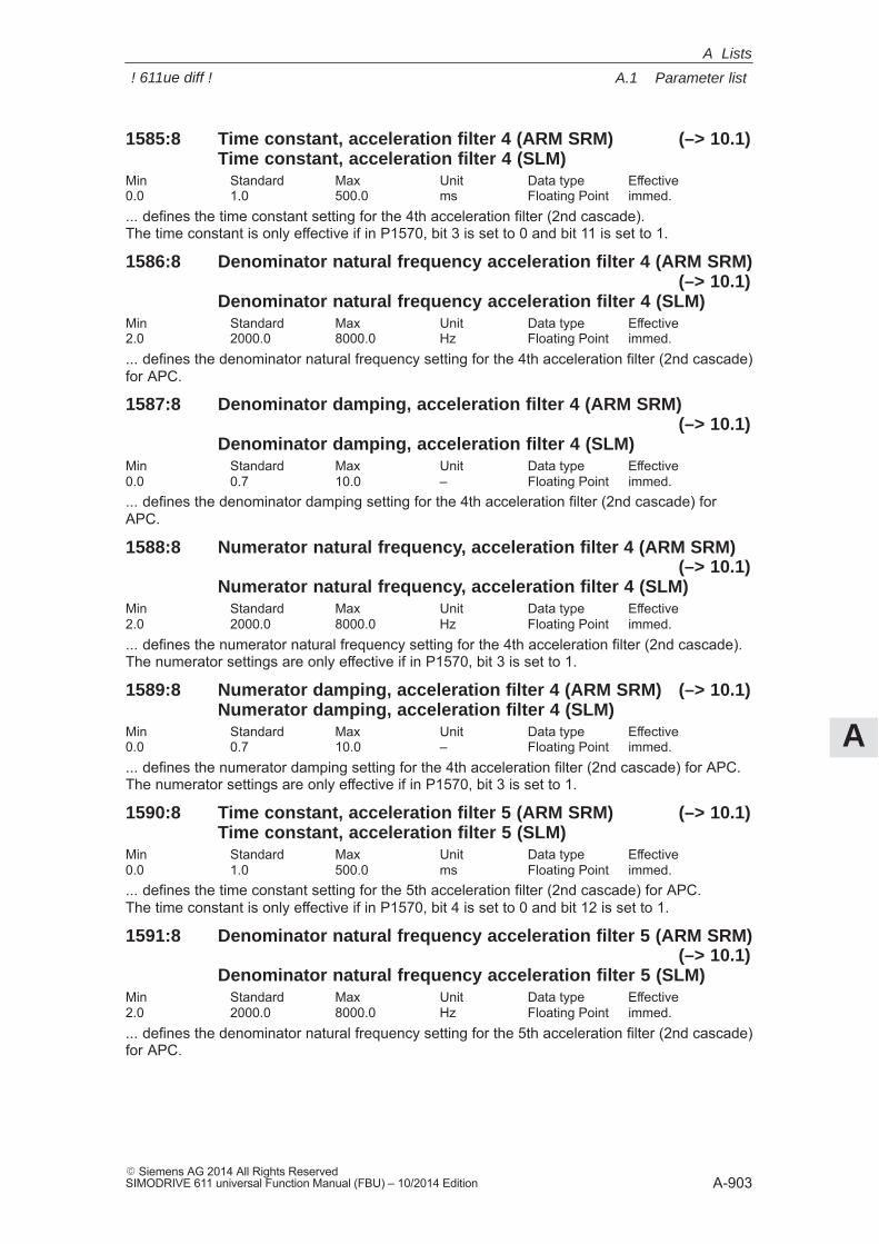
A
A.1 Parameter list
A-903� Siemens AG 2014 All Rights ReservedSIMODRIVE 611 universal Function Manual (FBU) – 10/2014 Edition
1585:8 Time constant, acceleration filter 4 (ARM SRM) (–> 10.1)Time constant, acceleration filter 4 (SLM)
Min Standard Max Unit Data type Effective0.0 1.0 500.0 ms Floating Point immed.... defines the time constant setting for the 4th acceleration filter (2nd cascade).The time constant is only effective if in P1570, bit 3 is set to 0 and bit 11 is set to 1.
1586:8 Denominator natural frequency acceleration filter 4 (ARM SRM)(–> 10.1)
Denominator natural frequency acceleration filter 4 (SLM)Min Standard Max Unit Data type Effective2.0 2000.0 8000.0 Hz Floating Point immed.... defines the denominator natural frequency setting for the 4th acceleration filter (2nd cascade)for APC.
1587:8 Denominator damping, acceleration filter 4 (ARM SRM)(–> 10.1)
Denominator damping, acceleration filter 4 (SLM)Min Standard Max Unit Data type Effective0.0 0.7 10.0 – Floating Point immed.... defines the denominator damping setting for the 4th acceleration filter (2nd cascade) forAPC.
1588:8 Numerator natural frequency, acceleration filter 4 (ARM SRM)(–> 10.1)
Numerator natural frequency, acceleration filter 4 (SLM)Min Standard Max Unit Data type Effective2.0 2000.0 8000.0 Hz Floating Point immed.... defines the numerator natural frequency setting for the 4th acceleration filter (2nd cascade).The numerator settings are only effective if in P1570, bit 3 is set to 1.
1589:8 Numerator damping, acceleration filter 4 (ARM SRM) (–> 10.1)Numerator damping, acceleration filter 4 (SLM)
Min Standard Max Unit Data type Effective0.0 0.7 10.0 – Floating Point immed.... defines the numerator damping setting for the 4th acceleration filter (2nd cascade) for APC.The numerator settings are only effective if in P1570, bit 3 is set to 1.
1590:8 Time constant, acceleration filter 5 (ARM SRM) (–> 10.1)Time constant, acceleration filter 5 (SLM)
Min Standard Max Unit Data type Effective0.0 1.0 500.0 ms Floating Point immed.... defines the time constant setting for the 5th acceleration filter (2nd cascade) for APC.The time constant is only effective if in P1570, bit 4 is set to 0 and bit 12 is set to 1.
1591:8 Denominator natural frequency acceleration filter 5 (ARM SRM)(–> 10.1)
Denominator natural frequency acceleration filter 5 (SLM)Min Standard Max Unit Data type Effective2.0 2000.0 8000.0 Hz Floating Point immed.... defines the denominator natural frequency setting for the 5th acceleration filter (2nd cascade)for APC.
A Lists
! 611ue diff !
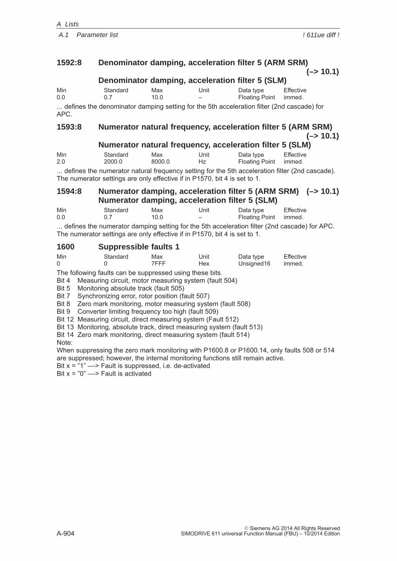
A
A.1 Parameter list
A-904� Siemens AG 2014 All Rights Reserved
SIMODRIVE 611 universal Function Manual (FBU) – 10/2014 Edition
1592:8 Denominator damping, acceleration filter 5 (ARM SRM)(–> 10.1)
Denominator damping, acceleration filter 5 (SLM)Min Standard Max Unit Data type Effective0.0 0.7 10.0 – Floating Point immed.... defines the denominator damping setting for the 5th acceleration filter (2nd cascade) forAPC.
1593:8 Numerator natural frequency, acceleration filter 5 (ARM SRM)(–> 10.1)
Numerator natural frequency, acceleration filter 5 (SLM)Min Standard Max Unit Data type Effective2.0 2000.0 8000.0 Hz Floating Point immed.... defines the numerator natural frequency setting for the 5th acceleration filter (2nd cascade).The numerator settings are only effective if in P1570, bit 4 is set to 1.
1594:8 Numerator damping, acceleration filter 5 (ARM SRM) (–> 10.1)Numerator damping, acceleration filter 5 (SLM)
Min Standard Max Unit Data type Effective0.0 0.7 10.0 – Floating Point immed.... defines the numerator damping setting for the 5th acceleration filter (2nd cascade) for APC.The numerator settings are only effective if in P1570, bit 4 is set to 1.
1600 Suppressible faults 1Min Standard Max Unit Data type Effective0 0 7FFF Hex Unsigned16 immed.The following faults can be suppressed using these bits.Bit 4 Measuring circuit, motor measuring system (fault 504)Bit 5 Monitoring absolute track (fault 505)Bit 7 Synchronizing error, rotor position (fault 507)Bit 8 Zero mark monitoring, motor measuring system (fault 508)Bit 9 Converter limiting frequency too high (fault 509)Bit 12 Measuring circuit, direct measuring system (Fault 512)Bit 13 Monitoring, absolute track, direct measuring system (fault 513)Bit 14 Zero mark monitoring, direct measuring system (fault 514)Note:When suppressing the zero mark monitoring with P1600.8 or P1600.14, only faults 508 or 514are suppressed; however, the internal monitoring functions still remain active.Bit x = ”1” ––> Fault is suppressed, i.e. de-activatedBit x = ”0” ––> Fault is activated
A Lists
! 611ue diff !
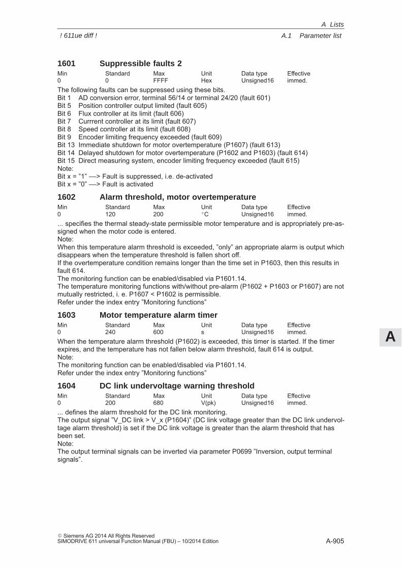
A
A.1 Parameter list
A-905� Siemens AG 2014 All Rights ReservedSIMODRIVE 611 universal Function Manual (FBU) – 10/2014 Edition
1601 Suppressible faults 2Min Standard Max Unit Data type Effective0 0 FFFF Hex Unsigned16 immed.The following faults can be suppressed using these bits.Bit 1 AD conversion error, terminal 56/14 or terminal 24/20 (fault 601)Bit 5 Position controller output limited (fault 605)Bit 6 Flux controller at its limit (fault 606)Bit 7 Currrent controller at its limit (fault 607)Bit 8 Speed controller at its limit (fault 608)Bit 9 Encoder limiting frequency exceeded (fault 609)Bit 13 Immediate shutdown for motor overtemperature (P1607) (fault 613)Bit 14 Delayed shutdown for motor overtemperature (P1602 and P1603) (fault 614)Bit 15 Direct measuring system, encoder limiting frequency exceeded (fault 615)Note:Bit x = ”1” ––> Fault is suppressed, i.e. de-activatedBit x = ”0” ––> Fault is activated
1602 Alarm threshold, motor overtemperatureMin Standard Max Unit Data type Effective0 120 200 �C Unsigned16 immed.... specifies the thermal steady-state permissible motor temperature and is appropriately pre-as-signed when the motor code is entered.Note:When this temperature alarm threshold is exceeded, ”only” an appropriate alarm is output whichdisappears when the temperature threshold is fallen short off.If the overtemperature condition remains longer than the time set in P1603, then this results infault 614.The monitoring function can be enabled/disabled via P1601.14.The temperature monitoring functions with/without pre-alarm (P1602 + P1603 or P1607) are notmutually restricted, i. e. P1607 < P1602 is permissible.Refer under the index entry ”Monitoring functions”
1603 Motor temperature alarm timerMin Standard Max Unit Data type Effective0 240 600 s Unsigned16 immed.When the temperature alarm threshold (P1602) is exceeded, this timer is started. If the timerexpires, and the temperature has not fallen below alarm threshold, fault 614 is output.Note:The monitoring function can be enabled/disabled via P1601.14.Refer under the index entry ”Monitoring functions”
1604 DC link undervoltage warning thresholdMin Standard Max Unit Data type Effective0 200 680 V(pk) Unsigned16 immed.... defines the alarm threshold for the DC link monitoring. The output signal ”V_DC link > V_x (P1604)” (DC link voltage greater than the DC link undervol-tage alarm threshold) is set if the DC link voltage is greater than the alarm threshold that hasbeen set.Note:The output terminal signals can be inverted via parameter P0699 ”Inversion, output terminalsignals”.
A Lists
! 611ue diff !
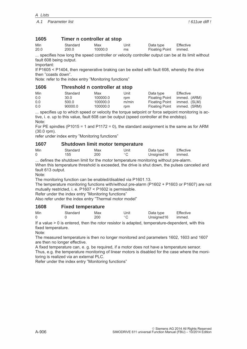
A
A.1 Parameter list
A-906� Siemens AG 2014 All Rights Reserved
SIMODRIVE 611 universal Function Manual (FBU) – 10/2014 Edition
1605 Timer n controller at stopMin Standard Max Unit Data type Effective20.0 200.0 10000.0 ms Floating Point immed.... specifies how long the speed controller or velocity controller output can be at its limit withoutfault 608 being output.Important: If P1605 < P1404, then regenerative braking can be exited with fault 608, whereby the drivethen ”coasts down”.Note: refer to the index entry ”Monitoring functions”
1606 Threshold n controller at stopMin Standard Max Unit Data type Effective0.0 30.0 100000.0 rpm Floating Point immed. (ARM)0.0 500.0 100000.0 m/min Floating Point immed. (SLM)0.0 90000.0 100000.0 rpm Floating Point immed. (SRM)... specifies up to which speed or velocity the torque setpoint or force setpoint monitoring is ac-tive, i. e. up to this value, fault 608 can be output (speed controller at the endstop).Note: For PE spindles (P1015 = 1 and P1172 = 0), the standard assignment is the same as for ARM(30.0 rpm).refer under index entry ”Monitoring functions”
1607 Shutdown limit motor temperatureMin Standard Max Unit Data type Effective0 155 200 �C Unsigned16 immed.... defines the shutdown limit for the motor temperature monitoring without pre-alarm.When this temperature threshold is exceeded, the drive is shut down, the pulses canceled andfault 613 output.Note:The monitoring function can be enabled/disabled via P1601.13.The temperature monitoring functions with/without pre-alarm (P1602 + P1603 or P1607) are notmutually restricted, i. e. P1607 < P1602 is permissible.Refer under the index entry ”Monitoring functions”Also refer under the index entry ”Thermal motor model”
1608 Fixed temperatureMin Standard Max Unit Data type Effective0 0 200 �C Unsigned16 immed.If a value > 0 is entered, then the rotor resistor is adapted, temperature-dependent, with thisfixed temperature.Note:The measured temperature is then no longer monitored and parameters 1602, 1603 and 1607are then no longer effective.A fixed temperature can, e. g. be required, if a motor does not have a temperature sensor.Thus, e.g. the temperature monitoring of linear motors is disabled for the case where the moni-toring is realized via an external PLC.Refer under the index entry ”Monitoring functions”
A Lists
! 611ue diff !
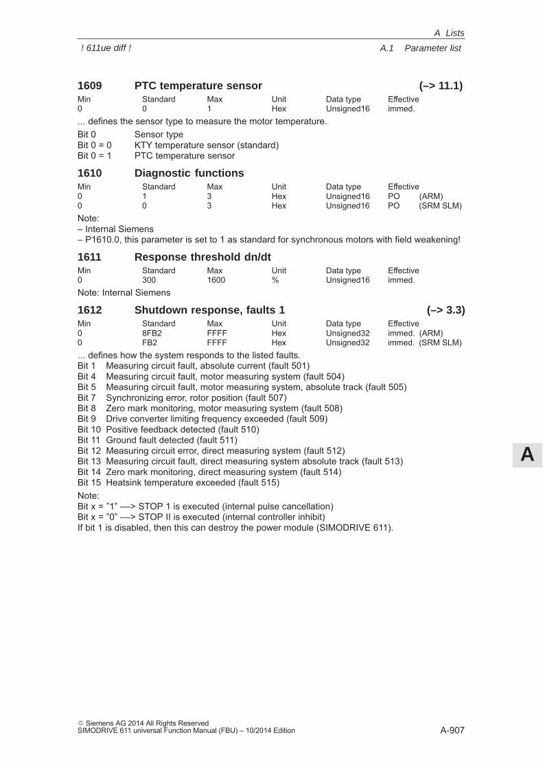
A
A.1 Parameter list
A-907� Siemens AG 2014 All Rights ReservedSIMODRIVE 611 universal Function Manual (FBU) – 10/2014 Edition
1609 PTC temperature sensor (–> 11.1)Min Standard Max Unit Data type Effective0 0 1 Hex Unsigned16 immed.... defines the sensor type to measure the motor temperature.Bit 0 Sensor typeBit 0 = 0 KTY temperature sensor (standard)Bit 0 = 1 PTC temperature sensor
1610 Diagnostic functionsMin Standard Max Unit Data type Effective0 1 3 Hex Unsigned16 PO (ARM)0 0 3 Hex Unsigned16 PO (SRM SLM)Note:– Internal Siemens– P1610.0, this parameter is set to 1 as standard for synchronous motors with field weakening!
1611 Response threshold dn/dtMin Standard Max Unit Data type Effective0 300 1600 % Unsigned16 immed.Note: Internal Siemens
1612 Shutdown response, faults 1 (–> 3.3)Min Standard Max Unit Data type Effective0 8FB2 FFFF Hex Unsigned32 immed. (ARM)0 FB2 FFFF Hex Unsigned32 immed. (SRM SLM)... defines how the system responds to the listed faults.Bit 1 Measuring circuit fault, absolute current (fault 501)Bit 4 Measuring circuit fault, motor measuring system (fault 504)Bit 5 Measuring circuit fault, motor measuring system, absolute track (fault 505)Bit 7 Synchronizing error, rotor position (fault 507)Bit 8 Zero mark monitoring, motor measuring system (fault 508)Bit 9 Drive converter limiting frequency exceeded (fault 509)Bit 10 Positive feedback detected (fault 510)Bit 11 Ground fault detected (fault 511)Bit 12 Measuring circuit error, direct measuring system (fault 512)Bit 13 Measuring circuit fault, direct measuring system absolute track (fault 513)Bit 14 Zero mark monitoring, direct measuring system (fault 514)Bit 15 Heatsink temperature exceeded (fault 515)Note:Bit x = ”1” ––> STOP 1 is executed (internal pulse cancellation)Bit x = ”0” ––> STOP II is executed (internal controller inhibit)If bit 1 is disabled, then this can destroy the power module (SIMODRIVE 611).
A Lists
! 611ue diff !
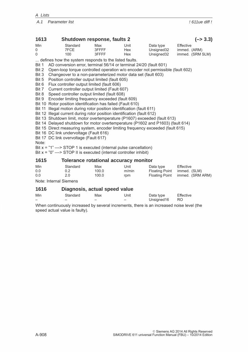
A
A.1 Parameter list
A-908� Siemens AG 2014 All Rights Reserved
SIMODRIVE 611 universal Function Manual (FBU) – 10/2014 Edition
1613 Shutdown response, faults 2 (–> 3.3)Min Standard Max Unit Data type Effective0 7FCE 3FFFF Hex Unsigned32 immed. (ARM)0 100 3FFFF Hex Unsigned32 immed. (SRM SLM)... defines how the system responds to the listed faults.Bit 1 AD conversion error, terminal 56/14 or terminal 24/20 (fault 601)Bit 2 Open-loop torque controlled operation w/o encoder not permissible (fault 602)Bit 3 Changeover to a non-parameterized motor data set (fault 603)Bit 5 Position controller output limited (fault 605)Bit 6 Flux controller output limited (fault 606)Bit 7 Current controller output limited (Fault 607)Bit 8 Speed controller output limited (fault 608)Bit 9 Encoder limiting frequency exceeded (fault 609)Bit 10 Rotor position identification has failed (Fault 610)Bit 11 Illegal motion during rotor position identification (fault 611)Bit 12 Illegal current during rotor position identification (fault 612)Bit 13 Shutdown limit, motor overtemperature (P1607) exceeded (fault 613)Bit 14 Delayed shutdown for motor overtemperature (P1602 and P1603) (fault 614)Bit 15 Direct measuring system, encoder limiting frequency exceeded (fault 615)Bit 16 DC link undervoltage (Fault 616)Bit 17 DC link overvoltage (Fault 617)Note:Bit x = ”1” ––> STOP 1 is executed (internal pulse cancellation)Bit x = ”0” ––> STOP II is executed (internal controller inhibit)
1615 Tolerance rotational accuracy monitorMin Standard Max Unit Data type Effective0.0 0.2 100.0 m/min Floating Point immed. (SLM)0.0 2.0 100.0 rpm Floating Point immed. (SRM ARM)Note: Internal Siemens
1616 Diagnosis, actual speed valueMin Standard Max Unit Data type Effective– – – – Unsigned16 ROWhen continuously increased by several increments, there is an increased noise level (thespeed actual value is faulty).
A Lists
! 611ue diff !
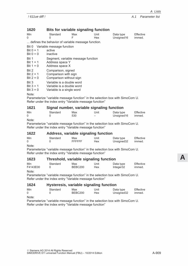
A
A.1 Parameter list
A-909� Siemens AG 2014 All Rights ReservedSIMODRIVE 611 universal Function Manual (FBU) – 10/2014 Edition
1620 Bits for variable signaling functionMin Standard Max Unit Data type Effective0 0 F Hex Unsigned16 immed.... defines the behavior of variable message function.Bit 0 Variable message functionBit 0 = 1 activeBit 0 = 0 inactiveBit 1 Segment, variable message functionBit 1 = 1 Address space YBit 1 = 0 Address space XBit 2 Comparison, signedBit 2 = 1 Comparison with signBit 2 = 0 Comparison without signBit 3 Variable is a double wordBit 3 = 1 Variable is a double wordBit 3 = 0 Variable is a single wordNote:Parameterize ”variable message function” in the selection box with SimoCom U.Refer under the index entry ”Variable message function”
1621 Signal number, variable signaling functionMin Standard Max Unit Data type Effective0 0 530 – Unsigned16 immed.Note: Parameterize ”variable message function” in the selection box with SimoCom U.Refer under the index entry ”Variable message function”
1622 Address, variable signaling functionMin Standard Max Unit Data type Effective0 0 FFFFFF Hex Unsigned32 immed.Note: Parameterize ”variable message function” in the selection box with SimoCom U.Refer under the index entry ”Variable message function”
1623 Threshold, variable signaling functionMin Standard Max Unit Data type EffectiveF4143E00 0 BEBC200 Hex Integer32 immed.Note:Parameterize ”variable message function” in the selection box with SimoCom U.Refer under the index entry ”Variable message function”
1624 Hysteresis, variable signaling functionMin Standard Max Unit Data type Effective0 0 BEBC200 Hex Unsigned32 immed.Note:Parameterize ”variable message function” in the selection box with SimoCom U.Refer under the index entry ”Variable message function”
A Lists
! 611ue diff !
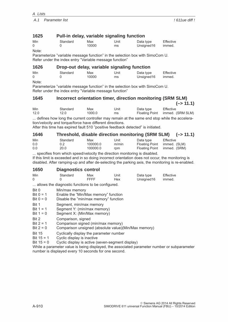
A
A.1 Parameter list
A-910� Siemens AG 2014 All Rights Reserved
SIMODRIVE 611 universal Function Manual (FBU) – 10/2014 Edition
1625 Pull-in delay, variable signaling functionMin Standard Max Unit Data type Effective0 0 10000 ms Unsigned16 immed.Note:Parameterize ”variable message function” in the selection box with SimoCom U.Refer under the index entry ”Variable message function”
1626 Drop-out delay, variable signaling functionMin Standard Max Unit Data type Effective0 0 10000 ms Unsigned16 immed.Note:Parameterize ”variable message function” in the selection box with SimoCom U.Refer under the index entry ”Variable message function”
1645 Incorrect orientation timer, direction monitoring (SRM SLM)(–> 11.1)
Min Standard Max Unit Data type Effective12.0 12.0 1000.0 ms Floating Point immed. (SRM SLM)... defines how long the current controller may remain at the same end stop while the accelera-tion/velocity and torque/force have different directions. After this time has expired fault 510 ”positive feedback detected” is initiated.
1646 Threshold, disable direction monitoring (SRM SLM) (–> 11.1)Min Standard Max Unit Data type Effective0.0 0.2 100000.0 m/min Floating Point immed. (SLM)0.0 20.0 100000.0 rpm Floating Point immed. (SRM)... specifies from which speed/velocity the direction monitoring is disabled. If this limit is exceeded and in so doing incorrect orientation does not occur, the monitoring isdisabled. After ramping-up and after de-selecting the parking axis, the monitoring is re-enabled.
1650 Diagnostics controlMin Standard Max Unit Data type Effective0 0 FFFF Hex Unsigned16 immed.... allows the diagnostic functions to be configured.Bit 0 Min/max memoryBit 0 = 1 Enable the ”Min/Max memory” functionBit 0 = 0 Disable the ”min/max memory” functionBit 1 Segment, min/max memoryBit 1 = 1 Segment Y: (min/max memory)Bit 1 = 0 Segment X: (Min/Max memory)Bit 2 Comparison, signedBit 2 = 1 Comparison signed (min/max memory)Bit 2 = 0 Comparison unsigned (absolute value)(Min/Max memory)Bit 15 Cyclically display the parameter numberBit 15 = 1 Cyclic display is inactiveBit 15 = 0 Cyclic display is active (seven-segment display)While a parameter value is being displayed, the associated parameter number or subparameternumber is displayed every 10 seconds for one second.
A Lists
! 611ue diff !
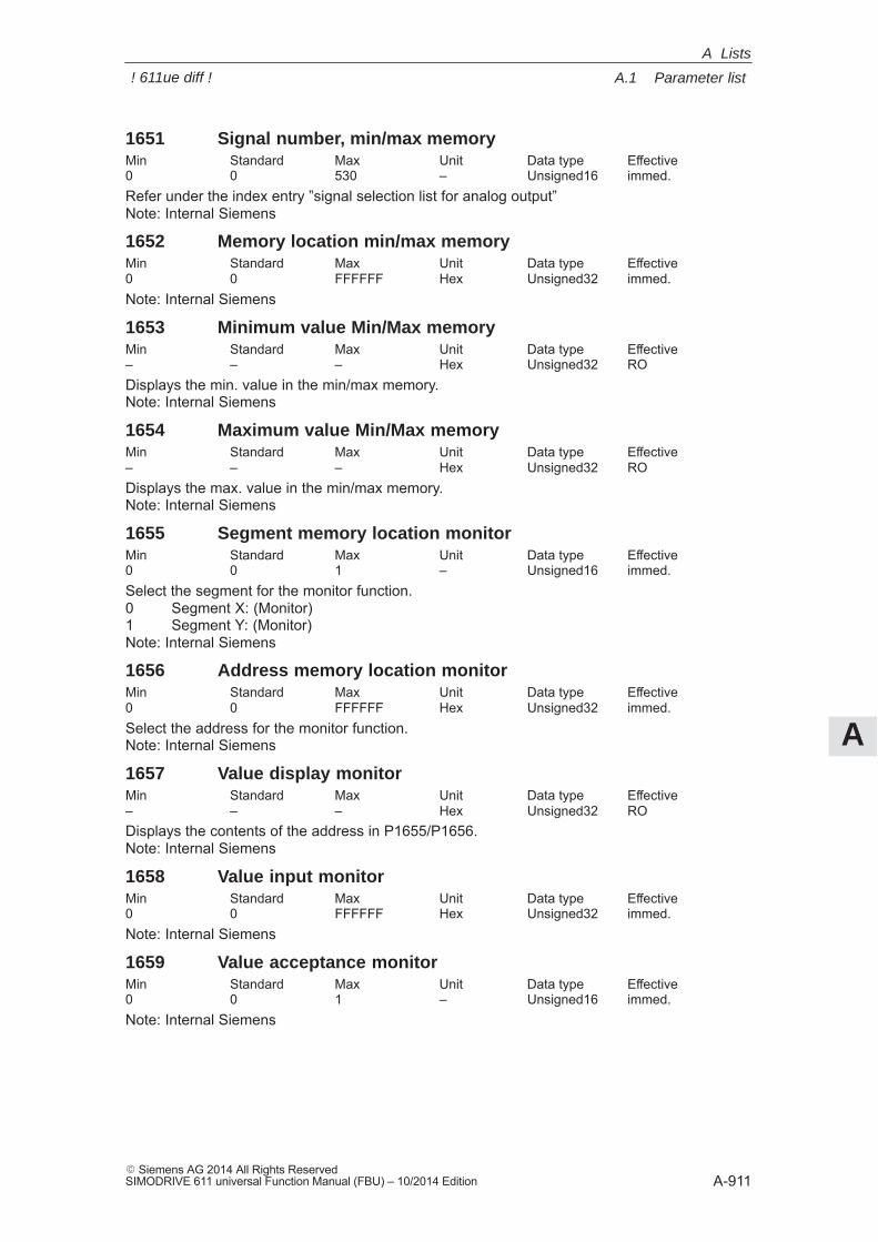
A
A.1 Parameter list
A-911� Siemens AG 2014 All Rights ReservedSIMODRIVE 611 universal Function Manual (FBU) – 10/2014 Edition
1651 Signal number, min/max memoryMin Standard Max Unit Data type Effective0 0 530 – Unsigned16 immed.Refer under the index entry ”signal selection list for analog output”Note: Internal Siemens
1652 Memory location min/max memoryMin Standard Max Unit Data type Effective0 0 FFFFFF Hex Unsigned32 immed.Note: Internal Siemens
1653 Minimum value Min/Max memoryMin Standard Max Unit Data type Effective– – – Hex Unsigned32 RODisplays the min. value in the min/max memory.Note: Internal Siemens
1654 Maximum value Min/Max memoryMin Standard Max Unit Data type Effective– – – Hex Unsigned32 RODisplays the max. value in the min/max memory.Note: Internal Siemens
1655 Segment memory location monitorMin Standard Max Unit Data type Effective0 0 1 – Unsigned16 immed.Select the segment for the monitor function.0 Segment X: (Monitor)1 Segment Y: (Monitor)Note: Internal Siemens
1656 Address memory location monitorMin Standard Max Unit Data type Effective0 0 FFFFFF Hex Unsigned32 immed.Select the address for the monitor function.Note: Internal Siemens
1657 Value display monitorMin Standard Max Unit Data type Effective– – – Hex Unsigned32 RODisplays the contents of the address in P1655/P1656.Note: Internal Siemens
1658 Value input monitorMin Standard Max Unit Data type Effective0 0 FFFFFF Hex Unsigned32 immed.Note: Internal Siemens
1659 Value acceptance monitorMin Standard Max Unit Data type Effective0 0 1 – Unsigned16 immed.Note: Internal Siemens
A Lists
! 611ue diff !
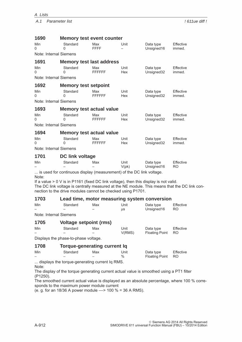
A
A.1 Parameter list
A-912� Siemens AG 2014 All Rights Reserved
SIMODRIVE 611 universal Function Manual (FBU) – 10/2014 Edition
1690 Memory test event counterMin Standard Max Unit Data type Effective0 0 FFFF – Unsigned16 immed.Note: Internal Siemens
1691 Memory test last addressMin Standard Max Unit Data type Effective0 0 FFFFFF Hex Unsigned32 immed.Note: Internal Siemens
1692 Memory test setpointMin Standard Max Unit Data type Effective0 0 FFFFFF Hex Unsigned32 immed.Note: Internal Siemens
1693 Memory test actual valueMin Standard Max Unit Data type Effective0 0 FFFFFF Hex Unsigned32 immed.Note: Internal Siemens
1694 Memory test actual valueMin Standard Max Unit Data type Effective0 0 FFFFFF Hex Unsigned32 immed.Note: Internal Siemens
1701 DC link voltageMin Standard Max Unit Data type Effective– – – V(pk) Unsigned16 RO... is used for continuous display (measurement) of the DC link voltage.Note: If a value > 0 V is in P1161 (fixed DC link voltage), then this display is not valid.The DC link voltage is centrally measured at the NE module. This means that the DC link con-nection to the drive modules cannot be checked using P1701.
1703 Lead time, motor measuring system conversionMin Standard Max Unit Data type Effective– – – μs Unsigned16 RONote: Internal Siemens
1705 Voltage setpoint (rms)Min Standard Max Unit Data type Effective– – – V(RMS) Floating Point RODisplays the phase-to-phase voltage.
1708 Torque-generating current IqMin Standard Max Unit Data type Effective– – – % Floating Point RO... displays the torque-generating current Iq RMS.Note:The display of the torque generating current actual value is smoothed using a PT1 filter(P1250).The smoothed current actual value is displayed as an absolute percentage, where 100 % corre-sponds to the maximum power module current (e. g. for an 18/36 A power module ––> 100 % = 36 A RMS).
A Lists
! 611ue diff !
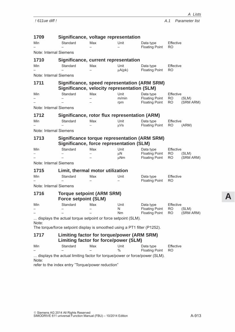
A
A.1 Parameter list
A-913� Siemens AG 2014 All Rights ReservedSIMODRIVE 611 universal Function Manual (FBU) – 10/2014 Edition
1709 Significance, voltage representationMin Standard Max Unit Data type Effective– – – – Floating Point RONote: Internal Siemens
1710 Significance, current representationMin Standard Max Unit Data type Effective– – – μA(pk) Floating Point RONote: Internal Siemens
1711 Significance, speed representation (ARM SRM)Significance, velocity representation (SLM)
Min Standard Max Unit Data type Effective– – – m/min Floating Point RO (SLM)– – – rpm Floating Point RO (SRM ARM)Note: Internal Siemens
1712 Significance, rotor flux representation (ARM)Min Standard Max Unit Data type Effective– – – μVs Floating Point RO (ARM)Note: Internal Siemens
1713 Significance torque representation (ARM SRM)Significance, force representation (SLM)
Min Standard Max Unit Data type Effective– – – μN Floating Point RO (SLM)– – – μNm Floating Point RO (SRM ARM)Note: Internal Siemens
1715 Limit, thermal motor utilizationMin Standard Max Unit Data type Effective– – – – Floating Point RONote: Internal Siemens
1716 Torque setpoint (ARM SRM)Force setpoint (SLM)
Min Standard Max Unit Data type Effective– – – N Floating Point RO (SLM)– – – Nm Floating Point RO (SRM ARM)... displays the actual torque setpoint or force setpoint (SLM).Note:The torque/force setpoint display is smoothed using a PT1 filter (P1252).
1717 Limiting factor for torque/power (ARM SRM)Limiting factor for force/power (SLM)
Min Standard Max Unit Data type Effective– – – % Floating Point RO... displays the actual limiting factor for torque/power or force/power (SLM).Note:refer to the index entry ”Torque/power reduction”
A Lists
! 611ue diff !
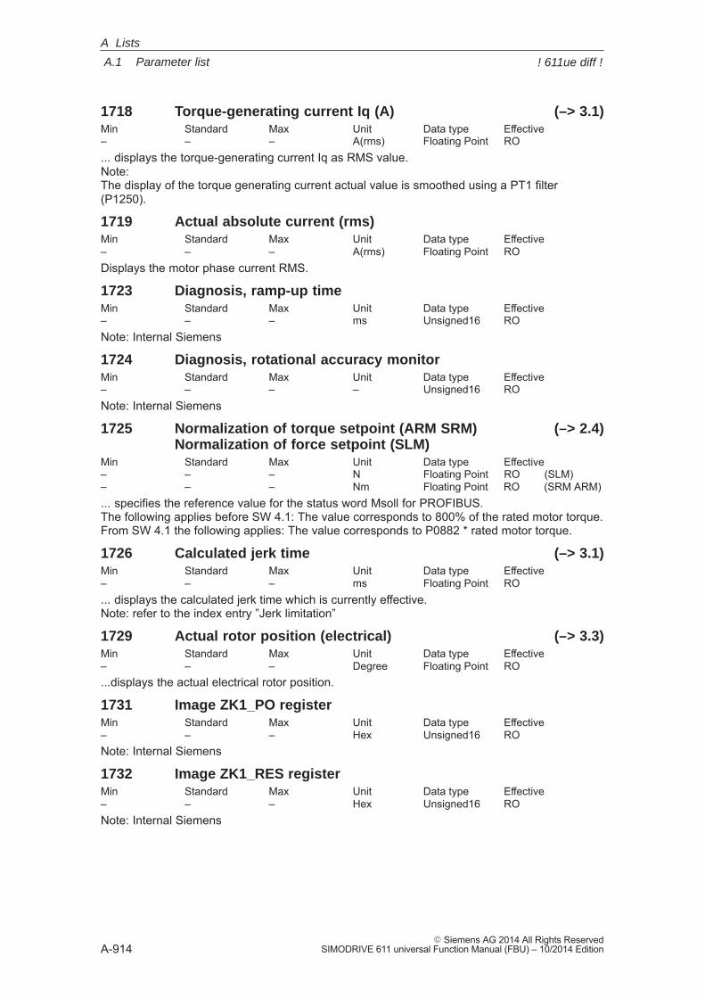
A
A.1 Parameter list
A-914� Siemens AG 2014 All Rights Reserved
SIMODRIVE 611 universal Function Manual (FBU) – 10/2014 Edition
1718 Torque-generating current Iq (A) (–> 3.1)Min Standard Max Unit Data type Effective– – – A(rms) Floating Point RO... displays the torque-generating current Iq as RMS value.Note:The display of the torque generating current actual value is smoothed using a PT1 filter(P1250).
1719 Actual absolute current (rms)Min Standard Max Unit Data type Effective– – – A(rms) Floating Point RODisplays the motor phase current RMS.
1723 Diagnosis, ramp-up timeMin Standard Max Unit Data type Effective– – – ms Unsigned16 RONote: Internal Siemens
1724 Diagnosis, rotational accuracy monitorMin Standard Max Unit Data type Effective– – – – Unsigned16 RONote: Internal Siemens
1725 Normalization of torque setpoint (ARM SRM) (–> 2.4)Normalization of force setpoint (SLM)
Min Standard Max Unit Data type Effective– – – N Floating Point RO (SLM)– – – Nm Floating Point RO (SRM ARM)... specifies the reference value for the status word Msoll for PROFIBUS.The following applies before SW 4.1: The value corresponds to 800% of the rated motor torque.From SW 4.1 the following applies: The value corresponds to P0882 * rated motor torque.
1726 Calculated jerk time (–> 3.1)Min Standard Max Unit Data type Effective– – – ms Floating Point RO... displays the calculated jerk time which is currently effective.Note: refer to the index entry ”Jerk limitation”
1729 Actual rotor position (electrical) (–> 3.3)Min Standard Max Unit Data type Effective– – – Degree Floating Point RO...displays the actual electrical rotor position.
1731 Image ZK1_PO registerMin Standard Max Unit Data type Effective– – – Hex Unsigned16 RONote: Internal Siemens
1732 Image ZK1_RES registerMin Standard Max Unit Data type Effective– – – Hex Unsigned16 RONote: Internal Siemens
A Lists
! 611ue diff !
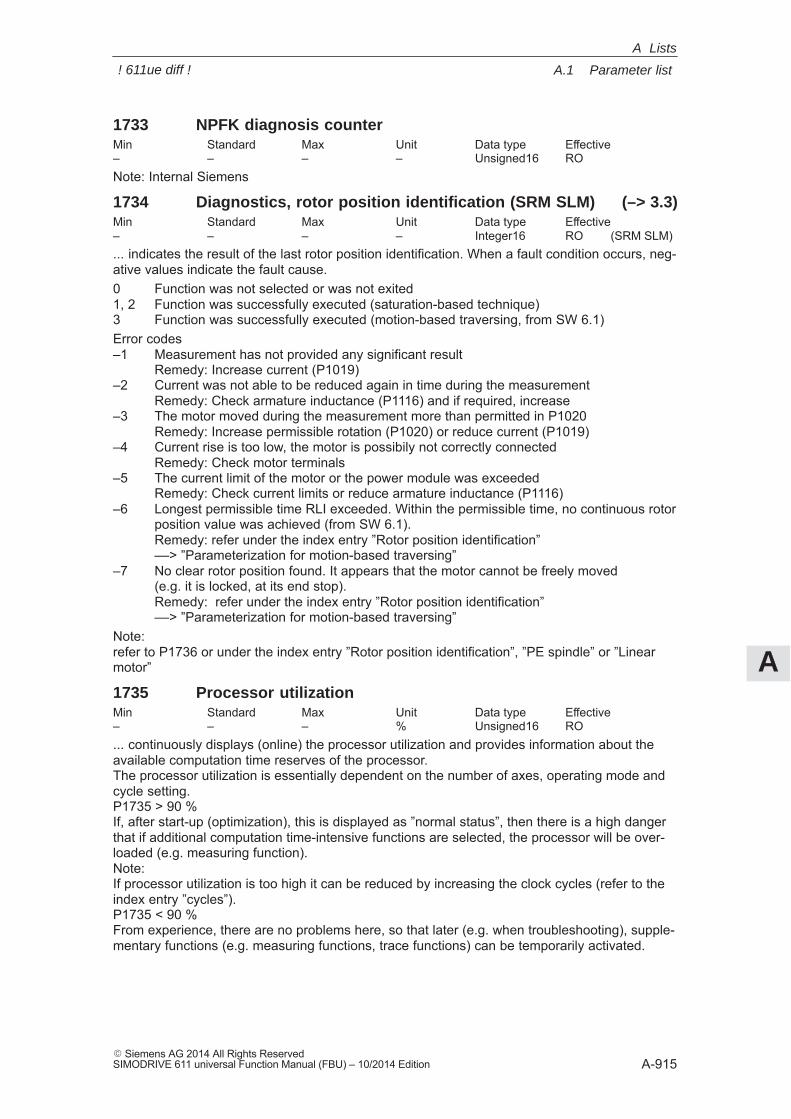
A
A.1 Parameter list
A-915� Siemens AG 2014 All Rights ReservedSIMODRIVE 611 universal Function Manual (FBU) – 10/2014 Edition
1733 NPFK diagnosis counterMin Standard Max Unit Data type Effective– – – – Unsigned16 RONote: Internal Siemens
1734 Diagnostics, rotor position identification (SRM SLM) (–> 3.3)Min Standard Max Unit Data type Effective– – – – Integer16 RO (SRM SLM)... indicates the result of the last rotor position identification. When a fault condition occurs, neg-ative values indicate the fault cause.0 Function was not selected or was not exited1, 2 Function was successfully executed (saturation-based technique)3 Function was successfully executed (motion-based traversing, from SW 6.1)Error codes–1 Measurement has not provided any significant result
Remedy: Increase current (P1019)–2 Current was not able to be reduced again in time during the measurement
Remedy: Check armature inductance (P1116) and if required, increase–3 The motor moved during the measurement more than permitted in P1020
Remedy: Increase permissible rotation (P1020) or reduce current (P1019)–4 Current rise is too low, the motor is possibily not correctly connected
Remedy: Check motor terminals–5 The current limit of the motor or the power module was exceeded
Remedy: Check current limits or reduce armature inductance (P1116)–6 Longest permissible time RLI exceeded. Within the permissible time, no continuous rotor
position value was achieved (from SW 6.1).Remedy: refer under the index entry ”Rotor position identification”––> ”Parameterization for motion-based traversing”
–7 No clear rotor position found. It appears that the motor cannot be freely moved (e.g. it is locked, at its end stop).Remedy: refer under the index entry ”Rotor position identification”––> ”Parameterization for motion-based traversing”
Note:refer to P1736 or under the index entry ”Rotor position identification”, ”PE spindle” or ”Linearmotor”
1735 Processor utilizationMin Standard Max Unit Data type Effective– – – % Unsigned16 RO... continuously displays (online) the processor utilization and provides information about theavailable computation time reserves of the processor.The processor utilization is essentially dependent on the number of axes, operating mode andcycle setting.P1735 > 90 %If, after start-up (optimization), this is displayed as ”normal status”, then there is a high dangerthat if additional computation time-intensive functions are selected, the processor will be over-loaded (e.g. measuring function).Note: If processor utilization is too high it can be reduced by increasing the clock cycles (refer to theindex entry ”cycles”).P1735 < 90 %From experience, there are no problems here, so that later (e.g. when troubleshooting), supple-mentary functions (e.g. measuring functions, trace functions) can be temporarily activated.
A Lists
! 611ue diff !
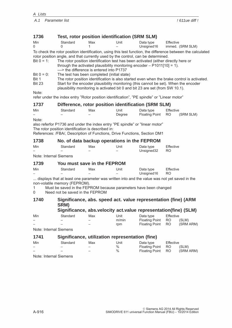
A
A.1 Parameter list
A-916� Siemens AG 2014 All Rights Reserved
SIMODRIVE 611 universal Function Manual (FBU) – 10/2014 Edition
1736 Test, rotor position identification (SRM SLM)Min Standard Max Unit Data type Effective0 0 1 – Unsigned16 immed. (SRM SLM)To check the rotor position identification, using this test function, the difference between the calculatedrotor position angle, and that currently used by the control, can be determined.Bit 0 = 1: The rotor position identification test has been activated (either directly here or
through the activated plausibility monitoring encoder – P1011[10] = 1).––> the difference is entered into P1737
Bit 0 = 0: The test has been completed (initial state)Bit 1 The rotor position identification is also started even when the brake control is activated.Bit 23 Start for the encoder plausibility monitoring (this cannot be set). When the encoder
plausibility monitoring is activated bit 0 and bit 23 are set (from SW 10.1).Note:refer under the index entry ”Rotor position identification”, ”PE spindle” or ”Linear motor”
1737 Difference, rotor position identification (SRM SLM)Min Standard Max Unit Data type Effective– – – Degree Floating Point RO (SRM SLM)Note:also referfor P1736 and under the index entry ”PE spindle” or ”linear motor”The rotor position identification is described in:References: /FBA/, Description of Functions, Drive Functions, Section DM1
1738 No. of data backup operations in the FEPROMMin Standard Max Unit Data type Effective– – – – Unsigned32 RONote: Internal Siemens
1739 You must save in the FEPROMMin Standard Max Unit Data type Effective– – – – Unsigned16 RO... displays that at least one parameter was written into and the value was not yet saved in thenon-volatile memory (FEPROM).1 Must be saved in the FEPROM because parameters have been changed0 Need not be saved in the FEPROM
1740 Significance, abs. speed act. value representation (fine) (ARMSRM)Significance, abs.velocity act.value representation(fine) (SLM)
Min Standard Max Unit Data type Effective– – – m/min Floating Point RO (SLM)– – – rpm Floating Point RO (SRM ARM)Note: Internal Siemens
1741 Significance, utilization representation (fine)Min Standard Max Unit Data type Effective– – – % Floating Point RO (SLM)– – – % Floating Point RO (SRM ARM)Note: Internal Siemens
A Lists
! 611ue diff !
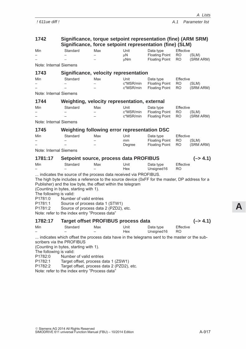
A
A.1 Parameter list
A-917� Siemens AG 2014 All Rights ReservedSIMODRIVE 611 universal Function Manual (FBU) – 10/2014 Edition
1742 Significance, torque setpoint representation (fine) (ARM SRM)Significance, force setpoint representation (fine) (SLM)
Min Standard Max Unit Data type Effective– – – μN Floating Point RO (SLM)– – – μNm Floating Point RO (SRM ARM)Note: Internal Siemens
1743 Significance, velocity representationMin Standard Max Unit Data type Effective– – – c*MSR/min Floating Point RO (SLM)– – – c*MSR/min Floating Point RO (SRM ARM)Note: Internal Siemens
1744 Weighting, velocity representation, externalMin Standard Max Unit Data type Effective– – – c*MSR/min Floating Point RO (SLM)– – – c*MSR/min Floating Point RO (SRM ARM)Note: Internal Siemens
1745 Weighting following error representation DSCMin Standard Max Unit Data type Effective– – – mm Floating Point RO (SLM)– – – Degree Floating Point RO (SRM ARM)Note: Internal Siemens
1781:17 Setpoint source, process data PROFIBUS (–> 4.1)Min Standard Max Unit Data type Effective– – – Hex Unsigned16 RO... indicates the source of the process data received via PROFIBUS.The high byte includes a reference to the source device (0xFF for the master, DP address for aPublisher) and the low byte, the offset within the telegram (Counting in bytes, starting with 1).The following is valid:P1781:0 Number of valid entriesP1781:1 Source of process data 1 (STW1)P1781:2 Source of process data 2 (PZD2), etc.Note: refer to the index entry ”Process data”
1782:17 Target offset PROFIBUS process data (–> 4.1)Min Standard Max Unit Data type Effective– – – Hex Unsigned16 RO... indicates which offset the process data have in the telegrams sent to the master or the sub-scribers via the PROFIBUS (Counting in bytes, starting with 1).The following is valid: P1782:0 Number of valid entriesP1782:1 Target offset, process data 1 (ZSW1)P1782:2 Target offset, process data 2 (PZD2), etc.Note: refer to the index entry ”Process data”
A Lists
! 611ue diff !
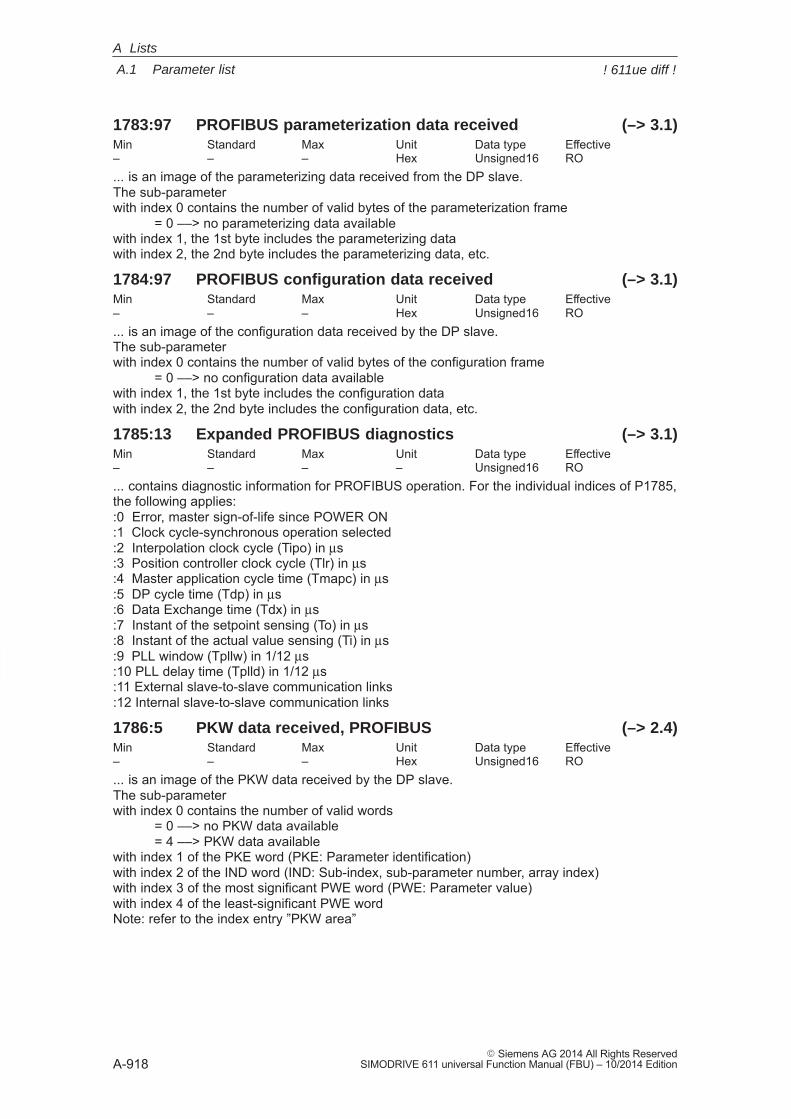
A
A.1 Parameter list
A-918� Siemens AG 2014 All Rights Reserved
SIMODRIVE 611 universal Function Manual (FBU) – 10/2014 Edition
1783:97 PROFIBUS parameterization data received (–> 3.1)Min Standard Max Unit Data type Effective– – – Hex Unsigned16 RO... is an image of the parameterizing data received from the DP slave.The sub-parameter with index 0 contains the number of valid bytes of the parameterization frame
= 0 ––> no parameterizing data availablewith index 1, the 1st byte includes the parameterizing datawith index 2, the 2nd byte includes the parameterizing data, etc.
1784:97 PROFIBUS configuration data received (–> 3.1)Min Standard Max Unit Data type Effective– – – Hex Unsigned16 RO... is an image of the configuration data received by the DP slave.The sub-parameter with index 0 contains the number of valid bytes of the configuration frame
= 0 ––> no configuration data availablewith index 1, the 1st byte includes the configuration datawith index 2, the 2nd byte includes the configuration data, etc.
1785:13 Expanded PROFIBUS diagnostics (–> 3.1)Min Standard Max Unit Data type Effective– – – – Unsigned16 RO... contains diagnostic information for PROFIBUS operation. For the individual indices of P1785,the following applies::0 Error, master sign-of-life since POWER ON:1 Clock cycle-synchronous operation selected:2 Interpolation clock cycle (Tipo) in μs:3 Position controller clock cycle (Tlr) in μs:4 Master application cycle time (Tmapc) in μs:5 DP cycle time (Tdp) in μs:6 Data Exchange time (Tdx) in μs:7 Instant of the setpoint sensing (To) in μs:8 Instant of the actual value sensing (Ti) in μs:9 PLL window (Tpllw) in 1/12 μs:10 PLL delay time (Tplld) in 1/12 μs:11 External slave-to-slave communication links:12 Internal slave-to-slave communication links
1786:5 PKW data received, PROFIBUS (–> 2.4)Min Standard Max Unit Data type Effective– – – Hex Unsigned16 RO... is an image of the PKW data received by the DP slave. The sub-parameter with index 0 contains the number of valid words
= 0 ––> no PKW data available= 4 ––> PKW data available
with index 1 of the PKE word (PKE: Parameter identification)with index 2 of the IND word (IND: Sub-index, sub-parameter number, array index) with index 3 of the most significant PWE word (PWE: Parameter value)with index 4 of the least-significant PWE wordNote: refer to the index entry ”PKW area”
A Lists
! 611ue diff !
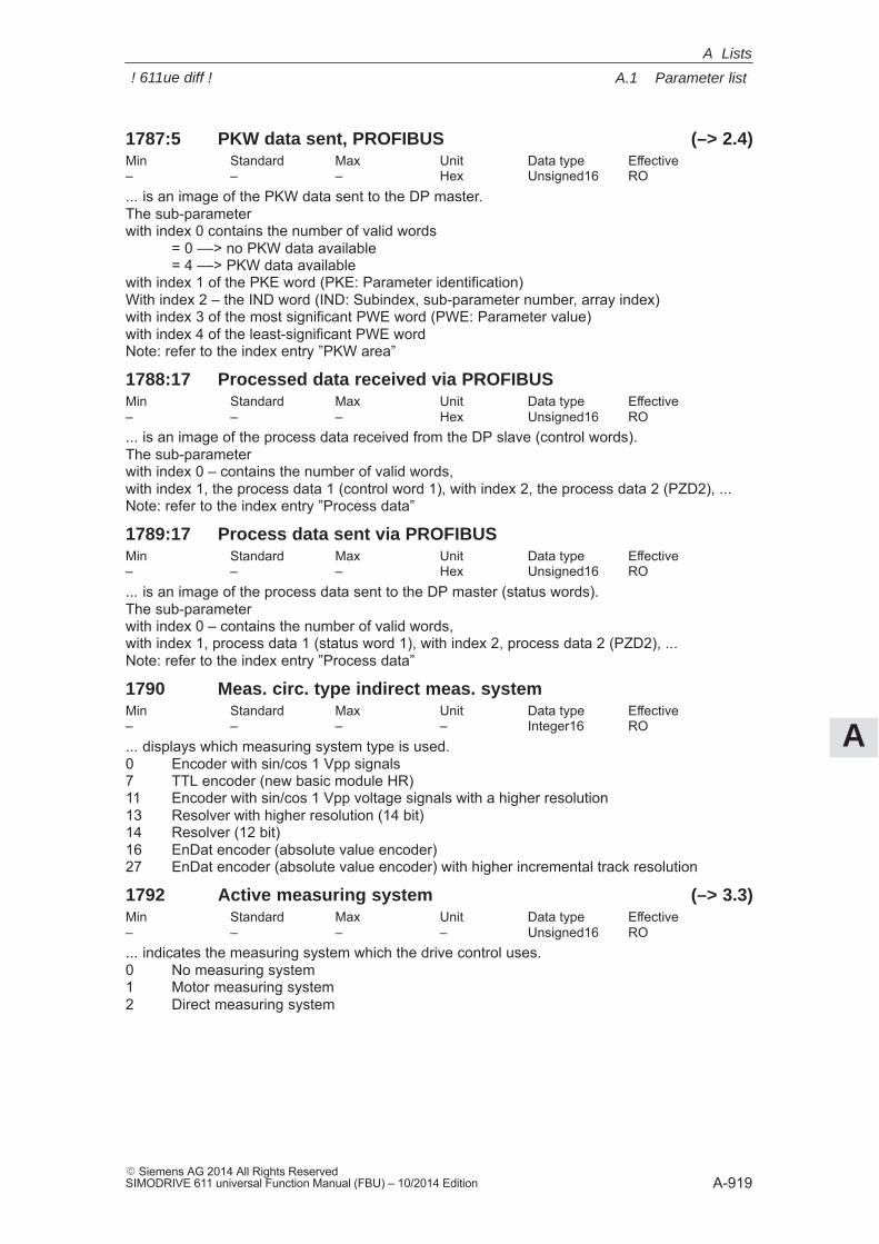
A
A.1 Parameter list
A-919� Siemens AG 2014 All Rights ReservedSIMODRIVE 611 universal Function Manual (FBU) – 10/2014 Edition
1787:5 PKW data sent, PROFIBUS (–> 2.4)Min Standard Max Unit Data type Effective– – – Hex Unsigned16 RO... is an image of the PKW data sent to the DP master.The sub-parameter with index 0 contains the number of valid words
= 0 ––> no PKW data available= 4 ––> PKW data available
with index 1 of the PKE word (PKE: Parameter identification)With index 2 – the IND word (IND: Subindex, sub-parameter number, array index)with index 3 of the most significant PWE word (PWE: Parameter value)with index 4 of the least-significant PWE wordNote: refer to the index entry ”PKW area”
1788:17 Processed data received via PROFIBUSMin Standard Max Unit Data type Effective– – – Hex Unsigned16 RO... is an image of the process data received from the DP slave (control words).The sub-parameter with index 0 – contains the number of valid words,with index 1, the process data 1 (control word 1), with index 2, the process data 2 (PZD2), ...Note: refer to the index entry ”Process data”
1789:17 Process data sent via PROFIBUSMin Standard Max Unit Data type Effective– – – Hex Unsigned16 RO... is an image of the process data sent to the DP master (status words).The sub-parameterwith index 0 – contains the number of valid words,with index 1, process data 1 (status word 1), with index 2, process data 2 (PZD2), ...Note: refer to the index entry ”Process data”
1790 Meas. circ. type indirect meas. systemMin Standard Max Unit Data type Effective– – – – Integer16 RO... displays which measuring system type is used.0 Encoder with sin/cos 1 Vpp signals7 TTL encoder (new basic module HR)11 Encoder with sin/cos 1 Vpp voltage signals with a higher resolution13 Resolver with higher resolution (14 bit)14 Resolver (12 bit)16 EnDat encoder (absolute value encoder)27 EnDat encoder (absolute value encoder) with higher incremental track resolution
1792 Active measuring system (–> 3.3)Min Standard Max Unit Data type Effective– – – – Unsigned16 RO... indicates the measuring system which the drive control uses.0 No measuring system1 Motor measuring system2 Direct measuring system
A Lists
! 611ue diff !
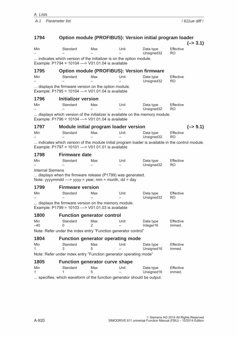
A
A.1 Parameter list
A-920� Siemens AG 2014 All Rights Reserved
SIMODRIVE 611 universal Function Manual (FBU) – 10/2014 Edition
1794 Option module (PROFIBUS): Version initial program loader(–> 3.1)
Min Standard Max Unit Data type Effective– – – – Unsigned32 RO... indicates which version of the initializer is on the option module.Example: P1794 = 10104 ––> V01.01.04 is available
1795 Option module (PROFIBUS): Version firmwareMin Standard Max Unit Data type Effective– – – – Unsigned32 RO... displays the firmware version on the option module.Example: P1795 = 10104 ––> V01.01.04 is available
1796 Initializer versionMin Standard Max Unit Data type Effective– – – – Unsigned32 RO... displays which version of the initializer is available on the memory module.Example: P1796 = 10104 ––> V01.01.04 is available
1797 Module initial program loader version (–> 9.1)Min Standard Max Unit Data type Effective– – – – Unsigned32 RO... indicates which version of the module initial program loader is available in the control module.Example: P1797 = 10101 ––> V01.01.01 is available
1798 Firmware dateMin Standard Max Unit Data type Effective– – – – Unsigned32 ROInternal Siemens... displays when the firmware release (P1799) was generated.Note: yyyymmdd ––> yyyy = year, mm = month, dd = day
1799 Firmware versionMin Standard Max Unit Data type Effective– – – – Unsigned32 RO... displays the firmware version on the memory module.Example: P1799 = 10103 ––> V01.01.03 is available
1800 Function generator controlMin Standard Max Unit Data type Effective–40 0 2 – Integer16 immed.Note: Refer under the index entry ”Function generator control”
1804 Function generator operating modeMin Standard Max Unit Data type Effective1 3 5 – Unsigned16 immed.Note: Refer under index entry ”Function generator operating mode”
1805 Function generator curve shapeMin Standard Max Unit Data type Effective1 1 5 – Unsigned16 immed.... specifies, which waveform of the function generator should be output.
A Lists
! 611ue diff !
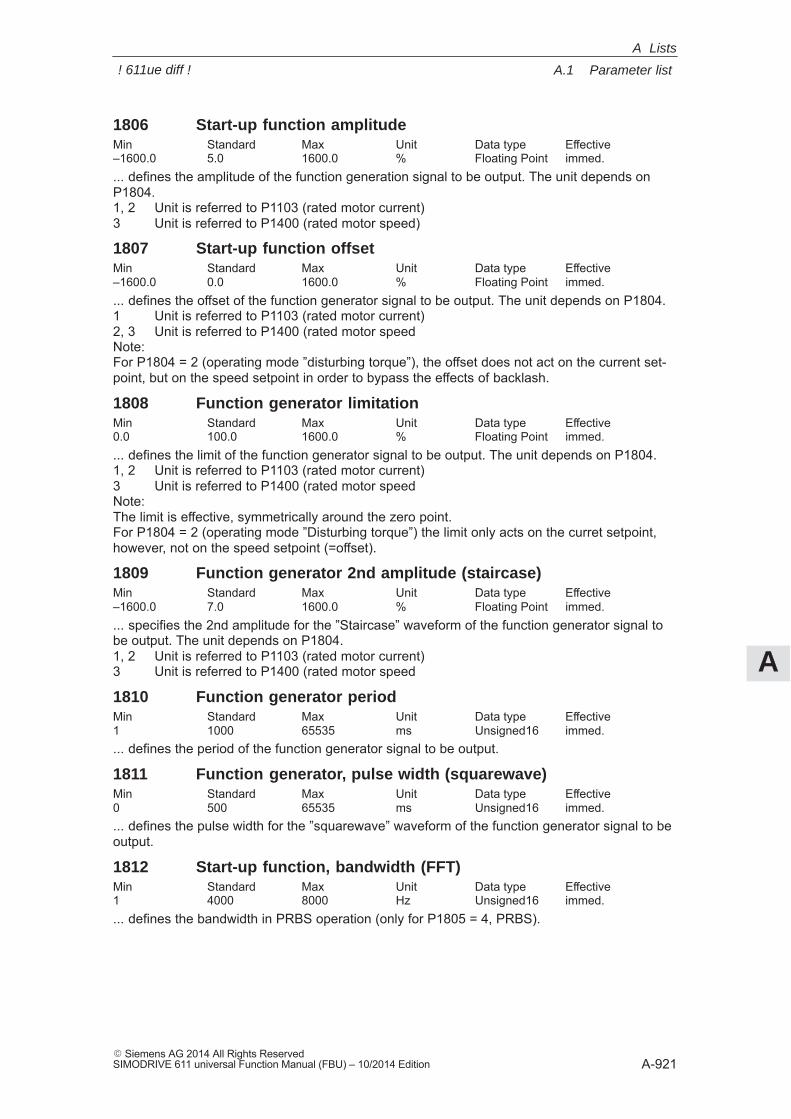
A
A.1 Parameter list
A-921� Siemens AG 2014 All Rights ReservedSIMODRIVE 611 universal Function Manual (FBU) – 10/2014 Edition
1806 Start-up function amplitudeMin Standard Max Unit Data type Effective–1600.0 5.0 1600.0 % Floating Point immed.... defines the amplitude of the function generation signal to be output. The unit depends onP1804.1, 2 Unit is referred to P1103 (rated motor current)3 Unit is referred to P1400 (rated motor speed)
1807 Start-up function offsetMin Standard Max Unit Data type Effective–1600.0 0.0 1600.0 % Floating Point immed.... defines the offset of the function generator signal to be output. The unit depends on P1804.1 Unit is referred to P1103 (rated motor current)2, 3 Unit is referred to P1400 (rated motor speedNote:For P1804 = 2 (operating mode ”disturbing torque”), the offset does not act on the current set-point, but on the speed setpoint in order to bypass the effects of backlash.
1808 Function generator limitationMin Standard Max Unit Data type Effective0.0 100.0 1600.0 % Floating Point immed.... defines the limit of the function generator signal to be output. The unit depends on P1804.1, 2 Unit is referred to P1103 (rated motor current)3 Unit is referred to P1400 (rated motor speedNote:The limit is effective, symmetrically around the zero point.For P1804 = 2 (operating mode ”Disturbing torque”) the limit only acts on the curret setpoint,however, not on the speed setpoint (=offset).
1809 Function generator 2nd amplitude (staircase)Min Standard Max Unit Data type Effective–1600.0 7.0 1600.0 % Floating Point immed.... specifies the 2nd amplitude for the ”Staircase” waveform of the function generator signal tobe output. The unit depends on P1804.1, 2 Unit is referred to P1103 (rated motor current)3 Unit is referred to P1400 (rated motor speed
1810 Function generator periodMin Standard Max Unit Data type Effective1 1000 65535 ms Unsigned16 immed.... defines the period of the function generator signal to be output.
1811 Function generator, pulse width (squarewave)Min Standard Max Unit Data type Effective0 500 65535 ms Unsigned16 immed.... defines the pulse width for the ”squarewave” waveform of the function generator signal to beoutput.
1812 Start-up function, bandwidth (FFT)Min Standard Max Unit Data type Effective1 4000 8000 Hz Unsigned16 immed.... defines the bandwidth in PRBS operation (only for P1805 = 4, PRBS).
A Lists
! 611ue diff !
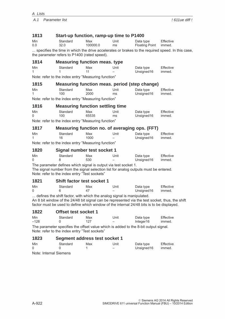
A
A.1 Parameter list
A-922� Siemens AG 2014 All Rights Reserved
SIMODRIVE 611 universal Function Manual (FBU) – 10/2014 Edition
1813 Start-up function, ramp-up time to P1400Min Standard Max Unit Data type Effective0.0 32.0 100000.0 ms Floating Point immed.... specifies the time in which the drive accelerates or brakes to the required speed. In this case,the parameter refers to P1400 (rated speed).
1814 Measuring function meas. typeMin Standard Max Unit Data type Effective1 1 11 – Unsigned16 immed.Note: refer to the index entry ”Measuring function”
1815 Measuring function meas. period (step change)Min Standard Max Unit Data type Effective1 100 2000 ms Unsigned16 immed.Note: refer to the index entry ”Measuring function”
1816 Measuring function settling timeMin Standard Max Unit Data type Effective0 100 65535 ms Unsigned16 immed.Note: refer to the index entry ”Measuring function”
1817 Measuring function no. of averaging ops. (FFT)Min Standard Max Unit Data type Effective1 16 1000 – Unsigned16 immed.Note: refer to the index entry ”Measuring function”
1820 Signal number test socket 1Min Standard Max Unit Data type Effective0 8 530 – Unsigned16 immed.The parameter defines which signal is output via test socket 1.The signal number from the signal selection list for analog outputs must be entered.Note: refer to the index entry ”Test sockets”
1821 Shift factor test socket 1Min Standard Max Unit Data type Effective0 6 47 – Unsigned16 immed.... defines the shift factor, with which the analog signal is manipulated.An 8 bit window of the 24/48 bit signal can be represented via the test socket, thus, the shiftfactor must be used to define which window of the internal 24/48 bits is to be displayed.
1822 Offset test socket 1Min Standard Max Unit Data type Effective–128 0 127 – Integer16 immed.The parameter specifies the offset value which is added to the 8-bit output signal.Note: refer to the index entry ”Test sockets”
1823 Segment address test socket 1Min Standard Max Unit Data type Effective0 0 1 – Unsigned16 immed.Note: Internal Siemens
A Lists
! 611ue diff !
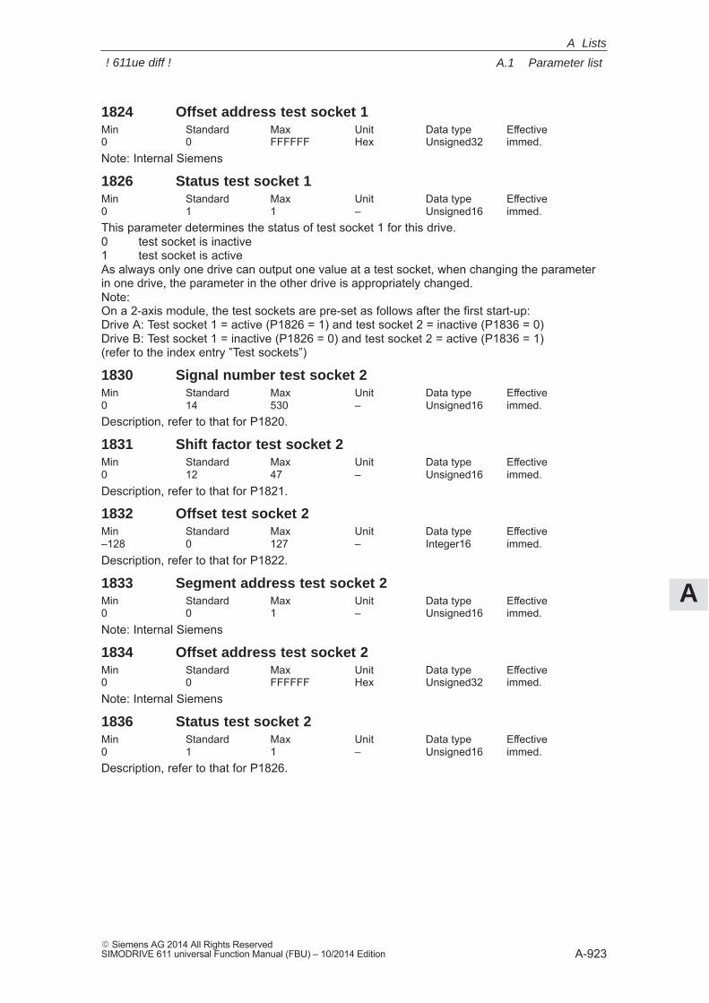
A
A.1 Parameter list
A-923� Siemens AG 2014 All Rights ReservedSIMODRIVE 611 universal Function Manual (FBU) – 10/2014 Edition
1824 Offset address test socket 1Min Standard Max Unit Data type Effective0 0 FFFFFF Hex Unsigned32 immed.Note: Internal Siemens
1826 Status test socket 1Min Standard Max Unit Data type Effective0 1 1 – Unsigned16 immed.This parameter determines the status of test socket 1 for this drive.0 test socket is inactive1 test socket is activeAs always only one drive can output one value at a test socket, when changing the parameterin one drive, the parameter in the other drive is appropriately changed.Note: On a 2-axis module, the test sockets are pre-set as follows after the first start-up:Drive A: Test socket 1 = active (P1826 = 1) and test socket 2 = inactive (P1836 = 0)Drive B: Test socket 1 = inactive (P1826 = 0) and test socket 2 = active (P1836 = 1)(refer to the index entry ”Test sockets”)
1830 Signal number test socket 2Min Standard Max Unit Data type Effective0 14 530 – Unsigned16 immed.Description, refer to that for P1820.
1831 Shift factor test socket 2Min Standard Max Unit Data type Effective0 12 47 – Unsigned16 immed.Description, refer to that for P1821.
1832 Offset test socket 2Min Standard Max Unit Data type Effective–128 0 127 – Integer16 immed.Description, refer to that for P1822.
1833 Segment address test socket 2Min Standard Max Unit Data type Effective0 0 1 – Unsigned16 immed.Note: Internal Siemens
1834 Offset address test socket 2Min Standard Max Unit Data type Effective0 0 FFFFFF Hex Unsigned32 immed.Note: Internal Siemens
1836 Status test socket 2Min Standard Max Unit Data type Effective0 1 1 – Unsigned16 immed.Description, refer to that for P1826.
A Lists
! 611ue diff !
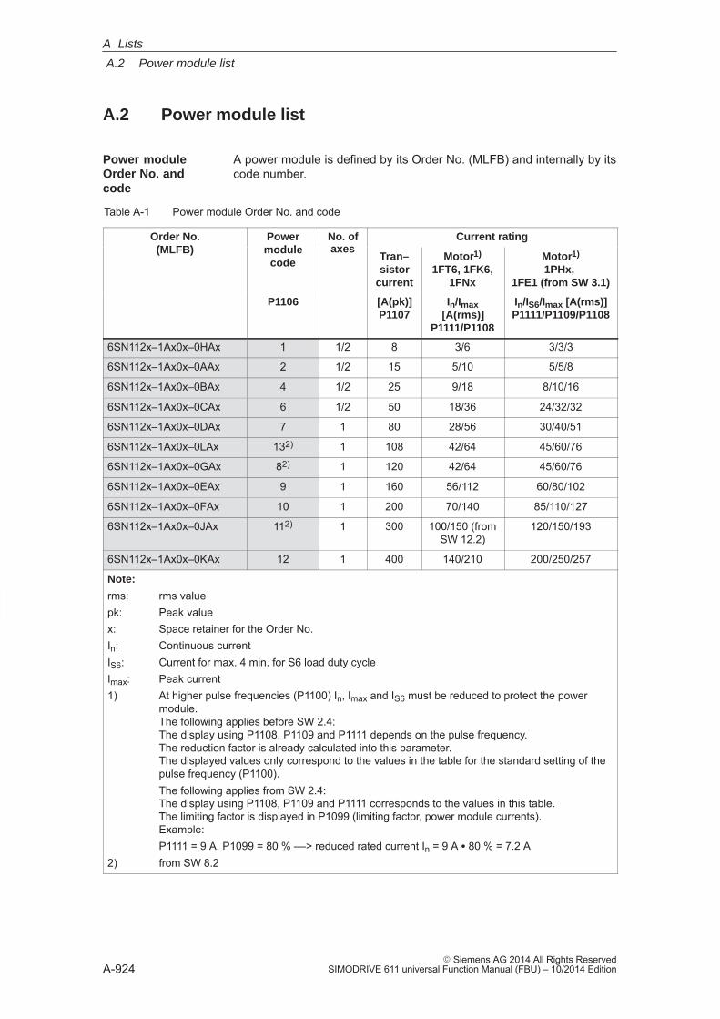
A
A.2 Power module list
A-924� Siemens AG 2014 All Rights Reserved
SIMODRIVE 611 universal Function Manual (FBU) – 10/2014 Edition
A.2 Power module list
A power module is defined by its Order No. (MLFB) and internally by itscode number.
Table A-1 Power module Order No. and code
Order No.(MLFB)
Powermodule
No. ofaxes
Current rating(MLFB) module
codeaxes
Tran–sistor
current
Motor1)
1FT6, 1FK6,1FNx
Motor1)
1PHx, 1FE1 (from SW 3.1)
P1106 [A(pk)]P1107
In/Imax[A(rms)]
P1111/P1108
In/IS6/Imax [A(rms)]P1111/P1109/P1108
6SN112x–1Ax0x–0HAx 1 1/2 8 3/6 3/3/3
6SN112x–1Ax0x–0AAx 2 1/2 15 5/10 5/5/8
6SN112x–1Ax0x–0BAx 4 1/2 25 9/18 8/10/16
6SN112x–1Ax0x–0CAx 6 1/2 50 18/36 24/32/32
6SN112x–1Ax0x–0DAx 7 1 80 28/56 30/40/51
6SN112x–1Ax0x–0LAx 132) 1 108 42/64 45/60/76
6SN112x–1Ax0x–0GAx 82) 1 120 42/64 45/60/76
6SN112x–1Ax0x–0EAx 9 1 160 56/112 60/80/102
6SN112x–1Ax0x–0FAx 10 1 200 70/140 85/110/127
6SN112x–1Ax0x–0JAx 112) 1 300 100/150 (fromSW 12.2)
120/150/193
6SN112x–1Ax0x–0KAx 12 1 400 140/210 200/250/257
Note:
rms: rms valuepk: Peak valuex: Space retainer for the Order No.In: Continuous currentIS6: Current for max. 4 min. for S6 load duty cycleImax: Peak current1) At higher pulse frequencies (P1100) In, Imax and IS6 must be reduced to protect the power
module.The following applies before SW 2.4:The display using P1108, P1109 and P1111 depends on the pulse frequency. The reduction factor is already calculated into this parameter.The displayed values only correspond to the values in the table for the standard setting of thepulse frequency (P1100).The following applies from SW 2.4:The display using P1108, P1109 and P1111 corresponds to the values in this table.The limiting factor is displayed in P1099 (limiting factor, power module currents).Example:P1111 = 9 A, P1099 = 80 % ––> reduced rated current In = 9 A � 80 % = 7.2 A
2) from SW 8.2
Power moduleOrder No. andcode
A Lists
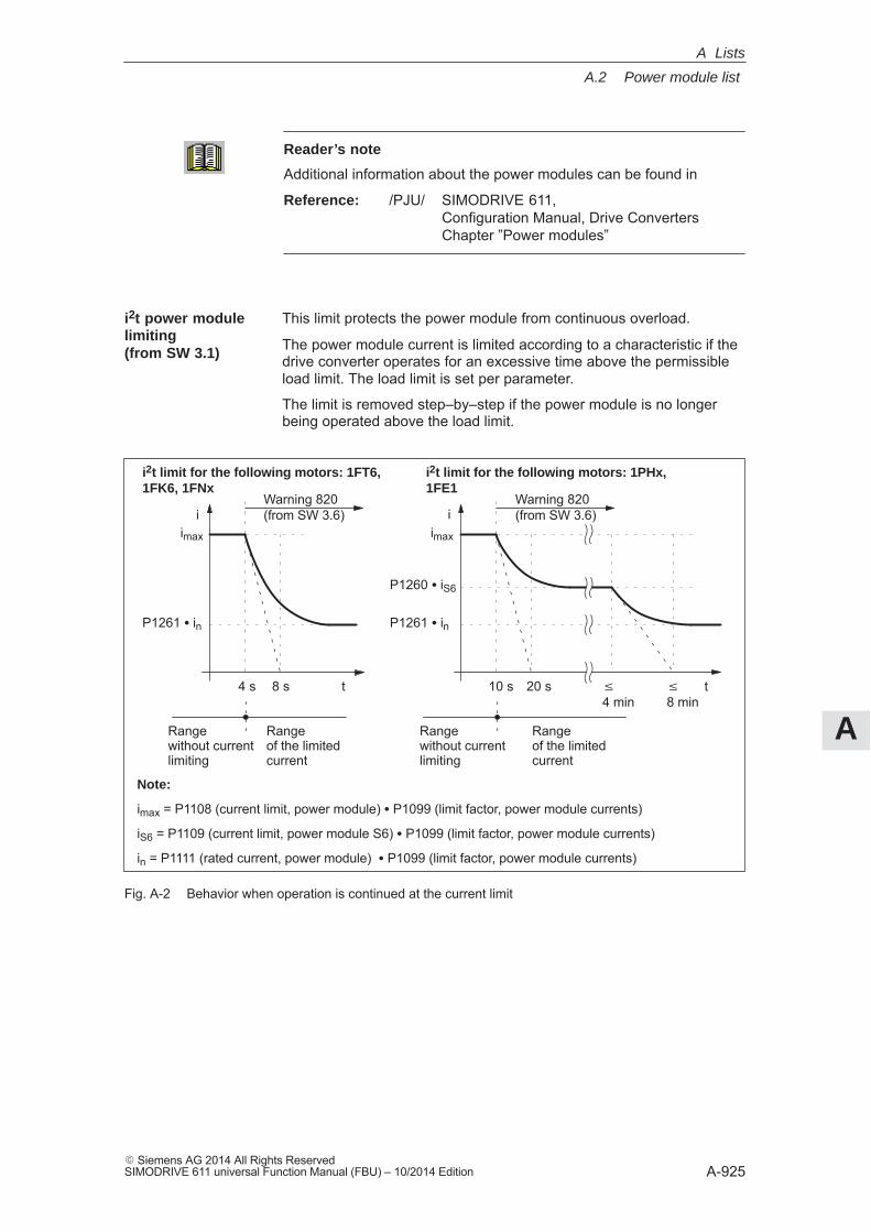
A
A.2 Power module list
A-925� Siemens AG 2014 All Rights ReservedSIMODRIVE 611 universal Function Manual (FBU) – 10/2014 Edition
Reader’s note
Additional information about the power modules can be found in
Reference: /PJU/ SIMODRIVE 611, Configuration Manual, Drive ConvertersChapter ”Power modules”
This limit protects the power module from continuous overload.
The power module current is limited according to a characteristic if thedrive converter operates for an excessive time above the permissibleload limit. The load limit is set per parameter.
The limit is removed step–by–step if the power module is no longerbeing operated above the load limit.
imax
P1260 � iS6
P1261 � in
t10 s 20 s
i
t4 s 8 s
i
i2t limit for the following motors: 1FT6,1FK6, 1FNx
i2t limit for the following motors: 1PHx,1FE1
Rangewithout currentlimiting
Rangeof the limitedcurrent
Rangewithout currentlimiting
Rangeof the limitedcurrent
P1261 � in
imax
� 4 min
� 8 min
Note:
imax = P1108 (current limit, power module) � P1099 (limit factor, power module currents)
iS6 = P1109 (current limit, power module S6) � P1099 (limit factor, power module currents)
in = P1111 (rated current, power module) � P1099 (limit factor, power module currents)
Warning 820(from SW 3.6)
Warning 820(from SW 3.6)
Fig. A-2 Behavior when operation is continued at the current limit
i2t power modulelimiting(from SW 3.1)
A Lists
A
A.2 Power module list
A-926� Siemens AG 2014 All Rights Reserved
SIMODRIVE 611 universal Function Manual (FBU) – 10/2014 Edition
The following signals are available for the ”i2t power module limit” func-tion:
� Output terminal signal ––> function number 37 (power module current not limited)
� PROFIBUS status signal ––> MeldW.10 (power module current not limited)
The following parameters are available for the ”i2t power module limit-ing” function:
� Parameters which have to be set:
– P1260 i2t limiting, limit current power module S6
– P1261 i2t limiting, rated power module current
These parameters are preset to protect the power module. Itmay be possible to protect the motor against continuous over-load by reducing the parameter values.
� Parameters used for diagnostics:
– P1262 i2t time in limiting
– P1263 actual i2t limit factor
– P1264 i2t actual utilization factor (from SW 4.1)
Interrelationship between parameters:
P1262 Constant Running
P1263 100 % <100 %
P1264 <100 % 100 %
––> Limiting? No Yes
Output signals(refer to Chapter 6.4.5 and 6.4.6)
Parameteroverview(refer to ChapterA.1)
A Lists
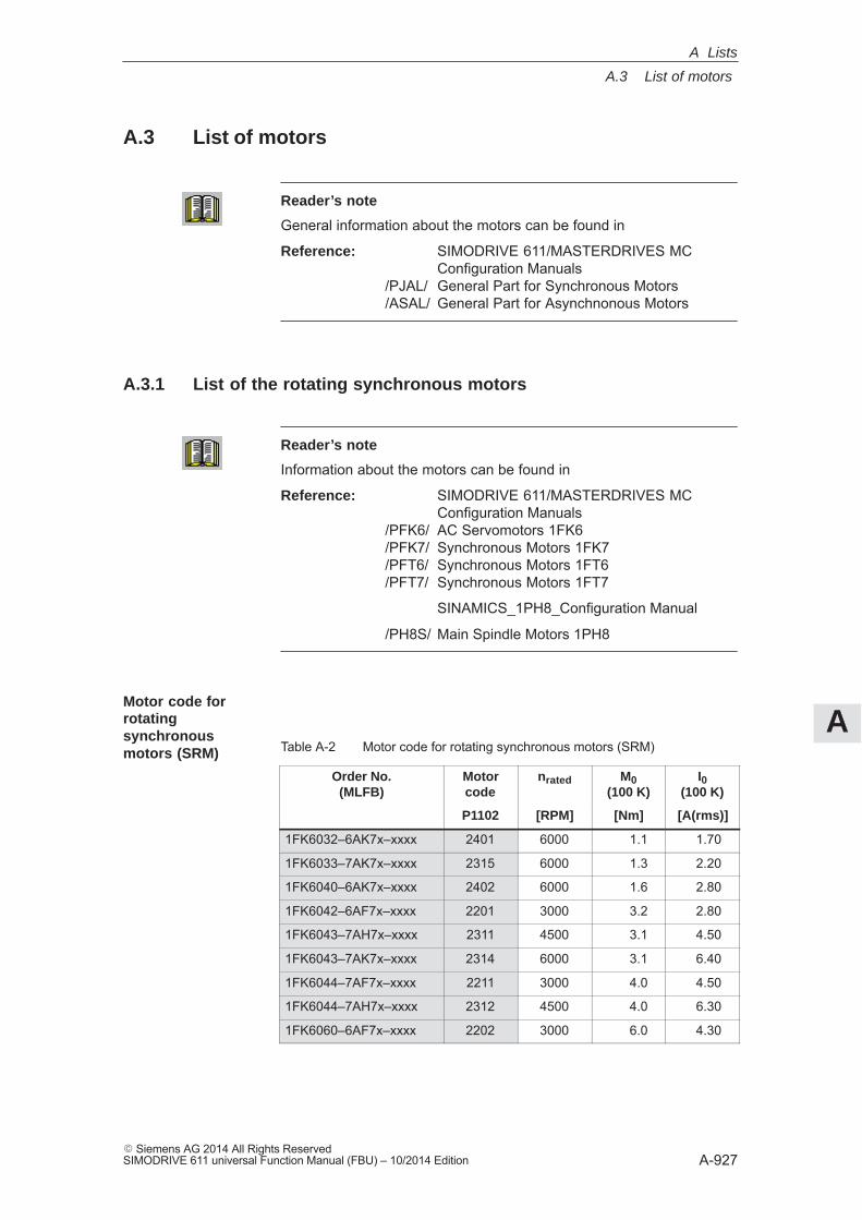
A
A.3 List of motors
A-927� Siemens AG 2014 All Rights ReservedSIMODRIVE 611 universal Function Manual (FBU) – 10/2014 Edition
A.3 List of motors
Reader’s note
General information about the motors can be found in
Reference: SIMODRIVE 611/MASTERDRIVES MC Configuration Manuals
/PJAL/ General Part for Synchronous Motors/ASAL/ General Part for Asynchnonous Motors
A.3.1 List of the rotating synchronous motors
Reader’s note
Information about the motors can be found in
Reference: SIMODRIVE 611/MASTERDRIVES MC Configuration Manuals
/PFK6/ AC Servomotors 1FK6/PFK7/ Synchronous Motors 1FK7/PFT6/ Synchronous Motors 1FT6/PFT7/ Synchronous Motors 1FT7
SINAMICS_1PH8_Configuration Manual
/PH8S/ Main Spindle Motors 1PH8
Table A-2 Motor code for rotating synchronous motors (SRM)
Order No.(MLFB)
Motorcode
nrated M0(100 K)
I0(100 K)
P1102 [RPM] [Nm] [A(rms)]
1FK6032–6AK7x–xxxx 2401 6000 1.1 1.70
1FK6033–7AK7x–xxxx 2315 6000 1.3 2.20
1FK6040–6AK7x–xxxx 2402 6000 1.6 2.80
1FK6042–6AF7x–xxxx 2201 3000 3.2 2.80
1FK6043–7AH7x–xxxx 2311 4500 3.1 4.50
1FK6043–7AK7x–xxxx 2314 6000 3.1 6.40
1FK6044–7AF7x–xxxx 2211 3000 4.0 4.50
1FK6044–7AH7x–xxxx 2312 4500 4.0 6.30
1FK6060–6AF7x–xxxx 2202 3000 6.0 4.30
Motor code forrotatingsynchronousmotors (SRM)
A Lists
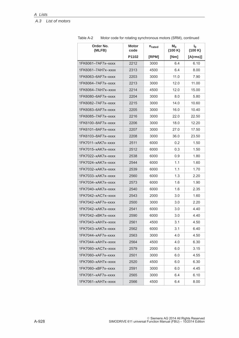
A
A.3 List of motors
A-928� Siemens AG 2014 All Rights Reserved
SIMODRIVE 611 universal Function Manual (FBU) – 10/2014 Edition
Table A-2 Motor code for rotating synchronous motors (SRM), continued
Order No.(MLFB)
I0(100 K)
M0(100 K)
nratedMotorcode
[A(rms)][Nm][RPM]P1102
1FK6061–7AF7x–xxxx 2212 3000 6.4 6.10
1FK6061–7AH7x–xxxx 2313 4500 6.4 8.00
1FK6063–6AF7x–xxxx 2203 3000 11.0 7.90
1FK6064–7AF7x–xxxx 2213 3000 12.0 11.00
1FK6064–7AH7x–xxxx 2214 4500 12.0 15.00
1FK6080–6AF7x–xxxx 2204 3000 8.0 5.80
1FK6082–7AF7x–xxxx 2215 3000 14.0 10.60
1FK6083–6AF7x–xxxx 2205 3000 16.0 10.40
1FK6085–7AF7x–xxxx 2216 3000 22.0 22.50
1FK6100–8AF7x–xxxx 2206 3000 18.0 12.20
1FK6101–8AF7x–xxxx 2207 3000 27.0 17.50
1FK6103–8AF7x–xxxx 2208 3000 36.0 23.50
1FK7011–xAK7x–xxxx 2511 6000 0.2 1.50
1FK7015–xAK7x–xxxx 2512 6000 0.3 1.50
1FK7022–xAK7x–xxxx 2538 6000 0.9 1.80
1FK7024–xAK7x–xxxx 2544 6000 1.1 1.60
1FK7032–xAK7x–xxxx 2539 6000 1.1 1.70
1FK7033–xAK7x–xxxx 2560 6000 1.3 2.20
1FK7034–xAK7x–xxxx 2573 6000 1.6 1.90
1FK7040–xAK7x–xxxx 2540 6000 1.6 2.35
1FK7042–xAC7x–xxxx 2543 2000 3.0 1.60
1FK7042–xAF7x–xxxx 2500 3000 3.0 2.20
1FK7042–xAK7x–xxxx 2541 6000 3.0 4.40
1FK7042–xBK7x–xxxx 2590 6000 3.0 4.40
1FK7043–xAH7x–xxxx 2561 4500 3.1 4.50
1FK7043–xAK7x–xxxx 2562 6000 3.1 6.40
1FK7044–xAF7x–xxxx 2563 3000 4.0 4.50
1FK7044–xAH7x–xxxx 2564 4500 4.0 6.30
1FK7060–xAC7x–xxxx 2579 2000 6.0 3.15
1FK7060–xAF7x–xxxx 2501 3000 6.0 4.55
1FK7060–xAH7x–xxxx 2520 4500 6.0 6.30
1FK7060–xBF7x–xxxx 2591 3000 6.0 4.45
1FK7061–xAF7x–xxxx 2565 3000 6.4 6.10
1FK7061–xAH7x–xxxx 2566 4500 6.4 8.00
A Lists
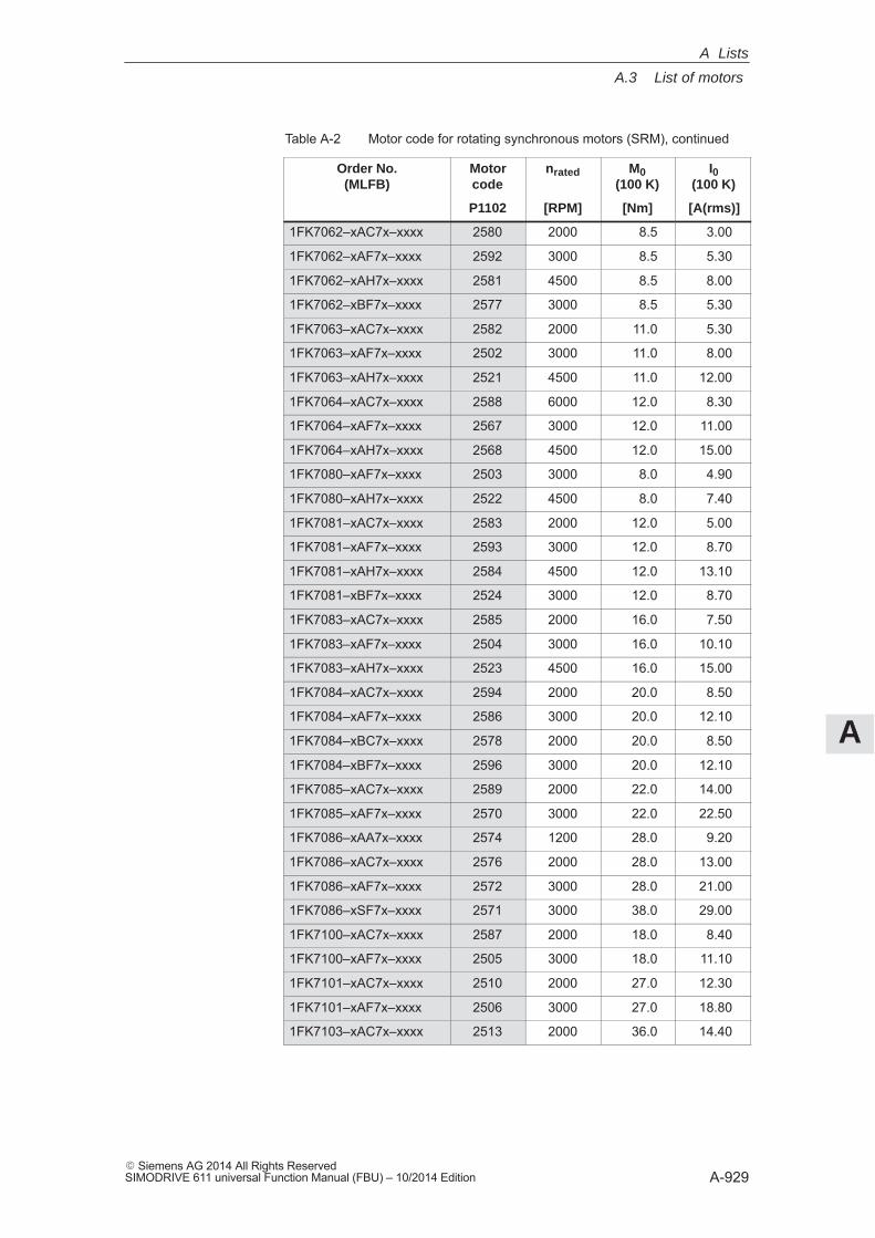
A
A.3 List of motors
A-929� Siemens AG 2014 All Rights ReservedSIMODRIVE 611 universal Function Manual (FBU) – 10/2014 Edition
Table A-2 Motor code for rotating synchronous motors (SRM), continued
Order No.(MLFB)
I0(100 K)
M0(100 K)
nratedMotorcode
[A(rms)][Nm][RPM]P1102
1FK7062–xAC7x–xxxx 2580 2000 8.5 3.00
1FK7062–xAF7x–xxxx 2592 3000 8.5 5.30
1FK7062–xAH7x–xxxx 2581 4500 8.5 8.00
1FK7062–xBF7x–xxxx 2577 3000 8.5 5.30
1FK7063–xAC7x–xxxx 2582 2000 11.0 5.30
1FK7063–xAF7x–xxxx 2502 3000 11.0 8.00
1FK7063–xAH7x–xxxx 2521 4500 11.0 12.00
1FK7064–xAC7x–xxxx 2588 6000 12.0 8.30
1FK7064–xAF7x–xxxx 2567 3000 12.0 11.00
1FK7064–xAH7x–xxxx 2568 4500 12.0 15.00
1FK7080–xAF7x–xxxx 2503 3000 8.0 4.90
1FK7080–xAH7x–xxxx 2522 4500 8.0 7.40
1FK7081–xAC7x–xxxx 2583 2000 12.0 5.00
1FK7081–xAF7x–xxxx 2593 3000 12.0 8.70
1FK7081–xAH7x–xxxx 2584 4500 12.0 13.10
1FK7081–xBF7x–xxxx 2524 3000 12.0 8.70
1FK7083–xAC7x–xxxx 2585 2000 16.0 7.50
1FK7083–xAF7x–xxxx 2504 3000 16.0 10.10
1FK7083–xAH7x–xxxx 2523 4500 16.0 15.00
1FK7084–xAC7x–xxxx 2594 2000 20.0 8.50
1FK7084–xAF7x–xxxx 2586 3000 20.0 12.10
1FK7084–xBC7x–xxxx 2578 2000 20.0 8.50
1FK7084–xBF7x–xxxx 2596 3000 20.0 12.10
1FK7085–xAC7x–xxxx 2589 2000 22.0 14.00
1FK7085–xAF7x–xxxx 2570 3000 22.0 22.50
1FK7086–xAA7x–xxxx 2574 1200 28.0 9.20
1FK7086–xAC7x–xxxx 2576 2000 28.0 13.00
1FK7086–xAF7x–xxxx 2572 3000 28.0 21.00
1FK7086–xSF7x–xxxx 2571 3000 38.0 29.00
1FK7100–xAC7x–xxxx 2587 2000 18.0 8.40
1FK7100–xAF7x–xxxx 2505 3000 18.0 11.10
1FK7101–xAC7x–xxxx 2510 2000 27.0 12.30
1FK7101–xAF7x–xxxx 2506 3000 27.0 18.80
1FK7103–xAC7x–xxxx 2513 2000 36.0 14.40
A Lists
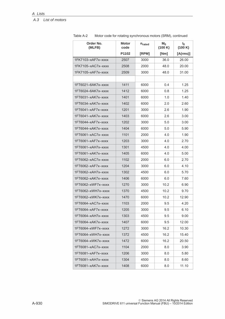
A
A.3 List of motors
A-930� Siemens AG 2014 All Rights Reserved
SIMODRIVE 611 universal Function Manual (FBU) – 10/2014 Edition
Table A-2 Motor code for rotating synchronous motors (SRM), continued
Order No.(MLFB)
I0(100 K)
M0(100 K)
nratedMotorcode
[A(rms)][Nm][RPM]P1102
1FK7103–xAF7x–xxxx 2507 3000 36.0 26.00
1FK7105–xAC7x–xxxx 2508 2000 48.0 20.00
1FK7105–xAF7x–xxxx 2509 3000 48.0 31.00
1FT6021–6AK7x–xxxx 1411 6000 0.4 1.25
1FT6024–6AK7x–xxxx 1412 6000 0.8 1.25
1FT6031–xAK7x–xxxx 1401 6000 1.0 1.40
1FT6034–xAK7x–xxxx 1402 6000 2.0 2.60
1FT6041–xAF7x–xxxx 1201 3000 2.6 1.90
1FT6041–xAK7x–xxxx 1403 6000 2.6 3.00
1FT6044–xAF7x–xxxx 1202 3000 5.0 3.00
1FT6044–xAK7x–xxxx 1404 6000 5.0 5.90
1FT6061–xAC7x–xxxx 1101 2000 4.0 1.90
1FT6061–xAF7x–xxxx 1203 3000 4.0 2.70
1FT6061–xAH7x–xxxx 1301 4500 4.0 4.00
1FT6061–xAK7x–xxxx 1405 6000 4.0 5.00
1FT6062–xAC7x–xxxx 1102 2000 6.0 2.70
1FT6062–xAF7x–xxxx 1204 3000 6.0 4.10
1FT6062–xAH7x–xxxx 1302 4500 6.0 5.70
1FT6062–xAK7x–xxxx 1406 6000 6.0 7.60
1FT6062–xWF7x–xxxx 1270 3000 10.2 6.90
1FT6062–xWH7x–xxxx 1370 4500 10.2 9.70
1FT6062–xWK7x–xxxx 1470 6000 10.2 12.90
1FT6064–xAC7x–xxxx 1103 2000 9.5 4.20
1FT6064–xAF7x–xxxx 1205 3000 9.5 6.10
1FT6064–xAH7x–xxxx 1303 4500 9.5 9.00
1FT6064–xAK7x–xxxx 1407 6000 9.5 12.00
1FT6064–xWF7x–xxxx 1272 3000 16.2 10.30
1FT6064–xWH7x–xxxx 1372 4500 16.2 15.40
1FT6064–xWK7x–xxxx 1472 6000 16.2 20.50
1FT6081–xAC7x–xxxx 1104 2000 8.0 3.90
1FT6081–xAF7x–xxxx 1206 3000 8.0 5.80
1FT6081–xAH7x–xxxx 1304 4500 8.0 8.60
1FT6081–xAK7x–xxxx 1408 6000 8.0 11.10
A Lists
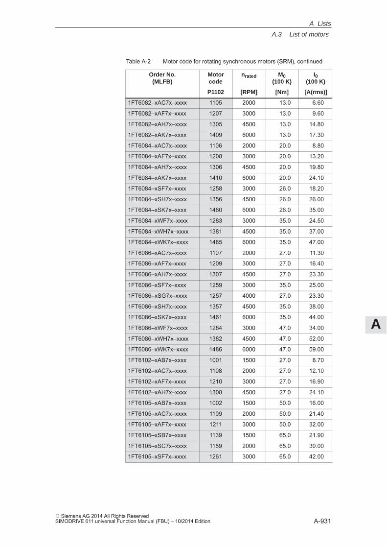
A
A.3 List of motors
A-931� Siemens AG 2014 All Rights ReservedSIMODRIVE 611 universal Function Manual (FBU) – 10/2014 Edition
Table A-2 Motor code for rotating synchronous motors (SRM), continued
Order No.(MLFB)
I0(100 K)
M0(100 K)
nratedMotorcode
[A(rms)][Nm][RPM]P1102
1FT6082–xAC7x–xxxx 1105 2000 13.0 6.60
1FT6082–xAF7x–xxxx 1207 3000 13.0 9.60
1FT6082–xAH7x–xxxx 1305 4500 13.0 14.80
1FT6082–xAK7x–xxxx 1409 6000 13.0 17.30
1FT6084–xAC7x–xxxx 1106 2000 20.0 8.80
1FT6084–xAF7x–xxxx 1208 3000 20.0 13.20
1FT6084–xAH7x–xxxx 1306 4500 20.0 19.80
1FT6084–xAK7x–xxxx 1410 6000 20.0 24.10
1FT6084–xSF7x–xxxx 1258 3000 26.0 18.20
1FT6084–xSH7x–xxxx 1356 4500 26.0 26.00
1FT6084–xSK7x–xxxx 1460 6000 26.0 35.00
1FT6084–xWF7x–xxxx 1283 3000 35.0 24.50
1FT6084–xWH7x–xxxx 1381 4500 35.0 37.00
1FT6084–xWK7x–xxxx 1485 6000 35.0 47.00
1FT6086–xAC7x–xxxx 1107 2000 27.0 11.30
1FT6086–xAF7x–xxxx 1209 3000 27.0 16.40
1FT6086–xAH7x–xxxx 1307 4500 27.0 23.30
1FT6086–xSF7x–xxxx 1259 3000 35.0 25.00
1FT6086–xSG7x–xxxx 1257 4000 27.0 23.30
1FT6086–xSH7x–xxxx 1357 4500 35.0 38.00
1FT6086–xSK7x–xxxx 1461 6000 35.0 44.00
1FT6086–xWF7x–xxxx 1284 3000 47.0 34.00
1FT6086–xWH7x–xxxx 1382 4500 47.0 52.00
1FT6086–xWK7x–xxxx 1486 6000 47.0 59.00
1FT6102–xAB7x–xxxx 1001 1500 27.0 8.70
1FT6102–xAC7x–xxxx 1108 2000 27.0 12.10
1FT6102–xAF7x–xxxx 1210 3000 27.0 16.90
1FT6102–xAH7x–xxxx 1308 4500 27.0 24.10
1FT6105–xAB7x–xxxx 1002 1500 50.0 16.00
1FT6105–xAC7x–xxxx 1109 2000 50.0 21.40
1FT6105–xAF7x–xxxx 1211 3000 50.0 32.00
1FT6105–xSB7x–xxxx 1139 1500 65.0 21.90
1FT6105–xSC7x–xxxx 1159 2000 65.0 30.00
1FT6105–xSF7x–xxxx 1261 3000 65.0 42.00
A Lists
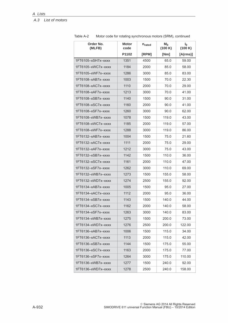
A
A.3 List of motors
A-932� Siemens AG 2014 All Rights Reserved
SIMODRIVE 611 universal Function Manual (FBU) – 10/2014 Edition
Table A-2 Motor code for rotating synchronous motors (SRM), continued
Order No.(MLFB)
I0(100 K)
M0(100 K)
nratedMotorcode
[A(rms)][Nm][RPM]P1102
1FT6105–xSH7x–xxxx 1351 4500 65.0 59.00
1FT6105–xWC7x–xxxx 1184 2000 85.0 58.00
1FT6105–xWF7x–xxxx 1286 3000 85.0 83.00
1FT6108–xAB7x–xxxx 1003 1500 70.0 22.30
1FT6108–xAC7x–xxxx 1110 2000 70.0 29.00
1FT6108–xAF7x–xxxx 1213 3000 70.0 41.00
1FT6108–xSB7x–xxxx 1140 1500 90.0 31.00
1FT6108–xSC7x–xxxx 1160 2000 90.0 41.00
1FT6108–xSF7x–xxxx 1260 3000 90.0 62.00
1FT6108–xWB7x–xxxx 1078 1500 119.0 43.00
1FT6108–xWC7x–xxxx 1185 2000 119.0 57.00
1FT6108–xWF7x–xxxx 1288 3000 119.0 86.00
1FT6132–xAB7x–xxxx 1004 1500 75.0 21.60
1FT6132–xAC7x–xxxx 1111 2000 75.0 29.00
1FT6132–xAF7x–xxxx 1212 3000 75.0 43.00
1FT6132–xSB7x–xxxx 1142 1500 110.0 36.00
1FT6132–xSC7x–xxxx 1161 2000 110.0 47.00
1FT6132–xSF7x–xxxx 1262 3000 110.0 69.00
1FT6132–xWB7x–xxxx 1273 1500 155.0 58.00
1FT6132–xWD7x–xxxx 1274 2500 155.0 92.00
1FT6134–xAB7x–xxxx 1005 1500 95.0 27.00
1FT6134–xAC7x–xxxx 1112 2000 95.0 36.00
1FT6134–xSB7x–xxxx 1143 1500 140.0 44.00
1FT6134–xSC7x–xxxx 1162 2000 140.0 58.00
1FT6134–xSF7x–xxxx 1263 3000 140.0 83.00
1FT6134–xWB7x–xxxx 1275 1500 200.0 73.00
1FT6134–xWD7x–xxxx 1276 2500 200.0 122.00
1FT6136–xAB7x–xxxx 1006 1500 115.0 34.00
1FT6136–xAC7x–xxxx 1113 2000 115.0 42.00
1FT6136–xSB7x–xxxx 1144 1500 175.0 55.00
1FT6136–xSC7x–xxxx 1163 2000 175.0 77.00
1FT6136–xSF7x–xxxx 1264 3000 175.0 110.00
1FT6136–xWB7x–xxxx 1277 1500 240.0 92.00
1FT6136–xWD7x–xxxx 1278 2500 240.0 158.00
A Lists
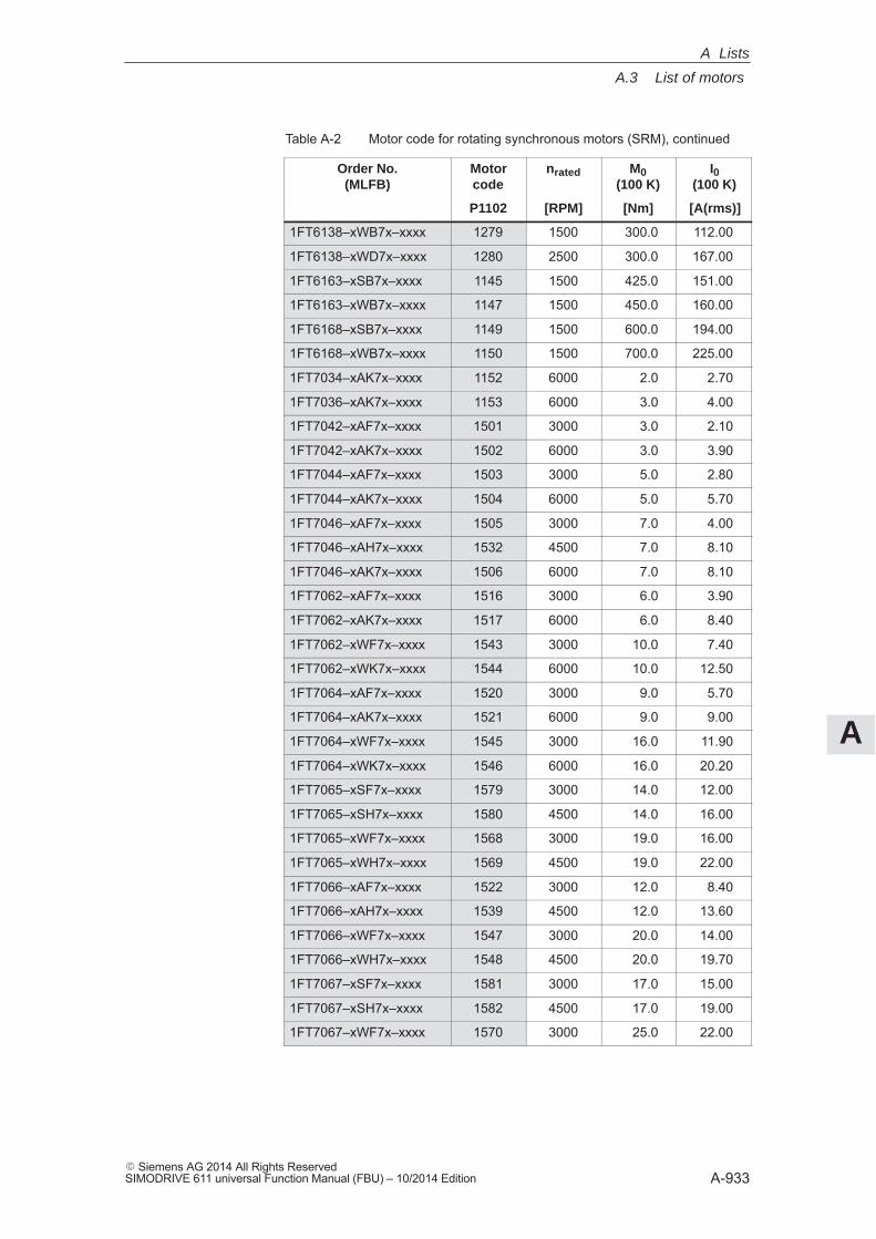
A
A.3 List of motors
A-933� Siemens AG 2014 All Rights ReservedSIMODRIVE 611 universal Function Manual (FBU) – 10/2014 Edition
Table A-2 Motor code for rotating synchronous motors (SRM), continued
Order No.(MLFB)
I0(100 K)
M0(100 K)
nratedMotorcode
[A(rms)][Nm][RPM]P1102
1FT6138–xWB7x–xxxx 1279 1500 300.0 112.00
1FT6138–xWD7x–xxxx 1280 2500 300.0 167.00
1FT6163–xSB7x–xxxx 1145 1500 425.0 151.00
1FT6163–xWB7x–xxxx 1147 1500 450.0 160.00
1FT6168–xSB7x–xxxx 1149 1500 600.0 194.00
1FT6168–xWB7x–xxxx 1150 1500 700.0 225.00
1FT7034–xAK7x–xxxx 1152 6000 2.0 2.70
1FT7036–xAK7x–xxxx 1153 6000 3.0 4.00
1FT7042–xAF7x–xxxx 1501 3000 3.0 2.10
1FT7042–xAK7x–xxxx 1502 6000 3.0 3.90
1FT7044–xAF7x–xxxx 1503 3000 5.0 2.80
1FT7044–xAK7x–xxxx 1504 6000 5.0 5.70
1FT7046–xAF7x–xxxx 1505 3000 7.0 4.00
1FT7046–xAH7x–xxxx 1532 4500 7.0 8.10
1FT7046–xAK7x–xxxx 1506 6000 7.0 8.10
1FT7062–xAF7x–xxxx 1516 3000 6.0 3.90
1FT7062–xAK7x–xxxx 1517 6000 6.0 8.40
1FT7062–xWF7x–xxxx 1543 3000 10.0 7.40
1FT7062–xWK7x–xxxx 1544 6000 10.0 12.50
1FT7064–xAF7x–xxxx 1520 3000 9.0 5.70
1FT7064–xAK7x–xxxx 1521 6000 9.0 9.00
1FT7064–xWF7x–xxxx 1545 3000 16.0 11.90
1FT7064–xWK7x–xxxx 1546 6000 16.0 20.20
1FT7065–xSF7x–xxxx 1579 3000 14.0 12.00
1FT7065–xSH7x–xxxx 1580 4500 14.0 16.00
1FT7065–xWF7x–xxxx 1568 3000 19.0 16.00
1FT7065–xWH7x–xxxx 1569 4500 19.0 22.00
1FT7066–xAF7x–xxxx 1522 3000 12.0 8.40
1FT7066–xAH7x–xxxx 1539 4500 12.0 13.60
1FT7066–xWF7x–xxxx 1547 3000 20.0 14.00
1FT7066–xWH7x–xxxx 1548 4500 20.0 19.70
1FT7067–xSF7x–xxxx 1581 3000 17.0 15.00
1FT7067–xSH7x–xxxx 1582 4500 17.0 19.00
1FT7067–xWF7x–xxxx 1570 3000 25.0 22.00
A Lists
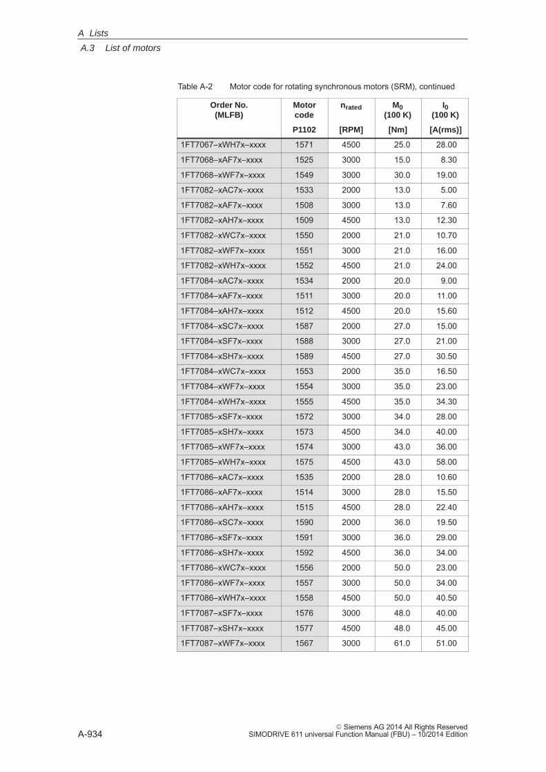
A
A.3 List of motors
A-934� Siemens AG 2014 All Rights Reserved
SIMODRIVE 611 universal Function Manual (FBU) – 10/2014 Edition
Table A-2 Motor code for rotating synchronous motors (SRM), continued
Order No.(MLFB)
I0(100 K)
M0(100 K)
nratedMotorcode
[A(rms)][Nm][RPM]P1102
1FT7067–xWH7x–xxxx 1571 4500 25.0 28.00
1FT7068–xAF7x–xxxx 1525 3000 15.0 8.30
1FT7068–xWF7x–xxxx 1549 3000 30.0 19.00
1FT7082–xAC7x–xxxx 1533 2000 13.0 5.00
1FT7082–xAF7x–xxxx 1508 3000 13.0 7.60
1FT7082–xAH7x–xxxx 1509 4500 13.0 12.30
1FT7082–xWC7x–xxxx 1550 2000 21.0 10.70
1FT7082–xWF7x–xxxx 1551 3000 21.0 16.00
1FT7082–xWH7x–xxxx 1552 4500 21.0 24.00
1FT7084–xAC7x–xxxx 1534 2000 20.0 9.00
1FT7084–xAF7x–xxxx 1511 3000 20.0 11.00
1FT7084–xAH7x–xxxx 1512 4500 20.0 15.60
1FT7084–xSC7x–xxxx 1587 2000 27.0 15.00
1FT7084–xSF7x–xxxx 1588 3000 27.0 21.00
1FT7084–xSH7x–xxxx 1589 4500 27.0 30.50
1FT7084–xWC7x–xxxx 1553 2000 35.0 16.50
1FT7084–xWF7x–xxxx 1554 3000 35.0 23.00
1FT7084–xWH7x–xxxx 1555 4500 35.0 34.30
1FT7085–xSF7x–xxxx 1572 3000 34.0 28.00
1FT7085–xSH7x–xxxx 1573 4500 34.0 40.00
1FT7085–xWF7x–xxxx 1574 3000 43.0 36.00
1FT7085–xWH7x–xxxx 1575 4500 43.0 58.00
1FT7086–xAC7x–xxxx 1535 2000 28.0 10.60
1FT7086–xAF7x–xxxx 1514 3000 28.0 15.50
1FT7086–xAH7x–xxxx 1515 4500 28.0 22.40
1FT7086–xSC7x–xxxx 1590 2000 36.0 19.50
1FT7086–xSF7x–xxxx 1591 3000 36.0 29.00
1FT7086–xSH7x–xxxx 1592 4500 36.0 34.00
1FT7086–xWC7x–xxxx 1556 2000 50.0 23.00
1FT7086–xWF7x–xxxx 1557 3000 50.0 34.00
1FT7086–xWH7x–xxxx 1558 4500 50.0 40.50
1FT7087–xSF7x–xxxx 1576 3000 48.0 40.00
1FT7087–xSH7x–xxxx 1577 4500 48.0 45.00
1FT7087–xWF7x–xxxx 1567 3000 61.0 51.00
A Lists
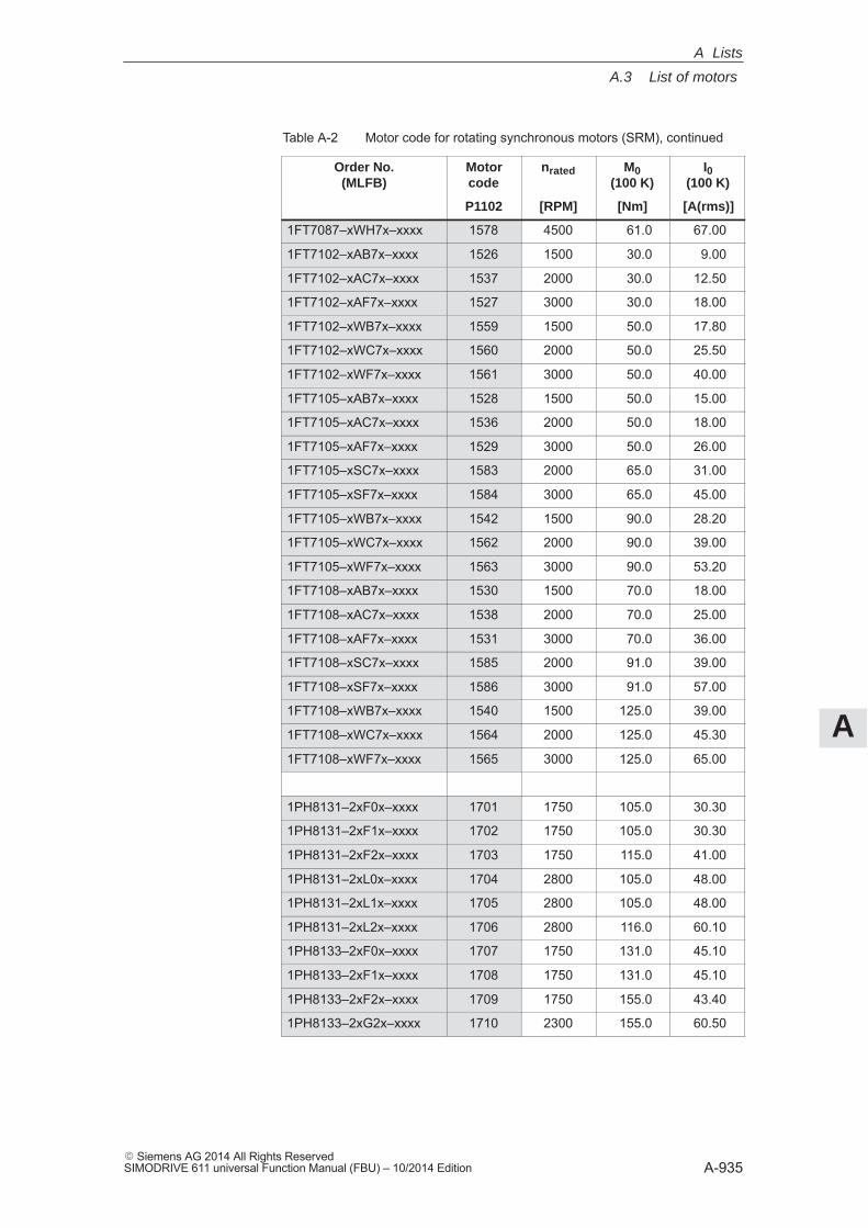
A
A.3 List of motors
A-935� Siemens AG 2014 All Rights ReservedSIMODRIVE 611 universal Function Manual (FBU) – 10/2014 Edition
Table A-2 Motor code for rotating synchronous motors (SRM), continued
Order No.(MLFB)
I0(100 K)
M0(100 K)
nratedMotorcode
[A(rms)][Nm][RPM]P1102
1FT7087–xWH7x–xxxx 1578 4500 61.0 67.00
1FT7102–xAB7x–xxxx 1526 1500 30.0 9.00
1FT7102–xAC7x–xxxx 1537 2000 30.0 12.50
1FT7102–xAF7x–xxxx 1527 3000 30.0 18.00
1FT7102–xWB7x–xxxx 1559 1500 50.0 17.80
1FT7102–xWC7x–xxxx 1560 2000 50.0 25.50
1FT7102–xWF7x–xxxx 1561 3000 50.0 40.00
1FT7105–xAB7x–xxxx 1528 1500 50.0 15.00
1FT7105–xAC7x–xxxx 1536 2000 50.0 18.00
1FT7105–xAF7x–xxxx 1529 3000 50.0 26.00
1FT7105–xSC7x–xxxx 1583 2000 65.0 31.00
1FT7105–xSF7x–xxxx 1584 3000 65.0 45.00
1FT7105–xWB7x–xxxx 1542 1500 90.0 28.20
1FT7105–xWC7x–xxxx 1562 2000 90.0 39.00
1FT7105–xWF7x–xxxx 1563 3000 90.0 53.20
1FT7108–xAB7x–xxxx 1530 1500 70.0 18.00
1FT7108–xAC7x–xxxx 1538 2000 70.0 25.00
1FT7108–xAF7x–xxxx 1531 3000 70.0 36.00
1FT7108–xSC7x–xxxx 1585 2000 91.0 39.00
1FT7108–xSF7x–xxxx 1586 3000 91.0 57.00
1FT7108–xWB7x–xxxx 1540 1500 125.0 39.00
1FT7108–xWC7x–xxxx 1564 2000 125.0 45.30
1FT7108–xWF7x–xxxx 1565 3000 125.0 65.00
1PH8131–2xF0x–xxxx 1701 1750 105.0 30.30
1PH8131–2xF1x–xxxx 1702 1750 105.0 30.30
1PH8131–2xF2x–xxxx 1703 1750 115.0 41.00
1PH8131–2xL0x–xxxx 1704 2800 105.0 48.00
1PH8131–2xL1x–xxxx 1705 2800 105.0 48.00
1PH8131–2xL2x–xxxx 1706 2800 116.0 60.10
1PH8133–2xF0x–xxxx 1707 1750 131.0 45.10
1PH8133–2xF1x–xxxx 1708 1750 131.0 45.10
1PH8133–2xF2x–xxxx 1709 1750 155.0 43.40
1PH8133–2xG2x–xxxx 1710 2300 155.0 60.50
A Lists
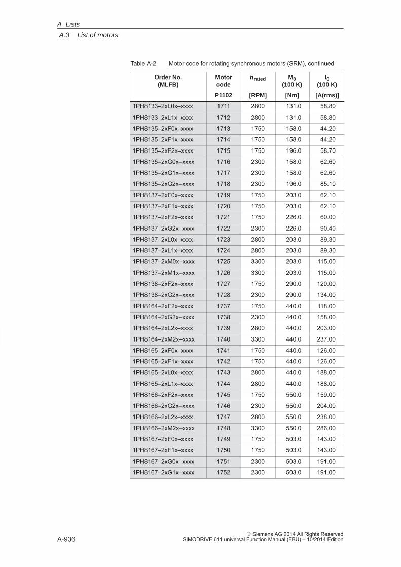
A
A.3 List of motors
A-936� Siemens AG 2014 All Rights Reserved
SIMODRIVE 611 universal Function Manual (FBU) – 10/2014 Edition
Table A-2 Motor code for rotating synchronous motors (SRM), continued
Order No.(MLFB)
I0(100 K)
M0(100 K)
nratedMotorcode
[A(rms)][Nm][RPM]P1102
1PH8133–2xL0x–xxxx 1711 2800 131.0 58.80
1PH8133–2xL1x–xxxx 1712 2800 131.0 58.80
1PH8135–2xF0x–xxxx 1713 1750 158.0 44.20
1PH8135–2xF1x–xxxx 1714 1750 158.0 44.20
1PH8135–2xF2x–xxxx 1715 1750 196.0 58.70
1PH8135–2xG0x–xxxx 1716 2300 158.0 62.60
1PH8135–2xG1x–xxxx 1717 2300 158.0 62.60
1PH8135–2xG2x–xxxx 1718 2300 196.0 85.10
1PH8137–2xF0x–xxxx 1719 1750 203.0 62.10
1PH8137–2xF1x–xxxx 1720 1750 203.0 62.10
1PH8137–2xF2x–xxxx 1721 1750 226.0 60.00
1PH8137–2xG2x–xxxx 1722 2300 226.0 90.40
1PH8137–2xL0x–xxxx 1723 2800 203.0 89.30
1PH8137–2xL1x–xxxx 1724 2800 203.0 89.30
1PH8137–2xM0x–xxxx 1725 3300 203.0 115.00
1PH8137–2xM1x–xxxx 1726 3300 203.0 115.00
1PH8138–2xF2x–xxxx 1727 1750 290.0 120.00
1PH8138–2xG2x–xxxx 1728 2300 290.0 134.00
1PH8164–2xF2x–xxxx 1737 1750 440.0 118.00
1PH8164–2xG2x–xxxx 1738 2300 440.0 158.00
1PH8164–2xL2x–xxxx 1739 2800 440.0 203.00
1PH8164–2xM2x–xxxx 1740 3300 440.0 237.00
1PH8165–2xF0x–xxxx 1741 1750 440.0 126.00
1PH8165–2xF1x–xxxx 1742 1750 440.0 126.00
1PH8165–2xL0x–xxxx 1743 2800 440.0 188.00
1PH8165–2xL1x–xxxx 1744 2800 440.0 188.00
1PH8166–2xF2x–xxxx 1745 1750 550.0 159.00
1PH8166–2xG2x–xxxx 1746 2300 550.0 204.00
1PH8166–2xL2x–xxxx 1747 2800 550.0 238.00
1PH8166–2xM2x–xxxx 1748 3300 550.0 286.00
1PH8167–2xF0x–xxxx 1749 1750 503.0 143.00
1PH8167–2xF1x–xxxx 1750 1750 503.0 143.00
1PH8167–2xG0x–xxxx 1751 2300 503.0 191.00
1PH8167–2xG1x–xxxx 1752 2300 503.0 191.00
A Lists
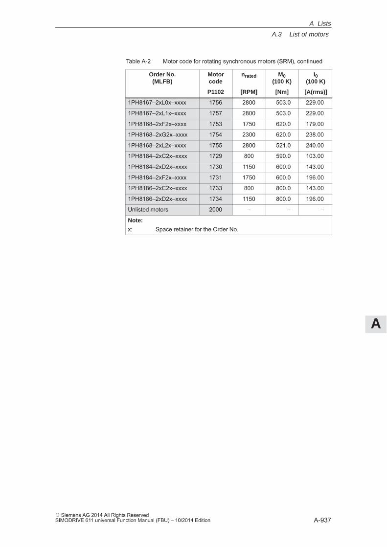
A
A.3 List of motors
A-937� Siemens AG 2014 All Rights ReservedSIMODRIVE 611 universal Function Manual (FBU) – 10/2014 Edition
Table A-2 Motor code for rotating synchronous motors (SRM), continued
Order No.(MLFB)
I0(100 K)
M0(100 K)
nratedMotorcode
[A(rms)][Nm][RPM]P1102
1PH8167–2xL0x–xxxx 1756 2800 503.0 229.00
1PH8167–2xL1x–xxxx 1757 2800 503.0 229.00
1PH8168–2xF2x–xxxx 1753 1750 620.0 179.00
1PH8168–2xG2x–xxxx 1754 2300 620.0 238.00
1PH8168–2xL2x–xxxx 1755 2800 521.0 240.00
1PH8184–2xC2x–xxxx 1729 800 590.0 103.00
1PH8184–2xD2x–xxxx 1730 1150 600.0 143.00
1PH8184–2xF2x–xxxx 1731 1750 600.0 196.00
1PH8186–2xC2x–xxxx 1733 800 800.0 143.00
1PH8186–2xD2x–xxxx 1734 1150 800.0 196.00
Unlisted motors 2000 – – –
Note:
x: Space retainer for the Order No.
A Lists
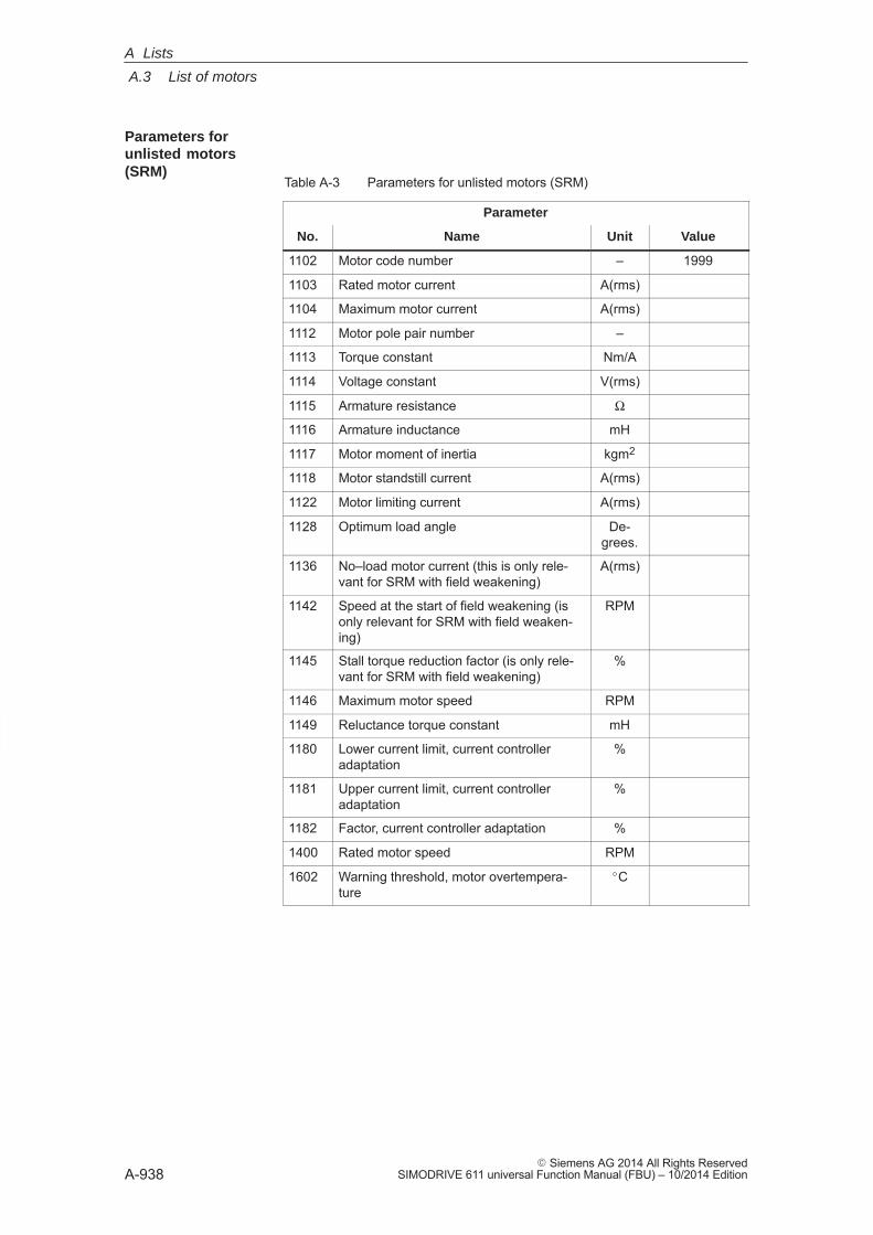
A
A.3 List of motors
A-938� Siemens AG 2014 All Rights Reserved
SIMODRIVE 611 universal Function Manual (FBU) – 10/2014 Edition
Table A-3 Parameters for unlisted motors (SRM)
Parameter
No. Name Unit Value
1102 Motor code number – 1999
1103 Rated motor current A(rms)
1104 Maximum motor current A(rms)
1112 Motor pole pair number –
1113 Torque constant Nm/A
1114 Voltage constant V(rms)
1115 Armature resistance Ω
1116 Armature inductance mH
1117 Motor moment of inertia kgm2
1118 Motor standstill current A(rms)
1122 Motor limiting current A(rms)
1128 Optimum load angle De-grees.
1136 No–load motor current (this is only rele-vant for SRM with field weakening)
A(rms)
1142 Speed at the start of field weakening (isonly relevant for SRM with field weaken-ing)
RPM
1145 Stall torque reduction factor (is only rele-vant for SRM with field weakening)
%
1146 Maximum motor speed RPM
1149 Reluctance torque constant mH
1180 Lower current limit, current controlleradaptation
%
1181 Upper current limit, current controlleradaptation
%
1182 Factor, current controller adaptation %
1400 Rated motor speed RPM
1602 Warning threshold, motor overtempera-ture
�C
Parameters forunlisted motors(SRM)
A Lists
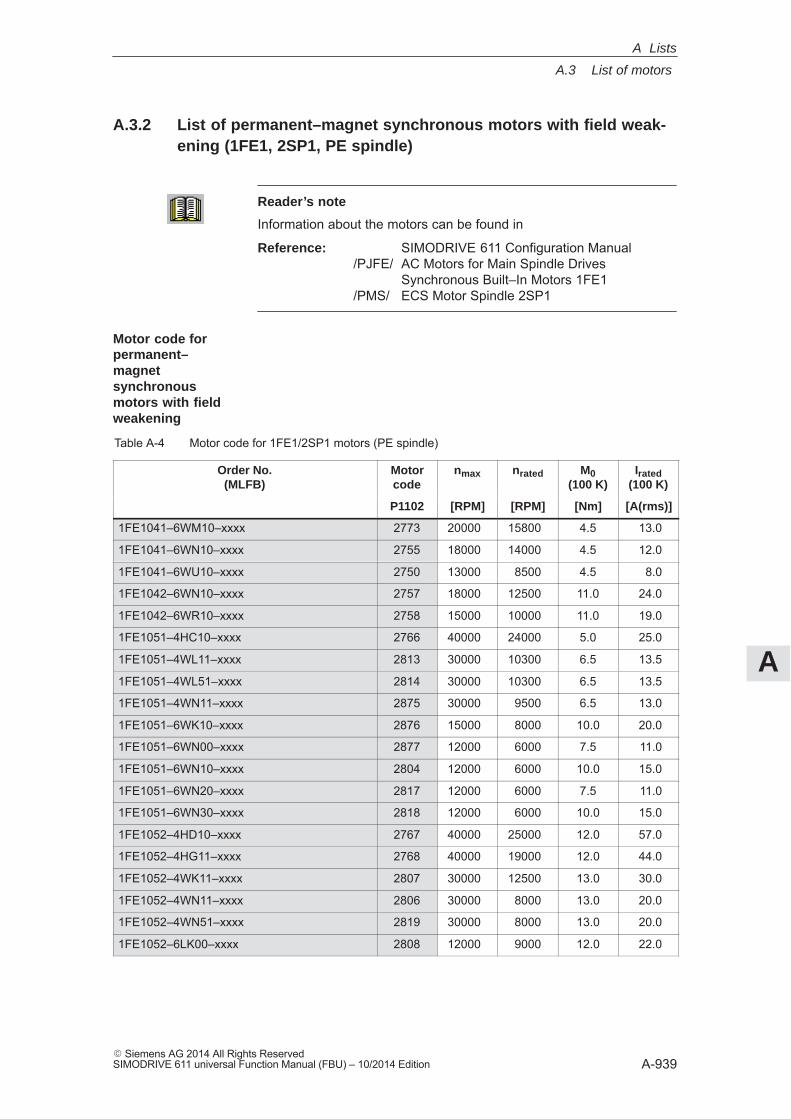
A
A.3 List of motors
A-939� Siemens AG 2014 All Rights ReservedSIMODRIVE 611 universal Function Manual (FBU) – 10/2014 Edition
A.3.2 List of permanent–magnet synchronous motors with field weak-ening (1FE1, 2SP1, PE spindle)
Reader’s note
Information about the motors can be found in
Reference: SIMODRIVE 611 Configuration Manual /PJFE/ AC Motors for Main Spindle Drives
Synchronous Built–In Motors 1FE1/PMS/ ECS Motor Spindle 2SP1
Table A-4 Motor code for 1FE1/2SP1 motors (PE spindle)
Order No.(MLFB)
Motorcode
nmax nrated M0(100 K)
Irated(100 K)
P1102 [RPM] [RPM] [Nm] [A(rms)]
1FE1041–6WM10–xxxx 2773 20000 15800 4.5 13.0
1FE1041–6WN10–xxxx 2755 18000 14000 4.5 12.0
1FE1041–6WU10–xxxx 2750 13000 8500 4.5 8.0
1FE1042–6WN10–xxxx 2757 18000 12500 11.0 24.0
1FE1042–6WR10–xxxx 2758 15000 10000 11.0 19.0
1FE1051–4HC10–xxxx 2766 40000 24000 5.0 25.0
1FE1051–4WL11–xxxx 2813 30000 10300 6.5 13.5
1FE1051–4WL51–xxxx 2814 30000 10300 6.5 13.5
1FE1051–4WN11–xxxx 2875 30000 9500 6.5 13.0
1FE1051–6WK10–xxxx 2876 15000 8000 10.0 20.0
1FE1051–6WN00–xxxx 2877 12000 6000 7.5 11.0
1FE1051–6WN10–xxxx 2804 12000 6000 10.0 15.0
1FE1051–6WN20–xxxx 2817 12000 6000 7.5 11.0
1FE1051–6WN30–xxxx 2818 12000 6000 10.0 15.0
1FE1052–4HD10–xxxx 2767 40000 25000 12.0 57.0
1FE1052–4HG11–xxxx 2768 40000 19000 12.0 44.0
1FE1052–4WK11–xxxx 2807 30000 12500 13.0 30.0
1FE1052–4WN11–xxxx 2806 30000 8000 13.0 20.0
1FE1052–4WN51–xxxx 2819 30000 8000 13.0 20.0
1FE1052–6LK00–xxxx 2808 12000 9000 12.0 22.0
Motor code for permanent–magnetsynchronousmotors with fieldweakening
A Lists
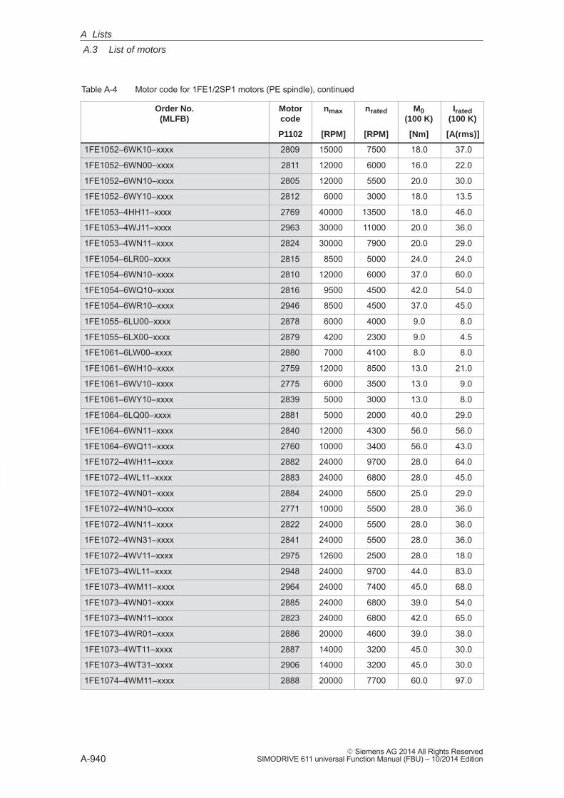
A
A.3 List of motors
A-940� Siemens AG 2014 All Rights Reserved
SIMODRIVE 611 universal Function Manual (FBU) – 10/2014 Edition
Table A-4 Motor code for 1FE1/2SP1 motors (PE spindle), continued
Order No.(MLFB)
Irated(100 K)
M0(100 K)
nratednmaxMotorcode
[A(rms)][Nm][RPM][RPM]P1102
1FE1052–6WK10–xxxx 2809 15000 7500 18.0 37.0
1FE1052–6WN00–xxxx 2811 12000 6000 16.0 22.0
1FE1052–6WN10–xxxx 2805 12000 5500 20.0 30.0
1FE1052–6WY10–xxxx 2812 6000 3000 18.0 13.5
1FE1053–4HH11–xxxx 2769 40000 13500 18.0 46.0
1FE1053–4WJ11–xxxx 2963 30000 11000 20.0 36.0
1FE1053–4WN11–xxxx 2824 30000 7900 20.0 29.0
1FE1054–6LR00–xxxx 2815 8500 5000 24.0 24.0
1FE1054–6WN10–xxxx 2810 12000 6000 37.0 60.0
1FE1054–6WQ10–xxxx 2816 9500 4500 42.0 54.0
1FE1054–6WR10–xxxx 2946 8500 4500 37.0 45.0
1FE1055–6LU00–xxxx 2878 6000 4000 9.0 8.0
1FE1055–6LX00–xxxx 2879 4200 2300 9.0 4.5
1FE1061–6LW00–xxxx 2880 7000 4100 8.0 8.0
1FE1061–6WH10–xxxx 2759 12000 8500 13.0 21.0
1FE1061–6WV10–xxxx 2775 6000 3500 13.0 9.0
1FE1061–6WY10–xxxx 2839 5000 3000 13.0 8.0
1FE1064–6LQ00–xxxx 2881 5000 2000 40.0 29.0
1FE1064–6WN11–xxxx 2840 12000 4300 56.0 56.0
1FE1064–6WQ11–xxxx 2760 10000 3400 56.0 43.0
1FE1072–4WH11–xxxx 2882 24000 9700 28.0 64.0
1FE1072–4WL11–xxxx 2883 24000 6800 28.0 45.0
1FE1072–4WN01–xxxx 2884 24000 5500 25.0 29.0
1FE1072–4WN10–xxxx 2771 10000 5500 28.0 36.0
1FE1072–4WN11–xxxx 2822 24000 5500 28.0 36.0
1FE1072–4WN31–xxxx 2841 24000 5500 28.0 36.0
1FE1072–4WV11–xxxx 2975 12600 2500 28.0 18.0
1FE1073–4WL11–xxxx 2948 24000 9700 44.0 83.0
1FE1073–4WM11–xxxx 2964 24000 7400 45.0 68.0
1FE1073–4WN01–xxxx 2885 24000 6800 39.0 54.0
1FE1073–4WN11–xxxx 2823 24000 6800 42.0 65.0
1FE1073–4WR01–xxxx 2886 20000 4600 39.0 38.0
1FE1073–4WT11–xxxx 2887 14000 3200 45.0 30.0
1FE1073–4WT31–xxxx 2906 14000 3200 45.0 30.0
1FE1074–4WM11–xxxx 2888 20000 7700 60.0 97.0
A Lists
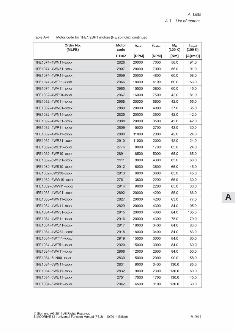
A
A.3 List of motors
A-941� Siemens AG 2014 All Rights ReservedSIMODRIVE 611 universal Function Manual (FBU) – 10/2014 Edition
Table A-4 Motor code for 1FE1/2SP1 motors (PE spindle), continued
Order No.(MLFB)
Irated(100 K)
M0(100 K)
nratednmaxMotorcode
[A(rms)][Nm][RPM][RPM]P1102
1FE1074–4WN11–xxxx 2826 20000 7000 56.0 91.0
1FE1074–4WN51–xxxx 2907 20000 7000 56.0 91.0
1FE1074–4WR11–xxxx 2959 20000 4800 60.0 58.0
1FE1074–4WT11–xxxx 2966 18000 4100 60.0 53.0
1FE1074–4WV11–xxxx 2965 15500 3800 60.0 45.0
1FE1082–4WF10–xxxx 2967 16000 7500 42.0 81.0
1FE1082–4WK11–xxxx 2958 20000 5600 42.0 55.0
1FE1082–4WN01–xxxx 2889 20000 4000 37.0 35.0
1FE1082–4WN11–xxxx 2825 20000 3500 42.0 42.0
1FE1082–4WN51–xxxx 2908 20000 3500 42.0 42.0
1FE1082–4WP11–xxxx 2809 15000 2700 42.0 30.0
1FE1082–4WR11–xxxx 2890 11000 2000 42.0 24.0
1FE1082–4WR31–xxxx 2910 11000 2000 42.0 24.0
1FE1082–6WE11–xxxx 2776 8000 1700 65.0 24.0
1FE1082–6WP10–xxxx 2891 8500 5000 65.0 65.0
1FE1082–6WQ11–xxxx 2911 9000 4300 65.0 60.0
1FE1082–6WS10–xxxx 2912 6000 3600 65.0 45.0
1FE1082–6WS30–xxxx 2913 6000 3600 65.0 45.0
1FE1082–6WW10–xxxx 2761 3800 2200 65.0 30.0
1FE1082–6WW11–xxxx 2914 9000 2200 65.0 30.0
1FE1083–4WN01–xxxx 2892 20000 4200 55.0 66.0
1FE1083–4WN11–xxxx 2827 20000 4200 63.0 77.0
1FE1084–4WN11–xxxx 2829 20000 4300 84.0 105.0
1FE1084–4WN31–xxxx 2915 20000 4300 84.0 105.0
1FE1084–4WP11–xxxx 2916 20000 4300 78.0 79.0
1FE1084–4WQ11–xxxx 2917 18000 3400 84.0 83.0
1FE1084–4WQ51–xxxx 2918 18000 3400 84.0 83.0
1FE1084–4WT11–xxxx 2919 15000 3000 84.0 60.0
1FE1084–4WT51–xxxx 2920 15000 3000 84.0 60.0
1FE1084–4WV11–xxxx 2968 12000 2600 84.0 50.0
1FE1084–6LN00–xxxx 2830 5000 2000 90.0 58.0
1FE1084–6WN11–xxxx 2831 9000 3400 130.0 85.0
1FE1084–6WR11–xxxx 2832 9000 2300 130.0 60.0
1FE1084–6WU11–xxxx 2751 7000 1700 130.0 45.0
1FE1084–6WX11–xxxx 2942 4500 1100 130.0 30.0
A Lists
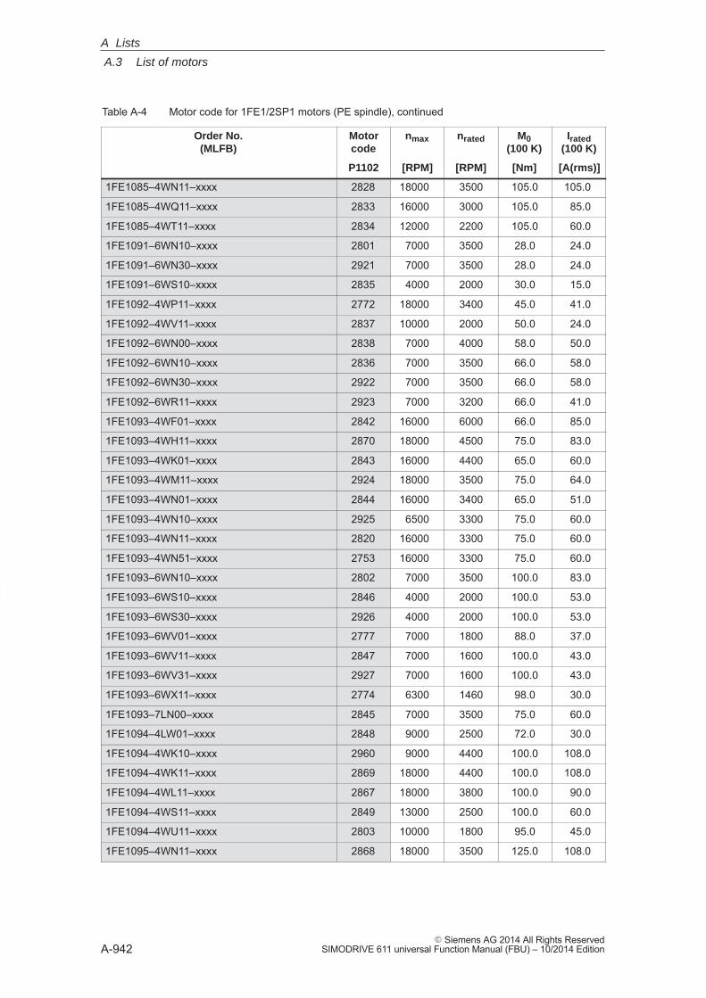
A
A.3 List of motors
A-942� Siemens AG 2014 All Rights Reserved
SIMODRIVE 611 universal Function Manual (FBU) – 10/2014 Edition
Table A-4 Motor code for 1FE1/2SP1 motors (PE spindle), continued
Order No.(MLFB)
Irated(100 K)
M0(100 K)
nratednmaxMotorcode
[A(rms)][Nm][RPM][RPM]P1102
1FE1085–4WN11–xxxx 2828 18000 3500 105.0 105.0
1FE1085–4WQ11–xxxx 2833 16000 3000 105.0 85.0
1FE1085–4WT11–xxxx 2834 12000 2200 105.0 60.0
1FE1091–6WN10–xxxx 2801 7000 3500 28.0 24.0
1FE1091–6WN30–xxxx 2921 7000 3500 28.0 24.0
1FE1091–6WS10–xxxx 2835 4000 2000 30.0 15.0
1FE1092–4WP11–xxxx 2772 18000 3400 45.0 41.0
1FE1092–4WV11–xxxx 2837 10000 2000 50.0 24.0
1FE1092–6WN00–xxxx 2838 7000 4000 58.0 50.0
1FE1092–6WN10–xxxx 2836 7000 3500 66.0 58.0
1FE1092–6WN30–xxxx 2922 7000 3500 66.0 58.0
1FE1092–6WR11–xxxx 2923 7000 3200 66.0 41.0
1FE1093–4WF01–xxxx 2842 16000 6000 66.0 85.0
1FE1093–4WH11–xxxx 2870 18000 4500 75.0 83.0
1FE1093–4WK01–xxxx 2843 16000 4400 65.0 60.0
1FE1093–4WM11–xxxx 2924 18000 3500 75.0 64.0
1FE1093–4WN01–xxxx 2844 16000 3400 65.0 51.0
1FE1093–4WN10–xxxx 2925 6500 3300 75.0 60.0
1FE1093–4WN11–xxxx 2820 16000 3300 75.0 60.0
1FE1093–4WN51–xxxx 2753 16000 3300 75.0 60.0
1FE1093–6WN10–xxxx 2802 7000 3500 100.0 83.0
1FE1093–6WS10–xxxx 2846 4000 2000 100.0 53.0
1FE1093–6WS30–xxxx 2926 4000 2000 100.0 53.0
1FE1093–6WV01–xxxx 2777 7000 1800 88.0 37.0
1FE1093–6WV11–xxxx 2847 7000 1600 100.0 43.0
1FE1093–6WV31–xxxx 2927 7000 1600 100.0 43.0
1FE1093–6WX11–xxxx 2774 6300 1460 98.0 30.0
1FE1093–7LN00–xxxx 2845 7000 3500 75.0 60.0
1FE1094–4LW01–xxxx 2848 9000 2500 72.0 30.0
1FE1094–4WK10–xxxx 2960 9000 4400 100.0 108.0
1FE1094–4WK11–xxxx 2869 18000 4400 100.0 108.0
1FE1094–4WL11–xxxx 2867 18000 3800 100.0 90.0
1FE1094–4WS11–xxxx 2849 13000 2500 100.0 60.0
1FE1094–4WU11–xxxx 2803 10000 1800 95.0 45.0
1FE1095–4WN11–xxxx 2868 18000 3500 125.0 108.0
A Lists
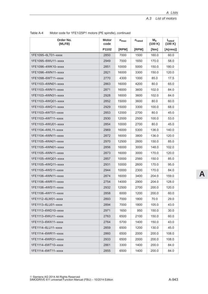
A
A.3 List of motors
A-943� Siemens AG 2014 All Rights ReservedSIMODRIVE 611 universal Function Manual (FBU) – 10/2014 Edition
Table A-4 Motor code for 1FE1/2SP1 motors (PE spindle), continued
Order No.(MLFB)
Irated(100 K)
M0(100 K)
nratednmaxMotorcode
[A(rms)][Nm][RPM][RPM]P1102
1FE1095–6LT01–xxxx 2850 7000 1500 160.0 60.0
1FE1095–6WU11–xxxx 2949 7000 1650 170.0 58.0
1FE1096–4WK10–xxxx 2851 10000 5000 150.0 180.0
1FE1096–4WN11–xxxx 2821 16000 3300 150.0 120.0
1FE1098–6WT11–xxxx 2770 4300 1000 85.0 17.5
1FE1103–4WN01–xxxx 2863 16000 4200 80.0 65.0
1FE1103–4WN11–xxxx 2871 16000 3600 102.0 84.0
1FE1103–4WN31–xxxx 2928 16000 3600 102.0 84.0
1FE1103–4WQ01–xxxx 2852 15000 3600 80.0 60.0
1FE1103–4WQ11–xxxx 2929 15000 3300 100.0 68.0
1FE1103–4WT01–xxxx 2853 12000 2700 80.0 45.0
1FE1103–4WT11–xxxx 2930 12000 2500 100.0 53.0
1FE1103–4WU01–xxxx 2854 10000 2700 80.0 45.0
1FE1104–4WL11–xxxx 2969 16000 5300 136.0 140.0
1FE1104–4WN11–xxxx 2872 16000 3800 136.0 120.0
1FE1105–4WA01–xxxx 2970 12500 2600 150.0 85.0
1FE1105–4WN01–xxxx 2856 16000 3000 148.0 102.0
1FE1105–4WN11–xxxx 2873 16000 3000 170.0 120.0
1FE1105–4WQ01–xxxx 2857 10000 2560 150.0 85.0
1FE1105–4WQ11–xxxx 2931 10000 2600 170.0 95.0
1FE1105–4WS11–xxxx 2944 10000 2300 170.0 84.0
1FE1106–4WN11–xxxx 2874 16000 3400 204.0 159.0
1FE1106–4WR11–xxxx 2754 14000 2900 204.0 128.0
1FE1106–4WS11–xxxx 2932 12500 2700 200.0 120.0
1FE1106–4WY11–xxxx 2858 6000 1200 200.0 60.0
1FE1112–6LW01–xxxx 2893 7000 1800 70.0 29.0
1FE1113–6LU01–xxxx 2894 7000 1800 105.0 43.0
1FE1113–6WD10–xxxx 2971 1650 950 150.0 30.0
1FE1113–6WU11–xxxx 2763 6500 2100 150.0 60.0
1FE1113–6WX11–xxxx 2764 5700 1400 150.0 43.0
1FE1114–6LU11–xxxx 2859 6500 1200 130.0 45.0
1FE1114–6WR11–xxxx 2860 6500 2000 200.0 108.0
1FE1114–6WR31–xxxx 2933 6500 2000 200.0 108.0
1FE1114–6WT10–xxxx 2861 3300 1400 200.0 84.0
1FE1114–6WT11–xxxx 2855 6500 1400 200.0 84.0
A Lists
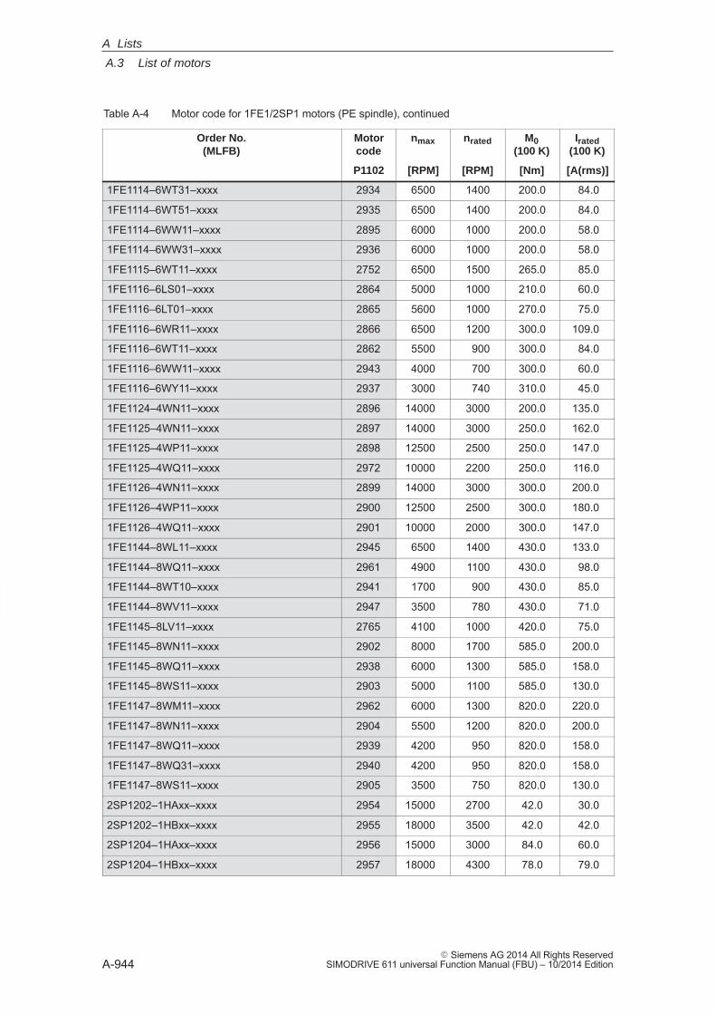
A
A.3 List of motors
A-944� Siemens AG 2014 All Rights Reserved
SIMODRIVE 611 universal Function Manual (FBU) – 10/2014 Edition
Table A-4 Motor code for 1FE1/2SP1 motors (PE spindle), continued
Order No.(MLFB)
Irated(100 K)
M0(100 K)
nratednmaxMotorcode
[A(rms)][Nm][RPM][RPM]P1102
1FE1114–6WT31–xxxx 2934 6500 1400 200.0 84.0
1FE1114–6WT51–xxxx 2935 6500 1400 200.0 84.0
1FE1114–6WW11–xxxx 2895 6000 1000 200.0 58.0
1FE1114–6WW31–xxxx 2936 6000 1000 200.0 58.0
1FE1115–6WT11–xxxx 2752 6500 1500 265.0 85.0
1FE1116–6LS01–xxxx 2864 5000 1000 210.0 60.0
1FE1116–6LT01–xxxx 2865 5600 1000 270.0 75.0
1FE1116–6WR11–xxxx 2866 6500 1200 300.0 109.0
1FE1116–6WT11–xxxx 2862 5500 900 300.0 84.0
1FE1116–6WW11–xxxx 2943 4000 700 300.0 60.0
1FE1116–6WY11–xxxx 2937 3000 740 310.0 45.0
1FE1124–4WN11–xxxx 2896 14000 3000 200.0 135.0
1FE1125–4WN11–xxxx 2897 14000 3000 250.0 162.0
1FE1125–4WP11–xxxx 2898 12500 2500 250.0 147.0
1FE1125–4WQ11–xxxx 2972 10000 2200 250.0 116.0
1FE1126–4WN11–xxxx 2899 14000 3000 300.0 200.0
1FE1126–4WP11–xxxx 2900 12500 2500 300.0 180.0
1FE1126–4WQ11–xxxx 2901 10000 2000 300.0 147.0
1FE1144–8WL11–xxxx 2945 6500 1400 430.0 133.0
1FE1144–8WQ11–xxxx 2961 4900 1100 430.0 98.0
1FE1144–8WT10–xxxx 2941 1700 900 430.0 85.0
1FE1144–8WV11–xxxx 2947 3500 780 430.0 71.0
1FE1145–8LV11–xxxx 2765 4100 1000 420.0 75.0
1FE1145–8WN11–xxxx 2902 8000 1700 585.0 200.0
1FE1145–8WQ11–xxxx 2938 6000 1300 585.0 158.0
1FE1145–8WS11–xxxx 2903 5000 1100 585.0 130.0
1FE1147–8WM11–xxxx 2962 6000 1300 820.0 220.0
1FE1147–8WN11–xxxx 2904 5500 1200 820.0 200.0
1FE1147–8WQ11–xxxx 2939 4200 950 820.0 158.0
1FE1147–8WQ31–xxxx 2940 4200 950 820.0 158.0
1FE1147–8WS11–xxxx 2905 3500 750 820.0 130.0
2SP1202–1HAxx–xxxx 2954 15000 2700 42.0 30.0
2SP1202–1HBxx–xxxx 2955 18000 3500 42.0 42.0
2SP1204–1HAxx–xxxx 2956 15000 3000 84.0 60.0
2SP1204–1HBxx–xxxx 2957 18000 4300 78.0 79.0
A Lists
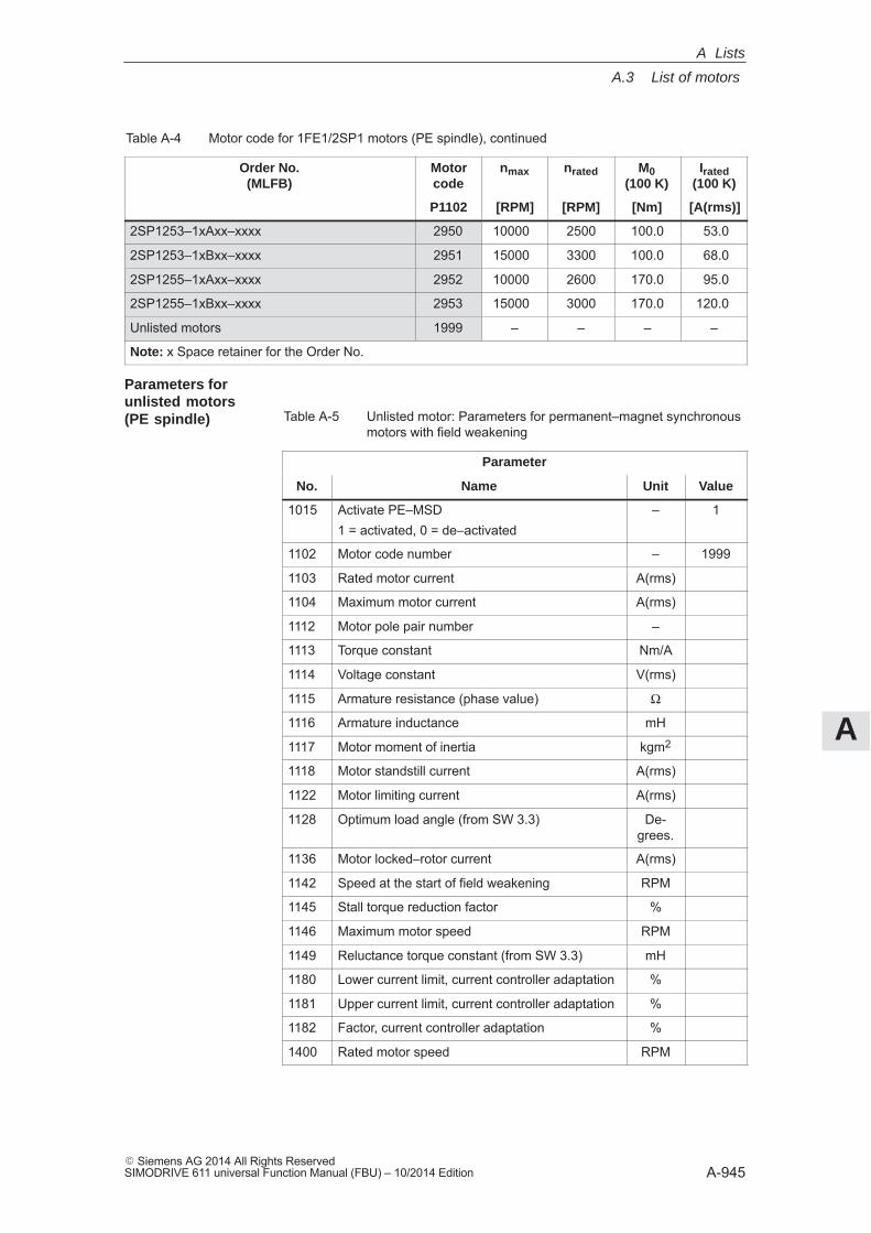
A
A.3 List of motors
A-945� Siemens AG 2014 All Rights ReservedSIMODRIVE 611 universal Function Manual (FBU) – 10/2014 Edition
Table A-4 Motor code for 1FE1/2SP1 motors (PE spindle), continued
Order No.(MLFB)
Irated(100 K)
M0(100 K)
nratednmaxMotorcode
[A(rms)][Nm][RPM][RPM]P1102
2SP1253–1xAxx–xxxx 2950 10000 2500 100.0 53.0
2SP1253–1xBxx–xxxx 2951 15000 3300 100.0 68.0
2SP1255–1xAxx–xxxx 2952 10000 2600 170.0 95.0
2SP1255–1xBxx–xxxx 2953 15000 3000 170.0 120.0
Unlisted motors 1999 – – – –
Note: x Space retainer for the Order No.
Table A-5 Unlisted motor: Parameters for permanent–magnet synchronousmotors with field weakening
Parameter
No. Name Unit Value
1015 Activate PE–MSD1 = activated, 0 = de–activated
– 1
1102 Motor code number – 1999
1103 Rated motor current A(rms)
1104 Maximum motor current A(rms)
1112 Motor pole pair number –
1113 Torque constant Nm/A
1114 Voltage constant V(rms)
1115 Armature resistance (phase value) Ω
1116 Armature inductance mH
1117 Motor moment of inertia kgm2
1118 Motor standstill current A(rms)
1122 Motor limiting current A(rms)
1128 Optimum load angle (from SW 3.3) De-grees.
1136 Motor locked–rotor current A(rms)
1142 Speed at the start of field weakening RPM
1145 Stall torque reduction factor %
1146 Maximum motor speed RPM
1149 Reluctance torque constant (from SW 3.3) mH
1180 Lower current limit, current controller adaptation %
1181 Upper current limit, current controller adaptation %
1182 Factor, current controller adaptation %
1400 Rated motor speed RPM
Parameters for unlisted motors(PE spindle)
A Lists
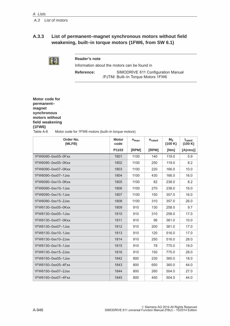
A
A.3 List of motors
A-946� Siemens AG 2014 All Rights Reserved
SIMODRIVE 611 universal Function Manual (FBU) – 10/2014 Edition
A.3.3 List of permanent–magnet synchronous motors without fieldweakening, built–in torque motors (1FW6, from SW 6.1)
Reader’s note
Information about the motors can be found in
Reference: SIMODRIVE 611 Configuration Manual /PJTM/ Built–In Torque Motors 1FW6
Table A-6 Motor code for 1FW6 motors (built–in torque motors)
Order No.(MLFB)
Motorcode
nmax nrated M0(100 K)
Irated(100 K)
P1102 [RPM] [RPM] [Nm] [A(rms)]
1FW6090–0xx05–0Fxx 1801 1100 140 119.0 5.9
1FW6090–0xx05–0Kxx 1802 1100 250 119.0 8.2
1FW6090–0xx07–0Kxx 1803 1100 220 166.0 10.0
1FW6090–0xx07–1Jxx 1804 1100 430 166.0 16.0
1FW6090–0xx10–0Kxx 1805 1100 82 238.0 8.2
1FW6090–0xx10–1Jxx 1806 1100 270 238.0 16.0
1FW6090–0xx15–1Jxx 1807 1100 150 357.0 16.0
1FW6090–0xx15–2Jxx 1808 1100 310 357.0 26.0
1FW6130–0xx05–0Kxx 1809 910 130 258.0 9.7
1FW6130–0xx05–1Jxx 1810 910 310 258.0 17.0
1FW6130–0xx07–0Kxx 1811 910 96 361.0 10.0
1FW6130–0xx07–1Jxx 1812 910 200 361.0 17.0
1FW6130–0xx10–1Jxx 1813 910 120 516.0 17.0
1FW6130–0xx10–2Jxx 1814 910 250 516.0 28.0
1FW6130–0xx15–1Jxx 1815 910 78 775.0 19.0
1FW6130–0xx15–2Jxx 1816 910 150 775.0 28.0
1FW6150–0xx05–1Jxx 1842 800 230 360.0 18.0
1FW6150–0xx05–4Fxx 1843 800 650 360.0 44.0
1FW6150–0xx07–2Jxx 1844 800 260 504.0 27.0
1FW6150–0xx07–4Fxx 1845 800 450 504.0 44.0
Motor code for permanent–magnetsynchronousmotors without field weakening(1FW6)
A Lists
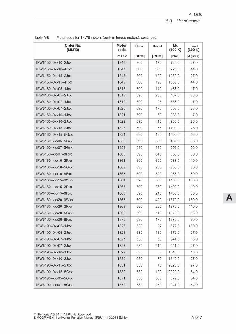
A
A.3 List of motors
A-947� Siemens AG 2014 All Rights ReservedSIMODRIVE 611 universal Function Manual (FBU) – 10/2014 Edition
Table A-6 Motor code for 1FW6 motors (built–in torque motors), continued
Order No.(MLFB)
Irated(100 K)
M0(100 K)
nratednmaxMotorcode
[A(rms)][Nm][RPM][RPM]P1102
1FW6150–0xx10–2Jxx 1846 800 170 720.0 27.0
1FW6150–0xx10–4Fxx 1847 800 300 720.0 44.0
1FW6150–0xx15–2Jxx 1848 800 100 1080.0 27.0
1FW6150–0xx15–4Fxx 1849 800 190 1080.0 44.0
1FW6160–0xx05–1Jxx 1817 690 140 467.0 17.0
1FW6160–0xx05–2Jxx 1818 690 250 467.0 28.0
1FW6160–0xx07–1Jxx 1819 690 96 653.0 17.0
1FW6160–0xx07–2Jxx 1820 690 170 653.0 28.0
1FW6160–0xx10–1Jxx 1821 690 60 933.0 17.0
1FW6160–0xx10–2Jxx 1822 690 110 933.0 28.0
1FW6160–0xx15–2Jxx 1823 690 66 1400.0 28.0
1FW6160–0xx15–5Gxx 1824 690 160 1400.0 56.0
1FW6160–xxx05–5Gxx 1858 690 590 467.0 56.0
1FW6160–xxx07–5Gxx 1859 690 390 653.0 56.0
1FW6160–xxx07–8Fxx 1860 690 610 653.0 80.0
1FW6160–xxx10–2Pxx 1861 690 600 933.0 110.0
1FW6160–xxx10–5Gxx 1862 690 260 933.0 56.0
1FW6160–xxx10–8Fxx 1863 690 390 933.0 80.0
1FW6160–xxx15–0Wxx 1864 690 560 1400.0 160.0
1FW6160–xxx15–2Pxx 1865 690 360 1400.0 110.0
1FW6160–xxx15–8Fxx 1866 690 240 1400.0 80.0
1FW6160–xxx20–0Wxx 1867 690 400 1870.0 160.0
1FW6160–xxx20–2Pxx 1868 690 260 1870.0 110.0
1FW6160–xxx20–5Gxx 1869 690 110 1870.0 56.0
1FW6160–xxx20–8Fxx 1870 690 170 1870.0 80.0
1FW6190–0xx05–1Jxx 1825 630 97 672.0 160.0
1FW6190–0xx05–2Jxx 1826 630 160 672.0 27.0
1FW6190–0xx07–1Jxx 1827 630 63 941.0 18.0
1FW6190–0xx07–2Jxx 1828 630 110 941.0 27.0
1FW6190–0xx10–1Jxx 1829 630 38 1340.0 18.0
1FW6190–0xx10–2Jxx 1830 630 70 1340.0 27.0
1FW6190–0xx15–2Jxx 1831 630 40 2020.0 27.0
1FW6190–0xx15–5Gxx 1832 630 100 2020.0 54.0
1FW6190–xxx05–5Gxx 1871 630 380 672.0 54.0
1FW6190–xxx07–5Gxx 1872 630 250 941.0 54.0
A Lists
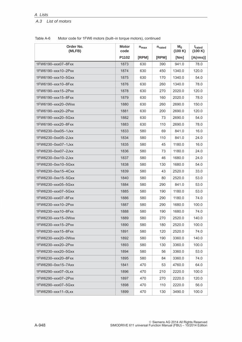
A
A.3 List of motors
A-948� Siemens AG 2014 All Rights Reserved
SIMODRIVE 611 universal Function Manual (FBU) – 10/2014 Edition
Table A-6 Motor code for 1FW6 motors (built–in torque motors), continued
Order No.(MLFB)
Irated(100 K)
M0(100 K)
nratednmaxMotorcode
[A(rms)][Nm][RPM][RPM]P1102
1FW6190–xxx07–8Fxx 1873 630 390 941.0 78.0
1FW6190–xxx10–2Pxx 1874 630 450 1340.0 120.0
1FW6190–xxx10–5Gxx 1875 630 170 1340.0 54.0
1FW6190–xxx10–8Fxx 1876 630 260 1340.0 78.0
1FW6190–xxx15–2Pxx 1878 630 270 2020.0 120.0
1FW6190–xxx15–8Fxx 1879 630 160 2020.0 78.0
1FW6190–xxx20–0Wxx 1880 630 260 2690.0 150.0
1FW6190–xxx20–2Pxx 1881 630 200 2690.0 120.0
1FW6190–xxx20–5Gxx 1882 630 73 2690.0 54.0
1FW6190–xxx20–8Fxx 1883 630 110 2690.0 78.0
1FW6230–0xx05–1Jxx 1833 580 69 841.0 16.0
1FW6230–0xx05–2Jxx 1834 580 110 841.0 24.0
1FW6230–0xx07–1Jxx 1835 580 45 1180.0 16.0
1FW6230–0xx07–2Jxx 1836 580 73 1180.0 24.0
1FW6230–0xx10–2Jxx 1837 580 46 1680.0 24.0
1FW6230–0xx10–5Gxx 1838 580 130 1680.0 54.0
1FW6230–0xx15–4Cxx 1839 580 43 2520.0 33.0
1FW6230–0xx15–5Gxx 1840 580 80 2520.0 53.0
1FW6230–xxx05–5Gxx 1884 580 290 841.0 53.0
1FW6230–xxx07–5Gxx 1885 580 190 1180.0 53.0
1FW6230–xxx07–8Fxx 1886 580 290 1180.0 74.0
1FW6230–xxx10–2Pxx 1887 580 290 1680.0 100.0
1FW6230–xxx10–8Fxx 1888 580 190 1680.0 74.0
1FW6230–xxx15–0Wxx 1889 580 270 2520.0 140.0
1FW6230–xxx15–2Pxx 1890 580 180 2520.0 100.0
1FW6230–xxx15–8Fxx 1891 580 120 2520.0 74.0
1FW6230–xxx20–0Wxx 1892 580 190 3360.0 140.0
1FW6230–xxx20–2Pxx 1893 580 130 3360.0 100.0
1FW6230–xxx20–5Gxx 1894 580 56 3360.0 53.0
1FW6230–xxx20–8Fxx 1895 580 84 3360.0 74.0
1FW6290–0xx15–7Axx 1841 470 53 4760.0 64.0
1FW6290–xxx07–0Lxx 1896 470 210 2220.0 100.0
1FW6290–xxx07–2Pxx 1897 470 270 2220.0 120.0
1FW6290–xxx07–5Gxx 1898 470 110 2220.0 56.0
1FW6290–xxx11–0Lxx 1899 470 130 3490.0 100.0
A Lists
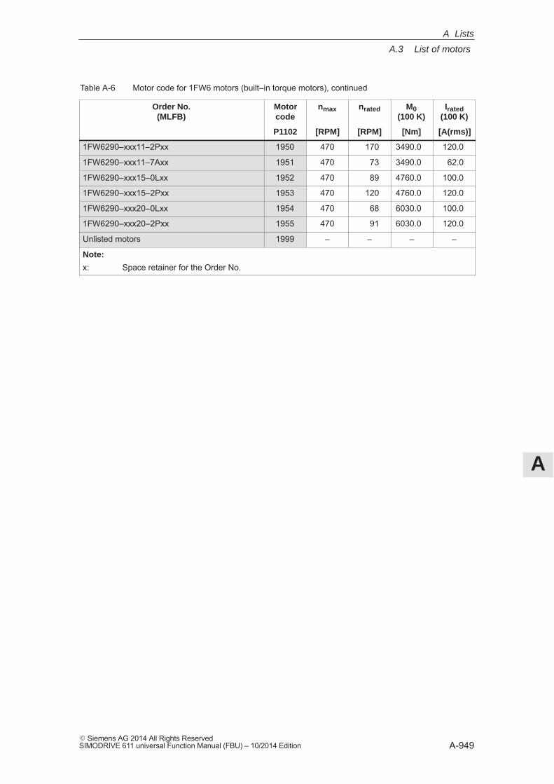
A
A.3 List of motors
A-949� Siemens AG 2014 All Rights ReservedSIMODRIVE 611 universal Function Manual (FBU) – 10/2014 Edition
Table A-6 Motor code for 1FW6 motors (built–in torque motors), continued
Order No.(MLFB)
Irated(100 K)
M0(100 K)
nratednmaxMotorcode
[A(rms)][Nm][RPM][RPM]P1102
1FW6290–xxx11–2Pxx 1950 470 170 3490.0 120.0
1FW6290–xxx11–7Axx 1951 470 73 3490.0 62.0
1FW6290–xxx15–0Lxx 1952 470 89 4760.0 100.0
1FW6290–xxx15–2Pxx 1953 470 120 4760.0 120.0
1FW6290–xxx20–0Lxx 1954 470 68 6030.0 100.0
1FW6290–xxx20–2Pxx 1955 470 91 6030.0 120.0
Unlisted motors 1999 – – – –
Note:
x: Space retainer for the Order No.
A Lists
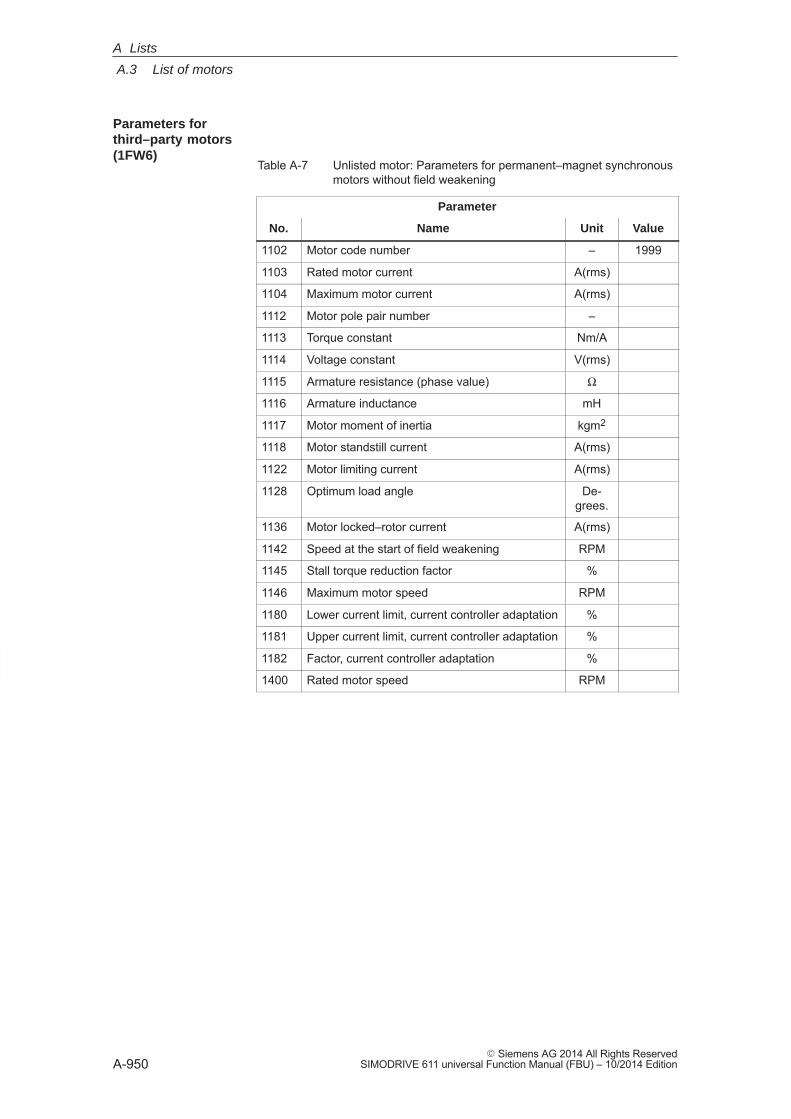
A
A.3 List of motors
A-950� Siemens AG 2014 All Rights Reserved
SIMODRIVE 611 universal Function Manual (FBU) – 10/2014 Edition
Table A-7 Unlisted motor: Parameters for permanent–magnet synchronousmotors without field weakening
Parameter
No. Name Unit Value
1102 Motor code number – 1999
1103 Rated motor current A(rms)
1104 Maximum motor current A(rms)
1112 Motor pole pair number –
1113 Torque constant Nm/A
1114 Voltage constant V(rms)
1115 Armature resistance (phase value) Ω
1116 Armature inductance mH
1117 Motor moment of inertia kgm2
1118 Motor standstill current A(rms)
1122 Motor limiting current A(rms)
1128 Optimum load angle De-grees.
1136 Motor locked–rotor current A(rms)
1142 Speed at the start of field weakening RPM
1145 Stall torque reduction factor %
1146 Maximum motor speed RPM
1180 Lower current limit, current controller adaptation %
1181 Upper current limit, current controller adaptation %
1182 Factor, current controller adaptation %
1400 Rated motor speed RPM
Parameters forthird–party motors(1FW6)
A Lists
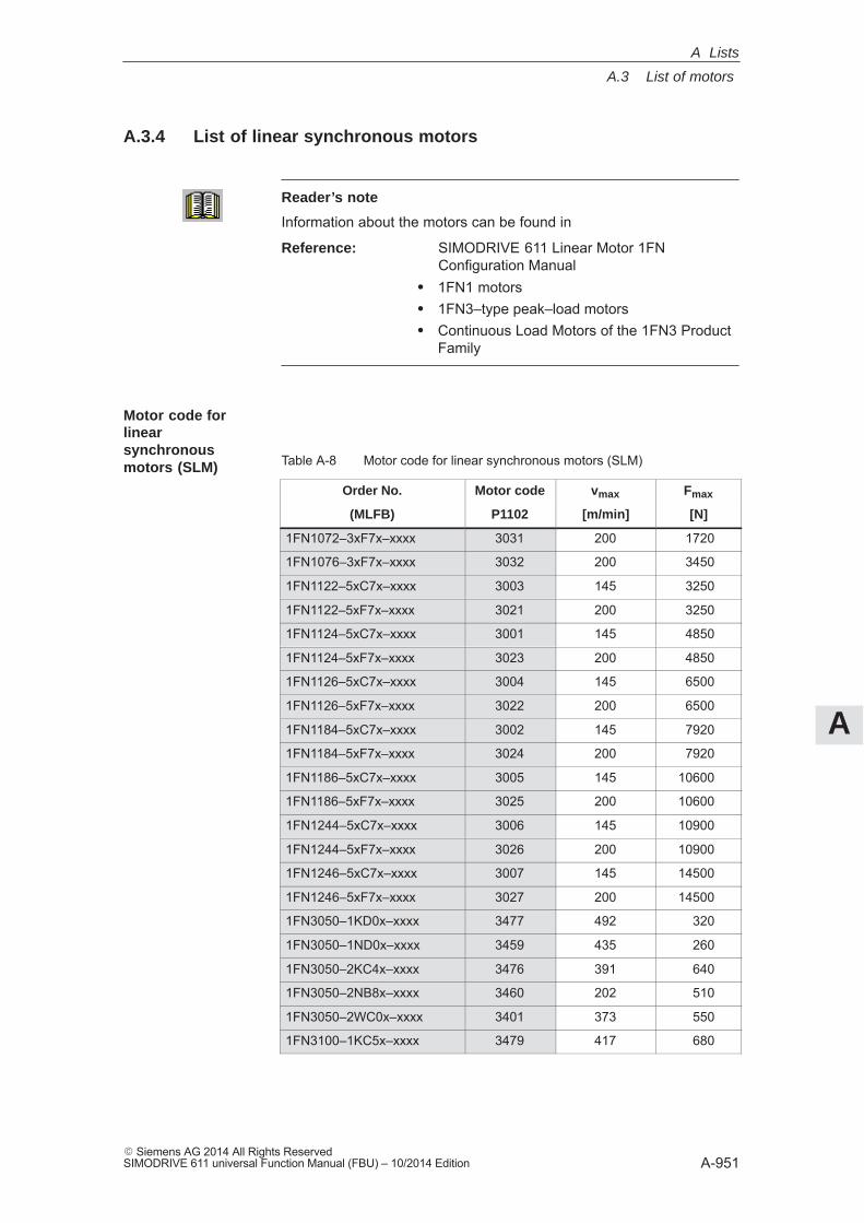
A
A.3 List of motors
A-951� Siemens AG 2014 All Rights ReservedSIMODRIVE 611 universal Function Manual (FBU) – 10/2014 Edition
A.3.4 List of linear synchronous motors
Reader’s note
Information about the motors can be found in
Reference: SIMODRIVE 611 Linear Motor 1FNConfiguration Manual
� 1FN1 motors� 1FN3–type peak–load motors� Continuous Load Motors of the 1FN3 Product
Family
Table A-8 Motor code for linear synchronous motors (SLM)
Order No. Motor code vmax Fmax
(MLFB) P1102 [m/min] [N]
1FN1072–3xF7x–xxxx 3031 200 1720
1FN1076–3xF7x–xxxx 3032 200 3450
1FN1122–5xC7x–xxxx 3003 145 3250
1FN1122–5xF7x–xxxx 3021 200 3250
1FN1124–5xC7x–xxxx 3001 145 4850
1FN1124–5xF7x–xxxx 3023 200 4850
1FN1126–5xC7x–xxxx 3004 145 6500
1FN1126–5xF7x–xxxx 3022 200 6500
1FN1184–5xC7x–xxxx 3002 145 7920
1FN1184–5xF7x–xxxx 3024 200 7920
1FN1186–5xC7x–xxxx 3005 145 10600
1FN1186–5xF7x–xxxx 3025 200 10600
1FN1244–5xC7x–xxxx 3006 145 10900
1FN1244–5xF7x–xxxx 3026 200 10900
1FN1246–5xC7x–xxxx 3007 145 14500
1FN1246–5xF7x–xxxx 3027 200 14500
1FN3050–1KD0x–xxxx 3477 492 320
1FN3050–1ND0x–xxxx 3459 435 260
1FN3050–2KC4x–xxxx 3476 391 640
1FN3050–2NB8x–xxxx 3460 202 510
1FN3050–2WC0x–xxxx 3401 373 550
1FN3100–1KC5x–xxxx 3479 417 680
Motor code for linearsynchronousmotors (SLM)
A Lists
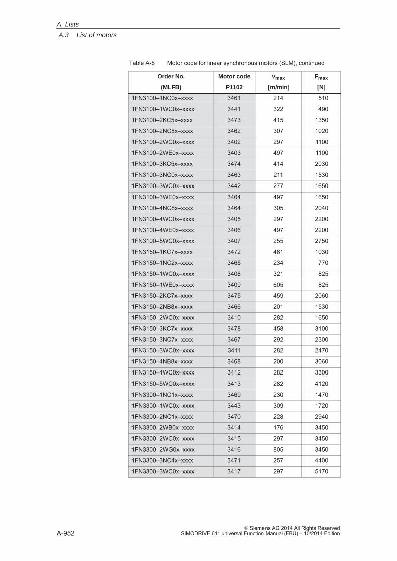
A
A.3 List of motors
A-952� Siemens AG 2014 All Rights Reserved
SIMODRIVE 611 universal Function Manual (FBU) – 10/2014 Edition
Table A-8 Motor code for linear synchronous motors (SLM), continued
Order No. FmaxvmaxMotor code
(MLFB) [N][m/min]P1102
1FN3100–1NC0x–xxxx 3461 214 510
1FN3100–1WC0x–xxxx 3441 322 490
1FN3100–2KC5x–xxxx 3473 415 1350
1FN3100–2NC8x–xxxx 3462 307 1020
1FN3100–2WC0x–xxxx 3402 297 1100
1FN3100–2WE0x–xxxx 3403 497 1100
1FN3100–3KC5x–xxxx 3474 414 2030
1FN3100–3NC0x–xxxx 3463 211 1530
1FN3100–3WC0x–xxxx 3442 277 1650
1FN3100–3WE0x–xxxx 3404 497 1650
1FN3100–4NC8x–xxxx 3464 305 2040
1FN3100–4WC0x–xxxx 3405 297 2200
1FN3100–4WE0x–xxxx 3406 497 2200
1FN3100–5WC0x–xxxx 3407 255 2750
1FN3150–1KC7x–xxxx 3472 461 1030
1FN3150–1NC2x–xxxx 3465 234 770
1FN3150–1WC0x–xxxx 3408 321 825
1FN3150–1WE0x–xxxx 3409 605 825
1FN3150–2KC7x–xxxx 3475 459 2060
1FN3150–2NB8x–xxxx 3466 201 1530
1FN3150–2WC0x–xxxx 3410 282 1650
1FN3150–3KC7x–xxxx 3478 458 3100
1FN3150–3NC7x–xxxx 3467 292 2300
1FN3150–3WC0x–xxxx 3411 282 2470
1FN3150–4NB8x–xxxx 3468 200 3060
1FN3150–4WC0x–xxxx 3412 282 3300
1FN3150–5WC0x–xxxx 3413 282 4120
1FN3300–1NC1x–xxxx 3469 230 1470
1FN3300–1WC0x–xxxx 3443 309 1720
1FN3300–2NC1x–xxxx 3470 228 2940
1FN3300–2WB0x–xxxx 3414 176 3450
1FN3300–2WC0x–xxxx 3415 297 3450
1FN3300–2WG0x–xxxx 3416 805 3450
1FN3300–3NC4x–xxxx 3471 257 4400
1FN3300–3WC0x–xxxx 3417 297 5170
A Lists
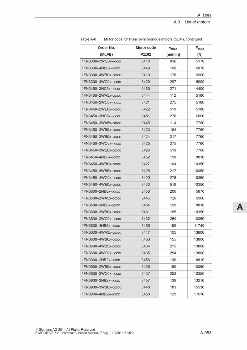
A
A.3 List of motors
A-953� Siemens AG 2014 All Rights ReservedSIMODRIVE 611 universal Function Manual (FBU) – 10/2014 Edition
Table A-8 Motor code for linear synchronous motors (SLM), continued
Order No. FmaxvmaxMotor code
(MLFB) [N][m/min]P1102
1FN3300–3WG0x–xxxx 3418 836 5170
1FN3300–4NB8x–xxxx 3449 196 5870
1FN3300–4WB0x–xxxx 3419 176 6900
1FN3300–4WC0x–xxxx 3420 297 6900
1FN3450–2NC5x–xxxx 3450 271 4400
1FN3450–2WA5x–xxxx 3444 112 5180
1FN3450–2WC0x–xxxx 3421 275 5180
1FN3450–2WE0x–xxxx 3422 519 5180
1FN3450–3NC5x–xxxx 3451 270 6600
1FN3450–3WA5x–xxxx 3445 114 7760
1FN3450–3WB0x–xxxx 3423 164 7760
1FN3450–3WB5x–xxxx 3424 217 7760
1FN3450–3WC0x–xxxx 3425 275 7760
1FN3450–3WE0x–xxxx 3426 519 7760
1FN3450–4NB8x–xxxx 3452 190 8810
1FN3450–4WB0x–xxxx 3427 164 10350
1FN3450–4WB5x–xxxx 3428 217 10350
1FN3450–4WC0x–xxxx 3429 275 10350
1FN3450–4WE0x–xxxx 3430 519 10350
1FN3600–2NB8x–xxxx 3453 200 5870
1FN3600–2WA5x–xxxx 3446 120 6900
1FN3600–3NB8x–xxxx 3454 199 8810
1FN3600–3WB0x–xxxx 3431 155 10350
1FN3600–3WC0x–xxxx 3432 254 10350
1FN3600–4NB8x–xxxx 3455 199 11740
1FN3600–4WA3x–xxxx 3447 105 13800
1FN3600–4WB0x–xxxx 3433 155 13800
1FN3600–4WB5x–xxxx 3434 215 13800
1FN3600–4WC0x–xxxx 3435 254 13800
1FN3900–2NB2x–xxxx 3456 130 8810
1FN3900–2WB0x–xxxx 3436 160 10350
1FN3900–2WC0x–xxxx 3437 253 10350
1FN3900–3NB2x–xxxx 3457 129 13210
1FN3900–3WB0x–xxxx 3448 181 15530
1FN3900–4NB2x–xxxx 3458 129 17610
A Lists
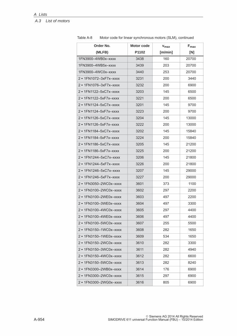
A
A.3 List of motors
A-954� Siemens AG 2014 All Rights Reserved
SIMODRIVE 611 universal Function Manual (FBU) – 10/2014 Edition
Table A-8 Motor code for linear synchronous motors (SLM), continued
Order No. FmaxvmaxMotor code
(MLFB) [N][m/min]P1102
1FN3900–4WB0x–xxxx 3438 160 20700
1FN3900–4WB5x–xxxx 3439 203 20700
1FN3900–4WC0x–xxxx 3440 253 20700
2 � 1FN1072–3xF7x–xxxx 3231 200 3440
2 � 1FN1076–3xF7x–xxxx 3232 200 6900
2 � 1FN1122–5xC7x–xxxx 3203 145 6500
2 � 1FN1122–5xF7x–xxxx 3221 200 6500
2 � 1FN1124–5xC7x–xxxx 3201 145 9700
2 � 1FN1124–5xF7x–xxxx 3223 200 9700
2 � 1FN1126–5xC7x–xxxx 3204 145 13000
2 � 1FN1126–5xF7x–xxxx 3222 200 13000
2 � 1FN1184–5xC7x–xxxx 3202 145 15840
2 � 1FN1184–5xF7x–xxxx 3224 200 15840
2 � 1FN1186–5xC7x–xxxx 3205 145 21200
2 � 1FN1186–5xF7x–xxxx 3225 200 21200
2 � 1FN1244–5xC7x–xxxx 3206 145 21800
2 � 1FN1244–5xF7x–xxxx 3226 200 21800
2 � 1FN1246–5xC7x–xxxx 3207 145 29000
2 � 1FN1246–5xF7x–xxxx 3227 200 29000
2 � 1FN3050–2WC0x–xxxx 3601 373 1100
2 � 1FN3100–2WC0x–xxxx 3602 297 2200
2 � 1FN3100–2WE0x–xxxx 3603 497 2200
2 � 1FN3100–3WE0x–xxxx 3604 497 3300
2 � 1FN3100–4WC0x–xxxx 3605 297 4400
2 � 1FN3100–4WE0x–xxxx 3606 497 4400
2 � 1FN3100–5WC0x–xxxx 3607 255 5500
2 � 1FN3150–1WC0x–xxxx 3608 282 1650
2 � 1FN3150–1WE0x–xxxx 3609 534 1650
2 � 1FN3150–2WC0x–xxxx 3610 282 3300
2 � 1FN3150–3WC0x–xxxx 3611 282 4940
2 � 1FN3150–4WC0x–xxxx 3612 282 6600
2 � 1FN3150–5WC0x–xxxx 3613 282 8240
2 � 1FN3300–2WB0x–xxxx 3614 176 6900
2 � 1FN3300–2WC0x–xxxx 3615 297 6900
2 � 1FN3300–2WG0x–xxxx 3616 805 6900
A Lists
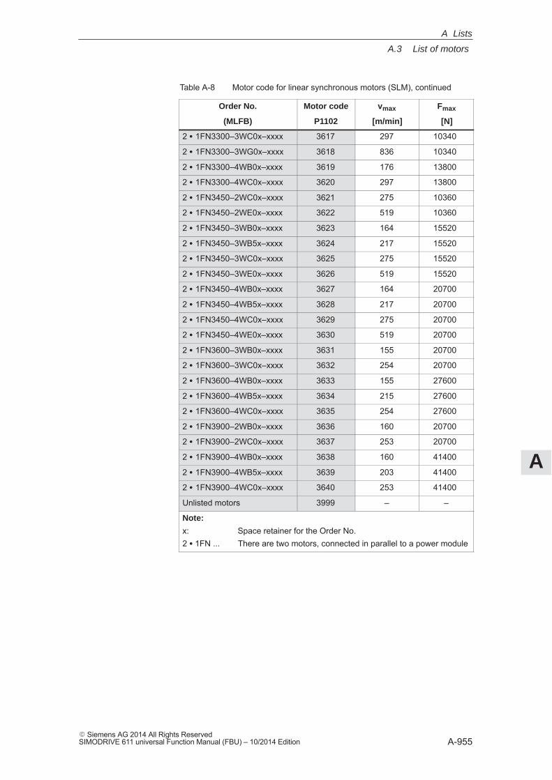
A
A.3 List of motors
A-955� Siemens AG 2014 All Rights ReservedSIMODRIVE 611 universal Function Manual (FBU) – 10/2014 Edition
Table A-8 Motor code for linear synchronous motors (SLM), continued
Order No. FmaxvmaxMotor code
(MLFB) [N][m/min]P1102
2 � 1FN3300–3WC0x–xxxx 3617 297 10340
2 � 1FN3300–3WG0x–xxxx 3618 836 10340
2 � 1FN3300–4WB0x–xxxx 3619 176 13800
2 � 1FN3300–4WC0x–xxxx 3620 297 13800
2 � 1FN3450–2WC0x–xxxx 3621 275 10360
2 � 1FN3450–2WE0x–xxxx 3622 519 10360
2 � 1FN3450–3WB0x–xxxx 3623 164 15520
2 � 1FN3450–3WB5x–xxxx 3624 217 15520
2 � 1FN3450–3WC0x–xxxx 3625 275 15520
2 � 1FN3450–3WE0x–xxxx 3626 519 15520
2 � 1FN3450–4WB0x–xxxx 3627 164 20700
2 � 1FN3450–4WB5x–xxxx 3628 217 20700
2 � 1FN3450–4WC0x–xxxx 3629 275 20700
2 � 1FN3450–4WE0x–xxxx 3630 519 20700
2 � 1FN3600–3WB0x–xxxx 3631 155 20700
2 � 1FN3600–3WC0x–xxxx 3632 254 20700
2 � 1FN3600–4WB0x–xxxx 3633 155 27600
2 � 1FN3600–4WB5x–xxxx 3634 215 27600
2 � 1FN3600–4WC0x–xxxx 3635 254 27600
2 � 1FN3900–2WB0x–xxxx 3636 160 20700
2 � 1FN3900–2WC0x–xxxx 3637 253 20700
2 � 1FN3900–4WB0x–xxxx 3638 160 41400
2 � 1FN3900–4WB5x–xxxx 3639 203 41400
2 � 1FN3900–4WC0x–xxxx 3640 253 41400
Unlisted motors 3999 – –
Note:
x: Space retainer for the Order No.2 � 1FN ... There are two motors, connected in parallel to a power module
A Lists
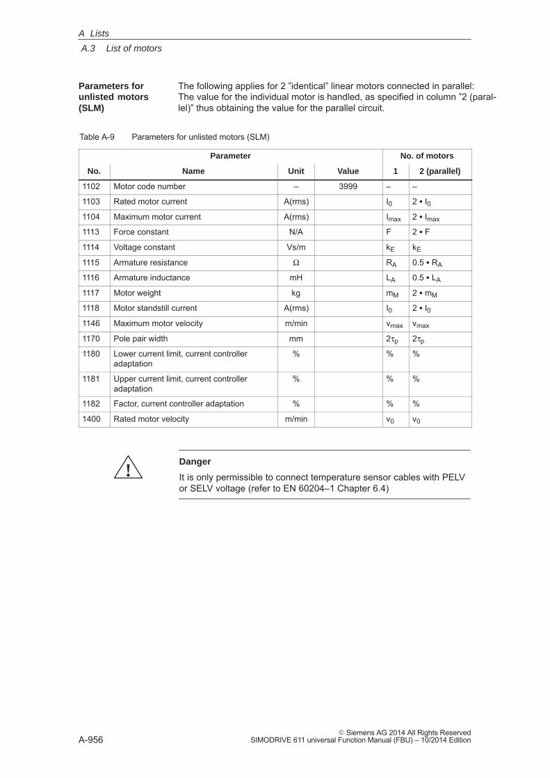
A
A.3 List of motors
A-956� Siemens AG 2014 All Rights Reserved
SIMODRIVE 611 universal Function Manual (FBU) – 10/2014 Edition
The following applies for 2 ”identical” linear motors connected in parallel:The value for the individual motor is handled, as specified in column ”2 (paral-lel)” thus obtaining the value for the parallel circuit.
Table A-9 Parameters for unlisted motors (SLM)
Parameter No. of motors
No. Name Unit Value 1 2 (parallel)
1102 Motor code number – 3999 – –
1103 Rated motor current A(rms) I0 2 � I01104 Maximum motor current A(rms) Imax 2 � Imax
1113 Force constant N/A F 2 � F
1114 Voltage constant Vs/m kE kE
1115 Armature resistance Ω RA 0.5 � RA
1116 Armature inductance mH LA 0.5 � LA
1117 Motor weight kg mM 2 � mM
1118 Motor standstill current A(rms) I0 2 � I01146 Maximum motor velocity m/min vmax vmax
1170 Pole pair width mm 2τp 2τp
1180 Lower current limit, current controlleradaptation
% % %
1181 Upper current limit, current controlleradaptation
% % %
1182 Factor, current controller adaptation % % %
1400 Rated motor velocity m/min v0 v0
!Danger
It is only permissible to connect temperature sensor cables with PELVor SELV voltage (refer to EN 60204–1 Chapter 6.4)
Parameters forunlisted motors(SLM)
A Lists
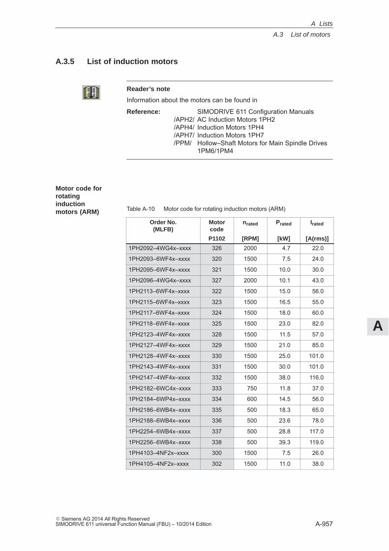
A
A.3 List of motors
A-957� Siemens AG 2014 All Rights ReservedSIMODRIVE 611 universal Function Manual (FBU) – 10/2014 Edition
A.3.5 List of induction motors
Reader’s note
Information about the motors can be found in
Reference: SIMODRIVE 611 Configuration Manuals /APH2/ AC Induction Motors 1PH2/APH4/ Induction Motors 1PH4/APH7/ Induction Motors 1PH7/PPM/ Hollow–Shaft Motors for Main Spindle Drives
1PM6/1PM4
Table A-10 Motor code for rotating induction motors (ARM)
Order No.(MLFB)
Motorcode
nrated Prated Irated
P1102 [RPM] [kW] [A(rms)]
1PH2092–4WG4x–xxxx 326 2000 4.7 22.0
1PH2093–6WF4x–xxxx 320 1500 7.5 24.0
1PH2095–6WF4x–xxxx 321 1500 10.0 30.0
1PH2096–4WG4x–xxxx 327 2000 10.1 43.0
1PH2113–6WF4x–xxxx 322 1500 15.0 56.0
1PH2115–6WF4x–xxxx 323 1500 16.5 55.0
1PH2117–6WF4x–xxxx 324 1500 18.0 60.0
1PH2118–6WF4x–xxxx 325 1500 23.0 82.0
1PH2123–4WF4x–xxxx 328 1500 11.5 57.0
1PH2127–4WF4x–xxxx 329 1500 21.0 85.0
1PH2128–4WF4x–xxxx 330 1500 25.0 101.0
1PH2143–4WF4x–xxxx 331 1500 30.0 101.0
1PH2147–4WF4x–xxxx 332 1500 38.0 116.0
1PH2182–6WC4x–xxxx 333 750 11.8 37.0
1PH2184–6WP4x–xxxx 334 600 14.5 56.0
1PH2186–6WB4x–xxxx 335 500 18.3 65.0
1PH2188–6WB4x–xxxx 336 500 23.6 78.0
1PH2254–6WB4x–xxxx 337 500 28.8 117.0
1PH2256–6WB4x–xxxx 338 500 39.3 119.0
1PH4103–4NF2x–xxxx 300 1500 7.5 26.0
1PH4105–4NF2x–xxxx 302 1500 11.0 38.0
Motor code forrotatinginductionmotors (ARM)
A Lists
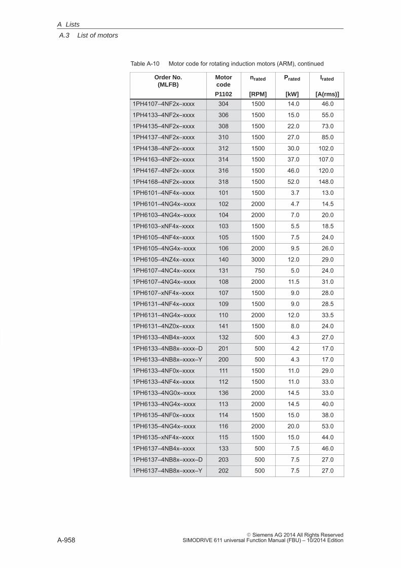
A
A.3 List of motors
A-958� Siemens AG 2014 All Rights Reserved
SIMODRIVE 611 universal Function Manual (FBU) – 10/2014 Edition
Table A-10 Motor code for rotating induction motors (ARM), continued
Order No.(MLFB)
IratedPratednratedMotorcode
[A(rms)][kW][RPM]P1102
1PH4107–4NF2x–xxxx 304 1500 14.0 46.0
1PH4133–4NF2x–xxxx 306 1500 15.0 55.0
1PH4135–4NF2x–xxxx 308 1500 22.0 73.0
1PH4137–4NF2x–xxxx 310 1500 27.0 85.0
1PH4138–4NF2x–xxxx 312 1500 30.0 102.0
1PH4163–4NF2x–xxxx 314 1500 37.0 107.0
1PH4167–4NF2x–xxxx 316 1500 46.0 120.0
1PH4168–4NF2x–xxxx 318 1500 52.0 148.0
1PH6101–4NF4x–xxxx 101 1500 3.7 13.0
1PH6101–4NG4x–xxxx 102 2000 4.7 14.5
1PH6103–4NG4x–xxxx 104 2000 7.0 20.0
1PH6103–xNF4x–xxxx 103 1500 5.5 18.5
1PH6105–4NF4x–xxxx 105 1500 7.5 24.0
1PH6105–4NG4x–xxxx 106 2000 9.5 26.0
1PH6105–4NZ4x–xxxx 140 3000 12.0 29.0
1PH6107–4NC4x–xxxx 131 750 5.0 24.0
1PH6107–4NG4x–xxxx 108 2000 11.5 31.0
1PH6107–xNF4x–xxxx 107 1500 9.0 28.0
1PH6131–4NF4x–xxxx 109 1500 9.0 28.5
1PH6131–4NG4x–xxxx 110 2000 12.0 33.5
1PH6131–4NZ0x–xxxx 141 1500 8.0 24.0
1PH6133–4NB4x–xxxx 132 500 4.3 27.0
1PH6133–4NB8x–xxxx–D 201 500 4.2 17.0
1PH6133–4NB8x–xxxx–Y 200 500 4.3 17.0
1PH6133–4NF0x–xxxx 111 1500 11.0 29.0
1PH6133–4NF4x–xxxx 112 1500 11.0 33.0
1PH6133–4NG0x–xxxx 136 2000 14.5 33.0
1PH6133–4NG4x–xxxx 113 2000 14.5 40.0
1PH6135–4NF0x–xxxx 114 1500 15.0 38.0
1PH6135–4NG4x–xxxx 116 2000 20.0 53.0
1PH6135–xNF4x–xxxx 115 1500 15.0 44.0
1PH6137–4NB4x–xxxx 133 500 7.5 46.0
1PH6137–4NB8x–xxxx–D 203 500 7.5 27.0
1PH6137–4NB8x–xxxx–Y 202 500 7.5 27.0
A Lists
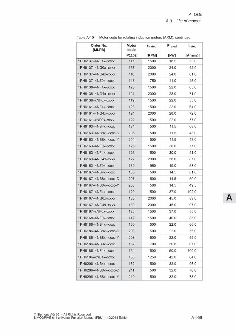
A
A.3 List of motors
A-959� Siemens AG 2014 All Rights ReservedSIMODRIVE 611 universal Function Manual (FBU) – 10/2014 Edition
Table A-10 Motor code for rotating induction motors (ARM), continued
Order No.(MLFB)
IratedPratednratedMotorcode
[A(rms)][kW][RPM]P1102
1PH6137–4NF4x–xxxx 117 1500 18.5 53.0
1PH6137–4NG0x–xxxx 137 2000 24.0 52.0
1PH6137–4NG4x–xxxx 118 2000 24.0 61.0
1PH6137–4NZ0x–xxxx 143 750 11.0 45.0
1PH6138–4NF4x–xxxx 120 1500 22.0 65.0
1PH6138–4NG4x–xxxx 121 2000 28.0 71.0
1PH6138–xNF0x–xxxx 119 1500 22.0 55.0
1PH6161–4NF4x–xxxx 123 1500 22.0 64.0
1PH6161–4NG4x–xxxx 124 2000 28.0 72.0
1PH6161–xNF0x–xxxx 122 1500 22.0 57.0
1PH6163–4NB4x–xxxx 134 500 11.5 68.0
1PH6163–4NB8x–xxxx–D 205 500 11.5 43.0
1PH6163–4NB8x–xxxx–Y 204 500 11.5 43.0
1PH6163–4NF0x–xxxx 125 1500 30.0 77.0
1PH6163–4NF4x–xxxx 126 1500 30.0 91.0
1PH6163–4NG4x–xxxx 127 2000 38.0 87.0
1PH6163–4NZ0x–xxxx 139 950 19.0 58.0
1PH6167–4NB4x–xxxx 135 500 14.5 81.0
1PH6167–4NB8x–xxxx–D 207 500 14.5 50.0
1PH6167–4NB8x–xxxx–Y 206 500 14.5 49.5
1PH6167–4NF4x–xxxx 129 1500 37.0 102.0
1PH6167–4NG0x–xxxx 138 2000 45.0 89.0
1PH6167–4NG4x–xxxx 130 2000 45.0 97.0
1PH6167–xNF0x–xxxx 128 1500 37.0 85.0
1PH6168–4NF0x–xxxx 142 1500 40.0 85.0
1PH6186–4NB4x–xxxx 160 500 22.0 66.0
1PH6186–4NB8x–xxxx–D 209 500 22.0 55.0
1PH6186–4NB8x–xxxx–Y 208 500 22.0 55.0
1PH6186–4NB9x–xxxx 167 700 30.8 67.0
1PH6186–4NF4x–xxxx 164 1500 50.0 100.0
1PH6186–xNE4x–xxxx 163 1250 42.0 84.0
1PH6206–4NB4x–xxxx 162 500 32.0 96.0
1PH6206–4NB8x–xxxx–D 211 500 32.0 78.0
1PH6206–4NB8x–xxxx–Y 210 500 32.0 78.0
A Lists
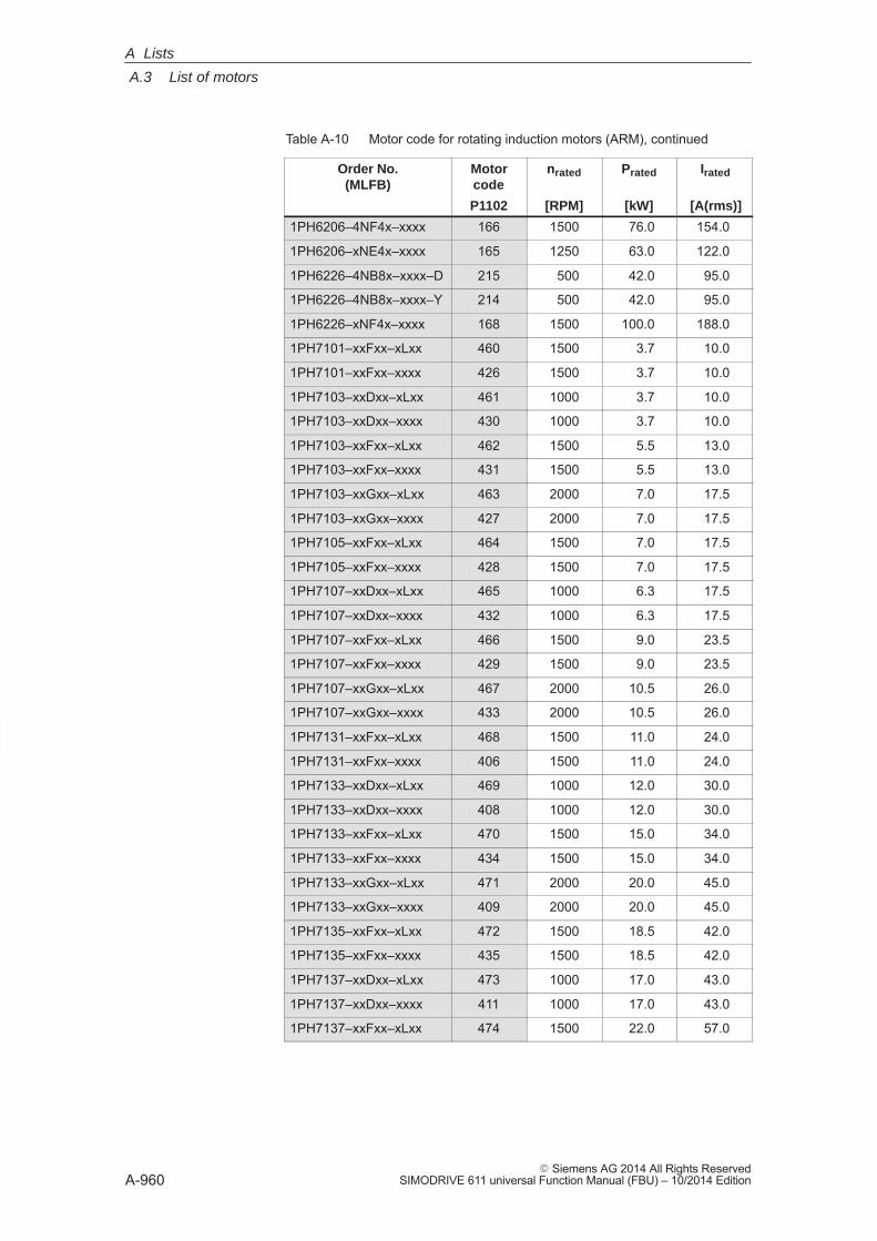
A
A.3 List of motors
A-960� Siemens AG 2014 All Rights Reserved
SIMODRIVE 611 universal Function Manual (FBU) – 10/2014 Edition
Table A-10 Motor code for rotating induction motors (ARM), continued
Order No.(MLFB)
IratedPratednratedMotorcode
[A(rms)][kW][RPM]P1102
1PH6206–4NF4x–xxxx 166 1500 76.0 154.0
1PH6206–xNE4x–xxxx 165 1250 63.0 122.0
1PH6226–4NB8x–xxxx–D 215 500 42.0 95.0
1PH6226–4NB8x–xxxx–Y 214 500 42.0 95.0
1PH6226–xNF4x–xxxx 168 1500 100.0 188.0
1PH7101–xxFxx–xLxx 460 1500 3.7 10.0
1PH7101–xxFxx–xxxx 426 1500 3.7 10.0
1PH7103–xxDxx–xLxx 461 1000 3.7 10.0
1PH7103–xxDxx–xxxx 430 1000 3.7 10.0
1PH7103–xxFxx–xLxx 462 1500 5.5 13.0
1PH7103–xxFxx–xxxx 431 1500 5.5 13.0
1PH7103–xxGxx–xLxx 463 2000 7.0 17.5
1PH7103–xxGxx–xxxx 427 2000 7.0 17.5
1PH7105–xxFxx–xLxx 464 1500 7.0 17.5
1PH7105–xxFxx–xxxx 428 1500 7.0 17.5
1PH7107–xxDxx–xLxx 465 1000 6.3 17.5
1PH7107–xxDxx–xxxx 432 1000 6.3 17.5
1PH7107–xxFxx–xLxx 466 1500 9.0 23.5
1PH7107–xxFxx–xxxx 429 1500 9.0 23.5
1PH7107–xxGxx–xLxx 467 2000 10.5 26.0
1PH7107–xxGxx–xxxx 433 2000 10.5 26.0
1PH7131–xxFxx–xLxx 468 1500 11.0 24.0
1PH7131–xxFxx–xxxx 406 1500 11.0 24.0
1PH7133–xxDxx–xLxx 469 1000 12.0 30.0
1PH7133–xxDxx–xxxx 408 1000 12.0 30.0
1PH7133–xxFxx–xLxx 470 1500 15.0 34.0
1PH7133–xxFxx–xxxx 434 1500 15.0 34.0
1PH7133–xxGxx–xLxx 471 2000 20.0 45.0
1PH7133–xxGxx–xxxx 409 2000 20.0 45.0
1PH7135–xxFxx–xLxx 472 1500 18.5 42.0
1PH7135–xxFxx–xxxx 435 1500 18.5 42.0
1PH7137–xxDxx–xLxx 473 1000 17.0 43.0
1PH7137–xxDxx–xxxx 411 1000 17.0 43.0
1PH7137–xxFxx–xLxx 474 1500 22.0 57.0
A Lists
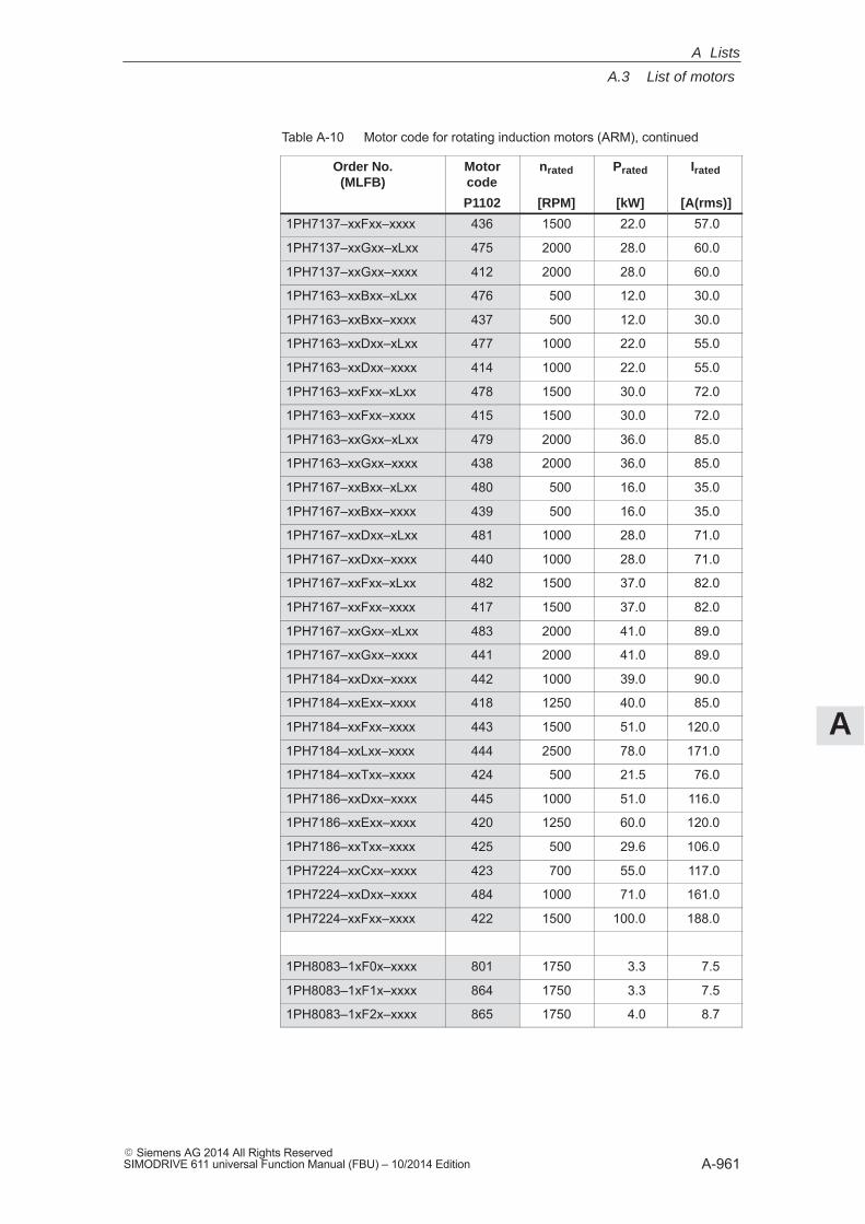
A
A.3 List of motors
A-961� Siemens AG 2014 All Rights ReservedSIMODRIVE 611 universal Function Manual (FBU) – 10/2014 Edition
Table A-10 Motor code for rotating induction motors (ARM), continued
Order No.(MLFB)
IratedPratednratedMotorcode
[A(rms)][kW][RPM]P1102
1PH7137–xxFxx–xxxx 436 1500 22.0 57.0
1PH7137–xxGxx–xLxx 475 2000 28.0 60.0
1PH7137–xxGxx–xxxx 412 2000 28.0 60.0
1PH7163–xxBxx–xLxx 476 500 12.0 30.0
1PH7163–xxBxx–xxxx 437 500 12.0 30.0
1PH7163–xxDxx–xLxx 477 1000 22.0 55.0
1PH7163–xxDxx–xxxx 414 1000 22.0 55.0
1PH7163–xxFxx–xLxx 478 1500 30.0 72.0
1PH7163–xxFxx–xxxx 415 1500 30.0 72.0
1PH7163–xxGxx–xLxx 479 2000 36.0 85.0
1PH7163–xxGxx–xxxx 438 2000 36.0 85.0
1PH7167–xxBxx–xLxx 480 500 16.0 35.0
1PH7167–xxBxx–xxxx 439 500 16.0 35.0
1PH7167–xxDxx–xLxx 481 1000 28.0 71.0
1PH7167–xxDxx–xxxx 440 1000 28.0 71.0
1PH7167–xxFxx–xLxx 482 1500 37.0 82.0
1PH7167–xxFxx–xxxx 417 1500 37.0 82.0
1PH7167–xxGxx–xLxx 483 2000 41.0 89.0
1PH7167–xxGxx–xxxx 441 2000 41.0 89.0
1PH7184–xxDxx–xxxx 442 1000 39.0 90.0
1PH7184–xxExx–xxxx 418 1250 40.0 85.0
1PH7184–xxFxx–xxxx 443 1500 51.0 120.0
1PH7184–xxLxx–xxxx 444 2500 78.0 171.0
1PH7184–xxTxx–xxxx 424 500 21.5 76.0
1PH7186–xxDxx–xxxx 445 1000 51.0 116.0
1PH7186–xxExx–xxxx 420 1250 60.0 120.0
1PH7186–xxTxx–xxxx 425 500 29.6 106.0
1PH7224–xxCxx–xxxx 423 700 55.0 117.0
1PH7224–xxDxx–xxxx 484 1000 71.0 161.0
1PH7224–xxFxx–xxxx 422 1500 100.0 188.0
1PH8083–1xF0x–xxxx 801 1750 3.3 7.5
1PH8083–1xF1x–xxxx 864 1750 3.3 7.5
1PH8083–1xF2x–xxxx 865 1750 4.0 8.7
A Lists
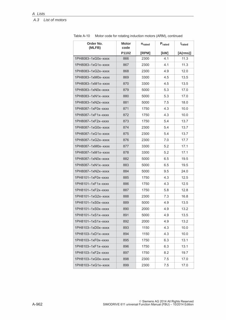
A
A.3 List of motors
A-962� Siemens AG 2014 All Rights Reserved
SIMODRIVE 611 universal Function Manual (FBU) – 10/2014 Edition
Table A-10 Motor code for rotating induction motors (ARM), continued
Order No.(MLFB)
IratedPratednratedMotorcode
[A(rms)][kW][RPM]P1102
1PH8083–1xG0x–xxxx 866 2300 4.1 11.3
1PH8083–1xG1x–xxxx 867 2300 4.1 11.3
1PH8083–1xG2x–xxxx 868 2300 4.9 12.0
1PH8083–1xM0x–xxxx 869 3300 4.5 13.5
1PH8083–1xM1x–xxxx 870 3300 4.5 13.5
1PH8083–1xN0x–xxxx 879 5000 5.3 17.0
1PH8083–1xN1x–xxxx 880 5000 5.3 17.0
1PH8083–1xN2x–xxxx 881 5000 7.5 18.0
1PH8087–1xF0x–xxxx 871 1750 4.3 10.0
1PH8087–1xF1x–xxxx 872 1750 4.3 10.0
1PH8087–1xF2x–xxxx 873 1750 5.4 13.7
1PH8087–1xG0x–xxxx 874 2300 5.4 13.7
1PH8087–1xG1x–xxxx 875 2300 5.4 13.7
1PH8087–1xG2x–xxxx 876 2300 7.0 17.7
1PH8087–1xM0x–xxxx 877 3300 5.2 17.1
1PH8087–1xM1x–xxxx 878 3300 5.2 17.1
1PH8087–1xN0x–xxxx 882 5000 6.5 19.5
1PH8087–1xN1x–xxxx 883 5000 6.5 19.5
1PH8087–1xN2x–xxxx 884 5000 9.5 24.0
1PH8101–1xF0x–xxxx 885 1750 4.3 12.5
1PH8101–1xF1x–xxxx 886 1750 4.3 12.5
1PH8101–1xF2x–xxxx 887 1750 5.8 12.8
1PH8101–1xG2x–xxxx 888 2300 7.3 16.8
1PH8101–1xS0x–xxxx 889 5000 4.9 13.5
1PH8101–1xS0x–xxxx 890 2000 4.9 13.2
1PH8101–1xS1x–xxxx 891 5000 4.9 13.5
1PH8101–1xS1x–xxxx 892 2000 4.9 13.2
1PH8103–1xD0x–xxxx 893 1150 4.3 10.0
1PH8103–1xD1x–xxxx 894 1150 4.3 10.0
1PH8103–1xF0x–xxxx 895 1750 6.3 13.1
1PH8103–1xF1x–xxxx 896 1750 6.3 13.1
1PH8103–1xF2x–xxxx 897 1750 8.2 19.7
1PH8103–1xG0x–xxxx 898 2300 7.5 17.0
1PH8103–1xG1x–xxxx 899 2300 7.5 17.0
A Lists

A
A.3 List of motors
A-963� Siemens AG 2014 All Rights ReservedSIMODRIVE 611 universal Function Manual (FBU) – 10/2014 Edition
Table A-10 Motor code for rotating induction motors (ARM), continued
Order No.(MLFB)
IratedPratednratedMotorcode
[A(rms)][kW][RPM]P1102
1PH8103–1xG2x–xxxx 900 2300 10.9 23.8
1PH8103–1xM0x–xxxx 920 3300 9.3 25.7
1PH8103–1xM1x–xxxx 921 3300 9.3 25.7
1PH8103–1xM2x–xxxx 922 3300 11.7 30.0
1PH8105–1xF0x–xxxx 901 1750 8.0 17.5
1PH8105–1xF1x–xxxx 902 1750 8.0 17.5
1PH8105–1xF2x–xxxx 903 1750 12.5 28.5
1PH8105–1xG2x–xxxx 904 2300 15.0 34.0
1PH8105–1xM2x–xxxx 923 3300 18.5 45.0
1PH8105–1xS0x–xxxx 905 5000 9.3 24.0
1PH8105–1xS0x–xxxx 906 2000 10.0 23.0
1PH8105–1xS1x–xxxx 907 5000 9.3 24.0
1PH8105–1xS1x–xxxx 908 2000 10.0 23.0
1PH8107–1xD0x–xxxx 909 1150 7.2 17.5
1PH8107–1xD1x–xxxx 910 1150 7.2 17.5
1PH8107–1xF0x–xxxx 911 1750 10.0 22.0
1PH8107–1xF1x–xxxx 912 1750 10.0 22.0
1PH8107–1xF2x–xxxx 913 1750 15.5 42.0
1PH8107–1xG0x–xxxx 914 2300 12.0 26.0
1PH8107–1xG1x–xxxx 915 2300 12.0 26.0
1PH8107–1xM0x–xxxx 924 3300 13.0 38.0
1PH8107–1xM1x–xxxx 925 3300 13.0 38.0
1PH8107–1xM2x–xxxx 926 3300 20.0 60.0
1PH8107–1xS0x–xxxx 916 5000 11.0 28.0
1PH8107–1xS0x–xxxx 917 2000 11.0 26.7
1PH8107–1xS1x–xxxx 918 5000 11.0 28.0
1PH8107–1xS1x–xxxx 919 2000 11.0 26.7
1PH8131–1xF0x–xxxx 803 1750 13.0 24.0
1PH8131–1xF1x–xxxx 804 1750 13.0 24.0
1PH8131–1xF2x–xxxx 805 1750 17.0 30.0
1PH8131–1xG2x–xxxx 806 2300 20.0 39.0
1PH8131–1xS0x–xxxx 807 5000 14.6 40.0
1PH8131–1xS0x–xxxx 808 2000 14.6 39.0
1PH8131–1xS1x–xxxx 809 2000 14.6 39.0
A Lists
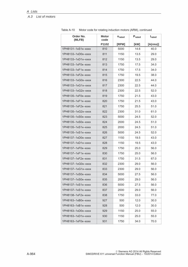
A
A.3 List of motors
A-964� Siemens AG 2014 All Rights Reserved
SIMODRIVE 611 universal Function Manual (FBU) – 10/2014 Edition
Table A-10 Motor code for rotating induction motors (ARM), continued
Order No.(MLFB)
IratedPratednratedMotorcode
[A(rms)][kW][RPM]P1102
1PH8131–1xS1x–xxxx 810 5000 14.6 40.0
1PH8133–1xD0x–xxxx 811 1150 13.5 29.0
1PH8133–1xD1x–xxxx 812 1150 13.5 29.0
1PH8133–1xF0x–xxxx 813 1750 17.5 34.0
1PH8133–1xF1x–xxxx 814 1750 17.5 34.0
1PH8133–1xF2x–xxxx 815 1750 19.5 38.0
1PH8133–1xG0x–xxxx 816 2300 22.5 44.0
1PH8133–1xG1x–xxxx 817 2300 22.5 44.0
1PH8133–1xG2x–xxxx 818 2300 22.5 52.0
1PH8135–1xF0x–xxxx 819 1750 21.5 43.0
1PH8135–1xF1x–xxxx 820 1750 21.5 43.0
1PH8135–1xF2x–xxxx 821 1750 25.5 51.0
1PH8135–1xG2x–xxxx 822 2300 31.0 61.0
1PH8135–1xS0x–xxxx 823 5000 24.5 52.0
1PH8135–1xS0x–xxxx 824 2000 24.5 51.0
1PH8135–1xS1x–xxxx 825 2000 24.5 51.0
1PH8135–1xS1x–xxxx 826 5000 24.5 52.0
1PH8137–1xD0x–xxxx 827 1150 19.5 43.0
1PH8137–1xD1x–xxxx 828 1150 19.5 43.0
1PH8137–1xF0x–xxxx 829 1750 25.0 56.0
1PH8137–1xF1x–xxxx 830 1750 25.0 56.0
1PH8137–1xF2x–xxxx 831 1750 31.5 67.0
1PH8137–1xG0x–xxxx 832 2300 29.0 56.0
1PH8137–1xG1x–xxxx 833 2300 29.0 56.0
1PH8137–1xS0x–xxxx 834 5000 27.5 56.0
1PH8137–1xS0x–xxxx 835 2000 29.0 56.0
1PH8137–1xS1x–xxxx 836 5000 27.5 56.0
1PH8137–1xS1x–xxxx 837 2000 29.0 56.0
1PH8138–1xF2x–xxxx 838 1750 33.0 77.0
1PH8163–1xB0x–xxxx 927 500 12.0 30.0
1PH8163–1xB1x–xxxx 928 500 12.0 30.0
1PH8163–1xD0x–xxxx 929 1150 25.0 55.0
1PH8163–1xD1x–xxxx 930 1150 25.0 55.0
1PH8163–1xF0x–xxxx 931 1750 34.0 70.0
A Lists
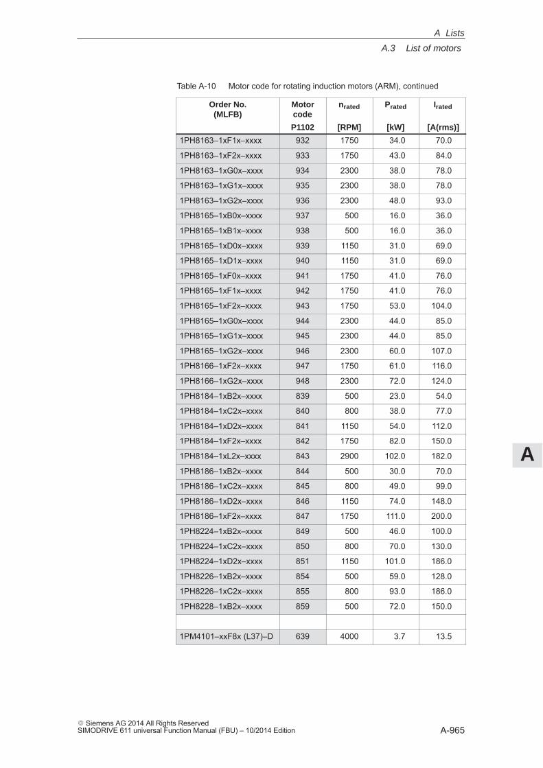
A
A.3 List of motors
A-965� Siemens AG 2014 All Rights ReservedSIMODRIVE 611 universal Function Manual (FBU) – 10/2014 Edition
Table A-10 Motor code for rotating induction motors (ARM), continued
Order No.(MLFB)
IratedPratednratedMotorcode
[A(rms)][kW][RPM]P1102
1PH8163–1xF1x–xxxx 932 1750 34.0 70.0
1PH8163–1xF2x–xxxx 933 1750 43.0 84.0
1PH8163–1xG0x–xxxx 934 2300 38.0 78.0
1PH8163–1xG1x–xxxx 935 2300 38.0 78.0
1PH8163–1xG2x–xxxx 936 2300 48.0 93.0
1PH8165–1xB0x–xxxx 937 500 16.0 36.0
1PH8165–1xB1x–xxxx 938 500 16.0 36.0
1PH8165–1xD0x–xxxx 939 1150 31.0 69.0
1PH8165–1xD1x–xxxx 940 1150 31.0 69.0
1PH8165–1xF0x–xxxx 941 1750 41.0 76.0
1PH8165–1xF1x–xxxx 942 1750 41.0 76.0
1PH8165–1xF2x–xxxx 943 1750 53.0 104.0
1PH8165–1xG0x–xxxx 944 2300 44.0 85.0
1PH8165–1xG1x–xxxx 945 2300 44.0 85.0
1PH8165–1xG2x–xxxx 946 2300 60.0 107.0
1PH8166–1xF2x–xxxx 947 1750 61.0 116.0
1PH8166–1xG2x–xxxx 948 2300 72.0 124.0
1PH8184–1xB2x–xxxx 839 500 23.0 54.0
1PH8184–1xC2x–xxxx 840 800 38.0 77.0
1PH8184–1xD2x–xxxx 841 1150 54.0 112.0
1PH8184–1xF2x–xxxx 842 1750 82.0 150.0
1PH8184–1xL2x–xxxx 843 2900 102.0 182.0
1PH8186–1xB2x–xxxx 844 500 30.0 70.0
1PH8186–1xC2x–xxxx 845 800 49.0 99.0
1PH8186–1xD2x–xxxx 846 1150 74.0 148.0
1PH8186–1xF2x–xxxx 847 1750 111.0 200.0
1PH8224–1xB2x–xxxx 849 500 46.0 100.0
1PH8224–1xC2x–xxxx 850 800 70.0 130.0
1PH8224–1xD2x–xxxx 851 1150 101.0 186.0
1PH8226–1xB2x–xxxx 854 500 59.0 128.0
1PH8226–1xC2x–xxxx 855 800 93.0 186.0
1PH8228–1xB2x–xxxx 859 500 72.0 150.0
1PM4101–xxF8x (L37)–D 639 4000 3.7 13.5
A Lists

A
A.3 List of motors
A-966� Siemens AG 2014 All Rights Reserved
SIMODRIVE 611 universal Function Manual (FBU) – 10/2014 Edition
Table A-10 Motor code for rotating induction motors (ARM), continued
Order No.(MLFB)
IratedPratednratedMotorcode
[A(rms)][kW][RPM]P1102
1PM4101–xxF8x (L37)–Y 638 1500 3.7 13.0
1PM4101–xxF8x–xxxx–D 601 4000 3.7 13.5
1PM4101–xxF8x–xxxx–Y 600 1500 3.7 13.0
1PM4101–xxW2x (L37) 640 1500 5.0 18.0
1PM4101–xxW2x–xxxx 620 1500 5.0 18.0
1PM4105–xxF8x (L37)–D 633 4000 7.5 24.0
1PM4105–xxF8x (L37)–Y 632 1500 7.5 23.0
1PM4105–xxF8x–xxxx–D 603 4000 7.5 24.0
1PM4105–xxF8x–xxxx–Y 602 1500 7.5 23.0
1PM4105–xxW2x (L37) 641 1500 11.0 38.0
1PM4105–xxW2x–xxxx 621 1500 11.0 38.0
1PM4133–xxF8x (L37)–D 634 4000 11.0 41.0
1PM4133–xxF8x (L37)–Y 635 1500 11.0 41.0
1PM4133–xxF8x–xxxx–D 605 4000 11.0 41.0
1PM4133–xxF8x–xxxx–Y 604 1500 11.0 41.0
1PM4133–xxW2x (L37) 642 1500 15.0 55.0
1PM4133–xxW2x–xxxx 618 1500 15.0 55.0
1PM4137–xxF8x (L37)–D 637 4000 18.5 56.0
1PM4137–xxF8x–xxxx–D 607 4000 18.5 56.0
1PM4137–xxF8x–xxxx–Y 606 1500 18.5 56.0
1PM4137–xxW2x (L37) 643 1500 27.0 85.0
1PM4137–xxW2x–xxxx 619 1500 27.0 85.0
1PM6101–xxF8x–(L37)–D 623 4000 3.7 13.5
1PM6101–xxF8x–(L37)–Y 622 1500 3.7 13.0
1PM6101–xxF8x–xxxx–D 609 4000 3.7 13.5
1PM6101–xxF8x–xxxx–Y 608 1500 3.7 13.0
1PM6105–xxF8x (L37)–D 625 4000 7.5 24.0
1PM6105–xxF8x (L37)–Y 624 1500 7.5 23.0
1PM6105–xxF8x–xxxx–D 611 4000 7.5 24.0
1PM6105–xxF8x–xxxx–Y 610 1500 7.5 23.0
1PM6107–xxF8x–xxxx–D 645 4000 9.0 30.0
1PM6107–xxF8x–xxxx–Y 644 1500 9.0 28.0
1PM6133–xxF8x (L37)–D 627 4000 11.0 41.0
1PM6133–xxF8x (L37)–Y 626 1500 11.0 41.0
A Lists
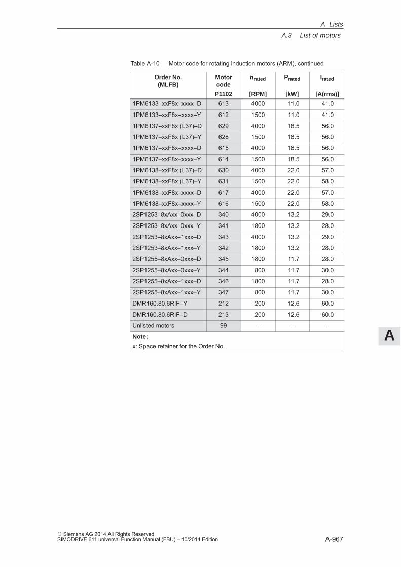
A
A.3 List of motors
A-967� Siemens AG 2014 All Rights ReservedSIMODRIVE 611 universal Function Manual (FBU) – 10/2014 Edition
Table A-10 Motor code for rotating induction motors (ARM), continued
Order No.(MLFB)
IratedPratednratedMotorcode
[A(rms)][kW][RPM]P1102
1PM6133–xxF8x–xxxx–D 613 4000 11.0 41.0
1PM6133–xxF8x–xxxx–Y 612 1500 11.0 41.0
1PM6137–xxF8x (L37)–D 629 4000 18.5 56.0
1PM6137–xxF8x (L37)–Y 628 1500 18.5 56.0
1PM6137–xxF8x–xxxx–D 615 4000 18.5 56.0
1PM6137–xxF8x–xxxx–Y 614 1500 18.5 56.0
1PM6138–xxF8x (L37)–D 630 4000 22.0 57.0
1PM6138–xxF8x (L37)–Y 631 1500 22.0 58.0
1PM6138–xxF8x–xxxx–D 617 4000 22.0 57.0
1PM6138–xxF8x–xxxx–Y 616 1500 22.0 58.0
2SP1253–8xAxx–0xxx–D 340 4000 13.2 29.0
2SP1253–8xAxx–0xxx–Y 341 1800 13.2 28.0
2SP1253–8xAxx–1xxx–D 343 4000 13.2 29.0
2SP1253–8xAxx–1xxx–Y 342 1800 13.2 28.0
2SP1255–8xAxx–0xxx–D 345 1800 11.7 28.0
2SP1255–8xAxx–0xxx–Y 344 800 11.7 30.0
2SP1255–8xAxx–1xxx–D 346 1800 11.7 28.0
2SP1255–8xAxx–1xxx–Y 347 800 11.7 30.0
DMR160.80.6RIF–Y 212 200 12.6 60.0
DMR160.80.6RIF–D 213 200 12.6 60.0
Unlisted motors 99 – – –
Note:
x: Space retainer for the Order No.
A Lists
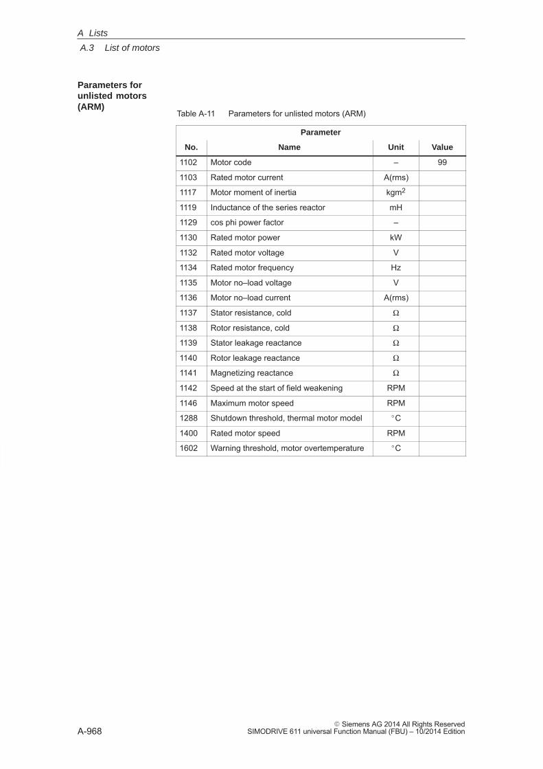
A
A.3 List of motors
A-968� Siemens AG 2014 All Rights Reserved
SIMODRIVE 611 universal Function Manual (FBU) – 10/2014 Edition
Table A-11 Parameters for unlisted motors (ARM)
Parameter
No. Name Unit Value
1102 Motor code – 99
1103 Rated motor current A(rms)
1117 Motor moment of inertia kgm2
1119 Inductance of the series reactor mH
1129 cos phi power factor –
1130 Rated motor power kW
1132 Rated motor voltage V
1134 Rated motor frequency Hz
1135 Motor no–load voltage V
1136 Motor no–load current A(rms)
1137 Stator resistance, cold Ω
1138 Rotor resistance, cold Ω
1139 Stator leakage reactance Ω
1140 Rotor leakage reactance Ω
1141 Magnetizing reactance Ω
1142 Speed at the start of field weakening RPM
1146 Maximum motor speed RPM
1288 Shutdown threshold, thermal motor model �C
1400 Rated motor speed RPM
1602 Warning threshold, motor overtemperature �C
Parameters forunlisted motors(ARM)
A Lists

A
A.4 Encoder list
A-969� Siemens AG 2014 All Rights ReservedSIMODRIVE 611 universal Function Manual (FBU) – 10/2014 Edition
A.4 Encoder list
A.4.1 Encoder code
The motor encoder being used is identified by its encoder code inP1006. If encoder systems are used, which are not marketed by SIEMENS(third–party encoder, encoder code = 99), then additional parametersmust be ”manually” set corresponding to the measuring systemmanufacturer’s data (refer to Table A-12).
A Lists
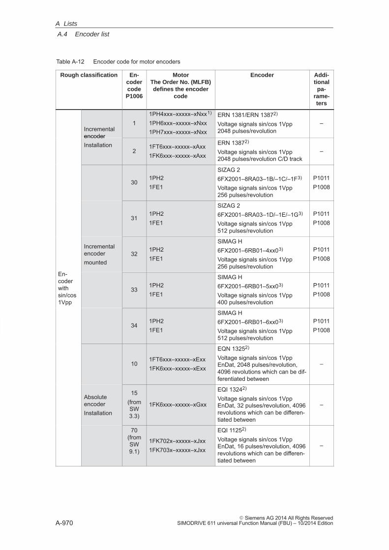
A
A.4 Encoder list
A-970� Siemens AG 2014 All Rights Reserved
SIMODRIVE 611 universal Function Manual (FBU) – 10/2014 Edition
Table A-12 Encoder code for motor encoders
Rough classification En-codercodeP1006
MotorThe Order No. (MLFB)defines the encoder
code
Encoder Addi-tional
pa-rame-ters
Incrementalencoder
11PH4xxx–xxxxx–xNxx1)
1PH6xxx–xxxxx–xNxx1PH7xxx–xxxxx–xNxx
ERN 1381/ERN 13872)
Voltage signals sin/cos 1Vpp2048 pulses/revolution
–
encoderInstallation
21FT6xxx–xxxxx–xAxx1FK6xxx–xxxxx–xAxx
ERN 13872)
Voltage signals sin/cos 1Vpp2048 pulses/revolution C/D track
–
301PH21FE1
SIZAG 26FX2001–8RA03–1B/–1C/–1F3)
Voltage signals sin/cos 1Vpp256 pulses/revolution
P1011P1008
311PH21FE1
SIZAG 26FX2001–8RA03–1D/–1E/–1G3)
Voltage signals sin/cos 1Vpp512 pulses/revolution
P1011P1008
En-
Incrementalencodermounted
321PH21FE1
SIMAG H6FX2001–6RB01–4xx03)
Voltage signals sin/cos 1Vpp256 pulses/revolution
P1011P1008
En-coderwithsin/cos1Vpp
331PH21FE1
SIMAG H6FX2001–6RB01–5xx03)
Voltage signals sin/cos 1Vpp400 pulses/revolution
P1011P1008
341PH21FE1
SIMAG H6FX2001–6RB01–6xx03)
Voltage signals sin/cos 1Vpp512 pulses/revolution
P1011P1008
101FT6xxx–xxxxx–xExx1FK6xxx–xxxxx–xExx
EQN 13252)
Voltage signals sin/cos 1VppEnDat, 2048 pulses/revolution,4096 revolutions which can be dif-ferentiated between
–
AbsoluteencoderInstallation
15(fromSW3.3)
1FK6xxx–xxxxx–xGxx
EQI 13242)
Voltage signals sin/cos 1VppEnDat, 32 pulses/revolution, 4096revolutions which can be differen-tiated between
–
70(fromSW9.1)
1FK702x–xxxxx–xJxx1FK703x–xxxxx–xJxx
EQI 11252)
Voltage signals sin/cos 1VppEnDat, 16 pulses/revolution, 4096revolutions which can be differen-tiated between
–
A Lists
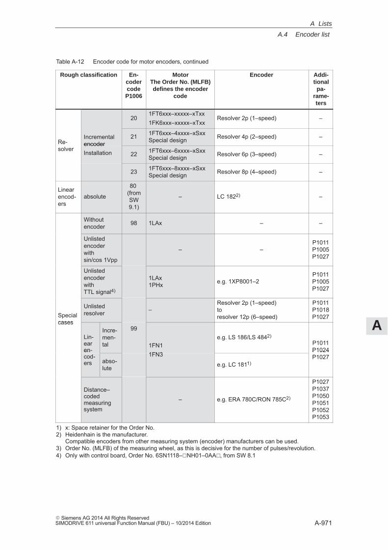
A
A.4 Encoder list
A-971� Siemens AG 2014 All Rights ReservedSIMODRIVE 611 universal Function Manual (FBU) – 10/2014 Edition
Table A-12 Encoder code for motor encoders, continued
Rough classification Addi-tional
pa-rame-ters
EncoderMotorThe Order No. (MLFB)defines the encoder
code
En-codercodeP1006
201FT6xxx–xxxxx–xTxx1FK6xxx–xxxxx–xTxx
Resolver 2p (1–speed) –
Re-solver
Incrementalencoder
21 1FT6xxx–4xxxx–xSxxSpecial design Resolver 4p (2–speed) –
Re-solver
encoderInstallation 22 1FT6xxx–6xxxx–xSxx
Special design Resolver 6p (3–speed) –
23 1FT6xxx–8xxxx–xSxxSpecial design Resolver 8p (4–speed) –
Linearencod-ers
absolute
80 (fromSW9.1)
– LC 1822) –
Withoutencoder 98 1LAx – –
Unlistedencoder withsin/cos 1Vpp
– –P1011P1005P1027
Unlistedencoder with TTL signal4)
1LAx1PHx e.g. 1XP8001–2
P1011P1005P1027
Specialcases
Unlistedresolver –
Resolver 2p (1–speed)toresolver 12p (6–speed)
P1011P1018P1027
cases
Lin-earen-
Incre-men-tal
99
1FN11FN3
e.g. LS 186/LS 4842)P1011P1024en-
cod-ers abso-
lute
1FN3
e.g. LC 1811)
P1024P1027
Distance–codedmeasuringsystem
– e.g. ERA 780C/RON 785C2)
P1027P1037P1050P1051P1052P1053
1) x: Space retainer for the Order No.2) Heidenhain is the manufacturer.
Compatible encoders from other measuring system (encoder) manufacturers can be used.3) Order No. (MLFB) of the measuring wheel, as this is decisive for the number of pulses/revolution.4) Only with control board, Order No. 6SN1118–�NH01–0AA�, from SW 8.1
A Lists
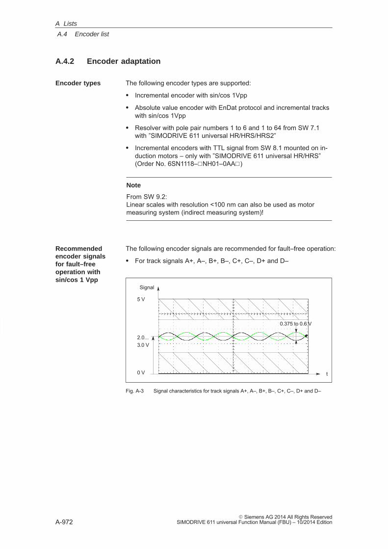
A
A.4 Encoder list
A-972� Siemens AG 2014 All Rights Reserved
SIMODRIVE 611 universal Function Manual (FBU) – 10/2014 Edition
A.4.2 Encoder adaptation
The following encoder types are supported:
� Incremental encoder with sin/cos 1Vpp
� Absolute value encoder with EnDat protocol and incremental tracks with sin/cos 1Vpp
� Resolver with pole pair numbers 1 to 6 and 1 to 64 from SW 7.1 with ”SIMODRIVE 611 universal HR/HRS/HRS2”
� Incremental encoders with TTL signal from SW 8.1 mounted on in-duction motors – only with ”SIMODRIVE 611 universal HR/HRS”(Order No. 6SN1118–�NH01–0AA�)
Note
From SW 9.2:Linear scales with resolution <100 nm can also be used as motormeasuring system (indirect measuring system)!
The following encoder signals are recommended for fault–free operation:
� For track signals A+, A–, B+, B–, C+, C–, D+ and D–
0 V
5 V
2.0...3.0 V
0.375 to 0.6 V
Signal
t
Fig. A-3 Signal characteristics for track signals A+, A–, B+, B–, C+, C–, D+ and D–
Encoder types
Recommended encoder signalsfor fault–freeoperation with sin/cos 1 Vpp
A Lists
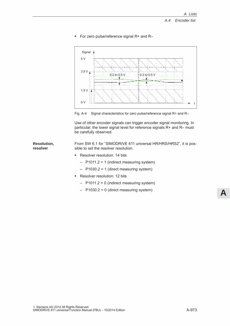
A
A.4 Encoder list
A-973� Siemens AG 2014 All Rights ReservedSIMODRIVE 611 universal Function Manual (FBU) – 10/2014 Edition
� For zero pulse/reference signal R+ and R–
0 V
5 V
Signal
0.2 to 0.5 V 0.2 to 0.5 V3.5 V
1.5 V
t
Fig. A-4 Signal characteristics for zero pulse/reference signal R+ and R–
Use of other encoder signals can trigger encoder signal monitoring. Inparticular, the lower signal level for reference signals R+ and R– mustbe carefully observed.
From SW 6.1 for ”SIMODRIVE 611 universal HR/HRS/HRS2”, it is pos-sible to set the resolver resolution.
� Resolver resolution: 14 bits
– P1011.2 = 1 (indirect measuring system)
– P1030.2 = 1 (direct measuring system)
� Resolver resolution: 12 bits
– P1011.2 = 0 (indirect measuring system)
– P1030.2 = 0 (direct measuring system)
Resolution, resolver
A Lists
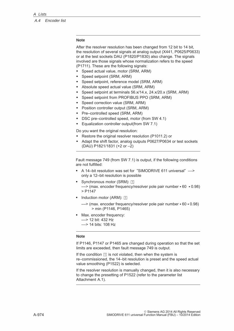
A
A.4 Encoder list
A-974� Siemens AG 2014 All Rights Reserved
SIMODRIVE 611 universal Function Manual (FBU) – 10/2014 Edition
Note
After the resolver resolution has been changed from 12 bit to 14 bit,the resolution of several signals at analog output (X441, P0625/P0633)or at the test sockets DAU (P1820/P1830) also change. The signalsinvolved are those signals whose normalization refers to the speed(P1711). These are the following signals:� Speed actual value, motor (SRM, ARM)� Speed setpoint (SRM, ARM)� Speed setpoint, reference model (SRM, ARM)� Absolute speed actual value (SRM, ARM)� Speed setpoint at terminals 56.x/14.x, 24.x/20.x (SRM, ARM)� Speed setpoint from PROFIBUS PPO (SRM, ARM)� Speed correction value (SRM, ARM)� Position controller output (SRM, ARM)� Pre–controlled speed (SRM, ARM)� DSC pre–controlled speed, motor (from SW 4.1)� Equalization controller output(from SW 7.1)
Do you want the original resolution:� Restore the original resolver resolution (P1011.2) or� Adapt the shift factor, analog outputs P0627/P0634 or test sockets
(DAU) P1821/1831 (+2 or –2)
Fault message 749 (from SW 7.1) is output, if the following conditionsare not fulfilled:� A 14–bit resolution was set for ”SIMODRIVE 611 universal” ––>
only a 12–bit resolution is possible� Synchronous motor (SRM): �
––> (max. encoder frequency/resolver pole pair number � 60 � 0.98)> P1147
� Induction motor (ARM): �––> (max. encoder frequency/resolver pole pair number � 60 � 0.98) > min (P1146, P1465)
� Max. encoder frequency:––> 12 bit: 432 Hz––> 14 bits: 108 Hz
Note
If P1146, P1147 or P1465 are changed during operation so that the setlimits are exceeded, then fault message 749 is output.If the condition � is not violated, then when the system isre–commissioned, the 14–bit resolution is preset and the speed actualvalue smoothing (P1522) is selected.If the resolver resolution is manually changed, then it is also necessaryto change the presetting of P1522 (refer to the parameter listAttachment A.1).
A Lists
A
A.4 Encoder list
A-975� Siemens AG 2014 All Rights ReservedSIMODRIVE 611 universal Function Manual (FBU) – 10/2014 Edition
An indirect measuring system is commissioned by entering a codenumber into P1006. If an encoder is used which is not saved in thefirmware, then the data according to Table 4-14 must be entered.
Refer to the parameter overview Chapter A.1 for the significance ofparameters P1005, P1021, P1022 and P1024.
For ”SIMODRIVE 611 universal” when a direct measuring system isused, it must be appropriately parameterized.
The direct measuring system is commissioned by entering a code num-ber into P1036. If an encoder is used which is not saved in the firm-ware, then the data according to Table 4-14 must be entered andP1036 set to 99.
Parameterizing an indirectmeasuring system
Parameterizing a direct measuringsystem
A Lists
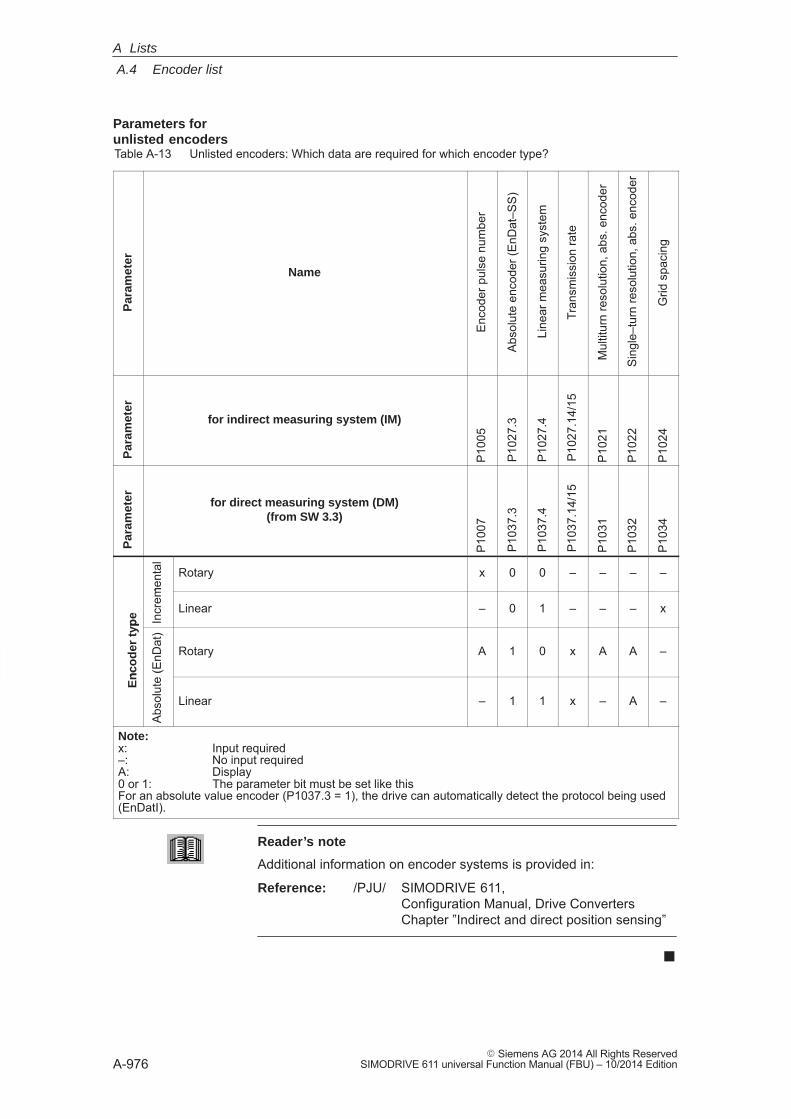
A
A.4 Encoder list
A-976� Siemens AG 2014 All Rights Reserved
SIMODRIVE 611 universal Function Manual (FBU) – 10/2014 Edition
Table A-13 Unlisted encoders: Which data are required for which encoder type?
Par
amet
er
Name
Enc
oder
pul
se n
umbe
r
Abs
olut
e en
code
r (E
nDat
–SS
)
Line
ar m
easu
ring
syst
em
Tran
smis
sion
rate
Mul
titur
n re
solu
tion,
abs
. enc
oder
Sing
le–t
urn
reso
lutio
n, a
bs. e
ncod
er
Grid
spa
cing
Par
amet
er
for indirect measuring system (IM)
P10
05
P10
27.3
P10
27.4
P10
27.1
4/15
P10
21
P10
22
P10
24
Par
amet
er for direct measuring system (DM)(from SW 3.3)
P10
07
P10
37.3
P10
37.4
P10
37.1
4/15
P10
31
P10
32
P10
34
men
tal
Rotary x 0 0 – – – –
typ
e Incr
eme
Linear – 0 1 – – – x
En
cod
er t
yp
te (E
nDat
)
Rotary A 1 0 x A A –
En
c
Abso
lute
(
Linear – 1 1 x – A –
Note:x: Input required–: No input requiredA: Display0 or 1: The parameter bit must be set like thisFor an absolute value encoder (P1037.3 = 1), the drive can automatically detect the protocol being used(EnDatI).
Reader’s note
Additional information on encoder systems is provided in:
Reference: /PJU/ SIMODRIVE 611, Configuration Manual, Drive ConvertersChapter ”Indirect and direct position sensing”
�
Parameters forunlisted encoders
A Lists
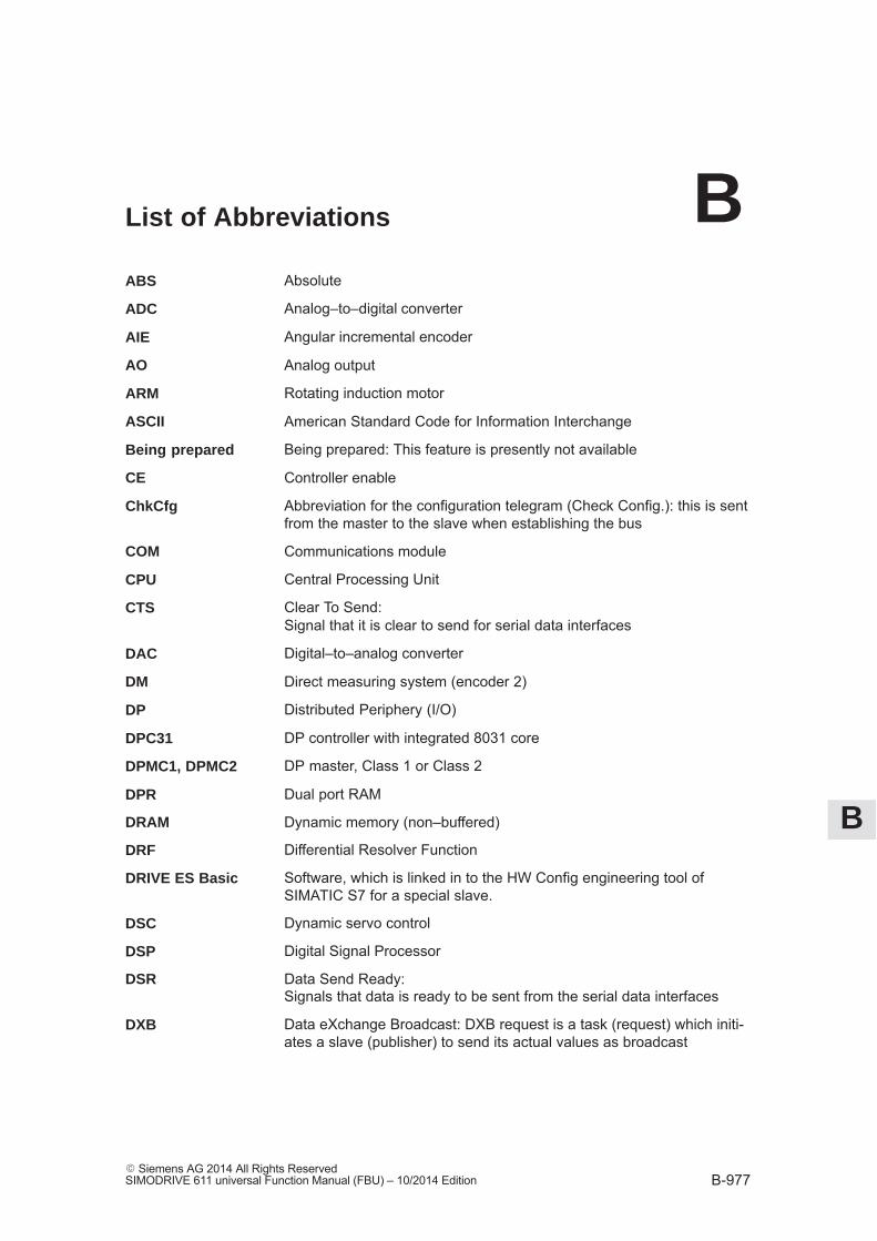
B
B-977� Siemens AG 2014 All Rights ReservedSIMODRIVE 611 universal Function Manual (FBU) – 10/2014 Edition
List of Abbreviations
Absolute
Analog–to–digital converter
Angular incremental encoder
Analog output
Rotating induction motor
American Standard Code for Information Interchange
Being prepared: This feature is presently not available
Controller enable
Abbreviation for the configuration telegram (Check Config.): this is sent from the master to the slave when establishing the bus
Communications module
Central Processing Unit
Clear To Send: Signal that it is clear to send for serial data interfaces
Digital–to–analog converter
Direct measuring system (encoder 2)
Distributed Periphery (I/O)
DP controller with integrated 8031 core
DP master, Class 1 or Class 2
Dual port RAM
Dynamic memory (non–buffered)
Differential Resolver Function
Software, which is linked in to the HW Config engineering tool ofSIMATIC S7 for a special slave.
Dynamic servo control
Digital Signal Processor
Data Send Ready: Signals that data is ready to be sent from the serial data interfaces
Data eXchange Broadcast: DXB request is a task (request) which initi-ates a slave (publisher) to send its actual values as broadcast
ABS
ADC
AIE
AO
ARM
ASCII
Being prepared
CE
ChkCfg
COM
CPU
CTS
DAC
DM
DP
DPC31
DPMC1, DPMC2
DPR
DRAM
DRF
DRIVE ES Basic
DSC
DSP
DSR
DXB
B
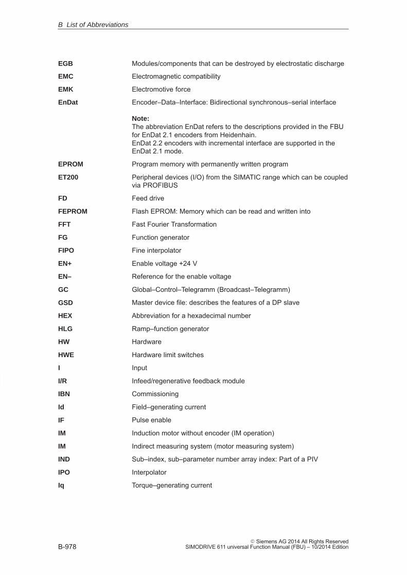
B
B-978� Siemens AG 2014 All Rights Reserved
SIMODRIVE 611 universal Function Manual (FBU) – 10/2014 Edition
Modules/components that can be destroyed by electrostatic discharge
Electromagnetic compatibility
Electromotive force
Encoder–Data–Interface: Bidirectional synchronous–serial interface
Note: The abbreviation EnDat refers to the descriptions provided in the FBUfor EnDat 2.1 encoders from Heidenhain.EnDat 2.2 encoders with incremental interface are supported in the EnDat 2.1 mode.
Program memory with permanently written program
Peripheral devices (I/O) from the SIMATIC range which can be coupledvia PROFIBUS
Feed drive
Flash EPROM: Memory which can be read and written into
Fast Fourier Transformation
Function generator
Fine interpolator
Enable voltage +24 V
Reference for the enable voltage
Global–Control–Telegramm (Broadcast–Telegramm)
Master device file: describes the features of a DP slave
Abbreviation for a hexadecimal number
Ramp–function generator
Hardware
Hardware limit switches
Input
Infeed/regenerative feedback module
Commissioning
Field–generating current
Pulse enable
Induction motor without encoder (IM operation)
Indirect measuring system (motor measuring system)
Sub–index, sub–parameter number array index: Part of a PIV
Interpolator
Torque–generating current
EGB
EMC
EMK
EnDat
EPROM
ET200
FD
FEPROM
FFT
FG
FIPO
EN+
EN–
GC
GSD
HEX
HLG
HW
HWE
I
I/R
IBN
Id
IF
IM
IM
IND
IPO
Iq
B List of Abbreviations
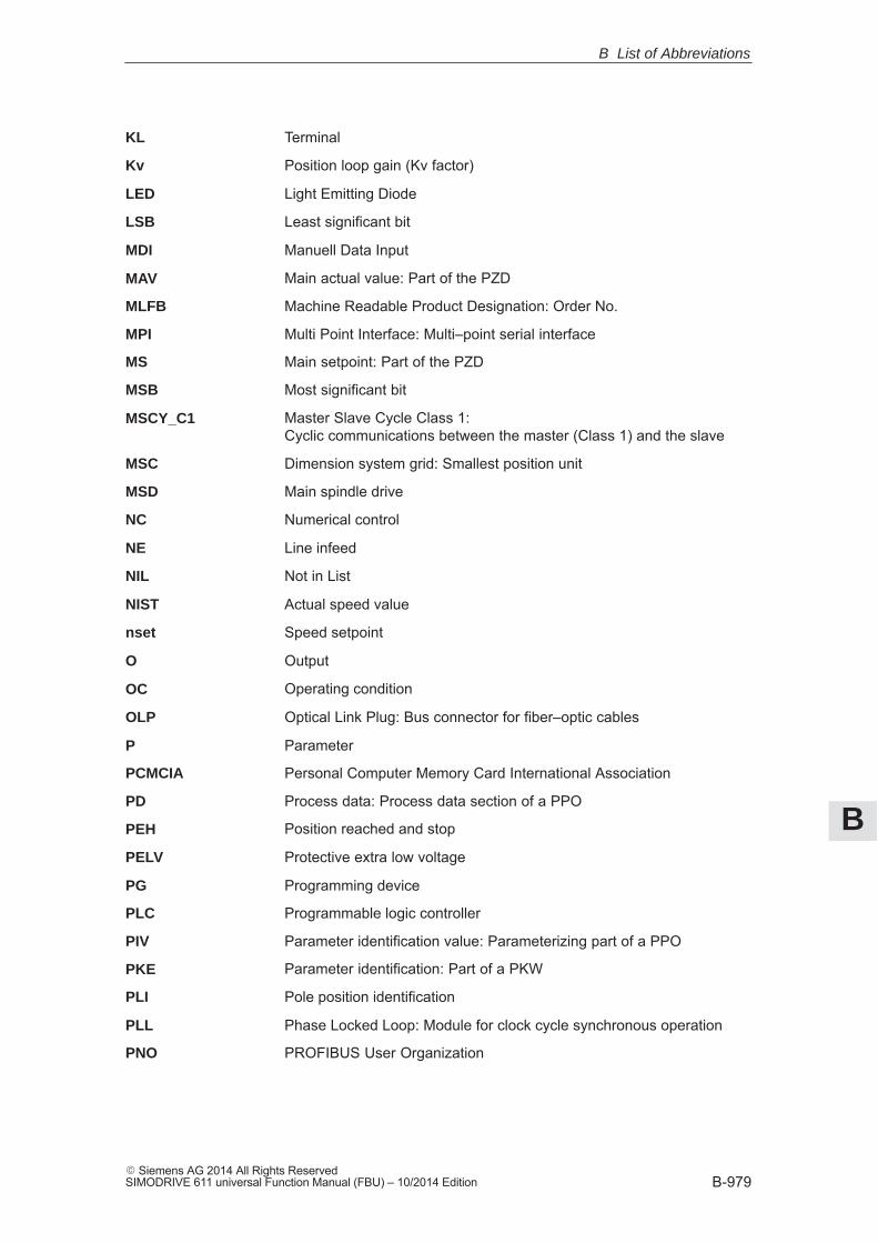
B
B-979� Siemens AG 2014 All Rights ReservedSIMODRIVE 611 universal Function Manual (FBU) – 10/2014 Edition
Terminal
Position loop gain (Kv factor)
Light Emitting Diode
Least significant bit
Manuell Data Input
Main actual value: Part of the PZD
Machine Readable Product Designation: Order No.
Multi Point Interface: Multi–point serial interface
Main setpoint: Part of the PZD
Most significant bit
Master Slave Cycle Class 1: Cyclic communications between the master (Class 1) and the slave
Dimension system grid: Smallest position unit
Main spindle drive
Numerical control
Line infeed
Not in List
Actual speed value
Speed setpoint
Output
Operating condition
Optical Link Plug: Bus connector for fiber–optic cables
Parameter
Personal Computer Memory Card International Association
Process data: Process data section of a PPO
Position reached and stop
Protective extra low voltage
Programming device
Programmable logic controller
Parameter identification value: Parameterizing part of a PPO
Parameter identification: Part of a PKW
Pole position identification
Phase Locked Loop: Module for clock cycle synchronous operation
PROFIBUS User Organization
KL
Kv
LED
LSB
MDI
MAV
MLFB
MPI
MS
MSB
MSCY_C1
MSC
MSD
NC
NE
NIL
NIST
nset
O
OC
OLP
P
PCMCIA
PD
PEH
PELV
PG
PLC
PIV
PKE
PLI
PLL
PNO
B List of Abbreviations
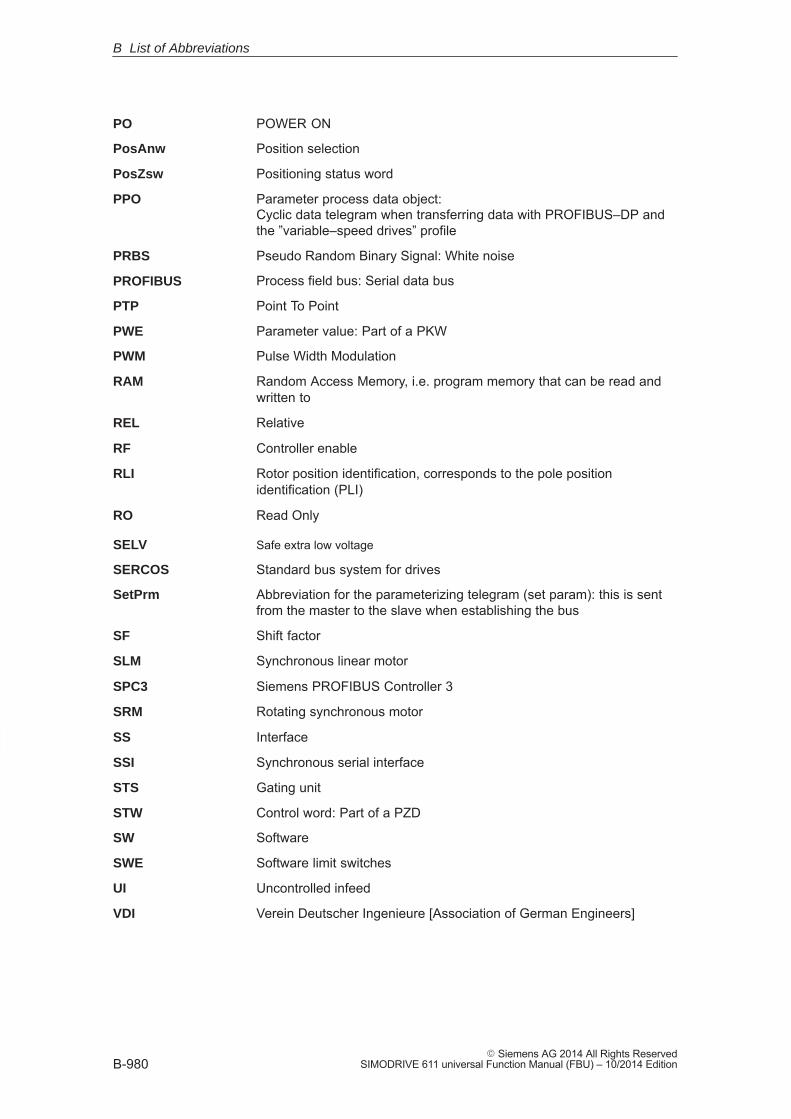
B
B-980� Siemens AG 2014 All Rights Reserved
SIMODRIVE 611 universal Function Manual (FBU) – 10/2014 Edition
POWER ON
Position selection
Positioning status word
Parameter process data object: Cyclic data telegram when transferring data with PROFIBUS–DP andthe ”variable–speed drives” profile
Pseudo Random Binary Signal: White noise
Process field bus: Serial data bus
Point To Point
Parameter value: Part of a PKW
Pulse Width Modulation
Random Access Memory, i.e. program memory that can be read andwritten to
Relative
Controller enable
Rotor position identification, corresponds to the pole positionidentification (PLI)
Read Only
Safe extra low voltage
Standard bus system for drives
Abbreviation for the parameterizing telegram (set param): this is sentfrom the master to the slave when establishing the bus
Shift factor
Synchronous linear motor
Siemens PROFIBUS Controller 3
Rotating synchronous motor
Interface
Synchronous serial interface
Gating unit
Control word: Part of a PZD
Software
Software limit switches
Uncontrolled infeed
Verein Deutscher Ingenieure [Association of German Engineers]
PO
PosAnw
PosZsw
PPO
PRBS
PROFIBUS
PTP
PWE
PWM
RAM
REL
RF
RLI
RO
SELV
SERCOS
SetPrm
SF
SLM
SPC3
SRM
SS
SSI
STS
STW
SW
SWE
UI
VDI
B List of Abbreviations

B
B-981� Siemens AG 2014 All Rights ReservedSIMODRIVE 611 universal Function Manual (FBU) – 10/2014 Edition
VP module,module to limit the DC link voltage when a fault condition occurs(VPM: Voltage Protection Module)
Peak–to–peak voltage
Machine tools
Actual position value
Position setpoint value
DC link
Status word: Part of a PZD
�
VPM
Vpp
WZM
xact
xset
ZK
ZSW
B List of Abbreviations

B
B-982� Siemens AG 2014 All Rights Reserved
SIMODRIVE 611 universal Function Manual (FBU) – 10/2014 Edition
B List of Abbreviations
Space for your notes
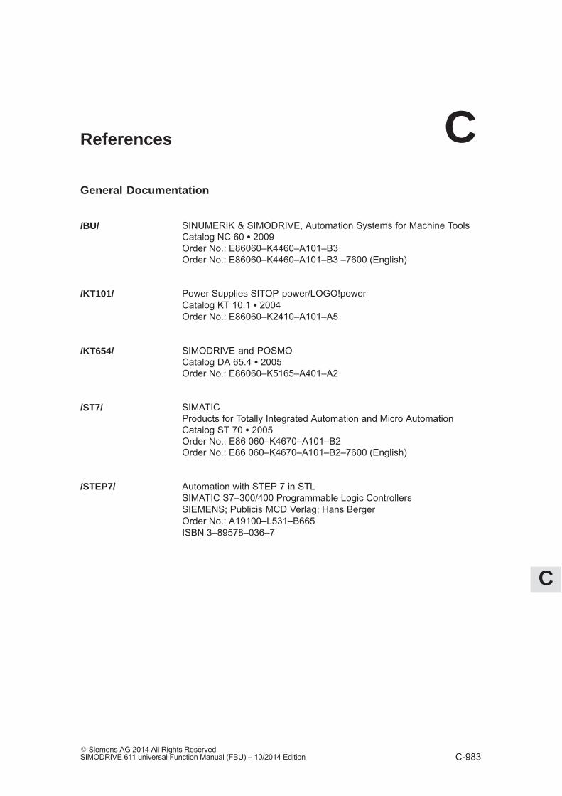
C
C-983� Siemens AG 2014 All Rights ReservedSIMODRIVE 611 universal Function Manual (FBU) – 10/2014 Edition
References
General Documentation
SINUMERIK & SIMODRIVE, Automation Systems for Machine ToolsCatalog NC 60 � 2009Order No.: E86060–K4460–A101–B3Order No.: E86060–K4460–A101–B3 –7600 (English)
Power Supplies SITOP power/LOGO!powerCatalog KT 10.1 � 2004Order No.: E86060–K2410–A101–A5
SIMODRIVE and POSMOCatalog DA 65.4 � 2005 Order No.: E86060–K5165–A401–A2
SIMATICProducts for Totally Integrated Automation and Micro AutomationCatalog ST 70 � 2005Order No.: E86 060–K4670–A101–B2Order No.: E86 060–K4670–A101–B2–7600 (English)
Automation with STEP 7 in STLSIMATIC S7–300/400 Programmable Logic ControllersSIEMENS; Publicis MCD Verlag; Hans BergerOrder No.: A19100–L531–B665ISBN 3–89578–036–7
/BU/
/KT101/
/KT654/
/ST7/
/STEP7/
C
C
C-984� Siemens AG 2014 All Rights Reserved
SIMODRIVE 611 universal Function Manual (FBU) – 10/2014 Edition
Documentation for PROFIBUS
Catalog IK PI � 2005Industrial Communications for Automation and DrivesOrder No. of the bound edition: E86060–K6710–A101–B6Order No. of the loose–leaf edition: E86060–K6710–A100–B6
PROFIBUS–DP/DPV1 IEC 61158Basic Information, Tips and Tricks for UsersHüthig; Manfred Popp, 2nd editionISBN 3–7785–2781–9
PROFIBUS–DP, Fast EntryPROFIBUS User Organisation e.V.; Manfred PoppOrder No.: 4.071
Decentralization with PROFIBUS–DP Design, Configuring and Using PROFIBUS–DP with SIMATIC S7SIEMENS; Publics MCD Verlag; Josef Weigmann, Gerhard KilianOrder No.: A19100–L531–B714ISBN 3–89578–074–X
Manual for PROFIBUS NetworksSIEMENS;Order No.: 6GK1 970–5CA10–0BA0
PROFIBUS & AS Interface, Components on the Fieldbus, Catalog ST PI 1999Order No. of the bound edition: E86060–K4660–A101–A3Order No. of the loose–leaf edition: E86060–K4660–A100–A3–7600
PROFIdrive Profile Drive Technology Draft PROFIBUS ProfileVersion 3.1.2, September 2004Version 4.1, May 2006PROFIBUS User Organization e.V. Haid–und–Neu–Straße 776131 KarlsruheOrder No. 3.172
/IKPI/
/P1/
/P2/
/P3/
/P4/
/STPI/
/PPA/
C References
C
C-985� Siemens AG 2014 All Rights ReservedSIMODRIVE 611 universal Function Manual (FBU) – 10/2014 Edition
PROFIBUS, Profile for Variable–Speed Drives, PROFIDRIVE,PROFIBUS User Organization e.V. Haid–und–Neu–Straße 776131 Karlsruhe;September 1997 Edition, Order No. 3.071
/PDP/ PROFIBUS Installation GuidelinesInstallation Guidelines for PROFIBUS–FMS/DPInstallation and Wiring Recommendation for RS 485 TransmissionVersion 1.0, Order No. 2.111 (German); 2.112 (English)
Manufacturer/Service Documentation
Note
A list of additional documents, updated on a monthly basis, is availableon the Internet for the available languages at:http://www.siemens.com/motioncontrolSelect ”Support” ––> ”Technical documentation” ––> ”Orderingdocumentation” ––> ”Printed documentation”.
SIMODRIVE 611 universalMounting Instructions Replacing Spare Parts (07.05 Edition)Order No.: On request
SIMODRIVE 611 universal (02.14 Edition)Mounting Instructions Replacing Spare Parts HRS/HRS2Order No.: On request
SIMODRIVE 611–A/611–D,SimoPro 3.1Program for Configuring Machine Tool DrivesOrder No.: 6SC6 111–6PC00–0BA�Ordering location: WK Fürth
SIMATIC S7–300 (2002 Edition)Installation Manual Technological Functions– Reference Manual: CPU Data (HW Description)Order No.: 6ES7 398–8AA03–8BA0
SIMATIC S7–300 (03.97 Edition)Manual: STEP 7, Fundamentals, V. 3.1Order No.: 6ES7 810–4CA02–8BA0
/PPD/
/FBU_TE/
/FBU_TEH/
/SP/
/S7H/
/S7HT/
C References

C
C-986� Siemens AG 2014 All Rights Reserved
SIMODRIVE 611 universal Function Manual (FBU) – 10/2014 Edition
SIMATIC S7–300 (03.97 Edition)Manual: STEP 7, Reference Manuals, V. 3.1Order No.: 6ES7 810–4CA02–8BR0
SIMATIC (05.01 Edition)Distributed ET 200XManual EWA 4NEB 780 6016–01 04Part of the package with Order No.6ES7 198–8FA01–8BA0
�
/S7HR/
/ET200X/
C References
D
D-987� Siemens AG 2014 All Rights ReservedSIMODRIVE 611 universal Function Manual (FBU) – 10/2014 Edition
Certificates
Note
The complete certification for the ”Safe standstill” function can befound as follows:
Reference: /PJU/ SIMODRIVE 611Configuration Manual, Drive Converters
You can find the EC declaration of conformance for the machinery directive, theEMC directive and the Low-Voltage-Directive in the Internet at:
http://support.automation.siemens.com/WW/view/de/32151216Certification Number: 664.EMNI1113.02.001Entry ID: 25447747 15257461There, as search term, enter the number 25447747 or contact the local Sie-mens office in your region.
Note
Please observe the following documentation:
Reference: /EMC/ EMC Configuring Guidelines(Order No.: 6FC5297– �AD30–0BP�
EG Declaration ofConformity
D
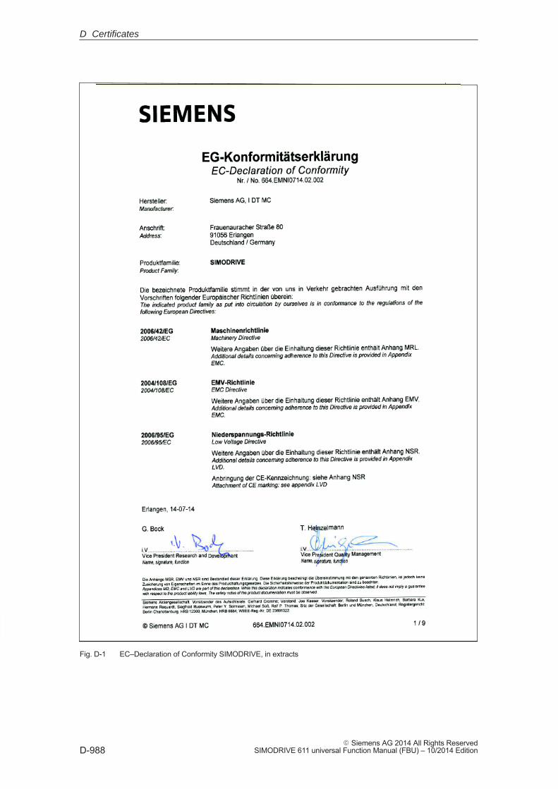
D
D-988� Siemens AG 2014 All Rights Reserved
SIMODRIVE 611 universal Function Manual (FBU) – 10/2014 Edition
Fig. D-1 EC–Declaration of Conformity SIMODRIVE, in extracts
D Certificates
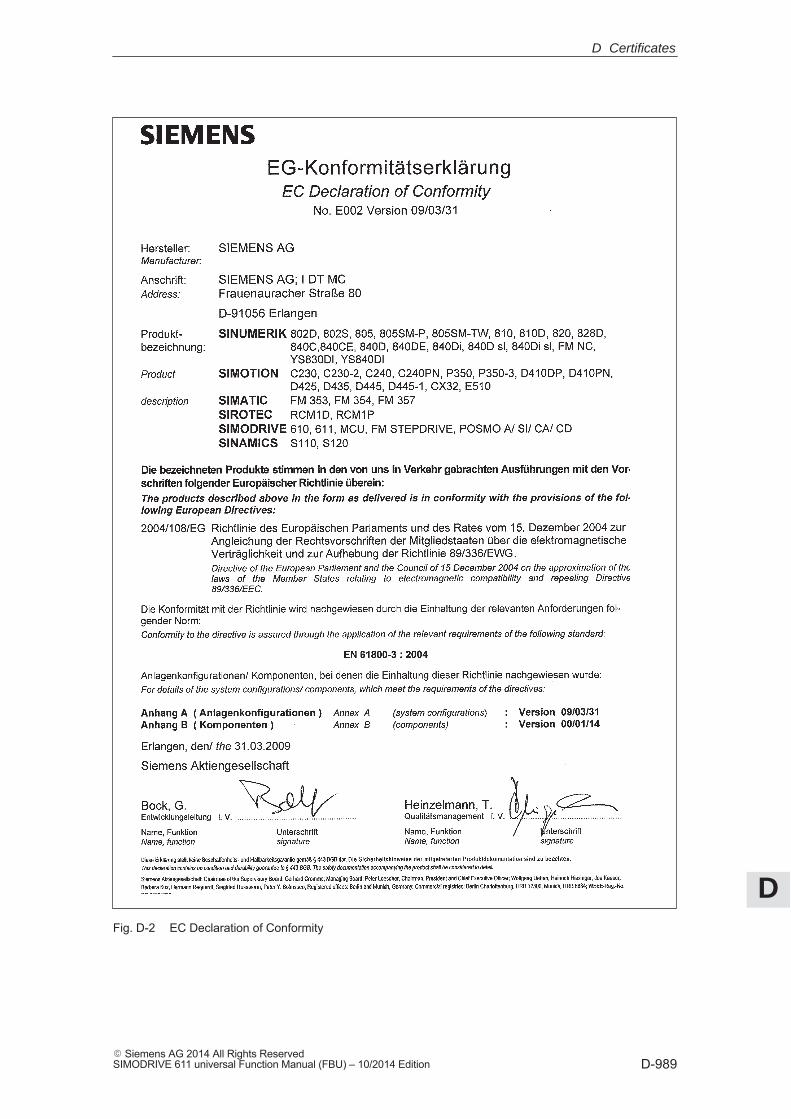
D
D-989� Siemens AG 2014 All Rights ReservedSIMODRIVE 611 universal Function Manual (FBU) – 10/2014 Edition
Fig. D-2 EC Declaration of Conformity
D Certificates
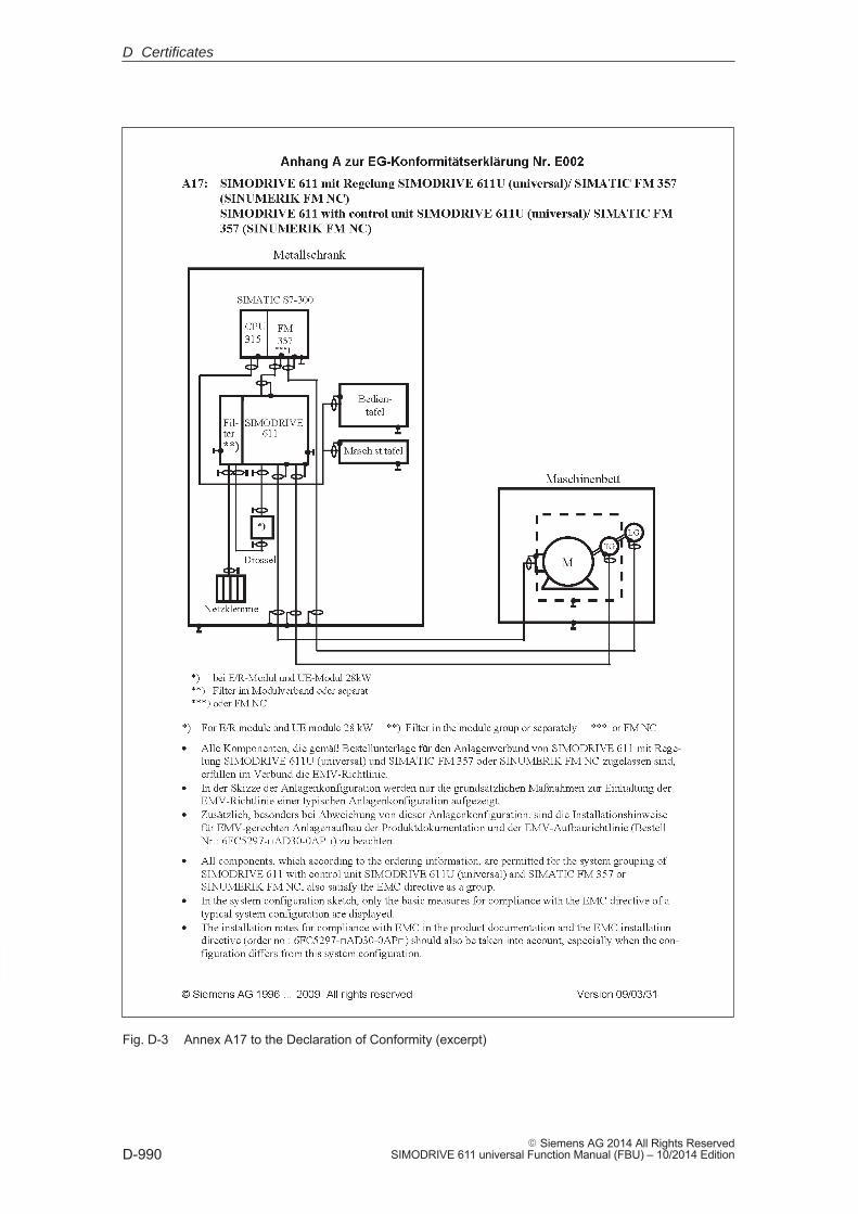
D
D-990� Siemens AG 2014 All Rights Reserved
SIMODRIVE 611 universal Function Manual (FBU) – 10/2014 Edition
Fig. D-3 Annex A17 to the Declaration of Conformity (excerpt)
D Certificates
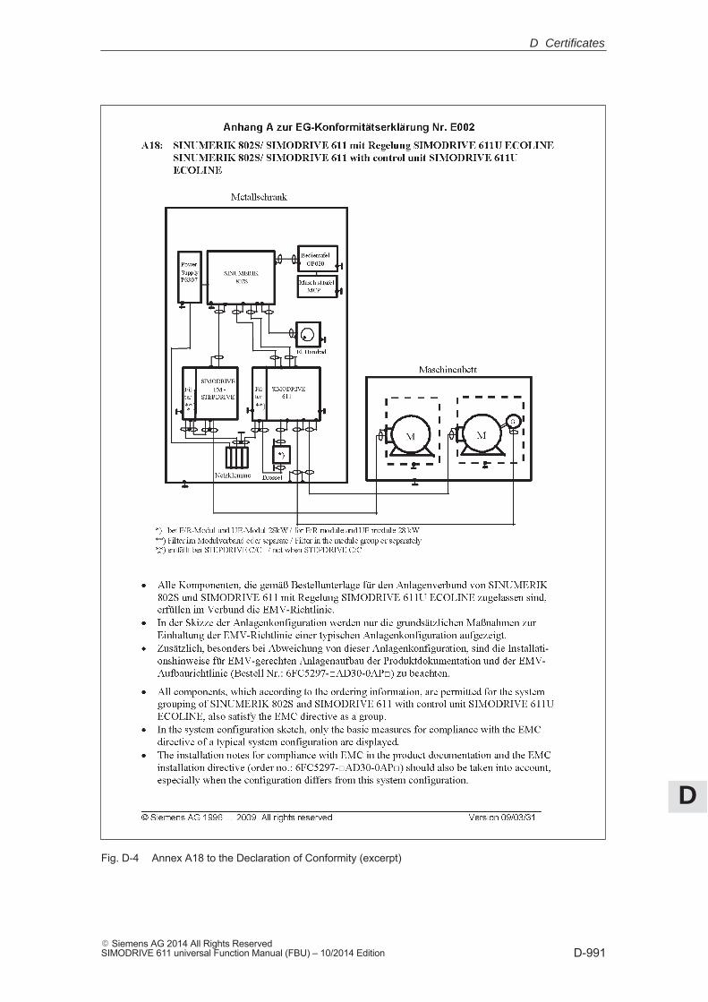
D
D-991� Siemens AG 2014 All Rights ReservedSIMODRIVE 611 universal Function Manual (FBU) – 10/2014 Edition
Fig. D-4 Annex A18 to the Declaration of Conformity (excerpt)
D Certificates
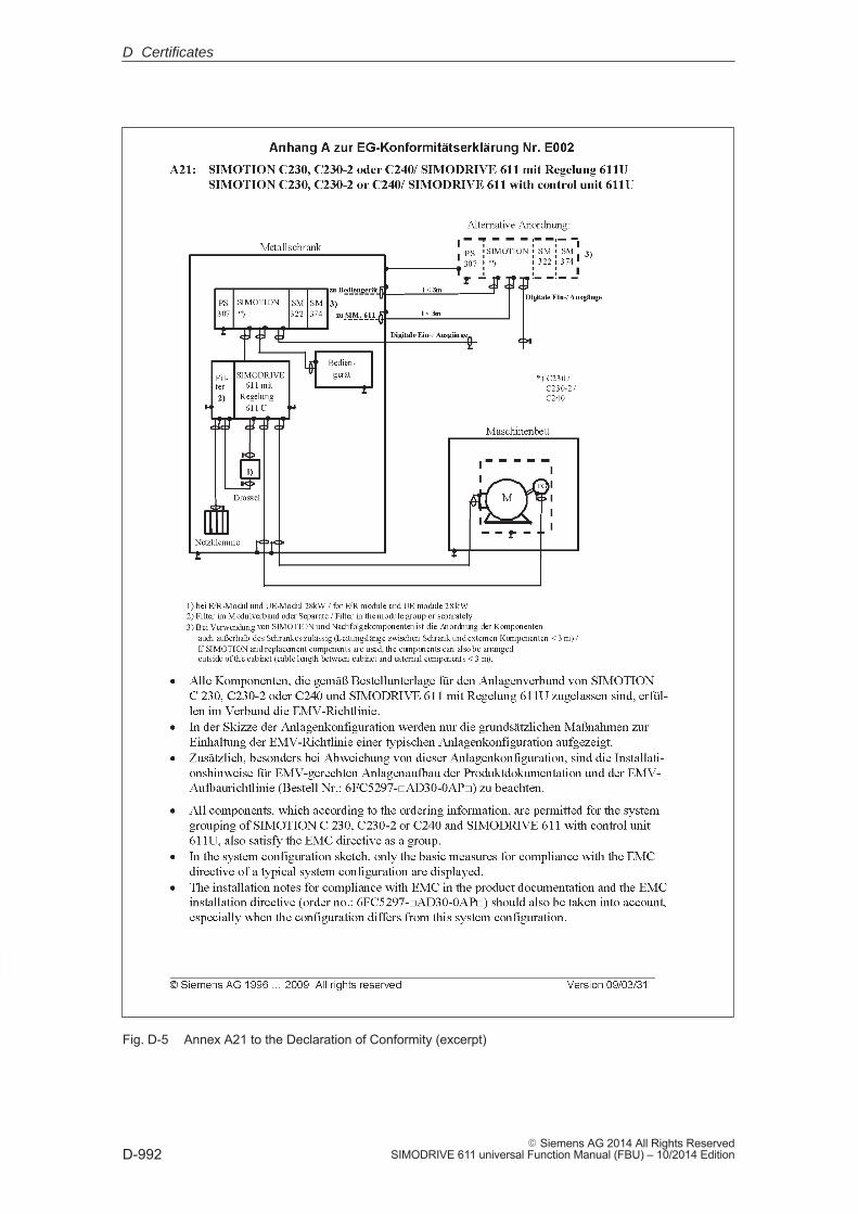
D
D-992� Siemens AG 2014 All Rights Reserved
SIMODRIVE 611 universal Function Manual (FBU) – 10/2014 Edition
Fig. D-5 Annex A21 to the Declaration of Conformity (excerpt)
D Certificates
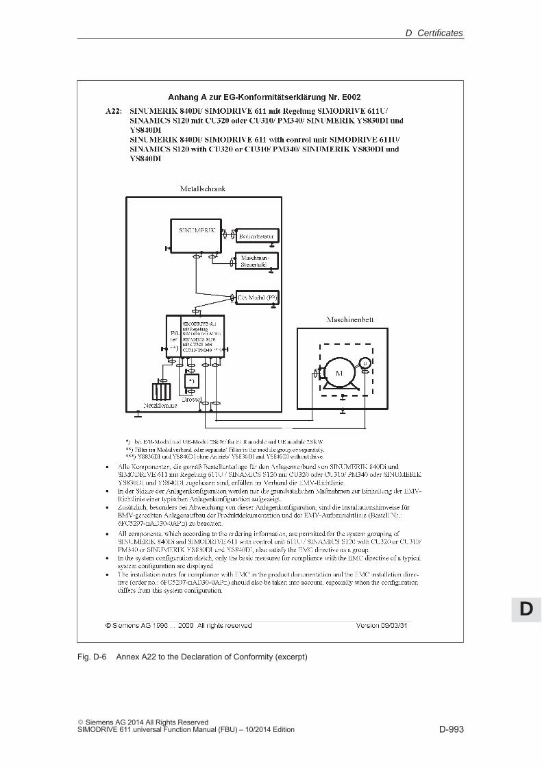
D
D-993� Siemens AG 2014 All Rights ReservedSIMODRIVE 611 universal Function Manual (FBU) – 10/2014 Edition
Fig. D-6 Annex A22 to the Declaration of Conformity (excerpt)
D Certificates
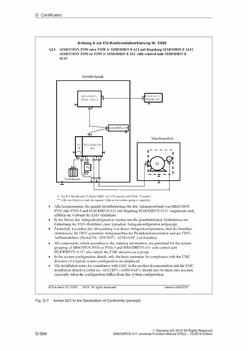
D
D-994� Siemens AG 2014 All Rights Reserved
SIMODRIVE 611 universal Function Manual (FBU) – 10/2014 Edition
Fig. D-7 Annex A23 to the Declaration of Conformity (excerpt)
D Certificates
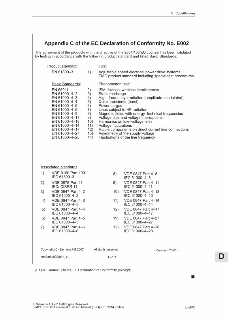
D
D-995� Siemens AG 2014 All Rights ReservedSIMODRIVE 611 universal Function Manual (FBU) – 10/2014 Edition
Appendix C of the EC Declaration of Conformity No. E002
Copyright (C) Siemens AG 2007 All rights reserved Version 07/08/15
konf/erkl/002/anh_c C–1/1
The agreement of the products with the directive of the 2004/108/EU counsel has been validatedby testing in accordance with the following product standard and listed Basic Standards.
Product standard: Title:
EN 61800–3 1) Adjustable speed electrical power drive systems;EMC product standard including special test procedures
Basic Standards: Phenomenon test:EN 55011 2) ISM devices; wireless interferencesEN 61000–4–2 3) Static dischargeEN 61000–4–3 4) High–frequency irradiation (amplitude–modulated)EN 61000–4–4 5) Quick transients (burst)EN 61000–4–5 6) Power surgesEN 61000–4–6 7) Lines subject to HF radiationEN 61000–4–8 8) Magnetic fields with energy–technical frequenciesEN 61000–4–11 9) Voltage dips and voltage interruptionsEN 61000–4–13 10) Harmonics on low–voltage linesEN 61000–4–14 11) Voltage fluctuationsEN 61000–4–17 12) Ripple components on direct current line connectionsEN 61000–4–27 13) Asymmetry of the supply voltageEN 61000–4–28 14) Fluctuations of the line frequency
Associated standards:1) VDE 0160 Part 100
IEC 61800–38) VDE 0847 Part 4–8
IEC 61000–4–82) VDE 0875 Part 11
IEC/ CISPR 119) VDE 0847 Part 4–11
IEC 61000–4–113) VDE 0847 Part 4–2
IEC 61000–4–210) VDE 0847 Part 4–13
IEC 61000–4–13 4) VDE 0847 Part 4–3
IEC 61000–4–311) VDE 0847 Part 4–14
IEC 61000–4–14 5) VDE 0847 Part 4–4
IEC 61000–4–412) VDE 0847 Part 4–17
IEC 61000–4–17 6) VDE 0847 Part 4–5
IEC 61000–4–511) VDE 0847 Part 4–27
IEC 61000–4–277) VDE 0847 Part 4–6
IEC 61000–4–612) VDE 0847 Part 4–28
IEC 61000–4–28
Fig. D-8 Annex C to the EC Declaration of Conformity (excerpt)
�
D Certificates

D
D-996� Siemens AG 2014 All Rights Reserved
SIMODRIVE 611 universal Function Manual (FBU) – 10/2014 Edition
D Certificates
Space for your notes
E
E-997� Siemens AG 2014 All Rights ReservedSIMODRIVE 611 universal Function Manual (FBU) – 10/2014 Edition
Index
�������! 611ue diff !, vi, 1-55! not 611u !, vi, 1-55! not 611ue !, vi, 1-55
�����1FE1 motors-, 4-163, A-9391FK6 motors-, A-9271FNx motors-, A-9511FT6 motors, A-9271FW6 motors-, A-9461PHx motors-, A-9572SP1 motors-, A-939
Abbreviations, B-977Acknowledging faults, 7-665
with POWER ON, 7-665with RESET FAULT MEMORY, 7-665
Activate function generator immediately(from SW 11.2), 6-653
Active oscillation damping (APC) (from SW10.1), 6-648
Actual position value, 6-396Adjusting
Absolute encoder, 6-414Reference cams, 6-407
Alarm log, 7-665Alarms, 7-664
Evaluating via PROFIBUS-DP, 5-301Handling the, 7-671List of, 7-673Overview of the, 7-664
Analog inputs, 2-80, 6-551Analog outputs, 2-79, 6-565
Analog signalsfor the current and speed control loop-,
6-575for the position control loop, 6-576
Angular incremental encoder interface, 2-81,6-579as an output, 6-581as input (from SW 3.3), 6-586, 6-590Handwheel connection, 6-590Terminating resistor, 1-39
Any gearbox ratio (from SW 8.1), 6-372APC (from SW 10.1), 6-648Automatic controller setting, 6-346Automatic power module identification,
4-144Axis couplings (from SW 3.3), 6-446
Equalization controller (from SW 7.1),6-484
Torque setpoint coupling via PROFIBUS(from SW 4.1), 6-478
with queue function (being prepared)-,6-463
�Backlash compensation, 6-391Ball screw, 6-369Basic commissioning, 3-107Block change enable, 6-431
CONTINUE EXTERNAL (from SW 3.1),6-434
CONTINUE FLYING, 6-433CONTINUE WITH STOP, 6-433END, 6-432
Block skip, 6-431Booting, 4-125Bootstrapping, 3-104, 4-139Brake sequence control, 6-594Built-in torque motors, 4-174, A-946
E
E
E-998� Siemens AG 2014 All Rights Reserved
SIMODRIVE 611 universal Function Manual (FBU) – 10/2014 Edition
�Cable, recommended, 2-72Cable diagram
for RS232, 2-89for RS485, 2-90
Calculate controller data, 4-139Calculate data
Controller data, 4-139Equiv cct diagram data, 4-140Optimize motor data, 4-141Unlisted motors, 4-140
Calculate the equivalent circuit diagramdata, 4-140
Calculate unlisted motor, 4-140CD, 1-32Certificates, ivChangeover
of motors (from SW 2.4), 6-604of parameter sets, 6-600of the dimension system, 6-380of the serial interface, 3-110
Clock cycles, 4-147Clock–synchronous PROFIBUS operation-,
5-303Closed–loop position control
Acceleration (maximum), 6-382Backlash compensation, 6-391Deceleration (maximum), 6-382Diagnostics, 6-403Dimension system, 6-380Direction adaptation, 6-396Follow–up mode, 6-402Following error monitoring, 6-397Jerk limiting (from SW 3.1), 6-383Limit switches, 6-386Overview, 6-379Position loop gain (Kv factor)-, 6-393Position monitoring, 6-400Speed pre–control, 6-394Standstill monitoring, 6-398Switching signals (cams), 6-390Velocity (maximal), 6-382Velocity override, 6-385
Coding the mini connectors, 2-71Command–dependent block information,
6-425
CommissioningBuilt-in torque motors, 4-176Checklist for, 4-123Direct measuring system (from SW 3.3),
4-205Firmware download-, 4-133First, 4-122Induction motor with TTL encoder (from
SW 8.1)-, 4-206Linear motor, 4-181PE spindle, 4-165Prerequisites for, 4-123PROFIBUS-DP, 5-295Series, 4-122Upgrading the FW, optional PROFIBUS
module-, 4-124Using the display and operator unit-,
4-135Using the SimoCom U tool, 4-126
Commissioning required, 3-107Communication
PROFIdrive conformance, 5-211via PROFIBUS-DP, 5-210via RS232, 3-111via RS485 (from hardware ...1), 3-112
Configurationthe drive group, 1-28the process data (from SW 3.1), 5-265
Configuring process data (from SW 3.1)-,5-265
Configuring the telegram (from SW 3.1)-,5-265
Connection diagramfor the control board, 2-75for the optional PROFIBUS-DP module,
2-84for the optional TERMINAL module, 2-82
Control board front panel, 1-37
E Index
E
E-999� Siemens AG 2014 All Rights ReservedSIMODRIVE 611 universal Function Manual (FBU) – 10/2014 Edition
Control unit, 1-381-axis for encoders with sin/cos 1Vpp ,
1-361-axis for resolvers, 1-32, 1-362-axis for encoders with sin/cos 1Vpp ,
1-32, 1-352-axis for encoders with TTL signals
(from SW 8.1)- , 1-322-axis for resolvers, 1-32, 1-352-axis for SINUMERIK 802D, 1-43Elements on the front panel, 1-37Memory module, 1-26
Controller enable, 6-495Couplings (from SW 3.3), 6-446
Equalization controller (from SW 7.1),6-484
Torque setpoint coupling via PROFIBUS(from SW 4.1), 6-478
with queue function (being prepared)-,6-463
CP xxxx, 3-117, 3-120Current controller, 6-342
Adaptation, 4-171Optimization, 6-346
Current references, iii
�DAC, 2-78, 7-773Danger and warning concept-, xiiiData carrier, 1-32Data Exchange Broadcast (from SW 4.1)--,
5-324Data transfer
Consistent , 5-293, 5-294Inconsistent , 5-293, 5-294
DC link, 2-74Diagnostics
Actual traversing block, 6-440LED on the control board, 7-672LED on the optional PROFIBUS module,
5-299of the movement status, 6-403Operating display, 4-142Parameters for, 4-141Using the 7–segment display, 7-669
Digital inputsfor control board, 2-80, 6-496for the optional TERMINAL module, 2-83,
6-549digital outputs
for control board, 2-81, 6-521for the optional TERMINAL module, 2-83,
6-549if all do not ”function”, 2-81, 2-83
Dimension system, 6-380Dimension system grid (MSR), 6-376, 6-380Direct measuring system, A-975Direct measuring system (from SW 3.3),
4-202Direction adaptation, 6-396Display and operator unit, 1-38
Example: Changing a parameter value,3-99
Display in cyclic operation, 4-125Display unit
Alarm mode, 3-93Hexadecimal values, 3-98Parameterizing mode, 3-93, 3-94Power–on mode, 3-93
Distancecoded reference marksn-set mode (from SW 4.1), 6-367pos mode (from SW 8.3)-, 6-410
Drive configuration, 3-107Drive group, 1-28Drive inactive, 4-146Drive number for RS485, 3-110DSC, 6-627DSR, 6-627Dynamic energy management (from SW
13.1), 6-657Dynamic monitoring of following errors,
6-397Dynamic Servo Control, 6-627
E Index
E
E-1000� Siemens AG 2014 All Rights Reserved
SIMODRIVE 611 universal Function Manual (FBU) – 10/2014 Edition
�Electrical braking when the encoder fails
(from SW 9.1), 6-646Electronic handwheel (from SW 8.1)
Angular incremental encoder – direction-dependent, 6-592
Angular incremental encoder handwheelevaluation-, 6-590
EMC Design Guidelines-, 2-70Encoder, 1-26, A-969Encoder adaptation, 6-369Encoder code, 4-145, A-969Encoder connection, 2-79Encoder interface (from SW 3.1), 1-51,
1-57, 5-253Encoder limit frequency, 1-48, 2-79Ends of conductors, 2-73Equalization controller (from SW 7.1), 6-484Equipment bus, 2-74, 2-78Equivalent zero mark, 6-418, 6-516ESDS information and instructions, xviiESDS measures-, 2-70Establish the status when originally shipped
(from SW 3.1), 3-104, 4-138Expert List, 3-106Explanation of symbols, xiiiExternal block change (from SW 3.1), 6-434
�FAQs, iiiFAULT LED-, 1-38, 7-672Fault without a number being displayed,
7-673Faults, 7-664
Acknowledging, 7-665Can be set (from SW 3.3), 7-668Evaluating via PROFIBUS-DP, 5-300Handling the, 7-670List of, 7-673Overview of the, 7-664Stop responses of, 7-667that can be suppressed, 7-668
FD operation with field weakening, 4-207FEPROM: Saving data, 4-138Fixed setpoint (from SW 3.1), 6-350Fixed speed setpoint (from SW 3.1), 6-350Fixed stop (from SW 3.3), 6-618Folder, of abbreviations, B-977Follow–up mode, 6-402Following error monitoring, 6-397Function generator, 7-763Function–initiating parameters, 4-138
�GSD, 5-291
�Hardware
limit switch (n-set mode)--, 6-358limit switch (pos mode)--, 6-386Parameter assignment, 4-144
Hardware limit switch-n-set mode-, 6-358pos mode-, 6-386
Help for the reader, viHolding brake, 6-594Hotline, iv
�i2t power module limiting (from SW 3.1)-,
A-925IM operation-, 4-148Image
Input signals, 4-143Input terminals, 4-143Output signals, 4-143Output terminals, 4-143
Increase in ruggedness (from SW 11.1),6-654
Indirect measuring system, A-975Input signal, analog, 6-551Input signal, digital
Accelerating time zero for controller en-able (from SW 3.1), 6-520
Activate angular incremental encoder,handwheel (from SW 8.1), 6-518
Activate coupling (from SW 3.3), 6-514Activate coupling via I0.x (from SW 3.3),
6-515Activate function generator (edge) (from
SW 8.1), 6-506Activate function generator immediately
(from SW 11.1), 6-500Activate MDI (from SW 7.1), 6-518Activate teach–in (from SW 4.1), 6-511Activate traversing task (edge), 6-509Angular incremental encoder handwheel
evaluation, bit 0 (from SW 8.1), 6-518Angular incremental encoder handwheel
evaluation, bit 1 (from SW 8.1), 6-518Block selection, 6-507Control requested/no control requested,
E Index
E
E-1001� Siemens AG 2014 All Rights ReservedSIMODRIVE 611 universal Function Manual (FBU) – 10/2014 Edition
6-511Enable inverter/pulse inhibit, 6-505Enable setpoint/inhibit setpoint, 6-518Equivalent zero mark, 6-516External block change (from SW 3.1),
6-512First speed setpoint filter off, 6-503Fixed speed setpoint (from SW 3.1),
6-503Fixed stop, sensor (from SW 3.3), 6-513Flying measurement (from SW 3.1),
6-517Follow–up mode, 6-513Inactive, 6-500Incremental jogging (from SW 4.1), 6-510Integrator inhibit, speed controller, 6-502Invert the angular incremental encoder
input (from SW 3.5)-, 6-516Jogging 1 ON/jogging 1 OFF, 6-510Jogging 2 ON/jogging 2 OFF, 6-510Master sign–of–life (from SW 3.1)-,
6-520Minus hardware limit switch (NC con-
tact)-, 6-517Motor changed over (from SW 2.4),
6-519Motor data set changeover (from SW
2.4)-, 6-501ON/OFF 1, 6-504Open–loop torque controlled mode,
6-501Opening the holding brake for test pur-
poses (from SW 4.1), 6-506Oper. condition/intermediate stop, 6-508Operating condition/OFF 2, 6-504Operating condition/OFF 3, 6-505Operating condition/reject traversing
task, 6-507Parameter set changeover-, 6-502Plus hardware limit switch (NC contact)-,
6-517Ramp–function generator start/ramp–
function generator stop, 6-518Ramp–up generator enabled, 6-505Ramp–up time zero, 6-501Reference cams, 6-516Request passive referencing (from SW
5.1), 6-513Reset the fault memory, 6-501Selection, parking axis, 6-506Set setpoint, master drive (from SW 4.1),
6-515Setting the home position, 6-514
Spindle positioning on (from SW 5.1),6-504
Start referencing/cancel referencing,6-511
Suppress fault 608 (from SW 3.1), 6-504Input terminals
Assignment, for the optional TERMINALmodule (from SW 4.1), 6-550
Delay time, 2-80for control board, 6-496for the optional TERMINAL module,
6-549Freely parameterizable, 6-496, 6-549Open, 2-80, 2-83Permanently–connected, 6-495
Installation and mountingan option module, 2-61new control boards, 2-64, 2-67of the control board, 2-60the memory module, 2-62
Integrated help, 3-108Interface converter, 3-112Interfaces, 1-24, 2-75Interrupts, 7-664
Displaying, 7-669Handling the, 7-670List of, 7-673Overview of the, 7-664Stop responses of, 7-667that can be parameterized, 7-668
InversionActual position value, 6-396Actual speed value, 6-342Output terminal signals, 6-522, 6-550Position setpoint, 6-396Reference cam signal, 6-406Speed setpoint via terminals, 6-555
�Jerk limiting (from SW 3.1), 6-383Jogging
incremental (from SW 4.1), 6-421via velocity, 6-421
�Key combinations, operator unit, 3-97Kv factor-, 6-393
E Index
E
E-1002� Siemens AG 2014 All Rights Reserved
SIMODRIVE 611 universal Function Manual (FBU) – 10/2014 Edition
�Leadscrew pitch, 6-369LED
on the control board, 1-38, 7-672on the optional PROFIBUS-DP module,
1-41, 5-299Limit switch monitoring functions-, 6-386Limits
Current limitation, 6-365Speed limitation, 6-359Speed range exclusion (from SW 11.1),
6-366Speed setpoint, 6-359Stationary minimum speed (from SW
11.1), 6-365Torque, 6-361Torque reduction at nset=0 (from SW
9.1), 6-364Linear motor, 4-178Link, Internet, iiiList
of encoders, A-969of faults and warnings, 7-673of induction motors, A-957of linear synchronous motors, A-951of parameters, A-782of permanent–magnet synchronous mo-
tors with field weakening (1FE1),A-939
of references, C-983of rotating synchronous motors, A-927of the input signals, 6-500of the output signals, 6-527of the permanent–magnet synchronous
motors without field weakening(1FW6), A-946
of the power modules-, A-924
�Master control, 3-106Master device file (GSD), 5-291Master/slave, 6-479, 6-563MDI operation (from SW 7.1)-, 6-441Measurement function, 3-104, 7-776Memory module, 1-26, 2-62Mini connector, 2-71Monitoring, 6-351
Monitoring when positioningDynamic monitoring of following errors,
6-397Position monitoring, 6-400Standstill monitoring, 6-398
Motor changeover (from SW 2.4), 6-604Motor code, 4-145
for linear synchronous motors, A-951for permanent–magnet synchronous mo-
tors with field weakening (1FE1),A-939
for permanent–magnet synchronous mo-tors without field weakening (1FW6),A-946
for rotating induction motors, A-957for rotating synchronous motors, A-927
Motor connection, 2-74Motor data optimization, 4-141, 4-155Motor data set, 6-605Motor diagnostics, ground fault test (from
SW 13.1), 6-660Motor holding brake, 6-594Motor temperature, 6-351Motors, 1-25, A-927MSC, 6-376, 6-380My Documentation Manager, iii
E Index
E
E-1003� Siemens AG 2014 All Rights ReservedSIMODRIVE 611 universal Function Manual (FBU) – 10/2014 Edition
New information
for SW 10.1, xifor SW 10.2, xifor SW 11.1, xiifor SW 11.2, xiifor SW 12.1, xiifor SW 12.2, xiifor SW 13.1, xiifor SW 13.2, xiiifor SW 2.4, viiifor SW 3.1/3.2, viiifor SW 3.3, ixfor SW 4.1, ixfor SW 5.1, xfor SW 6.1, xfor SW 7.1, xfor SW 8.1, xfor SW 8.3, xifor SW 9.1, xifor SW 9.2, xiIdentification of, vii
NotesBenefits, ivStandard scope, ivTarget group, iiiTechnical Support, iv
�Open input, 2-80, 2-83Open parameter, A-782Open–loop torque controlled mode, 6-557Opening the holding brake for test purposes
(from SW 4.1), 6-506Operating display (-status), 4-142Operating mode, 1-24, 4-146
Positioning (from SW 2.1), 6-368Speed/torque setpoint-, 6-341
OptimizationClosed-loop current and speed control-
lers, 6-346Position controller, 6-393
Optional modulePROFIBUS-DP, 1-25, 1-32, 1-41, 2-84TERMINALS, 1-25, 1-32, 1-40, 2-82
Oscillation (from SW 11.1), 6-653Output cam, 6-390Output signal, analog, 6-565Output signal, digital
Actual motor (from SW 2.4), 6-541Angular incremental encoder handwheel
active (from SW 8.1), 6-548Angular incremental encoder handwheel
evaluation, bit 0 (from SW 8.1), 6-548Angular incremental encoder handwheel
evaluation, bit 1 (from SW 8.1), 6-548Axis moves backwards, 6-544Axis moves forwards, 6-544Block processing inactive (from SW 8.1),
6-548Cam switching signal 1, 6-546Cam switching signal 2, 6-546Comparison value reached/comparison
value not reached, 6-538Control requested/no control possible,
6-538Control via PROFIBUS (from SW 3.1),
6-536DC link monitoring V–DC link greater
than V–x, 6-533Direct output 1 via the traversing block,
6-547Direct output 2 via the traversing block,
6-547Drive stationary/drive moving, 6-540External block change (from SW 7.1),
6-542Fault present/no fault present, 6-533First speed setpoint filter inactive, 6-541Fixed stop clamping torque reached
E Index
E
E-1004� Siemens AG 2014 All Rights Reserved
SIMODRIVE 611 universal Function Manual (FBU) – 10/2014 Edition
(from SW 3.3), 6-544Fixed stop reached (from SW 3.3), 6-543Follow–up mode active, 6-543Function generator active (from SW 6.1),
6-533Heatsink temperature pre-warning, 6-529In synchronism (from SW 3.3), 6-544Inactive, 6-527Integrator inhibit, speed controller, 6-531M less than M–x, 6-528MDI active (from SW 7.1), 6-547Minus software limit switch actuated-,
6-545Motor being changed over (from SW
3.3), 6-541Motor overtemperature pre-warning,
6-529Motor selected (from SW 2.4), 6-531n–act less than n–min, 6-527n–act less than n–x, 6-529n–set is equal to n–act, 6-532No following error/following error, 6-537No OFF 2 present/OFF 2 present, 6-537No OFF 3 present/OFF 3 present, 6-537Open holding brake, 6-535Open–loop torque controlled mode,
6-531Parameter set, 6-531Parking axis selected, 6-534Plus software limit switch actuated-,
6-545Power module current not limited (from
SW 3.1), 6-535Power–on inhibit/no power–on inhibit,
6-537Programmed velocity reached (from SW
11.1), 6-548Pulses enabled (from SW 3.1), 6-535Ramp–function gen. inactive, 6-541Ramp–up completed, 6-527Ready or no fault, 6-534Ready to be powered–up/not ready to be
powered–up, 6-536Reference point set/no reference point
set, 6-539Reference position reached/outside refer-
ence position, 6-539Request passive referencing (from SW
5.1), 6-543Setpoint acknowledge, 6-540Setpoint static, 6-544Slave sign–of–life (from SW 3.1)-, 6-542Spindle position reached (from SW 5.1),
6-537Spindle positioning on (from SW 5.1),
6-533Status, block selection, 6-536Status, controller enable, 6-534Status, fixed speed setpoint (from SW
3.1), 6-532Suppress fault 608 active (from SW 3.1),
6-542Teach–in executed (from SW 4.1), 6-540Travel to fixed stop active (from SW 3.3),
6-542Variable signaling function, 6-530Velocity limiting active, 6-547Warning present/no warning present,
6-533Output terminals
Assignment, for the optional TERMINALmodule (from SW 4.1), 6-550
for control board, 6-521for the optional TERMINAL module,
6-549Freely parameterizable, 6-521, 6-549Invert, 6-522, 6-550Permanently–connected, 6-521
Overcontrol protection, 6-566Override, 6-385Overview
of the input signals, 6-498of the output signals, 6-524
Overview of functions, 1-27
�Parameter
for diagnostics, 4-141function–initiating, 4-138Motor data set–dependent, 6-605parameter set–dependent, 6-600with . (bit number), viiwith :256 (traversing block–dependent),
6-426with :64 (traversing block–dependent), viiwith :8 (parameter set–dependent), vii,
6-600with: (sub–parameters), vii
Parameter assignment, 1-26, 3-92Overview when, 3-92Using SimoCom U, 3-100Using the display and operator unit-, 3-93via PROFIBUS, 5-297
Parameter set changeover, 6-600
E Index
E
E-1005� Siemens AG 2014 All Rights ReservedSIMODRIVE 611 universal Function Manual (FBU) – 10/2014 Edition
Parameterizing a direct measuring system,A-975
Parameterizing an indirect measuring sys-tem, A-975
Parking axis, 6-506Passive referencing (from SW 5.1), 6-469Password protection (from SW 8.1), 3-104PE spindle, 4-163Permanent–magnet spindle, 4-163Personnel – Qualified?, xiiiPin assignment
for encoder connection (X411, X412),2-86
for the optional PROFIBUS-DP module(X423), 2-88
of the serial interface (X471), 2-87Pinion, 6-369PKW area-, 5-216, 5-283Pole position identification (PLI), 6-639Position loop gain, 6-393Position monitoring, 6-400Position setpoint, 6-396Position–related switching signals (cams),
6-390Positioning mode, 6-431Power module-, 1-30, A-924
Automatic identification, 4-144Code-, 4-145, A-924Currents-, A-924Pulse frequency, A-924
Power section derating (from SW 13.1),6-655
Power–on inhibit, 4-142, 5-225POWER-ON RESET on the front panel,
1-38PPOs, 5-217Pre–control, 6-394Process data in the n-set-mode, 5-227,
5-229Control words
DAC1, 5-227, 5-235DAC2, 5-227, 5-235DezEing (from SW 4.1), 5-237DIG_OUT (from SW 3.1), 5-227,
5-236G1_STW (from SW 3.1), 5-227, 5-253G2_STW (from SW 3.3), 5-227, 5-253G3_STW (from SW 3.1), 5-227, 5-253KPC (from SW 4.1), 5-227, 5-234MomRed, 5-227, 5-234MsollExt (from SW 4.1), 5-227, 5-237NSET_A, 5-227, 5-233NSET_B (from SW 3.1), 5-227, 5-233
nset-l, 5-233SatzAnw, 5-227SatzAnw (from SW 4.1), 5-239STW1, 5-227, 5-230STW2, 5-227, 5-232XERR (from SW 4.1), 5-227, 5-234XSP (from SW 4.1), 5-227, 5-236
Status wordsADC1, 5-229, 5-246ADC2, 5-229, 5-246AktSatz (from SW 4.1), 5-229, 5-250Ausl, 5-229, 5-247DIG_IN (from SW 3.1), 5-229, 5-247G1_XIST1 (from SW 3.1), 5-229,
5-253G1_XIST2 (from SW 3.1), 5-229,
5-253G1_ZSW (from SW 3.1), 5-229, 5-253G2_XIST1 (from SW 3.3), 5-229,
5-253G2_XIST2 (from SW 3.3), 5-229,
5-253G2_ZSW (from SW 3.3), 5-229, 5-253G3_XIST1 (from SW 3.1), 5-229,
5-253G3_XIST2 (from SW 3.1), 5-229,
5-253G3_ZSW (from SW 3.1), 5-229, 5-253IqGl (from SW 3.1), 5-229, 5-249MeldW, 5-229, 5-246Mset, 5-229, 5-248nist–l, 5-245NIST_A, 5-229, 5-245NIST_B (from SW 3.1), 5-229, 5-245Pactive, 5-229, 5-248UZK (from SW 8.3), 5-229, 5-251XistP, 5-252ZSW1, 5-229, 5-243ZSW2, 5-229, 5-245
E Index
E
E-1006� Siemens AG 2014 All Rights Reserved
SIMODRIVE 611 universal Function Manual (FBU) – 10/2014 Edition
Process data in the pos mode-, 5-227,5-229Control words
DAC1, 5-227, 5-235DAC2, 5-227, 5-235DezEing (from SW 4.1), 5-227, 5-237DIG_OUT (from SW 3.1), 5-227,
5-236dXcorExt (from SW 4.1), 5-227, 5-241MDIAcc (from SW 7.1), 5-228, 5-242MDIDec (from SW 7.1), 5-228, 5-242MDIMode (from SW 7.1), 5-228,
5-242MDIPos (from SW 7.1), 5-228, 5-241MDIVel (from SW 7.1), 5-228, 5-242MomRed, 5-227, 5-234Over, 5-227, 5-240PosStw, 5-227, 5-240QStw (from SW 4.1), 5-227, 5-238SatzAnw, 5-227, 5-239STW1, 5-227, 5-231STW2, 5-227, 5-232Xext (from SW 4.1), 5-227, 5-241
Status wordsADC1, 5-229, 5-246ADC2, 5-229, 5-246AktSatz, 5-229, 5-250Ausl, 5-229, 5-247DIG_IN (from SW 3.1), 5-229, 5-247dXcor (from SW 4.1), 5-230, 5-252IqGl (from SW 3.1), 5-229, 5-249MeldW, 5-229, 5-246Mset, 5-229, 5-248nist–l, 5-245NIST_A, 5-245NIST_B, 5-245Pactive, 5-229, 5-248PosZsw, 5-229, 5-251QZsw, 5-249QZsw (from SW 4.1), 5-229UZK1 (from SW 8.3), 5-229, 5-251XistP (from SW 3.1), 5-229, 5-252XsollP (from SW 4.1), 5-230, 5-252ZSW1, 5-229, 5-244ZSW2, 5-229, 5-245
PROFIBUS-DPCommissioning, 5-295Diagnostics and troubleshooting, 5-299Encoder interface (from SW 3.1), 5-253Evaluating faults, 5-300Evaluating warnings, 5-301Example: Operate drive, 5-281Example: Reading parameters, 5-287Example: Write parameter, 5-289PZD configuring (from SW 3.1)-, 5-265Setting the address, 5-297, 5-298Switch out the DP slave (module)-, 5-315Terminals and signals, 5-222When can the modules be used?, 1-42Which modules are available?, 1-32,
1-41PROFIdrive conformance, 5-211Proper use, xvPulse enable, 6-495Pulse frequency, A-924PZD area-, 5-216, 5-226
�Qualified Personnel, xiii
E Index
E
E-1007� Siemens AG 2014 All Rights ReservedSIMODRIVE 611 universal Function Manual (FBU) – 10/2014 Edition
�Rack, 6-369Ramp–function generator, 6-344Ratio, 6-369Read/write protection-, 4-138Reference cams, 6-406Reference point approach, 6-404References, C-983Referencing/adjustment, 6-404Reformatting, 6-426Reformatting the memory, 6-426Resolution, resolver, A-973Resolver resolution, A-973Revisions, viiRotary axis
Axis coupling for modulo-rotary axes(from SW 4.1), 6-465
with modulo correction (from SW 2.4),6-370, 6-371, 6-373, 6-374, 6-431,6-432
without modulo correction, 6-370, 6-371Rotor position identification, 4-187Rotor position identification (RLI), 6-639Rotor position synchronization, 6-639RS232, 2-89, 3-111RS485 (from HW ...1), 2-90, 3-112Runtime behavior, 4-132
�Safe standstill, 1-33Safe start inhibit, 1-33, 2-76Safety notes, xiiiSaving data, 4-138Serial interface
Cable diagram for RS232, 2-89Cable diagram for RS485, 2-90Changing over, 3-110Pin assignment, 2-87
Servo control, 6-627Seven–segment display, 1-38Shield, 2-70Shield connection, 2-72Signal selection list for analog output, 6-569SimoCom U
Entry in, 3-103Information on, 3-104Installing/un–installing, 3-101, 3-102Integrated help, 3-108Optimum version, 3-101via PROFIBUS-DP, 3-115via serial interface, 3-109
SIMODRIVE 611 systemComponents, 1-31Integrating ”SIMODRIVE 611 universal”,
1-28SIMODRIVE 611 universal, 1-24, 1-32
Applications, 1-26Features, 1-32Overview of functions, 1-27System overview (schematic), 1-30
SIMODRIVE 611 universal E, 1-43Features, 1-43Front panel, 1-45Operating elements, 1-52Terminals and interfaces, 1-46What is different with respect to SIMO-
DRIVE 611 universal?, 1-55Slave–to–slave communications (from SW
4.1), 5-324Slave-to-slave communications (from SW
4.1), 5-324Software limit switches-, 6-387Spare parts, viSpeed controller, 6-342
Adaptation, 6-348Automatic setting, 6-346Optimization, 6-346
Speed controller at its endstop, 6-355Speed controller output limited, 6-355Speed pre–control, 6-394Speed range exclusion (from SW 11.1),
6-366Speed–controlled operation, 6-553Spindle positioning (from SW 5.1), 6-435,
6-629Stall torque reduction factor, 6-362Standstill monitoring, 6-398Star/delta operation--, 6-604Start inhibit, 1-33Stationary minimum speed (from SW 11.1),
6-365Stop responses, 7-667Support, ivSW limit switches-, 6-387Switch S1
on the control board, 1-39on the supply infeed module-, 2-73
System overview (schematic), 1-30
E Index
E
E-1008� Siemens AG 2014 All Rights Reserved
SIMODRIVE 611 universal Function Manual (FBU) – 10/2014 Edition
�Teach–in (from SW 4.1), 6-625Technical Support, ivTerminals
T. 15, 2-79T. 16.x/15, 2-79T. 19, 2-77T. 65.x, 2-80T. 663, 2-77T. 75.x/15, 2-79T. 9, 2-77, 2-80T. I0.x to I3.x, 2-80, 6-496T. I4 to I11, 2-83, 6-549T. O0.x to O3.x, 2-81, 6-522T. O4 to O11, 2-83, 6-549Term. 24.x/20.x, 2-80Term. 65.x/14.x, 2-80Term. AS1/AS2, 2-76Term. P24/M24, 2-77
Terminating resistorfor angular incremental encoder interface
as input (from SW 3.3)-, 1-39, 6-588for RS485, 1-39, 3-113
Test sockets, 2-78, 3-104, 7-773Thermal motor model, 6-353Tightening torque for screws retaining elec-
trical connections, 2-60Toolbox, 1-32Torque motors, A-946Torque reduction, 6-554, 6-558Torque/power reduction-, 6-560Trace function, 3-104, 7-771Training, iiiTravel to fixed stop (from SW 3.3), 6-618Traversing blocks
How many?, 6-368Intermediate stop, 6-438Overview, 6-423, 6-436Programming, 6-423Reject traversing task, 6-439Start, 6-437
�Units, A-782
in the degrees dimension system-, 6-378in the inch dimension system-, 6-377in the metric dimension system, 6-377
Unlisted motorsParameters for ARM, A-968Parameters for built-in torque motors,
A-950Parameters for PE spindles-, A-945Parameters for SLM, A-956Parameters for SRM, A-938What is an unlisted motor?, 4-137
Upgrading the firmware, 4-132Upgrading the software, 4-132Using the manual, vi
V/Hz operation with-
Induction motor (ARM), 7-777Synchronous motor (SRM), 7-778
Variable signaling function, 6-530Variants
of the control board, 1-32of the option modules, 1-32
Vertical axes, 6-622VP module, 4-164
E Index
E
E-1009� Siemens AG 2014 All Rights ReservedSIMODRIVE 611 universal Function Manual (FBU) – 10/2014 Edition
!Weight equalization, 6-622What’s new?
for SW 10.1, xifor SW 10.2, xifor SW 11.1, xiifor SW 11.2, xiifor SW 12.1, xiifor SW 12.2, xiifor SW 13.1, xiifor SW 13.2, xiiifor SW 2.4, viiifor SW 3.1/3.2, viiifor SW 3.3, ixfor SW 4.1, ixfor SW 5.1, xfor SW 6.1, xfor SW 7.1, xfor SW 8.1, xfor SW 8.3, xifor SW 9.1, xifor SW 9.2, xi
WiringEnds of conductors with cable lug, 2-73General information on, 2-70of the control board, 2-76the line supply infeed module, 2-73the optional PROFIBUS-DP module,
2-85the optional TERMINAL module, 2-83the power module, 2-74
Working offline, 3-105Working online, 3-105Write protection, 4-138
"X151, 2-74X302, 1-35, 1-36, 1-44X34, 2-78X351, 2-78X411, 2-79, 2-86, 2-87X412, 2-79, 2-86, 2-87X421, 2-76X422, 2-83X423, 2-88X431, 2-77X432, 2-83X441, 2-79X451, 2-80X452, 2-80X461, 2-81X462, 2-81X471, 2-78, 2-87
E Index
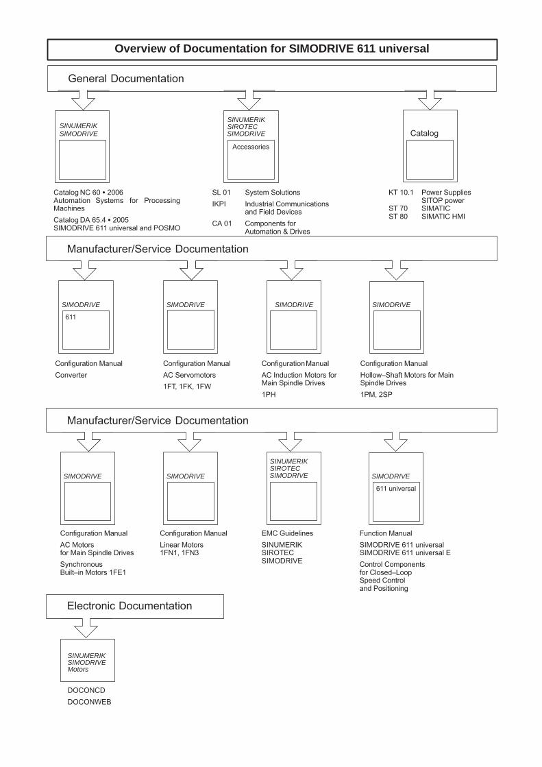
Manufacturer/Service Documentation
SIMODRIVE
Overview of Documentation for SIMODRIVE 611 universal
Configuration ManualAC Induction Motors forMain Spindle Drives1PH
Configuration ManualAC Servomotors1FT, 1FK, 1FW
Configuration ManualConverter
SIMODRIVE
611
Configuration ManualHollow–Shaft Motors for MainSpindle Drives1PM, 2SP
SIMODRIVE
Electronic Documentation
DOCONCDDOCONWEB
SINUMERIKSIMODRIVEMotors
Manufacturer/Service Documentation
SIMODRIVE
EMC GuidelinesSINUMERIKSIROTECSIMODRIVE
Configuration ManualAC Motors for Main Spindle DrivesSynchronousBuilt–in Motors 1FE1
Configuration ManualLinear Motors1FN1, 1FN3
SIMODRIVE
Function ManualSIMODRIVE 611 universalSIMODRIVE 611 universal EControl Componentsfor Closed–Loop Speed Control and Positioning
SIMODRIVE
611 universal
SIMODRIVESIROTECSINUMERIK
SIMODRIVE
General Documentation
SIMODRIVE
Catalog NC 60 � 2006Automation Systems for ProcessingMachinesCatalog DA 65.4 � 2005SIMODRIVE 611 universal and POSMO
SIMODRIVE
Accessories
SL 01 System SolutionsIKPI Industrial Communications
and Field DevicesCA 01 Components for
Automation & Drives
SIROTECSINUMERIKSINUMERIK
KT 10.1 Power SuppliesSITOP power
ST 70 SIMATICST 80 SIMATIC HMI
Catalog

www.siemens.com/motioncontrol
Änderungen vorbehalten© Siemens AG 2014
Siemens AGIndustry SectorDrive TechnologiesMotion Control SystemsPostfach 318091050 ERLANGENGERMANY