operator's manual for general purpose - adegis
TRANSCRIPT
Motoman NX100 Controller
Operator’s Manualfor General Purpose
Part Number: 150077-1CDRevision 1
Motoman, Incorporated 805 Liberty LaneWest Carrollton, OH 45449TEL: (937) 847-6200FAX: (937) 847-627724-Hour Service Hotline: (937) 847-3200

The information contained within this document is the proprietary property of Motoman, Inc., and may not be copied, reproduced or transmitted to other parties without the expressed written authorization of Motoman,
Inc.
©2007 by MOTOMANAll Rights Reserved
Because we are constantly improving our products, we reserve the right to change specifications without notice. MOTOMAN is a registered trademark of YASKAWA Electric Manufacturing.
COMPLETE OUR ONLINE SURVEYMotoman is committed to total customer satisfaction! Please give us your feedback on the technical manuals you
received with your Motoman robotic solution.
To participate, go to the following website:
http://www.motoman.com/forms/techpubs.asp
� �������������
� ������
������ �
,�� �"�������
This manual provides system information for General Purpose and contains the following sections:
�!��,����/�,��#��0��,��Provides general information about the structure of this manual, a list of reference documents, and customer service information.
�!��,���+�/���1!�2This section provides information regarding the safe use and operation of Motoman products.
�!��,���-�/��!�!#�'��0#���!�,���#0��,���Provides detailed information about the General Purpose Function.
3 #��� ������������ ��������������
For additional information refer to the following:
• NX100 Controller Manual (P/N 149201-1)
• Concurrent I/O Manual (P/N 149230-1)
• Operator’s Manual for your application
• Vendor manuals for system components not manufactured by Motoman
3+ ������� ��� )����,��� ������
If you are in need of technical assistance, contact the Motoman service staff at (937) 847-3200. Please have the following information ready before you call:
• Robot Type (EA1400, HP20, etc.)
• Application Type (arcwelding, spot welding, handling)
• Robot Serial Number (located on back side of robot arm)
• Robot Sales Order Number (located on back of controller)
����� �������
��

������ ����������
�������� ����������
NOTES
������� �����
��

� �������������
� ������
������ �+
�����%�
+3 ,�� �"������
,����������� ����� �� ������������%�������� ����������������4������%4������4���"������������"��4� �*��������4� ����4�� ���&�� ������*���������%���"��������� ����*����"��������� �������������������� ��������"������&�"3
��������������������� �������� �������������������������� ��������������������������� ���������������������������� �� ������ ������������ ������������������ ��������� �������� � ������� ���� �������������!"�#$%!&&&������������� �����������'
������������ ��������������&##�( �������)�*��+�,�-./0
���������1�2 �� ���03!#$�45'�6.-07�&&0%$#338�9'�6.-07�&&0%---3
���4��4�'���������� ����� ������
:�� ����1������������������ ���� ������������������������ ��������� ������������ � ���������������������� ������� �������������1�������1����� �� ���������������������� ������������������� ��������� ���������������������� ����
���������������������������������� ���������������1�������1���� �1����������������������������� ���� ������������2�������� � ���������������������� � ��� ������������������� �����������������
����� �������
��
������ ����������
�������� ������
�� ����������� ���������������������� ��'
; �������<������ ����6���� ���/�/7
; =������������� ���� ���6���� ���/�-7
; 2���� ��������>�� ����6���� ���/�07
; ������� ��������6���� ���/�"7
; )������ ��1�*���� ��1����2 �������������6���� ���/�$7
+3+ ����"� "����)�������
�� ������� ������������������ ���������–� ��������� ����������������� ��–�������������� ������������������������������� � ������������������� ������1�������������� ��������������������� ���������������� ����� ��1������ ��1�������� ��1����� �� � ����� ��� � ������
�������,��� ������������ ��*����������!#������ �������� �������������� �������� �����������"�������"������������5� "������4���������)��"�"4�&���� �������������"����4��� ������� ��������6� %�� ������������������""����������7��������"���*�3�
������,��� ������������ ��*������(�#�,�������� �������� �������������� ���������"��7��������� ���������������5� "����������� ����������� ��������6� %�� ������������������""����������7��������"���*�3�
��� ���,��� ������������ ��*��������0�,�������� �������� �������������� ���������"��7�������4�����&� �4���"�"����� �����5� "����������� ������������� ��� ��������6� %�� ��7��������"���*�3
������������ �������� ��� ������������ ������� � ����� ����� ����� ��� ��������� ����������� ������� ������ �������� �����
������� �����
��
� �������������
� ������
+3- ���� �������*�� "��*�����
������������1�����������1������������� ������ �����1�� �����������������1������� ����1������������? ������������������������������� � ��� ������������ �������� ��� � ��������������������� ��������� ������������ ����������� � ��������������������������� ����������������� ����=������������� ���� ���������������'
; �������������� ������������� ���������� �@���������������������� � �������*����� ���������������� � ��� ������������ �������� �������1������������A�������1������������ � �����1������� �������������� ����������������� ����������������� ��������������
; >����������������������������� ��� �� �� ������� ������� ����)�����������������������������������������������������������������
; ���������������� ���������������������������������� ����������������� �� ��������������������������������� �������������������*�6����������*������7�
; ������������������������ ��4�������������64%��*)7��������������� �� ������ ������
; ������������� �������������!"�#$%!&&&1����� ���0�/�"1������������4����1��������?������������������������ ���� � ������� �������������������������� ���!&!#�!0.�6/&<8�1�)���!&!#71�*����� ������������B�����������������=��������������6*�B�7�
+38 ����������������%���)����
������������� ���������������1���� � ����1��, � ��� � �����1���������� ����� �������������A��������� � � ����������� � ������������ �������� � ������� �������������������������������� ����������������������������������������������� ������ ���������1�����������!"�#$%!&&&�������������1������������������������������� ��������� ������ ������������� ������ ��� � ���������� � ����������������������������������� � ������������� � ���������� ������������ ������ ��1������ ��1����������� �������������� ��������� � ������ ������ ������������'
; ������������������ ���
; 5 �������� �����������������
; >���� �������?�
; 4���������������������������������������������� ��1�����������������1����������� ���������
<���?���������� � ��������� ���������������������� ������� �����������������%����� �� ��������� � ������ ���� ����
����� ������
��
������ ����������
�������� ������
+39 ,�����������������%
���� ������ ��� �������� ������������� ����������������� � ����������������� ���������� ������� ���������������������1���������������1��, �� ���������1�����1���������������������� �������� � ����������������������������������� � ������������� � ���������� ������������ ������ ��1������ ��1����������� ����������� ���� ���������������'
; +��������������� �� � ��������������� � ��� ����� ���������1�����������1��������������!"�#$%!&&&��������������������� �������� ����������� � ������
; ����� ���������?������������������������ �����������? ���1�� ���1������� �����
; )�� � ���������������������� ����������������?����������
; ������������� ���1� ������������������������������ ����������� C�������� �����������?����������
; 4� � ������������������������� ��������������������������� ������������������� � ������6� ������ ���7�
; )��� ������� � ��������� �� ����������?������������ ���������� ������� �������������������
+3: � �* �����*4���� �����4���"������������������%
������������1�����������1������������� ������ �����1�� �����������������1������� ����1������������? ������������������������������� � ��� ������������ �������� ��� � ��������������������� ������������� ���������� �@���������������������� � �������*����� ���������������� � ��� ������������ ��1������1������� ������ ��1����� � ������ ����������� ��������� ���������������������� ��������������1�������1����� �� ��������������������������� ��������� ������������ ����������� � ��������������������������� ����������������� ����
; ������������������������?������������������������������ ����C���������� � �����, ����+�������������� ����������������������1�� �1����� �1������
; +�������������������������� ��������<���?���������� � ���������������������� ������� �����������������%����� �� ��������� � ������ ���� ����
; >����������������������������� ��� �� �� ������� ������� ����+������������������������������ �������������� ������������������������?�����
; <���?�����4%��*)���������������������� �������������������������� ����������������� ���������������������������� ��4�������������64%��*)7��������������� �� ������ ������
; +�?������������������@����������� �������� ����������������������������������� ���������� ������ ��1��������1����@���1����?�������������������������������� ������������������������������������������������������ ���1�������� ��1����� � ������
������ �����
��
� �������������
� ������
; ������ � �� �������)����!1����������� ��1��������������������������������������*������������������������������� �@����������1���������������������������D�>�������?������� � �� �������)����!1����������� ����2? ������������� ������������ ��������� �� ������2������� ���(*�>�E*:���������ED
; ���������� ������ � ����������������������������� � ������� ���������������� ������������������2���������������E*:���������E���55�+4�(*�>� ������������������� �����������
; ������������������������������ � �� �������)����/1�:�������� ��1���������������������*�������������� � �� ��������������������������������, ����������������������=�����������������?���������? ������������ � �� ������������ � �� ��������������������������� ����������������������������������������������������������� �@����������1�����������������������������������������������������>�����%����?������� � �� ���������������������������������� ������������������������������������C����������������� ��� ����
; <���?��������������������� � �����������������������������������������������
; �� ��� � ������������� ��������������������� ����������4����� ��� ����������� �������������������������������������������� � �������> ���������������?������������������� ���� ��� �����������? �������� � �� �������������� ����
; >����������������� ����������������������������� ��������������� ������������������������� ������������ ���������
; :���������������������������
; ���������������� ���������������������������������� ����������������� �� ��������������������������������� �������������������*�6����������*������7�
����� �������
��

������ ����������
�������� ������
���!�
�������� �����
��
YASKAWA
NX100OPERATOR’S MANUALFOR GENERAL PURPOSE
Upon receipt of the product and prior to initial operation, read these instructions thoroughly, and retain for future reference.
MOTOMAN INSTRUCTIONSMOTOMAN- INSTRUCTIONSNX100 INSTRUCTIONSNX100 OPERATOR’S MANUALNX100 MAINTENANCE MANUAL
The NX100 operator’s manuals above correspond to specific usage. Be sure to use the appropriate manual.
YASKAWA MANUAL NO. RE-CSO-A032
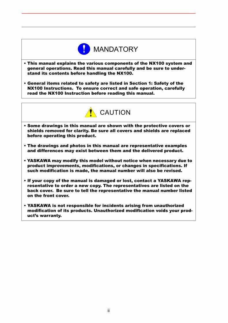
• This manual explains the various components of the NX100 system and general operations. Read this manual carefully and be sure to under-stand its contents before handling the NX100.
• General items related to safety are listed in Section 1: Safety of the NX100 Instructions. To ensure correct and safe operation, carefully read the NX100 Instruction before reading this manual.
• Some drawings in this manual are shown with the protective covers or shields removed for clarity. Be sure all covers and shields are replaced before operating this product.
• The drawings and photos in this manual are representative examples and differences may exist between them and the delivered product.
• YASKAWA may modify this model without notice when necessary due to product improvements, modifications, or changes in specifications. If such modification is made, the manual number will also be revised.
• If your copy of the manual is damaged or lost, contact a YASKAWA rep-resentative to order a new copy. The representatives are listed on the back cover. Be sure to tell the representative the manual number listed on the front cover.
• YASKAWA is not responsible for incidents arising from unauthorized modification of its products. Unauthorized modification voids your prod-uct’s warranty.
MANDATORY
CAUTION
ii
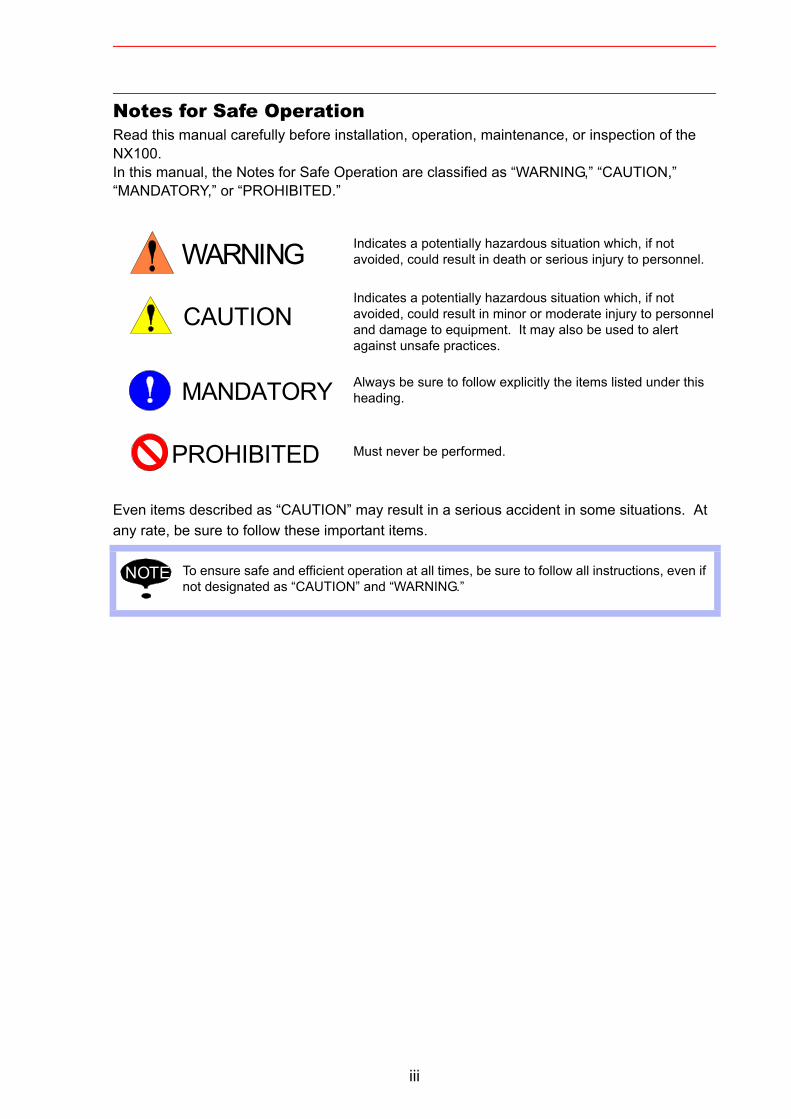
Notes for Safe OperationRead this manual carefully before installation, operation, maintenance, or inspection of the NX100. In this manual, the Notes for Safe Operation are classified as “WARNING,” “CAUTION,” “MANDATORY,” or “PROHIBITED.”
Even items described as “CAUTION” may result in a serious accident in some situations. At any rate, be sure to follow these important items.
Indicates a potentially hazardous situation which, if not avoided, could result in death or serious injury to personnel.
Indicates a potentially hazardous situation which, if not avoided, could result in minor or moderate injury to personnel and damage to equipment. It may also be used to alert against unsafe practices.
Always be sure to follow explicitly the items listed under this heading.
Must never be performed.
To ensure safe and efficient operation at all times, be sure to follow all instructions, even if not designated as “CAUTION” and “WARNING.”
WARNING
CAUTION
MANDATORY
PROHIBITED
NOTE
iii
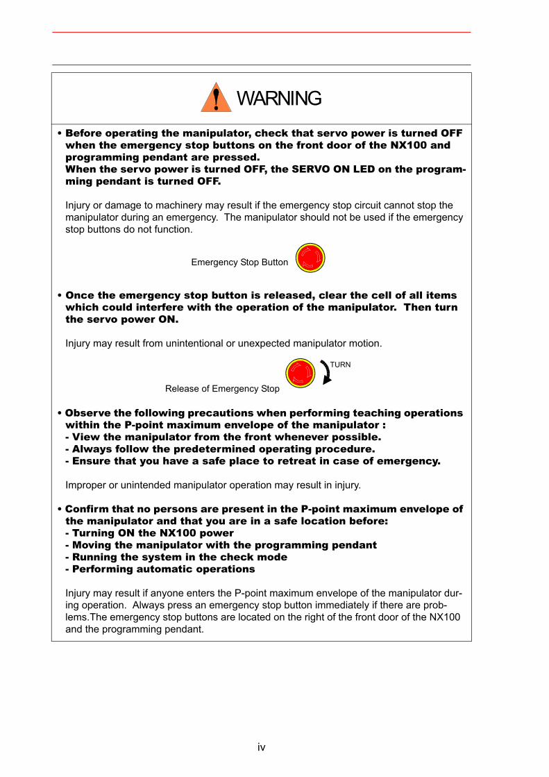
• Before operating the manipulator, check that servo power is turned OFF when the emergency stop buttons on the front door of the NX100 and programming pendant are pressed.When the servo power is turned OFF, the SERVO ON LED on the program-ming pendant is turned OFF.
Injury or damage to machinery may result if the emergency stop circuit cannot stop the manipulator during an emergency. The manipulator should not be used if the emergency stop buttons do not function.
Emergency Stop Button
• Once the emergency stop button is released, clear the cell of all items which could interfere with the operation of the manipulator. Then turn the servo power ON.
Injury may result from unintentional or unexpected manipulator motion.
Release of Emergency Stop
• Observe the following precautions when performing teaching operations within the P-point maximum envelope of the manipulator :- View the manipulator from the front whenever possible.- Always follow the predetermined operating procedure.- Ensure that you have a safe place to retreat in case of emergency.
Improper or unintended manipulator operation may result in injury.
• Confirm that no persons are present in the P-point maximum envelope of the manipulator and that you are in a safe location before:- Turning ON the NX100 power- Moving the manipulator with the programming pendant- Running the system in the check mode- Performing automatic operations
Injury may result if anyone enters the P-point maximum envelope of the manipulator dur-ing operation. Always press an emergency stop button immediately if there are prob-lems.The emergency stop buttons are located on the right of the front door of the NX100 and the programming pendant.
WARNING
TURN
iv
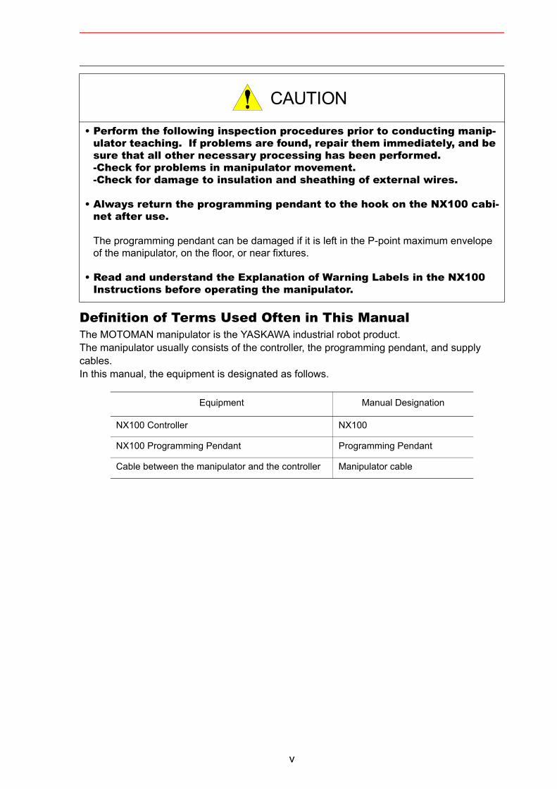
Definition of Terms Used Often in This ManualThe MOTOMAN manipulator is the YASKAWA industrial robot product.The manipulator usually consists of the controller, the programming pendant, and supply cables.In this manual, the equipment is designated as follows.
• Perform the following inspection procedures prior to conducting manip-ulator teaching. If problems are found, repair them immediately, and be sure that all other necessary processing has been performed.-Check for problems in manipulator movement.-Check for damage to insulation and sheathing of external wires.
• Always return the programming pendant to the hook on the NX100 cabi-net after use.
The programming pendant can be damaged if it is left in the P-point maximum envelope of the manipulator, on the floor, or near fixtures.
• Read and understand the Explanation of Warning Labels in the NX100 Instructions before operating the manipulator.
Equipment Manual Designation
NX100 Controller NX100
NX100 Programming Pendant Programming Pendant
Cable between the manipulator and the controller Manipulator cable
CAUTION
v
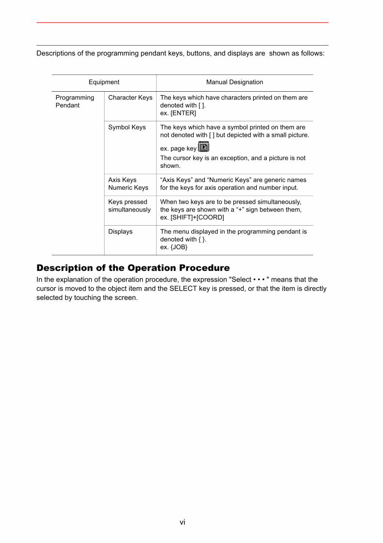
Descriptions of the programming pendant keys, buttons, and displays are shown as follows:
Description of the Operation ProcedureIn the explanation of the operation procedure, the expression "Select • • • " means that the cursor is moved to the object item and the SELECT key is pressed, or that the item is directly selected by touching the screen.
Equipment Manual Designation
Programming Pendant
Character Keys The keys which have characters printed on them are denoted with [ ].ex. [ENTER]
Symbol Keys The keys which have a symbol printed on them are not denoted with [ ] but depicted with a small picture.
ex. page keyThe cursor key is an exception, and a picture is not shown.
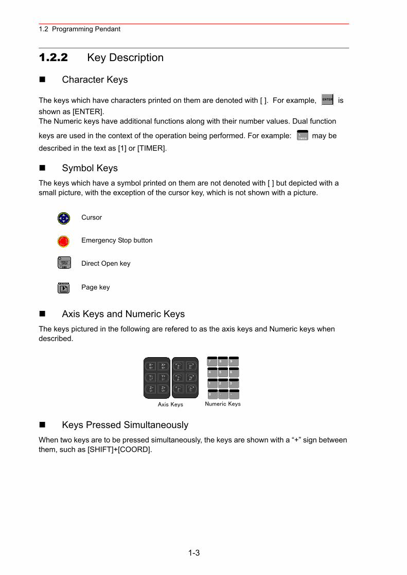
Axis KeysNumeric Keys
“Axis Keys” and “Numeric Keys” are generic names for the keys for axis operation and number input.
Keys pressed simultaneously
When two keys are to be pressed simultaneously, the keys are shown with a “+” sign between them, ex. [SHIFT]+[COORD]
Displays The menu displayed in the programming pendant is denoted with { }.ex. {JOB}
PAGE
GO BACK
vi
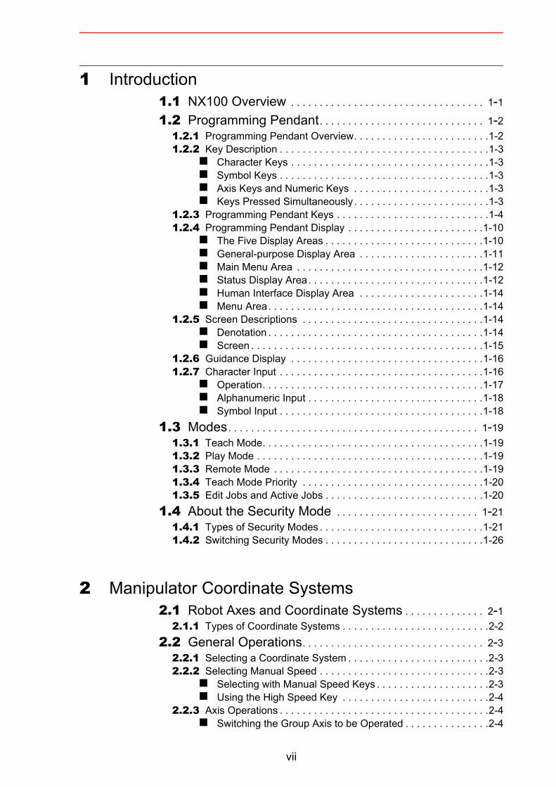
1 Introduction1.1 NX100 Overview . . . . . . . . . . . . . . . . . . . . . . . . . . . . . . . . . . 1-11.2 Programming Pendant. . . . . . . . . . . . . . . . . . . . . . . . . . . . . 1-2
1.2.1 Programming Pendant Overview. . . . . . . . . . . . . . . . . . . . . . . .1-21.2.2 Key Description . . . . . . . . . . . . . . . . . . . . . . . . . . . . . . . . . . . . .1-3
Character Keys . . . . . . . . . . . . . . . . . . . . . . . . . . . . . . . . . . .1-3 Symbol Keys . . . . . . . . . . . . . . . . . . . . . . . . . . . . . . . . . . . . .1-3 Axis Keys and Numeric Keys . . . . . . . . . . . . . . . . . . . . . . . .1-3 Keys Pressed Simultaneously. . . . . . . . . . . . . . . . . . . . . . . .1-3
1.2.3 Programming Pendant Keys . . . . . . . . . . . . . . . . . . . . . . . . . . .1-41.2.4 Programming Pendant Display . . . . . . . . . . . . . . . . . . . . . . . .1-10
The Five Display Areas . . . . . . . . . . . . . . . . . . . . . . . . . . . .1-10 General-purpose Display Area . . . . . . . . . . . . . . . . . . . . . .1-11 Main Menu Area . . . . . . . . . . . . . . . . . . . . . . . . . . . . . . . . .1-12 Status Display Area. . . . . . . . . . . . . . . . . . . . . . . . . . . . . . .1-12 Human Interface Display Area . . . . . . . . . . . . . . . . . . . . . .1-14 Menu Area. . . . . . . . . . . . . . . . . . . . . . . . . . . . . . . . . . . . . .1-14
1.2.5 Screen Descriptions . . . . . . . . . . . . . . . . . . . . . . . . . . . . . . . .1-14 Denotation . . . . . . . . . . . . . . . . . . . . . . . . . . . . . . . . . . . . . .1-14 Screen . . . . . . . . . . . . . . . . . . . . . . . . . . . . . . . . . . . . . . . . .1-15
1.2.6 Guidance Display . . . . . . . . . . . . . . . . . . . . . . . . . . . . . . . . . .1-161.2.7 Character Input . . . . . . . . . . . . . . . . . . . . . . . . . . . . . . . . . . . .1-16
Operation. . . . . . . . . . . . . . . . . . . . . . . . . . . . . . . . . . . . . . .1-17 Alphanumeric Input . . . . . . . . . . . . . . . . . . . . . . . . . . . . . . .1-18 Symbol Input . . . . . . . . . . . . . . . . . . . . . . . . . . . . . . . . . . . .1-18
1.3 Modes. . . . . . . . . . . . . . . . . . . . . . . . . . . . . . . . . . . . . . . . . . . . 1-191.3.1 Teach Mode. . . . . . . . . . . . . . . . . . . . . . . . . . . . . . . . . . . . . . .1-191.3.2 Play Mode . . . . . . . . . . . . . . . . . . . . . . . . . . . . . . . . . . . . . . . .1-191.3.3 Remote Mode . . . . . . . . . . . . . . . . . . . . . . . . . . . . . . . . . . . . .1-191.3.4 Teach Mode Priority . . . . . . . . . . . . . . . . . . . . . . . . . . . . . . . .1-201.3.5 Edit Jobs and Active Jobs . . . . . . . . . . . . . . . . . . . . . . . . . . . .1-20
1.4 About the Security Mode . . . . . . . . . . . . . . . . . . . . . . . . . 1-211.4.1 Types of Security Modes . . . . . . . . . . . . . . . . . . . . . . . . . . . . .1-211.4.2 Switching Security Modes . . . . . . . . . . . . . . . . . . . . . . . . . . . .1-26
2 Manipulator Coordinate Systems2.1 Robot Axes and Coordinate Systems . . . . . . . . . . . . . . 2-1
2.1.1 Types of Coordinate Systems . . . . . . . . . . . . . . . . . . . . . . . . . .2-22.2 General Operations. . . . . . . . . . . . . . . . . . . . . . . . . . . . . . . . 2-3
2.2.1 Selecting a Coordinate System . . . . . . . . . . . . . . . . . . . . . . . . .2-32.2.2 Selecting Manual Speed . . . . . . . . . . . . . . . . . . . . . . . . . . . . . .2-3
Selecting with Manual Speed Keys . . . . . . . . . . . . . . . . . . . .2-3 Using the High Speed Key . . . . . . . . . . . . . . . . . . . . . . . . . .2-4
2.2.3 Axis Operations . . . . . . . . . . . . . . . . . . . . . . . . . . . . . . . . . . . . .2-4 Switching the Group Axis to be Operated . . . . . . . . . . . . . . .2-4
vii
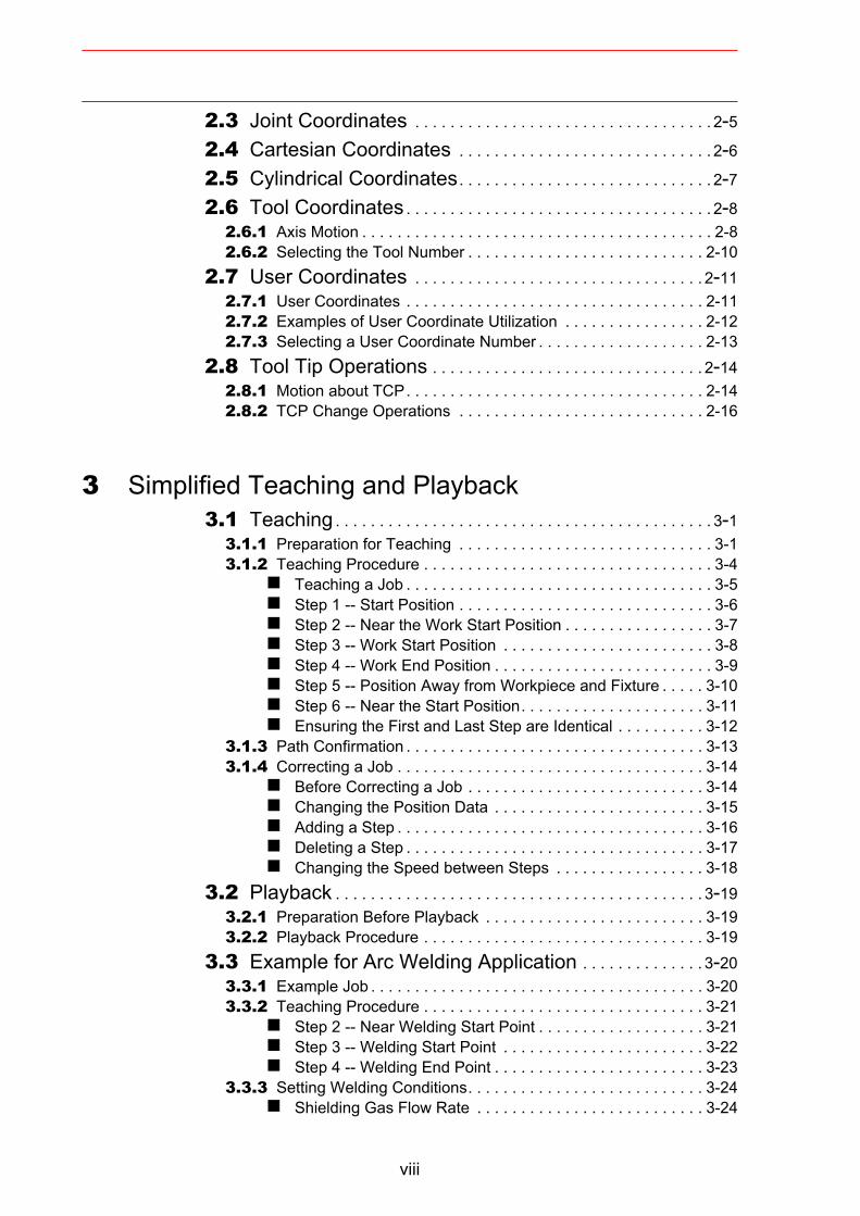
2.3 Joint Coordinates . . . . . . . . . . . . . . . . . . . . . . . . . . . . . . . . . . 2-52.4 Cartesian Coordinates . . . . . . . . . . . . . . . . . . . . . . . . . . . . . 2-62.5 Cylindrical Coordinates. . . . . . . . . . . . . . . . . . . . . . . . . . . . . 2-72.6 Tool Coordinates . . . . . . . . . . . . . . . . . . . . . . . . . . . . . . . . . . . 2-8
2.6.1 Axis Motion . . . . . . . . . . . . . . . . . . . . . . . . . . . . . . . . . . . . . . . . 2-82.6.2 Selecting the Tool Number . . . . . . . . . . . . . . . . . . . . . . . . . . . 2-10
2.7 User Coordinates . . . . . . . . . . . . . . . . . . . . . . . . . . . . . . . . . 2-112.7.1 User Coordinates . . . . . . . . . . . . . . . . . . . . . . . . . . . . . . . . . . 2-112.7.2 Examples of User Coordinate Utilization . . . . . . . . . . . . . . . . 2-122.7.3 Selecting a User Coordinate Number . . . . . . . . . . . . . . . . . . . 2-13
2.8 Tool Tip Operations . . . . . . . . . . . . . . . . . . . . . . . . . . . . . . . 2-142.8.1 Motion about TCP. . . . . . . . . . . . . . . . . . . . . . . . . . . . . . . . . . 2-142.8.2 TCP Change Operations . . . . . . . . . . . . . . . . . . . . . . . . . . . . 2-16
3 Simplified Teaching and Playback3.1 Teaching . . . . . . . . . . . . . . . . . . . . . . . . . . . . . . . . . . . . . . . . . . . 3-1
3.1.1 Preparation for Teaching . . . . . . . . . . . . . . . . . . . . . . . . . . . . . 3-13.1.2 Teaching Procedure . . . . . . . . . . . . . . . . . . . . . . . . . . . . . . . . . 3-4
Teaching a Job . . . . . . . . . . . . . . . . . . . . . . . . . . . . . . . . . . . 3-5 Step 1 -- Start Position . . . . . . . . . . . . . . . . . . . . . . . . . . . . . 3-6 Step 2 -- Near the Work Start Position . . . . . . . . . . . . . . . . . 3-7 Step 3 -- Work Start Position . . . . . . . . . . . . . . . . . . . . . . . . 3-8 Step 4 -- Work End Position . . . . . . . . . . . . . . . . . . . . . . . . . 3-9 Step 5 -- Position Away from Workpiece and Fixture . . . . . 3-10 Step 6 -- Near the Start Position. . . . . . . . . . . . . . . . . . . . . 3-11 Ensuring the First and Last Step are Identical . . . . . . . . . . 3-12
3.1.3 Path Confirmation . . . . . . . . . . . . . . . . . . . . . . . . . . . . . . . . . . 3-133.1.4 Correcting a Job . . . . . . . . . . . . . . . . . . . . . . . . . . . . . . . . . . . 3-14
Before Correcting a Job . . . . . . . . . . . . . . . . . . . . . . . . . . . 3-14 Changing the Position Data . . . . . . . . . . . . . . . . . . . . . . . . 3-15 Adding a Step . . . . . . . . . . . . . . . . . . . . . . . . . . . . . . . . . . . 3-16 Deleting a Step . . . . . . . . . . . . . . . . . . . . . . . . . . . . . . . . . . 3-17 Changing the Speed between Steps . . . . . . . . . . . . . . . . . 3-18
3.2 Playback . . . . . . . . . . . . . . . . . . . . . . . . . . . . . . . . . . . . . . . . . . 3-193.2.1 Preparation Before Playback . . . . . . . . . . . . . . . . . . . . . . . . . 3-193.2.2 Playback Procedure . . . . . . . . . . . . . . . . . . . . . . . . . . . . . . . . 3-19
3.3 Example for Arc Welding Application . . . . . . . . . . . . . . 3-203.3.1 Example Job . . . . . . . . . . . . . . . . . . . . . . . . . . . . . . . . . . . . . . 3-203.3.2 Teaching Procedure . . . . . . . . . . . . . . . . . . . . . . . . . . . . . . . . 3-21
Step 2 -- Near Welding Start Point . . . . . . . . . . . . . . . . . . . 3-21 Step 3 -- Welding Start Point . . . . . . . . . . . . . . . . . . . . . . . 3-22 Step 4 -- Welding End Point . . . . . . . . . . . . . . . . . . . . . . . . 3-23
3.3.3 Setting Welding Conditions. . . . . . . . . . . . . . . . . . . . . . . . . . . 3-24 Shielding Gas Flow Rate . . . . . . . . . . . . . . . . . . . . . . . . . . 3-24
viii
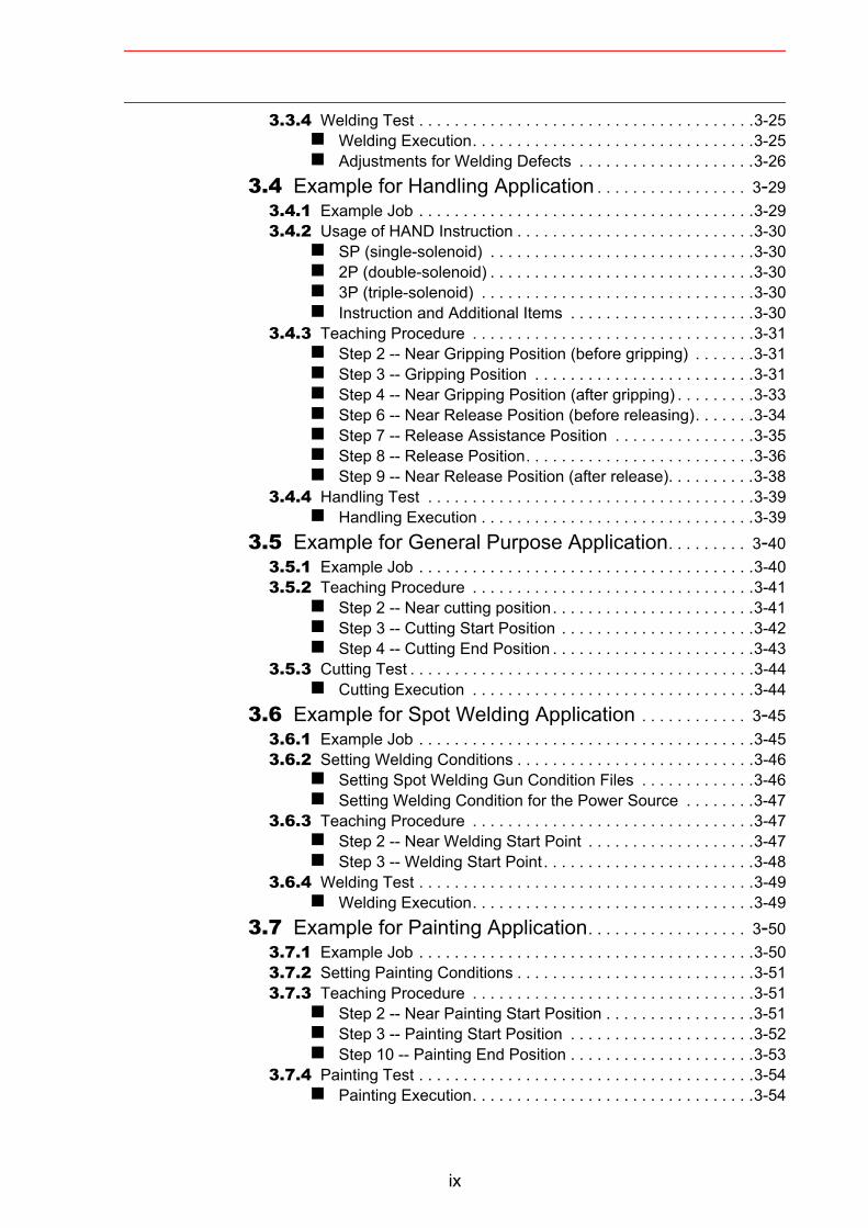
3.3.4 Welding Test . . . . . . . . . . . . . . . . . . . . . . . . . . . . . . . . . . . . . .3-25 Welding Execution. . . . . . . . . . . . . . . . . . . . . . . . . . . . . . . .3-25 Adjustments for Welding Defects . . . . . . . . . . . . . . . . . . . .3-26
3.4 Example for Handling Application . . . . . . . . . . . . . . . . . 3-293.4.1 Example Job . . . . . . . . . . . . . . . . . . . . . . . . . . . . . . . . . . . . . .3-293.4.2 Usage of HAND Instruction . . . . . . . . . . . . . . . . . . . . . . . . . . .3-30
SP (single-solenoid) . . . . . . . . . . . . . . . . . . . . . . . . . . . . . .3-30 2P (double-solenoid) . . . . . . . . . . . . . . . . . . . . . . . . . . . . . .3-30 3P (triple-solenoid) . . . . . . . . . . . . . . . . . . . . . . . . . . . . . . .3-30 Instruction and Additional Items . . . . . . . . . . . . . . . . . . . . .3-30
3.4.3 Teaching Procedure . . . . . . . . . . . . . . . . . . . . . . . . . . . . . . . .3-31 Step 2 -- Near Gripping Position (before gripping) . . . . . . .3-31 Step 3 -- Gripping Position . . . . . . . . . . . . . . . . . . . . . . . . .3-31 Step 4 -- Near Gripping Position (after gripping) . . . . . . . . .3-33 Step 6 -- Near Release Position (before releasing). . . . . . .3-34 Step 7 -- Release Assistance Position . . . . . . . . . . . . . . . .3-35 Step 8 -- Release Position. . . . . . . . . . . . . . . . . . . . . . . . . .3-36 Step 9 -- Near Release Position (after release). . . . . . . . . .3-38
3.4.4 Handling Test . . . . . . . . . . . . . . . . . . . . . . . . . . . . . . . . . . . . .3-39 Handling Execution . . . . . . . . . . . . . . . . . . . . . . . . . . . . . . .3-39
3.5 Example for General Purpose Application. . . . . . . . . 3-403.5.1 Example Job . . . . . . . . . . . . . . . . . . . . . . . . . . . . . . . . . . . . . .3-403.5.2 Teaching Procedure . . . . . . . . . . . . . . . . . . . . . . . . . . . . . . . .3-41
Step 2 -- Near cutting position. . . . . . . . . . . . . . . . . . . . . . .3-41 Step 3 -- Cutting Start Position . . . . . . . . . . . . . . . . . . . . . .3-42 Step 4 -- Cutting End Position . . . . . . . . . . . . . . . . . . . . . . .3-43
3.5.3 Cutting Test . . . . . . . . . . . . . . . . . . . . . . . . . . . . . . . . . . . . . . .3-44 Cutting Execution . . . . . . . . . . . . . . . . . . . . . . . . . . . . . . . .3-44
3.6 Example for Spot Welding Application . . . . . . . . . . . . 3-453.6.1 Example Job . . . . . . . . . . . . . . . . . . . . . . . . . . . . . . . . . . . . . .3-453.6.2 Setting Welding Conditions . . . . . . . . . . . . . . . . . . . . . . . . . . .3-46
Setting Spot Welding Gun Condition Files . . . . . . . . . . . . .3-46 Setting Welding Condition for the Power Source . . . . . . . .3-47
3.6.3 Teaching Procedure . . . . . . . . . . . . . . . . . . . . . . . . . . . . . . . .3-47 Step 2 -- Near Welding Start Point . . . . . . . . . . . . . . . . . . .3-47 Step 3 -- Welding Start Point . . . . . . . . . . . . . . . . . . . . . . . .3-48
3.6.4 Welding Test . . . . . . . . . . . . . . . . . . . . . . . . . . . . . . . . . . . . . .3-49 Welding Execution. . . . . . . . . . . . . . . . . . . . . . . . . . . . . . . .3-49
3.7 Example for Painting Application. . . . . . . . . . . . . . . . . . 3-503.7.1 Example Job . . . . . . . . . . . . . . . . . . . . . . . . . . . . . . . . . . . . . .3-503.7.2 Setting Painting Conditions . . . . . . . . . . . . . . . . . . . . . . . . . . .3-513.7.3 Teaching Procedure . . . . . . . . . . . . . . . . . . . . . . . . . . . . . . . .3-51
Step 2 -- Near Painting Start Position . . . . . . . . . . . . . . . . .3-51 Step 3 -- Painting Start Position . . . . . . . . . . . . . . . . . . . . .3-52 Step 10 -- Painting End Position . . . . . . . . . . . . . . . . . . . . .3-53
3.7.4 Painting Test . . . . . . . . . . . . . . . . . . . . . . . . . . . . . . . . . . . . . .3-54 Painting Execution. . . . . . . . . . . . . . . . . . . . . . . . . . . . . . . .3-54
ix
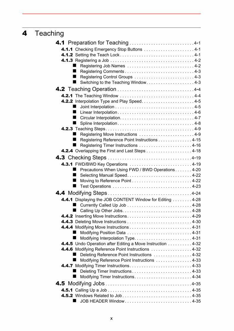
4 Teaching4.1 Preparation for Teaching . . . . . . . . . . . . . . . . . . . . . . . . . . . 4-1
4.1.1 Checking Emergency Stop Buttons . . . . . . . . . . . . . . . . . . . . . 4-14.1.2 Setting the Teach Lock . . . . . . . . . . . . . . . . . . . . . . . . . . . . . . . 4-14.1.3 Registering a Job . . . . . . . . . . . . . . . . . . . . . . . . . . . . . . . . . . . 4-2
Registering Job Names . . . . . . . . . . . . . . . . . . . . . . . . . . . . 4-2 Registering Comments . . . . . . . . . . . . . . . . . . . . . . . . . . . . . 4-3 Registering Control Groups . . . . . . . . . . . . . . . . . . . . . . . . . 4-3 Switching to the Teaching Window. . . . . . . . . . . . . . . . . . . . 4-3
4.2 Teaching Operation . . . . . . . . . . . . . . . . . . . . . . . . . . . . . . . . 4-44.2.1 The Teaching Window . . . . . . . . . . . . . . . . . . . . . . . . . . . . . . . 4-44.2.2 Interpolation Type and Play Speed. . . . . . . . . . . . . . . . . . . . . . 4-5
Joint Interpolation . . . . . . . . . . . . . . . . . . . . . . . . . . . . . . . . . 4-5 Linear Interpolation . . . . . . . . . . . . . . . . . . . . . . . . . . . . . . . . 4-6 Circular Interpolation. . . . . . . . . . . . . . . . . . . . . . . . . . . . . . . 4-7 Spline Interpolation . . . . . . . . . . . . . . . . . . . . . . . . . . . . . . . . 4-8
4.2.3 Teaching Steps. . . . . . . . . . . . . . . . . . . . . . . . . . . . . . . . . . . . . 4-9 Registering Move Instructions . . . . . . . . . . . . . . . . . . . . . . . 4-9 Registering Reference Point Instructions . . . . . . . . . . . . . . 4-15 Registering Timer Instructions . . . . . . . . . . . . . . . . . . . . . . 4-16
4.2.4 Overlapping the First and Last Steps . . . . . . . . . . . . . . . . . . . 4-184.3 Checking Steps . . . . . . . . . . . . . . . . . . . . . . . . . . . . . . . . . . . 4-19
4.3.1 FWD/BWD Key Operations . . . . . . . . . . . . . . . . . . . . . . . . . . 4-19 Precautions When Using FWD / BWD Operations . . . . . . . 4-20 Selecting Manual Speed. . . . . . . . . . . . . . . . . . . . . . . . . . . 4-22 Moving to Reference Point . . . . . . . . . . . . . . . . . . . . . . . . . 4-22 Test Operations . . . . . . . . . . . . . . . . . . . . . . . . . . . . . . . . . 4-23
4.4 Modifying Steps . . . . . . . . . . . . . . . . . . . . . . . . . . . . . . . . . . . 4-244.4.1 Displaying the JOB CONTENT Window for Editing . . . . . . . . 4-28
Currently Called Up Job . . . . . . . . . . . . . . . . . . . . . . . . . . . 4-28 Calling Up Other Jobs. . . . . . . . . . . . . . . . . . . . . . . . . . . . . 4-28
4.4.2 Inserting Move Instructions. . . . . . . . . . . . . . . . . . . . . . . . . . . 4-294.4.3 Deleting Move Instructions . . . . . . . . . . . . . . . . . . . . . . . . . . . 4-304.4.4 Modifying Move Instructions . . . . . . . . . . . . . . . . . . . . . . . . . . 4-31
Modifying Position Data . . . . . . . . . . . . . . . . . . . . . . . . . . . 4-31 Modifying Interpolation Type. . . . . . . . . . . . . . . . . . . . . . . . 4-31
4.4.5 Undo Operation after Editing a Move Instruction . . . . . . . . . . 4-324.4.6 Modifying Reference Point Instructions . . . . . . . . . . . . . . . . . 4-32
Deleting Reference Point Instructions . . . . . . . . . . . . . . . . 4-32 Modifying Reference Point Instructions . . . . . . . . . . . . . . . 4-33
4.4.7 Modifying Timer Instructions. . . . . . . . . . . . . . . . . . . . . . . . . . 4-33 Deleting Timer Instructions . . . . . . . . . . . . . . . . . . . . . . . . . 4-33 Modifying Timer Instructions. . . . . . . . . . . . . . . . . . . . . . . . 4-34
4.5 Modifying Jobs . . . . . . . . . . . . . . . . . . . . . . . . . . . . . . . . . . . . 4-354.5.1 Calling Up a Job . . . . . . . . . . . . . . . . . . . . . . . . . . . . . . . . . . . 4-354.5.2 Windows Related to Job . . . . . . . . . . . . . . . . . . . . . . . . . . . . . 4-35
JOB HEADER Window. . . . . . . . . . . . . . . . . . . . . . . . . . . . 4-35
x
JOB CONTENT Window . . . . . . . . . . . . . . . . . . . . . . . . . . .4-37 COMMAND POSITION Window . . . . . . . . . . . . . . . . . . . . .4-38 JOB CAPACITY Window. . . . . . . . . . . . . . . . . . . . . . . . . . .4-39
4.6 Editing Instructions . . . . . . . . . . . . . . . . . . . . . . . . . . . . . . . 4-404.6.1 Instruction Group . . . . . . . . . . . . . . . . . . . . . . . . . . . . . . . . . . .4-404.6.2 Inserting Instructions . . . . . . . . . . . . . . . . . . . . . . . . . . . . . . . .4-424.6.3 Deleting Instructions . . . . . . . . . . . . . . . . . . . . . . . . . . . . . . . .4-454.6.4 Modifying Instructions . . . . . . . . . . . . . . . . . . . . . . . . . . . . . . .4-454.6.5 Undo Operation after Modifying Instructions . . . . . . . . . . . . . .4-474.6.6 Viewing Description for an Instruction . . . . . . . . . . . . . . . . . . .4-484.6.7 Modifying Additional Numeric Data . . . . . . . . . . . . . . . . . . . . .4-494.6.8 Modifying Additional Items. . . . . . . . . . . . . . . . . . . . . . . . . . . .4-504.6.9 Inserting Additional Items . . . . . . . . . . . . . . . . . . . . . . . . . . . .4-514.6.10 Deleting Additional Items . . . . . . . . . . . . . . . . . . . . . . . . . . .4-524.6.11 Undo Operation after Modifying Additional Items . . . . . . . . .4-53
4.7 Editing Jobs . . . . . . . . . . . . . . . . . . . . . . . . . . . . . . . . . . . . . . 4-544.7.1 Selecting the Range . . . . . . . . . . . . . . . . . . . . . . . . . . . . . . . .4-564.7.2 Copying . . . . . . . . . . . . . . . . . . . . . . . . . . . . . . . . . . . . . . . . . .4-574.7.3 Cutting . . . . . . . . . . . . . . . . . . . . . . . . . . . . . . . . . . . . . . . . . . .4-574.7.4 Pasting. . . . . . . . . . . . . . . . . . . . . . . . . . . . . . . . . . . . . . . . . . .4-584.7.5 Reverse Pasting . . . . . . . . . . . . . . . . . . . . . . . . . . . . . . . . . . .4-59
4.8 Test Operations . . . . . . . . . . . . . . . . . . . . . . . . . . . . . . . . . . 4-60
4.9 Other Job-editing Functions . . . . . . . . . . . . . . . . . . . . . . 4-614.9.1 Editing Play Speed . . . . . . . . . . . . . . . . . . . . . . . . . . . . . . . . .4-61
Modification of Speed Type. . . . . . . . . . . . . . . . . . . . . . . . .4-61 Relative Modification . . . . . . . . . . . . . . . . . . . . . . . . . . . . . .4-61 Modification by TRT (Traverse Time) . . . . . . . . . . . . . . . . .4-63
4.9.2 Editing Interpolation Type . . . . . . . . . . . . . . . . . . . . . . . . . . . .4-654.9.3 Editing Condition Files. . . . . . . . . . . . . . . . . . . . . . . . . . . . . . .4-664.9.4 Editing User Variables . . . . . . . . . . . . . . . . . . . . . . . . . . . . . . .4-67
Displaying Byte, Integer, Double Precision Integer, and Real Type Variables . . . . . . . . . . . . . . . . . . . . . . . . . . .4-69
Setting Byte, Integer, Double Precision Integer, and Real Type Variables . . . . . . . . . . . . . . . . . . . . . . . . . . .4-70
Displaying Character Type Variables . . . . . . . . . . . . . . . . .4-71 Setting Character Type Variables . . . . . . . . . . . . . . . . . . . .4-72 Registering Variable Name . . . . . . . . . . . . . . . . . . . . . . . . .4-73 Displaying Position Variables . . . . . . . . . . . . . . . . . . . . . . .4-74 Setting Position Variables . . . . . . . . . . . . . . . . . . . . . . . . . .4-75 Setting Position Variables Using the Numeric Keys . . . . . .4-76 Setting Position Variables Using the Axis Keys . . . . . . . . .4-78 Deleting Data Set of Position Variables . . . . . . . . . . . . . . .4-79 Checking Positions by Position Variables . . . . . . . . . . . . . .4-80 Manipulator Types. . . . . . . . . . . . . . . . . . . . . . . . . . . . . . . .4-81
4.9.5 Editing Local Variables . . . . . . . . . . . . . . . . . . . . . . . . . . . . . .4-85 Setting the Number of Local Variables . . . . . . . . . . . . . . . .4-87
4.9.6 Searching . . . . . . . . . . . . . . . . . . . . . . . . . . . . . . . . . . . . . . . .4-88 Line Search . . . . . . . . . . . . . . . . . . . . . . . . . . . . . . . . . . . . .4-89 Step Search. . . . . . . . . . . . . . . . . . . . . . . . . . . . . . . . . . . . .4-89
xi
Label Search. . . . . . . . . . . . . . . . . . . . . . . . . . . . . . . . . . . . 4-90 Instruction Search. . . . . . . . . . . . . . . . . . . . . . . . . . . . . . . . 4-91 Tag Search . . . . . . . . . . . . . . . . . . . . . . . . . . . . . . . . . . . . . 4-92
5 Playback5.1 Preparation for Playback . . . . . . . . . . . . . . . . . . . . . . . . . . . 5-1
Calling a Job . . . . . . . . . . . . . . . . . . . . . . . . . . . . . . . . . . . . . 5-1 Registering the Master Job. . . . . . . . . . . . . . . . . . . . . . . . . . 5-2 Calling the Master Job . . . . . . . . . . . . . . . . . . . . . . . . . . . . . 5-3
5.2 Playback . . . . . . . . . . . . . . . . . . . . . . . . . . . . . . . . . . . . . . . . . . 5-55.2.1 The PLAYBACK Window . . . . . . . . . . . . . . . . . . . . . . . . . . . . . 5-5
Setting Display or Non-display of Cycle Time. . . . . . . . . . . . 5-65.2.2 Playback Operation . . . . . . . . . . . . . . . . . . . . . . . . . . . . . . . . . 5-6
Selecting the Start Device . . . . . . . . . . . . . . . . . . . . . . . . . . 5-6 Start Operation . . . . . . . . . . . . . . . . . . . . . . . . . . . . . . . . . . . 5-7 About the Operation Cycle . . . . . . . . . . . . . . . . . . . . . . . . . . 5-7
5.2.3 Special Playback Operations . . . . . . . . . . . . . . . . . . . . . . . . . . 5-9 Low Speed Operation . . . . . . . . . . . . . . . . . . . . . . . . . . . . . 5-10 Limited Speed Operations . . . . . . . . . . . . . . . . . . . . . . . . . 5-10 Dry-run Speed Operations . . . . . . . . . . . . . . . . . . . . . . . . . 5-11 Machine Lock Operation. . . . . . . . . . . . . . . . . . . . . . . . . . . 5-11 Check Mode Operation. . . . . . . . . . . . . . . . . . . . . . . . . . . . 5-12 Weaving Prohibit Setting during Check Mode Operation . . 5-12 Cancel All Special Operations . . . . . . . . . . . . . . . . . . . . . . 5-12
5.3 Stop and Restart . . . . . . . . . . . . . . . . . . . . . . . . . . . . . . . . . . 5-135.3.1 Hold . . . . . . . . . . . . . . . . . . . . . . . . . . . . . . . . . . . . . . . . . . . . 5-13
Using the Programming Pendant . . . . . . . . . . . . . . . . . . . . 5-13 Using an External Input Signal (System Input) . . . . . . . . . . 5-13
5.3.2 Emergency Stop . . . . . . . . . . . . . . . . . . . . . . . . . . . . . . . . . . . 5-145.3.3 Restart After Emergency Stop . . . . . . . . . . . . . . . . . . . . . . . . 5-165.3.4 Stop by Alarm . . . . . . . . . . . . . . . . . . . . . . . . . . . . . . . . . . . . . 5-165.3.5 Others . . . . . . . . . . . . . . . . . . . . . . . . . . . . . . . . . . . . . . . . . . . 5-17
Temporary Stop by Mode Change . . . . . . . . . . . . . . . . . . . 5-17 Temporary Stop by the PAUSE Instruction . . . . . . . . . . . . 5-17
5.4 Modifying Play Speed . . . . . . . . . . . . . . . . . . . . . . . . . . . . . 5-185.4.1 Modifying with Speed Override. . . . . . . . . . . . . . . . . . . . . . . . 5-18
Setting Speed Overrides. . . . . . . . . . . . . . . . . . . . . . . . . . . 5-20 Modifying Play Speed . . . . . . . . . . . . . . . . . . . . . . . . . . . . . 5-20 Modifying Speed Override Ratio. . . . . . . . . . . . . . . . . . . . . 5-21 Releasing Speed Override Settings . . . . . . . . . . . . . . . . . . 5-21
5.5 Playback with Reserved Start . . . . . . . . . . . . . . . . . . . . . 5-225.5.1 Preparation for Reserved Start . . . . . . . . . . . . . . . . . . . . . . . . 5-22
Enabling Reserved Start. . . . . . . . . . . . . . . . . . . . . . . . . . . 5-23 Registering Reserved Start I/O Signal . . . . . . . . . . . . . . . . 5-24 Registering Jobs to Stations . . . . . . . . . . . . . . . . . . . . . . . . 5-25 Deleting Registered Jobs from Stations . . . . . . . . . . . . . . . 5-26
xii
5.5.2 Playback from Reserved Start. . . . . . . . . . . . . . . . . . . . . . . . .5-27 Start Operation . . . . . . . . . . . . . . . . . . . . . . . . . . . . . . . . . .5-27 Checking Job Reservation Status . . . . . . . . . . . . . . . . . . . .5-28 Resetting Job Reservation . . . . . . . . . . . . . . . . . . . . . . . . .5-29
5.5.3 Hold Operation . . . . . . . . . . . . . . . . . . . . . . . . . . . . . . . . . . . .5-30 [HOLD] on the Programming Pendant . . . . . . . . . . . . . . . .5-30 Hold by External Input Signal (System Input) . . . . . . . . . . .5-30 Hold at the Station. . . . . . . . . . . . . . . . . . . . . . . . . . . . . . . .5-31
5.6 Displaying Job Stack . . . . . . . . . . . . . . . . . . . . . . . . . . . . . 5-32
6 Editing Jobs6.1 Copying Jobs. . . . . . . . . . . . . . . . . . . . . . . . . . . . . . . . . . . . . . 6-2
6.1.1 Copying Jobs on the JOB CONTENT Window . . . . . . . . . . . . .6-26.1.2 Copying Jobs on the JOB LIST Window . . . . . . . . . . . . . . . . . .6-4
6.2 Deleting Jobs. . . . . . . . . . . . . . . . . . . . . . . . . . . . . . . . . . . . . . 6-66.2.1 Deleting Jobs on the JOB CONTENT Window . . . . . . . . . . . . .6-66.2.2 Deleting Jobs on the JOB LIST Window . . . . . . . . . . . . . . . . . .6-7
6.3 Modifying Job Names. . . . . . . . . . . . . . . . . . . . . . . . . . . . . . 6-86.3.1 Modifying Job Names on the JOB CONTENT Window. . . . . . .6-86.3.2 Modifying Job Names on the JOB LIST Window. . . . . . . . . . .6-10
6.4 Editing Comments . . . . . . . . . . . . . . . . . . . . . . . . . . . . . . . . 6-11
6.5 Setting Edit Lock on Individual Job Units. . . . . . . . . . 6-12
6.6 Enabling the Modification of Position Data Only . . . 6-13
7 Convenient Functions7.1 One-touch Operation “Direct Open” . . . . . . . . . . . . . . . . 7-17.2 Parallel Shift Function . . . . . . . . . . . . . . . . . . . . . . . . . . . . . 7-3
7.2.1 Function Overview. . . . . . . . . . . . . . . . . . . . . . . . . . . . . . . . . . .7-37.2.2 Setting the Shift Value . . . . . . . . . . . . . . . . . . . . . . . . . . . . . . . .7-5
Registering Position Variables . . . . . . . . . . . . . . . . . . . . . . .7-5 Coordinate Systems . . . . . . . . . . . . . . . . . . . . . . . . . . . . . . .7-5 Setting the Shift Value. . . . . . . . . . . . . . . . . . . . . . . . . . . . . .7-6
7.2.3 Registering Shift Instructions. . . . . . . . . . . . . . . . . . . . . . . . . . .7-7 SFTON Instruction. . . . . . . . . . . . . . . . . . . . . . . . . . . . . . . . .7-8 SFTOF Instruction . . . . . . . . . . . . . . . . . . . . . . . . . . . . . . . .7-10 MSHIFT Instruction . . . . . . . . . . . . . . . . . . . . . . . . . . . . . . .7-10
7.2.4 Continuation of the Parallel Shift Function . . . . . . . . . . . . . . .7-137.2.5 Examples of Use . . . . . . . . . . . . . . . . . . . . . . . . . . . . . . . . . . .7-14
Example of Use of Shift Addition/Subtraction . . . . . . . . . . .7-14 Example of Use of MSHIFT Instruction . . . . . . . . . . . . . . . .7-15
xiii
7.3 Parallel Shift Job Conversion Function . . . . . . . . . . . . 7-167.3.1 Function Overview . . . . . . . . . . . . . . . . . . . . . . . . . . . . . . . . . 7-16
Coordinate Systems for Conversion . . . . . . . . . . . . . . . . . . 7-167.3.2 Operating Methods . . . . . . . . . . . . . . . . . . . . . . . . . . . . . . . . . 7-21
Specifying the Conversion Items . . . . . . . . . . . . . . . . . . . . 7-21 Specifying the Shift Value. . . . . . . . . . . . . . . . . . . . . . . . . . 7-22 Executing Conversion. . . . . . . . . . . . . . . . . . . . . . . . . . . . . 7-26
7.4 PAM Function . . . . . . . . . . . . . . . . . . . . . . . . . . . . . . . . . . . . . 7-277.4.1 Function Overview . . . . . . . . . . . . . . . . . . . . . . . . . . . . . . . . . 7-27
Input Ranges for Adjustment Data . . . . . . . . . . . . . . . . . . . 7-277.4.2 Operating Methods . . . . . . . . . . . . . . . . . . . . . . . . . . . . . . . . . 7-28
Setting Adjustment Data . . . . . . . . . . . . . . . . . . . . . . . . . . . 7-28 Executing the Adjustment . . . . . . . . . . . . . . . . . . . . . . . . . . 7-30 Editing Data . . . . . . . . . . . . . . . . . . . . . . . . . . . . . . . . . . . . 7-31
7.5 Mirror Shift Function. . . . . . . . . . . . . . . . . . . . . . . . . . . . . . . 7-337.5.1 Function Overview . . . . . . . . . . . . . . . . . . . . . . . . . . . . . . . . . 7-337.5.2 Pulse Mirror-shift Function . . . . . . . . . . . . . . . . . . . . . . . . . . . 7-33
Parameter Setting. . . . . . . . . . . . . . . . . . . . . . . . . . . . . . . . 7-33 Object Job. . . . . . . . . . . . . . . . . . . . . . . . . . . . . . . . . . . . . . 7-34 Group Axes Specification . . . . . . . . . . . . . . . . . . . . . . . . . . 7-34 Position Variables . . . . . . . . . . . . . . . . . . . . . . . . . . . . . . . . 7-34
7.5.3 Robot-coordinates Mirror-shift Function . . . . . . . . . . . . . . . . . 7-34 Object Job. . . . . . . . . . . . . . . . . . . . . . . . . . . . . . . . . . . . . . 7-34 Group Axes Specification . . . . . . . . . . . . . . . . . . . . . . . . . . 7-34 Position Variables . . . . . . . . . . . . . . . . . . . . . . . . . . . . . . . . 7-35
7.5.4 User-coordinates Mirror-shift Function . . . . . . . . . . . . . . . . . . 7-35 Object Job. . . . . . . . . . . . . . . . . . . . . . . . . . . . . . . . . . . . . . 7-35 Group Axes Specification . . . . . . . . . . . . . . . . . . . . . . . . . . 7-35 Position Variables . . . . . . . . . . . . . . . . . . . . . . . . . . . . . . . . 7-35
7.5.5 Notes on the Mirror Shift Function . . . . . . . . . . . . . . . . . . . . . 7-367.5.6 Operation Procedures. . . . . . . . . . . . . . . . . . . . . . . . . . . . . . . 7-37
Calling Up the JOB CONTENT Window. . . . . . . . . . . . . . . 7-37 Executing the Mirror Shift Conversion . . . . . . . . . . . . . . . . 7-38
8 Controlling Peripheral Devices8.1 External Memory Devices . . . . . . . . . . . . . . . . . . . . . . . . . . 8-1
8.1.1 Compact Flash Memory Card. . . . . . . . . . . . . . . . . . . . . . . . . . 8-1 Precautions. . . . . . . . . . . . . . . . . . . . . . . . . . . . . . . . . . . . . . 8-1 Inserting a Compact Flash . . . . . . . . . . . . . . . . . . . . . . . . . . 8-2
8.1.2 File Management . . . . . . . . . . . . . . . . . . . . . . . . . . . . . . . . . . . 8-3 Data that can be Saved and Save Destination File Names . 8-4 Saving Data . . . . . . . . . . . . . . . . . . . . . . . . . . . . . . . . . . . . . 8-7 Loading Data . . . . . . . . . . . . . . . . . . . . . . . . . . . . . . . . . . . 8-18 Verifying Data . . . . . . . . . . . . . . . . . . . . . . . . . . . . . . . . . . . 8-31 Deleting Data . . . . . . . . . . . . . . . . . . . . . . . . . . . . . . . . . . . 8-34 Job Selection Mode . . . . . . . . . . . . . . . . . . . . . . . . . . . . . . 8-38
xiv
9 Parameter9.1 Parameter Configuration. . . . . . . . . . . . . . . . . . . . . . . . . . . 9-19.2 Motion Speed Setting Parameters . . . . . . . . . . . . . . . . . 9-2
S1CxG000: IN-GUARD SAFE OPERATION MAX. SPEED .9-2 S1CxG001: DRY-RUN SPEED . . . . . . . . . . . . . . . . . . . . . . .9-2 S1CxG002 to S1CxG009: JOINT SPEED FOR
REGISTRATION . . . . . . . . . . . . . . . . . . . . . . . . . . . . . . . . . .9-2 S1CxG010 to S1CxG017: LINEAR SPEED FOR
REGISTRATION . . . . . . . . . . . . . . . . . . . . . . . . . . . . . . . . . .9-2 S1CxG018 to S1CxG025: POSITION ANGLE SPEED. . . . .9-3 S1CxG026 to S1CxG029: JOG OPERATION ABSOLUTE
VALUE SPEED . . . . . . . . . . . . . . . . . . . . . . . . . . . . . . . . . . .9-3 S1CxG030 to S1CxG032: INCHING MOVE AMOUNT. . . . .9-3 S1CxG033 to S1CxG040: POSITIONING ZONE . . . . . . . . .9-3 S1CxG044: LOW-SPEED START . . . . . . . . . . . . . . . . . . . .9-4 S1CxG045 to S1CxG048: JOG OPERATION LINK SPEED.9-5 S1CxG056: WORK HOME POSITION RETURN SPEED. . .9-5 S1CxG057: SEARCH MAX. SPEED. . . . . . . . . . . . . . . . . . .9-5 S2C153: POSTURE CONTROL AT CARTESIAN OPERATION
OF JOG . . . . . . . . . . . . . . . . . . . . . . . . . . . . . . . . . . . . . . . . .9-5 S2C154: OPERATION IN USER COORDINATE SYSTEM
(WHEN EXTERNAL REFERENCE POINT CONTROL FUNCTION USED) . . . . . . . . . . . . . . . . . . . . . . . . . . . . . . . .9-5
S2C238: CONTROLLED GROUP JOB TEACHING POSITION CHANGE . . . . . . . . . . . . . . . . . . . . . . . . . . . . . . . . . . . . . . . .9-6
S2C324, S2C325: OPERATION AFTER RESET FROM PATH DEVIATION . . . . . . . . . . . . . . . . . . . . . . . . . . . . . . . . . . . . . .9-6
S2C326: DEVIATED POSITION . . . . . . . . . . . . . . . . . . . . . .9-8 S2C515: EMERGENCY STOP CURSOR ADVANCE
CONTROL FUNCTION . . . . . . . . . . . . . . . . . . . . . . . . . . . . .9-8 S2C516: EMERGENCY STOP CURSOR ADVANCE
CONTROL FUNCTION CONT PROCESS COMPLETION POSITION . . . . . . . . . . . . . . . . . . . . . . . . . . . . . . . . . . . . . . .9-8
S2C517: EMERGENCY STOP ADVANCE CONTROL FUNCTION WORK START INSTRUCTION STEP MOTION COMPLETION DELAY TIME . . . . . . . . . . . . . . . . . . . . . . . .9-9
S2C560: BASE AXIS OPERATION KEY ALLOCATION SETTING. . . . . . . . . . . . . . . . . . . . . . . . . . . . . . . . . . . . . . . .9-9
S3C806 to S3C808: POSITION CORRECTING FUNCTION DURING PLAYBACK . . . . . . . . . . . . . . . . . . . . . . . . . . . . . .9-9
9.3 Mode Operation Setting Parameters . . . . . . . . . . . . . . 9-10 S2C147: SECURITY MODE WHEN CONTROL POWER
SUPPLY IS TURNED ON . . . . . . . . . . . . . . . . . . . . . . . . . .9-10 S2C148: SELECTION OF CARTESIAN/CYLINDRICAL. . .9-10 S2C149: COORDINATE SWITCHING PROHIBITED. . . . .9-10 S2C150: EXECUTION UNITS AT “FORWARD”
OPERATION . . . . . . . . . . . . . . . . . . . . . . . . . . . . . . . . . . . .9-11 S2C151: INSTRUCTION (EXCEPT FOR MOVE) EXECUTION
AT “FORWARD” OPERATION . . . . . . . . . . . . . . . . . . . . . .9-11
xv
S2C155: CHANGING STEP ONLY . . . . . . . . . . . . . . . . . . 9-11 S2C156: MANUAL SPEED STORING FOR EACH
COORDINATE . . . . . . . . . . . . . . . . . . . . . . . . . . . . . . . . . . 9-11 S2C158: ADDITIONAL STEP POSITION. . . . . . . . . . . . . . 9-12 S2C159: MASTER JOB CHANGING OPERATION . . . . . . 9-12 S2C160: CHECK AND MACHINE-LOCK KEY OPERATION IN
PLAY MODE. . . . . . . . . . . . . . . . . . . . . . . . . . . . . . . . . . . . 9-13 S2C161: RESERVED WORK JOB CHANGING
OPERATION . . . . . . . . . . . . . . . . . . . . . . . . . . . . . . . . . . . 9-13 S2C162: MASTER OR SUBMASTER CALL OPERATION IN
PLAY MODE. . . . . . . . . . . . . . . . . . . . . . . . . . . . . . . . . . . . 9-13 S2C163: LANGUAGE LEVEL. . . . . . . . . . . . . . . . . . . . . . . 9-13 S2C166: INSTRUCTION INPUT LEARNING FUNCTION . 9-14 S2C167: ADDRESS SETTING WHEN CONTROL POWER IS
TURNED ON . . . . . . . . . . . . . . . . . . . . . . . . . . . . . . . . . . . 9-14 S2C168: JOB LIST DISPLAY METHOD AT JOB
SELECTION . . . . . . . . . . . . . . . . . . . . . . . . . . . . . . . . . . . . 9-14 S2C169: INITIAL OPERATION OF MANIPULATOR . . . . . 9-14 S2C170: PLAYBACK EXECUTION AT CYCLE MODE
“1- STEP”. . . . . . . . . . . . . . . . . . . . . . . . . . . . . . . . . . . . . . 9-15 S2C171: EXTERNAL START. . . . . . . . . . . . . . . . . . . . . . . 9-15 S2C172: PROGRAMMING PENDANT START . . . . . . . . . 9-15 S2C173: SPEED DATA INPUT FORM. . . . . . . . . . . . . . . . 9-15 S2C174: RESERVED START . . . . . . . . . . . . . . . . . . . . . . 9-16 S2C176: JOB SELECTION AT REMOTE FUNCTION
(PLAY MODE) . . . . . . . . . . . . . . . . . . . . . . . . . . . . . . . . . . 9-16 S2C177: EXTERNAL MODE SWITCH. . . . . . . . . . . . . . . . 9-16 S2C178: MODE SWITCHING FROM PROGRAMMING
PENDANT . . . . . . . . . . . . . . . . . . . . . . . . . . . . . . . . . . . . . 9-16 S2C179: EXTERNAL CYCLE SWITCHING . . . . . . . . . . . . 9-16 S2C180: PROGRAMMING PENDANT CYCLE
SWITCHING . . . . . . . . . . . . . . . . . . . . . . . . . . . . . . . . . . . . 9-16 S2C181: SERVO ON FROM EXTERNAL DEVICE
PROHIBITION . . . . . . . . . . . . . . . . . . . . . . . . . . . . . . . . . . 9-17 S2C182: PROGRAMMING PENDANT OPERATION WHEN
“IO” IS SELECTED FOR REMOTE MODE . . . . . . . . . . . . 9-17 S2C186: STEP REGISTRATION AT TOOL NO. CHANGE 9-17 S2C211: REMOTE FIRST CYCLE MODE . . . . . . . . . . . . . 9-18 S2C212: LOCAL FIRST CYCLE MODE. . . . . . . . . . . . . . . 9-18 S2C230: POWER ON FIRST CYCLE MODE. . . . . . . . . . . 9-18 S2C231: TEACH MODE FIRST CYCLE MODE. . . . . . . . . 9-18 S2C232: PLAY MODE FIRST CYCLE MODE . . . . . . . . . . 9-18 S2C234: START CONDITION AFTER ABSOLUTE DATA
ALLOWABLE RANGE ERROR OCCURS. . . . . . . . . . . . . 9-19 S2C317 to S2C321: TIME RESET . . . . . . . . . . . . . . . . . . . 9-19 S2C333: TOOL NO. SWITCHING . . . . . . . . . . . . . . . . . . . 9-19 S2C335: POSITION TEACHING BUZZER. . . . . . . . . . . . . 9-19 S2C336: JOB LINKING DESIGNATION (When Twin
Synchronous Function Used) . . . . . . . . . . . . . . . . . . . . . . . 9-209.4 Parameters according to Interference Area . . . . . . . . 9-20
S1CxG200 to S1CxG215: PULSE SOFT LIMIT . . . . . . . . . 9-20
xvi
S2C001: CUBE SOFT LIMIT CHECK . . . . . . . . . . . . . . . . .9-21 S2C002: S-AXIS INTERFERENCE CHECK . . . . . . . . . . . .9-21 S2C003 to S2C050: CUBE/AXIS INTERFERENCE
CHECK . . . . . . . . . . . . . . . . . . . . . . . . . . . . . . . . . . . . . . . .9-22 S2C051 to S2C114: CUBE USING METHOD. . . . . . . . . . .9-24 S2C188 to S2C193: ROBOT INTERFERENCE CHECK . .9-26 S3C000 to S3C023: CUBE SOFT LIMIT. . . . . . . . . . . . . . .9-26 S3C024 to S3C031: S-AXIS INTERFERENCE AREA . . . .9-27 S3C032 to S3C543: CUBIC INTERFERENCE AREA. . . . .9-27 S3C801 to S3C804: ROBOT INTERFERENCE AREA. . . .9-27 S3C805: A SIDE LENGTH OF WORK-HOME-POSITION
CUBE . . . . . . . . . . . . . . . . . . . . . . . . . . . . . . . . . . . . . . . . .9-279.5 Parameters according to Status I/O . . . . . . . . . . . . . . . 9-27
S2C187: USER OUTPUT RELAY WHEN CONTROL POWER IS ON. . . . . . . . . . . . . . . . . . . . . . . . . . . . . . . . . . . . . . . . . .9-27
S4C000 to S4C007: PARITY OF USER INPUT GROUPS .9-28 S4C008 to S4C015: PARITY OF USER OUPUT
GROUPS. . . . . . . . . . . . . . . . . . . . . . . . . . . . . . . . . . . . . . .9-29 S4C016 to S4C023: DATA OF USER INPUT GROUPS. . .9-30 S4C024 to S4C031: DATA OF USER OUTPUT GROUPS.9-31 S4C032 to S4C039: USER OUTPUT GROUP TO BE
INITIALIZED AT SWITCHING MODE . . . . . . . . . . . . . . . . .9-32 S4C126: USER OUTPUT NO. WHEN MANIPULATOR DROP
ALLOWABLE RANGE ERROR OCCURS . . . . . . . . . . . . .9-329.6 Parameters according to Coordinated or Synchronized
Operation . . . . . . . . . . . . . . . . . . . . . . . . . . . . . . . . . . . . . . . . 9-32 S2C164: +MOV or +SMOV INSTRUCTION SPEED
INPUT . . . . . . . . . . . . . . . . . . . . . . . . . . . . . . . . . . . . . . . . .9-33 S2C165: +MOV INSTRUCTION INTERPOLATION INPUT9-33 S2C183: OPERATION METHOD AT FWD/BWD OPERATION
OR TEST RUN BY INDEPENDENT CONTROL. . . . . . . . .9-33 S2C184: JOB AT CALLING MASTER OF SUBTASK 1, 2, 3, 4,
5 BY INDEPENDENT CONTROL . . . . . . . . . . . . . . . . . . . .9-34 S2C194: STATION AXIS CURRENT VALUE DISPLAY
FUNCTION . . . . . . . . . . . . . . . . . . . . . . . . . . . . . . . . . . . . .9-34 S2C195 to S2C206: STATION AXIS DISPLAYED UNIT . .9-34 S2C322: POSTURE CONTROL OF SYNCHRONIZED
MANIPULATOR (When Twin Synchronous Function Used). . . . . . . . . . . . . . . . . . . . . . . . . . . . . . . . . . . . . . . . . .9-35
S2C323: POSTURE CONTROL OF MANIPULATOR IN MULTI-JOB (When Twin Synchronous Function Used) . . . . . . . . .9-35
S2C549: OPERATION OF JOB WITHOUT CONTROL GROUP SPECIFICATION. . . . . . . . . . . . . . . . . . . . . . . . . . . . . . . . .9-35
S2C550: EXECUTION OF “BWD” OPERATION. . . . . . . . .9-36 S3C809: MAXIMUM DEVIATION ANGLE OF CURRENT
STATION POSITION (When Twin Synchronous Function Used). . . . . . . . . . . . . . . . . . . . . . . . . . . . . . . . . . . . . . . . . .9-36
9.7 Parameters for Other Functions or Applications . . . 9-37 S1CxG049 to S1CxG051: YAG LASER SMALL CIRCLE
CUTTING . . . . . . . . . . . . . . . . . . . . . . . . . . . . . . . . . . . . . .9-37
xvii
S1CxG052 to S1CxG053: YAG LASER SMALL CIRCLE CUTTING DIRECTION LIMIT VALUE . . . . . . . . . . . . . . . . 9-37
S1CxG054 to S1CxG055: YAG LASER SMALL CIRCLE CUTTING OVERLAP VALUE. . . . . . . . . . . . . . . . . . . . . . . 9-37
S1CxG063, S1CxG064: PATTERN CUTTING DIMENSION . . . . . . . . . . . . . . . . . . . . . . . . . . . . . . . . . . . . . . . . . . . . . . 9-37
S1CxG065: MIRROR SHIFT SIGN INVERSION . . . . . . . . 9-37 S2C332: RELATIVE JOB OPERATION METHOD. . . . . . . 9-38 S3C819 to S3C898: ANALOG OUTPUT FILTER CONSTANT
(When analog output corresponding to speed function is used) . . . . . . . . . . . . . . . . . . . . . . . . . . . . . . . . . . . . . . . . 9-38
S3C899: CUT WIDTH CORRECTION VALUE (When form cutting function is used) . . . . . . . . . . . . . . . . . . . . . . . . . . . 9-38
9.8 Hardware Control Parameters . . . . . . . . . . . . . . . . . . . . . 9-38 S2C646: COOLING FAN ALARM DETECTION. . . . . . . . . 9-38 S4C181 to S4C212: SETTING OF OPERATING
RELAY NO. . . . . . . . . . . . . . . . . . . . . . . . . . . . . . . . . . . . . 9-38 S4C213 to S4C244: OPERATING METHOD OF
RELAYS . . . . . . . . . . . . . . . . . . . . . . . . . . . . . . . . . . . . . . . 9-39 S2C647 to S2C649: COOLING FAN ALARM
1 OPERATION . . . . . . . . . . . . . . . . . . . . . . . . . . . . . . . . . . 9-39 S2C650 to S2C652: COOLING FAN ALARM
2 OPERATION . . . . . . . . . . . . . . . . . . . . . . . . . . . . . . . . . . 9-39 S2C653 to S2C655: COOLING FAN ALARM
3 OPERATION . . . . . . . . . . . . . . . . . . . . . . . . . . . . . . . . . . 9-399.9 TRANSMISSION PARAMETERS . . . . . . . . . . . . . . . . . 9-40
RS000: COMMUNICATION PROTOCOL . . . . . . . . . . . . . 9-409.9.1 Basic Protocol . . . . . . . . . . . . . . . . . . . . . . . . . . . . . . . . . . . . . 9-40
RS030: NUMBER OF DATA BITS . . . . . . . . . . . . . . . . . . . 9-40 RS031: NUMBER OF STOP BITS . . . . . . . . . . . . . . . . . . . 9-40 RS032: PARITY . . . . . . . . . . . . . . . . . . . . . . . . . . . . . . . . . 9-40 RS033: TRANSMISSION SPEED . . . . . . . . . . . . . . . . . . . 9-40 RS034: RESPONSE WAITING TIMER (TIMER A) . . . . . . 9-40 RS035: TEXT TERMINATION MONITORING TIMER
(TIMER B). . . . . . . . . . . . . . . . . . . . . . . . . . . . . . . . . . . . . . 9-40 RS036: NUMBER OF ENQ RE-TRANSMISSION
RETRIES . . . . . . . . . . . . . . . . . . . . . . . . . . . . . . . . . . . . . . 9-40 RS037: NUMBER OF DATA RE-TRANSMISSION
RETRIES . . . . . . . . . . . . . . . . . . . . . . . . . . . . . . . . . . . . . . 9-40 RS038: BLOCK CHECK METHOD . . . . . . . . . . . . . . . . . . 9-41
9.9.2 FC1 Protocol . . . . . . . . . . . . . . . . . . . . . . . . . . . . . . . . . . . . . . 9-41 RS050: NUMBER OF DATA BITS . . . . . . . . . . . . . . . . . . . 9-41 RS051: NUMBER OF STOP BITS . . . . . . . . . . . . . . . . . . . 9-41 RS052: PARITY . . . . . . . . . . . . . . . . . . . . . . . . . . . . . . . . . 9-41 RS053: TRANSMISSION SPEED . . . . . . . . . . . . . . . . . . . 9-41 RS054: RESPONSE WAITING TIMER (TIMER A) . . . . . . 9-41 RS055: TEXT TERMINATION MONITORING TIMER
(TIMER B). . . . . . . . . . . . . . . . . . . . . . . . . . . . . . . . . . . . . . 9-41 RS056: NUMBER OF ENQ RE-TRANSMISSION
RETRIES . . . . . . . . . . . . . . . . . . . . . . . . . . . . . . . . . . . . . . 9-41
xviii
RS057: NUMBER OF DATA RE-TRANSMISSION RETRIES. . . . . . . . . . . . . . . . . . . . . . . . . . . . . . . . . . . . . . .9-41
RS058: FC2 FORMAT SPECIFICATION . . . . . . . . . . . . . .9-42 RS059: EXTERNAL MEMORY FILE OVERWRITE
SPECIFICATION. . . . . . . . . . . . . . . . . . . . . . . . . . . . . . . . .9-429.10 Application Parameters . . . . . . . . . . . . . . . . . . . . . . . . . 9-42
9.10.1 Arc Welding. . . . . . . . . . . . . . . . . . . . . . . . . . . . . . . . . . . . . .9-42 AxP000: APPLICATION . . . . . . . . . . . . . . . . . . . . . . . . . . .9-42 AxP003: WELDING ASSIGNMENT OF WELDING START
CONDITION FILE . . . . . . . . . . . . . . . . . . . . . . . . . . . . . . . .9-42 AxP004: WELDING ASSIGNMENT OF WELDING END
CONDITION FILES . . . . . . . . . . . . . . . . . . . . . . . . . . . . . . .9-42 AxP005: WELDING SPEED PRIORITY . . . . . . . . . . . . . . .9-43 AxP009: WORK CONTINUING. . . . . . . . . . . . . . . . . . . . . .9-43 AxP010: WELDING INSTRUCTION OUTPUT . . . . . . . . . .9-43 AxP011, AxP012: MANUAL WIRE OPERATION SPEED. .9-43 AxP013, AxP014: WELDING CONTROL TIME . . . . . . . . .9-43 AxP015 to AxP017: NUMBER OF WELDING CONTROL .9-43 AxP026 to AxP029: TOOL ON/OFF USER OUTPUT NO.
(Jigless system). . . . . . . . . . . . . . . . . . . . . . . . . . . . . . . . . .9-439.10.2 Handling Application . . . . . . . . . . . . . . . . . . . . . . . . . . . . . . .9-43
AxP002, AxP004: f1 KEY FUNCTION . . . . . . . . . . . . . . . .9-43 AxP003, AxP005: f2 KEY FUNCTION . . . . . . . . . . . . . . . .9-43
9.10.3 Spot Welding. . . . . . . . . . . . . . . . . . . . . . . . . . . . . . . . . . . . .9-44 AxP003: MAXIMUM NUMBERS OF CONNECTED POWER
SOURCES. . . . . . . . . . . . . . . . . . . . . . . . . . . . . . . . . . . . . .9-44 AxP004: GUN FULL OPEN STROKE ON/OFF SIGNAL . .9-44 AxP005: STROKE CHANGE ANSWER TIME LIMIT . . . . .9-44 AxP006: PARITY SPECIFICATION FOR WELDING
CONDITIONS . . . . . . . . . . . . . . . . . . . . . . . . . . . . . . . . . . .9-44 AxP007: ANTICIPATE TIME . . . . . . . . . . . . . . . . . . . . . . . .9-44 AxP015: WELDING ERROR RESET OUTPUT TIME. . . . .9-44 AxP016, AxP017: ELECTRODE WEAR AMOUNT ALARM
VALUE. . . . . . . . . . . . . . . . . . . . . . . . . . . . . . . . . . . . . . . . .9-459.10.4 General-purpose Application. . . . . . . . . . . . . . . . . . . . . . . . .9-45
AxP009: WORK CONTINUE PROHIBIT. . . . . . . . . . . . . . .9-45
10 System Setup10.1 Home Position Calibration. . . . . . . . . . . . . . . . . . . . . . . 10-1
10.1.1 Home Position Calibration. . . . . . . . . . . . . . . . . . . . . . . . . . .10-210.1.2 Calibrating Operation . . . . . . . . . . . . . . . . . . . . . . . . . . . . . .10-3
Registering All Axes at One Time . . . . . . . . . . . . . . . . . . . .10-3 Registering Individual Axes . . . . . . . . . . . . . . . . . . . . . . . . .10-4 Changing the Absolute Data . . . . . . . . . . . . . . . . . . . . . . . .10-5 Clearing Absolute Data . . . . . . . . . . . . . . . . . . . . . . . . . . . .10-6
10.1.3 Home Position of the Robot . . . . . . . . . . . . . . . . . . . . . . . . .10-710.2 Second Home Position (Check Point) . . . . . . . . . . . 10-8
xix
10.2.1 Purpose of Position Check Operation . . . . . . . . . . . . . . . . 10-1010.2.2 Setting the Second Home Position (Check Point) . . . . . . . 10-1210.2.3 Procedure After an Alarm. . . . . . . . . . . . . . . . . . . . . . . . . . 10-13
10.3 Setting the Controller Clock . . . . . . . . . . . . . . . . . . . . . 10-14
10.4 Setting Play Speed . . . . . . . . . . . . . . . . . . . . . . . . . . . . . 10-15
10.5 All Limits Releasing. . . . . . . . . . . . . . . . . . . . . . . . . . . . . 10-16
10.6 Overrun / Tool Shock Sensor Releasing . . . . . . . . 10-18
10.7 Interference Area . . . . . . . . . . . . . . . . . . . . . . . . . . . . . . . 10-2010.7.1 Interference Area . . . . . . . . . . . . . . . . . . . . . . . . . . . . . . . . 10-2010.7.2 Cubic Interference Area . . . . . . . . . . . . . . . . . . . . . . . . . . . 10-20
Cubic Interference Area . . . . . . . . . . . . . . . . . . . . . . . . . . 10-20 Cube Setting Method . . . . . . . . . . . . . . . . . . . . . . . . . . . . 10-21 Setting Operation . . . . . . . . . . . . . . . . . . . . . . . . . . . . . . . 10-22
10.7.3 Axis Interference Area . . . . . . . . . . . . . . . . . . . . . . . . . . . . 10-27 Axis Interference Area . . . . . . . . . . . . . . . . . . . . . . . . . . . 10-27 Setting Operation . . . . . . . . . . . . . . . . . . . . . . . . . . . . . . . 10-27
10.7.4 Clearing Interference Area Data. . . . . . . . . . . . . . . . . . . . . 10-3010.8 Work Home Position . . . . . . . . . . . . . . . . . . . . . . . . . . . . 10-31
10.8.1 What is the Work Home Position? . . . . . . . . . . . . . . . . . . . 10-3110.8.2 Setting Work Home Position . . . . . . . . . . . . . . . . . . . . . . . 10-31
Work Home Position Window . . . . . . . . . . . . . . . . . . . . . . 10-31 Registering/Changing the Work Home Position . . . . . . . . 10-32 Returning to the Work Home Position . . . . . . . . . . . . . . . 10-32 Output of the Work Home Position Signal . . . . . . . . . . . . 10-33
10.9 Tool Data Setting . . . . . . . . . . . . . . . . . . . . . . . . . . . . . . . 10-3310.9.1 Registering Tool Files. . . . . . . . . . . . . . . . . . . . . . . . . . . . . 10-33
Number of Tool Files . . . . . . . . . . . . . . . . . . . . . . . . . . . . 10-33 Registering Coordinate Data . . . . . . . . . . . . . . . . . . . . . . 10-33 Registering Tool Angle . . . . . . . . . . . . . . . . . . . . . . . . . . . 10-36 Setting the Tool Load Information. . . . . . . . . . . . . . . . . . . 10-37
10.9.2 Tool Calibration . . . . . . . . . . . . . . . . . . . . . . . . . . . . . . . . . 10-38 Tool Calibration. . . . . . . . . . . . . . . . . . . . . . . . . . . . . . . . . 10-38 Teaching . . . . . . . . . . . . . . . . . . . . . . . . . . . . . . . . . . . . . . 10-38 Clearing Calibration Data . . . . . . . . . . . . . . . . . . . . . . . . . 10-42 Checking the TCP. . . . . . . . . . . . . . . . . . . . . . . . . . . . . . . 10-43
10.9.3 Automatic Measurement of the Tool Load and the Center of Gravity . . . . . . . . . . . . . . . . . . . . . . . . . . . . . . . . . . . . . . 10-44 What is the Automatic Measurement of the Tool Load and the
Center of Gravity? . . . . . . . . . . . . . . . . . . . . . . . . . . . . . . 10-44 Measurement of the Tool Load and the Center of Gravity 10-44
10.10 User Coordinates Setting. . . . . . . . . . . . . . . . . . . . . . 10-4810.10.1 User Coordinates . . . . . . . . . . . . . . . . . . . . . . . . . . . . . . . 10-48
Definition of User Coordinates . . . . . . . . . . . . . . . . . . . . . 10-48 User Coordinates File . . . . . . . . . . . . . . . . . . . . . . . . . . . . 10-48
10.10.2 User Coordinates Setting. . . . . . . . . . . . . . . . . . . . . . . . . 10-49 Selecting User Coordinates File . . . . . . . . . . . . . . . . . . . . 10-49 Teaching User Coordinates . . . . . . . . . . . . . . . . . . . . . . . 10-50
xx
Clearing User Coordinates . . . . . . . . . . . . . . . . . . . . . . . .10-5210.11 ARM Control . . . . . . . . . . . . . . . . . . . . . . . . . . . . . . . . . 10-53
10.11.1 ARM Control . . . . . . . . . . . . . . . . . . . . . . . . . . . . . . . . . . .10-5310.11.2 ARM CONTROL Window . . . . . . . . . . . . . . . . . . . . . . . . .10-53
Robot Setup Condition . . . . . . . . . . . . . . . . . . . . . . . . . . .10-54 Setting . . . . . . . . . . . . . . . . . . . . . . . . . . . . . . . . . . . . . . . .10-57
10.11.3 Tool Load Information Setting. . . . . . . . . . . . . . . . . . . . . .10-58 Tool Load Information . . . . . . . . . . . . . . . . . . . . . . . . . . . .10-58 How to Calculate Tool Load Information . . . . . . . . . . . . . .10-58 Tool load Information registering. . . . . . . . . . . . . . . . . . . .10-65
10.12 Shock Detection Function . . . . . . . . . . . . . . . . . . . . 10-6710.12.1 Shock Detection Function. . . . . . . . . . . . . . . . . . . . . . . . .10-6710.12.2 Shock Detection Function Setting. . . . . . . . . . . . . . . . . . .10-67
Shock Detection Level Setting . . . . . . . . . . . . . . . . . . . . .10-67 Tool load Information Setting . . . . . . . . . . . . . . . . . . . . . .10-70 Instruction of Shock Detection Function . . . . . . . . . . . . . .10-72 Reset Shock detected . . . . . . . . . . . . . . . . . . . . . . . . . . . .10-77
10.13 Instruction Level Setting . . . . . . . . . . . . . . . . . . . . . . 10-7810.13.1 Setting Contents . . . . . . . . . . . . . . . . . . . . . . . . . . . . . . . .10-78
Instruction Set . . . . . . . . . . . . . . . . . . . . . . . . . . . . . . . . . .10-78 Learning Function . . . . . . . . . . . . . . . . . . . . . . . . . . . . . . .10-79
10.13.2 Setting Instruction Set Level Operation . . . . . . . . . . . . . .10-8010.14 Numeric Key Customize Function. . . . . . . . . . . . . 10-81
10.14.1 What is the Numeric Key Customize Function? . . . . . . . .10-8110.14.2 Allocatable Functions . . . . . . . . . . . . . . . . . . . . . . . . . . . .10-81
Key Allocation (EACH) . . . . . . . . . . . . . . . . . . . . . . . . . . .10-81 Key Allocation (SIM) . . . . . . . . . . . . . . . . . . . . . . . . . . . . .10-82
10.14.3 Allocating an Operation . . . . . . . . . . . . . . . . . . . . . . . . . .10-83 Allocation Window . . . . . . . . . . . . . . . . . . . . . . . . . . . . . . .10-83 Instruction Allocation . . . . . . . . . . . . . . . . . . . . . . . . . . . . .10-84 Job Call Allocation. . . . . . . . . . . . . . . . . . . . . . . . . . . . . . .10-86 Window Allocation . . . . . . . . . . . . . . . . . . . . . . . . . . . . . . .10-87 Alternate Output Allocation . . . . . . . . . . . . . . . . . . . . . . . .10-88 Momentary Output Allocation . . . . . . . . . . . . . . . . . . . . . .10-89 Pulse Output Allocation . . . . . . . . . . . . . . . . . . . . . . . . . . .10-89 Group (4-bit/8-bit) Output Allocation . . . . . . . . . . . . . . . . .10-90 Analog Output Allocation. . . . . . . . . . . . . . . . . . . . . . . . . .10-91 Analog Incremental Output Allocation . . . . . . . . . . . . . . . .10-92
10.14.4 Allocation of I/O Control Instructions . . . . . . . . . . . . . . . .10-9310.14.5 Execution of Allocation . . . . . . . . . . . . . . . . . . . . . . . . . . .10-95
Executing the Instruction/Output Control Allocation . . . . .10-95 Executing the Job Call Allocation . . . . . . . . . . . . . . . . . . .10-95 Executing the Window Allocation . . . . . . . . . . . . . . . . . . .10-95 Executing the I/O Control Allocation . . . . . . . . . . . . . . . . .10-95
10.15 Changing the Output Status . . . . . . . . . . . . . . . . . . 10-96
10.16 Temporary Release of Soft Limits. . . . . . . . . . . . . 10-98
10.17 Changing the Parameter Setting . . . . . . . . . . . . . . 10-99
xxi
10.18 File Initialize. . . . . . . . . . . . . . . . . . . . . . . . . . . . . . . . . . 10-10110.18.1 Initialize Job File . . . . . . . . . . . . . . . . . . . . . . . . . . . . . . 10-10110.18.2 Initialize Data File. . . . . . . . . . . . . . . . . . . . . . . . . . . . . . 10-10210.18.3 Initialize Parameter File . . . . . . . . . . . . . . . . . . . . . . . . . 10-10310.18.4 Initializing I/O Data. . . . . . . . . . . . . . . . . . . . . . . . . . . . . 10-10410.18.5 Initializing System Data . . . . . . . . . . . . . . . . . . . . . . . . . 10-105
11 General Purpose Application11.1 Operation for Tool Control . . . . . . . . . . . . . . . . . . . . . . . 11-1
11.1.1 Function Keys. . . . . . . . . . . . . . . . . . . . . . . . . . . . . . . . . . . . 11-111.1.2 Tool Control Settings . . . . . . . . . . . . . . . . . . . . . . . . . . . . . . 11-211.1.3 Work Instructions . . . . . . . . . . . . . . . . . . . . . . . . . . . . . . . . . 11-3
TOOLON/TOOLOF Instructions . . . . . . . . . . . . . . . . . . . . . 11-3 CALL Instruction . . . . . . . . . . . . . . . . . . . . . . . . . . . . . . . . . 11-4 WVON Instruction . . . . . . . . . . . . . . . . . . . . . . . . . . . . . . . . 11-5 WVOF Instruction . . . . . . . . . . . . . . . . . . . . . . . . . . . . . . . . 11-5
11.2 Using Files . . . . . . . . . . . . . . . . . . . . . . . . . . . . . . . . . . . . . . 11-611.2.1 Weaving Basic Coordinate System . . . . . . . . . . . . . . . . . . . 11-611.2.2 WEAVING CONDITION Window . . . . . . . . . . . . . . . . . . . . . 11-711.2.3 Operation Method. . . . . . . . . . . . . . . . . . . . . . . . . . . . . . . . . 11-9
Displaying a Weaving File . . . . . . . . . . . . . . . . . . . . . . . . . 11-9 Editing Condition Data . . . . . . . . . . . . . . . . . . . . . . . . . . . . 11-9 Cases that Require the Registration of Reference Points . 11-9 Prohibiting Weaving . . . . . . . . . . . . . . . . . . . . . . . . . . . . . 11-11 Method to Prohibit Weaving in the Check Mode. . . . . . . . 11-11 Method to Prohibit Weaving During a “TEST RUN” or FWD
Operation . . . . . . . . . . . . . . . . . . . . . . . . . . . . . . . . . . . . . 11-11 Prohibiting Weaving By Means of a System Input Signal. 11-12
11.3 Table of Work Instructions . . . . . . . . . . . . . . . . . . . . . . 11-12
12 Table of Basic Instructions12.1 Move Instructions. . . . . . . . . . . . . . . . . . . . . . . . . . . . . . . . 12-112.2 I/O Instructions . . . . . . . . . . . . . . . . . . . . . . . . . . . . . . . . . . 12-512.3 Control Instructions . . . . . . . . . . . . . . . . . . . . . . . . . . . . . . 12-812.4 Shift Instructions. . . . . . . . . . . . . . . . . . . . . . . . . . . . . . . . 12-11
12.5 Operating Instructions . . . . . . . . . . . . . . . . . . . . . . . . . . 12-12
13 Error13.1 Error Message List . . . . . . . . . . . . . . . . . . . . . . . . . . . . . . 13-1
13.1.1 System and General Operation . . . . . . . . . . . . . . . . . . . . . . 13-2
xxii

13.1.2 Editing . . . . . . . . . . . . . . . . . . . . . . . . . . . . . . . . . . . . . . . . . .13-513.1.3 Job Defined Data . . . . . . . . . . . . . . . . . . . . . . . . . . . . . . . . .13-513.1.4 External Memory Equipment. . . . . . . . . . . . . . . . . . . . . . . . .13-913.1.5 Concurrent I/O. . . . . . . . . . . . . . . . . . . . . . . . . . . . . . . . . . .13-1513.1.6 Maintenance Mode . . . . . . . . . . . . . . . . . . . . . . . . . . . . . . .13-16
xxiii
1.1 NX100 Overview
1 Introduction
1.1 NX100 Overview
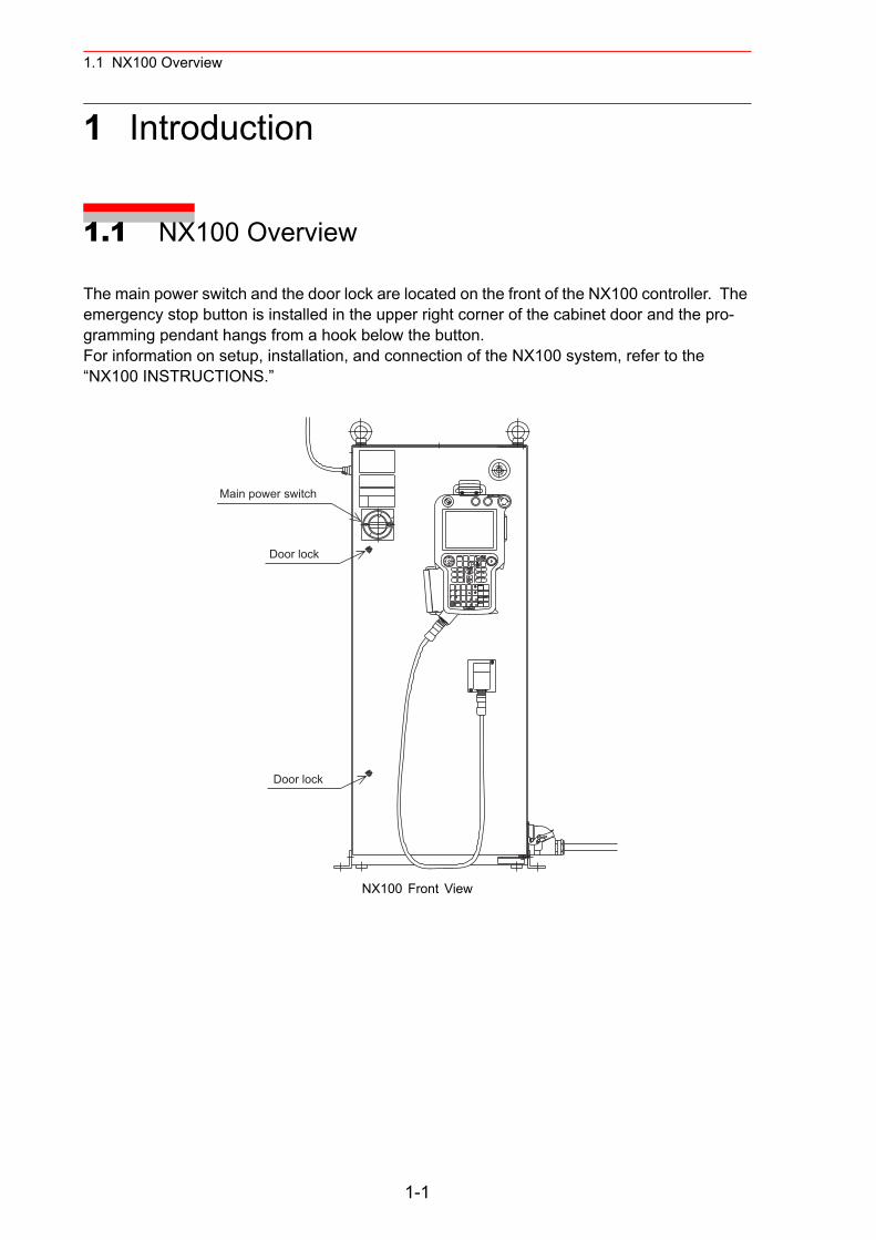
The main power switch and the door lock are located on the front of the NX100 controller. The emergency stop button is installed in the upper right corner of the cabinet door and the pro-gramming pendant hangs from a hook below the button.For information on setup, installation, and connection of the NX100 system, refer to the “NX100 INSTRUCTIONS.”
NX100 Front View
Main power switch
Door lock
Door lock
1-1
1.2 Programming Pendant
1.2 Programming Pendant
1.2.1 Programming Pendant Overview
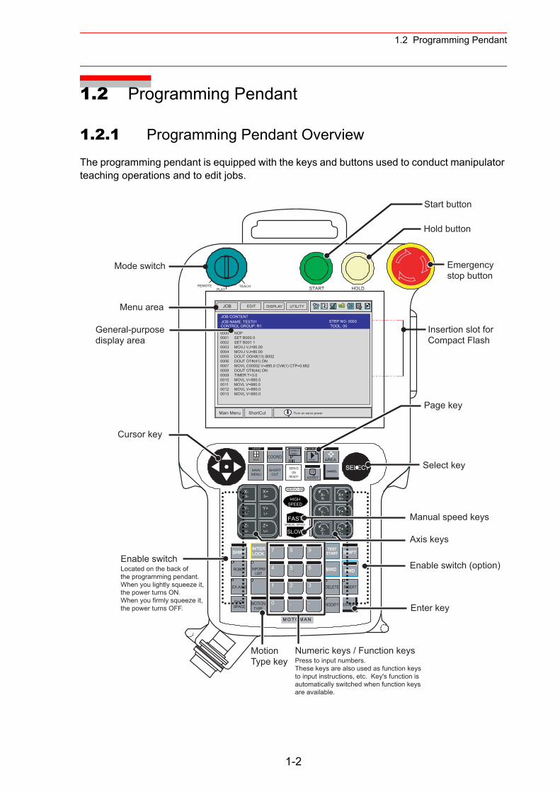
The programming pendant is equipped with the keys and buttons used to conduct manipulator teaching operations and to edit jobs.
HOLDSTARTPLAYTEACHREMOTE
T-Z-
T+Z+
B+Y+
R+X+
B-Y-
R-X-
..
HIGHSPEED
FAST
SLOWMANUAL SPEED
U-Z-
U+Z+
L+Y+
S+X+
L-Y-
S-X- SERVO ON
M O T O M A N
SELECTSERVOON
READY
MAINMENU
SHORTCUT
GO BACK
PAGE AREA
LAYOUT
Multi
CANCEL
COORDDIRECTOPEN
INFORMLIST
BACKSPACE
SHIFTINTERLOCK
ROBOT
EX.AXIS
MOTIONTYPE
TESTSTART
BWD
INSERT
MODIFY ENTER
FWD
DELETE
SHIFT7
4
2 3
. -
5. 6
0
8
1
9
JOB UTILITYEDIT DISPLAY
Main Menu ShortCut
JOB CONTENTJOB NAME: TEST01
0000 NOP0001 SET B000 00002 SET B001 10003 MOVJ VJ=80.000004 MOVJ VJ=80.000005 DOUT OGH#(13) B0020006 DOUT OT#(41) ON0007 MOVL C00002 V=880.0 CV#(1) CTP=0.6620008 DOUT OT#(44) ON0009 TIMER T=3.00010 MOVL V=880.00011 MOVL V=880.00012 MOVL V=880.00013 MOVL V=880.0
!Turn on servo power
Menu area
Mode switch
General-purposedisplay area
Cursor key
Enable switchLocated on the back of the programming pendant. When you lightly squeeze it, the power turns ON.When you firmly squeeze it,the power turns OFF.
Motion Type key
Numeric keys / Function keysPress to input numbers.These keys are also used as function keysto input instructions, etc. Key's function is automatically switched when function keys are available.
Page key
Select key
Manual speed keys
Axis keys
Enable switch (option)
Enter key
Insertion slot forCompact Flash
Start button
Hold button
Emergencystop button
ASSIST!?
TOOL: 00CONTROL GROUP: R1STEP NO: 0003
1-2
1.2 Programming Pendant
1.2.2 Key Description
Character Keys
The keys which have characters printed on them are denoted with [ ]. For example, is shown as [ENTER].The Numeric keys have additional functions along with their number values. Dual function
keys are used in the context of the operation being performed. For example: may be described in the text as [1] or [TIMER].
Symbol KeysThe keys which have a symbol printed on them are not denoted with [ ] but depicted with a small picture, with the exception of the cursor key, which is not shown with a picture.
Axis Keys and Numeric KeysThe keys pictured in the following are refered to as the axis keys and Numeric keys when described.
Keys Pressed SimultaneouslyWhen two keys are to be pressed simultaneously, the keys are shown with a “+” sign between them, such as [SHIFT]+[COORD].
Cursor
Emergency Stop button
Direct Open key
Page key
ENTER
1TIMER
DIRECTOPEN
PAGE
GO BACK
Axis Keys Numeric Keys
S+X-
L-Y-
U-Z-
S+X+
L+Y+
U+Z+
R-X-
B-Y-
T-Z-
R+X+
B+Y+
T+Z+
・ ・
7 8 9
4 6
1 2 3
・ -0
5
1-3
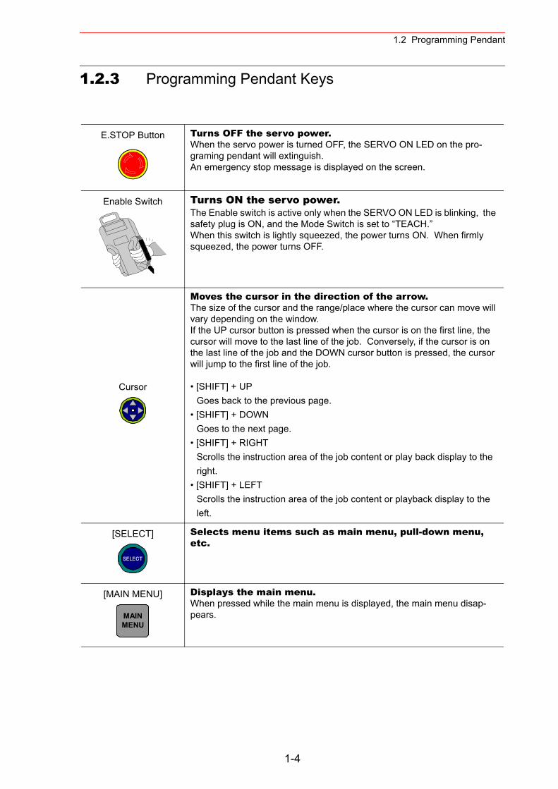
1.2 Programming Pendant
1.2.3 Programming Pendant Keys
E.STOP Button Turns OFF the servo power.When the servo power is turned OFF, the SERVO ON LED on the pro-graming pendant will extinguish.An emergency stop message is displayed on the screen.
Enable Switch Turns ON the servo power.The Enable switch is active only when the SERVO ON LED is blinking, the safety plug is ON, and the Mode Switch is set to “TEACH.”When this switch is lightly squeezed, the power turns ON. When firmly squeezed, the power turns OFF.
Cursor
Moves the cursor in the direction of the arrow.The size of the cursor and the range/place where the cursor can move will vary depending on the window.If the UP cursor button is pressed when the cursor is on the first line, the cursor will move to the last line of the job. Conversely, if the cursor is on the last line of the job and the DOWN cursor button is pressed, the cursor will jump to the first line of the job.
• [SHIFT] + UPGoes back to the previous page.
• [SHIFT] + DOWNGoes to the next page.
• [SHIFT] + RIGHTScrolls the instruction area of the job content or play back display to the right.
• [SHIFT] + LEFTScrolls the instruction area of the job content or playback display to the left.
[SELECT] Selects menu items such as main menu, pull-down menu, etc.
[MAIN MENU] Displays the main menu.When pressed while the main menu is displayed, the main menu disap-pears.
SELECT
MAINMENU
1-4
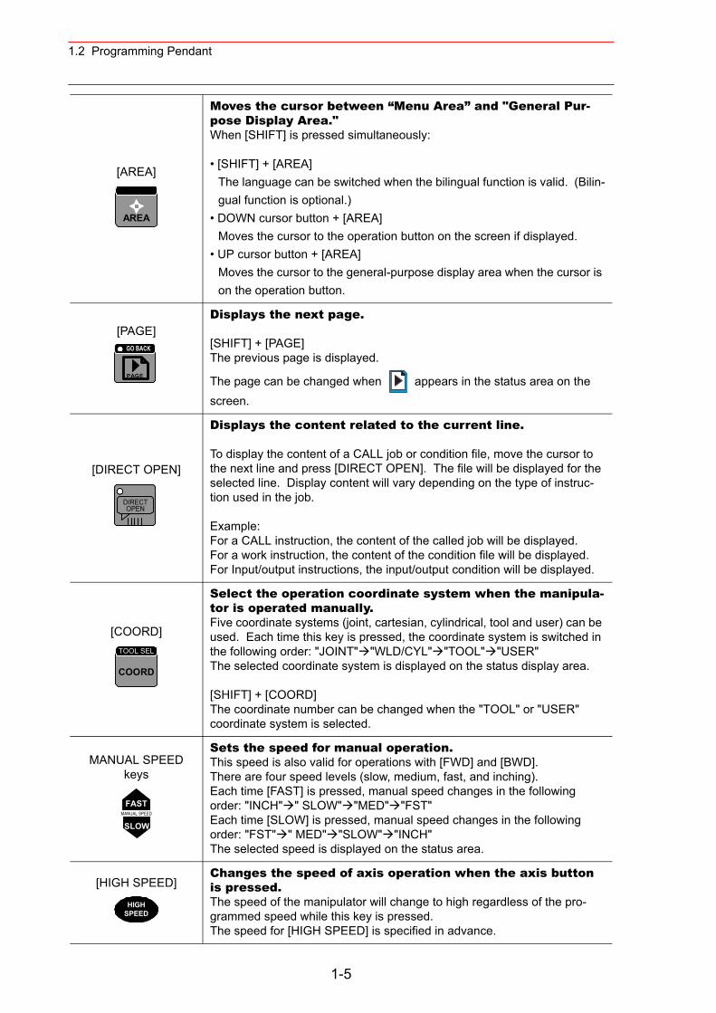
1.2 Programming Pendant
[AREA]
Moves the cursor between “Menu Area” and "General Pur-pose Display Area."When [SHIFT] is pressed simultaneously:
• [SHIFT] + [AREA]The language can be switched when the bilingual function is valid. (Bilin-gual function is optional.)
• DOWN cursor button + [AREA]Moves the cursor to the operation button on the screen if displayed.
• UP cursor button + [AREA]Moves the cursor to the general-purpose display area when the cursor is on the operation button.
[PAGE]Displays the next page.
[SHIFT] + [PAGE]The previous page is displayed.
The page can be changed when appears in the status area on the screen.
[DIRECT OPEN]
Displays the content related to the current line.
To display the content of a CALL job or condition file, move the cursor to the next line and press [DIRECT OPEN]. The file will be displayed for the selected line. Display content will vary depending on the type of instruc-tion used in the job.
Example:For a CALL instruction, the content of the called job will be displayed.For a work instruction, the content of the condition file will be displayed.For Input/output instructions, the input/output condition will be displayed.
[COORD]
Select the operation coordinate system when the manipula-tor is operated manually.Five coordinate systems (joint, cartesian, cylindrical, tool and user) can be used. Each time this key is pressed, the coordinate system is switched in the following order: "JOINT" "WLD/CYL" "TOOL" "USER"The selected coordinate system is displayed on the status display area.
[SHIFT] + [COORD]The coordinate number can be changed when the "TOOL" or "USER" coordinate system is selected.
MANUAL SPEED keys
Sets the speed for manual operation.This speed is also valid for operations with [FWD] and [BWD].There are four speed levels (slow, medium, fast, and inching).Each time [FAST] is pressed, manual speed changes in the following order: "INCH" " SLOW" "MED" "FST"Each time [SLOW] is pressed, manual speed changes in the following order: "FST" " MED" "SLOW" "INCH"The selected speed is displayed on the status area.
[HIGH SPEED]Changes the speed of axis operation when the axis button is pressed. The speed of the manipulator will change to high regardless of the pro-grammed speed while this key is pressed.The speed for [HIGH SPEED] is specified in advance.
AREA
PAGE
GO BACK
DIRECTOPEN
COORD
TOOL SEL
FASTMANUAL SPEED
SLOW
HIGHSPEED
1-5
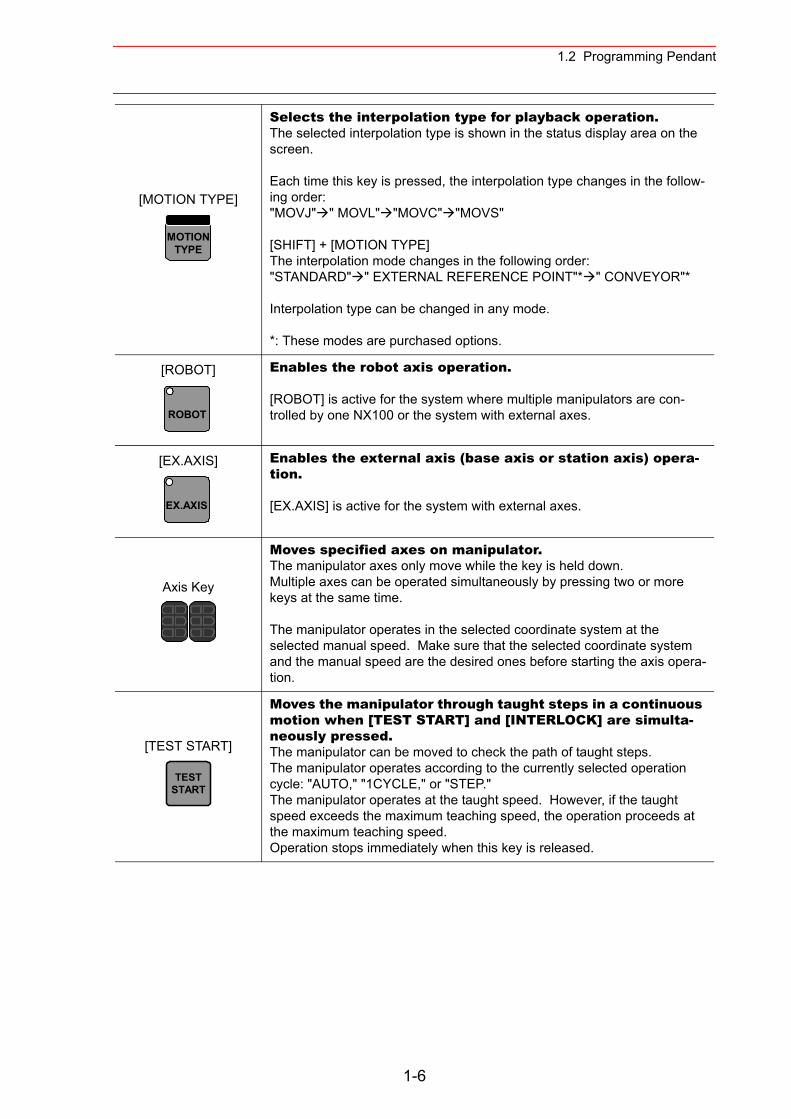
1.2 Programming Pendant
[MOTION TYPE]
Selects the interpolation type for playback operation.The selected interpolation type is shown in the status display area on the screen.
Each time this key is pressed, the interpolation type changes in the follow-ing order:"MOVJ" " MOVL" "MOVC" "MOVS"
[SHIFT] + [MOTION TYPE]The interpolation mode changes in the following order:"STANDARD" " EXTERNAL REFERENCE POINT"* " CONVEYOR"*
Interpolation type can be changed in any mode.
*: These modes are purchased options.
[ROBOT] Enables the robot axis operation.
[ROBOT] is active for the system where multiple manipulators are con-trolled by one NX100 or the system with external axes.
[EX.AXIS] Enables the external axis (base axis or station axis) opera-tion.
[EX.AXIS] is active for the system with external axes.
Axis Key
Moves specified axes on manipulator.The manipulator axes only move while the key is held down.Multiple axes can be operated simultaneously by pressing two or more keys at the same time.
The manipulator operates in the selected coordinate system at the selected manual speed. Make sure that the selected coordinate system and the manual speed are the desired ones before starting the axis opera-tion.
[TEST START]
Moves the manipulator through taught steps in a continuous motion when [TEST START] and [INTERLOCK] are simulta-neously pressed.The manipulator can be moved to check the path of taught steps.The manipulator operates according to the currently selected operation cycle: "AUTO," "1CYCLE," or "STEP."The manipulator operates at the taught speed. However, if the taught speed exceeds the maximum teaching speed, the operation proceeds at the maximum teaching speed.Operation stops immediately when this key is released.
MOTIONTYPE
ROBOT
EX.AXIS
TESTSTART
1-6
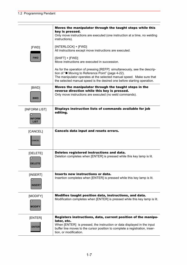
1.2 Programming Pendant
[FWD]
Moves the manipulator through the taught steps while this key is pressed.Only move instructions are executed (one instruction at a time, no welding instructions).
[INTERLOCK] + [FWD]All instructions except move instructions are executed.
[SHIFT] + [FWD]Move instructions are executed in succession.
As for the operation of pressing [REFP] simultaneously, see the descrip-tion of “ Moving to Reference Point” (page 4-22).The manipulator operates at the selected manual speed. Make sure that the selected manual speed is the desired one before starting operation.
[BWD] Moves the manipulator through the taught steps in the reverse direction while this key is pressed.Only move instructions are executed (no weld commands).
[INFORM LIST] Displays instruction lists of commands available for job editing.
[CANCEL] Cancels data input and resets errors.
[DELETE] Deletes registered instructions and data.Deletion completes when [ENTER] is pressed while this key lamp is lit.
[INSERT] Inserts new instructions or data.Insertion completes when [ENTER] is pressed while this key lamp is lit.
[MODIFY] Modifies taught position data, instructions, and data.Modification completes when [ENTER] is pressed while this key lamp is lit.
[ENTER] Registers instructions, data, current position of the manipu-lator, etc.When [ENTER] is pressed, the instruction or data displayed in the input buffer line moves to the cursor position to complete a registration, inser-tion, or modification.
FWD
BWD
INFORMLIST
CANCEL
DELETE
INSERT
MODIFY
ENTER
1-7
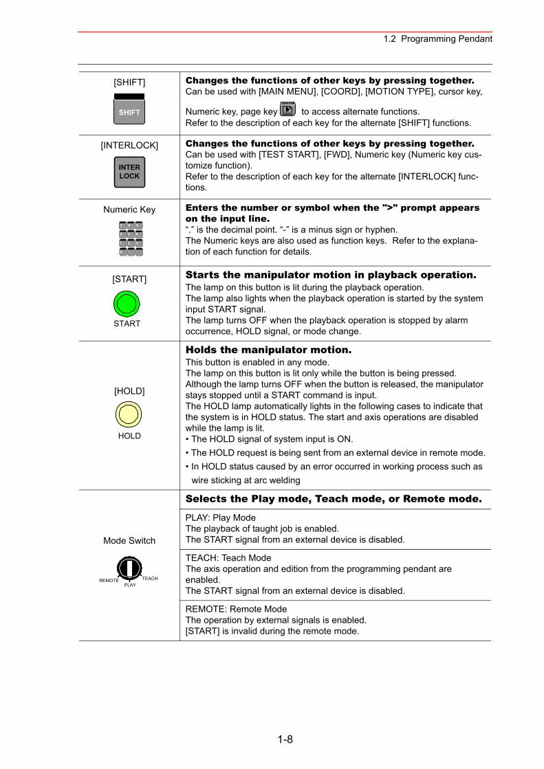
1.2 Programming Pendant
[SHIFT] Changes the functions of other keys by pressing together.Can be used with [MAIN MENU], [COORD], [MOTION TYPE], cursor key,
Numeric key, page key to access alternate functions.Refer to the description of each key for the alternate [SHIFT] functions.
[INTERLOCK] Changes the functions of other keys by pressing together.Can be used with [TEST START], [FWD], Numeric key (Numeric key cus-tomize function).Refer to the description of each key for the alternate [INTERLOCK] func-tions.
Numeric Key Enters the number or symbol when the ">" prompt appears on the input line.“.” is the decimal point. “-” is a minus sign or hyphen.The Numeric keys are also used as function keys. Refer to the explana-tion of each function for details.
[START] Starts the manipulator motion in playback operation.The lamp on this button is lit during the playback operation.The lamp also lights when the playback operation is started by the system input START signal.The lamp turns OFF when the playback operation is stopped by alarm occurrence, HOLD signal, or mode change.
[HOLD]
Holds the manipulator motion.This button is enabled in any mode.The lamp on this button is lit only while the button is being pressed. Although the lamp turns OFF when the button is released, the manipulator stays stopped until a START command is input.The HOLD lamp automatically lights in the following cases to indicate that the system is in HOLD status. The start and axis operations are disabled while the lamp is lit.• The HOLD signal of system input is ON.• The HOLD request is being sent from an external device in remote mode.• In HOLD status caused by an error occurred in working process such as
wire sticking at arc welding
Mode Switch
Selects the Play mode, Teach mode, or Remote mode.
PLAY: Play ModeThe playback of taught job is enabled.The START signal from an external device is disabled.
TEACH: Teach ModeThe axis operation and edition from the programming pendant are enabled.The START signal from an external device is disabled.
REMOTE: Remote ModeThe operation by external signals is enabled.[START] is invalid during the remote mode.
SHIFT PAGE
GO BACK
INTERLOCK
7 8 9
4 6
1 2 3
・ -0
5
START
HOLD
REMOTE TEACHPLAY
1-8
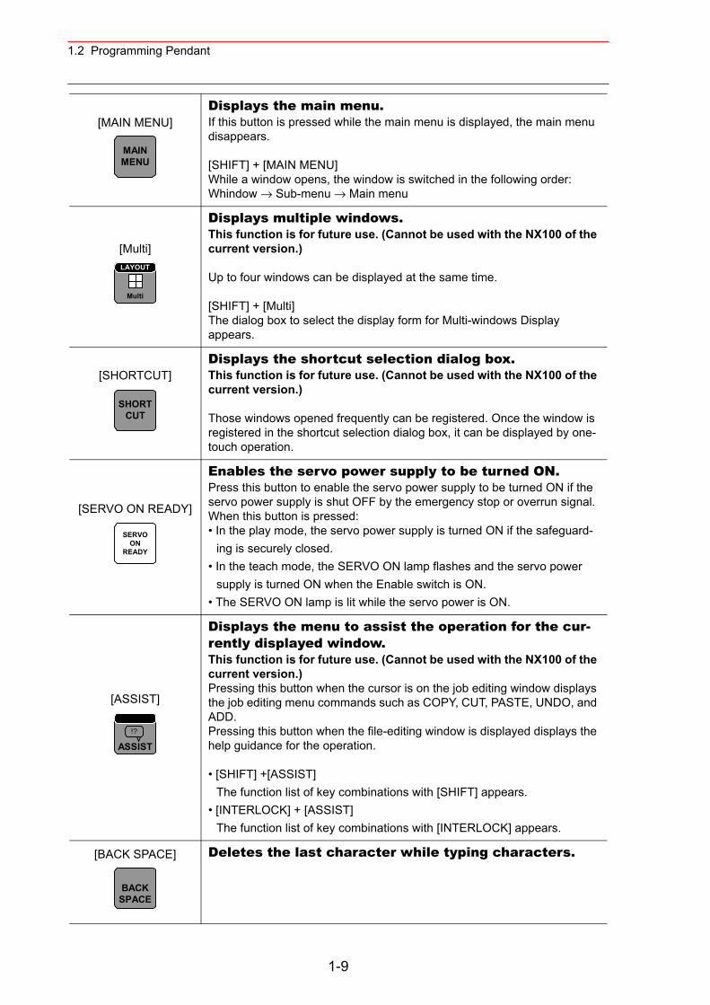
1.2 Programming Pendant
[MAIN MENU]Displays the main menu.If this button is pressed while the main menu is displayed, the main menu disappears.
[SHIFT] + [MAIN MENU]While a window opens, the window is switched in the following order:Whindow → Sub-menu → Main menu
[Multi]
Displays multiple windows.This function is for future use. (Cannot be used with the NX100 of the current version.)
Up to four windows can be displayed at the same time.
[SHIFT] + [Multi]The dialog box to select the display form for Multi-windows Display appears.
[SHORTCUT]Displays the shortcut selection dialog box.This function is for future use. (Cannot be used with the NX100 of the current version.)
Those windows opened frequently can be registered. Once the window is registered in the shortcut selection dialog box, it can be displayed by one-touch operation.
[SERVO ON READY]
Enables the servo power supply to be turned ON.Press this button to enable the servo power supply to be turned ON if the servo power supply is shut OFF by the emergency stop or overrun signal.When this button is pressed:• In the play mode, the servo power supply is turned ON if the safeguard-
ing is securely closed.• In the teach mode, the SERVO ON lamp flashes and the servo power
supply is turned ON when the Enable switch is ON.• The SERVO ON lamp is lit while the servo power is ON.
[ASSIST]
Displays the menu to assist the operation for the cur-rently displayed window.This function is for future use. (Cannot be used with the NX100 of the current version.)Pressing this button when the cursor is on the job editing window displays the job editing menu commands such as COPY, CUT, PASTE, UNDO, and ADD.Pressing this button when the file-editing window is displayed displays the help guidance for the operation.
• [SHIFT] +[ASSIST]The function list of key combinations with [SHIFT] appears.
• [INTERLOCK] + [ASSIST]The function list of key combinations with [INTERLOCK] appears.
[BACK SPACE] Deletes the last character while typing characters.
MAINMENU
Multi
LAYOUT
SHORTCUT
SERVOON
READY
ASSIST!?
BACKSPACE
1-9
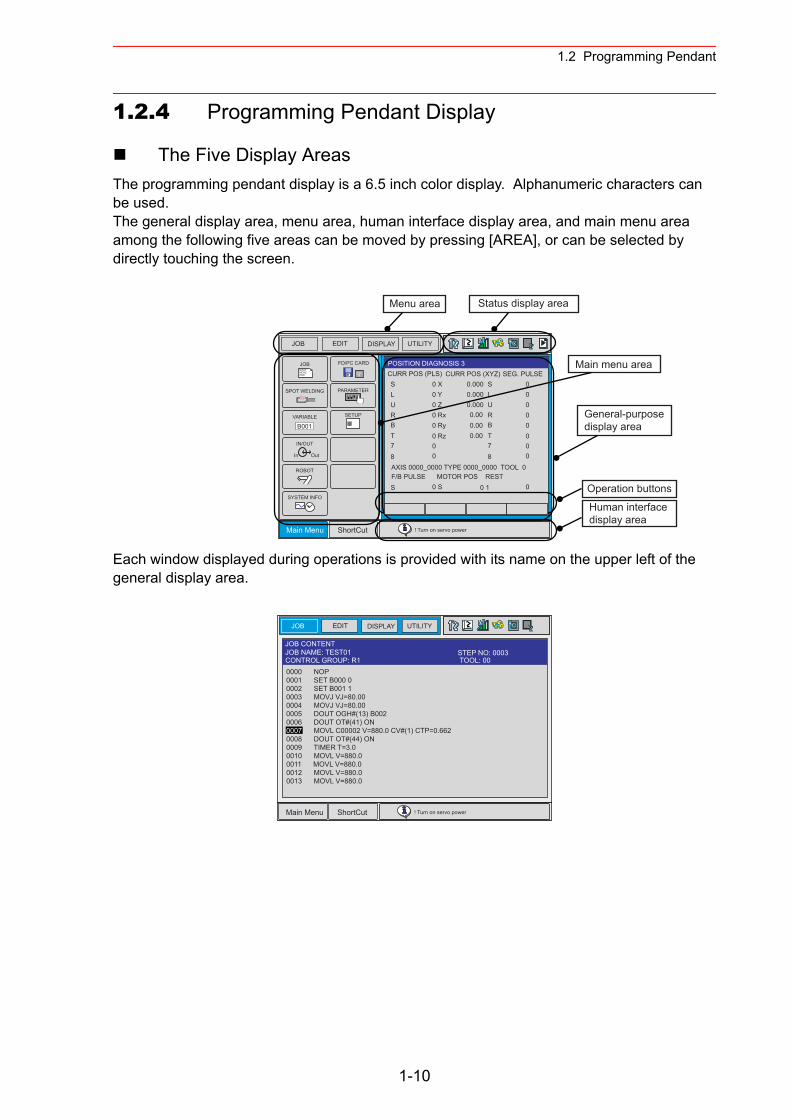
1.2 Programming Pendant
1.2.4 Programming Pendant Display
The Five Display AreasThe programming pendant display is a 6.5 inch color display. Alphanumeric characters can be used.The general display area, menu area, human interface display area, and main menu area among the following five areas can be moved by pressing [AREA], or can be selected by directly touching the screen.
Each window displayed during operations is provided with its name on the upper left of the general display area.
JOB EDIT DISPLAY UTILITY
Main Menu ShortCut ! Turn on servo power
JOBDOUTMOVEEND
IN/OUT
In Out
SYSTEM INFO
SETUP
SPOT WELDING
VARIABLE
B001
ROBOT
PARAMETER
CF
FD/PC CARD
CURR POS (PLS)POSITION DIAGNOSIS 3
CURR POS (XYZ) SEG. PULSESLURBT78
0 X0 Y0 Z0 Rx0 Ry0 Rz00
0.000 SLURBT78
0.0000.0000.000.000.00
00000000
AXIS 0000_0000 TYPE 0000_0000 TOOL 0F/B PULSE MOTOR POS RESTS 0 S 0 1 0
Menu area Status display area
Main menu area
General-purpose display area
Human interfacedisplay area
Operation buttons
JOB EDIT DISPLAY UTILITY
Main Menu ShortCut ! Turn on servo power
JOB CONTENTJOB NAME: TEST01
TOOL: 00CONTROL GROUP: R1STEP NO: 0003
0000 NOP0001 SET B000 00002 SET B001 10003 MOVJ VJ=80.000004 MOVJ VJ=80.000005 DOUT OGH#(13) B0020006 DOUT OT#(41) ON0007 MOVL C00002 V=880.0 CV#(1) CTP=0.6620008 DOUT OT#(44) ON0009 TIMER T=3.00010 MOVL V=880.00011 MOVL V=880.00012 MOVL V=880.00013 MOVL V=880.0
1-10
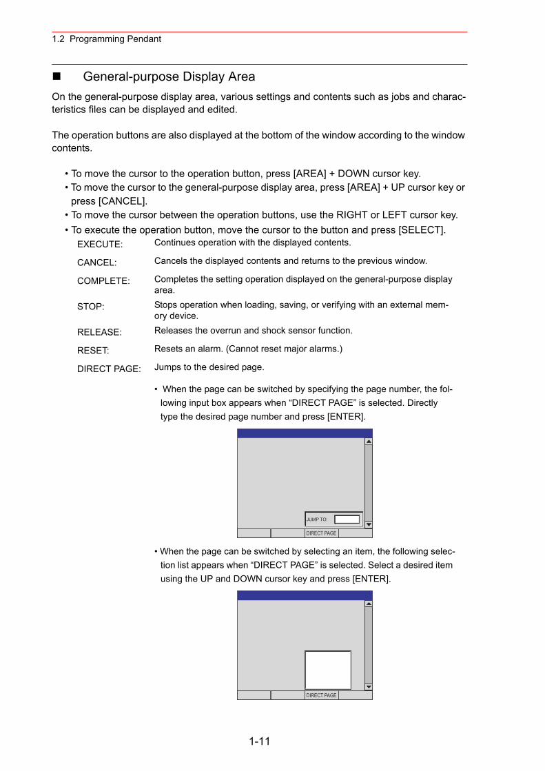
1.2 Programming Pendant
General-purpose Display AreaOn the general-purpose display area, various settings and contents such as jobs and charac-teristics files can be displayed and edited.
The operation buttons are also displayed at the bottom of the window according to the window contents.
• To move the cursor to the operation button, press [AREA] + DOWN cursor key. • To move the cursor to the general-purpose display area, press [AREA] + UP cursor key or
press [CANCEL]. • To move the cursor between the operation buttons, use the RIGHT or LEFT cursor key. • To execute the operation button, move the cursor to the button and press [SELECT].
EXECUTE: Continues operation with the displayed contents.
CANCEL: Cancels the displayed contents and returns to the previous window.
COMPLETE: Completes the setting operation displayed on the general-purpose display area.
STOP: Stops operation when loading, saving, or verifying with an external mem-ory device.
RELEASE: Releases the overrun and shock sensor function.
RESET: Resets an alarm. (Cannot reset major alarms.)
DIRECT PAGE: Jumps to the desired page.
• When the page can be switched by specifying the page number, the fol-lowing input box appears when “DIRECT PAGE” is selected. Directly type the desired page number and press [ENTER].
• When the page can be switched by selecting an item, the following selec-tion list appears when “DIRECT PAGE” is selected. Select a desired item using the UP and DOWN cursor key and press [ENTER].
JUMP TO:
DIRECT PAGE
DIRECT PAGE
1-11
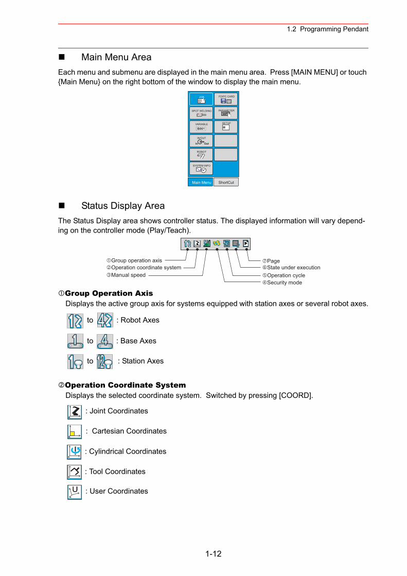
1.2 Programming Pendant
Main Menu AreaEach menu and submenu are displayed in the main menu area. Press [MAIN MENU] or touch {Main Menu} on the right bottom of the window to display the main menu.
Status Display AreaThe Status Display area shows controller status. The displayed information will vary depend-ing on the controller mode (Play/Teach).
Group Operation AxisDisplays the active group axis for systems equipped with station axes or several robot axes.
to : Robot Axes
to : Base Axes
to : Station Axes
Operation Coordinate SystemDisplays the selected coordinate system. Switched by pressing [COORD].
: Joint Coordinates
: Cartesian Coordinates
: Cylindrical Coordinates
: Tool Coordinates
: User Coordinates
DOUTMOVEEND
In Out
B001
CF
Main Menu ShortCut
JOB
IN/OUT
SYSTEM INFO
SETUP
SPOT WELDING
VARIABLE
ROBOT
PARAMETER
FD/PC CARD
Group operation axisOperation coordinate systemManual speed
PageState under executionOperation cycleSecurity mode
1-12
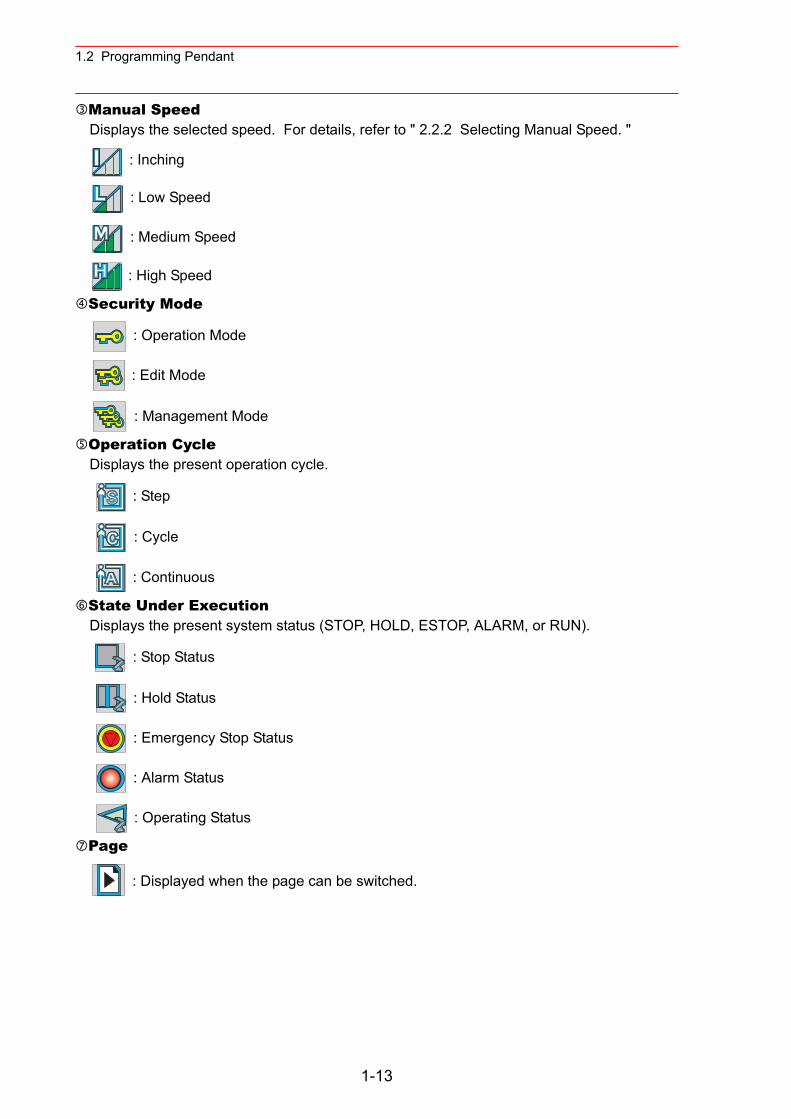
1.2 Programming Pendant
Manual SpeedDisplays the selected speed. For details, refer to " 2.2.2 Selecting Manual Speed. "
: Inching
: Low Speed
: Medium Speed
: High Speed
Security Mode
: Operation Mode
: Edit Mode
: Management Mode
Operation CycleDisplays the present operation cycle.
: Step
: Cycle
: Continuous
State Under ExecutionDisplays the present system status (STOP, HOLD, ESTOP, ALARM, or RUN).
: Stop Status
: Hold Status
: Emergency Stop Status
: Alarm Status
: Operating Status
Page
: Displayed when the page can be switched.
1-13
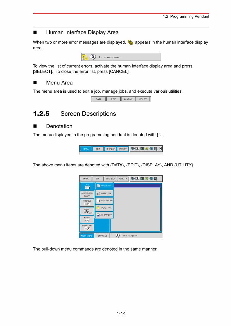
1.2 Programming Pendant
Human Interface Display Area
When two or more error messages are displayed, appears in the human interface display area.
To view the list of current errors, activate the human interface display area and press [SELECT]. To close the error list, press [CANCEL].
Menu AreaThe menu area is used to edit a job, manage jobs, and execute various utilities.
1.2.5 Screen Descriptions
DenotationThe menu displayed in the programming pendant is denoted with { }.
The above menu items are denoted with {DATA}, {EDIT}, {DISPLAY}, AND {UTILITY}.
The pull-down menu commands are denoted in the same manner.
! Turn on servo power.
DATA EDIT DISPLAY UTILITY
DATA EDIT DISPLAY UTILITY
DATA EDIT DISPLAY UTILITY
Main Menu ShortCut ! Turn on servo power
JOBDOUTMOVEEND
IN/OUT
In Out
SYSTEM INFO
ARC WELDING
VARIABLE
B001
ROBOT
SELECT JOB
MASTER JOB
JOB CAPACITY
DOUTMOVEEND JOB CONTENT
CREATE NEW JOB
1-14
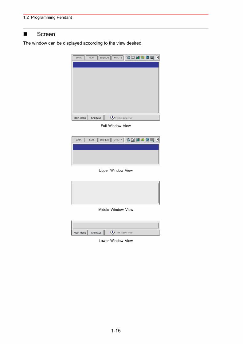
1.2 Programming Pendant
ScreenThe window can be displayed according to the view desired.
Full Window View
Upper Window View
Middle Window View
Lower Window View
DATA EDIT DISPLAY UTILITY
Main Menu ShortCut ! Turn on servo power
DATA EDIT DISPLAY UTILITY
Main Menu ShortCut ! Turn on servo power
1-15
1.2 Programming Pendant
1.2.6 Guidance Display
This function is for future use. (Cannot be used with the NX100 of the current version.)
Information to assist the operation can be displayed by the following key operation.• Press [SHIFT] + [ASSIST] to display the function list of key combinations with [SHIFT].• Press [INTERLOCK] + [ASSIST] to display the function list of key combinations with
[INTERLOCK].
1.2.7 Character Input
To input characters, display the software keypad on the programming pendant display.Move the cursor to the data for which characters are to be input, and press [SELECT] to dis-play the software keypad.
There are three types of software keypads: the alphanumeric keypads each for upper-case and lower-case characters and the symbol keypad. To switch between the alphanumeric key-pads and the symbol keypad, touch the button tab on the screen or press [PAGE]. To switch the alphanumeric keypads between upper-case and lower-case characters, touch “CapsLock OFF” or “CapsLock ON.”
1-16
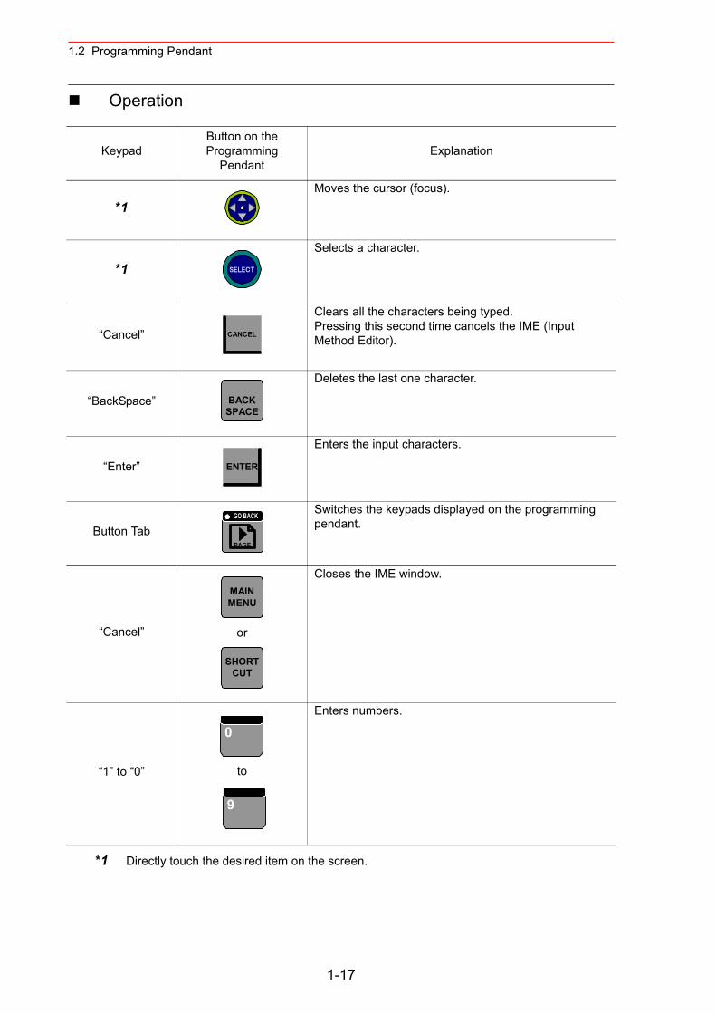
1.2 Programming Pendant
Operation
*1 Directly touch the desired item on the screen.
KeypadButton on the Programming
PendantExplanation
*1Moves the cursor (focus).
*1Selects a character.
“Cancel”
Clears all the characters being typed. Pressing this second time cancels the IME (Input Method Editor).
“BackSpace”
Deletes the last one character.
“Enter”
Enters the input characters.
Button Tab
Switches the keypads displayed on the programming pendant.
“Cancel” or
Closes the IME window.
“1” to “0”
to
Enters numbers.
SELECT
CANCEL
BACKSPACE
ENTER
PAGE
GO BACK
MAINMENU
SHORTCUT
0
9
1-17
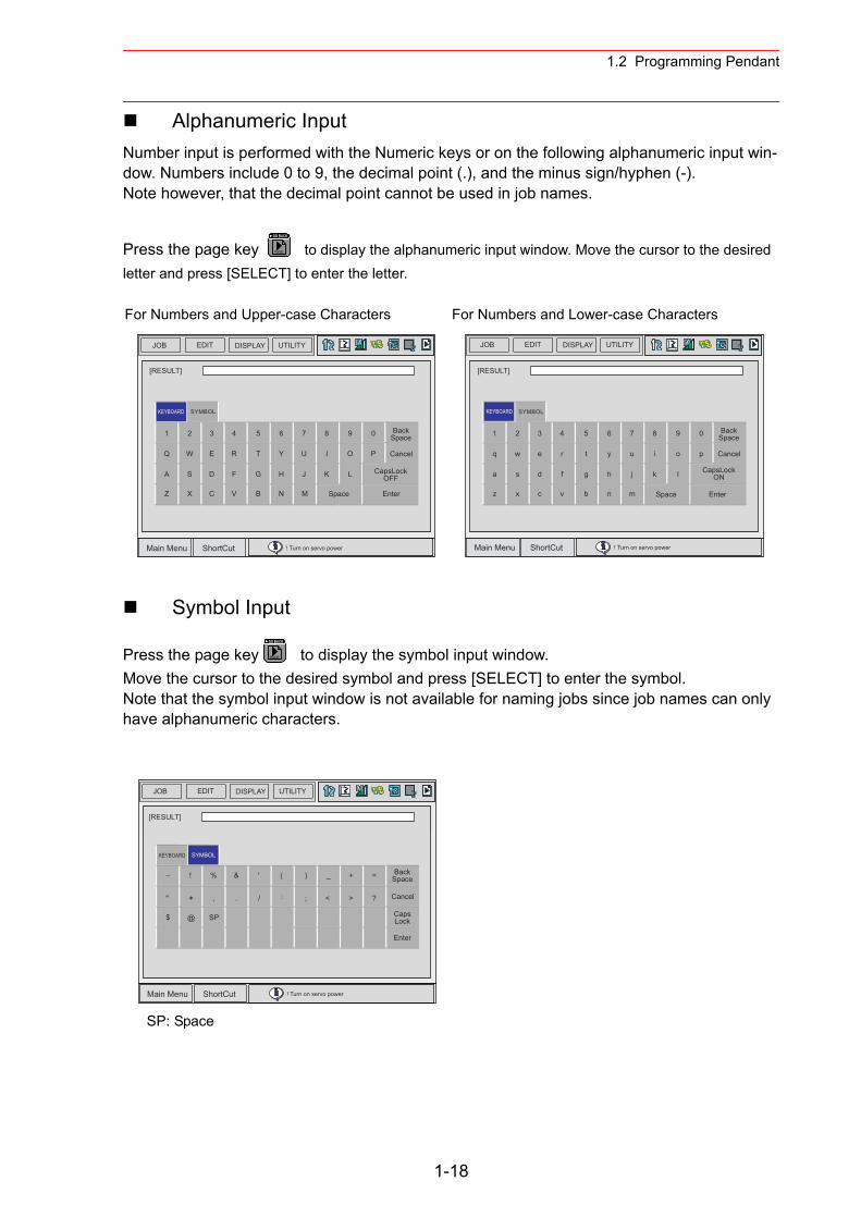
1.2 Programming Pendant
Alphanumeric InputNumber input is performed with the Numeric keys or on the following alphanumeric input win-dow. Numbers include 0 to 9, the decimal point (.), and the minus sign/hyphen (-).Note however, that the decimal point cannot be used in job names.
Press the page key to display the alphanumeric input window. Move the cursor to the desired letter and press [SELECT] to enter the letter.
Symbol Input
Press the page key to display the symbol input window.Move the cursor to the desired symbol and press [SELECT] to enter the symbol.Note that the symbol input window is not available for naming jobs since job names can only have alphanumeric characters.
For Numbers and Upper-case Characters For Numbers and Lower-case Characters
SP: Space
PAGE
GO BACK
JOB EDIT DISPLAY UTILITY
Main Menu ShortCut ! Turn on servo power
[RESULT]
BackSpace
Cancel
CapsLockOFF
EnterSpace
1 2 3 4 5 6 7 8 9 0
Q W E R T Y U I O P
A S D F G H J K L
Z X C V B N M
SYMBOLKEYBOARD
[RESULT]
BackSpace
Cancel
CapsLockON
EnterSpace
1 2 3 4 5 6 7 8 9 0
q w e r t y u i o p
a s d f g h j k l
z x c v b n m
SYMBOLKEYBOARD
JOB EDIT DISPLAY UTILITY
Main Menu ShortCut ! Turn on servo power
PAGE
GO BACK
[RESULT]
BackSpace
Cancel
CapsLock
Enter
KEYBOARD SYMBOL
"
! %
,
&
.
'
/
@$ SP
( )
;
_
<
+
>
− =
?
JOB EDIT DISPLAY UTILITY
Main Menu ShortCut ! Turn on servo power
1-18
1.3 Modes
1.3 Modes
The following three modes are available for NX100.• Teach Mode• Play Mode• Remote Mode
1.3.1 Teach Mode
In the teach mode, the following can be done.• Preparation and teaching of a job• Modification of a registered job• Setting of various characteristic files and parameters
1.3.2 Play Mode
In the play mode, the following can be done.• Playback of a taught job• Setting, modification, or deletion of various condition files
1.3.3 Remote Mode
In the remote mode, the operations such as Servo ON Ready, Start, Cycle Change, Call Mas-ter Job can be commanded by external input signals.The operations by external input signals become enabled in the remote mode, while [START] on the programming pendant becomes disabled.The data transmission function (optional function) is also available in the remote mode.
The following table shows how each operation is input in each mode.
Note: “PP” indicates the programming pendant.
Teach Mode Play Mode Remote Mode
Servo ON Ready PP PP External input signal
Start Invalid PP External input signal
Cycle Change PP PP External input signal
Call Master Job PP PP External input signal
1-19
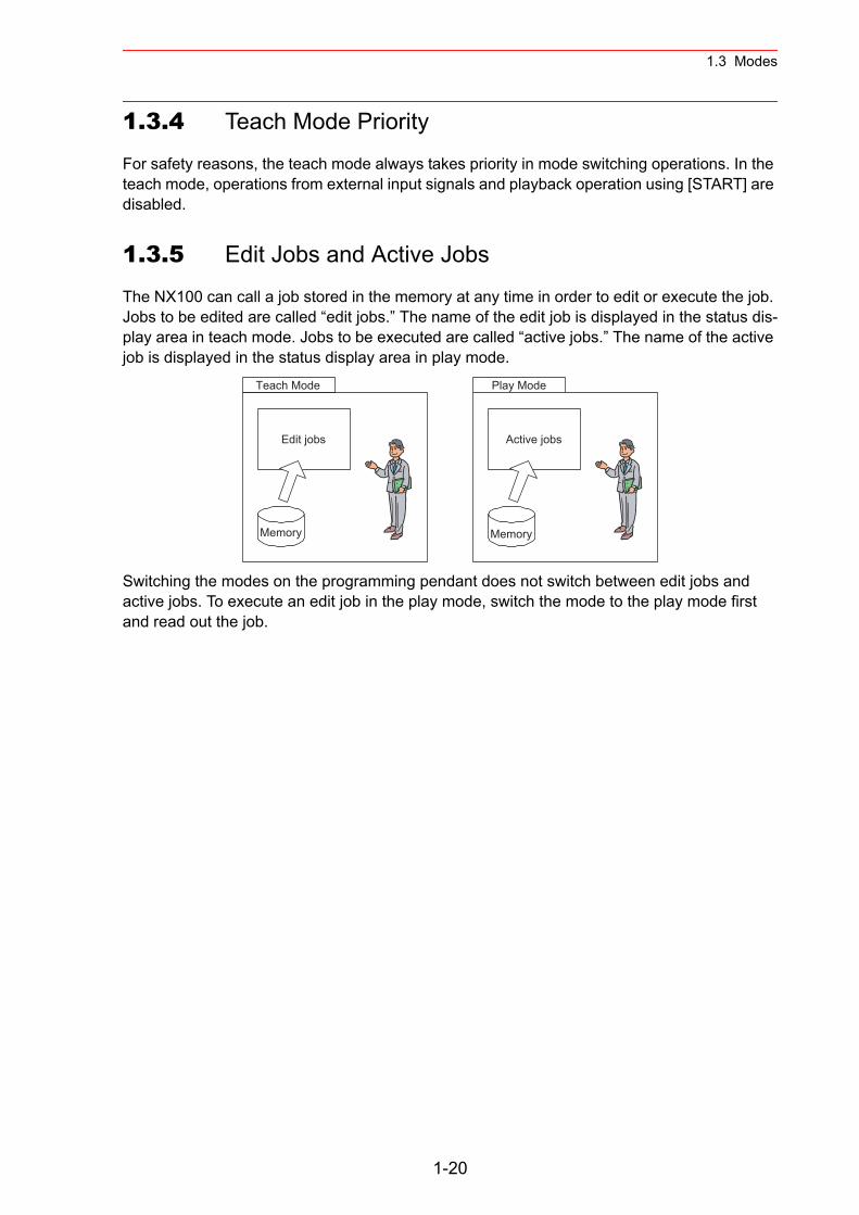
1.3 Modes
1.3.4 Teach Mode Priority
For safety reasons, the teach mode always takes priority in mode switching operations. In the teach mode, operations from external input signals and playback operation using [START] are disabled.
1.3.5 Edit Jobs and Active Jobs
The NX100 can call a job stored in the memory at any time in order to edit or execute the job. Jobs to be edited are called “edit jobs.” The name of the edit job is displayed in the status dis-play area in teach mode. Jobs to be executed are called “active jobs.” The name of the active job is displayed in the status display area in play mode.
Switching the modes on the programming pendant does not switch between edit jobs and active jobs. To execute an edit job in the play mode, switch the mode to the play mode first and read out the job.
Teach Mode
Edit jobs
Memory
Active jobs
Memory
Play Mode
1-20
1.4 About the Security Mode
1.4 About the Security Mode
1.4.1 Types of Security Modes
The following three types of security modes are available.Any operations in the edit mode and the management mode require a user ID. The user ID must contain betwen 4 and 8 letters, numbers, or symbols.
• Operation ModeDuring the operation mode, the operator can monitor the line operation and start and stop the manipulator. Repairs, etc. can be performed if any abnormalities are detected.
• Edit ModeDuring the edit mode, teaching, robot jog operations, and editing of jobs and various oper-ation files can be performed in addition to the operations enabled in the operation mode.
• Management ModeDuring the management mode, the operator who performs setup and maintenance for the system can set the machine control parameter, set the time, change the user ID, etc. in addition to the operations enabled in the edit mode.
1-21
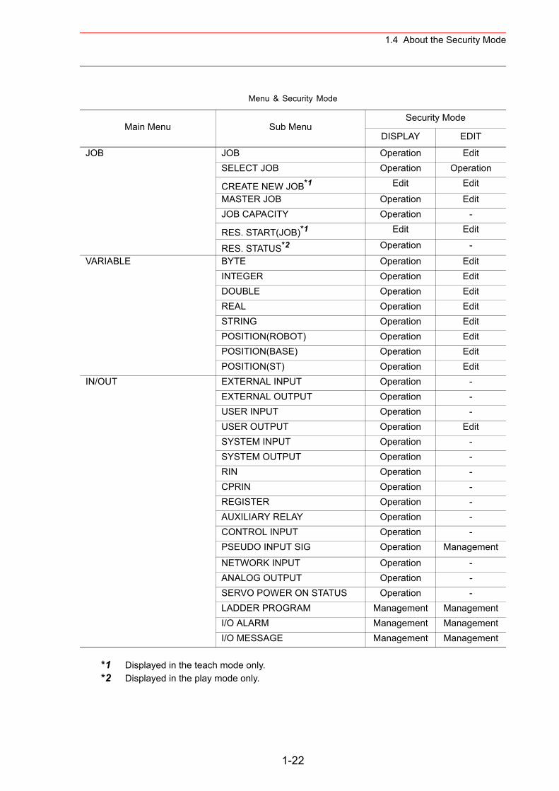
1.4 About the Security Mode
*1 Displayed in the teach mode only.*2 Displayed in the play mode only.
Menu & Security Mode
Main Menu Sub MenuSecurity Mode
DISPLAY EDIT
JOB JOB Operation EditSELECT JOB Operation Operation
CREATE NEW JOB*1 Edit Edit
MASTER JOB Operation EditJOB CAPACITY Operation -
RES. START(JOB)*1 Edit Edit
RES. STATUS*2 Operation -
VARIABLE BYTE Operation EditINTEGER Operation EditDOUBLE Operation EditREAL Operation EditSTRING Operation EditPOSITION(ROBOT) Operation EditPOSITION(BASE) Operation EditPOSITION(ST) Operation Edit
IN/OUT EXTERNAL INPUT Operation -EXTERNAL OUTPUT Operation -USER INPUT Operation -USER OUTPUT Operation EditSYSTEM INPUT Operation -SYSTEM OUTPUT Operation -RIN Operation -CPRIN Operation -REGISTER Operation -AUXILIARY RELAY Operation -CONTROL INPUT Operation -PSEUDO INPUT SIG Operation Management
NETWORK INPUT Operation -ANALOG OUTPUT Operation -SERVO POWER ON STATUS Operation -LADDER PROGRAM Management ManagementI/O ALARM Management ManagementI/O MESSAGE Management Management
1-22
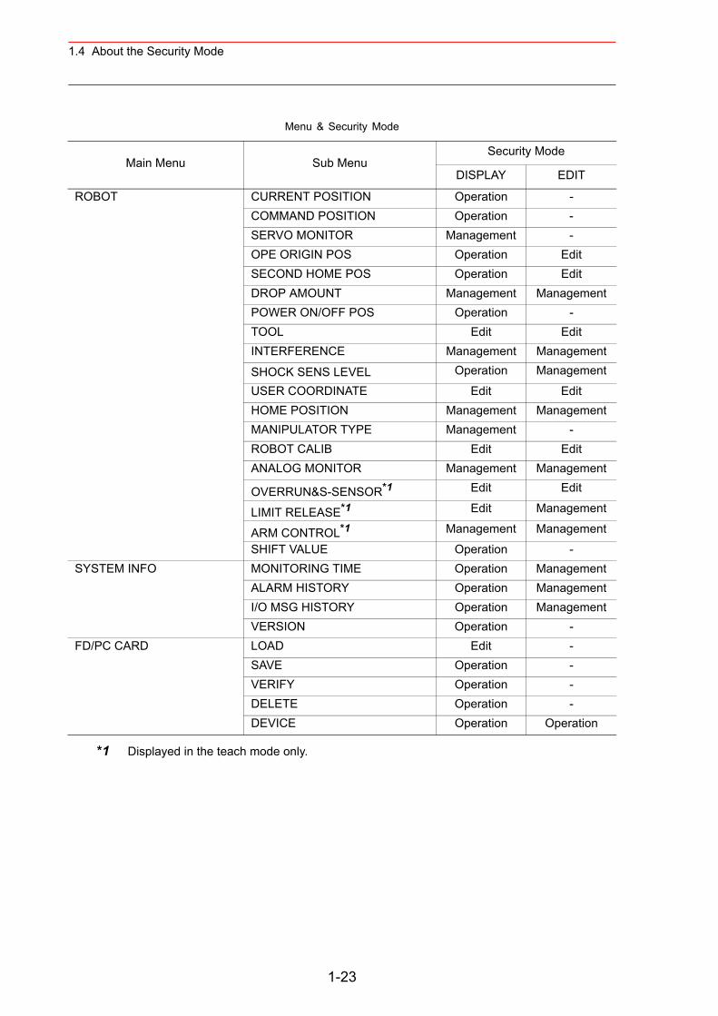
1.4 About the Security Mode
Menu & Security Mode
Main Menu Sub MenuSecurity Mode
DISPLAY EDIT
ROBOT CURRENT POSITION Operation -COMMAND POSITION Operation -SERVO MONITOR Management -OPE ORIGIN POS Operation EditSECOND HOME POS Operation EditDROP AMOUNT Management ManagementPOWER ON/OFF POS Operation -TOOL Edit EditINTERFERENCE Management Management
SHOCK SENS LEVEL Operation Management
USER COORDINATE Edit EditHOME POSITION Management ManagementMANIPULATOR TYPE Management -ROBOT CALIB Edit EditANALOG MONITOR Management Management
OVERRUN&S-SENSOR*1 Edit Edit
LIMIT RELEASE*1 Edit Management
ARM CONTROL*1 Management Management
SHIFT VALUE Operation -SYSTEM INFO MONITORING TIME Operation Management
ALARM HISTORY Operation ManagementI/O MSG HISTORY Operation ManagementVERSION Operation -
FD/PC CARD LOAD Edit -SAVE Operation -VERIFY Operation -DELETE Operation -DEVICE Operation Operation
*1 Displayed in the teach mode only.
1-23
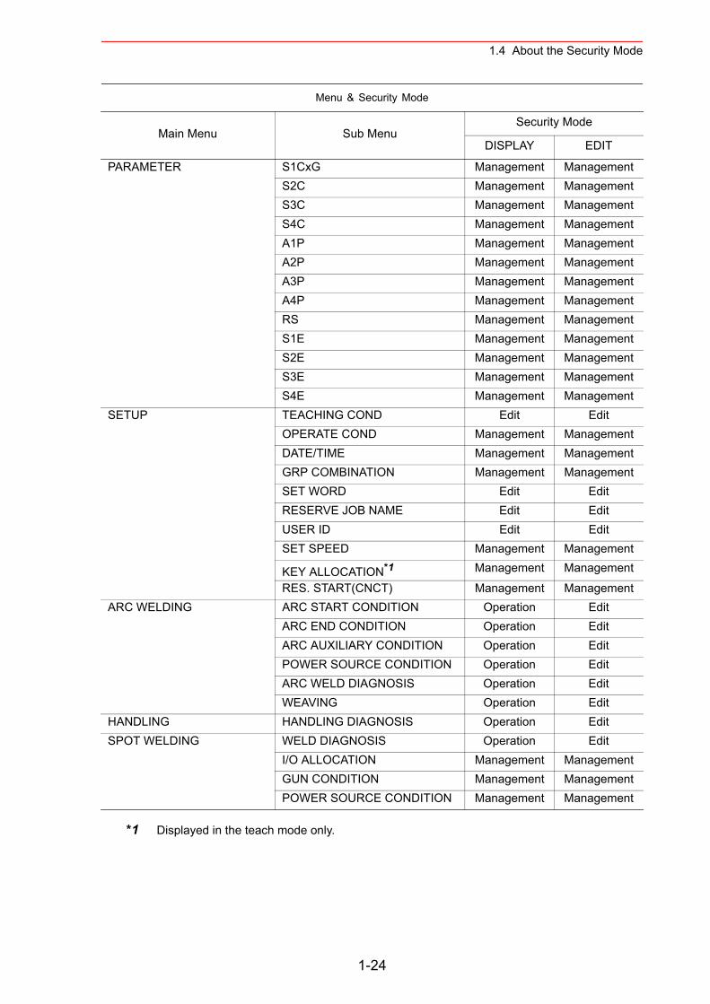
1.4 About the Security Mode
PARAMETER S1CxG Management ManagementS2C Management ManagementS3C Management ManagementS4C Management ManagementA1P Management ManagementA2P Management ManagementA3P Management ManagementA4P Management ManagementRS Management ManagementS1E Management ManagementS2E Management ManagementS3E Management ManagementS4E Management Management
SETUP TEACHING COND Edit EditOPERATE COND Management ManagementDATE/TIME Management ManagementGRP COMBINATION Management ManagementSET WORD Edit EditRESERVE JOB NAME Edit EditUSER ID Edit EditSET SPEED Management Management
KEY ALLOCATION*1 Management Management
RES. START(CNCT) Management ManagementARC WELDING ARC START CONDITION Operation Edit
ARC END CONDITION Operation EditARC AUXILIARY CONDITION Operation EditPOWER SOURCE CONDITION Operation EditARC WELD DIAGNOSIS Operation EditWEAVING Operation Edit
HANDLING HANDLING DIAGNOSIS Operation EditSPOT WELDING WELD DIAGNOSIS Operation Edit
I/O ALLOCATION Management ManagementGUN CONDITION Management ManagementPOWER SOURCE CONDITION Management Management
Menu & Security Mode
Main Menu Sub MenuSecurity Mode
DISPLAY EDIT
*1 Displayed in the teach mode only.
1-24
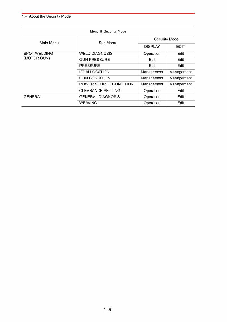
1.4 About the Security Mode
SPOT WELDING (MOTOR GUN)
WELD DIAGNOSIS Operation EditGUN PRESSURE Edit EditPRESSURE Edit EditI/O ALLOCATION Management ManagementGUN CONDITION Management ManagementPOWER SOURCE CONDITION Management Management
CLEARANCE SETTING Operation EditGENERAL GENERAL DIAGNOSIS Operation Edit
WEAVING Operation Edit
Menu & Security Mode
Main Menu Sub MenuSecurity Mode
DISPLAY EDIT
1-25
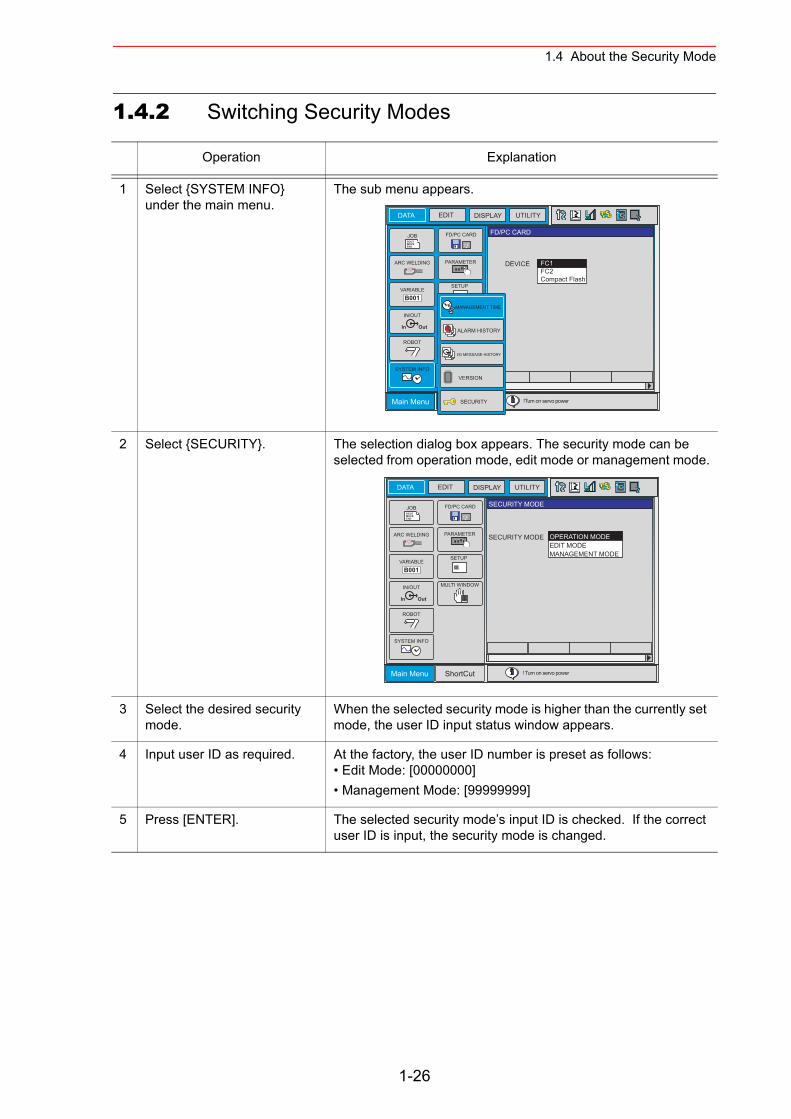
1.4 About the Security Mode
1.4.2 Switching Security Modes
Operation Explanation
1 Select {SYSTEM INFO} under the main menu.
The sub menu appears.
2 Select {SECURITY}. The selection dialog box appears. The security mode can be selected from operation mode, edit mode or management mode.
3 Select the desired security mode.
When the selected security mode is higher than the currently set mode, the user ID input status window appears.
4 Input user ID as required. At the factory, the user ID number is preset as follows:• Edit Mode: [00000000]• Management Mode: [99999999]
5 Press [ENTER]. The selected security mode’s input ID is checked. If the correct user ID is input, the security mode is changed.
DATA
Main Menu
JOBDOUTMOVEEND
IN/OUT
In Out
SYSTEM INFO
ARC WELDING
VARIABLEB001
ROBOT
PARAMETER
CF
FD/PC CARD
!Turn on servo power
EDIT DISPLAY UTILITY
FD/PC CARD
DEVICE FC1FC2Compact Flash
SETUP
MANAGEMENT TIME
ALARM HISTORY
I/O MESSAGE HISTORY
VERSION
SECURITY
DATA
Main Menu ShortCut
JOBDOUTMOVEEND
IN/OUT
In Out
SYSTEM INFO
MULTI WINDOW
ARC WELDING
VARIABLEB001
ROBOT
PARAMETER
CF
FD/PC CARD
! Turn on servo power
EDIT DISPLAY UTILITY
SECURITY MODE
SECURITY MODE
SETUP
OPERATION MODEEDIT MODEMANAGEMENT MODE
1-26
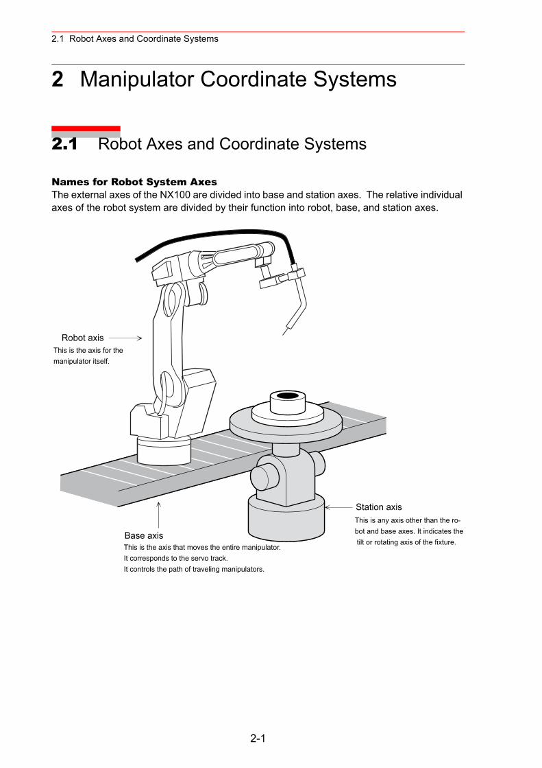
2.1 Robot Axes and Coordinate Systems
2 Manipulator Coordinate Systems
2.1 Robot Axes and Coordinate Systems
Names for Robot System AxesThe external axes of the NX100 are divided into base and station axes. The relative individual axes of the robot system are divided by their function into robot, base, and station axes.
Robot axis
Base axis
Station axis
This is the axis for the manipulator itself.
This is any axis other than the ro-bot and base axes. It indicates the tilt or rotating axis of the fixture.
This is the axis that moves the entire manipulator.It corresponds to the servo track.It controls the path of traveling manipulators.
2-1
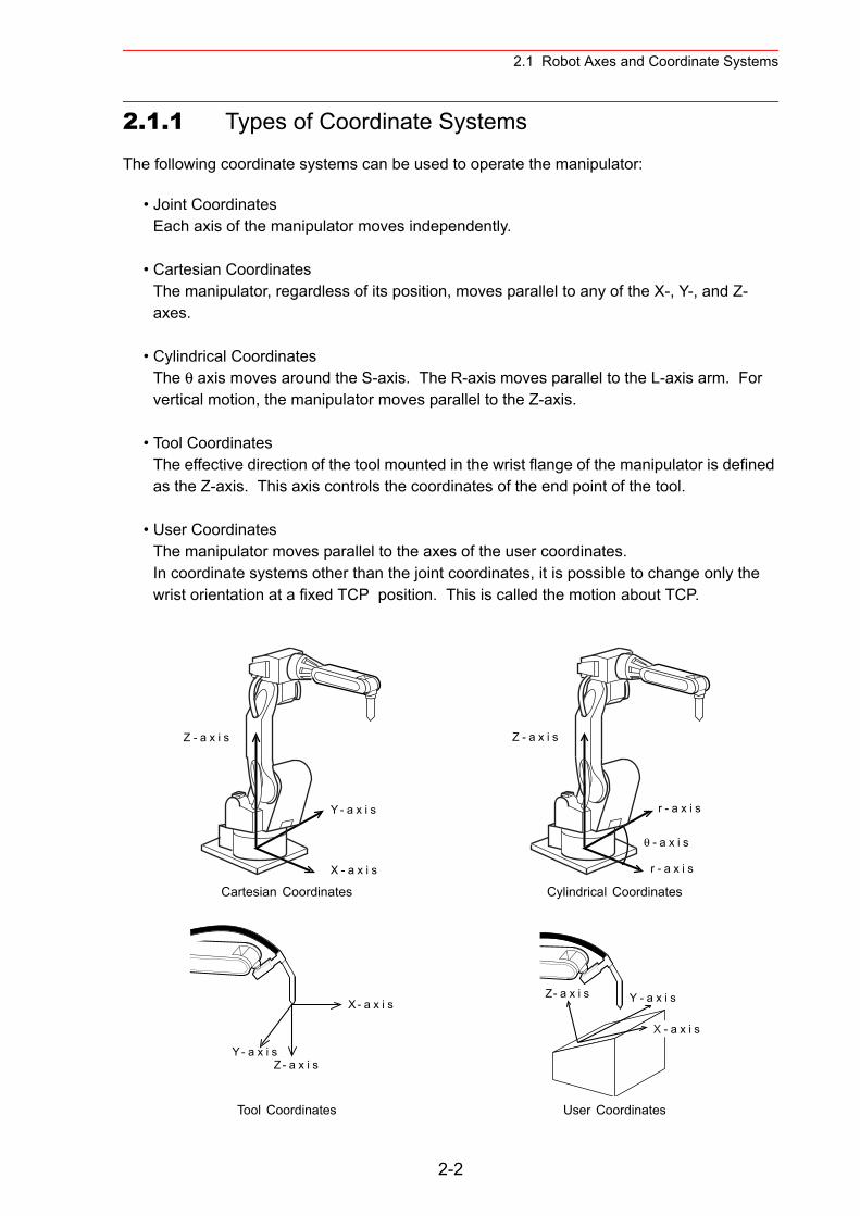
2.1 Robot Axes and Coordinate Systems
2.1.1 Types of Coordinate Systems
The following coordinate systems can be used to operate the manipulator:
• Joint CoordinatesEach axis of the manipulator moves independently.
• Cartesian CoordinatesThe manipulator, regardless of its position, moves parallel to any of the X-, Y-, and Z-axes.
• Cylindrical CoordinatesThe θ axis moves around the S-axis. The R-axis moves parallel to the L-axis arm. For vertical motion, the manipulator moves parallel to the Z-axis.
• Tool CoordinatesThe effective direction of the tool mounted in the wrist flange of the manipulator is defined as the Z-axis. This axis controls the coordinates of the end point of the tool.
• User CoordinatesThe manipulator moves parallel to the axes of the user coordinates.In coordinate systems other than the joint coordinates, it is possible to change only the wrist orientation at a fixed TCP position. This is called the motion about TCP.
Cartesian Coordinates Cylindrical Coordinates
Tool Coordinates User Coordinates
Y - a x i s
X - a x i s
Z - a x i s Z - a x i s
θ - a x i s
r - a x i s
r - a x i s
Y- a x i s
X- a x i s
Z- a x i s
Z- a x i s Y - a x i s
X - a x i s
2-2
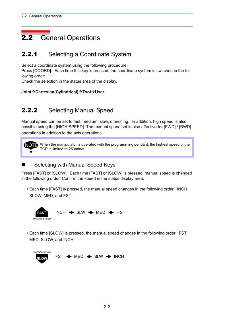
2.2 General Operations
2.2 General Operations
2.2.1 Selecting a Coordinate System
Select a coordinate system using the following procedure:Press [COORD]. Each time this key is pressed, the coordinate system is switched in the fol-lowing order:Check the selection in the status area of the display.
Joint Cartesian(Cylindrical) Tool User
2.2.2 Selecting Manual Speed
Manual speed can be set to fast, medium, slow, or inching. In addition, high speed is also possible using the [HIGH SPEED]. The manual speed set is also effective for [FWD] / [BWD] operations in addition to the axis operations.
Selecting with Manual Speed KeysPress [FAST] or [SLOW]. Each time [FAST] or [SLOW] is pressed, manual speed is changed in the following order. Confirm the speed in the status display area.
• Each time [FAST] is pressed, the manual speed changes in the following order: INCH, SLOW, MED, and FST.
• Each time [SLOW] is pressed, the manual speed changes in the following order: FST, MED, SLOW, and INCH.
When the manipulator is operated with the programming pendant, the highest speed of the TCP is limited to 250mm/s.
INCH SLW MED FST
FST MED SLW INCH
NOTE
FASTMANUAL SPEED
SLOW
MANUAL SPEED
2-3
2.2 General Operations
Using the High Speed KeyPressing [HIGH SPEED] while the axis keys are being held down makes the manipulator operate at high speed.
2.2.3 Axis Operations
Pressing an axis key in the teach mode makes it possible to move the respective axis of the manipulator and station to a desired position. The motion of each axis depends on the speci-fied coordinate system.
The axes move only while the axis key is being pressed.
Switching the Group Axis to be OperatedThe coordination robot system (optional function) with two or more axes, switches the group axis by the following procedure:
When the Job Content is DisplayedWhen the job content is displayed, the group axes which are registered in the displayed job will be operated.
<Example>Case that the group axes registered in the displayed job is R1 + S1
Press [EX. AXIS]. The station number is shown in the status display area and station axis operation becomes possible.The station axis operation is shown below:X + / X − : the first axisY + / Y − : the second axisZ+ / Z − : the third axis
To return to the robot axes from the station axes, press [ROBOT].
When the Job Content is not DisplayedIf the edit job does not exist, operate the manipulator or station by the following procedure:
1. Select the group axis as follows:For manipulators:Switch the manipulator by pressing [SHIFT] + [ROBOT].The lamp on [ROBOT] is lit.For stations:Switch the station by pressing [SHIFT] + [EX. AXIS].The lamp on [EX. AXIS] is lit.
2. Perform the axis operation.When [ROBOT] or [EX. AXIS] is pressed, the selection state of the group axis returns to the state that no group axis is selected.
[HIGH SPEED] has no effect if the manual speed is set to INCH.NOTE
2-4
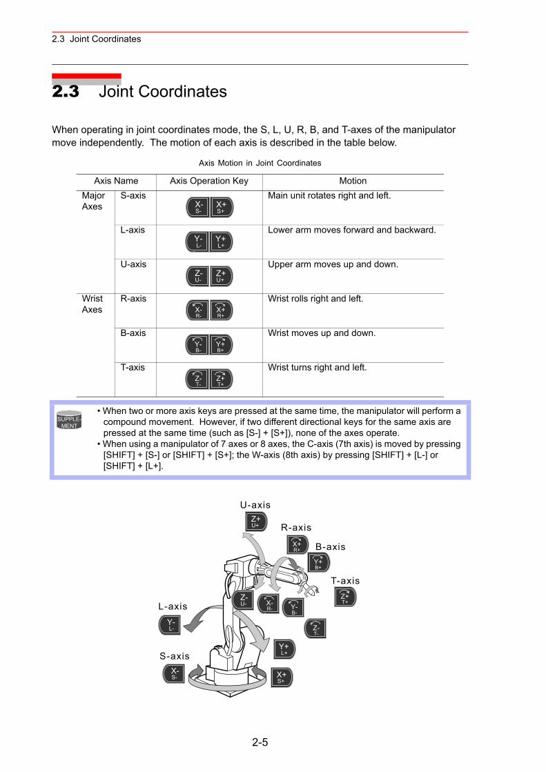
2.3 Joint Coordinates
2.3 Joint Coordinates
When operating in joint coordinates mode, the S, L, U, R, B, and T-axes of the manipulator move independently. The motion of each axis is described in the table below.
Axis Motion in Joint Coordinates
Axis Name Axis Operation Key MotionMajor Axes
S-axis Main unit rotates right and left.
L-axis Lower arm moves forward and backward.
U-axis Upper arm moves up and down.
Wrist Axes
R-axis Wrist rolls right and left.
B-axis Wrist moves up and down.
T-axis Wrist turns right and left.
• When two or more axis keys are pressed at the same time, the manipulator will perform a compound movement. However, if two different directional keys for the same axis are pressed at the same time (such as [S-] + [S+]), none of the axes operate.
• When using a manipulator of 7 axes or 8 axes, the C-axis (7th axis) is moved by pressing [SHIFT] + [S-] or [SHIFT] + [S+]; the W-axis (8th axis) by pressing [SHIFT] + [L-] or [SHIFT] + [L+].
X-S-
X+S+
Y-L-
Y+L+
Z-U-
Z+U+
X-R-
X+R+
Y-B-
Y+B+
Z-T-
Z+T+
SUPPLE-MENT
U-axis
R-axis
B-axis
T-axis
L-axis
S-axis
Y-L-
Y+L+
X-S- X+
S+
Z-U-
Z+U+
Y-B-
Y+B+
X-R-
X+R+
Z-T-
Z+T+
2-5
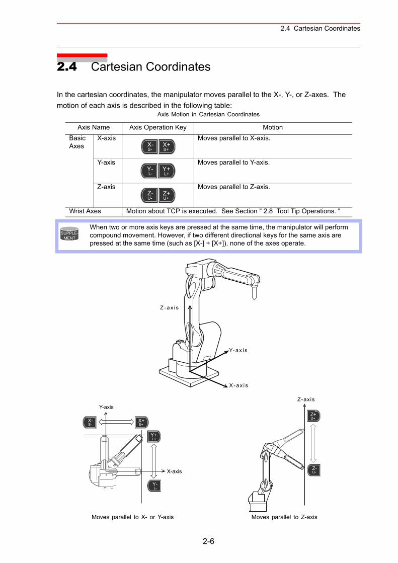
2.4 Cartesian Coordinates
2.4 Cartesian Coordinates
In the cartesian coordinates, the manipulator moves parallel to the X-, Y-, or Z-axes. The motion of each axis is described in the following table:
Axis Motion in Cartesian Coordinates
Axis Name Axis Operation Key MotionBasic Axes
X-axis Moves parallel to X-axis.
Y-axis Moves parallel to Y-axis.
Z-axis Moves parallel to Z-axis.
Wrist Axes Motion about TCP is executed. See Section " 2.8 Tool Tip Operations. "
When two or more axis keys are pressed at the same time, the manipulator will perform compound movement. However, if two different directional keys for the same axis are pressed at the same time (such as [X-] + [X+]), none of the axes operate.
Moves parallel to X- or Y-axis Moves parallel to Z-axis
X-S-
X+S+
Y-L-
Y+L+
Z-U-
Z+U+
SUPPLE-MENT
Z - a x i s
Y- a x i s
X - a x i s
Y-axis
X-axis
Y-L-
Y+L+
X-S-
X+S+
Z-axis
Z-U-
Z+U+
2-6
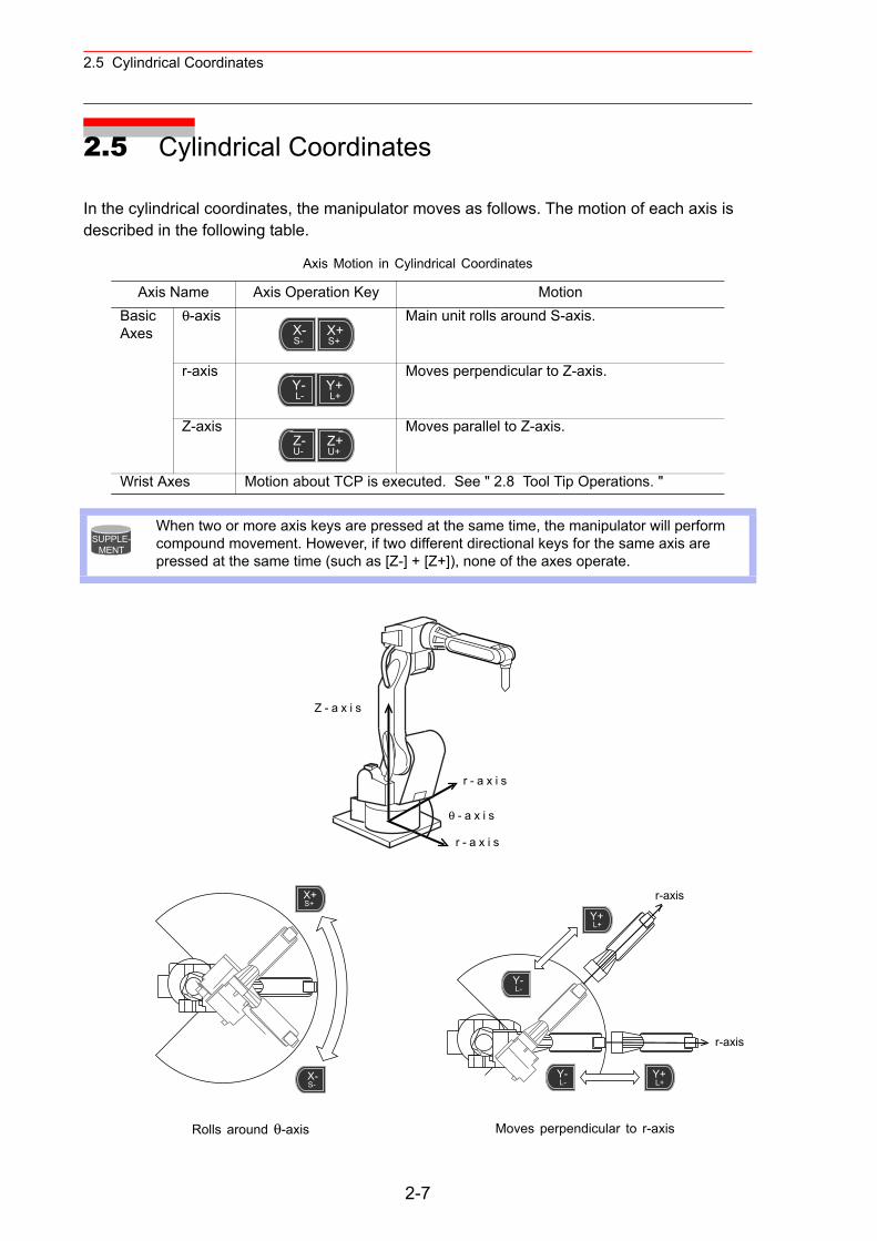
2.5 Cylindrical Coordinates
2.5 Cylindrical Coordinates
In the cylindrical coordinates, the manipulator moves as follows. The motion of each axis is described in the following table.
Axis Motion in Cylindrical Coordinates
Axis Name Axis Operation Key MotionBasic Axes
θ-axis Main unit rolls around S-axis.
r-axis Moves perpendicular to Z-axis.
Z-axis Moves parallel to Z-axis.
Wrist Axes Motion about TCP is executed. See " 2.8 Tool Tip Operations. "
When two or more axis keys are pressed at the same time, the manipulator will perform compound movement. However, if two different directional keys for the same axis are pressed at the same time (such as [Z-] + [Z+]), none of the axes operate.
Rolls around θ-axis Moves perpendicular to r-axis
X-S-
X+S+
Y-L-
Y+L+
Z-U-
Z+U+
SUPPLE-MENT
Z - a x i s
θ - a x i s
r - a x i s
r - a x i s
X-S-
X+S+
r-axis
r-axis
Y-L-
Y-L-
Y+L+
Y+L+
2-7
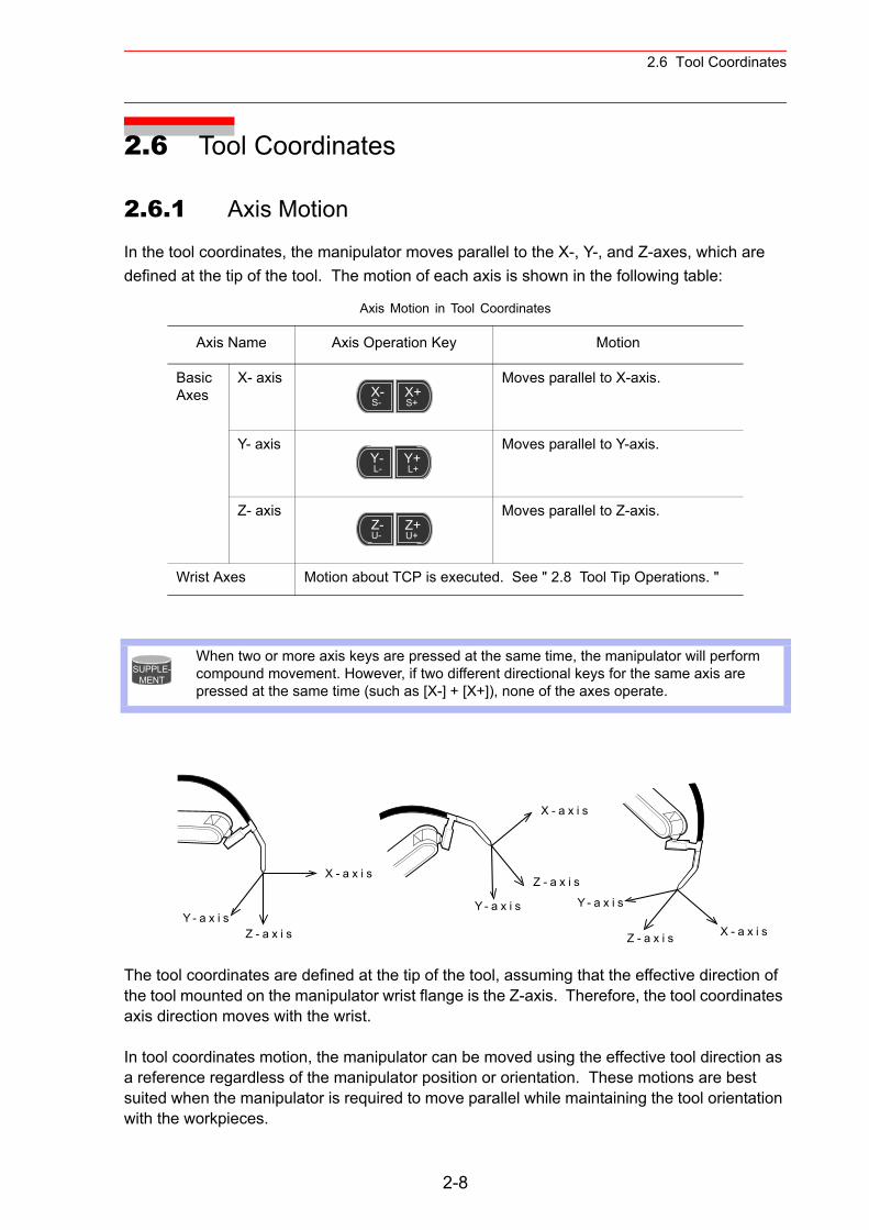
2.6 Tool Coordinates
2.6 Tool Coordinates
2.6.1 Axis Motion
In the tool coordinates, the manipulator moves parallel to the X-, Y-, and Z-axes, which are defined at the tip of the tool. The motion of each axis is shown in the following table:
The tool coordinates are defined at the tip of the tool, assuming that the effective direction of the tool mounted on the manipulator wrist flange is the Z-axis. Therefore, the tool coordinates axis direction moves with the wrist.
In tool coordinates motion, the manipulator can be moved using the effective tool direction as a reference regardless of the manipulator position or orientation. These motions are best suited when the manipulator is required to move parallel while maintaining the tool orientation with the workpieces.
Axis Motion in Tool Coordinates
Axis Name Axis Operation Key Motion
Basic Axes
X- axis Moves parallel to X-axis.
Y- axis Moves parallel to Y-axis.
Z- axis Moves parallel to Z-axis.
Wrist Axes Motion about TCP is executed. See " 2.8 Tool Tip Operations. "
When two or more axis keys are pressed at the same time, the manipulator will perform compound movement. However, if two different directional keys for the same axis are pressed at the same time (such as [X-] + [X+]), none of the axes operate.
X-S-
X+S+
Y-L-
Y+L+
Z-U-
Z+U+
SUPPLE-MENT
Y - a x i sZ - a x i s
Y - a x i s
X - a x i s
Z - a x i s
Y - a x i s
X - a x i sZ - a x i s
X - a x i s
2-8
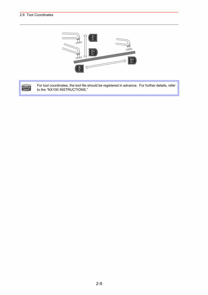
2.6 Tool Coordinates
For tool coordinates, the tool file should be registered in advance. For further details, refer to the “NX100 INSTRUCTIONS.”
X-S-
X+S+
Z-U-
Z+U+
SUPPLE-MENT
2-9
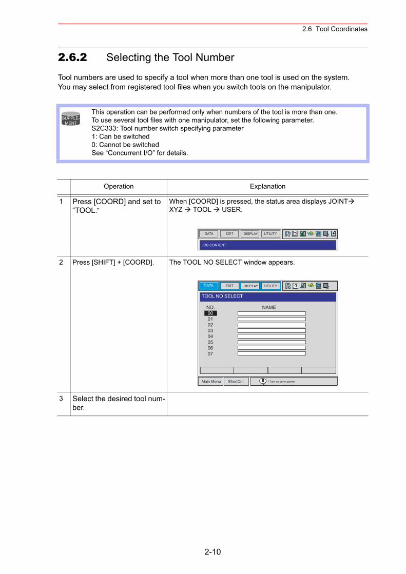
2.6 Tool Coordinates
2.6.2 Selecting the Tool Number
Tool numbers are used to specify a tool when more than one tool is used on the system.You may select from registered tool files when you switch tools on the manipulator.
This operation can be performed only when numbers of the tool is more than one. To use several tool files with one manipulator, set the following parameter.S2C333: Tool number switch specifying parameter1: Can be switched0: Cannot be switchedSee “Concurrent I/O” for details.
Operation Explanation
1 Press [COORD] and set to “TOOL.”
When [COORD] is pressed, the status area displays JOINT XYZ TOOL USER.
2 Press [SHIFT] + [COORD]. The TOOL NO SELECT window appears.
3 Select the desired tool num-ber.
SUPPLE-MENT
DATA EDIT DISPLAY UTILITY
JOB CONTENT
DATA UTILITYEDIT DISPLAY
Main Menu ShortCut ! Turn on servo power
TOOL NO SELECT
NO. NAME 00 01 02 03 04 05 06 07
2-10
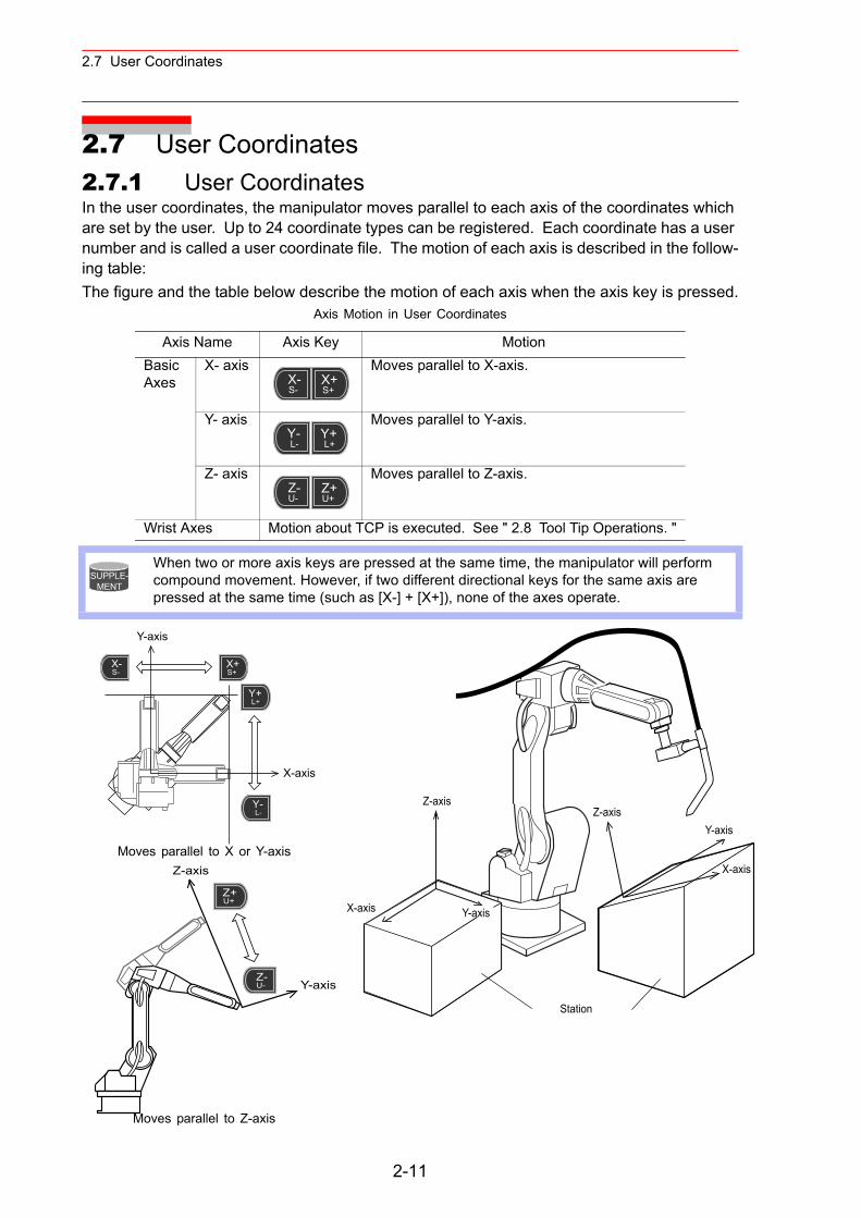
2.7 User Coordinates
2.7 User Coordinates2.7.1 User CoordinatesIn the user coordinates, the manipulator moves parallel to each axis of the coordinates which are set by the user. Up to 24 coordinate types can be registered. Each coordinate has a user number and is called a user coordinate file. The motion of each axis is described in the follow-ing table:The figure and the table below describe the motion of each axis when the axis key is pressed.
Axis Motion in User Coordinates
Axis Name Axis Key MotionBasic Axes
X- axis Moves parallel to X-axis.
Y- axis Moves parallel to Y-axis.
Z- axis Moves parallel to Z-axis.
Wrist Axes Motion about TCP is executed. See " 2.8 Tool Tip Operations. "
When two or more axis keys are pressed at the same time, the manipulator will perform compound movement. However, if two different directional keys for the same axis are pressed at the same time (such as [X-] + [X+]), none of the axes operate.
Moves parallel to X or Y-axis
Moves parallel to Z-axis
X-S-
X+S+
Y-L-
Y+L+
Z-U-
Z+U+
SUPPLE-MENT
Y-axis
X-axis
Y-L-
Y+L+
X-S-
X+S+
Station
Z-axis
X-axis
Y-axis
Z-axis
X-axis Y-axis
Z-axis
Y-axisZ-U-
Z+U+
2-11
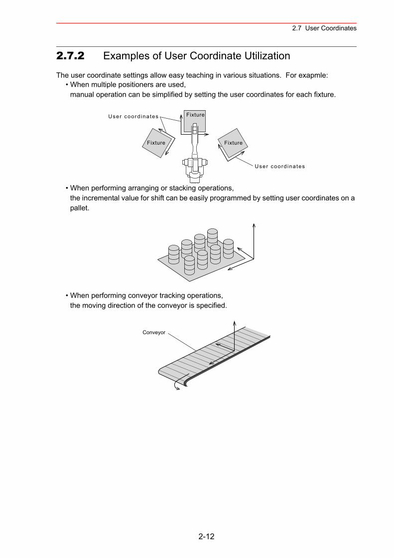
2.7 User Coordinates
2.7.2 Examples of User Coordinate Utilization
The user coordinate settings allow easy teaching in various situations. For exapmle:• When multiple positioners are used,
manual operation can be simplified by setting the user coordinates for each fixture.
• When performing arranging or stacking operations,the incremental value for shift can be easily programmed by setting user coordinates on a pallet.
• When performing conveyor tracking operations,the moving direction of the conveyor is specified.
User coord ina tes
Fixture
Fixture
Fixture
User coord ina tes
Conveyor
2-12
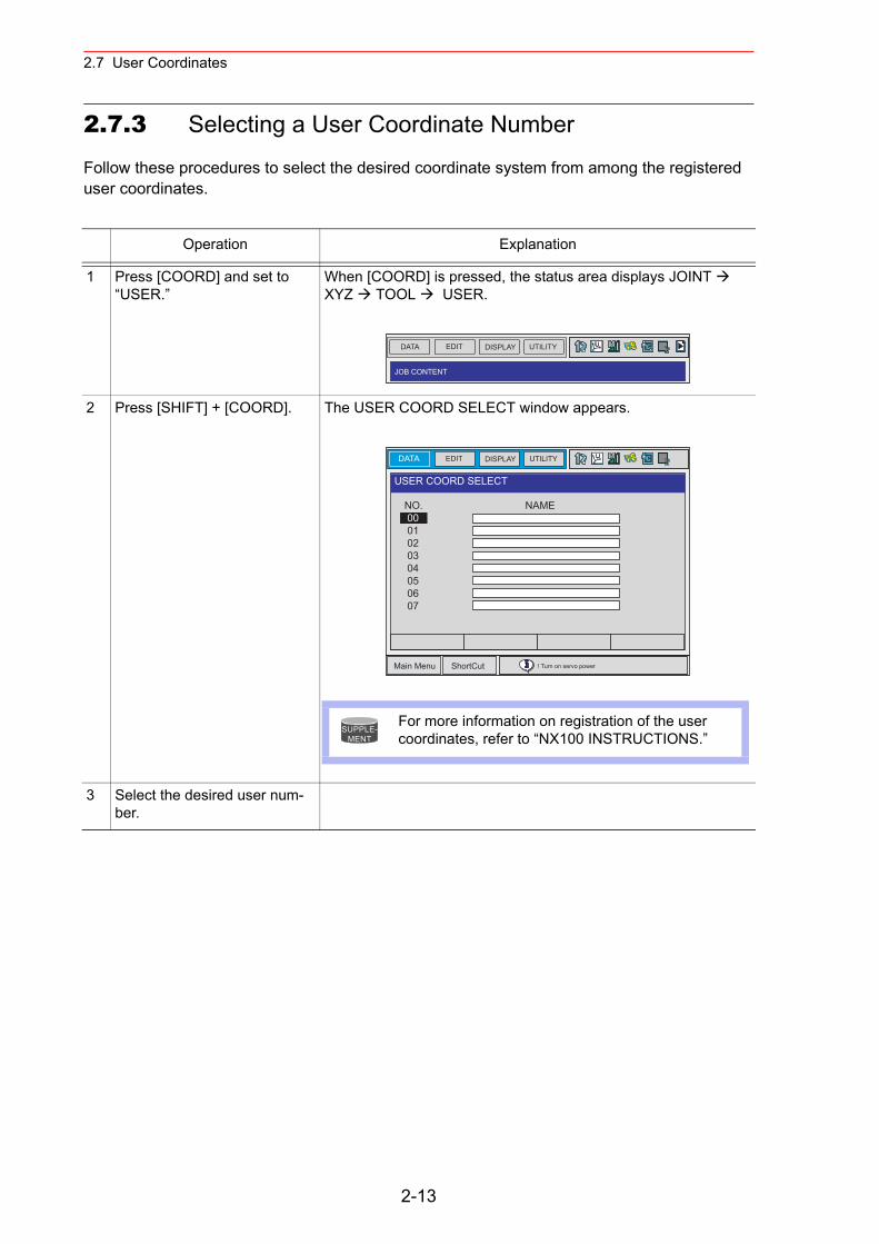
2.7 User Coordinates
2.7.3 Selecting a User Coordinate Number
Follow these procedures to select the desired coordinate system from among the registered user coordinates.
Operation Explanation
1 Press [COORD] and set to “USER.”
When [COORD] is pressed, the status area displays JOINT XYZ TOOL USER.
2 Press [SHIFT] + [COORD]. The USER COORD SELECT window appears.
3 Select the desired user num-ber.
DATA EDIT DISPLAY UTILITY
JOB CONTENT
DATA UTILITYEDIT DISPLAY
Main Menu ShortCut ! Turn on servo power
USER COORD SELECT
NO. NAME 00 01 02 03 04 05 06 07
For more information on registration of the user coordinates, refer to “NX100 INSTRUCTIONS.”
SUPPLE-MENT
2-13
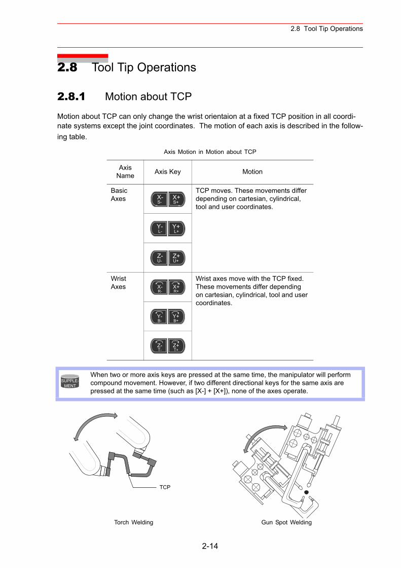
2.8 Tool Tip Operations
2.8 Tool Tip Operations
2.8.1 Motion about TCP
Motion about TCP can only change the wrist orientaion at a fixed TCP position in all coordi-nate systems except the joint coordinates. The motion of each axis is described in the follow-ing table.
Axis Motion in Motion about TCP
Axis Name Axis Key Motion
Basic Axes
TCP moves. These movements differ depending on cartesian, cylindrical, tool and user coordinates.
Wrist Axes
Wrist axes move with the TCP fixed. These movements differ depending on cartesian, cylindrical, tool and user coordinates.
When two or more axis keys are pressed at the same time, the manipulator will perform compound movement. However, if two different directional keys for the same axis are pressed at the same time (such as [X-] + [X+]), none of the axes operate.
Torch Welding Gun Spot Welding
X-S-
X+S+
Y-L-
Y+L+
Z-U-
Z+U+
X-R-
X+R+
Y-B-
Y+B+
Z-T-
Z+T+
SUPPLE-MENT
TCP
2-14
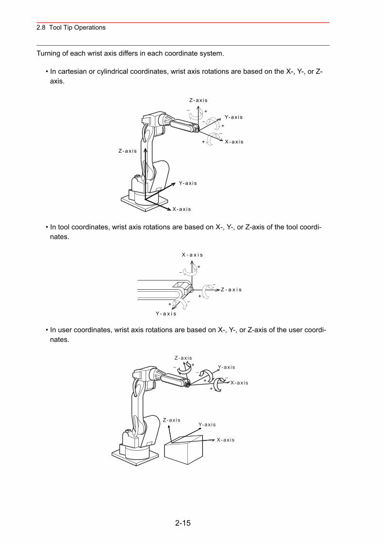
2.8 Tool Tip Operations
Turning of each wrist axis differs in each coordinate system.
• In cartesian or cylindrical coordinates, wrist axis rotations are based on the X-, Y-, or Z-axis.
• In tool coordinates, wrist axis rotations are based on X-, Y-, or Z-axis of the tool coordi-nates.
• In user coordinates, wrist axis rotations are based on X-, Y-, or Z-axis of the user coordi-nates.
Z - a x i s
+
+
+
−
−
−
Y- a x i s
X - a x i s
Z - a x i s
Y- a x i s
X - a x i s
Z - a x i s
Y - a x i s
X - a x i s
+
++
−
−
−
Z-ax is
X-ax is
Y-ax is
Z-ax is
X-ax is
Y-ax is+
++
−−
−
2-15
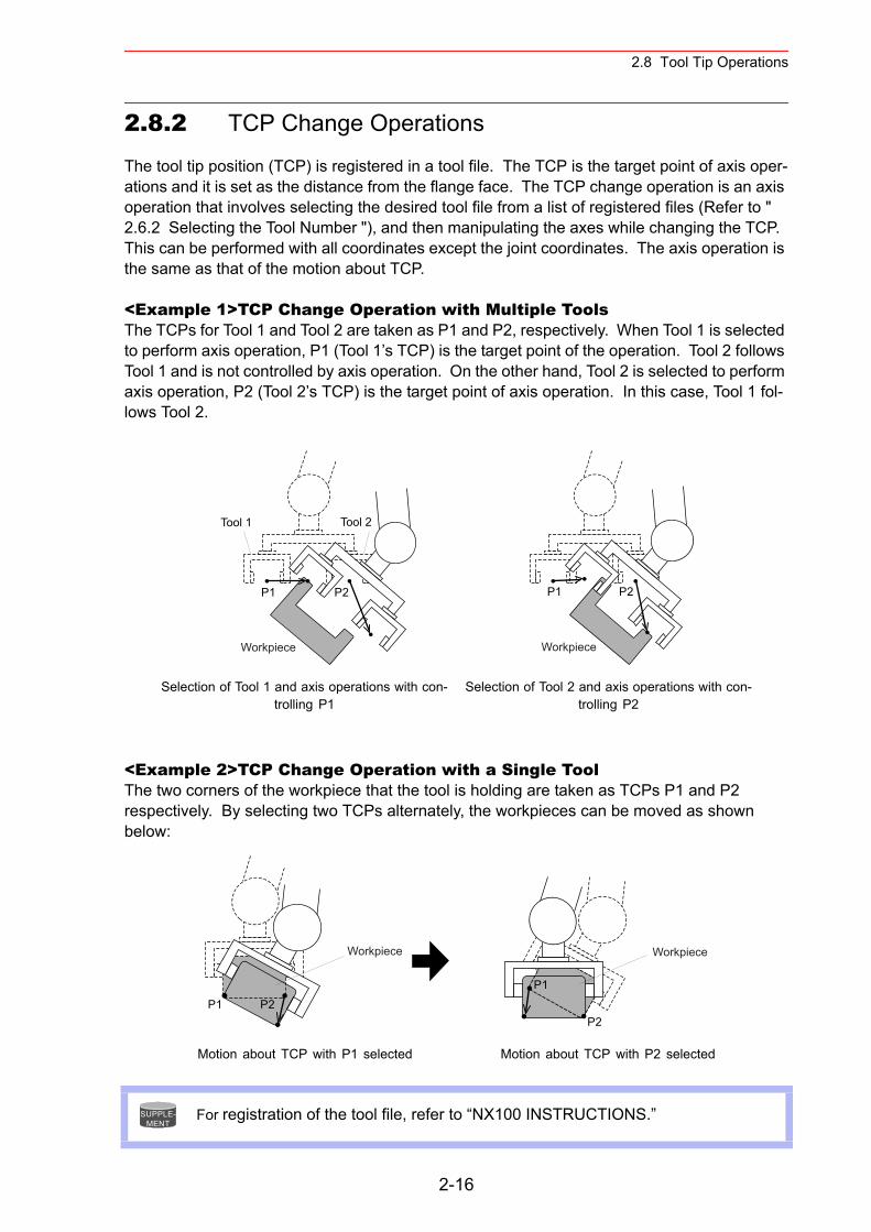
2.8 Tool Tip Operations
2.8.2 TCP Change Operations
The tool tip position (TCP) is registered in a tool file. The TCP is the target point of axis oper-ations and it is set as the distance from the flange face. The TCP change operation is an axis operation that involves selecting the desired tool file from a list of registered files (Refer to " 2.6.2 Selecting the Tool Number "), and then manipulating the axes while changing the TCP. This can be performed with all coordinates except the joint coordinates. The axis operation is the same as that of the motion about TCP.
<Example 1>TCP Change Operation with Multiple ToolsThe TCPs for Tool 1 and Tool 2 are taken as P1 and P2, respectively. When Tool 1 is selected to perform axis operation, P1 (Tool 1’s TCP) is the target point of the operation. Tool 2 follows Tool 1 and is not controlled by axis operation. On the other hand, Tool 2 is selected to perform axis operation, P2 (Tool 2’s TCP) is the target point of axis operation. In this case, Tool 1 fol-lows Tool 2.
<Example 2>TCP Change Operation with a Single ToolThe two corners of the workpiece that the tool is holding are taken as TCPs P1 and P2 respectively. By selecting two TCPs alternately, the workpieces can be moved as shown below:
Selection of Tool 1 and axis operations with con-trolling P1
Selection of Tool 2 and axis operations with con-trolling P2
Motion about TCP with P1 selected Motion about TCP with P2 selected
For registration of the tool file, refer to “NX100 INSTRUCTIONS.”
Tool 1
P2 P2P1P1
Tool 2
Workpiece Workpiece
P1 P2P2
P1
Workpiece Workpiece
SUPPLE-MENT
2-16

3.1 Teaching
3 Simplified Teaching and Playback
3.1 Teaching
3.1.1 Preparation for Teaching
Perform the following tasks before starting to teach.
• Set the operation mode to teach mode.• Enter the job name.
1. Confirm that the mode switch on the programming pendant is set to “TEACH.” If not, set the switch to “TEACH.”
2. Press [SERVO ON READY].The SERVO ON lamp will blink. If [SERVO ON READY] is not pressed, the servo power supply cannot be turned ON using the Enable switch.
3. Select {JOB} under the main menu, and select {CREATE NEW JOB} in the sub menu.
REMOTE TEACHPLAY
SERVOON
READY
DATA EDIT DISPLAY UTILITY
Main Menu ShortCut ! Turn on servo power
JOBDOUTMOVEEND
IN/OUT
In Out
SYSTEM INFO
ARC WELDING
VARIABLE
B001
ROBOT
SELECT JOB
MASTER JOB
JOB CAPACITY
DOUTMOVEEND JOB CONTENT
CREATE NEW JOB
MAINMENU
SELECT
SELECT
3-1
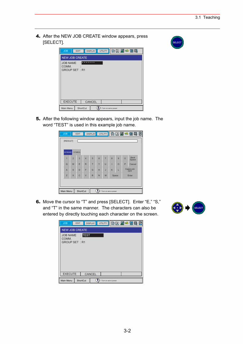
3.1 Teaching
4. After the NEW JOB CREATE window appears, press [SELECT].
5. After the following window appears, input the job name. The word “TEST” is used in this example job name.
6. Move the cursor to “T” and press [SELECT]. Enter “E,” “S,” and “T” in the same manner. The characters can also be entered by directly touching each character on the screen.
JOB UTILITYEDIT DISPLAY
Main Menu ShortCut ! Turn on servo power
NEW JOB CREATE
JOB NAME : * * * * * * *COMM. :GROUP SET : R1
EXECUTE CANCEL
SELECT
JOB UTILITYEDIT DISPLAY
[RESULT]
Main Menu ShortCut ! Turn on servo power
BackSpace
Cancel
CapsLockOFF
EnterSpace
1 2 3 4 5 6 7 8 9 0
Q W E R T Y U I O P
A S D F G H J K L
Z X C V B N M
SYMBOLKEYBOARD
JOB UTILITYEDIT DISPLAY
Main Menu ShortCut ! Turn on servo power
NEW JOB CREATE
JOB NAME : TESTCOMM. : GROUP SET : R1
EXECUTE CANCEL
SELECT
3-2
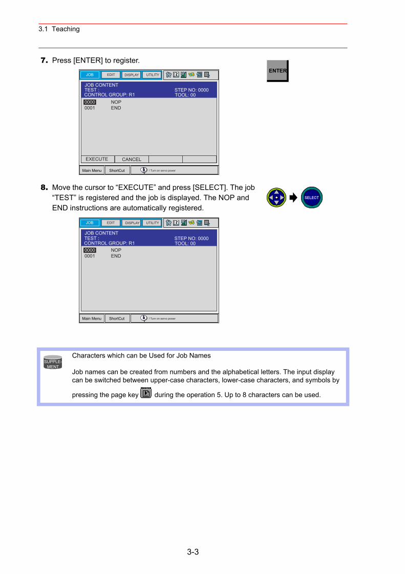
3.1 Teaching
7. Press [ENTER] to register.
8. Move the cursor to “EXECUTE” and press [SELECT]. The job “TEST” is registered and the job is displayed. The NOP and END instructions are automatically registered.
Characters which can be Used for Job Names
Job names can be created from numbers and the alphabetical letters. The input display can be switched between upper-case characters, lower-case characters, and symbols by
pressing the page key during the operation 5. Up to 8 characters can be used.
JOB CONTENTTEST : 0000 NOP0001 END
JOB UTILITYEDIT DISPLAY
Main Menu ShortCut ! Turn on servo power
TOOL: 00CONTROL GROUP: R1STEP NO: 0000
EXECUTE CANCEL
ENTER
JOB UTILITYEDIT DISPLAY
Main Menu ShortCut ! Turn on servo power
JOB CONTENT
0000 NOP0001 END
TEST :TOOL: 00CONTROL GROUP: R1STEP NO: 0000
SELECT
SUPPLE-MENT
PAGE
GO BACK
3-3
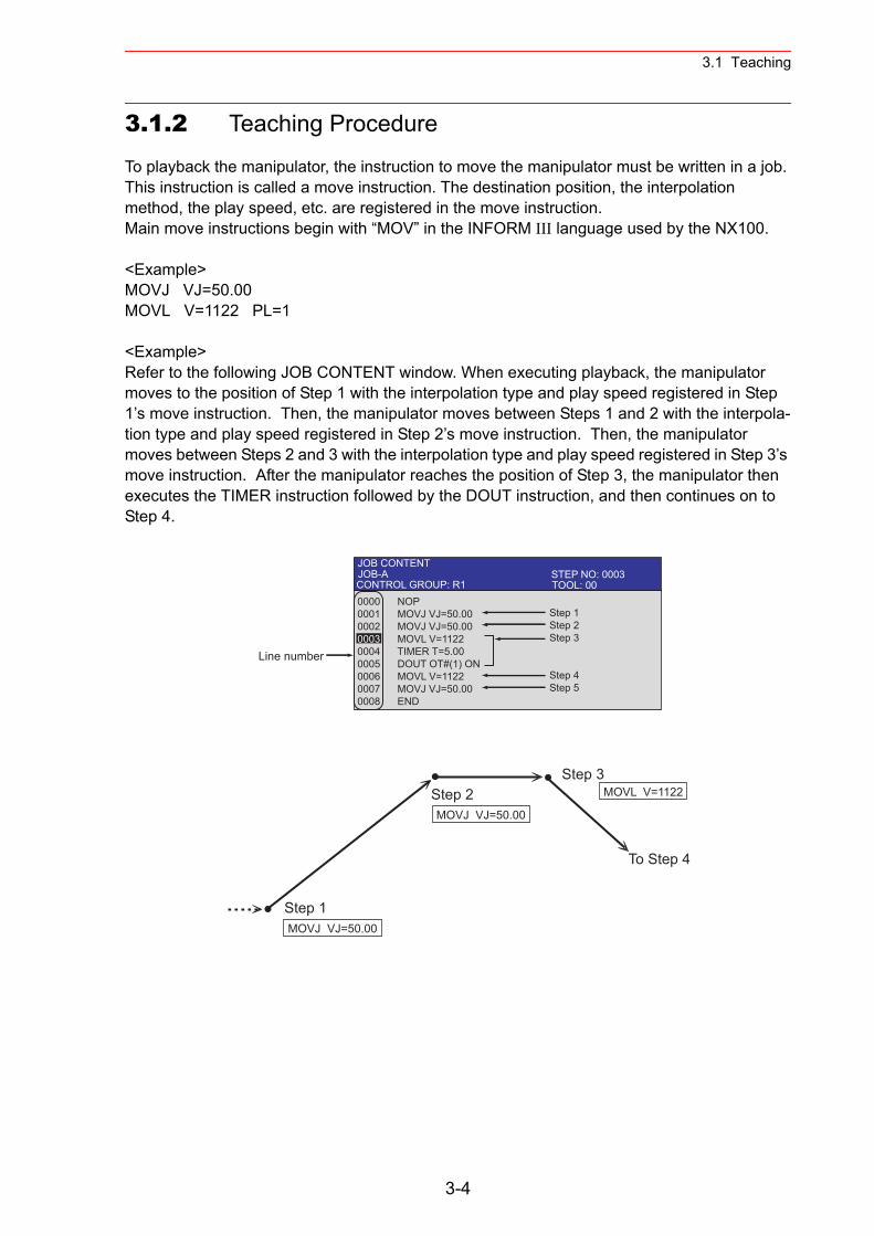
3.1 Teaching
3.1.2 Teaching Procedure
To playback the manipulator, the instruction to move the manipulator must be written in a job. This instruction is called a move instruction. The destination position, the interpolation method, the play speed, etc. are registered in the move instruction.Main move instructions begin with “MOV” in the INFORM III language used by the NX100.
<Example>MOVJ VJ=50.00MOVL V=1122 PL=1
<Example>Refer to the following JOB CONTENT window. When executing playback, the manipulator moves to the position of Step 1 with the interpolation type and play speed registered in Step 1’s move instruction. Then, the manipulator moves between Steps 1 and 2 with the interpola-tion type and play speed registered in Step 2’s move instruction. Then, the manipulator moves between Steps 2 and 3 with the interpolation type and play speed registered in Step 3’s move instruction. After the manipulator reaches the position of Step 3, the manipulator then executes the TIMER instruction followed by the DOUT instruction, and then continues on to Step 4.
JOB CONTENTJOB-A 0000 NOP0001 MOVJ VJ=50.000002 MOVJ VJ=50.000003 MOVL V=11220004 TIMER T=5.000005 DOUT OT#(1) ON0006 MOVL V=11220007 MOVJ VJ=50.000008 END
Step 1Step 2Step 3
Step 4Step 5
Line number
TOOL: 00CONTROL GROUP: R1STEP NO: 0003
MOVJ VJ=50.00
MOVJ VJ=50.00Step 1
Step 2Step 3
To Step 4
MOVL V=1122
3-4
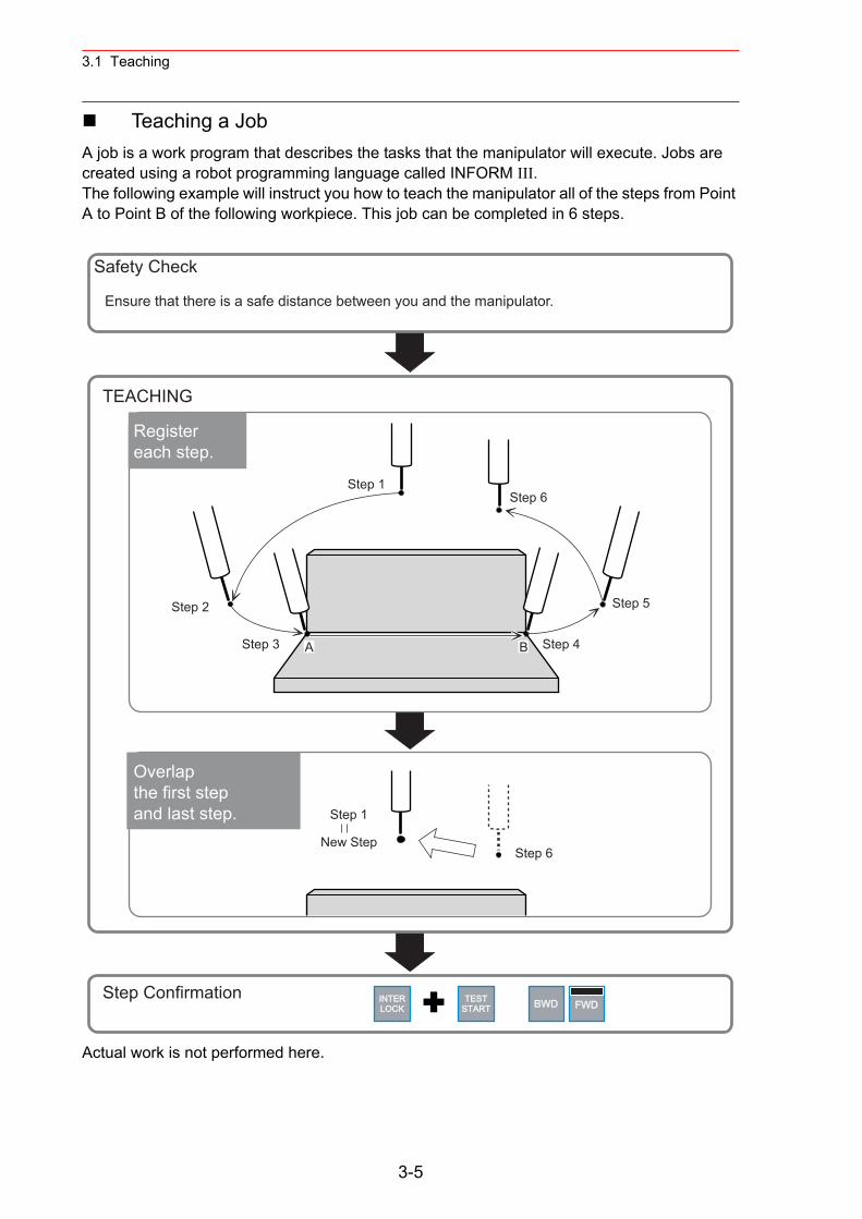
3.1 Teaching
Teaching a JobA job is a work program that describes the tasks that the manipulator will execute. Jobs are created using a robot programming language called INFORM III.The following example will instruct you how to teach the manipulator all of the steps from Point A to Point B of the following workpiece. This job can be completed in 6 steps.
Actual work is not performed here.
TESTSTART
INTERLOCK BWD FWD
Step 1
Step 2
A B Step 3 Step 4
Step 5
Step 6
Safety Check
TEACHING
Step Confirmation
Step 1
New StepStep 6
Overlap the first step and last step.
Registereach step.
Ensure that there is a safe distance between you and the manipulator.
3-5
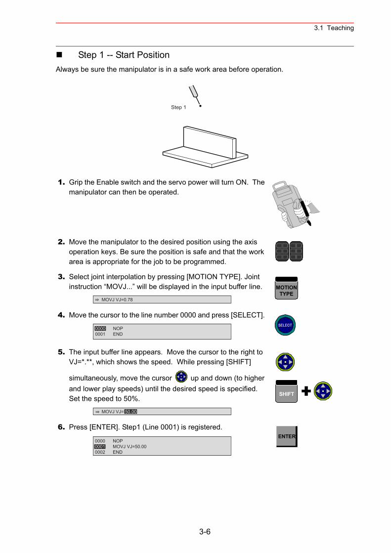
3.1 Teaching
Step 1 -- Start PositionAlways be sure the manipulator is in a safe work area before operation.
1. Grip the Enable switch and the servo power will turn ON. The manipulator can then be operated.
2. Move the manipulator to the desired position using the axis operation keys. Be sure the position is safe and that the work area is appropriate for the job to be programmed.
3. Select joint interpolation by pressing [MOTION TYPE]. Joint instruction “MOVJ...” will be displayed in the input buffer line.
4. Move the cursor to the line number 0000 and press [SELECT].
5. The input buffer line appears. Move the cursor to the right to VJ=*.**, which shows the speed. While pressing [SHIFT]
simultaneously, move the cursor up and down (to higher and lower play speeds) until the desired speed is specified.Set the speed to 50%.
6. Press [ENTER]. Step1 (Line 0001) is registered.
Step 1
MOVJ VJ=0.78
MOTIONTYPE
0000 NOP0001 END
SELECT
MOVJ VJ= 50.00
SHIFT
0000 NOP0001 MOVJ VJ=50.000002 END
ENTER
3-6
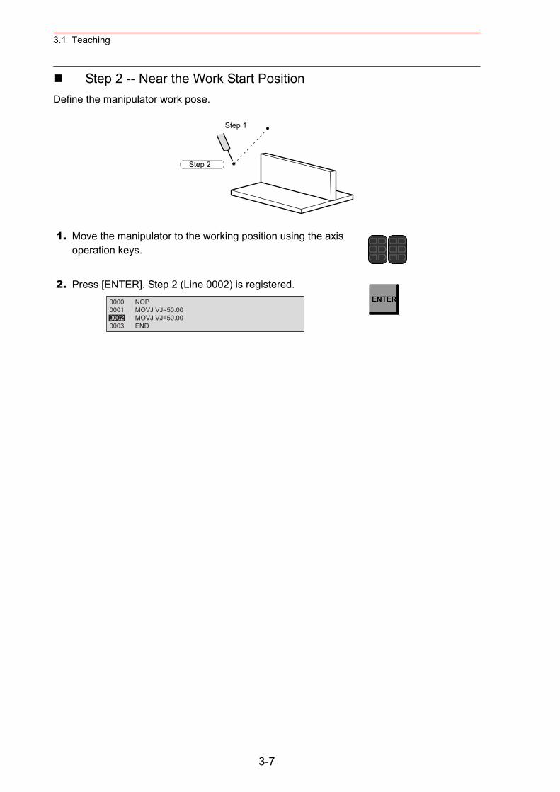
3.1 Teaching
Step 2 -- Near the Work Start PositionDefine the manipulator work pose.
1. Move the manipulator to the working position using the axis operation keys.
2. Press [ENTER]. Step 2 (Line 0002) is registered.
Step 1
Step 2
0000 NOP0001 MOVJ VJ=50.000002 MOVJ VJ=50.000003 END
ENTER
3-7
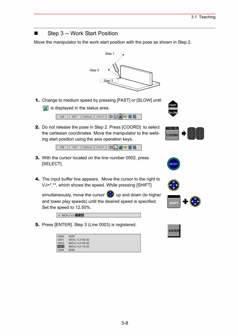
3.1 Teaching
Step 3 -- Work Start PositionMove the manipulator to the work start position with the pose as shown in Step 2.
1. Change to medium speed by pressing [FAST] or [SLOW] until
is displayed in the status area.
2. Do not release the pose in Step 2. Press [COORD] to select the cartesian coordinates. Move the manipulator to the weld-ing start position using the axis operation keys.
3. With the cursor located on the line number 0002, press [SELECT].
4. The input buffer line appears. Move the cursor to the right to VJ=*.**, which shows the speed. While pressing [SHIFT]
simultaneously, move the cursor up and down (to higher and lower play speeds) until the desired speed is specified.Set the speed to 12.50%.
5. Press [ENTER]. Step 3 (Line 0003) is registered.
Step 1
Step 2
Step 3
JOB EDIT DISPLAY UTILITY
FASTMANUAL SPEED
SLOW
JOB EDIT DISPLAY UTILITY
COORD
TOOL SEL
SELECT
MOVJ VJ= 12.50
SHIFT
0000 NOP0001 MOVJ VJ=50.000002 MOVJ VJ=50.000003 MOVJ VJ=12.500004 END
ENTER
3-8
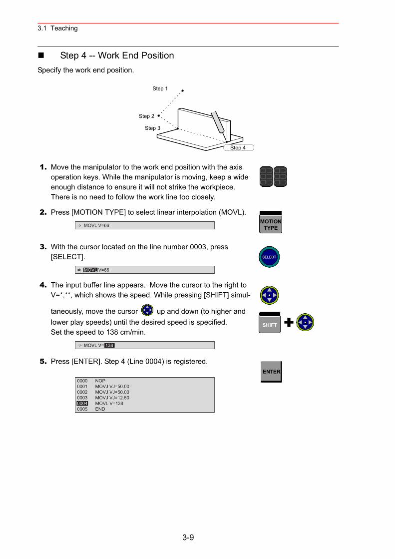
3.1 Teaching
Step 4 -- Work End PositionSpecify the work end position.
1. Move the manipulator to the work end position with the axis operation keys. While the manipulator is moving, keep a wide enough distance to ensure it will not strike the workpiece. There is no need to follow the work line too closely.
2. Press [MOTION TYPE] to select linear interpolation (MOVL).
3. With the cursor located on the line number 0003, press [SELECT].
4. The input buffer line appears. Move the cursor to the right to V=*.**, which shows the speed. While pressing [SHIFT] simul-
taneously, move the cursor up and down (to higher and lower play speeds) until the desired speed is specified.Set the speed to 138 cm/min.
5. Press [ENTER]. Step 4 (Line 0004) is registered.
Step 1
Step 2
Step 3
Step 4
MOVL V=66MOTION
TYPE
MOVL V=66
SELECT
MOVL V= 138
SHIFT
0000 NOP0001 MOVJ VJ=50.000002 MOVJ VJ=50.000003 MOVJ VJ=12.500004 MOVL V=1380005 END
ENTER
3-9
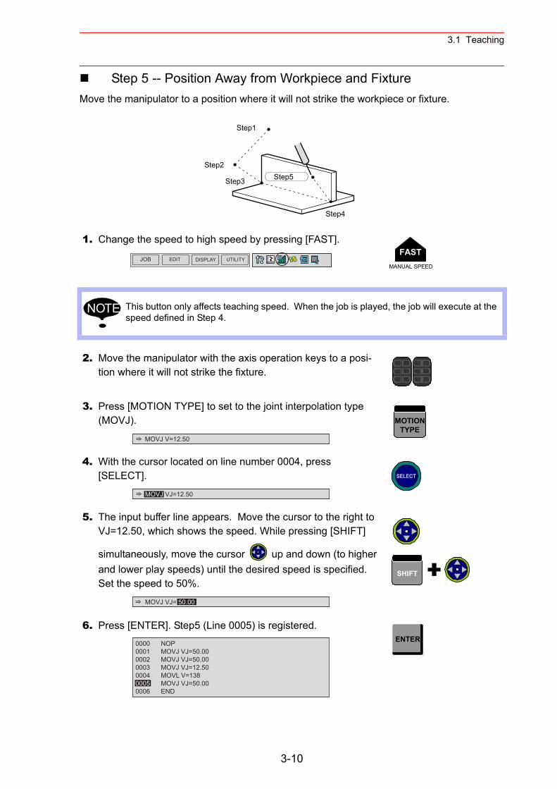
3.1 Teaching
Step 5 -- Position Away from Workpiece and FixtureMove the manipulator to a position where it will not strike the workpiece or fixture.
1. Change the speed to high speed by pressing [FAST].
This button only affects teaching speed. When the job is played, the job will execute at the speed defined in Step 4.
2. Move the manipulator with the axis operation keys to a posi-tion where it will not strike the fixture.
3. Press [MOTION TYPE] to set to the joint interpolation type (MOVJ).
4. With the cursor located on line number 0004, press [SELECT].
5. The input buffer line appears. Move the cursor to the right to VJ=12.50, which shows the speed. While pressing [SHIFT]
simultaneously, move the cursor up and down (to higher and lower play speeds) until the desired speed is specified.Set the speed to 50%.
6. Press [ENTER]. Step5 (Line 0005) is registered.
Step1
Step2
Step3
Step4
Step5
JOB EDIT DISPLAY UTILITYFAST
MANUAL SPEED
NOTE
MOVJ V=12.50
MOTIONTYPE
MOVJ VJ=12.50
SELECT
MOVJ VJ= 50.00
SHIFT
0000 NOP0001 MOVJ VJ=50.000002 MOVJ VJ=50.000003 MOVJ VJ=12.500004 MOVL V=1380005 MOVJ VJ=50.000006 END
ENTER
3-10
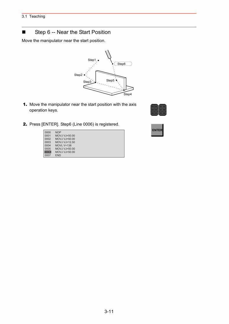
3.1 Teaching
Step 6 -- Near the Start PositionMove the manipulator near the start position.
1. Move the manipulator near the start position with the axis operation keys.
2. Press [ENTER]. Step6 (Line 0006) is registered.
Step1
Step2
Step3
Step4
Step5
Step6
0000 NOP0001 MOVJ VJ=50.000002 MOVJ VJ=50.000003 MOVJ VJ=12.500004 MOVL V=1380005 MOVJ VJ=50.000006 MOVJ VJ=50.000007 END
ENTER
3-11
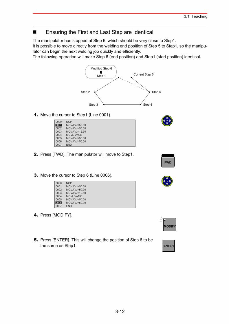
3.1 Teaching
Ensuring the First and Last Step are IdenticalThe manipulator has stopped at Step 6, which should be very close to Step1.It is possible to move directly from the welding end position of Step 5 to Step1, so the manipu-lator can begin the next welding job quickly and efficiently.The following operation will make Step 6 (end position) and Step1 (start position) identical.
1. Move the cursor to Step1 (Line 0001).
2. Press [FWD]. The manipulator will move to Step1.
3. Move the cursor to Step 6 (Line 0006).
4. Press [MODIFY].
5. Press [ENTER]. This will change the position of Step 6 to be the same as Step1.
Step 2
Step 3 Step 4
Step 5
Corrent Step 6
Modified Step 6
Step 1
0000 NOP0001 MOVJ VJ=50.000002 MOVJ VJ=50.000003 MOVJ VJ=12.500004 MOVL V=1380005 MOVJ VJ=50.000006 MOVJ VJ=50.000007 END
FWD
0000 NOP0001 MOVJ VJ=50.000002 MOVJ VJ=50.000003 MOVJ VJ=12.500004 MOVL V=1380005 MOVJ VJ=50.000006 MOVJ VJ=50.000007 END
MODIFY
ENTER
3-12
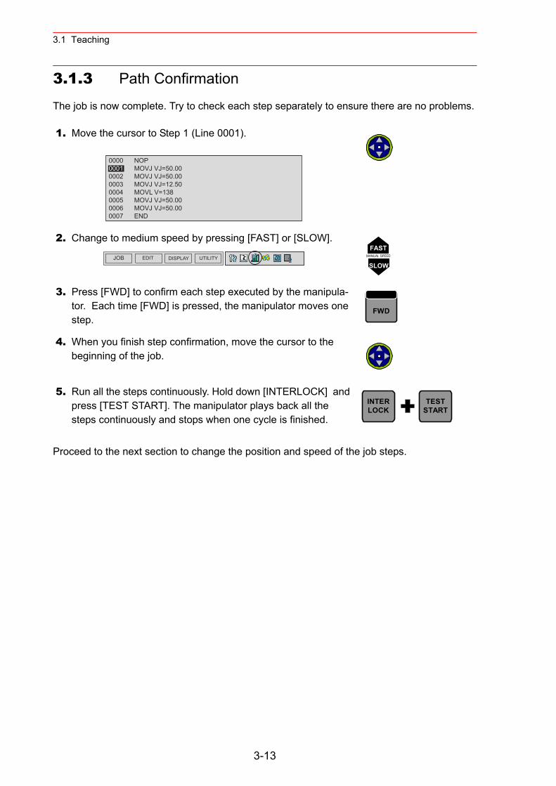
3.1 Teaching
3.1.3 Path Confirmation
The job is now complete. Try to check each step separately to ensure there are no problems.
Proceed to the next section to change the position and speed of the job steps.
1. Move the cursor to Step 1 (Line 0001).
2. Change to medium speed by pressing [FAST] or [SLOW].
3. Press [FWD] to confirm each step executed by the manipula-tor. Each time [FWD] is pressed, the manipulator moves one step.
4. When you finish step confirmation, move the cursor to the beginning of the job.
5. Run all the steps continuously. Hold down [INTERLOCK] and press [TEST START]. The manipulator plays back all the steps continuously and stops when one cycle is finished.
0000 NOP0001 MOVJ VJ=50.000002 MOVJ VJ=50.000003 MOVJ VJ=12.500004 MOVL V=1380005 MOVJ VJ=50.000006 MOVJ VJ=50.000007 END
JOB EDIT DISPLAY UTILITY
FASTMANUAL SPEED
SLOW
FWD
INTERLOCK
TESTSTART
3-13
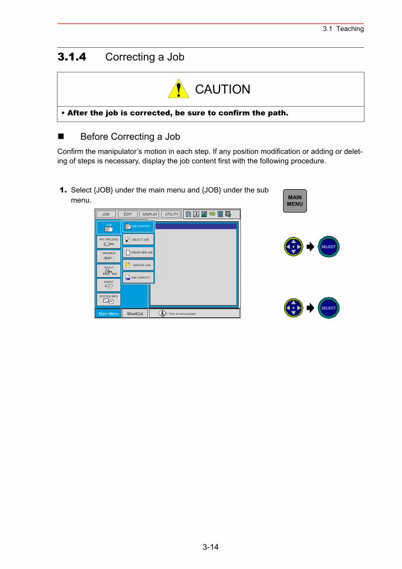
3.1 Teaching
3.1.4 Correcting a Job
Before Correcting a JobConfirm the manipulator’s motion in each step. If any position modification or adding or delet-ing of steps is necessary, display the job content first with the following procedure.
• After the job is corrected, be sure to confirm the path.
1. Select {JOB} under the main menu and {JOB} under the sub menu.
CAUTION
DOUTMOVEEND
In Out
B001
DOUTMOVEEND
JOB EDIT DISPLAY UTILITY
Main Menu ShortCut ! Turn on servo power
JOB
IN/OUT
SYSTEM INFO
ARC WELDING
VARIABLE
ROBOT
SELECT JOB
MASTER JOB
JOB CAPACITY
JOB CONTENT
CREATE NEW JOB
MAINMENU
SELECT
SELECT
3-14
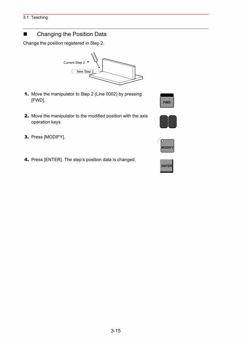
3.1 Teaching
Changing the Position DataChange the position registered in Step 2.
1. Move the manipulator to Step 2 (Line 0002) by pressing [FWD].
2. Move the manipulator to the modified position with the axis operation keys.
3. Press [MODIFY].
4. Press [ENTER]. The step’s position data is changed.
Current Step 2
New Step 2
FWD
MODIFY
ENTER
3-15
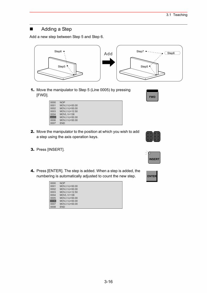
3.1 Teaching
Adding a StepAdd a new step between Step 5 and Step 6.
1. Move the manipulator to Step 5 (Line 0005) by pressing [FWD].
2. Move the manipulator to the position at which you wish to add a step using the axis operation keys.
3. Press [INSERT].
4. Press [ENTER]. The step is added. When a step is added, the numbering is automatically adjusted to count the new step.
Step5
Step6 Step6
Step5
Step7Add
0000 NOP0001 MOVJ VJ=50.000002 MOVJ VJ=50.000003 MOVJ VJ=12.500004 MOVL V=1380005 MOVJ VJ=50.000006 MOVJ VJ=50.000007 END
FWD
INSERT
0000 NOP0001 MOVJ VJ=50.000002 MOVJ VJ=50.000003 MOVJ VJ=12.500004 MOVL V=1380005 MOVJ VJ=50.000006 MOVJ VJ=50.000007 MOVJ VJ=50.000008 END
ENTER
3-16
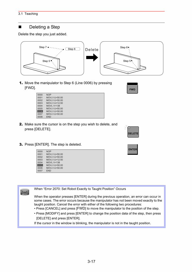
3.1 Teaching
Deleting a StepDelete the step you just added.
1. Move the manipulator to Step 6 (Line 0006) by pressing [FWD].
2. Make sure the cursor is on the step you wish to delete, and press [DELETE].
3. Press [ENTER]. The step is deleted.
When “Error 2070: Set Robot Exactly to Taught Position” Occurs
When the operator presses [ENTER] during the previous operation, an error can occur in some cases. The error occurs because the manipulator has not been moved exactly to the taught position. Cancel the error with either of the following two procedures: • Press [CANCEL] and press [FWD] to move the manipulator to the position of the step. • Press [MODIFY] and press [ENTER] to change the position data of the step, then press
[DELETE] and press [ENTER].If the cursor in the window is blinking, the manipulator is not in the taught position.
Step 5
Step 6Step 6
Step 5
Step 7Delete
0000 NOP0001 MOVJ VJ=50.000002 MOVJ VJ=50.000003 MOVJ VJ=12.500004 MOVL V=1380005 MOVJ VJ=50.000006 MOVJ VJ=50.000007 MOVJ VJ=50.000008 END
FWD
DELETE
0000 NOP0001 MOVJ VJ=50.000002 MOVJ VJ=50.000003 MOVJ VJ=12.500004 MOVL V=1380005 MOVJ VJ=50.000006 MOVJ VJ=50.000007 END
ENTER
SUPPLE-MENT
3-17
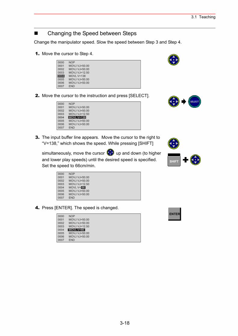
3.1 Teaching
Changing the Speed between StepsChange the manipulator speed. Slow the speed between Step 3 and Step 4.
1. Move the cursor to Step 4.
2. Move the cursor to the instruction and press [SELECT].
3. The input buffer line appears. Move the cursor to the right to “V=138,” which shows the speed. While pressing [SHIFT]
simultaneously, move the cursor up and down (to higher and lower play speeds) until the desired speed is specified.Set the speed to 66cm/min.
4. Press [ENTER]. The speed is changed.
0000 NOP0001 MOVJ VJ=50.000002 MOVJ VJ=50.000003 MOVJ VJ=12.500004 MOVL V=1380005 MOVJ VJ=50.000006 MOVJ VJ=50.000007 END
0000 NOP0001 MOVJ VJ=50.000002 MOVJ VJ=50.000003 MOVJ VJ=12.500004 MOVL V=1380005 MOVJ VJ=50.000006 MOVJ VJ=50.000007 END
SELECT
0000 NOP0001 MOVJ VJ=50.000002 MOVJ VJ=50.000003 MOVJ VJ=12.500004 MOVL V= 660005 MOVJ VJ=50.000006 MOVJ VJ=50.000007 END
SHIFT
0000 NOP0001 MOVJ VJ=50.000002 MOVJ VJ=50.000003 MOVJ VJ=12.500004 MOVL V=660005 MOVJ VJ=50.000006 MOVJ VJ=50.000007 END
ENTER
3-18
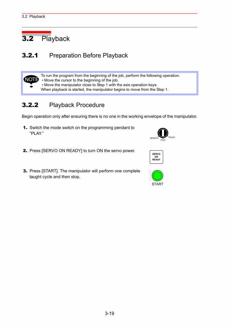
3.2 Playback
3.2 Playback
3.2.1 Preparation Before Playback
3.2.2 Playback Procedure
Begin operation only after ensuring there is no one in the working envelope of the manipulator.
To run the program from the beginning of the job, perform the following operation. • Move the cursor to the beginning of the job. • Move the manipulator close to Step 1 with the axis operation keys.When playback is started, the manipulator begins to move from the Step 1.
1. Switch the mode switch on the programming pendant to “PLAY.”
2. Press [SERVO ON READY] to turn ON the servo power.
3. Press [START]. The manipulator will perform one complete taught cycle and then stop.
NOTE
REMOTE TEACHPLAY
SERVOON
READY
START
3-19
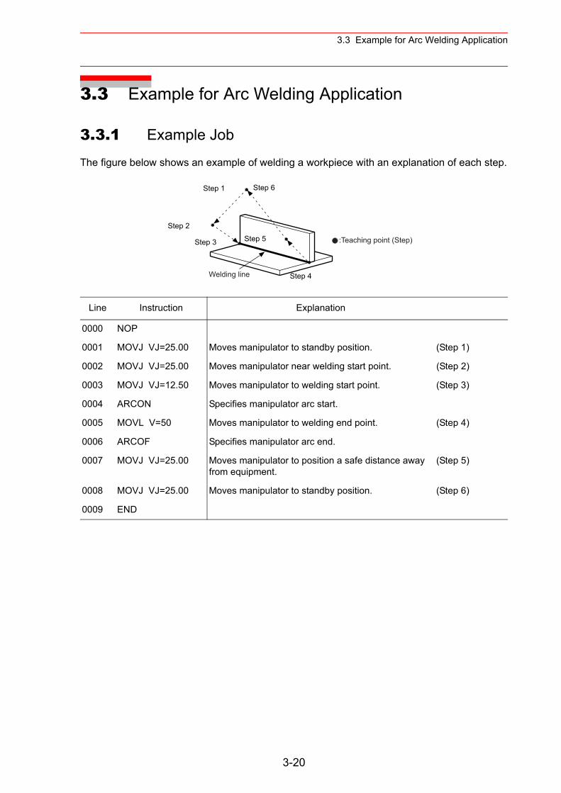
3.3 Example for Arc Welding Application
3.3 Example for Arc Welding Application
3.3.1 Example Job
The figure below shows an example of welding a workpiece with an explanation of each step.
Line Instruction Explanation
0000 NOP
0001 MOVJ VJ=25.00 Moves manipulator to standby position. (Step 1)
0002 MOVJ VJ=25.00 Moves manipulator near welding start point. (Step 2)
0003 MOVJ VJ=12.50 Moves manipulator to welding start point. (Step 3)
0004 ARCON Specifies manipulator arc start.
0005 MOVL V=50 Moves manipulator to welding end point. (Step 4)
0006 ARCOF Specifies manipulator arc end.
0007 MOVJ VJ=25.00 Moves manipulator to position a safe distance away from equipment.
(Step 5)
0008 MOVJ VJ=25.00 Moves manipulator to standby position. (Step 6)
0009 END
Step 1
Step 2
Step 3
Step 4
Step 5
Step 6
Welding line
:Teaching point (Step)
3-20
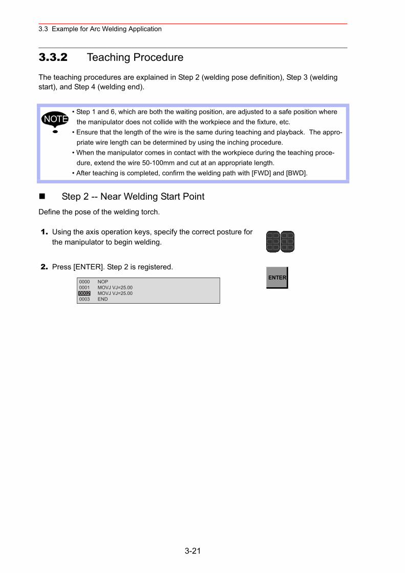
3.3 Example for Arc Welding Application
3.3.2 Teaching Procedure
The teaching procedures are explained in Step 2 (welding pose definition), Step 3 (welding start), and Step 4 (welding end).
Step 2 -- Near Welding Start PointDefine the pose of the welding torch.
• Step 1 and 6, which are both the waiting position, are adjusted to a safe position where the manipulator does not collide with the workpiece and the fixture, etc.
• Ensure that the length of the wire is the same during teaching and playback. The appro-priate wire length can be determined by using the inching procedure.
• When the manipulator comes in contact with the workpiece during the teaching proce-dure, extend the wire 50-100mm and cut at an appropriate length.
• After teaching is completed, confirm the welding path with [FWD] and [BWD].
1. Using the axis operation keys, specify the correct posture for the manipulator to begin welding.
2. Press [ENTER]. Step 2 is registered.
NOTE
0000 NOP0001 MOVJ VJ=25.000002 MOVJ VJ=25.000003 END
ENTER
3-21
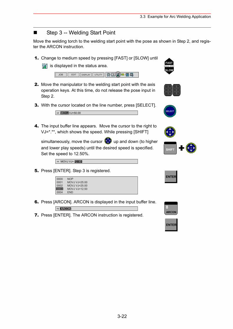
3.3 Example for Arc Welding Application
Step 3 -- Welding Start PointMove the welding torch to the welding start point with the pose as shown in Step 2, and regis-ter the ARCON instruction.
1. Change to medium speed by pressing [FAST] or [SLOW] until
is displayed in the status area.
2. Move the manipulator to the welding start point with the axis operation keys. At this time, do not release the pose input in Step 2.
3. With the cursor located on the line number, press [SELECT].
4. The input buffer line appears. Move the cursor to the right to VJ=*.**, which shows the speed. While pressing [SHIFT]
simultaneously, move the cursor up and down (to higher and lower play speeds) until the desired speed is specified. Set the speed to 12.50%.
5. Press [ENTER]. Step 3 is registered.
6. Press [ARCON]. ARCON is displayed in the input buffer line.
7. Press [ENTER]. The ARCON instruction is registered.
JOB EDIT DISPLAY UTILITY
FASTMANUAL SPEED
SLOW
MOVJ VJ=50.00 SELECT
MOVJ VJ= 12.50
SHIFT
0000 NOP0001 MOVJ VJ=25.000002 MOVJ VJ=25.000003 MOVJ VJ=12.500004 END
ENTER
ARCON 8ARCON
ENTER
3-22
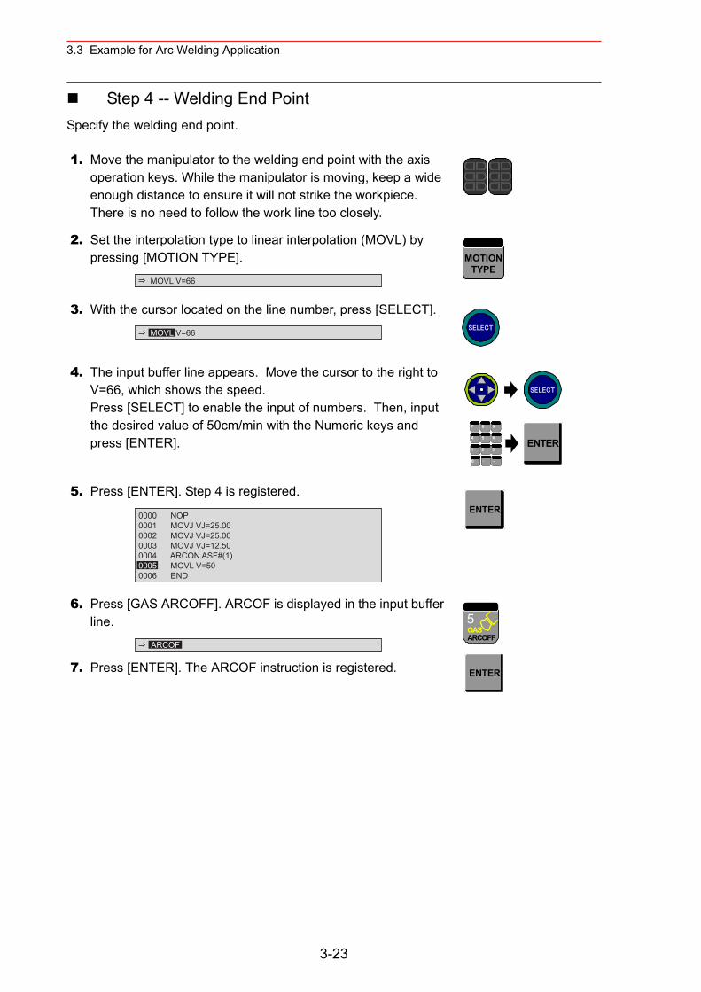
3.3 Example for Arc Welding Application
Step 4 -- Welding End PointSpecify the welding end point.
1. Move the manipulator to the welding end point with the axis operation keys. While the manipulator is moving, keep a wide enough distance to ensure it will not strike the workpiece. There is no need to follow the work line too closely.
2. Set the interpolation type to linear interpolation (MOVL) by pressing [MOTION TYPE].
3. With the cursor located on the line number, press [SELECT].
4. The input buffer line appears. Move the cursor to the right to V=66, which shows the speed.Press [SELECT] to enable the input of numbers. Then, input the desired value of 50cm/min with the Numeric keys and press [ENTER].
5. Press [ENTER]. Step 4 is registered.
6. Press [GAS ARCOFF]. ARCOF is displayed in the input buffer line.
7. Press [ENTER]. The ARCOF instruction is registered.
MOVL V=66
MOTIONTYPE
MOVL V=66 SELECT
SELECT
7 8 9
4 6
1 2 3
・ -0
5ENTER
0000 NOP0001 MOVJ VJ=25.000002 MOVJ VJ=25.000003 MOVJ VJ=12.500004 ARCON ASF#(1)0005 MOVL V=500006 END
ENTER
ARCOF
5GASARCOFF
ENTER
3-23
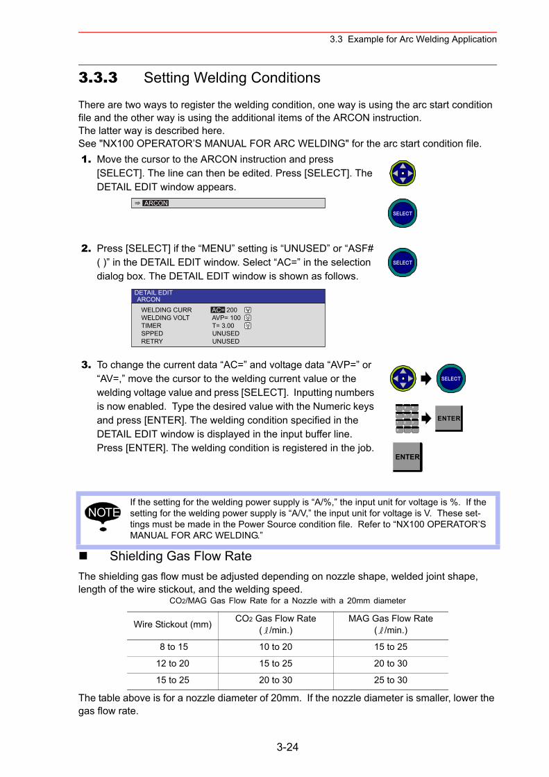
3.3 Example for Arc Welding Application
3.3.3 Setting Welding Conditions
There are two ways to register the welding condition, one way is using the arc start condition file and the other way is using the additional items of the ARCON instruction.The latter way is described here.See "NX100 OPERATOR’S MANUAL FOR ARC WELDING" for the arc start condition file.
Shielding Gas Flow RateThe shielding gas flow must be adjusted depending on nozzle shape, welded joint shape, length of the wire stickout, and the welding speed.
The table above is for a nozzle diameter of 20mm. If the nozzle diameter is smaller, lower the gas flow rate.
1. Move the cursor to the ARCON instruction and press [SELECT]. The line can then be edited. Press [SELECT]. The DETAIL EDIT window appears.
2. Press [SELECT] if the “MENU” setting is “UNUSED” or “ASF# ( )” in the DETAIL EDIT window. Select “AC=” in the selection dialog box. The DETAIL EDIT window is shown as follows.
3. To change the current data “AC=” and voltage data “AVP=” or “AV=,” move the cursor to the welding current value or the welding voltage value and press [SELECT]. Inputting numbers is now enabled. Type the desired value with the Numeric keys and press [ENTER]. The welding condition specified in the DETAIL EDIT window is displayed in the input buffer line. Press [ENTER]. The welding condition is registered in the job.
If the setting for the welding power supply is “A/%,” the input unit for voltage is %. If the setting for the welding power supply is “A/V,” the input unit for voltage is V. These set-tings must be made in the Power Source condition file. Refer to “NX100 OPERATOR’S MANUAL FOR ARC WELDING.”
CO2/MAG Gas Flow Rate for a Nozzle with a 20mm diameter
Wire Stickout (mm) CO2 Gas Flow Rate ( /min.)
MAG Gas Flow Rate ( /min.)
8 to 15 10 to 20 15 to 25
12 to 20 15 to 25 20 to 30
15 to 25 20 to 30 25 to 30
ARCONSELECT
DETAIL EDITARCON
WELDING CURR AC= 200WELDING VOLT AVP= 100TIMER T= 3.00SPPED UNUSEDRETRY UNUSED
SELECT
SELECT
7 8 9
4 6
1 2 3
・ -0
5ENTER
ENTER
NOTE
3-24
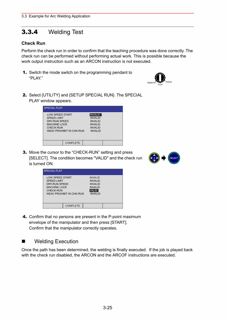
3.3 Example for Arc Welding Application
3.3.4 Welding Test
Check RunPerform the check run in order to confirm that the teaching procedure was done correctly. The check run can be performed without performing actual work. This is possible because the work output instruction such as an ARCON instruction is not executed.
Welding ExecutionOnce the path has been determined, the welding is finally executed. If the job is played back with the check run disabled, the ARCON and the ARCOF instructions are executed.
1. Switch the mode switch on the programming pendant to “PLAY.”
2. Select {UTILITY} and {SETUP SPECIAL RUN}. The SPECIAL PLAY window appears.
3. Move the cursor to the “CHECK-RUN” setting and press [SELECT]. The condition becomes "VALID" and the check run is turned ON.
4. Confirm that no persons are present in the P-point maximum envelope of the manipulator and then press [START].Confirm that the manipulator correctly operates.
REMOTE TEACHPLAY
SPECIAL PLAY
LOW SPEED START INVALIDSPEED LIMIT INVALIDDRY-RUN SPEED INVALIDMACHINE LOCK INVALIDCHECK-RUN INVALIDWEAV PROHIBIT IN CHK-RUN INVALID
COMPLETE
SPECIAL PLAY
LOW SPEED START INVALIDSPEED LIMIT INVALIDDRY-RUN SPEED INVALIDMACHINE LOCK INVALIDCHECK-RUN VALIDWEAV PROHIBIT IN CHK-RUN INVALID
COMPLETE
SELECT
3-25

3.3 Example for Arc Welding Application
Adjustments for Welding DefectsTo adjust welding conditions after welding, check the appearance of the welding bead.
Welding Defect Cause Correction Method
Pore:Generic name of defect caused by the influence of H2, N2, CO2, and Ar. Pits and blowholes, etc. may exist.
Shortage of shielding gas flow rate
• With no influence from the wind, and when the torch angle and wire stick-out are correct, 15 to 30 /min is assumed to be the suitable shielding gas rate.
• Change the gas flow rate according to the workpiece construction condi-tion.
Spatter adheres to nozzle • Remove the spatter frequently and thoroughly.
• Choose the best welding condition to prevent frequent spattering.
• Adjusting the torch angle and nozzle height will also reduce the amount of spatter.
Influence of wind • Close the shutter, door, and window.• Avoid using a fan during welding.• Use a screen.
Adhesion of rust and oil to surface
Remove rust and oil with thinner, brush, and grinder, etc.
Paint adhesion Remove paint using thinner.
Welding current, voltage, and welding speed are incorrect.
• Reset the voltage within the voltage range.
• Adjust the voltage in accordance with the arc length.
Torch angle and wire stick-out are incorrect.
• Make the torch angle smaller.• Set the wire stickout in accordance
with the welding condition.
Undercut:Defect name for when the groove is made and not completely filled along the toe of the weld.
Excessive welding current Lower the welding current.
Incorrect welding voltage Adjust the voltage.
Excessive welding speed Lower the welding speed.
Unsuitable torch angle and aim position
Adjust the torch angle and aim posi-tion.
Pit Blowhole
Undercut
3-26
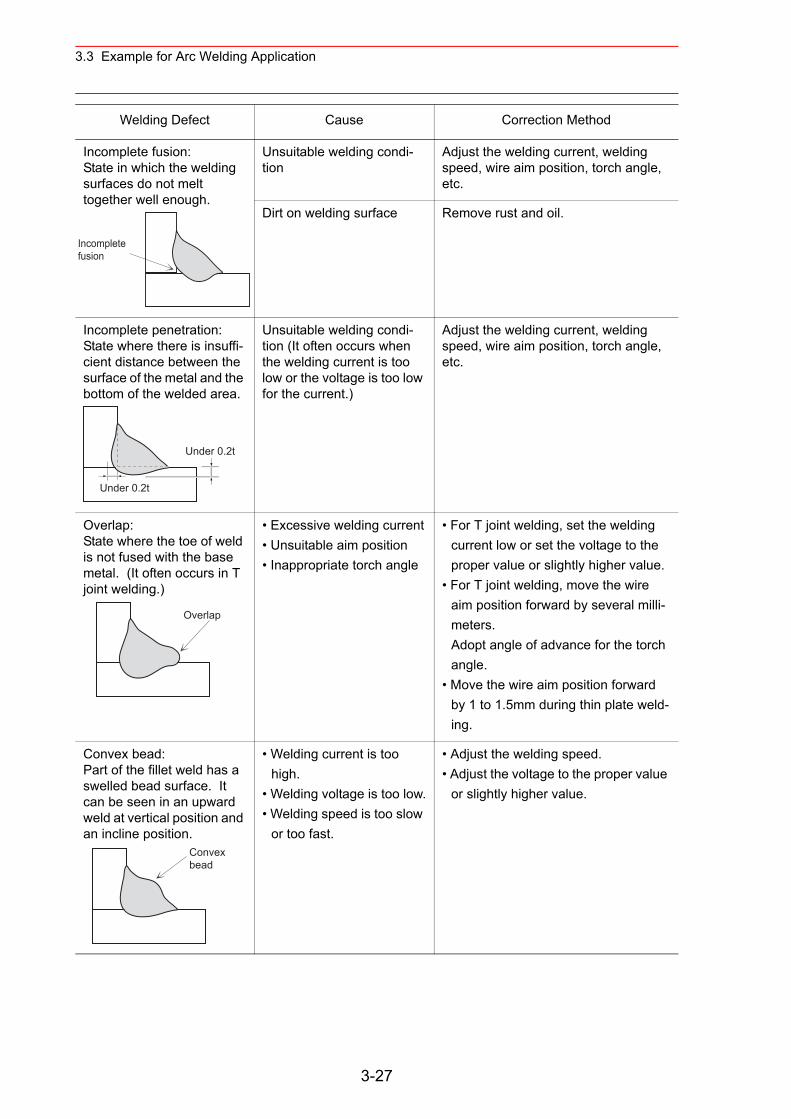
3.3 Example for Arc Welding Application
Incomplete fusion:State in which the welding surfaces do not melt together well enough.
Unsuitable welding condi-tion
Adjust the welding current, welding speed, wire aim position, torch angle, etc.
Dirt on welding surface Remove rust and oil.
Incomplete penetration:State where there is insuffi-cient distance between the surface of the metal and the bottom of the welded area.
Unsuitable welding condi-tion (It often occurs when the welding current is too low or the voltage is too low for the current.)
Adjust the welding current, welding speed, wire aim position, torch angle, etc.
Overlap:State where the toe of weld is not fused with the base metal. (It often occurs in T joint welding.)
• Excessive welding current• Unsuitable aim position• Inappropriate torch angle
• For T joint welding, set the welding current low or set the voltage to the proper value or slightly higher value.
• For T joint welding, move the wire aim position forward by several milli-meters.Adopt angle of advance for the torch angle.
• Move the wire aim position forward by 1 to 1.5mm during thin plate weld-ing.
Convex bead:Part of the fillet weld has a swelled bead surface. It can be seen in an upward weld at vertical position and an incline position.
• Welding current is too high.
• Welding voltage is too low.• Welding speed is too slow
or too fast.
• Adjust the welding speed.• Adjust the voltage to the proper value
or slightly higher value.
Welding Defect Cause Correction Method
Incompletefusion
Under 0.2t
Under 0.2t
Overlap
Convexbead
3-27
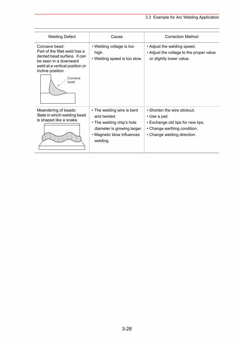
3.3 Example for Arc Welding Application
Concave bead:Part of the fillet weld has a dented bead surface. It can be seen in a downward weld at a vertical position or incline position
• Welding voltage is too high.
• Welding speed is too slow.
• Adjust the welding speed.• Adjust the voltage to the proper value
or slightly lower value.
Meandering of beads:State in which welding bead is shaped like a snake.
• The welding wire is bent and twisted.
• The welding chip’s hole diameter is growing larger.
• Magnetic blow influences welding.
• Shorten the wire stickout.• Use a pail.• Exchange old tips for new tips.• Change earthing condition.• Change welding direction.
Welding Defect Cause Correction Method
Concavebead
3-28
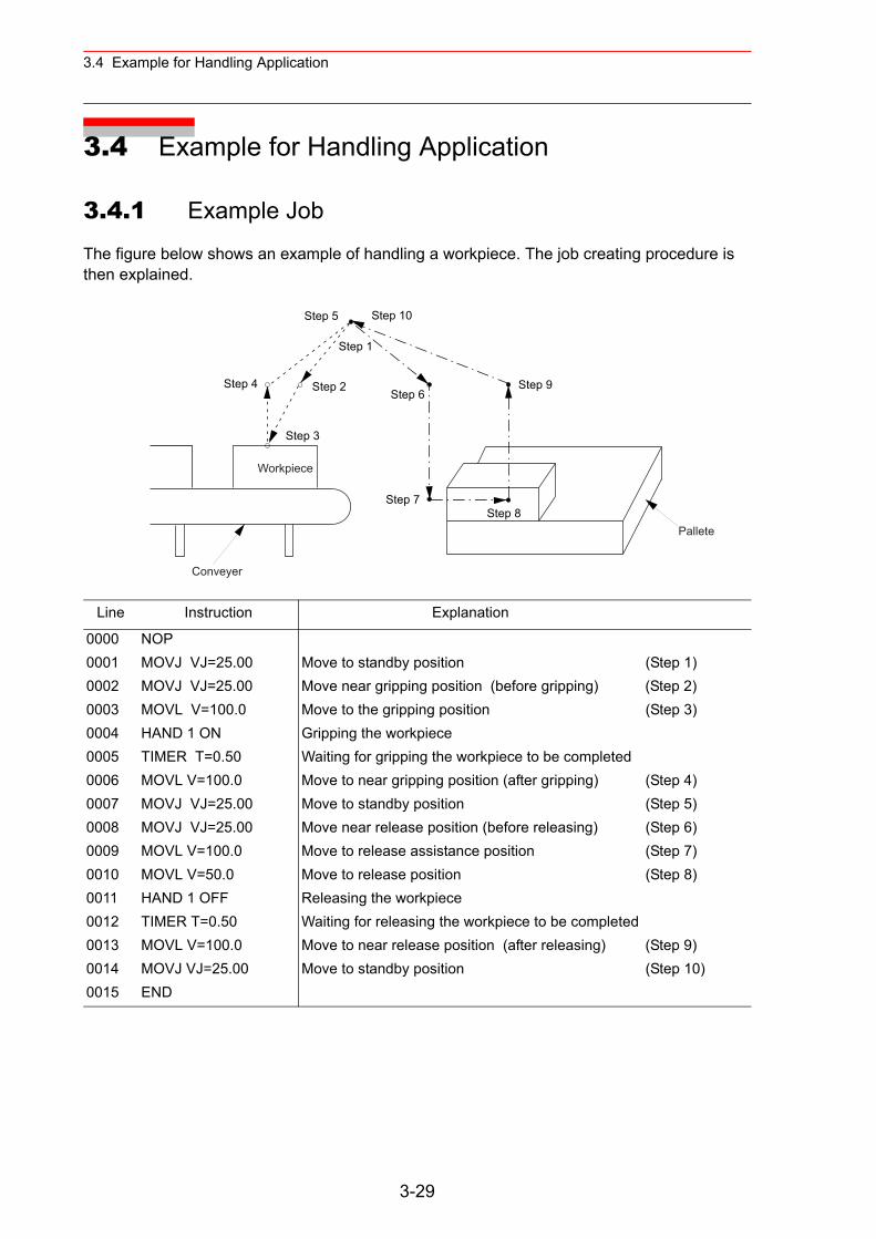
3.4 Example for Handling Application
3.4 Example for Handling Application
3.4.1 Example Job
The figure below shows an example of handling a workpiece. The job creating procedure is then explained.
Line Instruction Explanation
0000 NOP0001 MOVJ VJ=25.00 Move to standby position (Step 1)0002 MOVJ VJ=25.00 Move near gripping position (before gripping) (Step 2)0003 MOVL V=100.0 Move to the gripping position (Step 3)0004 HAND 1 ON Gripping the workpiece0005 TIMER T=0.50 Waiting for gripping the workpiece to be completed0006 MOVL V=100.0 Move to near gripping position (after gripping) (Step 4)0007 MOVJ VJ=25.00 Move to standby position (Step 5)0008 MOVJ VJ=25.00 Move near release position (before releasing) (Step 6)0009 MOVL V=100.0 Move to release assistance position (Step 7)0010 MOVL V=50.0 Move to release position (Step 8)0011 HAND 1 OFF Releasing the workpiece0012 TIMER T=0.50 Waiting for releasing the workpiece to be completed0013 MOVL V=100.0 Move to near release position (after releasing) (Step 9)0014 MOVJ VJ=25.00 Move to standby position (Step 10)0015 END
Step 1
Step 5 Step 10
Step 4 Step 2 Step 6
Step 3
Step 7Step 8
Step 9
Workpiece
Conveyer
Pallete
3-29
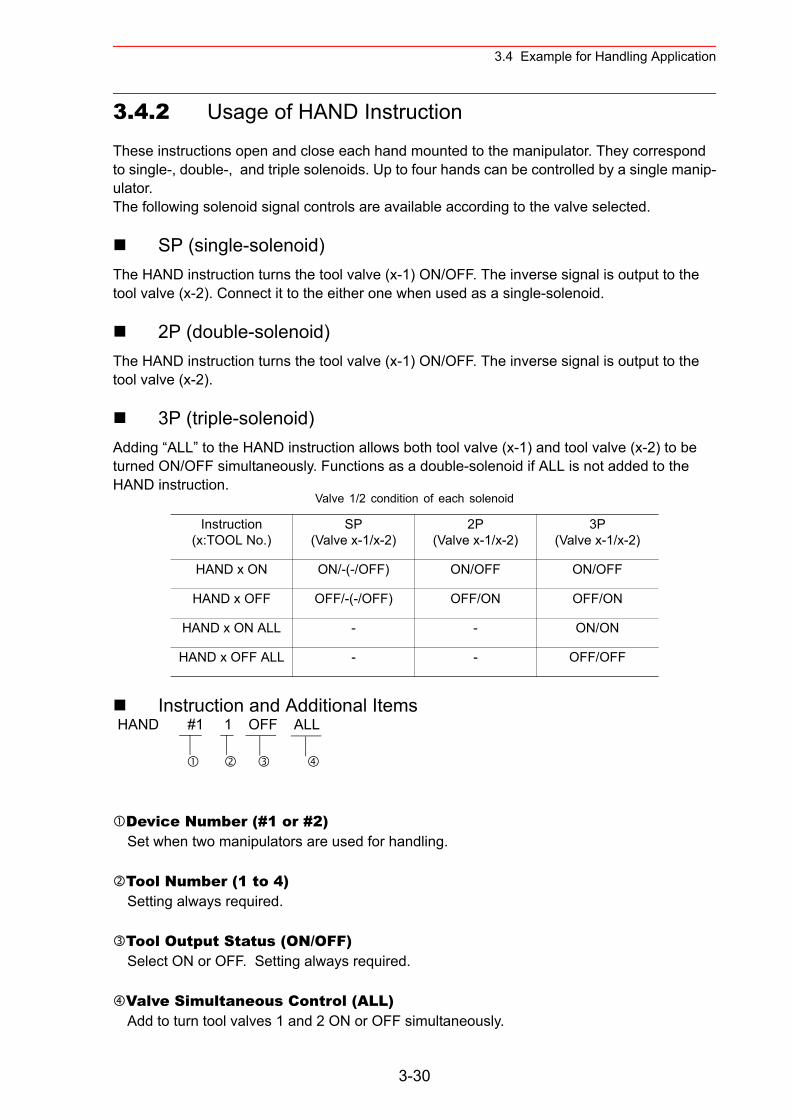
3.4 Example for Handling Application
3.4.2 Usage of HAND Instruction
These instructions open and close each hand mounted to the manipulator. They correspond to single-, double-, and triple solenoids. Up to four hands can be controlled by a single manip-ulator.The following solenoid signal controls are available according to the valve selected.
SP (single-solenoid)The HAND instruction turns the tool valve (x-1) ON/OFF. The inverse signal is output to the tool valve (x-2). Connect it to the either one when used as a single-solenoid.
2P (double-solenoid)The HAND instruction turns the tool valve (x-1) ON/OFF. The inverse signal is output to the tool valve (x-2).
3P (triple-solenoid)Adding “ALL” to the HAND instruction allows both tool valve (x-1) and tool valve (x-2) to be turned ON/OFF simultaneously. Functions as a double-solenoid if ALL is not added to the HAND instruction.
Instruction and Additional Items
Device Number (#1 or #2)Set when two manipulators are used for handling.
Tool Number (1 to 4)Setting always required.
Tool Output Status (ON/OFF)Select ON or OFF. Setting always required.
Valve Simultaneous Control (ALL)Add to turn tool valves 1 and 2 ON or OFF simultaneously.
Valve 1/2 condition of each solenoid
Instruction(x:TOOL No.)
SP(Valve x-1/x-2)
2P(Valve x-1/x-2)
3P(Valve x-1/x-2)
HAND x ON ON/-(-/OFF) ON/OFF ON/OFF
HAND x OFF OFF/-(-/OFF) OFF/ON OFF/ON
HAND x ON ALL - - ON/ON
HAND x OFF ALL - - OFF/OFF
HAND #1 1 OFF ALL
3-30
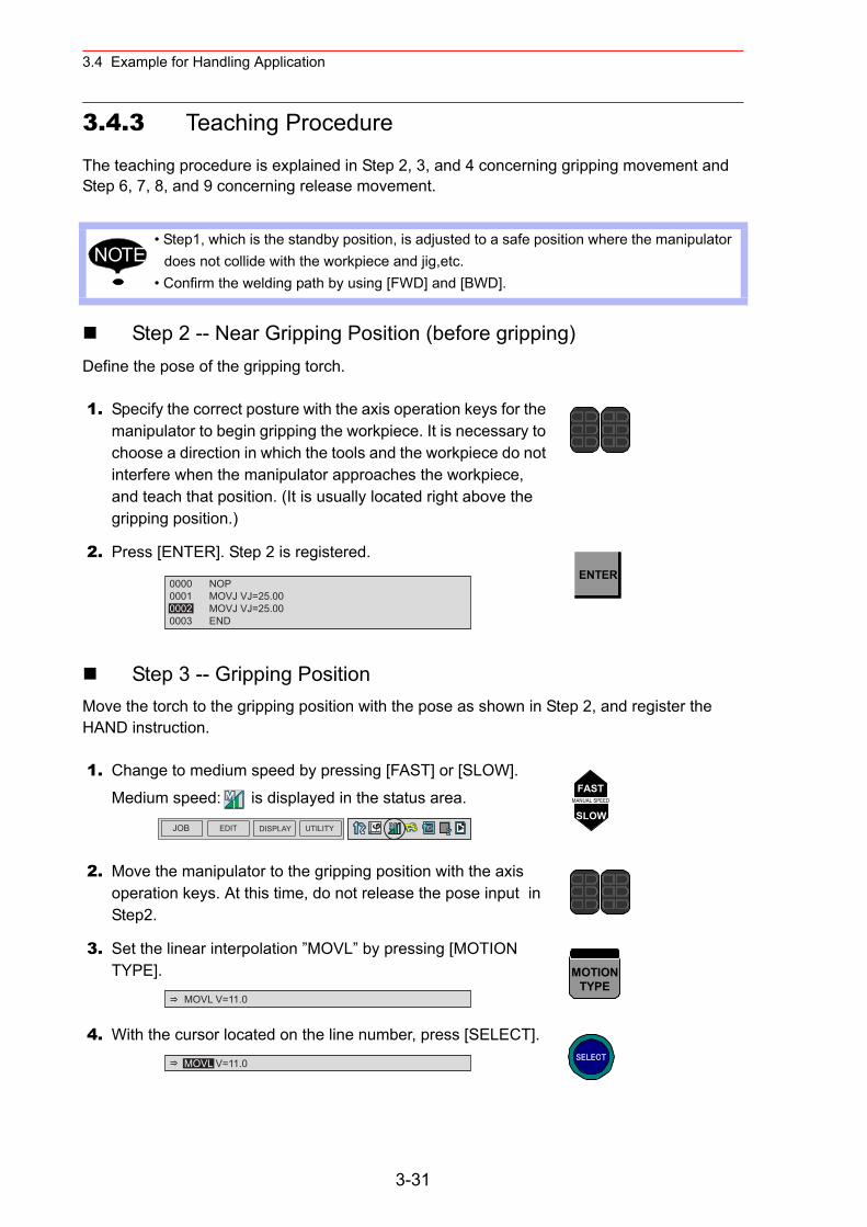
3.4 Example for Handling Application
3.4.3 Teaching Procedure
The teaching procedure is explained in Step 2, 3, and 4 concerning gripping movement and Step 6, 7, 8, and 9 concerning release movement.
Step 2 -- Near Gripping Position (before gripping)Define the pose of the gripping torch.
Step 3 -- Gripping PositionMove the torch to the gripping position with the pose as shown in Step 2, and register the HAND instruction.
• Step1, which is the standby position, is adjusted to a safe position where the manipulator does not collide with the workpiece and jig,etc.
• Confirm the welding path by using [FWD] and [BWD].
1. Specify the correct posture with the axis operation keys for the manipulator to begin gripping the workpiece. It is necessary to choose a direction in which the tools and the workpiece do not interfere when the manipulator approaches the workpiece, and teach that position. (It is usually located right above the gripping position.)
2. Press [ENTER]. Step 2 is registered.
1. Change to medium speed by pressing [FAST] or [SLOW].
Medium speed: is displayed in the status area.
2. Move the manipulator to the gripping position with the axis operation keys. At this time, do not release the pose input in Step2.
3. Set the linear interpolation ”MOVL” by pressing [MOTION TYPE].
4. With the cursor located on the line number, press [SELECT].
NOTE
0000 NOP0001 MOVJ VJ=25.000002 MOVJ VJ=25.000003 END
ENTER
JOB EDIT DISPLAY UTILITY
FASTMANUAL SPEED
SLOW
MOVL V=11.0
MOTIONTYPE
MOVL V=11.0 SELECT
3-31
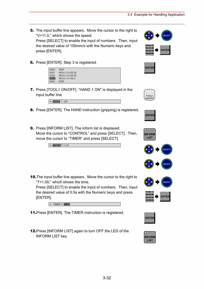
3.4 Example for Handling Application
5. The input buffer line appears. Move the cursor to the right to “V=11.0,” which shows the speed.Press [SELECT] to enable the input of numbers. Then, input the desired value of 100mm/s with the Numeric keys and press [ENTER].
6. Press [ENTER]. Step 3 is registered.
7. Press [TOOL1 ON/OFF]. “HAND 1 ON" is displayed in the input buffer line.
8. Press [ENTER]. The HAND instruction (gripping) is registered.
9. Press [INFORM LIST]. The inform list is displayed.Move the cursor to “CONTROL“ and press [SELECT]. Then, move the cursor to “TIMER” and press [SELECT].
10.The input buffer line appears. Move the cursor to the right to “T=1.00,” which shows the time.Press [SELECT] to enable the input of numbers. Then, input the desired value of 0.5s with the Numeric keys and press [ENTER].
11.Press [ENTER]. The TIMER instruction is registered.
12.Press [INFORM LIST] again to turn OFF the LED of the INFORM LIST key.
SELECT
7 8 9
4 6
1 2 3
・ -0
5ENTER
0000 NOP0001 MOVJ VJ=25.000002 MOVJ VJ=25.000003 MOVL V=100.00004 END
ENTER
HAND 1 ON
.TOOL1
ON/OFF
ENTER
TIMER T=1.00
INFORMLIST
SELECT
SELECT
TIMER T= 0.50
SELECT
7 8 9
4 6
1 2 3
・ -0
5ENTER
ENTER
INFORMLIST
3-32
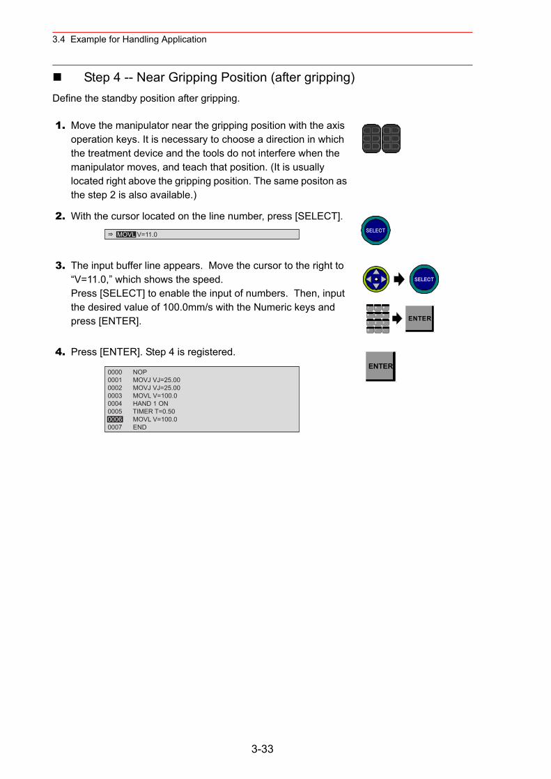
3.4 Example for Handling Application
Step 4 -- Near Gripping Position (after gripping)Define the standby position after gripping.
1. Move the manipulator near the gripping position with the axis operation keys. It is necessary to choose a direction in which the treatment device and the tools do not interfere when the manipulator moves, and teach that position. (It is usually located right above the gripping position. The same positon as the step 2 is also available.)
2. With the cursor located on the line number, press [SELECT].
3. The input buffer line appears. Move the cursor to the right to “V=11.0,” which shows the speed.Press [SELECT] to enable the input of numbers. Then, input the desired value of 100.0mm/s with the Numeric keys and press [ENTER].
4. Press [ENTER]. Step 4 is registered.
MOVL V=11.0 SELECT
SELECT
7 8 9
4 6
1 2 3
・ -0
5ENTER
0000 NOP0001 MOVJ VJ=25.000002 MOVJ VJ=25.000003 MOVL V=100.00004 HAND 1 ON0005 TIMER T=0.500006 MOVL V=100.00007 END
ENTER
3-33
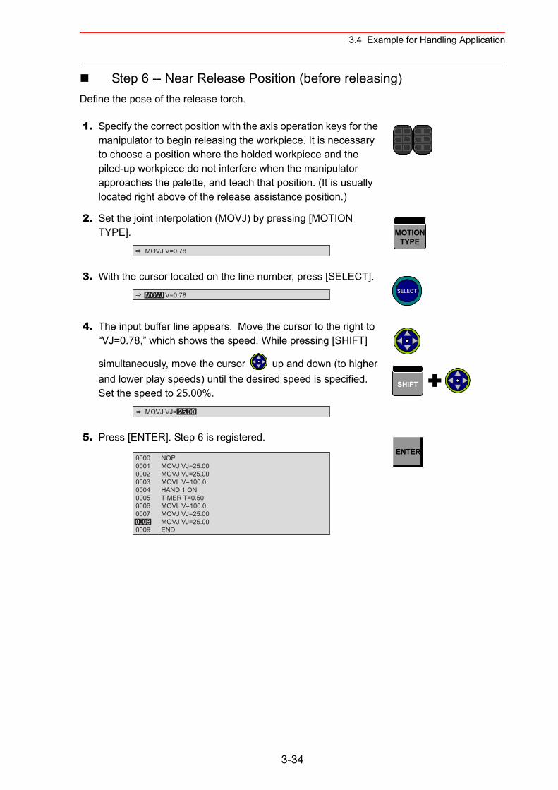
3.4 Example for Handling Application
Step 6 -- Near Release Position (before releasing)Define the pose of the release torch.
1. Specify the correct position with the axis operation keys for the manipulator to begin releasing the workpiece. It is necessary to choose a position where the holded workpiece and the piled-up workpiece do not interfere when the manipulator approaches the palette, and teach that position. (It is usually located right above of the release assistance position.)
2. Set the joint interpolation (MOVJ) by pressing [MOTION TYPE].
3. With the cursor located on the line number, press [SELECT].
4. The input buffer line appears. Move the cursor to the right to “VJ=0.78,” which shows the speed. While pressing [SHIFT]
simultaneously, move the cursor up and down (to higher and lower play speeds) until the desired speed is specified. Set the speed to 25.00%.
5. Press [ENTER]. Step 6 is registered.
MOVJ V=0.78
MOTIONTYPE
MOVJ V=0.78 SELECT
MOVJ VJ= 25.00
SHIFT
0000 NOP0001 MOVJ VJ=25.000002 MOVJ VJ=25.000003 MOVL V=100.00004 HAND 1 ON0005 TIMER T=0.500006 MOVL V=100.00007 MOVJ VJ=25.000008 MOVJ VJ=25.000009 END
ENTER
3-34
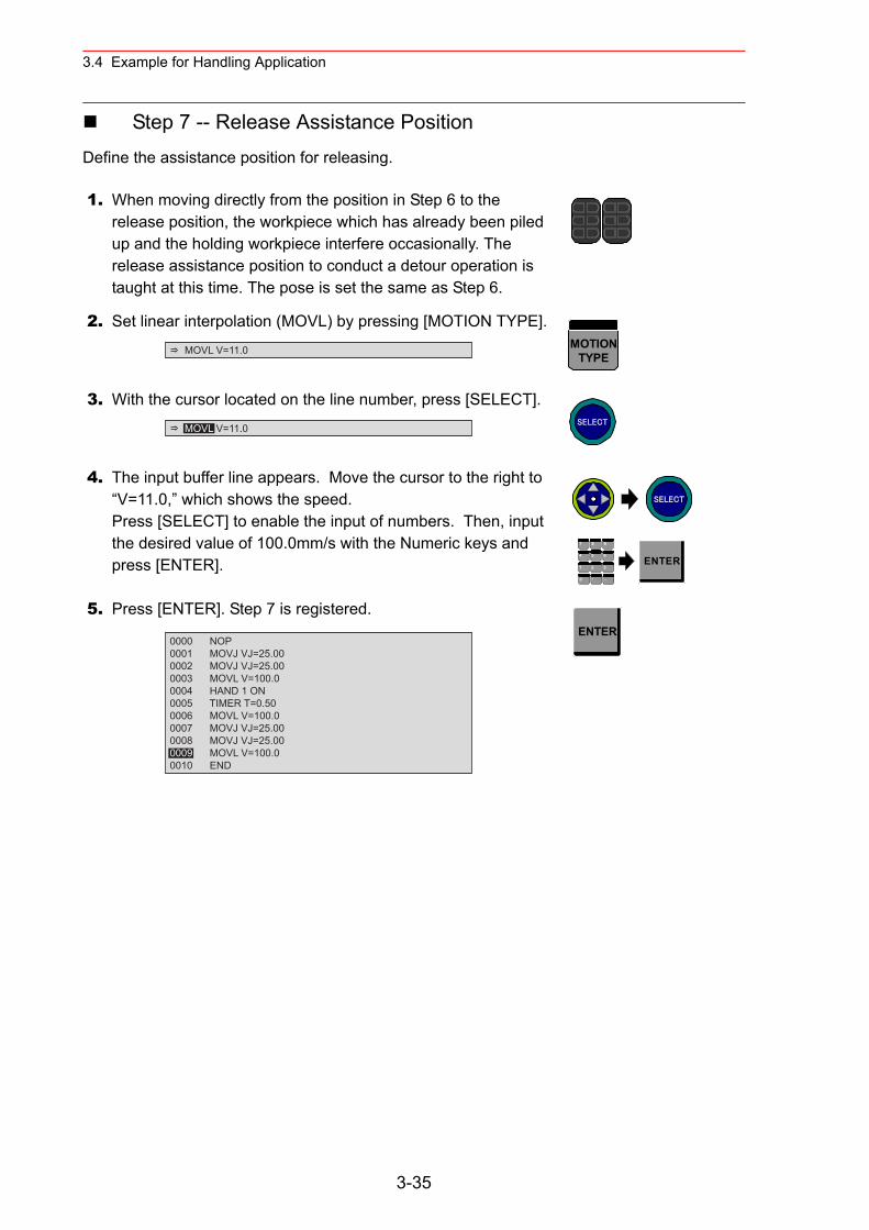
3.4 Example for Handling Application
Step 7 -- Release Assistance PositionDefine the assistance position for releasing.
1. When moving directly from the position in Step 6 to the release position, the workpiece which has already been piled up and the holding workpiece interfere occasionally. The release assistance position to conduct a detour operation is taught at this time. The pose is set the same as Step 6.
2. Set linear interpolation (MOVL) by pressing [MOTION TYPE].
3. With the cursor located on the line number, press [SELECT].
4. The input buffer line appears. Move the cursor to the right to “V=11.0,” which shows the speed.Press [SELECT] to enable the input of numbers. Then, input the desired value of 100.0mm/s with the Numeric keys and press [ENTER].
5. Press [ENTER]. Step 7 is registered.
MOVL V=11.0 MOTIONTYPE
MOVL V=11.0 SELECT
SELECT
7 8 9
4 6
1 2 3
・ -0
5ENTER
0000 NOP0001 MOVJ VJ=25.000002 MOVJ VJ=25.000003 MOVL V=100.00004 HAND 1 ON0005 TIMER T=0.500006 MOVL V=100.00007 MOVJ VJ=25.000008 MOVJ VJ=25.000009 MOVL V=100.00010 END
ENTER
3-35
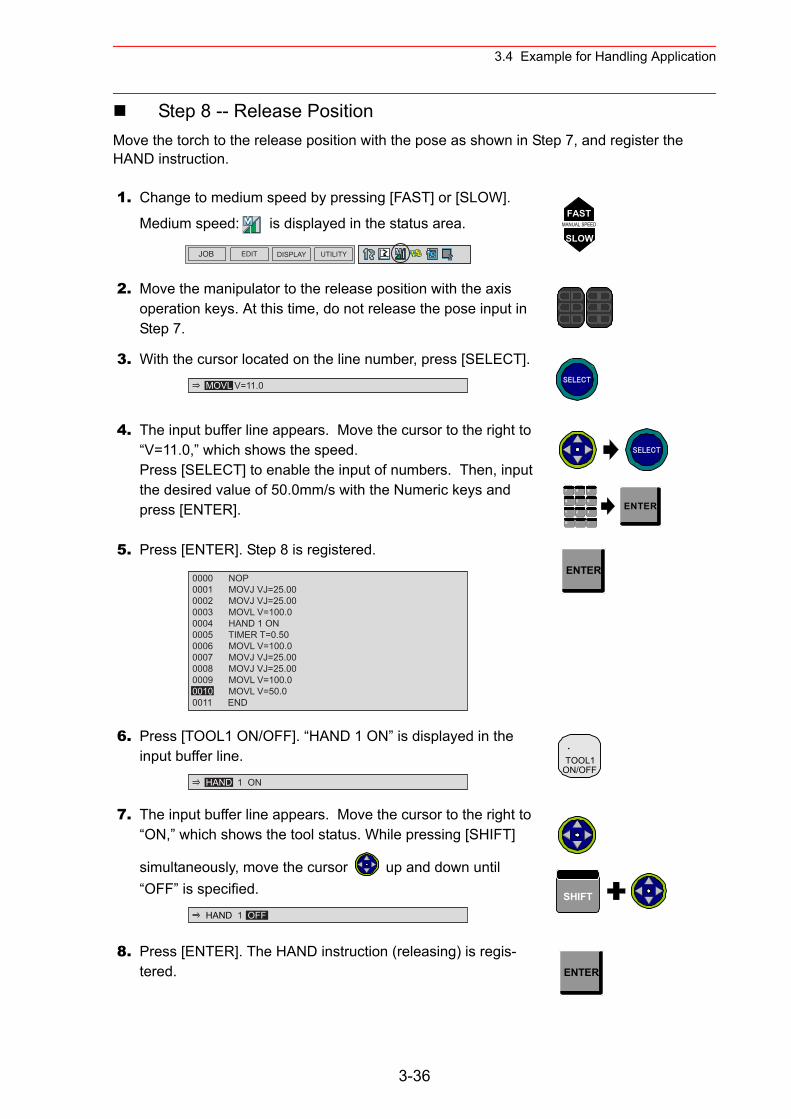
3.4 Example for Handling Application
Step 8 -- Release PositionMove the torch to the release position with the pose as shown in Step 7, and register the HAND instruction.
1. Change to medium speed by pressing [FAST] or [SLOW].
Medium speed: is displayed in the status area.
2. Move the manipulator to the release position with the axis operation keys. At this time, do not release the pose input in Step 7.
3. With the cursor located on the line number, press [SELECT].
4. The input buffer line appears. Move the cursor to the right to “V=11.0,” which shows the speed.Press [SELECT] to enable the input of numbers. Then, input the desired value of 50.0mm/s with the Numeric keys and press [ENTER].
5. Press [ENTER]. Step 8 is registered.
6. Press [TOOL1 ON/OFF]. “HAND 1 ON” is displayed in the input buffer line.
7. The input buffer line appears. Move the cursor to the right to “ON,” which shows the tool status. While pressing [SHIFT]
simultaneously, move the cursor up and down until “OFF” is specified.
8. Press [ENTER]. The HAND instruction (releasing) is regis-tered.
JOB EDIT DISPLAY UTILITY
FASTMANUAL SPEED
SLOW
MOVL V=11.0 SELECT
SELECT
7 8 9
4 6
1 2 3
・ -0
5ENTER
0000 NOP0001 MOVJ VJ=25.000002 MOVJ VJ=25.000003 MOVL V=100.00004 HAND 1 ON0005 TIMER T=0.500006 MOVL V=100.00007 MOVJ VJ=25.000008 MOVJ VJ=25.000009 MOVL V=100.00010 MOVL V=50.00011 END
ENTER
HAND 1 ON
.TOOL1
ON/OFF
HAND 1 OFF
SHIFT
ENTER
3-36
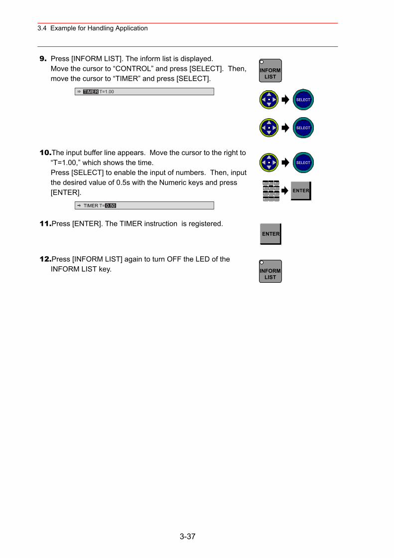
3.4 Example for Handling Application
9. Press [INFORM LIST]. The inform list is displayed.Move the cursor to “CONTROL” and press [SELECT]. Then, move the cursor to “TIMER” and press [SELECT].
10.The input buffer line appears. Move the cursor to the right to “T=1.00,” which shows the time.Press [SELECT] to enable the input of numbers. Then, input the desired value of 0.5s with the Numeric keys and press [ENTER].
11.Press [ENTER]. The TIMER instruction is registered.
12.Press [INFORM LIST] again to turn OFF the LED of the INFORM LIST key.
TIMER T=1.00
INFORMLIST
SELECT
SELECT
TIMER T= 0.50
SELECT
7 8 9
4 6
1 2 3
・ -0
5ENTER
ENTER
INFORMLIST
3-37
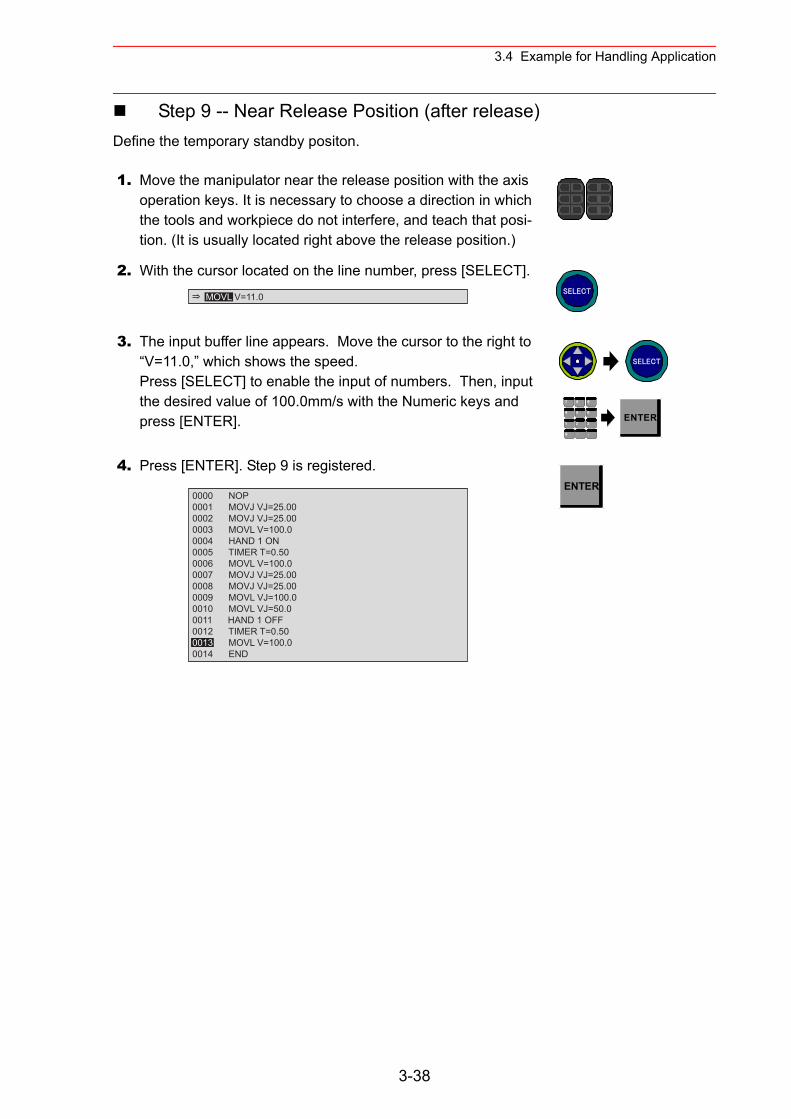
3.4 Example for Handling Application
Step 9 -- Near Release Position (after release)Define the temporary standby positon.
1. Move the manipulator near the release position with the axis operation keys. It is necessary to choose a direction in which the tools and workpiece do not interfere, and teach that posi-tion. (It is usually located right above the release position.)
2. With the cursor located on the line number, press [SELECT].
3. The input buffer line appears. Move the cursor to the right to “V=11.0,” which shows the speed.Press [SELECT] to enable the input of numbers. Then, input the desired value of 100.0mm/s with the Numeric keys and press [ENTER].
4. Press [ENTER]. Step 9 is registered.
MOVL V=11.0 SELECT
SELECT
7 8 9
4 6
1 2 3
・ -0
5ENTER
0000 NOP0001 MOVJ VJ=25.000002 MOVJ VJ=25.000003 MOVL V=100.00004 HAND 1 ON0005 TIMER T=0.500006 MOVL V=100.00007 MOVJ VJ=25.000008 MOVJ VJ=25.000009 MOVL VJ=100.00010 MOVL VJ=50.00011 HAND 1 OFF0012 TIMER T=0.50 0013 MOVL V=100.00014 END
ENTER
3-38
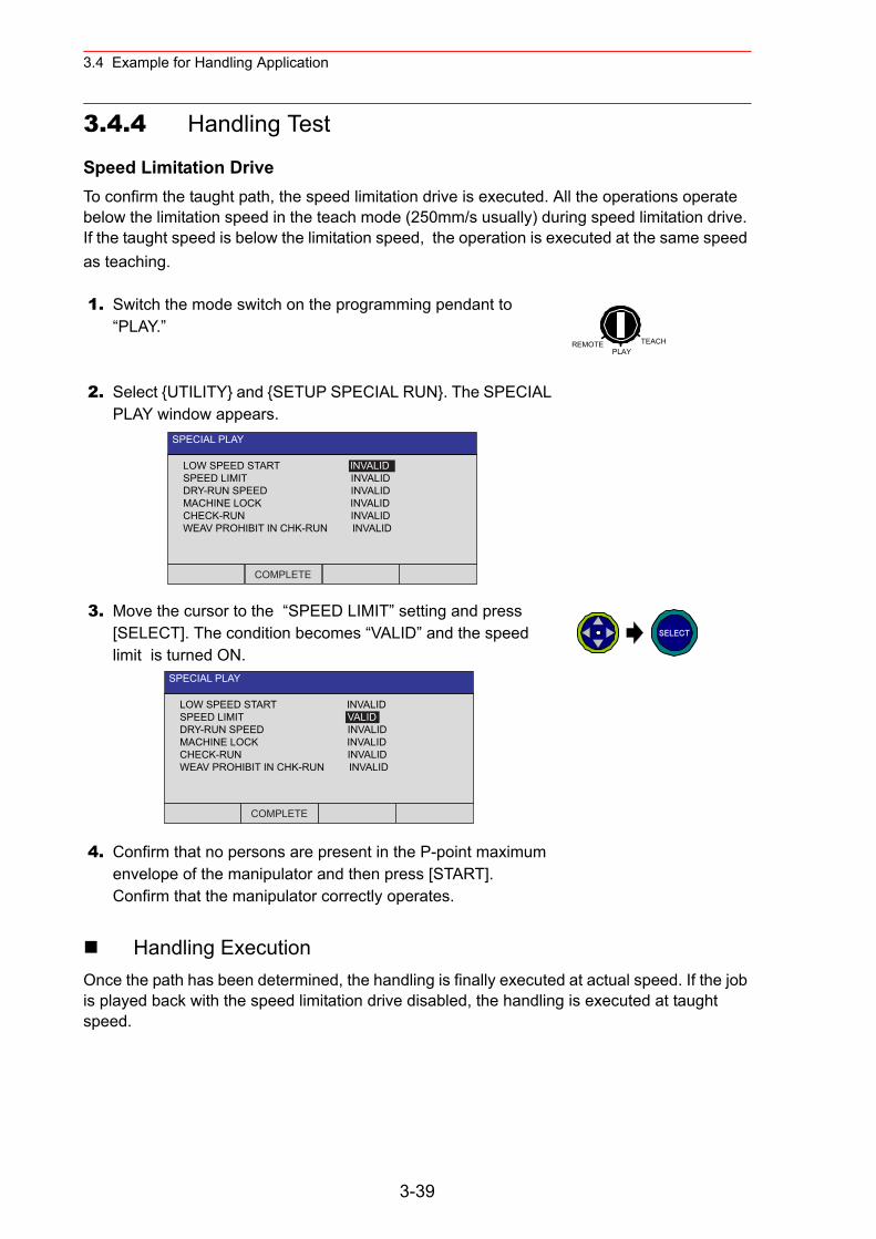
3.4 Example for Handling Application
3.4.4 Handling Test
Speed Limitation DriveTo confirm the taught path, the speed limitation drive is executed. All the operations operate below the limitation speed in the teach mode (250mm/s usually) during speed limitation drive. If the taught speed is below the limitation speed, the operation is executed at the same speed as teaching.
Handling ExecutionOnce the path has been determined, the handling is finally executed at actual speed. If the job is played back with the speed limitation drive disabled, the handling is executed at taught speed.
1. Switch the mode switch on the programming pendant to “PLAY.”
2. Select {UTILITY} and {SETUP SPECIAL RUN}. The SPECIAL PLAY window appears.
3. Move the cursor to the “SPEED LIMIT” setting and press [SELECT]. The condition becomes “VALID” and the speed limit is turned ON.
4. Confirm that no persons are present in the P-point maximum envelope of the manipulator and then press [START].Confirm that the manipulator correctly operates.
REMOTE TEACHPLAY
SPECIAL PLAY
LOW SPEED START INVALIDSPEED LIMIT INVALIDDRY-RUN SPEED INVALIDMACHINE LOCK INVALIDCHECK-RUN INVALIDWEAV PROHIBIT IN CHK-RUN INVALID
COMPLETE
SPECIAL PLAY
LOW SPEED START INVALIDSPEED LIMIT VALIDDRY-RUN SPEED INVALIDMACHINE LOCK INVALIDCHECK-RUN INVALIDWEAV PROHIBIT IN CHK-RUN INVALID
COMPLETE
SELECT
3-39
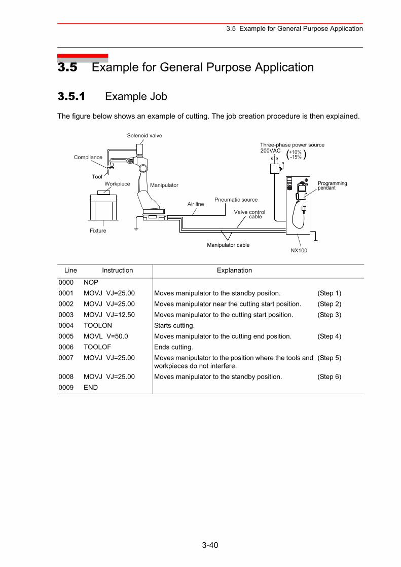
3.5 Example for General Purpose Application
3.5 Example for General Purpose Application
3.5.1 Example Job
The figure below shows an example of cutting. The job creation procedure is then explained.
Line Instruction Explanation
0000 NOP0001 MOVJ VJ=25.00 Moves manipulator to the standby positon. (Step 1)0002 MOVJ VJ=25.00 Moves manipulator near the cutting start position. (Step 2)0003 MOVJ VJ=12.50 Moves manipulator to the cutting start position. (Step 3)0004 TOOLON Starts cutting.0005 MOVL V=50.0 Moves manipulator to the cutting end position. (Step 4)0006 TOOLOF Ends cutting.0007 MOVJ VJ=25.00 Moves manipulator to the position where the tools and
workpieces do not interfere.(Step 5)
0008 MOVJ VJ=25.00 Moves manipulator to the standby position. (Step 6)0009 END
Three-phase power source 200VAC
Programmingpendant
Manipulator cable
Tool
Solenoid valve
( )
NX100
Pneumatic source
Manipulator
Air lineValve control cable
Fixture
Workpiece
Compliance+10% -15%
3-40
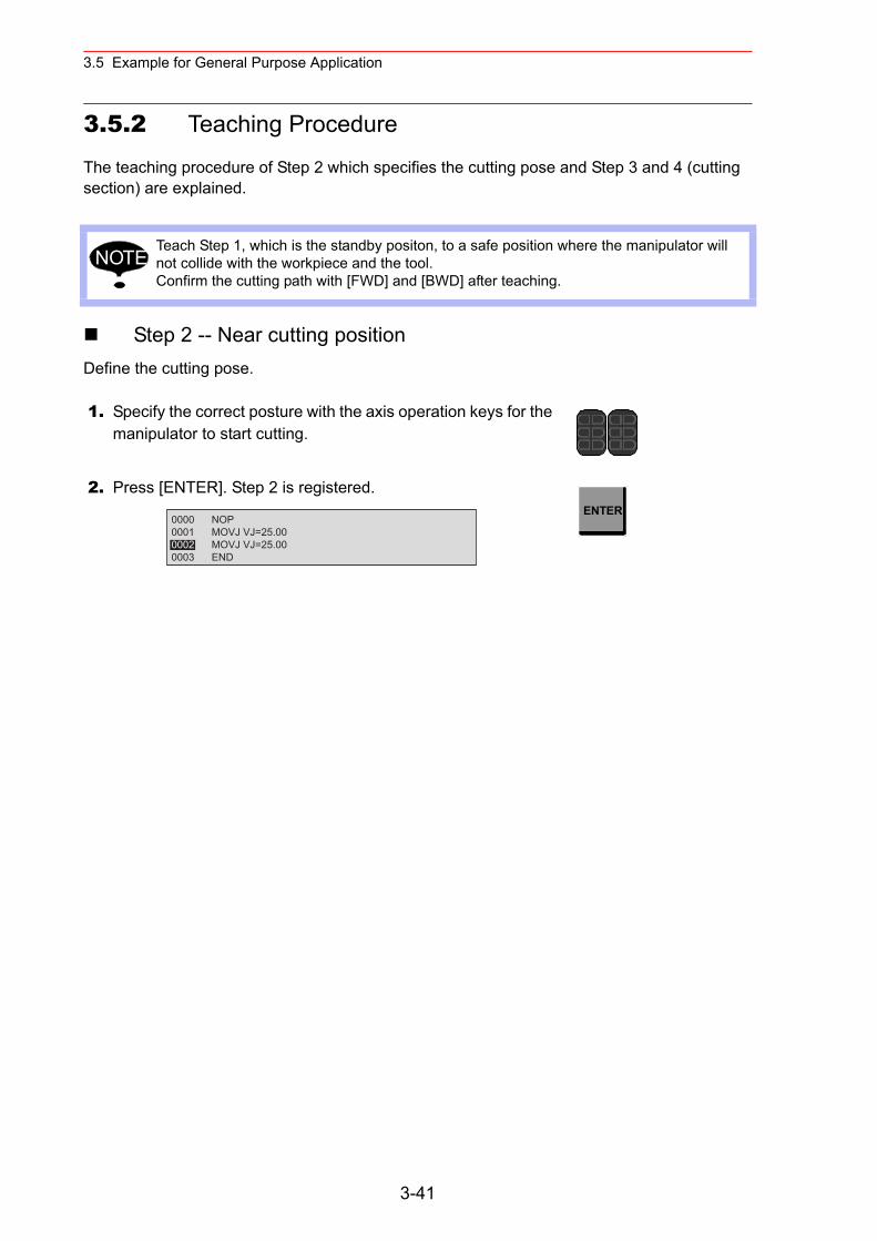
3.5 Example for General Purpose Application
3.5.2 Teaching Procedure
The teaching procedure of Step 2 which specifies the cutting pose and Step 3 and 4 (cutting section) are explained.
Step 2 -- Near cutting positionDefine the cutting pose.
Teach Step 1, which is the standby positon, to a safe position where the manipulator will not collide with the workpiece and the tool.Confirm the cutting path with [FWD] and [BWD] after teaching.
1. Specify the correct posture with the axis operation keys for the manipulator to start cutting.
2. Press [ENTER]. Step 2 is registered.
NOTE
0000 NOP0001 MOVJ VJ=25.000002 MOVJ VJ=25.000003 END
ENTER
3-41
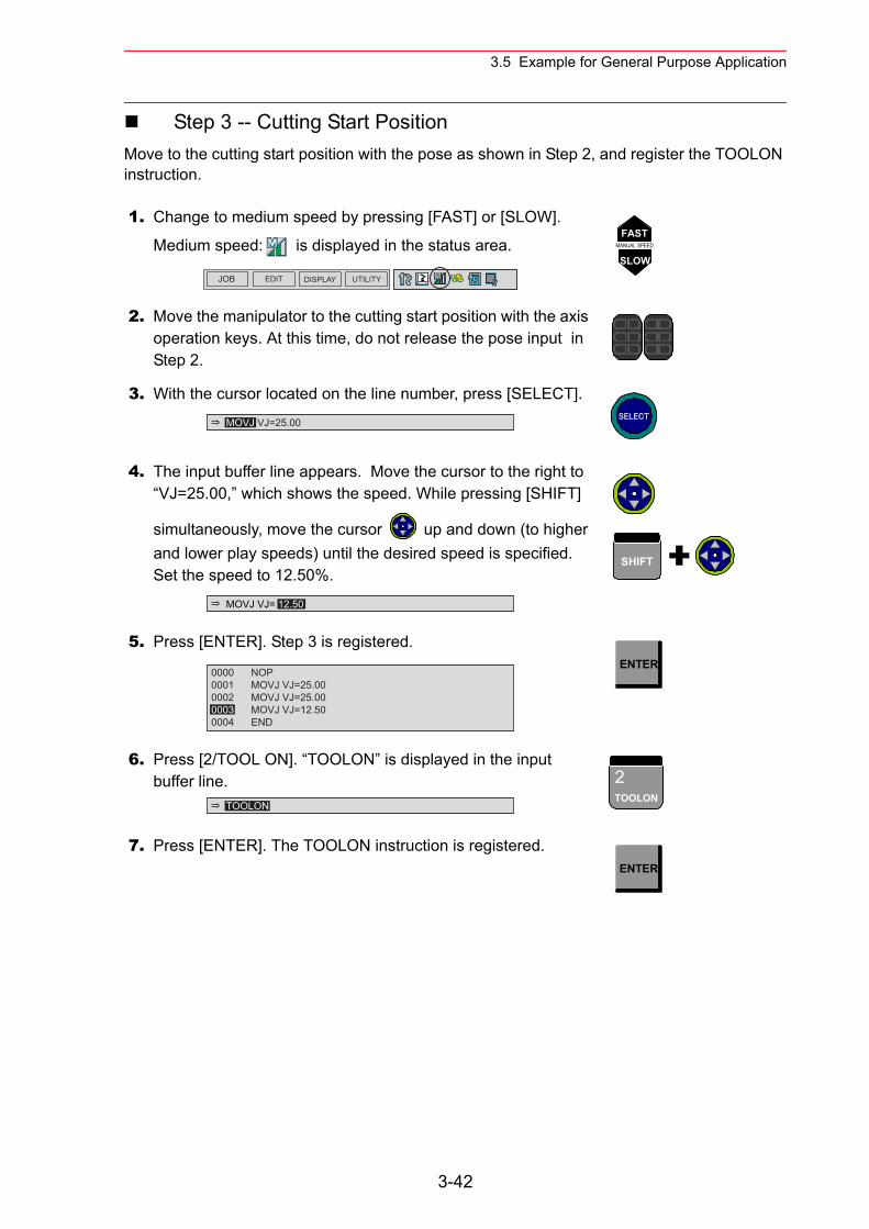
3.5 Example for General Purpose Application
Step 3 -- Cutting Start PositionMove to the cutting start position with the pose as shown in Step 2, and register the TOOLON instruction.
1. Change to medium speed by pressing [FAST] or [SLOW].
Medium speed: is displayed in the status area.
2. Move the manipulator to the cutting start position with the axis operation keys. At this time, do not release the pose input in Step 2.
3. With the cursor located on the line number, press [SELECT].
4. The input buffer line appears. Move the cursor to the right to “VJ=25.00,” which shows the speed. While pressing [SHIFT]
simultaneously, move the cursor up and down (to higher and lower play speeds) until the desired speed is specified.Set the speed to 12.50%.
5. Press [ENTER]. Step 3 is registered.
6. Press [2/TOOL ON]. “TOOLON” is displayed in the input buffer line.
7. Press [ENTER]. The TOOLON instruction is registered.
JOB EDIT DISPLAY UTILITY
FASTMANUAL SPEED
SLOW
MOVJ VJ=25.00 SELECT
MOVJ VJ= 12.50
SHIFT
0000 NOP0001 MOVJ VJ=25.000002 MOVJ VJ=25.000003 MOVJ VJ=12.500004 END
ENTER
TOOLON
2TOOLON
ENTER
3-42
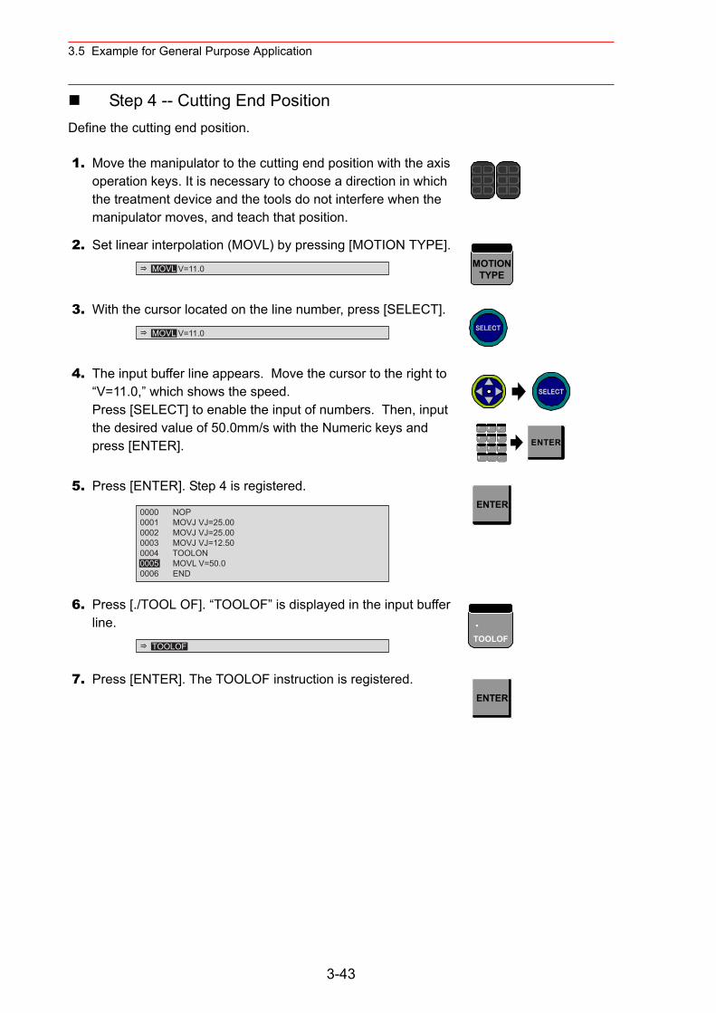
3.5 Example for General Purpose Application
Step 4 -- Cutting End PositionDefine the cutting end position.
1. Move the manipulator to the cutting end position with the axis operation keys. It is necessary to choose a direction in which the treatment device and the tools do not interfere when the manipulator moves, and teach that position.
2. Set linear interpolation (MOVL) by pressing [MOTION TYPE].
3. With the cursor located on the line number, press [SELECT].
4. The input buffer line appears. Move the cursor to the right to “V=11.0,” which shows the speed.Press [SELECT] to enable the input of numbers. Then, input the desired value of 50.0mm/s with the Numeric keys and press [ENTER].
5. Press [ENTER]. Step 4 is registered.
6. Press [./TOOL OF]. “TOOLOF” is displayed in the input buffer line.
7. Press [ENTER]. The TOOLOF instruction is registered.
MOVL V=11.0 MOTIONTYPE
MOVL V=11.0 SELECT
SELECT
7 8 9
4 6
1 2 3
・ -0
5ENTER
0000 NOP0001 MOVJ VJ=25.000002 MOVJ VJ=25.000003 MOVJ VJ=12.500004 TOOLON0005 MOVL V=50.0 0006 END
ENTER
TOOLOF
.TOOLOF
ENTER
3-43
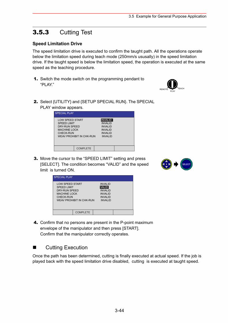
3.5 Example for General Purpose Application
3.5.3 Cutting Test
Speed Limitation DriveThe speed limitation drive is executed to confirm the taught path. All the operations operate below the limitation speed during teach mode (250mm/s ususally) in the speed limitation drive. If the taught speed is below the limitation speed, the operation is executed at the same speed as the teaching procedure.
Cutting ExecutionOnce the path has been determined, cutting is finally executed at actual speed. If the job is played back with the speed limitation drive disabled, cutting is executed at taught speed.
1. Switch the mode switch on the programming pendant to “PLAY.”
2. Select {UTILITY} and {SETUP SPECIAL RUN}. The SPECIAL PLAY window appears.
3. Move the cursor to the “SPEED LIMIT” setting and press [SELECT]. The condition becomes “VALID” and the speed limit is turned ON.
4. Confirm that no persons are present in the P-point maximum envelope of the manipulator and then press [START].Confirm that the manipulator correctly operates.
REMOTE TEACHPLAY
SPECIAL PLAY
LOW SPEED START INVALIDSPEED LIMIT INVALIDDRY-RUN SPEED INVALIDMACHINE LOCK INVALIDCHECK-RUN INVALIDWEAV PROHIBIT IN CHK-RUN INVALID
COMPLETE
SPECIAL PLAY
LOW SPEED START INVALIDSPEED LIMIT VALIDDRY-RUN SPEED INVALIDMACHINE LOCK INVALIDCHECK-RUN INVALIDWEAV PROHIBIT IN CHK-RUN INVALID
COMPLETE
SELECT
3-44
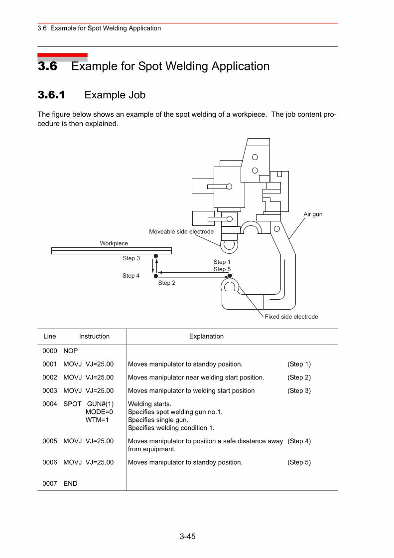
3.6 Example for Spot Welding Application
3.6 Example for Spot Welding Application
3.6.1 Example Job
The figure below shows an example of the spot welding of a workpiece. The job content pro-cedure is then explained.
Line Instruction Explanation
0000 NOP
0001 MOVJ VJ=25.00 Moves manipulator to standby position. (Step 1)
0002 MOVJ VJ=25.00 Moves manipulator near welding start position. (Step 2)
0003 MOVJ VJ=25.00 Moves manipulator to welding start position (Step 3)
0004 SPOT GUN#(1) MODE=0 WTM=1
Welding starts.Specifies spot welding gun no.1.Specifies single gun.Specifies welding condition 1.
0005 MOVJ VJ=25.00 Moves manipulator to position a safe disatance away from equipment.
(Step 4)
0006 MOVJ VJ=25.00 Moves manipulator to standby position. (Step 5)
0007 END
Workpiece
Step 3
Step 4
Step 1Step 5
Fixed side electrode
Moveable side electrode
Air gun
Step 2
3-45
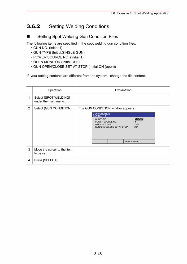
3.6 Example for Spot Welding Application
3.6.2 Setting Welding Conditions
Setting Spot Welding Gun Condition FilesThe following items are specified in the spot welding gun condition files.
• GUN NO. (Initial:1)• GUN TYPE (Initial:SINGLE GUN)• POWER SOURCE NO. (Initial:1)• OPEN MONITOR (Initial:OFF)• GUN OPEN/CLOSE SET AT STOP (Initial:ON (open))
If your setting contents are different from the system, change the file content.
Operation Explanation
1 Select {SPOT WELDING} under the main menu.
2 Select {GUN CONDITION}. The GUN CONDITION window appears.
3 Move the cursor to the item to be set.
4 Press [SELECT].
GUN CONDITIONGUN NO.: 1
GUN TYPE : SINGLEPOWER SOURCE NO. : 1OPEN MONITOR : OFFGUN OPEN/CLOSE SET AT STOP : ON
DIRECT PAGE
3-46
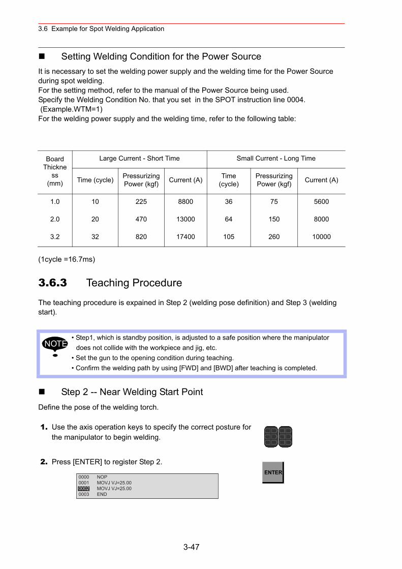
3.6 Example for Spot Welding Application
Setting Welding Condition for the Power SourceIt is necessary to set the welding power supply and the welding time for the Power Source during spot welding. For the setting method, refer to the manual of the Power Source being used.Specify the Welding Condition No. that you set in the SPOT instruction line 0004. (Example.WTM=1)For the welding power supply and the welding time, refer to the following table:
(1cycle =16.7ms)
3.6.3 Teaching Procedure
The teaching procedure is expained in Step 2 (welding pose definition) and Step 3 (welding start).
Step 2 -- Near Welding Start PointDefine the pose of the welding torch.
Board Thickne
ss(mm)
Large Current - Short Time Small Current - Long Time
Time (cycle) Pressurizing Power (kgf) Current (A) Time
(cycle)Pressurizing Power (kgf) Current (A)
1.0 10 225 8800 36 75 5600
2.0 20 470 13000 64 150 8000
3.2 32 820 17400 105 260 10000
• Step1, which is standby position, is adjusted to a safe position where the manipulator does not collide with the workpiece and jig, etc.
• Set the gun to the opening condition during teaching.• Confirm the welding path by using [FWD] and [BWD] after teaching is completed.
1. Use the axis operation keys to specify the correct posture for the manipulator to begin welding.
2. Press [ENTER] to register Step 2.
NOTE
0000 NOP0001 MOVJ VJ=25.000002 MOVJ VJ=25.000003 END
ENTER
3-47
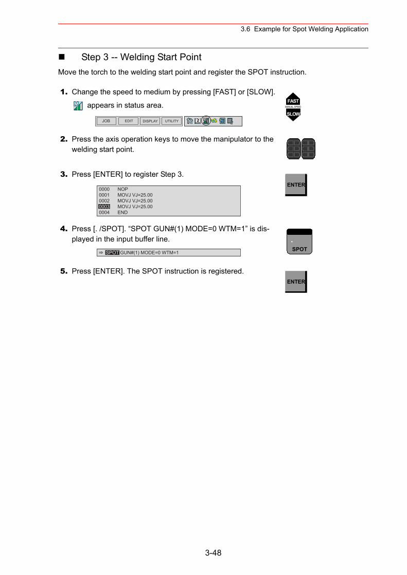
3.6 Example for Spot Welding Application
Step 3 -- Welding Start PointMove the torch to the welding start point and register the SPOT instruction.
1. Change the speed to medium by pressing [FAST] or [SLOW].
appears in status area.
2. Press the axis operation keys to move the manipulator to the welding start point.
3. Press [ENTER] to register Step 3.
4. Press [. /SPOT]. “SPOT GUN#(1) MODE=0 WTM=1” is dis-played in the input buffer line.
5. Press [ENTER]. The SPOT instruction is registered.
JOB EDIT DISPLAY UTILITY
FASTMANUAL SPEED
SLOW
0000 NOP0001 MOVJ VJ=25.000002 MOVJ VJ=25.000003 MOVJ VJ=25.000004 END
ENTER
SPOT GUN#(1) MODE=0 WTM=1
.SPOT
ENTER
3-48
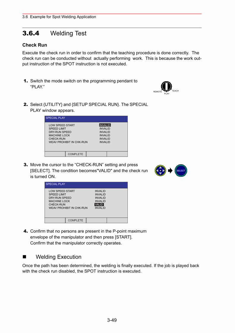
3.6 Example for Spot Welding Application
3.6.4 Welding Test
Check RunExecute the check run in order to confirm that the teaching procedure is done correctly. The check run can be conducted without actually performing work. This is because the work out-put instruction of the SPOT instruction is not executed.
Welding ExecutionOnce the path has been determined, the welding is finally executed. If the job is played back with the check run disabled, the SPOT instruction is executed.
1. Switch the mode switch on the programming pendant to “PLAY.”
2. Select {UTILITY} and {SETUP SPECIAL RUN}. The SPECIAL PLAY window appears.
3. Move the cursor to the “CHECK-RUN” setting and press [SELECT]. The condition becomes"VALID" and the check run is turned ON.
4. Confirm that no persons are present in the P-point maximum envelope of the manipulator and then press [START].Confirm that the manipulator correctly operates.
REMOTE TEACHPLAY
SPECIAL PLAY
LOW SPEED START INVALIDSPEED LIMIT INVALIDDRY-RUN SPEED INVALIDMACHINE LOCK INVALIDCHECK-RUN INVALIDWEAV PROHIBIT IN CHK-RUN INVALID
COMPLETE
SPECIAL PLAY
LOW SPEED START INVALIDSPEED LIMIT INVALIDDRY-RUN SPEED INVALIDMACHINE LOCK INVALIDCHECK-RUN VALIDWEAV PROHIBIT IN CHK-RUN INVALID
COMPLETE
SELECT
3-49
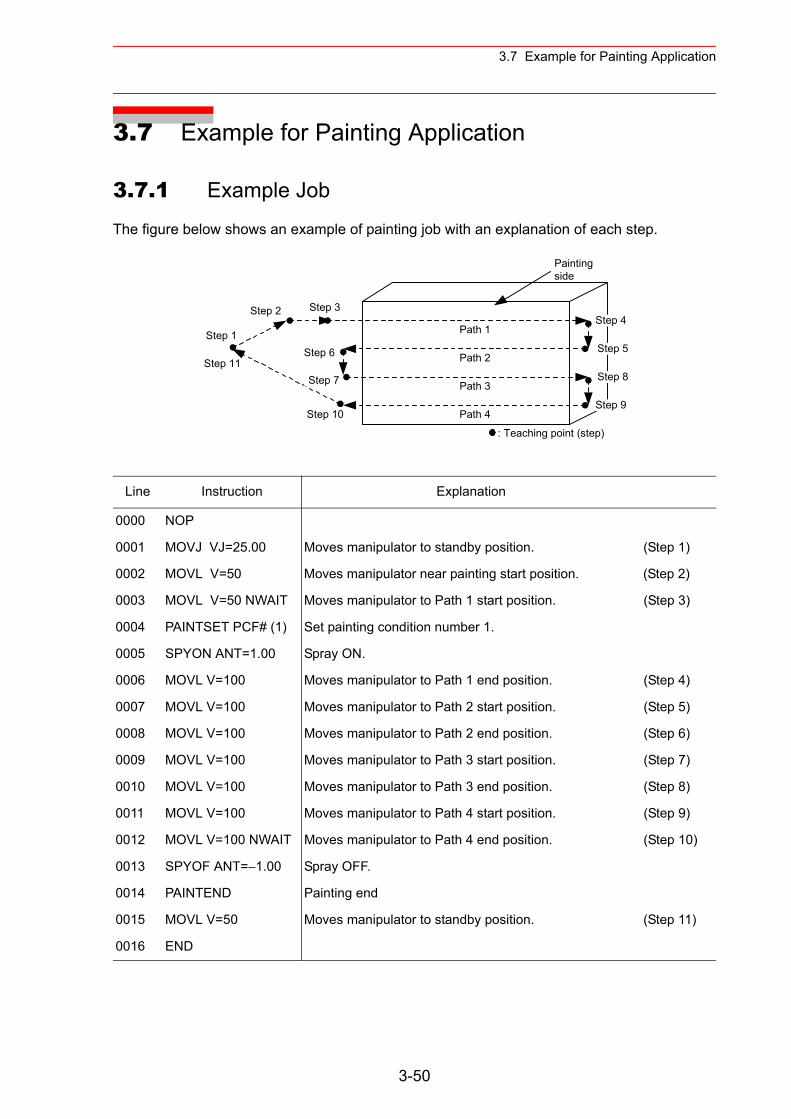
3.7 Example for Painting Application
3.7 Example for Painting Application
3.7.1 Example Job
The figure below shows an example of painting job with an explanation of each step.
Line Instruction Explanation
0000 NOP
0001 MOVJ VJ=25.00 Moves manipulator to standby position. (Step 1)
0002 MOVL V=50 Moves manipulator near painting start position. (Step 2)
0003 MOVL V=50 NWAIT Moves manipulator to Path 1 start position. (Step 3)
0004 PAINTSET PCF# (1) Set painting condition number 1.
0005 SPYON ANT=1.00 Spray ON.
0006 MOVL V=100 Moves manipulator to Path 1 end position. (Step 4)
0007 MOVL V=100 Moves manipulator to Path 2 start position. (Step 5)
0008 MOVL V=100 Moves manipulator to Path 2 end position. (Step 6)
0009 MOVL V=100 Moves manipulator to Path 3 start position. (Step 7)
0010 MOVL V=100 Moves manipulator to Path 3 end position. (Step 8)
0011 MOVL V=100 Moves manipulator to Path 4 start position. (Step 9)
0012 MOVL V=100 NWAIT Moves manipulator to Path 4 end position. (Step 10)
0013 SPYOF ANT=−1.00 Spray OFF.
0014 PAINTEND Painting end
0015 MOVL V=50 Moves manipulator to standby position. (Step 11)
0016 END
Step 6
Step 7
Step 4
Step 5Step 1
Step 2
Step 8
Step 9Step 10
Step 11
Path 1
: Teaching point (step)
Path 2
Path 3
Path 4
Paintingside
Step 3
3-50
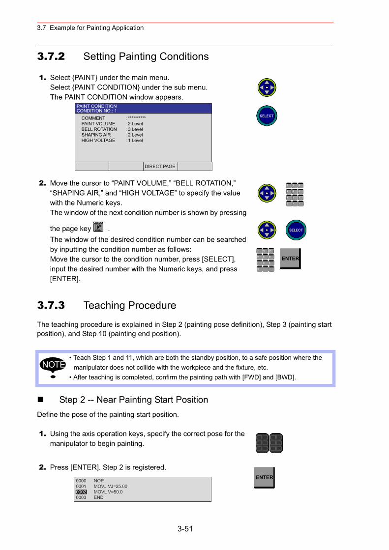
3.7 Example for Painting Application
3.7.2 Setting Painting Conditions
3.7.3 Teaching Procedure
The teaching procedure is explained in Step 2 (painting pose definition), Step 3 (painting start position), and Step 10 (painting end position).
Step 2 -- Near Painting Start PositionDefine the pose of the painting start position.
1. Select {PAINT} under the main menu.Select {PAINT CONDITION} under the sub menu.The PAINT CONDITION window appears.
2. Move the cursor to “PAINT VOLUME,” “BELL ROTATION,” “SHAPING AIR,” and “HIGH VOLTAGE” to specify the value with the Numeric keys.The window of the next condition number is shown by pressing
the page key .The window of the desired condition number can be searched by inputting the condition number as follows: Move the cursor to the condition number, press [SELECT], input the desired number with the Numeric keys, and press [ENTER].
• Teach Step 1 and 11, which are both the standby position, to a safe position where the manipulator does not collide with the workpiece and the fixture, etc.
• After teaching is completed, confirm the painting path with [FWD] and [BWD].
1. Using the axis operation keys, specify the correct pose for the manipulator to begin painting.
2. Press [ENTER]. Step 2 is registered.
PAINT CONDITIONCONDITION NO.: 1
COMMENT : **********PAINT VOLUME : 2 LevelBELL ROTATION : 3 LevelSHAPING AIR : 2 LevelHIGH VOLTAGE : 1 Level
DIRECT PAGE
SELECT
PAGE
GO BACK
7 8 9
4 6
1 2 3
・ -0
5
SELECT
7 8 9
4 6
1 2 3
・ -0
5 ENTER
NOTE
0000 NOP0001 MOVJ VJ=25.000002 MOVL V=50.00003 END
ENTER
3-51
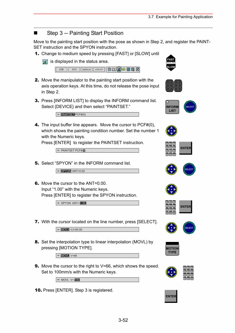
3.7 Example for Painting Application
Step 3 -- Painting Start PositionMove to the painting start position with the pose as shown in Step 2, and register the PAINT-SET instruction and the SPYON instruction.1. Change to medium speed by pressing [FAST] or [SLOW] until
is displayed in the status area.
2. Move the manipulator to the painting start position with the axis operation keys. At this time, do not release the pose input in Step 2.
3. Press [INFORM LIST] to display the INFORM command list. Select {DEVICE} and then select “PAINTSET.”
4. The input buffer line appears. Move the cursor to PCF#(0), which shows the painting condition number. Set the number 1 with the Numeric keys.Press [ENTER] to register the PAINTSET instruction.
5. Select “SPYON” in the INFORM command list.
6. Move the cursor to the ANT=0.00.Input “1.00” with the Numeric keys.Press [ENTER] to register the SPYON instruction.
7. With the cursor located on the line number, press [SELECT].
8. Set the interpolation type to linear interpolation (MOVL) by pressing [MOTION TYPE].
9. Move the cursor to the right to V=66, which shows the speed.Set to 100mm/s with the Numeric keys.
10. Press [ENTER]. Step 3 is registered.
JOB EDIT DISPLAY UTILITY
FASTMANUAL SPEED
SLOW
PAINTSET PCF#(0)
INFORMLIST
SELECT
PAINTSET PCF#(1)
7 8 9
4 6
1 2 3
・ -0
5 ENTER
SPYON ANT=0.00 SELECT
SPYON ANT= 1.00 7 8 9
4 6
1 2 3
・ -0
5 ENTER
MOVJ VJ=50.00 SELECT
MOVL V=66
MOTIONTYPE
MOVL V= 100
7 8 9
4 6
1 2 3
・ -0
5
ENTER
3-52
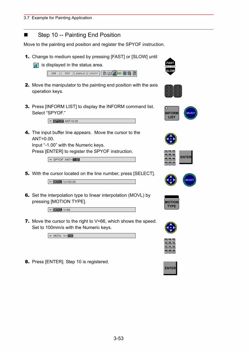
3.7 Example for Painting Application
Step 10 -- Painting End PositionMove to the painting end position and register the SPYOF instruction.
1. Change to medium speed by pressing [FAST] or [SLOW] until
is displayed in the status area.
2. Move the manipulator to the painting end position with the axis operation keys.
3. Press [INFORM LIST] to display the INFORM command list. Select “SPYOF.”
4. The input buffer line appears. Move the cursor to the ANT=0.00.Input “-1.00” with the Numeric keys.Press [ENTER] to register the SPYOF instruction.
5. With the cursor located on the line number, press [SELECT].
6. Set the interpolation type to linear interpolation (MOVL) by pressing [MOTION TYPE].
7. Move the cursor to the right to V=66, which shows the speed.Set to 100mm/s with the Numeric keys.
8. Press [ENTER]. Step 10 is registered.
JOB EDIT DISPLAY UTILITY
FASTMANUAL SPEED
SLOW
SPYOF ANT=0.00
INFORMLIST
SELECT
SPYOF ANT= 1.00
7 8 9
4 6
1 2 3
・ -0
5 ENTER
MOVJ VJ=50.00 SELECT
MOVL V=66
MOTIONTYPE
MOVL V= 1007 8 9
4 6
1 2 3
・ -0
5
ENTER
3-53
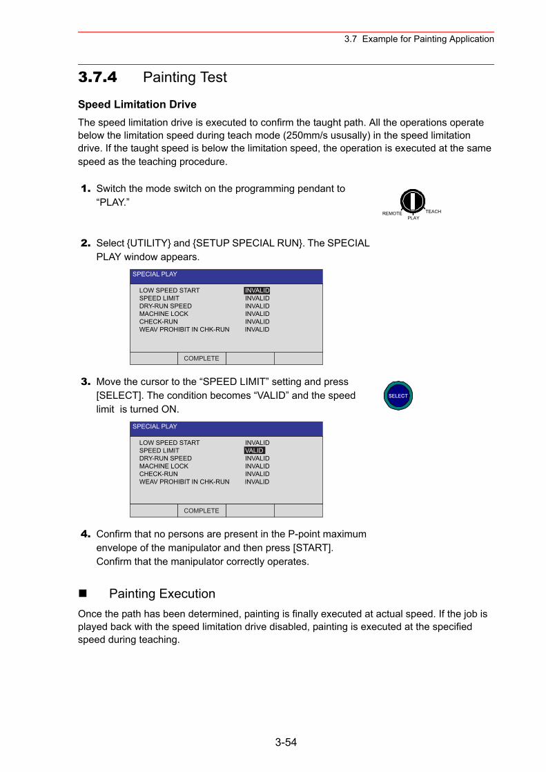
3.7 Example for Painting Application
3.7.4 Painting Test
Speed Limitation DriveThe speed limitation drive is executed to confirm the taught path. All the operations operate below the limitation speed during teach mode (250mm/s ususally) in the speed limitation drive. If the taught speed is below the limitation speed, the operation is executed at the same speed as the teaching procedure.
Painting ExecutionOnce the path has been determined, painting is finally executed at actual speed. If the job is played back with the speed limitation drive disabled, painting is executed at the specified speed during teaching.
1. Switch the mode switch on the programming pendant to “PLAY.”
2. Select {UTILITY} and {SETUP SPECIAL RUN}. The SPECIAL PLAY window appears.
3. Move the cursor to the “SPEED LIMIT” setting and press [SELECT]. The condition becomes “VALID” and the speed limit is turned ON.
4. Confirm that no persons are present in the P-point maximum envelope of the manipulator and then press [START].Confirm that the manipulator correctly operates.
REMOTE TEACHPLAY
SPECIAL PLAY
LOW SPEED START INVALIDSPEED LIMIT INVALIDDRY-RUN SPEED INVALIDMACHINE LOCK INVALIDCHECK-RUN INVALIDWEAV PROHIBIT IN CHK-RUN INVALID
COMPLETE
SPECIAL PLAY
LOW SPEED START INVALIDSPEED LIMIT VALIDDRY-RUN SPEED INVALIDMACHINE LOCK INVALIDCHECK-RUN INVALIDWEAV PROHIBIT IN CHK-RUN INVALID
COMPLETE
SELECT
3-54
4.1 Preparation for Teaching
4 Teaching
4.1 Preparation for Teaching
To ensure safety, the following operations should always be performed before teaching:
• Check the emergency stop buttons to be sure they function properly.• Set the mode switch to “TEACH.”• Register a job.
4.1.1 Checking Emergency Stop Buttons
The Servo ON button on the programming pendant should be lit while the power is ON for the servo system. Perform the following operation to ensure that the emergency stop buttons on both the NX100 and the programming pendant are functioning correctly before operating the manipulator.
4.1.2 Setting the Teach Lock
For safety purposes, always set the mode switch to “TEACH” before beginning to teach.While the teach lock is set, the mode of operation is tied to the teach mode and the machines cannot be played back using either [START] or external input.
Operation Explanation
1 Press E. STOP button. Press the emergency stop button on the NX100 or the program-ming pendant.
2 Confirm the servo power is turned OFF.
The SERVO ON button on the programming pendant lights while servo supply is turned ON. When the emergency stop button is pressed and the servo power is turned OFF, the SERVO ON lamp will turn OFF.
3 Press [SERVO ON READY]. After confirming correct operation, press [SERVO ON READY]. The servo power will be ready to turn ON. The servo power can be turned ON with the Enable switch while the SERVO ON button lamp blinks.
4-1
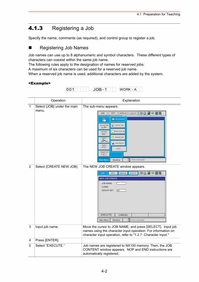
4.1 Preparation for Teaching
4.1.3 Registering a Job
Specify the name, comments (as required), and control group to register a job.
Registering Job NamesJob names can use up to 8 alphanumeric and symbol characters. These different types of characters can coexist within the same job name.The following rules apply to the designation of names for reserved jobs:A maximum of six characters can be used for a reserved job name.When a reserved job name is used, additional characters are added by the system.
<Example>
Operation Explanation
1 Select {JOB} under the main menu.
The sub-menu appears.
2 Select {CREATE NEW JOB}. The NEW JOB CREATE window appears.
3 Input job name. Move the cursor to JOB NAME, and press [SELECT]. Input job names using the character input operation. For information on character input operation, refer to "1.2.7 Character Input."
4 Press [ENTER].5 Select “EXECUTE.” Job names are registered to NX100 memory. Then, the JOB
CONTENT window appears. NOP and END instructions are automatically registered.
0 0 1 WORK - AJOB - 1
DOUTMOVEEND
In Out
B001
DOUTMOVEEND
JOB EDIT DISPLAY UTILITY
Main Menu ShortCut !Turn on servo power
JOB
IN/OUT
SYSTEM INFO
ARC WELDING
VARIABLE
ROBOT
SELECT JOB
MASTER JOB
JOB CAPACITY
JOB CONTENT
CREATE NEW JOB
CYCLE
JOB EDIT DISPLAY UTILITY
Main Menu ShortCut !Turn on servo power
NEW JOB CREATE
JOB NAME :
COMM. :
GROUP SET : R1
EXECUTE CANCEL
4-2
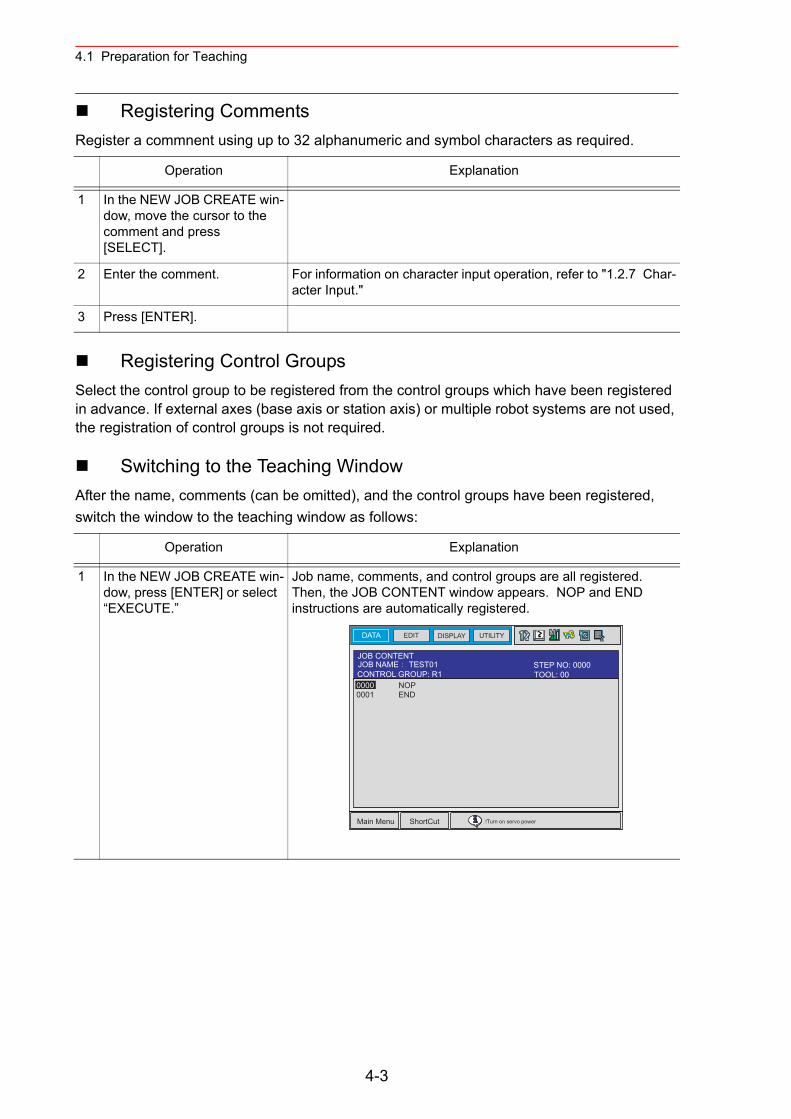
4.1 Preparation for Teaching
Registering CommentsRegister a commnent using up to 32 alphanumeric and symbol characters as required.
Registering Control GroupsSelect the control group to be registered from the control groups which have been registered in advance. If external axes (base axis or station axis) or multiple robot systems are not used, the registration of control groups is not required.
Switching to the Teaching WindowAfter the name, comments (can be omitted), and the control groups have been registered, switch the window to the teaching window as follows:
Operation Explanation
1 In the NEW JOB CREATE win-dow, move the cursor to the comment and press [SELECT].
2 Enter the comment. For information on character input operation, refer to "1.2.7 Char-acter Input."
3 Press [ENTER].
Operation Explanation
1 In the NEW JOB CREATE win-dow, press [ENTER] or select “EXECUTE.”
Job name, comments, and control groups are all registered. Then, the JOB CONTENT window appears. NOP and END instructions are automatically registered.
DATA EDIT DISPLAY UTILITY
Main Menu ShortCut !Turn on servo power
JOB CONTENTJOB NAME TEST01
0000 NOP0001 END
TOOL: 00CONTROL GROUP: R1STEP NO: 0000
4-3
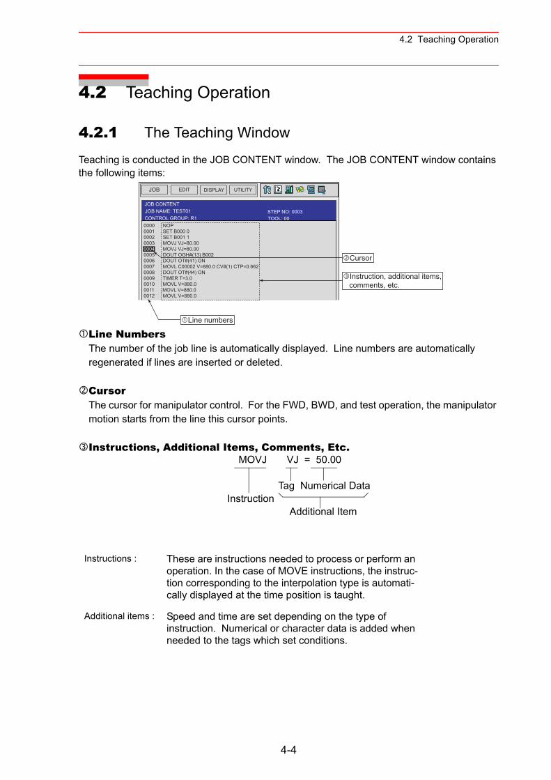
4.2 Teaching Operation
4.2 Teaching Operation
4.2.1 The Teaching Window
Teaching is conducted in the JOB CONTENT window. The JOB CONTENT window contains the following items:
Line NumbersThe number of the job line is automatically displayed. Line numbers are automatically regenerated if lines are inserted or deleted.
CursorThe cursor for manipulator control. For the FWD, BWD, and test operation, the manipulator motion starts from the line this cursor points.
Instructions, Additional Items, Comments, Etc.
Instructions : These are instructions needed to process or perform an operation. In the case of MOVE instructions, the instruc-tion corresponding to the interpolation type is automati-cally displayed at the time position is taught.
Additional items : Speed and time are set depending on the type of instruction. Numerical or character data is added when needed to the tags which set conditions.
JOB EDIT DISPLAY UTILITY
TOOL: 00CONTROL GROUP: R1STEP NO: 0003
JOB CONTENTJOB NAME: TEST01
0000 NOP0001 SET B000 00002 SET B001 10003 MOVJ VJ=80.000004 MOVJ VJ=80.000005 DOUT OGH#(13) B0020006 DOUT OT#(41) ON0007 MOVL C00002 V=880.0 CV#(1) CTP=0.6620008 DOUT OT#(44) ON0009 TIMER T=3.00010 MOVL V=880.00011 MOVL V=880.00012 MOVL V=880.0
Line numbers
Cursor
Instruction, additional items, comments, etc.
MOVJ VJ = 50.00
Tag Numerical Data Instruction Additional Item
4-4
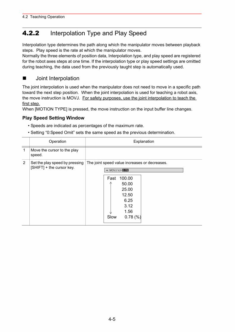
4.2 Teaching Operation
4.2.2 Interpolation Type and Play Speed
Interpolation type determines the path along which the manipulator moves between playback steps. Play speed is the rate at which the manipulator moves.Normally the three elements of position data, Interpolation type, and play speed are registered for the robot axes steps at one time. If the interpolation type or play speed settings are omitted during teaching, the data used from the previously taught step is automatically used.
Joint InterpolationThe joint interpolation is used when the manipulator does not need to move in a specific path toward the next step position. When the joint interpolation is used for teaching a robot axis, the move instruction is MOVJ. For safety purposes, use the joint interpolation to teach the first step.When [MOTION TYPE] is pressed, the move instruction on the input buffer line changes.
Play Speed Setting Window• Speeds are indicated as percentages of the maximum rate.• Setting “0:Speed Omit” sets the same speed as the previous determination.
Operation Explanation
1 Move the cursor to the play speed.
2 Set the play speed by pressing [SHIFT] + the cursor key.
The joint speed value increases or decreases.
MOVJ VJ= 0.78
Fast 100.00 50.00 25.00 12.50 6.25 3.12 1.56 Slow 0.78 (%)
4-5
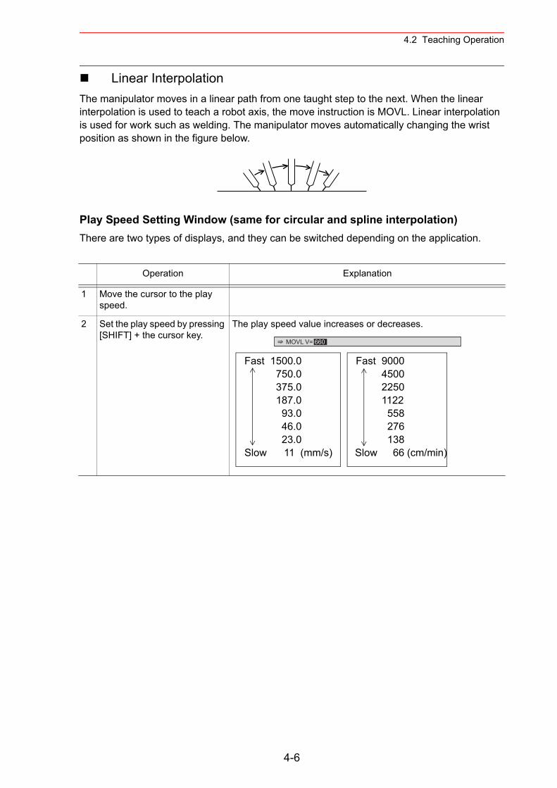
4.2 Teaching Operation
Linear InterpolationThe manipulator moves in a linear path from one taught step to the next. When the linear interpolation is used to teach a robot axis, the move instruction is MOVL. Linear interpolation is used for work such as welding. The manipulator moves automatically changing the wrist position as shown in the figure below.
Play Speed Setting Window (same for circular and spline interpolation) There are two types of displays, and they can be switched depending on the application.
Operation Explanation
1 Move the cursor to the play speed.
2 Set the play speed by pressing [SHIFT] + the cursor key.
The play speed value increases or decreases.
MOVL V= 660
Fast 1500.0 750.0 375.0 187.0 93.0 46.0 23.0 Slow 11 (mm/s)
Fast 9000 4500 2250 1122 558 276 138 Slow 66 (cm/min)
4-6
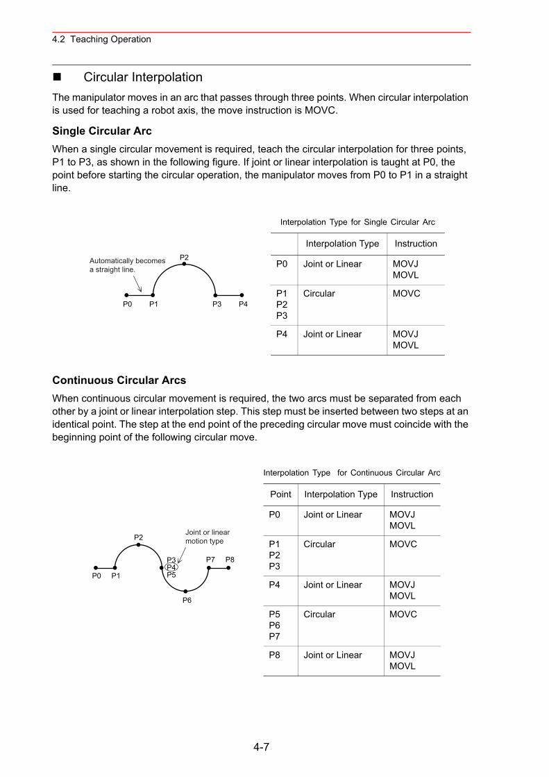
4.2 Teaching Operation
Circular InterpolationThe manipulator moves in an arc that passes through three points. When circular interpolation is used for teaching a robot axis, the move instruction is MOVC.
Single Circular ArcWhen a single circular movement is required, teach the circular interpolation for three points, P1 to P3, as shown in the following figure. If joint or linear interpolation is taught at P0, the point before starting the circular operation, the manipulator moves from P0 to P1 in a straight line.
Continuous Circular ArcsWhen continuous circular movement is required, the two arcs must be separated from each other by a joint or linear interpolation step. This step must be inserted between two steps at an identical point. The step at the end point of the preceding circular move must coincide with the beginning point of the following circular move.
P2
P3 P4P0 P1
Automatically becomesa straight line.
Interpolation Type for Single Circular Arc
Interpolation Type Instruction
P0 Joint or Linear MOVJMOVL
P1P2P3
Circular MOVC
P4 Joint or Linear MOVJMOVL
P0 P1
P7 P8
P2
P3P4P5
P6
Joint or linearmotion type
Interpolation Type for Continuous Circular Arc
Point Interpolation Type Instruction
P0 Joint or Linear MOVJMOVL
P1P2P3
Circular MOVC
P4 Joint or Linear MOVJMOVL
P5P6P7
Circular MOVC
P8 Joint or Linear MOVJMOVL
4-7
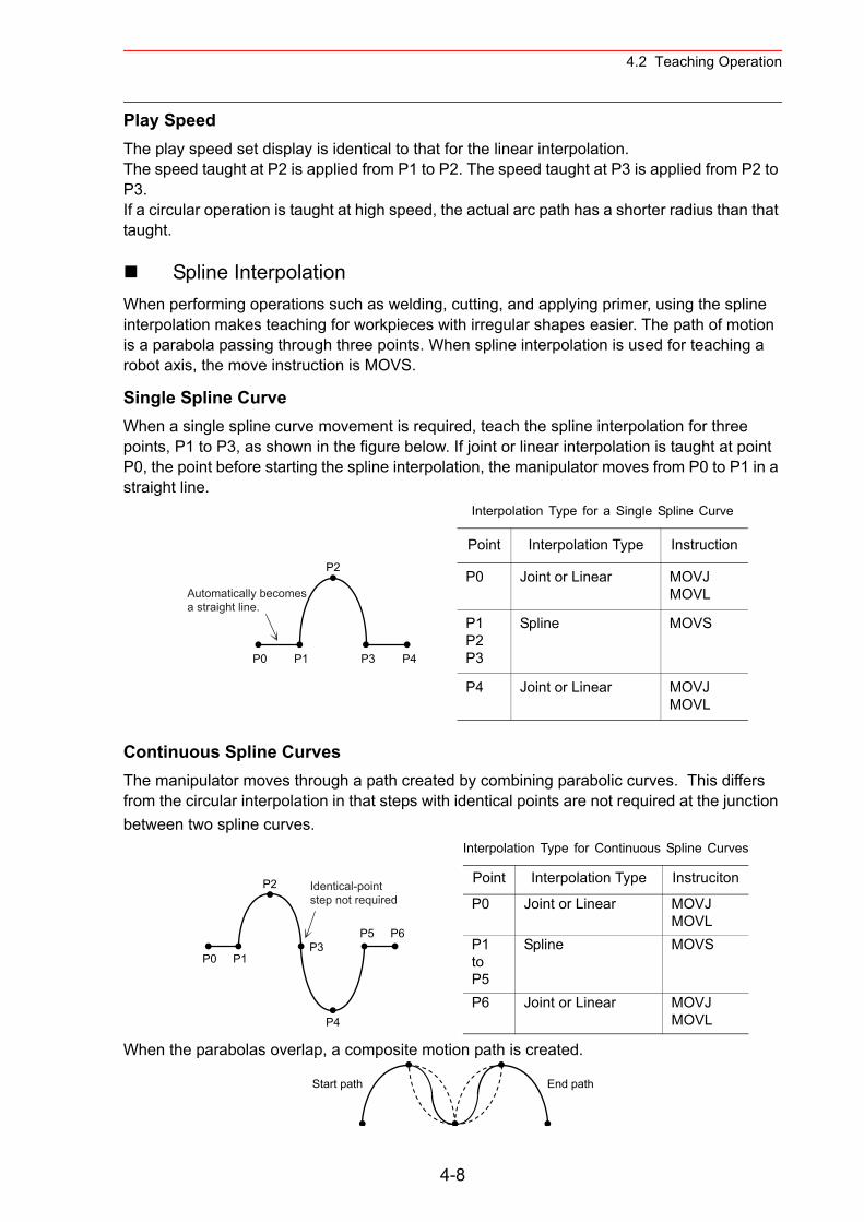
4.2 Teaching Operation
Play SpeedThe play speed set display is identical to that for the linear interpolation.The speed taught at P2 is applied from P1 to P2. The speed taught at P3 is applied from P2 to P3.If a circular operation is taught at high speed, the actual arc path has a shorter radius than that taught.
Spline InterpolationWhen performing operations such as welding, cutting, and applying primer, using the spline interpolation makes teaching for workpieces with irregular shapes easier. The path of motion is a parabola passing through three points. When spline interpolation is used for teaching a robot axis, the move instruction is MOVS.
Single Spline CurveWhen a single spline curve movement is required, teach the spline interpolation for three points, P1 to P3, as shown in the figure below. If joint or linear interpolation is taught at point P0, the point before starting the spline interpolation, the manipulator moves from P0 to P1 in a straight line.
Continuous Spline CurvesThe manipulator moves through a path created by combining parabolic curves. This differs from the circular interpolation in that steps with identical points are not required at the junction between two spline curves.
When the parabolas overlap, a composite motion path is created.
P2
P3 P4P0 P1
Automatically becomesa straight line.
Interpolation Type for a Single Spline Curve
Point Interpolation Type Instruction
P0 Joint or Linear MOVJMOVL
P1P2P3
Spline MOVS
P4 Joint or Linear MOVJMOVL
P0 P1
P5 P6
P2
P3
P4
Identical-pointstep not required
Interpolation Type for Continuous Spline Curves
Point Interpolation Type Instruciton
P0 Joint or Linear MOVJMOVL
P1toP5
Spline MOVS
P6 Joint or Linear MOVJMOVL
Start path End path
4-8
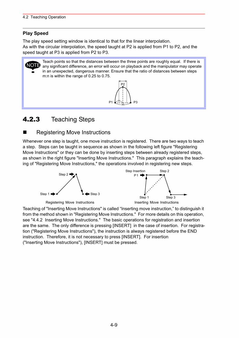
4.2 Teaching Operation
Play SpeedThe play speed setting window is identical to that for the linear interpolation.As with the circular interpolation, the speed taught at P2 is applied from P1 to P2, and the speed taught at P3 is applied from P2 to P3.
4.2.3 Teaching Steps
Registering Move InstructionsWhenever one step is taught, one move instruction is registered. There are two ways to teach a step. Steps can be taught in sequence as shown in the following left figure "Registering Move Instructions" or they can be done by inserting steps between already registered steps, as shown in the right figure "Inserting Move Instructions." This paragraph explains the teach-ing of "Registering Move Instructions," the operations involved in registering new steps.
Teaching of "Inserting Move Instructions" is called “Inserting move instruction,” to distinguish it from the method shown in "Registering Move Instructions." For more details on this operation, see "4.4.2 Inserting Move Instructions." The basic operations for registration and insertion are the same. The only difference is pressing [INSERT] in the case of insertion. For registra-tion ("Registering Move Instructions"), the instruction is always registered before the END instruction. Therefore, it is not necessary to press [INSERT]. For insertion ("Inserting Move Instructions"), [INSERT] must be pressed.
Teach points so that the distances between the three points are roughly equal. If there is any significant difference, an error will occur on playback and the manipulator may operate in an unexpected, dangerous manner. Ensure that the ratio of distances between steps m:n is within the range of 0.25 to 0.75.
Registering Move Instructions Inserting Move Instructions
NOTE
P2
P3P1 nm
Step 1
Step 2
Step 3
Step 2Step Insertion
Step 3
P1
Step 1
4-9
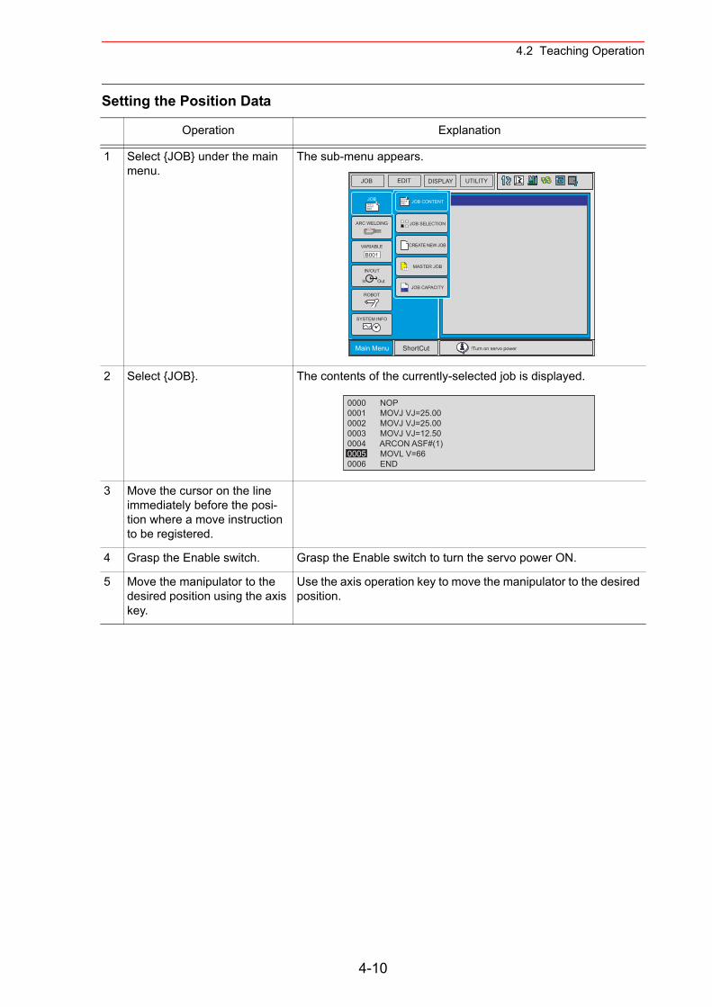
4.2 Teaching Operation
Setting the Position Data
Operation Explanation
1 Select {JOB} under the main menu.
The sub-menu appears.
2 Select {JOB}. The contents of the currently-selected job is displayed.
3 Move the cursor on the line immediately before the posi-tion where a move instruction to be registered.
4 Grasp the Enable switch. Grasp the Enable switch to turn the servo power ON.
5 Move the manipulator to the desired position using the axis key.
Use the axis operation key to move the manipulator to the desired position.
JOB EDIT DISPLAY UTILITY
Main Menu ShortCut !Turn on servo power
JOBDOUTMOVEEND
IN/OUT
In Out
SYSTEM INFO
ARC WELDING
VARIABLE
B001
ROBOT
JOB SELECTION
MASTER JOB
JOB CAPACITY
DOUTMOVEEND JOB CONTENT
CREATE NEW JOB
0000 NOP0001 MOVJ VJ=25.000002 MOVJ VJ=25.000003 MOVJ VJ=12.500004 ARCON ASF#(1)0005 MOVL V=660006 END
4-10
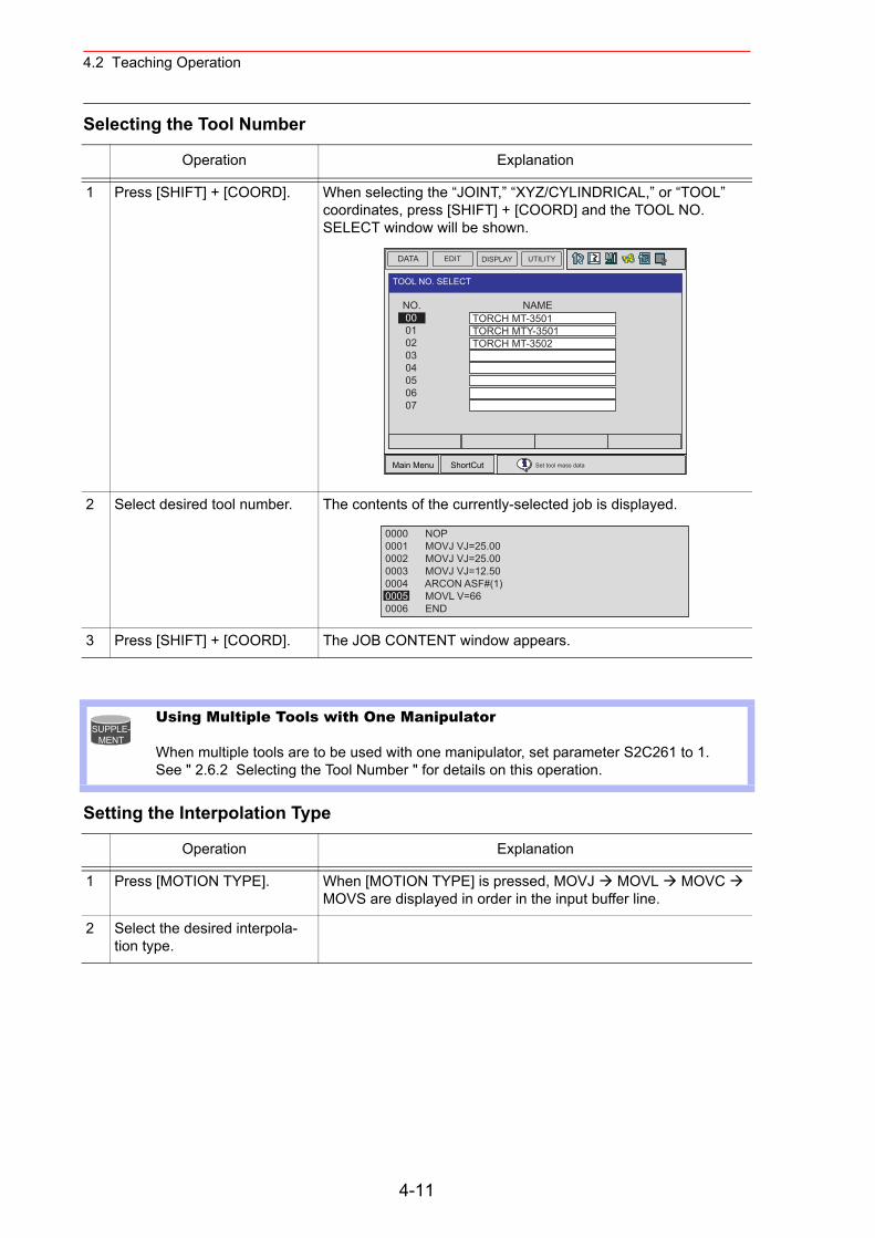
4.2 Teaching Operation
Selecting the Tool Number
Setting the Interpolation Type
Operation Explanation
1 Press [SHIFT] + [COORD]. When selecting the “JOINT,” “XYZ/CYLINDRICAL,” or “TOOL” coordinates, press [SHIFT] + [COORD] and the TOOL NO. SELECT window will be shown.
2 Select desired tool number. The contents of the currently-selected job is displayed.
3 Press [SHIFT] + [COORD]. The JOB CONTENT window appears.
Using Multiple Tools with One Manipulator
When multiple tools are to be used with one manipulator, set parameter S2C261 to 1.See " 2.6.2 Selecting the Tool Number " for details on this operation.
Operation Explanation
1 Press [MOTION TYPE]. When [MOTION TYPE] is pressed, MOVJ MOVL MOVC MOVS are displayed in order in the input buffer line.
2 Select the desired interpola-tion type.
DATA UTILITYEDIT DISPLAY
Main Menu ShortCut Set tool mass data
TOOL NO. SELECT
NO. NAME 00 01 02 03 04 05 06 07
TORCH MT-3501TORCH MTY-3501TORCH MT-3502
0000 NOP0001 MOVJ VJ=25.000002 MOVJ VJ=25.000003 MOVJ VJ=12.500004 ARCON ASF#(1)0005 MOVL V=660006 END
SUPPLE-MENT
4-11
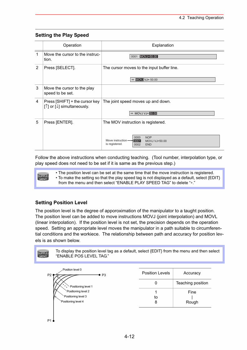
4.2 Teaching Operation
Setting the Play Speed
Follow the above instructions when conducting teaching. (Tool number, interpolation type, or play speed does not need to be set if it is same as the previous step.)
Setting Position LevelThe position level is the degree of apporoximation of the manipulator to a taught position.The position level can be added to move instructions MOVJ (joint interpolation) and MOVL (linear interpolation). If the position level is not set, the precision depends on the operation speed. Setting an appropriate level moves the manipulator in a path suitable to circumferen-tial conditions and the workiece. The relationship between path and accuracy for position lev-els is as shown below.
Operation Explanation
1 Move the cursor to the instruc-tion.
2 Press [SELECT]. The cursor moves to the input buffer line.
3 Move the cursor to the play speed to be set.
4 Press [SHIFT] + the cursor key [↑] or [↓] simultaneously.
The joint speed moves up and down.
5 Press [ENTER]. The MOV instruction is registered.
• The position level can be set at the same time that the move instruction is registered.• To make the setting so that the play speed tag is not displayed as a default, select {EDIT}
from the menu and then select “ENABLE PLAY SPEED TAG” to delete “∗.”
To display the position level tag as a default, select {EDIT} from the menu and then select “ENABLE POS LEVEL TAG.”
0001 MOVJ=50.00
MOVJ VJ= 50.00
MOVJ VJ= 50.00
0000 NOP0001 MOVJ VJ=50.000002 END
Move instructionis registered.
SUPPLE-MENT
SUPPLE-MENT
P2
P1
P3Position level 0
Positioning level 1Positioning level 2
Positioning level 3Positioning level 4
Position Levels Accuracy
0 Teaching position
1to8
Fine|
Rough
4-12
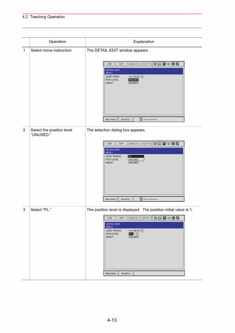
4.2 Teaching Operation
Operation Explanation
1 Select move instruction. The DETAIL EDIT window appears.
2 Select the position level “UNUSED.”
The selection dialog box appears.
3 Select “PL.” The position level is displayed. The position initial value is 1.
JOB UTILITYEDIT DISPLAY
Main Menu ShortCut Set tool mass data
DETAIL EDITMOVJJOINT SPEE VJ= 50.00POS LEVEL UNUSEDNWAIT UNUSED
JOB UTILITYEDIT DISPLAY
Main Menu ShortCut Set tool mass data
DETAIL EDITMOVJJOINT SPEED PLPOS LEVEL UNUSEDNWAIT UNUSED
JOB UTILITYEDIT DISPLAY
Main Menu ShortCut
DETAIL EDITMOVJJOINT SPEED VJ= 50.00POS LEVEL PL= 1NWAIT UNUSED
4-13
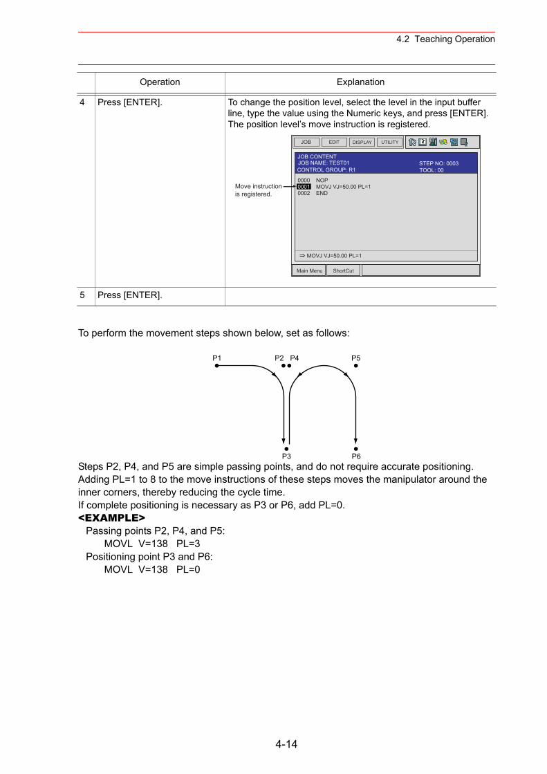
4.2 Teaching Operation
To perform the movement steps shown below, set as follows:
Steps P2, P4, and P5 are simple passing points, and do not require accurate positioning. Adding PL=1 to 8 to the move instructions of these steps moves the manipulator around the inner corners, thereby reducing the cycle time.If complete positioning is necessary as P3 or P6, add PL=0.<EXAMPLE>
Passing points P2, P4, and P5:MOVL V=138 PL=3
Positioning point P3 and P6:MOVL V=138 PL=0
4 Press [ENTER]. To change the position level, select the level in the input buffer line, type the value using the Numeric keys, and press [ENTER]. The position level’s move instruction is registered.
5 Press [ENTER].
Operation Explanation
JOB EDIT DISPLAY UTILITY
Main Menu ShortCut
JOB CONTENTJOB NAME: TEST01
0000 NOP0001 MOVJ VJ=50.00 PL=10002 END
MOVJ VJ=50.00 PL=1
Move instructionis registered.
TOOL: 00CONTROL GROUP: R1STEP NO: 0003
P1 P2 P4
P3
P5
P6
4-14
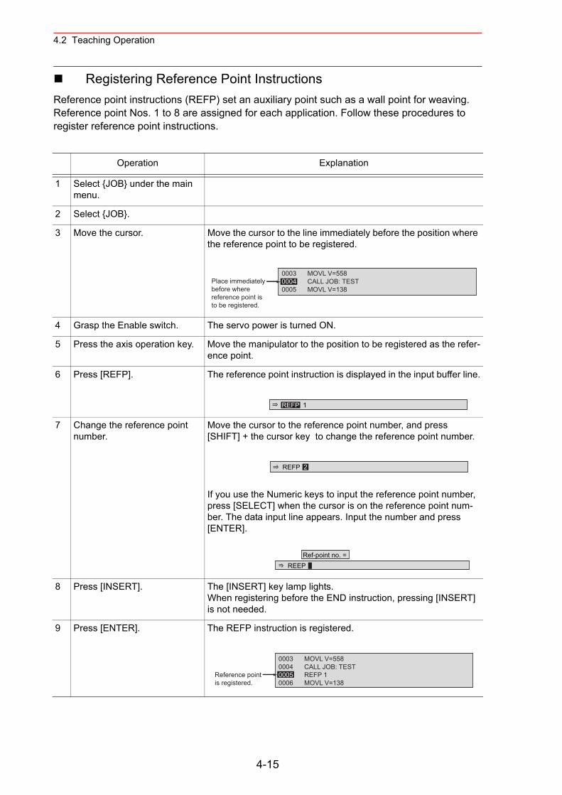
4.2 Teaching Operation
Registering Reference Point InstructionsReference point instructions (REFP) set an auxiliary point such as a wall point for weaving. Reference point Nos. 1 to 8 are assigned for each application. Follow these procedures to register reference point instructions.
Operation Explanation
1 Select {JOB} under the main menu.
2 Select {JOB}.
3 Move the cursor. Move the cursor to the line immediately before the position where the reference point to be registered.
4 Grasp the Enable switch. The servo power is turned ON.
5 Press the axis operation key. Move the manipulator to the position to be registered as the refer-ence point.
6 Press [REFP]. The reference point instruction is displayed in the input buffer line.
7 Change the reference point number.
Move the cursor to the reference point number, and press [SHIFT] + the cursor key to change the reference point number.
If you use the Numeric keys to input the reference point number, press [SELECT] when the cursor is on the reference point num-ber. The data input line appears. Input the number and press [ENTER].
8 Press [INSERT]. The [INSERT] key lamp lights.When registering before the END instruction, pressing [INSERT] is not needed.
9 Press [ENTER]. The REFP instruction is registered.
0003 MOVL V=5580004 CALL JOB: TEST0005 MOVL V=138
Place immediatelybefore wherereference point isto be registered.
REFP 1
REFP 2
REEP Ref-point no. =
0003 MOVL V=5580004 CALL JOB: TEST0005 REFP 10006 MOVL V=138
Reference pointis registered.
4-15
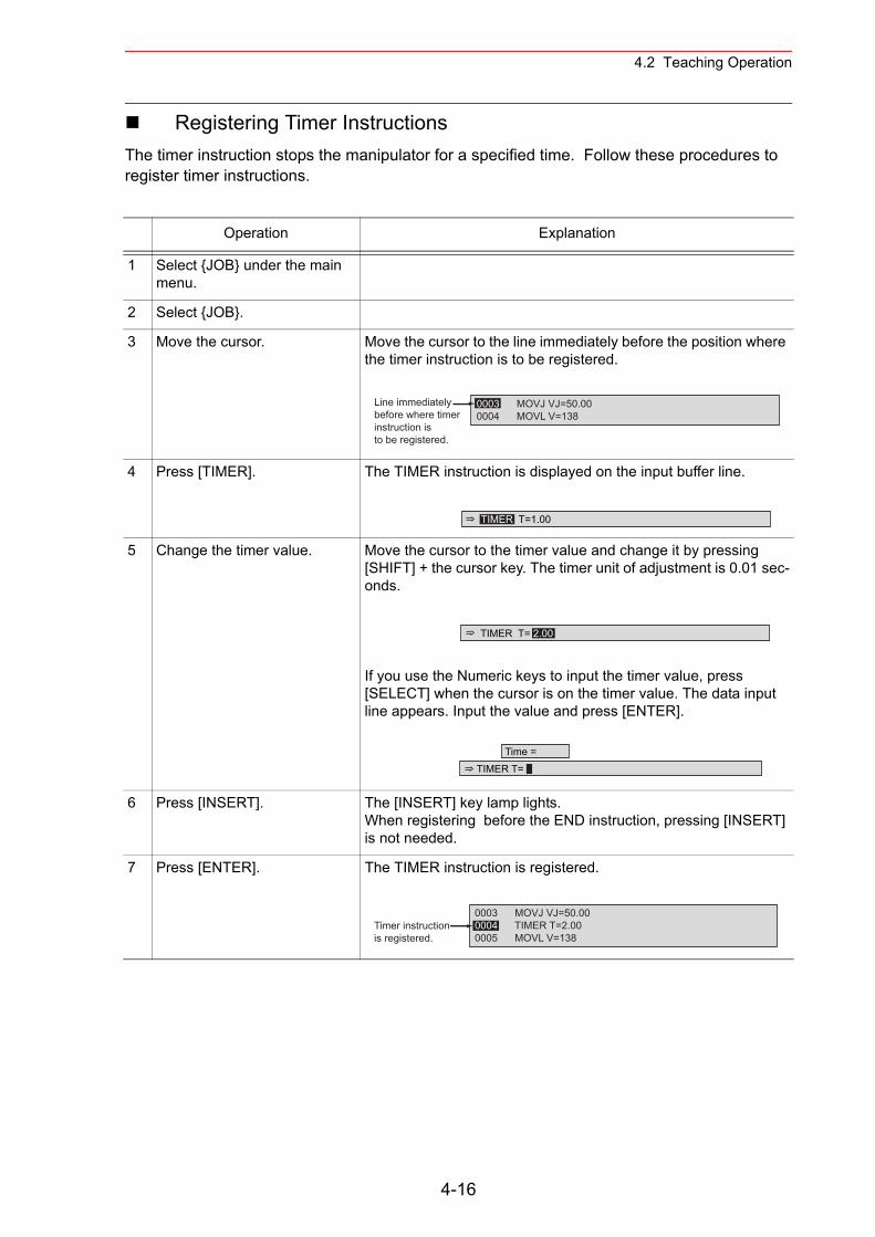
4.2 Teaching Operation
Registering Timer InstructionsThe timer instruction stops the manipulator for a specified time. Follow these procedures to register timer instructions.
Operation Explanation
1 Select {JOB} under the main menu.
2 Select {JOB}.
3 Move the cursor. Move the cursor to the line immediately before the position where the timer instruction is to be registered.
4 Press [TIMER]. The TIMER instruction is displayed on the input buffer line.
5 Change the timer value. Move the cursor to the timer value and change it by pressing [SHIFT] + the cursor key. The timer unit of adjustment is 0.01 sec-onds.
If you use the Numeric keys to input the timer value, press [SELECT] when the cursor is on the timer value. The data input line appears. Input the value and press [ENTER].
6 Press [INSERT]. The [INSERT] key lamp lights.When registering before the END instruction, pressing [INSERT] is not needed.
7 Press [ENTER]. The TIMER instruction is registered.
0003 MOVJ VJ=50.000004 MOVL V=138
Line immediatelybefore where timerinstruction is to be registered.
TIMER T=1.00
TIMER T= 2.00
Time =TIMER T=
0003 MOVJ VJ=50.000004 TIMER T=2.000005 MOVL V=138
Timer instructionis registered.
4-16
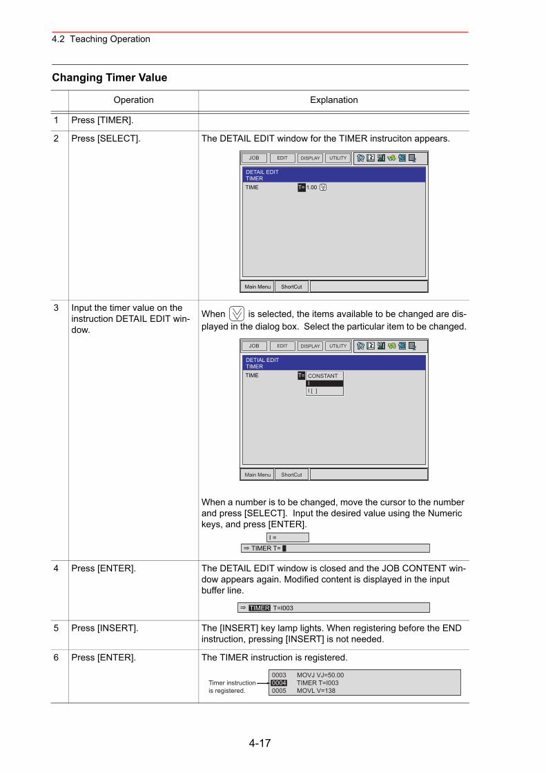
4.2 Teaching Operation
Changing Timer Value
Operation Explanation
1 Press [TIMER].
2 Press [SELECT]. The DETAIL EDIT window for the TIMER instruciton appears.
3 Input the timer value on the instruction DETAIL EDIT win-dow.
When is selected, the items available to be changed are dis-played in the dialog box. Select the particular item to be changed.
When a number is to be changed, move the cursor to the number and press [SELECT]. Input the desired value using the Numeric keys, and press [ENTER].
4 Press [ENTER]. The DETAIL EDIT window is closed and the JOB CONTENT win-dow appears again. Modified content is displayed in the input buffer line.
5 Press [INSERT]. The [INSERT] key lamp lights. When registering before the END instruction, pressing [INSERT] is not needed.
6 Press [ENTER]. The TIMER instruction is registered.
JOB UTILITYEDIT DISPLAY
Main Menu ShortCut
DETAIL EDITTIMERTIME T= 1.00
JOB UTILITYEDIT DISPLAY
Main Menu ShortCut
DETIAL EDITTIMERTIME T= 1.00CONSTANT
II [ ]
I =TIMER T=
TIMER T=I003
0003 MOVJ VJ=50.000004 TIMER T=I0030005 MOVL V=138
Timer instructionis registered.
4-17
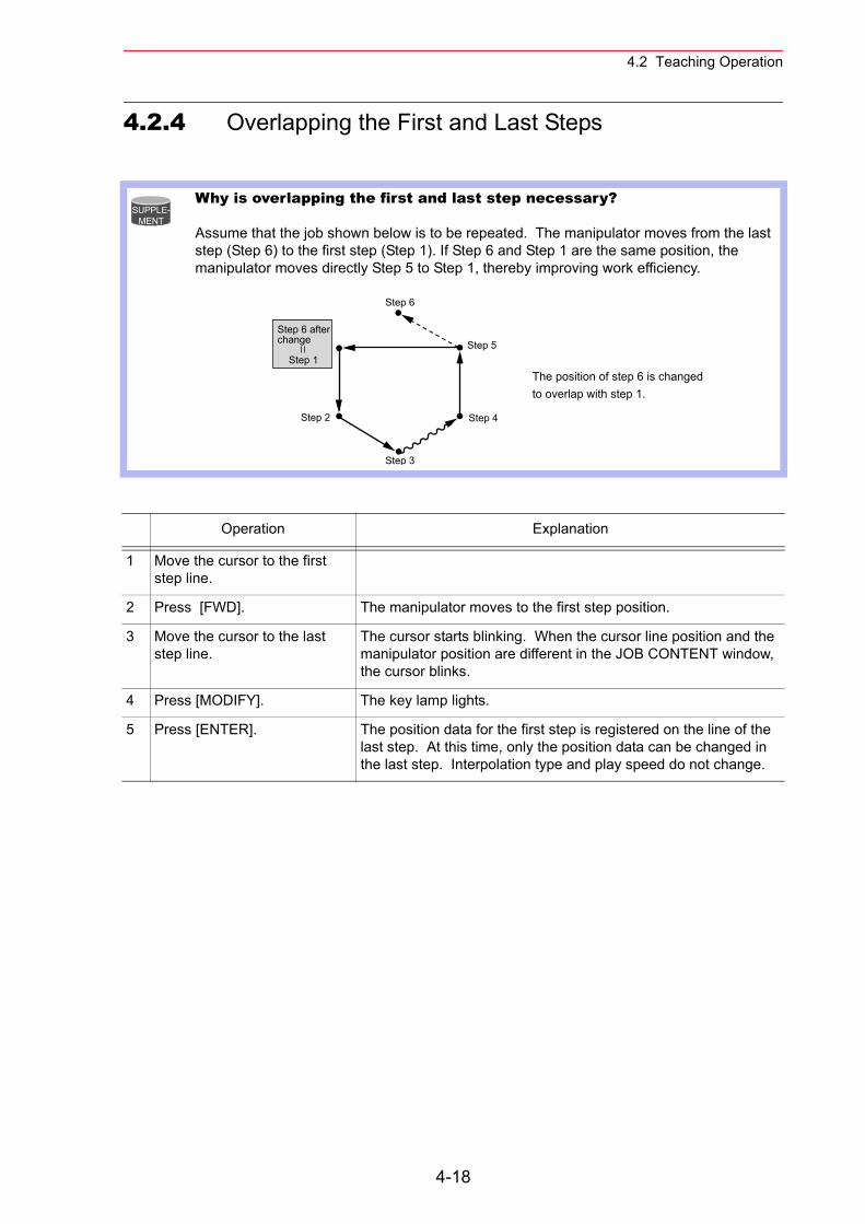
4.2 Teaching Operation
4.2.4 Overlapping the First and Last Steps
Why is overlapping the first and last step necessary?
Assume that the job shown below is to be repeated. The manipulator moves from the last step (Step 6) to the first step (Step 1). If Step 6 and Step 1 are the same position, the manipulator moves directly Step 5 to Step 1, thereby improving work efficiency.
Operation Explanation
1 Move the cursor to the first step line.
2 Press [FWD]. The manipulator moves to the first step position.
3 Move the cursor to the last step line.
The cursor starts blinking. When the cursor line position and the manipulator position are different in the JOB CONTENT window, the cursor blinks.
4 Press [MODIFY]. The key lamp lights.
5 Press [ENTER]. The position data for the first step is registered on the line of the last step. At this time, only the position data can be changed in the last step. Interpolation type and play speed do not change.
SUPPLE-MENT
Step 2
Step 3
Step 4
Step 5
The position of step 6 is changedto overlap with step 1.
Step 6
Step 6 afterchange
Step 1
4-18
4.3 Checking Steps
4.3 Checking Steps
4.3.1 FWD/BWD Key Operations
Check whether the position of the taught steps is appropriate using [FWD] or [BWD] on the programming pendant. Each time [FWD] or [BWD] is pressed, the manipulator moves by a single step.
[FWD] : Moves the manipulator ahead in step number sequence. Only the move instruction is executed when [FWD] is pressed, but when [INTERLOCK] + [FWD] are pressed, all instructions are executed. When [SHIFT] + [FWD] are pressed, the move instructions are executed in succession.
[BWD] : Moves the manipulator backward a step at a time in reverse step number sequence. Only the move instruction is executed.
For safety, set manual speed at or below.
Operation Explanation
1 Move the cursor to the step to be confirmed.
2 Press [FWD] or [BWD]. If [FWD] / [BWD] are continuously pressed, the manipulator reaches the following / previous step and stops.
To skip over a step, press [SHIFT] + the cursor key to move the cursor to desired position and press [FWD] or [BWD]. The manip-ulator moves directly to the step where the cursor is currently positioned.
NOTE
Even if [FWD] is pressed, the manipulator does not proceed to the next job when an instruction other than the move instruction is registered. To proceed to the next job, perform either of the following oper-ations:
When executing instructions other than the move instruction : Press [INTERLOCK] + [FWD].When not executing instructions other than the move instruction : Move the cursor to the next move instruction and press [FWD].When executing move instructions in succes-sion : Press [SHIFT] + [FWD].
NOTE
4-19
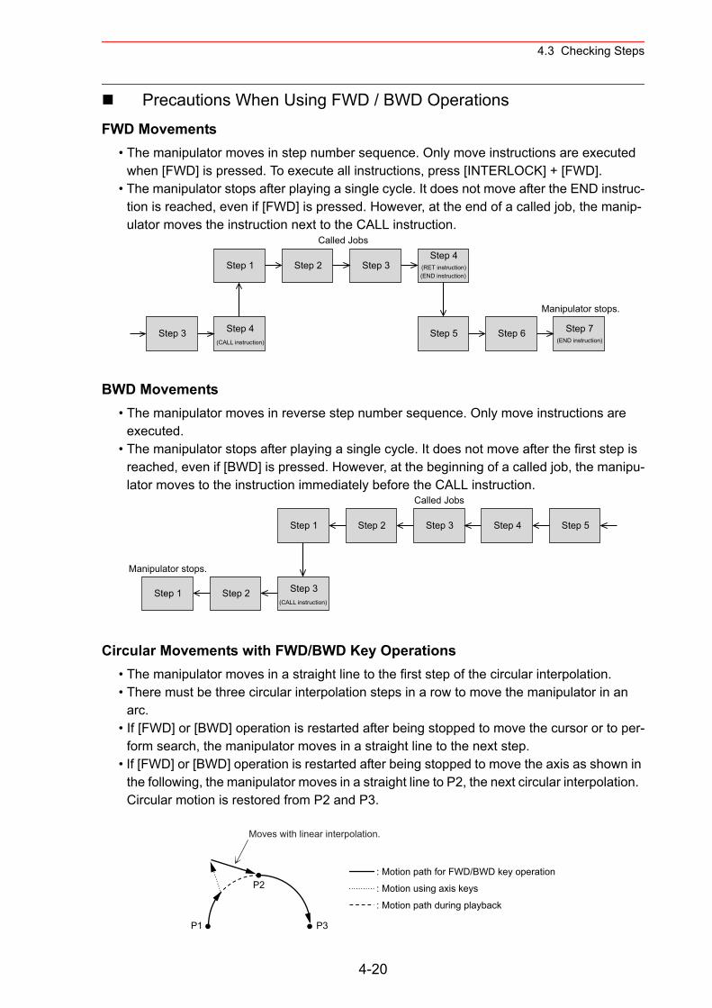
4.3 Checking Steps
Precautions When Using FWD / BWD OperationsFWD Movements
• The manipulator moves in step number sequence. Only move instructions are executed when [FWD] is pressed. To execute all instructions, press [INTERLOCK] + [FWD].
• The manipulator stops after playing a single cycle. It does not move after the END instruc-tion is reached, even if [FWD] is pressed. However, at the end of a called job, the manip-ulator moves the instruction next to the CALL instruction.
BWD Movements• The manipulator moves in reverse step number sequence. Only move instructions are
executed.• The manipulator stops after playing a single cycle. It does not move after the first step is
reached, even if [BWD] is pressed. However, at the beginning of a called job, the manipu-lator moves to the instruction immediately before the CALL instruction.
Circular Movements with FWD/BWD Key Operations• The manipulator moves in a straight line to the first step of the circular interpolation.• There must be three circular interpolation steps in a row to move the manipulator in an
arc.• If [FWD] or [BWD] operation is restarted after being stopped to move the cursor or to per-
form search, the manipulator moves in a straight line to the next step.• If [FWD] or [BWD] operation is restarted after being stopped to move the axis as shown in
the following, the manipulator moves in a straight line to P2, the next circular interpolation. Circular motion is restored from P2 and P3.
Step 3 Step 4
Step 1 Step 2 Step 3Step 4
Step 5 Step 6
Manipulator stops.
Called Jobs
Step 7(END instruction)
(RET instruction)(END instruction)
(CALL instruction)
Step 2 Step 3
Step 1 Step 2 Step 3
Step 1
Manipulator stops.
Step 4 Step 5
Called Jobs
(CALL instruction)
P2
P1 P3
: Motion path for FWD/BWD key operation
: Motion using axis keys
: Motion path during playback
Moves with linear interpolation.
4-20
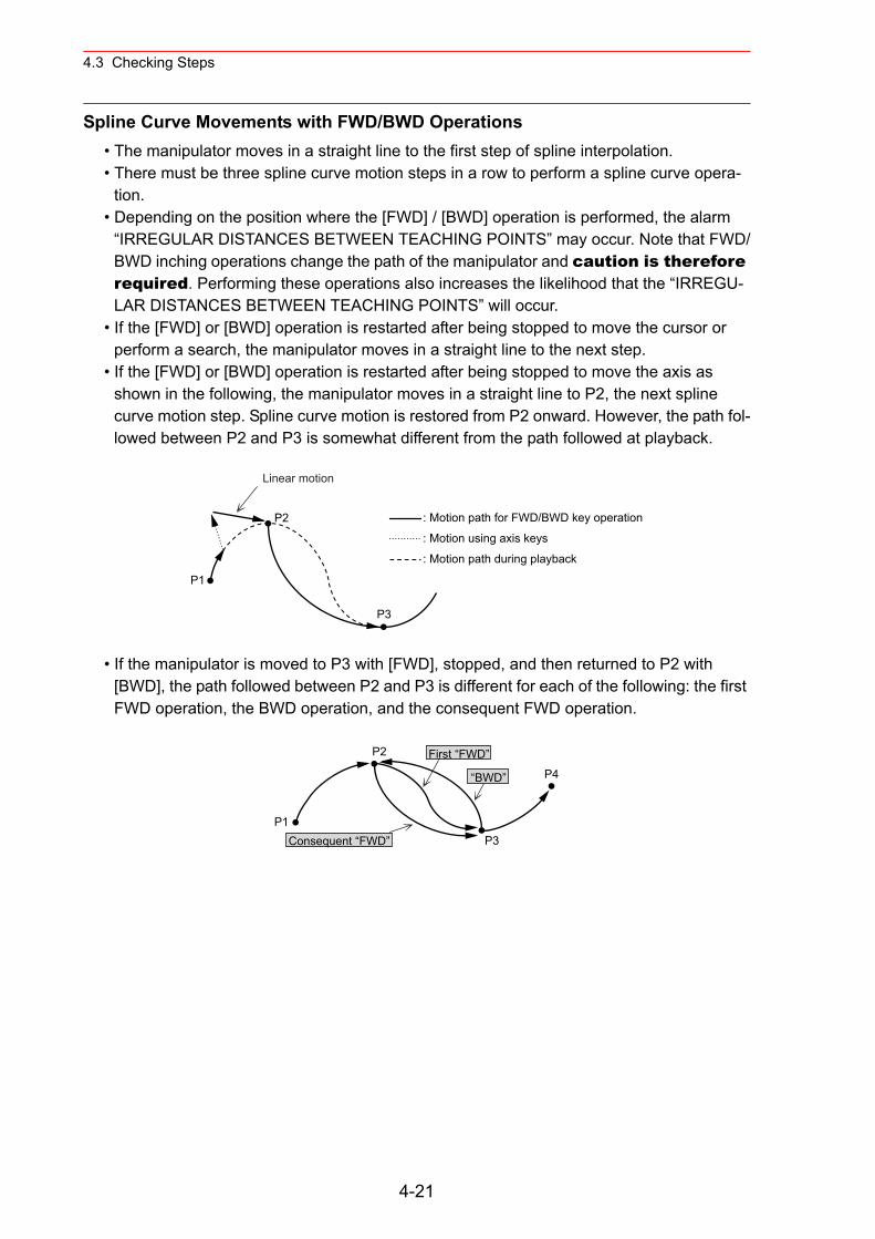
4.3 Checking Steps
Spline Curve Movements with FWD/BWD Operations• The manipulator moves in a straight line to the first step of spline interpolation.• There must be three spline curve motion steps in a row to perform a spline curve opera-
tion.• Depending on the position where the [FWD] / [BWD] operation is performed, the alarm
“IRREGULAR DISTANCES BETWEEN TEACHING POINTS” may occur. Note that FWD/BWD inching operations change the path of the manipulator and caution is therefore required. Performing these operations also increases the likelihood that the “IRREGU-LAR DISTANCES BETWEEN TEACHING POINTS” will occur.
• If the [FWD] or [BWD] operation is restarted after being stopped to move the cursor or perform a search, the manipulator moves in a straight line to the next step.
• If the [FWD] or [BWD] operation is restarted after being stopped to move the axis as shown in the following, the manipulator moves in a straight line to P2, the next spline curve motion step. Spline curve motion is restored from P2 onward. However, the path fol-lowed between P2 and P3 is somewhat different from the path followed at playback.
• If the manipulator is moved to P3 with [FWD], stopped, and then returned to P2 with [BWD], the path followed between P2 and P3 is different for each of the following: the first FWD operation, the BWD operation, and the consequent FWD operation.
P2
P1
P3
Linear motion
: Motion path for FWD/BWD key operation
: Motion using axis keys
: Motion path during playback
P2
P1P3
P4
4-21
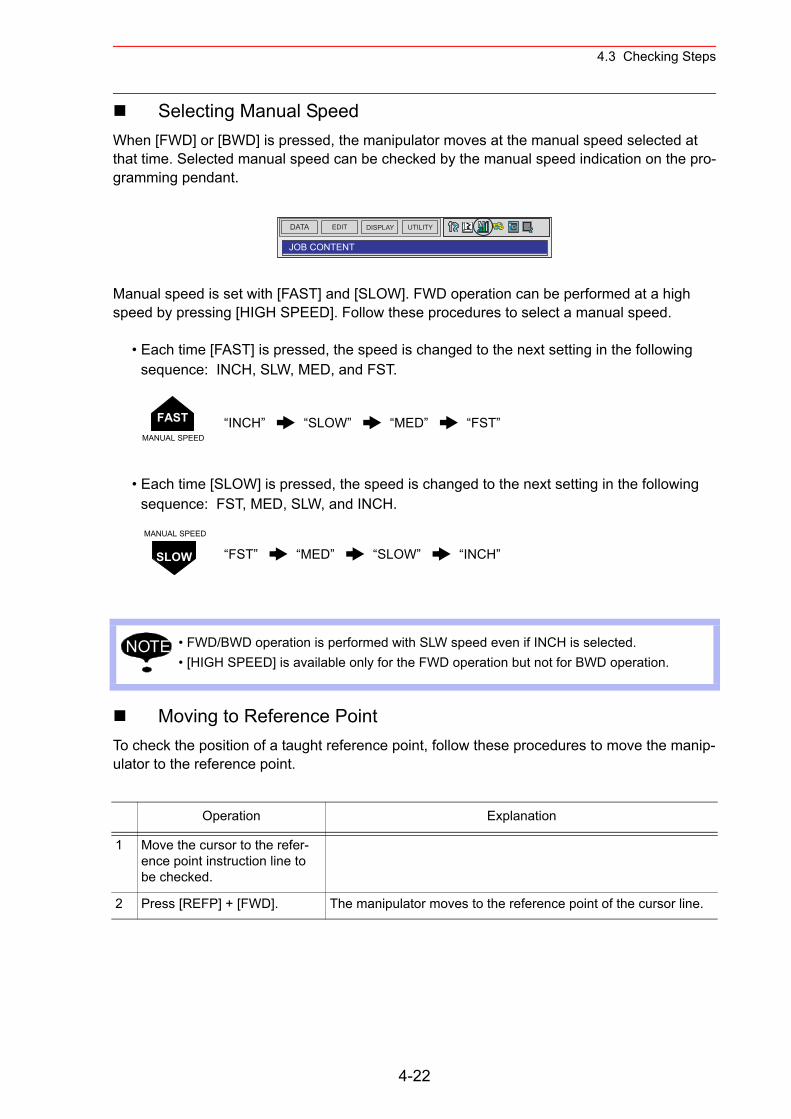
4.3 Checking Steps
Selecting Manual SpeedWhen [FWD] or [BWD] is pressed, the manipulator moves at the manual speed selected at that time. Selected manual speed can be checked by the manual speed indication on the pro-gramming pendant.
Manual speed is set with [FAST] and [SLOW]. FWD operation can be performed at a high speed by pressing [HIGH SPEED]. Follow these procedures to select a manual speed.
• Each time [FAST] is pressed, the speed is changed to the next setting in the following sequence: INCH, SLW, MED, and FST.
• Each time [SLOW] is pressed, the speed is changed to the next setting in the following sequence: FST, MED, SLW, and INCH.
Moving to Reference PointTo check the position of a taught reference point, follow these procedures to move the manip-ulator to the reference point.
“INCH” “SLOW” “MED” “FST”
“FST” “MED” “SLOW” “INCH”
• FWD/BWD operation is performed with SLW speed even if INCH is selected.• [HIGH SPEED] is available only for the FWD operation but not for BWD operation.
Operation Explanation
1 Move the cursor to the refer-ence point instruction line to be checked.
2 Press [REFP] + [FWD]. The manipulator moves to the reference point of the cursor line.
DATA UTILITYEDIT DISPLAY
JOB CONTENT
FASTMANUAL SPEED
SLOW
MANUAL SPEED
NOTE
4-22
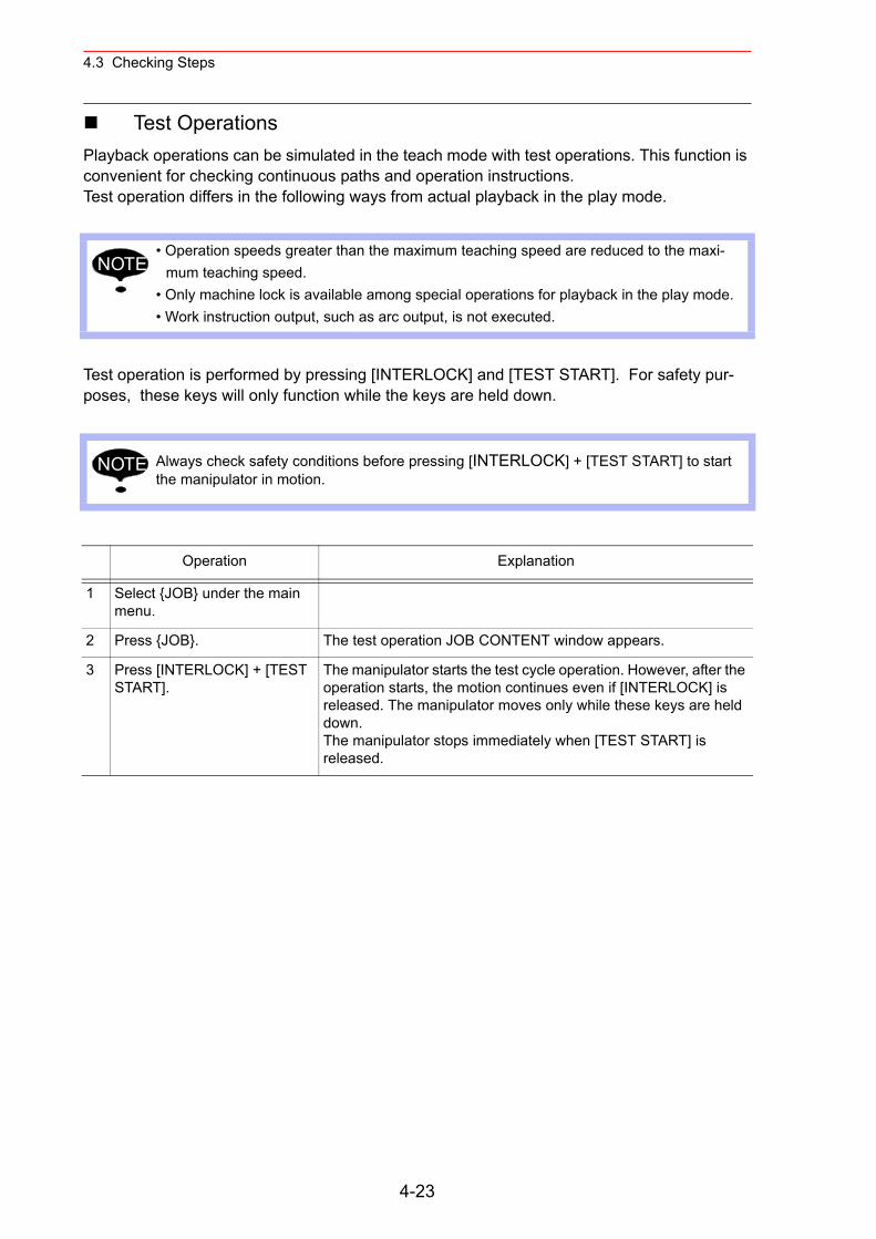
4.3 Checking Steps
Test OperationsPlayback operations can be simulated in the teach mode with test operations. This function is convenient for checking continuous paths and operation instructions.Test operation differs in the following ways from actual playback in the play mode.
Test operation is performed by pressing [INTERLOCK] and [TEST START]. For safety pur-poses, these keys will only function while the keys are held down.
• Operation speeds greater than the maximum teaching speed are reduced to the maxi-mum teaching speed.
• Only machine lock is available among special operations for playback in the play mode.• Work instruction output, such as arc output, is not executed.
Always check safety conditions before pressing [INTERLOCK] + [TEST START] to start the manipulator in motion.
Operation Explanation
1 Select {JOB} under the main menu.
2 Press {JOB}. The test operation JOB CONTENT window appears.
3 Press [INTERLOCK] + [TEST START].
The manipulator starts the test cycle operation. However, after the operation starts, the motion continues even if [INTERLOCK] is released. The manipulator moves only while these keys are held down.The manipulator stops immediately when [TEST START] is released.
NOTE
NOTE
4-23
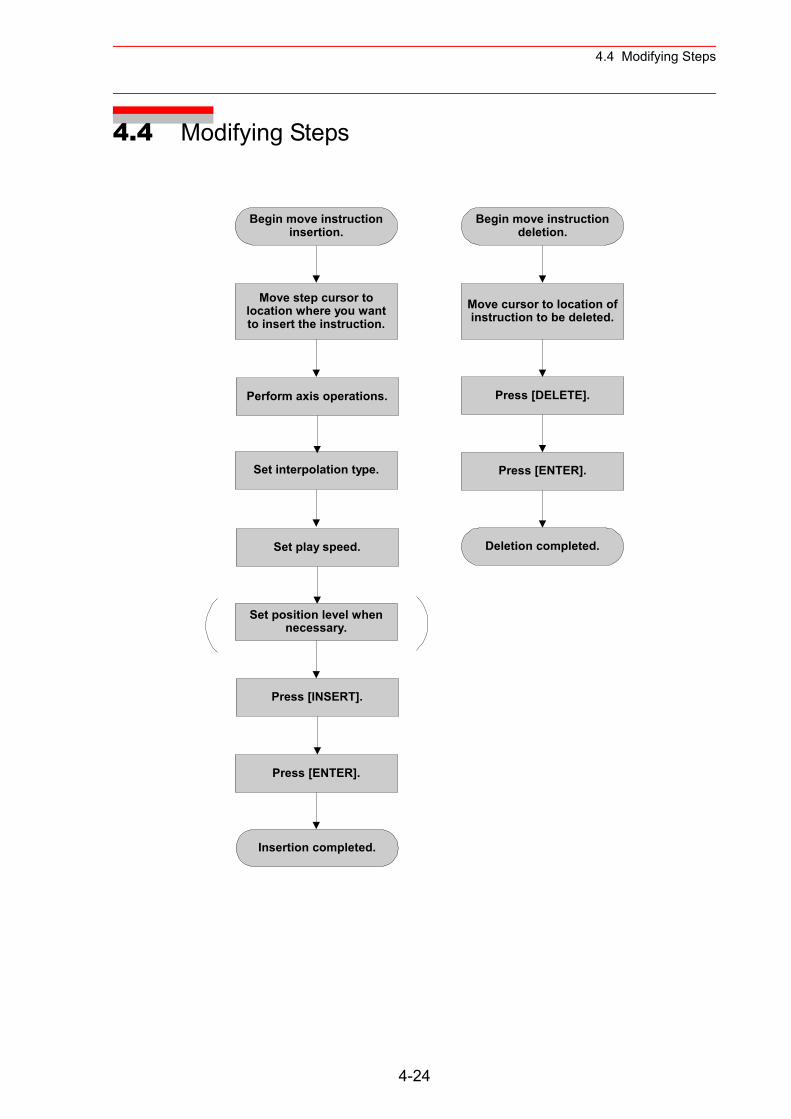
4.4 Modifying Steps
4.4 Modifying Steps
Begin move instructioninsertion.
Move step cursor tolocation where you wantto insert the instruction.
Perform axis operations.
Set interpolation type.
Set play speed.
Set position level whennecessary.
Press [ENTER].
Insertion completed.
Begin move instructiondeletion.
Move cursor to location ofinstruction to be deleted.
Press [DELETE].
Deletion completed.
Press [ENTER].
Press [INSERT].
4-24
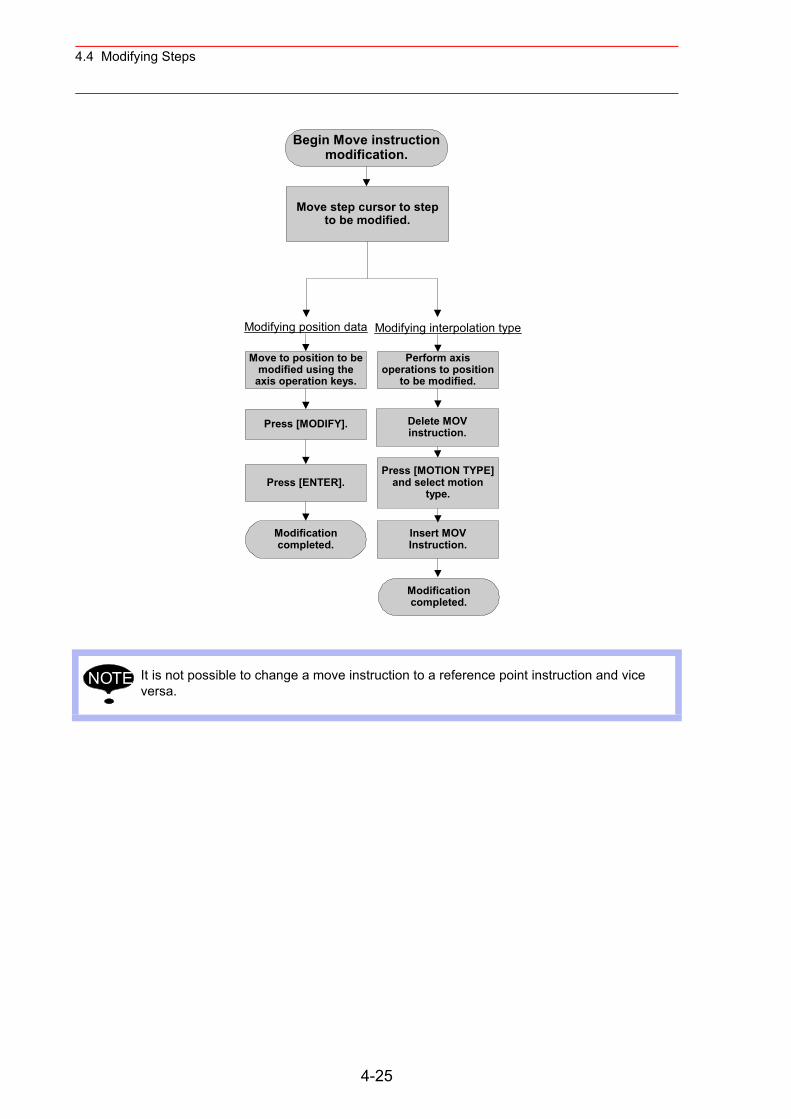
4.4 Modifying Steps
It is not possible to change a move instruction to a reference point instruction and vice versa.
Begin Move instructionmodification.
Move step cursor to stepto be modified.
Move to position to bemodified using the
axis operation keys.
Press [MODIFY].
Press [ENTER].
Modificationcompleted.
Modifying position data Modifying interpolation type
Perform axisoperations to position
to be modified.
Delete MOVinstruction.
Press [MOTION TYPE]and select motion
type.
Insert MOVInstruction.
Modificationcompleted.
NOTE
4-25
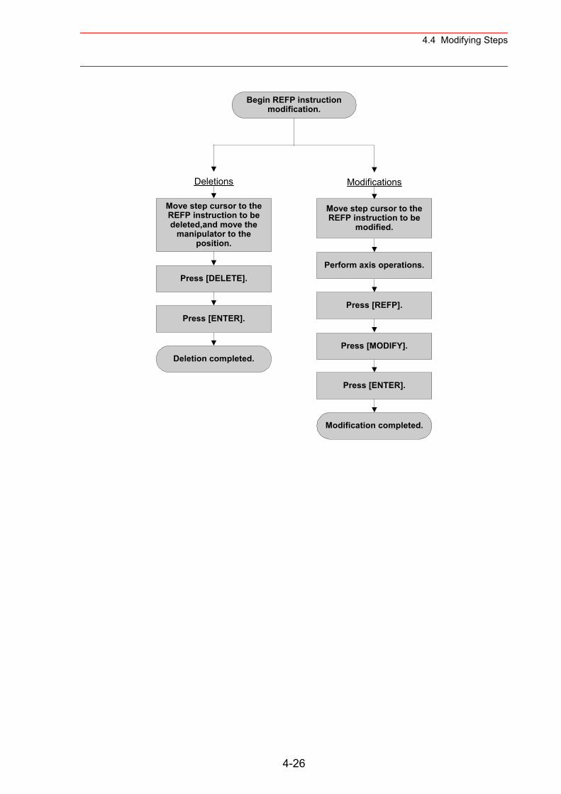
4.4 Modifying Steps
Begin REFP instructionmodification.
Move step cursor to theREFP instruction to be
modified.
Press [DELETE].
Move step cursor to theREFP instruction to bedeleted,and move the
manipulator to theposition.
Press [ENTER].
Deletion completed.
Deletions Modifications
Perform axis operations.
Press [REFP].
Press [ENTER].
Modification completed.
Press [MODIFY].
4-26
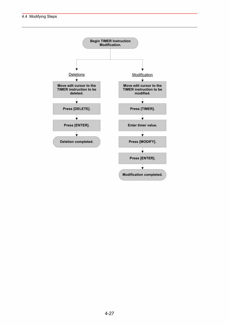
4.4 Modifying Steps
Begin TIMER InstructionModification.
Move edit cursor to theTIMER instruction to be
modified.
Press [DELETE].
Press [ENTER].
Deletion completed.
Deletions Modification
Press [TIMER].
Enter timer value.
Press [MODIFY].
Press [ENTER].
Modification completed.
Move edit cursor to theTIMER instruction to be
deleted.
4-27
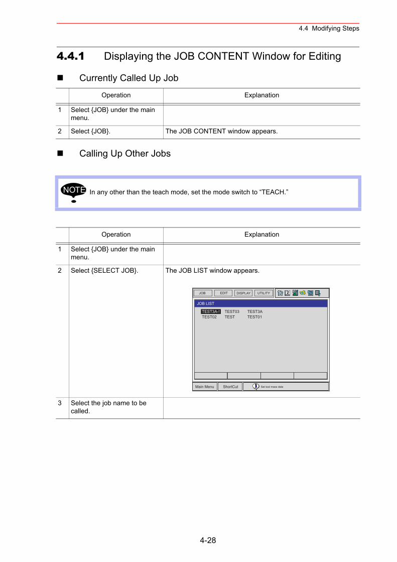
4.4 Modifying Steps
4.4.1 Displaying the JOB CONTENT Window for Editing
Currently Called Up Job
Calling Up Other Jobs
Operation Explanation
1 Select {JOB} under the main menu.
2 Select {JOB}. The JOB CONTENT window appears.
In any other than the teach mode, set the mode switch to “TEACH.”
Operation Explanation
1 Select {JOB} under the main menu.
2 Select {SELECT JOB}. The JOB LIST window appears.
3 Select the job name to be called.
NOTE
JOB UTILITYEDIT DISPLAY
Main Menu ShortCut Set tool mass data
TEST03TEST
TEST3ATEST01
JOB LIST
TEST3A-!TEST02
4-28
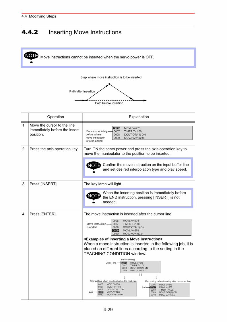
4.4 Modifying Steps
4.4.2 Inserting Move Instructions
Move instructions cannot be inserted when the servo power is OFF.
Operation Explanation
1 Move the cursor to the line immediately before the insert position.
2 Press the axis operation key. Turn ON the servo power and press the axis operation key to move the manipulator to the position to be inserted.
3 Press [INSERT]. The key lamp will light.
4 Press [ENTER]. The move instruction is inserted after the cursor line.
<Examples of Inserting a Move Instruction>When a move instruction is inserted in the following job, it is placed on different lines according to the setting in the TEACHING CONDITION window.
NOTE
Step where move instruction is to be inserted
Path before insertion
Path after insertion
0006 MOVL V=2760007 TIMER T=1.000008 DOUT OT#(1) ON0009 MOVJ VJ=100.0
Place immediatelybefore wheremove instructionis to be added.
Confirm the move instruction on the input buffer line and set desired interpolation type and play speed.
NOTE
When the inserting position is immediately before the END instruction, pressing [INSERT] is not needed.
NOTE
0006 MOVL V=2760007 TIMER T=1.000008 DOUT OT#(1) ON0009 MOVL V=5580010 MOVJ VJ=100.0
Move instructionis added.
0006 MOVL V=2760007 TIMER T=1.000008 DOUT OT#(1) ON0009 MOVL V=5580010 MOVJ VJ=100.0
Add
0006 MOVL V=2760007 MOVL V=5580008 TIMER T=1.000009 DOUT OT#(1) ON0010 MOVJ VJ=100.0
Add
Before adding
After adding: when inserting before the next step After adding: when inserting after the cursor line
0006 MOVL V=2760007 TIMER T=1.000008 DOUT OT#(1) ON0009 MOVJ VJ=100.0
Cursor line
4-29
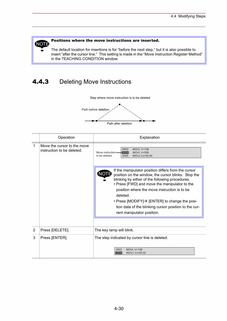
4.4 Modifying Steps
4.4.3 Deleting Move Instructions
Positions where the move instructions are inserted.
The default location for insertions is for “before the next step,” but it is also possible to insert “after the cursor line.” This setting is made in the “Move Instruction Register Method” in the TEACHING CONDITION window.
Operation Explanation
1 Move the cursor to the move instruction to be deleted.
2 Press [DELETE]. The key lamp will blink.
3 Press [ENTER]. The step indicated by cursor line is deleted.
NOTE
Step where move instruction is to be deleted
Path after deletion
Path before deletion
0003 MOVL V=1380004 MOVL V=5580005 MOVJ VJ=50.00
Move instructionto be deleted
If the manipulator position differs from the cursor position on the window, the cursor blinks. Stop the blinking by either of the following procedures.• Press [FWD] and move the manipulator to the
position where the move instruction is to be deleted.
• Press [MODIFY] [ENTER] to change the posi-tion data of the blinking cursor position to the cur-rent manipulator position.
NOTE
0003 MOVL V=1380004 MOVJ VJ=50.00
4-30
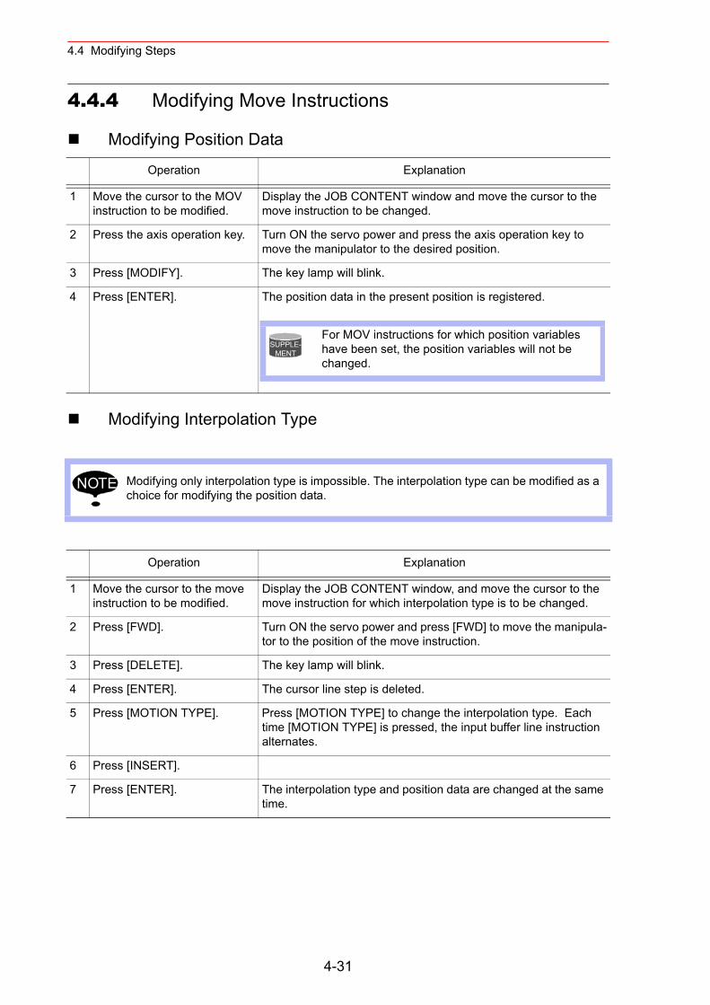
4.4 Modifying Steps
4.4.4 Modifying Move Instructions
Modifying Position Data
Modifying Interpolation Type
Operation Explanation
1 Move the cursor to the MOV instruction to be modified.
Display the JOB CONTENT window and move the cursor to the move instruction to be changed.
2 Press the axis operation key. Turn ON the servo power and press the axis operation key to move the manipulator to the desired position.
3 Press [MODIFY]. The key lamp will blink.
4 Press [ENTER]. The position data in the present position is registered.
Modifying only interpolation type is impossible. The interpolation type can be modified as a choice for modifying the position data.
Operation Explanation
1 Move the cursor to the move instruction to be modified.
Display the JOB CONTENT window, and move the cursor to the move instruction for which interpolation type is to be changed.
2 Press [FWD]. Turn ON the servo power and press [FWD] to move the manipula-tor to the position of the move instruction.
3 Press [DELETE]. The key lamp will blink.
4 Press [ENTER]. The cursor line step is deleted.
5 Press [MOTION TYPE]. Press [MOTION TYPE] to change the interpolation type. Each time [MOTION TYPE] is pressed, the input buffer line instruction alternates.
6 Press [INSERT].
7 Press [ENTER]. The interpolation type and position data are changed at the same time.
For MOV instructions for which position variables have been set, the position variables will not be changed.
SUPPLE-MENT
NOTE
4-31
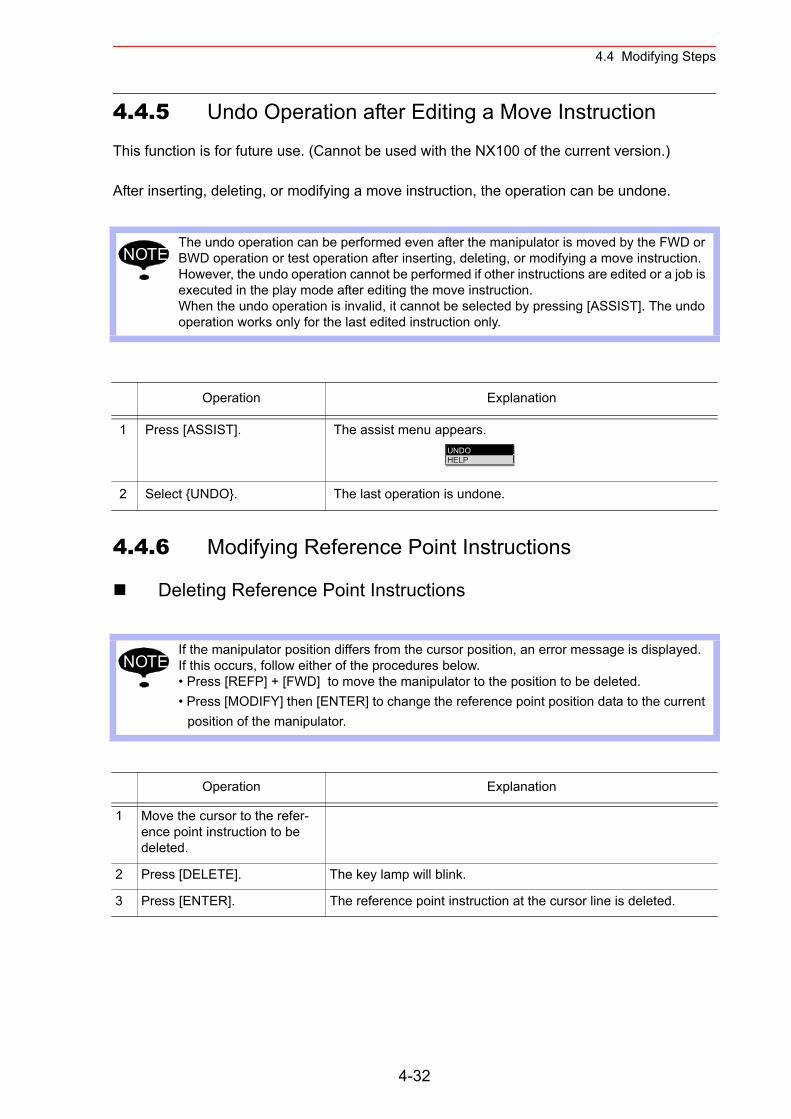
4.4 Modifying Steps
4.4.5 Undo Operation after Editing a Move Instruction
This function is for future use. (Cannot be used with the NX100 of the current version.)
After inserting, deleting, or modifying a move instruction, the operation can be undone.
4.4.6 Modifying Reference Point Instructions
Deleting Reference Point Instructions
The undo operation can be performed even after the manipulator is moved by the FWD or BWD operation or test operation after inserting, deleting, or modifying a move instruction. However, the undo operation cannot be performed if other instructions are edited or a job is executed in the play mode after editing the move instruction.When the undo operation is invalid, it cannot be selected by pressing [ASSIST]. The undo operation works only for the last edited instruction only.
Operation Explanation
1 Press [ASSIST]. The assist menu appears.
2 Select {UNDO}. The last operation is undone.
If the manipulator position differs from the cursor position, an error message is displayed. If this occurs, follow either of the procedures below.• Press [REFP] + [FWD] to move the manipulator to the position to be deleted.• Press [MODIFY] then [ENTER] to change the reference point position data to the current
position of the manipulator.
Operation Explanation
1 Move the cursor to the refer-ence point instruction to be deleted.
2 Press [DELETE]. The key lamp will blink.
3 Press [ENTER]. The reference point instruction at the cursor line is deleted.
NOTE
UNDOHELP
NOTE
4-32
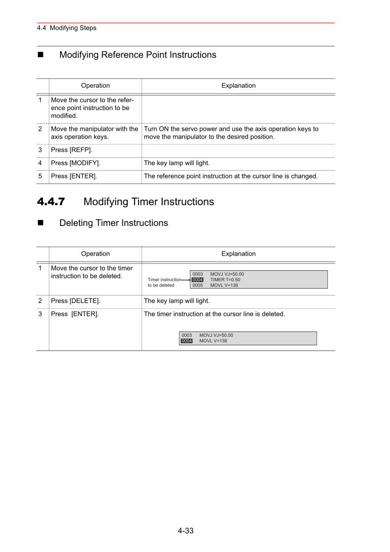
4.4 Modifying Steps
Modifying Reference Point Instructions
4.4.7 Modifying Timer Instructions
Deleting Timer Instructions
Operation Explanation
1 Move the cursor to the refer-ence point instruction to be modified.
2 Move the manipulator with the axis operation keys.
Turn ON the servo power and use the axis operation keys to move the manipulator to the desired position.
3 Press [REFP].
4 Press [MODIFY]. The key lamp will light.
5 Press [ENTER]. The reference point instruction at the cursor line is changed.
Operation Explanation
1 Move the cursor to the timer instruction to be deleted.
2 Press [DELETE]. The key lamp will light.
3 Press [ENTER]. The timer instruction at the cursor line is deleted.
0003 MOVJ VJ=50.000004 TIMER T=0.500005 MOVL V=138
Timer instructionto be deleted
0003 MOVJ VJ=50.000004 MOVL V=138
4-33
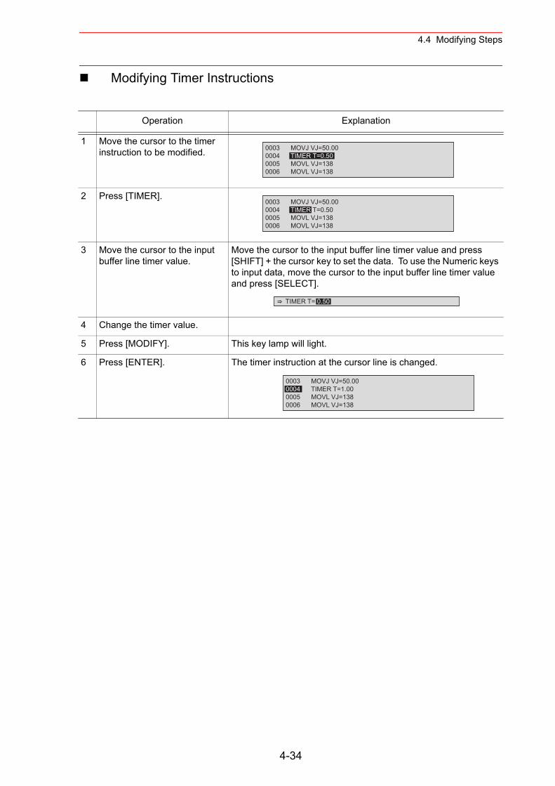
4.4 Modifying Steps
Modifying Timer Instructions
Operation Explanation
1 Move the cursor to the timer instruction to be modified.
2 Press [TIMER].
3 Move the cursor to the input buffer line timer value.
Move the cursor to the input buffer line timer value and press [SHIFT] + the cursor key to set the data. To use the Numeric keys to input data, move the cursor to the input buffer line timer value and press [SELECT].
4 Change the timer value.
5 Press [MODIFY]. This key lamp will light.
6 Press [ENTER]. The timer instruction at the cursor line is changed.
0003 MOVJ VJ=50.000004 TIMER T=0.500005 MOVL VJ=1380006 MOVL VJ=138
0003 MOVJ VJ=50.000004 TIMER T=0.500005 MOVL VJ=1380006 MOVL VJ=138
TIMER T= 0.50
0003 MOVJ VJ=50.000004 TIMER T=1.000005 MOVL VJ=1380006 MOVL VJ=138
4-34
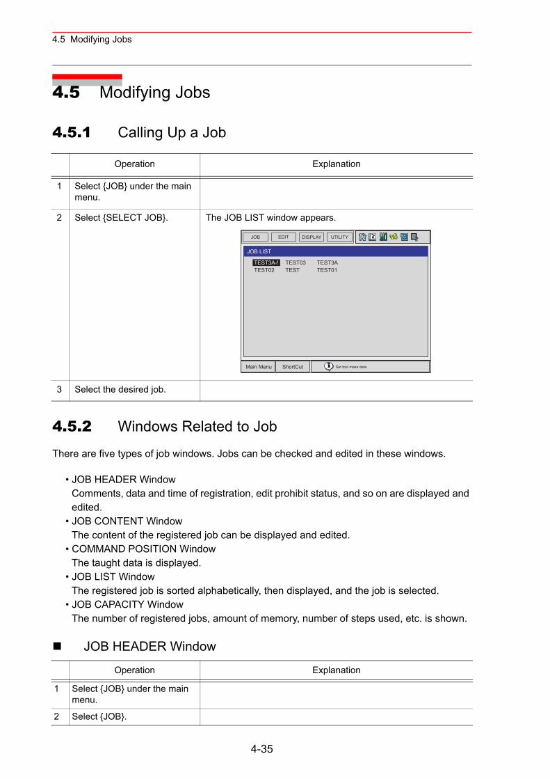
4.5 Modifying Jobs
4.5 Modifying Jobs
4.5.1 Calling Up a Job
4.5.2 Windows Related to Job
There are five types of job windows. Jobs can be checked and edited in these windows.
• JOB HEADER WindowComments, data and time of registration, edit prohibit status, and so on are displayed and edited.
• JOB CONTENT WindowThe content of the registered job can be displayed and edited.
• COMMAND POSITION WindowThe taught data is displayed.
• JOB LIST WindowThe registered job is sorted alphabetically, then displayed, and the job is selected.
• JOB CAPACITY WindowThe number of registered jobs, amount of memory, number of steps used, etc. is shown.
JOB HEADER Window
Operation Explanation
1 Select {JOB} under the main menu.
2 Select {SELECT JOB}. The JOB LIST window appears.
3 Select the desired job.
Operation Explanation
1 Select {JOB} under the main menu.
2 Select {JOB}.
JOB UTILITYEDIT DISPLAY
Main Menu ShortCut Set tool mass data
TEST03TEST
TEST3ATEST01
JOB LIST
TEST3A-!TEST02
4-35
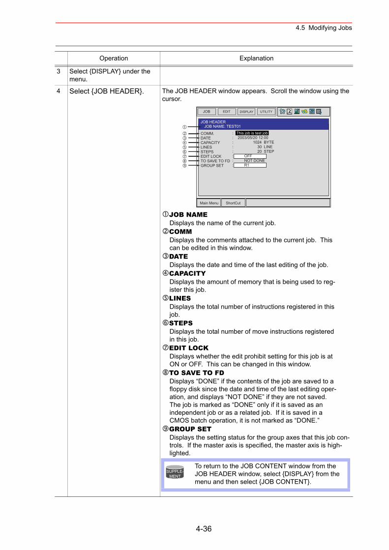
4.5 Modifying Jobs
3 Select {DISPLAY} under the menu.
4 Select {JOB HEADER}. The JOB HEADER window appears. Scroll the window using the cursor.
JOB NAMEDisplays the name of the current job.COMMDisplays the comments attached to the current job. This can be edited in this window.DATEDisplays the date and time of the last editing of the job.CAPACITYDisplays the amount of memory that is being used to reg-ister this job.LINESDisplays the total number of instructions registered in this job.STEPSDisplays the total number of move instructions registered in this job.EDIT LOCKDisplays whether the edit prohibit setting for this job is at ON or OFF. This can be changed in this window.TO SAVE TO FDDisplays “DONE” if the contents of the job are saved to a floppy disk since the date and time of the last editing oper-ation, and displays “NOT DONE” if they are not saved. The job is marked as “DONE” only if it is saved as an independent job or as a related job. If it is saved in a CMOS batch operation, it is not marked as “DONE.”GROUP SETDisplays the setting status for the group axes that this job con-trols. If the master axis is specified, the master axis is high-lighted.
Operation Explanation
JOB EDIT DISPLAY UTILITY
Main Menu ShortCut
JOB HEADERJOB NAME: TEST01
COMM.DATECAPACITYLINESSTEPSEDIT LOCKTO SAVE TO FDGROUP SET
: This job is test job: 2003/05/20 12:00: 1024 BYTE: 30 LINE: 20 STEP: OFF: NOT DONE: R1
To return to the JOB CONTENT window from the JOB HEADER window, select {DISPLAY} from the menu and then select {JOB CONTENT}.
SUPPLE-MENT
4-36
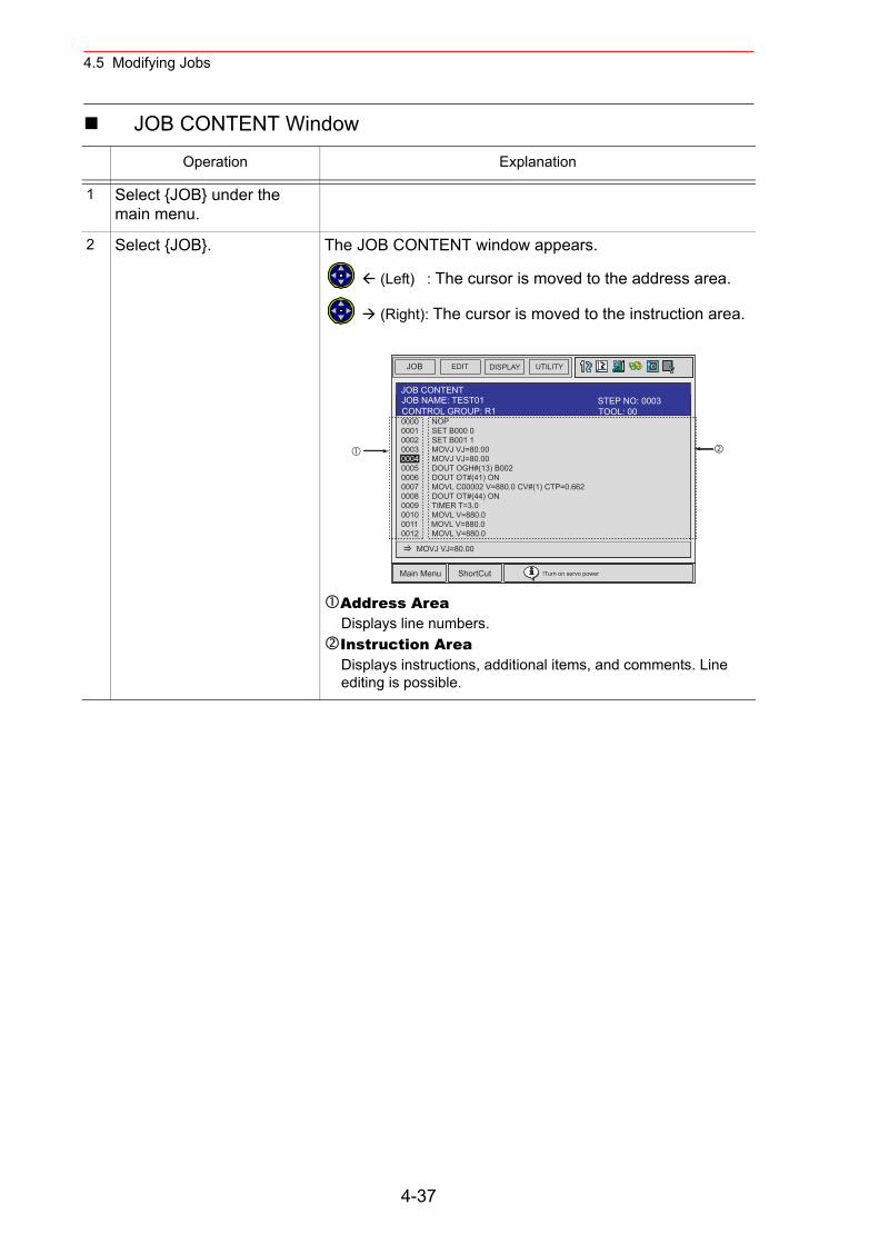
4.5 Modifying Jobs
JOB CONTENT Window
Operation Explanation
1 Select {JOB} under the main menu.
2 Select {JOB}. The JOB CONTENT window appears.
(Left) : The cursor is moved to the address area.
(Right): The cursor is moved to the instruction area.
Address AreaDisplays line numbers.Instruction AreaDisplays instructions, additional items, and comments. Line editing is possible.
JOB EDIT DISPLAY UTILITY
Main Menu ShortCut !Turn on servo power
JOB CONTENTJOB NAME: TEST01
0000 NOP0001 SET B000 00002 SET B001 10003 MOVJ VJ=80.000004 MOVJ VJ=80.000005 DOUT OGH#(13) B0020006 DOUT OT#(41) ON0007 MOVL C00002 V=880.0 CV#(1) CTP=0.6620008 DOUT OT#(44) ON0009 TIMER T=3.00010 MOVL V=880.00011 MOVL V=880.00012 MOVL V=880.0
MOVJ VJ=80.00
TOOL: 00CONTROL GROUP: R1STEP NO: 0003
4-37
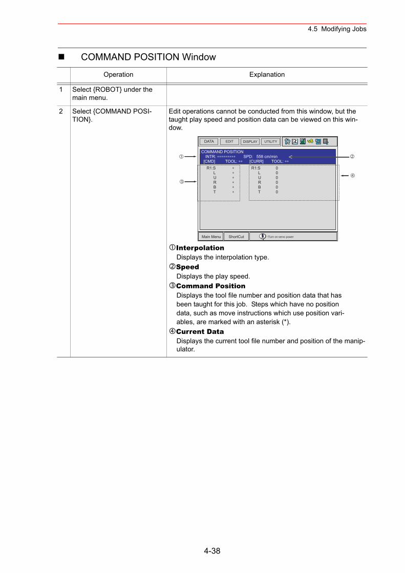
4.5 Modifying Jobs
COMMAND POSITION Window
Operation Explanation
1 Select {ROBOT} under the main menu.
2 Select {COMMAND POSI-TION}.
Edit operations cannot be conducted from this window, but the taught play speed and position data can be viewed on this win-dow.
InterpolationDisplays the interpolation type.SpeedDisplays the play speed.Command PositionDisplays the tool file number and position data that has been taught for this job. Steps which have no position data, such as move instructions which use position vari-ables, are marked with an asterisk (*).Current DataDisplays the current tool file number and position of the manip-ulator.
DATA EDIT DISPLAY UTILITY
Main Menu ShortCut !Turn on servo power
COMMAND POSITIONINTR: ∗∗∗∗∗∗∗∗∗ SPD: 558 cm/min
[CMD] TOOL: ∗∗ [CURR] TOOL: ∗∗
R1:S ∗ L ∗ U ∗ R ∗ B ∗ T ∗
R1:S 0 L 0 U 0 R 0 B 0 T 0
4-38
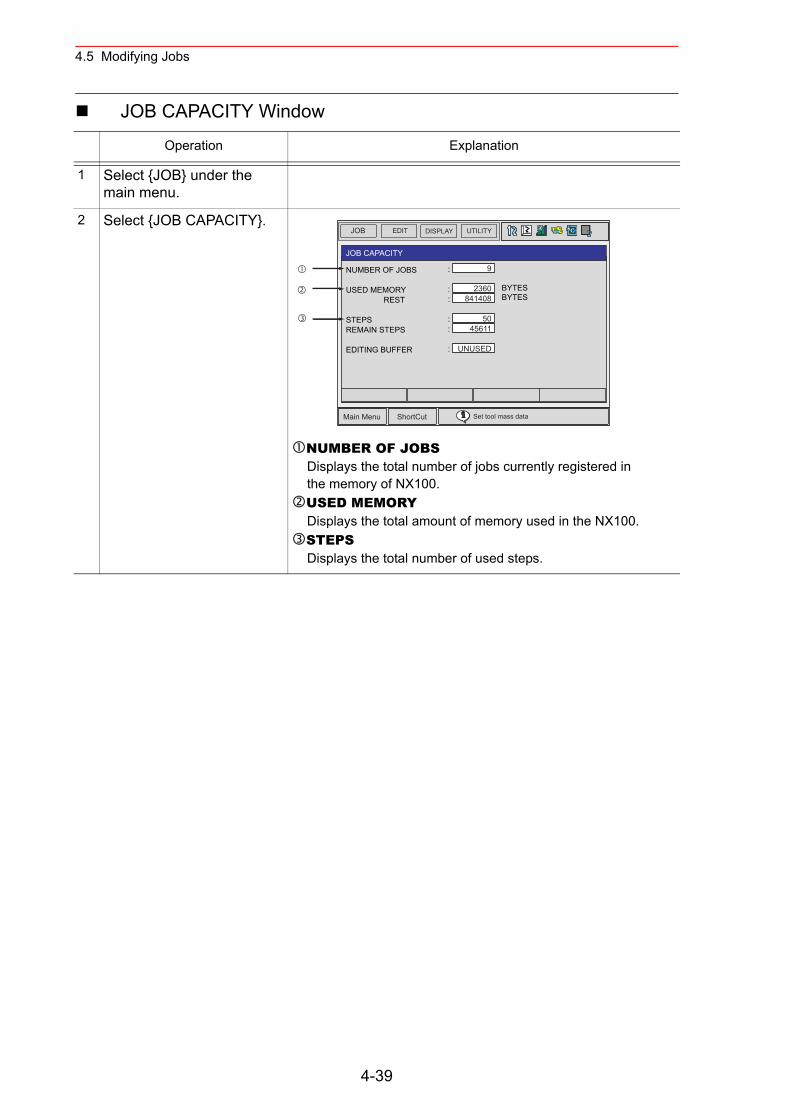
4.5 Modifying Jobs
JOB CAPACITY Window
Operation Explanation
1 Select {JOB} under the main menu.
2 Select {JOB CAPACITY}.
NUMBER OF JOBSDisplays the total number of jobs currently registered in the memory of NX100.USED MEMORYDisplays the total amount of memory used in the NX100.STEPSDisplays the total number of used steps.
JOB EDIT DISPLAY UTILITY
Main Menu ShortCut Set tool mass data
JOB CAPACITY
NUMBER OF JOBS
USED MEMORY REST
STEPSREMAIN STEPS
EDITING BUFFER
:
: :
: :
:
BYTESBYTES
9
2360841408
5045611
UNUSED
4-39
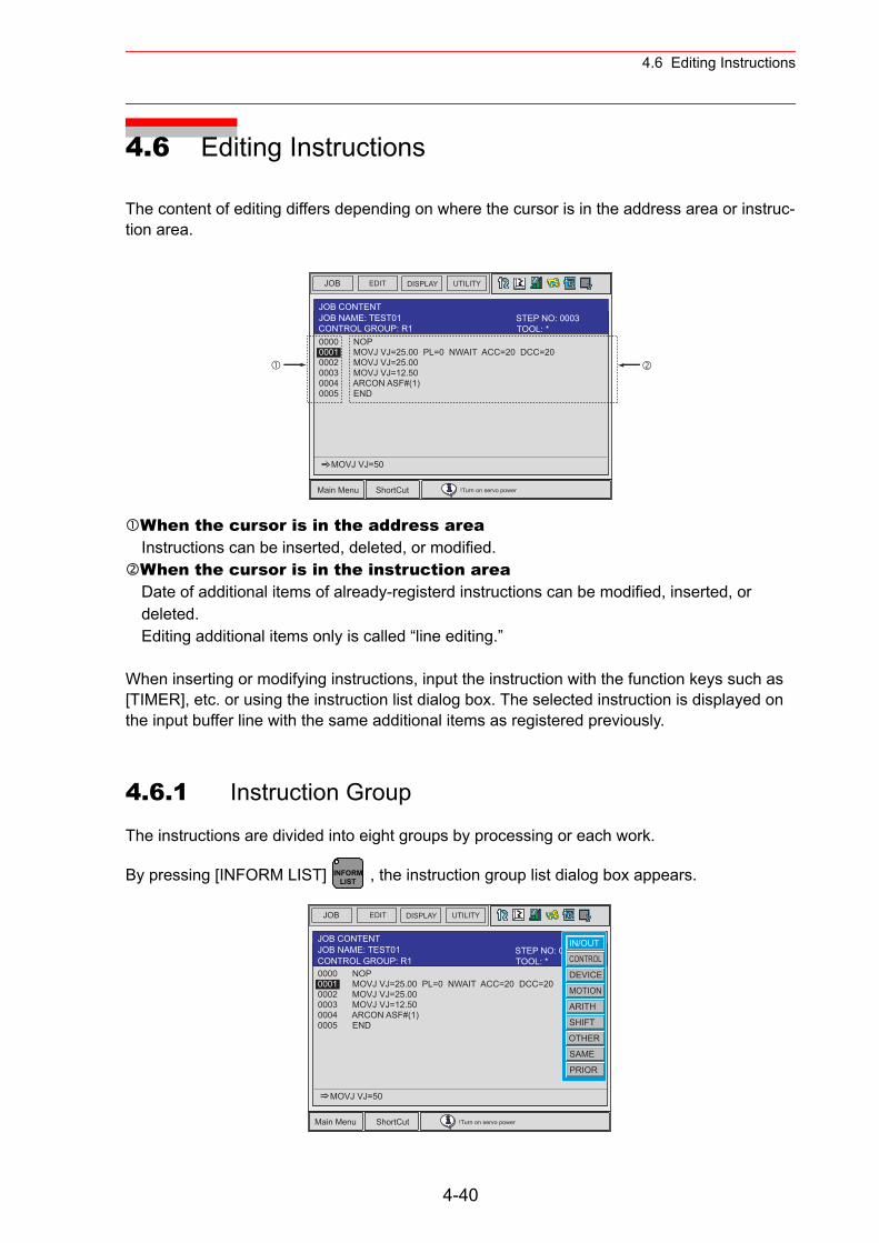
4.6 Editing Instructions
4.6 Editing Instructions
The content of editing differs depending on where the cursor is in the address area or instruc-tion area.
When the cursor is in the address areaInstructions can be inserted, deleted, or modified.When the cursor is in the instruction areaDate of additional items of already-registerd instructions can be modified, inserted, or deleted.Editing additional items only is called “line editing.”
When inserting or modifying instructions, input the instruction with the function keys such as [TIMER], etc. or using the instruction list dialog box. The selected instruction is displayed on the input buffer line with the same additional items as registered previously.
4.6.1 Instruction Group
The instructions are divided into eight groups by processing or each work.
By pressing [INFORM LIST] , the instruction group list dialog box appears.
JOB EDIT DISPLAY UTILITY
Main Menu ShortCut !Turn on servo power
JOB CONTENT
0000 NOP0001 MOVJ VJ=25.00 PL=0 NWAIT ACC=20 DCC=200002 MOVJ VJ=25.000003 MOVJ VJ=12.500004 ARCON ASF#(1) 0005 END
MOVJ VJ=50
JOB NAME: TEST01TOOL: *CONTROL GROUP: R1STEP NO: 0003
INFORMLIST
JOB EDIT DISPLAY UTILITY
Main Menu ShortCut !Turn on servo power
JOB CONTENT
0000 NOP0001 MOVJ VJ=25.00 PL=0 NWAIT ACC=20 DCC=200002 MOVJ VJ=25.000003 MOVJ VJ=12.500004 ARCON ASF#(1) 0005 END
MOVJ VJ=50
JOB NAME: TEST01 STEP NO: 0003TOOL: *CONTROL GROUP: R1
IN/OUT
CONTROL
DEVICE
MOTION
ARITH
SHIFT
OTHER
SAME
PRIOR
4-40
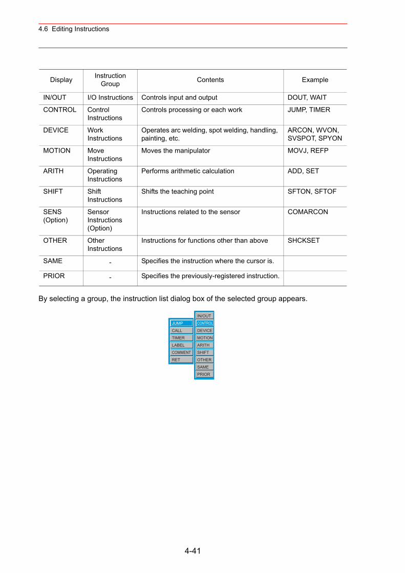
4.6 Editing Instructions
By selecting a group, the instruction list dialog box of the selected group appears.
Display Instruction Group Contents Example
IN/OUT I/O Instructions Controls input and output DOUT, WAIT
CONTROL Control Instructions
Controls processing or each work JUMP, TIMER
DEVICE Work Instructions
Operates arc welding, spot welding, handling, painting, etc.
ARCON, WVON, SVSPOT, SPYON
MOTION Move Instructions
Moves the manipulator MOVJ, REFP
ARITH Operating Instructions
Performs arithmetic calculation ADD, SET
SHIFT Shift Instructions
Shifts the teaching point SFTON, SFTOF
SENS (Option)
Sensor Instructions (Option)
Instructions related to the sensor COMARCON
OTHER Other Instructions
Instructions for functions other than above SHCKSET
SAME - Specifies the instruction where the cursor is.
PRIOR - Specifies the previously-registered instruction.
JUMP
CALL
TIMER
LABEL
COMMENT
RET
IN/OUT
CONTROL
DEVICE
MOTION
ARITH
SHIFT
OTHER
SAME
PRIOR
4-41

4.6 Editing Instructions
4.6.2 Inserting Instructions
Operation Explanation
1 Move the cursor to the address area in the JOB CON-TENT window.
Move the cursor to the line immediately before where the instruc-tion is to be inserted, in the teach mode.
2 Press [INFORM LIST]. The INFORM command list appears, and an underline is dis-played beneath the line number in the address area.
3 Select the instruction group. The instruction list dialog box appears. The selected instruction is displayed on the input buffer line with the same additional items as registered previously.
4 Select the instruction.
0000 NOP0001 MOVJ VJ=25.00 PL=0 NWAIT ACC=20 DCC=200002 MOVJ VJ=25.00
Line beforewhere instructionis to be added.
JOB EDIT DISPLAY UTILITY
Main Menu ShortCut !Turn on servo power
JOB CONTENT
0000 NOP0001 MOVJ VJ=25.00 PL=0 NWAIT ACC=20 DCC=200002 MOVJ VJ=25.000003 MOVJ VJ=12.500004 ARCON ASF#(1) 0005 END
MOVJ VJ=50
JOB NAME: TEST01 STEP NO: 0003TOOL: *CONTROL GROUP: R1
IN/OUT
CONTROL
DEVICE
MOTION
ARITH
SHIFT
OTHER
SAME
PRIOR
JOB EDIT DISPLAY UTILITY
Main Menu ShortCut !Turn on servo power
JOB CONTENT
0000 NOP0001 MOVJ VJ=25.00 PL=0 NWAIT ACC=20 DCC=200002 MOVJ VJ=25.000003 MOVJ VJ=12.500004 ARCON ASF#(1) 0005 END
JUMP *LABEL
JOB NAME: TEST01 STEP NO: 0003TOOL: *CONTROL GROUP: R1 JUMP
CALL
TIMER
LABEL
COMMENT
RET
IN/OUT
CONTROL
DEVICE
MOTION
ARITH
SHIFT
OTHER
SAME
PRIOR
4-42
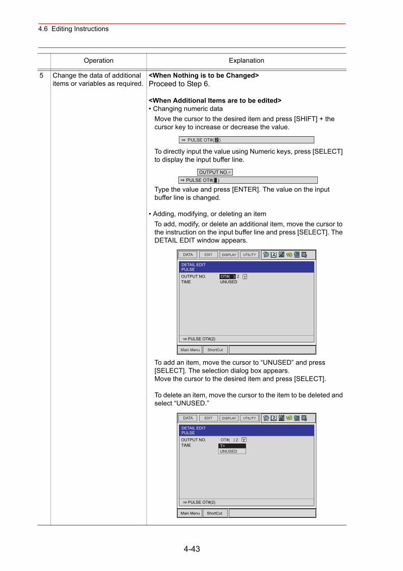
4.6 Editing Instructions
5 Change the data of additional items or variables as required.
<When Nothing is to be Changed>Proceed to Step 6.
<When Additional Items are to be edited>• Changing numeric data
Move the cursor to the desired item and press [SHIFT] + the cursor key to increase or decrease the value.
To directly input the value using Numeric keys, press [SELECT] to display the input buffer line.
Type the value and press [ENTER]. The value on the input buffer line is changed.
• Adding, modifying, or deleting an itemTo add, modify, or delete an additional item, move the cursor to the instruction on the input buffer line and press [SELECT]. The DETAIL EDIT window appears.
To add an item, move the cursor to “UNUSED” and press [SELECT]. The selection dialog box appears.Move the cursor to the desired item and press [SELECT].
To delete an item, move the cursor to the item to be deleted and select “UNUSED.”
Operation Explanation
PULSE OT#( 2 )
OUTPUT NO.PULSE OT#( )
DATA UTILITYEDIT DISPLAY
Main Menu ShortCut
DETAIL EDITPULSE
OUTPUT NO. OT#( ) 2TIME UNUSED
PULSE OT#(2)
DATA UTILITYEDIT DISPLAY
Main Menu ShortCut
DETAIL EDITPULSE
OUTPUT NO. OT#( ) 2TIME
PULSE OT#(2)
T=UNUSED
4-43
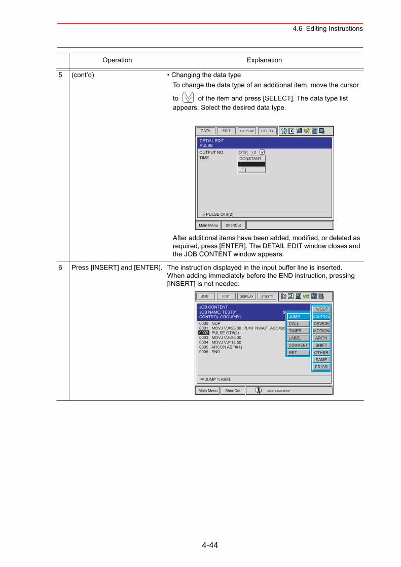
4.6 Editing Instructions
5 (cont’d) • Changing the data typeTo change the data type of an additional item, move the cursor
to of the item and press [SELECT]. The data type list appears. Select the desired data type.
After additional items have been added, modified, or deleted as required, press [ENTER]. The DETAIL EDIT window closes and the JOB CONTENT window appears.
6 Press [INSERT] and [ENTER]. The instruction displayed in the input buffer line is inserted.When adding immediately before the END instruction, pressing [INSERT] is not needed.
Operation Explanation
DATA UTILITYEDIT DISPLAY
Main Menu ShortCut
DETIAL EDITPULSE
OUTPUT NO. OT#( ) 2TIME
PULSE OT#(2)
CONSTANTII [ ]
JOB EDIT DISPLAY UTILITY
Main Menu ShortCut ! Turn on servo power
0000 NOP0001 MOVJ VJ=25.00 PL=0 NWAIT ACC=20 DCC=200002 PULSE OT#(2)0003 MOVJ VJ=25.000004 MOVJ VJ=12.500005 ARCON ASF#(1) 0006 END
JUMP *LABEL
JOB CONTENTJOB NAME: TEST01
:*CONTROL GROUP:R1STEP NO: 0003
JUMP
CALL
TIMER
LABEL
COMMENT
RET
IN/OUT
CONTROL
DEVICE
MOTION
ARITH
SHIFT
OTHER
SAME
PRIOR
4-44
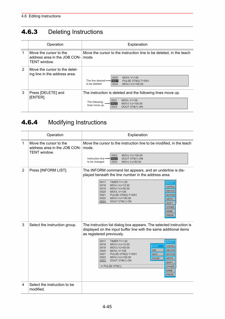
4.6 Editing Instructions
4.6.3 Deleting Instructions
4.6.4 Modifying Instructions
Operation Explanation
1 Move the cursor to the address area in the JOB CON-TENT window.
Move the cursor to the instruction line to be deleted, in the teach mode.
2 Move the cursor to the delet-ing line in the address area.
3 Press [DELETE] and [ENTER].
The instruction is deleted and the following lines move up.
Operation Explanation
1 Move the cursor to the address area in the JOB CON-TENT window.
Move the cursor to the instruction line to be modified, in the teach mode.
2 Press [INFORM LIST]. The INFORM command list appears, and an underline is dis-played beneath the line number in the address area.
3 Select the instruction group. The instruction list dialog box appears. The selected instruction is displayed on the input buffer line with the same additional items as registered previously.
4 Select the instruction to be modified.
0020 MOVL V=1380021 PULSE OT#(2) T=I0010022 MOVJ VJ=100.00
The line desiredto be deleted
0021 MOVL V=1380022 MOVJ VJ=100.000023 DOUT OT#(1) ON
The followinglines move up.
0022 MOVJ VJ=100.000023 DOUT OT#(1) ON 0024 MOVJ VJ=50.00
Instruction lineto be changed
0017 TIMER T=1.000018 MOVJ VJ=12.500019 MOVJ VJ=50.000020 MOVL V=1380021 PULSE OT#(2) T=I0010022 MOVJ VJ=100.000023 DOUT OT#(1) ON
IN/OUT
CONTROL
DEVICE
MOTION
ARITH
SHIFT
OTHER
SAME
PRIOR
0017 TIMER T=1.000018 MOVJ VJ=12.500019 MOVJ VJ=50.000020 MOVL V=1380021 PULSE OT#(2) T=I0010022 MOVJ VJ=100.000023 DOUT OT#(1) ON
PULSE OT#(1)
DOUT
DIN
WAIT
PULSE
IN/OUT
CONTROL
DEVICE
MOTION
ARITH
SHIFT
OTHER
SAME
PRIOR
4-45
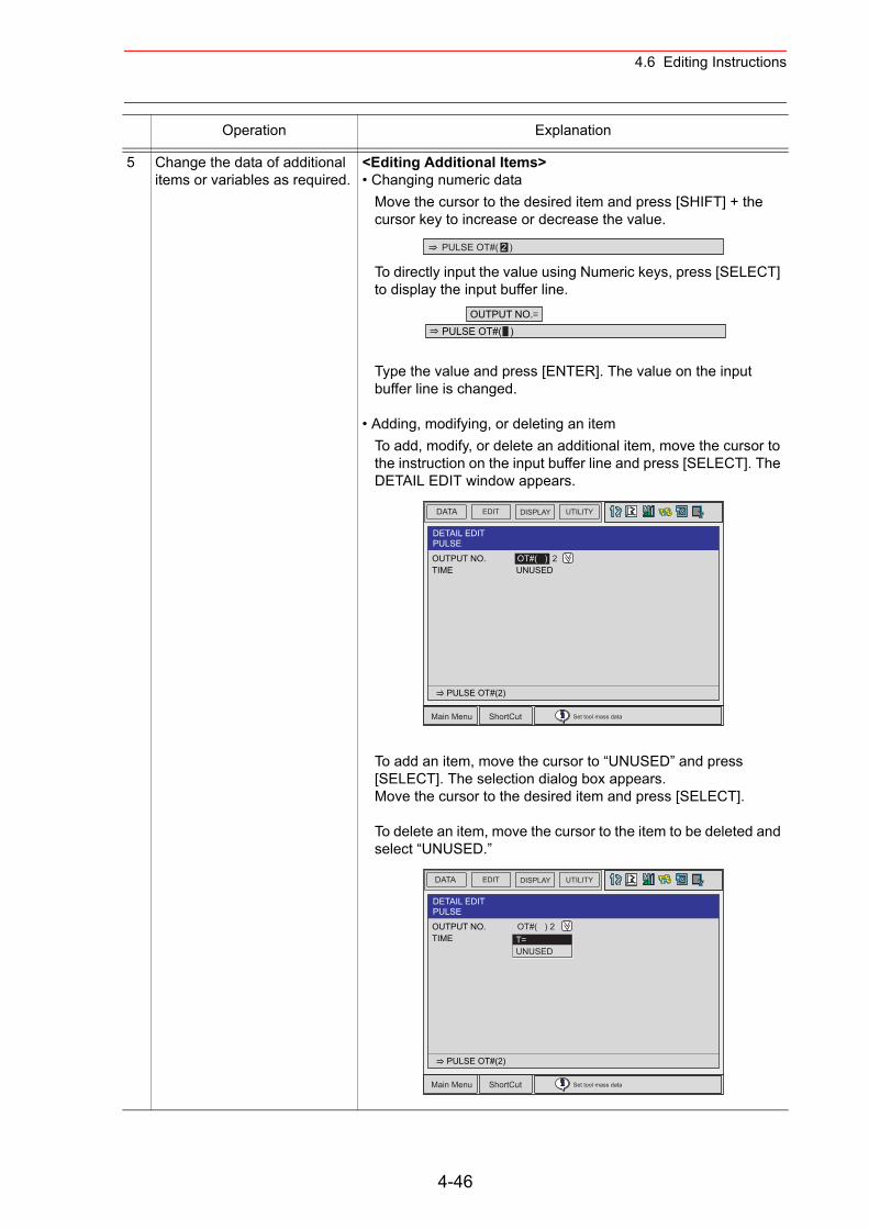
4.6 Editing Instructions
5 Change the data of additional items or variables as required.
<Editing Additional Items>• Changing numeric data
Move the cursor to the desired item and press [SHIFT] + the cursor key to increase or decrease the value.
To directly input the value using Numeric keys, press [SELECT] to display the input buffer line.
Type the value and press [ENTER]. The value on the input buffer line is changed.
• Adding, modifying, or deleting an itemTo add, modify, or delete an additional item, move the cursor to the instruction on the input buffer line and press [SELECT]. The DETAIL EDIT window appears.
To add an item, move the cursor to “UNUSED” and press [SELECT]. The selection dialog box appears.Move the cursor to the desired item and press [SELECT].
To delete an item, move the cursor to the item to be deleted and select “UNUSED.”
Operation Explanation
PULSE OT#( 2 )
OUTPUT NO.PULSE OT#( )
DATA UTILITYEDIT DISPLAY
Main Menu ShortCut Set tool mass data
DETAIL EDITPULSE
OUTPUT NO. OT#( ) 2TIME UNUSED
PULSE OT#(2)
DATA UTILITYEDIT DISPLAY
Main Menu ShortCut Set tool mass data
DETAIL EDITPULSE
OUTPUT NO. OT#( ) 2TIME
PULSE OT#(2)
T=UNUSED
4-46
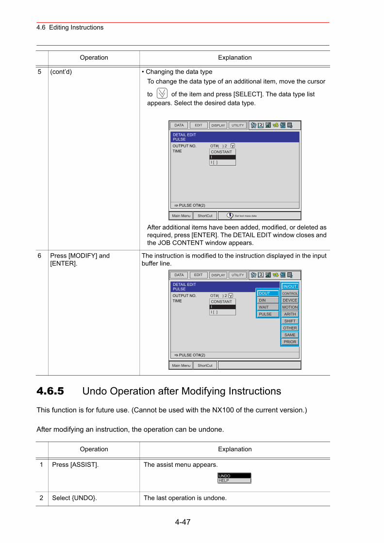
4.6 Editing Instructions
4.6.5 Undo Operation after Modifying Instructions
This function is for future use. (Cannot be used with the NX100 of the current version.)
After modifying an instruction, the operation can be undone.
5 (cont’d) • Changing the data typeTo change the data type of an additional item, move the cursor
to of the item and press [SELECT]. The data type list appears. Select the desired data type.
After additional items have been added, modified, or deleted as required, press [ENTER]. The DETAIL EDIT window closes and the JOB CONTENT window appears.
6 Press [MODIFY] and [ENTER].
The instruction is modified to the instruction displayed in the input buffer line.
Operation Explanation
1 Press [ASSIST]. The assist menu appears.
2 Select {UNDO}. The last operation is undone.
Operation Explanation
DATA UTILITYEDIT DISPLAY
Main Menu ShortCut Set tool mass data
DETAIL EDITPULSE
OUTPUT NO. OT#( ) 2TIME
PULSE OT#(2)
CONSTANTII [ ]
DATA UTILITYEDIT DISPLAY
Main Menu ShortCut
DETAIL EDITPULSE
OUTPUT NO. OT#( ) 2TIME UNUSED
PULSE OT#(2)
CONSTANTII [ ]
DOUT
DIN
WAIT
PULSE
IN/OUT
CONTROL
DEVICE
MOTION
ARITH
SHIFT
OTHER
SAME
PRIOR
UNDOHELP
4-47
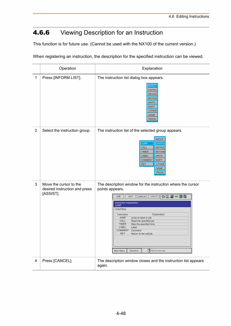
4.6 Editing Instructions
4.6.6 Viewing Description for an Instruction
This function is for future use. (Cannot be used with the NX100 of the current version.)
When registering an instruction, the description for the specified instruction can be viewed.
Operation Explanation
1 Press [INFORM LIST]. The instruction list dialog box appears.
2 Select the instruction group. The instruction list of the selected group appears.
3 Move the cursor to the desired instruction and press [ASSIST].
The description window for the instruciton where the cursor points appears.
4 Press [CANCEL]. The description window closes and the instruction list appears again.
IN/OUT
CONTROL
DEVICE
MOTION
ARITH
SHIFT
OTHER
SAME
PRIOR
JUMP
CALL
TIMER
LABEL
COMMENT
RET
IN/OUT
CONTROL
DEVICE
MOTION
ARITH
SHIFT
OTHER
SAME
PRIOR
JOB EDIT DISPLAY UTILITY
Main Menu ShortCut Set tool mass data
Instruction explanationJUMP
CONTROL
InstructionJUMPCALL
TIMERLABEL
COMMENTRET
ExplanationJump to label or jobRead the specified jobStop the specified timeLabelCommentReturn to the call job
4-48
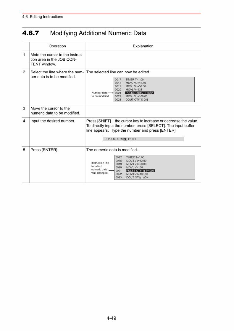
4.6 Editing Instructions
4.6.7 Modifying Additional Numeric Data
Operation Explanation
1 Mote the cursor to the instruc-tion area in the JOB CON-TENT window.
2 Select the line where the num-ber data is to be modified.
The selected line can now be edited.
3 Move the cursor to the numeric data to be modified.
4 Input the desired number. Press [SHIFT] + the cursor key to increase or decrease the value. To directly input the number, press [SELECT]. The input buffer line appears. Type the number and press [ENTER].
5 Press [ENTER]. The numeric data is modified.
0017 TIMER T=1.000018 MOVJ VJ=12.500019 MOVJ VJ=50.000020 MOVL V=1380021 PULSE OT#(2) T=I0010022 MOVJ VJ=100.000023 DOUT OT#(1) ON
Number datato be modified
PULSE OT#( 2 ) T=I001
0017 TIMER T=1.000018 MOVJ VJ=12.500019 MOVJ VJ=50.000020 MOVL V=1380021 PULSE OT#(1) T=I0010022 MOVJ VJ=100.000023 DOUT OT#(1) ON
Instruction line for which numeric data was changed.
4-49
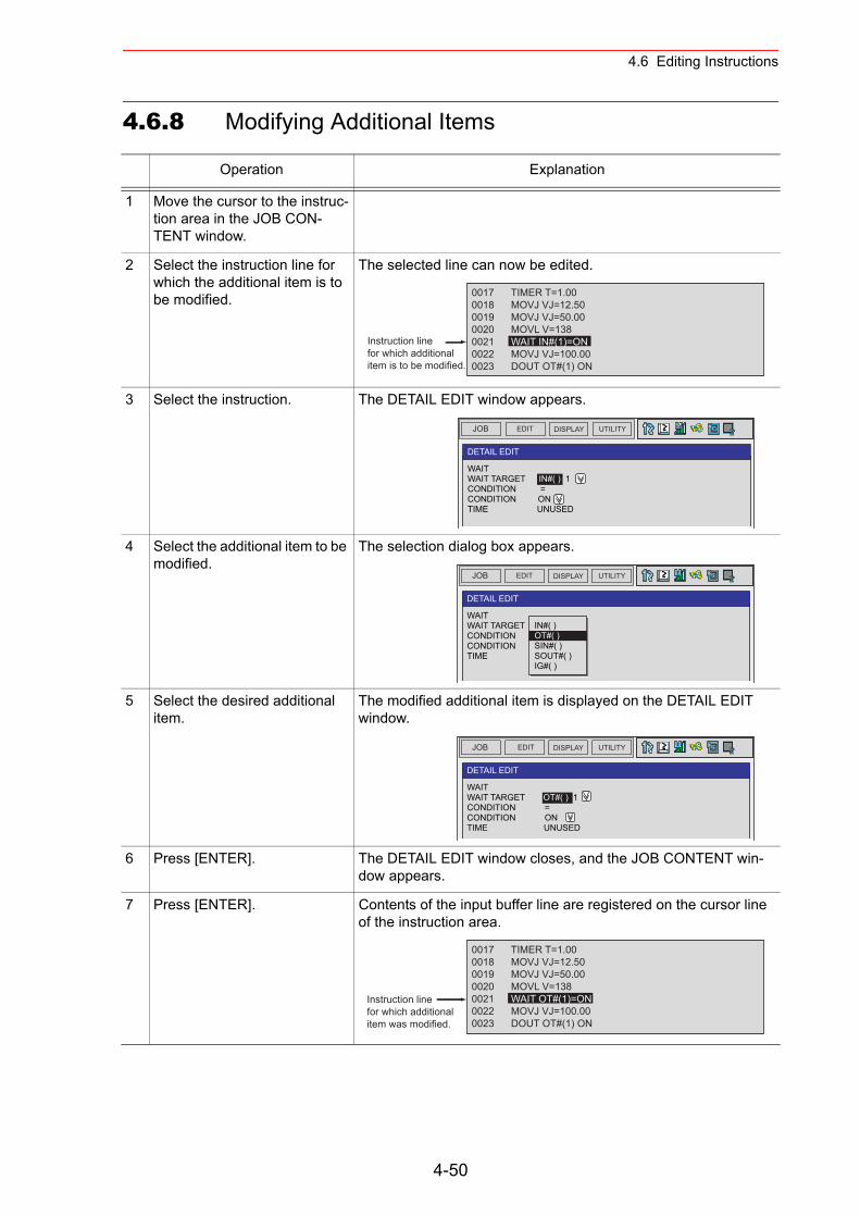
4.6 Editing Instructions
4.6.8 Modifying Additional Items
Operation Explanation
1 Move the cursor to the instruc-tion area in the JOB CON-TENT window.
2 Select the instruction line for which the additional item is to be modified.
The selected line can now be edited.
3 Select the instruction. The DETAIL EDIT window appears.
4 Select the additional item to be modified.
The selection dialog box appears.
5 Select the desired additional item.
The modified additional item is displayed on the DETAIL EDIT window.
6 Press [ENTER]. The DETAIL EDIT window closes, and the JOB CONTENT win-dow appears.
7 Press [ENTER]. Contents of the input buffer line are registered on the cursor line of the instruction area.
0017 TIMER T=1.00 0018 MOVJ VJ=12.500019 MOVJ VJ=50.000020 MOVL V=1380021 WAIT IN#(1)=ON0022 MOVJ VJ=100.00 0023 DOUT OT#(1) ON
Instruction linefor which additionalitem is to be modified.
JOB EDIT DISPLAY UTILITY
DETAIL EDIT
WAITWAIT TARGET IN#( ) 1 CONDITION =CONDITION ON TIME UNUSED
JOB EDIT DISPLAY UTILITY
DETAIL EDIT
WAITWAIT TARGET IN#( ) 1 CONDITION =CONDITION ON TIME
IN#( )OT#( )SIN#( )SOUT#( )IG#( )
JOB EDIT DISPLAY UTILITY
DETAIL EDIT
WAITWAIT TARGET OT#( ) 1 CONDITION =CONDITION ON TIME UNUSED
0017 TIMER T=1.00 0018 MOVJ VJ=12.500019 MOVJ VJ=50.000020 MOVL V=1380021 WAIT OT#(1)=ON0022 MOVJ VJ=100.00 0023 DOUT OT#(1) ON
Instruction linefor which additionalitem was modified.
4-50
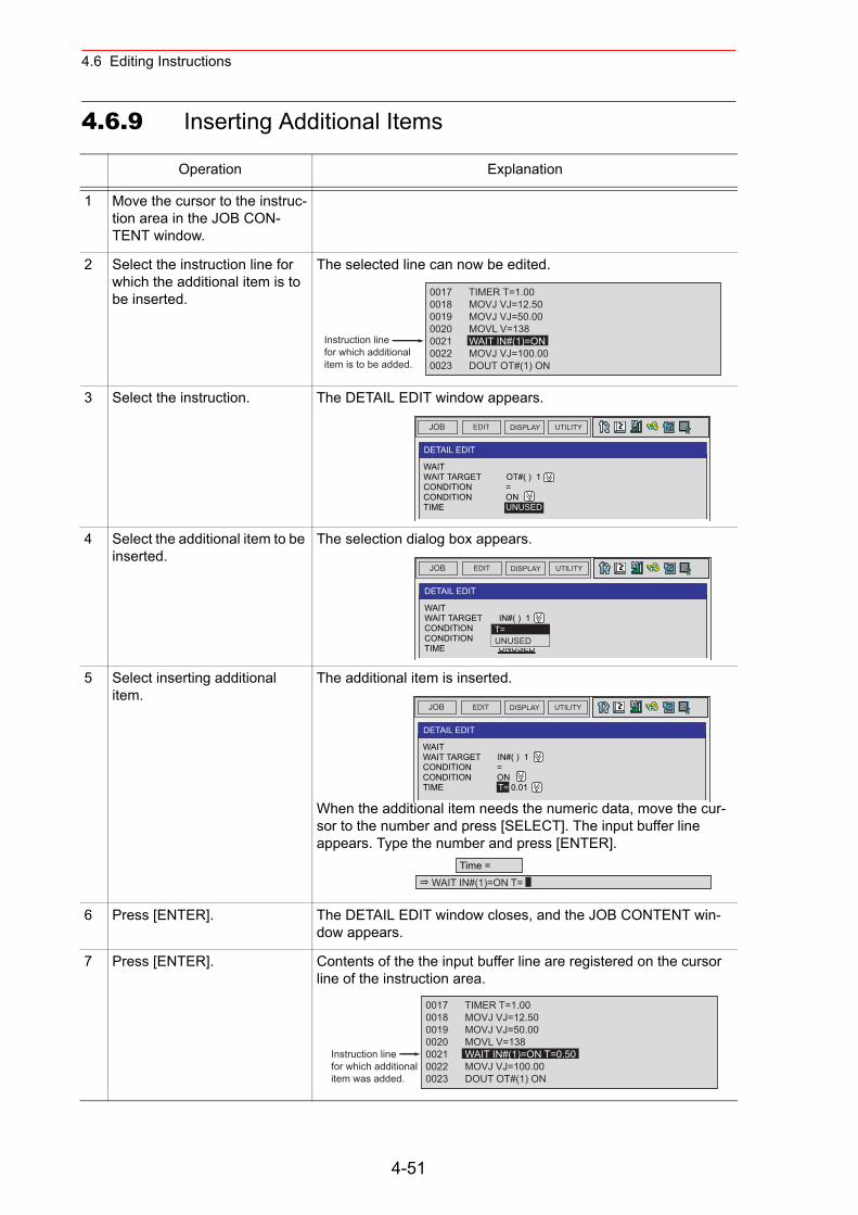
4.6 Editing Instructions
4.6.9 Inserting Additional Items
Operation Explanation
1 Move the cursor to the instruc-tion area in the JOB CON-TENT window.
2 Select the instruction line for which the additional item is to be inserted.
The selected line can now be edited.
3 Select the instruction. The DETAIL EDIT window appears.
4 Select the additional item to be inserted.
The selection dialog box appears.
5 Select inserting additional item.
The additional item is inserted.
When the additional item needs the numeric data, move the cur-sor to the number and press [SELECT]. The input buffer line appears. Type the number and press [ENTER].
6 Press [ENTER]. The DETAIL EDIT window closes, and the JOB CONTENT win-dow appears.
7 Press [ENTER]. Contents of the the input buffer line are registered on the cursor line of the instruction area.
0017 TIMER T=1.00 0018 MOVJ VJ=12.500019 MOVJ VJ=50.000020 MOVL V=1380021 WAIT IN#(1)=ON0022 MOVJ VJ=100.00 0023 DOUT OT#(1) ON
Instruction linefor which additionalitem is to be added.
JOB EDIT DISPLAY UTILITY
DETAIL EDIT
WAITWAIT TARGET OT#( ) 1 CONDITION =CONDITION ON TIME UNUSED
JOB EDIT DISPLAY UTILITY
DETAIL EDIT
WAITWAIT TARGET IN#( ) 1CONDITION =CONDITION ON TIME UNUSED
T=UNUSED
JOB EDIT DISPLAY UTILITY
DETAIL EDIT
WAITWAIT TARGET IN#( ) 1 CONDITION =CONDITION ON TIME T= 0.01
Time =WAIT IN#(1)=ON T=
0017 TIMER T=1.00 0018 MOVJ VJ=12.500019 MOVJ VJ=50.000020 MOVL V=1380021 WAIT IN#(1)=ON T=0.500022 MOVJ VJ=100.00 0023 DOUT OT#(1) ON
Instruction linefor which additionalitem was added.
4-51
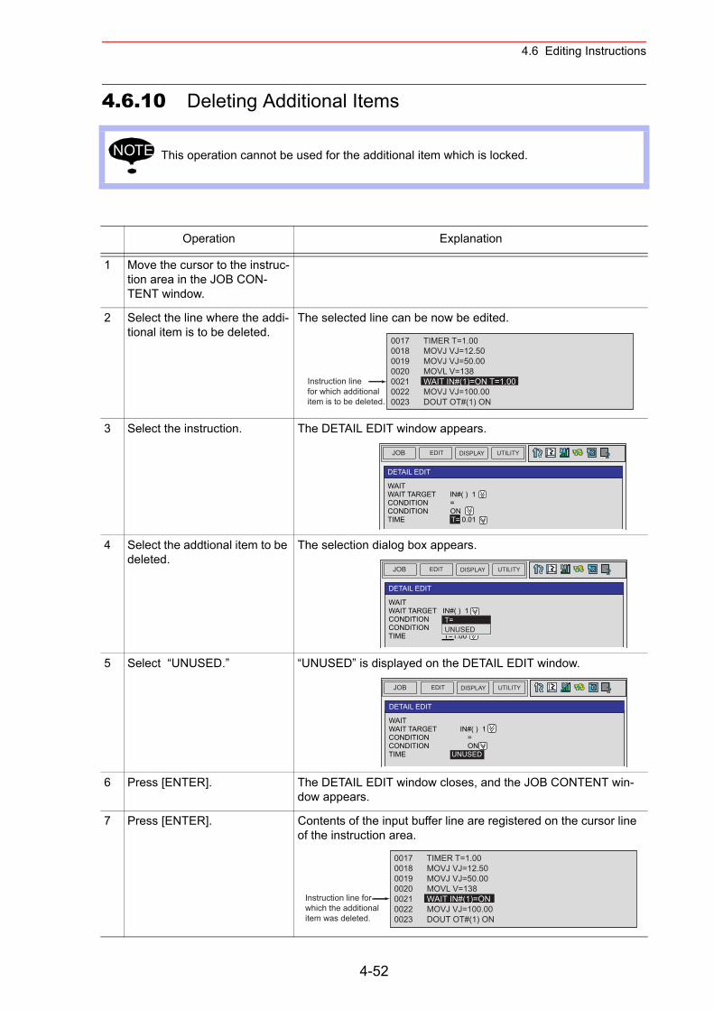
4.6 Editing Instructions
4.6.10 Deleting Additional Items
This operation cannot be used for the additional item which is locked.
Operation Explanation
1 Move the cursor to the instruc-tion area in the JOB CON-TENT window.
2 Select the line where the addi-tional item is to be deleted.
The selected line can be now be edited.
3 Select the instruction. The DETAIL EDIT window appears.
4 Select the addtional item to be deleted.
The selection dialog box appears.
5 Select “UNUSED.” “UNUSED” is displayed on the DETAIL EDIT window.
6 Press [ENTER]. The DETAIL EDIT window closes, and the JOB CONTENT win-dow appears.
7 Press [ENTER]. Contents of the input buffer line are registered on the cursor line of the instruction area.
NOTE
0017 TIMER T=1.00 0018 MOVJ VJ=12.500019 MOVJ VJ=50.000020 MOVL V=1380021 WAIT IN#(1)=ON T=1.000022 MOVJ VJ=100.00 0023 DOUT OT#(1) ON
Instruction linefor which additionalitem is to be deleted.
JOB EDIT DISPLAY UTILITY
DETAIL EDIT
WAITWAIT TARGET IN#( ) 1 CONDITION =CONDITION ON TIME T= 0.01
JOB EDIT DISPLAY UTILITY
DETAIL EDIT
WAITWAIT TARGET IN#( ) 1 CONDITION =CONDITION ON TIME T=1.00
T=UNUSED
JOB EDIT DISPLAY UTILITY
DETAIL EDIT
WAITWAIT TARGET IN#( ) 1CONDITION =CONDITION ONTIME UNUSED
0017 TIMER T=1.00 0018 MOVJ VJ=12.500019 MOVJ VJ=50.000020 MOVL V=1380021 WAIT IN#(1)=ON0022 MOVJ VJ=100.00 0023 DOUT OT#(1) ON
Instruction line for which the additionalitem was deleted.
4-52
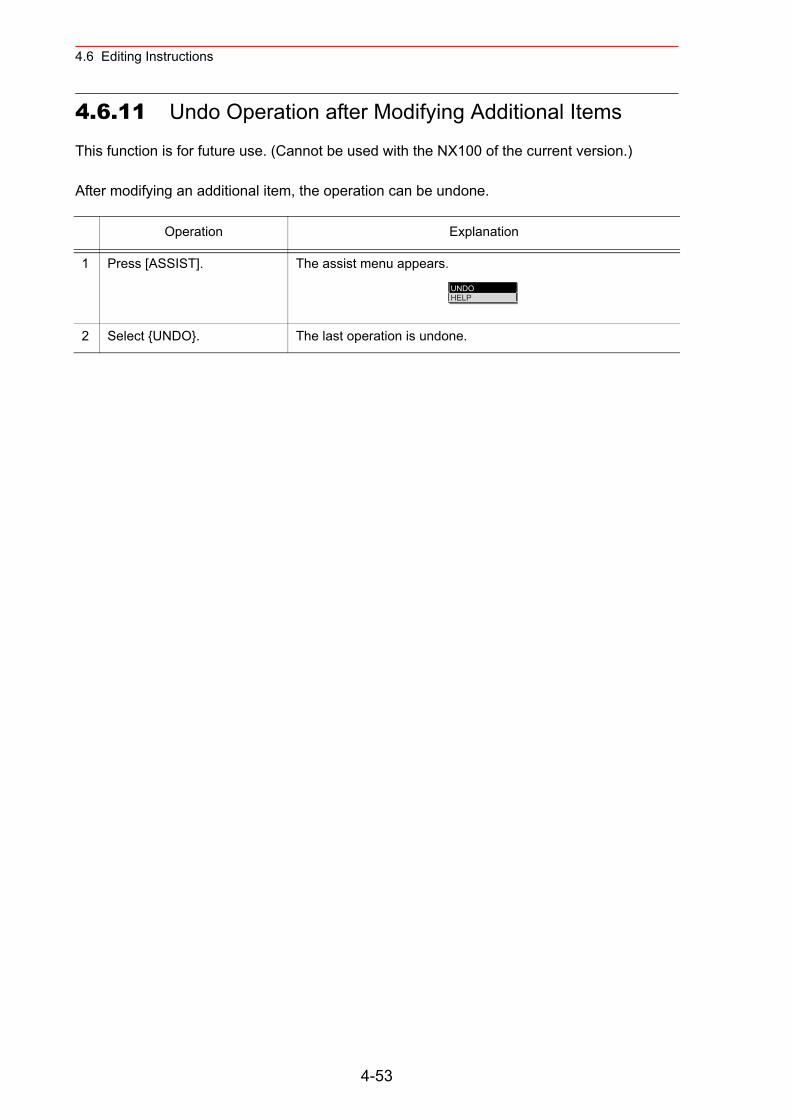
4.6 Editing Instructions
4.6.11 Undo Operation after Modifying Additional Items
This function is for future use. (Cannot be used with the NX100 of the current version.)
After modifying an additional item, the operation can be undone.
Operation Explanation
1 Press [ASSIST]. The assist menu appears.
2 Select {UNDO}. The last operation is undone.
UNDOHELP
4-53
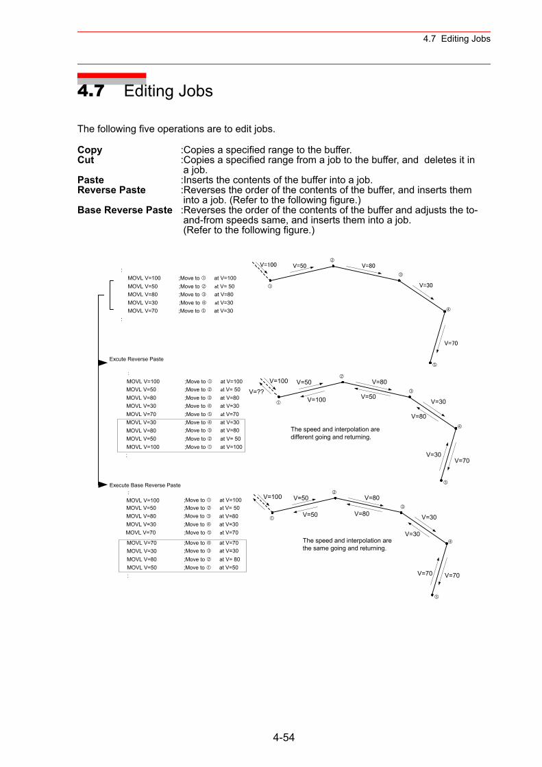
4.7 Editing Jobs
4.7 Editing Jobs
The following five operations are to edit jobs.
Copy :Copies a specified range to the buffer.Cut :Copies a specified range from a job to the buffer, and deletes it in
a job.Paste :Inserts the contents of the buffer into a job. Reverse Paste :Reverses the order of the contents of the buffer, and inserts them
into a job. (Refer to the following figure.)Base Reverse Paste :Reverses the order of the contents of the buffer and adjusts the to-
and-from speeds same, and inserts them into a job. (Refer to the following figure.)
Execute Base Reverse Paste
V=100 V=50
V=30
V=70
V=80
V=100 V=50
V=30
V=70
V=80
V=30
V=80
V=50V=100V=??
The speed and interpolation aredifferent going and returning.
V=100 V=50
V=30
V=70
V=80
V=30
V=80V=50
The speed and interpolation arethe same going and returning.
V=70
:MOVL V=100 ;Move to at V=100MOVL V=50 ;Move to at V= 50MOVL V=80 ;Move to at V=80MOVL V=30 ;Move to at V=30MOVL V=70 ;Move to at V=30
:
:
MOVL V=100 ;Move to at V=100MOVL V=50 ;Move to at V= 50MOVL V=80 ;Move to at V=80MOVL V=30 ;Move to at V=30MOVL V=70 ;Move to at V=70MOVL V=30 ;Move to at V=30MOVL V=80 ;Move to at V=80MOVL V=50 ;Move to at V= 50MOVL V=100 ;Move to at V=100:
:
MOVL V=100MOVL V=50MOVL V=80MOVL V=30MOVL V=70
Excute Reverse Paste
MOVL V=70 ;Move to at V=70MOVL V=30 ;Move to at V=30MOVL V=80 ;Move to at V= 80MOVL V=50 ;Move to at V=50:
;Move to at V=100;Move to at V= 50;Move to at V=80;Move to at V=30;Move to at V=70
4-54
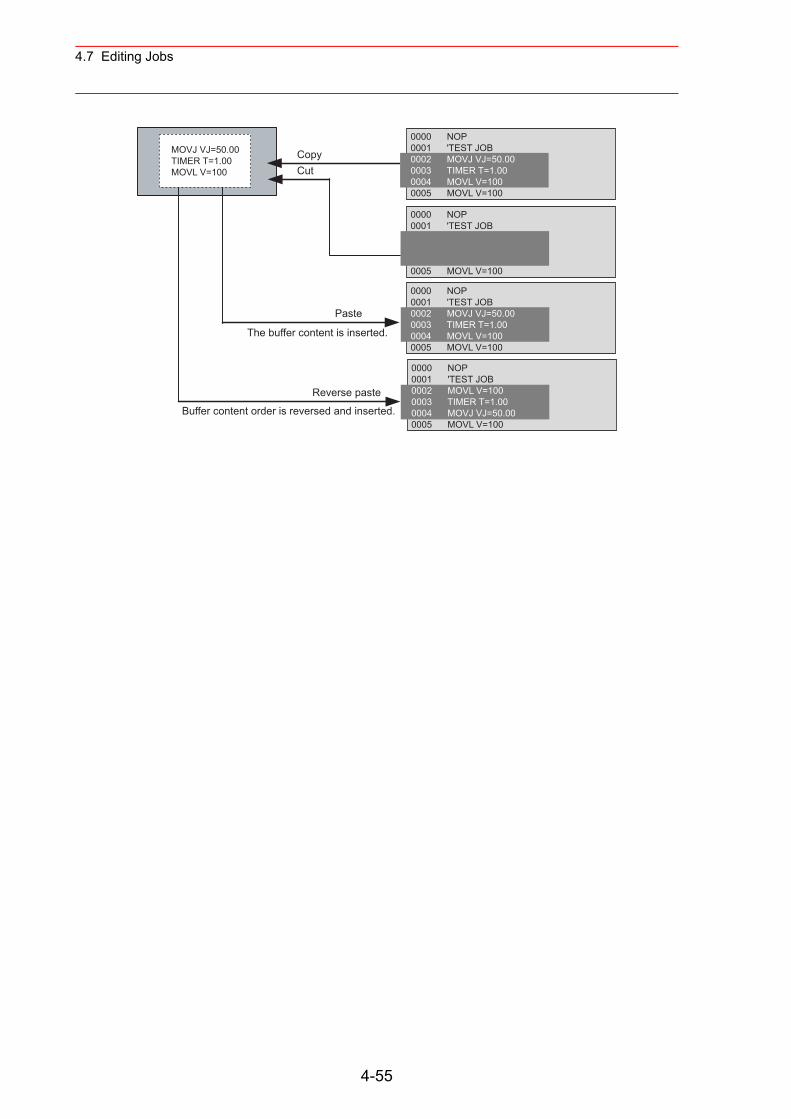
4.7 Editing Jobs
0000 NOP0001 'TEST JOB
0005 MOVL V=100
CopyCut
Paste
Reverse paste
The buffer content is inserted.
Buffer content order is reversed and inserted.
MOVJ VJ=50.00TIMER T=1.00MOVL V=100
0000 NOP0001 'TEST JOB0002 MOVJ VJ=50.000003 TIMER T=1.000004 MOVL V=1000005 MOVL V=100
0000 NOP0001 'TEST JOB0002 MOVJ VJ=50.000003 TIMER T=1.000004 MOVL V=1000005 MOVL V=100
0000 NOP0001 'TEST JOB0002 MOVL V=1000003 TIMER T=1.000004 MOVJ VJ=50.000005 MOVL V=100
4-55
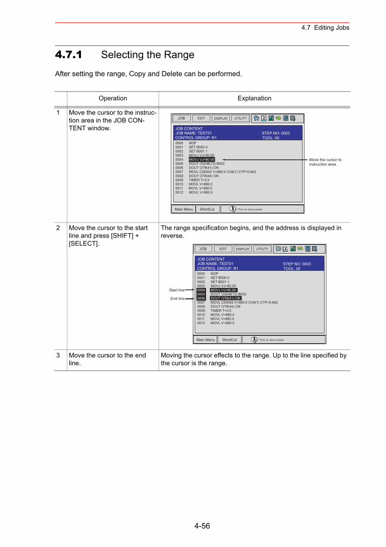
4.7 Editing Jobs
4.7.1 Selecting the Range
After setting the range, Copy and Delete can be performed.
Operation Explanation
1 Move the cursor to the instruc-tion area in the JOB CON-TENT window.
2 Move the cursor to the start line and press [SHIFT] + [SELECT].
The range specification begins, and the address is displayed in reverse.
3 Move the cursor to the end line.
Moving the cursor effects to the range. Up to the line specified by the cursor is the range.
JOB EDIT DISPLAY UTILITY
Main Menu ShortCut !Turn on servo power
JOB CONTENTJOB NAME: TEST01
0000 NOP0001 SET B000 00002 SET B001 10003 MOVJ VJ=80.000004 MOVJ VJ=80.000005 DOUT OGH#(13) B0020006 DOUT OT#(41) ON0007 MOVL C00002 V=880.0 CV#(1) CTP=0.6620008 DOUT OT#(44) ON0009 TIMER T=3.00010 MOVL V=880.00011 MOVL V=880.00012 MOVL V=880.0
Move the cursor toinstruction area.
TOOL: 00CONTROL GROUP: R1STEP NO: 0003
JOB EDIT DISPLAY UTILITY
Main Menu ShortCut !Turn on servo power
JOB CONTENTJOB NAME: TEST01
0000 NOP0001 SET B000 00002 SET B001 10003 MOVJ VJ=80.000004 MOVJ VJ=80.000005 DOUT OGH#(13) B0020006 DOUT OT#(41) ON0007 MOVL C00002 V=880.0 CV#(1) CTP=0.6620008 DOUT OT#(44) ON0009 TIMER T=3.00010 MOVL V=880.00011 MOVL V=880.00012 MOVL V=880.0
Start line
End line
TOOL: 00CONTROL GROUP: R1STEP NO: 0003
4-56
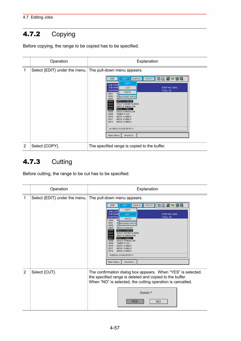
4.7 Editing Jobs
4.7.2 Copying
Before copying, the range to be copied has to be specified.
4.7.3 Cutting
Before cutting, the range to be cut has to be specified.
Operation Explanation
1 Select {EDIT} under the menu. The pull-down menu appears.
2 Select {COPY}. The specified range is copied to the buffer.
Operation Explanation
1 Select {EDIT} under the menu. The pull-down menu appears.
2 Select {CUT}. The confirmation dialog box appears. When “YES” is selected, the specified range is deleted and copied to the buffer.When “NO” is selected, the cutting operation is cancelled.
JOB EDIT DISPLAY UTILITY
Main Menu ShortCut
JOB CONTENTJOB NAME: TEST
0001 SET B000 00002 SET B001 10003 MOVJ VJ=80.000004 MOVJ VJ=80.000005 DOUT OGH#(13) B0020006 WAIT IF IN#(5)=ON0007 MOVL V=880.00008 DOUT OT#(44) ON0009 TIMER T=3.00010 MOVL V=880.00011 MOVL V=880.00012 MOVL V=880.0
MOVJ VJ=50.00 PL=1
TOOL: 00CONTROL GROUP: R1STEP NO: 0003
PASTE
COPY
CUT
REVERSE PASTE
JOB EDIT DISPLAY UTILITY
Main Menu ShortCut
JOB CONTENTJOB NAME: TEST
0000 NOP0001 SET B000 00002 SET B001 10003 MOVJ VJ=80.000004 MOVJ VJ=80.000005 DOUT OGH#(13) B0020006 WAIT IF IN#(5)=ON0007 MOVL V=880.00008 DOUT OT#(44) ON0009 TIMER T=3.00010 MOVL V=880.00011 MOVL V=880.00012 MOVL V=880.0
MOVJ VJ=50.00 PL=1
TOOL: 00CONTROL GROUP: R1STEP NO: 0003
PASTE
COPY
CUT
REVERSE PASTE
YES
Delete
NO
4-57
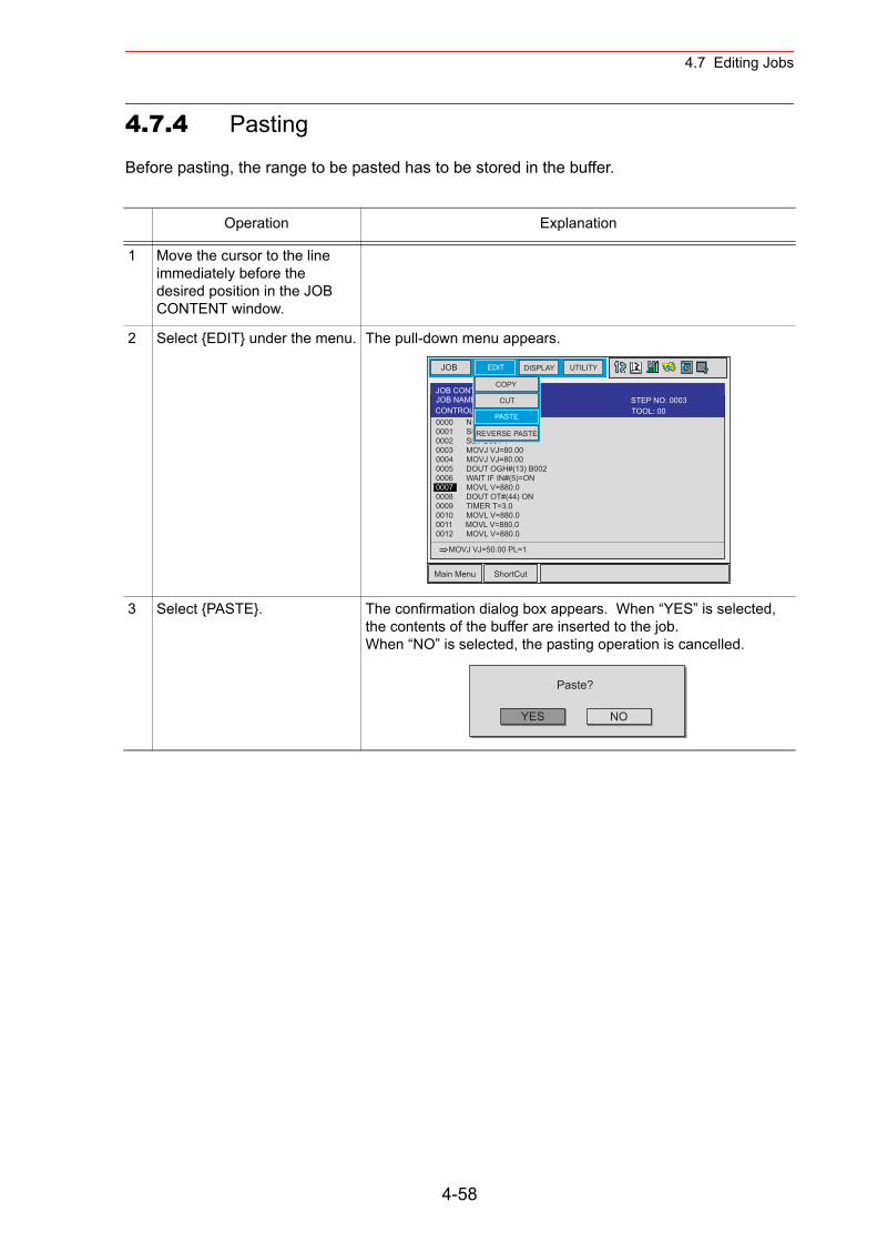
4.7 Editing Jobs
4.7.4 Pasting
Before pasting, the range to be pasted has to be stored in the buffer.
Operation Explanation
1 Move the cursor to the line immediately before the desired position in the JOB CONTENT window.
2 Select {EDIT} under the menu. The pull-down menu appears.
3 Select {PASTE}. The confirmation dialog box appears. When “YES” is selected, the contents of the buffer are inserted to the job.When “NO” is selected, the pasting operation is cancelled.
JOB EDIT DISPLAY UTILITY
Main Menu ShortCut
JOB CONTENTJOB NAME: TEST
0000 NOP0001 SET B000 00002 SET B001 10003 MOVJ VJ=80.000004 MOVJ VJ=80.000005 DOUT OGH#(13) B0020006 WAIT IF IN#(5)=ON0007 MOVL V=880.00008 DOUT OT#(44) ON0009 TIMER T=3.00010 MOVL V=880.00011 MOVL V=880.00012 MOVL V=880.0
MOVJ VJ=50.00 PL=1
TOOL: 00CONTROL GROUP: R1STEP NO: 0003
PASTE
COPY
CUT
REVERSE PASTE
YES
Paste?
NO
4-58
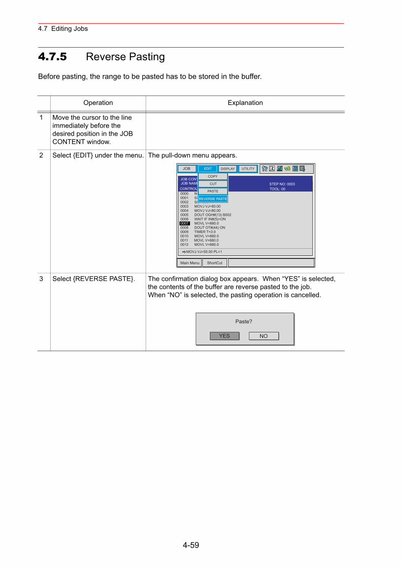
4.7 Editing Jobs
4.7.5 Reverse Pasting
Before pasting, the range to be pasted has to be stored in the buffer.
Operation Explanation
1 Move the cursor to the line immediately before the desired position in the JOB CONTENT window.
2 Select {EDIT} under the menu. The pull-down menu appears.
3 Select {REVERSE PASTE}. The confirmation dialog box appears. When “YES” is selected, the contents of the buffer are reverse pasted to the job.When “NO” is selected, the pasting operation is cancelled.
JOB EDIT DISPLAY UTILITY
Main Menu ShortCut
JOB CONTENTJOB NAME: TEST
0000 NOP0001 SET B000 00002 SET B001 10003 MOVJ VJ=80.000004 MOVJ VJ=80.000005 DOUT OGH#(13) B0020006 WAIT IF IN#(5)=ON0007 MOVL V=880.00008 DOUT OT#(44) ON0009 TIMER T=3.00010 MOVL V=880.00011 MOVL V=880.00012 MOVL V=880.0
MOVJ VJ=50.00 PL=1
TOOL: 00CONTROL GROUP: R1STEP NO: 0003
PASTE
COPY
CUT
REVERSE PASTE
YES
Paste?
NO
4-59
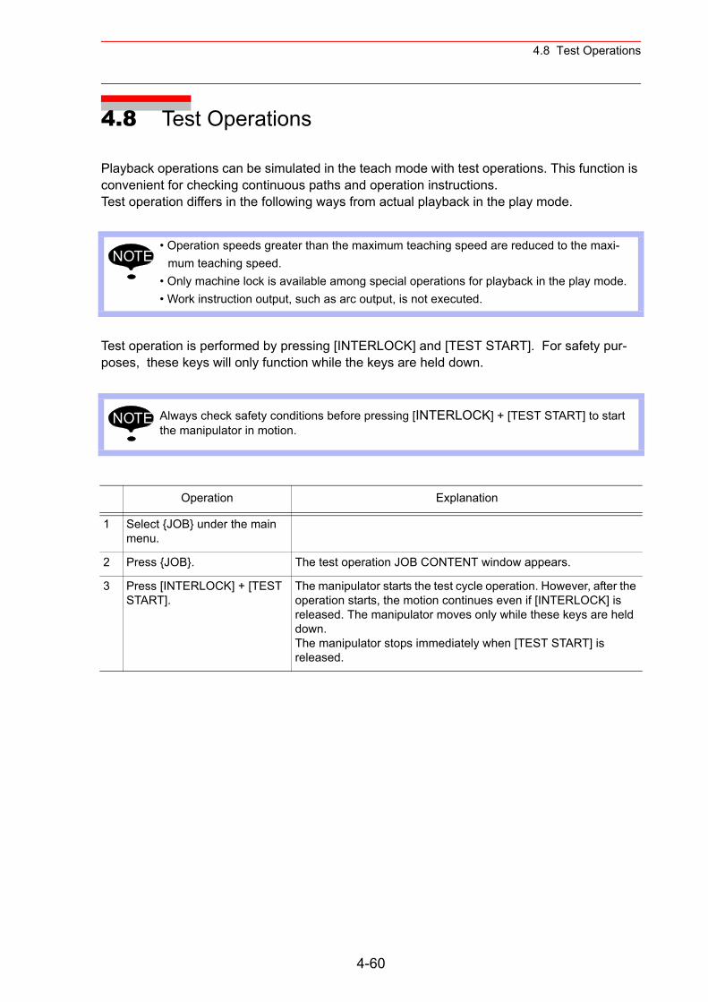
4.8 Test Operations
4.8 Test Operations
Playback operations can be simulated in the teach mode with test operations. This function is convenient for checking continuous paths and operation instructions.Test operation differs in the following ways from actual playback in the play mode.
Test operation is performed by pressing [INTERLOCK] and [TEST START]. For safety pur-poses, these keys will only function while the keys are held down.
• Operation speeds greater than the maximum teaching speed are reduced to the maxi-mum teaching speed.
• Only machine lock is available among special operations for playback in the play mode.• Work instruction output, such as arc output, is not executed.
Always check safety conditions before pressing [INTERLOCK] + [TEST START] to start the manipulator in motion.
Operation Explanation
1 Select {JOB} under the main menu.
2 Press {JOB}. The test operation JOB CONTENT window appears.
3 Press [INTERLOCK] + [TEST START].
The manipulator starts the test cycle operation. However, after the operation starts, the motion continues even if [INTERLOCK] is released. The manipulator moves only while these keys are held down.The manipulator stops immediately when [TEST START] is released.
NOTE
NOTE
4-60
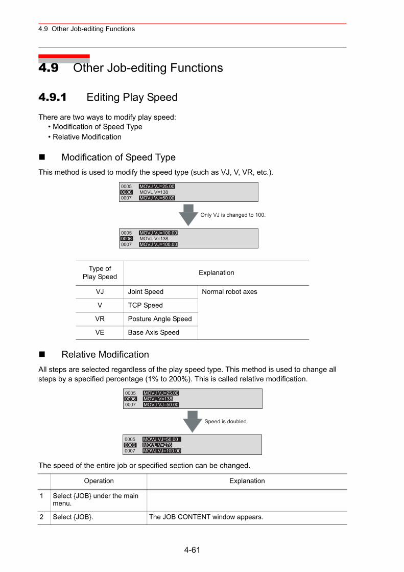
4.9 Other Job-editing Functions
4.9 Other Job-editing Functions
4.9.1 Editing Play Speed
There are two ways to modify play speed:• Modification of Speed Type• Relative Modification
Modification of Speed TypeThis method is used to modify the speed type (such as VJ, V, VR, etc.).
Relative ModificationAll steps are selected regardless of the play speed type. This method is used to change all steps by a specified percentage (1% to 200%). This is called relative modification.
The speed of the entire job or specified section can be changed.
Type ofPlay Speed Explanation
VJ Joint Speed Normal robot axes
V TCP Speed
VR Posture Angle Speed
VE Base Axis Speed
Operation Explanation
1 Select {JOB} under the main menu.
2 Select {JOB}. The JOB CONTENT window appears.
0005 MOVJ VJ=25.000006 MOVL V=1380007 MOVJ VJ=50.00
0005 MOVJ VJ=100.000006 MOVL V=1380007 MOVJ VJ=100.00
Only VJ is changed to 100.
Speed is doubled.
0005 MOVJ VJ=25.000006 MOVL V=1380007 MOVJ VJ=50.00
0005 MOVJ VJ=50.000006 MOVL V=2760007 MOVJ VJ=100.00
4-61
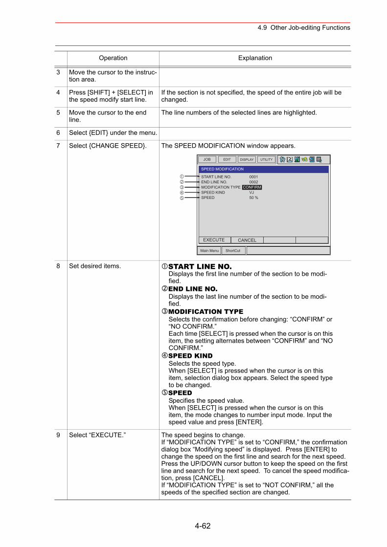
4.9 Other Job-editing Functions
3 Move the cursor to the instruc-tion area.
4 Press [SHIFT] + [SELECT] in the speed modify start line.
If the section is not specified, the speed of the entire job will be changed.
5 Move the cursor to the end line.
The line numbers of the selected lines are highlighted.
6 Select {EDIT} under the menu.
7 Select {CHANGE SPEED}. The SPEED MODIFICATION window appears.
8 Set desired items. START LINE NO.Displays the first line number of the section to be modi-fied.END LINE NO.Displays the last line number of the section to be modi-fied.MODIFICATION TYPESelects the confirmation before changing: “CONFIRM” or “NO CONFIRM.”Each time [SELECT] is pressed when the cursor is on this item, the setting alternates between “CONFIRM” and “NO CONFIRM.”SPEED KINDSelects the speed type.When [SELECT] is pressed when the cursor is on this item, selection dialog box appears. Select the speed type to be changed.SPEEDSpecifies the speed value.When [SELECT] is pressed when the cursor is on this item, the mode changes to number input mode. Input the speed value and press [ENTER].
9 Select “EXECUTE.” The speed begins to change.If “MODIFICATION TYPE” is set to “CONFIRM,” the confirmation dialog box “Modifying speed” is displayed. Press [ENTER] to change the speed on the first line and search for the next speed. Press the UP/DOWN cursor button to keep the speed on the first line and search for the next speed. To cancel the speed modifica-tion, press [CANCEL].If “MODIFICATION TYPE” is set to “NOT CONFIRM,” all the speeds of the specified section are changed.
Operation Explanation
JOB UTILITYEDIT DISPLAY
Main Menu ShortCut
SPEED MODIFICATION
START LINE NO.END LINE NO.MODIFICATION TYPESPEED KINDSPEED
0001 0002CONFIRM VJ 50 %
EXECUTE CANCEL
4-62
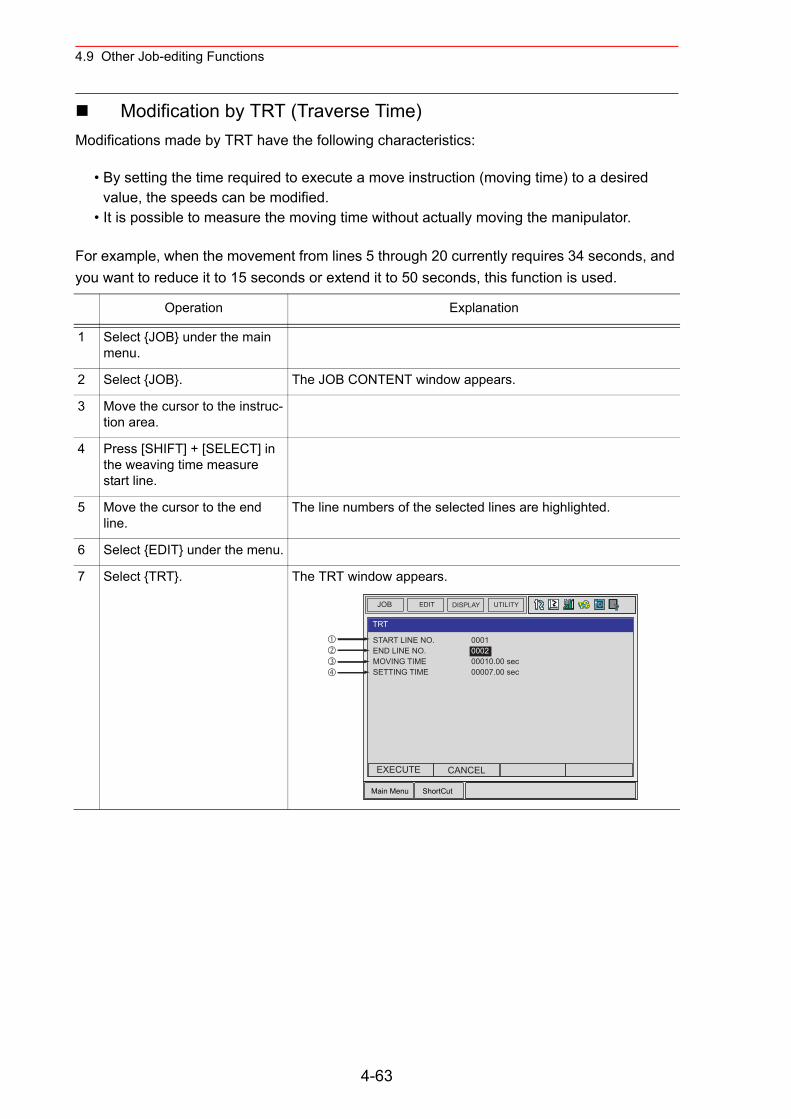
4.9 Other Job-editing Functions
Modification by TRT (Traverse Time)Modifications made by TRT have the following characteristics:
• By setting the time required to execute a move instruction (moving time) to a desired value, the speeds can be modified.
• It is possible to measure the moving time without actually moving the manipulator.
For example, when the movement from lines 5 through 20 currently requires 34 seconds, and you want to reduce it to 15 seconds or extend it to 50 seconds, this function is used.
Operation Explanation
1 Select {JOB} under the main menu.
2 Select {JOB}. The JOB CONTENT window appears.
3 Move the cursor to the instruc-tion area.
4 Press [SHIFT] + [SELECT] in the weaving time measure start line.
5 Move the cursor to the end line.
The line numbers of the selected lines are highlighted.
6 Select {EDIT} under the menu.
7 Select {TRT}. The TRT window appears.
JOB UTILITYEDIT DISPLAY
Main Menu ShortCut
TRT
START LINE NO.END LINE NO.MOVING TIMESETTING TIME
0001000200010.00 sec00007.00 sec
EXECUTE CANCEL
4-63
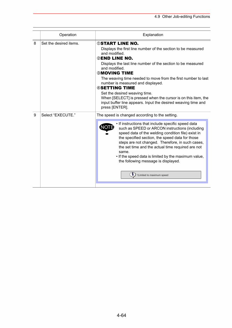
4.9 Other Job-editing Functions
8 Set the desired items. START LINE NO.Displays the first line number of the section to be measured and modified.END LINE NO.Displays the last line number of the section to be measured and modified.MOVING TIMEThe weaving time needed to move from the first number to last number is measured and displayed.SETTING TIMESet the desired weaving time.When [SELECT] is pressed when the cursor is on this item, the input buffer line appears. Input the desired weaving time and press [ENTER].
9 Select “EXECUTE.” The speed is changed according to the setting.
Operation Explanation
• If instructions that include specific speed data such as SPEED or ARCON instructions (including speed data of the welding condition file) exist in the specified section, the speed data for those steps are not changed. Therefore, in such cases, the set time and the actual time required are not same.
• If the speed data is limited by the maximum value, the following message is displayed.
NOTE
!Limited to maximum speed
4-64
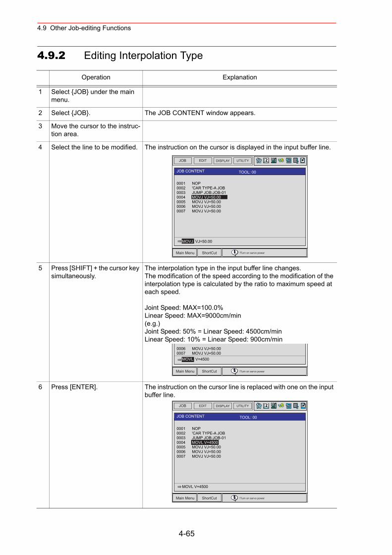
4.9 Other Job-editing Functions
4.9.2 Editing Interpolation Type
Operation Explanation
1 Select {JOB} under the main menu.
2 Select {JOB}. The JOB CONTENT window appears.
3 Move the cursor to the instruc-tion area.
4 Select the line to be modified. The instruction on the cursor is displayed in the input buffer line.
5 Press [SHIFT] + the cursor key simultaneously.
The interpolation type in the input buffer line changes.The modification of the speed according to the modification of the interpolation type is calculated by the ratio to maximum speed at each speed.
Joint Speed: MAX=100.0%Linear Speed: MAX=9000cm/min(e.g.)Joint Speed: 50% = Linear Speed: 4500cm/minLinear Speed: 10% = Linear Speed: 900cm/min
6 Press [ENTER]. The instruction on the cursor line is replaced with one on the input buffer line.
JOB EDIT DISPLAY UTILITY
Main Menu ShortCut !Turn on servo power
JOB CONTENT TOOL: 00
0001 NOP0002 'CAR TYPE-A JOB0003 JUMP JOB:JOB-010004 MOVJ VJ=50.000005 MOVJ VJ=50.000006 MOVJ VJ=50.000007 MOVJ VJ=50.00
MOVJ VJ=50.00
Main Menu ShortCut !Turn on servo power
0006 MOVJ VJ=50.000007 MOVJ VJ=50.00 MOVL V=4500
JOB EDIT DISPLAY UTILITY
Main Menu ShortCut !Turn on servo power
JOB CONTENT TOOL: 00
0001 NOP0002 'CAR TYPE-A JOB0003 JUMP JOB:JOB-010004 MOVL V=45000005 MOVJ VJ=50.000006 MOVJ VJ=50.000007 MOVJ VJ=50.00
MOVL V=4500
4-65
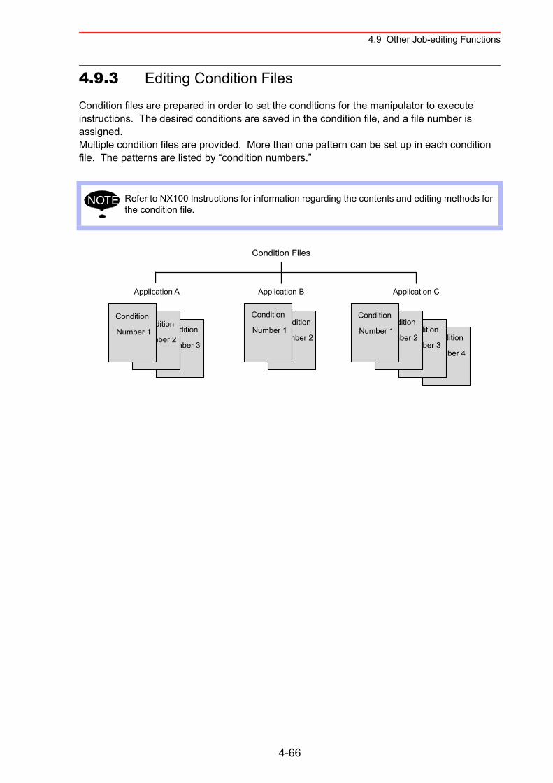
4.9 Other Job-editing Functions
4.9.3 Editing Condition Files
Condition files are prepared in order to set the conditions for the manipulator to execute instructions. The desired conditions are saved in the condition file, and a file number is assigned.Multiple condition files are provided. More than one pattern can be set up in each condition file. The patterns are listed by “condition numbers.”
Refer to NX100 Instructions for information regarding the contents and editing methods for the condition file.
NOTE
Condition
Number 4
Condition
Number 3
Condition
Number 2
Application A Application B Application C
Condition Files
Condition
Number 2
Condition
Number 1
Condition
Number 1 Condition
Number 3
Condition
Number 2
Condition
Number 1
4-66
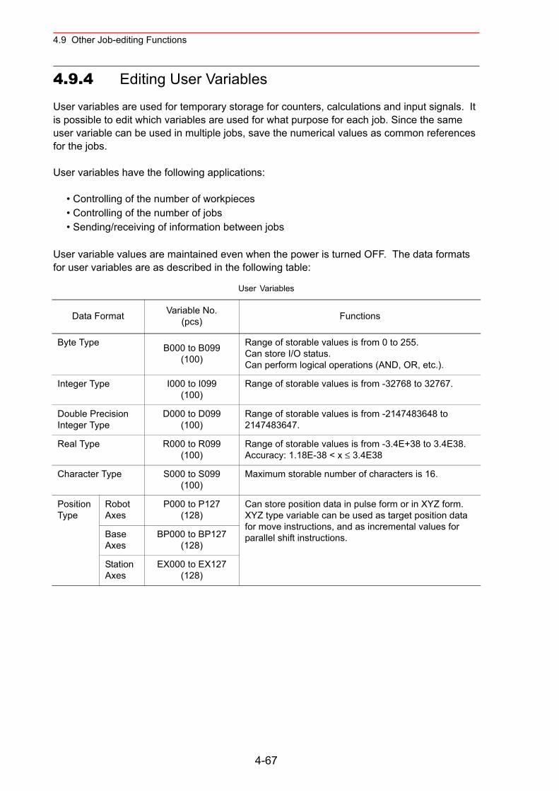
4.9 Other Job-editing Functions
4.9.4 Editing User Variables
User variables are used for temporary storage for counters, calculations and input signals. It is possible to edit which variables are used for what purpose for each job. Since the same user variable can be used in multiple jobs, save the numerical values as common references for the jobs.
User variables have the following applications:
• Controlling of the number of workpieces• Controlling of the number of jobs• Sending/receiving of information between jobs
User variable values are maintained even when the power is turned OFF. The data formats for user variables are as described in the following table:
User Variables
Data Format Variable No.(pcs) Functions
Byte Type B000 to B099(100)
Range of storable values is from 0 to 255.Can store I/O status.Can perform logical operations (AND, OR, etc.).
Integer Type I000 to I099(100)
Range of storable values is from -32768 to 32767.
Double Precision Integer Type
D000 to D099(100)
Range of storable values is from -2147483648 to 2147483647.
Real Type R000 to R099(100)
Range of storable values is from -3.4E+38 to 3.4E38.Accuracy: 1.18E-38 < x ≤ 3.4E38
Character Type S000 to S099(100)
Maximum storable number of characters is 16.
Position Type
Robot Axes
P000 to P127(128)
Can store position data in pulse form or in XYZ form.XYZ type variable can be used as target position data for move instructions, and as incremental values for parallel shift instructions.Base
AxesBP000 to BP127
(128)
Station Axes
EX000 to EX127(128)
4-67
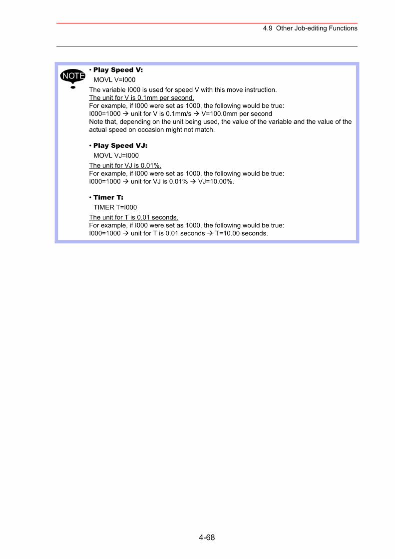
4.9 Other Job-editing Functions
• Play Speed V:MOVL V=I000
The variable I000 is used for speed V with this move instruction.The unit for V is 0.1mm per second.For example, if I000 were set as 1000, the following would be true:I000=1000 unit for V is 0.1mm/s V=100.0mm per secondNote that, depending on the unit being used, the value of the variable and the value of the actual speed on occasion might not match.
• Play Speed VJ:MOVL VJ=I000
The unit for VJ is 0.01%.For example, if I000 were set as 1000, the following would be true:I000=1000 unit for VJ is 0.01% VJ=10.00%.
• Timer T:TIMER T=I000
The unit for T is 0.01 seconds.For example, if I000 were set as 1000, the following would be true:I000=1000 unit for T is 0.01 seconds T=10.00 seconds.
NOTE
4-68
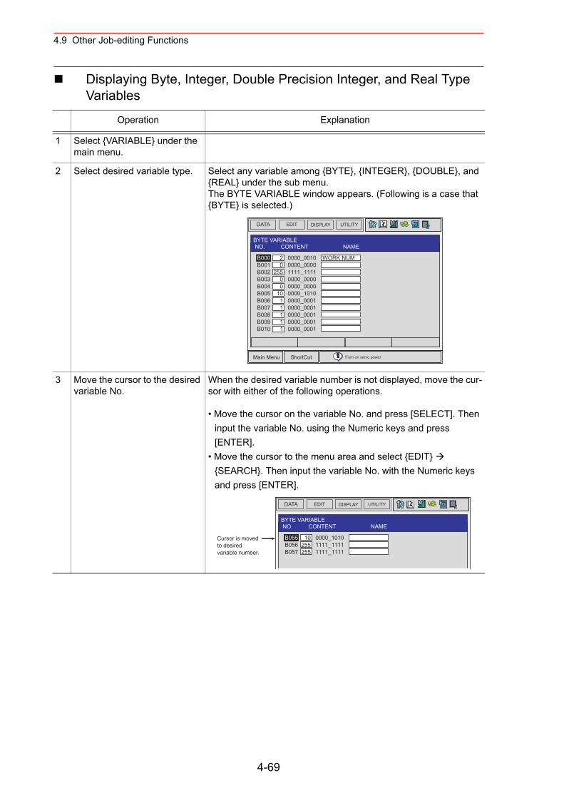
4.9 Other Job-editing Functions
Displaying Byte, Integer, Double Precision Integer, and Real Type Variables
Operation Explanation
1 Select {VARIABLE} under the main menu.
2 Select desired variable type. Select any variable among {BYTE}, {INTEGER}, {DOUBLE}, and {REAL} under the sub menu.The BYTE VARIABLE window appears. (Following is a case that {BYTE} is selected.)
3 Move the cursor to the desired variable No.
When the desired variable number is not displayed, move the cur-sor with either of the following operations.
• Move the cursor on the variable No. and press [SELECT]. Then input the variable No. using the Numeric keys and press [ENTER].
• Move the cursor to the menu area and select {EDIT} {SEARCH}. Then input the variable No. with the Numeric keys and press [ENTER].
DATA EDIT DISPLAY UTILITY
Main Menu ShortCut !Turn on servo power
BYTE VARIABLE NO. CONTENT NAME
B000 2 0000_0010 WORK NUMB001 0 0000_0000B002 255 1111_1111B003 0 0000_0000B004 0 0000_0000B005 10 0000_1010B006 1 0000_0001B007 1 0000_0001B008 1 0000_0001B009 1 0000_0001B010 1 0000_0001
DATA EDIT DISPLAY UTILITY
BYTE VARIABLE NO. CONTENT NAME
B055 10 0000_1010B056 255 1111_1111B057 255 1111_1111
Cursor is moved to desired variable number.
4-69
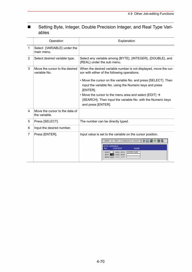
4.9 Other Job-editing Functions
Setting Byte, Integer, Double Precision Integer, and Real Type Vari-ables
Operation Explanation
1 Select {VARIABLE} under the main menu.
2 Select desired variable type. Select any variable among {BYTE}, {INTEGER}, {DOUBLE}, and {REAL} under the sub menu.
3 Move the cursor to the desired variable No.
When the desired variable number is not displayed, move the cur-sor with either of the following operations.
• Move the cursor on the variable No. and press [SELECT]. Then input the variable No. using the Numeric keys and press [ENTER].
• Move the cursor to the menu area and select {EDIT} {SEARCH}. Then input the variable No. with the Numeric keys and press [ENTER].
4 Move the cursor to the data of the variable.
5 Press [SELECT]. The number can be directly typed.
6 Input the desired number.
7 Press [ENTER]. Input value is set to the variable on the cursor position.
DATA EDIT DISPLAY UTILITY
BYTE VARIABLE NO. CONTENT NAME
B000 2 0000_0010 WORK NUMB001 12 0000_0000B002 255 1111_1111
4-70
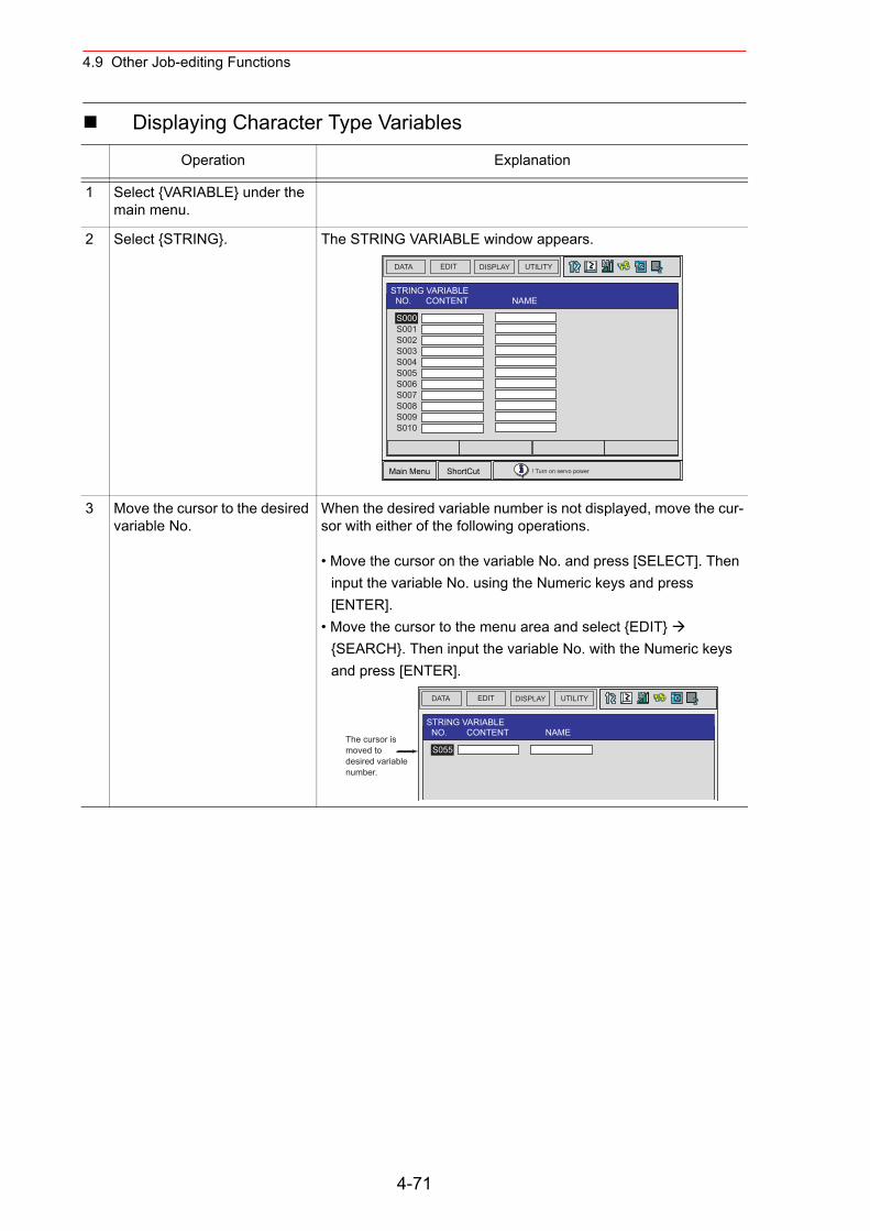
4.9 Other Job-editing Functions
Displaying Character Type Variables
Operation Explanation
1 Select {VARIABLE} under the main menu.
2 Select {STRING}. The STRING VARIABLE window appears.
3 Move the cursor to the desired variable No.
When the desired variable number is not displayed, move the cur-sor with either of the following operations.
• Move the cursor on the variable No. and press [SELECT]. Then input the variable No. using the Numeric keys and press [ENTER].
• Move the cursor to the menu area and select {EDIT} {SEARCH}. Then input the variable No. with the Numeric keys and press [ENTER].
DATA EDIT DISPLAY UTILITY
Main Menu ShortCut ! Turn on servo power
STRING VARIABLE NO. CONTENT NAME
S000S001S002S003S004S005S006S007S008S009S010
DATA EDIT DISPLAY UTILITY
STRING VARIABLE NO. CONTENT NAME
S055The cursor is moved to desired variable number.
4-71
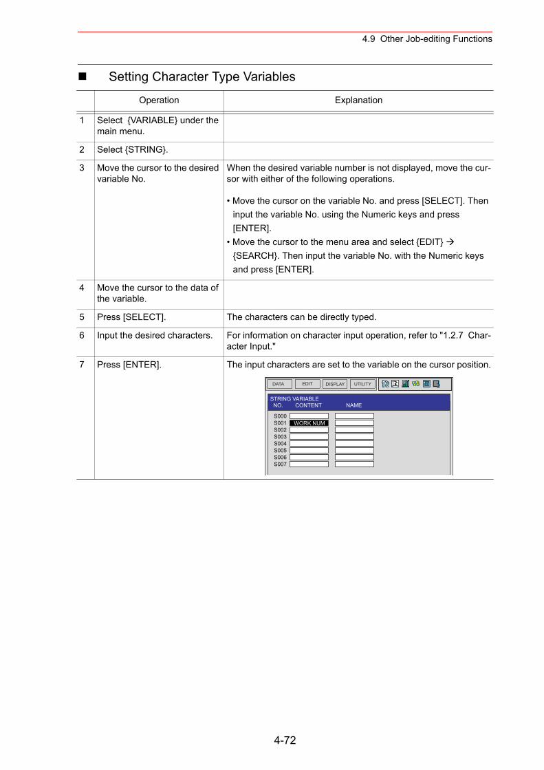
4.9 Other Job-editing Functions
Setting Character Type Variables
Operation Explanation
1 Select {VARIABLE} under the main menu.
2 Select {STRING}.
3 Move the cursor to the desired variable No.
When the desired variable number is not displayed, move the cur-sor with either of the following operations.
• Move the cursor on the variable No. and press [SELECT]. Then input the variable No. using the Numeric keys and press [ENTER].
• Move the cursor to the menu area and select {EDIT} {SEARCH}. Then input the variable No. with the Numeric keys and press [ENTER].
4 Move the cursor to the data of the variable.
5 Press [SELECT]. The characters can be directly typed.
6 Input the desired characters. For information on character input operation, refer to "1.2.7 Char-acter Input."
7 Press [ENTER]. The input characters are set to the variable on the cursor position.
DATA EDIT DISPLAY UTILITY
STRING VARIABLE NO. CONTENT NAME
S000S001S002S003S004S005S006S007
WORK NUM
4-72
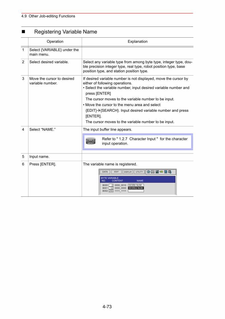
4.9 Other Job-editing Functions
Registering Variable Name
Operation Explanation
1 Select {VARIABLE} under the main menu.
2 Select desired variable. Select any variable type from among byte type, integer type, dou-ble precision integer type, real type, robot position type, base position type, and station position type.
3 Move the cursor to desired variable number.
If desired variable number is not displayed, move the cursor by either of following operations.• Select the variable number, input desired variable number and
press [ENTER]The cursor moves to the variable number to be input.
• Move the cursor to the menu area and select {EDIT} {SEARCH}. Input desired variable number and press [ENTER].The cursor moves to the variable number to be input.
4 Select “NAME.” The input buffer line appears.
5 Input name.
6 Press [ENTER]. The variable name is registered.
Refer to " 1.2.7 Character Input " for the character input operation.
SUPPLE-MENT
DATA EDIT DISPLAY UTILITY
BYTE VARIABLE NO. CONTENT NAME
B000 2 0000_0010 WORK NUMB001 12 0000_0000 WORK2 NUMB002 255 1111_1111
4-73
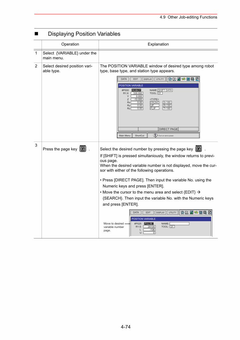
4.9 Other Job-editing Functions
Displaying Position Variables
Operation Explanation
1 Select {VARIABLE} under the main menu.
2 Select desired position vari-able type.
The POSITION VARIABLE window of desired type among robot type, base type, and station type appears.
3Press the page key . Select the desired number by pressing the page key .
If [SHIFT] is pressed simultaniously, the window returns to previ-ous page.When the desired variable number is not displayed, move the cur-sor with either of the following operations.
• Press [DIRECT PAGE]. Then input the variable No. using the Numeric keys and press [ENTER].
• Move the cursor to the menu area and select {EDIT} {SEARCH}. Then input the variable No. with the Numeric keys and press [ENTER].
DATA EDIT DISPLAY UTILITY
Main Menu ShortCut !Turn on servo power
POSITION VARIABLE
NAME: SHIFT DATATOOL: 01
<TYPE> FRONT S<180 UP R<180 FLIP T<180
#P000 R1:X Y Z Rx Ry Rz
ROBOT330.000
0.000-10.000
0.000.000.00
DIRECT PAGE
PAGE
GO BACK
PAGE
GO BACK
DATA EDIT DISPLAY UTILITY
POSITION VARIABLE
NAME: TOOL: 01
#P025 R1:S L U
PULSE28109
-1360
Move to desiredvariable numberpage.
4-74
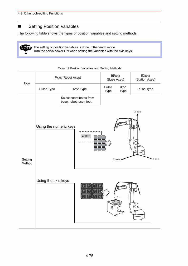
4.9 Other Job-editing Functions
Setting Position VariablesThe following table shows the types of position variables and setting methods.
The setting of position variables is done in the teach mode.Turn the servo power ON when setting the variables with the axis keys.
Types of Position Variables and Setting Methods
Type
Pxxx (Robot Axes) BPxxx(Base Axes)
EXxxx(Station Axes)
Pulse Type XYZ Type Pulse Type
XYZ Type Pulse Type
Setting Method
Select coordinates from base, robot, user, tool.
NOTE
Z-ax is
X-ax is Y-ax is
Using the numeric keys
Using the axis keys
45000
Y-L-
Y+L+
X-S-
X+S+
Z-U-
Z+U+
Y-B-
Y+B+
X-R-
X+R+
Z-T-
Z+T+
7
4
2 3
. -
5. 6
0
8
1
9
4-75
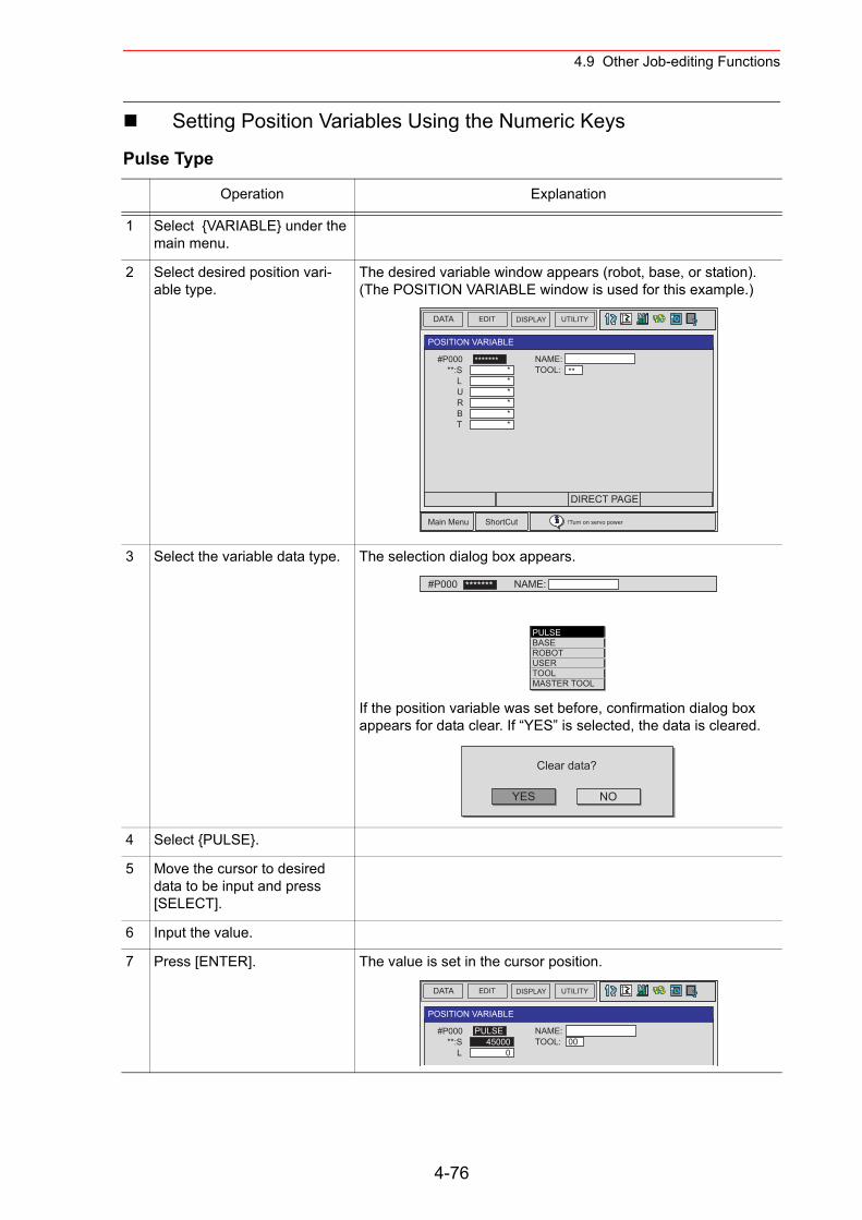
4.9 Other Job-editing Functions
Setting Position Variables Using the Numeric Keys
Pulse Type
Operation Explanation
1 Select {VARIABLE} under the main menu.
2 Select desired position vari-able type.
The desired variable window appears (robot, base, or station). (The POSITION VARIABLE window is used for this example.)
3 Select the variable data type. The selection dialog box appears.
If the position variable was set before, confirmation dialog box appears for data clear. If “YES” is selected, the data is cleared.
4 Select {PULSE}.
5 Move the cursor to desired data to be input and press [SELECT].
6 Input the value.
7 Press [ENTER]. The value is set in the cursor position.
DATA EDIT DISPLAY UTILITY
Main Menu ShortCut !Turn on servo power
POSITION VARIABLE
NAME: TOOL: **
#P000 **:S L U R B T
*************
DIRECT PAGE
NAME: #P000 *******
PULSEBASEROBOTUSERTOOLMASTER TOOL
YES
Clear data?
NO
DATA EDIT DISPLAY UTILITY
POSITION VARIABLE
NAME: TOOL: 00
#P000 **:S L
PULSE45000
0
4-76
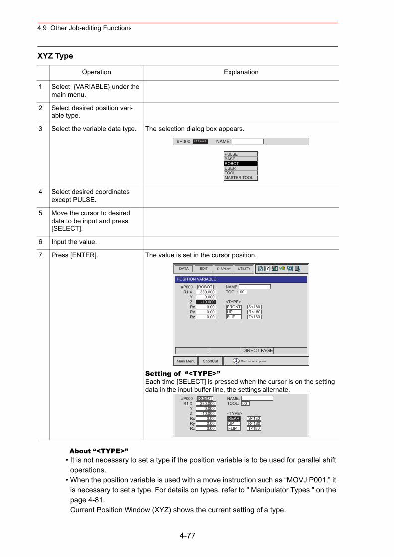
4.9 Other Job-editing Functions
XYZ Type
About “<TYPE>”• It is not necessary to set a type if the position variable is to be used for parallel shift
operations.• When the position variable is used with a move instruction such as “MOVJ P001,” it
is necessary to set a type. For details on types, refer to " Manipulator Types " on the page 4-81.Current Position Window (XYZ) shows the current setting of a type.
Operation Explanation
1 Select {VARIABLE} under the main menu.
2 Select desired position vari-able type.
3 Select the variable data type. The selection dialog box appears.
4 Select desired coordinates except PULSE.
5 Move the cursor to desired data to be input and press [SELECT].
6 Input the value.
7 Press [ENTER]. The value is set in the cursor position.
Setting of “<TYPE>”Each time [SELECT] is pressed when the cursor is on the setting data in the input buffer line, the settings alternate.
NAME: #P000 *******
PULSEBASEROBOTUSERTOOLMASTER TOOL
DATA EDIT DISPLAY UTILITY
Main Menu ShortCut !Turn on servo power
POSITION VARIABLE
NAME: TOOL: 00
<TYPE> FRONT S<180 UP R<180 FLIP T<180
#P000 R1:X Y Z Rx Ry Rz
ROBOT330.000
0.000-10.000
0.000.000.00
DIRECT PAGE
NAME: TOOL: 00
<TYPE> REAR S<180 UP R<180 FLIP T<180
#P000 R1:X Y Z Rx Ry Rz
ROBOT330.000
0.000-10.000
0.000.000.00
4-77
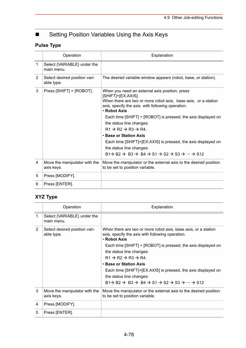
4.9 Other Job-editing Functions
Setting Position Variables Using the Axis Keys
Pulse Type
XYZ Type
Operation Explanation
1 Select {VARIABLE} under the main menu.
2 Select desired position vari-able type.
The desired variable window appears (robot, base, or station).
3 Press [SHIFT] + [ROBOT]. When you need an external axis position, press [SHIFT]+[EX.AXIS]. When there are two or more robot axis, base axis, or a station axis, specify the axis with following operation.• Robot Axis
Each time [SHIFT] + [ROBOT] is pressed, the axis displayed on the status line changes:R1 R2 R3 R4.
• Base or Station AxisEach time [SHIFT]+[EX.AXIS] is pressed, the axis displayed on the status line changes:B1 B2 B3 B4 S1 S2 S3 S12
4 Move the manipulator with the axis keys.
Move the manipulator or the external axis to the desired position to be set to position variable.
5 Press [MODIFY].
6 Press [ENTER].
Operation Explanation
1 Select {VARIABLE} under the main menu.
2 Select desired position vari-able type.
When there are two or more robot axis, base axis, or a station axis, specify the axis with following operation.• Robot Axis
Each time [SHIFT] + [ROBOT] is pressed, the axis displayed on the status line changes:R1 R2 R3 R4.
• Base or Station AxisEach time [SHIFT]+[EX.AXIS] is pressed, the axis displayed on the status line changes:B1 B2 B3 B4 S1 S2 S3 S12
3 Move the manipulator with the axis keys.
Move the manipulator or the external axis to the desired position to be set to position variable.
4 Press [MODIFY].
5 Press [ENTER].
4-78
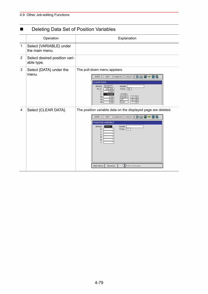
4.9 Other Job-editing Functions
Deleting Data Set of Position Variables
Operation Explanation
1 Select {VARIABLE} under the main menu.
2 Select desired position vari-able type.
3 Select {DATA} under the menu.
The pull-down menu appears.
4 Select {CLEAR DATA}. The position variable data on the displayed page are deleted.
DATA EDIT DISPLAY UTILITY
CLEAR DATA
NAME: TOOL: 00
<TYPE> FRONT S<180 UP R<180 FLIP T<180
#P000 R1:X Y Z Rx Ry Rz
ROBOT330.000
0.000-10.000
0.000.000.00
DATA EDIT DISPLAY UTILITY
Main Menu ShortCut !Turn on servo power
POSITION VARIABLE
NAME: TOOL: **
#P000 :S L U R B T
*************
4-79
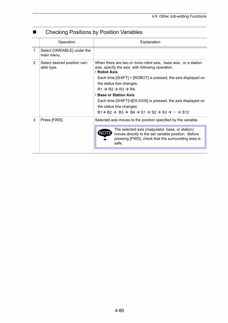
4.9 Other Job-editing Functions
Checking Positions by Position Variables
Operation Explanation
1 Select {VARIABLE} under the main menu.
2 Select desired position vari-able type.
When there are two or more robot axis, base axis, or a station axis, specify the axis with following operation.• Robot Axis
Each time [SHIFT] + [ROBOT] is pressed, the axis displayed on the status line changes:R1 R2 R3 R4.
• Base or Station AxisEach time [SHIFT]+[EX.AXIS] is pressed, the axis displayed on the status line changes:B1 B2 B3 B4 S1 S2 S3 S12
3 Press [FWD]. Selected axis moves to the position specified by the variable.
The selected axis (maipulator, base, or station) moves directly to the set variable position. Before pressing [FWD], check that the surrounding area is safe.
NOTE
4-80
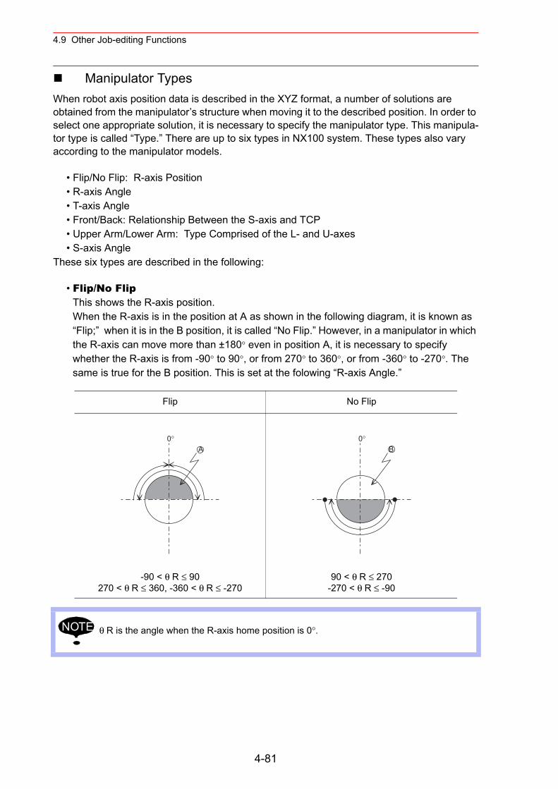
4.9 Other Job-editing Functions
Manipulator TypesWhen robot axis position data is described in the XYZ format, a number of solutions are obtained from the manipulator’s structure when moving it to the described position. In order to select one appropriate solution, it is necessary to specify the manipulator type. This manipula-tor type is called “Type.” There are up to six types in NX100 system. These types also vary according to the manipulator models.
• Flip/No Flip: R-axis Position• R-axis Angle • T-axis Angle• Front/Back: Relationship Between the S-axis and TCP• Upper Arm/Lower Arm: Type Comprised of the L- and U-axes• S-axis Angle
These six types are described in the following:
• Flip/No FlipThis shows the R-axis position.When the R-axis is in the position at A as shown in the following diagram, it is known as “Flip;” when it is in the B position, it is called “No Flip.” However, in a manipulator in which the R-axis can move more than ±180° even in position A, it is necessary to specify whether the R-axis is from -90° to 90°, or from 270° to 360°, or from -360° to -270°. The same is true for the B position. This is set at the folowing “R-axis Angle.”
Flip No Flip
-90 < θ R ≤ 90270 < θ R ≤ 360, -360 < θ R ≤ -270
90 < θ R ≤ 270-270 < θ R ≤ -90
θ R is the angle when the R-axis home position is 0°.
0°A
0°B
NOTE
4-81
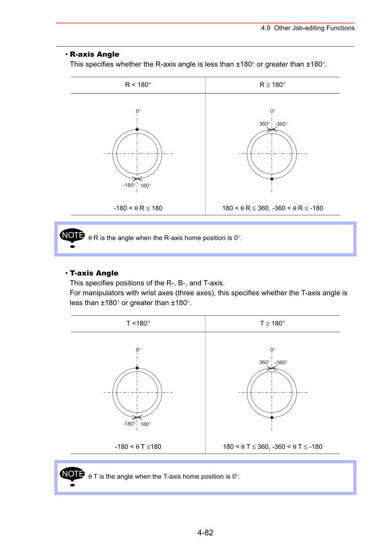
4.9 Other Job-editing Functions
• R-axis AngleThis specifies whether the R-axis angle is less than ±180° or greater than ±180°.
• T-axis AngleThis specifies positions of the R-, B-, and T-axis.For manipulators with wrist axes (three axes), this specifies whether the T-axis angle is less than ±180° or greater than ±180°.
R < 180° R ≥ 180°
-180 < θ R ≤ 180 180 < θ R ≤ 360, -360 < θ R ≤ -180
θ R is the angle when the R-axis home position is 0°.
T <180° T ≥ 180°
-180 < θ T ≤180 180 < θ T ≤ 360, -360 < θ T ≤ -180
θ T is the angle when the T-axis home position is 0°.
0°
-180° 180°
0°
-360°360°
NOTE
0°
-180° 180°
0°
-360°360°
NOTE
4-82
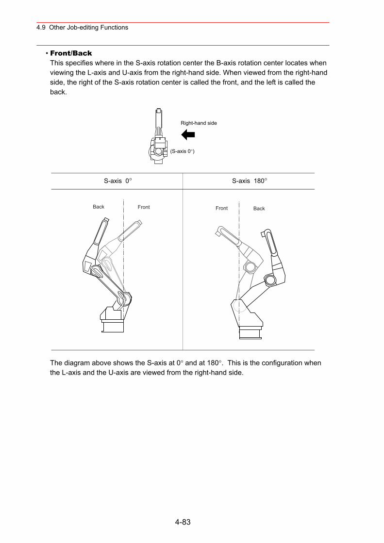
4.9 Other Job-editing Functions
• Front/BackThis specifies where in the S-axis rotation center the B-axis rotation center locates when viewing the L-axis and U-axis from the right-hand side. When viewed from the right-hand side, the right of the S-axis rotation center is called the front, and the left is called the back.
The diagram above shows the S-axis at 0° and at 180°. This is the configuration when the L-axis and the U-axis are viewed from the right-hand side.
S-axis 0° S-axis 180°
Right-hand side
(S-axis 0°)
Back Front Front Back
4-83
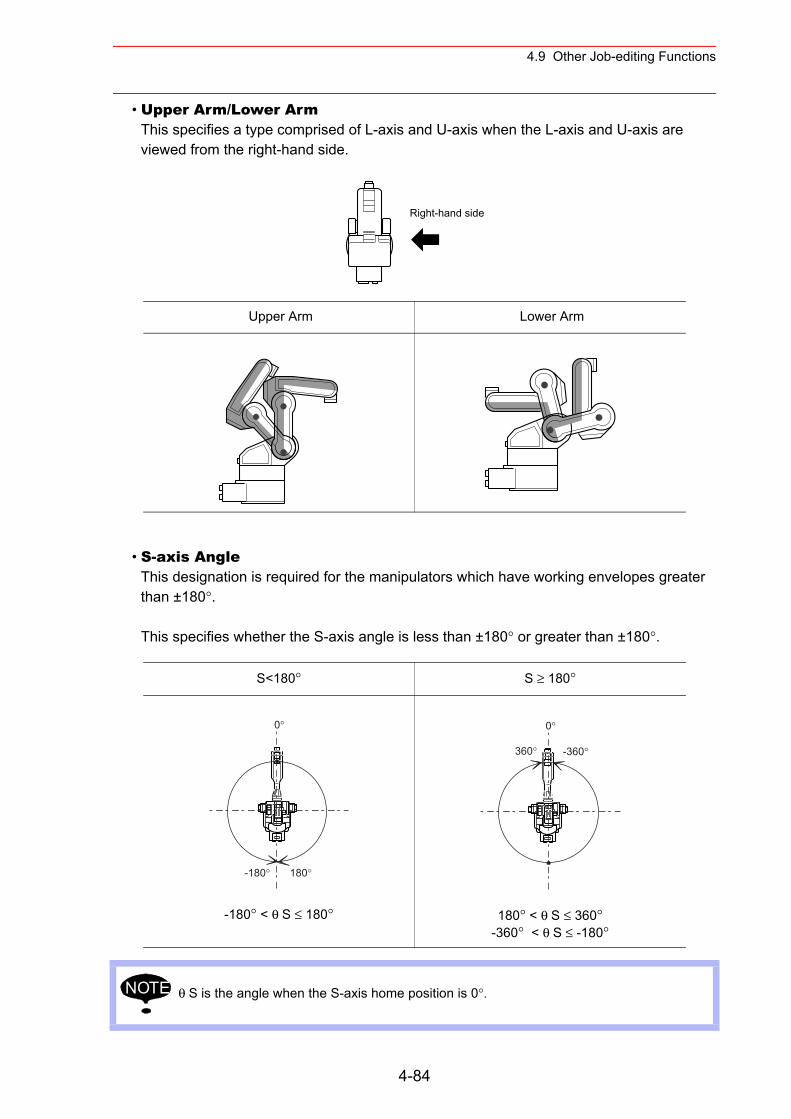
4.9 Other Job-editing Functions
• Upper Arm/Lower ArmThis specifies a type comprised of L-axis and U-axis when the L-axis and U-axis are viewed from the right-hand side.
• S-axis AngleThis designation is required for the manipulators which have working envelopes greater than ±180°.
This specifies whether the S-axis angle is less than ±180° or greater than ±180°.
Upper Arm Lower Arm
S<180° S ≥ 180°
-180° < θ S ≤ 180° 180° < θ S ≤ 360°-360° < θ S ≤ -180°
θ S is the angle when the S-axis home position is 0°.
Right-hand side
0°
-180° 180°
0°
-360°360°
NOTE
4-84
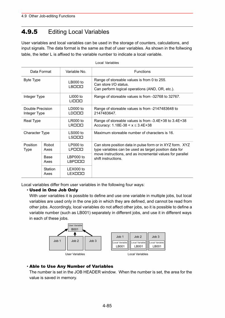
4.9 Other Job-editing Functions
4.9.5 Editing Local Variables
User variables and local variables can be used in the storage of counters, calculations, and input signals. The data format is the same as that of user variables. As shown in the follwoing table, the letter L is affixed to the variable number to indicate a local variable.
Local variables differ from user variables in the following four ways:• Used in One Job Only
With user variables it is possible to define and use one variable in multiple jobs, but local variables are used only in the one job in which they are defined, and cannot be read from other jobs. Accordingly, local variables do not affect other jobs, so it is possible to define a variable number (such as LB001) separately in different jobs, and use it in different ways in each of these jobs.
• Able to Use Any Number of VariablesThe number is set in the JOB HEADER window. When the number is set, the area for the value is saved in memory.
Local Variables
Data Format Variable No. Functions
Byte Type LB000 toLB
Range of storeable values is from 0 to 255.Can store I/O status.Can perform logical operations (AND, OR, etc.).
Integer Type Ll000 toLI
Range of storeable values is from -32768 to 32767.
Double Precision Integer Type
LD000 toLD
Range of storeable values is from -2147483648 to 2147483647.
Real Type LR000 toLR
Range of storeable values is from -3.4E+38 to 3.4E+38Accuracy: 1.18E-38 < x ≤ 3.4E+38
Character Type LS000 toLS
Maximum storeable number of characters is 16.
Position Type
Robot Axes
LP000 to LP
Can store position data in pulse form or in XYZ form. XYZ type variables can be used as target position data for move instructions, and as incremental values for parallel shift instructions.Base
AxesLBP000 toLBP
Station Axes
LEX000 toLEX
LB001Local Variable
LB001Local VariableJob 1 Job 2 Job 3
B001
User Variables
Job 1 Job 2 Job 3
Local Variables
LB001
User Variable
Local Variable
4-85
4.9 Other Job-editing Functions
• Not Able to Display the Variable ContentsTo display the local variable contents, user variables are needed.For example, to view the contents of local variable LP000, save it temporarily as user vari-able P001. Then execute the instruction SET P001 LP000, and view the POSITION VARI-ABLE window for P001.
• Enabled Only During the Execution of the Defined JobThe contents of the local variables are enabled only during the execution of the defined job.The local variable field is assured when the defined job is called (when the job is executed by a CALL or JUMP instruction, or the job is selected by the menu). Once the job is com-pleted by the execution of a RET, END, or JUMP instruction, the local variable data that was set is disabled. However, if a job which uses local variables itself calls a separate job, then is returned to by use of a RET instruction, the data that was present prior to the CALL instruction remains in effect and can be used.
Precautions for Variables and UnitsAs was the case with user variables, note that, depending on the value of the unit being used, the value of the variable and the value of the actual speed or time an occasion might not match. Refer to "4.9.4 Editing User Variables."
NOTE
4-86
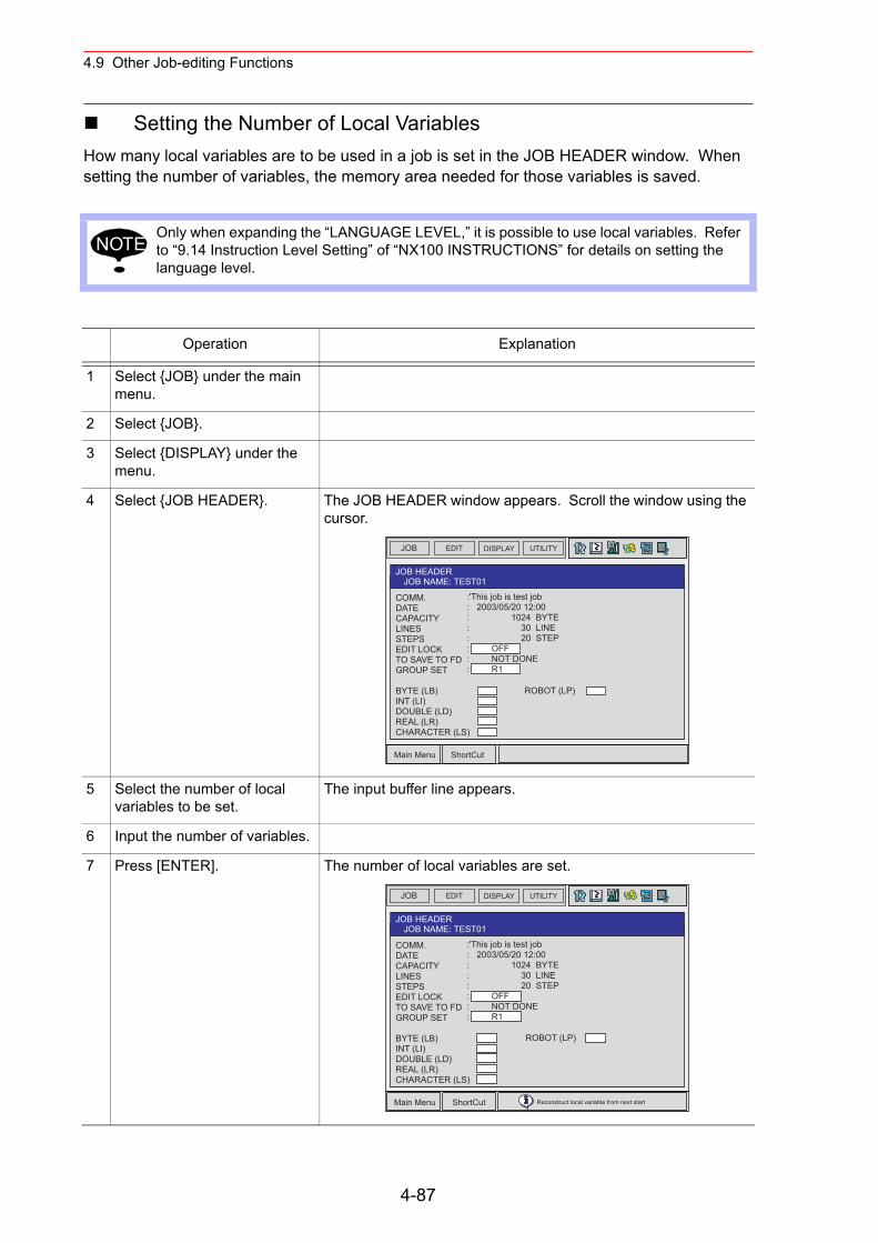
4.9 Other Job-editing Functions
Setting the Number of Local VariablesHow many local variables are to be used in a job is set in the JOB HEADER window. When setting the number of variables, the memory area needed for those variables is saved.
Only when expanding the “LANGUAGE LEVEL,” it is possible to use local variables. Refer to “9.14 Instruction Level Setting” of “NX100 INSTRUCTIONS” for details on setting the language level.
Operation Explanation
1 Select {JOB} under the main menu.
2 Select {JOB}.
3 Select {DISPLAY} under the menu.
4 Select {JOB HEADER}. The JOB HEADER window appears. Scroll the window using the cursor.
5 Select the number of local variables to be set.
The input buffer line appears.
6 Input the number of variables.
7 Press [ENTER]. The number of local variables are set.
NOTE
JOB EDIT DISPLAY UTILITY
Main Menu ShortCut
JOB HEADERJOB NAME: TEST01
COMM.DATECAPACITYLINESSTEPSEDIT LOCKTO SAVE TO FDGROUP SET
BYTE (LB)INT (LI)DOUBLE (LD)REAL (LR)CHARACTER (LS)
ROBOT (LP)
:'This job is test job: 2003/05/20 12:00: 1024 BYTE: 30 LINE: 20 STEP: OFF: NOT DONE: R1
JOB EDIT DISPLAY UTILITY
Main Menu ShortCut
JOB HEADERJOB NAME: TEST01
COMM.DATECAPACITYLINESSTEPSEDIT LOCKTO SAVE TO FDGROUP SET
BYTE (LB)INT (LI)DOUBLE (LD)REAL (LR)CHARACTER (LS)
ROBOT (LP)
:'This job is test job: 2003/05/20 12:00: 1024 BYTE: 30 LINE: 20 STEP: OFF: NOT DONE: R1
Reconstruct local variable from next start
4-87
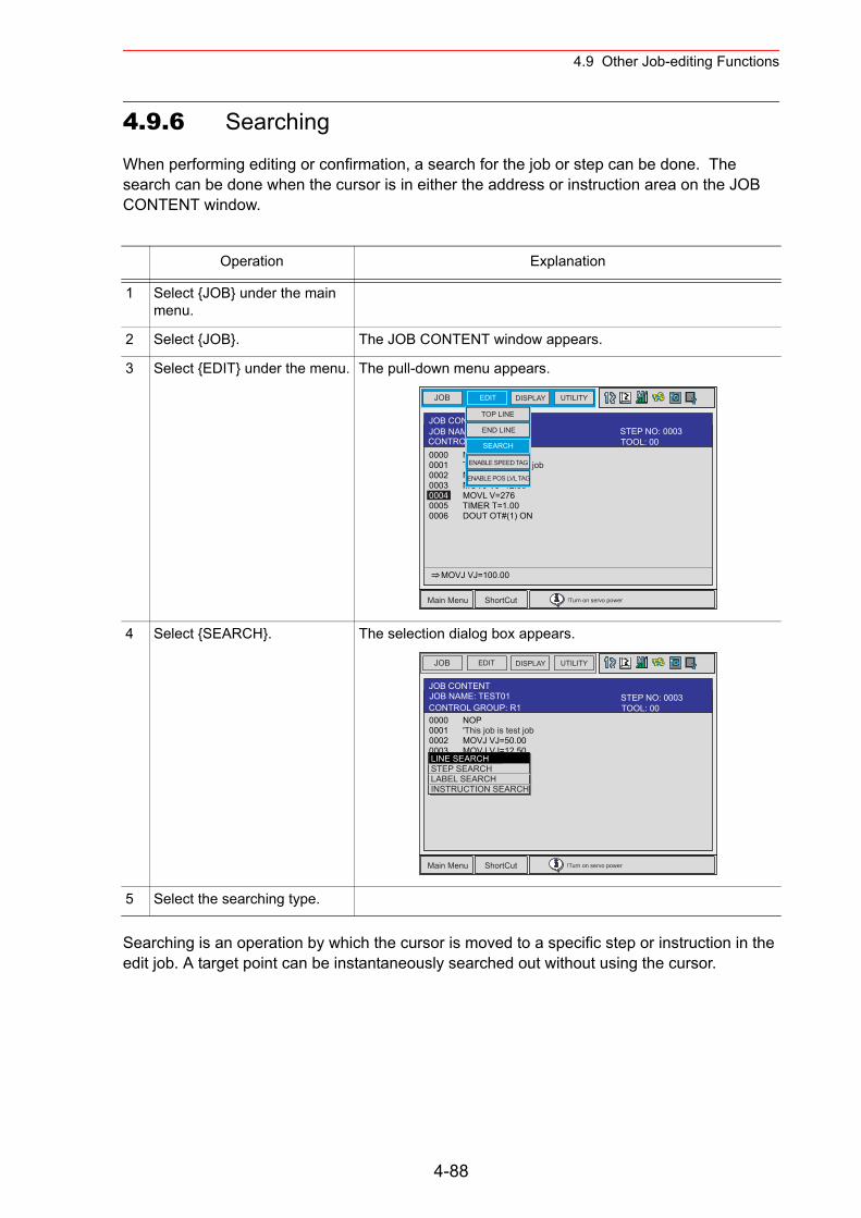
4.9 Other Job-editing Functions
4.9.6 Searching
When performing editing or confirmation, a search for the job or step can be done. The search can be done when the cursor is in either the address or instruction area on the JOB CONTENT window.
Searching is an operation by which the cursor is moved to a specific step or instruction in the edit job. A target point can be instantaneously searched out without using the cursor.
Operation Explanation
1 Select {JOB} under the main menu.
2 Select {JOB}. The JOB CONTENT window appears.
3 Select {EDIT} under the menu. The pull-down menu appears.
4 Select {SEARCH}. The selection dialog box appears.
5 Select the searching type.
JOB EDIT DISPLAY UTILITY
Main Menu ShortCut !Turn on servo power
JOB CONTENT
0000 NOP0001 THThis job is test job0002 MOVJ VJ=50.000003 MOVJ VJ=12.500004 MOVL V=2760005 TIMER T=1.000006 DOUT OT#(1) ON
MOVJ VJ=100.00
JOB NAME: TEST01TOOL: 00CONTROL GROUP: R1STEP NO: 0003
SEARCH
TOP LINE
END LINE
ENABLE SPEED TAG
ENABLE POS LVL TAG
JOB EDIT DISPLAY UTILITY
Main Menu ShortCut !Turn on servo power
JOB CONTENT
0000 NOP0001 'This job is test job0002 MOVJ VJ=50.000003 MOVJ VJ=12.500004 MOVL V=2760005 TIMER T=1.000006 DOUT OT#(1) ON0007 MOVL V=138
JOB NAME: TEST01
LINE SEARCHSTEP SEARCHLABEL SEARCHINSTRUCTION SEARCH
TOOL: 00CONTROL GROUP: R1STEP NO: 0003
4-88
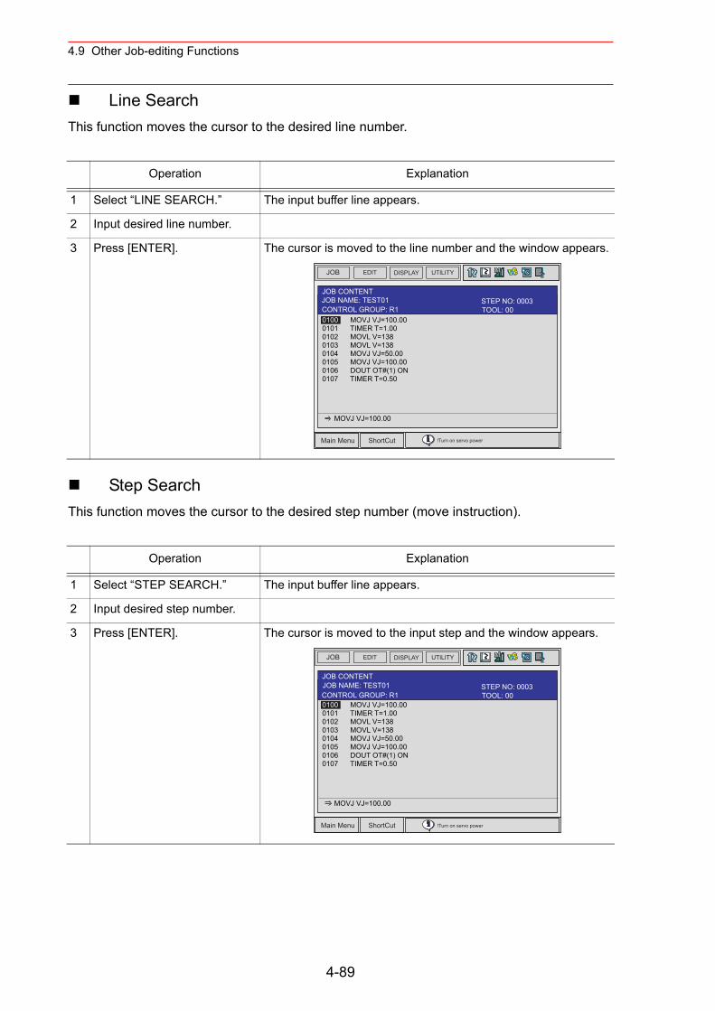
4.9 Other Job-editing Functions
Line SearchThis function moves the cursor to the desired line number.
Step SearchThis function moves the cursor to the desired step number (move instruction).
Operation Explanation
1 Select “LINE SEARCH.” The input buffer line appears.
2 Input desired line number.
3 Press [ENTER]. The cursor is moved to the line number and the window appears.
Operation Explanation
1 Select “STEP SEARCH.” The input buffer line appears.
2 Input desired step number.
3 Press [ENTER]. The cursor is moved to the input step and the window appears.
JOB EDIT DISPLAY UTILITY
Main Menu ShortCut !Turn on servo power
JOB CONTENT
0100 MOVJ VJ=100.000101 TIMER T=1.000102 MOVL V=1380103 MOVL V=1380104 MOVJ VJ=50.000105 MOVJ VJ=100.000106 DOUT OT#(1) ON0107 TIMER T=0.50
MOVJ VJ=100.00
JOB NAME: TEST01TOOL: 00CONTROL GROUP: R1STEP NO: 0003
JOB EDIT DISPLAY UTILITY
Main Menu ShortCut !Turn on servo power
JOB CONTENT
0100 MOVJ VJ=100.000101 TIMER T=1.000102 MOVL V=1380103 MOVL V=1380104 MOVJ VJ=50.000105 MOVJ VJ=100.000106 DOUT OT#(1) ON0107 TIMER T=0.50
MOVJ VJ=100.00
JOB NAME: TEST01TOOL: 00CONTROL GROUP: R1STEP NO: 0003
4-89
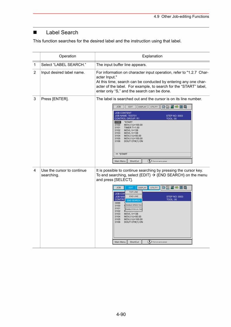
4.9 Other Job-editing Functions
Label SearchThis function searches for the desired label and the instruction using that label.
Operation Explanation
1 Select “LABEL SEARCH.” The input buffer line appears.
2 Input desired label name. For information on character input operation, refer to "1.2.7 Char-acter Input."At this time, search can be conducted by entering any one char-acter of the label. For example, to search for the “START” label, enter only “S,” and the search can be done.
3 Press [ENTER]. The label is searched out and the cursor is on its line number.
4 Use the cursor to continue searching.
It is possible to continue searching by pressing the cursor key.To end searching, select {EDIT} {END SEARCH} on the menu and press [SELECT].
JOB EDIT DISPLAY UTILITY
Main Menu ShortCut !Turn on servo power
JOB CONTENT
0099 *START 0100 MOVJ VJ=100.000101 TIMER T=1.000102 MOVL V=1380103 MOVL V=1380104 MOVJ VJ=50.000105 MOVJ VJ=100.00 0106 DOUT OT#(1) ON
*START
JOB NAME: TEST01TOOL: 00CONTROL GROUP: R1STEP NO: 0003
JOB EDIT DISPLAY UTILITY
Main Menu ShortCut !Turn on servo power
JOB CONTENT
0099 *START 0100 MOVJ VJ=100.000101 TIMER T=1.000102 MOVL V=1380103 MOVL V=1380104 MOVJ VJ=50.000105 MOVJ VJ=100.00 0106 DOUT OT#(1) ON
JOB NAME: TEST01TOOL: 00CONTROL GROUP: R1STEP NO: 0003
END SEARCH
TOP LINE
END LINE
ENABLE SPEED TAG
ENABLE POS LVL TAG
4-90
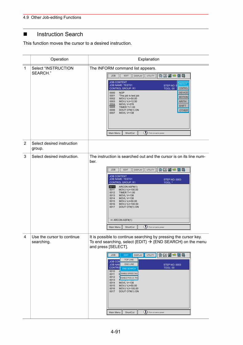
4.9 Other Job-editing Functions
Instruction SearchThis function moves the cursor to a desired instruction.
Operation Explanation
1 Select “INSTRUCTION SEARCH.”
The INFORM command list appears.
2 Select desired instruction group.
3 Select desired instruction. The instruction is searched out and the cursor is on its line num-ber.
4 Use the cursor to continue searching.
It is possible to continue searching by pressing the cursor key.To end searching, select {EDIT} {END SEARCH} on the menu and press [SELECT].
JOB EDIT DISPLAY UTILITY
Main Menu ShortCut !Turn on servo power
JOB CONTENT
0000 NOP0001 'This job is test job0002 MOVJ VJ=50.000003 MOVJ VJ=12.500004 MOVL V=2760005 TIMER T=1.000006 DOUT OT#(1) ON0007 MOVL V=138
JOB NAME: TEST01TOOL: 00CONTROL GROUP: R1STEP NO: 0003
IN/OUT
CONTROL
DEVICE
MOTION
ARITH
SHIFT
OTHER
JOB EDIT DISPLAY UTILITY
Main Menu ShortCut !Turn on servo power
JOB CONTENTJOB NAME: TEST01
0010 ARCON ASF#(1) 0011 MOVJ VJ=100.000012 TIMER T=1.000013 MOVL V=1380014 MOVL V=1380015 MOVJ VJ=50.000016 MOVJ VJ=100.00 0017 DOUT OT#(1) ON
ARCON ASF#(1)
TOOL: *CONTROL GROUP: R1STEP NO: 0003
JOB EDIT DISPLAY UTILITY
Main Menu ShortCut !Turn on servo power
JOB CONTENT
0010 ARCON ASF#(1) 0011 MOVJ VJ=100.000012 TIMER T=1.000013 MOVL V=1380014 MOVL V=1380015 MOVJ VJ=50.000016 MOVJ VJ=100.00 0017 DOUT OT#(1) ON
JOB NAME: TEST01TOOL: 00CONTROL GROUP: R1STEP NO: 0003
END SEARCH
TOP LINE
END LINE
ENABLE SPEED TAG
ENABLE POS LVL TAG
4-91
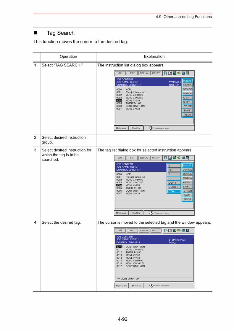
4.9 Other Job-editing Functions
Tag SearchThis function moves the cursor to the desired tag.
Operation Explanation
1 Select “TAG SEARCH.” The instruction list dialog box appears.
2 Select desired instruction group.
3 Select desired instruction for which the tag is to be searched.
The tag list dialog box for selected instruction appears.
4 Select the desired tag. The cursor is moved to the selected tag and the window appears.
JOB EDIT DISPLAY UTILITY
Main Menu ShortCut !Turn on servo power
JOB CONTENTJOB NAME: TEST01
0000 NOP0001 'This job is test job0002 MOVJ VJ=50.000003 MOVJ VJ=12.500004 MOVL V=2760005 TIMER T=1.000006 DOUT OT#(1) ON0007 MOVL V=138
TOOL: 00CONTROL GROUP: R1STEP NO: 0003IN/OUT
CONTROL
DEVICE
MOTION
ARITH
SHIFT
OTHER
SAME
PRIOR
JOB EDIT DISPLAY UTILITY
Main Menu ShortCut !Turn on servo power
JOB CONTENTJOB NAME: TEST01
0000 NOP0001 'This job is test job0002 MOVJ VJ=50.000003 MOVJ VJ=12.500004 MOVL V=2760005 TIMER T=1.000006 DOUT OT#(1) ON0007 MOVL V=138
IN/OUT
CONTROL
DEVICE
MOTION
ARITH
SHIFT
OTHER
SAME
PRIOR
B
B[ ]
D
I
OG#( )
OGH#( )
OT#( )
CONTROL GROUP: R1
JOB EDIT DISPLAY UTILITY
Main Menu ShortCut !Turn on servo power
JOB CONTENTJOB NAME: TEST01
0010 DOUT OT#(1) ON 0011 MOVJ VJ=100.000012 TIMER T=1.000013 MOVL V=1380014 MOVL V=1380015 MOVJ VJ=50.000016 MOVJ VJ=100.00 0017 DOUT OT#(1) ON
DOUT OT#(1) ON
TOOL: *CONTROL GROUP: R1STEP NO: 0003
4-92
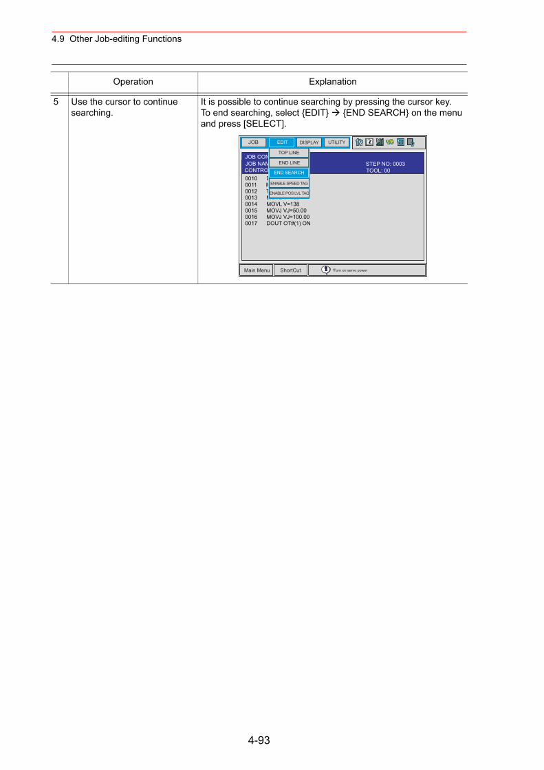
4.9 Other Job-editing Functions
5 Use the cursor to continue searching.
It is possible to continue searching by pressing the cursor key.To end searching, select {EDIT} {END SEARCH} on the menu and press [SELECT].
Operation Explanation
JOB EDIT DISPLAY UTILITY
Main Menu ShortCut !Turn on servo power
JOB CONTENT
0010 DOUT OT#(1) ON 0011 MOVJ VJ=100.000012 TIMER T=1.000013 MOVL V=1380014 MOVL V=1380015 MOVJ VJ=50.000016 MOVJ VJ=100.00 0017 DOUT OT#(1) ON
JOB NAME: TEST01TOOL: 00CONTROL GROUP: R1STEP NO: 0003
END SEARCH
TOP LINE
END LINE
ENABLE SPEED TAG
ENABLE POS LVL TAG
4-93
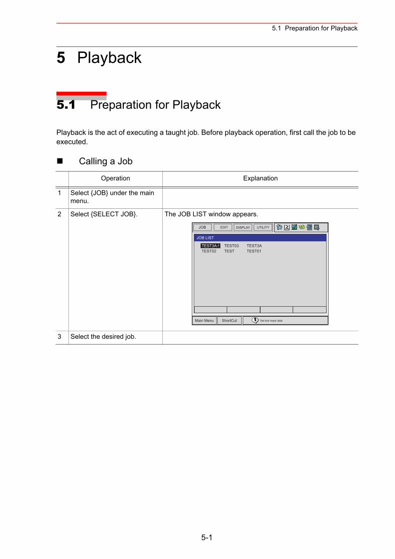
5.1 Preparation for Playback
5 Playback
5.1 Preparation for Playback
Playback is the act of executing a taught job. Before playback operation, first call the job to be executed.
Calling a Job
Operation Explanation
1 Select {JOB} under the main menu.
2 Select {SELECT JOB}. The JOB LIST window appears.
3 Select the desired job.
JOB UTILITYEDIT DISPLAY
Main Menu ShortCut Set tool mass data
TEST03TEST
TEST3ATEST01
JOB LIST
TEST3A-!TEST02
5-1
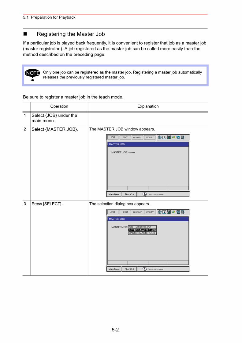
5.1 Preparation for Playback
Registering the Master JobIf a particular job is played back frequently, it is convenient to register that job as a master job (master registraton). A job registered as the master job can be called more easily than the method described on the preceding page.
Be sure to register a master job in the teach mode.
Only one job can be registered as the master job. Registering a master job automatically releases the previously registered master job.
Operation Explanation
1 Select {JOB} under the main menu.
2 Select {MASTER JOB}. The MASTER JOB window appears.
3 Press [SELECT]. The selection dialog box appears.
NOTE
JOB EDIT DISPLAY UTILITY
Main Menu ShortCut !Turn on servo power
MASTER JOB
MASTER JOB: *******
JOB EDIT DISPLAY UTILITY
Main Menu ShortCut !Turn on servo power
MASTER JOB
MASTER JOB: *******CALL MASTER JOBSETTING MASTER JOBCANCEL MASTER JOB
5-2
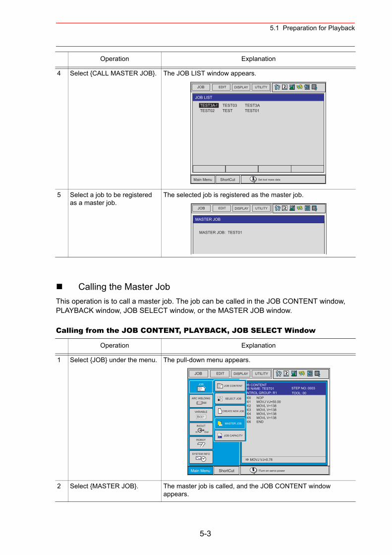
5.1 Preparation for Playback
Calling the Master JobThis operation is to call a master job. The job can be called in the JOB CONTENT window, PLAYBACK window, JOB SELECT window, or the MASTER JOB window.
Calling from the JOB CONTENT, PLAYBACK, JOB SELECT Window
4 Select {CALL MASTER JOB}. The JOB LIST window appears.
5 Select a job to be registered as a master job.
The selected job is registered as the master job.
Operation Explanation
1 Select {JOB} under the menu. The pull-down menu appears.
2 Select {MASTER JOB}. The master job is called, and the JOB CONTENT window appears.
Operation Explanation
JOB UTILITYEDIT DISPLAY
Main Menu ShortCut Set tool mass data
TEST03TEST
TEST3ATEST01
JOB LIST
TEST3A-!TEST02
JOB EDIT DISPLAY UTILITY
MASTER JOB
MASTER JOB: TEST01
JOB EDIT DISPLAY UTILITY
Main Menu ShortCut !Turn on servo power
0000 NOP0001 MOVJ VJ=50.000002 MOVL V=1380003 MOVL V=1380004 MOVL V=1380005 MOVL V=138 0006 END
MOVJ VJ=0.78
JOB CONTENTJOB NAME: TEST01
TOOL: 00CONTROL GROUP: R1STEP NO: 0003
JOBDOUTMOVEEND
IN/OUT
In Out
SYSTEM INFO
ARC WELDING
VARIABLE
B001
ROBOT
SELECT JOB
MASTER JOB
JOB CAPACITY
DOUTMOVEEND JOB CONTENT
CREATE NEW JOB
5-3
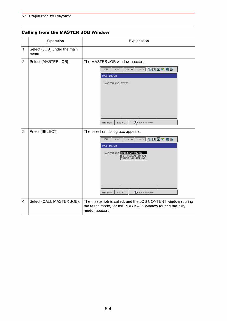
5.1 Preparation for Playback
Calling from the MASTER JOB Window
Operation Explanation
1 Select {JOB} under the main menu.
2 Select {MASTER JOB}. The MASTER JOB window appears.
3 Press [SELECT]. The selection dialog box appears.
4 Select {CALL MASTER JOB}. The master job is called, and the JOB CONTENT window (during the teach mode), or the PLAYBACK window (during the play mode) appears.
JOB EDIT DISPLAY UTILITY
Main Menu ShortCut !Turn on servo power
MASTER JOB
MASTER JOB: TEST01
JOB EDIT DISPLAY UTILITY
Main Menu ShortCut !Turn on servo power
MASTER JOB
MASTER JOB: *******CALL MASTER JOBSETTING MASTER JOBCANCEL MASTER JOB
5-4
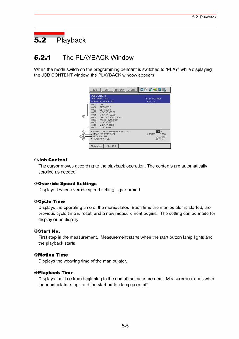
5.2 Playback
5.2 Playback
5.2.1 The PLAYBACK Window
When the mode switch on the programming pendant is switched to “PLAY” while displaying the JOB CONTENT window, the PLAYBACK window appears.
Job ContentThe cursor moves according to the playback operation. The contents are automatically scrolled as needed.
Override Speed SettingsDisplayed when override speed setting is performed.
Cycle TimeDisplays the operating time of the manipulator. Each time the manipulator is started, the previous cycle time is reset, and a new measurement begins. The setting can be made for display or no display.
Start No.First step in the measurement. Measurement starts when the start button lamp lights and the playback starts.
Motion TimeDisplays the weaving time of the manipulator.
Playback TimeDisplays the time from beginning to the end of the measurement. Measurement ends when the manipulator stops and the start button lamp goes off.
JOB EDIT DISPLAY UTILITY
Main Menu ShortCut
JOB CONTENTJOB NAME: TEST
0000 NOP0001 SET B000 00002 SET B001 10003 MOVJ VJ=80.000004 MOVJ VJ=80.000005 DOUT OGH#(13) B0020006 WAIT IF IN#(5)=ON0007 MOVL V=880.00008 MOVL V=880.00009 MOVL V=880.0
100 %J:TEST01 S:000 24.00 sec 44.50 sec
SPEED ADJUSTMENT (MODIFY: OF)MEASURE START JOBMOVING TIMEPLAYBACK TIME
TOOL: 00CONTROL GROUP: R1STEP NO: 0003
5-5
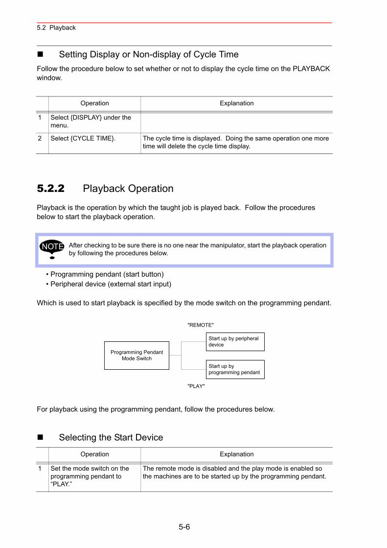
5.2 Playback
Setting Display or Non-display of Cycle TimeFollow the procedure below to set whether or not to display the cycle time on the PLAYBACK window.
5.2.2 Playback Operation
Playback is the operation by which the taught job is played back. Follow the procedures below to start the playback operation.
• Programming pendant (start button)• Peripheral device (external start input)
Which is used to start playback is specified by the mode switch on the programming pendant.
For playback using the programming pendant, follow the procedures below.
Selecting the Start Device
Operation Explanation
1 Select {DISPLAY} under the menu.
2 Select {CYCLE TIME}. The cycle time is displayed. Doing the same operation one more time will delete the cycle time display.
After checking to be sure there is no one near the manipulator, start the playback operation by following the procedures below.
Operation Explanation
1 Set the mode switch on the programming pendant to “PLAY.”
The remote mode is disabled and the play mode is enabled so the machines are to be started up by the programming pendant.
NOTE
"REMOTE"
Start up by peripheraldevice
Start up byprogramming pendant
Programming PendantMode Switch
"PLAY"
5-6
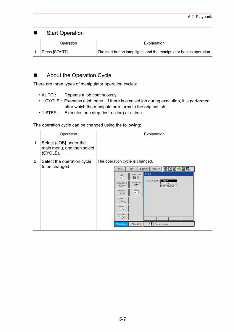
5.2 Playback
Start Operation
About the Operation CycleThere are three types of manipulator operation cycles:
• AUTO : Repeats a job continuously.• 1 CYCLE : Executes a job once. If there is a called job during execution, it is performed,
after which the manipulator returns to the original job.• 1 STEP : Executes one step (instruction) at a time.
The operation cycle can be changed using the following:
Operation Explanation
1 Press [START]. The start button lamp lights and the manipulator begins operation.
Operation Explanation
1 Select {JOB} under the main menu, and then select {CYCLE}.
2 Select the operation cycle to be changed.
The operation cycle is changed.
DATA
ShortCut
JOBDOUTMOVEEND
IN/OUT
In Out
SYSTEM INFO
ARC WELDING
VARIABLE
B001
ROBOT
PARAMETER
CF
FD/PC CARD
! Turn on servo power
EDIT DISPLAY UTILITY
SETUP
CYCLE
WORK SELECT 1 STEP1 CYCLECONTINUOUS
Main Menu
5-7
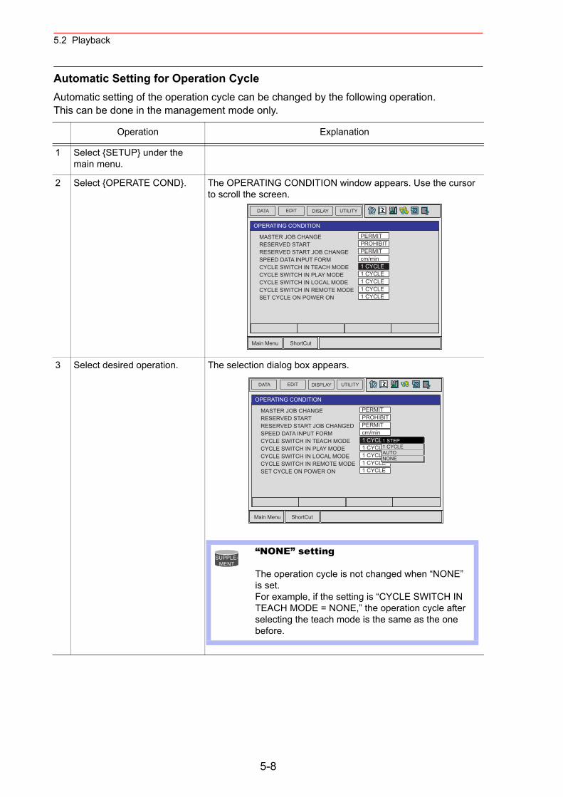
5.2 Playback
Automatic Setting for Operation Cycle Automatic setting of the operation cycle can be changed by the following operation.This can be done in the management mode only.
Operation Explanation
1 Select {SETUP} under the main menu.
2 Select {OPERATE COND}. The OPERATING CONDITION window appears. Use the cursor to scroll the screen.
3 Select desired operation. The selection dialog box appears.
DATA EDIT DISLAY UTILITY
Main Menu ShortCut
OPERATING CONDITION
MASTER JOB CHANGERESERVED STARTRESERVED START JOB CHANGESPEED DATA INPUT FORMCYCLE SWITCH IN TEACH MODECYCLE SWITCH IN PLAY MODECYCLE SWITCH IN LOCAL MODECYCLE SWITCH IN REMOTE MODESET CYCLE ON POWER ON
PERMITPROHIBITPERMITcm/min1 CYCLE1 CYCLE1 CYCLE1 CYCLE1 CYCLE
DATA EDIT DISPLAY UTILITY
Main Menu ShortCut
OPERATING CONDITION
MASTER JOB CHANGERESERVED STARTRESERVED START JOB CHANGEDSPEED DATA INPUT FORMCYCLE SWITCH IN TEACH MODECYCLE SWITCH IN PLAY MODECYCLE SWITCH IN LOCAL MODECYCLE SWITCH IN REMOTE MODESET CYCLE ON POWER ON
PERMITPROHIBITPERMITcm/min1 CYCLE1 CYCLE1 CYCLE1 CYCLE1 CYCLE
1 STEP1 CYCLEAUTONONE
“NONE” setting
The operation cycle is not changed when “NONE” is set.For example, if the setting is “CYCLE SWITCH IN TEACH MODE = NONE,” the operation cycle after selecting the teach mode is the same as the one before.
SUPPLE-MENT
5-8
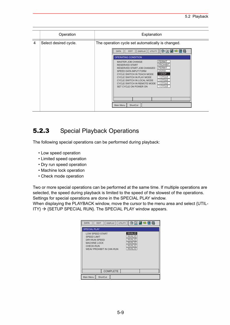
5.2 Playback
5.2.3 Special Playback Operations
The following special operations can be performed during playback:
• Low speed operation• Limited speed operation• Dry run speed operation• Machine lock operation• Check mode operation
Two or more special operations can be performed at the same time. If multiple operations are selected, the speed during playback is limited to the speed of the slowest of the operations. Settings for special operations are done in the SPECIAL PLAY window.When displaying the PLAYBACK window, move the cursor to the menu area and select {UTIL-ITY} {SETUP SPECIAL RUN}. The SPECIAL PLAY window appears.
4 Select desired cycle. The operation cycle set automatically is changed.
Operation Explanation
DATA EDIT DISPLAY UTILITY
Main Menu ShortCut
OPERATING CONDITION
MASTER JOB CHANGERESERVED STARTRESERVED START JOB CHANGEDSPEED DATA INPUT FORMCYCLE SWITCH IN TEACH MODECYCLE SWITCH IN PLAY MODECYCLE SWITCH IN LOCAL MODECYCLE SWITCH IN REMOTE MODESET CYCLE ON POWER ON
PERMITPROHIBITPERMITcm/min1 STEP1 CYCLE1 CYCLE1 CYCLE1 CYCLE
DATA
Main Menu ShortCut
SPECIAL PLAY
INVALIDINVALIDINVALIDINVALIDINVALIDINVALID
LOW SPEED STARTSPEED LIMITDRY-RUN SPEEDMACHINE LOCKCHECK-RUNWEAV PROHIBIT IN CHK-RUN
EDIT DISPLAY UTILITY
COMPLETE
5-9
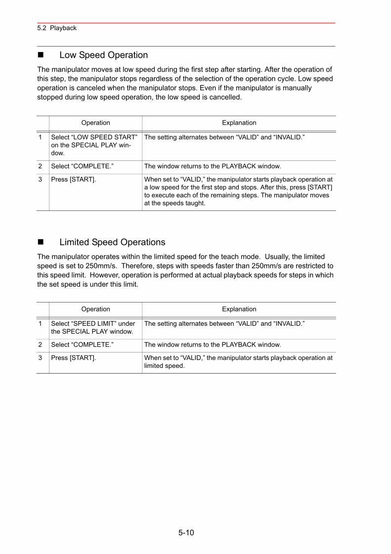
5.2 Playback
Low Speed OperationThe manipulator moves at low speed during the first step after starting. After the operation of this step, the manipulator stops regardless of the selection of the operation cycle. Low speed operation is canceled when the manipulator stops. Even if the manipulator is manually stopped during low speed operation, the low speed is cancelled.
Limited Speed OperationsThe manipulator operates within the limited speed for the teach mode. Usually, the limited speed is set to 250mm/s. Therefore, steps with speeds faster than 250mm/s are restricted to this speed limit. However, operation is performed at actual playback speeds for steps in which the set speed is under this limit.
Operation Explanation
1 Select “LOW SPEED START” on the SPECIAL PLAY win-dow.
The setting alternates between “VALID” and “INVALID.”
2 Select “COMPLETE.” The window returns to the PLAYBACK window.
3 Press [START]. When set to “VALID,” the manipulator starts playback operation at a low speed for the first step and stops. After this, press [START] to execute each of the remaining steps. The manipulator moves at the speeds taught.
Operation Explanation
1 Select “SPEED LIMIT” under the SPECIAL PLAY window.
The setting alternates between “VALID” and “INVALID.”
2 Select “COMPLETE.” The window returns to the PLAYBACK window.
3 Press [START]. When set to “VALID,” the manipulator starts playback operation at limited speed.
5-10
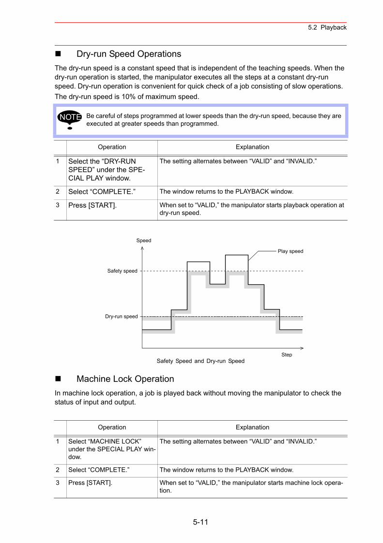
5.2 Playback
Dry-run Speed OperationsThe dry-run speed is a constant speed that is independent of the teaching speeds. When the dry-run operation is started, the manipulator executes all the steps at a constant dry-run speed. Dry-run operation is convenient for quick check of a job consisting of slow operations. The dry-run speed is 10% of maximum speed.
Safety Speed and Dry-run Speed
Machine Lock OperationIn machine lock operation, a job is played back without moving the manipulator to check the status of input and output.
Be careful of steps programmed at lower speeds than the dry-run speed, because they are executed at greater speeds than programmed.
Operation Explanation
1 Select the “DRY-RUN SPEED” under the SPE-CIAL PLAY window.
The setting alternates between “VALID” and “INVALID.”
2 Select “COMPLETE.” The window returns to the PLAYBACK window.
3 Press [START]. When set to “VALID,” the manipulator starts playback operation at dry-run speed.
Operation Explanation
1 Select “MACHINE LOCK” under the SPECIAL PLAY win-dow.
The setting alternates between “VALID” and “INVALID.”
2 Select “COMPLETE.” The window returns to the PLAYBACK window.
3 Press [START]. When set to “VALID,” the manipulator starts machine lock opera-tion.
NOTE
Safety speed
Dry-run speed
Speed
Step
Play speed
5-11
5.2 Playback
Check Mode OperationDuring check mode operation, the machine runs without issuing work instructions, such as the ARCON instruction. It is used primarily to check the path of the program.
Weaving Prohibit Setting during Check Mode Operation When weaving prohibit is specified for the check mode operation, the weaving operation is not executed in the weaving section of the job.
Cancel All Special Operations
Operation Explanation
1 Select “CHECK-RUN” under the SPECIAL PLAY window.
The setting alternates between “VALID” and “INVALID.”
2 Select “COMPLETE.” The window returns to the PLAYBACK window.
3 Press [START]. When set to “VALID,” the manipulator starts check operation.
Operation Explanation
1 Select “WEAV PROHIBIT IN CHK-RUN” under the SPE-CIAL PLAY window.
The setting alternates between “VALID” and “INVALID.”
2 Select “COMPLETE.” The window returns to the PLAYBACK window.
3 Press [START]. When set to “VALID,” the manipulator does not execute the weav-ing operation during check run execution.
Operation Explanation
1 Select {EDIT} from the menu.
2 Select “CANCEL ALL SELECT.”
The message “All special functions canceled” appears.
Special operations are also automatically cancelled if the main power is shut OFF.NOTE
5-12
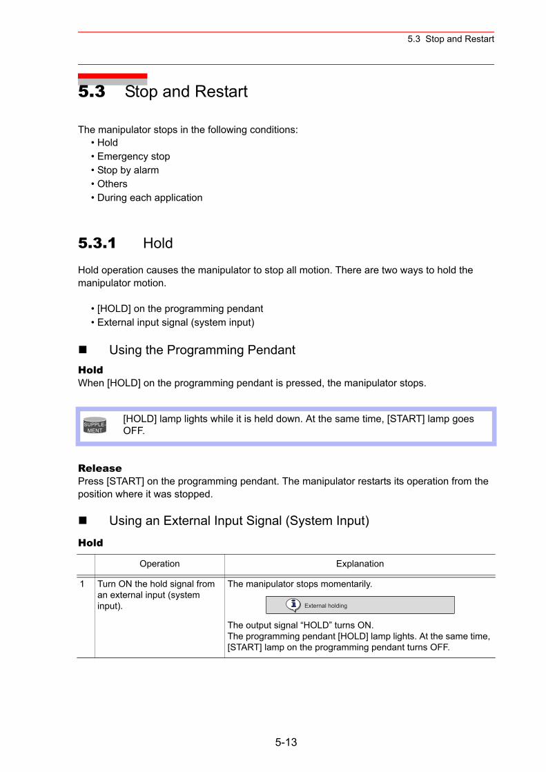
5.3 Stop and Restart
5.3 Stop and Restart
The manipulator stops in the following conditions:• Hold• Emergency stop• Stop by alarm• Others• During each application
5.3.1 Hold
Hold operation causes the manipulator to stop all motion. There are two ways to hold the manipulator motion.
• [HOLD] on the programming pendant• External input signal (system input)
Using the Programming PendantHoldWhen [HOLD] on the programming pendant is pressed, the manipulator stops.
ReleasePress [START] on the programming pendant. The manipulator restarts its operation from the position where it was stopped.
Using an External Input Signal (System Input)Hold
[HOLD] lamp lights while it is held down. At the same time, [START] lamp goes OFF.
Operation Explanation
1 Turn ON the hold signal from an external input (system input).
The manipulator stops momentarily.
The output signal “HOLD” turns ON.The programming pendant [HOLD] lamp lights. At the same time, [START] lamp on the programming pendant turns OFF.
SUPPLE-MENT
External holding
5-13
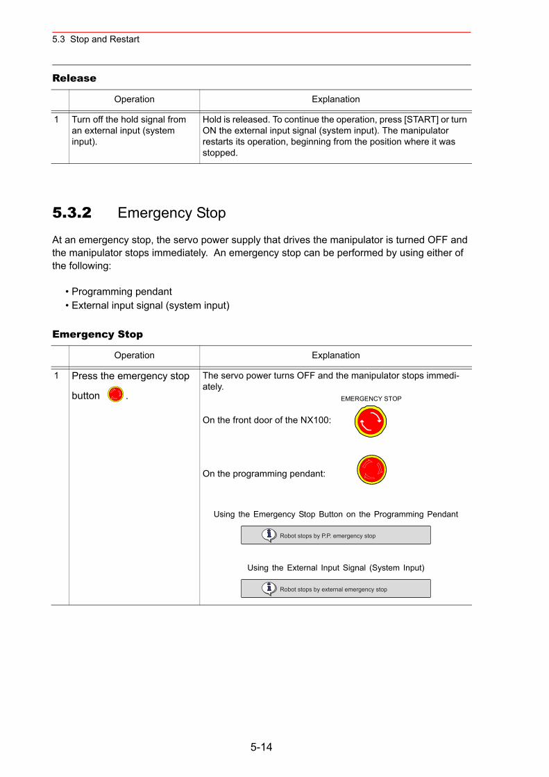
5.3 Stop and Restart
Release
5.3.2 Emergency Stop
At an emergency stop, the servo power supply that drives the manipulator is turned OFF and the manipulator stops immediately. An emergency stop can be performed by using either of the following:
• Programming pendant• External input signal (system input)
Emergency Stop
Operation Explanation
1 Turn off the hold signal from an external input (system input).
Hold is released. To continue the operation, press [START] or turn ON the external input signal (system input). The manipulator restarts its operation, beginning from the position where it was stopped.
Operation Explanation
1 Press the emergency stop
button .
The servo power turns OFF and the manipulator stops immedi-ately.
On the front door of the NX100:
On the programming pendant:
Using the Emergency Stop Button on the Programming Pendant
Using the External Input Signal (System Input)
EMERGENCY STOP
Robot stops by P.P. emergency stop
Robot stops by external emergency stop
5-14
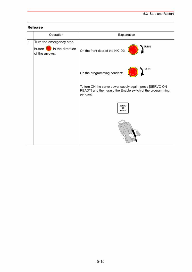
5.3 Stop and Restart
Release
Operation Explanation
1 Turn the emergency stop
button in the direction of the arrows.
On the front door of the NX100:
On the programming pendant:
To turn ON the servo power supply again, press [SERVO ON READY] and then grasp the Enable switch of the programming pendant.
TURN
TURN
SERVOON
READY
5-15
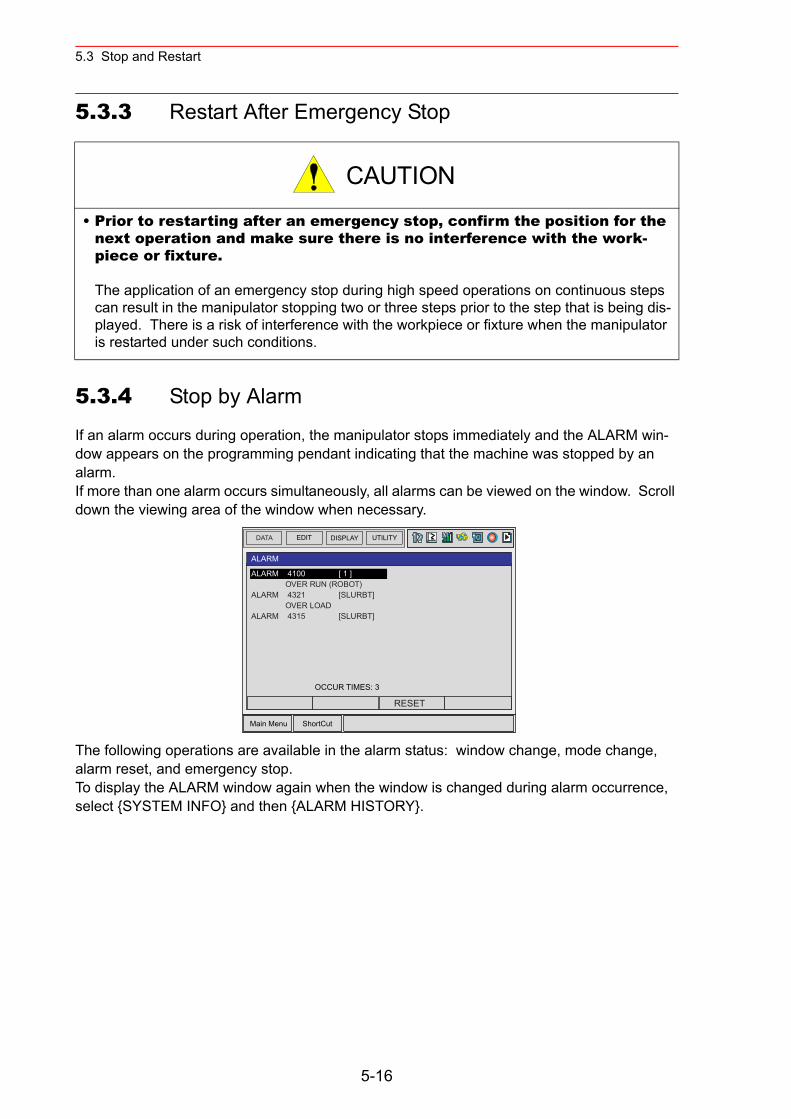
5.3 Stop and Restart
5.3.3 Restart After Emergency Stop
5.3.4 Stop by Alarm
If an alarm occurs during operation, the manipulator stops immediately and the ALARM win-dow appears on the programming pendant indicating that the machine was stopped by an alarm.If more than one alarm occurs simultaneously, all alarms can be viewed on the window. Scroll down the viewing area of the window when necessary.
The following operations are available in the alarm status: window change, mode change, alarm reset, and emergency stop.To display the ALARM window again when the window is changed during alarm occurrence, select {SYSTEM INFO} and then {ALARM HISTORY}.
• Prior to restarting after an emergency stop, confirm the position for the next operation and make sure there is no interference with the work-piece or fixture.
The application of an emergency stop during high speed operations on continuous steps can result in the manipulator stopping two or three steps prior to the step that is being dis-played. There is a risk of interference with the workpiece or fixture when the manipulator is restarted under such conditions.
CAUTION
DATA EDIT DISPLAY UTILITY
Main Menu ShortCut
ALARM
OCCUR TIMES: 3
ALARM 4100 [ 1 ] OVER RUN (ROBOT)
ALARM 4321 [SLURBT] OVER LOAD
ALARM 4315 [SLURBT]
RESET
5-16
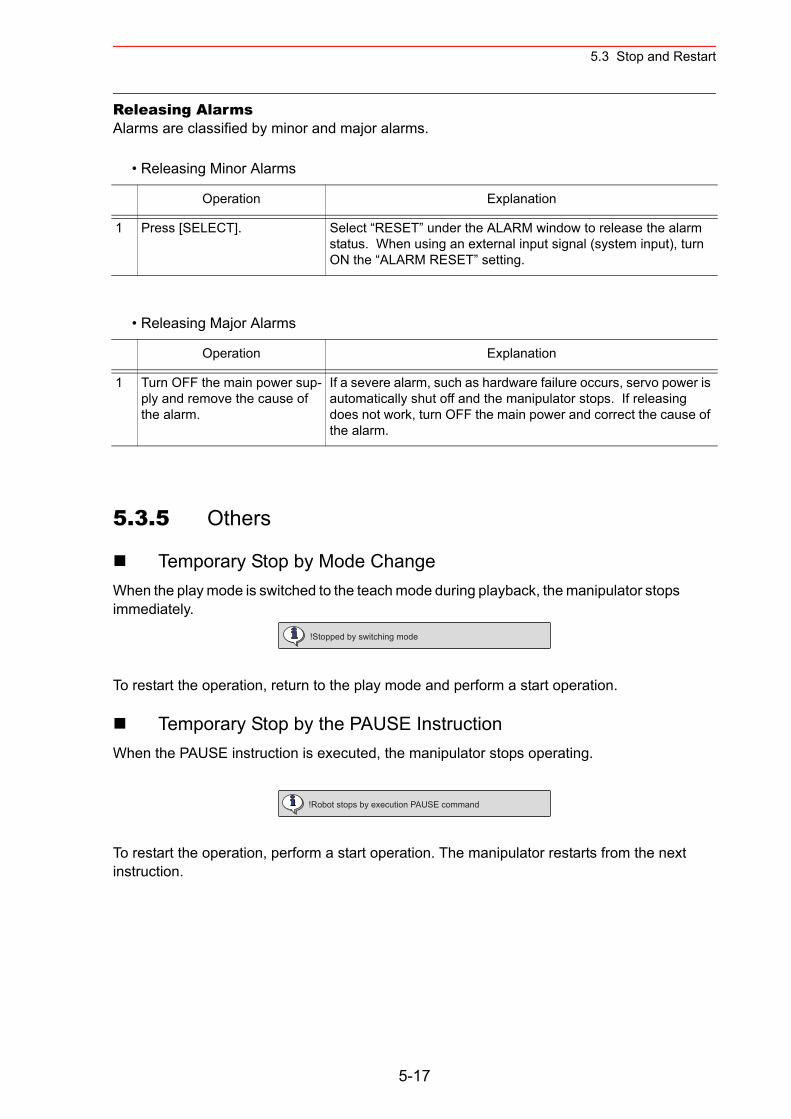
5.3 Stop and Restart
Releasing AlarmsAlarms are classified by minor and major alarms.
• Releasing Minor Alarms
• Releasing Major Alarms
5.3.5 Others
Temporary Stop by Mode ChangeWhen the play mode is switched to the teach mode during playback, the manipulator stops immediately.
To restart the operation, return to the play mode and perform a start operation.
Temporary Stop by the PAUSE InstructionWhen the PAUSE instruction is executed, the manipulator stops operating.
To restart the operation, perform a start operation. The manipulator restarts from the next instruction.
Operation Explanation
1 Press [SELECT]. Select “RESET” under the ALARM window to release the alarm status. When using an external input signal (system input), turn ON the “ALARM RESET” setting.
Operation Explanation
1 Turn OFF the main power sup-ply and remove the cause of the alarm.
If a severe alarm, such as hardware failure occurs, servo power is automatically shut off and the manipulator stops. If releasing does not work, turn OFF the main power and correct the cause of the alarm.
!Stopped by switching mode
!Robot stops by execution PAUSE command
5-17
5.4 Modifying Play Speed
5.4 Modifying Play Speed
5.4.1 Modifying with Speed Override
Speed modifications using the speed override have the following features:
• Speed can be modified during playback.• The job can be played back at various speeds until the play speed is properly adjusted.• Speed can be increased or decreased by a ratio of the current play speed. The ratio set-
tings range from 50% to 150% in increments of 1%.• All play speed values used in the job can be increased or decreased by a constant ratio.
Therefore, it is convenient when, for example, all play speed settings are to be increased by 150% at the same time.
The operation flow override of play speeds is as shown in the following:
5-18
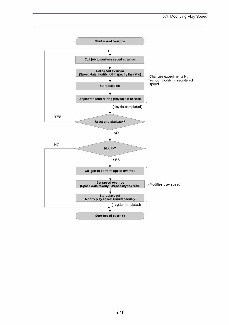
5.4 Modifying Play Speed
Start speed override
Call job to perform speed override
Set speed override(Speed data modify :OFF,specify the ratio)
Start playback
Adjust the ratio during playback if needed
Reset and playback?
(1cycle completed)
Modify?
YES
Call job to perform speed override
Set speed override(Speed data modify: ON,specify the ratio)
Start playbackModify play speed simultaneously
Start speed override
Changes experimentally,without modifying registeredspeed
Modifies play speed
NO
YES
(1cycle completed)
NO
5-19
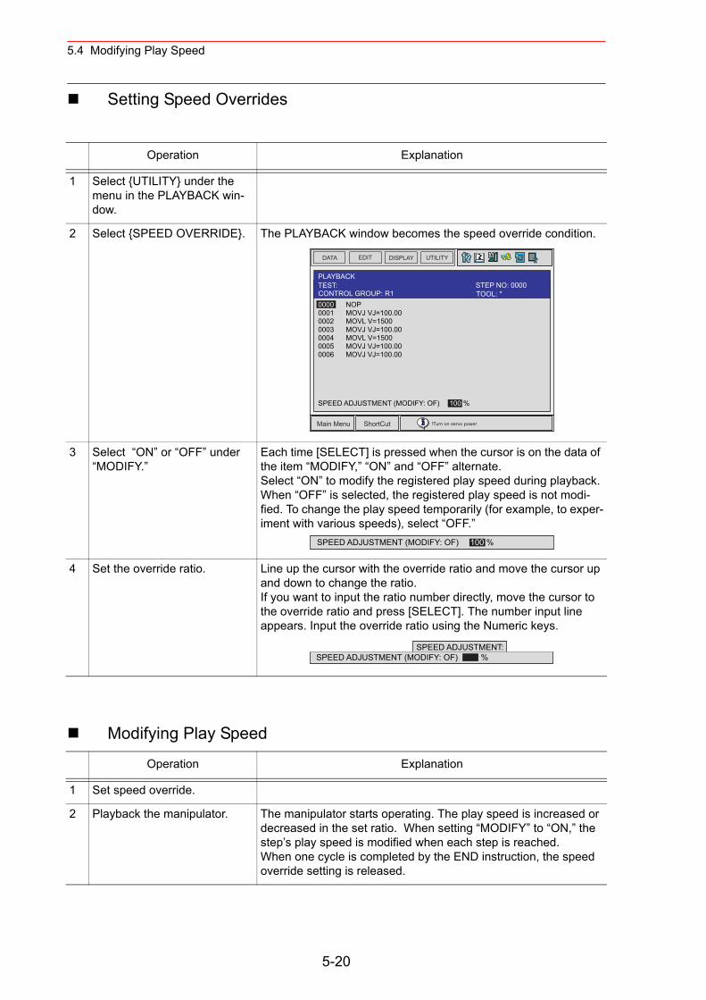
5.4 Modifying Play Speed
Setting Speed Overrides
Modifying Play Speed
Operation Explanation
1 Select {UTILITY} under the menu in the PLAYBACK win-dow.
2 Select {SPEED OVERRIDE}. The PLAYBACK window becomes the speed override condition.
3 Select “ON” or “OFF” under “MODIFY.”
Each time [SELECT] is pressed when the cursor is on the data of the item “MODIFY,” “ON” and “OFF” alternate.Select “ON” to modify the registered play speed during playback.When “OFF” is selected, the registered play speed is not modi-fied. To change the play speed temporarily (for example, to exper-iment with various speeds), select “OFF.”
4 Set the override ratio. Line up the cursor with the override ratio and move the cursor up and down to change the ratio.If you want to input the ratio number directly, move the cursor to the override ratio and press [SELECT]. The number input line appears. Input the override ratio using the Numeric keys.
Operation Explanation
1 Set speed override.
2 Playback the manipulator. The manipulator starts operating. The play speed is increased or decreased in the set ratio. When setting “MODIFY” to “ON,” the step’s play speed is modified when each step is reached.When one cycle is completed by the END instruction, the speed override setting is released.
DATA EDIT DISPLAY UTILITY
Main Menu ShortCut !Turn on servo power
PLAYBACKTEST:
0000 NOP0001 MOVJ VJ=100.000002 MOVL V=15000003 MOVJ VJ=100.000004 MOVL V=15000005 MOVJ VJ=100.000006 MOVJ VJ=100.00
SPEED ADJUSTMENT (MODIFY: OF) 100 %
TOOL: *CONTROL GROUP: R1STEP NO: 0000
SPEED ADJUSTMENT (MODIFY: OF) 100 %
SPEED ADJUSTMENT:SPEED ADJUSTMENT (MODIFY: OF) %
5-20
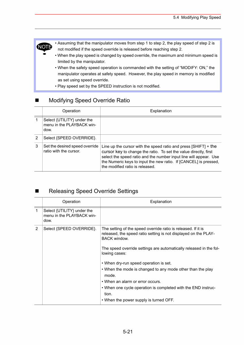
5.4 Modifying Play Speed
Modifying Speed Override Ratio
Releasing Speed Override Settings
• Assuming that the manipulator moves from step 1 to step 2, the play speed of step 2 is not modified if the speed override is released before reaching step 2.
• When the play speed is changed by speed override, the maximum and minimum speed is limited by the manipulator.
• When the safety speed operation is commanded with the setting of “MODIFY: ON,” the manipulator operates at safety speed. However, the play speed in memory is modified as set using speed override.
• Play speed set by the SPEED instruction is not modified.
Operation Explanation
1 Select {UTILITY} under the menu in the PLAYBACK win-dow.
2 Select {SPEED OVERRIDE}.
3 Set the desired speed override ratio with the cursor.
Line up the cursor with the speed ratio and press [SHIFT] + the cursor key to change the ratio. To set the value directly, first select the speed ratio and the number input line will appear. Use the Numeric keys to input the new ratio. If [CANCEL] is pressed, the modified ratio is released.
Operation Explanation
1 Select {UTILITY} under the menu in the PLAYBACK win-dow.
2 Select {SPEED OVERRIDE}. The setting of the speed override ratio is released. If it is released, the speed ratio setting is not displayed on the PLAY-BACK window.
The speed override settings are automatically released in the fol-lowing cases:
• When dry-run speed operation is set.• When the mode is changed to any mode other than the play
mode.• When an alarm or error occurs.• When one cycle operation is completed with the END instruc-
tion.• When the power supply is turned OFF.
NOTE
5-21
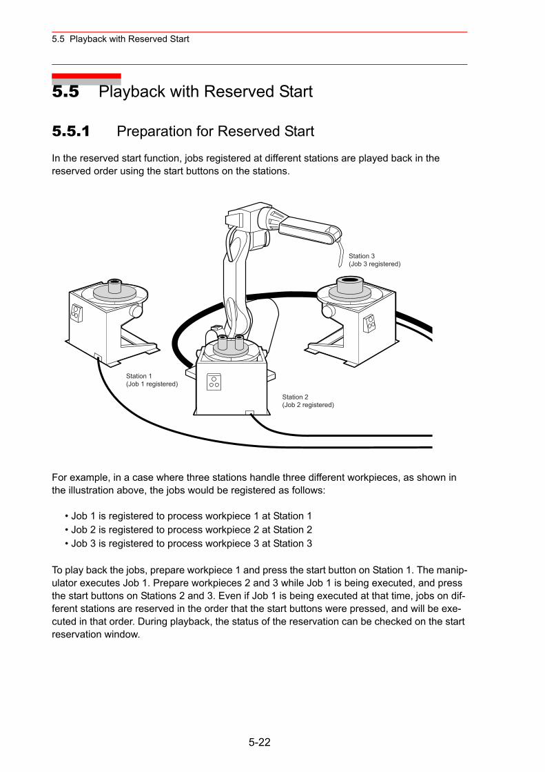
5.5 Playback with Reserved Start
5.5 Playback with Reserved Start
5.5.1 Preparation for Reserved Start
In the reserved start function, jobs registered at different stations are played back in the reserved order using the start buttons on the stations.
For example, in a case where three stations handle three different workpieces, as shown in the illustration above, the jobs would be registered as follows:
• Job 1 is registered to process workpiece 1 at Station 1• Job 2 is registered to process workpiece 2 at Station 2• Job 3 is registered to process workpiece 3 at Station 3
To play back the jobs, prepare workpiece 1 and press the start button on Station 1. The manip-ulator executes Job 1. Prepare workpieces 2 and 3 while Job 1 is being executed, and press the start buttons on Stations 2 and 3. Even if Job 1 is being executed at that time, jobs on dif-ferent stations are reserved in the order that the start buttons were pressed, and will be exe-cuted in that order. During playback, the status of the reservation can be checked on the start reservation window.
Station 1(Job 1 registered)
Station 2(Job 2 registered)
Station 3(Job 3 registered)
5-22
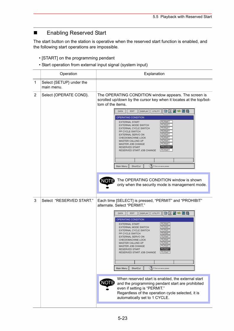
5.5 Playback with Reserved Start
Enabling Reserved StartThe start button on the station is operative when the reserved start function is enabled, and the following start operations are impossible.
• [START] on the programming pendant• Start operation from external input signal (system input)
Operation Explanation
1 Select {SETUP} under the main menu.
2 Select {OPERATE COND}. The OPERATING CONDITION window appears. The screen is scrolled up/down by the cursor key when it locates at the top/bot-tom of the items.
3 Select “RESERVED START.” Each time [SELECT] is pressed, “PERMIT” and “PROHIBIT” alternate. Select “PERMIT.”
DATA EDIT DISPLAY UTILITY
Main Menu ShortCut !Turn on servo power
OPERATING CONDITION
EXTERNAL STARTEXTERNAL MODE SWITCHEXTERNAL CYCLE SWITCHPP CYCLE SWITCHEXTERNAL SERVO ONCHECK/MACHINE LOCKMASTER CALLING UPMASTER JOB CHANGERESERVED STARTRESERVED START JOB CHANGE
PERMITPERMITPERMITPERMITPERMITPERMITPERMITPERMITPROHIBITPERMIT
The OPERATING CONDITION window is shown only when the security mode is management mode.
NOTE
DATA EDIT DISPLAY UTILITY
Main Menu ShortCut !Turn on servo power
OPERATING CONDITION
EXTERNAL STARTEXTERNAL MODE SWITCHEXTERNAL CYCLE SWITCHPP CYCLE SWITCHEXTERNAL SERVO ONCHECK/MACHINE LOCKMASTER CALLING UPMASTER JOB CHANGERESERVED STARTRESERVED START JOB CHANGE
PERMITPERMITPERMITPERMITPERMITPERMITPERMITPERMITPERMITPERMIT
When reserved start is enabled, the external start and the programming pendant start are prohibited even if setting is “PERMIT.”Regardless of the operation cycle selected, it is automatically set to 1 CYCLE.
NOTE
5-23
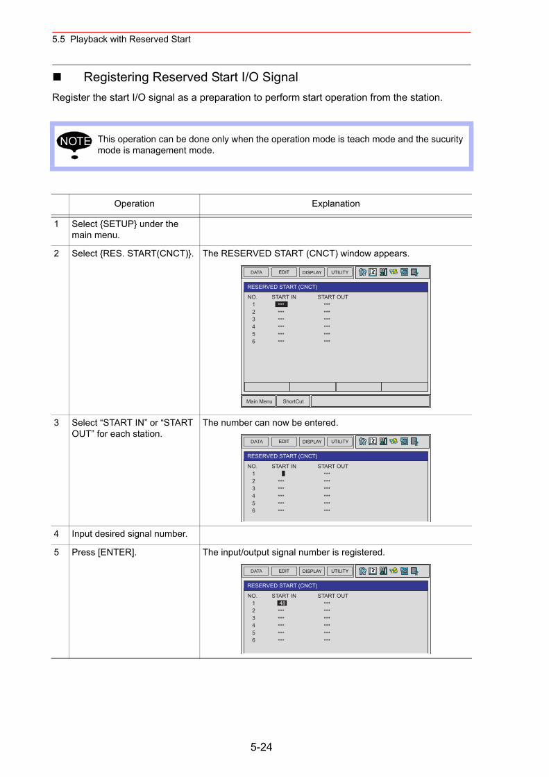
5.5 Playback with Reserved Start
Registering Reserved Start I/O SignalRegister the start I/O signal as a preparation to perform start operation from the station.
This operation can be done only when the operation mode is teach mode and the sucurity mode is management mode.
Operation Explanation
1 Select {SETUP} under the main menu.
2 Select {RES. START(CNCT)}. The RESERVED START (CNCT) window appears.
3 Select “START IN” or “START OUT” for each station.
The number can now be entered.
4 Input desired signal number.
5 Press [ENTER]. The input/output signal number is registered.
NOTE
DATA EDIT DISPLAY UTILITY
Main Menu ShortCut
RESERVED START (CNCT)
NO. 1 2 3 4 5 6
START OUT *** *** *** *** *** ***
START IN *** *** *** *** *** ***
DATA EDIT DISPLAY UTILITY
RESERVED START (CNCT)
NO. 1 2 3 4 5 6
START OUT *** *** *** *** *** ***
START IN
*** *** *** *** ***
DATA EDIT DISPLAY UTILITY
RESERVED START (CNCT)
NO. 1 2 3 4 5 6
START OUT *** *** *** *** *** ***
START IN 48 *** *** *** *** ***
5-24
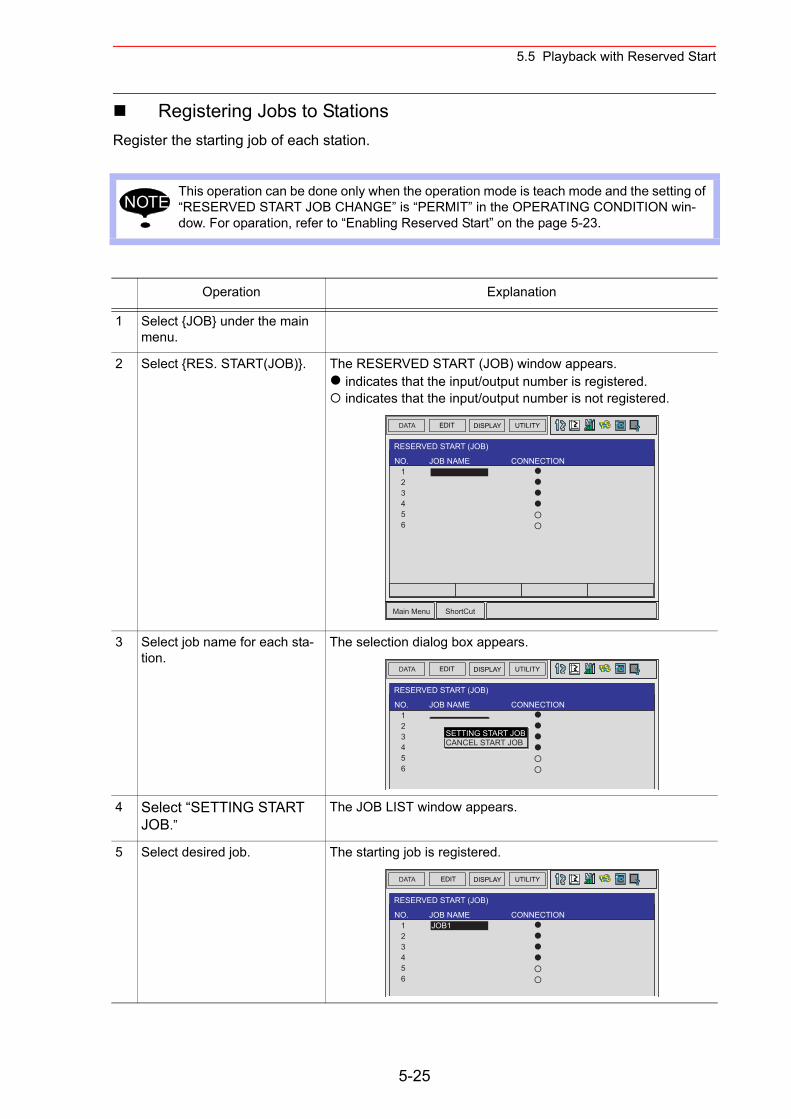
5.5 Playback with Reserved Start
Registering Jobs to StationsRegister the starting job of each station.
This operation can be done only when the operation mode is teach mode and the setting of “RESERVED START JOB CHANGE” is “PERMIT” in the OPERATING CONDITION win-dow. For oparation, refer to “Enabling Reserved Start” on the page 5-23.
Operation Explanation
1 Select {JOB} under the main menu.
2 Select {RES. START(JOB)}. The RESERVED START (JOB) window appears. indicates that the input/output number is registered. indicates that the input/output number is not registered.
3 Select job name for each sta-tion.
The selection dialog box appears.
4 Select “SETTING START JOB.”
The JOB LIST window appears.
5 Select desired job. The starting job is registered.
NOTE
DATA EDIT DISPLAY UTILITY
Main Menu ShortCut
RESERVED START (JOB)
NO. 1 2 3 4 5 6
CONNECTIONJOB NAME
DATA EDIT DISPLAY UTILITY
RESERVED START (JOB)
NO. 1 2 3 4 5 6
CONNECTIONJOB NAME
SETTING START JOBCANCEL START JOB
DATA EDIT DISPLAY UTILITY
RESERVED START (JOB)
NO. 1 2 3 4 5 6
CONNECTIONJOB NAME JOB1
5-25
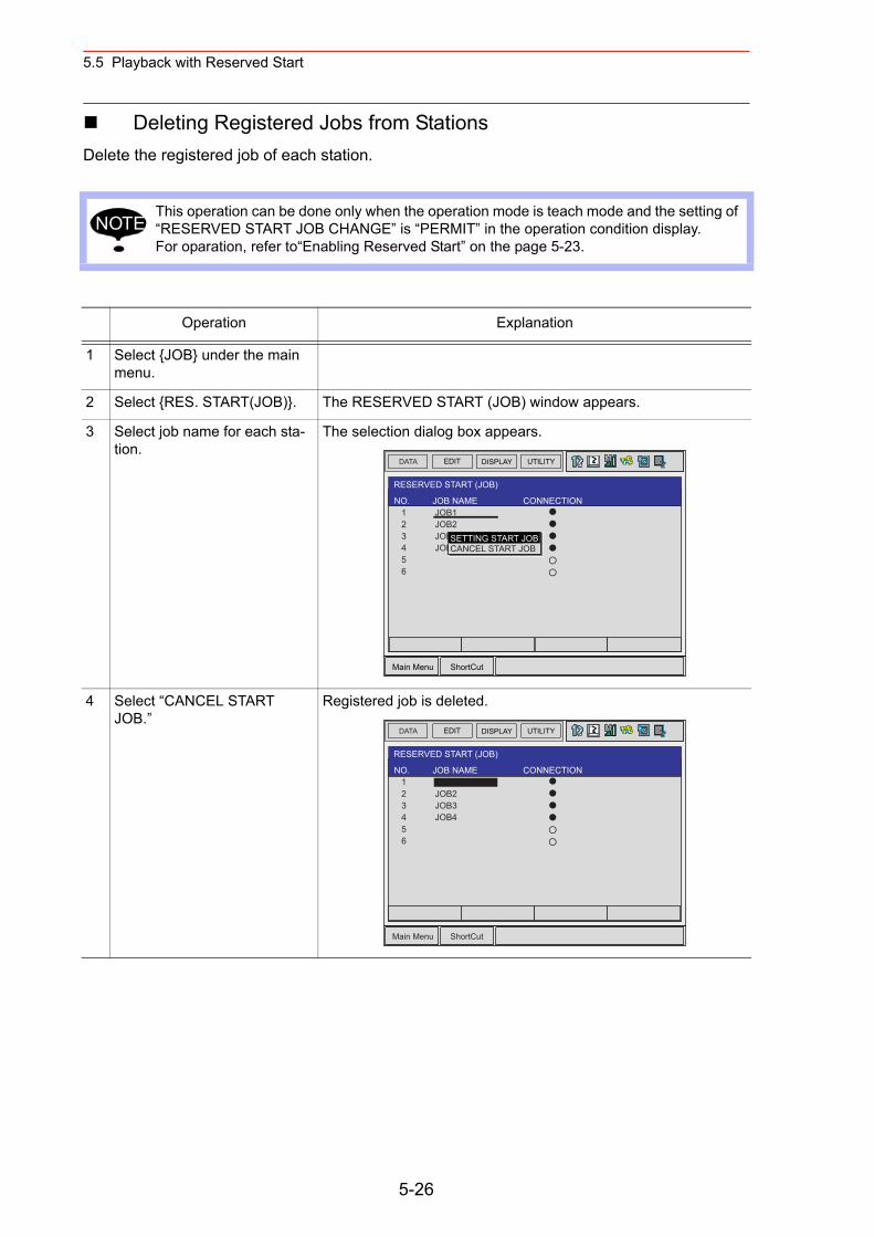
5.5 Playback with Reserved Start
Deleting Registered Jobs from StationsDelete the registered job of each station.
This operation can be done only when the operation mode is teach mode and the setting of “RESERVED START JOB CHANGE” is “PERMIT” in the operation condition display.For oparation, refer to“Enabling Reserved Start” on the page 5-23.
Operation Explanation
1 Select {JOB} under the main menu.
2 Select {RES. START(JOB)}. The RESERVED START (JOB) window appears.
3 Select job name for each sta-tion.
The selection dialog box appears.
4 Select “CANCEL START JOB.”
Registered job is deleted.
NOTE
DATA EDIT DISPLAY UTILITY
Main Menu ShortCut
RESERVED START (JOB)
NO. 1 2 3 4 5 6
CONNECTIONJOB NAME JOB1 JOB2 JOB3 JOB4
SETTING START JOBCANCEL START JOB
DATA EDIT DISPLAY UTILITY
Main Menu ShortCut
RESERVED START (JOB)
NO. 1 2 3 4 5 6
CONNECTIONJOB NAME JOB1 JOB2 JOB3 JOB4
5-26
5.5 Playback with Reserved Start
5.5.2 Playback from Reserved Start
Start Operation
Operation Explanation
1 Set the mode switch to “PLAY.”
2 Press start button on the sta-tion.
The job registered for the station starts up and the manipulator performs one cycle operation.
• While the job is being executed, the start button lamp on the station lamps.• If the workpiece must be prepared at the station, prepare it before pressing the start but-
ton.• If the start button of another station is pressed during execution of a job at one station, the
job on the station is reserved and prepares to start. Jobs are reserved and executed in the order that the start buttons are pressed.
• When a job is reserved, the start button lamp on the station blinks.• No station job is reserved when it is being executed even if its start button is pressed.• To suspend a job being executed, perform the Hold operation.
Reservations are cancelled when the start button is pressed again during the job reserva-tion operation.
NOTE
SUPPLE-MENT
5-27
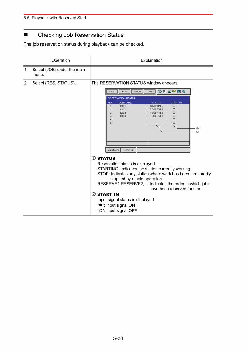
5.5 Playback with Reserved Start
Checking Job Reservation StatusThe job reservation status during playback can be checked.
Operation Explanation
1 Select {JOB} under the main menu.
2 Select {RES. STATUS}. The RESERVATION STATUS window appears.
STATUSReservation status is displayed.STARTING: Indicates the station currently working.STOP: Indicates any station where work has been temporarily
stopped by a hold operation.RESERVE1,RESERVE2,...: Indicates the order in which jobs
have been reserved for start. START INInput signal status is displayed.“ ”: Input signal ON“ ”: Input signal OFF
DATA EDIT DISPLAY UTILITY
Main Menu ShortCut
RESERVATION STATUS
NO. 1 2 3 4 5 6
STATUSSTARTINGRESERVE1RESERVE2RESERVE3
JOB NAME JOB1 JOB2 JOB3 JOB4
START IN
5-28
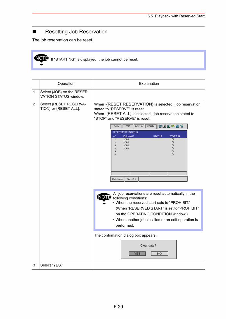
5.5 Playback with Reserved Start
Resetting Job ReservationThe job reservation can be reset.
If “STARTING” is displayed, the job cannot be reset.
Operation Explanation
1 Select {JOB} on the RESER-VATION STATUS window.
2 Select {RESET RESERVA-TION} or {RESET ALL}.
When {RESET RESERVATION} is selected, job reservation stated to “RESERVE“ is reset.When {RESET ALL} is selected, job reservation stated to “STOP” and “RESERVE” is reset.
The confirmation dialog box appears.
3 Select “YES.”
NOTE
DATA EDIT DISPLAY UTILITY
Main Menu ShortCut
RESERVATION STATUS
NO. 1 2 3 4 5 6
STATUSJOB NAME JOB1 JOB2 JOB3 JOB4
START IN
All job reservations are reset automatically in the following conditions:• When the reserved start sets to “PROHIBIT.”
(When “RESERVED START” is set to “PROHIBIT” on the OPERATING CONDITION window.)
• When another job is called or an edit operation is performed.
NOTE
YES
Clear data?
NO
5-29
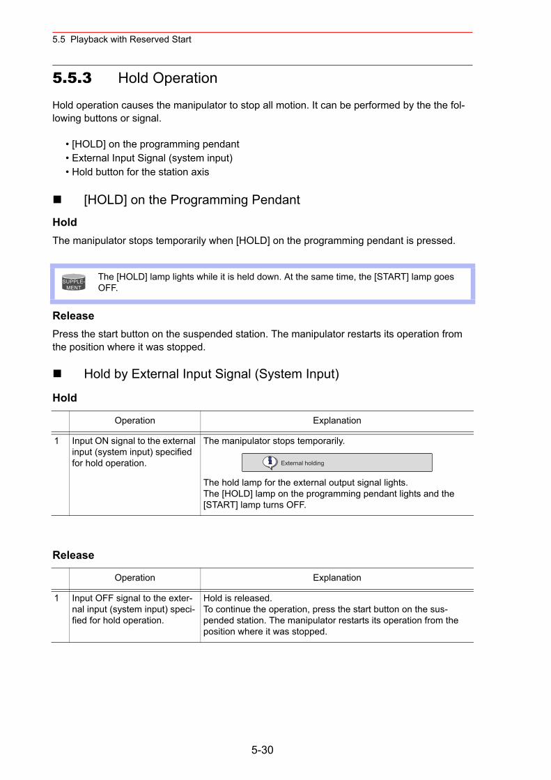
5.5 Playback with Reserved Start
5.5.3 Hold Operation
Hold operation causes the manipulator to stop all motion. It can be performed by the the fol-lowing buttons or signal.
• [HOLD] on the programming pendant• External Input Signal (system input)• Hold button for the station axis
[HOLD] on the Programming PendantHoldThe manipulator stops temporarily when [HOLD] on the programming pendant is pressed.
ReleasePress the start button on the suspended station. The manipulator restarts its operation from the position where it was stopped.
Hold by External Input Signal (System Input)
Hold
Release
The [HOLD] lamp lights while it is held down. At the same time, the [START] lamp goes OFF.
Operation Explanation
1 Input ON signal to the external input (system input) specified for hold operation.
The manipulator stops temporarily.
The hold lamp for the external output signal lights.The [HOLD] lamp on the programming pendant lights and the [START] lamp turns OFF.
Operation Explanation
1 Input OFF signal to the exter-nal input (system input) speci-fied for hold operation.
Hold is released.To continue the operation, press the start button on the sus-pended station. The manipulator restarts its operation from the position where it was stopped.
SUPPLE-MENT
External holding
5-30
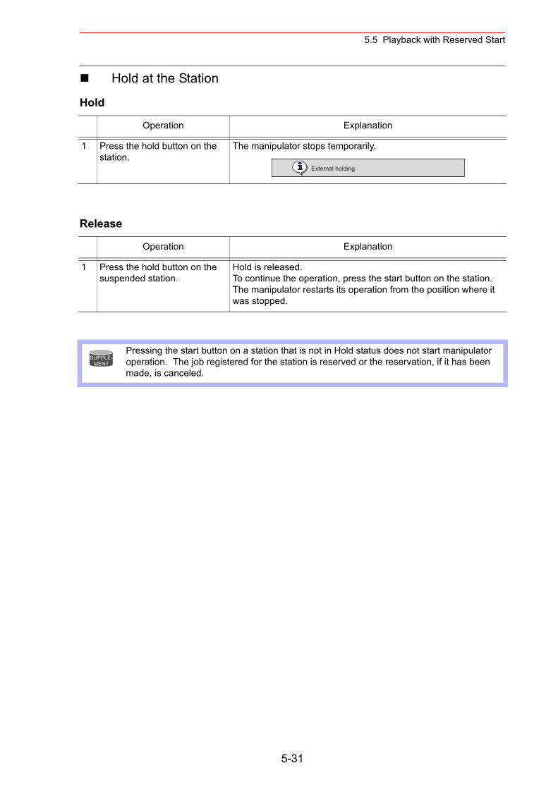
5.5 Playback with Reserved Start
Hold at the Station
Hold
Release
Operation Explanation
1 Press the hold button on the station.
The manipulator stops temporarily.
Operation Explanation
1 Press the hold button on the suspended station.
Hold is released.To continue the operation, press the start button on the station. The manipulator restarts its operation from the position where it was stopped.
Pressing the start button on a station that is not in Hold status does not start manipulator operation. The job registered for the station is reserved or the reservation, if it has been made, is canceled.
External holding
SUPPLE-MENT
5-31
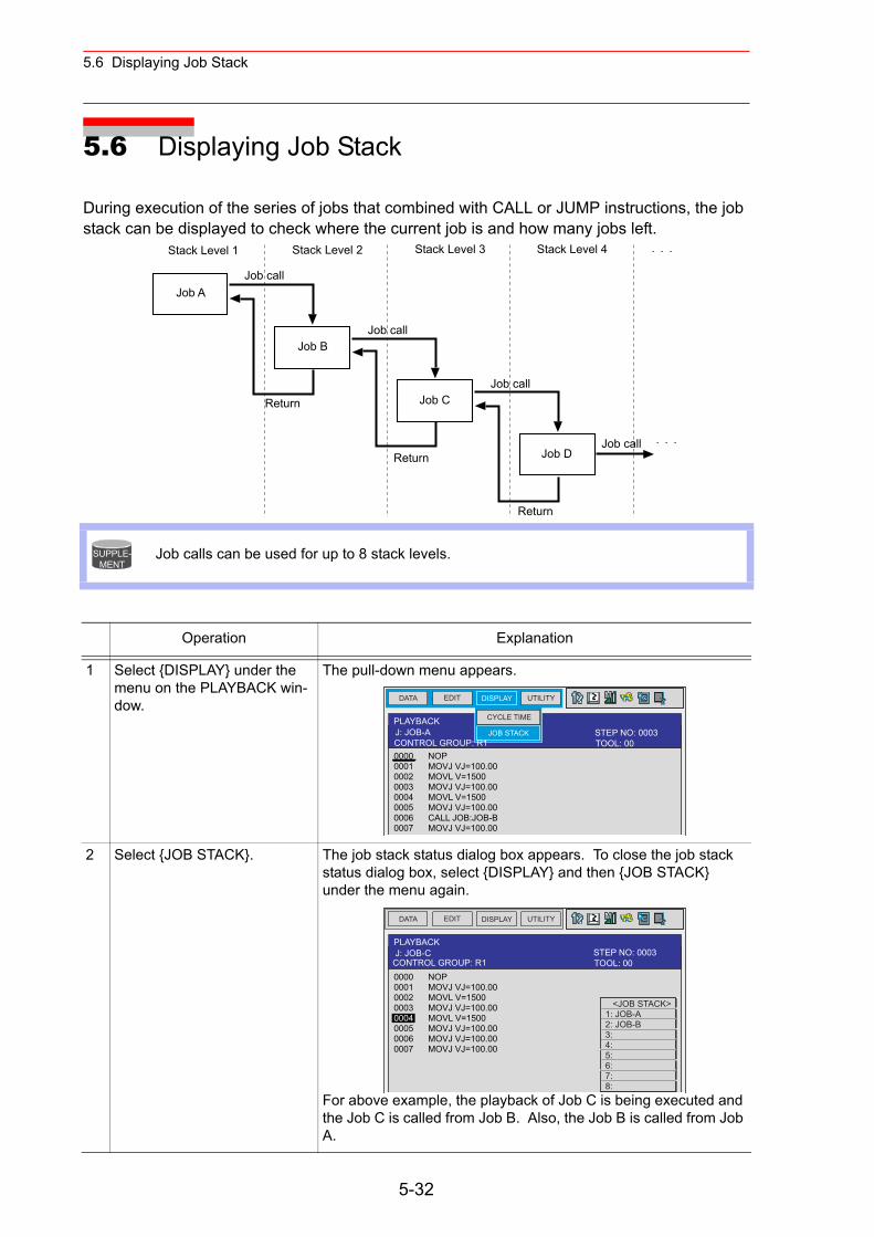
5.6 Displaying Job Stack
5.6 Displaying Job Stack
During execution of the series of jobs that combined with CALL or JUMP instructions, the job stack can be displayed to check where the current job is and how many jobs left.
Job calls can be used for up to 8 stack levels.
Operation Explanation
1 Select {DISPLAY} under the menu on the PLAYBACK win-dow.
The pull-down menu appears.
2 Select {JOB STACK}. The job stack status dialog box appears. To close the job stack status dialog box, select {DISPLAY} and then {JOB STACK} under the menu again.
For above example, the playback of Job C is being executed and the Job C is called from Job B. Also, the Job B is called from Job A.
Job A
Job B
Job C
Job D
Stack Level 1
Job call
Return
Stack Level 2 Stack Level 3 Stack Level 4
Job call
Job call
Job callReturn
Return
SUPPLE-MENT
DATA EDIT DISPLAY UTILITY
PLAYBACK
0000 NOP0001 MOVJ VJ=100.000002 MOVL V=15000003 MOVJ VJ=100.000004 MOVL V=15000005 MOVJ VJ=100.000006 CALL JOB:JOB-B0007 MOVJ VJ=100.00
J: JOB-A JOB STACK
CYCLE TIME
TOOL: 00CONTROL GROUP: R1STEP NO: 0003
DATA EDIT DISPLAY UTILITY
PLAYBACKJ: JOB-C
TOOL: 00CONTROL GROUP: R1STEP NO: 0003
0000 NOP0001 MOVJ VJ=100.000002 MOVL V=15000003 MOVJ VJ=100.000004 MOVL V=15000005 MOVJ VJ=100.000006 MOVJ VJ=100.000007 MOVJ VJ=100.00
<JOB STACK> 1: JOB-A 2: JOB-B 3: 4: 5: 6: 7: 8:
5-32
6 Editing Jobs
This section explains how to manage the jobs without moving the manipulator. Copying, deleting, and modifying of the jobs can be done in the teach mode only. Other operations can be done in any mode.
Edit operations are restricted when the edit lock is applied.
Editing Move Instructions
See " 4 Teaching " for basic information on editing move instructions.It is not possible to add, delete, or modify move instructions which have position data. See " 4.4 Modifying Steps " for details.
The following MOV instruction edit operations are explained in this section:
For move instructions:• Insertion, deletion, or modification of additional items• Modification of interpolation type or play speed for move instructions• Setting, modification, or deletion of UNTIL statements (interruption conditions based
on input signals)• Setting and deletion of NWAIT instructions
For move instructions using position variables:• Insertion and deletion of move instruction.
NOTE
NOTE
6-1
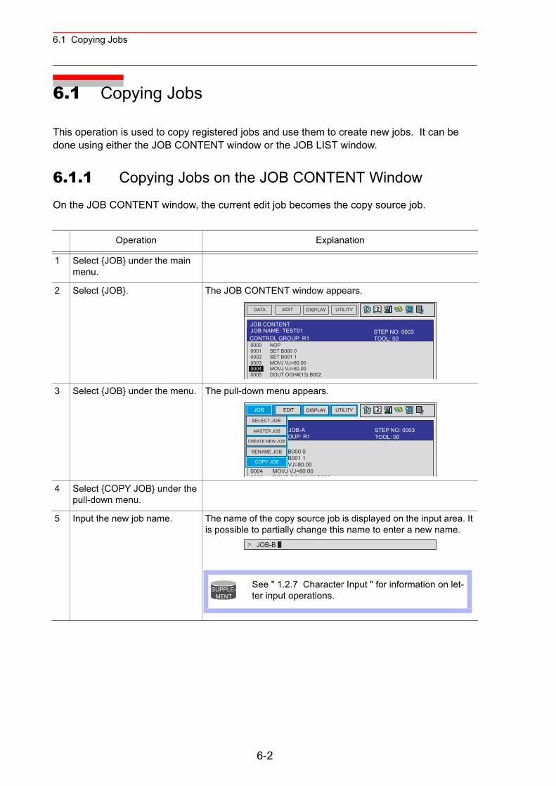
6.1 Copying Jobs
6.1 Copying Jobs
This operation is used to copy registered jobs and use them to create new jobs. It can be done using either the JOB CONTENT window or the JOB LIST window.
6.1.1 Copying Jobs on the JOB CONTENT Window
On the JOB CONTENT window, the current edit job becomes the copy source job.
Operation Explanation
1 Select {JOB} under the main menu.
2 Select {JOB}. The JOB CONTENT window appears.
3 Select {JOB} under the menu. The pull-down menu appears.
4 Select {COPY JOB} under the pull-down menu.
5 Input the new job name. The name of the copy source job is displayed on the input area. It is possible to partially change this name to enter a new name.
DATA EDIT DISPLAY UTILITY
JOB CONTENTJOB NAME: TEST01
0000 NOP0001 SET B000 00002 SET B001 10003 MOVJ VJ=80.000004 MOVJ VJ=80.000005 DOUT OGH#(13) B002
TOOL: 00CONTROL GROUP: R1STEP NO: 0003
JOB EDIT DISPLAY UTILITY
JOB NAME: JOB-A
0000 NOP0001 SET B000 00002 SET B001 10003 0OVJ VJ=80.000004 MOVJ VJ=80.000005 DOUT OGH#(13) B002
CONTROL GROUP: R1CREATE NEW JOB
SELECT JOB
MASTER JOB
RENAME JOB
COPY JOB
TOOL: 00STEP NO: 0003
JOB-B>
See " 1.2.7 Character Input " for information on let-ter input operations.
SUPPLE-MENT
6-2
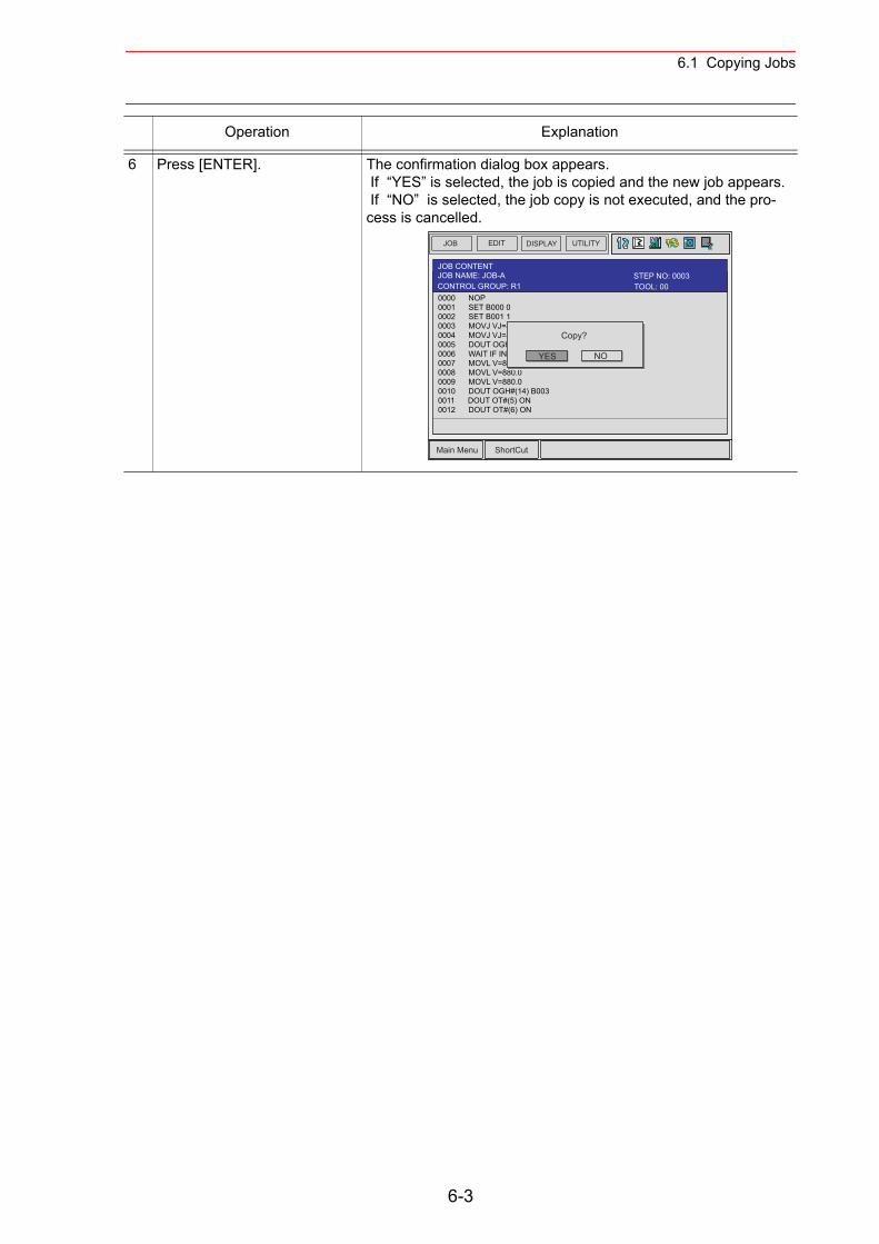
6.1 Copying Jobs
6 Press [ENTER]. The confirmation dialog box appears. If “YES” is selected, the job is copied and the new job appears. If “NO” is selected, the job copy is not executed, and the pro-cess is cancelled.
Operation Explanation
JOB EDIT DISPLAY UTILITY
Main Menu ShortCut
JOB CONTENTJOB NAME: JOB-A
0000 NOP0001 SET B000 00002 SET B001 10003 MOVJ VJ=80.000004 MOVJ VJ=80.000005 DOUT OGH#(13) B0020006 WAIT IF IN#(5)=ON0007 MOVL V=880.00008 MOVL V=880.00009 MOVL V=880.00010 DOUT OGH#(14) B0030011 DOUT OT#(5) ON0012 DOUT OT#(6) ON
YES
Copy?
NO
TOOL: 00CONTROL GROUP: R1STEP NO: 0003
6-3
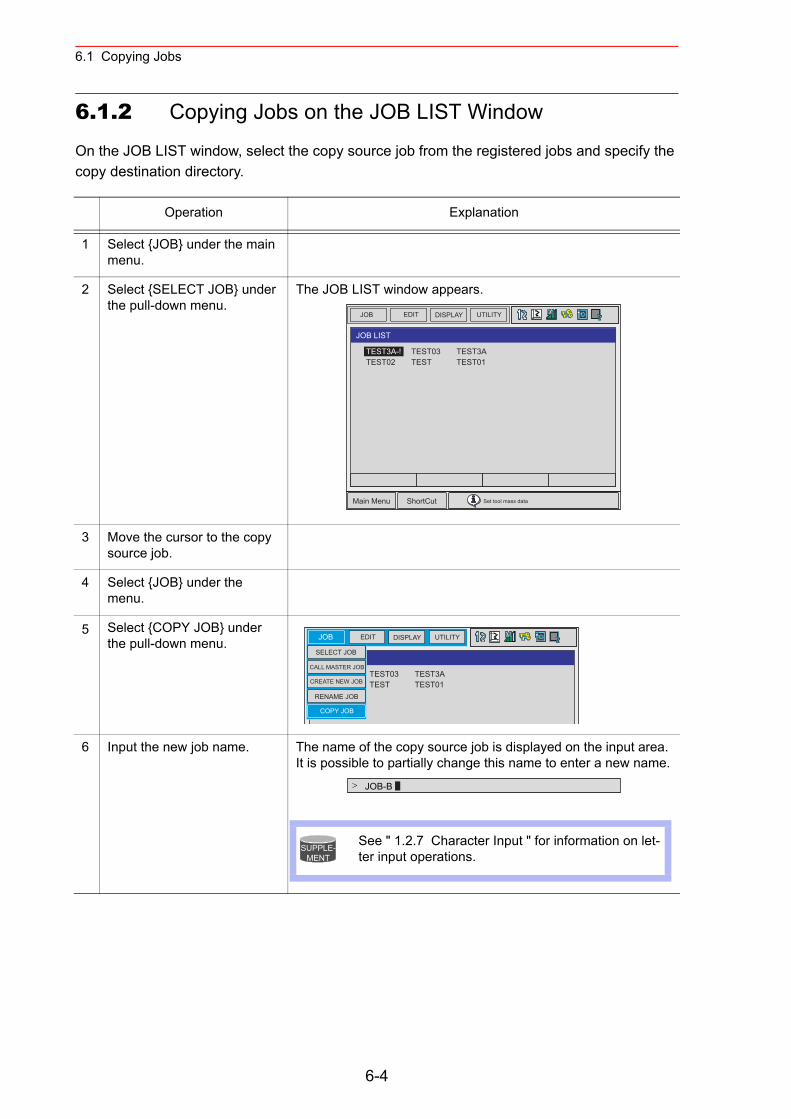
6.1 Copying Jobs
6.1.2 Copying Jobs on the JOB LIST Window
On the JOB LIST window, select the copy source job from the registered jobs and specify the copy destination directory.
Operation Explanation
1 Select {JOB} under the main menu.
2 Select {SELECT JOB} under the pull-down menu.
The JOB LIST window appears.
3 Move the cursor to the copy source job.
4 Select {JOB} under the menu.
5 Select {COPY JOB} under the pull-down menu.
6 Input the new job name. The name of the copy source job is displayed on the input area. It is possible to partially change this name to enter a new name.
JOB UTILITYEDIT DISPLAY
Main Menu ShortCut Set tool mass data
TEST03TEST
TEST3ATEST01
JOB LIST
TEST3A-!TEST02
JOB UTILITYEDIT DISPLAY
TEST03TEST
TEST3ATEST01
TEST3A-!TEST02CREATE NEW JOB
SELECT JOB
CALL MASTER JOB
RENAME JOB
COPY JOB
JOB-B>
See " 1.2.7 Character Input " for information on let-ter input operations.
SUPPLE-MENT
6-4

6.1 Copying Jobs
7 Press [ENTER]. The confirmation dialog box appears. If “YES” is selected, the job is copied and the new job appears. If “NO” is selected, the job copy is not executed, and the pro-cess is cancelled.
Operation Explanation
JOB EDIT DISPLAY UTILITY
Main Menu ShortCut
JOB CONTENTJOB NAME: JOB-A
0000 NOP0001 SET B000 00002 SET B001 10003 MOVJ VJ=80.000004 MOVJ VJ=80.000005 DOUT OGH#(13) B0020006 WAIT IF IN#(5)=ON0007 MOVL V=880.00008 MOVL V=880.00009 MOVL V=880.00010 DOUT OGH#(14) B0030011 DOUT OT#(5) ON0012 DOUT OT#(6) ON
YES
Copy?
NO
TOOL: 00CONTROL GROUP: R1STEP NO: 0003
6-5
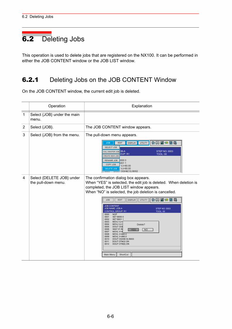
6.2 Deleting Jobs
6.2 Deleting Jobs
This operation is used to delete jobs that are registered on the NX100. It can be performed in either the JOB CONTENT window or the JOB LIST window.
6.2.1 Deleting Jobs on the JOB CONTENT Window
On the JOB CONTENT window, the current edit job is deleted.
Operation Explanation
1 Select {JOB} under the main menu.
2 Select {JOB}. The JOB CONTENT window appears.
3 Select {JOB} from the menu. The pull-down menu appears.
4 Select {DELETE JOB} under the pull-down menu.
The confirmation dialog box appears.When “YES” is selected, the edit job is deleted. When deletion is completed, the JOB LIST window appears.When “NO” is selected, the job deletion is cancelled.
JOB EDIT DISPLAY UTILITY
: JOB-A
0000 NOP0001 SET B000 00002 SET B001 10003 MOVJ VJ=80.000004 MOVJ VJ=80.000005 DOUT OGH#(13) B002
CONTROL GROUP: R1CREATE NEW JOB
SELECT JOB
CALL MASTER JOB
RENAME JOB
DELETE JOB
COPY JOB
TOOL: 00STEP NO: 0003
JOB EDIT DISPLAY UTILITY
Main Menu ShortCut
JOB CONTENTJOB NAME: JOB-A
0000 NOP0001 SET B000 00002 SET B001 10003 MOVJ VJ=80.000004 MOVJ VJ=80.000005 DOUT OGH#(13) B0020006 WAIT IF IN#(5)=ON0007 MOVL V=880.00008 MOVL V=880.00009 MOVL V=880.00010 DOUT OGH#(14) B0030011 DOUT OT#(5) ON0012 DOUT OT#(6) ON
YES
Delete?
NO
TOOL: 00CONTROL GROUP: R1STEP NO: 0003
6-6
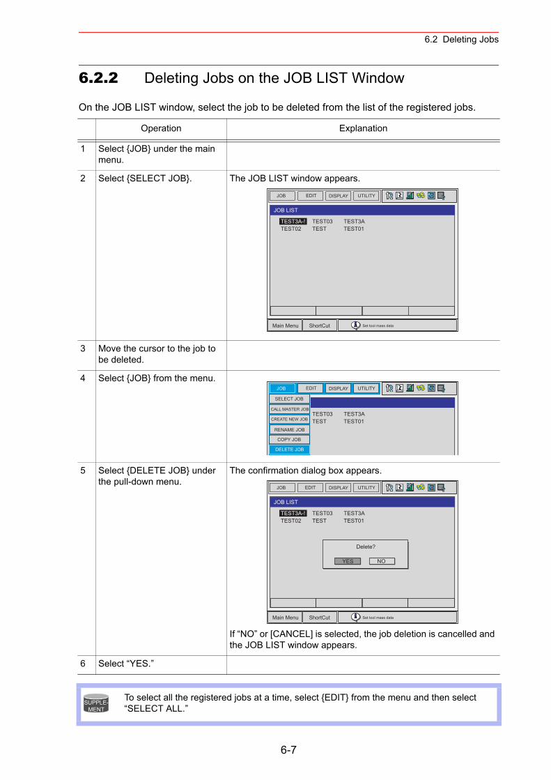
6.2 Deleting Jobs
6.2.2 Deleting Jobs on the JOB LIST Window
On the JOB LIST window, select the job to be deleted from the list of the registered jobs.
Operation Explanation
1 Select {JOB} under the main menu.
2 Select {SELECT JOB}. The JOB LIST window appears.
3 Move the cursor to the job to be deleted.
4 Select {JOB} from the menu.
5 Select {DELETE JOB} under the pull-down menu.
The confirmation dialog box appears.
If “NO” or [CANCEL] is selected, the job deletion is cancelled and the JOB LIST window appears.
6 Select “YES.”
To select all the registered jobs at a time, select {EDIT} from the menu and then select “SELECT ALL.”
JOB UTILITYEDIT DISPLAY
Main Menu ShortCut Set tool mass data
TEST03TEST
TEST3ATEST01
JOB LIST
TEST3A-!TEST02
JOB UTILITYEDIT DISPLAY
TEST03TEST
TEST3ATEST01
TEST3A-!TEST02CREATE NEW JOB
SELECT JOB
CALL MASTER JOB
RENAME JOB
DELETE JOB
COPY JOB
JOB UTILITYEDIT DISPLAY
Main Menu ShortCut Set tool mass data
TEST03TEST
TEST3ATEST01
JOB LIST
TEST3A-!TEST02
YES
Delete?
NO
SUPPLE-MENT
6-7
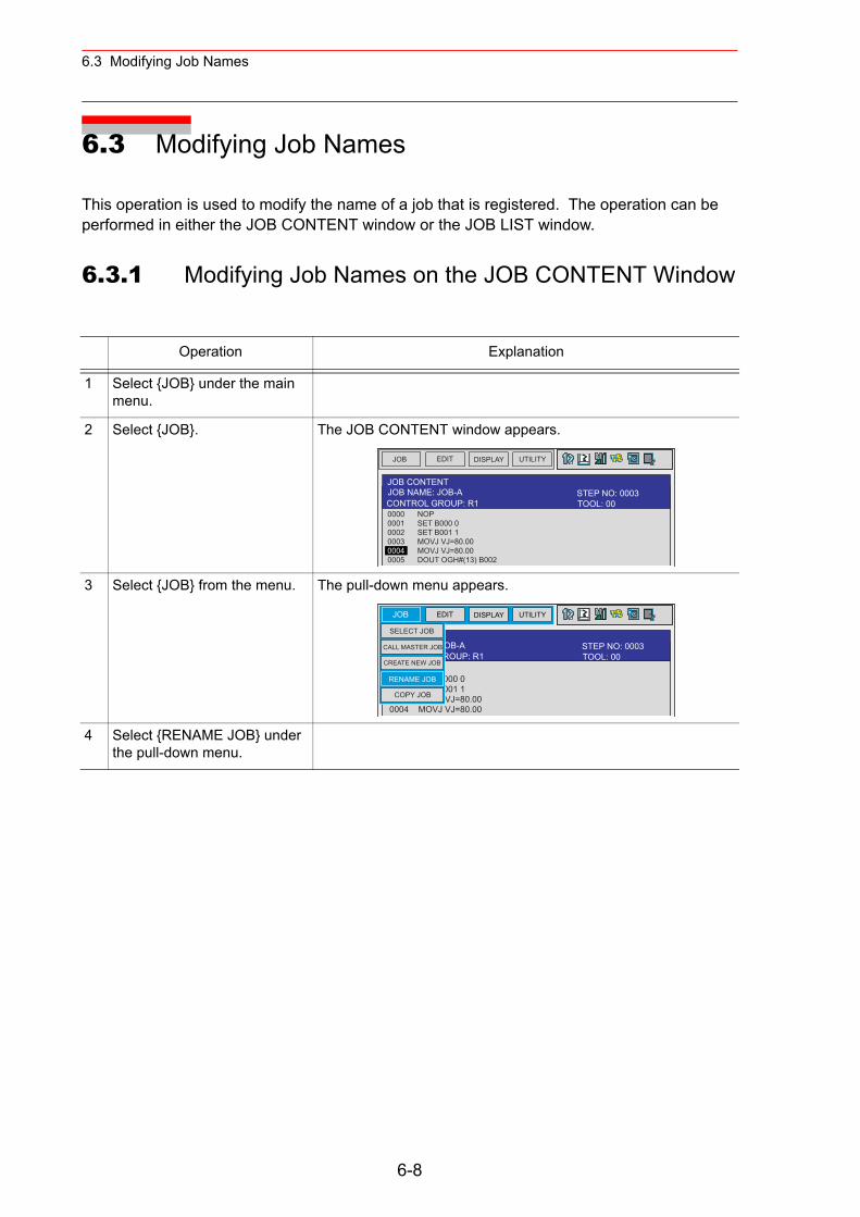
6.3 Modifying Job Names
6.3 Modifying Job Names
This operation is used to modify the name of a job that is registered. The operation can be performed in either the JOB CONTENT window or the JOB LIST window.
6.3.1 Modifying Job Names on the JOB CONTENT Window
Operation Explanation
1 Select {JOB} under the main menu.
2 Select {JOB}. The JOB CONTENT window appears.
3 Select {JOB} from the menu. The pull-down menu appears.
4 Select {RENAME JOB} under the pull-down menu.
JOB EDIT DISPLAY UTILITY
JOB CONTENTJOB NAME: JOB-A
0000 NOP0001 SET B000 00002 SET B001 10003 MOVJ VJ=80.000004 MOVJ VJ=80.000005 DOUT OGH#(13) B002
TOOL: 00CONTROL GROUP: R1STEP NO: 0003
JOB EDIT DISPLAY UTILITY
JOB NAME: JOB-A
0000 NOP0001 SET B000 00002 SET B001 10003 MOVJ VJ=80.000004 MOVJ VJ=80.00
CONTROL GROUP: R1CREATE NEW JOB
SELECT JOB
CALL MASTER JOB
RENAME JOB
COPY JOB
TOOL: 00STEP NO: 0003
6-8
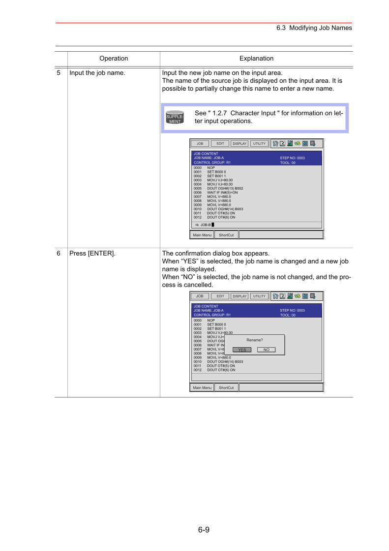
6.3 Modifying Job Names
5 Input the job name. Input the new job name on the input area.The name of the source job is displayed on the input area. It is possible to partially change this name to enter a new name.
6 Press [ENTER]. The confirmation dialog box appears.When “YES” is selected, the job name is changed and a new job name is displayed.When “NO” is selected, the job name is not changed, and the pro-cess is cancelled.
Operation Explanation
See " 1.2.7 Character Input " for information on let-ter input operations.
SUPPLE-MENT
JOB EDIT DISPLAY UTILITY
Main Menu ShortCut
JOB CONTENTJOB NAME: JOB-A
0000 NOP0001 SET B000 00002 SET B001 10003 MOVJ VJ=80.000004 MOVJ VJ=80.000005 DOUT OGH#(13) B0020006 WAIT IF IN#(5)=ON0007 MOVL V=880.00008 MOVL V=880.00009 MOVL V=880.00010 DOUT OGH#(14) B0030011 DOUT OT#(5) ON0012 DOUT OT#(6) ON
JOB-B
TOOL: 00CONTROL GROUP: R1STEP NO: 0003
JOB EDIT DISPLAY UTILITY
Main Menu ShortCut
JOB CONTENTJOB NAME: JOB-A
0000 NOP0001 SET B000 00002 SET B001 10003 MOVJ VJ=80.000004 MOVJ VJ=80.000005 DOUT OGH#(13) B0020006 WAIT IF IN#(5)=ON0007 MOVL V=880.00008 MOVL V=880.00009 MOVL V=880.00010 DOUT OGH#(14) B0030011 DOUT OT#(5) ON0012 DOUT OT#(6) ON
YES
Rename?
NO
TOOL: 00CONTROL GROUP: R1STEP NO: 0003
6-9
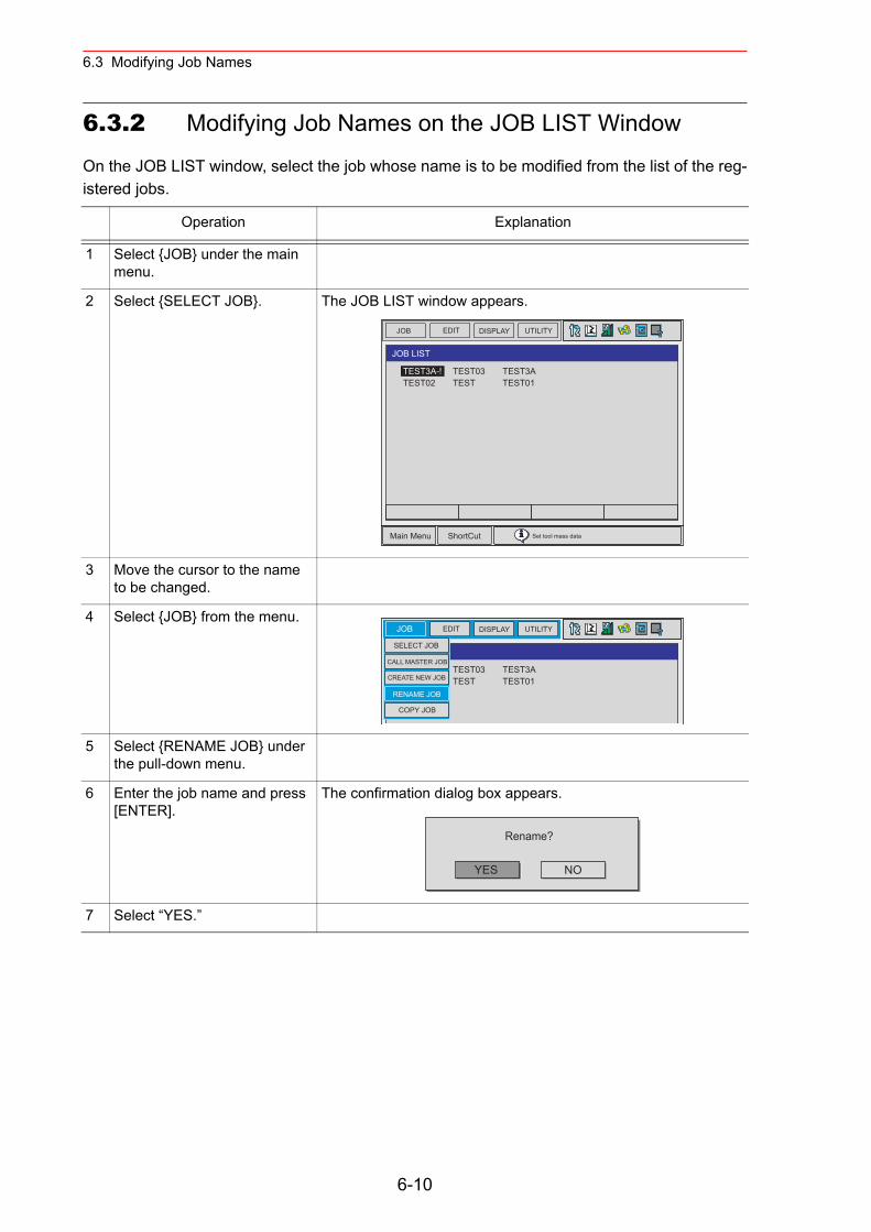
6.3 Modifying Job Names
6.3.2 Modifying Job Names on the JOB LIST Window
On the JOB LIST window, select the job whose name is to be modified from the list of the reg-istered jobs.
Operation Explanation
1 Select {JOB} under the main menu.
2 Select {SELECT JOB}. The JOB LIST window appears.
3 Move the cursor to the name to be changed.
4 Select {JOB} from the menu.
5 Select {RENAME JOB} under the pull-down menu.
6 Enter the job name and press [ENTER].
The confirmation dialog box appears.
7 Select “YES.”
JOB UTILITYEDIT DISPLAY
Main Menu ShortCut Set tool mass data
TEST03TEST
TEST3ATEST01
JOB LIST
TEST3A-!TEST02
JOB UTILITYEDIT DISPLAY
TEST03TEST
TEST3ATEST01
TEST3A-!TEST02CREATE NEW JOB
SELECT JOB
CALL MASTER JOB
RENAME JOB
COPY JOB
YES
Rename?
NO
6-10
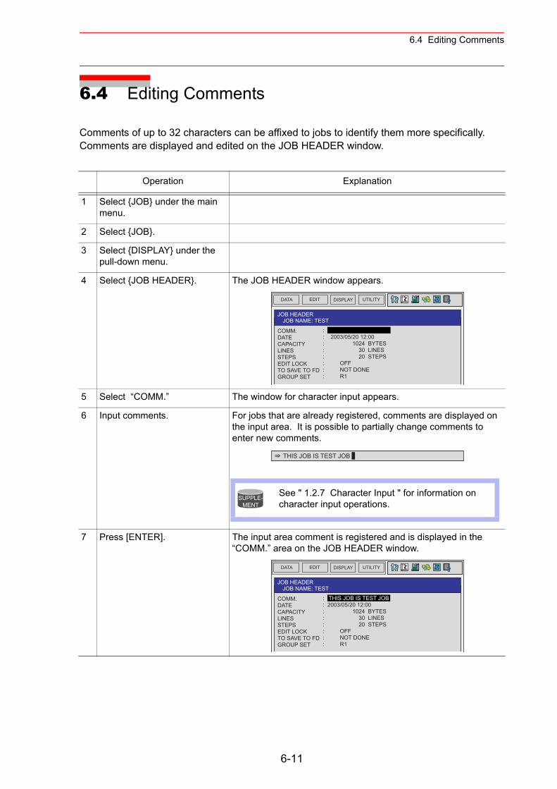
6.4 Editing Comments
6.4 Editing Comments
Comments of up to 32 characters can be affixed to jobs to identify them more specifically. Comments are displayed and edited on the JOB HEADER window.
Operation Explanation
1 Select {JOB} under the main menu.
2 Select {JOB}.
3 Select {DISPLAY} under the pull-down menu.
4 Select {JOB HEADER}. The JOB HEADER window appears.
5 Select “COMM.” The window for character input appears.
6 Input comments. For jobs that are already registered, comments are displayed on the input area. It is possible to partially change comments to enter new comments.
7 Press [ENTER]. The input area comment is registered and is displayed in the “COMM.” area on the JOB HEADER window.
DATA EDIT DISPLAY UTILITY
JOB HEADERJOB NAME: TEST
COMM.DATECAPACITYLINESSTEPSEDIT LOCKTO SAVE TO FDGROUP SET
: : 2003/05/20 12:00: 1024 BYTES: 30 LINES: 20 STEPS: OFF: NOT DONE: R1
THIS JOB IS TEST JOB
See " 1.2.7 Character Input " for information on character input operations.
SUPPLE-MENT
DATA EDIT DISPLAY UTILITY
JOB HEADERJOB NAME: TEST
COMM.DATECAPACITYLINESSTEPSEDIT LOCKTO SAVE TO FDGROUP SET
: THIS JOB IS TEST JOB: 2003/05/20 12:00: 1024 BYTES: 30 LINES: 20 STEPS: OFF: NOT DONE: R1
6-11
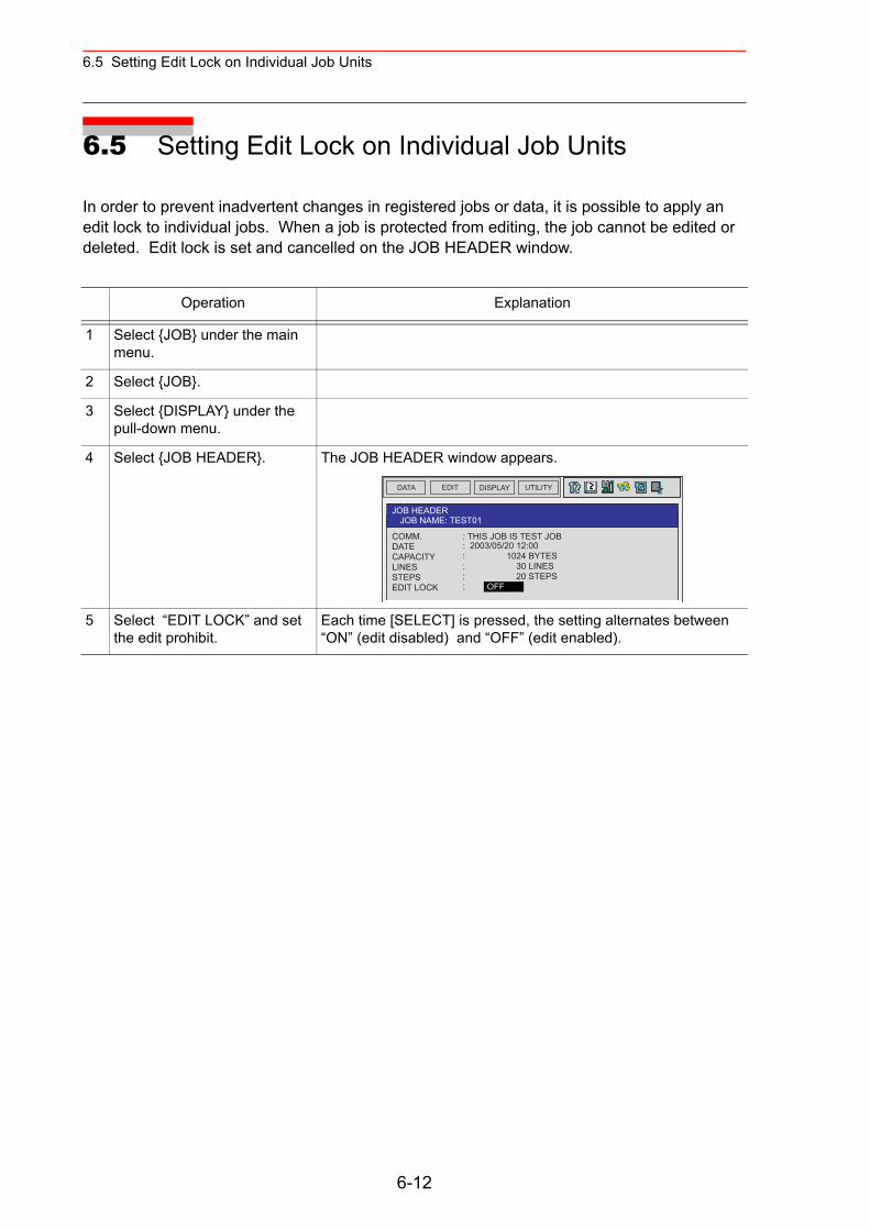
6.5 Setting Edit Lock on Individual Job Units
6.5 Setting Edit Lock on Individual Job Units
In order to prevent inadvertent changes in registered jobs or data, it is possible to apply an edit lock to individual jobs. When a job is protected from editing, the job cannot be edited or deleted. Edit lock is set and cancelled on the JOB HEADER window.
Operation Explanation
1 Select {JOB} under the main menu.
2 Select {JOB}.
3 Select {DISPLAY} under the pull-down menu.
4 Select {JOB HEADER}. The JOB HEADER window appears.
5 Select “EDIT LOCK” and set the edit prohibit.
Each time [SELECT] is pressed, the setting alternates between “ON” (edit disabled) and “OFF” (edit enabled).
DATA EDIT DISPLAY UTILITY
JOB HEADERJOB NAME: TEST01
COMM. : THIS JOB IS TEST JOBDATECAPACITYLINESSTEPSEDIT LOCK
: 2003/05/20 12:00: 1024 BYTES: 30 LINES: 20 STEPS: OFF
6-12
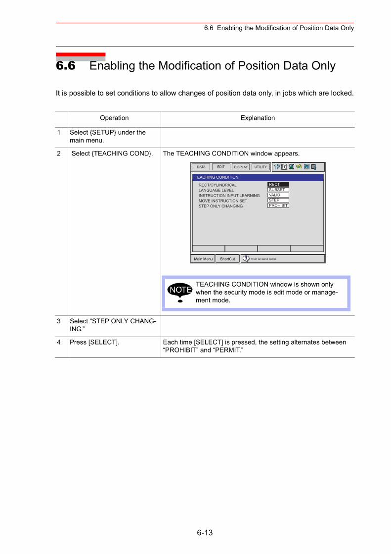
6.6 Enabling the Modification of Position Data Only
6.6 Enabling the Modification of Position Data Only
It is possible to set conditions to allow changes of position data only, in jobs which are locked.
Operation Explanation
1 Select {SETUP} under the main menu.
2 Select {TEACHING COND}. The TEACHING CONDITION window appears.
3 Select “STEP ONLY CHANG-ING.”
4 Press [SELECT]. Each time [SELECT] is pressed, the setting alternates between “PROHIBIT” and “PERMIT.”
DATA EDIT DISPLAY UTILITY
Main Menu ShortCut !Turn on servo power
TEACHING CONDITION
RECT/CYLINDRICALLANGUAGE LEVELINSTRUCTION INPUT LEARNINGMOVE INSTRUCTION SETSTEP ONLY CHANGING
RECTSUBSETVALIDSTEPPROHIBIT
TEACHING CONDITION window is shown only when the security mode is edit mode or manage-ment mode.
NOTE
6-13
7.1 One-touch Operation “Direct Open”
7 Convenient Functions
7.1 One-touch Operation “Direct Open”
The direct open function immediately shows the JOB CONTENT window or condition file con-tents of a job called with the CALL instruction. Move the cursor to the desired job name or
condition file name and simply press the direct open key to display the contents of the file. This function can be used for the following window:
• JOB CONTENT window for a job name directly specified by a CALL instruction• CONDITION FILE window for a file name directly specified by a work instruction• COMMAND POS window for a move instruction• I/O window with an I/O instruction (when I/O numbers are specified)
Directopen
7-1
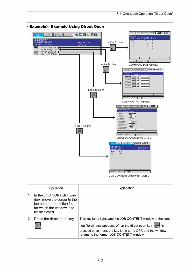
7.1 One-touch Operation “Direct Open”
<Example> Example Using Direct Open
Operation Explanation
1 In the JOB CONTENT win-dow, move the cursor to the job name or condition file for which the window is to be displayed.
2 Press the direct open key
.
This key lamp lights and the JOB CONTENT window or the condi-
tion file window appears. When the direct open key is pressed once more, the key lamp turns OFF, and the window returns to the former JOB CONTENT window.
JOB EDIT DISPLAY UTILITY
JOB CONTENTJOB NAME: TEST01
0008 MONJ VJ=50.000009 DOUT OT#(1) ON0010 WVON WEV#(2)0011 CALL JOB:JOB-C
Directopen
Directopen
Directopen
Directopen
In the 8th line
In the 9th line
In the 10th line
In the 11th line
COMMAND POS window
USER OUTPUT window
WEAVING CONDITION window
JOB CONTENT window for "JOB-C"
DATA EDIT DISPLAY UTILITY
Main Menu ShortCut
COMMAND POSINTR:********** SPD: 558 cm/min
[CMD] TOOL: ** [CURR] TOOL: **
R1:S L U R B T
R1:S L U R B T
******
000000
!Turn on servo power
DATA EDIT DISPLAY UTILITY
Main Menu ShortCut
USER OUTPUT GROUP OG#01 0: DEC. 00: HEX.
#1010#1011#1012#1013#1014#1015#1016#1017
OUT#C01OUT#C02OUT#C03OUT#C04OUT#C05OUT#C06OUT#C07OUT#C08
!Turn on servo power
DATA EDIT DISPLAY UTILITY
Main Menu ShortCut
WEAVING CONDITION WEAVING COND NO.: 1/16
SINGLEONFREQ 3.5 Hz
MODE SMOOTH SPEED FREQUENCY<PATTERN> AMPLITUDE VERTICAL HORIZONTAL ANGLE TRAVEL ANGLE<TIMER MODE>
45.00 ∞ 0.00 ∞
2.000 mm10.000 mm10.000 mm
!Turn on servo power
JOB UTILITYEDIT DISPLAY
Main Menu ShortCut
JOB CONTENTJOB NAME: JOB-C
0000 NOP0001 END
!Turn on servo power
TOOL: 00CONTROL GROUP: R1STEP NO: 0003
TOOL: 00CONTROL GROUP: R1STEP NO: 0003
Directopen
Directopen
7-2
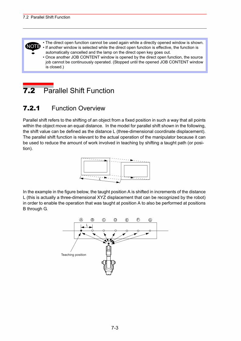
7.2 Parallel Shift Function
7.2 Parallel Shift Function
7.2.1 Function Overview
Parallel shift refers to the shifting of an object from a fixed position in such a way that all points within the object move an equal distance. In the model for parallel shift shown in the following, the shift value can be defined as the distance L (three-dimensional coordinate displacement). The parallel shift function is relevant to the actual operation of the manipulator because it can be used to reduce the amount of work involved in teaching by shifting a taught path (or posi-tion).
In the example in the figure below, the taught position A is shifted in increments of the distance L (this is actually a three-dimensional XYZ displacement that can be recognized by the robot) in order to enable the operation that was taught at position A to also be performed at positions B through G.
• The direct open function cannot be used again while a directly opened window is shown.• If another window is selected while the direct open function is effective, the function is
automatically cancelled and the lamp on the direct open key goes out.• Once another JOB CONTENT window is opened by the direct open function, the source
job cannot be continuously operated. (Stopped until the opened JOB CONTENT window is closed.)
NOTE
L
A B C D E F GL
Teaching position
7-3
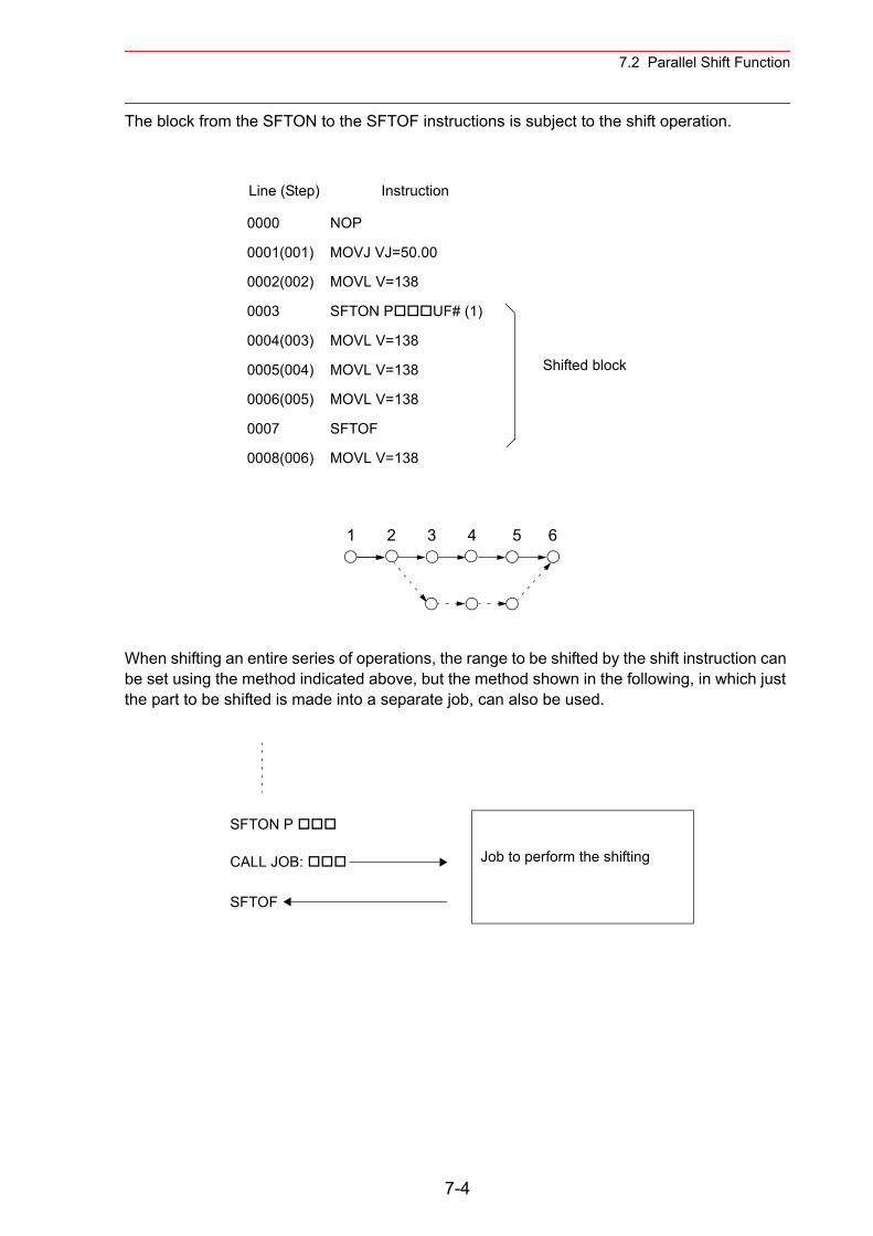
7.2 Parallel Shift Function
The block from the SFTON to the SFTOF instructions is subject to the shift operation.
When shifting an entire series of operations, the range to be shifted by the shift instruction can be set using the method indicated above, but the method shown in the following, in which just the part to be shifted is made into a separate job, can also be used.
SFTON P
CALL JOB: Job to perform the shifting
SFTOF
Line (Step) Instruction
0000 NOP
0001(001) MOVJ VJ=50.00
0002(002) MOVL V=138
0003 SFTON P UF# (1)
0004(003) MOVL V=138
0005(004) MOVL V=138
0006(005) MOVL V=138
0007 SFTOF
0008(006) MOVL V=138
Shifted block
1 2 3 4 5 6
7-4
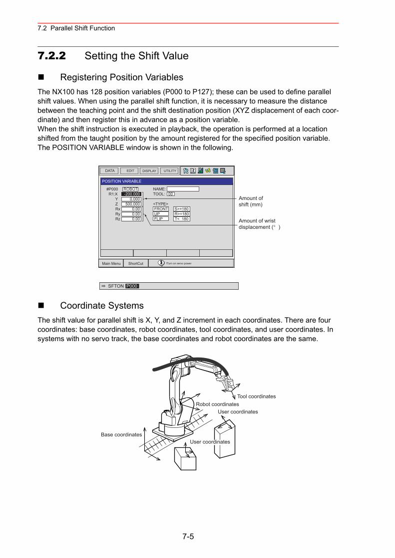
7.2 Parallel Shift Function
7.2.2 Setting the Shift Value
Registering Position VariablesThe NX100 has 128 position variables (P000 to P127); these can be used to define parallel shift values. When using the parallel shift function, it is necessary to measure the distance between the teaching point and the shift destination position (XYZ displacement of each coor-dinate) and then register this in advance as a position variable.When the shift instruction is executed in playback, the operation is performed at a location shifted from the taught position by the amount registered for the specified position variable. The POSITION VARIABLE window is shown in the following.
Coordinate SystemsThe shift value for parallel shift is X, Y, and Z increment in each coordinates. There are four coordinates: base coordinates, robot coordinates, tool coordinates, and user coordinates. In systems with no servo track, the base coordinates and robot coordinates are the same.
DATA EDIT DISPLAY UTILITY
Main Menu ShortCut !Turn on servo power
POSITION VARIABLE
NAME: TOOL: 00
<TYPE> FRONT S>=180 UP R>=180 FLIP T< 180
#P000 R1:X Y Z Rx Ry Rz
ROBOT-200.000
0.000500.000
0.000.000.00
Amount ofshift (mm)
Amount of wrist displacement (° )
SFTON P000
Base coordinates
Robot coordinatesTool coordinates
User coordinates
User coordinates
7-5
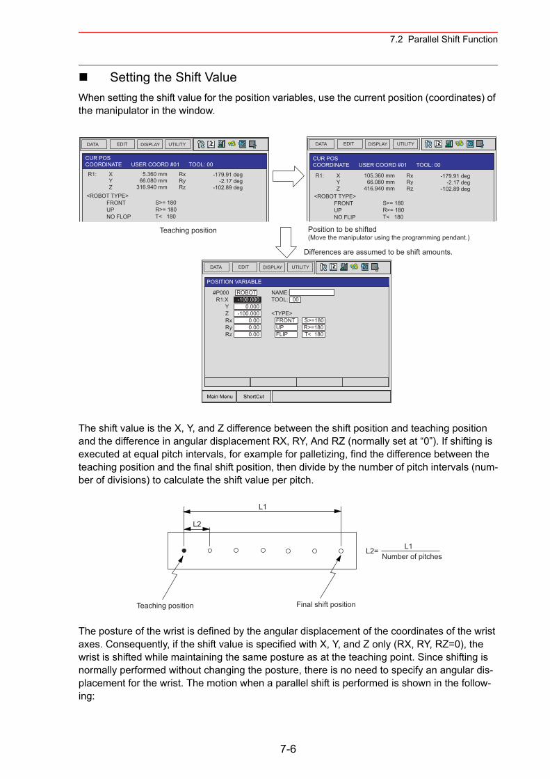
7.2 Parallel Shift Function
Setting the Shift ValueWhen setting the shift value for the position variables, use the current position (coordinates) of the manipulator in the window.
The shift value is the X, Y, and Z difference between the shift position and teaching position and the difference in angular displacement RX, RY, And RZ (normally set at “0”). If shifting is executed at equal pitch intervals, for example for palletizing, find the difference between the teaching position and the final shift position, then divide by the number of pitch intervals (num-ber of divisions) to calculate the shift value per pitch.
The posture of the wrist is defined by the angular displacement of the coordinates of the wrist axes. Consequently, if the shift value is specified with X, Y, and Z only (RX, RY, RZ=0), the wrist is shifted while maintaining the same posture as at the teaching point. Since shifting is normally performed without changing the posture, there is no need to specify an angular dis-placement for the wrist. The motion when a parallel shift is performed is shown in the follow-ing:
DATA EDIT DISPLAY UTILITY
DATA EDIT DISPLAY UTILITY DATA EDIT DISPLAY UTILITY
Main Menu ShortCut
POSITION VARIABLE
#P000 R1:X Y Z Rx Ry Rz
ROBOT-100.000
0.000-100.000
0.000.000.00
CUR POSCOORDINATE USER COORD #01 TOOL: 00
Differences are assumed to be shift amounts.
Position to be shifted(Move the manipulator using the programming pendant.)
R1: X Y Z
5.360 mm66.080 mm
316.940 mm
RxRyRz
-179.91 deg-2.17 deg
-102.89 deg<ROBOT TYPE> FRONT UP NO FLOP
S>= 180R>= 180T< 180
Teaching position
CUR POSCOORDINATE USER COORD #01 TOOL: 00
R1: X Y Z
105.360 mm66.080 mm
416.940 mm
RxRyRz
-179.91 deg-2.17 deg
-102.89 deg<ROBOT TYPE> FRONT UP NO FLIP
S>= 180R>= 180T< 180
NAME: TOOL: 00
<TYPE> FRONT S>=180 UP R>=180 FLIP T< 180
L2
Teaching position
L1
Final shift position
L2=Number of pitches
L1
7-6
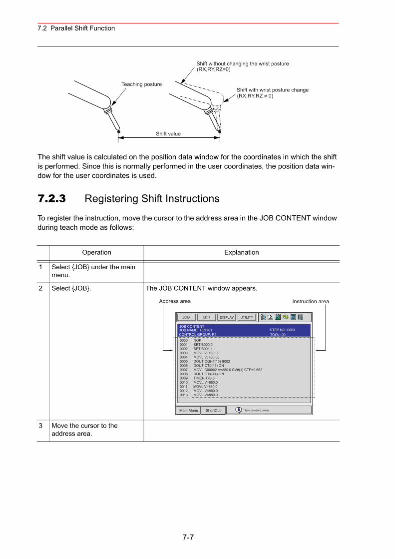
7.2 Parallel Shift Function
The shift value is calculated on the position data window for the coordinates in which the shift is performed. Since this is normally performed in the user coordinates, the position data win-dow for the user coordinates is used.
7.2.3 Registering Shift Instructions
To register the instruction, move the cursor to the address area in the JOB CONTENT window during teach mode as follows:
Operation Explanation
1 Select {JOB} under the main menu.
2 Select {JOB}. The JOB CONTENT window appears.
3 Move the cursor to the address area.
Shift value
Teaching posture
Shift without changing the wrist posture(RX,RY,RZ=0)
Shift with wrist posture change(RX,RY,RZ ≠ 0)
JOB UTILITYEDIT DISPLAY
Main Menu ShortCut !Turn on servo power
JOB CONTENT
0000 NOP0001 SET B000 00002 SET B001 10003 MOVJ VJ=80.000004 MOVJ VJ=80.000005 DOUT OGH#(13) B0020006 DOUT OT#(41) ON0007 MOVL C00002 V=880.0 CV#(1) CTP=0.6620008 DOUT OT#(44) ON0009 TIMER T=3.00010 MOVL V=880.00011 MOVL V=880.00012 MOVL V=880.00013 MOVL V=880.0
JOB NAME: TEST01
Address area Instruction area
TOOL: 00CONTROL GROUP: R1STEP NO: 0003
7-7
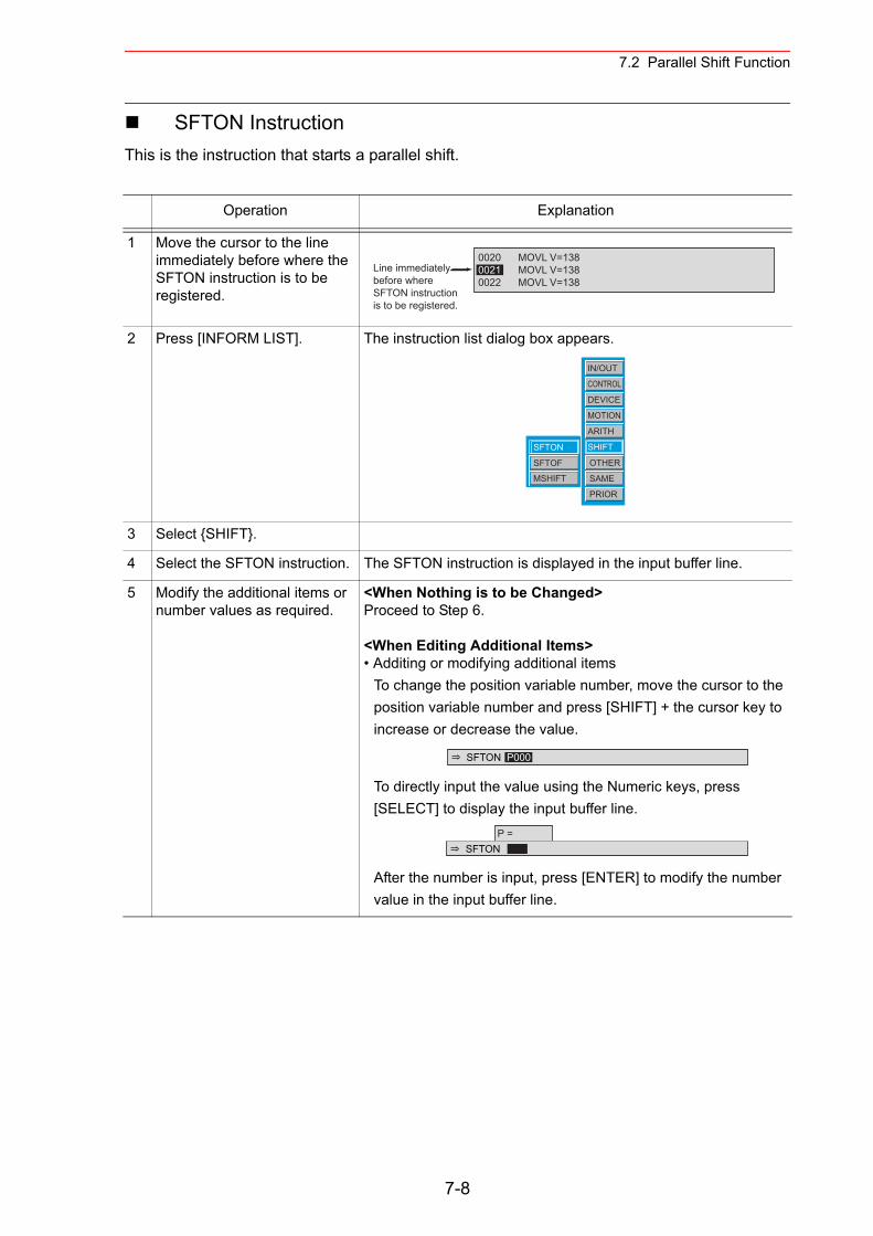
7.2 Parallel Shift Function
SFTON InstructionThis is the instruction that starts a parallel shift.
Operation Explanation
1 Move the cursor to the line immediately before where the SFTON instruction is to be registered.
2 Press [INFORM LIST]. The instruction list dialog box appears.
3 Select {SHIFT}.
4 Select the SFTON instruction. The SFTON instruction is displayed in the input buffer line.
5 Modify the additional items or number values as required.
<When Nothing is to be Changed>Proceed to Step 6.
<When Editing Additional Items>• Additing or modifying additional items
To change the position variable number, move the cursor to the position variable number and press [SHIFT] + the cursor key to increase or decrease the value.
To directly input the value using the Numeric keys, press [SELECT] to display the input buffer line.
After the number is input, press [ENTER] to modify the number value in the input buffer line.
0020 MOVL V=1380021 MOVL V=1380022 MOVL V=138
Line immediatelybefore whereSFTON instructionis to be registered.
IN/OUT
CONTROL
DEVICE
MOTION
ARITH
SHIFT
OTHER
SAME
PRIOR
SFTON
SFTOF
MSHIFT
SFTON P000
SFTONP =
7-8
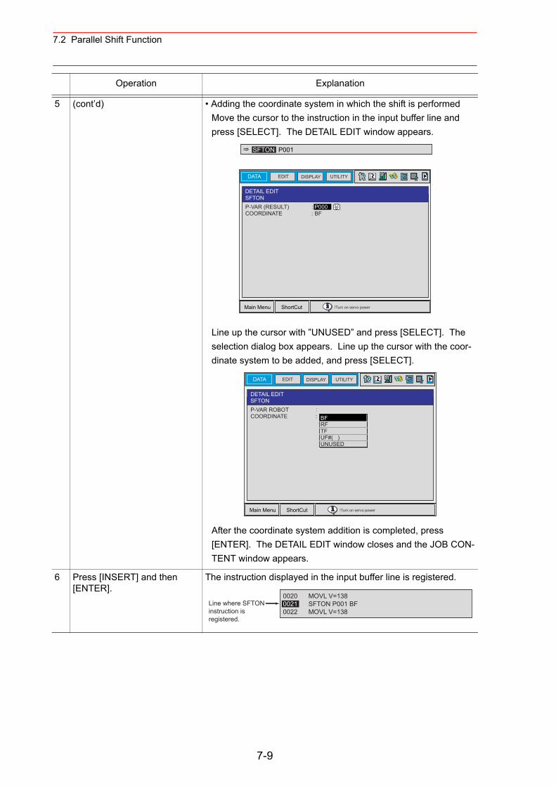
7.2 Parallel Shift Function
5 (cont’d) • Adding the coordinate system in which the shift is performedMove the cursor to the instruction in the input buffer line and press [SELECT]. The DETAIL EDIT window appears.
Line up the cursor with ”UNUSED” and press [SELECT]. The selection dialog box appears. Line up the cursor with the coor-dinate system to be added, and press [SELECT].
After the coordinate system addition is completed, press [ENTER]. The DETAIL EDIT window closes and the JOB CON-TENT window appears.
6 Press [INSERT] and then [ENTER].
The instruction displayed in the input buffer line is registered.
Operation Explanation
SFTON P001
DATA EDIT DISPLAY UTILITY
Main Menu ShortCut !Turn on servo power
DETAIL EDITSFTONP-VAR (RESULT) : P000COORDINATE : BF
DATA EDIT DISPLAY UTILITY
Main Menu ShortCut !Turn on servo power
DETAIL EDITSFTONP-VAR ROBOT COORDINATE : BF
RFTFUF#( )UNUSED
0020 MOVL V=1380021 SFTON P001 BF0022 MOVL V=138
Line where SFTON instruction isregistered.
7-9
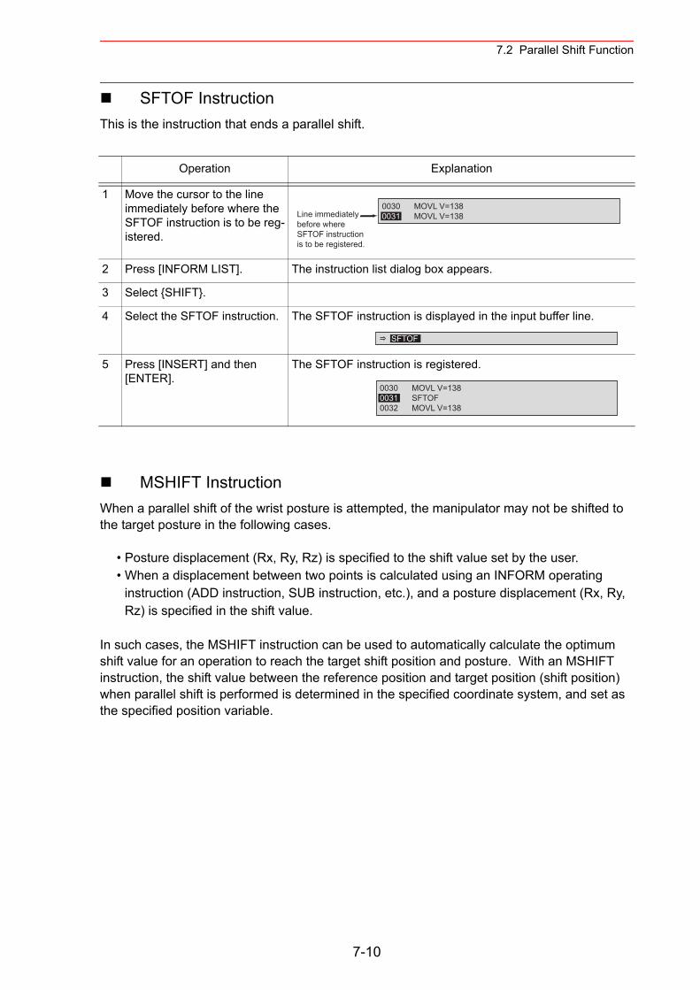
7.2 Parallel Shift Function
SFTOF InstructionThis is the instruction that ends a parallel shift.
MSHIFT InstructionWhen a parallel shift of the wrist posture is attempted, the manipulator may not be shifted to the target posture in the following cases.
• Posture displacement (Rx, Ry, Rz) is specified to the shift value set by the user.• When a displacement between two points is calculated using an INFORM operating
instruction (ADD instruction, SUB instruction, etc.), and a posture displacement (Rx, Ry, Rz) is specified in the shift value.
In such cases, the MSHIFT instruction can be used to automatically calculate the optimum shift value for an operation to reach the target shift position and posture. With an MSHIFT instruction, the shift value between the reference position and target position (shift position) when parallel shift is performed is determined in the specified coordinate system, and set as the specified position variable.
Operation Explanation
1 Move the cursor to the line immediately before where the SFTOF instruction is to be reg-istered.
2 Press [INFORM LIST]. The instruction list dialog box appears.
3 Select {SHIFT}.
4 Select the SFTOF instruction. The SFTOF instruction is displayed in the input buffer line.
5 Press [INSERT] and then [ENTER].
The SFTOF instruction is registered.
0030 MOVL V=1380031 MOVL V=138Line immediately
before where SFTOF instruction is to be registered.
SFTOF
0030 MOVL V=1380031 SFTOF0032 MOVL V=138
7-10
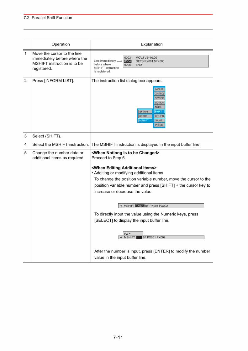
7.2 Parallel Shift Function
Operation Explanation
1 Move the cursor to the line immediately before where the MSHIFT instruction is to be registered.
2 Press [INFORM LIST]. The instruction list dialog box appears.
3 Select {SHIFT}.
4 Select the MSHIFT instruction. The MSHIFT instruction is displayed in the input buffer line.
5 Change the number data or additional items as required.
<When Notiong is to be Changed>Proceed to Step 6.
<When Editing Additional Items>• Additing or modifying additional items
To change the position variable number, move the cursor to the position variable number and press [SHIFT] + the cursor key to increase or decrease the value.
To directly input the value using the Numeric keys, press [SELECT] to display the input buffer line.
After the number is input, press [ENTER] to modify the number value in the input buffer line.
0003 MOVJ VJ=10.000004 GETS PX001 $PX0000005 END
Line immediatelybefore where MSHIFT instruction is registered.
IN/OUT
CONTROL
DEVICE
MOTION
ARITH
SHIFT
OTHER
SAME
PRIOR
SFTON
SFTOF
MSHIFT
MSHIFT PX000 BF PX001 PX002
PX =MSHIFT 0 BF PX001 PX002
7-11
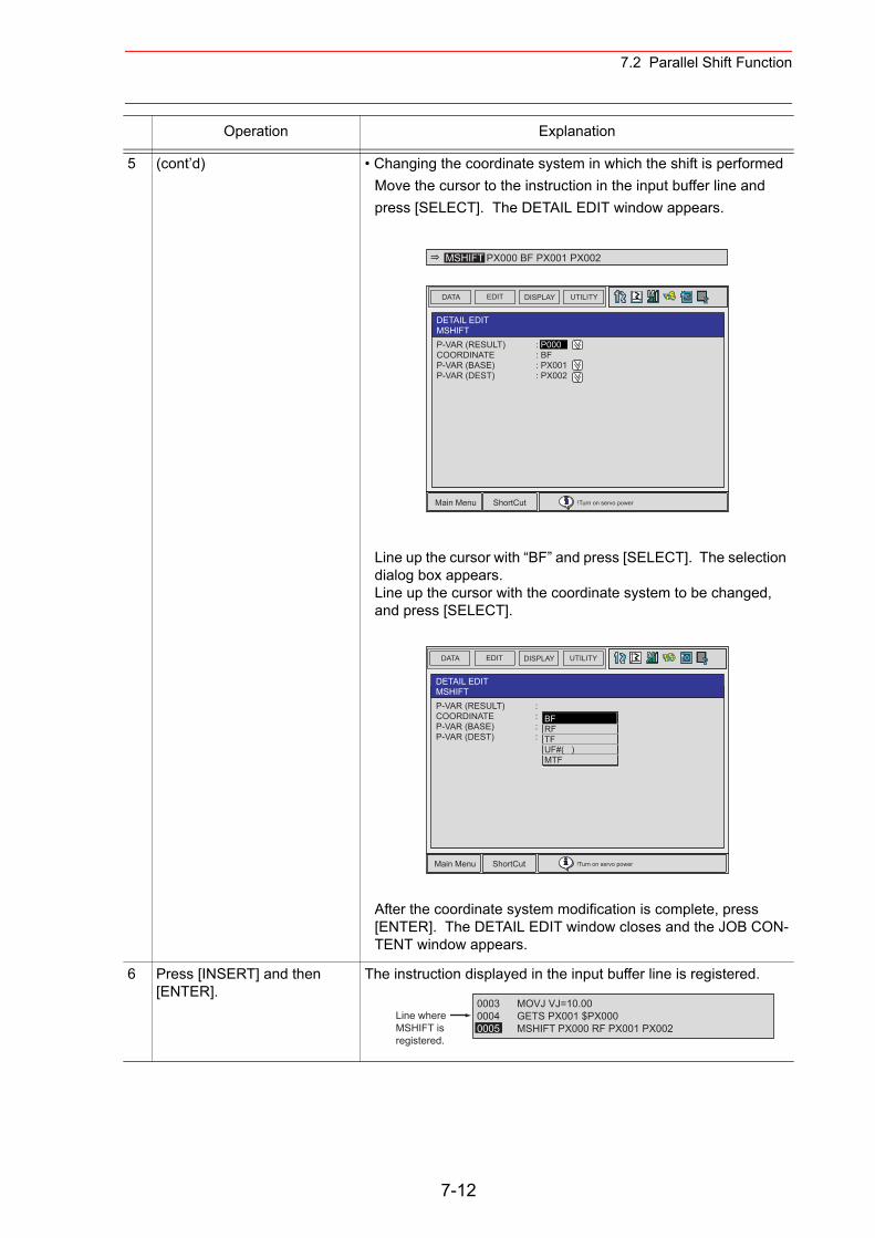
7.2 Parallel Shift Function
5 (cont’d) • Changing the coordinate system in which the shift is performed Move the cursor to the instruction in the input buffer line and press [SELECT]. The DETAIL EDIT window appears.
Line up the cursor with “BF” and press [SELECT]. The selection dialog box appears. Line up the cursor with the coordinate system to be changed, and press [SELECT].
After the coordinate system modification is complete, press [ENTER]. The DETAIL EDIT window closes and the JOB CON-TENT window appears.
6 Press [INSERT] and then [ENTER].
The instruction displayed in the input buffer line is registered.
Operation Explanation
MSHIFT PX000 BF PX001 PX002
DATA EDIT DISPLAY UTILITY
Main Menu ShortCut !Turn on servo power
DETAIL EDITMSHIFTP-VAR (RESULT) : P000COORDINATE : BFP-VAR (BASE) : PX001P-VAR (DEST) : PX002
DATA EDIT DISPLAY UTILITY
Main Menu ShortCut !Turn on servo power
DETAIL EDITMSHIFTP-VAR (RESULT) :COORDINATE : BFP-VAR (BASE) : PX001P-VAR (DEST) : PX002
BFRFTFUF#( )MTF
0003 MOVJ VJ=10.000004 GETS PX001 $PX0000005 MSHIFT PX000 RF PX001 PX002
Line whereMSHIFT isregistered.
7-12
7.2 Parallel Shift Function
7.2.4 Continuation of the Parallel Shift Function
If any of the following operations are performed after executing a parallel shift instruction, the shift function is cancelled.
• Job editing operation (changing, deleting, adding)• Job copy, job name change• Registering a new job, deleting a job, or modifying a selected job• Restart after the alarm occurs• When control power is turned OFF
• If the shift function is cancelled through a job editing operation after execution of a parallel shift instruction, the job must be started again from the beginning.
Because no shift is performed when the operation is restarted, there is a possibility of interference between the workpiece and fixture.
The parallel shift function remains in effect even if the control power supply is turned OFF.
CAUTION
NOTE
7-13
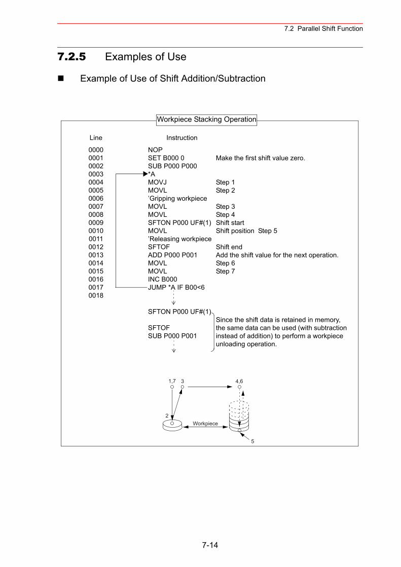
7.2 Parallel Shift Function
7.2.5 Examples of Use
Example of Use of Shift Addition/Subtraction
Line Instruction
0000000100020003000400050006000700080009001000110012001300140015001600170018
NOPSET B000 0SUB P000 P000*AMOVJMOVL’Gripping workpieceMOVLMOVLSFTON P000 UF#(1)MOVL’Releasing workpieceSFTOFADD P000 P001MOVLMOVLINC B000JUMP *A IF B00<6
SFTON P000 UF#(1)
SFTOFSUB P000 P001
Make the first shift value zero.
Step 1Step 2
Step 3Step 4Shift startShift position Step 5
Shift endAdd the shift value for the next operation.Step 6Step 7
Since the shift data is retained in memory, the same data can be used (with subtraction instead of addition) to perform a workpiece unloading operation.
1,7 3 4,6
2
5
Workpiece
Workpiece Stacking Operation
7-14
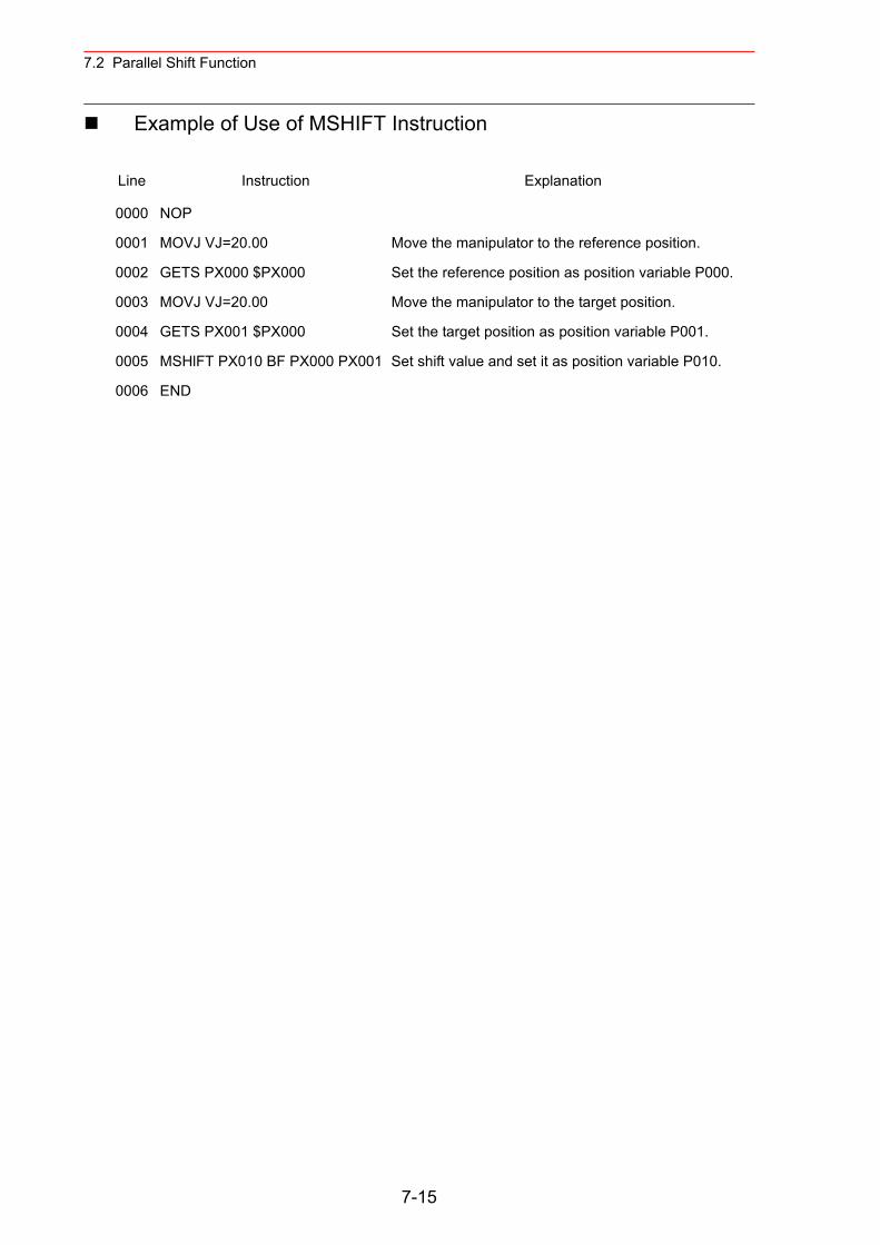
7.2 Parallel Shift Function
Example of Use of MSHIFT Instruction
Line Instruction Explanation
0000 NOP
0001 MOVJ VJ=20.00 Move the manipulator to the reference position.
0002 GETS PX000 $PX000 Set the reference position as position variable P000.
0003 MOVJ VJ=20.00 Move the manipulator to the target position.
0004 GETS PX001 $PX000 Set the target position as position variable P001.
0005 MSHlFT PX010 BF PX000 PX001 Set shift value and set it as position variable P010.
0006 END
7-15
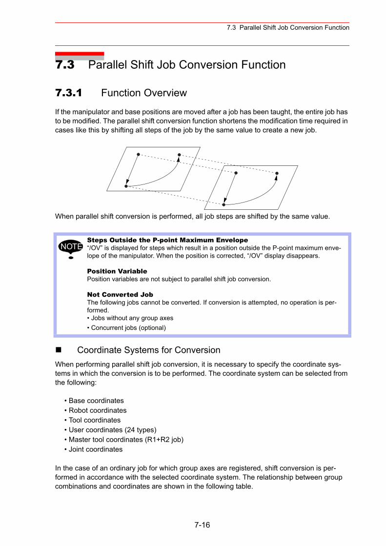
7.3 Parallel Shift Job Conversion Function
7.3 Parallel Shift Job Conversion Function
7.3.1 Function Overview
If the manipulator and base positions are moved after a job has been taught, the entire job has to be modified. The parallel shift conversion function shortens the modification time required in cases like this by shifting all steps of the job by the same value to create a new job.
When parallel shift conversion is performed, all job steps are shifted by the same value.
Coordinate Systems for ConversionWhen performing parallel shift job conversion, it is necessary to specify the coordinate sys-tems in which the conversion is to be performed. The coordinate system can be selected from the following:
• Base coordinates• Robot coordinates• Tool coordinates• User coordinates (24 types)• Master tool coordinates (R1+R2 job)• Joint coordinates
In the case of an ordinary job for which group axes are registered, shift conversion is per-formed in accordance with the selected coordinate system. The relationship between group combinations and coordinates are shown in the following table.
Steps Outside the P-point Maximum Envelope“/OV” is displayed for steps which result in a position outside the P-point maximum enve-lope of the manipulator. When the position is corrected, “/OV” display disappears.
Position VariablePosition variables are not subject to parallel shift job conversion.
Not Converted JobThe following jobs cannot be converted. If conversion is attempted, no operation is per-formed.• Jobs without any group axes• Concurrent jobs (optional)
NOTE
7-16
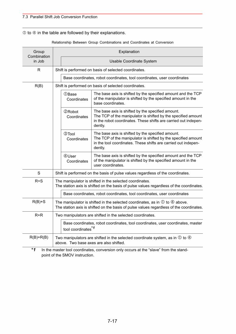
7.3 Parallel Shift Job Conversion Function
to in the table are followed by their explanations.
*1 In the master tool coordinates, conversion only occurs at the “slave” from the stand-point of the SMOV instruction.
Relationship Between Group Combinations and Coordinates at Conversion
Group Combination
in Job
Explanation
Usable Coordinate System
R Shift is performed on basis of selected coordinates.
Base coordinates, robot coordinates, tool coordinates, user coordinates
R(B) Shift is performed on basis of selected coordinates.
Base Coordinates
The base axis is shifted by the specified amount and the TCP of the manipulator is shifted by the specified amount in the base coordinates.
Robot Coordinates
The base axis is shifted by the specified amount.The TCP of the manipulator is shifted by the specified amount in the robot coordinates. These shifts are carried out indepen-dently.
Tool Coordinates
The base axis is shifted by the specified amount.The TCP of the manipulator is shifted by the specified amount in the tool coordinates. These shifts are carried out indepen-dently.
User Coordinates
The base axis is shifted by the specified amount and the TCP of the manipulator is shifted by the specified amount in the user coordinates.
S Shift is performed on the basis of pulse values regardless of the coordinates.
R+S The manipulator is shifted in the selected coordinates.The station axis is shifted on the basis of pulse values regardless of the coordinates.
Base coordinates, robot coordinates, tool coordinates, user coordinates
R(B)+S The manipulator is shifted in the selected coordinates, as in to above.The station axis is shifted on the basis of pulse values regardless of the coordinates.
R+R Two manipulators are shifted in the selected coordinates.
Base coordinates, robot coordinates, tool coordinates, user coordinates, master tool coordinates*1
R(B)+R(B) Two manipulators are shifted in the selected coordinate system, as in to above. Two base axes are also shifted.
7-17
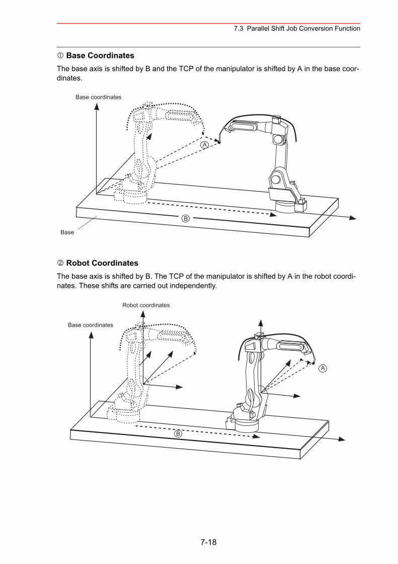
7.3 Parallel Shift Job Conversion Function
Base CoordinatesThe base axis is shifted by B and the TCP of the manipulator is shifted by A in the base coor-dinates.
Robot CoordinatesThe base axis is shifted by B. The TCP of the manipulator is shifted by A in the robot coordi-nates. These shifts are carried out independently.
Base
Base coordinates
A
B
Base coordinates
A
B
Robot coordinates
7-18
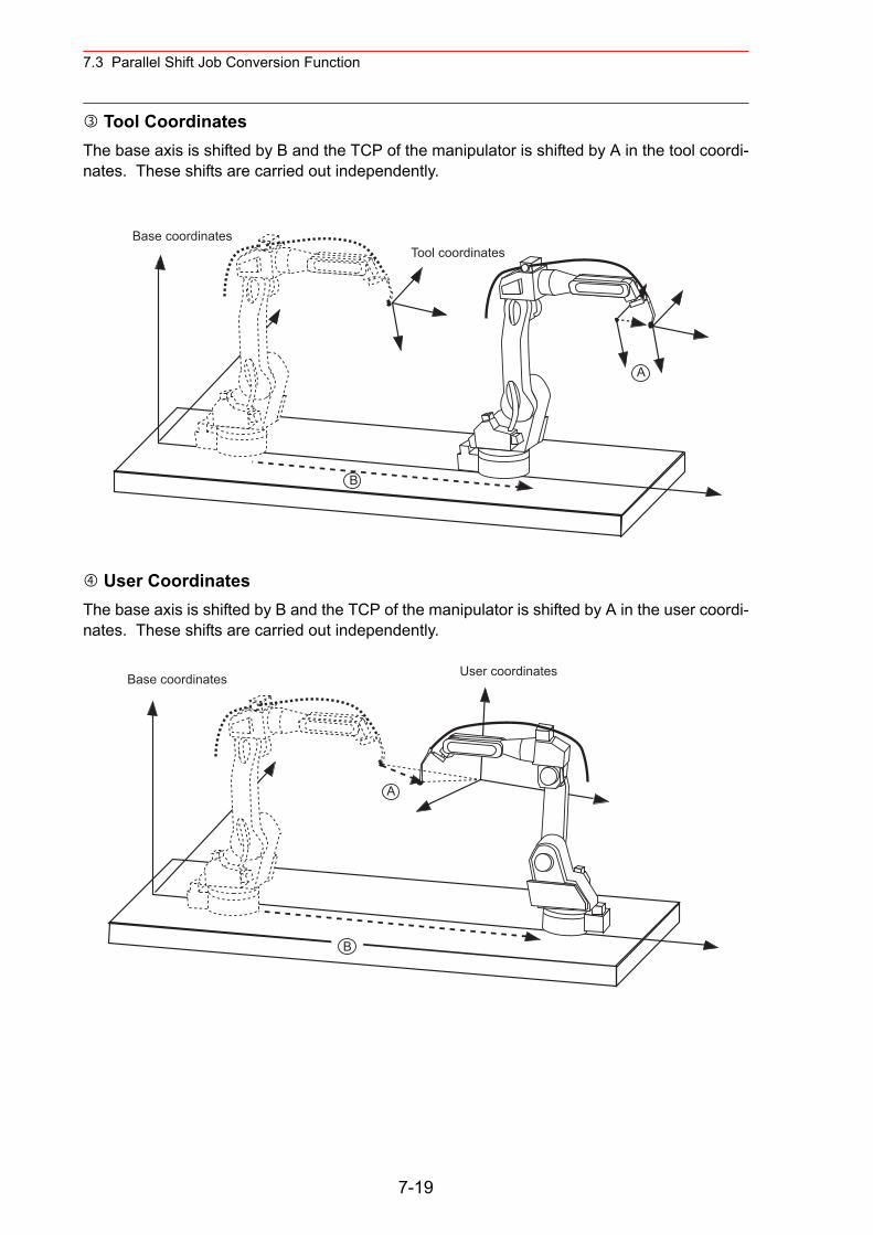
7.3 Parallel Shift Job Conversion Function
Tool CoordinatesThe base axis is shifted by B and the TCP of the manipulator is shifted by A in the tool coordi-nates. These shifts are carried out independently.
User CoordinatesThe base axis is shifted by B and the TCP of the manipulator is shifted by A in the user coordi-nates. These shifts are carried out independently.
Base coordinates
A
B
Tool coordinates
Base coordinates User coordinates
A
B
7-19
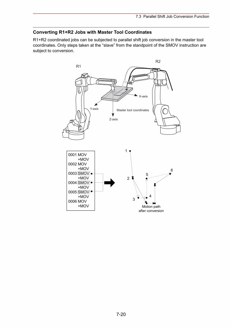
7.3 Parallel Shift Job Conversion Function
Converting R1+R2 Jobs with Master Tool CoordinatesR1+R2 coordinated jobs can be subjected to parallel shift job conversion in the master tool coordinates. Only steps taken at the “slave” from the standpoint of the SMOV instruction are subject to conversion.
R1R2
Y-axis
Z-axis
X-axis
Master tool coordinates
0001 MOV +MOV0002 MOV +MOV0003 SMOV +MOV0004 SMOV +MOV0005 SMOV +MOV0006 MOV +MOV
1
2
34
56
Motion pathafter conversion
7-20
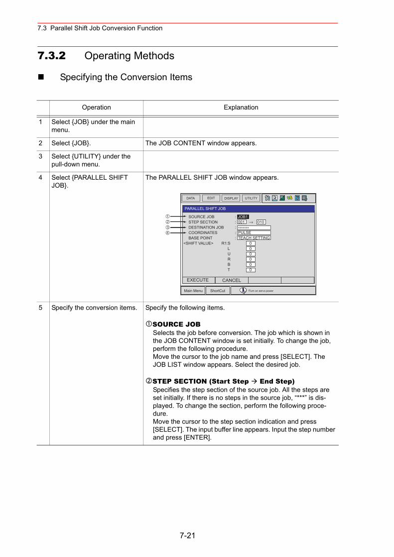
7.3 Parallel Shift Job Conversion Function
7.3.2 Operating Methods
Specifying the Conversion Items
Operation Explanation
1 Select {JOB} under the main menu.
2 Select {JOB}. The JOB CONTENT window appears.
3 Select {UTILITY} under the pull-down menu.
4 Select {PARALLEL SHIFT JOB}.
The PARALLEL SHIFT JOB window appears.
5 Specify the conversion items. Specify the following items.
SOURCE JOBSelects the job before conversion. The job which is shown in the JOB CONTENT window is set initially. To change the job, perform the following procedure.Move the cursor to the job name and press [SELECT]. The JOB LIST window appears. Select the desired job.
STEP SECTION (Start Step End Step)Specifies the step section of the source job. All the steps are set initially. If there is no steps in the source job, “***” is dis-played. To change the section, perform the following proce-dure. Move the cursor to the step section indication and press [SELECT]. The input buffer line appears. Input the step number and press [ENTER].
DATA EDIT DISPLAY UTILITY
Main Menu ShortCut !Turn on servo power
PARALLEL SHIFT JOB
SOURCE JOB STEP SECTION DESTINATION JOB COORDINATES BASE POINT
<SHIFT VALUE> R1:S L U R B T
000000
: JOB1: 001 → 010: *******: PULSE: TEACH SETTING
EXECUTE CANCEL
7-21
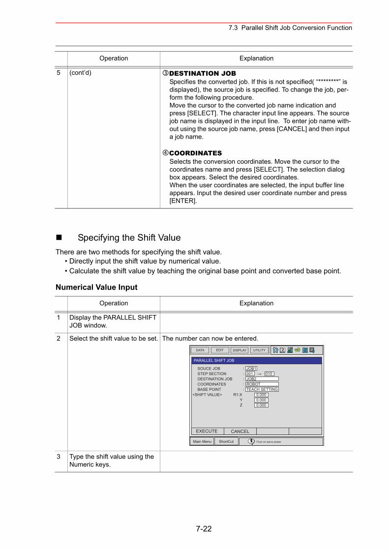
7.3 Parallel Shift Job Conversion Function
Specifying the Shift ValueThere are two methods for specifying the shift value.
• Directly input the shift value by numerical value.• Calculate the shift value by teaching the original base point and converted base point.
Numerical Value Input
5 (cont’d) DESTINATION JOBSpecifies the converted job. If this is not specified( “********” is displayed), the source job is specified. To change the job, per-form the following procedure.Move the cursor to the converted job name indication and press [SELECT]. The character input line appears. The source job name is displayed in the input line. To enter job name with-out using the source job name, press [CANCEL] and then input a job name.
COORDINATESSelects the conversion coordinates. Move the cursor to the coordinates name and press [SELECT]. The selection dialog box appears. Select the desired coordinates.When the user coordinates are selected, the input buffer line appears. Input the desired user coordinate number and press [ENTER].
Operation Explanation
1 Display the PARALLEL SHIFT JOB window.
2 Select the shift value to be set. The number can now be entered.
3 Type the shift value using the Numeric keys.
Operation Explanation
DATA EDIT DISPLAY UTILITY
Main Menu ShortCut !Turn on servo power
PARALLEL SHIFT JOB
SOUCE JOB STEP SECTION DESTINATION JOB COORDINATES BASE POINT
<SHIFT VALUE> R1:X Y Z
0.0000.0000.000
: JOB1: 001 → 010: JOB2: ROBOT: TEACH SETTING
EXECUTE CANCEL
7-22
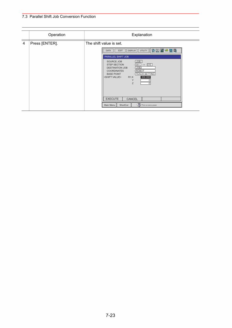
7.3 Parallel Shift Job Conversion Function
4 Press [ENTER]. The shift value is set.
Operation Explanation
DATA EDIT DISPLAY UTILITY
Main Menu ShortCut !Turn on servo power
PARALLEL SHIFT JOB
SOURCE JOB STEP SECTION DESTINATION JOB COORDINATES BASE POINT
<SHIFT VALUE> R1:X Y Z
200.00000
: JOB1: 001 → 010: JOB2: ROBOT: TEACH SETTING
EXECUTE CANCEL
7-23
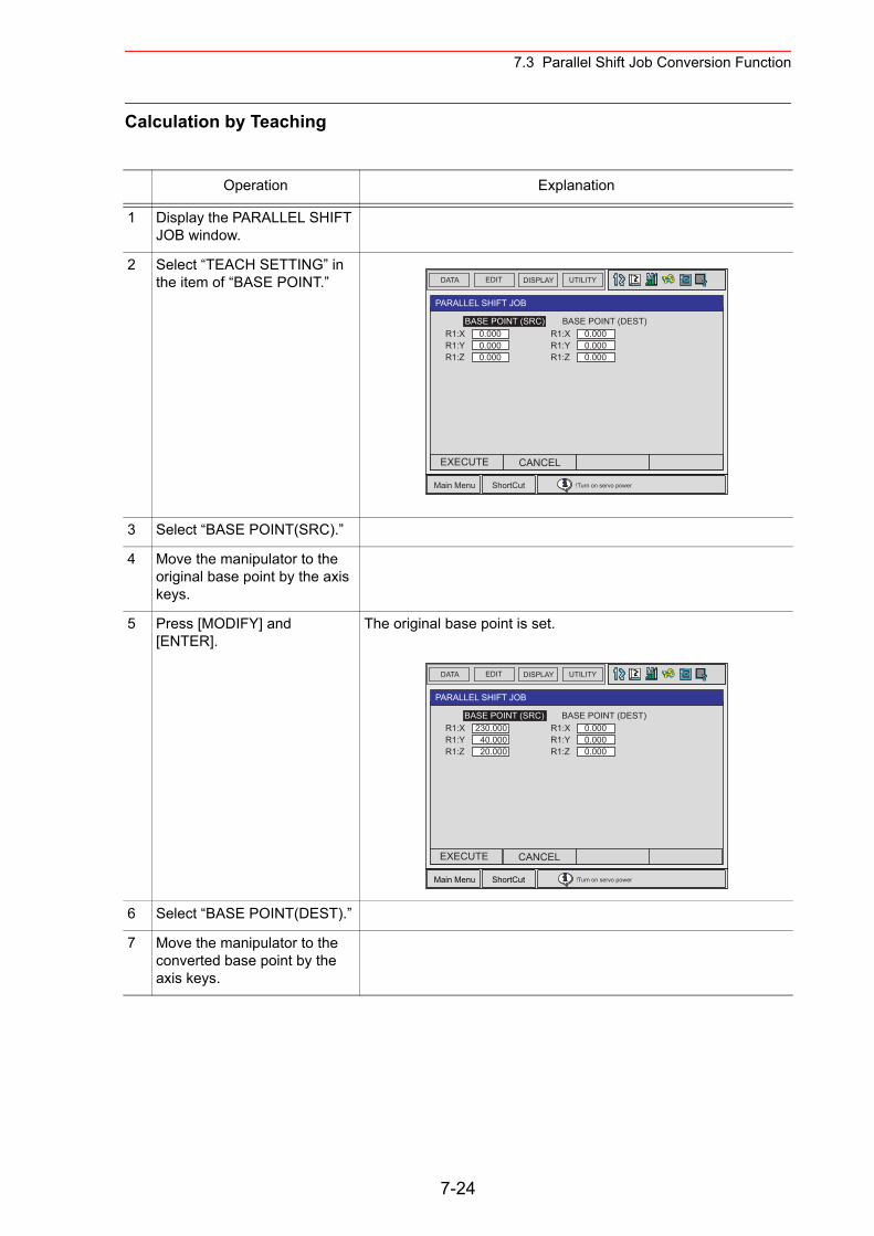
7.3 Parallel Shift Job Conversion Function
Calculation by Teaching
Operation Explanation
1 Display the PARALLEL SHIFT JOB window.
2 Select “TEACH SETTING” in the item of “BASE POINT.”
3 Select “BASE POINT(SRC).”
4 Move the manipulator to the original base point by the axis keys.
5 Press [MODIFY] and [ENTER].
The original base point is set.
6 Select “BASE POINT(DEST).”
7 Move the manipulator to the converted base point by the axis keys.
DATA EDIT DISPLAY UTILITY
Main Menu ShortCut !Turn on servo power
PARALLEL SHIFT JOB
BASE POINT (SRC) BASE POINT (DEST)
EXECUTE CANCEL
0.0000.0000.000
R1:XR1:YR1:Z
0.0000.0000.000
R1:XR1:YR1:Z
DATA EDIT DISPLAY UTILITY
Main Menu ShortCut !Turn on servo power
PARALLEL SHIFT JOB
BASE POINT (SRC) BASE POINT (DEST)
EXECUTE CANCEL
230.00040.00020.000
R1:XR1:YR1:Z
0.0000.0000.000
R1:XR1:YR1:Z
7-24
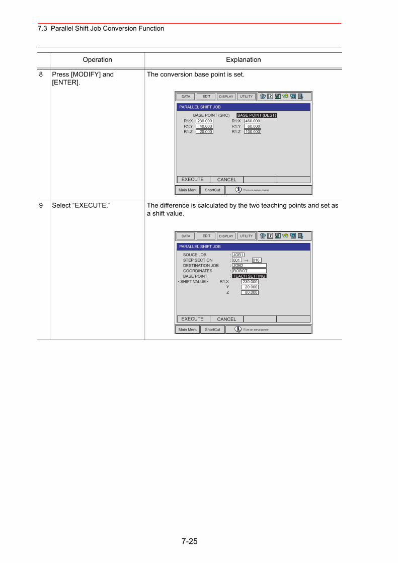
7.3 Parallel Shift Job Conversion Function
8 Press [MODIFY] and [ENTER].
The conversion base point is set.
9 Select “EXECUTE.” The difference is calculated by the two teaching points and set as a shift value.
Operation Explanation
DATA EDIT DISPLAY UTILITY
Main Menu ShortCut !Turn on servo power
PARALLEL SHIFT JOB
BASE POINT (SRC) BASE POINT (DEST)
EXECUTE CANCEL
230.00040.00020.000
R1:XR1:YR1:Z
460.00060.000
100.000
R1:XR1:YR1:Z
DATA EDIT DISPLAY UTILITY
Main Menu ShortCut !Turn on servo power
PARALLEL SHIFT JOB
SOUCE JOB STEP SECTION DESTINATION JOB COORDINATES BASE POINT
<SHIFT VALUE> R1:X Y Z
230.00020.00080.000
: JOB1: 001 → 010: JOB2: ROBOT: TEACH SETTING
EXECUTE CANCEL
7-25
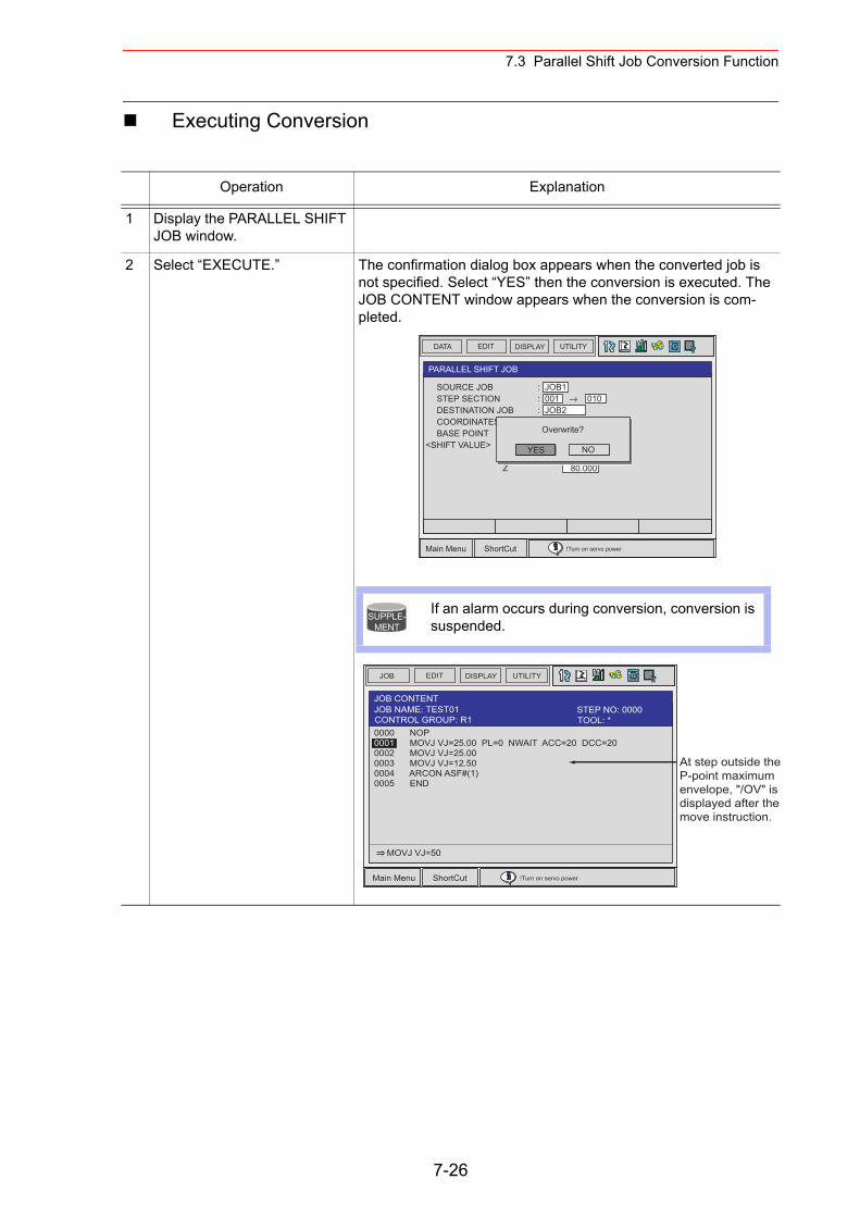
7.3 Parallel Shift Job Conversion Function
Executing Conversion
Operation Explanation
1 Display the PARALLEL SHIFT JOB window.
2 Select “EXECUTE.” The confirmation dialog box appears when the converted job is not specified. Select “YES” then the conversion is executed. The JOB CONTENT window appears when the conversion is com-pleted.
DATA EDIT DISPLAY UTILITY
Main Menu ShortCut !Turn on servo power
PARALLEL SHIFT JOB
SOURCE JOB STEP SECTION DESTINATION JOB COORDINATES BASE POINT
<SHIFT VALUE> R1:X Y Z
230.00020.00080.000
: JOB1: 001 → 010: JOB2
YES
Overwrite?
NO
If an alarm occurs during conversion, conversion is suspended.
SUPPLE-MENT
JOB EDIT DISPLAY UTILITY
Main Menu ShortCut !Turn on servo power
JOB CONTENT
0000 NOP0001 MOVJ VJ=25.00 PL=0 NWAIT ACC=20 DCC=200002 MOVJ VJ=25.000003 MOVJ VJ=12.500004 ARCON ASF#(1) 0005 END
MOVJ VJ=50
JOB NAME: TEST01
At step outside the P-point maximum envelope, "/OV" is displayed after the move instruction.
TOOL: *CONTROL GROUP: R1STEP NO: 0000
7-26
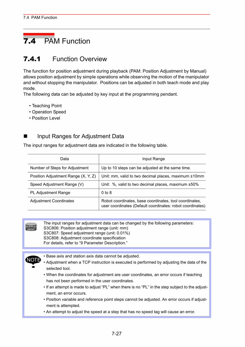
7.4 PAM Function
7.4 PAM Function
7.4.1 Function Overview
The function for position adjustment during playback (PAM: Position Adjustment by Manual) allows position adjustment by simple operations while observing the motion of the manipulator and without stopping the manipulator. Positions can be adjusted in both teach mode and play mode.The following data can be adjusted by key input at the programming pendant.
• Teaching Point• Operation Speed• Position Level
Input Ranges for Adjustment DataThe input ranges for adjustment data are indicated in the following table.
Data Input Range
Number of Steps for Adjustment Up to 10 steps can be adjusted at the same time.
Position Adjustment Range (X, Y, Z) Unit: mm, valid to two decimal places, maximum ±10mm
Speed Adjustment Range (V) Unit: %, valid to two decimal places, maximum ±50%
PL Adjustment Range 0 to 8
Adjustment Coordinates Robot coordinates, base coordinates, tool coordinates, user coordinates (Default coordinates: robot coordinates)
The input ranges for adjustment data can be changed by the following parameters:S3C806: Position adjustment range (unit: mm)S3C807: Speed adjustment range (unit: 0.01%)S3C808: Adjustment coordinate specificationFor details, refer to “9 Parameter Description.”
• Base axis and station axis data cannot be adjusted.• Adjustment when a TCP instruction is executed is performed by adjusting the data of the
selected tool.• When the coordinates for adjustment are user coordinates, an error occurs if teaching
has not been performed in the user coordinates.• If an attempt is made to adjust “PL” when there is no “PL” in the step subject to the adjust-
ment, an error occurs.• Position variable and reference point steps cannot be adjusted. An error occurs if adjust-
ment is attempted.• An attempt to adjust the speed at a step that has no speed tag will cause an error.
SUPPLE-MENT
NOTE
7-27
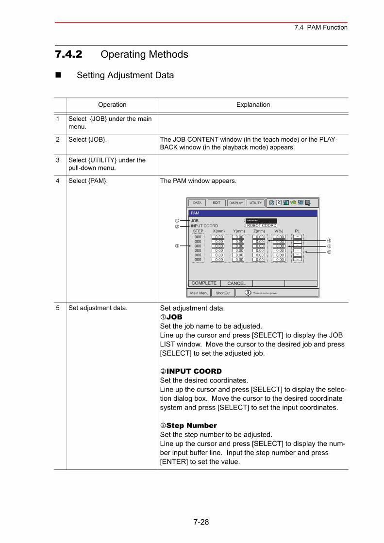
7.4 PAM Function
7.4.2 Operating Methods
Setting Adjustment Data
Operation Explanation
1 Select {JOB} under the main menu.
2 Select {JOB}. The JOB CONTENT window (in the teach mode) or the PLAY-BACK window (in the playback mode) appears.
3 Select {UTILITY} under the pull-down menu.
4 Select {PAM}. The PAM window appears.
5 Set adjustment data. Set adjustment data.JOB
Set the job name to be adjusted.Line up the cursor and press [SELECT] to display the JOB LIST window. Move the cursor to the desired job and press [SELECT] to set the adjusted job.
INPUT COORDSet the desired coordinates. Line up the cursor and press [SELECT] to display the selec-tion dialog box. Move the cursor to the desired coordinate system and press [SELECT] to set the input coordinates.
Step NumberSet the step number to be adjusted.Line up the cursor and press [SELECT] to display the num-ber input buffer line. Input the step number and press [ENTER] to set the value.
DATA EDIT DISPLAY UTILITY
Main Menu ShortCut !Turn on servo power
PAM
JOBINPUT COORD STEP X(mm) Y(mm) Z(mm) V(%) PL
: *******: ROBOT COORD
000000000000000000
0.000.000.000.000.000.00
−−−−−−
0.000.000.000.000.000.00
0.000.000.000.000.000.00
0.000.000.000.000.000.00
COMPLETE CANCEL
7-28
7.4 PAM Function
5 (cont’d) XYZ Coordinate AdjustmentSet the direction and amount of the X, Y, and Z coordinates.Line up the cursor with the data to be adjusted and press [SELECT] to display the number input buffer line. Input the number data and press [ENTER] to set the adjusted data.
V Coordinate AdjustmentSet the speed.Line up the cursor and press [SELECT] to display the num-ber input buffer line. Input the number data and press [ENTER] to set the adjusted data.
PLThis is displayed when the position level of the job to be adjusted for the step set in is already decided, and the data can be modified. When the position level is not decided, [-] is displayed, and cannot be set. To modify the position level, line up the cursor, press [SELECT], input the number value and press [ENTER].
Operation Explanation
7-29
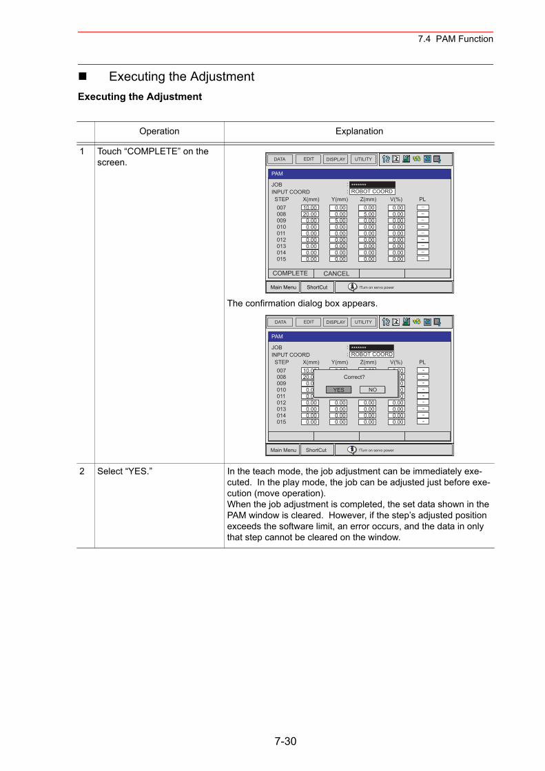
7.4 PAM Function
Executing the AdjustmentExecuting the Adjustment
Operation Explanation
1 Touch “COMPLETE” on the screen.
The confirmation dialog box appears.
2 Select “YES.” In the teach mode, the job adjustment can be immediately exe-cuted. In the play mode, the job can be adjusted just before exe-cution (move operation).When the job adjustment is completed, the set data shown in the PAM window is cleared. However, if the step’s adjusted position exceeds the software limit, an error occurs, and the data in only that step cannot be cleared on the window.
DATA EDIT DISPLAY UTILITY
Main Menu ShortCut !Turn on servo power
PAM
COMPLETE CANCEL
JOBINPUT COORD STEP X(mm) Y(mm) Z(mm) V(%) PL
: *******: ROBOT COORD
007008009010011012013014015
0.005.000.000.000.000.000.000.000.00
0.000.000.000.000.000.000.000.000.00
10.0020.00
0.000.000.000.000.000.000.00
0.000.005.000.000.000.000.000.000.00
−−−−−−−−−
DATA EDIT DISPLAY UTILITY
Main Menu ShortCut !Turn on servo power
PAM
JOBINPUT COORD STEP X(mm) Y(mm) Z(mm) V(%) PL
: *******: ROBOT COORD
007008009010011012013014015
0.005.000.000.000.000.000.000.000.00
0.000.000.000.000.000.000.000.000.00
10.0020.00
0.000.000.000.000.000.000.00
0.000.005.000.000.000.000.000.000.00
---------
YES
Correct?
NO
7-30
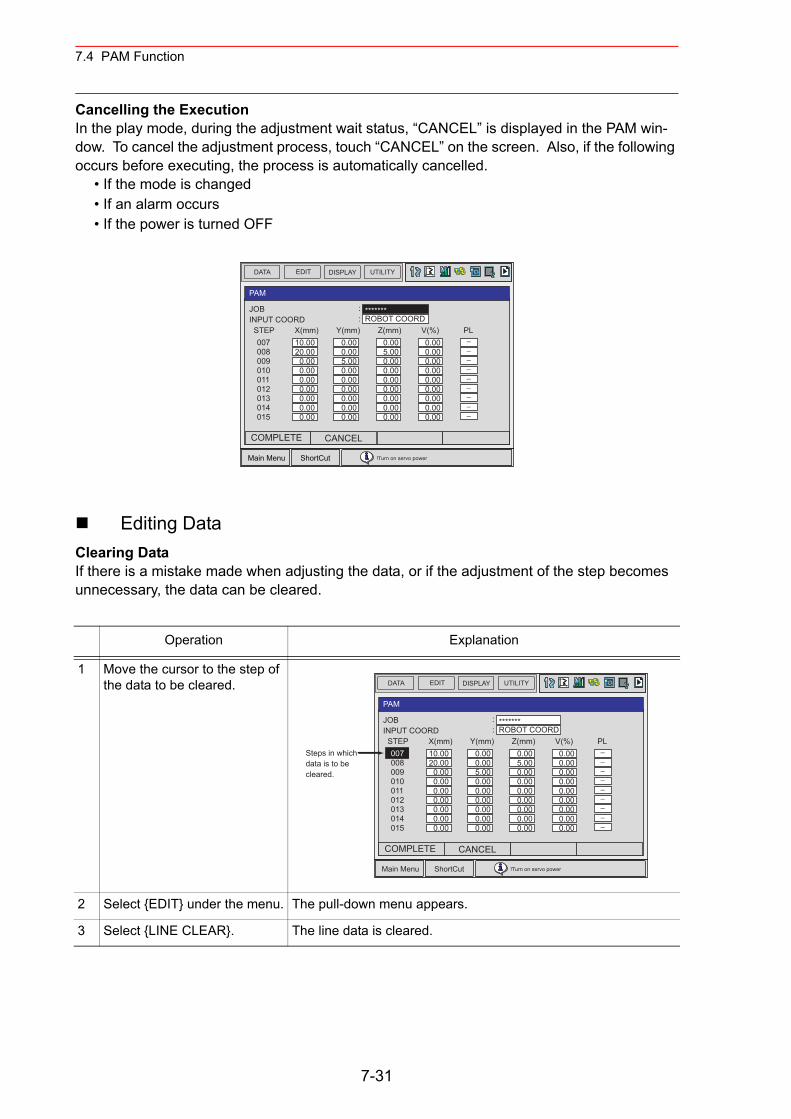
7.4 PAM Function
Cancelling the ExecutionIn the play mode, during the adjustment wait status, “CANCEL” is displayed in the PAM win-dow. To cancel the adjustment process, touch “CANCEL” on the screen. Also, if the following occurs before executing, the process is automatically cancelled.
• If the mode is changed• If an alarm occurs• If the power is turned OFF
Editing DataClearing DataIf there is a mistake made when adjusting the data, or if the adjustment of the step becomes unnecessary, the data can be cleared.
Operation Explanation
1 Move the cursor to the step of the data to be cleared.
2 Select {EDIT} under the menu. The pull-down menu appears.
3 Select {LINE CLEAR}. The line data is cleared.
DATA EDIT DISPLAY UTILITY
Main Menu ShortCut !Turn on servo power
PAM
COMPLETE CANCEL
JOBINPUT COORD STEP X(mm) Y(mm) Z(mm) V(%) PL
: *******: ROBOT COORD
007008009010011012013014015
0.005.000.000.000.000.000.000.000.00
0.000.000.000.000.000.000.000.000.00
10.0020.00
0.000.000.000.000.000.000.00
0.000.005.000.000.000.000.000.000.00
−−−−−−−−−
DATA EDIT DISPLAY UTILITY
Main Menu ShortCut !Turn on servo power
PAM
Steps in whichdata is to be cleared.
COMPLETE CANCEL
JOBINPUT COORD STEP X(mm) Y(mm) Z(mm) V(%) PL
: *******: ROBOT COORD
007008009010011012013014015
0.005.000.000.000.000.000.000.000.00
0.000.000.000.000.000.000.000.000.00
10.0020.00
0.000.000.000.000.000.000.00
0.000.005.000.000.000.000.000.000.00
−−−−−−−−−
7-31
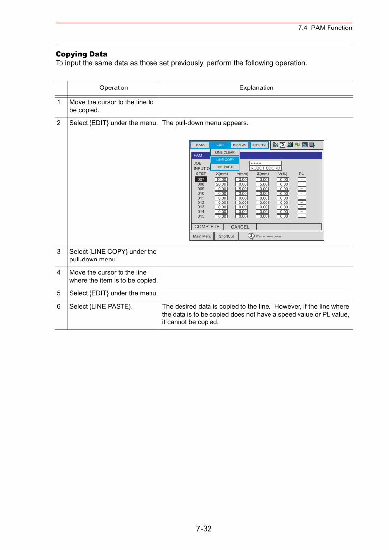
7.4 PAM Function
Copying DataTo input the same data as those set previously, perform the following operation.
Operation Explanation
1 Move the cursor to the line to be copied.
2 Select {EDIT} under the menu. The pull-down menu appears.
3 Select {LINE COPY} under the pull-down menu.
4 Move the cursor to the line where the item is to be copied.
5 Select {EDIT} under the menu.
6 Select {LINE PASTE}. The desired data is copied to the line. However, if the line where the data is to be copied does not have a speed value or PL value, it cannot be copied.
DATA EDIT DISPLAY UTILITY
Main Menu ShortCut !Turn on servo power
PAM
COMPLETE CANCEL
JOBINPUT COORD STEP X(mm) Y(mm) Z(mm) V(%) PL
: *******: ROBOT COORD
007008009010011012013014015
0.005.000.000.000.000.000.000.000.00
0.000.000.000.000.000.000.000.000.00
10.0020.00
0.000.000.000.000.000.000.00
0.000.005.000.000.000.000.000.000.00
−−−−−−−−−
LINE PASTE
LINE CLEAR
LINE COPY
7-32
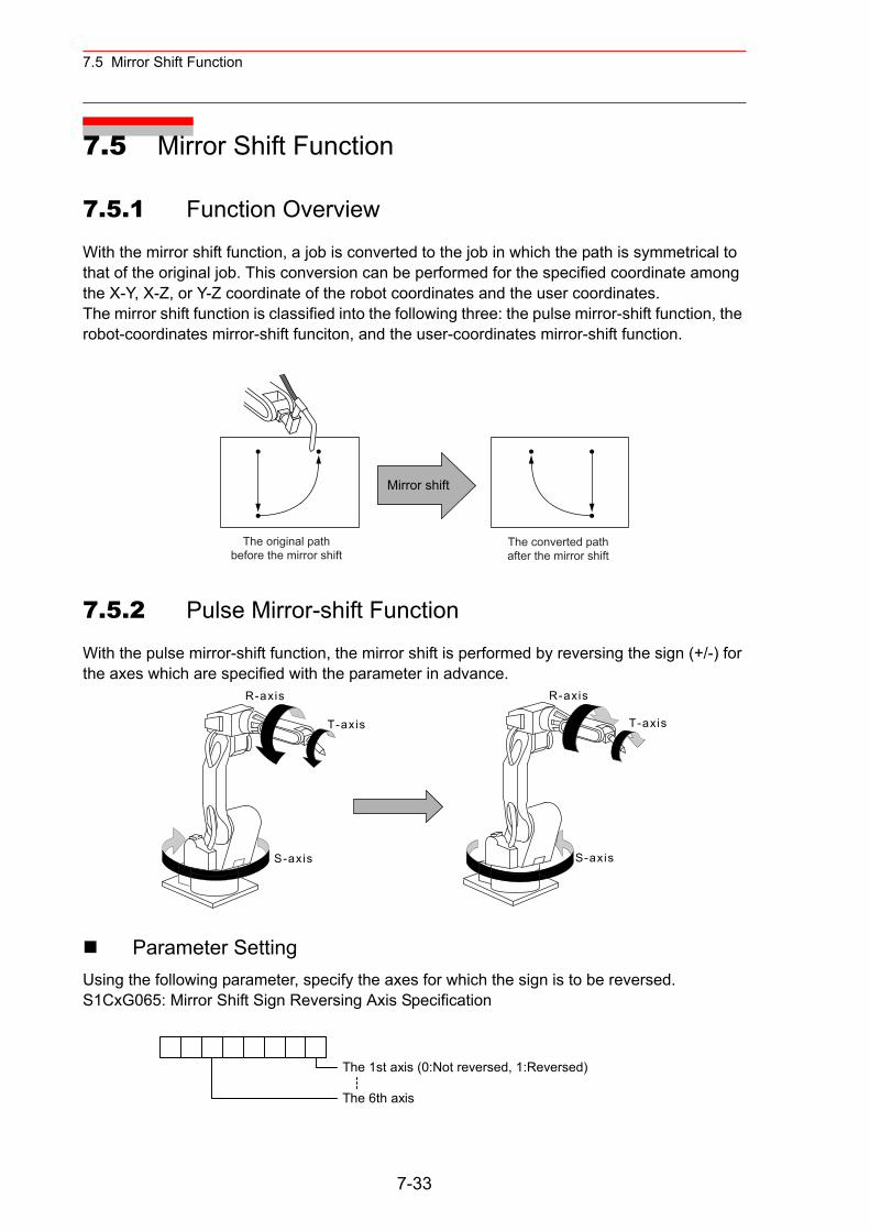
7.5 Mirror Shift Function
7.5 Mirror Shift Function
7.5.1 Function Overview
With the mirror shift function, a job is converted to the job in which the path is symmetrical to that of the original job. This conversion can be performed for the specified coordinate among the X-Y, X-Z, or Y-Z coordinate of the robot coordinates and the user coordinates.The mirror shift function is classified into the following three: the pulse mirror-shift function, the robot-coordinates mirror-shift funciton, and the user-coordinates mirror-shift function.
7.5.2 Pulse Mirror-shift Function
With the pulse mirror-shift function, the mirror shift is performed by reversing the sign (+/-) for the axes which are specified with the parameter in advance.
Parameter SettingUsing the following parameter, specify the axes for which the sign is to be reversed.S1CxG065: Mirror Shift Sign Reversing Axis Specification
Mirror shift
The original pathbefore the mirror shift
The converted pathafter the mirror shift
S-axis
R-axis
T-axis
S-axis
R-axis
T-axis
The 1st axis (0:Not reversed, 1:Reversed)
The 6th axis
7-33
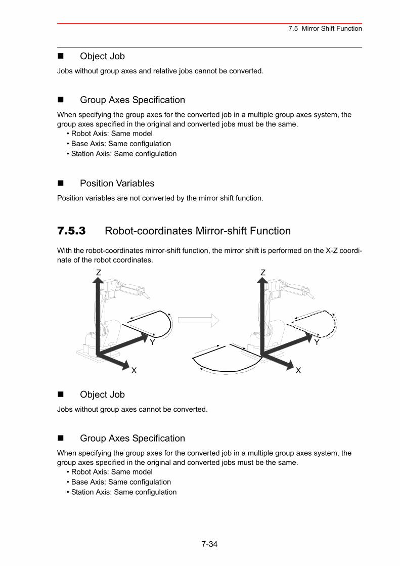
7.5 Mirror Shift Function
Object JobJobs without group axes and relative jobs cannot be converted.
Group Axes SpecificationWhen specifying the group axes for the converted job in a multiple group axes system, the group axes specified in the original and converted jobs must be the same.
• Robot Axis: Same model• Base Axis: Same configulation• Station Axis: Same configulation
Position VariablesPosition variables are not converted by the mirror shift function.
7.5.3 Robot-coordinates Mirror-shift Function
With the robot-coordinates mirror-shift function, the mirror shift is performed on the X-Z coordi-nate of the robot coordinates.
Object JobJobs without group axes cannot be converted.
Group Axes SpecificationWhen specifying the group axes for the converted job in a multiple group axes system, the group axes specified in the original and converted jobs must be the same.
• Robot Axis: Same model• Base Axis: Same configulation• Station Axis: Same configulation
Z
X
Y
Z
X
Y
7-34
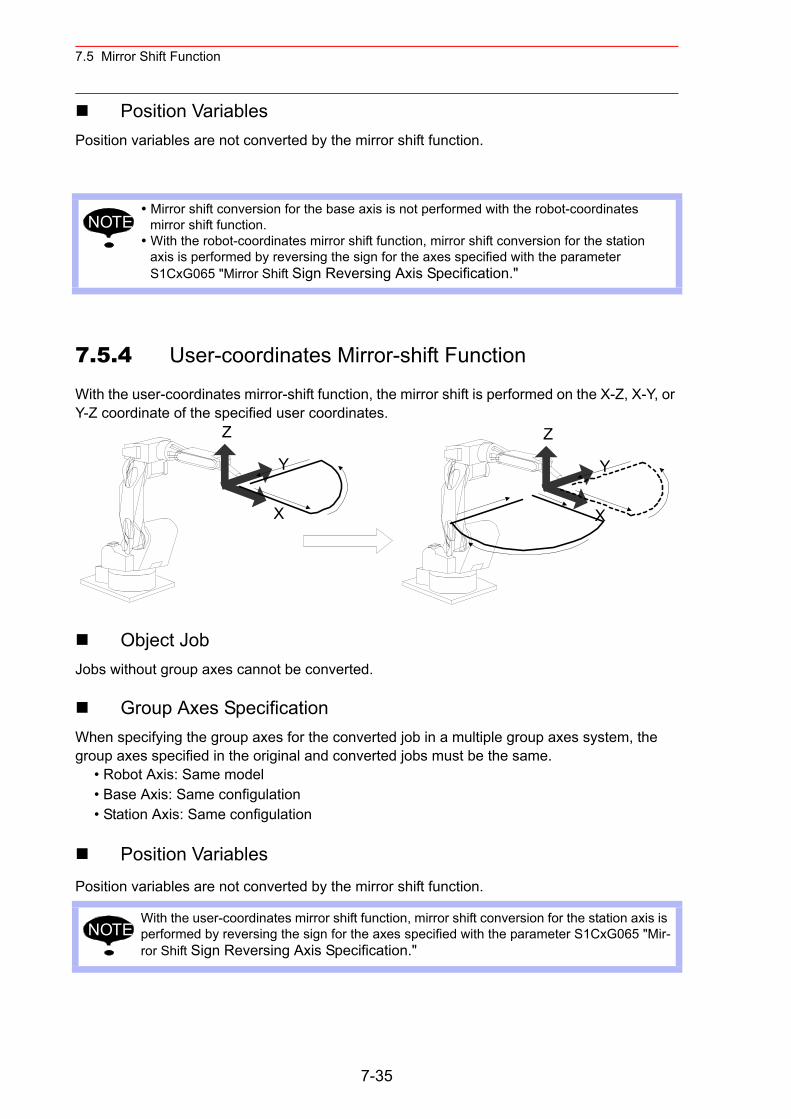
7.5 Mirror Shift Function
Position VariablesPosition variables are not converted by the mirror shift function.
7.5.4 User-coordinates Mirror-shift Function
With the user-coordinates mirror-shift function, the mirror shift is performed on the X-Z, X-Y, or Y-Z coordinate of the specified user coordinates.
Object JobJobs without group axes cannot be converted.
Group Axes SpecificationWhen specifying the group axes for the converted job in a multiple group axes system, the group axes specified in the original and converted jobs must be the same.
• Robot Axis: Same model• Base Axis: Same configulation• Station Axis: Same configulation
Position VariablesPosition variables are not converted by the mirror shift function.
Mirror shift conversion for the base axis is not performed with the robot-coordinates mirror shift function. With the robot-coordinates mirror shift function, mirror shift conversion for the station axis is performed by reversing the sign for the axes specified with the parameter S1CxG065 "Mirror Shift Sign Reversing Axis Specification."
With the user-coordinates mirror shift function, mirror shift conversion for the station axis is performed by reversing the sign for the axes specified with the parameter S1CxG065 "Mir-ror Shift Sign Reversing Axis Specification."
NOTE
Z
X
Y
Z
X
Y
NOTE
7-35
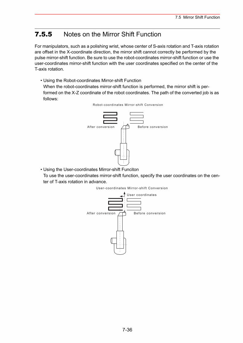
7.5 Mirror Shift Function
7.5.5 Notes on the Mirror Shift Function
For manipulators, such as a polishing wrist, whose center of S-axis rotation and T-axis rotation are offset in the X-coordinate direction, the mirror shift cannot correctly be performed by the pulse mirror-shift function. Be sure to use the robot-coordinates mirror-shift function or use the user-coordinates mirror-shift function with the user coordinates specified on the center of the T-axis rotation.
• Using the Robot-coordinates Mirror-shift FunctionWhen the robot-coordinates mirror-shift function is performed, the mirror shift is per-formed on the X-Z coordinate of the robot coordinates. The path of the converted job is as follows:
• Using the User-coordinates Mirror-shift FuncitonTo use the user-coordinates mirror-shift function, specify the user coordinates on the cen-ter of T-axis rotation in advance.
Robot-coordinates Mirror-shi f t Conversion
Before conversionAfter conversion
User-coordinates Mirror-shi f t Conversion
After conversion Before conversion
User coordinates
7-36
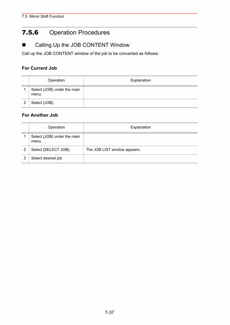
7.5 Mirror Shift Function
7.5.6 Operation Procedures
Calling Up the JOB CONTENT WindowCall up the JOB CONTENT window of the job to be converted as follows:
For Current Job
For Another Job
Operation Explanation
1 Select {JOB} under the main menu.
2 Select {JOB}.
Operation Explanation
1 Select {JOB} under the main menu.
2 Select {SELECT JOB}. The JOB LIST window appears.
3 Select desired job.
7-37
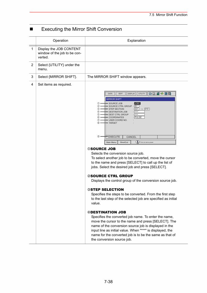
7.5 Mirror Shift Function
Executing the Mirror Shift Conversion
Operation Explanation
1 Display the JOB CONTENT window of the job to be con-verted.
2 Select {UTILITY} under the menu.
3 Select {MIRROR SHIFT}. The MIRROR SHIFT window appears.
4 Set items as required.
SOURCE JOBSelects the conversion source job. To select another job to be converted, move the cursor to the name and press [SELECT] to call up the list of jobs. Select the desired job and press [SELECT].
SOURCE CTRL GROUPDisplays the control group of the conversion source job.
STEP SELECTIONSpecifies the steps to be converted. From the first step to the last step of the selected job are specified as initial value.
DESTINATION JOBSpecifies the converted job name. To enter the name, move the cursor to the name and press [SELECT]. The name of the conversion source job is displayed in the input line as initial value. When "***" is displayed, the name for the converted job is to be the same as that of the conversion source job.
DATA EDIT DISPLAY UTILITY
Main Menu ShortCut !Turn on servo power
MIRROR SHIFT
SOURCE JOBSOURCE CTRL GROUPSTEP SECTIONDESTINATION JOBDEST CTRL GROUPCOORDINATESUSER COORD NO.TARGET
: JOB1: R1: 001 → 010: ****: ****: PULSE: :
EXECUTE CANCEL
7-38
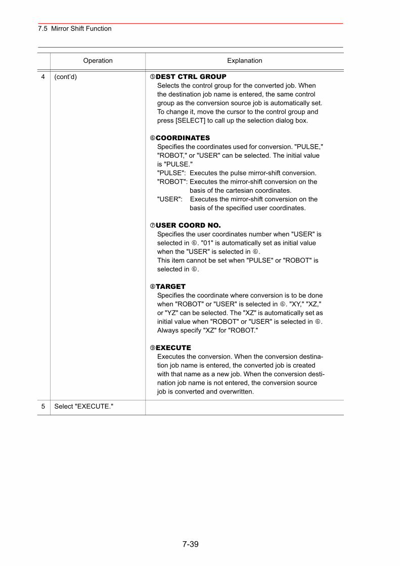
7.5 Mirror Shift Function
4 (cont’d) DEST CTRL GROUPSelects the control group for the converted job. When the destination job name is entered, the same control group as the conversion source job is automatically set. To change it, move the cursor to the control group and press [SELECT] to call up the selection dialog box.
COORDINATESSpecifies the coordinates used for conversion. "PULSE," "ROBOT," or "USER" can be selected. The initial value is "PULSE." "PULSE": Executes the pulse mirror-shift conversion."ROBOT": Executes the mirror-shift conversion on the
basis of the cartesian coordinates."USER": Executes the mirror-shift conversion on the
basis of the specified user coordinates.
USER COORD NO.Specifies the user coordinates number when "USER" is selected in . "01" is automatically set as initial value when the "USER" is selected in . This item cannot be set when "PULSE" or "ROBOT" is selected in .
TARGETSpecifies the coordinate where conversion is to be done when "ROBOT" or "USER" is selected in . "XY," "XZ," or "YZ" can be selected. The "XZ" is automatically set as initial value when "ROBOT" or "USER" is selected in . Always specify "XZ" for "ROBOT."
EXECUTEExecutes the conversion. When the conversion destina-tion job name is entered, the converted job is created with that name as a new job. When the conversion desti-nation job name is not entered, the conversion source job is converted and overwritten.
5 Select "EXECUTE."
Operation Explanation
7-39
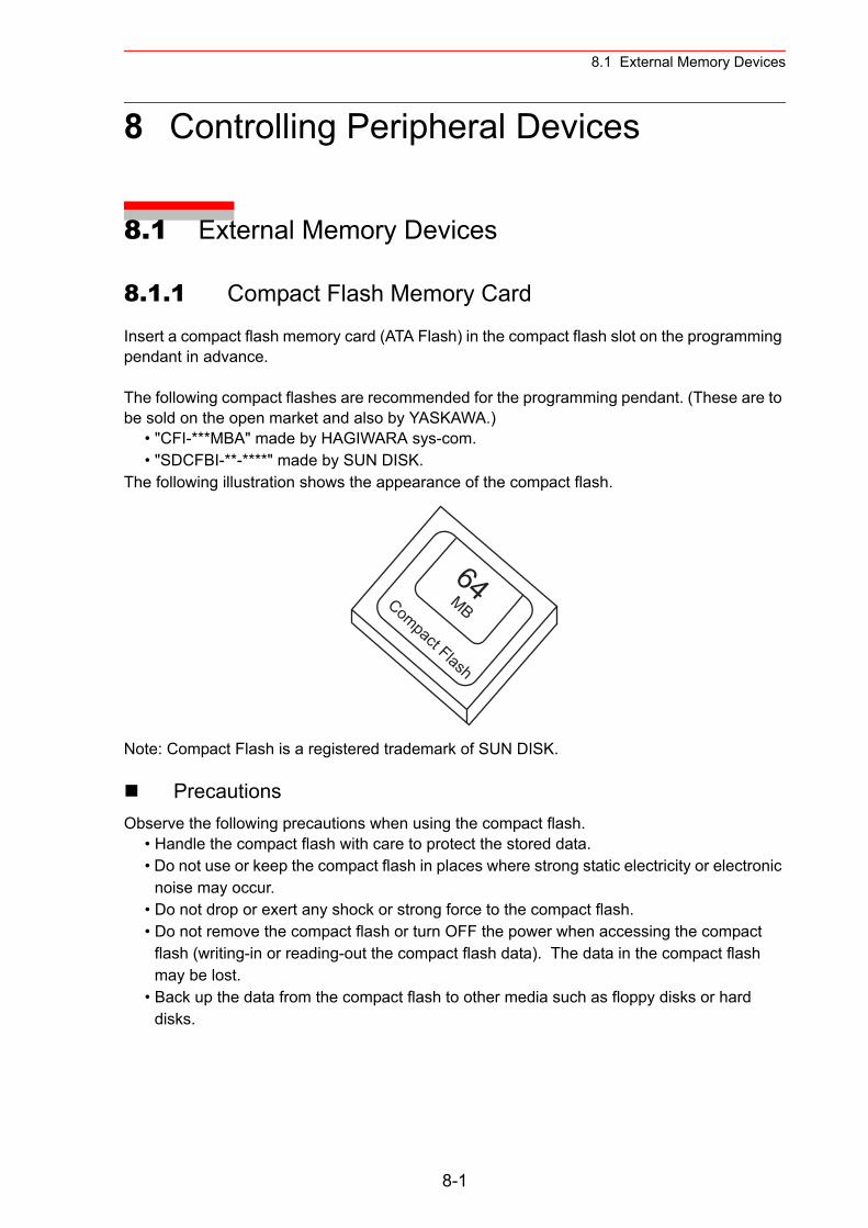
8.1 External Memory Devices
8 Controlling Peripheral Devices
8.1 External Memory Devices
8.1.1 Compact Flash Memory Card
Insert a compact flash memory card (ATA Flash) in the compact flash slot on the programming pendant in advance.
The following compact flashes are recommended for the programming pendant. (These are to be sold on the open market and also by YASKAWA.)
• "CFI-***MBA" made by HAGIWARA sys-com.• "SDCFBI-**-****" made by SUN DISK.
The following illustration shows the appearance of the compact flash.
Note: Compact Flash is a registered trademark of SUN DISK.
PrecautionsObserve the following precautions when using the compact flash.
• Handle the compact flash with care to protect the stored data.• Do not use or keep the compact flash in places where strong static electricity or electronic
noise may occur.• Do not drop or exert any shock or strong force to the compact flash.• Do not remove the compact flash or turn OFF the power when accessing the compact
flash (writing-in or reading-out the compact flash data). The data in the compact flash may be lost.
• Back up the data from the compact flash to other media such as floppy disks or hard disks.
64MBCompact Flash
8-1
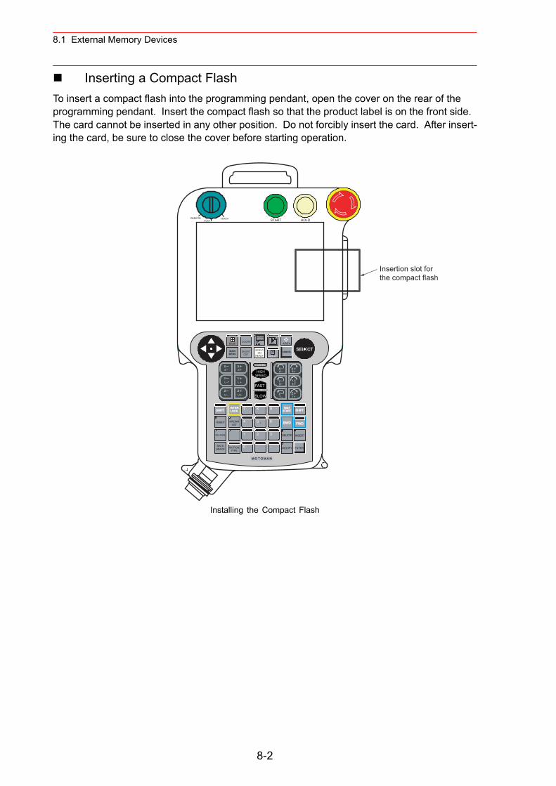
8.1 External Memory Devices
Inserting a Compact FlashTo insert a compact flash into the programming pendant, open the cover on the rear of the programming pendant. Insert the compact flash so that the product label is on the front side. The card cannot be inserted in any other position. Do not forcibly insert the card. After insert-ing the card, be sure to close the cover before starting operation.
Installing the Compact Flash
Insertion slot forthe compact flash
HOLDSTARTPLAYTEACHREMOTE
TZ
TZ
BY
RX
BY
RX
HIGHSPEED
FAST
SLOWMANUAL SPEED
UZ
UZ
LY
SX
LY
SX SERVO ON
M O T O M A N
SELECTSERVOON
READY
MAINMENU
SHORTCUT
GO BACK
PAGE AREA
LAYOUT
Multi
CANCEL
ASSIST!?
DIRECTOPEN
INFORMLIST
BACKSPACE
SHIFTINTERLOCK
ROBOT
EX.AXIS
MOTIONTYPE
TESTSTART
BWD
INSERT
MODIFY ENTER
FWD
DELETE
SHIFT7
4
2 3
. −
5 6
0
8
1
9
COORD
8-2
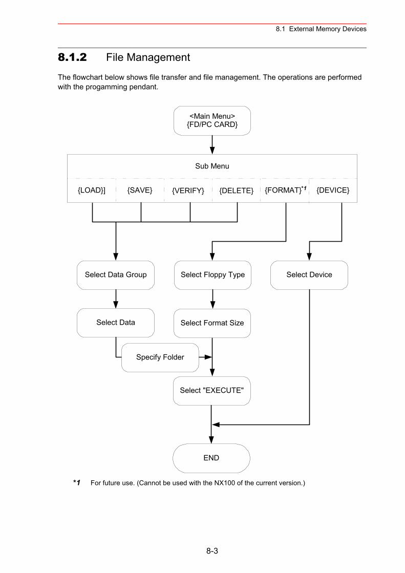
8.1 External Memory Devices
8.1.2 File Management
The flowchart below shows file transfer and file management. The operations are performed with the progamming pendant.
*1 For future use. (Cannot be used with the NX100 of the current version.)
<Main Menu>{FD/PC CARD}
Sub Menu
{LOAD}] {SAVE} {VERIFY} {DELETE} {FORMAT} {DEVICE}
Select Data Group Select Floppy Type Select Device
Select Data Select Format Size
Select "EXECUTE"
END
Specify Folder
*1
8-3
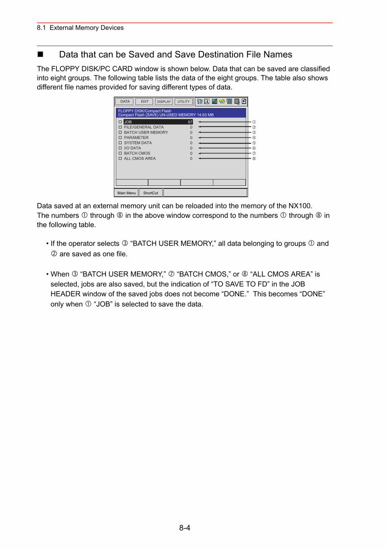
8.1 External Memory Devices
Data that can be Saved and Save Destination File NamesThe FLOPPY DISK/PC CARD window is shown below. Data that can be saved are classified into eight groups. The following table lists the data of the eight groups. The table also shows different file names provided for saving different types of data.
Data saved at an external memory unit can be reloaded into the memory of the NX100. The numbers through in the above window correspond to the numbers through in the following table.
• If the operator selects “BATCH USER MEMORY,” all data belonging to groups and are saved as one file.
• When “BATCH USER MEMORY,” “BATCH CMOS,” or “ALL CMOS AREA” is selected, jobs are also saved, but the indication of “TO SAVE TO FD” in the JOB HEADER window of the saved jobs does not become “DONE.” This becomes “DONE” only when “JOB” is selected to save the data.
DATA UTILITYEDIT DISPLAY
Main Menu ShortCut
JOB FILE/GENERAL DATA BATCH USER MEMORY PARAMETER SYSTEM DATA I/O DATA BATCH CMOS ALL CMOS AREA
570000000
FLOPPY DISK/Compact FlashCompact Flash (SAVE) UN-USED MEMORY 14.63 MB
8-4
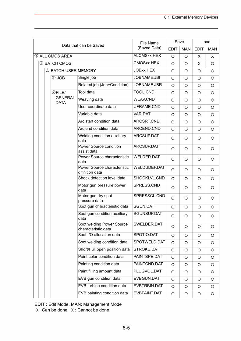
8.1 External Memory Devices
Data that can be Saved File Name(Saved Data)
Save Load
EDIT MAN EDIT MAN
ALL CMOS AREA ALCMSxx.HEX X X
BATCH CMOS CMOSxx.HEX X
BATCH USER MEMORY JOBxx.HEX
JOB Single job JOBNAME.JBI
Related job (Job+Condition) JOBNAME.JBR
FILE/GENERALDATA
Tool data TOOL.CND
Weaving data WEAV.CND
User coordinate data UFRAME.CND
Variable data VAR.DAT
Arc start condition data ARCSRT.CND
Arc end condition data ARCEND.CND
Welding condition auxiliary data
ARCSUP.DAT
Power Source condition assist data
ARCSUP.DAT
Power Source characteristic data
WELDER.DAT
Power Source characteristic difinition data
WELDUDEF.DAT
Shock detection level data SHOCKLVL.CND
Motor gun pressure power data
SPRESS.CND
Motor gun dry spot pressure data
SPRESSCL.CND
Spot gun characteristic data SGUN.DAT
Spot gun condition auxiliary data
SGUNSUP.DAT
Spot welding Power Source characteristic data
SWELDER.DAT
Spot I/O allocation data SPOTIO.DAT
Spot welding condition data SPOTWELD.DAT
Short/Full open position data STROKE.DAT
Paint color condition data PAINTSPE.DAT
Painting condition data PAINTCND.DAT
Paint filling amount data PLUGVOL.DAT
EVB gun condition data EVBGUN.DAT
EVB turbine condition data EVBTRBIN.DAT
EVB painting condition data EVBPAINT.DAT
EDIT : Edit Mode, MAN: Management Mode : Can be done, X : Cannot be done
8-5
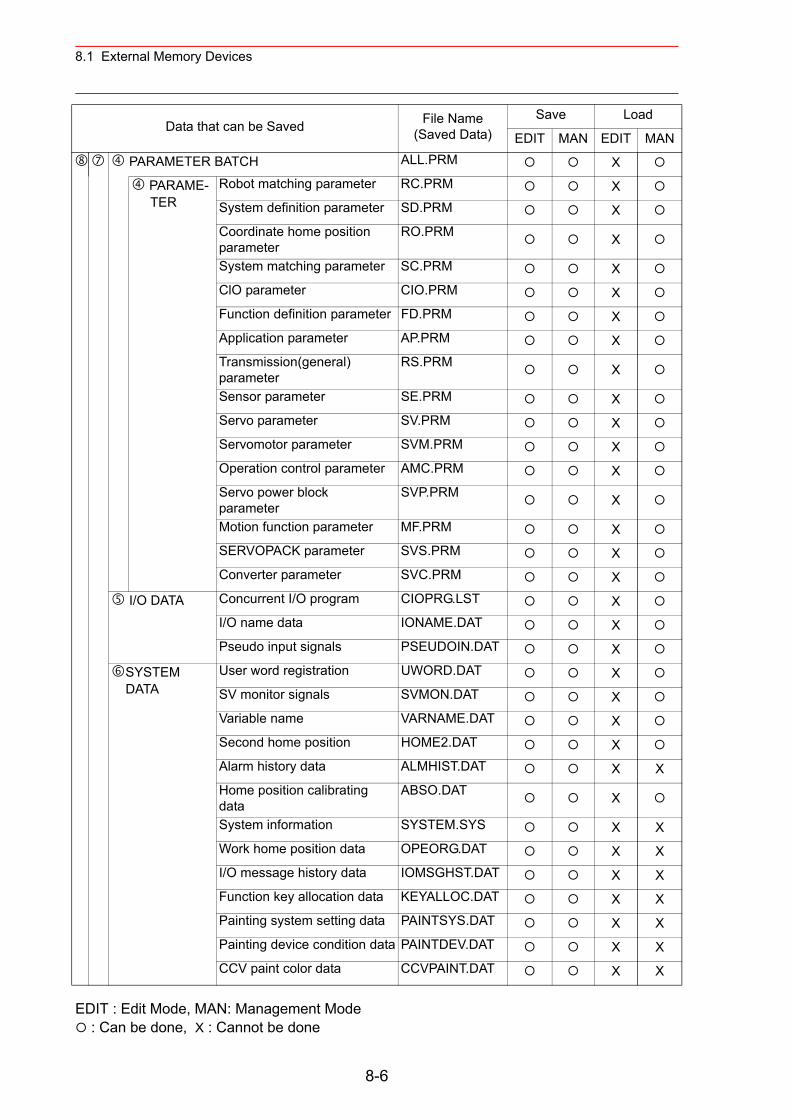
8.1 External Memory Devices
EDIT : Edit Mode, MAN: Management Mode : Can be done, X : Cannot be done
PARAMETER BATCH ALL.PRM X
PARAME-TER
Robot matching parameter RC.PRM XSystem definition parameter SD.PRM XCoordinate home position parameter
RO.PRM X
System matching parameter SC.PRM XClO parameter CIO.PRM XFunction definition parameter FD.PRM XApplication parameter AP.PRM XTransmission(general) parameter
RS.PRM X
Sensor parameter SE.PRM XServo parameter SV.PRM XServomotor parameter SVM.PRM XOperation control parameter AMC.PRM XServo power block parameter
SVP.PRM X
Motion function parameter MF.PRM XSERVOPACK parameter SVS.PRM XConverter parameter SVC.PRM X
I/O DATA Concurrent I/O program CIOPRG.LST XI/O name data IONAME.DAT XPseudo input signals PSEUDOIN.DAT X
SYSTEMDATA
User word registration UWORD.DAT XSV monitor signals SVMON.DAT XVariable name VARNAME.DAT XSecond home position HOME2.DAT XAlarm history data ALMHIST.DAT X XHome position calibrating data
ABSO.DAT X
System information SYSTEM.SYS X XWork home position data OPEORG.DAT X XI/O message history data IOMSGHST.DAT X XFunction key allocation data KEYALLOC.DAT X XPainting system setting data PAINTSYS.DAT X XPainting device condition data PAINTDEV.DAT X XCCV paint color data CCVPAINT.DAT X X
Data that can be Saved File Name(Saved Data)
Save Load
EDIT MAN EDIT MAN
8-6
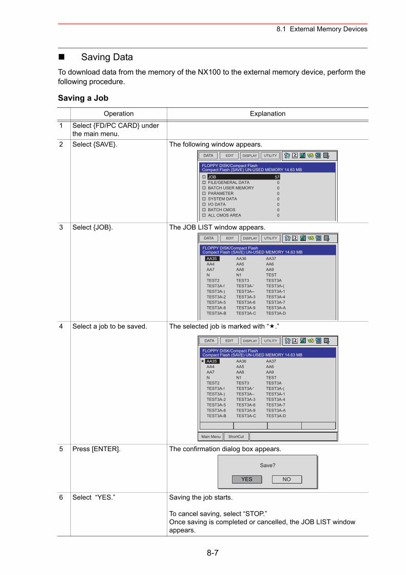
8.1 External Memory Devices
Saving DataTo download data from the memory of the NX100 to the external memory device, perform the following procedure.
Saving a Job
Operation Explanation
1 Select {FD/PC CARD} under the main menu.
2 Select {SAVE}. The following window appears.
3 Select {JOB}. The JOB LIST window appears.
4 Select a job to be saved. The selected job is marked with “ .”
5 Press [ENTER]. The confirmation dialog box appears.
6 Select “YES.” Saving the job starts.
To cancel saving, select “STOP.”Once saving is completed or cancelled, the JOB LIST window appears.
DATA UTILITYEDIT DISPLAY
FLOPPY DISK/Compact FlashCompact Flash (SAVE) UN-USED MEMORY 14.63 MB
JOB FILE/GENERAL DATA BATCH USER MEMORY PARAMETER SYSTEM DATA I/O DATA BATCH CMOS ALL CMOS AREA
570000000
DATA UTILITYEDIT DISPLAY
AA36AA5AA8N1TEST3TEST3A-'TEST3A--TEST3A-3TEST3A-6TEST3A-9TEST3A-C
AA37AA6AA9TESTTEST3ATEST3A-(TEST3A-1TEST3A-4TEST3A-7TEST3A-ATEST3A-D
AA35AA4AA7NTEST2TEST3A-!TEST3A-)TEST3A-2TEST3A-5TEST3A-8TEST3A-B
FLOPPY DISK/Compact FlashCompact Flash (SAVE) UN-USED MEMORY 14.63 MB
DATA UTILITYEDIT DISPLAY
Main Menu ShortCut
AA36AA5AA8N1TEST3TEST3A-'TEST3A--TEST3A-3TEST3A-6TEST3A-9TEST3A-C
AA37AA6AA9TESTTEST3ATEST3A-(TEST3A-1TEST3A-4TEST3A-7TEST3A-ATEST3A-D
AA35AA4AA7NTEST2TEST3A-!TEST3A-)TEST3A-2TEST3A-5TEST3A-8TEST3A-B
FLOPPY DISK/Compact FlashCompact Flash (SAVE) UN-USED MEMORY 14.63 MB
YES
Save?
NO
8-7
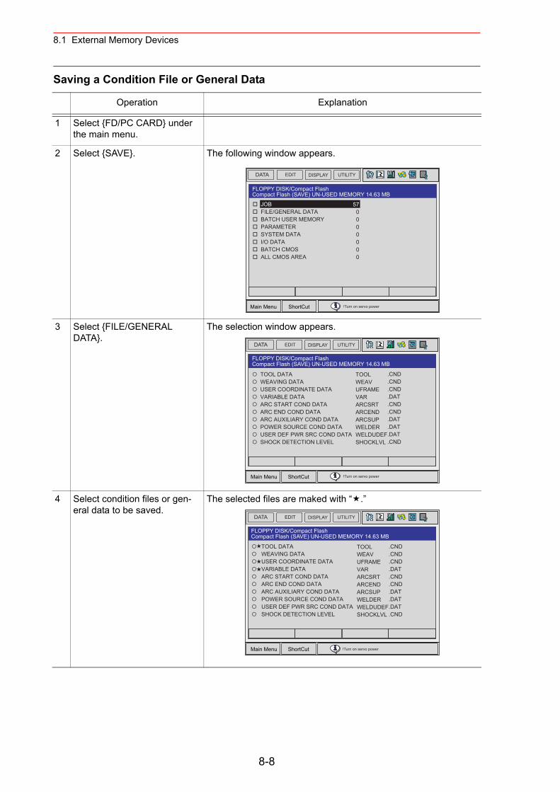
8.1 External Memory Devices
Saving a Condition File or General Data
Operation Explanation
1 Select {FD/PC CARD} under the main menu.
2 Select {SAVE}. The following window appears.
3 Select {FILE/GENERAL DATA}.
The selection window appears.
4 Select condition files or gen-eral data to be saved.
The selected files are maked with “ .”
DATA UTILITYEDIT DISPLAY
Main Menu ShortCut
JOB FILE/GENERAL DATA BATCH USER MEMORY PARAMETER SYSTEM DATA I/O DATA BATCH CMOS ALL CMOS AREA
570000000
!Turn on servo power
FLOPPY DISK/Compact FlashCompact Flash (SAVE) UN-USED MEMORY 14.63 MB
DATA UTILITYEDIT DISPLAY
Main Menu ShortCut
TOOL DATA WEAVING DATA USER COORDINATE DATA VARIABLE DATA ARC START COND DATA ARC END COND DATA ARC AUXILIARY COND DATA POWER SOURCE COND DATA USER DEF PWR SRC COND DATA SHOCK DETECTION LEVEL
TOOLWEAVUFRAMEVARARCSRTARCENDARCSUPWELDERWELDUDEFSHOCKLVL
.CND
.CND
.CND
.DAT
.CND
.CND
.DAT
.DAT
.DAT
.CND
!Turn on servo power
FLOPPY DISK/Compact FlashCompact Flash (SAVE) UN-USED MEMORY 14.63 MB
DATA UTILITYEDIT DISPLAY
Main Menu ShortCut
TOOLWEAVUFRAMEVARARCSRTARCENDARCSUPWELDERWELDUDEFSHOCKLVL
.CND
.CND
.CND
.DAT
.CND
.CND
.DAT
.DAT
.DAT
.CND
!Turn on servo power
FLOPPY DISK/Compact FlashCompact Flash (SAVE) UN-USED MEMORY 14.63 MB
TOOL DATA WEAVING DATA USER COORDINATE DATA VARIABLE DATA ARC START COND DATA ARC END COND DATA ARC AUXILIARY COND DATA POWER SOURCE COND DATA USER DEF PWR SRC COND DATA SHOCK DETECTION LEVEL
8-8
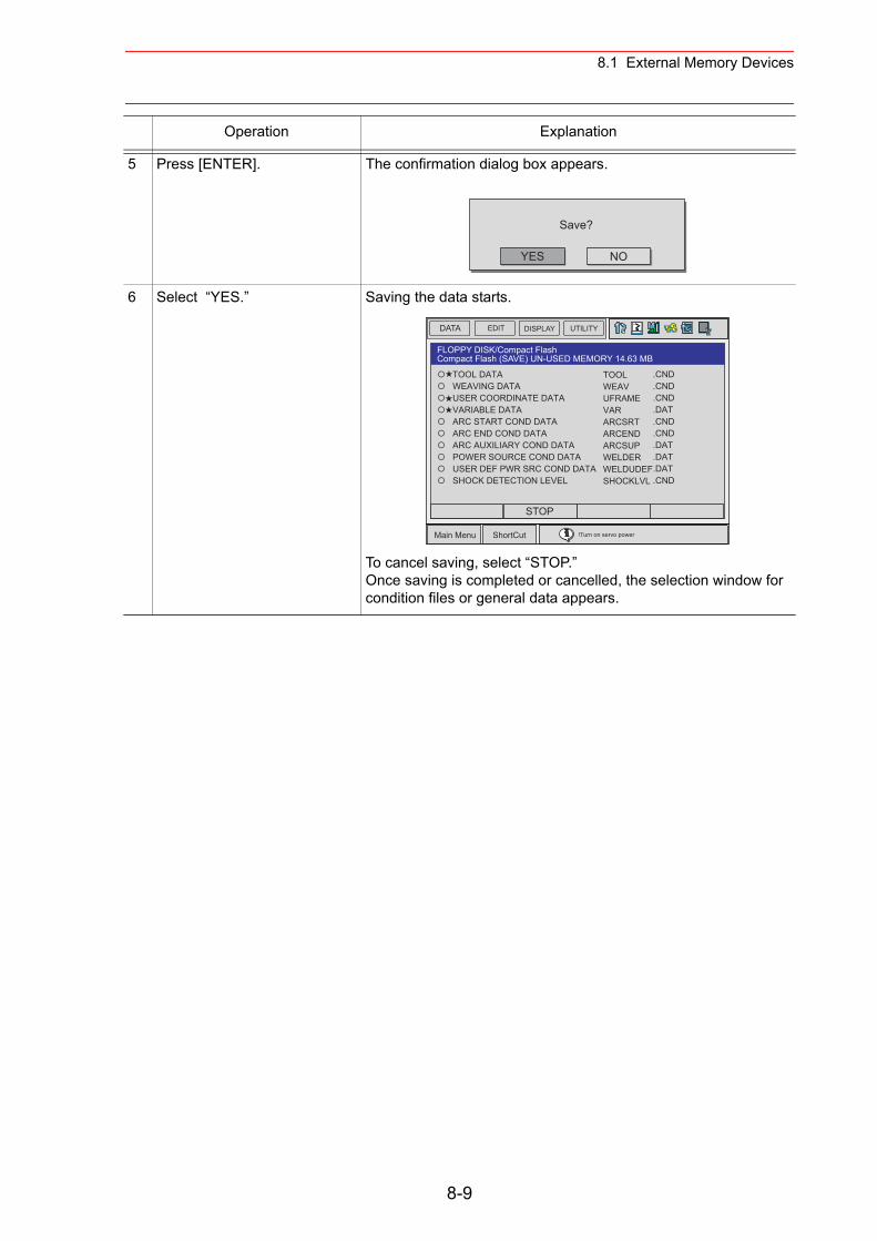
8.1 External Memory Devices
5 Press [ENTER]. The confirmation dialog box appears.
6 Select “YES.” Saving the data starts.
To cancel saving, select “STOP.”Once saving is completed or cancelled, the selection window for condition files or general data appears.
Operation Explanation
YES
Save?
NO
DATA UTILITYEDIT DISPLAY
Main Menu ShortCut !Turn on servo power
TOOLWEAVUFRAMEVARARCSRTARCENDARCSUPWELDERWELDUDEFSHOCKLVL
.CND
.CND
.CND
.DAT
.CND
.CND
.DAT
.DAT
.DAT
.CND
FLOPPY DISK/Compact FlashCompact Flash (SAVE) UN-USED MEMORY 14.63 MB
STOP
TOOL DATA WEAVING DATA USER COORDINATE DATA VARIABLE DATA ARC START COND DATA ARC END COND DATA ARC AUXILIARY COND DATA POWER SOURCE COND DATA USER DEF PWR SRC COND DATA SHOCK DETECTION LEVEL
8-9
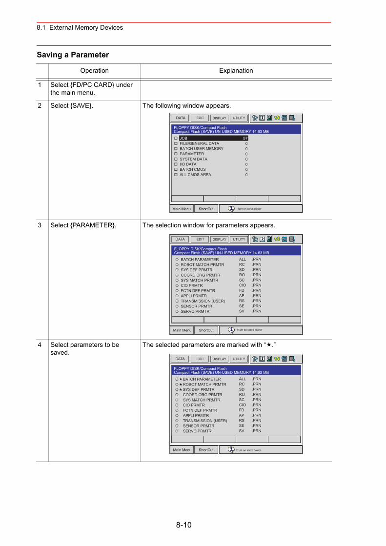
8.1 External Memory Devices
Saving a Parameter
Operation Explanation
1 Select {FD/PC CARD} under the main menu.
2 Select {SAVE}. The following window appears.
3 Select {PARAMETER}. The selection window for parameters appears.
4 Select parameters to be saved.
The selected parameters are marked with “ .”
DATA UTILITYEDIT DISPLAY
Main Menu ShortCut
JOB FILE/GENERAL DATA BATCH USER MEMORY PARAMETER SYSTEM DATA I/O DATA BATCH CMOS ALL CMOS AREA
570000000
!Turn on servo power
FLOPPY DISK/Compact FlashCompact Flash (SAVE) UN-USED MEMORY 14.63 MB
DATA UTILITYEDIT DISPLAY
Main Menu ShortCut
BATCH PARAMETER ROBOT MATCH PRMTR SYS DEF PRMTR COORD ORG PRMTR SYS MATCH PRMTR CIO PRMTR FCTN DEF PRMTR APPLI PRMTR TRANSMISSION (USER) SENSOR PRMTR SERVO PRMTR
ALLRCSDROSCCIOFDAPRSSESV
.PRN
.PRN
.PRN
.PRN
.PRN
.PRN
.PRN
.PRN
.PRN
.PRN
.PRN
!Turn on servo power
FLOPPY DISK/Compact FlashCompact Flash (SAVE) UN-USED MEMORY 14.63 MB
8-10
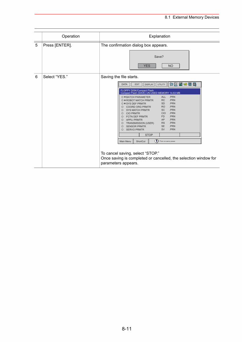
8.1 External Memory Devices
5 Press [ENTER]. The confirmation dialog box appears.
6 Select “YES.” Saving the file starts.
To cancel saving, select “STOP.” Once saving is completed or cancelled, the selection window for parameters appears.
Operation Explanation
YES
Save?
NO
DATA UTILITYEDIT DISPLAY
Main Menu ShortCut !Turn on servo power
BATCH PARAMETER ROBOT MATCH PRMTR SYS DEF PRMTR COORD ORG PRMTR SYS MATCH PRMTR CIO PRMTR FCTN DEF PRMTR APPLI PRMTR TRANSMISSION (USER) SENSOR PRMTR SERVO PRMTR
ALLRCSDROSCCIOFDAPRSSESV
.PRN
.PRN
.PRN
.PRN
.PRN
.PRN
.PRN
.PRN
.PRN
.PRN
.PRN
FLOPPY DISK/Compact FlashCompact Flash (SAVE) UN-USED MEMORY 14.63 MB
STOP
8-11
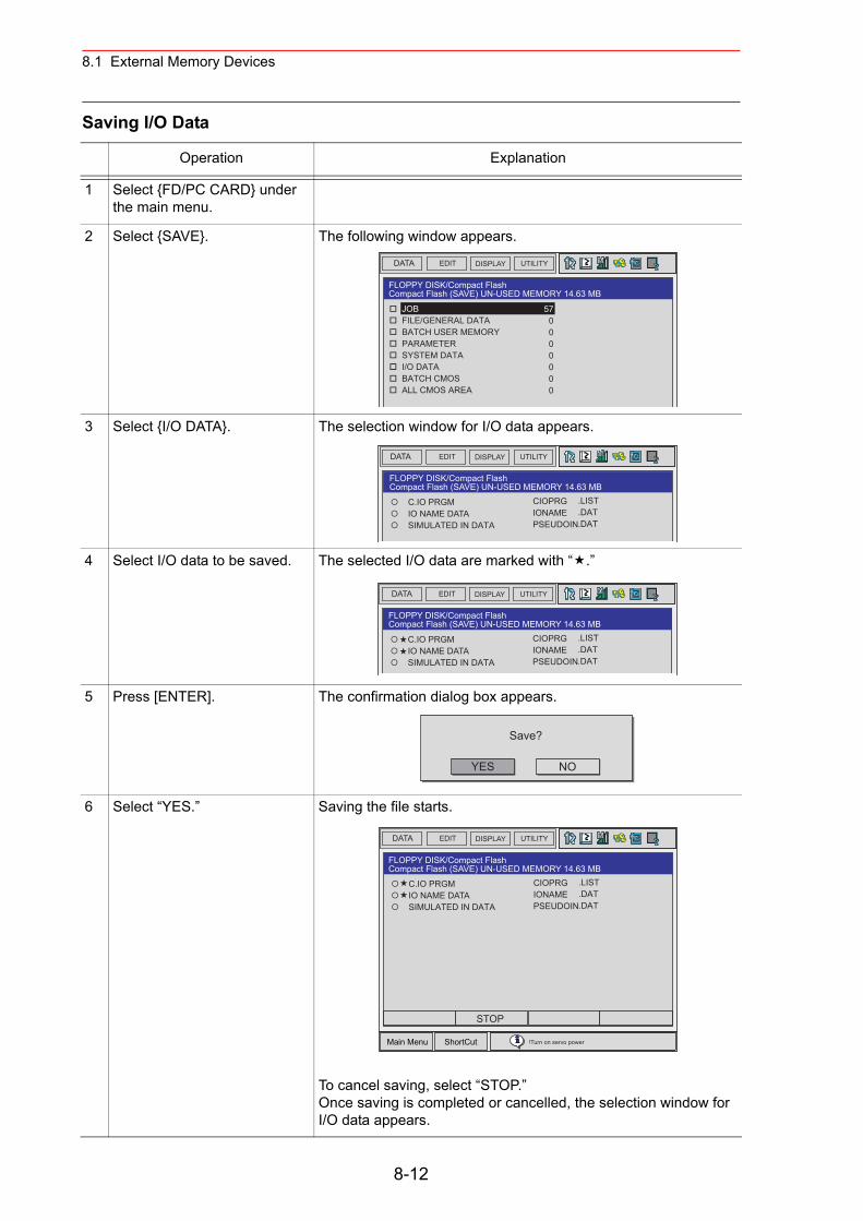
8.1 External Memory Devices
Saving I/O Data
Operation Explanation
1 Select {FD/PC CARD} under the main menu.
2 Select {SAVE}. The following window appears.
3 Select {I/O DATA}. The selection window for I/O data appears.
4 Select I/O data to be saved. The selected I/O data are marked with “ .”
5 Press [ENTER]. The confirmation dialog box appears.
6 Select “YES.” Saving the file starts.
To cancel saving, select “STOP.” Once saving is completed or cancelled, the selection window for I/O data appears.
DATA UTILITYEDIT DISPLAY
JOB FILE/GENERAL DATA BATCH USER MEMORY PARAMETER SYSTEM DATA I/O DATA BATCH CMOS ALL CMOS AREA
570000000
FLOPPY DISK/Compact FlashCompact Flash (SAVE) UN-USED MEMORY 14.63 MB
DATA UTILITYEDIT DISPLAY
C.IO PRGM IO NAME DATA SIMULATED IN DATA
CIOPRGIONAMEPSEUDOIN
.LIST
.DAT
.DAT
FLOPPY DISK/Compact FlashCompact Flash (SAVE) UN-USED MEMORY 14.63 MB
DATA UTILITYEDIT DISPLAY
C.IO PRGM IO NAME DATA SIMULATED IN DATA
CIOPRGIONAMEPSEUDOIN
.LIST
.DAT
.DAT
FLOPPY DISK/Compact FlashCompact Flash (SAVE) UN-USED MEMORY 14.63 MB
YES
Save?
NO
DATA UTILITYEDIT DISPLAY
Main Menu ShortCut
C.IO PRGM IO NAME DATA SIMULATED IN DATA
CIOPRGIONAMEPSEUDOIN
.LIST
.DAT
.DAT
!Turn on servo power
FLOPPY DISK/Compact FlashCompact Flash (SAVE) UN-USED MEMORY 14.63 MB
STOP
8-12
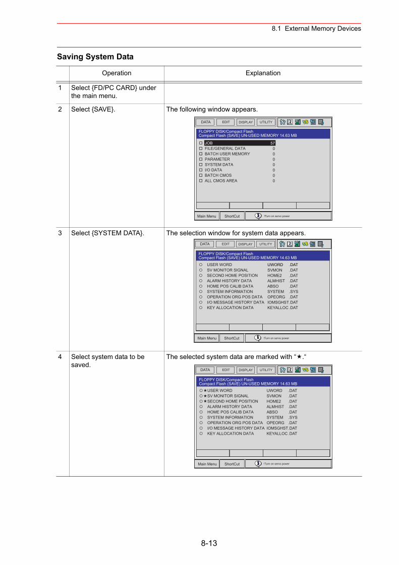
8.1 External Memory Devices
Saving System Data
Operation Explanation
1 Select {FD/PC CARD} under the main menu.
2 Select {SAVE}. The following window appears.
3 Select {SYSTEM DATA}. The selection window for system data appears.
4 Select system data to be saved.
The selected system data are marked with “ .“
DATA UTILITYEDIT DISPLAY
Main Menu ShortCut
JOB FILE/GENERAL DATA BATCH USER MEMORY PARAMETER SYSTEM DATA I/O DATA BATCH CMOS ALL CMOS AREA
570000000
!Turn on servo power
FLOPPY DISK/Compact FlashCompact Flash (SAVE) UN-USED MEMORY 14.63 MB
DATA UTILITYEDIT DISPLAY
Main Menu ShortCut
USER WORD SV MONITOR SIGNAL SECOND HOME POSITION ALARM HISTORY DATA HOME POS CALIB DATA SYSTEM INFORMATION OPERATION ORG POS DATA I/O MESSAGE HISTORY DATA KEY ALLOCATION DATA
UWORDSVMONHOME2ALMHISTABSOSYSTEMOPEORGIOMSGHSTKEYALLOC
.DAT
.DAT
.DAT
.DAT
.DAT
.SYS
.DAT
.DAT
.DAT
!Turn on servo power
FLOPPY DISK/Compact FlashCompact Flash (SAVE) UN-USED MEMORY 14.63 MB
8-13
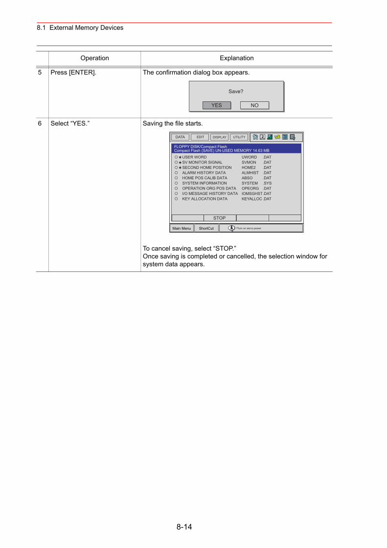
8.1 External Memory Devices
5 Press [ENTER]. The confirmation dialog box appears.
6 Select “YES.” Saving the file starts.
To cancel saving, select “STOP.” Once saving is completed or cancelled, the selection window for system data appears.
Operation Explanation
YES
Save?
NO
DATA UTILITYEDIT DISPLAY
Main Menu ShortCut !Turn on servo power
FLOPPY DISK/Compact FlashCompact Flash (SAVE) UN-USED MEMORY 14.63 MB
USER WORD SV MONITOR SIGNAL SECOND HOME POSITION ALARM HISTORY DATA HOME POS CALIB DATA SYSTEM INFORMATION OPERATION ORG POS DATA I/O MESSAGE HISTORY DATA KEY ALLOCATION DATA
UWORDSVMONHOME2ALMHISTABSOSYSTEMOPEORGIOMSGHSTKEYALLOC
.DAT
.DAT
.DAT
.DAT
.DAT
.SYS
.DAT
.DAT
.DAT
STOP
8-14
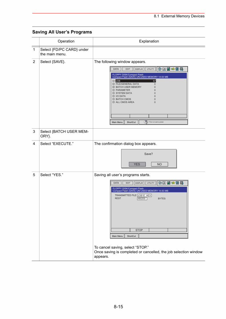
8.1 External Memory Devices
Saving All User’s Programs
Operation Explanation
1 Select {FD/PC CARD} under the main menu.
2 Select {SAVE}. The following window appears.
3 Select {BATCH USER MEM-ORY}.
4 Select “EXECUTE.” The confirmation dialog box appears.
5 Select “YES.” Saving all user’s programs starts.
To cancel saving, select “STOP.” Once saving is completed or cancelled, the job selection window appears.
DATA UTILITYEDIT DISPLAY
Main Menu ShortCut
FLOPPY DISK/Compact FlashCompact Flash (SAVE) UN-USED MEMORY 14.63 MB
JOB FILE/GENERAL DATA BATCH USER MEMORY PARAMETER SYSTEM DATA I/O DATA BATCH CMOS ALL CMOS AREA
570000000
!Turn on servo power
YES
Save?
NO
DATA UTILITYEDIT DISPLAY
Main Menu ShortCut
FLOPPY DISK/Compact FlashCompact Flash (SAVE) UN-USED MEMORY 14.63 MB
TRANSMITTED FILEREST
JOB1E .HEX480200 BYTES
STOP
8-15
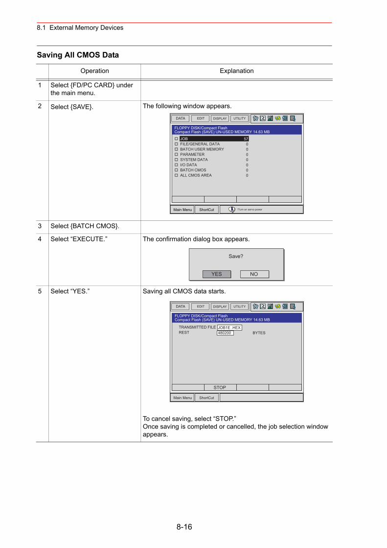
8.1 External Memory Devices
Saving All CMOS Data
Operation Explanation
1 Select {FD/PC CARD} under the main menu.
2 Select {SAVE}. The following window appears.
3 Select {BATCH CMOS}.
4 Select “EXECUTE.” The confirmation dialog box appears.
5 Select “YES.” Saving all CMOS data starts.
To cancel saving, select “STOP.” Once saving is completed or cancelled, the job selection window appears.
DATA UTILITYEDIT DISPLAY
Main Menu ShortCut
FLOPPY DISK/Compact FlashCompact Flash (SAVE) UN-USED MEMORY 14.63 MB
JOB FILE/GENERAL DATA BATCH USER MEMORY PARAMETER SYSTEM DATA I/O DATA BATCH CMOS ALL CMOS AREA
570000000
!Turn on servo power
YES
Save?
NO
DATA UTILITYEDIT DISPLAY
Main Menu ShortCut
FLOPPY DISK/Compact FlashCompact Flash (SAVE) UN-USED MEMORY 14.63 MB
TRANSMITTED FILEREST
JOB1E .HEX480200 BYTES
STOP
8-16
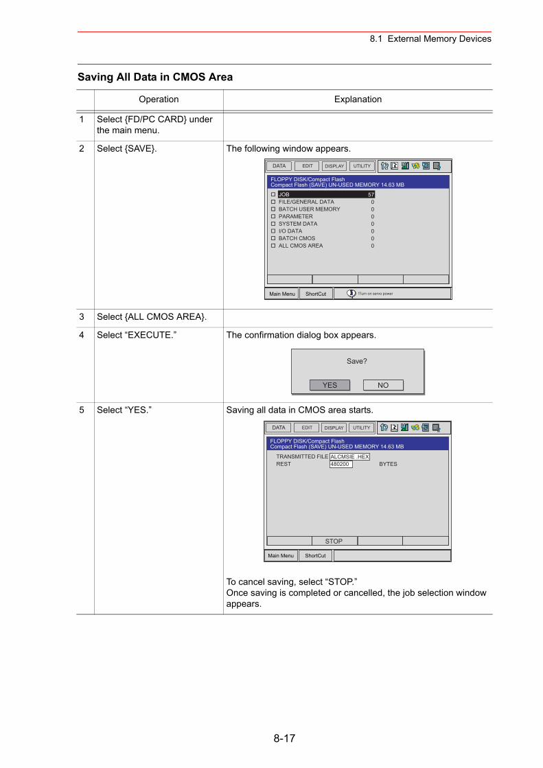
8.1 External Memory Devices
Saving All Data in CMOS Area
Operation Explanation
1 Select {FD/PC CARD} under the main menu.
2 Select {SAVE}. The following window appears.
3 Select {ALL CMOS AREA}.
4 Select “EXECUTE.” The confirmation dialog box appears.
5 Select “YES.” Saving all data in CMOS area starts.
To cancel saving, select “STOP.” Once saving is completed or cancelled, the job selection window appears.
DATA UTILITYEDIT DISPLAY
Main Menu ShortCut
FLOPPY DISK/Compact FlashCompact Flash (SAVE) UN-USED MEMORY 14.63 MB
JOB FILE/GENERAL DATA BATCH USER MEMORY PARAMETER SYSTEM DATA I/O DATA BATCH CMOS ALL CMOS AREA
570000000
!Turn on servo power
YES
Save?
NO
DATA UTILITYEDIT DISPLAY
Main Menu ShortCut
FLOPPY DISK/Compact FlashCompact Flash (SAVE) UN-USED MEMORY 14.63 MB
ALCMSIE .HEX480200 BYTES
STOP
TRANSMITTED FILEREST
8-17
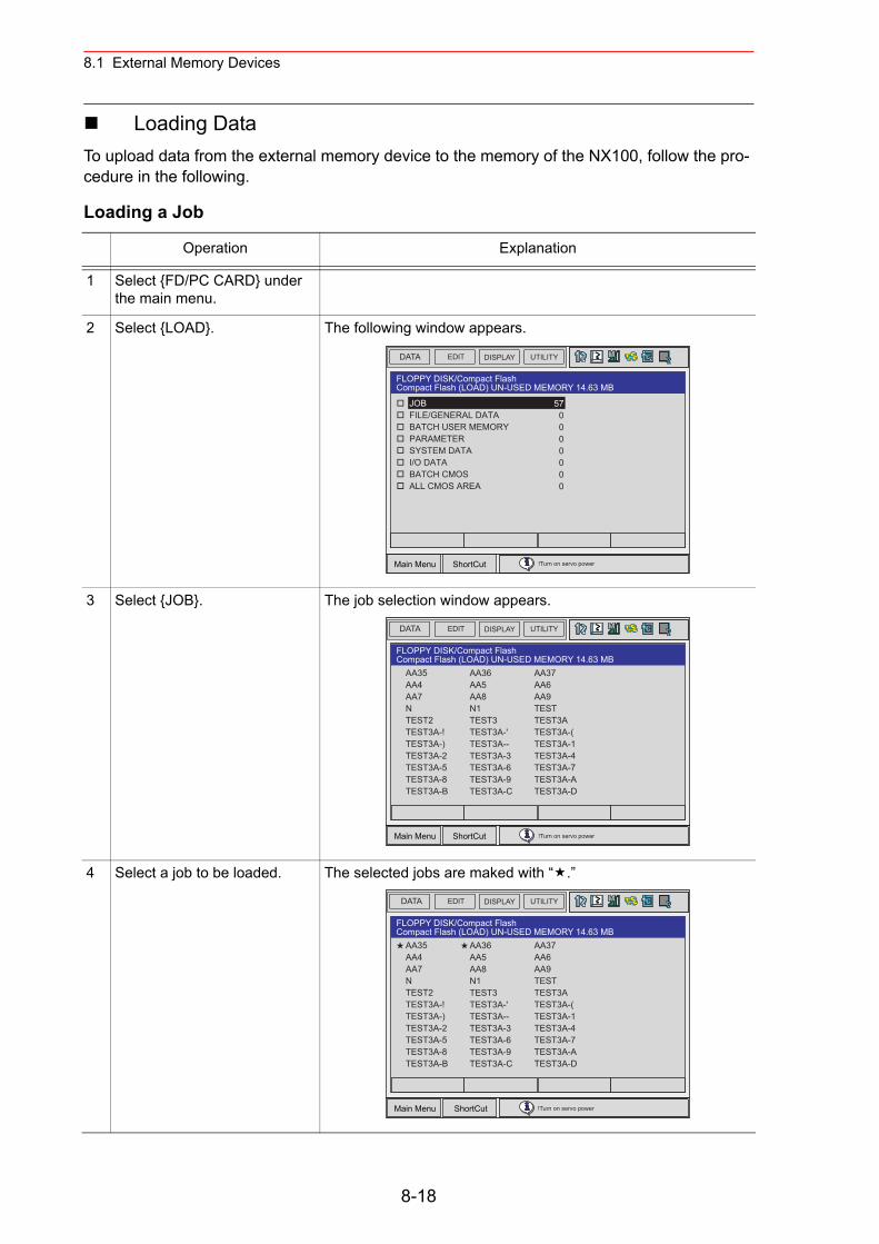
8.1 External Memory Devices
Loading DataTo upload data from the external memory device to the memory of the NX100, follow the pro-cedure in the following.
Loading a Job
Operation Explanation
1 Select {FD/PC CARD} under the main menu.
2 Select {LOAD}. The following window appears.
3 Select {JOB}. The job selection window appears.
4 Select a job to be loaded. The selected jobs are maked with “ .”
DATA UTILITYEDIT DISPLAY
Main Menu ShortCut
FLOPPY DISK/Compact FlashCompact Flash (LOAD) UN-USED MEMORY 14.63 MB
JOB FILE/GENERAL DATA BATCH USER MEMORY PARAMETER SYSTEM DATA I/O DATA BATCH CMOS ALL CMOS AREA
570000000
!Turn on servo power
DATA UTILITYEDIT DISPLAY
Main Menu ShortCut
FLOPPY DISK/Compact FlashCompact Flash (LOAD) UN-USED MEMORY 14.63 MB
AA36AA5AA8N1TEST3TEST3A-'TEST3A--TEST3A-3TEST3A-6TEST3A-9TEST3A-C
AA37AA6AA9TESTTEST3ATEST3A-(TEST3A-1TEST3A-4TEST3A-7TEST3A-ATEST3A-D
AA35AA4AA7NTEST2TEST3A-!TEST3A-)TEST3A-2TEST3A-5TEST3A-8TEST3A-B
!Turn on servo power
8-18
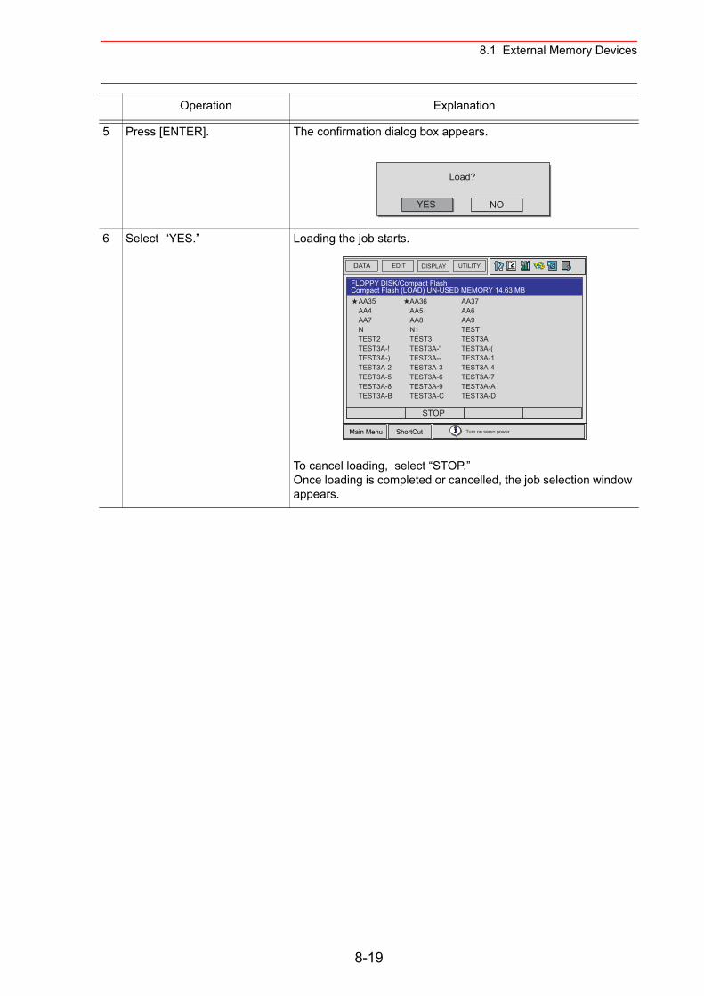
8.1 External Memory Devices
5 Press [ENTER]. The confirmation dialog box appears.
6 Select “YES.” Loading the job starts.
To cancel loading, select “STOP.”Once loading is completed or cancelled, the job selection window appears.
Operation Explanation
YES
Load?
NO
DATA UTILITYEDIT DISPLAY
Main Menu ShortCut
FLOPPY DISK/Compact FlashCompact Flash (LOAD) UN-USED MEMORY 14.63 MB
AA36AA5AA8N1TEST3TEST3A-'TEST3A--TEST3A-3TEST3A-6TEST3A-9TEST3A-C
AA37AA6AA9TESTTEST3ATEST3A-(TEST3A-1TEST3A-4TEST3A-7TEST3A-ATEST3A-D
AA35AA4AA7NTEST2TEST3A-!TEST3A-)TEST3A-2TEST3A-5TEST3A-8TEST3A-B
!Turn on servo power
STOP
8-19
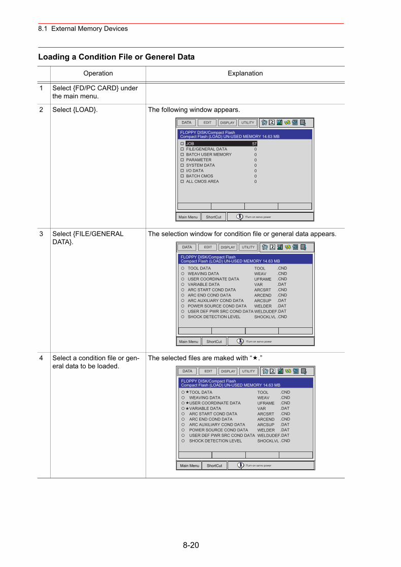
8.1 External Memory Devices
Loading a Condition File or Generel Data
Operation Explanation
1 Select {FD/PC CARD} under the main menu.
2 Select {LOAD}. The following window appears.
3 Select {FILE/GENERAL DATA}.
The selection window for condition file or general data appears.
4 Select a condition file or gen-eral data to be loaded.
The selected files are maked with “ .”
DATA UTILITYEDIT DISPLAY
Main Menu ShortCut
FLOPPY DISK/Compact FlashCompact Flash (LOAD) UN-USED MEMORY 14.63 MB
JOB FILE/GENERAL DATA BATCH USER MEMORY PARAMETER SYSTEM DATA I/O DATA BATCH CMOS ALL CMOS AREA
570000000
!Turn on servo power
DATA UTILITYEDIT DISPLAY
Main Menu ShortCut
FLOPPY DISK/Compact FlashCompact Flash (LOAD) UN-USED MEMORY 14.63 MB
TOOL DATA WEAVING DATA USER COORDINATE DATA VARIABLE DATA ARC START COND DATA ARC END COND DATA ARC AUXILIARY COND DATA POWER SOURCE COND DATA USER DEF PWR SRC COND DATA SHOCK DETECTION LEVEL
TOOLWEAVUFRAMEVARARCSRTARCENDARCSUPWELDERWELDUDEFSHOCKLVL
.CND
.CND
.CND
.DAT
.CND
.CND
.DAT
.DAT
.DAT
.CND
!Turn on servo power
8-20

8.1 External Memory Devices
5 Press [ENTER]. The confirmation dialog box appears.
6 Select “YES.” Loading the file starts.
To cancel loading, select “STOP.”Once loading is completed or cancelled, the selection window for condition file or general data appears.
Operation Explanation
YES
Load?
NO
DATA UTILITYEDIT DISPLAY
Main Menu ShortCut
FLOPPY DISK/Compact FlashCompact Flash (LOAD) UN-USED MEMORY 14.63 MB
TOOL DATA WEAVING DATA USER COORDINATE DATA VARIABLE DATA ARC START COND DATA ARC END COND DATA ARC AUXILIARY COND DATA POWER SOURCE COND DATA USER DEF PWR SRC COND DATA SHOCK DETECTION LEVEL
TOOLWEAVUFRAMEVARARCSRTARCENDARCSUPWELDERWELDUDEFSHOCKLVL
.CND
.CND
.CND
.DAT
.CND
.CND
.DAT
.DAT
.DAT
.CND
!Turn on servo power
STOP
8-21
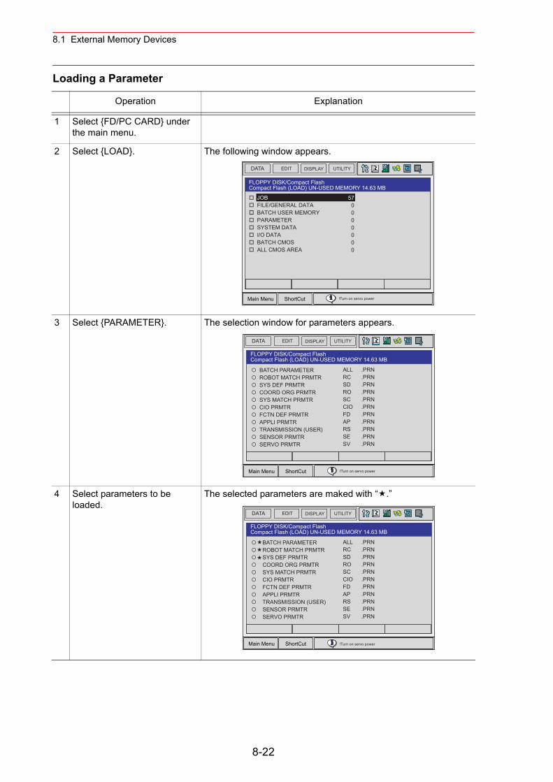
8.1 External Memory Devices
Loading a Parameter
Operation Explanation
1 Select {FD/PC CARD} under the main menu.
2 Select {LOAD}. The following window appears.
3 Select {PARAMETER}. The selection window for parameters appears.
4 Select parameters to be loaded.
The selected parameters are maked with “ .”
DATA UTILITYEDIT DISPLAY
Main Menu ShortCut
FLOPPY DISK/Compact FlashCompact Flash (LOAD) UN-USED MEMORY 14.63 MB
JOB FILE/GENERAL DATA BATCH USER MEMORY PARAMETER SYSTEM DATA I/O DATA BATCH CMOS ALL CMOS AREA
570000000
!Turn on servo power
DATA UTILITYEDIT DISPLAY
Main Menu ShortCut
FLOPPY DISK/Compact FlashCompact Flash (LOAD) UN-USED MEMORY 14.63 MB
BATCH PARAMETER ROBOT MATCH PRMTR SYS DEF PRMTR COORD ORG PRMTR SYS MATCH PRMTR CIO PRMTR FCTN DEF PRMTR APPLI PRMTR TRANSMISSION (USER) SENSOR PRMTR SERVO PRMTR
ALLRCSDROSCCIOFDAPRSSESV
.PRN
.PRN
.PRN
.PRN
.PRN
.PRN
.PRN
.PRN
.PRN
.PRN
.PRN
!Turn on servo power
8-22
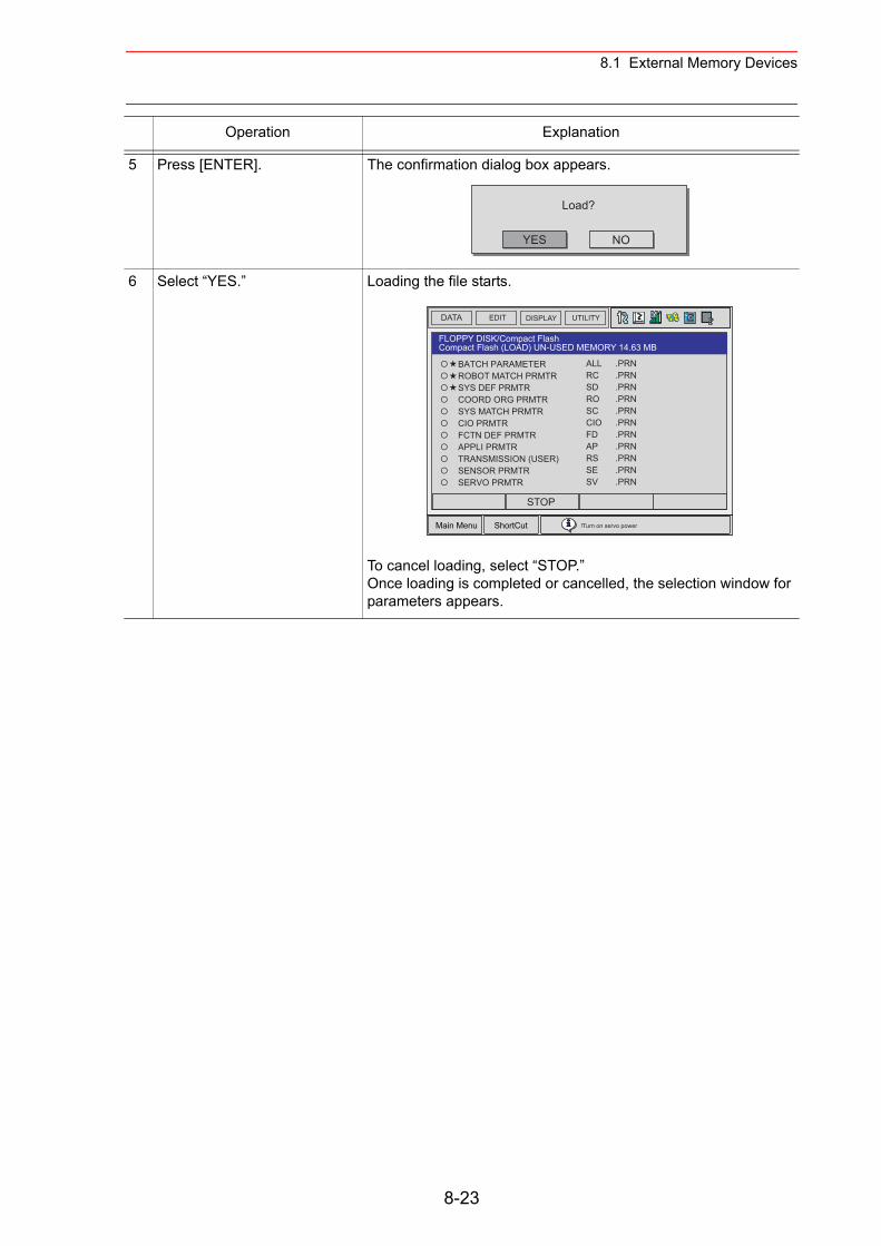
8.1 External Memory Devices
5 Press [ENTER]. The confirmation dialog box appears.
6 Select “YES.” Loading the file starts.
To cancel loading, select “STOP.”Once loading is completed or cancelled, the selection window for parameters appears.
Operation Explanation
YES
Load?
NO
DATA UTILITYEDIT DISPLAY
Main Menu ShortCut
FLOPPY DISK/Compact FlashCompact Flash (LOAD) UN-USED MEMORY 14.63 MB
BATCH PARAMETER ROBOT MATCH PRMTR SYS DEF PRMTR COORD ORG PRMTR SYS MATCH PRMTR CIO PRMTR FCTN DEF PRMTR APPLI PRMTR TRANSMISSION (USER) SENSOR PRMTR SERVO PRMTR
ALLRCSDROSCCIOFDAPRSSESV
.PRN
.PRN
.PRN
.PRN
.PRN
.PRN
.PRN
.PRN
.PRN
.PRN
.PRN
!Turn on servo power
STOP
8-23
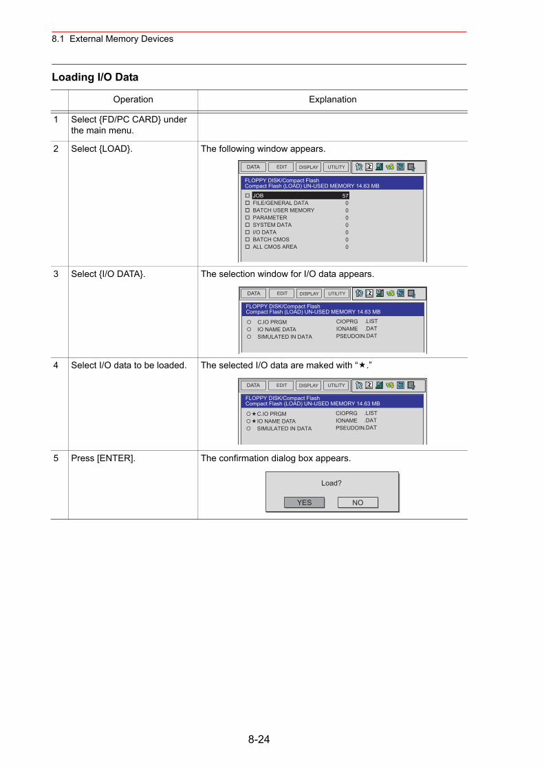
8.1 External Memory Devices
Loading I/O Data
Operation Explanation
1 Select {FD/PC CARD} under the main menu.
2 Select {LOAD}. The following window appears.
3 Select {I/O DATA}. The selection window for I/O data appears.
4 Select I/O data to be loaded. The selected I/O data are maked with “ .”
5 Press [ENTER]. The confirmation dialog box appears.
DATA UTILITYEDIT DISPLAY
FLOPPY DISK/Compact FlashCompact Flash (LOAD) UN-USED MEMORY 14.63 MB
JOB FILE/GENERAL DATA BATCH USER MEMORY PARAMETER SYSTEM DATA I/O DATA BATCH CMOS ALL CMOS AREA
570000000
DATA UTILITYEDIT DISPLAY
FLOPPY DISK/Compact FlashCompact Flash (LOAD) UN-USED MEMORY 14.63 MB
C.IO PRGM IO NAME DATA SIMULATED IN DATA
CIOPRGIONAMEPSEUDOIN
.LIST
.DAT
.DAT
DATA UTILITYEDIT DISPLAY
FLOPPY DISK/Compact FlashCompact Flash (LOAD) UN-USED MEMORY 14.63 MB
C.IO PRGM IO NAME DATA SIMULATED IN DATA
CIOPRGIONAMEPSEUDOIN
.LIST
.DAT
.DAT
YES
Load?
NO
8-24
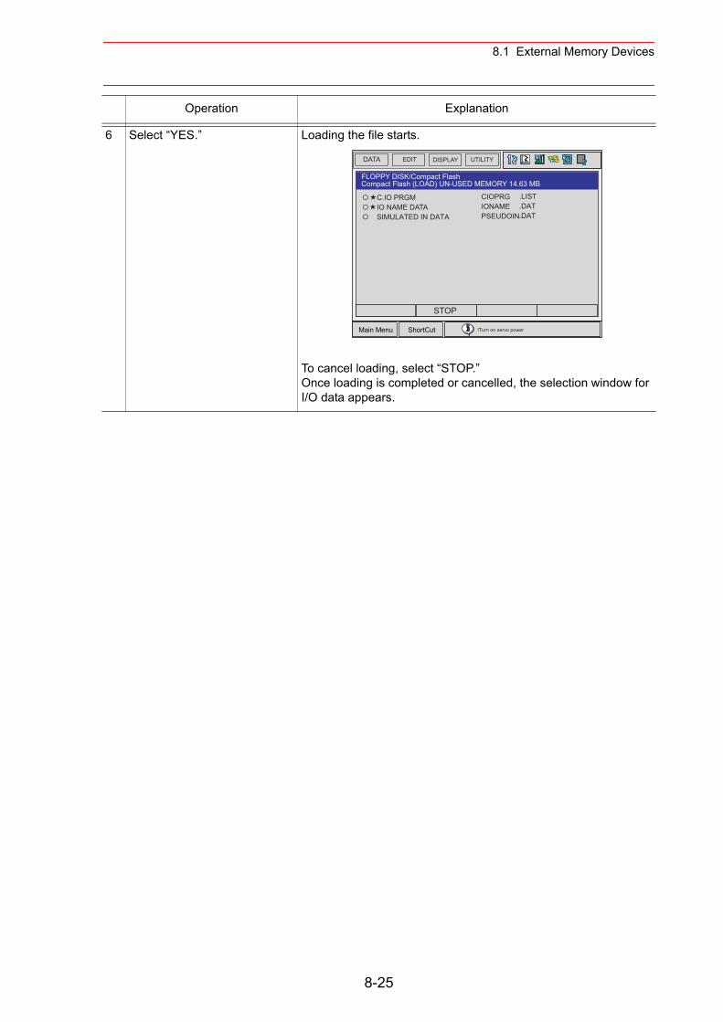
8.1 External Memory Devices
6 Select “YES.” Loading the file starts.
To cancel loading, select “STOP.”Once loading is completed or cancelled, the selection window for I/O data appears.
Operation Explanation
DATA UTILITYEDIT DISPLAY
Main Menu ShortCut
FLOPPY DISK/Compact FlashCompact Flash (LOAD) UN-USED MEMORY 14.63 MB
C.IO PRGM IO NAME DATA SIMULATED IN DATA
CIOPRGIONAMEPSEUDOIN
.LIST
.DAT
.DAT
!Turn on servo power
STOP
8-25
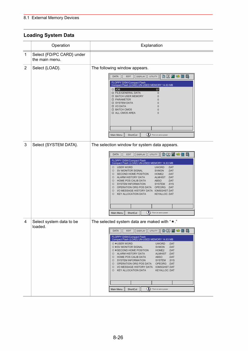
8.1 External Memory Devices
Loading System Data
Operation Explanation
1 Select {FD/PC CARD} under the main menu.
2 Select {LOAD}. The following window appears.
3 Select {SYSTEM DATA}. The selection window for system data appears.
4 Select system data to be loaded.
The selected system data are maked with “ .”
DATA UTILITYEDIT DISPLAY
Main Menu ShortCut
FLOPPY DISK/Compact FlashCompact Flash (LOAD) UN-USED MEMORY 14.63 MB
JOB FILE/GENERAL DATA BATCH USER MEMORY PARAMETER SYSTEM DATA I/O DATA BATCH CMOS ALL CMOS AREA
570000000
!Turn on servo power
DATA UTILITYEDIT DISPLAY
Main Menu ShortCut
FLOPPY DISK/Compact FlashCompact Flash (LOAD) UN-USED MEMORY 14.63 MB
USER WORD SV MONITOR SIGNAL SECOND HOME POSITION ALARM HISTORY DATA HOME POS CALIB DATA SYSTEM INFORMATION OPERATION ORG POS DATA I/O MESSAGE HISTORY DATA KEY ALLOCATION DATA
UWORDSVMONHOME2ALMHISTABSOSYSTEMOPEORGIOMSGHSTKEYALLOC
.DAT
.DAT
.DAT
.DAT
.DAT
.SYS
.DAT
.DAT
.DAT
!Turn on servo power
8-26
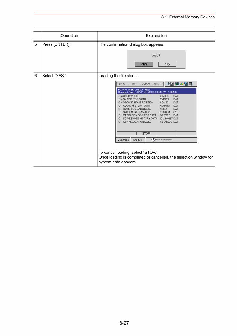
8.1 External Memory Devices
5 Press [ENTER]. The confirmation dialog box appears.
6 Select “YES.” Loading the file starts.
To cancel loading, select “STOP.” Once loading is completed or cancelled, the selection window for system data appears.
Operation Explanation
YES
Load?
NO
DATA UTILITYEDIT DISPLAY
Main Menu ShortCut
FLOPPY DISK/Compact FlashCompact Flash (LOAD) UN-USED MEMORY 14.63 MB
USER WORD SV MONITOR SIGNAL SECOND HOME POSITION ALARM HISTORY DATA HOME POS CALIB DATA SYSTEM INFORMATION OPERATION ORG POS DATA I/O MESSAGE HISTORY DATA KEY ALLOCATION DATA
UWORDSVMONHOME2ALMHISTABSOSYSTEMOPEORGIOMSGHSTKEYALLOC
.DAT
.DAT
.DAT
.DAT
.DAT
.SYS
.DAT
.DAT
.DAT
!Turn on servo power
STOP
8-27
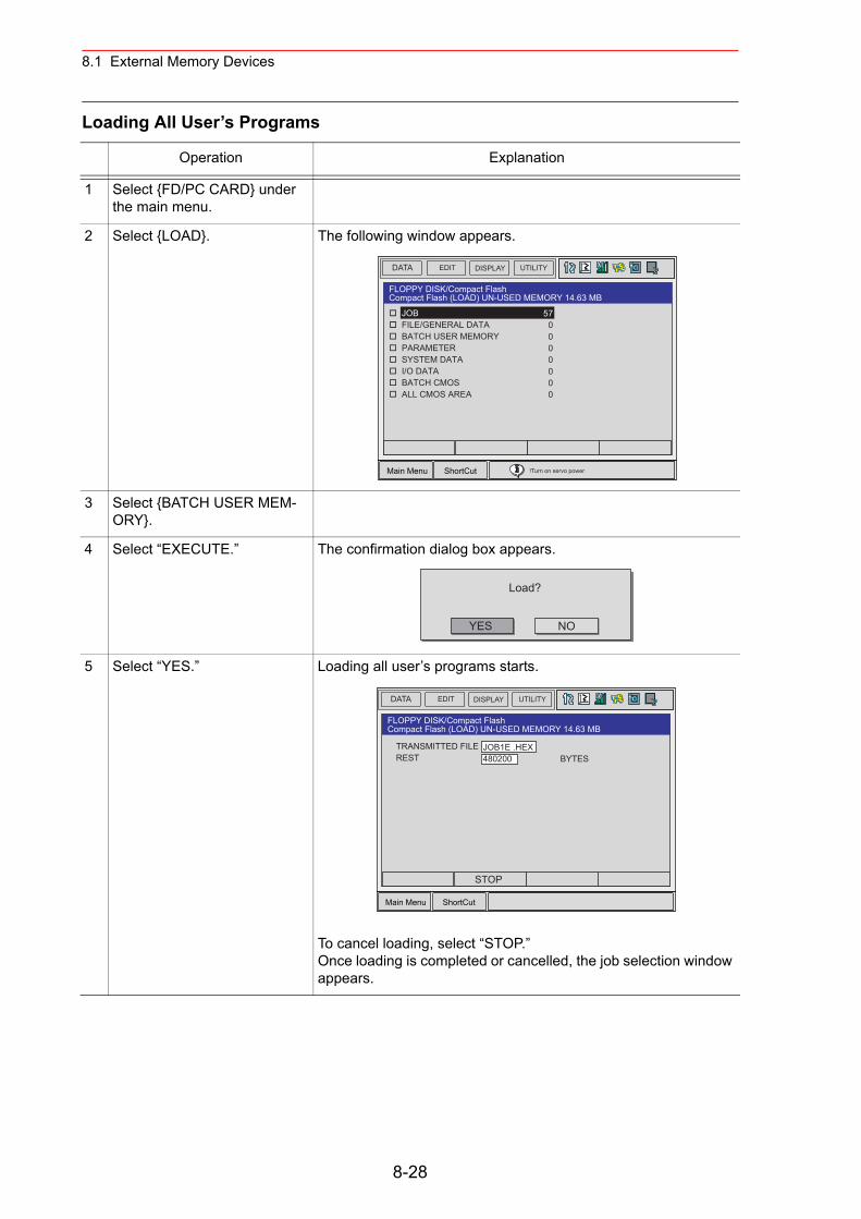
8.1 External Memory Devices
Loading All User’s Programs
Operation Explanation
1 Select {FD/PC CARD} under the main menu.
2 Select {LOAD}. The following window appears.
3 Select {BATCH USER MEM-ORY}.
4 Select “EXECUTE.” The confirmation dialog box appears.
5 Select “YES.” Loading all user’s programs starts.
To cancel loading, select “STOP.” Once loading is completed or cancelled, the job selection window appears.
DATA UTILITYEDIT DISPLAY
Main Menu ShortCut
FLOPPY DISK/Compact FlashCompact Flash (LOAD) UN-USED MEMORY 14.63 MB
JOB FILE/GENERAL DATA BATCH USER MEMORY PARAMETER SYSTEM DATA I/O DATA BATCH CMOS ALL CMOS AREA
570000000
!Turn on servo power
YES
Load?
NO
DATA UTILITYEDIT DISPLAY
Main Menu ShortCut
FLOPPY DISK/Compact FlashCompact Flash (LOAD) UN-USED MEMORY 14.63 MB
TRANSMITTED FILEREST
JOB1E .HEX480200 BYTES
STOP
8-28
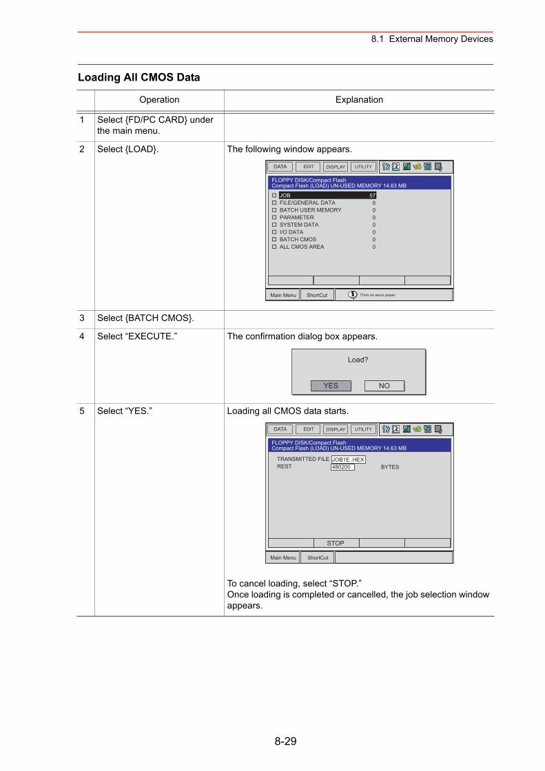
8.1 External Memory Devices
Loading All CMOS Data
Operation Explanation
1 Select {FD/PC CARD} under the main menu.
2 Select {LOAD}. The following window appears.
3 Select {BATCH CMOS}.
4 Select “EXECUTE.” The confirmation dialog box appears.
5 Select “YES.” Loading all CMOS data starts.
To cancel loading, select “STOP.” Once loading is completed or cancelled, the job selection window appears.
DATA UTILITYEDIT DISPLAY
Main Menu ShortCut
FLOPPY DISK/Compact FlashCompact Flash (LOAD) UN-USED MEMORY 14.63 MB
JOB FILE/GENERAL DATA BATCH USER MEMORY PARAMETER SYSTEM DATA I/O DATA BATCH CMOS ALL CMOS AREA
570000000
!Turn on servo power
YES
Load?
NO
DATA UTILITYEDIT DISPLAY
Main Menu ShortCut
FLOPPY DISK/Compact FlashCompact Flash (LOAD) UN-USED MEMORY 14.63 MB
TRANSMITTED FILEREST
JOB1E .HEX480200 BYTES
STOP
8-29
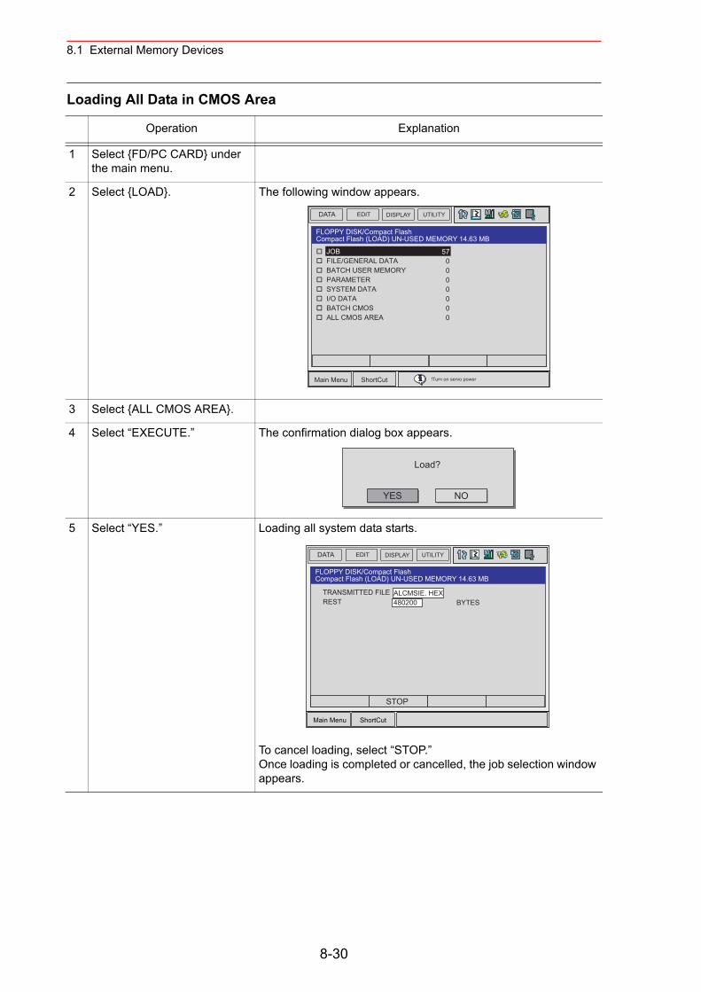
8.1 External Memory Devices
Loading All Data in CMOS Area
Operation Explanation
1 Select {FD/PC CARD} under the main menu.
2 Select {LOAD}. The following window appears.
3 Select {ALL CMOS AREA}.
4 Select “EXECUTE.” The confirmation dialog box appears.
5 Select “YES.” Loading all system data starts.
To cancel loading, select “STOP.” Once loading is completed or cancelled, the job selection window appears.
DATA UTILITYEDIT DISPLAY
Main Menu ShortCut
FLOPPY DISK/Compact FlashCompact Flash (LOAD) UN-USED MEMORY 14.63 MB
JOB FILE/GENERAL DATA BATCH USER MEMORY PARAMETER SYSTEM DATA I/O DATA BATCH CMOS ALL CMOS AREA
570000000
!Turn on servo power
YES
Load?
NO
DATA UTILITYEDIT DISPLAY
Main Menu ShortCut
FLOPPY DISK/Compact FlashCompact Flash (LOAD) UN-USED MEMORY 14.63 MB
TRANSMITTED FILEREST
ALCMSIE. HEX480200 BYTES
STOP
8-30
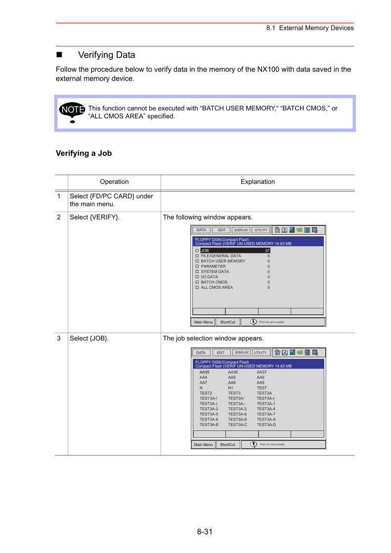
8.1 External Memory Devices
Verifying DataFollow the procedure below to verify data in the memory of the NX100 with data saved in the external memory device.
Verifying a Job
This function cannot be executed with “BATCH USER MEMORY,“ “BATCH CMOS,” or “ALL CMOS AREA” specified.
Operation Explanation
1 Select {FD/PC CARD} under the main menu.
2 Select {VERIFY}. The following window appears.
3 Select {JOB}. The job selection window appears.
NOTE
DATA UTILITYEDIT DISPLAY
Main Menu ShortCut
FLOPPY DISK/Compact FlashCompact Flash (VERIF UN-USED MEMORY 14.63 MB
JOB FILE/GENERAL DATA BATCH USER MEMORY PARAMETER SYSTEM DATA I/O DATA BATCH CMOS ALL CMOS AREA
570000000
!Turn on servo power
DATA UTILITYEDIT DISPLAY
Main Menu ShortCut
FLOPPY DISK/Compact FlashCompact Flash (VERIF UN-USED MEMORY 14.63 MB
AA36AA5AA8N1TEST3TEST3A-'TEST3A--TEST3A-3TEST3A-6TEST3A-9TEST3A-C
AA37AA6AA9TESTTEST3ATEST3A-(TEST3A-1TEST3A-4TEST3A-7TEST3A-ATEST3A-D
AA35AA4AA7NTEST2TEST3A-!TEST3A-)TEST3A-2TEST3A-5TEST3A-8TEST3A-B
!Turn on servo power
8-31
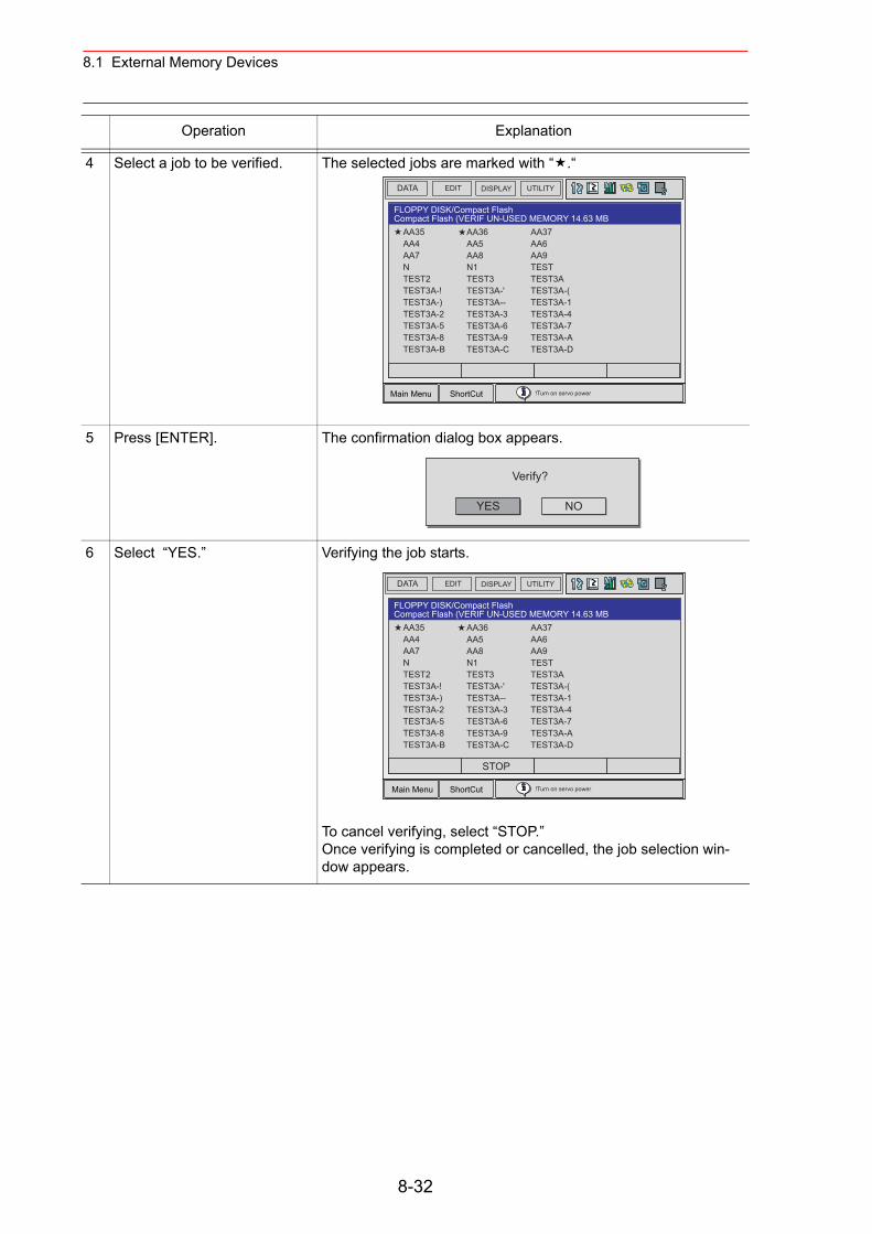
8.1 External Memory Devices
4 Select a job to be verified. The selected jobs are marked with “ .“
5 Press [ENTER]. The confirmation dialog box appears.
6 Select “YES.” Verifying the job starts.
To cancel verifying, select “STOP.”Once verifying is completed or cancelled, the job selection win-dow appears.
Operation Explanation
DATA UTILITYEDIT DISPLAY
Main Menu ShortCut
FLOPPY DISK/Compact FlashCompact Flash (VERIF UN-USED MEMORY 14.63 MB
AA36AA5AA8N1TEST3TEST3A-'TEST3A--TEST3A-3TEST3A-6TEST3A-9TEST3A-C
AA37AA6AA9TESTTEST3ATEST3A-(TEST3A-1TEST3A-4TEST3A-7TEST3A-ATEST3A-D
AA35AA4AA7NTEST2TEST3A-!TEST3A-)TEST3A-2TEST3A-5TEST3A-8TEST3A-B
!Turn on servo power
YES
Verify?
NO
DATA UTILITYEDIT DISPLAY
Main Menu ShortCut
FLOPPY DISK/Compact FlashCompact Flash (VERIF UN-USED MEMORY 14.63 MB
AA36AA5AA8N1TEST3TEST3A-'TEST3A--TEST3A-3TEST3A-6TEST3A-9TEST3A-C
AA37AA6AA9TESTTEST3ATEST3A-(TEST3A-1TEST3A-4TEST3A-7TEST3A-ATEST3A-D
AA35AA4AA7NTEST2TEST3A-!TEST3A-)TEST3A-2TEST3A-5TEST3A-8TEST3A-B
!Turn on servo power
STOP
8-32
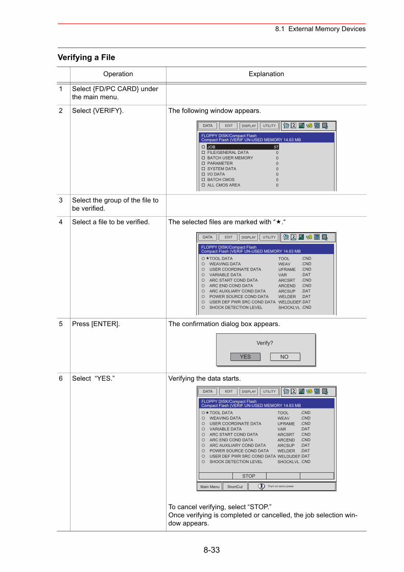
8.1 External Memory Devices
Verifying a File
Operation Explanation
1 Select {FD/PC CARD} under the main menu.
2 Select {VERIFY}. The following window appears.
3 Select the group of the file to be verified.
4 Select a file to be verified. The selected files are marked with “ .“
5 Press [ENTER]. The confirmation dialog box appears.
6 Select “YES.” Verifying the data starts.
To cancel verifying, select “STOP.”Once verifying is completed or cancelled, the job selection win-dow appears.
DATA UTILITYEDIT DISPLAY
FLOPPY DISK/Compact FlashCompact Flash (VERIF UN-USED MEMORY 14.63 MB
JOB FILE/GENERAL DATA BATCH USER MEMORY PARAMETER SYSTEM DATA I/O DATA BATCH CMOS ALL CMOS AREA
570000000
DATA UTILITYEDIT DISPLAY
FLOPPY DISK/Compact FlashCompact Flash (VERIF UN-USED MEMORY 14.63 MB
TOOL DATA WEAVING DATA USER COORDINATE DATA VARIABLE DATA ARC START COND DATA ARC END COND DATA ARC AUXILIARY COND DATA POWER SOURCE COND DATA USER DEF PWR SRC COND DATA SHOCK DETECTION LEVEL
TOOLWEAVUFRAMEVARARCSRTARCENDARCSUPWELDERWELDUDEFSHOCKLVL
.CND
.CND
.CND
.DAT
.CND
.CND
.DAT
.DAT
.DAT
.CND
YES
Verify?
NO
DATA UTILITYEDIT DISPLAY
Main Menu ShortCut
FLOPPY DISK/Compact FlashCompact Flash (VERIF UN-USED MEMORY 14.63 MB
TOOL DATA WEAVING DATA USER COORDINATE DATA VARIABLE DATA ARC START COND DATA ARC END COND DATA ARC AUXILIARY COND DATA POWER SOURCE COND DATA USER DEF PWR SRC COND DATA SHOCK DETECTION LEVEL
TOOLWEAVUFRAMEVARARCSRTARCENDARCSUPWELDERWELDUDEFSHOCKLVL
.CND
.CND
.CND
.DAT
.CND
.CND
.DAT
.DAT
.DAT
.CND
!Turn on servo power
STOP
8-33
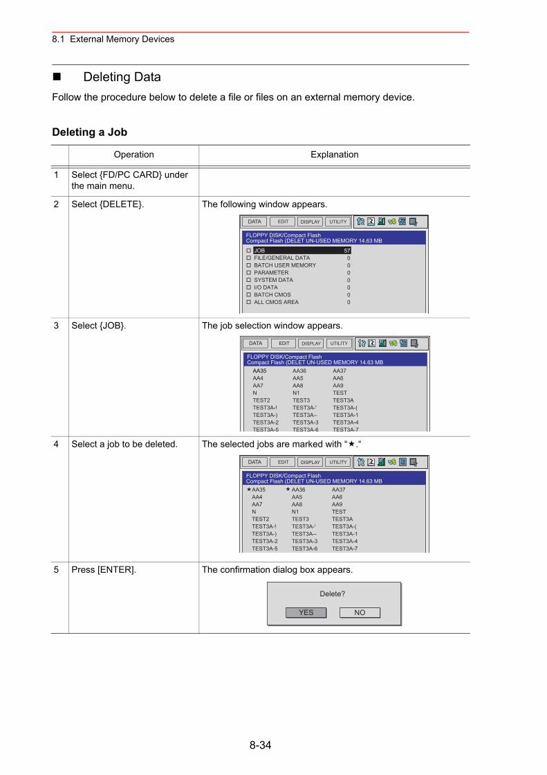
8.1 External Memory Devices
Deleting DataFollow the procedure below to delete a file or files on an external memory device.
Deleting a Job
Operation Explanation
1 Select {FD/PC CARD} under the main menu.
2 Select {DELETE}. The following window appears.
3 Select {JOB}. The job selection window appears.
4 Select a job to be deleted. The selected jobs are marked with “ .“
5 Press [ENTER]. The confirmation dialog box appears.
DATA UTILITYEDIT DISPLAY
FLOPPY DISK/Compact FlashCompact Flash (DELET UN-USED MEMORY 14.63 MB
JOB FILE/GENERAL DATA BATCH USER MEMORY PARAMETER SYSTEM DATA I/O DATA BATCH CMOS ALL CMOS AREA
570000000
DATA UTILITYEDIT DISPLAY
FLOPPY DISK/Compact FlashCompact Flash (DELET UN-USED MEMORY 14.63 MB
AA36AA5AA8N1TEST3TEST3A-'TEST3A--TEST3A-3TEST3A-6
AA37AA6AA9TESTTEST3ATEST3A-(TEST3A-1TEST3A-4TEST3A-7
AA35AA4AA7NTEST2TEST3A-!TEST3A-)TEST3A-2TEST3A-5
DATA UTILITYEDIT DISPLAY
FLOPPY DISK/Compact FlashCompact Flash (DELET UN-USED MEMORY 14.63 MB
AA36AA5AA8N1TEST3TEST3A-'TEST3A--TEST3A-3TEST3A-6
AA37AA6AA9TESTTEST3ATEST3A-(TEST3A-1TEST3A-4TEST3A-7
AA35AA4AA7NTEST2TEST3A-!TEST3A-)TEST3A-2TEST3A-5
YES
Delete?
NO
8-34

8.1 External Memory Devices
6 Select “YES.” Deleting the data starts.
To cancel deleting, select “STOP.”Once deleting is completed or cancelled, the job selection window appears.
Operation Explanation
DATA UTILITYEDIT DISPLAY
Main Menu ShortCut
FLOPPY DISK/Compact FlashCompact Flash (DELET UN-USED MEMORY 14.63 MB
AA36AA5AA8N1TEST3TEST3A-'TEST3A--TEST3A-3TEST3A-6TEST3A-9TEST3A-C
AA37AA6AA9TESTTEST3ATEST3A-(TEST3A-1TEST3A-4TEST3A-7TEST3A-ATEST3A-D
AA35AA4AA7NTEST2TEST3A-!TEST3A-)TEST3A-2TEST3A-5TEST3A-8TEST3A-B
!Turn on servo power
STOP
8-35
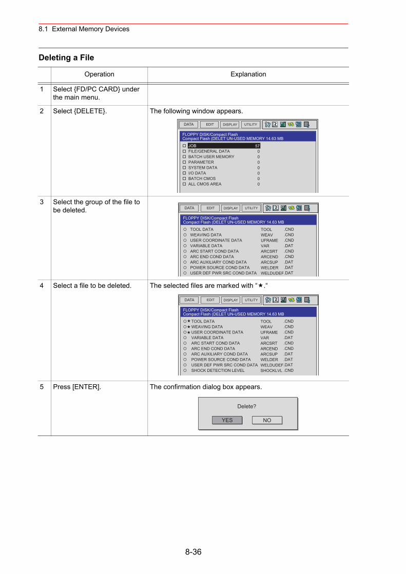
8.1 External Memory Devices
Deleting a File
Operation Explanation
1 Select {FD/PC CARD} under the main menu.
2 Select {DELETE}. The following window appears.
3 Select the group of the file to be deleted.
4 Select a file to be deleted. The selected files are marked with “ .“
5 Press [ENTER]. The confirmation dialog box appears.
DATA UTILITYEDIT DISPLAY
FLOPPY DISK/Compact FlashCompact Flash (DELET UN-USED MEMORY 14.63 MB
JOB FILE/GENERAL DATA BATCH USER MEMORY PARAMETER SYSTEM DATA I/O DATA BATCH CMOS ALL CMOS AREA
570000000
DATA UTILITYEDIT DISPLAY
FLOPPY DISK/Compact FlashCompact Flash (DELET UN-USED MEMORY 14.63 MB
TOOL DATA WEAVING DATA USER COORDINATE DATA VARIABLE DATA ARC START COND DATA ARC END COND DATA ARC AUXILIARY COND DATA POWER SOURCE COND DATA USER DEF PWR SRC COND DATA
TOOLWEAVUFRAMEVARARCSRTARCENDARCSUPWELDERWELDUDEF
.CND
.CND
.CND
.DAT
.CND
.CND
.DAT
.DAT
.DAT
DATA UTILITYEDIT DISPLAY
FLOPPY DISK/Compact FlashCompact Flash (DELET UN-USED MEMORY 14.63 MB
TOOL DATA WEAVING DATA USER COORDINATE DATA VARIABLE DATA ARC START COND DATA ARC END COND DATA ARC AUXILIARY COND DATA POWER SOURCE COND DATA USER DEF PWR SRC COND DATA SHOCK DETECTION LEVEL
TOOLWEAVUFRAMEVARARCSRTARCENDARCSUPWELDERWELDUDEFSHOCKLVL
.CND
.CND
.CND
.DAT
.CND
.CND
.DAT
.DAT
.DAT
.CND
YES
Delete?
NO
8-36
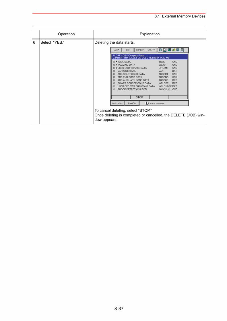
8.1 External Memory Devices
6 Select “YES.” Deleting the data starts.
To cancel deleting, select “STOP.”Once deleting is completed or cancelled, the DELETE (JOB) win-dow appears.
Operation Explanation
DATA UTILITYEDIT DISPLAY
Main Menu ShortCut
FLOPPY DISK/Compact FlashCompact Flash (DELET UN-USED MEMORY 14.63 MB
TOOL DATA WEAVING DATA USER COORDINATE DATA VARIABLE DATA ARC START COND DATA ARC END COND DATA ARC AUXILIARY COND DATA POWER SOURCE COND DATA USER DEF PWR SRC COND DATA SHOCK DETECTION LEVEL
TOOLWEAVUFRAMEVARARCSRTARCENDARCSUPWELDERWELDUDEFSHOCKLVL
.CND
.CND
.CND
.DAT
.CND
.CND
.DAT
.DAT
.DAT
.CND
!Turn on servo power
STOP
8-37
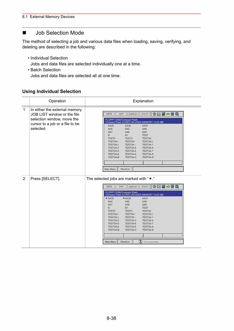
8.1 External Memory Devices
Job Selection ModeThe method of selecting a job and various data files when loading, saving, verifying, and deleting are described in the following:
• Individual SelectionJobs and data files are selected individually one at a time.
• Batch SelectionJobs and data files are selected all at one time.
Using Individual Selection
Operation Explanation
1 In either the external memory JOB LIST window or the file selection window, move the cursor to a job or a file to be selected.
2 Press [SELECT]. The selected jobs are marked with “ .“
DATA UTILITYEDIT DISPLAY
Main Menu ShortCut
FLOPPY DISK/Compact FlashCompact Flash (LOAD) UN-USED MEMORY 14.63 MB
AA36AA5AA8N1TEST3TEST3A-'TEST3A--TEST3A-3TEST3A-6TEST3A-9TEST3A-C
AA37AA6AA9TESTTEST3ATEST3A-(TEST3A-1TEST3A-4TEST3A-7TEST3A-ATEST3A-D
AA35AA4AA7NTEST2TEST3A-!TEST3A-)TEST3A-2TEST3A-5TEST3A-8TEST3A-B
DATA UTILITYEDIT DISPLAY
Main Menu ShortCut
FLOPPY DISK/Compact FlashCompact Flash (LOAD) UN-USED MEMORY 14.63 MB
AA37AA6AA9TESTTEST3ATEST3A-(TEST3A-1TEST3A-4TEST3A-7TEST3A-ATEST3A-D
AA35AA4AA7NTEST2TEST3A-!TEST3A-)TEST3A-2TEST3A-5TEST3A-8TEST3A-B
AA36AA5AA8N1TEST3TEST3A-'TEST3A--TEST3A-3TEST3A-6TEST3A-9TEST3A-C
!Turn on servo power
8-38
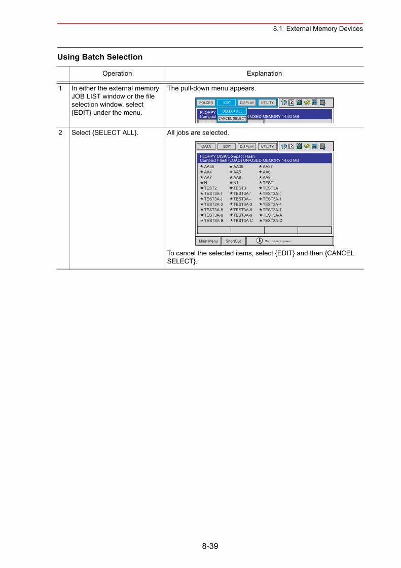
8.1 External Memory Devices
Using Batch Selection
Operation Explanation
1 In either the external memory JOB LIST window or the file selection window, select {EDIT} under the menu.
The pull-down menu appears.
2 Select {SELECT ALL}. All jobs are selected.
To cancel the selected items, select {EDIT} and then {CANCEL SELECT}.
FOLDER UTILITYEDIT DISPLAY
FLOPPY DISK/PC CARDCompact Flash (LOAD) UN-USED MEMORY 14.63 MBCANCEL SELECT
SELECT ALL
DATA UTILITYEDIT DISPLAY
Main Menu ShortCut
FLOPPY DISK/Compact FlashCompact Flash (LOAD) UN-USED MEMORY 14.63 MB
AA37AA6AA9TESTTEST3ATEST3A-(TEST3A-1TEST3A-4TEST3A-7TEST3A-ATEST3A-D
AA35AA4AA7NTEST2TEST3A-!TEST3A-)TEST3A-2TEST3A-5TEST3A-8TEST3A-B
AA36AA5AA8N1TEST3TEST3A-'TEST3A--TEST3A-3TEST3A-6TEST3A-9TEST3A-C
!Turn on servo power
8-39
9.1 Parameter Configuration
9 Parameter
9.1 Parameter Configuration
The parameters of NX100 can be classified into the following seven:
Motion Speed Setting ParameterDetermines the manipulator motion speed for jog operation at teaching, test operation, or playback operation.
Mode Operation Setting ParameterMakes the setting for various operations in the teach mode or remote mode.
Parameter according to Interference AreaLimits the P-point maximum envelope of the manipulator or sets the interference area for axis interference or cubic interference.
Parameter according to Status I/OSets the parity check or I/O setting for user input/output signals.
Parameter according to Coordinated or Synchronized OperationMakes the settings for coordinated or synchronized operations between manipulators or between manipulators and stations.
Parameter for Other Functions or ApplicationsMakes the settings for other functions or applications.
Hardware Control ParameterMakes the hardware settings for fan alarm or relay operation, etc.
S1CxG Parameters
The initial setting of S1CxG parameters depends on the manipulator model.For a system in which two manipulators are controlled, the following two types of parame-ters are used: S1C1G type and S1C2G type.
SUPPLE-MENT
9-1
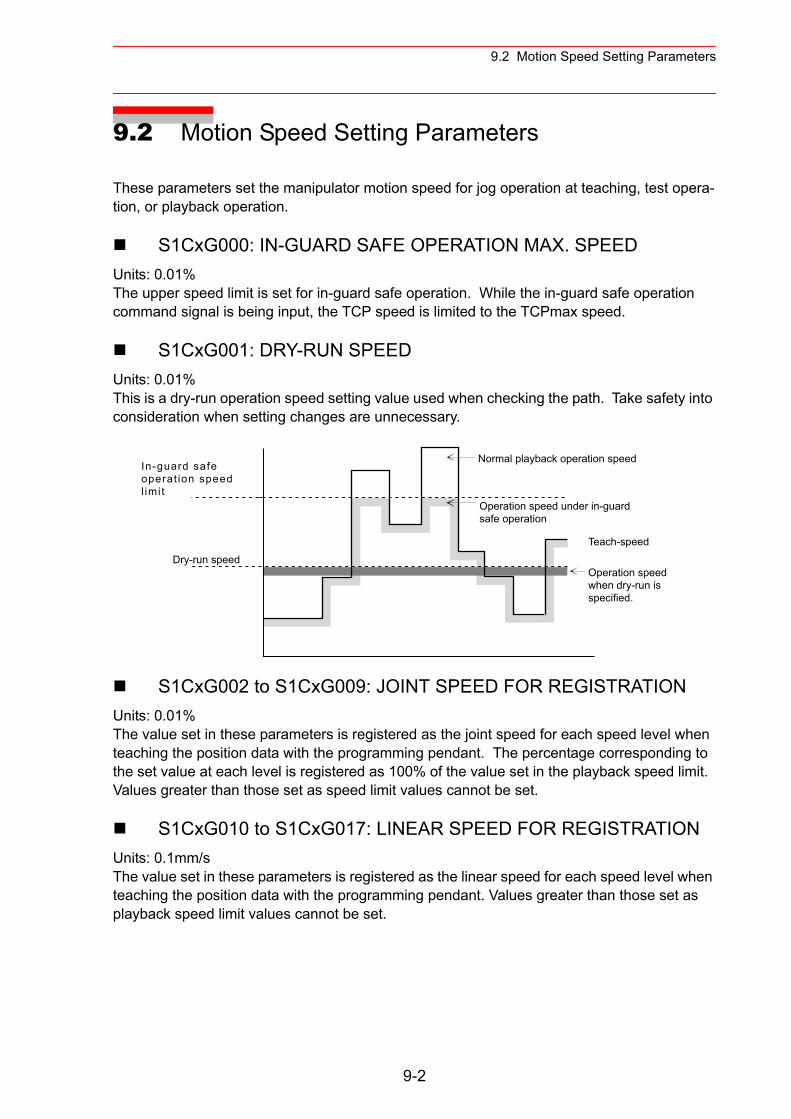
9.2 Motion Speed Setting Parameters
9.2 Motion Speed Setting Parameters
These parameters set the manipulator motion speed for jog operation at teaching, test opera-tion, or playback operation.
S1CxG000: IN-GUARD SAFE OPERATION MAX. SPEED Units: 0.01%The upper speed limit is set for in-guard safe operation. While the in-guard safe operation command signal is being input, the TCP speed is limited to the TCPmax speed.
S1CxG001: DRY-RUN SPEEDUnits: 0.01%This is a dry-run operation speed setting value used when checking the path. Take safety into consideration when setting changes are unnecessary.
S1CxG002 to S1CxG009: JOINT SPEED FOR REGISTRATIONUnits: 0.01%The value set in these parameters is registered as the joint speed for each speed level when teaching the position data with the programming pendant. The percentage corresponding to the set value at each level is registered as 100% of the value set in the playback speed limit. Values greater than those set as speed limit values cannot be set.
S1CxG010 to S1CxG017: LINEAR SPEED FOR REGISTRATIONUnits: 0.1mm/sThe value set in these parameters is registered as the linear speed for each speed level when teaching the position data with the programming pendant. Values greater than those set as playback speed limit values cannot be set.
In-guard safeoperat ion speed l imi t
Dry-run speed
Normal playback operation speed
Operation speed under in-guardsafe operation
Operation speedwhen dry-run isspecified.
Teach-speed
9-2
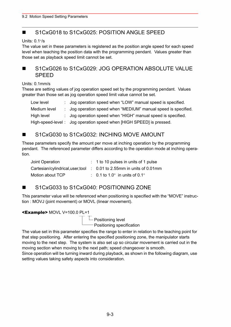
9.2 Motion Speed Setting Parameters
S1CxG018 to S1CxG025: POSITION ANGLE SPEEDUnits: 0.1°/sThe value set in these parameters is registered as the position angle speed for each speed level when teaching the position data with the programming pendant. Values greater than those set as playback speed limit cannot be set.
S1CxG026 to S1CxG029: JOG OPERATION ABSOLUTE VALUE SPEED
Units: 0.1mm/sThese are setting values of jog operation speed set by the programming pendant. Values greater than those set as jog operation speed limit value cannot be set.
S1CxG030 to S1CxG032: INCHING MOVE AMOUNTThese parameters specify the amount per move at inching operation by the programming pendant. The referenced parameter differs according to the operation mode at inching opera-tion.
S1CxG033 to S1CxG040: POSITIONING ZONEThis parameter value will be referenced when positioning is specified with the “MOVE” instruc-tion : MOVJ (joint movement) or MOVL (linear movement).
<Example> MOVL V=100.0 PL=1
The value set in this parameter specifies the range to enter in relation to the teaching point for that step positioning. After entering the specified positioning zone, the manipulator starts moving to the next step. The system is also set up so circular movement is carried out in the moving section when moving to the next path; speed changeover is smooth. Since operation will be turning inward during playback, as shown in the following diagram, use setting values taking safety aspects into consideration.
Low level : Jog operation speed when “LOW” manual speed is specified.Medium level : Jog operation speed when “MEDIUM” manual speed is specified.High level : Jog operation speed when “HIGH” manual speed is specified.High-speed-level : Jog operation speed when [HIGH SPEED] is pressed.
Joint Operation : 1 to 10 pulses in units of 1 pulseCartesian/cylindrical,user,tool : 0.01 to 2.55mm in units of 0.01mmMotion about TCP : 0.1 to 1.0° in units of 0.1°
Positioning levelPositioning specification
9-3
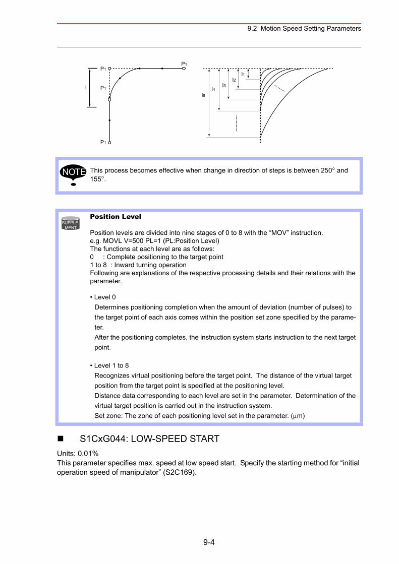
9.2 Motion Speed Setting Parameters
S1CxG044: LOW-SPEED STARTUnits: 0.01%This parameter specifies max. speed at low speed start. Specify the starting method for “initial operation speed of manipulator” (S2C169).
This process becomes effective when change in direction of steps is between 250° and 155°.
Position Level
Position levels are divided into nine stages of 0 to 8 with the “MOV” instruction.e.g. MOVL V=500 PL=1 (PL:Position Level) The functions at each level are as follows:0 : Complete positioning to the target point1 to 8 : Inward turning operationFollowing are explanations of the respective processing details and their relations with the parameter.
• Level 0Determines positioning completion when the amount of deviation (number of pulses) to the target point of each axis comes within the position set zone specified by the parame-ter. After the positioning completes, the instruction system starts instruction to the next target point.
• Level 1 to 8Recognizes virtual positioning before the target point. The distance of the virtual target position from the target point is specified at the positioning level. Distance data corresponding to each level are set in the parameter. Determination of the virtual target position is carried out in the instruction system. Set zone: The zone of each positioning level set in the parameter. (µm)
P1
l P1
P1
P1
l4l3
l1l2
l8
NOTE
SUPPLE-MENT
9-4
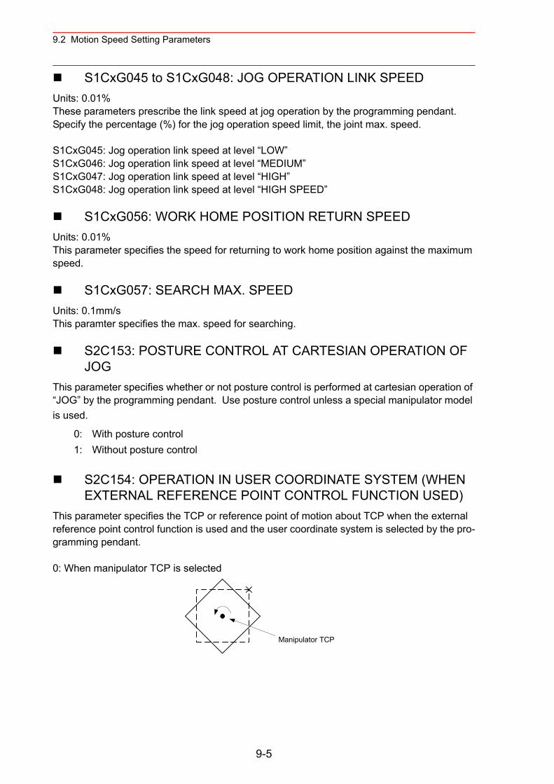
9.2 Motion Speed Setting Parameters
S1CxG045 to S1CxG048: JOG OPERATION LINK SPEED Units: 0.01%These parameters prescribe the link speed at jog operation by the programming pendant. Specify the percentage (%) for the jog operation speed limit, the joint max. speed.
S1CxG045: Jog operation link speed at level “LOW”S1CxG046: Jog operation link speed at level “MEDIUM”S1CxG047: Jog operation link speed at level “HIGH”S1CxG048: Jog operation link speed at level “HIGH SPEED”
S1CxG056: WORK HOME POSITION RETURN SPEEDUnits: 0.01%This parameter specifies the speed for returning to work home position against the maximum speed.
S1CxG057: SEARCH MAX. SPEEDUnits: 0.1mm/sThis paramter specifies the max. speed for searching.
S2C153: POSTURE CONTROL AT CARTESIAN OPERATION OF JOG
This parameter specifies whether or not posture control is performed at cartesian operation of “JOG” by the programming pendant. Use posture control unless a special manipulator model is used.
S2C154: OPERATION IN USER COORDINATE SYSTEM (WHEN EXTERNAL REFERENCE POINT CONTROL FUNCTION USED)
This parameter specifies the TCP or reference point of motion about TCP when the external reference point control function is used and the user coordinate system is selected by the pro-gramming pendant.
0: When manipulator TCP is selected
0: With posture control1: Without posture control
Manipulator TCP
9-5
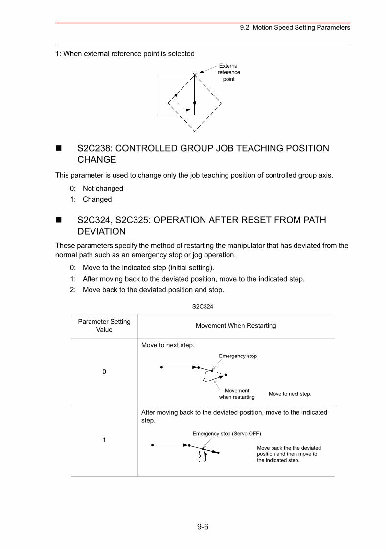
9.2 Motion Speed Setting Parameters
1: When external reference point is selected
S2C238: CONTROLLED GROUP JOB TEACHING POSITION CHANGE
This parameter is used to change only the job teaching position of controlled group axis.
S2C324, S2C325: OPERATION AFTER RESET FROM PATH DEVIATION
These parameters specify the method of restarting the manipulator that has deviated from the normal path such as an emergency stop or jog operation.
0: Not changed1: Changed
0: Move to the indicated step (initial setting).1: After moving back to the deviated position, move to the indicated step.2: Move back to the deviated position and stop.
S2C324
Parameter Setting Value Movement When Restarting
0
Move to next step.
1
After moving back to the deviated position, move to the indicated step.
Externalreference
point
Emergency stop
Movementwhen restarting Move to next step.
Emergency stop (Servo OFF)
Move back the the deviatedposition and then move tothe indicated step.
9-6
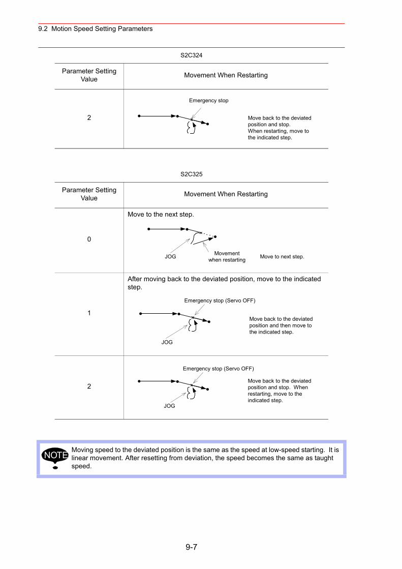
9.2 Motion Speed Setting Parameters
2
S2C325
Parameter Setting Value Movement When Restarting
0
Move to the next step.
1
After moving back to the deviated position, move to the indicated step.
2
Moving speed to the deviated position is the same as the speed at low-speed starting. It is linear movement. After resetting from deviation, the speed becomes the same as taught speed.
S2C324
Parameter Setting Value Movement When Restarting
Emergency stop
Move back to the deviatedposition and stop.When restarting, move tothe indicated step.
JOG Movementwhen restarting Move to next step.
JOG
Move back to the deviatedposition and then move tothe indicated step.
Emergency stop (Servo OFF)
JOG
Move back to the deviatedposition and stop. Whenrestarting, move to theindicated step.
Emergency stop (Servo OFF)
NOTE
9-7
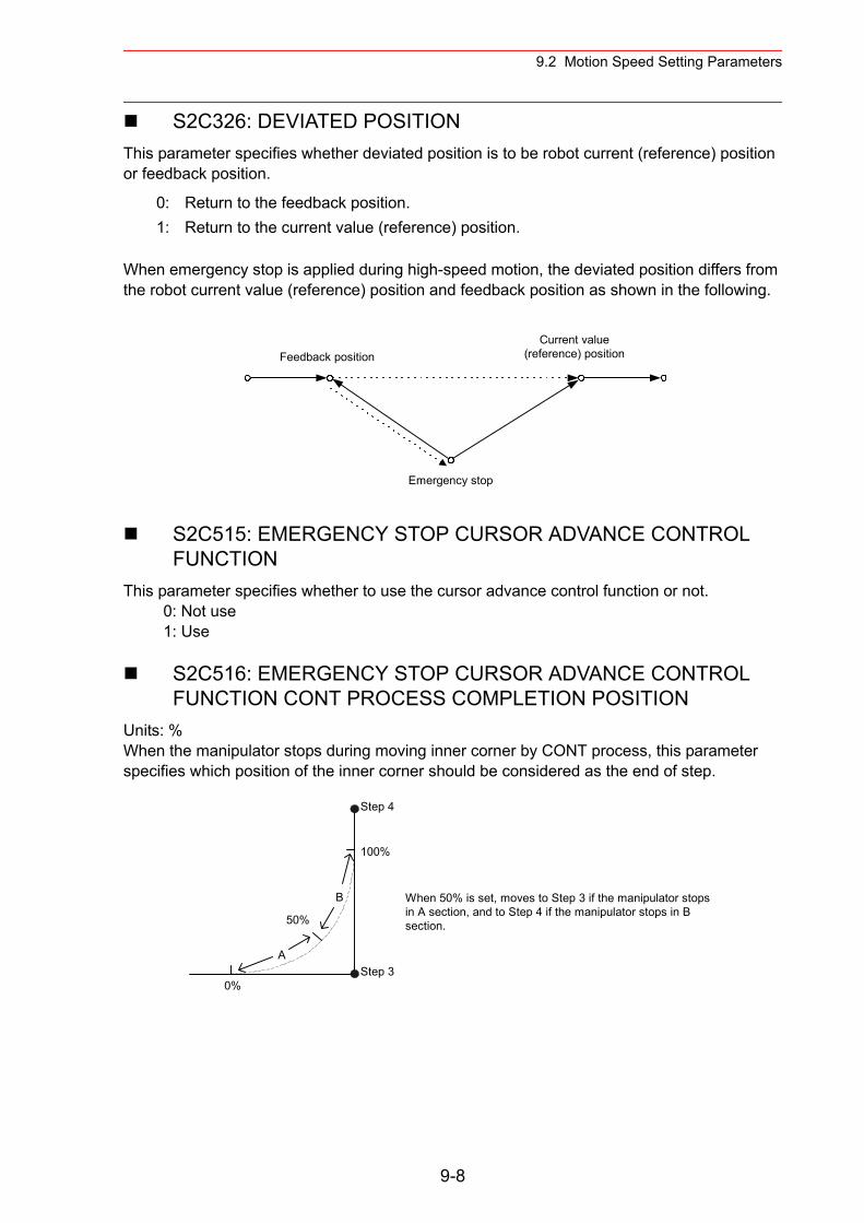
9.2 Motion Speed Setting Parameters
S2C326: DEVIATED POSITIONThis parameter specifies whether deviated position is to be robot current (reference) position or feedback position.
When emergency stop is applied during high-speed motion, the deviated position differs from the robot current value (reference) position and feedback position as shown in the following.
S2C515: EMERGENCY STOP CURSOR ADVANCE CONTROL FUNCTION
This parameter specifies whether to use the cursor advance control function or not. 0: Not use 1: Use
S2C516: EMERGENCY STOP CURSOR ADVANCE CONTROL FUNCTION CONT PROCESS COMPLETION POSITION
Units: %When the manipulator stops during moving inner corner by CONT process, this parameter specifies which position of the inner corner should be considered as the end of step.
0: Return to the feedback position.1: Return to the current value (reference) position.
Feedback positionCurrent value
(reference) position
Emergency stop
A
B
50%
100%
0%
Step 4
Step 3
When 50% is set, moves to Step 3 if the manipulator stopsin A section, and to Step 4 if the manipulator stops in Bsection.
9-8
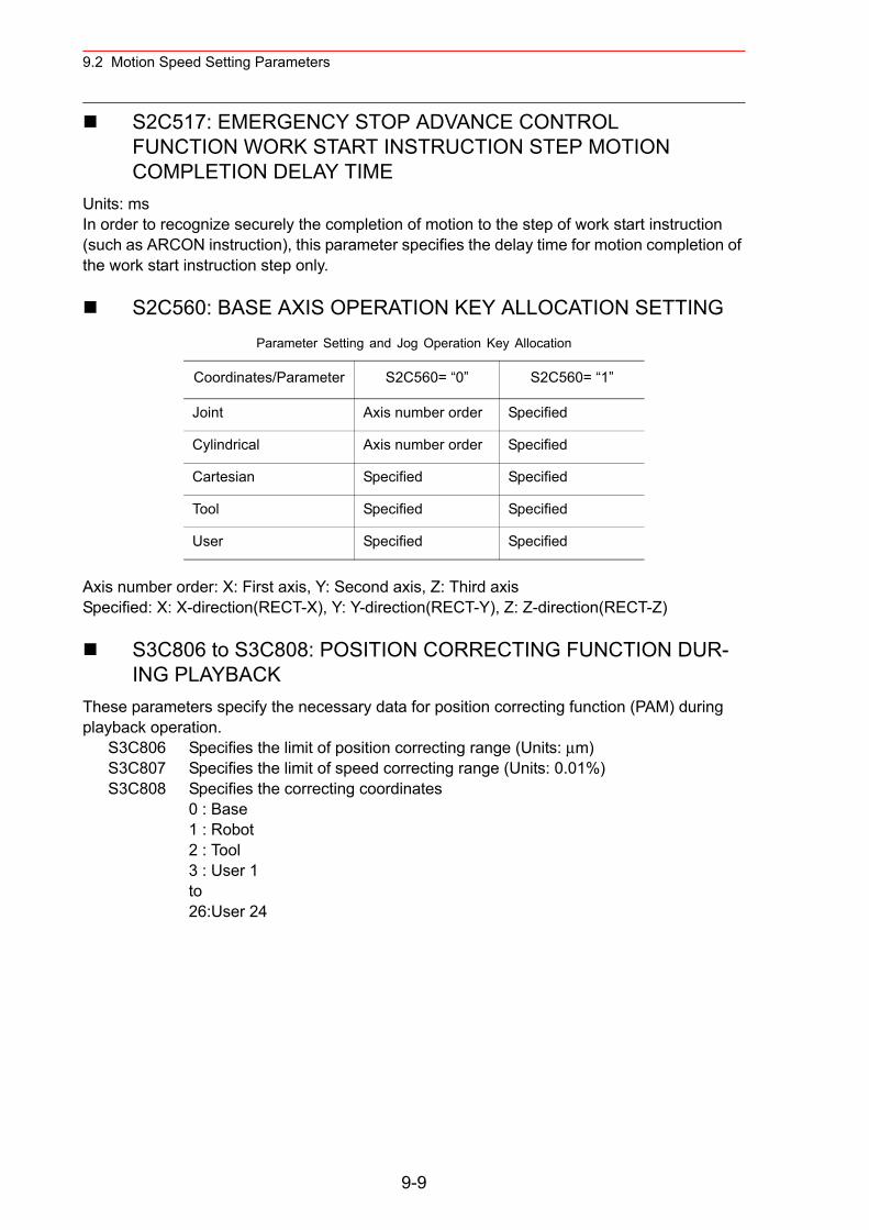
9.2 Motion Speed Setting Parameters
S2C517: EMERGENCY STOP ADVANCE CONTROL FUNCTION WORK START INSTRUCTION STEP MOTION COMPLETION DELAY TIME
Units: msIn order to recognize securely the completion of motion to the step of work start instruction (such as ARCON instruction), this parameter specifies the delay time for motion completion of the work start instruction step only.
S2C560: BASE AXIS OPERATION KEY ALLOCATION SETTING
Axis number order: X: First axis, Y: Second axis, Z: Third axisSpecified: X: X-direction(RECT-X), Y: Y-direction(RECT-Y), Z: Z-direction(RECT-Z)
S3C806 to S3C808: POSITION CORRECTING FUNCTION DUR-ING PLAYBACK
These parameters specify the necessary data for position correcting function (PAM) during playback operation.
Parameter Setting and Jog Operation Key Allocation
Coordinates/Parameter S2C560= “0” S2C560= “1”
Joint Axis number order Specified
Cylindrical Axis number order Specified
Cartesian Specified Specified
Tool Specified Specified
User Specified Specified
S3C806 Specifies the limit of position correcting range (Units: µm)S3C807 Specifies the limit of speed correcting range (Units: 0.01%)S3C808 Specifies the correcting coordinates
0 : Base1 : Robot2 : Tool3 : User 1to26:User 24
9-9
9.3 Mode Operation Setting Parameters
9.3 Mode Operation Setting Parameters
These parameters set various operations in the teach mode or remote mode.
S2C147: SECURITY MODE WHEN CONTROL POWER SUPPLY IS TURNED ON
The operation level when the control power supply is turned ON is set.
S2C148: SELECTION OF CARTESIAN/CYLINDRICALThis parameter specifies whether the cartesian mode or cylindrial mode is affected when car-tesian/cylindrical mode is selected by operation (coordinate) mode selection at axis operation of programming pendant. This specification can be done on the TEACHING CONDITION window.
S2C149: COORDINATE SWITCHING PROHIBITEDThis parameter prohibits switching coordinates during JOG operation by the programming pendant.
0: Operation Mode1: Editing Mode2: Management Mode
0: Cylindrical mode1: Cartesian mode
0: Switching permitted for tool coordinates and user coordinates1: Switching prohibited for tool coordinates2: Switching prohibited for user coordinates3: Switching prohibited for tool coordinates and user coordinates
9-10
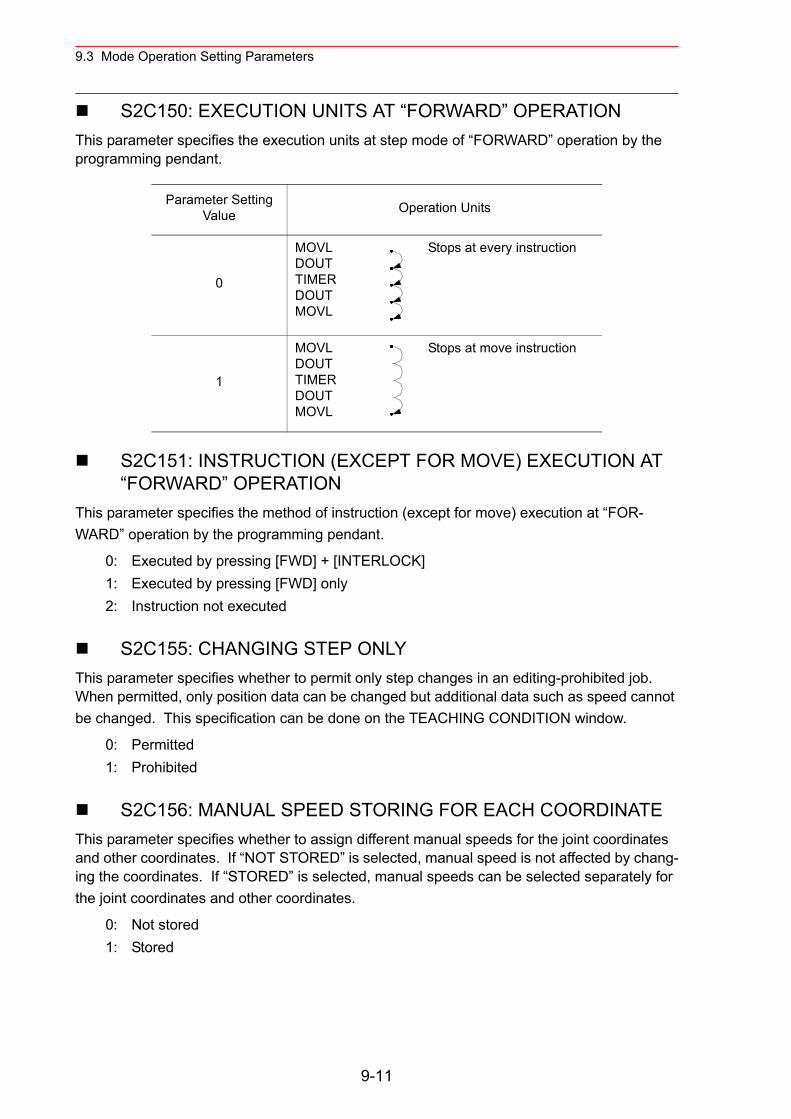
9.3 Mode Operation Setting Parameters
S2C150: EXECUTION UNITS AT “FORWARD” OPERATION This parameter specifies the execution units at step mode of “FORWARD” operation by the programming pendant.
S2C151: INSTRUCTION (EXCEPT FOR MOVE) EXECUTION AT “FORWARD” OPERATION
This parameter specifies the method of instruction (except for move) execution at “FOR-WARD” operation by the programming pendant.
S2C155: CHANGING STEP ONLY This parameter specifies whether to permit only step changes in an editing-prohibited job. When permitted, only position data can be changed but additional data such as speed cannot be changed. This specification can be done on the TEACHING CONDITION window.
S2C156: MANUAL SPEED STORING FOR EACH COORDINATE This parameter specifies whether to assign different manual speeds for the joint coordinates and other coordinates. If “NOT STORED” is selected, manual speed is not affected by chang-ing the coordinates. If “STORED” is selected, manual speeds can be selected separately for the joint coordinates and other coordinates.
Parameter Setting Value Operation Units
0
MOVLDOUT TIMER DOUT MOVL
Stops at every instruction
1
MOVL DOUTTIMER DOUTMOVL
Stops at move instruction
0: Executed by pressing [FWD] + [INTERLOCK]1: Executed by pressing [FWD] only2: Instruction not executed
0: Permitted1: Prohibited
0: Not stored1: Stored
9-11
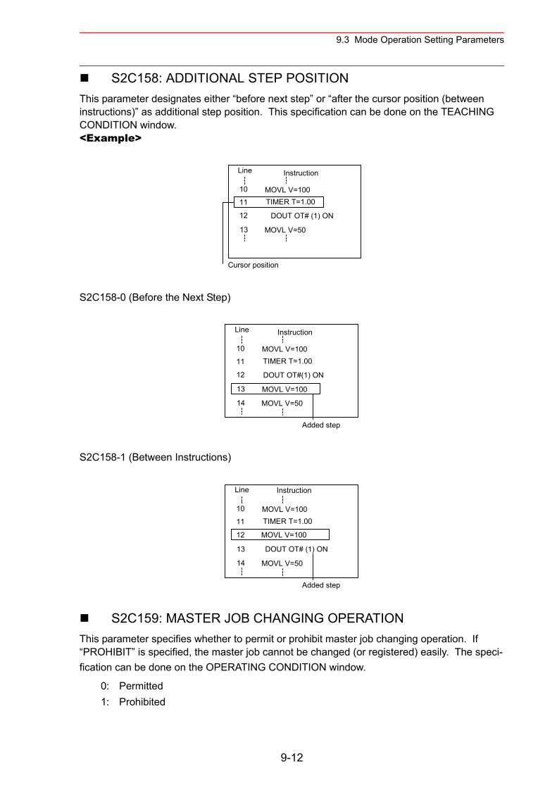
9.3 Mode Operation Setting Parameters
S2C158: ADDITIONAL STEP POSITIONThis parameter designates either “before next step” or “after the cursor position (between instructions)” as additional step position. This specification can be done on the TEACHING CONDITION window.<Example>
S2C158-0 (Before the Next Step)
S2C158-1 (Between Instructions)
S2C159: MASTER JOB CHANGING OPERATIONThis parameter specifies whether to permit or prohibit master job changing operation. If “PROHIBIT” is specified, the master job cannot be changed (or registered) easily. The speci-fication can be done on the OPERATING CONDITION window.
0: Permitted1: Prohibited
Line Instruction
10
11
12
13
MOVL V=100TIMER T=1.00
DOUT OT# (1) ON
MOVL V=50
Cursor position
Line Instruction
10
11
12
13
MOVL V=100TIMER T=1.00
DOUT OT#(1) ON
MOVL V=100
Added step
14 MOVL V=50
DOUT OT# (1) ON
Line Instruction
10
11
12
13
MOVL V=100TIMER T=1.00
MOVL V=100
Added step
14 MOVL V=50
9-12
9.3 Mode Operation Setting Parameters
S2C160: CHECK AND MACHINE-LOCK KEY OPERATION IN PLAY MODE
This parameter specifies whether to permit or prohibit in play mode to change the operation that changes the operation condition. Even if an error occurs because of the operation with the keys, the manipulator does not stop. The specification can be done on the OPERATING CONDITION window.
S2C161: RESERVED WORK JOB CHANGING OPERATIONThis parameter specifies whether to permit reserved work job changing operation.The designation can be done on the OPERATING CONDITION window.
S2C162: MASTER OR SUBMASTER CALL OPERATION IN PLAY MODE
This parameter specifies whether the master or submaster call operation in play mode is per-mitted or not. When the independent control function is valid, the master job for sub-task is specified at the same time. The specification can be done on the OPERATING CONDITION window.
S2C163: LANGUAGE LEVELThis parameter specifies the level of the robot language (INFORM III). The levels simplify the instruction registering operation. With NX100, all robot instructions can be executed regard-less of specification of instruction sets. The specification can be done on the TEACHING CONDITION window.
0: Contracted LevelOnly frequently used robot instructions are selected to reduce the number of instructions to be registered. Robot instructions displayed on the instruction dialog box are also reduced so that specification is simplified.
1: Stardard Level2: Expanded Level
All the robot instructions are available in standard and expanded levels. The two levels are distinguished by the number of additional information items (tags) that can be used with robot instructions. At the expanded level, the flowing functions are available.
• Local Variables and Array Variables • Use of Variables for Tags (Example: MOVJ VJ=I000)
The above functions are not available at the standard level, however, which reduces the number of data required to register instructions, thereby simplifying the operation.
0: Permitted1: Prohibited
0: Permitted1: Prohibited
0: Permitted1: Prohibited
9-13
9.3 Mode Operation Setting Parameters
S2C166: INSTRUCTION INPUT LEARNING FUNCTION This parameter specifies wheter to set a line of instructions that has been input on the input buffer line when pressing the first soft key for each instruction. If “PROVIDED” is selected, the instructions are set.
S2C167: ADDRESS SETTING WHEN CONTROL POWER IS TURNED ON
This parameter specifies the processing of the job name ,step No. , and line No. that are set when the control power supply is turned ON.
S2C168: JOB LIST DISPLAY METHOD AT JOB SELECTIONThese parameters specify the displaying method on the JOB LIST window at job selection.
S2C169: INITIAL OPERATION OF MANIPULATORThis parameter specifies the operation speed level of the first section when starting. Specify the operation speed with the low-speed start (S1CxG044). When starting at low-speed, the manipulator stops after reaching the indicated step regardless of the cycle setting. Once the manipulator is paused during the low-speed operation, it moves at teaching speed when restarted.
0: Without learning function1: With learning function
0: Reproduces the address when power supply is turned ON.1: Lead address (Line”0”) of the master job.
0: Order of Names1: Order of Date2: Order of Registration
0: Specified on the SPECIAL PLAY window. Operates at low speed only when low speed start is set. Operates at taught speed when not instructed.
1: Starts at low speed after editing regardless of soft key instructions.
9-14
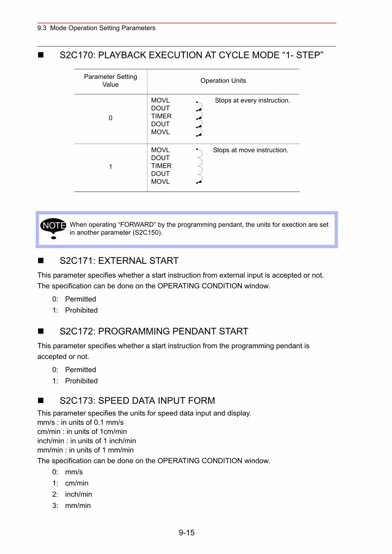
9.3 Mode Operation Setting Parameters
S2C170: PLAYBACK EXECUTION AT CYCLE MODE “1- STEP”
S2C171: EXTERNAL STARTThis parameter specifies whether a start instruction from external input is accepted or not. The specification can be done on the OPERATING CONDITION window.
S2C172: PROGRAMMING PENDANT STARTThis parameter specifies whether a start instruction from the programming pendant is accepted or not.
S2C173: SPEED DATA INPUT FORMThis parameter specifies the units for speed data input and display.mm/s : in units of 0.1 mm/scm/min : in units of 1cm/mininch/min : in units of 1 inch/minmm/min : in units of 1 mm/min The specification can be done on the OPERATING CONDITION window.
Parameter Setting Value Operation Units
0
MOVL DOUT TIMER DOUT MOVL
Stops at every instruction.
1
MOVL DOUTTIMERDOUTMOVL
Stops at move instruction.
When operating “FORWARD” by the programming pendant, the units for exection are set in another parameter (S2C150).
0: Permitted1: Prohibited
0: Permitted1: Prohibited
0: mm/s1: cm/min2: inch/min3: mm/min
NOTE
9-15
9.3 Mode Operation Setting Parameters
S2C174: RESERVED STARTThis parameter specifies whether a reserved start instruction from the programming pendant is accepted or not. The specification can be done on the OPERATING CONDITION window.
S2C176: JOB SELECTION AT REMOTE FUNCTION (PLAY MODE)
This parameter specifies whether a job selection in play mode at remote function is prohibited or not.
S2C177: EXTERNAL MODE SWITCHThis parameter specifies whether mode switching from the outside is accepted or not. The specification can be done on the OPERATING CONDITION window.
S2C178: MODE SWITCHING FROM PROGRAMMING PENDANTThis parameter specifies whether mode switching from the programming pendant is accepted or not. The specification can be done on the OPERATING CONDITION window.
S2C179: EXTERNAL CYCLE SWITCHINGThis parameter specifies whether cycle switching from the outside is accepted or not. The specification can be done on the OPERATING CONDITION window.
S2C180: PROGRAMMING PENDANT CYCLE SWITCHINGThis parameter specifies whether cycle switching from the programming pendant is accepted or not. The specification can be done on the OPERATING CONDITION window.
0: Permitted1: Prohibited
0: Permitted1: Prohibited
0: Permitted1: Prohibited
0: Permitted1: Prohibited
0: Permitted1: Prohibited
0: Permitted1: Prohibited
9-16
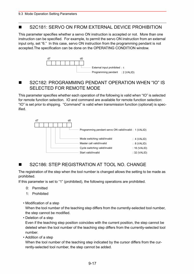
9.3 Mode Operation Setting Parameters
S2C181: SERVO ON FROM EXTERNAL DEVICE PROHIBITIONThis parameter specifies whether a servo ON instruction is accepted or not. More than one instruction can be specified. For example, to permit the servo ON instruction from an external input only, set “6.” In this case, servo ON instruction from the programming pendant is not accepted.The specification can be done on the OPERATING CONDITION window.
S2C182: PROGRAMMING PENDANT OPERATION WHEN “IO” IS SELECTED FOR REMOTE MODE
This parameter specifies whether each operation of the following is valid when “IO” is selected for remote function selection. IO and command are available for remote function selection: “IO” is set prior to shipping. “Command” is valid when transmission function (optional) is spec-ified.
S2C186: STEP REGISTRATION AT TOOL NO. CHANGEThe registration of the step when the tool number is changed allows the setting to be made as prohibited.If this parameter is set to “1” (prohibited), the following operations are prohibited.
• Modification of a stepWhen the tool number of the teaching step differs from the currently-selected tool number, the step cannot be modified.
• Deletion of a stepEven if the teaching step position coincides with the current position, the step cannot be deleted when the tool number of the teaching step differs from the currently-selected tool number.
• Addition of a stepWhen the tool number of the teaching step indicated by the cursor differs from the cur-rently-selected tool number, the step cannot be added.
0: Permitted1: Prohibited
d7 d0
External input prohibited
Programming pendant: 1
: 2 (VALID)
d7 d0
Programming pendant servo ON valid/invalid
Mode switching valid/invalid
Master call valid/invalid
Cycle switching valid/invalid
Start valid/invalid
: 1 (VALID)
: 4 (VALID)
: 8 (VALID)
: 16 (VALID)
: 32 (VALID)
9-17
9.3 Mode Operation Setting Parameters
S2C211: REMOTE FIRST CYCLE MODEThis parameter sets the cycle that changes from the local mode to the remote mode.The setting can be made on the OPERATING CONDITION window.
S2C212: LOCAL FIRST CYCLE MODEThis parameter sets the cycle that changes from the remote mode to the local mode.The setting can be made on the OPERATING CONDITION window.
S2C230: POWER ON FIRST CYCLE MODEThis parameter sets the first cycle mode for when the power is turned ON. The setting can be made on the OPERATING CONDITION window.
S2C231: TEACH MODE FIRST CYCLE MODEThis parameter sets the cycle that changes from the play mode to the teach mode.The setting can be made on the OPERATING CONDITION window.
S2C232: PLAY MODE FIRST CYCLE MODEThis parameter sets the cycle that changes from the teach mode to the play mode.The setting can be made on the OPERATING CONDITION window.
0: Step1: 1 cycle2: Continuous3: Setting retained
0: Step1: 1 cycle2: Continuous3: Setting retained
0: Step1: 1 cycle2: Continuous3: Setting retained
0: Step1: 1 cycle2: Continuous3: Setting retained
0: Step1: 1 cycle2: Continuous3: Setting retained
9-18
9.3 Mode Operation Setting Parameters
S2C234: START CONDITION AFTER ABSOLUTE DATA ALLOW-ABLE RANGE ERROR OCCURS
This parameter specifies the activating method after the absolute data allowable range error occurs.
S2C317 to S2C321: TIME RESETThese parameters specify whether resetting operation of the specified times is permitted or not.
“PERMIT” is set as the initial value for the work time and motion time.
S2C333: TOOL NO. SWITCHINGThis parameter specifies whether tool number switching is permitted or not. If “PERMIT” is selected, 24 types of tools from number 0 to 23 can be switched. If “NOT PERMIT” is selected, only number “0” can be used.
S2C335: POSITION TEACHING BUZZERThis parameter specifies whether the buzzer sound at position teaching is used or not.
0: Position check operation required1: Low-speed start up
S2C317 : CONTROL POWER ON TIMES2C318 : SERVO POWER ON TIMES2C319 : PLAYBACK TIMES2C320 : WORK TIMES2C321 : WEAVING TIME
0: Prohibit Resetting 1: Permit Resetting
0: Prohibited1: Permitted
0: With buzzer1: Without buzzer
9-19
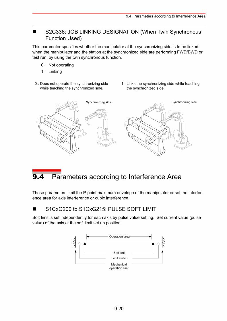
9.4 Parameters according to Interference Area
S2C336: JOB LINKING DESIGNATION (When Twin Synchronous Function Used)
This parameter specifies whether the manipulator at the synchronizing side is to be linked when the manipulator and the station at the synchronized side are performing FWD/BWD or test run, by using the twin synchronous function.
9.4 Parameters according to Interference Area
These parameters limit the P-point maximum envelope of the manipulator or set the interfer-ence area for axis interference or cubic interference.
S1CxG200 to S1CxG215: PULSE SOFT LIMIT Soft limit is set independently for each axis by pulse value setting. Set current value (pulse value) of the axis at the soft limit set up position.
0: Not operating1: Linking
0 : Does not operate the synchronizing side while teaching the synchronized side.
1 : Links the synchronizing side while teaching the synchronized side.
Synchronizing side Synchronizing side
Mechanicaloperation limit
Limit switch
Soft limit
Operation area
9-20
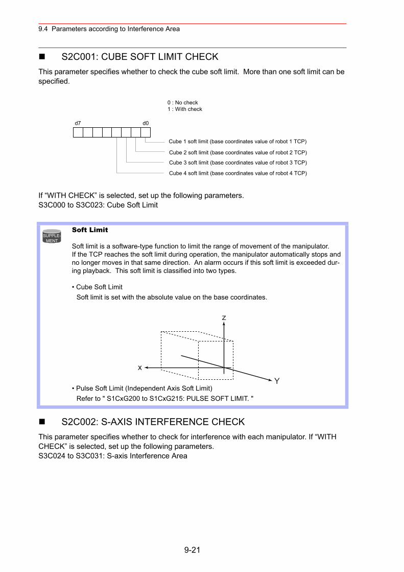
9.4 Parameters according to Interference Area
S2C001: CUBE SOFT LIMIT CHECK This parameter specifies whether to check the cube soft limit. More than one soft limit can be specified.
If “WITH CHECK” is selected, set up the following parameters.S3C000 to S3C023: Cube Soft Limit
S2C002: S-AXIS INTERFERENCE CHECKThis parameter specifies whether to check for interference with each manipulator. If “WITH CHECK” is selected, set up the following parameters.S3C024 to S3C031: S-axis Interference Area
Soft Limit
Soft limit is a software-type function to limit the range of movement of the manipulator. If the TCP reaches the soft limit during operation, the manipulator automatically stops and no longer moves in that same direction. An alarm occurs if this soft limit is exceeded dur-ing playback. This soft limit is classified into two types.
• Cube Soft LimitSoft limit is set with the absolute value on the base coordinates.
• Pulse Soft Limit (Independent Axis Soft Limit) Refer to " S1CxG200 to S1CxG215: PULSE SOFT LIMIT. "
d7 d0
Cube 1 soft limit (base coordinates value of robot 1 TCP)
Cube 2 soft limit (base coordinates value of robot 2 TCP)
0 : No check1 : With check
Cube 3 soft limit (base coordinates value of robot 3 TCP)
Cube 4 soft limit (base coordinates value of robot 4 TCP)
SUPPLE-MENT
z
Yx
9-21
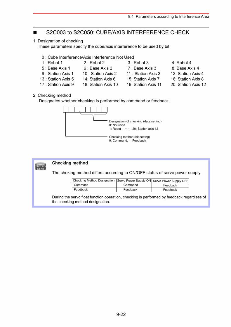
9.4 Parameters according to Interference Area
S2C003 to S2C050: CUBE/AXIS INTERFERENCE CHECK 1. Designation of checking These parameters specify the cube/axis interference to be used by bit.
0 : Cube Interference/Axis Interference Not Used 1 : Robot 1 2 : Robot 2 3 : Robot 3 4: Robot 45 : Base Axis 1 6 : Base Axis 2 7 : Base Axis 3 8: Base Axis 49 : Station Axis 1 10 : Station Axis 2 11 : Station Axis 3 12: Station Axis 4
13 : Station Axis 5 14: Station Axis 6 15: Station Axis 7 16: Station Axis 817 : Station Axis 9 18: Station Axis 10 19: Station Axis 11 20: Station Axis 12
2. Checking method Designates whether checking is performed by command or feedback.
Checking method
The cheking method differs according to ON/OFF status of servo power supply.
During the servo float function operation, checking is performed by feedback regardless of the checking method designation.
Designation of checking (data setting)0: Not used1: Robot 1, , 20: Station axis 12
Checking method (bit setting)0: Command, 1: Feedback
SUPPLE-MENT
Checking Method Designation Servo Power Supply ON Servo Power Supply OFFCommandFeedback
CommandFeedback
FeedbackFeedback
9-22
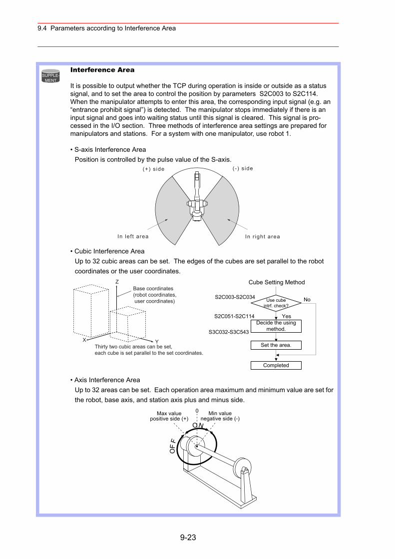
9.4 Parameters according to Interference Area
Interference Area
It is possible to output whether the TCP during operation is inside or outside as a status signal, and to set the area to control the position by parameters S2C003 to S2C114. When the manipulator attempts to enter this area, the corresponding input signal (e.g. an “entrance prohibit signal”) is detected. The manipulator stops immediately if there is an input signal and goes into waiting status until this signal is cleared. This signal is pro-cessed in the I/O section. Three methods of interference area settings are prepared for manipulators and stations. For a system with one manipulator, use robot 1.
• S-axis Interference AreaPosition is controlled by the pulse value of the S-axis.
• Cubic Interference AreaUp to 32 cubic areas can be set. The edges of the cubes are set parallel to the robot coordinates or the user coordinates.
• Axis Interference AreaUp to 32 areas can be set. Each operation area maximum and minimum value are set for the robot, base axis, and station axis plus and minus side.
SUPPLE-MENT
In lef t area
(+) s ide (-) s ide
In r ight area
Use cubeintrf. check?
Decide the usingmethod.
Set the area.
Completed
No
YesS2C051-S2C114
S3C032-S3C543
Cube Setting Method
S2C003-S2C034Base coordinates(robot coordinates, user coordinates)
Thirty two cubic areas can be set,each cube is set parallel to the set coordinates.
Z
X Y
Max valuepositive side (+)
Min valuenegative side (-)
0
ON
OF
F
9-23
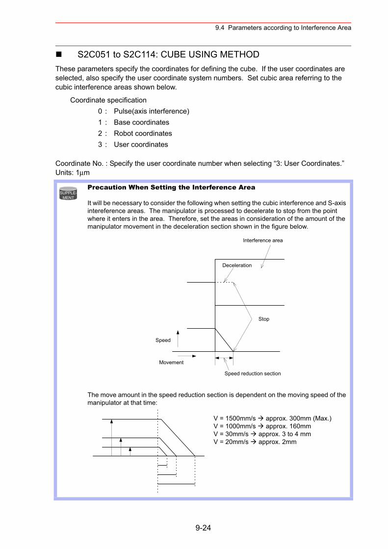
9.4 Parameters according to Interference Area
S2C051 to S2C114: CUBE USING METHODThese parameters specify the coordinates for defining the cube. If the user coordinates are selected, also specify the user coordinate system numbers. Set cubic area referring to the cubic interference areas shown below.
Coordinate No. : Specify the user coordinate number when selecting “3: User Coordinates.”Units: 1µm
Coordinate specification 0 : Pulse(axis interference) 1 : Base coordinates 2 : Robot coordinates 3 : User coordinates
Precaution When Setting the Interference Area
It will be necessary to consider the following when setting the cubic interference and S-axis intereference areas. The manipulator is processed to decelerate to stop from the point where it enters in the area. Therefore, set the areas in consideration of the amount of the manipulator movement in the deceleration section shown in the figure below.
The move amount in the speed reduction section is dependent on the moving speed of the manipulator at that time:
V = 1500mm/s approx. 300mm (Max.)V = 1000mm/s approx. 160mmV = 30mm/s approx. 3 to 4 mmV = 20mm/s approx. 2mm
SUPPLE-MENT
Stop
Deceleration
Interference area
Speed
Movement
Speed reduction section
9-24
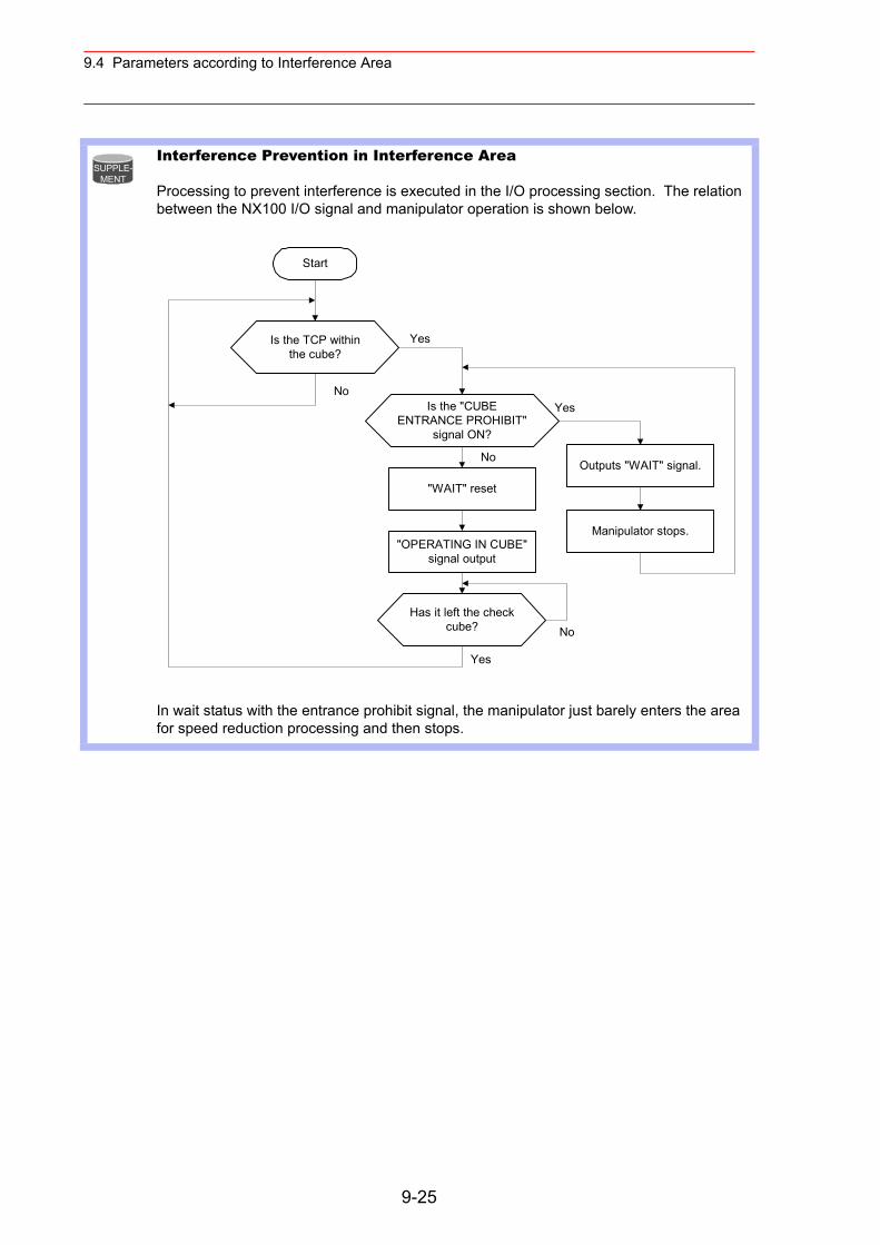
9.4 Parameters according to Interference Area
Interference Prevention in Interference Area
Processing to prevent interference is executed in the I/O processing section. The relation between the NX100 I/O signal and manipulator operation is shown below.
In wait status with the entrance prohibit signal, the manipulator just barely enters the area for speed reduction processing and then stops.
SUPPLE-MENT
Start
Is the TCP withinthe cube?
Is the "CUBEENTRANCE PROHIBIT"
signal ON?
"WAIT" reset
"OPERATING IN CUBE"signal output
Has it left the checkcube?
Outputs "WAIT" signal.
Manipulator stops.
Yes
No
No
Yes
No
Yes
9-25
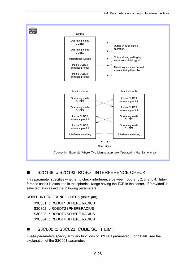
9.4 Parameters according to Interference Area
S2C188 to S2C193: ROBOT INTERFERENCE CHECKThis parameter specifies whether to check interference between robots 1, 2, 3, and 4. Inter-ference check is executed in the spherical range having the TCP in the center. If “provided” is selected, also select the following parameters.
ROBOT INTERFERENCE CHECK (units: µm)
S3C000 to S3C023: CUBE SOFT LIMITThese parameters specify auxiliary functions of S2C001 parameter. For details, see the explanation of the S2C001 parameter.
Connection Example Where Two Manipulators are Operated in the Same Area
S3C801 : ROBOT1 SPHERE RADIUSS3C802 : ROBOT 2 SPHERE RADIUS S3C803 : ROBOT3 SPHERE RADIUSS3C804 : ROBOT4 SPHERE RADIUS
SUPPLE-MENT
Operating insideCUBE1
Operating insideCUBE2
Interference waiting
Inside CUBE1entrance prohibit
Inside CUBE2entrance prohibit
NX100
Operating insideCUBE1
Operating insideCUBE2
Inside CUBE1entrance prohibit
Inside CUBE2entrance prohibit
Interference waiting
Inside CUBE1entrance prohibit
Inside CUBE2entrance prohibit
Operating insideCUBE1
Operating insideCUBE2
Interference waiting
Manipulator A Manipulator B
Alarm signal
Output in cube duringoperation.
Output during waiting byentrance prohibit signal.
These signals are checkedwhen entering the cube.
9-26
9.5 Parameters according to Status I/O
S3C024 to S3C031: S-AXIS INTERFERENCE AREAThese parameters specify auxiliary functions of S2C002 parameter. For details, see the explanation of the S2C002 parameter.
S3C032 to S3C543: CUBIC INTERFERENCE AREAThese parameters specify auxiliary functions of S2C003 to S2C034 parameters. For details, see the explanation of the S2C003 to S2C050 parameters.
S3C801 to S3C804: ROBOT INTERFERENCE AREAThese parameters specify auxiliary functions of S2C188 to S2C193 parameters. For details, see the explanation of the S2C188 to S2C193 parameters.
S3C805: A SIDE LENGTH OF WORK-HOME-POSITION CUBEUnits: 1µmThis parameter specifies a side length of the cube for the work home position.
9.5 Parameters according to Status I/O
These parameters set the parity check or I/O setting for user input/output signals.
S2C187: USER OUTPUT RELAY WHEN CONTROL POWER IS ON
This parameter specifies the state of the user output relays when the control power is turned ON. Since the power OFF state, including peripheral devices, cannot be completely repro-duced, take note when restarting.
0: Reset to the power OFF state1: Initialized (all user relays OFF)
9-27
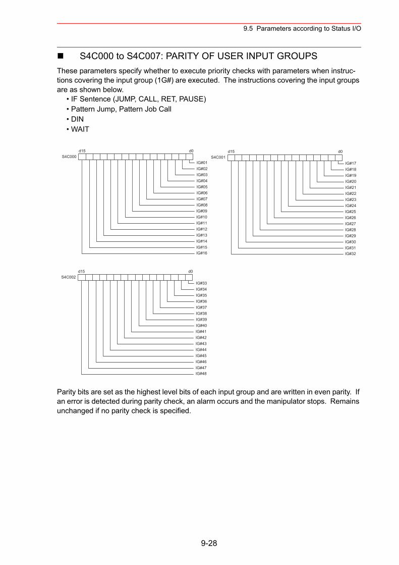
9.5 Parameters according to Status I/O
S4C000 to S4C007: PARITY OF USER INPUT GROUPS These parameters specify whether to execute priority checks with parameters when instruc-tions covering the input group (1G#) are executed. The instructions covering the input groups are as shown below.
• IF Sentence (JUMP, CALL, RET, PAUSE)• Pattern Jump, Pattern Job Call• DIN• WAIT
Parity bits are set as the highest level bits of each input group and are written in even parity. If an error is detected during parity check, an alarm occurs and the manipulator stops. Remains unchanged if no parity check is specified.
d15 d0
IG#01IG#02IG#03IG#04IG#05IG#06IG#07IG#08IG#09IG#10IG#11IG#12IG#13IG#14IG#15IG#16
S4C000d15 d0
IG#17IG#18IG#19IG#20IG#21IG#22IG#23IG#24IG#25IG#26IG#27IG#28IG#29IG#30IG#31IG#32
S4C001
d15 d0
IG#33IG#34IG#35IG#36IG#37IG#38IG#39IG#40IG#41IG#42IG#43IG#44IG#45IG#46IG#47IG#48
S4C002
9-28
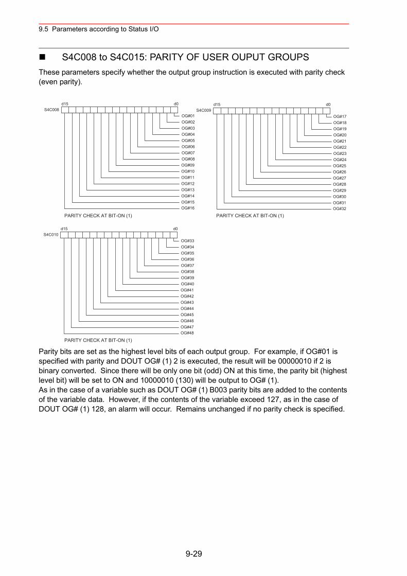
9.5 Parameters according to Status I/O
S4C008 to S4C015: PARITY OF USER OUPUT GROUPSThese parameters specify whether the output group instruction is executed with parity check (even parity).
Parity bits are set as the highest level bits of each output group. For example, if OG#01 is specified with parity and DOUT OG# (1) 2 is executed, the result will be 00000010 if 2 is binary converted. Since there will be only one bit (odd) ON at this time, the parity bit (highest level bit) will be set to ON and 10000010 (130) will be output to OG# (1).As in the case of a variable such as DOUT OG# (1) B003 parity bits are added to the contents of the variable data. However, if the contents of the variable exceed 127, as in the case of DOUT OG# (1) 128, an alarm will occur. Remains unchanged if no parity check is specified.
d15 d0
OG#01OG#02OG#03OG#04OG#05OG#06OG#07OG#08OG#09OG#10OG#11OG#12OG#13OG#14OG#15OG#16
S4C008d15 d0
OG#17OG#18OG#19OG#20OG#21OG#22OG#23OG#24OG#25OG#26OG#27OG#28OG#29OG#30OG#31OG#32
S4C009
d15 d0
OG#33OG#34OG#35OG#36OG#37OG#38OG#39OG#40OG#41OG#42OG#43OG#44OG#45OG#46OG#47OG#48
S4C010
PARITY CHECK AT BIT-ON (1)
PARITY CHECK AT BIT-ON (1)
PARITY CHECK AT BIT-ON (1)
9-29
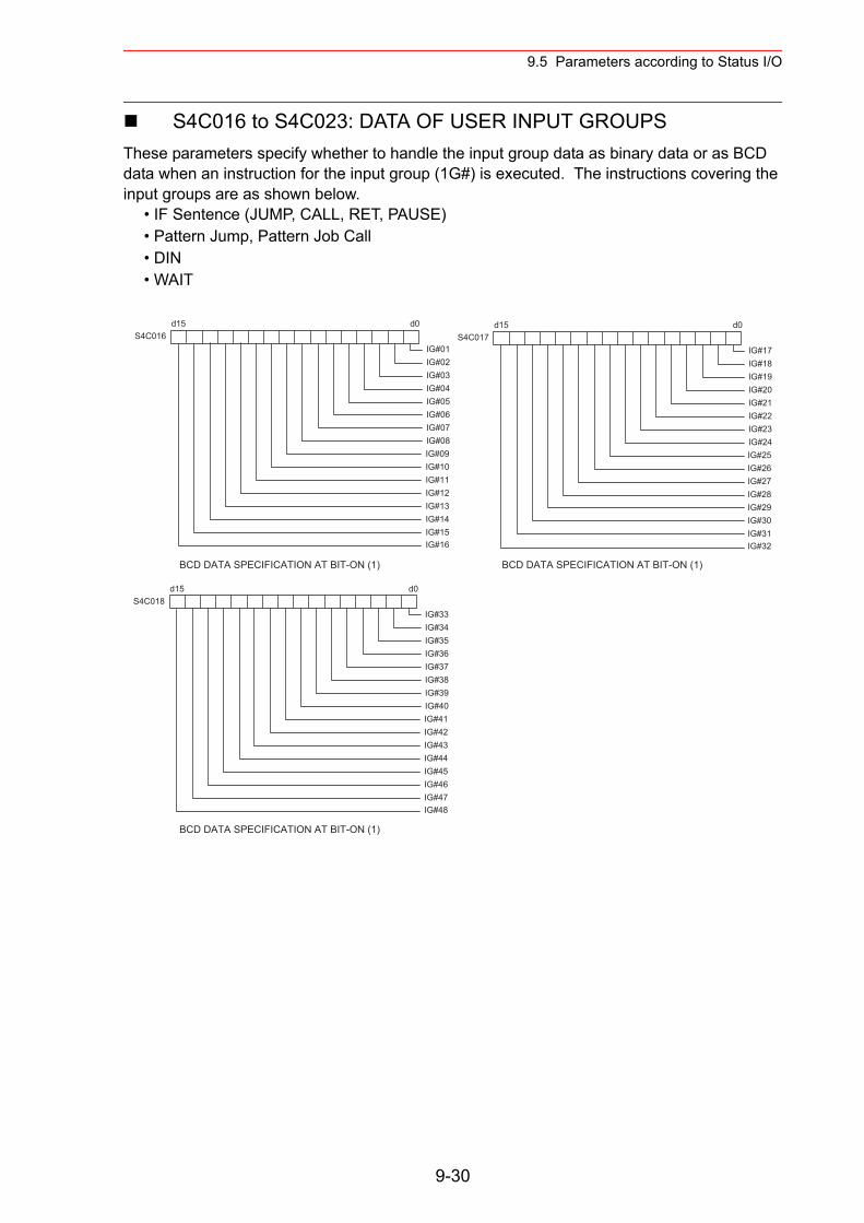
9.5 Parameters according to Status I/O
S4C016 to S4C023: DATA OF USER INPUT GROUPSThese parameters specify whether to handle the input group data as binary data or as BCD data when an instruction for the input group (1G#) is executed. The instructions covering the input groups are as shown below.
• IF Sentence (JUMP, CALL, RET, PAUSE)• Pattern Jump, Pattern Job Call• DIN• WAIT
d15 d0
IG#01IG#02IG#03IG#04IG#05IG#06IG#07IG#08IG#09IG#10IG#11IG#12IG#13IG#14IG#15IG#16
S4C016d15 d0
IG#17IG#18IG#19IG#20IG#21IG#22IG#23IG#24IG#25IG#26IG#27IG#28IG#29IG#30IG#31IG#32
S4C017
d15 d0
IG#33IG#34IG#35IG#36IG#37IG#38IG#39IG#40IG#41IG#42IG#43IG#44IG#45IG#46IG#47IG#48
S4C018
BCD DATA SPECIFICATION AT BIT-ON (1)
BCD DATA SPECIFICATION AT BIT-ON (1)
BCD DATA SPECIFICATION AT BIT-ON (1)
9-30
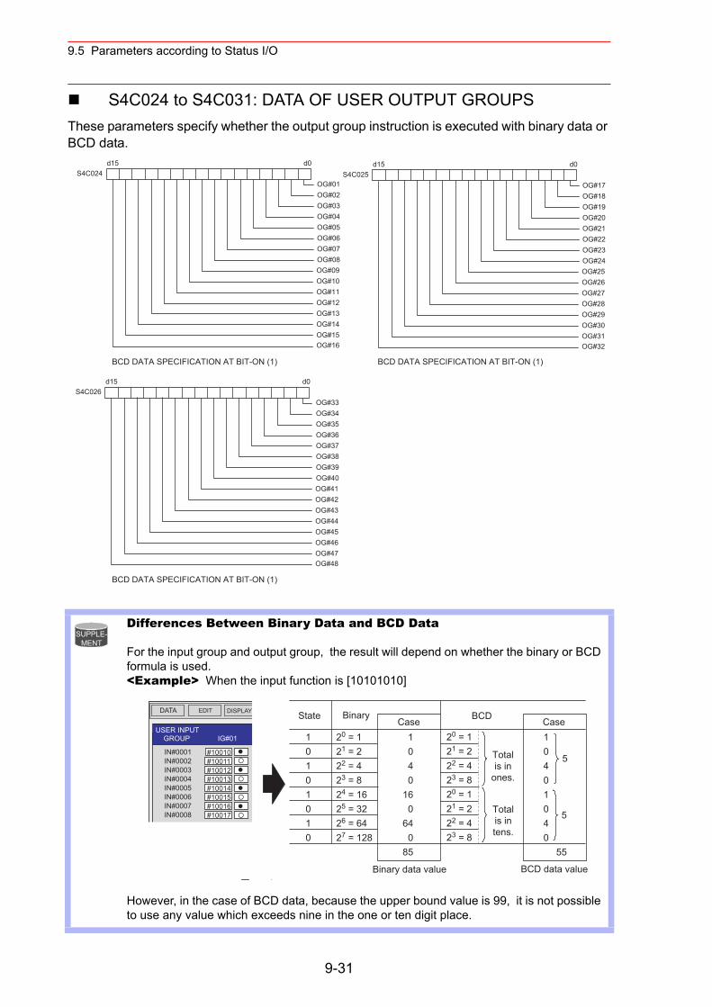
9.5 Parameters according to Status I/O
S4C024 to S4C031: DATA OF USER OUTPUT GROUPSThese parameters specify whether the output group instruction is executed with binary data or BCD data.
Differences Between Binary Data and BCD Data
For the input group and output group, the result will depend on whether the binary or BCD formula is used. <Example> When the input function is [10101010]
However, in the case of BCD data, because the upper bound value is 99, it is not possible to use any value which exceeds nine in the one or ten digit place.
d15 d0
OG#01OG#02OG#03OG#04OG#05OG#06OG#07OG#08OG#09OG#10OG#11OG#12OG#13OG#14OG#15OG#16
S4C024d15 d0
OG#17OG#18OG#19OG#20OG#21OG#22OG#23OG#24OG#25OG#26OG#27OG#28OG#29OG#30OG#31OG#32
S4C025
d15 d0
OG#33OG#34OG#35OG#36OG#37OG#38OG#39OG#40OG#41OG#42OG#43OG#44OG#45OG#46OG#47OG#48
S4C026
BCD DATA SPECIFICATION AT BIT-ON (1)
BCD DATA SPECIFICATION AT BIT-ON (1)
BCD DATA SPECIFICATION AT BIT-ON (1)
SUPPLE-MENT
DATA EDIT DISPLAY
USER INPUT GROUP IG#01 0:10 00:16
#10010#10011#10012#10013#10014#10015#10016#10017
IN#0001IN#0002IN#0003IN#0004IN#0005IN#0006IN#0007IN#0008
!
BCDState BinaryCase
Totalis in
ones.
Totalis intens.
10101010
20 = 121 = 222 = 423 = 824 = 1625 = 3226 = 6427 = 128
1040
160
640
85
20 = 121 = 222 = 423 = 820 = 121 = 222 = 423 = 8
Case10401040
55
5
5
Binary data value BCD data value
9-31
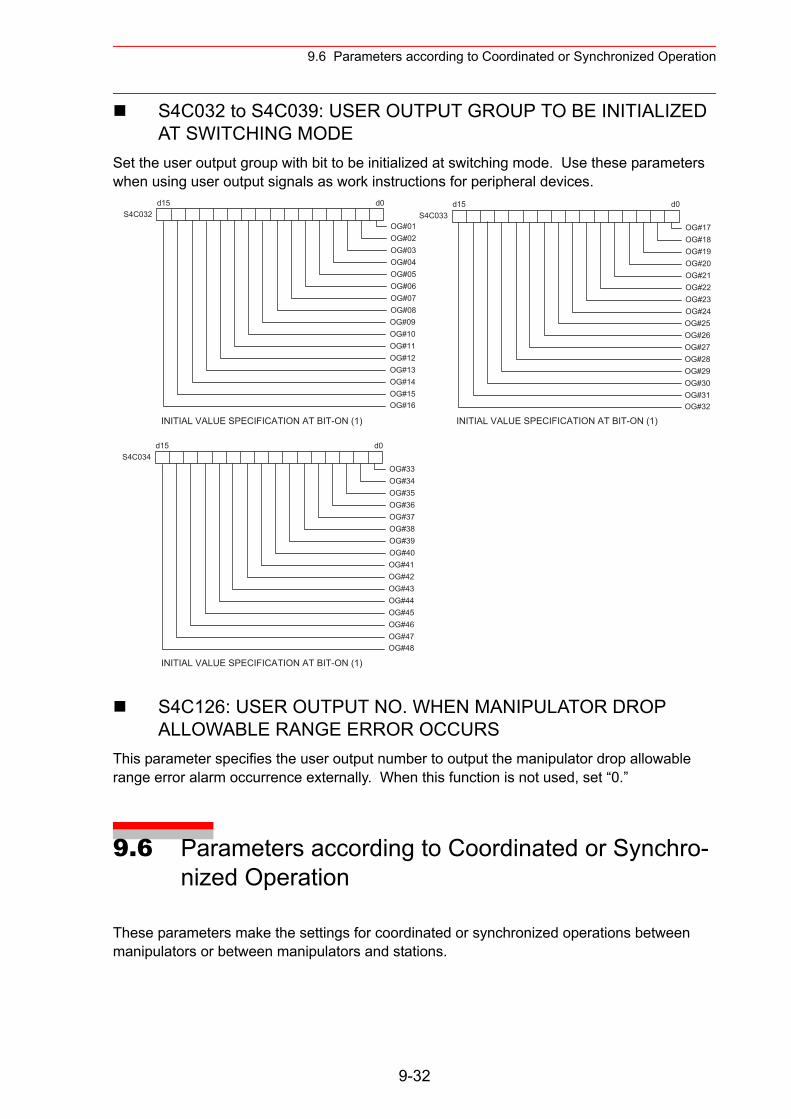
9.6 Parameters according to Coordinated or Synchronized Operation
S4C032 to S4C039: USER OUTPUT GROUP TO BE INITIALIZED AT SWITCHING MODE
Set the user output group with bit to be initialized at switching mode. Use these parameters when using user output signals as work instructions for peripheral devices.
S4C126: USER OUTPUT NO. WHEN MANIPULATOR DROP ALLOWABLE RANGE ERROR OCCURS
This parameter specifies the user output number to output the manipulator drop allowable range error alarm occurrence externally. When this function is not used, set “0.”
9.6 Parameters according to Coordinated or Synchro-nized Operation
These parameters make the settings for coordinated or synchronized operations between manipulators or between manipulators and stations.
INITIAL VALUE SPECIFICATION AT BIT-ON (1)
INITIAL VALUE SPECIFICATION AT BIT-ON (1)
INITIAL VALUE SPECIFICATION AT BIT-ON (1)
d15 d0
OG#01OG#02OG#03OG#04OG#05OG#06OG#07OG#08OG#09OG#10OG#11OG#12OG#13OG#14OG#15OG#16
S4C032d15 d0
OG#17OG#18OG#19OG#20OG#21OG#22OG#23OG#24OG#25OG#26OG#27OG#28OG#29OG#30OG#31OG#32
S4C033
d15 d0
OG#33OG#34OG#35OG#36OG#37OG#38OG#39OG#40OG#41OG#42OG#43OG#44OG#45OG#46OG#47OG#48
S4C034
9-32
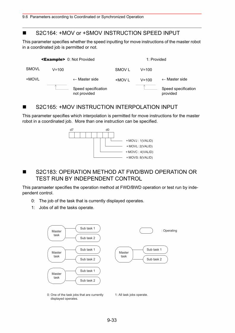
9.6 Parameters according to Coordinated or Synchronized Operation
S2C164: +MOV or +SMOV INSTRUCTION SPEED INPUTThis parameter specifies whether the speed inputting for move instructions of the master robot in a coordinated job is permitted or not.
S2C165: +MOV INSTRUCTION INTERPOLATION INPUTThis parameter specifies which interpolation is permitted for move instructions for the master robot in a coordinated job. More than one instruction can be specified.
S2C183: OPERATION METHOD AT FWD/BWD OPERATION OR TEST RUN BY INDEPENDENT CONTROL
This paramaeter specifies the operation method at FWD/BWD operation or test run by inde-pendent control.
<Example> 0: Not Provided 1: Provided
SMOVL V=100 SMOV L V=100
+MOVL ← Master side
Speed specification not provided
+MOV L V=100 ← Master side
Speed specification provided
0: The job of the task that is currently displayed operates. 1: Jobs of all the tasks operate.
d7 d0
+ MOVJ : 1(VALID)
+ MOVL: 2(VALID)
+ MOVC : 4(VALID)
+ MOVS: 8(VALID)
: Operating
0: One of the task jobs that are currently displayed operates.
1: All task jobs operate.
Sub task 1Master
taskSub task 2
Sub task 1Master
taskSub task 2
Sub task 1Master
taskSub task 2
Sub task 1Master
taskSub task 2
9-33
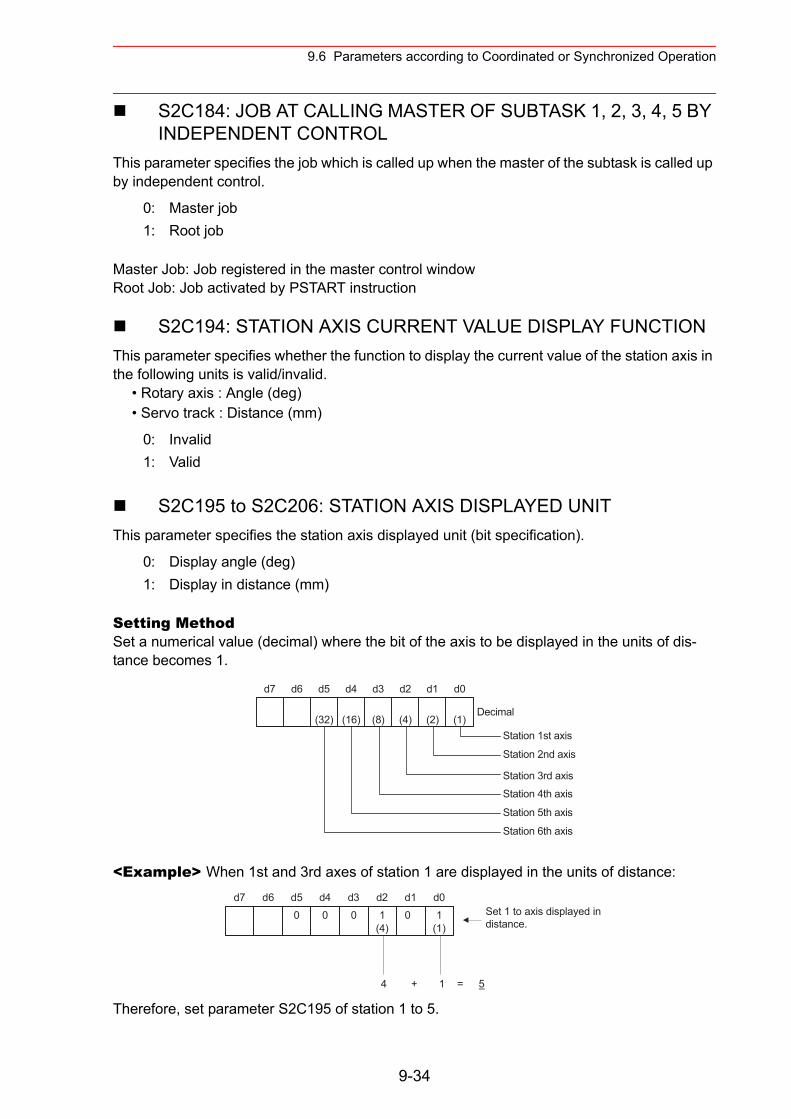
9.6 Parameters according to Coordinated or Synchronized Operation
S2C184: JOB AT CALLING MASTER OF SUBTASK 1, 2, 3, 4, 5 BY INDEPENDENT CONTROL
This parameter specifies the job which is called up when the master of the subtask is called up by independent control.
Master Job: Job registered in the master control window Root Job: Job activated by PSTART instruction
S2C194: STATION AXIS CURRENT VALUE DISPLAY FUNCTIONThis parameter specifies whether the function to display the current value of the station axis in the following units is valid/invalid.
• Rotary axis : Angle (deg)• Servo track : Distance (mm)
S2C195 to S2C206: STATION AXIS DISPLAYED UNITThis parameter specifies the station axis displayed unit (bit specification).
Setting MethodSet a numerical value (decimal) where the bit of the axis to be displayed in the units of dis-tance becomes 1.
<Example> When 1st and 3rd axes of station 1 are displayed in the units of distance:
Therefore, set parameter S2C195 of station 1 to 5.
0: Master job1: Root job
0: Invalid1: Valid
0: Display angle (deg)1: Display in distance (mm)
d7 d0
(2) (1)(4)(8)(16)(32)
d6 d5 d4 d3 d2 d1
Decimal
Station 1st axis
Station 2nd axis
Station 3rd axisStation 4th axis
Station 5th axis
Station 6th axis
d7 d01
(4)000 0 1
(1)
d6 d5 d4 d3 d2 d1Set 1 to axis displayed in distance.
4 + 1 = 5
9-34
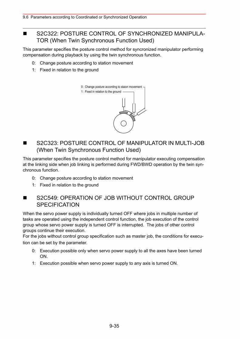
9.6 Parameters according to Coordinated or Synchronized Operation
S2C322: POSTURE CONTROL OF SYNCHRONIZED MANIPULA-TOR (When Twin Synchronous Function Used)
This parameter specifies the posture control method for syncronized manipulator performing compensation during playback by using the twin synchronous function.
S2C323: POSTURE CONTROL OF MANIPULATOR IN MULTI-JOB (When Twin Synchronous Function Used)
This parameter specifies the posture control method for manipulator executing compensation at the linking side when job linking is performed during FWD/BWD operation by the twin syn-chronous function.
S2C549: OPERATION OF JOB WITHOUT CONTROL GROUP SPECIFICATION
When the servo power supply is individually turned OFF where jobs in multiple number of tasks are operated using the independent control function, the job execution of the control group whose servo power supply is turned OFF is interrupted. The jobs of other control groups continue their execution.For the jobs without control group specification such as master job, the conditions for execu-tion can be set by the parameter.
0: Change posture according to station movement1: Fixed in relation to the ground
0: Change posture according to station movement1: Fixed in relation to the ground
0: Execution possible only when servo power supply to all the axes have been turned ON.
1: Execution possible when servo power supply to any axis is turned ON.
0 : Change posture according to staion movement1 : Fixed in relation to the ground
9-35
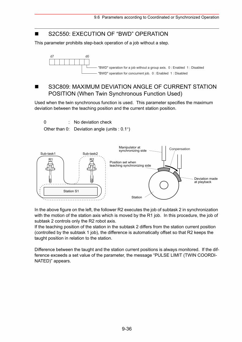
9.6 Parameters according to Coordinated or Synchronized Operation
S2C550: EXECUTION OF “BWD” OPERATIONThis parameter prohibits step-back operation of a job without a step.
S3C809: MAXIMUM DEVIATION ANGLE OF CURRENT STATION POSITION (When Twin Synchronous Function Used)
Used when the twin synchronous function is used. This parameter specifies the maximum deviation between the teaching position and the current station position.
In the above figure on the left, the follower R2 executes the job of subtask 2 in synchronization with the motion of the station axis which is moved by the R1 job. In this procedure, the job of subtask 2 controls only the R2 robot axis.If the teaching position of the station in the subtask 2 differs from the station current position (controlled by the subtask 1 job), the difference is automatically offset so that R2 keeps the taught position in relation to the station.
Difference between the taught and the station current positions is always monitored. If the dif-ference exceeds a set value of the parameter, the message “PULSE LIMIT (TWIN COORDI-NATED)” appears.
0 : No deviation checkOther than 0: Deviation angle (units : 0.1°)
d7 d0
"BWD" operation for a job without a group axis. 0 : Enabled 1 : Disabled
"BWD" operation for concurrent job. 0 : Enabled 1 : Disabled
Station S1
R1 R2
Sub-task1 Sub-task2
Station
Manipulator atsynchronizing side
Position set whenteaching synchronizing side
Deviation madeat playback
Conpensation
9-36
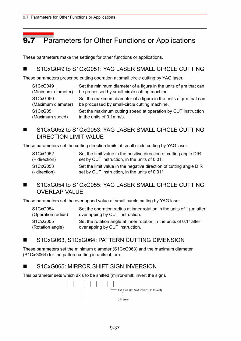
9.7 Parameters for Other Functions or Applications
9.7 Parameters for Other Functions or Applications
These parameters make the settings for other functions or applications.
S1CxG049 to S1CxG051: YAG LASER SMALL CIRCLE CUTTING These parameters prescribe cutting operation at small circle cutting by YAG laser.
S1CxG052 to S1CxG053: YAG LASER SMALL CIRCLE CUTTING DIRECTION LIMIT VALUE
These parameters set the cutting direction limits at small circle cutting by YAG laser.
S1CxG054 to S1CxG055: YAG LASER SMALL CIRCLE CUTTING OVERLAP VALUE
These parameters set the overlapped value at small curcle cutting by YAG laser.
S1CxG063, S1CxG064: PATTERN CUTTING DIMENSION These parameters set the minimum diameter (S1CxG063) and the maximum diameter (S1CxG064) for the pattern cutting in units of µm.
S1CxG065: MIRROR SHIFT SIGN INVERSION This parameter sets which axis to be shifted (mirror-shift: invert the sign).
S1CxG049 (Minimum diameter)
: Set the minimum diameter of a figure in the units of µm that can be processed by small-circle cutting machine.
S1CxG050 (Maximum diameter)
: Set the maximum diameter of a figure in the units of µm that can be processed by small-circle cutting machine.
S1CxG051 (Maximum speed)
: Set the maximum cutting speed at operation by CUT instruction in the units of 0.1mm/s.
S1CxG052 (+ direction)
: Set the limit value in the positive direction of cutting angle DIR set by CUT instruction, in the units of 0.01°.
S1CxG053 (- direction)
: Set the limit value in the negative direction of cutting angle DIR set by CUT instruction, in the units of 0.01°.
S1CxG054 (Operation radius)
: Set the operation radius at inner rotation in the units of 1 µm after overlapping by CUT instruction.
S1CxG055 (Rotation angle)
: Set the rotation angle at inner rotation in the units of 0.1° after overlapping by CUT instruction.
1st axis (0: Not invert, 1: Invert)
6th axis
9-37
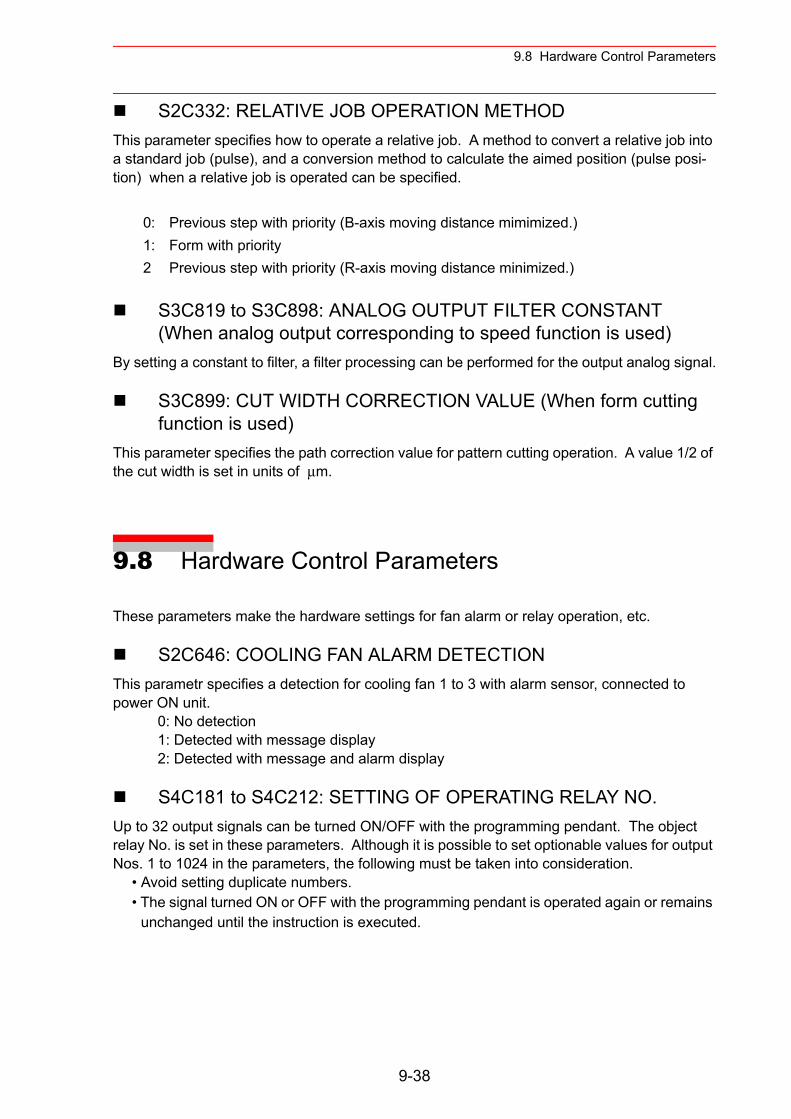
9.8 Hardware Control Parameters
S2C332: RELATIVE JOB OPERATION METHOD This parameter specifies how to operate a relative job. A method to convert a relative job into a standard job (pulse), and a conversion method to calculate the aimed position (pulse posi-tion) when a relative job is operated can be specified.
S3C819 to S3C898: ANALOG OUTPUT FILTER CONSTANT (When analog output corresponding to speed function is used)
By setting a constant to filter, a filter processing can be performed for the output analog signal.
S3C899: CUT WIDTH CORRECTION VALUE (When form cutting function is used)
This parameter specifies the path correction value for pattern cutting operation. A value 1/2 of the cut width is set in units of µm.
9.8 Hardware Control Parameters
These parameters make the hardware settings for fan alarm or relay operation, etc.
S2C646: COOLING FAN ALARM DETECTIONThis parametr specifies a detection for cooling fan 1 to 3 with alarm sensor, connected to power ON unit. 0: No detection 1: Detected with message display 2: Detected with message and alarm display
S4C181 to S4C212: SETTING OF OPERATING RELAY NO.Up to 32 output signals can be turned ON/OFF with the programming pendant. The object relay No. is set in these parameters. Although it is possible to set optionable values for output Nos. 1 to 1024 in the parameters, the following must be taken into consideration.
• Avoid setting duplicate numbers.• The signal turned ON or OFF with the programming pendant is operated again or remains
unchanged until the instruction is executed.
0: Previous step with priority (B-axis moving distance mimimized.)1: Form with priority2 Previous step with priority (R-axis moving distance minimized.)
9-38
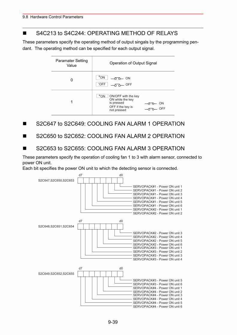
9.8 Hardware Control Parameters
S4C213 to S4C244: OPERATING METHOD OF RELAYSThese parameters specify the operating method of output singals by the programming pen-dant. The operating method can be specified for each output signal.
S2C647 to S2C649: COOLING FAN ALARM 1 OPERATION
S2C650 to S2C652: COOLING FAN ALARM 2 OPERATION
S2C653 to S2C655: COOLING FAN ALARM 3 OPERATIONThese parameters specify the operation of cooling fan 1 to 3 with alarm sensor, connected to power ON unit.Each bit specifies the power ON unit to which the detecting sensor is connected.
Paramater Setting Value Operation of Output Signal
0
1
+ON
-OFF
ON
OFF
+ON ON/OFF with the keyON while the key is pressedOFF if the key is not pressed
ONOFF
d7 d0S2C647,S2C650,S2C653
d7 d0S2C648,S2C651,S2C654
SERVOPACK#1 - Power ON unit 1SERVOPACK#1 - Power ON unit 2SERVOPACK#1 - Power ON unit 3SERVOPACK#1 - Power ON unit 4SERVOPACK#1 - Power ON unit 5SERVOPACK#1 - Power ON unit 6SERVOPACK#2 - Power ON unit 1SERVOPACK#2 - Power ON unit 2
SERVOPACK#3 - Power ON unit 1SERVOPACK#3 - Power ON unit 2SERVOPACK#3 - Power ON unit 3SERVOPACK#3 - Power ON unit 4
SERVOPACK#2 - Power ON unit 3SERVOPACK#2 - Power ON unit 4SERVOPACK#2 - Power ON unit 5SERVOPACK#2 - Power ON unit 6
d7 d0S2C649,S2C652,S2C655
SERVOPACK#4 - Power ON unit 3SERVOPACK#4 - Power ON unit 4SERVOPACK#4 - Power ON unit 5SERVOPACK#4 - Power ON unit 6
SERVOPACK#3 - Power ON unit 5SERVOPACK#3 - Power ON unit 6SERVOPACK#4 - Power ON unit 1SERVOPACK#4 - Power ON unit 2
9-39
9.9 TRANSMISSION PARAMETERS
9.9 TRANSMISSION PARAMETERS
RS000: COMMUNICATION PROTOCOLThe protocol of the serial port of the NCP01 circuit board is specified.
9.9.1 Basic Protocol
Specify when using Yaskawa data transmission functions.
RS030: NUMBER OF DATA BITSThis parameter specifies the number of data bits.
RS031: NUMBER OF STOP BITSThis parameter specifies the number of stop bits.
RS032: PARITYThis parameter specifies the parity bits.
RS033: TRANSMISSION SPEEDThis parameter specifies the transmission speed in units of bauds.
RS034: RESPONSE WAITING TIMER (TIMER A) Units: 0.1 secondsThis timer monitors the sequence. It specifies the response waiting time for invalid or missing responses.
RS035: TEXT TERMINATION MONITORING TIMER (TIMER B) This timer monitors text reception. Specify the monitoring time to wait for text termination character.
RS036: NUMBER OF ENQ RE-TRANSMISSION RETRIES This parameter specifies the number of re-transmission attempts of the control characters for invalid or missing responses.
RS037: NUMBER OF DATA RE-TRANSMISSION RETRIESThis parameter specifies the number of re-transmission attempts of text for block check error (NAK reception).
0: No protocol2: Basic protocol3: FC1 protocol
9-40
9.9 TRANSMISSION PARAMETERS
RS038: BLOCK CHECK METHODThis parameter specifies the checking method for text transmission errors. Set “0” for this pro-tocol.
9.9.2 FC1 Protocol
The following protocols naturally correspond to the external memory unit, YASNAC FC1 or FC2.
RS050: NUMBER OF DATA BITSThis parameter specifies the number of data bits.
RS051: NUMBER OF STOP BITSThis parameter specifies the number of stop bits.
RS052: PARITYThis parameter specifies the parity bits.
RS053: TRANSMISSION SPEEDThis parameter specifies the transmission speed in units of bauds.
RS054: RESPONSE WAITING TIMER (TIMER A)Units: 0.1 secondsThis timer monitors the sequence. It specifies the response waiting time for invalid or missing responses.
RS055: TEXT TERMINATION MONITORING TIMER (TIMER B)This timer monitors text reception. Specify the monitoring time to wait for text termination character.
RS056: NUMBER OF ENQ RE-TRANSMISSION RETRIES This parameter specifies the number of re-transmission attempts of the control characters for invalid or missing responses.
RS057: NUMBER OF DATA RE-TRANSMISSION RETRIESThis parameter specifies the number of re-transmission attempts of text for block check error (NAK reception).
9-41
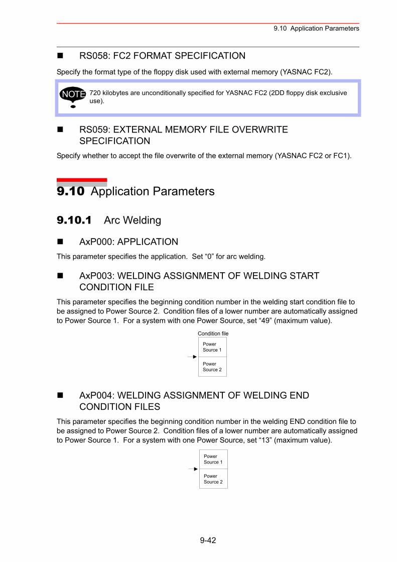
9.10 Application Parameters
RS058: FC2 FORMAT SPECIFICATIONSpecify the format type of the floppy disk used with external memory (YASNAC FC2).
RS059: EXTERNAL MEMORY FILE OVERWRITE SPECIFICATION
Specify whether to accept the file overwrite of the external memory (YASNAC FC2 or FC1).
9.10 Application Parameters
9.10.1 Arc Welding
AxP000: APPLICATIONThis parameter specifies the application. Set “0” for arc welding.
AxP003: WELDING ASSIGNMENT OF WELDING START CONDITION FILE
This parameter specifies the beginning condition number in the welding start condition file to be assigned to Power Source 2. Condition files of a lower number are automatically assigned to Power Source 1. For a system with one Power Source, set “49” (maximum value).
AxP004: WELDING ASSIGNMENT OF WELDING END CONDITION FILES
This parameter specifies the beginning condition number in the welding END condition file to be assigned to Power Source 2. Condition files of a lower number are automatically assigned to Power Source 1. For a system with one Power Source, set “13” (maximum value).
720 kilobytes are unconditionally specified for YASNAC FC2 (2DD floppy disk exclusive use).
NOTE
Condition file
PowerSource 1
PowerSource 2
PowerSource 1
PowerSource 2
9-42
9.10 Application Parameters
AxP005: WELDING SPEED PRIORITYThis parameter specifies whether the welding speed is specified by the “ARCON” instruction, by the welding start condition file, or by the additional times of the “MOV” instruction.
AxP009: WORK CONTINUINGThis parameter specifies whether to output an “ARCON” instruction to restart after the manip-ulator stopped while the “ARCON” instruction is being output.
AxP010: WELDING INSTRUCTION OUTPUTThis parameter specifies the beginning number (0 to 12) of the analog output channel to the Power Source. “0” indicates that no Power Source exists.
AxP011, AxP012: MANUAL WIRE OPERATION SPEED These parameters specify the manual wire operation speed as a percentage of the maximum instruction value. Instruction polarity is determined by the current instruction in the Power Source characteristic file. The setting range is from 0 to 100.
AxP013, AxP014: WELDING CONTROL TIMEThese parameters specify the welding control time in units of minutes. The setting range is from 0 to 999.
AxP015 to AxP017: NUMBER OF WELDING CONTROLThese parameters specify the number of welding controls. The setting range is from 0 to 99.
AxP026 to AxP029: TOOL ON/OFF USER OUTPUT NO. (Jigless system)
These parameters specify the user output number for the tool open/close operation by specific keys.
9.10.2 Handling Application
AxP002, AxP004: f1 KEY FUNCTIONThese parameters set the output signal to assign for f1 key. 0: Not specified 1 to 4: Specific outputs for HAND-1 to HAND4-1 5: User output (No. is specified by AxP004).
AxP003, AxP005: f2 KEY FUNCTIONThese parameters set the output signal to assign for f2 key. 0: Not specified 1 to 4: Specific outputs for HAND-2 to HAND4-2 5: User output (No. is specified by AxP005)
9-43
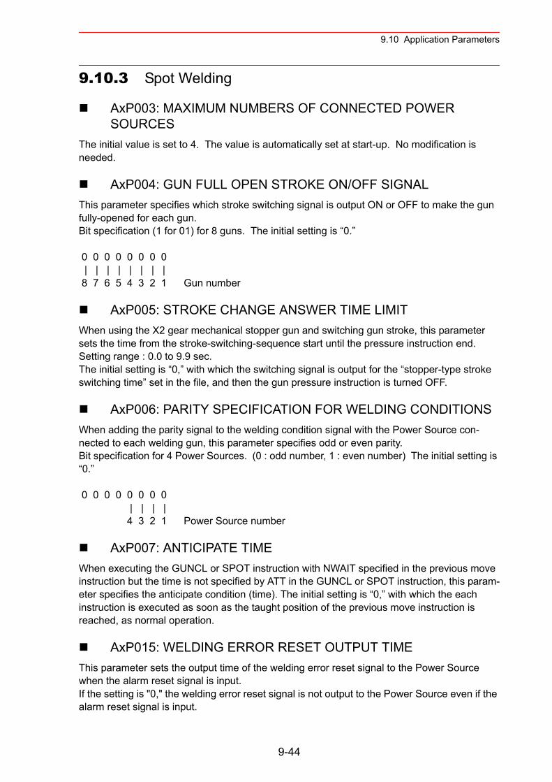
9.10 Application Parameters
9.10.3 Spot Welding
AxP003: MAXIMUM NUMBERS OF CONNECTED POWER SOURCES
The initial value is set to 4. The value is automatically set at start-up. No modification is needed.
AxP004: GUN FULL OPEN STROKE ON/OFF SIGNALThis parameter specifies which stroke switching signal is output ON or OFF to make the gun fully-opened for each gun.Bit specification (1 for 01) for 8 guns. The initial setting is “0.”
0 0 0 0 0 0 0 0 | | | | | | | | 8 7 6 5 4 3 2 1 Gun number
AxP005: STROKE CHANGE ANSWER TIME LIMITWhen using the X2 gear mechanical stopper gun and switching gun stroke, this parameter sets the time from the stroke-switching-sequence start until the pressure instruction end.Setting range : 0.0 to 9.9 sec.The initial setting is “0,” with which the switching signal is output for the “stopper-type stroke switching time” set in the file, and then the gun pressure instruction is turned OFF.
AxP006: PARITY SPECIFICATION FOR WELDING CONDITIONSWhen adding the parity signal to the welding condition signal with the Power Source con-nected to each welding gun, this parameter specifies odd or even parity.Bit specification for 4 Power Sources. (0 : odd number, 1 : even number) The initial setting is “0.”
0 0 0 0 0 0 0 0 | | | | 4 3 2 1 Power Source number
AxP007: ANTICIPATE TIMEWhen executing the GUNCL or SPOT instruction with NWAIT specified in the previous move instruction but the time is not specified by ATT in the GUNCL or SPOT instruction, this param-eter specifies the anticipate condition (time). The initial setting is “0,” with which the each instruction is executed as soon as the taught position of the previous move instruction is reached, as normal operation.
AxP015: WELDING ERROR RESET OUTPUT TIMEThis parameter sets the output time of the welding error reset signal to the Power Source when the alarm reset signal is input.If the setting is "0," the welding error reset signal is not output to the Power Source even if the alarm reset signal is input.
9-44

9.10 Application Parameters
AxP016, AxP017: ELECTRODE WEAR AMOUNT ALARM VALUEThese parameters set the electrode wear amount alarm values (AxP016: movable side, AxP017: fixed side) at the wear detection.
9.10.4 General-purpose Application
AxP009: WORK CONTINUE PROHIBITThis parameter specifies whether to output TOOLON instruction or not at restarting when the work is stopped for some reasons during the output of TOOLON instruction.
9-45
10.1 Home Position Calibration
10 System Setup
10.1 Home Position Calibration
• Before operating the manipulator, check that the SERVO ON lamp goes out when the emergency stop buttons on the right of the front door of the NX100 and the programming pendant are pressed.
Injury or damage to machinery may result if the manipulator cannot be stopped in case of an emergency.
• Observe the following precautions when performing teaching operations within the P-point maximum envelope of the manipulator :
- View the manipulator from the front whenever possible.- Always follow the predetermined operating procedure.- Ensure that you have a safe place to retreat in case of emergency.
Improper or unintended manipulator operation may result in injury.
• Prior to performing the following operations, be sure that no one is in the P-point maximum envelope of the manipulator, and be sure that you are in a safe place when:
- Turning ON the NX100 power.- Moving the manipulator with the programming pendant.
Injury may result from contact with the manipulator if persons enter the P-point maximum envelope of the manipulator.
• Always press the emergency stop button immediately if there are prob-lems.Emergency stop buttons are located on the right of the front door of the NX100 and the programming pendant.
WARNING
10-1
10.1 Home Position Calibration
10.1.1 Home Position Calibration
Home position calibration is an operation in which the home position and absolute encoder position coincide. Although this operation is performed prior to shipment at the factory, the fol-lowing cases require this operation to be performed again.
• Change in the combination of the manipulator and NX100• Replacement of the motor or absolute encoder• Clearing stored memory (by replacement of NCP01 circuit board, weak battery, etc.)• Home position deviation caused by hitting the manipulator against a workpiece, etc.
To calibrate the home position, use the axis keys to calibrate the home position mark on each axis so that the manipulator can take its posture for the home position. There are two opera-tions for home position calibration:
• All the axes can be moved at the same time: Recalibrate the home position by moving all the axes together if changing the combina-tion of manipulator and circuit board.
• Axes can be moved individually: Recalibrate the home position for the individual axes that were affected by the replacement, if replacing the motor or absolute encoder.
If the absolute data of its posture for the home position is already known, set the absolute data again after completing home position registration.
• Perform the following inspection procedures prior to teaching the manipulator. If problems are found, correct them immediately, and be sure that all other necessary tasks have been performed.
- Check for problems in manipulator movement.- Check for damage to the insulation and sheathing of external wires.
• Always return the programming pendant to its hook on the NX100 cabi-net after use.
If the programming pendant is inadvertently left on the manipulator, a fixture, or on the floor, the manipulator or a tool could collide with it during manipulator movement, possibly causing injury or equipment damage.
Teaching and playback are not possible before home position calibration is complete.In a system with two or more manipulators, the home position of all the manipulators must be calibrated before starting teaching or playback.
CAUTION
NOTE
10-2
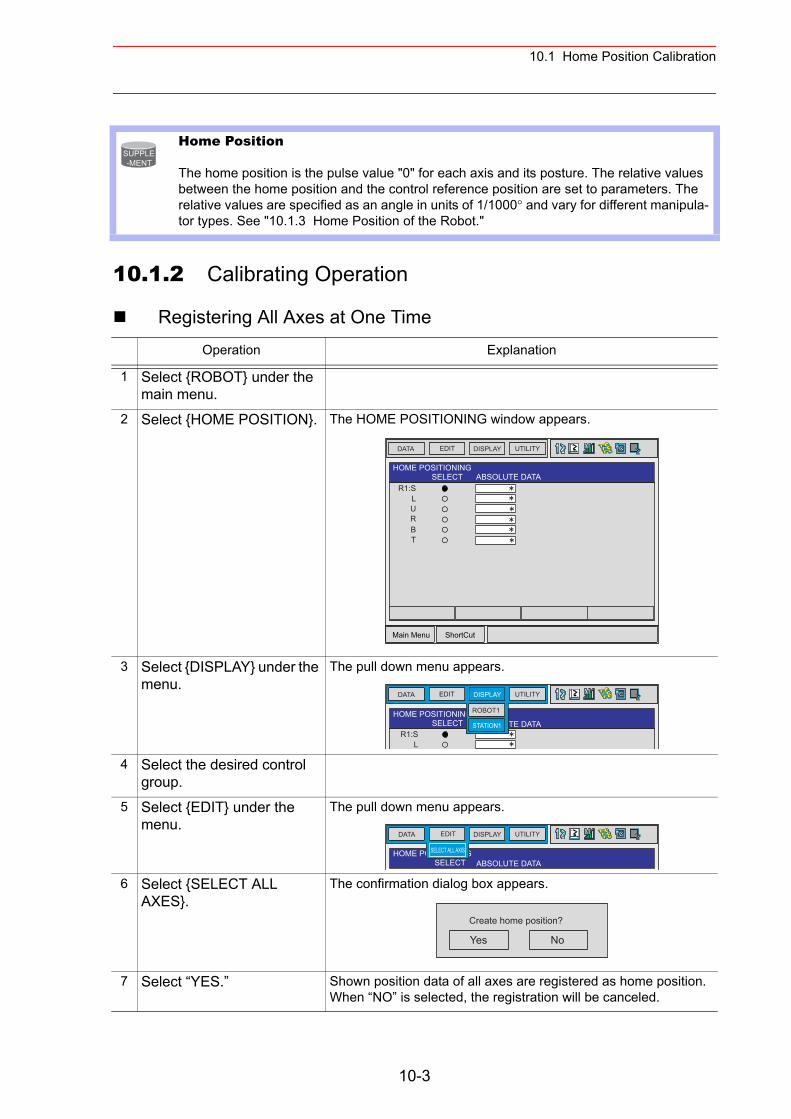
10.1 Home Position Calibration
10.1.2 Calibrating Operation
Registering All Axes at One Time
Home Position
The home position is the pulse value "0" for each axis and its posture. The relative values between the home position and the control reference position are set to parameters. The relative values are specified as an angle in units of 1/1000° and vary for different manipula-tor types. See "10.1.3 Home Position of the Robot."
Operation Explanation
1 Select {ROBOT} under the main menu.
2 Select {HOME POSITION}. The HOME POSITIONING window appears.
3 Select {DISPLAY} under the menu.
The pull down menu appears.
4 Select the desired control group.
5 Select {EDIT} under the menu.
The pull down menu appears.
6 Select {SELECT ALL AXES}.
The confirmation dialog box appears.
7 Select “YES.” Shown position data of all axes are registered as home position.When “NO” is selected, the registration will be canceled.
SUPPLE-MENT
Main Menu ShortCut
EDIT DISPLAY UTILITYDATA
HOME POSITIONINGSELECT ABSOLUTE DATA
R1:SLURBT
EDIT DISPLAY UTILITYDATA
HOME POSITIONINGSELECT ABSOLUTE DATA
R1:SL
ROBOT1
STATION1
EDIT DISPLAY UTILITYDATA
HOME POSITIONINGSELECT ABSOLUTE DATA
SELECT ALL AXIS
Yes No
Create home position?
10-3
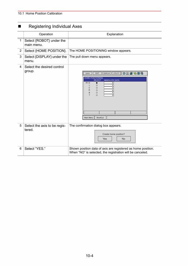
10.1 Home Position Calibration
Registering Individual AxesOperation Explanation
1 Select {ROBOT} under the main menu.
2 Select {HOME POSITION}. The HOME POSITIONING window appears.
3 Select {DISPLAY} under the menu.
The pull down menu appears.
4 Select the desired control group.
5 Select the axis to be regis-tered.
The confirmation dialog box appears.
6 Select “YES.” Shown position data of axis are registered as home position.When “NO” is selected, the registration will be canceled.
Main Menu ShortCut
EDIT DISPLAY UTILITYDATA
HOME POSITIONINGSELECT ABSOLUTE DATA
R1:SLURBT
Yes No
Create home position?
10-4
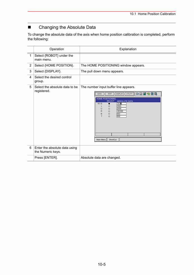
10.1 Home Position Calibration
Changing the Absolute DataTo change the absolute data of the axis when home position calibration is completed, perform the following:
Operation Explanation
1 Select {ROBOT} under the main menu.
2 Select {HOME POSITION}. The HOME POSITIONING window appears.
3 Select {DISPLAY}. The pull down menu appears.
4 Select the desired control group.
5 Select the absolute data to be registered.
The number input buffer line appears.
6 Enter the absolute data using the Numeric keys.
Press [ENTER]. Absolute data are changed.
Main Menu ShortCut
EDIT DISPLAY UTILITYDATA
HOME POSITIONINGSELECT ABSOLUTE DATA
R1:SLURBT
19329652698-66398692968
10-5
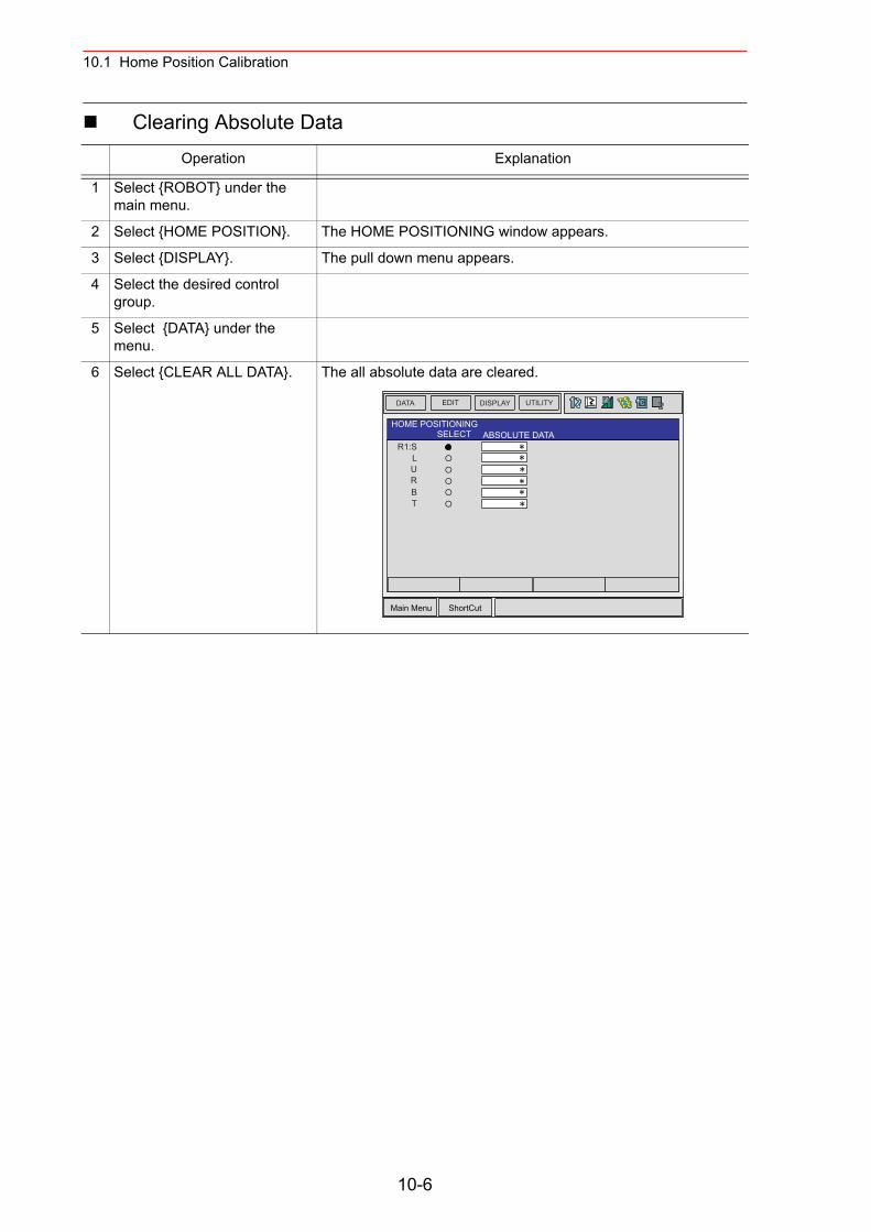
10.1 Home Position Calibration
Clearing Absolute DataOperation Explanation
1 Select {ROBOT} under the main menu.
2 Select {HOME POSITION}. The HOME POSITIONING window appears.
3 Select {DISPLAY}. The pull down menu appears.
4 Select the desired control group.
5 Select {DATA} under the menu.
6 Select {CLEAR ALL DATA}. The all absolute data are cleared.
Main Menu ShortCut
EDIT DISPLAY UTILITYDATA
HOME POSITIONINGSELECT ABSOLUTE DATA
R1:SLURBT
10-6
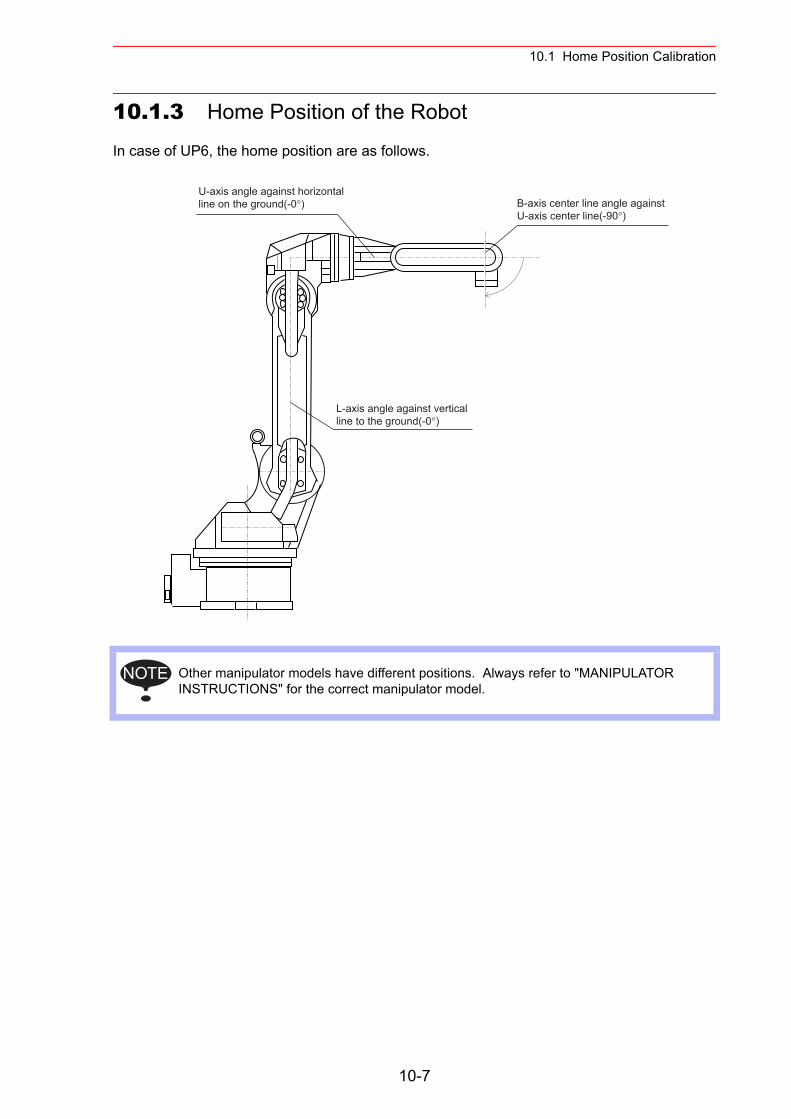
10.1 Home Position Calibration
10.1.3 Home Position of the Robot
In case of UP6, the home position are as follows.
Other manipulator models have different positions. Always refer to "MANIPULATOR INSTRUCTIONS" for the correct manipulator model.
U-axis angle against horizontalline on the ground(-0°) B-axis center line angle against
U-axis center line(-90°)
L-axis angle against verticalline to the ground(-0°)
NOTE
10-7
10.2 Second Home Position (Check Point)
10.2 Second Home Position (Check Point)
• Be aware of safety hazards when performing the position confirma-tion of the second home position (check point).
Abnormality of the PG system may be a cause for alarm. The manipulator may operate in an unexpected manner, and there is a risk of damage to equipment or injury to personnel.
• Before operating the manipulator, check that the SERVO ON lamp goes out when the emergency stop buttons on the front door of NX100 and the programming pendant are pressed.
Injury or damage to machinery may result if the manipulator cannot be stopped in case of an emergency.
• Observe the following precautions when performing teaching oper-ations within the P-point maximum envelope of the manipulator :
- View the manipulator from the front whenever possible.- Always follow the predetermined operating procedure.- Ensure that you have a safe place to retreat in case of emergency.
Improper or unintended manipulator operation may result in injury.
• Prior to performing the following operations, be sure that no one is in the P-point maximum envelope of the manipulator, and be sure that you are in a safe place when:
- Turning ON the NX100 power- Moving the manipulator with the programming pendant- Running the system in the check mode- Performing automatic operations
Injury may result from contact with the manipulator if persons enter the P-point max-imum envelope of the manipulator.
• Always press the emergency stop button immediately if there are problems.
Emergency stop buttons are attached on the right of the front door of the NX100 and the programming pendant.
WARNING
10-8
10.2 Second Home Position (Check Point)
• Perform the following inspection procedures prior to teaching the manipulator. If problems are found, correct them immediately, and be sure that all other necessary tasks have been performed.
- Check for problems in manipulator movement.- Check for damage to the insulation and sheathing of external
wires.- Always return the programming pendant to its hook on the NX100
cabinet after use.
If the programming pendant is inadvertently left on the manipulator, a fixture, or on the floor, the manipulator or a tool could collide with it during manipulator move-ment, possibly causing injury or equipment damage.
CAUTION
10-9
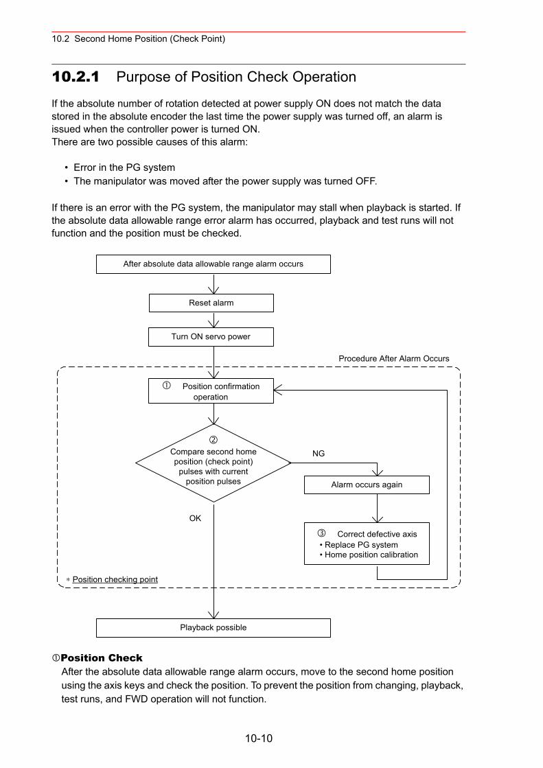
10.2 Second Home Position (Check Point)
10.2.1 Purpose of Position Check Operation
If the absolute number of rotation detected at power supply ON does not match the data stored in the absolute encoder the last time the power supply was turned off, an alarm is issued when the controller power is turned ON.There are two possible causes of this alarm:
• Error in the PG system • The manipulator was moved after the power supply was turned OFF.
If there is an error with the PG system, the manipulator may stall when playback is started. If the absolute data allowable range error alarm has occurred, playback and test runs will not function and the position must be checked.
Position CheckAfter the absolute data allowable range alarm occurs, move to the second home position using the axis keys and check the position. To prevent the position from changing, playback, test runs, and FWD operation will not function.
After absolute data allowable range alarm occurs
Reset alarm
Turn ON servo power
Position confirmationoperation
Alarm occurs again
Correct defective axis • Replace PG system • Home position calibration
Playback possible
Compare second homeposition (check point)
pulses with currentposition pulses
Procedure After Alarm Occurs
NG
OK
∗ Position checking point
10-10
10.2 Second Home Position (Check Point)
Pulse Difference CheckThe pulse number at the second home position is compared with that at the current posi-tion. If the difference is within the allowable range, playback is enabled. If not, the error alarm occurs again.
• The allowable range pulse is the number of pulses per rotation of the motor (PPR data).• The initial value of the second home position is the home position (where all axes are at
pulse 0). The second home position can be changed. For details, refer to "10.2 Second Home Position (Check Point)."
Alarm OccurenceIf the error alarm occurs again, there may be an error in the PG system. Check the system. After adjusting the erroneous axis, calibrate the home position of the axis, then check the position again.
• Home position calibration of all the axes at the same time enables playback operations without having to check the position.
• Sometimes in a system with a manipulator that has no brake, it is possible to enable playback without position checking after the absolute data allowable range error alarm occurs. However, as a rule, always check the position.Under the above special conditions, the manipulator moves as follows:After starting, the manipulator moves at low speed (1/10 of the maximum speed) to the step indicated by the cursor. If it is stopped and restarted during this motion, the low speed setting is retained until the step at cursor is reached. Regardless of cycle setting, the manipulator stops after the cursor step is reached. Starting the manipulator again then moves it at the programmed speed and cycle of the job.
NOTE
10-11
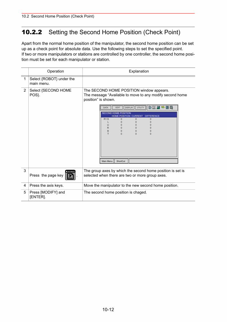
10.2 Second Home Position (Check Point)
10.2.2 Setting the Second Home Position (Check Point)
Apart from the normal home position of the manipulator, the second home position can be set up as a check point for absolute data. Use the following steps to set the specified point. If two or more manipulators or stations are controlled by one controller, the second home posi-tion must be set for each manipulator or station.
Operation Explanation
1 Select {ROBOT} under the main menu.
2 Select {SECOND HOME POS}.
The SECOND HOME POSITION window appears.The message “Available to move to any modify second home position” is shown.
3Press the page key .
The group axes by which the second home position is set is selected when there are two or more group axes.
4 Press the axis keys. Move the manipulator to the new second home position.
5 Press [MODIFY] and [ENTER].
The second home position is chaged.
Main Menu ShortCut
EDIT DISPLAY UTILITYDATA
R1:SLURBT
0 0 00 0 00 0 00 0 00 0 00 0 0
SECOND HOME POSITIONHOME POSITION CURRENT DIFFERENCE
PAGE
GO BACK
10-12
10.2 Second Home Position (Check Point)
10.2.3 Procedure After an Alarm
If the absolute data allowable range alarm occurs, perform the followings• Reset the alarm• Turn Servo power ON
and confirm the second home position. After the confirmation, if the PG system is found to be the cause of the alarm, perform the necessary operation, such as replacing the PG, etc.The robot current position data when turning main power supply OFF and ON can be con-firmed in “Power ON/OFF Position Window.”
• Be aware of safety hazards when performing the position confirma-tion of the specified point.
Abnormality of the PG system may be cause for alarm. The manipulator may oper-ate in an unexpected manner, and there is a risk of damage to equipment or injury to personnel.
Refer to NX100 MAINTENANCE MANUAL " 7.7 Position Data When Power is Turned ON/OFF " for details on the “Power ON/OFF Position Window.”
Operation Explanation
1 Select {ROBOT} under the main menu.
2 Select {SECOND HOME POS}.
The SECOND HOME POSITION window appears.
3Press the page key .
The group axes by which the second home position is set is selected when there are two or more group axes.
4 Press [FWD]. TCP moves to the second home position. The robot moving speed is set as selected manual operation speed.
5 Select {DATA} under the menu.
6 Select {CONFIRM POSITION}.
The message “Home position checked” appears.Pulse data of the second home position and current pulse data are compared. If the compared error is in allowed range, playback operation can be done.If the error is beyond the allowed range, the alarm occurs again.
WARNING
SUPPLE-MENT
PAGE
GO BACK
10-13
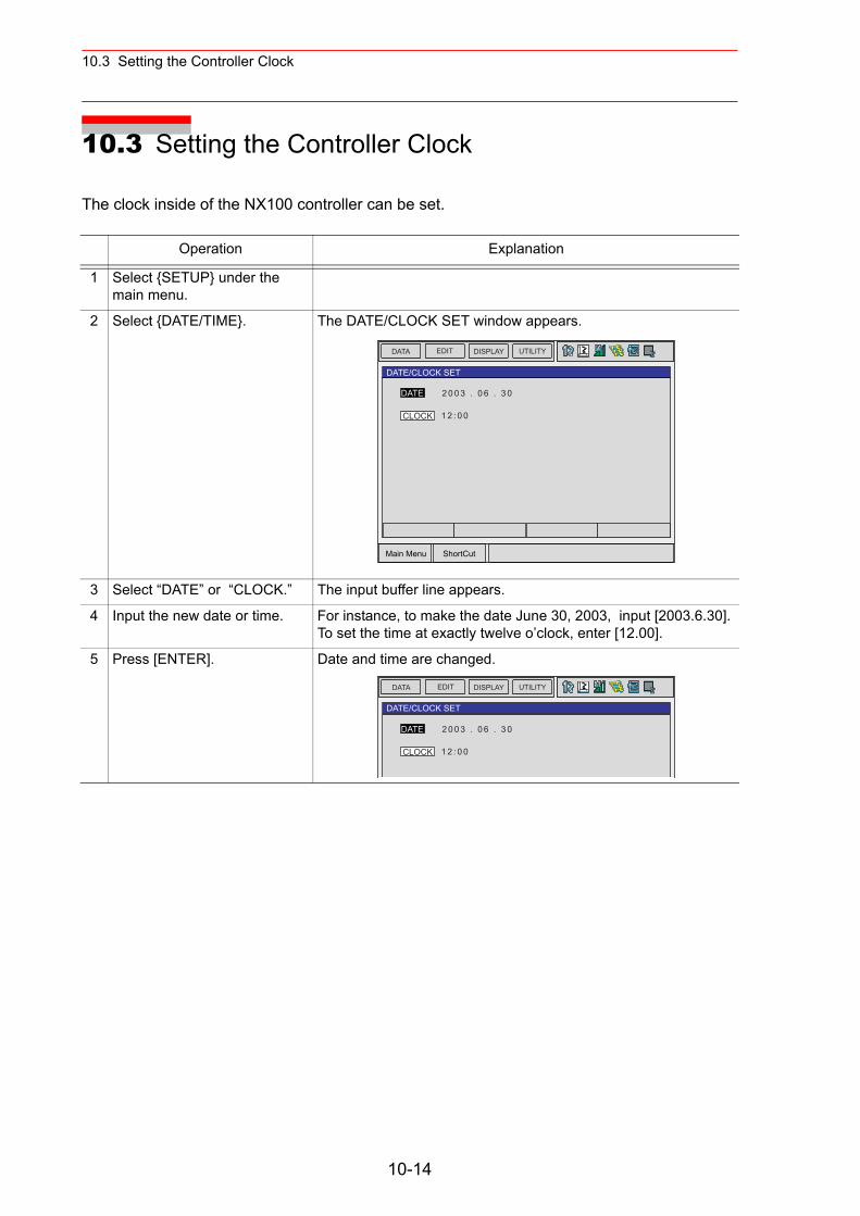
10.3 Setting the Controller Clock
10.3 Setting the Controller Clock
The clock inside of the NX100 controller can be set.
Operation Explanation
1 Select {SETUP} under the main menu.
2 Select {DATE/TIME}. The DATE/CLOCK SET window appears.
3 Select “DATE” or “CLOCK.” The input buffer line appears.
4 Input the new date or time. For instance, to make the date June 30, 2003, input [2003.6.30]. To set the time at exactly twelve o’clock, enter [12.00].
5 Press [ENTER]. Date and time are changed.
Main Menu ShortCut
EDIT DISPLAY UTILITYDATA
2 0 0 3 . 0 6 . 3 0
DATE/CLOCK SET
DATE
CLOCK 1 2 : 0 0
EDIT DISPLAY UTILITYDATA
DATE/CLOCK SET
2 0 0 3 . 0 6 . 3 0DATE
CLOCK 1 2 : 0 0
10-14
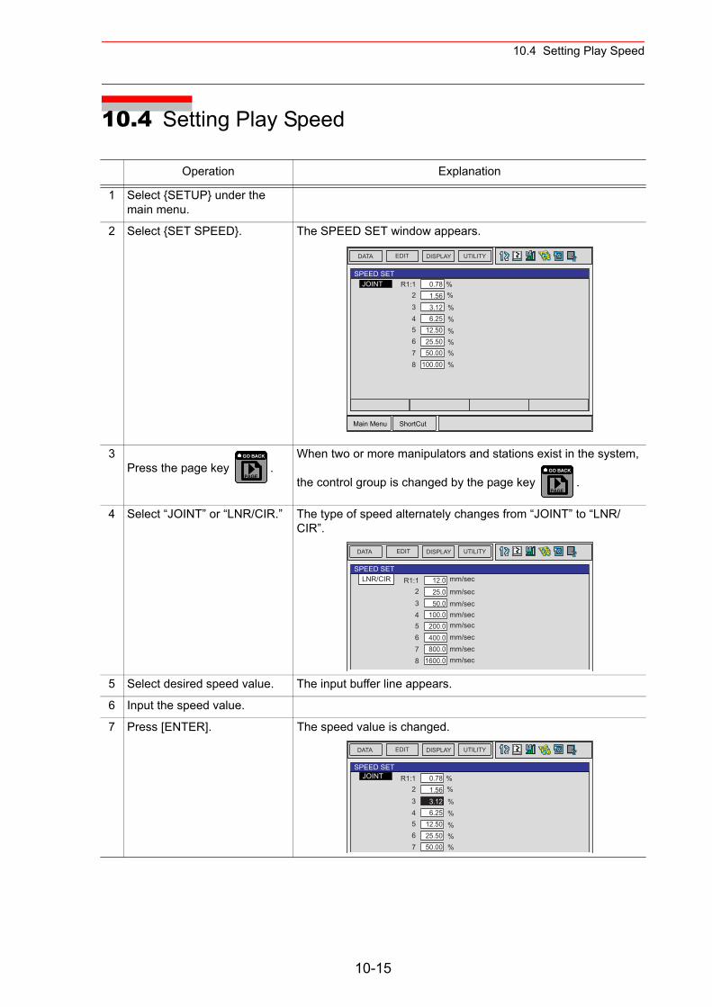
10.4 Setting Play Speed
10.4 Setting Play Speed
Operation Explanation
1 Select {SETUP} under the main menu.
2 Select {SET SPEED}. The SPEED SET window appears.
3Press the page key .
When two or more manipulators and stations exist in the system,
the control group is changed by the page key .
4 Select “JOINT” or “LNR/CIR.” The type of speed alternately changes from “JOINT” to “LNR/CIR”.
5 Select desired speed value. The input buffer line appears.
6 Input the speed value.
7 Press [ENTER]. The speed value is changed.
Main Menu ShortCut
EDIT DISPLAY UTILITYDATA
R1:1SPEED SET
JOINT 0.78 %
3 3.12 %4 6.25 %5 12.50 %6 25.50 %7 50.00 %8 100.00 %
2 1.56 %
PAGE
GO BACK
PAGE
GO BACK
EDIT DISPLAY UTILITYDATA
SPEED SETLNR/CIR mm/sec
mm/secmm/secmm/secmm/secmm/secmm/secmm/sec
R1:1 12.0
3 50.04 100.05 200.06 400.07 800.08 1600.0
2 25.0
EDIT DISPLAY UTILITYDATA
SPEED SETJOINT R1:1 0.78 %
3 3.12 %4 6.25 %5 12.50 %6 25.50 %7 50.00 %
2 1.56 %
10-15
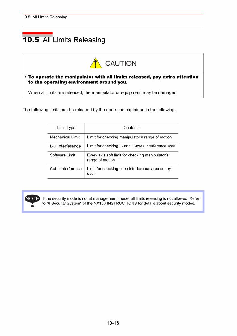
10.5 All Limits Releasing
10.5 All Limits Releasing
The following limits can be released by the operation explained in the following.
• To operate the manipulator with all limits released, pay extra attention to the operating environment around you. When all limits are released, the manipulator or equipment may be damaged.
Limit Type Contents
Mechanical Limit Limit for checking manipulator’s range of motion
L-U Interference Limit for checking L- and U-axes interference area
Software Limit Every axis soft limit for checking manipulator’s range of motion
Cube Interference Limit for checking cube interference area set by user
If the security mode is not at managememt mode, all limits releasing is not allowed. Refer to "8 Security System" of the NX100 INSTRUCTIONS for details about security modes.
CAUTION
NOTE
10-16
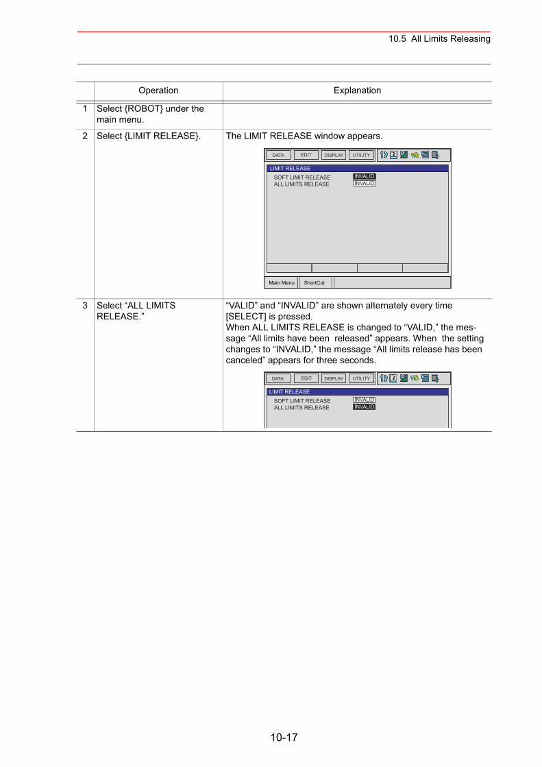
10.5 All Limits Releasing
Operation Explanation
1 Select {ROBOT} under the main menu.
2 Select {LIMIT RELEASE}. The LIMIT RELEASE window appears.
3 Select “ALL LIMITS RELEASE.”
“VALID” and “INVALID” are shown alternately every time [SELECT] is pressed. When ALL LIMITS RELEASE is changed to “VALID,” the mes-sage “All limits have been released” appears. When the setting changes to “INVALID,” the message “All limits release has been canceled” appears for three seconds.
Main Menu ShortCut
EDIT DISPLAY UTILITYDATA
SOFT LIMIT RELEASELIMIT RELEASE
INVALIDINVALIDALL LIMITS RELEASE
EDIT DISPLAY UTILITYDATA
SOFT LIMIT RELEASELIMIT RELEASE
INVALIDINVALIDALL LIMITS RELEASE
10-17
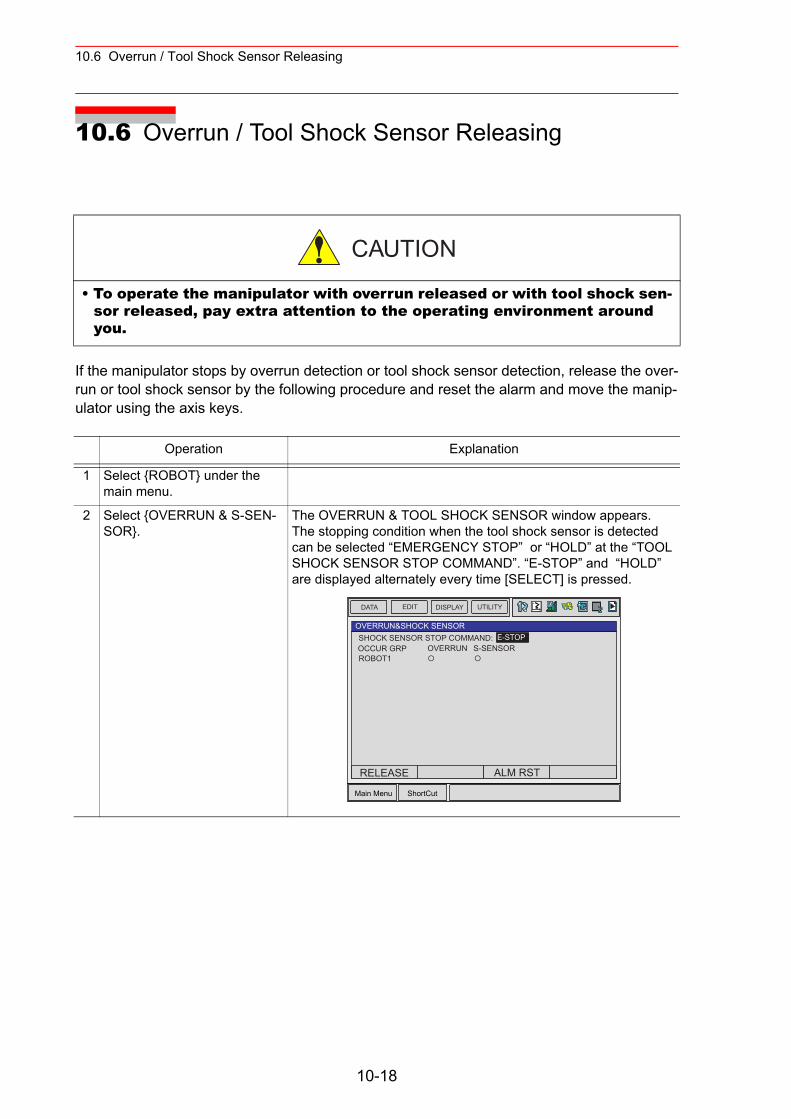
10.6 Overrun / Tool Shock Sensor Releasing
10.6 Overrun / Tool Shock Sensor Releasing
If the manipulator stops by overrun detection or tool shock sensor detection, release the over-run or tool shock sensor by the following procedure and reset the alarm and move the manip-ulator using the axis keys.
• To operate the manipulator with overrun released or with tool shock sen-sor released, pay extra attention to the operating environment around you.
Operation Explanation
1 Select {ROBOT} under the main menu.
2 Select {OVERRUN & S-SEN-SOR}.
The OVERRUN & TOOL SHOCK SENSOR window appears. The stopping condition when the tool shock sensor is detected can be selected “EMERGENCY STOP” or “HOLD” at the “TOOL SHOCK SENSOR STOP COMMAND”. “E-STOP” and “HOLD” are displayed alternately every time [SELECT] is pressed.
CAUTION
Main Menu ShortCut
EDIT DISPLAY UTILITYDATA
SHOCK SENSOR STOP COMMAND:OVERRUN&SHOCK SENSOR
E-STOPOCCUR GRP OVERRUNROBOT1
S-SENSOR
RELEASE ALM RST
10-18
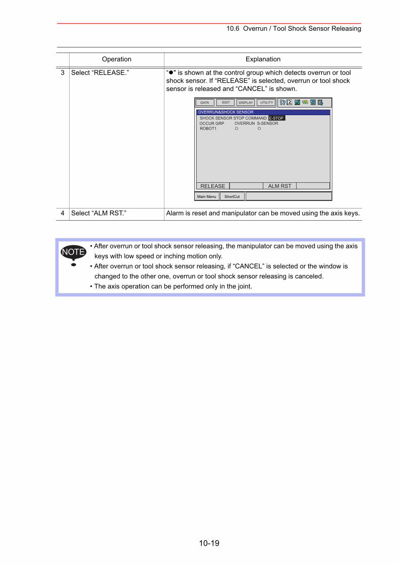
10.6 Overrun / Tool Shock Sensor Releasing
3 Select “RELEASE.” “ " is shown at the control group which detects overrun or tool shock sensor. If “RELEASE” is selected, overrun or tool shock sensor is released and “CANCEL” is shown.
4 Select “ALM RST.” Alarm is reset and manipulator can be moved using the axis keys.
• After overrun or tool shock sensor releasing, the manipulator can be moved using the axis keys with low speed or inching motion only.
• After overrun or tool shock sensor releasing, if “CANCEL” is selected or the window is changed to the other one, overrun or tool shock sensor releasing is canceled.
• The axis operation can be performed only in the joint.
Operation Explanation
Main Menu ShortCut
EDIT DISPLAY UTILITYDATA
SHOCK SENSOR STOP COMMAND:OVERRUN&SHOCK SENSOR
E-STOPOCCUR GRP OVERRUNROBOT1
S-SENSOR
RELEASE ALM RST
NOTE
10-19
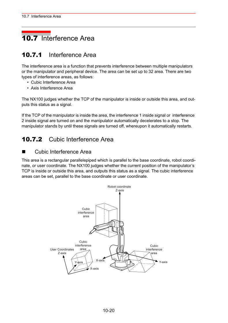
10.7 Interference Area
10.7 Interference Area
10.7.1 Interference Area
The interference area is a function that prevents interference between multiple manipulators or the manipulator and peripheral device. The area can be set up to 32 area. There are two types of interference areas, as follows:
• Cubic Interference Area• Axis Interference Area
The NX100 judges whether the TCP of the manipulator is inside or outside this area, and out-puts this status as a signal.
If the TCP of the manipulator is inside the area, the interference 1 inside signal or interference 2 inside signal are turned on and the manipulator automatically decelerates to a stop. The manipulator stands by until these signals are turned off, whereupon it automatically restarts.
10.7.2 Cubic Interference Area
Cubic Interference AreaThis area is a rectangular parallelepiped which is parallel to the base coordinate, robot coordi-nate, or user coordinate. The NX100 judges whether the current position of the manipulator’s TCP is inside or outside this area, and outputs this status as a signal. The cubic interference areas can be set, parallel to the base coordinate or user coordinate.
Cubicinterference
area
X-axis
User CoordinatesZ-axis
Cubicinterference
area
Cubicinterference
area
X-axis
Y-axisY-axis
10-20
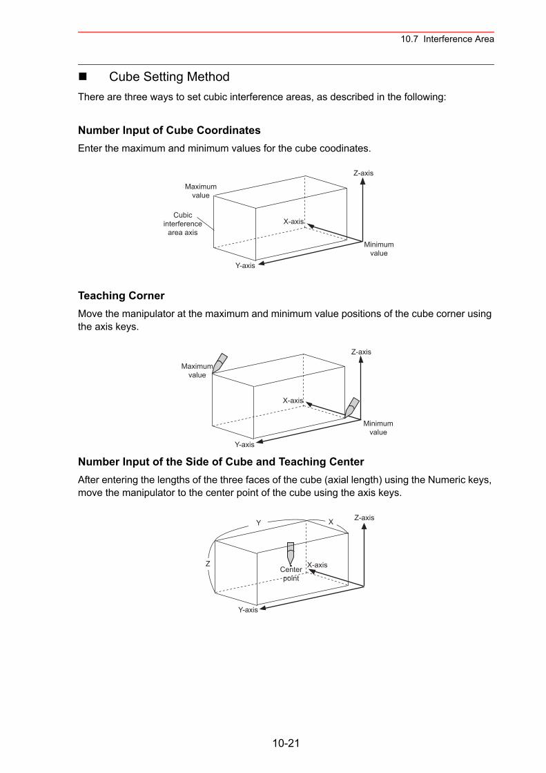
10.7 Interference Area
Cube Setting MethodThere are three ways to set cubic interference areas, as described in the following:
Number Input of Cube CoordinatesEnter the maximum and minimum values for the cube coodinates.
Teaching CornerMove the manipulator at the maximum and minimum value positions of the cube corner using the axis keys.
Number Input of the Side of Cube and Teaching CenterAfter entering the lengths of the three faces of the cube (axial length) using the Numeric keys, move the manipulator to the center point of the cube using the axis keys.
Minimumvalue
X-axis
Y-axis
Z-axis
Maximumvalue
Cubicinterference
area axis
Minimumvalue
X-axis
Y-axis
Z-axis
Maximumvalue
X-axis
Y-axis
Z-axis
Centerpoint
XY
Z
10-21
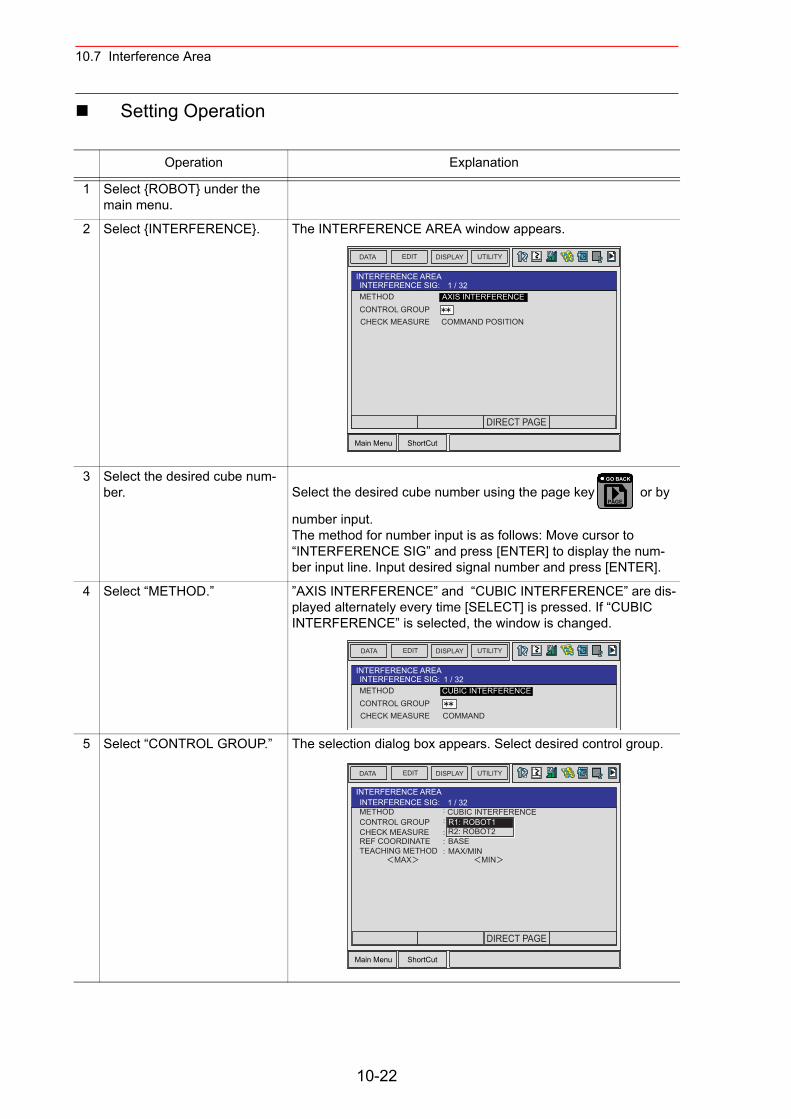
10.7 Interference Area
Setting Operation
Operation Explanation
1 Select {ROBOT} under the main menu.
2 Select {INTERFERENCE}. The INTERFERENCE AREA window appears.
3 Select the desired cube num-ber. Select the desired cube number using the page key or by
number input.The method for number input is as follows: Move cursor to “INTERFERENCE SIG” and press [ENTER] to display the num-ber input line. Input desired signal number and press [ENTER].
4 Select “METHOD.” ”AXIS INTERFERENCE” and “CUBIC INTERFERENCE” are dis-played alternately every time [SELECT] is pressed. If “CUBIC INTERFERENCE” is selected, the window is changed.
5 Select “CONTROL GROUP.” The selection dialog box appears. Select desired control group.
Main Menu ShortCut
EDIT DISPLAY UTILITYDATA
METHODCONTROL GROUPCHECK MEASURE COMMAND POSITION
AXIS INTERFERENCE
INTERFERENCE AREAINTERFERENCE SIG: 1 / 32
DIRECT PAGE
PAGE
GO BACK
EDIT DISPLAY UTILITYDATA
INTERFERENCE AREAINTERFERENCE SIG: 1 / 32METHODCONTROL GROUPCHECK MEASURE COMMAND
CUBIC INTERFERENCE
Main Menu ShortCut
EDIT DISPLAY UTILITYDATA
METHODCONTROL GROUPCHECK MEASURE
CUBIC INTERFERENCE
INTERFERENCE AREAINTERFERENCE SIG: 1 / 32
REF COORDINATETEACHING METHOD
BASEMAX/MIN
MAX MIN
R1: ROBOT1R2: ROBOT2
DIRECT PAGE
10-22
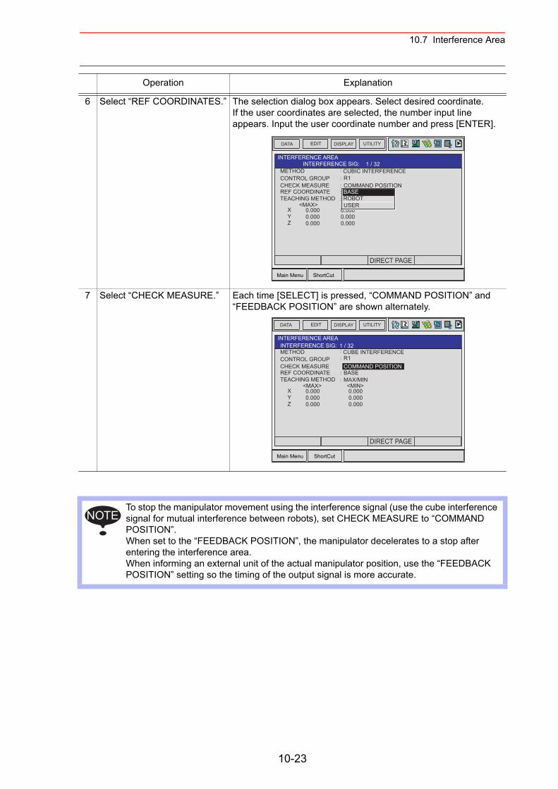
10.7 Interference Area
6 Select “REF COORDINATES.” The selection dialog box appears. Select desired coordinate. If the user coordinates are selected, the number input line appears. Input the user coordinate number and press [ENTER].
7 Select “CHECK MEASURE.” Each time [SELECT] is pressed, “COMMAND POSITION” and “FEEDBACK POSITION” are shown alternately.
To stop the manipulator movement using the interference signal (use the cube interference signal for mutual interference between robots), set CHECK MEASURE to “COMMAND POSITION”.When set to the “FEEDBACK POSITION”, the manipulator decelerates to a stop after entering the interference area.When informing an external unit of the actual manipulator position, use the “FEEDBACK POSITION” setting so the timing of the output signal is more accurate.
Operation Explanation
Main Menu ShortCut
EDIT DISPLAY UTILITYDATA
METHODCONTROL GROUPCHECK MEASURE COMMAND POSITION
CUBIC INTERFERENCE
INTERFERENCE AREAINTERFERENCE SIG: 1 / 32
REF COORDINATETEACHING METHOD
<MAX>
R1
XYZ
0.0000.0000.000
0.0000.0000.000
BASEROBOTUSER
DIRECT PAGE
Main Menu ShortCut
EDIT DISPLAY UTILITYDATA
METHODCONTROL GROUPCHECK MEASURE COMMAND POSITION
CUBE INTERFERENCE
INTERFERENCE AREAINTERFERENCE SIG: 1 / 32
REF COORDINATETEACHING METHOD
BASEMAX/MIN
<MAX> <MIN>
R1
XYZ
0.0000.0000.000
0.0000.0000.000
DIRECT PAGE
NOTE
10-23
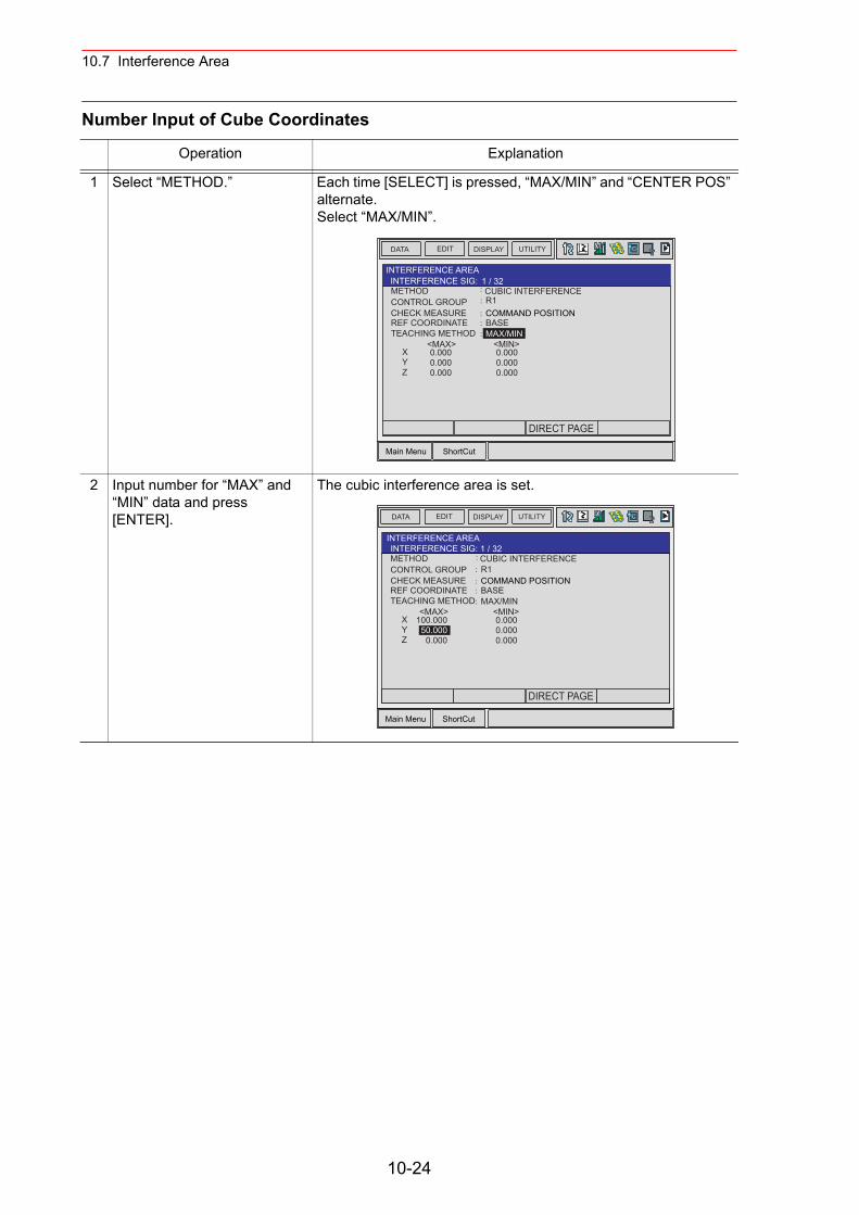
10.7 Interference Area
Number Input of Cube Coordinates
Operation Explanation
1 Select “METHOD.” Each time [SELECT] is pressed, “MAX/MIN” and “CENTER POS” alternate.Select “MAX/MIN”.
2 Input number for “MAX” and “MIN” data and press [ENTER].
The cubic interference area is set.
Main Menu ShortCut
EDIT DISPLAY UTILITYDATA
METHODCONTROL GROUPCHECK MEASURE COMMAND POSITION
CUBIC INTERFERENCE
INTERFERENCE AREAINTERFERENCE SIG: 1 / 32
REF COORDINATETEACHING METHOD
BASEMAX/MIN
<MAX> <MIN>
R1
XYZ
0.0000.0000.000
0.0000.0000.000
DIRECT PAGE
Main Menu ShortCut
EDIT DISPLAY UTILITYDATA
METHODCONTROL GROUPCHECK MEASURE COMMAND POSITION
CUBIC INTERFERENCE
INTERFERENCE AREAINTERFERENCE SIG: 1 / 32
REF COORDINATETEACHING METHOD
BASEMAX/MIN
<MAX> <MIN>
R1
XYZ
100.00050.000
0.000
0.0000.0000.000
DIRECT PAGE
10-24
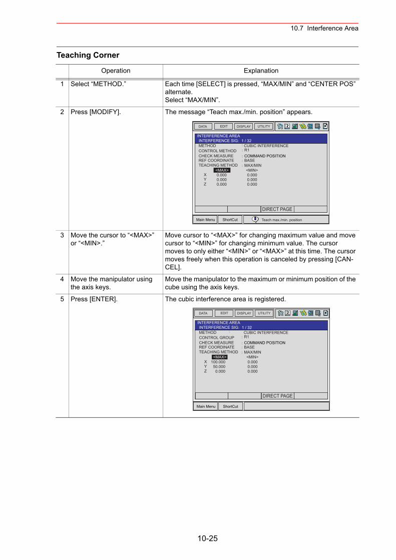
10.7 Interference Area
Teaching Corner
Operation Explanation
1 Select “METHOD.” Each time [SELECT] is pressed, “MAX/MIN” and “CENTER POS” alternate. Select “MAX/MIN”.
2 Press [MODIFY]. The message “Teach max./min. position” appears.
3 Move the cursor to “<MAX>” or “<MIN>.”
Move cursor to “<MAX>” for changing maximum value and move cursor to “<MIN>” for changing minimum value. The cursor moves to only either “<MIN>” or “<MAX>” at this time. The cursor moves freely when this operation is canceled by pressing [CAN-CEL].
4 Move the manipulator using the axis keys.
Move the manipulator to the maximum or minimum position of the cube using the axis keys.
5 Press [ENTER]. The cubic interference area is registered.
Main Menu ShortCut
EDIT DISPLAY UTILITYDATA
METHODCONTROL METHODCHECK MEASURE COMMAND POSITION
CUBIC INTERFERENCE
INTERFERENCE AREAINTERFERENCE SIG: 1 / 32
REF COORDINATETEACHING METHOD
BASEMAX/MIN
<MAX> <MIN>
R1
XYZ
0.0000.0000.000
0.0000.0000.000
DIRECT PAGE
Teach max./min. position
Main Menu ShortCut
EDIT DISPLAY UTILITYDATA
METHODCONTROL GROUPCHECK MEASURE COMMAND POSITION
CUBIC INTERFERENCE
INTERFERENCE AREAINTERFERENCE SIG: 1 / 32
REF COORDINATETEACHING METHOD
BASEMAX/MIN
<MAX> <MIN>
R1
XYZ
100.00050.000
0.000
0.0000.0000.000
DIRECT PAGE
10-25
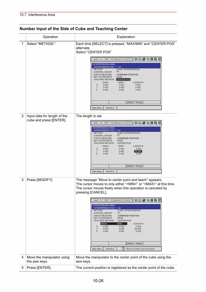
10.7 Interference Area
Number Input of the Side of Cube and Teaching Center
Operation Explanation
1 Select “METHOD.” Each time [SELECT] is pressed, “MAX/MIN” and “CENTER POS” alternate.Select “CENTER POS”
2 Input data for length of the cube and press [ENTER].
The length is set.
3 Press [MODIFY]. The message “Move to center point and teach” appears.The cursor moves to only either “<MIN>” or “<MAX>” at this time. The cursor moves freely when this operation is canceled by pressing [CANCEL].
4 Move the manipulator using the axis keys.
Move the manipulator to the center point of the cube using the axis keys.
5 Press [ENTER]. The current position is registered as the center point of the cube.
Main Menu ShortCut
EDIT DISPLAY UTILITYDATA
METHODCONTROL GROUPCHECK MEASURE COMMAND POSITION
CUBIC INTERFERENCE
INTERFERENCE AREAINTERFERENCE SIG: 1 / 32
REF COORDINATETEACHING METHOD
BASECENTER POS
<MAX> <MIN>
R1
XYZ
0.0000.0000.000
0.0000.0000.000
<LENGTH>0.0000.0000.000
DIRECT PAGE
Main Menu ShortCut
EDIT DISPLAY UTILITYDATA
METHODCONTROL GROUPCHECK MEASURE COMMAND POSITION
CUBIC INTERFERENCE
INTERFERENCE AREAINTERFERENCE SIG: 1 / 32
REF COORDINATETEACHING METHOD
BASECENTER POS
<MAX> <MIN>
R1
XYZ
0.0000.0000.000
0.0000.0000.000
<LENGTH>0.000
50.0000.000
DIRECT PAGE
Main Menu ShortCut
EDIT DISPLAY UTILITYDATA
METHODCONTROL GROUPCHECK MEASURE COMMAND POSITION
CUBIC INTERFERENCE
INTERFERENCE AREAINTERFERENCE SIG: 1 / 32
REF COORDINATETEACHING METHOD
BASECENTER POS
<MAX> <MIN>
R1
XYZ
0.0000.0000.000
0.0000.0000.000
<LENGTH>0.000
50.0000.000
Move to center point and teach
DIRECT PAGE
10-26
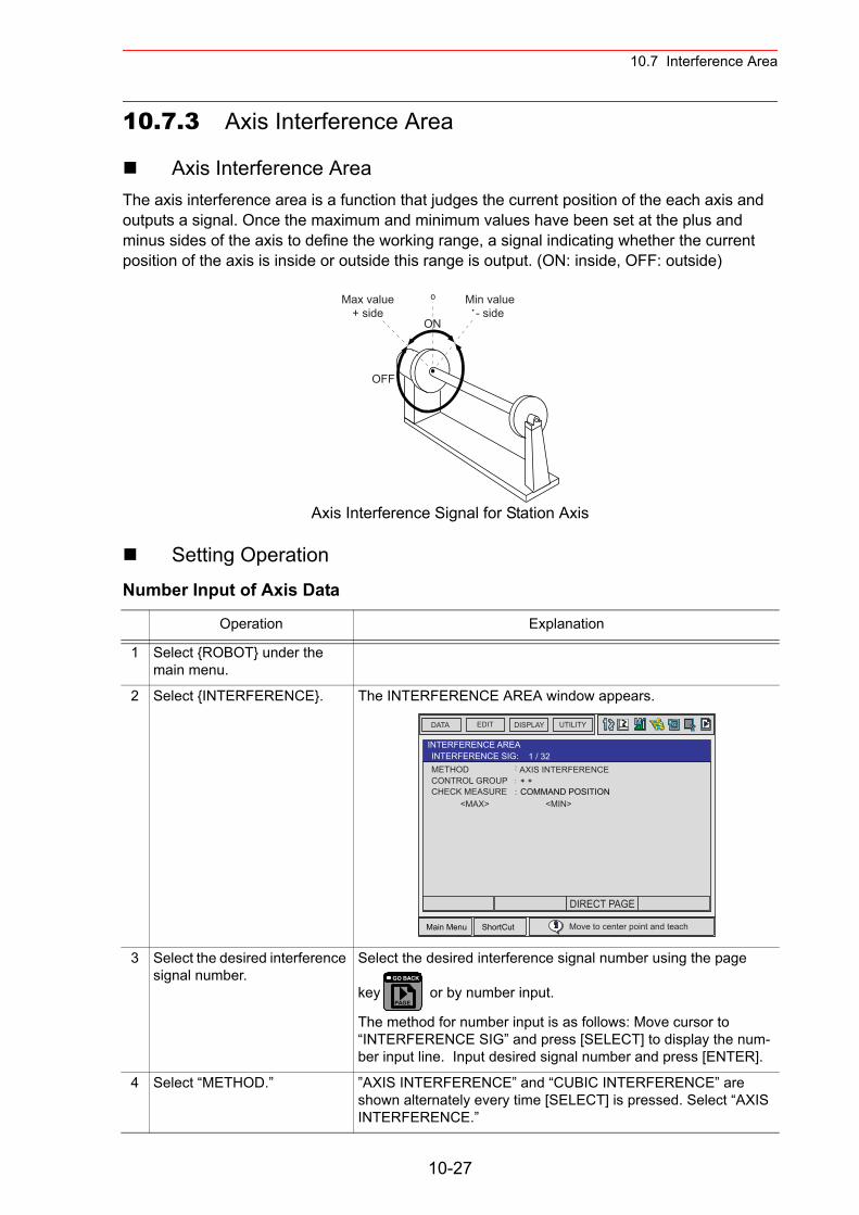
10.7 Interference Area
10.7.3 Axis Interference Area
Axis Interference AreaThe axis interference area is a function that judges the current position of the each axis and outputs a signal. Once the maximum and minimum values have been set at the plus and minus sides of the axis to define the working range, a signal indicating whether the current position of the axis is inside or outside this range is output. (ON: inside, OFF: outside)
Axis Interference Signal for Station Axis
Setting OperationNumber Input of Axis Data
Operation Explanation
1 Select {ROBOT} under the main menu.
2 Select {INTERFERENCE}. The INTERFERENCE AREA window appears.
3 Select the desired interference signal number.
Select the desired interference signal number using the page
key or by number input.
The method for number input is as follows: Move cursor to “INTERFERENCE SIG” and press [SELECT] to display the num-ber input line. Input desired signal number and press [ENTER].
4 Select “METHOD.” ”AXIS INTERFERENCE” and “CUBIC INTERFERENCE” are shown alternately every time [SELECT] is pressed. Select “AXIS INTERFERENCE.”
Max value+ side
Min value- side
ON
OFF
Main Menu ShortCut
EDIT DISPLAY UTILITYDATA
METHODCONTROL GROUPCHECK MEASURE COMMAND POSITION
AXIS INTERFERENCE
INTERFERENCE AREAINTERFERENCE SIG: 1 / 32
<MAX> <MIN>
Move to center point and teach
DIRECT PAGE
PAGE
GO BACK
10-27
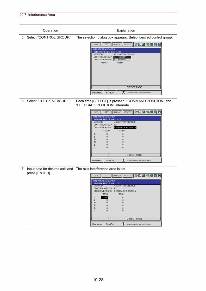
10.7 Interference Area
5 Select “CONTROL GROUP.” The selection dialog box appears. Select desired control group.
6 Select “CHECK MEASURE.” Each time [SELECT] is pressed, “COMMAND POSITION” and “FEEDBACK POSITION” alternate.
7 Input data for desired axis and press [ENTER].
The axis interference area is set.
Operation Explanation
Main Menu ShortCut
EDIT DISPLAY UTILITYDATA
METHODCONTROL GROUPCHECK MEASURE
AXIS INTERFERENCE
INTERFERENCE AREAINTERFERENCE SIG: 1 / 32
<MAX> <MIN>
Move to center point and teach
R1: ROBOT1R2: ROBOT2
DIRECT PAGE
Main Menu ShortCut
EDIT DISPLAY UTILITYDATA
METHODCONTROL GROUPCHECK MEASURE FEEDBACK POSITION
AXIS INTERFERENCE
INTERFERENCE AREAINTERFERENCE SIG: 1 / 32
<MAX> <MIN>
Move to center point and teach
SLURBT
000000
000000
R1
DIRECT PAGE
Main Menu ShortCut
EDIT DISPLAY UTILITYDATA
METHODCONTROL GROUPCHECK MEASURE FEEDBACK POSITION
AXIS INTERFERENCE
INTERFERENCE AREAINTERFERENCE SIG: 1 / 32
<MAX> <MIN>
Move to center point and teach
SLURBT
30000000
000000
R1
DIRECT PAGE
10-28
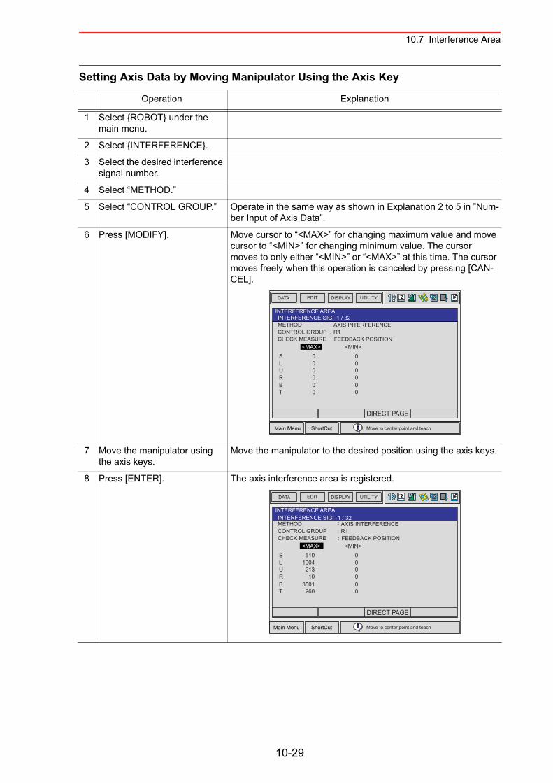
10.7 Interference Area
Setting Axis Data by Moving Manipulator Using the Axis Key
Operation Explanation
1 Select {ROBOT} under the main menu.
2 Select {INTERFERENCE}.
3 Select the desired interference signal number.
4 Select “METHOD.”
5 Select “CONTROL GROUP.” Operate in the same way as shown in Explanation 2 to 5 in ”Num-ber Input of Axis Data”.
6 Press [MODIFY]. Move cursor to “<MAX>” for changing maximum value and move cursor to “<MIN>” for changing minimum value. The cursor moves to only either “<MIN>” or “<MAX>” at this time. The cursor moves freely when this operation is canceled by pressing [CAN-CEL].
7 Move the manipulator using the axis keys.
Move the manipulator to the desired position using the axis keys.
8 Press [ENTER]. The axis interference area is registered.
Main Menu ShortCut
EDIT DISPLAY UTILITYDATA
METHODCONTROL GROUPCHECK MEASURE FEEDBACK POSITION
AXIS INTERFERENCE
INTERFERENCE AREAINTERFERENCE SIG: 1 / 32
<MAX> <MIN>
Move to center point and teach
SLURBT
000000
000000
R1
DIRECT PAGE
Main Menu ShortCut
EDIT DISPLAY UTILITYDATA
METHODCONTROL GROUPCHECK MEASURE FEEDBACK POSITION
AXIS INTERFERENCE
INTERFERENCE AREAINTERFERENCE SIG: 1 / 32
<MAX> <MIN>
Move to center point and teach
SLURBT
5101004
21310
3501260
000000
R1
DIRECT PAGE
10-29
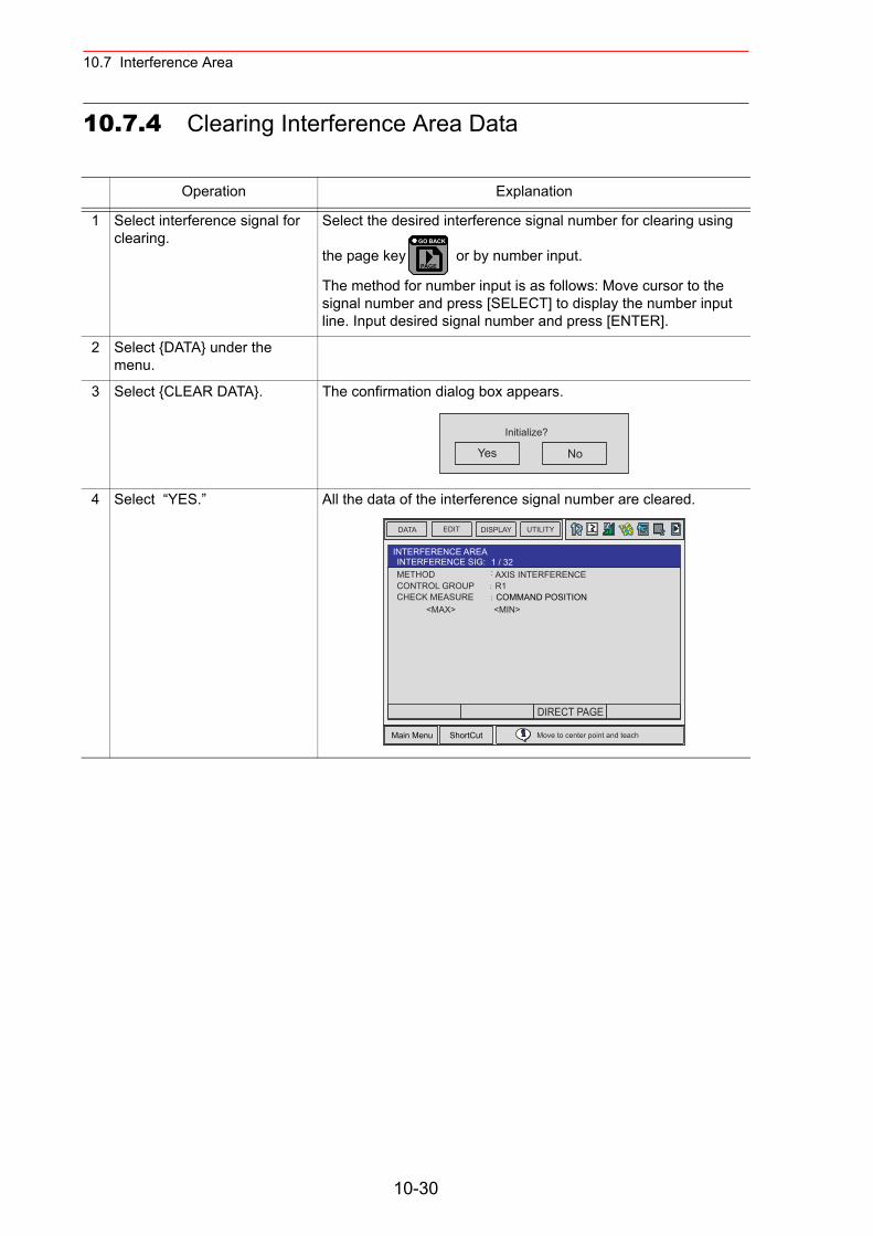
10.7 Interference Area
10.7.4 Clearing Interference Area Data
Operation Explanation
1 Select interference signal for clearing.
Select the desired interference signal number for clearing using
the page key or by number input.
The method for number input is as follows: Move cursor to the signal number and press [SELECT] to display the number input line. Input desired signal number and press [ENTER].
2 Select {DATA} under the menu.
3 Select {CLEAR DATA}. The confirmation dialog box appears.
4 Select “YES.” All the data of the interference signal number are cleared.
PAGE
GO BACK
Yes No
Initialize?
Main Menu ShortCut
EDIT DISPLAY UTILITYDATA
METHODCONTROL GROUPCHECK MEASURE COMMAND POSITION
AXIS INTERFERENCE
INTERFERENCE AREAINTERFERENCE SIG: 1 / 32
<MAX> <MIN>
Move to center point and teach
R1
DIRECT PAGE
10-30
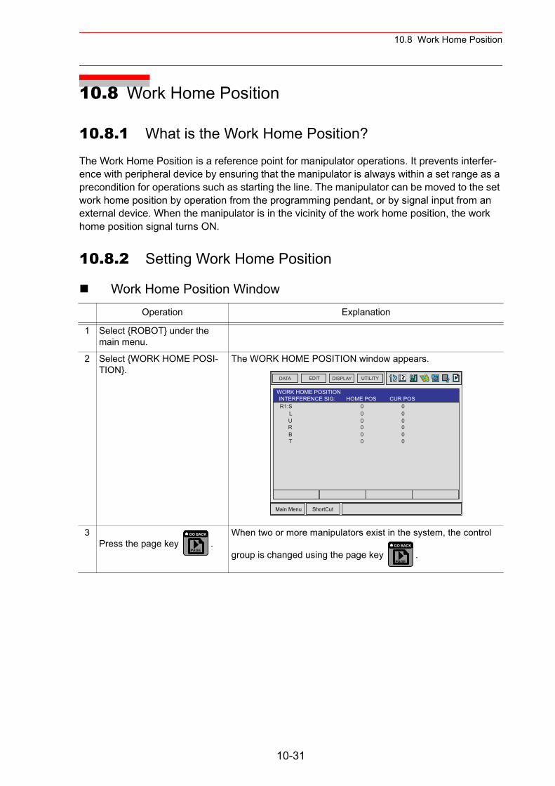
10.8 Work Home Position
10.8 Work Home Position
10.8.1 What is the Work Home Position?
The Work Home Position is a reference point for manipulator operations. It prevents interfer-ence with peripheral device by ensuring that the manipulator is always within a set range as a precondition for operations such as starting the line. The manipulator can be moved to the set work home position by operation from the programming pendant, or by signal input from an external device. When the manipulator is in the vicinity of the work home position, the work home position signal turns ON.
10.8.2 Setting Work Home Position
Work Home Position WindowOperation Explanation
1 Select {ROBOT} under the main menu.
2 Select {WORK HOME POSI-TION}.
The WORK HOME POSITION window appears.
3Press the page key .
When two or more manipulators exist in the system, the control
group is changed using the page key .
Main Menu ShortCut
EDIT DISPLAY UTILITYDATA
R1:SLU
WORK HOME POSITIONINTERFERENCE SIG: HOME POS CUR POS
RBT
000000
000000
PAGE
GO BACK
PAGE
GO BACK
10-31
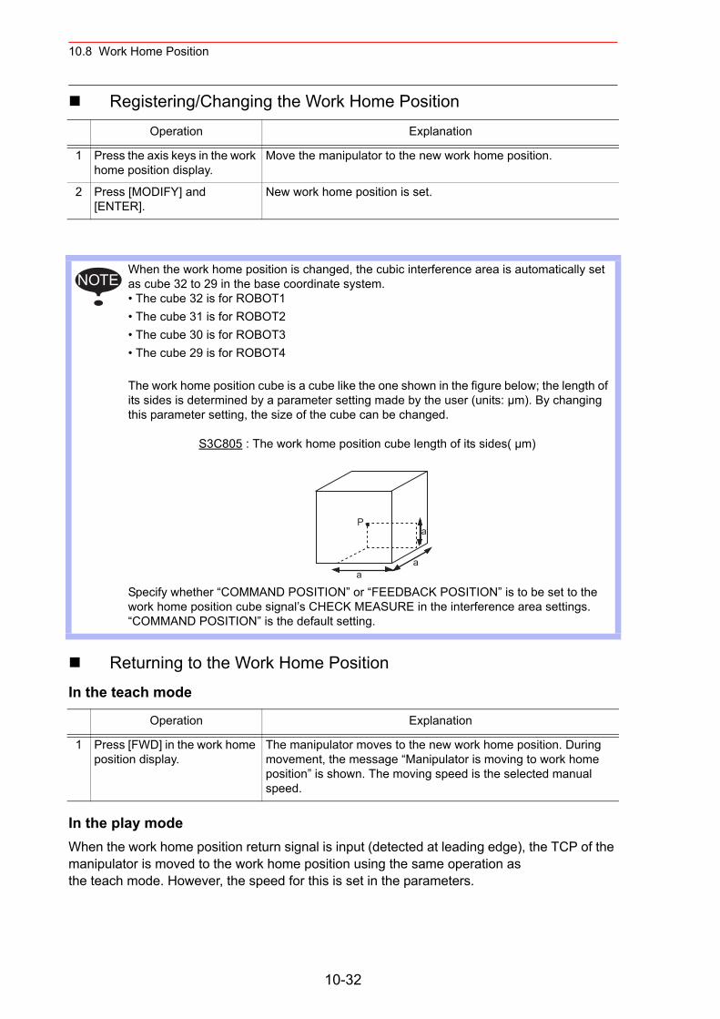
10.8 Work Home Position
Registering/Changing the Work Home Position
Returning to the Work Home Position In the teach mode
In the play mode When the work home position return signal is input (detected at leading edge), the TCP of the manipulator is moved to the work home position using the same operation asthe teach mode. However, the speed for this is set in the parameters.
Operation Explanation
1 Press the axis keys in the work home position display.
Move the manipulator to the new work home position.
2 Press [MODIFY] and [ENTER].
New work home position is set.
When the work home position is changed, the cubic interference area is automatically set as cube 32 to 29 in the base coordinate system. • The cube 32 is for ROBOT1• The cube 31 is for ROBOT2• The cube 30 is for ROBOT3• The cube 29 is for ROBOT4
The work home position cube is a cube like the one shown in the figure below; the length of its sides is determined by a parameter setting made by the user (units: µm). By changing this parameter setting, the size of the cube can be changed.
S3C805 : The work home position cube length of its sides( µm)
Specify whether “COMMAND POSITION” or “FEEDBACK POSITION” is to be set to the work home position cube signal’s CHECK MEASURE in the interference area settings. “COMMAND POSITION” is the default setting.
Operation Explanation
1 Press [FWD] in the work home position display.
The manipulator moves to the new work home position. During movement, the message “Manipulator is moving to work home position” is shown. The moving speed is the selected manual speed.
NOTE
P
aa
a
10-32
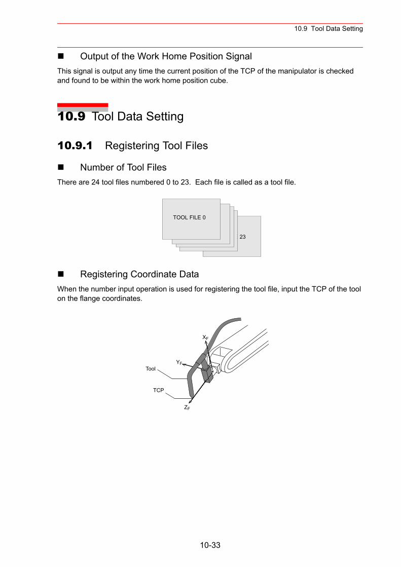
10.9 Tool Data Setting
Output of the Work Home Position Signal This signal is output any time the current position of the TCP of the manipulator is checked and found to be within the work home position cube.
10.9 Tool Data Setting
10.9.1 Registering Tool Files
Number of Tool FilesThere are 24 tool files numbered 0 to 23. Each file is called as a tool file.
Registering Coordinate DataWhen the number input operation is used for registering the tool file, input the TCP of the tool on the flange coordinates.
TOOL FILE 23
TOOL FILE 0
TCP
XF
YF
ZF
Tool
10-33
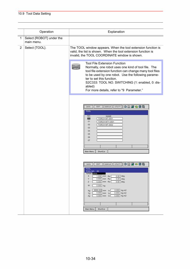
10.9 Tool Data Setting
Operation Explanation
1 Select {ROBOT} under the main menu.
2 Select {TOOL}. The TOOL window appears. When the tool extension function is valid, the list is shown. When the tool extension function is invalid, the TOOL COORDINATE window is shown.
Tool File Extension FunctionNormally, one robot uses one kind of tool file. The tool file extension function can change many tool files to be used by one robot. Use the following parame-ter to set this function.S2C333: TOOL NO. SWITCHING (1: enabled, 0: dis-abled)For more details, refer to "9 Parameter.”
SUPPLE-MENT
Main Menu ShortCut
EDIT DISPLAY UTILITYDATA
NO.0001
TOOL
0203
TORCH MT-3501TORCH MTY-3501TORCH MT-3502
04050607
NAME
Main Menu ShortCut
EDIT DISPLAY UTILITYDATA
NAME:XY
TOOLTOOL NO. 00
Z
W
mmmmmm
dhhh1.5560.0005.000
kg0.000
mmmmmm
9999.0000.0000.000
XgYgZg
RxRyRz
deg.deg.deg.
0.000.000.00
kg.m2kg.m2kg.m2
0.0000.0000.000
IxIyIz
10-34

10.9 Tool Data Setting
<SettingExample>
3 Select the desired tool num-ber.
When the TOOL window is shown, move the cursor and press [SELECT]. The coordinate window of the selected tool appears. If
the coordinate window appears, press the page key to
select the desired tool.To switch the TOOL window and the coordinate window, press {DISPLAY} {LIST} or {DISPLAY} {COORDINATE DATA}.
4 Select the desired coordinate axis to modify.
The number input line appears.
5 Input the tool data.
6 Press [ENTER]. The tool data is registered.
Case of Tool A, B Case of Tool C
Operation Explanation
PAGE
GO BACK
EDIT DISPLAY UTILITYDATA
TOOLTOOL NO. 00NAME: dhhh
LIST
Main Menu ShortCut
EDIT DISPLAY UTILITYDATA
NAME
TOOLTOOL NO. 00
TORCH MT-3501XYZ
W
mmmmmm
0.000260.000
kg0.000
mmXg
RxRyRz
deg.deg.deg.
0.000.000.00
0.000
0.000
ZFTCP
Tool A
260 mm
145 mmZF
260 mm260 mm
TCPTCP
Tool B Tool C
XYZ
mmmmmm
0.000260.000
RxRyRz
deg.deg.deg.
0.000.000.00
0.000 XYZ
mmmmmm
145.000260.000
RxRyRz
deg.deg.deg.
0.000.000.00
0.000
10-35
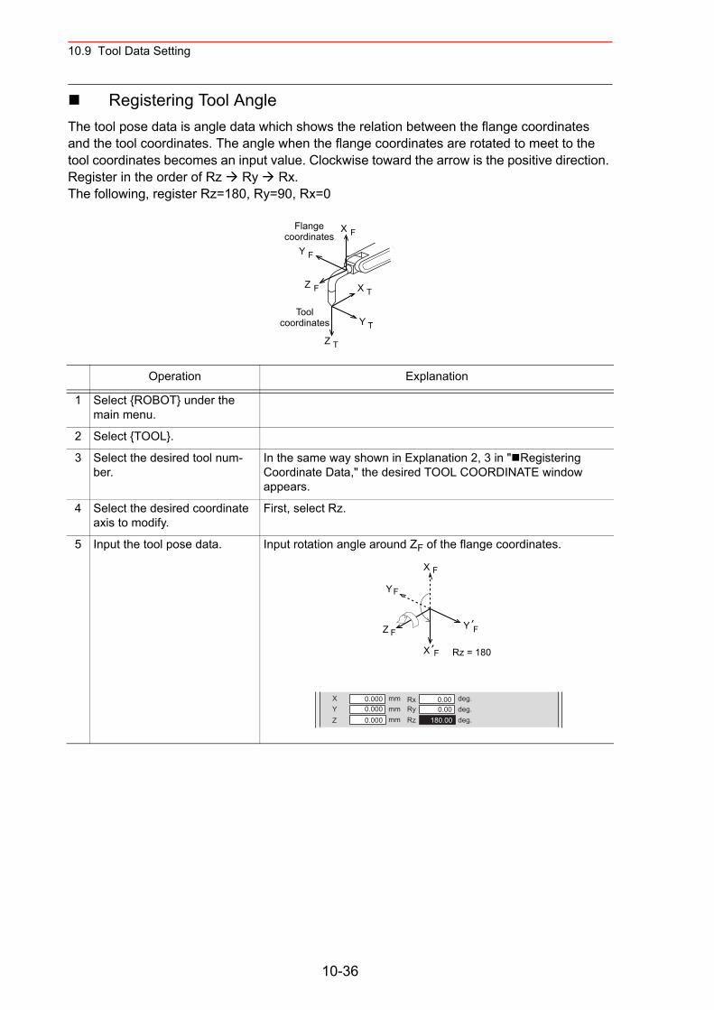
10.9 Tool Data Setting
Registering Tool AngleThe tool pose data is angle data which shows the relation between the flange coordinates and the tool coordinates. The angle when the flange coordinates are rotated to meet to the tool coordinates becomes an input value. Clockwise toward the arrow is the positive direction. Register in the order of Rz Ry Rx.The following, register Rz=180, Ry=90, Rx=0
Operation Explanation
1 Select {ROBOT} under the main menu.
2 Select {TOOL}.
3 Select the desired tool num-ber.
In the same way shown in Explanation 2, 3 in " Registering Coordinate Data," the desired TOOL COORDINATE window appears.
4 Select the desired coordinate axis to modify.
First, select Rz.
5 Input the tool pose data. Input rotation angle around ZF of the flange coordinates.
X F
Z F
Y F
X T
Z T
Y T
Flangecoordinates
Toolcoordinates
X F
Z F
YF
X F
Y F
Rz = 180
X
Y
Z
mm
mm
mm
0.000RxRy
Rz
deg.
deg.
deg.
0.000.00
180.00
0.000
0.000
10-36
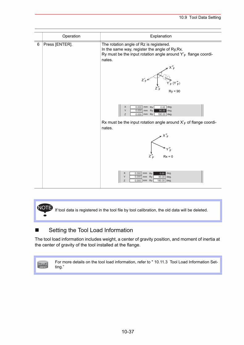
10.9 Tool Data Setting
Setting the Tool Load InformationThe tool load information includes weight, a center of gravity position, and moment of inertia at the center of gravity of the tool installed at the flange.
6 Press [ENTER]. The rotation angle of Rz is registered.In the same way, register the angle of Ry,Rx.Ry must be the input rotation angle around Y’F flange coordi-nates.
Rx must be the input rotation angle around X’F of flange coordi-nates.
If tool data is registered in the tool file by tool calibration, the old data will be deleted.
For more details on the tool load information, refer to " 10.11.3 Tool Load Information Set-ting.”
Operation Explanation
Z F
Z F
Y F (Y )F
X F
Ry = 90
X
Y
Z
mm
mm
mm
0.0000.000
0.000
RxRy
Rz
deg.
deg.
deg.
0.0090.00
180.00
Z F
Y F
X F
Rx = 0
X
Y
Z
mm
mm
mm
0.0000.000
0.000
RxRy
Rz
deg.
deg.
deg.
0.0090.00
180.00
NOTE
SUPPLE-MENT
10-37
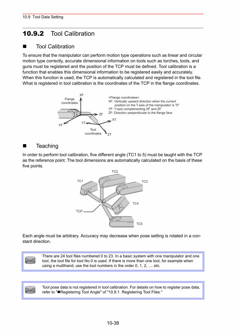
10.9 Tool Data Setting
10.9.2 Tool Calibration
Tool CalibrationTo ensure that the manipulator can perform motion type operations such as linear and circular motion type correctly, accurate dimensional information on tools such as torches, tools, and guns must be registered and the position of the TCP must be defined. Tool calibration is a function that enables this dimensional information to be registered easily and accurately. When this function is used, the TCP is automatically calculated and registered in the tool file. What is registered in tool calibration is the coordinates of the TCP in the flange coordinates.
TeachingIn order to perform tool calibration, five different angle (TC1 to 5) must be taught with the TCP as the reference point. The tool dimensions are automatically calculated on the basis of these five points.
Each angle must be arbitrary. Accuracy may decrease when pose setting is rotated in a con-stant direction.
There are 24 tool files numbered 0 to 23. In a basic system with one manipulator and one tool, the tool file for tool No.0 is used. If there is more than one tool, for example when using a multihand, use the tool numbers in the order 0, 1, 2, .... etc.
Tool pose data is not registered in tool calibration. For details on how to register pose data, refer to " Registering Tool Angle" of "10.9.1 Registering Tool Files."
Flangecoordinates
XF
YF
ZFXT
YT
ZT
<Flange coordinates>XF: Vertically upward direction when the current position on the T-axis of the manipulator is "0"YF: Y-axis complementing XF and ZFZF: Direction perpendicular to the flange face
Toolcoordinates
TCP
TC1
TC2
TC3
TC4
TC5
SUPPLE-MENT
SUPPLE-MENT
10-38
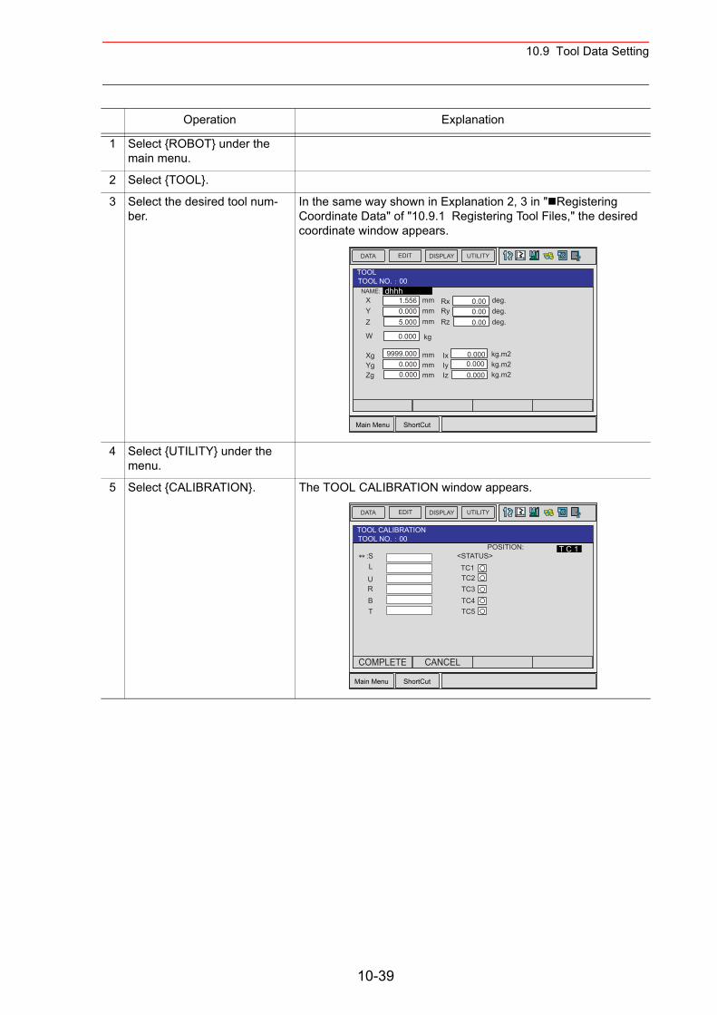
10.9 Tool Data Setting
Operation Explanation
1 Select {ROBOT} under the main menu.
2 Select {TOOL}.
3 Select the desired tool num-ber.
In the same way shown in Explanation 2, 3 in " Registering Coordinate Data" of "10.9.1 Registering Tool Files," the desired coordinate window appears.
4 Select {UTILITY} under the menu.
5 Select {CALIBRATION}. The TOOL CALIBRATION window appears.
Main Menu ShortCut
EDIT DISPLAY UTILITYDATA
NAME:
TOOLTOOL NO. 00
dhhhXYZ
W
mmmmmm
kg
mmmmmm
XgYgZg
RxRyRz
deg.deg.deg.
kg.m2kg.m2kg.m2
IxIyIz
1.5560.0005.000
0.000
9999.0000.0000.000
0.000.000.00
0.0000.0000.000
Main Menu ShortCut
EDIT DISPLAY UTILITYDATA
POSITION::S
TOOL CALIBRATIONTOOL NO. 00
T C 1
L
URBT
<STATUS>TC1TC2TC3TC4TC5
COMPLETE CANCEL
10-39
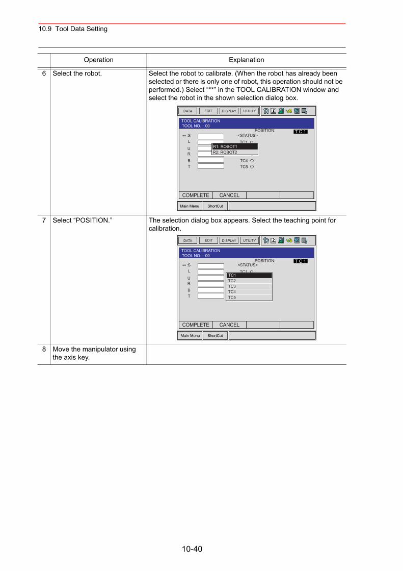
10.9 Tool Data Setting
6 Select the robot. Select the robot to calibrate. (When the robot has already been selected or there is only one of robot, this operation should not be performed.) Select “**” in the TOOL CALIBRATION window and select the robot in the shown selection dialog box.
7 Select “POSITION.” The selection dialog box appears. Select the teaching point for calibration.
8 Move the manipulator using the axis key.
Operation Explanation
Main Menu ShortCut
EDIT DISPLAY UTILITYDATA
TOOL CALIBRATIONTOOL NO. 00
T C 1POSITION::SL
URBT
<STATUS>TC1TC2TC3TC4TC5
R1: ROBOT1R2: ROBOT2
COMPLETE CANCEL
Main Menu ShortCut
EDIT DISPLAY UTILITYDATA
POSITION:
TOOL CALIBRATIONTOOL NO. 00
T C 1:SL
URBT
<STATUS>TC1TC2TC3TC4TC5
TC1TC2TC3TC4TC5
COMPLETE CANCEL
10-40
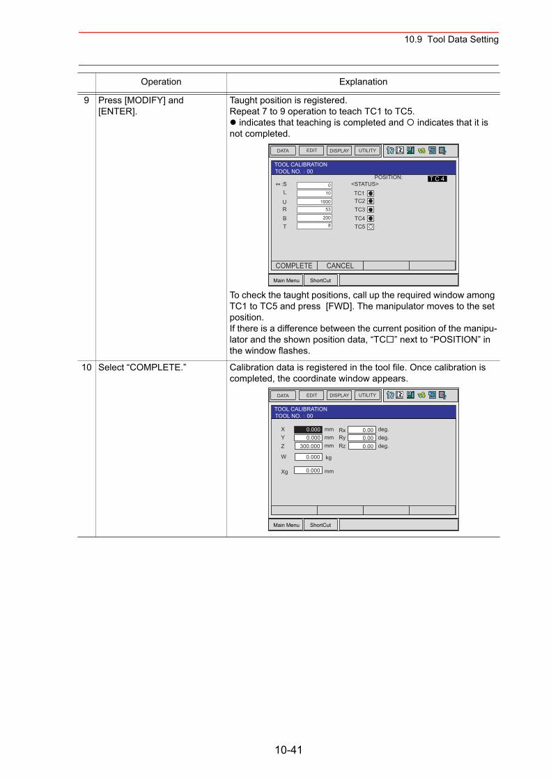
10.9 Tool Data Setting
9 Press [MODIFY] and [ENTER].
Taught position is registered.Repeat 7 to 9 operation to teach TC1 to TC5.
indicates that teaching is completed and indicates that it is not completed.
To check the taught positions, call up the required window among TC1 to TC5 and press [FWD]. The manipulator moves to the set position. If there is a difference between the current position of the manipu-lator and the shown position data, “TC ” next to “POSITION” in the window flashes.
10 Select “COMPLETE.” Calibration data is registered in the tool file. Once calibration is completed, the coordinate window appears.
Operation Explanation
Main Menu ShortCut
EDIT DISPLAY UTILITYDATA
TOOL CALIBRATIONTOOL NO. 00
T C 4POSITION::SL
URBT
<STATUS>TC1TC2TC3TC4TC5
010
100053
2008
COMPLETE CANCEL
Main Menu ShortCut
EDIT DISPLAY UTILITYDATA
XYZ
W
mmmmmm
kg
mmXg
RxRyRz
deg.deg.deg.
0.0000.000
0.000
0.000
300.000
0.000.000.00
TOOL CALIBRATIONTOOL NO. 00
10-41
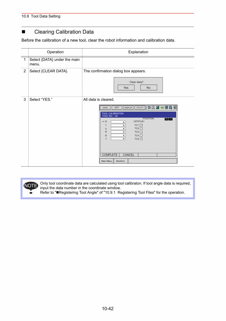
10.9 Tool Data Setting
Clearing Calibration DataBefore the calibration of a new tool, clear the robot information and calibration data.
Operation Explanation
1 Select {DATA} under the main menu.
2 Select {CLEAR DATA}. The confirmation dialog box appears.
3 Select “YES.” All data is cleared.
Only tool coordinate data are calculated using tool calibraton. If tool angle data is required, input the data number in the coordinate window.Refer to " Registering Tool Angle" of "10.9.1 Registering Tool Files" for the operation.
Yes No
Clear data?
Main Menu ShortCut
EDIT DISPLAY UTILITYDATA
POSITION::S
TOOL CALIBRATIONTOOL NO. 00
T C 1
L
URBT
<STATUS>TC1TC2TC3TC4TC5
COMPLETE CANCEL
NOTE
10-42
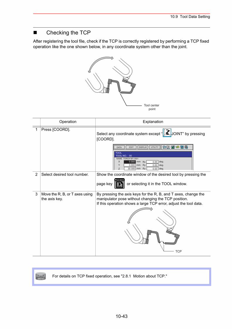
10.9 Tool Data Setting
Checking the TCPAfter registering the tool file, check if the TCP is correctly registered by performing a TCP fixed operation like the one shown below, in any coordinate system other than the joint.
Operation Explanation
1 Press [COORD].Select any coordinate system except “ JOINT” by pressing [COORD].
2 Select desired tool number. Show the coordinate window of the desired tool by pressing the
page key or selecting it in the TOOL window.
3 Move the R, B, or T axes using the axis key.
By pressing the axis keys for the R, B, and T axes, change the manipulator pose without changing the TCP position. If this operation shows a large TCP error, adjust the tool data.
For details on TCP fixed operation, see "2.8.1 Motion about TCP."
Tool center point
EDIT DISPLAY UTILITYDATA
NAME
TOOLTOOL NO. 00
TORCH MT-3501XYZ
mmmmmm
RxRyRz
deg.deg.deg.
0.0000.000
30.000
0.000.000.00
PAGE
GO BACK
TCP
SUPPLE-MENT
10-43
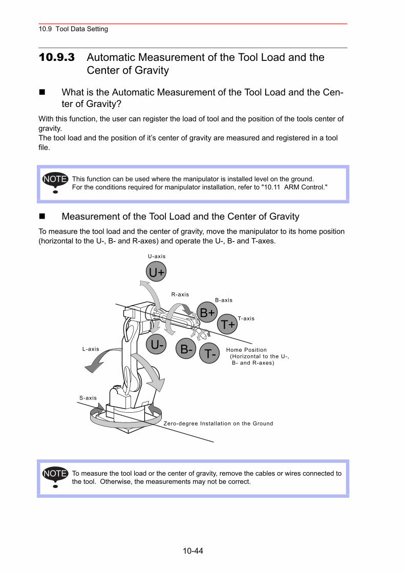
10.9 Tool Data Setting
10.9.3 Automatic Measurement of the Tool Load and the Center of Gravity
What is the Automatic Measurement of the Tool Load and the Cen-ter of Gravity?
With this function, the user can register the load of tool and the position of the tools center of gravity.The tool load and the position of it’s center of gravity are measured and registered in a tool file.
Measurement of the Tool Load and the Center of GravityTo measure the tool load and the center of gravity, move the manipulator to its home position (horizontal to the U-, B- and R-axes) and operate the U-, B- and T-axes.
This function can be used where the manipulator is installed level on the ground.For the conditions required for manipulator installation, refer to "10.11 ARM Control."
To measure the tool load or the center of gravity, remove the cables or wires connected to the tool. Otherwise, the measurements may not be correct.
NOTE
U-axis
R-axisB-axis
T-axis
L-axis
S-axis
U-
U+
B-
B+
T-
T+
Zero-degree Installation on the Ground
Home Position (Horizontal to the U-, B- and R-axes)
NOTE
10-44
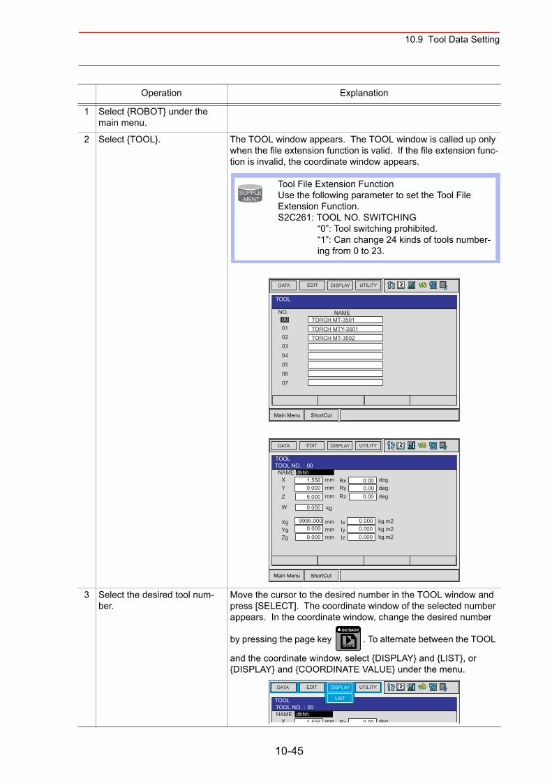
10.9 Tool Data Setting
Operation Explanation
1 Select {ROBOT} under the main menu.
2 Select {TOOL}. The TOOL window appears. The TOOL window is called up only when the file extension function is valid. If the file extension func-tion is invalid, the coordinate window appears.
3 Select the desired tool num-ber.
Move the cursor to the desired number in the TOOL window and press [SELECT]. The coordinate window of the selected number appears. In the coordinate window, change the desired number
by pressing the page key . To alternate between the TOOL
and the coordinate window, select {DISPLAY} and {LIST}, or {DISPLAY} and {COORDINATE VALUE} under the menu.
Tool File Extension FunctionUse the following parameter to set the Tool File Extension Function.S2C261: TOOL NO. SWITCHING
“0”: Tool switching prohibited.“1”: Can change 24 kinds of tools number-ing from 0 to 23.
SUPPLE-MENT
Main Menu ShortCut
EDIT DISPLAY UTILITYDATA
NO.0001
TOOL
0203
TORCH MT-3501TORCH MTY-3501TORCH MT-3502
04050607
NAME
Main Menu ShortCut
EDIT DISPLAY UTILITYDATA
TOOLTOOL NO. 00NAME:
XYZ
W
mmmmmm
dhhh1.5560.0005.000
kg0.000
mmmmmm
9999.0000.0000.000
XgYgZg
RxRyRz
deg.deg.deg.
0.000.000.00
kg.m2kg.m2kg.m2
0.0000.0000.000
IxIyIz
PAGE
GO BACK
EDIT DISPLAY UTILITYDATA
LISTTOOLTOOL NO. 00NAME:
X mmdhhh
1 556 Rx deg.0 00
10-45
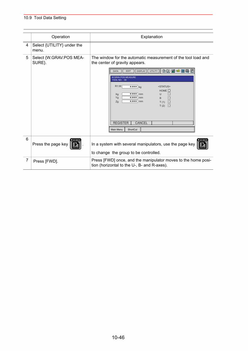
10.9 Tool Data Setting
4 Select {UTILITY} under the menu.
5 Select {W.GRAV.POS MEA-SURE}.
The window for the automatic measurement of the tool load and the center of gravity appears.
6Press the page key . In a system with several manipulators, use the page key
to change the group to be controlled.
7 Press [FWD]. Press [FWD] once, and the manipulator moves to the home posi-tion (horizontal to the U-, B- and R-axes).
Operation Explanation
Main Menu ShortCut
EDIT DISPLAY UTILITYDATA
W.GRAV.POS MEASURETOOL NO. 00
R1:W
XgYgZg
<STATUS>HOMEUBT (1)T (2)
.
.
.
. kg
mmmmmm
REGISTER CANCEL
PAGE
GO BACK
PAGE
GO BACK
10-46
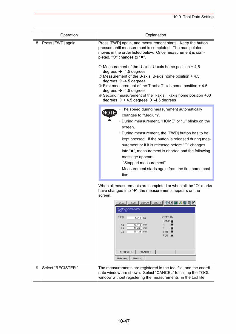
10.9 Tool Data Setting
8 Press [FWD] again. Press [FWD] again, and measurement starts. Keep the button pressed until measurement is completed. The manipulator moves in the order listed below. Once measurement is com-pleted, “ “ changes to “ “.
Measurement of the U-axis: U-axis home position + 4.5 degrees -4.5 degrees Measurement of the B-axis: B-axis home position + 4.5 degrees -4.5 degrees First measurement of the T-axis: T-axis home position + 4.5 degrees -4.5 degrees Second measurement of the T-axis: T-axis home position +60 degrees + 4.5 degrees -4.5 degrees
When all measurements are completed or when all the “ “ marks have changed into “ “, the measurements appears on the screen.
9 Select “REGISTER.” The measurements are registered in the tool file, and the coordi-nate window are shown. Select “CANCEL” to call up the TOOL window without registering the measurements in the tool file.
Operation Explanation
• The speed during measurement automatically changes to “Medium”.
• During measurement, “HOME” or “U” blinks on the screen.
• During measurement, the [FWD] button has to be kept pressed. If the button is released during mea-surement or if it is released before “ “ changes into “ “, measurement is aborted and the following message appears. “Stopped measurement”Measurement starts again from the first home posi-tion.
NOTE
Main Menu ShortCut
EDIT DISPLAY UTILITYDATA
W.GRAV.POS MEASURETOOL 00
R1:W
XgYgZg
<STATUS>HOMEUBT (1)T (2)
4.513
10.11210.43555.123
kg
mmmmmm
REGISTER CANCEL
10-47
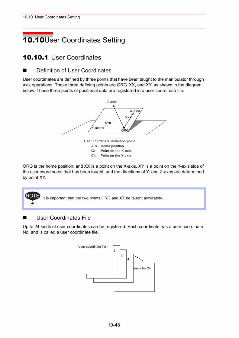
10.10 User Coordinates Setting
10.10User Coordinates Setting
10.10.1 User Coordinates
Definition of User CoordinatesUser coordinates are defined by three points that have been taught to the manipulator through axis operations. These three defining points are ORG, XX, and XY, as shown in the diagram below. These three points of positional data are registered in a user coordinate file.
ORG is the home position, and XX is a point on the X-axis. XY is a point on the Y-axis side of the user coordinates that has been taught, and the directions of Y- and Z-axes are determined by point XY.
User Coordinates FileUp to 24 kinds of user coordinates can be registered. Each coordinate has a user coordinate No. and is called a user coordinate file.
It is important that the two points ORG and XX be taught accurately.
ORG
XY
XX
NOTE
User coordinate file 24
User coordinate file 4User coordinate file 3
User coordinate file 2User coordinate file 1
10-48
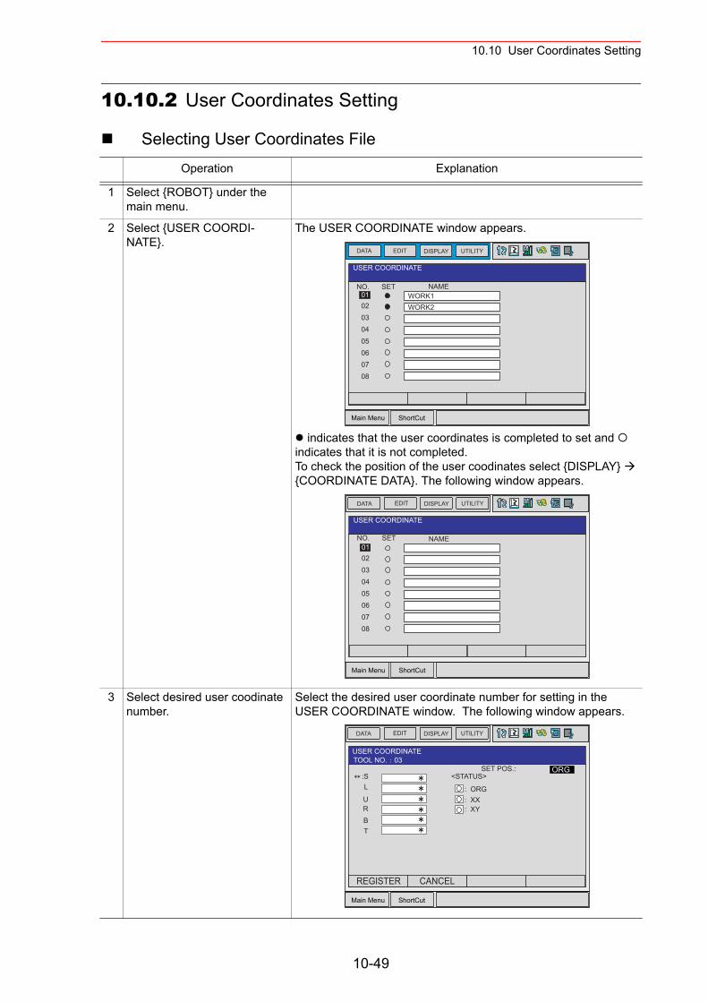
10.10 User Coordinates Setting
10.10.2 User Coordinates Setting
Selecting User Coordinates FileOperation Explanation
1 Select {ROBOT} under the main menu.
2 Select {USER COORDI-NATE}.
The USER COORDINATE window appears.
indicates that the user coordinates is completed to set and indicates that it is not completed.To check the position of the user coodinates select {DISPLAY} {COORDINATE DATA}. The following window appears.
3 Select desired user coodinate number.
Select the desired user coordinate number for setting in the USER COORDINATE window. The following window appears.
Main Menu ShortCut
EDITDATA DISPLAY UTILITY
NO.0102
USER COORDINATE
030405060708
NAMESETWORK1WORK2
Main Menu ShortCut
EDIT DISPLAY UTILITYDATA
NO.0102
USER COORDINATE
030405060708
NAMESET
Main Menu ShortCut
EDIT DISPLAY UTILITYDATA
SET POS.::S
ORG
L
URBT
<STATUS>
: ORG: XX: XY
USER COORDINATETOOL NO. 03
REGISTER CANCEL
10-49
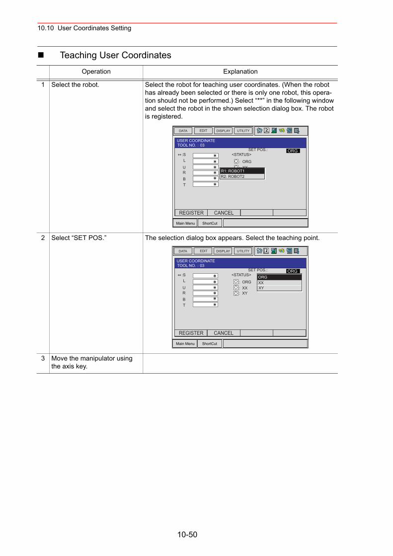
10.10 User Coordinates Setting
Teaching User CoordinatesOperation Explanation
1 Select the robot. Select the robot for teaching user coordinates. (When the robot has already been selected or there is only one robot, this opera-tion should not be performed.) Select “**” in the following window and select the robot in the shown selection dialog box. The robot is registered.
2 Select “SET POS.” The selection dialog box appears. Select the teaching point.
3 Move the manipulator using the axis key.
Main Menu ShortCut
EDIT DISPLAY UTILITYDATA
:SL
URBT
SET POS.: ORG<STATUS>
: ORG: XX: XY
USER COORDINATETOOL NO. 03
R1: ROBOT1R2: ROBOT2
REGISTER CANCEL
Main Menu ShortCut
EDIT DISPLAY UTILITYDATA
:SL
URBT
SET POS.: ORG<STATUS>
: ORG: XX: XY
USER COORDINATETOOL NO. 03
ORGXXXY
REGISTER CANCEL
10-50
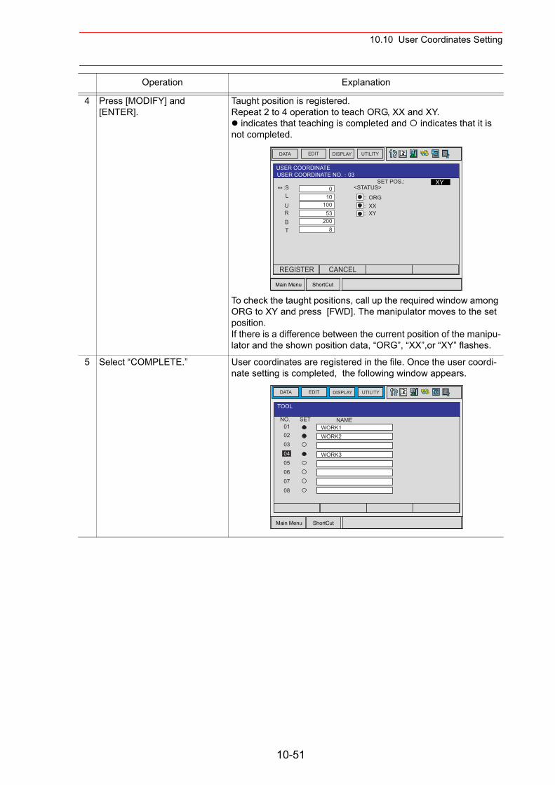
10.10 User Coordinates Setting
4 Press [MODIFY] and [ENTER].
Taught position is registered.Repeat 2 to 4 operation to teach ORG, XX and XY.
indicates that teaching is completed and indicates that it is not completed.
To check the taught positions, call up the required window among ORG to XY and press [FWD]. The manipulator moves to the set position. If there is a difference between the current position of the manipu-lator and the shown position data, “ORG”, “XX”,or “XY” flashes.
5 Select “COMPLETE.” User coordinates are registered in the file. Once the user coordi-nate setting is completed, the following window appears.
Operation Explanation
Main Menu ShortCut
EDIT DISPLAY UTILITYDATA
SET POS.::S
XY
L
URBT
<STATUS>
: ORG: XX: XY
USER COORDINATEUSER COORDINATE NO. 03
010
10053
2008
REGISTER CANCEL
Main Menu ShortCut
EDITDATA DISPLAY UTILITY
NO.0102
TOOL
030405060708
NAMESETWORK1WORK2
WORK3
10-51
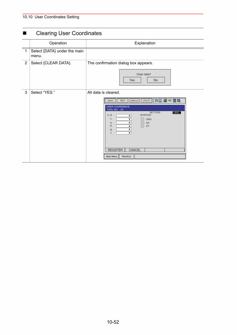
10.10 User Coordinates Setting
Clearing User CoordinatesOperation Explanation
1 Select {DATA} under the main menu.
2 Select {CLEAR DATA}. The confirmation dialog box appears.
3 Select “YES.” All data is cleared.
Yes No
Clear data?
Main Menu ShortCut
EDIT DISPLAY UTILITYDATA
SET POS.::S
ORG
L
URBT
<STATUS>
: ORG: XX: XY
USER COORDINATETOOL NO. 03
REGISTER CANCEL
10-52
10.11 ARM Control
10.11ARM Control
10.11.1 ARM Control
In NX100, the operation performance of the robot which satisfies various demands on the production site such as the improvement of the path accuracy and the cycle time shortening is achieved by adopting the ARM(Advanced Robot Motion) control which Yaskawa originally developed. The moment of inertia and the gravity moment etc. of each axis are calculated in the ARM control, and NX100 controls robot motion according to it. It is necessary to set the Robot setup condition and the tool load information to request these accurately. The robot setup condition is robot installation angle relative to ground and the weight and a center of gravity position of the load installed at each part of robot, etc.The tool load information is weight, a center of gravity position, and moment of inertia at the center of gravity, of the tool installed at the flange.
It is necessary to set these information correctly to do a better operation control by the ARM control.
10.11.2 ARM CONTROL Window
In ARM CONTROL window, the robot setup condition etc. are set.
• Set the robot setup condition exactly.
Set the robot setup condition very noting of mistake the unit, the value or the positive and negative of number.An appropriate operation control cannot be done, decrease the speed reducer longevity, or occur the alarm when these are not correctly set.
• Confirm the operation path of robot of each job when you change set-ting.
Set the robot setup condition when you basically set up the robot. Confirm the operation path of robot of each job afterwards when you change the setting unavoidably.Injury or damage to machinery may result by collision between tool and positioner because the operation path might be changed slightly when the setting about the ARM control is changed.
CAUTION
10-53
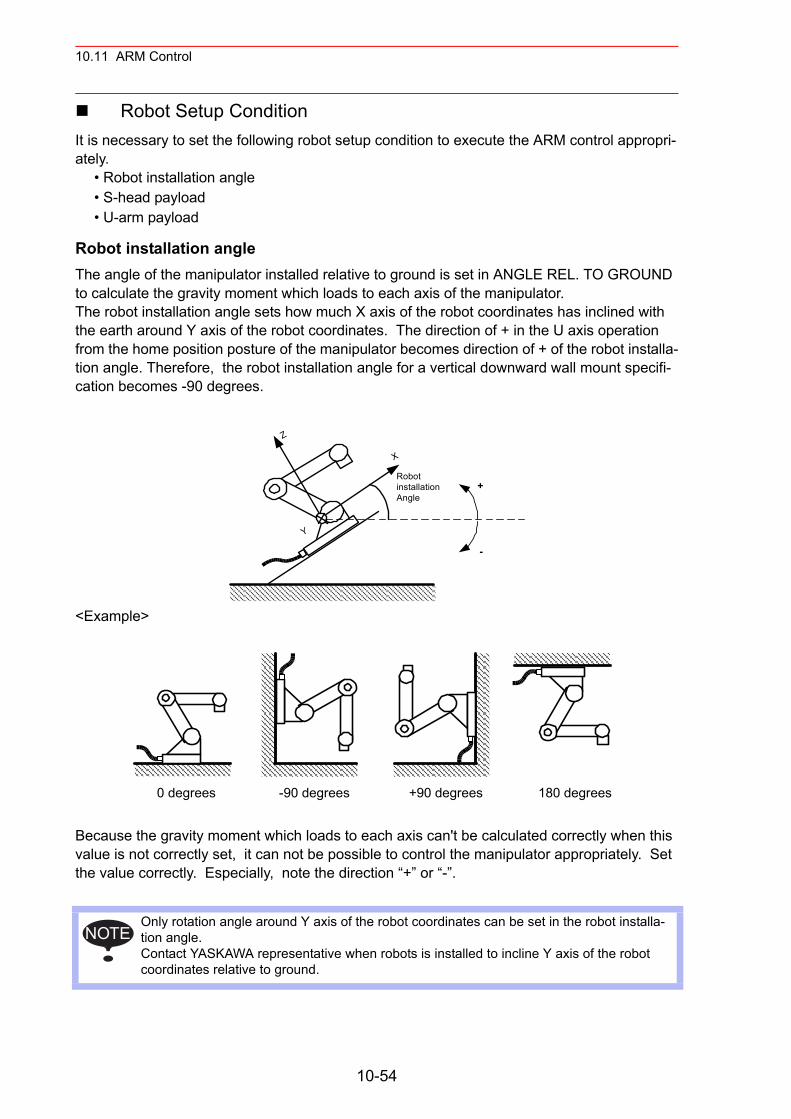
10.11 ARM Control
Robot Setup ConditionIt is necessary to set the following robot setup condition to execute the ARM control appropri-ately.
• Robot installation angle• S-head payload• U-arm payload
Robot installation angleThe angle of the manipulator installed relative to ground is set in ANGLE REL. TO GROUND to calculate the gravity moment which loads to each axis of the manipulator.The robot installation angle sets how much X axis of the robot coordinates has inclined with the earth around Y axis of the robot coordinates. The direction of + in the U axis operation from the home position posture of the manipulator becomes direction of + of the robot installa-tion angle. Therefore, the robot installation angle for a vertical downward wall mount specifi-cation becomes -90 degrees.
<Example>
Because the gravity moment which loads to each axis can't be calculated correctly when this value is not correctly set, it can not be possible to control the manipulator appropriately. Set the value correctly. Especially, note the direction “+” or “-”.
Only rotation angle around Y axis of the robot coordinates can be set in the robot installa-tion angle. Contact YASKAWA representative when robots is installed to incline Y axis of the robot coordinates relative to ground.
RobotinstallationAngle
+
-
X
Z
Y
0 degrees -90 degrees +90 degrees 180 degrees
NOTE
10-54
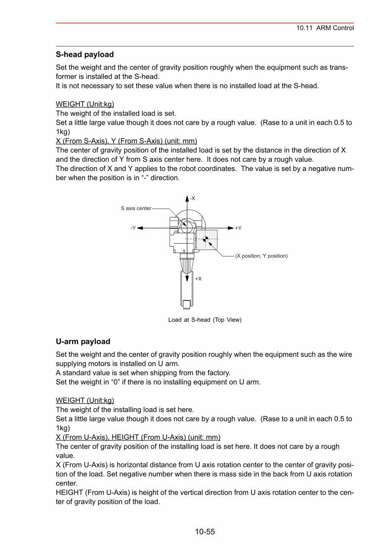
10.11 ARM Control
S-head payloadSet the weight and the center of gravity position roughly when the equipment such as trans-former is installed at the S-head.It is not necessary to set these value when there is no installed load at the S-head.
WEIGHT (Unit:kg)The weight of the installed load is set. Set a little large value though it does not care by a rough value. (Rase to a unit in each 0.5 to 1kg) X (From S-Axis), Y (From S-Axis) (unit: mm)The center of gravity position of the installed load is set by the distance in the direction of X and the direction of Y from S axis center here. It does not care by a rough value. The direction of X and Y applies to the robot coordinates. The value is set by a negative num-ber when the position is in “-” direction.
Load at S-head (Top View)
U-arm payloadSet the weight and the center of gravity position roughly when the equipment such as the wire supplying motors is installed on U arm.A standard value is set when shipping from the factory.Set the weight in “0” if there is no installing equipment on U arm.
WEIGHT (Unit:kg)The weight of the installing load is set here. Set a little large value though it does not care by a rough value. (Rase to a unit in each 0.5 to 1kg) X (From U-Axis), HEIGHT (From U-Axis) (unit: mm)The center of gravity position of the installing load is set here. It does not care by a rough value. X (From U-Axis) is horizontal distance from U axis rotation center to the center of gravity posi-tion of the load. Set negative number when there is mass side in the back from U axis rotation center.HEIGHT (From U-Axis) is height of the vertical direction from U axis rotation center to the cen-ter of gravity position of the load.
S axis center
(X position, Y position)
+X
+Y
-X
-Y
10-55
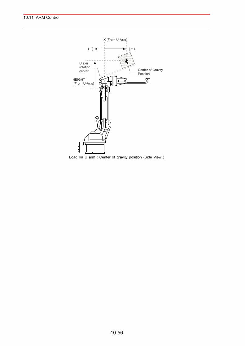
10.11 ARM Control
Load on U arm : Center of gravity position (Side View )
X (From U-Axis)
U axisrotationcenter Center of Gravity
Position
( + )( - )
HEIGHT (From U-Axis)
10-56
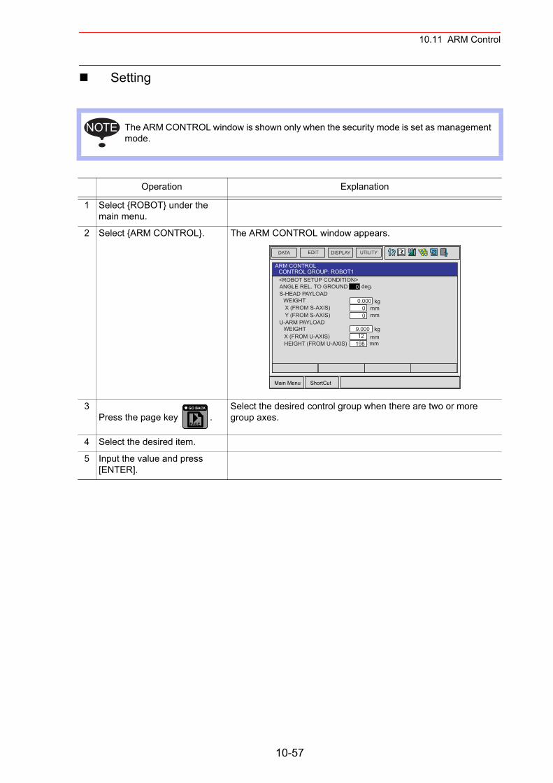
10.11 ARM Control
Setting
The ARM CONTROL window is shown only when the security mode is set as management mode.
Operation Explanation
1 Select {ROBOT} under the main menu.
2 Select {ARM CONTROL}. The ARM CONTROL window appears.
3Press the page key .
Select the desired control group when there are two or more group axes.
4 Select the desired item.
5 Input the value and press [ENTER].
NOTE
Main Menu ShortCut
EDIT DISPLAY UTILITYDATA
<ROBOT SETUP CONDITION>ANGLE REL. TO GROUND
ARM CONTROLCONTROL GROUP: ROBOT1
kg
0
0.000S-HEAD PAYLOAD
WEIGHTX (FROM S-AXIS)Y (FROM S-AXIS)
U-ARM PAYLOADWEIGHTX (FROM U-AXIS)HEIGHT (FROM U-AXIS)
deg.
mm0mm0
kg9.000mm12mm198
PAGE
GO BACK
10-57
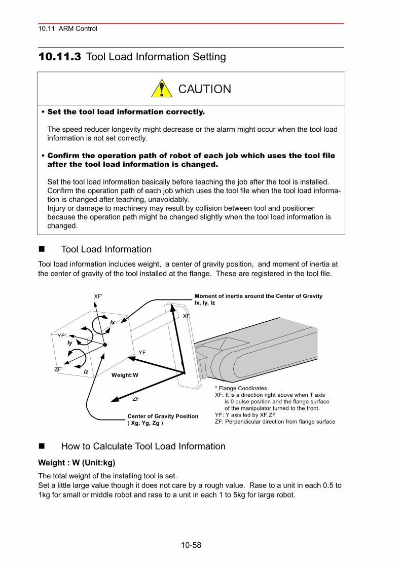
10.11 ARM Control
10.11.3 Tool Load Information Setting
Tool Load InformationTool load information includes weight, a center of gravity position, and moment of inertia at the center of gravity of the tool installed at the flange. These are registered in the tool file.
How to Calculate Tool Load InformationWeight : W (Unit:kg)The total weight of the installing tool is set. Set a little large value though it does not care by a rough value. Rase to a unit in each 0.5 to 1kg for small or middle robot and rase to a unit in each 1 to 5kg for large robot.
• Set the tool load information correctly.
The speed reducer longevity might decrease or the alarm might occur when the tool load information is not set correctly.
• Confirm the operation path of robot of each job which uses the tool file after the tool load information is changed.
Set the tool load information basically before teaching the job after the tool is installed.Confirm the operation path of each job which uses the tool file when the tool load informa-tion is changed after teaching, unavoidably.Injury or damage to machinery may result by collision between tool and positioner because the operation path might be changed slightly when the tool load information is changed.
CAUTION
* Flange CoodinatesXF: It is a direction right above when T axis is 0 pulse position and the flange surface of the manipulator turned to the front.YF: Y axis led by XF,ZFZF: Perpendicular direction from flange surface
XF
ZF
YF
XF'
ZF'
YF'
Center of Gravity Position( Xg, Yg, Zg )
Iy
Iz
Ix
Moment of inertia around the Center of GravityIx, Iy, Iz
Weight:W
10-58
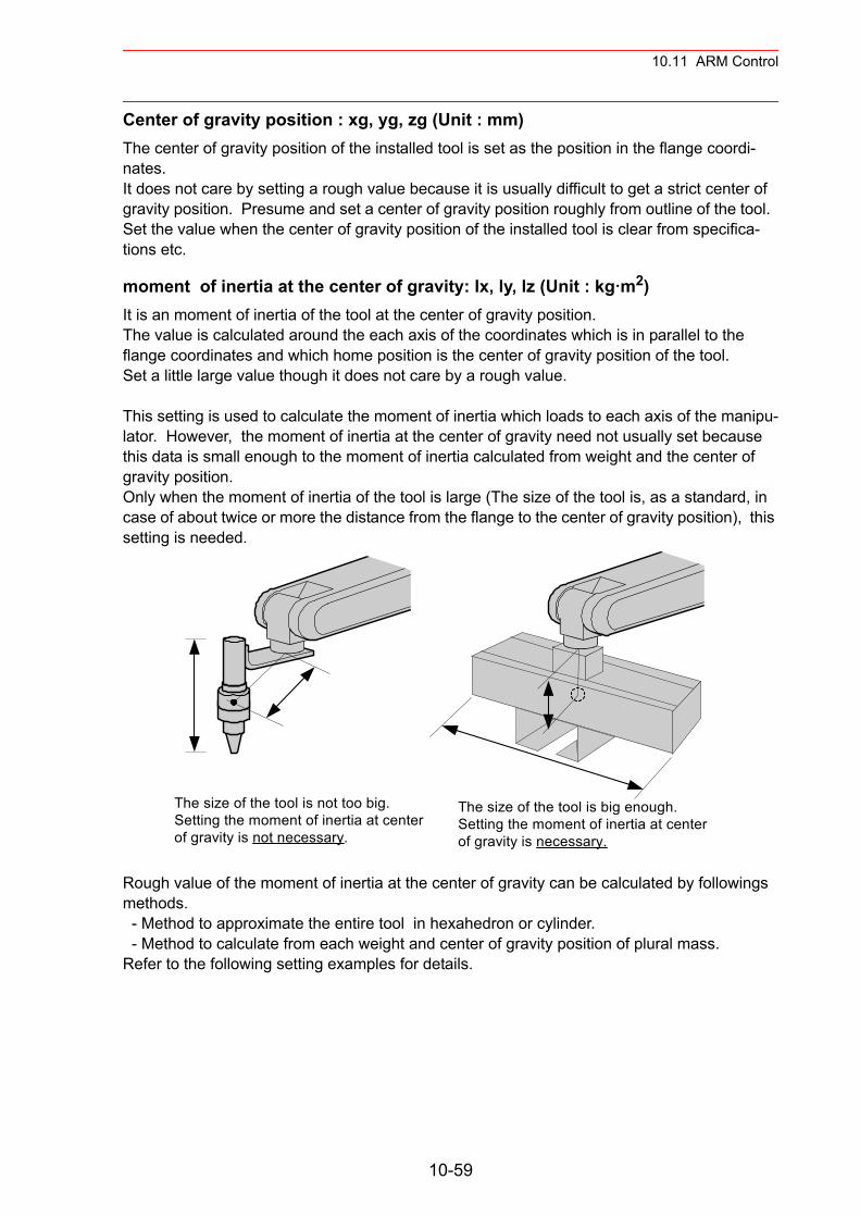
10.11 ARM Control
Center of gravity position : xg, yg, zg (Unit : mm)The center of gravity position of the installed tool is set as the position in the flange coordi-nates.It does not care by setting a rough value because it is usually difficult to get a strict center of gravity position. Presume and set a center of gravity position roughly from outline of the tool. Set the value when the center of gravity position of the installed tool is clear from specifica-tions etc.
moment of inertia at the center of gravity: lx, ly, lz (Unit : kg m2)It is an moment of inertia of the tool at the center of gravity position. The value is calculated around the each axis of the coordinates which is in parallel to the flange coordinates and which home position is the center of gravity position of the tool.Set a little large value though it does not care by a rough value.
This setting is used to calculate the moment of inertia which loads to each axis of the manipu-lator. However, the moment of inertia at the center of gravity need not usually set because this data is small enough to the moment of inertia calculated from weight and the center of gravity position.Only when the moment of inertia of the tool is large (The size of the tool is, as a standard, in case of about twice or more the distance from the flange to the center of gravity position), this setting is needed.
Rough value of the moment of inertia at the center of gravity can be calculated by followings methods. - Method to approximate the entire tool in hexahedron or cylinder. - Method to calculate from each weight and center of gravity position of plural mass.Refer to the following setting examples for details.
The size of the tool is not too big.Setting the moment of inertia at centerof gravity is not necessary.
The size of the tool is big enough.Setting the moment of inertia at centerof gravity is necessary.
10-59
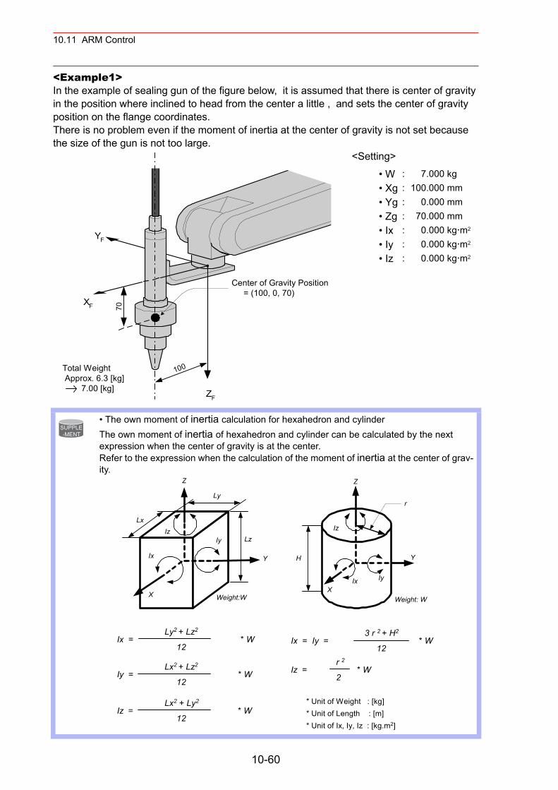
10.11 ARM Control
<Example1>In the example of sealing gun of the figure below, it is assumed that there is center of gravity in the position where inclined to head from the center a little , and sets the center of gravity position on the flange coordinates.There is no problem even if the moment of inertia at the center of gravity is not set because the size of the gun is not too large.
<Setting>
• W : 7.000 kg• Xg : 100.000 mm• Yg : 0.000 mm• Zg : 70.000 mm• Ix : 0.000 kg m2
• Iy : 0.000 kg m2
• Iz : 0.000 kg m2
• The own moment of inertia calculation for hexahedron and cylinder The own moment of inertia of hexahedron and cylinder can be calculated by the next expression when the center of gravity is at the center.Refer to the expression when the calculation of the moment of inertia at the center of grav-ity.
ZF
XF
YF
70
100
Center of Gravity Position = (100, 0, 70)
Total Weight Approx. 6.3 [kg] 7.00 [kg]
SUPPLE-MENT
3 r 2 + H2
Ix = Iy = * W 12 r 2Iz = * W 2
Ly2 + Lz2
Ix = * W 12
Lx2 + Lz2
Iy = * W 12
Lx2 + Ly2
Iz = * W 12 * Unit of Length : [m]
* Unit of Ix, Iy, Iz : [kg.m2]
* Unit of Weight : [kg]
X
Y
Z
IyIz
Ix
Ly
Lx
Weight:W
Lz
H
X
Z
Iz
Ix
r
Weight: W
Iy
Y
10-60
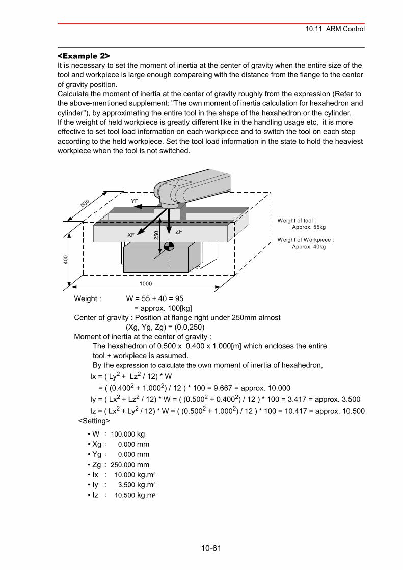
10.11 ARM Control
<Example 2>It is necessary to set the moment of inertia at the center of gravity when the entire size of the tool and workpiece is large enough compareing with the distance from the flange to the center of gravity position.Calculate the moment of inertia at the center of gravity roughly from the expression (Refer to the above-mentioned supplement: "The own moment of inertia calculation for hexahedron and cylinder"), by approximating the entire tool in the shape of the hexahedron or the cylinder.If the weight of held workpiece is greatly different like in the handling usage etc, it is more effective to set tool load information on each workpiece and to switch the tool on each step according to the held workpiece. Set the tool load information in the state to hold the heaviest workpiece when the tool is not switched.
Weight : W = 55 + 40 = 95 = approx. 100[kg] Center of gravity : Position at flange right under 250mm almost (Xg, Yg, Zg) = (0,0,250) Moment of inertia at the center of gravity : The hexahedron of 0.500 x 0.400 x 1.000[m] which encloses the entire tool + workpiece is assumed. By the expression to calculate the own moment of inertia of hexahedron,
Ix = ( Ly2 + Lz2 / 12) * W = ( (0.4002 + 1.0002) / 12 ) * 100 = 9.667 = approx. 10.000Iy = ( Lx2 + Lz2 / 12) * W = ( (0.5002 + 0.4002) / 12 ) * 100 = 3.417 = approx. 3.500Iz = ( Lx2 + Ly2 / 12) * W = ( (0.5002 + 1.0002) / 12 ) * 100 = 10.417 = approx. 10.500
<Setting>
• W : 100.000 kg• Xg : 0.000 mm• Yg : 0.000 mm• Zg : 250.000 mm• Ix : 10.000 kg.m2
• Iy : 3.500 kg.m2
• Iz : 10.500 kg.m2
Weight of tool : Approx. 55kg
Weight of Workpiece : Approx. 40kg
250
1000
400
500
XF ZF
YF
10-61
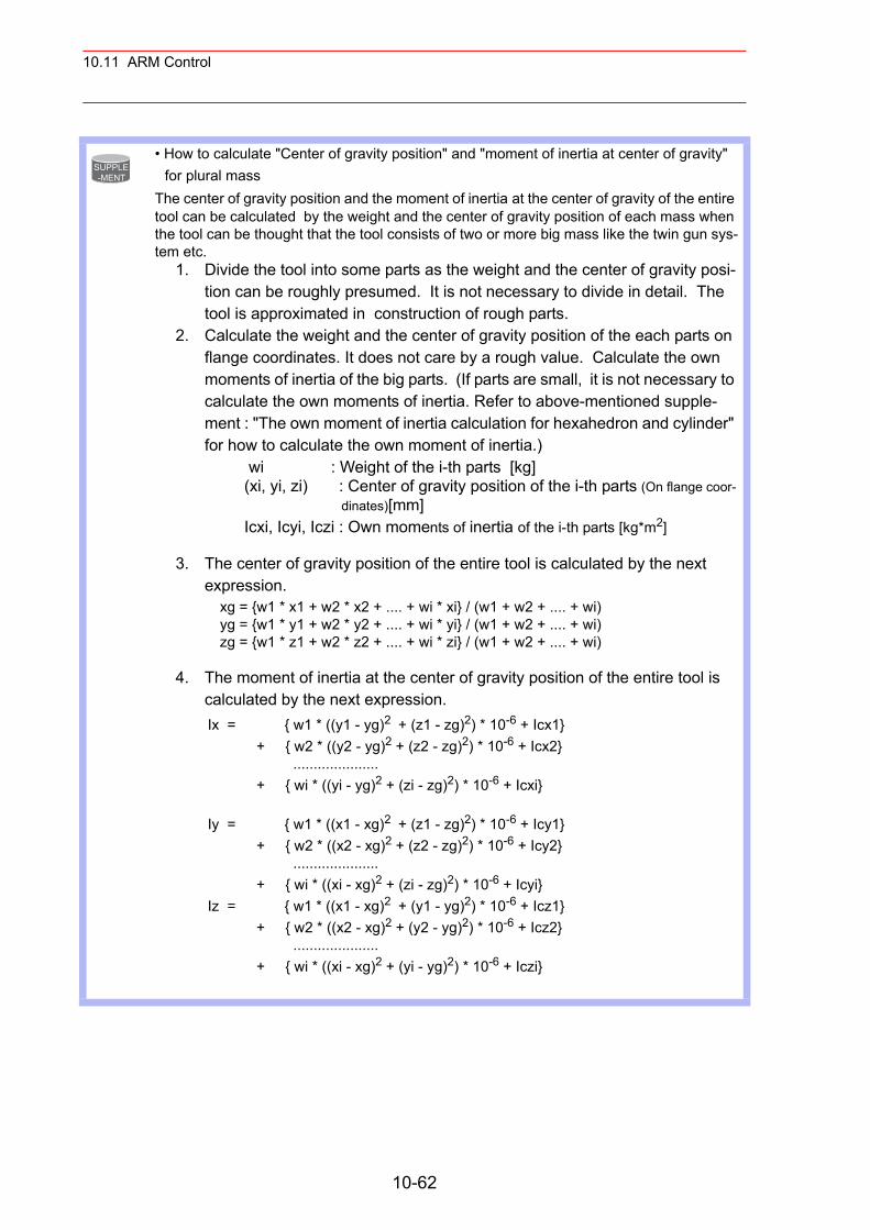
10.11 ARM Control
• How to calculate "Center of gravity position" and "moment of inertia at center of gravity" for plural mass
The center of gravity position and the moment of inertia at the center of gravity of the entire tool can be calculated by the weight and the center of gravity position of each mass when the tool can be thought that the tool consists of two or more big mass like the twin gun sys-tem etc.
1. Divide the tool into some parts as the weight and the center of gravity posi-tion can be roughly presumed. It is not necessary to divide in detail. The tool is approximated in construction of rough parts.
2. Calculate the weight and the center of gravity position of the each parts on flange coordinates. It does not care by a rough value. Calculate the own moments of inertia of the big parts. (If parts are small, it is not necessary to calculate the own moments of inertia. Refer to above-mentioned supple-ment : "The own moment of inertia calculation for hexahedron and cylinder" for how to calculate the own moment of inertia.)
wi : Weight of the i-th parts [kg] (xi, yi, zi) : Center of gravity position of the i-th parts (On flange coor-
dinates)[mm] Icxi, Icyi, Iczi : Own moments of inertia of the i-th parts [kg*m2]
3. The center of gravity position of the entire tool is calculated by the next expression.
xg = {w1 * x1 + w2 * x2 + .... + wi * xi} / (w1 + w2 + .... + wi) yg = {w1 * y1 + w2 * y2 + .... + wi * yi} / (w1 + w2 + .... + wi) zg = {w1 * z1 + w2 * z2 + .... + wi * zi} / (w1 + w2 + .... + wi)
4. The moment of inertia at the center of gravity position of the entire tool is calculated by the next expression.
Ix = { w1 * ((y1 - yg)2 + (z1 - zg)2) * 10-6 + Icx1} + { w2 * ((y2 - yg)2 + (z2 - zg)2) * 10-6 + Icx2} ..................... + { wi * ((yi - yg)2 + (zi - zg)2) * 10-6 + Icxi}
Iy = { w1 * ((x1 - xg)2 + (z1 - zg)2) * 10-6 + Icy1} + { w2 * ((x2 - xg)2 + (z2 - zg)2) * 10-6 + Icy2} ..................... + { wi * ((xi - xg)2 + (zi - zg)2) * 10-6 + Icyi} Iz = { w1 * ((x1 - xg)2 + (y1 - yg)2) * 10-6 + Icz1} + { w2 * ((x2 - xg)2 + (y2 - yg)2) * 10-6 + Icz2} ..................... + { wi * ((xi - xg)2 + (yi - yg)2) * 10-6 + Iczi}
SUPPLE-MENT
10-62
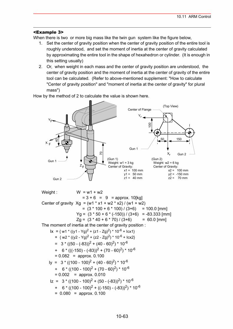
10.11 ARM Control
<Example 3>When there is two or more big mass like the twin gun system like the figure below,
1. Set the center of gravity position when the center of gravity position of the entire tool is roughly understood, and set the moment of inertia at the center of gravity calculated by approximating the entire tool in the shape of hexahedron or cylinder. (It is enough in this setting usually)
2. Or, when weight in each mass and the center of gravity position are understood, the center of gravity position and the moment of inertia at the center of gravity of the entire tool can be calculated. (Refer to above-mentioned supplement: "How to calculate "Center of gravity position" and "moment of inertia at the center of gravity" for plural mass")
How by the method of 2 to calculate the value is shown here.
Weight : W = w1 + w2 = 3 + 6 = 9 = approx. 10[kg] Center of gravity Xg = (w1 * x1 + w2 * x2) / (w1 + w2) = (3 * 100 + 6 * 100) / (3+6) = 100.0 [mm] Yg = (3 * 50 + 6 * (-150)) / (3+6) = -83.333 [mm] Zg = (3 * 40 + 6 * 70) / (3+6) = 60.0 [mm] The moment of inertia at the center of gravity position : Ix = { w1 * ((y1 - Yg)2 + (z1 - Zg)2) * 10-6 + Icx1} + { w2 * ((y2 - Yg)2 + (z2 - Zg)2) * 10-6 + Icx2}
= 3 * ((50 - (-83))2 + (40 - 60)2) * 10-6 + 6 * (((-150) - (-83))2 + (70 - 60)2) * 10-6
= 0.082 = approx. 0.100 Iy = 3 * ((100 - 100)2 + (40 - 60)2) * 10-6
+ 6 * ((100 - 100)2 + (70 - 60)2) * 10-6
= 0.002 = approx. 0.010 Iz = 3 * ((100 - 100)2 + (50 - (-83))2) * 10-6
+ 6 * ((100 - 100)2 + ((-150) - (-83))2) * 10-6
= 0.080 = approx. 0.100
YF
40
70
Gun 1
Gun 2
X F
Z F
(Gun 1) Weight: w1 = 3 kg Center of Gravity:
x1 = 100 mmy1 = 50 mmz1 = 40 mm
(Gun 2) Weight: w2 = 6 kg Center of Gravity:
x2 = 100 mmy2 = -150 mmz2 = 70 mm
YF
XF
Center of Flange
100
50 150
Gun 1
Gun 2
(Top View)
10-63

10.11 ARM Control
* Here, the own moment of inertia (Icxi,Icyi,Iczi) of the gun is disregarded, because each gun are smaller enough than the entire tool.
<Setting>
• W : 10.000 kg• Xg : 100.000 mm• Yg : -83.333 mm• Zg : 60.000 mm• Ix : 0.100 kg.m2
• Iy : 0.010 kg.m2
• Iz : 0.100 kg.m2
10-64
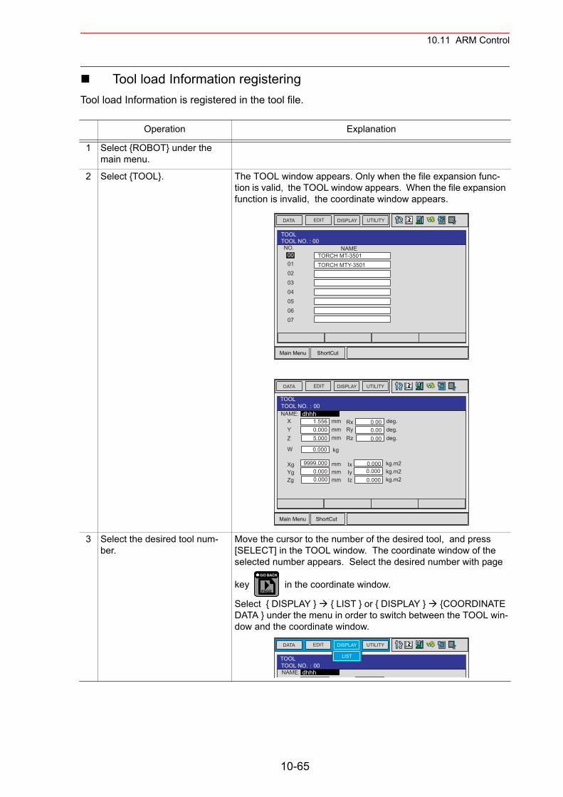
10.11 ARM Control
Tool load Information registeringTool load Information is registered in the tool file.
Operation Explanation
1 Select {ROBOT} under the main menu.
2 Select {TOOL}. The TOOL window appears. Only when the file expansion func-tion is valid, the TOOL window appears. When the file expansion function is invalid, the coordinate window appears.
3 Select the desired tool num-ber.
Move the cursor to the number of the desired tool, and press [SELECT] in the TOOL window. The coordinate window of the selected number appears. Select the desired number with page
key in the coordinate window.
Select { DISPLAY } { LIST } or { DISPLAY } {COORDINATE DATA } under the menu in order to switch between the TOOL win-dow and the coordinate window.
Main Menu ShortCut
EDIT DISPLAY UTILITYDATA
NO.0001
TOOLTOOL NO. : 00
0203
TORCH MT-3501TORCH MTY-3501
04050607
NAME
Main Menu ShortCut
EDIT DISPLAY UTILITYDATA
NAME:
TOOLTOOL NO. 00
dhhhXYZ
W
mmmmmm
kg
mmmmmm
XgYgZg
RxRyRz
deg.deg.deg.
kg.m2kg.m2kg.m2
IxIyIz
1.5560.0005.000
0.000
9999.0000.0000.000
0.000.000.00
0.0000.0000.000
PAGE
GO BACK
EDIT DISPLAY UTILITYDATA
TOOLTOOL NO. 00NAME: dhhh
X d
LIST
10-65
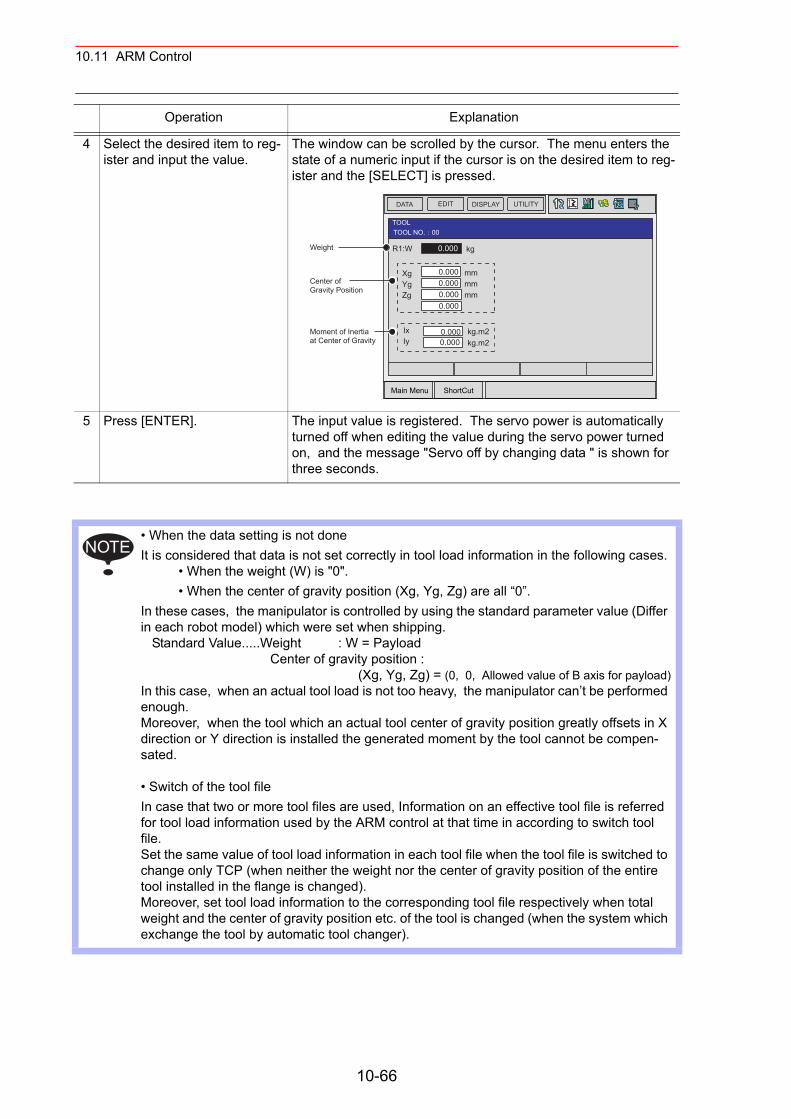
10.11 ARM Control
4 Select the desired item to reg-ister and input the value.
The window can be scrolled by the cursor. The menu enters the state of a numeric input if the cursor is on the desired item to reg-ister and the [SELECT] is pressed.
5 Press [ENTER]. The input value is registered. The servo power is automatically turned off when editing the value during the servo power turned on, and the message "Servo off by changing data " is shown for three seconds.
• When the data setting is not done It is considered that data is not set correctly in tool load information in the following cases.
• When the weight (W) is "0".• When the center of gravity position (Xg, Yg, Zg) are all “0”.
In these cases, the manipulator is controlled by using the standard parameter value (Differ in each robot model) which were set when shipping. Standard Value.....Weight : W = Payload Center of gravity position : (Xg, Yg, Zg) = (0, 0, Allowed value of B axis for payload)In this case, when an actual tool load is not too heavy, the manipulator can’t be performed enough.Moreover, when the tool which an actual tool center of gravity position greatly offsets in X direction or Y direction is installed the generated moment by the tool cannot be compen-sated.
• Switch of the tool file In case that two or more tool files are used, Information on an effective tool file is referred for tool load information used by the ARM control at that time in according to switch tool file.Set the same value of tool load information in each tool file when the tool file is switched to change only TCP (when neither the weight nor the center of gravity position of the entire tool installed in the flange is changed). Moreover, set tool load information to the corresponding tool file respectively when total weight and the center of gravity position etc. of the tool is changed (when the system which exchange the tool by automatic tool changer).
Operation Explanation
Main Menu ShortCut
EDIT DISPLAY UTILITYDATA
TOOLTOOL NO. 00
R1:WWeight
Center ofGravity Position
Moment of Inertiaat Center of Gravity
kg
mmmmmm
XgYgZg
0.000
0.0000.000
0.000
kg.m2kg.m2
IxIy
0.0000.000
0.000
NOTE
10-66
10.12 Shock Detection Function
10.12Shock Detection Function
10.12.1 Shock Detection Function
The shock detection function is a function to decrease damage because of the collision by instantaneously detecting the shock and stopping the manipulator without any external sensor when the tool or the manipulator collide with peripheral device.When the shock is detected either in teach mode and in play mode, the manipulator is stopped instantaneously.
10.12.2 Shock Detection Function Setting
The shock detection function is set not to mis-detect the shock even if operating by the ratings load with the maximum speed when shipping from the factory. If tool load information is set correctly, the detection sensitivity can be improved. Moreover, it is possible to set the lower sensitivity of detection only for a specific section where the contact work etc. The sensitivity of detection is set by setting the detection level.
Shock Detection Level SettingThe shock detection level is set in the shock detection level set file. The shock detection level set file are nine condition files as following figure.Condition number 1 to 7 are used when the detection level is changed in a specific section in play mode. Condition number 8 is a file used as standard in play mode. This function is operated by the detection level set in this file when playback operation. Condition number 9 is a file for teach mode. The shock is detected by the detection level set in this file when the manipulator is operated in teach mode.The detection level is changed by the SHCKSET instruction. After this instruction is exe-cuted, the shock will be detected by the detection level of the specified file when the condition number is specified at SHCKSET instruction. The detection level is returned to standard level when the SHCKRST instruction is executed.
• This function cannot do away with the damage to peripheral device completely. Moreover, this function does not guarantee safety to the person. Prepare the safety measures such as the safeguarding etc. Refer to the NX100 INSTRUCTIONS for the safety measures in detail.
Injury or damage to machinery may result by contact with the manipulator.
WARNING
10-67
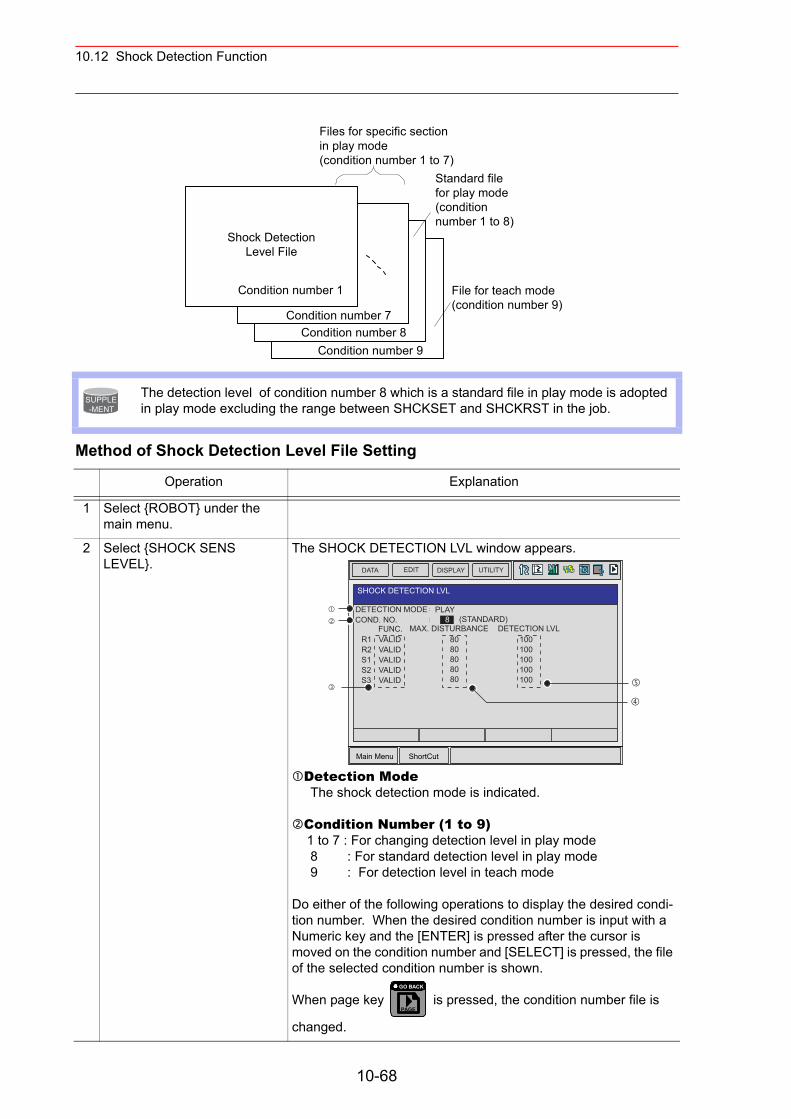
10.12 Shock Detection Function
Method of Shock Detection Level File Setting
The detection level of condition number 8 which is a standard file in play mode is adopted in play mode excluding the range between SHCKSET and SHCKRST in the job.
Operation Explanation
1 Select {ROBOT} under the main menu.
2 Select {SHOCK SENS LEVEL}.
The SHOCK DETECTION LVL window appears.
Detection Mode The shock detection mode is indicated.
Condition Number (1 to 9) 1 to 7 : For changing detection level in play mode 8 : For standard detection level in play mode 9 : For detection level in teach mode
Do either of the following operations to display the desired condi-tion number. When the desired condition number is input with a Numeric key and the [ENTER] is pressed after the cursor is moved on the condition number and [SELECT] is pressed, the file of the selected condition number is shown.
When page key is pressed, the condition number file is
changed.
Shock DetectionLevel File
Condition number 1
Files for specific sectionin play mode(condition number 1 to 7)
Standard filefor play mode(conditionnumber 1 to 8)
File for teach mode(condition number 9)
Condition number 7Condition number 8
Condition number 9
SUPPLE-MENT
Main Menu ShortCut
EDIT DISPLAY UTILITYDATA
DETECTION MODE
SHOCK DETECTION LVL
COND. NO.PLAY
8FUNC. MAX. DISTURBANCE DETECTION LVL
(STANDARD)
R1R2S1S2S3
VALIDVALIDVALIDVALIDVALID
8080808080
100100100100100
PAGE
GO BACK
10-68
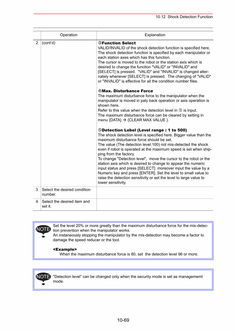
10.12 Shock Detection Function
2 (cont’d) Function SelectVALID/INVALID of the shock detection function is specified here. The shock detection function is specified by each manipulator or each station axes which has this function.The cursor is moved to the robot or the station axis which is desired to change the function "VALID" or "INVALID" and [SELECT] is pressed. "VALID" and "INVALID" is changed alter-nately whenever [SELECT] is pressed. The changing of "VALID" or "INVALID" is effective for all the condition number files.
Max. Disturbance ForceThe maximum disturbance force to the manipulator when the manipulator is moved in paly back operation or axis operation is shown here.Refer to this value when the detection level in is input.The maximum disturbance force can be cleared by setting in menu {DATA} {CLEAR MAX VALUE }.
Detection Lebel (Level range : 1 to 500)The shock detection level is specified here. Bigger value than the maximum disturbance force should be set. The value (The detection level:100) not mis-detected the shock even if robot is operated at the maximum speed is set when ship-ping from the factory. To change "Detection level", move the cursor to the robot or the station axis which is desired to change to appear the numeric input status and press [SELECT] moreover input the value by a Numeric key and press [ENTER]. Set the level to small value to raise the detection sensitivity or set the level to large value to lower sensitivity.
3 Select the desired condition number.
4 Select the desired item and set it.
Set the level 20% or more greatly than the maximum disturbance force for the mis-detec-tion prevention when the manipulator works. An instaneously stopping the manipulator by the mis-detection may become a factor to damage the speed reducer or the tool.
<Example> When the maximum disturbance force is 80, set the detection level 96 or more.
"Detection level” can be changed only when the security mode is set as managememt mode.
Operation Explanation
NOTE
NOTE
10-69
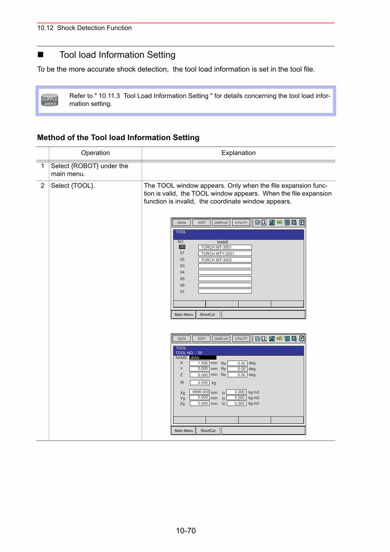
10.12 Shock Detection Function
Tool load Information SettingTo be the more accurate shock detection, the tool load information is set in the tool file.
Method of the Tool load Information Setting
Refer to " 10.11.3 Tool Load Information Setting " for details concerning the tool load infor-mation setting.
Operation Explanation
1 Select {ROBOT} under the main menu.
2 Select {TOOL}. The TOOL window appears. Only when the file expansion func-tion is valid, the TOOL window appears. When the file expansion function is invalid, the coordinate window appears.
SUPPLE-MENT
Main Menu ShortCut
EDIT DISPLAY UTILITYDATA
NO.0001
TOOL
0203
TORCH MT-3501TORCH MTY-3501TORCH MT-3502
04050607
NAME
Main Menu ShortCut
EDIT DISPLAY UTILITYDATA
TOOLTOOL NO. 00NAME:
XYZ
W
mmmmmm
dhhh1.5560.0005.000
kg0.000
mmmmmm
9999.0000.0000.000
XgYgZg
RxRyRz
deg.deg.deg.
0.000.000.00
kg.m2kg.m2kg.m2
0.0000.0000.000
IxIyIz
10-70
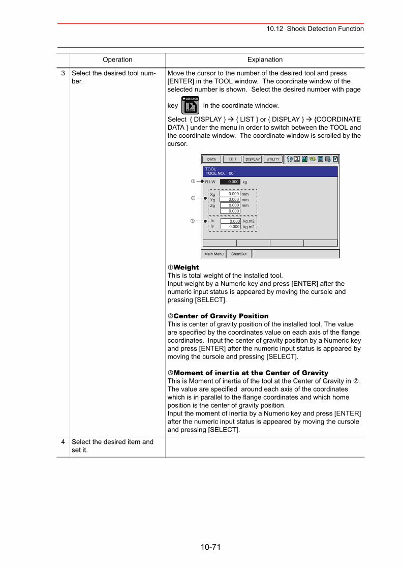
10.12 Shock Detection Function
3 Select the desired tool num-ber.
Move the cursor to the number of the desired tool and press [ENTER] in the TOOL window. The coordinate window of the selected number is shown. Select the desired number with page
key in the coordinate window.
Select { DISPLAY } { LIST } or { DISPLAY } {COORDINATE DATA } under the menu in order to switch between the TOOL and the coordinate window. The coordinate window is scrolled by the cursor.
WeightThis is total weight of the installed tool. Input weight by a Numeric key and press [ENTER] after the numeric input status is appeared by moving the cursole and pressing [SELECT].
Center of Gravity PositionThis is center of gravity position of the installed tool. The value are specified by the coordinates value on each axis of the flange coordinates. Input the center of gravity position by a Numeric key and press [ENTER] after the numeric input status is appeared by moving the cursole and pressing [SELECT].
Moment of inertia at the Center of GravityThis is Moment of inertia of the tool at the Center of Gravity in . The value are specified around each axis of the coordinates which is in parallel to the flange coordinates and which home position is the center of gravity position.Input the moment of inertia by a Numeric key and press [ENTER] after the numeric input status is appeared by moving the cursole and pressing [SELECT].
4 Select the desired item and set it.
Operation Explanation
PAGE
GO BACK
Main Menu ShortCut
EDIT DISPLAY UTILITYDATA
TOOLTOOL NO. 00
R1:W kg
mmmmmm
XgYgZg
0.000
0.0000.000
0.000
kg.m2kg.m2
IxIy
0.0000.000
0.000
10-71
10.12 Shock Detection Function
Instruction of Shock Detection FunctionSHCKSET instruction
The SHCKSET instruction changes the shock detection level to the value set in the shock detection level file during play back operation. The additional items of the SHCKSET instruction are as follows.
Robot / Station SettingThe robot or the station axis which is desired to change the shock detection level is speci-fied. If nothing is specified, the shock detection level of the control group of the job to which this instruction is registered is changed. However, if the job is coordinated job, the shock detection level of the slave axis group is changed.
Shock Detection Level File (1 to 7)The shock detection level file number is specified here. The shock detection level value when playback operation is set in the file. The shock detection level is changed by the con-dition of the file set here.
SHCKRST instructionThe shock detection level changed by the SHCKSET instruction is reset and returned to the detection level of the standard (value set in condition number 8) by the SHCKRST instruction. The additional item of the SHCKRST instruction is as follows.
Robot / Station SettingThe robot or the station axis which is desired to reset the shock detection level is specified here. If nothing is specified, the shock detection level of the control group of the job to which this instruction is registered is changed. However, if the job is coordinated job, the shock detection level of the slave axis group is changed.
SHCKSET R1 SSL#(1)
SHCKRST R1
10-72
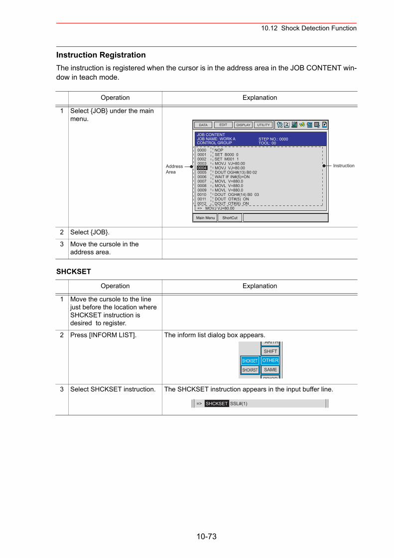
10.12 Shock Detection Function
Instruction RegistrationThe instruction is registered when the cursor is in the address area in the JOB CONTENT win-dow in teach mode.
SHCKSET
Operation Explanation
1 Select {JOB} under the main menu.
2 Select {JOB}.
3 Move the cursole in the address area.
Operation Explanation
1 Move the cursole to the line just before the location where SHCKSET instruction is desired to register.
2 Press [INFORM LIST]. The inform list dialog box appears.
3 Select SHCKSET instruction. The SHCKSET instruction appears in the input buffer line.
Main Menu ShortCut
EDIT DISPLAY UTILITYDATA
JOB CONTENTJOB NAME: WORK A STEP NO.: 0000CONTROL GROUP TOOL: 00
0000000100020003000400050006000700080009001000110012=> MOVJ VJ=80.00
NOPSET B000 0SET M001 1MOVJ VJ=80.00MOVJ VJ=80.00DOUT OGH#(13) B0 02WAIT IF IN#(5)=ONMOVL V=880.0MOVL V=880.0MOVL V=880.0DOUT OGH#(14) B0 03DOUT OT#(5) ONDOUT OT#(6) ON
AddressArea
Instruction
ARITH
SHIFT
OTHER
SAME
PRIOR
SHCKSET
SHCKRST
=> SHCKSET SSL#(1)
10-73
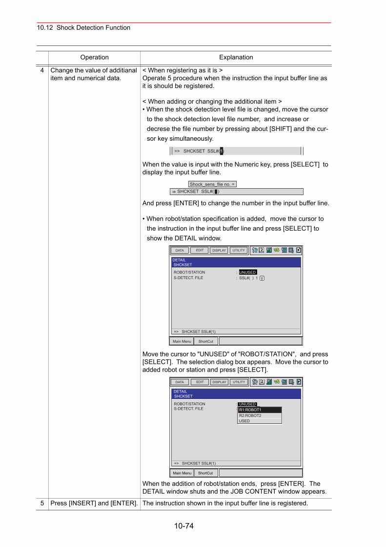
10.12 Shock Detection Function
4 Change the value of additianal item and numerical data.
< When registering as it is > Operate 5 procedure when the instruction the input buffer line as it is should be registered.
< When adding or changing the additional item >• When the shock detection level file is changed, move the cursor
to the shock detection level file number, and increase or decrese the file number by pressing about [SHIFT] and the cur-sor key simultaneously.
When the value is input with the Numeric key, press [SELECT] to display the input buffer line.
And press [ENTER] to change the number in the input buffer line.
• When robot/station specification is added, move the cursor to the instruction in the input buffer line and press [SELECT] to show the DETAIL window.
Move the cursor to "UNUSED" of "ROBOT/STATION", and press [SELECT]. The selection dialog box appears. Move the cursor to added robot or station and press [SELECT].
When the addition of robot/station ends, press [ENTER]. The DETAIL window shuts and the JOB CONTENT window appears.
5 Press [INSERT] and [ENTER]. The instruction shown in the input buffer line is registered.
Operation Explanation
=> SHCKSET SSL#(1)
Shock_sens_file no. =SHCKSET SSL#( )
Main Menu ShortCut
EDIT DISPLAY UTILITYDATA
ROBOT/STATION
DETAILSHCKSET
S-DETECT. FILE: UNUSED: SSL#( ) 1
=> SHCKSET SSL#(1)
Main Menu ShortCut
EDIT DISPLAY UTILITYDATA
ROBOT/STATION
DETAILSHCKSET
S-DETECT. FILE: UNUSED: SSL#( ) 1
=> SHCKSET SSL#(1)
R1:ROBOT1R2:ROBOT2USED
10-74
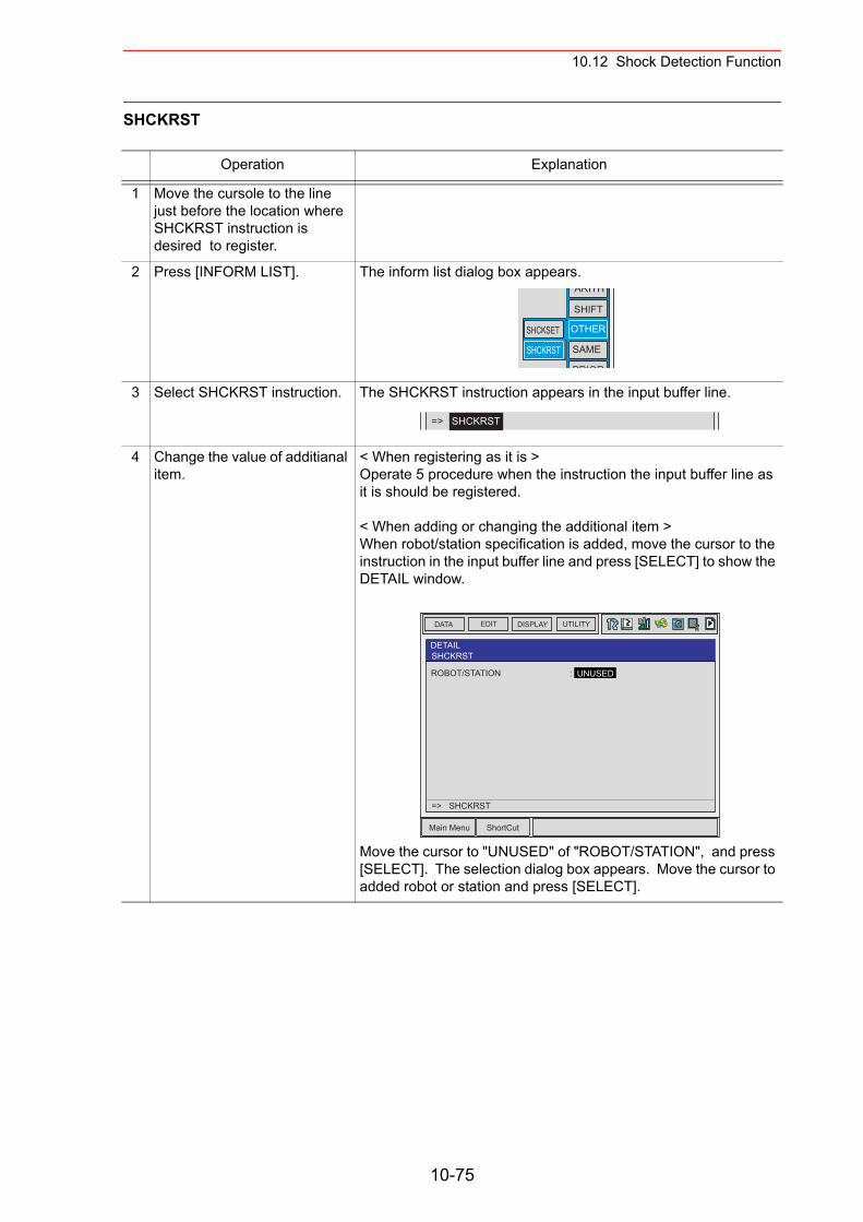
10.12 Shock Detection Function
SHCKRST
Operation Explanation
1 Move the cursole to the line just before the location where SHCKRST instruction is desired to register.
2 Press [INFORM LIST]. The inform list dialog box appears.
3 Select SHCKRST instruction. The SHCKRST instruction appears in the input buffer line.
4 Change the value of additianal item.
< When registering as it is > Operate 5 procedure when the instruction the input buffer line as it is should be registered.
< When adding or changing the additional item >When robot/station specification is added, move the cursor to the instruction in the input buffer line and press [SELECT] to show the DETAIL window.
Move the cursor to "UNUSED" of "ROBOT/STATION", and press [SELECT]. The selection dialog box appears. Move the cursor to added robot or station and press [SELECT].
ARITH
SHIFT
OTHER
SAME
PRIOR
SHCKSET
SHCKRST
=> SHCKRST
Main Menu ShortCut
EDIT DISPLAY UTILITYDATA
ROBOT/STATION
DETAILSHCKRST
: UNUSED
=> SHCKRST
10-75
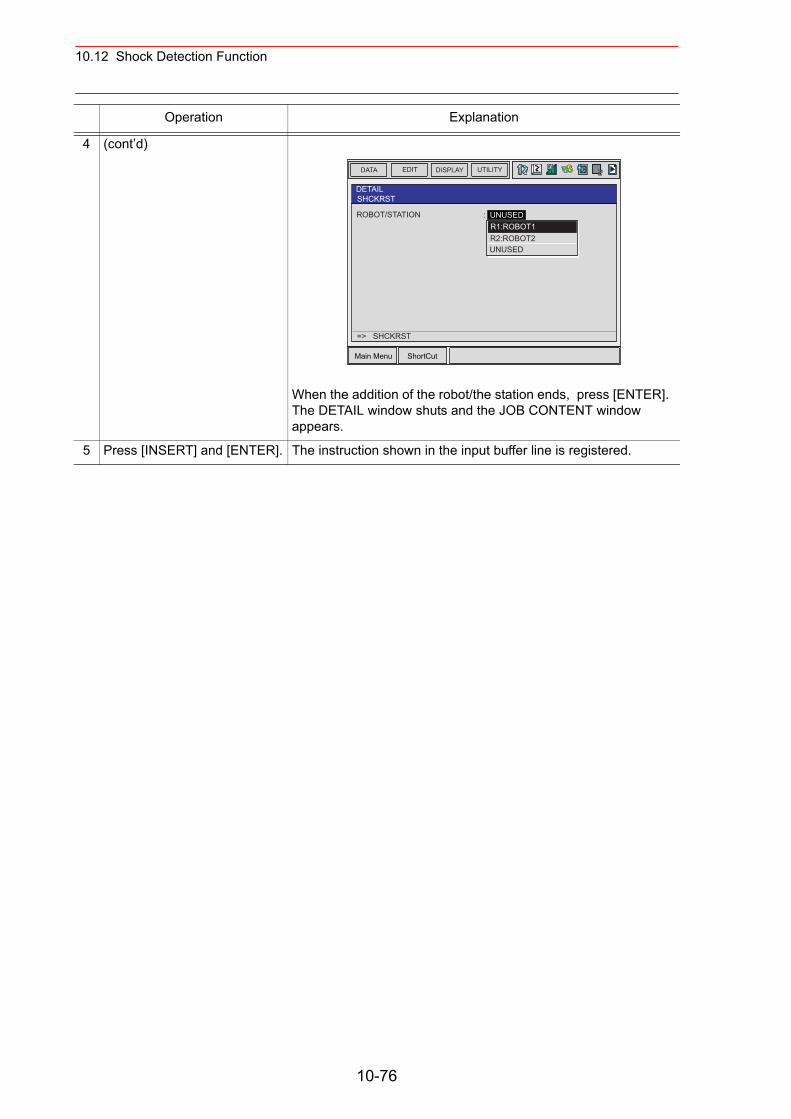
10.12 Shock Detection Function
4 (cont’d)
When the addition of the robot/the station ends, press [ENTER]. The DETAIL window shuts and the JOB CONTENT window appears.
5 Press [INSERT] and [ENTER]. The instruction shown in the input buffer line is registered.
Operation Explanation
Main Menu ShortCut
EDIT DISPLAY UTILITYDATA
ROBOT/STATION
DETAILSHCKRST
: UNUSED
=> SHCKRST
R1:ROBOT1R2:ROBOT2UNUSED
10-76
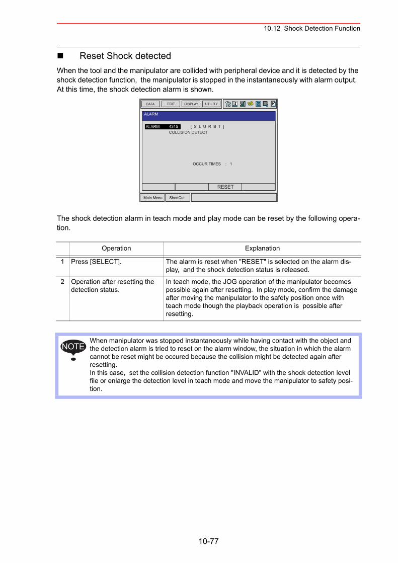
10.12 Shock Detection Function
Reset Shock detected When the tool and the manipulator are collided with peripheral device and it is detected by the shock detection function, the manipulator is stopped in the instantaneously with alarm output. At this time, the shock detection alarm is shown.
The shock detection alarm in teach mode and play mode can be reset by the following opera-tion.
Operation Explanation
1 Press [SELECT]. The alarm is reset when "RESET" is selected on the alarm dis-play, and the shock detection status is released.
2 Operation after resetting the detection status.
In teach mode, the JOG operation of the manipulator becomes possible again after resetting. In play mode, confirm the damage after moving the manipulator to the safety position once with teach mode though the playback operation is possible after resetting.
When manipulator was stopped instantaneously while having contact with the object and the detection alarm is tried to reset on the alarm window, the situation in which the alarm cannot be reset might be occured because the collision might be detected again after resetting. In this case, set the collision detection function "INVALID" with the shock detection level file or enlarge the detection level in teach mode and move the manipulator to safety posi-tion.
Main Menu ShortCut
EDIT DISPLAY UTILITYDATA
ALARM
ALARM
4315 [ S L U R B T ]COLLISION DETECT
OCCUR TIMES : 1
RESET
NOTE
10-77
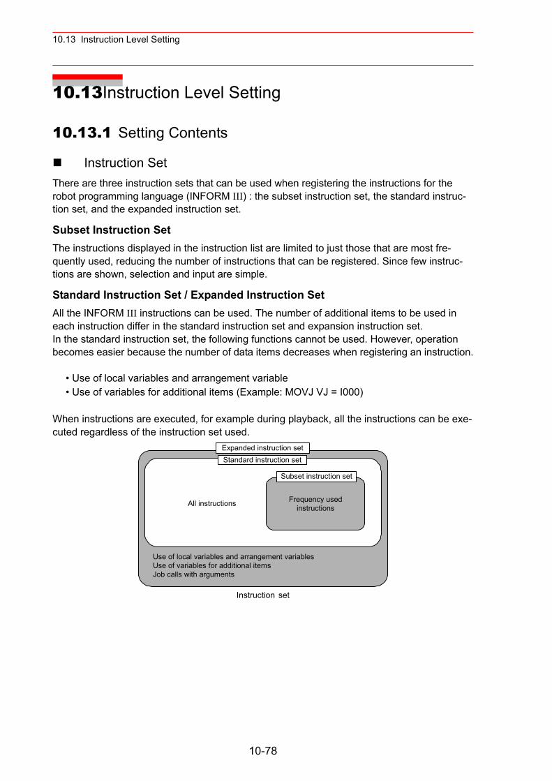
10.13 Instruction Level Setting
10.13Instruction Level Setting
10.13.1 Setting Contents
Instruction SetThere are three instruction sets that can be used when registering the instructions for the robot programming language (INFORM III) : the subset instruction set, the standard instruc-tion set, and the expanded instruction set.
Subset Instruction Set The instructions displayed in the instruction list are limited to just those that are most fre-quently used, reducing the number of instructions that can be registered. Since few instruc-tions are shown, selection and input are simple.
Standard Instruction Set / Expanded Instruction Set All the INFORM III instructions can be used. The number of additional items to be used in each instruction differ in the standard instruction set and expansion instruction set.In the standard instruction set, the following functions cannot be used. However, operation becomes easier because the number of data items decreases when registering an instruction.
• Use of local variables and arrangement variable• Use of variables for additional items (Example: MOVJ VJ = I000)
When instructions are executed, for example during playback, all the instructions can be exe-cuted regardless of the instruction set used.
Instruction set
Frequency usedinstructions
Expanded instruction setStandard instruction set
Subset instruction set
All instructions
Use of local variables and arrangement variablesUse of variables for additional itemsJob calls with arguments
10-78
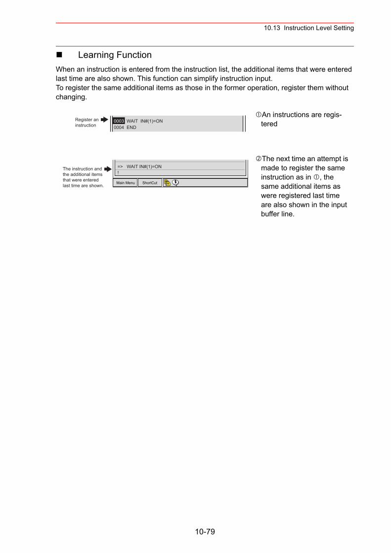
10.13 Instruction Level Setting
Learning FunctionWhen an instruction is entered from the instruction list, the additional items that were entered last time are also shown. This function can simplify instruction input. To register the same additional items as those in the former operation, register them without changing.
An instructions are regis-tered
The next time an attempt is made to register the same instruction as in , the same additional items as were registered last time are also shown in the input buffer line.
0003 WAIT IN#(1)=ON0004 END
Register aninstruction
Main Menu ShortCut
The instruction andthe additional itemsthat were enteredlast time are shown.
!=> WAIT IN#(1)=ON
10-79
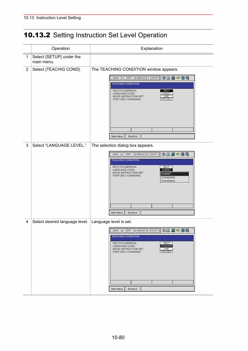
10.13 Instruction Level Setting
10.13.2 Setting Instruction Set Level Operation
Operation Explanation
1 Select {SETUP} under the main menu.
2 Select {TEACHIG COND}. The TEACHING CONDITION window appears.
3 Select “LANGUAGE LEVEL.” The selection dialog box appears.
4 Select desired language level. Language level is set.
Main Menu ShortCut
EDIT DISPLAY UTILITYDATA
RECT/CYLINDRICAL
TEACHING CONDITION
LANGUAGE LEVELMOVE INSTRUCTION SETSTEP ONLY CHANGING
RECTSUBSET
LINEPROHIBIT
Main Menu ShortCut
EDIT DISPLAY UTILITYDATA
RECT/CYLINDRICAL
TEACHING CONDITION
LANGUAGE LEVELMOVE INSTRUCTION SETSTEP ONLY CHANGING
RECTSUBSET
SUBSETSTANDARDEXPANDED
Main Menu ShortCut
EDIT DISPLAY UTILITYDATA
RECT/CYLINDRICAL
TEACHING CONDITION
LANGUAGE LEVELMOVE INSTRUCTION SETSTEP ONLY CHANGING
RECTSTANDARD
LINEPROHIBIT
10-80
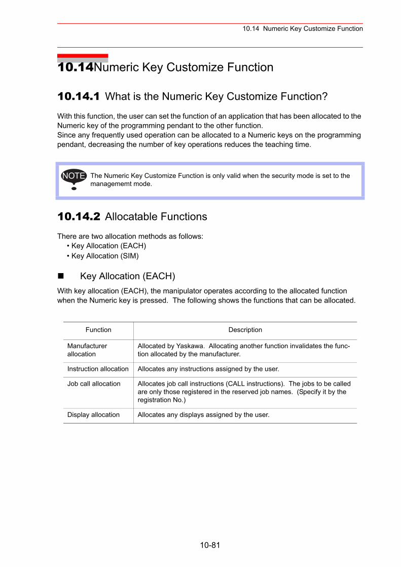
10.14 Numeric Key Customize Function
10.14Numeric Key Customize Function
10.14.1 What is the Numeric Key Customize Function?
With this function, the user can set the function of an application that has been allocated to the Numeric key of the programming pendant to the other function.Since any frequently used operation can be allocated to a Numeric keys on the programming pendant, decreasing the number of key operations reduces the teaching time.
10.14.2 Allocatable Functions
There are two allocation methods as follows:• Key Allocation (EACH)• Key Allocation (SIM)
Key Allocation (EACH)With key allocation (EACH), the manipulator operates according to the allocated function when the Numeric key is pressed. The following shows the functions that can be allocated.
The Numeric Key Customize Function is only valid when the security mode is set to the managememt mode.
Function Description
Manufacturer allocation
Allocated by Yaskawa. Allocating another function invalidates the func-tion allocated by the manufacturer.
Instruction allocation Allocates any instructions assigned by the user.
Job call allocation Allocates job call instructions (CALL instructions). The jobs to be called are only those registered in the reserved job names. (Specify it by the registration No.)
Display allocation Allocates any displays assigned by the user.
NOTE
10-81
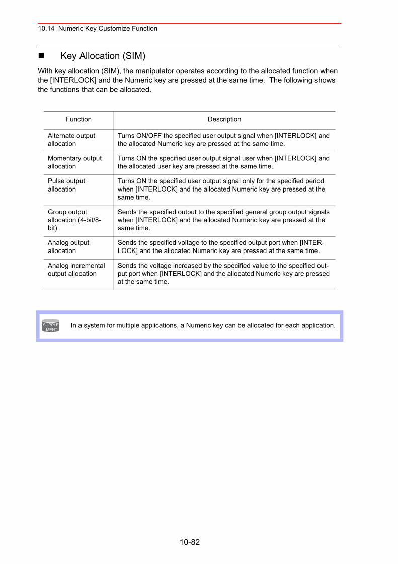
10.14 Numeric Key Customize Function
Key Allocation (SIM)With key allocation (SIM), the manipulator operates according to the allocated function when the [INTERLOCK] and the Numeric key are pressed at the same time. The following shows the functions that can be allocated.
Function Description
Alternate output allocation
Turns ON/OFF the specified user output signal when [INTERLOCK] and the allocated Numeric key are pressed at the same time.
Momentary output allocation
Turns ON the specified user output signal user when [INTERLOCK] and the allocated user key are pressed at the same time.
Pulse output allocation
Turns ON the specified user output signal only for the specified period when [INTERLOCK] and the allocated Numeric key are pressed at the same time.
Group output allocation (4-bit/8-bit)
Sends the specified output to the specified general group output signals when [INTERLOCK] and the allocated Numeric key are pressed at the same time.
Analog output allocation
Sends the specified voltage to the specified output port when [INTER-LOCK] and the allocated Numeric key are pressed at the same time.
Analog incremental output allocation
Sends the voltage increased by the specified value to the specified out-put port when [INTERLOCK] and the allocated Numeric key are pressed at the same time.
In a system for multiple applications, a Numeric key can be allocated for each application.SUPPLE-MENT
10-82
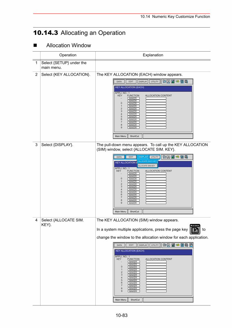
10.14 Numeric Key Customize Function
10.14.3 Allocating an Operation
Allocation WindowOperation Explanation
1 Select {SETUP} under the main menu.
2 Select {KEY ALLOCATION}. The KEY ALLOCATION (EACH) window appears.
3 Select {DISPLAY}. The pull-down menu appears. To call up the KEY ALLOCATION (SIM) window, select {ALLOCATE SIM. KEY}.
4 Select {ALLOCATE SIM. KEY}.
The KEY ALLOCATION (SIM) window appears.
In a system multiple applications, press the page key to
change the window to the allocation window for each application.
Main Menu ShortCut
EDIT DISPLAY UTILITYDATA
APPLI. NO.: 1
KEY ALLOCATION (EACH)
KEY-.
123
0
456789
FUNCTIONMAKERMAKERMAKERMAKERMAKERMAKERMAKERMAKERMAKERMAKERMAKER
ALLOCATION CONTENT
MAKER
Main Menu ShortCut
EDIT DISPLAY UTILITYDATA
APPLI. NO.: 1
KEY ALLOCATION EACH
KEY-.
123
0
456789
FUNCTIONMAKERMAKERMAKERMAKERMAKERMAKERMAKERMAKERMAKERMAKERMAKER
ALLOCATION CONTENT
MAKER
ALLOCATE EACH KEY
ALLOCATE SIM.KEY
PAGE
GO BACK
Main Menu ShortCut
EDIT DISPLAY UTILITYDATA
APPLI. NO.: 1
KEY ALLOCATION (EACH)
KEY-.
123
0
456789
FUNCTIONMAKERMAKERMAKERMAKERMAKERMAKERMAKERMAKERMAKERMAKERMAKER
ALLOCATION CONTENT
MAKER
10-83
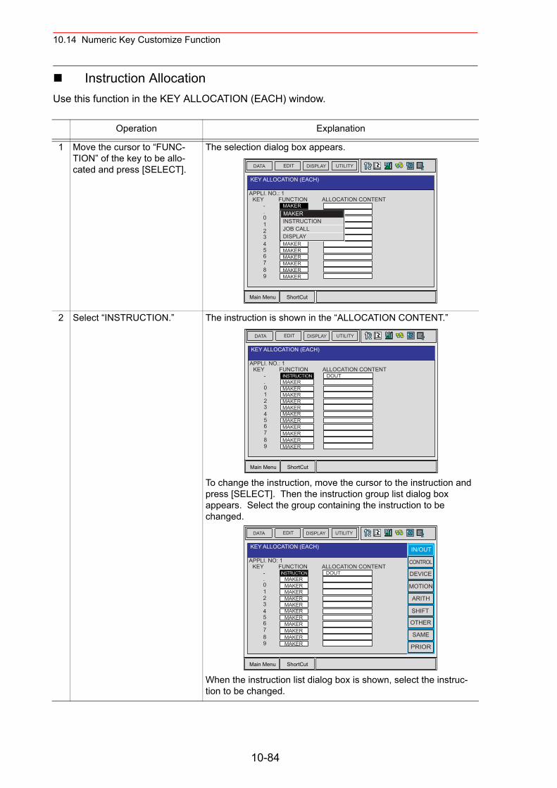
10.14 Numeric Key Customize Function
Instruction AllocationUse this function in the KEY ALLOCATION (EACH) window.
Operation Explanation
1 Move the cursor to “FUNC-TION” of the key to be allo-cated and press [SELECT].
The selection dialog box appears.
2 Select “INSTRUCTION.” The instruction is shown in the “ALLOCATION CONTENT.”
To change the instruction, move the cursor to the instruction and press [SELECT]. Then the instruction group list dialog box appears. Select the group containing the instruction to be changed.
When the instruction list dialog box is shown, select the instruc-tion to be changed.
Main Menu ShortCut
EDIT DISPLAY UTILITYDATA
APPLI. NO.: 1
KEY ALLOCATION (EACH)
KEY-.
123
0
456789
FUNCTIONMAKERMAKERMAKERMAKERMAKERMAKERMAKERMAKERMAKERMAKERMAKER
ALLOCATION CONTENT
MAKER
MAKERINSTRUCTIONJOB CALLDISPLAY
Main Menu ShortCut
EDIT DISPLAY UTILITYDATA
APPLI. NO.: 1
KEY ALLOCATION (EACH)
KEY-.
123
0
456789
FUNCTIONINSTRUCTIONMAKERMAKERMAKERMAKERMAKERMAKERMAKERMAKERMAKERMAKER
ALLOCATION CONTENT
MAKER
DOUT
Main Menu ShortCut
EDIT DISPLAY UTILITYDATA
APPLI. NO: 1
KEY ALLOCATION (EACH)
KEY-.
123
0
456789
FUNCTIONINSTRUCTION
MAKERMAKERMAKERMAKERMAKERMAKERMAKERMAKERMAKERMAKER
ALLOCATION CONTENT
MAKER
DOUT
IN/OUT
CONTROL
DEVICE
MOTION
ARITH
SHIFT
OTHER
SAME
PRIOR
10-84
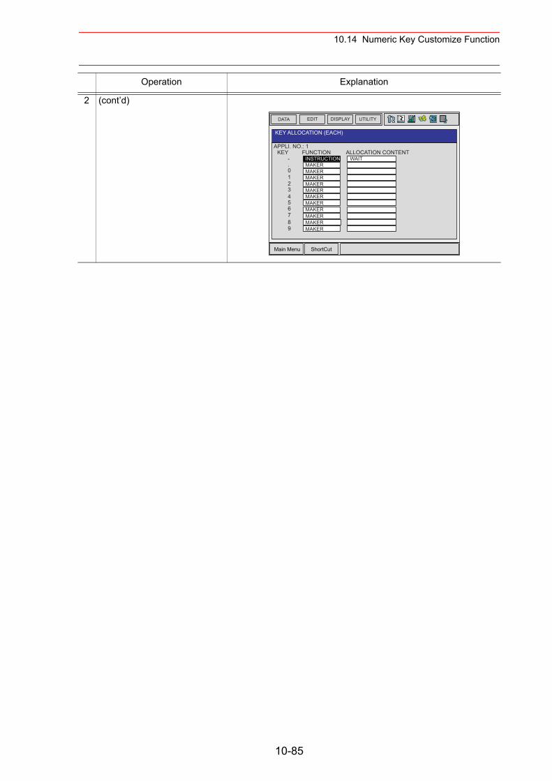
10.14 Numeric Key Customize Function
2 (cont’d)
Operation Explanation
Main Menu ShortCut
EDIT DISPLAY UTILITYDATA
APPLI. NO.: 1
KEY ALLOCATION (EACH)
KEY-.
123
0
456789
FUNCTIONINSTRUCTIONMAKERMAKERMAKERMAKERMAKERMAKERMAKERMAKERMAKERMAKER
ALLOCATION CONTENT
MAKER
WAIT
10-85
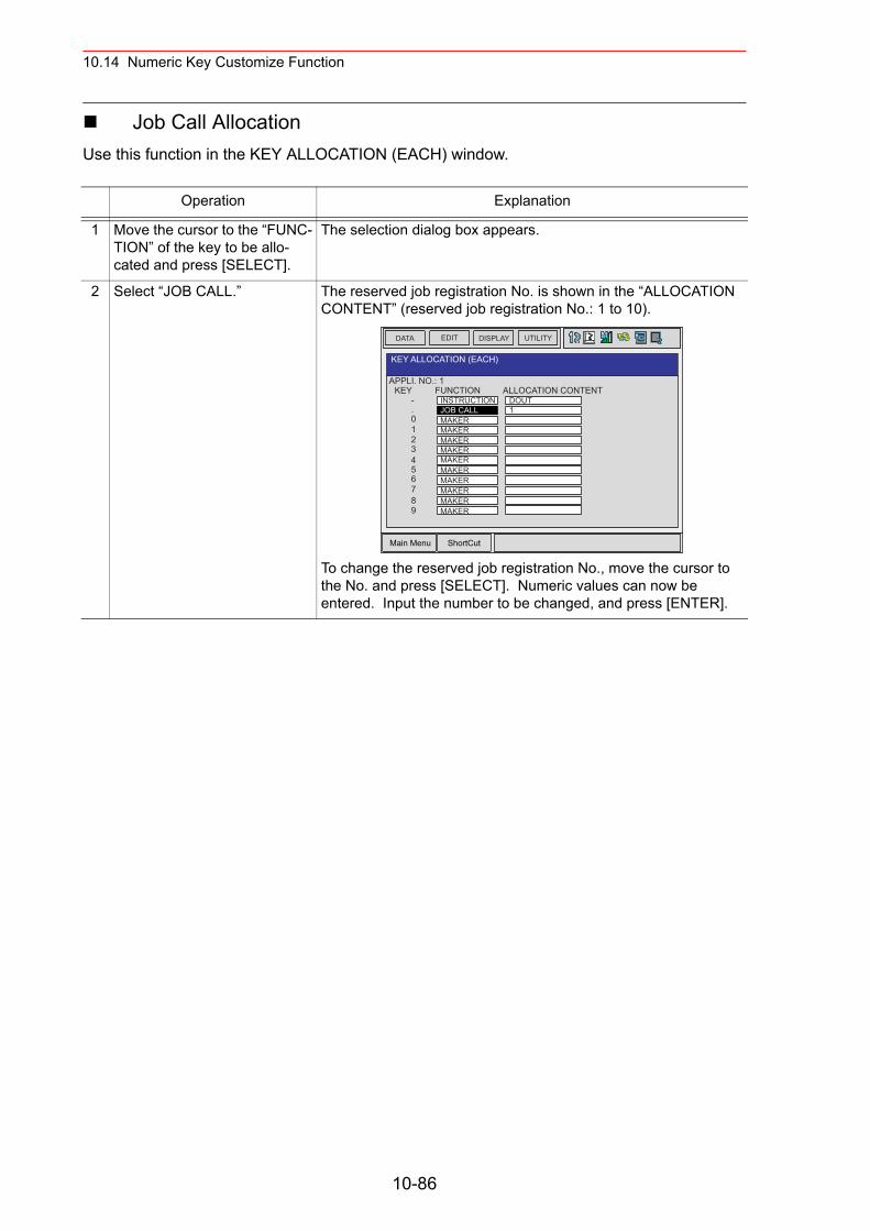
10.14 Numeric Key Customize Function
Job Call AllocationUse this function in the KEY ALLOCATION (EACH) window.
Operation Explanation
1 Move the cursor to the “FUNC-TION” of the key to be allo-cated and press [SELECT].
The selection dialog box appears.
2 Select “JOB CALL.” The reserved job registration No. is shown in the “ALLOCATION CONTENT” (reserved job registration No.: 1 to 10).
To change the reserved job registration No., move the cursor to the No. and press [SELECT]. Numeric values can now be entered. Input the number to be changed, and press [ENTER].
Main Menu ShortCut
EDIT DISPLAY UTILITYDATA
APPLI. NO.: 1
KEY ALLOCATION (EACH)
KEY-.
123
0
456789
FUNCTIONINSTRUCTIONJOB CALLMAKERMAKERMAKERMAKERMAKERMAKERMAKERMAKERMAKER
ALLOCATION CONTENT
MAKER
DOUT1
10-86
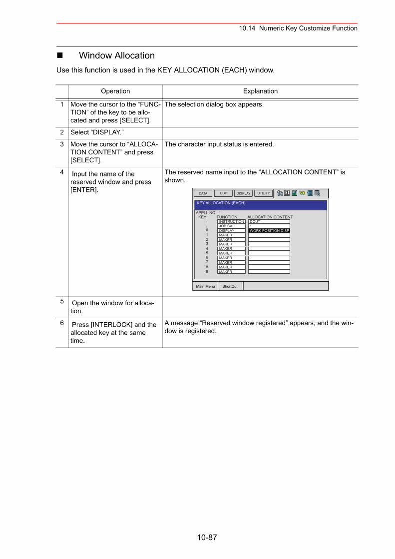
10.14 Numeric Key Customize Function
Window AllocationUse this function is used in the KEY ALLOCATION (EACH) window.
Operation Explanation
1 Move the cursor to the “FUNC-TION” of the key to be allo-cated and press [SELECT].
The selection dialog box appears.
2 Select “DISPLAY.”
3 Move the cursor to “ALLOCA-TION CONTENT” and press [SELECT].
The character input status is entered.
4 Input the name of the reserved window and press [ENTER].
The reserved name input to the “ALLOCATION CONTENT” is shown.
5 Open the window for alloca-tion.
6 Press [INTERLOCK] and the allocated key at the same time.
A message “Reserved window registered” appears, and the win-dow is registered.
Main Menu ShortCut
EDIT DISPLAY UTILITYDATA
APPLI. NO.: 1
KEY ALLOCATION (EACH)
KEY-.
123
0
456789
FUNCTIONINSTRUCTIONJOB CALLDISPLAYMAKERMAKERMAKERMAKERMAKERMAKERMAKERMAKER
ALLOCATION CONTENT
MAKER
DOUT1WORK POSITION DISP
10-87
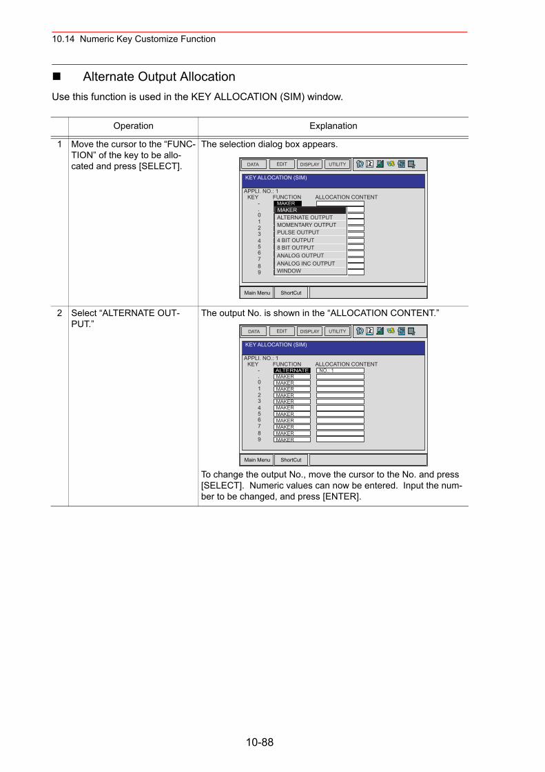
10.14 Numeric Key Customize Function
Alternate Output AllocationUse this function is used in the KEY ALLOCATION (SIM) window.
Operation Explanation
1 Move the cursor to the “FUNC-TION” of the key to be allo-cated and press [SELECT].
The selection dialog box appears.
2 Select “ALTERNATE OUT-PUT.”
The output No. is shown in the “ALLOCATION CONTENT.”
To change the output No., move the cursor to the No. and press [SELECT]. Numeric values can now be entered. Input the num-ber to be changed, and press [ENTER].
Main Menu ShortCut
EDIT DISPLAY UTILITYDATA
APPLI. NO.: 1
KEY ALLOCATION (SIM)
KEY-.
123
0
456789
FUNCTIONMAKERMAKERMAKERMAKERMAKERMAKERMAKERMAKERMAKERMAKERMAKER
ALLOCATION CONTENT
MAKER
MAKERALTERNATE OUTPUTMOMENTARY OUTPUTPULSE OUTPUT4 BIT OUTPUT8 BIT OUTPUTANALOG OUTPUTANALOG INC OUTPUTWINDOW
Main Menu ShortCut
EDIT DISPLAY UTILITYDATA
APPLI. NO.: 1
KEY ALLOCATION (SIM)
KEY-.
123
0
456789
FUNCTIONALTERNATEMAKERMAKERMAKERMAKERMAKERMAKERMAKERMAKERMAKERMAKER
ALLOCATION CONTENT
MAKER
NO.: 1
10-88
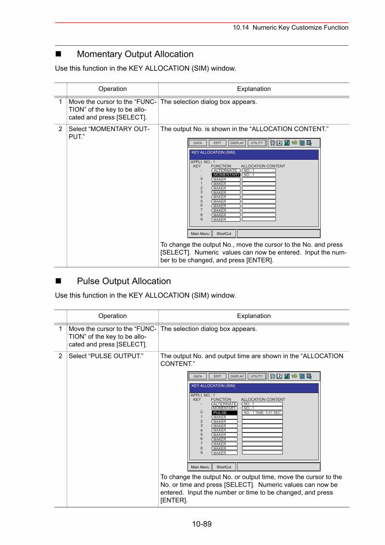
10.14 Numeric Key Customize Function
Momentary Output AllocationUse this function in the KEY ALLOCATION (SIM) window.
Pulse Output Allocation Use this function in the KEY ALLOCATION (SIM) window.
Operation Explanation
1 Move the cursor to the “FUNC-TION” of the key to be allo-cated and press [SELECT].
The selection dialog box appears.
2 Select “MOMENTARY OUT-PUT.”
The output No. is shown in the “ALLOCATION CONTENT.”
To change the output No., move the cursor to the No. and press [SELECT]. Numeric values can now be entered. Input the num-ber to be changed, and press [ENTER].
Operation Explanation
1 Move the cursor to the “FUNC-TION” of the key to be allo-cated and press [SELECT].
The selection dialog box appears.
2 Select “PULSE OUTPUT.” The output No. and output time are shown in the “ALLOCATION CONTENT.”
To change the output No. or output time, move the cursor to the No. or time and press [SELECT]. Numeric values can now be entered. Input the number or time to be changed, and press [ENTER].
Main Menu ShortCut
EDIT DISPLAY UTILITYDATA
APPLI. NO.: 1
KEY ALLOCATION (SIM)
KEY-.
123
0
456789
FUNCTIONALTERNATE
MAKERMAKERMAKERMAKERMAKERMAKERMAKERMAKERMAKER
ALLOCATION CONTENT
MAKER
NO.: 1MOMENTARY NO.: 1
Main Menu ShortCut
EDIT DISPLAY UTILITYDATA
APPLI. NO.: 1
KEY ALLOCATION (SIM)
KEY-.
123
0
456789
FUNCTIONALTERNATE
PULSEMAKERMAKERMAKERMAKERMAKERMAKERMAKERMAKER
ALLOCATION CONTENT
MAKER
NO.: 1MOMENTARY NO.: 1
NO.: 1 TIME: 0.01 SEC
10-89
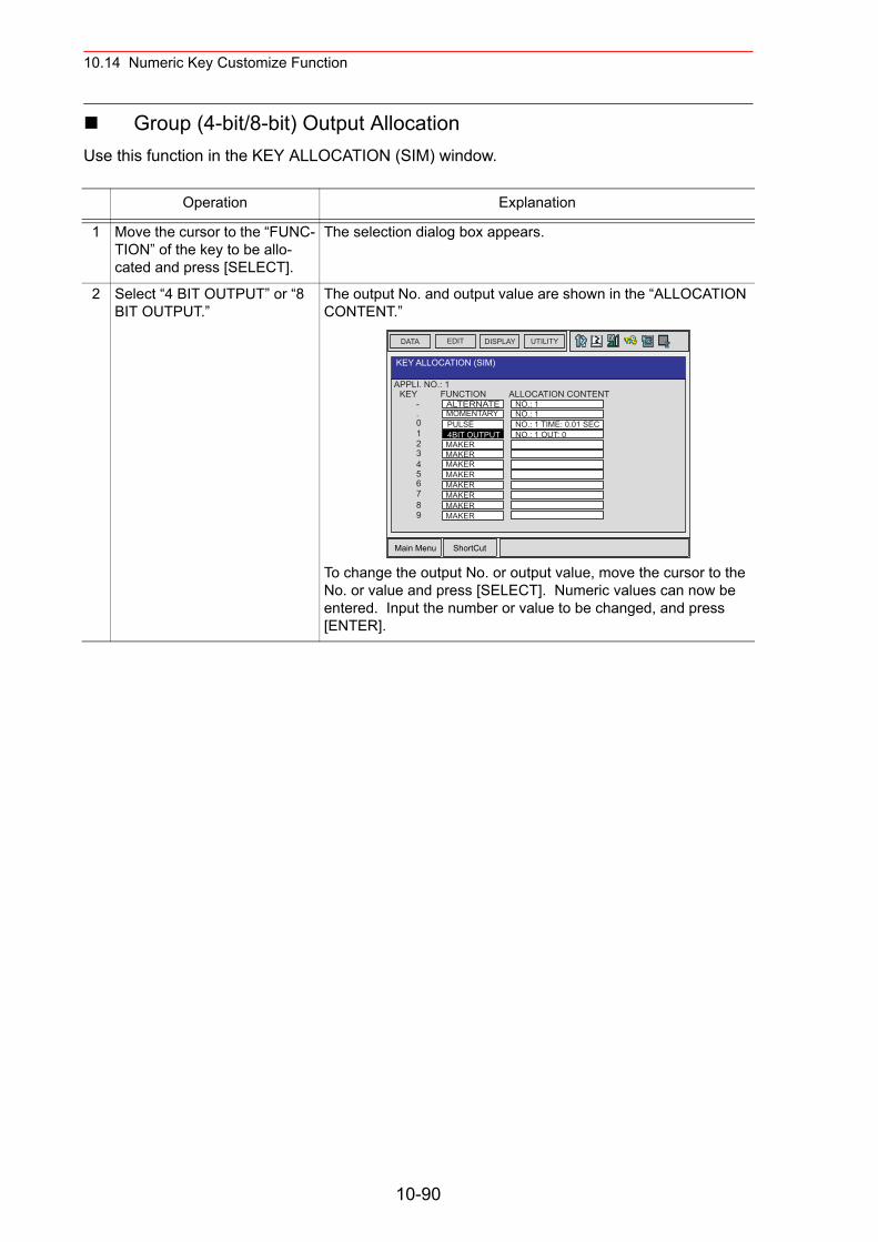
10.14 Numeric Key Customize Function
Group (4-bit/8-bit) Output AllocationUse this function in the KEY ALLOCATION (SIM) window.
Operation Explanation
1 Move the cursor to the “FUNC-TION” of the key to be allo-cated and press [SELECT].
The selection dialog box appears.
2 Select “4 BIT OUTPUT” or “8 BIT OUTPUT.”
The output No. and output value are shown in the “ALLOCATION CONTENT.”
To change the output No. or output value, move the cursor to the No. or value and press [SELECT]. Numeric values can now be entered. Input the number or value to be changed, and press [ENTER].
Main Menu ShortCut
EDIT DISPLAY UTILITYDATA
APPLI. NO.: 1
KEY ALLOCATION (SIM)
KEY-.
123
0
456789
FUNCTIONALTERNATE
PULSE4BIT OUTPUTMAKERMAKERMAKERMAKERMAKERMAKERMAKER
ALLOCATION CONTENT
MAKER
NO.: 1MOMENTARY NO.: 1
NO.: 1 TIME: 0.01 SECNO.: 1 OUT: 0
10-90
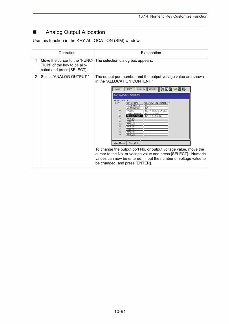
10.14 Numeric Key Customize Function
Analog Output AllocationUse this function in the KEY ALLOCATION (SIM) window.
Operation Explanation
1 Move the cursor to the “FUNC-TION” of the key to be allo-cated and press [SELECT].
The selection dialog box appears.
2 Select “ANALOG OUTPUT.” The output port number and the output voltage value are shown in the “ALLOCATION CONTENT.”
To change the output port No. or output voltage value, move the cursor to the No. or voltage value and press [SELECT]. Numeric values can now be entered. Input the number or voltage value to be changed, and press [ENTER].
Main Menu ShortCut
EDIT DISPLAY UTILITYDATA
APPLI. NO.: 1
KEY ALLOCATION (SIM)
KEY-.
123
0
456789
FUNCTIONALTERNATE
PULSE4BIT OUTPUT
ANALOG OUTMAKERMAKERMAKERMAKERMAKERMAKER
ALLOCATION CONTENT
MAKER
NO.: 1MOMENTARY NO.: 1
NO.: 1 TIME: 0.01 SECNO.: 1 OUT: 0NO.: 1 OUT: 0.00
10-91
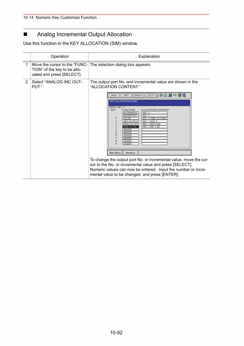
10.14 Numeric Key Customize Function
Analog Incremental Output AllocationUse this function in the KEY ALLOCATION (SIM) window.
Operation Explanation
1 Move the cursor to the “FUNC-TION” of the key to be allo-cated and press [SELECT].
The selection dialog box appears.
2 Select “ANALOG INC OUT-PUT.”
The output port No. and incremental value are shown in the “ALLOCATION CONTENT.”
To change the output port No. or incremental value, move the cur-sor to the No. or incremental value and press [SELECT]. Numeric values can now be entered. Input the number or incre-mental value to be changed, and press [ENTER].
Main Menu ShortCut
EDIT DISPLAY UTILITYDATA
APPLI. NO.: 1
KEY ALLOCATION (SIM)
KEY-.
123
0
456789
FUNCTIONALTERNATE
PULSE4BIT OUTPUTANALOG OUTANALOG INCMAKERMAKERMAKERMAKERMAKER
ALLOCATION CONTENT
MAKER
NO.: 1MOMENTARY NO.: 1
NO.: 1 TIME: 0.01 SECNO.: 1 OUT: 0NO.: 1 OUT: 0.00NO.: 1 INC: 1.00
10-92
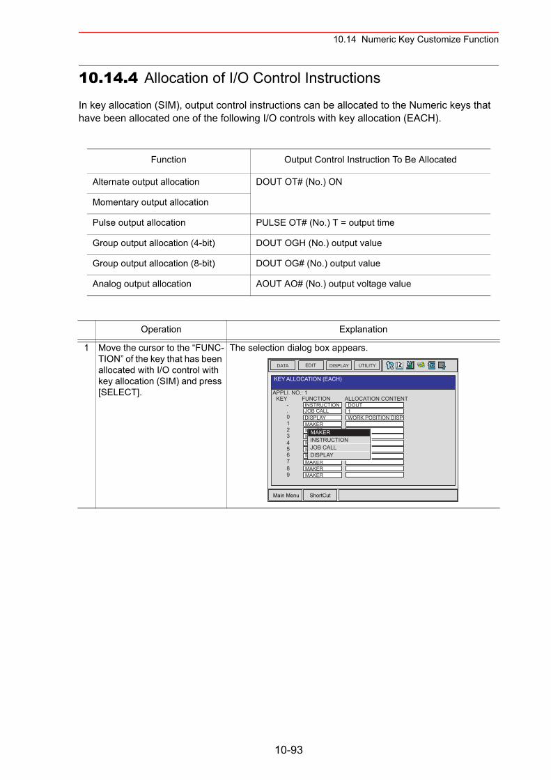
10.14 Numeric Key Customize Function
10.14.4 Allocation of I/O Control Instructions
In key allocation (SIM), output control instructions can be allocated to the Numeric keys that have been allocated one of the following I/O controls with key allocation (EACH).
Function Output Control Instruction To Be Allocated
Alternate output allocation DOUT OT# (No.) ON
Momentary output allocation
Pulse output allocation PULSE OT# (No.) T = output time
Group output allocation (4-bit) DOUT OGH (No.) output value
Group output allocation (8-bit) DOUT OG# (No.) output value
Analog output allocation AOUT AO# (No.) output voltage value
Operation Explanation
1 Move the cursor to the “FUNC-TION” of the key that has been allocated with I/O control with key allocation (SIM) and press [SELECT].
The selection dialog box appears.
Main Menu ShortCut
EDIT DISPLAY UTILITYDATA
APPLI. NO.: 1
KEY ALLOCATION (EACH)
KEY-.
123
0
456789
FUNCTIONINSTRUCTION
DISPLAYMAKERMAKERMAKERMAKERMAKERMAKERMAKERMAKER
ALLOCATION CONTENT
MAKER
DOUTJOB CALL 1
WORK POSITION DISP
MAKERINSTRUCTIONJOB CALLDISPLAY
10-93
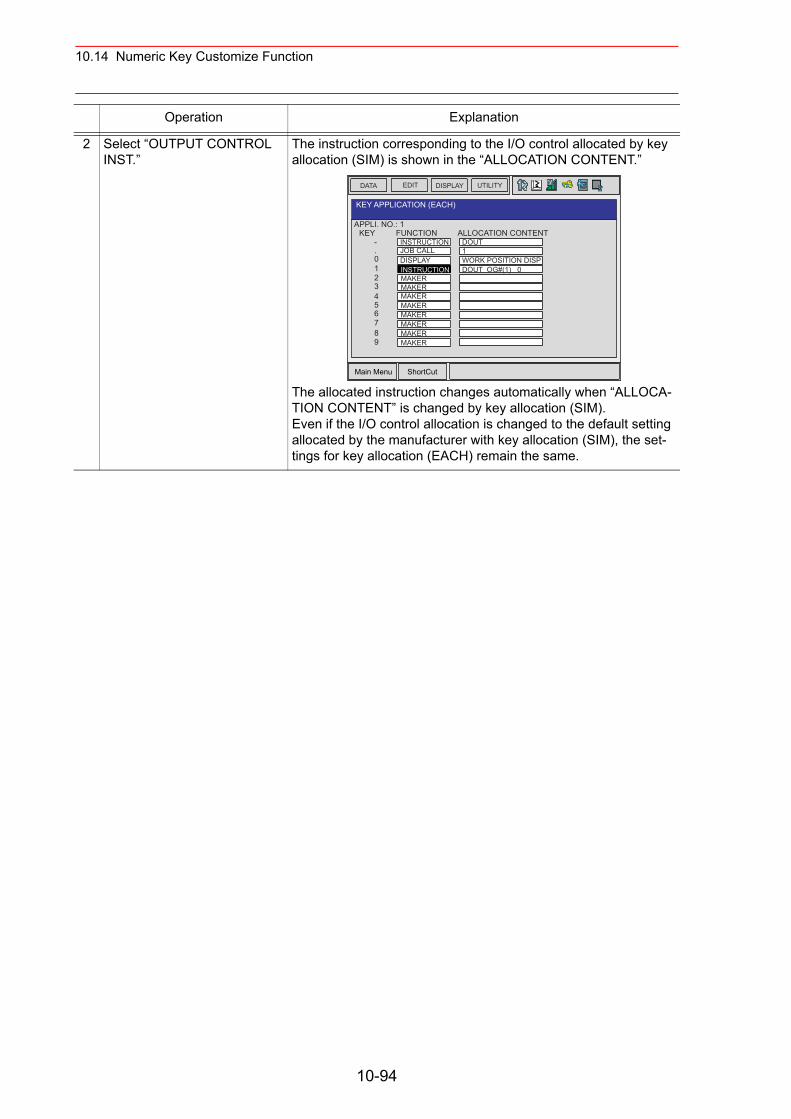
10.14 Numeric Key Customize Function
2 Select “OUTPUT CONTROL INST.”
The instruction corresponding to the I/O control allocated by key allocation (SIM) is shown in the “ALLOCATION CONTENT.”
The allocated instruction changes automatically when “ALLOCA-TION CONTENT” is changed by key allocation (SIM).Even if the I/O control allocation is changed to the default setting allocated by the manufacturer with key allocation (SIM), the set-tings for key allocation (EACH) remain the same.
Operation Explanation
Main Menu ShortCut
EDIT DISPLAY UTILITYDATA
APPLI. NO.: 1
KEY APPLICATION (EACH)
KEY-.
123
0
456789
FUNCTIONINSTRUCTION
DISPLAYINSTRUCTIONMAKERMAKERMAKERMAKERMAKERMAKERMAKER
ALLOCATION CONTENT
MAKER
DOUTJOB CALL 1
WORK POSITION DISPDOUT OG#(1) 0
10-94
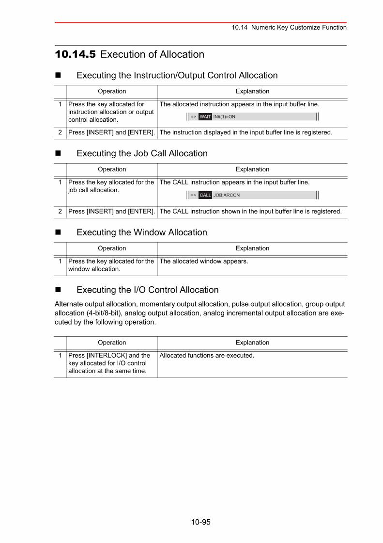
10.14 Numeric Key Customize Function
10.14.5 Execution of Allocation
Executing the Instruction/Output Control Allocation
Executing the Job Call Allocation
Executing the Window Allocation
Executing the I/O Control AllocationAlternate output allocation, momentary output allocation, pulse output allocation, group output allocation (4-bit/8-bit), analog output allocation, analog incremental output allocation are exe-cuted by the following operation.
Operation Explanation
1 Press the key allocated for instruction allocation or output control allocation.
The allocated instruction appears in the input buffer line.
2 Press [INSERT] and [ENTER]. The instruction displayed in the input buffer line is registered.
Operation Explanation
1 Press the key allocated for the job call allocation.
The CALL instruction appears in the input buffer line.
2 Press [INSERT] and [ENTER]. The CALL instruction shown in the input buffer line is registered.
Operation Explanation
1 Press the key allocated for the window allocation.
The allocated window appears.
Operation Explanation
1 Press [INTERLOCK] and the key allocated for I/O control allocation at the same time.
Allocated functions are executed.
=> WAIT IN#(1)=ON
=> CALL JOB:ARCON
10-95
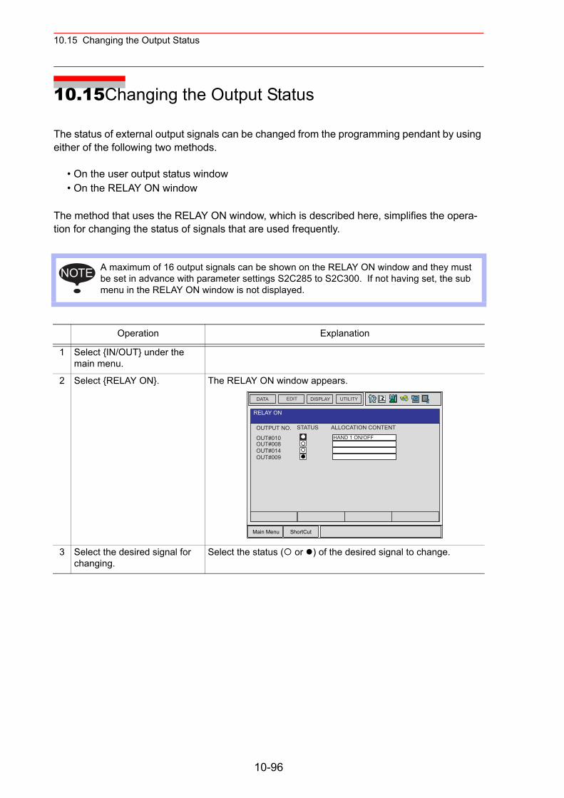
10.15 Changing the Output Status
10.15Changing the Output Status
The status of external output signals can be changed from the programming pendant by using either of the following two methods.
• On the user output status window• On the RELAY ON window
The method that uses the RELAY ON window, which is described here, simplifies the opera-tion for changing the status of signals that are used frequently.
A maximum of 16 output signals can be shown on the RELAY ON window and they must be set in advance with parameter settings S2C285 to S2C300. If not having set, the sub menu in the RELAY ON window is not displayed.
Operation Explanation
1 Select {IN/OUT} under the main menu.
2 Select {RELAY ON}. The RELAY ON window appears.
3 Select the desired signal for changing.
Select the status ( or ) of the desired signal to change.
NOTE
Main Menu ShortCut
EDIT DISPLAY UTILITYDATA
OUTPUT NO.
RELAY ON
STATUS ALLOCATION CONTENT
HAND 1 ON/OFFOUT#010OUT#008OUT#014OUT#009
10-96
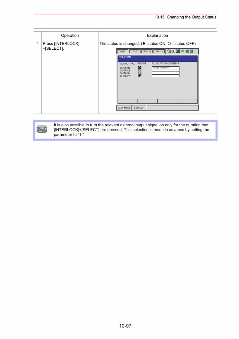
10.15 Changing the Output Status
4 Press [INTERLOCK] +[SELECT].
The status is changed. ( : status ON, : status OFF)
It is also possible to turn the relevant external output signal on only for the duration that [INTERLOCK]+[SELECT] are pressed. This selection is made in advance by setting the parameter to “1.”
Operation Explanation
Main Menu ShortCut
EDIT DISPLAY UTILITYDATA
OUTPUT NO.
RELAY ON
STATUS ALLOCATION CONTENT
HAND 1 ON/OFFOUT#010OUT#008OUT#014OUT#009
SUPPLE-MENT
10-97
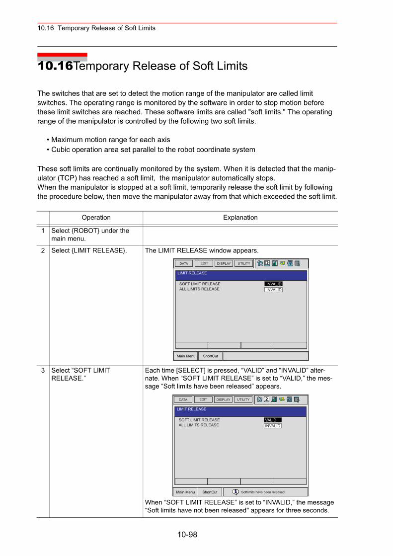
10.16 Temporary Release of Soft Limits
10.16Temporary Release of Soft Limits
The switches that are set to detect the motion range of the manipulator are called limit switches. The operating range is monitored by the software in order to stop motion before these limit switches are reached. These software limits are called "soft limits." The operating range of the manipulator is controlled by the following two soft limits.
• Maximum motion range for each axis• Cubic operation area set parallel to the robot coordinate system
These soft limits are continually monitored by the system. When it is detected that the manip-ulator (TCP) has reached a soft limit, the manipulator automatically stops. When the manipulator is stopped at a soft limit, temporarily release the soft limit by following the procedure below, then move the manipulator away from that which exceeded the soft limit.
Operation Explanation
1 Select {ROBOT} under the main menu.
2 Select {LIMIT RELEASE}. The LIMIT RELEASE window appears.
3 Select “SOFT LIMIT RELEASE.”
Each time [SELECT] is pressed, “VALID” and “INVALID” alter-nate. When “SOFT LIMIT RELEASE” is set to “VALID,” the mes-sage “Soft limits have been released” appears.
When “SOFT LIMIT RELEASE” is set to “INVALID,” the message “Soft limits have not been released" appears for three seconds.
Main Menu ShortCut
EDIT DISPLAY UTILITYDATA
LIMIT RELEASE
INVALIDSOFT LIMIT RELEASEALL LIMITS RELEASE INVALID
Main Menu ShortCut
EDIT DISPLAY UTILITYDATA
LIMIT RELEASE
VALIDSOFT LIMIT RELEASEALL LIMITS RELEASE INVALID
Softlimits have been released
10-98
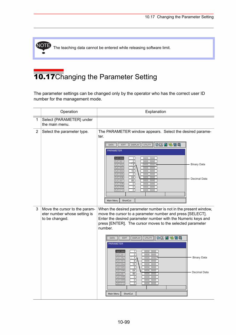
10.17 Changing the Parameter Setting
10.17Changing the Parameter Setting
The parameter settings can be changed only by the operator who has the correct user ID number for the management mode.
The teaching data cannot be entered while releasing software limit.
Operation Explanation
1 Select {PARAMETER} under the main menu.
2 Select the parameter type. The PARAMETER window appears. Select the desired parame-ter.
3 Move the cursor to the param-eter number whose setting is to be changed.
When the desired parameter number is not in the present window, move the cursor to a parameter number and press [SELECT]. Enter the desired parameter number with the Numeric keys and press [ENTER]. The cursor moves to the selected parameter number.
NOTE
Main Menu ShortCut
EDIT DISPLAY UTILITYDATA
PARAMETER
S2C000S2C001S2C002S2C003S2C004S2C005S2C006S2C007S2C008S2C009S2C010S2C011
1248
162
6489
0000_00000000_00000000_00000000_00000000_00000000_00000000_00000000_00000000_00000000_00000000_00000000_0000
0000
Binary Data
Decimal Data
Main Menu ShortCut
EDIT DISPLAY UTILITYDATA
PARAMETER
S2C001S2C002S2C003S2C004S2C005S2C006S2C007S2C008S2C009S2C010S2C011
1
48
162
6489
0000_00000000_00000000_00000000_00000000_00000000_00000000_00000000_00000000_00000000_00000000_00000000_0000
0000
S2C0002
Binary Data
Decimal Data
10-99
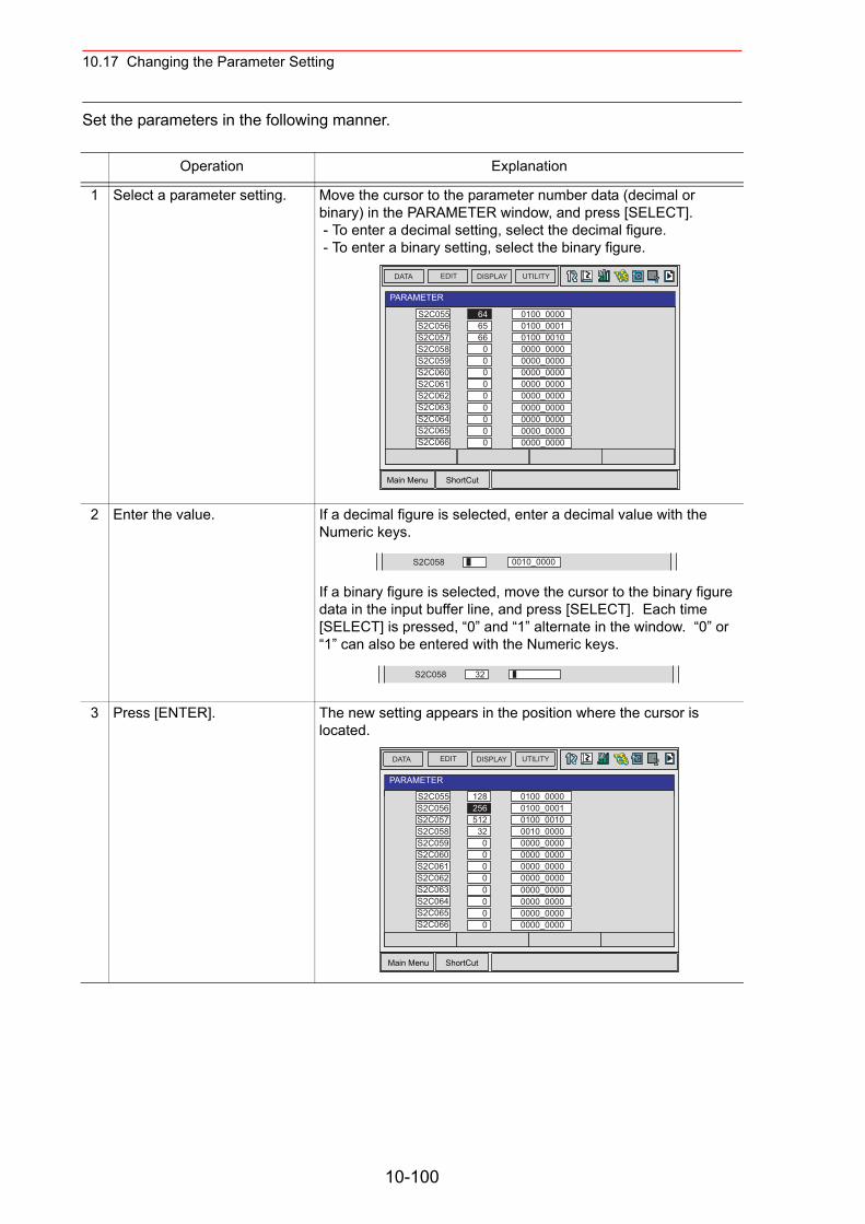
10.17 Changing the Parameter Setting
Set the parameters in the following manner.
Operation Explanation
1 Select a parameter setting. Move the cursor to the parameter number data (decimal or binary) in the PARAMETER window, and press [SELECT]. - To enter a decimal setting, select the decimal figure. - To enter a binary setting, select the binary figure.
2 Enter the value. If a decimal figure is selected, enter a decimal value with the Numeric keys.
If a binary figure is selected, move the cursor to the binary figure data in the input buffer line, and press [SELECT]. Each time [SELECT] is pressed, “0” and “1” alternate in the window. “0” or “1” can also be entered with the Numeric keys.
3 Press [ENTER]. The new setting appears in the position where the cursor is located.
Main Menu ShortCut
EDIT DISPLAY UTILITYDATA
PARAMETER
S2C055S2C056S2C057S2C058S2C059S2C060S2C061S2C062S2C063S2C064S2C065S2C066
646566
00000
0100_00000100_00010100_00100000_00000000_00000000_00000000_00000000_00000000_00000000_00000000_00000000_0000
0000
S2C058 0010_0000
S2C058 32
Main Menu ShortCut
EDIT DISPLAY UTILITYDATA
PARAMETER
S2C055S2C056S2C057S2C058S2C059S2C060S2C061S2C062S2C063S2C064S2C065S2C066
128256512
320000
0100_00000100_00010100_00100010_00000000_00000000_00000000_00000000_00000000_00000000_00000000_00000000_0000
0000
10-100
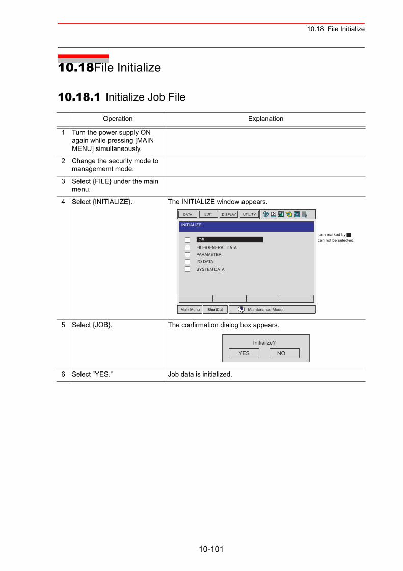
10.18 File Initialize
10.18File Initialize
10.18.1 Initialize Job File
Operation Explanation
1 Turn the power supply ON again while pressing [MAIN MENU] simultaneously.
2 Change the security mode to managememt mode.
3 Select {FILE} under the main menu.
4 Select {INITIALIZE}. The INITIALIZE window appears.
5 Select {JOB}. The confirmation dialog box appears.
6 Select “YES.” Job data is initialized.
Main Menu ShortCut
EDIT DISPLAY UTILITYDATA
INITIALIZE
JOB
FILE/GENERAL DATAPARAMETER
I/O DATA
SYSTEM DATA
Maintenance Mode
Item marked bycan not be selected.
YES NO
Initialize?
10-101
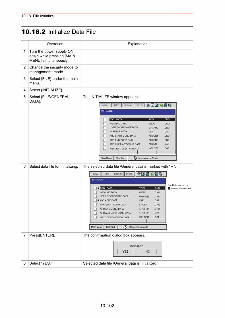
10.18 File Initialize
10.18.2 Initialize Data File
Operation Explanation
1 Turn the power supply ON again while pressing [MAIN MENU] simultaneously.
2 Change the security mode to managememt mode.
3 Select {FILE} under the main menu.
4 Select {INITIALIZE}.
5 Select {FILE/GENERAL DATA}.
The INITIALIZE window appears.
6 Select data file for initializing. The selected data file /General data is marked with “ “.
7 Press[ENTER]. The confirmation dialog box appears.
8 Select “YES.” Selected data file /General data is initialized.
Main Menu ShortCut
EDIT DISPLAY UTILITYDATA
INITIALIZE
TOOL DATA
WEAVING DATAUSER COORDINATE DATA
VARIABLE DATA
ARC START COND DATA
Maintenance Mode
ARC END COND DATA
ARC AUXILIARY COND DATA
WELDER CONDITION DATA
TOOL .CND
WEAV .CND
UFRAME .CNDVAR .DAT
ARCSRT .CND
ARCEND .CND
ARCSUP .DAT
WELDER .DAT
Main Menu ShortCut
EDIT DISPLAY UTILITYDATA
INITIALIZE
TOOL DATA
WEAVING DATAUSER COORDINATE DATA
VARIABLE DATA
ARC START COND DATA
Maintenance Mode
ARC END COND DATA
ARC AUXILIARY COND DATA
WELDER CONDITION DATA
TOOL .CND
WEAV
File/Data marked bycan not be selected.
.CND
UFRAME .CNDVAR .DAT
ARCSRT .CND
ARCEND .CND
ARCSUP .DAT
WELDER .DAT
YES NO
Initialize?
10-102
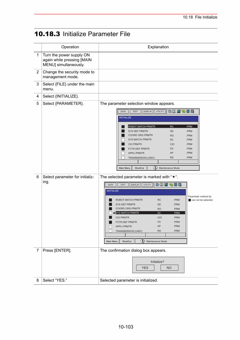
10.18 File Initialize
10.18.3 Initialize Parameter File
Operation Explanation
1 Turn the power supply ON again while pressing [MAIN MENU] simultaneously.
2 Change the security mode to management mode.
3 Select {FILE} under the main menu.
4 Select {INITIALIZE}.
5 Select {PARAMETER}. The parameter selection window appears.
6 Select parameter for initializ-ing.
The selected parameter is marked with “ “.
7 Press [ENTER]. The confirmation dialog box appears.
8 Select “YES.” Selected parameter is initialized.
Main Menu ShortCut
EDIT DISPLAY UTILITYDATA
INITIALIZE
ROBOT MATCH PRMTR
SYS DEF PRMTRCOORD ORG PRMTR
SYS MATCH PRMTR
CIO PRMTR
Maintenance Mode
FCTN DEF PRMTR
APPLI PRMTR
TRANSMISSION (UNIV)
RC .PRM
SD .PRM
RO .PRMSC .PRM
CIO .PRM
FD .PRM
AP .PRM
RS .PRM
Main Menu ShortCut
EDIT DISPLAY UTILITYDATA
Parameter marked bycan not be selected.
INITIALIZE
ROBOT MATCH PRMTR
SYS DEF PRMTRCOORD ORG PRMTR
SYS MATCH PRMTR
CIO PRMTR
Maintenance Mode
FCTN DEF PRMTR
APPLI PRMTR
TRANSMISSION (UNIV)
RC .PRM
SD .PRM
RO .PRMSC .PRM
CIO .PRM
FD .PRM
AP .PRM
RS .PRM
YES NO
Initialize?
10-103
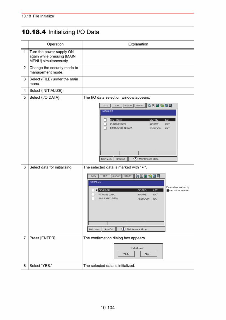
10.18 File Initialize
10.18.4 Initializing I/O Data
Operation Explanation
1 Turn the power supply ON again while pressing [MAIN MENU] simultaneously.
2 Change the security mode to management mode.
3 Select {FILE} under the main menu.
4 Select {INITIALIZE}.
5 Select {I/O DATA}. The I/O data selection window appears.
6 Select data for initializing. The selected data is marked with “ “.
7 Press [ENTER]. The confirmation dialog box appears.
8 Select “YES.” The selected data is initialized.
Main Menu ShortCut
EDIT DISPLAY UTILITYDATA
INITIALIZE
CIO PRGM
IO NAME DATASIMULATED IN DATA
Maintenance Mode
CIOPRG .LST
IONAME .DAT
PSEUDOIN .DAT
Main Menu ShortCut
EDIT DISPLAY UTILITYDATA
INITIALIZE
CIO PRGM
IO NAME DATASIMULATED DATA
Maintenance Mode
CIOPRG .LST
IONAME .DAT
PSEUDOIN .DAT
Parameters marked bycan not be selected.
YES NO
Initialize?
10-104
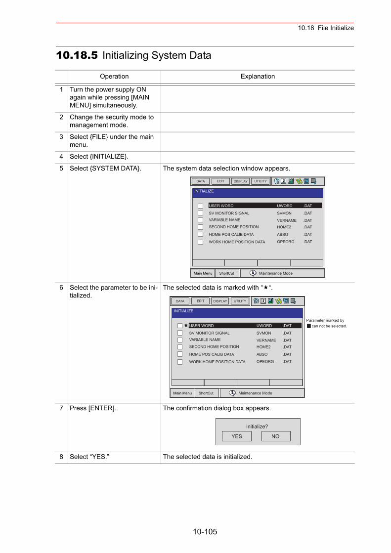
10.18 File Initialize
10.18.5 Initializing System Data
Operation Explanation
1 Turn the power supply ON again while pressing [MAIN MENU] simultaneously.
2 Change the security mode to management mode.
3 Select {FILE} under the main menu.
4 Select {INITIALIZE}.
5 Select {SYSTEM DATA}. The system data selection window appears.
6 Select the parameter to be ini-tialized.
The selected data is marked with “ “.
7 Press [ENTER]. The confirmation dialog box appears.
8 Select “YES.” The selected data is initialized.
Main Menu ShortCut
EDIT DISPLAY UTILITYDATA
INITIALIZE
USER WORD
SV MONITOR SIGNALVARIABLE NAME
SECOND HOME POSITION
HOME POS CALIB DATA
Maintenance Mode
WORK HOME POSITION DATA
UWORD .DAT
SVMON .DAT
VERNAME .DATHOME2 .DAT
ABSO .DAT
OPEORG .DAT
Main Menu ShortCut
EDIT DISPLAY UTILITYDATA
Parameter marked bycan not be selected.
INITIALIZE
USER WORD
SV MONITOR SIGNALVARIABLE NAME
SECOND HOME POSITION
HOME POS CALIB DATA
Maintenance Mode
WORK HOME POSITION DATA
UWORD .DAT
SVMON .DAT
VERNAME .DATHOME2 .DAT
ABSO .DAT
OPEORG .DAT
YES NO
Initialize?
10-105
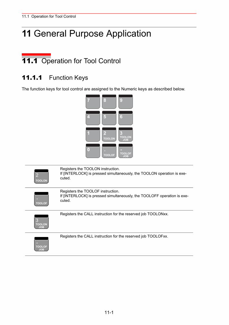
11.1 Operation for Tool Control
11 General Purpose Application
11.1 Operation for Tool Control
11.1.1 Function Keys
The function keys for tool control are assigned to the Numeric keys as described below.
Registers the TOOLON instruction.If [INTERLOCK] is pressed simultaneously, the TOOLON operation is exe-cuted.
Registers the TOOLOF instruction.If [INTERLOCK] is pressed simultaneously, the TOOLOFF operation is exe-cuted.
Registers the CALL instruction for the reserved job TOOLONxx.
Registers the CALL instruction for the reserved job TOOLOFxx.
7 8 9
4 5 6
1 2 3
0 . -
TOOLON TOOLONJOB
TOOLOF TOOLOFJOB
2TOOLON
.TOOLOF
3TOOLON
JOB
-TOOLOF
JOB
11-1
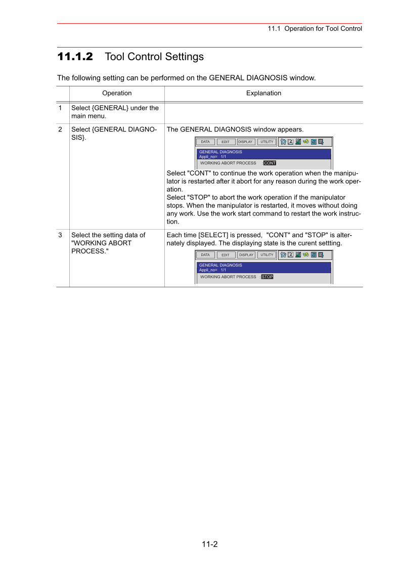
11.1 Operation for Tool Control
11.1.2 Tool Control Settings
The following setting can be performed on the GENERAL DIAGNOSIS window.
Operation Explanation
1 Select {GENERAL} under the main menu.
2 Select {GENERAL DIAGNO-SIS}.
The GENERAL DIAGNOSIS window appears.
Select "CONT" to continue the work operation when the manipu-lator is restarted after it abort for any reason during the work oper-ation.Select "STOP" to abort the work operation if the manipulator stops. When the manipulator is restarted, it moves without doing any work. Use the work start command to restart the work instruc-tion.
3 Select the setting data of "WORKING ABORT PROCESS."
Each time [SELECT] is pressed, "CONT" and "STOP" is alter-nately displayed. The displaying state is the curent settting.
DATA UTILITYEDIT DISPLAY
GENERAL DIAGNOSISAppli_no= 1/1 WORKING ABORT PROCESS : CONT
DATA UTILITYEDIT DISPLAY
GENERAL DIAGNOSISAppli_no= 1/1
WORKING ABORT PROCESS : STOP
11-2
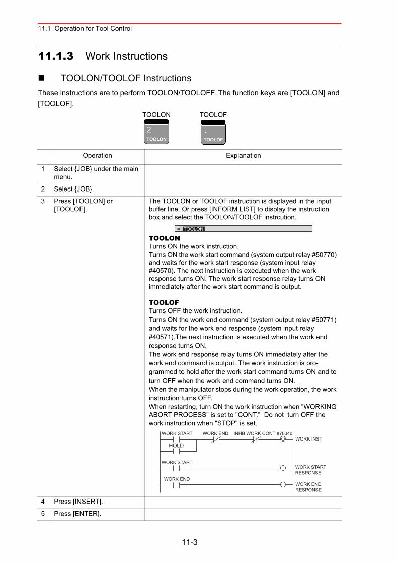
11.1 Operation for Tool Control
11.1.3 Work Instructions
TOOLON/TOOLOF InstructionsThese instructions are to perform TOOLON/TOOLOFF. The function keys are [TOOLON] and [TOOLOF].
TOOLON TOOLOF
Operation Explanation
1 Select {JOB} under the main menu.
2 Select {JOB}.
3 Press [TOOLON] or [TOOLOF].
The TOOLON or TOOLOF instruction is displayed in the input buffer line. Or press [INFORM LIST] to display the instruction box and select the TOOLON/TOOLOF instrcution.
TOOLONTurns ON the work instruction.Turns ON the work start command (system output relay #50770) and waits for the work start response (system input relay #40570). The next instruction is executed when the work response turns ON. The work start response relay turns ON immediately after the work start command is output.
TOOLOFTurns OFF the work instruction.Turns ON the work end command (system output relay #50771) and waits for the work end response (system input relay #40571).The next instruction is executed when the work end response turns ON.The work end response relay turns ON immediately after the work end command is output. The work instruction is pro-grammed to hold after the work start command turns ON and toturn OFF when the work end command turns ON.When the manipulator stops during the work operation, the work instruction turns OFF.When restarting, turn ON the work instruction when "WORKING ABORT PROCESS" is set to "CONT." Do not turn OFF the work instruction when "STOP" is set.
4 Press [INSERT].
5 Press [ENTER].
2TOOLON
.TOOLOF
TOOLON
WORK START WORK END INHB WORK CONT #70040
HOLD
WORK START
WORK END
WORK INST
WORK STARTRESPONSE
WORK ENDRESPONSE
11-3
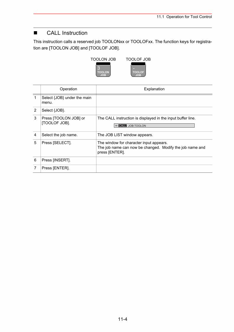
11.1 Operation for Tool Control
CALL InstructionThis instruction calls a reserved job TOOLONxx or TOOLOFxx. The function keys for registra-tion are [TOOLON JOB] and [TOOLOF JOB].
TOOLON JOB TOOLOF JOB
Operation Explanation
1 Select {JOB} under the main menu.
2 Select {JOB}.
3 Press [TOOLON JOB] or [TOOLOF JOB].
The CALL instruction is displayed in the input buffer line.
4 Select the job name. The JOB LIST window appears.
5 Press [SELECT]. The window for character input appears. The job name can now be changed. Modify the job name and press [ENTER].
6 Press [INSERT].
7 Press [ENTER].
3TOOLON
JOB
-TOOLOF
JOB
CALL JOB:TOOLON
11-4
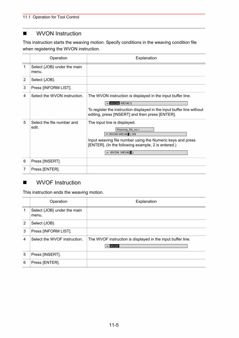
11.1 Operation for Tool Control
WVON InstructionThis instruction starts the weaving motion. Specify conditions in the weaving condition file when registering the WVON instruction.
WVOF InstructionThis instruction ends the weaving motion.
Operation Explanation
1 Select {JOB} under the main menu.
2 Select {JOB}.
3 Press [INFORM LIST].
4 Select the WVON instruction. The WVON instruction is displayed in the input buffer line.
To register the instruction displayed in the input buffer line without editing, press [INSERT] and then press [ENTER].
5 Select the file number and edit.
The input line is displayed.
Input weaving file number using the Numeric keys and press [ENTER]. (In the following example, 2 is entered.)
6 Press [INSERT].
7 Press [ENTER].
Operation Explanation
1 Select {JOB} under the main menu.
2 Select {JOB}.
3 Press [INFORM LIST].
4 Select the WVOF instruction. The WVOF instruction is displayed in the input buffer line.
5 Press [INSERT].
6 Press [ENTER].
WVON WEV#(1)
Weaving_file_no.WVON WEV#( ) ON
WVON WEV#( 2 )
WVOF
11-5
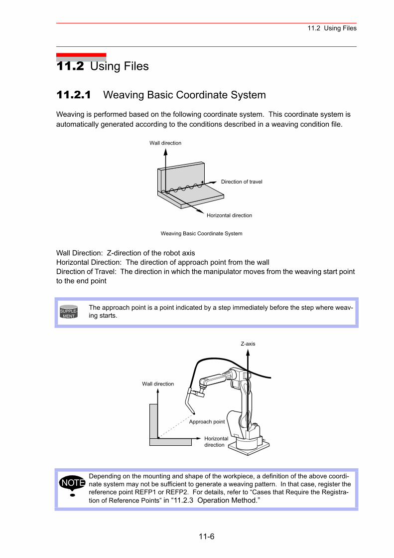
11.2 Using Files
11.2 Using Files
11.2.1 Weaving Basic Coordinate System
Weaving is performed based on the following coordinate system. This coordinate system is automatically generated according to the conditions described in a weaving condition file.
Wall Direction: Z-direction of the robot axisHorizontal Direction: The direction of approach point from the wallDirection of Travel: The direction in which the manipulator moves from the weaving start point to the end point
The approach point is a point indicated by a step immediately before the step where weav-ing starts.
Depending on the mounting and shape of the workpiece, a definition of the above coordi-nate system may not be sufficient to generate a weaving pattern. In that case, register the reference point REFP1 or REFP2. For details, refer to “Cases that Require the Registra-tion of Reference Points” in “11.2.3 Operation Method.”
Horizontal direction
Weaving Basic Coordinate System
Direction of travel
Wall direction
SUPPLE-MENT
Wall direction
Z-axis
Horizontaldirection
Approach point
NOTE
11-6
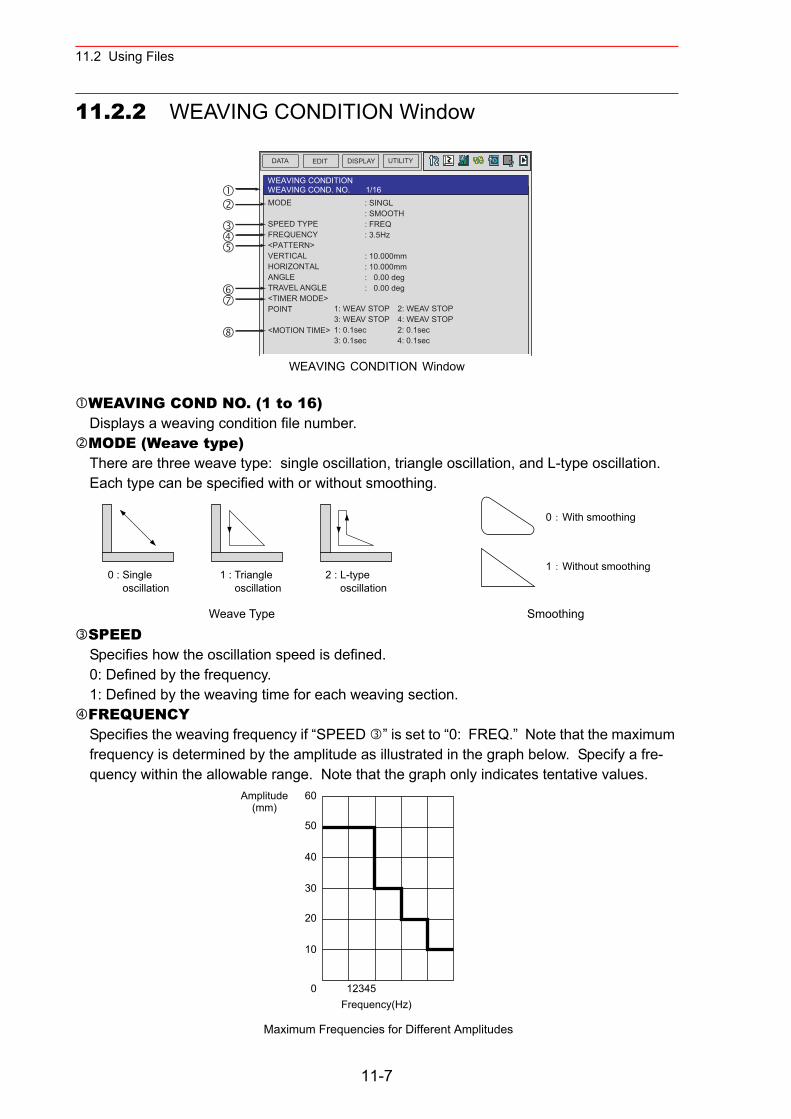
11.2 Using Files
11.2.2 WEAVING CONDITION Window
WEAVING CONDITION Window
WEAVING COND NO. (1 to 16)Displays a weaving condition file number.MODE (Weave type)There are three weave type: single oscillation, triangle oscillation, and L-type oscillation. Each type can be specified with or without smoothing.
SPEEDSpecifies how the oscillation speed is defined.0: Defined by the frequency.1: Defined by the weaving time for each weaving section.FREQUENCYSpecifies the weaving frequency if “SPEED ” is set to “0: FREQ.” Note that the maximum frequency is determined by the amplitude as illustrated in the graph below. Specify a fre-quency within the allowable range. Note that the graph only indicates tentative values.
WEAVING CONDITIONWEAVING COND. NO. 1/16
1: WEAV STOP 2: WEAV STOP3: WEAV STOP 4: WEAV STOP1: 0.1sec 2: 0.1sec3: 0.1sec 4: 0.1sec
MODE
SPEED TYPEFREQUENCY<PATTERN>VERTICALHORIZONTALANGLETRAVEL ANGLE<TIMER MODE>POINT
<MOTION TIME>
: SINGL: SMOOTH: FREQ: 3.5Hz
: 10.000mm: 10.000mm: 0.00 deg: 0.00 deg
DATA UTILITYEDIT DISPLAY
0 : Single oscillation
1 : Triangle oscillation
2 : L-type oscillation
0 With smoothing
1 Without smoothing
Weave Type Smoothing
123450
60
50
40
30
20
10
Amplitude(mm)
Frequency(Hz)
Maximum Frequencies for Different Amplitudes
11-7
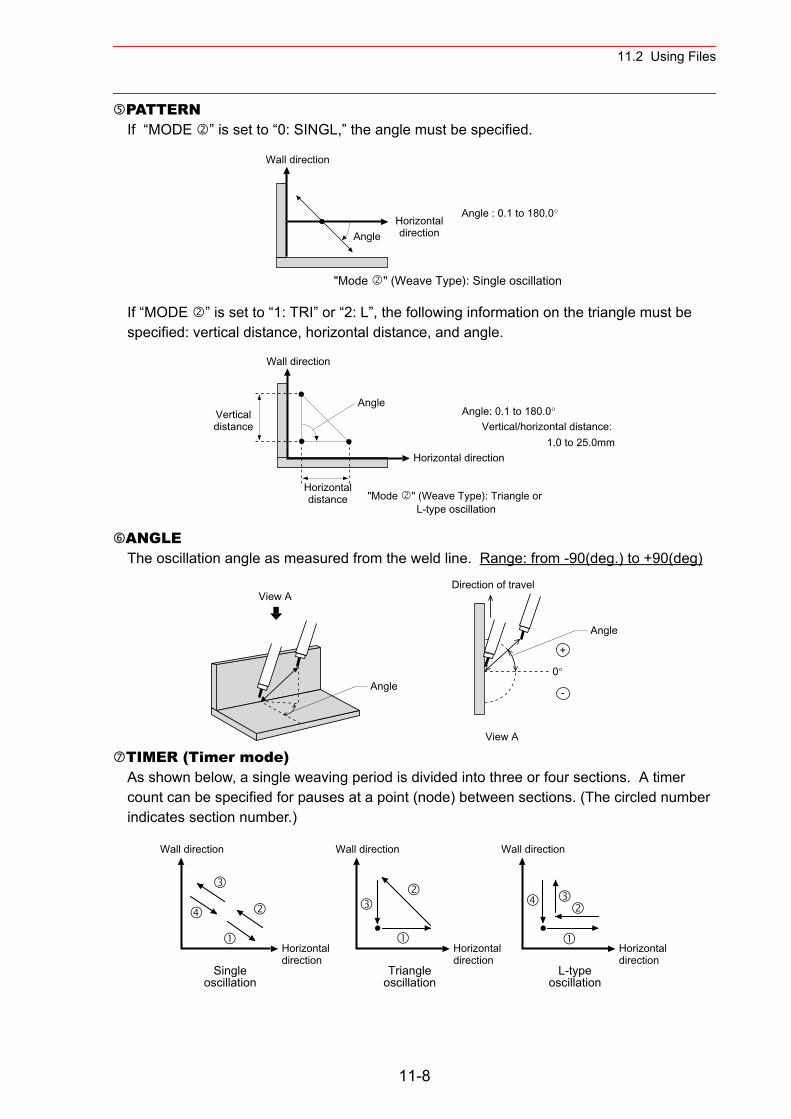
11.2 Using Files
PATTERNIf “MODE ” is set to “0: SINGL,” the angle must be specified.
If “MODE ” is set to “1: TRI” or “2: L”, the following information on the triangle must be specified: vertical distance, horizontal distance, and angle.
ANGLEThe oscillation angle as measured from the weld line. Range: from -90(deg.) to +90(deg)
TIMER (Timer mode)As shown below, a single weaving period is divided into three or four sections. A timer count can be specified for pauses at a point (node) between sections. (The circled number indicates section number.)
Angle
Angle : 0.1 to 180.0°
"Mode " (Weave Type): Single oscillation
Wall direction
Horizontaldirection
Angle: 0.1 to 180.0°Vertical/horizontal distance:
1.0 to 25.0mm
Wall direction
Angle
Horizontal direction
"Mode " (Weave Type): Triangle or L-type oscillation
Verticaldistance
Horizontaldistance
View A
Angle
View A
0°
+
-
Direction of travel
Angle
Singleoscillation
Triangleoscillation
L-typeoscillation
Wall direction
Horizontaldirection
Wall direction
Horizontaldirection
Wall direction
Horizontal direction
11-8
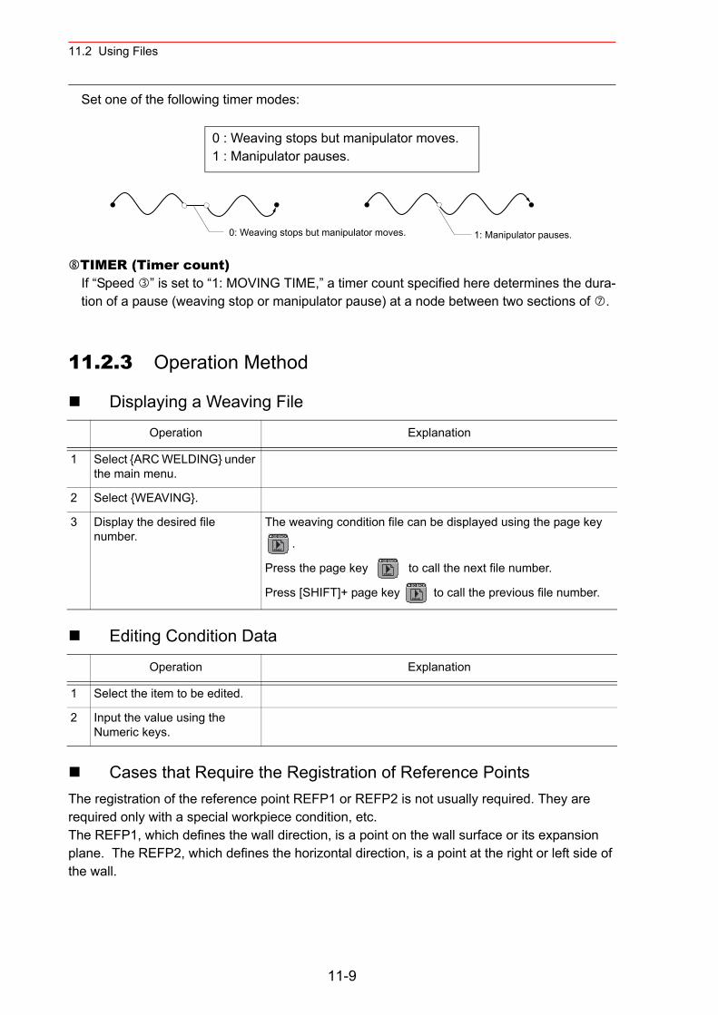
11.2 Using Files
Set one of the following timer modes:
TIMER (Timer count)If “Speed ” is set to “1: MOVING TIME,” a timer count specified here determines the dura-tion of a pause (weaving stop or manipulator pause) at a node between two sections of .
11.2.3 Operation Method
Displaying a Weaving File
Editing Condition Data
Cases that Require the Registration of Reference PointsThe registration of the reference point REFP1 or REFP2 is not usually required. They are required only with a special workpiece condition, etc.The REFP1, which defines the wall direction, is a point on the wall surface or its expansion plane. The REFP2, which defines the horizontal direction, is a point at the right or left side of the wall.
0 : Weaving stops but manipulator moves.1 : Manipulator pauses.
Operation Explanation
1 Select {ARC WELDING} under the main menu.
2 Select {WEAVING}.
3 Display the desired file number.
The weaving condition file can be displayed using the page key
.
Press the page key to call the next file number.
Press [SHIFT]+ page key to call the previous file number.
Operation Explanation
1 Select the item to be edited.
2 Input the value using the Numeric keys.
0: Weaving stops but manipulator moves. 1: Manipulator pauses.
PAGE
GO BACK
PAGE
GO BACK
PAGE
GO BACK
11-9
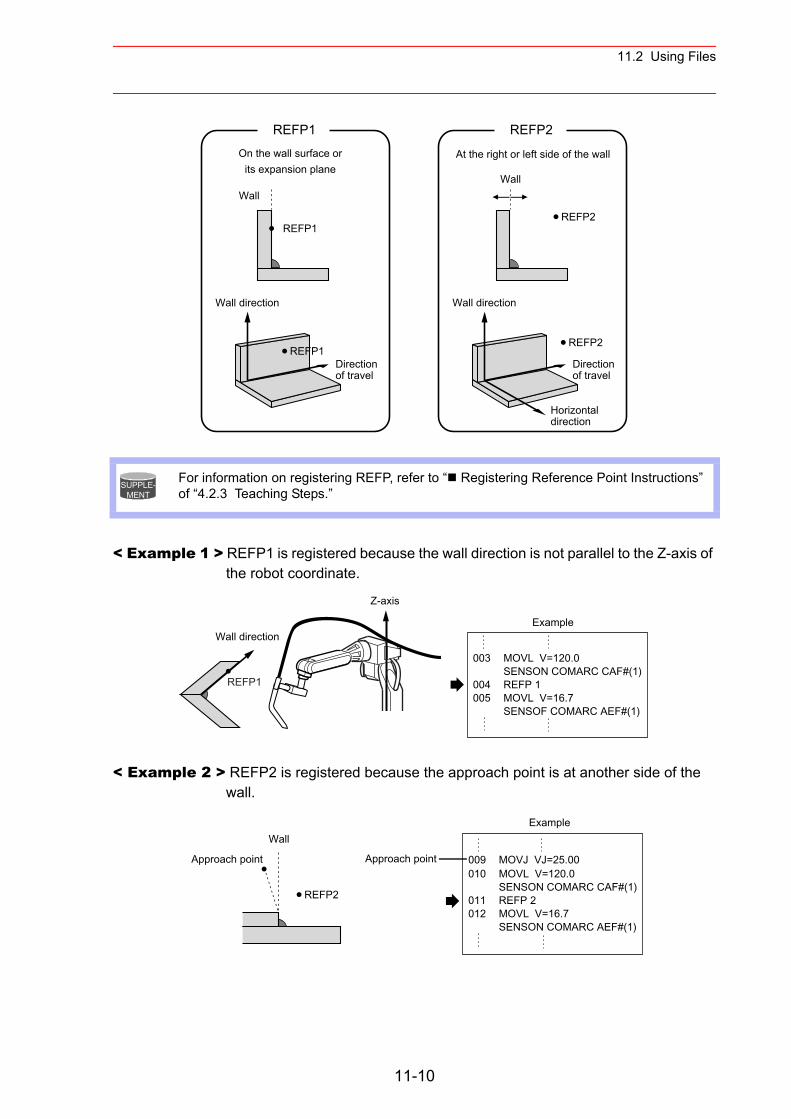
11.2 Using Files
< Example 1 > REFP1 is registered because the wall direction is not parallel to the Z-axis of the robot coordinate.
< Example 2 > REFP2 is registered because the approach point is at another side of the wall.
For information on registering REFP, refer to “ Registering Reference Point Instructions” of “4.2.3 Teaching Steps.”
REFP1 REFP2On the wall surface or
its expansion planeAt the right or left side of the wall
Horizontaldirection
Directionof travel
Wall direction
WallWall
REFP1
REFP1
REFP2
REFP2
Directionof travel
Wall direction
SUPPLE-MENT
Wall direction
003
004005
MOVL V=120.0SENSON COMARC CAF#(1)REFP 1MOVL V=16.7SENSOF COMARC AEF#(1)
Example
REFP1
Z-axis
Example
010
011012
MOVL V=120.0SENSON COMARC CAF#(1)REFP 2MOVL V=16.7SENSON COMARC AEF#(1)
009 MOVJ VJ=25.00Approach pointApproach point
Wall
REFP2
11-10
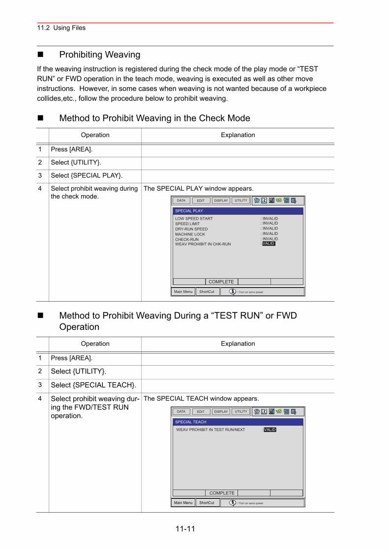
11.2 Using Files
Prohibiting WeavingIf the weaving instruction is registered during the check mode of the play mode or “TEST RUN” or FWD operation in the teach mode, weaving is executed as well as other move instructions. However, in some cases when weaving is not wanted because of a workpiece collides,etc., follow the procedure below to prohibit weaving.
Method to Prohibit Weaving in the Check Mode
Method to Prohibit Weaving During a “TEST RUN” or FWD Operation
Operation Explanation
1 Press [AREA].
2 Select {UTILITY}.
3 Select {SPECIAL PLAY}.
4 Select prohibit weaving during the check mode.
The SPECIAL PLAY window appears.
Operation Explanation
1 Press [AREA].
2 Select {UTILITY}.
3 Select {SPECIAL TEACH}.
4 Select prohibit weaving dur-ing the FWD/TEST RUN operation.
The SPECIAL TEACH window appears.
DATA UTILITYEDIT DISPLAY
Main Menu ShortCut ! Turn on servo power
SPECIAL PLAY
LOW SPEED STARTSPEED LIMITDRY-RUN SPEEDMACHINE LOCKCHECK-RUNWEAV PROHIBIT IN CHK-RUN
: INVALID: INVALID: INVALID: INVALID: INVALID: VALID
COMPLETE
SPECIAL TEACH
WEAV PROHIBIT IN TEST RUN/NEXT : VALID
DATA UTILITYEDIT DISPLAY
Main Menu ShortCut ! Turn on servo power
COMPLETE
11-11
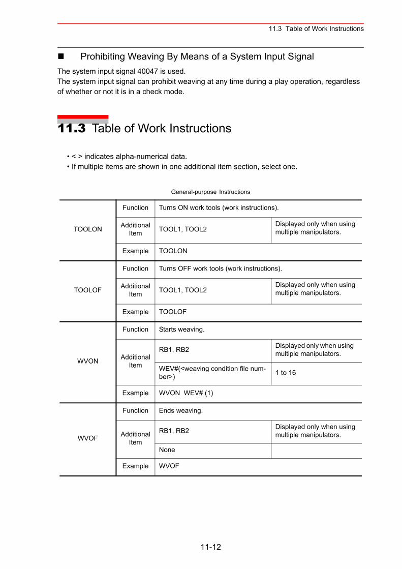
11.3 Table of Work Instructions
Prohibiting Weaving By Means of a System Input SignalThe system input signal 40047 is used.The system input signal can prohibit weaving at any time during a play operation, regardless of whether or not it is in a check mode.
11.3 Table of Work Instructions
• < > indicates alpha-numerical data.• If multiple items are shown in one additional item section, select one.
General-purpose Instructions
TOOLON
Function Turns ON work tools (work instructions).
Additional Item TOOL1, TOOL2
Displayed only when using multiple manipulators.
Example TOOLON
TOOLOF
Function Turns OFF work tools (work instructions).
Additional Item TOOL1, TOOL2
Displayed only when using multiple manipulators.
Example TOOLOF
WVON
Function Starts weaving.
Additional Item
RB1, RB2 Displayed only when using multiple manipulators.
WEV#(<weaving condition file num-ber>) 1 to 16
Example WVON WEV# (1)
WVOF
Function Ends weaving.
Additional Item
RB1, RB2 Displayed only when using multiple manipulators.
None
Example WVOF
11-12
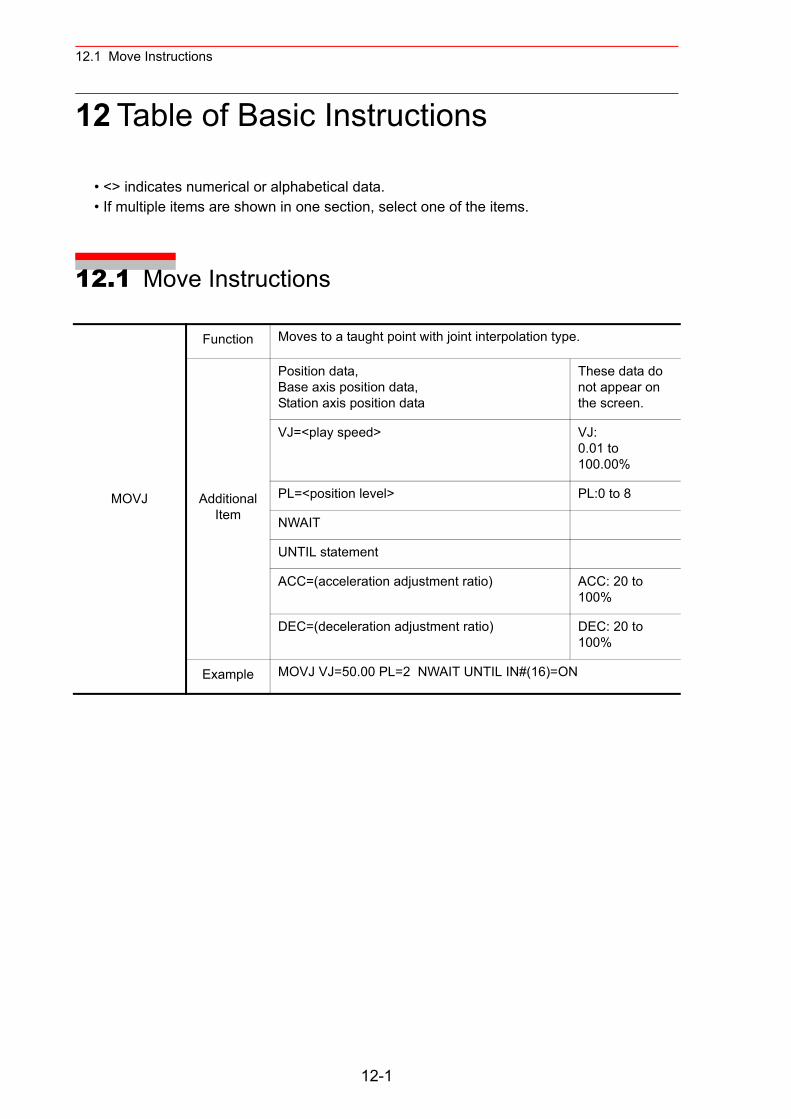
12.1 Move Instructions
12 Table of Basic Instructions
• <> indicates numerical or alphabetical data.• If multiple items are shown in one section, select one of the items.
12.1 Move Instructions
MOVJ
Function Moves to a taught point with joint interpolation type.
Additional Item
Position data, Base axis position data,Station axis position data
These data do not appear on the screen.
VJ=<play speed> VJ:0.01 to 100.00%
PL=<position level> PL:0 to 8
NWAIT
UNTIL statement
ACC=(acceleration adjustment ratio) ACC: 20 to 100%
DEC=(deceleration adjustment ratio) DEC: 20 to 100%
Example MOVJ VJ=50.00 PL=2 NWAIT UNTIL IN#(16)=ON
12-1
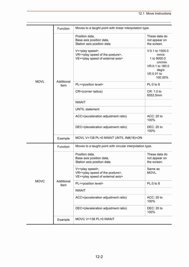
12.1 Move Instructions
MOVL
Function Moves to a taught point with linear interpolation type.
Additional Item
Position data, Base axis position data,Station axis position data
These data do not appear on the screen.
V=<play speed>,VR=<play speed of the posture>,VE=<play speed of external axis>
V:0.1 to 1500.0 mm/s 1 to 9000.0 cm/minVR:0.1 to 180.0 deg/sVE:0.01 to 100.00%
PL=<position level> PL:0 to 8
CR=(corner radius) CR: 1.0 to 6553.5mm
NWAIT
UNTIL statement
ACC=(acceleration adjustment ratio) ACC: 20 to 100%
DEC=(deceleration adjustment ratio) DEC: 20 to 100%
Example MOVL V=138 PL=0 NWAIT UNTIL IN#(16)=ON
MOVC
Function Moves to a taught point with circular interpolation type.
Additional Item
Position data, Base axis position data,Station axis position data
These data do not appear on the screen.
V=<play speed>,VR=<play speed of the posture>,VE=<play speed of external axis>
Same as MOVL.
PL=<position level> PL:0 to 8
NWAIT
ACC=(acceleration adjustment ratio) ACC: 20 to 100%
DEC=(deceleration adjustment ratio) DEC: 20 to 100%
Example MOVC V=138 PL=0 NWAIT
12-2
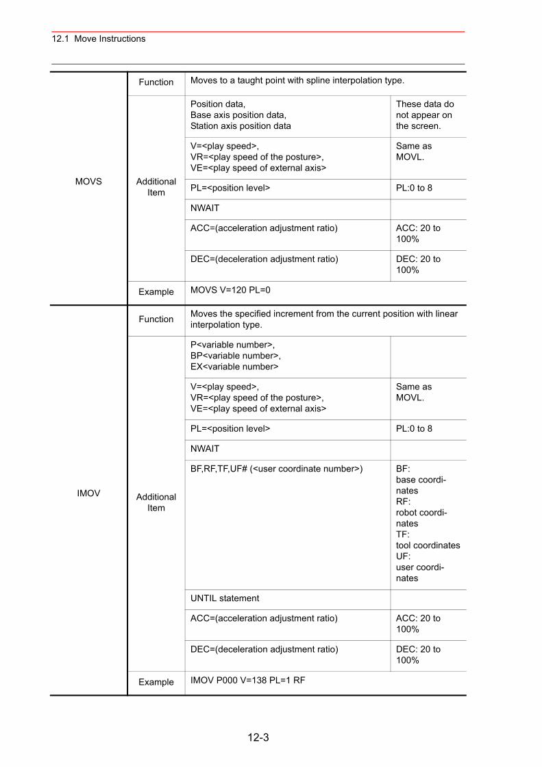
12.1 Move Instructions
MOVS
Function Moves to a taught point with spline interpolation type.
Additional Item
Position data, Base axis position data,Station axis position data
These data do not appear on the screen.
V=<play speed>,VR=<play speed of the posture>,VE=<play speed of external axis>
Same as MOVL.
PL=<position level> PL:0 to 8
NWAIT
ACC=(acceleration adjustment ratio) ACC: 20 to 100%
DEC=(deceleration adjustment ratio) DEC: 20 to 100%
Example MOVS V=120 PL=0
IMOV
Function Moves the specified increment from the current position with linear interpolation type.
Additional Item
P<variable number>,BP<variable number>,EX<variable number>
V=<play speed>,VR=<play speed of the posture>,VE=<play speed of external axis>
Same as MOVL.
PL=<position level> PL:0 to 8
NWAIT
BF,RF,TF,UF# (<user coordinate number>) BF:base coordi-natesRF:robot coordi-natesTF:tool coordinatesUF:user coordi-nates
UNTIL statement
ACC=(acceleration adjustment ratio) ACC: 20 to 100%
DEC=(deceleration adjustment ratio) DEC: 20 to 100%
Example IMOV P000 V=138 PL=1 RF
12-3
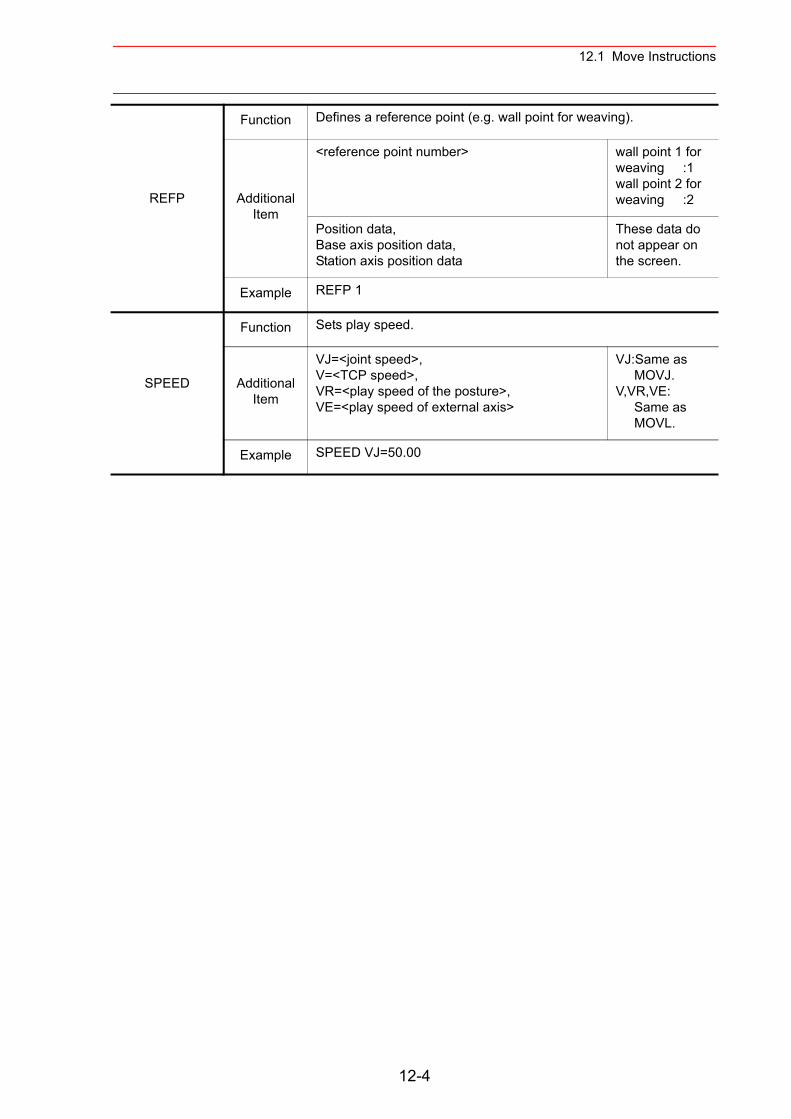
12.1 Move Instructions
REFP
Function Defines a reference point (e.g. wall point for weaving).
Additional Item
<reference point number> wall point 1 for weaving :1wall point 2 for weaving :2
Position data, Base axis position data,Station axis position data
These data do not appear on the screen.
Example REFP 1
SPEED
Function Sets play speed.
Additional Item
VJ=<joint speed>,V=<TCP speed>,VR=<play speed of the posture>,VE=<play speed of external axis>
VJ:Same as MOVJ.V,VR,VE: Same as MOVL.
Example SPEED VJ=50.00
12-4
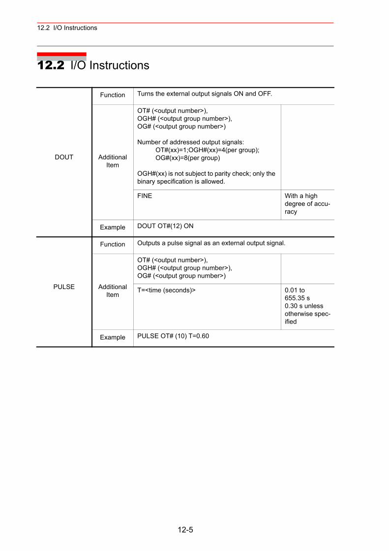
12.2 I/O Instructions
12.2 I/O Instructions
DOUT
Function Turns the external output signals ON and OFF.
Additional Item
OT# (<output number>),OGH# (<output group number>),OG# (<output group number>)
Number of addressed output signals: OT#(xx)=1;OGH#(xx)=4(per group); OG#(xx)=8(per group)
OGH#(xx) is not subject to parity check; only the binary specification is allowed.
FINE With a high degree of accu-racy
Example DOUT OT#(12) ON
PULSE
Function Outputs a pulse signal as an external output signal.
Additional Item
OT# (<output number>),OGH# (<output group number>),OG# (<output group number>)
T=<time (seconds)> 0.01 to 655.35 s0.30 s unless otherwise spec-ified
Example PULSE OT# (10) T=0.60
12-5
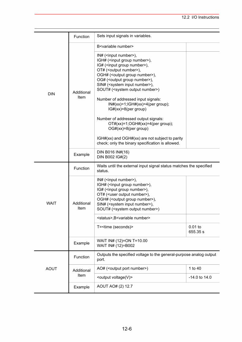
12.2 I/O Instructions
DIN
Function Sets input signals in variables.
Additional Item
B<variable number>
IN# (<input number>),IGH# (<input group number>),IG# (<input group number>),OT# (<output number>),OGH# (<output group number>),OG# (<output group number>),SIN# (<system input number>),SOUT# (<system output number>)
Number of addressed input signals: IN#(xx)=1;IGH#(xx)=4(per group); IG#(xx)=8(per group)
Number of addressed output signals: OT#(xx)=1;OGH#(xx)=4(per group); OG#(xx)=8(per group)
IGH#(xx) and OGH#(xx) are not subject to parity check; only the binary specification is allowed.
Example DIN B016 IN#(16)DIN B002 IG#(2)
WAIT
Function Waits until the external input signal status matches the specified status.
Additional Item
IN# (<input number>),IGH# (<input group number>),IG# (<input group number>),OT# (<user output number>),OGH# (<output group number>),SIN# (<system input number>),SOUT# (<system output number>)
<status>,B<variable number>
T=<time (seconds)> 0.01 to 655.35 s
Example WAIT IN# (12)=ON T=10.00WAIT IN# (12)=B002
AOUT
Function Outputs the specified voltage to the general-purpose analog output port.
Additional Item
AO# (<output port number>) 1 to 40
<output voltage(V)> -14.0 to 14.0
Example AOUT AO# (2) 12.7
12-6
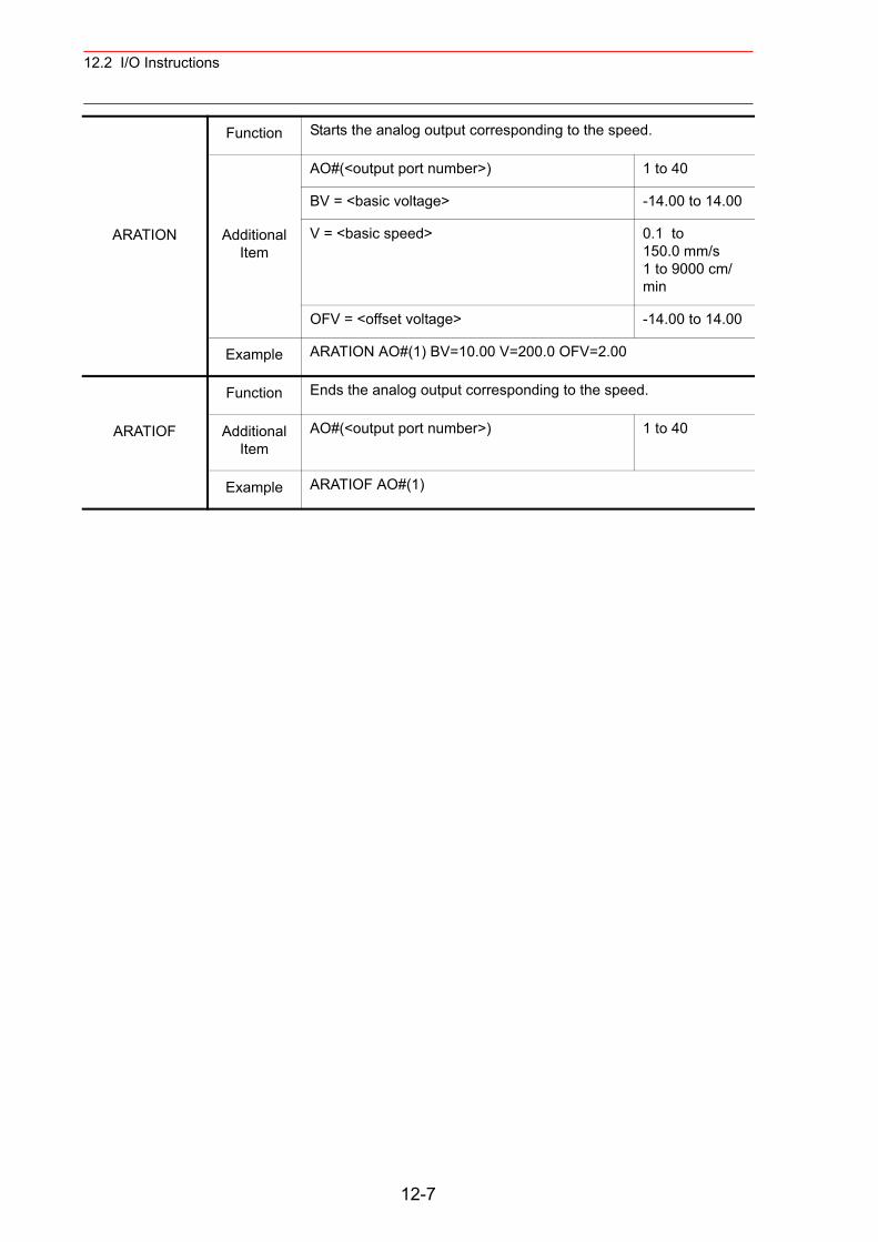
12.2 I/O Instructions
ARATION
Function Starts the analog output corresponding to the speed.
Additional Item
AO#(<output port number>) 1 to 40
BV = <basic voltage> -14.00 to 14.00
V = <basic speed> 0.1 to 150.0 mm/s1 to 9000 cm/min
OFV = <offset voltage> -14.00 to 14.00
Example ARATION AO#(1) BV=10.00 V=200.0 OFV=2.00
ARATIOF
Function Ends the analog output corresponding to the speed.
Additional Item
AO#(<output port number>) 1 to 40
Example ARATIOF AO#(1)
12-7
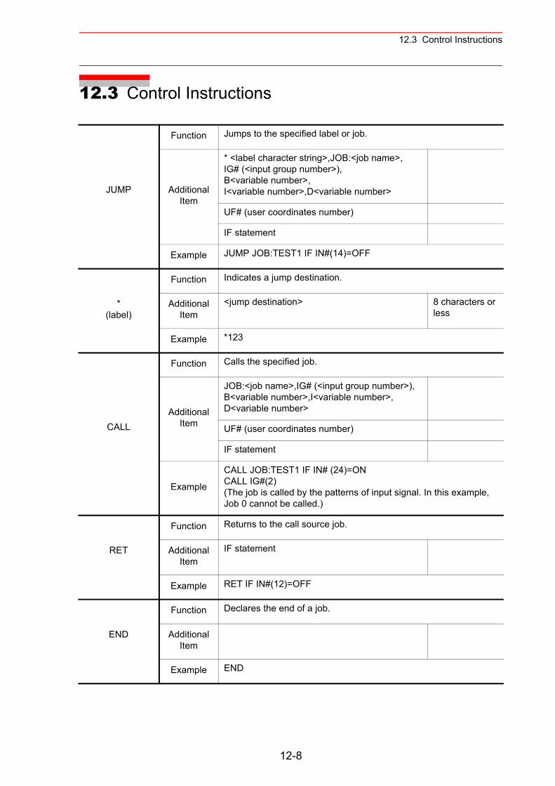
12.3 Control Instructions
12.3 Control Instructions
JUMP
Function Jumps to the specified label or job.
Additional Item
* <label character string>,JOB:<job name>,IG# (<input group number>),B<variable number>,I<variable number>,D<variable number>
UF# (user coordinates number)
IF statement
Example JUMP JOB:TEST1 IF IN#(14)=OFF
* (label)
Function Indicates a jump destination.
Additional Item
<jump destination> 8 characters or less
Example *123
CALL
Function Calls the specified job.
Additional Item
JOB:<job name>,IG# (<input group number>),B<variable number>,I<variable number>,D<variable number>
UF# (user coordinates number)
IF statement
Example
CALL JOB:TEST1 IF IN# (24)=ONCALL IG#(2)(The job is called by the patterns of input signal. In this example, Job 0 cannot be called.)
RET
Function Returns to the call source job.
Additional Item
IF statement
Example RET IF IN#(12)=OFF
END
Function Declares the end of a job.
Additional Item
Example END
12-8
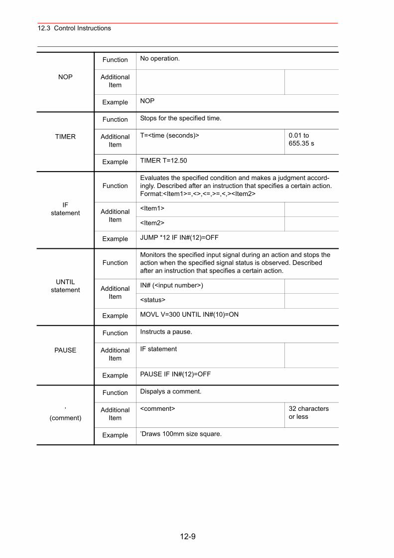
12.3 Control Instructions
NOP
Function No operation.
Additional Item
Example NOP
TIMER
Function Stops for the specified time.
Additional Item
T=<time (seconds)> 0.01 to 655.35 s
Example TIMER T=12.50
IFstatement
FunctionEvaluates the specified condition and makes a judgment accord-ingly. Described after an instruction that specifies a certain action.Format:<Item1>=,<>,<=,>=,<,><Item2>
Additional Item
<Item1>
<Item2>
Example JUMP *12 IF IN#(12)=OFF
UNTILstatement
FunctionMonitors the specified input signal during an action and stops the action when the specified signal status is observed. Described after an instruction that specifies a certain action.
Additional Item
IN# (<input number>)
<status>
Example MOVL V=300 UNTIL IN#(10)=ON
PAUSE
Function Instructs a pause.
Additional Item
IF statement
Example PAUSE IF IN#(12)=OFF
’ (comment)
Function Dispalys a comment.
Additional Item
<comment> 32 characters or less
Example ’Draws 100mm size square.
12-9
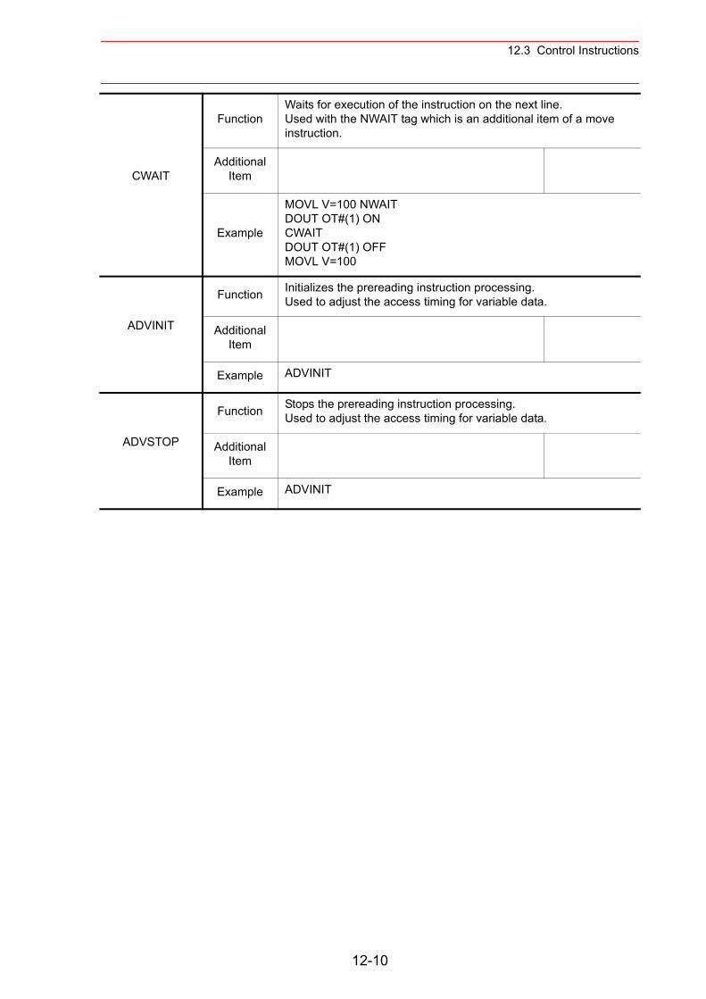
12.3 Control Instructions
CWAIT
FunctionWaits for execution of the instruction on the next line. Used with the NWAIT tag which is an additional item of a move instruction.
Additional Item
Example
MOVL V=100 NWAITDOUT OT#(1) ONCWAITDOUT OT#(1) OFFMOVL V=100
ADVINIT
Function Initializes the prereading instruction processing. Used to adjust the access timing for variable data.
Additional Item
Example ADVINIT
ADVSTOP
Function Stops the prereading instruction processing.Used to adjust the access timing for variable data.
Additional Item
Example ADVINIT
12-10
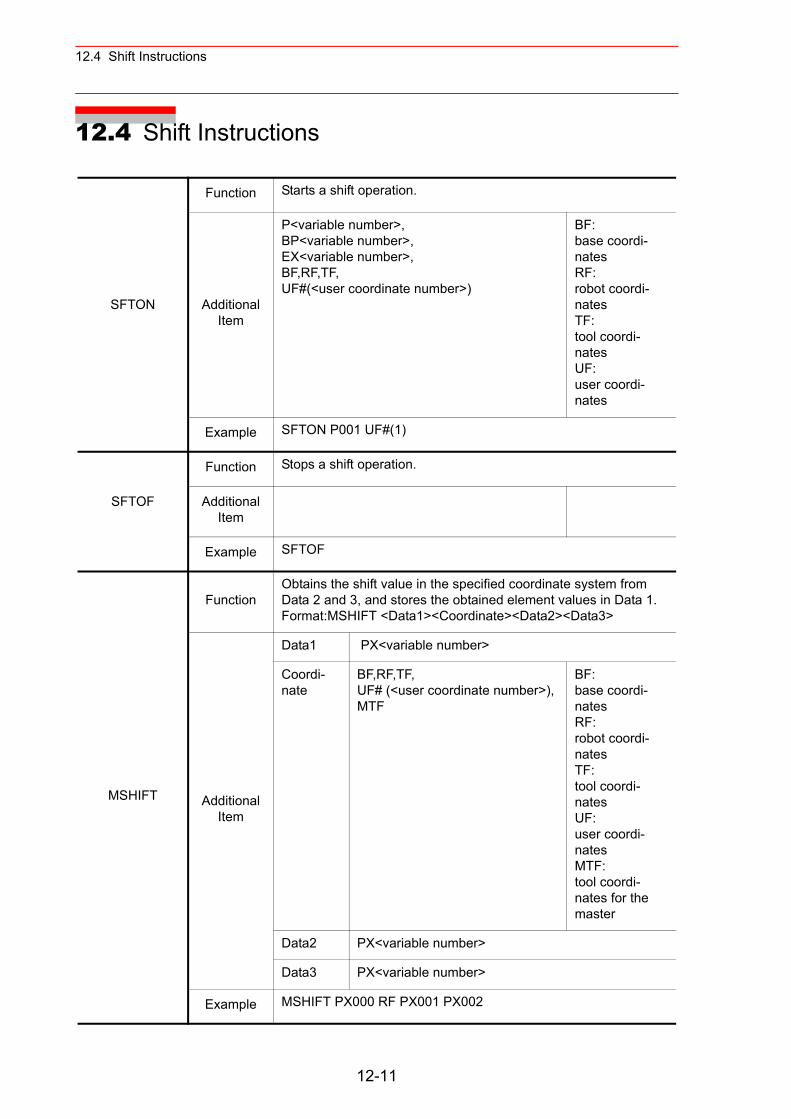
12.4 Shift Instructions
12.4 Shift Instructions
SFTON
Function Starts a shift operation.
Additional Item
P<variable number>, BP<variable number>,EX<variable number>,BF,RF,TF,UF#(<user coordinate number>)
BF:base coordi-natesRF:robot coordi-natesTF:tool coordi-natesUF:user coordi-nates
Example SFTON P001 UF#(1)
SFTOF
Function Stops a shift operation.
Additional Item
Example SFTOF
MSHIFT
FunctionObtains the shift value in the specified coordinate system from Data 2 and 3, and stores the obtained element values in Data 1.Format:MSHIFT <Data1><Coordinate><Data2><Data3>
Additional Item
Data1 PX<variable number>
Coordi-nate
BF,RF,TF,UF# (<user coordinate number>), MTF
BF:base coordi-natesRF:robot coordi-natesTF:tool coordi-natesUF:user coordi-natesMTF:tool coordi-nates for the master
Data2 PX<variable number>
Data3 PX<variable number>
Example MSHIFT PX000 RF PX001 PX002
12-11
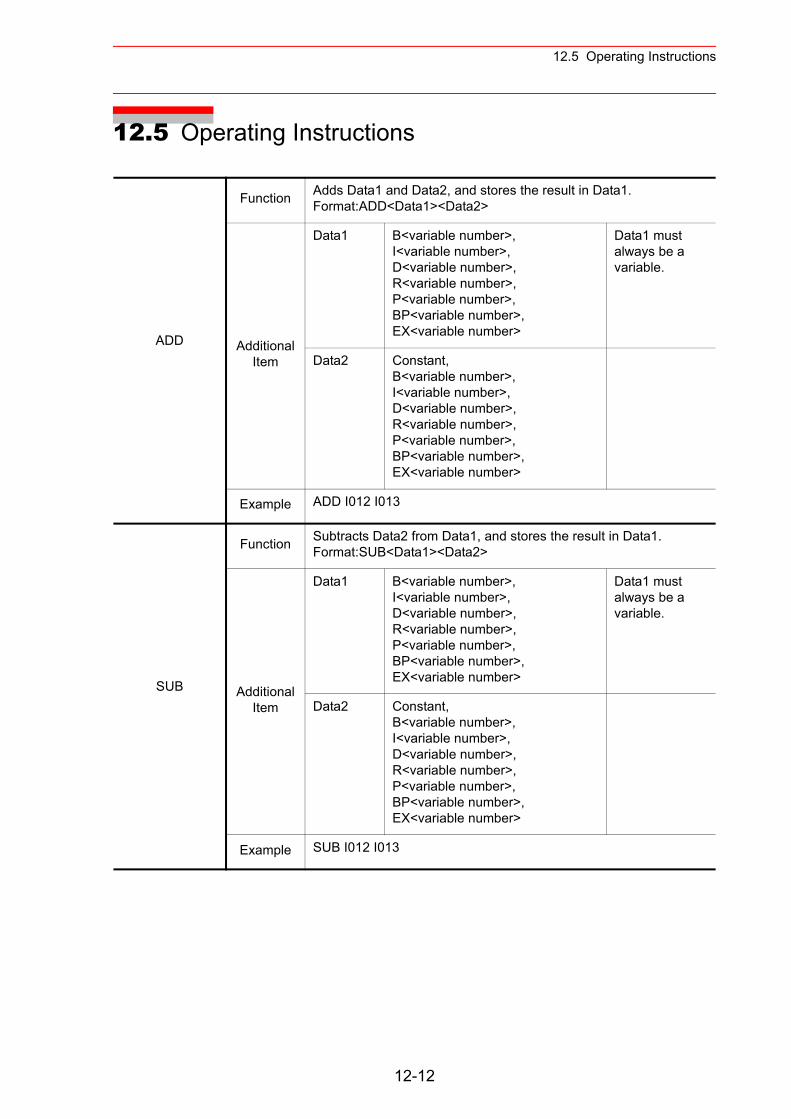
12.5 Operating Instructions
12.5 Operating Instructions
ADD
Function Adds Data1 and Data2, and stores the result in Data1.Format:ADD<Data1><Data2>
Additional Item
Data1 B<variable number>,I<variable number>,D<variable number>,R<variable number>,P<variable number>,BP<variable number>,EX<variable number>
Data1 must always be a variable.
Data2 Constant,B<variable number>,I<variable number>,D<variable number>,R<variable number>,P<variable number>,BP<variable number>,EX<variable number>
Example ADD I012 I013
SUB
Function Subtracts Data2 from Data1, and stores the result in Data1.Format:SUB<Data1><Data2>
Additional Item
Data1 B<variable number>,I<variable number>,D<variable number>,R<variable number>,P<variable number>,BP<variable number>,EX<variable number>
Data1 must always be a variable.
Data2 Constant,B<variable number>,I<variable number>,D<variable number>,R<variable number>,P<variable number>,BP<variable number>,EX<variable number>
Example SUB I012 I013
12-12
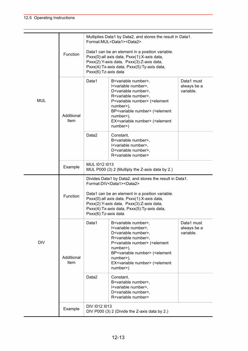
12.5 Operating Instructions
MUL
Function
Multiplies Data1 by Data2, and stores the result in Data1.Format:MUL<Data1><Data2>
Data1 can be an element in a position variable.Pxxx(0):all axis data, Pxxx(1):X-axis data,Pxxx(2):Y-axis data, Pxxx(3):Z-axis data,Pxxx(4):Tx-axis data, Pxxx(5):Ty-axis data,Pxxx(6):Tz-axis data
Additional Item
Data1 B<variable number>,I<variable number>,D<variable number>,R<variable number>,P<variable number> (<element number>),BP<variable number> (<element number>),EX<variable number> (<element number>)
Data1 must always be a variable.
Data2 Constant,B<variable number>,I<variable number>,D<variable number>,R<variable number>
Example MUL I012 I013MUL P000 (3) 2 (Multiply the Z-axis data by 2.)
DIV
Function
Divides Data1 by Data2, and stores the result in Data1.Format:DIV<Data1><Data2>
Data1 can be an element in a position variable.Pxxx(0):all axis data, Pxxx(1):X-axis data,Pxxx(2):Y-axis data, Pxxx(3):Z-axis data,Pxxx(4):Tx-axis data, Pxxx(5):Ty-axis data,Pxxx(6):Tz-axis data
Additional Item
Data1 B<variable number>,I<variable number>,D<variable number>,R<variable number>,P<variable number> (<element number>),BP<variable number> (<element number>),EX<variable number> (<element number>)
Data1 must always be a variable.
Data2 Constant,B<variable number>,I<variable number>,D<variable number>,R<variable number>
Example DIV I012 I013DIV P000 (3) 2 (Divide the Z-axis data by 2.)
12-13
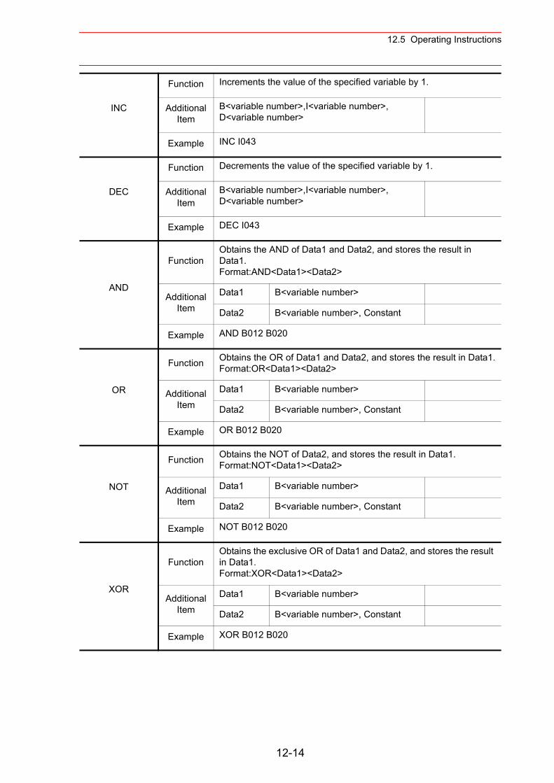
12.5 Operating Instructions
INC
Function Increments the value of the specified variable by 1.
Additional Item
B<variable number>,I<variable number>,D<variable number>
Example INC I043
DEC
Function Decrements the value of the specified variable by 1.
Additional Item
B<variable number>,I<variable number>,D<variable number>
Example DEC I043
AND
FunctionObtains the AND of Data1 and Data2, and stores the result in Data1.Format:AND<Data1><Data2>
Additional Item
Data1 B<variable number>
Data2 B<variable number>, Constant
Example AND B012 B020
OR
Function Obtains the OR of Data1 and Data2, and stores the result in Data1.Format:OR<Data1><Data2>
Additional Item
Data1 B<variable number>
Data2 B<variable number>, Constant
Example OR B012 B020
NOT
Function Obtains the NOT of Data2, and stores the result in Data1.Format:NOT<Data1><Data2>
Additional Item
Data1 B<variable number>
Data2 B<variable number>, Constant
Example NOT B012 B020
XOR
FunctionObtains the exclusive OR of Data1 and Data2, and stores the result in Data1.Format:XOR<Data1><Data2>
Additional Item
Data1 B<variable number>
Data2 B<variable number>, Constant
Example XOR B012 B020
12-14
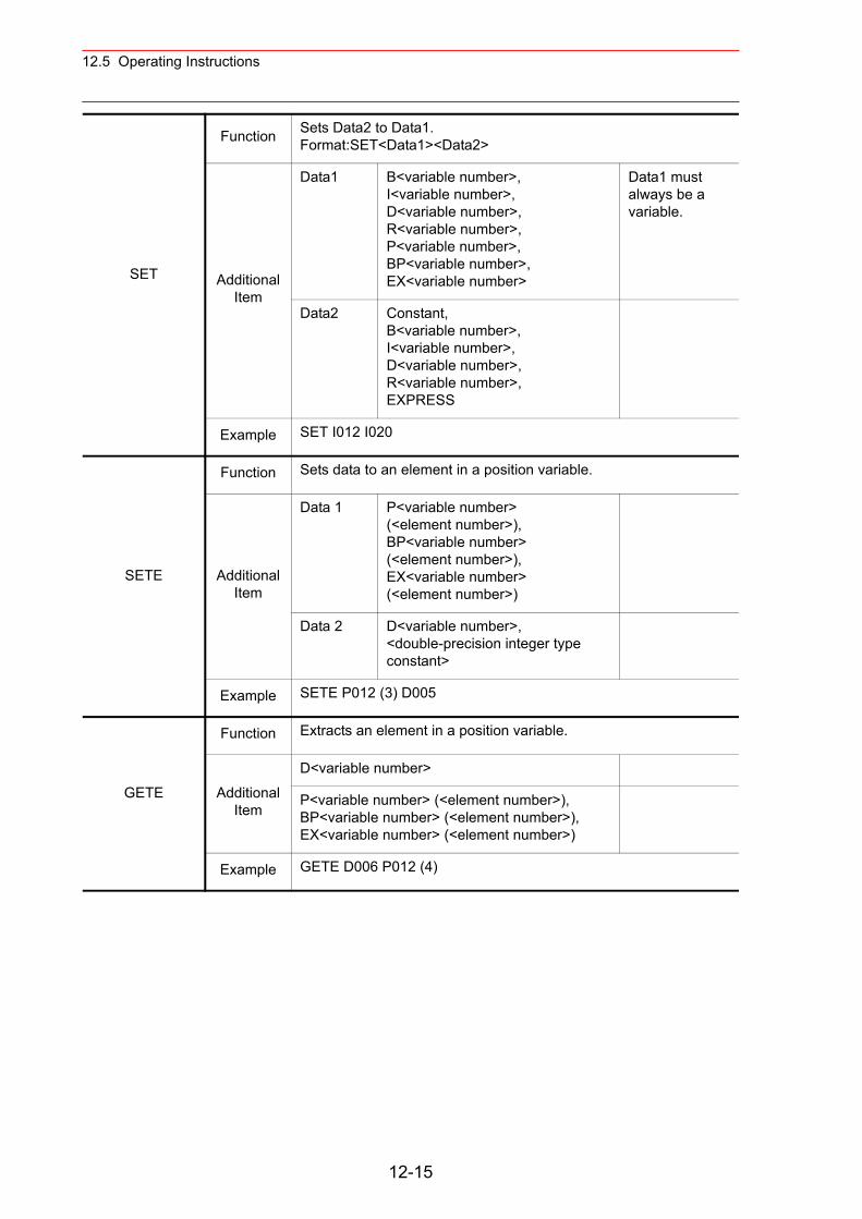
12.5 Operating Instructions
SET
Function Sets Data2 to Data1.Format:SET<Data1><Data2>
Additional Item
Data1 B<variable number>,I<variable number>,D<variable number>,R<variable number>,P<variable number>,BP<variable number>,EX<variable number>
Data1 must always be a variable.
Data2 Constant,B<variable number>,I<variable number>,D<variable number>,R<variable number>,EXPRESS
Example SET I012 I020
SETE
Function Sets data to an element in a position variable.
Additional Item
Data 1 P<variable number> (<element number>),BP<variable number> (<element number>),EX<variable number> (<element number>)
Data 2 D<variable number>,<double-precision integer type constant>
Example SETE P012 (3) D005
GETE
Function Extracts an element in a position variable.
Additional Item
D<variable number>
P<variable number> (<element number>),BP<variable number> (<element number>),EX<variable number> (<element number>)
Example GETE D006 P012 (4)
12-15
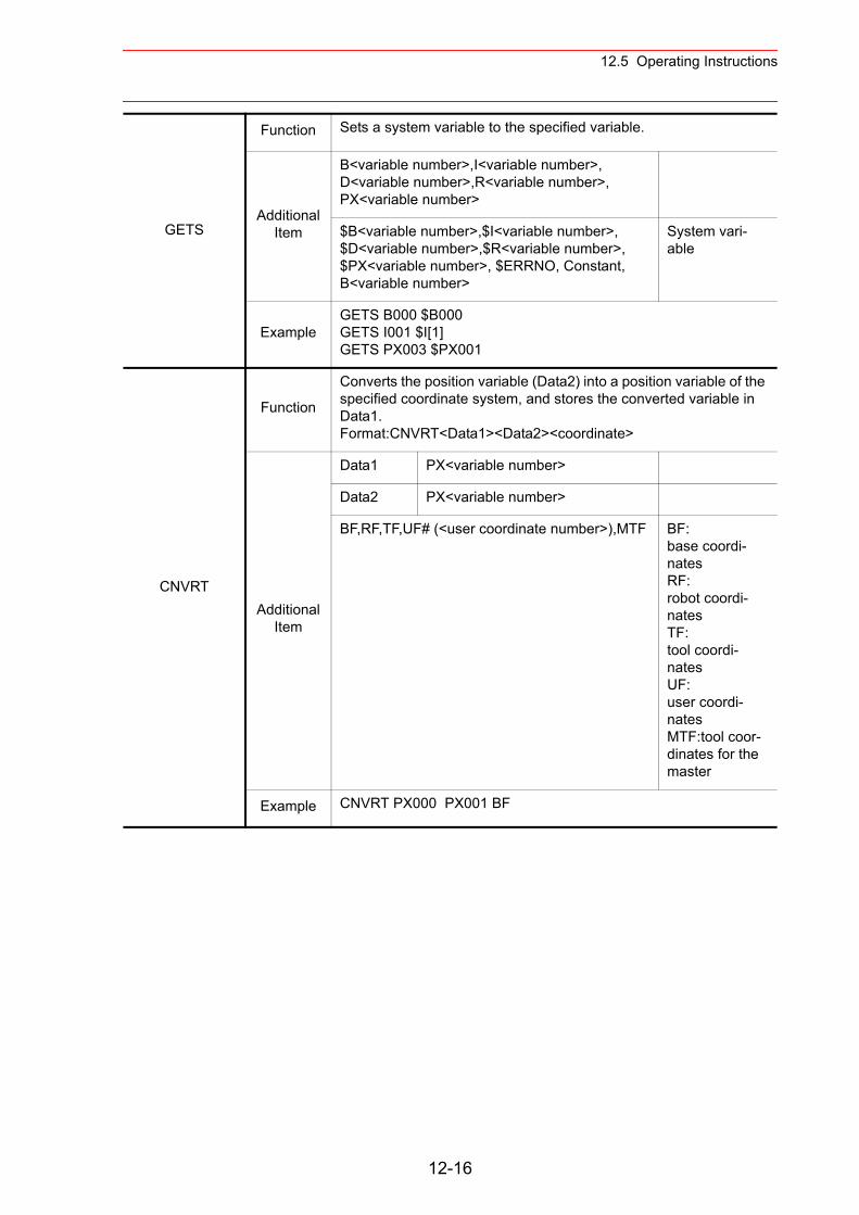
12.5 Operating Instructions
GETS
Function Sets a system variable to the specified variable.
Additional Item
B<variable number>,I<variable number>, D<variable number>,R<variable number>, PX<variable number>
$B<variable number>,$I<variable number>,$D<variable number>,$R<variable number>,$PX<variable number>, $ERRNO, Constant, B<variable number>
System vari-able
ExampleGETS B000 $B000GETS I001 $I[1]GETS PX003 $PX001
CNVRT
Function
Converts the position variable (Data2) into a position variable of the specified coordinate system, and stores the converted variable in Data1.Format:CNVRT<Data1><Data2><coordinate>
Additional Item
Data1 PX<variable number>
Data2 PX<variable number>
BF,RF,TF,UF# (<user coordinate number>),MTF BF:base coordi-natesRF:robot coordi-natesTF: tool coordi-natesUF:user coordi-natesMTF:tool coor-dinates for the master
Example CNVRT PX000 PX001 BF
12-16
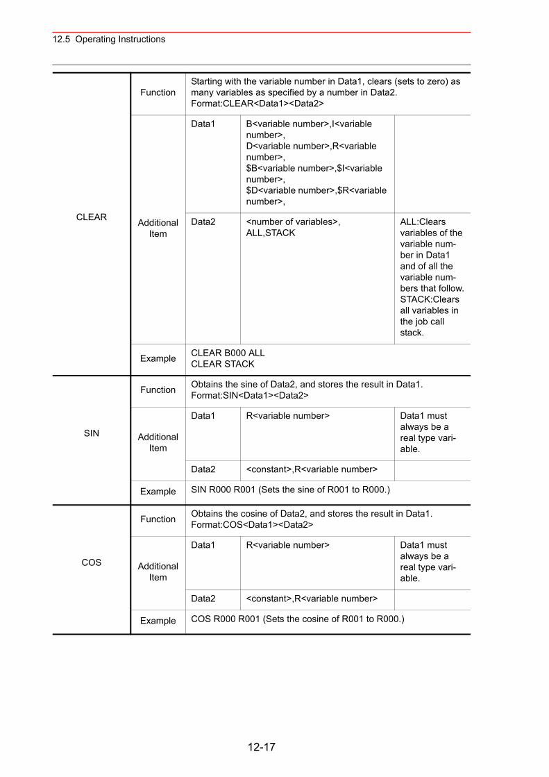
12.5 Operating Instructions
CLEAR
FunctionStarting with the variable number in Data1, clears (sets to zero) as many variables as specified by a number in Data2.Format:CLEAR<Data1><Data2>
Additional Item
Data1 B<variable number>,I<variable number>,D<variable number>,R<variable number>,$B<variable number>,$I<variable number>,$D<variable number>,$R<variable number>,
Data2 <number of variables>, ALL,STACK
ALL:Clears variables of the variable num-ber in Data1 and of all the variable num-bers that follow.STACK:Clears all variables in the job call stack.
Example CLEAR B000 ALLCLEAR STACK
SIN
Function Obtains the sine of Data2, and stores the result in Data1.Format:SIN<Data1><Data2>
Additional Item
Data1 R<variable number> Data1 must always be a real type vari-able.
Data2 <constant>,R<variable number>
Example SIN R000 R001 (Sets the sine of R001 to R000.)
COS
Function Obtains the cosine of Data2, and stores the result in Data1.Format:COS<Data1><Data2>
Additional Item
Data1 R<variable number> Data1 must always be a real type vari-able.
Data2 <constant>,R<variable number>
Example COS R000 R001 (Sets the cosine of R001 to R000.)
12-17
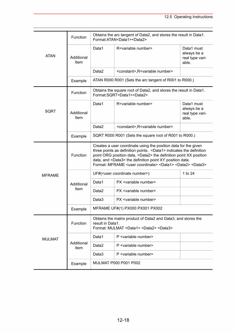
12.5 Operating Instructions
ATAN
Function Obtains the arc tangent of Data2, and stores the result in Data1.Format:ATAN<Data1><Data2>
Additional Item
Data1 R<variable number> Data1 must always be a real type vari-able.
Data2 <constant>,R<variable number>
Example ATAN R000 R001 (Sets the arc tangent of R001 to R000.)
SQRT
Function Obtains the square root of Data2, and stores the result in Data1.Format:SQRT<Data1><Data2>
Additional Item
Data1 R<variable number> Data1 must always be a real type vari-able.
Data2 <constant>,R<variable number>
Example SQRT R000 R001 (Sets the square root of R001 to R000.)
MFRAME
Function
Creates a user coordinate using the position data for the given three points as definition points. <Data1> indicates the definition point ORG position data, <Data2> the definition point XX position data, and <Data3> the definition point XY position data.Format: MFRAME <user coordinate> <Data1> <Data2> <Data3>
Additional Item
UF#(<user coordinate number>) 1 to 24
Data1 PX <variable number>
Data2 PX <variable number>
Data3 PX <variable number>
Example MFRAME UF#(1) PX000 PX001 PX002
MULMAT
FunctionObtains the matrix product of Data2 and Data3, and stores the result in Data1.Format: MULMAT <Data1> <Data2> <Data3>
Additional Item
Data1 P <variable number>
Data2 P <variable number>
Data3 P <variable number>
Example MULMAT P000 P001 P002
12-18
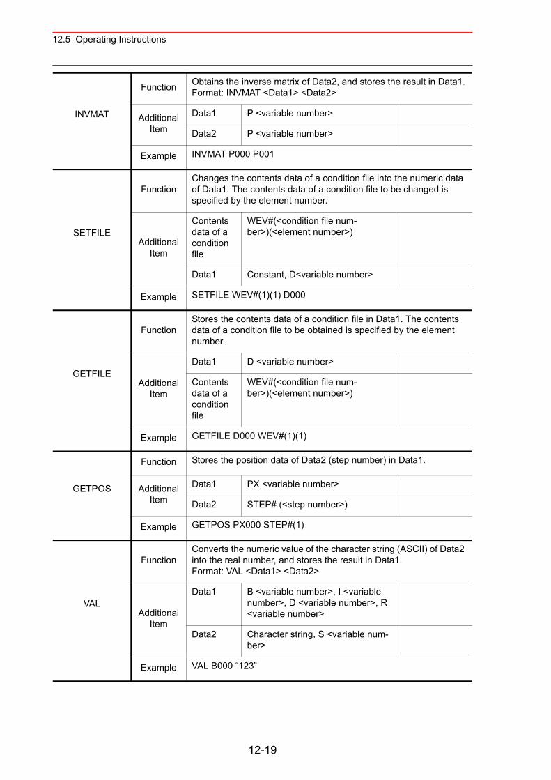
12.5 Operating Instructions
INVMAT
Function Obtains the inverse matrix of Data2, and stores the result in Data1.Format: INVMAT <Data1> <Data2>
Additional Item
Data1 P <variable number>
Data2 P <variable number>
Example INVMAT P000 P001
SETFILE
FunctionChanges the contents data of a condition file into the numeric data of Data1. The contents data of a condition file to be changed is specified by the element number.
Additional Item
Contents data of a condition file
WEV#(<condition file num-ber>)(<element number>)
Data1 Constant, D<variable number>
Example SETFILE WEV#(1)(1) D000
GETFILE
FunctionStores the contents data of a condition file in Data1. The contents data of a condition file to be obtained is specified by the element number.
Additional Item
Data1 D <variable number>
Contents data of a condition file
WEV#(<condition file num-ber>)(<element number>)
Example GETFILE D000 WEV#(1)(1)
GETPOS
Function Stores the position data of Data2 (step number) in Data1.
Additional Item
Data1 PX <variable number>
Data2 STEP# (<step number>)
Example GETPOS PX000 STEP#(1)
VAL
FunctionConverts the numeric value of the character string (ASCII) of Data2 into the real number, and stores the result in Data1.Format: VAL <Data1> <Data2>
Additional Item
Data1 B <variable number>, I <variable number>, D <variable number>, R <variable number>
Data2 Character string, S <variable num-ber>
Example VAL B000 “123”
12-19
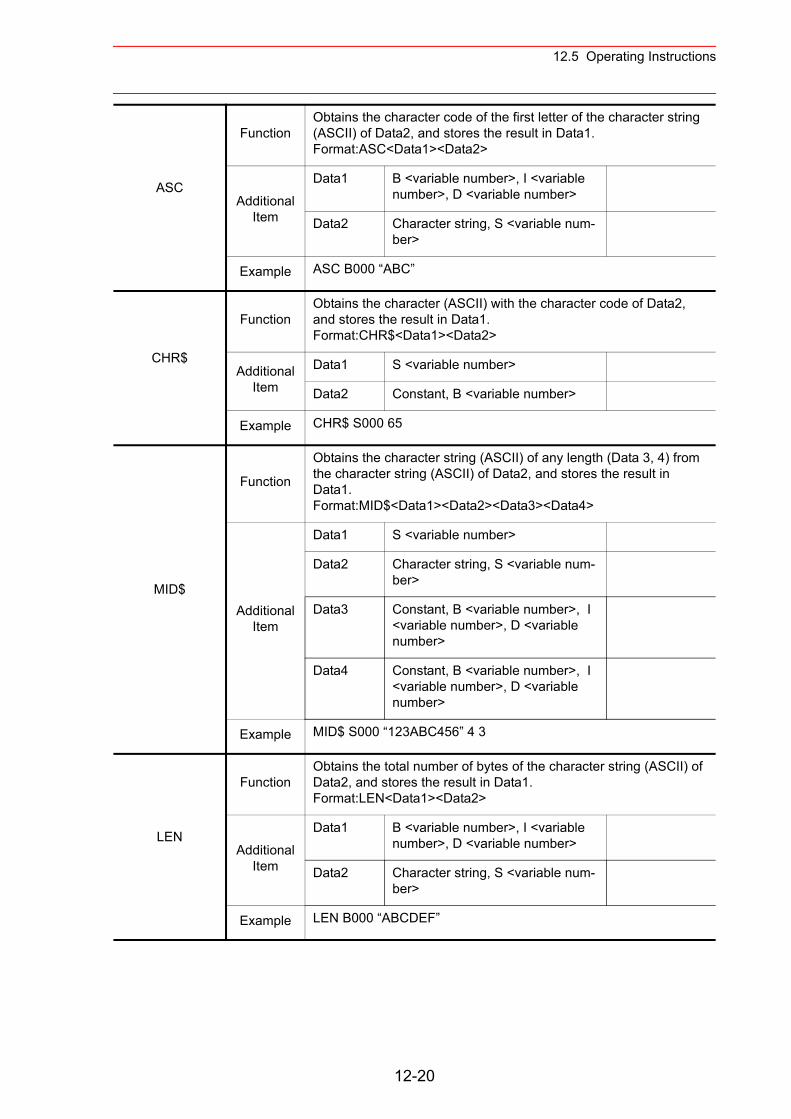
12.5 Operating Instructions
ASC
FunctionObtains the character code of the first letter of the character string (ASCII) of Data2, and stores the result in Data1.Format:ASC<Data1><Data2>
Additional Item
Data1 B <variable number>, I <variable number>, D <variable number>
Data2 Character string, S <variable num-ber>
Example ASC B000 “ABC”
CHR$
FunctionObtains the character (ASCII) with the character code of Data2, and stores the result in Data1.Format:CHR$<Data1><Data2>
Additional Item
Data1 S <variable number>
Data2 Constant, B <variable number>
Example CHR$ S000 65
MID$
Function
Obtains the character string (ASCII) of any length (Data 3, 4) from the character string (ASCII) of Data2, and stores the result in Data1.Format:MID$<Data1><Data2><Data3><Data4>
Additional Item
Data1 S <variable number>
Data2 Character string, S <variable num-ber>
Data3 Constant, B <variable number>, I <variable number>, D <variable number>
Data4 Constant, B <variable number>, I <variable number>, D <variable number>
Example MID$ S000 “123ABC456” 4 3
LEN
FunctionObtains the total number of bytes of the character string (ASCII) of Data2, and stores the result in Data1.Format:LEN<Data1><Data2>
Additional Item
Data1 B <variable number>, I <variable number>, D <variable number>
Data2 Character string, S <variable num-ber>
Example LEN B000 “ABCDEF”
12-20
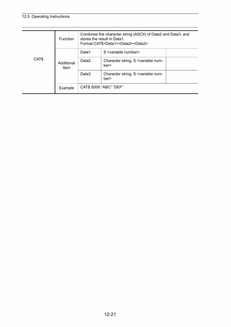
12.5 Operating Instructions
CAT$
FunctionCombines the character string (ASCII) of Data2 and Data3, and stores the result in Data1.Format:CAT$<Data1><Data2><Data3>
Additional Item
Data1 S <variable number>
Data2 Character string, S <variable num-ber>
Data3 Character string, S <variable num-ber>
Example CAT$ S000 “ABC” “DEF”
12-21
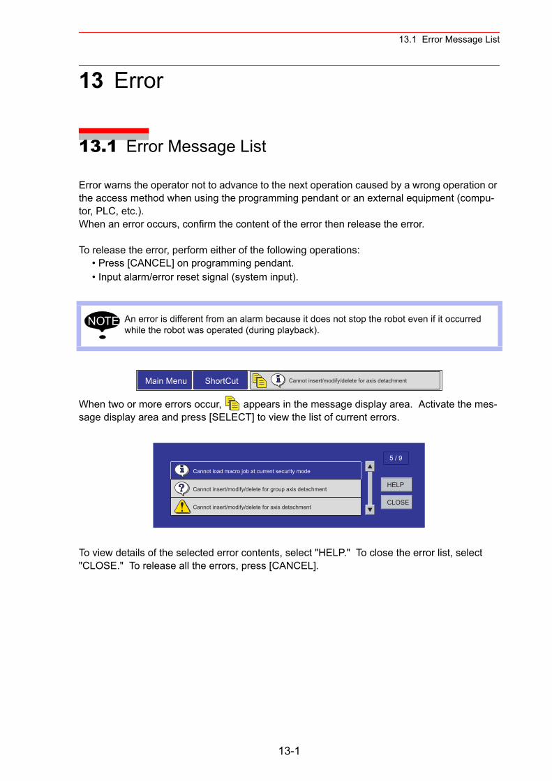
13.1 Error Message List
13 Error
13.1 Error Message List
Error warns the operator not to advance to the next operation caused by a wrong operation or the access method when using the programming pendant or an external equipment (compu-tor, PLC, etc.).When an error occurs, confirm the content of the error then release the error.
To release the error, perform either of the following operations:• Press [CANCEL] on programming pendant.• Input alarm/error reset signal (system input).
When two or more errors occur, appears in the message display area. Activate the mes-sage display area and press [SELECT] to view the list of current errors.
To view details of the selected error contents, select "HELP." To close the error list, select "CLOSE." To release all the errors, press [CANCEL].
An error is different from an alarm because it does not stop the robot even if it occurred while the robot was operated (during playback).
NOTE
Main Menu ShortCut Cannot insert/modify/delete for axis detachment
HELP
CLOSE
5 / 9
Cannot load macro job at current security mode
Cannot insert/modify/delete for group axis detachment
Cannot insert/modify/delete for axis detachment
13-1
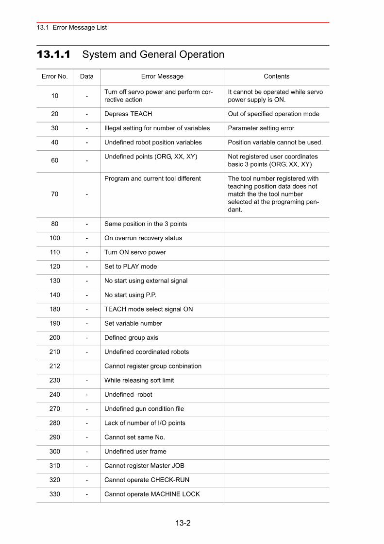
13.1 Error Message List
13.1.1 System and General Operation
Error No. Data Error Message Contents
10 - Turn off servo power and perform cor-rective action
It cannot be operated while servo power supply is ON.
20 - Depress TEACH Out of specified operation mode
30 - Illegal setting for number of variables Parameter setting error
40 - Undefined robot position variables Position variable cannot be used.
60 - Undefined points (ORG, XX, XY) Not registered user coordinates basic 3 points (ORG, XX, XY)
70 -
Program and current tool different The tool number registered with teaching position data does not match the the tool number selected at the programing pen-dant.
80 - Same position in the 3 points
100 - On overrun recovery status
110 - Turn ON servo power
120 - Set to PLAY mode
130 - No start using external signal
140 - No start using P.P.
180 - TEACH mode select signal ON
190 - Set variable number
200 - Defined group axis
210 - Undefined coordinated robots
212 Cannot register group conbination
230 - While releasing soft limit
240 - Undefined robot
270 - Undefined gun condition file
280 - Lack of number of I/O points
290 - Cannot set same No.
300 - Undefined user frame
310 - Cannot register Master JOB
320 - Cannot operate CHECK-RUN
330 - Cannot operate MACHINE LOCK
13-2
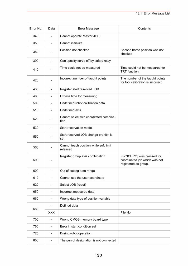
13.1 Error Message List
340 - Cannot operate Master JOB
350 - Cannot initialize
380 - Position not checked Second home position was not checked.
390 - Can specify servo off by safety relay
410 - Time could not be measured Time could not be measured for TRT function.
420 - Incorrect number of taught points The number of the taught points for tool calibration is incorrect.
430 - Register start reserved JOB
460 - Excess time for measuring
500 - Undefined robot calibration data
510 - Undefined axis
520 - Cannot select two coorditated combina-tion
530 - Start reservation mode
550 - Start reserved JOB change prohibit is set
560 - Cannot teach position while soft limit released
590 -Register group axis combination [SYNCHRO] was pressed for
coordinated job which was not registered as group.
600 - Out of setting data range
610 - Cannot use the user coordinate
620 - Select JOB (robot)
650 - Incorrect measured data
660 - Wrong data type of position variable
680- Defined data
XXX File No.
700 - Wrong CMOS memory board type
760 - Error in start condition set
770 - During robot operation
800 - The gun of designation is not connected
Error No. Data Error Message Contents
13-3
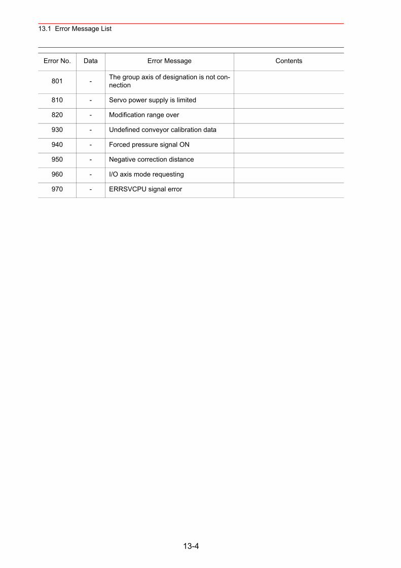
13.1 Error Message List
801 - The group axis of designation is not con-nection
810 - Servo power supply is limited
820 - Modification range over
930 - Undefined conveyor calibration data
940 - Forced pressure signal ON
950 - Negative correction distance
960 - I/O axis mode requesting
970 - ERRSVCPU signal error
Error No. Data Error Message Contents
13-4
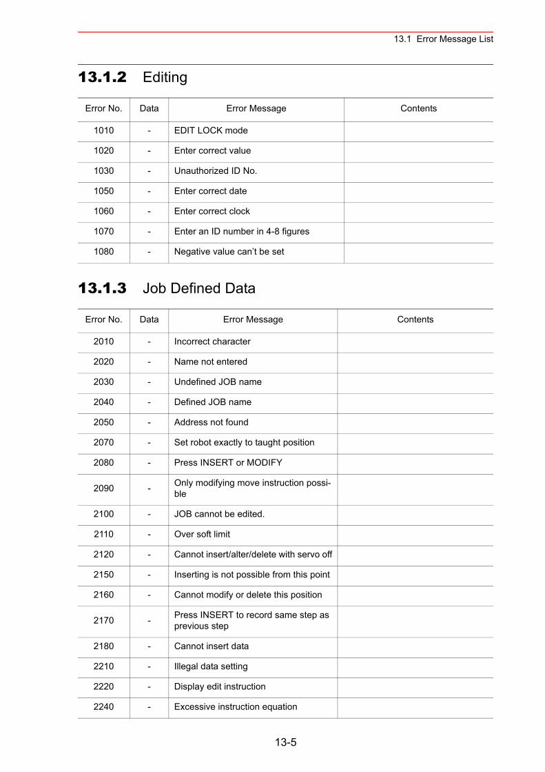
13.1 Error Message List
13.1.2 Editing
13.1.3 Job Defined Data
Error No. Data Error Message Contents
1010 - EDIT LOCK mode
1020 - Enter correct value
1030 - Unauthorized ID No.
1050 - Enter correct date
1060 - Enter correct clock
1070 - Enter an ID number in 4-8 figures
1080 - Negative value can’t be set
Error No. Data Error Message Contents
2010 - Incorrect character
2020 - Name not entered
2030 - Undefined JOB name
2040 - Defined JOB name
2050 - Address not found
2070 - Set robot exactly to taught position
2080 - Press INSERT or MODIFY
2090 - Only modifying move instruction possi-ble
2100 - JOB cannot be edited.
2110 - Over soft limit
2120 - Cannot insert/alter/delete with servo off
2150 - Inserting is not possible from this point
2160 - Cannot modify or delete this position
2170 - Press INSERT to record same step as previous step
2180 - Cannot insert data
2210 - Illegal data setting
2220 - Display edit instruction
2240 - Excessive instruction equation
13-5
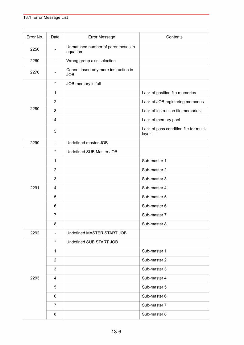
13.1 Error Message List
2250 - Unmatched number of parentheses in equation
2260 - Wrong group axis selection
2270 - Cannot insert any more instruction in JOB
2280
* JOB memory is full
1 Lack of position file memories
2 Lack of JOB registering memories
3 Lack of instruction file memories
4 Lack of memory pool
5 Lack of pass condition file for multi-layer
2290 - Undefined master JOB
2291
* Undefined SUB Master JOB
1 Sub-master 1
2 Sub-master 2
3 Sub-master 3
4 Sub-master 4
5 Sub-master 5
6 Sub-master 6
7 Sub-master 7
8 Sub-master 8
2292 - Undefined MASTER START JOB
2293
* Undefined SUB START JOB
1 Sub-master 1
2 Sub-master 2
3 Sub-master 3
4 Sub-master 4
5 Sub-master 5
6 Sub-master 6
7 Sub-master 7
8 Sub-master 8
Error No. Data Error Message Contents
13-6
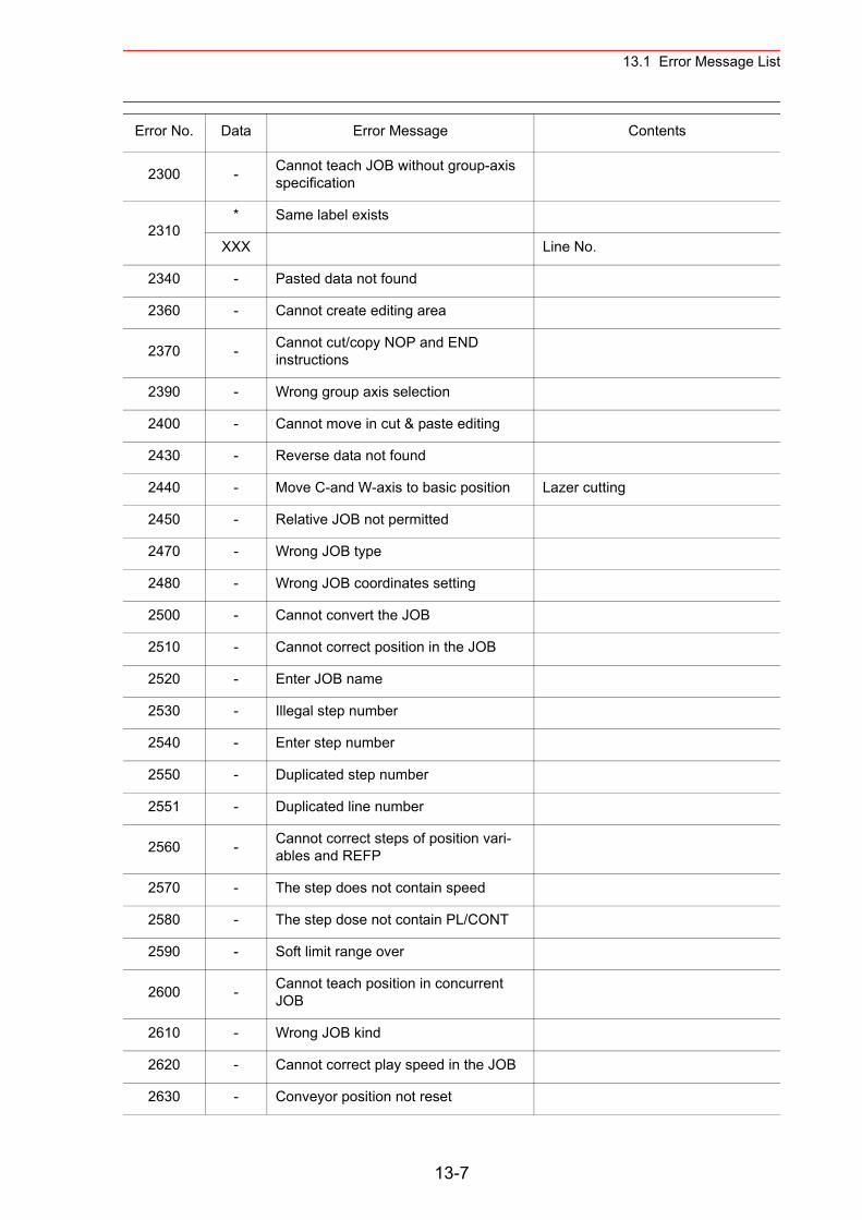
13.1 Error Message List
2300 - Cannot teach JOB without group-axis specification
2310* Same label exists
XXX Line No.
2340 - Pasted data not found
2360 - Cannot create editing area
2370 - Cannot cut/copy NOP and END instructions
2390 - Wrong group axis selection
2400 - Cannot move in cut & paste editing
2430 - Reverse data not found
2440 - Move C-and W-axis to basic position Lazer cutting
2450 - Relative JOB not permitted
2470 - Wrong JOB type
2480 - Wrong JOB coordinates setting
2500 - Cannot convert the JOB
2510 - Cannot correct position in the JOB
2520 - Enter JOB name
2530 - Illegal step number
2540 - Enter step number
2550 - Duplicated step number
2551 - Duplicated line number
2560 - Cannot correct steps of position vari-ables and REFP
2570 - The step does not contain speed
2580 - The step dose not contain PL/CONT
2590 - Soft limit range over
2600 - Cannot teach position in concurrent JOB
2610 - Wrong JOB kind
2620 - Cannot correct play speed in the JOB
2630 - Conveyor position not reset
Error No. Data Error Message Contents
13-7
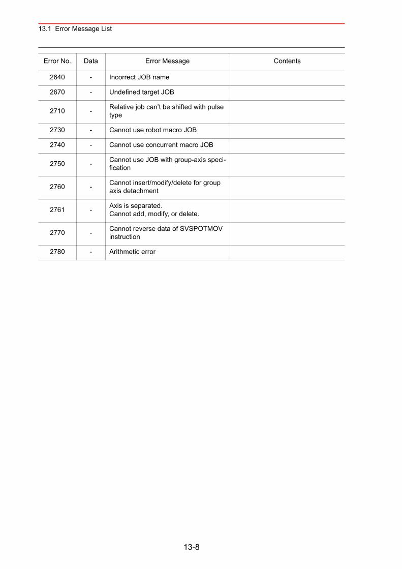
13.1 Error Message List
2640 - Incorrect JOB name
2670 - Undefined target JOB
2710 - Relative job can’t be shifted with pulse type
2730 - Cannot use robot macro JOB
2740 - Cannot use concurrent macro JOB
2750 - Cannot use JOB with group-axis speci-fication
2760 - Cannot insert/modify/delete for group axis detachment
2761 - Axis is separated.Cannot add, modify, or delete.
2770 - Cannot reverse data of SVSPOTMOV instruction
2780 - Arithmetic error
Error No. Data Error Message Contents
13-8
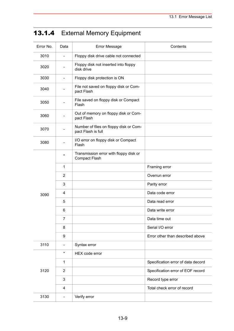
13.1 Error Message List
13.1.4 External Memory Equipment
Error No. Data Error Message Contents
3010 - Floppy disk drive cable not connected
3020 - Floppy disk not inserted into floppy disk drive
3030 - Floppy disk protection is ON
3040 - File not saved on floppy disk or Com-pact Flash
3050 - File saved on floppy disk or Compact Flash
3060 - Out of memory on floppy disk or Com-pact Flash
3070 - Number of files on floppy disk or Com-pact Flash is full
3080 - I/O error on floppy disk or Compact Flash
3090
* Transmission error with floppy disk or Compact Flash
1 Framing error
2 Overrun error
3 Parity error
4 Data code error
5 Data read error
6 Data write error
7 Data time out
8 Serial I/O error
9 Error other than described above
3110 - Syntax error
3120
* HEX code error
1 Specification error of data decord
2 Specification error of EOF record
3 Record type error
4 Total check error of record
3130 - Verify error
13-9
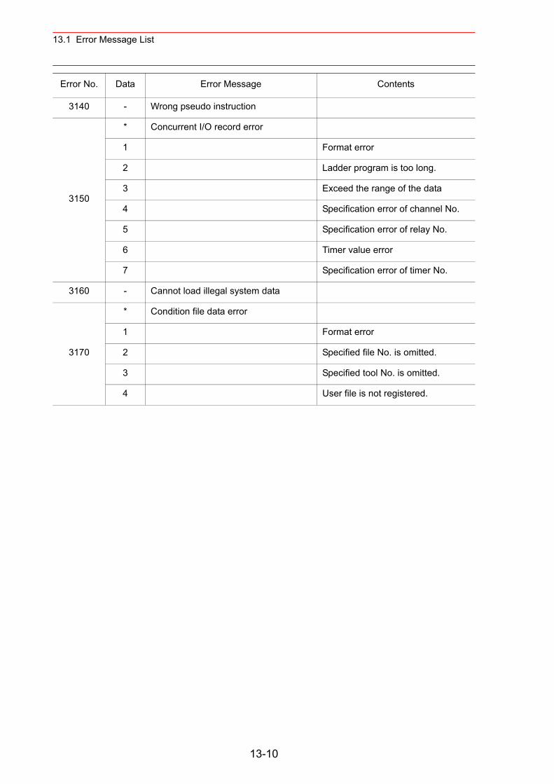
13.1 Error Message List
3140 - Wrong pseudo instruction
3150
* Concurrent I/O record error
1 Format error
2 Ladder program is too long.
3 Exceed the range of the data
4 Specification error of channel No.
5 Specification error of relay No.
6 Timer value error
7 Specification error of timer No.
3160 - Cannot load illegal system data
3170
* Condition file data error
1 Format error
2 Specified file No. is omitted.
3 Specified tool No. is omitted.
4 User file is not registered.
Error No. Data Error Message Contents
13-10
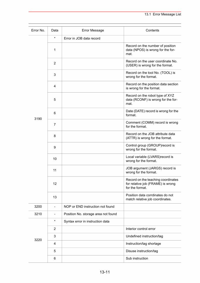
13.1 Error Message List
3190
* Error in JOB data record
1Record on the number of position data (NPOS) is wrong for the for-mat.
2 Record on the user coordinate No. (USER) is wrong for the format.
3 Record on the tool No. (TOOL) is wrong for the format.
4 Record on the position data section is wrong for the format.
5Record on the robot type of XYZ data (RCONF) is wrong for the for-mat.
6 Date (DATE) record is wrong for the format.
7 Comment (COMM) record is wrong for the format.
8 Record on the JOB attribute data (ATTR) is wrong for the format.
9 Control group (GROUP)record is wrong for the format.
10 Local variable (LVARS)record is wrong for the format.
11 JOB argument (JARGS) record is wrong for the format.
12Record on the teaching coordinates for relative job (FRAME) is wrong for the format.
13 Position data corrdinates do not match relative job coordinates.
3200 - NOP or END instruction not found
3210 - Position No. storage area not found
3220
* Syntax error in instruction data
2 Interior control error
3 Undefined instruction/tag
4 Instruction/tag shortage
5 Disuse instruction/tag
6 Sub instruction
Error No. Data Error Message Contents
13-11
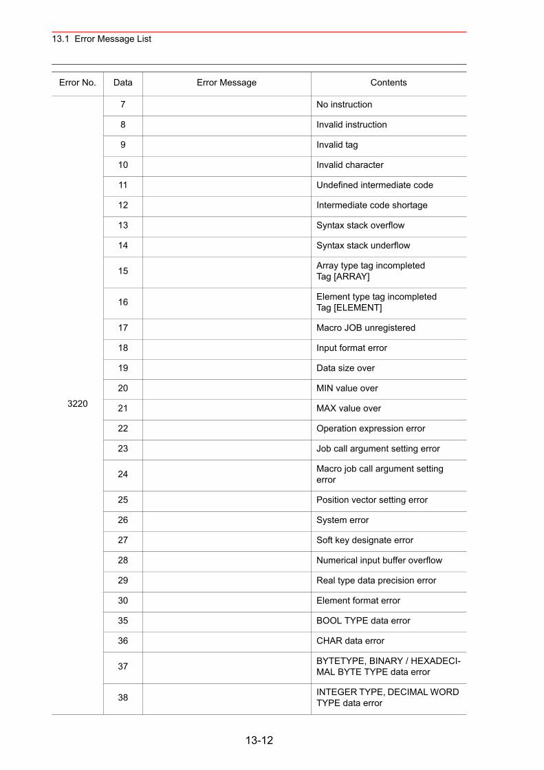
13.1 Error Message List
3220
7 No instruction
8 Invalid instruction
9 Invalid tag
10 Invalid character
11 Undefined intermediate code
12 Intermediate code shortage
13 Syntax stack overflow
14 Syntax stack underflow
15 Array type tag incompleted Tag [ARRAY]
16 Element type tag incompleted Tag [ELEMENT]
17 Macro JOB unregistered
18 Input format error
19 Data size over
20 MIN value over
21 MAX value over
22 Operation expression error
23 Job call argument setting error
24 Macro job call argument setting error
25 Position vector setting error
26 System error
27 Soft key designate error
28 Numerical input buffer overflow
29 Real type data precision error
30 Element format error
35 BOOL TYPE data error
36 CHAR data error
37 BYTETYPE, BINARY / HEXADECI-MAL BYTE TYPE data error
38 INTEGER TYPE, DECIMAL WORD TYPE data error
Error No. Data Error Message Contents
13-12
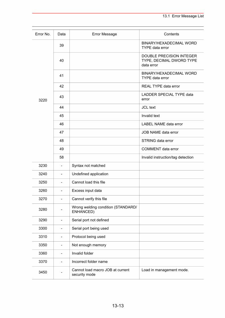
13.1 Error Message List
3220
39 BINARY/HEXADECIMAL WORD TYPE data error
40DOUBLE PRECISION INTEGER TYPE, DECIMAL DWORD TYPE data error
41 BINARY/HEXADECIMAL WORD TYPE data error
42 REAL TYPE data error
43 LADDER SPECIAL TYPE data error
44 JCL text
45 Invalid text
46 LABEL NAME data error
47 JOB NAME data error
48 STRING data error
49 COMMENT data error
58 Invalid instruction/tag detection
3230 - Syntax not matched
3240 - Undefined application
3250 - Cannot load this file
3260 - Excess input data
3270 - Cannot verify this file
3280 - Wrong welding condition (STANDARD/ENHANCED)
3290 - Serial port not defined
3300 - Serial port being used
3310 - Protocol being used
3350 - Not enough memory
3360 - Invalid folder
3370 - Incorrect folder name
3450 - Cannot load macro JOB at current security mode
Load in management mode.
Error No. Data Error Message Contents
13-13
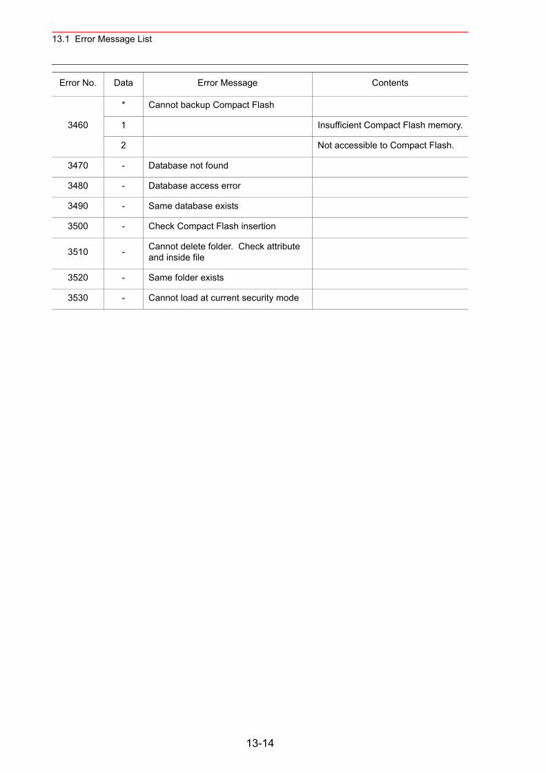
13.1 Error Message List
3460
* Cannot backup Compact Flash
1 Insufficient Compact Flash memory.
2 Not accessible to Compact Flash.
3470 - Database not found
3480 - Database access error
3490 - Same database exists
3500 - Check Compact Flash insertion
3510 - Cannot delete folder. Check attribute and inside file
3520 - Same folder exists
3530 - Cannot load at current security mode
Error No. Data Error Message Contents
13-14
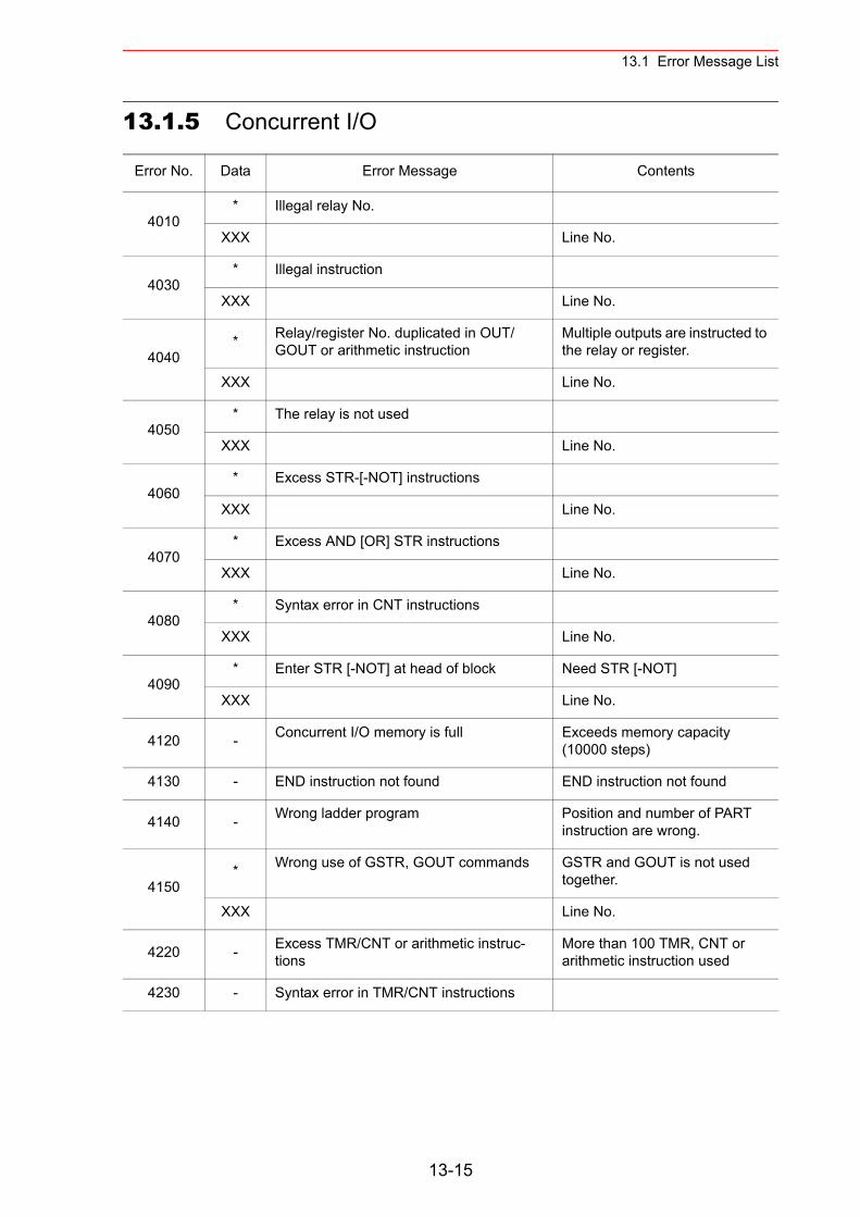
13.1 Error Message List
13.1.5 Concurrent I/O
Error No. Data Error Message Contents
4010* Illegal relay No.
XXX Line No.
4030* Illegal instruction
XXX Line No.
4040* Relay/register No. duplicated in OUT/
GOUT or arithmetic instructionMultiple outputs are instructed to the relay or register.
XXX Line No.
4050* The relay is not used
XXX Line No.
4060* Excess STR-[-NOT] instructions
XXX Line No.
4070* Excess AND [OR] STR instructions
XXX Line No.
4080* Syntax error in CNT instructions
XXX Line No.
4090* Enter STR [-NOT] at head of block Need STR [-NOT]
XXX Line No.
4120 - Concurrent I/O memory is full Exceeds memory capacity (10000 steps)
4130 - END instruction not found END instruction not found
4140 - Wrong ladder program Position and number of PART instruction are wrong.
4150* Wrong use of GSTR, GOUT commands GSTR and GOUT is not used
together.
XXX Line No.
4220 - Excess TMR/CNT or arithmetic instruc-tions
More than 100 TMR, CNT or arithmetic instruction used
4230 - Syntax error in TMR/CNT instructions
13-15
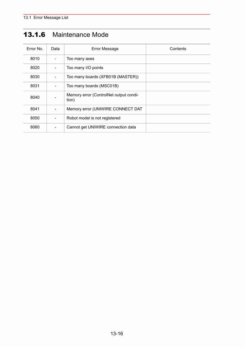
13.1 Error Message List
13.1.6 Maintenance Mode
Error No. Data Error Message Contents
8010 - Too many axes
8020 - Too many I/O points
8030 - Too many boards (XFB01B (MASTER))
8031 - Too many boards (MSC01B)
8040 - Memory error (ControlNet output condi-tion)
8041 - Memory error (UNIWIRE CONNECT DAT
8050 - Robot model is not registered
8060 - Cannot get UNIWIRE connection data
13-16
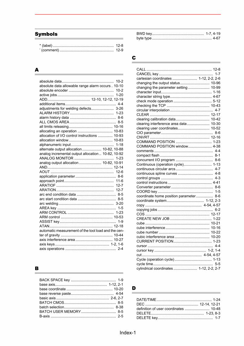
Symbols
* (label) ...................................................... 12-8’ (comment) ................................................ 12-9
A
absolute data.............................................. 10-2absolute data allowable range alarm occurs . 10-10absolute encoder ........................................ 10-2active jobs .................................................. 1-20ADD...................................... 12-10, 12-12, 12-19additional items............................................. 4-4adjustments for welding defects.................... 3-26ALARM HISTORY....................................... 1-23alarm history data ......................................... 8-6ALL CMOS AREA ......................................... 8-5all limits releasing....................................... 10-16allocating an operation ............................... 10-83allocation of I/O control instructions ............. 10-93allocation window....................................... 10-83alphanumeric input...................................... 1-18alternate output allocation ................. 10-82, 10-88analog incremental output allocation .. 10-82, 10-92ANALOG MONITOR ................................... 1-23analog output allocation .................... 10-82, 10-91AND.......................................................... 12-14AOUT ........................................................ 12-6application parameter .................................... 8-6approach point............................................ 11-6ARATIOF ................................................... 12-7ARATION ................................................... 12-7arc end condition data ................................... 8-5arc start condition data .................................. 8-5arc welding ................................................. 3-20AREA key .................................................... 1-5ARM CONTROL ......................................... 1-23ARM control .............................................. 10-53ASSIST key.................................................. 1-9ATAN........................................................ 12-18automatic measurement of the tool load and the cen-ter of gravity .............................................. 10-44axis interference area ................................. 10-27axis keys ................................................ 1-2, 1-6axis operations ............................................. 2-4
B
BACK SPACE key ........................................ 1-9base axis.............................................. 1-12, 2-1base coordinate ......................................... 10-20base reverse paste...................................... 4-54basic axis ............................................... 2-6, 2-7BATCH CMOS.............................................. 8-5batch selection............................................ 8-38BATCH USER MEMORY............................... 8-5B-axis .......................................................... 2-5
BWD key.............................................. 1-7, 4-19byte type ..................................................... 4-67
C
CALL .......................................................... 12-8CANCEL key ................................................ 1-7cartesian coordinates ...................... 1-12, 2-2, 2-6changing the output status .......................... 10-96changing the parameter setting ................... 10-99character input............................................. 1-16character string type..................................... 4-67check mode operation .................................. 5-12checking the TCP ...................................... 10-43circular interpolation ...................................... 4-7CLEAR ..................................................... 12-17clearing calibration data.............................. 10-42clearing interference area data .................... 10-30clearing user coordinates............................ 10-52ClO parameter.............................................. 8-6CNVRT ..................................................... 12-16COMMAND POSITION ................................ 1-23COMMAND POSITION window..................... 4-38comments .................................................... 4-4compact flash ............................................... 8-1concurrent I/O program ................................. 8-6Continuous (operation cycle)......................... 1-13continuous circular arcs ................................. 4-7continuous spline curves ............................... 4-8control groups .............................................. 4-3control instructions ....................................... 4-41Converter parameter ..................................... 8-6COORD key ................................................. 1-5coordinate home position parameter ............... 8-6coordinate system................................. 1-12, 2-3copy .................................................. 4-54, 4-57copying jobs ................................................. 6-2COS ......................................................... 12-17CREATE NEW JOB ..................................... 1-22cube ......................................................... 10-21cube interference ....................................... 10-16cube number ............................................. 10-22cubic interference area ............................... 10-20CURRENT POSITION.................................. 1-23cursor .......................................................... 4-4cursor key .............................................. 1-2, 1-4cut ..................................................... 4-54, 4-57Cycle (operation cycle) ................................. 1-13cycle time..................................................... 5-5cylindrical coordinates ..................... 1-12, 2-2, 2-7
D
DATE/TIME................................................. 1-24DEC ............................................... 12-14, 12-21definition of user coordinates ...................... 10-48DELETE............................................... 1-23, 8-3DELETE key................................................. 1-7
Index-1
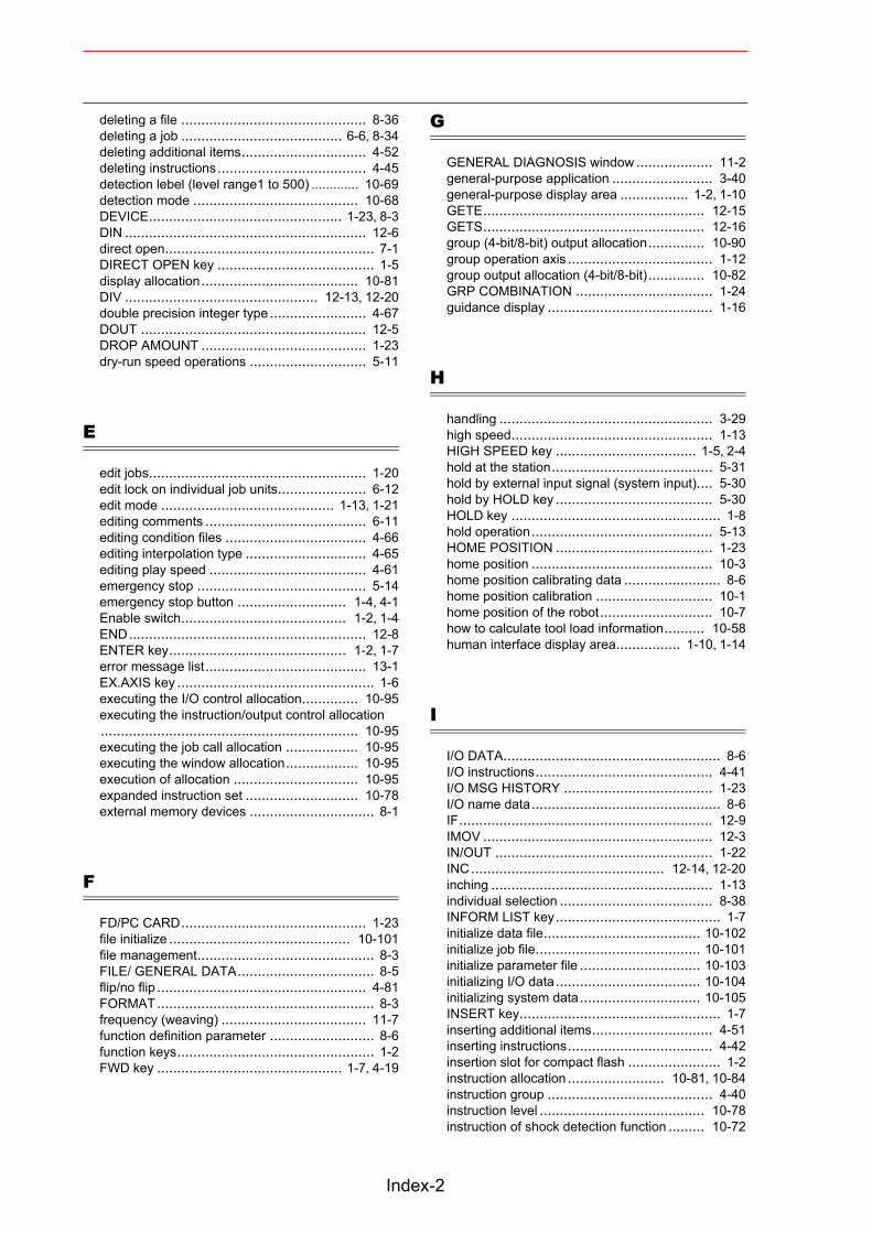
deleting a file .............................................. 8-36deleting a job ........................................ 6-6, 8-34deleting additional items............................... 4-52deleting instructions ..................................... 4-45detection lebel (level range1 to 500) ............. 10-69detection mode ......................................... 10-68DEVICE................................................ 1-23, 8-3DIN ............................................................ 12-6direct open.................................................... 7-1DIRECT OPEN key ....................................... 1-5display allocation ....................................... 10-81DIV ................................................ 12-13, 12-20double precision integer type ........................ 4-67DOUT ........................................................ 12-5DROP AMOUNT ......................................... 1-23dry-run speed operations ............................. 5-11
E
edit jobs...................................................... 1-20edit lock on individual job units...................... 6-12edit mode ........................................... 1-13, 1-21editing comments ........................................ 6-11editing condition files ................................... 4-66editing interpolation type .............................. 4-65editing play speed ....................................... 4-61emergency stop .......................................... 5-14emergency stop button ........................... 1-4, 4-1Enable switch......................................... 1-2, 1-4END ........................................................... 12-8ENTER key............................................ 1-2, 1-7error message list........................................ 13-1EX.AXIS key ................................................. 1-6executing the I/O control allocation.............. 10-95executing the instruction/output control allocation................................................................ 10-95executing the job call allocation .................. 10-95executing the window allocation.................. 10-95execution of allocation ............................... 10-95expanded instruction set ............................ 10-78external memory devices ............................... 8-1
F
FD/PC CARD.............................................. 1-23file initialize ............................................. 10-101file management............................................ 8-3FILE/ GENERAL DATA.................................. 8-5flip/no flip .................................................... 4-81FORMAT ...................................................... 8-3frequency (weaving) .................................... 11-7function definition parameter .......................... 8-6function keys................................................. 1-2FWD key .............................................. 1-7, 4-19
G
GENERAL DIAGNOSIS window ................... 11-2general-purpose application ......................... 3-40general-purpose display area ................. 1-2, 1-10GETE....................................................... 12-15GETS....................................................... 12-16group (4-bit/8-bit) output allocation.............. 10-90group operation axis .................................... 1-12group output allocation (4-bit/8-bit).............. 10-82GRP COMBINATION .................................. 1-24guidance display ......................................... 1-16
H
handling ..................................................... 3-29high speed.................................................. 1-13HIGH SPEED key ................................... 1-5, 2-4hold at the station........................................ 5-31hold by external input signal (system input).... 5-30hold by HOLD key ....................................... 5-30HOLD key .................................................... 1-8hold operation ............................................. 5-13HOME POSITION ....................................... 1-23home position ............................................. 10-3home position calibrating data ........................ 8-6home position calibration ............................. 10-1home position of the robot............................ 10-7how to calculate tool load information.......... 10-58human interface display area................ 1-10, 1-14
I
I/O DATA...................................................... 8-6I/O instructions............................................ 4-41I/O MSG HISTORY ..................................... 1-23I/O name data............................................... 8-6IF............................................................... 12-9IMOV ......................................................... 12-3IN/OUT ...................................................... 1-22INC ................................................ 12-14, 12-20inching ....................................................... 1-13individual selection ...................................... 8-38INFORM LIST key ......................................... 1-7initialize data file....................................... 10-102initialize job file......................................... 10-101initialize parameter file .............................. 10-103initializing I/O data .................................... 10-104initializing system data .............................. 10-105INSERT key.................................................. 1-7inserting additional items.............................. 4-51inserting instructions.................................... 4-42insertion slot for compact flash ....................... 1-2instruction allocation ........................ 10-81, 10-84instruction group ......................................... 4-40instruction level ......................................... 10-78instruction of shock detection function ......... 10-72
Index-2
instruction search........................................ 4-91instruction set ............................................ 10-78integer type ................................................ 4-67INTERFERENCE ........................................ 1-23interference area........................................ 10-20INTERLOCK key........................................... 1-8interpolation type .................................. 4-5, 4-11INVMAT .................................................... 12-19
J
JOB ..................................................... 1-22, 8-5job call ...................................................... 10-86job call allocation ....................................... 10-81JOB CAPACITY.......................................... 1-22JOB CAPACITY window .............................. 4-39JOB CONTENT window............................... 4-37JOB HEADER window................................. 4-35job stack .................................................... 5-32joint coordinates.............................. 1-12, 2-2, 2-5joint interpolation........................................... 4-5JUMP......................................................... 12-8
K
KEY ALLOCATION ..................................... 1-24key allocation (EACH) ................................ 10-81key allocation (SIM).................................... 10-81keypads ..................................................... 1-16
L
label search................................................ 4-90L-axis........................................................... 2-5learning function ........................................ 10-79LIMIT RELEASE ......................................... 1-23limit switch................................................. 10-98limited speed operations .............................. 5-10line number .................................................. 4-4line search.................................................. 4-89linear interpolation......................................... 4-6LOAD .................................................. 1-23, 8-3loading a condition file or generel data .......... 8-20loading a job ............................................... 8-18loading a parameter .................................... 8-22loading all CMOS data................................. 8-29loading all data in CMOS area...................... 8-30loading all user’s programs .......................... 8-28loading I/O data .......................................... 8-24loading system data .................................... 8-26local variables............................................. 4-85low speed................................................... 1-13low speed operation .................................... 5-10L-U interference ......................................... 10-16
M
machine lock operation................................. 5-11main menu area.................................. 1-10, 1-12MAIN MENU key..................................... 1-4, 1-9major alarms ............................................... 5-17major axes ................................................... 2-5management mode ............................. 1-13, 1-21manipulator coordinate systems ..................... 2-1MANIPULATOR TYPE ................................. 1-23manipulator type .......................................... 4-81manual speed............................... 1-13, 2-3, 4-22MANUAL SPEED keys ............................ 1-2, 1-5manufacturer allocation .............................. 10-81MASTER JOB ............................................. 1-22master job .................................................... 5-2max. disturbance force ............................... 10-69measurement of the tool load and the center of grav-ity ............................................................. 10-44mechanical limit ......................................... 10-16medium speed............................................. 1-13menu area.................................... 1-2, 1-10, 1-14method of shock detection level file setting... 10-68method of the tool load information setting ... 10-70MFRAME .................................................. 12-18minor alarms ............................................... 5-17mirror shift function ...................................... 7-33MODE (weave type)..................................... 11-7mode switch ................................................. 1-8modification of speed type ............................ 4-61MODIFY key................................................. 1-7modifying additional items............................. 4-50modifying additional numeric data ................. 4-49modifying instructions ................................... 4-45modifying job names ..................................... 6-8momentary output allocation ............. 10-82, 10-89MONITORING TIME .................................... 1-23motion about TCP ........................................ 2-14motion function parameter ............................. 8-6motion time .................................................. 5-5MOTION TYPE key................................. 1-2, 1-6motor gun dry spot pressure data ................... 8-5motor gun pressure power data...................... 8-5MOVC ........................................................ 12-2move instructions.................................. 4-9, 4-41MOVJ ......................................................... 12-1MOVL ......................................................... 12-2MOVS......................................................... 12-3MSHIFT .................................................... 12-11MUL ........................... 12-10, 12-13, 12-19, 12-20MULMAT .................................................. 12-18Multi key ...................................................... 1-9
N
NEW JOB CREATE window .......................... 3-2NOP ........................................................... 12-9NOT ......................................................... 12-14number of tool files..................................... 10-33numeric key customize function................... 10-81
Index-3
Numeric keys ......................................... 1-2, 1-8
O
OPE ORIGIN POS ...................................... 1-23OPERATE COND................................ 1-24, 5-23operating instructions................................... 4-41operation control parameter............................ 8-6operation cycle...................................... 1-13, 5-7operation mode ................................... 1-13, 1-21OR ........................................................... 12-14ORG ........................................................ 10-48output of the work home position signal ....... 10-33override speed settings .................................. 5-5overrun releasing ...................................... 10-18OVERRUN&S-SENSOR .............................. 1-23
P
page .......................................................... 1-13PAGE key.............................................. 1-2, 1-5painting application...................................... 3-50painting conditions....................................... 3-51PAM function .............................................. 7-27parallel shift function ...................................... 7-3parallel shift job conversion function .............. 7-16PARAMETER ....................................... 1-24, 8-6PARAMETER BATCH ................................... 8-6paste.................................................. 4-54, 4-58PAUSE....................................................... 12-9play mode................................................... 1-19play speed ............................................ 4-5, 4-12playback ............................................... 3-19, 5-1playback time................................................ 5-5position level ............................................... 4-12position type ............................................... 4-67POWER ON/OFF POS ................................ 1-23Power Source characteristic data.................... 8-5Power Source characteristic difinition data ....... 8-5Power Source condition assist data................. 8-5programming pendant.................................... 1-2programming pendant display....................... 1-10prohibiting weaving.................................... 11-11PULSE ....................................................... 12-5pulse mirror-shift function ............................. 7-33pulse output allocation ..................... 10-82, 10-89
R
R-axis .......................................................... 2-5r-axis............................................................ 2-7real type ..................................................... 4-67reference point instructions .......................... 4-15REFP ......................................................... 12-4registering a job ............................................ 4-2
registering tool angle ................................. 10-36registering tool load information .................. 10-65registering/changing the work home position 10-32related job (job+condition) .............................. 8-5relative modification..................................... 4-61remote mode .............................................. 1-19RES. START(CNCT) ........................... 1-24, 5-24RES. START(JOB)...................................... 1-22RES. STATUS .................................... 1-22, 5-28RESERVE JOB NAME ................................ 1-24reserved job................................................ 11-1reserved start.............................................. 5-22RESET RESERVATION .............................. 5-29reset shock detected ................................. 10-77restart ........................................................ 5-13RET ........................................................... 12-8returning to the work home position ............ 10-32reverse paste...................................... 4-54, 4-59ROBOT ...................................................... 1-23robot axis ............................................. 1-12, 2-1ROBOT CALIB............................................ 1-23robot coordinate ........................................ 10-20robot installation angle ............................... 10-54ROBOT key .................................................. 1-6robot matching parameter .............................. 8-6robot programming language (INFORM III) .. 10-78robot setup condition ................................. 10-54robot-coordinates mirror-shift funciton ........... 7-33
S
SAVE ................................................... 1-23, 8-3saving a condition file or general data ............. 8-8saving a job .................................................. 8-7saving a parameter...................................... 8-10saving all CMOS data .................................. 8-16saving all data in CMOS area ....................... 8-17saving all user’s programs............................ 8-15saving I/O data............................................ 8-12saving system data...................................... 8-13S-axis .......................................................... 2-5SECOND HOME POS ................................. 1-23second home position.................................... 8-6second home position (check point) .............. 10-8security mode ..................................... 1-13, 1-21SELECT JOB.............................................. 1-22SELECT key ........................................... 1-2, 1-4selecting a coordinate system ........................ 2-3selecting the range ...................................... 4-56selecting user coordinates file .................... 10-49sensor parameter .......................................... 8-6SERVO MONITOR...................................... 1-23SERVO ON READY key .......................... 1-9, 3-1servo parameter............................................ 8-6servo power block parameter ......................... 8-6servomotor parameter ................................... 8-6SERVOPACK parameter ............................... 8-6SET ......................................................... 12-15SET SPEED ............................................... 1-24SET WORD ................................................ 1-24SETE ....................................................... 12-15
Index-4
setting contents ......................................... 10-78setting play speed ...................................... 10-15setting shock detection function................... 10-67setting the controller clock........................... 10-14setting the second home position (check point)................................................................ 10-12
setting the tool load information 10-37, 10-58, 10-70setting user coordinates.............................. 10-48setting work home position.......................... 10-31SETUP....................................................... 1-24SFTOF...................................................... 12-11SFTON ..................................................... 12-11SHCKRST instruction ................................. 10-72SHCKSET instruction ....................... 10-67, 10-72S-head payload ......................................... 10-55shielding gas flow rate ................................. 3-24shift instructions .................................... 4-41, 7-7SHIFT key .................................................... 1-8shift value..................................................... 7-5shock detection function ............................. 10-67shock detection level data.............................. 8-5short/full open position data ........................... 8-5SHORTCUT key ........................................... 1-9SIN ........................................................... 12-17single circular arc .......................................... 4-7single job...................................................... 8-5single spline curve ........................................ 4-8software limit ................................... 10-16, 10-98solenoid signal controls ............................... 3-30special playback operations ........................... 5-9SPEED ...................................................... 12-4speed (weaving) ......................................... 11-7speed limitation drive................................... 3-39speed override............................................ 5-18spline interpolation ........................................ 4-8spot gun characteristic data ........................... 8-5spot welding ............................................... 3-45spot welding gun condition ........................... 3-46spot welding Power Source characteristic data 8-5SQRT ....................................................... 12-18standard instruction set............................... 10-78START key............................................. 1-8, 4-1start No. ....................................................... 5-5state under execution .................................. 1-13station axis ........................................... 1-12, 2-1status display area .............................. 1-10, 1-12Step (operation cycle).................................. 1-13step search ................................................ 4-89stop ........................................................... 5-13stop by alarm.............................................. 5-16SUB............................ 12-10, 12-12, 12-19, 12-20subset instruction set.................................. 10-78SV monitor signals ........................................ 8-6switch of the tool file ................................... 10-66symbol input ............................................... 1-18SYSTEM DATA ............................................ 8-6system definition parameter ........................... 8-6SYSTEM INFO ........................................... 1-23system information ........................................ 8-6system matching parameter ........................... 8-6
T
tag search ................................................... 4-92T-axis .......................................................... 2-5teach lock..................................................... 4-1teach mode ................................................. 1-19teaching ................................................. 3-1, 4-1TEACHING COND....................................... 1-24teaching user coordinates........................... 10-50temporary release of soft limits.................... 10-98test operations.................................... 4-23, 4-60TEST START key ......................................... 1-6theta(q)-axis ................................................. 2-7TIMER ........................................................ 12-9timer (weaving timer count)........................... 11-9timer instruction ........................................... 4-16TOOL ......................................................... 1-23tool calibration ........................................... 10-38tool control .................................................. 11-1tool control instruction .................................. 11-1tool coordinates .............................. 1-12, 2-2, 2-8tool data....................................................... 8-5tool data setting ......................................... 10-33tool file ...................................................... 10-33tool file extension function........................... 10-45tool load information................................... 10-58tool number ........................................ 2-10, 4-11tool shock sensor releasing......................... 10-18tool tip......................................................... 2-14TOOLOF.................................. 11-1, 11-3, 11-12TOOLON ................................. 11-1, 11-3, 11-12transmission(general) parameter .................... 8-6TRT ............................................................ 4-63
U
U-arm payload........................................... 10-55U-axis .......................................................... 2-5undo ........................................................... 4-32undo operation after modifying additional items . 4-53undo operation after modifying instructions..... 4-47UNTIL......................................................... 12-9USER COORDINATE .................................. 1-23user coordinate................................ 10-20, 10-48user coordinate data ..................................... 8-5user coordinate number................................ 2-13user coordinates ........................... 1-12, 2-2, 2-11user coordinates file ................................... 10-48USER ID ..................................................... 1-24user variables .............................................. 4-67user word registration .................................... 8-6user-coordinates mirror-shift function ............. 7-33
V
VARIABLE .................................................. 1-22
Index-5
variable data ................................................. 8-5variable name ............................................... 8-6VERIFY ................................................ 1-23, 8-3verifying a file.............................................. 8-33verifying a job.............................................. 8-31verifying data .............................................. 8-31VERSION ................................................... 1-23viewing description for an instruction ............. 4-48
W
WAIT.......................................................... 12-6weaving angle ............................................. 11-8weaving basic coordinate system.................. 11-6weaving condition file................................... 11-7weaving condition No................................... 11-7weaving data ................................................ 8-5weaving file................................................. 11-9weaving in the check mode ........................ 11-11weaving pattern........................................... 11-8weaving prohibit .......................................... 5-12weaving start instruction............................... 11-5weaving timer mode .................................... 11-8welding conditions setting ............................ 3-24window allocation ...................................... 10-87work home position.................................... 10-31work home position cube length of its sides . 10-32work instructions ......................................... 4-41working abort process specification ............... 11-2wrist axis ......................................... 2-5, 2-6, 2-7WVOF instruction .............................. 11-5, 11-12WVON instruction.............................. 11-5, 11-12
X
X-axis........................................................... 2-6XOR......................................................... 12-14XX ........................................................... 10-48XY ........................................................... 10-48
Y
Y-axis........................................................... 2-6
Z
Z-axis .................................................... 2-6, 2-7
Index-6
NX100OPERATOR’S MANUALFOR GENERAL PURPOSE
HEAD OFFICE2-1 Kurosaki-Shiroishi, Yahatanishi-ku, Kitakyusyu-shi, 806-0004, JapanPhone 81-93-645-7745 Fax 81-93-645-7746
MOTOMAN INC. HEADQUARTERS805 Liberty Lane West Carrollton, OH 45449, U.S.A.Phone 1-937-847-6200 Fax 1-937-847-6277
YASKAWA MOTOMAN CANADA LTD.2280 Argentia Road, Mississauga, Ontario, L5N 6H8, CanadaPhone 1-905-813-5900 Fax 1-905-813-5911
YASKAWA ELECTRIC AMERICA, INC.2121 Norman Drive South Waukegan, IL 60085, U.S.A.Phone 1-847-887-7000 Fax 1-847-887-7370
YASKAWA ELECTRIC EUROPE GmbHAm Kronberger Hang 2, 65824 Schwalbach,GermanyPhone 49-6196-569-300 Fax 49-6196-888-301
MOTOMAN ROBOTICS EUROPE ABBox 504 S38525 Torsas, SwedenPhone 46-486-48800 Fax 46-486-41410
MOTOMAN ROBOTEC GmbHKammerfeldstr.1,D-85391 Allershausen, GermanyPhone 49-8166-90100 Fax 49-8166-90103
YASKAWA ELECTRIC KOREA CORPORATIONKFPA Bldg #1201, 35-4 Yeoido-dong, Youngdungpo-Ku, Seoul 150-010, KoreaPhone 82-2-784-7844 Fax 82-2-784-8495
YASKAWA ELECTRIC (SINGAPORE) PTE. LTD.151 Lorong Chuan, #04-01, New Tech Park Singapore 556741, SingaporePhone 65-6282-3003 Fax 65-6289-3003
YASKAWA ELECTRIC (SINGAPORE) PTE. LTD. MALAYSIA REPRESENTATIVE OFFICEB615, 6th Floor, East Wing, Wisma Tractors, No.7, Jalan SS 16/1, Subang Jaya, 47500 Petaling Jaya, Selangor D.E. MalaysiaPhone 60-3-5031-5311 Fax 60-3-5031-5312
YASKAWA ELECTRIC (SHANGHAI) CO., LTD.4F No Aona Road, Waigaoqiao Free Trade Zone, Pudong New Area, Shanghai 200131, ChinaPhone 86-21-5866-3470 Fax 86-21-5866-3869
YASKAWA ELECTRIC TAIWAN CORPORATION9F, 16, Nanking E. RD., Sec. 3, Taipei, TaiwanPhone 886-2-2502-5003 Fax 886-2-2505-1280
YASKAWA ELECTRIC (HK) COMPANY LIMITEDRm. 2909-10, Hong Kong Plaza, 186-191 Connaught Road West, Hong KongPhone 852-2803-2385 Fax 852-2547-5773
BEIJING OFFICERoom No. 301 Office Building Intemational Club, 21 Jianguomenwai Avenue, Beijing 100020, ChinaPhone 86-10-6532-1850 Fax 86-10-6532-1851
BEIJING YASKAWA BEIKE AUTOMATION ENGINEERING CO.,LTD.30 Xue Yuan Road, Haidian, Beijing P.R. China Post Code: 100083, ChinaPhone 86-10-6234-5003 Fax 86-10-6234-5002
SHOUGANG MOTOMAN ROBOT CO., LTD.7,Yongchang-North Road, Beijing Economic & Technological Development Area, Beijing 100076, ChinaPhone 86-10-6788-0541 Fax 86-10-6788-2878
YASKAWA
YASKAWA ELECTRIC CORPORATION
Specifications are subject to change without noticefor ongoing product modifications and improvements.
MANUAL NO. RE-CSO-A032Printed in Japan October 2003 03-10C
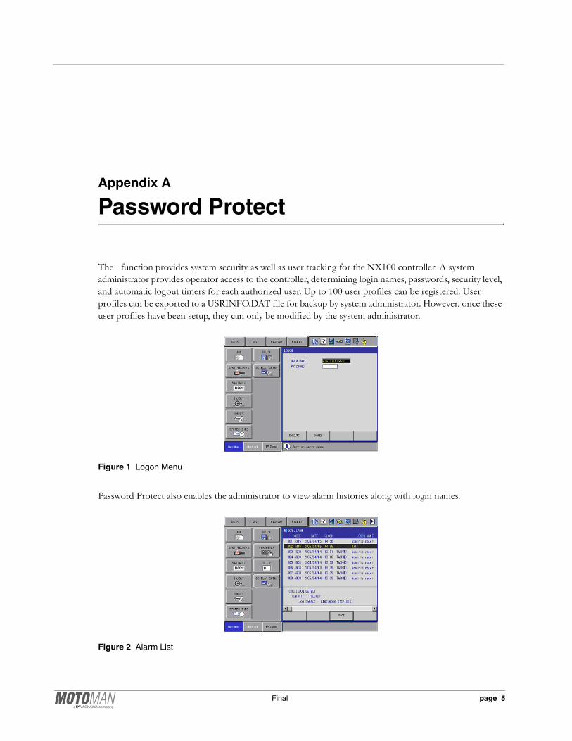
Appendix A
Password Protect
The function provides system security as well as user tracking for the NX100 controller. A system administrator provides operator access to the controller, determining login names, passwords, security level, and automatic logout timers for each authorized user. Up to 100 user profiles can be registered. User profiles can be exported to a USRINFO.DAT file for backup by system administrator. However, once these user profiles have been setup, they can only be modified by the system administrator.
Figure 1 Logon Menu
Password Protect also enables the administrator to view alarm histories along with login names.
Figure 2 Alarm List
Final page 5

Appendix A Password Protect
A.1 User Accounts
Two separate accounts allow access to the NX100 controller as described below:
Administrator AccountThe Administrator account is the one you use when you first set up for the NX100 controller. You must use this account before creating other user accounts. The Administrator account has full control over access to the NX100 controller including setup of all User accounts. The Admin username and password should therefore be filed for safe-keeping by the person acting as Administrator.
The Administrator account can never be deleted, disabled, or removed, ensuring that you never lock yourself out of the controller by deleting or disabling all system accounts. This feature sets the Administrator account apart from other user accounts.
User Accounts allows up to 100 user accounts. The Administrator sets rights and permissions for each User account including login name, password, security level, comment, and automatic logout timer. User permissions are defined as follows:
MANAGEMENT MODE - Management mode allows those authorized to set up and maintain robot system: parameters, system time and modify user IDs.
EDIT MODE - Edit mode allows the operator to teach and edit jobs and robot settings.
OPERATION MODE - Operation mode allows basic operation of the robot (stopping, starting, etc.) for people operating the robot on a production line.
page 6 Final
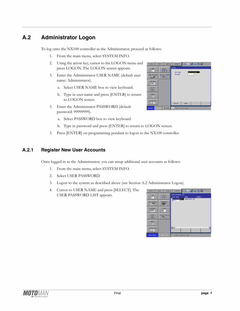
A.2 Administrator Logon
To log onto the NX100 controller as the Administrator, proceed as follows:
1. From the main menu, select SYSTEM INFO.
2. Using the arrow key, cursor to the LOGON menu and press LOGON. The LOGON screen appears.
3. Enter the Administrator USER NAME (default user name: Administrator).
a. Select USER NAME box to view keyboard.
b. Type in user name and press [ENTER] to return to LOGON screen.
3. Enter the Administrator PASSWORD (default password: 99999999).
a. Select PASSWORD box to view keyboard.
b. Type in password and press [ENTER] to return to LOGON screen.
3. Press [ENTER] on programming pendant to logon to the NX100 controller.
A.2.1 Register New User Accounts
Once logged in as the Administrator, you can setup additional user accounts as follows:
1. From the main menu, select SYSTEM INFO.
2. Select USER PASSWORD.
3. Logon to the system as described above (see Section A.2 Administrator Logon).
4. Cursor to USER NAME and press [SELECT]. The USER PASSWORD LIST appears.
Final page 7
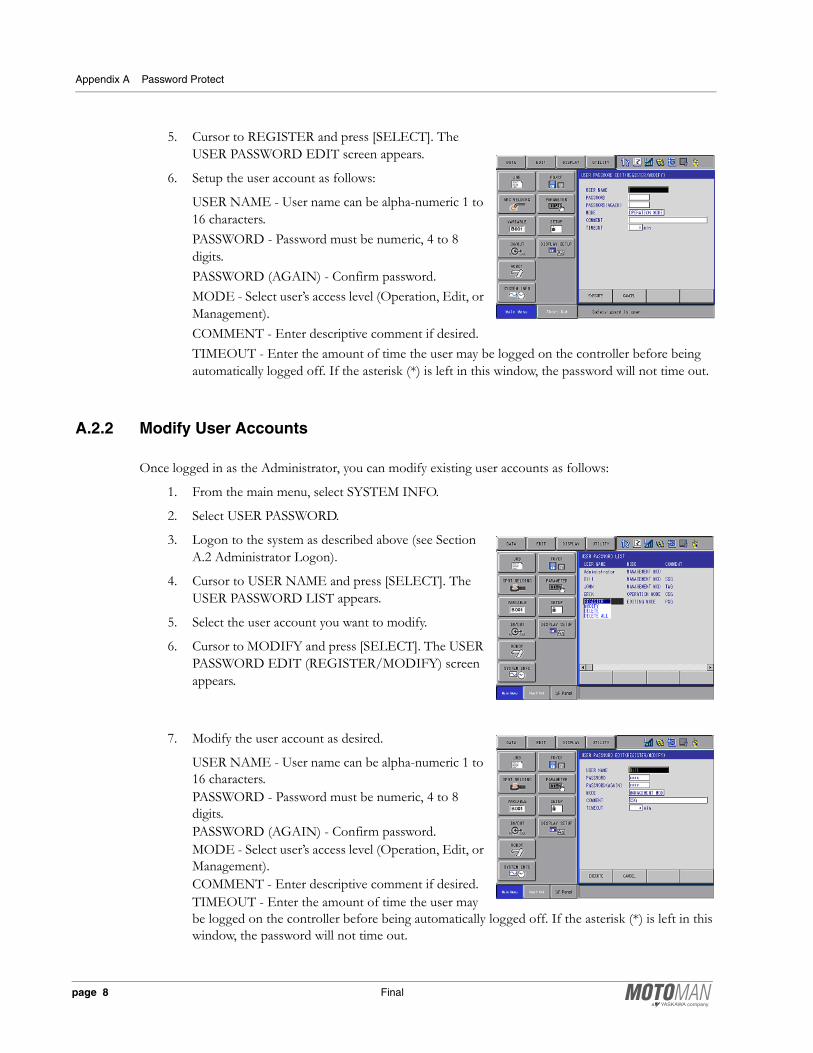
Appendix A Password Protect
5. Cursor to REGISTER and press [SELECT]. The USER PASSWORD EDIT screen appears.
6. Setup the user account as follows:
USER NAME - User name can be alpha-numeric 1 to 16 characters.PASSWORD - Password must be numeric, 4 to 8 digits.PASSWORD (AGAIN) - Confirm password.MODE - Select user’s access level (Operation, Edit, or Management).COMMENT - Enter descriptive comment if desired.TIMEOUT - Enter the amount of time the user may be logged on the controller before being automatically logged off. If the asterisk (*) is left in this window, the password will not time out.
A.2.2 Modify User Accounts
Once logged in as the Administrator, you can modify existing user accounts as follows:
1. From the main menu, select SYSTEM INFO.
2. Select USER PASSWORD.
3. Logon to the system as described above (see Section A.2 Administrator Logon).
4. Cursor to USER NAME and press [SELECT]. The USER PASSWORD LIST appears.
5. Select the user account you want to modify.
6. Cursor to MODIFY and press [SELECT]. The USER PASSWORD EDIT (REGISTER/MODIFY) screen appears.
7. Modify the user account as desired.
USER NAME - User name can be alpha-numeric 1 to 16 characters.PASSWORD - Password must be numeric, 4 to 8 digits.PASSWORD (AGAIN) - Confirm password.MODE - Select user’s access level (Operation, Edit, or Management).COMMENT - Enter descriptive comment if desired.TIMEOUT - Enter the amount of time the user may be logged on the controller before being automatically logged off. If the asterisk (*) is left in this window, the password will not time out.
page 8 Final
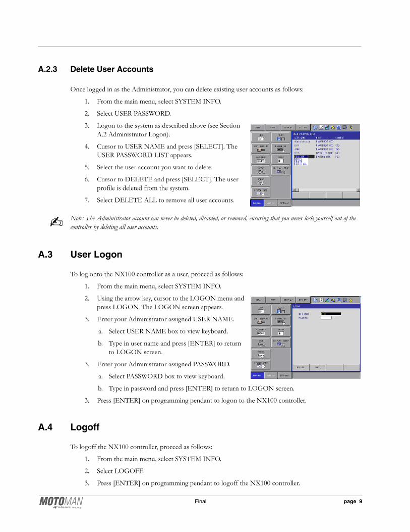
A.2.3 Delete User Accounts
Once logged in as the Administrator, you can delete existing user accounts as follows:
1. From the main menu, select SYSTEM INFO.
2. Select USER PASSWORD.
3. Logon to the system as described above (see Section A.2 Administrator Logon).
4. Cursor to USER NAME and press [SELECT]. The USER PASSWORD LIST appears.
5. Select the user account you want to delete.
6. Cursor to DELETE and press [SELECT]. The user profile is deleted from the system.
7. Select DELETE ALL to remove all user accounts.
Note: The Administrator account can never be deleted, disabled, or removed, ensuring that you never lock yourself out of the controller by deleting all user accounts.
A.3 User Logon
To log onto the NX100 controller as a user, proceed as follows:
1. From the main menu, select SYSTEM INFO.
2. Using the arrow key, cursor to the LOGON menu and press LOGON. The LOGON screen appears.
3. Enter your Administrator assigned USER NAME.
a. Select USER NAME box to view keyboard.
b. Type in user name and press [ENTER] to return to LOGON screen.
3. Enter your Administrator assigned PASSWORD.
a. Select PASSWORD box to view keyboard.
b. Type in password and press [ENTER] to return to LOGON screen.
3. Press [ENTER] on programming pendant to logon to the NX100 controller.
A.4 Logoff
To logoff the NX100 controller, proceed as follows:
1. From the main menu, select SYSTEM INFO.
2. Select LOGOFF.
3. Press [ENTER] on programming pendant to logoff the NX100 controller.
Final page 9

Appendix A Password Protect
Notes
page 10 Final