operator's manual - euroboor
TRANSCRIPT

lllodel [HG.230/3
Portable Metal Cutting Circular Saw
LINE VOLTAGEPRESENT
MODEL E HC.230 I 3 (220v-240V I 50Hz)
OPERATOR'S MANUAL
TO REDUCE THE RISK OF INJURY, USER MUST READ AND UNDERSTAND INSTRUCTION MANUAL.
NEVER PLACEFINGERS NEAR
CUTTING AREA.BEWARE OF
ROTATINGMACHINE PARTS
A wARNtNc!
EYE PROTECTION HEARING PROTECTIONREOUIRED REQUIRED
Serial # Date of Purchase
GENERAL SAFETY RULES
A WnnNING! Read and Understand all Instructions.
Failure to follow all instructions listed below, may result in electric shock, fire and/or serious personal injury.
SAVE THESE INSTRUCTIONS
Work Area
'Keep Your Work Area Cleon ond Well L¡¡.
'Cluttered benches and dark areas invite accidents.
'Do .not operale power tools in explosive olmospheres, such as in rhe presence of flommoble liquids, goses,or dust. Power tools create sparks which may ignite the dust or fumes.
'Keep byslanders, ch¡ldren, ond visitors away while operaling a power too/. Distractions can cause you tolose control.
Electrical Safetv
' Grounded lools must be plugged inlo on outlel properly inslolled ond grounded ¡n accordance wilh ollcodes ond ord¡nonces. Never remove lhe grounding prong or modify the plug in ony way. Do not use onyadopter plugs Check wilh a qualified eleclrician if you are in doubt os lo whether lhe ouÍlel is properlygrounded.lf the tools should electrically malfunction or break down, grounding provides a low resistancepath to carry electricity away from the user.
'Avoid body contoctwith grounded surfoces such as pipes, rodiolors, ronges ond re{rigerolors. There is anincreased risk of electric shock if your body is grounded.
'Don'l expose power lools Ío rain or wel condifions. Water entering a power toolwill increase the risk ofelectric shock.
'Do nol abuse lhe cord. Never use lhe cord lo corry lhe Íools or pull the plug from on ouilet. Keep cordaway from heol, oì1, sharp edges or moving porls. Replace damaged cords immediately, Damaged cordsincrease the risk of electric shock.
'When operoling o power tool oulside, use on ouldoor exlension cord morked "W-A" or "W." These cordsare rated for outdoor use and reduce the risk of electric shock.
(Note) When using an extension cord, be sure to use one heavy enough to carry the current your productwill draw. An undersized cord will cause a drop in line voltage resulting in loss of power and overheating.The recommended minimum is a 12 gauge extension cord not exceeding 50 feet.
SPECIFIC SAFETY RULES AND SYMBOLS
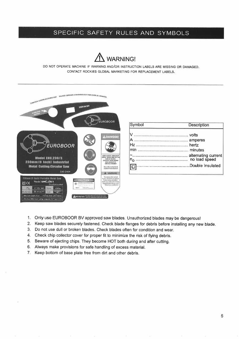
A wARNtNc!DO NOT OPERATE MACHINE IF WARNING RI'IO/OR INSTRUCTION LABELS ARE MISSING OR DAMAGED.
CONTACT ROCKIES GLOBAL MARKETING FOR REPLACEMENT LABELS.
4,DANGERI
@@@
1. Only use EUROBOOR BV approved saw blades. Unauthorized blades may be dangerous!2. Keep saw blades securely fastened. Check blade flanges for debris before installing any new blade.3. Do not use dull or broken blades. Check blades often for condition and wear.4. Check chip collector cover for proper fit to minimize the risk of flying debris.5. Beware of ejecting chips. They become HOT both during and after cutting.6. Always make provisions for safe handling of excess material.7. Keep bottom of base plate free from dirt and other debris.
tr ....,..........Doub1e lnsulated
À4o(lel EHC.23olllgl \\ tl rJr,- t,!,uj=r
27AO/ rJñ |BCC¡. )5 t,. | | ,,-,lly'
itD¡ ¡r.þh.rI l/ In15¡nìljri5ô¡1
r¡.,r,af irSrc:iaLreraj."..\ I r). ll,2 )
SPECIFIC SAFETY RULES (continued)
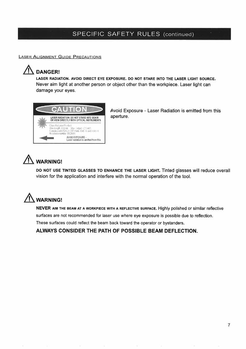
Lnsen AITcNMENT Guroe PREcRurlol.ls
DANGER!LASER RADIATION. AVOID DIRECT EYE EXPOSURE. DO NOT STARE INTO THE LASER LIGHT SOURCE.
Never aim light at another person or object other than the workpiece. Laser light candamage your eyes.
I-ASER RAt)IATION-OO NOT STARE INTO BEAMOR VIEW OIRECTLYWITH OPTICAL INSTRUMENTS
Class llla LasÉr Pr r'Jurt!\,bvdÉn!tì lj¡U nm llar ,ìrtÞ!l .:5 mT,,
Cùìtl¡¿5 $ith FDAr I aFÊ'Pdts lt,l{, lrr ¿nd liqú l l
At,rissrin nuûllryr !!:ûúg I
+ lY$15J,13,',Y'l'*'n*n,*,,
Avoid Exposure - Laser Radiation is emitted from thisaperture.
WARNING!
DO NOT USE TINTED GLASSES TO ENHANCE THE LASER LlcHT. Tinted glasses will reduce overallvision for the application and interfere with the normal operation of the tool.
WARNING!
NEVER AtM THE BEAM AT A woRKprEcE wrrH A REFLEcTvE suRFAcE. Highly polished or similar reflective
surlaces are not recommended for laser use where eye exposure is possible due to reflection.
These surfaces could reflect the beam back toward the operator or bystanders.
ALWAYS CONSIDER THE PATH OF POSSIBLE BEAM DEFLECTION.
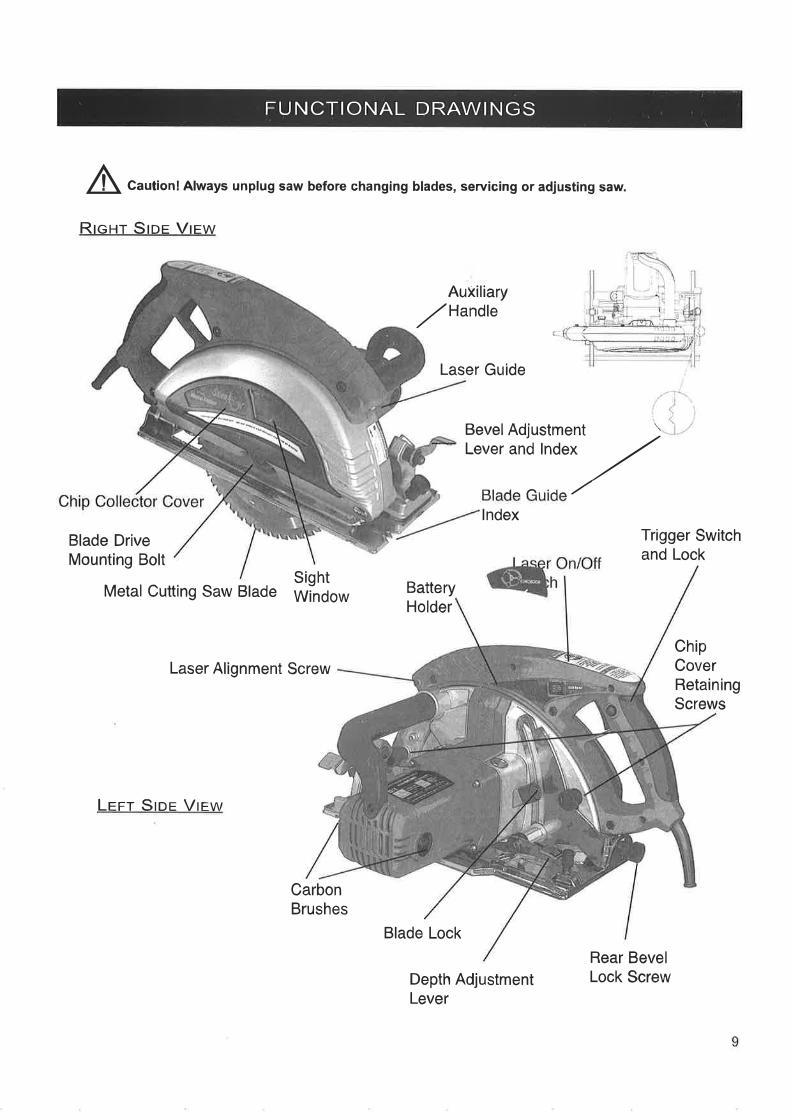
FUNCTIONAL DRAWINGS
A Caution! Always unplug saw before changing blades, servicing or adjusting saw.
RrcHr Sroe Vrew
AuXiliary
,,zHandle
Laser Guide
lndex
Blade DriveMounting Bolt
Metal Cutting Saw Blade BatteryHolder
Blade Lock
Depth AdjustmentLever
Trigger Switchand Lock
ChipCoverRetainingScrews
SightWindow
Laser Alignment Screw
Lrrr Sror Vrew
CarbonBrushes
Rear BevelLock Screw
BevelAdjustment \Lever and lndex ,/
Ftl^l^ ¡^..:l^ ,/

PARTS LIST
1 PLASTIC TRIM COVER SM.1 1
2 SIGHT WINDOW SM-2 1
3 CHIP COLLECTOR COVER SM-3 1
4 TRIM COVER SCREWS SM4 2
5 INNER CHIP COVER PLATE SM-s 1
6 WASHER SM-6 4
7 SCREW SM-7 4
8 BOLT, BLADE DRIVE MOUNTING SM-8 1
9 WASHER, OUTER BLADE DRIVE SM-g 1
10 FLANGE, OUTER BLADE DRIVE SM-IO 1
11 SAW BLADE 230 OOO3 1
12 FLANGE, INNER BLADE DRIVE SM-12 1
13 RETAINER, MOVEABLE GUARD SM-13 1
14 BLADE GUARD SM-14 1
1s scREW SM-15 2
16 SPRING, BLADE GUARD RETURN SM.16 1
17 FIXED GUARD SM-17 1
18 CHIP DEFLECTOR BRACKET SM-18 1,19 BLADE GUARD BUMPER SM-19 1
20 CLIP, THUMBSCREW RETAINING SM-20 2
21 MAIN FRAME SM-21 1
22 THUMBSCREW, CHIP COVER RETAINING SM-22 2
23 PLASTIC BATTERY COVER, OUTER SM-23 1
24 BATTERY HOLDER SM-24 1
25 BATTERY HOLDER SUPPORT SM-25 1
26
27
28
29
30
31
32
33
u35
Jb
37
38
39
40
41
42
43
44
45
46
47
48
49
50
51
52
53
54
BATTERY AAAWPEBATTERY COVER
PLATE, GEARBOX COVER
BEARING, BALL
BEARING, BALL
COUNTER-SHAFT
KEY
GEAR
RETAINER CLIP
BUSHING
GEAR HOUSING
SPRING, BLADE LOCK
BLADE LOCK
SCREW, AUXILIARY HANDLE
AUXILIARY HANDLE
SCREW
WASHER
CARBON BRUSH HOLDER
CARBON BRUSH
CARBON BRUSH COVER
MOTOR HOUSING
BUSHING, BEARING HOLDER
FIELD WINDING
SCREWS, FIELD WINDING
FAN SHROUD
BEARING
ARMATURE
SM-28
SM-29
SM-30
SM.31
SM.32
SM-33
SM-34
SM.35
SM-36
SM-37
SM-38
SM-39
SM.4O
SM.4ISM-42
SM.43
SM44SM-45
sM-46SM-47
SM-48
sM49SM-50
SM.51
SM-52
SM-53
SM.54
2
1
1
1
1
1
I1
1
1
I1
1
'l
1
4
4
2
2
2
II1
2
1
1
1
55 BEARING
56 HANDLE, LEFT SIDE TRIGGER
57 NUT, HANDLE RETAINING
58 HANDLE, SOFT GRIP
59 POWER CORD
60 STRAIN RELIEF, CORD
61 CLIR STRAIN RELIEF
62 SCREW
63 TRIGGER SWITCH
64 LASER SWITCH
65 BEZEL, LASER SWITCH
66 oVERLOAD (SOME MODELS)
67 HOLDER, LASER DIODE
68 LASER DIODE69 SPRING, LASER ADJUSTING
70 HANDLE, RIGHT SIDE TRIGGER
SM.58
SM-59
SM-60
SM.63
SM.64
SM.65
SM-67
72
71 WASHER
SCREW
SM.71
SM.7273 THUMBSCREW, EDGE GUIDE/BEVEL LOCK SM-73
74 WASHER SM-74
75 SPRING SM.7576 CL|P SM-7677 SHOE PLATE (REPLACEDASASSEMBLY) SM-77
78 BUSHTNG (PART OF ASS.EMBLY #77) SM-7879 EDGE GUIDE SM-79
1
1
3
1
'l,|
I2
1
1
'l
'l
I1
1
,|
3
3
3
2
1
1
1
1
1
1
I3
'l
1
1
SM-66
80 RIVET (PART OF ASSEMBL,Y #77)
81 RETAINÉR, EDGE GUIDE
82 SCREW
83 PIN, SHOE PLATE FRONT
84 THUMBSCREW
85 WRENCH, BLADE
86
87
88 BOLT
89 BRACKET, MOVABLE BEVEL
90 BRACKET, STATIONARY BEVEL
9I WASHER
92 SPRING
93 . LEVER, BEVEL LOCK
94 CLIP, RETAINING
95 NUT, BEVEL LOCK
96 SCREW, BLADE GUARD SPRING
97 BOLÏ DEPTHADJUSTING
98 SCREW, GEARBOX COVER
99 SCREWLASERADJUSTINGlOO BRACKEÏ RÉAR DEPTH ADJUST
101 CONNECTING ROD
102 BOLT DEPTHADJUST
103 WASHER
104 GEAR, OUTPUÏ SHAFT
105 KEY,106 OUTPUT SHAFT
1O7 RETAINING CLIP
SM-80
SM.81
SM-82
sM-83SM-84
SM.85
sM-88SM-89
SM-90
sM-91
SM-92
SM-93
SM-94
SM-95
SM-96
SM-97
SM-98
sM-99sM-100
sM-l0lsM-102sM-103sM-104sM-105
sM-106sM-107
'l
1
1
1
1
1
1
1
1
1
3
1
1
1
II1
I1
1
11
OPERATION
WHAT YOU SHOULD KNOW BEFORE SAWING
Â,*oRNrNc!NEVER START THE SAW WITH CUTTING EDGE OF SAW BLADE CONTACTING WORK SURFACE.DO NOT RETRACT BLADE GUARD (rrV+ t+) rirnruUnllY. GUARD RETRACTS AUTOMAT|CALLY.
1.
2.3.3.
4.
5.
6.
7.L9.
10.11.
12.
WHAT YOU SHOULD KNOW WHILE SAWING
Select the correct saw blade appropriate to the material being cut. (mild steel, stainless steel or aluminum)The material surface should be clean and level, free from rust, dirt, scale, and other debris.Material may become heat treated if flame cut. Always avoid cutting near these areas whenever possible.Adjust the base plate to the desired bevel angle by loosening and then re-tightening the Bevel Lever Lock(item# 93) at front of saw and the Rear Bevel Lock at rear of saw.When making long, straight cuts in sheet stock, insert the edge guide to the desired width and secure withthumb screws (item# 73), or use the electronic Laser Guide.Adjust to the proper depth of cut by loosening and re-tightening the rear Lever Lock (item# 93) at rear of saw.ln most cases, depth should be set at maximum unless there are obstructions below the work surface, Depthcan be set by observing index marks printed on housing along depth bracket.Connect machine to power source.Firmly grasp guide handle and trigger handle switch (item# 82 and 83).Position saw base plate on work surface near the cutting area.While observing Cautions and Warnings above, turn on the Laser On/Off switch. lf Laser does notturn on, check batteries. (Note: Laser is not required for saw operation.)When ready, start saw motor by activating trigger switch (item# 83).Slowly approach material edge and gently apply pressure until saw blade has established a cutting groove in thematerial.Apply smooth, constant pressure without over-loading saw motor.
A wARNrNc!IF SAW MOTOR SHOULD STALL OR STOP BEFORE A COMPLETE CUT IS MADE ALWAYS REMOVE BLADE FROM
MATERIAL BEFORE ATTEMPTING TO RESTART MOTOR. FAILURE TO DO SO COULD RESULT IN PERSONAL INJURY.
AFTER COMPLETING THE CUT
1. After the cut, release trigger switch to the "OFF" position.
2. When saw motor completely stops, place saw on secure and level surface.
3. Turn Laser On/Off switch to Off position.
13
OPERATION (continued)
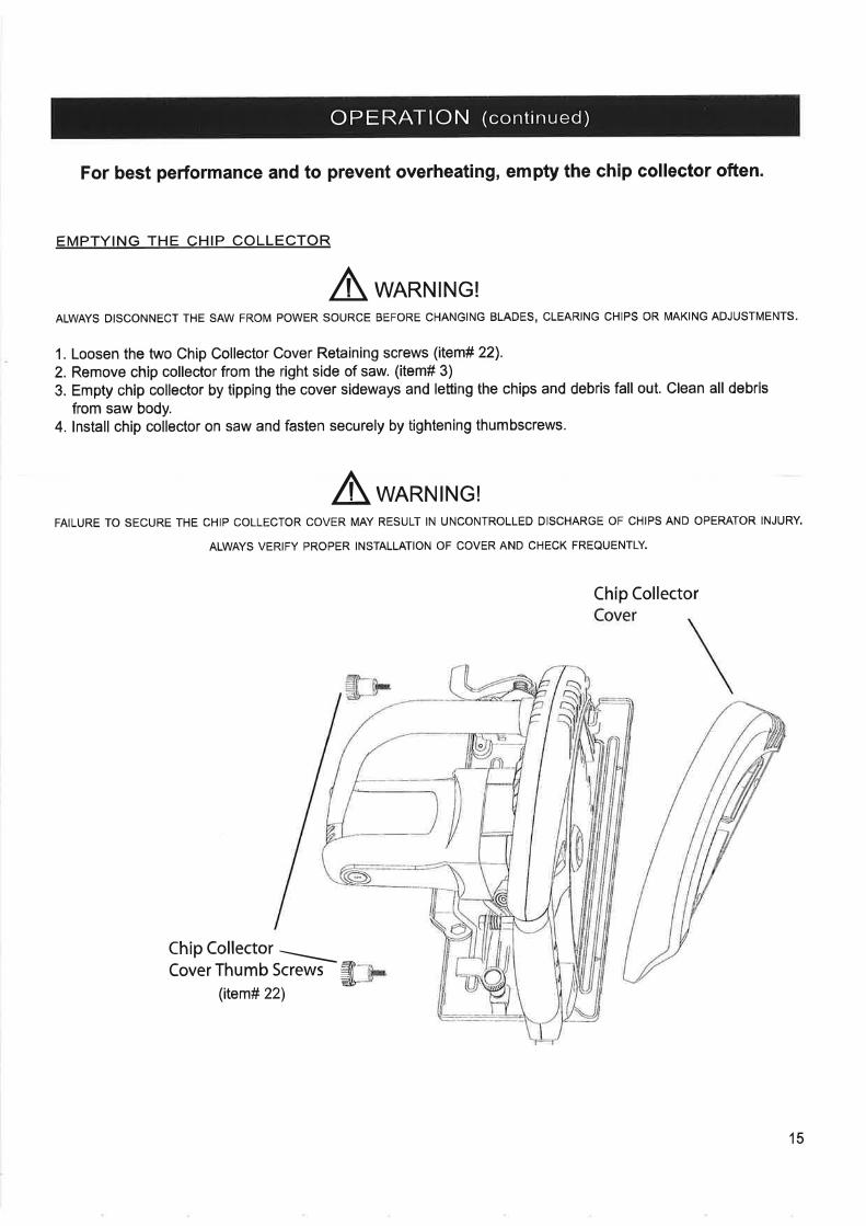
For best performance and to prevent overheating, empty the chip collector often.
EMPTYING THE CHIP COLLECTOR
A *ARNTNG!ALWAYS DISCONNECT THE SAW FROM POWER SOURCE BEFORE CHANGING BLADES, CLEARING CHIPS OR MAKING ADJUSTMENTS.
1. Loosen the two Chip Collector Cover Retaining screws (ilem# 22).
2. Remove chip collector from the right side of saw. (item# 3)
3. Empty chip collector by tipping the cover sideways and letting the chips and debris fall out. Clean all debris
from saw body.4. lnstall chip collector on saw and fasten securely by tightening thumbscrews.
A*ARNTNG!FAILURE TO SECURE THE CHIP COLLECTOR COVER MAY RESULT IN UNCONTROLLED DISCHARGE OF CHIPS AND OPERATOR INJURY.
ALWAYS VERIFY PROPER INSTALLATION OF COVER AND CHECK FREOUENTLY.
Chip Collector
Chip Collector \Cover Thumb Screwì ãr
-åu-(item# 22\
15
TROUBLESHOOTING CHECKLIST
3
4.
5.
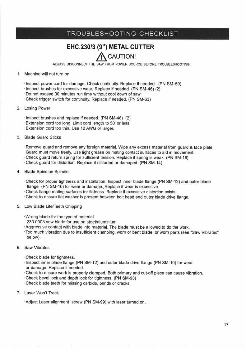
EHC.230/3 (9") METAL CUTTER
ALWAys D r scoN N Ecr r- = A-:f':JJ:JJ -"
= B EF'RE rRou BLES H oo' N G.
1. Machine will not turn on
'lnspect power cord for damage. Check continuity. Replace if needed. (PN SM-59).lnspect brushes for excessive wear. Replace if needed. (PN SM-46) (2).Do not exceed 30 minutes run time without cool down of saw,.Check trigger switch for continuity. Replace if needed. (PN SM-63)
2. Losing Power
.lnspect brushes and replace if needed. (PN SM-46) (2)
.Extension cord too long. Limit cord length to 50'or less.
.Extension cord too thin. Use 12 AWG or larger.
Blade Guard Sticks
'Remove guard and remove any foreign material. Wipe any excess material from guard & face plate.Guard must move freely. Use light grease on mating contact surfaces to aid in movement.
'Check guard return spring for sufficient tension. Replace if spring is weak. (PN SM-16)'Check guard for distortion. Replace if distorted or damaged. (PN SM-14)
Blade Spins on Spindle
'Check for proper tightness and installation. lnspect inner blade flange (PN SM-12) and outer bladeflange (PN SM-10) for wear or damage. Repla.ce if wear is excessive.
'Check flange mating surfaces for flatness. Replace if excessive distortion exists.'Check to ensure flat washer is present between bolt head and outer blade drive flange.
Low Blade Life/Teeth Chipping
.Wrong blade for the type of material.230.0003 saw blade for use on steel/aluminium.
'Aggressive contact with blade into material. The blade must be allowed to do the work.'Too much vibration due to insufficient clamping, worn or bent blade, or worn parts (see "Saw Vibrates"
below).
Saw Vibrates
.Check blade for tightness.'lnspect inner blade flange (PN SM-12) and outer blade drive flange (PN SM-10)for wearor damage. Replace if needed.
'Check to ensure work is properly clamped. Both primary and cut-off piece can cause vibration..Check bevel lock and depth lock for tightness. (PN SM-93).Check blade teeth for missing carbide, bends or cracks.
Laser Won't Track
'Adjust Laser alignment screw (PN SM-99) with laser turned on.
6.
7
17

Model#
PRODUCT REGISTRATION AND WARRANTY CARDThank you for purchasing a EUR0B00R@product!
Please fìll out this form and return promptly so that we may register your purchase.
Serial #
Plzase detach and retain this top portinnfor2our records.
Date of Purchase
Mr.ü Mrs.E ^s
tr Misstr
First Name Last Name
Company Name
Street Address
ZpCity State
Phone Number
May ure contact you by: Mail tr Fax El E-mail Address tr
Fax Number E-mail Address
Date of Purchase
Where did you purchased your EUR0B00R product from
What are the top two reasons that influenced your purchase of this EUROBOoR brand product?
Reputation EJ Value for pricè tr 'Wè¡ s¡te tr
Safety features E Magazine ad tr Availability trRecomrnendation E Reputation of retailer EStyle/Appearance E Quality/Durability tr Other tr
ln your o¡rinion, what is the BEST industry publication you regularly read?
ls this: A f¡rst time purchase? E An additional unit? tr A replacement unit? O For which brand?
Additional comments:
Thank You! We value your answers and input.flYes, put me on the EUROBOOR email list for special offers.
-q.--!-¡--*r-È-tiiE.óÈ-t.*-+õr,-.'-.t.J¡È.+-Ú.J¡--'--¿L--È-t!!!+!¡J-.r-.-.ùr-Ê
ãa1r,ow at@q atat¡ adrl amz¡¿
ATTENTION : WARRANTY D EPARTM ENT

SPECIF ICATIONS
l[odel IllG.230/3
DIMENSIONS AND SPECIFICATIONS
Height 340mm (13.4')widrh 340mm (13.4.)
Length 466mm (18.4")
Weight 9.8k9 (21lbs.)
Motor 230V - 1800W
50Hz I 2700 RPM
Blade Arbor 25.4mm (l,0")Blade Diameter 230mm (9.0")
of CuVPipe or Angle (maximum) 82.5mm (3.25")
Depth of CuVPlate or Bar (maximum) 13mm Mild Steel (1/2")
13mm Aluminum (1/2")
8mm Stainless Steel (5/16")
Case Dimensions 394mm H (15.5")
381mm W (15")
546mm L (21.5")
ACCESSORI ES
Saw Blades
Application
For cutting mild steel / Aluminium
Part #
230.0003
YOUR EUROBOOR DISTRIBUTOR
18
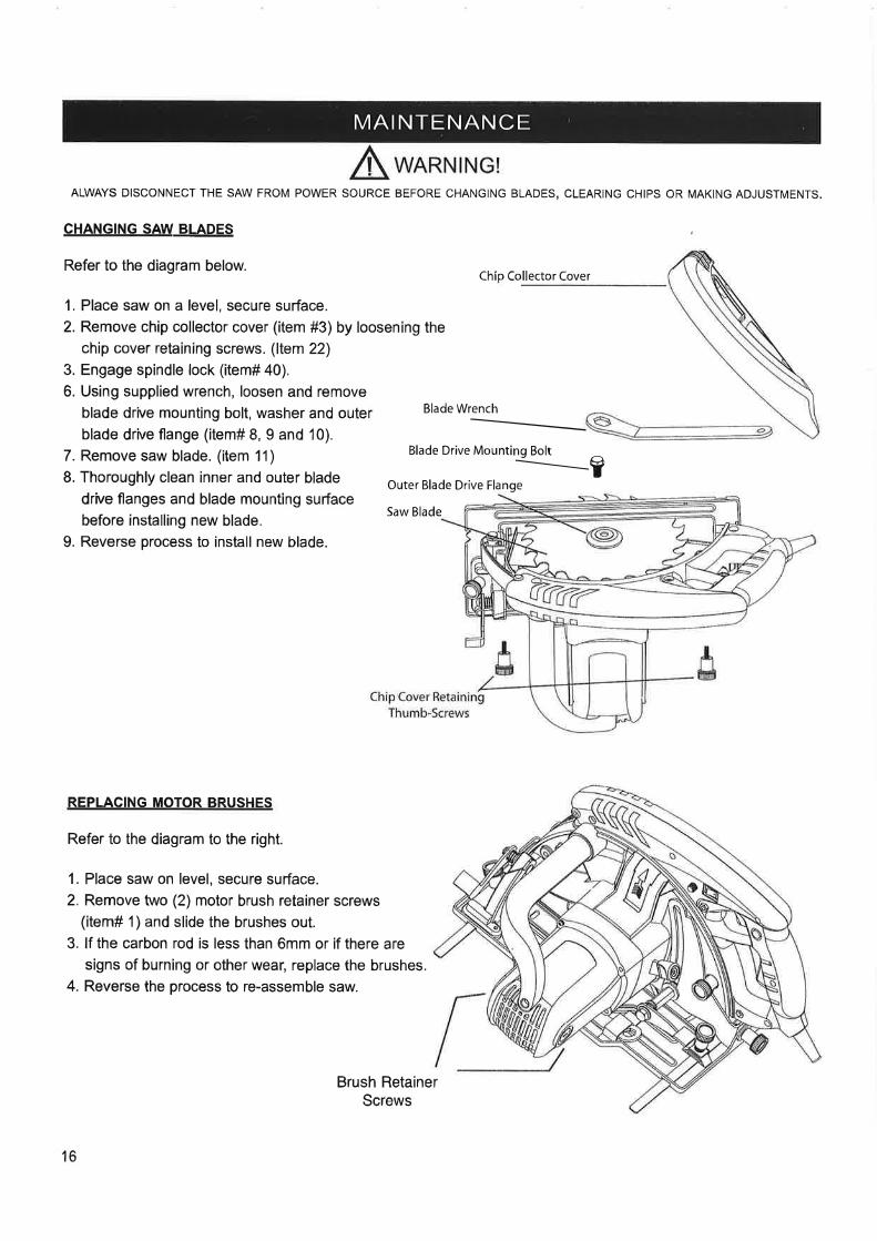
MAI NTENANCE
ALWAYS DISCONNECT THE SAW FROM POWER SOURCE BEFORE CHANGING BLADES, CLEARING CHIPS OR MAKING ADJUSTMENTS,
CHANGTNG SAW-BLAqES
Refer to the diagram below.
1. Place saw on a level, secure surface.
2. Remove chip collector cover (item #3) by loosening the
chip cover retaining screws. (ltem 22)3. Engage spindle lock (item# 40).
6. Using supplied wrench, loosen and remove
blade drive mounting bolt, washer and outerblade drive flange (item# 8, 9 and 10).
7. Remove saw blade. (item 11)
8. Thoroughly clean inner and outer blade
drive flanges and blade mounting surface
before installing new blade.
9. Reverse process to install new blade.
Blade Drive Mounting Bolt IOuter Blade Drive Flange
Chip Collector Cover
Blade Wrench____________
REPLACING MOTOR BRUSHES
Refer to the diagram to the right.
1. Place saw on level, secure surface.
2. Remove two (2) motor brush retainer screws(item# 1) and slide the brushes out.
3. lf the carbon rod is less than 6mm or if there are
signs of burning or other wea¡ replace the brushes.
4. Reverse the process to re-assemble saw.
Saw Blade
Brush RetainerScrews
16
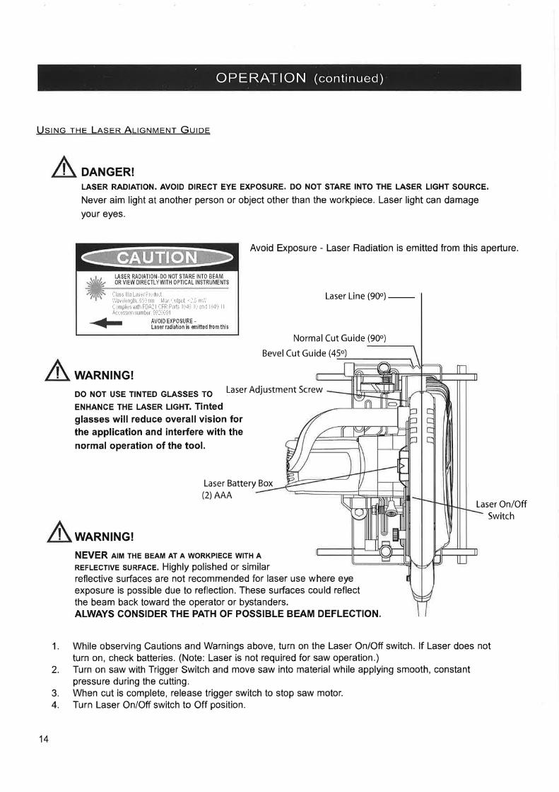
OPERATION (continued)
Uslruc tHe LRsrR Allc¡.lvErur Guroe
DANGER!LASER RADIATION. AVOID DIRECT EYE EXPOSURE. DO NOT STARE INTO THE LASER LIGHT SOURCE.
Never aim light at another person or object other than the workpiece. Laser light can damageyour eyes.
Avoid Exposure - Laser Radiation is emitted from this aperture.
USER RAOIATION_DO NOT STARE INTO BEAMOR VIEW DIRECTLYWITH OPTICAL INSTRUMENTS
'-'lass llla LaìÈr F¡:"iuÇt'',¡,avtl¿Ò!h rií['nìt hla/ Í,((l'Ul .,] í ÌrìÌ'C rììÞliÈs wlth FûA: I iFR F¿nti lrr,lf lú en,1 I irl! I I
ÂrrÉssri,n numlÈr !ì!:' rú!i I
+ tYgP,S}[ff][k-edrromthis
Laser Line (9oo)
-Normal Cut Guide (90o)
Bevel Cut Guide (4
WARNING!
Do Nor usE TTNTED GLASsES To Laser Adjustment screw
ENHANCE THE LASER LIGHT. TiNtCdglasses will reduce overallvision forthe application and interfere with thenormal operation of the tool.
Laser Battery Box(2)AAA
Laser On/OffSwitch
1.
2.
3.4.
WARNING!
NEVER AIM THE BEAM AT A WORKPIECE WITH A
REFLEcnvE suRFAcE. Highly polished or similarreflective surfaces are not recommended for laser use where eyeexposure is possible due to reflection. These surfaces could reflectthe beam back toward the operator or bystanders.ALWAYS CONSIDER THE PATH OF POSSIBLE BEAM DEFLECTION.
While observing Cautions and Warnings above, turn on the Laser On/Off switch. lf Laser does notturn on, check batteries. (Note: Laser is not required for saw operation.)Turn on saw with Trigger Switch and move saw into material while applying smooth, constantpressure during the cutting.When cut is complete, release trigger switch to stop saw motor.Turn Laser On/Off switch to Off position.
14
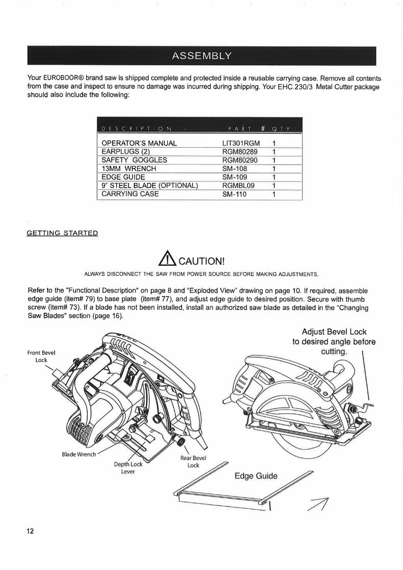
ASS E M BLY
Your EUROBOOR@ brand saw is shipped complete and protected inside a reusable carrying case. Remove all contentsfrom the case and inspect to ensure no damage was incurred during shipping. Your EHC.230/3 Metal Cutter packageshould also include the following:
GETTING STARTED
AcAU'oN!ALWAYS DISCONNECT THE SAW FROM POWER SOURCE BEFORE MAKING ADJUSTMENTS.
Refer to the "Functional Description" on page I and "Exploded View" drawing on page 10. lf required, assembleedge guide (item# 79) to base plate (item# 77), and adjust edge guide to desired position. Secure with thumbscrew (item# 73). lf a blade has not been installed, install an authorized saw blade as detailed in the "ChangingSaw Blades" section (page 16).
Adjust Bevel Lockto desired angle before
Front BevelLock
Blade Wrench
DESCRIPTION PART # ATY
OPERATOR'S MANUAL
13MM WRENCHEDGE GUIDE9'STEEL BLADE
sM-110 1
12
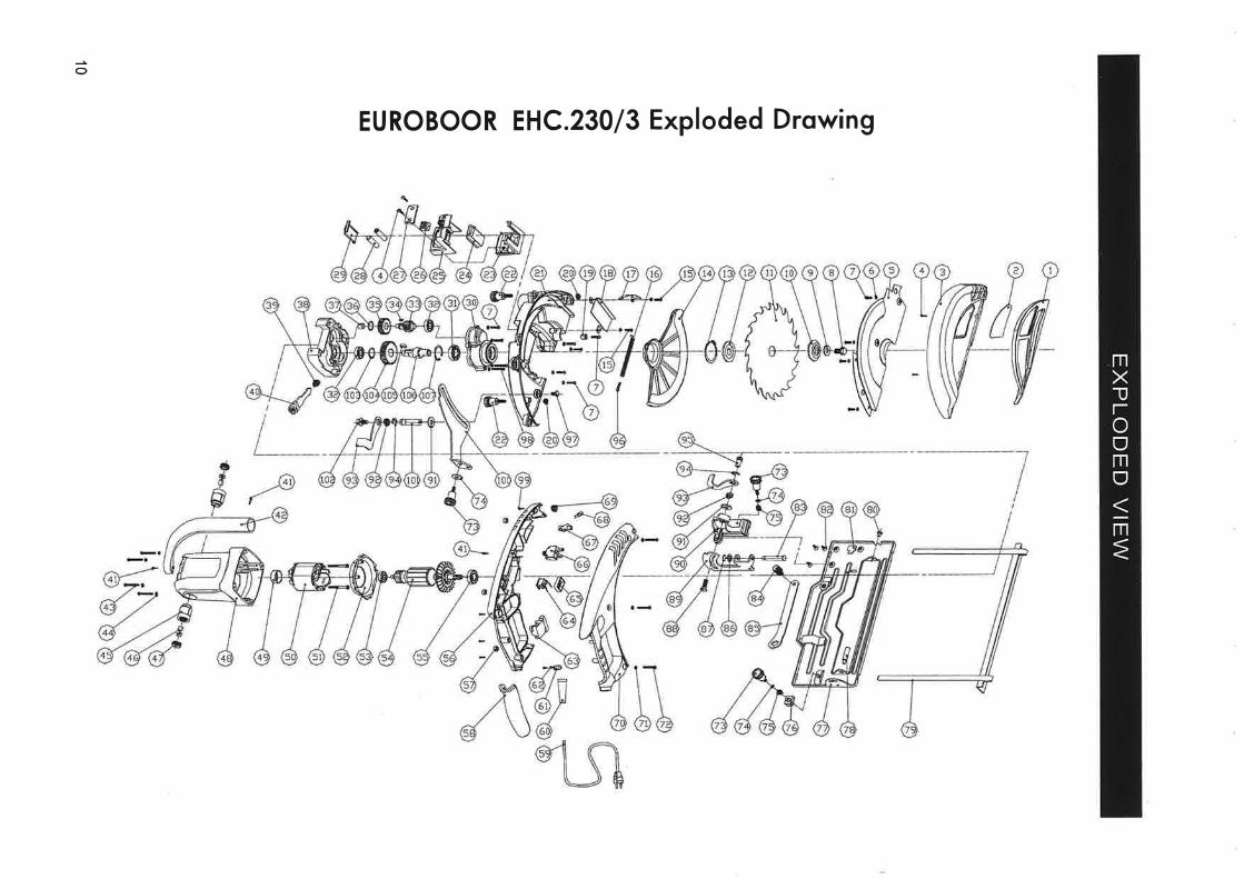
o
EUROBOOR EHC.230/3 Exploded Drowing
SPECIFIC SAFETY RULES (continued)
CAUSES AND OPERATOR PREVENTION OF KICKBACK
Kickback is a sudden reaction to a pinched, bound or misaligned saw blade,causing an uncontrolled saw to lift up and out of the workpiece toward the oper-ator. When the blade is pinched or bound tightly by the kerf (saw cut) closingdown, the blade stalls and the motorreaction drives the unit rapidly back toward the operator. lf the blade becomestwisted or misaligned in the cut, the teeth at the back edge of the blade can diginto the top surface of the material causing the blade to climb out of the kerf andjump back toward operator. Kickback is the result of tool misuse and/or incorrectoperating procedures or conditions and can be avoided by taking proper precau-tions as given below:
Maintain a firm grip with both hands on the saw and position your body and armto allow you to resist KICKBACK forces. KICKBACK forces can be controlled bythe operator, if proper precautions are taken.
When blade is binding, or when interrupting a cut for any reason, release thetrigger and hold the saw motionless in the material until the blade comes to a
complete stop. Never attempt to remove the saw from the work or pull the sawbackward while the blade is in motion or KICKBACK may occur. lnvestigate andtake corrective actions to eliminate the cause of blade binding.
When restarting a saw in the workpiece, center the saw blade in the kerf andcheck that saw teeth are not engaged into the material. lf saw blade is binding,it may walk up or KICKBACK from the workpiece as the saw is restarted.
Support largeLargepanels tend topanel on both
panels to minimize the risk of blade pinching and KICKBACK.
Do not use dull orke rfcausing excessive
sag under their own weight. Supports must be placed under thesides, near the line of cut and near the edge of the panel.
damaged blade. Dull or improperly set blades produce narrow
friction, blade binding and KICKBACK.
Blade depth and bevel adjusting locking levers must be tight and secure beforemaking a cut. lf blade adjustment shifts while cutting, it may cause binding andKICKBACK.
SPECIFIC SAFETY RULES (continued)
- DANGER! - Keep hands and body away from and to the side of the blade. Contact with blade will result in
serious injury.
- WARNING! - To reduce the risk of injury, check lower guard. lt must close instantly! Hold saw with both
hands. Support and clamp work. Wear eye protection.
Additional Soecific Safetv Rules:
DANGERI Keep hands away from cutting area and blade. Keep your second hand on auxiliary handle, or motor
housing. lf both hands are holding the saw, they cannot be cut by the blade.
.Keep your body positioned to either side of the saw blade, but not in line with the saw blade. KICKBACK could
cause the saw to jump backwards. (See "Causes and Operator Prevention of Kickback.")
.Do not reach underneath the work. The guard can not protect you from the blade below the work.
.Check lower guard for proper closing before each use. Do not operate saw if lower guard does not move freely
and close instantly. Never clamp or tie the lower guard into the open position. lf saw is accidentally dropped,
lower guard may be bent. Raise the lower guard and make sure it moves freely and does not touch the blade or
any other part, in all angles and depths of cut.
.Check the operation and condition of the lower guard spring. lf the guard and the spring are not operating
properly, they must be serviced before use. Lower guard may operate sluggishly due to damaged pads, gummy
deposits, or a buildup of debris.
.Always observe that the lower guard is covering the blade before placing saw down on bench or floor. An
unprotected, coasting blade will cause the saw to walk backwards, cutting whatever is in its path. Be aware of
the time it takes for the blade to stop after switch is released.
.NEVER hold piece being cut in your hands or across your leg. lt is important to support the work properly to
minimize body exposure, blade binding, or loss of control.
.Hold tool by insulated gripping surfaces when performing an operation where the cutting tool may contact
hidden wiring or its own cord. Contact with a "live" wire will also make exposed metal parts of the tool "live" and
shock the operator.
.When ripping always use a rip fence or straight edge guide. This improves the accuracy of cut and reduces the
chance for blade binding.
.Always use blades with correct size and shape (diamond vs. round) arbor holes. Blades that do not match the
mounting hardware of the saw will run eccentrically, causing loss of control.
.Never use damaged or incorrect blade washer or bolts. The blade washer and bolt were specially designed
for your saw, for optimum performance and safety of operation'
6
GENERAL SAFETY RULES (continued)
Personal Safetv.Sloy olert, watch whot you ore doing ond use common sense when operoting o power tool. Do nol use tool
while tired or under the influence of drugs, olcohol, or nedicotion, A moment of inattention while operatingpower tools may result in serious personal injury.
, Dress properly Do not weor loose clothing or iewelry. Conloin long hoir. Keep your hoir, clothing, ond gloves
owoy fron moving porfs. Loose clothes, jewelry, or long hair can be caught in moving parts.
.Avoid occidentol storting. Be sure swilch is off before plugging in. Carrying tools with your finger on the
switch or plugging in tools that have the switch on invites accidents.
.Remove odiusting keys or swilches before lurning lhe toolon. Awrench or a key that is left attached to arotating part of the tool may result in personal injury.
.Do not overreoch. Keep proper fooling ond bolonce otoll times. Properfooting and balance enables bettercontrol of the tool in unexpected situations.
,Use sofely equipmenl. Alwoys weor eye proleclion. Dust mask, non-skid safety shoes, hard hat, or hearingprotection must be used for appropriate conditions.
Tool Use and Gare,lJse clomps or olher proclicol woy to secure and support the workpiece lo a slable plotforn. Holding the
work by hand or against your body is unstable and may lead to loss of control.
.Do noÍ force tool. lJse the correcl lool for your applicoüon. The correct tool will do the job better and safer atthe rate for which it is designed.
. Do not use tool if switch does nol lurn if on or off. Any tool that cannot be controlled with the switch isdangerous and must be repaired.
.Disconnecl the plug from lhe power source before making any adiuslmenls, changing accessories, orstoring the tool. Such preventive safety measures reduce the risk of starting the tool accidentally.
.Store idle tools out of reoch of ch¡ldren ond olher untroined persons. Tools are dangerous in the hands ofuntrained users.
.Maintoin tools with core. Keep cutling lools sharp ond clean. Properly maintained tools, with sharp cuttingedges are less likely to bind and are easier to control.
.Check for misolignnent or binding of movÌng parts, breokoge of porls, ond ony olher condiÍion lhal nayoffect the tools operolion. lf domoged, have rhe bol serviced before using. Many accidents are caused bypoorly maintained tools.
.lJse only occessories lhot ore recommended by the monufocturer for your model. Accessories that may be
suitable for one tool, may become hazardous when used on another tool.
SERVICE.Tool service must be perforned only by quolified repoh personnel. Service or maintenance performed by
unqualified personnel could result in a risk of injury.
.When servicing o lool, use only idenlical replocemenl porls. Follow instruclions in lhe Maintenance seclion
of th¡s monuol. Use of unauthorized parts or failure to follow Maintenance lnstructions may create a risk ofelectric shock or injury.
4
Portable Metal Cutting Circular SawCongratulations on your purchase of a Euroboor Bladerunner Metal Cutter Saw. Please complete andmail your product registration card. Doing so will validate your machine's warranty period and erìsureprompt service if needed. We Sincerely thank you for selecting a product from Euroboor BV.
rABLE OF CONTENTSLimitedWarranty ......2General Safety Rules and Specific lnstructions ....3-4Specific Safety Rules and Symbols . . . .5-8Functional Drawings ....9ExplodedView ......10Partslist ...11AssemblyView ......12Operation ....13Operation (Laser) . . . . .14Emptying the Chip Chamber . . . . . .15Maintenance / Changing Saw Blades ,.....16Troubleshooting Checklist.. ......17Specifications ......18Accessories ......18
LIMITED WARRANTYEuroboor BV will, within twelve (12) months from the original date of purchase, repair or replace anygoods found to be defective in materials or workmanship, provided the product warranty registratiorr cardhas been returned to Euroboor BVwithin thirty (30) days of purchase date (proof of purchase reqr-rired).Thiswarrantyisvoidif tool isusedonmaterialsthickerthan 13mm (112") solidforaluminum, 13 trtm(112") formild steel, orSmm (5/16') forsolid stainless steel, has been damaged by accident, nectlect,improperservice, orother causes not arising out of defects in materials orworkmanship. Thiswarrantydoes not apply to machines and/or components which have been altered, changed, or modified i rr anyway, or subjected to use beyond recommended capacities and specifications. Electrical components aresubject to respective manufacturers' warranties, All goods returned defective shall be returned prepaidfreight to Euroboor BV, which shall be the buyer 's sole and exclusive remedy for defective goods- I rl noevent shall Euroboor BV be liable for loss or damage resulting directly or indirectly from the r-¡se ofmerchandise or from any other cause. Euroboor BV is not liable for any costs incurred on such goocl s orconsequential damages. No officer, employee or agent of Euroboor BV is authorized to make oralrepresentations of fltness or to waive any of the foregoing terms of sale and none shall be bindi rìg onEuroboor BV.
Euroboor BV RESERVES THE RIGHT TO MAKE
IMPROVEMENTS AND MODIFICATIONS TO DESIGN WITHOUT PRIOR NOTICE.EUROBOOR BVLoodstraat 1-3
2718 RV Zoetermeer
The Netherlands
2