geniuspro & lightpalette - operator's manual
TRANSCRIPT

GeniusPro & Lightpalette Software Version 2.6
Operator's Manual
Welcome Thank you for buying Strand Lighting control equipment. We hope that you will find that your lighting needs are met by your new system and that you will enjoy exploring the new facilities that your new system offers. You are provided with essential information to help you install and operate your system. Please look through all the documents and keep them safely for future use. If you have any difficulties, please do not hesitate to contact Strand Lighting or any authorized Strand service center for advice. This equipment is designed to operate from the mains electrical supply and contains voltages, which, if touched, may cause death or injury. It should only be operated in accordance with the instructions provided and for the purpose of a lighting control system. Do not open the console. There are no user serviceable parts inside. Avoid spilling liquid on the equipment If this should happen, switch the equipment off immediately at the mains. To reduce the risk of fire or electric shock, do not expose the equipment to rain or moisture. For indoor use only. This equipment is designed and manufactured to comply with international safety standards 1EC950, UL1950, CS950 and is intended for use as part of a lighting control system. It must not be used for other purposes where there is a risk of safety to persons. The equipment contains power voltages, socket outlets shall be installed near to the equipment and be easily accessible. • Working Voltage/Current 100-120 (2A) 220-240 (1A) • Frequency 50/60 Hz • Max Ambient Temp 350C • Do not restrict ventilation This manual describes the installation and operational procedures for Strand Lighting’s 300 and 500 series Control Console.

Offices and Service Centers Phone numbers do not include country code or other international access data. World Wide Web: http://www.strandlighting.com/ Berlin Strand Lighting GMBH Ullsteinstrasse. 114-142, HAUS C D-12109 Berlin, Germany Tel. +49-30-707-9510 Fax +49-30-707-95199 Hong Kong Strand Lighting Asia LTD 20/F., Delta House 3 On Yiu Street Shatin, N.T. Hong Kong Tel. +852-2757-3033 Fax +852-2757-1767 London Strand Lighting Limited Unit 3 Hammersmith Studios Yeldham Road Hammersmith London, England W6 8JF Tel. +44-20-8735-9790 Fax +44-20-8735-9799 Los Angeles Strand Lighting Inc 6603 Darin Way Cypress, CA 90630 U.S.A. Tel. +1 714-230-8200 Fax +1 714-230-8173 Moscow Strand Lighting Novinsky Boulevard 20A Building 3-6 12069 Moscow, Russia Tel. +7 095-234-42-20 Fax. +7 095-234 42-21 Rome Strand Lighting Italia Via Delle Gardenie S.N.C. Pontina Vecchia KM 33,400 00040 Pomezia, Italy Tel. +39-0691-9631 Fax +39-0691-47138 Toronto Strand Lighting (Canada) Inc 2430 Lucknow Drive #15, Mississauga, Ontario, L5S 1V3 Canada Tel. +1 905-677-7130 Fax. +1 905-677-6859
i
Table of Contents
Detailed Contents
Chapter 1 Introduction Page: 1
• Introducing GeniusPro and Lightpalette
• Console RAM Memory
• Password Registration
• Console Differences
o Model Numbers and Processor Speed
o Features Available with New Electronics
o 520 Series Differences
o 300 Series Differences
• Conventions Used in This Document
• Configuring European Keyboards
• Technical Assistance
• Safety Warning
• DOS License Agreement
Chapter 2 Product Specification Page: 25
• General
• Number of Attribute Chanels Available
Chapter 3 Loading Software Page: 36
• Pre-Installed Software
• Upgrading Your Console Software
• Adding Additional Channels or Applications to Version 2.2 or Later Software
• Adding Additional Channels or Applications to Version 2.1 or Earlier Software
• Checking the Software Version Number
• Files Included on Installation Disk
Chapter 4 Common Features Page: 44
• Live Screen
ii
o Screen Format
o Live LCD Menu
o Title Bar
• Locking the Console Faders and Keys
• Locking the Console Memory
• Error Messages
• Edit Field Protection
• Mouse Functions
Chapter 5 Working with Channel Levels Page: 48
• Editing the Command Line
• Setting up the Channel Levels Window
• Channel Status Identification
• Channel Type Identification
• Selecting Channels
• Channel Selection List
• Current Channel Selection
• Extending the Current Channel Selection
• Selecting the Next or Last Channel
• Clearing the Current Selection
• Setting Levels with the Keypad
• Using Recorded Items in Channel Lists
• Attribute Groups
• Attribute Filters
• Referenced Groups
• Using the Level Wheel
• Setting Attribute Levels
• Setting DMX Levels
• Copying Channel Levels
• Undoing Level Changes
iii
• Holding Channels on the Channel Control
• Restoring Playback Levels
• Flashing Channel Levels
• Bumping Channel Levels
• Channel Check
• Changing Levels in Preview (Blind) Display
• Fading in Intensity Channels in Time
• Fading in Attribute Channels in Time
Chapter 6 Basic Recording Page: 55
• Recording Levels and Properties
• Changing Properties Without Recording Levels
• Editing in a Preview (Blind) Display
• Copying from a Preview (Blind) Display
Chapter 7 Submasters and Channel Faders Page: 65
• Channel Faders
• Submaster Pages
• The Current Submaster
• Recording Submaster Levels
• Recording Submaster Properties
o Setting Submaster Properties
o Fade Times
o Fader Properties
o Submaster Functions
§ Pileon Submaster (Normal)
§ Independent Submaster (Indep)
§ Exclusive Submaster (Exclusive)
§ Inhibitive Submaster (Inhibit)
§ Sound to Light Submaster (S/Light)
§ DMX Channel Submaster (DMX Chan)
iv
§ DMX Dimmer Submaster (DMX DMNR)
§ Submaster Supermaster (Sub Super)
§ Effects Supermaster (FX Super)
§ Flash Supermaster (Flash SPR)
§ Grandmasters (GM1, GM2)
§ Audio Threshold Supermaster (AUDO THR)
§ Midi Ratio Supermaster (MIDI RATI)
o External Faders
o Submaster Bump Mode
o Text Labels
o Updating and Adding to Submasters
o Updating Submasters from the Live Screen
o Quick Recording
• Assigning Effects and Macros
• Using Submaster Faders
• Gang Loading of Subs
• The Submaster Window
• Viewing and Editing Submasters
o The Submaster Screen
o The State Screen
o Viewing Submaster Channel Levels
o Editing Submaster Channel Levels
o Clearing Submasters
o Copying Levels from a Submaster
• One and Two-Scene Preset
Chapter 8 Recording Cues Page: 72
• Cue and Part Numbering
• Recording Cue Levels
• Recording Cue Properties
v
o Fade Time
o Delay Time
o Wait Time
o Assigning Fade Profiles
o Assigning Fade Times to Attributes
o Asigning Fade Profiles to Attributes
o Assigning an Effect
o Assigning a Macro
o Links, Subroutines and Loops
o Fade Types (Cue Types)
o Creating a New Cue
o Copying an Existing Cue
o Level Tracking
o Recording a Text Label
Chapter 9 Running Cues Page: 93
• The Current Cue
• Running Timed Cues
• Running Manual Cues
• Loading a Cue
• Loading a Cue with Overrides
• Changing Cue Direction
• Jumping Directly to a Cue
• Using the Rate/Level Wheel to Change Fade Progress (500 Series Consoles)
• Using the Level Wheel to Change Fade Progress (300 Series Consoles)
• Cue Fade Progress in Manual Time
• Updating and adding to Cues
• Updating Cues from the Live Screen
• Changing Cues Temporarily
• Fading Cues with the Level Wheel
vi
• Viewing and Editing Cues
Chapter 10 X Playbacks Page: 110
• Assigning Cues to X Playbacks
• Playback Mode
• The X Playback Window (GeniusPro)
• The X Playback Window (Lightpalette)
• Using the X Playbacks
• X Playback in Manual Fade Mode
Chapter 11 Effects Page: 133
• The Current Effect Step
• Recording Effect Step Levels
• Recording Effect Properties
o Effect Text
o Effect Type
o Effect Direction
o Effect Fade Times
o Effect Mode
o Effect Level
o Next Fx
o Assigning Fade Profiles to Effects
o Stop After Field
o Step Control Field
o Step Default Values Field
• Recording Effect Step Properties
o Step Time Field
o In, Dwell, and Out Times Field
o Attribute Fade Time Field
o Low and High Scaling Field
• Using Effect Playbacks
vii
o The Effects Window
o The Effect Supermaster
o Effect Playback Selection
o The Current Playback
o Loading an Effect
o Running an Effect
o Pausing an Effect
o Stepping an Effect
o Changing Effect Times While Effect is Running
o Changing Effect Types While Effect is Running
o Changing Effect Direction
o Updating Effects
o Updating Effects from the Live Screen
o Unloading an Effect
• Using Effects in Cues and Subs
• Viewing and Editing Effects
o The Effect Display
o Effect Setting Fields
o Effect Step Fields
o Creating a New Effect
o Assigning Fade Times to Effects
o Assigning Profiles to Effects
o Creating Effect Steps
o Viewing Step Channel Levels
o Editing Step Channel Levels
o Deleting Effect Steps
o Copying Levels from an Effect Step
Chapter 12 Groups Page: 138
• Predefined Groups
viii
• The Current Group
• Recording Group Levels
• Recording Group Properties
• Using Referenced Groups
• Viewing and Editing Groups
• Updating and Adding to Groups
• Updating Groups from the Live Screen
• The Group Display
• Creating a New Group
• Viewing Group Channel Levels
• Editing Group Levels
• Deleting Groups
• Copying Levels from a Group
Chapter 13 Patches Page: 166
• Output Properties
• The Patch Display
• Selecting Outputs
• Changing Live and Edit Patches
• The Copy Patch Menu
o Copying Patch Information
o Moving Patch Information
o Swapping Patch Information
• Changing the Output Numbering Style
• Customising the Patch Display
• Deleting Channels
• Deleting Unpatched Attributes
• Renumbering Channels
• Default Patching
• Clearing Default Patching
ix
• Patching Channel Intensities
• Patching Double Width Outputs
• Assigning Output Profiles
• Patching Channel Attributes
• Patching Non-Dims
• Patching DMX In
• Unpatching
Chapter 14 Auto-Mod Page: 176
• What is Auto-Mod
• Using Auto-Mod
• Customising the Auto-Mod Screen
• Deleting Auto-Mod Channels
• Updating the Show from the Auto-Mod Screen
• Using Auto-Mod with Moving Lights
Chapter 15 Direct Output Control Page: 193
• The Current Output Selection
• Setting Levels
• Setting DMX Levels
• Repatching
Chapter 16 User Setup (The Setup Key) Page: 196
• Changing the User Setup
• Locking the Console Memory
Chapter 17 The Archive Screen Page: 199
• Archive Selection Window
• Show List Window
• Software Operations
o Password Operations
o Loading Operating Software
x
o Loading Application Software
• Disk Operations
o Why Save a Show?
o Storing Floppy Disks
o Naming the Show
o Changing the Current Drive and Directory
o Saving a Show
o Loading a Show
o Restoring or Deleting a Backup Copy of the Show
o Local Disk Functions
§ Creating a Local Disk Directory
§ Copy a Show
§ Delete a Show from the Local Disk
§ Delete a Local Disk Directory
§ Formatting a Floppy Disk
§ Write Protecting the Floppy Disk
• Print Operations
o Printer Setup
o Printing
• Clear Operations
Chapter 18 Macros Page: 200
• Macro Properties
• Pre-Assigned Macros
• Learning a Macro
• Deleting a Macro
• Running a Macro Manually
• Running a Macro Automatically
• Viewing Macros
• Creating a New Macro
xi
• Editing Macros
• Macro Tablet
o Setting Up the Macro Tablet
o Using the Macro Tablet
o Fitting the Macro Tablet Template
o Defining, Learning, Editing and Deleting Macro Tablet Macros
• Macro Trigger Card
Chapter 19 Profiles Page: 215
• Profile Properties
• Predefined Profiles
• Viewing and Editing Profiles
o The Profile Display
o The Current Profile
o Creating Profiles
o Using End Editing
o Using DMX Values for Points
o Using Graph Editing
o Deleting a Profile
o Profile Learn
§ Viewing and Editing Learned Profiles
§ Stopping the Learn Process
§ Assigning Profiles
Chapter 20 Report Displays Page: 224
• The Channel Summary Screen
• The Cue Summary Screen
• The Dimmer Summary Screen
• The System Report Menu
• The System Report Screen
• Advanced Setup Menus

xii
o User Setup
§ The Control Modes Window
§ Channel Control Mode
§ CC Auto Hold Mode
§ On Level %
§ Up/Down %
§ Wheel Mastering
§ Wheel Sensitivity
§ Stop Key
§ The Display Options Window
§ Display Language
§ Channel Display
§ Smart Channel Display
§ Auto Channel Page
§ Channel Formatting
§ Live Screen Layout
§ X Playback Colours
§ X Playback Order
§ X Playback Format
§ Show Last Recorded Cue
§ Screen Menus
§ The Default Times Window
§ X Back, Cut
§ Cue Fade Up/Down
§ Cue Delay Up/Down
§ Cue Wait
§ FX Step
§ FX Step In/Dwell/Out
§ FX Up/Down
§ Undo Time

xiii
§ The Console Window
§ Number of Screens
§ LCD Contrast/Backlight
§ Gooseneck Brightness
§ Buzzer Volume
§ Macro Tablet
§ Mouse
§ Console Keys Layout
§ Submaster Layout
§ GeniusPro, Lightpalette, Default
o Show Setup Screen
§ Show Details Window
§ Cue Tracking
§ Playback Modes
§ Auto Move While Dark
§ Auto Move Fade Delay
§ Auto Preheat
§ Auto Preheat Fade Delay
§ Power Up Restore
§ Power Up Macro
§ GM1 Fade Up/Down
§ GM2 Fade Up/Down
§ Channel Partitioning
§ Playback Partitioning
§ Cue Sheet Macros
§ MIDI Window
§ Timecode Options Window
§ Patch Window
§ Default Scale %
§ Default Frame
xiv
§ Default Non-Dim %
§ Console Time Window
§ Time Display
§ Date Display
§ Set Time
§ Set Date
§ At Time Macros Window
o Console Setup Screen
§ Output Connections Window
§ D54/AMX
§ DMX 1 - 4
§ Network Window
§ Networker On/Off
§ Networker Video Slot
§ NET 1 - NET 4
§ Communications Window
§ Reporter On/Off
§ Handheld Remote Communications Setup
§ ASCII Remote Input
§ GO Key Output
§ Macro Trigger
§ Remote Test
§ Audio Input Macro
§ Remote Trigger Macro
§ Trigger Bytes
§ External Submasters Window
• Setting Access Rights
o User Access Rights Window
o Console Access Rights Window
o Combined User and Access Rights Window
xv
• Locking the Console Memory
• Dimmer Log Screen
• The System Diagnostic Menu
o The Status Log
o The Network Diagnostics Screen
o The Internal Diagnostic Screen
• Exit and System Shutdown
Chapter 21 Console Reporter Page: 246
• Setting Up the Rack Configuration
• Dimmer Fault Reporting
• Dimmer Command Menu
• Dimmer Log Screen
• Output Filter Display
• Recording a Dimmer Backup Scene
Chapter 22 Notes Page: 251
• Writing and Editing Notes
• Loading Files
• Viewing and Editing Configuration Files
Chapter 23 Key, Wheel VGA Remapping Page: 253
• Loading the Map Configuration File
• Remapping Keys (500 Series Consoles)
o Identifying Key Positions
o Key Numbering
• Remapping Keys (300 Series Consoles)
o Key Numbering
• Key Functions
• Key Remapping Examples
• Remapping Console Wheels, Rotaries and Trackball
• Console Identification
xvi
• Remapping VGA Screens
Chapter 24 510i and 310 Show Controller Page: 261
• User Interface
• Macro Screen
• Submaster Screen
• Disk Browse Screen
o Loading a Show
o Copying a Show
o Loading Operating Software
• Timecode Events Screen
§ Time Format
§ Setting/Resetting the Internal Clock
§ Stepping the Light Show Timing
• Cues and X Playbacks Screen
• Backup Screen
• Panel Setup
• Video Line Error
• PC Editing
• Submaster Macro Inputs
Chapter 25 Offline Editor & PC Software Page: 269
• Prerequisites
• Installing the Offline Editor Software
o Installing Offline Editor Using DOS 3.1 or later
o Installing Offline Editor Using Windows9X
• Installing the Backup PC Kit
o Installing the Ethernet Card
o Configuring the Ethernet Card
o Installing the Dongle
o Installing the Backup PC Software from DOS
xvii
o Installing the Backup PC Software from Windows 9X
o Installing the Networker & Utilities Software Using DOS 3.1 or Later
o Installing the Networker & Utilities Software Using Windows 9x
• Installing the Help File Using DOS 3.1 or Later
• Installing the Help File Using Windows 9X
• Running the Software (Offline Editor or Backup PC)
• Notes on Running Offline Editor or Backup PC Software
• Designer Keypad
• Keyboard Map
Chapter 26 Handheld Remotes Page: 283
• Designer's Remote
o Installing the Designer's Remote
o Operating the Designer's Remote
• The R120 Handheld Remote
o Installing and Configuring the R120 Handheld Remote
§ Installing the R120 Wired Remote
§ Installing the R120 Radio Base
§ Installing the R120 Radio Handheld Remote
§ R120 Base Pinouts
o Operating the R120 Handheld Remote
• R130 Handheld Remote
o Installing and Configuring the R130 Handheld Remote
§ Installing the R130 Wired Remote
§ Installing the R130 Radio Handheld Remote
§ Installing the R130 Radio Base
§ R130 Base Pinouts
o Operating the R130 Handheld Remote
• iPaq WiFi Wireless Remote Operating Instructions
o SN110 Node Configuration
xviii
o Overview
Chapter 27 Console Connectors Page: 298
500 Series Consoles
o DMX 1,2,3 and 4
o AUX 1, 2 and 3
o D54
o Audio
o Remote
o Midi In, Thru, Out
o Printer Port
o Serial Ports
o VGA
o PS2 Ports
o COM1 and COM2
o Ethernet 10BT
o Submaster Macro Inputs (510i)
300 Series Processor Unit
o DMX 1 and 2
o AUX 1 and 2
o Sbus 1-4
o Parallel Printer
o COM1
o PS2 Mouse
o PS2 Keyboard
o VGA
o TFT Panellink
o SMPTE Input
o MIDI In, Thru, Out
o Submaster Macros 1-24 (310)
300 Series Modules
xix
o Sbus 1-4
o Serial Port
o PS2 Port
o TFT Panellink
Chapter 28 CommuniquéPro Page: 311
• External Submasters
o Setting Up External Submasters
o Setting Up an External Submaster as a Macro Trigger
• DMX In
o Setting Up DMX In Submasters
o Patching DMX In Dimmers
o Using DMX In Dimmers
o Using DMX In Channels
• MIDI
o Controlling Effects Using MIDI
o MIDI Show Control
o MIDI Keys and Faders
o MIDI Note
o MIDI Message
o MIDI Trigger Macro
• Audio Input Macro
• ASCII Remote Control Output
• ASCII Remote Go Output
• ASCII Remote Control Input
• SMPTE Time Code Events
o Event List
o Time Code Format and Synchronisation
o Event List Menu
xx
o Inserting and Deleting Events
o Editing Event Labels, Cues and Commands
o Selecting Events for Time Editing
o Editing Timecodes
o Moving or Copying Events with Time Edit Commands
o Searching for Events Using Time Edit Commands
o Timecode Event Playback Screen
o Setting the Event Playback Start and Stop Time
o Setting/Resetting the Internal SMPTE Clock
o Stepping the Light Show Timing
o Changes in SMPTE External Clock Input
Chapter 29 Networker Software Page: 322
• Network Port Selection
• Node Addresses
• Broadcast Communication
• Point to Point Communication
• Default IP Addresses
• 220node.cfg Network Configuration File
• SN10X Configuration File Format
• Network Node Configuration File Example
• SN10X Node Self Test Software
• Preserving Configuration Files
• Network DMX
• Network Video
• Tracking Backup
o Overview of Tracking Backup
o Configuration for Tracking Backup
o Tracking Backup Status
o Tracking Backup Commands
xxi
o Shifted Backup Commands
o Testing Backup Takeover
o Console Lock on Backup
• Remote Consoles
o Remote Console Configuration
o Setting Remote Console Mode Without Using the Login Display
o Using Remote Console Submasters
o Remote Console Status
o Remote Console Controls
o Channel Partitioning
o Viewing Other User's Displays
• Remote Ports
Chapter 30 Tracker Software Page: 341
• Attributes
o What Are Attributes?
o Using Attributes
o Trackerball Keys
o Rotary Controls
o Mouse Control of Features
• Tracker Displays
o Smart Channel Display
o Rotary Controls Window (Live Display)
• Channel Control Syntax
o Controlling Intensity and Attributes
o Copying Channel Attributes
• Patching Attributes
o Patching Attributes to a Single Channel
o Patching Fixtures
o The Copy Patch Menu
xxii
§ Copying Patch Information
§ Moving Patch Information
§ Swapping Patch Information
o Range Patching
• Recording and Playback
o Attributes in Cues
o Attributes in Submasters
o Attributes LTP - Intensities HTP
o Auto Move While Dark
• Referenced Groups (Preset Focus)
• Colour Palettes
• Attribute Filters
• Updating Attribute Filters from the Live Screen
• Fixture Library List
Chapter 31 Server Software Page: 358
• Creating a Standalone File Server Using a PC
o Loading Networker & Utilities on a PC using DOS 3.1, or later
o Windows 95/NT PC Server
o Configuring a File Server
o Operating a File Server
o Accessing a File Server
• User Logins
o Configuring Logins
o Configuring Access Rights
o Console Access Rights
o Login Display
o Logging In Without Using the Login Display
o Seeing Who Else is Logged In
o Exit Softkey
• Integrating File Server and Logins
xxiii
Chapter 32 Shownet Configuration Software Page: 367
• Shownet Software Installation
• Windows Network Configuration
• Running Shownet Software
• Pop-Up Speed Menu
• Editing the Shownet Configuration
o Shownet Sites Window
o Shownet Nodes Window
o Shownet Universes Window
o Shownet Patches Window
o Shownet Ports Window
• Shownet Command Buttons
Chapter 33 SN100 and SN102 Network Nodes Page: 372
• SN100 and SN102 Safety
• SN100 & SN102 Controls and Displays
• SN100 Installation
• SN102Installation
• SN100 and SN102 Interface List
Chapter 34 Ethernet Overview Page: 381
• Cabling Systems
o Thick Net
o Thin Net (Thin Wire, 10BASE2, 10B2) Backbone
o Thin Net (Thin Wire, 10BASE1, 10B2) Star
o Twisted Pair (UTP 10BASET, 10BT) Star
o Optical Fibre
• Network Topology
o Ethernet 4-3-2 Rule
o Ethernet Hubs
xxiv
o Typical Ethernet Configurations
• Ethernet Card Installation on Older Consoles
Chapter 35 Networker for SN10X Software Installation Page: 390
• Displaying the Current Version Number
• Floppy Disk Installation
• Remote Installation
• Remote Installation from an SN100/SN102
• Remote Install from a PC
• Assigning New IP Addresses
Chapter 36 Showport File Conversion Page: 394
• Showport Software Installation
• Running Showport Software
• Showport File Formats
Chapter 37 Additional Information Page: 400
• Notes on Upgrading Old Software
• Problems Starting the Software
• Fitting RAM Memory
• Macro Trigger Card
• Tracker Library Files
• Site Configuration Files
• DOS Utilities
• DOS Environment Variables
• Country Keyboard Support
• Changing the HTML Help Files
• Converting German Galaxy Files to Strand Show Files.
Top of Page
1-25
Chapter 1 - Introduction
This section introduces GeniusPro and Lightpalette and includes important topics with which the user should be familiar before using these instructions. Particular attention should be paid to 'Console Differences’, which explains the differences between the Strand Lighting console models, highlights operational differences between older and newer consoles and points out mechanical and functional differences between models.
GeniusPro and Lightpalette Operating Software are control software products for Strand Lighting's 24-submaster 520 and 520i lighting control consoles, for the 30 submaster 430, 530 and 530i consoles, for the 54 submaster 550 and 550i consoles, for the 510i rack-mounted show control/backup unit and for the new 300 series consoles and the 310 show controller.
GeniusPro and Lightpalette software is copyright Strand Lighting Ltd. 1994 to 2001. All rights reserved. The software is supplied under the terms of , and may only be used with, the License Agreement.
This version of software should be loaded on all consoles, PCs and remote consoles to take advantage of improvements. Load both Operating Software and Networker & Utilities software. Refer to Upgrading Your Console Software
The following topics are covered in this section:
• Technical Assistance • Safety Warning • DOS License Agreement • Introducing GeniusPro and Lightpalette • Console RAM Memory • Console Differences • Conventions Used in This Document • Configuring European Keyboards

1-26
Technical Assistance
The console requires a minimum of maintenance and servicing. If equipment fails to operate properly upon installation, or under normal load and temperature conditions, and basic troubleshooting procedures are not effective, please contact your nearest Strand Authorised Service Centre or Strand Lighting Field Service at the office serving your area. For technical questions regarding setup, operation, or maintenance of this equipment, please contact your nearest Strand Authorised Service Centre or the Strand Lighting Field Service office serving your area. For purchase of upgrades, accessories, peripherals or documentation, please contact your nearest Strand Authorised Service Centre or the Strand Lighting office serving your area. For comments regarding equipment functions and possible improvements, or for comments on these instructions, please write to the Strand Lighting office serving your area.
You can access the Strand Lighting World Wide Web site at http://www.strandlighting.com/
Addresses for all of the Strand Lighting offices are as shown:
Phone numbers do not include country code or other international access data. Asia: Strand Lighting Asia, LTD 20/F., Delta House, 3 On Yiu Street, Shatin, N.T. Hong Kong Tel: 757 3033 Fax: 757 1767 Canada : 2430 Lucknow Dr., Unit 15, Mississauga, Ontario L5S 1V3 Canada Tel: 905 677 7130 Fax: 905 677 6859 Germany: Ullsteinstrasse 114-142, 12109 Berlin Tel: 004930 707 9510 Fax: 004930 707 95199 Italy: Via delle Gardenie 33 (Pontia Vecchia KM 33,400), 00040 Pomezia-Roma, Italy Tel: 6914 7123 Fax: 6914 7136 U.K.: Strand Lighting Ltd. Mitchelston Industrial Estate, Kirkcaldy, Fife KY1 3LY, Scotland. Tel 01592 652333 Fax 01592 653528 U.S.A Service & Support 800 4 STRAND (800 478 7263) U.S.A.: 6603 Darin Way Cypress, CA 90630 USA Tel: 714-230-8200 Fax: .714-899-0042 The information in this manual is for information purposes only and is subject to change without notice. Strand Lighting assumes no responsibility for any errors or omissions, which may appear in this manual. For comments and suggestions regarding corrections and/or updates to this manual, please contact your nearest Strand Lighting office.
Safety Warning This equipment is designed to operate from the mains electricity supply and contains voltages which, if touched, may cause death or injury. It should only be operated in accordance with these instructions and for the purpose of a lighting control system. Do not open the 500 Series consoles. There are no user serviceable parts inside. The console configuration can be changed, as described in the Installation manual for the 300 Series consoles. Before attempting to reconfigure the consoles, ensure that the mains supply is isolated and that the mains plug is removed. Avoid spilling liquid on the console. If this should happen, switch the console off immediately.
1-27
DOS License Agreement END-USER LICENSE AGREEMENT FOR MICROSOFT SOFTWARE IMPORTANT-READ CAREFULLY: This End-User License Agreement ("EULA") is a legal agreement between you (either an individual or a single entity) and the manufacturer ("Manufacturer") of the special purpose computing device ("SYSTEM") you acquired which includes certain Microsoft software product(s) installed on the SYSTEM ("SOFTWARE PRODUCT" or "SOFTWARE"). The SOFTWARE includes computer software, the associated media, any printed materials, and any "online" or electronic documentation. Any software provided along with the SOFTWARE PRODUCT that is associated with a separate end-user license agreement is licensed to you under the terms of that license agreement. By installing, copying, downloading, accessing, or otherwise using the SOFTWARE, you agree to be bound by the terms of this EULA. If you do not agree to the terms of this EULA, Manufacturer and Microsoft Licensing, Inc. ("MS") are unwilling to license the SOFTWARE to you. In such event, you may not use or copy the SOFTWARE, and you should promptly contact Manufacturer for instructions on return of the unused product(s) for a refund. SOFTWARE LICENSE The SOFTWARE is protected by copyright laws and international copyright treaties, as well as other intellectual property laws and treaties. The SOFTWARE is licensed, not sold. 1. GRANT OF LICENSE. This EULA grants you the following rights: · Software. You may use the SOFTWARE as installed on the SYSTEM. · Application Sharing. The SOFTWARE may contain technology that enables applications to be shared between two or more SYSTEMS, even if an application is installed on only one of the SYSTEMS. You should consult your application license agreement or contact the application licensor to determine whether sharing the application is permitted by its licensor. · Storage/Network Use. If the SOFTWARE PRODUCT is installed on the SYSTEM over an internal network from a server, you must acquire and dedicate a license for the SOFTWARE PRODUCT for each SYSTEM on which the SOFTWARE PRODUCT is used or to which it is distributed. A license for the SOFTWARE PRODUCT may not be shared or used concurrently on different SYSTEMS. · Back-up Copy. If MANUFACTURER has not included a copy of the SOFTWARE on separate media with the SYSTEM, you may make a single copy of the SOFTWARE for use solely for archival purposes with the SYSTEM. Back-up Utility. If the SOFTWARE PRODUCT includes a Microsoft back-up utility, you may use the utility to make the single back-up copy. After the single back-up copy is made, the backup utility will be permanently disabled. Except as expressly provided in this EULA, you may not otherwise make copies of the SOFTWARE PRODUCT, including the printed materials accompanying the SOFTWARE. 2. DESCRIPTION OF OTHER RIGHTS AND LIMITATIONS. · Limitations on Reverse Engineering, Decompilation and Disassembly. You may not reverse engineer, decompile, or disassemble the SOFTWARE, except and only to the extent that such activity is expressly permitted by applicable law not withstanding this limitation. · Single SYSTEM. The SOFTWARE is licensed with the SYSTEM as a single integrated product. The SOFTWARE may only be used with the SYSTEM. · Rental. You may not rent or lease the SOFTWARE. · Software Transfer. You may permanently transfer all of your rights under this EULA only as part of a sale or transfer of the SYSTEM, provided you retain no copies, you transfer all of the SOFTWARE (including all component parts, the media, any upgrades or backup copies, and this EULA, and if applicable, the Certificate(s) of Authenticity), and the recipient agrees to the terms of this EULA. If the SOFTWARE is an upgrade, any transfer must include all prior versions of the SOFTWARE. · Termination. Without prejudice to any other rights, Manufacturer or MS may terminate this EULA if you fail to comply with the terms and conditions of this EULA. In such event, you must destroy all copies of the SOFTWARE and all of its component parts. · Single EULA. The package for the SOFTWARE may contain multiple versions of this EULA,
1-28
such as multiple translations and/or multiple media versions (e.g., in the user documentation and in the software). In this case, you are only licensed to use one (1) copy of the SOFTWARE PRODUCT. · Export Restrictions. You agree that you will not export or re-export the SOFTWARE to any country, person, entity or end user subject to U.S. export restrictions. You specifically agree not to export or re-export the SOFTWARE (i) to any country to which the U.S. has embargoed or restricted the export of goods or services, which as of May 1999 include, but are not necessarily limited to Cuba, Iran, Iraq, Libya, North Korea, Sudan, Syria, and the Federal Republic of Yugoslavia (including Serbia, but not Montenegro), or to any national of any such country, wherever located, who COMPANY knows intends to transmit or transport the product(s) back to such country; (ii) to an end user you know or have reason to know will utilize the SOFTWARE in the design, development or production of nuclear, chemical or biological weapons; or (iii) to any end-user who has been prohibited from participating in U.S. export transactions by any federal agency of the U.S. government. 3. UPGRADES AND RECOVERY MEDIA. · If the SOFTWARE is provided by Manufacturer on media separate from the SYSTEM and is labeled "For Upgrade Purposes Only" ("Upgrade SOFTWARE"), you may install one copy of the Upgrade SOFTWARE onto the SYSTEM as a replacement copy for the SOFTWARE originally installed on the SYSTEM and use it in accordance with Section 1 of this EULA. You may also install additional copies of the Upgrade SOFTWARE as replacement copies onto additional SYSTEMS which are the same brand and model as the SYSTEM and contain a duly licensed copy of the same version and language release of the SOFTWARE ("ADDITIONAL SYSTEMS"), provided that (1) Manufacturer has supplied a corresponding serialized sticker for each additional copy of the Upgrade SOFTWARE, and (2) you affix a serialized sticker per Manufacturer's instructions for each unit of Upgrade SOFTWARE you install. · If the SOFTWARE is provided by Manufacturer on separate media and labeled "Recovery Media" ("Recovery Media"), you may not make a copy of the SOFTWARE as described in Section 1 for archival purposes. Instead, you may use the Recovery Media solely to restore or reinstall the same version and language release of the SOFTWARE as originally installed on the SYSTEM and thereafter use the SOFTWARE as restored or reinstalled in accordance with Section 1 of this EULA. A single unit of Recovery Media may be used by you to restore or reinstall the SOFTWARE on ADDITIONAL SYSTEMS. 4. COPYRIGHT. All title and copyrights in and to the SOFTWARE (including but not limited to any images, photographs, animations, video, audio, music, text and "applets," incorporated into the SOFTWARE), the accompanying printed materials, and any copies of the SOFTWARE, are owned by MS or its suppliers (including Microsoft Corporation). You may not copy the printed materials accompanying the SOFTWARE. All rights not specifically granted under this EULA are reserved by MS and its suppliers (including Microsoft Corporation). 5. PRODUCT SUPPORT. Product support for the SOFTWARE is not provided by MS, its parent corporation, Microsoft Corporation, or their affiliates or subsidiaries . For product support, please refer to Manufacturer's support number provided in the documentation for the SYSTEM. Should you have any questions concerning this EULA, or if you desire to contact Manufacturer for any other reason, please refer to the address provided in the documentation for the SYSTEM. 6. LIMITED WARRANTY. · Limited Warranty. Manufacturer warrants that the SOFTWARE will perform substantially in accordance with the accompanying written materials for a period of ninety (90) days from the date of receipt. Any implied warranties on the SOFTWARE are limited to ninety (90) days. Some states/jurisdictions do not allow limitations on duration of an implied warranty, so the above limitation may not apply to you. · Customer Remedies. Manufacturer's and its suppliers' entire liability and your exclusive remedy shall be, at Manufacturer's option, either (a) return of the price paid, or (b) repair or replacement of the SOFTWARE that does not meet the above Limited Warranty and which is returned to Manufacturer with a copy of your receipt. This Limited Warranty is void if failure of the SOFTWARE has resulted from accident, abuse, or misapplication. Any replacement SOFTWARE will be warranted for the remainder of the original warranty period or thirty (30) days, whichever is longer.
1-29
· No Other Warranties. EXCEPT AS EXPRESSLY PROVIDED IN THE LIMITED WARRANTY SECTION ABOVE, THE SOFTWARE IS PROVIDED TO THE END USER "AS IS" WITHOUT WARRANTY OF ANY KIND, EITHER EXPRESSED OR IMPLIED, INCLUDING, BUT NOT LIMITED TO, WARRANTIES OF NON-INFRINGEMENT, MERCHANTABILITY, AND/OR FITNESS FOR A PARTICULAR PURPOSE. THE ENTIRE RISK OF THE QUALITY AND PERFORMANCE OF THE SOFTWARE IS WITH YOU. · No Liability for Consequential Damages. MANUFACTURER OR MANUFACTURER'S SUPPLIERS, INCLUDING MS AND ITS SUPPLIERS, SHALL NOT BE HELD TO ANY LIABILITY FOR ANY DAMAGES SUFFERED OR INCURRED BY THE END USER (INCLUDING, BUT NOT LIMITED TO, GENERAL, SPECIAL, CONSEQUENTIAL OR INCIDENTAL DAMAGES INCLUDING DAMAGES FOR LOSS OF BUSINESS PROFITS, BUSINESS INTERRUPTION, LOSS OF BUSINESS INFORMATION AND THE LIKE), ARISING FROM OR IN CONNECTION WITH THE DELIVERY, USE OR PERFORMANCE OF THE SOFTWARE. 7. NOTE ON JAVA SUPPORT. THE SOFTWARE PRODUCT MAY CONTAIN SUPPORT FOR PROGRAMS WRITTEN IN JAVA. JAVA TECHNOLOGY IS NOT FAULT TOLERANT AND IS NOT DESIGNED, MANUFACTURED, OR INTENDED FOR USE OR RESALE AS ON-LINE CONTROL EQUIPMENT IN HAZARDOUS ENVIRONMENTS REQUIRING FAIL-SAFE PERFORMANCE, SUCH AS IN THE OPERATION OF NUCLEAR FACILITIES, AIRCRAFT NAVIGATION OR COMMUNICATION SYSTEMS, AIR TRAFFIC CONTROL, DIRECT LIFE SUPPORT MACHINES, OR WEAPONS SYSTEMS, IN WHICH THE FAILURE OF JAVA TECHNOLOGY COULD LEAD DIRECTLY TO DEATH, PERSONAL INJURY, OR SEVERE PHYSICAL OR ENVIRONMENTAL DAMAGE. If you acquired this EULA in the United States, this EULA is governed by the laws of the State of Washington. If you acquired this EULA in Canada, this EULA is governed by the laws of the Province of Ontario, Canada. Each of the parties hereto irrevocably attorns to the jurisdiction of the courts of the Province of Ontario and further agrees to commence any litigation which may arise hereunder in the courts located in the Judicial District of York, Province of Ontario. U.S. GOVERNMENT RESTRICTED RIGHTS
Introducing GeniusPro and Lightpalette
Strand’s lighting control consoles with GeniusPro and Lightpalette software offer you the flexibility to choose and upgrade your console software, including the basic operating software, through an integral floppy disk drive.
This flexibility lets you update when you need to without having to buy new hardware. The maximum number of channels and attributes available depends on the hardware performance, and is different for various consoles. Please contact Strand Lighting for specifics.
All application software, with the exception of the Server software is supplied as standard on all consoles.
The CommuniquéPro software is used to add SMPTE, MIDI, MIDI Show Control, DMX input, external submasters, serial, and other means of communication. The Tracker software supports advanced facilities for automated fixture control including additional types of attributes (for instance, pan and tilt), preset focus groups, and fixture libraries. The Networker software
1-30
provides remote video, remote DMX via Ethernet, and access to all SN node ports. Console Reporter is an add-on software package used to monitor and report temperature, electronic status and system and load information for all SV Series dimmers. This facility allows the user to know the status of all lamps on a rig and to record rack-based backup cues simply and easily.Other software can be easily added as it is developed.
Regardless of your level of lighting knowledge, this complete family of software lets you grow as your experience increases, or start at a significantly higher level, all as economically as possible.
Refer to the Product Specification section for full list of all software features available on 300 and 500 series control consoles.
Software updates and manuals are available on the internet at http://www.strandlighting.com/. FTP (File Transfer) browsers may also be used. The internet address is 193.129.67.250. Some of the download items require a user name and password to be entered.
Console RAM Memory
The i version now requires at least 32Mbytes of RAM installed in the console or PC. The non-i version still operates in 8Mbytes or more. The more memory, the faster the console executes commands (although mux outputs always transmit at the normal rate). Up to 64Mbytes of RAM is supported in consoles fitted with new CS electronics or in the PC. Refer to Console Differences. See also Fitting RAM memory
Password Registration
If your current version of Operating Software is earlier than version 2.0, you will need to re-register your console and PC, if fitted with a CS card or dongle, in order to use this release. Refer to Upgrading Your Console Software
Console Differences
This section covers the following topics:
o Model Numbers and Processor Speed o Features Available with New Electronics
1-31
o 520 Series Differences o 300 Series Differences
Model Numbers and Processor Speed Over recent years, Strand Lighting have improved the performance and ability of the hardware and software associated with their range of lighting control consoles. Since most of the functions described in this manual are software-based, many of the new functions developed in recent years can be added to older consoles simply by updating the software, albeit that some of the newer functions will not operate as efficiently on older consoles, as they were designed to run on newer and faster processors. Models 300 These consoles are designed on a modular basis using S bus network protocol and a Pentium processor. The standard memory console comprises a processor unit, a command module and a submaster module comprising 24 submaster faders. Channel fader sections, comprising 24 faders can be physically connected to the control surface, up to a maximum of 168 faders (6 additional fader modules). LCD monitor modules are also available for use in place of the standard VGA monitors and are provided as standard on Memory 400 and 600 models. Model 310 The 310 Show Controller/Backup Unit is designed primarily to serve the lighting requirements of the themed environment market and to operate over a network as a backup unit to a main console. The unit is similar to the Processor Unit of the 300 series consoles, but includes an operator interface, comprising a touch screen. Refer to (refer to 510i/310 Show Controller/ Backup Unit). Models 430, 530 and 530i (30 Submaster Faders) These consoles are similar in style and have the same mechanical features. The difference between the consoles is the type, and speed of the processor used in the motherboard as follows:
• 430 Consoles - 486 Processor or Pentium Processor • 530 Consoles - Pentium Processor • 530i Consoles - Pentium Pro or Pentium II Processor
Models 550 and 550i (54 Submaster Faders) Again, these models are similar and have the same mechanical features. The difference is the type and speed of the processor used in the motherboard as follows:
• 550 Consoles - Pentium Processor • 550i Consoles - Pentium Pro or Pentium II Processor
Models 520 and 520i (24 Submaster Faders) Again, these models are similar and have the same mechanical features. The difference is the type and speed of the processor used in the motherboard as follows:
1-32
• 520 Consoles - Pentium Processor • 520i Consoles - Pentium Pro or Pentium II Processor
Model 510i (Show Controller) This is a rack-mounted lighting controller designed primarily to serve the lighting requirements of the themed environment market and to operate over a network as a backup unit to a main console. This controller runs the same operating and application software as the other consoles, however the user interface is completely different (refer to 510i/310 Show Controller/Backup Unit). The 510i is only available with the latest Pentium Processor.
Features Available with 500 Series New Electronic Sub-System All 500 series consoles are now fitted with the latest Pentium Processor and a new-style electronic sub-system enabling additional features that were not possible with previous, slower processors. You can check if your console is fitted with the new electronics by checking the position of the Ethernet Port on the rear of the console, which, on consoles fitted with new electronics is fitted on the same panel as the DMX AUX ports, rather than being an optional expansion card (although a second network card can be fitted in addition to the built-in port). The new electronics provide the following additional facilities:
• Built-in Ethernet Ports (no built-in ports on old electronics) • Handheld remotes can be connected to any AUX port (AUX 3 only for old electronics) • All 4 DMX ports are supported. DMX 4 is of opposite gender to the others for use as a
DMX input, although it can be set as a fourth output (DMX 3 is available as an input with old electronics).
• New SMPTE input port, accessible vi a the Audio connector.
520 Series Differences Apart from the number of submaster faders, the 520 and 520i have a number of mechanical differences from the other consoles as follows:
• 520 and 520i does not have an On/Off button and Stop button at the top of the console. An On/Off switch is fitted at the rear of the console.
• 520 and 520i does not have Grandmaster faders. You can assign submasters as Grandmasters faders
• 520 and 520i does not have a separate Rate Wheel (the Level Wheel doubles as a Rate Wheel)
• 520 and 520i does not have a centre LCD • 520 and 520i has only four centre softkeys • 520 and 520i has 14 direct macro keys rather than 7. • 520 and 520i has the floppy disk drive fitted below the front of the console.
1-33
520 Series LCD Softkeys 520 series consoles have no centre LCD. The soft menus which pop up on the centre LCD on other consoles for [BUMP MODE], [FX TIME] etc. use the right LCD on 520 series consoles.
[CUE], [GROUP] and [SUB] no longer pop up {INTS ONLY} and {ATTS ONLY} soft keys on 520 series consoles. To access these keys, press the [REC MODE] key when required during [CUE], [GROUP] and [SUB] commands.
300 Series Differences
A special version of the GeniusPro/Lightpalette operating software and the application software packages has been developed to run on 300 series consoles. While all of the functionality available on the 500 series consoles is also available on 300 series consoles, a number of keys on the 500 series consoles are omitted from the 300 series consoles. Specifically the [REC TIME] [SUB PAGE] [BUMP MODE] [FX SEL], [FX DIR], [FX TIME] and [FX LOAD] keys are not available on the 300 series consoles. The 300 series consoles have an intellimouse in place of the trackball and rotaries and have only one LCD display.
It should be emphasised, unless specifically stated otherwise, that all software functions described in this manual are available within all consoles. Where keys are omitted, there are other methods of achieving the same result, e.g., Edit Mode, by using an ASCII Keyboard and PC Emulation Template, by creating a macro to simulate the key function, or by key remapping.
Note: The Strand logo key on 300 Series Consoles is equivalent to the [SHIFT] key on 500 Series consoles.
Differences in operation between 500 and 300 series consoles are explained at the appropriate points in this manual
The functions performed by the trackball on a 500 series console can be performed on a 300 series console using the Microsoft Intellimouse Trackball connected to the PS2 or COM ports on the command module/processor unit. When a mouse, or trackball is not available, the functions can be performed using the navigation keys on a standard ASCII keyboard connected to the keyboard connection on the processor unit, or to the PS2 port on the back of the command module.
For details on how to control moving lights using a Microsoft Intellimouse Trackball, refer to Mouse Control of Features
Panel Configuration (300 Series Consoles)
When you purchase a 300 Series console, the configuration of the fader modules supplied is set at the factory. The maximum number of fader panels is 7, so if you have 5 fader panels and a command module in your system. the fader panels are numbered in the 220node.cfg file as fdr1 to fdr 5.
1-34
If you purchase additional fader panels and connect them to the system, or you remove one or more fader panels, you must reset the panel configuration.
To reset the panel configuration after adding or removing fader panels, proceed as follows:
• With all panels connected to the command module, press <REPORT> {ADV SETUP} then {PANEL SETUP}.This will cause each fader panel to display its fader number by illuminating the number of LEDs in red on the left-hand side of the top row of the fader panel according to its fader number (1 - 7). For instance, fader number 3 will illuminate three LEDs.
• You can change the fader panel number by pressing one of the first 7 bump keys on the on the top row of the fader panel. For instance, to change a fader panel to Fader 3, press the third bump key from the left on the top row
• Once you have reset the panel configuration, yoy must press {SAVE} to save the new panel configuration. After pressing {SAVE} you will require to shutdown and restart the console.
• If you have removed one or more fader panels, you most clear the configuration by pressin {CLEAR}. This will extinguish all the LEDs and reset all faders in the 220node.cfg file to 00.
• You can then set the panel fader numbers using the bump keys as previously described. • Press {SAVE} and shutdown and restart the console..
To leave the 'Orders' Menu, press the {BACK} softkey.
Conventions Used in This Document
The following conventions are used throughout this document.
[CUE] The console keys. This example shows the key labelled CUE. <SETUP> The display keys. These are above the right LCD on the console and are shown in italics to distinguish them from other keys with the same name. (The LCDs are the three small display areas across the centre of the console.) {BACK} The console soft keys; these are the row of 4 or 6 unmarked keys whose function can change depending on what you are doing. This example shows the soft key labelled BACK. wheel Level Wheel movement. trackball Trackball movement. fader Fader movement. Bump 1 A submaster bump button. Direct Entry 1 Digit A channel level entry in Direct Entry 1 Digit format. Direct Entry 2 Digit A channel level entry in Direct Entry 2 Digit format. Command Line A channel level entry in Command Line format. # Used in syntax or field descriptions as a place holder for a number. The # symbol is never actually entered
1-35
Important Note:
Throughout this manual, references to trackball should be taken as a generic term covering the series 500 trackball or Intellimouse Trackball.
The Strand Logo key on 300 Series consoles is equivalent to the [SHIFT] key on 500 Series consoles. References to the [SHIFT] key in this manual apply equally to the Strand Logo key.
The [@ATT] key (500 Series consoles) is equivalent to the [ATTRIB] key on 300 Series consoles. This manual refers to [@ATT]
Configuring European Keyboards
The console is configured at the factory for the US ASCII keyboard. You need to configure keyboards for other locales.
Refer to Country Keyboard Support

2-36
Chapter 2 - Product Specifications
General
• 300 Series 24/48 Manual Memory Console • 300 Series 48/96 Manual/Memory Console • 300 Series Memory 125 Console • 300 Series Memory 250 Console • 300 Series Memory 400 Console • 300 Series Memory 600 Console • 300 Series 120 Submaster Console • 520 Console • 530i Console • 550i Console
300 Series Consoles
Model 24/48 Manual/Memory
• Intensity Channels = 50 • Attribute Channels = 50 • Submasters = 24 • VGA Monitors as Standard = 1* • DMX Outputs = 1024/1536*** • No.of Subs/Super/G'Masters = 24 • Sub Pages = 4 • Cues = 600 • Cue P/Backs = 2 • Max Simult. Fades = 100 • Macros = 3000 • Groups = 500 • Preset Focus Groups = 500 • Effects = 300 • Effect Steps/Effect = 99 • Max Effect Steps = 1500 • Effect Playbacks = 12 • Profiles = 99 • SMPTE Events = 2000 • Patches = 1 • Atts/Channel = 99 • Fixture Library = 99 • Handheld Remotes = 2 • No. of Show File Backups = 1 • Remote Video = 9

2-37
Model 48/96 Manual/Memory
• Intensity Channels = 100 • Attribute Channels = 100 • VGA Monitors as Standard = 1* • DMX Outputs = 1024/1536*** • No.of Subs/Super/G'Masters = 24 • Sub Pages = 4 • Cues = 600 • Cue P/Backs = 2 • Max Simult. Fades = 100 • Macros = 3000 • Groups = 500 • Preset Focus Groups = 500 • Effects = 300 • Effect Steps/Effect = 99 • Max Effect Steps = 1500 • Effect Playbacks = 12 • Profiles = 99 • SMPTE Events = 2000 • Patches = 1 • Atts/Channel = 99 • Fixture Library = 99 • Handheld Remotes = 2 • Remote Video = 9 • No. of Show File Backups = 1
Memory 125
• Intensity Channels = 125 • Attribute Channels = 125 • VGA Monitors as Standard = 1* • DMX Outputs = 1024/1536*** • No.of Subs/Super/G'Masters = 24 • Sub Pages = 4 • Cues = 600 • Cue P/Backs = 2 • Max Simult. Fades = 100 • Macros = 3000 • Groups = 500 • Preset Focus Groups = 500 • Effects = 300 • Effect Steps/Effect = 99 • Max Effect Steps =1500 • Effect Playbacks = 12 • Profiles = 99 • SMPTE Events = 2000 • Patches = 1

2-38
• Atts/Channel = 99 • Fixture Library = 99 • Handheld Remotes = 2 • Remote Video = 9 • No. of Show File Backups = 1
Memory 250
• Intensity Channels = 250 • Attribute Channels = 250 • VGA Monitors as Standard = 1* • DMX Outputs = 1024/1536*** • No.of Subs/Super/G'Masters = 24 • Sub Pages = 4 • Cues = 600 • Cue P/Backs = 2 • Max Simult. Fades = 100 • Macros = 3000 • Groups = 500 • Preset Focus Groups = 500 • Effects = 300 • Effect Steps/Effect = 99 • Max Effect Steps = 1500 • Effect Playbacks = 12 • Profiles = 99 • SMPTE Events = 2000 • Patches = 1 • Atts/Channel = 99 • Fixture Library = 99 • Handheld Remotes = 2 • Remote Video = 9 • No. of Show File Backups = 1
Memory 400
• Intensity Channels = 400 • Attribute Channels = 400 • VGA Monitors as Standard = 2* • DMX Outputs = 1024/1536*** • No.of Subs/Super/G'Masters = 24 • Sub Pages = 4 • Cues = 600 • Cue P/Backs = 2 • Max Simult. Fades = 100 • Macros = 3000 • Groups = 500 • Preset Focus Groups = 500

2-39
• Effects = 300 • Effect Steps/Effect = 99 • Max Effect Steps = 1500 • Effect Playbacks = 12 • Profiles = 99 • SMPTE Events = 2000 • Patches = 1 • Atts/Channel = 99 • Fixture Library = 99 • Handheld Remotes = 2 • Remote Video = 9 • No. of Show File Backups = 1
Memory 600
• Intensity Channels = 600 • Attribute Channels = 400 • VGA Monitors as Standard = 2* • DMX Outputs = 1024/1536*** • No.of Subs/Super/G'Masters = 24 • Sub Pages = 4 • Cues = 600 • Cue P/Backs = 2 • Max Simult. Fades = 100 • Macros = 3000 • Groups = 500 • Preset Focus Groups = 500 • Effects = 300 • Effect Steps/Effect = 99 • Max Effect Steps = 1500 • Effect Playbacks = 12 • Profiles = 99 • SMPTE Events = 2000 • Patches = 1 • Atts/Channel = 99 • Fixture Library = 99 • Handheld Remotes = 2 • Remote Video = 9 • No. of Show File Backups = 1
120 Submaster
• Intensity Channels = 600 • Attribute Channels = 400 • VGA Monitors as Standard = 2* • DMX Outputs = 1024/1536*** • No.of Subs/Super/G'Masters = 120

2-40
• Sub Pages = 4 • Cues = 600 • Cue P/Backs = 2 • Max Simult. Fades = 100 • Macros = 3000 • Groups = 500 • Preset Focus Groups = 500 • Effects = 300 • Effect Steps/Effect = 99 • Max Effect Steps = 1500 • Effect Playbacks = 12 • Profiles = 50 • SMPTE Events = 2000 • Patches = 1 • Atts/Channel = 99 • Fixture Library = 99 • Handheld Remotes = 2 • Remote Video = 9 • No. of Show File Backups = 1
500 Series Consoles
520 Console
• Intensity Channels = 200 • Attribute Channels = 200 • VGA Monitors as Standard = 2* • DMX Outputs = 1024/1536*** • No.of Subs/Super/G'Masters = 24 • Sub Pages = 6 • Cues = 2000 • Cue P/Backs = 2 • Max Simult. Fades = 200 • Macros = 3000 • Groups = 1000 • Preset Focus Groups = 750 • Effects = 600 • Effect Steps/Effect = 99 • Max Effect Steps = 14850 • Effect Playbacks = 30 • Profiles = 99 • SMPTE Events = 3000 • Patches = 2 • Atts/Channel = 99 • Fixture Library = 99 • Handheld Remotes = 4 • Remote Video = 9 • No. of Show File Backups = 10
2-41
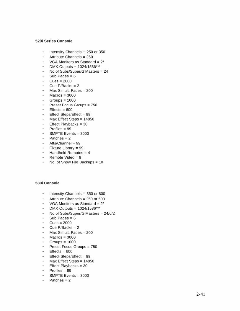
520i Series Console
• Intensity Channels = 250 or 350 • Attribute Channels = 250 • VGA Monitors as Standard = 2* • DMX Outputs = 1024/1536*** • No.of Subs/Super/G'Masters = 24 • Sub Pages = 6 • Cues = 2000 • Cue P/Backs = 2 • Max Simult. Fades = 200 • Macros = 3000 • Groups = 1000 • Preset Focus Groups = 750 • Effects = 600 • Effect Steps/Effect = 99 • Max Effect Steps = 14850 • Effect Playbacks = 30 • Profiles = 99 • SMPTE Events = 3000 • Patches = 2 • Atts/Channel = 99 • Fixture Library = 99 • Handheld Remotes = 4 • Remote Video = 9 • No. of Show File Backups = 10
530i Console
• Intensity Channels = 350 or 800 • Attribute Channels = 250 or 500 • VGA Monitors as Standard = 2* • DMX Outputs = 1024/1536*** • No.of Subs/Super/G'Masters = 24/6/2 • Sub Pages = 6 • Cues = 2000 • Cue P/Backs = 2 • Max Simult. Fades = 200 • Macros = 3000 • Groups = 1000 • Preset Focus Groups = 750 • Effects = 600 • Effect Steps/Effect = 99 • Max Effect Steps = 14850 • Effect Playbacks = 30 • Profiles = 99 • SMPTE Events = 3000 • Patches = 2

2-42
• Atts/Channel = 99 • Fixture Library = 99 • Handheld Remotes = 4 • Remote Video = 9 • No. of Show File Backups = 10
550i Consoles
• Intensity Channels = 800 or 2000 or 6000 • Attribute Channels = 400 or 500 or 2000 • VGA Monitors as Standard = 2* • DMX Outputs = 1024/1536*** • No.of Subs/Super/G'Masters = 48/ 6/ 2 • Sub Pages = 6 • Cues = 2000 • Cue P/Backs = 2 • Max Simult. Fades = 200 • Macros = 3000 • Groups = 1000 • Preset Focus Groups = 750 • Effects = 600 • Effect Steps/Effect = 99 • Max Effect Steps = 14850 • Effect Playbacks = 30 • Profiles = 99 • SMPTE Events = 3000 • Patches = 2 • Atts/Channel = 99 • Fixture Library = 99 • Handheld Remotes = 4 • Remote Video = 9 • No. of Show File Backups = 10
Notes:
*All consoles have the ability to use two VGA monitors as standard. All consoles can use either 3 or 4 VGA monitors, with an optional additional dual VGA card. **Additional channels can be purchased in lots of 50 or 200 intensity channels, up to the maximum of 600 (300 Series) and 6000 (500 Series). *** The maximum number of DMX outputs using Networker software and the maximum number of network slots
2-43
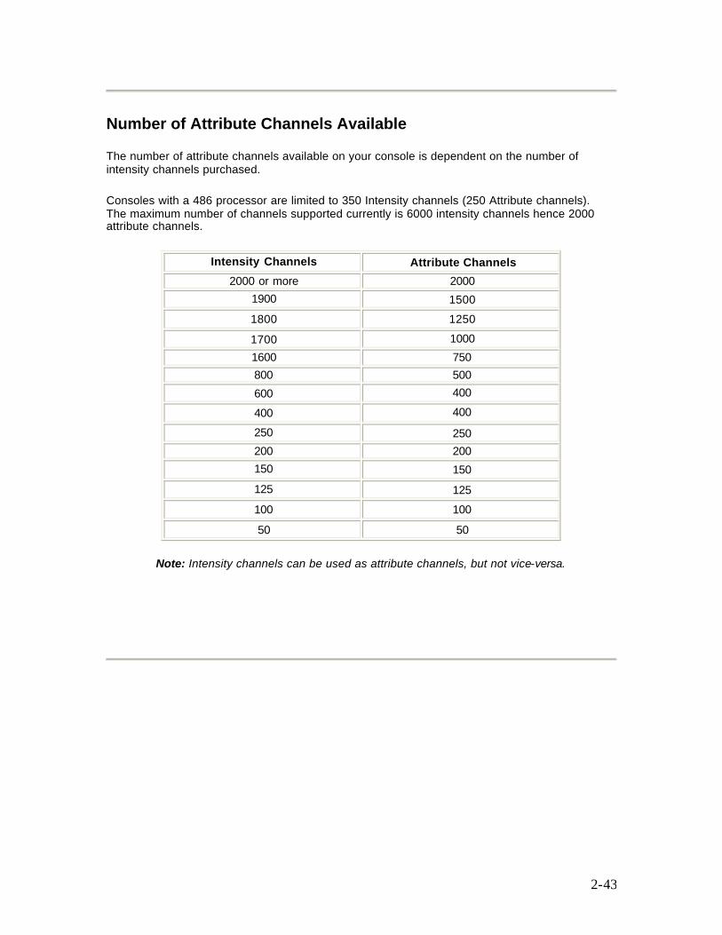
Number of Attribute Channels Available
The number of attribute channels available on your console is dependent on the number of intensity channels purchased.
Consoles with a 486 processor are limited to 350 Intensity channels (250 Attribute channels). The maximum number of channels supported currently is 6000 intensity channels hence 2000 attribute channels.
Intensity Channels Attribute Channels 2000 or more 2000
1900 1500 1800 1250 1700 1000 1600 750 800 500 600 400 400 400 250 250 200 200 150 150 125 125 100 100 50 50
Note: Intensity channels can be used as attribute channels, but not vice-versa.
3-44
Chapter 3 - Loading Software
Your Strand Lighting Control System is software-based to allow you to upgrade and add capabilities as new, or enhanced programs are introduced. Some software products include a security registration feature that ensures that you have received a reliable, supported and legal copy of the program. Your completed registration will also enable us to keep you informed of all the latest advances in the programs you have purchased. The following topics are covered in this section:
• Pre-Installed Software • Upgrading Your Console Software • Adding Additional Channels or Applications to Version 2.2 or Later Software • Adding Additional Channels or Applications to Version 2.1 or Earlier Software • Checking the Software Version Number • Files Included on CD
Pre-Installed Software
If you have purchased a new lighting control console, the operating software is pre-installed and configured so that you can use your system immediately. In order that we can provide you with an efficient software support service, it is important that you register the software. Please complete the Software Registration Form supplied and return it to Strand Lighting.
Upgrading Your Console Software Note: Due to new installation file names, you can only upgrade the operating software to version 2.4a if version 2.3f is already installed on your console. To obtain version 2.3f operating software, refer to the Strand Internet site on http://www.strandlighting.com/ or obtain the software from the 2.4a CD. To verify the integrity of the operating software, run the crccheck utility from DOS., e.g., >A: >CRCCHECK '[5] files checked' is displayed if all files are OK If you received the operating software by e-mail, or from the Strand Web Site, copy them to DOS floppy disk (high density, 1.44Mb) and run crccheck from DOS to verify before installing. If you are upgrading your console software, please procede as follows:
3-45
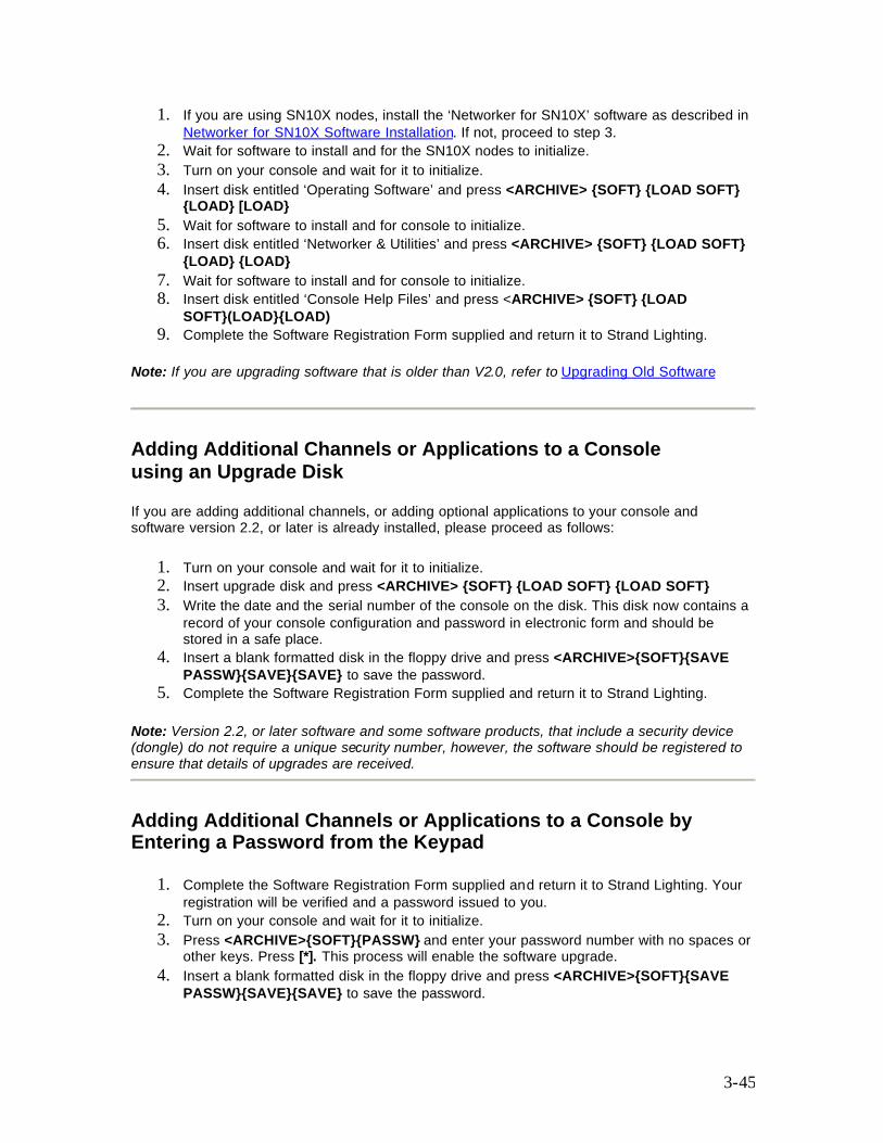
1. If you are using SN10X nodes, install the ‘Networker for SN10X’ software as described in Networker for SN10X Software Installation. If not, proceed to step 3.
2. Wait for software to install and for the SN10X nodes to initialize. 3. Turn on your console and wait for it to initialize. 4. Insert disk entitled ‘Operating Software’ and press <ARCHIVE> {SOFT} {LOAD SOFT}
{LOAD} [LOAD} 5. Wait for software to install and for console to initialize. 6. Insert disk entitled ‘Networker & Utilities’ and press <ARCHIVE> {SOFT} {LOAD SOFT}
{LOAD} {LOAD} 7. Wait for software to install and for console to initialize. 8. Insert disk entitled ‘Console Help Files’ and press <ARCHIVE> {SOFT} {LOAD
SOFT}(LOAD}{LOAD) 9. Complete the Software Registration Form supplied and return it to Strand Lighting.
Note: If you are upgrading software that is older than V2.0, refer to Upgrading Old Software
Adding Additional Channels or Applications to a Console using an Upgrade Disk
If you are adding additional channels, or adding optional applications to your console and software version 2.2, or later is already installed, please proceed as follows:
1. Turn on your console and wait for it to initialize. 2. Insert upgrade disk and press <ARCHIVE> {SOFT} {LOAD SOFT} {LOAD SOFT} 3. Write the date and the serial number of the console on the disk. This disk now contains a
record of your console configuration and password in electronic form and should be stored in a safe place.
4. Insert a blank formatted disk in the floppy drive and press <ARCHIVE>{SOFT}{SAVE PASSW}{SAVE}{SAVE} to save the password.
5. Complete the Software Registration Form supplied and return it to Strand Lighting.
Note: Version 2.2, or later software and some software products, that include a security device (dongle) do not require a unique security number, however, the software should be registered to ensure that details of upgrades are received.
Adding Additional Channels or Applications to a Console by Entering a Password from the Keypad
1. Complete the Software Registration Form supplied and return it to Strand Lighting. Your registration will be verified and a password issued to you.
2. Turn on your console and wait for it to initialize. 3. Press <ARCHIVE>{SOFT}{PASSW} and enter your password number with no spaces or
other keys. Press [*]. This process will enable the software upgrade. 4. Insert a blank formatted disk in the floppy drive and press <ARCHIVE>{SOFT}{SAVE
PASSW}{SAVE}{SAVE} to save the password.
3-46
5. Press <ARCHIVE>{SOFT}{SAVE PASSW}{SAVE}{SAVE} . This process will save the password to the upgrade floppy disk, thereby enabling the upgrade software to be reinstalled on the console if it become necessary.
Checking the Software Version Number
To see what operating software version is installed in your console, and which options are currently enabled: Press <REPORT> to show the System Report display. The APPLICATION field shows the applications installed. For example GENPRO COMPRO TRK REP NET SVR shows that GeniusPro software is installed and the CommuniquePro, Tracker, Reporter, Networker and Server application software is installed. The OS/Channels field shows the operating software version number and the number of channels. If the floppy disk version number is greater than the installed version number, you should update the software by following the steps in Upgrading Your Console Software
Files Included on Disk
GeniusPro and Lightpalette operating software is issued on CD. The files are contained in the Software directory as shown.
Common Files (File checksums can be found in C:\220os\crcfile.crc) crccheck.exe Checksum testing utility crcfile.crc Contains checksums for the other files licence.txt Software licence agreement release .txt Release notes. GeniusPro and Lightpalette Files 500 series (non i) c5instal.exe installation utility c5instal.z install file GeniusPro and Lightpalette files 500 series (i) ciinstal.exe installation utility ciinstal.z install file GeniusPro and Lightpalette files (300 series) c3instal.exe installation utility c3instal.z install file Help Files hcinstal.exe GeniusPro/Lightpalette help utility hcinstal.z GeniusPro/Lightpalett instal file Remote console Networker & Utilities files:

3-47
cninstal.exe Networker & Utilities installation utility cninstal.z Networker & Utilities install file SN Node software is included and used to upgrade SN10X nodes for use with GeniusPro and Lightpalette software, (refer to Networker for SN10X Software Installation) When loading new operating software, the disks must be installed in the following order:
1. Networker for SN10X (if SN10X nodes are being used) 2. Operating Software 3. Networker & Utilities 4. Console Help
See also: Installing Lightpalette or GeniusPro Software on PC Showport Software Installation Shownet Software Installation Loading Server Software
4-48
Chapter 4 - Common Features
The following topics are covered in this section:
• Live Screen • Locking the Console Faders and Keys • Locking the Console Memory • Error Messages • Edit Field Protection • Mouse Functions
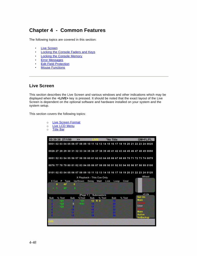
Live Screen
This section describes the Live Screen and various windows and other indications which may be displayed when the <LIVE> key is pressed. It should be noted that the exact layout of the Live Screen is dependent on the optional software and hardware installed on your system and the system setup.
This section covers the following topics:
o Live Screen Format o Live LCD Menu o Title Bar
4-49
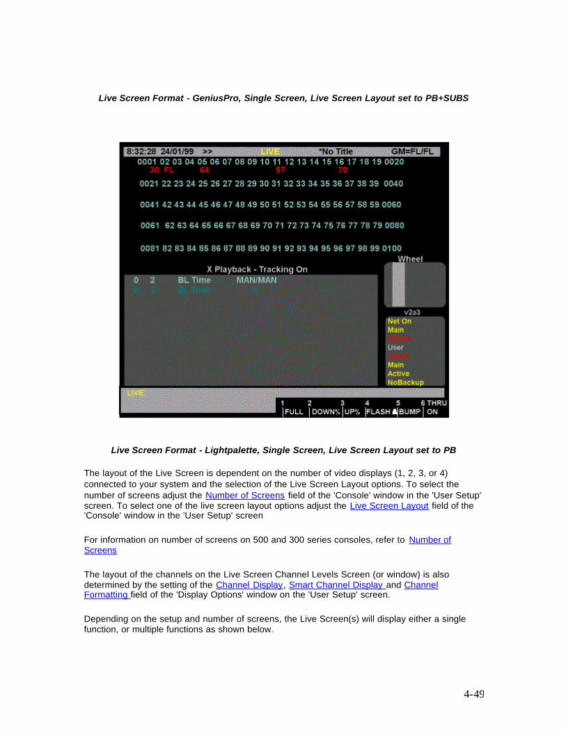
Live Screen Format - GeniusPro, Single Screen, Live Screen Layout set to PB+SUBS
Live Screen Format - Lightpalette, Single Screen, Live Screen Layout set to PB
The layout of the Live Screen is dependent on the number of video displays (1, 2, 3, or 4) connected to your system and the selection of the Live Screen Layout options. To select the number of screens adjust the Number of Screens field of the 'Console' window in the 'User Setup' screen. To select one of the live screen layout options adjust the Live Screen Layout field of the 'Console' window in the 'User Setup' screen
For information on number of screens on 500 and 300 series consoles, refer to Number of Screens
The layout of the channels on the Live Screen Channel Levels Screen (or window) is also determined by the setting of the Channel Display, Smart Channel Display and Channel Formatting field of the 'Display Options' window on the 'User Setup' screen.
Depending on the setup and number of screens, the Live Screen(s) will display either a single function, or multiple functions as shown below.
4-50
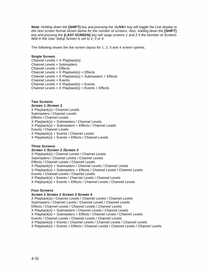
Note: Holding down the [SHIFT] key and pressing the <LIVE> key will toggle the Live display to the next screen format shown below for the number of screens. Also, holding down the [SHIFT] key and pressing the [LAST SCREEN] key will swap screens 1 and 2 if the Number of Screens field in the User Setup Screen is set to 2, 3 or 4.
The following shows the live screen layout for 1, 2, 3 and 4 screen sytems.
Single Screen: Channel Levels + X Playback(s) Channel Levels + Submasters Channel Levels + Effects Channel Levels + X Playback(s) + Effects Channel Levels + X Playback(s) + Submasters + Effects Channel Levels + Events Channel Levels + X Playback(s) + Events Channel Levels + X Playback(s) + Events + Effects
Two Screens Screen 1 /Screen 2 X Playback(s) / Channel Levels Submasters / Channel Levels Effects / Channel Levels X Playback(s) + Submasters / Channel Levels X Playback(s) + Submasters + Effects / Channel Levels Events / Channel Levels X Playback(s) + Events / Channel Levels X Playback(s) + Events + Effects / Channel Levels Three Screens Screen 1 /Screen 2 /Screen 3 X Playback(s) / Channel Levels / Channel Levels Submasters / Channel Levels / Channel Levels Effects / Channel Levels / Channel Levels X Playback(s) + Submasters / Channel Levels / Channel Levels X Playback(s) + Submasters + Effects / Channel Levels / Channel Levels Events / Channel Levels / Channel Levels X Playback(s) + Events / Channel Levels / Channel Levels X Playback(s) + Events + Effects / Channel Levels / Channel Levels Four Screens Screen 1 Screen 2 Screen 3 Screen 4 X Playback(s) / Channel Levels / Channel Levels / Channel Levels Submasters / Channel Levels / Channel Levels / Channel Levels Effects / Channel Levels / Channel Levels / Channel Levels X Playback(s) + Submasters / Channel Levels / Channel Levels X Playback(s) + Submasters + Effects / Channel Levels / Channel Levels Events / Channel Levels / Channel Levels / Channel Levels X Playback(s) + Events / Channel Levels / Channel Levels / Channel Levels X Playback(s) + Events + Effects / Channel Levels / Channel Levels / Channel Levels

4-51
Notes: 1. The third and fourth screen only ever shows channel levels. The number of channels displayed on the channel display screen (s) depends on whether GeniusPro or Lightpalette are being used and on the setting of the Channel Display field in the User Setup Screen. Pressing [PAGE UP] or [PAGE DOWN] displays the next screen of channels. 2. When the [CUE], [GROUP], [SUB] or [FX] key is pressed, the 2nd, 3rd and 4th screen (if fitted) will display the preview screen for the selected function and show the Cue, Group, Sub or FX levels for each channel. The distribution of channels across three and four screen systems is as described above. 3. When the 'Playbacks' field in the 'Show Details' window of the 'Show Setup' Screen is set to 'Single', or 'Split Single'(not 300 series), only 'X Playback 1' window is shown. However, if the field is set to 'Dual LTP' or 'Dual HTP', both 'X Playback 1' and 'X Playback 2' windows are displayed on the Live Screen. For further information refer to the Playbacks in the Show Setup Screen 4. With the 'Tracker' software installed on a dual screen system, a 'Rotary' window is displayed on the Live Screen.The entries in this window show the attributes currently being controlled by the trackerball (the top two entries) and the four rotary controls to the right of the trackerball. For further information refer to Tracker Software. (for 300 series, refer to Mouse Control of Features) 5. The 'Wheel' window shows movements of the wheel for the selected channel(s) with the lowest intensity.
Live LCD Menu The Live Menu on the Channel Control LCD indicates the last Channel, Cue, Effect and Group to have been selected, together with the following softkeys. 300 Series consoles can support either one or two monitor. 300 Series 400 and 600 Memory consoles are supplied with two LCD monitor modules.
{FULL} Sets the currently selected channels to full on {DOWN%}{UP%} Decreases/Increases the intensity of the specified channel(s) by the percentage set in the Up/Down % field of the 'Control Modes' window of the 'User Setup' screen. The default value is 5%. {FLASH } Flashes the currently selected channel(s). Refer to Flashing Channel Levels {BUMP} Bumps the currently selected channels. Refer to Bumping Channel Levels {THRU ON} Used to select a channel range including only channels whose intensity level is greater than 0. Refer to Channel Selection List
Title Bar
During initialisation (for about 15 secs) the applications available on the console are flashed on the title bar at the top of each screen. After initialisation, the title bar shows the 'Current Time and Date', the current 'Show Name' and the setting of the 'Grandmaster Fader(s)'. The date and time can be set in the Console Window of the Show Setup Screen. The show name is preceded with an asterisk if changes have been made to the show since it was last saved. On consoles without fixed submaster faders, you have the option of setting any one (300 Series consoles) or two (520 Consoles) submasters as grandmaster 1(GM1) or grandmaster 2 (GM2). If no submasters are set as grandmasters, the software automatically set the grandmaster level to full (FL)
4-52
Memory and Console Locked Indicator When the memory has been locked Memory Locked is shown on a red background on the screen header. In order to avoid accidental changes to a show, you can lock the console faders and keys. The right LCD shows Locked in the upper right corner when the console keys and faders are locked, The Live Display also shows Console Locked with a red background at the top of the screen when the console keys and faders are locked. When a show has been recorded, the memory can be locked to ensure that accidental changes cannot be made. For further information, refer to Locking the Console Faders and Keys and Locking the Console Memory
Save Indicator Show data is held on the system internal hard disk (the local disk). When recording or updating cues, effect steps, submasters, etc., data is automatically saved to the local disk. The / symbol between grandmaster levels changes to a flashing magenta box to indicate that automatic saving is taking place.
Locking the Console Faders and Keys
In order to avoid accidental changes to a show, you can lock the console faders and keys. The right LCD shows LOCKED in the upper right corner when the console keys and faders are locked, or when memory is locked (see below)
The display also shows CONSOLE LOCKED in yellow with a red background on the title bar on the top of all screens when the console keys and faders are locked or when the console and memory are locked.
[SHIFT]<HELP>toggles the console keyboard and fader state between locked and unlocked.
510i and 310 Show Controllers
[DISABLE] keylock switches the console keyboard and fader state between locked and unlocked.
Error Messages If the Buzzer Volume is set to ON in the User Setup Screen, the console beeps and displays an error message below the Command Line if entries do not fit with the current syntax, or values are out of range. The console also beeps and posts a message on screen if an entry needs to be confirmed or cancelled. To confirm the action you usually press the same key again or press [*]. To cancel the action, press [CLR] or [UNDO].
Note: If the optional 'Console Reporter' software is installed and a fault has occurred on a patched dimmer, the fault condition is displayed on all screens below the command line. For futher information on dimmer fault reports refer to Console Reporter
Edit Field Protection
4-53
An edit field protection feature prevents accidentally changing existing settings when carrying out channel control operations. This feature affects the Cue, Sub, Macro, X Playback and Group screens.
When the user enters any of these screen by pressing the appropriate key all editable fields are displayed in yellow (non -editable) and the trackball can only be used to scroll up and down the list of Cues, Subs, Macros, etc. Similarly, when the Fx screen is displayed, The trackball will only scroll the existing effects, or effect steps using the {EDIT STEPS} {EDIT FX} softkeys. All existing effect properties are displayed in yellow.
The user can still perform all channel control functions and create and record new Cues, Subs, Macros, Effects and Effect Steps.
When the [SHIFT] key is held pressed while moving the trackball, all fields in the current display become green (editable)
Pressing the [*] key returns to the edit field protection mode.
Mouse Functions
GeniusPro and Lightpalette software supports a range of mice and trackballs, including the 'intelli' type mouse and trackball, to mimic the trackball, trackball softkeys and rotaries on the 500 series consoles. Any of the mouse options can be used with either 500 or 300 series consoles for the control of attributes and to mimic the other functions of the trackball, e.g., moving the highlight on the setup screens, scrolling the help screens and activating help hyperlinks. PS2 mice should be plugged into the PS2 port and serial mice should be plugged into one of the COM ports, unless the mouse is dual function (i.e., PS2/Serial). On the 300 Series consoles, the intellitrackball may be connected to the PS2 port on the Processor unit or on the command module. Alternatively, the intellitrackball may be plugged into either the COM1 port on the processor unit, or the COM2 port on the command module using the appropriate adaptor.
Important Note: Throughout this manual, references to trackball should be taken as a generic term covering the series 500 trackball or the trackball of a two or three button or 'Intelli' type mouse or trackball. In the event of a mouse/trackball not being available or inoperable, all the functions performed by the trackball/mouse can be simulated using the four navigation keys on a PC keyboard connected to the console, or, on 300 Series consoles by pressing [SHIFT] [0] to enter cursor lock mode and using the arrow keys on the console keypad.
When you initially connect a mouse to a 300 Series console, the mouse will not operate until you set the Mouse Net Node and Port fields in the User Setup Screen. To do this, press <SETUP> then press [SHIFT] [0] to enter cursor lock mode. You can then use the cursor keys on the console keypad to highlight the Net Node and Port fields and the [+] or [-] keys to set the options.
Supported Mice
Microsoft or Logitech 2-button PS2 or serial mouse Microsoft or Logitech 3-button PS2 or serial mouse Microsoft Intellimouse or Intellitrackball or Logitech equivalents.

4-54
Important Note: When using a PS2 mouse, the mouse must be plugged into the PS2 port before you switch on the console, otherwise, the mouse will not work.
When in any of the Setup Screens, the screen highlight will move left and right, or up and down according to the X and Y movement of the mouse ball.
When in the Help Screen, moving the mouse through the Y axis will scroll the help screen up or down. Pressing the left mouse button will activate the help hyperlinks.
For information on using the mouse to control moving lights, refer to Mouse Control of Features

5-55
Chapter 5 - Working with Channel Levels
The Channel Control is used to manually select and modify channel levels to record submasters, cues, groups, and effects, or for overriding the recorded show. The Main Console, Remote Consoles, and Handheld Remotes have separate channel controls and operate independently of each other on a latest takes precedence basis. Using remote consoles requires the Networker software. See the Networker Software for more details. A channel can have an intensity, an intensity plus attributes, or just attributes. Once a channel is selected in the Live display, you can change the intensity with the Level Wheel and the attributes with the Trackball and the rotary controls. In other displays you can control the intensity and all attributes, but not at the same time. If the CC Auto Hold Mode field in the User Setup Screen is set to OFF (GeniusPro default) and you select channelss using the channel controls, they are stolen from effects, submasters (except independent submasters and effects) or X playbacks which are controlling those channels. Effects set for latest takes precedence instead of independent operation steal back channels only when a new effect is run. Submasters steal back channels when the fader is moved off 0 or a bump button is pressed. X playbacks steal when a new cue is run. When ON (Lightpalette Default), channels cannot be “stolen” from the Channel Control by cues, subs, and effects. Or you can return to the state before channel changes by pressing [UNDO] [*]
The Channel Control also lets you modify cues, submasters, effects steps, and groups blind, though the Level Wheel.
The syntax used to enter command in the command line is determined by the setting of the Channel Control Mode field in the User Setup Screen. To change the Channel Control Mode, press [SETUP] and select the Channel Control Mode. For further information on Channel Control Modes refer to Channel Control Mode
This section contains the following topics:
• Editing the Command Line • Setting up the Channel Levels Window • Channel Status Identification • Channel Type Identification • Selecting Channels • Channel Selection List • Current Channel Selection • Extending the Current Channel Selection • Selecting the Next or Last Channel • Clearing the Current Selection • Setting Levels with the Keypad • Using Recorded Items in Channel Lists • Attribute Groups • Attribute Filters • Referenced Groups • Using the Level Wheel • Setting Attribute Levels • Setting DMX Levels • Copying Channel Levels • Undoing Level Changes • Holding Channels on the Channel Control
5-56
• Restoring Playback Levels • Flashing Channel Levels • Bumping Channel Levels • Channel Check • Changing Levels in Preview (Blind) Display • Fading in Intensity Channels in Time • Fading in Attribute Channels in Time
Editing the Command Line
At any time before a command on the command line is complete, you can move back through the command line to correct it.
[CLR] Clears the last entered key when a command is being entered. If no command is being entered this has no effect except in the Live display when it clears the current channel selection.
[SHIFT] [CLR] Clears the complete command line when a command is being entered. If no command is being entered it has no effect.
Setting Up the Channel Levels Window
The layoutof the Channel Levels Window is determined by the setting of the Channel Display, Smart Channel Display and Channel Formatting fields within the User Setup Screen.
• The Channel Display field sets the Strand console type that the Channel Levels window will mimic.
• The Smart Channel field, sets the format of the display to show all attributes of a fixture. • The Channel Formatting field controls whether or not all channels will be shown on
screen. 'Hidden' channels are indicated in the channel listing with'I' o When set to OFF, all defined channels are shown. o When set to COMPACT, only channels that are on, or moved to zero at the last
Channel Control or X Playback action, are shown. o When set to DISPLAY GROUP, only channels defined in the special Display
Group (Group 994.1) are shown. o When set to AUTO, only channels that have been used are shown. The Display
Group is automatically updated to include channels as they are used. o When set to CHANNELS IN USE Automatically displays the channels used in all
cues, submasters and effects (not groups or macros). When selected, the displayed channels will be updated whenever any of the current cues,
o submasters or effects are changed or deleted, or when a show file is loaded.
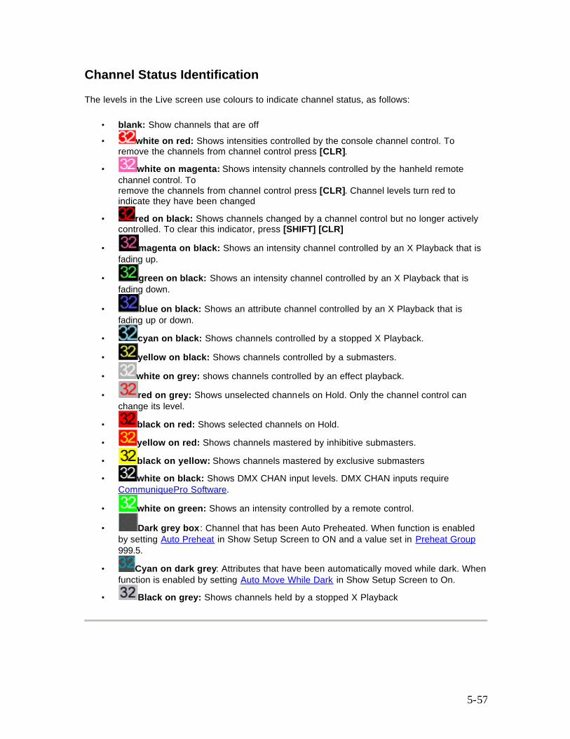
5-57
Channel Status Identification
The levels in the Live screen use colours to indicate channel status, as follows:
• blank: Show channels that are off • white on red: Shows intensities controlled by the console channel control. To
remove the channels from channel control press [CLR].
• white on magenta: Shows intensity channels controlled by the hanheld remote channel control. To remove the channels from channel control press [CLR]. Channel levels turn red to indicate they have been changed
• red on black: Shows channels changed by a channel control but no longer actively controlled. To clear this indicator, press [SHIFT] [CLR]
• magenta on black: Shows an intensity channel controlled by an X Playback that is fading up.
• green on black: Shows an intensity channel controlled by an X Playback that is fading down.
• blue on black: Shows an attribute channel controlled by an X Playback that is fading up or down.
• cyan on black: Shows channels controlled by a stopped X Playback.
• yellow on black: Shows channels controlled by a submasters.
• white on grey: shows channels controlled by an effect playback.
• red on grey: Shows unselected channels on Hold. Only the channel control can change its level.
• black on red: Shows selected channels on Hold.
• yellow on red: Shows channels mastered by inhibitive submasters.
• black on yellow: Shows channels mastered by exclusive submasters
• white on black: Shows DMX CHAN input levels. DMX CHAN inputs require CommuniquePro Software.
• white on green: Shows an intensity controlled by a remote control.
• Dark grey box: Channel that has been Auto Preheated. When function is enabled by setting Auto Preheat in Show Setup Screen to ON and a value set in Preheat Group 999.5.
• Cyan on dark grey: Attributes that have been automatically moved while dark. When function is enabled by setting Auto Move While Dark in Show Setup Screen to On.
• Black on grey: Shows channels held by a stopped X Playback
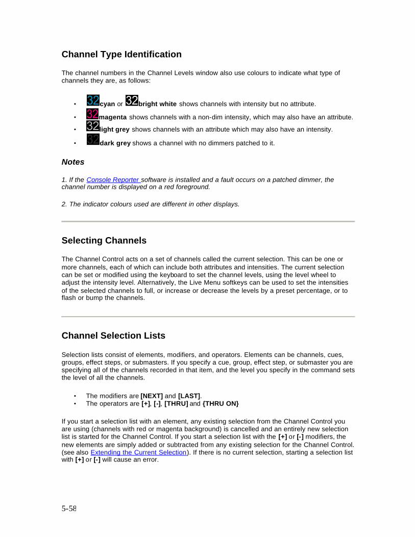
5-58
Channel Type Identification
The channel numbers in the Channel Levels window also use colours to indicate what type of channels they are, as follows:
• cyan or bright white shows channels with intensity but no attribute.
• magenta shows channels with a non-dim intensity, which may also have an attribute. • light grey shows channels with an attribute which may also have an intensity.
• dark grey shows a channel with no dimmers patched to it.
Notes
1. If the Console Reporter software is installed and a fault occurs on a patched dimmer, the channel number is displayed on a red foreground.
2. The indicator colours used are different in other displays.
Selecting Channels
The Channel Control acts on a set of channels called the current selection. This can be one or more channels, each of which can include both attributes and intensities. The current selection can be set or modified using the keyboard to set the channel levels, using the level wheel to adjust the intensity level. Alternatively, the Live Menu softkeys can be used to set the intensities of the selected channels to full, or increase or decrease the levels by a preset percentage, or to flash or bump the channels.
Channel Selection Lists
Selection lists consist of elements, modifiers, and operators. Elements can be channels, cues, groups, effect steps, or submasters. If you specify a cue, group, effect step, or submaster you are specifying all of the channels recorded in that item, and the level you specify in the command sets the level of all the channels.
• The modifiers are [NEXT] and [LAST]. • The operators are [+], [-], [THRU] and {THRU ON}
If you start a selection list with an element, any existing selection from the Channel Control you are using (channels with red or magenta background) is cancelled and an entirely new selection list is started for the Channel Control. If you start a selection list with the [+] or [-] modifiers, the new elements are simply added or subtracted from any existing selection for the Channel Control. (see also Extending the Current Selection). If there is no current selection, starting a selection list with [+] or [-] will cause an error.
5-59
The examples shown immediately below are command segments you can use to create your channel lists. You can then use combinations of these command segments to replace chans where it appears in full command descriptions.
• [+] Adds elements to the channel list. • [1] [+] [3] Adds channels 1 and 3 to the channel list. • [SUB] [1] [+] [SUB] [2] Adds channels recorded in submasters 1 and 2 to the channel
list. • [SUB] [1] [+] [2] Adds channels recorded in submasters 1, plus channel 2, to the channel
list. • [CUE] [1] [PART] [2] [+] [SUB] [1] Adds channels recorded in cue 1, part 2, plus
channels recorded in submaster 1, to the channel list.
[-] removes elements from the channels that are already on the channel list. Since all command processing is from left to right, you can specify a large range, then subtract a range from the currently listed channels, and then add back one or two channels in the range you subtracted.
• [1] [THRU] [3] [-] [2] Adds channels 1 and 3 to the channel list. • [SUB] [1] [THRU] [3] [-] [2] Adds channels recorded in submasters 1 through 3, minus
channel 2, to the channel list. • [THRU] specifies a range of elements to the channel list. This has a higher priority than
[+] and [-]. • [1] [THRU] [3] • [3] [THRU] [1] Adds channels 1, 2, and 3 to the channel list. • [1] [THRU] [LAST] Puts all channels on the channel list. • [SUB] [1] [THRU] [3] Adds channels recorded in submasters 1 through 3 to the channel
list. • [1] [THRU] [2] [+] [6] [THRU] [7] • [1] [THRU] [7] [-] [3] [THRU] [5] Adds channels 1, 2, 6, and 7 to the channel list. This
shows the higher priority of [THRU].
{THRU ON} only adds channels which are on (have levels above 0) to the channel list.{THRU ON} is a soft key on the LCD Live menu. It has a higher priority than [+] and [-] and the same priority as [THRU]. You cannot only use {THRU ON} to specify a range of channels, not a range of cues, groups, effect steps, or submasters.
• [1] {THRU ON} [3] Adds channels 1, 2, and 3 to the channel list if they are on[NEXT] and [LAST] can be used when selecting a cue, group, effect step, or submaster to select the item after or before the current cue, group, effect step, or submaster. The current cue, group, effect step, and submaster are shown on the right LCD.
• [SUB] [NEXT] Adds channels recorded in the submaster after the current submaster to the channel list.
• [CUE] [LAST] Adds channels recorded in the submaster before the current submaster to the channel list.
{THRU ON} is most often used to adjust the level of all lights that are on in a given cue. The designer may require all on light to be increased (or decreased by, say 5%). This is easily achieved by the commands [GOTO] [CUE] # and # [THRU] # {THRU ON} {UP%} or {DOWN %} (the Up and Down % value is set in the Up Down % field of the User Setup Screen
5-60
Current Channel Selection
The Channel Control only modifies channels in the current selection. The channels in the current selection are shown on the Live display with a red background (white text). (see also Extending the Current Selection) To select channels you specify the selection as shown above and then press [*].
• chan [*] makes the specified channels the current selection • [1] [+] [2] [*] Select channels 1 and 2 at their current levels. • [*] makes all channels which are on (those above 0 or on At 0) the current selection. This
is the same as [1] {THRU ON} [9] [9] [9] [9] [*] • [*] Select all on channels.
Extending the Current Channel Selection
• [+]chan [*] or [-] chan [*] add or subtract channels from an already existing channel selection.
• [+] [4] [THRU] [9] [*] Adds channel 4 through 9 to the existing channel selection. • [-] [4] [5] [*] Subtracts channel 45 from the existing channel selection.
Note: Providing a channel list has been selected since the console was last switched on, the list is held in memory until a new list is created to replace it. You can therefore add or subtract channels from the current list, even though the Live Screen Channel Display is blank. Pressing the [+] or [-] keys will restore the last channel list and allow you to add or subtract channels from the selection.
Selecting the Next or Last Channel
The CHAN field on the right LCD shows the current channel. This is the final channel listed when making a selection.
• The [NEXT] and [LAST] keys make the channel after or before the current channel of the same type (intensity or attribute) the current selection. When controlling channels, these buttons are most commonly used for channel checks by setting the first desired channel to Full and then using [NEXT] and [LAST] to step through the channels.
• [NEXT] selects the channel after the highest numbered channel in the current selection. • [1] [THRU] [3] [*] Wheel [NEXT] Selects channels 1, 2, 3, adjusts them to the desired
level, and then selects the next intensity channel (channel 4 in this case). • [1] {THRU ON} [3] [NEXT] Selects the next intensity channel after channel 3 regardless
of whether channel 3 is on. • [LAST] selects the channel before the lowest numbered channel in the current selection. • [1] [THRU] [3] [@ATT] [*] [LAST] Selects attribute channels 1, 2, 3 then selects the
previous attribute channel (e.g. channel 2 if this has attributes). Another [LAST] selects the previous attribute channel (e.g. channel 1 if this has attributes).
5-61
Clearing the current selection
The current selection can be cleared so that no channels are selected. The Channel Control will then have no effect. [CLR] removes all channels from the selection list. When a command is being entered, [CLR] instead deletes the last key entry.
Setting Levels With the Keypad
Channel levels can be set directly from the command line by using the Levels keypad to select channels and specify levels.
chans [@] # [*] selects the listed channels and sets their intensity levels to the specified # level. To set levels for the current selection, omit chans. [1] [@] [0] [.] [1] Direct 1 Digit [1] [@] [0] [1] Direct 2 Digit [1] [@] [0] [1] [*] Command Line Makes channel 1 the current selection and sets its level to 1%. [1] [+] [3] [@] [1] Direct 1 Digit [1] [+] [3] [@] [1] [*] Direct 2 Digit [1] [+] [3] [@] [1] [*] Command Line Selects channels 1 and 3 and sets their levels to 10%. [@] [1] [.] [1] Direct 1 Digit [@] [1] [1] Direct 2 Digit [@] [1] [1] [*] Command Line Changes the levels of the current selection to 11%. chans [@] [+] # [*] selects the listed channels and increases their intensity levels by the specified # level. To set levels for the current selection, omit chans. [1] [@] [+] [1] Direct 1 Digit [1] [@] [+] [1] [0] Direct 2 Digit [1] [@] [+] [1] [*] Command Line Makes channel 1 the current selection and increases its level by 10%. For example, a channel at 55% would go to 65%. Any levels over 100% are limited at 100%. [@] [+] [1] [.] [1] Direct 1 Digit [@] [+] [1] [.] [1] Direct 2 Digit [@] [+] [1] [1] [*] Command Line The existing current selection is unchanged but their levels are increased by 11%. chans [@] [-]# [*] selects the listed channels and decreases their intensity levels by the specified # level. To set levels for the current selection, omit chans. [1] [@] [-] [1] Direct 1 Digit [1] [@] [-] [1] [0] Direct 2 Digit [1] [@] [-] [1] [*] Command Line Makes channel 1 the current selection and decreases its level by 10%. For example, a channel at 55% would go to 45%. Any levels under 0% are limited at 0.
5-62
[@] [-] [0] [.] [1] Direct 1 Digit [@] [-] [0] [1] Direct 2 Digit [@] [-] [0] [1] [*] Command Line The existing current selection is unchanged but their levels are decreased by 1% chans {UP%} selects the listed channels and increases their intensity levels by the percentage set in the Up/Down % field in the User Setup Screen Control Modes window. The default is 5%, and will be used in examples. To set levels for the current selection, omit chans. [1] {UP%} Command Line Makes channel 1 the current selection and increases its level by 5%. For example, a channel at 55% would go to 60%. Any levels over 100% are limited at 100%. {UP%} appears on the LCD Live menu. chans {DOWN%} selects the listed channels and decreases their intensity levels by the percentage set in the Up/Down % field in the User Setup Screen Control Modes window. The default is 5%, and will be used in examples. To set levels for the current selection, omit chans. [1] {DOWN%} Command Line Makes channel 1 the current selection and decreases its level by 5%. For example, a channel at 55% would go to 50%. Any levels under 0% are limited at 0%. {DOWN%} appears on the LCD Live menu. chan {FULL} or chan [@] {FULL} [*] selects the listed channels and sets their intensity levels to Full (100%). To set the current selection to Full, omit chans. [1] {FULL} All Modes [1] [@] {FULL} Direct 2 Digit [1] [@] {FULL} [*] Command Line Makes channel 1 the current selection and sets its level to Full. The [1] {FULL} syntax only works in the Live display. {FULL} The existing current selection is unchanged but their levels are set to Full. {FULL} appears on the LCD Live menu. This only works in the Live display chans [ON] or chans [@] [ON] [*] selects the listed channels and sets their intensity levels to the on level. The on level is set by the On Level % field in the User Setup Screen (initially 100%) or the ON Level group (group 993.1). The ON Level group takes precedence over the ON Level % field. For further information, refer to Groups. To set levels for the current selection to the on level, omit chans. [1] [ON] All Modes [1] [@] [ON] Direct 2 Digit [1] [@] [ON] [*] Command Line Makes channel 1 the current selection and sets its level to the on level.[ON] The existing current selection is unchanged but their levels are set to the on level.
5-63
chans [@] [*] or chans [@] [.] [*] or chans [@] {OFF} [*] selects the listed channels and sets their intensity levels to off. To set levels for the current selection to off, omit chans. [1] [@] [*] All Modes [1] [@] [.] Direct 1 and 2 Digit [1] [@] [SHIFT] Direct 1 and 2 Digit [1] [@] [.] [*] Command Line [1] [@] {OFF} [*] Command Line Makes channel 1 the current selection and sets its level off.
Note:If you use this command in the Live display when Tracking is on, it sets channel levels to zero. If you record these channels, a zero level is recorded in the cue only if levels changed from previous cues. Otherwise off is recorded in the cue, and levels track through from the previous cue. If you use this command in the Cue/Preview display, the channels appear at their levels from the previous cue since turning a channel off (rather than setting it to zero) makes it track.
chans [@] [0] [*] selects the listed channels and sets their intensity levels to zero. To set levels for the current selection to zero, omit chans. [1] [@] [0] Direct 1 Digit [1] [@] [0] [0] Direct 2 Digit [1] [@] [0] [*] Command Line Makes channel 1 the current selection and sets its level on at 0.
Note: If you use this command in the Live display when Tracking is on, it sets channel levels to zero. If you record these channels, a zero level is recorded in the cue only if levels changed from previous cues. Otherwise off is recorded in the cue, and levels track through from the previous cue. If you use this command in the Cue/Preview display the channels are forced to zero and tracking for those channels is blocked at the cue
chans [REM DIM] selects the listed channels and sets all other intensity channels to 0%. If the selected intensity channels are all at 0, they are set to the on level as set in the Setup display.
This feature is useful if a designer wants to check the focus of one or more lights. By selecting the light(s) to be checked and pressing [REMDIM], the selection is immediately set to the On value (default 100%) with all other lights switched off. [1] [REMDIM] All Modes Makes channel 1 the current selection and sets all other channels to 0%. [REM DIM] [REM DIM] All Modes If a current selection exists, its channels are unchanged and all others are set to 0%. If there is no current selection, all channels are set to 0% after a second press of the key. This is a very useful way to achieve a blackout.

5-64
Fading in Intensity Channels in Time You can set a channel selection to reach the set levels over a period of time using the [TIME] key as shown. [1] [THRU] [3] [TIME] [5] [@] [5] Set channels 1 to 3 inclusive from current level to 50% over a period of 5 seconds. (Direct Action Modes). Time must be specified as 2-digit for Direct 2 Digit Mode. [1] [THU] [3] [@] [5] [TIME] [5] [*] Set channels 1 to 3 inclusive from current level to 50% over a period of 5 seconds. (Command Line Mode).
Fading In Attribute Channel Levels in Time You can fade in attribute channel levels in the same way as for intensity channels. [1] [.] [3] [TIME] [5] [@] [5] Moves the channel 1 luminair pan to position 5 over a period of 5 seconds. (Direct Digit Modes) [1] [.] [3] [@] [5] [TIME] [5] [*] Moves the channel 1 luminair pan to position 5 over a period of 5 seconds. (Command Line Mode)
6-65
Chapter 6 - Basic Recording
Cues, groups, effects, and submasters are the four item types in which you can store intensity and attribute levels. In addition, each item type has properties that you can set. This section discusses recording channel levels and text for cues, groups, effects, and submasters, and recording up and down fade times for cues, effects and submasters.
This chapter contains the following topics:
• Recording Levels and Properties • Changing Properties Without Recording Levels • Editing in a Preview (Blind) Display • Copying from a Preview (Blind) Display
Recording Levels and Properties
You can record levels and properties into cues, groups, effects, and submasters from the Live, Cue/Preview, Group, Effect, or Submaster displays. Levels are always taken from the current display and recorded into the item type specified by one of the selection keys ([SUB], [CUE], [GROUP], or [FX]). In this section, type is used to mean one of the selection keys.
The general format for recording levels and properties is: type # properties {RECORD]
Properties that are not listed in the command are recorded at default values for new items, and remain unchanged when you are re-recording. If the specified item has already been recorded, an overrecord message gives you the chance to cancel the recording. Press again to rerecord, or [CLR] or [UNDO] to cancel the command.
If you do not enter an item type, cue is assumed. The [CUE] key in all of the examples below is optional.
Recording clears the current selection from the Channel Control
The following records the intensity and attribute levels on the current display into the specified cue, group, effect step, or submaster. For submasters, levels are recorded into the current page.
[SUB] [1] [RECORD] Direct 1 Digit and Direct 2 Digit [RECORD] [SUB] [1] [*] Command Line Records current display levels into submaster 1. [CUE] [3] [4] [RECORD] Direct 1 Digit and Direct 2 Digit [RECORD] [3] [4] [*] Command Line Records current display levels into cue 34. [FX] [1] [.] [2] [RECORD] Direct 1 Digit and Direct 2 Digit [RECORD] [FX] [1] [.] [2] [*] Command Line Records current display levels into effect 1 step 2.
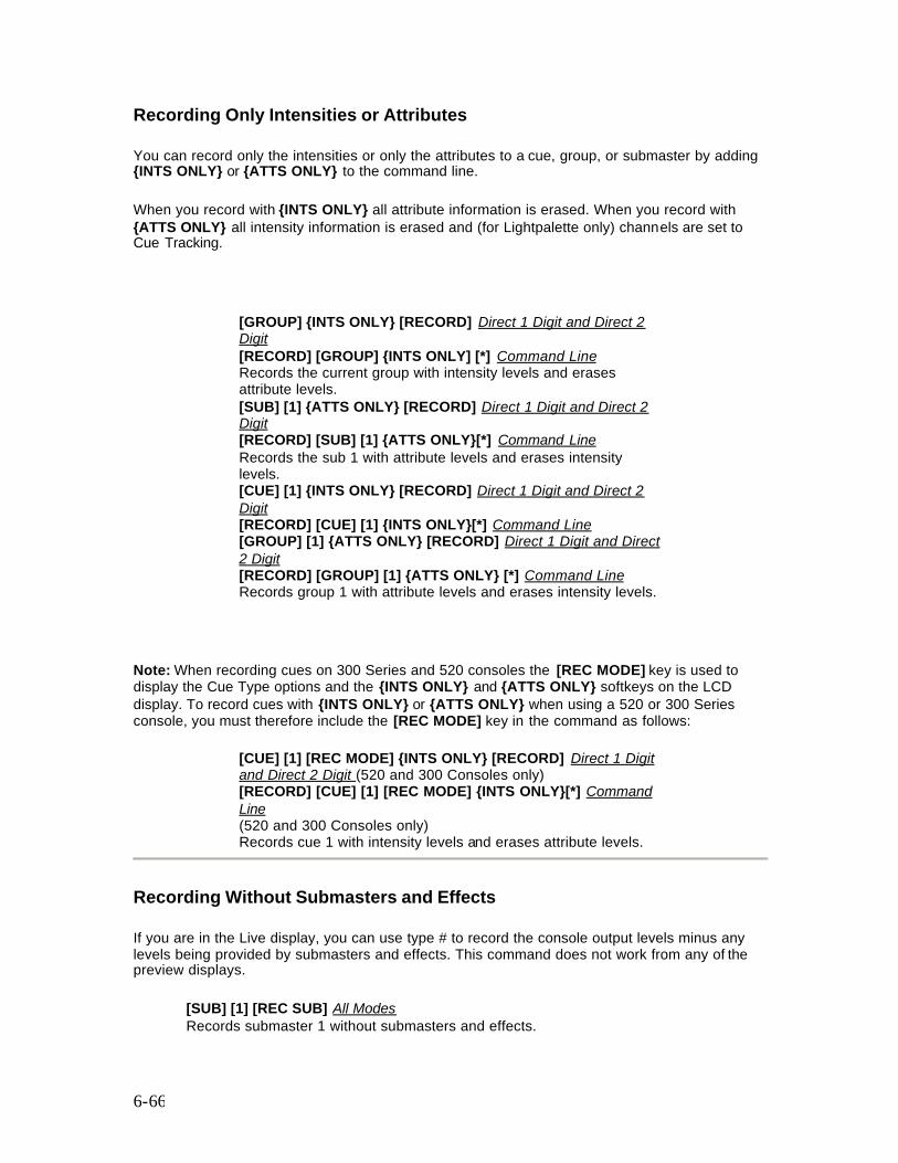
6-66
Recording Only Intensities or Attributes
You can record only the intensities or only the attributes to a cue, group, or submaster by adding {INTS ONLY} or {ATTS ONLY} to the command line.
When you record with {INTS ONLY} all attribute information is erased. When you record with {ATTS ONLY} all intensity information is erased and (for Lightpalette only) channels are set to Cue Tracking.
[GROUP] {INTS ONLY} [RECORD] Direct 1 Digit and Direct 2 Digit [RECORD] [GROUP] {INTS ONLY] [*] Command Line Records the current group with intensity levels and erases attribute levels. [SUB] [1] {ATTS ONLY} [RECORD] Direct 1 Digit and Direct 2 Digit [RECORD] [SUB] [1] {ATTS ONLY}[*] Command Line Records the sub 1 with attribute levels and erases intensity levels. [CUE] [1] {INTS ONLY} [RECORD] Direct 1 Digit and Direct 2 Digit [RECORD] [CUE] [1] {INTS ONLY}[*] Command Line [GROUP] [1] {ATTS ONLY} [RECORD] Direct 1 Digit and Direct 2 Digit [RECORD] [GROUP] [1] {ATTS ONLY} [*] Command Line Records group 1 with attribute levels and erases intensity levels.
Note: When recording cues on 300 Series and 520 consoles the [REC MODE] key is used to display the Cue Type options and the {INTS ONLY} and {ATTS ONLY} softkeys on the LCD display. To record cues with {INTS ONLY} or {ATTS ONLY} when using a 520 or 300 Series console, you must therefore include the [REC MODE] key in the command as follows:
[CUE] [1] [REC MODE] {INTS ONLY} [RECORD] Direct 1 Digit and Direct 2 Digit (520 and 300 Consoles only) [RECORD] [CUE] [1] [REC MODE] {INTS ONLY}[*] Command Line (520 and 300 Consoles only) Records cue 1 with intensity levels and erases attribute levels.
Recording Without Submasters and Effects
If you are in the Live display, you can use type # to record the console output levels minus any levels being provided by submasters and effects. This command does not work from any of the preview displays.
[SUB] [1] [REC SUB] All Modes Records submaster 1 without submasters and effects.
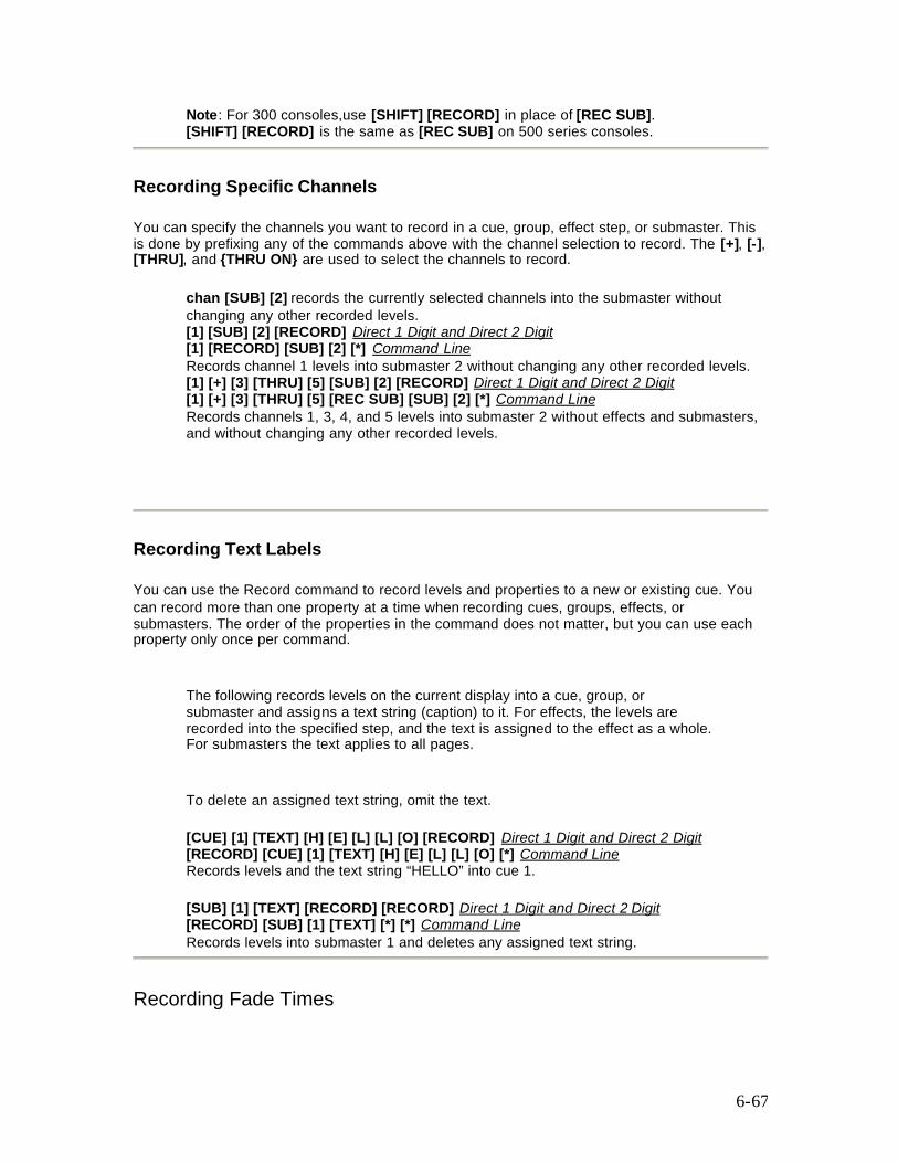
6-67
Note: For 300 consoles,use [SHIFT] [RECORD] in place of [REC SUB]. [SHIFT] [RECORD] is the same as [REC SUB] on 500 series consoles.
Recording Specific Channels
You can specify the channels you want to record in a cue, group, effect step, or submaster. This is done by prefixing any of the commands above with the channel selection to record. The [+], [-], [THRU], and {THRU ON} are used to select the channels to record.
chan [SUB] [2] records the currently selected channels into the submaster without changing any other recorded levels. [1] [SUB] [2] [RECORD] Direct 1 Digit and Direct 2 Digit [1] [RECORD] [SUB] [2] [*] Command Line Records channel 1 levels into submaster 2 without changing any other recorded levels. [1] [+] [3] [THRU] [5] [SUB] [2] [RECORD] Direct 1 Digit and Direct 2 Digit [1] [+] [3] [THRU] [5] [REC SUB] [SUB] [2] [*] Command Line Records channels 1, 3, 4, and 5 levels into submaster 2 without effects and submasters, and without changing any other recorded levels.
Recording Text Labels
You can use the Record command to record levels and properties to a new or existing cue. You can record more than one property at a time when recording cues, groups, effects, or submasters. The order of the properties in the command does not matter, but you can use each property only once per command.
The following records levels on the current display into a cue, group, or submaster and assigns a text string (caption) to it. For effects, the levels are recorded into the specified step, and the text is assigned to the effect as a whole. For submasters the text applies to all pages.
To delete an assigned text string, omit the text. [CUE] [1] [TEXT] [H] [E] [L] [L] [O] [RECORD] Direct 1 Digit and Direct 2 Digit [RECORD] [CUE] [1] [TEXT] [H] [E] [L] [L] [O] [*] Command Line Records levels and the text string “HELLO” into cue 1. [SUB] [1] [TEXT] [RECORD] [RECORD] Direct 1 Digit and Direct 2 Digit [RECORD] [SUB] [1] [TEXT] [*] [*] Command Line Records levels into submaster 1 and deletes any assigned text string.
Recording Fade Times
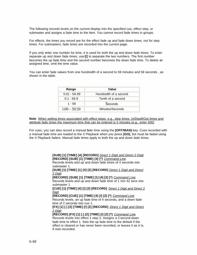
6-68
The following records levels on the current display into the specified cue, effect step, or submaster and assigns a fade time to the item. You cannot record fade times in groups.
For effects, the times you record are for the effect fade up and fade down times, not for step times. For submasters, fade times are recorded into the current page.
If you only enter one number for time, it is used for both the up and down fade times. To enter separate up and down fade times, use [/] to separate the two numbers. The first number becomes the up fade time and the second number becomes the down fade time. To delete an assigned time, omit the time value.
You can enter fade values from one hundredth of a second to 59 minutes and 59 seconds , as shown in the table.
Range Value 0.01 - 59.99 Hundredth of a second
0.1 - 59.9 Tenth of a second 1 - 59 Seconds
1:00 - 59:59 Minutes/Seconds
Note: When setting times associated with effect steps, e.g., step times, In/Dwell/Out times and attribute fade times the maximum time that can be entered is 5 minutes (e.g., enter 500)
For cues, you can also record a manual fade time using the {OFF/MAN} key. Cues recorded with a manual fade time are loaded to the X Playback when you press [GO], but must be faded using the X Playback faders. Manual fade times apply to both the up and down fade times.
[SUB] [1] [TIME] [4] [RECORD] Direct 1 Digit and Direct 2 Digit [RECORD] [SUB] [1] [TIME] [4] [*] Command Line Records levels and up and down fade times of 4 seconds into submaster 1. [SUB] [1] [TIME] [1] [4] [2] [RECORD] Direct 1 Digit and Direct 2 Digit [RECORD] [SUB] [1] [TIME] [1] [4] [2] [*] Command Line Records levels and up and down fade time of 1 min 42 secs into submaster 1 [CUE] [1] [TIME] [4] [/] [2] [RECORD] Direct 1 Digit and Direct 2 Digit [RECORD] [CUE] [1] [TIME] [4] [/] [2] [*] Command Line Records levels, an up fade time of 4 seconds, and a down fade time of 2 seconds into cue 1. [FX] [1] [.] [2] [TIME] [/] [2] [RECORD] Direct 1 Digit and Direct 2 Digit [RECORD] [FX] [1] [.] [2] [TIME] [/] [2] [*] Command Line Records levels into effect 1 step 2. Assigns a 2 second down fade time to effect 1. Sets the up fade time to the default if the effect is cleared or has never been recorded, or leaves it as it is, if over-recorded.
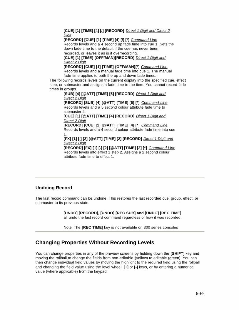
6-69
[CUE] [1] [TIME] [4] [/] [RECORD] Direct 1 Digit and Direct 2 Digit [RECORD] [CUE] [1] [TIME] [4] [/] [*] Command Line Records levels and a 4 second up fade time into cue 1. Sets the down fade time to the default if the cue has never been recorded, or leaves it as is if overrecording. [CUE] [1] [TIME] {OFF/MAN}[RECORD] Direct 1 Digit and Direct 2 Digit [RECORD] [CUE] [1] [TIME] {OFF/MAN}[*] Command Line Records levels and a manual fade time into cue 1. The manual fade time applies to both the up and down fade times.
The following records levels on the current display into the specified cue, effect step, or submaster and assigns a fade time to the item. You cannot record fade times in groups.
[SUB] [4] [@ATT] [TIME] [5] [RECORD] Direct 1 Digit and Direct 2 Digit [RECORD] [SUB] [4] [@ATT] [TIME] [5] [*] Command Line Records levels and a 5 second colour attribute fade time to submaster 4. [CUE] [1] [@ATT] [TIME] [4] [RECORD] Direct 1 Digit and Direct 2 Digit [RECORD] [CUE] [1] [@ATT] [TIME] [4] [*] Command Line Records levels and a 4 second colour attribute fade time into cue 1. [FX] [1] [.] [2] [@ATT] [TIME] [2] [RECORD] Direct 1 Digit and Direct 2 Digit [RECORD] [FX] [1] [.] [2] [@ATT] [TIME] [2] [*] Command Line Records levels into effect 1 step 2. Assigns a 2 second colour attribute fade time to effect 1.
Undoing Record
The last record command can be undone. This restores the last recorded cue, group, effect, or submaster to its previous state.
[UNDO] [RECORD], [UNDO] [REC SUB] and [UNDO] [REC TIME] all undo the last record command regardless of how it was recorded. Note: The [REC TIME] key is not available on 300 series consoles
Changing Properties Without Recording Levels
You can change properties in any of the preview screens by holding down the [SHIFT] key and moving the rollball to change the fields from non-editable (yellow) to editable (green). You can then change individual field values by moving the highlight to the required field using the rollball and changing the field value using the level wheel, [+] or [-] keys, or by entering a numerical value (where applicable) from the keypad.
6-70
Alternatively, you can change item properties from the command line without changing any levels. The general command format for doing this is: type # properties * Properties that are not listed in the command remain unchanged. You do not get an overrecord warning with this command if the item exists. You can use these commands to change the properties of existing items, and to create new items without recording any intensities or attributes. Confirmation is required when cues are created.
You can use these commands to change properties for existing items in another preview (blind) display, but you cannot use this syntax to create an item in another preview (blind) display.
From anywhere,
[CUE] [1] [2] [TIME] [4] [*] All Modes [CUE] [1] [2] [TIME] [[4] [REC TIME] All Modes will change the cue 12 up and down fade times if cue 12 exists, but will result in an error message if cue 12 does not exist.
If you do not enter an item type and number before the [TIME] key, cue is assumed. Entering [TIME] # [*] will change the fade time to the entered value in the current cue. Changing properties clears the current selection from the Channel Control. type # [TIME] # [*] changes the fade time of a submaster, cue, group, or effect without changing recorded levels. [CUE] [1] [TIME] [*] All Modes Sets cue 1 fade time to the manual fade up and down (MAN/MAN) [CUE] [1] [TIME] [4] [*] All Modes Changes cue 1 up and down fade times to 4 seconds without changing any levels. [SUB] [1] [TIME] [4] [/] [2] [*] All Modes Changes submaster 1 up fade time to 4 seconds and its down fade time to 2 seconds without changing any levels. [FX] [1] [TIME] [/] [2] [*] All Modes Changes the effect 1 down fade time to 2 seconds without recording new levels. Does not change the up fade time. [CUE] [TIME] [4] [/] [*] All Modes Changes the current cue up fade time to 4 seconds without recording new levels. Does not change the down fade.
Editing In a Preview (Blind) Display
When you are in a blind display (the Submaster, Preview, Group, and Effect displays), changing a level or property automatically records it into the currently displayed item Preview, Group, or Effect
Changing Channel Levels

6-71
You can use Channel Control commands (for example [1] [@] [1], [CUE] [1] [@] [5]) to set and record channel levels. Some of the soft keys and the Level Wheel are not available in preview (blind) displays. Otherwise the syntax for recording is the same from all locations.
Changing Properties
Properties for setup, cues, submasters, effects, and groups can be changed by editing property fields in the State screen of the appropriate display.
To select a field, use the Trackball to move the highlight to the field.
To reset a field in the Effect Screen press {DEFLT}.
Copying From a Preview (Blind) Display
You can record submasters, cues, groups, and effect steps while you are in the Submaster, Preview, Group, or Effect displays. This takes the currently displayed levels and records them into another item. The destination item can be of any type.
Using recording commands while you are in a preview (blind) display copies the display levels to the target submaster, cue, group, or effect step. For example, if you are in the Submaster display and the current submaster is 1, then [CUE] [2] [RECORD] (Direct Entry Mode) or [RECORD] [CUE] [2] [*] (Command Line) will copy the levels from submaster 1 into cue 2.
To learn how to copy a submaster to another submaster page, refer to 'Copying Levels from a Submaster' in Submasters
Recording clears the current selection from the Channel Control.
7-72
Chapter 7 - Submasters and Channel Faders
Submaster faders let you manually fade in a lighting state, called a submaster, which can have both intensity and attribute levels with an associated fade time. Note: Although the terms are often used interchangeably, a submaster is different from a submaster fader. A submaster fader is the physical device on which you play a submaster. Since there are 6 submaster pages for 500 Series consoles and 5 pages for 300 Series consoles, there are actually 6 and 5 submasters for each fader, respectively. The following topics are covered in this section:
• Channel Faders • Submaster Pages • The Current Submaster • Recording Submaster Levels • Recording Submaster Properties • Using Submaster Faders • Gang Loading of Subs • The Submaster Window • Viewing and Editing Submasters • One and Two-Scene Preset
Channel Faders
A channel fader is a fader that controls the level of one channel only and is used extensively in One and Two-Scene Preset mode. On 500 series consoles, all faders are submaster faders with all the features described in this section of the manual.. You can also use the submasters as channel faders as described in One and Two Scene Preset mode.
300 series consoles are designed on a modular basis. The basic 300 series building block comprises an external 'processor' unit, a command module and a 24-way fader module configured as submasters. Additional fader panels can be physically and electronically coupled to the basic unit to provide additional channel faders for use with one and two-scene preset.
Note: If you add or subtract fader panels from a 300 Series console, you must reconfigure the numbering of the fader panels , as described in the Introduction section of this manual
All faders on 500 series consoles are configured as submaster faders, but can be used as channel faders (refer to One and Two-Scene Preset)
7-73
Submaster Pages
There are either five or six submaster pages (depending on the model), each with its own separate set of recorded submasters. The Live display and Submaster display keep track of the current submaster page separately, and the submaster faders take their data from the Live display. By changing to a different page when you go to the Submaster display, you can edit submasters without changing the data loaded on the faders.
Note: The 120 Submaster version of the 300 Series console has only one page of submaster page.
Changing the current Live display submaster page reloads the submaster faders with new levels and fade times, and changes the Submaster display submaster page to match.
Note: Changing the current Live display submaster page does not change the submaster output until it is reloaded by moving the fader to 0 (or 10 for inhibitive submasters).
When you record to or from a submaster while in the Submaster display you are recording to or from the current page of the Submaster display. When you record to or from a submaster while in any other display you are recording to or from the current page of the Live display. The current page number is shown at the top of the Submasters window on the State screen.
[SUB] [+] Changes the current page to the next page. For example, if at page 3, this will change to page 4. At the end page, this changes to the first page. [SUB] [-] Changes the current page to the previous page. For example, if at page 3, this will change to page 2. At the first page, this changes to the end page. [SUB PAGE] [2] - (500 series consoles only) Changes the current page directly to page 2.
The Current Submaster
The last referenced submaster is known as the current submaster. It can be used in submaster selection. All submaster recording commands act on a single submaster which is shown by # in the command description. If you do not enter a submaster number, the current submaster is used. You can also use [NEXT] and [LAST] to select a submaster relative to the current submaster.
[SUB] Specifies the current submaster. [SUB] [1] Specifies submaster 1. [SUB] [NEXT] If the current submaster is submaster 3, then this specifies submaster 4. If the current submaster is the highest submaster number, this specifies submaster 1. [SUB] [LAST] If the current submaster is submaster 3, then this specifies submaster 2. If the current submaster is submaster 1, this specifies the highest submaster number.
7-74
Recording Submaster Levels
[SUB] # [RECORD] (Direct 1 Digit and Direct 2 Digit) [RECORD] [SUB] # [*] (Command Line) Records the levels on the current display (the Live, Cue/Preview, Group, Effect, or Submaster display) into the currently specified submaster page. For information on setting intensity and attribute levels, refer to Working with Channel Levels, and Basic Recording for examples of recording. You can record just the intensities or just the attributes to a submaster by adding {INTS ONLY} or {ATTS ONLY} to the command line . Before recording a submaster, make sure that you are in the correct submaster page. Recording is always done to the current page. Recording a submaster immediately reloads it, so if the submaster fader is up, the levels appear at the console output immediately.
Recording Submaster Properties
The only properties that can be specifi ed for submasters separately on each submaster page are the text, the up and down fade times, and the attribute fade time. All other properties are common to all submaster pages. The following topics are covered in this section
• Setting Submaster Properties • Fade Times • Fader Properties • Submaster Functions • Assigning Effects and Macros • External Faders • Submaster Bump Mode • Text Labels • Updating and Adding to Submasters • Updating Submasters from the Live Screen • Quick Recording
Setting Submaster Properties Submaster properties can be set from the command line using the console keypad. Alternatively, the properties can be set by holding down the [SHIFT] key and moving the trackball, to change the edit fields from yellow (non-editable) to green (editable), then positioning the highlight over the field to be set and using the level wheel or [+] or [-] keys to change the value. Values for the Up/Down and ATT fields can be entered directly from the keyboard. Press [*] to cancel edit mode.
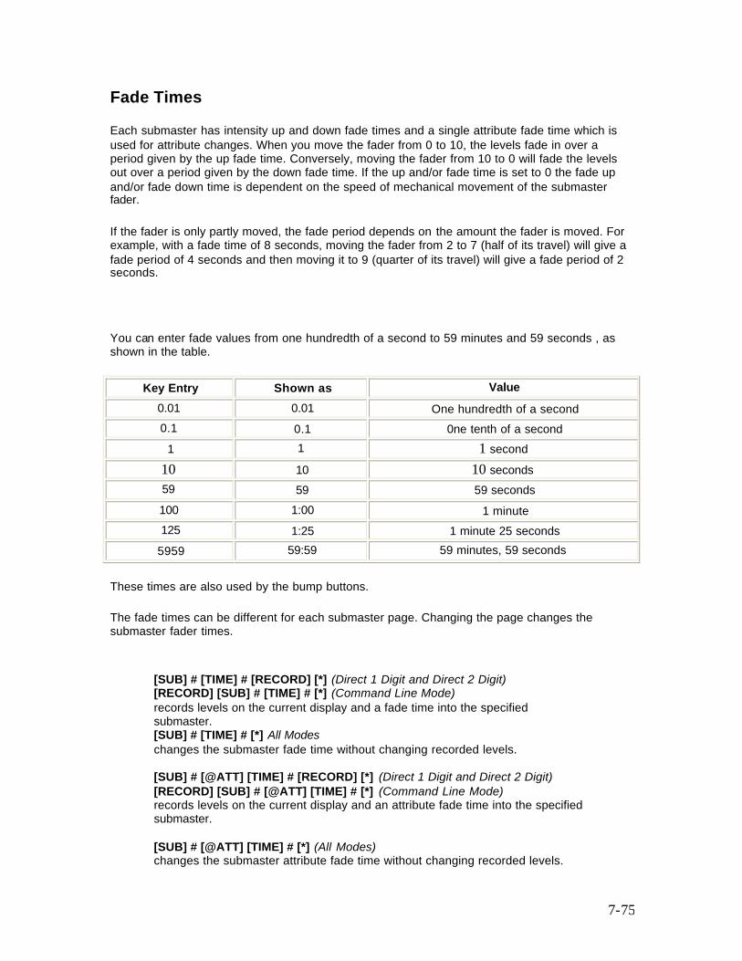
7-75
Fade Times
Each submaster has intensity up and down fade times and a single attribute fade time which is used for attribute changes. When you move the fader from 0 to 10, the levels fade in over a period given by the up fade time. Conversely, moving the fader from 10 to 0 will fade the levels out over a period given by the down fade time. If the up and/or fade time is set to 0 the fade up and/or fade down time is dependent on the speed of mechanical movement of the submaster fader.
If the fader is only partly moved, the fade period depends on the amount the fader is moved. For example, with a fade time of 8 seconds, moving the fader from 2 to 7 (half of its travel) will give a fade period of 4 seconds and then moving it to 9 (quarter of its travel) will give a fade period of 2 seconds.
You can enter fade values from one hundredth of a second to 59 minutes and 59 seconds , as shown in the table.
Key Entry Shown as Value 0.01 0.01 One hundredth of a second 0.1 0.1 0ne tenth of a second 1 1 1 second 10 10 10 seconds 59 59 59 seconds 100 1:00 1 minute 125 1:25 1 minute 25 seconds 5959 59:59 59 minutes, 59 seconds
These times are also used by the bump buttons.
The fade times can be different for each submaster page. Changing the page changes the submaster fader times.
[SUB] # [TIME] # [RECORD] [*] (Direct 1 Digit and Direct 2 Digit) [RECORD] [SUB] # [TIME] # [*] (Command Line Mode) records levels on the current display and a fade time into the specified submaster. [SUB] # [TIME] # [*] All Modes changes the submaster fade time without changing recorded levels. [SUB] # [@ATT] [TIME] # [RECORD] [*] (Direct 1 Digit and Direct 2 Digit) [RECORD] [SUB] # [@ATT] [TIME] # [*] (Command Line Mode) records levels on the current display and an attribute fade time into the specified submaster. [SUB] # [@ATT] [TIME] # [*] (All Modes) changes the submaster attribute fade time without changing recorded levels.
7-76
For specific examples, please see Recording Levels and Properties in Basic Recording.
Fader Properties
Submaster faders have the following properties that can be specified when recording, or edited later:
• Submaster Functions • Assigning Effects and Macros • External Faders • Submaster Bump Mode • Text
These properties are associated with the fader and not the submaster, so they are common across all submaster pages.
Submaster Function
When a submaster number is set to a function, that function applies to the submaster on all submaster pages. The same submaster cannot have different functions on different submaster pages.
Each submaster fader can have one of several functions. The submaster function is initially set to Normal for all submasters. You can eliminate or move any supermaster, and change submaster functions for other submaster faders as needed.
Submaster functions are one of the following values:
• Pileon Submaster (Normal) • Independent Submaster (Indep) • Exclusive Submaster (Exclusive) • Inhibitive Submaster (Inhibit) • Sound to Light Submaster (S/Light) (500 Series Consoles only) • DMX Channel Submaster (DMX Chan) • DMX Dimmer Submaster (DMX DMNR) • Submaster Supermaster (Sub Super) • Effects Supermaster (FX Super) • Flash Supermaster (Flash SPR) • Grandmasters (GM1, GM2) • Audio Threshold Supermaster (AUDO THR) (500 Series Consoles only) • Midi Ratio Supermaster (MIDI RATI)
NORMAL (Pileon submaster) - Default Submaster intensities are combined with effects, playbacks, and other submasters on a highest takes precedence basis. Attributes are combined on a latest takes precedence basis. Selecting a channel with the Channel Control steals it from the submaster.

7-77
INDEP (Independent submaster) Submaster intensities are combined with effects, playbacks, and other submasters on a highest takes precedence basis. Attributes are combined on a latest takes precedence basis. Submaster channels can not be stolen by the Channel Control, but the Channel Control can increase the channel intensity over the submaster level. Once you decrease the channel level to below the submaster level, the submaster level will take over again. EXCLUSIVE (Exclusive submaster) Submaster intensities are as recorded in the submaster and modified by the submaster fader, the Submaster Supermaster, and the grand master. They are not changed when cues or effects run, when other submasters are changed, or when channel control is used on the same channels. If the same channel is used in two exclusive submasters, the last submaster to move off zero steals that channel. INHIBIT (Inhibitive submaster) Acting like a grandmaster fader, the submaster fader masters all output channels that have any intensity recorded in the submaster. Channels with only attributes recorded in the submaster are ignored. Channels under control of an inhibitive submaster appear on the Levels screen with yellow text on a red background if they have a level, or as a red block with no text when they are at zero. You can use the Channel Control to bring channel levels up to the current level of the submaster. Multiple inhibitive submasters which control the same output channels are combined on a lowest takes precedence basis. S/LIGHT (Sound To Light Submaster) - 500 Series Consoles only Submaster intensities are combined with effects, playbacks, and other submasters on a highest takes precedence basis. Attributes are combined on a latest takes precedence basis. The local submaster controls the maximum level of sound to light, and the external Audio Input controls the level of the submaster up to that maximum. Submaster channels can be stolen by the Channel Control. This facility is only available with the CommuniquéPro software. For more information see CommuniquéPro Software. Only one submaster can be a Sound To Light Submaster. DMX CHAN (DMX Channel Submaster) The DMX input signals become levels for channels 1-512 in the submaster, and are combined with effects, playbacks, and other submasters on a highest takes precedence basis. The local submaster controls the level of the DMX input. Recorded submaster levels are ignored. Submaster channels can be stolen by the Channel Control. This facility is only available with the CommuniquéPro software. For more information see CommuniquéPro Software. Only one submaster can be a DMX Channel Submaster. DMX DIMR (DMX Dimmer Submaster) The local submaster controls the level of the DMX input, and thus the levels of any dimmers patched to DMX inputs. Recorded submaster levels are ignored. Only one submaster can be a DMX Dimmer Submaster. This facility is only available with the CommuniquéPro software. For more information see CommuniquéPro Software. Only one submaster can be a DMX Dimmer Submaster. SUB SUPER (Submaster Supermaster) The submaster fader controls the level of all submasters. Channels are controlled by individual submasters, which are in turn controlled by the Submaster Supermaster. Only one submaster can be the Submaster Supermaster. If no submasters are assigned as the Submaster Supermaster, all submasters can be controlled between 0 and 10. FX SUPER (Effect Supermaster)

7-78
The submaster fader controls the overall level of all effects. Channels are controlled by the effects, which are in turn mastered by the Effect Supermaster. Recorded submaster levels are ignored. Only one submaster can be the Effect Supermaster. If no submasters are assigned as the Effect Supermaster, all effects run at their recorded levels. FLASH SPR (Flash Supermaster) The submaster fader controls the level for bumps and flashes. Only one submaster can be the Flash Supermaster. If no submaster is assigned as the Flash Supermaster, channels and submasters always flash to Full. GM1, GM2 (Grandmaster 1 and 2) 530 and 550 consoles are supplied with two grandmaster faders, while, 520 consoles and consoles in the 300 series have no dedicated grandmaster faders. You can, however, select one submaster fader (GM1) to perform the function of a grandmaster fader (300 series consoles), or two submaster faders (500 series consoles) to perform the function of grandmaster fader GM1 and GM2. AUDIO THR (Audio Threshold Supermaster) - 500 Series Consoles only The submaster fader controls the sensitivity of the Audio Input. The Audio Input can be used to control the stepping of an effect. Recorded submaster levels are ignored. This facility is only available with the CommuniquéPro Software. For more information see CommuniquéPro Software. Only one submaster can be the Audio Threshold Supermaster. MIDI RATI (Midi Ratio Supermaster) The submaster fader sets the number of MIDI sync pulses which the effect must count before it will move to the next step. Recorded submaster levels are ignored. This facility is only available with the CommuniquéPro software. For more information see CommuniquéPro Software. Only one submaster can be the Midi Ratio Supermaster.
To set the submaster function in the Submaster display, press <SUB> to see the Submaster display and then change the Function field for the appropriate submaster.
[SUB] # function [RECORD] records levels on the current display into the specified submaster and changes the submaster function. [SUB] # function [*] changes the function of the specified submaster without changing recorded levels.
The key sequences represented by function are:
Pileon submaster {SUB FUNC} {NORMAL} Independent submaster {SUB FUNC} {INDEP} Exclusive submaster {SUB FUNC} { EXCLUS} Inhibitive submaster {SUB FUNC} {INHIB} Sound To Light Submaster {SUB FUNC} {SUPER I/P} {SOUND LIGHT} DMX Channel Submaster {SUB FUNC} {SUPER I/P} {DMX IN CHAN} DMX Dimmer Submaster {SUB FUNC} {SUPER I/P} {DMX IN DIMMER} Submaster Supermaster {SUB FUNC} {SUPER} {SUB SUPER} Effect Supermaster {SUB FUNC} {SUPER} {FX SUPER} Flash Supermaster {SUB FUNC} {SUPER} {FLASH SUPER} Audio Threshold Supermaster {SUB FUNC} {SUPER I/P} {AUDIO THRESH} Midi Ratio Supermaster {SUB FUNC} {SUPER I/P} {MIDI RATIO} Grandmaster 1 {SUB FUNC} {GM 1} Grandmaster 2 {SUB FUNC} {GM 2} (500 Series consoles only)
7-79
Assigning Effects and Macros
Both a macro and an effect can be associated with a submaster fader, so that when the fader is reloaded it automatically runs the macro and/or effect. The macro and effect are the same for all submaster pages. When an effect or macro is assigned to a submaster fader, the fader controls the levels of the channels running in the effect or macro, together with channels recorded in the submaster.
[SUB] # [FX] # [RECORD] (Direct 1 Digit and Direct 2 Digit) [RECORD] [SUB] # [FX] # [*] (Command Line) Records levels on the current display into the specified submaster and assigns an effect to it. If the submaster has already been recorded, an overrecord message gives you the chance to cancel the recording. To rerecord the submaster, press [RECORD] again. To cancel the recording, press [CLR] or [UNDO]. When the submaster is moved up from zero the effect is automatically started. To delete an assigned effect, rerecord omitting the effect number.
[SUB] [1] [FX] [2] [RECORD] (Direct 1 Digit and Direct 2 Digit) [RECORD] [SUB] [1] [FX] [2] [*] (Command Line) Records levels into submaster 1 and assigns effect 2 to it. [SUB] [1] [FX] [RECORD] (Direct 1 Digit and Direct 2 Digit) [RECORD] [SUB] [1] [FX] [*] (Command Line) Records levels into submaster 1 and deletes any assigned effect
[SUB] # [FX] # [*] changes the effect assigned to the specified submaster without changing recorded levels. You do not get an overrecord warning with this command if the submaster exists.
[SUB] [1] [FX] [*] (All Modes) Deletes the effect assigned to submaster 1 without changing any levels. [SUB] [1] [FX] [2] [*] (All Modes) Changes the effect assigned to submaster 1 to effect 2 without changing any levels.
[SUB] # [MACRO] # records levels on the current display into the specified submaster and assigns a macro to it. If the submaster has already been recorded, an overrec ord message gives you the chance to cancel the recording. To rerecord the submaster, press [RECORD] [*] again. To cancel the recording, press [CLR] or [UNDO]. When the submaster is moved up from zero the macro is automatically started. To delete an assigned macro, omit the macro number.
[SUB] [1] [MACRO] [3] [RECORD] (Direct 1 Digit and Direct 2 Digit) [RECORD] [SUB] [1] [MACRO] [3] [*] (Command Line) Records levels into submaster 1 and assigns Macro 3 to it. [SUB] [1] [MACRO] [RECORD] (Direct 1 Digit and Direct 2 Digit) [RECORD] [SUB] [1] [MACRO] [*] (Command Line) Records levels into submaster 1 and deletes any assigned
7-80
macro.
[SUB] # [MACRO] # [*] changes the macro assigned to the specified submaster without changing recorded levels. You do not get an overrecord warning with this command if the submaster exists.
[SUB] [1] [MACRO] [*] (All Modes) Deletes the macro assigned to submaster 1 without changing any levels. [SUB] [1] [MACRO] [2] [*] (All Modes) Changes the macro assigned to submaster 1 to macro 2 without changing any levels.
External Faders
The numbered submaster fader normally controls the submaster or supermaster directly. However, each submaster can be set to use one of the 12 analog inputs from the REMOTE connector, in which case the fader level is combined with the analog input level on a highest takes precedence basis. Each analog input can only be used once.
Submaster Bump Modes
You can record a bump mode for each individual submaster. To record a bump mode you must be in the Submaster display. To change the bump mode, press [SUB] to see the submaster display, and hold down the [SHIFT] key and move the trackball to change to edit mode. Select the Bump field for the appropriate submaster and use the [+] or [-] keys or the level wheel to change the bump mode. All submasters are initially set to Flash mode.
Off Pressing the bump button does nothing. Flsh (Flash) Pressing the bump button is same as moving the submaster fader to 10. The output is set to the level of the Flash Supermaster. Solo (Solo) Pressing the bump button leaves the output of the submaster the same. All other (non-bumped) submasters, as well as effects, cues, and the Channel Control, are set to zero. The Flash Supermaster is ignored. F+S (Flash plus Solo) Pressing the bump button is same as moving the submaster fader to 10. The output is set to the level of the Flash Supermaster. All other (non-bumped) submasters, as well as effects, cues, and the Channel Control, are set to zero. Mac Disables the bump button's flash and solo operation and instead allows it to trigger the macro with the same number as the bump button (not the macro assigned to the bump button) The submaster bump buttons are also controlled by the {KEYS LATCH} soft key accessed using the [BUMP MODE] key. This softkey appears in the centre LCD (consoles with 3 LCD displays) or right LCD (consoles with 2 LCD displays) as labels above the soft keys. The setting of the this softkey determines the operation of the submaster bump keys and the operation of the {BUMP} softkey on the channel control
7-81
display. The other softkeys, {FLASH}, {SOLO} and {FLASH + SOLO}, control the action of the {BUMP} softkey on the channel control display and have no effect on the submaster bump keys. For information on setting the action of the channel control {BUMP} softkey, refer to Bumping Channel Levels Press this key to view the current setting. A bar above the label shows the current mode. Press [BUMP MODE] again to return to normal operation. For consoles without a [BUMP MODE] key, refer to Console Differences
The {KEYS LATCH} softkey can only be selected when the {FLASH} softkey is also selected. In {SOLO} or {FLASH + SOLO} modes, the {KEYS LATCH} is automatically disabled. The {KEYS ON} and {KEYS OFF} soft keys have effect on the Submaster bump keys. When {KEYS LATCH} is selected, pressing and releasing the submaster bump keys bumps the levels until the bump button is pressed again.
{KEYS LATCH} When selected, pressing and releasing a submaster bump key bump the levels until the bump button is pressed again.
{KEYS ON} While the bump button is pressed, the channel levels are bumped. Releasing the bump button releases the bump.
{KEYS OFF} The bump buttons are disabled.
Text Labels
You can record a text label (caption) with each submaster to help identify the submaster. The submaster text label is entered using the external keypad.
[SUB] # [TEXT] text [RECORD] records levels on the current display into the specified submaster and assigns a text label (caption) to it. [SUB] # [TEXT] text [*] changes the text label (caption) assigned to a submaster without changing recorded levels.
For examples, refer to Recording Levels and Properties in Basic Recording.
Updating and Adding to Submasters
[UPDATE] [SUB] # [*] changes levels in the specified submaster as necessary based on channels that have been modified live (red or purple channels on the Live display). This command excludes channels that are not already in the submaster, and channels that have been removed from the modified list by using [SHIFT] [CLR].
Note: When using submasters the [UPDATE] key is set to default to update only channels already in the submaster. Pressing the [UPDATE] key as part of a submaster command syntax, e.g., [UPDATE] [SUB] # [*] is the same as entering [UPDATE] {CHANS IN} [SUB] # [*]. So when updating a submaster to include
7-82
only changes in channels already inthe submaster, there is no need to use the {CHANS IN} softkey. The {CHANS IN} softkey is used, as necessary, when updating cues.
Channels that are off in the selection will be removed from the submaster.
[UPDATE] [SUB] [1] [*] (All Modes) Updates levels that have been modified in submaster 1, excluding levels of channels that were not already in the submaster. [SUB] [7] [*] [UPDATE] [SUB] [1] [*] (All Modes) First selects all of the channels in submaster 7, then updates their levels in submaster 1, excluding levels of channels that were not already in the submaster.
Including the {ADD ALL} softkey in the update command includes level changes in channels that are not already in the submaster.
[UPDATE]{ADD ALL} [SUB] # [*] (All Modes) Updates levels in the specified submaster for channels that have been modified. Includes modified channels that are not already in the submaster, and channels that have been removed from the modified list by using [SHIFT] [CLR]. Channels that are off in the selection will be removed from the submaster. [UPDATE]{ADD ALL} [SUB] [1] [*] (All Modes) Updates all channels that have been modified in submaster 1, including channels that are not already in submaster 1. [SUB] [7] [*] [UPDATE] {ADD ALL} [SUB] [1] [*] (All Modes) First selects all of the channels in submaster 7, then records their levels in submaster 1, including channels that are not already in the submaster 7.
chan [UPDATE] [SUB] # [*] updates levels of the specified channels in the specified submasters to match the current Levels screen for the selected channels, regardless of whether or not they have been modified. Excludes channels that are not already in the submaster, regardless of whether or not they have been modified. Channels that are off in the selection will be removed from the submaster.
[1] [THRU] [5] [UPDATE] [SUB] [*] (All Modes) Changes channel 1 through 5 levels in submaster 1, excluding channels that are not already in the submaster. If the submaster fader is not at 0 then the updated levels are adjusted to avoid output bumps. For example, if the submaster fader is at 50% and a channel level of 10% (from the output) is updated, the level recorded into the submaster is actually 20% so that the submaster output is 10%. The maximum level that can be recorded into the submaster is 100% so output bumps can still occur with a low fader and high levels.
Note: To clear the changed indicator and set red channel levels back to cyan, press [SHIFT] [CLR].
7-83
Updating Submasters from the Live Screen
When in the Submaster Screen, you can update the current submaster in accordance with levels in the Live Screen using the syntax chans [@] [LIVE]
[1] [THRU] [5] [@] [LIVE] Direct Action Modes
[1] [THRU] [5] [@] [LIVE] [*] Command Line Mode
Updates channels 1 to 5 inthe currently selected submaster in the Submaster Screen according to the levels in the Live Screen. If any of the channels are not already in the submaster, they are added tothe submaster
Alternatively, you can update the value of only the channels already in the submaster screen in accordance with the levels in the Live Screen using the syntax [SUB] [@] [LIVE}
[SUB] [1] [@] [LIVE] Direct Action Modes
[SUB] [1] [@] [LIVE] [*] Command Line Mode
Selects the channels in submaster 1 and updates them to the values in the Live Screen.
Quick Recording
Pressing the bump button for a submaster (this is below the submaster fader) is a quick way of recording a submaster. This does not actually bump the submaster.
[SUB] Sub 1 button Records submaster 1. This is the same as [SUB] [1] [RECORD]
chan, [SUB] Sub 1 button Adds the specified channels to the submaster and sets their levels to match the current Levels screen.
[1] [THRU] [5] Sub 1 button (All Modes) Adds channels 1 through 5 to submaster 1 and sets their levels to the levels on the current Levels screen. If the channels are already in the submaster the levels are changed to match the current Levels screen.
chan [SUB] [-] Sub 1 button Deletes the specified channels from the submaster (sets their levels off).
[4] [+] [5] [SUB] [-] Sub button 1 (All Modes) Deletes channels 4 and 5 from submaster 1 and returns the current Levels screen to it’s levels without the submaster
7-84
Using Submaster Faders
Each submaster is controlled by a submaster fader and the bump button below the fader. Refer to the Product Specification for number of submasters
Each submaster fader has two lights to show submaster status. A Submaster Supermaster controls the levels of all submasters. The submaster faders and bump buttons can be used from any display. They have no effect on the output if the submaster has no recorded levels (intensities or attributes). The Submasters window at the bottom of the Live display State screen shows the current state of the submasters.
Note: If you experience occasional flicker on the output from submaster channels, this is dueto a hardware problem to do with submaster scanning. Contact Strand Service for console fix.
Gang Loading of Subs
A sequence of cues, effects or groups to be loaded simultaneously to a sequence of subs, e.g., Enter the range of cues, effects or groups using the [THRU] key, then press the bump key for the first sub in the range. The number of subs required is assigned automatically.
[CUE] [1] [THRU] [1] [2] Sub Bump Button 1 (All Modes) loads cues 1 through 12 in Subs 1 through 12 [FX] [1] [THRU] [3] Sub Bump Button 13 (All Modes) loads effects 1 through 3 in Subs 13 through 16 [GROUP] [1] [THRU] [6] Sub Bump Button 19 (All Modes) loads groups 1 through 6 in Subs 19 through 24
Re-assigning cues, subs or Groups to Subs already assigned will automatically overwrite the original assignment.
The Submasters Window
The Submasters window in the Live display shows the current state of the submasters and is used to show submaster fader status. If the State screen does not show the Submasters window, go to the User Setup Screen and change the Live Screen Layout value to PB+SUBS or SUBS. Then press [LIVE] to show the Live display.
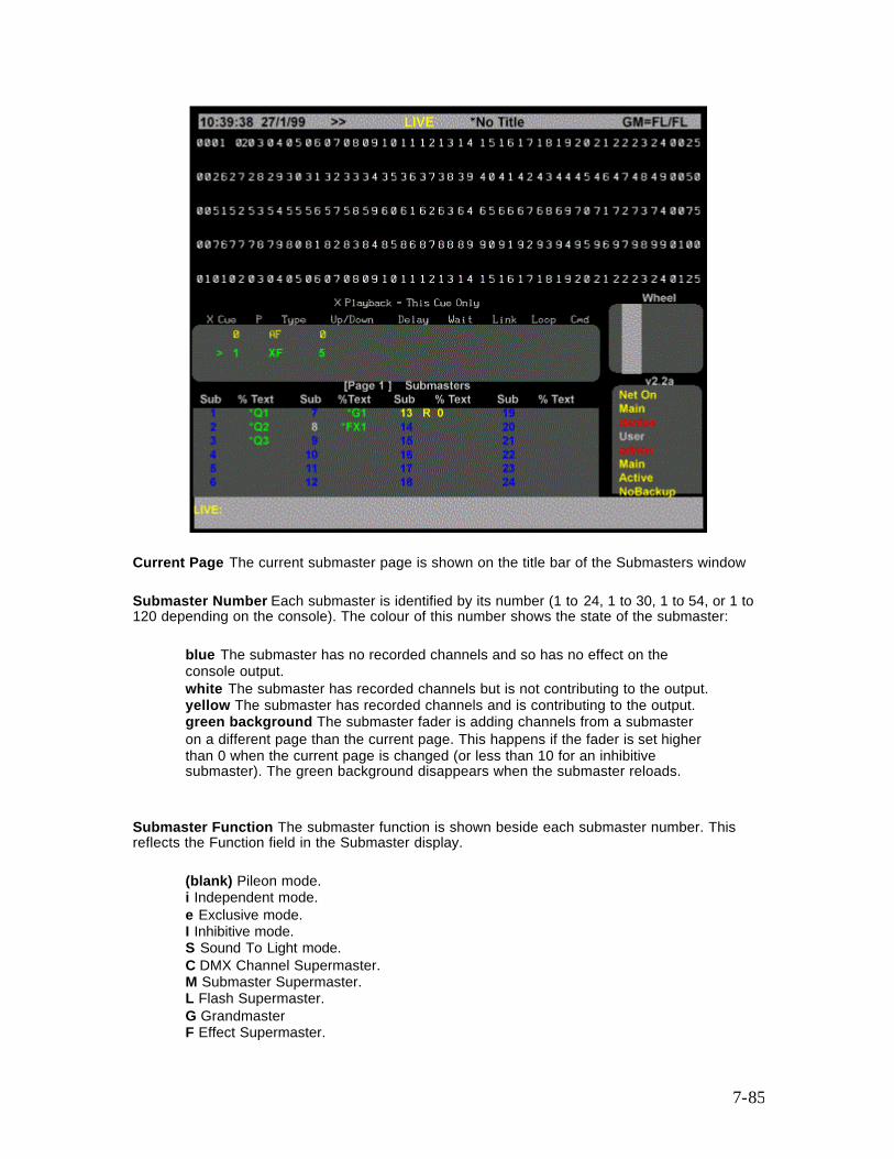
7-85
Current Page The current submaster page is shown on the title bar of the Submasters window
Submaster Number Each submaster is identified by its number (1 to 24, 1 to 30, 1 to 54, or 1 to 120 depending on the console). The colour of this number shows the state of the submaster:
blue The submaster has no recorded channels and so has no effect on the console output. white The submaster has recorded channels but is not contributing to the output. yellow The submaster has recorded channels and is contributing to the output. green background The submaster fader is adding channels from a submaster on a different page than the current page. This happens if the fader is set higher than 0 when the current page is changed (or less than 10 for an inhibitive submaster). The green background disappears when the submaster reloads.
Submaster Function The submaster function is shown beside each submaster number. This reflects the Function field in the Submaster display.
(blank) Pileon mode. i Independent mode. e Exclusive mode. I Inhibitive mode. S Sound To Light mode. C DMX Channel Supermaster. M Submaster Supermaster. L Flash Supermaster. G Grandmaster F Effect Supermaster.
7-86
D DMX Dimmer Supermaster. A Audio Threshold Supermaster. R MIDI Ratio Supermaster.
Submaster Fader Level The current fader level of each submaster is shown beside the submaster number after the mode. This ranges from 0 to 99 or FL for 100%, and shows the level as it fades, not just the fader position.
Viewing and Editing Submasters
You can view and edit submasters and supermasters in the Submaster display.
Note: Changing levels while in this display changes the recorded levels in the current submaster without a record command and without warning you.
The following topics are covered in this section:
o The Submaster Screen o The State Screen o Viewing Submaster Channel Levels o Editing Submaster Channel Levels o Clearing Submasters o Copying Levels from a Submaster
The Submaster Screen
To show the Submaster screen press [SUB] in the Display keypad (not [SUB] in the Levels keypad). The Submaster display State screen shows a page of submasters and their associated fields. The current submaster number is highlighted with a red background. The current page is shown at the top of this window.
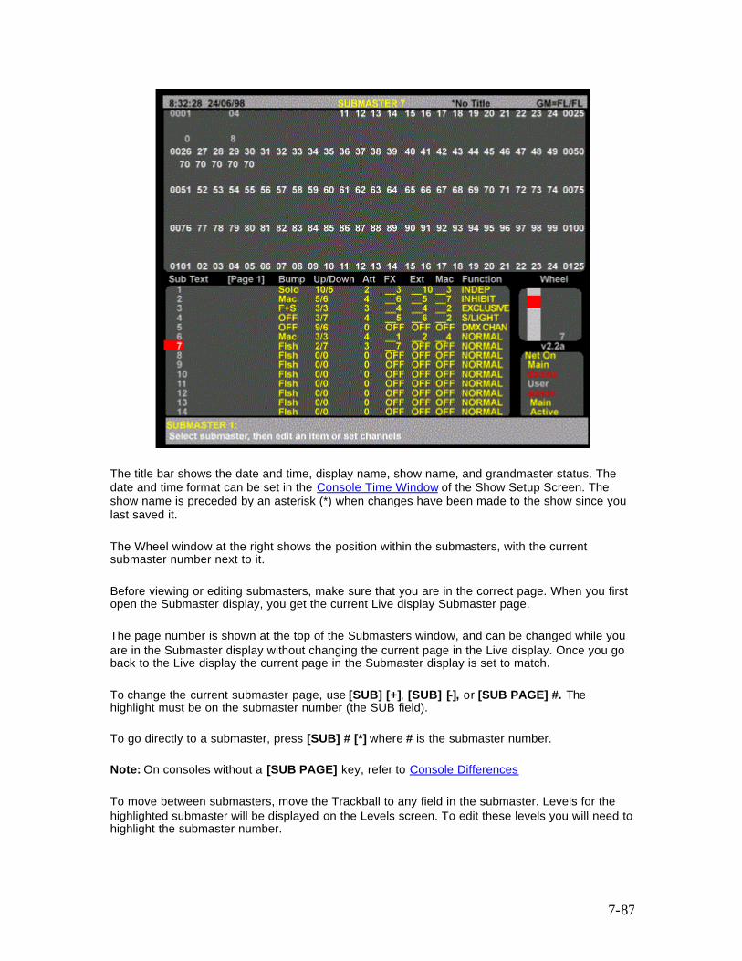
7-87
The title bar shows the date and time, display name, show name, and grandmaster status. The date and time format can be set in the Console Time Window of the Show Setup Screen. The show name is preceded by an asterisk (*) when changes have been made to the show since you last saved it.
The Wheel window at the right shows the position within the submasters, with the current submaster number next to it.
Before viewing or editing submasters, make sure that you are in the correct page. When you first open the Submaster display, you get the current Live display Submaster page.
The page number is shown at the top of the Submasters window, and can be changed while you are in the Submaster display without changing the current page in the Live display. Once you go back to the Live display the current page in the Submaster display is set to match.
To change the current submaster page, use [SUB] [+], [SUB] [-], or [SUB PAGE] #. The highlight must be on the submaster number (the SUB field).
To go directly to a submaster, press [SUB] # [*] where # is the submaster number.
Note: On consoles without a [SUB PAGE] key, refer to Console Differences
To move between submasters, move the Trackball to any field in the submaster. Levels for the highlighted submaster will be displayed on the Levels screen. To edit these levels you will need to highlight the submaster number.
7-88
You can also use [NEXT] and [LAST] to change submasters if the highlight is on the submaster number.
State Screen
Fields on the Submaster display State screen show the current values for submaster properties. To learn more about these properties refer to Recording Submaster Properties and Fader Properties
The fields are shown below.
SUB The number of the submaster These are fixed and cannot be changed.(Refer to the Product Specification for number of submasters). See also, One and Two-Scene Preset
TEXT The text label (caption) attached to this submaster.
Up/Down The intensity up and down fade times. Can be from one hundredth of a second to 59 minutes and 59 seconds
Att Attribute fade times. The same time is used for both up and down fades. Can be from one hundredth of a second to 59 minutes and 59 seconds
Fx OFF if no effect is associated with this submaster. Otherwise the effect number to start when the submaster is moved off zero.
Ext OFF if no external fader is used. Otherwise the analog input number which is combined with this fader on a highest takes precedence basis.
Mac OFF if no macro is associated with this submaster. Otherwise the macro number of the macro to run when the submaster is moved off zero.
Function Controls how the submaster is used. For further information about supermasters and other submaster functions refer to Submaster Functions
Bump Controls the submaster bump mode. Refer to Submaster Bump Mode
7-89
Viewing Submaster Channel Levels
To view the recorded levels in a submaster, select the required submaster. The levels are then shown on the Levels screen. Only submasters set to Normal, Independent, Exclusive, Inhibitive, or Sound To Light functions use the channel levels. Channel levels are ignored in other submaster modes.
Channels which are off are shown with a blank level. Channels which are on at 0 are shown with a level of 0. For Inhibitive mode, intensity channels with levels (including on At 0) are inhibited and attribute channels or channels which are off are ignored. For Normal, Independent, and Exclusive modes, on At 0 and off are treated as a level of 0.
Editing Submaster Channel Levels
Once you have selected the required submaster and put the highlight on the submaster number (the SUB field), you can select channels and modify them using the same commands as for channel control, for example [1] [@] [1], [CUE] [1] [@] [5] and so on. The Level Wheel cannot be used to change levels.
If a submaster is referenced in a channel command (for example [SUB] [1] [@]) then the submaster from the current page in the Submaster display is used. This lets you copy submaster levels on the same page.
Clearing Submasters
To clear a submaster, set all intensity levels and attribute levels for the submaster off, or highlight the submaster number (the SUB field) in the State screen and use {CLEAR}. For information about clearing all submasters or a range of submasters from the Archive display refer to Clear Operations in the Archive Screen.
{CLEAR} This soft key appears on the right LCD Submaster menu. Press {CLEAR} twice, a message appears to let you cancel. To clear the submaster, press {CLEAR} again. To cancel, press [CLR] or [UNDO].
Using {CLEAR} sets all intensity levels and attribute levels in the selected submaster to 0, clears any macro or external fader, and sets the submaster mode to Normal. {CLEAR} can be used with a single submaster or with a [THRU] range.
{CLEAR} [*] [*] (All Modes) Clears the current submaster. [SUB] [1] {CLEAR} [*] (All Modes) Clears submaster 1. [SUB] [1] [THRU] [3] {CLEAR} [*] (All Modes) Clears submasters 1, 2, and 3.
7-90
Copying Levels from a Submaster
You can record submasters, cues, groups, and effect steps while you are in the Submaster display. The highlight must be on the submaster number (the SUB field).
Using record commands while you are in the Submaster display copies the Submaster display levels to the target submaster, cue, group, or effect step. For example, if the current submaster is 1, then [RECORD] [CUE] [2] [*] (Command Line), or [CUE] [2] [RECORD] (Direct Entry) will copy the levels from submaster 1 into cue 2.
Submasters are recorded into the current submaster page of the Submaster display. You cannot copy submasters between pages. Since submasters are recorded into the current submaster page of the Submaster display, this copies the submaster to a different submaster in the same submaster page. There is no direct way to copy a submaster to another page. You can copy submasters to another page indirectly by following the steps below, which use the Live display to record the contents of page1 submaster 1 into page 3 submaster 4.
Go to the Live display and make sure all channels are off. Press [SUB PAGE] [1] [*] to set the initial submaster page. Press [SUB] [1] [@] {FULL} [*] to set the submaster levels in the current display. Press [SUB PAGE] [3] [*] to change the submaster page. (for 300 series consoles, the [SUB PAGE] key can be simulated using the 'V' key on an ASCII keyboard) Press [SUB] [4] [RECORD] (Direct Entry Mode), or [RECORD] [SUB] [4] [*] (Command Line Mode) to record the new submaster. Note: On consoles without a [SUB PAGE] key, refer to Console Differences
One and Two-Scene Preset All 300 and 500 series control desks can be set up to operate as a conventional single, or two scene preset lighting desk, with or without a submaster bank. 300 series control desks are provided with two [PB MODE] keys, which are used to set the functions of the two X Playback faders. 500 series consoles have no PB Mode key. The keyboard equivalents are Ctrl A and Ctrl B. The options are as follows: Pressing the appropriate [PB MODE] key (300 Series Consoles) or Ctrl A/Ctrl B (500 Series Consoles) will display the following LCD softkey menu for the playback. Note: You must press the appropriate [PB MODE] key, or Ctrl A/Ctrl B to return to Live mode after you have selected the playback mode. X2 Playback {AUTO FADE} GeniusPro/Lightpalette normal operating mode (refer to X Playbacks section). {MAN FADE} GeniusPro/Lightpalette manual operating mode (refer to X Playbacks section) X1 Playback
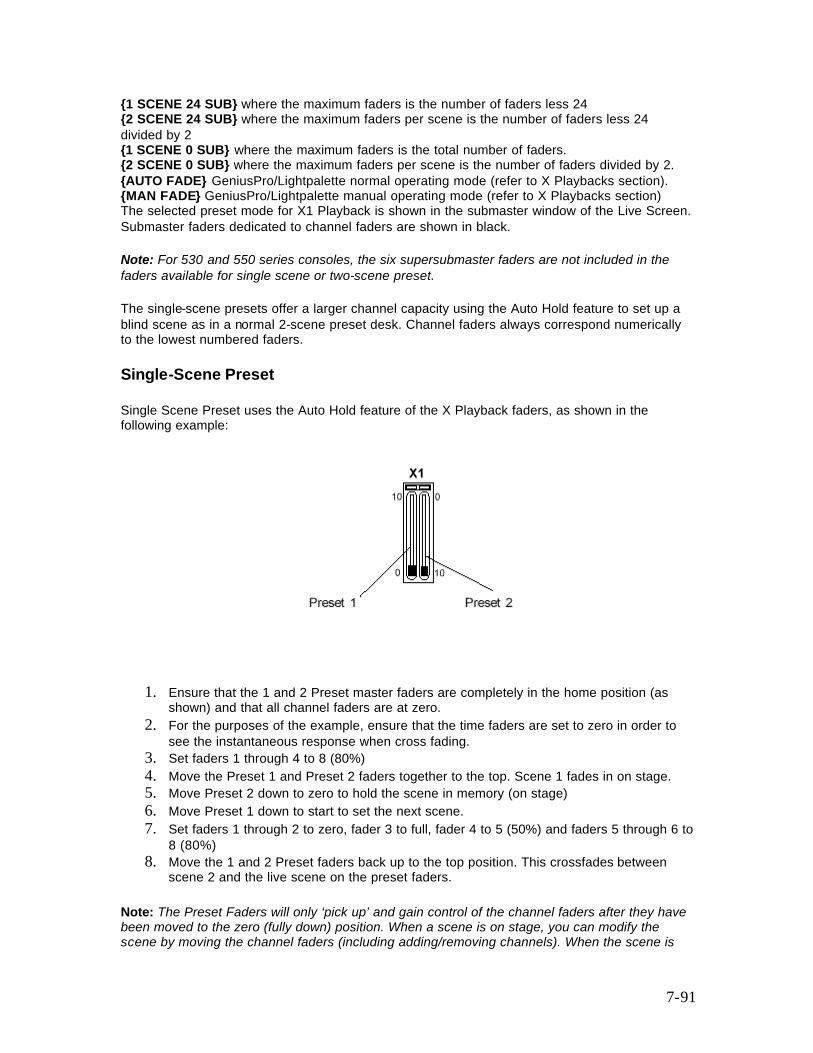
7-91
{1 SCENE 24 SUB} where the maximum faders is the number of faders less 24 {2 SCENE 24 SUB} where the maximum faders per scene is the number of faders less 24 divided by 2 {1 SCENE 0 SUB} where the maximum faders is the total number of faders. {2 SCENE 0 SUB} where the maximum faders per scene is the number of faders divided by 2. {AUTO FADE} GeniusPro/Lightpalette normal operating mode (refer to X Playbacks section). {MAN FADE} GeniusPro/Lightpalette manual operating mode (refer to X Playbacks section) The selected preset mode for X1 Playback is shown in the submaster window of the Live Screen. Submaster faders dedicated to channel faders are shown in black. Note: For 530 and 550 series consoles, the six supersubmaster faders are not included in the faders available for single scene or two-scene preset. The single-scene presets offer a larger channel capacity using the Auto Hold feature to set up a blind scene as in a normal 2-scene preset desk. Channel faders always correspond numerically to the lowest numbered faders. Single-Scene Preset Single Scene Preset uses the Auto Hold feature of the X Playback faders, as shown in the following example:
1. Ensure that the 1 and 2 Preset master faders are completely in the home position (as shown) and that all channel faders are at zero.
2. For the purposes of the example, ensure that the time faders are set to zero in order to see the instantaneous response when cross fading.
3. Set faders 1 through 4 to 8 (80%) 4. Move the Preset 1 and Preset 2 faders together to the top. Scene 1 fades in on stage. 5. Move Preset 2 down to zero to hold the scene in memory (on stage) 6. Move Preset 1 down to start to set the next scene. 7. Set faders 1 through 2 to zero, fader 3 to full, fader 4 to 5 (50%) and faders 5 through 6 to
8 (80%) 8. Move the 1 and 2 Preset faders back up to the top position. This crossfades between
scene 2 and the live scene on the preset faders.
Note: The Preset Faders will only ‘pick up’ and gain control of the channel faders after they have been moved to the zero (fully down) position. When a scene is on stage, you can modify the scene by moving the channel faders (including adding/removing channels). When the scene is
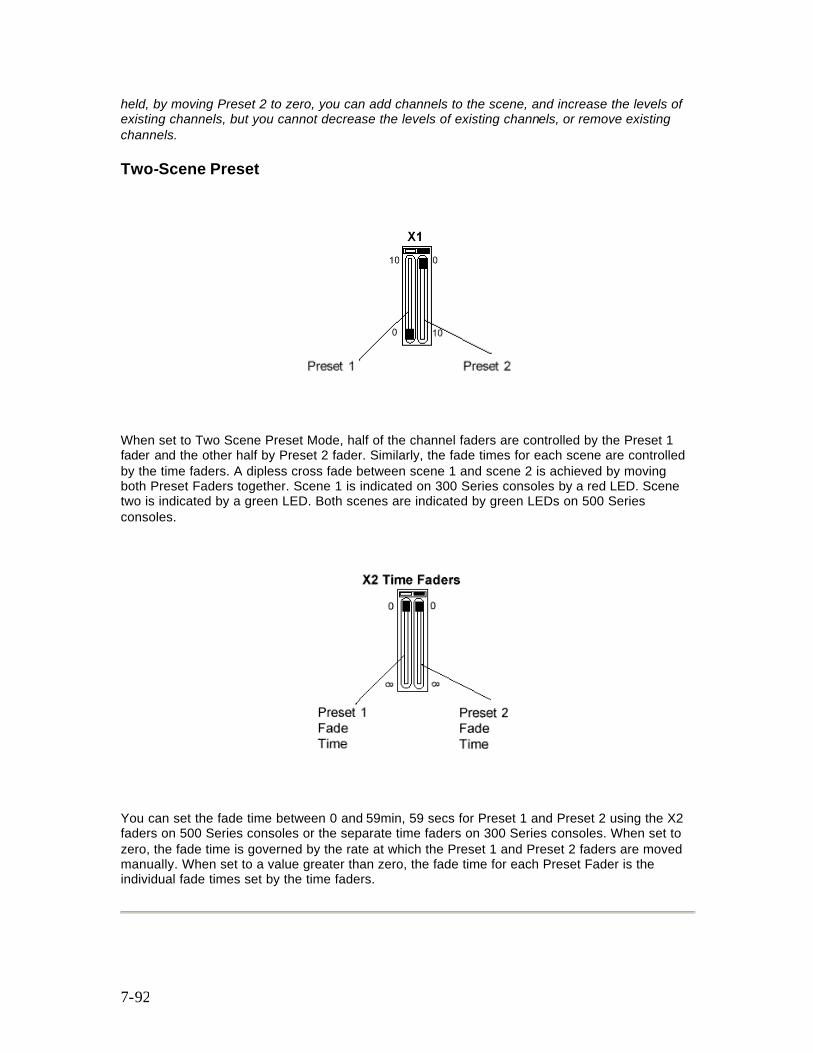
7-92
held, by moving Preset 2 to zero, you can add channels to the scene, and increase the levels of existing channels, but you cannot decrease the levels of existing channels, or remove existing channels. Two-Scene Preset
When set to Two Scene Preset Mode, half of the channel faders are controlled by the Preset 1 fader and the other half by Preset 2 fader. Similarly, the fade times for each scene are controlled by the time faders. A dipless cross fade between scene 1 and scene 2 is achieved by moving both Preset Faders together. Scene 1 is indicated on 300 Series consoles by a red LED. Scene two is indicated by a green LED. Both scenes are indicated by green LEDs on 500 Series consoles.
You can set the fade time between 0 and 59min, 59 secs for Preset 1 and Preset 2 using the X2 faders on 500 Series consoles or the separate time faders on 300 Series consoles. When set to zero, the fade time is governed by the rate at which the Preset 1 and Preset 2 faders are moved manually. When set to a value greater than zero, the fade time for each Preset Fader is the individual fade times set by the time faders.
8-93
Chapter 8 - Recording Cues see also Running Cues X Playbacks
This section describes how to set up and record the levels and properties of individual cues and cue parts. To show the Cue Sheet press the <PREVIEW> key. The following topics are covered:
• Cue and Part Numbering • Recording Cue Levels • Recording Cue Properties
Cue and Part Numbering All cues, can comprise up to 12 parts numbered from 1 to 12. Each cue consists of a minimum of 1 part (e.g., Cue 1 Part 1, Cue 3.2 part 12, etc). If a part number is not specified using the {PART} softkey ([PART] hardkey on 300 Series consoles) when recording a cue, part 1 is automatically assumed. When a cue is run, all parts of the cue are run together. For the maximum number of cues, refer to Product Specification If you initially record whole number cues only, you can use a decimal cue number (for instance 3.5) to insert extra cues between whole numbers. You can insert decimal cues .1 through .9 between any two consecutively numbered cues. Entering a . 0 is optional in a cue number and is the same as if omitted (cue 1 is the same as cue 1.0). Examples of cues (in cue sheet order) are:
0.1 1 (first full numbered cue - same as 1.0). 1.1 1.3 2 100 999.9 (last possible cue).
When a cue is run, all of its parts are run together. If you record a channel in a cue part that has already been recorded in another part of the same cue, the new level (latest recorded level) is used for the channel. Cue wait times, macros, links/loops and commands apply only to the cue as a whole, but separate delay times and profiles can be used on each part. If a cue is referenced without specifying a part, part 1 is assumed.
Cross Fade, Block, and All Fade cues can only have one part (numbered 1) since otherwise all parts would have all channels and the last one would over-ride all previous parts. Parts are always Move Fades (GeniusPro) or Tracking Cues (Lightpalette)
Recording Cue Levels
[RECORD] [*] records the levels (intensity levels and attribute levels) on the current display into the current cue.
8-94
[CUE] # [RECORD] [RECORD] (Direct Digit Modes) [RECORD] [CUE] # [*] (Command Line Mode) Records the levels on the current display (the Live, Cue/Preview, Group, Effect, or Submaster display) into the specified cue. For information on setting intensity and attribute levels, refer to Working With Channel Levels . For examples of recording, refer to Basic Recording.
Note: . When you set channel levels in the Preview display with Cue Tracking on, you can set them off (chans [@] {OFF} [*]) or set them to zero (chans [@] [0] [*]). When set off, levels track through from previous cues. When set to 0, levels are forced to zero in the cue. Thus you can set levels off in a Cross Fade (Blocking Cue) to make individual channels track through the cue, or at zero in a Move Fade (Tracking Cue) to block individual channels. When you record from the Live display with the Cue Tracking field in the Show Setup display set ON, channels at zero are set to zero level in the cue only if they change from the previous cue. Otherwise they are recorded Off and channel levels can track through from the previous cue in later editing
• For GeniusPro, recording a new cue sets it as a Cross Fade when Tracking is off or a Move Fade when Tracking is on unless otherwise specified. Recording over an existing cue does not change the fade type unless you explicitly change it.
• For Lightpalette, All new cues are Tracking Cues unless you explicitly specify that they should be Block Cues or All Fade Cues. Recording over an existing cue does not change the cue type unless you explicitly change it.
• Recording a cue blind (in the Cue/Preview display) does not affect the console output. The cue needs to be loaded and run for the new levels to appear on stage.
• The default wait, fade and delay times are assigned to new cues unless you specify values for them in the record command. The defaults for these values are given by the Cue Fade, Cue Delay, and Cue Wait fields in the The Default Times Window of the User Setup display.
• Recording over an existing cue leaves these values alone unless you explicitly change them.
• Recording a new cue sets it with no links, loops, macro, or effect. Recording over an existing cue leaves these values alone unless you explicitly change them.
• The last recorded cue appears at the bottom of the X Playback window if the Show Last Recorded Cue field in the User Setup display is ON.
• You can record just the intensities or just the attributes to a cue by adding {INTS ONLY} or {ATTS ONLY} to the command line before [RECORD], e.g.,
[CUE] [1] [0] {INTS ONLY} [RECORD] - Direct Digit [RECORD] [CUE] [1] [0] {ATTS ONLY} [*] - Command Line Note: For 520 and 300 Series Consoles, you must include the {REC MODE] key in the command in order to display the {INTS ONLY} and {ATTS ONLY} softkeys, e.g., [CUE] [1] [0] [REC MODE] {INTS ONLY} [RECORD] - Direct Digit [RECORD] [CUE] [1] [0] [REC MODE] {ATTS ONLY} [*] - Command Line
Recording Cue Properties
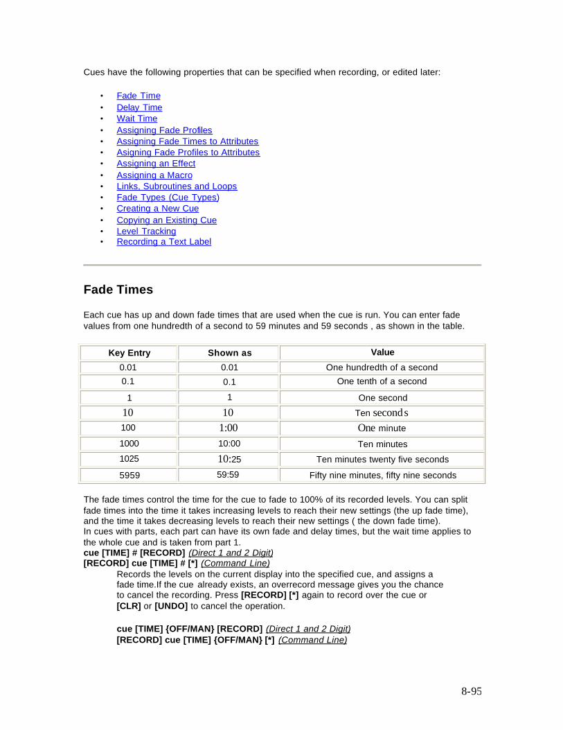
8-95
Cues have the following properties that can be specified when recording, or edited later:
• Fade Time • Delay Time • Wait Time • Assigning Fade Profiles • Assigning Fade Times to Attributes • Asigning Fade Profiles to Attributes • Assigning an Effect • Assigning a Macro • Links, Subroutines and Loops • Fade Types (Cue Types) • Creating a New Cue • Copying an Existing Cue • Level Tracking • Recording a Text Label
Fade Times
Each cue has up and down fade times that are used when the cue is run. You can enter fade values from one hundredth of a second to 59 minutes and 59 seconds , as shown in the table.
Key Entry Shown as Value 0.01 0.01 One hundredth of a second 0.1 0.1 One tenth of a second 1 1 One second 10 10 Ten seconds 100 1:00 One minute
1000 10:00 Ten minutes 1025 10:25 Ten minutes twenty five seconds 5959 59:59 Fifty nine minutes, fifty nine seconds
The fade times control the time for the cue to fade to 100% of its recorded levels. You can split fade times into the time it takes increasing levels to reach their new settings (the up fade time), and the time it takes decreasing levels to reach their new settings ( the down fade time). In cues with parts, each part can have its own fade and delay times, but the wait time applies to the whole cue and is taken from part 1. cue [TIME] # [RECORD] (Direct 1 and 2 Digit) [RECORD] cue [TIME] # [*] (Command Line)
Records the levels on the current display into the specified cue, and assigns a fade time.If the cue already exists, an overrecord message gives you the chance to cancel the recording. Press [RECORD] [*] again to record over the cue or [CLR] or [UNDO] to cancel the operation. cue [TIME] {OFF/MAN} [RECORD] (Direct 1 and 2 Digit) [RECORD] cue [TIME] {OFF/MAN} [*] (Command Line)
8-96
Records the levels on the current display into the specified cue, and makes the cue into a manual fade. If the cue already exists, an overrecord message gives you the chance to cancel the recording. Press [RECORD] [*] again to record over the cue or [CLR] or [UNDO] tocancel the operation.
For examples of setting fade time, refer to Recording Levels and Properties
See also Assigning Fade Times to Attributes
Delay Times
Each cue has up and down delay times and a wait time which are used when the cue is run. These can be set to values from one hundredth of a second to 59 minutes and 59 seconds as shown for Fade Times
Delay times are used to delay the start of a fade from when you press [GO]. You can split delay times into the time until the channels whose levels are increasing start to fade (the up delay time), and the time until the channels whose levels are decreasing start to fade (the down delay time).
In cues with parts, each part can have its own fade and delay times, but the wait time applies to the whole cue and is taken from part 1.
cue [DELAY] # [RECORD] (Direct 1 and 2 Digit) [RECORD] cue [DELAY] # [*] (Command Line) records the levels on the current display into the specified cue, and records a delay time. If the cue already exists, an overrecord message gives you the chance to cancel the recording. Press [RECORD] [*] again to record over the cue or [CLR] or [UNDO] to cancel the operation.
If you only enter one number for time, it is used for both the up and down delay times. To enter separate up and down delay times, use [/] to separate the two numbers. The first number becomes the up delay time and the second number becomes the down delay time.
Separate delay times can be assigned to each cue part. To delete an assigned delay time, omit the time value.
[CUE] [1] [DELAY] [4] [RECORD] Direct 1 and 2 Digit [RECORD] [CUE] [1] [DELAY] [4] [*] Command Line Records levels into cue 1 and assigns up and down delay times of 4 seconds. [CUE] [1] [DELAY] [4] [/] [2] [*] Direct 1 and 2 Digit [RECORD] [CUE] [1] [DELAY] [4] [/] [2] [*] Command Line Records levels into cue 1 and assigns an up delay time of 4 seconds and a down delay time of 2 seconds. [CUE] [1] [DELAY] [/] [2] [RECORD] Direct 1 and 2 Digit [RECORD] [CUE] [1] [DELAY] [/] [2] [*] Command Line Records levels into cue 1 and assigns a 2 second delay for down fades. Sets the delay time for the up fade to the default time, or leaves it as is if over-recording [CUE] [1] [DELAY] [4] [/] [RECORD] Direct 1 and 2 Digit
8-97
[RECORD] [CUE] [1] [DELAY] [4] [/] [*] Command Line Records levels into cue 1 and assigns a 4 second delay for up fades. Sets the delay time for the down fade to the default time, or leaves it as is if over-recording. cue [DELAY] # [*] changes the delay time of the specified cue without changing recorded levels. You do not get an overrecord warning with this command if the cue exists.
If the specified cue doesn’t exist, creates a new cue with no levels but with the specified delay times. If you only enter one number for time, it is used for both the up and down delay times. To enter separate up and down delay times, use [/] to separate the two numbers. The first number becomes the up delay time and the second number becomes the down delay time.
[CUE] [1] [DELAY] [*] All Modes Resets cue 1 delay time to the non-split default delay time in the User Setup Screen Cue Delay Up/Down field. [CUE] [1] [DEL AY] [4] [*] All Modes Changes cue 1 up and down delay times to 4 seconds without changing any levels. [CUE] [1] [DELAY] [4] [/] [2] [*] All Modes Changes cue 1 up delay time to 4 seconds and its down delay time to 2 seconds without changing any levels. [CUE] [1] [DELAY] [/] [2] [*] All Modes Changes cue 1 down delay time to 2 seconds without changing any levels. The up delay time is set to the time in the User Setup Screen Cue Delay Up field if this is a new cue or left as it is if over-recording. [CUE] [1] [DELAY] [4] [/] [*] All Modes Changes cue 1 up delay time to 4 seconds without changing any levels. The down delay time is set to the time in the User Set up Screen Cue Delay Down field if this is a new cue or left as it is if over-recording.
Wait Time
Each cue has a wait time which is used when the cue is run. These can be set to values from one hundredth of a second to 59 minutes and 59 seconds as shown for Fade Times . When a cue’s wait time is set, the next cue in sequence will start automatically the set time after the start of the cue. If the wait time is zero, the next cue starts at the same time as the cue with the zero wait time. If the wait time is off the next cue will not run automatically. In cues with parts, each part can have its own fade and delay times, but the wait time applies to the whole cue and is the same for each part of the cue.
cue [WAIT] # [RECORD] [RECORD] cue [WAIT] # [*] Records the levels on the Live display into the specified cue, and assigns a wait time to it. If the cue already exists, an overrecord message gives you the chance to cancel the recording. Press [RECORD] [*] again to record over the cue or [CLR] or [UNDO] to cancel the operation.The wait time cannot be split. In multi-part cues, only the wait time in the first part is used. To delete an assigned wait time, omit the time value. [CUE] [1] [WAIT] [4] [RECORD] Direct 1 and 2 Digit
8-98
[RECORD] [CUE] [1] [WAIT] [4] [*] Command Line Records cue 1 with levels and a wait time of 4 seconds. cue [WAIT] # [*] changes the wait time of the specified cue without changing recorded levels. If the cue doesn’t exist, creates a new cue with no levels but with the specified wait time. You do not get an overrecord warning with this command if the cue exists. [CUE] [1] [WAIT] [*] All Modes Resets cue 1 wait time to the setting of the Cue Wait field in the User Setup Screen (Default = OFF) [CUE] [1] [WAIT] [4] [*] All Modes Changes the cue 1 wait time to 4 seconds without changing any levels.
Assigning Fade Profiles
Profiles let you change the fade characteristics of cues.
You can assign a profile to the cue, or assign separate profiles to the up fade and down fade.
cue [PROFILE] # [RECORD] Direct 1 and 2 Digit [RECORD] cue [PROFILE] # [*] Command Line Records the levels on the current display into the specified cue and assigns a fade profile to it. If the cue already exists, an overrecord message gives you the chance to cancel the recording. Press [RECORD] [*] again to record over the cue or [CLR] or [UNDO] to cancel theoperation. For information on how to create and edit profiles, refer to Profiles.
If you only enter one fade profile number, it is used for both the up and down fades. To enter separate up and down fade profiles, use [/] to separate the two numbers. The first number becomes the up fade profile and the second number becomes the down fade profile.
Separate fade profiles can be assigned to each cue part. To delete an assigned fade profile, omit the fade profile number. Separate fade profiles can be assigned to each cue part. To delete an assigned fade profile, omit the fade profile number. [CUE] [1] [PROFILE] [3] [RECORD] Direct 1 and 2 Digit [RECORD] [CUE] [1] [PROFILE] [3] [*] Command Line Records levels into cue 1 and assigns fade profile 3 to both the up and down fades. [CUE] [1] [PROFILE] [3] [/] [1] [RECORD] Direct 1 and 2 Digit [RECORD] [CUE] [1] [PROFILE] [3] [/] [1] [*] Command Line Records levels into cue 1 and assigns fade profile 3 to the up fade and fade profile 1 to the down fade. [CUE] [1] [PROFILE] [/] [1] [RECORD] Direct 1 and 2 Digit [RECORD] [CUE] [1] [PROFILE] [/] [1] [*] Command Line Records levels into cue 1 and assigns fade profile 1 to the down fade. The up fade profile is set to 0 if this is a new cue, or left as it is if over-recording. [CUE] [1] [PROFILE] [3] [/] [RECORD] Direct 1 and 2 Digit [RECORD] [CUE] [1] [PROFILE] [3] [/] [*] Command Line
8-99
Records levels into cue 1 and assigns fade profile 3 to the up fade. The down fade profile is set to 0 if this is a new cue, or left as it is if over-recording. [CUE] [1] [PROFILE] [RECORD] Direct 1 and 2 Digit [RECORD] [CUE] [1] [PROFILE] [*] Command Line Records levels in cue 1 and deletes any assigned fadeprofiles. cue [PROFILE] # [*] changes the fade profile assigned to the specified cue without changing recorded levels. If the cue doesn’t exist, this command creates a new cue with no levels but with the specified fade profile assignment. You do not get an overrecord warning with this command if the cue exists. [CUE] [1] [PROFILE] [*] All Modes Deletes the fade profile assigned to cue 1 without changing recorded levels. [CUE] [1] [PROFILE] [2] [*] All Modes Changes the up and down fade profiles assigned to cue 1 to fade profile 2 without changing recorded levels. [CUE] [1] [PROFILE] [4] [/] [2] [*] All Modes Changes the up fade profile assigned to cue 1 to fade profile 4 and the down fade profile to fade profile 2 without changing recorded levels. [CUE] [1] [PROFILE] [/] [2] [*] All Modes Changes the down fade profile assigned to cue 1 to fade profile 2 without changing recorded levels. Does not change the up fade profile. [CUE] [1] [PROFILE] [2] [/] [*] All Modes Changes the up fade profile assigned to cue 1 to fade profile 2 without changing recorded levels. Does not change the down fade profile.
See also Asigning Fade Profiles to Attributes
Assigning Fade Times to Attributes
You can assign a fade time to the attribute change for the cue. This can be set to values from one hundredth of a second to 59 minutes and 59 seconds as shown for Fade Times .
cue [@ATT] [TIME] # [RECORD] Direct 1 and 2 Digit [RECORD] cue [@ATT] [TIME] # [*] Command Line Records the levels on the current display into the specified cue, and assigns an attribute fade time. If the cue already exists, an overrecord message gives you the chance to cancel the recording. Press [RECORD] [*] again to record over the cue or [CLR] or [UNDO] to cancel the operation. [CUE] [1] [@ATT] [TIME] [4] [RECORD] Direct 1 and 2 Digit [RECORD] [CUE] [1] [@ATT] [TIME] [4] [*] Command Line Records levels into cue 1 and assigns an attribute fade time of 4 seconds.
cue [@ATT] [TIME] # [*] changes the fade time assigned to the specified cue’s attributes without changing recorded levels. If the cue doesn’t exist, this command creates a new cue with no levels but with the specified attribute fade time assigned. You do not get an overrecord warning with this command if the cue exists. [CUE] [1] [@ATT] [TIME] [5] [*] All Modes Changes the attribute fade time for cue 1 to 5 seconds without changing any levels or other cue properties.
8-100
See also Fade Time
Assigning Fade Profiles to Attributes
You can assign a profile to the attribute change for the cue.
[RECORD] cue [@ATT] [PROFILE] # [RECORD] [*] records the levels on the current display into the specified cue and assigns a fade profile for attribute changes in the cue. If the cue already exists, an overrecord message gives you the chance to cancel the recording. To rerecord the cue, press [RECORD] [*] again. To cancel the recording, press [CLR] or [UNDO]. For information on creating and editing profiles, refer to Profiles
Separate fade profiles can be assigned to each cue part for attributes. To delete an assigned fade profile, omit the fade profile number.
[CUE] [1] [@ATT] [PROFILE] [3] [RECORD] Direct 1 and 2 Digit [RECORD] [CUE] [1] [@ATT] [PROFILE] [3] [*] Command Line Records levels into cue 1 and assigns fade profile 3 to the attributes. [CUE] [1] [@ATT] [PROFILE] [RECORD] Direct 1 and 2 Digit [RECORD] [CUE] [1] [@ATT] [PROFILE] [*] Command Line Records levels into cue 1 and deletes any fade profile assigned to attributes. cue [@ATT] [PROFILE] # [*] changes the fade profile assigned to the specified cue’s attributes without changing recorded levels. If the cue doesn’t exist this command creates a new cue with no levels but with the specified fade profile assignment. You do not get an overrecord warning with this command if the cue exists. [CUE] [1] [@ATT] [PROFILE] [*] All Modes Deletes the fade profile assigned to cue 1 attributes without changing recorded levels. See also Assigning Fade Profiles
Assigning an Effect
[RECORD] cue [FX] # [RECORD] [*] records the levels on the Live display into the specified cue and assigns an effect to it. If the effect number is positive the cue starts the effect. If the effect number is negative the cue stops the effect. If the cue exists, an overrecord message gives you the chance to cancel the recording. To rerecord the cue, press [RECORD] [*] again. To cancel the recording, press [CLR] or [UNDO].
For GeniusPro, effects run by cues are stopped if you use [CUE]# [CUT] or [CUE] # [GO] except in Move Fade cues. To go to a new cue without stopping these effects, use [CUE] # [GO] if the cue is a Move Fade, or CUE # [LOAD] [GO] for any fade.
For Lightpalette, Effects run by cues are stopped if you use [GOTO] {CUE] # [*]. To go to a new cue without stopping these effects, use [LOAD] [CUE] # [*] [GO]
8-101
The effect starts (positive effect number) or stops (negative effect number) when you run the cue. The up fade time of the cue overrides the fade up time of a starting effect. The down fade time of the cue overrides the fade down time of a stopping effect. To delete an assigned effect, omit the effect number. [CUE] [1] [FX] [2] [RECORD] Direct 1 and 2 Digit [RECORD] [CUE] [1] [FX] [2] [*] Command Line Records levels into cue 1 and assigns effect 2 start to it. [CUE] [2] [FX] [-] [2] [RECORD] Direct 1 and 2 Digit [RECORD] [CUE] [2] [FX] [-] [2] [*] Command Line Records levels into cue 2 and assigns effect 2 stop to it. [CUE] [1] [FX] [RECORD] Direct 1 and 2 Digit [RECORD] [CUE] [1] [FX] [*] Command Line Records levels into cue 1 and deletes any assigned effect. cue [FX] # [*] changes the effect start or stop assigned to the specified cue without changing recorded levels. If the cue doesn’t exist, creates a new cue with no levels but with the specified effect assignment. You do not get an overrecord warning with this command if the cue exists. [CUE] [1] [FX] [*] All Modes Deletes the effect assigned to cue 1 without changing recorded levels. [CUE] [1] [FX] [3] [*] All Modes Changes the effect assigned to cue 1 to effect 3 start without changing recorded levels. [CUE] [2] [FX] [-] [3] [*] All Modes Changes the effect assigned to cue 1 to effect 3 stop without changing recorded levels.
Assigning a Macro
[RECORD] cue [MACRO] # [RECORD] [*] records the levels on the Live display into the specified cue and assigns a macro to it. If the cue already exists, an overrecord message gives you the chance to cancel the recording. To rerecord the cue, press [RECORD] [*] again. To cancel the recording, press [CLR] or [UNDO].
When the cue is run the macro is automatically started. To delete an assigned macro, omit the macro number.
[CUE] [1] [MACRO] [3] [RECORD] Direct 1 and 2 Digit [RECORD] [CUE] [1] [MACRO] [3] [*] Command Line Records levels into cue 1 and assigns Macro 3 to it. [CUE] [1] [MACRO] [RECORD] Direct 1 and 2 Digit [RECORD] [CUE] [1] [MACRO] [*] Command Line Records levels into cue 1 and deletes any assigned macro. cue [MACRO] # [*] changes the macro assigned to the specified cue without changing recorded levels. If the cue doesn’t exist, creates a new cue with no levels but with the specified macro assignment. You do not get an overrecord warning with this command if the cue exists. [CUE] [1] [MACRO] [*] All Modes Deletes the macro assigned to cue 1 without changing recorded levels. [CUE] [1] [MACRO] [2] [*] All Modes Changes the macro assigned to cue 1 to macro 2 without changing recorded levels.
8-102
Links, Subroutines, and Loops
Normally, cues are run sequentially from the beginning of the cue sheet to the end. Links, loops, and subroutines can be used to run cues out of sequence. These can only be applied to the first part of a cue.
Links: Links are used to jump to any cue in the cue sheet. Cues then run sequentially from that cue. Their most common usage is as part of a loop (discussed later) or to rearrange cues without having to rerecord a number of cues.
For example, assume that we have already recorded cues 1 through 20. The director changes the order of some characters entering, making it so that you need to run cues 7, 8, and 9 before you run cues 5 and 6. Of course, you can simply rerecord the cues to put them in the correct order. However, depending on the complexity of the cues, this could time consuming. The alternative is to set the Link property in cue 4 to 7, the Link property of cue 9 to 5, and the Link property of cue 6 to 10. The cues will now run as 3, 4, 7, 8, 9, 5, 6, 10, 11… One of the links in this sequence actually goes backwards in the cue sheet. This is OK, as long as you create a way to get yourself out of an infinite loop, which we did in this case by linking cue 6 to cue 10.
In order to terminate linked cues in a chain, set the link field in the last cue to Rtrn. This will force an end to the cue sheet and will not start any more cues until you explicitly reload it.
cue {LINK} # [RECORD] Direct 1 and 2 Digit [RECORD] cue {LINK} # [*] Command Line Records the levels from the current display into the specified cue and assigns a link to it. If the cue already exists, an overrecord message gives you the chance to cancel the recording. To rerecord the cue, press [RECORD] [*] again. To cancel the recording, press [CLR] or [UNDO].
[CUE] [1] {LINK} [1] [0] [5] [RECORD] Direct 1 and 2 Digit [RECORD] [CUE] [1] {LINK} [1] [0] [5] [*] Command Line Records levels into cue 1 and sets the cue to link to cue 105. If you run cues in normal order, cue 105 will now be the next cue after cue 1.
cue {LINK} # [*] changes the link assigned to the specified cue without changing recorded levels. If the cue does not exist, this command creates a new cue with no levels but with the specified link assignment. You do not get an overrecord warning with this command. To delete an existing link, omit the linked cue number.
[CUE] [1] {LINK} [1] [0] [6] [*] All Modes Changes cue 1 so it links to cue 106. [CUE] [1] {LINK} [*] All Modes Deletes the link assigned to cue 1 without changing recorded levels.
Subroutines: Subroutines let you link to a series of cues in another part of the cue sheet. They consist of a forward link from a “calling” cue to the first cue in the series, and a value of Rtrn for the Link property in the last cue in the series. You must set the Loop property of the calling
8-103
cue to at least 1 if you want the subroutine to return. If you set it to zero, the playback will stop once it reaches the last cue in the subroutine (the one with the Link property set to Rtrn). Once called, when the subroutine returns it starts the cue after the calling cue. You can call subroutines from more than one place in the cue sheet.
For example, suppose that you have a series of 4 cues that need to run each of 12 times that a certain character appears. You could copy the series of cues 12 times. This is time consuming and takes up 48 cues worth of memory in the console. Or you could record the 4 cues in series with high cue numbers (for instance, 800, 801, 802, and 803) to keep them out of the way of your normal cue sheet numbers, and turn this series into a subroutine by setting the Link property of the last cue (803 in this case) to Rtrn. Now you can call these cues from as many places as you want. If you set the Link property of cue 2 to 800 (the start of the subroutine) and the Link property of cue 15 to 800, and the Loop properties of both of these cues to 1, then your cues will proceed as follows: 1, 2, 800, 801, 802, 803, 3…14, 15, 800, 801, 802, 803, 16… Wherever you want these four cues, you just link the cue before them to cue 800 with a Loop property of 1.
cue {LINK} [.] [*] changes the link assigned to the specified cue to a Rtrn value without changing recorded levels. If the cue does not exist, this command creates a new cue with no levels but with a Rtrn link value. You do not get an overrecord warning with this command. To delete an existinglink, omit the [.]. [CUE] [1] {LINK} [.] [*] All Modes Changes cue 1 link value to Rtrn. [CUE] [1] {LINK} [*] All Modes Deletes the link assigned to cue 1 without changing recorded levels.
Loops: Loops are special cases of links and subroutines that let you go through a series of cues a fixed number of times. For instance, suppose you need to go through cues 6, 7, 8, and 9 three times and then proceed with the rest of the cue sheet. You can set the Link property in cue 9 to 6, then set the Loop property in cue 9 to 3. In this example the loop will pass through cue 9 three times. If you start at cue 5 you get 5, 6, 7, 8, 9, 5, 6, 7, 8, 9, 5, 6, 7, 8, 9, 5, 6, 7, 8, 9, 10. You actually go through all of the cues 4 times. If you use [GOTO] [CUE] [9] to get to cue 9 and then start, you are already in cue 9 the first time so the sequence goes 6, 7, 8, 9, 6, 7, 8, 9, 6, 7, 8, 9, 10. In this case you only go through the cue sequence 3 times.
Note:If you link back to a cue with its Loop property set to 0 (the default) the loop will continue forever.
Now assume that you have a series of cues that you need to call from many places in the show, but the series needs to run more than once. In this case, you want to set up a subroutine loop. Set up a subroutine as described above but set the Loop property of the calling cue to the number of times you need the sequence to repeat. If necessary, you can have a different number of repetitions each time you call the subroutine.
Note: In general, if you want to create a loop with a series of cues only once, use a linked loop, but if you want to use the loop multiple times during the show, create a subroutine loop.
Loops can be nested up to 4 levels, which means you can have loops within loops. If you explicitly load a playback, all loop counts are cleared so that when you run the sequence again it will run the loops the correct number of times.
8-104
cue {LOOP} # [RECORD] Direct 1 and 2 Digit [RECORD] cue {LOOP} # [*] Command Line Records the levels from the current display into the specified cue and assigns a loop count to it. If the cue already exists, an overrecord message gives you the chance to cancel the recording. To rerecord the cue, press [RECORD] [*] again. To cancel the recording, press [CLR] or [UNDO]. [CUE] [9] {LOOP} [5] [RECORD] Direct 1 and 2 Digit [RECORD] [CUE] [9] {LOOP} [5] [*] Command Line Records levels into cue 9 and sets the cue loop count to 5. For looping subroutines, put the loop count in the calling cue. For standard loops, put the loop count in the last cue of the loop. cue {LOOP} # [*] changes the loop count assigned to the specified cue without changing recorded levels. If the cue does not exist, this command creates a new cue with no levels but with the specified loop count. You do not get an overrecord warning with this command. To delete an existing loop count, omit the loop count. [CUE] [9] {LOOP} [6] [*] All Modes Changes the cue 9 loop count to 6. [CUE] [9] {LOOP} [*] All Modes Deletes the loop count assigned to cue 9 without changing recorded levels.
With dual playbacks, each playback keeps track of loops separately. There are a number of error conditions with Loops. If any of these occur, the playback will not run any more cues until explicitly reloaded.
• A cue is linked to a non existent cue. • A loop is nested more than 4 levels. This can happen if loops call themselves, since this
will nest infinitely. • A subroutine return is linked to another cue. • A cue is looped to a cue assigned to the other playback in one of the dual playback
modes.
Within the above restrictions, links and loops can be intermixed and used in any way.
Note: Remember that you can also record cues as effect steps. You may be able to implement some of your loops as effects, thus effectively increasing the number of looping levels in a cue sequence.
Fade (Cue) Types
When you are initially setting up cues, you simply change the levels as necessary for each lighting state and then record the cue. When you start running cues, or go back to make changes or add new cues, you need to know how the console treats unchanging levels.
Unless explicitly overridden, GeniusPro records all cues as Cross Fades (Cue Tracking field in Show Setup Screen Off - Default). With Cue Tracking On, GeniusPro records all new cues as

8-105
Move Fades (shown as blank in Cue Type field). To record a cue which only changes the channel levels that change in the cue, you must record a Move Fade cue.
Unless explicitly overridden, Lightpalette records all cues as Tracking Cues (shown as blank in Cue Type field).
Note: Cue Tracking cannot be set to Off when using Lightpalette)
See also Level Tracking
Move Fades (MF): - GeniusPro Only. A Move Fade remembers only the channels for which levels change. All other channels are not remembered. Levels set in a cue track through subsequent cues until they come to a cue which explicitly sets those levels. You can play up to 128 Move Fades at once between the two playbacks. Cues with separate up and down fades count as two fades for this total. Running more than 128 cues stops the oldest running cue.
When you use [GOTO], [CUT], or [LOAD], if you have tracking off, only the channels that move in the target cue will change levels. If you have tracking on, the channel levels are adjusted as though you took all of the cues leading up to the specified cue.
Move Fades are abbreviated as MF on displays, unless Cue Tracking is On, in which case they are shown as blank.
Cross Fade: - GeniusPro Only. A cross fade remembers levels for all channels, and forces all cue levels to the recorded levels. A blank channel level is equivalent to a zero level. If you go back and record a new channel on in cue 4 that was never used before (channel levels in all cues are zero), it is only on in that one cue, and then it is forced back to zero If you change a Move Fade to a Cross Fade, you can change it back to a true Move Fade by changing the fade type. Channels that were tracking before you changed to a Cross Fade will now track again. Cross Fades are abbreviated as XF on displays, and are the same as Hard Block Cues.
All Fades (AF): - GeniusPro and Lightpalette. An All Fade is the same as a Cross Fade except that when it runs it is combined with other output sources on a latest takes precedence basis (that is, it fades all channels on all playbacks). It is only useful when the Playback mode in the Show Setp Screen is set to Dual HTP mode. Otherwise it is the same as a Cross Fade
All Fades are abbreviated as AF on displays.
Tracking Cues: - Lightpalette Only. When cues are recorded, only the levels that changed in the cue are remembered. If you change a level in a cue, and that cue level wasn't changed for the rest of the show, the new level will now "track" through the entire show. By default, Lightpalette records all cues as Tracking Cues.
8-106
To avoid surprises resulting from tracking (particularly in blackouts) you can record a Soft Block Cue or a Hard Block cue, or change a tracking cue into a Soft Block Cue or Hard Block Cue. You can use the {TRACK THRU} soft key to change a Soft Block Cue or Hard Block Cue back into a Tracking cue. Soft Block Cues:- GeniusPro and Lightpalette Soft Block Cues record explicit levels for every channel in the system, so that any changes made to cues before the cue will track only up to the cue. You can set individual channels to tracking by explicitly setting them off (use # [@] [*] or # [@] {OFF} [*] in the Cue/Preview display). Once set to off, channels in a Soft Block Cue will continue to track changes in previous cues. Soft Block Cues show all zero levels with an explicit zero in the Cue/Preview display. Channel levels are white because they are set in the cue, not tracking from the previous cue. In GeniusPro, selecting the {BLOCK CUE} softkey sets the cue as a soft block cue (shown as MF (Move Fade) in the Cue Type Field) Hard Block Cues: - Lightpalette Only Hard Block Cues record explicit levels for every channel in the system, so that any changes made to cues before the cue will track only up to the cue. You can force individual channels to track changes in previous cues by explicitly setting them off (use # [@] [*] or # [@] {OFF} [*] in the Cue/Preview display). ). However, unlike Soft Block Cues, once the selected channels are matched to the previous cue they are once again blocked. The next time you change a channel in a previous cue, it will again be blocked by the cue. To allow tracking through a Hard Block Cue you need to change it into a Soft Block Cue or a Tracking cue. Hard Block Cues show all zero levels with an explicit zero in the Cue/Preview display. Channel levels are white because they are set in the cue, not tracking from the previous cue.
Creating a New Cue Unless otherwise specified, a new cue is always recorded as a cross fade if tracking is off or a Move Fade if Cue Tracking is on. Note: When Cue Tracking is on MF (Move Fade) is not displayed in the Type field if a new cue is created or a cue is specified as Move Fade using the {MOVE FADE} softkey. cue [*] [*] creates a new cue with all fields set to the default value. Cue Tracking Off - GeniusPro Only (GeniusPro Default) [CUE] [2] [6] [*] [*] Creates a new cue numbered 26 as a Cross Fade cue(XF). All other fields are set to default values. [CUE] [2] [7] {MOVE FADE} [*] [*] Creates a new cue numbered 27 as a Move Fade cue (MF). All other fields are set to default values. [CUE] [2] [8] {ALL FADE} [*] [*] Creates a new cue numbered 28 as an All Fade cue (AF). All other fields are set to default values. [CUE] [2] [9] (BLOCK CUE} [*] [*] Creates a new cue numbered 29 as a Soft Block Cue (MF). All other fields are set to default values.
8-107
Cue Tracking On or This Cue Only - GeniusPro or Lightpalette GeniusPro [CUE] [2] [6] [*] [*] Creates a new cue numbered 26 as a Move Fade (Blank). All other fields are set to default values. [CUE] [2] [7] {ALL FADE} [*] [*] Creates a new cue numbered 27 as an All Fade cue (AF). All other fields are set to default values. [CUE] [2] [8] {CROSS FADE} [*] [*] Creates a new cue numbered 28 as a Cross Fade cue (XF). All other fields are set to default values. [CUE] [2] [9] (BLOCK CUE} [*] [*] Creates a new cue numbered 29 as a Block Cue (blank). All other fields are set to default values. Lightpalette [CUE] [2] [6] [*] [*] Creates a new cue numbered 26 as a Tracking cue (blank). All other fields are set to default values. [CUE] [2] [7] {HARD BLOCK} [*] [*] Creates a new cue numbered 27 as a Hard Block cue (BL). All other fields are set to default values. [CUE] [2] [8] {SOFT BLOCK} [*] [*] Creates a new cue numbered 28 as a Soft Block cue (blank). All other fields are set to default values. [CUE] [2] [9] (ALL FADE} [*] [*] Creates a new cue numbered 29 as an All Fade Cue (AF). All other fields are set to default values.
Copying an Existing Cue With the Cue Spreadsheet Screen displayed and the cursor positioned alongside an existing cue, you can create a new cue based on the details of the existing cue as shown: Cue Tracking Off - GeniusPro Only (GeniusPro Default)
[CUE] [3] [0] [RECORD] Creates a new cue numbered 30 and copies the field values of the cue alongside the cursor position. [CUE] [3] [1] {ALL FADE} [RECORD] Creates a new cue numbered 31, changes the Cue Type to All Fade (AF) and copies the field values of the cue alongside the cursor position. [CUE] [3] [2] {BLOCK CUE} {RECORD} Creates a new cue numbered 32, changes the Cue Type to Soft Block Cue (MF) and copies the field values of the cue alongside the cursor position.
8-108
Cue Tracking On or This Cue Only - GeniusPro or Lightpalette GeniusPro [CUE] [2] [6] [RECORD] Creates a new cue numbered 26 and copies the field values of the cue alongside the cursor position. [CUE] [2] [7] {ALL FADE} [RECORD] Creates a new cue numbered 27, changes the Cue Type to All Fade (AF) and copies the field values of the cue alongside the cursor position. [CUE] [2] [8] {CROSS FADE} [RECORD] Creates a new cue numbered 28, changes the Cue Type to Cross Fade (XF) and copies the field values of the cue alongside the cursor position. [CUE] [2] [9] (BLOCK CUE} [RECORD] Creates a new cue numbered 29, changes the Cue Type to Soft Block Cue (blank) and copies the field values of the cue alongside the cursor position. Note: Cue parts cannot be All Fade Lightpalette [CUE] [2] [6] [RECORD] Creates a new cue numbered 26 as a Tracking cue (blank) and copies the field values of the cue alongside the cursor position. [CUE] [2] [7] {HARD BLOCK} [RECORD] Creates a new cue numbered 27, changes the Cue Type to Hard Block (BL) and copies the field values of the cue alongside the cursor position. [CUE] [2] [8] {SOFT BLOCK} [RECORD] Creates a new cue numbered 28, changes the Cue Type to Soft Block (BL) and copies the field values of the cue alongside the cursor position. [CUE] [2] [9] (ALL FADE} [RECORD] Creates a new cue numbered 29, changes the Cue Type to Soft Block (BL) and copies the field values of the cue alongside the cursor position. When in the Live Screen or any of the Preview Screens (Cue, Group, Effect or Sub) you can copy the levels of a cue to another cue using the {COPY FROM} softkey, e.g.,
[CUE] [5] [@] {COPY FROM} [CUE] [2]
You can expose the record mode soft keys at any time by using the [REC MODE] key. This key is a toggle, and switches the centre LCD (consoles with 3 LCD displays) or the left LCD (consoles with 2 LCD displays) or the LCD (Consoles with one LCD) between its normal display and the record mode soft keys.
Level Tracking
Since Cross Fades and All Fades (Block Cues) record all channels, whether they change or not, to change levels in a series of Cross Fades or All Fades (Block Cues) you must re-record each one of the cues.
8-109
Move Fades (Tracking Cues), on the other hand, are easy to modify. When the Cue Tracking field in the Show Setup Screen is set ON (Lightpalette default) all level changes track through subsequent cues to wherever the channel level is next changed. Also when Cue Tracking is set to ON all cues are automatically recorded as Move Fades (Tracking Cues) unless another type is explicitly selected. If you want to avoid level tracking when you subsequently modify cues, you can set the Cue Tracking field to THIS CUE ONLY. In this mode level changes are recorded into one cue and do not track through to subsequent cues.
For GeniusPro, when the Cue Tracking field is set to OFF (GeniusPro default) cues are recorded as Cross Fades unless explicitly recorded as another type.
The [Q ONLY/TRACK] key changes the state of the Cue Tracking field from ON to THIS CUE ONLY or from THIS CUE ONLY to ON for a single cue. [CUE] [1] [Q ONLY/TRACK] [RECORD] Direct 1 and 2 Digit [RECORD] [CUE] [1] [Q ONLY/TRACK] [*] Command Line Records cue 1 with altered tracking state as described above.
Recording a Text Label
You can record a text label (caption) with each cue to help identify the cue.
[CUE] # [TEXT] text [RECORD] Direct 1 and 2 Digit [RECORD] [CUE] # [TEXT] text [*] Command Line Records levels on the current display into the specified cue and assigns a text string (caption) to it.
[CUE] # [TEXT] text [*] changes the text string (caption) assigned to a cue without changing recorded levels.
Refer to Basic Recording for examples.
9-110
Chapter 9 - Running Cues
see also:
Recording Cues X Playback This section contains the following topics:
• The Current Cue • Running Timed Cues • Running Manual Cues • Loading a Cue • Loading a Cue with Overrides • Changing Cue Direction • Jumping Directly to a Cue • Using the Rate/Level Wheel to Change Fade Progress (500 Series Consoles) • Using the Level Wheel to Change Fade Progress (300 Series Consoles) • Cue Fade Progress in Manual Time • Updating and adding to Cues • Updating Cues from the Live Screen • Changing Cues Temporarily • Fading Cues with the Level Wheel • Viewing and Editing Cues
The Current Cue
The CUE field in the right LCD shows the current cue. This is the last cue which has been referenced. It can be used in a cue selection.
All cue recording commands act on a single cue part. When you press [CUE], the soft keys change to include {PART} which lets you select one of the cue parts. [PART] is a hard key on 300 Series consoles.
If you do not include a cue part, part 1 is assumed for a new cue and the current part is assumed for an existing cue.
A cursor (>) shows the current cue. This is the cue that will be recorded if you use recording commands and do not specify a cue number. It is also the cue that will appear when you press <PREVIEW> to see the Preview display and LCD menu.
• When you record a new cue the cursor moves to the newly recorded cue. • When you load a cue onto a playback, the cursor moves to the loaded cue.
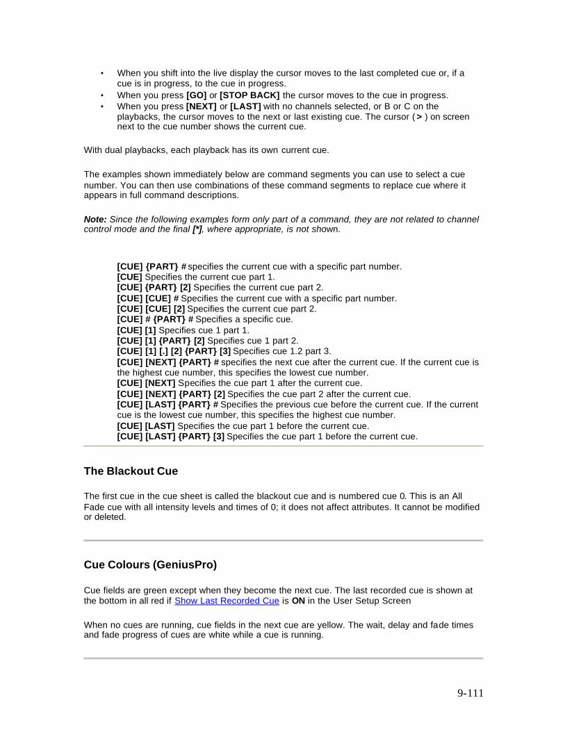
9-111
• When you shift into the live display the cursor moves to the last completed cue or, if a cue is in progress, to the cue in progress.
• When you press [GO] or [STOP BACK] the cursor moves to the cue in progress. • When you press [NEXT] or [LAST] with no channels selected, or B or C on the
playbacks, the cursor moves to the next or last existing cue. The cursor ( > ) on screen next to the cue number shows the current cue.
With dual playbacks, each playback has its own current cue.
The examples shown immediately below are command segments you can use to select a cue number. You can then use combinations of these command segments to replace cue where it appears in full command descriptions.
Note: Since the following examples form only part of a command, they are not related to channel control mode and the final [*], where appropriate, is not shown.
[CUE] {PART} # specifies the current cue with a specific part number. [CUE] Specifies the current cue part 1. [CUE] {PART} [2] Specifies the current cue part 2. [CUE] [CUE] # Specifies the current cue with a specific part number. [CUE] [CUE] [2] Specifies the current cue part 2. [CUE] # {PART} # Specifies a specific cue. [CUE] [1] Specifies cue 1 part 1. [CUE] [1] {PART} [2] Specifies cue 1 part 2. [CUE] [1] [.] [2] {PART} [3] Specifies cue 1.2 part 3. [CUE] [NEXT] {PART} # specifies the next cue after the current cue. If the current cue is the highest cue number, this specifies the lowest cue number. [CUE] [NEXT] Specifies the cue part 1 after the current cue. [CUE] [NEXT] {PART} [2] Specifies the cue part 2 after the current cue. [CUE] [LAST] {PART} # Specifies the previous cue before the current cue. If the current cue is the lowest cue number, this specifies the highest cue number. [CUE] [LAST] Specifies the cue part 1 before the current cue. [CUE] [LAST] {PART} [3] Specifies the cue part 1 before the current cue.
The Blackout Cue
The first cue in the cue sheet is called the blackout cue and is numbered cue 0. This is an All Fade cue with all intensity levels and times of 0; it does not affect attributes. It cannot be modified or deleted.
Cue Colours (GeniusPro)
Cue fields are green except when they become the next cue. The last recorded cue is shown at the bottom in all red if Show Last Recorded Cue is ON in the User Setup Screen
When no cues are running, cue fields in the next cue are yellow. The wait, delay and fade times and fade progress of cues are white while a cue is running.
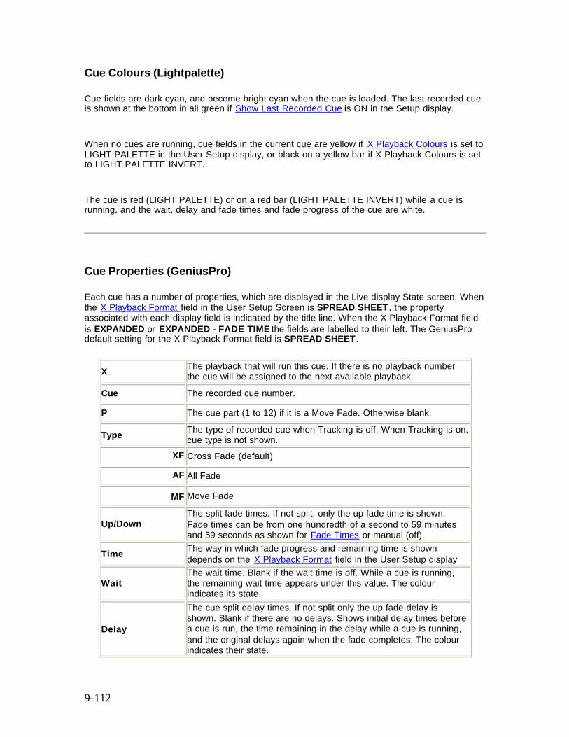
9-112
Cue Colours (Lightpalette)
Cue fields are dark cyan, and become bright cyan when the cue is loaded. The last recorded cue is shown at the bottom in all green if Show Last Recorded Cue is ON in the Setup display.
When no cues are running, cue fields in the current cue are yellow if X Playback Colours is set to LIGHT PALETTE in the User Setup display, or black on a yellow bar if X Playback Colours is set to LIGHT PALETTE INVERT.
The cue is red (LIGHT PALETTE) or on a red bar (LIGHT PALETTE INVERT) while a cue is running, and the wait, delay and fade times and fade progress of the cue are white.
Cue Properties (GeniusPro)
Each cue has a number of properties, which are displayed in the Live display State screen. When the X Playback Format field in the User Setup Screen is SPREAD SHEET, the property associated with each display field is indicated by the title line. When the X Playback Format field is EXPANDED or EXPANDED - FADE TIME the fields are labelled to their left. The GeniusPro default setting for the X Playback Format field is SPREAD SHEET.
X The playback that will run this cue. If there is no playback number the cue will be assigned to the next available playback.
Cue The recorded cue number.
P The cue part (1 to 12) if it is a Move Fade. Otherwise blank.
Type The type of recorded cue when Tracking is off. When Tracking is on, cue type is not shown.
XF Cross Fade (default)
AF All Fade
MF Move Fade
Up/Down The split fade times. If not split, only the up fade time is shown. Fade times can be from one hundredth of a second to 59 minutes and 59 seconds as shown for Fade Times or manual (off).
Time The way in which fade progress and remaining time is shown depends on the X Playback Format field in the User Setup display
Wait The wait time. Blank if the wait time is off. While a cue is running, the remaining wait time appears under this value. The colour indicates its state.
Delay
The cue split delay times. If not split only the up fade delay is shown. Blank if there are no delays. Shows initial delay times before a cue is run, the time remaining in the delay while a cue is running, and the original delays again when the fade completes. The colour indicates their state.
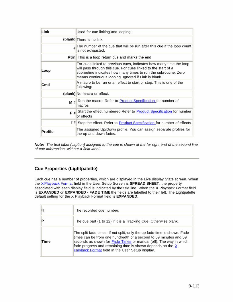
9-113
Link Used for cue linking and looping:
(blank) There is no link.
# The number of the cue that will be run after this cue if the loop count is not exhausted.
Rtrn This is a loop return cue and marks the end
Loop For cues linked to previous cues, indicates how many time the loop will pass through this cue. For cues linked to the start of a subroutine indicates how many times to run the subroutine. Zero means continuous looping. Ignored if Link is blank.
Cmd A macro to be run or an effect to start or stop. This is one of the following:
(blank) No macro or effect.
M # Run the macro. Refer to Product Specification for number of macros
F # Start the effect numbered.Refer to Product Specification for number of effects
f # Stop the effect. Refer to Product Specification for number of effects
Profile The assigned Up/Down profile. You can assign separate profiles for the up and down fades.
Note: The text label (caption) assigned to the cue is shown at the far right end of the second line of cue information, without a field label.
Cue Properties (Lightpalette)
Each cue has a number of properties, which are displayed in the Live display State screen. When the X Playback Format field in the User Setup Screen is SPREAD SHEET, the property associated with each display field is indicated by the title line. When the X Playback Format field is EXPANDED or EXPANDED - FADE TIME the fields are labelled to their left. The Lightpalette default setting for the X Playback Format field is EXPANDED.
Q The recorded cue number.
P The cue part (1 to 12) if it is a Tracking Cue. Otherwise blank.
Time
The split fade times. If not split, only the up fade time is shown. Fade times can be from one hundredth of a second to 59 minutes and 59 seconds as shown for Fade Times or manual (off). The way in which fade progress and remaining time is shown depends on the X Playback Format field in the User Setup display.
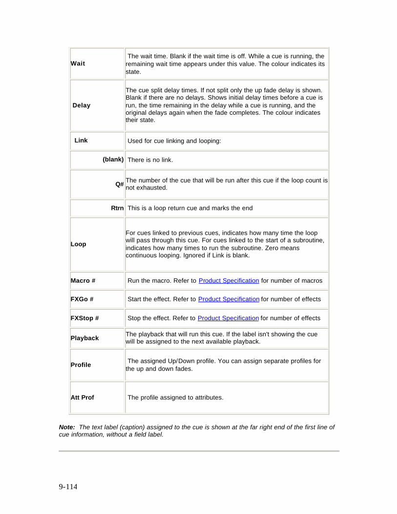
9-114
Wait The wait time. Blank if the wait time is off. While a cue is running, the remaining wait time appears under this value. The colour indicates its state.
Delay
The cue split delay times. If not split only the up fade delay is shown. Blank if there are no delays. Shows initial delay times before a cue is run, the time remaining in the delay while a cue is running, and the original delays again when the fade completes. The colour indicates their state.
Link Used for cue linking and looping:
(blank) There is no link.
Q# The number of the cue that will be run after this cue if the loop count is not exhausted.
Rtrn This is a loop return cue and marks the end
Loop For cues linked to previous cues, indicates how many time the loop will pass through this cue. For cues linked to the start of a subroutine, indicates how many times to run the subroutine. Zero means continuous looping. Ignored if Link is blank.
Macro # Run the macro. Refer to Product Specification for number of macros
FXGo # Start the effect. Refer to Product Specification for number of effects
FXStop # Stop the effect. Refer to Product Specification for number of effects
Playback The playback that will run this cue. If the label isn't showing the cue will be assigned to the next available playback.
Profile The assigned Up/Down profile. You can assign separate profiles for the up and down fades.
Att Prof The profile assigned to attributes.
Note: The text label (caption) assigned to the cue is shown at the far right end of the first line of cue information, without a field label.
9-115
Running Timed Cues
On power-up, each playback is positioned on the cue which was the current cue when you shut down the console. Press [GO] to run the next cue and automatically load the cue after that, once fading is complete. The [GO] button light flashes while the cue is fading, but not during any delay or wait time. The light is on if a cue is loaded for playback, otherwise the light is off.
If there are any stopped or reversing cues, pressing [GO] restarts those cues running forwards. Continuously pressing [GO] will step sequentially through the cue sheet.
Running timed cues will sequence through the cue sheet, taking account of link and loop cues. When the end of the cue sheet is reached, the playback is cleared and no more cues can be run until the playback is reloaded.
Note: A link to a non existent cue (or any other link/loop error) will also clear the playback.
Cues do not have to complete before another cue is run. However a maximum of (refer to Product Specification for number of simultaneous fades) can be run where each cue part counts as a fade and split cues and parts count as 2 fades.
Note: (GeniusPro) Running a Cross/All Fade immediately steals channels from all previous Cross/All or Move Fades.
Note: (Lightpalette) Running a Block Cue immediately steals channels from all previous Move Fades.
Running Manual Cues
Manual cues are sequenced and loaded by the X playbacks the same as timed cues, except that the playback will not actually run the cue.
1. Press [GO] to load the manual cue. 2. Make sure that the fader is not in Rate mode by pressing {UNRATE} if required (500
Series Consoles only). 3. Move the playback faders all the way to the bottom (0). 4. Move the playback faders up to fade the cue in. You can start the two faders at different
times and move them at different rates if required.
Loading a Cue
If you need to run cues out of their normal cue sheet order, you can load a cue onto the X Playback.
Individual cue parts cannot be loaded.
9-116
If the cue does not exist, a warning is given and the command is ignored. Loading a cue resets any loops to their initial loop count. [CUE] # [LOAD] Direct 1 and 2 Digit [LOAD] [CUE] # [*] Command Line Loads a cue into the playback. This does not affect the output until you press [GO] to run the cue. To load the current cue, omit the cue number. The CUE field in the right LCD shows the current cue. [CUE] [LOAD] Direct 1 and 2 Digit [LOAD] [CUE] [*] Command Line Loads the current cue into the playback. [CUE] [1] [.] [2] [LOAD] Direct 1 and 2 Digit [LOAD] [CUE] [1] [.] [2] [*] Command Line Loads cue 1.2 into the playback. [LOAD] [1] [.] [2] [*] All Modes Loads cue 1.2 into the playback (the [CUE] key is assumed).
[CUE] # [GO] Loads and runs the cue. It is equivalent to [CUE] # [LOAD] followed by [GO]. [CUE] [GO] All Modes Loads and runs the current cue. [CUE] [1] [.] [2] [GO] All Modes Loads and runs cue 1.2.
Loading a Cue With Overrides
The cue times, links, and profiles can be temporarily overridden when loading the cue using the same syntax as when recording the cue. In addition, you can load any cue as a Move Fade (Tracking Cue) regardless of how it was recorded. This does not permanently change the properties of the cue.
[CUE] [TIME] [2] [/] [3] {DELAY} [/] [4] {WAIT} [5] [LOAD] Direct 1 and 2 Digit [LOAD] [CUE] [TIME] [2] [/] [3] {DELAY} [/] [4] [WAIT] [5] [*] Command Line Loads the current cue into the playback with up and down fade times of 2 and 3 seconds, down delay time of 4 seconds and wait time of 5 seconds. [CUE] [+] [2] [LOAD] Direct 1 and 2 Digit Loads cue 2 into the playback and forces it to be a Move Fade (GeniusPro). [LOAD] [CUE] [2] [PB] [2] [*] [GO] Command Line Loads cue 2 into playback 2 irrespective of load type.
9-117
Changing Cue Direction
Running cues can be stopped and then cut backwards. The backwards cut time is given by the X Back, Cut field in the User Setup display, or by the playback faders if you are in Manual Time mode. When cutting backwards, the previous cue in the cue sheet is always cut to, rather than the previously run cue.
To stop any forward running cues, press [STOP/BACK]. A second press cuts stopped cues backwards to the previous cue. If there are no running or stopped cues, the first press cuts backwards to the previous cue.
While there are cue fades which are stopped or cutting, the [GO] light flashes.
Jumping Directly to a Cue
Normally a cue waits and then delays and finally fades to completion. When going to or cutting to a cue, wait and delay times are ignored and the fade time is taken from the X Back, Cut field in the Default Times window of the User Setup Screen
[CUT] has the same effect as [GO] if there are stopped or reversing cues. The stopped or reversing cues are restarted forwards. Otherwise it cuts to the next unrun cue. Unlike [GO], if you are on the last cue in the cue sheet and you press [CUT], it cuts to the first cue in the cue sheet.
[CUT] All Modes Cuts to the next unrun cue. [CUE] # [CUT] or [GOTO] [CUE] # [*] cuts to the specified cue. If the cue does not exist, a warning is given and the command is ignored. To cut to the current cue (shown in the Live LCD Menui), omit the cue number. These commands force the cue to its correct final state for intensity levels and attribute levels regardless of the current Tracking setting. Note: Delay times and assigned effects and macros are ignored. [CUE] [CUT] Direct 1 and 2 Digit [GOTO] [*] All Modes [GOTO] [CUE] [*] All Modes Cuts to the current cue. [CUE] [1] [.] [2] [CUT] Direct 1 and 2 Digit [GOTO] [1] [.] [2] [*] All Modes [GOTO] [CUE] [1] [.] [2] [*] All Modes Cuts to cue 1.2.
For GeniusPro, you can temporarily override the default Cut time when cutting to a cue by using the same syntax as when recording the cue. This has no effect on the recorded cue. This is the same as the equivalent [GO] command except that any delay times are ignored.

9-118
[CUE] [TIME] [2] [/] [3] [CUT] Direct 1 and 2 Digit (GeniusPro) Cuts to current cue with up and down fade times of 2 and 3 seconds. [GOTO] [CUE] # [PB] # [*] cuts to the specified cue and runs it on the specified playback. [GOTO] [CUE] [5] [PB] [2] [*] Direct 1 and 2 Digit Cuts to cue 5 on playback 2. GeniusPro Effects run by cues are stopped if you use [CUE] # [CUT] or [CUE] # [GO]. To go to a new cue without stopping these effects, use [CUE] # [LOAD] [GO] for any fade, or [CUE] # [GO] if the cue is a Move Fade. Lightpalette Effects run by cues are stopped if you use [GOTO] [CUE] # [*] or [CUE] # [GO]. To go to a new cue without stopping these effects, use [LOAD] [CUE] # [*] [GO].
Using the Rate/Level Wheel to Change Fade Progress (500 Series Consoles)
Normally cue fades progress automatically. However, you can use the Rate Wheel to change the fade progress of all currently running cues or parts on either X playback, or change the rate of a single running cue or cue part.
On consoles with two wheels, the Rate Wheel is next to the X playbacks. Do not confuse it with the Level Wheel. On consoles with only one wheel, the single wheel is the Level Wheel normally, and the Rate Wheel while rate functions are active.
To put all fades on a playback under Rate Wheel control, press the {RATE} softkey above the appropriate playback. The left LCD changes to {UNRATE}, {UPRATE} and {DOWNRATE} .
{UPRATE} and {DOWNRATE} are toggle keys, so that you can control the up fade rate, the down fade rate, or both. When you first press {RATE}, both are highlighted.
Changing the current fade rate does not change the recorded fade time for any cues or parts. Rather, it changes the time remaining for cues that are running when you press {RATE}. If there is more than one cue or cue part running when you press {RATE}, the Rate Wheel changes their fade rates proportionally.
The Rate Wheel loses control of fades when all fades are completed, or when a new fade is started.
To move the cursor ( > ) up or down and select a single cue or part for Rate Wheel control, press up or down When you are controlling only one cue, to return to controlling all of the running cues or parts, press {UNRATE} {RATE}.
To toggle the up fade rate control between on and off, press {UPRATE}. When there is a bar above this soft key, the Rate Wheel changes the fade time of channels which are fading up.
To toggle the down fade rate control between on and off, press {DOWN RATE}. When there is a bar above this soft key, the Rate Wheel changes the fade time of channels which are fading down.
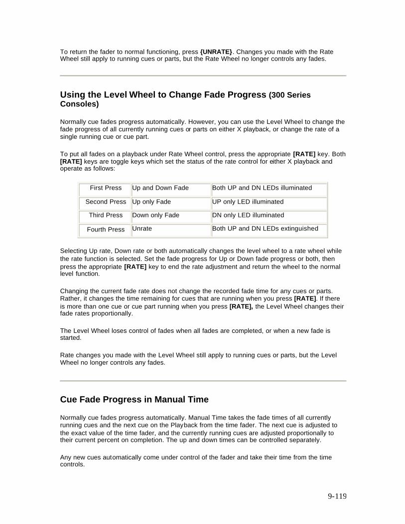
9-119
To return the fader to normal functioning, press {UNRATE}. Changes you made with the Rate Wheel still apply to running cues or parts, but the Rate Wheel no longer controls any fades.
Using the Level Wheel to Change Fade Progress (300 Series Consoles)
Normally cue fades progress automatically. However, you can use the Level Wheel to change the fade progress of all currently running cues or parts on either X playback, or change the rate of a single running cue or cue part.
To put all fades on a playback under Rate Wheel control, press the appropriate [RATE] key. Both [RATE] keys are toggle keys which set the status of the rate control for either X playback and operate as follows:
First Press Up and Down Fade Both UP and DN LEDs illuminated
Second Press Up only Fade UP only LED illuminated
Third Press Down only Fade DN only LED illuminated
Fourth Press Unrate Both UP and DN LEDs extinguished
Selecting Up rate, Down rate or both automatically changes the level wheel to a rate wheel while the rate function is selected. Set the fade progress for Up or Down fade progress or both, then press the appropriate [RATE] key to end the rate adjustment and return the wheel to the normal level function.
Changing the current fade rate does not change the recorded fade time for any cues or parts. Rather, it changes the time remaining for cues that are running when you press [RATE]. If there is more than one cue or cue part running when you press [RATE], the Level Wheel changes their fade rates proportionally.
The Level Wheel loses control of fades when all fades are completed, or when a new fade is started.
Rate changes you made with the Level Wheel still apply to running cues or parts, but the Level Wheel no longer controls any fades.
Cue Fade Progress in Manual Time
Normally cue fades progress automatically. Manual Time takes the fade times of all currently running cues and the next cue on the Playback from the time fader. The next cue is adjusted to the exact value of the time fader, and the currently running cues are adjusted proportionally to their current percent on completion. The up and down times can be controlled separately.
Any new cues automatically come under control of the fader and take their time from the time controls.
9-120
To change the playback faders into time controls, press {MAN TIME} over the playback. The LCD changes to {AUTO}, {INST} and {MAN FADE} in this mode. The time for the fade will now be taken from the playback faders acting as time controls. The scales for time are on the outside of the two faders and are marked from 0 to infinity
To instantly complete a fade, press {INST}.
To return to normal mode where the fades continue automatically, press {AUTO}. Changes made while you were in Manual Time mode remain on the fader but all new cues will be run using their recorded times.
Updating and Adding To Cues
[UPDATE] cue # [*] changes levels in the specified cues as necessary based on channels that have been modified including channels that are not already in the cues. Channels that are off in the selection are removed from the cues. The cues must already exist.
Note: The [UPDATE] command for cues defaults to updating all channels, including channels that are not already in the cue. [UPDATE] cue # [*] is the same as [UPDATE] {ADD ALL} cue # [*]. When updating a cue to include all channels, it is therefore not necessary to include the {ADD ALL} softkey in the syntax.
[UPDATE] [CUE] [1] [*] All Modes Records all channels that have been modified live into cue 1including channels that are not already in the cue. [SUB] [7] [*] [UPDATE] [CUE] [1] [*] All Modes First selects all of the channels in submaster 7, then records their levels in cue 1, including channels that are not already in cue 1.
[UPDATE] {CHANS IN} cue [*] changes levels in the specified cues as necessary based on channels that have been modified ignoring channels that are not already in the cues. Channels that are off in the selection are removed from the cues. The cues must already exist. [UPDATE] {CHANS IN} [CUE] [1] [*] All Modes Records all channels that have been modified live into cue 1, ignoring channels that are not already in the cue. [SUB] [7] [*] [UPDATE] {CHANS IN} [CUE] [1] [*] All Modes First selects all of the channels in submaster 7, then records their levels in cue 1, ignoring channels that are not already in the cue. chan [UPDATE] cue [*] changes levels of the specified channels in the specified cues to match the current Levels screen. Adds channels that are not already in the cues. Channels that are off in the selection are removed from the cues. The cues must already exist.
9-121
[1] [THRU] [5] [UPDATE] [CUE] [1] [*] All Modes Changes channel 1 through 5 levels in cue 1, adding channels that are not already in the cue. [1] [THRU] [5] [UPDATE] [CUE] [1] [THRU] [4] [*] All Modes Changes channel 1 through 5 levels in cues 1 through 4, adding channels that are not already in the cues. Note: To clear the changed indicator and set red channel levels back to cyan, press [SHIFT] [CLEAR]
Updating Cues from the Live Screen
When in one of the two Cue Preview screens (Cue Sheet or X Ref) you can update cues according to the levels in the Live Screen (on stage) using the syntax chans [@] [LIVE]. This syntax will set the selected channel levels into currently highlighted cue in the Preview Screen, including channels not already in the cue. Alternatively, you can update only the channels in the cue using the syntax cue [@] [LIVE].
[1] [THRU] [5] [@] [LIVE] Direct Action Modes
[1] [THRU] [5] [@] [LIVE] [*] Command Line Mode
Sets the levels of channels 1 to 5 in the currently selected cue to the levels in the Live Screen (levels on stage). If any of the channels are not already in the cue, they are added to the cue.
[CUE] [1] [@] [LIVE] Direct Action modes
[CUE] [1] [@] [LIVE] [*] Command Line Mode
Selects the channels in cue 1 and sets them according to the levels in the Live Screen (on stage)
Changing Cues Temporarily
You can change levels and properties for the next cue temporarily by using the Playback display. These changes are not recorded in the cue, so the next time you run it the recorded properties and levels will be used. This does not modify the current cue (the cue with > next to it). It modifies the cue currently loaded and ready for playback when you press [GO].
[PB] # [*] opens the Playback display for the specified playback so that you can modify the next cue. Press [LIVE] to return to the Live display. [PB] [1] [*] Opens the Playback display for X Playback 1. You can now change properties or levels for the next cue that will be run on the playback. Changes you make in this display are temporary, and are not recorded into the cue.
9-122
Fading Cues with the Level Wheel
You can use the Level Wheel to fade individual cues in and out without putting them on an X playback thereby disrupting the remainder of the cue flow. [CUE] [+] # wheel fades the specified cue on. Levels are combined on a highest takes precedence basis with cue and effects playbacks and submasters. Channel levels increase as you move the Level Wheel up (away from you). [CUE] [-] # wheel fades all channels from the specified cue off. Channel levels decrease as you move the Level Wheel up (away from you).
Viewing and Editing Cues
Once you have recorded cues, you can view and edit them in the Preview display. You can also use the Preview display to create new cues.
Note: Changing levels while in this display changes the recorded levels in the current cue without a record command and without warning you.
The Preview Display
To show the Preview display press <PREVIEW> in the Display keypad.
The Preview display Levels screen shows the recorded channel levels (intensity levels and attribute levels) of the current cue. The Levels screen background is grey rather than black to show that levels changed in this display are not being changed live. To change output levels you must be in the Live display.
The Preview display State screen shows the recorded cues. The current cue is shown in the CUE field on the right LCD, and also has a cursor (>) next to it in the Preview display State screen. To move between cues, use [NEXT] and [LAST] or the Up or Down keys over the X playback. The cursor (>) follows the current cue Cue Sheet Mode
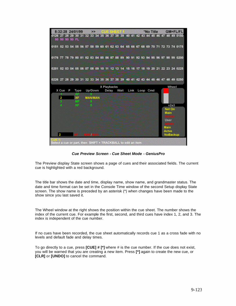
9-123
Cue Preview Screen - Cue Sheet Mode - GeniusPro
The Preview display State screen shows a page of cues and their associated fields. The current cue is highlighted with a red background.
The title bar shows the date and time, display name, show name, and grandmaster status. The date and time format can be set in the Console Time window of the second Setup display State screen. The show name is preceded by an asterisk (*) when changes have been made to the show since you last saved it.
The Wheel window at the right shows the position within the cue sheet. The number shows the index of the current cue. For example the first, second, and third cues have index 1, 2, and 3. The index is independent of the cue number.
If no cues have been recorded, the cue sheet automatically records cue 1 as a cross fade with no levels and default fade and delay times.
To go directly to a cue, press [CUE] # [*] where # is the cue number. If the cue does not exist, you will be warned that you are creating a new item. Press [*] again to create the new cue, or [CLR] or [UNDO] to cancel the command.
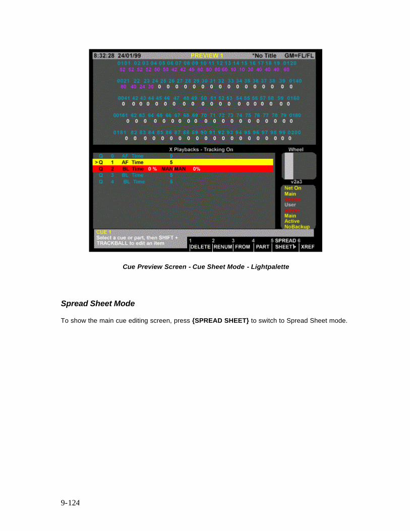
9-124
Cue Preview Screen - Cue Sheet Mode - Lightpalette
Spread Sheet Mode
To show the main cue editing screen, press {SPREAD SHEET} to switch to Spread Sheet mode.
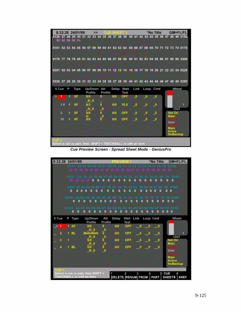
9-125
Cue Preview Screen - Spread Sheet Mode - GeniusPro

9-126
Cue Preview Screen - Spread Sheet Mode - GeniusPro The Preview display State screen shows a page of cues and their associated fields. The current cue is highlighted with a red background. The title bar shows the date and time, display name, show name, and grandmaster status. The date and time format can be set in the Console Time window of the second Setup display State screen. The show name is preceded by an asterisk (*) when changes have been made to the show since you last saved it. The Wheel window at the right shows the position within the cue sheet. The number shows the index of the current cue. For example the first, second, and third cues have index 1, 2, and 3. The index is independent of the cue number. If no cues have been recorded, the cue sheet automatically records cue 1 as a cross fade with no levels and default fade and delay times. To go directly to a cue, press [CUE] # [*] where # is the cue number. If the cue does not exist, you will be warned that you are creating a new item. Press [*] again to create the new cue, or [CLR] or [UNDO] to cancel the command. To move between existing cues, move the Trackball to any field in the cue you want to edit. Levels for the highlighted cue will be displayed on the Levels screen, but to edit these levels you will need to highlight the cue number. You can also use [NEXT], [LAST], or the up or down keys to change cues if the highlight is on the cue number.
The Cue XRef display
When you are in the Preview display you can choose to have channel levels displayed in the cross reference format rather than the standard Levels screen format.
To show the Cue XRef display press <PREVIEW> in the Display keypad and then the {X REF} soft key. This automatically puts the State screen into Spread Sheet mode.
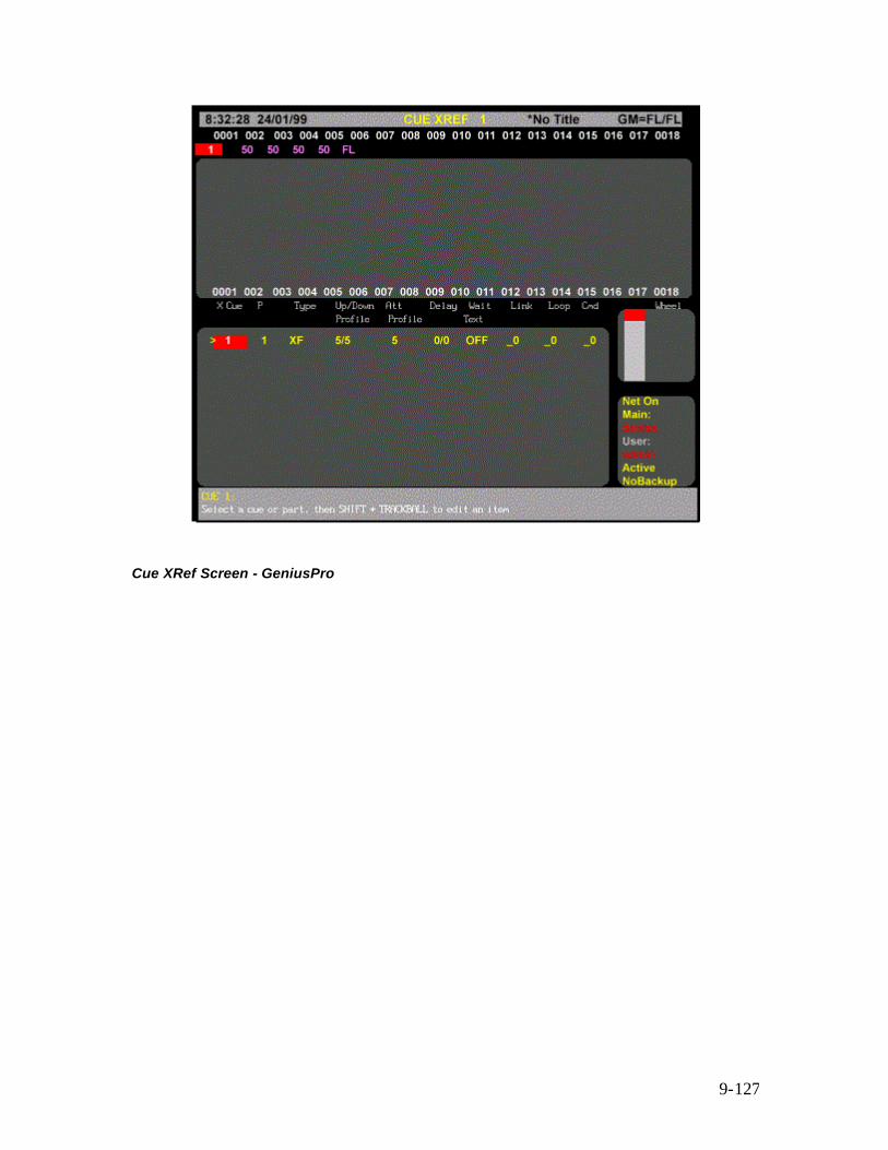
9-127
Cue XRef Screen - GeniusPro
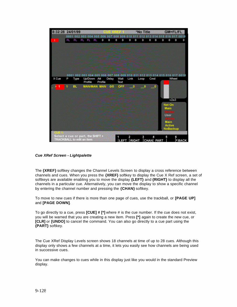
9-128
Cue XRef Screen - Lightpalette The {XREF} softkey changes the Channel Levels Screen to display a cross reference between channels and cues. When you press the {XREF} softkey to display the Cue X Ref screen, a set of softkeys are available enabling you to move the display {LEFT} and {RIGHT} to display all the channels in a particular cue. Alternatively, you can move the display to show a specific channel by entering the channel number and pressing the {CHAN} softkey. To move to new cues if there is more than one page of cues, use the trackball, or [PAGE UP] and [PAGE DOWN]. To go directly to a cue, press [CUE] # [*] where # is the cue number. If the cue does not exist, you will be warned that you are creating a new item. Press [*] again to create the new cue, or [CLR] or [UNDO] to cancel the command. You can also go directly to a cue part using the {PART} softkey. The Cue XRef Display Levels screen shows 18 channels at time of up to 28 cues. Although this display only shows a few channels at a time, it lets you easily see how channels are being used in successive cues. You can make changes to cues while in this display just like you would in the standard Preview display.
9-129
Note: If, when using channel [*] to select a channel on a new page records an unwanted zero in move fade cues use channel the {CHAN} softkey.
Levels Screen Colours
Channel levels in the Levels Screen have different colours depending on the cue type and the level itself.
green The intensity level is lower than the previous cue. magenta The intensity level is higher than the previouscue. blue The attribute level is changed from the previous cue. white The intensity level is fixed. (Tracking On). The intensity or attribute level is fixed. (Tracking Off). cyan The intensity or attribute level is the same as the previous cue. (Tracking On) grey The intensity or attribute level is the same as the previous cue. (Tracking Off) white on grey The attribute level is fixed. (Tracking Off)
State Screen Fields
Fields on the Preview display State screen show the current values for cue properties. The fields in this display are the same as in the X Playback window of the Live display with the following addition.
Note: The fields in the Cue Sheet version of the State screen are identical to the fields in the Live Screen. You cannot see the attribute time and attribute profile (GeniusPro) from the Cue Sheet version, though you can modify them.
Att Profile: The assigned attribute time and profile (one on each cue line).
Creating a New Cue
To switch to the Preview display and create a new cue, press <PREVIEW> [CUE] # [*] where # is the new cue number.
To create a new cue while you are in the Preview display, press [CUE] # [*] where # is the new cue number.
You will be warned that you are creating a new item. Press [*] again to create and display the new cue or [CLR] or [UNDO] to cancel the command.

9-130
Viewing Cue Channel
To show the recorded levels of a cue in the Levels display, select the required cue.
For a Move Fade (Tracking Cue), channels which are off are shown with a blank level; channels which are on at 0 are shown with a level of 0. For a cross fade, both of these are shown as blank and treated as a level of 0 since all channels are used in the fade.
Editing Cue Channels
First select the cue and ensure that the highlight is on the cue number. Use the Channel Control commands (for example [1] [@] [1] [*] , [CUE] [1] [@] [5] [*] ) to set channel levels. once you set channel levels in this display, they are automatically recorded. The Level Wheel and some soft keys cannot be used to change levels in the Preview display.
Note: When you set channel levels in the Preview display with Tracking on, you can set them off (chans [@] {OFF} [*]) or set them to zero (chans [@] [0] [*]). When set off, levels track through from previous cues. When set to 0, levels are forced to zero in the cue. You can set levels off in a Cross Fade (Blocking Cue) to make individual channels track through the cue, or at zero in a Move Fade (Tracking Cue) to block individual channels. When you record from the Live display with Tracking on, channels at zero are set to zero level in the cue only if they change from the previous cue. Otherwise they are recorded off and channel levels track through from the previous cue.
Setting Channel Tracking Status
Normally any channels you record into a cue take on the channel tracking status currently set in the Cue Tracking field of the Show Details window of the Show Setup Screen. You can change the tracking status of channels as you set their levels by using the [Q ONLY/TRACK] key.
If Cue Tracking is set to ON the selected channel levels will be changed only in the current cue. If Cue Tracking is set to OFF or THIS CUE ONLY, the selected channel levels will be changed in the current cue and track through subsequent cues to where the channel levels are next set.
[1] [+] [5] [@] [Q ONLY/TRACK] [5] Direct 1 and 2 Digit [1] [+] [5] [@] [Q ONLY/TRACK] [5] [*] Command Line Sets channels 1 and 5 to 50% and changes the set tracking state for those channels only.
9-131
Deleting Cues
Cues can be deleted from the Preview display. This is a good way to delete cues if you are only going to delete a few. To learn how to delete all cues or a range of cues from the Archive display refer to 'Clear Operations' in the Archive Screen.
{DELETE} This soft key appears on the LCD Preview menu and deletes the cue parts. Either a single part or a single THRU range can be specified. If you do not specify a part number, part 1 is deleted. This can be used with [+], [-], and [THRU] keys. {DELETE} {DELETE} Direct 1 and 2 Digit {DELETE} [*] [*] Command Line Deletes the current cue part 1. [CUE] [1] {DELETE} {DELETE} Direct 1 and 2 Digit {DELETE} [1] [*] [*] Command Line Deletes cue 1 part 1. [CUE] [1] [PART] [2] {DELETE} {DELETE} Direct 1 and 2 Digit {DELETE} [1] [PART] [2] [*] [*] Command Line Deletes cue 1 part 2. [CUE] [1] [THRU] [3] {DELETE} {DELETE} Direct 1 and 2 Digit [DELETE} [1] [THRU] [3] [*] [*] Command Line Deletes cues 1 part 1 to cue 3 part 1
Renumbering Cues
Renumbering changes the cue numbers so that they start at 1 and increase in increments of 1; that is 1, 2, 3… cue parts are also renumbered similarly. Decimal point cues are changed to whole number cues but the order of cues remains the same. You can renumber the whole cue sheet or specify a start cue for renumbering. Link properties in the cues are updated to reflect the new cue numbers.
{RENUM} renumbers all cues starting at cue 1. {RENUM} {RENUM} All Modes Renumbers all cues (two key presses). [CUE] # {FROM} # {RENUM}{{RENUM} renumbers all cues starting with the cue specified, to new numbers starting with the From number specified. [CUE] [5] {FROM} [4] [0] {RENUM} {RENUM} All Modes Renumbers all cues starting at cue 5. Cue 5 will now be numbered cue 40, and subsequent cues will be numbered accordingly. Note: After renumbering cues, you can still insert cues as necessary using numbers after a decimal point, e.g., 3.5.
Copying from a Cue

9-132
You can record submasters, cues, groups, and effect steps while you are in the Preview display. The syntax is the same as for recording from the Live display. The highlight must be on the cue number (the CUE field).
Using recording commands while you are in the Preview display copies the Preview display levels to the target submaster, cue, group, or effect step. For example, if the current cue is 1, then [SUB] [2] [RECORD] will copy the levels from cue 1 into submaster 2. This also lets you copy cues.For example, [CUE] [2] [RECORD] copies the levels from cue 1 into cue 2.
10-133
Chapter 10 - X Playbacks See Also Recording Cues Running Cues
The X Playbacks function lets you automatically or manually fade between recorded lighting states, called cues, which contain intensity and/or attribute levels with associated fade, delay and wait times, profiles, and other attributes.
There are 2 X playbacks, labelled X1 and X2, each with its own keys and sliders. The console can be configured to use one or both of these. Each X playback runs cues in order from the cue sheet by fading from one cue to the next unless you explicitly load a cue out of order. By default, cue ordering is by cue number, but you can change the cue ordering by using links, subroutines, and loops. In this section, playback is used to mean one of the X playbacks
This section covers the following topics:
• Assigning Cues to X Playbacks • Playback Mode • The X Playback Window (GeniusPro) • The X Playback Window (Lightpalette) • Using the X Playbacks • X Playback in Manual Fade Mode
Assigning Cues to Playbacks
Normally, cues can be run on either playback. They can however be assigned to a particular one. The other playback will then treat the cue as if it does not exist.
cue [PB] # [RECORD] [*] - Direct Digit [RECORD] cue [PB] # [*] - Command Line
Records the levels on the current display into the specified cue and assigns the cue to the specified playback. If the cue already exists, an overrecord message gives you the chance to cancel the recording. To rerecord the cue, press [RECORD] [*] again. To cancel the recording, press [CLR] or [UNDO].
In multi-part cues, only the playback set in part 1 is used. If the console is set for two playbacks, cues will only run on their assigned playback. If the console is set for a single playback this assignment has no effect. To delete a playback assignment, omit the playback number.
[CUE] [1] [PB] [2] [RECORD] Direct 1 and 2 Digit [RECORD] [CUE] [1] [PB] [2] [*] Command Line Records levels into cue 1 and assigns it to Playback 2. [CUE] [1] [PB] [RECORD] Direct 1 and 2 Digit [RECORD] [CUE] [1] [PB] [*] Command Line
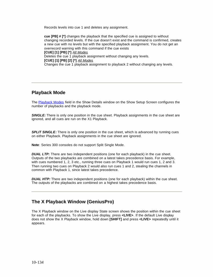
10-134
Records levels into cue 1 and deletes any assignment. cue [PB] # [*] changes the playback that the specified cue is assigned to without changing recorded levels. If the cue doesn’t exist and the command is confirmed, creates a new cue with no levels but with the specified playback assignment. You do not get an overrecord warning with this command if the cue exists [CUE] [1] [PB] [*] All Modes Deletes the cue 1 playback assignment without changing any levels. [CUE] [1] [PB] [2] [*] All Modes Changes the cue 1 playback assignment to playback 2 without changing any levels.
Playback Mode
The Playback Modes field in the Show Details window on the Show Setup Screen configures the number of playbacks and the playback mode.
SINGLE: There is only one position in the cue sheet. Playback assignments in the cue sheet are ignored, and all cues are run on the X1 Playback.
SPLIT SINGLE: There is only one position in the cue sheet, which is advanced by running cues on either Playback. Playback assignments in the cue sheet are ignored.
Note: Series 300 consoles do not support Split Single Mode.
DUAL LTP: There are two independent positions (one for each playback) in the cue sheet. Outputs of the two playbacks are combined on a latest takes precedence basis. For example, with cues numbered 1, 2, 3 etc., running three cues on Playback 1 would run cues 1, 2 and 3. Then running two cues on Playback 2 would also run cues 1 and 2, stealing the channels in common with Playback 1, since latest takes precedence.
DUAL HTP: There are two independent positions (one for each playback) within the cue sheet. The outputs of the playbacks are combined on a highest takes precedence basis.
The X Playback Window (GeniusPro)
The X Playback window on the Live display State screen shows the position within the cue sheet for each of the playbacks. To show the Live display, press <LIVE>. If the default Live display does not show the X Playback window, hold down [SHIFT] and press <LIVE> repeatedly until it appears.
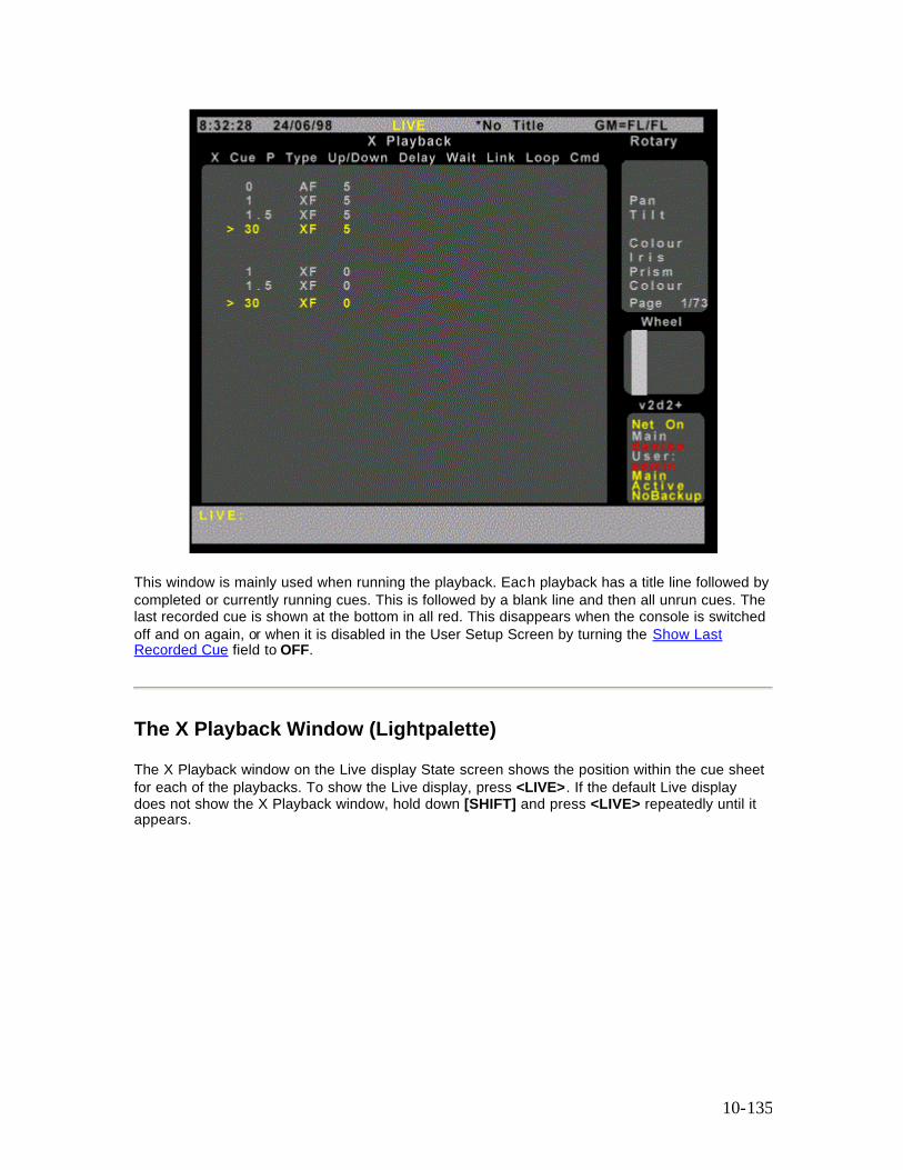
10-135
This window is mainly used when running the playback. Each playback has a title line followed by completed or currently running cues. This is followed by a blank line and then all unrun cues. The last recorded cue is shown at the bottom in all red. This disappears when the console is switched off and on again, or when it is disabled in the User Setup Screen by turning the Show Last Recorded Cue field to OFF.
The X Playback Window (Lightpalette)
The X Playback window on the Live display State screen shows the position within the cue sheet for each of the playbacks. To show the Live display, press <LIVE>. If the default Live display does not show the X Playback window, hold down [SHIFT] and press <LIVE> repeatedly until it appears.
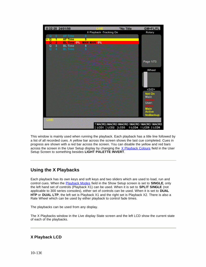
10-136
This window is mainly used when running the playback. Each playback has a title line followed by a list of all recorded cues. A yellow bar across the screen shows the last cue completed. Cues in progress are shown with a red bar across the screen. You can disable the yellow and red bars across the screen in the User Setup display by changing the X Playback Colours field in the User Setup Screen to something besides LIGHT PALETTE INVERT.
Using the X Playbacks
Each playback has its own keys and soft keys and two sliders which are used to load, run and control cues. When the Playback Modes field in the Show Setup screen is set to SINGLE, only the left hand set of controls (Playback X1) can be used. When it is set to SPLIT SINGLE (not applicable to 300 series consoles), either set of controls can be used. When it is set to DUAL HTP or DUAL LTP, the left set is Playback X1 and the right set is Playback X2. There is also a Rate Wheel which can be used by either playback to control fade times.
The playbacks can be used from any display.
The X Playbacks window in the Live display State screen and the left LCD show the current state of each of the playbacks.
X Playback LCD
10-137
The X Playback LCD shows the current cue being run and the wait, delay or fade time for each playback. This information is duplicated from the Live display. In addition, the LCD shows the current playback mode as selected by the soft keys below the LCD. If the cue is fading it shows AUTO FADING, MAN TIMING, or MAN FADING. If the cue has completed it shows AUTO, MAN TIME, or MAN FADING. If the cue is stopped it shows STOPPED, MAN TIME STOP, or MAN FADE STOP.
X Playback in Manual Fade Mode
To change the playback to Manual Fade mode, press {MAN FADE}.
Normally cue fades progress automatically. Manual Fade takes the current fade progress from the progress faders for the last fade on the playback. The scale for fade progress is between the two playback faders, and is marked from 0% to 100%. The left fader controls up fades and the right fader controls down fades.
Going to Manual Fade mode stops the fades. The fader must be moved to 0, then moved to pick up the current position of the cue after which it moves the progress between 0% and 100%.
When the fade reaches 100% the fader loses control of it. Moving both faders to 0% then starts the next cue running. Any cue wait or delay times are ignored. This automatic sequencing can be turned off.
To change to Manual Fade mode, press {MAN FADE} above the playback. The up and down fade progresses are controlled by the faders. The LCD changes to {AUTO}, {MAN TIME} and {SEQ}.
To toggle automatic sequencing of manually faded cues, press {SEQ}. When automatic sequencing is enabled, a bar appears over the soft key.
To return the faders to automatic fade mode, press {AUTO}. New cues will use their recorded fade times and will be automatically sequenced.
11-138
Chapter 11 - Effects
Effect playbacks are used to run repeated sets of lighting states, called effects. Each lighting state in an effect has a set of intensity and attribute levels and is called an effect step. The effect playbacks let you run effects in a variety of ways to give different chase, build, and random output levels. (Refer to the Product Specification for number of effect playbacks)
Note: The [FX SEL], [FX DIR], [FX TIME] and [FX LOAD] keys are omitted from 300 Series consoles. If you are a 300 Series console user and require to use the functions controlled by these keys, use an external keyboard, in conjunction with the keyboard template at the back of this manual to simulate the keys, or use Edit Mode
This chapter contains the following topics:
• The Current Effect Step • Recording Effect Step Levels • Recording Effect Properties • Recording Effect Step Properties • Using Effect Playbacks • Using Effects in Cues and Subs • Viewing and Editing Effects
The Current Effect Step
The current effect step is shown in the FX field on the LCD. This is the last step which has been referenced and can be used in a step selection. All step recording commands act on a single step which is shown in the command descriptions below. The [+], [-], [THRU], and {THRU ON} keys cannot be used in a step selection.
The examples shown immediately below are effect step selections that you can use to replace steps where they appears in full command descriptions.
Note: Since these examples are only part of a command, they do not show a concluding [*] key.
[FX] # [.] # selects the specified effect and step. If the effect number is missing, the current effect is used. The step number must always be present.
[FX] [1] [.] [2] Selects effect 1 step 2. [FX] [.] [9] Selects current effect step 9. For example, if the current effect step is 1.2 then this will select 1.9.
[FX] [SHIFT] [NEXT] selects the next step after the current step. This cannot be used if the current step is 99.
11-139
[FX] [NEXT] When recording effects, selects the next step after the current step. For example, if the current effect step is 1.2 then this will select 1.3. [FX] [SHIFT] [LAST] selects the previous step to the current step. This cannot be used if the current step is 1. [FX] [LAST] When recording effects, selects the previous step to the current step. For example, if the current effect step is 1.2 then this will select 1.1.
Recording Effect Steps Levels
[FX] # [RECORD] (Direct 1 Digit and Direct 2 Digit) [RECORD] [FX] # [*] (Command Line) Records the levels on the current display (the Live, Cue/Preview, Group, Effect, or Submaster display) into the current effect step. Refer to Working With Channel Levels for information on how to set intensity and attribute levels, and Basic Recording for examples of recording. Refer to the Product Specification for the number of effects, number of effect steps per effect and the total number of effect steps for your console. Effects are numbered with the effect number and the effect step number .1 to .99 (e.g., 1.25). Recording an effect does not change the output until the playback is reloaded. When you record a new step in an existing effect its values are set using the Step Defaults values for the effect. If this is the first step of a new effect, the Step Default values for the effect are first set from the FX Step, FXStep In/Dwell/Out, and FXUp/Down fields in the Setup display, and then the step values are set from these Step Default values. The {APPEND FXSTEP} soft key, which appears when you switch to the Effect display, appends a new step to the current effect and switches you to the new step in the Effect display. The new step has default values for step time, in, dwell, and out times, attribute fade time, low and high settings, and scaling. It has no assigned levels. You cannot create a new effect using this command.
Recording Effect Properties
Effects have the following properties that can be specified when recording, or edited later:
o Effect Text o Effect Type o Effect Direction o Effect Fade Times o Effect Mode o Effect Level o Next Fx
11-140
o Assigning Fade Profiles to Effects o Stop After Field o Step Control Field o Step Default Values Field
These properties apply to the whole effect, not to individual steps. Effect step properties are discussed later in this section
Edit Mode
You can record or edit the effect properties using keyboard command as described in the following paragraphs. Alternatively, you can set up and edit the overall effect properties and the effect step properties while in the Effect Screen by holding down the [SHIFT] key and moving the trackball to change the fields from non-edit mode (yellow) to edit mode (green). In edit mode, you can highlight a field and set its value using the level wheel or the [+] or [-] key, or by entering a numerical value from the keypad, as appropriate. To return the the non-edit mode, press [*]
Recording Effect Text
You can record a text label (caption) with each effect to help identify the effect.
[FX] # [TEXT] text [*] changes the text string (caption) assigned to an effect without changing recorded levels. For examples, refer to Basic Recording
Recording Effect Type
Effects can be either chases or builds. You can control this property from the Effects display or by pressing [FX TYPE] and selecting the appropriate option from the appropriate LCD menu.
[FX] [1] [FX TYPE] {CHASE} [*] Sets FX 1 type to chase [FX] [1] [FX TYPE] {BUILD} [*] Sets FX 1 type to build
Chase Only one step is high at a time and steps are played sequentially according to direction property. As each step runs, its levels go high and all other levels in the effect go low. Build One step at a time goes high, but previous steps are not sent low. Once all of the steps are high, they are all sent low and the build starts again.
11-141
Recording Effect Direction
The effect can be set to run in one of four directions, as listed below. You can control this property from the Effects display or by pressing [FX DIR] and selecting the appropriate option from the LCD display
Note: On consoles without an [FX DIR] key, you require to set up this field using edit mode, as described above.
[FX] [1] [FX DIR] {FWD} [* ] Sets FX 1 direction to forward [FX] [1] [FX DIR] {REV} [* ] Sets FX 1 direction to reverse [FX] [1] [FX DIR] {BOUNCE} [* ] Sets FX 1 direction to bounce [FX] [1] [FX DIR] {RANDOM} [* ] Sets FX 1 direction to random
Forward The effect steps are played sequentially from the lowest step number to the highest step number and are then repeated from the first step number. Reverse The effect steps are played sequentially from the highest step number to the lowest step number and are then repeated from the highest step number. Bounce The effect steps are played sequentially from the lowest step number to the highest step number, and then from the highest step number back to the lowest step number. Steps are then repeated in the same sequence. Random Steps are played randomly. All steps are played once before a new random sequence is started.
Effect Fade Times
You can enter fade values from one hundredth of a second to 59.59 seconds, as shown in the table. Values of less than one second can be set in hundredths of a second.
Key Entry Shown as Value 0.01 0.01 One hundredth of a second. .0.1 0.1 One tenth of a second 1 1 One second 10 10 Ten seconds
100 1:00 One minute
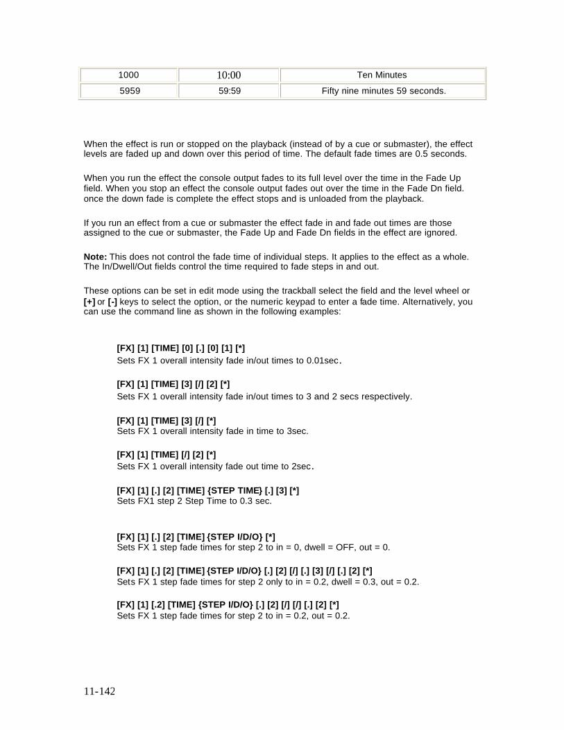
11-142
1000 10:00 Ten Minutes 5959 59:59 Fifty nine minutes 59 seconds.
When the effect is run or stopped on the playback (instead of by a cue or submaster), the effect levels are faded up and down over this period of time. The default fade times are 0.5 seconds.
When you run the effect the console output fades to its full level over the time in the Fade Up field. When you stop an effect the console output fades out over the time in the Fade Dn field. once the down fade is complete the effect stops and is unloaded from the playback.
If you run an effect from a cue or submaster the effect fade in and fade out times are those assigned to the cue or submaster, the Fade Up and Fade Dn fields in the effect are ignored.
Note: This does not control the fade time of individual steps. It applies to the effect as a whole. The In/Dwell/Out fields control the time required to fade steps in and out.
These options can be set in edit mode using the trackball select the field and the level wheel or [+] or [-] keys to select the option, or the numeric keypad to enter a fade time. Alternatively, you can use the command line as shown in the following examples:
[FX] [1] [TIME] [0] [.] [0] [1] [*] Sets FX 1 overall intensity fade in/out times to 0.01sec. [FX] [1] [TIME] [3] [/] [2] [*] Sets FX 1 overall intensity fade in/out times to 3 and 2 secs respectively. [FX] [1] [TIME] [3] [/] [*] Sets FX 1 overall intensity fade in time to 3sec. [FX] [1] [TIME] [/] [2] [*] Sets FX 1 overall intensity fade out time to 2sec. [FX] [1] [.] [2] [TIME] {STEP TIME} [.] [3] [*] Sets FX1 step 2 Step Time to 0.3 sec.
[FX] [1] [.] [2] [TIME] {STEP I/D/O} [*] Sets FX 1 step fade times for step 2 to in = 0, dwell = OFF, out = 0. [FX] [1] [.] [2] [TIME] {STEP I/D/O} [.] [2] [/] [.] [3] [/] [.] [2] [*] Sets FX 1 step fade times for step 2 only to in = 0.2, dwell = 0.3, out = 0.2. [FX] [1] [.2] [TIME] {STEP I/D/O} [.] [2] [/] [/] [.] [2] [*] Sets FX 1 step fade times for step 2 to in = 0.2, out = 0.2.
11-143
Alternatively, you can vary the fade rate by pressing [FX TIME], selecting {FADE RATE} and using the Rate Wheel (or Level Wheel on consoles without a rate wheel) to increase or decrease the fade time.
Effect Mode
The Mode property controls how the effect combines with other effects and with the other playbacks and faders. This property can only be changed from the Effects display in edit mode using the trackerball to select the field and the level wheel or [+] or [-] keys to change the option. It is initially set to indHTP. indHTP Independent Highest Takes Precedence mode combines the effect with all other output sources on a highest takes precedence basis. If you use any other output source to set a channel level higher than the low effect setting for the channel, but lower than the high effect setting for the channel, the channel will switch between the other output source level and the high effect setting. LTP Latest Takes Precedence mode lets other effects, cues, and the Channel Control steal channels from the effect. When you select a channel, its current state (high or low) is frozen and the channel is assigned to the Channel Control. Its level then follows the Channel Control (not the effect) until you reload and restart the effect.
Effect Level
The Level property determines how the effect channel levels are interpreted. This property can only be changed from the Effects display, and is initially set to NORMAL. NORMAL Channels in active steps are set high and channels in inactive steps are set low. NEGATIVE Channels in active steps are set low and channels in inactive steps are set high. NRM NEG (Normal Negative) Levels start as Normal and then alternate between Negative and Normal for each successive effect cycle. NEG NRM (Negative Normal) Levels start as Negative and then alternate between Normal and Negative for each successive effect cycle. RANDOM Steps are randomly set to any level between the high and low levels. These options can be set in edit mode using the trackball select the field and the level wheel or [+] or [-] keys to select the option, or using the command line as shown in the following examples: [FX] [1] {LEVEL} [NORMAL] [*] Sets FX 1 intensity type for all steps to Normal [FX] [1] {LEVEL} [NEGATIVE] [*] Sets FX 1 intensity type for all steps to Negative [FX] [1] {LEVEL} [NORM/NEG] [*] Sets FX 1 intensity type for all steps to Normal/Negative
11-144
[FX] [1] {LEVEL} [NEG/NORM] [*] Sets FX 1 intensity type for all steps to Negative/Normal [FX] [1] {LEVEL} [RANDOM] [*] Sets FX 1 intensity type for all steps to Random
Next Fx
You can have a new effect automatically start at the end of any effects for which the Stop After property is set to Time or Cycles. The Next Fx property determines whether a new effect is started, and what the new effect number is. This property can only be changed from the Effects display, and is initially set to OFF. You can set the Next Fx to be any other effect number or OFF.
This field can be set using the in edit mode using the trackballball to select the field and the level wheel or [+] or [-] keys to select the option. Alternatively, the field can be set using the command line as shown in the following example:
[FX] [1]{NEXT FX} [2] [*] Sets FX 1 follow-on FX to Fx 2
Assigning Fade Profiles to Effects
The Profile property lets you assign a profile to the fade up and fade down times. The profile applies to both the fade up and the fade down. To learn how to create a profile, refer to Profiles
This field can be set in edit mode using the trackball to select the field and the level wheel or [+] or [-] keys to select the option. Alternatively, the field can be set using the command line as shown in the following example:
[FX] [1] [PROFILE] [3] [*] Sets FX 1 overall fade profiles to 3
Stop After
The Stop After property determines what happens when you press [FX STOP]. This property can only be changed from the Effects display, and is initially set to FX STOP. FX STOP The effect stops and is unloaded when you press [FX STOP] for its effect playback.
11-145
FX LOAD The effect is not unloaded until another effect is loaded onto the same effect playback. The effect is only paused when you press [FX STOP]. You can then press [FX GO] to restart the effect. LAST STEP When you press [FX STOP], the effect continues to run normally until it reaches the last effect step. It then fades out and stops in the time specified by the Fade Dn field (or cue or submaster time). CYCLES The effect stops after the number of cycles specified in the Cycles field. TIME The effect stops after the amount of time specified in the Time field. You can enter values in the range 0.01 seconds to 59.59 seconds (refer to Effect Fade Times) This field can be set in edit mode using the trackball to select the field and the level wheel or [+] or [-] keys to select the option. Alternatively, the field can be set using the command line as shown in the following examples: [FX] [1] {STOP AFTER} [FXLOAD] [*] Sets FX 1 to stop only after next Fx loaded [FX] [1] {STOP AFTER} [1] [2] [*] Sets FX 1 to stop after 12 complete cycles [FX] [1] {STOP AFTER}[TIME] [1] [2] [*] Sets FX 1 to stop after 12 seconds [FX] [1] {STOP AFTER} [SUB] [*] Sets FX 1 to stop when the submaster fader it is attached to is brought to 0% [FX] [1] {STOP AFTER} [.] [*] Sets FX 1 to stop when the last step is run after the FXSTOP key is pressed
Step Control
The Step Control determines how the console knows when to take the next effect step. This property can only be changed from the Effects display, and is initially set to TIMED. TIMED The effect playback takes stepping cues from the timer, which uses the Step Time settings for each step. MANUAL The effect playback takes stepping cues from the [FX STEP] button. MIDI
11-146
The effect playback takes stepping cues from the MIDI input. This option requires the CommuniquéPro software. Refer to CommuniquéPro Software for more information. AUDIO (500 Series Consoles only) The effect playback takes stepping cues from the base track of the Audio input. This option requires the CommuniquéPro software. Refer to CommuniquéPro Software for more information. This field can be set in edit mode using the trackball to select the field and the level wheel or [+] or [-] keys to select the option. Alternatively, the field can be set using the command line as shown in the following examples: [FX] [1] {STEP CTR} {TIMED} [*] Sets FX 1 step control to Timed [FX] [1] {STEP CTR} {MANUAL} [*] Sets FX 1 step control to Manual [FX] [1] {STEP CTR} {MIDI} [*] Sets FX 1 step control to MIDI [FX] [1] {STEP CTR} {AUDIO} [*] Sets FX 1 step control to Audio
Step Default Values
Step Default Values are the values initially set for the effect step properties. When you create a new step, these values are applied. You can change values for any individual step if required. Changing the default value changes the value for the property in all steps where it has not been specifically overridden. Step properties at their default values are shown in black text. Step properties that have been overridden are shown in green text. You can set default values for all of the step properties.
Recording Effect Step Properties
Individual effect steps have the following properties that can be specified when recording, or edited later:
o Step Time Field o In, Dwell, and Out Times Field o Attribute Fade Time Field o Low and High Scaling Field
These properties apply to each effect step individually. Effects as a whole also have properties, including the default values for steps.
When you create a step, all step properties take on the values set in the Step Defaults for the effect. These defaults are set from the The Default Times Window of the User Setup Screen when you create the effect. All step values that you don’t change will automatically track the Step
11-147
Defaults values. Step properties that you have modified in the step will not change when you change the Step Defaults, even if you reset them to the current Step Defaults value.
To set a property back to its “default” (black text), use the trackball to highlight it and then press {DEFLT}
Step Time
The step time controls the time from the start of a step until the next step is activated. Step time can be “default” (black text) or any value between 0.01 and 5 minutes, and is initially set to the value of the FX Step field of the Default Times window of the User Setup Screen. Times below one second can be specified in hundredths of a second.
This field can be set in edit mode using the trackball to select the field and the level wheel or [+] or [-] keys to select the option. Alternatively, the field can be set using the command line as shown in the following example:
[FX] [1] [.] [2] [TIME] {STEP TIME} [.] [3] [*] Sets FX1 step 2 Step Time to 0.3sec.
In, Dwell, and Out Times
The in, dwell, and out times determine the actual length of each step (time from when the step is activated until it is deactivated) rather than the time until the next step. The total length of a step is the sum of these three values. The sum of these values does not need to equal the step time, making it possible to have steps that overlap with the next step, or have a distinct gap between them and the next step.
The In property is the time from when the step starts until the channel levels are at the high level. In time can be “default” (black text) or any value between 0.01 and 5 minutes, and is initially set to the value of the FX Step In/Dwell/Out field of the Default Times of the User Setup Screen. Times below one second can be specified in hundredths of a second
The Dwell property is the time that an activated step will remain in its high state. Dwell time can be “default” (black text), OFF (Dwell time = Step time), or any value between 0.01 and 5 minutes, and is initially set to the value of the In field of the Step Defaults. Times below one minute can be specified in hundredths of a minute.
The Out property is the time from when the dwell time ends until the channel levels are at the low level. Out time can be “default” (black text) or any value between 0.01 and 5 minutes, and is initially set to the value of the Out field of the Step Defaults. Times below one minute can be specified in hundredths of a minute
This field can be set using the trackball to select the field and the level wheel or [+] or [-] keys to select the option. Alternatively, the field can be set using the command line as shown in the following examples:
11-148
[FX] [1] [.] [2] [TIME] {STEP I/D/O} [.] [2] [/] [.] [3] [/] [.] [2] [*] Sets FX 1 step fade times for step 2 only to in = 0.2, dwell = 0.3, out = 0.2. [FX] [1] [.2] [TIME] {STEP I/D/O} [.] [2] [/] [/] [.] [2] [*] Sets FX 1 step fade times for step 2 to in = 0.2, out = 0.2. [FX] [1] [.] [2] [TIME] {STEP I/D/O} [/] {OFF/MAN} [*] Sets FX 1 step fade times for step 2 to dwell = OFF
Attribute Fade Time
The attribute fade time controls the time it takes to change fixture attributes if there is a change on the same fixture between two steps of an effect. Attribute fade time can be “default” (black text) or any value between 0.01 and 5 minutes, and is initially set to the value of the FX Up/Down field of the Default Times of the User Setup Screen. Times below one minute can be specified hundredths of a minute.
This field can be set using the rollball or mouse to select the field and the level wheel or [+] or [-] keys to select the option. Alternatively, the field can be set using the command line as shown in the following examples:
[FX] [1] [.] [2] [@ATT] [TIME] [*] Sets FX 1 overall attribute fade in time for step 2 to 0s [FX] [1] [.] [2] [@ATT] [TIME] [3] [*] Sets FX 1 overall attribute fade in time for step 2 to 3s
Low and High Scaling
Effect steps are either high or low. The actual levels represented by high and low states are controlled by the Level and Low/ High Scaling fields and by the channel levels set in the effect.
The Low and High Scaling properties for steps scale the channel levels set in each step. These numbers can be “default” (black text) or a percentage (0-100), and modify all channel levels in the specified step.
High Scaling sets the percentage of channel level to use for the “on” part of the effect step. Low Scaling sets the percentage of channel level to use for the “off” part of the effect step.
To set the low level at 10% of the recorded channel levels, set it to 10. If you have a channel at FL, the actual output level for the channel when it is “off” will be 10%. If you have a channel at 80%, the actual output level for the channel when it is off will be 8%.
The Low Scaling property is initially set to the value you set in the Low field of the Step Defaults for the effect. The High scaling property is initially set to the value you set in the High field of the Step Defaults for the effect.
11-149
This field can be set using the rollball or mouse to select the field and the level wheel or [+] or [-] keys to select the option. Alternatively, the field can be set using the command line as shown in the following examples:
[FX] [1] [.] [2] {LO/HI LEVEL} [*] Sets FX 1 low and high levels for step 2 to 0% and 100% [FX] [1] [.] [2] {LO/HI LEVEL} [4] [*] Sets FX 1 low level only for step 2 to 40% [FX] [1] [.] [2] {LO/HI LEVEL} [4] [/] [8] [*] Sets FX 1 low and high levels for step 2 to 40% and 80% [FX] [1] [.] [2] {LO/HI LEVEL} [/] [1] [0] [0] [*] Sets FX 1 high level only for step 2 to 100%
Using Effect Playbacks
The Effect Keypad provides keys for controlling the effect playbacks. The Effect Supermaster (if one is assigned) masters the levels of all effects regardless of whether they are being played on an effect playback or played from a cue or submaster. (Refer to the Product Specification for number of effect playbacks on your console)
This section covers the following topics:
• The Effects Window • The Effect Supermaster • Effect Playback Selection • The Current Playback • Loading an Effect • Running an Effect • Pausing an Effect • Stepping an Effect • Changing Effect Times While Effect is Running • Changing Effect Types • Changing Effect Direction • Updating Effects • Updating Effects from the Live Screen • Unloading an Effect
The Effects Window
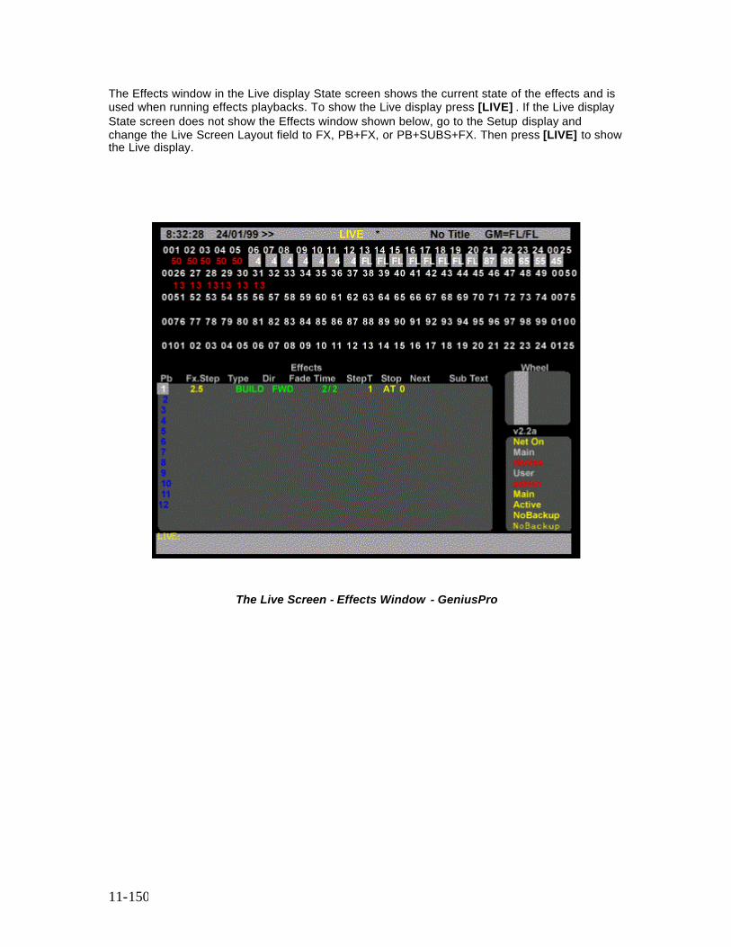
11-150
The Effects window in the Live display State screen shows the current state of the effects and is used when running effects playbacks. To show the Live display press [LIVE] . If the Live display State screen does not show the Effects window shown below, go to the Setup display and change the Live Screen Layout field to FX, PB+FX, or PB+SUBS+FX. Then press [LIVE] to show the Live display.
The Live Screen - Effects Window - GeniusPro
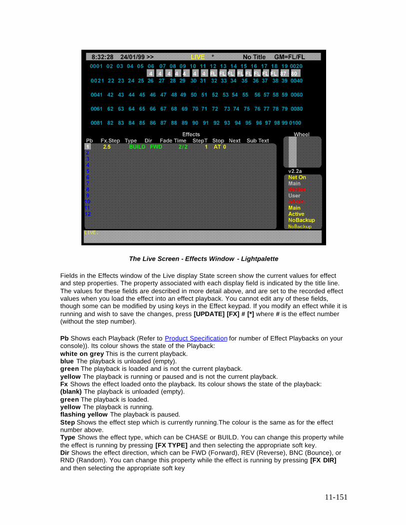
11-151
The Live Screen - Effects Window - Lightpalette Fields in the Effects window of the Live display State screen show the current values for effect and step properties. The property associated with each display field is indicated by the title line. The values for these fields are described in more detail above, and are set to the recorded effect values when you load the effect into an effect playback. You cannot edit any of these fields, though some can be modified by using keys in the Effect keypad. If you modify an effect while it is running and wish to save the changes, press [UPDATE] [FX] # [*] where # is the effect number (without the step number). Pb Shows each Playback (Refer to Product Specification for number of Effect Playbacks on your console)). Its colour shows the state of the Playback: white on grey This is the current playback. blue The playback is unloaded (empty). green The playback is loaded and is not the current playback. yellow The playback is running or paused and is not the current playback. Fx Shows the effect loaded onto the playback. Its colour shows the state of the playback: (blank) The playback is unloaded (empty). green The playback is loaded. yellow The playback is running. flashing yellow The playback is paused. Step Shows the effect step which is currently running.The colour is the same as for the effect number above. Type Shows the effect type, which can be CHASE or BUILD. You can change this property while the effect is running by pressing [FX TYPE] and then selecting the appropriate soft key. Dir Shows the effect direction, which can be FWD (Forward), REV (Reverse), BNC (Bounce), or RND (Random). You can change this property while the effect is running by pressing [FX DIR] and then selecting the appropriate soft key
11-152
Fade Time The up and down fade time for starting and stopping the effect. You can change these properties while the effect is running by pressing [FX TIME], pressing {FADE RATE}, and then increasing or decreasing the times using the Rate Wheel.(500 Series only) StepT The step time for the current step. Stop Shows how the effect is to be stopped. This can be AT 0 (on Fx stop), blank (on Fx load), LAST (on last step), XXXs (after XXX seconds), or XXXX (after XXXX cycles). You cannot change this property while the effect is running. Next Shows the effect to be started when this effect is stopped (if any). This property only takes effect if you set the Stop After property to TIMER or CYCLES in the Effect display. You cannot change this property while the effect is running. Sub Shows the submaster to which the effect is attached (if any). You cannot change this property while the effect is running. Text Shows the text label (caption) associated with the effect (if any). You cannot change this property while the effect is running.
The Effect Supermaster
All effect output levels are mastered by the Effect Supermaster if one is assigned. Moving the Effect Supermaster to 0 stops any effects from contributing to the output. Moving it to 10 puts the full effect levels onto the output. The Effect Supermaster is normally one of the last 6 submasters. You can change it to another fader or eliminate it altogether by changing the Function properties of the submaster faders involved. If there is no Effect Supermaster, its level is set to 100%.
To learn about the submaster function property refer to Submasters and Channel Faders
Effect Playback Selection
All effect playback commands act on a single playback. The selection can be the current playback, an effect number, a playback number or a combined effect and playback number, in the following format:
[FX] fx# [PB] pb# If you leave out fx#, the current effect is assumed. If you leave out pb# and the specified effect is not loaded, the next available playback is used. If you don’t include pb# and the specified effect is loaded, the effect playback on which it is loaded is assumed. If you don’t include pb# and multiple copies of the effect are loaded, the lowest numbered effect playback on which the effect is running is assumed.
Note: Since these examples are only part of a command, they do not have concluding [*] key.
The [+], [-], [THRU], {THRU ON}, [LAST], and [NEXT] keys cannot be used in an effect playback selection.
The examples shown immediately below are effect playback selections that you can use to replace fx where it appears in full command descriptions.
Note: To load and run an effect on a 300 Series console, press [FX] # [FX GO]. This will load the effect on the next available effect playback and start the effect running. To load an effect without running the effect, you can simulate the [FX LOAD] key using the ACII key command (Alt 4)
11-153
[FX] # [FX LOAD] (Direct 1 and Direct 2 Digit) [FX LOAD] [FX] # [*] (Command Line) Specifies the effect number to load on the next available effect playback. If the effect is already loaded, it reloads it onto the same playback. If the effect is loaded on multiple playbacks, it reloads it onto the lowest numbered of these playbacks. If the effect does not exist or all playbacks are loaded, the command is ignored. [FX] [1] [FX LOAD] (Direct 1 and Direct 2 Digit) [FX LOAD] [FX] [1] [*] (Command Line) If effect 1 is already loaded, selects that Playback. Otherwise, selects the first unloaded playback (if any) and loads it with effect 1 (if recorded).
[FX] # [PB] # [FX LOAD] (Direct 1 and Direct 2 Digit) [FX LOAD] [FX] # [PB] #[*] (Command Line) Specifies an effect and a playback to load. If the effect does not exist, the command is ignored.
[FX] [1] [PB] [2] [FX LOAD] (Direct 1 and Direct 2 Digit) [FX LOAD] [FX] [1] [PB] [2] [*] (Command Line) If effect 1 is already loaded on Playback 2, selects it. Otherwise selects Playback 2 and loads it with effect 1 (if recorded). [FX] [PB] # [FX LOAD] (Direct 1 and Direct 2 Digit) [FX LOAD] [FX] [PB] #[*] (Command Line) Selects the specified playback. If there is no effect loaded in it, the command is ignored.
[FX] [PB] [2] [FX LOAD] [FX LOAD] [FX] [PB] [2] Selects Playback 2.
The Current Playback
All commands can apply to the current playback. Only one Playback can be the current playback. This playback is shown in white on grey in the Effects window. The current playback is different from the current effect which is shown in the LCD.
[FX SEL] selects the next higher numbered playback as the current playback. (If necessary, use Alt 8 on the PC keyboard to simulate the [FX SEL] key for 300 Series consoles. ) [FX SEL] All Modes Selects the next higher numbered playback as the current playback. For example, if the current playback is 3, pressing [FX SEL] selects playback 4. Another press selects playback 5. At the highest numbered playback, pressing [FX SEL] selects playback 1. [FX] # [PB] # [*] selects the specified playback as the current playback [SHIFT] [FX SEL] All Modes Selects the next lower numbered playback as the current playback.
11-154
[SHIFT] [FX SEL] All Modes Selects the next lower numbered playback as the current playback. For example, if the current playback is 5, pressing [SHIFT] [FX SEL] selects playback 4. Another press selects playback 3. At playback 1, pressing [SHIFT] [FX SEL] selects the highest numbered playback. [FX] # [FX SEL] Selects the lowest numbered playback on which the specified effect is loaded, or if the effect is not yet loaded, selects the next available playback and loads the effect. If the effect does not exist, the command is ignored. [FX] [1] [FX SEL] All Modes If effect 1 is already loaded, selects that Playback as the current playback. Otherwise, selects the first unloaded Play back and loads it with effect 1 (if recorded). [FX] # [PB] # [FX SEL] Loads the specified (or current) effect onto the specified playback. [FX] [PB] [1] [FX SEL] All Modes If the current effect is already loaded on playback 1, selects it as the current playback. Otherwise selects playback 1 and loads it with the current effect. [FX] [1] [PB] [2] [FX SEL] All Modes If effect 1 is already loaded on playback 2, selects it as the current playback. Otherwise selects playback 2 and loads it with effect 1 (if recorded).
Loading an Effect
An effect can be loaded onto one or more of the effect playbacks. After loading, the playback is stopped and set to step 0 where it does not contribute to the output. Any previous effect on this playback is unloaded. Other commands will also load the effect if it is not already loaded. (Use Alt 4 on an ASCII keyboard if it is necessry to simulate the [FX LOAD] key when using a 300 series console).
[FX] # [FX LOAD] (Direct 1 and Direct 2 Digit)
[FX LOAD] [FX] # [*] (Command Line) loads an effect onto a playback. This command is ignored if the specified effect does not exist. [FX] [1] [FX LOAD] (Direct 1 and Direct 2 Digit) [FX LOAD] [FX] [1] [*] (Command Line) If effect 1 is already loaded, selects that playback then re-loads it. Otherwise selects the first unloaded playback and loads it with effect 1 (if recorded). [FX] [PB] [2] [FX LOAD] (Direct 1 and Direct 2 Digit) [FX LOAD] [FX] [PB] [2] [*] (Command Line) Loads playback 2 with the current effect. [FX] [1] [PB] [2] [FX LOAD] (Direct 1 and Direct 2 Digit) [FX LOAD] [FX] [1] [PB] [2] [*] (Command Line) Loads playback 2 with the effect 1.
11-155
Running an Effect
Once an effect is loaded on a playback, it can be started, then paused and started again. When the effect is started, the levels fade in over the time recorded into the effect. Stopping an effect fades the levels out over the recorded time and then unloads the effect. The effect continues to run until it is unloaded. The Effects window shows the current effect (whether or not it is running) with a white on grey playback number. Loaded but not started effects are shown with green text for the step number, step time, and stop setting. Running effects are shown by yellow text for the step number, step time, and stop setting. Paused effects are shown by flashing yellow text for the step number.
[FX GO] starts the current playback if there is an effect loaded on it. [FX] # [PB] # [FX GO] loads the specified (or current) effect onto the specified playback and starts it. [FX] [1] [FX GO] All Modes If effect 1 is already loaded, this selects that playback then starts it. Otherwise it selects the first unloaded Playback (if any), loads it with effect 1 (if recorded) and starts it. [FX] [PB] [2] [FX GO] All Modes Loads the current effect onto playback 2 and starts it. [FX] [1] [PB] [2] [FX GO] All Modes Loads effect 1 onto playback 2 and starts it. Effects can also be run from cues (refer to Assigning an Effect in Cues and X Playbacks) or from submasters (see Assigning Effects and Macros in 'Submasters').
Pausing an Effect An effect can be paused; this stops any more steps running but it does not stop any fade in or fade out caused by [FX GO], and does not unload the effect. The step number in the Effects window will remain fixed while the effect is paused. This command is ignored if the playback has not been started or has nothing loaded on it. Paused effects are shown by flashing yellow text for the FX Step field. Press [FX PAUSE] to pause a running effect. Press [FX PAUSE] again to resume running the effect. [FX] # [PB] # [FX PAUSE] pauses the specified playback. [FX] [1] [FX PAUSE] All Modes If effect 1 is already loaded, selects that playback then pauses or restarts it. If effect 1 has never been started and paused, this command is ignored. If effect 1 is not loaded, selects the first unloaded playback (if any) and loads it with effect 1 (if recorded). [FX] [PB] [2] [FX PAUSE] All Modes If playback 2 is loaded, selects the playback and then pauses or restarts it. If the playback is not loaded, loads the current effect onto the playback. [FX] [1] [PB] [2] [FX PAUSE] All Modes If effect 1 is loaded on playback 2, selects then pauses or releases it. If effect 1 is not loaded on playback 2, selects playback 2 and loads it with effect 1 (if recorded).
11-156
Stepping an Effect
You can step through an effect manually by setting the Step Control field in the Effects display to MANUAL and then loading the effect.
To step the effect to the next step, make sure the desired playback is the current playback and press [FX STEP] each time you want to move to the next step
Changing Effect Times while Effect is Running
The fade and step times are recorded in the effect, but can be changed while the effect is running.
To change the fade time of an effect press [FX TIME] then press {FADE RATE} and use the Rate Wheel on consoles with two wheels or the Level Wheel on consoles with one wheel to increase or decrease the fade time. Both the up and down fade time will be changed.
To change the step time of an effect press [FX TIME] then press {STEP RATE} and use the Rate Wheel to increase or decrease the step time. This changes the step time for all steps proportionally.
Note: Effect times on 300 Series consoles are changed from the Effect Screen using edit mode. If it is necessary to simulate the [FX TIME] key, use the Alt 6 keys on a PC keyboard.
Changing Effect Type While Effect is Running
The effect type is recorded in the effect, but you can change it while the effect is running. The bottom line in the Effects window shows the effect type for the current playback.
To change the effect type, press [FX TYPE] and then press the desired type {CHASE} or {BUILD}
Note: Effect type on 300 Series consoles is changed from the Effect Screen using edit mode. If it is necessary to simulate the [FX TYPE] key, use the Alt 7 keys on a PC keyboard
Changing Effect Direction While Effect is Running
The effect direction is recorded in the effect, but you can change it while the effect is running. The bottom line in the Effects window shows the effect type for the current playback.
To change the effect direction, press [FX DIR] and then press the desired direction ({FWD}, {REV}, {BOUNCE}, or {RANDOM}).
Note: Effect direction on 300 Series consoles is changed from the Effect Screen using edit mode. If it is necessary to simulate the [FX DIR] key, use the Alt 9 keys on a PC keyboard.
11-157
Updating Effects
The effect default step time, direction, and type can be updated from a currently running effect once you have made changes using the effect playback buttons. Updating an effect does not update channel levels in steps, or other properties that you cannot access through the effect playback buttons. The effect must be loaded and running with the changes when you do the update.
[UPDATE] [TIME] [FX] # [*] updates the effect default step, in, dwell, and out times as scaled by the Rate (or Level) Wheel, and the step direction and type from the playback currently running this effect. The effect levels and other effect properties are not changed. [UPDATE] [TIME] [FX] [1] [*] Updates times from the Playback in effect 1.
Note: You cannot update individual steps of an effect. If the default step time was overridden in a step, the step time for that step will not be updated.
Note: [UPDATE] FX] n [RECORD] does not update levels or step times recorded in individual steps which override the default times. In this case, re-record the effect.
Updating Effects from the Live Screen When in the Effects Screen, with {EDIT STEPS} selected, you can update an effect step, in accordance with the levels in the Live Screen using the syntax chans [@] [LIVE] [1] [THRU] [5] [@] [LIVE] Direct Action Modes [1] [THRU] [5] [@] [LIVE] [*] Command Line Mode Updates the levels of channels 1 to 5 in the current effect step to the levels in the Live Screen (on stage). If any of the selected channels are not already in the effect step, they are added to the effect step. You can record the complete current stage lighting scene in the current effect step using the syntax: [1] [THRU] [LAST] [@] [LIVE] Direct Action MOdes [1] [THRU] [LAST] [@] [LIVE] [*] Command Line Mode
Stopping and Unloading an Effect
You can stop and unload an effect from any playback using the [FX STOP] key as shown:
[FX] [1] [PB] [2] [FX STOP] Direct Entry 1 and 2 Digit [FX STOP] [FX] [1] [PB] [2] [*] Command Line
You can also stop and unload all effects from all playbacks using the syntax: [FX] [0] [FX GO] All Modes
11-158
The following alternative commands apply to 500 series consoles.
[FX] [0] [PB] [2] [FX LOAD] Direct Entry 1 and 2 Digit [FX LOAD] [0] [PB] [2] [*] Command Line Selects playback 2 and unloads the effect from it (if any). [FX] [0] [FX LOAD] Direct Entry 1 and 2 Digit [FX LOAD] [0] [*] Command Line Unloads all effects from all playbacks. [FX LOAD] [0] [PB] [2] [*] Direct Entry 1 and 2 Digit Selects playback 2 and unloads the effect from it (if any)..
Using Effects in Cues and Subs
You can control effects with cues by assigning the effect to one cue for starting and a different cue for stopping. For information on assigning effects to cues, turn to Assigning an Effect in Recording Cues
Note: Stopping an effect from a cue with zero fadeout time sometimes causes the effect to step on one more step after being stopped. Use a 2-part cue with a 0.1s delay between parts. The earlier part stopping the effect and the later part setting the required cue level.
You can control effects with submasters by assigning the effect to a submaster. Moving the submaster away from zero starts the effect and moving it back to zero stops the effect.
Viewing and Editing Effects
Once you have recorded effects, you can view and edit them in the Effect display. You can also use the Effect display to create new effects.
The following topics are covered in this section:
• The Effect Display • Effect Setting Fields • Fx Step Fields • Creating a New Effect • Assigning Fade Times to Effects • Assigning Profiles to Effects • Creating Effect Steps • Viewing Step Channel Levels • Editing Step Channel Levels • Deleting Effect Steps • Copying Levels from an Effect Step
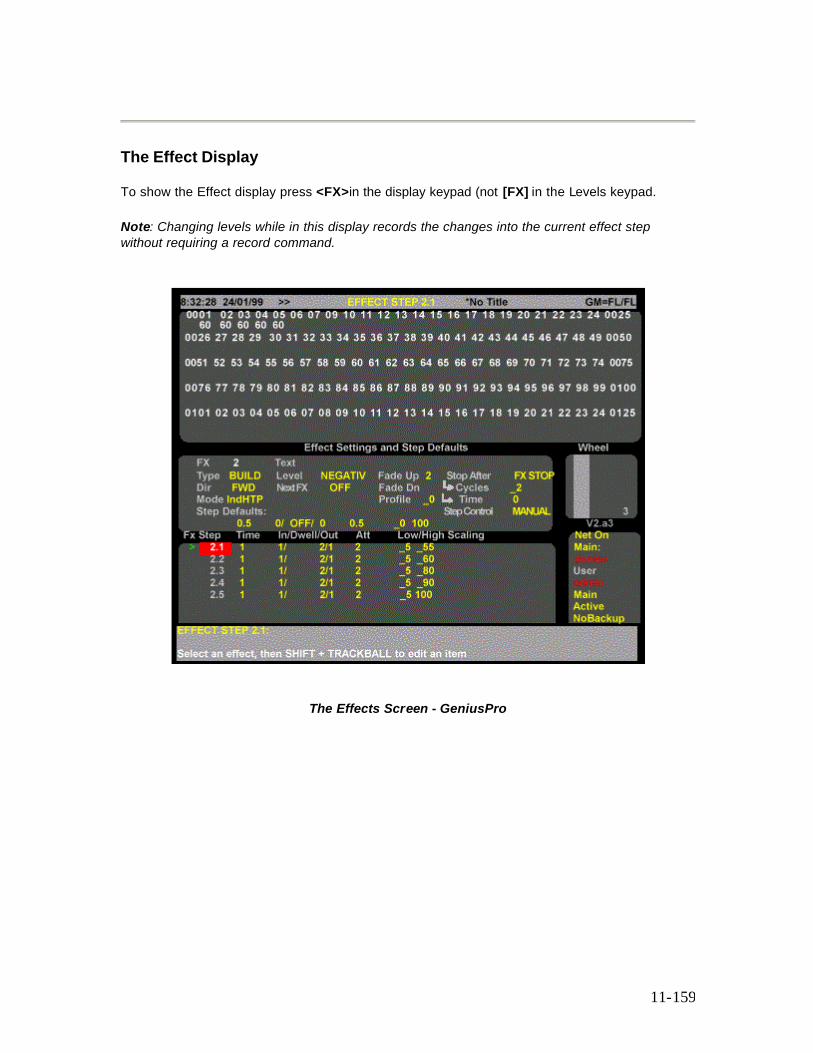
11-159
The Effect Display
To show the Effect display press <FX>in the display keypad (not [FX] in the Levels keypad.
Note: Changing levels while in this display records the changes into the current effect step without requiring a record command.
The Effects Screen - GeniusPro
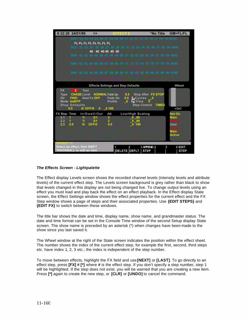
11-160
The Effects Screen - Lightpalette
The Effect display Levels screen shows the recorded channel levels (intensity levels and attribute levels) of the current effect step. The Levels screen background is grey rather than black to show that levels changed in this display are not being changed live. To change output levels using an effect you must load and play back the effect on an effect playback. In the Effect display State screen, the Effect Settings window shows the effect properties for the current effect and the FX Step window shows a page of steps and their associated properties. Use {EDIT STEPS} and {EDIT FX} to switch between these windows.
The title bar shows the date and time, display name, show name, and grandmaster status. The date and time format can be set in the Console Time window of the second Setup display State screen. The show name is preceded by an asterisk (*) when changes have been made to the show since you last saved it.
The Wheel window at the right of the State screen indicates the position within the effect sheet. The number shows the index of the current effect step, for example the first, second, third steps etc. have index 1, 2, 3 etc.; the index is independent of the step number.
To move between effects, highlight the FX field and use [NEXT] or [LAST]. To go directly to an effect step, press [FX] # [*] where # is the effect step. If you don’t specify a step number, step 1 will be highlighted. If the step does not exist, you will be warned that you are creating a new item. Press [*] again to create the new step, or [CLR] or [UNDO] to cancel the command.
11-161
To change values in effect fields, hold down the [SHIFT] key and move the trackball to change from non-edit mode (green) to edit mode (yellow), then use the trackball to highlight the field to be edited. Edit the field using the wheel, or [+] or [-] key to change the field, or enter a value from the keypad, as apprpriate. Press [*] to return to the non-edit mode (green)
Effect Setting Fields
Fields in the Effect display Effect Settings window show the current values for effect properties, and the Step Defaults. To change any of the effect properties:
1. Make sure that the highlight is in the upper part of the State display (press {EDIT FX} if it isn’t).
2. Use the Trackball to move the highlight to the field you want to change. 3. Type a new value or use [+] and [-] to increment or decrement the value. 4. The new value is recorded when you move the highlighting out of the field. 5. To move between effects, use the Trackball to move the highlight to the FX field and then
use [NEXT] and [LAST] to move between effects.
FX The number of the effect. Cannot be changed, but if you highlight it you can use [NEXT] and [LAST] to move between effects. Text The text label (caption) associated with the effect. Type The type of effect. Can be one of CHASE or BUILD. Dir The direction of the effect. Can be one of FWD (forward), REV (reverse), BOUNCE, or RANDOM. Mode The way in which the effect interacts with other output sources such as the X playbacks and submasters. Can be one of indHTP (Independent Highest Takes Precedence) or LTP (Latest Takes Precedence). Level The way in which the high and low effect settings are interpreted. Can be one of NORMAL, NEGATIV, NEG|NRM, NRM|NEG, or RANDOM. Next Fx The next effect to be started when this effect stops. Only applies to effects where the Stop After field is set to TIMED or CYCLES. Can be OFF or an effect number. Fade Up The time it takes the effect to fade in after you press [FX GO]. Can be from 0 to 59 minutes, 59 seconds. Fade Dn The time it takes the effect (not an effect step) to fade out after you press [FX STOP]. Can be from 0 to 59 minutes, 59 seconds. Profile The profile assigned to the effect fade times. Applies to both the fade up and fade down times. Stop After How the effect will stopped. Can be one of FX STOP (on Fx stop), FX LOAD (on Fx load),
11-162
LAST STEP (on last step), TIME (after XXX seconds), or CYCLES (after XXX cycles). For CYCLES set the number of cycles in the Cycles field. For TIME set the time in the Time field. Step Control The way steps are started. Can be one of TIMED, MANUAL, MIDI, or AUDIO. Step DefaultsThe values that will be assigned to step properties when you create a step. These values can be changed if necessary after the step is created. Included fields for step time (Step TIME), step in, dwell, and out times (In/Dwell/Out), attribute fade time (Att), step low and high values (Low/High), and scaling (Scaling). Scaling is not implemented at this time.
Effect Step Fields
Fields in the Effect display FX Step window show the current values for effect step properties. The property associated with each display field is indicated by the title line.
To change any of the effect step properties:
1. Make sure that the highlight is in the lower part of the State display (press [EDIT STEPS] if it isn’t).
2. Use the Trackball to move the highlight to the field you want to change. 3. Type a new value or use [+] and [-] to increment or decrement the value. The new value
is recorded when you move the highlighting out of the field.
To move between steps, use the Trackball to move the highlight to the FX Step field and then use [NEXT] and [LAST] to move between steps.
FX Step The number of the effect step. These are fixed and cannot be changed. Step Time Step time for the step. In/Dwell/Out The in, dwell, and out times for the step. The in time is the time from step start until the step is at its high setting. The dwell time is the time the step stays at its high setting. The out time is the time from the end of the dwell time until the step is back at its low setting. Att The time it takes to change attribute levels once the step has started. Low/High The low and high settings for the step. The high setting is the level that channels go to when a step is active with the Level field set to NORMAL. Scaling Not implemented at this time.
Creating a New Effect
To switch to the Effect display and create a new effect or step, press <FX> [FX] # [*] where # is an unused effect or step number. To create a new effect or step while you are in the Effect display, press [FX] # [*] where # is an unused effect or step number. You will be warned that you are creating a new item. Press [*] again to create the new effect or step, or [CLR] or [UNDO] to
11-163
cancel the command. If this is a new effect and you did not specify a step, step 1 is created automatically. The cursor is on the newly created step.
Note: The <FX> display key is at the top of the console. Do not confuse it with the lower [FX] key.
Assigning Fade Times to Effects
fx# [TIME] # [*] changes the fade time of the specified effect without changing recorded levels. If the effect doesn’t exist, this command creates a new effect with no levels but with the specified fade times. You do not get an over-record warning with this command if the effect exists. If you only enter one number for time, it is used for both the up and down fade times. To enter separate up and down fade times, use [/] to separate the two numbers. The first number becomes the up fade time and the second number becomes the down fade time.
[FX] [1] [TIME] [*] All Modes Resets effect 1 fade time to the non-split default effect time in the Setup display FX|Up/Down field. [FX] [1] [TIME] [4] [*] All Modes Changes effect 1 up and down fade times to 4 seconds without changing any levels. [FX] [1] [TIME] [4] [/] [2] [*] All Modes Changes effect 1 up fade time to 4 seconds and its down fade time to 2 seconds without changing any levels. [FX] [1] [TIME] [/] [2] [*] All Modes Changes effect 1 down fade time to 2 seconds without changing any levels. Sets the up fade time to the time in the Setup display FX|Up/ field if this is a new effect or leaves it as is if over-recording. F[FX] [1] [TIME] [4] [/] [*] All Modes Changes effect 1 up fade time to 4 seconds without changing any levels. Sets the down fade time to the time in the Setup display FX|/Down field if this is a new effect or leaves it as is if over-recording.
Assigning Profiles to Effects
fx# [PROFILE] # [*] assigns a fade profile to the effect. Since no levels are changed, you get no rerecord warning with this command. To learn how to create and edit profiles refer to Profiles To delete an assigned fade profile, omit the fade profile number.
[FX] [1] [PROFILE] [3] [*] All Modes Assigns fade profile 3 to effect 1. [FX] [1] [PROFILE] [*] All Modes Deletes any fade profile assigned to effect 1.
Creating Effect Steps
11-164
To add a new effect step to the current effect, press {APPEND FXSTEP} when in the Effect display. This adds a new step to the current effect and puts the cursor on the newly created step. The new step has default values for step time, in, dwell, and out times, attribute fade time, low and high settings, and scaling. It has no assigned levels.
Viewing Step Channel Levels
To view the recorded levels in a step: If the cursor is in the Effect Settings window, press {EDIT STEPS} to put it on the first effect step number in the FX Step window. If the cursor is in the FX Step window but not on the effect step number, use the Trackball to highlight the step number rather than timing or level data. Once the cursor is on the effect step number, use [NEXT] and [LAST] to move between steps and view channel levels.
Editing Step Channel Levels
First select the step and ensure that the highlight is on the step number (the FX STEP field). The channels can then be selected and modified using the same commands as for Channel Control, for example [1] [@] [1] [*], [SUB] [1] [@] [5] [*] and so on. The Level Wheel and some of the soft keys in the Channel Control cannot be used to change levels.
Deleting Effect Steps
Steps can be deleted from the Effect display. This is a good way to delete effects if you are only going to delete a few. For information on how to delete all effects or a range of effects from the Archive display turn to Clear Operations
{DELETE} appears on the LCD Effect menu when you are in the Effect display and delete steps, either a single step or a single THRU range can be specified. The highlight must be on the step number. This can be used with [+], [-], and [THRU] keys.
{DELETE} {DELETE} Direct Entry 1 and 2 Digit {DELETE} [*] Direct Entry 1 and 2 Digit {DELETE} {DELETE} {DELETE} Command Line {DELETE} [*] [*] Command Line Deletes the current step. [FX] [1] [.] [2] {DELETE} {DELETE} All Modes Deletes effect 1 step 2. [FX] [1] [.] [2] [THRU] [3] [.] [4] {DELETE} {DELETE} All Modes Deletes effect 1 step 2 through effect 3 step 4.

11-165
Copying Levels From an Effect Step
You can record submasters, cues, groups, and effect steps while you are in the Effect display. The highlight must be on the step number (the FX STEP field).
Using recording commands while you are in the Effect display copies the Effect display levels to the target submaster, cue, group, or effect step. For example, if effect step 1.1 is highlighted in the Effects display, then entering [SUB] [2] [RECORD] will copy the levels from effect 1 step 1 into cue 2. This also allows steps to be copied from one step to another, for example, if the screen highlight is on effects 1, step 1, entering [FX] [3] [.] [4] [RECORD] will copy the levels from effect 1 step 1 into effect 3, step 4.
12-166
Chapter 12 - Groups
Groups are used to store sets of levels which can be used later as building blocks, but which do not show up on the cue sheet. The only way to get group information to the console output is to call up group levels as part of a channel command and show them in the Live display, or to record them in a submaster, cue, or effect.
The following topics are covered in this section:
• Predefined Groups • The Current Group • Recording Group Levels • Recording Group Properties • Using Referenced Groups • Viewing and Editing Groups • Updating and Adding to Groups • Updating Groups from the Live Screen • The Group Display • Creating a New Group • Viewing Group Channel Levels • Editing Group Levels • Deleting Groups • Copying Levels from a Group
Predefined Groups
There are several predefined groups that provide levels for console components. You can also call them up and use them like any other group if necessary These are:
o Group 993.1 - *ON console o Group 993.2 - *ON 2 o Group 993.3 - *ON 3 o Group 993.6 - *ON Handheld o Group 994.1 - *Display console o Group 994.1 - *Display 2 o Group 994.1 - *Display 3 o Group 998.1 - *Partition console o Group 998.2 - *Partition 2 o Group 998.3 - *Partition 3 o Group 999.1 - *Grand Master 1 o Group 999.2 - *Grand Master 2 o Group 999.3 - *X Playback 1 o Group 999.4 - *X Playback 2 o Group 999.5 - *Preheat
12-167
ON console Controls the ON level for channels controlled from the main console. All channels are initially off (blank level). If a channel has a level in this group, the ON level is taken from the group. If not, the ON level is taken from the On Level % field in the User Setup Screen ON 2 & ON 3 Controls the ON level for channels controlled from the remote consoles. All channels are initially off (blank level). If a channel has a level in this group, the ON level is taken from the group. If not, the ON level is taken from the On Level % field in the User Setup Screen ON Handheld Controls the ON level for channels controlled from the handheld remote. All channels are initially off (blank level). If a channel has a level in this submaster, the ON level for the handheld remote is taken from the submaster. If not, the ON level is taken from the On Level % field in the User Setup Screen Display console Controls what channels will be shown on the main console level displays if the Channel Formatting field in the User Setup Screen is set to DISPLAY GROUP. All channels are initially set to FL, and can only be set to off and FL. If a channel has no level in this group, it will not show on any of the Levels screens (including the Group display). If channel formatting is set to AUTO, channels are added to the display groups as they are used. This is an easy way to automatically create a display group based on channels actually used in the show. Display 2 & Display 3 Controls what channels will be shown on the remote console level displays if the Channel Formatting field in the User Setup Screen is set to DISPLAYGROUP. All channels are initially set to FL, and can only be set to off and FL. If a channel has no level in this group, it will not show on any of the Levels screens (including the Group display). If channel formatting is set to AUTO, channels are added to the display groups as they are used. This is an easy way to automatically create a display group based on channels actually used in the show. Partition Console, Partition 2 & Partition 3 Determines what channels will be controlled by each console if the Channel Partitioning field in the Show Details window of the Show Setup Screen is set to ON. All channels are initially set to their maximum setting in the Console Channels group and off in the other groups. Channels can only be set to their minimum or maximum levels. Setting a channel to a non-zero value in one group sets it to its maximum level and removes it from its previous group. Regardless of which console is generating level data, all information is recorded in the main console. Grand Master 1 Channels with levels in this group are controlled by Grand Master 1. All channels are initially set to FL, and can only be set to off and FL. For channels that overlap with Grand Master 2, the lower of the two output levels is used. Grand Master 2 Channels with levels in this group are controlled by Grand Master 2. All channels are initially set to FL, and can only be set to off and FL. For channels that overlap with Grand Master 1, the lower of the two output levels is used. X Playback 1
12-168
Channels with levels in this group are controlled by X Playback 1. All channels are initially set to FL, and can only be set to off and FL. For channels that overlap with X Playback 2, the higher of the two output levels will be used. X Playback 1 X Playback 2 Channels with levels in this group are controlled by X Playback 1. All channels are initially set to FL, and can only be set to off and FL. For channels that overlap with X Playback 1, the higher of the two output levels will be used. Preheat Controls the preheat level for channels if the Auto Preheat field in the Show Setup Screen is set to ON. All channels are initially off (blank level). Preheat levels for all channels are taken from this group.
The Current Group The current group is the last group which has been referenced in the Group display or recorded from another display. It is shown in the right LCD, and can be used in a group selection or in group recording. All group recording commands act on a single group which is shown by # in the command description. If you do not enter a group number, the current group is used. You can use [NEXT] and [LAST] instead of # to select a group relative to the current group.
[GROUP] Specifies the current group. [GROUP] [1] Specifies group 1. [GROUP] [NEXT] If the current group is group 3, this specifies group 4. If the current group is the highest group number, this specifies the lowest group number. [GROUP] [LAST] If the current group is group 3, then this specifies group 2. If the current group is the lowest group number, this specifies the highest group number.
Recording Group Levels
[GROUP] records the levels (intensity levels and attribute levels) on the current display into the current group. [GROUP] # records the levels on the current display (the Live, Cue/Preview, Group, Effect, or Submaster display) into the specified group. For information on how to set intensity and attribute levels, refer to Working with Channel Levels and Basic Recording for examples of recording. Groups can be numbered from 1 to 999.9, and you can have up to 1000 groups in a show. You can record just intensities or just attributes to a group by adding {INTS ONLY} or {ATTS ONLY} to the command line. In preset focus terms, Attributes are only active if their levels are shown as bright white on the Group display. To record a group from a selection with no Intensities you must include a channel list before the Group Record command, e.g.
[1] [THRU] [3] [@] [GROUP] [5]
12-169
Recording Group Properties
Groups have only one property which can be specified when recording or edited later. You can record a text label (caption) with each group to help identify the group (see Recording Levels and Properties in Basic Recording).
Using Referenced Groups
You can record intensities and attributes in groups 1 through 750 and then use these groups in cues, effect steps, and submasters as reference groups (sometimes called preset focus groups). Channels inserted into cues, effect steps, and submasters using reference groups are automatically updated in the recorded item when you update the group. This lets you reference the group in multiple locations and then change the referenced values only in one place to update the entire show. chans [@] [GROUP # [*] sets intensities and attributes for the selected channels to the levels set in the specified group. The cue, effect step, or submaster then takes levels for the selected channels from the group, so if you change the group the recorded item will also change. [1] [THRU] [4] [@] [GROUP] [1] [2] [3] [*] Sets channels 1 through 4 intensities and attributes to the levels set in group 123. chans [@] [GROUP] # {INTS ONLY} [*] sets intensities only for the selected channels to the levels set in the specified group. The cue, effect step, or submaster then takes levels for the selected channels from the group, so if you change the group the recorded item will also change. [1] [THRU] [4] [@]GROUP] [3] {INTS ONLY} [*] Sets channels 1 through 4 intensities only to the levels set in group 3. chan [@] [GROUP] # {ATTS ONLY} [*] sets attributes only for the selected channels to the levels set in the specified group. The cue, effect step, or submaster then takes levels for the selected channels from the group, so if you change the group the recorded item will also change. [1] [THRU] [3] [@] [GROUP] [5] {ATTS ONLY} [*] Sets channels 1 through 3 attributes only to the levels set in group 5. This command requires a Pentium processor (or better) and the Tracker software. For additional information, refer to Tracker Software
Viewing and Editing Groups
Once you have recorded groups, you can view and edit them in the Group display. You can also use the Group display to create new groups.
Note: Changing levels while in this display changes the recorded levels in the current group without a record command and without warning you.
12-170
Updating and Adding to Groups
[UPDATE] [GROUP] # [*] changes levels in the specified group as necessary based on channels that have been modified live (red or purple channels on the Live display). This command excludes channels that are not already in the group, and channels that have been removed from the modified list by using [SHIFT] [CLR]. Note: When using groups the [UPDATE] key is set to default to update only channels already in the group. Pressing the [UPDATE] key as part of a group command syntax, e.g., [UPDATE] [GROUP] # [*] is the same as entering [UPDATE] {CHANS IN} [GROUP] # [*]. So when updating a group to include only changes in channels already in the group, there is no need to use the {CHANS IN} softkey. The {CHANS IN} softkey is used, as necessary, when updating cues. Channels that are off in the selection will be removed from the group. [UPDATE] [GROUP] [1] [*] (All Modes)
Updates levels that have been modified in group 1, excluding levels of channels that were not already in the group.
[GROUP] [7] [*] [UPDATE] [GROUP] [1] [*] (All Modes)
First selects all of the channels in group 7, then updates their levels in group 1, excluding levels of channels that were not already in the submaster. Including the {ADD ALL} softkey in the update command includes level changes in channels that are not already in the group. [UPDATE]{ADD ALL} [GROUP] # [*] (All Modes)
Updates levels in the specified group for channels that have been modified. Includes modified channels that are not already in the group, and channels that have been removed from the modified list by using [SHIFT] [CLR]. Channels that are off in the selection will be removed from the group.
[UPDATE]{ADD ALL} [GROUP] [1] [*] (All Modes)
Updates all channels that have been modified in group 1, including channels that are not already in group 1.
[GROUP] [7] [*] [UPDATE] {ADD ALL} [GROUP] [1] [*] (All Modes) First selects all of the channels in group 7, then records their levels in group 1, including channels that are not already in the group 7. chan [UPDATE] [GROUP] # [*] updates levels of the specified channels in the specified group to match the current Levels screen for the selected channels, regardless of whether or not they have been modified. Excludes channels that are not already in the group, regardless of whether or not they have been modified. Channels that are off in the selection will be removed from the group.
You can usethe following command to record a selection of channels (rather than all channels) into a new group.
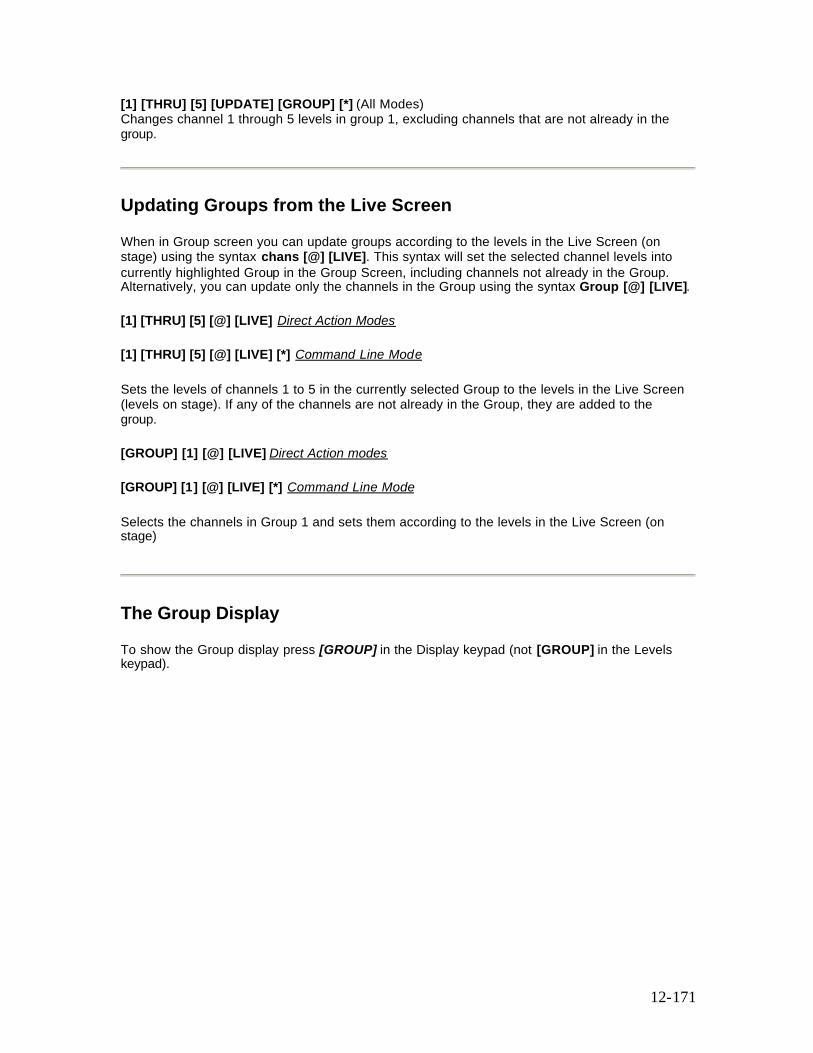
12-171
[1] [THRU] [5] [UPDATE] [GROUP] [*] (All Modes) Changes channel 1 through 5 levels in group 1, excluding channels that are not already in the group.
Updating Groups from the Live Screen
When in Group screen you can update groups according to the levels in the Live Screen (on stage) using the syntax chans [@] [LIVE]. This syntax will set the selected channel levels into currently highlighted Group in the Group Screen, including channels not already in the Group. Alternatively, you can update only the channels in the Group using the syntax Group [@] [LIVE].
[1] [THRU] [5] [@] [LIVE] Direct Action Modes
[1] [THRU] [5] [@] [LIVE] [*] Command Line Mode
Sets the levels of channels 1 to 5 in the currently selected Group to the levels in the Live Screen (levels on stage). If any of the channels are not already in the Group, they are added to the group.
[GROUP] [1] [@] [LIVE] Direct Action modes
[GROUP] [1] [@] [LIVE] [*] Command Line Mode
Selects the channels in Group 1 and sets them according to the levels in the Live Screen (on stage)
The Group Display
To show the Group display press [GROUP] in the Display keypad (not [GROUP] in the Levels keypad).
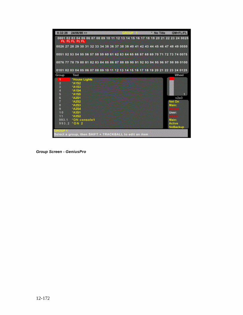
12-172
Group Screen - GeniusPro
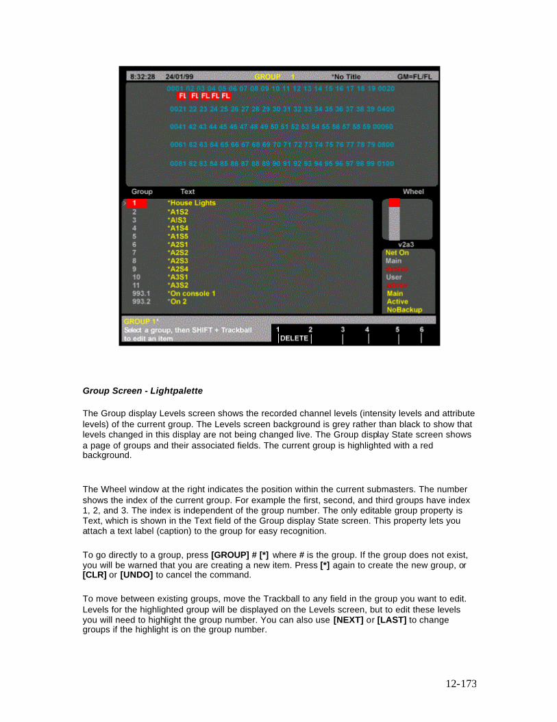
12-173
Group Screen - Lightpalette
The Group display Levels screen shows the recorded channel levels (intensity levels and attribute levels) of the current group. The Levels screen background is grey rather than black to show that levels changed in this display are not being changed live. The Group display State screen shows a page of groups and their associated fields. The current group is highlighted with a red background.
The Wheel window at the right indicates the position within the current submasters. The number shows the index of the current group. For example the first, second, and third groups have index 1, 2, and 3. The index is independent of the group number. The only editable group property is Text, which is shown in the Text field of the Group display State screen. This property lets you attach a text label (caption) to the group for easy recognition.
To go directly to a group, press [GROUP] # [*] where # is the group. If the group does not exist, you will be warned that you are creating a new item. Press [*] again to create the new group, or [CLR] or [UNDO] to cancel the command.
To move between existing groups, move the Trackball to any field in the group you want to edit. Levels for the highlighted group will be displayed on the Levels screen, but to edit these levels you will need to highlight the group number. You can also use [NEXT] or [LAST] to change groups if the highlight is on the group number.
12-174
You can also page through the group list by using the Level Wheel.
Creating a New Group
To switch to the Group display and create a new group, press <GROUP> [GROUP} # [*] where # is the new group number.
To create a new group while you are in the Group display, press [GROUP] # [*] where # is the new group number.
You will be warned that you are creating a new item. Press [*] again to create and display the new group or [CLR] or [UNDO] to cancel the command.
The <GROUP> display key is at the top of the console. Do not confuse it with the lower [GROUP] key.
Viewing Group Channel Levels
To view the recorded levels in a group, select the required group. The levels are then shown in the Levels screen. Channels which are off are shown with a blank level. Channels which are on At 0 are shown with a level of 0.
Editing Group Levels
Once you have selected the required group, highlight the group number (the Group field), select channels and modify them using the same commands as for channel control, for example [1] [@] [1], [CUE] [1] [@] [5] and so on. The Level Wheel cannot be used to change levels while you are in the Group display.
Deleting Groups
Groups can be deleted from the Group display. This is a good way to delete groups if you are only going to delete a few. To learn how to delete all groups or a range of groups refer to Clear Operations in the Archive Screen
To delete a group, press {DELETE} # [*]. {DELETE} [*] [*] Deletes the current group. [GROUP] [6] {DELETE} {DELETE} {DELETE} [6] [*] [*] Deletes group 6

12-175
Copying Levels From a Group
You can record submasters, cues, groups, and effect steps while you are in the Group display by copying the group levels. The highlight must be on the group number (the Group field).
Using recording commands while you are in the Group display copies the Group display levels to the target submaster, cue, group, or effect step. For example, if the current group is 1, then [CUE] [2] [RECORD] will copy the levels from group 1 into cue 2. This also allows groups to be copied. For example [GROUP] [4] [RECORD] will copy the levels from group 1 into group 4.
13-176
Chapter 13 - Patches This section describes the patch system, which lets you set which channels control which console outputs. Patching sets up the channel that controls each console output. For intensity channels, these outputs usually control dimmers or non-dims, which in turn control fixture intensity. For attribute channels, these outputs usually control scrollers, which in turn control fixture colour. Each channel can have an intensity, an attribute or both, so a dimmer and a scroller can both be patched to the same channel. The Live display shows both the intensity and the attribute levels for each channel. The Tracker software allows multiple attributes per channel. For information on how to patch multiple attributes and complete fixtures, refer to Tracker Software. An output can control any device capable of taking an AMX192, D54 (500 Series only) or DMX512 signal and translating it into a command, including scrollers and other moving light fixtures. The outputs from the patch system can be further manipulated within the console by DMX signal assignment (refer to Output Connections Window of the Console Setup Screen) and again at the input of many dimmer racks. There are 2 Patches available (1 only on 300 Series consoles), called patch 1 and patch 2. The patch that is currently being used by the output is called the live patch. The patch currently being edited is called the edit patch. You can set either patch to be the live patch and either patch to be the edit patch. If you set the live and edit patch to the same number, changes you make will show immediately on stage. If you set the live and edit patches to be different, changes you make in the patch will not show on stage. The following topics are covered in this section:
• Output Properties • The Patch Display • Selecting Outputs • Changing Live and Edit Patches • The Copy Patch Menu • Changing the Output Numbering Style • Customising the Patch Display • Deleting Channels • Deleting Unpatched Attributes • Renumbering Channels • Default Patching • Clearing Default Patching • Patching Channel Intensities • Patching Double Width Outputs • Assigning Output Profiles • Patching Channel Attributes • Patching Non-Dims • Patching DMX In • Unpatching
13-177
Output Properties
Outputs have the following editable properties, which can be specified when patching or edited later.
• Output Type • Output Profile • Scaling Value
Types
Each output can be set to one of several types.
Unpatched No channel number. The output is not patched to any channel and so its output is always 0. (see Unpatching) Intensity The channel number is white (or yellow if it is not a one-to-one patch) and the output is grey in Channel Order. In Output order, the Output is white and the channel number is grey (or yellow if it is not a one-to-one patch. . The intensity output is patched to a channel intensity. The output has a Scaling Factor (shown in grey below the channel number) which modifies the basic channel level and can range from 0% to 200%. A value of 100% has no effect, a value of 0% disables the output (its value is always 0). For example with a level of 80% on the Live display, scaling of 50% would cause an output of 40%. Scaling values over 100% cause the output to reach its full intensity faster than other outputs. For instance, if the scaling is 150% the output will be at 75% when the channel it is patched to is still at 50%. When the channel is at 67% the output reaches full intensity. Its intensity will not increase as the channel intensity increases above 67% If no scaling factor is set, the default scaling factor is assumed. Scaling of 100% is not displayed on the patch screen. (see Patching Channel Intensities) The default scaling is set in the Default Scale % field of the Patch Window of the Show Setup Screen. Its default is 100%. NonDim The channel number is white in Channel Order or grey in Output Order (or yellow if it is not a one-to-one patch). The non-dim output is patched to a channel intensity or attribute. It has a threshold (in magenta below the channel number) which is the level at which the output turns on or off. For example, if a non-dim has a threshold of 60%, channel levels from 0% to 60% will give an output of 0% and levels from 61% to 100% have an output of 100%. (see Patching Non-Dims) Basic Attribute The channel number is yellow. The output is patched to the basic attribute (colour) of a channel. It has a maximum frame number (in green below the channel number) which is the full value for the attribute, and can range from 1 to 100. (see Patching Channel Attributes) Tracker Attribute The channel number is blue. The output is patched to an attribute controlled by the Tracker Software (see Patching Attributes). DMX In The channel number is Magenta and has a trailing letter 'D'. The output is patched directly to a DMX input channel. This is only used when the CommuniquéPro
13-178
software is installed. For additional information refer to DMX IN CommuniquéPro Software.
Profiles
Each output can have a profile assigned to it. This lets you change the fade characteristics of individual outputs if necessary. You may need to do this because you are using several different types of dimmers whose dimming characteristics don’t match, because the output is actually controlling a fixture attribute that needs a non-linear “fade,” or because you need an output for a particular special effect, etc. For further information refer to Profiles.
Scaling Value
Each output has a scaling value assigned. The meaning of the scaling value depends on the type of output.
Unpatched There is no scaling value. Intensity Scales the intensity as provided by the channel that the output is patched to. Refer to Patching Channel Intensities Non-dim The scaling value is the threshold for the non-dim. Any channel level above the threshold forces the output to Full. Any value below the threshold forces the output to 0 (zero). Refer to Patching Non-Dims Attribute The scaling value is the maximum frame number. Refer to Patching Attributes
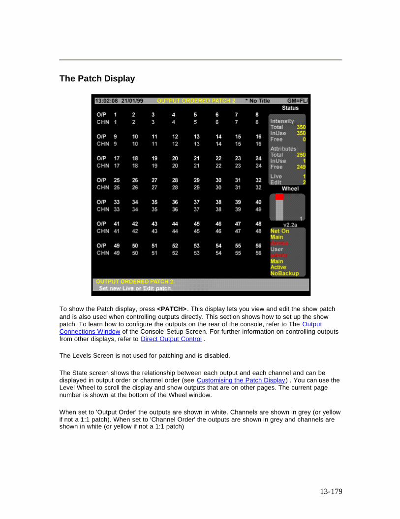
13-179
The Patch Display
To show the Patch display, press <PATCH>. This display lets you view and edit the show patch and is also used when controlling outputs directly. This section shows how to set up the show patch. To learn how to configure the outputs on the rear of the console, refer to The Output Connections Window of the Console Setup Screen. For further information on controlling outputs from other displays, refer to Direct Output Control .
The Levels Screen is not used for patching and is disabled.
The State screen shows the relationship between each output and each channel and can be displayed in output order or channel order (see Customising the Patch Display) . You can use the Level Wheel to scroll the display and show outputs that are on other pages. The current page number is shown at the bottom of the Wheel window.
When set to 'Output Order' the outputs are shown in white. Channels are shown in grey (or yellow if not a 1:1 patch). When set to 'Channel Order' the outputs are shown in grey and channels are shown in white (or yellow if not a 1:1 patch)
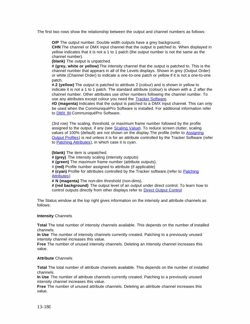
13-180
The first two rows show the relationship between the output and channel numbers as follows:
O/P The output number. Double width outputs have a grey background. CHN The channel or DMX input channel that the output is patched to. When displayed in yellow indicates that it is not a 1 to 1 patch (the output number is not the same as the channel number). (blank) The output is unpatched. # (grey, white or yellow) The intensity channel that the output is patched to. This is the channel number that appears in all of the Levels displays. Shown in grey (Output Order) or white (Channel Order) to indicate a one-to-one patch or yellow if it is not a one-to-one patch. #.2 (yellow) The output is patched to attribute 2 (colour) and is shown in yellow to indicate it is not a 1 to 1 patch. The standard attribute (colour) is shown with a .2 after the channel number. Other attributes use other numbers following the channel number. To use any attributes except colour you need the Tracker Software. #D (magenta) Indicates that the output is patched to a DMX input channel. This can only be used when the CommuniquéPro Software is installed. For additional information refer to DMX IN CommuniquéPro Software. (3rd row) The scaling, threshold, or maximum frame number followed by the profile assigned to the output, if any (see Scaling Value). To reduce screen clutter, scaling values of 100% (default) are not shown on the display.The profile (refer to Assigning Output Profiles) is red unless it is for an attribute controlled by the Tracker Software (refer to Patching Attributes), in which case it is cyan. (blank) The item is unpatched. # (grey) The intensity scaling (intensity outputs) # (green) The maximum frame number (attribute outputs). # (red) Profile number assigned to attribute (if applicable) # (cyan) Profile for attributes controlled by the Tracker software.(refer to Patching Attributes) # N (magenta) The non-dim threshold (non-dims). # (red background) The output level of an output under direct control. To learn how to control outputs directly from other displays refer to Direct Output Control
The Status window at the top right gives information on the intensity and attribute channels as follows:
Intensity Channels Total The total number of intensity channels available. This depends on the number of installed channels. In Use The number of intensity channels currently created. Patching to a previously unused intensity channel increases this value. Free The number of unused intensity channels. Deleting an intensity channel increases this value. Attribute Channels Total The total number of attribute channels available. This depends on the number of installed channels. In Use The number of attribute channels currently created. Patching to a previously unused intensity channel increases this value. Free The number of unused attribute channels. Deleting an attribute channel increases this value.

13-181
Output Numbers (500 Series Consoles) A 500 Series console can control 2048 outputs, in four banks of 512, through the four DMX ports. In addition, using Networker Software, the outputs can be sent via the network. The network has 4096 virtual outputs. The 2048 console outputs can be assigned to different ranges of the 4096 virtual outputs. This could, for example, allow two consoles to each control half of the network system (e.g. one console for moving lights, the other for conventional lights) without interfering with each other. Outputs can be specified and/or displayed as output numbers, 0 to 4096 (or in Universe.Dmx format). In Universe.Dmx format, each output connector has its own number from 1 to 8 and each signal from the connector has its own number from 1 to 512. The two numbers are used together, so that the 123 rd output from the 3rd DMX connector is addressed as 3.123. DMX connectors 1 through 4 are output from the console. The remainder of the DMX connectors must be on the network. Output Numbers (300 Series Consoles) A 300 Series console can control 1024 outputs, in two banks of 512, through the two DMX ports. In addition, using Networker Software, the outputs can be sent via the network. The network has 2048 virtual outputs. The 1024 console outputs can be assigned to different ranges of the 2048 virtual outputs. This could, for example, allow two consoles to each control half of the network system (e.g., one console for moving lights, the other for conventional lights) without interfering with each other. Outputs can be specified and/or displayed as output numbers, 0 to 2048 (or in Universe.DMX format). In Universe.Dmx format, each output has its own number 1 to 4 and each signal from the connector has its own number from 1 to 512. The two numbers are used together, so that the 123 rd output from the 2nd DMX connector is addressed as 2.123. The two DMX connectors are output from the console. The remainder of the DMX connectors must be n the network. The patch does not directly configure the mapping of output numbers to the output multiplex signals. For further information on setting up the console output to patch output mapping refer to Output Connections Window of the Console Setup Screen.
Channel Numbers
Refer to Product Specification for number of intensity and attribute channels.
You can increase the number of attribute channels beyond the purchased maximum by deleting intensity channels and assigning them as attribute channels.
Channel attributes are specified by a decimal point as follows using channel 10 as an example:
10 channel 10 intensity 10.1 channel 10 intensity (displayed as 10). 10.2 channel 10 attribute.
The standard software allows one attribute (colour) per channel. The Tracker software lets you specify multiple attributes per channel (attribute numbers .2 to .99).
The default patch numbers channels from 1 to the number of channels purchased and assigns them only intensities. To use a new channel number and assign it an intensity you must first delete a channel with intensity. This will delete the levels of that channel in all cues, submasters,
13-182
effects and patches. Patching to the new channel number will then create a new channel. For further information on deleting channels refer to Deleting Channels.
Note:Deleting a channel is different from unpatching. Deleting removes the channel from all channel displays and removes all its recorded levels. Unpatching only removes the association between the channel and the output. Channel levels are preserved so that if it is repatched to the same or another output, the previous levels reappear.
The number of free and used channels is shown in the Status Window of the Patch Screen.
Selecting Outputs
Most patch commands act on a selection of 1 or more outputs. Outputs can be specified in standard output number format, where outputs are numbered from 1 to the maximum number available, or in Universe.Dmx format. The two formats can be used interchangeably, and can be used in the same command.
The examples shown immediately below are commands you can use to create the output list before patching them to a channel. You can use these commands to replace out where it appears in full command descriptions. Outputs are not actually selected until you press [@] to end the selection list.
Note: Since these examples are only part of a command, the [*] key. (where applicable). is not shown.
These selections will only work in the Patch display. # puts the specified output on the output list.
[1] Puts output 1 on the output list. [1] [.] [6] Puts output 6 on the output list. [+] # adds the specified output to the output list. [1] [+] [3] Puts outputs 1 and 3 on the output list. [3] [.] [4] [6] [+] [3] [.] [5] [6] Puts outputs 1070 and 1080 on the output list. # [THRU] adds a range of outputs to the output list. [1] [THRU] [3] or [3] [THRU] [1] Puts outputs 1, 2, and 3 on the output list. [2] [.] [4] [THRU] [5] [1] [8] or [5] [1] [6] [THRU] [2] [.] [6] Puts outputs 516 through 518 on the output list. [-] # removes an output from the output list. It only removes outputs that are already in the list. [1] [THRU] [3] [-] [2] Puts outputs 1 and 3 on the output list. [1] [THRU] [3] [-] [2] [+] [4] Puts outputs 1, 3, and 4 on the output list.
13-183
Changing Live and Edit Patches (500 Series Consoles only)
There are 2 separate show patches. The Patch display always shows the Edit Patch. You can edit one patch while the other is live. The current Live Patch and Edit Patch numbers are shown in the top left corner of the LCD Patch menu and on the bottom of the Status Window of the Patch Screen..
To change the Live Patch:
1. Press {SET} on the LCD Patch menu to show the LCD Set Patch menu. 2. Press {LIVE=}. You will be asked to confirm this action. 3. Press {LIVE=} . It can take several seconds for the Live Patch to change. 4. Press {BACK} to return to the LCD Patch menu.
To change the Edit Patch:
1. Press {SET} on the LCD Patch menu to show the LCD Set Patch menu. 2. Press {EDIT=}. 3. Press {BACK} to return to the LCD Patch menu.
The Copy Patch Menu
Pressing {COPY/SWAP} from the Set Patch menu displays the Copy Patch menu with softkeys {COPY PATCH}, {MOVE PATCH} and {SWAP PATCH}. These softkeys enable output attributes or fixtures to be copied, moved or swapped within, or between the Live or Edit Patch.
• Copying Patch Information • Moving Patch Information • Swapping Patch Information
Copying Patch Information
Press {SET} from the LCD Patch Menu to display the LCD Set Patch Menu. Press {COPY/SWAP} to display the Copy Patch Menu.
Copying Attributes Enter the output number (or range of outputs), of the attribute(s) to be copied, followed by the {COPY PATCH} softkey and the output number (or first output number), where the attribute(s) has to be copied, then [*]. A confirmation is requested after each command. Press [*] again.
13-184
[1] {COPY PATCH} [1] [0] [*] Copies attribute 1 to output 10 [1] [THRU] [10] {COPY PATCH} [1] [1] [*] Copies attributes on outputs 1 to 10 to outputs 11 to 20.
Press {BACK} to return to the LCD Set Patch Menu.
Copying Fixtures Enter the first output number (or range of outputs) of the fixture(s) to be copied, followed by the {COPY PATCH} softkey and the first output number where the fixture has to be copied to, then [*]. A confirmation is requested after each command. Press [*] again.
[2] [2] {COPY PATCH} {4] [4] [*] Copies the fixture starting on output 22 to start on output 44. [2] [2] [THRU] [5] [2] {COPY PATCH} [5] [4] [*] Copies the fixtures patched to outputs 22 to 52 to start on output 54.
Press {BACK} to return to the LCD Set Patch Menu.
Copying Patch Screens You can copy the entire contents of Edit Patch Screen to Live Patch screen.
Press {SET} from the LCD Patch Menu to display the LCD Set Patch Menu. Press {COPY/SWAP} to display the Copy Patch Menu.
Press {COPY PATCH} confirmation required {COPY PATCH} The contents of the Edit Patch are copied to the Live patch
Press {BACK} to return to the LCD Set Patch Menu.
Moving Patch Information
Press {SET} from the LCD Patch Menu to display the LCD Set Patch Menu. Press {COPY/SWAP} to display the Copy Patch Menu.
Moving Attributes Enter the output number, or range of outputs, of the attribute to be copied, followed by the {MOVE PATCH} softkey and the output number where the attribute(s) has to be moved to, then [*]. A confirmation is requested after each command. Press [*] again.
[1] {MOVE PATCH} [1] [0] [@PATCH] [2] [*] Moves attribute 1 to output 10 on the non-edit patch screen. [1] [THRU] [10] {MOVE PATCH} [1] [1] [*] Moves attributes on outputs 1 to 10 to outputs 11 to 20.
Press {BACK} to return to the LCD Set Patch Menu.

13-185
Moving Fixtures Enter the first output number of the attribute to be copied, followed by the {MOVE PATCH} softkey and the first output number where the fixture has to be copied, then [*].
[2] [2] {MOVE PATCH} {4] [4] [*] Moves the fixture starting on output 22 to start on output 44. [2] [2] [THRU] [5] [2] {MOVE PATCH} [5] [4] [*] Moves the fixtures patched to outputs 22 to 52 to start on output 54.
Press {BACK} to return to the LCD Set Patch Menu.
Swapping Patch Information
Swapping Attributes
Press {SET} from the LCD Patch Menu to display the LCD Set Patch Menu. Press {COPY/SWAP} to display the Copy Patch Menu, then enter the output number, or range of outputs, of the attribute(s) to be swapped, followed by the {SWAP PATCH} softkey and first output number of the attribute to be swapped with, then [*]. A confirmation is requested after each command. Press [*] again.
[1] {SWAP PATCH} [1] [0] [*] Swaps attributes on output 1 and 10 [1] [THRU] [8] {SWAP PATCH} [1] [7] [*] Swaps attributes on outputs 1 to 8 with attributes on the eight outputs starting on output 17.
Press {BACK} to return to the LCD Patch menu.
Swapping Fixtures The position of individual fixtures, or a range of fixtures can be swapped by entering the outputs used by the fixture to be swapped and the first output used by the fixture that it has to be swapped with.
Note:The fixture, or range of fixtures, using the most number of outputs must be entered first.
Press {SET} {COPY/SWAP} to display the Copy Patch Menu, then enter the output number, or range of outputs, of the fixtures(s) to be swapped, followed by the {SWAP PATCH} softkey and first output number of the fixture, or range of fixtures, to be swapped with, then [*]. A confirmation is requested after each command. Press [*] again.
The following example assumes that a PALS Piouette 16 is patched to outputs 25 through 28 and a PALS Pirouette is patched to outputs 9 through 12
[2] [5] [THRU] [3] [0] {SWAP PATCH} [9] [*] Swaps a PALS Pirouette 16, patched to outputs 25 through 30 with a PALS Pirouette, patched to outputs 9 through 12.
Press {BACK} to return to the LCD Patch menu.
13-186
Note:The required number of outputs must be available in the ‘swap to’ position, otherwise, the swap cannot take place and an invalid range error message displayed. If say, an eight output fixture is being swapped with a six output fixture, all eight outputs will be swapped, including any attributes on the other two outputs.
Changing the Output Numbering Style
To change the Patch display between showing standard output numbers and showing output numbers in Universe.Dmx format, press {DMX OUTPUT}
1. Press {SET} on the LCD Patch menu to show the LCD Set Patch menu. 2. Press {DMX OUTPUT}. If the patch previously showed standard output numbers, these
change to Universe.Dmx format. If output numbers were shown in Universe.Dmx format, they will now be shown as standard output numbers.
3. Press {BACK} to return to the LCD Patch menu.
Note: Regardless of how the output numbers are displayed on the Patch Screen, you can mix and match formats in your output selection commands.
Customising the Patch Display
You can customise the Patch Display to show threshold data or load data in Output order or Channel order
1. Press {SET} on the LCD Patch menu to show the LCD Set Patch menu. 2. Press {SET DISP} to show the Set Patch menu. 3. Press {OUTPUT ORDER} to show the Patch display in output order. 4. Press {CHAN ORDER} to show the Patch display in channel order. 5. Press {LOADS ON} to display Learned Loads for outputs or channels. 6. Press {LOADS OFF} to display Threshold values for outputs or channels. 7. Press {BACK} to return to the LCD Patch menu.
Only outputs patched to an intensity channel with a learned load will display load values. Refer to Console Reporter
Deleting Channels
Deleting an intensity or attribute channel increases the number of free channels of that type. This is necessary if you want to create a new channel number but there are no free channels. You can delete channels from the LCD Channel menu which is a submenu on the LCD Patch menu. Press {CHAN} to show this menu. The {BACK} soft key returns you to the LCD Patch menu. chan {DELETE CHAN} This deletes the channel(s), including levels from all cues, submasters and effects. If this is currently used in a cue or patch you will be prompted to press the {DELETE CHAN} key a second time to confirm the deletion.
13-187
Note: Submasters and effects are not checked for channel usage.
Deleting can sometimes take a considerable time (over a minute). The command prompt shows a message while the delete is being processed.
[1] {DELETE CHAN} {DELETE CHAN} All Modes Deletes channel 1 completely (intensity and attributes) [1] [.] [1] {DELETE CHAN} {DELETE CHAN} All Modes Deletes channel 1 intensity. [1] [.] [2] {DELETE CHAN} {DELETE CHAN} All Modes Deletes channel 1 attribute. [3] [THRU] [5] {DELETE CHAN} {DELETE CHAN} All Modes Deletes channels 3, 4, and 5 completely (intensity and attributes).
After you are finished deleting channels, press {BACK} to return to the LCD Patch menu. Note: A line is shown on the Live Screen to indicate that intensity channels have been deleted. You can now assign the deleted intensity channel(s) to attribute channel(s)
Deleting Unpatched Attributes
Unpatched attributes, resulting from deleting a patched fixture can be removed using the {CHAN} softkey to display the Channel Menu, then the {CLEAN ATTS} softkey, thereby freeing the attributes for use elsewhere.
The {CLEAN ATTS} softkey can be used to remove unpatched attributes from the entire patch screen, or from a particular output, or range of outputs. You will be required to press the {CLEAN ATTS} softkey a second time to confirm the action.
[1] [THRU] [1] [0] {CLEAN ATTS} [*] Deletes unpatched attributes from outputs 1 to 10. If any of the unpatched attributes are contained in a Cue or Group, confirmation is required before deletion.
The {BACK} soft key returns you to the LCD Patch menu.
13-188
Renumbering Channels
After you have deleted channels you may wish to renumber all of the channels so that you don’t have any gaps in channel numbers.
1. If you are not already in the LCD Channel menu, press {CHAN} to show the menu. 2. Select the channel to renumber and press {RENUM CHAN}. 3. Enter the new channel number. 4. Press [*] to renumber the channels or [CLR] or [UNDO] to cancel the operation. 5. Repeat as necessary.
Default Patching
You can set any output, list of outputs, or all outputs back to the default patch with default scaling.
out {DEFLT} sets the default patch. {DEFLT} is a soft key on the LCD Patch menu. [1] [THRU] [3] {DEFLT} All Modes Sets output 1, 2, and 3 to the default patch. If any of these default channels have been deleted they will be re-created. If there are no free channels, the command will fail. {DEFLT} {DEFLT} All Modes Defaults the whole patch. This re-creates all the default channels and deletes all other channels. This may take considerable time if many channels need to be deleted.
Clearing Default Patching
You may wish to start patching with no outputs assigned to channels, instead of tyhe default 1:1 patch. You can clear individual patches, groups of patches, individual universes or the complete patch, as follows:
[1] [THRU] [1] [0] [@ [*] (All Modes) Clears default patch on channels 1 to 10 [1] [THRU] [5] [1] [2] [@] [*] (All modes) Clears default patch on first universe [1] [THRU] [2] [0] [4] [8] [@] [*] (All Modes) Clears defaults on entire patch
Patching Channel Intensities
Outputs can be patched to a channel intensity. If the channel’s intensity does not exist, it is first created. The scaling for the intensity is also set. If you do not specify scaling, the default (from the Default Scale % field in the Show Setup Screen) is used. An intensity channel is identified by the channel number by itself or followed by 1.
13-189
Note: Each output can have its own scaling, even if more than one output is patched to the same channel.
out [@] chan [*] patches the output to the channel’s intensity. If the channel is not patched, the default scaling is used. Otherwise scaling is left unchanged. [1] [@] [5] [*] All Modes [1] [@] [5] [.] [1] [*] All Modes Patches output 1 to channel 5 intensity. out [@] chan [@] [*] patches the output with default scaling to the channel intensity. [1] [THRU] [1] [0] [@] [5] [@] [*] All Modes [1] [THRU] [1] [0] [@] [5] [.] [1] [@] [*] All Modes Patches outputs 1 through 10 with default scaling to channel 5 intensity . out [@] chan [@] # [*] patches the output to the channel’s intensity with the specified scaling. [1] [@] [5] [@] [7] [5] [*] All Modes [1] [@] [5] [.] [1] [@] [7] [5] [*] All Modes Patches output 1with 75% scaling to channel 5 intensity . out [@] [@] [*] changes the output to use the default scaling without changing any other aspect of the patch. [1] [THRU] [5] [@] [@] [*] All Modes Changes output 1 through 5 scaling to the default. out [@] [@] # [*] changes the output to use the specified scaling without changing any other aspect of the patch. [1] [THRU] [5] [@] [@] [1] [5] [0] [*] All Modes Sets output 1 through 5 scaling to 150%.
Patching Double Width Outputs
Some analog multiplexed dimmer systems have double width dimmer modules which take two consecutive output signals (for example, Strand’s CD80 dimmers, which take single width 2.4K or 6K dimmers or double width 12K dimmers). These can be handled by unpatching the unused output or patching both outputs to the same channel. For example if outputs 3 and 4 control a double width dimmer then we might patch as follows (the output addresses are also shown, assuming the default AMX mapping in the Setup display):
Output 1 2 3 4 5 6 … Channel 1 2 3 4 5 …
DMX output 1 2 3 5 6 …
Outputs 5 onwards need to be changed from their default 1 to 1 patch. The alternative is to define output 3 as a double width output in which case it will automatically take two output addresses. The same patch would then appear as a default 1 to 1 patch as follows:
Output 1 2 3 4 5 6 … Channel 1 2 3 4 5 6 …
DMX output 1 2 3 5 6 7 …
13-190
You must be very careful using this facility since outputs 4…are really outputs 5… (since they are actually mapped to output address 5…). In addition, the last output is now ignored since its number is now one larger.
out {@6k12k} [*] changes a normal output to a double width output or a double width output to a normal output. Double width outputs are shown on the Patch display State screen as a grey bar. [1] {@6k12k} [*] All Modes Toggles output 1 between normal and double width.
Assigning Output Profiles
Any output can have a profile assigned to it. Profiles let you change the fade characteristics of the output. You cannot assign a profile to a non-dim output.
Since profiles set here are assigned to outputs rather than channels, you can use them to compensate for dimmers with different output curves, fixtures with different specifications for colour frame start and stop location, gel strings that have stretched, and other output related differences.
out [PROFILE] # [*] assigns the profile # to the selected outputs. All other output information is left as is. The profile number appears in red next to the scaling or maximum frame value. [1] [PROFILE] [5] [*] All Modes Assigns profile 5 to output 1. out [@] # [*] out [PROFILE] # [*] assigns outputs to a channel and then assigns a profile to the outputs. You cannot patch an output and assign a profile in a single command. You can assign one profile to many outputs in a single command. The profile number appears in magenta next to the scaling or maximum frame value. [2] [1] [THRU] [2] [5] [@] [3] [*] [2] [1] [THRU] [2] [5] [PROFILE] [5] [*] All Modes Patches outputs 21 through 25 to channel 3 and then assigns profile 5 to the outputs.
Patching Channel Attributes
The output can be patched to a channel attribute. If the attribute does not exist, it is first created. The maximum frame for the attribute is also set. If the maximum frame is not specified, the default from the Default Frame field in the Show Setup Screen is used. The maximum frame number cannot be changed if more than one output is patched to the same channel attribute. All except one output must be unpatched before changing the maximum frame number. Note: Frame numbers start at 0 (zero). This means that a scroller with 16 frames has frames numbered from 0 to 15, and should have a maximum frame number of 15. A channel can have both attribute and intensity non-dim parts. This is done by setting two separate outputs to the same channel; one as an intensity (.1) non-dim and another as an attribute (.2) non-dim.
13-191
An attribute part of a channel is identified by the channel number followed by .2 (the Tracker software controls up to 99 attributes per channel). For advanced attribute patching, refer to Tracker Software. out [@] # [.] [2] or out [@ATT] # patches the output to the channel attribute. If the output is not patched, the default maximum frame is used. Otherwise the maximum frame is left unchanged. [1] [@] [5] [.] [2] [*] All Modes [1] [@ATT] [5] [*] All Modes Patches output 1 to channel 5 attribute 2 (colour). out [@] # [.] [2] [@] or out [@ATT] # [@] patches the output with the default maximum frame to the channel attribute. [1] [@] [5] [.] [2] [@ ] [*] All Modes [1] [@ATT] [5] [@ATT] [*] All Modes Patches output 1 with the default maximum frame to channel 5 colour attribute. out [@] # [.] [2] [@] # or out [@ATT] # [@ATT] patches the output with the specified maximum frame to the channel attribute. [1] [@] [5] [.] [2] [@] [2] [0] [*] All Modes [1] [@ATT] [5] [@ATT] [2] [0] [*] All Modes Patches output 1 with a maximum frame of 20 to the channel 5 colour attribute. out [@ATT] [@ATT] sets the default maximum frame for the output without changing the existing patch. [1] [THRU] [5] [@ATT] [@ATT] [*] All Modes Changes outputs 1 to 5 to use the default maximum frame. out [@ATT] [@ATT] # sets the channel attribute to the specified maximum frame without changing the existing patch. [1] [@ATT] [@ATT] [2] [0] [*] All Modes Sets channel 1 attribute to a maximum frame of 20.
Patching Non-Dims
You can patch an output to a channel, set the output as a non-dim, and set its threshold. If you omit the threshold, the default threshold from the Default Non-Dim % field in the Show Setup Screen is used. You can patch outputs as non-dims to intensity channels with a single command, but it requires two commands to patch an output as a non-dim to an attribute channel.{@NON} is a soft key on the LCD Patch menu. out {@NON} # [*] patches the output as a non-dim to the selected channel. It sets the threshold to the default if the output is not a non-dim, or leaves the threshold alone if the output is already a non-dim.
[1] {@NON} [5] [*] All Modes Patches output 1 as a non-dim to channel 5 intensity. out {@NON} # {@NON} patches the output as a non-dim to the selected channel intensity and sets the threshold to the default threshold. [1] {@NON} [5] {@NON} [*] All Modes Patches output 1 as a non-dim with the default threshold to channel 5 intensity. out {@NON} # {@NON} thold [*] patches the output as a non-dim to the selected channel intensity and sets the threshold to the specified value. [1] {@NON} [5] {@NON} [4] [0] [*] All Modes Patches output 1 as a non-dim with a threshold of 40% to channel 5 intensity.
13-192
out {@NON} {@NON} [*] changes the output to a non-dim with the default threshold without changing the channel it is patched to. [1] [THRU] [5] {@NON} {@NON} [*] All Modes Changes outputs 1 to 5 to non-dims with the default threshold. out [@NON} {@NON} thold [*] sets the outputs to non-dim with the specified threshold without changing the channels they are patched to. [1] {@NON} {@NON} [8] [0] [*] All Modes Sets output 1 to non-dim with an 80% threshold. out [@] # [.] [2] [*] or out [@ATT] # [*] patches the output(s) to the channel attribute. out [@NON} {@NON} thold [*] can then set the output(s) to non-dim with the specified threshold without changing the channels they are patched to. [2] [0] [0] [1] [@ATT] [6] [*] [2] [0] [0] [1] {@NON} {@NON} [9] [0] [*] All Modes Assigns output 2001 to the channel 6 colour attribute and then makes output 2001 into a non-dim with an 90% threshold. [2] [0] [0] [2] [@] [6] [.] [4] [*] [2] [0] [0] [2] {@NON} {@NON} [*] All Modes Assigns output 2002 to attribute #4 of channel 6 and then makes the output into a non-dim with the default threshold. [2] [0] [0] [1] {@NON} {@NON} [5] [0] [*] All Modes Changes non-dim threshold for output 2001 to 50% without changing the channel it is patched to.
Patching DMX In
If you have the CommuniquéPro software, you can patch outputs to a DMX input channel and set their scaling. If you omit the scaling, the console uses the default (from the Default Scale % field in the Show Setup Screen). Refer to Patching DMX In Dimmers - CommuniqePro
Unpatching
An output can be unpatched, in which case it has a level of 0 (zero).
out [@] [*], out [@ATT] [*], and out {@NON} [*] unpatch the selected output(s) regardless of whether they are currently an intensity or attribute etc. [1] [@] [*] All Modes [1] [@ATT] [*] All Modes [1] {@NON} [*] All Modes Unpatches output 1
An output is automatically unpatched if you use the [DIMMER] key to directly set a level on it from either the Live display or from a preview display.
To set an output level directly, press [DIMMER] # [@] level [*]. To repatch all outputs controlled this way, press [DIMMER] {RE-PATCH}.
14-193
Chapter 14 - Auto-Mod
The following topics are covered in this section:
• What is Automod • Using Auto-Mod • Customising the Auto-Mod Screen • Deleting Auto-Mod Channels • Updating the Show from the Auto-Mod Screen
What is Auto-Mod?
If a lamp blows during a show you can set AutoMod to temporarily transfer control of the blown lamp (source) to drive another channel, or channels (destination). AutoMod allows you to apply a scaling factor to compensate for the difference in light intensity between the source and destination luminaires.
The AutoMod facility allows you to permanenly update the show to incorporate any temporary settings made in Automod.
You can enter a maximum of 87 AutoMod pairs (Destination and Source) and include a scaling factor for each pairing of 10% to 90% (1-digit mode) 1 to 99% (2-digit mode)
When you set one or more channels to be replaced by another, the channels are replaced in all cues, subs, groups and effects during playback mode.
Using Auto-Mod
The AutoMod Screen is displayed when you press <MORE> {AUTOMOD}. If there are no Automod instructions, the body of the screen will be blank.
The following examples show how to set up an AutoMod instruction:
[8] {A-MOD FROM} [3] [*] Sets channel 8 to the current level of channel 3 on an htp basis and sets channel 3 to zero (All Modes)
[8] {A-MOD FROM} [3] [@] [8] [*] Sets channel 3 to be replaced by channel 8 at 80% of its current level on an htp basis (Direct 1 Digit Mode} Note: For Direct 2 Digit mode, 80% must be entered as 80. [8] {A-MOD FROM} [3] [THRU] [5] [*] Sets channels 3 to 5 to be replaced by channel 8 (All Modes) [6] [THRU] [8] {A-MOD FROM} [5] [*] Sets channel 5 to be replaced by channels 6 to 8 (All Modes)
14-194
Note: When a fixture is paired in automod, all associated attribute channels are automatically paired. You can also Automod individual intensity or attribute channels using the decimal notation, (e.g., [3] [.] [1] {A-MOD FROM} [6] [.] [1] [*]).
You can Automod a channel to itself. This would provide the opportunity to apply a scaling factor to the channel
[6] {A-MOD FROM} [6] [+] [3] [*] Sets the intensity of channel 6 up 30% Note: For Direct 2 Digit mode, 30% must be entered as 30.
When you have set up the Automod pairing, press {A-MOD ON}. A warning will appear (white on a magenta box) USING AUTOMOD while Automod is active. To reset the channels to normal operation, press {A-MOD OFF} to cancel Automod and clear the warning box.
Customising the Auto-Mod Screen
The Automod Screen can order the display in Destination order (default) or Source order. Press the {SOURCE ORDER} softkey to display the paired channels in source order. Press the {DEST ORDER} softkey to return the display to destination order.
Note: where more than one destination channel is paired to a source channel and the display is in destination order, duplicate destination channels are shown in black. Similarly, if more than one source channel is paired to a destination channel and the display is in source order, the duplicate source channels are shown in black.
Deleting Auto-Mod Channels
You can delete specified destination channels from the Automod Screen or delete all Automod pairing using the {DELETE} softkey, as shown:
[3] {DELETE} [*] Deletes the destination channel 30 (All Modes)
Note: Where only one destination channel is paired to one source channel, deleting the destination channel will clear the source channel from the display (source channel no longer paired in Automod). Where more than one destination channel is paired to a source channel and one of the destination channels is deleted, the remaining destination channel(s) will remain paired to the source channel. You cannot delete source channels from the Automod Screen.
{AUTOMOD FROM} [3] {DELETE} [*] Deletes source channel 3
{DELETE} {DELETE} Deletes all auto-mod entries from the Auto-Mod Screen

14-195
Updating the Show from the Auto-Mod Screen
Automod channels shown on the Automod Screen will remain paired while in the USE AUTOMOD mode. Pressing the {A-MOD OFF} key will remove the Automod pairing from the show. You can permanently update cues, subs, groups or effects from the Live screen to incorporate the pairing set in the AutoMod Screen as shown:
[UPDATE] {UPDATE A-MOD} [CUE] [1] [THRU] [8] [*] Updates cues 1 to 8 from the Auto-Mod Screen
[UPDATE] {UPDATE A-MOD} [SUB] [2] [THRU] [4] [*] Updates submaster 2 to 4 from Auto- Mod Sceen
[UPDATE] {UPDATE A-MOD} [GROUP] [3] [*] Updates group 3 from the Auto-Mod Screen
[UPDATE] {UPDATE A-MOD} [FX] [5] [*] Updates effect 5 from the Auto-Mod Screen
Using Automod with Moving Lights
Since all associated attribute channels and channels in all cues, subs, groups and effects are automatically paired, Auto-Mod can be used to considerable advantage when setting up moving lights. For instance, when the characteristics of a moving light have been set up for one light, you can pair its intensitiy and attribute values to other moving lights, and to itself. In this way, cues, subs, groups and effects using the same moving lights can be set with the minimum number of keystrokes. You can then decide to apply the settings to individual or ranges of cues, subs, groups and effects using the syntax described above.
15-196
Chapter 15 - Direct Output Control
This section describes how to directly control outputs (dimmers). An output can control any device capable of taking an AMX192, D54 (500 Series Consoles only) or DMX512 signal and translating it into a command, including scrollers and other moving light fixtures. The outputs from the patch system can be further manipulated within this console by DMX signal assignment (see Output Connections Window of the Console Setup Screen), and again at the input of many dimmer racks.
Each output is normally patched to a channel so that the output follows the channel level. You can use the [DIMMER] key to unpatch the output from the channel and set its output to a fixed level. While any output(s) are unpatched, the command prompt includes OUTPUTS UNPATCHED. You can easily repatch the outputs so that they follow their channel settings. You can use the [DIMMER] key in any display except Setup, Archive, Notes, Report, and Help.
This chapter contains the following topics:
• The Current Output Selection • Setting Levels • Setting DMX Levels • Repatching
The Current Output Selection
Most output commands act on a selection of 1 or more outputs. Th e examples shown immediately below are output selections that you can use to replace out where it appears in full command descriptions. Outputs are not actually selected until you press [@] to end the output list.
Outputs can be specified as output numbers (0 to 4096 on 500 Series or 2048 on 300 Series) or in Universe.Dmx format. In Universe.Dmx format, each output connector has its own number from 1 to 8 (1 to 4 on 300 Series consoles) and each signal from the connector has its own number from 1 to 512. The two numbers are used together, so that the 123 rd output from the 3 rd DMX connector is addressed as 3.123. DMX connectors 1 through 4 are output from the console. The remainder of the DMX connectors are output from network nodes.
Note: Since these examples are only part of a command, they do not have a concluding [*] key.
[*] puts the specified output on the output list.
[DIMMER] [1] Puts output 1 on the output list. [DIMMER] [1] [.] [6] Puts output 6 on the output list. # [+] # puts the listed outputs to the output list. [DIMMER] [1] [+] [3] Puts outputs 1 and 3 on the output list.
15-197
[DIMMER] [3] [.] [4] [6] [+] [3] [.] [5] [6] Puts outputs 1070 and 1080 on the output list. # THRU # puts a range of outputs to the output list. [DIMMER] [1] [THRU] [3] or [DIMMER] [3] [THRU] [1] Puts outputs 1, 2, and 3 on the output list. [DIMMER] [2] [.] [4] [THRU] [5] [1] [8] or [DIMMER] [5] [1] [6] [THRU] [2] [.] [6] Puts outputs 516 through 518 on the output list. # [-] # removes the listed outputs from the output list. It only removes outputs that are listed before it in the command. [DIMMER] [1] [THRU] [3] [-] [2] Puts outputs 1 and 3 on the output list. [DIMMER] [1] [THRU] [3] [-] [2] [+] [4] Puts outputs 1, 3, and 4 on the output list.
Setting Levels
Output levels can be set directly from the command line. The level format depends on the Entry Mode. You cannot enter fractions of 10% (e.g. 5.1) in Direct 1 Digit entry mode. If you are in the Live or Patch display you can use the Level Wheel to change the selected dimmer levels until a new command or the[CLR] key deselects them.
[DIMMER] out [*] or out {UNPATCH} selects the outputs. If already unpatched (i.e. set by the Output Control) they remain at their unpatched level. Otherwise (if patched) they are unpatched and initially set to the level of the channel they are being unpatched from. [DIMMER] [1] [+] [2] [*] All Modes [DIMMER] [1] [THRU] [2] {UNPATCH} All Modes Outputs 1 and 2 become the current selection and are unpatched. [DIMMER] out [@] # selects the listed outputs and sets their levels to # . [DIMMER] [1] [@] [1] ) Direct 1 Digit [DIMMER] [1] [@] [0] [1] Direct 2 Digit [DIMMER] [1] [@] [1] [*] Command Line Makes output 1 the current selection and sets its level to 1%. This cannot be done in Direct 1 Digit entry mode. [DIMMER] [1] [+] [3] [@] [1] Direct 1 Digit [DIMMER] [1] [+] [3] [@] [1] [0] Direct 2 Digit [DIMMER] [1] [+] [3] [@] [1] [*] Command Line Makes outputs 1 and 3 the current selection and sets their levels to 10%. [DIMMER] out [@] {FULL} [*] selects the listed outputs and sets their levels to Full (100%). {FULL} is a soft key on the LCD Patch menu. It appears after you press [@]. [DIMMER] [1] [@] {FULL} [*] All Modes Makes channel 1 the current selection and sets its level to Full.
15-198
[DIMMER] [1] [+] [3] [@] [*] All Modes Makes channels 1 and 3 the current selection and sets their levels to off.
Setting DMX Levels
Normally, output levels are set from 0% to 100%. However, the actual DMX level is an 8 bit number ranging from 0 to 255. The {DMX} soft key lets you set output levels to exact DMX levels if necessary.
Setting actual DMX levels gives you more precise control over the levels you set. The display will show the nearest standard (00 to FL) level rather than the exact DM X level you set.
[DIMMER] out [@] {DMX}# selects the specified channels and sets their levels to the specified output where # is 0 to 255. [DIMMER] [1] [@] {DMX} [0] [1] [2] Direct 1 and 2 Digit [DIMMER] [1] [@] {DMX} [1] [2] [*] Command Line Makes Output 1 the current selection and sets its level to 12 (about 4%, i.e. 12/255).
Repatching
An output can be patched back so that it uses the channel level again.
[DIMMER] out {REPATCH}, or [DIMMER] out [DIMMER] repatches the selected outputs to use the channel level. To repatch all previously patched outputs, omit out. {REPATCH} is a soft key on the LCD Patch menu.
[DIMMER] [1] [DIMMER] All Modes [DIMMER] [1] {REPATCH} All Modes Repatches Output 1. [DIMMER] [DIMMER] All Modes [DIMMER] {REPATCH} All Modes Repatches all outputs
16-199
Chapter 16 - The Setup Key
When the [SETUP] key is pressed, the User Setup Screen is displayed and the Setup menu is shown on the right-hand LCD.
This section covers the following topics:
• Changing the User Setup • Locking the Console Memory
Changing the User Setup
The User Setup Screen determines the way that the console operates and displays information.
Use the trackball, the cursor keys on the PC keyboard, or the console cursor keys on 300 Series consoles to move between fields. Change values by using [+] and [-] or the Level Wheel, or by typing in numbers where appropriate. Choices available for the currently selected field appear at the bottom of the display, with the currently selected choice highlighted as white on a red background.
Only items shown in green text can be modified. Yellow text indicates items that are not available with the current system configuration.
When a field is selected, you can apply the default value for the field by pressing the {DEFLT} softkey. The default value in some fields is dependant on the setting of the GENIUSPRO/PALETTE field in the Console Window.
To select the first field in the Setup display press [*]. To close the UserSetup Screen and return to the previously displayed screen, press the {BACK} softkey. Refer to User Setup Screen for further information regarding the various windows and fields of this screen.
Locking the Console Memory
When the memory is locked, you cannot record anything, or change anything that is already recorded. You can, however, play back cues, effects and macros in any order in manual or auto mode. Channel control operations and the movement of submasters is also permitted when the memory is locked This is generally used after a show has been plotted to ensure that accidental changes are not made. [REPORT] {ADV SETUP} {ACCESS RIGHTS} {MEMORY LOCK} [3] [1] [7] [1] [*] [REPORT] {ADV SETUP} {ACCESS RIGHTS} {MEMORY LOCK} [3] [1] [7] [1] [*] toggles the memory state between locked and unlocked. This code is the same for all consoles.
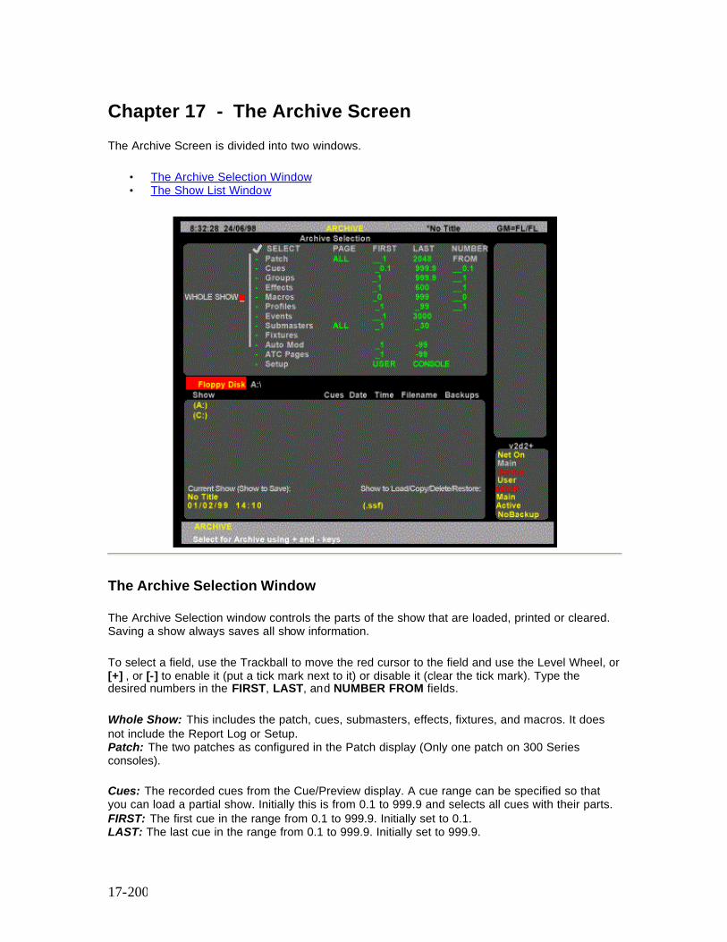
17-200
Chapter 17 - The Archive Screen
The Archive Screen is divided into two windows.
• The Archive Selection Window • The Show List Window
The Archive Selection Window
The Archive Selection window controls the parts of the show that are loaded, printed or cleared. Saving a show always saves all show information.
To select a field, use the Trackball to move the red cursor to the field and use the Level Wheel, or [+] , or [-] to enable it (put a tick mark next to it) or disable it (clear the tick mark). Type the desired numbers in the FIRST, LAST, and NUMBER FROM fields.
Whole Show: This includes the patch, cues, submasters, effects, fixtures, and macros. It does not include the Report Log or Setup. Patch: The two patches as configured in the Patch display (Only one patch on 300 Series consoles). Cues: The recorded cues from the Cue/Preview display. A cue range can be specified so that you can load a partial show. Initially this is from 0.1 to 999.9 and selects all cues with their parts. FIRST: The first cue in the range from 0.1 to 999.9. Initially set to 0.1. LAST: The last cue in the range from 0.1 to 999.9. Initially set to 999.9.
17-201
NUMBER FROM : Renumbers the specified range of cues starting with this number. This lets you load cues from other shows without erasing the same numbered cues in the current show. Groups: The recorded groups from the Group display. A group range can be specified. Initially this is from 1 to 999.9 and selects all groups. FIRST: The first group in the range from 1 to 999.9. Initially set to 1. LAST The last group in the range from 1 to 999.9. Initially set to 999.9. NUMBER FROM: Renumbers the specified range of groups starting with this number. This lets you load groups from other shows without erasing the same numbered groups in the current show. Effects: The recorded effects from the Effect display. An effect range can be specified. Initially this is from 1 to 600 and selects all effects. Individual effect steps cannot be specified, only whole effects with all their steps. FIRST: The first effect in the range from 1 to 600. Initially set to 1. LAST The last effect in the range from 1 to 600. Initially set to 600. NUMBER FROM: Renumbers the specified range of effects starting with this number. This lets you load effects from other shows without erasing the same numbered effects in the current show. Submasters: All pages of the recorded submasters from the Submaster display. A submaster range can be specified. Initially this is from 1 to the highest submaster number for the console, and selects all submasters. Individual submaster pages cannot be specified. If you select all submasters, the last 6 submasters in the recorded show will appear as the last 6 submasters on your console, regardless of how many submasters there were on the console that saved the show. FIRST: The first submaster in the range from 1 to the highest submaster number for the console. Initially set to 1. LAST: The last submaster in the range from 1 to the highest submaster number for the console. Initially set to the highest submaster number for the console Profiles: The recorded profiles from the Profile display. A profile range can be specified. Initially this is from 1 to 99 and selects all profiles. FIRST: The first profile in the range from 1 to 99. Initially set to 1. LAST: The last profile in the range from 1 to 99. Initially set to 99. NUMBER FROM Renumbers the specified range of profiles starting with this number. This lets you load profiles from other shows without erasing the same numbered profiles in the current show. Macros: The recorded macros from the Macros display. A macro range can be specified. Initially this is from 0 to 2999 and selects all macros. FIRST: The first macro in the range from 0 to 999. Initially set to 0. LAST: The last macro in the range from 0 to 999. Initially set to 999. NUMBER FROM: Renumbers the specified range of macros starting with this number. This lets you load macros from other shows without erasing the same numbered macros in the current show. Fixtures: The fixtures from the Patch display. A fixture range can be specified. Initially this is from 1 to 99 and selects all fixtures. FIRST: The first fixture in the range from 1 to 99. Initially set to 1. LAST: The last fixture in the range from 1 to 99 Initially set to 99. Auto Mod: Automod pairs from the Auto Mod Screen. You must select the complete Auto Mod Screen Setup: The configuration from the Setup Screens.
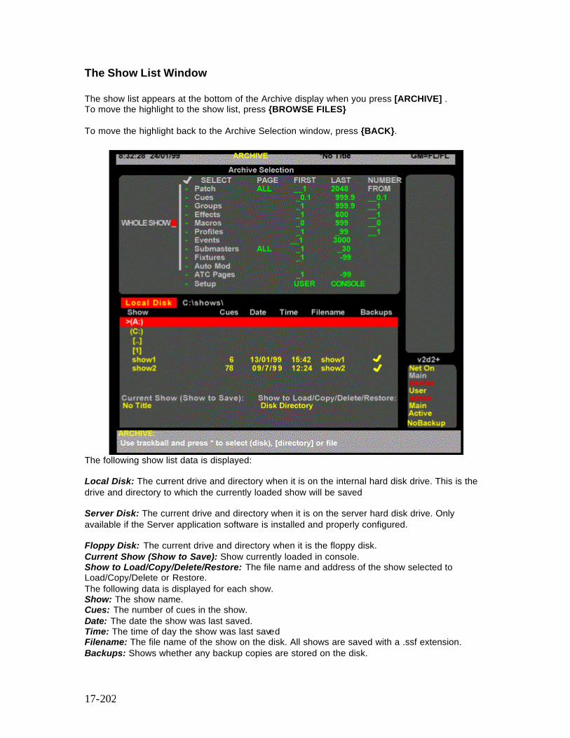
17-202
The Show List Window
The show list appears at the bottom of the Archive display when you press [ARCHIVE] . To move the highlight to the show list, press {BROWSE FILES} To move the highlight back to the Archive Selection window, press {BACK}.
The following show list data is displayed: Local Disk: The current drive and directory when it is on the internal hard disk drive. This is the drive and directory to which the currently loaded show will be saved Server Disk: The current drive and directory when it is on the server hard disk drive. Only available if the Server application software is installed and properly configured. Floppy Disk: The current drive and directory when it is the floppy disk. Current Show (Show to Save): Show currently loaded in console. Show to Load/Copy/Delete/Restore: The file name and address of the show selected to Load/Copy/Delete or Restore. The following data is displayed for each show. Show: The show name. Cues: The number of cues in the show. Date: The date the show was last saved. Time: The time of day the show was last saved Filename: The file name of the show on the disk. All shows are saved with a .ssf extension. Backups: Shows whether any backup copies are stored on the disk.

17-203
You can access all software, disk, printing and clearing operations from one of the Archive displays.
Pressing [ARCHIVE] brings up the LCD Archive menu. This shows the soft keys {SAVE SHOW}, {LOAD SHOW}, {BROWSE FILES}, {PRINT}, {CLR} and {SOFT}.
The section covers the following topics:
• Software Operations • Disk Operations • Print Operations • Clear Operations
Software Operations
Press [ARCHIVE] {SOFT} to show the LCD Software menu. This is used to load new operating and application software and to password enable the application software. Operating Software is the GeniusPro and Lightpalette operating system. Application software is any optional software which runs on the operating software, e.g., CommuniquePro, Tracker, Server, Networker, Shownet, Showport and PC Software. In this display the LCD changes to the Software menu with a number of soft keys. {SAVE PASSW}, {ENTER PASSW} {LOAD SOFT} and {BACK}. {BACK} sends you back to the LCD Archive menu.
The following topics are covered in this section:
• Password Operations • Loading Operating Software • Loading Application Software
Password Operations {SAVE PASSWORD} Allows you to save the application password to floppy disk. When you press the {SAVE PASSW} softkey, you will be prompted to insert a formatted floppy disk in the disk drive and to press the {SAVE} softkey on the Password LCD Menu. For information on formatting a floppy disk, refer to Formatting a Floppy Disk.
{ENTER PASSWORD} Entering the password enables application software. A registration form is included with the application software. Complete this including your console serial number and fax it to the Software Registration Centre at Strand Lighting UK, who will verify it and issue your password.
17-204
To find the console serial number, press [REPORT] and look at the CONS field in the System Report Screen Configuration window. This password is unique to your console with its application software and is not transferable. Keep a record of your password. If you change the password for additional application software, entering the old password will revert to the previous configuration. {ENTER PASSW} lets you enter the password. If you are not already in the Software menu, press [ARCHIVE] {SOFT}. Type in the supplied password number with no spaces or other keys then press [*]. If the password is entered incorrectly a Password 'Please Re-enter' message appears. To cancel the operation, press {BACK} . Once entered, the password cannot be displayed again. Note: A new password is sometimes rejected with incorrect ILLEGAL CONSOLE error. If this happens, press the [*] key before entering the password digits.
Loading Software
The operating software is pre-loaded at manufacture. You will need to update this software if new versions are released. For further information on how to load the operating software refer to Loading Software. The OS field in the System Report Screen Configuration window shows the operating software that is currently loaded on the console. To show this field, press [REPORT]. Note: Show files from version 2.4 software cannot be loaded into previous software versions. You must load this version of software into the console before loading the show.
Loading Application Software
You will need to load application software if you are loading additional application software (e.g., Server Software) or if you are adding channels to your console. For information on how to load application software refer to Adding Additional Channels or Applications
After you enter a password, or if the 21 day period ends, this method of loading application software will not work. Refer to Password Operations for information on how to enter and save the password.
The APPL field in the System Report Screen Configuration window shows the application software currently loaded on the console. To show this field, press [REPORT]
17-205
Disk Operations
Each time you make changes to your show they are stored in an internal hard disk drive (drive C:, the local disk), so that when you turn your console on the data is still there. You can also save copies of a show to a floppy disk for later retrieval. You can store up to 200 shows in any one local disk directory, and can store one show per floppy disk .If the Server application software is installed you will also be able to save shows to a file server. For more information refer to Server Software. When you save to the local disk, the console automatically saves any existing version of the show as a backup copy. It will save the last 10 versions of the show as backup copies so that you can easily go back to previous versions if necessary. Note: When you save a show, all data including Setup information is saved, regardless of what you check in the Archive display. The following topics are covered in this section:
• Why Save a Show? • Storing Floppy Disks • Naming the Show • Changing the Current Drive and Directory • Saving a Show • Loading a Show • Restoring or Deleting a Backup Copy of the Show • Local Disk Functions
Why Save the Show?
It’s important to save your show frequently, both to restore a show if it is lost due to disaster or equipment failure, and to retrieve information from previous versions of a show if necessary.
• Save the show to the local disk several times during a recording session. This automatically saves up to 10 backup copies of the show, and it’s as simple as pressing [ARCHIVE] {SAVE SHOW} {SAVE SHOW} .
• Save each different show in your current repertory with a different name. • Save the show you are working on to a floppy disk at the end of each recording session.
Rotate floppy disks each day so that you have a record of several days sessions. • Save archive copies at the end of a show so that you can reproduce it at some later date
if necessary.
17-206
Storing Floppy Disks
Floppy disks are your ultimate backup and archiving medium. A few precautions will ensure that the backup is there when and if you need it.
• Store floppy disks away from the console, even in a different building if possible, so that they are not damaged if the console is damaged by some external cause (fire, pipes bursting, etc.).
• Don’t store floppy disks near large magnetic sources, such as the outputs and power transformers.
• Don’t store floppy disks where there will be extreme fluctuations in temperature and/or humidity.
• Don’t leave floppy disks where they may be exposed to direct sunlight. • If you archive the show for future use, make at least two copies and store them in
different locations. • Floppy disks are not rated as an archival medium, which means that they have a lifetime
rating of less than 10 years. For important shows, make new copies of the show after each season of use, even if no changes were made to the show.
Naming the Show
Before you store your show, you should name it so that you can easily identify it when you need to load it back into the console. Press [ARCHIVE] to see the Archive display. Ensure that the required disk (local or floppy) is highlighted in red and that the correct directory is shown to the right of the highlighted disk. If you require to change directories or create a new directory, refer to Changing the Current Drive or Directory before naming the show.Type [TEXT] show name [*] entering the show name from the external keyboard. To clear a name, type [TEXT] [*]. The name you set here willl appear at the very top of each screen, to the right of the display name. Now that you have set up the show name, you can save the show as described below.
Saving a Show
When you save a show, the current show is saved in the current drive and directory. All data, including the setup, is saved. Before you save a show, ensure that the correct disk and directory that the show will be saved into is shown in the Local Disk/Floppy Disk field above the show list. If you require to change the drive or directory, proceed as described below, before saving the show. To save a show to the current drive and directory, press [ARCHIVE] to display the Archive Screen, if it is not already displayed then press {SAVE SHOW} and press {SAVE SHOW} to confirm action or [CLR] or [UNDO] to cancel.

17-207
Note: Some show files are too big to fit on the floppy disk. At DOS, use the msbackup command to create a compressed backup of the file on a new floppy. Select the show file as the file to backup, and do a full backup. You must use msbackup to restore the file from floppy. Or you can connect a ZIP drive to the parallel printer port, and add the necessarydevice driver line to the USEREXEC.BAT file (not AUTOEXEC.BAT).
Changing the Current Drive and Directory
Shows are always saved to the current drive and directory. The first time you turn on the console the current drive is set to Floppy Disk (drive A:) if there is a disk in the floppy disk drive. Otherwise it is set to Local Disk. The console saves to the current drive and directory setting when you shut down and tries to use the same drive or directory when you turn the console on again.
If the current drive was set to Floppy Disk when you shut down, and there is no disk in the floppy disk drive when you turn the console on again and open the Archive display, the current drive is reset to the last local disk directory you used.
1. Press [ARCHIVE] {BROWSE FILES} to get to the LCD Browse menu. This menu lets you select where you want the console to save shows to and load, copy, delete, and restore shows from.
2. Use the Trackball or mouse to highlight a drive or directory. To change to the parent directory of the current directory, highlight [..].
Press [*] to select the drive or directory. The new drive and directory appear in the Local Disk/Floppy Disk field above the show list. Before saving a show to a different drive or directory, set up the required drive and directory as follows:
1. Press [ARCHIVE] {BROWSE FILES} to see the LCD Browse menu. 2. Switch to the drive and directory that you want to save to, as described above. 3. Press {BACK} to return to the LCD Archive menu. 4. Name the show, if it is a new show (refer to Naming the Show) 5. Press {SAVE SHOW} to request the save. You will be asked to confirm this action. 6. Press {SAVE SHOW} to save the show or [CLR] or [UNDO] to cancel the operation.
Now that you have set up the show name and the destination, you can use [ARCHIVE] {SAVE SHOW} {SAVE SHOW} to save the show periodically to the default drive. Note: When you save a show, all data including Setup information is saved, regardless of what you check in the Archive display.

17-208
Loading a Show
You can store and load shows from floppy disk or local disk. Storing a show on floppy disk is a good way to transfer shows between consoles or store a copy in another location. Note: Show files from this version of operating software cannot be loaded into previous versions. Before loading the software, ensure that version 2.4 software is loaded in the console or PC. Storing a show on the local disk is also a convenient and quick way to save and retrieve shows that you use often. If you are running shows in repertory you can easily retrieve the correct show for the day. To load a show proceed as follows:
1. Press [ARCHIVE] to get to the LCD Archive menu. 2. If you don’t want to load the whole show, use [-] to turn the WHOLE SHOW field off.
Then use the Trackball or mouse to highlight each item you want to load and use [+] to turn its SELECT field on. Type the desired numbers in the FIRST, LAST, and NUMBER FROM fields as desribed under The Archive Selection Window.
3. Press {BROWSE FILES} to get to the LCD Browse menu. 4. Switch to the drive and directory containing the show you want to load as described
under Changing the Current Drive and Directory . 5. Use the Trackball to highlight the show. 6. Press [*] to request the load. You will be asked to confirm this action. 7. Press [*] again to load the show or [CLR] or [UNDO] to cancel the operation.
Once you load a show, if you don’t change the current drive and directory you can use [ARCHIVE] {SAVE SHOW} {SAV E SHOW} to save the show periodically to the same drive and directory.
Restoring or Deleting a Backup Copy of the Show
Each time you save the show to the local disk it makes a backup copy of the show. The console automatically saves the last 10 copies of the show. (Only one backup is saved for 300 Series consoles). You can restore, or delete a particular backup copy of a show as follows:
1. Press [ARCHIVE] to get to the LCD Archive menu. 2. If you don’t want to load the whole show, use [-] to turn the WHOLE SHOW field off.
Then use the Trackball, or mouse to highlight each item you want to load and use [+] to turn its SELECT field on. Type the desired numbers in the FIRST, LAST, and NUMBER FROM fields, as described under The Archive Selection Window. You cannot delete parts of a show.
3. Press {BROWSE FILES} to get to the LCD Browse menu. 4. Switch to the drive and directory containing the show you want to restore, as described
under Changing the Current Drive and Directory . 5. Use the Trackball, or mouse to highlight show name. 6. Press {BACKUP VIEW} to see a list of backup copies for the selected show. 7. Use the Trackball, or mouse to highlight the backup version you want to load or delete.
17-209
8. Press {LOAD BACKUP} to request the load, or {DELETE} to delete the backup version.You will be asked to confirm this action.
9. Press {LOAD BACKUP} again to load the backup or {DELETE} again to delete the backup copy, or [CLR] or [UNDO] to cancel the operation.
10. The selected backup copy of the show will be loaded/deleted. Depending on the size of the show, loading the show may take some time.
Note: Once you load a show, if you don’t change the current drive and directory you can use [ARCHIVE] {SAVE SHOW} {SAVE SHOW} to save the show periodically to the same drive and directory.
Local Disk Functions
Although shows are saved by default to the “shows” directory on the local disk, you can add directories, change them for saving shows, and delete directories and shows as needed to help you organize your shows. You can have up to 200 directories on your local disk, and can save up to 200 shows per directory, depending on the capacity of the local disk and the size of your shows. Remember that each backup copy of a show counts as one copy of the show. The console already has a directory on the local disk called “Shows,” where the shows are most commonly stored. The topics covered in this section are as follows:
• Creating a Local Disk Directory • Copy a Show • Delete a Show from the Local Disk • Delete a Local Disk Directory • Formatting a Floppy Disk • Write Protecting the Floppy Disk
Create a Local Disk Directory
You can create a subdirectory within the current directory by using the {MAKE DIR} key. You may want to do this to help organize your show database and save similar shows in separate directories.
Press [ARCHIVE] {BROWSE FILES} to get to the LCD Browse menu.
1. If you want to create a subdirectory in a directory other than the current directory, change to the desired directory.
2. Press {MAKE DIR}. 3. Type the new directory name from the external keyboard. It must follow standard MS/PC-
DOS 8.3 file name rules, i.e., up to 8 alphanumeric characters and _ (underscore), e.g., show_12 (Do not use spaces, dots or the following characters (* ? - \ /)
4. Press ENTER on the keyboard. You will be asked to confirm this action.
17-210
5. Press ENTER on the keyboard to create the new directory or [CLR] or [UNDO] to cancel the operation.
Copy a Show
You can copy a show from any drive or directory to any other drive or directory. This feature lets you copy files directly between two locations without the need to load them as the current show.
1. Press [ARCHIVE] {BROWSE FILES} to get to the LCD Browse menu. 2. Switch to the drive and directory containing the show you want to copy as described
under Changing the Current Drive and Directory. 3. Use the Trackball or mouse to highlight the show. 4. Press {COPY SHOW} to request the copy. You will be asked to select a destination
directory. 5. Select the destination drive and directory, or create a new directory as described under
Create a Local Disk Directory. 6. Ensure that the name of the target disk and directory is displayed alongside the
highlighted field LOCAL DISK or FLOPPY DISK. 7. Press {COPY SHOW} 8. You will be asked to confirm this action. Press {COPY SHOW} again to copy the show to
the selected directory or [CLR] or [UNDO] to cancel the operation.
Delete a Show from the Local Disk
You can delete a show from the local disk by using the {DELETE} key. This deletes the show and all of its backups. You may wish to copy the show to a floppy disk before you delete it from the local disk.
1. Press [ARCHIVE] {BROWSE FILES} to get to the LCD Browse menu. 2. Switch to the drive and directory containing the show you want to delete, as described
under Changing the Current Drive and Directory.. 3. Use the Trackball, or mouse to highlight the show. 4. Press {DELETE} to request the delete. You will be asked to confirm this action. 5. Press {DELETE} to delete the show or [CLR] or [UNDO] to cancel the operation.
Delete a Local Disk Directory
You can delete a directory on the local disk by using the {DELETE} key. The directory must be empty before you can delete it.
1. Press [ARCHIVE] {BROWSE} to get to the LCD Browse menu. 2. Switch to the directory you want to delete and make sure all shows in it are deleted. You
may wish to copy the shows to floppy disk before deleting them. 3. Switch to the parent directory of the directory you want to delete, as described under
Changing the Current Drive and Directory...
17-211
4. Use the Trackball, or mouse to highlight the directory you want to delete. 5. Press {DELETE} to request the delete. You will be asked to confirm this action. 6. Press {DELETE} to delete the directory or [CLR] or [UNDO] to cancel the operation. 7. If a mesage is displayed saying that the directory is not empty, there may be backup
copies of the show that have not been deleted. Refer to Restoring or Deleting a Backup Copy of the Show to delete all backup copies, then reselect the directory and press {DELETE} {DELETE}
Formatting a Floppy Disk
Before using a floppy disk, it must be formatted. To save time you can use preformatted floppy disks compatible with MS/PC-DOS (either 720Kb or 1.44Mb disks). If you need to format your own floppy disks, follow the procedure below, which formats a 1.44Mb disk. You cannot format a 720Kb disk with on this console, though you can use pre-formatted 720Kb disks.
Note: This procedure will erase any data already on the floppy disk.
1. Press [ARCHIVE] {BROWSE FILES} to get to the LCD Browse menu. 2. Insert the floppy disk. 3. Press {FORMAT FLOPPY} to request formatting. You will be asked to confirm this
action. 4. Press {FORMAT FLOPPY} to start the format operation or [CLR] or [UNDO] to cancel
the operation.
A progress indicator appears while the console is formatting the disk.
Write Protecting the Floppy Disk
After saving, the floppy disk can be write protected by moving the write protect tab so that the hole is open. This stops it being accidentally formatted or overwritten by another save.
Print Operations
The Print display lets you configure your printer and print show information. Although you can use the Print Screen macro [SHIFT] [P1] to print the current contents of all screens (1 screen per page), the archive print functions are provided for printing whole cues and shows.
Pressing [ARCHIVE] {{PRINT} shows the Print display and the LCD Print menu.
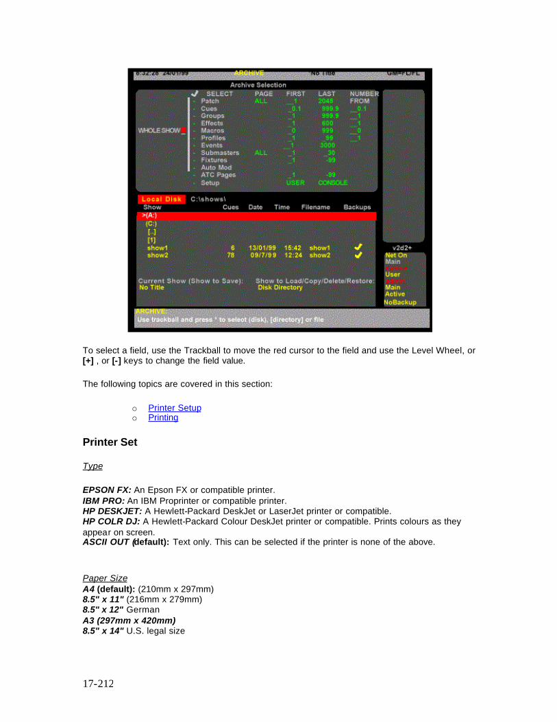
17-212
To select a field, use the Trackball to move the red cursor to the field and use the Level Wheel, or [+] , or [-] keys to change the field value.
The following topics are covered in this section:
o Printer Setup o Printing
Printer Set
Type
EPSON FX: An Epson FX or compatible printer. IBM PRO: An IBM Proprinter or compatible printer. HP DESKJET: A Hewlett-Packard DeskJet or LaserJet printer or compatible. HP COLR DJ: A Hewlett-Packard Colour DeskJet printer or compatible. Prints colours as they appear on screen. ASCII OUT (default): Text only. This can be selected if the printer is none of the above.
Paper Size A4 (default): (210mm x 297mm) 8.5" x 11" (216mm x 279mm) 8.5" x 12" German A3 (297mm x 420mm) 8.5" x 14" U.S. legal size
17-213
14.5"x 11" Computer fanfold paper (132 column) 11" x 17" U.S. tabloid (B) size Port Sets the parallel port that the printer is connected to. LPT1 (default) Printer connected to the first parallel port. This is marked PRINTER on the rear of the console. FILE Will print to a file on the local disk. The file is put in the SHOW subdirectory, and its name is based on the current show name with a .txt extension. Net Node Sets the location of the printer to Local or the specified Network Node Local (Default) The main console Network Node Name Alternative printer location
Printing
From the Print display you can print all or part of the show by pressing the {PRINT SHOW} softkey. In addition, by using {DIMMER LOG}, {STATUS LOG} or {NOTES} you can print the contents of the Dimmer Log or the Status Log, or the Notes pages. Since the default printer is ASCII, you should be able to print without selecting a specific printer. However, for the best possible printouts with your printer, you should set the printer type first.
1. Press [ARCHIVE] {PRINT} to show the Print display. 2. Use the Trackball, or mouse to highlight the Type field in the Printer Setup window. 3. Use the Wheel to select a printer type compatible with the printer connected to your
system. If you are not sure which printer type will work best, try printing few cues with each printer setting.
4. If you are printing a show, select the parts of the show to print from the Archive Selection window, or select Whole Show . Use the Trackball, or mouse, to move the red highlight and [+] or [-] to select or clear the parts to load. Type the desired numbers in the FIRST, LAST, and NUMBER FROM fields.
5. Select the channels you want to print. You can select a range of channels in use and a range of channels not in use that you want to print. Channels in use are channels that are used in any cue, group, effect, or submaster, not just channels in cues, and includes intensity and attribute channels.
6. Select the printing options you want. Press {PRINT SHOW}, {DIMMER LOG}, {STATUS LOG} or {NOTES} to start printing.
7. To cancel printing while it is in progress, press {STOP}. To go back to the LCD Archive menu press {BACK}.
While the console is printing, a Print Operation % Complete message shows printing progress from 0% to 100%. {PRINT SHOW} prints all of the items you checked in the Archive Selection window. Printing options available for this print mode are:
Print Channels Includes channel levels for each item. Add Attributes lets you print channel attributes as well as intensities. Level Changes Only prints only items with changes in them.
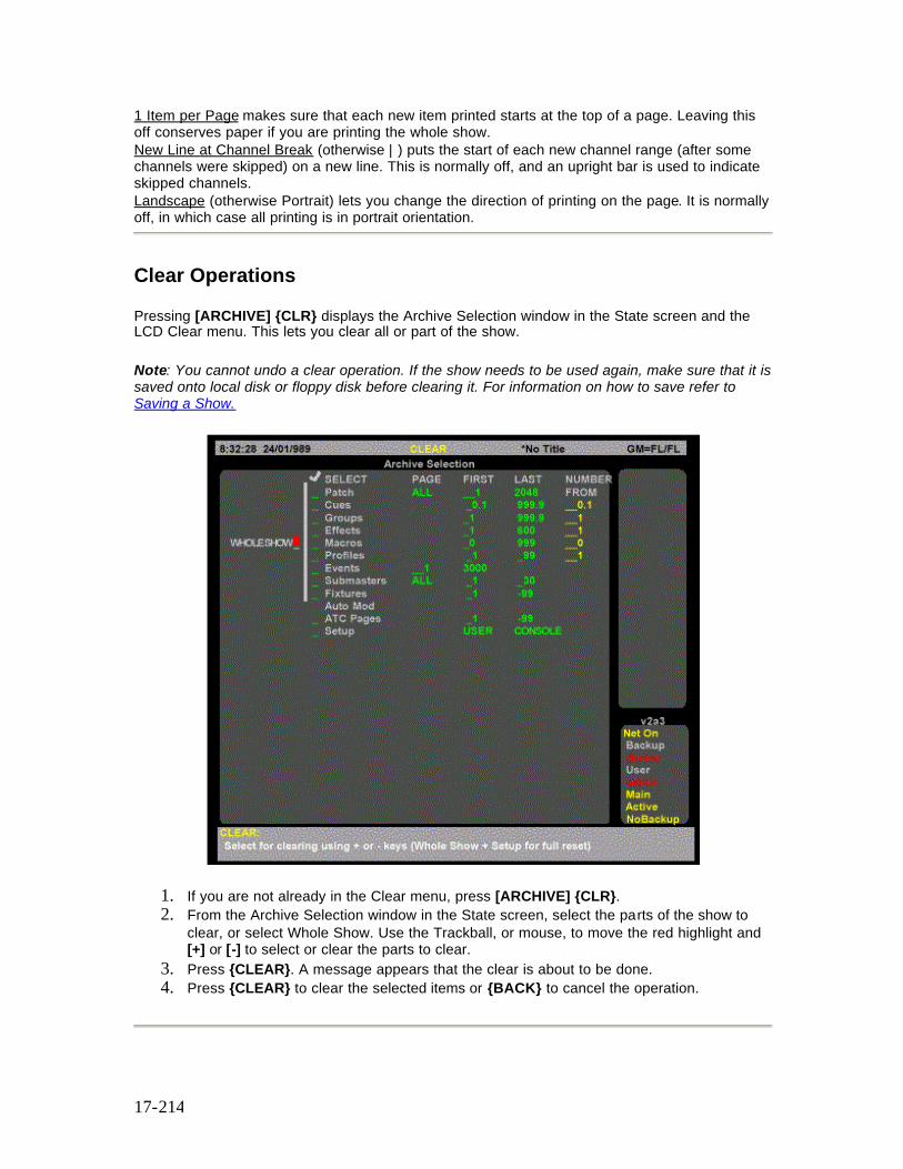
17-214
1 Item per Page makes sure that each new item printed starts at the top of a page. Leaving this off conserves paper if you are printing the whole show. New Line at Channel Break (otherwise | ) puts the start of each new channel range (after some channels were skipped) on a new line. This is normally off, and an upright bar is used to indicate skipped channels. Landscape (otherwise Portrait) lets you change the direction of printing on the page. It is normally off, in which case all printing is in portrait orientation.
Clear Operations
Pressing [ARCHIVE] {CLR} displays the Archive Selection window in the State screen and the LCD Clear menu. This lets you clear all or part of the show.
Note: You cannot undo a clear operation. If the show needs to be used again, make sure that it is saved onto local disk or floppy disk before clearing it. For information on how to save refer to Saving a Show.
1. If you are not already in the Clear menu, press [ARCHIVE] {CLR}. 2. From the Archive Selection window in the State screen, select the parts of the show to
clear, or select Whole Show. Use the Trackball, or mouse, to move the red highlight and [+] or [-] to select or clear the parts to clear.
3. Press {CLEAR}. A message appears that the clear is about to be done. 4. Press {CLEAR} to clear the selected items or {BACK} to cancel the operation.
18-215
Chapter 18 - Macros
Macros let you record and then play back a regularly used sequence of commands. For example, you could record a macro with the commands to load and then run a particular cue. Running this macro will then replay all of these commands. Macros can be recorded from any display and then played back using a macro playback key or a macro playback command, or by assigning the macro to a cue or submaster. Once recorded, they can be viewed and edited in the Macro display. With the optional A4 or A3 macro tablet, you can activate up to 1600 macros using a pen or pointing device on a macro button grid placed on a Wacom Intuos or Concept 2012 A4 graphic tablet. There are up to 3000 macros numbered 0 to 2999. Each macro can contain up to 120 keys. Most keys can be recorded into a macro. Trackball movements can also be recorded, but you cannot use the wheels, faders and rotaries within a macro. You must use the numeric keypad to enter numbers. A macro cannot call another macro. This chapter contains the following topics:
• Macro Properties • Pre-Assigned Macros • Learning a Macro • Deleting a Macro • Running a Macro Manually • Running a Macro Automatically • Viewing Macros • Creating a New Macro • Editing Macros • Macro Tablet
Macro Properties
Macros have only one property which can be specified when recording or edited later. You can record a text label (caption) with each macro to help identify the macro.
In the text label for a macro, any text after an exclamation point will be sent to the Macro Trigger Output port if you have the CommuniquéPro software, the Macro Trigger Output field in the Console Setup Screen is set to On and the associated Net Node, Port, Baud and Config fields are set up correctly. Refer to ASCII Remote Control Output

18-216
Pre-Assigned Macros
There are up to 3000 macros numbered 0 to 2999. Macros 951 to 964 are reserved as macros P1 to P14. You can access these macros directly using [P1] through [P14], or through the numeric keypad as macros 951 to 964. Macros 971 to 984 are reserved as macros SP1 to SP14. You can access these macros directly using [SHIFT] [P1] through [SHIFT] [P14], or through the numeric keypad as macros 971 to 984. Keys [P8] through [P14] and [SHIFT] [P8] through [SHIFT] [P14], are available only on 520 and 300 series consoles. However you can access these macros from the keyboard on 530 and 550 consoles using 958 to 964 and 978 to 984 respectively. Macros 991 to 996 are reserved as macros LCD1 to LCD6. You can access these macros directly through the centre LCD buttons (or the first four through the four centre unlabelled keys in consoles with only 2 LCD displays), or through the numeric keypad as macros 991 to 996. Macro 998 is reserved for the USER macro. You can access this macro directly using [USER], or through the numeric keypad as macro 998. HHM1 to HHM4 are reserved for the functon keys F1 to F4 on R120, R130 Remote Handheld Units. HHM1 to HHM3 only can be fired from F1 to F3 on a Designer's Remote Hand-Held units. The twelve keys on the front of a 300 Series LCD Monitor are used to fire preset macros. The number of LCD monitors fitted is detected by the software and the preset macros reserved as follows: 1 LCD Monitor - 12 macros numbered 901 - 912 V1 - V12 2 LCD Monitors - 24 macros numbered 901 - 924 V1 - V24 3 LCD Monitors - 36 macros numbered 901 - 936 V1 - V36 4 LCD Monitors - 48 macros numbered 901- 948 V1 - V48 Note: after loading from a pre version 2.0 show file, the macro key macros may go to the wrong place as follows: Original P1-7 (macros 991-997) becomes LCD1-6 and 997 Original LCD1-6 (macros 981 -986) becomes SP11-14, 985, 986 Original SP1-7 (macros 971-977) remain the same Original USER (998) remains the same. To overcome this problem, load the whole show, then clear macros 971-997 at the Archive Clear display, then load macros 981-986 starting from 991 and macros 991-997 starting from 951.
18-217
Learning a Macro
Before a Macro can be used it must first be recorded. You can record a macro from any display by using the Learn command, or you can record or edit a macro from the Macros display.
This section shows how to use the Learn command to record a macro. Before you start recording a macro, make sure that you are in the display from which you want to play back the macro. Or make sure that the first keystroke puts you into the correct display. This is particularly important if soft keys are used in the macro since these will generally have a different effect if the macro is played in another display.
[MACRO] # {LEARN} {LEARN} or key {LEARN} {LEARN} (key represents the actual LCD key, P key, or User key). This starts recording the specified macro. Note: [MACRO] is at the bottom of the console. Do not confuse this with [MACRO] in the display keypad. {LEARN} is a soft key which appears when you press [MACRO]. Press the keys you want to record into the macro. To finish the macro recording, press [MACRO] [MACRO] . While the macro is being recorded the display prompt shows 'MACRO LEARN' in flashing red as a reminder. Note: The macro actions will be carried out while recording is in progress. Up to 120 keys can be recorded in a macro; recording automatically finishes if this limit is reached.
[MACRO] [2] [4] {LEARN} [CUE] [2] [0] [GO] [MACRO] [MACRO] Records Macro 24 to run cue 20.
Note: Macros containing [SHIFT] get stuck in shift mode, as if the key is held down permanently, e.g., [CUE][ [SHIFT] [NEXT] [RECORD]. In order to overcome this problem, add another [SHIFT] key after the key on which it operates, e..g., [CUE] [SHIFT] [NEXT] [SHIFT] [RECORD]
18-218
Deleting a Macro
Macros can be deleted from any display. This is a good way to delete macros if you are only going to delete a few. For information on how to delete all macros or a range of macros from the Archive display refer to Clear Operations
[MACRO] # {DELETE} All Modes This deletes the specified macro. You will be prompted to press the {DELETE} key a second time to confirm the deletion. {DELETE} is a soft key which appears when you press [MACRO] . [MACRO] [2] [4] {DELETE} {DELETE} All Modes Deletes macro 24.
Running a Macro Manually
Recorded macros can be started manually, linked to a submaster, or cue, run at console power-up or run at a preset time. Macros cannot be run while you are in the macro display, but they can be run from any other display. [MACRO] # [*] This runs the specified macro.
[MACRO] [2] [4] [*] All Modes Runs Macro 24.
If the macro does not exist you will get a warning beep. Any errors encountered while a macro is running are ignored, but the remainder of the macro will still run. [P1] through [P14} Shortcuts for macros 951… 964. Pressing these runs the macro the same as using [MACRO] # [*].
[P1] Runs macro 951 (P1)
Note: [P8] through [P14], and therefore the associated macros, are available only on 510 and 520 series consoles. [SHIFT] [P1] through [SHIFT] [P14] Shortcuts for macros 971… 984. Pressing these runs the macro the same as using [MACRO] # [*]. [SHIFT] [P1] Runs macro 971 (macro SP1). Note: [SHIFT] [P8] through [SHIFT] [P14], and therefore the associated macros, are available only on 510 and 520 series consoles.
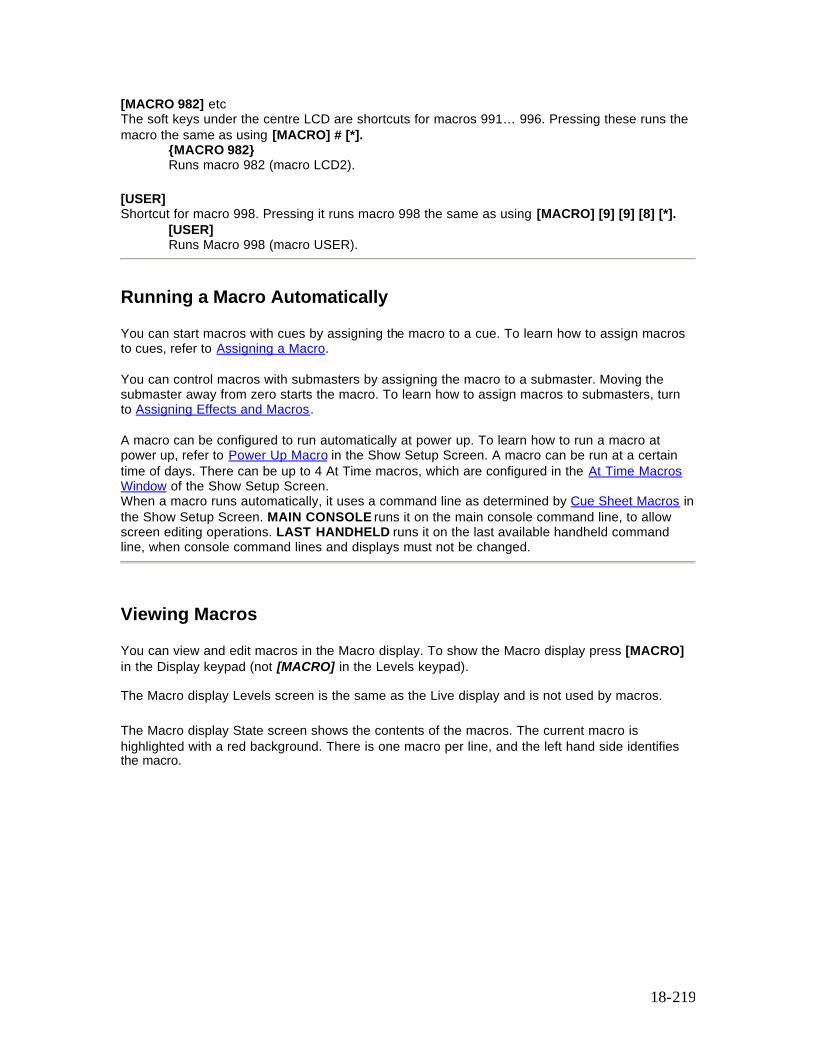
18-219
[MACRO 982] etc The soft keys under the centre LCD are shortcuts for macros 991… 996. Pressing these runs the macro the same as using [MACRO] # [*].
{MACRO 982} Runs macro 982 (macro LCD2).
[USER] Shortcut for macro 998. Pressing it runs macro 998 the same as using [MACRO] [9] [9] [8] [*].
[USER] Runs Macro 998 (macro USER).
Running a Macro Automatically
You can start macros with cues by assigning the macro to a cue. To learn how to assign macros to cues, refer to Assigning a Macro. You can control macros with submasters by assigning the macro to a submaster. Moving the submaster away from zero starts the macro. To learn how to assign macros to submasters, turn to Assigning Effects and Macros. A macro can be configured to run automatically at power up. To learn how to run a macro at power up, refer to Power Up Macro in the Show Setup Screen. A macro can be run at a certain time of days. There can be up to 4 At Time macros, which are configured in the At Time Macros Window of the Show Setup Screen. When a macro runs automatically, it uses a command line as determined by Cue Sheet Macros in the Show Setup Screen. MAIN CONSOLE runs it on the main console command line, to allow screen editing operations. LAST HANDHELD runs it on the last available handheld command line, when console command lines and displays must not be changed.
Viewing Macros
You can view and edit macros in the Macro display. To show the Macro display press [MACRO] in the Display keypad (not [MACRO] in the Levels keypad). The Macro display Levels screen is the same as the Live display and is not used by macros.
The Macro display State screen shows the contents of the macros. The current macro is highlighted with a red background. There is one macro per line, and the left hand side identifies the macro.
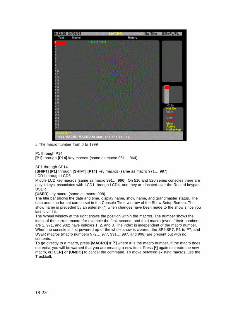
18-220
# The macro number from 0 to 1999 P1 through P14 [P1] through [P14] key macros (same as macro 951… 964). SP1 through SP14 [SHIFT] [P1] through [SHIFT] [P14] key macros (same as macro 971… 997). LCD1 through LCD6 Middle LCD key macros (same as macro 991… 996). On 510 and 520 series consoles there are only 4 keys, associated with LCD1 through LCD4, and they are located over the Record keypad. USER [USER] key macro (same as macro 998). The title bar shows the date and time, display name, show name, and grandmaster status. The date and time format can be set in the Console Time window of the Show Setup Screen. The show name is preceded by an asterisk (*) when changes have been made to the show since you last saved it. The Wheel window at the right shows the position within the macros. The number shows the index of the current macro, for example the first, second, and third macro (even if their numbers are 1, 971, and 982) have indexes 1, 2, and 3. The index is independent of the macro number. When the console is first powered up or the whole show is cleared, the SP2-SP7, P1 to P7, and USER macros (macro numbers 972… 977, 991… 997, and 998) are present but with no contents. To go directly to a macro, press [MACRO] # [*] where # is the macro number. If the macro does not exist, you will be warned that you are creating a new item. Press [*] again to create the new macro, or [CLR] or [UNDO] to cancel the command. To move between existing macros, use the Trackball.
18-221
Creating a New Macro
To create a new macro while you are in the Macro display, press [MACRO] # [*] where # is the new macro number. You will be warned that you are creating a new item. Press [*] again to create and display the new macro or [CLR] or [UNDO] to cancel the command.
To switch to the Macro display and create a new macro, press [MACRO] [MACRO] # [*] where # is the new macro number. You will be warned that you are creating a new item. Press [*] again to create and display the new macro or [CLR] or [UNDO] to cancel the command.
The [MACRO] display key is at the top of the console. Do not confuse it with the lower [MACRO] key. Creating a macro automatically puts it into edit mode.
Editing Macros
The macro contents are shown in red as the macro is being edited. [MACRO] [MACRO] puts the macro into editing mode. To start editing, select the macro with the Trackball and then press [MACRO] [MACRO]. [MACRO] # [*], [P1] or [SHIFT] [P1] or [USER] selects an existing macro and starts editing (you don’ t have to press [MACRO] [MACRO]). If the macro does not exist, it creates the macro and starts editing. Once the macro is in editing mode, keys, and Trackball movements, are recorded onto the end of the current contents. To stop recording, press [MACRO] [MACRO] Note: The actions will not be carried out while editing. You can record up to 120 keys in a macro. Editing automatically finishes if this limit is reached. [MACRO] [2] [4] [*] [CUE] [2] [0] [GO] [MACRO] [MACRO] This adds the keystrokes into macro 24 that will run cue 20. [CLR] deletes the last key while editing the macro. This key cannot be recorded into the macro while editing it although it can be recorded by [MACRO] # {LEARN}.
Macro Tablet
This section covers the following topics:
o Setting Up the Macro Tablet o Using the Macro Tablet o Fitting the Macro Tablet Template o Defining, Learning, Editing and Deleting Macro Tablet Macros
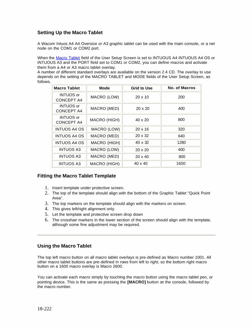
18-222
Setting Up the Macro Tablet
A Wacom Intuos A4 A4 Oversize or A3 graphic tablet can be used with the main console, or a net node on the COM1 or COM2 port. When the Macro Tablet field of the User Setup Screen is set to INTUOUS A4 INTUOUS A4 OS or INTUOUS A3 and the PORT field set to COM1 or COM2, you can define macros and activate them from a A4 or A3 macro tablet overlay. A number of different standard overlays are available on the version 2.4 CD. The overlay to use depends on the setting of the MACRO TABLET and MODE fields of the User Setup Screen, as follows.
Macro Tablet Mode Grid to Use No. of Macros INTUOS or
CONCEPT A4 MACRO (LOW) 20 x 10 200
INTUOS or CONCEPT A4 MACRO (MED) 20 x 20 400
INTUOS or CONCEPT A4 MACRO (HIGH) 40 x 20 800
INTUOS A4 OS MACRO (LOW) 20 x 16 320 INTUOS A4 OS MACRO (MED) 20 x 32 640 INTUOS A4 OS MACRO (HIGH) 40 x 32 1280
INTUOS A3 MACRO (LOW) 20 x 20 400 INTUOS A3 MACRO (MED) 20 x 40 800 INTUOS A3 MACRO (HIGH) 40 x 40 1600
Fitting the Macro Tablet Template
1. Insert template under protective screen. 2. The top of the template should align with the bottom of the Graphic Tablet "Quick Point
Area". 3. The top markers on the template should align with the markers on screen. 4. This gives left/right alignment only. 5. Let the template and protective screen drop down 6. The crosshair markers in the lower section of the screen should align with the template,
although some fine adjustment may be required.
Using the Macro Tablet
The top left macro button on all macro tablet overlays is pre-defined as Macro number 1001. All other macro tablet buttons are pre-defined in rows from left to right, so the bottom right macro button on a 1600 macro overlay is Macro 2600.
You can activate each macro simply by touching the macro button using the macro tablet pen, or pointing device. This is the same as pressing the [MACRO] button on the console, followed by the macro number.

18-223
Defining, Learning, Editing and Deleting Macro Tablet Macros
Macros assigned to the macro tablet are defined, learned, edited and deleted in the same way as macros assigned to the console. Refer to instructions contained in this section.
19-224
Chapter 19 - Profiles
Profiles let you change the fade characteristics of cues, effects, and outputs. For cues you can assign profiles separately to the up fade, down fade, and attribute fade times. For effects the profile applies to the fade up and fade down times of the effect (not an effect step). You can modify the fade characteristics of a fixture intensity by attaching a profile to the intensity output for the fixture, and modify the movement characteristics of the fixture by attaching profiles to appropriate attribute outputs.
You can modify profiles in 1% or 5% increments graphically or through the command line, or with DMX values (0-255) through the command line. When you are editing with 256 step resolution the points are displayed as coordinates rather than as a graph.
Profiles can be recorded, viewed, and edited only from the Profile display. Once recorded, they can be attached to cues , effects or outputs.
This section shows you how to create the profiles, and contains the following topics:
• Profile Properties • Predefined Profiles • Viewing and Editing Profiles • Profile Learn
o Viewing and Editing Learned Profiles o Stopping the Learn Process o Assigning Profiles o Undoing a Profile
Profile Properties
Profiles have only one property which can be specified when recording or edited later. You can record a text label (caption) with each profile to help identify the profile.
Predefined Profiles
There are 2 predefined profiles. These are:
• Profile 98 - S Curve • Profile 99 - Square
Note: You cannot delete, or edit the predefined profiles
19-225
Viewing and Editing Profiles
You can view and edit profiles in the Profile display. Since you must be in the Profile display to define profiles and to change their characteristics, there is no difference between editing and recording profiles.
This section covers the following topics:
o The Profile Display o The Current Profile o Creating Profiles o Using End Editing o Using DMX Values for Points o Using Graph Editing o Deleting a Profile
The Profile Display
The Profile Display To show the Profile display press [MORE] in the Display keypad and then press {PROF DISP}. To view a specific profile, use [NEXT], [LAST] , profile # [*] , or the Trackball, or mouse to highlight the profile number.
The Levels screen still shows the Live display when the State screen is in the Profile display. You cannot change channel levels with any of the channel control commands. However, you can use the submaster faders, X playbacks, and effect playbacks to change channels levels and record the results into submasters, cues, groups, or effect steps.
The title bar shows the date and time, display name, show name, and grandmaster status. The date and time format can be set in the Console Time window of the second Setup display State screen. The show name is preceded by an asterisk (*) when changes have been made to the show since you last saved it.
The profile graph is scaled in percentage and shows profile processor input levels across the bottom and output levels up the side. When you create a new profile it starts as a linear curve (0% in = 0% out, 50% in = 50% out, etc.).
The Current Profile
The current profile is shown with a highlight on the State screen. To change the current profile, use [NEXT], [LAST], or the Trackball or mouse to move the highlight to the appropriate profile. The highlight must be on the profile number (the Profile field) to change the current profile. You must be in the Profile display before you can use the Trackball, or mouse to change the current profile.
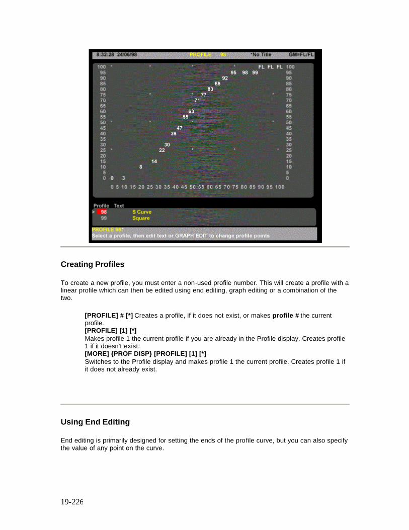
19-226
Creating Profiles
To create a new profile, you must enter a non-used profile number. This will create a profile with a linear profile which can then be edited using end editing, graph editing or a combination of the two.
[PROFILE] # [*] Creates a profile, if it does not exist, or makes profile # the current profile. [PROFILE] [1] [*] Makes profile 1 the current profile if you are already in the Profile display. Creates profile 1 if it doesn’t exist. [MORE] {PROF DISP} [PROFILE] [1] [*] Switches to the Profile display and makes profile 1 the current profile. Creates profile 1 if it does not already exist.
Using End Editing
End editing is primarily designed for setting the ends of the profile curve, but you can also specify the value of any point on the curve.
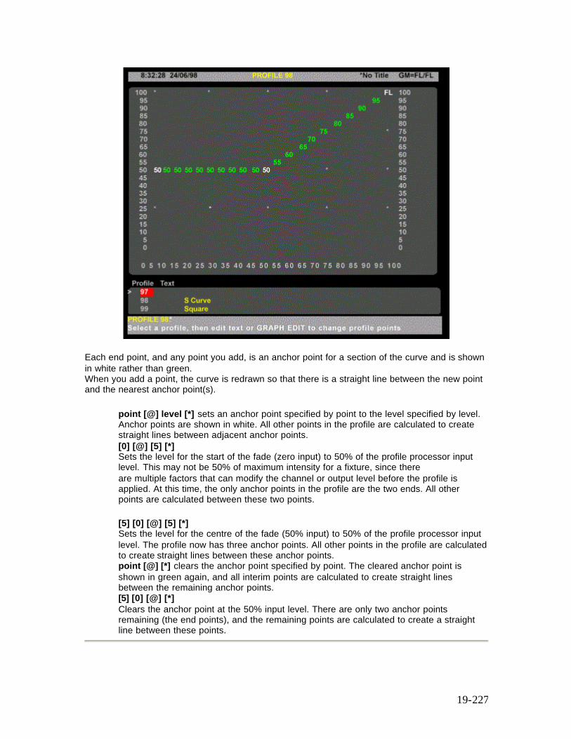
19-227
Each end point, and any point you add, is an anchor point for a section of the curve and is shown in white rather than green. When you add a point, the curve is redrawn so that there is a straight line between the new point and the nearest anchor point(s).
point [@] level [*] sets an anchor point specified by point to the level specified by level. Anchor points are shown in white. All other points in the profile are calculated to create straight lines between adjacent anchor points. [0] [@] [5] [*] Sets the level for the start of the fade (zero input) to 50% of the profile processor input level. This may not be 50% of maximum intensity for a fixture, since there are multiple factors that can modify the channel or output level before the profile is applied. At this time, the only anchor points in the profile are the two ends. All other points are calculated between these two points. [5] [0] [@] [5] [*] Sets the level for the centre of the fade (50% input) to 50% of the profile processor input level. The profile now has three anchor points. All other points in the profile are calculated to create straight lines between these anchor points. point [@] [*] clears the anchor point specified by point. The cleared anchor point is shown in green again, and all interim points are calculated to create straight lines between the remaining anchor points. [5] [0] [@] [*] Clears the anchor point at the 50% input level. There are only two anchor points remaining (the end points), and the remaining points are calculated to create a straight line between these points.

19-228
Using DMX values for Points
You can specify points and levels using DMX values rather than percent value. This lets you specify more precise curves than is possible with percent values.
point [@] {DMX} level [*] sets the anchor point specified by point to the DMX level specified by level. The anchor point can be from 0 to 100 while the level can be from 0 to 255. The display will show the nearest percent level for the specified DMX level, but the system will use the DMX level. [1] [0] [@] {DMX} [3] [0] [*] Sets the 10% point to a DMX level of 30. This shows on screen as 12%. {DMX} point # {DMX} level # [*] sets the anchor point specified by point to the DMX level specified by level. Both numbers can be any number from 0 to 255. Unlike the syntax for specifying points by percent, there is no [@] used in this command.
Since the graph view can only display 100 points and 100 levels, once you specify a point using this method for a profile, the graph view is replaced with a point list and the Graph Editing function is no longer available for that profile.
{DMX} [2] [3] {DMX} [4] [0] [*] Sets the point represented by the DMX value of 23 to a DMX level of 40. The State screen switches to a point list rather than the standard profile graph. {DMX} [2] [3] [*] Clears the above command
Using Graph Editing
Graph editing lets you use the trackball or mouse to highlight where you want to place an anchor point and then insert the point. You can move the end points this way, and easily add more points.
Each end point, and any point you add, is an anchor point for a section of the curve and is shown in white rather than green. When you add a point, the curve is redrawn so that there is a straight line between the new point and the nearest anchor point(s).
trackerball or mouse {INSERT POINT} {INSERT POINT} sets an anchor point in the profile. Anchor points are shown in white. All other points in the profile are calculated to create straight lines between adjacent anchor points. trackerball or mouse Highlights the location for the new point. The trackball or mouse moves the highlight in 5% steps. To change point values in 1% steps, use [+] and [-]. {INSERT POINT} {INSERT POINT} Inserts the point and recalculates all points between the end points and the new anchor point {DELETE POINT} {DELETE POINT} deletes an anc hor point in the profile. The profile is recalculated so that there is a straight line between the anchor points on either side of the deleted point. You cannot delete end points. They are always anchor points. trackerball or mouse Highlights the point you wish to delete. {DELETE POINT} {DELETE POINT} Deletes the point and recalculates all points between the two anchor points that were adjacent to it.
19-229
Deleting a Profile
Profiles can be deleted in the Profile display. This is a good way to delete profiles if you are only going to delete a few. For information on deleting all profiles or a range of profiles from the Archive display refer to Clear Operations in the Archive Screen
[PROFILE] # {DELETE PROF} [DELETE PROF} or [PROFILE] # {DELETE PROF} [*] or Select profile with trackball, mouse, or [NEXT] or [LAST] keys, then [DELETE PROF} {DELETE PROF} Deletes the selected specified profile.
Profile Learn You can create fade profiles for up, down and attribute fades by selecting one of the two X Playbacks, selecting a profile number and pressing the {LEARN} softkey on the Profile LCD Menu, followed by [*]. Running the next cue by pressing [GO X1] or [GO X2] or moving the appropriate X Playback fader off zero will start the profile learn process. Note: A profile ‘learned’ in this way is not permanently assigned to the cue. It is only used once, when the [GO X1] or [GO X2] key is pressed. Movement of the X Playback fader, including the Up and Down Fade Time and all movements of the fader when not on zero or 100% are used to calculate the fade profiles. Note: During learning, the Status Window will show PROFILE LEARN in flashing white text on a red background. The Playback LCD on 500 Series consoles will show the profile numbers being learned and the VGA title bar in the Profile Screen will show PROFILE PP LEARNING. [PB] [PROFILE] [5] [PB] [1] {LEARN} [*] Learns intensity and attribute profi les on X Playback 1 (All Modes) . Where 5 is the Upfade profile and attribute fade, and 5 + 1 is the Downfade profile. [PB] {PROFILE] [6] [/] [7] [PB] [2] {LEARN} [*] Learns intensity profiles on X Playback 2 (All Modes). Where 6 is the Upfade profile, 7 is the Downfade and the attribute fade is not affected. Note: If Playbacks field in the Show Setup Screen is set to Single, or Split Single and Playback 2 is selected. An error message is generated. [PB] {PROFILE] [/] [3] [PB] [1] {LEARN} [*] Learns intensity profile on X Playback 1 (All Modes). Where 3 is the Downfade profile and the Upfade and attribute profiles are unaffected.
19-230
Viewing and Editing Learned Profiles. When you have created the profile(s), you can view and edit them in the Profile Display using End Editing only, as previously described.
Stopping the Learn Process You can stop an active learn on either playback as shown: [PB] [2] [PROFILE] [PROFILE]
Assigning Profiles You can assign the same profile, or different profiles to the up fade and attribute fades and to down fades, as follows: [CUE] [8] [PROFILE] [6] [/] [7] [LOAD] Assigns the following profiles to Cue 8. Profile 6 to the Upfade, profile 7 to the down fade and uses any attribute fades, if already assigned. Loads to X1 or X2 Playback as selected. (Direct Action Modes) [LOAD] [CUE] [8] [PROLFILE] [6] [/] [7] [*] As above for Command Line Mode [CUE] [6] [@ATT] [PROFILE] [4] [LOAD] Assigns profile 4 to the attribute fade profile of cue 6 and loads to X1 or X2 Playback as selected. (Direct Action Modes) [LOAD] [CUE] [6] [@ATT] [PROFILE] [4] [*] As above for Command Line Mode
Undoing a Profile You can undo the learn action using the [UNDO] key. This will restore the profile field in the cue to the state before the learn took place. [UNDO] [PROFILE] Undoes the last profile learn action
20-231
Chapter 20 - Report Displays
Entering a channel number, cue number (or cue part) or dimmer number prior to pressing the [REPORT] key will display the Channel, Cue or Dimmer Summary Report for the channel, cue or dimmer number entered.
Pressing the [REPORT] key without pressing any other keys will display the System Report Screen and the System Report Menu on the right-hand LCD providing softkey access to all other reports and functions listed below. The System Diagnostic Menu and associated displays are designed for use by a technician during fault-finding and system testing and do not contain any user information. This chapter contains the following topics:
• The Channel Summary Screen • The Cue Summary Screen • The Dimmer Summary Screen • The System Report Menu • The System Report Screen • Advanced Setup Menu • Setting Access Rights • The Dimmer Log Screen • The System Diagnostic Menu • Exit and System Shutdown
The Channel Summary Screen
Command Syntax (a) [1][REPORT] No attribute specified. (b) [1][.][3][REPORT] Attribute specified
The channel summary screen shows the following information for the channel or channel attribute specified and is updated once per second:
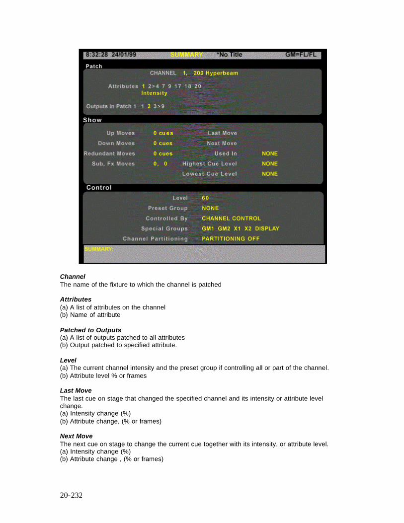
20-232
Channel The name of the fixture to which the channel is patched Attributes (a) A list of attributes on the channel (b) Name of attribute Patched to Outputs (a) A list of outputs patched to all attributes (b) Output patched to specified attribute. Level (a) The current channel intensity and the preset group if controlling all or part of the channel. (b) Attribute level % or frames Last Move The last cue on stage that changed the specified channel and its intensity or attribute level change. (a) Intensity change (%) (b) Attribute change, (% or frames) Next Move The next cue on stage to change the current cue together with its intensity, or attribute level. (a) Intensity change (%) (b) Attribute change , (% or frames)
20-233
Used in Cues The first and last cues having an effect on the selected channel. Cue Moves Up The total number of cross fade and movefade cues that increase the level of the channel. (a) Total cues which change intensity or attributes. (b) Total cues that change specified attribute. Cue Moves Down The total number of cross fade and movefade cues that decrease the level of the channel. (a) Total cues which change intensity or attributes. (b) Total cues that change specified attribute. Controlled By X PLAYBACK, FX PLAYBACK, SUBMASTER or CHANNEL CONTROL, followed by user@node, HAND HELD or blank, if not controlled. Hold Status Whether the channel or channel attribute is held, autoheld or not held Active in Special Groups List of special groups that specify the channel. GM1, GM2, X1, X2, ON, PREHEAT, DISPLAY or NONE Channel Partitioning The name of the channel partitioning group specfying the channel as user@node, or NONE or PARTITIONING OFF.
The Cue Summary Screen
Command Syntax (a) [CUE] [REPORT] No cue or part specified; uses current cue (b) [CUE] [1] [2] [3] [.] [4] [REPORT] No Part specified. Cue 0 is allowed. (c) [CUE] [1] [PART] [2] [REPORT] Part specified.
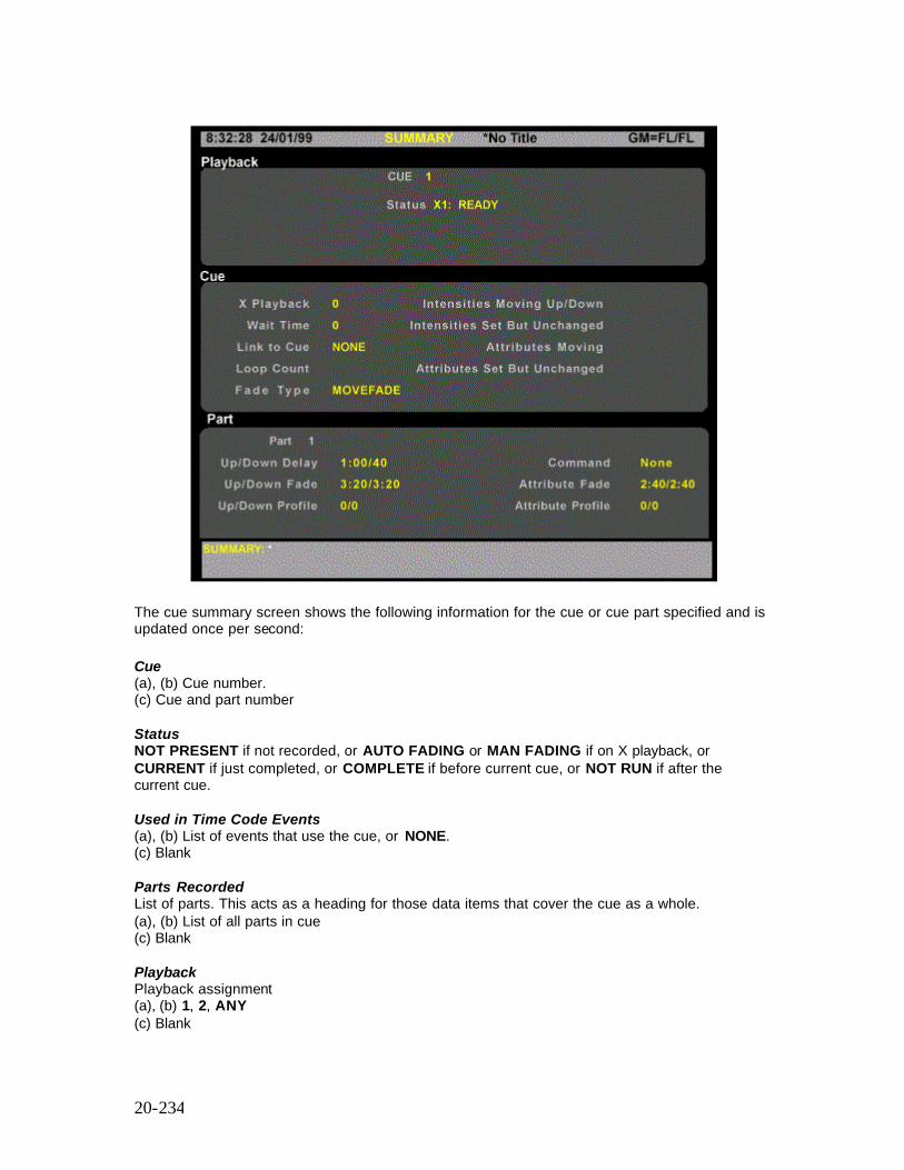
20-234
The cue summary screen shows the following information for the cue or cue part specified and is updated once per second: Cue (a), (b) Cue number. (c) Cue and part number Status NOT PRESENT if not recorded, or AUTO FADING or MAN FADING if on X playback, or CURRENT if just completed, or COMPLETE if before current cue, or NOT RUN if after the current cue. Used in Time Code Events (a), (b) List of events that use the cue, or NONE. (c) Blank Parts Recorded List of parts. This acts as a heading for those data items that cover the cue as a whole. (a), (b) List of all parts in cue (c) Blank Playback Playback assignment (a), (b) 1, 2, ANY (c) Blank
20-235
Wait Time (a), (b) Times in seconds, or blank if playback is in manual fade mode. (c) Blank Link to Cue (a), (b) Cue number (c) Blank Loop Count (a), (b) Loop count (c) Blank Intensities Moving Up/Down Total intensities moving up/down in this cue. Intensities Set but Unchanged Total intensities set to the same level as the last cue. Attributes Moving Up/Down Total attributes moving in this cue Attributes Set but Unchanged Total attributes set to same level as previous cue Part 1 Acts as a heading for the part-specific data items (a), (b) Data for first part (c) Data for selected part Fade Type (a), (b), (c) if part 1 - CROSSFADE, MOVEFADE, ALLFADE (c) if not part 1 - MOVEFADE Up/Down Delay (a), (b) Delay times in seconds, or MAN/MAN if playback is in manual fade mode. (c) Blank Up/Down Profile Profile numbes, or DEFAULT if none assigned Command MACRO #, FX START #, FX STOP #, or NONE Attribute Fade Fade time in seconds, or MAN/MAN if playback is in manual fade mode. Attribute Profile Proifile number or DEFAULT if none assigned.
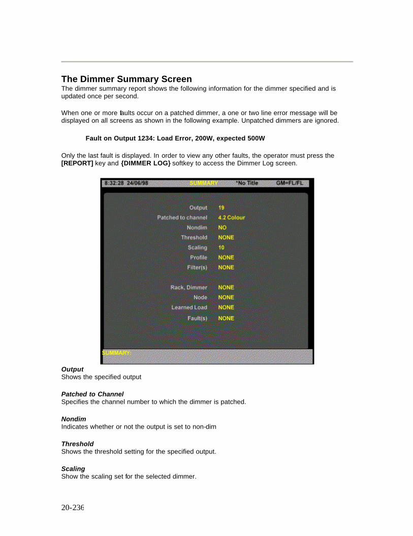
20-236
The Dimmer Summary Screen The dimmer summary report shows the following information for the dimmer specified and is updated once per second.
When one or more faults occur on a patched dimmer, a one or two line error message will be displayed on all screens as shown in the following example. Unpatched dimmers are ignored.
Fault on Output 1234: Load Error, 200W, expected 500W
Only the last fault is displayed. In order to view any other faults, the operator must press the [REPORT] key and {DIMMER LOG} softkey to access the Dimmer Log screen.
Output Shows the specified output Patched to Channel Specifies the channel number to which the dimmer is patched. Nondim Indicates whether or not the output is set to non-dim Threshold Shows the threshold setting for the specified output. Scaling Show the scaling set for the selected dimmer.
20-237
Profile Shows the output profile for the selected dimmer (if any) Filter(s) Shows fault conditions filtered out by the Console Reporter filter function. Rack, Dimmer Shows the dimmer rack associated with the selected dimmer. Node Shows the node number associated with the selected dimmer. Only applicable if Networker software is installed. Learned Load Shows the learned load for the specified dimmer (if any). Fault(s) Shows the number of faults on the specified dimmer (if any)
The System Report Menu
Pressing the [REPORT] key will display the System Report screen and display the System Report Menu on the right-hand LCD display.
The System Report Menu softkeys provide access to the Setup Screens, Dimmer Log, System Diagnostics screens and to the Exit function softkeys.
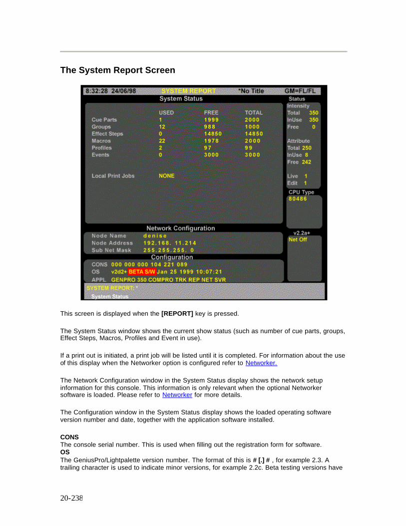
20-238
The System Report Screen
This screen is displayed when the [REPORT] key is pressed.
The System Status window shows the current show status (such as number of cue parts, groups, Effect Steps, Macros, Profiles and Event in use).
If a print out is initiated, a print job will be listed until it is completed. For information about the use of this display when the Networker option is configured refer to Networker.
The Network Configuration window in the System Status display shows the network setup information for this console. This information is only relevant when the optional Networker software is loaded. Please refer to Networker for more details.
The Configuration window in the System Status display shows the loaded operating software version number and date, together with the application software installed.
CONS The console serial number. This is used when filling out the registration form for software. OS The GeniusPro/Lightpalette version number. The format of this is # [.] # , for example 2.3. A trailing character is used to indicate minor versions, for example 2.2c. Beta testing versions have
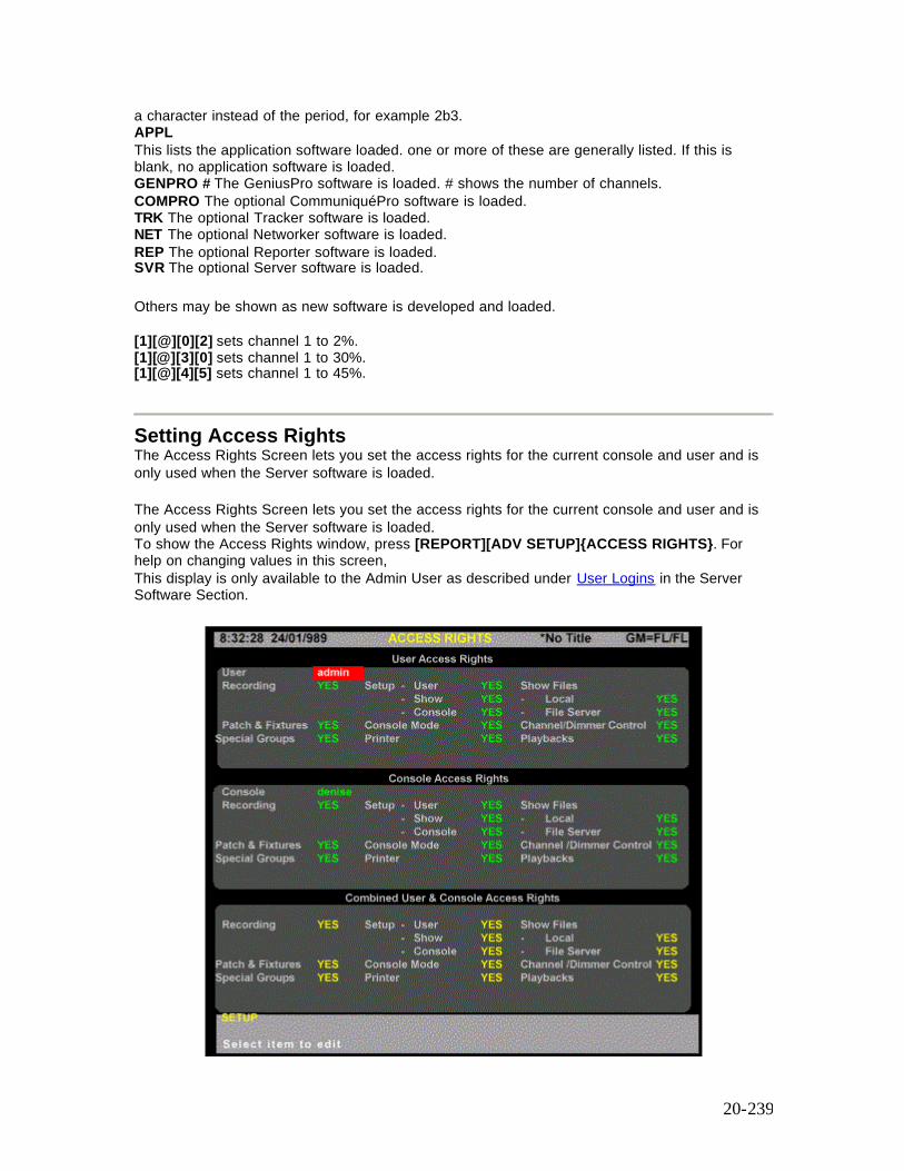
20-239
a character instead of the period, for example 2b3. APPL This lists the application software loaded. one or more of these are generally listed. If this is blank, no application software is loaded. GENPRO # The GeniusPro software is loaded. # shows the number of channels. COMPRO The optional CommuniquéPro software is loaded. TRK The optional Tracker software is loaded. NET The optional Networker software is loaded. REP The optional Reporter software is loaded. SVR The optional Server software is loaded.
Others may be shown as new software is developed and loaded. [1][@][0][2] sets channel 1 to 2%. [1][@][3][0] sets channel 1 to 30%. [1][@][4][5] sets channel 1 to 45%.
Setting Access Rights The Access Rights Screen lets you set the access rights for the current console and user and is only used when the Server software is loaded. The Access Rights Screen lets you set the access rights for the current console and user and is only used when the Server software is loaded. To show the Access Rights window, press [REPORT][ADV SETUP]{ACCESS RIGHTS}. For help on changing values in this screen, This display is only available to the Admin User as described under User Logins in the Server Software Section.

20-240
The Access Rights Screen is divided into three windows:
• User Access Rights Window • Console Access Rights Window • Combined User and Access Rights Window
User Access Rights
This window allows the Admin User to check the User Access Rights for the user who is logged on. The display shows the user name and the preset access rights for various aspects of the system as follows:
Recording: Access to record Cues, Effects, Groups, etc. YES or NO Patch and Fixtures: Access to patch channels and attributes. YES or NO Special Groups: Access to change special groups. YES or NO Setup: Access to change the setup values for User, Show and Console Setup Screens. Individual access rights for each setup screen may be set as required. YES or NO Console Mode: Printer: Show Files: Access to show files on the local console or on the file server. Individual rights can be set for local and server files. YES or NO. Channel/Dimmer Controls: Access to change the channel levels and dimmer controls. YES or NO Playbacks: Access to run the X Playbacks YES or NO
Console Access Rights
This window allows the Admin User to check the access rights of the logged on user to operate the consoles on the network. By selecting the consoles on the network using the Console field, the Admin User can set the access rights for various aspects of the system, as described above, for each console on the network. If access rights for particular aspects of the system have been set to NO, the Admin User cannot permit access to this function on any of the consoles on the network. While a user may have access to all aspects of the lighting system, the Admin User can restrict the access rights to particular consoles within the network.
Combined User and Console Access Rights
This window allows the Admin User to check the access rights of the logged on user to use the various control aspects of each console on the network. By selecting the console on the Console Field of the Console Access Rights window, the access permitted by the combination of User Access Rights and Console Access Rights is shown on the Combined User and Console Access Rights window.
Selecting the {ACCESS RIGHT} softkey displays a {MEMORY LOCK} softkey and a {BACK} softkey to return to the previous LCD display. For further information on locking the console memory see below.
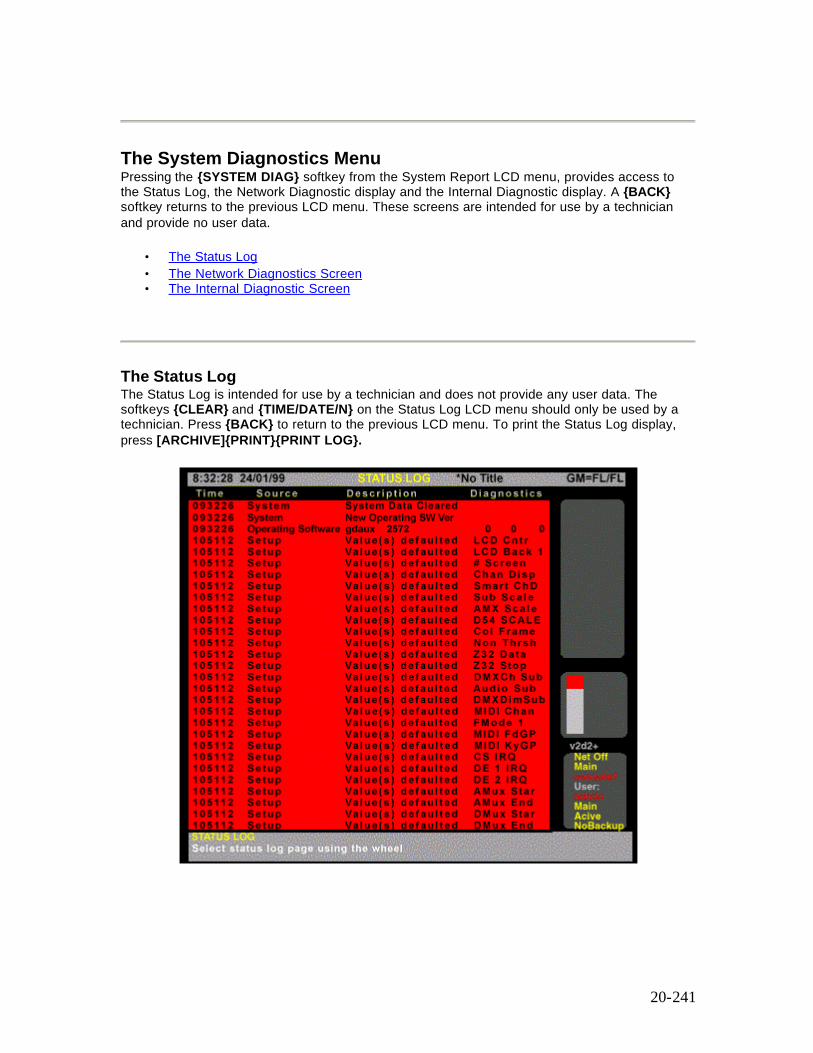
20-241
The System Diagnostics Menu Pressing the {SYSTEM DIAG} softkey from the System Report LCD menu, provides access to the Status Log, the Network Diagnostic display and the Internal Diagnostic display. A {BACK} softkey returns to the previous LCD menu. These screens are intended for use by a technician and provide no user data.
• The Status Log • The Network Diagnostics Screen • The Internal Diagnostic Screen
The Status Log The Status Log is intended for use by a technician and does not provide any user data. The softkeys {CLEAR} and {TIME/DATE/N} on the Status Log LCD menu should only be used by a technician. Press {BACK} to return to the previous LCD menu. To print the Status Log display, press [ARCHIVE]{PRINT}{PRINT LOG}.
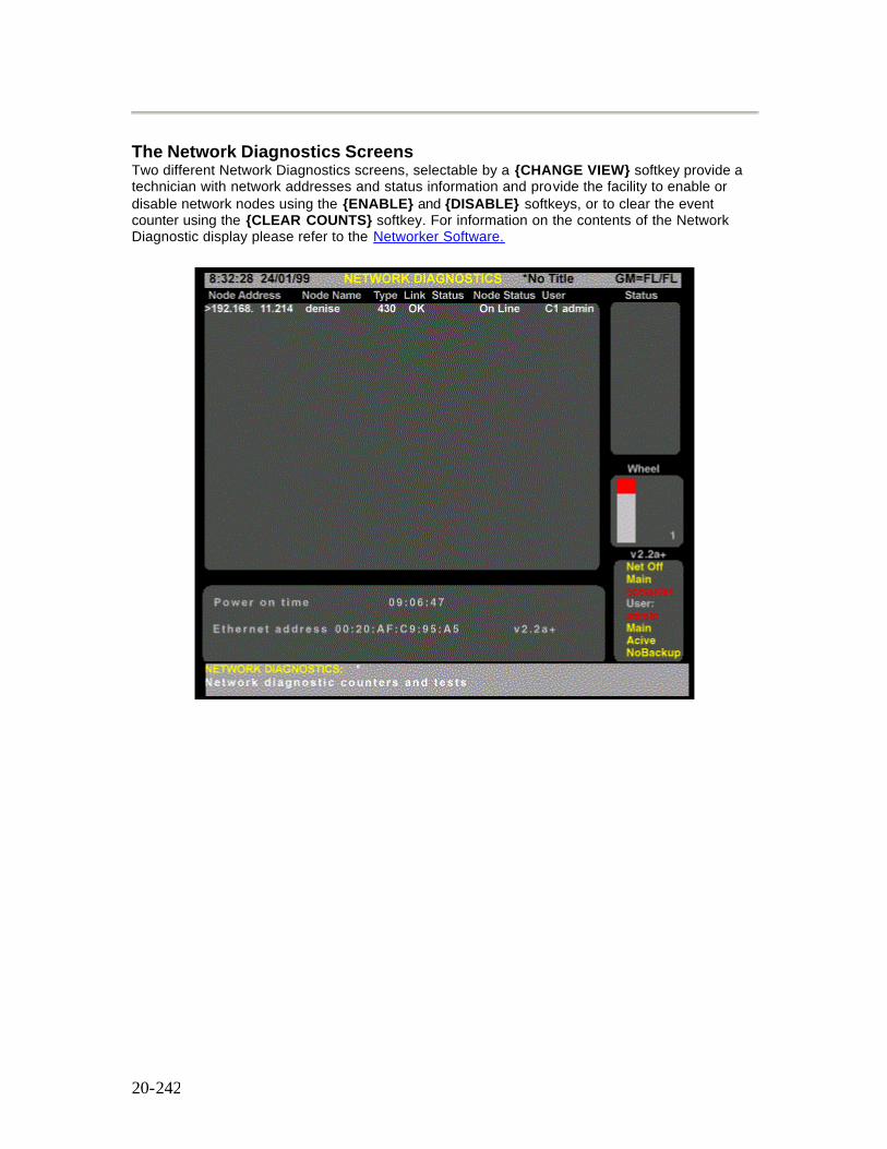
20-242
The Network Diagnostics Screens Two different Network Diagnostics screens, selectable by a {CHANGE VIEW} softkey provide a technician with network addresses and status information and provide the facility to enable or disable network nodes using the {ENABLE} and {DISABLE} softkeys, or to clear the event counter using the {CLEAR COUNTS} softkey. For information on the contents of the Network Diagnostic display please refer to the Networker Software.
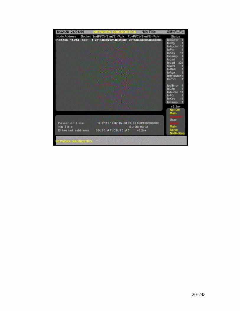
20-243
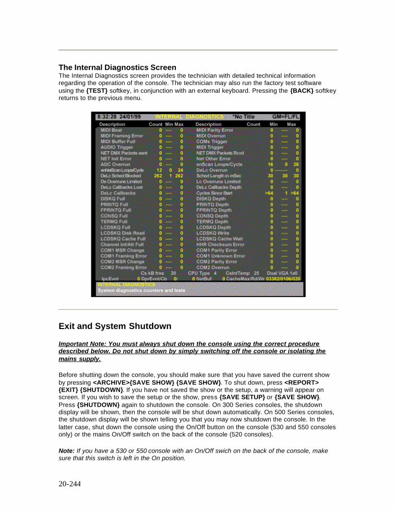
20-244
The Internal Diagnostics Screen The Internal Diagnostics screen provides the technician with detailed technical information regarding the operation of the console. The technician may also run the factory test software using the {TEST} softkey, in conjunction with an external keyboard. Pressing the {BACK} softkey returns to the previous menu.
Exit and System Shutdown Important Note: You must always shut down the console using the correct procedure described below. Do not shut down by simply switching off the console or isolating the mains supply. Before shutting down the console, you should make sure that you have saved the current show by pressing <ARCHIVE>{SAVE SHOW} {SAVE SHOW}. To shut down, press <REPORT> {EXIT} {SHUTDOWN}. If you have not saved the show or the setup, a warning will appear on screen. If you wish to save the setup or the show, press {SAVE SETUP} or {SAVE SHOW}. Press {SHUTDOWN} again to shutdown the console. On 300 Series consoles, the shutdown display will be shown, then the console will be shut down automatically. On 500 Series consoles, the shutdown display will be shown telling you that you may now shutdown the console. In the latter case, shut down the console using the On/Off button on the console (530 and 550 consoles only) or the mains On/Off switch on the back of the console (520 consoles). Note: If you have a 530 or 550 console with an On/Off swich on the back of the console, make sure that this switch is left in the On position.

20-245
You can shutdown and restart the console using the {EXIT & RESTRT} softkey Server Software Installed If the optional Server software is installed and User Logins are enabled, you can log out as the current user by pressing {LOGOUT} {LOGOUT} which will display the LOGIN Screen giving you the opportunity to either shutdown the console using the {SHUTDOWN} softkey or for another user to login using the {LOG IN} softkey. Refer to Server Software.
21-245
Chapter 21 - Console Reporter
Console Reporter is a standard software package for use with Strand's 500 and 300 Series consoles and GeniusPro and Lightpalette software. It is used to monitor and report temperature, electronic status and system and load information for all SV Series dimmers. This facility allows the user to know the status of all lamps on a rig and to record rack-based backup cues simply and easily.
The following topics are covered in this section:
• Setting Up the Rack Configuration • Dimmer Fault Reporting • Dimmer Command Menu • Dimmer Log Screen • Output Filter Display • Recording a Dimmer Backup Scene
Setting Up the Rack Configuration
The configuration of the dimmer racks is set up in a file called ‘220RACK.CFG’ which can be edited. The file 220RACK.CFG determines the configuration of each dimmer rack, and must be edited for each console:
To set up and edit the Reporter Rack Configuration file, press the <MORE>key and select the {NOTES DISP} soft key to display the Notes Menu, then select {LOAD FILE} then {CONF FILES} and {RACK CONFIG}.
The user can setup and edit the rack configuration file, (220RACK.CFG) using the Notes editor to set up the rack
RACK=RACK_NUM ADDR PORT NODE where RACK_NUM = 1 to 99 ADDR = SMX rack processor address 1 to 250 PORT = COM1, COM2, 4AUX1, 4AUX2, 4AUX3 NODE = IP address of SN10x (xxx.xxx.xxx.xxx). A node address of 0.0.0.0. is interpreted as the local console.
At start up, Reporter will automatically interrogate all configured racks to determine the mapping between rack and dimmer id to console output. This configuration is used when reporting any subsequent dimmer faults.
21-246
Dimmer Fault Reporting
The optional software, if enabled by the password, may be toggled On or Off in the Reporter On/Off field of the Communications window of the Console Setup Screen
Note: Reporter may be used in conjunction with Networker by setting Networker ‘On’ in the Console Setup Display (refer to Networker Software)
When one or more faults occur on a patched dimmer, a one or two line error message will be displayed on all screens as shown in the following example. Unpatched dimmers are ignored.
Fault on Output 1234: Load Error, 200W, expected 500W
Only the last fault is displayed. In order to view any other faults, the operator must press the [REPORT] key and {DIMMER LOG} softkey to access the Dimmer Log screen.
In addition, in order to draw the operator’s attention to the fault condition, the word Dimmer! is displayed in red on the top line of the Status screen.
The error message is removed from the current display on the next key press, however, the Dimmer ! warning remains on the Status screen until the operator enters the Dimmer Log screen.
Note: When the Channel Screen is displayed, and one or more dimmer faults exist, the channel number to which the faulty dimmer is patched will be highlighted in red.
Dimmer Command Menu
Pressing the [DIMMER] key will display the Dimmer softkey menu as follows:
Note: The [DIMMER] menu can be selected from any display except Setup, Archive, Notes, Report and Help.
{RE-PATCH} Re-patches all dimmers patched to each channel (or range) specified on the command line. (Refer to Direct Output Control) {UN-PATCH} Un-patches all dimmers patched to each channel (or range) specified on the command line. (Refer to Direct Output Control) {AT CHAN} Specifies that the number following in the command line is a channel number rather than a dimmer number.
Note: The {AT CHAN} softkey enables the operator to address dimmer command line entries to channels patched to dimmers, without knowing the dimmer numbers.
21-247
{BACKUP} Enables a dimmer backup scene to be recorded. In the event of a major failure, the dimmer backup condition can then be set manually at the dimmer rack. The following examples show how to set a backup scene for a dimmer rack.
[RECORD] [DIMMER] {BACKUP} [8] [*] (Command line) [DIMMER] {BACKUP} [8] [RECORD] (Direct digit) Records backup scene 8 for all racks.(1-99 recordable) [RECORD] [DIMMER] {BACKUP} [8] [TIME] [5]*(Command line) [DIMMER] {BACKUP} [8] [TIME] [5] [RECORD] (Direct digit) Records backup scene 8 and sets fade time of 5 seconds. [GOTO] [DIMMER] {BACKUP}#[*] Instructs all dimmer racks to fade the backup scene # in the recorded fade time. (1-99 user recordable, 0 = blackout, 254 = fully on)
dimmer{FILTER} Displays a softkey menu enabling the operator to determine which fault types will be displayed on the Dimmer Filter display.
Note: The commands shown below are used to set up the format of the Dimmer Filter display. No action is taken until the {DIMMER FILT} softkey is selected from the Dimmer Log screen.
{HIGH DC} {OVERLOAD} {OVERHEAT} {OUTPUT ERROR} {LOAD LIMIT} {TRIP}
Note: By default, the filter status of all fault types is Off, e.g., no filtering, or all fault conditions displayed on the Dimmer Filter display. When one or more of the above softkey commands are included in the command line, the fault type is inhibited from the Dimmer Filter display. To re-instate a fault type, include the command [-] before the softkey, as shown.
[DIMMER] [2] [3] [4] [5] {FILTER} {OVERLOAD} {OVERHEAT} [-] {HIGH DC} [*] Sets Overload and Overheat filter On (not displayed) and resets the High DC filter Off (displayed) for faults on dimmer number 2345 [DIMMER] [AT CHAN] [2] [THRU] [5] {FILTER} {OUTPUT LIMIT} {LOAD LIMIT} [*] Sets Output Limit and Load Limit filter On (not displayed) for faults on dimmers patched to channels 2 to 5. [DIMMER] [2] [3] [4] [5] [THRU] [2] [3] [5] [0] [SHIFT] [FILTER] [*] Sets all filters of dimmers 2345 to 2350 to On (all fault displays inhibited in range) [DIMMER] [1] [FILTER] [*] Sets all filters of dimmer 1 to Off, such that all fault conditions on dimmer 1 are displayed. [DIMMER] [2] [3] [4] [5] [REPORT] Shows the summary display for dimmer 2345. [DIMMER] [AT CHAN] [1] [2] [3] [4] [REPORT] Shows the summary display for the first dimmer patched to channel 1234.
Note: Dimmer Filter settings cannot be printed
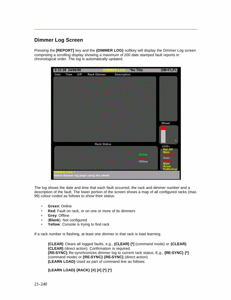
21-248
Dimmer Log Screen
Pressing the [REPORT] key and the {DIMMER LOG} softkey will display the Dimmer Log screen comprising a scrolling display showing a maximum of 200 date stamped fault reports in chronological order. The log is automatically updated.
The log shows the date and time that each fault occurred, the rack and dimmer number and a description of the fault. The lower portion of the screen shows a map of all configured racks (max. 99) colour-coded as follows to show their status:
• Green: Online • Red: Fault on rack, or on one or more of its dimmers • Grey: Offline • (Blank): Not configured • Yellow : Console is trying to find rack
If a rack number is flashing, at least one dimmer in that rack is load learning.
{CLEAR} Clears all logged faults, e.g., {CLEAR} [*] (command mode) or {CLEAR} {CLEAR} (direct action). Confirmation is required. {RE-SYNC} Re-synchronizes dimmer log to current rack status. E.g., {RE-SYNC} [*] (command mode) or {RE-SYNC} {RE-SYNC} (direct action) {LEARN LOAD} Used as part of command line as follows: {LEARN LOAD} {RACK} [#] [#] [*] [*]
21-249
Learns load on specified rack number {LEARN LOAD} [DIMMER] [#] [#] [#] [#] [*] [*] Learns load on specified dimmer number {LEARN LOAD} [DIMMER} {AT CHAN} [#] [#] [#] [#] [*] [*] Learns load at specified channel number. {LEARN LOAD} [DIMMER] {AT CHAN} [#] [#] [#] [#} [*] [*] Learns loads on all dimmers on the specified channel number. {RACK} Allows selection of Rack, as above. {OUTPUT FILT} Displays Output Filter screen {BACK} Returns to previous menu
Output Filter Display
You can filter out particular fault conditions, such that Reporter will ignore the filtered fault for the output specified. By default, all dimme faults are reported.
You can filter out fault reporting using the [DIMMER] key to display the Dimmer Softkey Menu and the {FILTER} softkey to display the Dimmer Filter Softkey Menu. Using the softkeys as part of a command, enables you to filter out specific fault conditions for an output or range of outputs. The following filter softkeys are available:
{HIGH DC} {OVERLOAD} {OVERHEAT} {OUTPUT ERROR} {LOAD LIMIT} {TRIP}
The following shows examples of the filter function:
[DIMMER] [6] {FILTER} {OUTPUT ERROR} [*]
Filter out any output fault reports for output 6 (All Modes)
[DIMMER] [1] [THRU] [5] {FILTER} {HIGH DC} {OVERHEAT [*]
Filters out any high DC fault and overheat reports for outputs 1 to 5 (All Modes).
[DIMMER] [6] [SHIFT] {FILTER} [*]
Inhibits all reporting for output 6 (All Modes)
[DIMMER] [6] {FILTER} [*]
Removes all filters from output 6 (All Modes)
Note: Alternatively, you can remove some of the filters from an output, while retaining others, by using the [-] key, as shown:
[DIMMER] [6] {FILTER} [-] {LOAD LIMIT} [*]
Removes the load limit filter from output 6 (All Modes)
Pressing <REPORT> {DIMMER LOG} {OUTPUT FILT} shows the Output Filter screen. This screen shows a list of fault types that have been filtered out for particular outputs. The output
21-250
numbers are listed down the left -hand column and filtered out faults for each output are indicated by a yellow tick under the particular fault type.
Recording a Dimmer Backup Scene
This Reporter feature enables a backup scene to be recorded. In the event of a major failure, the dimmer backup scene can then be set manually from the dimmer rack. Up to 99 different backup scenes can be recorded. The following examples show how to set a backup scene for a dimmer rack:
[DIMMER] {BACKUP} [8] [RECORD]
Records the dimmer backup scene 8 for all racks (Direct Action Mode)
[RECORD] [DIMMER] {BACKUP} [8] [*]
Records dimmer backup scene 8 for all racks (Command Line Mode)
You can also record a backup fade time within a backup command, as shown:
[DIMMER] {BACKUP} [8] [TIME] [5] [RECORD]
Records dimmer backup scene 8 and sets a fade time of 5 seconds (Direct Action Mode)
[RECORD] [DIMMER] {BACKUP} [8] [TIME [5] [*]
Records dimmer backup scene 8 and set a fade time of 5 seconds (Command Line Mode)
[GOTO] [DIMMER] {BACKUP} [8] [*]
Instructs all dimmer racks to fade to the backup scene 8 in the recorded fade time (All Modes)
22-251
Chapter 22 - Notes
Notes provides the user with the facility to type, edit and save notes, to access the 'Readme First' file containing release text about the software installed on the console and to load view and amend the Attribute Control Page (ATC Page), Fixture Library and the files associated with the Network Configuration, Key, Wheel and VDU Remapping configuration and the Console Reporter Rack Configuration
This section covers the following topics:
• Writing and Editing Notes • Loading Files • Viewing and Editing Configuration Files
Writing and Editing Notes
The Notes Menu is accessed by pressing the [MORE] key and {NOTES DISP} softkey, which displays the Notes Page. This page, which is initially blank, provides the facility to type messages or notes using the external keyboard. The Notes Page operates like a normal text editor. When you come to the end of a line, the cursor will automatically move to a new line. Pressing the Return key will create a blank line. You can use the trackball or mouse to position the cursor for insertion or deletion, or you can use the keyboard left, right, up or down keys. To cut a line of text, position the cursor on the line and press the {CUT LINE} softkey. To copy a line, position the cursor on the line and press the {COPY LINE} softkey. You can paste a line of text which has been cut or copied by positioning the cursor on a blank line and pressing the {PASTE LINE} softkey. Once you have completed typing your note, you can save it to file by pressing the {SAVE FILE} softkey.
Loading Files
The {LOAD FILES} softkey allows you to load any saved notes pages and, if you have the Tracker software installed, you can load and edit the ATC pages and Fixture Library (see Fixture Library List). It also provides a means of viewing the Readme First file to learn about changes made when you install a new operating system or software. The softkeys available when you press {LOAD FILES} are {NOTES PAGES}, {README FIRST}, {ATC PAGE}, {FIXT LIB}, {CONF FILES} and {BACK}. The {BACK} softkey returns to the previous notes menu.
22-252
Viewing and Editing Configuration Files
Pressing {LOAD FILES} and {CONF FILES} softkey allows you to edit the Network Configuration (220node.cfg Network Configuration File ), the Map Configuration File (220map.cfg Console Key. Wheel, VDU mapping configuration), and the Rack Configuration File for console reporter (220rack.cfg Reporter Rack Configuration File). Softkeys available when you press the {CONF FILES} softkey are {NET CONFIG}, {MAP CONFIG}, {RACK CONFIG} and {BACK}. The {BACK} softkey returns to the previous notes menu.
Notes:
1. Opening a new file automatically saves the file you are currently working on. 2. Changes to the Notes Pages, the ATC Page, the Fixture Library, the Map, Network and
the Rack Configuration files are saved in a show file when the show is saved. New shows access the original Fixture Library ATC Page and configuration files until they are edited.
23-253
Chapter 23 - Key, Wheel and VGA Remapping
Pressing <MORE> {NOTES DISP} {LOAD FILES} {CONF FILES} and {MAP CONFIG} softkeys from the allows the user to edit the configuration file 220map.cfg and to assign alternative functions to the console keys and controls.
This facility, in its simplest form, allows the functionality of the keys on a 500 series control desk to be remapped within the control surface to suit specific user requirements.
The remapping facility also enables certain key groups, VGAs, rate wheels and other controls to be assigned to duplicate functionality and allows keys/wheels to be assigned to a separate user within the system, thereby creating a virtual remote console, within any 500, or 300 series control desk.
This section covers the following topics:
• Loading the Map Configuration File • Remapping Keys (500 Series Consoles)
o Identifying Key Positions o Key Numbering o Alternative Key Expansion Board o Bump Keys o Key Functions o Key Remapping Examples
• Remapping Console Wheels, Rotaries and Trackball • Console Identification • Remapping VGA Screens
Loading the Map Configuration File
Press the {MAP CONFIG} softkey. The existing, or default Map Configuration file is displayed with full instructions on how to remap up to four alternative functions to each key and to remap the functions of the console playback and channel control wheels, rotaries, trackball and VDUs.
Remapping Keys (500 Series Consoles)
Identifying Key Positions The syntax used to identify keys to be remapped is as follows: XXX_YYY_n
where XXX is the console type (520, 530, 550) YYY is the key type as shown below n is the key number
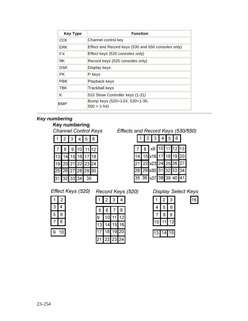
23-254
Key Type Function CCK Channel control key ERK Effect and Record keys (530 and 550 consoles only) FX Effect keys (520 consoles only) RK Record keys (520 consoles only) DSK Display keys PK P keys PBK Playback keys TBK Trackball keys K 510 Show Controller keys (1-31)
BMP Bump keys (520=1-24, 530=1-30, 550 = 1-54)
Key numbering
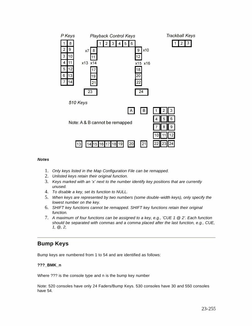
23-255
Notes
1. Only keys listed in the Map Configuration File can be remapped. 2. Unlisted keys retain their original function. 3. Keys marked with an ‘x’ next to the number identify key positions that are currently
unused. 4. To disable a key, set its function to NULL. 5. When keys are represented by two numbers (some double-width keys), only specify the
lowest number on the key. 6. SHIFT key functions cannot be remapped. SHIFT key functions retain their original
function. 7. A maximum of four functions can be assigned to a key, e.g., ‘CUE 1 @ 2’. Each function
should be separated with commas and a comma placed after the last function, e.g., CUE, 1, @, 2,
Bump Keys Bump keys are numbered from 1 to 54 and are identified as follows: ???_BMK_n Where ??? is the console type and n is the bump key number Note: 520 consoles have only 24 Faders/Bump Keys. 530 consoles have 30 and 550 consoles have 54.
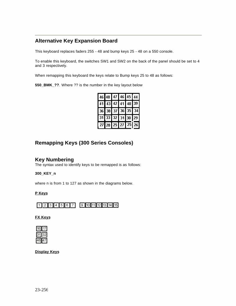
23-256
Alternative Key Expansion Board This keyboard replaces faders 255 - 48 and bump keys 25 - 48 on a 550 console. To enable this keyboard, the switches SW1 and SW2 on the back of the panel should be set to 4 and 3 respectively. When remapping this keyboard the keys relate to Bump keys 25 to 48 as follows: 550_BMK_??. Where ?? is the number in the key layout below
Remapping Keys (300 Series Consoles)
Key Numbering The syntax used to identify keys to be remapped is as follows: 300_KEY_n
where n is from 1 to 127 as shown in the diagrams below.
P Keys
FX Keys
Display Keys
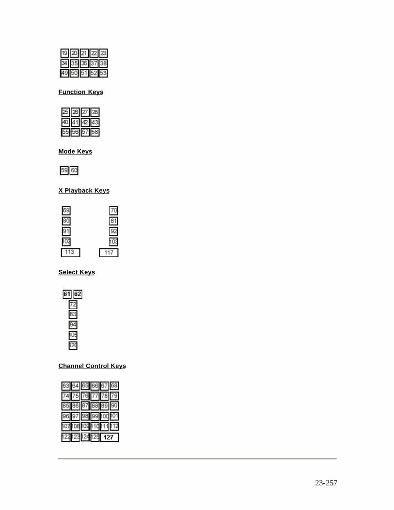
23-257
Function Keys
Mode Keys
X Playback Keys
Select Keys
Channel Control Keys
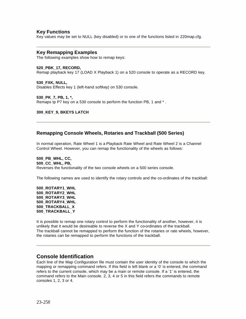
23-258
Key Functions Key values may be set to NULL (key disabled) or to one of the functions listed in 220map.cfg.
Key Remapping Examples The following examples show how to remap keys: 520_PBK_17, RECORD, Remap playback key 17 (LOAD X Playback 1) on a 520 console to operate as a RECORD key. 530_FXK, NULL, Disables Effects key 1 (left-hand softkey) on 530 console. 530_PK_7, PB, 1, *, Remaps tp P7 key on a 530 console to perform the function PB, 1 and * . 300_KEY_9, BKEYS LATCH
Remapping Console Wheels, Rotaries and Trackball (500 Series) In normal operation, Rate Wheel 1 is a Playback Rate Wheel and Rate Wheel 2 is a Channel Control Wheel. However, you can remap the functionality of the wheels as follows: 500_PB_WHL, CC, 500_CC_WHL, PB, Reverses the functionality of the two console wheels on a 500 series console. The following names are used to identify the rotary controls and the co-ordinates of the trackball: 500_ROTARY1_WHL 500_ROTARY2_WHL 500_ROTARY3_WHL 500_ROTARY4_WHL 500_TRACKBALL_X 500_TRACKBALL_Y It is possible to remap one rotary control to perform the functionality of another, however, it is unlikely that it would be desireable to reverse the X and Y co-ordinates of the trackball. The trackball cannot be remapped to perform the function of the rotaries or rate wheels, however, the rotaries can be remapped to perform the functions of the trackball.
Console Identification Each line of the Map Configuration file must contain the user identity of the console to which the mapping or remapping command refers. If this field is left blank or a ‘0’ is entered, the command refers to the current console, which may be a main or remote console. If a ‘1’ is entered, the command refers to the Main console. 2, 3, 4 or 5 in this field refers the commands to remote consoles 1, 2, 3 or 4.
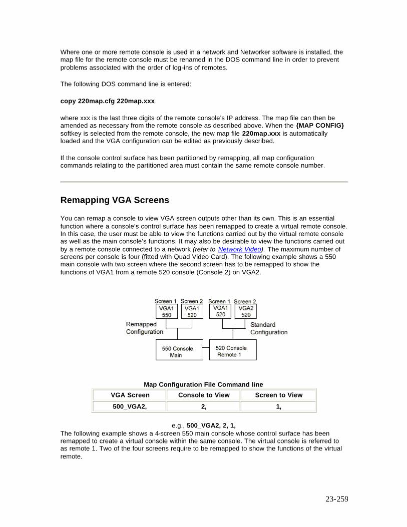
23-259
Where one or more remote console is used in a network and Networker software is installed, the map file for the remote console must be renamed in the DOS command line in order to prevent problems associated with the order of log-ins of remotes. The following DOS command line is entered: copy 220map.cfg 220map.xxx where xxx is the last three digits of the remote console’s IP address. The map file can then be amended as necessary from the remote console as described above. When the {MAP CONFIG} softkey is selected from the remote console, the new map file 220map.xxx is automatically loaded and the VGA configuration can be edited as previously described. If the console control surface has been partitioned by remapping, all map configuration commands relating to the partitioned area must contain the same remote console number.
Remapping VGA Screens You can remap a console to view VGA screen outputs other than its own. This is an essential function where a console’s control surface has been remapped to create a virtual remote console. In this case, the user must be able to view the functions carried out by the virtual remote console as well as the main console’s functions. It may also be desirable to view the functions carried out by a remote console connected to a network (refer to Network Video). The maximum number of screens per console is four (fitted with Quad Video Card). The following example shows a 550 main console with two screen where the second screen has to be remapped to show the functions of VGA1 from a remote 520 console (Console 2) on VGA2.
Map Configuration File Command line VGA Screen Console to View Screen to View 500_VGA2, 2, 1,
e.g., 500_VGA2, 2, 1,
The following example shows a 4-screen 550 main console whose control surface has been remapped to create a virtual console within the same console. The virtual console is referred to as remote 1. Two of the four screens require to be remapped to show the functions of the virtual remote.
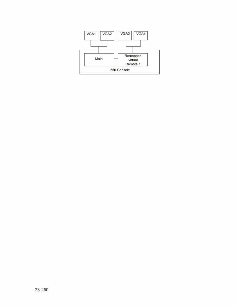
23-260

24-261
Chapter 24 - The 510 i and 310 Show Controller/Backup Unit
The 510i is a 19 inch, rack-mounted unit and the 310 may be desk, wall or 19inch rack-mounted. Both units are designed to match the lighting needs of the themed environment market, where the requirement is for repetitive playback of shows controlled by one of the following:
• SMPTE Audio or Video Timecodes • MIDI Show Controller • 48 Contact Closure Inputs • Internal Clock • Manual Playback
The 510i and 310 also supports playback of shows recorded on GSX and LBX. The creation of a light show based on SMPTE time-stamped events and MIDI Show Control is described in CommuniquéPro Software SMPTE Time Code Events In addition, since the software configuration of applications and channel capacity of the 510i and 310 is identical to the other 500 and 300 Series consoles, the 510i, or 310 can serve as a compact and cost effective tracking backup unit for a main 500 or 300 series lighting control console, Refer to Tracking Backup (Networker) The 501i and 310 runs on the same GeniusPro or Lightpallette operating software as the 500 and 300 Series consoles. This section describes the operating features applicable to the 510i and 310. It contains the following topics:
• User Interface • Macro Display and Menu • Submaster Display and Menu • Browse Display and Menu • Event Display and Menu • Playbacks Display and Menu • Backup Display • Setup Display and Menu • Error Line • Off-Line Editing • Submaster Macro Inputs
User Interface
The front panel controls of the 510i provide the minimum user interface required to operate all the GeniusPro, Lightpallette, CommuniquéPro and Networker playback functions. Access to the full software functionality (in particular, show set-up, editing and saving) is only possible using an external keyboard and video display or a remote control unit.

24-262
The 310 Show Controller incorporates a touch screen LCD display, incorporating the keys on the 510i in the form of on-sceen touch softkeys. The 510i LCD display on the front panel, provides all the displays and associated softkeys necessary to control the playback functions of the system. The Macro display is shown at startup., however, the operator can select other menus using the [DISPLAY] key (or DISPLAY touch key on the 310) to cycle through the various menus as follows: MACRO, SUBS, BROWSE, EVENT, PLAYBACK, BACKUP, SETUP and back to MACRO, etc. Entry to the displayed Macro LCD menu is achieved using the key combination [SHIFT][DISPLAY]. Note: The SHIFT touch key on the 310 is set to toggle between On and Off. It is therefore not necessary to hold down the SHIFT key when selectingg 'Shift' function. However it is necessary to press the SHIFT key again to deselect the function. A [STOP SHOW] pushbutton (Red button on the 310) is provided to enable the operator to stop the pre-programmed lighting show and apply a pre-defined safe lighting condition. On the 510i, this panel button is protected from accidental operation by a hinged cover. On both the 510i and 310, the illuminated button will flash when selected. The operation of the button is mapped to macro 997 as well as the 500 Series console STOP key function.. The LED in the [STOP SHOW] button will flash if any Stop key mode is selected, e.g., ‘ BLACKOUT’ , ‘ STOP ATTS’ or ‘ ST ATTS+BO’ . During playback, the operator can prevent any unauthorised use of the panel pushbuttons (except [STOP SHOW]) by means of a [DISABLE KEYS] keyswitch with removable key. When locked, the condition is displayed on the panel LCD, the keyswitch LED (510i only) is illuminated and the LCD dims. Fourteen panel buttons, when operated with or without the [SHIFT] key depressed, will apply one of 28 pre-set macro conditions, [P1-P14], or [SHIFT] [P1-P14]. These macros can be triggered directly using the panel buttons, or from the Macro Display LCD. The [USER] key is mapped to macro 998. The [CLR] key clears the last command. Note: The P1 to P14 (SP1 to SP14) keys, together with the SHIFT and DISPLAY keys are shown on all screens of the 310 Show Controller. Where text labels are assigned by the user to the P (or S) keys, the text labels are shown in place of the P or S number on all displays of the 310.
Macro Display and Menu
The 510i and 310 Macro Display and Menu enables viewing and play back of sequences of commands previously recorded using a Series 300, 430, 500, LBX or GSX console. Up to 2000 macros (0-1999) may have been recorded. (Refer to Macros)
Up to eight macros can be displayed at one time on the LCD display, the currently selected macro identified with the marker > after the macro number. Pressing [SHIFT][DISPLAY] will enter the Macro Screen.
Individual macros can be selected from the macro display and run using the softkeys, as follows:
{LAST} Selects the previous macro in the macro list. {NEXT} Selects the next macro in the macro list {MACRO-100} Subtract 100 from the current macro number (if applicable) and display as the current macro. {MACRO+100) Add 100 to the current macro number (if applicable) and display as the current
24-263
macro. {FIRST MACRO} Selects the first macro as current. {RUN} Runs the selected macro.
While the [SHIFT] key is depressed (or toggled On - 310), an alternative set of LCD softkeys is displayed, as follows:
{LAST 8} Displays the previous eight macros. {NEXT 8} Displays the next eight macros {MACRO-100} As before [MACRO+100} As before {FIRST MACRO} As before {RUN} As before
Note: Macros 951 to 964 and 971 to 984 are reserved for the fourteen macro keys on the 510i panel and 310 on-screen softkeys. Pressing [P1] to [P14] selects and runs macros 951 to 964 respectively. Pressing [SHIFT] [P1] to [P14] selects SP1 to SP14 and runs macros 971 to 984 respectively. All 28 macros can be selected and run from the macro display as described above. Pressing the [USER] button on the panel, applies macro 998. Pressing the [STOP SHOW] button runs macro 997.
Submasters Display and Menu
The 510i and 310 Submaster Display and Menu enables viewing and play back of up to 54 submasters previously recorded using a Series 500, or Series 300 console). The display shows eight subs at a time from the currently selected sub page and displays the sub number, level, text and associated macro against each sub. The currently selected sub is identified by a > marker after the sub number. Using the LCD softkeys, the operator can scan through the six pages of subs, select a sub from the displayed page and increment, decrement, or bump the sub level as follows: {LAST} Moves the marker to the previous sub on the page. {NEXT} Moves the marker to the next sub on the page {PAGE +} Increments the sub pages, e.g., 1>2>3>4>5>6>1, etc. {DOWN %} Decrements the level of the currently selected sub by 5%. {UP %} Increments the level of the currently selected sub by 5%. {BUMP SUB} Bumps the currently selected sub. While the [SHIFT] key is depressed (or toggled On - 310), an alternative set of softkeys is displayed as follows: {LAST 8} Displays the previous eight subs on the selected page. {NEXT 8} Displays the next eight subs on the selected page. {PAGE -} Decrements the sub pages, e.g., 6.5.4.3.2.1.6, etc. {TO 0%} Sets level of currently selected sub to 0%. {TO 100%} Sets level of currently selected sub to 100%. {BUMP SUB} Bumps the currently selected sub.
Browse Display and Menu
24-264
The Browse Display and Menu lists all light shows stored within the 510i or 310 hard disk, or floppy disk (or server if used) and enables the operator to browse through the list of shows either on the hard disk, or floppy disk (or server), to load a show for playback, or to copy a show between disks and/or directories. This menu is also used in conjunction with the floppy disk drive to load new operating software.
This section covers the following topics
o Loading a Show o Copying a Show o Loading Operating Software
Loading a Show
To load a show from floppy or hard drive, use the {LAST} and {NEXT} softkeys to position the > marker alongside the drive field (A:) or the hard drive field (C:) and press {SELECT}. Press the {LAST} or {NEXT} softkey to position the marker alongside the Directory field and press the {SELECT} softkey until the required directory is displayed. The drive and directory is shown on the top line of the display and the shows contained in the selected drive/directory are listed below. To load a show from the show list, use the {LAST} or {NEXT} keys to move the > marker to the required show and press {SELECT}. A Show Load prompt and confirm message will appear. Pressing {SELECT} again will load the show. The show files on the disk on the disk browser are identified by their show name and date and time of recording. Alternatively, the operator can browse long lists of shows by holding down the [SHIFT] key (or toggling the key On - 310) and using the {LAST 4} or {NEXT 4} softkeys to display shows 4 at a time.
Copying a Show
To copy a show, firstly move the > marker as described above using the {NEXT}, {LAST} and {SELECT} keys. When the marker is on the required show, press the {COPY SHOW} key. The menu title will change on the LCD display to ‘ Copy Menu’ . The copy function is active when this menu title is present.In response to a prompt message, use the {NEXT}, {LAST} and {SELECT} keys to select destination disk and directory. The destination path is shown on the LCD display. If the path displayed is correct, press the {COPY SHOW} key again to confirm the copy command. Pressing the [CLR] key at any time during the copy process will return to the Browse menu.
Loading Operating Software
To load new operating software, insert the floppy disk in the disk drive and select the {SOFT LOAD} softkey. A software load prompt and confirm message is displayed. Pressing the {SOFT LOAD} softkey again will load the operating software from the floppy disk.

24-265
Event Display and Menu
The 510i and 310 is designed to operate in conjunction with an externally applied SMTE time code, however, in the absence of a SMPTE time code, the operator can enable an internal clock to control the show events.When the external SMPTE clock is selected and running, the internal SMPTE clock is automatically synchronised to it. This Event Display and Menu enables the operator to select the source of timing of show events and displays each event and programmed event time in sequence as the light show progresses. A < marker indicates the next event to trigger and a * marker indicates the last event triggered. Select {EXT.CLK} to apply an external SMTE time code input via the 3-pin Audio XLR outlet. Select {INT.CLK} to apply the internal time code clock. The status of the timing source and SMPTE time is displayed on the LCD as EXTERNAL, OVERRIDE (internal clock taken over), NO CLOCK (external clock absent), INTERNAL or PAUSE).
Note: The time code source must be set to SMPTE at the Show Setup display before the internal or external clock can be used.
This section covers the following topics:
§ Time Format § Setting/Resetting the Internal Clock § Stepping the Light Show Timing
Time Format
The time format for the internal clock is in the same format as the SMPTE input time code and is set at Show Setup:
Form: HH:MM:SS:FF where HH = Hours (0-23) MM =- Minutes (0-59) SS = Seconds (0-59) FF = Frames per second (0-24, 0-25, 0-30 drop or 0-30 non-drop)
Setting/Resetting the Internal Clock
When the clock is INTERNAL or *PAUSED*, the {SET CLOCK} softkey may be used to display alternative softkeys used to increment, decrement or reset the internal clock, as follows: {+HH} Add one hour to the internal clock time.
24-266
{+MM} Add one minute to the internal clock time. {+SS} Add one second to the internal clock time. {+FF} Add one frame to the internal clock time. {+5FF} Add 5 frames to the internal clock time. {BACK} Return to the Events Display and Menu. [SHIFT] {-HH} Subtract one hour from the internal clock time. [SHIFT] {-MM} Subtract one minute from internal clock time. [SHIFT] {-FF} Subtract one frame from the internal clock time. [SHIFT] {-5FF} Subtract 5 frames from the internal clock time. [SHIFT] {RESET TIME}. Reset internal clock to 00:00:00:00
Stepping the Light Show Timing
Selecting {PAUSE CLOCK} stops the internal or external clock at the time of the displayed event. Pressing {STEP} will manually trigger the next event. Alternatively, with {PAUSE CLOCK} selected the operator may move the < marker to a different event using the [SHIFT] key and the softkeys displayed on the Event List, as follows: {LAST} Sets the < marker and clock time to the last event. {NEXT} Sets the < marker and clock time to the next event. {BEGIN LIST} Sets the < marker and clock time to the first event on the list. {END LIST} Sets the marker and clock time to the last event on the list. The following softkeys clear any incomplete commands {UNBUMP ALL} Unbumps any bumped submasters. {STOP FX} Stops all running effects
Playback Display and Menu
The layout and content of the Playback Display is determined by the options selected on the setup screen and the individual cue levels and properties attributed to each cue when first recorded using the lighting control console. The 510i and 310 panels are designed as show playback units and do not provide direct editing facilities for cues without the aid of an external video display and keyboard or remote control. The Cues and X Playback menu on the 510i and 310 panels are intended to provide the operator with the facility to view the cue list, to select and load individual cues and to run the cue, or cue sequence on demand. The display shows the cue list for X1 or X2. A > marker, shown to the left of the cue number identifies the current cue. The percentage completion of the last run cue is also displayed. The next cue to run is indicated with a < marker after the cue number. The last cue is identified by a ‘ *’ after the cue number. The softkeys on the LCD display enable the operator to select and run cues as follows: Note: Pressing the [SHIFT] key will toggle between X1 Playback and X2 Playback (if a dual playback mode is selected in the Show Setup). All key actions apply to the playback displayed on the LCD, i.e., X1 or X2. {LAST} Selects the previous cue on the displayed cue sheet as the cue to be loaded {NEXT} Selects the next cue on the displayed cue sheet as the cue to be loaded.
24-267
{LOAD} Loads a selected cue into the X Playback and resets any loops to their original loop count. This action has no effect on the output until the {GO} softkey is pressed. {STOP/BACK} Press once to stop the current cue. Press again to move to the previous cue. {GO TO CUE 0} Selects cue 0 (Blackout) {GO} Runs the current cue.
Backup Display
This display is applicable when the 510i, or 310 is used to provide tracking backup to a 500, or 300 Series Lighting Control Console using an Ethernet network. (Refer to Tracking Backup (Networker) The 510i and 310 Backup LCD displays the following network information: Networker: On Mode: As specified by 220node.cfg This Node: ‘ Net name’ , ‘ node number’ Backup node: ‘ Net name’ . ‘ node number’ . Status: As current network status. For information on backup commands, refer to ‘Backup Commands' (Networker)
Setup Display and Menu
The Setup Display and menu shows the current software version, the unit serial number, the software applications loaded and the number of submasters detected. The display also shows the backlight and contrast settings for the panel LCD display. The following softkeys are displayed. {CONTR DOWN} Decreases the LCD contrast {CONTR UP} Increases the LCD contrast {BACKLT DOWN} Decreases the LCD backlight brightness {BACKLT UP} Increases the LCD backlight brightness {SHUTDOWN} Displays warning/confirm message. Press {SHUTDOWN} to shut down the system or the [CLR] key to cancel.
Error Line
Text, that would appear on the error line of a 500 Series, or 310 video monitor is displayed on the 510i, or 310 LCD display. Pressing the [CLR] button cancels the error message.
Off Line Editor
The 510i and 310 incorporates the GeniusPro and Lightpallette Off-line Editor and PC Software, providing full emulation of the 500 Series, or 300 Series console operating software on a standard PC.
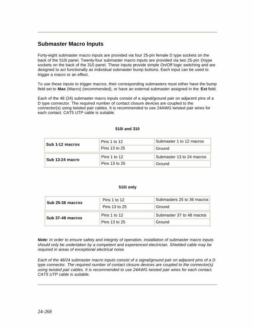
24-268
Submaster Macro Inputs
Forty-eight submaster macro inputs are provided via four 25-pin female D type sockets on the back of the 510i panel. Twenty-four submaster macro inputs are provided via two 25-pin D-type sockets on the back of the 310 panel. These inputs provide simple On/Off logic switching and are designed to act functionally as individual submaster bump buttons. Each input can be used to trigger a macro or an effect. To use these inputs to trigger macros, their corresponding submasters must either have the bump field set to Mac (Macro) (recommended), or have an external submaster assigned in the Ext field. Each of the 48 (24) submaster macro inputs consist of a signal/ground pair on adjacent pins of a D type connector. The required number of contact closure devices are coupled to the connector(s) using twisted pair cables. It is recommended to use 24AWG twisted pair wires for each contact. CAT5 UTP cable is suitable.
510i and 310
Pins 1 to 12 Submaster 1 to 12 macros Sub 1-12 macros
Pins 13 to 25 Ground
Pins 1 to 12 Submaster 13 to 24 macros Sub 13-24 macro
Pins 13 to 25 Ground
510i only
Pins 1 to 12 Submasters 25 to 36 macros Sub 25-36 macros
Pins 13 to 25 Ground
Pins 1 to 12 Submaster 37 to 48 macros Sub 37-48 macros Pins 13 to 25 Ground
Note: In order to ensure safety and integrity of operation, installation of submaster macro inputs should only be undertaken by a competent and experienced electrician. Shielded cable may be required in areas of exceptional electrical noise. Each of the 48/24 submaster macro inputs consist of a signal/ground pair on adjacent pins of a D type connector. The required number of contact closure devices are coupled to the connector(s) using twisted pair cables. It is recommended to use 24AWG twisted pair wires for each contact. CAT5 UTP cable is suitable.
25-269
Chapter 25 - Offline Editor & PC Software
GeniusPro and Lightpalette Off-line Editor and PC Backup Software provide full emulations of the console Operating Software on a standard PC. Off-Line Editor provides the following facilities :-
• Read and Write show files. • Generate Printouts. • Edit Cues, Groups, Patch, Effects, Submasters. • Preview on screen all recorded elements of show.
PC Backup Software provides the following :
• Link to Ethernet network using the supplied Network Card and Networker software. • Operate as Tracking Backup to a main console or PC. • Operate a Designer’s Remote to a main console or PC with independent command line
and screens. • Provide standalone PC Show Controller use network for DMX distribution SN series
nodes.
The following topics are covered in this section:
• Prerequisites • Installing the Offline Editor Software
o Installing Offline Editor Using DOS 3.1 or later o Installing Offline Editor Using Windows9X
• Installing the Backup PC Kit o Installing the Ethernet Card o Configuring the Ethernet Card o Installing the Dongle o Installing the Backup PC Software from DOS o Installing the Backup PC Software from Windows 9X o Installing the Networker & Utilities Software Using DOS 3.1 or Later o Installing the Networker & Utilities Software Using Windows 9x
• Installing the Help File Using DOS 3.1 or Later • Installing the Help File Using Windows 9X • Running the Software (Offline Editor or Backup PC) • Notes on Running Offline Editor or Backup PC Software • Designer Keypad • Keyboard Map
Prerequisites
Before starting please check you have the following :- For Off-Line Editor and PC Software.
• Standard VGA display or Strand Dual VGA Card • DOS 3.1 or later (or Windows 95/98)
25-270
• 32Mb RAM recommended • 10 M Free Hard Disk Space • 580k Free Conventional Memory • Minimum 486 PC (DX) for use with a 430 console only • Minimum Pentium processor-based PC for use with a 520, 530, 550 or 300 console • Minimum PentiumPro or Pentium II PC or use with consoles running 'i' sofware (520i,
530i or 550i)
For PC Software only.
• Spare ISA slot for network card (Supplied) • Standard Parallel Port for dongle (Supplied)
Notes:
The OLE/Backup PC software will NOT run under Windows 3.x or Windows NT but will run under Windows 9x
To run the OLE/Backup PC software using DOS, HIMEM.SYS must be loaded. If it is not, an error message "32rtm error: Couldn't initialise DPMI32VM.OVL" will be given when running the software. To install HIMEM.SYS, add the line "DEVICE=HIMEM.SYS" at the top of the file C:\CONFIG.SYS.
The OLE/Backup PC software does not change the DOS PATH to include its install directory. Edit the PATH= line in the file C:\AUTOEXEC.BAT to include the software directory specified if required.
The OLE/Backup PC software will not run on a PC with a 3-COM network card connected to a standard PC network. The PC must be taken off the network before running the OLE. If the network card is not a 3-COM card it may be run on the PC network.
Installing the Offline Editor Software
Installing Offline Editor Using DOS 3.1 or Later
1. The following procedures assume that the software is being installed from floppy drive A: to drive C:
2. Insert the appropriate operating software disk in the floppy disk drive and type:
A:C5INSTAL<Enter> for non i 400 or 500 Series consoles, or A:CIINSTAL<Enter> for 500i Series consoles, or A:C3INSTAL<Enter> for 300 Series consoles
3. You will be given a choice of platform, e.g.,
3 300 Series 4 400 Series 5 500 Series B Backup PC

25-271
O Offline Editor F File Server
4. To install the Offline Editor software, type O 5. Specify either GeniusPro or Lightpalette installation by typing g or i. This should match
the console software type. 6. You will be prompted to enter a destination path for the Offline Editor software. By
default, the software will be installed in C:\geniusp or C:\lightp. Enter a destination directory name of 8 characters or less, or accept the default destination by pressing <Enter>.
7. You will be prompted to enter a destination path for the show files. By default, the show files will be stored in C:\shows. Enter a destination path, or accept the default location by pressing <Enter>.
8. The Strand Lighting licence agreement is displayed on screen. Press any key to scroll the display.
9. If you agree with the terms of the licence, press Y, or press N to terminate the installation. 10. The Offline Editor software will install on your PC. This may take some time. 11. If the installation was successful, 'Instal Successful' is displayed on screen. 12. Type CD geniusp<Enter> or CD lightp<Enter> to open the appropriate directory. 13. Type geniusp <Enter> or lightp <Enter> to run the Offline Editor 14. Close the Offline Editor and return to DOS to install the help file, press Ctrl F12, followed
by F2 three times. 15. Install the Help file as described under Installing the Help file under DOS 3.1 or Later 16. Repeat step 12 and 13 to run the Offline Editor. 17. Refer to the Keyboard Map or to the template at the back of the Operator Guide to
simulate the console keys using the PC keyboard.
Installing Offline Editor Using Windows 9X
1. The following procedures assume that the software is being installed from floppy drive A: to drive C:
2. Open the A: drive window and double click on the installation icon, as follows
C5INSTAL<Enter> for non i 400 or 500 Series consoles, or CIINSTAL<Enter> for 500i Series consoles, or C3INSTAL<Enter> for 300 Series consoles)
3. You will be given a choice of platform, e.g.,
3 300 Series 4 400 Series 5 500 Series B Backup PC O Offline Editor F File Server
4. To install the Offline Editor software, type O 5. Specify either GeniusPro or Lightpalette installation by typing g or i. This should match
the console software type.
25-272
6. You will be prompted to enter a destination path for the Offline Editor software. By default, the software will be installed in C:\geniusp or C:\lightp. Enter a destination directory name of 8 characters or less, or accept the default destination by pressing <Enter>.
7. You will be prompted to enter a destination path for the show files. By default, the show files will be stored in C:\shows. Enter a destination path, or accept the default location by pressing <Enter>.
8. The Strand Lighting licence agreement is displayed on screen. Press any key to scroll the display.
9. If you agree with the terms of the licence, press Y, or press N to terminate the installation. 10. The Offline Editor software will install on your PC. 11. If the installation was successful, 'Instal Successful' is displayed on screen. 12. Open Windows Explorer and locate the Offline Editor filename geniusp or lightp (or the
aternative name allocated in step 6). 13. If the default filename was used a shotcut (gp_95 or lp_95) is available within the
directory. Drag the shortcut to the desktop, or cut/paste to another location. You can rename the shortcut to as required. You can now run the software by double-clicking on the shortcut icon.
14. If you used a different name in step 6, locate the shortcut gp_95 or lp_95 and use the right mouse button and select Properties. Select the 'Program' tab and change the 'Cmd Line' and 'Working Directory' to match the alternative location.
15. Alternatively, you can run the Offline Editor software by double clicking on the geniusp.exe or lightp.exe files in the geniusp or lightp directory, or alternative location.
16. Close the Offline Editor and return to the desktop to instal the Helpfile, press Ctrl F12, followed by F2 three times.
17. Instal the Help file, as described under Installing the Help file under Windows 9X 18. Double click on the shortcut or the geniusp.bat/lightp.bat to run the Offline Editor
software 19. Refer to the Keyboard Map or to the template at the back of the Operator Guide to
simulate the console keys using the PC keyboard.
Installing the Backup PC Kit
PC Software is supplied with a 100 channel application disk and a Networker Application disk. You must register these disks with Strand’s Software Registration Centre and load the password with the dongle connected. The dongle is then programmed with the password facilities. If the dongle is disconnected, the PC software becomes the OffLine Editor, with maximum channels and other facilities but no Networker.
Installing the Ethernet Card (PC Software only)
Install the supplied Ethernet card in your desktop PC following the instructions supplied with the card. This procedure should only be carried out by qualified personnel. If in doubt please refer to your dealer/supplier or Strand Service to arrange installation by qualified personnel.
25-273
Configuring the Ethernet Card (PC Software only)
For PC Software configure the Ethernet card as :-
Parameter Settings Note
I/O Base Address 300h
Interrupt 10
Ethernet Port RJ45 or BNC
Plug and Play BIOS OFF This must be turned off
To change the defaults or run the Ethernet card self test software, follow these instructions :-
1. Power up the PC. 2. From the DOS prompt run the 3C5X9CFG.EXE program supplied on a floppy disk with
the network card. 3. Using the on screen menus change the parameters as shown. 4. Select the test option and ensure that all tests pass. 5. Exit from the network card configuration utility. 6. Power down the PC. 7. When configured and tested, connect the Ethernet card to the network
Installing the Dongle (PC Software only)
For PC Software plug the supplied dongle into the parallel port of the PC. Applications are registered to the Dongle Security Number stored inside the dongle and marked on the outside of the dongle. The number will be composed of 6 groups of 3 digits between 0 and 255; e.g. 001 002 003 002 003 004. Dongles can be moved between PCs and when plugged into consoles are used instead of the internal Console Security Number.
Installing the Backup PC Software from DOS
1. The following procedures assume that the software is being installed from floppy drive A: to drive C:
2. Insert the appropriate operating software disk in the floppy disk drive and type:
A:C5INSTAL<Enter> for non i 400 or 500 Series consoles, or A:CIINSTAL<Enter> for 500i Series consoles, or A:C3INSTAL<Enter> for 300 Series consoles)
3. You will be given a choice of platform, e.g.,
3 300 Series 4 400 Series
25-274
5 500 Series B Backup PC O Offline Editor F File Server
4. Press B to install the Backup PC Software 5. Specify either GeniusPro or Lightpalette installation by typing g or i. This should match
the console software type. 6. You will be prompted to enter a destination path for the Backup PC software. By default,
the software will be installed in C:\geniusp or C:\lightp. Enter a destination directory name of 8 characters or less, or accept the default destination by pressing <Enter>.
7. You will be prompted to enter a destination path for the show files. By default, the show files will be stored in C:\shows. Enter a destination path, or accept the default location by pressing <Enter>.
8. The Strand Lighting licence agreement is displayed on screen. Press any key to scroll the display.
9. If you agree with the terms of the licence, press Y, or press N to terminate the installation. 10. The Backup PC software will install on your PC. This may take some time. 11. If the installation was successful, 'Instal Successful' is displayed on screen. 12. Type CD\geniusp or CD\lightp as appropriate. If you have elected to save the operating
software in another directory, type the name of the directory in place of geniuspro or lightpalette.
13. Type geniusp<Enter> or lightp<Enter> to run the software. 14. Type Ctrl F12, followed by F2 three times to return to DOS. 15. You must now proceed to install the Networker & Utilities software from the disk supplied.
(Refer to Installing the Networker and Utilities Software Using DOS 3.1 or Later) and Installing the Help file under DOS 3.1 or later)
Installing the Backup PC Software from Windows 9X
1. The following procedures assume that the software is being installed from floppy drive A: to drive C:
2. Open the A: drive window and double click on the installation icon, as follows
C5INSTAL<Enter> for non i 400 or 500 Series consoles, or CIINSTAL<Enter> for 500i Series consoles, or C3INSTAL<Enter> for 300 Series consoles)
3. You will be given a choice of platform, e.g.,
3 300 Series 4 400 Series 5 500 Series B Backup PC O Offline Editor F File Server
4. To install the Offline Editor software, type O
25-275
5. Specify either GeniusPro or Lightpalette installation by typing g or i. This should match the console software type.
6. You will be prompted to enter a destination path for the Backup PC software. By default, the software will be installed in C:\geniusp or C:\lightp. Enter a destination directory name of 8 characters or less, or accept the default destination by pressing <Enter>.
7. You will be prompted to enter a destination path for the show files. By default, the show files will be stored in C:\shows. Enter a destination path, or accept the default location by pressing <Enter>.
8. The Strand Lighting licence agreement is displayed on screen. Press any key to scroll the display.
9. If you agree with the terms of the licence, press Y, or press N to terminate the installation. 10. The Backup PC software will install on your PC. 11. If the installation was successful, 'Instal Successful' is displayed on screen. 12. Open Windows Explorer and locate the Backup PC filename geniusp or lightp (or the
aternative name allocated in step 6). 13. If the default filename was used a shotcut (gp_95 or lp_95) is available within the
directory. Drag the shortcut to the desktop, or cut/paste to another location. Rename the shortcut to 'Offline Editor'. You can now run the software by double-clicking on the shortcut icon.
14. If you used a different name in step 6, locate the shortcut gp_95 or lp_95 and use the right mouse button and select Properties. Select the 'Program' tab and change the 'Cmd Line' and 'Working Directory' to match the alternative location.
15. Alternatively, you can run the Backup PC software by double clicking on the geniusp.bat or lightp.bat files in the geniusp or lightp directory, or alternative location.
16. Press Ctrl F12, followed by F2 three times to return to the desktop. 17. You must now proceed to install the Networker & Utilities software from the disk supplied.
(Refer to Installing the Networker and Utilities Software Under DOS 3.1 or Later and Installing the Help File under Windows 9X).
Installing the Networker & Utilities Software Using DOS 3.1 or later
1. Insert the disk CNINSTAL in the floppy drive ant type A:CNINSTAL to install Networker & Utilities software.
2. You will be given a choice of platform, e.g.,
3 300 Series 4 400 Series 5 500 Series B Backup PC O Offline Editor F File Server
3. Press B to install the Backup PC Software 4. Specify either GeniusPro or Lightpalette installation by typing g or i. This should match
the console software type. 5. You will be prompted to enter a destination pat h for the Backup PC software. By default,
the software will be installed in C:\geniusp or C:\lightp. Enter a destination directory name of 8 characters or less, or accept the default destination by pressing <Enter>.

25-276
6. You will be prompted to enter a destination path for the show files. By default, the show files will be stored in C:\shows. Enter a destination path, or accept the default location by pressing <Enter>.
7. The Strand Lighting licence agreement is displayed on screen. Press any key to scroll the display.
8. If you agree with the terms of the licence, press Y, or press N to terminate the installation. 9. The Networker software will install on your PC. 10. If the installation was successful, 'Instal Successful' is displayed on screen. 11. Press Ctrl F12, followed by F2 three times to return to DOS 12. Proceed to install the Help file as described under Installing Help under DOS 3.1 or later
If the DOS installation fails, try disabling SHARE or SMARTDRV lines in the PC's AUTOEXEC.BAT file. You can enable them again after installation. WARNING: You should disable Norton Commander because it can cause hard disk corruption when running operating software on a PC.
Installing the Networker & Utilities Software from Windows 9X
1. Insert the Networker &Utilities disk in the floppy drive 2. Open the A: drive window and double click on the installation icon, as follows
C5INSTAL<Enter> for non i 400 or 500 Series consoles, or CIINSTAL<Enter> for 500i Series consoles, or C3INSTAL<Enter> for 300 Series consoles)
3. You will be given a choice of platform, e.g.,
3 300 Series 4 400 Series 5 500 Series B Backup PC O Offline Editor F File Server
4. Press B to install the backup PC software 5. Specify either GeniusPro or Lightpalette installation by typing g or i. This should match
the console software type. 6. You will be prompted to enter a destination path for the Backup PC software. By default,
the software will be installed in C:\geniusp or C:\lightp. Enter a destination directory name of 8 characters or less, or accept the default destination by pressing <Enter>.
7. You will be prompted to enter a destination path for the show files. By default, the show files will be stored in C:\shows. Enter a destination path, or accept the default location by pressing <Enter>.
8. The Strand Lighting licence agreement is displayed on screen. Press any key to scroll the display.
9. If you agree with the terms of the licence, press Y, or press N to terminate the installation. 10. The Networker software will install on your PC.
25-277
11. If the installation was successful, 'Instal Successful' is displayed on screen. 12. Press Ctrl F12, followed by F2 three times to return to the desktop. 13. Proceed to install the Help file as described under Installing Help under DOS 3.1 or later
Installing the Help File Using DOS 3.1 or Later
1. Insert the disk HCINSTAL in the floppy drive ant type A:HCINSTAL to install tyhe help file
2. You will be given a choice of platform, e.g.,
3 300 Series 4 400 Series 5 500 Series B Backup PC O Offline Editor F File Server
3. Press O to install the Off-Line Editor or B to install the Backup PC Software 4. Specify either GeniusPro or Lightpalette installation by typing g or i. This should match
the console software type. 5. You will be prompted to enter a destination path for the Off-Line Editor or Backup PC
software. By default, the software will be installed in C:\geniusp or C:\lightp. Enter a destination directory name of 8 characters or less, or accept the default destination by pressing <Enter>.
6. You will be prompted to enter a destination path for the show files. By default, the show files will be stored in C:\shows. Enter a destination path, or accept the default location by pressing <Enter>.
7. The Strand Lighting licence agreement is displayed on screen. Press any key to scroll the display.
8. If you agree with the terms of the licence, press Y, or press N to terminate the installation. 9. The Help file will install on your PC. 10. If the installation was successful, 'Instal Successful' is displayed on screen.
Installing the Help File Using Window 9x
1. Insert the help disk in the floppy drive 2. Open the A: drive window and double click on the installation icon. HCINSTAL 3. You will be given a choice of platform, e.g.,
3 300 Series 4 400 Series 5 500 Series B Backup PC O Offline Editor F File Server
4. Press O to instal the Offline Editor or B to install the backup PC software
25-278
5. Specify either GeniusPro or Lightpalette installation by typing g or i. This should match the console software type.
6. You will be prompted to enter a destination path for the Backup PC software. By default, the software will be installed in C:\geniusp or C:\lightp. Enter a destination directory name of 8 characters or less, or accept the default destination by pressing <Enter>.
7. You will be prompted to enter a destination path for the show files. By default, the show files will be stored in C:\shows. Enter a destination path, or accept the default location by pressing <Enter>.
8. The Strand Lighting licence agreement is displayed on screen. Press any key to scroll the display.
9. If you agree with the terms of the licence, press Y, or press N to terminate the installation. 10. The Help file will install on your PC. 11. If the installation was successful, 'Instal Successful' is displayed on screen.
Running the Software (Offline Editor or Backup PC)
In DOS, type cd \geniusp or cd\lightp <return> to open the directory, then type geniusp or lightp <return> (for GeniusPro software) or lightp <return> (for Lightpalette software)
In Window 9X double click on the shortcut or open Windows Explorer and double click on geniusp.exe, or lightp.exe in the geniusp or lightp directory.
Note: The dongle will allocate 100 channels to the software. You will require to upgrade the number of channels according to the number of channels purchased with the Backup PC Kit. Refer to Adding Additional Channels or Applications to Version 2.2 or Later Software or Adding Additional Channels or Applications to Version 2.1 or Earlier Software
To simulate the console keys and controls, refer to Keyboard Map or use the appropriate template at the back of the Operator's Manual.
Before using the PC to backup a console, the Networker On/Off field in the The Network Window of the Console Screen must be set to ON. Refer also to Tracking Backup in the Networker section of this manual.
Notes on Running Offline Editor and PC Software
1. If you run the software with Networker in a Windows DOS box, you need to run: WINPKT 0x7e before starting Windows, so that the interrupt service routine in the packet driver remains at a fixed address. This is assuming that the packet driver has been attached to the 0x7e software interrupt vector (normal case in os.bat). WINPKT is a Windows utility, located in your Windows mdirectory. If you can’t find it, you can download a copy from Strands Web Site (http://www.strandlight.com/).
2. If you run the software under Windows 9X, and other applications complain that they are short of memory, you can reduce the amount of memory which the program uses by changing the DOS environment variable 220maxmem in userinit.bat, for example: set
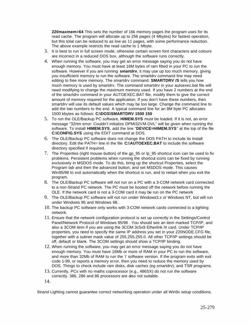
25-279
220maxmem=64 This sets the number of 16k memory pages the program uses for its read cache. The program will allocate up to 256 pages (4 Mbytes) for fastest operation, but this total can be reduced to as low as 11 pages, with some performance reduction. The above example restricts the read cache to 1 Mbyte.
3. It is best to run in full screen mode, otherwise certain screen font characters and colours are incorrect in a reduced DOS box, although the software runs correctly.
4. When running the software, you may get an error message saying you do not have enough memory. You must have at least 16M bytes of ram fitted in your PC to run the software. However if you are running smartdrv, it may use up too much memory, giving you insufficient memory to run the software. The smartdrv command line may need editing to free more memory. The smartdrv command: SMARTDRV /S tells you how much memory is used by smartdrv. The command smartdrv in your autoexec.bat file will need modifying to change the maximum memory used. If you have 2 numbers at the end of the smartdrv command in your AUTOEXEC.BAT file, modify them to give the correct amount of memory required for the application. If you don’t have these numbers, then smartdrv will use its default values which may be too large. Change the command line to add the two numbers to the end. A typical command line for an 8M byte PC allocates 1500 kbytes as follows: C:\DOS\SMARTDRV 1500 150
5. To run the OLE/Backup PC software, HIMEM.SYS must be loaded. If it is not, an error message “32rtm error: Couldn’t initialize DPMI32VM.OVL” will be given when running the software. To install HIMEM.SYS, add the line “DEVICE=HIMEM.SYS” at the top of the file C:\CONFIG.SYS using the EDIT command at DOS.
6. The OLE/Backup PC software does not change the DOS PATH to include its install directory. Edit the PATH= line in the file C:\AUTOEXEC.BAT to include the software directory specified if required.
7. The Properties (right mouse button) of the gp_95 or lp_95 shortcut icon can be used to fix problems. Persistent problems when running the shortcut icons can be fixed by running exclusively in MSDOS mode. To do this, bring up the shortcut Properties, select the Program tab and then the advanced button, and set MSDOS mode. This causes Win95/98 to exit automatically when the shortcut is run, and to restart when you exit the program.
8. The OLE/Backup PC software will not run on a PC with a 3-COM network card connected to a non-Strand PC network. The PC must be booted off the network before running the OLE. If the network card is not a 3-COM card it may be run on the PC network
9. The OLE/Backup PC software will not run under Windows3.x or Windows NT, but will run under Windows 95 and Windows 98..
10. The backup PC software only works with 3-COM network cards connected to a lighting network.
11. Ensure that the network configuration protocol is set up correctly in the Settings/Control Panel/Network Protocol of Windows 95/98 . You should see an item marked TCP/IP, and also a 3COM item if you are using the 3COM 3c5x9 Etherlink III card. Under TCP/IP properties, you need to specify the same IP address you set in your 220NODE.CFG file, together with a subnet mask value of 255.255.255.0. All other TCP/IP settings should be off, default or blank. The 3COM settings should show a TCP/IP binding.
12. When running the software, you may get an error message saying you do not have enough memory. You must have 16Mb or more of RAM in your PC to run the software, and more than 32Mb of RAM to run the 'i' software version. If the program exits with exit code 1-99, or reports a memory error, then you need to reduce the memory used by DOS. Things to check include ram disks, disk caches (eg smartdrv), and TSR programs.
13. Currently, PCs with no maths coprocessor (e.g., 486SX) do not run the software correctly. 386, 286 and 86 processors are also not suitable.
14.
Strand Lighting cannot guarantee correct networking operation under all Win9x setup conditions.
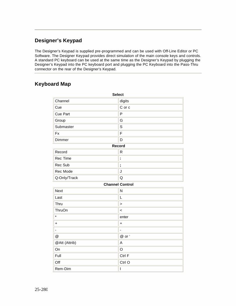
25-280
Designer’s Keypad
The Designer’s Keypad is supplied pre-programmed and can be used with Off-Line Editor or PC Software. The Designer Keypad provides direct simulation of the main console keys and controls. A standard PC keyboard can be used at the same time as the Designer’s Keypad by plugging the Designer’s Keypad into the PC keyboard port and plugging the PC Keyboard into the Pass-Thru connector on the rear of the Designer’s Keypad.
Keyboard Map
Select Channel digits Cue C or c Cue Part P Group G Submaster S Fx F Dimmer D
Record Record R Rec Time : Rec Sub ; Rec Mode J Q-Only/Track Q
Channel Control Next N Last L Thru > ThruOn < * enter + + - - @ @ or ‘ @Att (Attrib) A On O Full Ctrl F Off Ctrl O Rem-Dim I
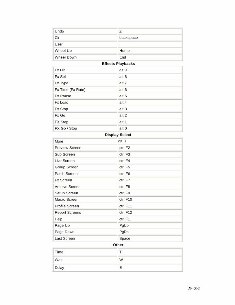
25-281
Undo Z Clr backspace User ! Wheel Up Home Wheel Down End
Effects Playbacks Fx Dir alt 9 Fx Sel alt 8 Fx Type alt 7 Fx Time (Fx Rate) alt 6 Fx Pause alt 5 Fx Load alt 4 Fx Stop alt 3 Fx Go alt 2 FX Step alt 1 FX Go / Stop alt 0
Display Select More alt R Preview Screen ctrl F2 Sub Screen ctrl F3 Live Screen ctrl F4 Group Screen ctrl F5 Patch Screen ctrl F6 Fx Screen ctrl F7 Archive Screen ctrl F8 Setup Screen ctrl F9 Macro Screen ctrl F10 Profile Screen ctrl F11 Report Screens ctrl F12 Help ctrl F1 Page Up PgUp Page Down PgDn Last Screen Space
Other
Time T
Wait W
Delay E
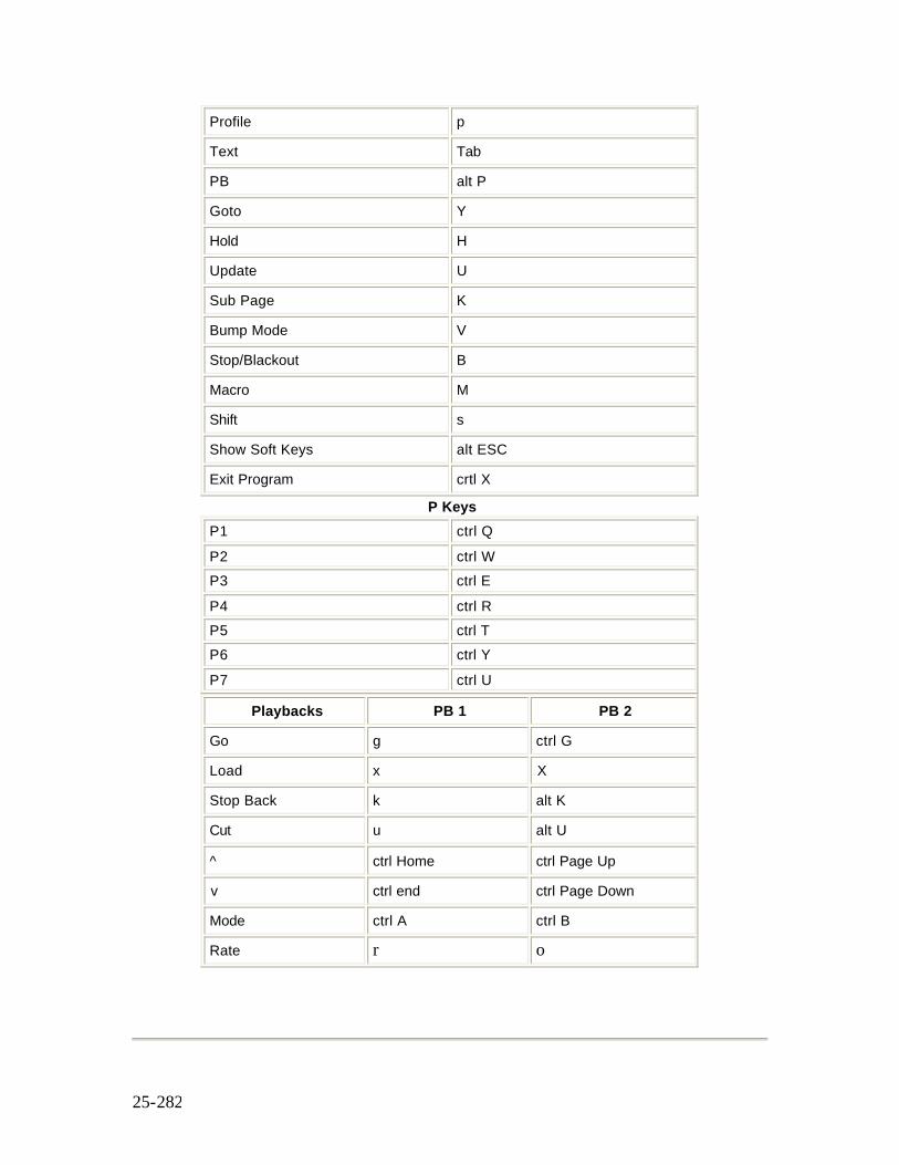
25-282
Profile p
Text Tab
PB alt P
Goto Y
Hold H
Update U
Sub Page K
Bump Mode V
Stop/Blackout B
Macro M
Shift s
Show Soft Keys alt ESC
Exit Program crtl X
P Keys P1 ctrl Q P2 ctrl W P3 ctrl E P4 ctrl R P5 ctrl T P6 ctrl Y P7 ctrl U
Playbacks PB 1 PB 2
Go g ctrl G
Load x X
Stop Back k alt K
Cut u alt U
ctrl Home ctrl Page Up
v ctrl end ctrl Page Down
Mode ctrl A ctrl B
Rate r o
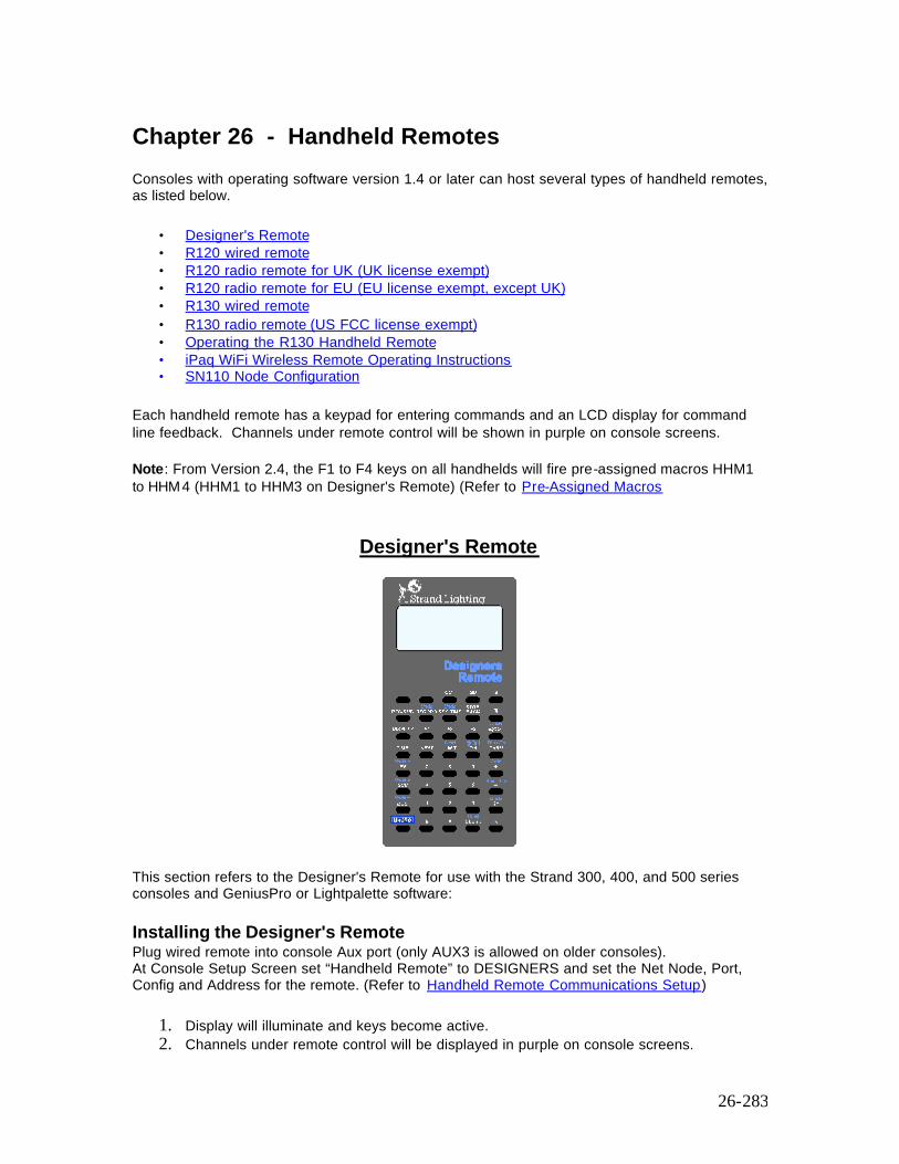
26-283
Chapter 26 - Handheld Remotes
Consoles with operating software version 1.4 or later can host several types of handheld remotes, as listed below.
• Designer's Remote • R120 wired remote • R120 radio remote for UK (UK license exempt) • R120 radio remote for EU (EU license exempt, except UK) • R130 wired remote • R130 radio remote (US FCC license exempt) • Operating the R130 Handheld Remote • iPaq WiFi Wireless Remote Operating Instructions • SN110 Node Configuration
Each handheld remote has a keypad for entering commands and an LCD display for command line feedback. Channels under remote control will be shown in purple on console screens. Note: From Version 2.4, the F1 to F4 keys on all handhelds will fire pre-assigned macros HHM1 to HHM4 (HHM1 to HHM3 on Designer's Remote) (Refer to Pre-Assigned Macros
Designer's Remote
This section refers to the Designer's Remote for use with the Strand 300, 400, and 500 series consoles and GeniusPro or Lightpalette software: Installing the Designer's Remote Plug wired remote into console Aux port (only AUX3 is allowed on older consoles). At Console Setup Screen set “Handheld Remote” to DESIGNERS and set the Net Node, Port, Config and Address for the remote. (Refer to Handheld Remote Communications Setup)
1. Display will illuminate and keys become active. 2. Channels under remote control will be displayed in purple on console screens.
26-284
3. To alter the display contrast use the thumbwheel on the right-hand side of the unit.
Operating the Designer's Remote
Operation of the Designer's Handheld Remote uses the same syntax as the command line on the main console. A few examples of commands when the console is set to Command Line mode are shown below. Refer to Alternative keys to use the alternative function for keys having a function, in blue, above the main key function in grey. Note: From Version 2.4, the F1 to F4 keys on all handhelds will fire pre-assigned macros HHM1 to HHM4 (Refer to Pre-Assigned Macros Setting Levels 1 @ 5 * Set channel 1 to 50% . 2 + 9 @ 4.5 * Set channels 2 and 9 to 45%. 9 THRU 12 @ 4 * Set channels 9 through 12 to 40% . @ 5 * Set current selection to 50% . ON Set current selection to ON level . FULL Set current selection to 100% s Increase level(s) of the current selection. tDecrease level(s) of the current selection. NEXT Next channel if a channel is selected, otherwise next cue. LAST Last channel if a channel is selected, otherwise last cue. REM-DIM Set current selection to On and turn all other channels Off. Recording & Playback RECORD CUE 1 * Record current levels into cue 1. GO Run the next cue on X PLAYBACK 1.
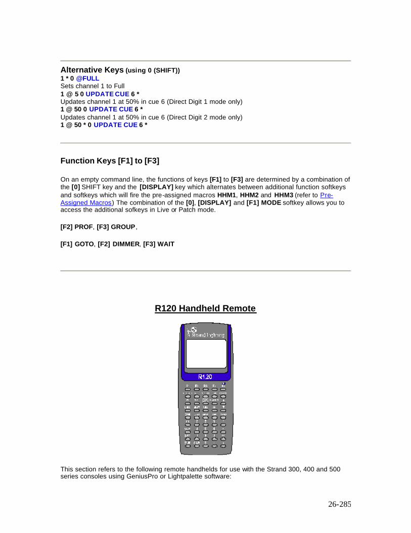
26-285
Alternative Keys (using 0 (SHIFT)) 1 * 0 @FULL Sets channel 1 to Full 1 @ 5 0 UPDATE CUE 6 * Updates channel 1 at 50% in cue 6 (Direct Digit 1 mode only) 1 @ 50 0 UPDATE CUE 6 * Updates channel 1 at 50% in cue 6 (Direct Digit 2 mode only) 1 @ 50 * 0 UPDATE CUE 6 *
Function Keys [F1] to [F3]
On an empty command line, the functions of keys [F1] to [F3] are determined by a combination of the [0] SHIFT key and the [DISPLAY] key which alternates between additional function softkeys and softkeys which will fire the pre-assigned macros HHM1, HHM2 and HHM3 (refer to Pre-Assigned Macros) The combination of the [0], [DISPLAY] and [F1] MODE softkey allows you to access the additional sofkeys in Live or Patch mode.
[F2] PROF, [F3] GROUP,
[F1] GOTO, [F2] DIMMER, [F3] WAIT
R120 Handheld Remote
This section refers to the following remote handhelds for use with the Strand 300, 400 and 500 series consoles using GeniusPro or Lightpalette software:
26-286
Part Number Description Contents
66129 Wired Remote UK/EU Wired Remote
66126 Radio Remote UK 418 MHz for UK (MPT 1340) Battery Charger - 230v 13 AMP PSU
66124 Base Station UK 418 MHz for UK (MPT 1340) Base Station Cable
66127 Radio Remote EU 433.92 MHz for Europe (ETS 300- 220) Battery Charger - 230v Euro PSU
66123 Base Station EU 433.92 MHz for Europe (ETS 300-220) Base Station Cable
• All parts require Operating Software V1.4 or later. Please contact your dealer or Strand if you do not have this software.
• Check with local licensing authority before using radio units outside licence exempt areas.
This section covers the following topics:
• Installing and Configuring the R120 Handheld Remote • Operating the R120 Handheld Remote
Installing and Configuring the R120 Handheld Remote
This section describes the installation and configuration of the following:
§ Installing the R120 Wired Remote § Installing the R120 Radio Base § Installing the R120 Radio Handheld Remote § R120 Base Pinouts
Installing the R120 Wired Remote
1. Plug wired remote into console Aux port (only AUX3 is allowed on older consoles). 2. At Operating Software setup screen set “Handheld Remote” to “R120 Wired” and set the
port that the handheld remote is plugged into. 3. Display will illuminate and keys become active. 4. Channels under remote control will be displayed in purple on console screens. 5. Simultaneously press and hold “.” and “*” keys (2 bottom right keys) to adjust display
contrast using up and down keys.
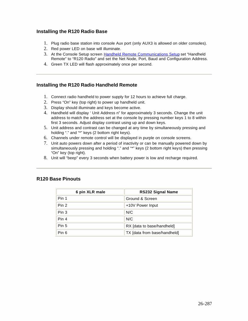
26-287
Installing the R120 Radio Base
1. Plug radio base station into console Aux port (only AUX3 is allowed on older consoles). 2. Red power LED on base will illuminate. 3. At the Console Setup screen Handheld Remote Communications Setup set “Handheld
Remote” to “R120 Radio” and set the Net Node, Port, Baud and Configuration Address. 4. Green TX LED will flash approximately once per second.
Installing the R120 Radio Handheld Remote
1. Connect radio handheld to power supply for 12 hours to achieve full charge. 2. Press “On” key (top right) to power up handheld unit. 3. Display should illuminate and keys become active. 4. Handheld will display ‘ Unit Address n” for approximately 3 seconds. Change the unit
address to match the address set at the console by pressing number keys 1 to 8 within first 3 seconds. Adjust display contrast using up and down keys.
5. Unit address and contrast can be changed at any time by simultaneously pressing and holding “.” and “*” keys (2 bottom right keys).
6. Channels under remote control will be displayed in purple on console screens. 7. Unit auto powers down after a period of inactivity or can be manually powered down by
simultaneously pressing and holding “.” and “*” keys (2 bottom right keys) then pressing “On” key (top right).
8. Unit will “beep” every 3 seconds when battery power is low and recharge required.
R120 Base Pinouts
6 pin XLR male RS232 Signal Name Pin 1 Ground & Screen Pin 2 +10V Power Input Pin 3 N/C Pin 4 N/C Pin 5 RX [data to base/handheld] Pin 6 TX [data from base/handheld]
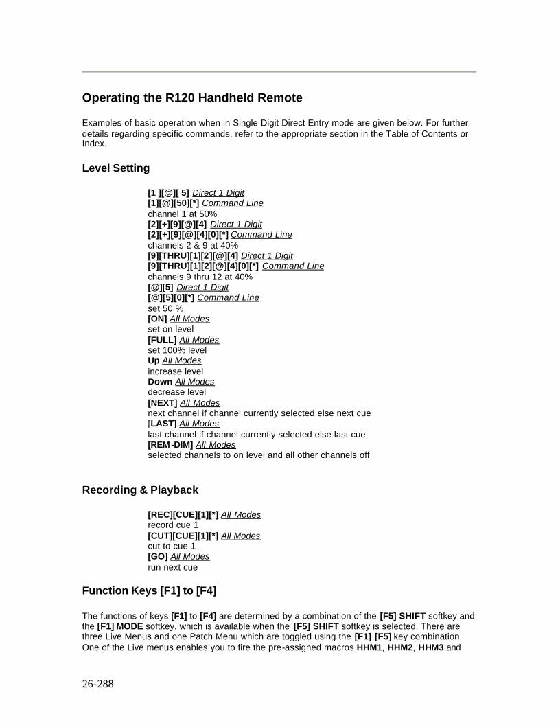
26-288
Operating the R120 Handheld Remote
Examples of basic operation when in Single Digit Direct Entry mode are given below. For further details regarding specific commands, refer to the appropriate section in the Table of Contents or Index.
Level Setting
[1 ][@][ 5] Direct 1 Digit [1][@][50][*] Command Line channel 1 at 50% [2][+][9][@][4] Direct 1 Digit [2][+][9][@][4][0][*] Command Line channels 2 & 9 at 40% [9][THRU][1][2][@][4] Direct 1 Digit [9][THRU][1][2][@][4][0][*] Command Line channels 9 thru 12 at 40% [@][5] Direct 1 Digit [@][5][0][*] Command Line set 50 % [ON] All Modes set on level [FULL] All Modes set 100% level Up All Modes increase level Down All Modes decrease level [NEXT] All Modes next channel if channel currently selected else next cue [LAST] All Modes last channel if channel currently selected else last cue [REM-DIM] All Modes selected channels to on level and all other channels off
Recording & Playback
[REC][CUE][1][*] All Modes record cue 1 [CUT][CUE][1][*] All Modes cut to cue 1 [GO] All Modes run next cue
Function Keys [F1] to [F4]
The functions of keys [F1] to [F4] are determined by a combination of the [F5] SHIFT softkey and the [F1] MODE softkey, which is available when the [F5] SHIFT softkey is selected. There are three Live Menus and one Patch Menu which are toggled using the [F1] [F5] key combination. One of the Live menus enables you to fire the pre-assigned macros HHM1, HHM2, HHM3 and
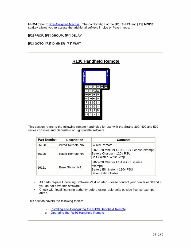
26-289
HHM4 (refer to Pre-Assigned Macros). The combination of the [F5] SHIFT and [F1] MODE softkey allows you to access the additional sofkeys in Live or Patch mode.
[F2] PROF, [F3] GROUP , [F4] DELAY
[F1] GOTO, [F2] DIMMER, [F3] WAIT
R130 Handheld Remote
This section refers to the following remote handhelds for use with the Strand 300, 400 and 500 series consoles and GeniusPro or Lightpalette software:
Part Number Description Contents 66128 Wired Remote NA Wired Remote
66125 Radio Remote NA 902-928 Mhz for USA (FCC License exempt} Battery Charger - 120v PSU Belt Holster, Wrist Strap
66121 Base Station NA 902-928 Mhz for USA (FCC License exempt} Battery Eliminator - 120v PSU Base Station Cable
• All parts require Operating Software V1.4 or later. Please contact your dealer or Strand if you do not have this software.
• Check with local licensing authority before using radio units outside licence exempt areas.
This section covers the following topics:
o Installing and Configuring the R130 Handheld Remote o Operating the R130 Handheld Remote
26-290
Installing and Configuring the R130 Handheld Remote
This section describes the installation and configuration of the following:
o Installing the R130 Wired Remote o Installing the R130 Radio Handheld Remote o Installing the R130 Radio Base o R130 Base Pinouts
Installing the R130 Wired Remote
1. Plug wired remote into console Aux port (only AUX3 is allowed on older consoles). 2. At Console Setup screen, Handheld Remote Communications Setup set “Handheld
Remote” to “R130 Wired”, and set the Net Node, Port, Baud Rate and Configuration Address.
3. Display will illuminate and keys become active. 4. Channels under remote control will be displayed in purple on console screens.
Installing the R130 Radio Handheld Remote
1. Remove rear cover from handheld be loosening two Phillips screws and connect re-chargeable battery pack. Replace cover.
2. Connect radio handheld to power supply for 12 hours to achieve full charge. 3. Press “On” key (top right) to power up handheld unit and hold down “CLR” (bottom left) &
“*” (bottom right) keys as unit powers up to gain access to setup menus. 4. Using setup menu set COMS as follows :-
Radio Channel: 4 (default) Radio Sub-Channel: 1 (default) Internal Radio Sn: xxxxxxxx (can’ t change this - write it down) Destination Sn: xxxxxxxx (read from lable on base station) Display Serial Errors: No (default) Aud Serial Errors: No (default) Support XON/XOFF: No (default) Exit & Store Changes: Yes
5. Press “On” key (top right) twice to power down unit.
26-291
Installing the R130 Radio Base
1. Write down serial number of base station xxxxxxxx - you will need it later. 2. Connect PSU to base station & red power LED will illuminate. 3. Plug radio base station into console Aux port (only AUX3 is allowed on older consoles). 4. At Console Setup screen, Handheld Remote Communications Setup, set “Handheld
Remote” to “R130 Radio” and set and set the Net Node, Port, Baud Rate. Set the configuration address (8 digit number, up to 4 digits In the left field and 4 digits in the right field) to “Internal Radio Sn” previously recorded.
R130 Base Pinouts
6 pin XLR male RS232 Signal Name Pin 1 Ground & Screen Pin 2 +10V Power Input Pin 3 N/C Pin 4 N/C Pin 5 RX [data to base/handheld] Pin 6 TX [data from base/handheld]
Operating the R130 Handheld Remote
Examples of basic operation when in Single Digit Direct Entry mode are given below. For further details regarding specific commands, refer to the appropriate section in the Table of Contents or Index.
Level Setting
[1 ][@][ 5] Direct 1 Digit [1][@][50][*] Command Line channel 1 at 50% [2][+][9][@][4] Direct 1 Digit [2][+][9][@][4][0][*] Command Line channels 2 & 9 at 40% [9][THRU][1][2][@][4] Direct 1 Digit [9][THRU][1][2][@][4][0][*] Command Line channels 9 thru 12 at 40% [@][5] Direct 1 Digit [@][5][0][*] Command Line set 50 % [ON] All Modes set on level [FULL] All Modes

26-292
set 100% level Up All Modes increase level Down All Modes decrease level [NEXT] All Modes next channel if channel currently selected else next cue [LAST] All Modes last channel if channel currently selected else last cue [REM-DIM] All Modes selected channels to on level and all other channels off
Function Keys [F1] to [F4]
The functions of keys [F1] to [F4] are determined by a combination of the [F5] SHIFT softkey and the [F1] MODE softkey, which is available when the [F5] SHIFT softkey is selected. There are three Live Menus and one Patch Menu which are toggled using the [F1] [F5] key combination. One of the Live menus enables you to fire the pre-assigned macros HHM1, HHM2, HHM3 and HHM4 (refer to Pre-Assigned Macros). The combination of the [F5] SHIFT and [F1] MODE softkey allows you to access the additional sofkeys in Live or Patch mode.
[F2] PROF, [F3] GROUP, [F4] DELAY
[F1] GOTO, [F2] DIMMER, [F3] WAIT
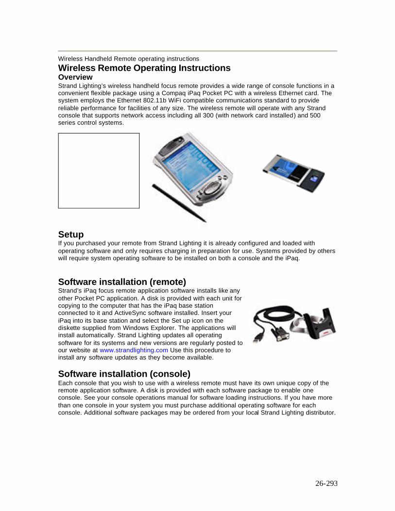
26-293
Wireless Handheld Remote operating instructions
Wireless Remote Operating Instructions Overview Strand Lighting’s wireless handheld focus remote provides a wide range of console functions in a convenient flexible package using a Compaq iPaq Pocket PC with a wireless Ethernet card. The system employs the Ethernet 802.11b WiFi compatible communications standard to provide reliable performance for facilities of any size. The wireless remote will operate with any Strand console that supports network access including all 300 (with network card installed) and 500 series control systems.
Setup If you purchased your remote from Strand Lighting it is already configured and loaded with operating software and only requires charging in preparation for use. Systems provided by others will require system operating software to be installed on both a console and the iPaq.
Software installation (remote) Strand’s iPaq focus remote application software installs like any other Pocket PC application. A disk is provided with each unit for copying to the computer that has the iPaq base station connected to it and ActiveSync software installed. Insert your iPaq into its base station and select the Set up icon on the diskette supplied from Windows Explorer. The applications will install automatically. Strand Lighting updates all operating software for its systems and new versions are regularly posted to our website at www.strandlighting.com Use this procedure to install any software updates as they become available.
Software installation (console) Each console that you wish to use with a wireless remote must have its own unique copy of the remote application software. A disk is provided with each software package to enable one console. See your console operations manual for software loading instructions. If you have more than one console in your system you must purchase additional operating software for each console. Additional software packages may be ordered from your local Strand Lighting distributor.
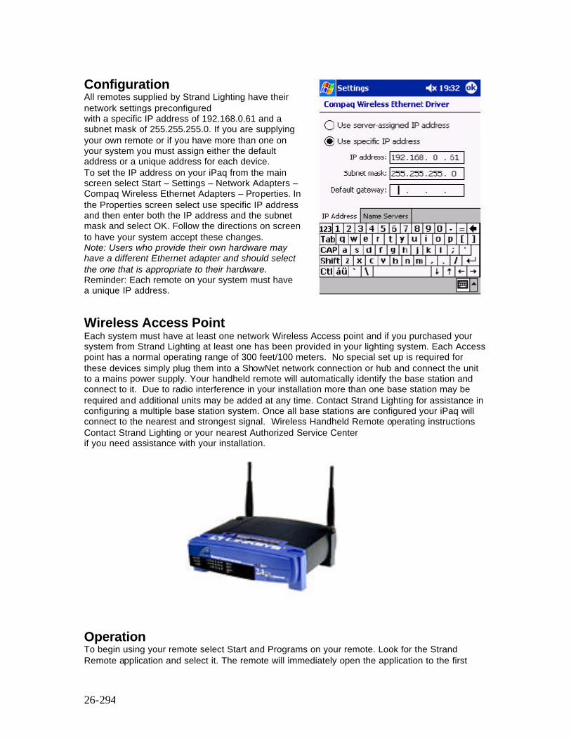
26-294
Configuration All remotes supplied by Strand Lighting have their network settings preconfigured with a specific IP address of 192.168.0.61 and a subnet mask of 255.255.255.0. If you are supplying your own remote or if you have more than one on your system you must assign either the default address or a unique address for each device. To set the IP address on your iPaq from the main screen select Start – Settings – Network Adapters – Compaq Wireless Ethernet Adapters – Properties. In the Properties screen select use specific IP address and then enter both the IP address and the subnet mask and select OK. Follow the directions on screen to have your system accept these changes. Note: Users who provide their own hardware may have a different Ethernet adapter and should select the one that is appropriate to their hardware. Reminder: Each remote on your system must have a unique IP address.
Wireless Access Point Each system must have at least one network Wireless Access point and if you purchased your system from Strand Lighting at least one has been provided in your lighting system. Each Access point has a normal operating range of 300 feet/100 meters. No special set up is required for these devices simply plug them into a ShowNet network connection or hub and connect the unit to a mains power supply. Your handheld remote will automatically identify the base station and connect to it. Due to radio interference in your installation more than one base station may be required and additional units may be added at any time. Contact Strand Lighting for assistance in configuring a multiple base station system. Once all base stations are configured your iPaq will connect to the nearest and strongest signal. Wireless Handheld Remote operating instructions Contact Strand Lighting or your nearest Authorized Service Center if you need assistance with your installation.
Operation To begin using your remote select Start and Programs on your remote. Look for the Strand Remote application and select it. The remote will immediately open the application to the first
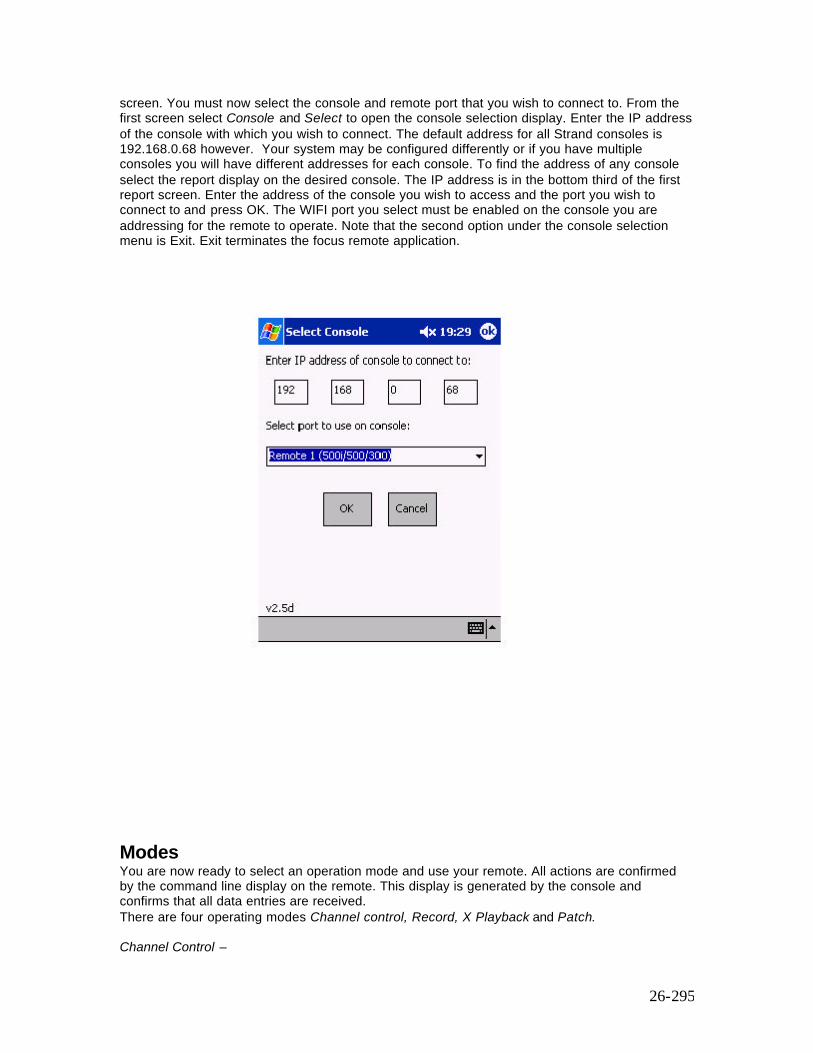
26-295
screen. You must now select the console and remote port that you wish to connect to. From the first screen select Console and Select to open the console selection display. Enter the IP address of the console with which you wish to connect. The default address for all Strand consoles is 192.168.0.68 however. Your system may be configured differently or if you have multiple consoles you will have different addresses for each console. To find the address of any console select the report display on the desired console. The IP address is in the bottom third of the first report screen. Enter the address of the console you wish to access and the port you wish to connect to and press OK. The WIFI port you select must be enabled on the console you are addressing for the remote to operate. Note that the second option under the console selection menu is Exit. Exit terminates the focus remote application.
Modes You are now ready to select an operation mode and use your remote. All actions are confirmed by the command line display on the remote. This display is generated by the console and confirms that all data entries are received. There are four operating modes Channel control, Record, X Playback and Patch. Channel Control –
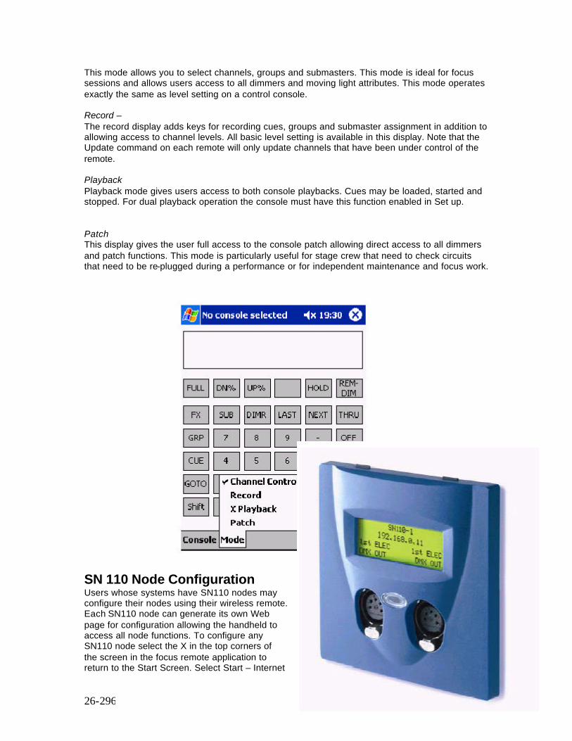
26-296
This mode allows you to select channels, groups and submasters. This mode is ideal for focus sessions and allows users access to all dimmers and moving light attributes. This mode operates exactly the same as level setting on a control console. Record – The record display adds keys for recording cues, groups and submaster assignment in addition to allowing access to channel levels. All basic level setting is available in this display. Note that the Update command on each remote will only update channels that have been under control of the remote. Playback Playback mode gives users access to both console playbacks. Cues may be loaded, started and stopped. For dual playback operation the console must have this function enabled in Set up. Patch This display gives the user full access to the console patch allowing direct access to all dimmers and patch functions. This mode is particularly useful for stage crew that need to check circuits that need to be re-plugged during a performance or for independent maintenance and focus work.
SN 110 Node Configuration Users whose systems have SN110 nodes may configure their nodes using their wireless remote. Each SN110 node can generate its own Web page for configuration allowing the handheld to access all node functions. To configure any SN110 node select the X in the top corners of the screen in the focus remote application to return to the Start Screen. Select Start – Internet
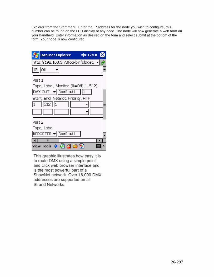
26-297
Explorer from the Start menu. Enter the IP address for the node you wish to configure, this number can be found on the LCD display of any node. The node will now generate a web form on your handheld. Enter information as desired on the form and select submit at the bottom of the form. Your node is now configured.
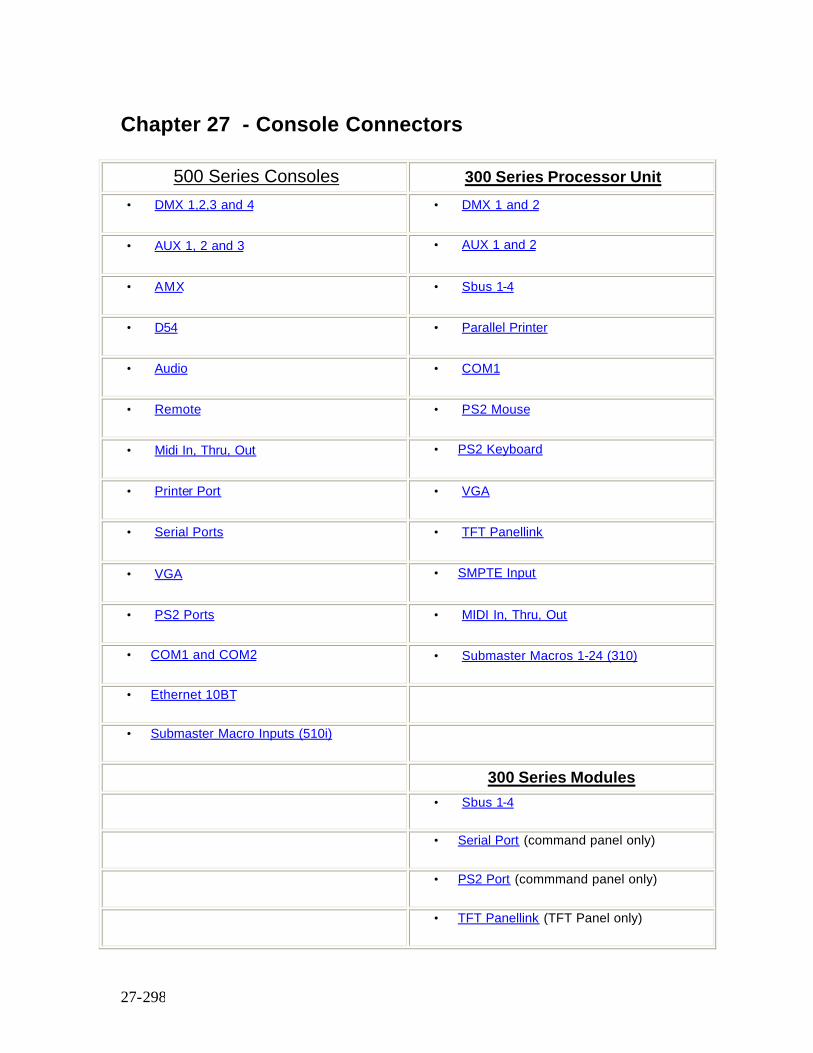
27-298
Chapter 27 - Console Connectors
500 Series Consoles 300 Series Processor Unit
• DMX 1,2,3 and 4 • DMX 1 and 2
• AUX 1, 2 and 3 • AUX 1 and 2
• AMX • Sbus 1-4
• D54 • Parallel Printer
• Audio • COM1
• Remote • PS2 Mouse
• Midi In, Thru, Out • PS2 Keyboard
• Printer Port • VGA
• Serial Ports • TFT Panellink
• VGA • SMPTE Input
• PS2 Ports • MIDI In, Thru, Out
• COM1 and COM2 • Submaster Macros 1-24 (310)
• Ethernet 10BT www
• Submaster Macro Inputs (510i) ww
www 300 Series Modules
www • Sbus 1-4
www • Serial Port (command panel only)
• PS2 Port (commmand panel only)
• TFT Panellink (TFT Panel only)
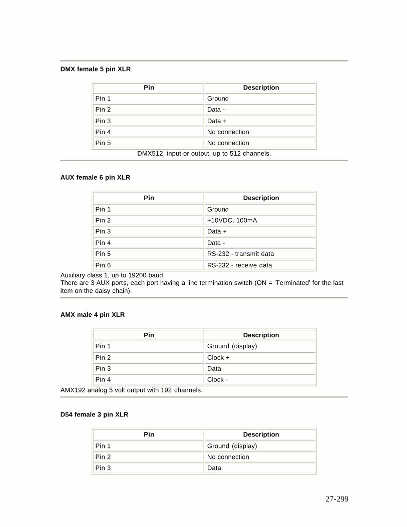
27-299
DMX female 5 pin XLR
Pin Description Pin 1 Ground Pin 2 Data - Pin 3 Data + Pin 4 No connection Pin 5 No connection
DMX512, input or output, up to 512 channels.
AUX female 6 pin XLR
Pin Description Pin 1 Ground Pin 2 +10VDC, 100mA Pin 3 Data + Pin 4 Data - Pin 5 RS-232 - transmit data Pin 6 RS-232 - receive data
Auxiliary class 1, up to 19200 baud. There are 3 AUX ports, each port having a line termination switch (ON = 'Terminated' for the last item on the daisy chain).
AMX male 4 pin XLR
Pin Description Pin 1 Ground (display) Pin 2 Clock + Pin 3 Data Pin 4 Clock -
AMX192 analog 5 volt output with 192 channels.
D54 female 3 pin XLR
Pin Description Pin 1 Ground (display) Pin 2 No connection Pin 3 Data
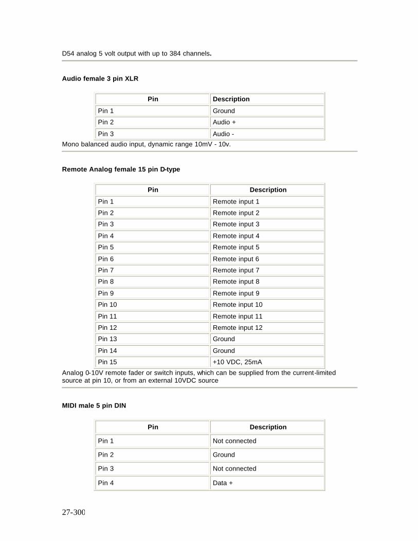
27-300
D54 analog 5 volt output with up to 384 channels.
Audio female 3 pin XLR
Pin Description Pin 1 Ground Pin 2 Audio + Pin 3 Audio -
Mono balanced audio input, dynamic range 10mV - 10v.
Remote Analog female 15 pin D-type
Pin Description Pin 1 Remote input 1 Pin 2 Remote input 2 Pin 3 Remote input 3 Pin 4 Remote input 4 Pin 5 Remote input 5 Pin 6 Remote input 6 Pin 7 Remote input 7 Pin 8 Remote input 8 Pin 9 Remote input 9 Pin 10 Remote input 10 Pin 11 Remote input 11 Pin 12 Remote input 12 Pin 13 Ground Pin 14 Ground Pin 15 +10 VDC, 25mA
Analog 0-10V remote fader or switch inputs, which can be supplied from the current-limited source at pin 10, or from an external 10VDC source
MIDI male 5 pin DIN
Pin Description
Pin 1 Not connected
Pin 2 Ground
Pin 3 Not connected
Pin 4 Data +
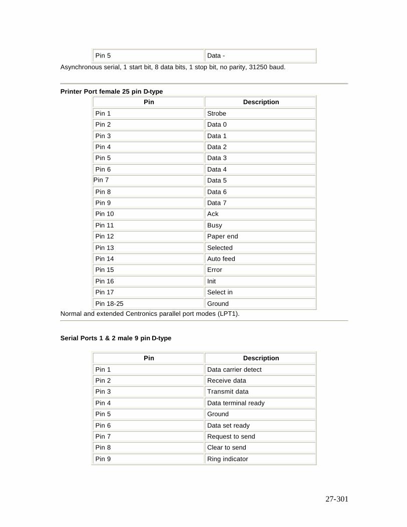
27-301
Pin 5 Data - Asynchronous serial, 1 start bit, 8 data bits, 1 stop bit, no parity, 31250 baud.
Printer Port female 25 pin D-type
Pin Description Pin 1 Strobe Pin 2 Data 0 Pin 3 Data 1 Pin 4 Data 2 Pin 5 Data 3 Pin 6 Data 4 Pin 7 Data 5 Pin 8 Data 6 Pin 9 Data 7 Pin 10 Ack Pin 11 Busy Pin 12 Paper end Pin 13 Selected Pin 14 Auto feed Pin 15 Error Pin 16 Init Pin 17 Select in Pin 18-25 Ground
Normal and extended Centronics parallel port modes (LPT1).
Serial Ports 1 & 2 male 9 pin D-type
Pin Description Pin 1 Data carrier detect Pin 2 Receive data Pin 3 Transmit data Pin 4 Data terminal ready Pin 5 Ground Pin 6 Data set ready Pin 7 Request to send Pin 8 Clear to send Pin 9 Ring indicator
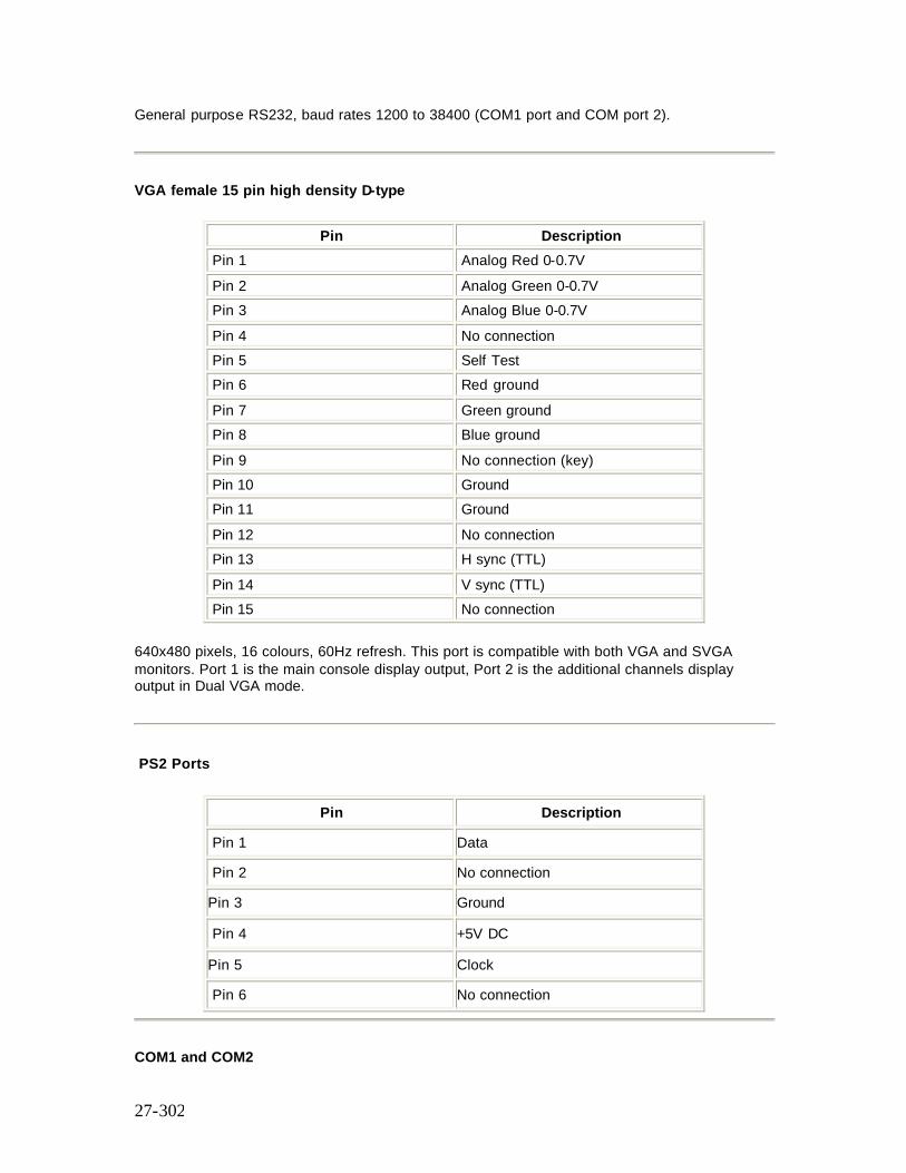
27-302
General purpose RS232, baud rates 1200 to 38400 (COM1 port and COM port 2).
VGA female 15 pin high density D-type
Pin Description Pin 1 Analog Red 0-0.7V Pin 2 Analog Green 0-0.7V Pin 3 Analog Blue 0-0.7V Pin 4 No connection Pin 5 Self Test Pin 6 Red ground Pin 7 Green ground Pin 8 Blue ground Pin 9 No connection (key) Pin 10 Ground Pin 11 Ground Pin 12 No connection Pin 13 H sync (TTL) Pin 14 V sync (TTL) Pin 15 No connection
640x480 pixels, 16 colours, 60Hz refresh. This port is compatible with both VGA and SVGA monitors. Port 1 is the main console display output, Port 2 is the additional channels display output in Dual VGA mode.
PS2 Ports
Pin Description
Pin 1 Data
Pin 2 No connection
Pin 3 Ground
Pin 4 +5V DC
Pin 5 Clock
Pin 6 No connection
COM1 and COM2
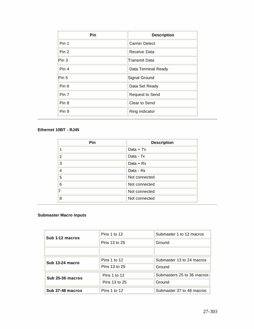
27-303
Pin Description
Pin 1 Carrier Detect
Pin 2 Receive Data
Pin 3 Transmit Data
Pin 4 Data Terminal Ready
Pin 5 Signal Ground
Pin 6 Data Set Ready
Pin 7 Request to Send
Pin 8 Clear to Send
Pin 9 Ring indicator
Ethernet 10BT - RJ45
Pin Description 1 Data + Tx 2 Data - Tx 3 Data + Rx 4 Data - Rx 5 Not connected 6 Not connected 7 Not connected 8 Not connected
Submaster Macro Inputs
Pins 1 to 12 Submaster 1 to 12 macros
Sub 1-12 macros Pins 13 to 25 Ground
Pins 1 to 12 Submaster 13 to 24 macros Sub 13-24 macro
Pins 13 to 25 Ground
Pins 1 to 12 Submasters 25 to 36 macros Sub 25-36 macros
Pins 13 to 25 Ground
Sub 37-48 macros Pins 1 to 12 Submaster 37 to 48 macros
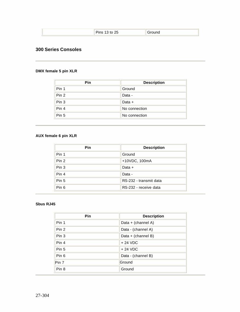
27-304
Pins 13 to 25 Ground
300 Series Consoles
DMX female 5 pin XLR
Pin Description Pin 1 Ground Pin 2 Data - Pin 3 Data + Pin 4 No connection Pin 5 No connection
AUX female 6 pin XLR
Pin Description Pin 1 Ground Pin 2 +10VDC, 100mA Pin 3 Data + Pin 4 Data - Pin 5 RS-232 - transmit data Pin 6 RS-232 - receive data
Sbus RJ45
Pin Description Pin 1 Data + (channel A) Pin 2 Data - (channel A) Pin 3 Data + (channel B) Pin 4 + 24 VDC Pin 5 + 24 VDC Pin 6 Data - (channel B) Pin 7 Ground Pin 8 Ground
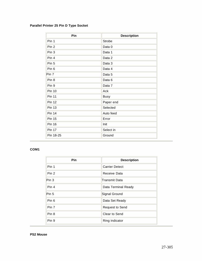
27-305
Parallel Printer 25 Pin D Type Socket
Pin Description Pin 1 Strobe Pin 2 Data 0 Pin 3 Data 1 Pin 4 Data 2 Pin 5 Data 3 Pin 6 Data 4 Pin 7 Data 5 Pin 8 Data 6 Pin 9 Data 7 Pin 10 Ack Pin 11 Busy Pin 12 Paper end Pin 13 Selected Pin 14 Auto feed Pin 15 Error Pin 16 Init Pin 17 Select in Pin 18-25 Ground
COM1
Pin Description
Pin 1 Carrier Detect
Pin 2 Receive Data
Pin 3 Transmit Data
Pin 4 Data Terminal Ready
Pin 5 Signal Ground
Pin 6 Data Set Ready
Pin 7 Request to Send
Pin 8 Clear to Send
Pin 9 Ring indicator
PS2 Mouse
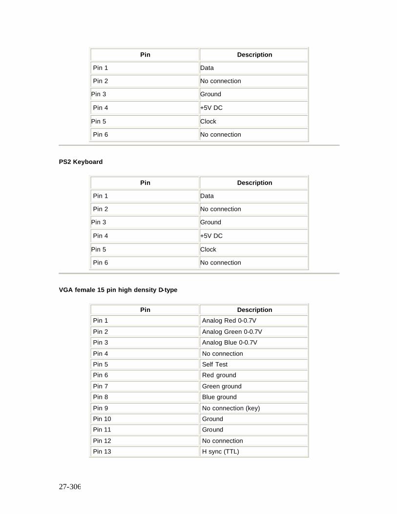
27-306
Pin Description
Pin 1 Data
Pin 2 No connection
Pin 3 Ground
Pin 4 +5V DC
Pin 5 Clock
Pin 6 No connection
PS2 Keyboard
Pin Description
Pin 1 Data
Pin 2 No connection
Pin 3 Ground
Pin 4 +5V DC
Pin 5 Clock
Pin 6 No connection
VGA female 15 pin high density D-type
Pin Description Pin 1 Analog Red 0-0.7V Pin 2 Analog Green 0-0.7V Pin 3 Analog Blue 0-0.7V Pin 4 No connection Pin 5 Self Test Pin 6 Red ground Pin 7 Green ground Pin 8 Blue ground Pin 9 No connection (key) Pin 10 Ground Pin 11 Ground Pin 12 No connection Pin 13 H sync (TTL)
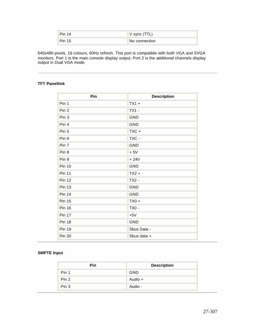
27-307
Pin 14 V sync (TTL) Pin 15 No connection
640x480 pixels, 16 colours, 60Hz refresh. This port is compatible with both VGA and SVGA monitors. Port 1 is the main console display output, Port 2 is the additional channels display output in Dual VGA mode.
TFT Panellink
Pin Description Pin 1 TX1 + Pin 2 TX1 - Pin 3 GND Pin 4 GND Pin 5 TXC + Pin 6 TXC - Pin 7 GND Pin 8 + 5V Pin 9 + 24V Pin 10 GND Pin 11 TX2 + Pin 12 TX2 - Pin 13 GND Pin 14 GND Pin 15 TX0 + Pin 16 TX0 - Pin 17 +5V Pin 18 GND Pin 19 Sbus Data - Pin 20 Sbus data +
SMPTE Input
Pin Description Pin 1 GND Pin 2 Audio + Pin 3 Audio -
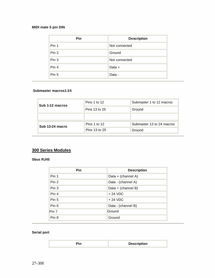
27-308
MIDI male 5 pin DIN
Pin Description
Pin 1 Not connected
Pin 2 Ground
Pin 3 Not connected
Pin 4 Data +
Pin 5 Data -
Submaster macros1-24
Pins 1 to 12 Submaster 1 to 12 macros Sub 1-12 macros
Pins 13 to 25 Ground
Pins 1 to 12 Submaster 13 to 24 macros Sub 13-24 macro
Pins 13 to 25 Ground
300 Series Modules
Sbus RJ45
Pin Description Pin 1 Data + (channel A) Pin 2 Data - (channel A) Pin 3 Data + (channel B) Pin 4 + 24 VDC Pin 5 + 24 VDC Pin 6 Data - (channel B) Pin 7 Ground Pin 8 Ground
Serial port
Pin Description
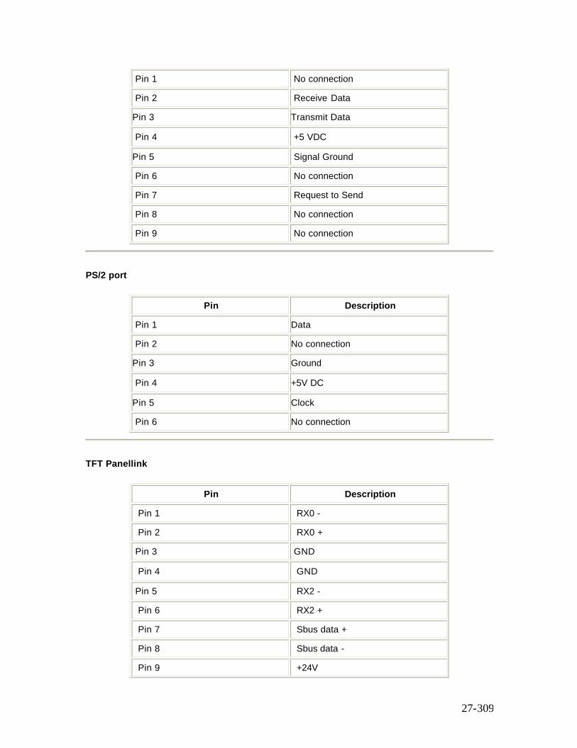
27-309
Pin 1 No connection
Pin 2 Receive Data
Pin 3 Transmit Data
Pin 4 +5 VDC
Pin 5 Signal Ground
Pin 6 No connection
Pin 7 Request to Send
Pin 8 No connection
Pin 9 No connection
PS/2 port
Pin Description
Pin 1 Data
Pin 2 No connection
Pin 3 Ground
Pin 4 +5V DC
Pin 5 Clock
Pin 6 No connection
TFT Panellink
Pin Description
Pin 1 RX0 -
Pin 2 RX0 +
Pin 3 GND
Pin 4 GND
Pin 5 RX2 -
Pin 6 RX2 +
Pin 7 Sbus data +
Pin 8 Sbus data -
Pin 9 +24V
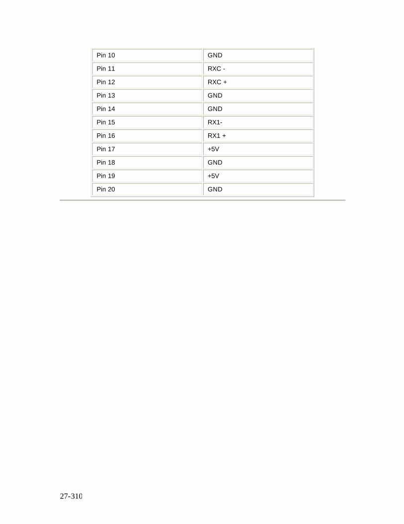
27-310
Pin 10 GND
Pin 11 RXC -
Pin 12 RXC +
Pin 13 GND
Pin 14 GND
Pin 15 RX1-
Pin 16 RX1 +
Pin 17 +5V
Pin 18 GND
Pin 19 +5V
Pin 20 GND
28-311
Chapter 28 - CommuniquéPro
See Also: CommuniquéPro Continued
CommuniquéPro is a standard software package for Strand Lighting’s 500 Series Consoles and GeniusPro or Lightpalette Operating software. It provides the following communication features:
The following topics are covered in this section:
• External Submasters • DMX In • MIDI • ASCII Remote Control Output • ASCII Remote Go Output • ASCII Remote Control Input • SMPTE Time Code Events • Audio Input Macro
External Submasters
Up to 12 Submasters can be remotely controlled by external faders or a manual desk such as Strand Lighting’s LX. If the Submasters have been configured as macro triggers, then only an external volt-free switch contact is required since a +10v supply pin is provided on the Remote Analog Input connector. This facility could be used to allow a stage manager to control house lights, or to trigger any macro, or to run a cue remotely.
This section includes the following topics:
o Setting Up External Submasters o Setting Up an External Submaster as a Macro Trigger
Setting Up External Submasters
To set up External Submasters, go to the SUBMASTER screen by pressing the [SUB] screen key. Set the Submaster Ext(ernal) field as follows:
1. Use the trackball to move to the Ext field of the Submaster to change. 2. Use the wheel (or the [+] or [-] keys) to change its value (1 - 12 or OFF).
External Submasters are not indicated in the Submaster window of the LIVE screen.
28-312
On the Console Setup Screen screen, external Submasters can have their top level adjusted by an External Subs Scaling factor between 80% and 120%. Scaling allows you to compensate for any variations in signal levels between your console and the external equipment to which you are connected. External Submaster fader levels are combined with the console Submaster fader levels on a HTP (Highest Takes Precedence) basis.
Setting Up External Submasters as a Macro Trigger
If a Submaster has been configured as a macro trigger, then only an external volt-free switch contact (such as MIDI, RS232, RS485, audio; perhaps a ‘click’ track, or via an approved digital input card) is required since a +10v supply pin is provided on the Analogue Input connector. This facility could be used to allow a stage manager to control house lights, or to trigger any macro, or to run a cue remotely.
To set up, go to the SUBMASTER screen and set the relevant Submaster Ext field the same as for External Submasters.
1. [SUB] Go to SUBMASTER screen 2. Press [SHIFT] and move the trackball or mouse 3. Use the trackball to move to the Ext field of the Submaster to change 4. Use the wheel or the [+] or [-] keys select the external channel, 1 - 12 or OFF 5. Next, set the Macro field to the macro number you wish to associate with this external
Submaster. 6. Use the trackball to move to the Macro field of the Submaster. 7. Use the wheel or the [+] or [-] keys or enter the number to change it to the macro
number.
The selected macro will be run whenever either the remote or console submaster faders move off 0.
DMX In
This is one of the console’s most powerful communication features and allows an external DMX source, for instance an FX desk, to be combined with the existing console dimmer patch.
DMX IN has two operating modes which can be used together:
DMX In Dimmer Mode patches the incoming DMX levels to outgoing DMX via the dimmer patch. A user selectable Submaster fader can master these dimmer levels. They cannot be recorded and are not visible on the LIVE screen. [first 512 dimmers only].
Channel Mode uses the incoming DMX levels as the contents of a user selectable Submaster. A user selectable Submaster fader can master these channel levels. The levels are visible on the LIVE screen when they are active and are recordable. [max. 512 channels]
This section covers the following topics:
o Setting Up DMX In Submasters
28-313
o Patching DMX In Dimmers o Using DMX In Dimmers o Using DMX In Channels
Setting Up DMX In Submasters
Set the DMX field in the Console Setup Screen to DMX IN.
Note: Only the last available DMX connector can optionally input 512 signals if it is not outputting signals.
Select the SUBMASTER screen by pressing the [SUB] screen key. Set the Submaster Function to DMX DIMR or DMX CHAN as follows:
1. Use the trackball to move to the Function field of the Submaster to change. 2. Use the wheel or the [+] or [-] keys to change it to DMX DIMR or DMX CHAN.
The Submaster window of the LIVE screen indicates DMX In Submasters by a C (DMX Channel) or D (DMX Dimmer). No channel levels need be entered for DMX IN Submasters.
Patching DMX In Dimmers
To patch DMX IN Dimmers go to the PATCH screen by pressing the [PATCH] screen key.
DMX IN Dimmers are identified on the display by a trailing D (e.g. 1D, 2D, 50D) and are displayed in magenta.
To change the default use one of the following commands:
sel [@] [+] # [*] This patches the output to the DMX Input Channel. The default Scaling is used if this is not currently patched to a DMX Input Channel otherwise it is left unchanged. [1] [THRU] [1] [0] [@] [+] [5] [THRU] [1] [4] [*] Patches output 1 to 10 to DMX Input Channel 5 to 14, scaling unchanged. sel [@] [+] # [@] [*] This patches the output to the DMX Input Channel; default Scaling is always used, as defined in Setup. [1] [@] [+] [5] [@] [*] Patches output 1 to DMX Input Channel 5 with default scaling. sel [@] [+] # [@] # [*]
28-314
This patches the output to the DMX Input Channel with the specified Scaling. [1] [@] [+] [5] [@[7] [5] [*] Patches output 1 to DMX Input Channel 5 with 75% scaling. sel [@] [@] # [*] The existing patch is unchanged but the DMX Input Channel is used with the specified Scaling. [1] [@] [@] [7] [5] [*] Patch is unchanged but is set to DMX Input with 75% Scaling.
Using DMX In Dimmers
Once you have configured a Submaster as DMX IN and set up the patch, connect your DMX source to the DMX IN port and push the Submaster fader up.
You won’t be able to see any changes in the LIVE screen, as dimmer levels are not displayed. Look at the lights being driven by your console; those patched to the external source will be controlled by it and the levels mastered by the Submaster fader.
Using DMX In Channels
Once you have selected a DMX Channel Submaster, simply connect your DMX source to the DMX IN port and push the Submaster fader up. You will see the DMX IN Channels on the LIVE screen in white. Changes in the incoming levels will be displayed on the LIVE screen and mastered by the Submaster fader. The DMX Channel Submaster can then be used just like other Submasters, except that any channels defined in the submaster memory are ignored.
MIDI
This feature allows show playback to be controlled from a MIDI show controller. MIDI is used to link equipment with a MIDI interface together.
CommuniquéPro support different parts of the MIDI Specification to achieve different degrees of remote control for console functions.
Full information on MIDI can be obtained from:
The International MIDI Association (IMA), 23634 Emelita Street, Woodland Hills, CA 91367 USA. Tel: 818/598-0088 Fax: 818/346-8578
28-315
This section covers the following topics:
o Controlling Effects Using MIDI o MIDI Show Control o MIDI Keys and Faders o MIDI Note o MIDI Message o MIDI Trigger Macro
Controlling Effects Using MIDI
MIDI sends time information to keep equipment in synchronisation with each other, often referred to as tempo. A master device, normally a sequencer or keyboard, sends out these timing signals at regular intervals. Speed up the tempo and more signals are sent, reduce the tempo and fewer signals are sent.
CommuniquéPro can receive these timing signals and use the frequency at which they are received to control the speed of a running Effect.
The Effect Step Control must be set to MIDI. The number of timing signals received before the effect steps are advanced can be adjusted on the effect playback by adjusting the MIDI RATIO supermaster fader.
CommuniquéPro also receives two additional MIDI timing commands: STOP which halts the effect and START which continues running the effect. A MIDI device normally sends out these commands when the tempo is stopped or started.
MIDI Show Control
MIDI Show Control (MSC) is a sub-set of the MIDI Specification dedicated to controlling show equipment.
CommuniquéPro currently supports the recommended Minimum Set which is defined as a ‘Simple Controlled Device; no time code; basic data only’. More specifically:
GO Acts as a normal GO button and resumes a fade after it has been stopped. RESUME Starts the next cue; it does not resume the previous fade. GO CUE #.# Go cue, where #.# is a specific cue (same as CUE #.# GO). STOP Stops the current fade. FIRE # Runs user macro # (# from 0 to 127). LOAD #.# Loads the X playback with cue #.#. ALL_OFF Blackout on. RESTORE Blackout off. RESET & GO_OFF Go Cue 0.
Note: All playback actions take effect only on X playback 1.
28-316
MSC output is activated when the MSC ID Tx option in the MIDI Window in the Show Setup Screen is set to a value between 0 and 127. If the MSC ID Tx is OFF no MSC messages are transmitted. Received MSC messages are only accepted if the MSC ID Rx matches the received message ID or the MSC ID is set to 127 (All Call).
Note:Midi Show Control GO_OFF does not run cue 0. Instead use MSC RESET instead. Also, Midi Show Control does not support playback 2. Instead fire a macro containing the GOX2 key.
MIDI Keys And Faders
All key and fader changes are transmitted via MIDI OUT and received via MIDI IN simultaneously. This will allow a second desk to be used as a full backup unit or as a slave unit. It will also allow all key presses and fader movements to be recorded on a sequencer in real time and played back in real time, in particular, the recording and playback of Cues, Effects and Submasters. The Channel option in the MIDI Window in the Show Setup Screen will select the MIDI channel on which to receive and transmit the key and faders on. When OFF, no key or fader events will be received or transmitted across MIDI. The Fader and Key Controller selections (between 1 and 4) select which MIDI General Purpose Controller is used to transmit and receive keys and faders. For tracking backup and slaving, the controller numbers must be different. The Mode determines if all keys and faders are sent (BACKUP) or if only a subset are sent (SLAVE).
MIDI Note
The Midi Note On and Note Off commands are received and used to flash Submasters or channels.
The Notes field in the MIDI window of the SHOW SETUP screen can be set as follows.
OFF Any received Note On or Note Off is ignored. FADERS The Note number matches faders 1 to 12. SUBS All Note On/Off messages will cause a Submaster to be flashed. ssed) of the MIDI note message is acted upon. When Velocity is OFF, any velocity greater than 0 is treated as full on, and 0 is off. When Velocity is ON the velocity determines the
The Velocity option determines if the velocity (strength at which a key is deprelevel to which the bump key is flashed: press a key hard the level is high, press a key lightly and the level is low.
MIDI Messages
This section is for experienced MIDI programmers only.
Control Change Consists of two General Purpose Controllers, 1 for faders the other for keys. General Purpose Controller 1 MSB (Controller 10h) and LSB (controller 30h) is used for faders and General Purpose Controller 2 MSB (Controller 11h) and LSB (controller 31h) is used for keys.
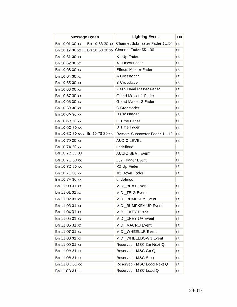
28-317
Message Bytes Lighting Event Dir
Bn 10 01 30 xx … Bn 10 36 30 xx Channel/Submaster Fader 1…54 r,t Bn 10 17 30 xx … Bn 10 60 30 xx Channel Fader 55…96 r,t Bn 10 61 30 xx X1 Up Fader r,t Bn 10 62 30 xx X1 Down Fader r,t Bn 10 63 30 xx Effects Master Fader r,t Bn 10 64 30 xx A Crossfader r,t Bn 10 65 30 xx B Crossfader r,t Bn 10 66 30 xx Flash Level Master Fader r,t Bn 10 67 30 xx Grand Master 1 Fader r,t Bn 10 68 30 xx Grand Master 2 Fader r,t Bn 10 69 30 xx C Crossfader r,t Bn 10 6A 30 xx D Crossfader r,t Bn 10 6B 30 xx C Time Fader r,t Bn 10 6C 30 xx D Time Fader r,t Bn 10 6D 30 xx …Bn 10 78 30 xx Remote Submaster Fader 1…12 r,t Bn 10 79 30 xx AUDIO LEVEL r,t Bn 10 7A 30 xx undefined - Bn 10 7B 30 00 AUDIO BEAT Event r,t Bn 10 7C 30 xx 232 Trigger Event r,t Bn 10 7D 30 xx X2 Up Fader r,t Bn 10 7E 30 xx X2 Down Fader r,t Bn 10 7F 30 xx undefined - Bn 11 00 31 xx MIDI_BEAT Event r,t Bn 11 01 31 xx MIDI_TRIG Event r,t Bn 11 02 31 xx MIDI_BUMPKEY Event r,t Bn 11 03 31 xx MIDI_BUMPKEY UP Event r,t Bn 11 04 31 xx MIDI_CKEY Event r,t Bn 11 05 31 xx MIDI_CKEY UP Event r,t Bn 11 06 31 xx MIDI_MACRO Event r,t Bn 11 07 31 xx MIDI_WHEELUP Event r,t Bn 11 08 31 xx MIDI_WHEELDOWN Event r,t Bn 11 09 31 xx Reserved - MSC Go Next Q r,t Bn 11 0A 31 xx Reserved - MSC Go Q r,t Bn 11 0B 31 xx Reserved - MSC Stop r,t Bn 11 0C 31 xx Reserved - MSC Load Next Q r,t Bn 11 0D 31 xx Reserved - MSC Load Q r,t
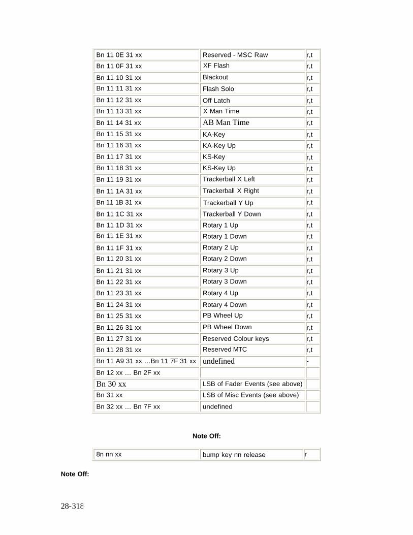
28-318
Bn 11 0E 31 xx Reserved - MSC Raw r,t Bn 11 0F 31 xx XF Flash r,t Bn 11 10 31 xx Blackout r,t Bn 11 11 31 xx Flash Solo r,t Bn 11 12 31 xx Off Latch r,t Bn 11 13 31 xx X Man Time r,t Bn 11 14 31 xx AB Man Time r,t Bn 11 15 31 xx KA-Key r,t Bn 11 16 31 xx KA-Key Up r,t Bn 11 17 31 xx KS-Key r,t Bn 11 18 31 xx KS-Key Up r,t Bn 11 19 31 xx Trackerball X Left r,t Bn 11 1A 31 xx Trackerball X Right r,t Bn 11 1B 31 xx Trackerball Y Up r,t Bn 11 1C 31 xx Trackerball Y Down r,t Bn 11 1D 31 xx Rotary 1 Up r,t Bn 11 1E 31 xx Rotary 1 Down r,t Bn 11 1F 31 xx Rotary 2 Up r,t Bn 11 20 31 xx Rotary 2 Down r,t Bn 11 21 31 xx Rotary 3 Up r,t Bn 11 22 31 xx Rotary 3 Down r,t Bn 11 23 31 xx Rotary 4 Up r,t Bn 11 24 31 xx Rotary 4 Down r,t Bn 11 25 31 xx PB Wheel Up r,t Bn 11 26 31 xx PB Wheel Down r,t Bn 11 27 31 xx Reserved Colour keys r,t Bn 11 28 31 xx Reserved MTC r,t Bn 11 A9 31 xx …Bn 11 7F 31 xx undefined - Bn 12 xx … Bn 2F xx Bn 30 xx LSB of Fader Events (see above) Bn 31 xx LSB of Misc Events (see above) Bn 32 xx … Bn 7F xx undefined
Note Off:
8n nn xx bump key nn release r
Note Off:
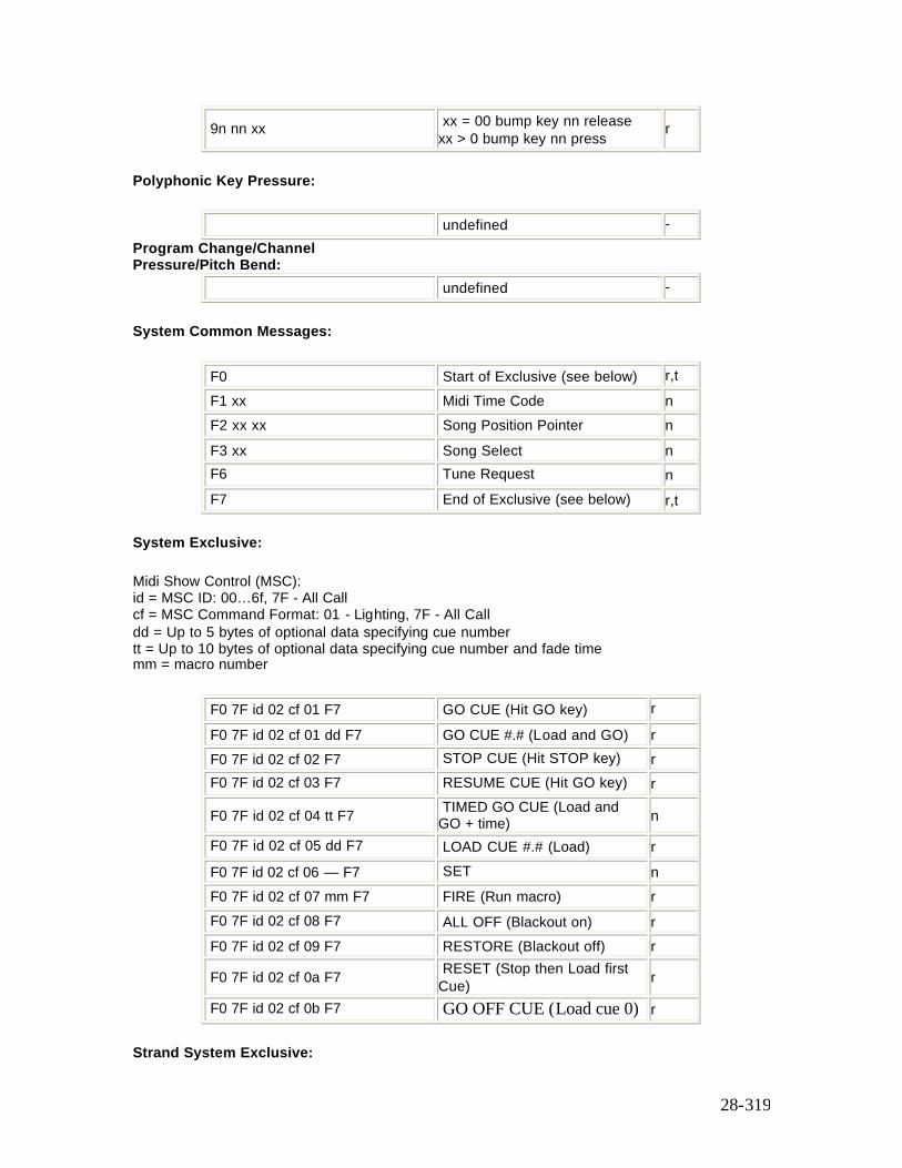
28-319
9n nn xx xx = 00 bump key nn release xx > 0 bump key nn press r
Polyphonic Key Pressure:
undefined - Program Change/Channel Pressure/Pitch Bend:
undefined -
System Common Messages:
F0 Start of Exclusive (see below) r,t F1 xx Midi Time Code n F2 xx xx Song Position Pointer n F3 xx Song Select n F6 Tune Request n F7 End of Exclusive (see below) r,t
System Exclusive:
Midi Show Control (MSC): id = MSC ID: 00…6f, 7F - All Call cf = MSC Command Format: 01 - Lighting, 7F - All Call dd = Up to 5 bytes of optional data specifying cue number tt = Up to 10 bytes of optional data specifying cue number and fade time mm = macro number
F0 7F id 02 cf 01 F7 GO CUE (Hit GO key) r F0 7F id 02 cf 01 dd F7 GO CUE #.# (Load and GO) r F0 7F id 02 cf 02 F7 STOP CUE (Hit STOP key) r F0 7F id 02 cf 03 F7 RESUME CUE (Hit GO key) r
F0 7F id 02 cf 04 tt F7 TIMED GO CUE (Load and GO + time) n
F0 7F id 02 cf 05 dd F7 LOAD CUE #.# (Load) r F0 7F id 02 cf 06 — F7 SET n F0 7F id 02 cf 07 mm F7 FIRE (Run macro) r F0 7F id 02 cf 08 F7 ALL OFF (Blackout on) r F0 7F id 02 cf 09 F7 RESTORE (Blackout off) r
F0 7F id 02 cf 0a F7 RESET (Stop then Load first Cue) r
F0 7F id 02 cf 0b F7 GO OFF CUE (Load cue 0) r
Strand System Exclusive:
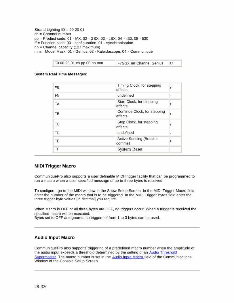
28-320
Strand Lighting ID = 00 20 01 ch = Channel number pp = Product code: 01 - MX, 02 - GSX, 03 - LBX, 04 - 430, 05 - 530 ff = Function code: 00 - configuration, 01 - synchronisation nn = Channel capacity (127 maximum) mm = Model Mask: 01 - Genius, 02 - Kaleidoscope, 04 - Communiqué
F0 00 20 01 ch pp 00 nn mm F7GSX nn Channel Genius r,t
System Real Time Messages:
F8 Timing Clock, for stepping effects r
F9 undefined -
FA Start Clock, for stepping effects r
FB Continue Clock, for stepping effects r
FC Stop Clock, for stepping effects r
FD undefined -
FE Active Sensing (Break in comms) r
FF System Reset
MIDI Trigger Macro
CommuniquéPro also supports a user definable MIDI trigger facility that can be programmed to run a macro when a user specified message of up to three bytes is received.
To configure, go to the MIDI window in the Show Setup Screen. In the MIDI Trigger Macro field enter the number of the macro that is to be triggered. In the MIDI Trigger Bytes field enter the three trigger byte values [in decimal] you require.
When Macro is OFF or all three bytes are OFF, no triggers occur. When a trigger is received the specified macro will be executed. Bytes set to OFF are ignored, so triggers of from 1 to 3 bytes can be used.
Audio Input Macro
CommuniquéPro also supports triggering of a predefined macro number when the amplitude of the audio input exceeds a threshold determined by the setting of an Audio Threshold Supermaster. The macro number is set in the Audio Input Macro field of the Communications Window of the Console Setup Screen.

28-321
See Also: CommuniquéPro Continued
29-322
Chapter 29 - Networker
Networker is a standard software package for Strand Lighting’s 500 Series Consoles and GeniusPro or Lightpalette Operating software. It uses an Ethernet network to provide the following features:-
• Tracking Backup - Tracks state and changes from one console to another. Backup console will automatically take over running the show when the main console fails.
• Remote Consoles - Multiple consoles can operate together on the same show. • Remote Video - Distributes console video information over the network to SN network
nodes. • Remote DMX - Distributes DMX data over the network to SN network nodes. • Remote Handhelds - Use Remote port on SN100 and SN102 network nodes to connect
handheld remotes. • Remote Faders - Use Analogue port on SN100 and SN102 network nodes to connect
remote faders or to use the faders fitted to the SN100. • Remote MIDI - Use MIDI ports on SN100 and SN102 to extend the range of your MIDI
connections.
This section covers the following topics:
• Network Port Selection • Node Addresses • Broadcast Communication • Point to Point Communication • Default IP Addresses • 220node.cfg Network Configuration File • SN10X Configuration File Format • Network Node Configuration File Example • SN10X Node Self Test Software • Preserving Configuration Files • Network DMX • Network Video • Tracking Backup • Remote Consoles • Remote Ports
Network Port Selection Consoles with newer electronics have built-in Ethernet ports, rather than use a plug-in card. By default, the RJ-45 port (phone-style) is enabled. To enable the BNC port instead, an empty flag file needs to be present in the operating software directory. To do this, add this line to the file USERINIT.BAT in that directory: ECHO > BNC_IF.FLG To change the port selection on the plug-in 3Com card, use the EtherDisk floppy supplied with the card, and run the 3c5x9cfg.exe utility.
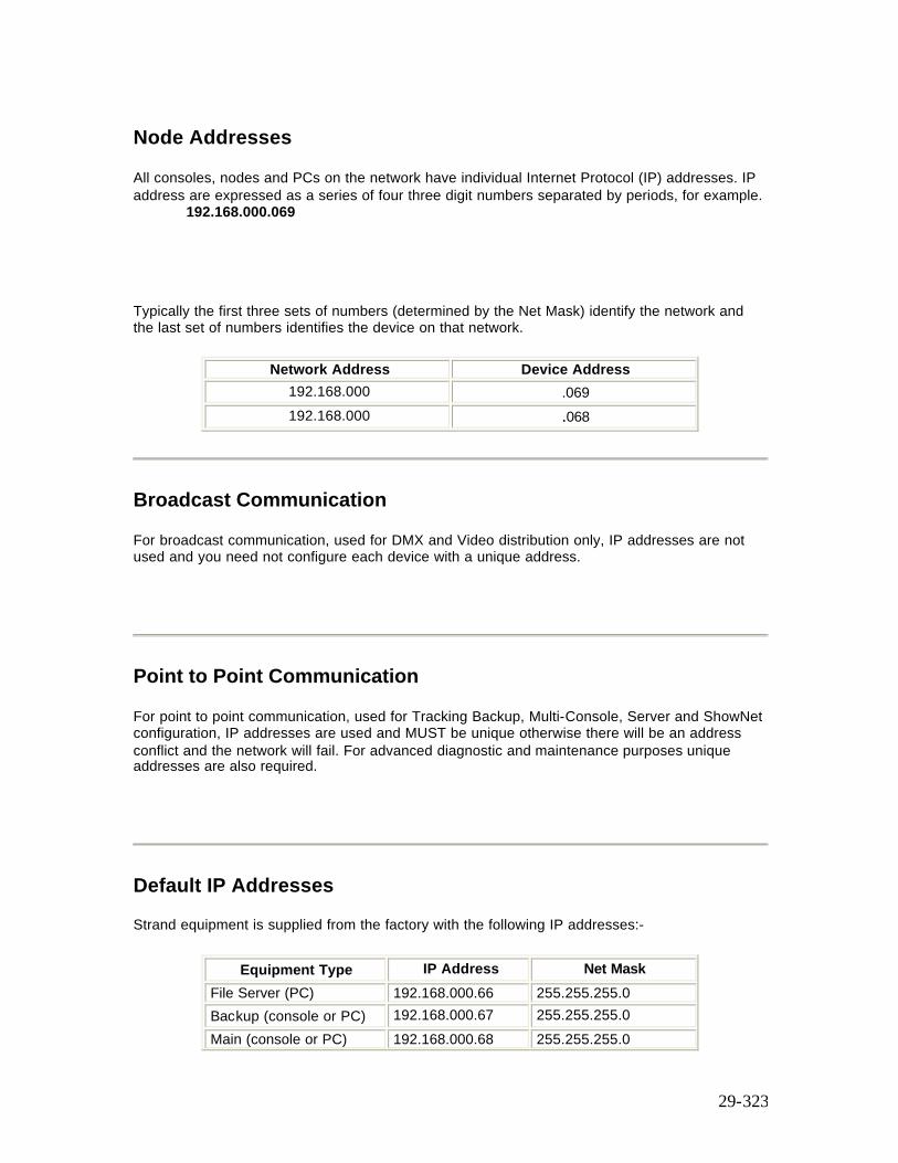
29-323
Node Addresses All consoles, nodes and PCs on the network have individual Internet Protocol (IP) addresses. IP address are expressed as a series of four three digit numbers separated by periods, for example.
192.168.000.069
Typically the first three sets of numbers (determined by the Net Mask) identify the network and the last set of numbers identifies the device on that network.
Network Address Device Address 192.168.000 .069 192.168.000 .068
Broadcast Communication
For broadcast communication, used for DMX and Video distribution only, IP addresses are not used and you need not configure each device with a unique address.
Point to Point Communication
For point to point communication, used for Tracking Backup, Multi-Console, Server and ShowNet configuration, IP addresses are used and MUST be unique otherwise there will be an address conflict and the network will fail. For advanced diagnostic and maintenance purposes unique addresses are also required.
Default IP Addresses
Strand equipment is supplied from the factory with the following IP addresses:-
Equipment Type IP Address Net Mask File Server (PC) 192.168.000.66 255.255.255.0 Backup (console or PC) 192.168.000.67 255.255.255.0 Main (console or PC) 192.168.000.68 255.255.255.0
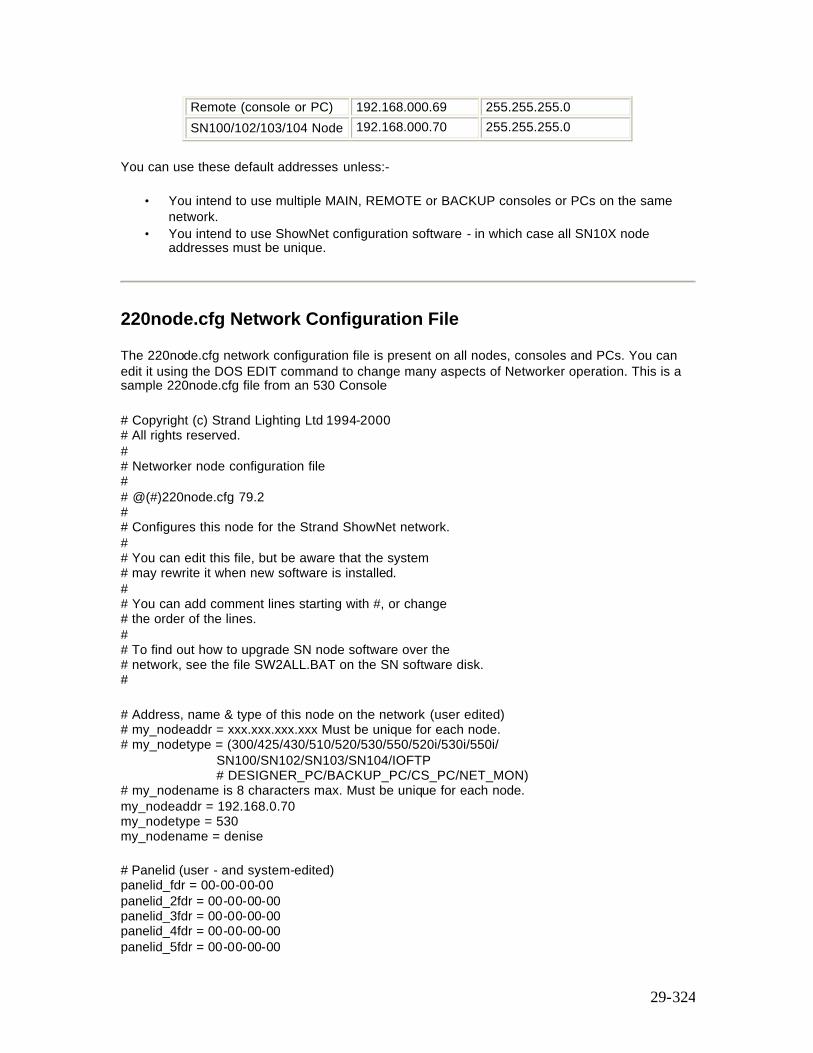
29-324
Remote (console or PC) 192.168.000.69 255.255.255.0 SN100/102/103/104 Node 192.168.000.70 255.255.255.0
You can use these default addresses unless:-
• You intend to use multiple MAIN, REMOTE or BACKUP consoles or PCs on the same network.
• You intend to use ShowNet configuration software - in which case all SN10X node addresses must be unique.
220node.cfg Network Configuration File
The 220node.cfg network configuration file is present on all nodes, consoles and PCs. You can edit it using the DOS EDIT command to change many aspects of Networker operation. This is a sample 220node.cfg file from an 530 Console
# Copyright (c) Strand Lighting Ltd 1994-2000 # All rights reserved. # # Networker node configuration file # # @(#)220node.cfg 79.2 # # Configures this node for the Strand ShowNet network. # # You can edit this file, but be aware that the system # may rewrite it when new software is installed. # # You can add comment lines starting with #, or change # the order of the lines. # # To find out how to upgrade SN node software over the # network, see the file SW2ALL.BAT on the SN software disk. #
# Address, name & type of this node on the network (user edited) # my_nodeaddr = xxx.xxx.xxx.xxx Must be unique for each node. # my_nodetype = (300/425/430/510/520/530/550/520i/530i/550i/
SN100/SN102/SN103/SN104/IOFTP # DESIGNER_PC/BACKUP_PC/CS_PC/NET_MON)
# my_nodename is 8 characters max. Must be unique for each node. my_nodeaddr = 192.168.0.70 my_nodetype = 530 my_nodename = denise # Panelid (user - and system-edited) panelid_fdr = 00-00-00-00 panelid_2fdr = 00-00-00-00 panelid_3fdr = 00-00-00-00 panelid_4fdr = 00-00-00-00 panelid_5fdr = 00-00-00-00
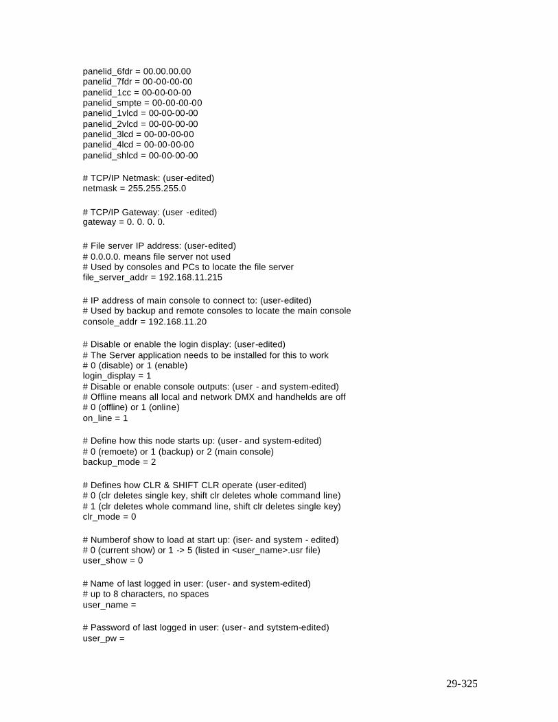
29-325
panelid_6fdr = 00.00.00.00 panelid_7fdr = 00-00-00-00 panelid_1cc = 00-00-00-00 panelid_smpte = 00-00-00-00 panelid_1vlcd = 00-00-00-00 panelid_2vlcd = 00-00-00-00 panelid_3lcd = 00-00-00-00 panelid_4lcd = 00-00-00-00 panelid_shlcd = 00-00-00-00
# TCP/IP Netmask: (user-edited) netmask = 255.255.255.0
# TCP/IP Gateway: (user -edited) gateway = 0. 0. 0. 0.
# File server IP address: (user-edited) # 0.0.0.0. means file server not used # Used by consoles and PCs to locate the file server file_server_addr = 192.168.11.215 # IP address of main console to connect to: (user-edited) # Used by backup and remote consoles to locate the main console console_addr = 192.168.11.20 # Disable or enable the login display: (user-edited) # The Server application needs to be installed for this to work # 0 (disable) or 1 (enable) login_display = 1 # Disable or enable console outputs: (user - and system-edited) # Offline means all local and network DMX and handhelds are off # 0 (offline) or 1 (online) on_line = 1 # Define how this node starts up: (user- and system-edited) # 0 (remoete) or 1 (backup) or 2 (main console) backup_mode = 2 # Defines how CLR & SHIFT CLR operate (user-edited) # 0 (clr deletes single key, shift clr deletes whole command line) # 1 (clr deletes whole command line, shift clr deletes single key) clr_mode = 0 # Numberof show to load at start up: (iser- and system - edited) # 0 (current show) or 1 -> 5 (listed in <user_name>.usr file) user_show = 0 # Name of last logged in user: (user- and system-edited) # up to 8 characters, no spaces user_name = # Password of last logged in user: (user- and sytstem-edited) user_pw =
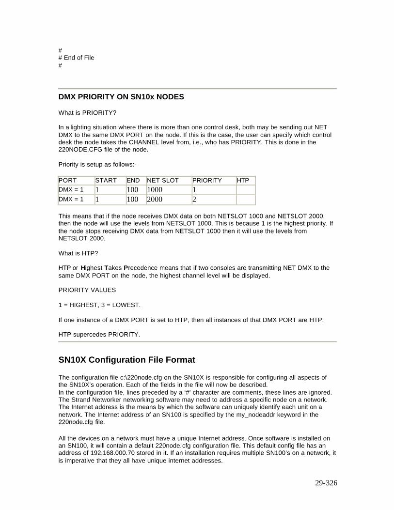
29-326
# # End of File #
DMX PRIORITY ON SN10x NODES What is PRIORITY? In a lighting situation where there is more than one control desk, both may be sending out NET DMX to the same DMX PORT on the node. If this is the case, the user can specify which control desk the node takes the CHANNEL level from, i.e., who has PRIORITY. This is done in the 220NODE.CFG file of the node. Priority is setup as follows:-
PORT START END NET SLOT PRIORITY HTP DMX = 1 1 100 1000 1 DMX = 1 1 100 2000 2 This means that if the node receives DMX data on both NETSLOT 1000 and NETSLOT 2000, then the node will use the levels from NETSLOT 1000. This is because 1 is the highest priority. If the node stops receiving DMX data from NETSLOT 1000 then it will use the levels from NETSLOT 2000. What is HTP? HTP or Highest Takes Precedence means that if two consoles are transmitting NET DMX to the same DMX PORT on the node, the highest channel level will be displayed. PRIORITY VALUES 1 = HIGHEST, 3 = LOWEST. If one instance of a DMX PORT is set to HTP, then all instances of that DMX PORT are HTP. HTP supercedes PRIORITY.
SN10X Configuration File Format
The configuration file c:\220node.cfg on the SN10X is responsible for configuring all aspects of the SN10X’s operation. Each of the fields in the file will now be described. In the configuration file, lines preceded by a ‘#’ character are comments, these lines are ignored. The Strand Networker networking software may need to address a specific node on a network. The Internet address is the means by which the software can uniquely identify each unit on a network. The Internet address of an SN100 is specified by the my_nodeaddr keyword in the 220node.cfg file. All the devices on a network must have a unique Internet address. Once software is installed on an SN100, it will contain a default 220node.cfg configuration file. This default config file has an address of 192.168.000.70 stored in it. If an installation requires multiple SN100’s on a network, it is imperative that they all have unique internet addresses.
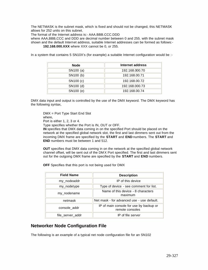
29-327
The NETMASK is the subnet mask, which is fixed and should not be changed, this NETMASK allows for 252 units on this subnet. The format of the Internet address is:- AAA.BBB.CCC.DDD where AAA,BBB,CCC and DDD are decimal number between 0 and 255. with the subnet mask shown and the default Internet address, suitable Internet addresses can be formed as follows:-
192.168.000.XXX where XXX cannot be 0, or 255.
In a system that contains 5 SN10X’s (for example) a suitable Internet configuration would be :-
Node Internet address SN100 (a) 192.168.000.70 SN100 (b) 192.168.00.71 SN100 (c) 192.168.00.72 SN100 (d) 192.168.000.73 SN100 (e) 192.168.00.74
DMX data input and output is controlled by the use of the DMX keyword. The DMX keyword has the following syntax,
DMX = Port Type Start End Slot where, Port is either 1, 2, 3 or 4. Type specifies whether the Port is IN, OUT or OFF. IN specifies that DMX data coming in on the specified Port should be placed on the network at the specified global network slot, the first and last dimmers sent out from the incoming DMX frame are specified by the START and END numbers. The START and END numbers must be between 1 and 512. OUT specifies that DMX data coming in on the network at the specified global network channel offset, will be sent out of the DM X Port specified. The first and last dimmers sent out for the outgoing DMX frame are specified by the START and END numbers. OFF Specifies that this port is not being used for DMX
Field Name Description my_nodeaddr IP of this device my_nodetype Type of device - see comment for list.
my_nodename Name of this device - 8 characters maximum
netmask Net mask - for advanced use - use default.
console_addr IP of main console for use by backup or remote consoles
file_server_addr IP of file server
Networker Node Configuration File
The following is an example of a typical net node configuration file for an SN102
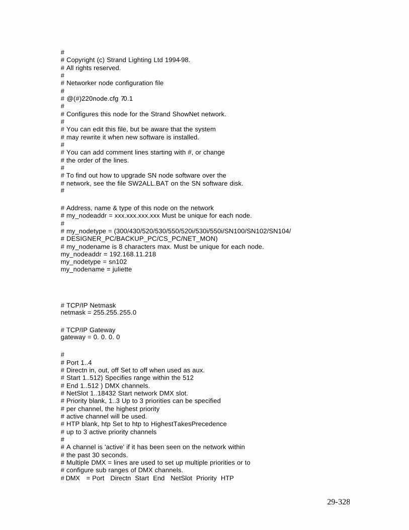
29-328
# # Copyright (c) Strand Lighting Ltd 1994-98. # All rights reserved. # # Networker node configuration file # # @(#)220node.cfg 70.1 # # Configures this node for the Strand ShowNet network. # # You can edit this file, but be aware that the system # may rewrite it when new software is installed. # # You can add comment lines starting with #, or change # the order of the lines. # # To find out how to upgrade SN node software over the # network, see the file SW2ALL.BAT on the SN software disk. #
# Address, name & type of this node on the network # my_nodeaddr = xxx.xxx.xxx.xxx Must be unique for each node. # # my_nodetype = (300/430/520/530/550/520i/530i/550i/SN100/SN102/SN104/ # DESIGNER_PC/BACKUP_PC/CS_PC/NET_MON) # my_nodename is 8 characters max. Must be unique for each node. my_nodeaddr = 192.168.11.218 my_nodetype = sn102 my_nodename = juliette
# TCP/IP Netmask netmask = 255.255.255.0
# TCP/IP Gateway gateway = 0. 0. 0. 0
# # Port 1..4 # Directn in, out, off Set to off when used as aux. # Start 1..512) Specifies range within the 512 # End 1..512 ) DMX channels. # NetSlot 1..18432 Start network DMX slot. # Priority blank, 1..3 Up to 3 priorities can be specified # per channel, the highest priority # active channel will be used. # HTP blank, htp Set to htp to HighestTakesPrecedence # up to 3 active priority channels # # A channel is 'active' if it has been seen on the network within # the past 30 seconds. # Multiple DMX = lines are used to set up multiple priorities or to # configure sub ranges of DMX channels. # DMX = Port Directn Start End NetSlot Priority HTP
29-329
DMX = 1 out 1 512 1
DMX = 2 out 1 512 1
DMX = 3 out 1 512 1025
DMX = 4 out 1 512 1537 # # Configuration end
SN10X Node Self Test Software
SN10X nodes are supplied with comprehensive built-in test software which verifies correct operation at power up. If a fault should be detected a message will appear on the VGA1 monitor and the Fader LEDs will flash. Contact your dealer or Strand service department for more information. Service engineers can access the built in diagnostics as follows, using a PC keyboard and the supplied adapter :-
1. Press Ctrl-X to exit from the application and return to DOS. 2. Restart the application in test mode by typing 220os /TEST in the c:\220os directory and
follow the on-screen prompts. 3. The optional command line switches /MASTER and /SLAVE can be used with the /TEST
switch to perform back-to-back Ethernet tests with two SN10X Nodes.
Preserving Configuration Files
When installing a new release, the existing 220NODE.CFG file gets overwritten with a default config file supplied in the install disk or the remote install compressed file. The installation utility will first copy the existing 220NODE.CFG to 220NODE.OLD in the same directory before overwriting it. This provides a mechanism for re-instating the old configuration file via the batch file RECOVER.BAT which the user supplies in the C:\220OS directory. As described above, the install utility will look for the batch file RECOVER.BAT and run it if it exists at the end of the installation process.
As a minimum, the RECOVER.BAT file should contain the following:- copy 220NODE.OLD 220NODE.CFG /v /y If the old config file is not re-instated, then the result of loading the new release on all SN10Xs, will be that they will all have the same IP address and therefore create confusion in the consoles and pc’s running the ioftpxxx programs. The batch file RECOVER.BAT can be easily copied to the SN100 and SN102 as they contain a floppy drive. However, the only method for the SN104 is to download it via the IOFTPxxx program. The procedure for doing it is as follows:-
1. Determine the node name or IP address of the SN104. 2. Create the batch file locally on the PC which you will use to run the IOFTPxxx program.
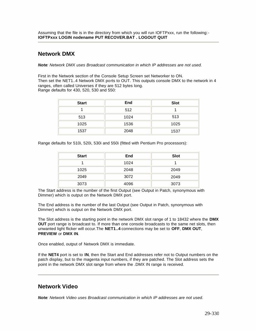
29-330
Assuming that the file is in the directory from which you will run IOFTPxxx, run the following:- IOFTPxxx LOGIN nodename PUT RECOVER.BAT . LOGOUT QUIT
Network DMX
Note: Network DMX uses Broadcast communication in which IP addresses are not used.
First in the Network section of the Console Setup Screen set Networker to ON. Then set the NET1..4 Network DMX ports to OUT. This outputs console DMX to the network in 4 ranges, often called Universes if they are 512 bytes long. Range defaults for 430, 520, 530 and 550:
Start End Slot 1 512 1
513 1024 513 1025 1536 1025 1537 2048 1537
Range defaults for 510i, 520i, 530i and 550i (fitted with Pentium Pro processors):
Start End Slot 1 1024 1
1025 2048 2049 2049 3072 2049 3073 4096 3073
The Start address is the number of the first Output (see Output in Patch, synonymous with Dimmer) which is output on the Network DMX port. The End address is the number of the last Output (see Output in Patch, synonymous with Dimmer) which is output on the Network DMX port. The Slot address is the starting point in the network DMX slot range of 1 to 18432 where the DMX OUT port range is broadcast to. If more than one console broadcasts to the same net slots, then unwanted light flicker will occur.The NET1..4 connections may be set to OFF, DMX OUT, PREVIEW or DMX IN. Once enabled, output of Network DMX is immediate. If the NET4 port is set to IN, then the Start and End addresses refer not to Output numbers on the patch display, but to the magenta input numbers, if they are patched. The Slot address sets the point in the network DMX slot range from where the .DMX IN range is received.
Network Video
Note: Network Video uses Broadcast communication in which IP addresses are not used.
29-331
First in the Network section of the Console Setup Screen set Networker to ON. Then set the NET Video Slot address to 1. This outputs the console’s first screen in Net Video Slot 1, second screen in Net Video Slot 2 and so on. If there are multiple main consoles on the same network it may be necessary to set a NET Video Slot number other than 1 to avoid conflicts.
Once enabled, output of Network Video is immediate.
Tracking Backup
Note: Tracking Backup uses Point to Point communications in which IP addresses are used and MUST be unique.
This section covers the following topics:
o Overview of Tracking Backup o Configuration for Tracking Backup o Tracking Backup Status o Tracking Backup Commands o Shifted Backup Commands o Testing Backup Takeover o Console Lock on Backup
Overview of Tracking Backup
Tracking Backup allows 2 consoles/PCs running identical configurations of GeniusPro or Lightpalette to work together as main and backup consoles/PCs for added security of operation.
Notes
1. ‘Identical configurations’ means that main and backup should be registered with the same applications and number of channels. If the backup is a PC, this requires that it should have a serial numbered dongle (available since version 2.0 software) which enables the PC to be registered with a password just like a console.
2. Any two types of console can be used as a main/backup pair, but non-i consoles may not be able to have enough channels.
3. Backup PCs do not need to be fitted with dual VGA cards, because video screen modes track correctly without them.
During normal operation the main desk runs the show (is in control) and generates wired or network DMX to drive the lights. The backup console will be in exactly the same state as the main console (in synchronization (sync)) and will execute all commands the main console executes (tracking) but will not output DMX (or other information). Should the main console fail or become disconnected from the backup console the backup console will take control of the show and start to output DMX levels. This change over happens in a matter of a few seconds during which the lighting levels are maintained.
29-332
But first, in order to get the backup into sync, the operator of the main console must give sync to the backup. This can take a minute or so and would normally be done when the console is first powered on.
When disconnected the main and backup console can both run different shows provided they are configured not to output network DMX or video to the same slots at the same time and cause a conflict.
The status of the backup (and main) is always displayed in a small window under the wheel bar.
Configuration for Tracking Backup.
You can use consoles or PCs as main or backup consoles.
To guarantee tracking, both main and backup must have identical passwords (number of channels, applications loaded). This now also applies to PCs, now that PC dongles are registered with channels and applications.
Note: PCs no longer need to have a dual VGA card.
A PC used for backup should also have its number of submasters set to match those of the main. This can be done by creating a file called USERINIT.BAT in the backup PC program directory with a line according to the main console type:
If the main is a 520, the line should be: SET 220NUMSUBS=24 If the main is a 530: SET 220NUMSUBS=30 If the main is a 550: SET 220NUMSUBS=54
This file does not need editing after installing new software. (Never edit the AUTOEXEC.BAT or CONFIG.SYS files - these are recreated when new software is installed.)
A backup console with a different number of submasters to the main also needs 220NUMSUBS setting to match the main.
You must have a floppy disk in main and backup drives if you use disk archive operations which access the floppy, or you will lose sync.
Ensure that the same version of the operating software is installed on the main and backup.
Edit main 220NODE.CFG file in addition to the general settings:
on_line = 1 backup_mode = 2
Edit backup 220NODE.CFG file in addition to the general settings:
29-333
on_line = 1 backup_mode = 1 console_addr = 192.168.0.aaa aaa must match my_nodeaddr of the main console
Start main console
1. Power up, or run 'os' from c:\220os at DOS. If you are using the login display, enter OnLine=YES, Mode=MAIN, Main=LOCAL.
2. Press F1 to log in. The default admin user password is blank. 3. Start backup console or PC 4. Power up, or run 'os' from c:\220os at DOS. If you are using the login display, enter
OnLine=YES, Mode=BACKUP, Main= Console1. Both consoles should then show 'Main Ok Backup Ok No Sync'.
To Achieve Sync
On Main or Backup, at the Backup Commands menu (under the More key, or Alt R on the alpha keyboard), press M Give Sync or M Take Sync (main give sync to backup, or main take sync from backup). The console giving sync saves the current show, the shows file is transferred, and the other console loads the show file. Both consoles should then show 'Main Active In Sync'.
Demonstrate Backup Taking Over
Disconnect the main console from the network. After a few seconds, backup shows 'Backup in control no sync'. Main will show 'Backup Gone Offline'.
Resync Main After Backup Has Taken Over
Reconnect main and do Main Take Sync. (You need to power any remote console or PC down and up again to ensure it tracks again to main and backup.)
Shutdown From Main
Only allowed when not in sync - use the backup command Break Sync first. Use Shutdown on main console only to return to DOS. (A warning is given if remote users are logged in.)
Tracking Backup Status
Tracking backup status is displayed on the levels screen under the wheel bar. States are the same on main and backup except for:- M - Seen on Main only. B - Seen on Backup only.
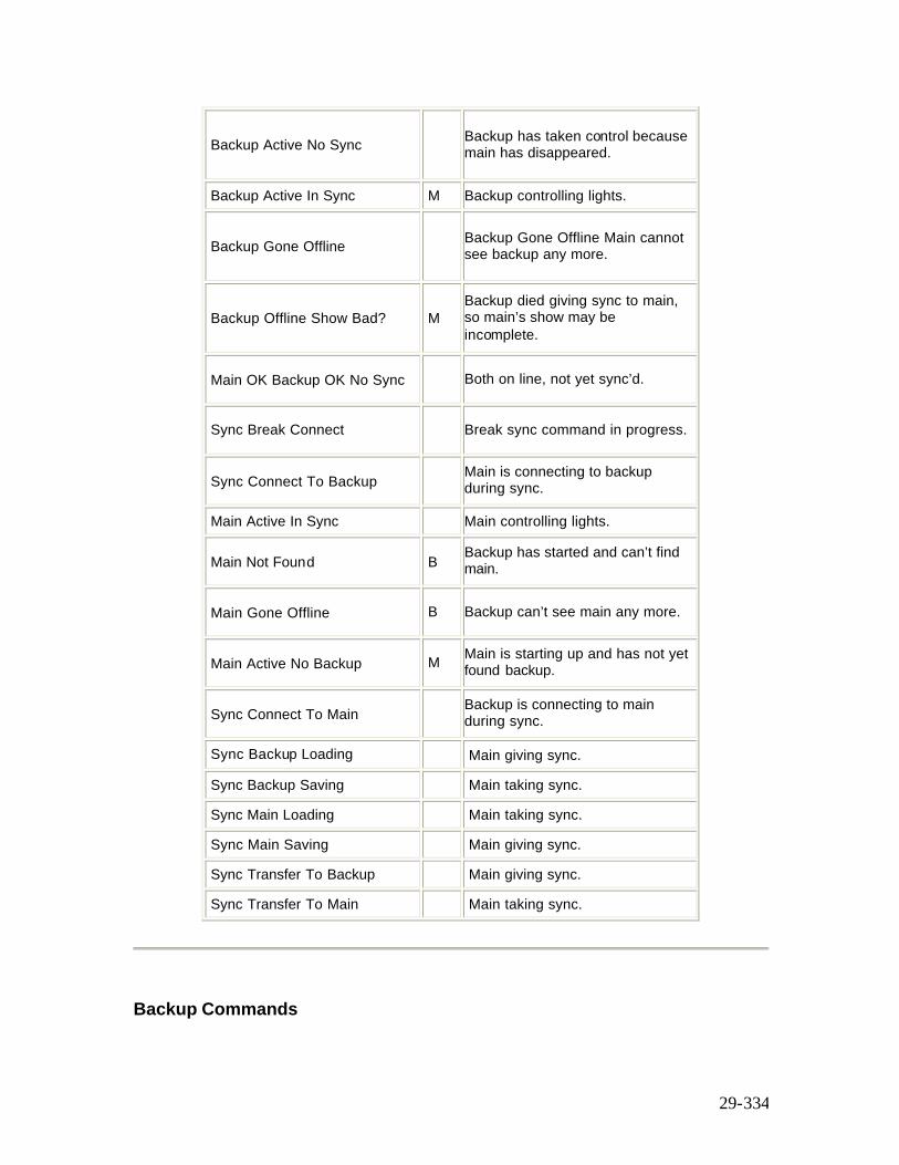
29-334
Backup Active No Sync Backup has taken control because main has disappeared.
Backup Active In Sync M Backup controlling lights.
Backup Gone Offline Backup Gone Offline Main cannot see backup any more.
Backup Offline Show Bad? M Backup died giving sync to main, so main’s show may be incomplete.
Main OK Backup OK No Sync Both on line, not yet sync’d.
Sync Break Connect Break sync command in progress.
Sync Connect To Backup Main is connecting to backup during sync.
Main Active In Sync Main controlling lights.
Main Not Found B Backup has started and can’t find main.
Main Gone Offline B Backup can’t see main any more.
Main Active No Backup M Main is starting up and has not yet found backup.
Sync Connect To Main Backup is connecting to main during sync.
Sync Backup Loading Main giving sync.
Sync Backup Saving Main taking sync.
Sync Main Loading Main taking sync.
Sync Main Saving Main giving sync.
Sync Transfer To Backup Main giving sync.
Sync Transfer To Main Main taking sync.
Backup Commands
29-335
Backup commands are available if both main and backup powered up with the state Main OK Backup OK No Sync displayed. If states such as Main (or Backup) Gone Offline, or Main (or Backup) Not Found are displayed, these commands are not available. Backup commands are accessed by pressing [MORE]{BACKUP CMDS} , revealing the following set of soft keys:- {M GIVE SYNC}, {M TAKE SYNC}, {M GIVE CTRL}, {M TAKE CTRL}, {BREAK SYNC} and {RESET DESK} {M GIVE SYNC} Main give sync to backup: the current show is transferred to the backup and only the main’s outputs are enabled. State sequence:
• Sync Transfer To Backup • Sync Backup Loading (if the sync fails for any reason here, see Shifted Backup
commands below) • Sync Connect To Backup • Sync Connect To Main • Main Active In Sync.
{M TAKE SYNC} Main take sync from backup: the current show is transferred from the backup and only the main’s outputs are enabled. State sequence:
• Sync Transfer To Main • Sync Main Loading (if the sync fails for any reason here, see Shifted Backup commands
below) • Sync Connect To Backup • Sync Connect To Main • Main Active In Sync
{M GIVE CTRL} Main give control to backup: the main’s outputs are disabled and the backup’s outputs are enabled. New state:
• Backup Active In Sync
{M TAKE CTRL} Main take control from backup: the main’s outputs are enabled and the backup’s outputs are disabled. New state
• Main Active In Sync
29-336
{BREAK SYNC} Break sync: the tracking connection between main and backup is broken, which is necessary in order to shut down either console. Only the main’s outputs are enabled. New state:
• Main Ok Backup Ok No Sync
{RESET DESK} Reset Desk resets many console parameters to power-up defaults. It is run automatically at the end of the Give/Take Sync commands, but is available manually here.
Shifted Backup Commands Two other commands are available, by holding down the [SHIFT] key first. {M GIVE SYNC} Quick Main Give Sync To Backup. Main and backup are connected without the show data or console state being transferred. Only available in the Main OK, Backup OK, No Sync state. State sequence:
• Sync Connect To Backup • Sync Connect To Main • Main Active In Sync
{M TAKE SYNC} Quick Main Take Sync From Backup. Main and backup are connected without the show data or console state being transferred. Only available in the Backup Active No Sync state (i.e. when the backup has taken control automatically, and the main has now restarted). State sequence:
• Sync Connect To Backup • Sync Connect To Main • Main Active In Sync
Note: Give or Take Sync may occasionally fail after the sync show has loaded on the destination machine, with the message 'Sync Failed - please try again'. If this happens, use [SHIFT] [M TAKE SYNC] to do a quick sync withou transferring the show file. To get main back in control after backup has taken over, use [SHIFT] [M TAKE SYNC] to do a quick sync withou transferring the show.
Testing Backup Takeover
Once main and backup are in sync, you can use the Main Give Control to test that the backup outputs are working. Use Main Take Control to restore main’s outputs. To test automatic backup takeover when in sync, switch off the main or disconnect its network cable. After the network timeout period expires (several seconds), the backup state changes to Backup Active No Sync, and its outputs are enabled. When the main is powered up again or reconnected, its state also changes to Backup Active No Sync, and its outputs stay disabled.
29-337
To restore control to main at this point, you can do Main Take Sync at either console, which will transfer the show as well (in case any changes were made while main was off). If no show changes were made, you can hold SHIFT down while pressing Main Take Sync, which does a quick sync (ie. no show transfer).
Console Lock On Backup
Normally the backup console controls are active when in sync. Commands entered on the backup are echoed back to the main so both consoles stay in sync. To prevent the controls on the backup console being accidentally pressed they can be locked out by pressing the keys [SHIFT][HELP] together. Use [SHIFT][HELP] again to toggle the console lock off. On the 510i show controller, turn the keyswitch to the locked position and remove the key.
Remote Consoles
Note: Remote Consoles use Point to Point communications in which IP addresses are used and MUST be unique.
Remote Console/PC allows one Main and several Remote consoles to work together on the same show file at the same time. The main and remote need not have the same configuration of software or hardware. Each console/PC user has their own command line and screen but shares the same show (cues, groups, effects, etc.).
The main console and all remote consoles and PCs must have Operating Software and Networker Utilities software of the same version loaded. Networker Utilities software is loaded using the same Archive menu sequence as for Operating Software. In addition, you can load the Server application to use the Login display, with its easy mode change and login facilities. Without Server, you need to force remote mode without using the login display as described below.
The following topics are covered in this section:
o Remote Console Configuration o Setting Remote Console Mode Without Using the Login Display o Using Remote Console Submasters o Remote Console Status o Remote Console Controls o Channel Partitioning o Viewing Other User's Displays
Remote Console Configuration
You can use consoles or PCs as main or backup consoles.
Ensure that the same version of the operating software are installed on both main and remote. Ensure that Networker & Utilities is loaded on both main and remote.
29-338
Ensure that the main and remote console 220node.cfg files are setup as shown below. My_nodeaddr needs to be unique for both consoles. Edit main 220node.cfg
my_nodeaddr = 192.168.000.68 my_nodetype = 530 (console type) my_nodename = main on_line =1 # IP address of main console to connect to (user-edited) console_addr = 192.168.000.68 # Define how this node starts up: (user- and system-edited) 0 (remote) or 1 (backup) or 2 (main console) backup_mode = 2 Edit the remote 220node.cfg my_nodeaddr = 192.168.000.69 my_nodetype = 530 (console type) my_nodename = remote # IP address of main console to connect to (user-edited) console_addr = 192.168.000.68 # Define how this node starts up: (user- and system-edited) # 0 (remote) or 1 (backup) or 2 (main console) backup_mode = 0
Setting Remote Console Mode Without Using The Login Display
If a console is to always start as a remote logged in to a particular main console, edit 220NODE.CFG like this:
login_display = 0 console_addr = 192.168.0.68 (or whatever the main console’s address is) backup_mode = 0 Other fixed startup modes are: main: backup_mode = 2 backup: backup_mode = 1
Using Remote Console Submasters
When a remote console logs in, its submaster faders control the same submasters as the faders on the main console. For a fader to take control of a submaster, it must be moved to match the position of the fader on the other console which currently controls the submaster. The faders on a remote console can also be used to control submasters 31-54 on a 530 main console, or 25-54 on a 520 main console. To do this, add the line
29-339
set 220numsubs=54 in the file USERINIT.BAT on the 530 or 520, and set the submaster layout setup field to “25-36 & 37-48” on the remote console.
Remote Console Status
The node name of each console, together with the name of the main console which the remote is logged into, is displayed on most screens below the wheel bar.
Remote Console Controls
Control interaction between main and remote is summarized below: -
Control Mode Command Line separate Channel Controls separate Screens separate Macro Execution separate Cue Playbacks shared Fx Playbacks shared
Submasters shared (unless submaster layout setup is changed)
Grandmasters shared Supermasters shared
Channel Partitioning
This is an important productivity aid to help users of main and remote consoles work together more easily. It allows channels to be assigned to only one or other user for all channel control and record operations. So one user could plot moving light cues while the other plots dimmer cues, without recording or changing the other’s channels.
To enable channel partitioning, define the contents of each user’s channel partition group, and enable Channel Partitioning in the Show Setup Screen. When partitioning is enabled, no channel can be assigned to both users at the same time. When you add a channel to a partition group, it is automatically removed from the other partition groups.
Viewing Other Users’ Displays
29-340
At main or remote consoles, you can view the current display of the other console by pressing [SHIFT][MORE] together. To return to your local display, press [SHIFT] [MORE] again. The status display below the wheel bar shows which console display is selected.
Remote Ports Using the NET NODE field of the Console Setup Screen, you can reassign local console ports to be connected to corresponding ports on an SN100 or SN102. Remote Handheld: Connecting a handheld remote to the remote connector on an SN100 or SN102 means you have to set the Net Node field of Handheld Remote Communications Setup in the Console Setup Screen to the name of the SN node. Only COM2 is valid for the port. Notes:
1. Older SN100’s remote connectors were not wired correctly.Contact Strand Service if your SN100 remote connector does not work.
2. Some SN102’s remote connectors were not wired for output. If your handheld keys work when connected to an SN102 but the display does not update, contact Strand Sevice.
Remote Printing: You can specify the NET NODE name of another PC or SN100/102 at the Printer Setup in the Archive Print display. Note: Do not send very long printouts to SN nodes, as they have limited file buffer memory. Not all the printout may print correctly. Remote Analogue Input: The Analogue connector on an SN100 or SN102 may be used by setting the NET NODE fields of the External Submasters Window on the Console Setup Screen. Each external submaster may be set to a different NET NODE if required. Remember to also assign external submasters and their contents at the submaster display. Remote ASCII Input: This NET NODE can be set to any SN100 or SN102 COM1 or COM2 port. Remote GO key output (which sends a message whenever GO is pressed) and remote macro trigger output (which sends the contents of the text string of the text label of any macro which starts with “!”) are similar. Remote MIDI: SN100 and SN102 MIDI ports can be used instead of local ports.
30-341
Chapter 30 - Tracker Software
Tracker is a standard software package for Strand Lighting’ s Consoles using GeniusPro or Lightpalette Operating software and provides the following features: ·
• Intelligent Control of any DMX Moving Light. • Pan & Tilt on the trackball or mouse. • Rotary Control and mouse control of attributes. Up to 99 pages of rotary control
assignments. • Continuous (e.g. Pan) or Discrete Attributes (e.g. frame). • True 16 Bit DMX fades for Pan and Tilt. • Copy, move and swap levels and attributes between channels. • Attribute Display Formats. • Automatic Display Format Switching. • Patch All Attributes of one fixture to a single channel. • Fixture Library for easy patching. • Auto-Move-When-Dark removes the need to record Mark cues and have consoles
automatically reposition lights while dark ready for next cue (Not available on 430 consoles).
• Preset Focus Positions allow you to record cues, submaster and effects as links to focus positions (groups). Subsequent changes to the focus positions are automatically linked into the referencing cue, submaster and effect. (Only available on Pentium-based consoles).
• Colour Palettes allow a library of colour assignments to be created and applied to scrollers or moving lights by name.
This section covers the following topics:
• Attributes • Tracker Displays • Channel Control Syntax • Patching Attributes • Recording and Playback • Referenced Groups (Preset Focus) • Colour Palettes • Attribute Filters • Updating Attribute Filters from the Live Screen • Fixture Library List
Attributes
This section introduces the concept of attributes and how they are used with Tracker.
The following topics are covered in this section:
o What Are Attributes? o Using Attributes
30-342
o Trackerball Keys o Rotary Controls o Mouse Control Features
Refer to Product Specification for information on maximum attribute channels.
What Are Attributes?
Today’ s moving fixtures have a much greater control requirement than varying the lamp intensity. They typically now have movement control (pan and tilt), focus, iris, colour wheel, cyan-magenta-yellow colour mixing, gobos - and often more. A traditional control console will allocate one control channel (and hence one DMX address) to each of these fixture parameters, and each channel has to be individually set or wheeled to a level to achieve the required position and look. Quite a laborious process, and quite a job for the operator to keep track of all those channel numbers. The Tracker approach is radically different: instead of upwards of a dozen channels per fixture, only one is required - with all the fixture parameters as attributes of the main control channel. For example, a moving fixture patched to control channel 1 has its colour wheel controlled as attribute 2, pan as attribute 3, tilt as attribute 4 - and so on. These attributes are referred to as channel 1.2, channel 1.3, channel 1.4 etc. The fixture’ s lamp is always attribute 1, or channel 1.1. In this way, with one channel per fixture, the complexities of a rig full of fixtures become much more manageable, without limiting functionality.
Using Attributes
Attributes can be accessed directly using the decimal channel notation, e.g.: [1] [@] [5] [*] Sets intensity ‘ attribute’ to 50% [1] [.] [2] [@] [8] [*] Sets colour attribute to frame 8
Each of these places the named attribute on the wheel for fine control. However, the real ease of use comes with the rotary controls:
[1] [*] Places channel 1 and its attributes on the rotary controls.
The default ordering of the rotary controls is: 1.1 intensity wheel 1.2 colour rotary 1 (top) 1.3 pan track ball (sideways movement) 1.4 tilt track ball (up & down movement) The rotaries are even more flexible in that they can be ‘ paged’ through all remaining attributes of the selected fixture using the keys above the trackball. Not all fixtures use all attributes, and only the attributes which the selected fixture supports are placed under rotary control. Note: A ‘fixture’ may comprise two completely separate devices, namely a luminaire and a scroller, at two completely separate DMX addresses. They can still be controlled as one fixture. A library of fixtures is held on the console’ s hard disk and is read at power up. It is used during patch operations, which is where fixtures are assigned to control channels.
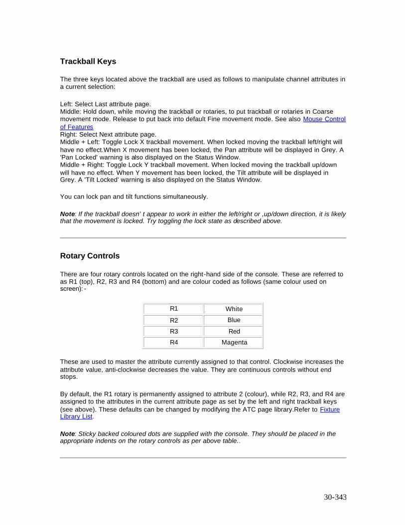
30-343
Trackball Keys
The three keys located above the trackball are used as follows to manipulate channel attributes in a current selection:
Left: Select Last attribute page. Middle: Hold down, while moving the trackball or rotaries, to put trackball or rotaries in Coarse movement mode. Release to put back into default Fine movement mode. See also Mouse Control of Features Right: Select Next attribute page. Middle + Left: Toggle Lock X trackball movement. When locked moving the trackball left/right will have no effect.When X movement has been locked, the Pan attribute will be displayed in Grey. A 'Pan Locked' warning is also displayed on the Status Window. Middle + Right: Toggle Lock Y trackball movement. When locked moving the trackball up/down will have no effect. When Y movement has been locked, the Tilt attribute will be displayed in Grey. A 'Tilt Locked' warning is also displayed on the Status Window.
You can lock pan and tilt functions simultaneously.
Note: If the trackball doesn’ t appear to work in either the left/right or ,up/down direction, it is likely that the movement is locked. Try toggling the lock state as described above.
Rotary Controls
There are four rotary controls located on the right-hand side of the console. These are referred to as R1 (top), R2, R3 and R4 (bottom) and are colour coded as follows (same colour used on screen): -
R1 White R2 Blue R3 Red R4 Magenta
These are used to master the attribute currently assigned to that control. Clockwise increases the attribute value, anti-clockwise decreases the value. They are continuous controls without end stops.
By default, the R1 rotary is permanently assigned to attribute 2 (colour), while R2, R3, and R4 are assigned to the attributes in the current attribute page as set by the left and right trackball keys (see above). These defaults can be changed by modifying the ATC page library.Refer to Fixture Library List.
Note: Sticky backed coloured dots are supplied with the console. They should be placed in the appropriate indents on the rotary controls as per above table..
30-344
Mouse Control of Features
GeniusPro and Lightpalette software supports a range of mice and trackballs, including the 'intelli' type mouse and trackball, to mimic the trackball, trackball softkeys and rotaries on the 500 series consoles. Any of the mouse options can be used with either 500 or 300 series consoles for the control of attributes and to mimic the other functions of the trackball, e.g., moving the highlight on the setup screens, scrolling the help screens and activating help hyperlinks. PS2 mice should be plugged into the PS2 port and serial mice should be plugged into one of the COM ports, unless the mouse is dual function (i.e., PS2/Serial)
Supported Mice
Microsoft or Logitech 2-button PS2 or serial mouse Microsoft or Logitech 3-button PS2 or serial mouse Microsoft Intellimouse or Intellitrackball or Logitech equivalents.
Important Note: When using a PS2 mouse, the mouse must be plugged into the PS2 port before you switch on the console, otherwise, the mouse will not work.
Using an intellimouse, or intellitrackball to control moving lights.
• The ball of an intellimouse or intellitrackball performs the pan and tilt functions. • Moving the ball in a horizontal plane to the right increases the pan value, while moving
the ball in a horizontal plane to the left decreases the pan value. Similarly, moving the ball in a verical plane away from you increases the tilt value and moving the ball in a vertical plane towards you reduces the tilt value.
• Pressing the wheel button and left mouse button lock the tilt function and pressing the wheel button and right mouse button locks the pan function. A warning is displayed in the Status Window when either Pan or Tilt, or both are locked.
• Turning the intellimouse or intellitrackball wheel selects the attribute as indicated by an arrow to the right of the attribute.
• Turning the wheel, while holding the wheel button depressed applies the course adjustment mode.
Limited functionality is can be provided with a two, or three button mouse, as described below.
The two-button mouse ball performs the X and Y functions of the 500 series trackball (pan and tilt). The left and right buttons step forwards and backwards through the attributes of the selected fixture as indicated by an arrow to the right of the attribute. Further pressing the left or right buttons when the arrow is on the last or first attribute will display the last or next ATC page respectively.
On a three-button mouse, pressing the centre button and moving the mouse left or right changes the value of the selected attribute. Pressing the middle button and left button together will lock the tilt function and pressing the middle button and right button together will lock the pan function.
Tracker Displays
This section describes the displays which are used by the Tracker application and covers the following topics:
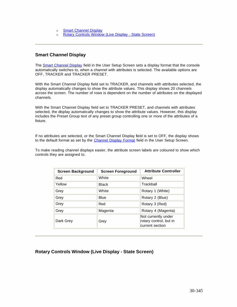
30-345
o Smart Channel Display o Rotary Controls Window (Live Display - State Screen)
Smart Channel Display
The Smart Channel Display field in the User Setup Screen sets a display format that the console automatically switches to, when a channel with attributes is selected. The available options are OFF, TRACKER and TRACKER PRESET. With the Smart Channel Display field set to TRACKER, and channels with attributes selected, the display automatically changes to show the attribute values. This display shows 20 channels across the screen. The number of rows is dependent on the number of attributes on the displayed channels. With the Smart Channel Display field set to TRACKER PRESET, and channels with attributes selected, the display automatically changes to show the attribute values. However, this display includes the Preset Group text of any preset group controlling one or more of the attributes of a fixture. If no attributes are selected, or the Smart Channel Display field is set to OFF, the display shows to the default format as set by the Channel Display Format field in the User Setup Screen. To make reading channel displays easier, the attribute screen labels are coloured to show which controls they are assigned to.
Screen Background Screen Foreground Attribute Controller Red White Wheel Yellow Black Trackball Grey White Rotary 1 (White) Grey Blue Rotary 2 (Blue) Grey Red Rotary 3 (Red) Grey Magenta Rotary 4 (Magenta)
Dark Grey Grey Not currently under rotary control, but in current section
Rotary Controls Window (Live Display - State Screen)
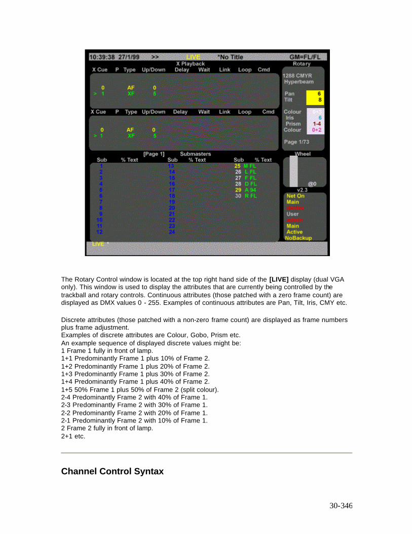
30-346
The Rotary Control window is located at the top right hand side of the [LIVE] display (dual VGA only). This window is used to display the attributes that are currently being controlled by the trackball and rotary controls. Continuous attributes (those patched with a zero frame count) are displayed as DMX values 0 - 255. Examples of continuous attributes are Pan, Tilt, Iris, CMY etc. Discrete attributes (those patched with a non-zero frame count) are displayed as frame numbers plus frame adjustment. Examples of discrete attributes are Colour, Gobo, Prism etc. An example sequence of displayed discrete values might be: 1 Frame 1 fully in front of lamp. 1+1 Predominantly Frame 1 plus 10% of Frame 2. 1+2 Predominantly Frame 1 plus 20% of Frame 2. 1+3 Predominantly Frame 1 plus 30% of Frame 2. 1+4 Predominantly Frame 1 plus 40% of Frame 2. 1+5 50% Frame 1 plus 50% of Frame 2 (split colour). 2-4 Predominantly Frame 2 with 40% of Frame 1. 2-3 Predominantly Frame 2 with 30% of Frame 1. 2-2 Predominantly Frame 2 with 20% of Frame 1. 2-1 Predominantly Frame 2 with 10% of Frame 1. 2 Frame 2 fully in front of lamp. 2+1 etc.
Channel Control Syntax
30-347
Tracker extends existing intensity and colour Channel Control syntaxes. All syntaxes are listed in the Command Summary mode. The following Control Operations are covered in this section:
• Controlling Intensity and Attributes • Copying Channel Attributes
Controlling Intensity and Attributes Examples:
[1] [@] [3] [*] Chan 1 Intensity to 30% [1] [@ATT] [5] [*] Channel 1 Colour (Attribute 2) to frame 5 [1] [.] [2] [@] [5] [*] Chan 1 Colour (Attribute 2) to frame 5 [1] [.] [8] [@] [5] [*] Chan 1 Gobo (Attribute 8) to frame 5 [1] [.] [3] [@] [6] [*] Chan 1 Pan (Attribute 3) to 60% [1] [.] [2] [0] [@] {DMX} [2] [5] [0] [*] Chan 1 Reset (Attribute 20) to DMX 250 [1] [THRU] [5] [@] [4] Chans 1 Through 5 Intensity at 40% [1] [THRU] [5] [@ATT] [2] [*] Chans 1 Through 5 Colour (Attribute 2) to frame 2 [1] [THRU] [5] [.] [2] [@] [[2] [*] Chans 1 Through 5 Colour (Attribute 2) to frame 2 [1] [THRU] [5] [.] [5] [@ATT] [3] [*] Chans 1 through 5 Iris (Attribute 5) to 30%
Copying Channel Attributes
The {COPY FROM} soft key on the [*] key menu allows some or all of one channel’ s attribute levels to be copied to one or more channels. This is very useful for copying all of one fixture’ s settings to one or more other fixtures.
Select the channel to copy from: chan [@] {COPY FROM} # copies all attribute values of channel # to the selected channel(s). e.g. [1] [THRU] [5] [@] {COPY FROM} [1] [0] [*] Copy all attribute values from channel 10 to channels 1 to 5 [1] [THRU] [5] [.] [2] [@] {COPY FROM} [1] [0] [*] Copy colour only.
30-348
Patching Attributes
This section describes how Attributes are patched to Outputs (DMX) from the [PATCH] screen and covers the following topics:
o Patching Attributes to a Single Channel o Fixture Libraries o The Copy Patch Menu o Range Patching
Patching Attributes To a Single Channel
Patching attribute channels is the same as ‘ normal’ intensity patching except that the attribute number must be specified. From the [PATCH] screen. [1] [0] [0] [@] [4] [.] [3] [*] Patch Output 100 to Channel 4 Attribute 3 (Pan) [9] [9] [@] [4] [.] [4] [*] Patch Output 99 to Channel 4 Attribute 4 (Tilt) To invert an attribute (i.e. 0% = 255 DMX output to 100% = 0 DMX output) use a ‘ -’ before the scaling or frame number. e.g. [1] [1] [0]@] [5] [@] [-] [0] [*] Patch Dimmer 110 to Channel 5 (Intensity) and flip output. [1] [@] [3] [.] [3] [@] [-] [0] [*] Patch Output 1 to Channel 3 Attribute 3 (Pan) as continuous and flip output. By a combination of swapping Pan & Tilt and inverting or not, any orientation of fixture can be set so Pan left/right always pans left/right across stage and tilt moves up/down stage. Continuous attributes (0 entered as frame count) display as 0 - FL on the output screen and as DMX values (0 - 255) on the rotary window.
Patching Fixtures When complete fixtures are patched using the {@ FIXTURE} softkey the attribute channels used are shown in blue on the Patch Screen, with the function of each attribute channel shown in blue below the channel number. If the patch display is in 'Output Order' the name of the fixture is shown in white above the channel numbers. Changes to the standard fixture, e.g. Inverting Pan, are displayed in cyan. Pan and Tilt can also be swapped and/or inverted on a fixture.
[3] [@] [5] {@FIXTURE} [2] [1] [*] Patch output 3 channel 5 to fixture 21. [2] [0] {@FIXTURE} [2] [3] [*] Patch output 20 to fixture 23 using output 20s current channel. [3] {@FIXTURE} [NEXT] . . [NEXT] . . [*] Browse fixture names on command line and patch output 3 to selected fixture. [3] {@FIXTURE} [LAST] . . [LAST] . . [*] Browse fixture names on command line, and patch output 3 to selected fixture. [3] [@] [5] {@FIXTURE} [2] [1] {SWAP P + TILT} [*]
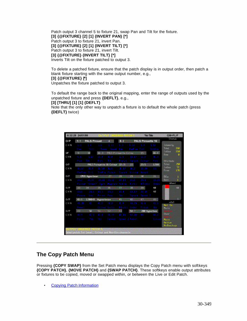
30-349
Patch output 3 channel 5 to fixture 21, swap Pan and Tilt for the fixture. [3] {@FIXTURE} [2] [1] {INVERT PAN} [*] Patch output 3 to fixture 21, invert Pan. [3] {@FIXTURE} [2] [1] {INVERT TILT} [*] Patch output 3 to fixture 21, invert Tilt. [3] {@FIXTURE} {INVERT TILT} [*] Inverts Tilt on the fixture patched to output 3. To delete a patched fixture, ensure that the patch display is in output order, then patch a blank fixture starting with the same output number, e.g., [3] {@FIXTURE} [*] Unpatches the fixture patched to output 3. To default the range back to the original mapping, enter the range of outputs used by the unpatched fixture and press {DEFLT}, e.g., [3] [THRU] [1] [1] {DEFLT} Note that the only other way to unpatch a fixture is to default the whole patch (press {DEFLT} twice)
The Copy Patch Menu
Pressing {COPY SWAP} from the Set Patch menu displays the Copy Patch menu with softkeys {COPY PATCH}, {MOVE PATCH} and {SWAP PATCH}. These softkeys enable output attributes or fixtures to be copied, moved or swapped within, or between the Live or Edit Patch.
• Copying Patch Information
30-350
• Moving Patch Information • Swapping Patch Information
Copying Patch Information
Press {SET} from the LCD Patch Menu to display the LCD Set Patch Menu. Press {COPY/SWAP} to display the Copy Patch Menu.
Copying Attributes Enter the output number (or range of outputs), of the attribute(s) to be copied, followed by the {COPY PATCH} softkey and the output number (or first output number), where the attribute(s) has to be copied, then [*]. A confirmation is requested after each command. Press [*] again.
[1] {COPY PATCH} [1] [0] [*] Copies attribute on output 1 to output 10 [1] [THRU] [10] {COPY PATCH} [1] [1] [*] Copies attributes on outputs 1 to 10 to outputs 11 to 20.
Press {BACK} to return to the LCD Set Patch Menu.
Copying Fixtures Enter the first output number (or range of outputs) of the fixture(s) to be copied, followed by the {COPY PATCH} softkey and the first output number where the fixture has to be copied to, then [*]. A confirmation is requested after each command. Press [*] again.
[2] [2] {COPY PATCH} {4] [4] [*] Copies the fixture starting on output 22 to start on output 44. [2] [2] [THRU] [5] [2] {COPY PATCH} [5] [4] [*] Copies the fixtures patched to outputs 22 to 52 to start on output 54.
Press {BACK} to return to the LCD Set Patch Menu.
Copying Patch Screens You can copy the entire contents of Patch 1 to Live Patch 2.
{COPY PATCH} confirmation required {COPY PATCH}
Press {BACK} to return to the LCD Set Patch Menu.
Moving Patch Information
Press {SET} from the LCD Patch Menu to display the LCD Set Patch Menu. Press {COPY SWAP} to display the Copy Patch Menu.
Moving Attributes Enter the output number, or range of outputs, of the attribute to be copied, followed by the
30-351
{MOVE PATCH} softkey and the output number where the attribute(s) has to be moved to, then [*]. A confirmation is requested after each command. Press [*] again.
[1] {MOVE PATCH} [1] [0] [@PATCH] [2] [*] Moves attribute on output 1 to output 10 on Patch 2 [1] [THRU] [10] {MOVE PATCH} [1] [1] [*] Moves attributes on outputs 1 to 10 to outputs 11 to 20.
Press {BACK} to return to the LCD Set Patch Menu.
Moving Fixtures Enter the first output number of the attribute to be copied, followed by the {MOVE PATCH} softkey and the first output number where the fixture has to be copied, then [*].
[2] [2] {MOVE PATCH} {4] [4] [*] Moves the fixture starting on output 22 to start on output 44. [2] [2] [THRU] [5] [2] {MOVE PATCH} [5] [4] [*] Moves the fixtures patched to outputs 22 to 52 to start on output 54.
Press {BACK} to return to the LCD Set Patch Menu.
Swapping Patch Information
Press {SET} from the LCD Patch Menu to display the LCD Set Patch Menu. Press {COPY SWAP} to display the Copy Patch Menu.
Swapping Attributes Enter the output number, or range of outputs, of the attribute(s) to be swapped, followed by the {SWAP PATCH} softkey and first output number of the attribute to be swapped with, then [*].A confirmation is requested after each command. Press [*] again.
[1] {SWAP PATCH} [1] [0] [*] Swaps attributes on output 1 and 10 [1] [THRU] [8] {SWAP PATCH} [1] [7] [*] Swaps attributes on outputs 1 to 8 with attributes on the eight outputs starting on output 17.
Press {BACK} to return to the LCD Patch menu.
Swapping Fixtures The position of individual fixture, or a range of fixture can be swapped by entering the outputs used by the fixture to be swapped and the first output used by the fixture that it has to be swapped with.
Note:The fixture, or range of fixtures, using the most number of outputs must be entered first.
Enter the output number, or range of outputs, of the fixtures(s) to be swapped, followed by the {SWAP PATCH} softkey and first output number of the fixture, or range of fixtures, to be swapped with, then [*].
30-352
A confirmation is requested after each command. Press [*] again.
[2] [5] [THRU] [3] [0] {SWAP PATCH} [9] [*] Swaps a fixture patched to outputs 25 through 30 with the same fixture patched to outputs 9 through 12.
Note:The required number of outputs must be available in the ‘swap to’ position, otherwise, the swap cannot take place and an invalid range error message displayed. If say, an eight output fixture is being swapped with a six output fixture, all eight outputs will be swapped, including any attributes on the other two outputs.
Range Patching
Multiple patching of channels and fixtures is achieved as follows:
[1] [THRU] [5] [@] [1] [0] [THRU] [1] [4] Patches channels 10 - 14 to outputs 1 - 5 [1] [THRU] [5] [@] [1] [4] [THRU] [1] [0] Patches channels 14 - 10 to outputs 1 - 5 [1] [THRU] [2] [0] [@] [4] [THRU] [8] {@FIXTURE} [1] Patches outputs 1 to 20 to channels 1 to 8 and patches fixture 1 to each patch. [1] [THRU] [2] [0] [@] [8] [THRU] [4] {A FIXTURE} [1] Patches outputs 1 to 20 to channels 8 to 1 and patches fixture 1 to each patch
Deleting Attribute Channels
The configured maximum number of attribute and intensity channels is displayed in the Patch Status window. This window also shows the number of channels in use and the number free. If the quota of attributes has been used up and more are required, one of two things can be done: From the Patch Display, delete unused attribute channels using the CHAN DELETE syntax. e.g. {CHAN} [1] [.] [2] [THRU] [1] [.] [9] [9] {DELETE CHAN} {DELETE CHAN} {BACK} or: From the Patch Display, delete unused intensity channels using the CHAN DELETE syntax. e.g. {CHAN} [1] [0] [0] [THRU] [1] [9] [9] {DELETE CHAN} {DELETE CHAN} {BACK}
Note: Deleted intensity channels may be used as attribute channels, but deleted attribute channels cannot be used as intensity channels.
Recording and Playback
The recording and playback of attribute channels is exactly the same as for intensity channels. Refer to Basic Recording and Recording Cues Because attribute channels are treated differently, there are a few things to be aware of when working with attributes. These are explained in the following topics
30-353
• Attributes in Cues • Attributes in Submasters • Attributes LTP - Intensities HTP • Auto Move While Dark
Attributes In Cues
Cues have separate fade times for intensities and attributes. Attributes can be recorded and edited in Cues in exactly the same way as intensities.
Attributes In Submasters
Submasters have separate fade times for intensities and attributes. If the submaster contains both intensities and attributes then the fader will continuously master the intensities, but the attributes will fade in the attribute fade time starting at the point when the fader handle is moved off the zero position.
If a submaster consists only of attributes then the submaster fader will continuously master the attributes.
Attributes LTP - Intensities HTP
Attributes work on a LTP (Latest Takes Precedence) basis. This is different to intensities which work on a HTP (Highest Takes Precedence) basis. The following example will help clarify this:
At the [PATCH] display, create a colour attribute for channel 1 by patching to output 2:- [2] [@] [1].] [2] [*] On the [LIVE] display, follow this sequence:- [1] [@] [6] [@ATT] [7] [*] Channel 1 intensity 60%, colour frame 7. [SUB] [1] [RECORD] Record submaster 1. [1] [@] [4] [@ATT] [2] [*] Channel 1 intensity 40%, colour frame 2. [CUE] [1] [RECORD] Record cue 1.
This has recorded Submaster 1 and Cue 1 each with different intensity and attribute values for channel 1. Next, move Submaster 1 to zero then to full. Notice how only the intensity level is being mastered, the attribute value having snapped to frame 7 when the submaster was moved off zero (the default attribute fade time being zero).

30-354
Now run Cue 1. Notice that the attribute value has faded to the new position of 2, but the intensity value has not changed. This is because the intensity level HTP’ d, and so did not change because the submaster intensity was higher than the cue, but the attribute level LTP’ d.
Auto Move When Dark Auto Move When Dark (AMWD) is a time saving feature that automatically moves attributes (colour, pan, tilt, etc.) to the next required position when the light is dark. AMWD may eliminate or reduce the need to record and maintain Mark cues (cues ,that move attributes with the light dark). AMWD is enabled in the Show Setup Screen screen option by setting Auto Move While Dark to ON and entering the required Fade and Delay times. The Fade time is the time for all attributes to fade in all AMWD fades. The Delay time is the time after all parts of a normal cue fade have complete before an AMWD fade starts. Note: AMWD Fade and Delay times are set per show not per fade. AMWD fades are not recorded and do not appear in the cue sheet. However they can be seen as running fades (grayed out) on some output formats. If an attribute has not completed moving when the next cue starts the attribute will fade to the next recorded position in the cue attribute fade time (often zero). For an attribute to Auto Move the following must be true: -
• AMWD must be enabled. • The intensity of the channel on stage must be zero • The intensity of the channel in the next cue must be non zero. • The attribute value in the next cue must differ from the current value on stage.
AMWD can be overridden on a cue by cue basis by setting non-zero intensity values, 1% is sufficient to disable AMWD. Any Manual recorded Mark cues (cues that move attributes with the intensity off) will still be executed as normal.
Referenced Groups (Preset Focus)
Note: Preset Groups is only available with Tracker on Pentium based consoles. 486 based consoles do not support this feature. Preset allows individual channels or attributes in Cues, Effects and Submasters to be recorded as links to the same intensity or attribute in one of 750 groups (Groups 1..750). On playback the values of the intensities and/or attributes are obtained from the Group they are linked to, instead of being obtained for the Cue, Submaster or Effect they are recorded in. This lookup is done each and every time the Cue, Submaster or Effect is replayed. Thus if the value of an intensity or attribute in a Group is changed, every Cue, Effect or Submaster that uses this Group will play back the linked channel with the new value. When used to record focus positions (pan and tilt) this facility is referred to as Preset Focus.
30-355
The following example shows how to set up Preset (or Referenced) groups; in this instance, Preset Focus.
1. Press <SETUP> and set Smart Channel Display to TRACKER PRESET 2. Press <PATCH> and patch a fixture as follows:
[1] {@FIXTURE} [5] [*] (All Modes)
3. Press <LIVE> and press [1] [*] to show the Smart Channel display 4. Use the trackball, or mouse to set the Pan and Tilt attribute to 50%, or enter
[1] [.] [3] [@ [5] (Direct 1 Digit Mode) or [1] [.] [3] [@] [5] [0] (Direct 2 Digit Mode) or [1] [.] [3] [@] [5] [*] (Command Line Mode) and [1] [.] [4] [@ [5] (Direct 1 Digit Mode) or [1] [.] [4] [@] [5] [0] (Direct 2 Digit Mode) or [1] [.] [4] [@] [5] [*] (Command Line Mode)
5. Press [GROUP] [1] {ATTS ONLY} [RECORD] (Direct Entry Modes) or [RECORD] [GROUP] [1] {ATTS ONLY] [*] (Command Line Mode)
6. Press [GROUP] [1] [TEXT] Focus 1 [*] (All Modes), entering the group text label from the external keyboard.
7. Press [1] [@] [GROUP] [1] [*] (All Modes). All attributes of channel 1 are displayed with the group text name 'Focus'.
Note: Any cues, submasters and effects that are recorded when the group name is displayed on the live screen, are linked to that group. Any changes made to the group levels are reflected in the cue, submaster or effect.
8. Press [CUE] [1] [RECORD] (Direct Entry Modes) or [RECORD] [CUE] [1] [*] (Command Line Mode)
9. Press <CUE/PREVIEW> to display the Cue Sheet. Note that the level of all attributes are shown as 'Focus'
10. Press <GROUP> to display the Group Screen. The levels are shown at their set values. Change the level of Pan and Tilt 80% by entering the following commands:
[1] [.] [3] [@ [8] (Direct 1 Digit Mode) or [1] [.] [3] [@] [8] [0] (Direct 2 Digit Mode) or [1] [.] [3] [@] [8] [*] (Command Line Mode) and [1] [.] [4] [@ [8] (Direct 1 Digit Mode) or [1] [.] [4] [@] [8] [0] (Direct 2 Digit Mode) or [1] [.] [4] [@] [8] [*] (Command Line Mode).
11. Press <LIVE> to show the Live Screen. 12. Press [CUE] [1] [LOAD] [GO] (All Modes). You will see the Pan and Tilt Attributes fading
up to 80%, then showing 'Focus'. The word 'Focus' for pan and tilt are displayed in blue, rather than cian, to indicate that the levels have been changed.
Colour Palettes
30-356
Colour Palettes are another application of the Preset mechanism used by Preset Focus. Instead of recording Pan and Tilt positions use any of the first 750 groups to record colours, either gel number or CMY position for mixing units or a combination of both. Give the groups meaningful text names such as BLUE, GREEN, L802, F324. When plotting, assign colours using the [1] [@] [GROUP] [TEXT]blue[*] syntax. The Preset display format can be used to see the colour names (group text) on live and preview screens. You need an external keyboard connected to do this.
Attribute Filters
The decimal notation used to identify the many attributes associated with fixtures with multiple attributes is shown in the ATC page. This page also provides the facility to set up a series of six filter softkeys (F1 to F6). The softkey functions, displayed on the LCD display when the [@ ATT] key is pressed, is dependent on the F1 to F6 titles, shown in square brackets in the ATC Page. You can edit the ATC page to change the softkey titles or the attributes associated with the softkey functions. To edit the ATC Page softkey functions and attribute channels, press <MORE> {NOTES DISP} {LOAD FILES} [ATC PAGE}. You can edit the ATC functions and attribute channels using the notes editor. By default, the attribute filter softkeys are set to Position (F1), Colour (F2), Beam (F3), Focus (F4), Shutter (F5) and User (F6) Selecting one, or more, of the softkeys selects the levels recorded in the referenced group asociated with all of the function attributes relevant to the particular fixture. Attribute filters is similar to Preset Focus, except that when a fixture within a referenced group is set to the group level, you can use the [@ATT] key and use one or more softkey to select only the particular functions that you wish to set to the recorded reference group value, e.g. [2] [5] [@ATT] {POSITION} {COLOUR} [1] Sets only the position and colour attributes of the fixture on channel 25 to the levels recorded in the referenced group (Group 1)
Updating Attribute Filters from the Live Screen When in the Group Screen and with one of the referenced groups highligted, you can update the referenced group from the Live Screen using the syntax chans [@ATT] Attribute Filter Softkey [LIVE] [5] [0] [@ATT] {POSITION} [LIVE] Direct Action Modes [5] [0] [@ATT] {POSITION} [LIVE] [*] Command Line Mode The positional attributes of the current referenced group is updated to the current live (on stage) position of the fixture on channel 50
Fixture Library List
The fixture library defines the fixture codes used by the {@FIXTURE} command on the [PATCH] screen .The fixture library is updated from time to time by Strand. If you have a new fixture you wish to add, please contact you nearest Strand Lighting office. The Fixture will be added to the standard fixture list. Alternatively, you can edit the Fixture Library file which is read when the console is started or the fixture library changed.

30-357
Fixtures can be modified, or new ones added, by modifying the file FIXTURE.LIB (Fixture Library) with the console notes editor.
Warning: Installing new Operating Software or entering a new password will overwrite the changes you have made to the FIXTURE file. The old file will be saved as FIXTURE.OLD. Any modifications you have been made should be edited into to the new file, otherwise you can rename the .OLD file to .LIB thereby using your old file in full. See also Site Configuration Files
The fixture library file is composed of several sections, one for each fixture type. Each section starts with a unique fixture number hFixture followed by the fixture name. Each successive line in the section describes one DMX address for the fixture. Each DMX line starts with the attribute number hAtt which describes what this DMX byte controls, see ATCPAGE.LIB for list. The remainder of each DMX line provides parameters which describe how this attribute is used by the fixture, for example whether it is a continuous or stepped control, and which profile, if any, to apply to the attribute.
[hFixture] [FixtureName] hAtt, Steps, Ndim, Max, Min, hProfile… etc. hAtt, Steps, Ndim, Max, Min, hProfile
hFixture Fixture Number (1 .. 99) FixtureName Fixture Name for each DMX address used:
hAtt Attribute number (1 .. 99) Steps Number of Steps/Frames (0 =continuous) Ndim Non-dim threshold (0 .. 255) Scale Maximum DMX output value (0 ..255) (Scaling factor 255 = 100%) Min Minimum DMX output value (0 .. 255) (if Max < Min, attribute is inverted.) hProfile Profile/Law number
Lines starting with # are comment lines and are not processed. The Fixture Library file is read when the console is started or the fixture library changed. The file is updated when a show is loaded that has different fixture assignments.
For further information, refer to Tracker Library Files
31-358
Chapter 31 - Server Software
The optional file server application provides a central place on the ShowNet network to store show files, user login configuration files, Networker configuration files, archive copies of operating software - in fact anything you like. You can use any console or PC on the network as the file server, although many people use a PC (DOS or Win9X or NT) which can be fitted with a tape drive or other backup device for added security.
Controlling user access to the file server is another issue in some sites, and using a PC running NT means that the security features of NT can be used to prevent unauthorised users from making unwanted changes to the file server.
Another feature that Server provides is a central place on the network to direct all archive printing operations. Note: File Server uses Point to Point communications in which IP addresses are used and MUST be unique. The following topics are covered in this section:
• Loading the Server Password Disk • Setting Up a File Server • User Logins • Integrating File Server and Logins
Loading the Server Password Disk
The Server Password Disk is Used to Enable Communication between a console on a network and the file server and to provide User Logins. Before installing the Server Password disk, check that the Server Software is already installed on the console. Press <REPORT> and check the configuration window at the bottom of the screen. The word NET should appear on the list of applications.
1. Insert Server disk and press <ARCHIVE> {SOFT} {LOAD SOFT} {LOAD SOFT} 2. Write the date and the serial number of the console on the disk. This disk now contains a
record of your console configuration and password in electronic form and should be stored in a safe place.
3. Insert a blank formatted disk in the floppy drive and press <ARCHIVE>{SOFT}{SAVE PASSW}{SAVE}{SAVE} to save the password.
Complete the Software Registration Form supplied and return it to Strand Lighting.
31-359
Setting Up a File Server
This section covers the following topics:
o Creating a Standalone File Server Using a PC o Loading Networker & Utilities on a PC using DOS 3.1, or later o Windows 95/NT PC Server o Configuring a File Server o Operating a File Server o Accessing a File Server
Creating a Standalone File Server Using a PC For a minimal installation only Networker & Utilities need be loaded. In this case, it is the ioftp family of programs which provide all standalone file server functionality.
Loading Networker & Utilities on a PC using DOS 3.1 or Later
To create a standalone file server on a DOS PCs, assuming that the PC is fitted with a standard Ethernet card (3COM Etherlink III), proceed as follows:
1. Insert the Networker and Utilities Disk in the floppy drive and type
A:\CNINSTAL (above version 2.3f)
2. You will be given a choice of platform, e.g.,
3 300 Series 4 400 Series 5 500 Series B Backup PC O Offline Editor F File Server
3. To install the File Server, type F I 4. f the installation program detects that operating software is present, it will prompt you to
load into the same directory. If not, you can specify any directory. 5. The Strand Lighting licence agreement is displayed on screen. Press any key to scroll the
display. 6. If you agree with the terms of the licence, press Y, or press N to terminate the installation. 7. The File Server software will install on your PC. 8. If the installation was successful, 'Instal Successful' is displayed on screen.
31-360
9. To run the file server, type the following in order:
CALL NETON IOFTPDOS
10. To exit the file server type 11. EXIT
CALL NETOFF
These can be packaged in a batch file for convenience.
Note: If you have a different Ethernet card, the packet driver software which NETON loads may not work: you will have to provide another packet driver. This should work if it conforms to the standard packet driver software interface, but Strand Lighting can not guarantee its performance.
Win95/NT PC Server
Making a standalone server on a Win95 or NT PC is not as simple as running the above DOS commands in a DOS box - it won’t work. You need to follow the steps under Windows Network Configuration in the ShowNet Configuration Software In short:
1. If you have not yet configured your Ethernet card under Win9X/NT, follow the supplier’s instructions for doing so.
2. Add this line to the end of your AUTOEXEC.BAT startup file:
WINPKT 0x7e Then restart Windows.
3. Insert the Networker and Utilities Disk in the floppy drive and open the 3 1/2" floppy A: window in Windows Explorer, or Windows NT Explorer. Double click on
CNINSTAL.exe (above version 2.3f)
4. You will be given a choice of platform, e.g.,
3 300 Series 4 400 Series 5 500 Series B Backup PC O Offline Editor F File Server
5. To install the File Server, type F 6. If the installation program detects that operating software is present, it will prompt you to
load into the same directory. If not, you can specify any directory. 7. The Strand Lighting licence agreement is displayed on screen. Press any key to scroll the
display. 8. If you agree with the terms of the licence, press Y, or press N to terminate the installation.
31-361
9. The File Server software will install on your PC. 10. If the installation was successful, 'Instal Successful' is displayed on screen. 11. Using Windows Explorer, or WindowsNT Explorer to locate IOFTP32.EXE (loaded as
part of Networker Utilities), and using the right mouse button, create a shortcut to it on the desktop.
12. Double-click on the shortcut and you should see a command window with the IOFTP> prompt. If it disappears quickly, the network card could not be accessed. Contact Strand Lighting for assistance.
Configuring A File Server
The ioftp programs use the 220NODE.CFG file to set its network address, in the same way as consoles and PCs: my_nodeaddr = 192.168.021.66 my_nodetype = ioftp my_nodename = server All consoles and PCs on the ShowNet network which access the file server must name the file server IP address in their own 220NODE.CFG files: file_server_addr = 192.168.021.66
To disable file server access at any time, restore this line to its factory default: file_server_addr = 0.0.0.0
Operating A File Server
You must first create the directory structure you require to hold your show files, and any other file types you intend to store. Next, run IOFTPDOS (DOS) or IOFTP32 (Win9x/NT) as described above. Once you can see the #IOFTP# prompt, the file server is working and is ready to be accessed by other ShowNet devices. To check that other ShowNet devices are on line and available, use the WHO command, which gives a similar display to Network Diagnostics at a console:
#IOFTP# who
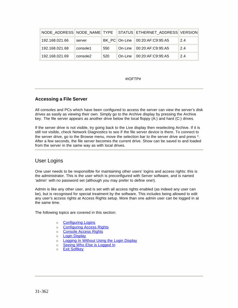
31-362
NODE_ADDRESS NODE_NAME TYPE STATUS ETHERNET_ADDRESS VERSION
192.168.021.66 server BK_PC On-Line 00:20:AF:C9:95:A5 2.4
192.168.021.68 console1 550 On-Line 00:20:AF:C9:95:A5 2.4
192.168.021.69 console2 520 On-Line 00:20:AF:C9:95:A5 2.4
#IOFTP#
Accessing a File Server
All consoles and PCs which have been configured to access the server can view the server’s disk drives as easily as viewing their own. Simply go to the Archive display by pressing the Archive key. The file server appears as another drive below the local floppy (A:) and hard (C:) drives. If the server drive is not visible, try going back to the Live display then reselecting Archive. If it is still not visible, check Network Diagnostics to see if the file server device is there. To connect to the server drive, go to the Browse menu, move the selection bar to the server drive and press *. After a few seconds, the file server becomes the current drive. Show can be saved to and loaded from the server in the same way as with local drives.
User Logins
One user needs to be responsilble for maintaining other users’ logins and access rights: this is the administrator. This is the user which is preconfigured with Server software, and is named ‘admin’ with no password set (although you may prefer to define one!). Admin is like any other user, and is set with all access rights enabled (as indeed any user can be), but is recognised for special treatment by the software. This includes being allowed to edit any user’s access rights at Access Rights setup. More than one admin user can be logged in at the same time. The following topics are covered in this section:
o Configuring Logins o Configuring Access Rights o Console Access Rights o Login Display o Logging In Without Using the Login Display o Seeing Who Else is Logged In o Exit Softkey
31-363
Configuring Logins
Each user must be named, using up to 8 alpha-numeric characters. This forms the basis of the user configuration file. The admin user’s file is called ADMIN.USR, and is supplied with the operating software. You can use this file as a template for all users. The act of creating a new user is simply one of copying ADMIN.USR to, say, FRED.USR.
The user file contains five sections:
1. Password 2. Access rights 3. User setup preferences 4. Last-used show file names 5. Channel partition group
You can edit the password, access rights and partition group channels as required, but a new user can log in if no editing is done; you can change these settings at any time. You can set the initial User Setup values if you like, but the software will rewrite this section when the user logs out. Do not edit the last-used show section - the software does this for you. Each line in the file starting with # is a comment, and is ignored by the software. The other lines are of the form TOKEN = VALUE Do not change the TOKEN names. If you do, an error (‘User file token is invalid’) will appear in the status log every time that user logs in. You can change the VALUE however. If you leave the value blank, the existing value for that token in the console will be used; a blank password means that none needs be entered. It is recommended that all users’ access rights are explicitly set, to avoid inheriting too many or too few rights from the previous logged-in user. To find out what user setup values are used in the file, experiment by saving user setup when logging out, and look at the file each time.
Configuring Access Rights
Each user’s access rights are defined in their user file. This example shows all access rights enabled; to disable any one, replace the 1 with a 0:
acc_record = 1 Can record from Live. acc_patch_fix = 1 Can patch new fixtures (requires Tracker). acc_spec_grps = 1 Can change special groups (display, partition, etc). acc_stp_user = 1 Can change User Setup. acc_stp_show = 1 Can change Show Setup. acc_stp_cons = 1 Can change Console Setup. acc_cons_mode = 1 Can change console mode at the login display. acc_printer = 1 Can use the printer. acc_show_loc = 1 Can save or delete shows on local disk drives. acc_show_svr = 1 Can save or delete shows on the server disk drives. acc_chan_ctrl = 1 Can use channel control to set levels. acc_playback = 1 Can run cues on the X playbacks.
31-364
Console Access Rights
Each console as well as each user has a login configuration fi le. This allows physical consoles to have particular rights, irrespective of who logs in. For example, a designer’s console may have all channel control disabled.
Console files are in the same format as .USR files: they are called .CON files instead. The name should match the ShowNet node name defined in the 220NODE.CFG file. The console called MAIN will need a file called MAIN.CON. A default file is installed with the operating software to act as a template: its name is CONSOLE.CON. This file is used if no specific .CON files are created. You can create a .CON file for each console and PC by copying CONSOLE.NEW, which is created with the software.
To set up a new console’s access rights, copy the CONSOLE.NEW file to <node name>.CON, and edit the access rights as required. Note that there is no password line, as consoles don’t log in with passwords. User access rights are combined with console access rights at login time as follows (the combination of the current user and console is always shown at the Access Rights setup display): COPY CONSOLE.NEW CONSOLE1.CON Note: If either user or console access rights disable a feature, then the feature is disabled. A feature is only enabled if both user and console access rights enable it. The other sections of the console file are ignored if user logins are enabled: the settings are taken from the user file instead. If user logins are disabled, and the Server application is installed, then the settings in this file are used.
Login Display
The login display is enabled by first editing the 220NODE.CFG file:
login_display = 1
The login display provides user login validation, mode changing (easier than editing 220NODE.CFG), and quick re-loading of the user’s last-saved show. When all entries have been made, pressing the LOGIN soft key accepts them. If any entries cannot be accepted (eg. incorrect password), an error message is displayed and the screen stays displays. Otherwise, the console Live display appears.
User name: chosen from a list of all the .USR files found in the program directory. Password: must match the entry in the user’s .USR file. If this entry is blank, nothing has to be typed. Mode: available modes are MAIN, OFFLINE, BACKUP and REMOTE MAIN The console starts with outputs active, and can accept logins from other consoles or PCs OFFLINE The console start with all outputs disabled, but the file server can still be accessed. In all other respects, the console behaves as an Offline Editor (except that networking is enabled, but no network video or mux is transmitted). BACKUP The console will associate itself with the main console chosen elsewhere on the screen. This console’s status is shown in yellow, and must display as on-line for the backup console to connect to it. REMOTE The console will log in as a remote console to the main console chosen elsewhere on the screen. This console’s status must display as on-line, and there must be room for another user to log in, otherwise this console’s login will be refused. The user will share the show currently loaded in the selected main console.
31-365
Main console: this selects a console from those detected on the ShowNet network, for connection in Backup and Remote modes. There is no need to define this list anywhere - the system detects it for you. Show to load: a value of 0 will not load a show when the LOGIN soft key is pressed. A value of 1 to 5 will select the show of that number from the list at the bottom of the screen, which are the shows that the user last saved. This is a quick way of returning to work on your last show -but remember that any show already in the main console you are logging in to will be replaced by this new show, so all users need to agree on the use of this facility. The initial values for these fields come from the 220NODE.CFG file.
Logging In Without Using The Login Display
If you want to start a console with one user’s settings, you can disable the login display and specify a user name and optional password by editing the 220NODE.CFG file:
login_display = 0 user_name = fred user_pw = letmein
Seeing Who Else Is Logged In
To find out who else is logged in to the main console you are using, you can look at Network Diagnostics (via the soft key at the REPORT display). The logged-in users are coded C1 (always the main console), C2, C3 etc (other remotes), and are marked with their user and node names in ‘user@node’ format. You can also press SHIFT and MORE together to look at the next user’s current display. The console is identified on the display panel under the wheel bar. Keep pressing [SHIFT] [MORE] to get back to your own display.
The Exit Soft Key
When the login display is disabled in 220NODE.CFG, pressing the {EXIT} soft key at the Report Menu display results in a prompt to press it again to confirm shutting down the console. When the login display is enabled in 220NODE.CFG, pressing the EXIT key provides a range of softkeys as follows: {LOGOUT} Takes you back to the login display {SHUT DOWN} Shuts the console down and returns to DOS {SAVE SETUP} If you have changed your User Setup, you are prompted to save it by pressing this soft key. If you do,your User Setup preferences will be restored at your next login. If you do not, your User Setup changes will be lost. Other Setup screens are not affected by this. {SAVE SHOW} If you have changed any other show data, you are prompted to save the show by pressing this soft key. If you do, the show file for the current working show will be updated. If you
31-366
do not, the working show remains in the console (in the .DAT files) until it is changed or replaced with an other show, but its show file will not have been updated. If you are shutting down a main console which still has other users logged in, you are warned that you will log them out too
Integrating File Server and Logins If you have a file server, you can take advantage of the centralisation and security it offers to help manage your user and console configuration files. This is particularly important if your network has several consoles or PCs. Automatic downloading of confi guration files over the network itself beats walking round with floppy disks! First, set up directories on the file server to hold all your .USR and .CON files. Then modify, or create the USERINIT.BAT file in all the consoles to automatically download their own .CON file and all .USR files when they start up, as in the following examples. Let’s say that your server has these directories: c:\ioftp Where ioftpdos or ioftp32 has been installed c:\users Where all your .USR files are kept c:\consoles Where all your .CON files are kept Assuming that the server’s node name is SERVER, add these lines to console MAIN’s USERINIT.BAT file: CALL NETON IOFTPDOS login SERVER cd c:\users get *.usr .cd c:\consoles get main.con . CALL NETOFF This procedure will download all user login files and console main’s login file every time the operating software starts. Remember that all .USR files must be present on all consoles and PCs which support logins, but each one only needs its own .CON file.
32-367
Chapter 32 - Shownet Configuration Software
ShowNet configuration software runs on a PC running Windows NT or 95 and compatible network software. ShowNet manages the patching of DMX information across a ShowNet network between SN series nodes and/or 500 series consoles running Networker software. Multiple patches can be edited off-line, stored on the PC hard disk, printed and downloaded to the nodes as required.
ShowNet does not download patch information to consoles or PCs.
The following topics are covered in this section:
• Shownet Software Installation • Windows Network Configuration • Running Shownet Software • Pop-Up Speed Menu • Editing the Shownet Configuration • Shownet Command Buttons
ShowNet Software Installation
To install ShowNet software on your Windows NT or 95 PC place the first ShowNet disk in the floppy drive and select :- START | RUN | A:SETUP.EXE Follow the on screen prompts for further instructions. Once installed you will be able to run ShowNet software but you must also install and configure your PC network adapter before you can download patch information to nodes. Note: Some new PCs and laptops are shipped with a network component called "OSB supplement for USB". This needs to be uninstalled for the ioftp32 networker utility to work. This utility is needed for Shownet to be able to download node configuration files.
Windows Network Configuration
You must install and configure your PC network adapter before you can download patch information to nodes. ShowNet uses standard PC network adapters and the network drivers supplied with Windows NT and 95 to download configurations to SN nodes. Configure as follows :-
1. Install the Ethernet adapter card in you PC. Any 10baseT or 10base2 adapter which is supported by Windows NT or 95 can be used. See adapter and/or PC documentation for full instructions.
2. Configure Windows1 to run TCP/IP over you Ethernet adapter. For Windows 95 Network Setup install the appropriate Adapter and the TCP/IP Protocol. Configure the
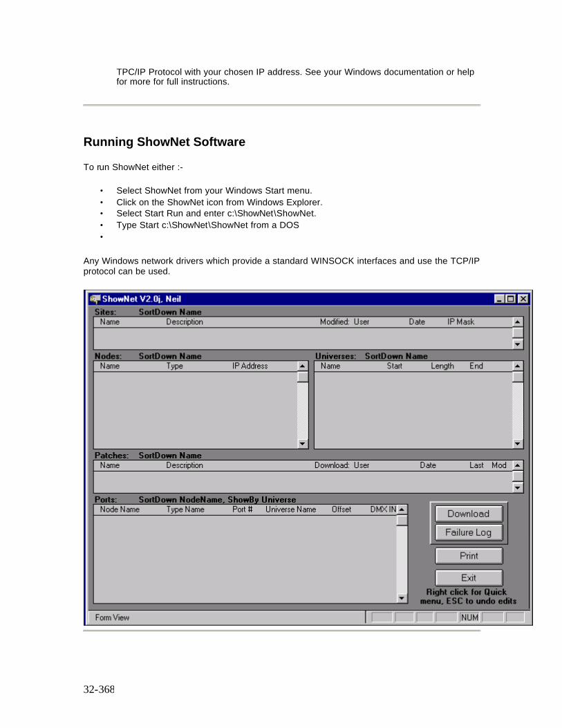
32-368
TPC/IP Protocol with your chosen IP address. See your Windows documentation or help for more for full instructions.
Running ShowNet Software
To run ShowNet either :-
• Select ShowNet from your Windows Start menu. • Click on the ShowNet icon from Windows Explorer. • Select Start Run and enter c:\ShowNet\ShowNet. • Type Start c:\ShowNet\ShowNet from a DOS •
Any Windows network drivers which provide a standard WINSOCK interfaces and use the TCP/IP protocol can be used.
32-369
Pop-Up Speed Menu
The right hand mouse button pops-up a context sensitive speed menu. Options which cannot be selected are greyed out. Options usually act on the selected field and are:-
Menu Option Description New Creates new Site, Node, Universe or Patch. Clone Copies current Site, Node, Universe or Patch to new one. Delete Deletes current Site, Node, Universe or Patch. Find Pop-up find dialogue box. Sort Up Sorts current field in ascending order. Sort Down Sorts current field in descending order. Show All Shows all ports on all nodes in Ports - window only. Cut Copies current field to clipboard and deletes. Copy Copies current field to clipboard. Paste Pastes from clipboard to current field.
Editing the Shownet Configuration
ShowNet configuration information is entered, displayed and manipulated through a series of windows shown below:
o Shownet Sites Window o Shownet Nodes Window o Shownet Universes Window o Shownet Patches Window o Shownet Ports Window
Shownet Sites Window
This window contains information relating to one single installation of nodes and/or consoles. All the configuration information for each site is stored in a separate file named SITE.MDB in the ShowNet directory. These files can be archived or moved to other PCs as required. This window also indicates when and by whom a site configuration was last changed.
Each site is the collection of all nodes, universes, patches and ports on the rest of the screen. The same site can have alternative definitions if you like - just create a new site name and start again.
Shownet Nodes Window
32-370
This window contains a list of all the nodes (SN nodes or 500 series consoles or PCs) connected to the network in the current site. Each node must have a unique name and unique IP address. Node types can be selected from a pick list.
Shownet Universes Window
This window contains a list of all the universes configured for the current site. Each universe is a subset of the available network DMX range of slots (DMX addresses), which is currently 4096 in ShowNet.
Universes allow you to give meaningful names to DMX ranges which you go on to assign to node ports in the Ports window. The ShowNet slot at which the universe begins is set by the Start value, and the number of DMX addresses in each universe is set by the Length value.
Shownet Patches Window
Each site can have several patches, each of which consists of the universe to port assignments shown in the Ports window. The contents of the Ports window belong to the currently selected Patch.
Patches are a way of allowing for alternative mappings of universes to ports, using the same set of universes and ports in the current site.
Shownet Ports Window
This window contains a list of universe to port assignments for the current site & patch. The window usually displays all the ports on the current node if a node is selected OR all the ports to which a universe is patched if a universe is selected. The Show All option on the right mouse click quick menu can be activated whilst in the Ports windows to display all ports on all nodes.
The Source tick box determines whether the port is an input or output. The Offset value (normally 1) determines the first DMX address at the port where the universe is output or input from. For example, if the 200-slot universe SCROLLERS starts at net slot 700 and it is mapped to port SN100_1 with an offset of 10, the resulting SN node configuration file could contain the lines:
# DMX = Port Direction(in/out) Start End NetSlot DMX = 1 out 10 209 700
The fi rst 9 addresses making up the physical DMX frame would still be output from the port but would contain zero levels. An offset of 1 would give instead:
# DMX = Port Direction(in/out) Start End NetSlot
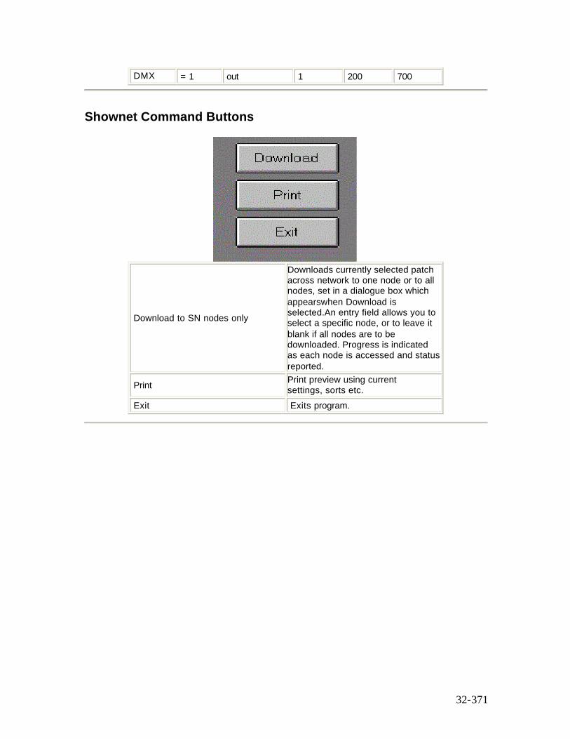
32-371
DMX = 1 out 1 200 700
Shownet Command Buttons
Download to SN nodes only
Downloads currently selected patch across network to one node or to all nodes, set in a dialogue box which appearswhen Download is selected.An entry field allows you to select a specific node, or to leave it blank if all nodes are to be downloaded. Progress is indicated as each node is accessed and status reported.
Print Print preview using current settings, sorts etc.
Exit Exits program.

33-372
Chapter 33 - SN100 and SN102 Network Nodes
The SN100 and SN102 are Ethernet lighting concentrators which provide lighting services remote from the console over Ethernet cable.
The following topics are covered in this section
• SN100 and SN102 Safety • SN100 & SN102 Controls and Displays • SN100 Installation • SN102Installation • SN100 and SN102 Interface List
SN100 and SN102 Safety
SN100 and SN102 are designed and manufactured to comply with international safety standards IEC950, IEC65, UL1950, CS950 and are intended for use as part of a lighting control system. They must not be used for other purposes where there is a risk of injury to people.
SN100 SN102 and SN103 are mains (line) powered. They must not be used in any environment where they could come into contact with water or become damp. They contain no user serviceable parts inside. Refer to Strand or an authorized service agent for repair. The ventilation holes on either end of the nodes must not be obstructed.
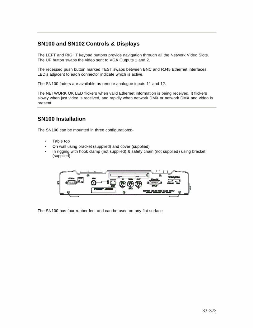
33-373
SN100 and SN102 Controls & Displays
The LEFT and RIGHT keypad buttons provide navigation through all the Network Video Slots. The UP button swaps the video sent to VGA Outputs 1 and 2. The recessed push button marked TEST swaps between BNC and RJ45 Ethernet interfaces. LED’s adjacent to each connector indicate which is active. The SN100 faders are available as remote analogue inputs 11 and 12. The NETWORK OK LED flickers when valid Ethernet information is being received. It flickers slowly when just video is received, and rapidly when network DMX or network DMX and video is present.
SN100 Installation
The SN100 can be mounted in three configurations:-
• Table top • On wall using bracket (supplied) and cover (supplied) • In rigging with hook clamp (not supplied) & safety chain (not supplied) using bracket
(supplied).
The SN100 has four rubber feet and can be used on any flat surface
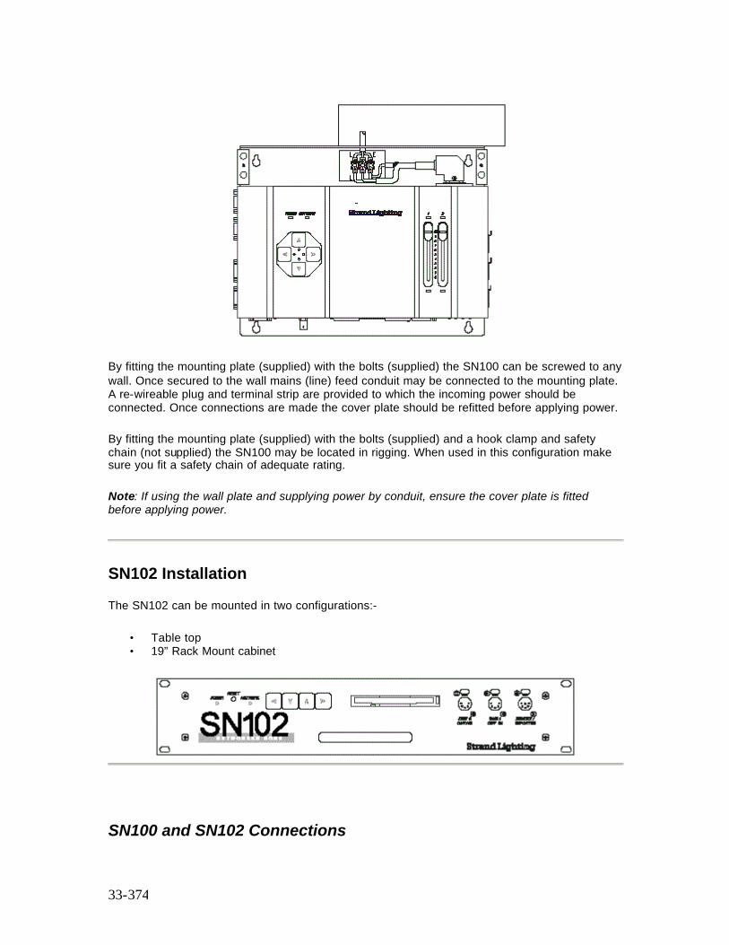
33-374
By fitting the mounting plate (supplied) with the bolts (supplied) the SN100 can be screwed to any wall. Once secured to the wall mains (line) feed conduit may be connected to the mounting plate. A re-wireable plug and terminal strip are provided to which the incoming power should be connected. Once connections are made the cover plate should be refitted before applying power.
By fitting the mounting plate (supplied) with the bolts (supplied) and a hook clamp and safety chain (not supplied) the SN100 may be located in rigging. When used in this configuration make sure you fit a safety chain of adequate rating.
Note: If using the wall plate and supplying power by conduit, ensure the cover plate is fitted before applying power.
SN102 Installation
The SN102 can be mounted in two configurations:-
• Table top • 19” Rack Mount cabinet
SN100 and SN102 Connections
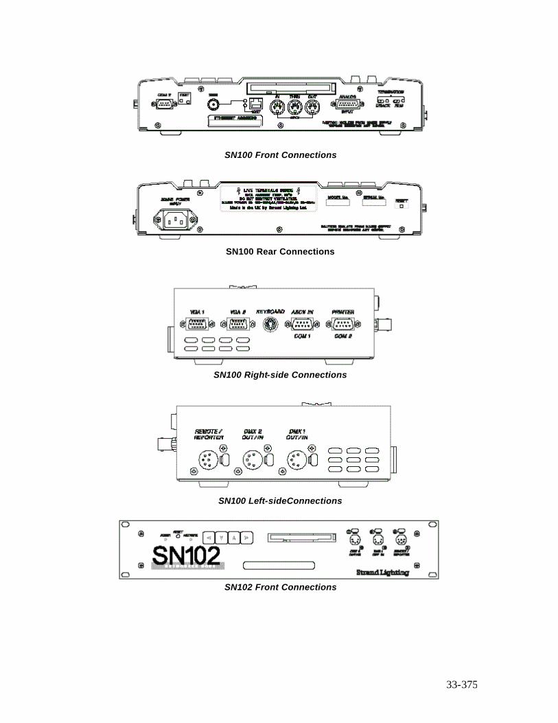
33-375
SN100 Front Connections
SN100 Rear Connections
SN100 Right-side Connections
SN100 Left-sideConnections
SN102 Front Connections
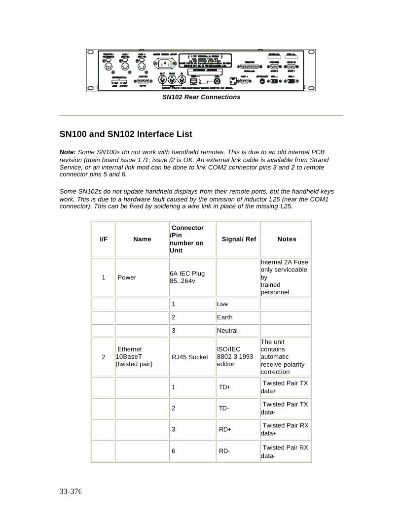
33-376
SN102 Rear Connections
SN100 and SN102 Interface List
Note: Some SN100s do not work with handheld remotes. This is due to an old internal PCB revision (main board issue 1 /1; issue /2 is OK. An external link cable is available from Strand Service, or an internal link mod can be done to link COM2 connector pins 3 and 2 to remote connector pins 5 and 6.
Some SN102s do not update handheld displays from their remote ports, but the handheld keys work. This is due to a hardware fault caused by the omission of inductor L25 (near the COM1 connector). This can be fixed by soldering a wire link in place of the missing L25.
I/F Name Connector /Pin number on Unit
Signal/ Ref Notes
1 Power 6A IEC Plug 85..264v
Internal 2A Fuse only serviceable by trained personnel
1 Live
2 Earth
3 Neutral
2 Ethernet 10BaseT (twisted pair)
RJ45 Socket ISO/IEC 8802-3 1993 edition
The unit contains automatic receive polarity correction
1 TD+ Twisted Pair TX data+
2 TD- Twisted Pair TX data-
3 RD+ Twisted Pair RX data+
6 RD- Twisted Pair RX data-
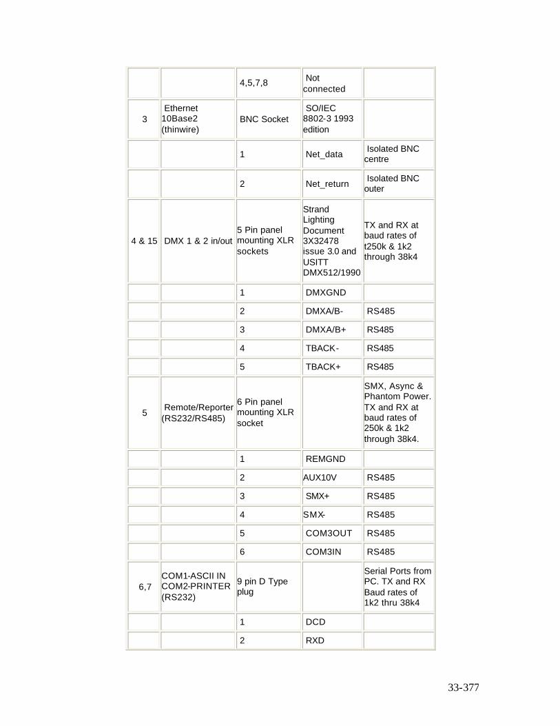
33-377
4,5,7,8 Not connected
3 Ethernet 10Base2 (thinwire)
BNC Socket SO/IEC 8802-3 1993 edition
1 Net_data Isolated BNC centre
2 Net_return Isolated BNC outer
4 & 15 DMX 1 & 2 in/out 5 Pin panel mounting XLR sockets
Strand Lighting Document 3X32478 issue 3.0 and USITT DMX512/1990
TX and RX at baud rates of t250k & 1k2 through 38k4
1 DMXGND
2 DMXA/B- RS485
3 DMXA/B+ RS485
4 TBACK- RS485
5 TBACK+ RS485
5 Remote/Reporter (RS232/RS485)
6 Pin panel mounting XLR socket
SMX, Async & Phantom Power. TX and RX at baud rates of 250k & 1k2 through 38k4.
1 REMGND
2 AUX10V RS485
3 SMX+ RS485
4 SMX- RS485
5 COM3OUT RS485
6 COM3IN RS485
6,7 COM1-ASCII IN COM2-PRINTER (RS232)
9 pin D Type plug
Serial Ports from PC. TX and RX Baud rates of 1k2 thru 38k4
1 DCD
2 RXD
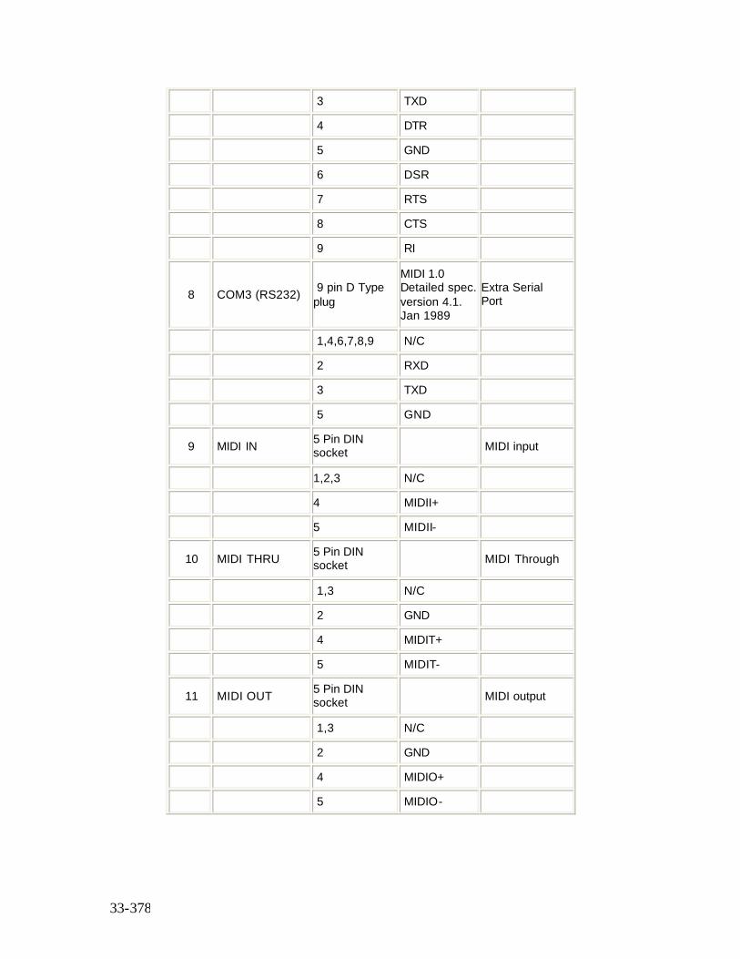
33-378
3 TXD
4 DTR
5 GND
6 DSR
7 RTS
8 CTS
9 RI
8 COM3 (RS232) 9 pin D Type plug
MIDI 1.0 Detailed spec. version 4.1. Jan 1989
Extra Serial Port
1,4,6,7,8,9 N/C
2 RXD
3 TXD
5 GND
9 MIDI IN 5 Pin DIN socket MIDI input
1,2,3 N/C
4 MIDII+
5 MIDII-
10 MIDI THRU 5 Pin DIN socket MIDI Through
1,3 N/C
2 GND
4 MIDIT+
5 MIDIT-
11 MIDI OUT 5 Pin DIN socket MIDI output
1,3 N/C
2 GND
4 MIDIO+
5 MIDIO-
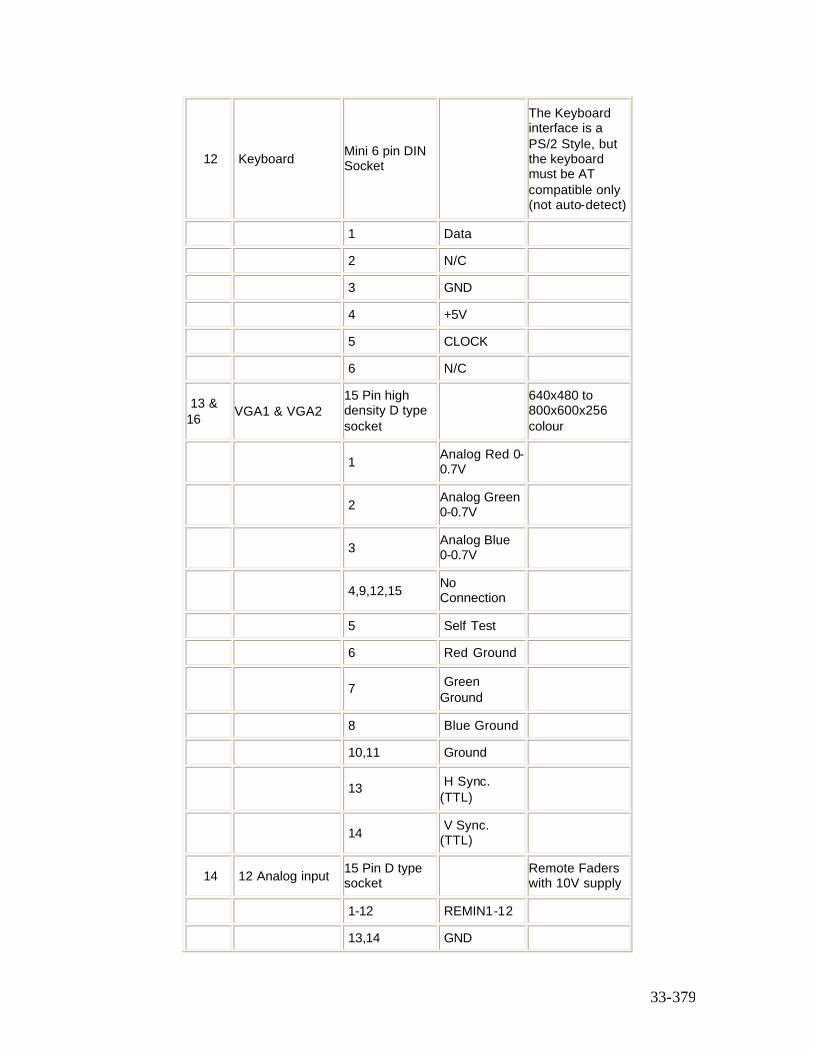
33-379
12 Keyboard Mini 6 pin DIN Socket
The Keyboard interface is a PS/2 Style, but the keyboard must be AT compatible only (not auto-detect)
1 Data
2 N/C
3 GND
4 +5V
5 CLOCK
6 N/C
13 & 16 VGA1 & VGA2
15 Pin high density D type socket
640x480 to 800x600x256 colour
1 Analog Red 0-0.7V
2 Analog Green 0-0.7V
3 Analog Blue 0-0.7V
4,9,12,15 No Connection
5 Self Test
6 Red Ground
7 Green Ground
8 Blue Ground
10,11 Ground
13 H Sync. (TTL)
14 V Sync. (TTL)
14 12 Analog input 15 Pin D type socket Remote Faders
with 10V supply
1-12 REMIN1-12
13,14 GND
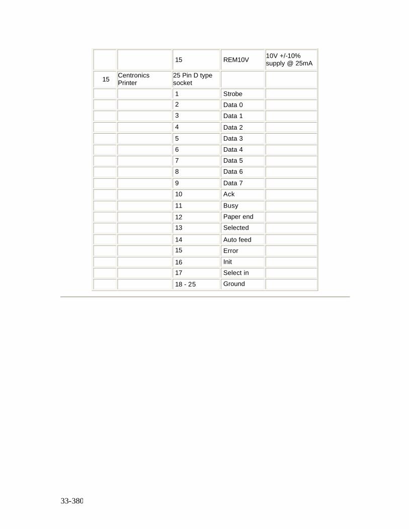
33-380
15 REM10V 10V +/-10% supply @ 25mA
15 Centronics Printer
25 Pin D type socket
1 Strobe 2 Data 0 3 Data 1 4 Data 2 5 Data 3 6 Data 4 7 Data 5 8 Data 6 9 Data 7 10 Ack 11 Busy 12 Paper end 13 Selected 14 Auto feed 15 Error 16 Init 17 Select in 18 - 25 Ground
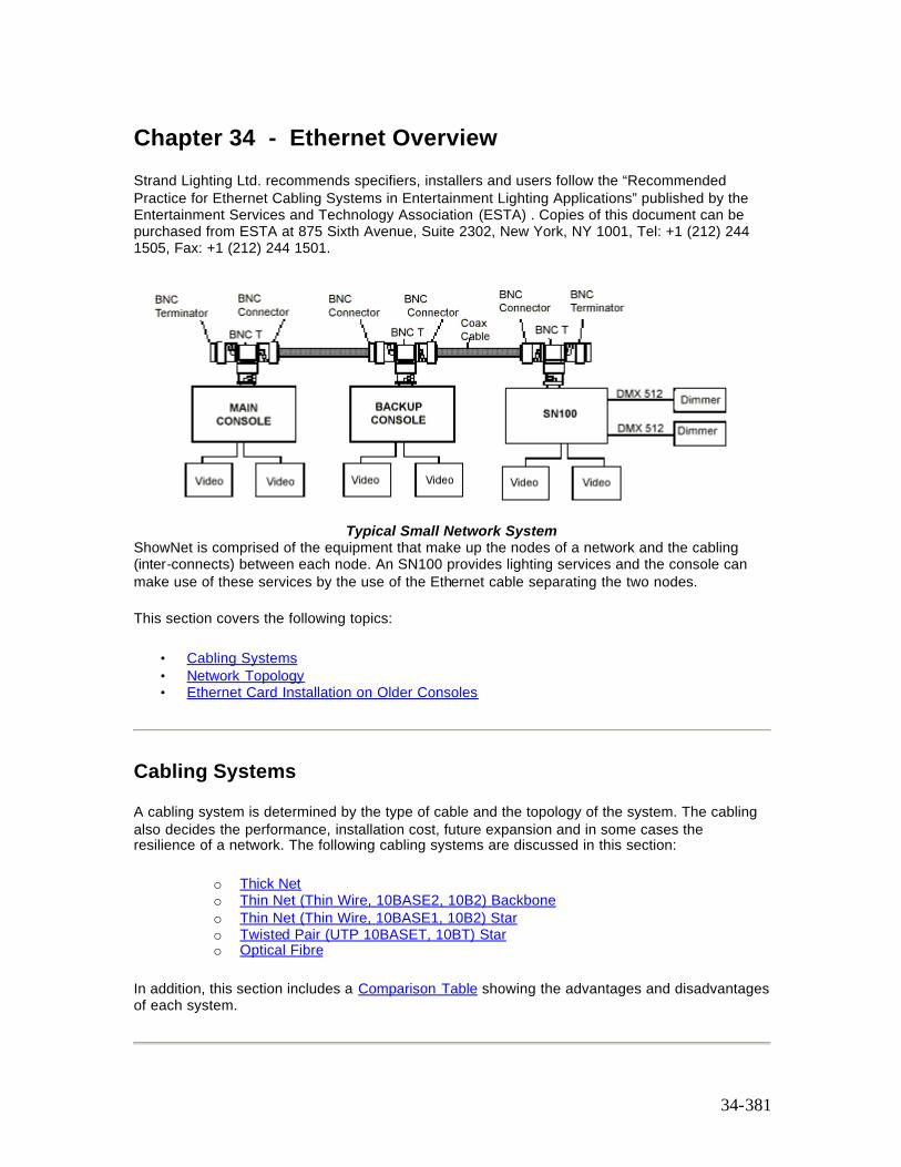
34-381
Chapter 34 - Ethernet Overview
Strand Lighting Ltd. recommends specifiers, installers and users follow the “Recommended Practice for Ethernet Cabling Systems in Entertainment Lighting Applications” published by the Entertainment Services and Technology Association (ESTA) . Copies of this document can be purchased from ESTA at 875 Sixth Avenue, Suite 2302, New York, NY 1001, Tel: +1 (212) 244 1505, Fax: +1 (212) 244 1501.
Typical Small Network System
ShowNet is comprised of the equipment that make up the nodes of a network and the cabling (inter-connects) between each node. An SN100 provides lighting services and the console can make use of these services by the use of the Ethernet cable separating the two nodes.
This section covers the following topics:
• Cabling Systems • Network Topology • Ethernet Card Installation on Older Consoles
Cabling Systems
A cabling system is determined by the type of cable and the topology of the system. The cabling also decides the performance, installation cost, future expansion and in some cases the resilience of a network. The following cabling systems are discussed in this section:
o Thick Net o Thin Net (Thin Wire, 10BASE2, 10B2) Backbone o Thin Net (Thin Wire, 10BASE1, 10B2) Star o Twisted Pair (UTP 10BASET, 10BT) Star o Optical Fibre
In addition, this section includes a Comparison Table showing the advantages and disadvantages of each system.
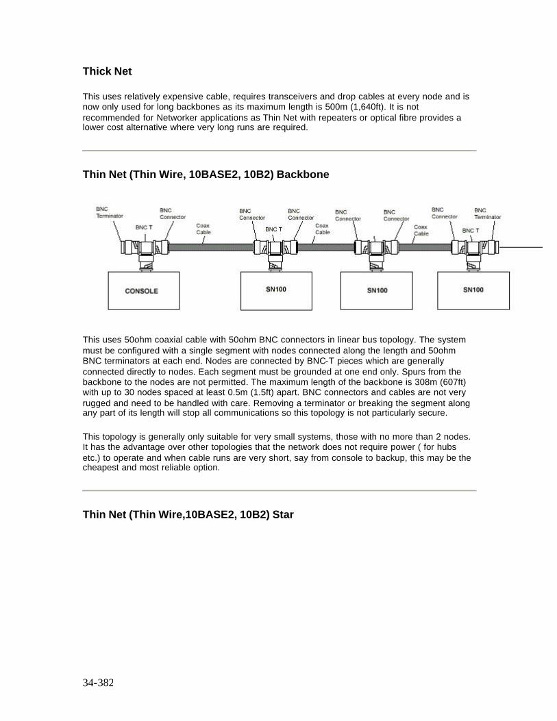
34-382
Thick Net
This uses relatively expensive cable, requires transceivers and drop cables at every node and is now only used for long backbones as its maximum length is 500m (1,640ft). It is not recommended for Networker applications as Thin Net with repeaters or optical fibre provides a lower cost alternative where very long runs are required.
Thin Net (Thin Wire, 10BASE2, 10B2) Backbone
This uses 50ohm coaxial cable with 50ohm BNC connectors in linear bus topology. The system must be configured with a single segment with nodes connected along the length and 50ohm BNC terminators at each end. Nodes are connected by BNC-T pieces which are generally connected directly to nodes. Each segment must be grounded at one end only. Spurs from the backbone to the nodes are not permitted. The maximum length of the backbone is 308m (607ft) with up to 30 nodes spaced at least 0.5m (1.5ft) apart. BNC connectors and cables are not very rugged and need to be handled with care. Removing a terminator or breaking the segment along any part of its length will stop all communications so this topology is not particularly secure.
This topology is generally only suitable for very small systems, those with no more than 2 nodes. It has the advantage over other topologies that the network does not require power ( for hubs etc.) to operate and when cable runs are very short, say from console to backup, this may be the cheapest and most reliable option.
Thin Net (Thin Wire,10BASE2, 10B2) Star
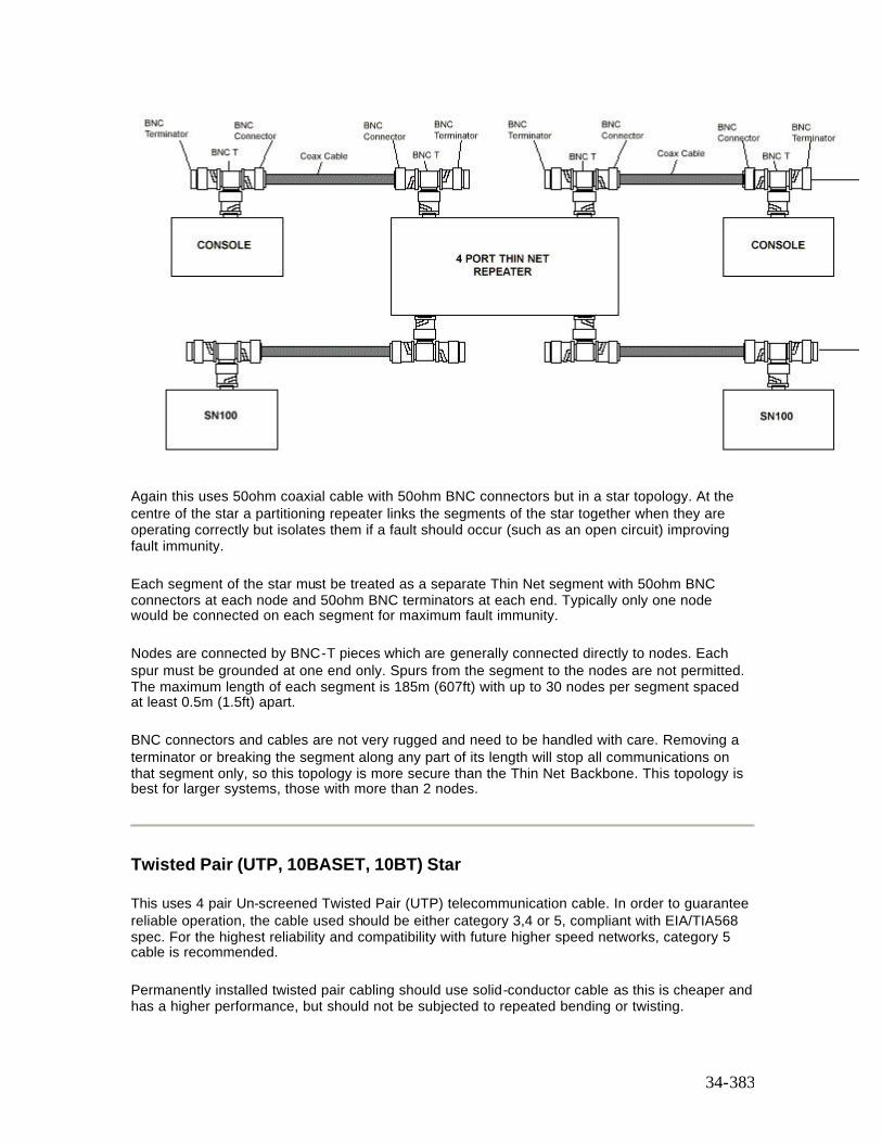
34-383
Again this uses 50ohm coaxial cable with 50ohm BNC connectors but in a star topology. At the centre of the star a partitioning repeater links the segments of the star together when they are operating correctly but isolates them if a fault should occur (such as an open circuit) improving fault immunity.
Each segment of the star must be treated as a separate Thin Net segment with 50ohm BNC connectors at each node and 50ohm BNC terminators at each end. Typically only one node would be connected on each segment for maximum fault immunity.
Nodes are connected by BNC-T pieces which are generally connected directly to nodes. Each spur must be grounded at one end only. Spurs from the segment to the nodes are not permitted. The maximum length of each segment is 185m (607ft) with up to 30 nodes per segment spaced at least 0.5m (1.5ft) apart.
BNC connectors and cables are not very rugged and need to be handled with care. Removing a terminator or breaking the segment along any part of its length will stop all communications on that segment only, so this topology is more secure than the Thin Net Backbone. This topology is best for larger systems, those with more than 2 nodes.
Twisted Pair (UTP, 10BASET, 10BT) Star
This uses 4 pair Un-screened Twisted Pair (UTP) telecommunication cable. In order to guarantee reliable operation, the cable used should be either category 3,4 or 5, compliant with EIA/TIA568 spec. For the highest reliability and compatibility with future higher speed networks, category 5 cable is recommended.
Permanently installed twisted pair cabling should use solid-conductor cable as this is cheaper and has a higher performance, but should not be subjected to repeated bending or twisting.
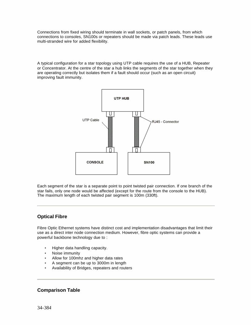
34-384
Connections from fixed wiring should terminate in wall sockets, or patch panels, from which connections to consoles, SN100s or repeaters should be made via patch leads. These leads use multi-stranded wire for added flexibility.
A typical configuration for a star topology using UTP cable requires the use of a HUB, Repeater or Concentrator. At the centre of the star a hub links the segments of the star together when they are operating correctly but isolates them if a fault should occur (such as an open circuit) improving fault immunity.
Each segment of the star is a separate point to point twisted pair connection. If one branch of the star fails, only one node would be affected (except for the route from the console to the HUB). The maximum length of each twisted pair segment is 100m (330ft).
Optical Fibre
Fibre Optic Ethernet systems have distinct cost and implementation disadvantages that limit their use as a direct inter node connection medium. However, fibre optic systems can provide a powerful backbone technology due to :
• Higher data handling capacity. • Noise immunity • Allow for 100mhz and higher data rates • A segment can be up to 3000m in length • Availability of Bridges, repeaters and routers
Comparison Table
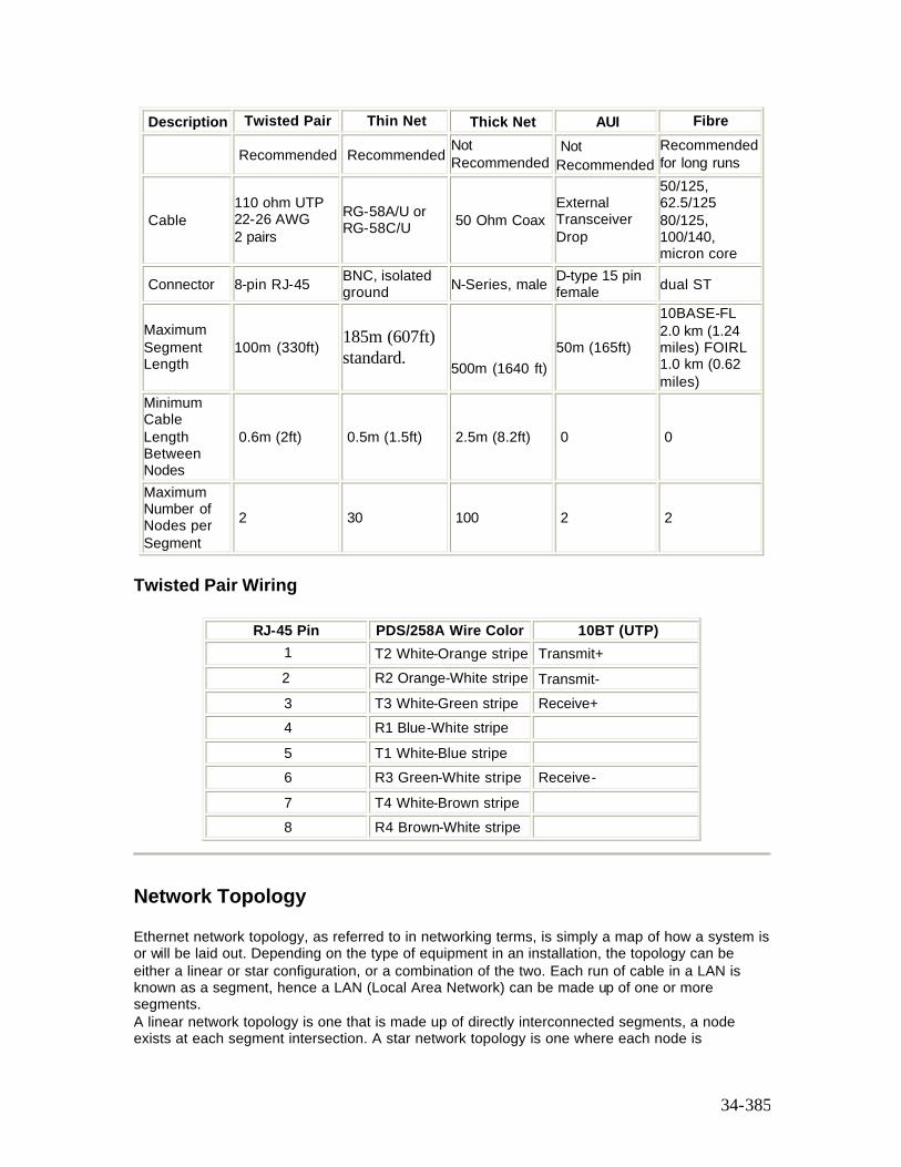
34-385
Description Twisted Pair Thin Net Thick Net AUI Fibre
Recommended Recommended Not Recommended
Not Recommended
Recommended for long runs
Cable 110 ohm UTP 22-26 AWG 2 pairs
RG-58A/U or RG-58C/U 50 Ohm Coax
External Transceiver Drop
50/125, 62.5/125 80/125, 100/140, micron core
Connector 8-pin RJ-45 BNC, isolated ground N-Series, male D-type 15 pin
female dual ST
Maximum Segment Length
100m (330ft) 185m (607ft) standard.
500m (1640 ft) 50m (165ft)
10BASE-FL 2.0 km (1.24 miles) FOIRL 1.0 km (0.62 miles)
Minimum Cable Length Between Nodes
0.6m (2ft) 0.5m (1.5ft) 2.5m (8.2ft) 0 0
Maximum Number of Nodes per Segment
2 30 100 2 2
Twisted Pair Wiring
RJ-45 Pin PDS/258A Wire Color 10BT (UTP) 1 T2 White-Orange stripe Transmit+ 2 R2 Orange-White stripe Transmit- 3 T3 White-Green stripe Receive+ 4 R1 Blue-White stripe 5 T1 White-Blue stripe 6 R3 Green-White stripe Receive- 7 T4 White-Brown stripe 8 R4 Brown-White stripe
Network Topology
Ethernet network topology, as referred to in networking terms, is simply a map of how a system is or will be laid out. Depending on the type of equipment in an installation, the topology can be either a linear or star configuration, or a combination of the two. Each run of cable in a LAN is known as a segment, hence a LAN (Local Area Network) can be made up of one or more segments. A linear network topology is one that is made up of directly interconnected segments, a node exists at each segment intersection. A star network topology is one where each node is
34-386
connected to a central hub. The hub establishes, maintains and terminates all connections between the nodes. In a LAN, the hub is may be a workstation or in a larger multi-port network the hub is most likely to be a multiplexer.
If a segment in an installation is longer than the length allowed by Ethernet rules, a repeater must be used. A repeater is a device that connects two or more segments and mirrors whatever it sees on one segment to all the other attached segments. A partitioning repeater can recognize a fault on any of its segments and cease to reflect from that until the fault is rectified. This prevents wiring problems on one segment interfering with communications on other segments.
This section covers the following topics:
o Ethernet 4-3-2 Rule o Ethernet Hubs o Ethernet Backbone o Typical Ethernet Configurations
Ethernet 4-3-2 Rule
As a rule of thumb, when designing an Ethernet topology to a achieve a reliable system you must follow the 4-3-2 Rule.
• In any LAN, there can be no more than four repeaters • In any thinnet LAN, only three segments can have active nodes. Other segments can
only exist as extensions of the overall length of the LAN. • In any LAN, there can be no more than two repeaters between any two communicating
nodes.
Ethernet Hubs
As stated earlier, a HUB forms the centre of a star topology network or cabling system. A multi-node UTP network of more than two nodes require a hub. Conceptually the node connections ‘radiate’ outward from a centrally located hub. By mixing hubs with thinnet or fibre optic backbones, network topologies with two or more ‘stars’ can be created.
Ethernet Backbone
Backbone is a generic term for LAN or WAN (Wide Area Network) connectivity between subnetworks. Subnetworks are connected to the backbone via bridges and/or routers. The backbone acts as a communications trunk. In permanent installations, a backbone topology will provide for greater preconfigured connectivity, heavier total data traffic and greater expansion potential. A backbone can provide the basis of an Ethernet system. The backbone can be either a thinnet or fibre optic.
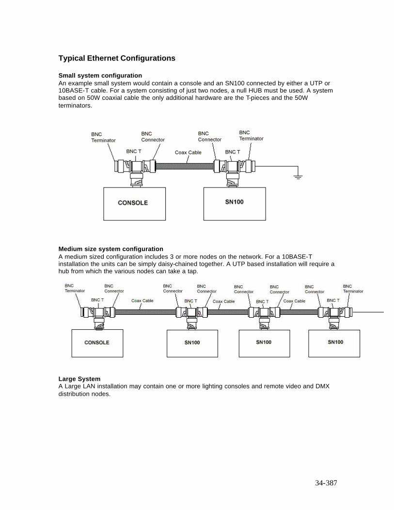
34-387
Typical Ethernet Configurations
Small system configuration An example small system would contain a console and an SN100 connected by either a UTP or 10BASE-T cable. For a system consisting of just two nodes, a null HUB must be used. A system based on 50W coaxial cable the only additional hardware are the T-pieces and the 50W terminators.
Medium size system configuration A medium sized configuration includes 3 or more nodes on the network. For a 10BASE-T installation the units can be simply daisy-chained together. A UTP based installation will require a hub from which the various nodes can take a tap.
Large System A Large LAN installation may contain one or more lighting consoles and remote video and DMX distribution nodes.
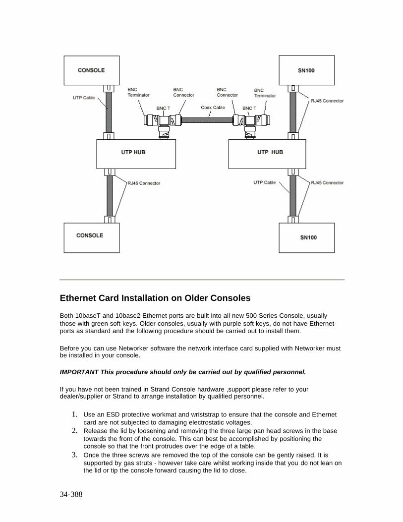
34-388
Ethernet Card Installation on Older Consoles
Both 10baseT and 10base2 Ethernet ports are built into all new 500 Series Console, usually those with green soft keys. Older consoles, usually with purple soft keys, do not have Ethernet ports as standard and the following procedure should be carried out to install them.
Before you can use Networker software the network interface card supplied with Networker must be installed in your console.
IMPORTANT This procedure should only be carried out by qualified personnel.
If you have not been trained in Strand Console hardware ,support please refer to your dealer/supplier or Strand to arrange installation by qualified personnel.
1. Use an ESD protective workmat and wriststrap to ensure that the console and Ethernet card are not subjected to damaging electrostatic voltages.
2. Release the lid by loosening and removing the three large pan head screws in the base towards the front of the console. This can best be accomplished by positioning the console so that the front protrudes over the edge of a table.
3. Once the three screws are removed the top of the console can be gently raised. It is supported by gas struts - however take care whilst working inside that you do not lean on the lid or tip the console forward causing the lid to close.
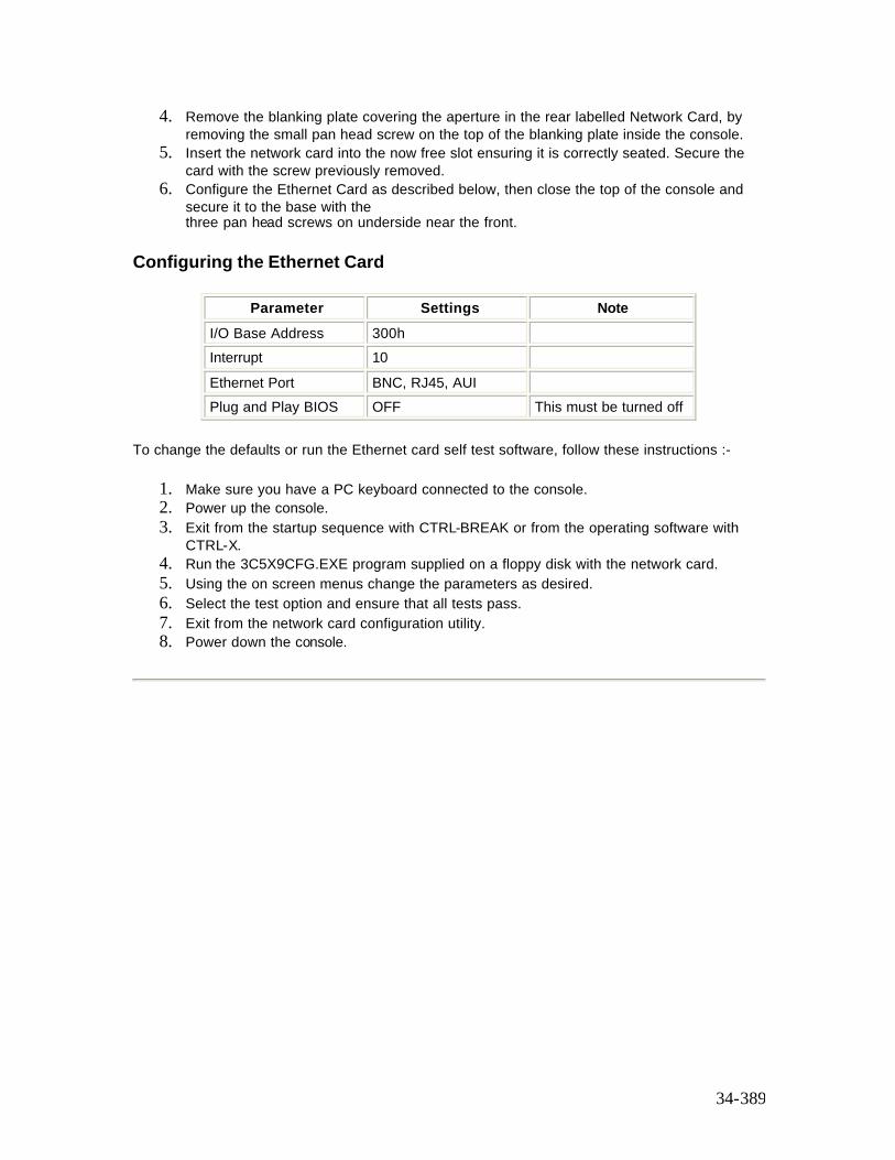
34-389
4. Remove the blanking plate covering the aperture in the rear labelled Network Card, by removing the small pan head screw on the top of the blanking plate inside the console.
5. Insert the network card into the now free slot ensuring it is correctly seated. Secure the card with the screw previously removed.
6. Configure the Ethernet Card as described below, then close the top of the console and secure it to the base with the three pan head screws on underside near the front.
Configuring the Ethernet Card
Parameter Settings Note I/O Base Address 300h Interrupt 10 Ethernet Port BNC, RJ45, AUI Plug and Play BIOS OFF This must be turned off
To change the defaults or run the Ethernet card self test software, follow these instructions :-
1. Make sure you have a PC keyboard connected to the console. 2. Power up the console. 3. Exit from the startup sequence with CTRL-BREAK or from the operating software with
CTRL-X. 4. Run the 3C5X9CFG.EXE program supplied on a floppy disk with the network card. 5. Using the on screen menus change the parameters as desired. 6. Select the test option and ensure that all tests pass. 7. Exit from the network card configuration utility. 8. Power down the console.
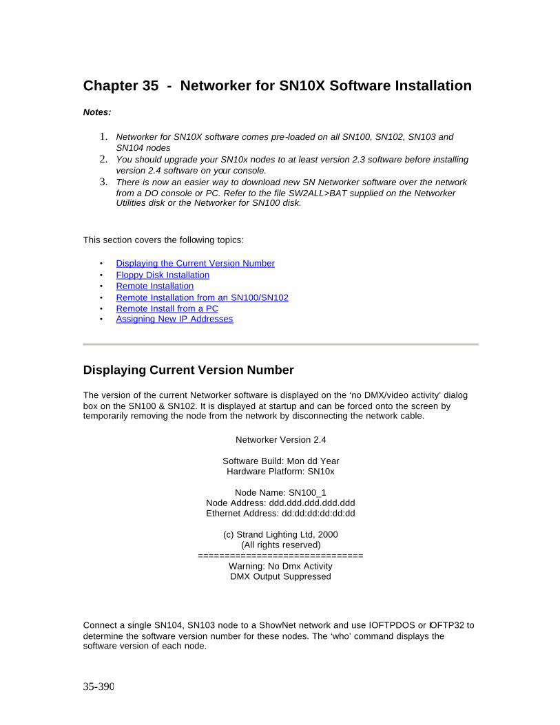
35-390
Chapter 35 - Networker for SN10X Software Installation
Notes:
1. Networker for SN10X software comes pre-loaded on all SN100, SN102, SN103 and SN104 nodes
2. You should upgrade your SN10x nodes to at least version 2.3 software before installing version 2.4 software on your console.
3. There is now an easier way to download new SN Networker software over the network from a DO console or PC. Refer to the file SW2ALL>BAT supplied on the Networker Utilities disk or the Networker for SN100 disk.
This section covers the following topics:
• Displaying the Current Version Number • Floppy Disk Installation • Remote Installation • Remote Installation from an SN100/SN102 • Remote Install from a PC • Assigning New IP Addresses
Displaying Current Version Number
The version of the current Networker software is displayed on the ‘no DMX/video activity’ dialog box on the SN100 & SN102. It is displayed at startup and can be forced onto the screen by temporarily removing the node from the network by disconnecting the network cable.
Networker Version 2.4
Software Build: Mon dd Year Hardware Platform: SN10x
Node Name: SN100_1
Node Address: ddd.ddd.ddd.ddd.ddd Ethernet Address: dd:dd:dd:dd:dd:dd
(c) Strand Lighting Ltd, 2000
(All rights reserved) ===============================
Warning: No Dmx Activity DMX Output Suppressed
Connect a single SN104, SN103 node to a ShowNet network and use IOFTPDOS or IOFTP32 to determine the software version number for these nodes. The ‘who’ command displays the software version of each node.
35-391
Floppy Disk Installation
Only possible on the SN100 and SN102 nodes; the other Networker models are supplied without floppy disk drives, see next section for install instructions for those units. The disk to use is the Networker Operating Software disk included in console operating software packages. If you received the installation files by E-Mail, copy them to a DOS floppy disk (high density, 1.44Mb) and make it bootable using the following DOS command: >SYS C: A: Assuming that your PC’s system files are in drive C: and the floppy drive is named A:. New releases supplied by Strand on floppy disk are already bootable. Then to verify the integrity of the installation disk, run the crccheck utility from DOS as follows: >A: >CRCCHECK To preserve the 220NODE.CFG configuration file, you can create a file called RECOVER.BAT on a PC, then copy it to a floppy disk for copying to the C:\220OS directory on the Networker. When ready to do this, you must connect a keyboard and monitor to the Networker, power the unit up, then press Ctrl and X to get back to DOS. The file should contain: COPY 220NODE.OLD 220NODE.CFG /V /Y If you are upgrading a Networker which contains a release earlier than Beta 2v0, then you may need to manually create a new 220NODE.CFG as the format has changed. In that case delete the batch file RECOVER.BAT, make a temporary copy so that DMX in/out info and the IP address can be transferred to the default 220NODE.CFG which is created as part of the installation process. Then the latest software can be installed by inserting the release disk in the floppy drive and rebooting the Networker by either typing CTRL, ALT & DEL keys on the keyboard simultaneously or pressing the recessed RESET switch using a pen. On completion of installation, you will be prompted to reset the SN10X again so that the new software can be operational.
Remote Installation
Download is achieved using one of the following ioftp programs supplied on the installation disk:
IOFTPDOS.EXE IOFTP32.EXE SW2ALL.BAT
Along with appropriate packet drivers or Windows based TCP/IP protocol stacks. The IOFTP program used must be the same software version as on the SN10X node being downloaded to.
Note: Network compatibility between different versions is not guaranteed.
Remote download is possible on all SN10Xs which are installed with software releases Beta 2v0 and later. It is NOT possible to do a remote download on SN10Xs with production release 1.5 nor maintenance release 1.55. In those cases, only a floppy disk installation is possible
You will require a PC with an Ethernet network card, or use an existing SN100 or SN102 which already come supplied with networking capability.
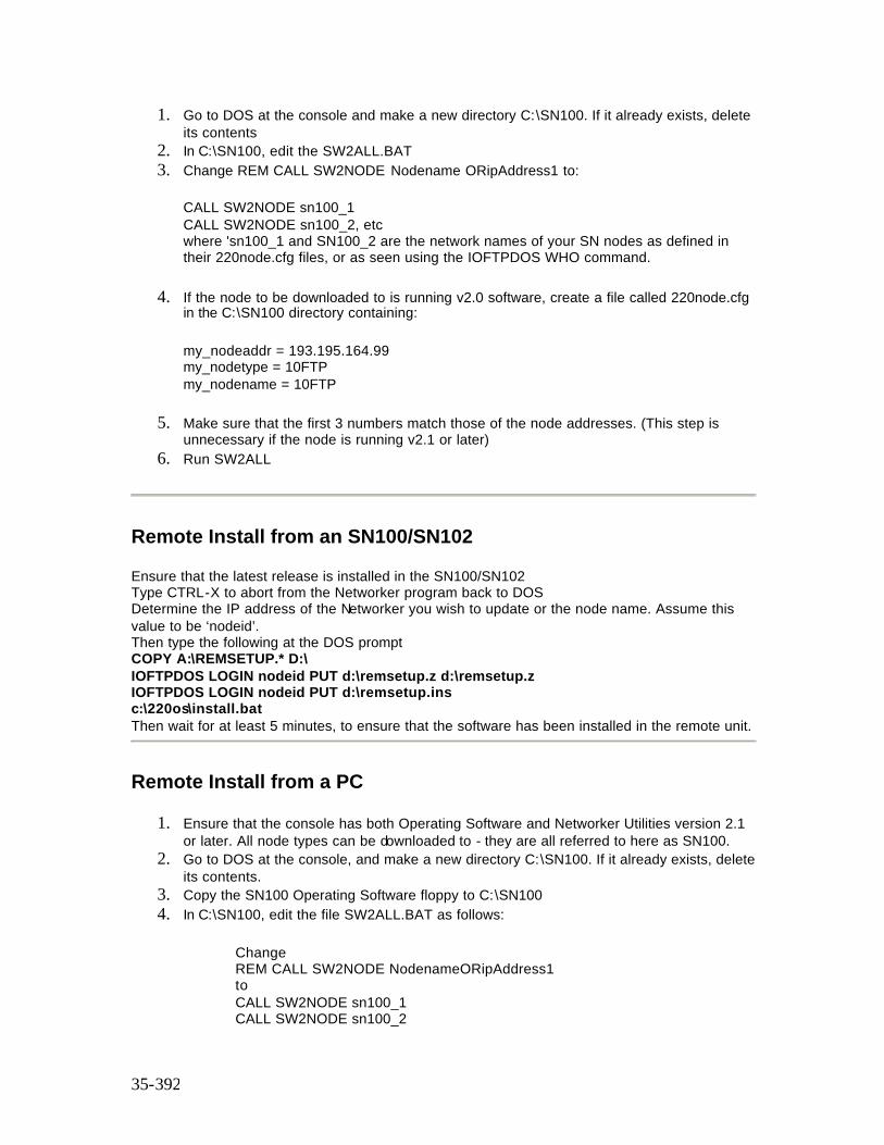
35-392
1. Go to DOS at the console and make a new directory C:\SN100. If it already exists, delete its contents
2. In C:\SN100, edit the SW2ALL.BAT 3. Change REM CALL SW2NODE Nodename ORipAddress1 to:
CALL SW2NODE sn100_1 CALL SW2NODE sn100_2, etc where 'sn100_1 and SN100_2 are the network names of your SN nodes as defined in their 220node.cfg files, or as seen using the IOFTPDOS WHO command.
4. If the node to be downloaded to is running v2.0 software, create a file called 220node.cfg in the C:\SN100 directory containing:
my_nodeaddr = 193.195.164.99 my_nodetype = 10FTP my_nodename = 10FTP
5. Make sure that the first 3 numbers match those of the node addresses. (This step is unnecessary if the node is running v2.1 or later)
6. Run SW2ALL
Remote Install from an SN100/SN102
Ensure that the latest release is installed in the SN100/SN102 Type CTRL-X to abort from the Networker program back to DOS Determine the IP address of the Networker you wish to update or the node name. Assume this value to be ‘nodeid’. Then type the following at the DOS prompt COPY A:\REMSETUP.* D:\ IOFTPDOS LOGIN nodeid PUT d:\remsetup.z d:\remsetup.z IOFTPDOS LOGIN nodeid PUT d:\remsetup.ins c:\220os\install.bat Then wait for at least 5 minutes, to ensure that the software has been installed in the remote unit.
Remote Install from a PC
1. Ensure that the console has both Operating Software and Networker Utilities version 2.1 or later. All node types can be downloaded to - they are all referred to here as SN100.
2. Go to DOS at the console, and make a new directory C:\SN100. If it already exists, delete its contents.
3. Copy the SN100 Operating Software floppy to C:\SN100 4. In C:\SN100, edit the file SW2ALL.BAT as follows:
Change REM CALL SW2NODE NodenameORipAddress1 to CALL SW2NODE sn100_1 CALL SW2NODE sn100_2
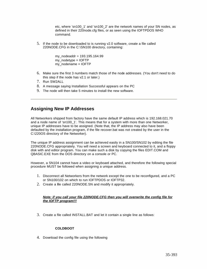
35-393
etc, where 'sn100_1' and 'sn100_2' are the network names of your SN nodes, as defined in their 220node.cfg files, or as seen using the IOFTPDOS WHO command.
5. If the node to be downloaded to is running v2.0 software, create a file called 220NODE.CFG in the C:\SN100 directory, containing:
my_nodeaddr = 193.195.164.99 my_nodetype = IOFTP my_nodename = IOFTP
6. Make sure the first 3 numbers match those of the node addresses. (You don't need to do this step if the node has v2.1 or later.)
7. Run SW2ALL 8. A message saying Installation Successful appears on the PC 9. The node will then take 5 minutes to install the new software.
Assigning New IP Addresses
All Networkers shipped from factory have the same default IP address which is 192.168.021.70 and a node name of ‘sn100_1’. This means that for a system with more than one Networker, unique IP addresses have to be assigned. (Note that, the IP address may also have been defaulted by the installation program, if the file recover.bat was not created by the user in the C:\220OS directory of the Networker).
The unique IP address assignment can be achieved easily in a SN100/SN102 by editing the file 220NODE.CFG appropriately. You will need a screen and keyboard connected to it, and a floppy disk with and editor program. You can make such a disk by copying the files EDIT.COM and QBASIC.EXE from the DOS directory on a console or PC.
However, a SN104 cannot have a video or keyboard attached, and therefore the following special procedure MUST be followed when assigning a unique address.
1. Disconnect all Networkers from the network except the one to be reconfigured, and a PC or SN100/102 on which to run IOFTPDOS or IOFTP32.
2. Create a file called 220NODE.SN and modify it appropriately.
Note: if you call your file 220NODE.CFG then you will overwrite the config file for the IOFTP program!!!
3. Create a file called INSTALL.BAT and let it contain a single line as follows:
COLDBOOT
4. Download the config file using the following

35-394
IOFTPxxx LOGIN SN100_1 PUT 220NODE.SN 220NODE.CFG LOGOUT
5. Download the install batch file using the following
IOFTPxxx LOGIN SN100_1 PUT INSTALL.BAT . LOGOUT
6. Wait for up to a minute for the new values in the new downloaded 220node.cfg to take effect.
7. Connect the next Networker back onto the network and follow steps 2 through 6.
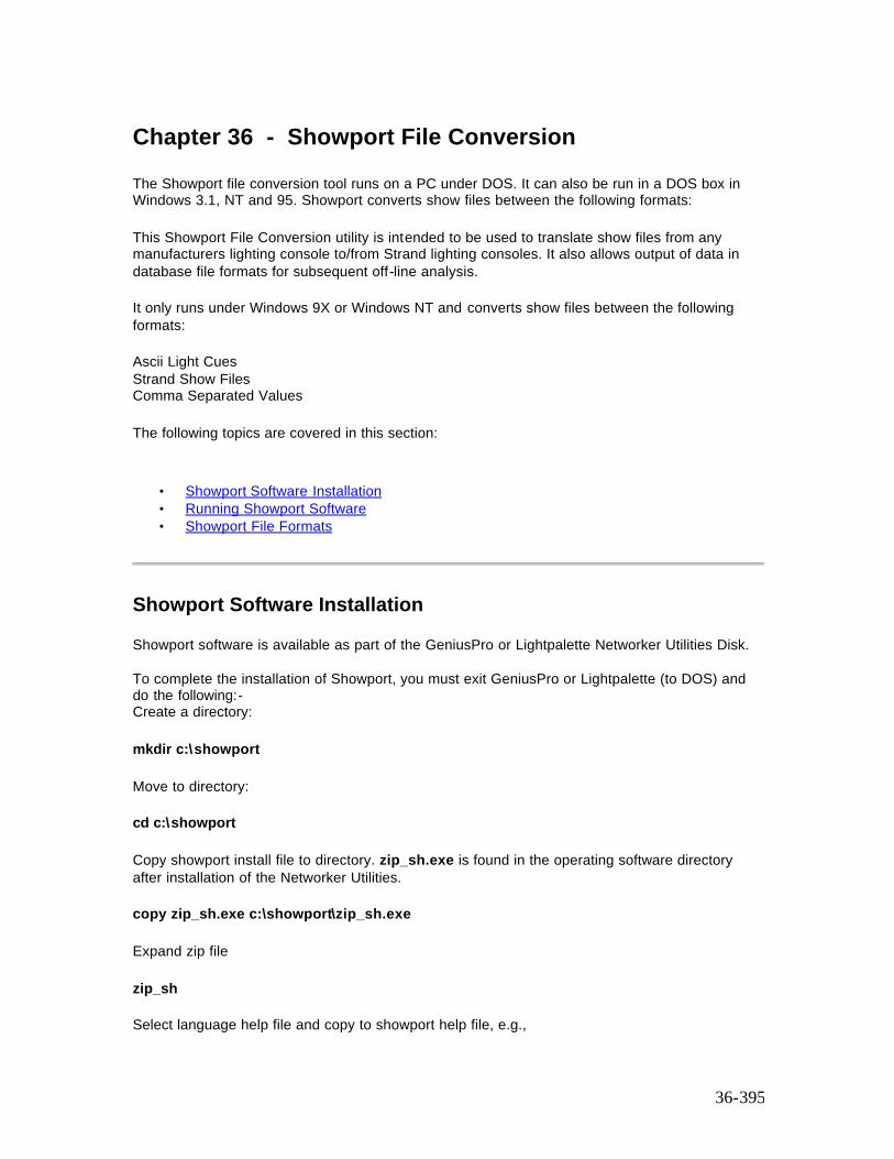
36-395
Chapter 36 - Showport File Conversion
The Showport file conversion tool runs on a PC under DOS. It can also be run in a DOS box in Windows 3.1, NT and 95. Showport converts show files between the following formats: This Showport File Conversion utility is intended to be used to translate show files from any manufacturers lighting console to/from Strand lighting consoles. It also allows output of data in database file formats for subsequent off-line analysis. It only runs under Windows 9X or Windows NT and converts show files between the following formats: Ascii Light Cues Strand Show Files Comma Separated Values The following topics are covered in this section:
• Showport Software Installation • Running Showport Software • Showport File Formats
Showport Software Installation
Showport software is available as part of the GeniusPro or Lightpalette Networker Utilities Disk. To complete the installation of Showport, you must exit GeniusPro or Lightpalette (to DOS) and do the following:- Create a directory: mkdir c:\showport Move to directory: cd c:\showport Copy showport install file to directory. zip_sh.exe is found in the operating software directory after installation of the Networker Utilities. copy zip_sh.exe c:\showport\zip_sh.exe Expand zip file zip_sh Select language help file and copy to showport help file, e.g.,

36-396
copy english.msg showport.msg After installation, read the RELEASE2.TXT in the operating software directory for further important notes on PC configuration. If the DOS installation fails, try disabling SHARE or SMARTDRV lines in the PCs AUTOEXEC.BAT file. You can enable them again after installation. WARNING: You should disable Norton Commander because it can cause hard disk corruption when running operating software on the PC.
Running Showport Software Once ShowPort is running, you will be faced with a dialog box with several fields. The fields show:
• The current directory. This will change as you use the mouse/keyboard in the directory listing to move around the selected disk drive.
• A list of files to translate from. You may select one file, or several files for simultaneous translation.
• A list of subdirectories in the current directory. You can select a new directory or disk drive by double clicking on it.
• A drop down box to select the file type to translate from. Click on the arrow to select a new type. Note that you are unable to translate between files of the same type.
• Another drop down box to select the file type to translate to. • A progress bar to show how the conversion is progressing. The progress bar will go from
0 to 100% during reading and then from 0 to 100% during writing. • A log window to show the status of the conversion. • The Convert button should be clicked to start conversion. While converting, this button
changes to an Abort button which may be clicked to stop conversion.
ShowPort File Formats
• Strand Show File (file extension: .ssf). This format is proprietary to Strand Lighting Ltd. and will not be discussed here.
• Ascii Light Cues format (file extension: .alq)
This format is the USITT ASCII Text representation for lighting console data and conforms to version 3.0 (March 1992) of the standard. ShowPort implements several manufacturer specific keywords for Strand Lighting consoles.
The manufacturer and console records are as follows:
Manufactuer Strand Console GENIUSPLUS
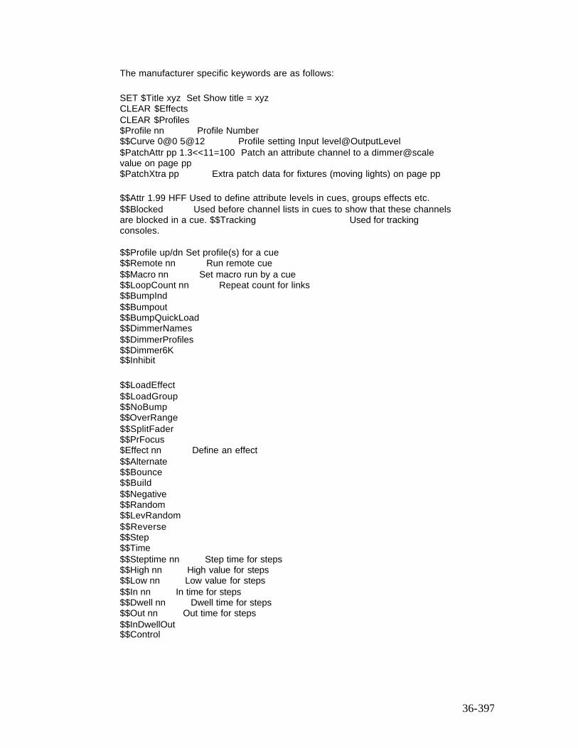
36-397
The manufacturer specific keywords are as follows:
SET $Title xyz Set Show title = xyz CLEAR $Effects CLEAR $Profiles $Profile nn Profile Number $$Curve 0@0 5@12 Profile setting Input level@OutputLevel $PatchAttr pp 1.3<<11=100 Patch an attribute channel to a dimmer@scale value on page pp $PatchXtra pp Extra patch data for fixtures (moving lights) on page pp
$$Attr 1.99 HFF Used to define attribute levels in cues, groups effects etc. $$Blocked Used before channel lists in cues to show that these channels are blocked in a cue. $$Tracking Used for tracking consoles. $$Profile up/dn Set profile(s) for a cue $$Remote nn Run remote cue $$Macro nn Set macro run by a cue $$LoopCount nn Repeat count for links $$BumpInd $$Bumpout $$BumpQuickLoad $$DimmerNames $$DimmerProfiles $$Dimmer6K $$Inhibit
$$LoadEffect $$LoadGroup $$NoBump $$OverRange $$SplitFader $$PrFocus $Effect nn Define an effect $$Alternate $$Bounce $$Build $$Negative $$Random $$LevRandom $$Reverse $$Step $$Time $$Steptime nn Step time for steps $$High nn High value for steps $$Low nn Low value for steps $$In nn In time for steps $$Dwell nn Dwell time for steps $$Out nn Out time for steps $$InDwellOut $$Control
36-398
• Comma separated value (file extension: .csv)
Comma seperated value files are intended to be compatible with most spreadsheet packages. Processing can be performed on show data using a speadsheet, and the results can be converted back into a console-specific format or ascii light cues format.
The data are stored in several separate .csv files, which reside in a single directory. The filename you specify to ShowPort is actually the name of this directory.
Each file in the directory represents a different part of the show file. The first line contains the column headings as text strings, and the following lines contain the corresponding data.
The files generated are:
cuelist.csv Cue Part Text UpTime UpDelay DownTime DownDelay Wait CrossFade Link LoopCount ProfileUp ProfileDn Remote Effect Macro SplitFader cuelev.csv Cue Part Channel Level Blocked Preset grplist.csv Group Text grplev.csv Group Channel Level Preset sublist.csv Submaster Text TimeUp TimeDown BumpInd BumpOut BumpQuickLoad BumpNone OverRange Effect Group Macro Inhibit sublev.csv Submaster Channel Level Preset fxlist.csv Effect Text LevelType EffectType Direction Steptime Up Dwell Down Lo High fxlev.csv Effect Step Channel Level Preset fxstep.csv Effect Step Steptime Up Dwell Down Lo High patch.csv Patch Mux Channel Min Max Profile 6k/12k Fixture Threshold Steps MuxIn SwapPanTilt InvPan InvTilt First Last Notes about the representation of values:
• Channel numbers are whole numbers except if channel attributes are used when they are a decimal number with the decimal part denoting the attribute number.
• Channel levels are in the range 0-255 decimal so that maximum accuracy is available. • Submaster numbers are shown as Sub . Page • Effect steps are shown as Fx . Step • Patch number are shown as Dimmer . Page • Some special numbers are used to denote special flags in some fields: • A wait value of -2 denotes no wait time • An effect value of -2 denotes no effect for a cue • A macro value of -2 denotes no macro for a cue

36-399
37-400
Chapter 37 - Additional Information
This section covers the following topics:
• Notes on Upgrading Old Software • Tracking Backup Notes • Fitting RAM Memory • Macro Trigger Card • Tracker Library Files • Site Configuration Files • DOS Utilities • DOS Environment Variables • Country Keyboard Support • Changing the HTML Help Files
Notes on Upgrading Old Software
If your current version of operating software is earlier than 2.0, you need to re-register your console, and PC, if fitted with a CS card or dongle, in order to use release 2.4.
Important Note: If you are installing over software which is older than 2v0, you must delete 220NET.CFG files, and edit 220NODE.CFG files on all consoles and SN100s to match the format in 220NODE.NEW supplied with the new software. If you forget to change these, consoles may not start, and backup PCs may not have control of their keyboard.
Editing the 220NODE.CFG Network Configuration File
All devices used on the ShowNet network must have the following defined: my_nodeaddr = 192.168.0.aaa These are the four decimal numbers of the IP address. aaa can be 1 to 254 my_nodetype = 530 For example - see the list of types in the file (See also 220TYPEASCFG enviroment variable) my_nodename = abcdefgh Any name up to 8 characters, no spaces or punctuation netmask = 255.255.255.0 Do not change this
CREATE <nodename>.CON FILE
This is the console setup defaults file. You can create one for each console and PC by copying CONSOLE.NEW which is installed with the software. So for console1, create CONSOLE1.CON at DOS by doing:
copy CONSOLE.NEW CONSOLE1.CON

37-401
Problems Starting the Software
If the console freezes or gives errors over the startup screen. In the unlikely event of the show data becoming corrupt, the console can be completely cleared down by either deleting all the DAT files using 220 CLEAN.BAT, or by clearing the Whole Show and setup together at the Archive clear display.
To get to DOS during start up, press Ctrl and Break together as soon as the start up screen appears. Enter Y at the prompt 'Terminate Batch Job' (Y/N)
Fitting RAM Memory
Software version 2.2 and later require more than 16Mb of RAM (memory) for the 'i' software version to run. The non-'i' version 2.2 operating software will still run in 8Mb of RAM. All consoles have at least 8Mb, but a few early 'i' consoles had 16Mb. To see how much memory your console has, watch the screen messages at powerup (eg '8192 kbytes tested ok' indicates 8Mbytes installed).
If you have only 4Mb in a non-'i',or 16Mb on an i console, you must upgrade to at least 8Mb (old electronics) or 16Mb (new electronics) or 32Mb for i consoles BEFORE installing this version of software. Strand Service (or your supplier) will upgrade your console - contact them for details.
You can run the non-'i' software version in an 'i' console which only has 16Mb of RAM.
Older non-'i' consoles cannot be fitted with more than 8Mbytes, but all newer consoles (with the built-in network connectors) can be fitted with up to 32Mbytes (non-Pentium Pro or -Pentium II) or 64Mbytes (Pentium Pro or Pentium II). Fitting more memory improves performance in all areas of operation
Macro Trigger Card
An optional digital input card can now be used as a macro trigger device. The card is RS part number 192-0056, and is enabled by setting a DOS variable MACRO_CARD_IO_BASE to the IO base address of the card, which should be 310. The card's jumpers should be set to this address too. Invalid IO addresses cause the card to be ignored. The card is also ignored if the variable is not set, which is the normal case; only special purpose systems need this card.
The card has 16 data lines which are used as follows: Line 1-8: macro number 1-255, binary encoded Line 16: data active strobe which causes the console to read Lines 0-7 Line 9-15: direct trigger to macros 9-15, ignoring strobe See below for more details of DOS variables.
37-402
Tracker Library Files
The console software uses some text files on disk when it starts up, to read in Tracker library information.
You can edit these files at the Notes display or with the DOS EDIT command to meet your own requirements, and the changes you make will take effect at the next startup. The files are in the program directory, normally c:\220os.
Files you can edit: FIXTURE.LIB The Fixture library, used in @FIXTURE patching ATCPAGE.LIB The Attribute Controller Page library, used to group attributes into pages for the trackball keys. If the console can not read ATCPAGE.LIB, it uses a single default page with 1 intensity and 1 colour. FIXTURE.BAK A backup of FIXTURE.LIB made by the Notes editor. ATCPAGE.BAK A backup of ATCPAGE.LIB made by the Notes editor. Files installed when new Operating Software is loaded: FIXTURE.NEW The release version, used to reset FIXTURE.LIB when Fixtures are cleared (extra fixtures you inserted in .LIB are retained) ATCPAGE.NEW The release version, used to reset ATCPAGE.LIB when Setup is cleared (extra pages you inserted in .LIB are NOT retained) FIXTURE.LIB A copy of FIXTURE.NEW ATCPAGE.LIB A copy of ATCPAGE.NEW FIXTURE.OLD Your old FIXTURE.LIB file from the previous version ATCPAGE.OLD Your old ATCPAGE.LIB file from the previous version
The .LIB files are saved inside show files (the ATC pages are part of Setup), and are also updated when a show is loaded or cleared.
If you lose the .new files, you can get them back by re-installing the software.
All comment lines are moved to the top of the files when these files are updated after clearing or loading a show, and when the Notes editor is used.
You can preserve your .LIB files through software installation by copying them from .OLD's using RECOVER.BAT.
Site Configuration Files
OS.BAT This is NOT a site configuration file! If you edit this file, your changes will be lost when you install new software. Instead, edit files starting with USER, which OS.BAT runs for you if they exist. They are all optional - the software will run without them.
USEREXEC.BAT (optional) At every startup, the console AUTOEXEC.BAT file looks for a file called USEREXEC.BAT, and if it exists it is run. This file is not installed with the software - you
37-403
provide it yourself. You can use it to log on to a network file server; install your keyboard language support; set DOS environment variables such as 220maxmem; or anything else required at startup.
USERINIT.BAT (optional) Every time the console is started from DOS using OS, GENIUSP or LIGHTP, USERINIT.BAT is run if it is there. Use it to set enviroment variables, or to force a console to log in as a remote to another main by adding the line 'ECHO. > REMOTE.CFG'
RECOVER.BAT (recommended) After new Operating Software is installed, the RECOVER.BAT batch file is run if it exists. Again, you provide it; if it is not there, the console restarts as normal. You can use it to copy back your customised fixture library (which is normally renamed to FIXTURE.OLD during installation) and your network configuration files. The batch file could look like this: COPY FIXTURE.OLD FIXTURE.LIB /Y COPY ATCPAGE.OLD ATCPAGE.LIB /Y COPY 220NODE.OLD 220NODE.CFG /Y Note that installing software at DOS does NOT run RECOVER.BAT.
DOS Utilities
220CLEAN.BAT This is a useful tool for cleaning up the console's hard disk. You are advised to save your current show before running it. Run it by typing 220CLEAN, and it prompts you if you want to:
• Check and display the console's PC resources • Delete the working files used to hold the current show. This is useful if you are
experiencing erratic or unusual operation. • Check AND FIX any hard disk corruption. You may need to reload the Operating
Software if errors appear. • Defragment the hard disk, which may result in a significant increase in console speed
after this is done. • Check AND FIX any hard disk corruption caused by defragmentation • Check that the Operating Software files are correctly installed You may need to reload
the Operating Software if errors appear.
NETON Loads the packet driver for the console network interface. Do this before running IOFTPDOS.
NETOFF Unloads the network card packet driver. Do this after running IOFTPDOS and before restarting the Operating Software.
OS Starts the Operating Software from DOS.
LIGHTP/GENIUSP Starts the Off Line Editor software from DOS.
DOS Environment Variables

37-404
DOS environment variables are used to configure the operating software for special site or test requirements. They are usually defined in USERINIT.BAT so that they are preserved when new software is installed.
To set a variable to a value, the batch file command format is: SET VARIABLE=VALUE To clear a variable, the batch file command format is SET VARIABLE= All these variables are normally absent.
Variable Values Use 220NUMSUBS 24, 30, 54 or 120 Forces a different number of submasters than detected at startup 220MAXMEM 10..255 Limits the number of read (1 page = 16k) cache pages allocated at startup, to free up memory for other programs MACRO_CARD_IO_BASE 310 Sets io base address for the macro trigger card (if fitted) 220KEYBOARD US, UK, FR Set the type of the external GR, RU or SV keyboard in use on the console Two letter codes are those used by the keyb DOS program See "Country Keyboard Support" below. AUTOTEST 1 or x (absent) Remote Test only: 1=when COM1 or COM2 set to Remote Test, all control events are echoed to the test port. 1=Network drives ignored x=Events not echoed. This is normal case for MIDI operation, where MIDI in events must not be echoed to MIDI out port x=Network drives recognised 220TRACE any value If defined, enables tracking state tracing to btrace.log 220TYPEASCFG any value If defined, prevents the Console (v2b2 and later) node type defined in 220NODE.CFG being overridden by the node type derived from the CS type. (Only valid if CS present)
Country Keyboard Support
From software version 2.1 onwards the console has increased support of country-specific keyboards. This requires both the installation of the correct keyb DOS program and the setting of the environment variable 220KEYBOARD.
Running on DOS Add one of the following sets of 3 lines to your USEREXEC.BAT file in the operating software directory:
France: c:\dos\mode CON CODEPAGE PREPARE=((437) C:\DOS\EGA.CPI) c:\dos\keyb fr, 437, c:\dos\keyboard.sys set 220KEYBOARD=fr
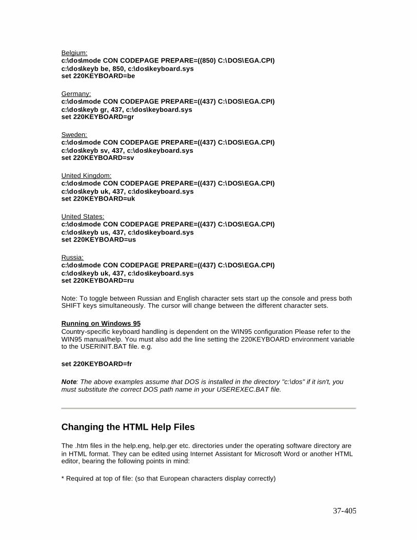
37-405
Belgium: c:\dos\mode CON CODEPAGE PREPARE=((850) C:\DOS\EGA.CPI) c:\dos\keyb be, 850, c:\dos\keyboard.sys set 220KEYBOARD=be
Germany: c:\dos\mode CON CODEPAGE PREPARE=((437) C:\DOS\EGA.CPI) c:\dos\keyb gr, 437, c:\dos\keyboard.sys set 220KEYBOARD=gr
Sweden: c:\dos\mode CON CODEPAGE PREPARE=((437) C:\DOS\EGA.CPI) c:\dos\keyb sv, 437, c:\dos\keyboard.sys set 220KEYBOARD=sv
United Kingdom: c:\dos\mode CON CODEPAGE PREPARE=((437) C:\DOS\EGA.CPI) c:\dos\keyb uk, 437, c:\dos\keyboard.sys set 220KEYBOARD=uk
United States: c:\dos\mode CON CODEPAGE PREPARE=((437) C:\DOS\EGA.CPI) c:\dos\keyb us, 437, c:\dos\keyboard.sys set 220KEYBOARD=us
Russia: c:\dos\mode CON CODEPAGE PREPARE=((437) C:\DOS\EGA.CPI) c:\dos\keyb uk, 437, c:\dos\keyboard.sys set 220KEYBOARD=ru
Note: To toggle between Russian and English character sets start up the console and press both SHIFT keys simultaneously. The cursor will change between the different character sets.
Running on Windows 95 Country-specific keyboard handling is dependent on the WIN95 configuration Please refer to the WIN95 manual/help. You must also add the line setting the 220KEYBOARD environment variable to the USERINIT.BAT file. e.g.
set 220KEYBOARD=fr
Note: The above examples assume that DOS is installed in the directory "c:\dos" if it isn't, you must substitute the correct DOS path name in your USEREXEC.BAT file.
Changing the HTML Help Files
The .htm files in the help.eng, help.ger etc. directories under the operating software directory are in HTML format. They can be edited using Internet Assistant for Microsoft Word or another HTML editor, bearing the following points in mind:
* Required at top of file: (so that European characters display correctly)
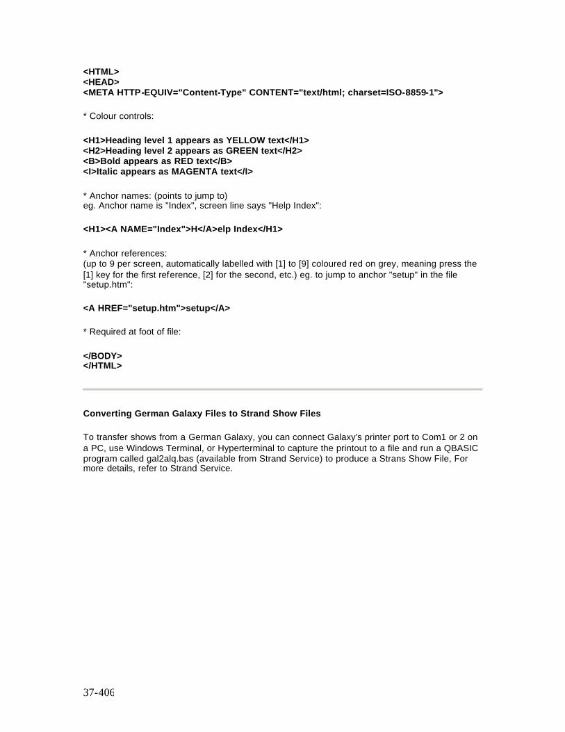
37-406
<HTML> <HEAD> <META HTTP-EQUIV="Content-Type" CONTENT="text/html; charset=ISO-8859-1">
* Colour controls:
<H1>Heading level 1 appears as YELLOW text</H1> <H2>Heading level 2 appears as GREEN text</H2> <B>Bold appears as RED text</B> <I>Italic appears as MAGENTA text</I>
* Anchor names: (points to jump to) eg. Anchor name is "Index", screen line says "Help Index":
<H1><A NAME="Index">H</A>elp Index</H1>
* Anchor references: (up to 9 per screen, automatically labelled with [1] to [9] coloured red on grey, meaning press the [1] key for the first reference, [2] for the second, etc.) eg. to jump to anchor "setup" in the file "setup.htm":
<A HREF="setup.htm">setup</A>
* Required at foot of file:
</BODY> </HTML>
Converting German Galaxy Files to Strand Show Files
To transfer shows from a German Galaxy, you can connect Galaxy's printer port to Com1 or 2 on a PC, use Windows Terminal, or Hyperterminal to capture the printout to a file and run a QBASIC program called gal2alq.bas (available from Strand Service) to produce a Strans Show File, For more details, refer to Strand Service.