operator's manual - index of
TRANSCRIPT
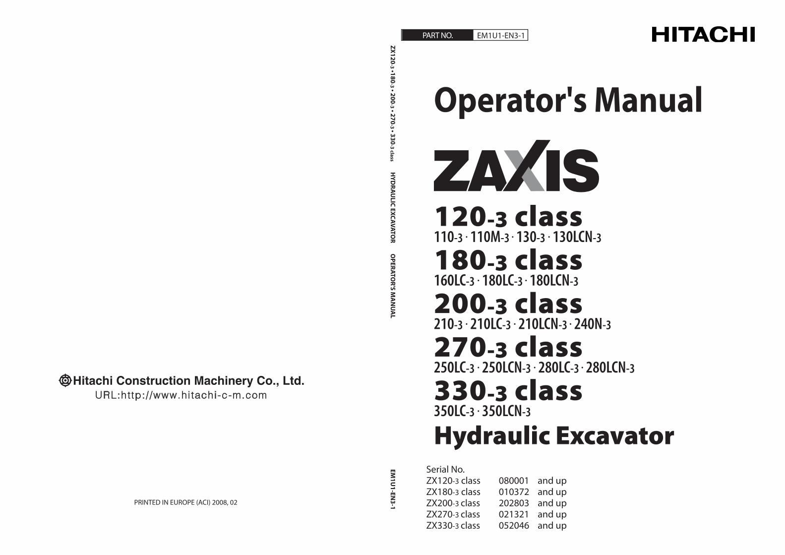
Operator's Manual
Serial No.ZX120-3 class 080001 and upZX180-3 class 010372 and upZX200-3 class 202803 and upZX270-3 class 021321 and upZX330-3 class 052046 and up
PRINTED IN EUROPE (ACI) 2008, 02
PART NO. EM1U1-EN3-1
ZX120-3 •180
-3 • 200-3 • 270
-3 • 330-3 class H
YDRA
ULIC EXCAVATO
R OPERATO
R'S MA
NU
AL
EM1U
1-EN3-1
120-3 class110-3 • 110M-3 • 130-3 • 130LCN-3
180-3 class160LC-3 • 180LC-3 • 180LCN-3
200-3 class210-3 • 210LC-3 • 210LCN-3 • 240N-3
270-3 class250LC-3 • 250LCN-3 • 280LC-3 • 280LCN-3
330-3 class350LC-3 • 350LCN-3
Hydraulic Excavator
INTRODUCTION
Read this manual carefully to learn how to operate and service your machine correctly. Failure to do so could result in personal injury or machine damage.
This standard specification machine can be operated under the following conditions without being modified.Atmospheric Temperature: −20°C to 40°C (−4°F to 104°F)Altitude: 0 m to 2000 m (0 ft to 6600 ft)
In case the machine is used under conditions other than described above, consult your nearest Hitachi dealer.
This manual should be considered a permanent part of your machine and should remain with the machine when you sell it.
This machine is of metric design. Measurements in this manual are metric. Use only metric hardware and tools as specified.
Right-hand and left-hand sides are determined by fac-ing in the direction of forward travel.
Write product identification numbers in the Machine Numbers section. Accurately record all the numbers to help in tracing the machine should it be stolen. Your dealer also needs these numbers when you order parts. If this manual is kept on the machine, also file the identifica-tion numbers in a secure place off the machine.
Use only diesel fuel with quality specified in JIS K-2204, EN-590, ASTM D-975, GOST R52368 or GB252. Failure to use diesel fuel with quality as specified above may allow the engine to emit exhaust gas which clean-ness can not conform to the requests in various relevant regulations. In addition, serious damage to the engine may result. Consult with your nearest Hitachi dealer for detailed information.
Warranty is provided as a part of Hitachi’s support pro-gram for customers who operate and maintain their equipment as described in this manual. The warranty is explained on the warranty certificate which you should have received from your dealer.
This warranty provides you the assurance that Hitachi will back its products where defects appear within the war-ranty period. In some circumstances, Hitachi also provides field improvements, often without charge to the custom-er, even if the product is out of warranty. Should the equipment be abused, or modified to change its performance beyond the original factory specifications, the warranty will become void and field improvements may be denied. Setting fuel delivery above specifications or otherwise overpowering machines will result in such action.
Only qualified, experienced operators officially licensed (according to local law) should be allowed to operate the machine. Moreover, only officially licensed personnel should be allowed to inspect and service the machine.
PRIOR TO OPERATING THIS MACHINE, INCLUDING SATELLITE COMMUNICATION SYSTEM, IN A COUNTRY OTHER THAN A COUNTRY OF ITS INTENDED USE, IT MAY BE NECESSARY TO MAKE MODIFICATIONS TO IT SO THAT IT COMPLIES WITH THE LOCAL REGULATORY STANDARDS (INCLUDING SAFETY STANDARDS) AND LEGAL REQUIREMENTS OF THAT PARTICULAR COUN-TRY. PLEASE DO NOT EXPORT OR OPERATE THIS MA-CHINE OUTSIDE OF THE COUNTRY OF ITS INTENDED USE UNTIL SUCH COMPLIANCE HAS BEEN CONFIRMED. PLEASE CONTACT HITACHI CONSTRUCTION MACHIN-ERY CO., LTD. OR ANY OF OUR AUTHORIZED DISTRIBU-TOR OR DEALER IF YOU HAVE ANY QUESTIONS CON-CERNING COMPLIANCE.
©2008 Hitachi Construction Machinery Co., Ltd.All rights reserved.
Hitachi machine models are classified into 5 classes and 1 model as shown in the table below. When referring to the texts and/or illustrations indicated with the applicable machine class names in this manual, check that the machine models concerned are included using this table.
Class ZX120-3 Class ZX110-3, 110M-3, 130-3, 130LCN-3ZX180-3 Class ZX160LC-3, 180LC-3, 180LCN-3ZX200-3 Class ZX210-3, 210LC-3, 210LCN-3, 240N-3ZX270-3 Class ZX250LC-3, 250LCN-3, 280LC-3, 280LCN-3ZX330-3 Class ZX350LC-3, 350LCN-3
ModelStd. Model ZX110-3, 110M-3, 130-3, 130LCN-3, 160LC-3, 180LC-3, 180LCN-3, 210-3, 210LC-3, 210LCN-3,
240N-3, 250LC-3, 250LCN-3, 280LC-3, 280LCN-3, 350LC-3, 350LCN-3
All information, illustrations and specifications in this manual are based on the latest product information available at the time of publication. The right is reserved to make changes at any time without notice.
T
MACHINE NUMBERSSAFETYSAFETY SIGNSCOMPONENTS NAMEOPERATOR’S STATIONBREAK-INOPERATING THE ENGINEDRIVING THE MACHINEOPERATING THE MACHINETRANSPORTINGMAINTENANCEHYDRAULIC CIRCUIT AND ELECTRICAL CIRCUITMAINTENANCE UNDER SPECIAL ENVIRONMENTAL CONDITIONS STORAGETROUBLESHOOTINGSPECIFICATIONSOPTIONAL ATTACHMENTS AND DEVICESINDEX
INDEX
EM1U1-EN3-1

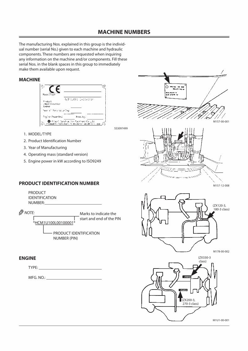
MACHINE NUMBERS
The manufacturing Nos. explained in this group is the individ-ual number (serial No.) given to each machine and hydraulic components. These numbers are requested when inquiring any information on the machine and/or components. Fill these serial Nos. in the blank spaces in this group to immediately make them available upon request.
MACHINE
SS3097499
1. MODEL/TYPE
2. Product Identification Number
3. Year of Manufacturing
4. Operating mass (standard version)
5. Engine power in kW according to ISO9249
PRODUCT IDENTIFICATION NUMBER
PRODUCT IDENTIFICATION NUMBER:
NOTE:
*HCM1U100L00100001*
ENGINE
TYPE:
MFG. NO.:
Marks to indicate the start and end of the PIN
PRODUCT IDENTIFICATION NUMBER (PIN)
(ZX330-3 class)
(ZX200-3, 270-3 class)
M178-00-002
M1U1-00-001
M157-12-008
M157-00-001
(ZX120-3, 180-3 class)
MACHINE NUMBERS
TRAVEL MOTOR
TYPE:
MFG. NO.:
SWING MOTOR
TYPE:
MFG. NO.:
HYDRAULIC PUMP
TYPE:
MFG. NO.:
M178-07-086
M178-07-047
M157-00-004
CONTENTS
MACHINE NUMBERS
SAFETYRecognize Safety Information ....................................................S-1Understand Signal Words .............................................................S-1Follow Safety Instructions ............................................................S-2Prepare for Emergencies ...............................................................S-3Wear Protective Clothing..............................................................S-3Protect Against Noise ....................................................................S-3Inspect Machine ..............................................................................S-4General Precautions for Cab ........................................................S-4Use Handholds and Steps ............................................................S-5Adjust the Operator’s Seat ...........................................................S-5Ensure Safety Before Rising from or Leaving Operator’s Seat .........................................................S-5Fasten Your Seat Belt ......................................................................S-6Move and Operate Machine Safely ...........................................S-6Handle Starting Aids Safely .........................................................S-6Operate Only from Operator’s Seat ..........................................S-7Jump Starting ...................................................................................S-7Keep Riders Off Machine ..............................................................S-7Precautions for Operations ..........................................................S-8Investigate Job Site Beforehand ................................................S-9Equipment of Head Guard, Rops, Fops ................................ S-10Provide Signals for Jobs Involving Multiple Numbers of Machines ........................................ S-10Confirm Direction of Machine to Be Driven ........................ S-10Drive Machine Safely ................................................................... S-11Avoid Injury from Rollaway Accidents .................................. S-13Avoid Injury from Back-over and Swing Accidents .......... S-14Keep Person Clear from Working Area.................................. S-15Never Position Bucket Over Anyone ..................................... S-15Avoid Undercutting ..................................................................... S-15Avoid Tipping ................................................................................. S-16Never Undercut a High Bank .................................................... S-16Dig with Caution ........................................................................... S-17Operate with Caution ................................................................. S-17Avoid Power Lines ........................................................................ S-18Precautions for Lightning .......................................................... S-18Object Handling ........................................................................... S-18Protect Against Flying Debris .................................................. S-19Park Machine Safely ..................................................................... S-19Handle Fluids Safely−Avoid Fires............................................ S-19Transport Safely ............................................................................ S-20Practice Safe Maintenance ........................................................ S-21Warn Others of Service Work ................................................... S-22Support Machine Properly ........................................................ S-22Stay Clear of Moving Parts ........................................................ S-22Prevent Parts from Flying .......................................................... S-23Store Attachments Safely .......................................................... S-23Prevent Burns ................................................................................. S-24Replace Rubber Hoses Periodically ........................................ S-24Avoid High-pressure Fluids ....................................................... S-25Prevent Fires ................................................................................... S-26Evacuating in Case of Fire .......................................................... S-27
Beware of Exhaust Fumes.......................................................... S-27Precautions for Welding and Grinding ................................. S-27Avoid Heating Near Pressurized Fluid Lines ....................... S-28Avoid Applying Heat to Lines Containing Flammable Fluids .................................................................. S-28Remove Paint Before Welding or Heating ........................... S-28Beware of Asbestos Dust ........................................................... S-29Prevent Battery Explosions ....................................................... S-29Service Air Conditioning System Safely ............................... S-29Handle Chemical Products Safely ........................................... S-30Dispose of Waste Properly ......................................................... S-30
SAFETY SIGNS .............................................................................. S-31
COMPONENTS NAME ................................................................. 1-1
OPERATOR’S STATIONCab Features ..................................................................................... 1-2Multi Function Monitor ................................................................ 1-3Outline ................................................................................................ 1-4 Menu Screen (23) ..................................................................... 1-7 Hour Meter ................................................................................. 1-8 Fuel Gauge ................................................................................. 1-8 Clock ............................................................................................. 1-8 Back Monitor Selector ............................................................ 1-8 Menu Key .................................................................................... 1-9 Optional Function Key ........................................................... 1-9 Return to Basic Screen Key .................................................. 1-9 Alarm Light ................................................................................ 1-9 Optional Function Display .................................................. 1-9 Coolant Temperature Gauge .............................................1-10 Operating Status Icon Display ..........................................1-10Alarm Occurrence Screen ..........................................................1-15Contents of Alarms ......................................................................1-17Clock Setting ..................................................................................1-19Attachment Selection (Only Machines Equipped with Optional Parts) .........1-20Pump 2 Flow Rate Adjustment (Only Machines Equipped with Optional Parts) .........1-24Displaying Operating Conditions ...........................................1-25Fuel Rate Display/No Display ...................................................1-26Back Monitor Settings ................................................................1-34Maintenance Settings .................................................................1-36Mail (Optional) ...............................................................................1-41Language Settings .......................................................................1-43Switch Panel ...................................................................................1-45Engine Control Dial ......................................................................1-46Auto-idle Switch ...........................................................................1-46Power Mode Switch ....................................................................1-47Travel Mode Switch .....................................................................1-47Work Light Switch ........................................................................1-48Wiper/Washer Switch ..................................................................1-49Switch Panel (Optional) ..............................................................1-51Key Switch .......................................................................................1-53Power Boost Switch .....................................................................1-53
CONTENTS
Horn Switch ....................................................................................1-53Cigar Lighter ...................................................................................1-54Cab Light .........................................................................................1-55Installing Fire Extinguisher (Optional) ..................................1-55Pilot Control Shut-off Lever ......................................................1-56Engine Stop Switch ......................................................................1-56Fuse Box ...........................................................................................1-57Auto Air Conditioner ...................................................................1-58Cab Heater Operation .................................................................1-62Cooling Operation .......................................................................1-62Defroster Operation ....................................................................1-63Tips for Optimal Air Conditioner Usage ...............................1-64Cab Heater (Optional) .................................................................1-65Cab Heater Operation .................................................................1-66Defroster Operation ....................................................................1-67AM/FM Radio Operation ............................................................1-68Digital Clock Setting Procedure ..............................................1-69Cab Door Release Lever .............................................................1-70Opening Upper Front Window ................................................1-70Closing Upper Front Window ...................................................1-71Removing and Storing Lower Front Window .....................1-72Opening Side Windows ..............................................................1-72Opening/Closing Overhead Window ....................................1-73Emergency Exit .............................................................................1-74Adjusting the Seat .......................................................................1-75Seat with a Built-in Heater.........................................................1-76Adjusting the Air-suspension Seat (Optional) ...................1-77Seat with a Built-in Heater.........................................................1-78Adjusting Console Height .........................................................1-79Seat Belt ...........................................................................................1-80
BREAK-INObserve Engine Operation Closely .......................................... 2-1Every 8 Hours or Daily ................................................................... 2-1After the First 50 Hours ................................................................ 2-1After the First 100 Hours .............................................................. 2-1
OPERATING THE ENGINEInspect Machine Daily Before Starting ................................... 3-1Before Starting Engine ................................................................. 3-2Starting the Engine in Ordinary Temperature ...................... 3-3Starting in Cold Weather.............................................................. 3-5Check Instruments After Starting ............................................. 3-7Using Booster Batteries ................................................................ 3-8Stopping the Engine ...................................................................3-10
DRIVING THE MACHINEDrive the Machine Carefully ....................................................... 4-1Steering the Machine Using Pedals ......................................... 4-2Steering the Machine Using Levers ......................................... 4-3Travel Mode Switch ....................................................................... 4-4Travel Alarm (Optional) ................................................................ 4-4Operating on Soft Ground .......................................................... 4-5Raise One Track Using Boom and Arm ................................... 4-5Towing Machine a Short Distance ............................................ 4-6
Operating in Water or Mud ......................................................... 4-7Parking the Machine on Slopes ................................................. 4-8Parking the Machine ..................................................................... 4-8
OPERATING THE MACHINEControl Lever (Iso Pattern) .......................................................... 5-1Attachment Pedal (Hydraulic Breaker) (Optional) .............. 5-2Attachment Pedal (Hydraulic Crusher) (Optional) .............. 5-3Pilot Control Shut-off Lever ........................................................ 5-4Engine Speed Control ................................................................... 5-6Auto-idle ............................................................................................ 5-7Work Mode ....................................................................................... 5-8Work Mode Select .......................................................................... 5-9Power Boost ...................................................................................5-10Power Mode ..................................................................................5-11Operating Backhoe ......................................................................5-12Grading Operation .......................................................................5-12Face Shovel Operation................................................................5-13Avoid Abusive Operation ..........................................................5-13Operating Tips ...............................................................................5-14Select Correct Track Shoes ........................................................5-14Hydraulic Breaker and Hydraulic Crusher ............................5-15Pipings for Breaker and Crusher ..............................................5-16Secondary Relief Pressure Adjustment ................................5-18Precautions for Breaker Operation .........................................5-20Breaker Maintenance ..................................................................5-23Precautions for Crusher Operation ........................................5-24Attachment .....................................................................................5-26Attachment Connection Parts .................................................5-30Precaution for Arm Roll-in/Bucket Roll-in Combined Operation --- If Headguard-Integrated Cab or Rainguard is Equipped ..........................................5-31When Installing an Attachment Longer Than Standard Bucket ..........................................................5-31Shackle Hole Usage .....................................................................5-32Overnight Storage Instructions ...............................................5-32Emergency Boom Lowering Procedure (Without hose-rupture safety valve) ..............................5-33Object Handling --- If Equipped ..............................................5-35
TRANSPORTINGTransporting By Road ................................................................... 6-1Loading/unloading on a Trailer ................................................. 6-1Machine Lifting Procedure .......................................................... 6-5
MAINTENANCECorrect Maintenance and Inspection Procedures .............. 7-1Check the Hour Meter Regularly ............................................... 7-2Use Correct Fuels and Lubricants ............................................. 7-2Layout ................................................................................................. 7-3Maintenance Guide Table ............................................................ 7-4Prepare Machine for Maintenance ........................................... 7-6Hood and Access Covers (ZX120-3, 180-3 Class) ................ 7-7Hood and Access Covers (ZX200-3, 270-3, 330-3 Class) ... 7-8Periodic Replacement of Parts ................................................... 7-9
CONTENTS
Maintenance Guide .....................................................................7-10A. Greasing ......................................................................................7-16 Front Joint Pins .......................................................................7-16 Swing Bearing .........................................................................7-18 Swing Internal Gear ..............................................................7-19B. Engine ..........................................................................................7-20 Engine Oil Level ......................................................................7-20 Change Engine Oil ................................................................7-21 Replace Engine Oil Filter .....................................................7-21C. Transmission ..............................................................................7-23 Pump Transmission ...............................................................7-23 Swing Reduction Gear .........................................................7-24 Travel Reduction Gear ..........................................................7-25D. Hydraulic System .....................................................................7-27 Inspection and Maintenance of Hydraulic Equipment...........................................................................7-27 Breaker Maintenance ...........................................................7-29 Check Hydraulic Oil Level ...................................................7-30 Change Hydraulic Oil ...........................................................7-31 Suction Filter Cleaning ........................................................7-31 Replace Hydraulic Tank Oil Filter ......................................7-34 Replace Pilot Oil Filter ..........................................................7-35 Replace Air Breather Element ...........................................7-36 Check Hoses and Lines ........................................................7-37 Service Recommendations for Hydraulic Fittings .....7-40E. Fuel System ................................................................................7-42 Drain Fuel Tank Sump .........................................................7-44 Drain Fuel Filter ......................................................................7-45 Replace Fuel Main Filter Element .....................................7-49 Replace Fuel Pre-Filter Element ........................................7-50 Clean Fuel Solenoid Pump Strainer ................................7-51 Check Fuel Hoses ...................................................................7-52F. Air Cleaner ...................................................................................7-53 Clean Air Cleaner Outer Element .....................................7-53 Replace Air Cleaner Outer and Inner Elements ..........7-53G. Cooling System ........................................................................7-55 Check Coolant Level .............................................................7-57 Check and Adjust Fan Belt Tension (ZX120-3, 180-3 Class) .....................................................7-58 Check and Adjust Fan Belt Tension (ZX200-3, ZX270-3, ZX330-3 Class) .............................7-59 Change Coolant .....................................................................7-60 Clean Radiator Interior.........................................................7-60 Clean Radiator, Oil Cooler Core and Inter Cooler Outside ................................................7-61 Clean Oil Cooler, Radiator and Inter Cooler Front Screen .........................................................7-61 Clean Air Conditioner Condenser ....................................7-61 Clean Fuel Oil Cooler ...........................................................7-61 Clean Air Conditioner Front Screen (Opt.) ....................7-61H. Electrical System ......................................................................7-62 Replace Batteries ...................................................................7-65 Remove and Installing Battery .........................................7-66 Replacing Fuses ......................................................................7-66I. Miscellaneous ............................................................................7-68 Check Bucket Teeth ...............................................................7-68
Change Bucket .......................................................................7-72 Convert Bucket Connection Into Face Shovel .............7-73 Adjust Bucket Linkage .........................................................7-74 Remove Travel Levers ...........................................................7-75 Check and Replace Seat Belt Check ................................7-75 Check Windshield Washer Fluid Level ............................7-76 Check Track Sag ......................................................................7-77 Clean and Replace Air Conditioner Filter ......................7-79 Check Air Conditioner ..........................................................7-81 Clean Cab Floor ......................................................................7-82 Retighten Cylinder Head Bolt............................................7-83 Inspect and Adjust Valve Clearance ................................7-83 Measure Engine Compression Pressure ........................7-83 Check Starter and Alternator.............................................7-83 Check and Replace EGR Device ........................................7-83 Check Tightening Torque of Bolts and Nuts ................7-84
HYDRAULIC CIRCUIT AND ELECTRICAL CIRCUITHydraulic Circuit ............................................................................. 8-1Electrical Circuit .............................................................................. 8-2Electrical Diagram .......................................................................... 8-3
MAINTENANCE UNDER SPECIAL ENVIRONMENTAL CONDITIONSMaintenance Under Special Environmental Conditions .................................................................................. 9-1
STORAGEStoring the Machine ....................................................................10-1Removing the Machine from Storage ...................................10-2
TROUBLESHOOTINGImpossible to Start the Engine ................................................11-1Engine ...............................................................................................11-2Electrical System ...........................................................................11-6Mode Selection .............................................................................11-8Control Levers ................................................................................11-9Hydraulic System ..........................................................................11-9
SPECIFICATIONSSpecifications (ZX110-3, 110M-3) ...........................................12-1Working Ranges (ZX110-3, 110M-3) ......................................12-2Shoe Types and Applications (ZX110-3) ..................................................................................12-3 (ZX110M-3) ..............................................................................12-4Bucket Types and Applications (ZX110-3, 110M-3) ..........12-5Specifications (ZX130-3, 130LCN-3) .......................................12-6Working Ranges (ZX130-3, 130LCN-3) ..................................12-7Shoe Types and Applications (ZX130-3)...............................12-8Shoe Types and Applications (ZX130LCN-3) ......................12-9Bucket Types and Applications (ZX130-3, 130LCN-3) ...........................................................12-10Specifications (ZX160LC-3) .....................................................12-11Working Ranges (ZX160LC-3) ................................................12-12Shoe Types and Applications (ZX160LC-3) ........................12-14
CONTENTS
Bucket Types and Applications (ZX160LC-3) ....................12-15Specifications (ZX180LC-3, 180LCN-3) ................................12-16Working Ranges (ZX180LC-3, 180LCN-3) ...........................12-17Shoe Types and Applications (ZX180LC-3, 180LCN-3) ......................................................12-19Bucket Types and Applications (ZX180LC-3, 180LCN-3) ......................................................12-20Specifications (ZX210-3, 210LC-3) ........................................12-21Working Ranges (ZX210-3, 210LC-3) ...................................12-22Shoe Types and Applications (ZX210-3, 210LC-3) ..........12-23Bucket Types and Applications (ZX210-3, 210LC-3) .......12-24Specifications (ZX210LCN-3, 240N-3) .................................12-25Working Ranges (ZX210LCN-3, 240N-3).............................12-26Shoe Types and Applications (ZX210LCN-3, 240N-3) .......................................................12-27Bucket Types and Applications (ZX210LCN-3, 240N-3) .......................................................12-28Specifications (ZX250LC-3, 250LCN-3) ................................12-29Working Ranges (ZX250LC-3, 250LCN-3) ...........................12-30Shoe Types and Applications (ZX250LC-3, 250LCN-3) ......................................................12-31Bucket Types and Applications (ZX250LC-3, 250LCN-3) ......................................................12-32Specifications (ZX280LC-3, 280LCN-3) ................................12-33Working Ranges (ZX280LC-3, 280LCN-3) ...........................12-34Shoe Types and Applications (ZX280LC-3, 280LCN-3) ......................................................12-35Bucket Types and Applications (ZX280LC-3, 280LCN-3) ......................................................12-36Specifications (ZX350LC-3, 350LCN-3) ................................12-37Working Ranges (ZX350LC-3, 350LCN-3) ...........................12-38Shoe Types and Applications (ZX350LC-3, 350LCN-3) ......................................................12-39Bucket Types and Applications (ZX350LC-3, 350LCN-3) ......................................................12-40Sound Level Results (2000/14/EC) .......................................12-41Vibration Level .............................................................................12-41
OPTIONAL ATTACHMENTS AND DEVICESUsing Pad Crawler Shoe .............................................................13-1Traveling and Other Cautions ..................................................13-2Transporting ...................................................................................13-3Precautions for Transporting Machines with Pad Crawler Shoes .......................................................13-3Long Arm Operation --- If Equipped ......................................13-6Blade Lever .....................................................................................13-7Precautions For Blade Operation ............................................13-7Avoid Hitting Blade with Front-end Attachment..............13-8Avoid Hitting Blade with Bucket .............................................13-8Avoid Striking The Blade Into a Rock .....................................13-8Blade Maintenance ......................................................................13-9Specifications (ZX110-3 with Blade) ....................................13-10Working Ranges (ZX110-3 with Blade) ...............................13-11Shoe Types and Applications (ZX110-3 with Blade) ..........................................................13-12
Specifications (ZX130-3 with Blade) ....................................13-13Working Ranges (ZX130-3 with Blade) ...............................13-14Shoe Types and Applications (ZX130-3 with Blade) ..........................................................13-15Offset Arm Front .........................................................................13-16Offset Direction and Working Range ..................................13-17Precautions for Operating with The Offset Function .....13-18Maintenance ................................................................................13-19Specifications (ZX110-3, 110M-3 Offset) ............................13-20Working Ranges (ZX110-3, 110M-3 Offset) .......................13-21Bucket Teeth (Transverse-type-pin-used Type) ...............13-222-piece Boom ...............................................................................13-23Maintenance (2-piece Boom) .................................................13-24Specifications ZX130-3, 130LCN-3 (2-piece Boom) ..............................13-27Working Ranges ZX130-3, 130LCN-3 (2-piece Boom) ..............................13-28Shoe Types and Applications ZX130-3 (2-piece Boom) ...................................................13-29 ZX130LCN-3 (2-piece Boom) ...........................................13-30Specifications ZX210-3, 210LC-3 (2-piece Boom) .................................13-31Working Ranges ZX210-3, 210LC-3 (2-piece Boom) .................................13-32Shoe Types and Applications ZX210-3 (2-piece Boom) ...................................................13-33 ZX210LC-3 (2-piece Boom) ..............................................13-33Specifications ZX210LCN-3, 240N-3 (2-piece Boom) ...........................13-34Working Ranges ZX210LCN-3, 240N-3 (2-piece Boom) ...........................13-35Shoe Types and Applications ZX210LCN-3 (2-piece Boom) ...........................................13-36 ZX240N-3 (2-piece Boom) ................................................13-36Specifications ZX250LC-3, 250LCN-3 (2-piece Boom) .........................13-37Working Ranges ZX250LC-3, 250LCN-3 (2-piece Boom) .........................13-38Shoe Types and Applications ZX250LC-3 (2-piece Boom) ..............................................13-39 ZX250LCN-3 (2-piece Boom) ...........................................13-39Specifications ZX280LC-3, 280LCN-3 (2-piece Boom) .........................13-40Working Ranges ZX280LC-3, 280LCN-3 (2-piece Boom) .........................13-41Shoe Types and Applications ZX280LC-3 (2-piece Boom) ..............................................13-42 ZX280LCN-3 (2-piece Boom) ...........................................13-42Specifications ZX350LC-3, 350LCN-3 (2-piece Boom) .........................13-43Working Ranges ZX350LC-3, 350LCN-3 (2-piece Boom) .........................13-44Shoe Types and Applications ZX350LC-3 (2-piece Boom) ..............................................13-45 ZX350LCN-3 (2-piece Boom) ...........................................13-45Lifting Hook ..................................................................................13-46

CONTENTS
Lifting Capacities ........................................................................13-48
INDEX ...............................................................................................14-1

CONTENTS
MEMO...................................................................................................................................................................................................................................................
...................................................................................................................................................................................................................................................
...................................................................................................................................................................................................................................................
...................................................................................................................................................................................................................................................
...................................................................................................................................................................................................................................................
...................................................................................................................................................................................................................................................
...................................................................................................................................................................................................................................................
...................................................................................................................................................................................................................................................
...................................................................................................................................................................................................................................................
...................................................................................................................................................................................................................................................
...................................................................................................................................................................................................................................................
...................................................................................................................................................................................................................................................
...................................................................................................................................................................................................................................................
...................................................................................................................................................................................................................................................
...................................................................................................................................................................................................................................................
...................................................................................................................................................................................................................................................
...................................................................................................................................................................................................................................................
...................................................................................................................................................................................................................................................
...................................................................................................................................................................................................................................................
...................................................................................................................................................................................................................................................
...................................................................................................................................................................................................................................................
...................................................................................................................................................................................................................................................
...................................................................................................................................................................................................................................................
...................................................................................................................................................................................................................................................
...................................................................................................................................................................................................................................................
...................................................................................................................................................................................................................................................
...................................................................................................................................................................................................................................................
...................................................................................................................................................................................................................................................
...................................................................................................................................................................................................................................................
...................................................................................................................................................................................................................................................
...................................................................................................................................................................................................................................................
...................................................................................................................................................................................................................................................
...................................................................................................................................................................................................................................................
...................................................................................................................................................................................................................................................
...................................................................................................................................................................................................................................................
...................................................................................................................................................................................................................................................
...................................................................................................................................................................................................................................................
SAFETY
S-1
SA-688
SA-1223
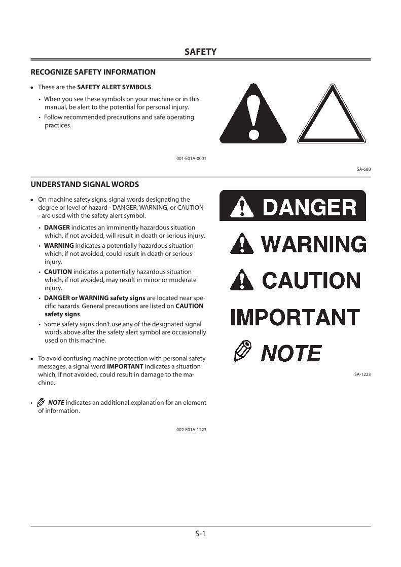
RECOGNIZE SAFETY INFORMATION
• These are the SAFETY ALERT SYMBOLS.
• When you see these symbols on your machine or in this manual, be alert to the potential for personal injury.
• Follow recommended precautions and safe operating practices.
001-E01A-0001
UNDERSTAND SIGNAL WORDS
• On machine safety signs, signal words designating the degree or level of hazard - DANGER, WARNING, or CAUTION - are used with the safety alert symbol.
• DANGER indicates an imminently hazardous situation which, if not avoided, will result in death or serious injury.
• WARNING indicates a potentially hazardous situation which, if not avoided, could result in death or serious injury.
• CAUTION indicates a potentially hazardous situation which, if not avoided, may result in minor or moderate injury.
• DANGER or WARNING safety signs are located near spe-cific hazards. General precautions are listed on CAUTION safety signs.
• Some safety signs don’t use any of the designated signal words above after the safety alert symbol are occasionally used on this machine.
• To avoid confusing machine protection with personal safety messages, a signal word IMPORTANT indicates a situation which, if not avoided, could result in damage to the ma-chine.
• NOTE indicates an additional explanation for an element of information.
002-E01A-1223
SAFETY
S-2
FOLLOW SAFETY INSTRUCTIONS
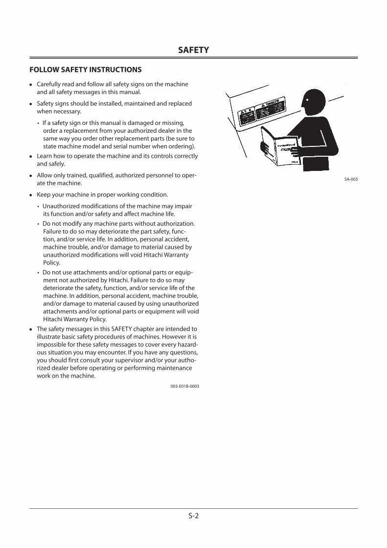
• Carefully read and follow all safety signs on the machine and all safety messages in this manual.
• Safety signs should be installed, maintained and replaced when necessary.
• If a safety sign or this manual is damaged or missing, order a replacement from your authorized dealer in the same way you order other replacement parts (be sure to state machine model and serial number when ordering).
• Learn how to operate the machine and its controls correctly and safely.
• Allow only trained, qualified, authorized personnel to oper-ate the machine.
• Keep your machine in proper working condition.
• Unauthorized modifications of the machine may impair its function and/or safety and affect machine life.
• Do not modify any machine parts without authorization. Failure to do so may deteriorate the part safety, func-tion, and/or service life. In addition, personal accident, machine trouble, and/or damage to material caused by unauthorized modifications will void Hitachi Warranty Policy.
• Do not use attachments and/or optional parts or equip-ment not authorized by Hitachi. Failure to do so may deteriorate the safety, function, and/or service life of the machine. In addition, personal accident, machine trouble, and/or damage to material caused by using unauthorized attachments and/or optional parts or equipment will void Hitachi Warranty Policy.
• The safety messages in this SAFETY chapter are intended to illustrate basic safety procedures of machines. However it is impossible for these safety messages to cover every hazard-ous situation you may encounter. If you have any questions, you should first consult your supervisor and/or your autho-rized dealer before operating or performing maintenance work on the machine.
003-E01B-0003
SA-003
SAFETY
S-3
PREPARE FOR EMERGENCIES
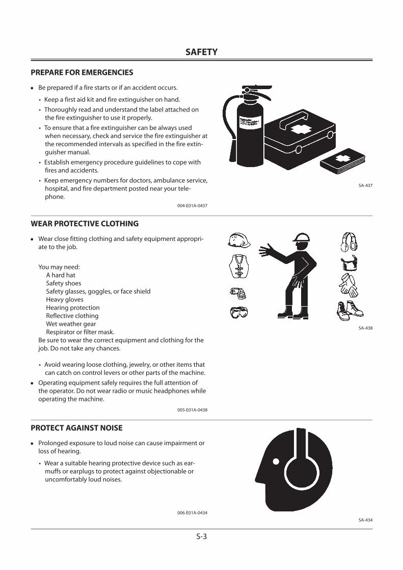
• Be prepared if a fire starts or if an accident occurs.
• Keep a first aid kit and fire extinguisher on hand.• Thoroughly read and understand the label attached on
the fire extinguisher to use it properly.• To ensure that a fire extinguisher can be always used
when necessary, check and service the fire extinguisher at the recommended intervals as specified in the fire extin-guisher manual.
• Establish emergency procedure guidelines to cope with fires and accidents.
• Keep emergency numbers for doctors, ambulance service, hospital, and fire department posted near your tele-phone.
004-E01A-0437
WEAR PROTECTIVE CLOTHING
• Wear close fitting clothing and safety equipment appropri-ate to the job.
You may need:A hard hatSafety shoesSafety glasses, goggles, or face shieldHeavy glovesHearing protectionReflective clothingWet weather gearRespirator or filter mask.
Be sure to wear the correct equipment and clothing for the job. Do not take any chances.
• Avoid wearing loose clothing, jewelry, or other items that can catch on control levers or other parts of the machine.
• Operating equipment safely requires the full attention of the operator. Do not wear radio or music headphones while operating the machine.
005-E01A-0438
PROTECT AGAINST NOISE
• Prolonged exposure to loud noise can cause impairment or loss of hearing.
• Wear a suitable hearing protective device such as ear-muffs or earplugs to protect against objectionable or uncomfortably loud noises.
006-E01A-0434
SA-437
SA-434
SA-438
SAFETY
S-4
INSPECT MACHINE
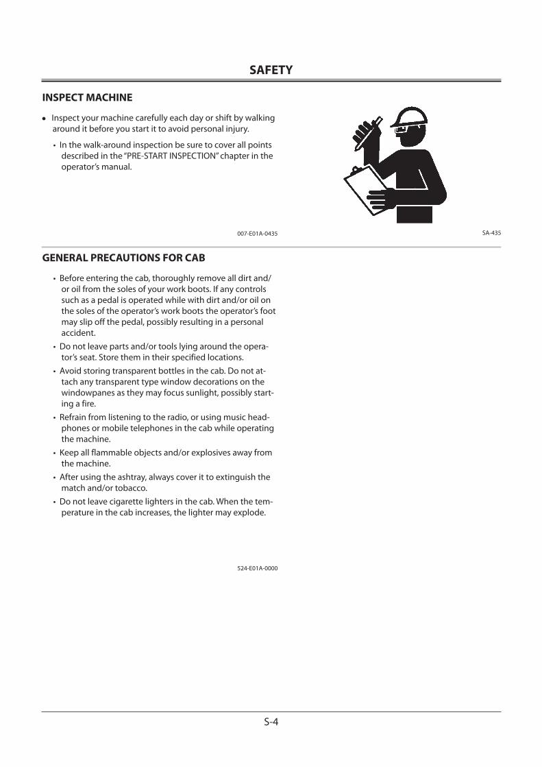
• Inspect your machine carefully each day or shift by walking around it before you start it to avoid personal injury.
• In the walk-around inspection be sure to cover all points described in the “PRE-START INSPECTION” chapter in the operator’s manual.
007-E01A-0435
GENERAL PRECAUTIONS FOR CAB
• Before entering the cab, thoroughly remove all dirt and/or oil from the soles of your work boots. If any controls such as a pedal is operated while with dirt and/or oil on the soles of the operator’s work boots the operator’s foot may slip off the pedal, possibly resulting in a personal accident.
• Do not leave parts and/or tools lying around the opera-tor’s seat. Store them in their specified locations.
• Avoid storing transparent bottles in the cab. Do not at-tach any transparent type window decorations on the windowpanes as they may focus sunlight, possibly start-ing a fire.
• Refrain from listening to the radio, or using music head-phones or mobile telephones in the cab while operating the machine.
• Keep all flammable objects and/or explosives away from the machine.
• After using the ashtray, always cover it to extinguish the match and/or tobacco.
• Do not leave cigarette lighters in the cab. When the tem-perature in the cab increases, the lighter may explode.
524-E01A-0000
SA-435
SAFETY
S-5
USE HANDHOLDS AND STEPS
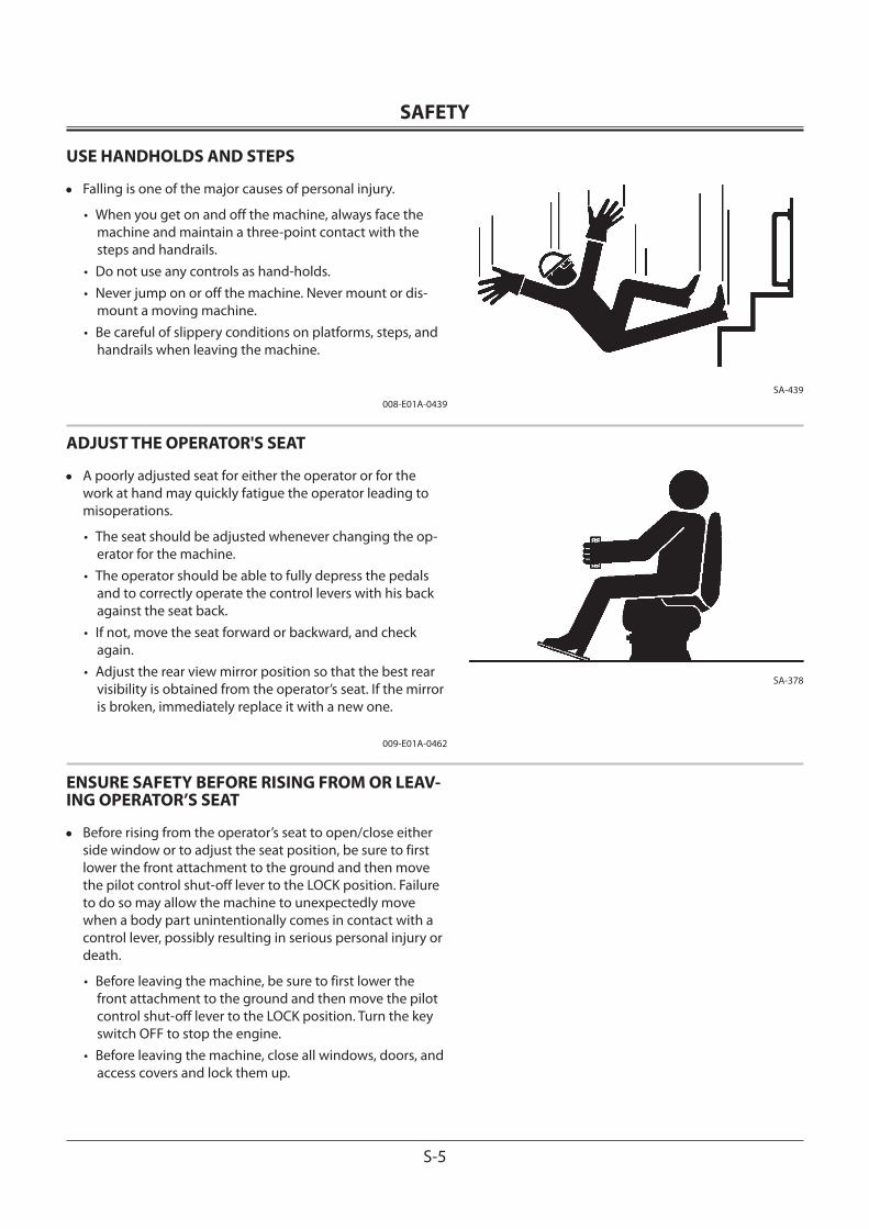
• Falling is one of the major causes of personal injury.
• When you get on and off the machine, always face the machine and maintain a three-point contact with the steps and handrails.
• Do not use any controls as hand-holds.• Never jump on or off the machine. Never mount or dis-
mount a moving machine.• Be careful of slippery conditions on platforms, steps, and
handrails when leaving the machine.
008-E01A-0439
ADJUST THE OPERATOR'S SEAT
• A poorly adjusted seat for either the operator or for the work at hand may quickly fatigue the operator leading to misoperations.
• The seat should be adjusted whenever changing the op-erator for the machine.
• The operator should be able to fully depress the pedals and to correctly operate the control levers with his back against the seat back.
• If not, move the seat forward or backward, and check again.
• Adjust the rear view mirror position so that the best rear visibility is obtained from the operator’s seat. If the mirror is broken, immediately replace it with a new one.
009-E01A-0462
ENSURE SAFETY BEFORE RISING FROM OR LEAV-ING OPERATOR’S SEAT
• Before rising from the operator’s seat to open/close either side window or to adjust the seat position, be sure to first lower the front attachment to the ground and then move the pilot control shut-off lever to the LOCK position. Failure to do so may allow the machine to unexpectedly move when a body part unintentionally comes in contact with a control lever, possibly resulting in serious personal injury or death.
• Before leaving the machine, be sure to first lower the front attachment to the ground and then move the pilot control shut-off lever to the LOCK position. Turn the key switch OFF to stop the engine.
• Before leaving the machine, close all windows, doors, and access covers and lock them up.
SA-439
SA-378
SAFETY
S-6
FASTEN YOUR SEAT BELT
• If the machine should overturn, the operator may become injured and/or thrown from the cab. Additionally the opera-tor may be crushed by the overturning machine, resulting in serious injury or death.
• Prior to operating the machine, thoroughly examine web-bing, buckle and attaching hardware. If any item is dam-aged or worn, replace the seat belt or component before operating the machine.
• Be sure to remain seated with the seat belt securely fastened at all times when the machine is in operation to minimize the chance of injury from an accident.
• We recommend that the seat belt be replaced every three years regardless of its apparent condition.
010-E01A-0237
MOVE AND OPERATE MACHINE SAFELY
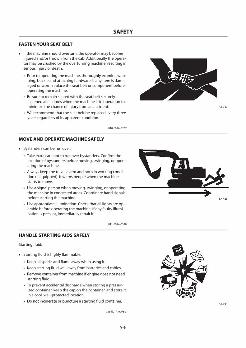
• Bystanders can be run over.
• Take extra care not to run over bystanders. Confirm the location of bystanders before moving, swinging, or oper-ating the machine.
• Always keep the travel alarm and horn in working condi-tion (if equipped). It warns people when the machine starts to move.
• Use a signal person when moving, swinging, or operating the machine in congested areas. Coordinate hand signals before starting the machine.
• Use appropriate illumination. Check that all lights are op-erable before operating the machine. If any faulty illumi-nation is present, immediately repair it.
011-E01A-0398
HANDLE STARTING AIDS SAFELY
Starting fluid:
• Starting fluid is highly flammable.
• Keep all sparks and flame away when using it.• Keep starting fluid well away from batteries and cables.• Remove container from machine if engine does not need
starting fluid.• To prevent accidental discharge when storing a pressur-
ized container, keep the cap on the container, and store it in a cool, well-protected location.
• Do not incinerate or puncture a starting fluid container.
036-E01A-0293-3
SA-237
SA-426
SA-293
SAFETY
S-7
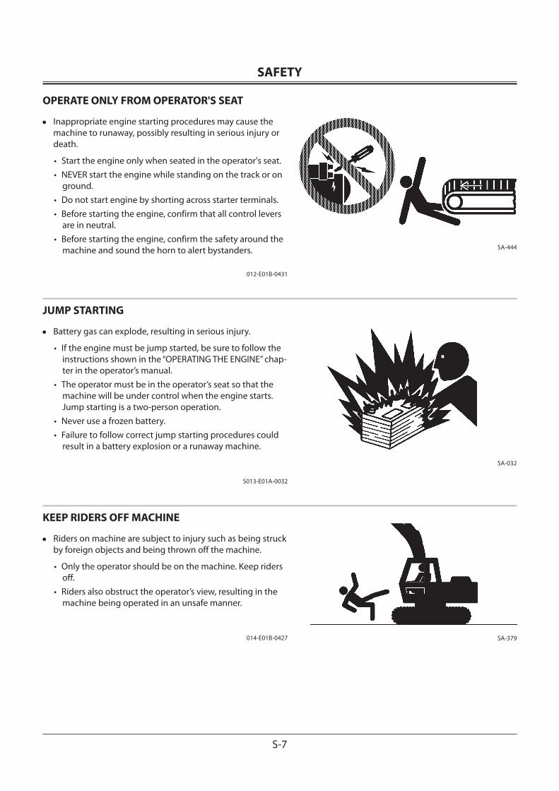
OPERATE ONLY FROM OPERATOR'S SEAT
• Inappropriate engine starting procedures may cause the machine to runaway, possibly resulting in serious injury or death.
• Start the engine only when seated in the operator's seat.• NEVER start the engine while standing on the track or on
ground.• Do not start engine by shorting across starter terminals.• Before starting the engine, confirm that all control levers
are in neutral.• Before starting the engine, confirm the safety around the
machine and sound the horn to alert bystanders.
012-E01B-0431
JUMP STARTING
• Battery gas can explode, resulting in serious injury.
• If the engine must be jump started, be sure to follow the instructions shown in the “OPERATING THE ENGINE” chap-ter in the operator’s manual.
• The operator must be in the operator’s seat so that the machine will be under control when the engine starts. Jump starting is a two-person operation.
• Never use a frozen battery.• Failure to follow correct jump starting procedures could
result in a battery explosion or a runaway machine.
S013-E01A-0032
KEEP RIDERS OFF MACHINE
• Riders on machine are subject to injury such as being struck by foreign objects and being thrown off the machine.
• Only the operator should be on the machine. Keep riders off.
• Riders also obstruct the operator’s view, resulting in the machine being operated in an unsafe manner.
014-E01B-0427
SA-444
SA-032
SA-379
SAFETY
S-8
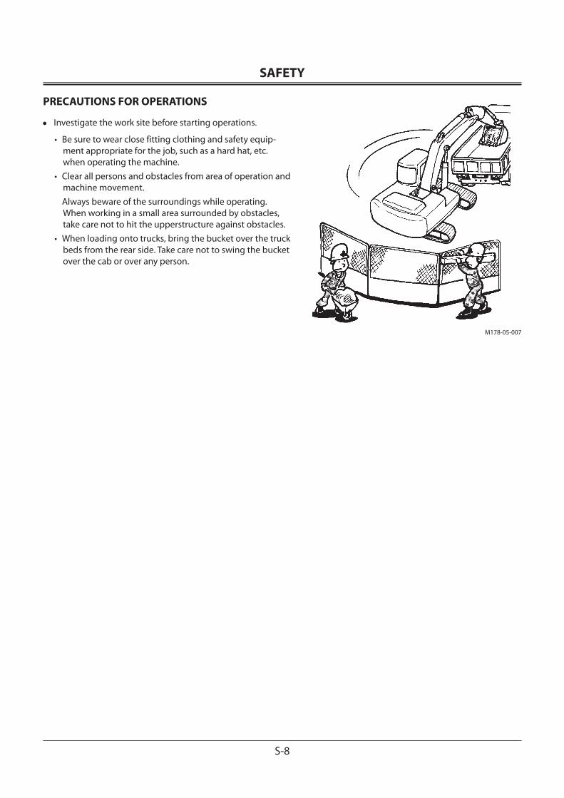
PRECAUTIONS FOR OPERATIONS
• Investigate the work site before starting operations.
• Be sure to wear close fitting clothing and safety equip-ment appropriate for the job, such as a hard hat, etc. when operating the machine.
• Clear all persons and obstacles from area of operation and machine movement.
Always beware of the surroundings while operating. When working in a small area surrounded by obstacles, take care not to hit the upperstructure against obstacles.
• When loading onto trucks, bring the bucket over the truck beds from the rear side. Take care not to swing the bucket over the cab or over any person.
M178-05-007
SAFETY
S-9
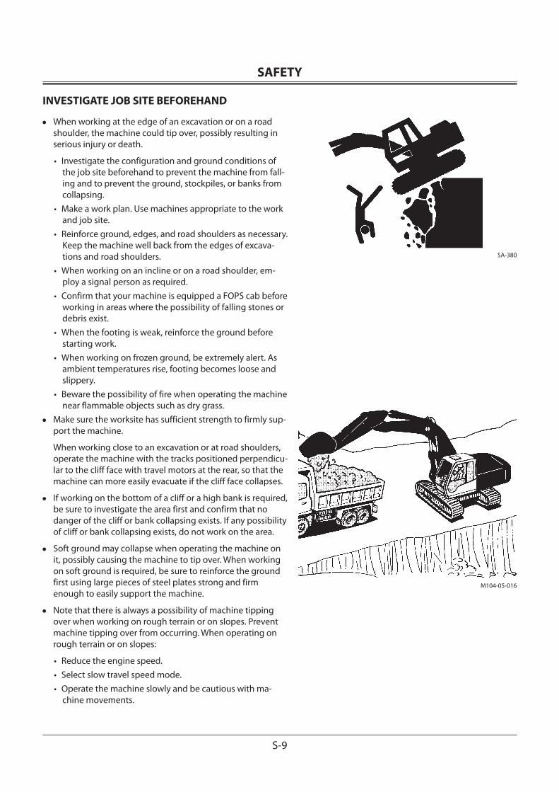
INVESTIGATE JOB SITE BEFOREHAND
• When working at the edge of an excavation or on a road shoulder, the machine could tip over, possibly resulting in serious injury or death.
• Investigate the configuration and ground conditions of the job site beforehand to prevent the machine from fall-ing and to prevent the ground, stockpiles, or banks from collapsing.
• Make a work plan. Use machines appropriate to the work and job site.
• Reinforce ground, edges, and road shoulders as necessary. Keep the machine well back from the edges of excava-tions and road shoulders.
• When working on an incline or on a road shoulder, em-ploy a signal person as required.
• Confirm that your machine is equipped a FOPS cab before working in areas where the possibility of falling stones or debris exist.
• When the footing is weak, reinforce the ground before starting work.
• When working on frozen ground, be extremely alert. As ambient temperatures rise, footing becomes loose and slippery.
• Beware the possibility of fire when operating the machine near flammable objects such as dry grass.
• Make sure the worksite has sufficient strength to firmly sup-port the machine.
When working close to an excavation or at road shoulders, operate the machine with the tracks positioned perpendicu-lar to the cliff face with travel motors at the rear, so that the machine can more easily evacuate if the cliff face collapses.
• If working on the bottom of a cliff or a high bank is required, be sure to investigate the area first and confirm that no danger of the cliff or bank collapsing exists. If any possibility of cliff or bank collapsing exists, do not work on the area.
• Soft ground may collapse when operating the machine on it, possibly causing the machine to tip over. When working on soft ground is required, be sure to reinforce the ground first using large pieces of steel plates strong and firm enough to easily support the machine.
• Note that there is always a possibility of machine tipping over when working on rough terrain or on slopes. Prevent machine tipping over from occurring. When operating on rough terrain or on slopes:
• Reduce the engine speed.• Select slow travel speed mode.• Operate the machine slowly and be cautious with ma-
chine movements.
SA-380
M104-05-016
SAFETY
S-10
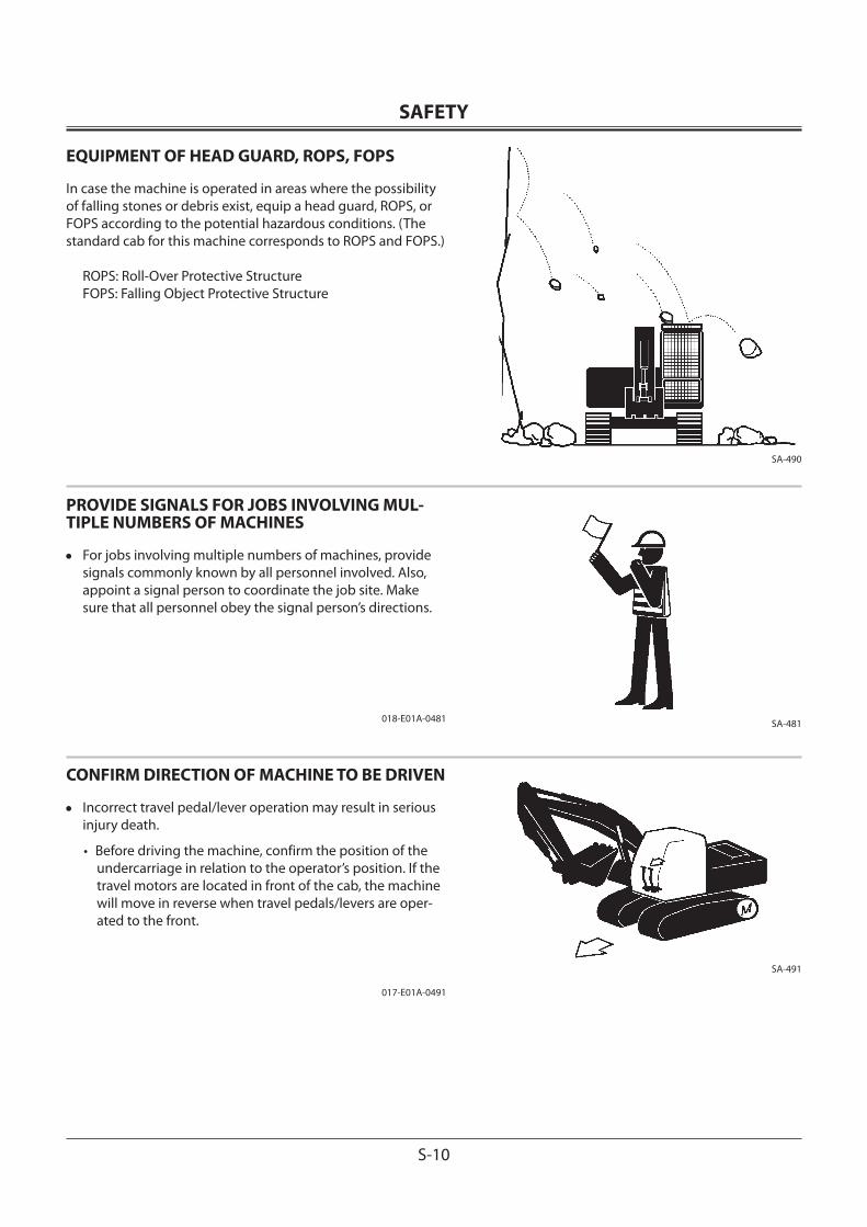
EQUIPMENT OF HEAD GUARD, ROPS, FOPS
In case the machine is operated in areas where the possibility of falling stones or debris exist, equip a head guard, ROPS, or FOPS according to the potential hazardous conditions. (The standard cab for this machine corresponds to ROPS and FOPS.)
ROPS: Roll-Over Protective StructureFOPS: Falling Object Protective Structure
PROVIDE SIGNALS FOR JOBS INVOLVING MUL-TIPLE NUMBERS OF MACHINES
• For jobs involving multiple numbers of machines, provide signals commonly known by all personnel involved. Also, appoint a signal person to coordinate the job site. Make sure that all personnel obey the signal person’s directions.
018-E01A-0481
CONFIRM DIRECTION OF MACHINE TO BE DRIVEN
• Incorrect travel pedal/lever operation may result in serious injury death.
• Before driving the machine, confirm the position of the undercarriage in relation to the operator’s position. If the travel motors are located in front of the cab, the machine will move in reverse when travel pedals/levers are oper-ated to the front.
017-E01A-0491
SA-490
SA-481
SA-491
SAFETY
S-11
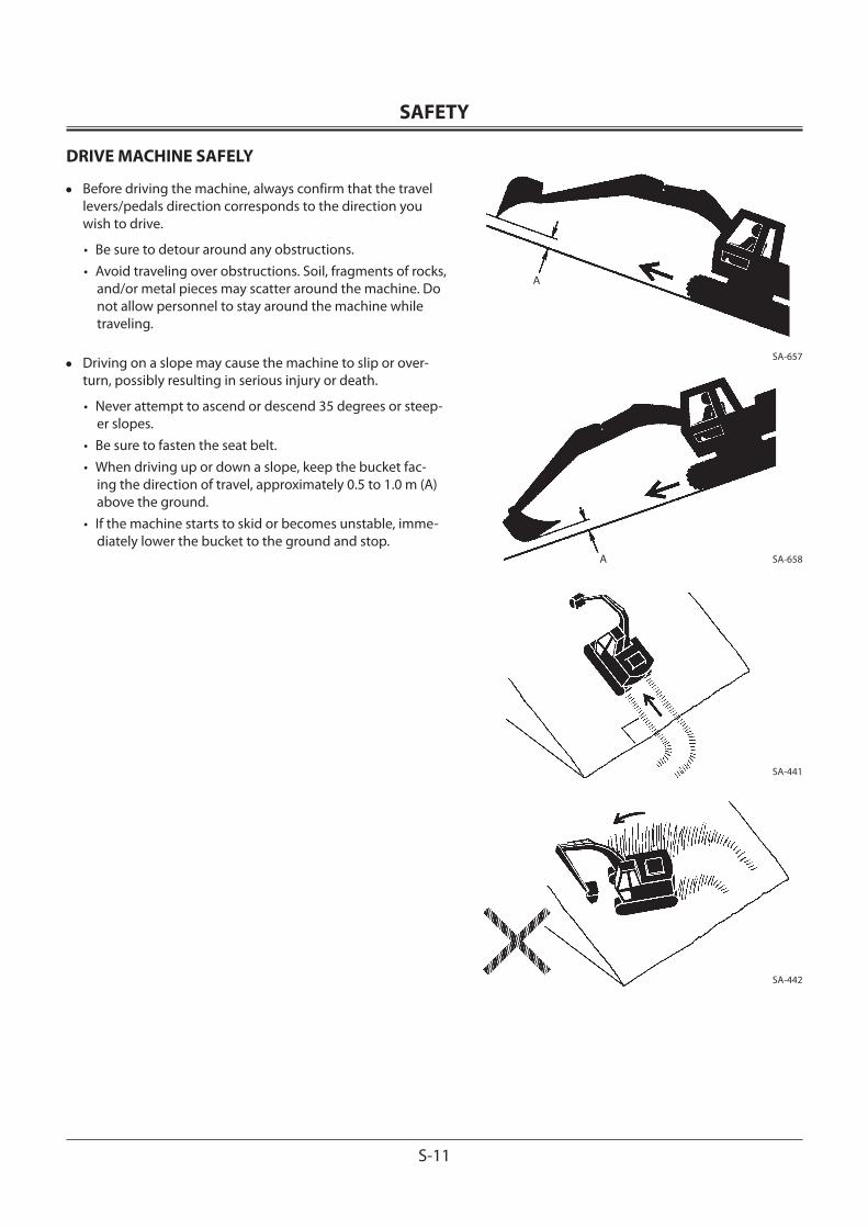
DRIVE MACHINE SAFELY
• Before driving the machine, always confirm that the travel levers/pedals direction corresponds to the direction you wish to drive.
• Be sure to detour around any obstructions.• Avoid traveling over obstructions. Soil, fragments of rocks,
and/or metal pieces may scatter around the machine. Do not allow personnel to stay around the machine while traveling.
• Driving on a slope may cause the machine to slip or over-turn, possibly resulting in serious injury or death.
• Never attempt to ascend or descend 35 degrees or steep-er slopes.
• Be sure to fasten the seat belt.• When driving up or down a slope, keep the bucket fac-
ing the direction of travel, approximately 0.5 to 1.0 m (A) above the ground.
• If the machine starts to skid or becomes unstable, imme-diately lower the bucket to the ground and stop.
A
A
SA-657
SA-658
SA-441
SA-442
SAFETY
S-12
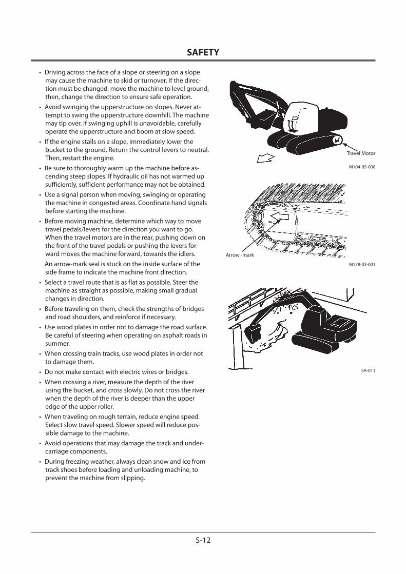
• Driving across the face of a slope or steering on a slope may cause the machine to skid or turnover. If the direc-tion must be changed, move the machine to level ground, then, change the direction to ensure safe operation.
• Avoid swinging the upperstructure on slopes. Never at-tempt to swing the upperstructure downhill. The machine may tip over. If swinging uphill is unavoidable, carefully operate the upperstructure and boom at slow speed.
• If the engine stalls on a slope, immediately lower the bucket to the ground. Return the control levers to neutral. Then, restart the engine.
• Be sure to thoroughly warm up the machine before as-cending steep slopes. If hydraulic oil has not warmed up sufficiently, sufficient performance may not be obtained.
• Use a signal person when moving, swinging or operating the machine in congested areas. Coordinate hand signals before starting the machine.
• Before moving machine, determine which way to move travel pedals/levers for the direction you want to go. When the travel motors are in the rear, pushing down on the front of the travel pedals or pushing the levers for-ward moves the machine forward, towards the idlers.
An arrow-mark seal is stuck on the inside surface of the side frame to indicate the machine front direction.
• Select a travel route that is as flat as possible. Steer the machine as straight as possible, making small gradual changes in direction.
• Before traveling on them, check the strengths of bridges and road shoulders, and reinforce if necessary.
• Use wood plates in order not to damage the road surface. Be careful of steering when operating on asphalt roads in summer.
• When crossing train tracks, use wood plates in order not to damage them.
• Do not make contact with electric wires or bridges.• When crossing a river, measure the depth of the river
using the bucket, and cross slowly. Do not cross the river when the depth of the river is deeper than the upper edge of the upper roller.
• When traveling on rough terrain, reduce engine speed. Select slow travel speed. Slower speed will reduce pos-sible damage to the machine.
• Avoid operations that may damage the track and under-carriage components.
• During freezing weather, always clean snow and ice from track shoes before loading and unloading machine, to prevent the machine from slipping.
Travel Motor
Arrow -mark
M104-05-008
M178-03-001
SA-011
SAFETY
S-13
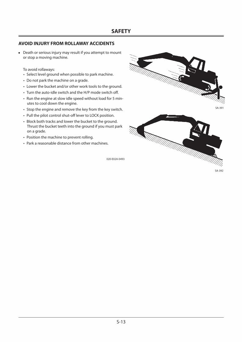
AVOID INJURY FROM ROLLAWAY ACCIDENTS
• Death or serious injury may result if you attempt to mount or stop a moving machine.
To avoid rollaways:• Select level ground when possible to park machine.• Do not park the machine on a grade.• Lower the bucket and/or other work tools to the ground.• Turn the auto-idle switch and the H/P mode switch off.• Run the engine at slow idle speed without load for 5 min-
utes to cool down the engine.• Stop the engine and remove the key from the key switch.• Pull the pilot control shut-off lever to LOCK position.• Block both tracks and lower the bucket to the ground.
Thrust the bucket teeth into the ground if you must park on a grade.
• Position the machine to prevent rolling.• Park a reasonable distance from other machines.
020-E02A-0493
SA-392
SA-391
SAFETY
S-14
AVOID INJURY FROM BACK-OVER AND SWING ACCIDENTS
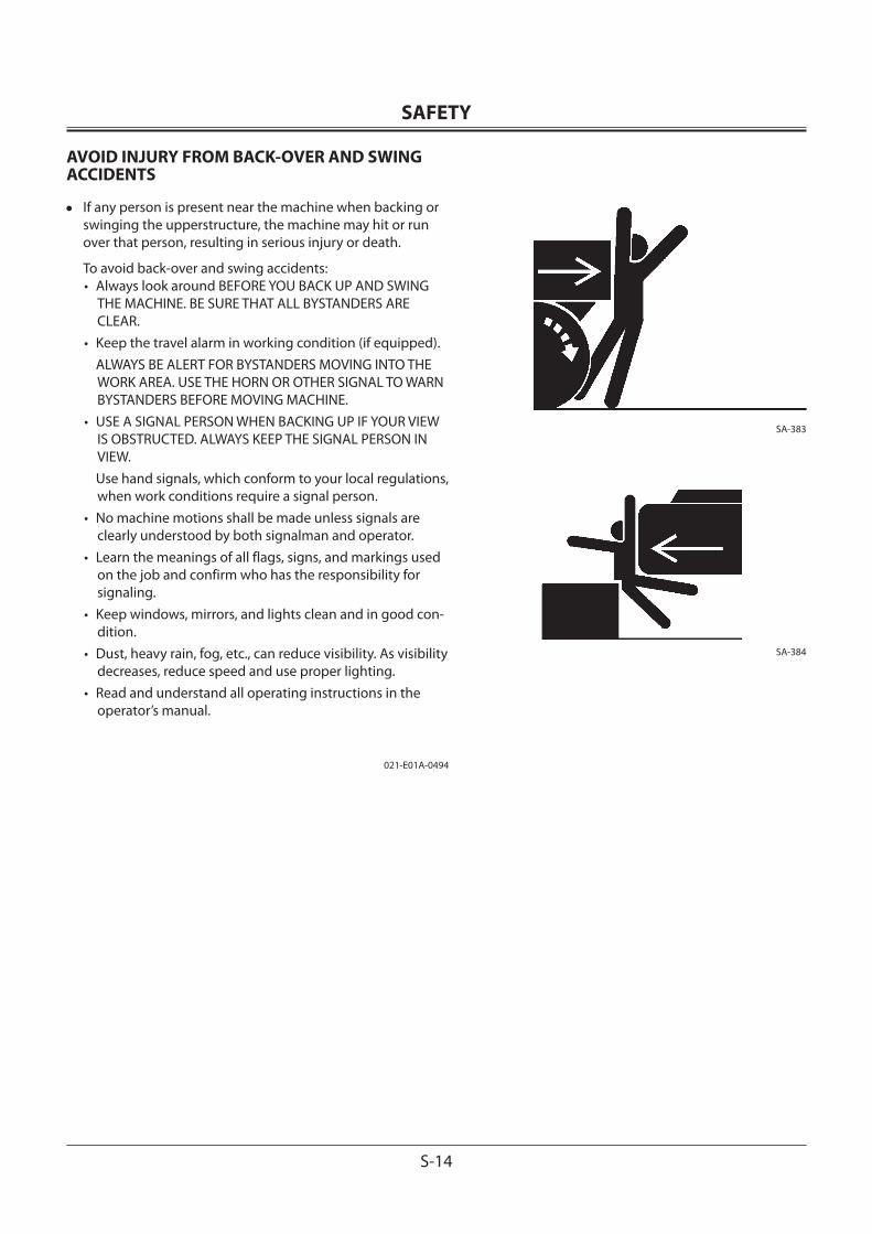
• If any person is present near the machine when backing or swinging the upperstructure, the machine may hit or run over that person, resulting in serious injury or death.
To avoid back-over and swing accidents:• Always look around BEFORE YOU BACK UP AND SWING
THE MACHINE. BE SURE THAT ALL BYSTANDERS ARE CLEAR.
• Keep the travel alarm in working condition (if equipped). ALWAYS BE ALERT FOR BYSTANDERS MOVING INTO THE
WORK AREA. USE THE HORN OR OTHER SIGNAL TO WARN BYSTANDERS BEFORE MOVING MACHINE.
• USE A SIGNAL PERSON WHEN BACKING UP IF YOUR VIEW IS OBSTRUCTED. ALWAYS KEEP THE SIGNAL PERSON IN VIEW.
Use hand signals, which conform to your local regulations, when work conditions require a signal person.
• No machine motions shall be made unless signals are clearly understood by both signalman and operator.
• Learn the meanings of all flags, signs, and markings used on the job and confirm who has the responsibility for signaling.
• Keep windows, mirrors, and lights clean and in good con-dition.
• Dust, heavy rain, fog, etc., can reduce visibility. As visibility decreases, reduce speed and use proper lighting.
• Read and understand all operating instructions in the operator’s manual.
021-E01A-0494
SA-383
SA-384
SAFETY
S-15
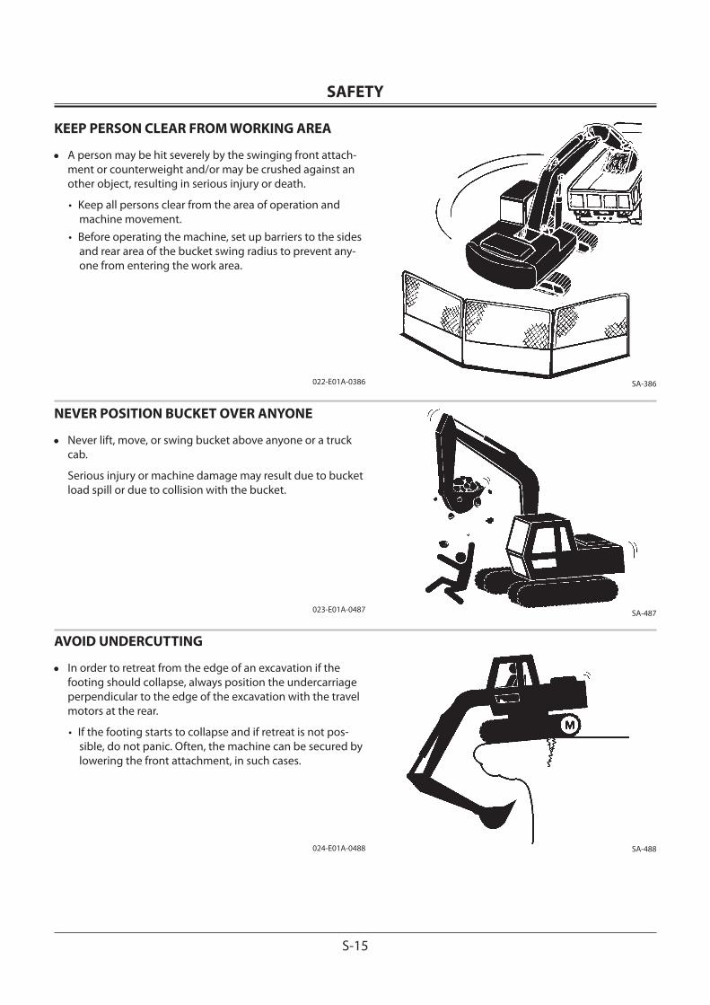
KEEP PERSON CLEAR FROM WORKING AREA
• A person may be hit severely by the swinging front attach-ment or counterweight and/or may be crushed against an other object, resulting in serious injury or death.
• Keep all persons clear from the area of operation and machine movement.
• Before operating the machine, set up barriers to the sides and rear area of the bucket swing radius to prevent any-one from entering the work area.
022-E01A-0386
NEVER POSITION BUCKET OVER ANYONE
• Never lift, move, or swing bucket above anyone or a truck cab.
Serious injury or machine damage may result due to bucket load spill or due to collision with the bucket.
023-E01A-0487
AVOID UNDERCUTTING
• In order to retreat from the edge of an excavation if the footing should collapse, always position the undercarriage perpendicular to the edge of the excavation with the travel motors at the rear.
• If the footing starts to collapse and if retreat is not pos-sible, do not panic. Often, the machine can be secured by lowering the front attachment, in such cases.
024-E01A-0488
SA-386
SA-487
SA-488
SAFETY
S-16
AVOID TIPPING
DO NOT ATTEMPT TO JUMP CLEAR OF TIPPING MA-CHINE---SERIOUS OR FATAL CRUSHING INJURIES WILL RESULTMACHINE WILL TIP OVER FASTER THAN YOU CAN JUMP FREE FASTEN YOUR SEAT BELT
• The danger of tipping is always present when operating on a grade, possibly resulting in serious injury or death.
To avoid tipping:• Be extra careful before operating on a grade.
• Prepare machine operating area flat.• Keep the bucket low to the ground and close to the ma-
chine.• Reduce operating speeds to avoid tipping or slipping.• Avoid changing direction when traveling on grades.• NEVER attempt to travel across a grade steeper than 15
degrees if crossing the grade is unavoidable.• Reduce swing speed as necessary when swinging loads.
• Be careful when working on frozen ground.
• Temperature increases will cause the ground to become soft and make ground travel unstable.
025-E03B-0463
NEVER UNDERCUT A HIGH BANK
• The edges could collapse or a land slide could occur causing serious injury or death.
026-E01A-0519
SA-012
SA-440
SA-489
SAFETY
S-17
DIG WITH CAUTION
• Accidental severing of underground cables or gas lines may cause an explosion and/or fire, possibly resulting in serious injury or death.
• Before digging check the location of cables, gas lines, and water lines.
• Keep the minimum distance required, by law, from cables, gas lines, and water lines.
• If a fiber optic cable should be accidentally severed, do not look into the end. Doing so may result in serious eye injury.
• Contact your local “diggers hot line” if available in your area , and/or the utility companies directly.
Have them mark all underground utilities.
027-E01A-0382
OPERATE WITH CAUTION
• If the front attachment or any other part of the machine hits against an overhead obstacle, such as a bridge, both the machine and the overhead obstacle will be damaged, and personal injury may result as well.
• Take care to avoid hitting overhead obstacles with the boom or arm.
028-E01A-0389
SA-382
SA-389
SAFETY
S-18
AVOID POWER LINES
• Serious injury or death can result if the machine or front at-tachments are not kept a safe distance from electric lines.
• When operating near an electric line, NEVER move any part of the machine or load closer than 3 m plus twice the line insulator length.
• Check and comply with any local regulations that may ap-ply.
• Wet ground will expand the area that could cause any person on it to be affected by electric shock. Keep all bystanders or co-workers away from the site.
029-E01A-0381
PRECAUTIONS FOR LIGHTNING
• The machine is vulnerable to lightning strikes.
• In the event of an electrical storm, immediately stop op-eration, and lower the bucket to the ground. Evacuate to a safe place far away from the machine.
• After the electrical storm has passed, check all of the machine safety devices for any failure. If any failed safety devices are found, operate the machine only after repair-ing them.
OBJECT HANDLING
• If a lifted load should fall, any person nearby may be struck by the falling load or may be crushed underneath it, result-ing in serious injury or death.
• When using the machine for craning operations, be sure to comply with all local regulations.
• Do not use damaged chains or frayed cables, sables, slings, or ropes.
• Before craning, position the upperstructure with the travel motors at the rear.
• Move the load slowly and carefully. Never move it sud-denly.
• Keep all persons well away from the load.• Never move a load over a person’s head.• Do not allow anyone to approach the load until it is safely
and securely situated on supporting blocks or on the ground.
• Never attach a sling or chain to the bucket teeth. They may come off, causing the load to fall.
032-E01A-0132
SA-381
SA-1088
SA-014
SAFETY
S-19
PROTECT AGAINST FLYING DEBRIS
• If flying debris hit eyes or any other part of the body, serious injury may result.
• Guard against injury from flying pieces of metal or debris; wear goggles or safety glasses.
• Keep bystanders away from the working area before strik-ing any object.
031-E01A-0432
PARK MACHINE SAFELY
To avoid accidents:• Park machine on a firm, level surface.• Lower bucket to the ground.• Turn auto-idle switch and H/P mode switch OFF.• Run engine at slow idle speed without load for 5 minutes.• Turn key switch to OFF to stop engine.• Remove the key from the key switch.• Pull the pilot control shut-off lever to the LOCK position.• Close windows, roof vent, and cab door.• Lock all access doors and compartments.
HANDLE FLUIDS SAFELY−AVOID FIRES
• Handle fuel with care; it is highly flammable. If fuel ignites, an explosion and/or a fire may occur, possibly resulting in serious injury or death.
• Do not refuel the machine while smoking or when near open flame or sparks.
• Always stop the engine before refueling the machine. • Fill the fuel tank outdoors.
• All fuels, most lubricants, and some coolants are flammable.
• Store flammable fluids well away from fire hazards.• Do not incinerate or puncture pressurized containers.• Do not store oily rags; they can ignite and burn spontane-
ously.• Securely tighten the fuel and oil filler cap.
034-E01A-0496
SA-432
SA-390
SA-018
SA-019
SAFETY
S-20
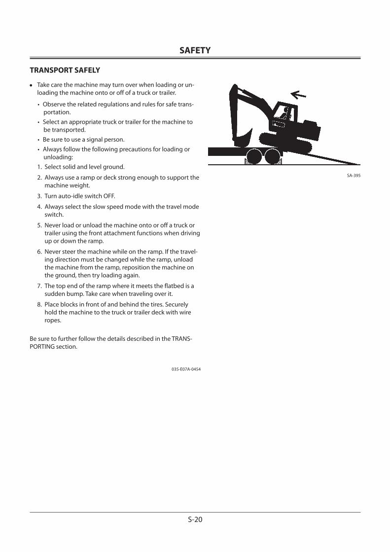
TRANSPORT SAFELY
• Take care the machine may turn over when loading or un-loading the machine onto or off of a truck or trailer.
• Observe the related regulations and rules for safe trans-portation.
• Select an appropriate truck or trailer for the machine to be transported.
• Be sure to use a signal person.• Always follow the following precautions for loading or
unloading:1. Select solid and level ground.
2. Always use a ramp or deck strong enough to support the machine weight.
3. Turn auto-idle switch OFF.
4. Always select the slow speed mode with the travel mode switch.
5. Never load or unload the machine onto or off a truck or trailer using the front attachment functions when driving up or down the ramp.
6. Never steer the machine while on the ramp. If the travel-ing direction must be changed while the ramp, unload the machine from the ramp, reposition the machine on the ground, then try loading again.
7. The top end of the ramp where it meets the flatbed is a sudden bump. Take care when traveling over it.
8. Place blocks in front of and behind the tires. Securely hold the machine to the truck or trailer deck with wire ropes.
Be sure to further follow the details described in the TRANS-PORTING section.
035-E07A-0454
SA-395
SAFETY
S-21
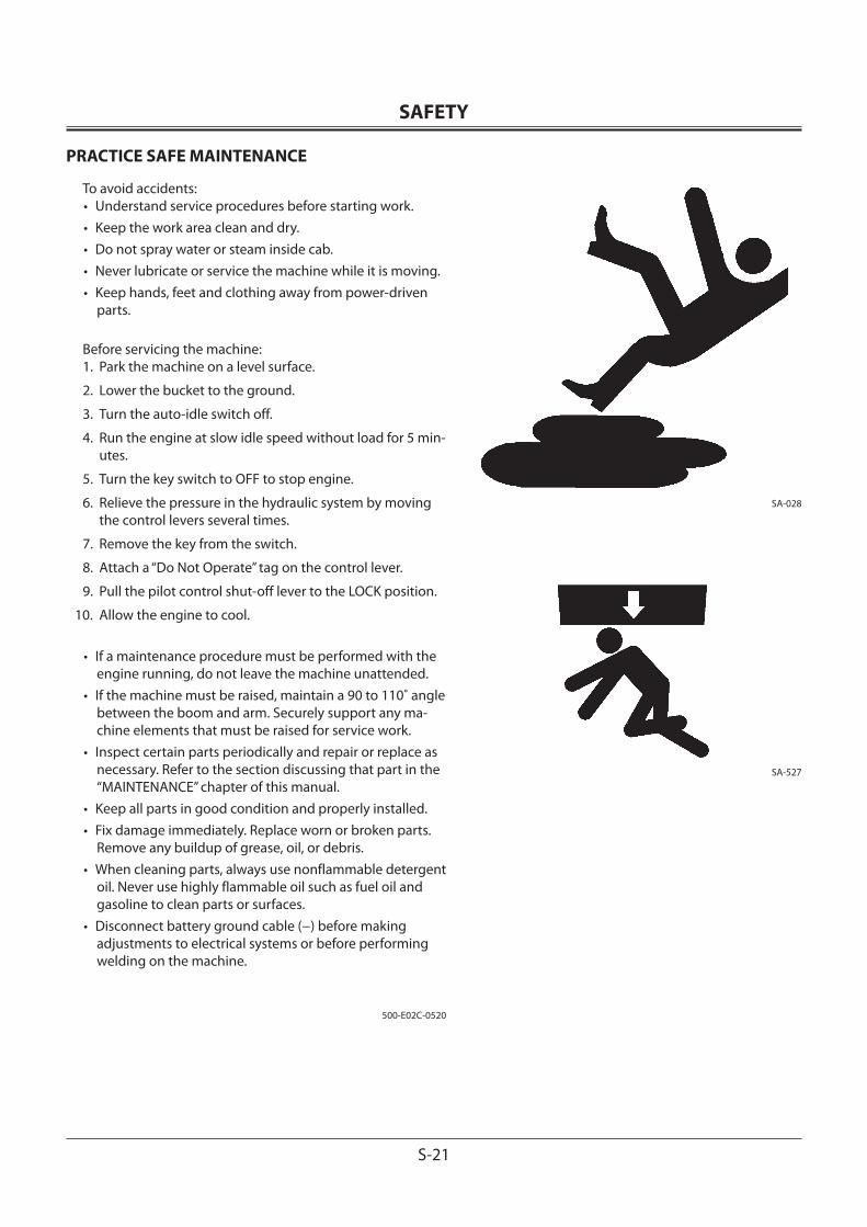
PRACTICE SAFE MAINTENANCE
To avoid accidents:• Understand service procedures before starting work. • Keep the work area clean and dry. • Do not spray water or steam inside cab.• Never lubricate or service the machine while it is moving.• Keep hands, feet and clothing away from power-driven
parts.
Before servicing the machine:1. Park the machine on a level surface.
2. Lower the bucket to the ground.
3. Turn the auto-idle switch off.
4. Run the engine at slow idle speed without load for 5 min-utes.
5. Turn the key switch to OFF to stop engine.
6. Relieve the pressure in the hydraulic system by moving the control levers several times.
7. Remove the key from the switch.
8. Attach a “Do Not Operate” tag on the control lever.
9. Pull the pilot control shut-off lever to the LOCK position.
10. Allow the engine to cool.
• If a maintenance procedure must be performed with the engine running, do not leave the machine unattended.
• If the machine must be raised, maintain a 90 to 110˚ angle between the boom and arm. Securely support any ma-chine elements that must be raised for service work.
• Inspect certain parts periodically and repair or replace as necessary. Refer to the section discussing that part in the “MAINTENANCE” chapter of this manual.
• Keep all parts in good condition and properly installed.• Fix damage immediately. Replace worn or broken parts.
Remove any buildup of grease, oil, or debris.• When cleaning parts, always use nonflammable detergent
oil. Never use highly flammable oil such as fuel oil and gasoline to clean parts or surfaces.
• Disconnect battery ground cable (−) before making adjustments to electrical systems or before performing welding on the machine.
500-E02C-0520
SA-028
SA-527
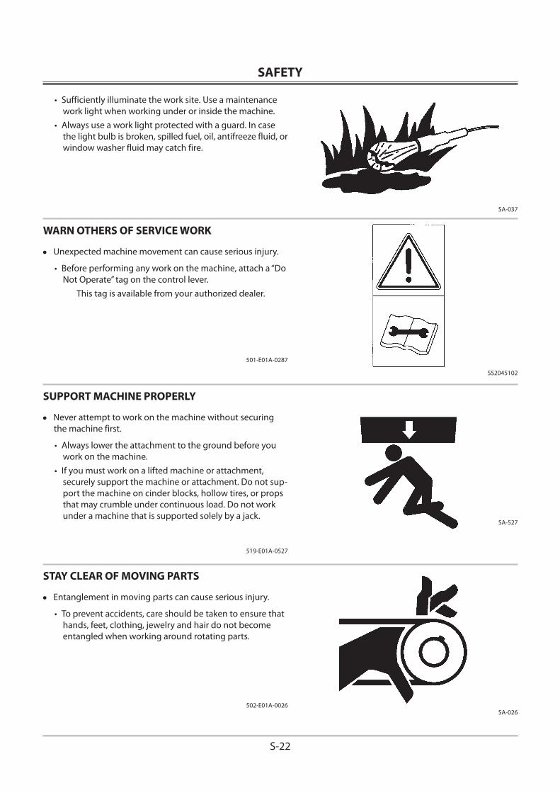
SAFETY
S-22
• Sufficiently illuminate the work site. Use a maintenance work light when working under or inside the machine.
• Always use a work light protected with a guard. In case the light bulb is broken, spilled fuel, oil, antifreeze fluid, or window washer fluid may catch fire.
WARN OTHERS OF SERVICE WORK
• Unexpected machine movement can cause serious injury.
• Before performing any work on the machine, attach a “Do Not Operate” tag on the control lever.
This tag is available from your authorized dealer.
501-E01A-0287
SUPPORT MACHINE PROPERLY
• Never attempt to work on the machine without securing the machine first.
• Always lower the attachment to the ground before you work on the machine.
• If you must work on a lifted machine or attachment, securely support the machine or attachment. Do not sup-port the machine on cinder blocks, hollow tires, or props that may crumble under continuous load. Do not work under a machine that is supported solely by a jack.
519-E01A-0527
STAY CLEAR OF MOVING PARTS
• Entanglement in moving parts can cause serious injury.
• To prevent accidents, care should be taken to ensure that hands, feet, clothing, jewelry and hair do not become entangled when working around rotating parts.
502-E01A-0026
SA-037
SS2045102
SA-527
SA-026
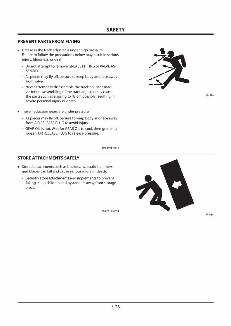
SAFETY
S-23
PREVENT PARTS FROM FLYING
• Grease in the track adjuster is under high pressure. Failure to follow the precautions below may result in serious injury, blindness, or death.
• Do not attempt to remove GREASE FITTING or VALVE AS-SEMBLY.
• As pieces may fly off, be sure to keep body and face away from valve.
• Never attempt to disassemble the track adjuster. Inad-vertent disassembling of the track adjuster may cause the parts such as a spring to fly off, possibly resulting in severe personal injury or death.
• Travel reduction gears are under pressure.
• As pieces may fly off, be sure to keep body and face away from AIR RELEASE PLUG to avoid injury.
• GEAR OIL is hot. Wait for GEAR OIL to cool, then gradually loosen AIR RELEASE PLUG to release pressure.
503-E01B-0344
STORE ATTACHMENTS SAFELY
• Stored attachments such as buckets, hydraulic hammers, and blades can fall and cause serious injury or death.
• Securely store attachments and implements to prevent falling. Keep children and bystanders away from storage areas.
504-E01A-0034
SA-344
SA-034
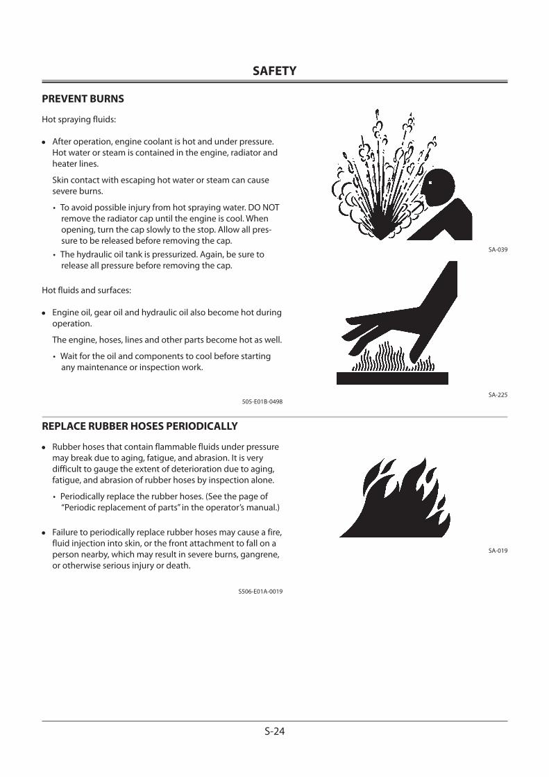
SAFETY
S-24
PREVENT BURNS
Hot spraying fluids:
• After operation, engine coolant is hot and under pressure. Hot water or steam is contained in the engine, radiator and heater lines.
Skin contact with escaping hot water or steam can cause severe burns.
• To avoid possible injury from hot spraying water. DO NOT remove the radiator cap until the engine is cool. When opening, turn the cap slowly to the stop. Allow all pres-sure to be released before removing the cap.
• The hydraulic oil tank is pressurized. Again, be sure to release all pressure before removing the cap.
Hot fluids and surfaces:
• Engine oil, gear oil and hydraulic oil also become hot during operation.
The engine, hoses, lines and other parts become hot as well.
• Wait for the oil and components to cool before starting any maintenance or inspection work.
505-E01B-0498
REPLACE RUBBER HOSES PERIODICALLY
• Rubber hoses that contain flammable fluids under pressure may break due to aging, fatigue, and abrasion. It is very difficult to gauge the extent of deterioration due to aging, fatigue, and abrasion of rubber hoses by inspection alone.
• Periodically replace the rubber hoses. (See the page of “Periodic replacement of parts” in the operator’s manual.)
• Failure to periodically replace rubber hoses may cause a fire, fluid injection into skin, or the front attachment to fall on a person nearby, which may result in severe burns, gangrene, or otherwise serious injury or death.
S506-E01A-0019
SA-039
SA-225
SA-019
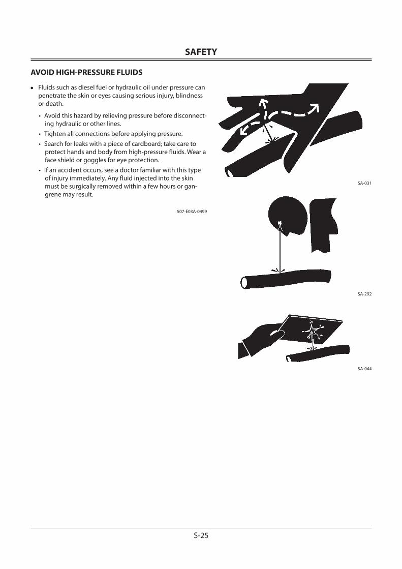
SAFETY
S-25
AVOID HIGH-PRESSURE FLUIDS
• Fluids such as diesel fuel or hydraulic oil under pressure can penetrate the skin or eyes causing serious injury, blindness or death.
• Avoid this hazard by relieving pressure before disconnect-ing hydraulic or other lines.
• Tighten all connections before applying pressure.• Search for leaks with a piece of cardboard; take care to
protect hands and body from high-pressure fluids. Wear a face shield or goggles for eye protection.
• If an accident occurs, see a doctor familiar with this type of injury immediately. Any fluid injected into the skin must be surgically removed within a few hours or gan-grene may result.
507-E03A-0499
SA-031
SA-292
SA-044
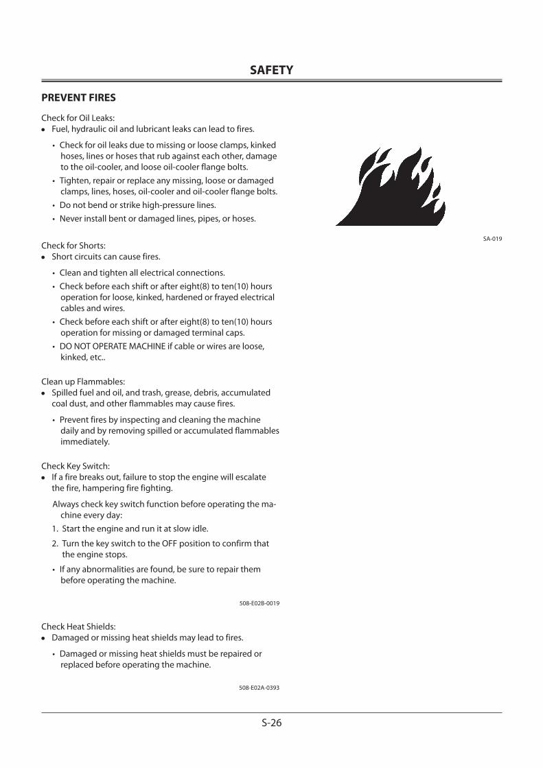
SAFETY
S-26
PREVENT FIRES
Check for Oil Leaks:• Fuel, hydraulic oil and lubricant leaks can lead to fires.
• Check for oil leaks due to missing or loose clamps, kinked hoses, lines or hoses that rub against each other, damage to the oil-cooler, and loose oil-cooler flange bolts.
• Tighten, repair or replace any missing, loose or damaged clamps, lines, hoses, oil-cooler and oil-cooler flange bolts.
• Do not bend or strike high-pressure lines.• Never install bent or damaged lines, pipes, or hoses.
Check for Shorts:• Short circuits can cause fires.
• Clean and tighten all electrical connections.• Check before each shift or after eight(8) to ten(10) hours
operation for loose, kinked, hardened or frayed electrical cables and wires.
• Check before each shift or after eight(8) to ten(10) hours operation for missing or damaged terminal caps.
• DO NOT OPERATE MACHINE if cable or wires are loose, kinked, etc..
Clean up Flammables:• Spilled fuel and oil, and trash, grease, debris, accumulated
coal dust, and other flammables may cause fires.
• Prevent fires by inspecting and cleaning the machine daily and by removing spilled or accumulated flammables immediately.
Check Key Switch:• If a fire breaks out, failure to stop the engine will escalate
the fire, hampering fire fighting.
Always check key switch function before operating the ma-chine every day:
1. Start the engine and run it at slow idle.
2. Turn the key switch to the OFF position to confirm that the engine stops.
• If any abnormalities are found, be sure to repair them before operating the machine.
508-E02B-0019
Check Heat Shields:• Damaged or missing heat shields may lead to fires.
• Damaged or missing heat shields must be repaired or replaced before operating the machine.
508-E02A-0393
SA-019
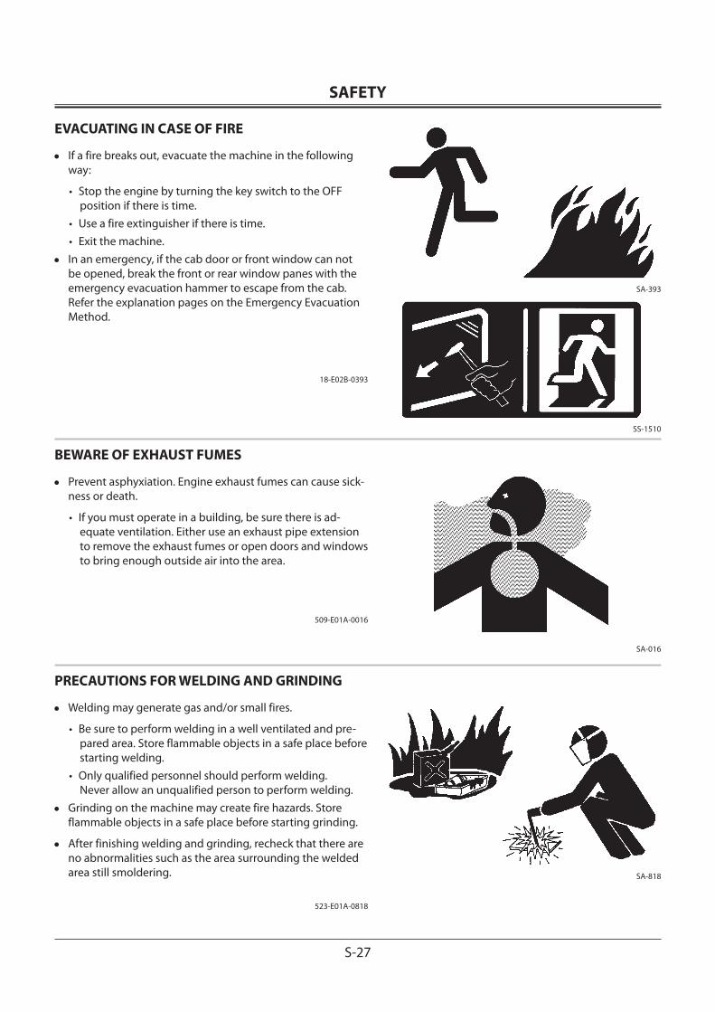
SAFETY
S-27
EVACUATING IN CASE OF FIRE
• If a fire breaks out, evacuate the machine in the following way:
• Stop the engine by turning the key switch to the OFF position if there is time.
• Use a fire extinguisher if there is time.• Exit the machine.
• In an emergency, if the cab door or front window can not be opened, break the front or rear window panes with the emergency evacuation hammer to escape from the cab. Refer the explanation pages on the Emergency Evacuation Method.
18-E02B-0393
BEWARE OF EXHAUST FUMES
• Prevent asphyxiation. Engine exhaust fumes can cause sick-ness or death.
• If you must operate in a building, be sure there is ad-equate ventilation. Either use an exhaust pipe extension to remove the exhaust fumes or open doors and windows to bring enough outside air into the area.
509-E01A-0016
PRECAUTIONS FOR WELDING AND GRINDING
• Welding may generate gas and/or small fires.
• Be sure to perform welding in a well ventilated and pre-pared area. Store flammable objects in a safe place before starting welding.
• Only qualified personnel should perform welding. Never allow an unqualified person to perform welding.
• Grinding on the machine may create fire hazards. Store flammable objects in a safe place before starting grinding.
• After finishing welding and grinding, recheck that there are no abnormalities such as the area surrounding the welded area still smoldering.
523-E01A-0818
SA-393
SS-1510
SA-016
SA-818
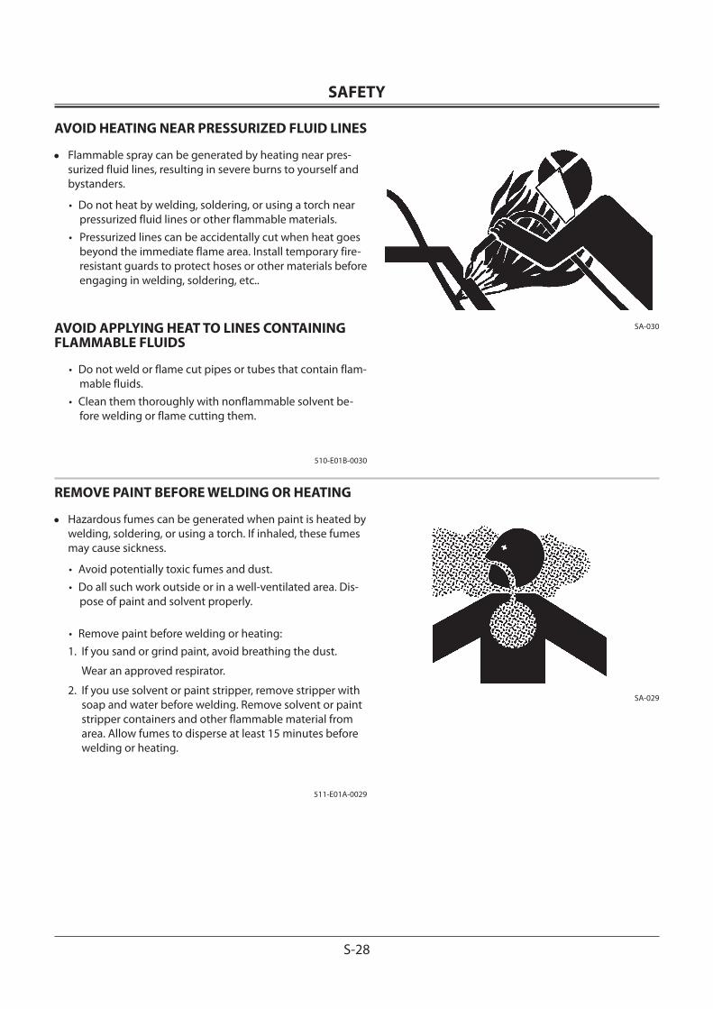
SAFETY
S-28
AVOID HEATING NEAR PRESSURIZED FLUID LINES
• Flammable spray can be generated by heating near pres-surized fluid lines, resulting in severe burns to yourself and bystanders.
• Do not heat by welding, soldering, or using a torch near pressurized fluid lines or other flammable materials.
• Pressurized lines can be accidentally cut when heat goes beyond the immediate flame area. Install temporary fire-resistant guards to protect hoses or other materials before engaging in welding, soldering, etc..
AVOID APPLYING HEAT TO LINES CONTAINING FLAMMABLE FLUIDS
• Do not weld or flame cut pipes or tubes that contain flam-mable fluids.
• Clean them thoroughly with nonflammable solvent be-fore welding or flame cutting them.
510-E01B-0030
REMOVE PAINT BEFORE WELDING OR HEATING
• Hazardous fumes can be generated when paint is heated by welding, soldering, or using a torch. If inhaled, these fumes may cause sickness.
• Avoid potentially toxic fumes and dust.• Do all such work outside or in a well-ventilated area. Dis-
pose of paint and solvent properly.
• Remove paint before welding or heating:1. If you sand or grind paint, avoid breathing the dust.
Wear an approved respirator.
2. If you use solvent or paint stripper, remove stripper with soap and water before welding. Remove solvent or paint stripper containers and other flammable material from area. Allow fumes to disperse at least 15 minutes before welding or heating.
511-E01A-0029
SA-030
SA-029
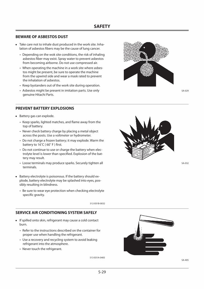
SAFETY
S-29
BEWARE OF ASBESTOS DUST
• Take care not to inhale dust produced in the work site. Inha-lation of asbestos fibers may be the cause of lung cancer.
• Depending on the wok site conditions, the risk of inhaling asbestos fiber may exist. Spray water to prevent asbestos from becoming airborne. Do not use compressed air.
• When operating the machine in a work site where asbes-tos might be present, be sure to operate the machine from the upwind side and wear a mask rated to prevent the inhalation of asbestos.
• Keep bystanders out of the work site during operation.• Asbestos might be present in imitation parts. Use only
genuine Hitachi Parts.
PREVENT BATTERY EXPLOSIONS
• Battery gas can explode.
• Keep sparks, lighted matches, and flame away from the top of battery.
• Never check battery charge by placing a metal object across the posts. Use a voltmeter or hydrometer.
• Do not charge a frozen battery; it may explode. Warm the battery to 16˚C ( 60˚ F ) first.
• Do not continue to use or charge the battery when elec-trolyte level is lower than specified. Explosion of the bat-tery may result.
• Loose terminals may produce sparks. Securely tighten all terminals.
• Battery electrolyte is poisonous. If the battery should ex-plode, battery electrolyte may be splashed into eyes, pos-sibly resulting in blindness.
• Be sure to wear eye protection when checking electrolyte specific gravity.
512-E01B-0032
SERVICE AIR CONDITIONING SYSTEM SAFELY
• If spilled onto skin, refrigerant may cause a cold contact burn.
• Refer to the instructions described on the container for proper use when handling the refrigerant.
• Use a recovery and recycling system to avoid leaking refrigerant into the atmosphere.
• Never touch the refrigerant.
513-E01A-0405
SA-029
SA-032
SA-405
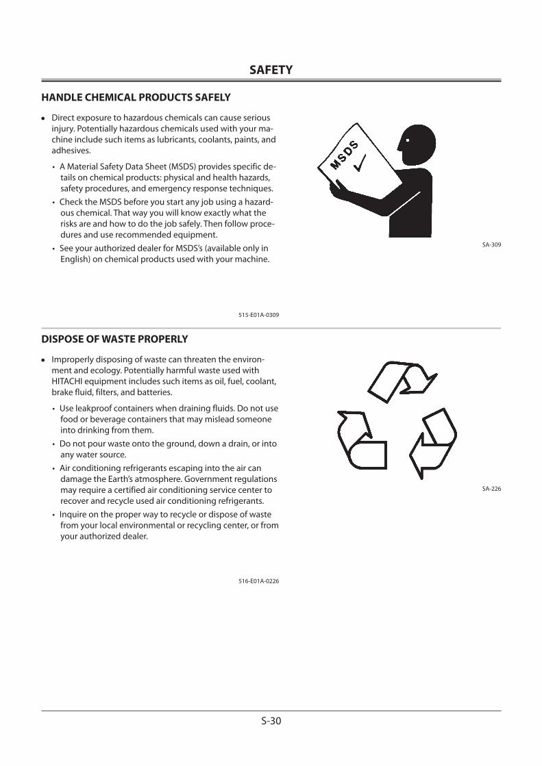
SAFETY
S-30
HANDLE CHEMICAL PRODUCTS SAFELY
• Direct exposure to hazardous chemicals can cause serious injury. Potentially hazardous chemicals used with your ma-chine include such items as lubricants, coolants, paints, and adhesives.
• A Material Safety Data Sheet (MSDS) provides specific de-tails on chemical products: physical and health hazards, safety procedures, and emergency response techniques.
• Check the MSDS before you start any job using a hazard-ous chemical. That way you will know exactly what the risks are and how to do the job safely. Then follow proce-dures and use recommended equipment.
• See your authorized dealer for MSDS’s (available only in English) on chemical products used with your machine.
515-E01A-0309
DISPOSE OF WASTE PROPERLY
• Improperly disposing of waste can threaten the environ-ment and ecology. Potentially harmful waste used with HITACHI equipment includes such items as oil, fuel, coolant, brake fluid, filters, and batteries.
• Use leakproof containers when draining fluids. Do not use food or beverage containers that may mislead someone into drinking from them.
• Do not pour waste onto the ground, down a drain, or into any water source.
• Air conditioning refrigerants escaping into the air can damage the Earth’s atmosphere. Government regulations may require a certified air conditioning service center to recover and recycle used air conditioning refrigerants.
• Inquire on the proper way to recycle or dispose of waste from your local environmental or recycling center, or from your authorized dealer.
516-E01A-0226
SA-309
SA-226
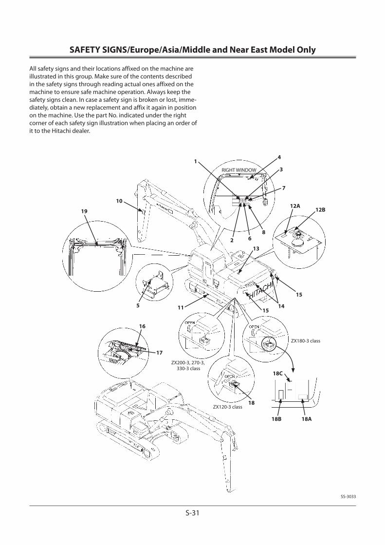
SAFETY SIGNS/Europe/Asia/Middle and Near East Model Only
S-31
All safety signs and their locations affixed on the machine are illustrated in this group. Make sure of the contents described in the safety signs through reading actual ones affixed on the machine to ensure safe machine operation. Always keep the safety signs clean. In case a safety sign is broken or lost, imme-diately, obtain a new replacement and affix it again in position on the machine. Use the part No. indicated under the right corner of each safety sign illustration when placing an order of it to the Hitachi dealer.
1
10
2 6
3
4
18A
11
17
16
13
8
RIGHT WINDOW
19
5
ZX180-3 class
ZX120-3 class
ZX200-3, 270-3, 330-3 class
15
1415
12B
7
18B
18C
12A
18
SS-3033

SAFETY SIGNS/Europe/Asia/Middle and Near East Model Only
S-32
1.WARNING!
Prior to operation, maintenance, disassembling, and trans-portation of the machine, be sure to read and understand the Operator’s Manual.
2.If the parked machine is unexpectedly moved, serious injury or death due to crushing may result. Be sure to lower the front attachment to the ground, lock the control levers, and remove the engine key before leaving the machine unat-tended.
3.Sign indicates an electrocution hazard if machine is brought too near electric power lines.Keep a safe distance from electric power lines.
4.Sign indicates a hazard form falling window.After raising window, be sure to lock it in place with lock pins.
SS4420333
SS4420332
SS4420335
SS4420334
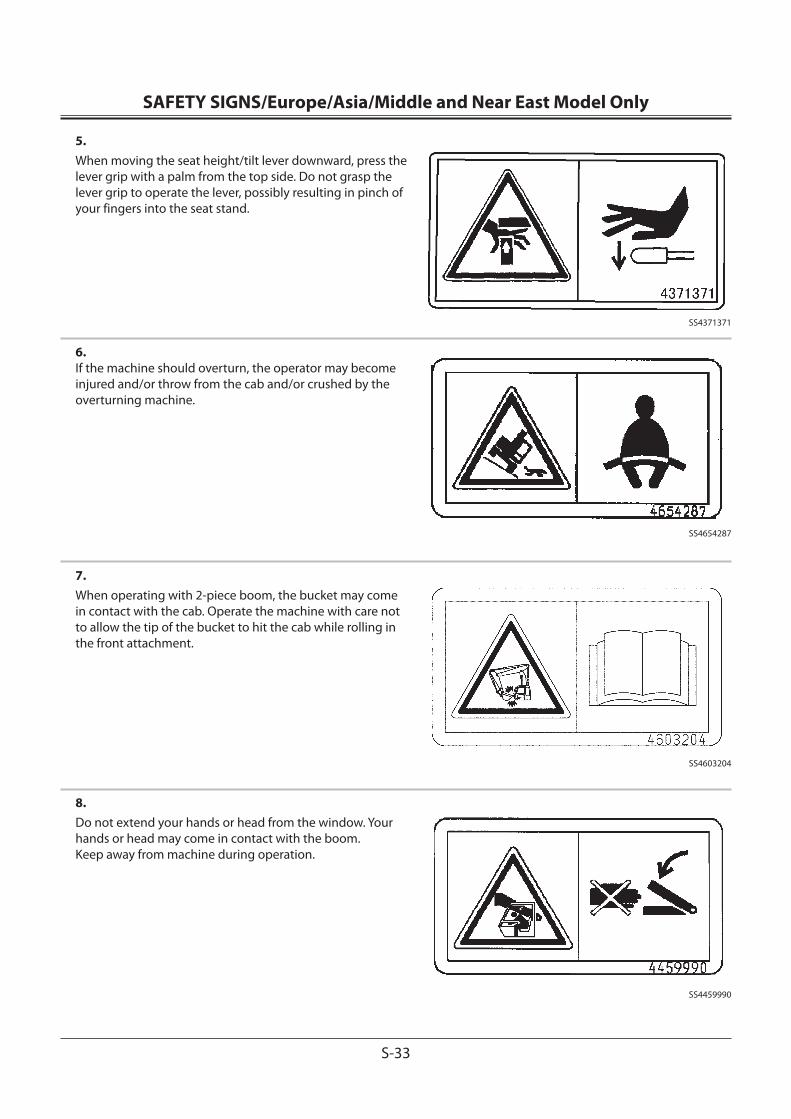
SAFETY SIGNS/Europe/Asia/Middle and Near East Model Only
S-33
5.When moving the seat height/tilt lever downward, press the lever grip with a palm from the top side. Do not grasp the lever grip to operate the lever, possibly resulting in pinch of your fingers into the seat stand.
6.If the machine should overturn, the operator may become injured and/or throw from the cab and/or crushed by the overturning machine.
7.When operating with 2-piece boom, the bucket may come in contact with the cab. Operate the machine with care not to allow the tip of the bucket to hit the cab while rolling in the front attachment.
8.Do not extend your hands or head from the window. Your hands or head may come in contact with the boom.Keep away from machine during operation.
SS4603204
SS4654287
SS4459990
SS4371371
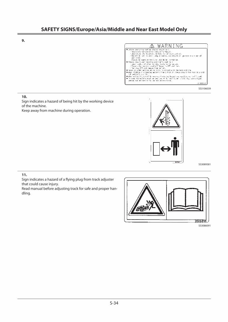
SAFETY SIGNS/Europe/Asia/Middle and Near East Model Only
S-34
9.
10.Sign indicates a hazard of being hit by the working device of the machine.Keep away from machine during operation.
11.Sign indicates a hazard of a flying plug from track adjuster that could cause injury.Read manual before adjusting track for safe and proper han-dling.
SS3106039
SS3089581
SS3086091

SAFETY SIGNS/Europe/Asia/Middle and Near East Model Only
S-35
12.Sign indicates a burn hazard from compressed air and spurt-ing hot oil if the oil inlet is uncapped during or right after operation.Read manual for safe and proper handling.
Sign indicates a burn hazard from spurting hot water or oil if radiator or hydraulic tank is uncapped while hot.Allow radiator or hydraulic tank to cool before removing cap.
13.Sign indicates a hazard of falling.Do not stand on this place.
14.Sign indicates a hazard of falling off the fender or hood.Never stand close to the edge.
SS3092125
SS4459928
A
B
SS4420336
SS3092126

SAFETY SIGNS/Europe/Asia/Middle and Near East Model Only
S-36
15.Sign indicates a crush hazard by rotation of upper structure of the machine.Keep away from swinging area of machine.
16.Sign indicates a burn hazard from spurting hot water or oil if radiator or hydraulic tank is uncapped while hot.Allow radiator or hydraulic tank to cool before removing cap.
17.Sign indicates a hazard of rotating parts, such as belt.Turn off before inspection and maintenance.
SS4420336
SS3092127
SS3086090
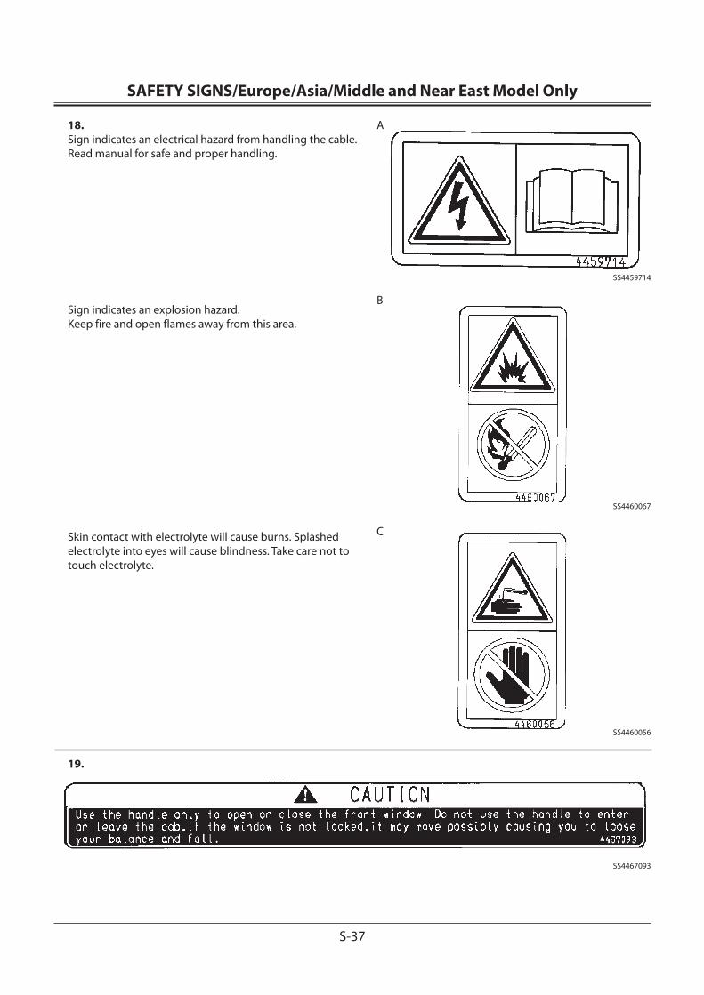
SAFETY SIGNS/Europe/Asia/Middle and Near East Model Only
S-37
18.Sign indicates an electrical hazard from handling the cable. Read manual for safe and proper handling.
Sign indicates an explosion hazard.Keep fire and open flames away from this area.
Skin contact with electrolyte will cause burns. Splashed electrolyte into eyes will cause blindness. Take care not to touch electrolyte.
19.
SS4459714
SS4467093
C
A
B
SS4460067
SS4460056

SAFETY SIGNS/Europe/Asia/Middle and Near East Model Only
S-38
MEMO...................................................................................................................................................................................................................................................
...................................................................................................................................................................................................................................................
...................................................................................................................................................................................................................................................
...................................................................................................................................................................................................................................................
...................................................................................................................................................................................................................................................
...................................................................................................................................................................................................................................................
...................................................................................................................................................................................................................................................
...................................................................................................................................................................................................................................................
...................................................................................................................................................................................................................................................
...................................................................................................................................................................................................................................................
...................................................................................................................................................................................................................................................
...................................................................................................................................................................................................................................................
...................................................................................................................................................................................................................................................
...................................................................................................................................................................................................................................................
...................................................................................................................................................................................................................................................
...................................................................................................................................................................................................................................................
...................................................................................................................................................................................................................................................
...................................................................................................................................................................................................................................................
...................................................................................................................................................................................................................................................
...................................................................................................................................................................................................................................................
...................................................................................................................................................................................................................................................
...................................................................................................................................................................................................................................................
...................................................................................................................................................................................................................................................
...................................................................................................................................................................................................................................................
...................................................................................................................................................................................................................................................
...................................................................................................................................................................................................................................................
...................................................................................................................................................................................................................................................
...................................................................................................................................................................................................................................................
...................................................................................................................................................................................................................................................
...................................................................................................................................................................................................................................................
...................................................................................................................................................................................................................................................
...................................................................................................................................................................................................................................................
...................................................................................................................................................................................................................................................
...................................................................................................................................................................................................................................................
...................................................................................................................................................................................................................................................
...................................................................................................................................................................................................................................................
...................................................................................................................................................................................................................................................
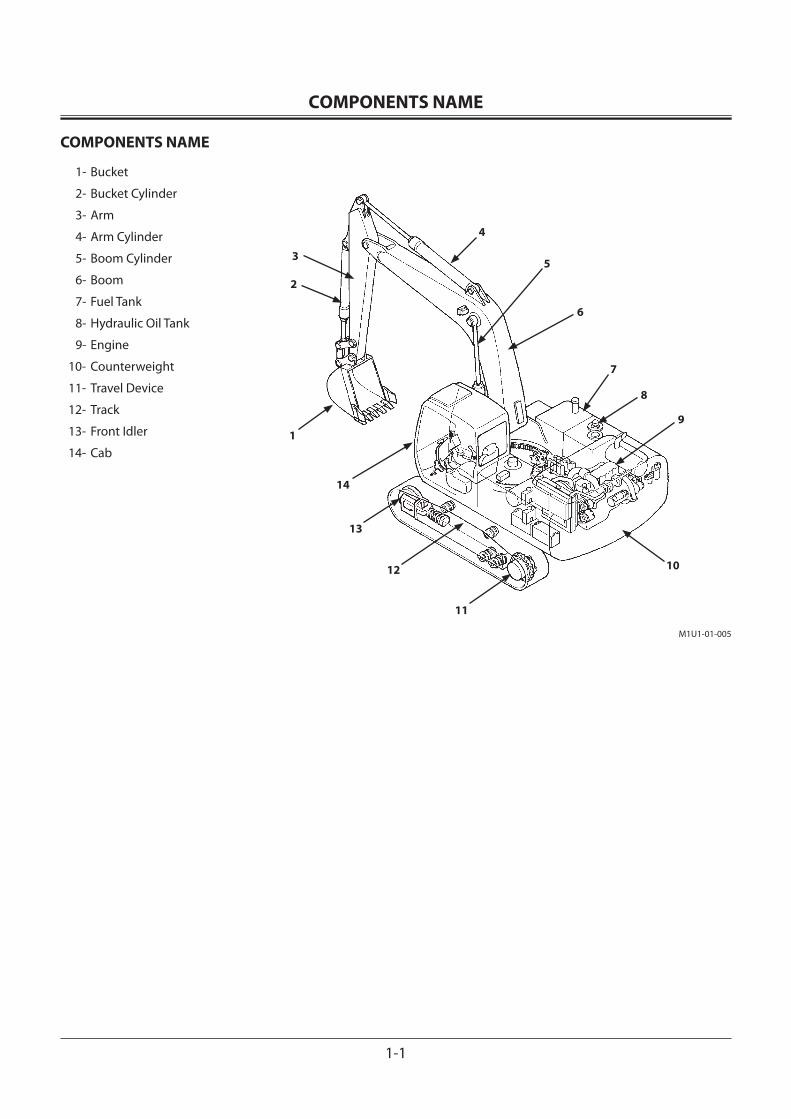
OPERATOR'S STATION
1-1
COMPONENTS NAME
COMPONENTS NAME
1- Bucket
2- Bucket Cylinder
3- Arm
4- Arm Cylinder
5- Boom Cylinder
6- Boom
7- Fuel Tank
8- Hydraulic Oil Tank
9- Engine
10- Counterweight
11- Travel Device
12- Track
13- Front Idler
14- Cab
3
2
1
4
5
6
7
8
9
10
11
12
13
14
M1U1-01-005
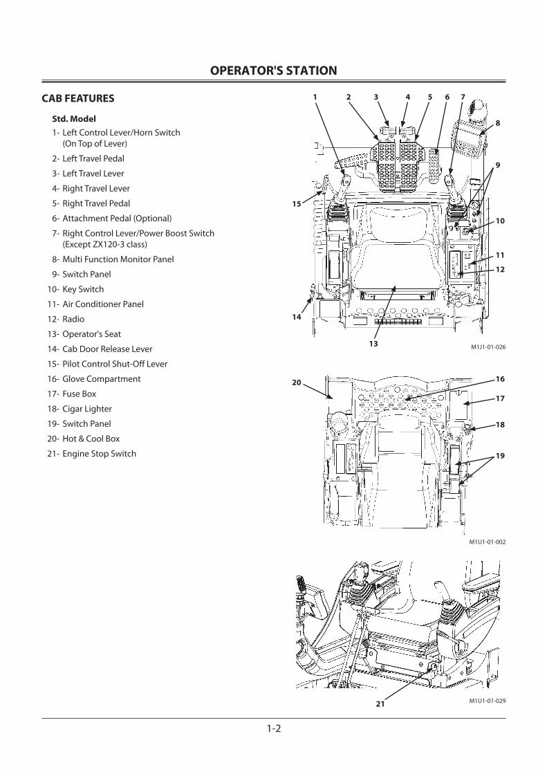
OPERATOR'S STATION
1-2
CAB FEATURES
Std. Model1- Left Control Lever/Horn Switch
(On Top of Lever)
2- Left Travel Pedal
3- Left Travel Lever
4- Right Travel Lever
5- Right Travel Pedal
6- Attachment Pedal (Optional)
7- Right Control Lever/Power Boost Switch (Except ZX120-3 class)
8- Multi Function Monitor Panel
9- Switch Panel
10- Key Switch
11- Air Conditioner Panel
12- Radio
13- Operator's Seat
14- Cab Door Release Lever
15- Pilot Control Shut-Off Lever
16- Glove Compartment
17- Fuse Box
18- Cigar Lighter
19- Switch Panel
20- Hot & Cool Box
21- Engine Stop Switch
M1U1-01-002
M1U1-01-02921
19
18
17
1620
1 2 3 4 5 6 7
12
11
10
9
8
14
15
13 M1J1-01-026
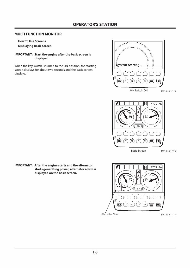
OPERATOR'S STATION
1-3
MULTI FUNCTION MONITOR
How To Use ScreensDisplaying Basic Screen
IMPORTANT: Start the engine after the basic screen is displayed.
When the key switch is turned to the ON position, the starting screen displays for about two seconds and the basic screen displays.
IMPORTANT: After the engine starts and the alternator starts generating power, alternator alarm is displayed on the basic screen.
T1V1-05-01-115
T1V1-05-01-123
T1V1-05-01-117
Key Switch: ON
Basic Screen
Alternator Alarm
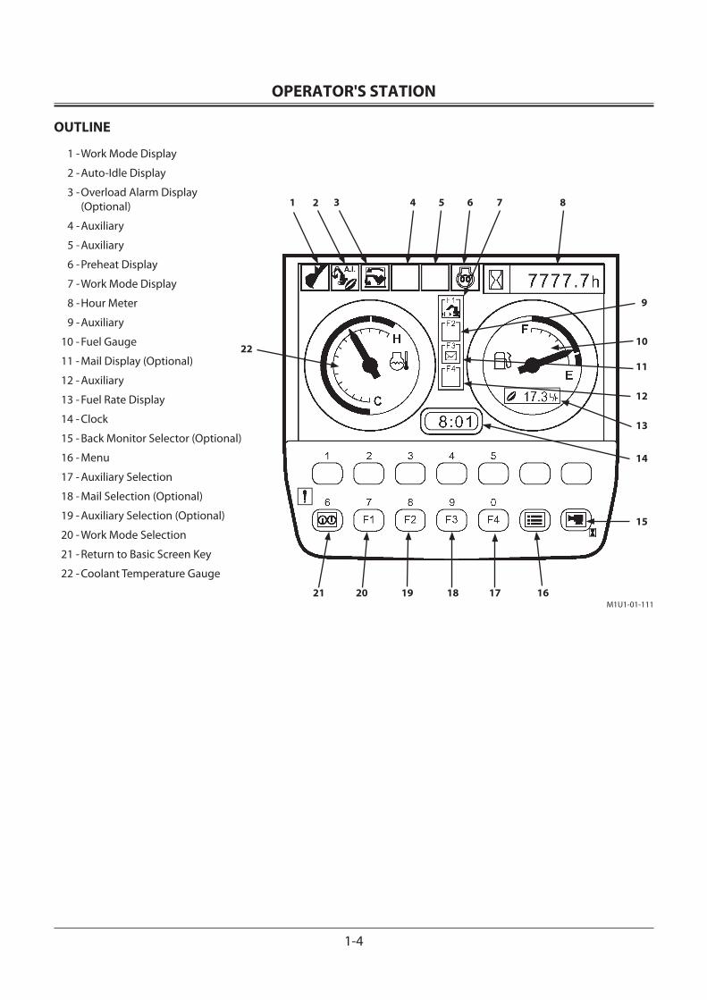
OPERATOR'S STATION
1-4
OUTLINE
1 - Work Mode Display
2 - Auto-Idle Display
3 - Overload Alarm Display (Optional)
4 - Auxiliary
5 - Auxiliary
6 - Preheat Display
7 - Work Mode Display
8 - Hour Meter
9 - Auxiliary
10 - Fuel Gauge
11 - Mail Display (Optional)
12 - Auxiliary
13 - Fuel Rate Display
14 - Clock
15 - Back Monitor Selector (Optional)
16 - Menu
17 - Auxiliary Selection
18 - Mail Selection (Optional)
19 - Auxiliary Selection (Optional)
20 - Work Mode Selection
21 - Return to Basic Screen Key
22 - Coolant Temperature Gauge
1 2 4 5 6 7 83
22
9
10
11
12
13
14
15
161718192021M1U1-01-111
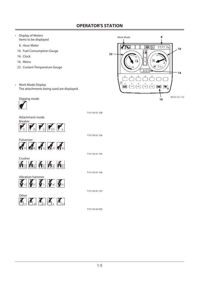
OPERATOR'S STATION
1-5
Work Mode 8
10
14
16
22
M1U1-01-112
• Display of Meters Items to be displayed
8. Hour Meter
10. Fuel Consumption Gauge
14. Clock
16. Menu
22. Coolant Temperature Gauge
• Work Mode Display The attachments being used are displayed.
Digging mode
T1V1-05-01-108
Attachment modeBreaker
T1V1-05-01-104
Pulverizer
T1V1-05-01-105
Crusher
T1V1-05-01-106
Vibration hammer
T1V1-05-01-107
Other
T1V1-05-02-003
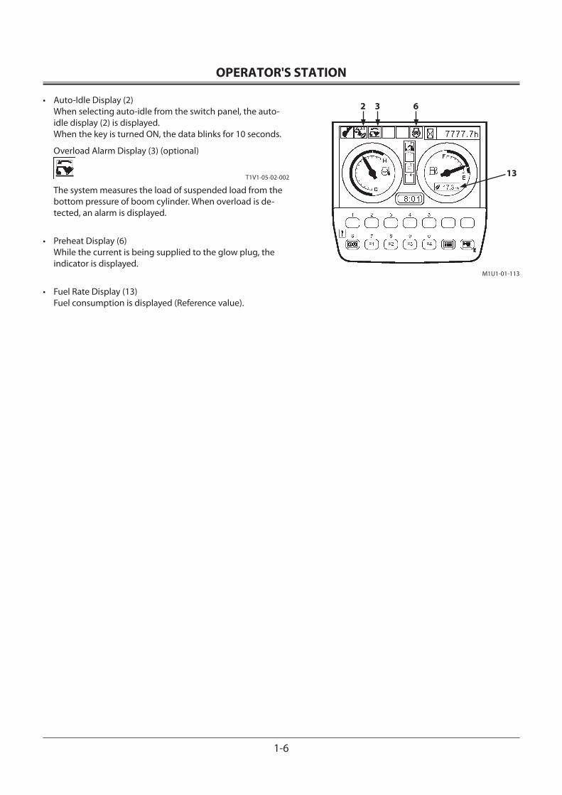
OPERATOR'S STATION
1-6
• Auto-Idle Display (2) When selecting auto-idle from the switch panel, the auto-idle display (2) is displayed. When the key is turned ON, the data blinks for 10 seconds.
Overload Alarm Display (3) (optional)
T1V1-05-02-002
The system measures the load of suspended load from the bottom pressure of boom cylinder. When overload is de-tected, an alarm is displayed.
• Preheat Display (6) While the current is being supplied to the glow plug, the indicator is displayed.
• Fuel Rate Display (13) Fuel consumption is displayed (Reference value).
2 6
13
3
M1U1-01-113
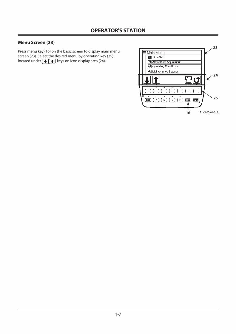
OPERATOR'S STATION
1-7
Menu Screen (23)
Press menu key (16) on the basic screen to display main menu screen (23). Select the desired menu by operating key (25) located under keys on icon display area (24).
23
24
25
16 T1V5-05-01-019
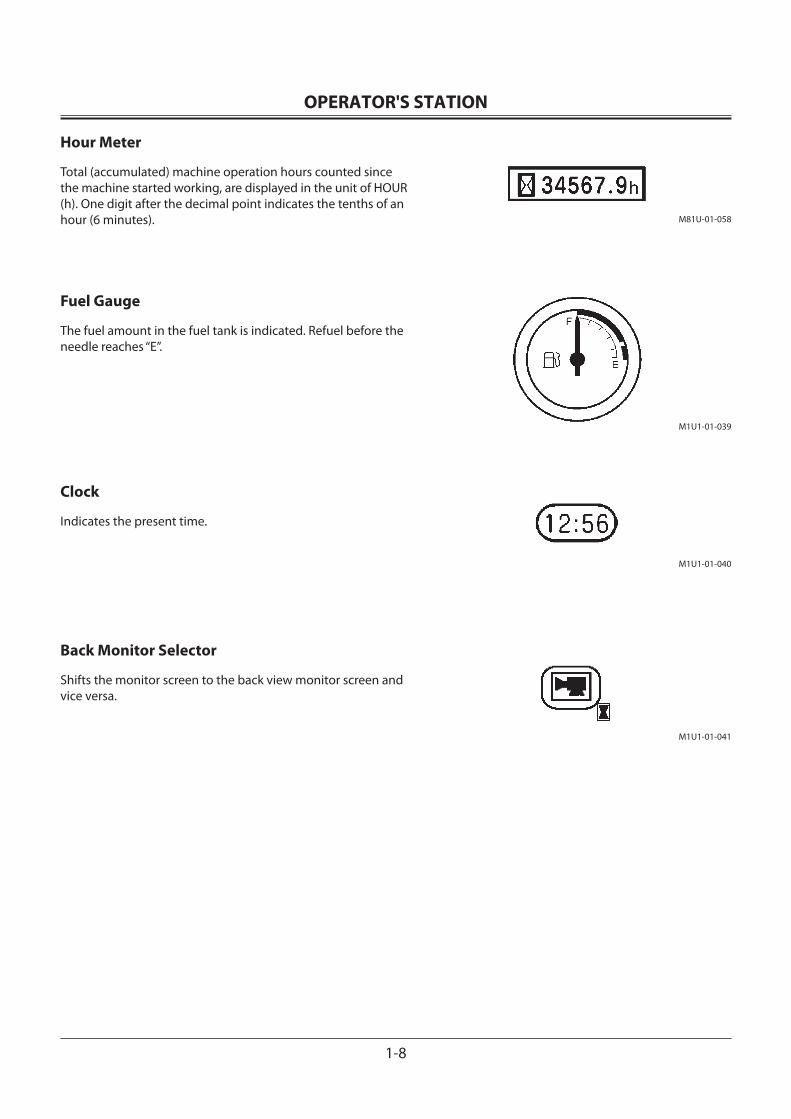
OPERATOR'S STATION
1-8
Hour Meter
Total (accumulated) machine operation hours counted since the machine started working, are displayed in the unit of HOUR (h). One digit after the decimal point indicates the tenths of an hour (6 minutes).
Fuel Gauge
The fuel amount in the fuel tank is indicated. Refuel before the needle reaches “E”.
Clock
Indicates the present time.
Back Monitor Selector
Shifts the monitor screen to the back view monitor screen and vice versa.
M1U1-01-039
M81U-01-058
M1U1-01-041
M1U1-01-040
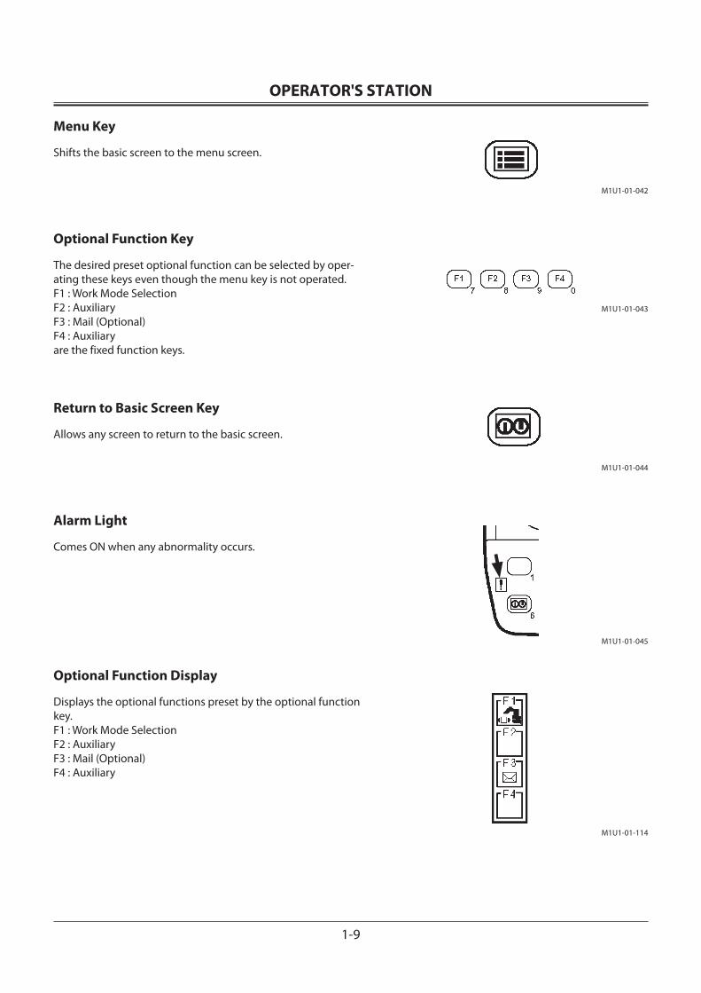
OPERATOR'S STATION
1-9
Menu Key
Shifts the basic screen to the menu screen.
Optional Function Key
The desired preset optional function can be selected by oper-ating these keys even though the menu key is not operated.F1 : Work Mode SelectionF2 : AuxiliaryF3 : Mail (Optional)F4 : Auxiliaryare the fixed function keys.
Return to Basic Screen Key
Allows any screen to return to the basic screen.
Alarm Light
Comes ON when any abnormality occurs.
Optional Function Display
Displays the optional functions preset by the optional function key.F1 : Work Mode SelectionF2 : AuxiliaryF3 : Mail (Optional) F4 : Auxiliary
M1U1-01-042
M1U1-01-043
M1U1-01-044
M1U1-01-045
M1U1-01-114
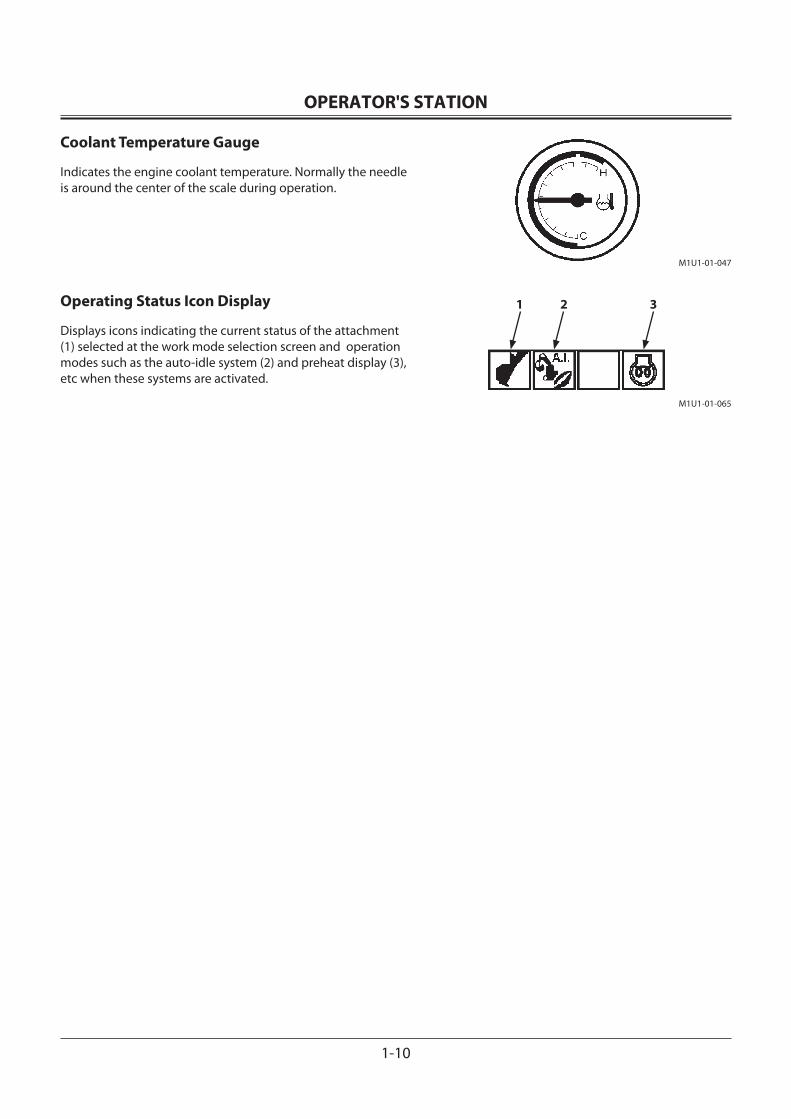
OPERATOR'S STATION
1-10
Coolant Temperature Gauge
Indicates the engine coolant temperature. Normally the needle is around the center of the scale during operation.
Operating Status Icon Display
Displays icons indicating the current status of the attachment (1) selected at the work mode selection screen and operation modes such as the auto-idle system (2) and preheat display (3), etc when these systems are activated.
1 2 3
M1U1-01-065
M1U1-01-047
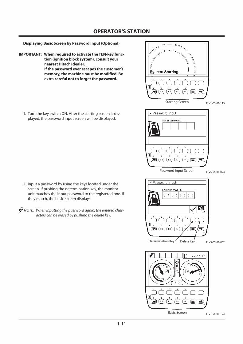
OPERATOR'S STATION
1-11
Displaying Basic Screen by Password Input (Optional)
IMPORTANT: When required to activate the TEN-key func-tion (ignition block system), consult your nearest Hitachi dealer.If the password ever escapes the customer’s memory, the machine must be modified. Be extra careful not to forget the password.
1. Turn the key switch ON. After the starting screen is dis-played, the password input screen will be displayed.
2. Input a password by using the keys located under the screen. If pushing the determination key, the monitor unit matches the input password to the registered one. If they match, the basic screen displays.
NOTE: When inputting the password again, the entered char-acters can be erased by pushing the delete key.
Starting Screen
Password Input Screen
Basic Screen
Determination Key Delete Key
T1V1-05-01-115
T1V5-05-01-093
T1V5-05-01-002
T1V1-05-01-123
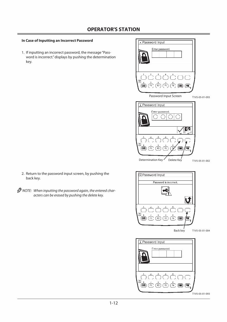
OPERATOR'S STATION
1-12
In Case of Inputting an Incorrect Password
1. If inputting an incorrect password, the message “Pass-word is incorrect.” displays by pushing the determination key.
2. Return to the password input screen, by pushing the back key.
NOTE: When inputting the password again, the entered char-acters can be erased by pushing the delete key.
Back key T1V5-05-01-004
T1V5-05-01-093
Determination Key Delete Key T1V5-05-01-002
T1V5-05-01-093Password Input Screen
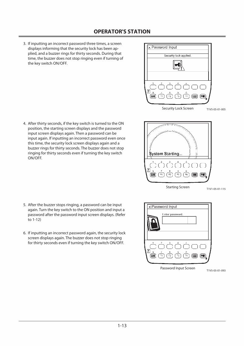
OPERATOR'S STATION
1-13
3. If inputting an incorrect password three times, a screen displays informing that the security lock has been ap-plied, and a buzzer rings for thirty seconds. During that time, the buzzer does not stop ringing even if turning of the key switch ON/OFF.
4. After thirty seconds, if the key switch is turned to the ON position, the starting screen displays and the password input screen displays again. Then a password can be input again. If inputting an incorrect password even once this time, the security lock screen displays again and a buzzer rings for thirty seconds. The buzzer does not stop ringing for thirty seconds even if turning the key switch ON/OFF.
5. After the buzzer stops ringing, a password can be input again. Turn the key switch to the ON position and input a password after the password input screen displays. (Refer to 1-12)
6. If inputting an incorrect password again, the security lock screen displays again. The buzzer does not stop ringing for thirty seconds even if turning the key switch ON/OFF.
T1V1-05-01-115
T1V5-05-01-093
T1V5-05-01-005Security Lock Screen
Starting Screen
Password Input Screen
OPERATOR'S STATION
1-14
Extending Password Duration Time
IMPORTANT: This operation is applicable only to those machines that display the basic screen based upon password input.
By using the password duration screen, password duration time can be set. When you restarting the machine, a pass-word need not be input within that timeframe.
1. When turn the key switch to the OFF position, the moni-tor unit displays the password duration screen for ten seconds.
2. While the password duration screen is still displayed, push a relevant key, and password duration time is set. Duration time assigned to each key is as follows:
key 1: 0 minute key 2: 30 minutes key 3: 60 minutes key 4: 90 minutes key 5: 120 minutes
NOTE: If password duration time is not set explicitly, 0 minute on duration time is assumed.
3. If turning the key switch to the ON position within pass-word duration time, the monitor unit displays the basic screen after the starting screen.
Key 1
Key2 Key3 Key4 Key5
T1V1-05-01-115Key Switch: ON
T1V1-05-01-123Basic Screen
Password Duration Screen (Key Switch: OFF)T1V1-05-01-012
OPERATOR'S STATION
1-15
ALARM OCCURRENCE SCREEN
In case any abnormality occurs, the alarm marks are displayed on the basic screen.
• When the number of alarms is two or less
• When the number of alarms is three or more
T1V1-05-01-096
T1V1-05-01-095
OPERATOR'S STATION
1-16
In case any abnormality occurs, push the key located under the alarm mark. The monitor displays the corrective action to the alarm situation.
Push a Relevant Key T1V1-05-01-095
T1V5-05-01-013
OPERATOR'S STATION
1-17
CONTENTS OF ALARMS
Display Contents of Alarms Remedy
M178-01-036
Overheat Alarm Engine coolant temperature has abnormally increased. Stop operation. Run the engine at slow idle speed and lower the cool-ant temperature.
M183-01-080
Engine Warning Alarm Engine or engine related parts are abnormal. Consult your nearest Hitachi dealer.
M178-01-037
Engine Oil Pressure Alarm Engine oil pressure has decreased. Immediately stop engine. Check engine oil system and oil level.
M183-01-071
Alternator Alarm Electrical system is abnormal. Consult your nearest Hitachi dealer.
M178-01-034
Remaining Fuel Alarm Fuel level is low. Refill fuel as soon as possible.
M1CC-01-039
Hydraulic Oil Filter Alarm Hydraulic oil filter is clogged. Replace filter.
M183-01-067
Air Filter Clogged Alarm Air filter elements are clogged.Clean or replace air filter elements.
M1U1-01-116
Fuel Filter Clogged Alarm Fuel filter elements (pre-filter, main filter) are clogged. Replace fuel filter elements.
T1V1-05-01-102
Work Mode Alarm Work Mode system is abnormal. Consult your nearest Hitachi dealer.
T1V1-05-01-103
Pilot Control Shut-Off Lever Alarm
Pilot control shut-off lever system is abnormal. Consult your nearest Hitachi dealer.
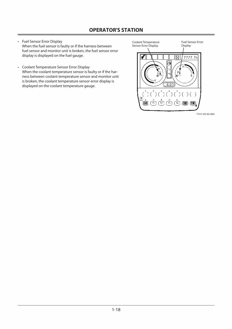
OPERATOR'S STATION
1-18
• Fuel Sensor Error Display When the fuel sensor is faulty or if the harness between fuel sensor and monitor unit is broken, the fuel sensor error display is displayed on the fuel gauge.
• Coolant Temperature Sensor Error Display When the coolant temperature sensor is faulty or if the har-ness between coolant temperature sensor and monitor unit is broken, the coolant temperature sensor error display is displayed on the coolant temperature gauge.
Coolant TemperatureSensor Error Display
Fuel Sensor Error Display
T1V1-05-02-005
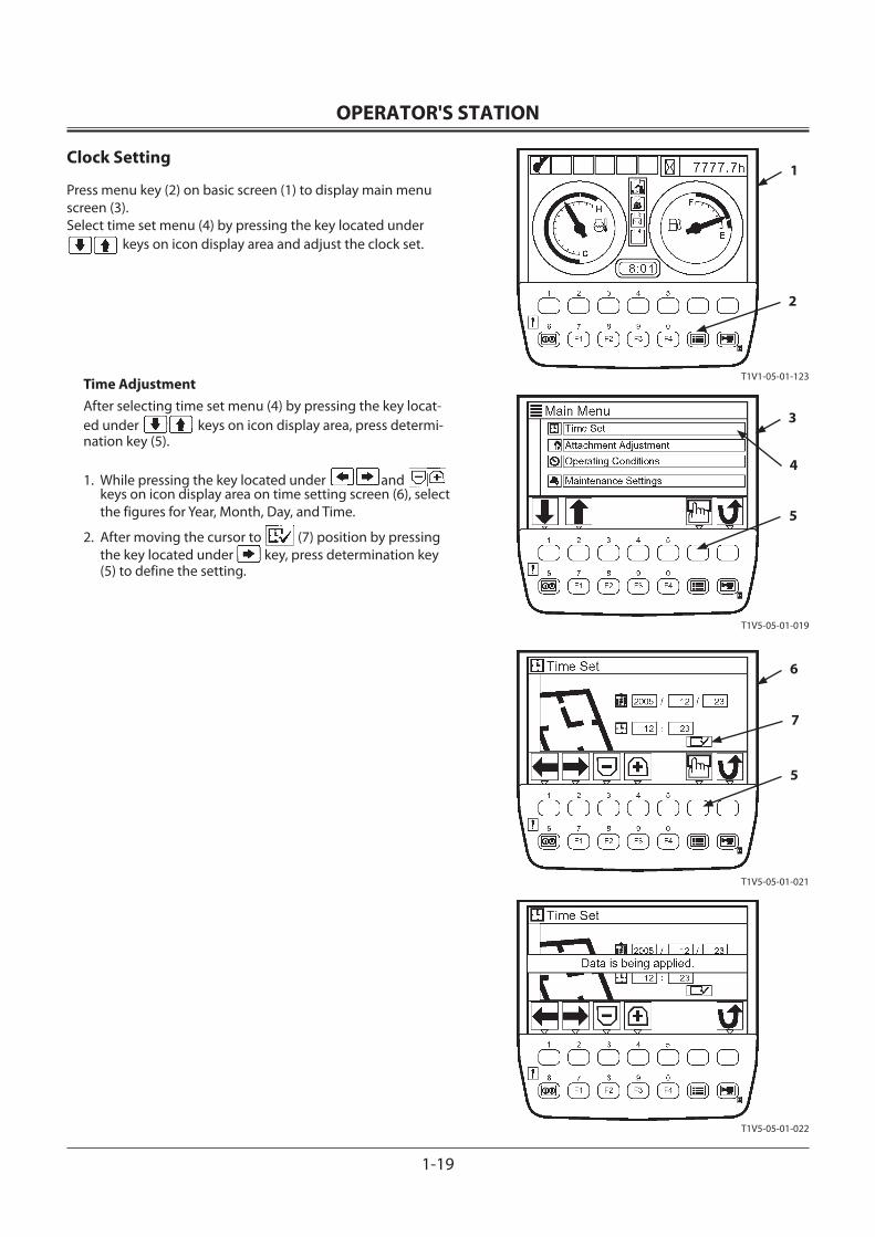
OPERATOR'S STATION
1-19
Clock Setting
Press menu key (2) on basic screen (1) to display main menu screen (3). Select time set menu (4) by pressing the key located under
keys on icon display area and adjust the clock set.
Time AdjustmentAfter selecting time set menu (4) by pressing the key locat-ed under keys on icon display area, press determi-nation key (5).
1. While pressing the key located under andkeys on icon display area on time setting screen (6), select the figures for Year, Month, Day, and Time.
2. After moving the cursor to (7) position by pressing the key located under key, press determination key (5) to define the setting.
1
2
5
3
4
5
6
7
T1V1-05-01-123
T1V5-05-01-019
T1V5-05-01-021
T1V5-05-01-022
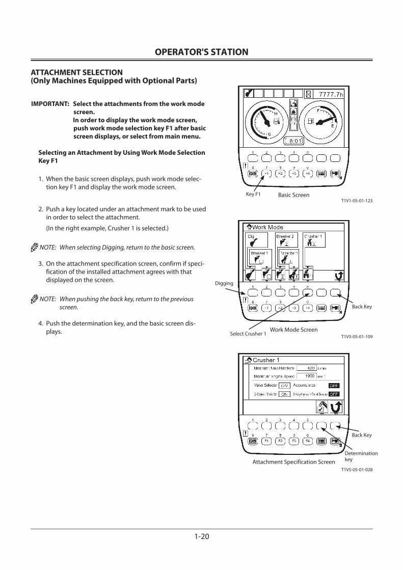
OPERATOR'S STATION
1-20
ATTACHMENT SELECTION(Only Machines Equipped with Optional Parts)
IMPORTANT: Select the attachments from the work mode screen.
In order to display the work mode screen, push work mode selection key F1 after basic screen displays, or select from main menu.
Selecting an Attachment by Using Work Mode Selection Key F1
1. When the basic screen displays, push work mode selec-tion key F1 and display the work mode screen.
2. Push a key located under an attachment mark to be used in order to select the attachment.
(In the right example, Crusher 1 is selected.)
NOTE: When selecting Digging, return to the basic screen.
3. On the attachment specification screen, confirm if speci-fication of the installed attachment agrees with that displayed on the screen.
NOTE: When pushing the back key, return to the previous screen.
4. Push the determination key, and the basic screen dis-plays.
Key F1
Back Key
Back Key
Determination key
Digging
Select Crusher 1
T1V1-05-01-123
T1V5-05-01-109
T1V5-05-01-028
Basic Screen
Work Mode Screen
Attachment Specification Screen
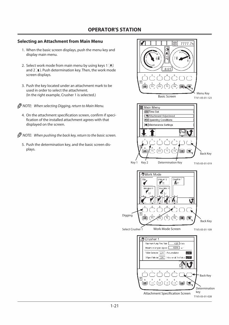
OPERATOR'S STATION
1-21
Selecting an Attachment from Main Menu
1. When the basic screen displays, push the menu key and display main menu.
2. Select work mode from main menu by using keys 1 and 2 . Push determination key. Then, the work mode screen displays.
3. Push the key located under an attachment mark to be used in order to select the attachment. (In the right example, Crusher 1 is selected.)
NOTE: When selecting Digging, return to Main Menu.
4. On the attachment specification screen, confirm if speci-fication of the installed attachment agrees with that displayed on the screen.
NOTE: When pushing the back key, return to the basic screen.
5. Push the determination key, and the basic screen dis-plays.
Menu Key
Back Key
Determination KeyKey 2Key 1
Back Key
Select Crusher 1
Digging
Back Key
Determination key
T1V1-05-01-123Basic Screen
T1V5-05-01-109Work Mode Screen
T1V5-05-01-028
T1V5-05-01-019
Attachment Specification Screen
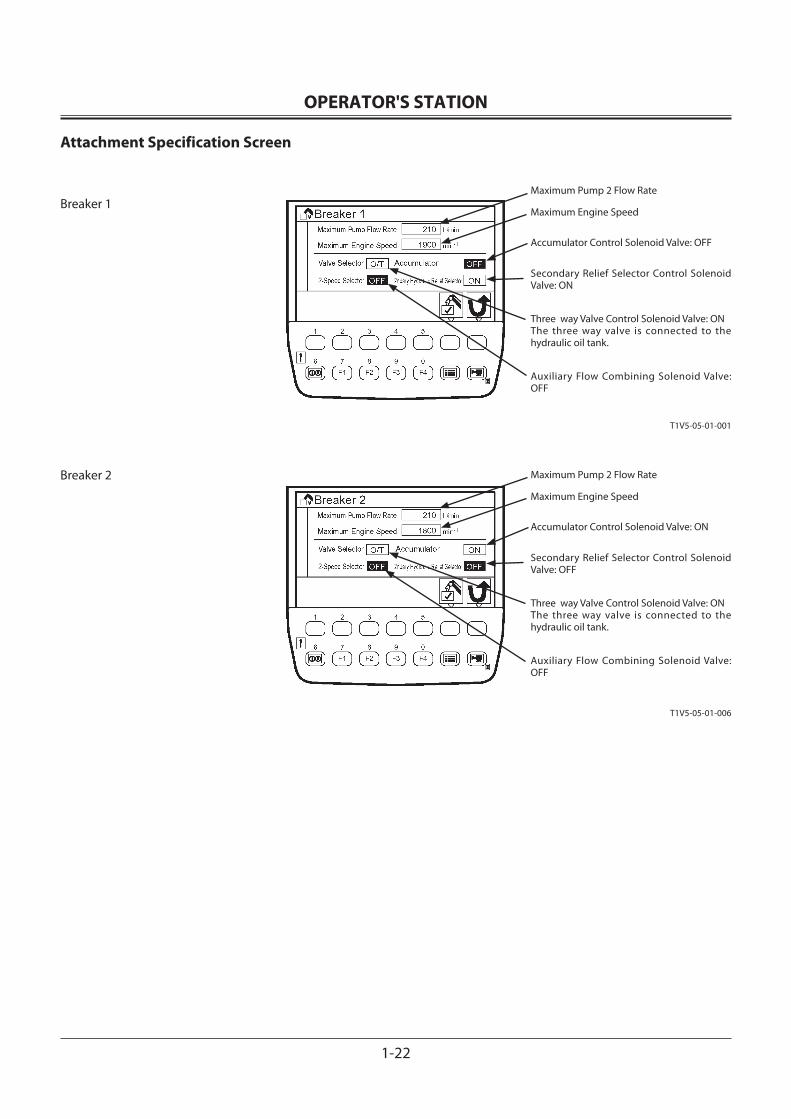
OPERATOR'S STATION
1-22
Attachment Specification Screen
Breaker 1
Breaker 2
Maximum Pump 2 Flow Rate
Maximum Engine Speed
Accumulator Control Solenoid Valve: OFF
Secondary Relief Selector Control Solenoid Valve: ON
Three way Valve Control Solenoid Valve: ON The three way valve is connected to the hydraulic oil tank.
Auxiliary Flow Combining Solenoid Valve: OFF
Maximum Pump 2 Flow Rate
Maximum Engine Speed
Accumulator Control Solenoid Valve: ON
Secondary Relief Selector Control Solenoid Valve: OFF
Three way Valve Control Solenoid Valve: ON The three way valve is connected to the hydraulic oil tank.
Auxiliary Flow Combining Solenoid Valve: OFF
T1V5-05-01-001
T1V5-05-01-006
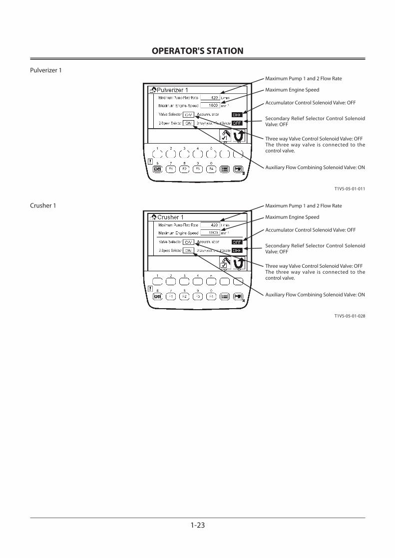
OPERATOR'S STATION
1-23
Pulverizer 1
Crusher 1
Maximum Pump 1 and 2 Flow Rate
Maximum Engine Speed
Accumulator Control Solenoid Valve: OFF
Secondary Relief Selector Control Solenoid Valve: OFF
Three way Valve Control Solenoid Valve: OFF The three way valve is connected to the control valve.
Auxiliary Flow Combining Solenoid Valve: ON
Maximum Pump 1 and 2 Flow Rate
Maximum Engine Speed
Accumulator Control Solenoid Valve: OFF
Secondary Relief Selector Control Solenoid Valve: OFF
Three way Valve Control Solenoid Valve: OFF The three way valve is connected to the control valve.
Auxiliary Flow Combining Solenoid Valve: ON
T1V5-05-01-011
T1V5-05-01-028
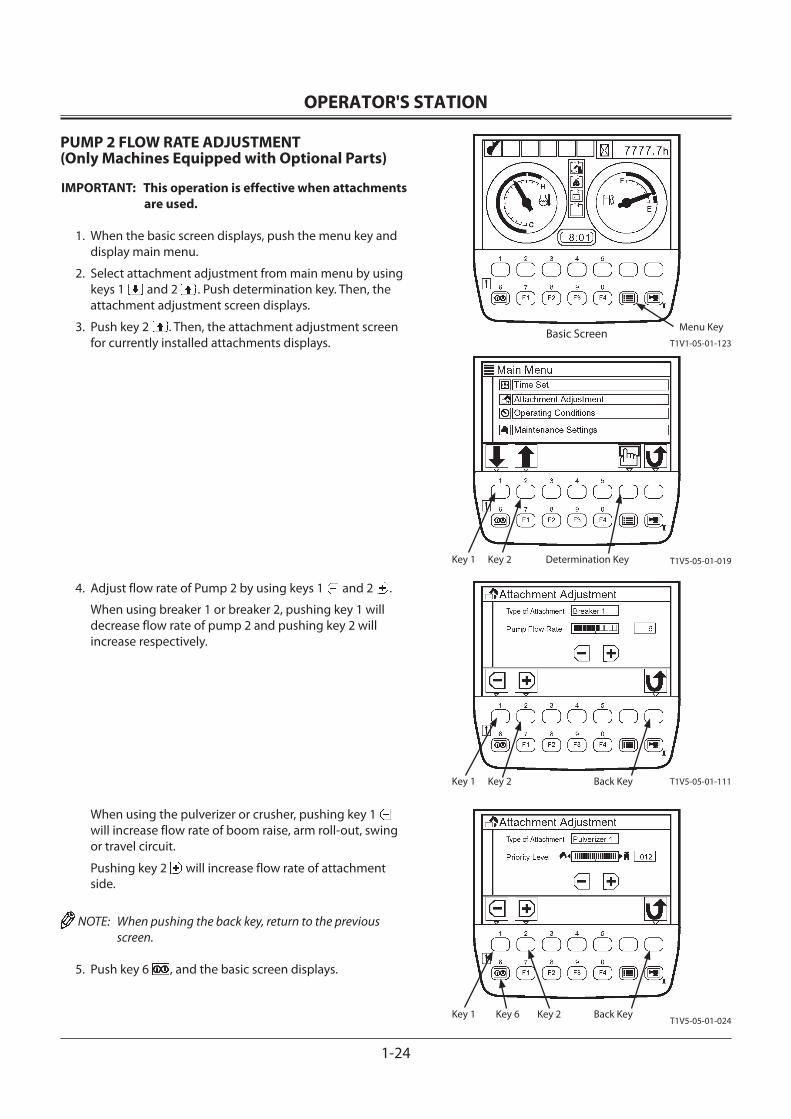
OPERATOR'S STATION
1-24
PUMP 2 FLOW RATE ADJUSTMENT(Only Machines Equipped with Optional Parts)
IMPORTANT: This operation is effective when attachments are used.
1. When the basic screen displays, push the menu key and display main menu.
2. Select attachment adjustment from main menu by using keys 1 and 2 . Push determination key. Then, the attachment adjustment screen displays.
3. Push key 2 . Then, the attachment adjustment screen for currently installed attachments displays.
4. Adjust flow rate of Pump 2 by using keys 1 and 2 .
When using breaker 1 or breaker 2, pushing key 1 will decrease flow rate of pump 2 and pushing key 2 will increase respectively.
When using the pulverizer or crusher, pushing key 1 will increase flow rate of boom raise, arm roll-out, swing or travel circuit.
Pushing key 2 will increase flow rate of attachment side.
NOTE: When pushing the back key, return to the previous screen.
5. Push key 6 , and the basic screen displays.
Back KeyKey 2Key 1
Back KeyKey 2Key 1 Key 6
Menu Key
Determination KeyKey 2Key 1
T1V1-05-01-123Basic Screen
T1V5-05-01-019
T1V5-05-01-111
T1V5-05-01-024
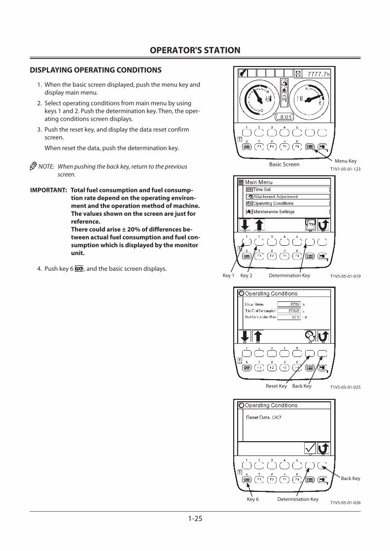
OPERATOR'S STATION
1-25
DISPLAYING OPERATING CONDITIONS
1. When the basic screen displayed, push the menu key and display main menu.
2. Select operating conditions from main menu by using keys 1 and 2. Push the determination key. Then, the oper-ating conditions screen displays.
3. Push the reset key, and display the data reset confirm screen.
When reset the data, push the determination key.
NOTE: When pushing the back key, return to the previous screen.
IMPORTANT: Total fuel consumption and fuel consump-tion rate depend on the operating environ-ment and the operation method of machine. The values shown on the screen are just for reference.There could arise ± 20% of differences be-tween actual fuel consumption and fuel con-sumption which is displayed by the monitor unit.
4. Push key 6 , and the basic screen displays.
Back KeyReset Key
Back Key
Determination KeyKey 6
Menu Key
Determination KeyKey 2Key 1
T1V1-05-01-123Basic Screen
T1V5-05-01-019
T1V5-05-01-025
T1V5-05-01-026
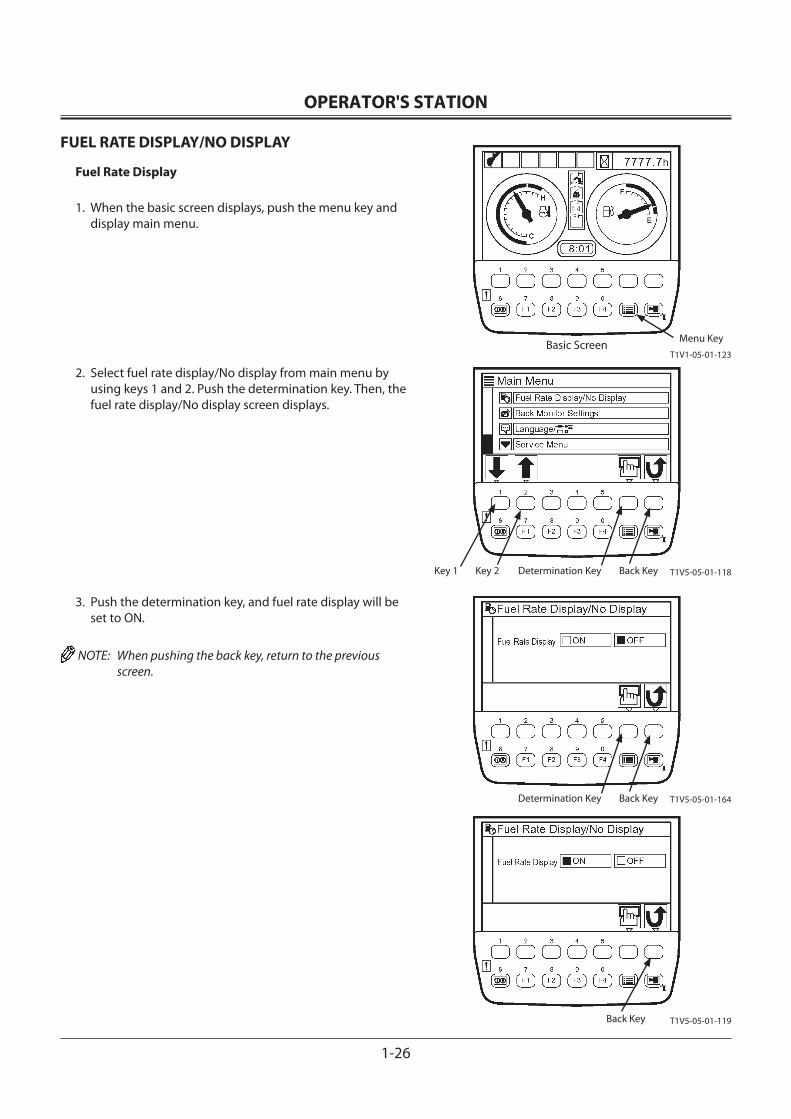
OPERATOR'S STATION
1-26
T1V1-05-01-123
FUEL RATE DISPLAY/NO DISPLAY
Fuel Rate Display
1. When the basic screen displays, push the menu key and display main menu.
2. Select fuel rate display/No display from main menu by using keys 1 and 2. Push the determination key. Then, the fuel rate display/No display screen displays.
3. Push the determination key, and fuel rate display will be set to ON.
NOTE: When pushing the back key, return to the previous screen.
Back Key
Back Key
Menu KeyBasic Screen
T1V5-05-01-118
T1V5-05-01-164
T1V5-05-01-119
Determination KeyKey 2Key 1
Back KeyDetermination Key
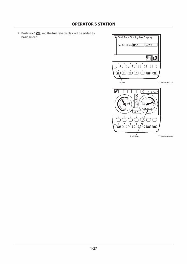
OPERATOR'S STATION
1-27
4. Push key 6 , and the fuel rate display will be added to basic screen.
Key 6
Fuel Rate
T1V5-05-01-119
T1V1-05-01-007
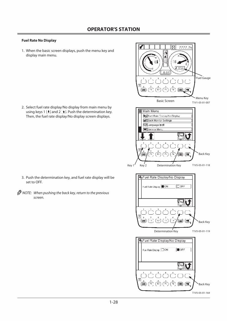
OPERATOR'S STATION
1-28
Basic Screen
Fuel Rate No Display
1. When the basic screen displays, push the menu key and display main menu.
2. Select fuel rate display/No display from main menu by using keys 1 and 2 . Push the determination key. Then, the fuel rate display/No display screen displays.
3. Push the determination key, and fuel rate display will be set to OFF.
NOTE: When pushing the back key, return to the previous screen.
Determination KeyKey 1 Key 2
Back Key
Back Key
Determination Key
Fuel Gauge
Menu KeyT1V1-05-01-007
T1V5-05-01-118
T1V5-05-01-119
T1V5-05-01-164
Back Key
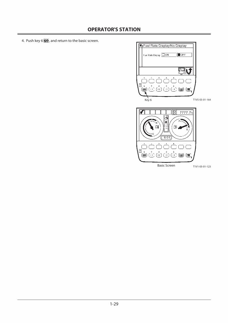
OPERATOR'S STATION
1-29
4. Push key 6 , and return to the basic screen.
Key 6 T1V5-05-01-164
T1V1-05-01-123Basic Screen
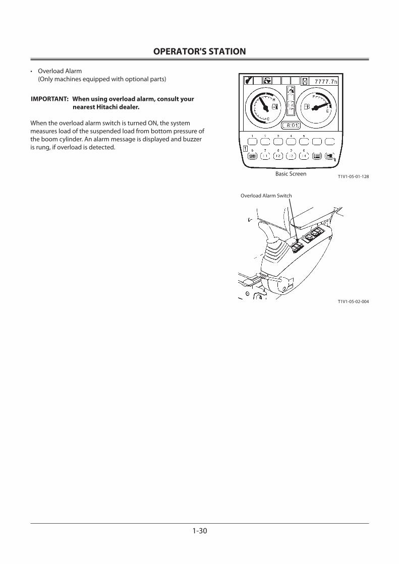
OPERATOR'S STATION
1-30
• Overload Alarm (Only machines equipped with optional parts)
IMPORTANT: When using overload alarm, consult your nearest Hitachi dealer.
When the overload alarm switch is turned ON, the system measures load of the suspended load from bottom pressure of the boom cylinder. An alarm message is displayed and buzzer is rung, if overload is detected.
Overload Alarm Switch
T1V1-05-01-128Basic Screen
T1V1-05-02-004
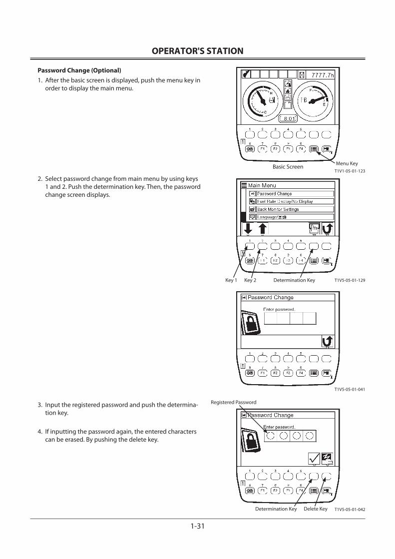
OPERATOR'S STATION
1-31
Password Change (Optional)1. After the basic screen is displayed, push the menu key in
order to display the main menu.
2. Select password change from main menu by using keys 1 and 2. Push the determination key. Then, the password change screen displays.
3. Input the registered password and push the determina-tion key.
4. If inputting the password again, the entered characters can be erased. By pushing the delete key.
Menu Key
Determination KeyKey 1 Key 2
Delete KeyDetermination Key
Registered Password
T1V1-05-01-123Basic Screen
T1V5-05-01-129
T1V5-05-01-041
T1V5-05-01-042
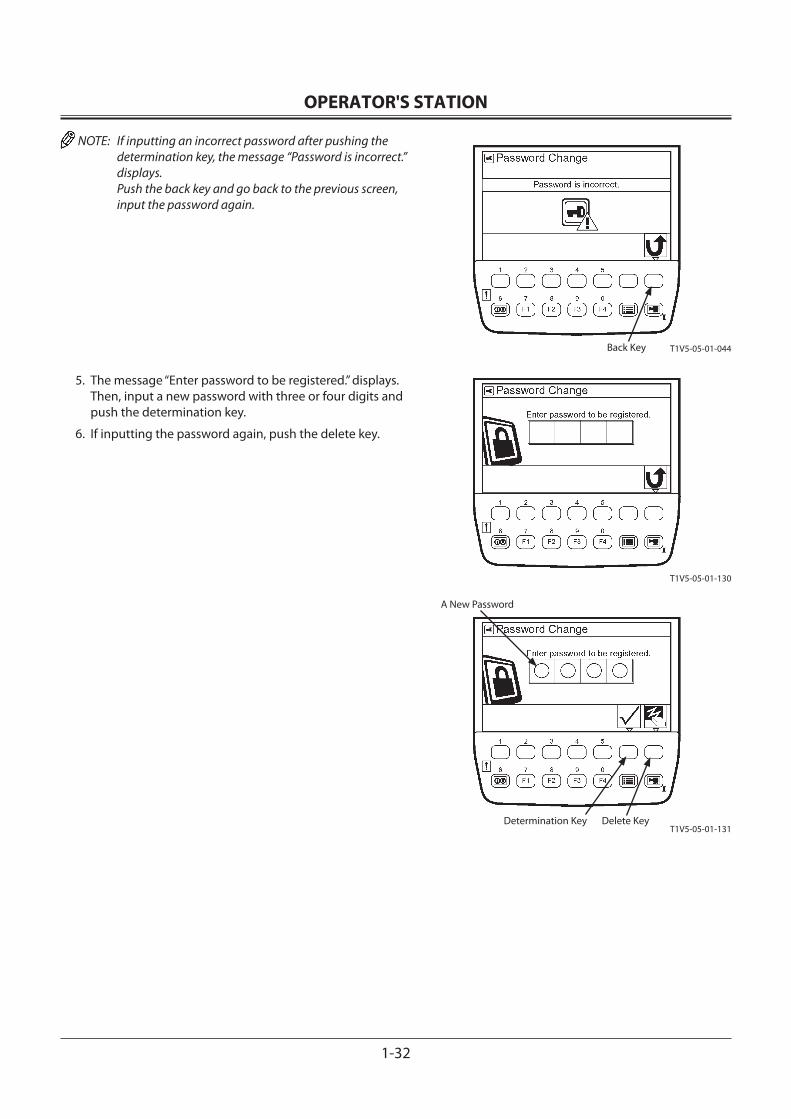
OPERATOR'S STATION
1-32
NOTE: If inputting an incorrect password after pushing the determination key, the message “Password is incorrect.” displays. Push the back key and go back to the previous screen, input the password again.
5. The message “Enter password to be registered.” displays. Then, input a new password with three or four digits and push the determination key.
6. If inputting the password again, push the delete key.
Back Key
Delete KeyDetermination Key
A New Password
T1V5-05-01-044
T1V5-05-01-130
T1V5-05-01-131
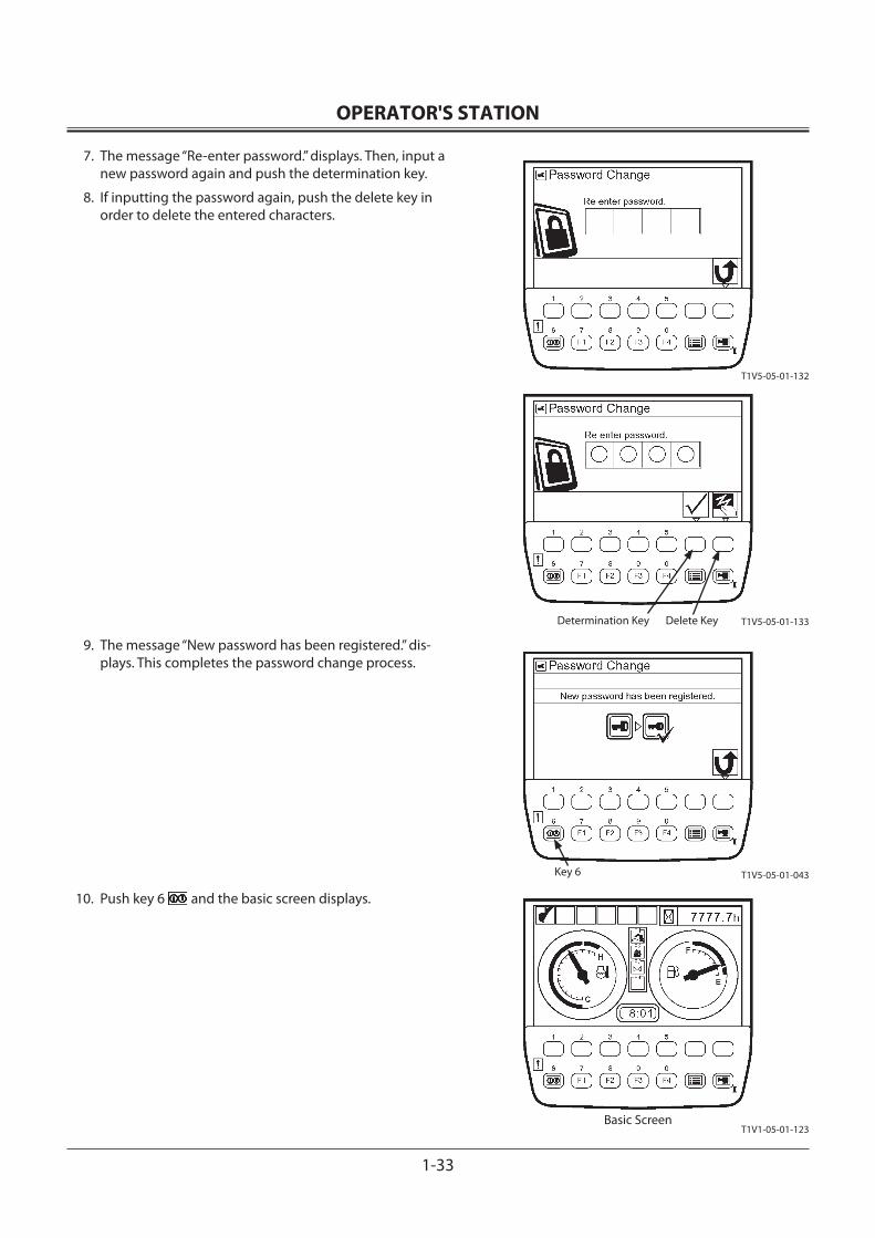
OPERATOR'S STATION
1-33
7. The message “Re-enter password.” displays. Then, input a new password again and push the determination key.
8. If inputting the password again, push the delete key in order to delete the entered characters.
9. The message “New password has been registered.” dis-plays. This completes the password change process.
10. Push key 6 and the basic screen displays.
Key 6
T1V1-05-01-123Basic Screen
T1V5-05-01-132
T1V5-05-01-133
T1V5-05-01-043
Delete KeyDetermination Key
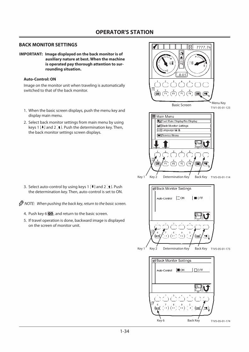
OPERATOR'S STATION
1-34
BACK MONITOR SETTINGS
IMPORTANT: Image displayed on the back monitor is of auxiliary nature at best. When the machine is operated pay thorough attention to sur-rounding situation.
Auto-Control: ONImage on the monitor unit when traveling is automatically switched to that of the back monitor.
1. When the basic screen displays, push the menu key and display main menu.
2. Select back monitor settings from main menu by using keys 1 and 2 . Push the determination key. Then, the back monitor settings screen displays.
3. Select auto-control by using keys 1 and 2 . Push the determination key. Then, auto-control is set to ON.
NOTE: When pushing the back key, return to the basic screen.
4. Push key 6 , and return to the basic screen.
5. If travel operation is done, backward image is displayed on the screen of monitor unit.
Back KeyKey 6
Menu KeyT1V1-05-01-123
Basic Screen
T1V5-05-01-174
T1V5-05-01-114
T1V5-05-01-173
Back KeyDetermination KeyKey 2Key 1
Back KeyDetermination KeyKey 2Key 1
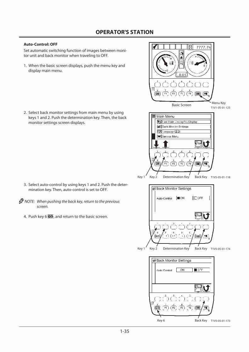
OPERATOR'S STATION
1-35
Auto-Control: OFFSet automatic switching function of images between moni-tor unit and back monitor when traveling to OFF.
1. When the basic screen displays, push the menu key and display main menu.
2. Select back monitor settings from main menu by using keys 1 and 2. Push the determination key. Then, the back monitor settings screen displays.
3. Select auto-control by using keys 1 and 2. Push the deter-mination key. Then, auto-control is set to OFF.
NOTE: When pushing the back key, return to the previous screen.
4. Push key 6 , and return to the basic screen.
Key 6
Menu KeyT1V1-05-01-123
Basic Screen
T1V5-05-01-173Back Key
T1V5-05-01-174Back KeyDetermination KeyKey 2Key 1
T1V5-05-01-118Back KeyDetermination KeyKey 2Key 1
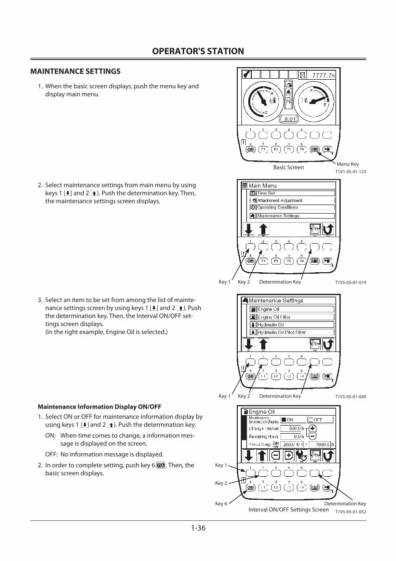
OPERATOR'S STATION
1-36
MAINTENANCE SETTINGS
1. When the basic screen displays, push the menu key and display main menu.
2. Select maintenance settings from main menu by using keys 1 and 2 . Push the determination key. Then, the maintenance settings screen displays.
3. Select an item to be set from among the list of mainte-nance settings screen by using keys 1 and 2 . Push the determination key. Then, the Interval ON/OFF set-tings screen displays.(In the right example, Engine Oil is selected.)
Maintenance Information Display ON/OFF1. Select ON or OFF for maintenance information display by
using keys 1 and 2 . Push the determination key.
ON: When time comes to change, a information mes-sage is displayed on the screen.
OFF: No information message is displayed.
2. In order to complete setting, push key 6 . Then, the basic screen displays.
Determination KeyKey 6
Key 1
Key 2
Menu KeyT1V1-05-01-123
Basic Screen
T1V5-05-01-019Determination KeyKey 2Key 1
T1V5-05-01-049Determination KeyKey 2Key 1
T1V5-05-01-052Interval ON/OFF Settings Screen
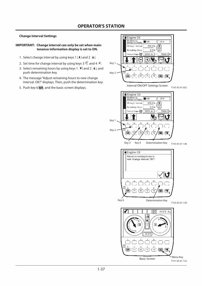
OPERATOR'S STATION
1-37
Change Interval Settings
IMPORTANT: Change interval can only be set when main-tenance information display is set to ON.
1. Select change interval by using keys 1 and 2 .
2. Set time for change interval by using keys 3 and 4 .3. Select remaining hours by using keys 1 and 2 , and
push determination key.
4. The message “Adjust remaining hours to new change interval. OK?” displays. Then, push the determination key.
5. Push key 6 , and the basic screen displays.
Key 1
Key 2
Key 1
Key 2
Key 3 Key 4 Determination Key
Determination KeyKey 6
Menu KeyT1V1-05-01-123
Basic Screen
T1V5-05-01-052Interval ON/OFF Settings Screen
T1V5-05-01-138
T1V5-05-01-139
OPERATOR'S STATION
1-38
Resetting DataIf data is reset, push key 5 on the Interval ON/OFF set-tings screen.The message “Reset Data. OK?” displays. Then, push the determination key.The value of remaining hours is reset to that of change interval. Previous change date/hour is updated with current date and time.
Determination Key
Key 5
T1V5-05-01-052Interval ON/OFF Settings Screen
T1V5-05-01-140
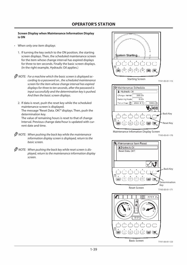
OPERATOR'S STATION
1-39
Screen Display when Maintenance Information Display is ON
• When only one item displays
1. If turning the key switch to the ON position, the starting screen displays. Then, the scheduled maintenance screen for the item whose change interval has expired displays for three to ten seconds. Finally the basic screen displays.(In the right example, Hydraulic Oil applies.)
NOTE: For a machine which the basic screen is displayed ac-cording to a password on , the scheduled maintenance screen for the item whose change interval has expired displays for three to ten seconds, after the password is input successfully and the determination key is pushed. And then the basic screen displays.
2. If data is reset, push the reset key while the scheduled maintenance screen is displayed.The message “Reset Data. OK?” displays. Then, push the determination key.The value of remaining hours is reset to that of change Interval. Previous change date/hour is updated with cur-rent date and time.
NOTE: When pushing the back key while the maintenance information display screen is displayed, return to the basic screen.
NOTE: When pushing the back key while reset screen is dis-played, return to the maintenance information display screen.
Reset Key
Back Key
Determination Key
Back Key
T1V1-05-01-123Basic Screen
T1V1-05-01-115Starting Screen
Maintenance Infomation Display ScreenT1V5-05-01-170
T1V5-05-01-171Reset Screen
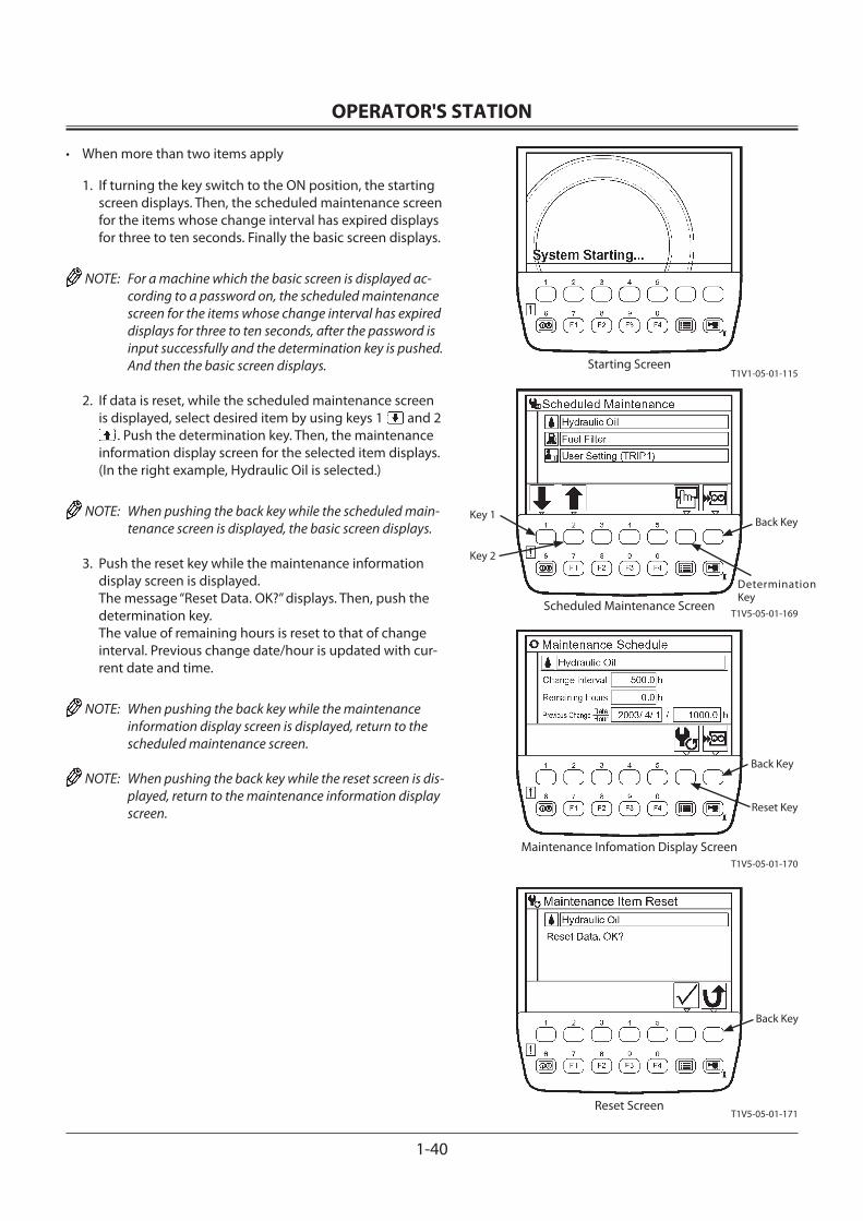
OPERATOR'S STATION
1-40
• When more than two items apply
1. If turning the key switch to the ON position, the starting screen displays. Then, the scheduled maintenance screen for the items whose change interval has expired displays for three to ten seconds. Finally the basic screen displays.
NOTE: For a machine which the basic screen is displayed ac-cording to a password on, the scheduled maintenance screen for the items whose change interval has expired displays for three to ten seconds, after the password is input successfully and the determination key is pushed. And then the basic screen displays.
2. If data is reset, while the scheduled maintenance screen is displayed, select desired item by using keys 1 and 2
. Push the determination key. Then, the maintenance information display screen for the selected item displays. (In the right example, Hydraulic Oil is selected.)
NOTE: When pushing the back key while the scheduled main-tenance screen is displayed, the basic screen displays.
3. Push the reset key while the maintenance information display screen is displayed.The message “Reset Data. OK?” displays. Then, push the determination key.The value of remaining hours is reset to that of change interval. Previous change date/hour is updated with cur-rent date and time.
NOTE: When pushing the back key while the maintenance information display screen is displayed, return to the scheduled maintenance screen.
NOTE: When pushing the back key while the reset screen is dis-played, return to the maintenance information display screen.
Determination Key
Back KeyKey 1
Key 2
T1V1-05-01-115Starting Screen
Reset Key
Back Key
Back Key
Maintenance Infomation Display ScreenT1V5-05-01-170
T1V5-05-01-171Reset Screen
T1V5-05-01-169Scheduled Maintenance Screen
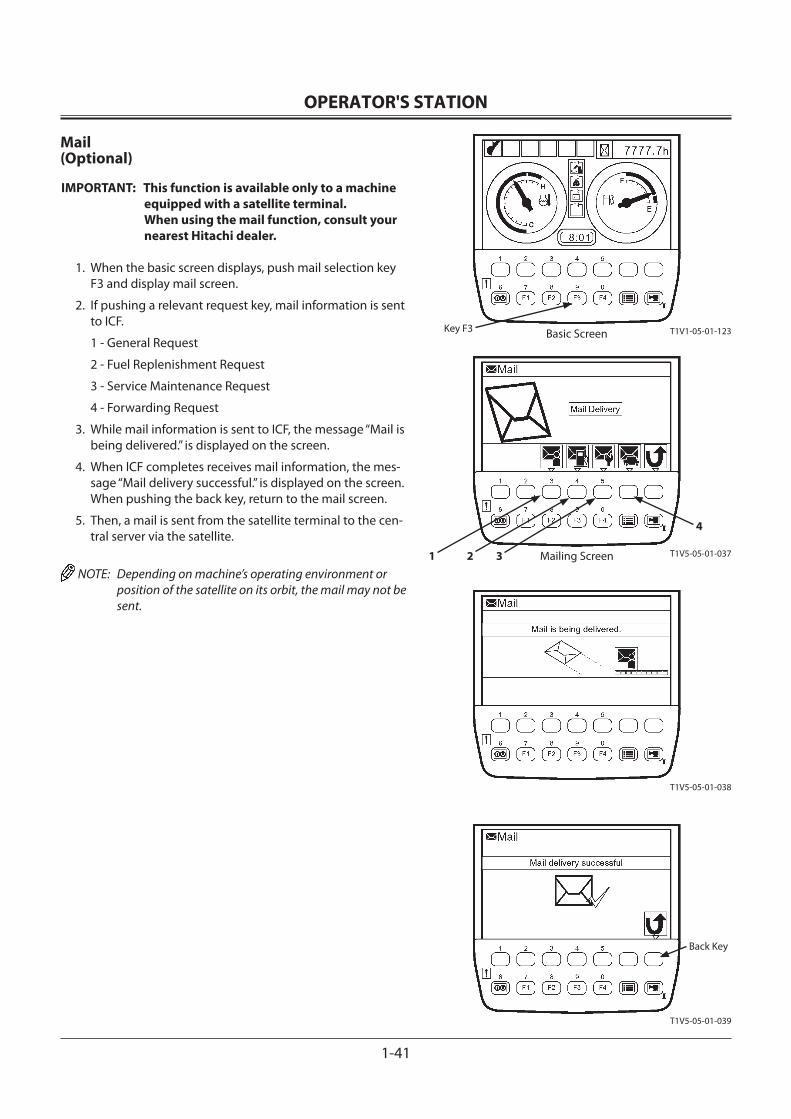
OPERATOR'S STATION
1-41
Mailing Screen
Key F3
Back Key
T1V1-05-01-123
Mail(Optional)
IMPORTANT: This function is available only to a machine equipped with a satellite terminal. When using the mail function, consult your nearest Hitachi dealer.
1. When the basic screen displays, push mail selection key F3 and display mail screen.
2. If pushing a relevant request key, mail information is sent to ICF.
1 - General Request
2 - Fuel Replenishment Request
3 - Service Maintenance Request
4 - Forwarding Request
3. While mail information is sent to ICF, the message “Mail is being delivered.” is displayed on the screen.
4. When ICF completes receives mail information, the mes-sage “Mail delivery successful.” is displayed on the screen. When pushing the back key, return to the mail screen.
5. Then, a mail is sent from the satellite terminal to the cen-tral server via the satellite.
NOTE: Depending on machine’s operating environment or position of the satellite on its orbit, the mail may not be sent.
T1V5-05-01-037
T1V5-05-01-038
T1V5-05-01-039
2 31
4
Basic Screen
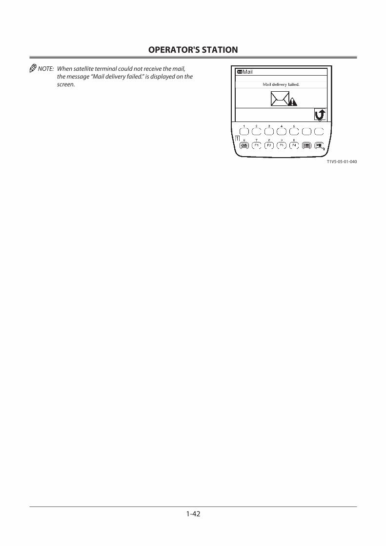
OPERATOR'S STATION
1-42
NOTE: When satellite terminal could not receive the mail, the message “Mail delivery failed.” is displayed on the screen.
T1V5-05-01-040
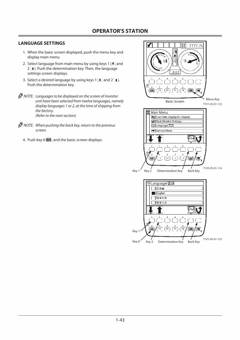
OPERATOR'S STATION
1-43
LANGUAGE SETTINGS
1. When the basic screen displayed, push the menu key and display main menu.
2. Select language from main menu by using keys 1 and 2 . Push the determination key. Then, the language settings screen displays.
3. Select a desired language by using keys 1 and 2 . Push the determination key.
NOTE: Languages to be displayed on the screen of monitor unit have been selected from twelve languages, namely display languages 1 or 2, at the time of shipping from the factory. (Refer to the next section)
NOTE: When pushing the back key, return to the previous screen.
4. Push key 6 , and the basic screen displays.
Key 6
T1V1-05-01-123Basic Screen
T1V5-05-01-114
T1V1-05-01-137
Back KeyDetermination KeyKey 2Key 1
Back KeyDetermination KeyKey 2
Key 1
Menu Key
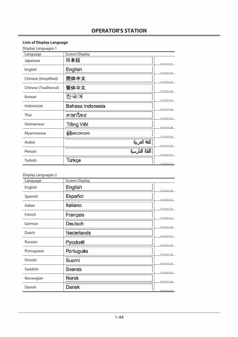
OPERATOR'S STATION
1-44
Lists of Display LanguageDisplay Languages 1
Language Screen Display
JapaneseT1V1-05-01-141
EnglishT1V1-05-01-142
Chinese (Simplified)T1V1-05-01-143
Chinese (Traditional)T1V1-05-01-144
KoreanT1V1-05-01-145
IndonesianT1V1-05-01-146
ThaiT1V1-05-01-147
VietnameseT1V1-05-01-148
MyanmareseT1V1-05-01-149
ArabicT1V1-05-01-150
PersianT1V1-05-01-151
TurkishT1V1-05-01-152
Display Languages 2Language Screen Display
EnglishT1V1-05-01-142
SpanishT1V1-05-01-153
ItalianT1V1-05-01-154
FrenchT1V1-05-01-155
GermanT1V1-05-01-156
DutchT1V1-05-01-157
RussianT1V1-05-01-158
PortugueseT1V1-05-01-159
FinnishT1V1-05-01-160
SwedishT1V1-05-01-161
NorwegianT1V1-05-01-162
DanishT1V1-05-01-163
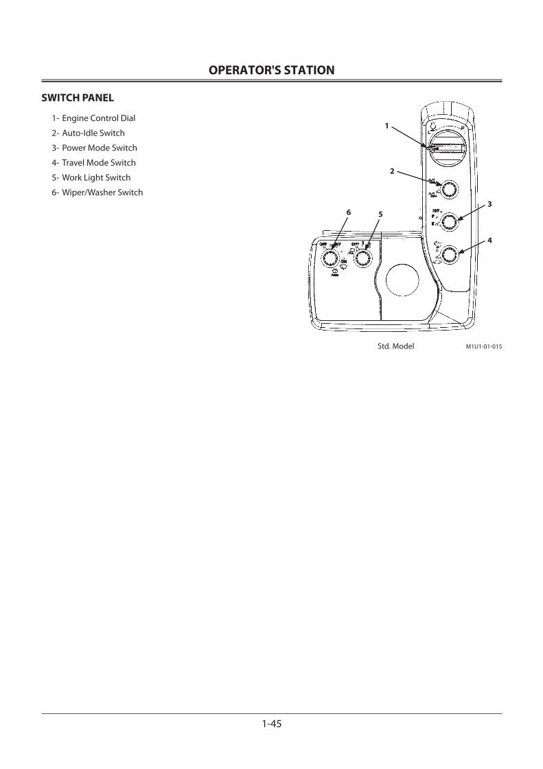
OPERATOR'S STATION
1-45
SWITCH PANEL
1- Engine Control Dial
2- Auto-Idle Switch
3- Power Mode Switch
4- Travel Mode Switch
5- Work Light Switch
6- Wiper/Washer Switch
Std. Model
1
2
3
4
56
M1U1-01-015
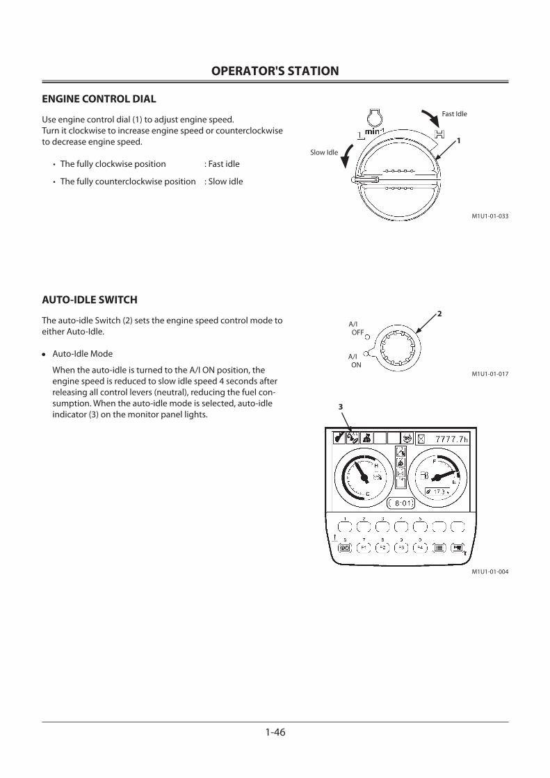
OPERATOR'S STATION
1-46
ENGINE CONTROL DIAL
Use engine control dial (1) to adjust engine speed.Turn it clockwise to increase engine speed or counterclockwise to decrease engine speed.
• The fully clockwise position : Fast idle
• The fully counterclockwise position : Slow idle
AUTO-IDLE SWITCH
The auto-idle Switch (2) sets the engine speed control mode to either Auto-Idle.
• Auto-Idle Mode
When the auto-idle is turned to the A/I ON position, the engine speed is reduced to slow idle speed 4 seconds after releasing all control levers (neutral), reducing the fuel con-sumption. When the auto-idle mode is selected, auto-idle indicator (3) on the monitor panel lights.
Fast Idle
Slow Idle
A/I OFF
A/I ON
3
1
2
M1U1-01-033
M1U1-01-017
M1U1-01-004
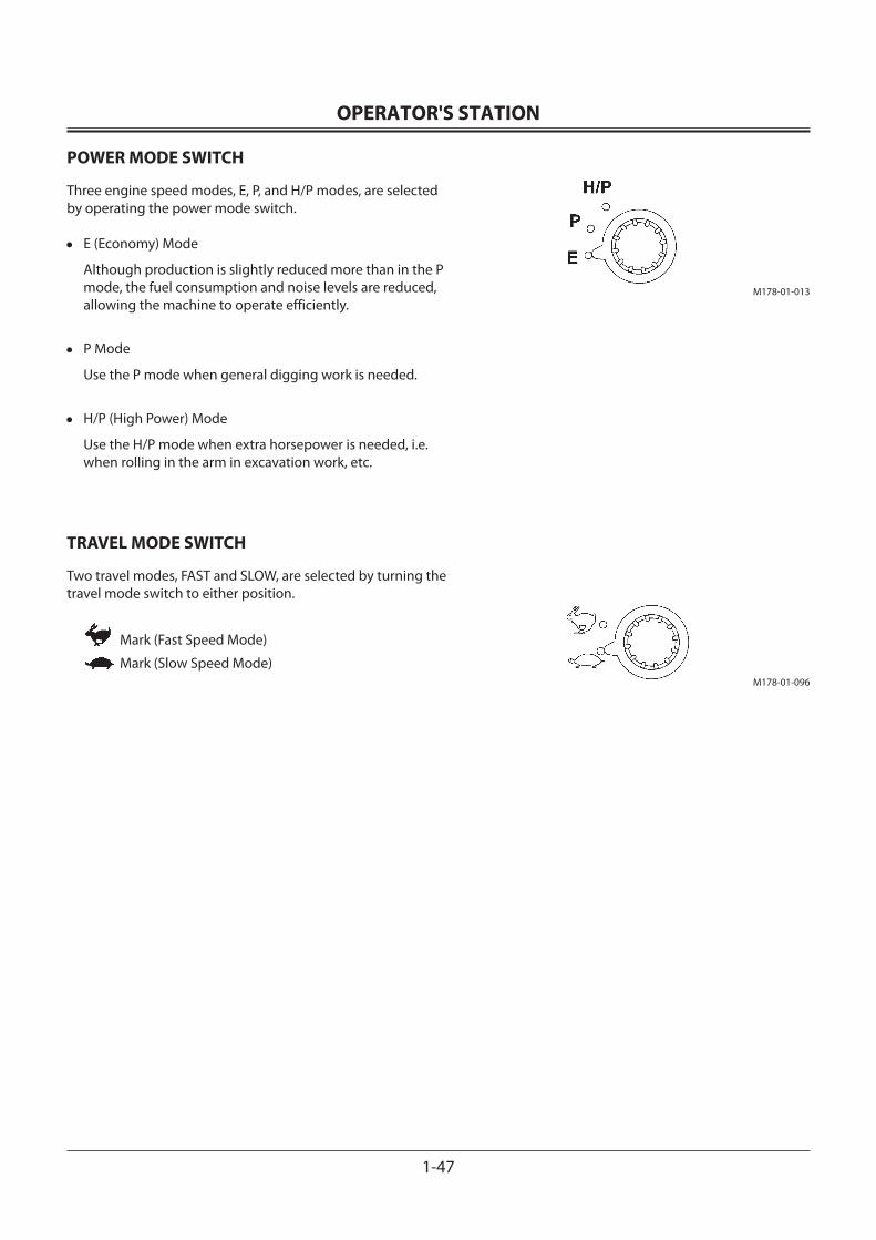
OPERATOR'S STATION
1-47
POWER MODE SWITCH
Three engine speed modes, E, P, and H/P modes, are selected by operating the power mode switch.
• E (Economy) Mode
Although production is slightly reduced more than in the P mode, the fuel consumption and noise levels are reduced, allowing the machine to operate efficiently.
• P Mode
Use the P mode when general digging work is needed.
• H/P (High Power) Mode
Use the H/P mode when extra horsepower is needed, i.e. when rolling in the arm in excavation work, etc.
TRAVEL MODE SWITCH
Two travel modes, FAST and SLOW, are selected by turning the travel mode switch to either position.
Mark (Fast Speed Mode)
Mark (Slow Speed Mode)
M178-01-013
M178-01-096
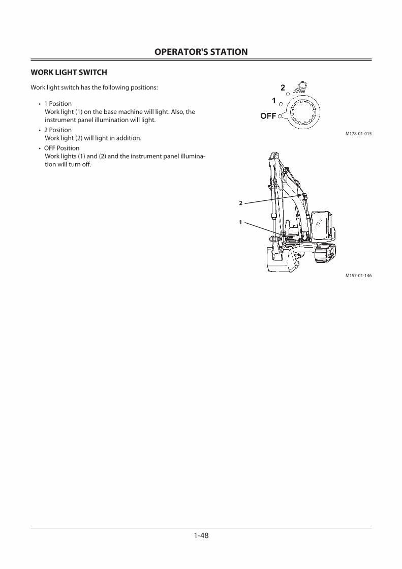
OPERATOR'S STATION
1-48
WORK LIGHT SWITCH
Work light switch has the following positions:
• 1 Position Work light (1) on the base machine will light. Also, the instrument panel illumination will light.
• 2 Position Work light (2) will light in addition.
• OFF Position Work lights (1) and (2) and the instrument panel illumina-tion will turn off.
M178-01-015
M157-01-146
2
1
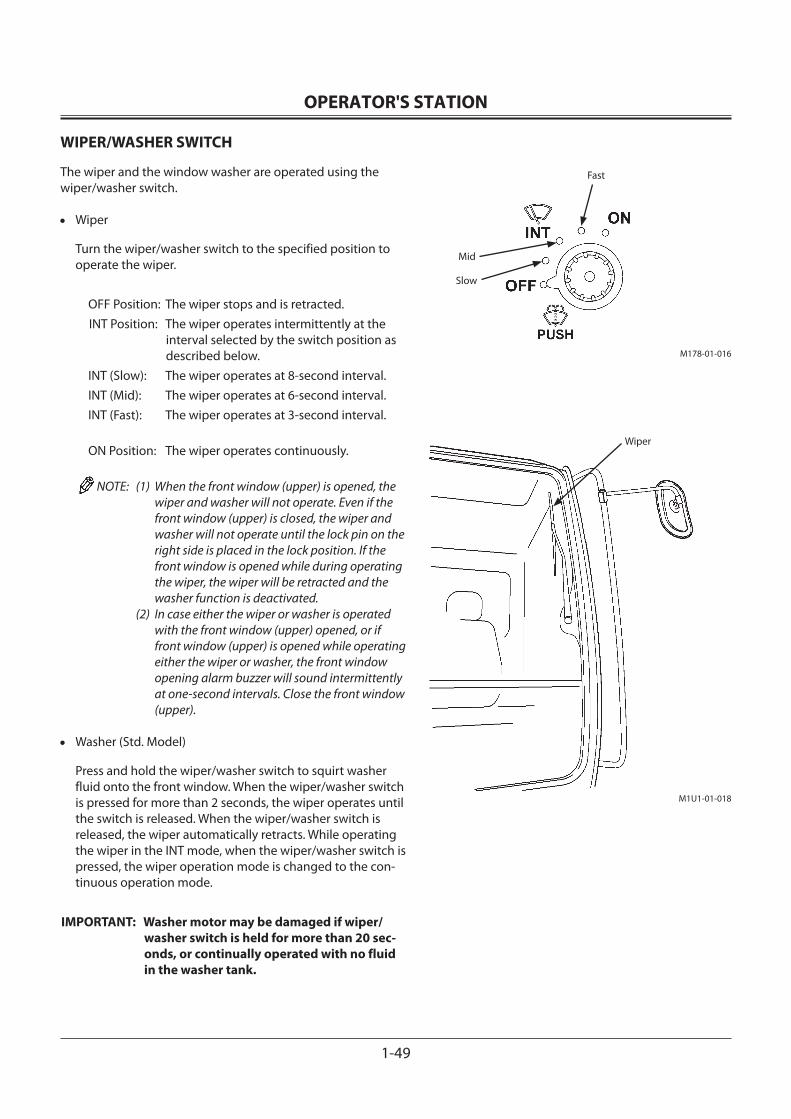
OPERATOR'S STATION
1-49
WIPER/WASHER SWITCH
The wiper and the window washer are operated using the wiper/washer switch.
• Wiper
Turn the wiper/washer switch to the specified position to operate the wiper.
OFF Position: The wiper stops and is retracted.INT Position: The wiper operates intermittently at the
interval selected by the switch position as described below.
INT (Slow): The wiper operates at 8-second interval.INT (Mid): The wiper operates at 6-second interval.INT (Fast): The wiper operates at 3-second interval.
ON Position: The wiper operates continuously.
NOTE: (1) When the front window (upper) is opened, the wiper and washer will not operate. Even if the front window (upper) is closed, the wiper and washer will not operate until the lock pin on the right side is placed in the lock position. If the front window is opened while during operating the wiper, the wiper will be retracted and the washer function is deactivated.
(2) In case either the wiper or washer is operated with the front window (upper) opened, or if front window (upper) is opened while operating either the wiper or washer, the front window opening alarm buzzer will sound intermittently at one-second intervals. Close the front window (upper).
• Washer (Std. Model)
Press and hold the wiper/washer switch to squirt washer fluid onto the front window. When the wiper/washer switch is pressed for more than 2 seconds, the wiper operates until the switch is released. When the wiper/washer switch is released, the wiper automatically retracts. While operating the wiper in the INT mode, when the wiper/washer switch is pressed, the wiper operation mode is changed to the con-tinuous operation mode.
IMPORTANT: Washer motor may be damaged if wiper/washer switch is held for more than 20 sec-onds, or continually operated with no fluid in the washer tank.
M178-01-016
Fast
Mid
Slow
Wiper
M1U1-01-018
OPERATOR'S STATION
1-50
• Washer (K Model) (Overhead Window)
As long as the wiper washer switch (1) is held down, washer fluid will be squirted from the nozzles on the front window and overhead window. Continue holding the wiper washer switch (1) for more than 2 seconds to automatically operate the front window wiper. Release the wiper washer switch to stop fluid from being squirted from the nozzles and to automatically stop and retract the wipers. While the wiper is operating in the INT position, when the wiper washer switch is pushed, the wiper will change to operate continuously.
IMPORTANT: The washer motor in the washer fluid tank may be damaged if washer fluid is kept squirted for more than 20 seconds or the motor is continuously operated with the washer fluid tank empty. Monitor the wash-er fluid squirting time and the fluid level in the washer reservoir.
Wiper Switch (2) (Overhead Window: Optional)Wiper switch has two positions as follows:
ON Position ...........Overhead window wiper (3) operates.
OFF Position ..........Overhead window wiper (3) stops.
M1U1-01-007
M1U1-01-008
3
1
2
M157-01-081
OPERATOR'S STATION
1-51
SWITCH PANEL (Optional)
NOTE: • The optional switch locations differ depending on the kinds of optional devices are equipped. Before us-ing the switches on the switch panel, make sure what kind of optional devices are equipped. All available optional devices are shown below.
• Raise the armrest when operating the optional switch.
• Travel Alarm Deactivation• Swing Alarm Deactivation• Rear Light• Overload Alarm Device Switch• Seat Heat Switch• Rotating Lamp• Electric Type Control Lever
Travel Alarm Deactivation Switch (Optional)The travel alarm buzzer sounds during travel operation. When push the travel alarm deactivation switch (1) , the travel alarm buzzer function is deactivated.
Swing Alarm Deactivation Switch (Optional)The swing alarm system sounds the buzzer and turns the beacon light ON during swing operation. When push the swing alarm deactivation switch (2) is set to the OFF posi-tion, the swing alarm buzzer function is deactivated.
Rear Light Switch (Optional)When rear light switch (3) is turned ON. The rear light at the rear of the cab roof comes ON.
T1V1-05-02-004
Optional Switch
M1U1-01-035
1
M1U1-01-036
2
M1U1-01-009
3
Armrest
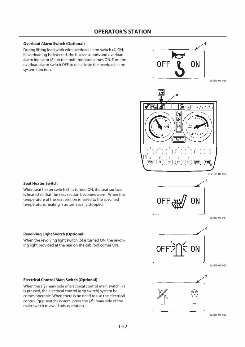
OPERATOR'S STATION
1-52
Overload Alarm Switch (Optional)During lifting load work with overload alarm switch (4) ON, if overloading is detected, the buzzer sounds and overload alarm indicator (8) on the multi-monitor comes ON. Turn the overload alarm switch OFF to deactivate the overload alarm system function.
Seat Heater Switch When seat heater switch (5) is turned ON, the seat surface is heated so that the seat section becomes warm. When the temperature of the seat section is raised to the specified temperature, heating is automatically stopped.
Revolving Light Switch (Optional)When the revolving light switch (6) is turned ON, the revolv-ing light provided at the rear on the cab roof comes ON.
Electrical Control Main Switch (Optional)
When the ( ) mark side of electrical control main switch (7) is pressed, the electrical control (grip switch) system be-comes operable. When there is no need to use the electrical control (grip switch) system, press the ( ) mark side of the main switch to avoid mis-operation.
M1U1-01-013
7
T1V1-05-01-094
8
M1U1-01-011
5
M1U1-01-012
6
M1U1-01-010
4
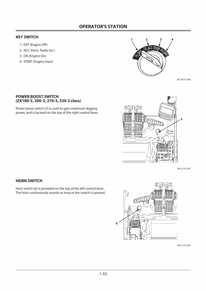
OPERATOR'S STATION
1-53
KEY SWITCH
1- OFF (Engine Off )
2- ACC (Horn, Radio etc.)
3- ON (Engine On)
4- START (Engine Start)
POWER BOOST SWITCH (ZX180-3, 200-3, 270-3, 330-3 class)
Power boost switch (5) is used to gain maximum digging power, and is located on the top of the right control lever.
HORN SWITCH
Horn switch (6) is provided on the top of the left control lever. The horn continuously sounds as long as the switch is pressed.
M178-01-049
1 2 3 4
M1J1-01-024
5
M1J1-01-025
6
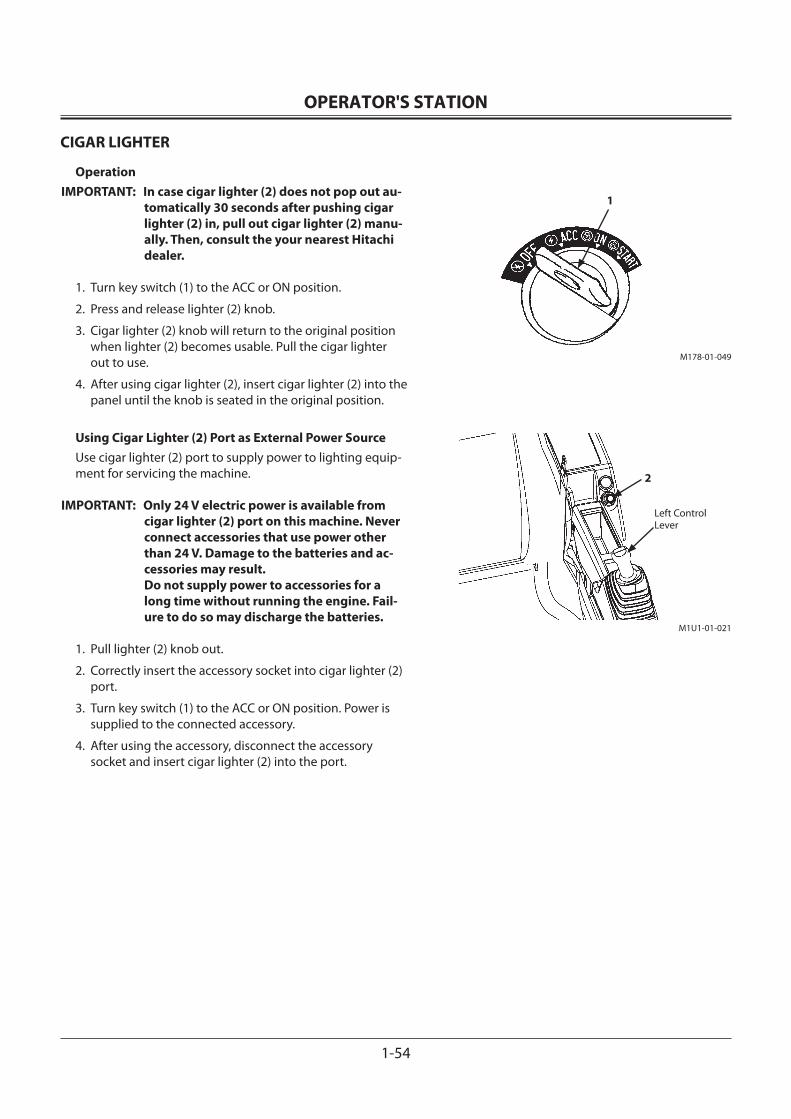
OPERATOR'S STATION
1-54
CIGAR LIGHTER
OperationIMPORTANT: In case cigar lighter (2) does not pop out au-
tomatically 30 seconds after pushing cigar lighter (2) in, pull out cigar lighter (2) manu-ally. Then, consult the your nearest Hitachi dealer.
1. Turn key switch (1) to the ACC or ON position.
2. Press and release lighter (2) knob.
3. Cigar lighter (2) knob will return to the original position when lighter (2) becomes usable. Pull the cigar lighter out to use.
4. After using cigar lighter (2), insert cigar lighter (2) into the panel until the knob is seated in the original position.
Using Cigar Lighter (2) Port as External Power SourceUse cigar lighter (2) port to supply power to lighting equip-ment for servicing the machine.
IMPORTANT: Only 24 V electric power is available from cigar lighter (2) port on this machine. Never connect accessories that use power other than 24 V. Damage to the batteries and ac-cessories may result.Do not supply power to accessories for a long time without running the engine. Fail-ure to do so may discharge the batteries.
1. Pull lighter (2) knob out.
2. Correctly insert the accessory socket into cigar lighter (2) port.
3. Turn key switch (1) to the ACC or ON position. Power is supplied to the connected accessory.
4. After using the accessory, disconnect the accessory socket and insert cigar lighter (2) into the port.
M178-01-049
1
M1U1-01-021
2
Left Control Lever
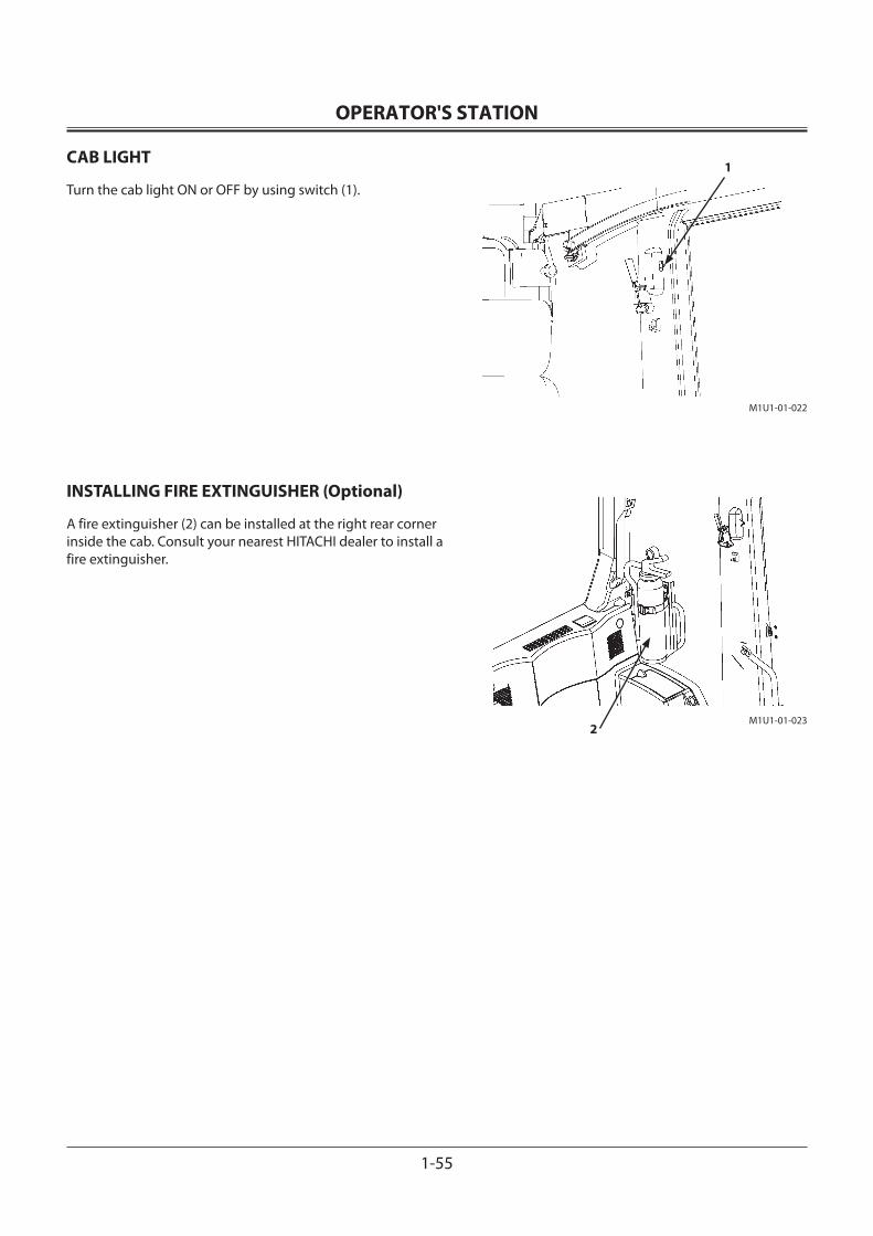
OPERATOR'S STATION
1-55
CAB LIGHT
Turn the cab light ON or OFF by using switch (1).
INSTALLING FIRE EXTINGUISHER (Optional)
A fire extinguisher (2) can be installed at the right rear corner inside the cab. Consult your nearest HITACHI dealer to install a fire extinguisher.
1
2
M1U1-01-022
M1U1-01-023
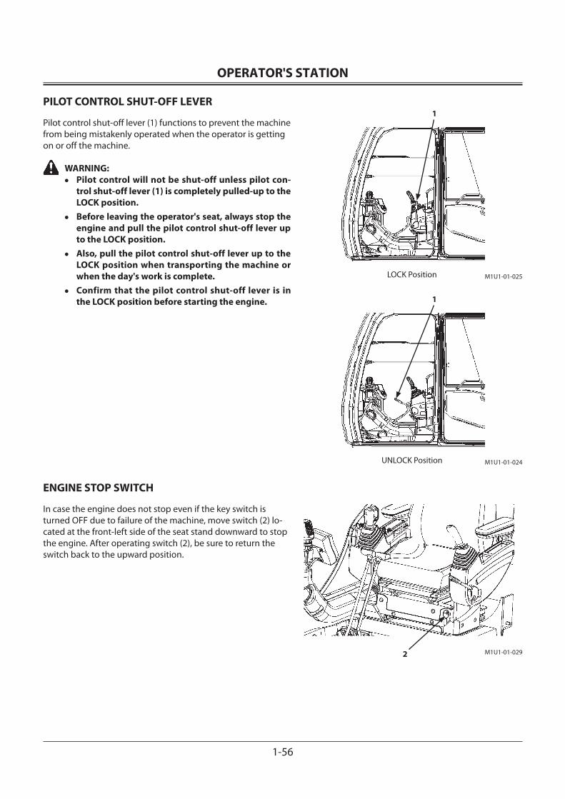
OPERATOR'S STATION
1-56
PILOT CONTROL SHUT-OFF LEVER
Pilot control shut-off lever (1) functions to prevent the machine from being mistakenly operated when the operator is getting on or off the machine.
WARNING:• Pilot control will not be shut-off unless pilot con-
trol shut-off lever (1) is completely pulled-up to the LOCK position.
• Before leaving the operator's seat, always stop the engine and pull the pilot control shut-off lever up to the LOCK position.
• Also, pull the pilot control shut-off lever up to the LOCK position when transporting the machine or when the day's work is complete.
• Confirm that the pilot control shut-off lever is in the LOCK position before starting the engine.
ENGINE STOP SWITCH
In case the engine does not stop even if the key switch is turned OFF due to failure of the machine, move switch (2) lo-cated at the front-left side of the seat stand downward to stop the engine. After operating switch (2), be sure to return the switch back to the upward position.
M1U1-01-025
1
LOCK Position
M1U1-01-024
1
UNLOCK Position
M1U1-01-0292
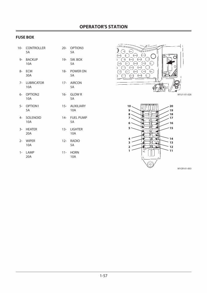
OPERATOR'S STATION
1-57
FUSE BOX
10- CONTROLLER 5A
20- OPTION3 5A
9- BACKUP 10A
19- SW. BOX 5A
8- ECM 30A
18- POWER ON 5A
7- LUBRICATOR 10A
17- AIRCON 5A
6- OPTION2 10A
16- GLOW R 5A
5- OPTION1 5A
15- AUXILIARY 10A
4- SOLENOID 10A
14- FUEL PUMP 5A
3- HEATER 20A
13- LIGHTER 10A
2- WIPER 10A
12- RADIO 5A
1- LAMP 20A
11- HORN 10A
20191817
16
15
14131211
10987
6
5
4321
M1U1-01-026
M1GR-01-003
OPERATOR'S STATION
1-58
AUTO AIR CONDITIONER
Distinctive Feature• Temperature Control:
Automatically controls the cab temperature to maintain the temperature set by the temperature control switch regardless of outside air temperature and insolation.
• Max. Cooling and Heating: Maximum cooling or heating can be obtained by mov-ing the temperature control switch to the full right or left respectively.
• Preheating: During preheating the cab in winter with the foot vent selected, the air volume is reduced to Low until the cool-ant temperature rises to prevent cool air from entering the cab.
1- Front Vent
2- Foot Vent
3- Defroster Vent
4- Rear Vent
5- Control Panel
6- Blower Switch
7- Liquid-Cristal Display (LCD)
8- Air Conditioner Switch
9- AUTO Switch
10- OFF Switch
11- Temperature Control Switch
12- Circulation Mode Switch
13- Fresh Air Mode Switch
14- Mode Switch
NOTE: Except for the foot vent, all vents are provided with louvers to adjust the air flow direction. In addition, the louvers on the front vent and defroster vent can be completely opened and closed by hand.
M1U1-01-025
1
23
M1U1-01-027
4
M178-01-073
5 6 7 8 9
1011121314
OPERATOR'S STATION
1-59
Control Panel Designation and Function• Mode Switch (14):
Selects the air vent. The selected air vent is indicated on LCD (7).
Air flows out of front vent and the defroster vents.Air flows out of the front and rear vents and the defroster vents.Air flows out of the front and foot vents and the defroster vents.
Air flows out of the foot vents.
Each time mode switch (14) is pressed, the vent location can be changed in four stages as illustrated below.
AUTO → → → →
• When AUTO switch (9) is selected the AUTO, the air vent location is automatically selected.
• Temperature Control Switch (11):
Sets temperature in the cab from 18.0 to 32.0 °C or 63 to 91 °F by 0.5 °C or 1 °F step. The set-temperature is displayed on LCD (7).
• FC (Full-Cool)
Push the button after setting air temperature to 18 °C or 63 °F. Air flow temperature is set to the lowest and the “FC” symbol is displayed on LCD (7).
• FH (Full-Heat)
Push the button after setting air temperature to 32 °C or 91 °F. Air flow temperature is set to the highest and the “FH” symbol is displayed on LCD (7).
• When the AUTO indicator is ON, air temperature at the vents is automatically set together with the blower speed and vent locations.
• When the AUTO indicator is OFF, only air temperature at the vents is automatically set.
• When the “FC” symbol is displayed on LCD (7), air tem-perature at the vent, air vent (front and rear vents) loca-tions, recirculation air suction port, and blower speed are maintained at the lowest cooling conditions. However, in case the circulation indicator is ON before the “FC” symbol is displayed, circulation operation is maintained.
7
M178-01-074
9
14Display when AUTO switch (9) is pressed:
M178-01-075
7 11
Display when the button is pressed after displaying 25.0 °C (77 °F):
M178-01-076
7
Display when the LCD displays “FC” symbol:
AUTO Indicator
OPERATOR'S STATION
1-60
• When the “FH” symbol is displayed on LCD (7), air flow-in temperature at the vent, air vent (front and rear vents) locations, fresh air suction port, and blower speed are maintained at the highest heating conditions. However, in case the circulation indicator is ON before the “FH” symbol is displayed, circulation operation is maintained.
Selecting Display Between Celsius And Fahrenheit1. While depressing both A/C (8) and mode (14) switches,
turn the key switch “ON”.
2. The LCD will display “Sd” for approx. 5 seconds.
3. After display “Sd” is deleted, all LED will come ON.
4. After all LED come ON, repeat to press the blower switch (6) four times.
5. Sequentially, press the A/C (8) and blower (6) switches at the same time.
6. Then, the selection mode between celsius and fahrenheit starts.
Each time the fresh air mode switch (13) is pressed, the display is shifted between celsius and fahrenheit. When celsius is displayed, the LED displays “C.” When fahrenheit is displayed, the LED displays “F.” Select either one to be preferred.
7. After selection is complete, end by turning the key switch “OFF”.
The LED will display in the selected mode when the ma-chine is operated next time.
Display on LCDCelsius (°C) 18.0 to 32.0Fahrenheit (°F) 63 to 91
• Blower Switch (6):• When the AUTO indicator is ON, the blower speed is auto-
matically controlled.
• When the AUTO indicator is OFF, the blower speed is controlled in 4 steps. When the button is pressed with the blower OFF, the blower starts running in the HI mode. Then, each time the button is pressed, the blower speed is reduced by one step. The LCD indicates the blower fan speed. When the button is pressed with the blower OFF, the blower starts running in the LO mode. Then, each time the button is pressed, the blower speed is increased by one step. The LCD indicates the corresponding blower fan speed.
M178-01-077
7
Display when the LCD displays “FH” symbol:
M178-01-075
6AUTO Indicator
OPERATOR'S STATION
1-61
• Circulation Mode Switch (12):
• Fresh Air Mode Switch (13): Changes the air circulation mode and automatically selects the air vent. When fresh air mode switch (13) is pressed, the indicator comes ON and the fresh air circulation mode is selected, allowing fresh air to flow in. When fresh air mode switch (13) is pressed again, the indicator goes OFF and the fresh air suction port is closed. When circulation mode switch (12) is pressed, the indicator comes ON and the circu-lation mode is selected. When circulation mode switch (12) is pressed again, the indicator goes OFF and the fresh air suction port is opened.
NOTE: Operating the above switches controls the fresh air suc-tion port manually or automatically. Therefore, even if the AUTO switch is turned ON, the fresh air suction port status will not be change
• Air Conditioner (A/C) Switch (8): Press A/C switch (8) to turn the air conditioner and the A/C indicator ON. However, unless the blower is running (the fan display of blower switch (6) is lit), the air conditioner will not be turned ON.
• OFF Switch (10): Press OFF switch (10) to turn the blower and the air condi-tioner OFF.
• AUTO Switch (9): Press AUTO switch (9) to turn the AUTO and the A/C indi-cators ON so that the air flow-in temperature at the vent, blower speed, vent locations, and fresh air suction port are automatically controlled.
M178-01-07813
Display when fresh air vent switch (13) is pressed:12
M178-01-075
8
Display when Air Conditiioner Switch (8) is pressed:
A/C Indicator
6 10
M178-01-075
9
Display when AUTO Switch (9) is pressed:
AUTO Indicator
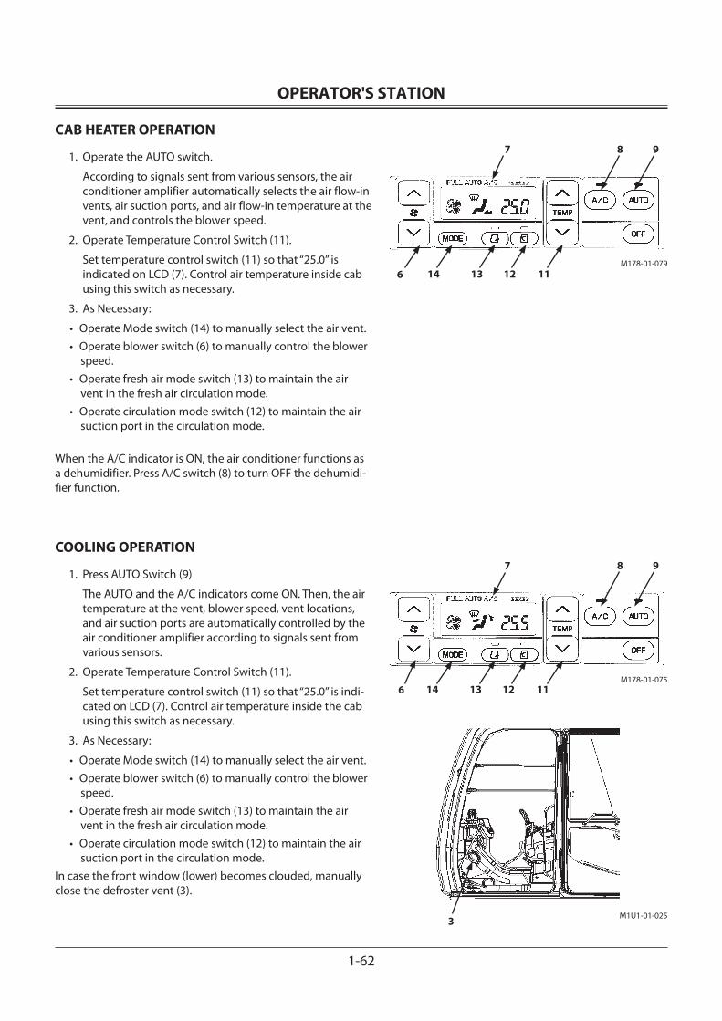
OPERATOR'S STATION
1-62
CAB HEATER OPERATION
1. Operate the AUTO switch.
According to signals sent from various sensors, the air conditioner amplifier automatically selects the air flow-in vents, air suction ports, and air flow-in temperature at the vent, and controls the blower speed.
2. Operate Temperature Control Switch (11).
Set temperature control switch (11) so that “25.0” is indicated on LCD (7). Control air temperature inside cab using this switch as necessary.
3. As Necessary:
• Operate Mode switch (14) to manually select the air vent. • Operate blower switch (6) to manually control the blower
speed.• Operate fresh air mode switch (13) to maintain the air
vent in the fresh air circulation mode.• Operate circulation mode switch (12) to maintain the air
suction port in the circulation mode.
When the A/C indicator is ON, the air conditioner functions as a dehumidifier. Press A/C switch (8) to turn OFF the dehumidi-fier function.
COOLING OPERATION
1. Press AUTO Switch (9)
The AUTO and the A/C indicators come ON. Then, the air temperature at the vent, blower speed, vent locations, and air suction ports are automatically controlled by the air conditioner amplifier according to signals sent from various sensors.
2. Operate Temperature Control Switch (11).
Set temperature control switch (11) so that “25.0” is indi-cated on LCD (7). Control air temperature inside the cab using this switch as necessary.
3. As Necessary:
• Operate Mode switch (14) to manually select the air vent. • Operate blower switch (6) to manually control the blower
speed.• Operate fresh air mode switch (13) to maintain the air
vent in the fresh air circulation mode.• Operate circulation mode switch (12) to maintain the air
suction port in the circulation mode.In case the front window (lower) becomes clouded, manually close the defroster vent (3).
M178-01-079
8 9
111213146
M178-01-075
8 9
111213146
3 M1U1-01-025
7
7
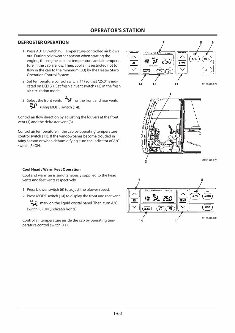
OPERATOR'S STATION
1-63
DEFROSTER OPERATION
1. Press AUTO Switch (9). Temperature-controlled air blows out. During cold weather season when starting the engine, the engine coolant temperature and air tempera-ture in the cab are low. Then, cool air is restricted not to flow in the cab to the minimum (LO) by the Heater Start-Operation Control System.
2. Set temperature control switch (11) so that “25.0” is indi-cated on LCD (7). Set fresh air vent switch (13) in the fresh air circulation mode.
3. Select the front vents or the front and rear vents
using MODE switch (14). Control air flow direction by adjusting the louvers at the front vent (1) and the defroster vent (3).
Control air temperature in the cab by operating temperature control switch (11). If the windowpanes become clouded in rainy season or when dehumidifying, turn the indicator of A/C switch (8) ON.
Cool Head / Warm Feet OperationCool and warm air is simultaneously supplied to the head vents and feet vents respectively.
1. Press blower switch (6) to adjust the blower speed.
2. Press MODE switch (14) to display the front and rear vent
mark on the liquid crystal panel. Then, turn A/C
switch (8) ON (indicator lights).
Control air temperature inside the cab by operating tem-perature control switch (11).
3 M1U1-01-025
1
M178-01-074
8 9
111314
M178-01-080
6 8
1114
7
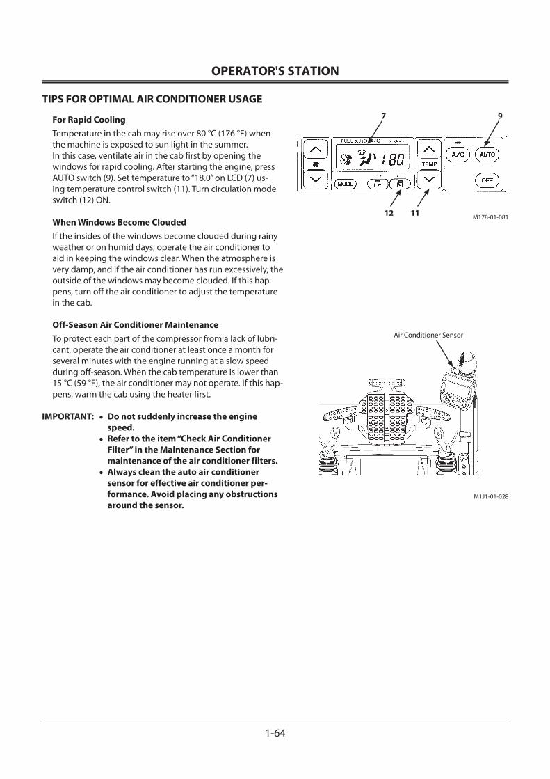
OPERATOR'S STATION
1-64
TIPS FOR OPTIMAL AIR CONDITIONER USAGE
For Rapid CoolingTemperature in the cab may rise over 80 °C (176 °F) when the machine is exposed to sun light in the summer. In this case, ventilate air in the cab first by opening the windows for rapid cooling. After starting the engine, press AUTO switch (9). Set temperature to “18.0” on LCD (7) us-ing temperature control switch (11). Turn circulation mode switch (12) ON.
When Windows Become CloudedIf the insides of the windows become clouded during rainy weather or on humid days, operate the air conditioner to aid in keeping the windows clear. When the atmosphere is very damp, and if the air conditioner has run excessively, the outside of the windows may become clouded. If this hap-pens, turn off the air conditioner to adjust the temperature in the cab.
Off-Season Air Conditioner MaintenanceTo protect each part of the compressor from a lack of lubri-cant, operate the air conditioner at least once a month for several minutes with the engine running at a slow speed during off-season. When the cab temperature is lower than 15 °C (59 °F), the air conditioner may not operate. If this hap-pens, warm the cab using the heater first.
IMPORTANT: • Do not suddenly increase the engine speed.
• Refer to the item “Check Air Conditioner Filter” in the Maintenance Section for maintenance of the air conditioner filters.
• Always clean the auto air conditioner sensor for effective air conditioner per-formance. Avoid placing any obstructions around the sensor.
M178-01-081
9
1112
7
M1J1-01-028
Air Conditioner Sensor
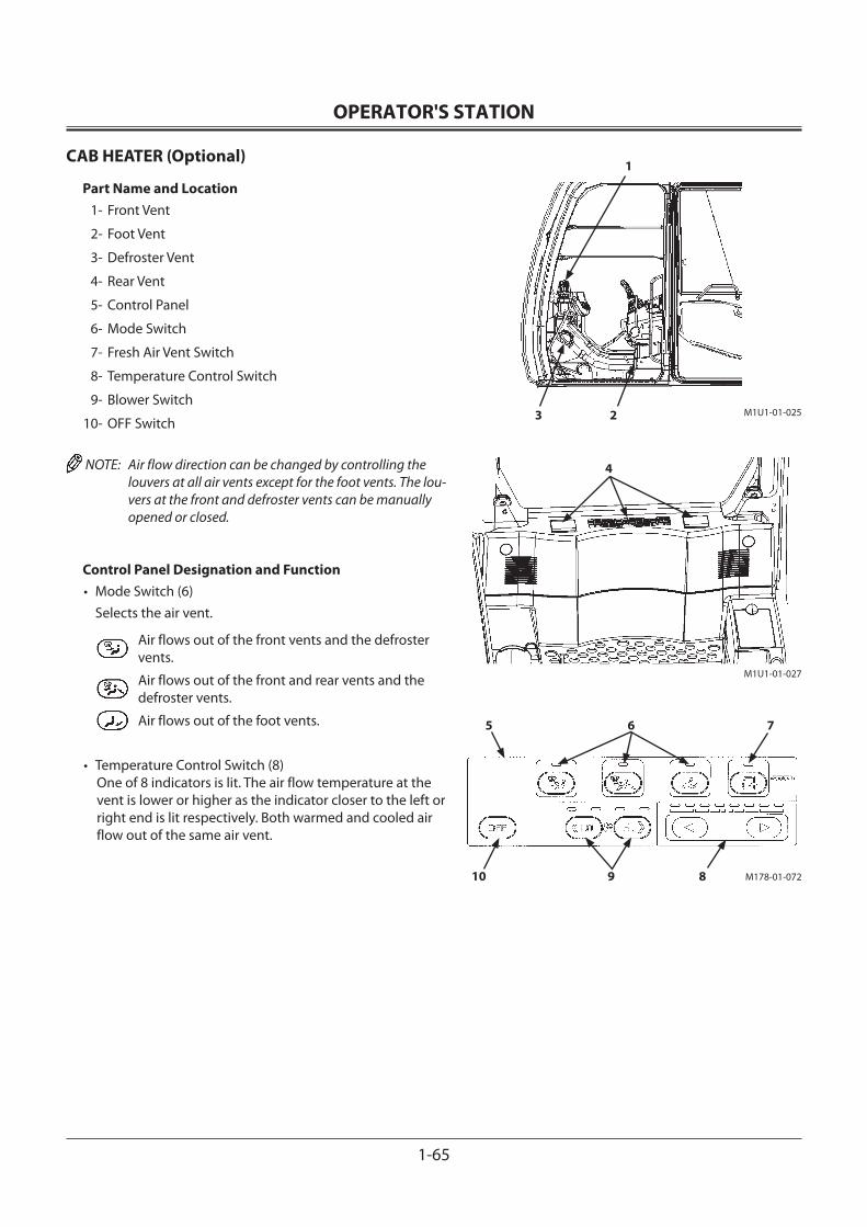
OPERATOR'S STATION
1-65
CAB HEATER (Optional)
Part Name and Location 1- Front Vent
2- Foot Vent
3- Defroster Vent
4- Rear Vent
5- Control Panel
6- Mode Switch
7- Fresh Air Vent Switch
8- Temperature Control Switch
9- Blower Switch
10- OFF Switch
NOTE: Air flow direction can be changed by controlling the louvers at all air vents except for the foot vents. The lou-vers at the front and defroster vents can be manually opened or closed.
Control Panel Designation and Function• Mode Switch (6) Selects the air vent.
Air flows out of the front vents and the defroster vents.
Air flows out of the front and rear vents and the defroster vents.
Air flows out of the foot vents.
• Temperature Control Switch (8) One of 8 indicators is lit. The air flow temperature at the vent is lower or higher as the indicator closer to the left or right end is lit respectively. Both warmed and cooled air flow out of the same air vent.
3
1
2
4
M1U1-01-025
M1U1-01-027
M178-01-072
5 6 7
8910
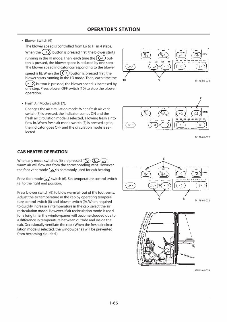
OPERATOR'S STATION
1-66
M178-01-07210 9
M178-01-072
7
M178-01-07289
6
M1U1-01-024
• Blower Switch (9)The blower speed is controlled from Lo to Hi in 4 steps.
When the button is pressed first, the blower starts
running in the HI mode. Then, each time the but-ton is pressed, the blower speed is reduced by one step. The blower speed indicator corresponding to the blower
speed is lit. When the button is pressed first, the blower starts running in the LO mode. Then, each time the
button is pressed, the blower speed is increased by one step. Press blower OFF switch (10) to stop the blower operation.
• Fresh Air Mode Switch (7):Changes the air circulation mode. When fresh air vent switch (7) is pressed, the indicator comes ON and the fresh air circulation mode is selected, allowing fresh air to flow in. When fresh air mode switch (7) is pressed again, the indicator goes OFF and the circulation mode is se-lected.
CAB HEATER OPERATION
When any mode switches (6) are pressed ( , , ), warm air will flow out from the corresponding vent. However, the foot vent mode is commonly used for cab heating.
Press foot mode switch (6). Set temperature control switch (8) to the right end position.
Press blower switch (9) to blow warm air out of the foot vents. Adjust the air temperature in the cab by operating tempera-ture control switch (8) and blower switch (9). When required to quickly increase air temperature in the cab, select the air recirculation mode. However, if air recirculation mode is used for a long time, the windowpanes will become clouded due to a difference in temperature between outside and inside the cab. Occasionally ventilate the cab. (When the fresh air circu-lation mode is selected, the windowpanes will be prevented from becoming clouded.)
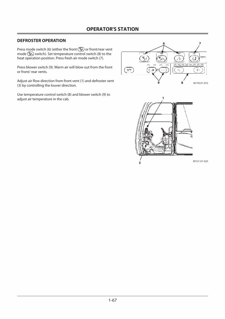
OPERATOR'S STATION
1-67
M178-01-072
6 7
89
3
1
M1U1-01-025
DEFROSTER OPERATION
Press mode switch (6) (either the front or front/rear vent mode switch). Set temperature control switch (8) to the heat operation position. Press fresh air mode switch (7).
Press blower switch (9). Warm air will blow out from the front or front/ rear vents.
Adjust air flow direction from front vent (1) and defroster vent (3) by controlling the louver direction.
Use temperature control switch (8) and blower switch (9) to adjust air temperature in the cab.
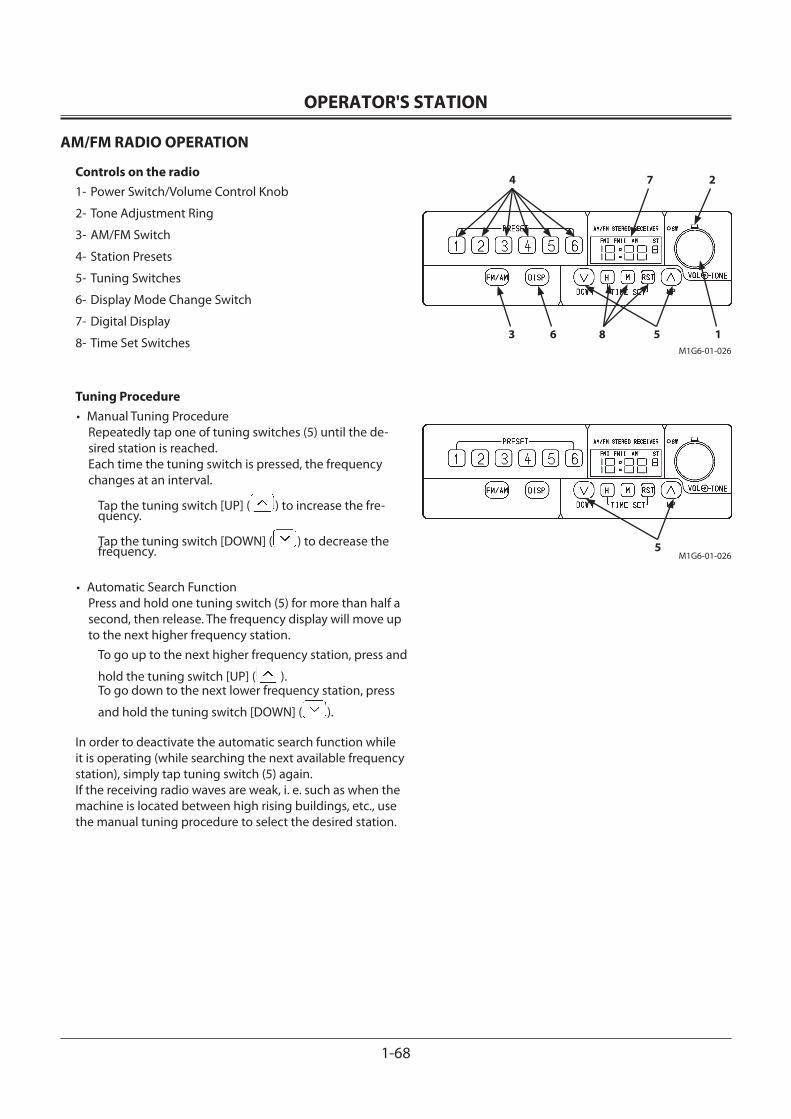
OPERATOR'S STATION
1-68
M1G6-01-0265
M1G6-01-026
3
4 7 2
6 8 5 1
AM/FM RADIO OPERATION
Controls on the radio1- Power Switch/Volume Control Knob
2- Tone Adjustment Ring
3- AM/FM Switch
4- Station Presets
5- Tuning Switches
6- Display Mode Change Switch
7- Digital Display
8- Time Set Switches
Tuning Procedure• Manual Tuning Procedure
Repeatedly tap one of tuning switches (5) until the de-sired station is reached. Each time the tuning switch is pressed, the frequency changes at an interval.
Tap the tuning switch [UP] ( ) to increase the fre-quency.
Tap the tuning switch [DOWN] ( ) to decrease the frequency.
• Automatic Search FunctionPress and hold one tuning switch (5) for more than half a second, then release. The frequency display will move up to the next higher frequency station.
To go up to the next higher frequency station, press and
hold the tuning switch [UP] ( ).To go down to the next lower frequency station, press
and hold the tuning switch [DOWN] ( ).
In order to deactivate the automatic search function while it is operating (while searching the next available frequency station), simply tap tuning switch (5) again. If the receiving radio waves are weak, i. e. such as when the machine is located between high rising buildings, etc., use the manual tuning procedure to select the desired station.
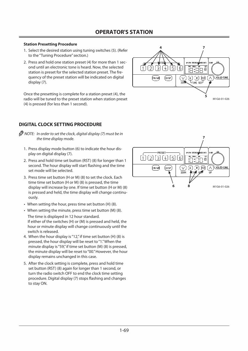
OPERATOR'S STATION
1-69
M1G6-01-026
4 7
5
M1G6-01-026
7
6 8
Station Presetting Procedure1. Select the desired station using tuning switches (5). (Refer
to the “Tuning Procedure” section.)
2. Press and hold one station preset (4) for more than 1 sec-ond until an electronic tone is heard. Now, the selected station is preset for the selected station preset. The fre-quency of the preset station will be indicated on digital display (7).
Once the presetting is complete for a station preset (4), the radio will be tuned to the preset station when station preset (4) is pressed (for less than 1 second).
DIGITAL CLOCK SETTING PROCEDURE
NOTE: In order to set the clock, digital display (7) must be in the time display mode.
1. Press display mode button (6) to indicate the hour dis-play on digital display (7).
2. Press and hold time set button (RST) (8) for longer than 1 second. The hour display will start flashing and the time set mode will be selected.
3. Press time set button (H or M) (8) to set the clock. Each time time set button (H or M) (8) is pressed, the time display will increase by one. If time set button (H or M) (8) is pressed and held, the time display will change continu-ously.
• When setting the hour, press time set button (H) (8).• When setting the minute, press time set button (M) (8).
The time is displayed in 12 hour standard.If either of the switches (H) or (M) is pressed and held, the hour or minute display will change continuously until the switch is released.
4. When the hour display is “12,” if time set button (H) (8) is pressed, the hour display will be reset to “1.” When the minute display is “59,” if time set button (M) (8) is pressed, the minute display will be reset to “00.” However, the hour display remains unchanged in this case.
5. After the clock setting is complete, press and hold time set button (RST) (8) again for longer than 1 second, or turn the radio switch OFF to end the clock time setting procedure. Digital display (7) stops flashing and changes to stay ON.
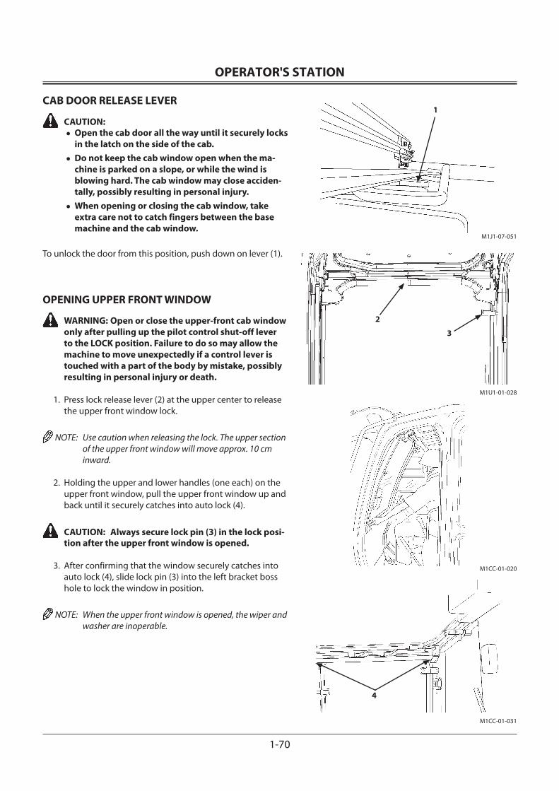
OPERATOR'S STATION
1-70
M1J1-07-051
M1CC-01-020
M1CC-01-031
M1U1-01-028
2
3
1
4
CAB DOOR RELEASE LEVER
CAUTION: •Open the cab door all the way until it securely locks
in the latch on the side of the cab.•Do not keep the cab window open when the ma-
chine is parked on a slope, or while the wind is blowing hard. The cab window may close acciden-tally, possibly resulting in personal injury.
•When opening or closing the cab window, take extra care not to catch fingers between the base machine and the cab window.
To unlock the door from this position, push down on lever (1).
OPENING UPPER FRONT WINDOW
WARNING: Open or close the upper-front cab window only after pulling up the pilot control shut-off lever to the LOCK position. Failure to do so may allow the machine to move unexpectedly if a control lever is touched with a part of the body by mistake, possibly resulting in personal injury or death.
1. Press lock release lever (2) at the upper center to release the upper front window lock.
NOTE: Use caution when releasing the lock. The upper section of the upper front window will move approx. 10 cm inward.
2. Holding the upper and lower handles (one each) on the upper front window, pull the upper front window up and back until it securely catches into auto lock (4).
CAUTION: Always secure lock pin (3) in the lock posi-tion after the upper front window is opened.
3. After confirming that the window securely catches into auto lock (4), slide lock pin (3) into the left bracket boss hole to lock the window in position.
NOTE: When the upper front window is opened, the wiper and washer are inoperable.
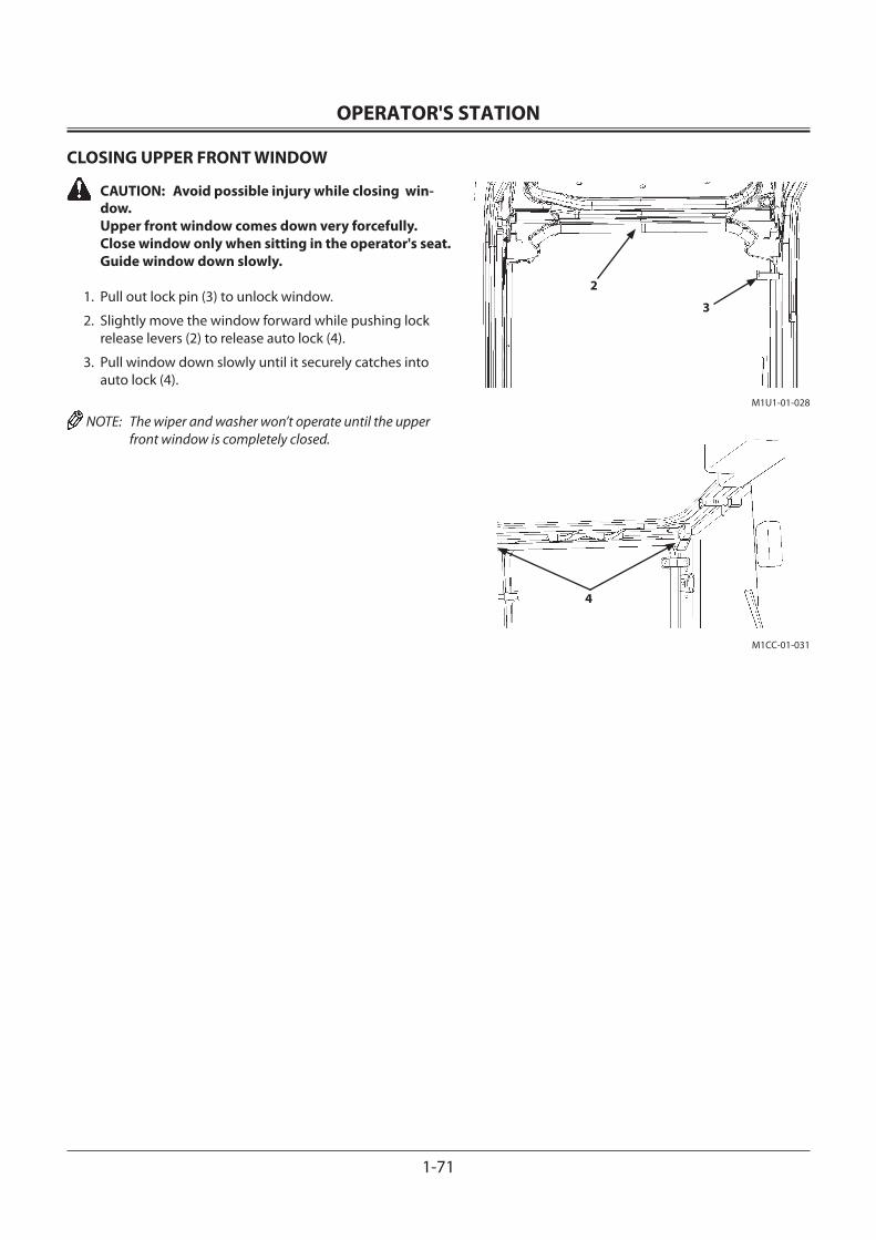
OPERATOR'S STATION
1-71
4
M1CC-01-031
M1U1-01-028
2
3
CLOSING UPPER FRONT WINDOW
CAUTION: Avoid possible injury while closing win-dow. Upper front window comes down very forcefully. Close window only when sitting in the operator's seat. Guide window down slowly.
1. Pull out lock pin (3) to unlock window.
2. Slightly move the window forward while pushing lock release levers (2) to release auto lock (4).
3. Pull window down slowly until it securely catches into auto lock (4).
NOTE: The wiper and washer won’t operate until the upper front window is completely closed.
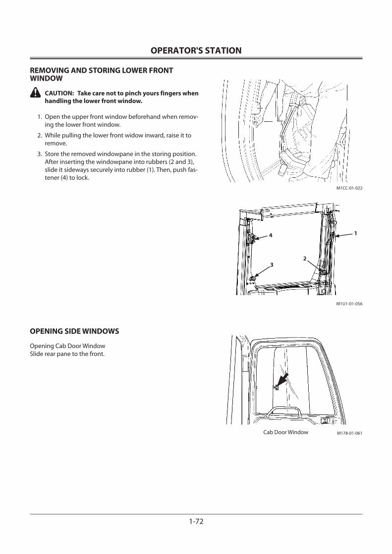
OPERATOR'S STATION
1-72
M1U1-01-056
4
32
1
M1CC-01-022
M178-01-061Cab Door Window
REMOVING AND STORING LOWER FRONT WINDOW
CAUTION: Take care not to pinch yours fingers when handling the lower front window.
1. Open the upper front window beforehand when remov-ing the lower front window.
2. While pulling the lower front widow inward, raise it to remove.
3. Store the removed windowpane in the storing position. After inserting the windowpane into rubbers (2 and 3), slide it sideways securely into rubber (1). Then, push fas-tener (4) to lock.
OPENING SIDE WINDOWS
Opening Cab Door WindowSlide rear pane to the front.
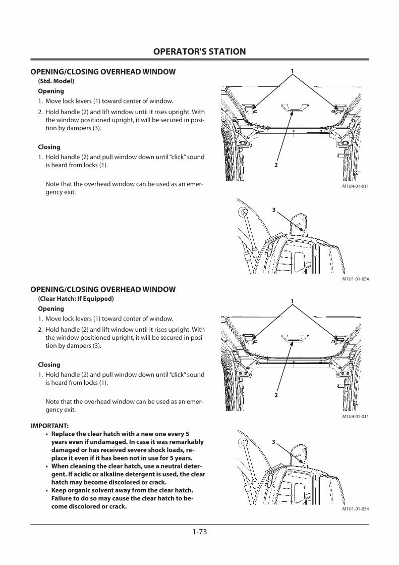
OPERATOR'S STATION
1-73
M1U1-01-054
3
M1U1-01-054
3
2
1
M1U4-01-011
2
1
M1U4-01-011
OPENING/CLOSING OVERHEAD WINDOW(Std. Model)Opening1. Move lock levers (1) toward center of window.
2. Hold handle (2) and lift window until it rises upright. With the window positioned upright, it will be secured in posi-tion by dampers (3).
Closing1. Hold handle (2) and pull window down until “click” sound
is heard from locks (1).
Note that the overhead window can be used as an emer-gency exit.
OPENING/CLOSING OVERHEAD WINDOW(Clear Hatch: If Equipped)Opening1. Move lock levers (1) toward center of window.
2. Hold handle (2) and lift window until it rises upright. With the window positioned upright, it will be secured in posi-tion by dampers (3).
Closing1. Hold handle (2) and pull window down until “click” sound
is heard from locks (1).
Note that the overhead window can be used as an emer-gency exit.
IMPORTANT: • Replace the clear hatch with a new one every 5
years even if undamaged. In case it was remarkably damaged or has received severe shock loads, re-place it even if it has been not in use for 5 years.
• When cleaning the clear hatch, use a neutral deter-gent. If acidic or alkaline detergent is used, the clear hatch may become discolored or crack.
• Keep organic solvent away from the clear hatch. Failure to do so may cause the clear hatch to be-come discolored or crack.
OPERATOR'S STATION
1-74
2
M1U1-01-115
3
1
M1U1-01-022
2
M1U4-01-012
3
EMERGENCY EXIT
Escape from the cab in emergency in the following methods:
CAUTION: The danger of downfall is always present when escaping from the cab in emergency, possibly resulting in serious personal injury. Escape from the cab as safely as possible, depending on the posture of machine and the outside situation.
1. Open the cab door. Escape through the door.
2. If the cab door should be difficult to open or use, open the upper front window. Escape through the window.
NOTE: • Emergency exit decals (2) are affixed to the front and rear windows.
• See page “OPENING UPPER FRONT WINDOW” for the opening method of the upper front window.
CAUTION: • If decal (3) is affixed to the front window glass, the
glass can be broken. However if decal (3) is not af-fixed to the front window glass, the glass cannot be broken.
• Take care not to be injured with pieces of broken glass.
3. If upper front window should be difficult to open, check the decal (3) affixed to the window glass.
If decal (3) is affixed to the front window glass, break the front window glass using the emergency evacuation tool (1) installed the cab left side. Then escape through the broken window.
4. If decal (3) is not affixed to the front window glass, or if the front window is not available for escaping, break the rear window glass using the emergency evacuation tool (1). Then escape through the broken window.
5. If neither of front and rear windows are available for emergency exit, open the overhead window to escape from the cab.
OPERATOR'S STATION
1-75
SS-955
Caution: Possibility of pinched fingers
Push down with the palm.
M178-01-065
1
34
5
2
ADJUSTING THE SEAT
Seat Height and Angle AdjustmentSeat height adjustment range is 60 mm (2.4 in) with steps every 15 mm (0.6 in) (5 positions in total). Moreover, the height of the front part and the rear part of the seat are adjusted independently, thus allowing the angle of the seat to be adjusted.
CAUTION: Avoid possible injury while operating lever (1). When pushing down lever (1), do not grab it. Fingers may be pinched between lever (1) and the seat stand. Be sure to push on the upper face of lever (1).
Use lever (1) to adjust the seat height and/or seat angle as follows:• To adjust the front part of the seat:
Push down lever (1) while sitting on the seat, and apply or remove body weight to obtain the desired height. When the desired height is obtained, release lever (1).
• To adjust the rear part of the seat:Pull up lever (1) while sitting on the seat, and apply or remove body weight to obtain the desired height. When the desired height is obtained, release lever (1).
Console and Seat Fore-aft AdjustmentPull lever (2) to the right to adjust the seat and both right and left consoles to desired distance from the travel pedals and levers. Release lever to lock seat and consoles into posi-tion. NOTE: Seat and console fore-aft adjustment range is 120 mm
(4.7 in) with steps every 20 mm (0.8 in).
Seat Fore-Aft AdjustmentPull lever (3) to unlock the seat from both consoles. With lever (3), slide the seat to the desired distance from pilot control levers. Release the lever. NOTE: Seat fore-aft adjustment range is 160 mm (6.3 in) with
steps every 16 mm (0.8 in).
Suspension AdjustmentTurn knob (4) clockwise to increase suspension stiffness.Turn knob (4) counterclockwise to decrease suspension stiff-ness.
Backrest AdjustmentPull up lever (5) to release backrest lock. Move backrest to the desired position and release the lever.

OPERATOR'S STATION
1-76
M1G6-01-017
6
7
M1U1-01-011
8
Armrest AdjustmentArmrest (6) can be pulled upright by hand to get on and off the machine easily.The angle of armrest (6) can be adjusted to the desired posi-tion by turning adjusting dial (7) located on the bottom of armrest (6).
SEAT WITH A BUILT-IN HEATER
The heater installed inside the seat activates by operating seat heater switch (8) on the optional equipment control switch panel.
NOTE: Depending on what kinds of optional equipments are installed, the switch button function may differ. Use the switch only after confirming the kinds of the installed optional equipment.
OPERATOR'S STATION
1-77
SS-955
M1U1-01-014
1
34
5
2
Caution: Possibility of pinched fingers
Push down with the palm.
ADJUSTING THE AIR-SUSPENSION SEAT (Optional)
Seat Height and Angle AdjustmentSeat height adjustment range is 60 mm (2.4 in) with steps every 15 mm (0.6 in) (5 positions in total). Moreover, the height of the front part and the rear part of the seat are adjusted independently, thus allowing the angle of the seat to be adjusted.
CAUTION: Avoid possible injury while operating lever (1). When pushing down lever (1), do not grab it. Fingers may be pinched between lever (1) and the seat stand. Be sure to push on the upper face of lever (1).
Use lever (1) to adjust the seat height and/or seat angle as follows:• To adjust the front part of the seat:
Push down lever (1) while sitting on the seat, and apply or remove body weight to obtain the desired height. When the desired height is obtained, release lever (1).
• To adjust the rear part of the seat:Pull up lever (1) while sitting on the seat, and apply or remove body weight to obtain the desired height. When the desired height is obtained, release lever (1).
Console and Seat Fore-aft AdjustmentPull lever (2) to the right to adjust the seat and both right and left consoles to desired distance from the travel pedals and levers. Release lever to lock seat and consoles into posi-tion. NOTE: Seat and console fore-aft adjustment range is 120 mm
(4.7 in) with steps every 20 mm (0.8 in).
Seat Fore-Aft AdjustmentPull lever (3) to unlock the seat from both consoles. With lever (3), slide the seat to the desired distance from pilot control levers. Release the lever. NOTE: Seat fore-aft adjustment range is 160 mm (6.3 in) with
steps every 16 mm (0.8 in).
Suspension AdjustmentPush knob (4) to increase suspension stiffness.Pull knob (4) to decrease suspension stiffness.
Backrest AdjustmentPull up lever (5) to release backrest lock. Move backrest to the desired position and release the lever.
OPERATOR'S STATION
1-78
M1G6-01-017
6
7
M1U1-01-011
8
Armrest AdjustmentArmrest (6) can be pulled upright by hand to get on and off the machine easily.The angle of armrest (6) can be adjusted to the desired posi-tion by turning adjusting dial (7) located on the bottom of armrest (6).
SEAT WITH A BUILT-IN HEATER
The heater installed inside the seat activates by operating seat heater switch (8) on the optional equipment control switch panel.
NOTE: Depending on what kinds of optional equipments are installed, the switch button function may differ. Use the switch only after confirming the kinds of the installed optional equipment.
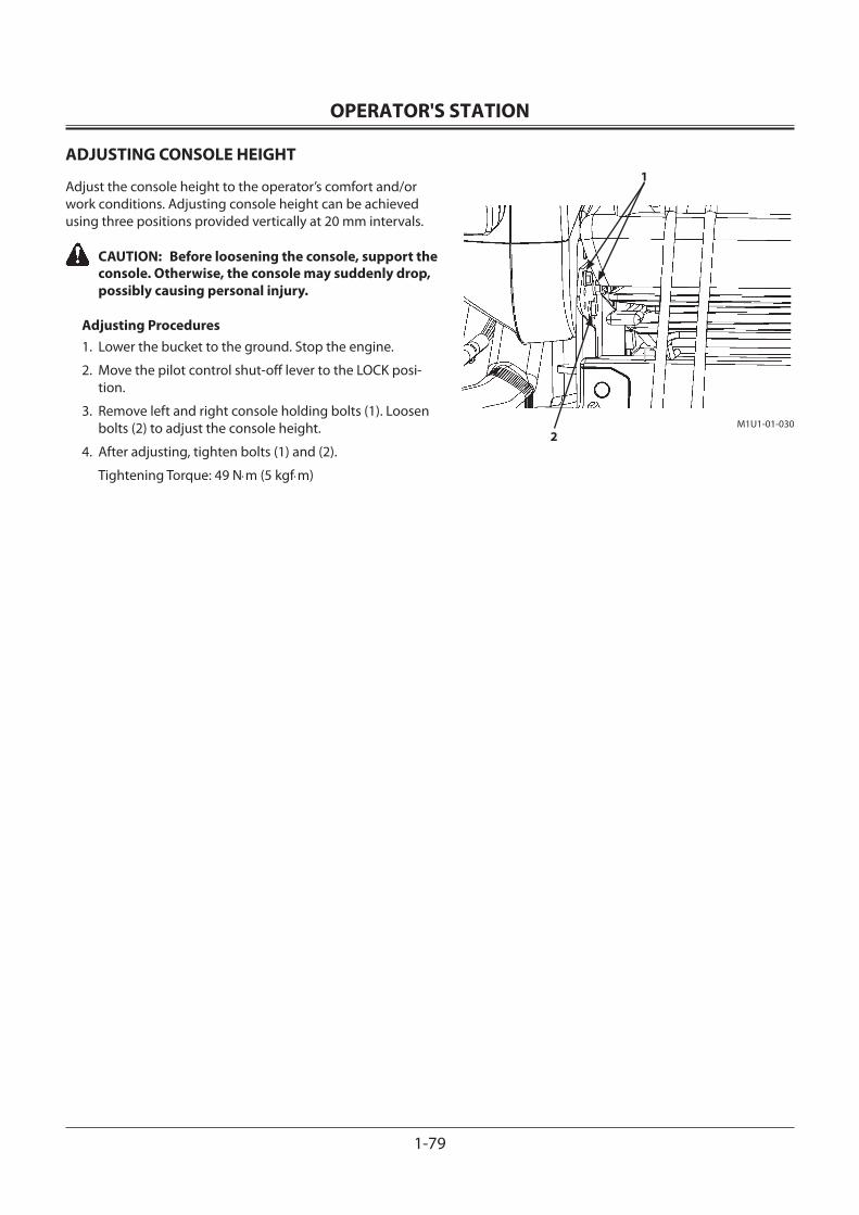
OPERATOR'S STATION
1-79
M1U1-01-030
1
2
ADJUSTING CONSOLE HEIGHT
Adjust the console height to the operator’s comfort and/or work conditions. Adjusting console height can be achieved using three positions provided vertically at 20 mm intervals.
CAUTION: Before loosening the console, support the console. Otherwise, the console may suddenly drop, possibly causing personal injury.
Adjusting Procedures1. Lower the bucket to the ground. Stop the engine.
2. Move the pilot control shut-off lever to the LOCK posi-tion.
3. Remove left and right console holding bolts (1). Loosen bolts (2) to adjust the console height.
4. After adjusting, tighten bolts (1) and (2).
Tightening Torque: 49 N⋅m (5 kgf⋅m)
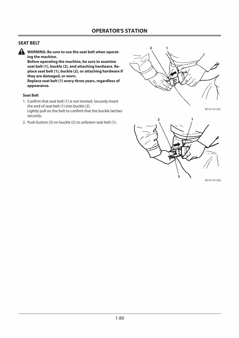
OPERATOR'S STATION
1-80
M1U1-01-031
2 1
M1U1-01-032
12
3
SEAT BELT
WARNING: Be sure to use the seat belt when operat-ing the machine. Before operating the machine, be sure to examine seat belt (1), buckle (2), and attaching hardware. Re-place seat belt (1), buckle (2), or attaching hardware if they are damaged, or worn. Replace seat belt (1) every three years, regardless of appearance.
Seat Belt1. Confirm that seat belt (1) is not twisted. Securely insert
the end of seat belt (1) into buckle (2).Lightly pull on the belt to confirm that the buckle latches securely.
2. Push button (3) on buckle (2) to unfasten seat belt (1).
BREAK-IN
2-1
OBSERVE ENGINE OPERATION CLOSELY
IMPORTANT: Be extra cautious during the first 50 hours, until you become thoroughly familiar with the sound and feel of your new machine.
1. Operate the machine only in economy (E) mode and limit the engine horsepower up to about 80 % of full load.
2. Avoid excess engine idling.
3. Check indicator lights and gauges frequently during operation.
EVERY 8 HOURS OR DAILY
1. Perform 8-hour or daily service. (See Maintenance guide -- 8 hours.)
2. Watch for fluid leaks.
3. Lubricate working tool pivots every 8 hours for the first 50 hours, and every 8 hours when working in mud and water.
AFTER THE FIRST 50 HOURS
1. Perform 50-hour service. (See Maintenance guide -- 50 hours.)
2. Check accessible hardware torque. (See Hardware Torque Specifications in Maintenance chapter.)
AFTER THE FIRST 100 HOURS
Perform 50-hour and 100-hour service. (See Maintenance Guide -- 50 hours and 100 hours.)

BREAK-IN
2-2
MEMO...................................................................................................................................................................................................................................................
...................................................................................................................................................................................................................................................
...................................................................................................................................................................................................................................................
...................................................................................................................................................................................................................................................
...................................................................................................................................................................................................................................................
...................................................................................................................................................................................................................................................
...................................................................................................................................................................................................................................................
...................................................................................................................................................................................................................................................
...................................................................................................................................................................................................................................................
...................................................................................................................................................................................................................................................
...................................................................................................................................................................................................................................................
...................................................................................................................................................................................................................................................
...................................................................................................................................................................................................................................................
...................................................................................................................................................................................................................................................
...................................................................................................................................................................................................................................................
...................................................................................................................................................................................................................................................
...................................................................................................................................................................................................................................................
...................................................................................................................................................................................................................................................
...................................................................................................................................................................................................................................................
...................................................................................................................................................................................................................................................
...................................................................................................................................................................................................................................................
...................................................................................................................................................................................................................................................
...................................................................................................................................................................................................................................................
...................................................................................................................................................................................................................................................
...................................................................................................................................................................................................................................................
...................................................................................................................................................................................................................................................
...................................................................................................................................................................................................................................................
...................................................................................................................................................................................................................................................
...................................................................................................................................................................................................................................................
...................................................................................................................................................................................................................................................
...................................................................................................................................................................................................................................................
...................................................................................................................................................................................................................................................
...................................................................................................................................................................................................................................................
...................................................................................................................................................................................................................................................
...................................................................................................................................................................................................................................................
...................................................................................................................................................................................................................................................
...................................................................................................................................................................................................................................................
OPERATING THE ENGINE
3-1
INSPECT MACHINE DAILY BEFORE STARTING
ELECTRICAL SYSTEMCheck for worn or frayed wires and loose connections.
BOOM, BUCKET, SHEET METAL, TRACKSCheck for bent, broken or missing parts.
HARDWARECheck for loose or missing parts.
FUEL SYSTEMDrain water and deposits from fuel tank.
HYDRAULIC SYSTEMCheck for leaks, kinked hoses, and lines or hoses that rub against each other or other parts.
LUBRICATIONCheck lubrication points on the Periodic Service Chart.
PROTECTIVE DEVICESCheck guards, fenders.
SAFETYWalk around machine to clear all bystanders/obstacles from machine area.
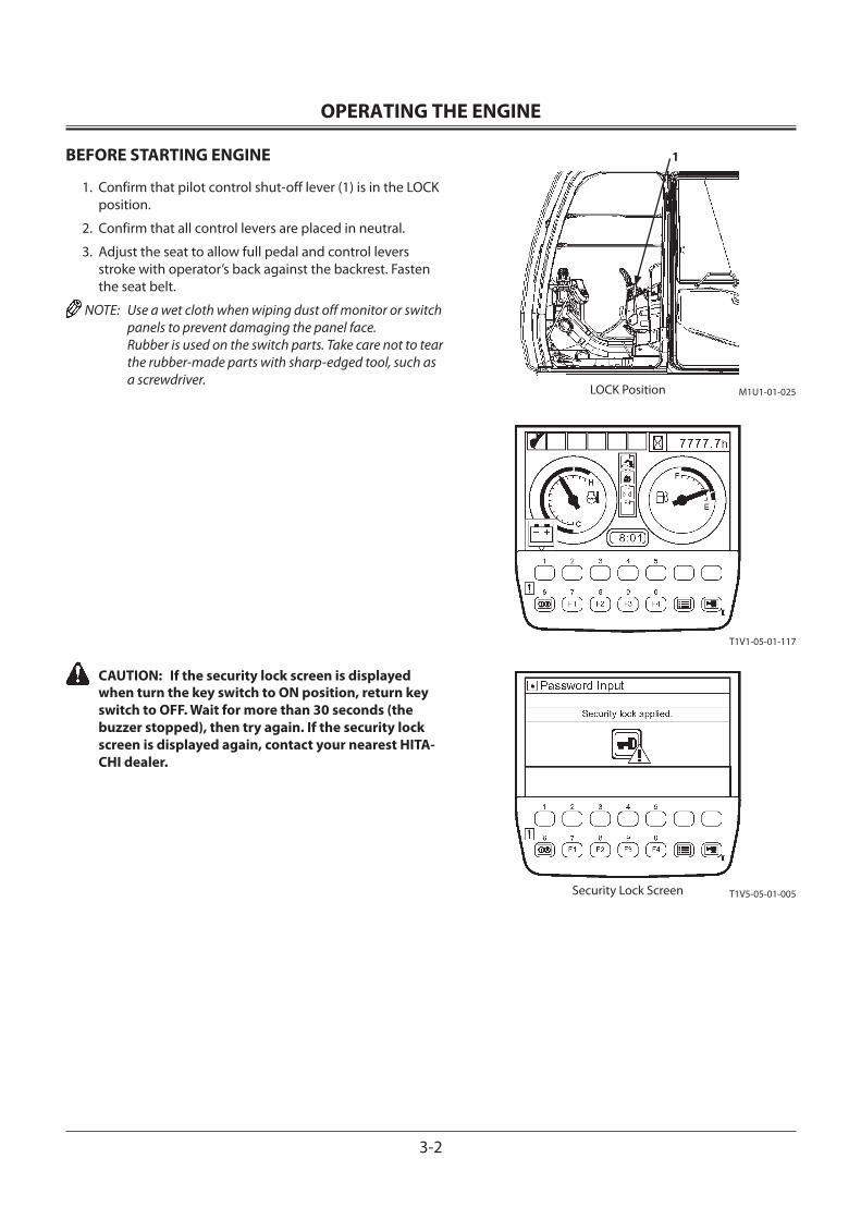
OPERATING THE ENGINE
3-2
BEFORE STARTING ENGINE
1. Confirm that pilot control shut-off lever (1) is in the LOCK position.
2. Confirm that all control levers are placed in neutral.
3. Adjust the seat to allow full pedal and control levers stroke with operator’s back against the backrest. Fasten the seat belt.
NOTE: Use a wet cloth when wiping dust off monitor or switch panels to prevent damaging the panel face. Rubber is used on the switch parts. Take care not to tear the rubber-made parts with sharp-edged tool, such as a screwdriver.
CAUTION: If the security lock screen is displayed when turn the key switch to ON position, return key switch to OFF. Wait for more than 30 seconds (the buzzer stopped), then try again. If the security lock screen is displayed again, contact your nearest HITA-CHI dealer.
1
LOCK Position M1U1-01-025
T1V1-05-01-117
T1V5-05-01-005Security Lock Screen
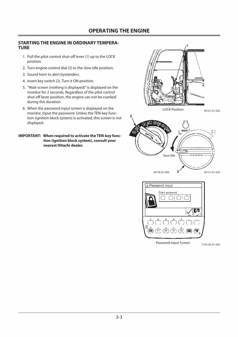
OPERATING THE ENGINE
3-3
STARTING THE ENGINE IN ORDINARY TEMPERA-TURE
1. Pull the pilot control shut-off lever (1) up to the LOCK position.
2. Turn engine control dial (3) to the slow idle position.
3. Sound horn to alert bystanders.
4. Insert key switch (2). Turn it ON position.
5. “Wait-screen (nothing is displayed)” is displayed on the monitor for 2 seconds. Regardless of the pilot control shut-off lever position, the engine can not be cranked during this duration.
6. When the password input screen is displayed on the monitor, input the password. Unless the TEN-key func-tion (ignition block system) is activated, this screen is not displayed.
IMPORTANT: When required to activate the TEN-key func-tion (ignition block system), consult your nearest Hitachi dealer.
1
LOCK Position M1U1-01-025
M178-01-049 M1U1-01-0333
2
Slow Idle
T1V5-05-01-002Password Input Screen
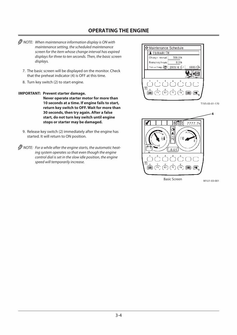
OPERATING THE ENGINE
3-4
NOTE: When maintenance information display is ON with maintenance setting, the scheduled maintenance screen for the item whose change interval has expired displays for three to ten seconds. Then, the basic screen displays.
7. The basic screen will be displayed on the monitor. Check that the preheat indicator (4) is OFF at this time.
8. Turn key switch (2) to start engine.
IMPORTANT: Prevent starter damage. Never operate starter motor for more than 10 seconds at a time. If engine fails to start, return key switch to OFF. Wait for more than 30 seconds, then try again. After a false start, do not turn key switch until engine stops or starter may be damaged.
9. Release key switch (2) immediately after the engine has started. It will return to ON position.
NOTE: For a while after the engine starts, the automatic heat-ing system operates so that even though the engine control dial is set in the slow idle position, the engine speed will temporarily increase.
M1U1-03-001Basic Screen
4
T1V5-05-01-170
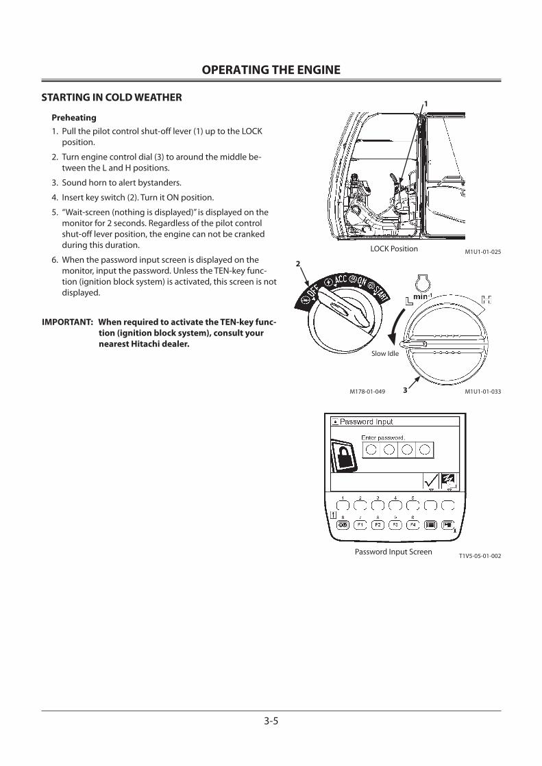
OPERATING THE ENGINE
3-5
STARTING IN COLD WEATHER
Preheating1. Pull the pilot control shut-off lever (1) up to the LOCK
position.
2. Turn engine control dial (3) to around the middle be-tween the L and H positions.
3. Sound horn to alert bystanders.
4. Insert key switch (2). Turn it ON position.
5. “Wait-screen (nothing is displayed)” is displayed on the monitor for 2 seconds. Regardless of the pilot control shut-off lever position, the engine can not be cranked during this duration.
6. When the password input screen is displayed on the monitor, input the password. Unless the TEN-key func-tion (ignition block system) is activated, this screen is not displayed.
IMPORTANT: When required to activate the TEN-key func-tion (ignition block system), consult your nearest Hitachi dealer.
1
LOCK Position M1U1-01-025
M178-01-049 M1U1-01-0333
2
Slow Idle
T1V5-05-01-002Password Input Screen
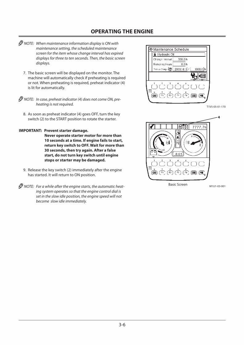
OPERATING THE ENGINE
3-6
NOTE: When maintenance information display is ON with maintenance setting, the scheduled maintenance screen for the item whose change interval has expired displays for three to ten seconds. Then, the basic screen displays.
7. The basic screen will be displayed on the monitor. The machine will automatically check if preheating is required or not. When preheating is required, preheat indicator (4) is lit for automatically.
NOTE: In case, preheat indicator (4) does not come ON, pre-heating is not required.
8. As soon as preheat indicator (4) goes OFF, turn the key switch (2) to the START position to rotate the starter.
IMPORTANT: Prevent starter damage. Never operate starter motor for more than 10 seconds at a time. If engine fails to start, return key switch to OFF. Wait for more than 30 seconds, then try again. After a false start, do not turn key switch until engine stops or starter may be damaged.
9. Release the key switch (2) immediately after the engine has started. It will return to ON position.
NOTE: For a while after the engine starts, the automatic heat-ing system operates so that the engine control dial is set in the slow idle position, the engine speed will not become slow idle immediately.
M1U1-03-001Basic Screen
4
T1V5-05-01-170
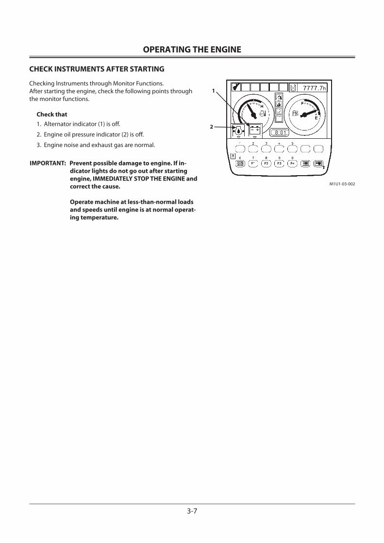
OPERATING THE ENGINE
3-7
CHECK INSTRUMENTS AFTER STARTING
Checking lnstruments through Monitor Functions.After starting the engine, check the following points through the monitor functions.
Check that1. Alternator indicator (1) is off.
2. Engine oil pressure indicator (2) is off.
3. Engine noise and exhaust gas are normal.
IMPORTANT: Prevent possible damage to engine. If in-dicator lights do not go out after starting engine, IMMEDIATELY STOP THE ENGINE and correct the cause. Operate machine at less-than-normal loads and speeds until engine is at normal operat-ing temperature.
1
2
M1U1-03-002
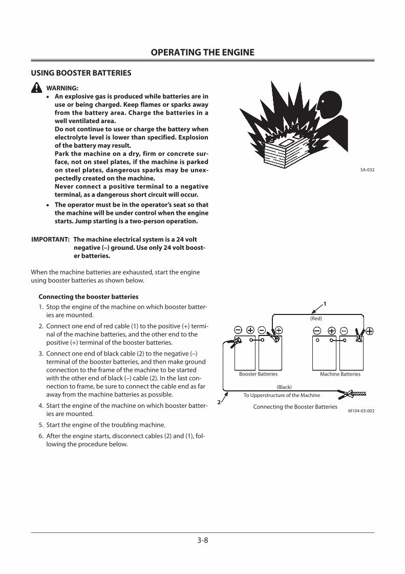
OPERATING THE ENGINE
3-8
USING BOOSTER BATTERIES
WARNING:• An explosive gas is produced while batteries are in
use or being charged. Keep flames or sparks away from the battery area. Charge the batteries in a well ventilated area.
Do not continue to use or charge the battery when electrolyte level is lower than specified. Explosion of the battery may result.
Park the machine on a dry, firm or concrete sur-face, not on steel plates, if the machine is parked on steel plates, dangerous sparks may be unex-pectedly created on the machine.
Never connect a positive terminal to a negative terminal, as a dangerous short circuit will occur.
• The operator must be in the operator’s seat so that the machine will be under control when the engine starts. Jump starting is a two-person operation.
IMPORTANT: The machine electrical system is a 24 volt negative (–) ground. Use only 24 volt boost-er batteries.
When the machine batteries are exhausted, start the engine using booster batteries as shown below.
Connecting the booster batteries1. Stop the engine of the machine on which booster batter-
ies are mounted.
2. Connect one end of red cable (1) to the positive (+) termi-nal of the machine batteries, and the other end to the positive (+) terminal of the booster batteries.
3. Connect one end of black cable (2) to the negative (–) terminal of the booster batteries, and then make ground connection to the frame of the machine to be started with the other end of black (–) cable (2). In the last con-nection to frame, be sure to connect the cable end as far away from the machine batteries as possible.
4. Start the engine of the machine on which booster batter-ies are mounted.
5. Start the engine of the troubling machine.
6. After the engine starts, disconnect cables (2) and (1), fol-lowing the procedure below.
SA-032
1
(Black)
Booster Batteries Machine Batteries
(Red)
To Upperstructure of the Machine2
Connecting the Booster BatteriesM104-03-002
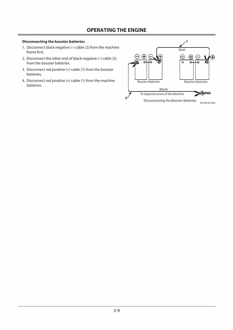
OPERATING THE ENGINE
3-9
Disconnecting the booster batteries1. Disconnect black negative (–) cable (2) from the machine
frame first.
2. Disconnect the other end of black negative (–) cable (2) from the booster batteries.
3. Disconnect red positive (+) cable (1) from the booster batteries.
4. Disconnect red positive (+) cable (1) from the machine batteries.
1
(Black)
Booster Batteries Machine Batteries
(Red)
To Upperstructure of the Machine2
Disconnecting the Booster BatteriesM104-03-002
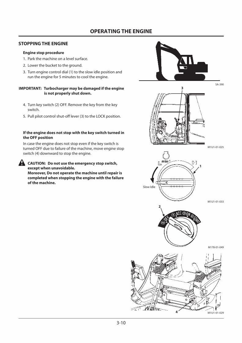
OPERATING THE ENGINE
3-10
STOPPING THE ENGINE
Engine stop procedure1. Park the machine on a level surface.
2. Lower the bucket to the ground.
3. Turn engine control dial (1) to the slow idle position and run the engine for 5 minutes to cool the engine.
IMPORTANT: Turbocharger may be damaged if the engine is not properly shut down.
4. Turn key switch (2) OFF. Remove the key from the key switch.
5. Pull pilot control shut-off lever (3) to the LOCK position.
If the engine does not stop with the key switch turned in the OFF positionIn case the engine does not stop even if the key switch is turned OFF due to failure of the machine, move engine stop switch (4) downward to stop the engine.
CAUTION: Do not use the emergency stop switch, except when unavoidable. Moreover, Do not operate the machine until repair is completed when stopping the engine with the failure of the machine.
SA-390
M1U1-01-025
M178-01-049
2
M1U1-01-0294
M1U1-01-033
1
Slow Idle
3
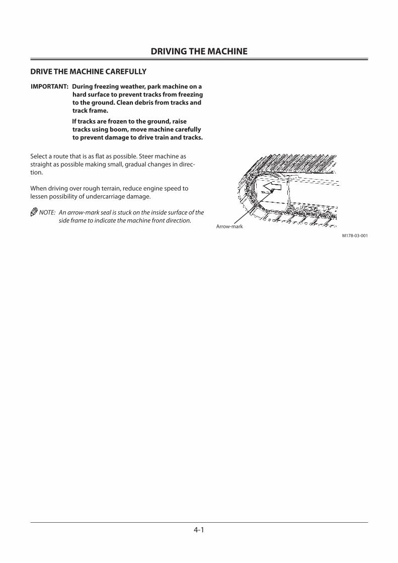
DRIVING THE MACHINE
4-1
DRIVE THE MACHINE CAREFULLY
IMPORTANT: During freezing weather, park machine on a hard surface to prevent tracks from freezing to the ground. Clean debris from tracks and track frame.
If tracks are frozen to the ground, raise tracks using boom, move machine carefully to prevent damage to drive train and tracks.
Select a route that is as flat as possible. Steer machine as straight as possible making small, gradual changes in direc-tion.
When driving over rough terrain, reduce engine speed to lessen possibility of undercarriage damage.
NOTE: An arrow-mark seal is stuck on the inside surface of the side frame to indicate the machine front direction.
M178-03-001
Arrow-mark

DRIVING THE MACHINE
4-2
STEERING THE MACHINE USING PEDALS
WARNING: In the standard travel position, the front idlers are positioned at the front of the machine and the travel motors at the rear. If the travel motors are positioned at the front of the machine, the control actions of the travel pedals will be reversed. Be sure to confirm the position of the travel motors before traveling.
• FORWARD TRAVEL Push down on front (A) of both pedals.
• REVERSE TRAVEL Push down on rear (B) of both pedals.
• NEUTRAL POSITION (C) When the travel pedals are placed in neutral, travel brakes automatically will stop and/or hold the machine.
• RIGHT TURN Push down on front of left pedal.
• LEFT TURN Push down on front of right pedal.
• SHORT TURN (Spin turn) Push down the front of one pedal and the rear of the other.
NOTE: For long-term traveling, push down on pedal tabs (D) and rest feet on footrests.
M104-01-038
CabFront Idler
Travel Motor
Forward and Reverse
AD
CB
A
DC
B
Pivot Turn
Spin Turn
M104-04-009
M104-04-003
M104-04-010
M104-04-005
M104-04-011
M104-04-007
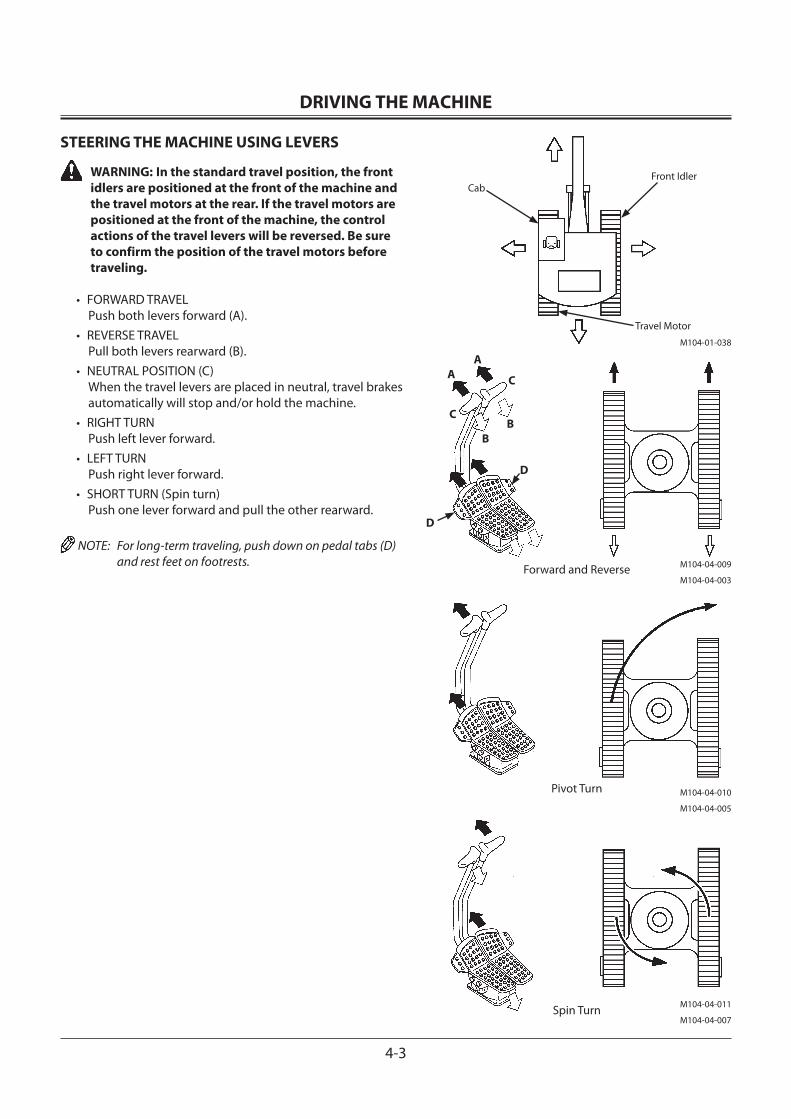
DRIVING THE MACHINE
4-3
STEERING THE MACHINE USING LEVERS
WARNING: In the standard travel position, the front idlers are positioned at the front of the machine and the travel motors at the rear. If the travel motors are positioned at the front of the machine, the control actions of the travel levers will be reversed. Be sure to confirm the position of the travel motors before traveling.
• FORWARD TRAVEL Push both levers forward (A).
• REVERSE TRAVEL Pull both levers rearward (B).
• NEUTRAL POSITION (C) When the travel levers are placed in neutral, travel brakes automatically will stop and/or hold the machine.
• RIGHT TURN Push left lever forward.
• LEFT TURN Push right lever forward.
• SHORT TURN (Spin turn) Push one lever forward and pull the other rearward.
NOTE: For long-term traveling, push down on pedal tabs (D) and rest feet on footrests.
M104-01-038
CabFront Idler
Travel Motor
Forward and Reverse
D
D
Pivot Turn
Spin Turn
M104-04-009
M104-04-003
M104-04-010
M104-04-005
M104-04-011
M104-04-007
A C
B
A
CB
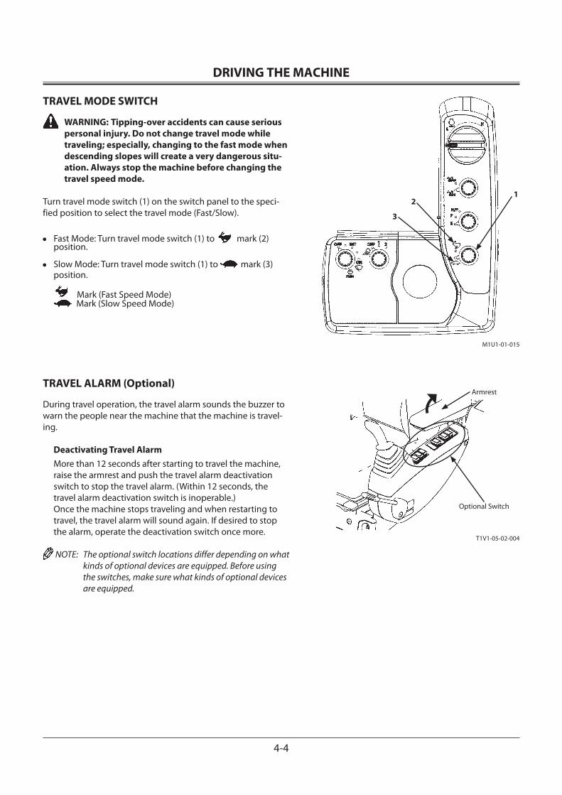
DRIVING THE MACHINE
4-4
TRAVEL MODE SWITCH
WARNING: Tipping-over accidents can cause serious personal injury. Do not change travel mode while traveling; especially, changing to the fast mode when descending slopes will create a very dangerous situ-ation. Always stop the machine before changing the travel speed mode.
Turn travel mode switch (1) on the switch panel to the speci-fied position to select the travel mode (Fast/Slow).
• Fast Mode: Turn travel mode switch (1) to mark (2) position.
• Slow Mode: Turn travel mode switch (1) to mark (3) position.
Mark (Fast Speed Mode) Mark (Slow Speed Mode)
TRAVEL ALARM (Optional)
During travel operation, the travel alarm sounds the buzzer to warn the people near the machine that the machine is travel-ing.
Deactivating Travel AlarmMore than 12 seconds after starting to travel the machine, raise the armrest and push the travel alarm deactivation switch to stop the travel alarm. (Within 12 seconds, the travel alarm deactivation switch is inoperable.)Once the machine stops traveling and when restarting to travel, the travel alarm will sound again. If desired to stop the alarm, operate the deactivation switch once more.
NOTE: The optional switch locations differ depending on what kinds of optional devices are equipped. Before using the switches, make sure what kinds of optional devices are equipped.
M1U1-01-015
12
3
T1V1-05-02-004
Optional Switch
Armrest
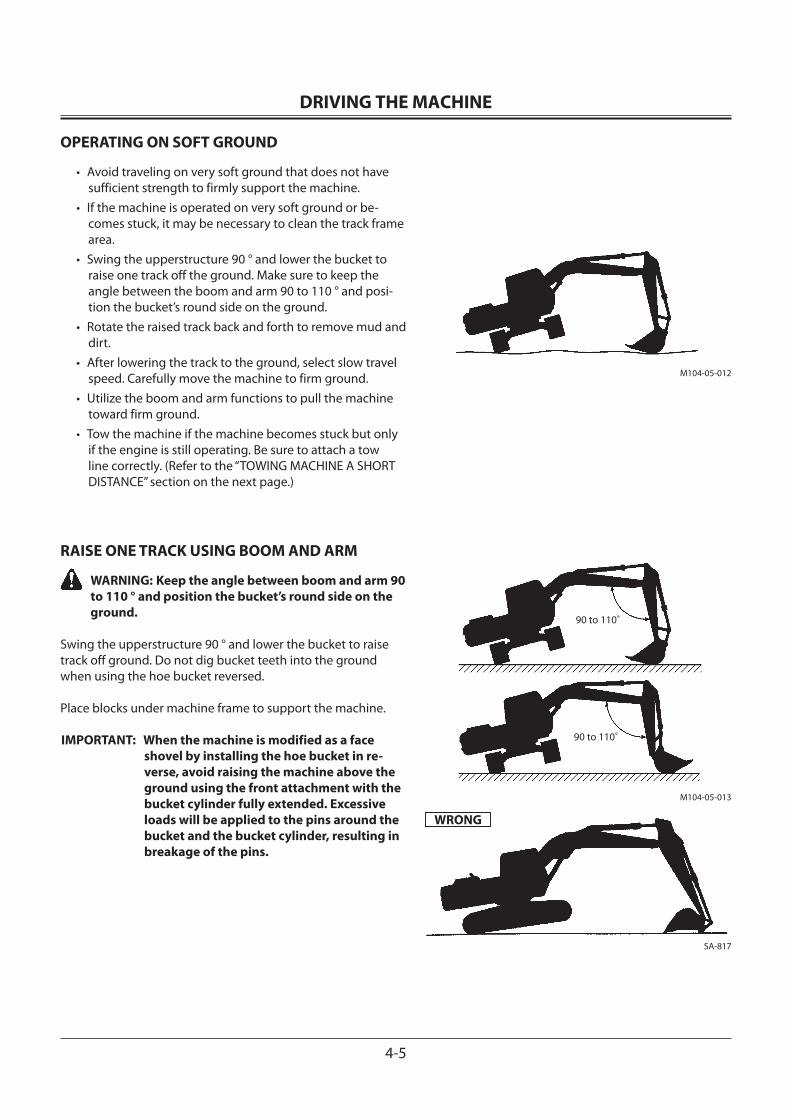
DRIVING THE MACHINE
4-5
OPERATING ON SOFT GROUND
• Avoid traveling on very soft ground that does not have sufficient strength to firmly support the machine.
• If the machine is operated on very soft ground or be-comes stuck, it may be necessary to clean the track frame area.
• Swing the upperstructure 90 ° and lower the bucket to raise one track off the ground. Make sure to keep the angle between the boom and arm 90 to 110 ° and posi-tion the bucket’s round side on the ground.
• Rotate the raised track back and forth to remove mud and dirt.
• After lowering the track to the ground, select slow travel speed. Carefully move the machine to firm ground.
• Utilize the boom and arm functions to pull the machine toward firm ground.
• Tow the machine if the machine becomes stuck but only if the engine is still operating. Be sure to attach a tow line correctly. (Refer to the “TOWING MACHINE A SHORT DISTANCE” section on the next page.)
RAISE ONE TRACK USING BOOM AND ARM
WARNING: Keep the angle between boom and arm 90 to 110 ° and position the bucket’s round side on the ground.
Swing the upperstructure 90 ° and lower the bucket to raise track off ground. Do not dig bucket teeth into the ground when using the hoe bucket reversed.
Place blocks under machine frame to support the machine.
IMPORTANT: When the machine is modified as a face shovel by installing the hoe bucket in re-verse, avoid raising the machine above the ground using the front attachment with the bucket cylinder fully extended. Excessive loads will be applied to the pins around the bucket and the bucket cylinder, resulting in breakage of the pins.
M104-05-012
M104-05-013
90 to 110˚
90 to 110˚
WRONG
SA-817
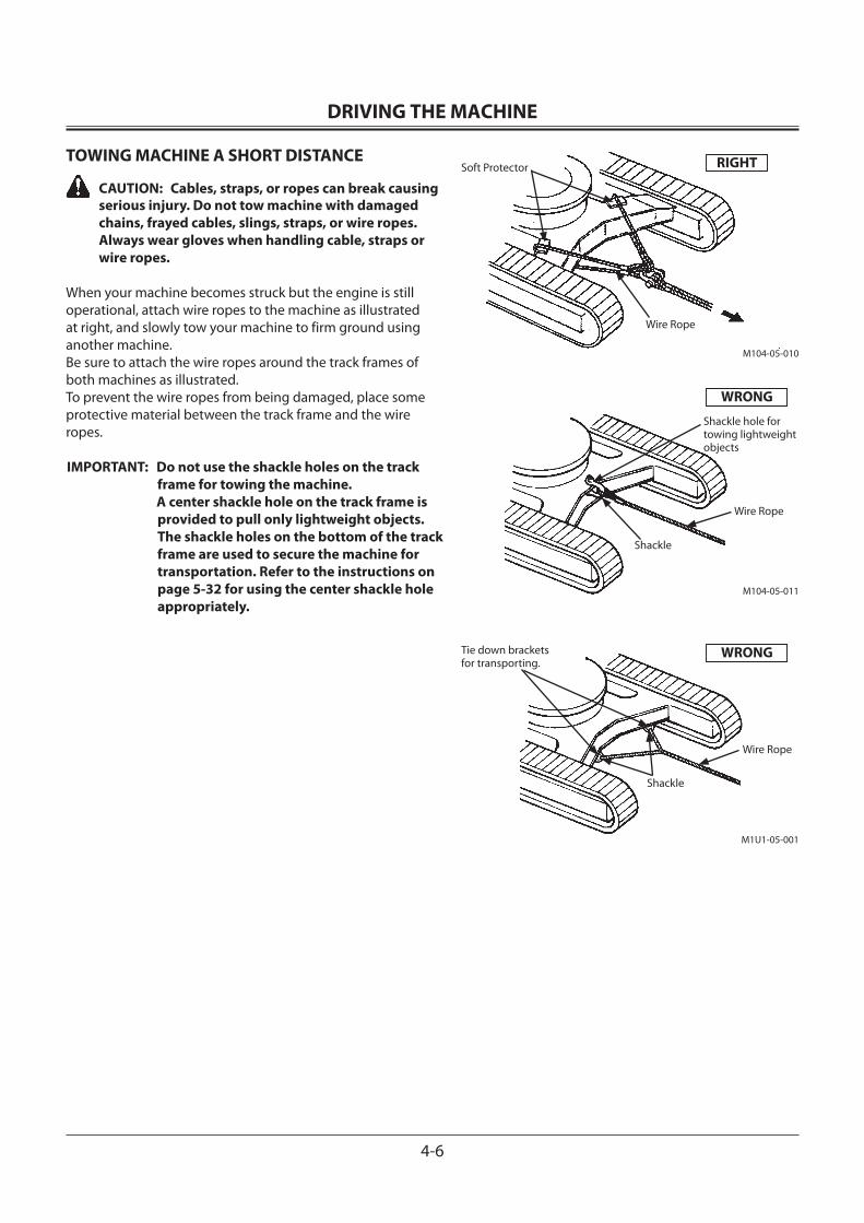
DRIVING THE MACHINE
4-6
TOWING MACHINE A SHORT DISTANCE
CAUTION: Cables, straps, or ropes can break causing serious injury. Do not tow machine with damaged chains, frayed cables, slings, straps, or wire ropes. Always wear gloves when handling cable, straps or wire ropes.
When your machine becomes struck but the engine is still operational, attach wire ropes to the machine as illustrated at right, and slowly tow your machine to firm ground using another machine.Be sure to attach the wire ropes around the track frames of both machines as illustrated.To prevent the wire ropes from being damaged, place some protective material between the track frame and the wire ropes.
IMPORTANT: Do not use the shackle holes on the track frame for towing the machine.
A center shackle hole on the track frame is provided to pull only lightweight objects. The shackle holes on the bottom of the track frame are used to secure the machine for transportation. Refer to the instructions on page 5-32 for using the center shackle hole appropriately.
M104-05-010
RIGHT
Wire Rope
Tie down brackets for transporting.
M1U1-05-001
Wire Rope
Shackle
M104-05-011
Shackle hole for towing lightweight objects
WRONG
Wire Rope
Shackle
WRONG
Soft Protector
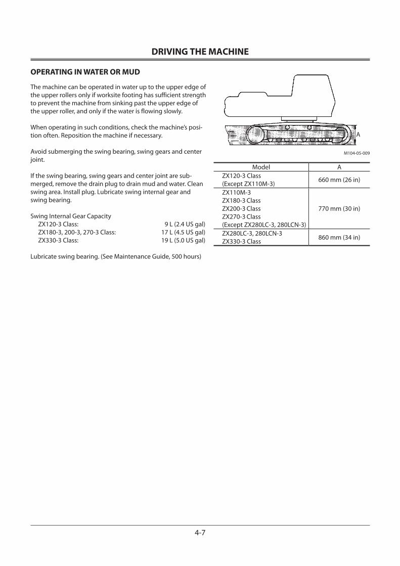
DRIVING THE MACHINE
4-7
OPERATING IN WATER OR MUD
The machine can be operated in water up to the upper edge of the upper rollers only if worksite footing has sufficient strength to prevent the machine from sinking past the upper edge of the upper roller, and only if the water is flowing slowly.
When operating in such conditions, check the machine’s posi-tion often. Reposition the machine if necessary.
Avoid submerging the swing bearing, swing gears and center joint.
If the swing bearing, swing gears and center joint are sub-merged, remove the drain plug to drain mud and water. Clean swing area. Install plug. Lubricate swing internal gear and swing bearing.
Swing Internal Gear CapacityZX120-3 Class: 9 L (2.4 US gal)ZX180-3, 200-3, 270-3 Class: 17 L (4.5 US gal)ZX330-3 Class: 19 L (5.0 US gal)
Lubricate swing bearing. (See Maintenance Guide, 500 hours)
M104-05-009
A
Model AZX120-3 Class (Except ZX110M-3) 660 mm (26 in)
ZX110M-3ZX180-3 Class
ZX200-3 Class
ZX270-3 Class
(Except ZX280LC-3, 280LCN-3)
770 mm (30 in)
ZX280LC-3, 280LCN-3ZX330-3 Class 860 mm (34 in)
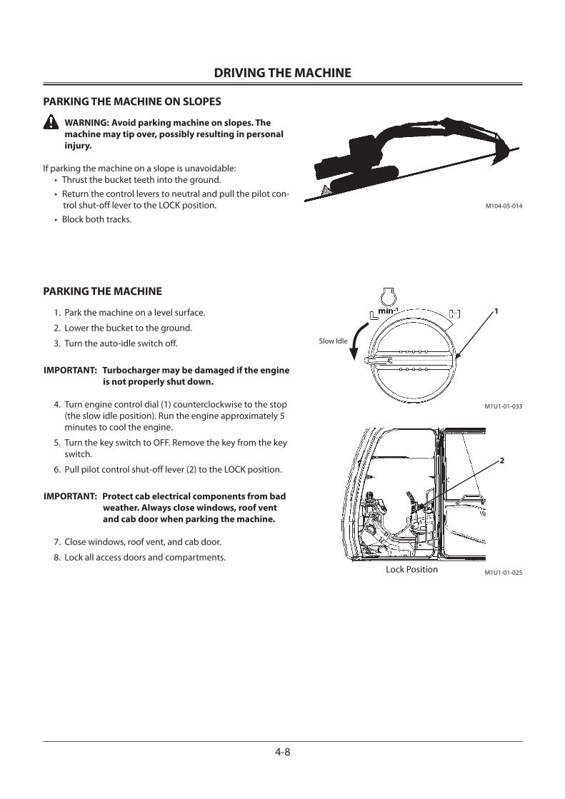
DRIVING THE MACHINE
4-8
PARKING THE MACHINE ON SLOPES
WARNING: Avoid parking machine on slopes. The machine may tip over, possibly resulting in personal injury.
If parking the machine on a slope is unavoidable:• Thrust the bucket teeth into the ground.• Return the control levers to neutral and pull the pilot con-
trol shut-off lever to the LOCK position.• Block both tracks.
PARKING THE MACHINE
1. Park the machine on a level surface.
2. Lower the bucket to the ground.
3. Turn the auto-idle switch off.
IMPORTANT: Turbocharger may be damaged if the engine is not properly shut down.
4. Turn engine control dial (1) counterclockwise to the stop (the slow idle position). Run the engine approximately 5 minutes to cool the engine.
5. Turn the key switch to OFF. Remove the key from the key switch.
6. Pull pilot control shut-off lever (2) to the LOCK position.
IMPORTANT: Protect cab electrical components from bad weather. Always close windows, roof vent and cab door when parking the machine.
7. Close windows, roof vent, and cab door.
8. Lock all access doors and compartments.
M104-05-014
M1U1-01-033
M1U1-01-025
1
Slow Idle
2
Lock Position
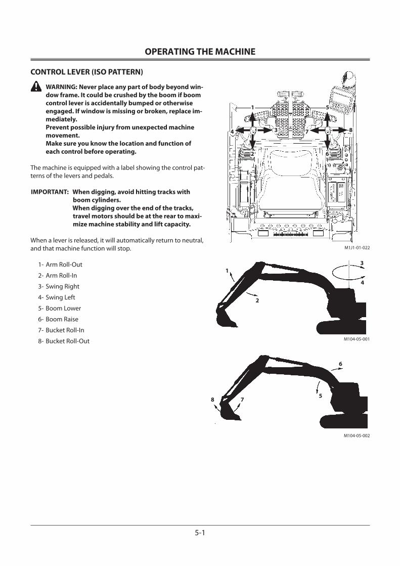
OPERATING THE MACHINE
5-1
CONTROL LEVER (ISO PATTERN)
WARNING: Never place any part of body beyond win-dow frame. It could be crushed by the boom if boom control lever is accidentally bumped or otherwise engaged. If window is missing or broken, replace im-mediately. Prevent possible injury from unexpected machine movement. Make sure you know the location and function of each control before operating.
The machine is equipped with a label showing the control pat-terns of the levers and pedals.
IMPORTANT: When digging, avoid hitting tracks with boom cylinders.
When digging over the end of the tracks, travel motors should be at the rear to maxi-mize machine stability and lift capacity.
When a lever is released, it will automatically return to neutral, and that machine function will stop.
1- Arm Roll-Out
2- Arm Roll-In
3- Swing Right
4- Swing Left
5- Boom Lower
6- Boom Raise
7- Bucket Roll-In
8- Bucket Roll-Out M104-05-001
M104-05-002
1
2
3
4
6
57
1
3
2
4
5
8
6
7
M1J1-01-022
8
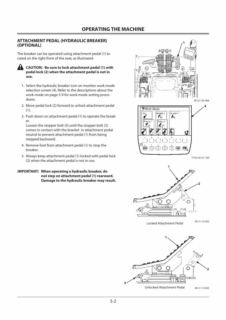
OPERATING THE MACHINE
5-2
ATTACHMENT PEDAL (HYDRAULIC BREAKER) (OPTIONAL)
The breaker can be operated using attachment pedal (1) lo-cated on the right front of the seat, as illustrated.
CAUTION: Be sure to lock attachment pedal (1) with pedal lock (2) when the attachment pedal is not in use.
1. Select the hydraulic breaker icon on monitor work mode selection screen (4). Refer to the descriptions about the work mode on page 5-9 for work mode setting proce-dures.
2. Move pedal lock (2) forward to unlock attachment pedal (1).
3. Push down on attachment pedal (1) to operate the break-er. Loosen the stopper bolt (3) until the stopper bolt (3) comes in contact with the bracket in attachment pedal neutral to prevent attachment pedal (1) from being stepped backward.
4. Remove foot from attachment pedal (1) to stop the breaker.
5. Always keep attachment pedal (1) locked with pedal lock (2) when the attachment pedal is not in use.
IMPORTANT: When operating a hydraulic breaker, do not step on attachment pedal (1) rearward. Damage to the hydraulic breaker may result.
M1U1-05-008
T1V5-05-01-109
1
4
M1J1-13-003
1
2
Unlocked Attachment Pedal
M1J1-13-002
1
2
Locked Attachment Pedal
3
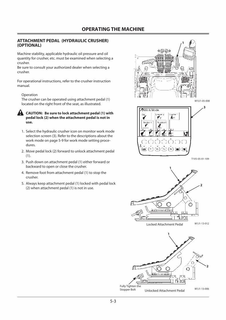
OPERATING THE MACHINE
5-3
ATTACHMENT PEDAL (HYDRAULIC CRUSHER) (OPTIONAL)
Machine stability, applicable hydraulic oil pressure and oil quantity for crusher, etc. must be examined when selecting a crusher.Be sure to consult your authorized dealer when selecting a crusher.
For operational instructions, refer to the crusher instruction manual.
OperationThe crusher can be operated using attachment pedal (1) located on the right front of the seat, as illustrated.
CAUTION: Be sure to lock attachment pedal (1) with pedal lock (2) when the attachment pedal is not in use.
1. Select the hydraulic crusher icon on monitor work mode selection screen (3). Refer to the descriptions about the work mode on page 5-9 for work mode setting proce-dures.
2. Move pedal lock (2) forward to unlock attachment pedal (1).
3. Push down on attachment pedal (1) either forward or backward to open or close the crusher.
4. Remove foot from attachment pedal (1) to stop the crusher.
5. Always keep attachment pedal (1) locked with pedal lock (2) when attachment pedal (1) is not in use.
M1U1-05-008
T1V5-05-01-109
1
3
M1J1-13-012
1
2
Locked Attachment Pedal
M1J1-13-006
1
2
Unlocked Attachment PedalFully Tighten the Stopper Bolt
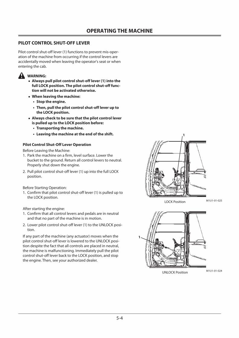
OPERATING THE MACHINE
5-4
PILOT CONTROL SHUT-OFF LEVER
Pilot control shut-off lever (1) functions to prevent mis-oper-ation of the machine from occurring if the control levers are accidentally moved when leaving the operator's seat or when entering the cab.
WARNING:• Always pull pilot control shut-off lever (1) into the
full LOCK position. The pilot control shut-off func-tion will not be activated otherwise.
• When leaving the machine:• Stop the engine.• Then, pull the pilot control shut-off lever up to
the LOCK position.• Always check to be sure that the pilot control lever
is pulled up to the LOCK position before:• Transporting the machine.• Leaving the machine at the end of the shift.
Pilot Control Shut-Off Lever OperationBefore Leaving the Machine:1. Park the machine on a firm, level surface. Lower the
bucket to the ground. Return all control levers to neutral. Properly shut down the engine.
2. Pull pilot control shut-off lever (1) up into the full LOCK position.
Before Starting Operation:1. Confirm that pilot control shut-off lever (1) is pulled up to
the LOCK position.
After starting the engine:1. Confirm that all control levers and pedals are in neutral
and that no part of the machine is in motion.
2. Lower pilot control shut-off lever (1) to the UNLOCK posi-tion.
If any part of the machine (any actuator) moves when the pilot control shut-off lever is lowered to the UNLOCK posi-tion despite the fact that all controls are placed in neutral, the machine is malfunctioning. Immediately pull the pilot control shut-off lever back to the LOCK position, and stop the engine. Then, see your authorized dealer.
M1U1-01-025LOCK Position
M1U1-01-024UNLOCK Position
1
1
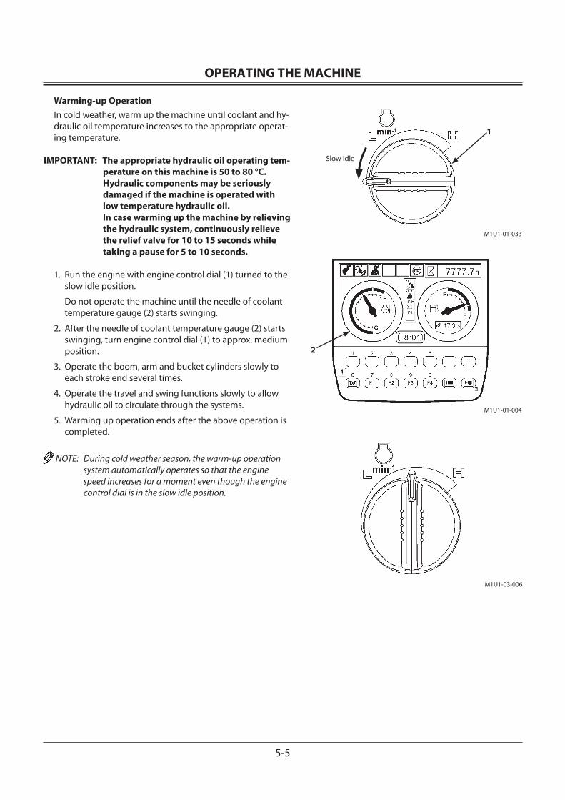
OPERATING THE MACHINE
5-5
Warming-up OperationIn cold weather, warm up the machine until coolant and hy-draulic oil temperature increases to the appropriate operat-ing temperature.
IMPORTANT: The appropriate hydraulic oil operating tem-perature on this machine is 50 to 80 °C. Hydraulic components may be seriously damaged if the machine is operated with low temperature hydraulic oil. In case warming up the machine by relieving the hydraulic system, continuously relieve the relief valve for 10 to 15 seconds while taking a pause for 5 to 10 seconds.
1. Run the engine with engine control dial (1) turned to the slow idle position.
Do not operate the machine until the needle of coolant temperature gauge (2) starts swinging.
2. After the needle of coolant temperature gauge (2) starts swinging, turn engine control dial (1) to approx. medium position.
3. Operate the boom, arm and bucket cylinders slowly to each stroke end several times.
4. Operate the travel and swing functions slowly to allow hydraulic oil to circulate through the systems.
5. Warming up operation ends after the above operation is completed.
NOTE: During cold weather season, the warm-up operation system automatically operates so that the engine speed increases for a moment even though the engine control dial is in the slow idle position.
M1U1-01-033
1
M1U1-01-004
Slow Idle
M1U1-03-006
2
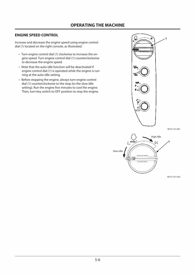
OPERATING THE MACHINE
5-6
ENGINE SPEED CONTROL
Increase and decrease the engine speed using engine control dial (1) located on the right console, as illustrated.
• Turn engine control dial (1) clockwise to increase the en-gine speed. Turn engine control dial (1) counterclockwise to decrease the engine speed.
• Note that the auto-idle function will be deactivated if engine control dial (1) is operated while the engine is run-ning at the auto-idle setting.
• Before stopping the engine, always turn engine control dial (1) counterclockwise to the stop (to the slow idle setting). Run the engine five minutes to cool the engine. Then, turn key switch to OFF position to stop the engine.
1
M1U1-01-033
1
M1V1-01-001
Slow Idle
High Idle
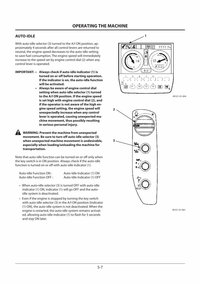
OPERATING THE MACHINE
5-7
AUTO-IDLE
With auto-idle selector (3) turned to the A/I ON position, ap-proximately 4 seconds after all control levers are returned to neutral, the engine speed decreases to the auto-idle setting to save fuel consumption. The engine speed will immediately increase to the speed set by engine control dial (2) when any control lever is operated.
IMPORTANT: • Always check if auto-idle indicator (1) is turned on or off before starting operation. If the indicator is on, the auto-idle function will be activated.
• Always be aware of engine control dial setting when auto-idle selector (1) turned to the A/I ON position. If the engine speed is set high with engine control dial (2), and if the operator is not aware of the high en-gine speed setting, the engine speed will unexpectedly increase when any control lever is operated, causing unexpected ma-chine movement, thus possibly resulting in serious personal injury.
WARNING: Prevent the machine from unexpected movement. Be sure to turn off auto-idle selector (3) when unexpected machine movement is undesirable, especially when loading/unloading the machine for transportation.
Note that auto-idle function can be turned on or off only when the key switch is in ON position. Always check if the auto-idle function is turned on or off with auto-idle indicator (1).
Auto-Idle Function ON : Auto-Idle Indicator (1) ONAuto-Idle Function OFF : Auto-Idle Indicator (1) OFF
• When auto-idle selector (3) is turned OFF with auto-idle indicator (1) ON, indicator (1) will go OFF and the auto-idle system is deactivated.
• Even if the engine is stopped by turning the key switch with auto-idle selector (3) in the A/I ON position [indicator (1) ON], the auto-idle system is not deactivated. When the engine is restarted, the auto-idle system remains activat-ed, allowing auto-idle indicator (1) to flash for 5 seconds and stay ON later.
M1V1-01-001
M1U1-01-004
1
2
3
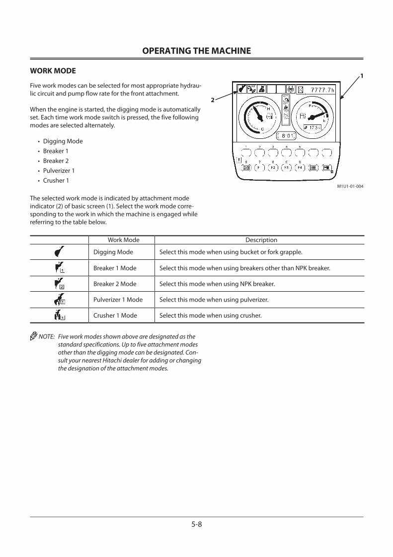
OPERATING THE MACHINE
5-8
WORK MODE
Five work modes can be selected for most appropriate hydrau-lic circuit and pump flow rate for the front attachment.
When the engine is started, the digging mode is automatically set. Each time work mode switch is pressed, the five following modes are selected alternately.
• Digging Mode• Breaker 1• Breaker 2• Pulverizer 1• Crusher 1
The selected work mode is indicated by attachment mode indicator (2) of basic screen (1). Select the work mode corre-sponding to the work in which the machine is engaged while referring to the table below.
Work Mode Description
Digging Mode Select this mode when using bucket or fork grapple.
Breaker 1 Mode Select this mode when using breakers other than NPK breaker.
Breaker 2 Mode Select this mode when using NPK breaker.
Pulverizer 1 Mode Select this mode when using pulverizer.
Crusher 1 Mode Select this mode when using crusher.
NOTE: Five work modes shown above are designated as the standard specifications. Up to five attachment modes other than the digging mode can be designated. Con-sult your nearest Hitachi dealer for adding or changing the designation of the attachment modes.
M1U1-01-004
1
2
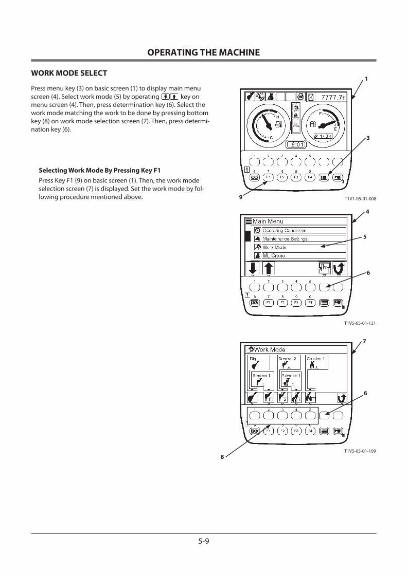
OPERATING THE MACHINE
5-9
T1V1-05-01-008
T1V5-05-01-121
T1V5-05-01-109
1
3
4
5
6
7
6
8
9
WORK MODE SELECT
Press menu key (3) on basic screen (1) to display main menu screen (4). Select work mode (5) by operating key on menu screen (4). Then, press determination key (6). Select the work mode matching the work to be done by pressing bottom key (8) on work mode selection screen (7). Then, press determi-nation key (6).
Selecting Work Mode By Pressing Key F1Press Key F1 (9) on basic screen (1). Then, the work mode selection screen (7) is displayed. Set the work mode by fol-lowing procedure mentioned above.
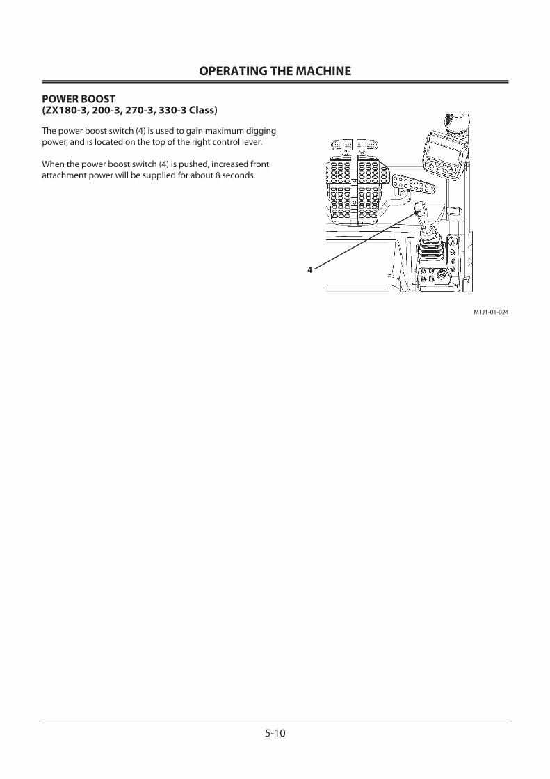
OPERATING THE MACHINE
5-10
POWER BOOST (ZX180-3, 200-3, 270-3, 330-3 Class)
The power boost switch (4) is used to gain maximum digging power, and is located on the top of the right control lever.
When the power boost switch (4) is pushed, increased front attachment power will be supplied for about 8 seconds.
M1J1-01-024
4
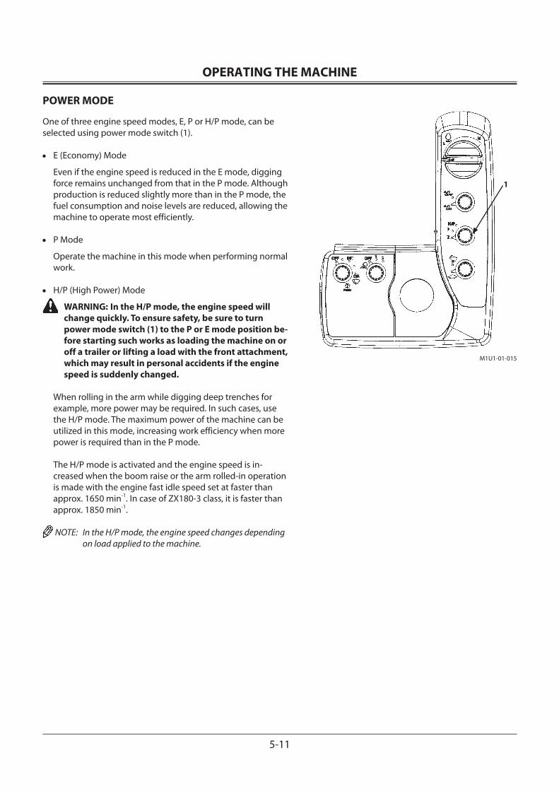
OPERATING THE MACHINE
5-11
POWER MODE
One of three engine speed modes, E, P or H/P mode, can be selected using power mode switch (1).
• E (Economy) Mode
Even if the engine speed is reduced in the E mode, digging force remains unchanged from that in the P mode. Although production is reduced slightly more than in the P mode, the fuel consumption and noise levels are reduced, allowing the machine to operate most efficiently.
• P Mode
Operate the machine in this mode when performing normal work.
• H/P (High Power) Mode
WARNING: In the H/P mode, the engine speed will change quickly. To ensure safety, be sure to turn power mode switch (1) to the P or E mode position be-fore starting such works as loading the machine on or off a trailer or lifting a load with the front attachment, which may result in personal accidents if the engine speed is suddenly changed.
When rolling in the arm while digging deep trenches for example, more power may be required. In such cases, use the H/P mode. The maximum power of the machine can be utilized in this mode, increasing work efficiency when more power is required than in the P mode.
The H/P mode is activated and the engine speed is in-creased when the boom raise or the arm rolled-in operation is made with the engine fast idle speed set at faster than approx. 1650 min-1. In case of ZX180-3 class, it is faster than approx. 1850 min-1.
NOTE: In the H/P mode, the engine speed changes depending on load applied to the machine.
M1U1-01-015
1
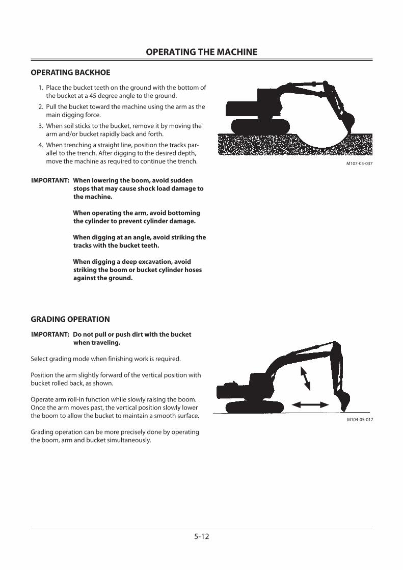
OPERATING THE MACHINE
5-12
OPERATING BACKHOE
1. Place the bucket teeth on the ground with the bottom of the bucket at a 45 degree angle to the ground.
2. Pull the bucket toward the machine using the arm as the main digging force.
3. When soil sticks to the bucket, remove it by moving the arm and/or bucket rapidly back and forth.
4. When trenching a straight line, position the tracks par-allel to the trench. After digging to the desired depth, move the machine as required to continue the trench.
IMPORTANT: When lowering the boom, avoid sudden stops that may cause shock load damage to the machine.
When operating the arm, avoid bottoming the cylinder to prevent cylinder damage.
When digging at an angle, avoid striking the tracks with the bucket teeth.
When digging a deep excavation, avoid striking the boom or bucket cylinder hoses against the ground.
GRADING OPERATION
IMPORTANT: Do not pull or push dirt with the bucket when traveling.
Select grading mode when finishing work is required.
Position the arm slightly forward of the vertical position with bucket rolled back, as shown.
Operate arm roll-in function while slowly raising the boom. Once the arm moves past, the vertical position slowly lower the boom to allow the bucket to maintain a smooth surface.
Grading operation can be more precisely done by operating the boom, arm and bucket simultaneously.
M107-05-037
M104-05-017
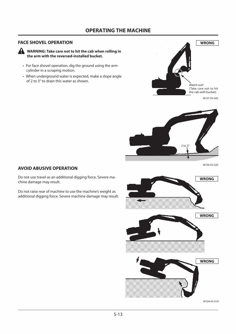
OPERATING THE MACHINE
5-13
FACE SHOVEL OPERATION
WARNING: Take care not to hit the cab when rolling in the arm with the reversed-installed bucket.
• For face shovel operation, dig the ground using the arm cylinder in a scraping motion.
• When underground water is expected, make a slope angle of 2 to 3° to drain this water as shown.
AVOID ABUSIVE OPERATION
Do not use travel as an additional digging force. Severe ma-chine damage may result.
Do not raise rear of machine to use the machine’s weight as additional digging force. Severe machine damage may result.
WRONG
WRONG
WRONG
WRONG
M104-05-020
M104-05-018
M107-05-045
Watch out!(Take care not to hit the cab with bucket)
2 to 3°
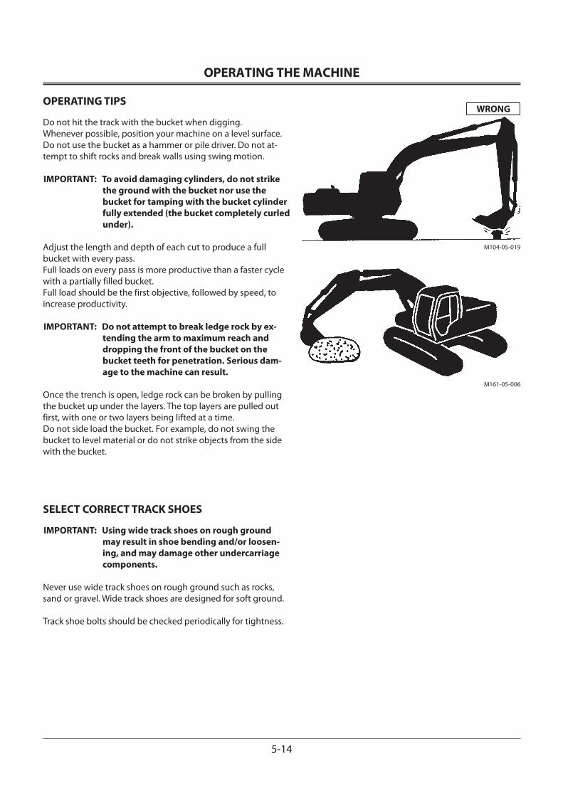
OPERATING THE MACHINE
5-14
OPERATING TIPS
Do not hit the track with the bucket when digging.Whenever possible, position your machine on a level surface.Do not use the bucket as a hammer or pile driver. Do not at-tempt to shift rocks and break walls using swing motion.
IMPORTANT: To avoid damaging cylinders, do not strike the ground with the bucket nor use the bucket for tamping with the bucket cylinder fully extended (the bucket completely curled under).
Adjust the length and depth of each cut to produce a full bucket with every pass.Full loads on every pass is more productive than a faster cycle with a partially filled bucket.Full load should be the first objective, followed by speed, to increase productivity.
IMPORTANT: Do not attempt to break ledge rock by ex-tending the arm to maximum reach and dropping the front of the bucket on the bucket teeth for penetration. Serious dam-age to the machine can result.
Once the trench is open, ledge rock can be broken by pulling the bucket up under the layers. The top layers are pulled out first, with one or two layers being lifted at a time.Do not side load the bucket. For example, do not swing the bucket to level material or do not strike objects from the side with the bucket.
SELECT CORRECT TRACK SHOES
IMPORTANT: Using wide track shoes on rough ground may result in shoe bending and/or loosen-ing, and may damage other undercarriage components.
Never use wide track shoes on rough ground such as rocks, sand or gravel. Wide track shoes are designed for soft ground.
Track shoe bolts should be checked periodically for tightness.
M161-05-006
WRONG
M104-05-019
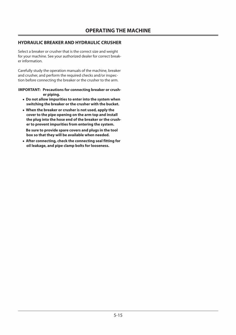
OPERATING THE MACHINE
5-15
HYDRAULIC BREAKER AND HYDRAULIC CRUSHER
Select a breaker or crusher that is the correct size and weight for your machine. See your authorized dealer for correct break-er information.
Carefully study the operation manuals of the machine, breaker and crusher, and perform the required checks and/or inspec-tion before connecting the breaker or the crusher to the arm.
IMPORTANT: Precautions for connecting breaker or crush-er piping.
•Do not allow impurities to enter into the system when switching the breaker or the crusher with the bucket.
•When the breaker or crusher is not used, apply the cover to the pipe opening on the arm top and install the plug into the hose end of the breaker or the crush-er to prevent impurities from entering the system.
Be sure to provide spare covers and plugs in the tool box so that they will be available when needed.
•After connecting, check the connecting seal fitting for oil leakage, and pipe clamp bolts for looseness.
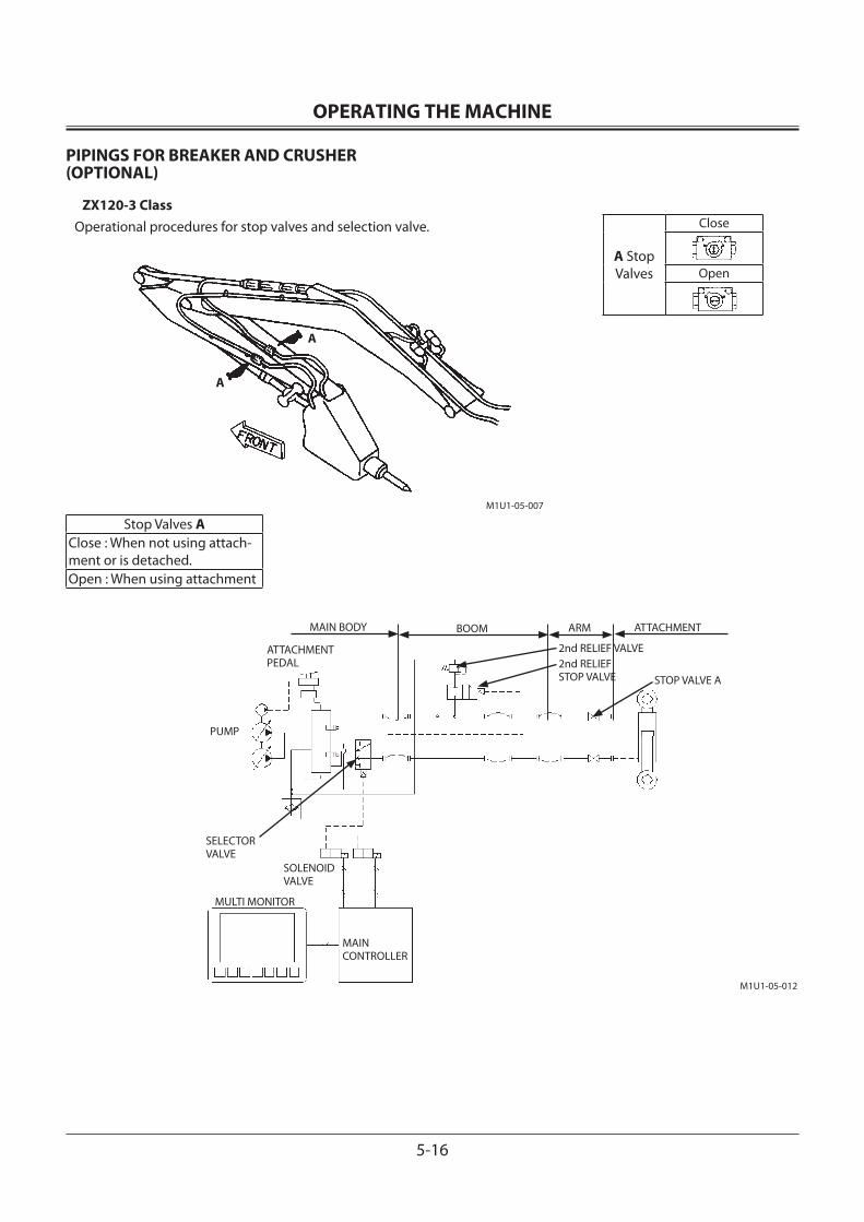
OPERATING THE MACHINE
5-16
PIPINGS FOR BREAKER AND CRUSHER (OPTIONAL)
ZX120-3 ClassOperational procedures for stop valves and selection valve.
Stop Valves AClose : When not using attach-ment or is detached.Open : When using attachment
A Stop Valves
Close
Open
ATTACHMENT PEDAL
PUMP
ARMBOOMMAIN BODY ATTACHMENT
MULTI MONITOR
MAINCONTROLLER
SOLENOIDVALVE
SELECTORVALVE
2nd RELIEF VALVE
STOP VALVE A2nd RELIEFSTOP VALVE
A
A
M1U1-05-007
M1U1-05-012
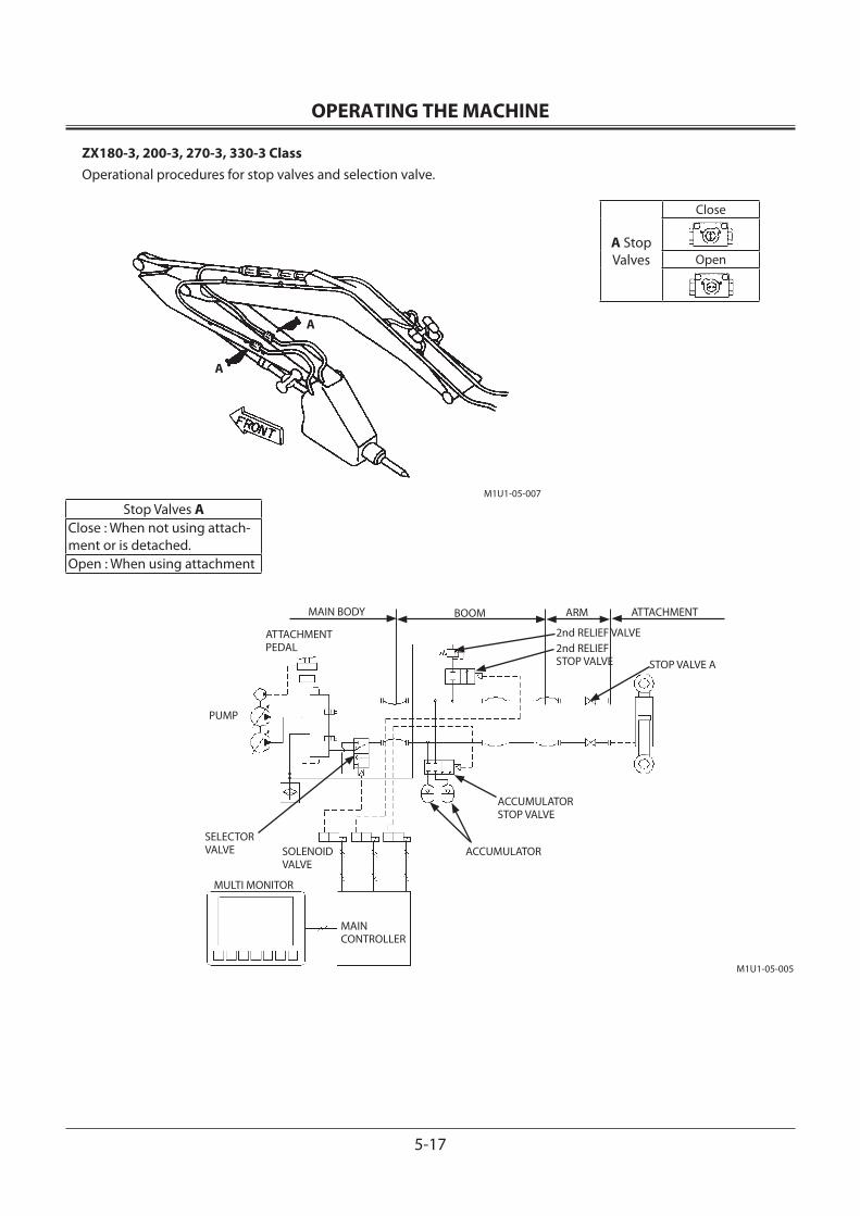
OPERATING THE MACHINE
5-17
ZX180-3, 200-3, 270-3, 330-3 ClassOperational procedures for stop valves and selection valve.
Stop Valves AClose : When not using attach-ment or is detached.Open : When using attachment
A Stop Valves
Close
Open
ATTACHMENT PEDAL
PUMP
ARMBOOMMAIN BODY ATTACHMENT
MULTI MONITOR
MAINCONTROLLER
SOLENOIDVALVE
SELECTORVALVE
ACCUMULATORSTOP VALVE
ACCUMULATOR
2nd RELIEF VALVE
STOP VALVE A2nd RELIEFSTOP VALVE
A
A
M1U1-05-007
M1U1-05-005
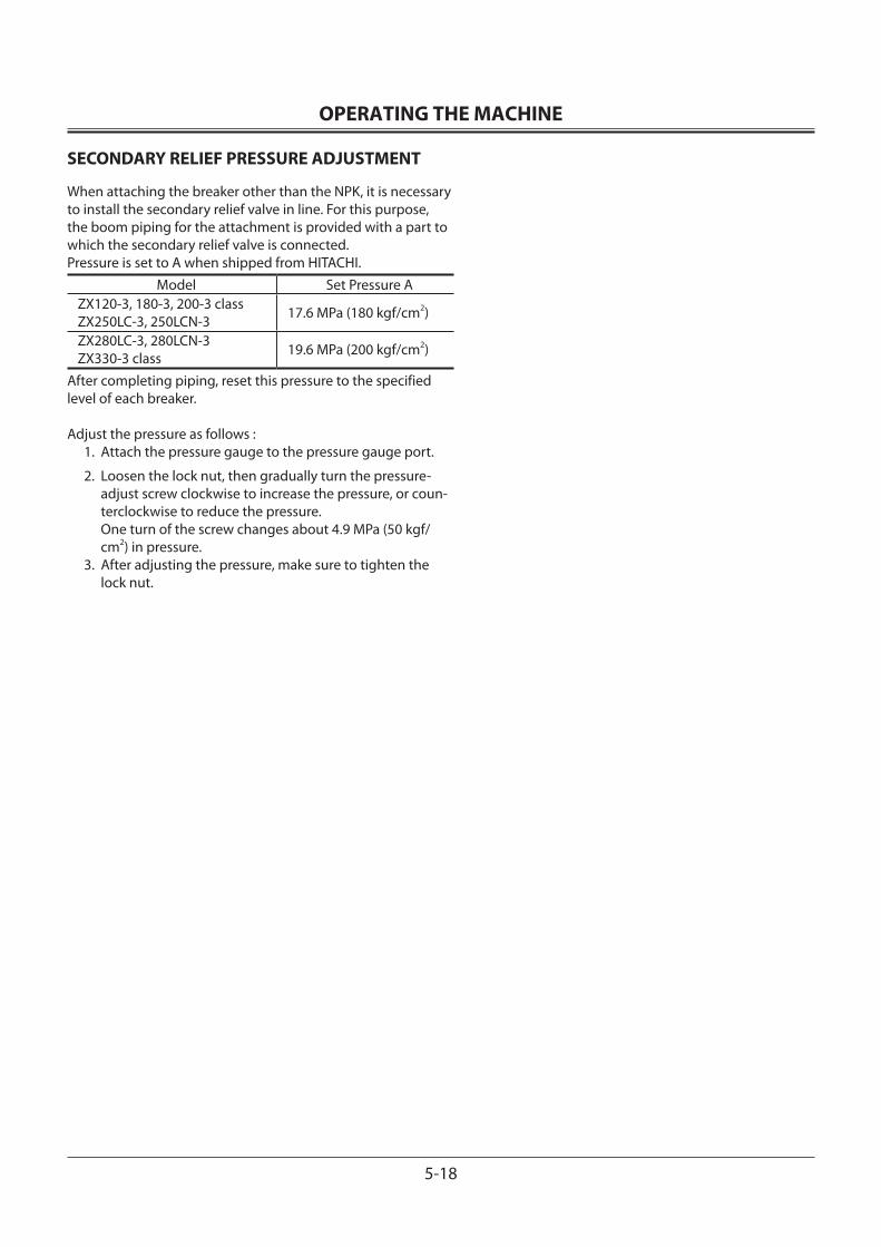
OPERATING THE MACHINE
5-18
SECONDARY RELIEF PRESSURE ADJUSTMENT
When attaching the breaker other than the NPK, it is necessary to install the secondary relief valve in line. For this purpose, the boom piping for the attachment is provided with a part to which the secondary relief valve is connected.Pressure is set to A when shipped from HITACHI.
Model Set Pressure AZX120-3, 180-3, 200-3 class ZX250LC-3, 250LCN-3 17.6 MPa (180 kgf/cm2)
ZX280LC-3, 280LCN-3ZX330-3 class 19.6 MPa (200 kgf/cm2)
After completing piping, reset this pressure to the specified level of each breaker.
Adjust the pressure as follows : 1. Attach the pressure gauge to the pressure gauge port.
2. Loosen the lock nut, then gradually turn the pressure-adjust screw clockwise to increase the pressure, or coun-terclockwise to reduce the pressure. One turn of the screw changes about 4.9 MPa (50 kgf/cm2) in pressure.
3. After adjusting the pressure, make sure to tighten the lock nut.
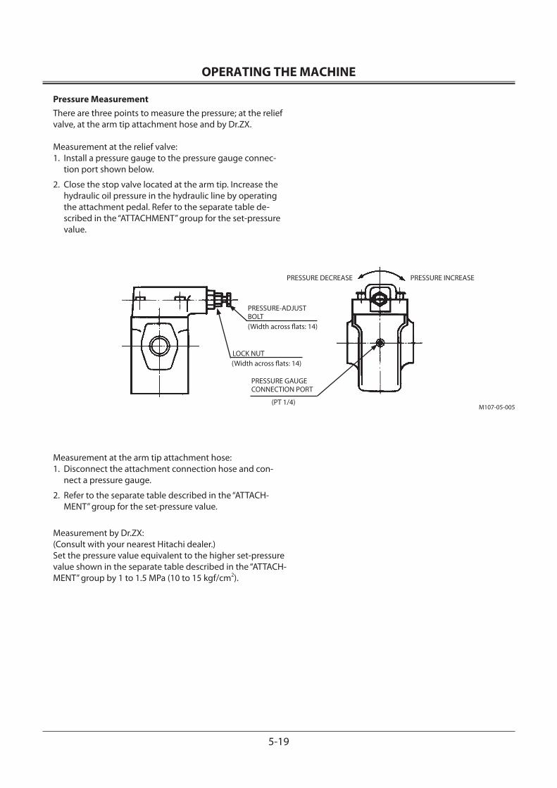
OPERATING THE MACHINE
5-19
LOCK NUT(Width across flats: 14)
PRESSURE-ADJUSTBOLT(Width across flats: 14)
M107-05-005
PRESSURE INCREASEPRESSURE DECREASE
PRESSURE GAUGECONNECTION PORT
(PT 1/4)
Pressure MeasurementThere are three points to measure the pressure; at the relief valve, at the arm tip attachment hose and by Dr.ZX.
Measurement at the relief valve:1. Install a pressure gauge to the pressure gauge connec-
tion port shown below.
2. Close the stop valve located at the arm tip. Increase the hydraulic oil pressure in the hydraulic line by operating the attachment pedal. Refer to the separate table de-scribed in the “ATTACHMENT” group for the set-pressure value.
Measurement at the arm tip attachment hose:1. Disconnect the attachment connection hose and con-
nect a pressure gauge.
2. Refer to the separate table described in the “ATTACH-MENT” group for the set-pressure value.
Measurement by Dr.ZX:(Consult with your nearest Hitachi dealer.)Set the pressure value equivalent to the higher set-pressure value shown in the separate table described in the “ATTACH-MENT” group by 1 to 1.5 MPa (10 to 15 kgf/cm2).
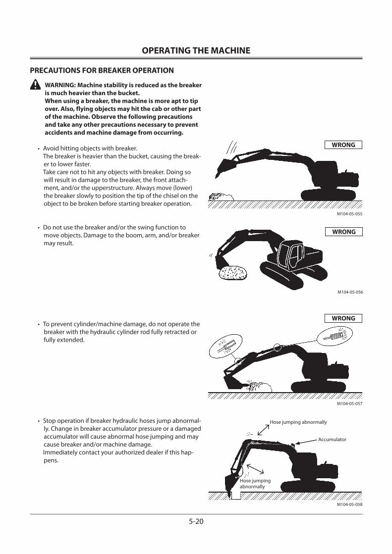
OPERATING THE MACHINE
5-20
PRECAUTIONS FOR BREAKER OPERATION
WARNING: Machine stability is reduced as the breaker is much heavier than the bucket. When using a breaker, the machine is more apt to tip over. Also, flying objects may hit the cab or other part of the machine. Observe the following precautions and take any other precautions necessary to prevent accidents and machine damage from occurring.
• Avoid hitting objects with breaker. The breaker is heavier than the bucket, causing the break-
er to lower faster. Take care not to hit any objects with breaker. Doing so
will result in damage to the breaker, the front attach-ment, and/or the upperstructure. Always move (lower) the breaker slowly to position the tip of the chisel on the object to be broken before starting breaker operation.
• Do not use the breaker and/or the swing function to move objects. Damage to the boom, arm, and/or breaker may result.
• To prevent cylinder/machine damage, do not operate the breaker with the hydraulic cylinder rod fully retracted or fully extended.
• Stop operation if breaker hydraulic hoses jump abnormal-ly. Change in breaker accumulator pressure or a damaged accumulator will cause abnormal hose jumping and may cause breaker and/or machine damage.
Immediately contact your authorized dealer if this hap-pens.
Hose jumping abnormally
Accumulator
M104-05-055
WRONG
M104-05-056
WRONG
M104-05-057
WRONG
Hose jumping abnormally
M104-05-058
OPERATING THE MACHINE
5-21
• Do not operate the breaker in water. Doing so will cause rust and seal damage, resulting in damage to the hydrau-lic system components.
• Do not use breaker for lifting operation. The machine tip-ping over and/or breaker damage may result.
• Do not operate the breaker to the side of the machine. The machine may become unstable and undercarriage component life may shorten as a result from operating the breaker to the side of the machine.
• Operate the hydraulic excavator carefully to avoid hitting the boom.
M104-05-059
M104-05-060
M104-05-061
M104-05-062
WRONG
WRONG
WRONG
Watch Out!Take care not to hit the boom with the breaker
WRONG
RIGHT RIGHT
WRONG
Rod
OPERATING THE MACHINE
5-22
• Do not operate breaker with the arm positioned vertically. Excessive vibration to the arm cylinder will occur, causing oil leakage.
• Press the breaker so that the chisel (the axis) is positioned and thrust perpendicular to the object.
• Do not operate the breaker continuously longer than one minute. Excessive chisel wear will result. If an object could not be broken within one minute, apply the chisel to other locations, less than one minute for each location.
• Raising the front part of the undercarriage by pressing down the breaker may cause damage to the front attach-ment. Although raising the front edge of the undercar-riage up to 150 mm (6 in) is tolerable, do not practice this method more than necessary. Never raise the front edge of the undercarriage higher than 150 mm (6 in) by press-ing the breaker down.
M147-05-013
M147-05-014
M147-05-015
M147-05-016
RIGHT WRONG
If an object could not be broken within one minute, apply the chisel to other locations, less than one minute for each location.
WRONG
Pressing Down
Raising 100 to 150 mm
OPERATING THE MACHINE
5-23
BREAKER MAINTENANCE
Change Hydraulic Oil and Replace Hydraulic Oil Tank Filter
Hydraulic breaker operation subjects the hydraulic system to become contaminated faster and to quickly deteriorate the hy-draulic oil. For this reason, hydraulic oil must be changed and the hydraulic oil tank filter must be replaced more often than the machine equipped with a bucket. Failure to do so may result in damage to the breaker, hydraulic oil pump, and other
related hydraulic system components. Recommended changing intervals are shown below. (For filter replace-ment and oil changing intervals are shown below. (For filter replacement and oil changing procedures, refer to the “Hydraulic System” in the “MAINTENANCE” Section.)
IMPORTANT: Use a high performance element (micro-glass) on excavators engaged in demolition and logging work. In case using a filter-pa-per element is unavoidable, replace hydrau-lic oil and the filter element at the intervals as illustrated with dotted lines.
NOTE: Full-flow filter restriction indicator is optional. If a filter-paper element is used, this indicator does not operate. (Refer to the Hydraulic System in the Maintenance section.)
Excavator Operating Hours
Attachment Availability *Hydraulic Oil Full Flow Filter Element **Element Type
Bucket 100%1500
1000 Standard Filter Paper High Performance Element2500
5000
Hydraulic Breaker 100% 600 100 Standard Filter Paper1000 300 High Performance Element
Changing intervals (Hours)
* : Replacement intervals differ depending on the brand of hydraulic oil used. Refer to the Hydraulic System in the MAIN-TENANCE section.
** : Use the high performance element (micro-glass) on excavators engaged in demolition and logging work.
Replacement Intervals (Hours) of Hydraulic Oil and Full Flow Filter Element
Hours to Replace Element
Average Breaker Operating Availability (%)
Hours to Replace Hydraulic Oil
Replacement Interval when using 1500-hour life time hydraulic oil
Replacement Interval when using 5000-hour life time hydraulic oil
Replacement Interval when using 2500-hour life time hydraulic oil
: When using high performance element (micro-glass) : When using filter-paper element
400030002000100000
20
40
60
80
100
5000
M1U1-05-006
OPERATING THE MACHINE
5-24
PRECAUTIONS FOR CRUSHER OPERATION
Prevent machine tipping over and damage to the front attach-ment. Observe the following precautions for crusher opera-tion.
WARNING: Machine stability is reduced as crusher is much heavier than bucket. When operating with a crusher, the machine is more apt to tip over. Also, falling or flying objects may hit the cab or other part of the machine. Observe the following precautions and take any other precautions necessary to prevent accidents and machine damage from occurring.
• Do not allow the machine’s weight to be supported by the crusher or bucket cylinder with the bucket cylinder fully extended or retracted. Doing so may damage the front attachment. In particular, avoid doing so with the bucket cylinder fully extended, as the front attachment will be easily damaged.
Take care to prevent this from happening when disman-tling foundation structures using the crusher.
• Using the front attachment, do not raise the base ma-chine off the ground with the arm cylinder fully extended. Failure to do so may result in damage to the arm cylinder.
• When a heavyweight attachment such as a crusher is installed, avoid quickly starting or stopping the front attachment. Failure to do so may result in damage to the front attachment.
• Do not attempt to perform crushing on either side of the machine. Always perform crushing operations to the fore or rear, parallel with the tracks. Otherwise, tipping over may occur.
• Operate the hydraulic excavator carefully to avoid hitting the boom, and cab.
WRONG
M107-05-046
M107-05-047
WRONG
WRONG
M1G6-05-009
Watch Out!Take care not to hit the boom with the crusher
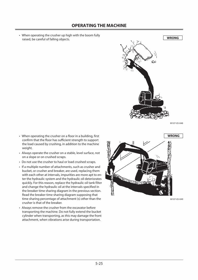
OPERATING THE MACHINE
5-25
• When operating the crusher up high with the boom fully raised, be careful of falling objects.
• When operating the crusher on a floor in a building, first confirm that the floor has sufficient strength to support the load caused by crushing, in addition to the machine weight.
• Always operate the crusher on a stable, level surface, not on a slope or on crushed scraps.
• Do not use the crusher to haul or load crushed scraps.• If a multiple number of attachments, such as crusher and
bucket, or crusher and breaker, are used, replacing them with each other at intervals, impurities are more apt to en-ter the hydraulic system and the hydraulic oil deteriorates quickly. For this reason, replace the hydraulic oil tank filter and change the hydraulic oil at the intervals specified in the breaker time sharing diagram in the previous section. Read the breaker time sharing diagram supposing that time sharing percentage of attachment (s) other than the crusher is that of the breaker.
• Always remove the crusher from the excavator before transporting the machine. Do not fully extend the bucket cylinder when transporting, as this may damage the front attachment, when vibrations arise during transportation.
WRONG
M107-05-048
WRONG
M107-05-049
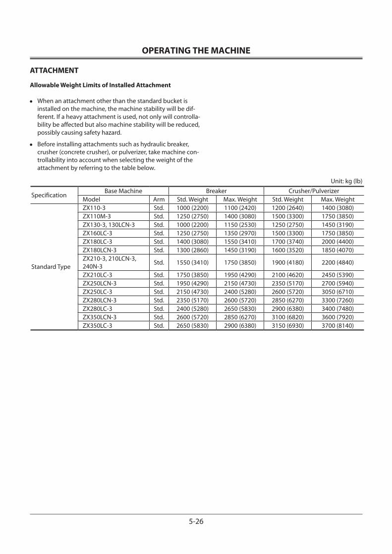
OPERATING THE MACHINE
5-26
ATTACHMENT
Allowable Weight Limits of Installed Attachment
• When an attachment other than the standard bucket is installed on the machine, the machine stability will be dif-ferent. If a heavy attachment is used, not only will controlla-bility be affected but also machine stability will be reduced, possibly causing safety hazard.
• Before installing attachments such as hydraulic breaker, crusher (concrete crusher), or pulverizer, take machine con-trollability into account when selecting the weight of the attachment by referring to the table below.
Unit: kg (lb)
SpecificationBase Machine Breaker Crusher/Pulverizer
Model Arm Std. Weight Max. Weight Std. Weight Max. Weight
Standard Type
ZX110-3 Std. 1000 (2200) 1100 (2420) 1200 (2640) 1400 (3080)ZX110M-3 Std. 1250 (2750) 1400 (3080) 1500 (3300) 1750 (3850)ZX130-3, 130LCN-3 Std. 1000 (2200) 1150 (2530) 1250 (2750) 1450 (3190)ZX160LC-3 Std. 1250 (2750) 1350 (2970) 1500 (3300) 1750 (3850)ZX180LC-3 Std. 1400 (3080) 1550 (3410) 1700 (3740) 2000 (4400)ZX180LCN-3 Std. 1300 (2860) 1450 (3190) 1600 (3520) 1850 (4070)ZX210-3, 210LCN-3, 240N-3 Std. 1550 (3410) 1750 (3850) 1900 (4180) 2200 (4840)
ZX210LC-3 Std. 1750 (3850) 1950 (4290) 2100 (4620) 2450 (5390)ZX250LCN-3 Std. 1950 (4290) 2150 (4730) 2350 (5170) 2700 (5940)ZX250LC-3 Std. 2150 (4730) 2400 (5280) 2600 (5720) 3050 (6710)ZX280LCN-3 Std. 2350 (5170) 2600 (5720) 2850 (6270) 3300 (7260)ZX280LC-3 Std. 2400 (5280) 2650 (5830) 2900 (6380) 3400 (7480)ZX350LCN-3 Std. 2600 (5720) 2850 (6270) 3100 (6820) 3600 (7920)ZX350LC-3 Std. 2650 (5830) 2900 (6380) 3150 (6930) 3700 (8140)
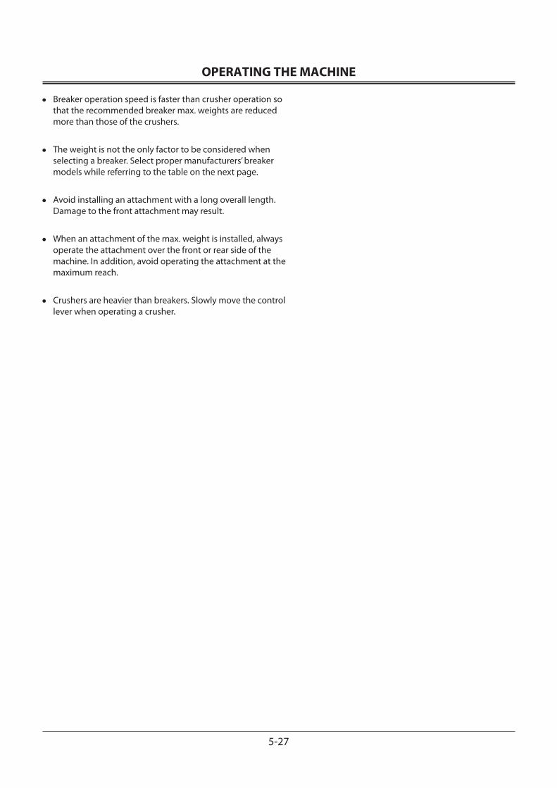
OPERATING THE MACHINE
5-27
• Breaker operation speed is faster than crusher operation so that the recommended breaker max. weights are reduced more than those of the crushers.
• The weight is not the only factor to be considered when selecting a breaker. Select proper manufacturers’ breaker models while referring to the table on the next page.
• Avoid installing an attachment with a long overall length. Damage to the front attachment may result.
• When an attachment of the max. weight is installed, always operate the attachment over the front or rear side of the machine. In addition, avoid operating the attachment at the maximum reach.
• Crushers are heavier than breakers. Slowly move the control lever when operating a crusher.
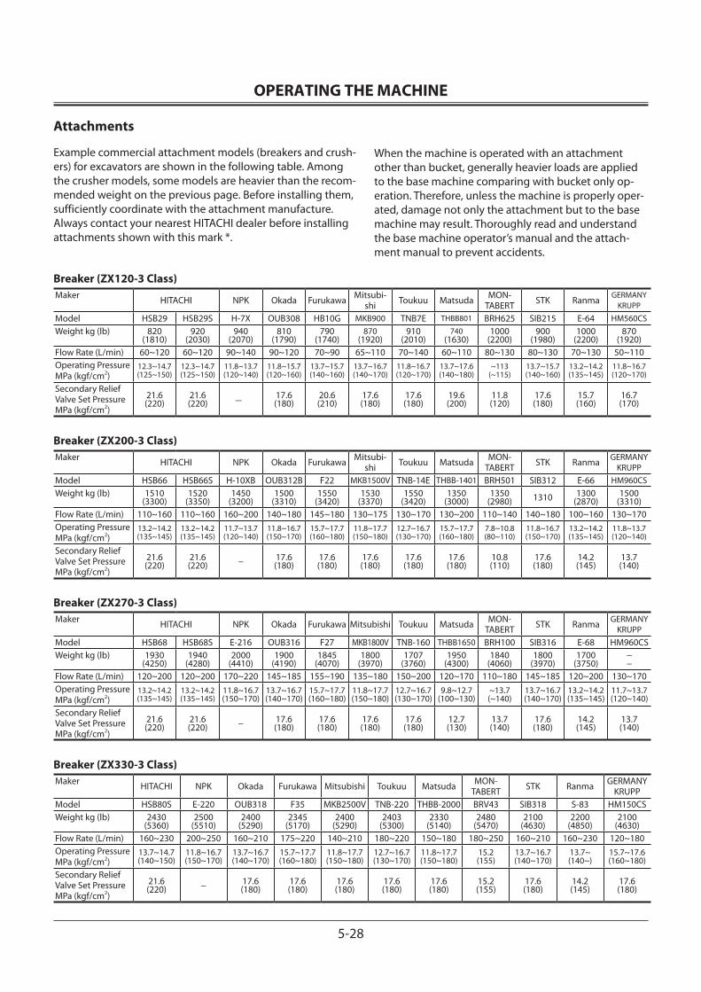
OPERATING THE MACHINE
5-28
Attachments
Example commercial attachment models (breakers and crush-ers) for excavators are shown in the following table. Among the crusher models, some models are heavier than the recom-mended weight on the previous page. Before installing them, sufficiently coordinate with the attachment manufacture. Always contact your nearest HITACHI dealer before installing attachments shown with this mark *.
Breaker (ZX120-3 Class)Maker HITACHI NPK Okada Furukawa Mitsubi-
shi Toukuu Matsuda MON-TABERT STK Ranma
GERMANY KRUPP
Model HSB29 HSB29S H-7X OUB308 HB10G MKB900 TNB7E THBB801 BRH625 SIB215 E-64 HM560CSWeight kg (lb) 820
(1810)920
(2030)940
(2070)810
(1790)790
(1740)870
(1920)910
(2010)740
(1630)1000
(2200)900
(1980)1000
(2200)870
(1920)Flow Rate (L/min) 60~120 60~120 90~140 90~120 70~90 65~110 70~140 60~110 80~130 80~130 70~130 50~110Operating Pressure MPa (kgf/cm2)
12.3~14.7(125~150)
12.3~14.7(125~150)
11.8~13.7(120~140)
11.8~15.7(120~160)
13.7~15.7(140~160)
13.7~16.7(140~170)
11.8~16.7(120~170)
13.7~17.6(140~180)
~113(~115)
13.7~15.7(140~160)
13.2~14.2(135~145)
11.8~16.7(120~170)
Secondary Relief Valve Set Pressure MPa (kgf/cm2)
21.6(220)
21.6(220) − 17.6
(180)20.6(210)
17.6(180)
17.6(180)
19.6(200)
11.8(120)
17.6(180)
15.7(160)
16.7(170)
Breaker (ZX200-3 Class)Maker HITACHI NPK Okada Furukawa Mitsubi-
shi Toukuu Matsuda MON-TABERT STK Ranma GERMANY
KRUPPModel HSB66 HSB66S H-10XB OUB312B F22 MKB1500V TNB-14E THBB-1401 BRH501 SIB312 E-66 HM960CSWeight kg (lb) 1510
(3300)1520
(3350)1450
(3200)1500
(3310)1550
(3420)1530
(3370)1550
(3420)1350
(3000)1350
(2980) 1310 1300(2870)
1500(3310)
Flow Rate (L/min) 110~160 110~160 160~200 140~180 145~180 130~175 130~170 130~200 110~140 140~180 100~160 130~170Operating Pressure MPa (kgf/cm2)
13.2~14.2(135~145)
13.2~14.2(135~145)
11.7~13.7(120~140)
11.8~16.7(150~170)
15.7~17.7(160~180)
11.8~17.7(150~180)
12.7~16.7(130~170)
15.7~17.7(160~180)
7.8~10.8(80~110)
11.8~16.7(150~170)
13.2~14.2(135~145)
11.8~13.7(120~140)
Secondary Relief Valve Set Pressure MPa (kgf/cm2)
21.6(220)
21.6(220) − 17.6
(180)17.6(180)
17.6(180)
17.6(180)
17.6(180)
10.8(110)
17.6(180)
14.2(145)
13.7(140)
Breaker (ZX270-3 Class)Maker HITACHI NPK Okada Furukawa Mitsubishi Toukuu Matsuda MON-
TABERT STK Ranma GERMANY KRUPP
Model HSB68 HSB68S E-216 OUB316 F27 MKB1800V TNB-160 THBB1650 BRH100 SIB316 E-68 HM960CSWeight kg (lb) 1930
(4250)1940
(4280)2000
(4410)1900
(4190)1845
(4070)1800
(3970)1707
(3760)1950
(4300)1840
(4060)1800
(3970)1700
(3750)−−
Flow Rate (L/min) 120~200 120~200 170~220 145~185 155~190 135~180 150~200 120~170 110~180 145~185 120~200 130~170Operating Pressure MPa (kgf/cm2)
13.2~14.2(135~145)
13.2~14.2(135~145)
11.8~16.7(150~170)
13.7~16.7(140~170)
15.7~17.7(160~180)
11.8~17.7(150~180)
12.7~16.7(130~170)
9.8~12.7(100~130)
~13.7(~140)
13.7~16.7(140~170)
13.2~14.2(135~145)
11.7~13.7(120~140)
Secondary Relief Valve Set Pressure MPa (kgf/cm2)
21.6(220)
21.6(220) − 17.6
(180)17.6(180)
17.6(180)
17.6(180)
12.7(130)
13.7(140)
17.6(180)
14.2(145)
13.7(140)
Breaker (ZX330-3 Class)Maker HITACHI NPK Okada Furukawa Mitsubishi Toukuu Matsuda MON-
TABERT STK Ranma GERMANY KRUPP
Model HSB80S E-220 OUB318 F35 MKB2500V TNB-220 THBB-2000 BRV43 SIB318 S-83 HM150CSWeight kg (lb) 2430
(5360)2500
(5510)2400
(5290)2345
(5170)2400
(5290)2403
(5300)2330
(5140)2480
(5470)2100
(4630)2200
(4850)2100
(4630)Flow Rate (L/min) 160~230 200~250 160~210 175~220 140~210 180~220 150~180 180~250 160~210 160~230 120~180Operating Pressure MPa (kgf/cm2)
13.7~14.7(140~150)
11.8~16.7(150~170)
13.7~16.7(140~170)
15.7~17.7(160~180)
11.8~17.7(150~180)
12.7~16.7(130~170)
11.8~17.7(150~180)
15.2(155)
13.7~16.7(140~170)
13.7~(140~)
15.7~17.6(160~180)
Secondary Relief Valve Set Pressure MPa (kgf/cm2)
21.6(220) − 17.6
(180)17.6(180)
17.6(180)
17.6(180)
17.6(180)
15.2(155)
17.6(180)
14.2(145)
17.6(180)
When the machine is operated with an attachment other than bucket, generally heavier loads are applied to the base machine comparing with bucket only op-eration. Therefore, unless the machine is properly oper-ated, damage not only the attachment but to the base machine may result. Thoroughly read and understand the base machine operator’s manual and the attach-ment manual to prevent accidents.
OPERATING THE MACHINE
5-29
Crusher (ZX120-3 Class)Maker SANGO JYUKI NPK* Sakato* Oosumi* STK*
Model TS700RCD S-15X SPAC70R-3 MR800 CX750Weight kg (lb) 1200 (2650) 1410 (3110) 1300 (2870) 1400 (3090) 1250 (2760)
Overall Length mm (ft·in) 1980(6’6”)
2230 (7’4”)
1620 (5’4”)
1900 (6’3”)
2000 (6’7”)
Rated Pressure MPa (kgf/cm2)
24.5(250)
20.6(210)
27.4(280)
~31.4(~320)
27.4(280)
Maximum Opening Width mm (ft·in)
700(2’4”)
750(2’6”)
750(2’6”)
800(2’8”)
750(2’6”)
Swing Method Free Free Free Free
Crusher (ZX200-3 Class)Maker HITACHI SANGO JYUKI NPK* Sakato* Oosumi* STK*
Model HSC100 HSC160 TS850RCD S-22XA SDS250 RC MR1000L MR1100 DX-900
Weight kg (lb) 2430(5360)
2300(5070)
2000(4410)
2010(4430)
2390(5270)
1900(4190)
2350(5180)
2100(4630)
Overall Length mm (ft·in) 2340(7’8”)
2600(8’6”)
2400(7’11”)
2326(7’8”)
2425 (7’11”)
2200(7’3”)
2250(7’5”)
2380(7’10”)
Rated Pressure MPa (kgf/cm2)
27.9(285)
27.9(285)
27.5(280)
31.4(320)
Maximum Opening Width mm (ft·in)
900(2’11”)
850(2’9”)
850(2’9”)
850(2’9”)
1050(3’5”)
1060(3’6”)
1060(3’6”)
900(2’11”)
Swing Method Hydraulic Hydraulic Free Free Free Free Free FreeJaw Tip Crushing Force
kN(tf·f )
640(65)
981(100)
961(98)
834(85)
Jaw Center Crushing Force
kN(tf·f )
980(100)
1570(160)
1570(160)
1470(150)
1240(126)
1540(157)
Crusher (ZX270-3 Class)Maker HITACHI NPK* Oosumi* STK
Model HSC100 HSC160 S-26X MR1100 CX-1100
Weight kg (lb) 2430(5360)
2300(5070)
2520(5560)
2350(5180)
2650(5840)
Overall Length mm (ft·in) 2340(7’8”)
2600(8’6”)
2602(8’6”)
2250(7’5”)
2450(8’0”)
Rated Pressure MPa (kgf/cm2)
27.9(285)
27.9(285)
Maximum Opening Width mm (ft·in)
900(2’11”)
850(2’9”)
1000(3’3”)
1060(3’6”)
1100(3’7”)
Swing Method Hydraulic Hydraulic Free Free FreeJaw Tip Crushing Force
kN(tf·f )
640(65)
1080(110)
Jaw Center Crushing Force
kN(tf·f )
980(100)
1570(160)
1660(169)
1540(157)
Crusher (ZX330-3 Class)Maker SANGO JYUKI NPK* Sakato* Oosumi* STK*
Model 1100RCD S-35X SDS350 RC MR1300 DX-1500
Weight kg (lb) 2940(6480)
3500(7720)
3550(7830)
3070(6770)
3400(7500)
Overall Length mm (ft·in) 2765(9’1”)
2824(9’3”)
3285 (10’9”)
2800(9’2”)
2550(8’4”)
Rated Pressure MPa (kgf/cm2)
31.4(320)
31.4(320)
Maximum Opening Width mm (ft·in)
1500(4’11”)
1100(3’7”)
1300(4’3”)
1300(4’3”)
1300(4’3”)
Swing Method Free Free Free Free FreeJaw Tip Crushing Force
kN(tf·f )
1780(181)
1230(125)
981(100)
Jaw Center Crushing Force
kN(tf·f )
3380(345)
1770(180)
1540(157)
OPERATING THE MACHINE
5-30
ATTACHMENT CONNECTION PARTS
The attachment hydraulic line and connection parts are locat-ed as illustrated below. When the attachment is disconnected, be sure to install caps or plugs to the ends of both the arm and attachment side hydraulic lines to prevent dust from entering or from sticking.
Part No. List (Fill attachment manufacturer’s part Nos. in the blank spaces.)Maker Adapter Size Adapter Cap Plug Hose
Form / Size Male-Type PF-UNF
ZX120-3 Class PF1-1-1/16UN 4456399 4222711 4222264ZX180-3, 200-3, 270-3 Class ZX330-3 Class left side piping PF1X1-5/16UN 4214444
4222712 4222265ZX200-3, 270-3 Class only right side piping*ZX330-3 Class only right side piping PF1-1/4X1-5/16UN 4314094
Form / Size Female-Type PF-PF30°
ZX120-3 Class PF1-PF3/4 4129457 9718916 4222047ZX180-3, 200-3, 270-3 Class ZX330-3 Class left side piping PF1XPF1 4042034
9718917 4168177ZX200-3, 270-3 Class only right side piping*ZX330-3 Class only right side piping PF1-1/4XPF1 4317614
Form / Size Male-Type PF-PF30°
ZX120-3 Class PF1-PF3/4 4456120 4222715 4222044ZX180-3, 200-3, 270-3 Class ZX330-3 Class left side piping PF1XPF1 4456118
4222716 4222045ZX200-3, 270-3 Class only right side piping*ZX330-3 Class only right side piping PF1-1/4XPF1 4653961
* If equipped
Adapter tightening torque: PF1 205 N•m (21 kgf•m)PF1-1/4 340 N•m (34 kgf•m)
(ZX200-3, 270-3 class only right side piping*) (ZX330-3 class only right side piping)
Plug
Plug Thread Size : JIS B2351 O-Type PF1 : JIS B2351 O-Type PF1-1/4
(ZX200-3, 270-3 class only right side piping*) (ZX330-3 class only right side piping)
When the attachment is disconnected:Cap
Hose
Adapter
M175-05-005
OPERATING THE MACHINE
5-31
PRECAUTION FOR ARM ROLL-IN/BUCKET ROLL-IN COMBINED OPERATION --- If Headguard-Integrated Cab or Rainguard is Equipped
WARNING: The bucket teeth will hit the headguard or rainguard if the bucket is rolled in with the arm fully rolled in, as illustrated. When performing combined operation of long arm roll-in/bucket roll-in or when rolling in the bucket with the arm fully retracted, be careful not to hit the headguard or rainguard with the bucket teeth.
WHEN INSTALLING AN ATTACHMENT LONGER THAN STANDARD BUCKET
WARNING: When an attachment (such as a hydraulic breaker or crusher), the overall length of which is longer than that of the bucket, is installed, the attach-ment may come in contact with the cab and/or the boom. Operate the machine with care not to allow the tip of the front attachment to hit the cab and/or the boom while rolling in the front attachment.
M107-05-072
M1G6-05-009Watch Out!Take care not to hit the boom with the front attachment
OPERATING THE MACHINE
5-32
SHACKLE HOLE USAGE
A shackle hole is provided on the track frame to tow light weight objects as specified below.
IMPORTANT: Be sure to conform to the restrictions and precautions stated below when towing a light weight object using the shackle hole provided on the track frame. The track frame and/or the shackle hole may be damaged otherwise.
• The maximum drawbar pull.
Model Maximum Drawbar PullZX110-3 39200 N (4.0 tf )ZX110M-3 53900 N (5.5 tf )ZX130-3, 130LCN-3 44100 N (4.5 tf )ZX180-3 Class 53900 N (5.5 tf )ZX200-3 Class 73600 N (7.5 tf )ZX270-3 Class (Except 280LC-3, 280LCN-3) 83400 N (8.5 tf )
ZX280LC-3, 280LCN-3 98000 N (10.0 tf )ZX330-3 Class 108000 N (11.0 tf )
• Be sure to use a shackle.• Keep the tow line horizontal, straight, and parallel to the
tracks.• Select the slow travel mode. Slowly drive the machine
when towing.
OVERNIGHT STORAGE INSTRUCTIONS
1. After finishing the day’s operation, drive the machine to a firm, level ground where no possibility of falling stones, ground collapse, or floods.
Park the machine referring to the “PARKING THE MA-CHINE” in the “DRIVING THE MACHINE” section.
2. Fill the fuel tank with fuel.
3. Clean the machine.
4. If anti-freeze or long life coolant is not used in cold weather, be sure to drain coolant from the radiator and the engine jacket. Also, be sure to put a tag in a visible place if the coolant has been drained.
Wire Rope
Shackle
Shackle hole for towing lightweight objects.
Track Frame
M104-05-011
M1U1-05-003
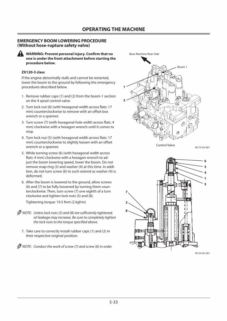
OPERATING THE MACHINE
5-33
M175-05-001
EMERGENCY BOOM LOWERING PROCEDURE (Without hose-rupture safety valve)
WARNING: Prevent personal injury. Confirm that no one is under the front attachment before starting the procedure below.
ZX120-3 classIf the engine abnormally stalls and cannot be restarted, lower the boom to the ground by following the emergency procedures described below.
1. Remove rubber caps (1) and (2) from the boom-1 section on the 4 spool control valve.
2. Turn lock nut (8) (with hexagonal width across flats: 17 mm) counterclockwise to remove with an offset box wrench or a spanner.
3. Turn screw (7) (with hexagonal hole width across flats: 4 mm) clockwise with a hexagon wrench until it comes to stop.
4. Turn lock nut (5) (with hexagonal width across flats: 17 mm) counterclockwise to slightly loosen with an offset wrench or a spanner.
5. While turning screw (6) (with hexagonal width across flats: 4 mm) clockwise with a hexagon wrench to ad-just the boom lowering speed, lower the boom. Do not remove snap ring (3) and washer (4) at this time. In addi-tion, do not turn screw (6) to such extend as washer (4) is deformed.
6. After the boom is lowered to the ground, allow screws (6) and (7) to be fully loosened by turning them coun-terclockwise. Then, turn screw (7) one eighth of a turn clockwise and tighten lock nuts (5) and (8).
Tightening torque: 19.5 N•m (2 kgf•m)
NOTE: Unless lock nuts (5) and (8) are sufficiently tightened, oil leakage may increase. Be sure to completely tighten the lock nuts to the torque specified above.
7. Take care to correctly install rubber caps (1) and (2) in their respective original position.
NOTE: Conduct the work of screw (7) and screw (6) in order.
M154-05-001
2
Boom 1
1
Control Valve
2
7
5
1
4
3
6
8
Base Machine Rear Side
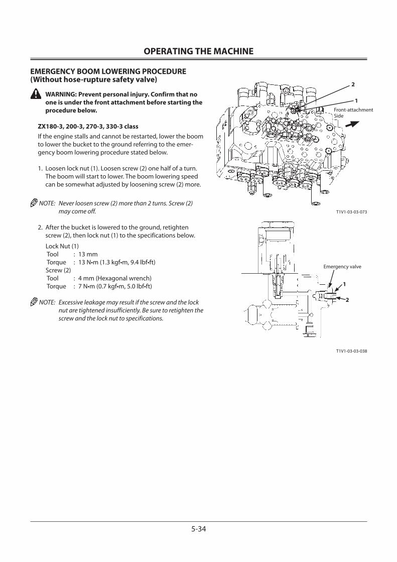
OPERATING THE MACHINE
5-34
2
1Front-attachmentSide
T1V1-03-03-073
Emergency valve
1
2
T1V1-03-03-038
EMERGENCY BOOM LOWERING PROCEDURE (Without hose-rupture safety valve)
WARNING: Prevent personal injury. Confirm that no one is under the front attachment before starting the procedure below.
ZX180-3, 200-3, 270-3, 330-3 classIf the engine stalls and cannot be restarted, lower the boom to lower the bucket to the ground referring to the emer-gency boom lowering procedure stated below.
1. Loosen lock nut (1). Loosen screw (2) one half of a turn. The boom will start to lower. The boom lowering speed can be somewhat adjusted by loosening screw (2) more.
NOTE: Never loosen screw (2) more than 2 turns. Screw (2) may come off.
2. After the bucket is lowered to the ground, retighten screw (2), then lock nut (1) to the specifications below.
Lock Nut (1) Tool : 13 mm Torque : 13 N•m (1.3 kgf•m, 9.4 lbf•ft)Screw (2) Tool : 4 mm (Hexagonal wrench) Torque : 7 N•m (0.7 kgf•m, 5.0 lbf•ft)
NOTE: Excessive leakage may result if the screw and the lock nut are tightened insufficiently. Be sure to retighten the screw and the lock nut to specifications.
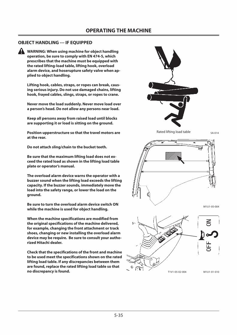
OPERATING THE MACHINE
5-35
OBJECT HANDLING --- IF EQUIPPED
WARNING: When using machine for object handling operation, be sure to comply with EN 474-5, which prescribes that the machine must be equipped with the rated lifting-load table, lifting hook, overload alarm device, and hoserupture safety valve when ap-plied to object handling. Lifting hook, cables, straps, or ropes can break, caus-ing serious injury. Do not use damaged chains, lifting hook, frayed cables, slings, straps, or ropes to crane.
Never move the load suddenly. Never move load over a person’s head. Do not allow any persons near load.
Keep all persons away from raised load until blocks are supporting it or load is sitting on the ground.
Position upperstructure so that the travel motors are at the rear.
Do not attach sling/chain to the bucket teeth.
Be sure that the maximum lifting load does not ex-ceed the rated load as shown in the lifting load table plate or operator’s manual.
The overload alarm device warns the operator with a buzzer sound when the lifting load exceeds the lifting capacity. If the buzzer sounds, immediately move the load into the safety range, or lower the load on the ground.
Be sure to turn the overload alarm device switch ON while the machine is used for object handling.
When the machine specifications are modified from the original specifications of the machine delivered, for example, changing the front attachment or track shoes, changing or new installing the overload alarm device may be require. Be sure to consult your autho-rized Hitachi dealer.
Check that the specifications of the front and machine to be used meet the specifications shown on the rated lifting load table. If any discrepancies between them are found, replace the rated lifting load table so that no discrepancy is found.
SA-014Rated lifting load table
T1V1-05-02-004 M1U1-01-010
M1U1-05-004
OPERATING THE MACHINE
5-36
1. Secure sling/chain tightly to the load being lifted. Wear gloves when securing sling/chain.
2. Fasten sling/chain to bucket loop, with the bucket curled and arm retracted.
3. Coordinate hand signals with your signal man before starting.
4. Be aware of the location of all persons in the working area.
5. Attach a hand line to load and make sure person holding it is well away from load.
6. Before lifting, test your load.
• Park your machine close to load.
• Attach load to the machine.
• Raise load 50 mm above the ground.
• Swing the load all the way to one side.
• While keeping load close to the ground, move it away from machine.
• If there is any indication of reduced stability of your ma-chine, lower load to the ground.
7. Lift load only as high as necessary.
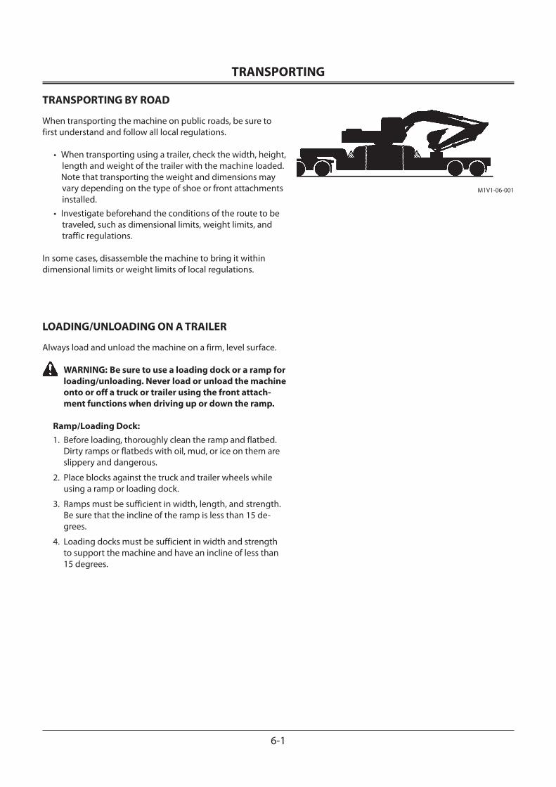
TRANSPORTING
6-1
TRANSPORTING BY ROAD
When transporting the machine on public roads, be sure to first understand and follow all local regulations.
• When transporting using a trailer, check the width, height, length and weight of the trailer with the machine loaded.
Note that transporting the weight and dimensions may vary depending on the type of shoe or front attachments installed.
• Investigate beforehand the conditions of the route to be traveled, such as dimensional limits, weight limits, and traffic regulations.
In some cases, disassemble the machine to bring it within dimensional limits or weight limits of local regulations.
LOADING/UNLOADING ON A TRAILER
Always load and unload the machine on a firm, level surface.
WARNING: Be sure to use a loading dock or a ramp for loading/unloading. Never load or unload the machine onto or off a truck or trailer using the front attach-ment functions when driving up or down the ramp.
Ramp/Loading Dock:1. Before loading, thoroughly clean the ramp and flatbed.
Dirty ramps or flatbeds with oil, mud, or ice on them are slippery and dangerous.
2. Place blocks against the truck and trailer wheels while using a ramp or loading dock.
3. Ramps must be sufficient in width, length, and strength. Be sure that the incline of the ramp is less than 15 de-grees.
4. Loading docks must be sufficient in width and strength to support the machine and have an incline of less than 15 degrees.
M1V1-06-001
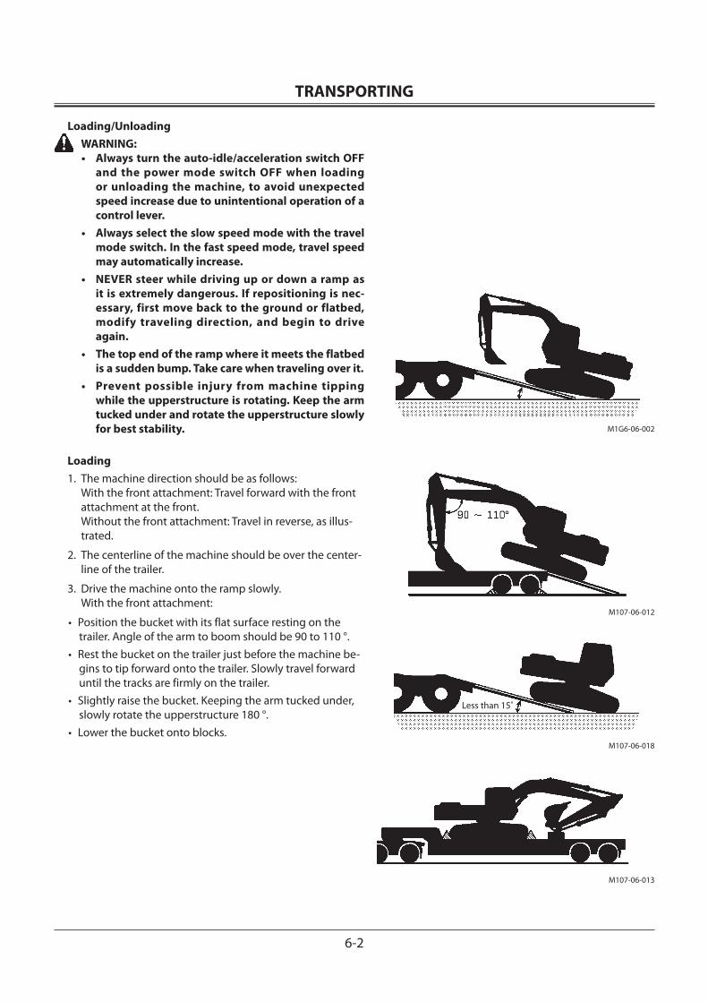
TRANSPORTING
6-2
Loading/Unloading WARNING:
• Always turn the auto-idle/acceleration switch OFF and the power mode switch OFF when loading or unloading the machine, to avoid unexpected speed increase due to unintentional operation of a control lever.
• Always select the slow speed mode with the travel mode switch. In the fast speed mode, travel speed may automatically increase.
• NEVER steer while driving up or down a ramp as it is extremely dangerous. If repositioning is nec-essary, first move back to the ground or flatbed, modify traveling direction, and begin to drive again.
• The top end of the ramp where it meets the flatbed is a sudden bump. Take care when traveling over it.
• Prevent possible injury from machine tipping while the upperstructure is rotating. Keep the arm tucked under and rotate the upperstructure slowly for best stability.
Loading1. The machine direction should be as follows:
With the front attachment: Travel forward with the front attachment at the front. Without the front attachment: Travel in reverse, as illus-trated.
2. The centerline of the machine should be over the center-line of the trailer.
3. Drive the machine onto the ramp slowly. With the front attachment:
• Position the bucket with its flat surface resting on the trailer. Angle of the arm to boom should be 90 to 110 °.
• Rest the bucket on the trailer just before the machine be-gins to tip forward onto the trailer. Slowly travel forward until the tracks are firmly on the trailer.
• Slightly raise the bucket. Keeping the arm tucked under, slowly rotate the upperstructure 180 °.
• Lower the bucket onto blocks.
M107-06-012
M107-06-018
M107-06-013
Less than 15˚
M1G6-06-002

TRANSPORTING
6-3
4. Stop the engine. Remove key from switch.
5. Move the control levers several times until hydraulic pres-sure in the cylinders is released.
6. Pull pilot control shut-off lever to LOCK position.
7. Close cab windows, roof vent and door, and cover the exhaust opening, to prevent entry of wind and water.
CAUTION: In cold weather, be sure to warm up the machine before loading or unloading it.
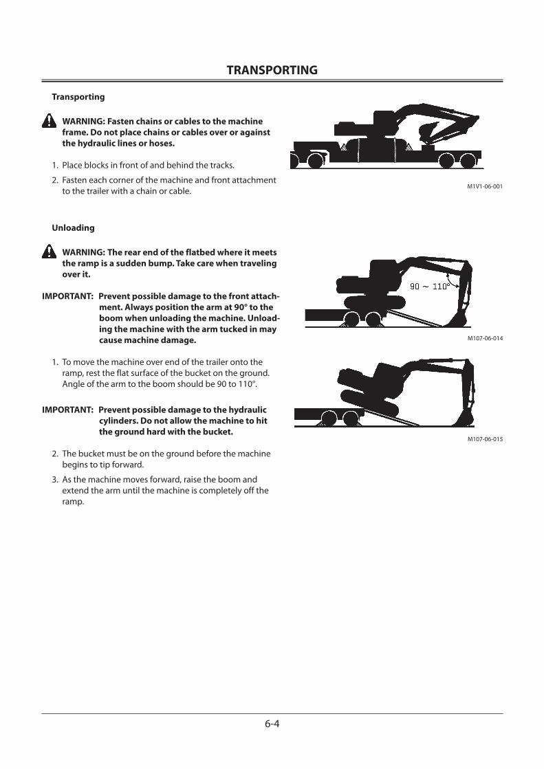
TRANSPORTING
6-4
Transporting
WARNING: Fasten chains or cables to the machine frame. Do not place chains or cables over or against the hydraulic lines or hoses.
1. Place blocks in front of and behind the tracks.
2. Fasten each corner of the machine and front attachment to the trailer with a chain or cable.
Unloading
WARNING: The rear end of the flatbed where it meets the ramp is a sudden bump. Take care when traveling over it.
IMPORTANT: Prevent possible damage to the front attach-ment. Always position the arm at 90° to the boom when unloading the machine. Unload-ing the machine with the arm tucked in may cause machine damage.
1. To move the machine over end of the trailer onto the ramp, rest the flat surface of the bucket on the ground. Angle of the arm to the boom should be 90 to 110°.
IMPORTANT: Prevent possible damage to the hydraulic cylinders. Do not allow the machine to hit the ground hard with the bucket.
2. The bucket must be on the ground before the machine begins to tip forward.
3. As the machine moves forward, raise the boom and extend the arm until the machine is completely off the ramp.
M1V1-06-001
M107-06-014
M107-06-015
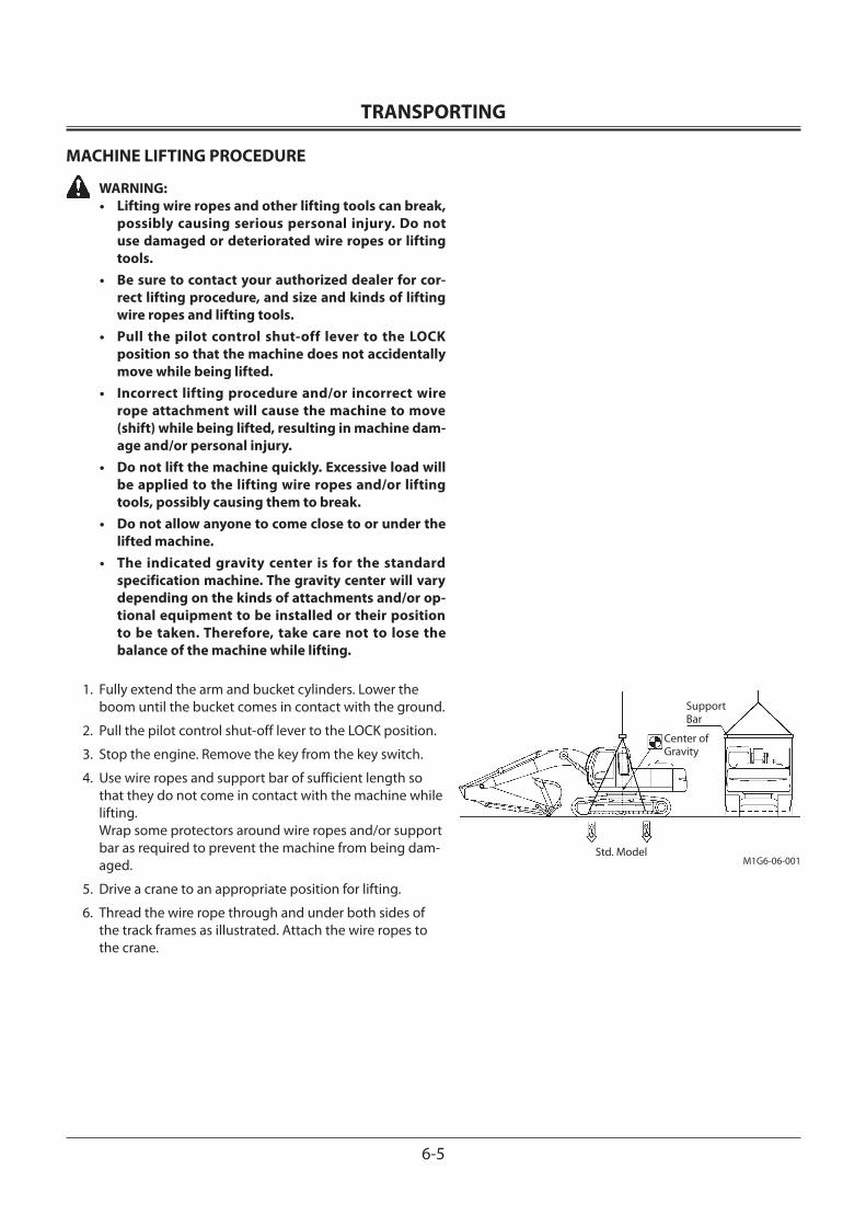
TRANSPORTING
6-5
MACHINE LIFTING PROCEDURE
WARNING:• Lifting wire ropes and other lifting tools can break,
possibly causing serious personal injury. Do not use damaged or deteriorated wire ropes or lifting tools.
• Be sure to contact your authorized dealer for cor-rect lifting procedure, and size and kinds of lifting wire ropes and lifting tools.
• Pull the pilot control shut-off lever to the LOCK position so that the machine does not accidentally move while being lifted.
• Incorrect lifting procedure and/or incorrect wire rope attachment will cause the machine to move (shift) while being lifted, resulting in machine dam-age and/or personal injury.
• Do not lift the machine quickly. Excessive load will be applied to the lifting wire ropes and/or lifting tools, possibly causing them to break.
• Do not allow anyone to come close to or under the lifted machine.
• The indicated gravity center is for the standard specification machine. The gravity center will vary depending on the kinds of attachments and/or op-tional equipment to be installed or their position to be taken. Therefore, take care not to lose the balance of the machine while lifting.
1. Fully extend the arm and bucket cylinders. Lower the boom until the bucket comes in contact with the ground.
2. Pull the pilot control shut-off lever to the LOCK position.
3. Stop the engine. Remove the key from the key switch.
4. Use wire ropes and support bar of sufficient length so that they do not come in contact with the machine while lifting. Wrap some protectors around wire ropes and/or support bar as required to prevent the machine from being dam-aged.
5. Drive a crane to an appropriate position for lifting.
6. Thread the wire rope through and under both sides of the track frames as illustrated. Attach the wire ropes to the crane.
SupportBar
Center ofGravity
Std. ModelM1G6-06-001

TRANSPORTING
6-6
MEMO...................................................................................................................................................................................................................................................
...................................................................................................................................................................................................................................................
...................................................................................................................................................................................................................................................
...................................................................................................................................................................................................................................................
...................................................................................................................................................................................................................................................
...................................................................................................................................................................................................................................................
...................................................................................................................................................................................................................................................
...................................................................................................................................................................................................................................................
...................................................................................................................................................................................................................................................
...................................................................................................................................................................................................................................................
...................................................................................................................................................................................................................................................
...................................................................................................................................................................................................................................................
...................................................................................................................................................................................................................................................
...................................................................................................................................................................................................................................................
...................................................................................................................................................................................................................................................
...................................................................................................................................................................................................................................................
...................................................................................................................................................................................................................................................
...................................................................................................................................................................................................................................................
...................................................................................................................................................................................................................................................
...................................................................................................................................................................................................................................................
...................................................................................................................................................................................................................................................
...................................................................................................................................................................................................................................................
...................................................................................................................................................................................................................................................
...................................................................................................................................................................................................................................................
...................................................................................................................................................................................................................................................
...................................................................................................................................................................................................................................................
...................................................................................................................................................................................................................................................
...................................................................................................................................................................................................................................................
...................................................................................................................................................................................................................................................
...................................................................................................................................................................................................................................................
...................................................................................................................................................................................................................................................
...................................................................................................................................................................................................................................................
...................................................................................................................................................................................................................................................
...................................................................................................................................................................................................................................................
...................................................................................................................................................................................................................................................
...................................................................................................................................................................................................................................................
...................................................................................................................................................................................................................................................
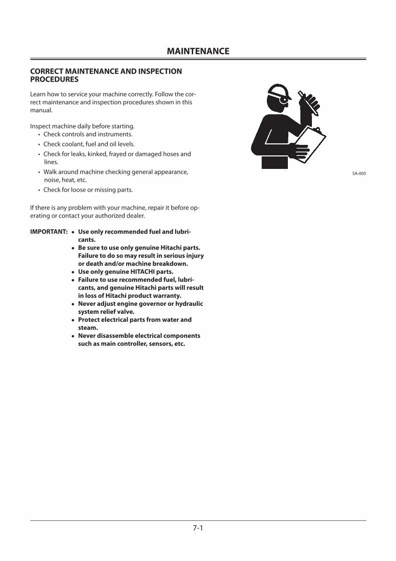
MAINTENANCE
7-1
CORRECT MAINTENANCE AND INSPECTION PROCEDURES
Learn how to service your machine correctly. Follow the cor-rect maintenance and inspection procedures shown in this manual.
Inspect machine daily before starting.• Check controls and instruments.• Check coolant, fuel and oil levels.• Check for leaks, kinked, frayed or damaged hoses and
lines.• Walk around machine checking general appearance,
noise, heat, etc.• Check for loose or missing parts.
If there is any problem with your machine, repair it before op-erating or contact your authorized dealer.
IMPORTANT: • Use only recommended fuel and lubri-cants.
• Be sure to use only genuine Hitachi parts. Failure to do so may result in serious injury or death and/or machine breakdown.
• Use only genuine HITACHI parts. • Failure to use recommended fuel, lubri-
cants, and genuine Hitachi parts will result in loss of Hitachi product warranty.
• Never adjust engine governor or hydraulic system relief valve.
• Protect electrical parts from water and steam.
• Never disassemble electrical components such as main controller, sensors, etc.
SA-005
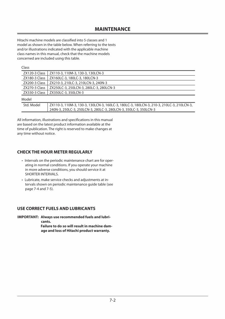
MAINTENANCE
7-2
Hitachi machine models are classified into 5 classes and 1 model as shown in the table below. When referring to the texts and/or illustrations indicated with the applicable machine class names in this manual, check that the machine models concerned are included using this table.
Class ZX120-3 Class ZX110-3, 110M-3, 130-3, 130LCN-3ZX180-3 Class ZX160LC-3, 180LC-3, 180LCN-3ZX200-3 Class ZX210-3, 210LC-3, 210LCN-3, 240N-3ZX270-3 Class ZX250LC-3, 250LCN-3, 280LC-3, 280LCN-3ZX330-3 Class ZX350LC-3, 350LCN-3
ModelStd. Model ZX110-3, 110M-3, 130-3, 130LCN-3, 160LC-3, 180LC-3, 180LCN-3, 210-3, 210LC-3, 210LCN-3,
240N-3, 250LC-3, 250LCN-3, 280LC-3, 280LCN-3, 350LC-3, 350LCN-3
All information, illustrations and specifications in this manual are based on the latest product information available at the time of publication. The right is reserved to make changes at any time without notice.
CHECK THE HOUR METER REGULARLY
• Intervals on the periodic maintenance chart are for oper-ating in normal conditions. If you operate your machine in more adverse conditions, you should service it at SHORTER INTERVALS.
• Lubricate, make service checks and adjustments at in-tervals shown on periodic maintenance guide table (see page 7-4 and 7-5).
USE CORRECT FUELS AND LUBRICANTS
IMPORTANT: Always use recommended fuels and lubri-cants.
Failure to do so will result in machine dam-age and loss of Hitachi product warranty.
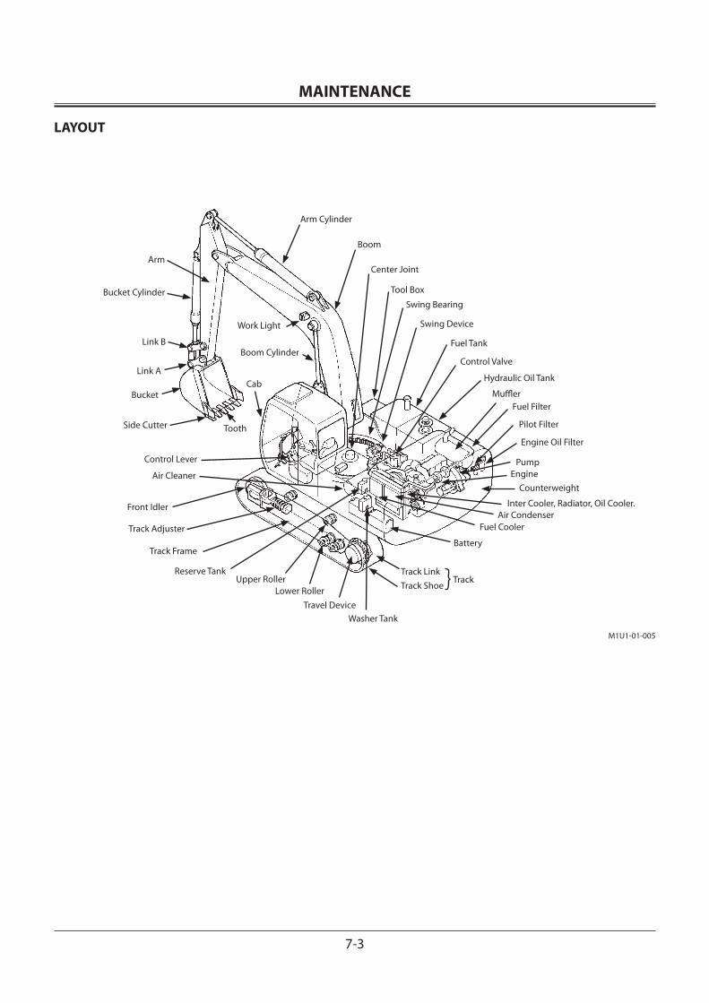
MAINTENANCE
7-3
LAYOUT
Arm Cylinder
Boom
Tool Box
Center Joint
Swing Device
Swing Bearing
Fuel Tank
Control Valve
Hydraulic Oil Tank
MufflerFuel Filter
Engine Oil Filter
PumpEngine
Counterweight
Inter Cooler, Radiator, Oil Cooler.
Fuel CoolerAir Condenser
Battery
Washer TankTravel Device
Lower RollerUpper Roller
Track Frame
Reserve Tank
Track Adjuster
Front Idler
Air Cleaner
Control Lever
Track LinkTrack Shoe
Track
Side Cutter
BucketCab
Boom Cylinder
Work Light
Tooth Pilot Filter
Arm
Link B
Bucket Cylinder
Link A
M1U1-01-005
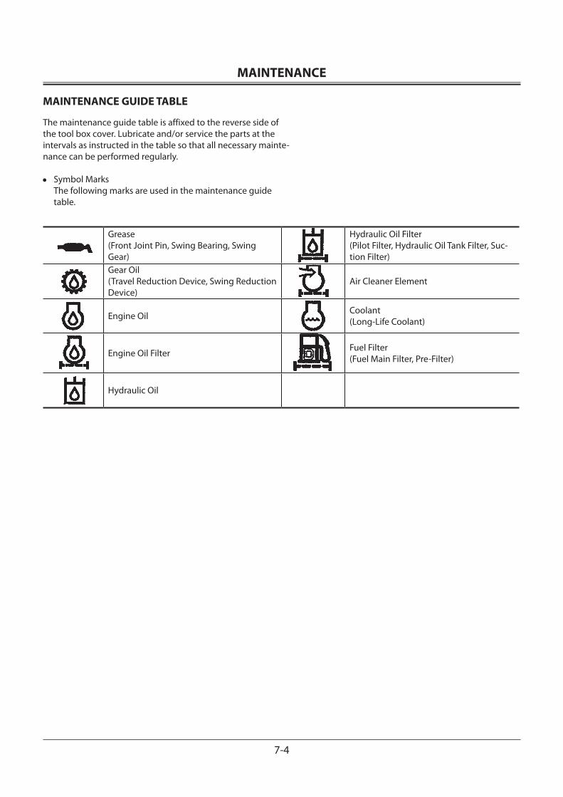
MAINTENANCE
7-4
MAINTENANCE GUIDE TABLE
The maintenance guide table is affixed to the reverse side of the tool box cover. Lubricate and/or service the parts at the intervals as instructed in the table so that all necessary mainte-nance can be performed regularly.
• Symbol Marks The following marks are used in the maintenance guide
table.
Grease(Front Joint Pin, Swing Bearing, Swing Gear)
Hydraulic Oil Filter(Pilot Filter, Hydraulic Oil Tank Filter, Suc-tion Filter)
Gear Oil(Travel Reduction Device, Swing Reduction Device)
Air Cleaner Element
Engine Oil Coolant (Long-Life Coolant)
Engine Oil Filter Fuel Filter(Fuel Main Filter, Pre-Filter)
Hydraulic Oil
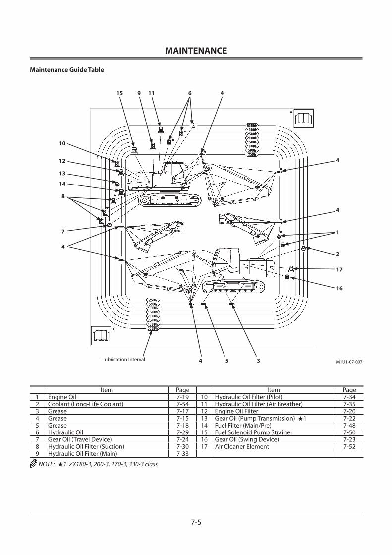
MAINTENANCE
7-5
Maintenance Guide Table
Item Page Item Page1 Engine Oil 7-19 10 Hydraulic Oil Filter (Pilot) 7-342 Coolant (Long-Life Coolant) 7-54 11 Hydraulic Oil Filter (Air Breather) 7-353 Grease 7-17 12 Engine Oil Filter 7-204 Grease 7-15 13 Gear Oil (Pump Transmission) ★1 7-225 Grease 7-18 14 Fuel Filter (Main/Pre) 7-486 Hydraulic Oil 7-29 15 Fuel Solenoid Pump Strainer 7-507 Gear Oil (Travel Device) 7-24 16 Gear Oil (Swing Device) 7-238 Hydraulic Oil Filter (Suction) 7-30 17 Air Cleaner Element 7-529 Hydraulic Oil Filter (Main) 7-33
NOTE: ★1. ZX180-3, 200-3, 270-3, 330-3 class
M1U1-07-007
4611915
10
12
13
14
8
7
4
4
4
1
2
17
16
4 5 3Lubrication Interval
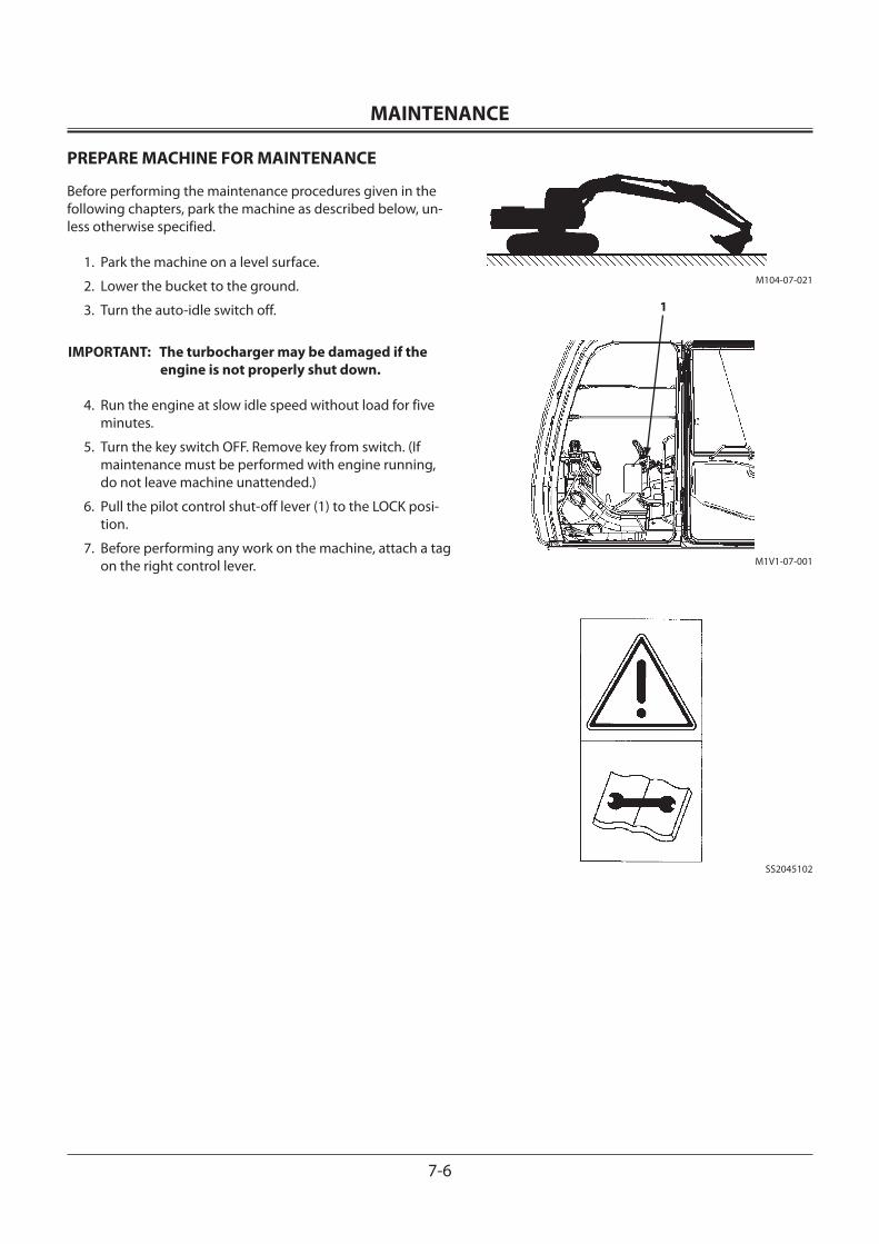
MAINTENANCE
7-6
PREPARE MACHINE FOR MAINTENANCE
Before performing the maintenance procedures given in the following chapters, park the machine as described below, un-less otherwise specified.
1. Park the machine on a level surface.
2. Lower the bucket to the ground.
3. Turn the auto-idle switch off.
IMPORTANT: The turbocharger may be damaged if the engine is not properly shut down.
4. Run the engine at slow idle speed without load for five minutes.
5. Turn the key switch OFF. Remove key from switch. (If maintenance must be performed with engine running, do not leave machine unattended.)
6. Pull the pilot control shut-off lever (1) to the LOCK posi-tion.
7. Before performing any work on the machine, attach a tag on the right control lever.
1
SS2045102
M1V1-07-001
M104-07-021
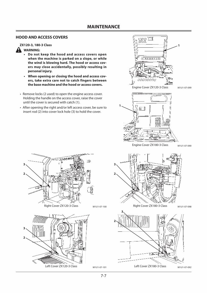
MAINTENANCE
7-7
HOOD AND ACCESS COVERS
ZX120-3, 180-3 Class WARNING:
• Do not keep the hood and access covers open when the machine is parked on a slope, or while the wind is blowing hard. The hood or access cov-ers may close accidentally, possibly resulting in personal injury.
• When opening or closing the hood and access cov-ers, take extra care not to catch fingers between the base machine and the hood or access covers.
• Remove locks (2 used) to open the engine access cover. Holding the handle on the access cover, raise the cover until the cover is secured with catch (1).
• After opening the right and/or left access cover, be sure to insert rod (2) into cover lock hole (3) to hold the cover.
3
M1U1-07-098
1
M1U1-07-090
2
3
M1U1-07-092
2
Engine Cover ZX180-3 Class
Right Cover ZX180-3 Class
Left Cover ZX180-3 Class
M1U1-07-099
1
M1U1-07-100
M1U1-07-101
Engine Cover ZX120-3 Class
Right Cover ZX120-3 Class
Left Cover ZX120-3 Class
3
2
3
2
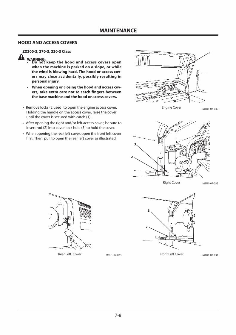
MAINTENANCE
7-8
HOOD AND ACCESS COVERS
ZX200-3, 270-3, 330-3 Class
WARNING:• Do not keep the hood and access covers open
when the machine is parked on a slope, or while the wind is blowing hard. The hood or access cov-ers may close accidentally, possibly resulting in personal injury.
• When opening or closing the hood and access cov-ers, take extra care not to catch fingers between the base machine and the hood or access covers.
• Remove locks (2 used) to open the engine access cover. Holding the handle on the access cover, raise the cover until the cover is secured with catch (1).
• After opening the right and/or left access cover, be sure to insert rod (2) into cover lock hole (3) to hold the cover.
• When opening the rear left cover, open the front left cover first. Then, pull to open the rear left cover as illustrated.
1
3
2
3
2
M1U1-07-030Engine Cover
M1U1-07-032Right Cover
M1U1-07-031Front Left CoverM1U1-07-033Rear Left Cover
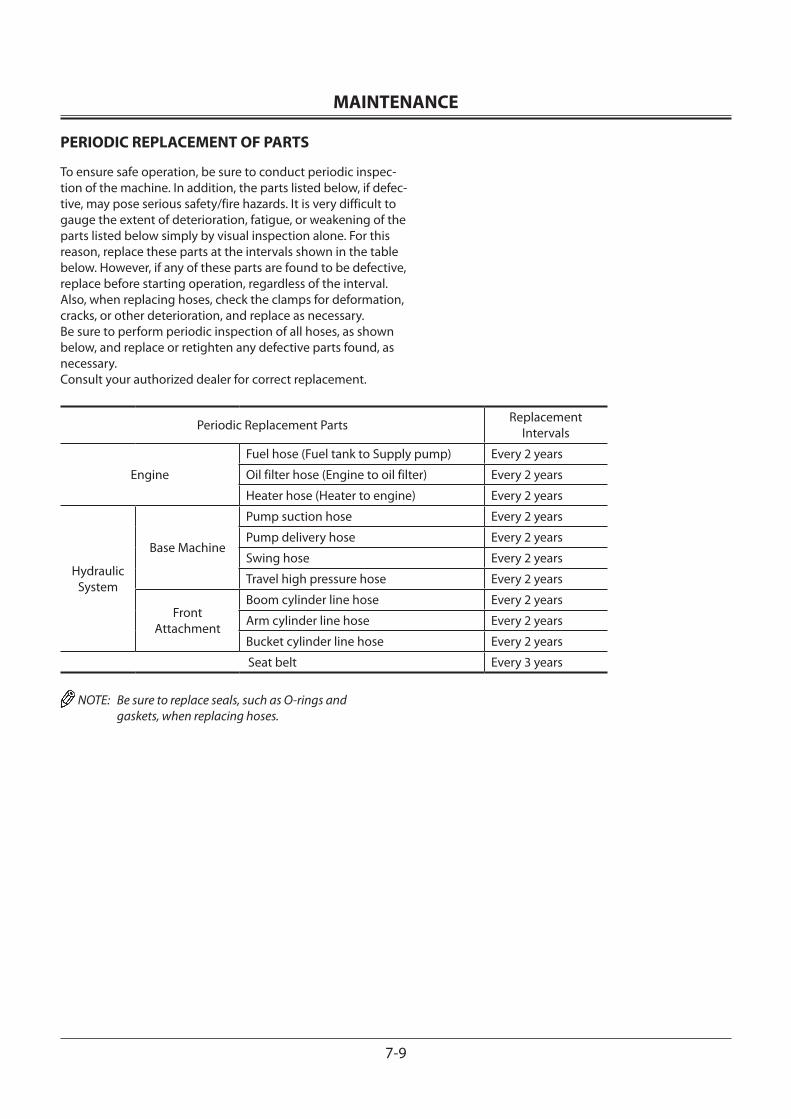
MAINTENANCE
7-9
PERIODIC REPLACEMENT OF PARTS
To ensure safe operation, be sure to conduct periodic inspec-tion of the machine. In addition, the parts listed below, if defec-tive, may pose serious safety/fire hazards. It is very difficult to gauge the extent of deterioration, fatigue, or weakening of the parts listed below simply by visual inspection alone. For this reason, replace these parts at the intervals shown in the table below. However, if any of these parts are found to be defective, replace before starting operation, regardless of the interval.Also, when replacing hoses, check the clamps for deformation, cracks, or other deterioration, and replace as necessary.Be sure to perform periodic inspection of all hoses, as shown below, and replace or retighten any defective parts found, as necessary.Consult your authorized dealer for correct replacement.
Periodic Replacement Parts Replacement Intervals
Engine
Fuel hose (Fuel tank to Supply pump) Every 2 years
Oil filter hose (Engine to oil filter) Every 2 years
Heater hose (Heater to engine) Every 2 years
HydraulicSystem
Base Machine
Pump suction hose Every 2 years
Pump delivery hose Every 2 years
Swing hose Every 2 years
Travel high pressure hose Every 2 years
FrontAttachment
Boom cylinder line hose Every 2 years
Arm cylinder line hose Every 2 years
Bucket cylinder line hose Every 2 years
Seat belt Every 3 years
NOTE: Be sure to replace seals, such as O-rings and gaskets, when replacing hoses.
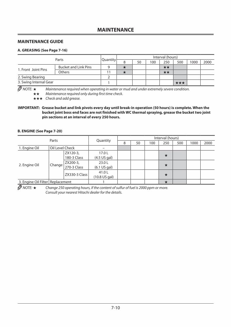
MAINTENANCE
7-10
MAINTENANCE GUIDE
A. GREASING (See Page 7-16)
Parts QuantityInterval (hours)
8 50 100 250 500 1000 2000
1. Front Joint PinsBucket and Link Pins 9 ★ ★★
Others 11 ★ ★★
2. Swing Bearing 23. Swing Internal Gear 1 ★★★
NOTE: ★ Maintenance required when operating in water or mud and under extremely severe condition. ★★ Maintenance required only during first time check. ★★★ Check and add grease.
IMPORTANT: Grease bucket and link pivots every day until break-in operation (50 hours) is complete. When the bucket joint boss end faces are not finished with WC thermal spraying, grease the bucket two joint pin sections at an interval of every 250 hours.
B. ENGINE (See Page 7-20)
Parts QuantityInterval (hours)
8 50 100 250 500 1000 20001. Engine Oil Oil Level Check –
2. Engine Oil Change
ZX120-3, 180-3 Class
17.0 L (4.5 US gal) ★
ZX200-3, 270-3 Class
23.0 L (6.1 US gal) ★
ZX330-3 Class 41.0 L (10.8 US gal) ★
3. Engine Oil Filter Replacement 1 ★
NOTE: ★ Change 250 operating hours, if the content of sulfur of fuel is 2000 ppm or more. Consult your nearest Hitachi dealer for the details.
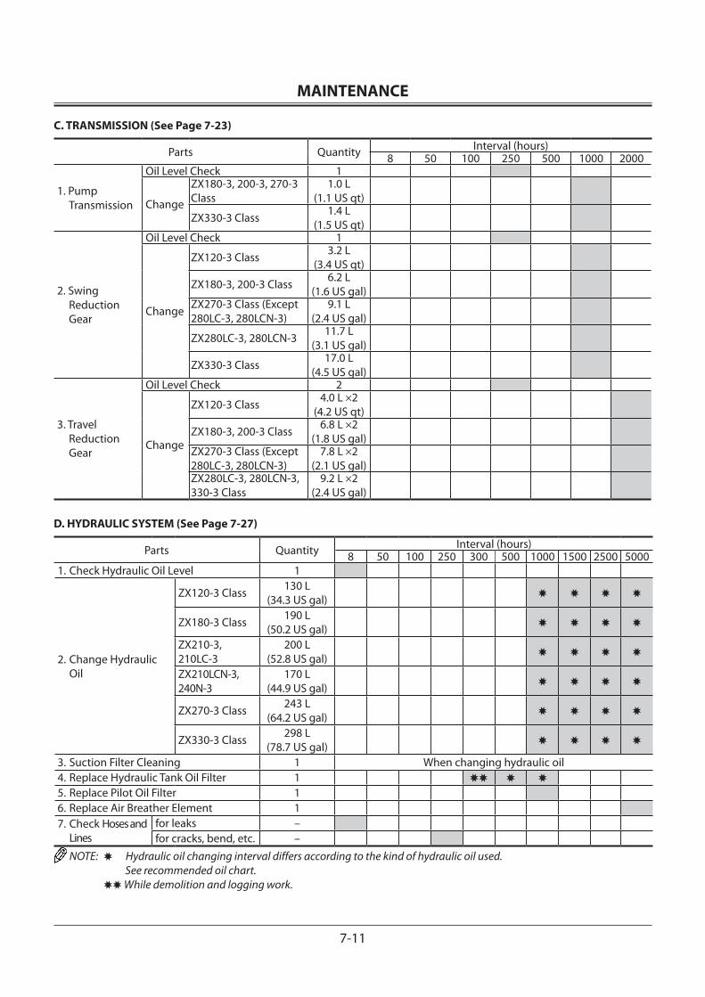
MAINTENANCE
7-11
C. TRANSMISSION (See Page 7-23)
Parts Quantity Interval (hours)8 50 100 250 500 1000 2000
1. Pump Transmission
Oil Level Check 1
Change
ZX180-3, 200-3, 270-3 Class
1.0 L (1.1 US qt)
ZX330-3 Class 1.4 L (1.5 US qt)
2. Swing Reduction Gear
Oil Level Check 1
Change
ZX120-3 Class 3.2 L (3.4 US qt)
ZX180-3, 200-3 Class 6.2 L (1.6 US gal)
ZX270-3 Class (Except 280LC-3, 280LCN-3)
9.1 L (2.4 US gal)
ZX280LC-3, 280LCN-3 11.7 L (3.1 US gal)
ZX330-3 Class 17.0 L (4.5 US gal)
3. Travel Reduction Gear
Oil Level Check 2
Change
ZX120-3 Class 4.0 L ×2 (4.2 US qt)
ZX180-3, 200-3 Class 6.8 L ×2 (1.8 US gal)
ZX270-3 Class (Except 280LC-3, 280LCN-3)
7.8 L ×2 (2.1 US gal)
ZX280LC-3, 280LCN-3, 330-3 Class
9.2 L ×2(2.4 US gal)
D. HYDRAULIC SYSTEM (See Page 7-27)
Parts Quantity Interval (hours)8 50 100 250 300 500 1000 1500 2500 5000
1. Check Hydraulic Oil Level 1
2. Change Hydraulic Oil
ZX120-3 Class 130 L (34.3 US gal) ✸ ✸ ✸ ✸
ZX180-3 Class 190 L (50.2 US gal) ✸ ✸ ✸ ✸
ZX210-3, 210LC-3
200 L (52.8 US gal) ✸ ✸ ✸ ✸
ZX210LCN-3, 240N-3
170 L(44.9 US gal) ✸ ✸ ✸ ✸
ZX270-3 Class 243 L (64.2 US gal) ✸ ✸ ✸ ✸
ZX330-3 Class 298 L (78.7 US gal)
3. Suction Filter Cleaning 1 When changing hydraulic oil4. Replace Hydraulic Tank Oil Filter 1 ✸✸ ✸ ✸
5. Replace Pilot Oil Filter 16. Replace Air Breather Element 17. Check Hoses and
Linesfor leaks –for cracks, bend, etc. –
NOTE: ✸ Hydraulic oil changing interval differs according to the kind of hydraulic oil used. See recommended oil chart.
✸✸ While demolition and logging work.
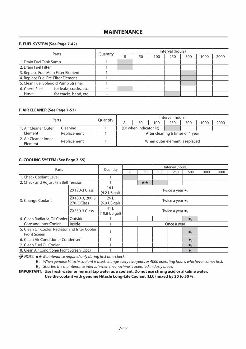
MAINTENANCE
7-12
E. FUEL SYSTEM (See Page 7-42)
Parts QuantityInterval (hours)
8 50 100 250 500 1000 20001. Drain Fuel Tank Sump 12. Drain Fuel Filter 13. Replace Fuel Main Filter Element 14. Replace Fuel Pre-Filter Element 15. Clean Fuel Solenoid Pump Strainer 16. Check Fuel Hoses
for leaks, cracks, etc. –for cracks, bend, etc. –
F. AIR CLEANER (See Page 7-53)
Parts QuantityInterval (hours)
8 50 100 250 500 1000 20001. Air Cleaner Outer
ElementCleaning 1 (Or when indicator lit)Replacement 1 After cleaning 6 times or 1 year
2. Air Cleaner Inner Element Replacement 1 When outer element is replaced
G. COOLING SYSTEM (See Page 7-55)
Parts QuantityInterval (hours)
8 50 100 250 500 1000 20001. Check Coolant Level 12. Check and Adjust Fan Belt Tension 1 ★★
3. Change Coolant
ZX120-3 Class 16 L (4.2 US gal) Twice a year ✸1
ZX180-3, 200-3, 270-3 Class
26 L (6.9 US gal) Twice a year ✸1
ZX330-3 Class 41 L (10.8 US gal) Twice a year ✸1
4. Clean Radiator, Oil Cooler Core and Inter Cooler
Outside 1 ✸2
Inside 1 Once a year5. Clean Oil Cooler, Radiator and Inter Cooler
Front Screen 1 ✸2
6. Clean Air Conditioner Condenser 1 ✸2
7. Clean Fuel Oil Cooler 1 ✸2
8. Clean Air Conditioner Front Screen (Opt.) 1 ✸2
NOTE: ★★ Maintenance required only during first time check. ✸1 When genuine Hitachi coolant is used, change every two years or 4000 operating hours, whichever comes first. ✸2 Shorten the maintenance interval when the machine is operated in dusty areas.IMPORTANT: Use fresh water or normal tap water as a coolant. Do not use strong acid or alkaline water.
Use the coolant with genuine Hitachi Long-Life Coolant (LLC) mixed by 30 to 50 %.
MAINTENANCE
7-13
H. ELECTRICAL SYSTEM (See Page 7-62)I. MISCELLANEOUS (See Page 7-68)
Parts QuantityInterval (hours)
8 50 100 250 500 1000 2000 40001. Check Bucket Teeth for Wear and Looseness —2. Change Bucket — As required3. Convert Bucket Connection Into Face Shovel — As required4. Adjust Bucket Linkage 1 As required5. Remove Travel Levers 2 As required6. Check and Replace Seat Belt 1 Every 3 years (Replace)7. Check Windshield Fluid Level 1 As required8. Check Track Sag 2
9. Check Air Conditioner Filter (Opt.)
Circulating Air Filter
Cleaning 1Replacement 1 After cleaning 6 times or so
Fresh Air FilterCleaning 1Replacement 1 After cleaning 6 times or so
10. Check Air Conditioner (Opt.) —11. Clean Cab Floor — As required12. Retighten Cylinder Head Bolt — ✸As required13. Inspect and Adjust Valve Clearance — ✸
14. Measure Engine Compression Pressure — ✸
15. Check Starter and Alternator — ✸
16. Check and Replace EGR Device — ✸As required17. Check Tightening Torque of Bolts and Nuts — ★★
NOTE: Contact your authorized dealer for maintenance. ★★ Maintenance required only during first time check.
MAINTENANCE
7-14
Brand Names of Recommended GreaseWhere to be
appliedManufacturer
Bucket, Arm and Boom, Swing Gear, Swing Bearing, etc.–20 to 40 °C (–4 to 104 °F)
Nippon Koyu SEP 2 ✸1British Petroleum BP Energrease LS-EP2Caltex Oil Multifax EP2Esso Beacon EP2Idemitsu Kosan Daphne Coronex Grease EP2Mobil Oil Mobilux EP2Nippon Oil Epinoc Grease AP2Shell Oil Shell Alvania EP2 ✸2
NOTE: The machine shipped from the factory is filled with lubricants marked with .
✸1 Front Joint Pin and Swing Bearing ✸2 Swing Gear
Recommended Engine Oil
IMPORTANT: Use only genuine Hitachi engine oil as shown below or engine oil equivalent to DH-1 speci-fied in JASO. Failure to do so may deterio-rate the engine performance and/or shorten the engine service life. Please be noted that all engine failures caused by using engine oil other than specified are excluded from Hitachi Warranty Policy. Consult your near-est Hitachi dealer for the unclear points.
Air Temp.
Brand Names of Recommended Engine OilKind of Oil Engine Oil
Application
Manufacturer
Engine Crank Case
-20 to 30 ˚C (-4 to 86 ˚F)
-15 to 40 ˚C (5 to 104 ˚F)
JASO
Hitachi Super wide DH-1 10W-30
Super wide DH-1 15W-40 DH-1
MAINTENANCE
7-15
Brand Names of Recommended OilApplication Swing and Travel Reduction Gear Pump Transmission
Kind of Oil Gear oil Engine OilAir Temp.
Manufacturer –20 to 40 °C (–4 to 104 °F) –20 to 40 °C (–4 to 104 °F)
–10 to 35 °C (14 to 95 °F)
25 to 40 °C (77 to 104 °F)
British Petroleum BP Gear oil SAE80W-90BP Vanellus C3
30 40
Caltex Oil Thuban SAE 90RPM DELO 300 Oil30 40
Esso Esso Gear Oil GP80W-90Essolube D-3
30 40
Idemitsu Kosan Apollo Gear HE90Apolloil super wide
15W-40Apolloil diesel motiveS-330 S-340
Mobil Oil Mobilube GX80W-90Mobil Delvac
1330 1340
Nippon Oil Gear Lube SP90 ✸2
Hidiesel S3
15W-40 ✸1–20 to 35 °C(–4 to 95 °F)
10W-30
Shell Oil Shell Spirax EP90Rymla D
30 40Remarks API GL 4 Class API CD Class
NOTE: The machine shipped from the factory is filled with oil marked . ✸1 Engine oil for pump transmission ✸2 Gear oil for swing and travel reduction device.
Brand Names of Recommended Hydraulic OilKind of Lubricant Hydraulic OilWhere to be applied Hydraulic SystemChange Interval 5000 hours 2500 hours 1500 hours
EnvironmentalTemp.
Manufacturer
–20 to 40 °C(–4 to 104 °F)
–10 to 40 °C (14 to 104 °F)
–20 to 40 °C(–4 to 104 °F)
–10 to 40 °C (14 to 104 °F)
–20 to 40 °C(–4 to 104 °F)
–10 to 40 °C (14 to 104 °F)
Hitachi Super EX 46HNIdemitsu Kosan Super Hydro 46 WRHUBritish Petroleum Bartran HV46
Caltex Oil Rando Oil HD46
Texaco INC. Rando Oil HD46
Chevron U.S.A INC. Chevron AW46Esso NUTO H46Mobil Oil DTE 25Shell Oil Tellus Oil S46 Tellus Oil 46Remarks Anti-wear type hydraulic oil
NOTE: Use proper hydraulic oil in accordance with the atmospheric temperature. The machine shipped from the factory is filled with oil marked . When the atmospheric temperature is between -40 °C and +20 °C: Use the proper hydraulic oil having high and low temperature characteristics by referring to the values shown below. Low Temperature Viscosity: Less than 4000 cSt at -40 °C High Temperature Viscosity: More than 6.5 cSt at +80 °C The above values are approximately equivalent to ISO viscosity grade #22. However, low temperature viscosity will differ depending on each product. Contact each hydraulic oil manufacture directly. When the atmospheric temperature is below -40 °C: Contact your authorized dealer.
MAINTENANCE
7-16
A. GREASING
1 Front Joint Pins
Bucket --- every 250 hoursLink Pins --- every 500 hours
Others --- every 500 hours• Boom Cylinder Bottom
• Boom Foot
ZX200-3, 270-3, 330-3 Class
ZX120-3, 180-3, 200-3, 270-3, 330-3 Class
ZX200-3, 270-3, 330-3 Class
M178-07-007
M157-07-156
M157-07-155
M104-07-002ZX120-3, 180-3 Class
ZX120-3, 180-3 Class M154-07-002
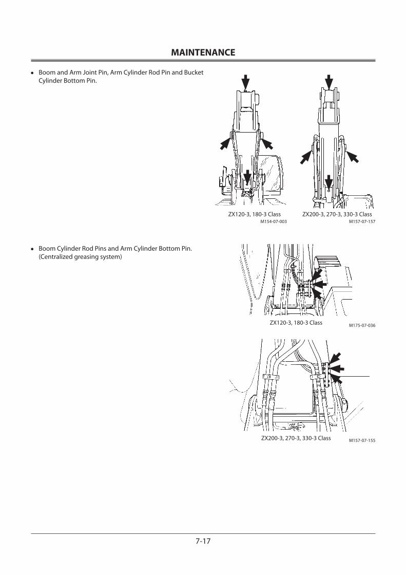
MAINTENANCE
7-17
• Boom and Arm Joint Pin, Arm Cylinder Rod Pin and Bucket Cylinder Bottom Pin.
• Boom Cylinder Rod Pins and Arm Cylinder Bottom Pin. (Centralized greasing system)
ZX120-3, 180-3 Class ZX200-3, 270-3, 330-3 ClassM157-07-157M154-07-003
M157-07-155
ZX120-3, 180-3 Class M175-07-036
ZX200-3, 270-3, 330-3 Class
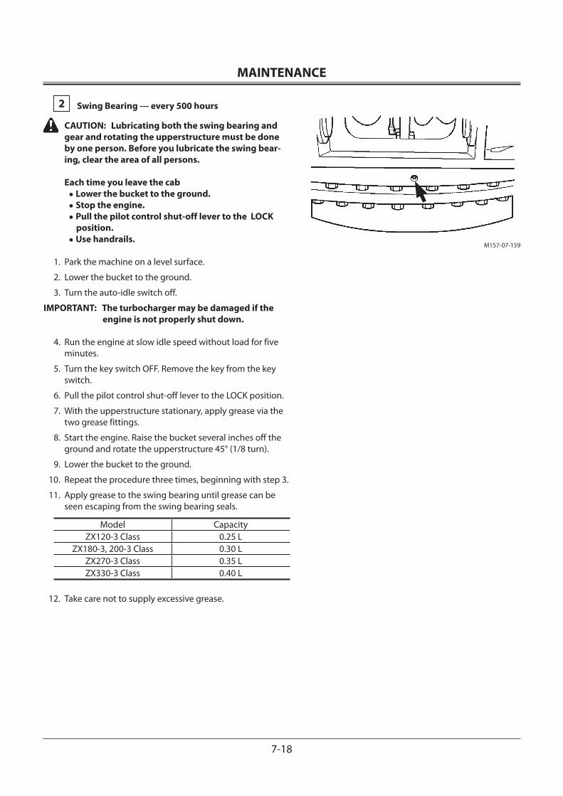
MAINTENANCE
7-18
2 Swing Bearing --- every 500 hours
CAUTION: Lubricating both the swing bearing and gear and rotating the upperstructure must be done by one person. Before you lubricate the swing bear-ing, clear the area of all persons.
Each time you leave the cab • Lower the bucket to the ground. • Stop the engine. • Pull the pilot control shut-off lever to the LOCK
position. • Use handrails.
1. Park the machine on a level surface.
2. Lower the bucket to the ground.
3. Turn the auto-idle switch off.
IMPORTANT: The turbocharger may be damaged if the engine is not properly shut down.
4. Run the engine at slow idle speed without load for five minutes.
5. Turn the key switch OFF. Remove the key from the key switch.
6. Pull the pilot control shut-off lever to the LOCK position.
7. With the upperstructure stationary, apply grease via the two grease fittings.
8. Start the engine. Raise the bucket several inches off the ground and rotate the upperstructure 45° (1/8 turn).
9. Lower the bucket to the ground.
10. Repeat the procedure three times, beginning with step 3.
11. Apply grease to the swing bearing until grease can be seen escaping from the swing bearing seals.
Model CapacityZX120-3 Class 0.25 L
ZX180-3, 200-3 Class 0.30 LZX270-3 Class 0.35 LZX330-3 Class 0.40 L
12. Take care not to supply excessive grease.
M157-07-159
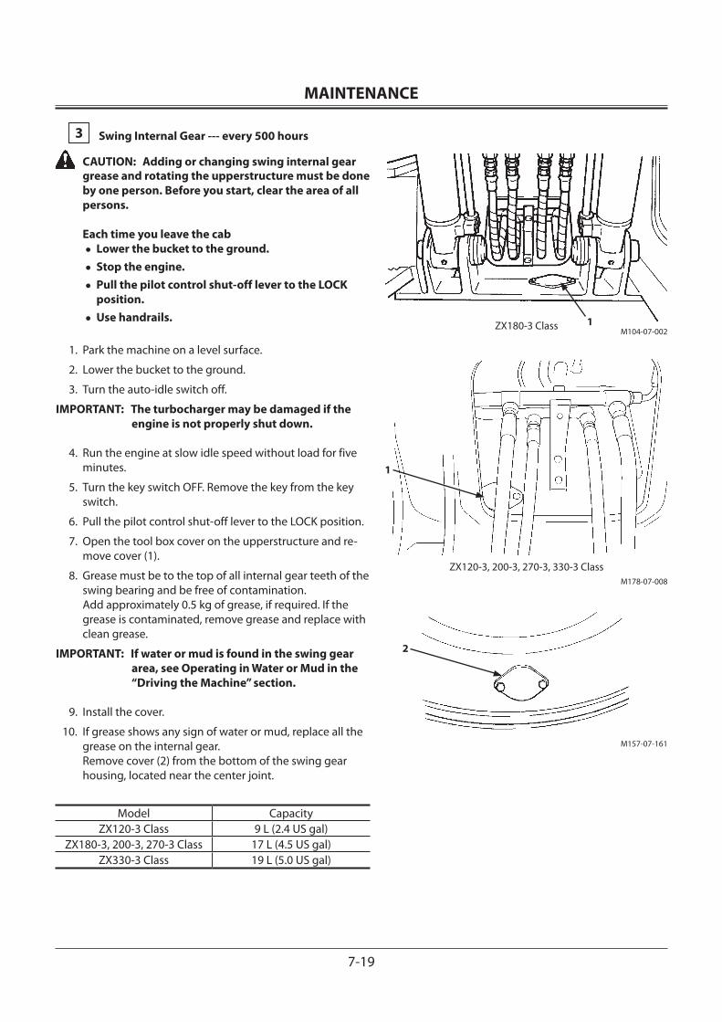
MAINTENANCE
7-19
3 Swing Internal Gear --- every 500 hours
CAUTION: Adding or changing swing internal gear grease and rotating the upperstructure must be done by one person. Before you start, clear the area of all persons. Each time you leave the cab• Lower the bucket to the ground.• Stop the engine.• Pull the pilot control shut-off lever to the LOCK
position.• Use handrails.
1. Park the machine on a level surface.
2. Lower the bucket to the ground.
3. Turn the auto-idle switch off.
IMPORTANT: The turbocharger may be damaged if the engine is not properly shut down.
4. Run the engine at slow idle speed without load for five minutes.
5. Turn the key switch OFF. Remove the key from the key switch.
6. Pull the pilot control shut-off lever to the LOCK position.
7. Open the tool box cover on the upperstructure and re-move cover (1).
8. Grease must be to the top of all internal gear teeth of the swing bearing and be free of contamination. Add approximately 0.5 kg of grease, if required. If the grease is contaminated, remove grease and replace with clean grease.
IMPORTANT: If water or mud is found in the swing gear area, see Operating in Water or Mud in the “Driving the Machine” section.
9. Install the cover.
10. If grease shows any sign of water or mud, replace all the grease on the internal gear. Remove cover (2) from the bottom of the swing gear housing, located near the center joint.
Model CapacityZX120-3 Class 9 L (2.4 US gal)
ZX180-3, 200-3, 270-3 Class 17 L (4.5 US gal)ZX330-3 Class 19 L (5.0 US gal)
1
2
ZX120-3, 200-3, 270-3, 330-3 ClassM178-07-008
M157-07-161
M104-07-002ZX180-3 Class 1
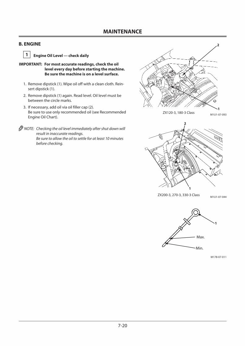
MAINTENANCE
7-20
B. ENGINE
1 Engine Oil Level --- check daily
IMPORTANT: For most accurate readings, check the oil level every day before starting the machine. Be sure the machine is on a level surface.
1. Remove dipstick (1). Wipe oil off with a clean cloth. Rein-sert dipstick (1).
2. Remove dipstick (1) again. Read level. Oil level must be between the circle marks.
3. If necessary, add oil via oil filler cap (2). Be sure to use only recommended oil (see Recommended
Engine Oil Chart).
NOTE: Checking the oil level immediately after shut down will result in inaccurate readings. Be sure to allow the oil to settle for at least 10 minutes before checking.
2
1
Max.
Min.
M1U1-07-044
M178-07-011
2
1M1U1-07-093
1
ZX120-3, 180-3 Class
ZX200-3, 270-3, 330-3 Class
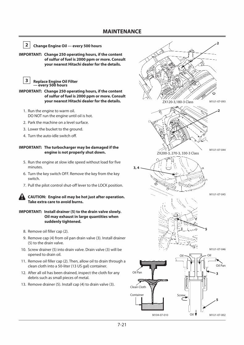
MAINTENANCE
7-21
2 Change Engine Oil --- every 500 hours
IMPORTANT: Change 250 operating hours, if the content of sulfur of fuel is 2000 ppm or more. Consult your nearest Hitachi dealer for the details.
3 Replace Engine Oil Filter --- every 500 hours
IMPORTANT: Change 250 operating hours, if the content of sulfur of fuel is 2000 ppm or more. Consult your nearest Hitachi dealer for the details.
1. Run the engine to warm oil. DO NOT run the engine until oil is hot.
2. Park the machine on a level surface.
3. Lower the bucket to the ground.
4. Turn the auto-idle switch off.
IMPORTANT: The turbocharger may be damaged if the engine is not properly shut down.
5. Run the engine at slow idle speed without load for five minutes.
6. Turn the key switch OFF. Remove the key from the key switch.
7. Pull the pilot control shut-off lever to the LOCK position.
CAUTION: Engine oil may be hot just after operation. Take extra care to avoid burns.
IMPORTANT: Install drainer (5) to the drain valve slowly. Oil may exhaust in large quantities when suddenly tightened.
8. Remove oil filler cap (2).
9. Remove cap (4) from oil pan drain valve (3). Install drainer (5) to the drain valve.
10. Screw drainer (5) into drain valve. Drain valve (3) will be opened to drain oil.
11. Remove oil filler cap (2). Then, allow oil to drain through a clean cloth into a 50-liter (13 US gal) container.
12. After all oil has been drained, inspect the cloth for any debris such as small pieces of metal.
13. Remove drainer (5). Install cap (4) to drain valve (3).
Oil Pan
Clean Cloth
Container
5
3, 4
3
5Screw
Oil Oil
Oil Pan
Oil
M1U1-07-045
M1U1-07-046
M1U1-07-002M104-07-010
M1U1-07-044
2
M1U1-07-093ZX120-3,180-3 Class
2
ZX200-3, 270-3, 330-3 Class
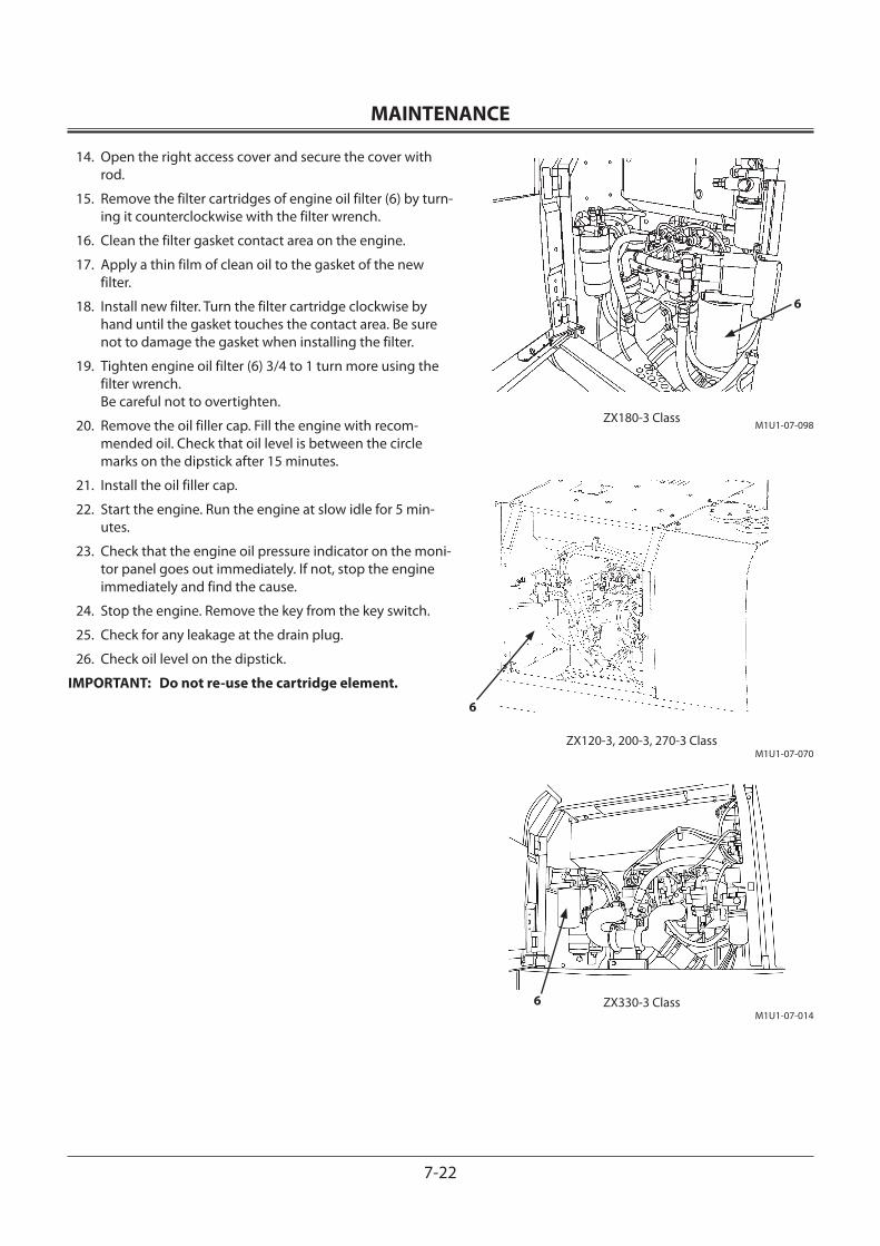
MAINTENANCE
7-22
14. Open the right access cover and secure the cover with rod.
15. Remove the filter cartridges of engine oil filter (6) by turn-ing it counterclockwise with the filter wrench.
16. Clean the filter gasket contact area on the engine.
17. Apply a thin film of clean oil to the gasket of the new filter.
18. Install new filter. Turn the filter cartridge clockwise by hand until the gasket touches the contact area. Be sure not to damage the gasket when installing the filter.
19. Tighten engine oil filter (6) 3/4 to 1 turn more using the filter wrench. Be careful not to overtighten.
20. Remove the oil filler cap. Fill the engine with recom-mended oil. Check that oil level is between the circle marks on the dipstick after 15 minutes.
21. Install the oil filler cap.
22. Start the engine. Run the engine at slow idle for 5 min-utes.
23. Check that the engine oil pressure indicator on the moni-tor panel goes out immediately. If not, stop the engine immediately and find the cause.
24. Stop the engine. Remove the key from the key switch.
25. Check for any leakage at the drain plug.
26. Check oil level on the dipstick.
IMPORTANT: Do not re-use the cartridge element.
6
6
6
ZX180-3 ClassM1U1-07-098
ZX120-3, 200-3, 270-3 ClassM1U1-07-070
ZX330-3 ClassM1U1-07-014
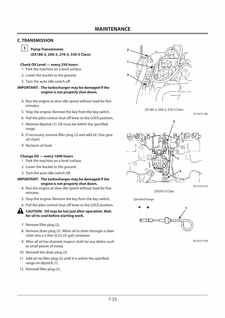
MAINTENANCE
7-23
C. TRANSMISSION
1 Pump Transmission (ZX180-3, 200-3, 270-3, 330-3 Class)
Check Oil Level --- every 250 hours1. Park the machine on a level surface.
2. Lower the bucket to the ground.
3. Turn the auto-idle switch off.
IMPORTANT: The turbocharger may be damaged if the engine is not properly shut down.
4. Run the engine at slow idle speed without load for five minutes.
5. Stop the engine. Remove the key from the key switch.
6. Pull the pilot control shut-off lever to the LOCK position.
7. Remove dipstick (1). Oil must be within the specified range.
8. If necessary, remove filler plug (2) and add oil. (See gear oil chart)
9. Recheck oil level.
Change Oil --- every 1000 hours1. Park the machine on a level surface.
2. Lower the bucket to the ground.
3. Turn the auto-idle switch off.
IMPORTANT: The turbocharger may be damaged if the engine is not properly shut down.
4. Run the engine at slow idle speed without load for five minutes.
5. Stop the engine. Remove the key from the key switch.
6. Pull the pilot control shut-off lever to the LOCK position.
CAUTION: Oil may be hot just after operation. Wait for oil to cool before starting work.
7. Remove filler plug (2).
8. Remove drain plug (3). Allow oil to drain through a clean cloth into a 2-liter (0.52 US gal) container.
9. After all oil has drained, inspect cloth for any debris such as small pieces of metal.
10. Reinstall the drain plug (3).
11. Add oil via filler plug (2) until it is within the specified range on dipstick (1).
12. Reinstall filler plug (2).
2
1
3
2
1
3
Specified Range
1
M178-07-085ZX180-3, 200-3, 270-3 Class
ZX330-3 Class
M110-07-015
M1G6-07-004
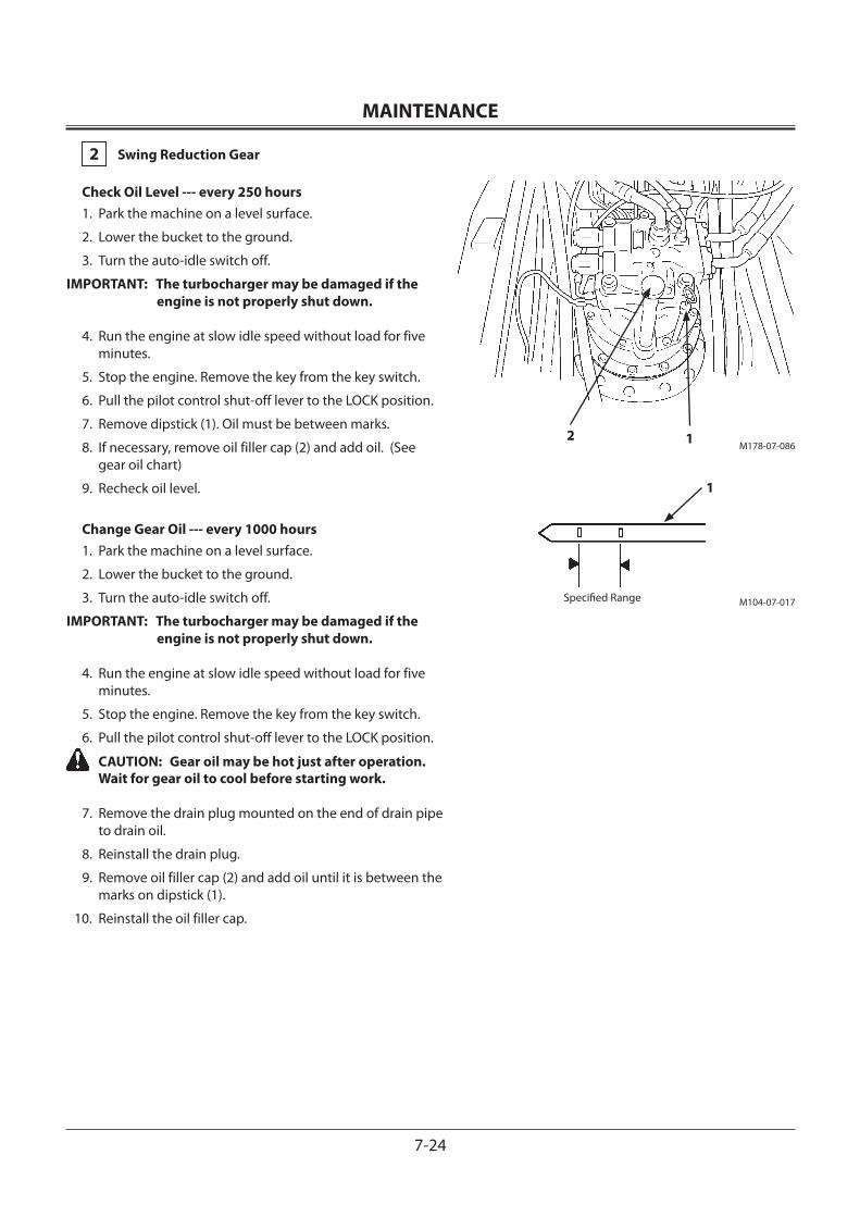
MAINTENANCE
7-24
2 Swing Reduction Gear
Check Oil Level --- every 250 hours1. Park the machine on a level surface.
2. Lower the bucket to the ground.
3. Turn the auto-idle switch off.
IMPORTANT: The turbocharger may be damaged if the engine is not properly shut down.
4. Run the engine at slow idle speed without load for five minutes.
5. Stop the engine. Remove the key from the key switch.
6. Pull the pilot control shut-off lever to the LOCK position.
7. Remove dipstick (1). Oil must be between marks.
8. If necessary, remove oil filler cap (2) and add oil. (See gear oil chart)
9. Recheck oil level.
Change Gear Oil --- every 1000 hours1. Park the machine on a level surface.
2. Lower the bucket to the ground.
3. Turn the auto-idle switch off.
IMPORTANT: The turbocharger may be damaged if the engine is not properly shut down.
4. Run the engine at slow idle speed without load for five minutes.
5. Stop the engine. Remove the key from the key switch.
6. Pull the pilot control shut-off lever to the LOCK position.
CAUTION: Gear oil may be hot just after operation. Wait for gear oil to cool before starting work.
7. Remove the drain plug mounted on the end of drain pipe to drain oil.
8. Reinstall the drain plug.
9. Remove oil filler cap (2) and add oil until it is between the marks on dipstick (1).
10. Reinstall the oil filler cap.
M178-07-086
M104-07-017
Specified Range
12
1
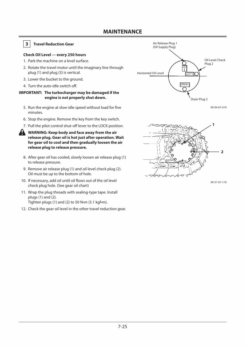
MAINTENANCE
7-25
3 Travel Reduction Gear
Check Oil Level --- every 250 hours1. Park the machine on a level surface.
2. Rotate the travel motor until the imaginary line through plug (1) and plug (3) is vertical.
3. Lower the bucket to the ground.
4. Turn the auto-idle switch off.
IMPORTANT: The turbocharger may be damaged if the engine is not properly shut down.
5. Run the engine at slow idle speed without load for five minutes.
6. Stop the engine. Remove the key from the key switch.
7. Pull the pilot control shut-off lever to the LOCK position.
WARNING: Keep body and face away from the air release plug. Gear oil is hot just after operation. Wait for gear oil to cool and then gradually loosen the air release plug to release pressure.
8. After gear oil has cooled, slowly loosen air release plug (1) to release pressure.
9. Remove air release plug (1) and oil level check plug (2). Oil must be up to the bottom of hole.
10. If necessary, add oil until oil flows out of the oil level check plug hole. (See gear oil chart)
11. Wrap the plug threads with sealing-type tape. Install plugs (1) and (2). Tighten plugs (1) and (2) to 50 N•m (5.1 kgf•m).
12. Check the gear oil level in the other travel reduction gear.
M104-07-019
M157-07-170
Air Release Plug 1(Oil Supply Plug)
Horizontal Oil Level
Oil Level CheckPlug 2
Drain Plug 3
1
2
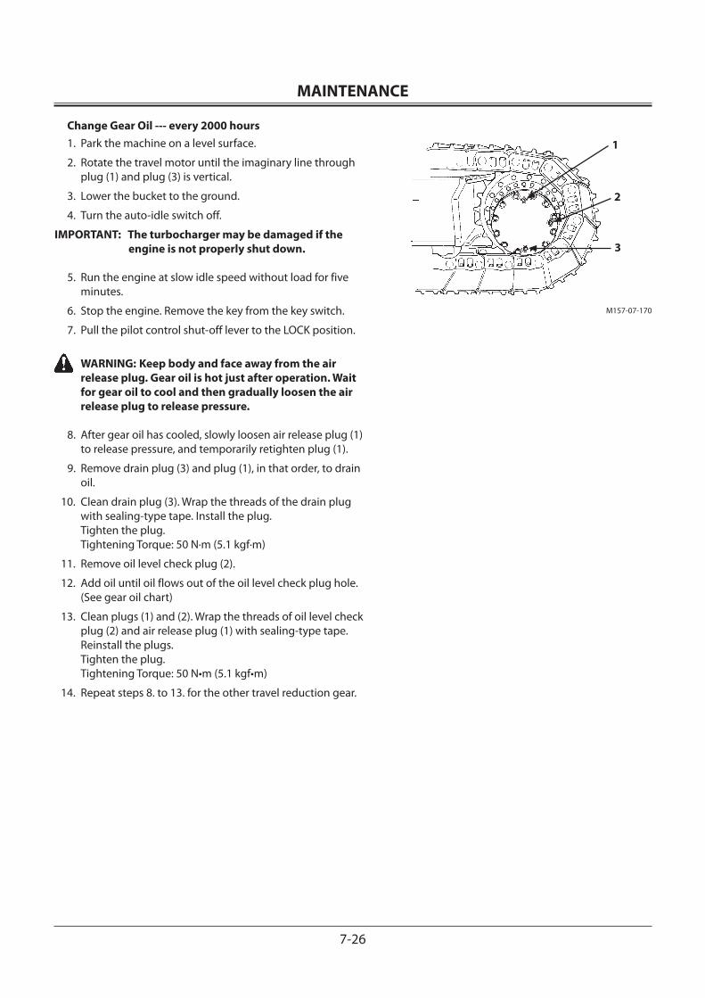
MAINTENANCE
7-26
Change Gear Oil --- every 2000 hours1. Park the machine on a level surface.
2. Rotate the travel motor until the imaginary line through plug (1) and plug (3) is vertical.
3. Lower the bucket to the ground.
4. Turn the auto-idle switch off.
IMPORTANT: The turbocharger may be damaged if the engine is not properly shut down.
5. Run the engine at slow idle speed without load for five minutes.
6. Stop the engine. Remove the key from the key switch.
7. Pull the pilot control shut-off lever to the LOCK position.
WARNING: Keep body and face away from the air release plug. Gear oil is hot just after operation. Wait for gear oil to cool and then gradually loosen the air release plug to release pressure.
8. After gear oil has cooled, slowly loosen air release plug (1) to release pressure, and temporarily retighten plug (1).
9. Remove drain plug (3) and plug (1), in that order, to drain oil.
10. Clean drain plug (3). Wrap the threads of the drain plug with sealing-type tape. Install the plug. Tighten the plug. Tightening Torque: 50 N·m (5.1 kgf·m)
11. Remove oil level check plug (2).
12. Add oil until oil flows out of the oil level check plug hole. (See gear oil chart)
13. Clean plugs (1) and (2). Wrap the threads of oil level check plug (2) and air release plug (1) with sealing-type tape. Reinstall the plugs. Tighten the plug. Tightening Torque: 50 N•m (5.1 kgf•m)
14. Repeat steps 8. to 13. for the other travel reduction gear.
M157-07-170
1
2
3
MAINTENANCE
7-27
D. HYDRAULIC SYSTEM
INSPECTION AND MAINTENANCE OF HYDRAULIC EQUIPMENT
CAUTION: During operation, the parts of the hydrau-lic system become very hot.
Allow the machine to cool down before beginning inspection or maintenance.
1. Be sure that the machine is parked on a level, firm surface before servicing hydraulic equipment.
2. Lower the bucket to the ground and stop the engine.
3. Begin servicing hydraulic components only after compo-nents, hydraulic oil and lubricants are completely cooled, and after releasing residual pressure.
3.1 Bleed air from the hydraulic oil tank to release internal pressure.
3.2 Allow the machine to cool down. Note that servicing heated and pressurized hydraulic components may cause hot parts and/or oil to fly off or escape suddenly, possibly resulting in personal injury.
3.3 Keep body parts and face away from plugs or screws when removing them. Hydraulic components may be pressurized even when cooled.
3.4 Never attempt to service or inspect the travel and swing motor circuits on slopes. They are highly pressurized due to self-weight.
4. When connecting hydraulic hoses and pipes, take spe-cial care to keep seal surfaces free from dirt and to avoid damaging them. Keep these precautions in mind:
4.1 Wash hoses, pipes, and the tank interior with a washing liquid and thoroughly wipe it out before reconnecting them.
4.2 Only use O-rings that are free of damage or defects. Be careful not to damage them during reassembly.
4.3 Do not allow high pressure hoses to twist when con-necting them. The life of twisted hoses will be short-ened considerably.
4.4 Carefully tighten low pressure hose clamps. Do not overtighten them.

MAINTENANCE
7-28
5. When adding hydraulic oil, always use the same brand of oil; do not mix brands of oil. As the machine is filled with Super EX 46HN when it is shipped from the factory, use it as a general rule. When selecting to use another brand of oil listed in the table “Brand names of recommended hydraulic oil”, be sure to completely replace the oil in the system.
6. Do not use hydraulic oils other than those listed in the table “Brand names of recommended hydraulic oil”.
7. Never run the engine without oil in the hydraulic oil tank.
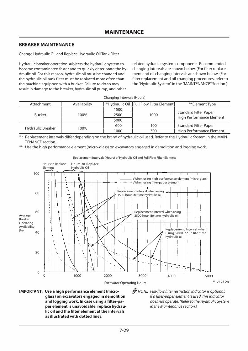
MAINTENANCE
7-29
BREAKER MAINTENANCE
Change Hydraulic Oil and Replace Hydraulic Oil Tank Filter
Hydraulic breaker operation subjects the hydraulic system to become contaminated faster and to quickly deteriorate the hy-draulic oil. For this reason, hydraulic oil must be changed and the hydraulic oil tank filter must be replaced more often than the machine equipped with a bucket. Failure to do so may result in damage to the breaker, hydraulic oil pump, and other
related hydraulic system components. Recommended changing intervals are shown below. (For filter replace-ment and oil changing intervals are shown below. (For filter replacement and oil changing procedures, refer to the “Hydraulic System” in the “MAINTENANCE” Section.)
IMPORTANT: Use a high performance element (micro-glass) on excavators engaged in demolition and logging work. In case using a filter-pa-per element is unavoidable, replace hydrau-lic oil and the filter element at the intervals as illustrated with dotted lines.
NOTE: Full-flow filter restriction indicator is optional. If a filter-paper element is used, this indicator does not operate. (Refer to the Hydraulic System in the Maintenance section.)
Excavator Operating Hours
Attachment Availability *Hydraulic Oil Full Flow Filter Element **Element Type
Bucket 100%1500
1000 Standard Filter Paper High Performance Element2500
5000
Hydraulic Breaker 100% 600 100 Standard Filter Paper1000 300 High Performance Element
Changing intervals (Hours)
* : Replacement intervals differ depending on the brand of hydraulic oil used. Refer to the Hydraulic System in the MAIN-TENANCE section.
** : Use the high performance element (micro-glass) on excavators engaged in demolition and logging work.
Hours to Replace Element
Average Breaker Operating Availability (%)
Replacement Intervals (Hours) of Hydraulic Oil and Full Flow Filter Element
Hours to Replace Hydraulic Oil
Replacement Interval when using 1500-hour life time hydraulic oil
Replacement Interval when using 5000-hour life time hydraulic oil
Replacement Interval when using 2500-hour life time hydraulic oil
: When using high performance element (micro-glass) : When using filter-paper element
400030002000100000
20
40
60
80
100
5000M1U1-05-006
MAINTENANCE
7-30
1 Check Hydraulic Oil Level --- daily
IMPORTANT: Never run the engine without oil in hydraulic oil tank.
1. Park the machine on a level surface.
2. Position the machine with the arm cylinder fully retracted and the bucket cylinder fully extended.
3. Lower the bucket to the ground.
4. Turn the auto-idle switch off.
IMPORTANT: The turbocharger may be damaged if the engine is not properly shut down.
5. Run the engine at slow idle speed without load for five minutes.
6. Turn the key switch OFF. Remove the key from the key switch.
7. Pull the pilot control shut-off lever to the LOCK position.
8. Open the access door in front of the main pump. Check oil level with level gauge (1) on hydraulic oil tank. Oil must be between marks on the gauge. If necessary, add oil.
CAUTION: The hydraulic oil tank is pressurized. Push the pressure release button on the tank cap to release pressure, and carefully remove the cap.
To add oil:9. Push the pressure release button on the air breather to
release pressure. Remove the cover.
10. Add oil. Recheck oil level with level gauge (1).
11. Install the cover. Make sure the filter and rod assembly is in correct position.
1
1
ZX180-3 Class
ZX200-3, 270-3, 330-3 Class
M1U1-07-102ZX120-3 Class
1
M104-07-021
M1U1-07-075
M1U1-07-048
MAINTENANCE
7-31
2 Change Hydraulic Oil
3 Suction Filter Cleaning --- every 5000 hours, 2500 hours or 1500 hours
CAUTION: Hydraulic oil may be hot just after opera-tion. Wait for oil to cool before starting work.
IMPORTANT: Hydraulic oil changing intervals differ ac-cording to kind of hydraulic oils used. (See Recommended Oil Chart in this group)
1. Park the machine on a level surface with the upperstruc-ture rotated 90° for easier access.
2. Position the machine with the arm cylinder fully retracted and the bucket cylinder fully extended.
3. Lower the bucket to the ground.
4. Turn the auto-idle switch off.
IMPORTANT: The turbocharger may be damaged if the engine is not properly shut down.
5. Run the engine at slow idle speed without load for five minutes.
6. Stop the engine. Remove the key from the key switch.
7. Pull the pilot control shut-off lever to the LOCK position.
8. Clean the top of the hydraulic oil tank to keep dirt out of the hydraulic system.
CAUTION: The hydraulic oil tank is pressurized. Push the pressure release button on the air breather before removing the air breather.
9. Push pressure release button (1) on the air breather.
10. Remove cover (2).
11. Remove oil using a suction pump. The hydraulic oil tank capacity, up to specified oil level, is approximately A.
Model AZX120-3 Class 130 L (34.3 US gal)ZX180-3 Class 190 L (50.2 US gal)ZX210-3, 210LC-3 200 L (52.8 US gal)ZX210LCN-3, 240N-3 170 L (44.9 US gal)ZX270-3 Class 243 L (64.2 US gal)ZX330-3 Class 298 L (78.7 US gal)
M157-07-016
12
Level Gauge
M104-07-117
M1U1-07-076
1
2
MAINTENANCE
7-32
12. Remove drain plug (3). Allow oil to drain.
13. Remove suction filter and rod assembly (4).
14. Clean the filter and tank interior. If the filter is to be re-placed, install new filter on the rod as shown. Tighten nut to 14.5 to 19.5 N•m (1.5 to 2.0 kgf•m, 11.0 to 14.5 lbf•ft).
Model AZX120-3 Class 732 mm (28.8 in)ZX180-3, 200-3, 270-3, 330-3 Class 869 mm (34.2 in)
15. Install filter and rod assembly (4). Make sure the filter is positioned correctly on the outlet.
16. Replace the hydraulic tank oil filter. (See “Maintenance Every 500 Hours” Section)
17. Clean, install and tighten drain plug (3).
18. Add oil until it is between the marks on the oil level gauge.
19. Install cover (2). Make sure filter and rod assembly (4) are in correct positions. Tighten the bolts to 49 N•m (5 kgf•m, 36 lbf•ft).
20. Be sure to bleed air form the system following the proce-dures shown next page.
M1U1-07-047
3
M157-07-062
2
4
M107-07-070
4
A
20 mm (0.79 in)
MAINTENANCE
7-33
Air Bleeding Procedures
IMPORTANT: If the hydraulic pump is not filled with oil, it will be damaged when the engine is started.
The machine is equipped with two main pumps. Bleed air from these pumps after changing hydraulic oil.
1. Remove air bleed plugs (5) on each pumps.
2. Fill the pump with oil through air bleed plugs (5) port on each pumps until oil flows out of air bleed plug (5) hole.
3. Temporarily tighten air bleed plugs (5) on each pumps, start the engine and run at slow idle. Loosen one of air bleed plugs (5) slightly until oil flows from plug port to release trapped air completely. Tighten air bleed plug (5). Repeat this step for the rest of plugs.
4. Purge air from the hydraulic system by running the en-gines at slow idle and operating the control levers slowly and smoothly for 15 minutes.
5. Position the machine as illustrated in the oil level check-ing procedure.
6. Lower the bucket to the ground.
7. Turn the auto-idle switch off.
8. Stop the engines. Remove the key from the key switches.
9. Pull the pilot control shut-off lever to the LOCK position
10. Check the hydraulic oil tank gauge. Remove cover (2) to add oil if necessary.
5
M1U1-07-035ZX180-3, 200-3, 270-3, 330-3 Class
ZX120-3 Class M175-07-005
5
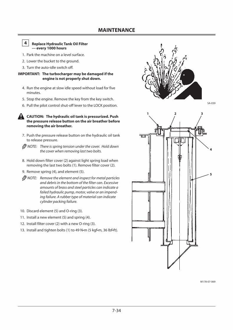
MAINTENANCE
7-34
4 Replace Hydraulic Tank Oil Filter --- every 1000 hours
1. Park the machine on a level surface.
2. Lower the bucket to the ground.
3. Turn the auto-idle switch off.
IMPORTANT: The turbocharger may be damaged if the engine is not properly shut down.
4. Run the engine at slow idle speed without load for five minutes.
5. Stop the engine. Remove the key from the key switch.
6. Pull the pilot control shut-off lever to the LOCK position.
CAUTION: The hydraulic oil tank is pressurized. Push the pressure release button on the air breather before removing the air breather.
7. Push the pressure release button on the hydraulic oil tank to release pressure.
NOTE: There is spring tension under the cover. Hold down the cover when removing last two bolts.
8. Hold down filter cover (2) against light spring load when removing the last two bolts (1). Remove filter cover (2).
9. Remove spring (4), and element (5).
NOTE: Remove the element and inspect for metal particles and debris in the bottom of the filter can. Excessive amounts of brass and steel particles can indicate a failed hydraulic pump, motor, valve or an impend-ing failure. A rubber type of material can indicate cylinder packing failure.
10. Discard element (5) and O-ring (3).
11. Install a new element (5) and spring (4).
12. Install filter cover (2) with a new O-ring (3).
13. Install and tighten bolts (1) to 49 N•m (5 kgf•m, 36 lbf•ft).
SA-039
M178-07-069
1 2
4
5
3
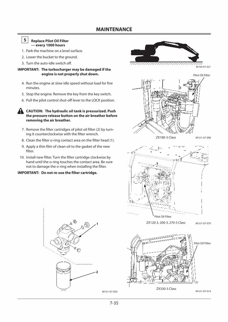
MAINTENANCE
7-35
5 Replace Pilot Oil Filter --- every 1000 hours1. Park the machine on a level surface.
2. Lower the bucket to the ground.
3. Turn the auto-idle switch off.
IMPORTANT: The turbocharger may be damaged if the engine is not properly shut down.
4. Run the engine at slow idle speed without load for five minutes.
5. Stop the engine. Remove the key from the key switch.
6. Pull the pilot control shut-off lever to the LOCK position.
CAUTION: The hydraulic oil tank is pressurized. Push the pressure release button on the air breather before removing the air breather.
7. Remove the filter cartridges of pilot oil filter (2) by turn-ing it counterclockwise with the filter wrench.
8. Clean the filter o-ring contact area on the filter head (1).
9. Apply a thin film of clean oil to the gasket of the new filter.
10. Install new filter. Turn the filter cartridge clockwise by hand until the o-ring touches the contact area. Be sure not to damage the o-ring when installing the filter.
IMPORTANT: Do not re-use the filter cartridge.
M1U1-07-014
Pilot Oil Filter
ZX330-3 Class
ZX120-3, 200-3, 270-3 Class M1U1-07-070
Pilot Oil Filter
ZX180-3 Class M1U1-07-098
Pilot Oil Filter
1
2
M1U1-07-050
M104-07-021
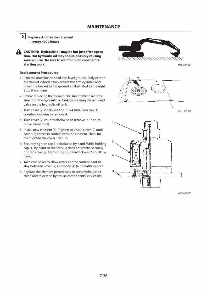
MAINTENANCE
7-36
6 Replace Air Breather Element --- every 4000 hours
CAUTION: Hydraulic oil may be hot just after opera-tion. Hot hydraulic oil may spout, possibly causing severe burns. Be sure to wait for oil to cool before starting work.
Replacement Procedures1. Park the machine on solid and level ground. Fully extend
the bucket cylinder, fully retract the arm cylinder, and lower the bucket to the ground as illustrated to the right. Stop the engine.
2. Before replacing the element, be sure to bleed air pres-sure from the hydraulic oil tank by pressing the air bleed valve on the hydraulic oil tank.
3. Turn cover (2) clockwise about 1/4 turn. Turn cap (1) counterclockwise to remove it.
4. Turn cover (2) counterclockwise to remove it. Then, re-move element (3).
5. Install new element (3). Tighten to install cover (2) until cover (2) comes in contact with the element. Then, fur-ther tighten the cover 1/4 turn.
6. Securely tighten cap (1) clockwise by hand. While holding cap (1) by hand so that cap (1) does not rotate, securely tighten cover (2) by rotating counterclockwise 5 to 10° by hand.
7. Take care never to allow water and/or contaminant to stay between cover (2) and body (4) (air breathing port).
8. Replace the element periodically to keep hydraulic oil clean and to extend hydraulic components service life.
M104-07-021
M1G6-07-001
1
3
4
2
M1U1-07-076
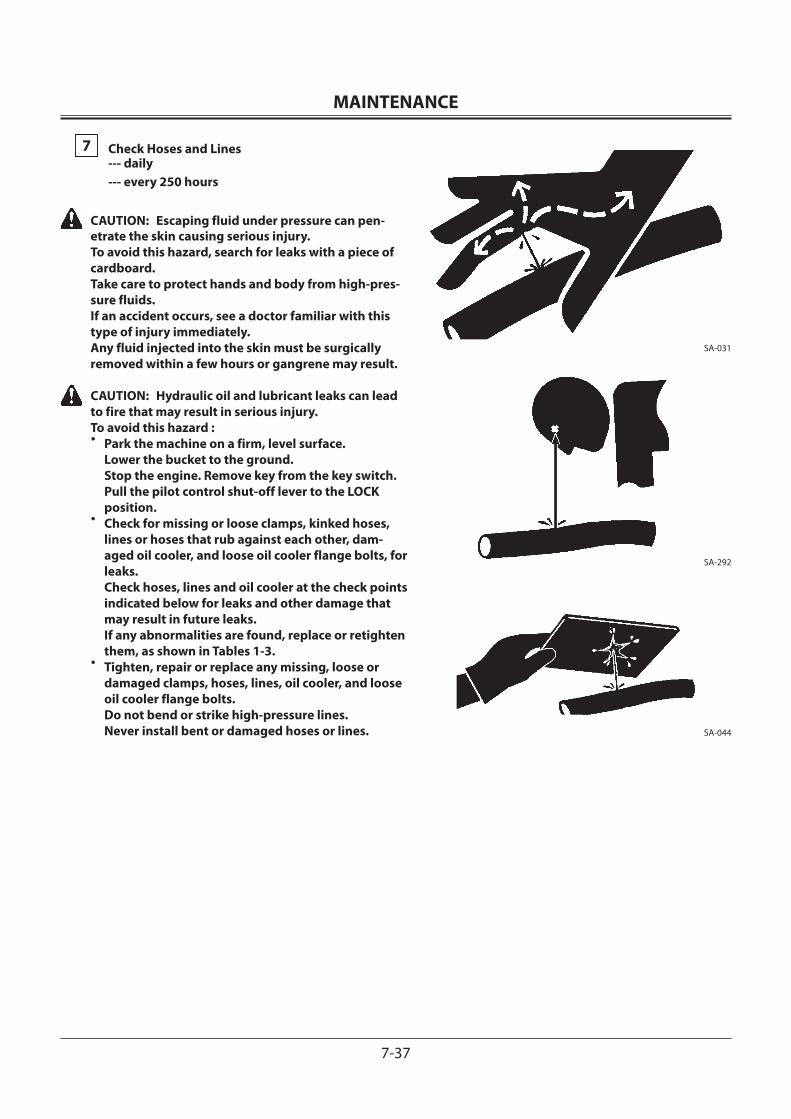
MAINTENANCE
7-37
7 Check Hoses and Lines --- daily --- every 250 hours
CAUTION: Escaping fluid under pressure can pen-etrate the skin causing serious injury. To avoid this hazard, search for leaks with a piece of cardboard. Take care to protect hands and body from high-pres-sure fluids. If an accident occurs, see a doctor familiar with this type of injury immediately. Any fluid injected into the skin must be surgically removed within a few hours or gangrene may result.
CAUTION: Hydraulic oil and lubricant leaks can lead to fire that may result in serious injury. To avoid this hazard :• Park the machine on a firm, level surface.
Lower the bucket to the ground. Stop the engine. Remove key from the key switch. Pull the pilot control shut-off lever to the LOCK position.
• Check for missing or loose clamps, kinked hoses, lines or hoses that rub against each other, dam-aged oil cooler, and loose oil cooler flange bolts, for leaks. Check hoses, lines and oil cooler at the check points indicated below for leaks and other damage that may result in future leaks. If any abnormalities are found, replace or retighten them, as shown in Tables 1-3.
• Tighten, repair or replace any missing, loose or damaged clamps, hoses, lines, oil cooler, and loose oil cooler flange bolts. Do not bend or strike high-pressure lines. Never install bent or damaged hoses or lines.
SA-031
SA-292
SA-044
MAINTENANCE
7-38
Table 1. Hoses
Interval (hours) Check Points Abnormalities Remedies
Daily Hose coversHose endsFittings
Leak (1)Leak (2)Leak (3)
ReplaceReplaceRetighten or replace hose or O-ring
Every 250 hours
Hose coversHose ends
Hose coversHose covers
Hose
Hose
Hose ends and fittings
Crack (4)Crack (5)
Exposed reinforcement (6)Blister (7)
Bend (8)
Collapse (9)
Deformation or corrosion (10)
ReplaceReplace
ReplaceReplace
Replace
Replace(Use proper bend radius)
Replace
NOTE: Refer to the illustrations in Fig.1 for each check point location or for a description of the abnormality. Use genuine Hitachi parts.
Fig. 1
M137-07-008
3 2
3
2
1
M115-07-145
3 2
3
2
1
M115-07-146
5
4
M115-07-147
6
7
M115-07-148
8
M115-07-149
9
10
MAINTENANCE
7-39
Table 2. Lines
Interval (hours) Check Points Abnormalities Remedies
Daily Contact surfaces of flange joints
Welded surfaces on joints
Leak (11)
Leak (12)
ReplaceO-ring and/or retighten bolts
Replace
Every 250 hours Joint neckWelded surfaces on jointsClamps
Crack (13)Crack (12) MissingDeformationLoose
ReplaceReplace
ReplaceReplaceRetighten
NOTE: Refer to the illustrations in Fig.2 for each check point location or for a description of the abnormality. Use genuine Hitachi parts
Table 3. Oil cooler
Interval (hours) Check Points Abnormalities Remedies
Every 250 hours Oil coolerCoupling and rubber hose
Leak (14)Leak (15)
ReplaceRetighten or replace
NOTE: Refer to the illustrations in Fig.3 for each check point location.
Fig. 2
M137-07-001
13 12
11
M137-07-007
13 12
Fig. 3
M1U1-07-051
14
15
MAINTENANCE
7-40
SERVICE RECOMMENDATIONS FOR HYDRAULIC FITTINGS
Two hydraulic fitting designs are used on this machine.
Flat Face O-ring Seal Fitting (ORS Fitting)An O-ring is used on the sealing surfaces to prevent oil leak-age.
1. Inspect fitting sealing surfaces (6). They must be free of dirt or defects.
2. Replace O-ring (1) with a new one when assembling fit-tings.
3. Lubricate O-ring (1) and install it into groove (3) using petroleum jelly to hold it in place.
4. Tighten fitting (2) by hand, pressing the fitting joint together to ensure O-ring (1) remains in place and is not damaged.
5. Tighten fitting (2) or nut (4) to the torque values shown. Do not allow hose (5) to twist when tightening fittings.
6. Check for leaks. If oil leaks from a loose connection, do not tighten fitting (2). Open the connection, replace O-ring (1) and check for correct O-ring position before tightening the connection.
Torque specifications ±10%Width across flats (mm) 27 32 36 41,46
Fastening torqueN•m 93 137 175 205
(kgf•m) (9.5) (14) (18) (21)
2 6 1 4 5
36
M104-07-033
MAINTENANCE
7-41
Metal Face Seal FittingsFittings are used on smaller hoses and consist of a metal flare and a metal flare seat.
1. Inspect flare (10) and flare seat (9). They must be free of dirt or obvious defects.
IMPORTANT: Defects in the tube flare cannot be repaired. Overtightening a defective flare fitting will not stop a leak.
2. Tighten fitting (7) by hand.
3. Tighten fitting (7) or nut (8) to the torque values shown. Do not allow hose (5) to twist when tightening fittings.
Width across flats (mm) 17 19 22 27
Fastening torque
N•m 24.5 29.5 39 78(kgf•m) (2.5) (3) (4) (8.0)
Pilot Piping Fittings (For shuttle valve)
Width across flats (mm) 17, 19
Fastening torqueN•m 34.3
(kgf•m) (3.5)
M1U1-07-043
Shuttle Valve
7 9 10 5
M202-07-051
8
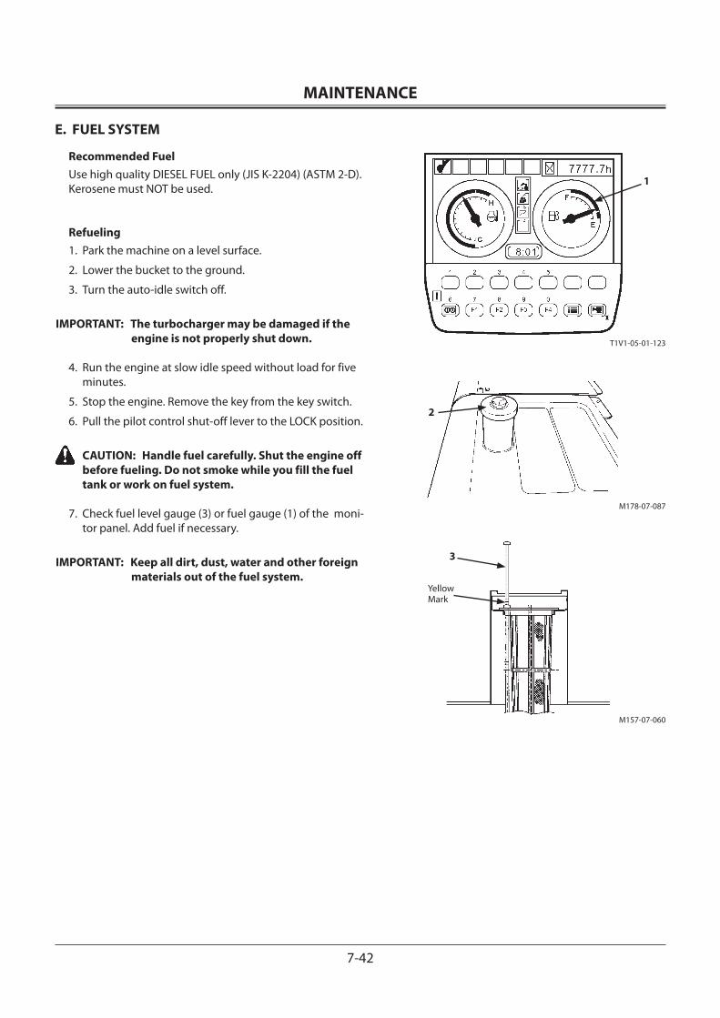
MAINTENANCE
7-42
E. FUEL SYSTEM
Recommended FuelUse high quality DIESEL FUEL only (JIS K-2204) (ASTM 2-D). Kerosene must NOT be used.
Refueling1. Park the machine on a level surface.
2. Lower the bucket to the ground.
3. Turn the auto-idle switch off.
IMPORTANT: The turbocharger may be damaged if the engine is not properly shut down.
4. Run the engine at slow idle speed without load for five minutes.
5. Stop the engine. Remove the key from the key switch.
6. Pull the pilot control shut-off lever to the LOCK position.
CAUTION: Handle fuel carefully. Shut the engine off before fueling. Do not smoke while you fill the fuel tank or work on fuel system.
7. Check fuel level gauge (3) or fuel gauge (1) of the moni-tor panel. Add fuel if necessary.
IMPORTANT: Keep all dirt, dust, water and other foreign materials out of the fuel system.
T1V1-05-01-123
M157-07-060
3
Yellow Mark
1
2
M178-07-087
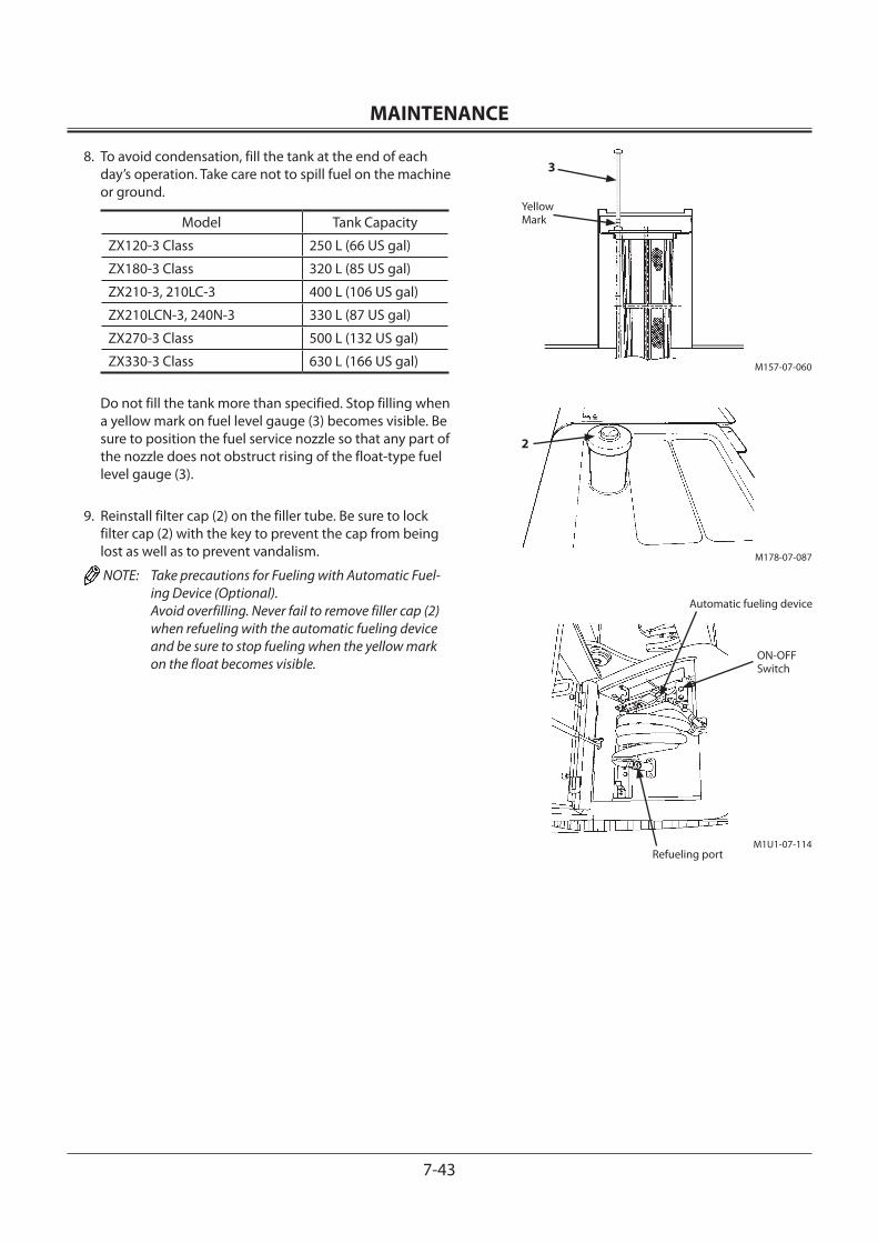
MAINTENANCE
7-43
8. To avoid condensation, fill the tank at the end of each day’s operation. Take care not to spill fuel on the machine or ground.
Model Tank Capacity
ZX120-3 Class 250 L (66 US gal)
ZX180-3 Class 320 L (85 US gal)
ZX210-3, 210LC-3 400 L (106 US gal)
ZX210LCN-3, 240N-3 330 L (87 US gal)
ZX270-3 Class 500 L (132 US gal)
ZX330-3 Class 630 L (166 US gal)
Do not fill the tank more than specified. Stop filling when a yellow mark on fuel level gauge (3) becomes visible. Be sure to position the fuel service nozzle so that any part of the nozzle does not obstruct rising of the float-type fuel level gauge (3).
9. Reinstall filter cap (2) on the filler tube. Be sure to lock filter cap (2) with the key to prevent the cap from being lost as well as to prevent vandalism.
NOTE: Take precautions for Fueling with Automatic Fuel-ing Device (Optional). Avoid overfilling. Never fail to remove filler cap (2) when refueling with the automatic fueling device and be sure to stop fueling when the yellow mark on the float becomes visible.
M178-07-087
2
M157-07-060
3
Yellow Mark
M1U1-07-114
Automatic fueling device
ON-OFF Switch
Refueling port
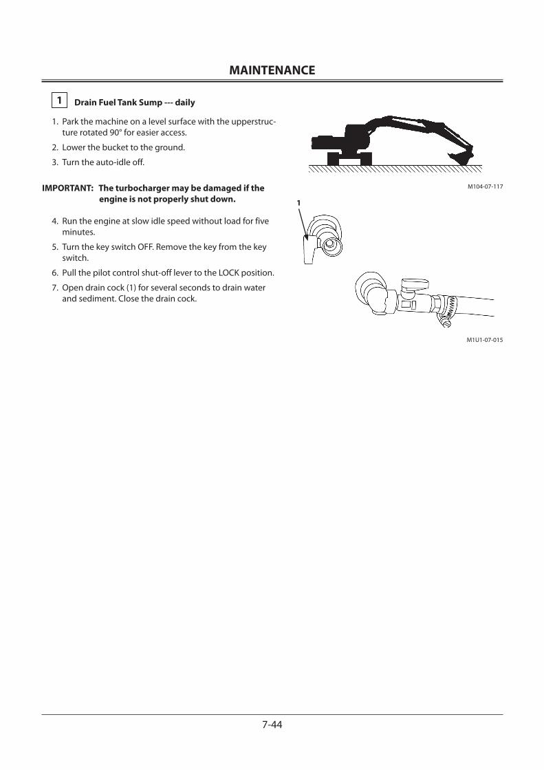
MAINTENANCE
7-44
1 Drain Fuel Tank Sump --- daily
1. Park the machine on a level surface with the upperstruc-ture rotated 90° for easier access.
2. Lower the bucket to the ground.
3. Turn the auto-idle off.
IMPORTANT: The turbocharger may be damaged if the engine is not properly shut down.
4. Run the engine at slow idle speed without load for five minutes.
5. Turn the key switch OFF. Remove the key from the key switch.
6. Pull the pilot control shut-off lever to the LOCK position.
7. Open drain cock (1) for several seconds to drain water and sediment. Close the drain cock.
M1U1-07-015
1
M104-07-117
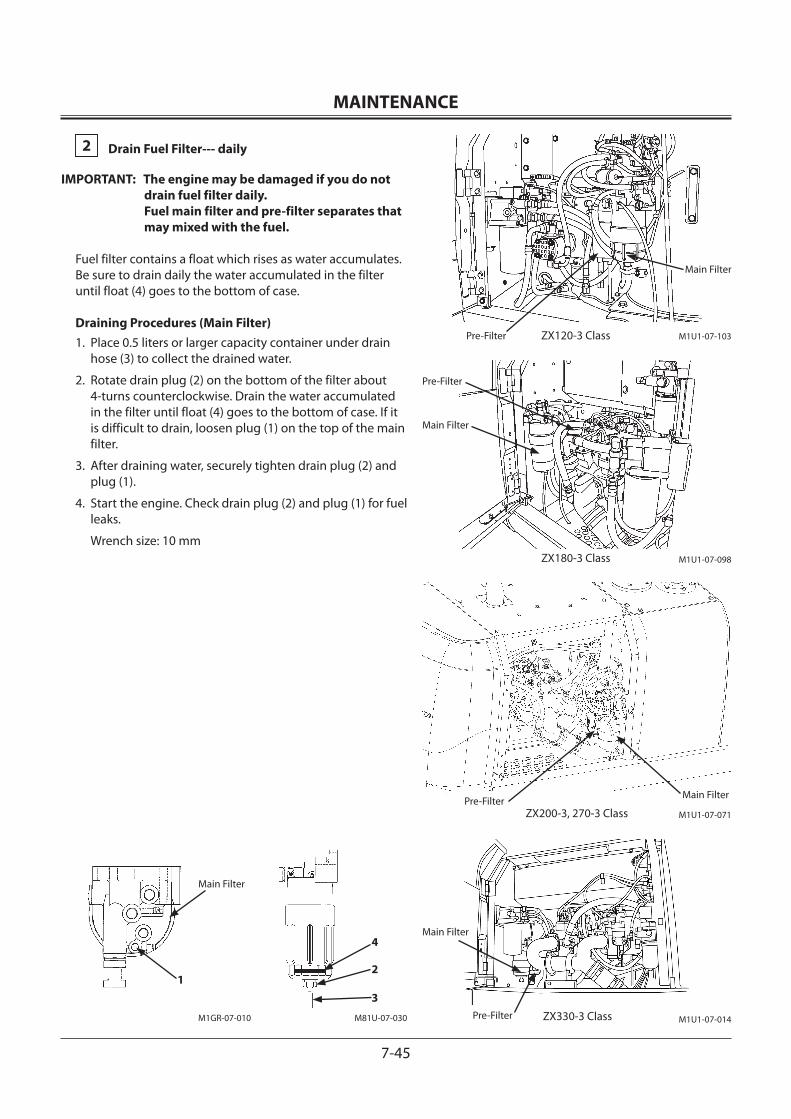
MAINTENANCE
7-45
2 Drain Fuel Filter--- daily
IMPORTANT: The engine may be damaged if you do not drain fuel filter daily. Fuel main filter and pre-filter separates that may mixed with the fuel.
Fuel filter contains a float which rises as water accumulates. Be sure to drain daily the water accumulated in the filter until float (4) goes to the bottom of case.
Draining Procedures (Main Filter)1. Place 0.5 liters or larger capacity container under drain
hose (3) to collect the drained water.
2. Rotate drain plug (2) on the bottom of the filter about 4-turns counterclockwise. Drain the water accumulated in the filter until float (4) goes to the bottom of case. If it is difficult to drain, loosen plug (1) on the top of the main filter.
3. After draining water, securely tighten drain plug (2) and plug (1).
4. Start the engine. Check drain plug (2) and plug (1) for fuel leaks.
Wrench size: 10 mm
M1U1-07-014
Main Filter
M81U-07-030M1GR-07-010
Main Filter
1
ZX330-3 Class
ZX200-3, 270-3 Class M1U1-07-071Pre-Filter
Main Filter
ZX180-3 Class M1U1-07-098
Pre-Filter
Main Filter
4
2
3
M1U1-07-103Pre-Filter
Main Filter
ZX120-3 Class
Pre-Filter
MAINTENANCE
7-46
Draining Procedures (Pre-Filter) 1. Place 0.5 liters or larger capacity container under drain
hose (6) to collect the drained water.
2. Rotate drain plug (5) on the bottom of the filter coun-terclockwise. Drain the water accumulated in the filter until float (8) goes to the bottom of case. If it is difficult to drain, loosen plug (7) on the top of the fuel pre-filter.
3. After draining water, securely tighten drain plug (5) and plug (7).
4. Start the engine. Check drain plug (5) and plug (7) for fuel leaks.
IMPORTANT: After draining water mixed in fuel, bleed air from the fuel supply system.
Wrench size: 14 mm
M1U1-07-004
7
M81U-07-031 M1U1-07-014
Main Filter
ZX330-3 Class
ZX200-3, 270-3 Class M1U1-07-071Pre-Filter
Main Filter
ZX180-3 Class M1U1-07-098
Pre-Filter
Main Filter
M1U1-07-103Pre-Filter
Main Filter
ZX120-3 Class
Pre-Filter
8
5
6
Pre-Filter
MAINTENANCE
7-47
Air Bleeding Procedures
IMPORTANT: Air in the fuel system may make the engine hard to start or make it run irregularly. After draining water and sediment from the fuel filter, replacing the fuel filter, cleaning the fuel solenoid pump strainer or running the fuel tank dry, be sure to bleed the air from the fuel system.
This machine is equipped with a fuel solenoid pump.
CAUTION: Fuel leaks may lead to fires.
1. Check that fuel cock (3) on the bottom of the fuel tank is opened.
2. Turn the key switch ON and hold it in that position for ap-prox. 3 minutes. Thereby, the electrical fuel pump oper-ates, starting to bleed air.
3. While holding the key switch in the ON position, recip-rocate fuel main filter priming pump (6). After air is bled from the main filter, return priming pump (6) to the origi-nal position.
4. After the main filter is filled with fuel, hold the key switch in the ON position for 30 seconds.
5. Start the engine. Check the fuel supply system for fuel leaks.
IMPORTANT: Even if air is not thoroughly bled, do not hold the key switch in the ON position for more than 5 minutes. In case air is not thor-oughly bled, first return the key switch to the OFF position. Then, after waiting for more than 30 seconds, turn the key switch ON again. Failure to do so may cause dam-age to the electrical pump and/or discharg-ing the batteries.
M1U1-07-015
3
M81U-07-030
6
MAINTENANCE
7-48
Air Bleeding by Priming PumpIn case air is not bled due to malfunction of the fuel sole-noid pump, operating the priming pump only can bleed air.
1. Check that fuel cock (3) on the bottom of the fuel tank is opened.
2. Loosen air bleed plug (1) on the fuel main filter.
3. Supply fuel by reciprocating priming pump (6). After no air bubbles are spouted through air bleed plug (1), tight-en air bleed plug (1).
4. After tightening air bleed plug (1), reciprocate priming pump (6) approx. 150 strokes.
5. Wipe off any spilled fuel.
6. Start the engine. Check that no fuel leaks are present. If the engine does not start, repeat the above procedures from step 1.
Wrench size: 10 mm
Air Bleeding by CrankingBleed air from the fuel system after changing the common rail.Bleeding Procedures1. Bleed air until the engine supply pump entrance enough
according to the above-mentioned procedures.
2. Operate starter motor for long cranking within 20 sec-onds. If engine falls to start, return key switch to OFF. Wait more than about 60 seconds, then try again.
M1U1-07-015
3
M1GR-07-010
Main Filter
1
M81U-07-030
6
MAINTENANCE
7-49
3 Replace Fuel Main Filter Element --- every 500 hours
IMPORTANT: Be sure to use only genuine Hitachi elements for the main fuel filter element and the pre-filter element. Failure to do so may deterio-rate the engine performance and/or shorten the engine service life. Please be noted that all engine failures caused by using other manufacturers’ elements are excluded from Hitachi Warranty Policy.
Procedures:1. Close cock (3) on the bottom of the fuel tank.
2. Place a 1-liter or larger capacity drain container under drain hose (6).
3. Loosen air bleed plug (1) and drain plug (2). Drain fuel until fuel does not flow out of the filter.
4. Remove transparent filter case (7) using the exclusive tool.
5. When transparent filter case (7) is removed, the element is exposed. Remove the element by hand.
6. Install a new element. Tighten transparent filter case (7) to 29.4 ± 2 N·m using the exclusive tool.
7. Tighten air bleed plug (1) and drain plug (2).
8. Open cock (3) on the bottom of the fuel tank.
9. Bleed air from the fuel supply system.
After replacing the fuel filter element, bleed air from the fuel supply system. (Refer to the air bleed procedures described on page 7-46.)
Wrench size: 10 mm
M1GR-07-010 M81U-07-030
Main Filter
1
7
2
6
3
M1U1-07-015
M1U1-07-014
Main Filter
ZX330-3 Class
ZX200-3, 270-3 Class M1U1-07-071Pre-Filter
Main Filter
ZX180-3 Class M1U1-07-098
Pre-Filter
Main Filter
M1U1-07-103Pre-Filter
Main Filter
ZX120-3 Class
Pre-Filter
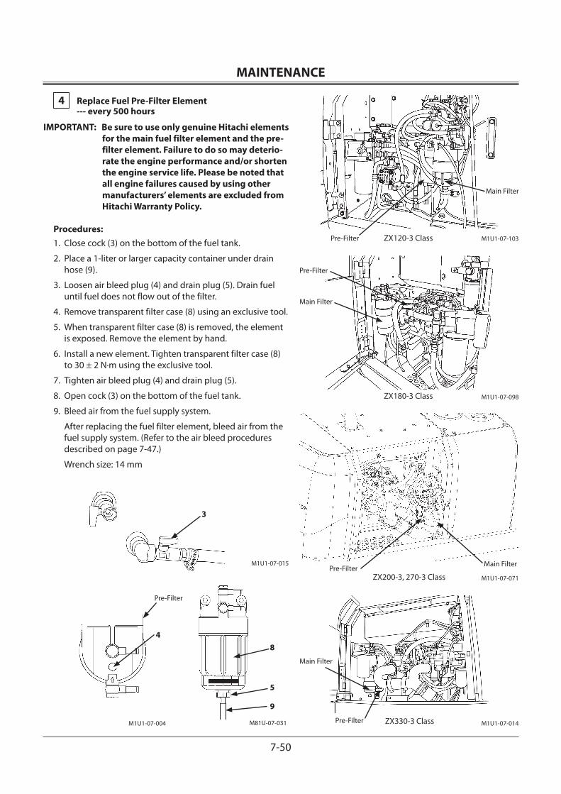
MAINTENANCE
7-50
4 Replace Fuel Pre-Filter Element --- every 500 hours
IMPORTANT: Be sure to use only genuine Hitachi elements for the main fuel filter element and the pre-filter element. Failure to do so may deterio-rate the engine performance and/or shorten the engine service life. Please be noted that all engine failures caused by using other manufacturers’ elements are excluded from Hitachi Warranty Policy.
Procedures:1. Close cock (3) on the bottom of the fuel tank.
2. Place a 1-liter or larger capacity container under drain hose (9).
3. Loosen air bleed plug (4) and drain plug (5). Drain fuel until fuel does not flow out of the filter.
4. Remove transparent filter case (8) using an exclusive tool.
5. When transparent filter case (8) is removed, the element is exposed. Remove the element by hand.
6. Install a new element. Tighten transparent filter case (8) to 30 ± 2 N·m using the exclusive tool.
7. Tighten air bleed plug (4) and drain plug (5).
8. Open cock (3) on the bottom of the fuel tank.
9. Bleed air from the fuel supply system.
After replacing the fuel filter element, bleed air from the fuel supply system. (Refer to the air bleed procedures described on page 7-47.)
Wrench size: 14 mm
M1U1-07-014
Main Filter
ZX330-3 Class
ZX200-3, 270-3 Class M1U1-07-071Pre-Filter
Main Filter
ZX180-3 Class M1U1-07-098
Pre-Filter
Main Filter
M1U1-07-103Pre-Filter
Main Filter
ZX120-3 Class
Pre-Filter
3
M1U1-07-015
M1U1-07-004
4
M81U-07-031
8
5
9
Pre-Filter
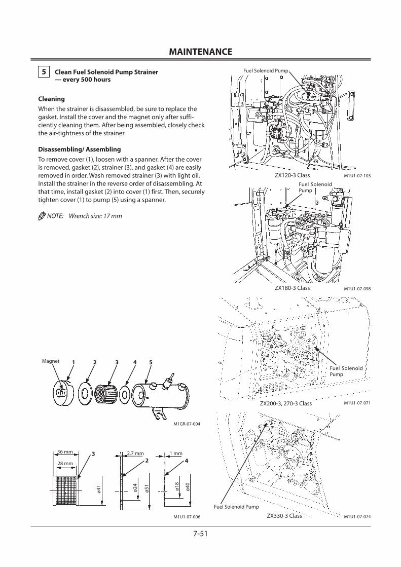
MAINTENANCE
7-51
5 Clean Fuel Solenoid Pump Strainer --- every 500 hours
CleaningWhen the strainer is disassembled, be sure to replace the gasket. Install the cover and the magnet only after suffi-ciently cleaning them. After being assembled, closely check the air-tightness of the strainer.
Disassembling/ AssemblingTo remove cover (1), loosen with a spanner. After the cover is removed, gasket (2), strainer (3), and gasket (4) are easily removed in order. Wash removed strainer (3) with light oil. Install the strainer in the reverse order of disassembling. At that time, install gasket (2) into cover (1) first. Then, securely tighten cover (1) to pump (5) using a spanner.
NOTE: Wrench size: 17 mm
M1GR-07-004
M1U1-07-006
1 2 3 4 5Magnet
36 mm
28 mm
2.7 mm 1 mm32 4
ø41
ø24
ø51
ø18
ø40
ZX330-3 Class
Fuel Solenoid Pump
M1U1-07-074
Fuel Solenoid Pump
Fuel Solenoid Pump
ZX200-3, 270-3 Class M1U1-07-071
ZX180-3 Class M1U1-07-098
M1U1-07-103ZX120-3 Class
Fuel Solenoid Pump
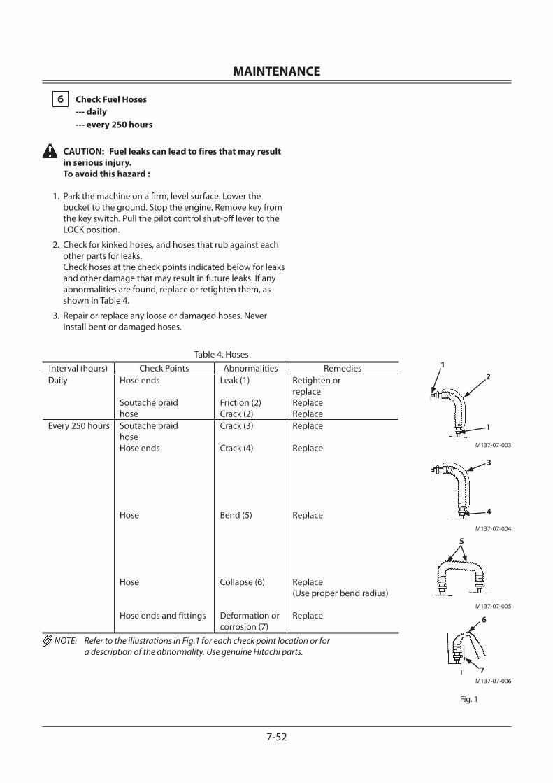
MAINTENANCE
7-52
6 Check Fuel Hoses --- daily --- every 250 hours
CAUTION: Fuel leaks can lead to fires that may result in serious injury. To avoid this hazard :
1. Park the machine on a firm, level surface. Lower the bucket to the ground. Stop the engine. Remove key from the key switch. Pull the pilot control shut-off lever to the LOCK position.
2. Check for kinked hoses, and hoses that rub against each other parts for leaks. Check hoses at the check points indicated below for leaks and other damage that may result in future leaks. If any abnormalities are found, replace or retighten them, as shown in Table 4.
3. Repair or replace any loose or damaged hoses. Never install bent or damaged hoses.
M137-07-006
6
7
Fig. 1
M137-07-003
1
1
2
M137-07-005
5
M137-07-004
4
3
Table 4. HosesInterval (hours) Check Points Abnormalities RemediesDaily Hose ends
Soutache braidhose
Leak (1) Friction (2)Crack (2)
Retighten or replaceReplaceReplace
Every 250 hours Soutache braidhoseHose ends
Hose
Hose
Hose ends and fittings
Crack (3)
Crack (4)
Bend (5)
Collapse (6)
Deformation or corrosion (7)
Replace
Replace
Replace
Replace(Use proper bend radius)
Replace
NOTE: Refer to the illustrations in Fig.1 for each check point location or for a description of the abnormality. Use genuine Hitachi parts.
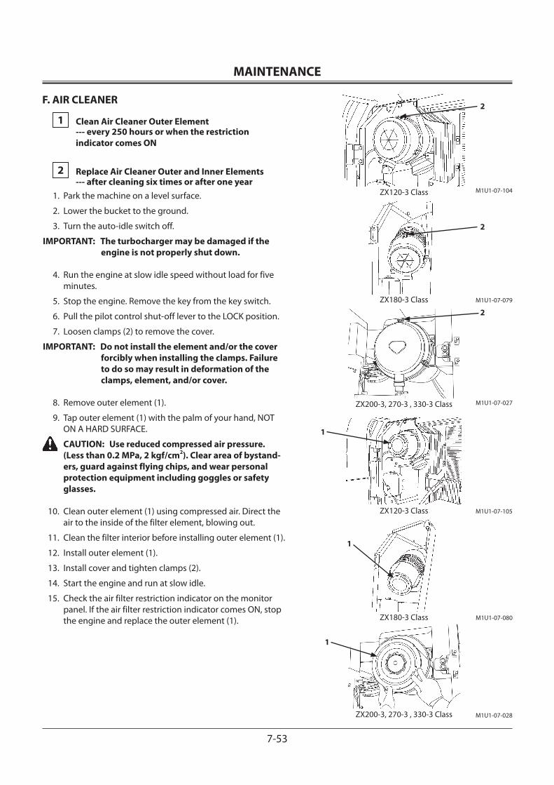
MAINTENANCE
7-53
F. AIR CLEANER
1 Clean Air Cleaner Outer Element --- every 250 hours or when the restriction indicator comes ON
2 Replace Air Cleaner Outer and Inner Elements --- after cleaning six times or after one year1. Park the machine on a level surface.
2. Lower the bucket to the ground.
3. Turn the auto-idle switch off.
IMPORTANT: The turbocharger may be damaged if the engine is not properly shut down.
4. Run the engine at slow idle speed without load for five minutes.
5. Stop the engine. Remove the key from the key switch.
6. Pull the pilot control shut-off lever to the LOCK position.
7. Loosen clamps (2) to remove the cover.
IMPORTANT: Do not install the element and/or the cover forcibly when installing the clamps. Failure to do so may result in deformation of the clamps, element, and/or cover.
8. Remove outer element (1).
9. Tap outer element (1) with the palm of your hand, NOT ON A HARD SURFACE.
CAUTION: Use reduced compressed air pressure. (Less than 0.2 MPa, 2 kgf/cm2). Clear area of bystand-ers, guard against flying chips, and wear personal protection equipment including goggles or safety glasses.
10. Clean outer element (1) using compressed air. Direct the air to the inside of the filter element, blowing out.
11. Clean the filter interior before installing outer element (1).
12. Install outer element (1).
13. Install cover and tighten clamps (2).
14. Start the engine and run at slow idle.
15. Check the air filter restriction indicator on the monitor panel. If the air filter restriction indicator comes ON, stop the engine and replace the outer element (1).
2
M1U1-07-027
M1U1-07-028
1
2
ZX200-3, 270-3 , 330-3 Class
ZX180-3 Class
M1U1-07-080
1
M1U1-07-079
M1U1-07-104ZX120-3 Class
2
ZX180-3 Class
ZX200-3, 270-3 , 330-3 Class
M1U1-07-105ZX120-3 Class
1
MAINTENANCE
7-54
16. When replacing the air cleaner filter element, replace both outer (1) and inner (3) elements together. Remove outer element (1). Clean the filter interior before remov-ing inner element (3). Remove inner element (3). First install inner element (3) and then install outer element (1).
IMPORTANT: Do not reuse the inner element. Always re-place the new one.
M157-07-061
Air Restriction Switch 1 2
Valve3
Cover

MAINTENANCE
7-55
G. COOLING SYSTEM
CoolantUse fresh water or normal tap water as a coolant. Do not use strong acid or alkaline water. Use the coolant with genuine Hitachi Long-Life Coolant (LLC) mixed by 30 to 50 %.
If the air temperature is expected to fall below 0 °C (32 °F), fill the cooling system with an genuine Hitachi Long-Life Coolant (LLC) and soft water mix. As a general rule, the ratio of LLC should range between 30% and 50% as shown in the table below. If the ratio is below 30%, the system may devel-op rust, and if it is above 50%, the engine may overheat.

MAINTENANCE
7-56
LLC Mixing Table (ZX120-3 Class)
Air temperature Mixing ratio
Refill capacitiesLLC Soft water
°C °F % liters liters–1 30 30 4.8 11.2–4 25 30 4.8 11.2–7 19 30 4.8 11.2
–11 12 30 4.8 11.2–15 5 35 5.6 10.4–20 –4 40 6.4 9.6–25 –13 45 7.2 8.8–30 –22 50 8.0 8.0
LLC Mixing Table (ZX180-3 Class)
Air temperature Mixing ratio
Refill capacitiesLLC Soft water
°C °F % liters liters–1 30 30 5.4 12.6–4 25 30 5.4 12.6–7 19 30 5.4 12.6
–11 12 30 5.4 12.6–15 5 35 6.3 11.7–20 –4 40 7.2 10.8–25 –13 45 8.1 9.9–30 –22 50 9.0 9.0
LLC Mixing Table (ZX200-3, 270-3 Class)
Air temperature Mixing ratio
Refill capacitiesLLC Soft water
°CC °FF % liters liters–1 30 30 7.8 18.2–4 25 30 7.8 18.2–7 19 30 7.8 18.2
–11 12 30 7.8 18.2–15 5 35 9.1 16.9–20 –4 40 10.4 15.6–25 –13 45 11.7 14.3–30 –22 50 13.0 13.0
LLC Mixing Table (ZX330-3 Class)
Air temperature Mixing ratio
Refill capacitiesLLC Soft water
°CC °FF % liters liters–1 30 30 9.6 22.4–4 25 30 9.6 22.4–7 19 30 9.6 22.4
–11 12 30 9.6 22.4–15 5 35 11.2 20.8–20 –4 40 12.8 19.2–25 –13 45 14.4 17.6–30 –22 50 16.0 16.0
CAUTION: • Antifreeze is poisonous; if ingested, it can cause
serious injury or death. Induce vomiting and get emergency medical attention immediately.
• When storing antifreeze, be sure to keep it in a clearly marked container with a tight lid. Always keep ANTIFREEZE out of the reach of children.
• If antifreeze is accidentally splashed into eyes, flush with water for 10 to 15 minutes and get emergency medical attention.
• When storing or disposing of antifreeze, be sure to comply with all local regulations.
MAINTENANCE
7-57
1 Check Coolant Level --- daily
CAUTION: Do not loosen radiator filler cap (1) unless the system is cool. Loosen the cap slowly to the stop. Release all pressure before removing the cap.
With the engine cold, the coolant level must be between the FULL and LOW marks on coolant reservoir (2), located behind the radiator access door. If the coolant level is below the low mark, add coolant to coolant reservoir (2).If coolant reservoir (2) is empty, add coolant to the radiator and then to coolant reservoir (2).
M1U1-07-024
1
M1U1-07-022
FULL
LOW
2
M1U1-07-081
1
M1U1-07-082
FULL
LOW
M1U1-07-106
M1U1-07-107
ZX200-3, 270-3 , 330-3 Class
ZX180-3 Class
ZX120-3 Class
ZX180-3 Class
ZX200-3, 270-3 , 330-3 Class
ZX120-3 Class
1
2
FULL
LOW
2
MAINTENANCE
7-58
2 Check and Adjust Fan Belt Tension (ZX120-3, 180-3 Class) --- every 100 hours (first time after 50 hours)
IMPORTANT: Loose fan belt may result in insufficient bat-tery charging, engine overheating as well as a rapid, abnormal belt wear. Belts that are too tight, however, can damage both bear-ings and belts.
Visually check the belt for wear. Replace if necessary. Check fan belt tension by depressing the midpoint between fan pulley (3) and alternator pulley (4) with the thumb. Deflec-tion must be A with a depressing force of approximately 98 N (10 kgf, 22 lbf ).
Model A
ZX120-3, 180-3 Class 7 to 8 mm (0.28 to 0.32 in)
CheckingCheck the drive belt for any wear and/or damage. Replace the belt as needed. Check the belt tension if required.
Adjust Drive Belt Tension1. Loosen lock nut (6) and alternator lower mounting bolt
(7).
2. Rotate tension adjust bolt (5) to adjust the belt tension.
3. After completing adjustment, tighten lock nut (6) and alternator lower mounting bolt (3) to specifications.
Standard Tightening Torque:Nut: 25 N•m (2.5 kgf•m, 18 lbf•ft)Bolt: 51 N•m (5.2 kgf•m, 38 lbf•ft)
NOTE: When a new belt is installed, be sure to re-adjust the tension after operating the engine for 3 to 5 minutes at slow idle speed to be sure that the new belt is seated correctly.
63
Deflection7~8 mm98 N (10 kgf )
M1U1-07-089ZX120-3, 180-3 Class
1
5
4
7
MAINTENANCE
7-59
2 Check and Adjust Fan Belt Tension (ZX200-3, 270-3, 330-3 Class) --- every 100 hours (first time after 50 hours)
IMPORTANT: Loose fan belt may result in insufficient bat-tery charging, engine overheating as well as a rapid, abnormal belt wear. Belts that are too tight, however, can damage both bear-ings and belts.
Visually check the belt for wear. Replace if necessary. Check fan belt tension by depressing the midpoint between fan pulley (3) and alternator pulley (4) with the thumb. Deflec-tion must be A with a depressing force of approximately 98 N (10 kgf, 22 lbf ).
Model A
ZX200-3, 270-3, 330-3 Class 5 to 6 mm (0.2 to 0.24 in)
If tension is not within specifications, loosen nuts (5) and (7) for the adjusting plate and alternator bracket. Move the alternator by bolt (6) until tension is correct. Tighten the adjusting plate and nuts (5) and (7).
NOTE: When a new belt is installed, be sure to re-adjust the tension after operating the engine for 3 to 5 minutes at slow idle speed to be sure that the new belt is seated correctly.
3
M178-07-030
4
ZX200-3, 270-3 Class
Deflection5~6 mm98 N (10 kgf )
M1HM-07-001
3
Deflection5~6 mm98 N (10 kgf )
4
ZX330-3 Class
M197-07-072
5
6
7
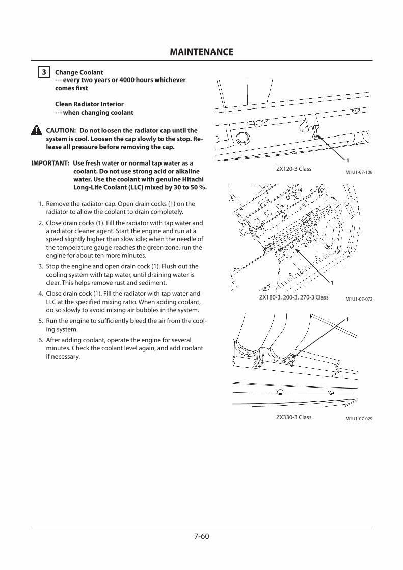
MAINTENANCE
7-60
3 Change Coolant --- every two years or 4000 hours whichever comes first Clean Radiator Interior --- when changing coolant
CAUTION: Do not loosen the radiator cap until the system is cool. Loosen the cap slowly to the stop. Re-lease all pressure before removing the cap.
IMPORTANT: Use fresh water or normal tap water as a coolant. Do not use strong acid or alkaline water. Use the coolant with genuine Hitachi Long-Life Coolant (LLC) mixed by 30 to 50 %.
1. Remove the radiator cap. Open drain cocks (1) on the radiator to allow the coolant to drain completely.
2. Close drain cocks (1). Fill the radiator with tap water and a radiator cleaner agent. Start the engine and run at a speed slightly higher than slow idle; when the needle of the temperature gauge reaches the green zone, run the engine for about ten more minutes.
3. Stop the engine and open drain cock (1). Flush out the cooling system with tap water, until draining water is clear. This helps remove rust and sediment.
4. Close drain cock (1). Fill the radiator with tap water and LLC at the specified mixing ratio. When adding coolant, do so slowly to avoid mixing air bubbles in the system.
5. Run the engine to sufficiently bleed the air from the cool-ing system.
6. After adding coolant, operate the engine for several minutes. Check the coolant level again, and add coolant if necessary.
1
M1U1-07-029
1
M1U1-07-072
ZX330-3 Class
ZX120-3 Class
ZX180-3, 200-3, 270-3 Class
M1U1-07-108
1
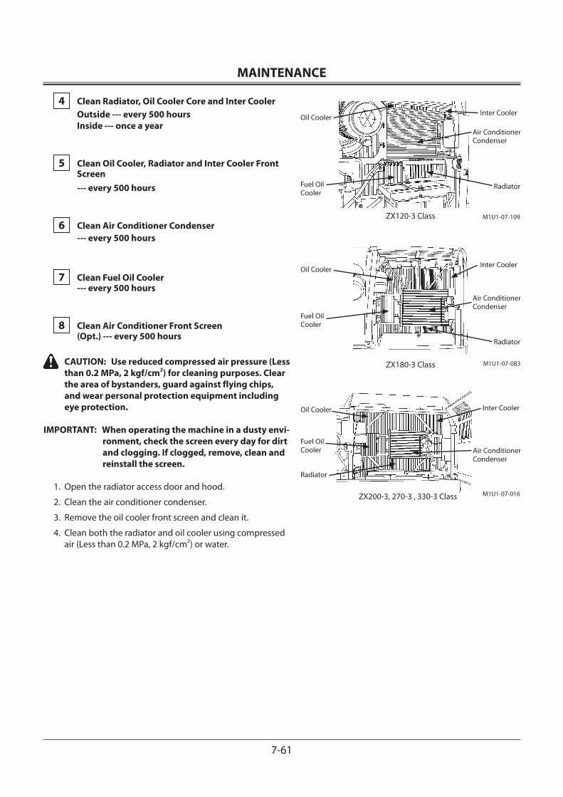
MAINTENANCE
7-61
4 Clean Radiator, Oil Cooler Core and Inter Cooler Outside --- every 500 hours Inside --- once a year
5 Clean Oil Cooler, Radiator and Inter Cooler Front Screen --- every 500 hours
6 Clean Air Conditioner Condenser --- every 500 hours
7 Clean Fuel Oil Cooler --- every 500 hours
8 Clean Air Conditioner Front Screen (Opt.) --- every 500 hours
CAUTION: Use reduced compressed air pressure (Less than 0.2 MPa, 2 kgf/cm2) for cleaning purposes. Clear the area of bystanders, guard against flying chips, and wear personal protection equipment including eye protection.
IMPORTANT: When operating the machine in a dusty envi-ronment, check the screen every day for dirt and clogging. If clogged, remove, clean and reinstall the screen.
1. Open the radiator access door and hood.
2. Clean the air conditioner condenser.
3. Remove the oil cooler front screen and clean it.
4. Clean both the radiator and oil cooler using compressed air (Less than 0.2 MPa, 2 kgf/cm2) or water.
M1U1-07-016
M1U1-07-083
ZX200-3, 270-3 , 330-3 Class
ZX180-3 Class
ZX120-3 Class M1U1-07-109
Oil CoolerInter Cooler
Radiator
Oil Cooler Inter Cooler
Radiator
Fuel Oil Cooler
Air Conditioner Condenser
Oil CoolerInter Cooler
Radiator
Fuel Oil Cooler
Air Conditioner Condenser
Fuel Oil Cooler Air Conditioner
Condenser
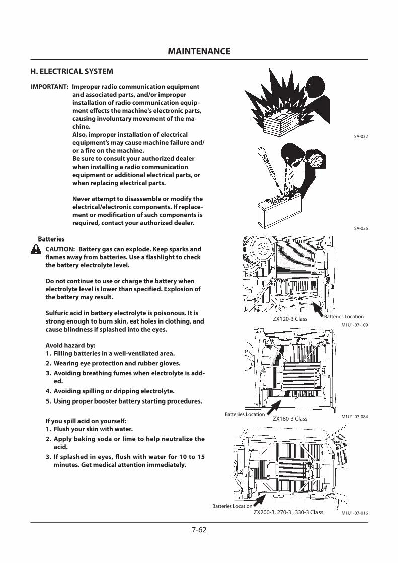
MAINTENANCE
7-62
H. ELECTRICAL SYSTEM
IMPORTANT: Improper radio communication equipment and associated parts, and/or improper installation of radio communication equip-ment effects the machine's electronic parts, causing involuntary movement of the ma-chine. Also, improper installation of electrical equipment’s may cause machine failure and/or a fire on the machine. Be sure to consult your authorized dealer when installing a radio communication equipment or additional electrical parts, or when replacing electrical parts. Never attempt to disassemble or modify the electrical/electronic components. If replace-ment or modification of such components is required, contact your authorized dealer.
Batteries CAUTION: Battery gas can explode. Keep sparks and
flames away from batteries. Use a flashlight to check the battery electrolyte level. Do not continue to use or charge the battery when electrolyte level is lower than specified. Explosion of the battery may result.
Sulfuric acid in battery electrolyte is poisonous. It is strong enough to burn skin, eat holes in clothing, and cause blindness if splashed into the eyes. Avoid hazard by:1. Filling batteries in a well-ventilated area.2. Wearing eye protection and rubber gloves.3. Avoiding breathing fumes when electrolyte is add-
ed.4. Avoiding spilling or dripping electrolyte.5. Using proper booster battery starting procedures.
If you spill acid on yourself:1. Flush your skin with water.2. Apply baking soda or lime to help neutralize the
acid.3. If splashed in eyes, flush with water for 10 to 15
minutes. Get medical attention immediately.
SA-036
M1U1-07-016Batteries Location
M1U1-07-084Batteries Location
ZX200-3, 270-3 , 330-3 Class
ZX180-3 Class
ZX120-3 ClassM1U1-07-109
Batteries Location
SA-032
MAINTENANCE
7-63
If acid is swallowed:1. Drink large amounts of water or milk.2. Then drink milk of magnesia, beaten eggs, or veg-
etable oil.3. Get medical attention immediately.
IMPORTANT: Add water to batteries in freezing weather before you begin operating your machine for the day, or else charge the batteries.
IMPORTANT: If the battery is used with the electrolyte level lower than the specified lower level, the battery may deteriorate quickly.
IMPORTANT: Do not refill electrolyte more than the speci-fied upper level. Electrolyte may spill, dam-aging the painted surfaces and/or corroding other machine parts.
NOTE: In case electrolyte is refilled more than the specified upper level line or beyond the bottom end of the sleeve, remove the excess electrolyte until the electro-lyte level is down to the bottom end of the sleeve using a pipette. After neutralizing the removed electrolyte with sodium bicarbonate, flush it with plenty of water, otherwise, consult the battery manufacturer.
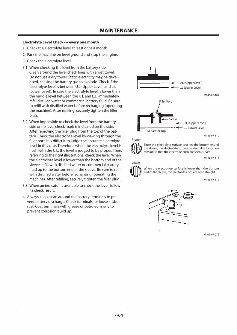
MAINTENANCE
7-64
Electrolyte Level Check --- every one month1. Check the electrolyte level at least once a month.
2. Park the machine on level ground and stop the engine.
3. Check the electrolyte level.
3.1 When checking the level from the battery side: Clean around the level check lines with a wet towel. Do not use a dry towel. Static electricity may be devel-oped, causing the battery gas to explode. Check if the electrolyte level is between U.L (Upper Level) and L.L (Lower Level). In case the electrolyte level is lower than the middle level between the U.L and L.L, immediately refill distilled water or commercial battery fluid. Be sure to refill with distilled water before recharging (operating the machine). After refilling, securely tighten the filler plug.
3.2 When impossible to check the level from the battery side or no level check mark is indicated on the side: After removing the filler plug from the top of the bat-tery. Check the electrolyte level by viewing through the filler port. It is difficult to judge the accurate electrolyte level in this case. Therefore, when the electrolyte level is flush with the U.L, the level is judged to be proper. Then, referring to the right illustrations, check the level. When the electrolyte level is lower than the bottom end of the sleeve, refill with distilled water or commercial battery fluid up to the bottom end of the sleeve. Be sure to refill with distilled water before recharging (operating the machine). After refilling, securely tighten the filler plug.
3.3 When an indicator is available to check the level, follow its check result.
4. Always keep clean around the battery terminals to pre-vent battery discharge. Check terminals for loose and/or rust. Coat terminals with grease or petroleum jelly to prevent corrosion build up.
M409-07-072
M146-07-109
U.L (Upper Level)
L.L (Lower Level)
M146-07-110
Filler Port
U.L (Upper Level)
L.L (Lower Level)
Sleeve
Separator Top
M146-07-111
Proper
Since the electrolyte surface touches the bottom end of the sleeve, the electrolyte surface is raised due to surface tension so that the electrode ends are seen curved.
M146-07-112
Lower
When the electrolyte surface is lower than the bottom end of the sleeve, the electrode ends are seen straight.
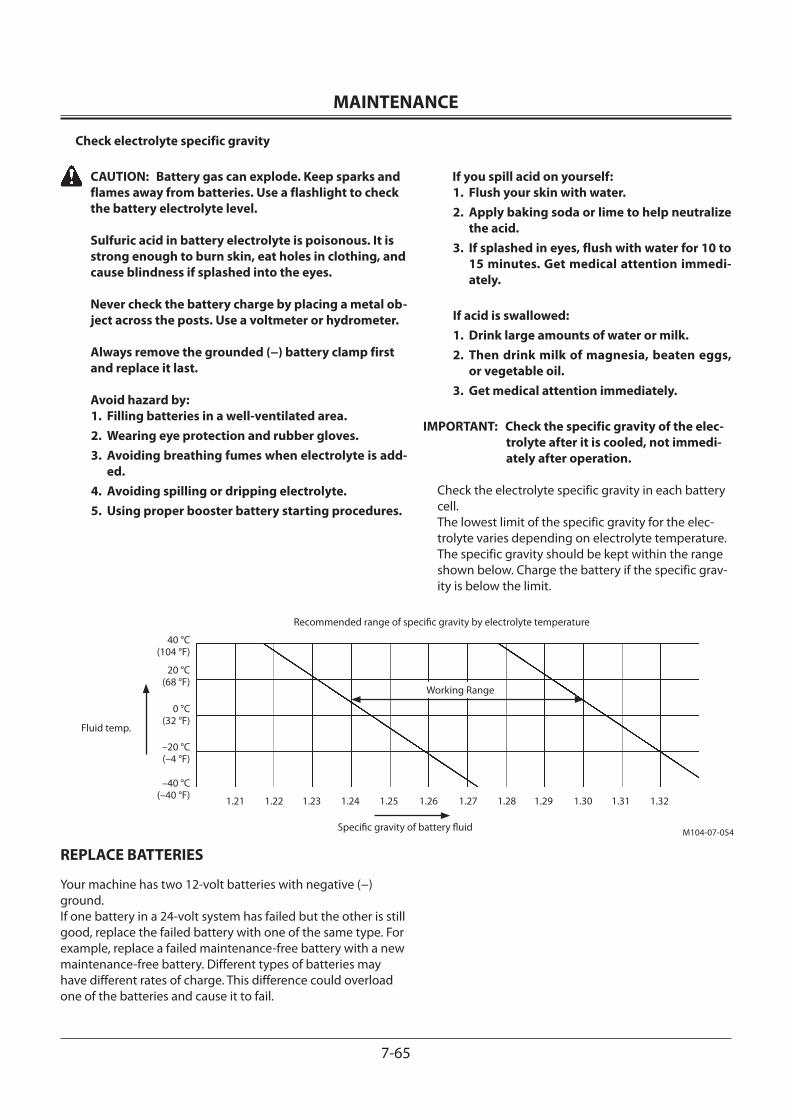
MAINTENANCE
7-65
Check electrolyte specific gravity
CAUTION: Battery gas can explode. Keep sparks and flames away from batteries. Use a flashlight to check the battery electrolyte level. Sulfuric acid in battery electrolyte is poisonous. It is strong enough to burn skin, eat holes in clothing, and cause blindness if splashed into the eyes. Never check the battery charge by placing a metal ob-ject across the posts. Use a voltmeter or hydrometer. Always remove the grounded (−) battery clamp first and replace it last.
Avoid hazard by:1. Filling batteries in a well-ventilated area.2. Wearing eye protection and rubber gloves.3. Avoiding breathing fumes when electrolyte is add-
ed.4. Avoiding spilling or dripping electrolyte.5. Using proper booster battery starting procedures.
If you spill acid on yourself:1. Flush your skin with water.2. Apply baking soda or lime to help neutralize
the acid.3. If splashed in eyes, flush with water for 10 to
15 minutes. Get medical attention immedi-ately.
If acid is swallowed:1. Drink large amounts of water or milk.2. Then drink milk of magnesia, beaten eggs,
or vegetable oil.3. Get medical attention immediately.
IMPORTANT: Check the specific gravity of the elec-trolyte after it is cooled, not immedi-ately after operation.
Check the electrolyte specific gravity in each battery cell.The lowest limit of the specific gravity for the elec-trolyte varies depending on electrolyte temperature. The specific gravity should be kept within the range shown below. Charge the battery if the specific grav-ity is below the limit.
REPLACE BATTERIES
Your machine has two 12-volt batteries with negative (−) ground.If one battery in a 24-volt system has failed but the other is still good, replace the failed battery with one of the same type. For example, replace a failed maintenance-free battery with a new maintenance-free battery. Different types of batteries may have different rates of charge. This difference could overload one of the batteries and cause it to fail.
Recommended range of specific gravity by electrolyte temperature
Working Range
40 °C (104 °F)
1.21 1.22 1.23 1.24 1.25 1.26 1.27 1.28 1.29 1.30 1.31 1.32
Specific gravity of battery fluid
Fluid temp.
20 °C (68 °F)
0 °C (32 °F)
–20 °C (–4 °F)
–40 °C (–40 °F)
M104-07-054
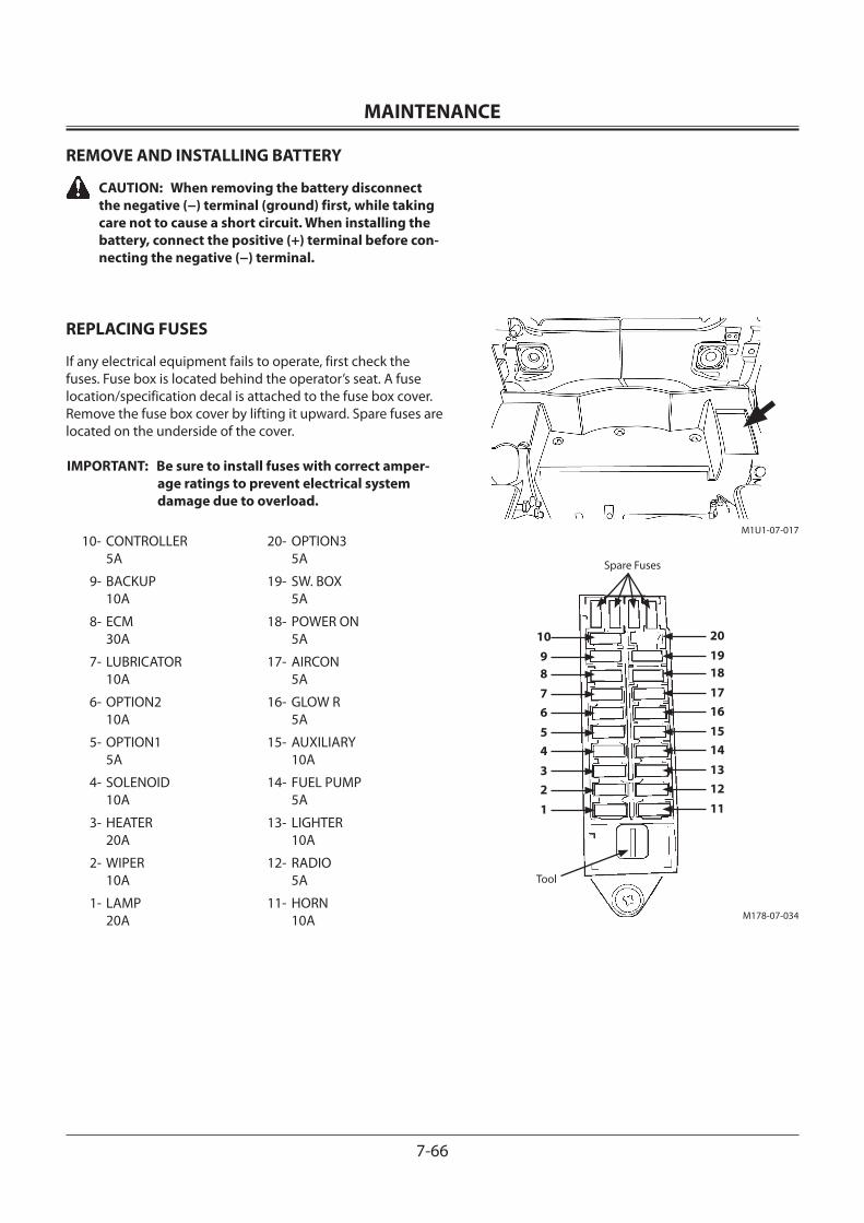
MAINTENANCE
7-66
REMOVE AND INSTALLING BATTERY CAUTION: When removing the battery disconnect
the negative (−) terminal (ground) first, while taking care not to cause a short circuit. When installing the battery, connect the positive (+) terminal before con-necting the negative (−) terminal.
REPLACING FUSES
If any electrical equipment fails to operate, first check the fuses. Fuse box is located behind the operator’s seat. A fuse location/specification decal is attached to the fuse box cover.Remove the fuse box cover by lifting it upward. Spare fuses are located on the underside of the cover.
IMPORTANT: Be sure to install fuses with correct amper-age ratings to prevent electrical system damage due to overload.
10- CONTROLLER 5A
20- OPTION3 5A
9- BACKUP 10A
19- SW. BOX 5A
8- ECM 30A
18- POWER ON 5A
7- LUBRICATOR 10A
17- AIRCON 5A
6- OPTION2 10A
16- GLOW R 5A
5- OPTION1 5A
15- AUXILIARY 10A
4- SOLENOID 10A
14- FUEL PUMP 5A
3- HEATER 20A
13- LIGHTER 10A
2- WIPER 10A
12- RADIO 5A
1- LAMP 20A
11- HORN 10A M178-07-034
Tool
Spare Fuses
151617181920
11121314
56789
10
1234
M1U1-07-017
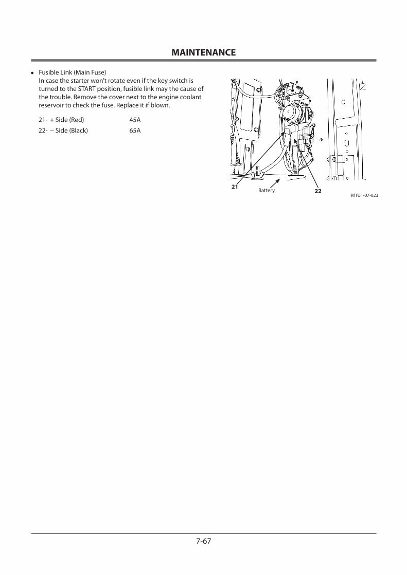
MAINTENANCE
7-67
• Fusible Link (Main Fuse) In case the starter won’t rotate even if the key switch is turned to the START position, fusible link may the cause of the trouble. Remove the cover next to the engine coolant reservoir to check the fuse. Replace it if blown.
21- + Side (Red) 45A
22- − Side (Black) 65A
M1U1-07-023
2122Battery
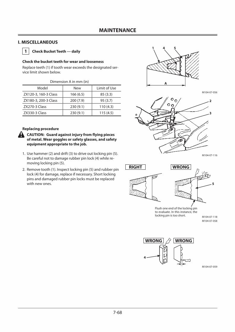
MAINTENANCE
7-68
I. MISCELLANEOUS
1 Check Bucket Teeth --- daily
Check the bucket teeth for wear and loosenessReplace teeth (1) if tooth wear exceeds the designated ser-vice limit shown below.
Dimension A in mm (in)
Model New Limit of Use
ZX120-3, 160-3 Class 166 (6.5) 85 (3.3)
ZX180-3, 200-3 Class 200 (7.9) 95 (3.7)
ZX270-3 Class 230 (9.1) 110 (4.3)
ZX330-3 Class 230 (9.1) 115 (4.5)
Replacing procedure CAUTION: Guard against injury from flying pieces
of metal. Wear goggles or safety glasses, and safety equipment appropriate to the job.
1. Use hammer (2) and drift (3) to drive out locking pin (5). Be careful not to damage rubber pin lock (4) while re-moving locking pin (5).
2. Remove tooth (1). Inspect locking pin (5) and rubber pin lock (4) for damage, replace if necessary. Short locking pins and damaged rubber pin locks must be replaced with new ones.
M104-07-056
M104-07-116
M104-07-118M104-07-058
RIGHT
1 4 5
A
2
3
Flush one end of the locking pin to evaluate. In this instance, the locking pin is too short.
WRONG
5
M104-07-059
WRONG WRONG
4
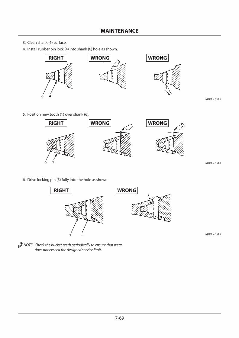
MAINTENANCE
7-69
3. Clean shank (6) surface.
4. Install rubber pin lock (4) into shank (6) hole as shown.
5. Position new tooth (1) over shank (6).
6. Drive locking pin (5) fully into the hole as shown.
NOTE: Check the bucket teeth periodically to ensure that wear does not exceed the designed service limit.
M104-07-0606 4
M104-07-0616 1
M104-07-0621 5
RIGHT WRONG WRONG
RIGHT WRONG WRONG
RIGHT WRONG
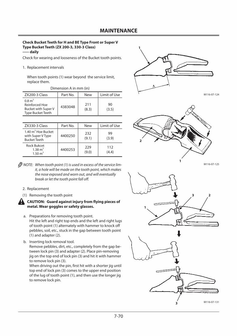
MAINTENANCE
7-70
Check Bucket Teeth for H and BE Type Front or Super V Type Bucket Teeth (ZX 200-3, 330-3 Class) ----- dailyCheck for wearing and looseness of the Bucket tooth points.
1. Replacement intervals When tooth points (1) wear beyond the service limit, replace them.
Dimension A in mm (in)
ZX200-3 Class Part No. New Limit of Use0.8 m3 Reinforced Hoe Bucket with Super V Type Bucket Teeth
4383048 211(8.3)
90(3.5)
ZX330-3 Class Part No. New Limit of Use1.40 m3 Hoe Bucket with Super V Type Bucket Teeth
4400250 232(9.1)
99(3.9)
Rock Bukcet 1.38 m3
1.50 m34400253 229
(9.0)112(4.4)
NOTE: When tooth point (1) is used in excess of the service lim-it, a hole will be made on the tooth point, which makes the nose exposed and worn out, and will eventually break or let the tooth point fall off.
2. Replacement
(1) Removing the tooth point CAUTION: Guard against injury from flying pieces of
metal. Wear goggles or safety glasses.
a. Preparations for removing tooth point. Hit the left and right top ends and the left and right lugs of tooth point (1) alternately with hammer to knock off pebbles, soil, etc., stuck in the gap between tooth point (1) and adapter (2).
b. Inserting lock removal tool. Remove pebbles, dirt, etc., completely from the gap be-tween lock pin (3) and adapter (2). Place pin-removing jig on the top end of lock pin (3) and hit it with hammer to remove lock pin (3). When driving out the pin, first hit with a shorter jig until top end of lock pin (3) comes to the upper end position of the lug of tooth point (1), and then use the longer jig to remove lock pin.
M116-07-124
1
M116-07-125
2
1
M116-07-131
1
3 2
3
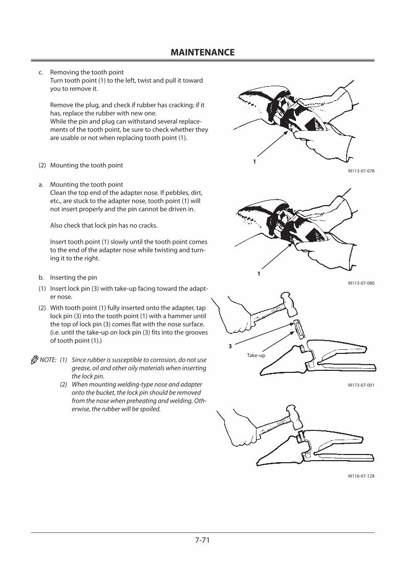
MAINTENANCE
7-71
c. Removing the tooth point Turn tooth point (1) to the left, twist and pull it toward you to remove it. Remove the plug, and check if rubber has cracking; if it has, replace the rubber with new one. While the pin and plug can withstand several replace-ments of the tooth point, be sure to check whether they are usable or not when replacing tooth point (1).
(2) Mounting the tooth point
a. Mounting the tooth point Clean the top end of the adapter nose. If pebbles, dirt, etc., are stuck to the adapter nose, tooth point (1) will not insert properly and the pin cannot be driven in. Also check that lock pin has no cracks. Insert tooth point (1) slowly until the tooth point comes to the end of the adapter nose while twisting and turn-ing it to the right.
b. Inserting the pin
(1) Insert lock pin (3) with take-up facing toward the adapt-er nose.
(2) With tooth point (1) fully inserted onto the adapter, tap lock pin (3) into the tooth point (1) with a hammer until the top of lock pin (3) comes flat with the nose surface. (i.e. until the take-up on lock pin (3) fits into the grooves of tooth point (1).)
NOTE: (1) Since rubber is susceptible to corrosion, do not use grease, oil and other oily materials when inserting the lock pin.
(2) When mounting welding-type nose and adapter onto the bucket, the lock pin should be removed from the nose when preheating and welding. Oth-erwise, the rubber will be spoiled.
M173-07-001
M116-07-128
M113-07-078
1
M113-07-080
1
3Take-up
MAINTENANCE
7-72
2 Change Bucket
CAUTION: When driving the connecting pins in or out, guard against injury from flying pieces of metal or debris; wear goggles or safety glasses, and safety equipment appropriate to the job.
1. Park the machine on a level surface. Lower the bucket to the ground and position it with the flat surface rest-ing on the ground. Be sure the bucket will not roll when the pins are removed.
2. Slide the O-rings out of the way, as shown.
3. Remove bucket pins A and B to separate the arm and bucket. Clean the pins and pin bores. Apply sufficient grease to the pins and pin bores.
4. Align the arm and alternate bucket. Be sure the bucket will not roll.
5. Install bucket pins A and B.
6. Install the locking pins and snap ring on pins A and B.
7. Adjust bucket linkage clearance for pins A. See adjust-ing bucket linkage clearance procedure.
8. Apply grease to pin joints A and B.
9. Start the engine and run at slow idle. Slowly operate the bucket in both directions to check for any interference in bucket movement. Do not operate a machine that has any movement interference. Correct interference problem.
M104-07-063
O-Ring Shift
Bucket Boss
Link
AB
MAINTENANCE
7-73
3 Convert Bucket Connection Into Face Shovel
CAUTION: When driving the connecting pins in or out, guard against injury from flying pieces of metal or debris; wear goggles or safety glasses, and safety equipment appropriate to the job.
IMPORTANT: Provide ample space for turning the bucket 180°. Before starting converting work, keep bystanders clear of the machine. When using a signal person, coordinate hand signals before starting.
1. Park the machine on a level surface. Lower the bucket to the ground and position it with the flat surface resting on the ground. Be sure the bucket will not roll when the pins are removed.
2. Slide the O-rings out of the way, as shown.
3. Remove bucket pins A and B to separate the arm and bucket. Clean the pins and pin bores. Apply sufficient grease to the pins and pin bores.
4. Turn the bucket 180°. Be sure the bucket will not roll.
5. Align the arm and bucket. Install bucket pins A and B, then install the locking pins and snap rings on pins A and B.
6. Apply grease to pin joints A and B.
7. Start the engine and run at slow idle. Slowly operate the bucket in both directions and check for any interference in bucket movement. Do not operate a machine that has any movement interference. Correct interference prob-lem.
O-Ring Shift
Bucket Boss
Link
A
B
M104-07-064
Link
B
A
MAINTENANCE
7-74
4 Adjust Bucket Linkage
The machine is provided with a bucket adjustment system to take up play in the linkage. When play in the linkage increases, remove and install shims as follows:
1. Park the machine on a level surface. Lower the bucket to the ground with the flat side down so that the bucket will not roll.
2. Run the engine at slow idle. With the bucket on the ground, slowly swing counterclockwise slightly until the top of the left bucket boss contacts the arm.
3. Stop the engine. Pull the pilot control shut-off lever to the LOCK position.
NOTE: Bolt (1) does not need to be removed to remove shims. Shims are of a split type that can be easily pushed off with a screwdriver after bolts (1) have been loosened.
4. Slightly loosen three (M14) bolts (1) using a 22 mm wrench. Remove all shims (2) from clearance (c) between plate (3) and bucket.
5. Push and hold bolts (1) to remove all clearance (a) be-tween arm and boss (4). Holding boss (4) against arm increases clearance (b). Measure distance (b) using a feeler gauge. This distance should not be adjusted below 0.5 mm (0.02 in).
6. Install as many shims (2) into clearance (b) as possible.
NOTE: Remaining shims (2) must be installed in clearance (c) to prevent arm end face or bolt damage.
7. Install remaining shims (2) into clearance (c) and tighten bolts (1) to 140 N•m (14.3 kgf•m, 103 lbf•ft).
NOTE: The total number of shims (2) used is A. A : 12 (6 pairs)
8. Replace boss (4) if measurement (d) is 5 mm (0.2 in) or less.
M503-07-056
Clearance Adjust Part
M104-07-066SECTION II
Bucket Pin Armd
II
ab c
II
42
3
1
Bucket
MAINTENANCE
7-75
5 Remove Travel Levers
The travel levers may be removed if desired.
1. Park the machine on a level surface.
2. Lower the bucket to the ground.
3. Turn the auto-idle switch off.
4. Turn the key switch OFF. Remove the key.
5. Pull the pilot control shut-off lever to the LOCK position.
6. Remove bolts (1) and (2) to remove levers (3) and (4) from brackets.
NOTE: Wrench size 17 mm Tightening torque 50 N •m (5.1 kgf •m, 37 lbf •ft)
6 Check and Replace Seat Belt Check --- daily Replace --- every 3 yearsAlways maintain the seat belt in a functional condition and replace when necessary to ensure proper performance. Prior to operating the machine, thoroughly examine belt (5), buckle (6) and attaching hardware (7) and tether belt (8). If any item is damaged or materially worn, replace the seat belt or component before operating the machine. We recommend that the seat belt be replaced every three years regardless of its apparent condition.
3
M178-07-077
4
2
1
6
7
8
5
M1U1-07-008
M1U1-07-009
56
7
8
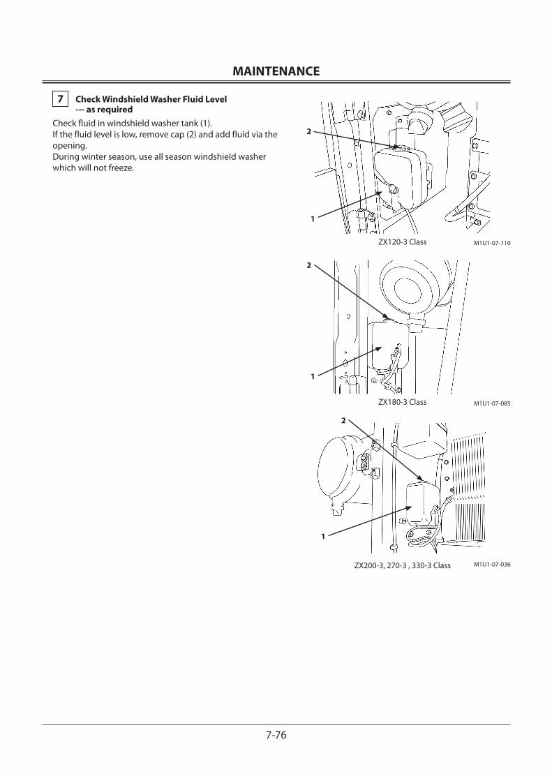
MAINTENANCE
7-76
7 Check Windshield Washer Fluid Level --- as requiredCheck fluid in windshield washer tank (1).If the fluid level is low, remove cap (2) and add fluid via the opening.During winter season, use all season windshield washer which will not freeze.
M1U1-07-085
2
1
M1U1-07-036
2
1
ZX200-3, 270-3 , 330-3 Class
ZX180-3 Class
M1U1-07-110ZX120-3 Class
2
1
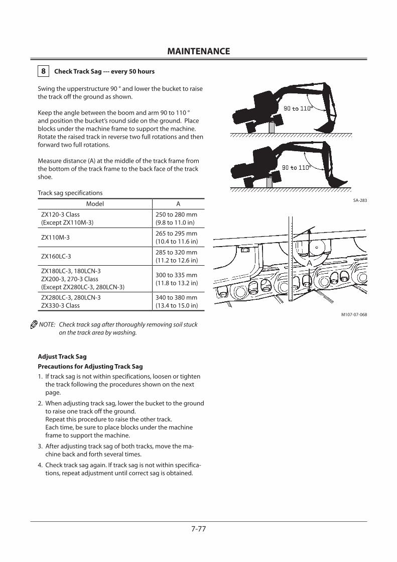
MAINTENANCE
7-77
8 Check Track Sag --- every 50 hours
Swing the upperstructure 90 ° and lower the bucket to raise the track off the ground as shown.
Keep the angle between the boom and arm 90 to 110 ° and position the bucket’s round side on the ground. Place blocks under the machine frame to support the machine.Rotate the raised track in reverse two full rotations and then forward two full rotations.
Measure distance (A) at the middle of the track frame from the bottom of the track frame to the back face of the track shoe.
Track sag specifications
Model A
ZX120-3 Class (Except ZX110M-3)
250 to 280 mm (9.8 to 11.0 in)
ZX110M-3 265 to 295 mm (10.4 to 11.6 in)
ZX160LC-3 285 to 320 mm (11.2 to 12.6 in)
ZX180LC-3, 180LCN-3ZX200-3, 270-3 Class(Except ZX280LC-3, 280LCN-3)
300 to 335 mm (11.8 to 13.2 in)
ZX280LC-3, 280LCN-3 ZX330-3 Class
340 to 380 mm (13.4 to 15.0 in)
NOTE: Check track sag after thoroughly removing soil stuck on the track area by washing.
Adjust Track SagPrecautions for Adjusting Track Sag1. If track sag is not within specifications, loosen or tighten
the track following the procedures shown on the next page.
2. When adjusting track sag, lower the bucket to the ground to raise one track off the ground. Repeat this procedure to raise the other track. Each time, be sure to place blocks under the machine frame to support the machine.
3. After adjusting track sag of both tracks, move the ma-chine back and forth several times.
4. Check track sag again. If track sag is not within specifica-tions, repeat adjustment until correct sag is obtained.
SA-283
M107-07-068
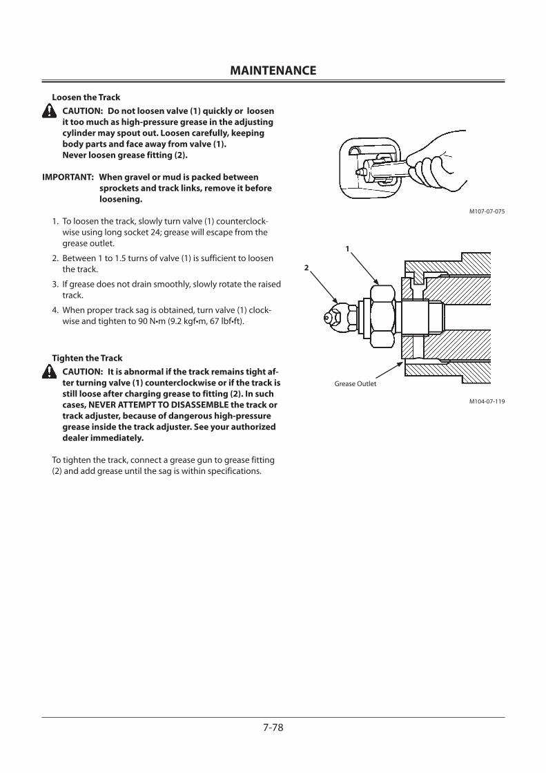
MAINTENANCE
7-78
Loosen the Track CAUTION: Do not loosen valve (1) quickly or loosen
it too much as high-pressure grease in the adjusting cylinder may spout out. Loosen carefully, keeping body parts and face away from valve (1). Never loosen grease fitting (2).
IMPORTANT: When gravel or mud is packed between sprockets and track links, remove it before loosening.
1. To loosen the track, slowly turn valve (1) counterclock-wise using long socket 24; grease will escape from the grease outlet.
2. Between 1 to 1.5 turns of valve (1) is sufficient to loosen the track.
3. If grease does not drain smoothly, slowly rotate the raised track.
4. When proper track sag is obtained, turn valve (1) clock-wise and tighten to 90 N•m (9.2 kgf•m, 67 lbf•ft).
Tighten the Track CAUTION: It is abnormal if the track remains tight af-
ter turning valve (1) counterclockwise or if the track is still loose after charging grease to fitting (2). In such cases, NEVER ATTEMPT TO DISASSEMBLE the track or track adjuster, because of dangerous high-pressure grease inside the track adjuster. See your authorized dealer immediately.
To tighten the track, connect a grease gun to grease fitting (2) and add grease until the sag is within specifications.
M107-07-075
M104-07-119
1
2
Grease Outlet
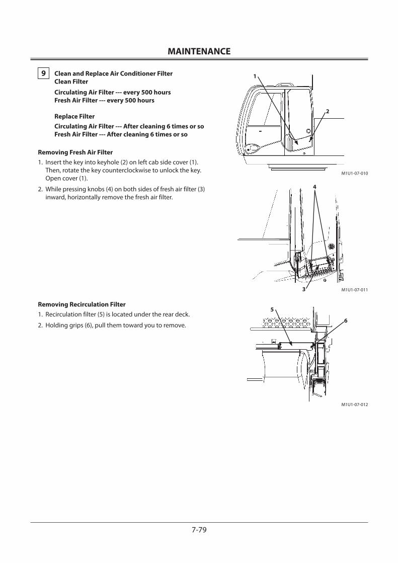
MAINTENANCE
7-79
9 Clean and Replace Air Conditioner Filter Clean Filter
Circulating Air Filter --- every 500 hours Fresh Air Filter --- every 500 hours Replace Filter Circulating Air Filter --- After cleaning 6 times or so Fresh Air Filter --- After cleaning 6 times or so
Removing Fresh Air Filter1. Insert the key into keyhole (2) on left cab side cover (1).
Then, rotate the key counterclockwise to unlock the key. Open cover (1).
2. While pressing knobs (4) on both sides of fresh air filter (3) inward, horizontally remove the fresh air filter.
Removing Recirculation Filter1. Recirculation filter (5) is located under the rear deck.
2. Holding grips (6), pull them toward you to remove.
M1U1-07-010
M1U1-07-011
M1U1-07-012
1
2
4
3
5
6
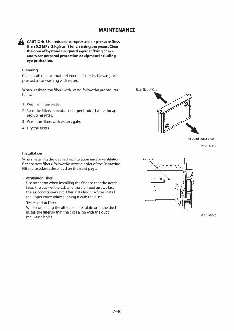
MAINTENANCE
7-80
CAUTION: Use reduced compressed air pressure (less than 0.2 MPa, 2 kgf/cm2) for cleaning purposes. Clear the area of bystanders, guard against flying chips, and wear personal protection equipment including eye protection.
CleaningClean both the external and internal filters by blowing com-pressed air or washing with water.
When washing the filters with water, follow the procedures below:
1. Wash with tap water.
2. Soak the filters in neutral detergent-mixed water for ap-prox. 5 minutes.
3. Wash the filters with water again.
4. Dry the filters.
InstallationWhen installing the cleaned recirculation and/or ventilation filter or new filters, follow the reverse order of the Removing Filter procedures described on the front page.
• Ventilation Filter Use attention when installing the filter so that the notch faces the back of the cab and the stamped arrows face the air conditioner unit. After installing the filter, install the upper cover while aligning it with the duct.
• Recirculation Filter While contacting the attached filter plate onto the duct, install the filter so that the clips align with the duct mounting holes.
M1U1-07-013
Rear Side of Cab
Air Conditioner Side
M1U1-07-012
Support
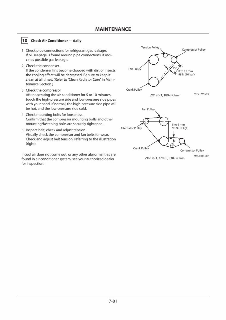
MAINTENANCE
7-81
10 Check Air Conditioner --- daily
1. Check pipe connections for refrigerant gas leakage. If oil seepage is found around pipe connections, it indi-cates possible gas leakage.
2. Check the condenser. If the condenser fins become clogged with dirt or insects, the cooling effect will be decreased. Be sure to keep it clean at all times. (Refer to “Clean Radiator Core” in Main-tenance Section.)
3. Check the compressor After operating the air conditioner for 5 to 10 minutes, touch the high-pressure side and low-pressure side pipes with your hand. If normal, the high-pressure side pipe will be hot, and the low-pressure side cold.
4. Check mounting bolts for looseness. Confirm that the compressor mounting bolts and other mounting/fastening bolts are securely tightened.
5. Inspect belt, check and adjust tension. Visually check the compressor and fan belts for wear. Check and adjust belt tension, referring to the illustration (right).
If cool air does not come out, or any other abnormalities are found in air conditioner system, see your authorized dealer for inspection.
M1U1-07-086
Fan Pulley
Crank Pulley
Compressor PulleyTension Pulley
8 to 12 mm98 N (10 kgf )
M1GR-07-007
Fan Pulley
Crank PulleyCompressor Pulley
Alternator Pulley5 to 6 mm98 N (10 kgf )
150
ZX200-3, 270-3 , 330-3 Class
ZX120-3, 180-3 Class
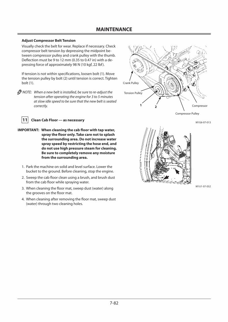
MAINTENANCE
7-82
Adjust Compressor Belt TensionVisually check the belt for wear. Replace if necessary. Check compressor belt tension by depressing the midpoint be-tween compressor pulley and crank pulley with the thumb. Deflection must be 9 to 12 mm (0.35 to 0.47 in) with a de-pressing force of approximately 98 N (10 kgf, 22 lbf ).
If tension is not within specifications, loosen bolt (1). Move the tension pulley by bolt (2) until tension is correct. Tighten bolt (1).
NOTE: When a new belt is installed, be sure to re-adjust the tension after operating the engine for 3 to 5 minutes at slow idle speed to be sure that the new belt is seated correctly.
11 Clean Cab Floor --- as necessary
IMPORTANT: When cleaning the cab floor with tap water, spray the floor only. Take care not to splash the surrounding area. Do not increase water spray speed by restricting the hose end, and do not use high pressure steam for cleaning. Be sure to completely remove any moisture from the surrounding area.
1. Park the machine on solid and level surface. Lower the bucket to the ground. Before cleaning, stop the engine.
2. Sweep the cab floor clean using a brush, and brush dust from the cab floor while spraying water.
3. When cleaning the floor mat, sweep dust (water) along the grooves on the floor mat.
4. When cleaning after removing the floor mat, sweep dust (water) through two cleaning holes.
M1U1-07-052
M1G6-07-013
Crank Pulley
Tension Pulley
Compressor
Compressor Pulley
1 2
MAINTENANCE
7-83
12 Retighten Cylinder Head Bolt --- as requiredSee your authorized dealer.
13 Inspect and Adjust Valve Clearance --- every 1000 hours See your authorized dealer.
14 Measure Engine Compression Pressure --- every 1000 hours See your authorized dealer.
15 Check Starter and Alternator --- every 1000 hoursSee your authorized dealer.
16 Check and Replace EGR Device --- as requiredSee your authorized dealer.
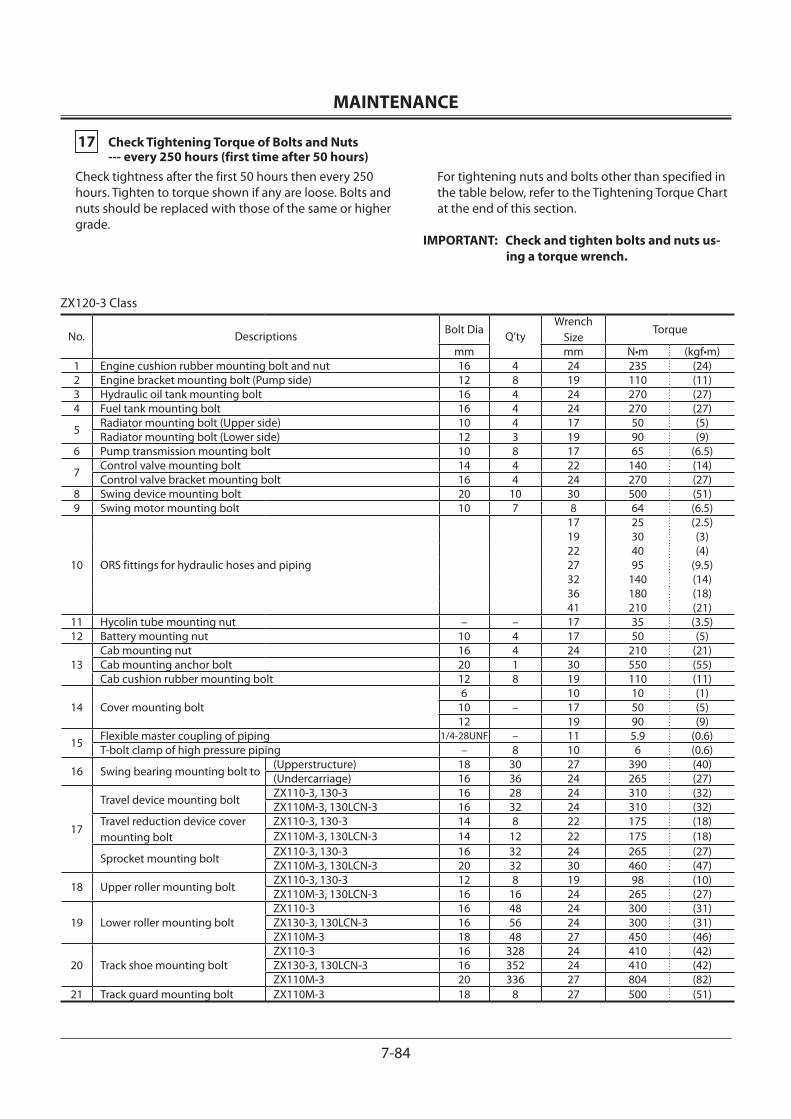
MAINTENANCE
7-84
17 Check Tightening Torque of Bolts and Nuts --- every 250 hours (first time after 50 hours)Check tightness after the first 50 hours then every 250 hours. Tighten to torque shown if any are loose. Bolts and nuts should be replaced with those of the same or higher grade.
For tightening nuts and bolts other than specified in the table below, refer to the Tightening Torque Chart at the end of this section.
IMPORTANT: Check and tighten bolts and nuts us-ing a torque wrench.
ZX120-3 Class
No. Descriptions Bolt Dia Q’tyWrench
SizeTorque
mm mm N•m (kgf•m)1 Engine cushion rubber mounting bolt and nut 16 4 24 235 (24)2 Engine bracket mounting bolt (Pump side) 12 8 19 110 (11)3 Hydraulic oil tank mounting bolt 16 4 24 270 (27)4 Fuel tank mounting bolt 16 4 24 270 (27)
5 Radiator mounting bolt (Upper side) 10 4 17 50 (5)Radiator mounting bolt (Lower side) 12 3 19 90 (9)
6 Pump transmission mounting bolt 10 8 17 65 (6.5)
7 Control valve mounting bolt 14 4 22 140 (14)Control valve bracket mounting bolt 16 4 24 270 (27)
8 Swing device mounting bolt 20 10 30 500 (51)9 Swing motor mounting bolt 10 7 8 64 (6.5)
10 ORS fittings for hydraulic hoses and piping
17 25 (2.5)19 30 (3)22 40 (4)27 95 (9.5)32 140 (14)36 180 (18)41 210 (21)
11 Hycolin tube mounting nut – – 17 35 (3.5)12 Battery mounting nut 10 4 17 50 (5)
13Cab mounting nut 16 4 24 210 (21)Cab mounting anchor bolt 20 1 30 550 (55)Cab cushion rubber mounting bolt 12 8 19 110 (11)
14 Cover mounting bolt6 10 10 (1)
10 – 17 50 (5)12 19 90 (9)
15 Flexible master coupling of piping 1/4-28UNF – 11 5.9 (0.6)T-bolt clamp of high pressure piping – 8 10 6 (0.6)
16 Swing bearing mounting bolt to (Upperstructure) 18 30 27 390 (40)(Undercarriage) 16 36 24 265 (27)
17
Travel device mounting bolt ZX110-3, 130-3 16 28 24 310 (32)ZX110M-3, 130LCN-3 16 32 24 310 (32)
Travel reduction device cover mounting bolt
ZX110-3, 130-3 14 8 22 175 (18)ZX110M-3, 130LCN-3 14 12 22 175 (18)
Sprocket mounting bolt ZX110-3, 130-3 16 32 24 265 (27)ZX110M-3, 130LCN-3 20 32 30 460 (47)
18 Upper roller mounting bolt ZX110-3, 130-3 12 8 19 98 (10)ZX110M-3, 130LCN-3 16 16 24 265 (27)
19 Lower roller mounting boltZX110-3 16 48 24 300 (31)ZX130-3, 130LCN-3 16 56 24 300 (31)ZX110M-3 18 48 27 450 (46)
20 Track shoe mounting boltZX110-3 16 328 24 410 (42)ZX130-3, 130LCN-3 16 352 24 410 (42)ZX110M-3 20 336 27 804 (82)
21 Track guard mounting bolt ZX110M-3 18 8 27 500 (51)
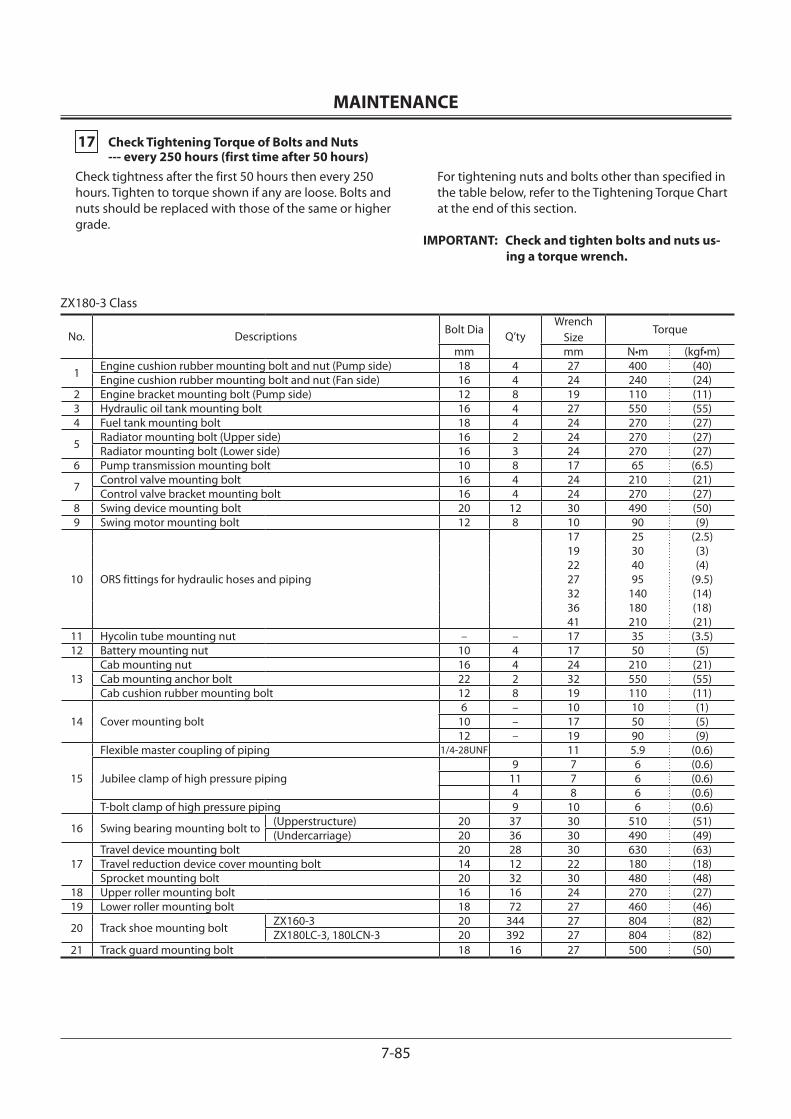
MAINTENANCE
7-85
17 Check Tightening Torque of Bolts and Nuts --- every 250 hours (first time after 50 hours)Check tightness after the first 50 hours then every 250 hours. Tighten to torque shown if any are loose. Bolts and nuts should be replaced with those of the same or higher grade.
For tightening nuts and bolts other than specified in the table below, refer to the Tightening Torque Chart at the end of this section.
IMPORTANT: Check and tighten bolts and nuts us-ing a torque wrench.
ZX180-3 Class
No. Descriptions Bolt Dia Q’tyWrench
SizeTorque
mm mm N•m (kgf•m)
1 Engine cushion rubber mounting bolt and nut (Pump side) 18 4 27 400 (40)Engine cushion rubber mounting bolt and nut (Fan side) 16 4 24 240 (24)
2 Engine bracket mounting bolt (Pump side) 12 8 19 110 (11)3 Hydraulic oil tank mounting bolt 16 4 27 550 (55)4 Fuel tank mounting bolt 18 4 24 270 (27)
5 Radiator mounting bolt (Upper side) 16 2 24 270 (27)Radiator mounting bolt (Lower side) 16 3 24 270 (27)
6 Pump transmission mounting bolt 10 8 17 65 (6.5)
7 Control valve mounting bolt 16 4 24 210 (21)Control valve bracket mounting bolt 16 4 24 270 (27)
8 Swing device mounting bolt 20 12 30 490 (50)9 Swing motor mounting bolt 12 8 10 90 (9)
10 ORS fittings for hydraulic hoses and piping
17 25 (2.5)19 30 (3)22 40 (4)27 95 (9.5)32 140 (14)36 180 (18)41 210 (21)
11 Hycolin tube mounting nut – – 17 35 (3.5)12 Battery mounting nut 10 4 17 50 (5)
13Cab mounting nut 16 4 24 210 (21)Cab mounting anchor bolt 22 2 32 550 (55)Cab cushion rubber mounting bolt 12 8 19 110 (11)
14 Cover mounting bolt6 – 10 10 (1)
10 – 17 50 (5)12 – 19 90 (9)
15
Flexible master coupling of piping 1/4-28UNF 11 5.9 (0.6)
Jubilee clamp of high pressure piping9 7 6 (0.6)
11 7 6 (0.6)4 8 6 (0.6)
T-bolt clamp of high pressure piping 9 10 6 (0.6)
16 Swing bearing mounting bolt to (Upperstructure) 20 37 30 510 (51)(Undercarriage) 20 36 30 490 (49)
17Travel device mounting bolt 20 28 30 630 (63)Travel reduction device cover mounting bolt 14 12 22 180 (18)Sprocket mounting bolt 20 32 30 480 (48)
18 Upper roller mounting bolt 16 16 24 270 (27)19 Lower roller mounting bolt 18 72 27 460 (46)
20 Track shoe mounting bolt ZX160-3 20 344 27 804 (82)ZX180LC-3, 180LCN-3 20 392 27 804 (82)
21 Track guard mounting bolt 18 16 27 500 (50)
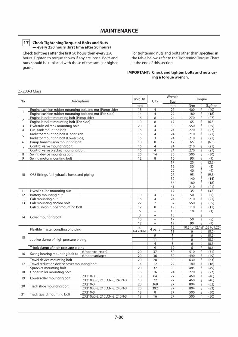
MAINTENANCE
7-86
17 Check Tightening Torque of Bolts and Nuts --- every 250 hours (first time after 50 hours)Check tightness after the first 50 hours then every 250 hours. Tighten to torque shown if any are loose. Bolts and nuts should be replaced with those of the same or higher grade.
For tightening nuts and bolts other than specified in the table below, refer to the Tightening Torque Chart at the end of this section.
IMPORTANT: Check and tighten bolts and nuts us-ing a torque wrench.
ZX200-3 Class
No. Descriptions Bolt Dia Q’tyWrench
SizeTorque
mm mm N•m (kgf•m)
1 Engine cushion rubber mounting bolt and nut (Pump side) 18 4 27 400 (40)Engine cushion rubber mounting bolt and nut (Fan side) 14 4 22 180 (18)
2 Engine bracket mounting bolt (Pump side) 16 8 24 270 (27)Engine bracket mounting bolt (Fan side) 10 8 17 65 (6.5)
3 Hydraulic oil tank mounting bolt 20 4 30 550 (55)4 Fuel tank mounting bolt 16 4 24 270 (27)
5 Radiator mounting bolt (Upper side) 16 4 24 210 (21)Radiator mounting bolt (Lower side) 16 3 24 210 (21)
6 Pump transmission mounting bolt 10 8 17 65 (6.5)
7 Control valve mounting bolt 16 4 24 210 (21)Control valve bracket mounting bolt 16 4 24 270 (27)
8 Swing device mounting bolt 20 14 30 500 (50)9 Swing motor mounting bolt 12 8 10 90 (9)
10 ORS fittings for hydraulic hoses and piping
17 25 (2.5)19 30 (3)22 40 (4)27 95 (9.5)32 140 (14)36 180 (18)41 210 (21)
11 Hycolin tube mounting nut – – 17 35 (3.5)12 Battery mounting nut 10 4 17 50 (5)
13Cab mounting nut 16 4 24 210 (21)Cab mounting anchor bolt 22 2 32 550 (55)Cab cushion rubber mounting bolt 12 8 19 110 (11)
14 Cover mounting bolt
6 – 10 10 (1)8 – 13
10 – 17 50 (5)12 – 19 90 (9)
15
Flexible master coupling of piping 81/4-28UNF 4 pairs 13 10.3 to 12.4 (1.05 to1.26)
11 6 (0.6)
Jubilee clamp of high pressure piping9 7 6 (0.6)
11 7 6 (0.6)4 8 6 (0.6)
T-bolt clamp of high pressure piping 9 10 6 (0.6)
16 Swing bearing mounting bolt to (Upperstructure) 20 37 30 510 (51)(Undercarriage) 20 36 30 490 (49)
17Travel device mounting bolt 20 28 30 630 (63)Travel reduction device cover mounting bolt 14 12 22 180 (18)Sprocket mounting bolt 20 32 30 485 (49)
18 Upper roller mounting bolt 16 16 24 270 (27)
19 Lower roller mounting bolt ZX210-3 18 64 27 460 (46)ZX210LC-3, 210LCN-3, 240N-3 18 72 27 460 (46)
20 Track shoe mounting bolt ZX210-3 20 368 27 804 (82)ZX210LC-3, 210LCN-3, 240N-3 20 392 27 804 (82)
21 Track guard mounting bolt ZX210-3 18 8 27 500 (50)ZX210LC-3, 210LCN-3, 240N-3 18 16 27 500 (50)
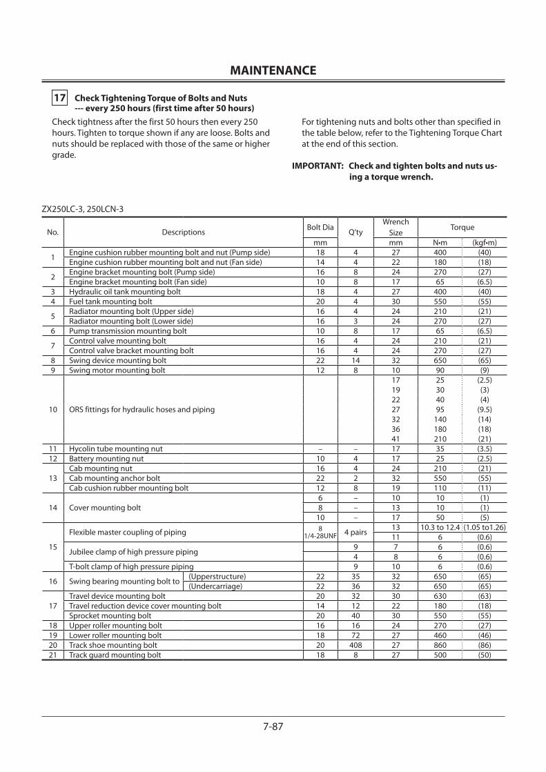
MAINTENANCE
7-87
17 Check Tightening Torque of Bolts and Nuts --- every 250 hours (first time after 50 hours)Check tightness after the first 50 hours then every 250 hours. Tighten to torque shown if any are loose. Bolts and nuts should be replaced with those of the same or higher grade.
For tightening nuts and bolts other than specified in the table below, refer to the Tightening Torque Chart at the end of this section.
IMPORTANT: Check and tighten bolts and nuts us-ing a torque wrench.
ZX250LC-3, 250LCN-3
No. Descriptions Bolt Dia Q’tyWrench
SizeTorque
mm mm N•m (kgf•m)
1 Engine cushion rubber mounting bolt and nut (Pump side) 18 4 27 400 (40)Engine cushion rubber mounting bolt and nut (Fan side) 14 4 22 180 (18)
2 Engine bracket mounting bolt (Pump side) 16 8 24 270 (27)Engine bracket mounting bolt (Fan side) 10 8 17 65 (6.5)
3 Hydraulic oil tank mounting bolt 18 4 27 400 (40)4 Fuel tank mounting bolt 20 4 30 550 (55)
5 Radiator mounting bolt (Upper side) 16 4 24 210 (21)Radiator mounting bolt (Lower side) 16 3 24 270 (27)
6 Pump transmission mounting bolt 10 8 17 65 (6.5)
7 Control valve mounting bolt 16 4 24 210 (21)Control valve bracket mounting bolt 16 4 24 270 (27)
8 Swing device mounting bolt 22 14 32 650 (65)9 Swing motor mounting bolt 12 8 10 90 (9)
10 ORS fittings for hydraulic hoses and piping
17 25 (2.5)19 30 (3)22 40 (4)27 95 (9.5)32 140 (14)36 180 (18)41 210 (21)
11 Hycolin tube mounting nut – – 17 35 (3.5)12 Battery mounting nut 10 4 17 25 (2.5)
13Cab mounting nut 16 4 24 210 (21)Cab mounting anchor bolt 22 2 32 550 (55)Cab cushion rubber mounting bolt 12 8 19 110 (11)
14 Cover mounting bolt6 – 10 10 (1)8 – 13 10 (1)
10 – 17 50 (5)
15
Flexible master coupling of piping 81/4-28UNF 4 pairs 13 10.3 to 12.4 (1.05 to1.26)
11 6 (0.6)
Jubilee clamp of high pressure piping 9 7 6 (0.6)4 8 6 (0.6)
T-bolt clamp of high pressure piping 9 10 6 (0.6)
16 Swing bearing mounting bolt to (Upperstructure) 22 35 32 650 (65)(Undercarriage) 22 36 32 650 (65)
17Travel device mounting bolt 20 32 30 630 (63)Travel reduction device cover mounting bolt 14 12 22 180 (18)Sprocket mounting bolt 20 40 30 550 (55)
18 Upper roller mounting bolt 16 16 24 270 (27)19 Lower roller mounting bolt 18 72 27 460 (46)20 Track shoe mounting bolt 20 408 27 860 (86)21 Track guard mounting bolt 18 8 27 500 (50)
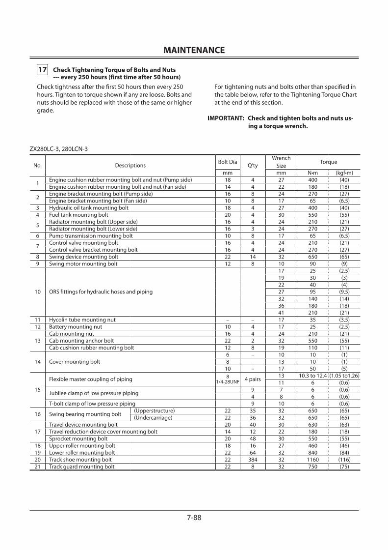
MAINTENANCE
7-88
17 Check Tightening Torque of Bolts and Nuts --- every 250 hours (first time after 50 hours)Check tightness after the first 50 hours then every 250 hours. Tighten to torque shown if any are loose. Bolts and nuts should be replaced with those of the same or higher grade.
For tightening nuts and bolts other than specified in the table below, refer to the Tightening Torque Chart at the end of this section.
IMPORTANT: Check and tighten bolts and nuts us-ing a torque wrench.
ZX280LC-3, 280LCN-3
No. Descriptions Bolt Dia Q’tyWrench
SizeTorque
mm mm N•m (kgf•m)
1 Engine cushion rubber mounting bolt and nut (Pump side) 18 4 27 400 (40)Engine cushion rubber mounting bolt and nut (Fan side) 14 4 22 180 (18)
2 Engine bracket mounting bolt (Pump side) 16 8 24 270 (27)Engine bracket mounting bolt (Fan side) 10 8 17 65 (6.5)
3 Hydraulic oil tank mounting bolt 18 4 27 400 (40)4 Fuel tank mounting bolt 20 4 30 550 (55)
5 Radiator mounting bolt (Upper side) 16 4 24 210 (21)Radiator mounting bolt (Lower side) 16 3 24 270 (27)
6 Pump transmission mounting bolt 10 8 17 65 (6.5)
7 Control valve mounting bolt 16 4 24 210 (21)Control valve bracket mounting bolt 16 4 24 270 (27)
8 Swing device mounting bolt 22 14 32 650 (65)9 Swing motor mounting bolt 12 8 10 90 (9)
10 ORS fittings for hydraulic hoses and piping
17 25 (2.5)19 30 (3)22 40 (4)27 95 (9.5)32 140 (14)36 180 (18)41 210 (21)
11 Hycolin tube mounting nut – – 17 35 (3.5)12 Battery mounting nut 10 4 17 25 (2.5)
13Cab mounting nut 16 4 24 210 (21)Cab mounting anchor bolt 22 2 32 550 (55)Cab cushion rubber mounting bolt 12 8 19 110 (11)
14 Cover mounting bolt6 – 10 10 (1)8 – 13 10 (1)
10 – 17 50 (5)
15
Flexible master coupling of piping 8 1/4-28UNF 4 pairs 13 10.3 to 12.4 (1.05 to1.26)
11 6 (0.6)
Jubilee clamp of low pressure piping 9 7 6 (0.6)4 8 6 (0.6)
T-bolt clamp of low pressure piping 9 10 6 (0.6)
16 Swing bearing mounting bolt (Upperstructure) 22 35 32 650 (65)(Undercarriage) 22 36 32 650 (65)
17Travel device mounting bolt 20 40 30 630 (63)Travel reduction device cover mounting bolt 14 12 22 180 (18)Sprocket mounting bolt 20 48 30 550 (55)
18 Upper roller mounting bolt 18 16 27 460 (46)19 Lower roller mounting bolt 22 64 32 840 (84)20 Track shoe mounting bolt 22 384 32 1160 (116)21 Track guard mounting bolt 22 8 32 750 (75)
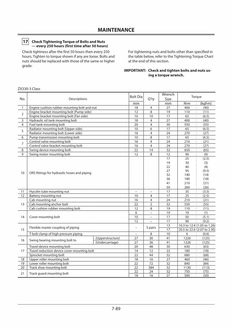
MAINTENANCE
7-89
17 Check Tightening Torque of Bolts and Nuts --- every 250 hours (first time after 50 hours)Check tightness after the first 50 hours then every 250 hours. Tighten to torque shown if any are loose. Bolts and nuts should be replaced with those of the same or higher grade.
For tightening nuts and bolts other than specified in the table below, refer to the Tightening Torque Chart at the end of this section.
IMPORTANT: Check and tighten bolts and nuts us-ing a torque wrench.
ZX330-3 Class
No. Descriptions Bolt Dia Q’tyWrench
SizeTorque
mm mm N•m (kgf•m)1 Engine cushion rubber mounting bolt and nut 18 4 27 400 (40)
2Engine bracket mounting bolt (Pump side) 12 8 19 110 (11)Engine bracket mounting bolt (Fan side) 10 10 17 65 (6.5)
3 Hydraulic oil tank mounting bolt 18 4 27 400 (40)4 Fuel tank mounting bolt 20 4 30 550 (55)
5Radiator mounting bolt (Upper side) 10 6 17 65 (6.5)Radiator mounting bolt (Lower side) 16 4 24 270 (27)
6 Pump transmission mounting bolt 10 8 17 65 (6.5)
7Control valve mounting bolt 16 4 24 210 (21)Control valve bracket mounting bolt 16 4 24 270 (27)
8 Swing device mounting bolt 22 14 32 650 (65)9 Swing motor mounting bolt 12 8 12 90 (9)
10 ORS fittings for hydraulic hoses and piping
17 25 (2.5)19 30 (3)22 40 (4)27 95 (9.5)32 140 (14)36 180 (18)41 210 (21)50 260 (26)
11 Hycolin tube mounting nut – – 17 35 (3.5)12 Battery mounting nut 10 4 17 25 (2.5)
13Cab mounting nut 16 4 24 210 (21)Cab mounting anchor bolt 22 2 32 550 (55)Cab cushion rubber mounting bolt 12 8 19 110 (11)
14 Cover mounting bolt6 – 10 10 (1)
10 – 17 50 (5.1)12 – 17 90 (9.2)
15Flexible master coupling of piping – 5 pairs
13 10.3 to 12.4 (1.05 to 1.26)17 20.5 to 22.6 (2.07 to 2.30)
T-bolt clamp of high pressure piping – 8 10 6 (0.6)
16 Swing bearing mounting bolt to(Upperstructure) 27 36 41 1226 (125)(Undercarriage) 27 36 41 1226 (125)
17Travel device mounting bolt 20 48 30 630 (63)Travel reduction device cover mounting bolt 14 12 22 180 (18)Sprocket mounting bolt 22 44 32 680 (68)
18 Upper roller mounting bolt 18 16 27 460 (46)19 Lower roller mounting bolt 22 72 32 840 (84)20 Track shoe mounting bolt 22 384 32 1130 (113)
21 Track guard mounting bolt 22 24 32 750 (75)18 16 27 500 (50)
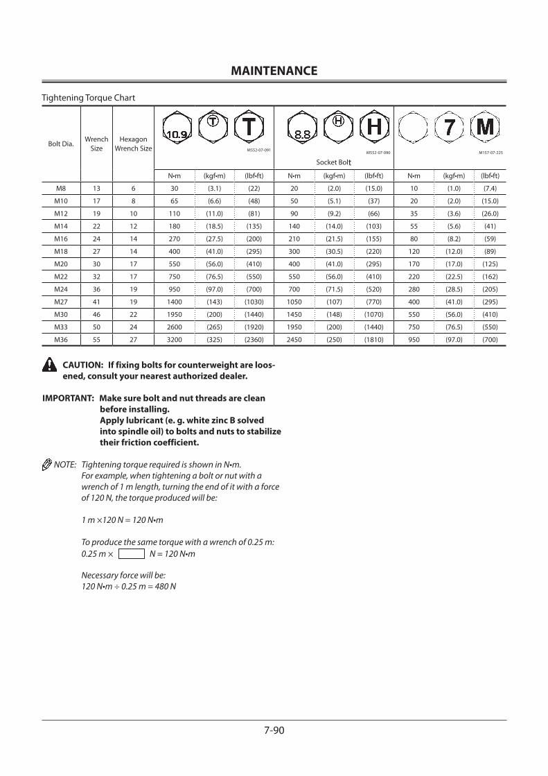
MAINTENANCE
7-90
Tightening Torque Chart
Bolt Dia.Wrench
SizeHexagon
Wrench Size M552-07-091M552-07-090
Socket BoltM157-07-225
N•m (kgf•m) (lbf•ft) N•m (kgf•m) (lbf•ft) N•m (kgf•m) (lbf•ft)
M8 13 6 30 (3.1) (22) 20 (2.0) (15.0) 10 (1.0) (7.4)
M10 17 8 65 (6.6) (48) 50 (5.1) (37) 20 (2.0) (15.0)
M12 19 10 110 (11.0) (81) 90 (9.2) (66) 35 (3.6) (26.0)
M14 22 12 180 (18.5) (135) 140 (14.0) (103) 55 (5.6) (41)
M16 24 14 270 (27.5) (200) 210 (21.5) (155) 80 (8.2) (59)
M18 27 14 400 (41.0) (295) 300 (30.5) (220) 120 (12.0) (89)
M20 30 17 550 (56.0) (410) 400 (41.0) (295) 170 (17.0) (125)
M22 32 17 750 (76.5) (550) 550 (56.0) (410) 220 (22.5) (162)
M24 36 19 950 (97.0) (700) 700 (71.5) (520) 280 (28.5) (205)
M27 41 19 1400 (143) (1030) 1050 (107) (770) 400 (41.0) (295)
M30 46 22 1950 (200) (1440) 1450 (148) (1070) 550 (56.0) (410)
M33 50 24 2600 (265) (1920) 1950 (200) (1440) 750 (76.5) (550)
M36 55 27 3200 (325) (2360) 2450 (250) (1810) 950 (97.0) (700)
CAUTION: If fixing bolts for counterweight are loos-ened, consult your nearest authorized dealer.
IMPORTANT: Make sure bolt and nut threads are clean before installing. Apply lubricant (e. g. white zinc B solved into spindle oil) to bolts and nuts to stabilize their friction coefficient.
NOTE: Tightening torque required is shown in N•m. For example, when tightening a bolt or nut with a wrench of 1 m length, turning the end of it with a force of 120 N, the torque produced will be:
1 m ×120 N = 120 N•m
To produce the same torque with a wrench of 0.25 m: 0.25 m × N = 120 N•m
Necessary force will be: 120 N•m ÷ 0.25 m = 480 N
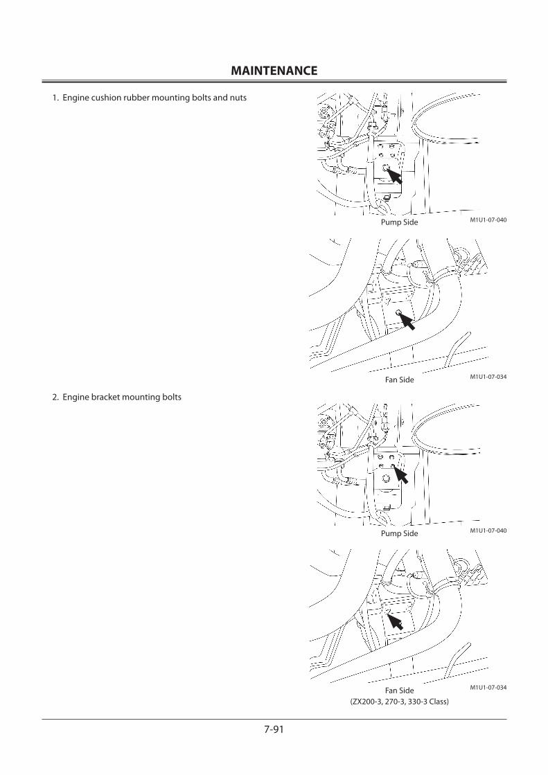
MAINTENANCE
7-91
1. Engine cushion rubber mounting bolts and nuts
2. Engine bracket mounting bolts
M1U1-07-040
M1U1-07-040
M1U1-07-034
M1U1-07-034
Pump Side
Pump Side
Fan Side
Fan Side(ZX200-3, 270-3, 330-3 Class)
MAINTENANCE
7-92
3. Hydraulic oil tank mounting bolts
4. Fuel tank mounting bolts
5. Radiator mounting bolt
ZX120-3, 180-3 Class
M1U1-07-073
ZX270-3 ClassM1U1-07-056
ZX330-3 ClassM1U1-07-057
ZX330-3 ClassM1U1-07-055
ZX200-3 Class
M1U1-07-097
M1U1-07-038
M1U1-07-038
ZX120-3, 180-3 ClassM1U1-07-096
(Upper Side) (Lower Side)
MAINTENANCE
7-93
6. Pump transmission mounting bolts
7. Control valve mounting bolts
Control valve bracket mounting bolts
M1U1-07-021
M1U1-07-025
M1U1-07-041
M175-07-024ZX120-3 Class ZX180-3, 200-3, 270-3, 330-3 Class
M175-07-023ZX120-3 Class ZX180-3, 200-3, 270-3, 330-3 Class
M175-07-026ZX120-3 Class ZX180-3, 200-3, 270-3, 330-3 Class
MAINTENANCE
7-94
8. Swing device mounting bolts
9. Swing motor mounting bolts
10. ORS fittings for hydraulic hoses and piping
11. Hycolin tube mounting nut
M1U1-07-053
M1U1-07-053
M104-07-079
M1U1-07-035
M175-00-002ZX120-3 Class ZX180-3, 200-3, 270-3, 330-3 Class
M175-00-002ZX120-3 Class ZX180-3, 200-3, 270-3, 330-3 Class
M1U1-07-111ZX120-3 Class ZX180-3, 200-3, 270-3, 330-3 Class
MAINTENANCE
7-95
12. Battery mounting nuts
13. Cab mounting nuts
M1U1-07-026
M1U1-07-083
M1U1-07-054Anchor Bolt Bottom View
M1U1-07-016ZX200-3, 270-3 , 330-3 Class
ZX180-3 ClassM1U1-07-109
ZX120-3 Class
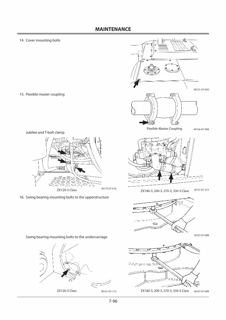
MAINTENANCE
7-96
14. Cover mounting bolts
15. Flexible master coupling
Jubilee and T-bolt clamp
16. Swing bearing mounting bolts to the upperstructure
Swing bearing mounting bolts to the undercarriage M107-07-088
M107-07-089
M1U1-07-042
M1G6-07-008
M157-07-215
Flexible Master Coupling
M175-07-016ZX120-3 Class
M1U1-07-113ZX120-3 Class ZX180-3, 200-3, 270-3, 330-3 Class
ZX180-3, 200-3, 270-3, 330-3 Class
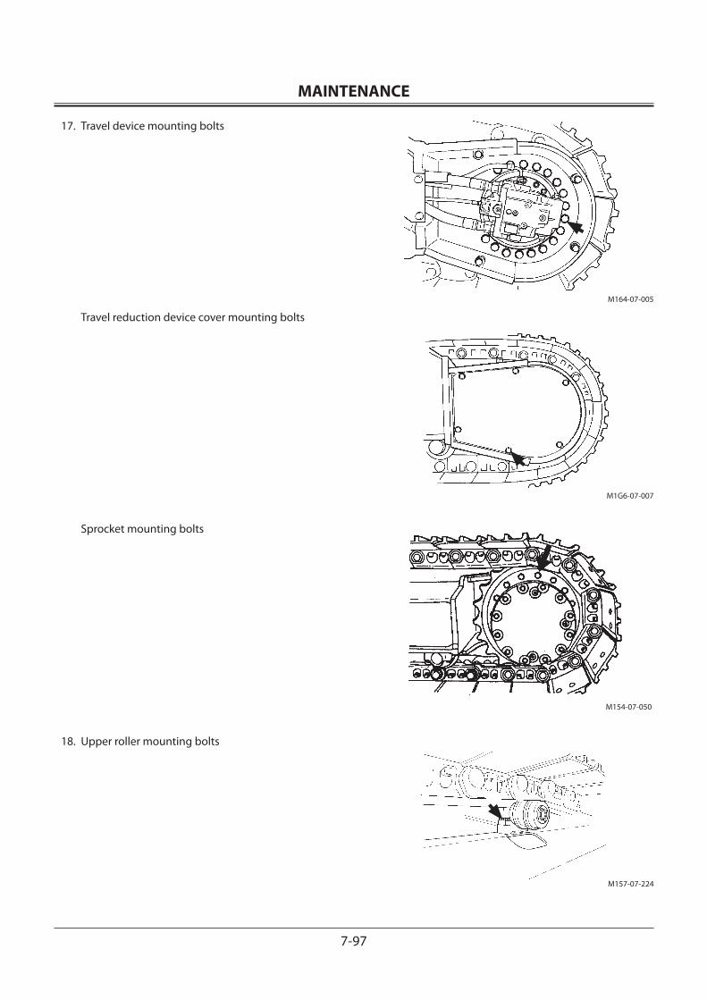
MAINTENANCE
7-97
17. Travel device mounting bolts
Travel reduction device cover mounting bolts
Sprocket mounting bolts
18. Upper roller mounting bolts
M164-07-005
M1G6-07-007
M157-07-224
M154-07-050
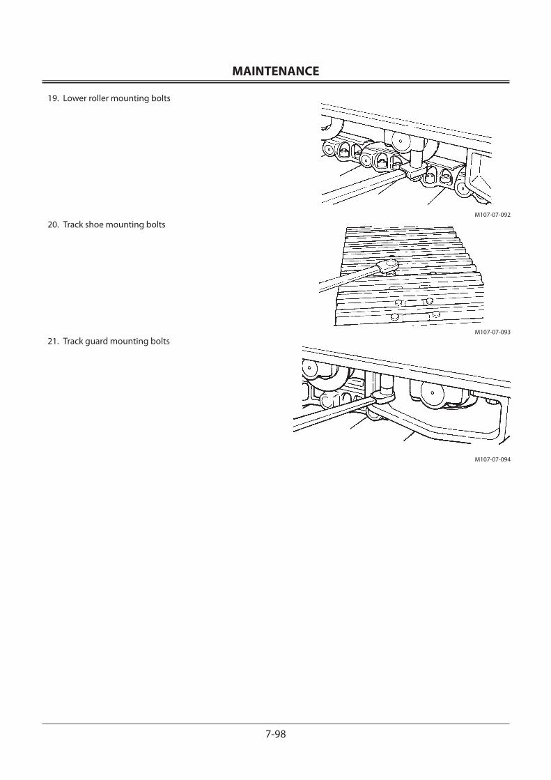
MAINTENANCE
7-98
19. Lower roller mounting bolts
20. Track shoe mounting bolts
21. Track guard mounting bolts
M107-07-092
M107-07-093
M107-07-094
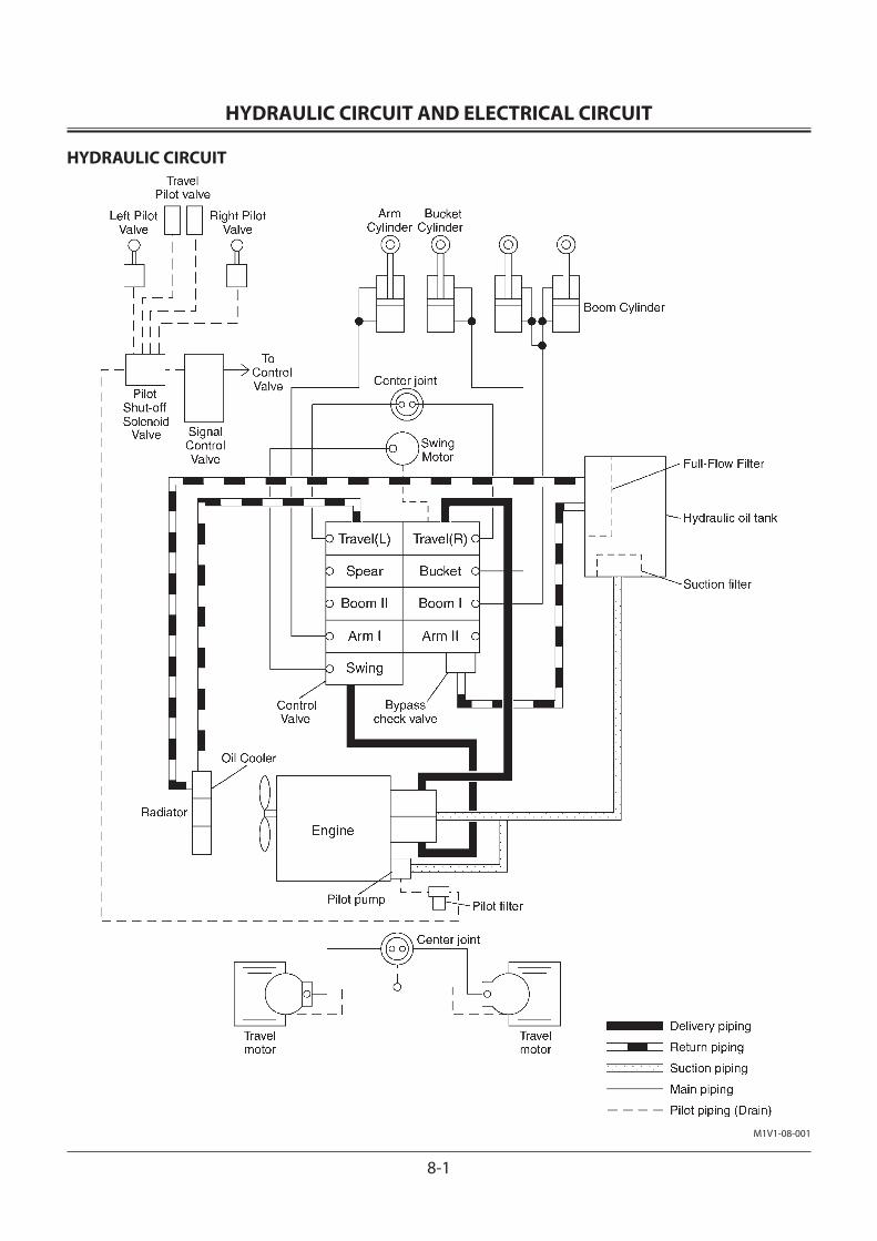
HYDRAULIC CIRCUIT AND ELECTRICAL CIRCUIT
8-1
HYDRAULIC CIRCUIT
M1V1-08-001

HYDRAULIC CIRCUIT AND ELECTRICAL CIRCUIT
8-2
ELECTRICAL CIRCUIT
ZX120-3/180-3/200-3/270-3/330-3 CLASS ELECTRICAL DIAGRAM1. FUSIBLE LINK2. BATTERY3. BATTERY RELAY4. STARTER5. SAFETY RELAY6. ALTERNATOR7. ENGINE8. GLOW RELAY9. AUTO RE-FUELING SYSTEM
10. PILOT SHUT-OFF SOLENOID VALVE11. PILOT SHUT-OFF RELAY12. ECM CONTROLLER13. KEY SIGNAL14. MAIN POWER15. BACK UP GND16. MAIN GND17. PRESSURE SWITCH18. COMPRESSOR19. AMBIENT SENSOR20. STARTER SWITCH21. STARTER CUT RELAY22. LOAD DUMP RELAY23. FUSE24. SECURITY RELAY25. SECURITY HORN26. SECURITY HORN RELAY27. WIPER MOTOR28. WIPER RELAY29. SOLAR RADIATION SENSOR30. AIR-CON. UNIT31. HEATER UNIT (OPTIONAL)32. ROOM LIGHT33. LIGHTER34. RADIO35. SPEAKER R36. SPEAKER L37. LIGHT RELAY238. LIGHT RELAY139. WASHER RELAY40. HORN RELAY41. HORN SWITCH
42. WORK LIGHT43. LUBRICATOR44. BOOM LIGHT45. WASHER46. HORN (H), HORN (L)47. MONITOR48. 5.8 INCH LCD49. EC DIAL SIGNAL IN-PUT50. WIPER SIGNAL IN-PUT51. POWER DIGGING SWITCH52. MC CONTROLLER53. KEY SIGNAL54. MAIN POWER55. SOLENOID POWER56. MAIN GND57. SOLENOID GND58. SWITCH BOX59. HP, P, E MODE SW60. TRAVEL 2-SPEED SW61. ENGINE SPEED CONTROL DIAL62. INTERIOR LIGHT63. LIGHT SW64. WASHER SW65. AUTO-IDLE66. ICF CONTROLLER67. MAIN POWER68. MAIN GND69. ICF Dr. ZX70. HYD. OIL FILTER WARNING71. AIR CLEANER RESTRICTION SW.72. FUEL SENSOR73. COOLANT TEMP. SENSOR74. OVER-HEAT SW75. TRAVEL ALARM76. SWING ALARM77. PRESSURE SENSOR (L)78. PRESSURE SENSOR (H)79. PRESSURE SENSOR (L)80. PRESSURE SENSOR (H)81. PRESSURE SENSOR (L)82. BUZZER
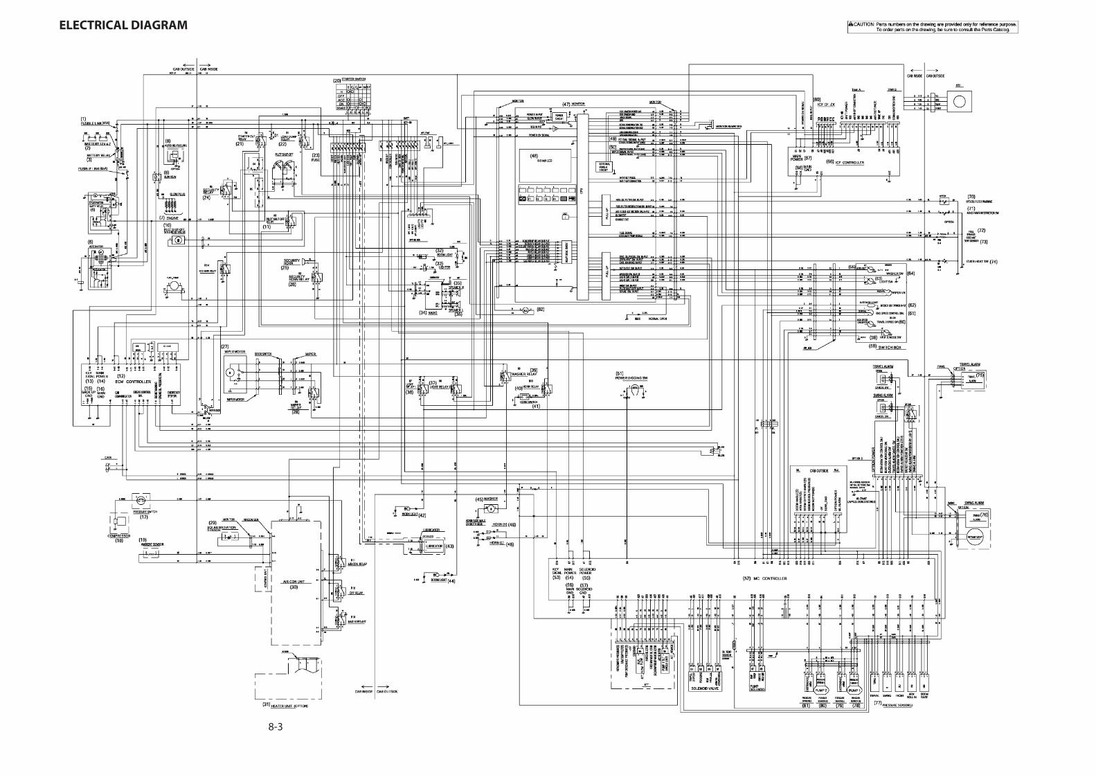
8-3
ELECTRICAL DIAGRAM


MAINTENANCE UNDER SPECIAL ENVIRONMENTAL CONDITIONS
9-1
MAINTENANCE UNDER SPECIAL ENVIRONMENTAL CONDITIONS
Operating Conditions Precautions for MaintenanceMuddy Soil, Rainy or
Snowy Weather Before Operation: Check the tightness of plug and all drain cocks.
After Operation: Clean the machine and check for cracks, damaged, loose or missing bolts and nuts. Lubricate all necessary parts without delay.
Near the Ocean Before Operation: Check tightness of plugs and all drain cocks.
After Operation: Thoroughly clean the machine with fresh water to wash off salt. Service elec-trical equipment often to prevent corrosion.
Dusty Atmosphere
Air Cleaner: Clean the element regularly at shorter service intervals.
Radiator: Clean the oil cooler screen to prevent clogging of the radiator core.
Fuel System: Clean the filter element and strainer regularly at shorter service intervals.
Electrical Equipment: Clean them regularly, in particular, the commutator surface of the alternator and starter.
Rocky Ground Tracks: Carefully operate while checking for cracks, damage and loose bolts and nuts. Loosen the tracks a little more than usual.
Front Attachment: Standard attachment may be damaged when digging rocky ground. Rein-force the bucket before using it, or use a heavy duty bucket.
Freezing Weather Fuel: Use high quality fuel suitable for low temperature.
Lubricant: Use high quality low viscosity hydraulic oil and engine oil.
Engine Coolant: Be sure to use antifreeze.
Battery: Fully charge the batteries regularly at shorter service intervals. If not fully charged, electrolyte may freeze.
Tracks: Keep the track clean. Park the machine on a hard surface to prevent the tracks from freezing to the ground.
Falling Stones Cab: Provide a cab guard to protect the machine from falling stones when neces-sary.

MAINTENANCE UNDER SPECIAL ENVIRONMENTAL CONDITIONS
9-2
MEMO...................................................................................................................................................................................................................................................
...................................................................................................................................................................................................................................................
...................................................................................................................................................................................................................................................
...................................................................................................................................................................................................................................................
...................................................................................................................................................................................................................................................
...................................................................................................................................................................................................................................................
...................................................................................................................................................................................................................................................
...................................................................................................................................................................................................................................................
...................................................................................................................................................................................................................................................
...................................................................................................................................................................................................................................................
...................................................................................................................................................................................................................................................
...................................................................................................................................................................................................................................................
...................................................................................................................................................................................................................................................
...................................................................................................................................................................................................................................................
...................................................................................................................................................................................................................................................
...................................................................................................................................................................................................................................................
...................................................................................................................................................................................................................................................
...................................................................................................................................................................................................................................................
...................................................................................................................................................................................................................................................
...................................................................................................................................................................................................................................................
...................................................................................................................................................................................................................................................
...................................................................................................................................................................................................................................................
...................................................................................................................................................................................................................................................
...................................................................................................................................................................................................................................................
...................................................................................................................................................................................................................................................
...................................................................................................................................................................................................................................................
...................................................................................................................................................................................................................................................
...................................................................................................................................................................................................................................................
...................................................................................................................................................................................................................................................
...................................................................................................................................................................................................................................................
...................................................................................................................................................................................................................................................
...................................................................................................................................................................................................................................................
...................................................................................................................................................................................................................................................
...................................................................................................................................................................................................................................................
...................................................................................................................................................................................................................................................
...................................................................................................................................................................................................................................................
...................................................................................................................................................................................................................................................

STORAGE
10-1
STORING THE MACHINE
1. Inspect the machine. Repair worn or damaged parts. Install new parts if necessary.
2. Clean the primary air cleaner element.
3. Retract all hydraulic cylinders, if possible. If not, coat exposed cylinder rods with grease.
4. Lubricate all grease points.
5. Park the tracks on long stable blocks.
6. Wash the machine.
7. Remove the batteries and store them in a dry protected place after charging fully. If not removed, disconnect the negative battery cable from the (−) terminal.
8. Add an antirust agent to the coolant. In cold weather, add an antifreeze, or drain the coolant completely. Be sure to attach a “No Water in Radiator” tag on a clearly visible location if the system is drained.
9. Loosen the alternator belt and fan belt.
10. Paint necessary areas to prevent rust.
11. Store the machine in a dry, protected place. If stored outside, cover with a waterproof cover.
12. If the machine is stored for a long time, operate hydraulic functions for travel, swing and digging two to three times for lubrication, at least once a month. Be sure to check the coolant level and lubrication condi-tions before operating.
Precautions for Disconnecting or Connecting BatteriesIn case the batteries are kept disconnected for more than one month or when the batteries are reconnected, contact your nearest Hitachi dealer. Resetting of the ICF (Information Controller) may be required.
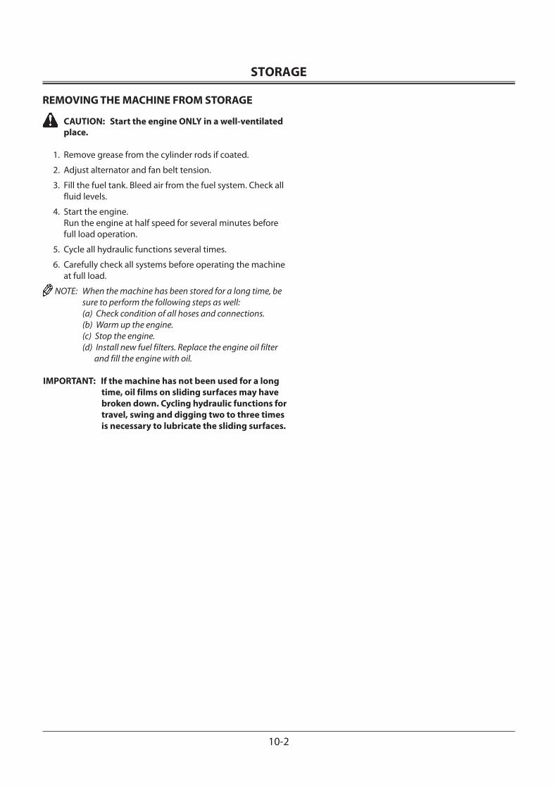
STORAGE
10-2
REMOVING THE MACHINE FROM STORAGE
CAUTION: Start the engine ONLY in a well-ventilated place.
1. Remove grease from the cylinder rods if coated.
2. Adjust alternator and fan belt tension.
3. Fill the fuel tank. Bleed air from the fuel system. Check all fluid levels.
4. Start the engine. Run the engine at half speed for several minutes before
full load operation.
5. Cycle all hydraulic functions several times.
6. Carefully check all systems before operating the machine at full load.
NOTE: When the machine has been stored for a long time, be sure to perform the following steps as well:
(a) Check condition of all hoses and connections. (b) Warm up the engine. (c) Stop the engine. (d) Install new fuel filters. Replace the engine oil filter
and fill the engine with oil.
IMPORTANT: If the machine has not been used for a long time, oil films on sliding surfaces may have broken down. Cycling hydraulic functions for travel, swing and digging two to three times is necessary to lubricate the sliding surfaces.
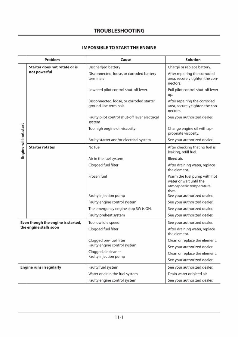
TROUBLESHOOTING
11-1
IMPOSSIBLE TO START THE ENGINE
Problem Cause Solution
Engi
ne w
ill n
ot s
tart
Starter does not rotate or is not powerful
Discharged battery
Disconnected, loose, or corroded battery terminals
Lowered pilot control shut-off lever.
Disconnected, loose, or corroded starter ground line terminals.
Faulty pilot control shut-off lever electrical system
Too high engine oil viscosity
Faulty starter and/or electrical system
Charge or replace battery.
After repairing the corroded area, securely tighten the con-nectors.
Pull pilot control shut-off lever up.
After repairing the corroded area, securely tighten the con-nectors.
See your authorized dealer.
Change engine oil with ap-propriate viscosity.
See your authorized dealer.
Starter rotates No fuel
Air in the fuel system
Clogged fuel filter
Frozen fuel Faulty injection pump
Faulty engine control system
The emergency engine stop SW is ON.
Faulty preheat system
After checking that no fuel is leaking, refill fuel.
Bleed air.
After draining water, replace the element.
Warm the fuel pump with hot water or wait until the atmospheric temperature rises.See your authorized dealer.
See your authorized dealer.
See your authorized dealer.
See your authorized dealer.
Even though the engine is started, the engine stalls soon
Too low idle speed
Clogged fuel filter
Clogged pre-fuel filter Faulty engine control system
Clogged air cleaner Faulty injection pump
See your authorized dealer.
After draining water, replace the element.
Clean or replace the element.
See your authorized dealer.
Clean or replace the element.
See your authorized dealer.
Engine runs irregularly Faulty fuel system
Water or air in the fuel system
Faulty engine control system
See your authorized dealer.
Drain water or bleed air.
See your authorized dealer.
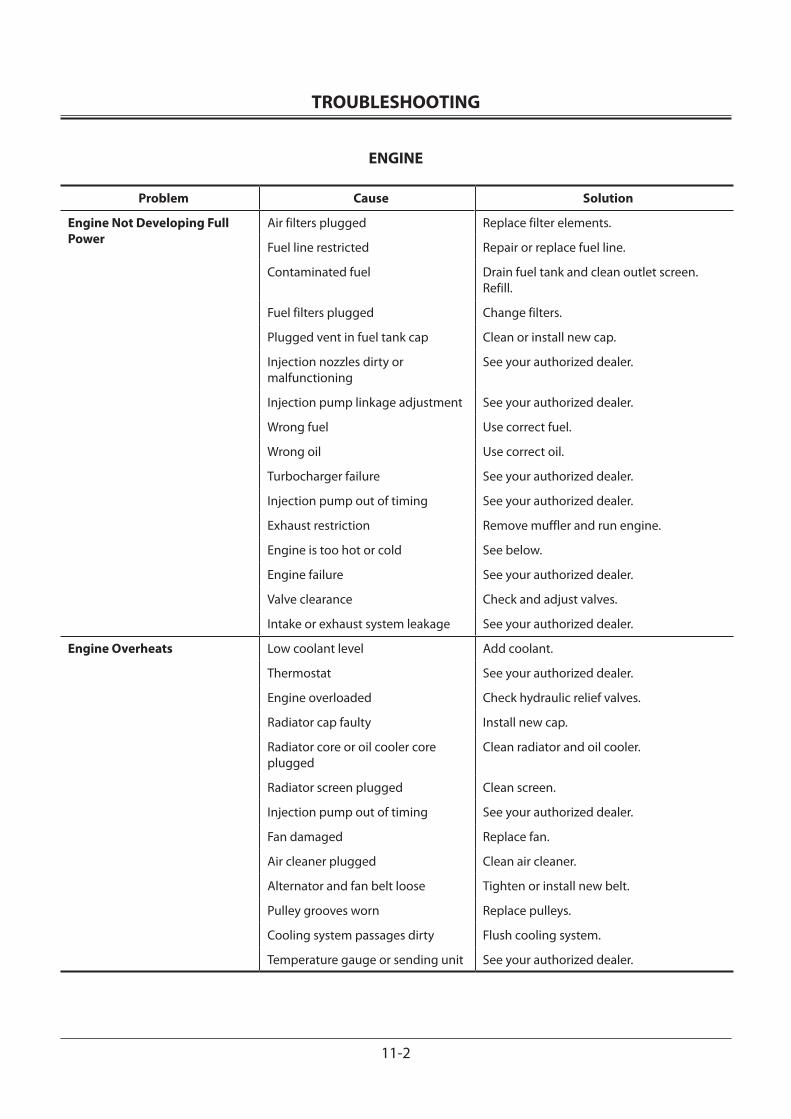
TROUBLESHOOTING
11-2
ENGINE
Problem Cause Solution
Engine Not Developing Full Power
Air filters plugged Replace filter elements.
Fuel line restricted Repair or replace fuel line.
Contaminated fuel Drain fuel tank and clean outlet screen.Refill.
Fuel filters plugged Change filters.
Plugged vent in fuel tank cap Clean or install new cap.
Injection nozzles dirty or malfunctioning
See your authorized dealer.
Injection pump linkage adjustment See your authorized dealer.
Wrong fuel Use correct fuel.
Wrong oil Use correct oil.
Turbocharger failure See your authorized dealer.
Injection pump out of timing See your authorized dealer.
Exhaust restriction Remove muffler and run engine.
Engine is too hot or cold See below.
Engine failure See your authorized dealer.
Valve clearance Check and adjust valves.
Intake or exhaust system leakage See your authorized dealer.
Engine Overheats Low coolant level Add coolant.
Thermostat See your authorized dealer.
Engine overloaded Check hydraulic relief valves.
Radiator cap faulty Install new cap.
Radiator core or oil cooler core plugged
Clean radiator and oil cooler.
Radiator screen plugged Clean screen.
Injection pump out of timing See your authorized dealer.
Fan damaged Replace fan.
Air cleaner plugged Clean air cleaner.
Alternator and fan belt loose Tighten or install new belt.
Pulley grooves worn Replace pulleys.
Cooling system passages dirty Flush cooling system.
Temperature gauge or sending unit See your authorized dealer.
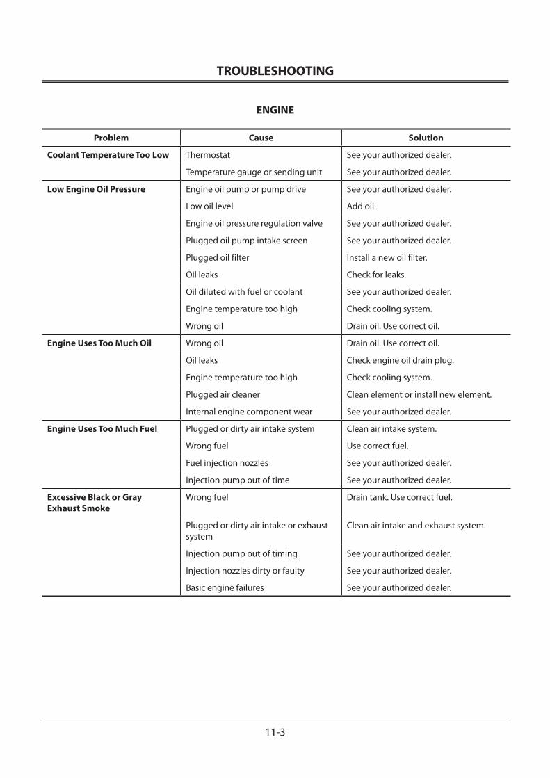
TROUBLESHOOTING
11-3
ENGINE
Problem Cause Solution
Coolant Temperature Too Low Thermostat See your authorized dealer.
Temperature gauge or sending unit See your authorized dealer.
Low Engine Oil Pressure Engine oil pump or pump drive See your authorized dealer.
Low oil level Add oil.
Engine oil pressure regulation valve See your authorized dealer.
Plugged oil pump intake screen See your authorized dealer.
Plugged oil filter Install a new oil filter.
Oil leaks Check for leaks.
Oil diluted with fuel or coolant See your authorized dealer.
Engine temperature too high Check cooling system.
Wrong oil Drain oil. Use correct oil.
Engine Uses Too Much Oil Wrong oil Drain oil. Use correct oil.
Oil leaks Check engine oil drain plug.
Engine temperature too high Check cooling system.
Plugged air cleaner Clean element or install new element.
Internal engine component wear See your authorized dealer.
Engine Uses Too Much Fuel Plugged or dirty air intake system Clean air intake system.
Wrong fuel Use correct fuel.
Fuel injection nozzles See your authorized dealer.
Injection pump out of time See your authorized dealer.
Excessive Black or Gray Exhaust Smoke
Wrong fuel Drain tank. Use correct fuel.
Plugged or dirty air intake or exhaust system
Clean air intake and exhaust system.
Injection pump out of timing See your authorized dealer.
Injection nozzles dirty or faulty See your authorized dealer.
Basic engine failures See your authorized dealer.
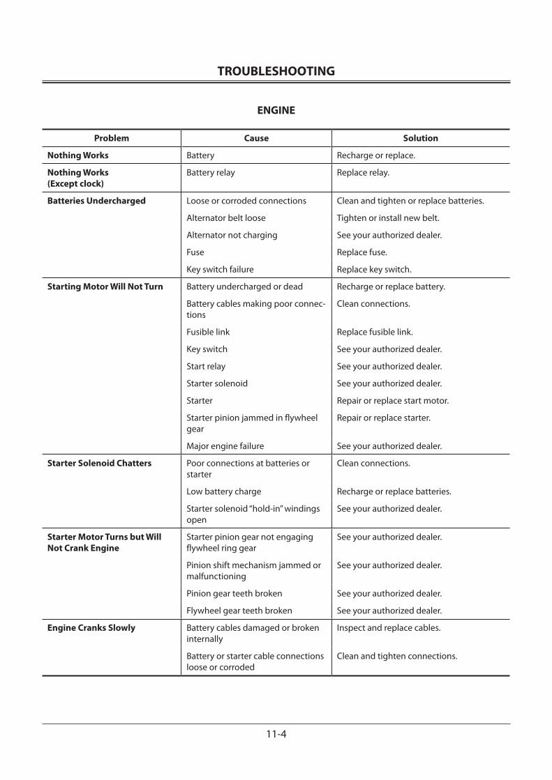
TROUBLESHOOTING
11-4
ENGINE
Problem Cause Solution
Nothing Works Battery Recharge or replace.
Nothing Works (Except clock)
Battery relay Replace relay.
Batteries Undercharged Loose or corroded connections Clean and tighten or replace batteries.
Alternator belt loose Tighten or install new belt.
Alternator not charging See your authorized dealer.
Fuse Replace fuse.
Key switch failure Replace key switch.
Starting Motor Will Not Turn Battery undercharged or dead Recharge or replace battery.
Battery cables making poor connec-tions
Clean connections.
Fusible link Replace fusible link.
Key switch See your authorized dealer.
Start relay See your authorized dealer.
Starter solenoid See your authorized dealer.
Starter Repair or replace start motor.
Starter pinion jammed in flywheel gear
Repair or replace starter.
Major engine failure See your authorized dealer.
Starter Solenoid Chatters Poor connections at batteries or starter
Clean connections.
Low battery charge Recharge or replace batteries.
Starter solenoid “hold-in” windings open
See your authorized dealer.
Starter Motor Turns but Will Not Crank Engine
Starter pinion gear not engaging flywheel ring gear
See your authorized dealer.
Pinion shift mechanism jammed or malfunctioning
See your authorized dealer.
Pinion gear teeth broken See your authorized dealer.
Flywheel gear teeth broken See your authorized dealer.
Engine Cranks Slowly Battery cables damaged or broken internally
Inspect and replace cables.
Battery or starter cable connections loose or corroded
Clean and tighten connections.

TROUBLESHOOTING
11-5
ENGINE
Problem Cause Solution
Exhaust Gas is White Wrong fuel Drain tank. Use correct fuel.
Cold engine Run engine until warm.
Thermostat faulty or too “cool” See your authorized dealer.
Injection pump out of time See your authorized dealer.
Coolant leakage into engine cylinder See your authorized dealer.
Turbocharger Excessively Noisy or Vibrates
Bearings not lubricated Insufficient oil pressure.Check for restricted turbocharger oil line.
Worn bearings See your authorized dealer.
Air leak in engine, intake or exhaust manifold
Inspect, repair.
Improper clearance between turbine wheel and turbine housing
See your authorized dealer.
Broken blades on turbine Remove exhaust elbow and air inlet hose and inspect.
Oil Dripping from Turbocharger Adapter
Damaged or worn bearings and/or worn seals
See your authorized dealer. Inspect and clean air cleaner. Check for proper engine service intervals or dirt enter into engine.
Excessive crankcase pressure Check vent tube to ensure tube is not plugged. Clean.
Turbocharger oil return line carbon build up where line passes exhaust manifold
Remove line. Inspect, clean.
Excessive Drag in Turbocharger Rotating Members
Carbon build-up behind turbine wheel caused by combustion deposits
Inspect, clean.
Dirt build-up behind compressor wheel caused by air intake leaks
Inspect, clean.
Bearing seizure or dirty or worn bear-ings, caused by excessive temperature, unbalanced wheel, dirty oil, oil starva-tion, or insufficient lubrication
See your authorized dealer.

TROUBLESHOOTING
11-6
ELECTRICAL SYSTEM
Problem Cause Solution
Engine Cranks Slowly Battery discharged or will not hold a charge
Replace battery.
Starter “dragging” See your authorized dealer.
Low battery voltage Recharge or replace battery.
Starter Motor Continues to Run After Engine Starts
Start relay stuck See your authorized dealer.
Starter solenoid stuck See your authorized dealer.
Starter not disengaging See your authorized dealer.
Key switch See your authorized dealer.
Charging Indicator Light On-Engine Running
Loose or glazed alternator belt Check belt. Replace if glazed, tighten if loose.
Engine rpm low Adjust rpm to specification.
Excessive electrical load from added accessories
Remove accessories or install higher out-put alternator.
Loose or corroded electrical connec-tions on battery, ground strap, starter, or alternator
Inspect, clean, or tighten electrical con-nections.
Battery voltage low Change or replace battery.
Alternator or regulator See your authorized dealer.
Indicator circuit See your authorized dealer.
Noisy Alternator Worn drive belt Replace belt.
Worn pulleys Replace pulleys and belt.
Pulley misaligned Adjust alternator mount.
Alternator bearing Loosen alternator belts. Turn pulley by hand. If any roughness is felt, repair alternator.
No Monitor Panel Indicators Work
Fuse Replace fuse.
Wiring harness See your authorized dealer.
Individual Light in Monitor Panel is Not Working
Bulb Replace bulb.
Fuse Replace fuse.
Wiring harness See your authorized dealer.

TROUBLESHOOTING
11-7
ELECTRICAL SYSTEM
Problem Cause Solution
No Indicators in Gauge Panel Operate
Circuit board See your authorized dealer.
Wiring harness See your authorized dealer.
Fuse Replace fuse.
Indicator Light in Gauge Panel is Inoperative
Fuse Replace fuse.
Sender Do sender check.
Wiring harness failure See your authorized dealer.
Coolant Temperature Gauge Does Not Work
Fuse Replace fuse.
Gauge See your authorized dealer.
Gauge sender Do coolant temperature gauge sender check.
Wiring harness See your authorized dealer.
Indicator Lights Do Not Operate Auto-idle
Bulb Replace bulb.
Auto-idle switch See your authorized dealer.
Fuel Gauge Does Not Work Fuse Replace fuse.
Gauge See your authorized dealer.
Wiring harness See your authorized dealer.
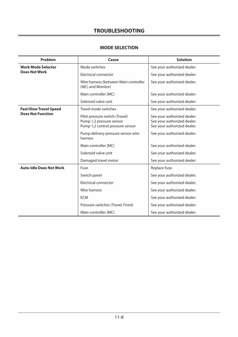
TROUBLESHOOTING
11-8
MODE SELECTION
Problem Cause Solution
Work Mode Selector Does Not Work
Mode switches See your authorized dealer.
Electrical connector See your authorized dealer.
Wire harness (between Main controller (MC) and Monitor)
See your authorized dealer.
Main controller (MC) See your authorized dealer.
Solenoid valve unit See your authorized dealer.
Fast/Slow Travel Speed Does Not Function
Travel mode switches See your authorized dealer.
Pilot pressure switch (Travel)Pump 1,2 pressure sensorPump 1,2 control pressure sensor
See your authorized dealer.See your authorized dealer.See your authorized dealer.
Pump delivery pressure sensor wire harness
See your authorized dealer.
Main controller (MC) See your authorized dealer.
Solenoid valve unit See your authorized dealer.
Damaged travel motor See your authorized dealer.
Auto-Idle Does Not Work Fuse Replace fuse.
Switch panel See your authorized dealer.
Electrical connector See your authorized dealer.
Wire harness See your authorized dealer.
ECM See your authorized dealer.
Pressure switches (Travel, Front) See your authorized dealer.
Main controller (MC) See your authorized dealer.
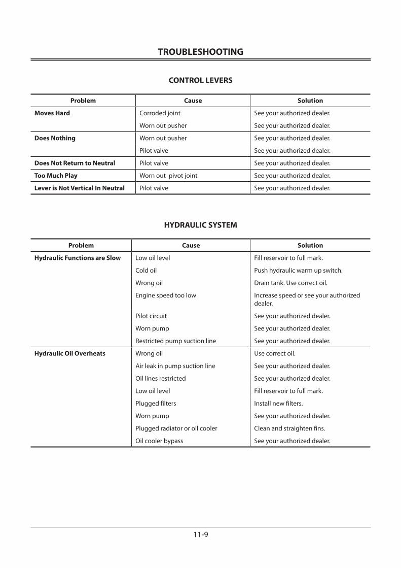
TROUBLESHOOTING
11-9
CONTROL LEVERS
Problem Cause Solution
Moves Hard Corroded joint See your authorized dealer.
Worn out pusher See your authorized dealer.
Does Nothing Worn out pusher See your authorized dealer.
Pilot valve See your authorized dealer.
Does Not Return to Neutral Pilot valve See your authorized dealer.
Too Much Play Worn out pivot joint See your authorized dealer.
Lever is Not Vertical In Neutral Pilot valve See your authorized dealer.
HYDRAULIC SYSTEM
Problem Cause Solution
Hydraulic Functions are Slow Low oil level Fill reservoir to full mark.
Cold oil Push hydraulic warm up switch.
Wrong oil Drain tank. Use correct oil.
Engine speed too low Increase speed or see your authorized dealer.
Pilot circuit See your authorized dealer.
Worn pump See your authorized dealer.
Restricted pump suction line See your authorized dealer.
Hydraulic Oil Overheats Wrong oil Use correct oil.
Air leak in pump suction line See your authorized dealer.
Oil lines restricted See your authorized dealer.
Low oil level Fill reservoir to full mark.
Plugged filters Install new filters.
Worn pump See your authorized dealer.
Plugged radiator or oil cooler Clean and straighten fins.
Oil cooler bypass See your authorized dealer.

TROUBLESHOOTING
11-10
HYDRAULIC SYSTEM
Problem Cause Solution
Hydraulic Oil Overheats Relief valve See your authorized dealer.
Contaminated oil Drain oil and refill.
Travel motors See your authorized dealer.
Improperly adjusted hydraulic components
See your authorized dealer.
Oil Foams Air leak in line from reservoir to pump Repair leak or see your authorized dealer.
Kinks or dents in oil lines Check lines.
Wrong oil Use correct oil.
Water in oil Change oil.
High or low oil level Correct level.
Low or No Oil Pressure Wrong oil Use correct oil.
Improperly adjusted hydraulic components
See your authorized dealer.
No oil in system Fill with correct oil.
Worn cylinder packings See your authorized dealer.
Relief valve See your authorized dealer.
No Hydraulic Functions (Noise from pumps)
Hydraulic pump See your authorized dealer.
Decreased set-pressure of main relief valve in control valve
Lack of hydraulic oil Add oil.
Damaged suction line or hose See your authorized dealer.
Clogged suction filter Clean.
Sucked air from oil suction port
Hydraulic Cylinders Operate but Cannot Lift Load
Hydraulic pump worn See your authorized dealer.
Main relief valve pressure low See your authorized dealer.
Hydraulic oil level low Add oil.
Suction screen plugged Clean strainer and system.
Pump suction line leaking Inspect suction line.
Pressure switches See your authorized dealer.
Solenoid valve See your authorized dealer.

TROUBLESHOOTING
11-11
HYDRAULIC SYSTEM
Problem Cause Solution
One Control Lever Does Not Work
Relief valve pressure low See your authorized dealer.
Tube or hose damaged Repair or replace.
Hydraulic fittings loose Tighten.
Damaged O-rings in fittings Install new O-ring.
Hydraulic Pump See your authorized dealer.
Pilot valve See your authorized dealer.
Pilot lines Repair or replace.
One Cylinder Does Not Work Control valve spool damaged or contaminated with dirt
See your authorized dealer.
Hydraulic lines damaged Repair or replace.
Fittings loose Tighten.
O-ring in fitting damaged Install new O-ring.
Pilot valve See your authorized dealer.
Pilot lines Repair or replace.
One Cylinder Does Not Work or Has Little Power
Piston seals leaking See your authorized dealer.
Cylinder rod damaged See your authorized dealer.
Pilot lines Repair or replace.
Pilot valve See your authorized dealer.
Failed wiring harness See your authorized dealer.
Both Travel Motors Do Not Work
Center joint failure See your authorized dealer.
One Travel Motor Does Not Work
Travel motor See your authorized dealer.
Parking brake not releasing See your authorized dealer.
Pilot valve See your authorized dealer.
Pilot lines Repair or replace.
Travel is Not Smooth Track adjustment Adjust tension.
Track idler or rollers damaged See your authorized dealer.
Track frame bent See your authorized dealer.

TROUBLESHOOTING
11-12
HYDRAULIC SYSTEM
Problem Cause Solution
Travel is Not Smooth Rocks or mud “jammed” in track frame Remove and repair.
Travel brake not releasing See your authorized dealer.
Swing Does Not Work Swing brake release valve See your authorized dealer.
Swing motor See your authorized dealer.
Pilot valve See your authorized dealer.
Swing is Not Smooth Swing gear See your authorized dealer.
Swing bearing See your authorized dealer.
Lack of grease Apply grease.
Combination valve See your authorized dealer.
Engine Stops When Travel or/and Control Lever Moved
Failure of connector contact Repair or replace.
Failed wiring harness See your authorized dealer.
Failed Main controller See your authorized dealer.
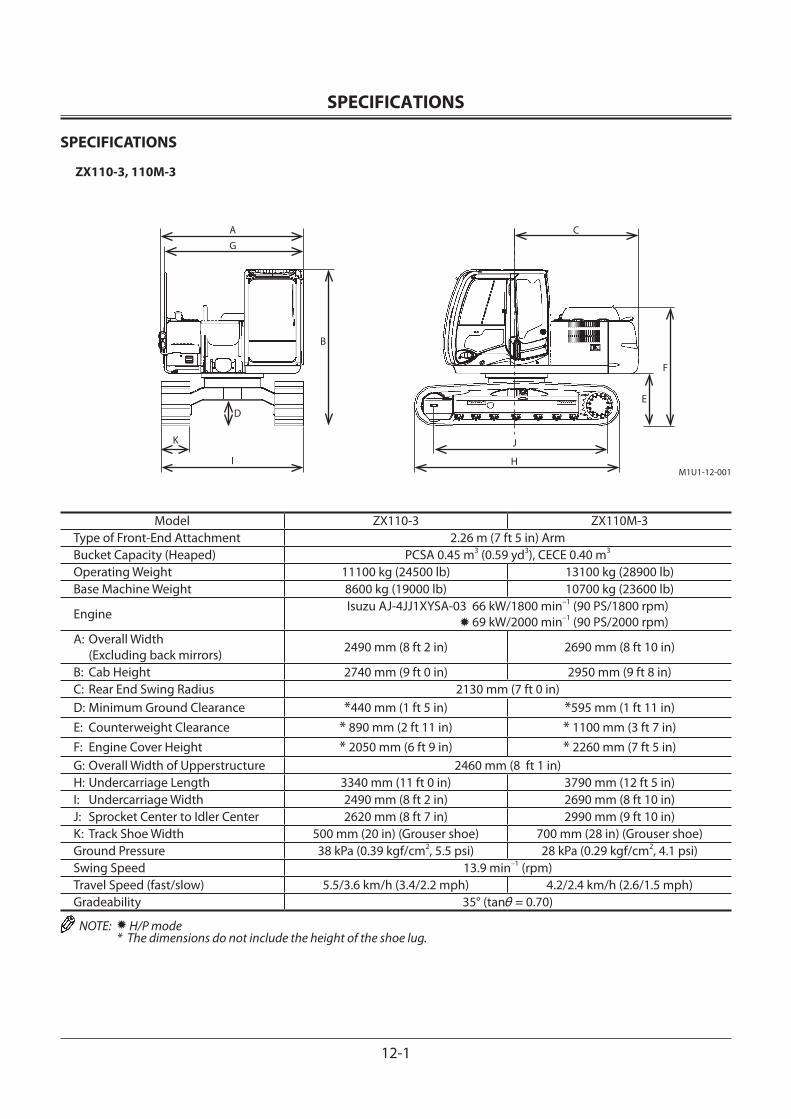
SPECIFICATIONS
12-1
SPECIFICATIONS
ZX110-3, 110M-3
M1U1-12-001
AG
D
K
I
B
C
E
F
J
H
Model ZX110-3 ZX110M-3Type of Front-End Attachment 2.26 m (7 ft 5 in) ArmBucket Capacity (Heaped) PCSA 0.45 m3 (0.59 yd3), CECE 0.40 m3
Operating Weight 11100 kg (24500 lb) 13100 kg (28900 lb)Base Machine Weight 8600 kg (19000 lb) 10700 kg (23600 lb)
Engine Isuzu AJ-4JJ1XYSA-03 66 kW/1800 min–1 (90 PS/1800 rpm) 69 kW/2000 min–1 (90 PS/2000 rpm)
A: Overall Width (Excluding back mirrors) 2490 mm (8 ft 2 in) 2690 mm (8 ft 10 in)
B: Cab Height 2740 mm (9 ft 0 in) 2950 mm (9 ft 8 in)C: Rear End Swing Radius 2130 mm (7 ft 0 in)D: Minimum Ground Clearance *440 mm (1 ft 5 in) *595 mm (1 ft 11 in)E: Counterweight Clearance * 890 mm (2 ft 11 in) * 1100 mm (3 ft 7 in)F: Engine Cover Height * 2050 mm (6 ft 9 in) * 2260 mm (7 ft 5 in)G: Overall Width of Upperstructure 2460 mm (8 ft 1 in)H: Undercarriage Length 3340 mm (11 ft 0 in) 3790 mm (12 ft 5 in)I: Undercarriage Width 2490 mm (8 ft 2 in) 2690 mm (8 ft 10 in)J: Sprocket Center to Idler Center 2620 mm (8 ft 7 in) 2990 mm (9 ft 10 in)K: Track Shoe Width 500 mm (20 in) (Grouser shoe) 700 mm (28 in) (Grouser shoe)Ground Pressure 38 kPa (0.39 kgf/cm2, 5.5 psi) 28 kPa (0.29 kgf/cm2, 4.1 psi)Swing Speed 13.9 min–1 (rpm)Travel Speed (fast/slow) 5.5/3.6 km/h (3.4/2.2 mph) 4.2/2.4 km/h (2.6/1.5 mph)Gradeability 35° (tanθ = 0.70)
NOTE: H/P mode * The dimensions do not include the height of the shoe lug.
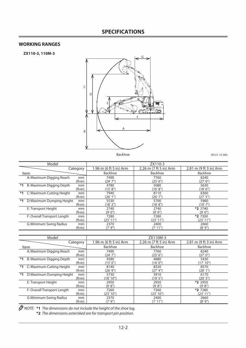
SPECIFICATIONS
12-2
WORKING RANGES
ZX110-3, 110M-3
M1U1-12-005
A
G
C
D
E
F
B
Backhoe
Model ZX110-3Category
Item1.96 m (6 ft 5 in) Arm 2.26 m (7 ft 5 in) Arm 2.81 m (9 ft 3 in) Arm
Backhoe Backhoe BackhoeA: Maximum Digging Reach mm (ft•in)
7490 (24' 7”)
7760(25' 6”)
8240(27' 0”)
*1 B: Maximum Digging Depth mm (ft•in)
4780(15' 8”)
5080(16' 8”)
5630(18' 6”)
*1 C: Maximum Cutting Height mm (ft•in)
7940(26' 1”)
8110(26' 7”)
8360(27' 5”)
*1 D: Maximum Dumping Height mm (ft•in)
5530(18' 2”)
5700(18' 8”)
5960(19' 7”)
E: Transport Height mm (ft•in)
2740(9' 0”)
2740(9' 0”)
*2 2740 (9' 0”)
F: Overall Transport Length mm (ft•in)
7280(23' 11”)
7280(23' 11”)
*2 7300 (23' 11”)
G: Minimum Swing Radius mm (ft•in)
2370(7' 9”)
2400(7' 11”)
2660(8' 9”)
Model ZX110M-3Category
Item1.96 m (6 ft 5 in) Arm 2.26 m (7 ft 5 in) Arm 2.81 m (9 ft 3 in) Arm
Backhoe Backhoe BackhoeA: Maximum Digging Reach mm (ft•in)
7490(24' 7”)
7760(25' 6”)
8240(27' 0”)
*1 B: Maximum Digging Depth mm (ft•in)
4580(15' 0”)
4880(16' 0”)
5430(17' 10”)
*1 C: Maximum Cutting Height mm (ft•in)
8140(26' 9”)
8320(27' 4”)
8570(28' 1”)
*1 D: Maximum Dumping Height mm (ft•in)
5730(18' 10”)
5910(19' 5”)
6170(20' 3”)
E: Transport Height mm (ft•in)
2950(9' 8”)
2950(9' 8”)
*2 2950 (9' 8”)
F: Overall Transport Length mm (ft•in)
7260(23' 10”)
7260(23' 10”)
*2 7280 (23' 11”)
G: Minimum Swing Radius mm (ft•in)
2370(7' 9”)
2400(7' 11”)
2660(8' 9”)
NOTE: *1 The dimensions do not include the height of the shoe lug. *2 The dimensions asterisked are for transport pin position.
SPECIFICATIONS
12-3
SHOE TYPES AND APPLICATIONS
ZX110-3
Shoe Width 500 mm (20”)Grouser Shoe
600 mm (24”)Grouser Shoe
700 mm (28”)Grouser Shoe
800 mm (31”)Grouser Shoe
Application For Ordinary Ground (Standard)
For Weak Footing (Option)
For Weak Footing (Option)
For Weak Footing (Option)
Operating Weight kg (lb)
11100(24500)
11300(24900)
11500(25400)
11700(25800)
Base Machine Weight kg (lb)
8600(19000)
8800(19400)
9000(19800)
9200(20300)
Cab Height mm (ft•in)
2740 (9’ 0”)
2740 (9’ 0”)
2740 (9’ 0”)
2750 (9’ 0”)
Minimum Ground mmClearance (ft•in)
440 (1’ 5”)
440(1’ 5”)
440(1’ 5”)
440(1’ 5”)
Undercarriage mmLength (ft•in)
3340(11’ 0”)
3340(11’ 0”)
3340(11’ 0”)
3340(11’ 0”)
Undercarriage Width mm (ft•in)
2490(8’ 2”)
2590(8’ 6”)
2690(8’ 10”)
2790(9’ 2”)
Ground Pressure 38 kPa(0.39 kgf/cm2, 5.5 psi)
32 kPa(0.33 kgf/cm2, 4.6 psi)
28 kPa(0.29 kgf/cm2, 4.1psi)
25 kPa(0.25 kgf/cm2, 3.6 psi)
Shoe Width 500 mm (20”)Pad Crawler Shoe
Application For Paved Road (Option)
Operating Weight kg (lb)
10900(24000)
Base Machine Weight kg (lb)
8500(18700)
Cab Height mm (ft•in)
2780(9' 1”)
Minimum Ground mmClearance (ft•in)
500(1' 8”)
Undercarriage mmLength (ft•in)
3420(11' 3”)
Undercarriage Width mm (ft•in)
2490(8' 2”)
Ground Pressure 37 kPa(0.38 kgf/cm2, 5.4 psi)
NOTE: • The specifications for the front-end attachment are for a 2.26 m (7 ft 5 in) arm with PCSA 0.45 m3 (0.59 yd3) standard bucket.
• 600 mm (24 in), 700 mm (28 in), 800 mm (31 in) grouser shoe, 500 mm (20 in) pad crawler shoe should not be used on gravel or rocky ground.
• The dimensions do not include the height of the shoe lug.
SPECIFICATIONS
12-4
SHOE TYPES AND APPLICATIONS
ZX110M-3
Shoe Width 700 mm (28”)Grouser Shoe
800 mm (31”)Grouser Shoe
900 mm (35”)Grouser Shoe
960 mm (38”)High Grouser Shoe
Application For Weak Footing (Standard)
For Weak Footing (Option)
For Weak Footing (Option)
For Weak Footing (Option)
Operating Weight kg (lb)
13100(28900)
13400(29500)
13600(30000)
14000(30900)
Base Machine Weight kg (lb)
10700(23600)
11000(24300)
11200(24700)
11500(25400)
Cab Height mm (ft•in)
2950(9' 8”)
2950(9' 8”)
2950(9' 8”)
2980(9' 9”)
Minimum Ground mmClearance (ft•in)
595(1' 11”)
595(1' 11”)
595(1' 11”)
600(2' 0”)
Undercarriage mmLength (ft•in)
3790(12' 5”)
3790(12' 5”)
3790(12' 5”)
3790(12' 5”)
Undercarriage Width mm (ft•in)
2690(8' 10”)
2790(9' 2”)
2890(9' 6”)
2950(9' 8”)
Ground Pressure 28 kPa(0.29 kgf/cm2, 4.1 psi)
25 kPa(0.26 kgf/cm2, 3.6 psi)
23 kPa(0.23 kgf/cm2, 3.3 psi)
22 kPa(0.22 kgf/cm2, 3.2 psi)
NOTE: • The specifications for the front-end attachment are for a 2.26 m (7 ft 5 in) arm with PCSA 0.45 m3 (0.59 yd3) standard bucket.
• 800 mm (31 in), 900 mm (35 in) grouser shoe, 960 mm (38 in) high grouser shoe should not be used on gravel or rocky ground.
• The dimensions do not include the height of the shoe lug.
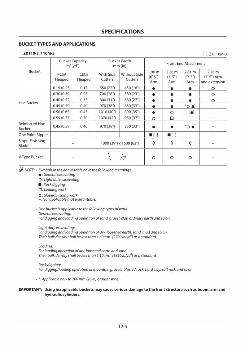
SPECIFICATIONS
12-5
BUCKET TYPES AND APPLICATIONS
ZX110-3, 110M-3
Bucket
Bucket Capacitym3 (yd3)
Bucket Widthmm (in) Front-End Attachment
PCSAHeaped
CECEHeaped
With SideCutters
Without Side Cutters
1.96 m (6' 5") Arm
2.26 m (7' 5") Arm
2.81 m (9' 3") Arm
2.26 m (7' 5") Arm
and extension
Hoe Bucket
0.19 (0.25) 0.17 550 (22”) 450 (18”)0.30 (0.39) 0.25 700 (28”) 580 (23”)0.40 (0.52) 0.33 800 (31”) 680 (27”)0.45 (0.59) 0.40 970 (38”) 850 (33”) * [ ] −0.50 (0.65) 0.45 1010 (40”) 890 (35”) − [ ] − 0.59 (0.77) 0.50 1070 (42”) 950 (37”) − −
Reinforced Hoe Bucket 0.45 (0.59) 0.40 970 (38") 850 (33") * [ ] −
One Point Ripper − − ■ [−] ■ [−] − −Slope-Finishing Blade − 1000 (39") x 1600 (63") −
V-Type Bucket − −
NOTE: • Symbols in the above table have the following meanings. : General excavating : Light duty excavating : Rock digging : Loading work
: Slope-finishing work −: Not applicable (not warrantable)
• Hoe bucket is applicable to the following types of work. General excavating: For digging and loading operation of sand, gravel, clay, ordinary earth and so on.
Light duty excavating: For digging and loading operation of dry, loosened earth, sand, mud and so on. Their bulk density shall be less than 1.60 t/m3 (2700 lb/yd3) as a standard.
Loading: For loading operation of dry, loosened earth and sand. Their bulk density shall be less than 1.10 t/m3 (1850 lb/yd3) as a standard.
Rock digging: For digging/loading operation of mountain gravels, blasted rock, hard clay, soft rock and so on.
• *: Applicable only to 700 mm (28 in) grouser shoe.
IMPORTANT: Using inapplicable buckets may cause serious damage to the front structure such as boom, arm and hydraulic cylinders.
[ ]: ZX110M-3
45°
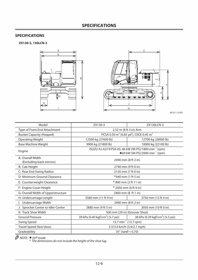
SPECIFICATIONS
12-6
SPECIFICATIONS
ZX130-3, 130LCN-3
M1U1-12-001
AG
D
K
I
B
C
E
F
J
H
Model ZX130-3 ZX130LCN-3Type of Front-End Attachment 2.52 m (8 ft 3 in) ArmBucket Capacity (Heaped) PCSA 0.50 m3 (0.65 yd3), CECE 0.45 m3
Operating Weight 12500 kg (27600 lb) 12700 kg (28000 lb)Base Machine Weight 9900 kg (21800 lb) 10000 kg (22100 lb)
Engine ISUZU AJ-4JJ1XYSA-03, 66 kW (90 PS)/1800 min–1 (rpm) 69 kW (94 PS)/2000 min–1 (rpm)
A: Overall Width (Excluding back mirrors) 2490 mm (8 ft 2 in)
B: Cab Height 2740 mm (9 ft 0 in)C: Rear End Swing Radius 2130 mm (7 ft 0 in)
D: Minimum Ground Clearance *440 mm (1 ft 5 in)
E: Counterweight Clearance * 890 mm (2 ft 11 in)
F: Engine Cover Height * 2050 mm (6 ft 9 in)
G: Overall Width of Upperstructure 2460 mm (8 ft 1 in)H: Undercarriage Length 3580 mm (11 ft 9 in) 3750 mm (12 ft 4 in)I: Undercarriage Width 2490 mm (8 ft 2 in)J: Sprocket Center to Idler Center 2880 mm (9 ft 5 in) 3050 mm (10 ft 0 in)K: Track Shoe Width 500 mm (20 in) (Grouser Shoe) Ground Pressure 39 kPa (0.40 kgf/cm2) (5.7 psi) 38 kPa (0.39 kgf/cm2) (5.5 psi)Swing Speed 13.7 min–1 (13.7 rpm)Travel Speed (fast/slow) 5.5/3.4 km/h (3.4/2.1 mph)Gradeability 35° (tanθ = 0.70)
NOTE: H/P mode * The dimensions do not include the height of the shoe lug.
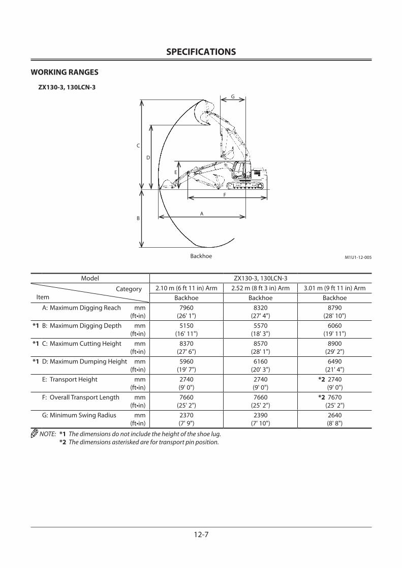
SPECIFICATIONS
12-7
WORKING RANGES
ZX130-3, 130LCN-3
Model ZX130-3, 130LCN-3
CategoryItem
2.10 m (6 ft 11 in) Arm 2.52 m (8 ft 3 in) Arm 3.01 m (9 ft 11 in) ArmBackhoe Backhoe Backhoe
A: Maximum Digging Reach mm (ft•in)
7960(26' 1")
8320(27' 4")
8790(28' 10")
*1 B: Maximum Digging Depth mm (ft•in)
5150(16' 11")
5570(18' 3")
6060(19' 11")
*1 C: Maximum Cutting Height mm (ft•in)
8370(27' 6")
8570(28' 1")
8900(29' 2")
*1 D: Maximum Dumping Height mm (ft•in)
5960(19' 7")
6160(20' 3")
6490(21' 4")
E: Transport Height mm (ft•in)
2740(9' 0")
2740(9' 0")
*2 2740 (9' 0")
F: Overall Transport Length mm (ft•in)
7660(25' 2")
7660(25' 2")
*2 7670 (25' 2")
G: Minimum Swing Radius mm (ft•in)
2370(7' 9")
2390(7' 10")
2640(8' 8")
NOTE: *1 The dimensions do not include the height of the shoe lug. *2 The dimensions asterisked are for transport pin position.
M1U1-12-005
A
G
C
D
E
F
B
Backhoe
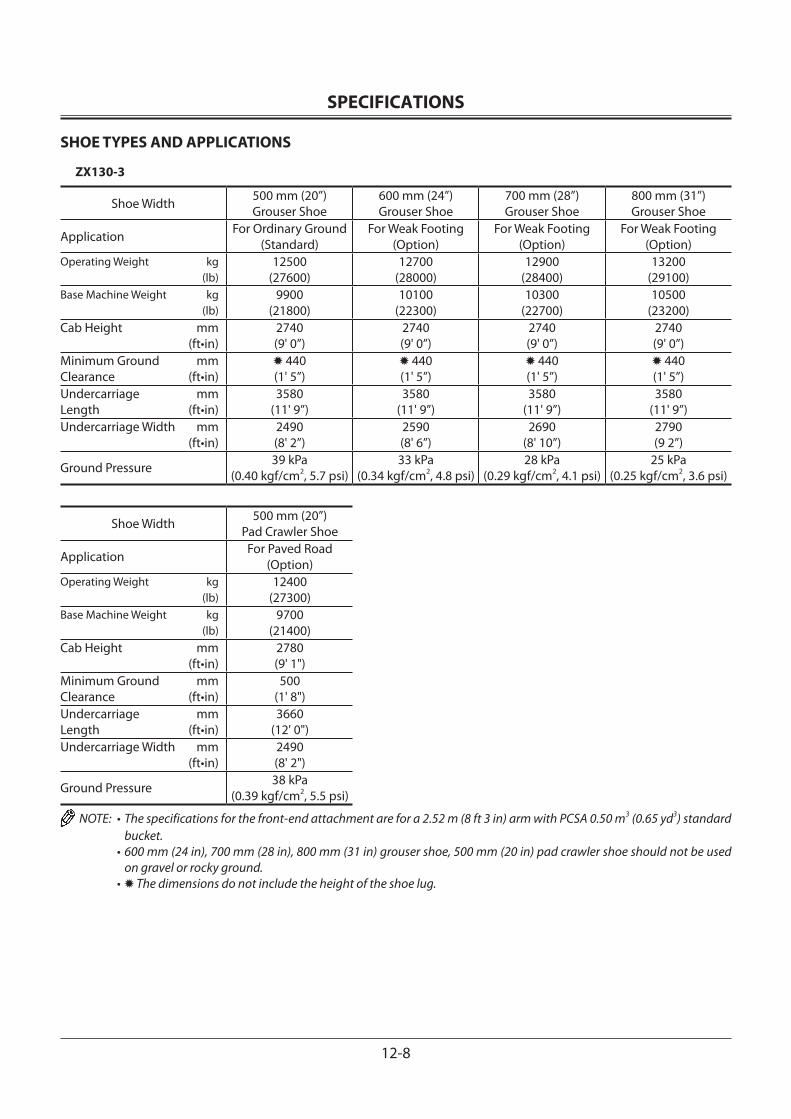
SPECIFICATIONS
12-8
SHOE TYPES AND APPLICATIONS
ZX130-3
Shoe Width 500 mm (20”)Grouser Shoe
600 mm (24”)Grouser Shoe
700 mm (28”)Grouser Shoe
800 mm (31”)Grouser Shoe
Application For Ordinary Ground (Standard)
For Weak Footing (Option)
For Weak Footing (Option)
For Weak Footing (Option)
Operating Weight kg (lb)
12500(27600)
12700(28000)
12900(28400)
13200(29100)
Base Machine Weight kg (lb)
9900(21800)
10100(22300)
10300(22700)
10500(23200)
Cab Height mm (ft•in)
2740(9' 0”)
2740(9' 0”)
2740(9' 0”)
2740(9' 0”)
Minimum Ground mmClearance (ft•in)
440(1' 5”)
440(1' 5”)
440(1' 5”)
440(1' 5”)
Undercarriage mmLength (ft•in)
3580(11' 9”)
3580(11' 9”)
3580(11' 9”)
3580(11' 9”)
Undercarriage Width mm (ft•in)
2490(8' 2”)
2590(8' 6”)
2690(8' 10”)
2790(9 2”)
Ground Pressure 39 kPa(0.40 kgf/cm2, 5.7 psi)
33 kPa(0.34 kgf/cm2, 4.8 psi)
28 kPa(0.29 kgf/cm2, 4.1 psi)
25 kPa(0.25 kgf/cm2, 3.6 psi)
Shoe Width 500 mm (20”)Pad Crawler Shoe
Application For Paved Road (Option)
Operating Weight kg (lb)
12400(27300)
Base Machine Weight kg (lb)
9700(21400)
Cab Height mm (ft•in)
2780(9' 1")
Minimum Ground mmClearance (ft•in)
500(1' 8")
Undercarriage mmLength (ft•in)
3660(12' 0")
Undercarriage Width mm (ft•in)
2490(8' 2")
Ground Pressure 38 kPa(0.39 kgf/cm2, 5.5 psi)
NOTE: • The specifications for the front-end attachment are for a 2.52 m (8 ft 3 in) arm with PCSA 0.50 m3 (0.65 yd3) standard bucket.
• 600 mm (24 in), 700 mm (28 in), 800 mm (31 in) grouser shoe, 500 mm (20 in) pad crawler shoe should not be used on gravel or rocky ground.
• The dimensions do not include the height of the shoe lug.
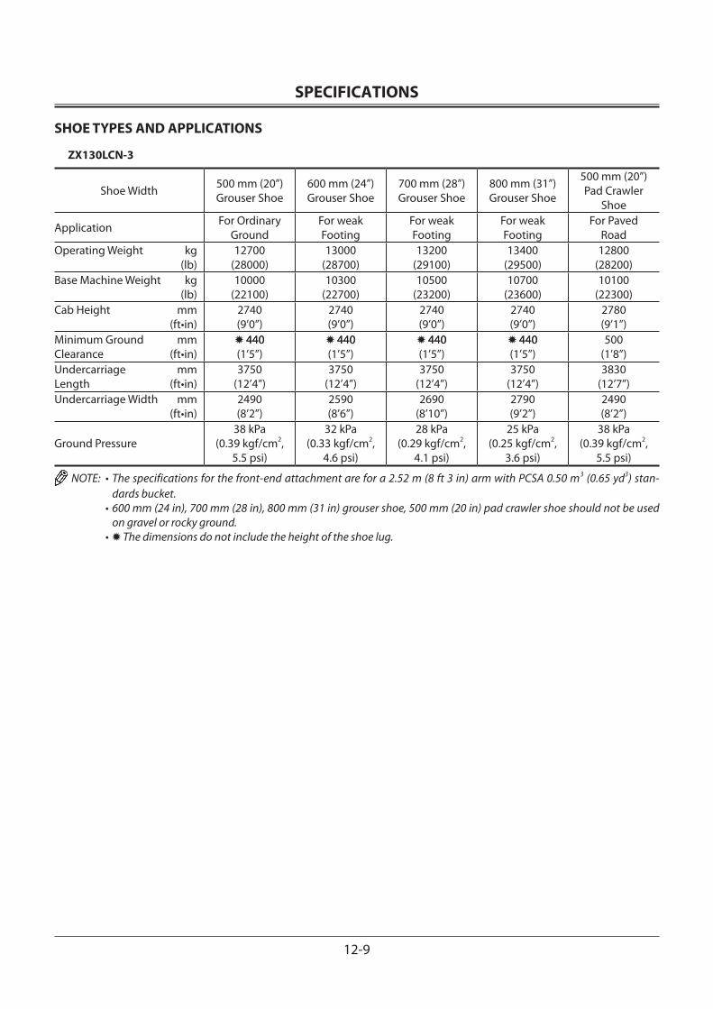
SPECIFICATIONS
12-9
SHOE TYPES AND APPLICATIONS
ZX130LCN-3
Shoe Width 500 mm (20”)Grouser Shoe
600 mm (24”)Grouser Shoe
700 mm (28”)Grouser Shoe
800 mm (31”)Grouser Shoe
500 mm (20”)Pad Crawler
Shoe
Application For Ordinary Ground
For weak Footing
For weak Footing
For weak Footing
For Paved Road
Operating Weight kg (lb)
12700 (28000)
13000 (28700)
13200 (29100)
13400 (29500)
12800 (28200)
Base Machine Weight kg (lb)
10000 (22100)
10300 (22700)
10500 (23200)
10700 (23600)
10100 (22300)
Cab Height mm (ft•in)
2740 (9’0”)
2740 (9’0”)
2740 (9’0”)
2740 (9’0”)
2780 (9’1”)
Minimum Ground mmClearance (ft•in)
440440(1’5”)
440440(1’5”)
440440(1’5”)
440440(1’5”)
500(1’8”)
Undercarriage mmLength (ft•in)
3750(12’4”)
3750(12’4”)
3750(12’4”)
3750(12’4”)
3830(12’7”)
Undercarriage Width mm (ft•in)
2490(8’2”)
2590(8’6”)
2690(8’10”)
2790(9’2”)
2490(8’2”)
Ground Pressure38 kPa
(0.39 kgf/cm2, 5.5 psi)
32 kPa(0.33 kgf/cm2,
4.6 psi)
28 kPa(0.29 kgf/cm2,
4.1 psi)
25 kPa(0.25 kgf/cm2,
3.6 psi)
38 kPa(0.39 kgf/cm2,
5.5 psi)
NOTE: • The specifications for the front-end attachment are for a 2.52 m (8 ft 3 in) arm with PCSA 0.50 m3 (0.65 yd3) stan-dards bucket.
• 600 mm (24 in), 700 mm (28 in), 800 mm (31 in) grouser shoe, 500 mm (20 in) pad crawler shoe should not be used on gravel or rocky ground.
• The dimensions do not include the height of the shoe lug.
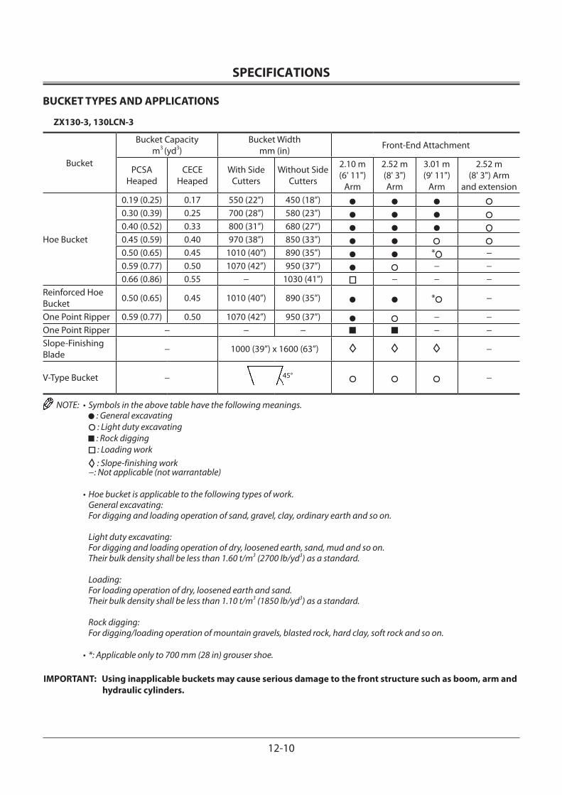
SPECIFICATIONS
12-10
BUCKET TYPES AND APPLICATIONS
ZX130-3, 130LCN-3
Bucket
Bucket Capacitym3 (yd3)
Bucket Widthmm (in) Front-End Attachment
PCSAHeaped
CECEHeaped
With SideCutters
Without Side Cutters
2.10 m(6' 11")
Arm
2.52 m(8' 3") Arm
3.01 m(9' 11")
Arm
2.52 m(8' 3") Arm
and extension
Hoe Bucket
0.19 (0.25) 0.17 550 (22”) 450 (18”)0.30 (0.39) 0.25 700 (28”) 580 (23”)0.40 (0.52) 0.33 800 (31”) 680 (27”)0.45 (0.59) 0.40 970 (38”) 850 (33”)0.50 (0.65) 0.45 1010 (40”) 890 (35”) * −0.59 (0.77) 0.50 1070 (42”) 950 (37”) − −0.66 (0.86) 0.55 − 1030 (41”) − − −
Reinforced Hoe Bucket 0.50 (0.65) 0.45 1010 (40”) 890 (35”) * −
One Point Ripper 0.59 (0.77) 0.50 1070 (42”) 950 (37”) − −One Point Ripper − − − ■ ■ − −Slope-Finishing Blade − 1000 (39”) x 1600 (63”) −
V-Type Bucket − −
NOTE: • Symbols in the above table have the following meanings. : General excavating : Light duty excavating : Rock digging : Loading work
: Slope-finishing work −: Not applicable (not warrantable)
• Hoe bucket is applicable to the following types of work. General excavating: For digging and loading operation of sand, gravel, clay, ordinary earth and so on.
Light duty excavating: For digging and loading operation of dry, loosened earth, sand, mud and so on. Their bulk density shall be less than 1.60 t/m3 (2700 lb/yd3) as a standard.
Loading: For loading operation of dry, loosened earth and sand. Their bulk density shall be less than 1.10 t/m3 (1850 lb/yd3) as a standard.
Rock digging: For digging/loading operation of mountain gravels, blasted rock, hard clay, soft rock and so on.
• *: Applicable only to 700 mm (28 in) grouser shoe.
IMPORTANT: Using inapplicable buckets may cause serious damage to the front structure such as boom, arm and hydraulic cylinders.
45°
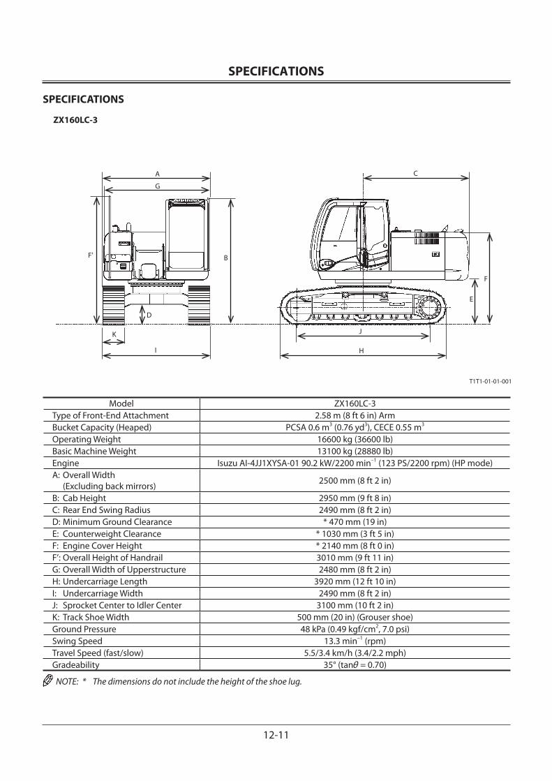
SPECIFICATIONS
12-11
SPECIFICATIONS
ZX160LC-3
Model ZX160LC-3Type of Front-End Attachment 2.58 m (8 ft 6 in) ArmBucket Capacity (Heaped) PCSA 0.6 m3 (0.76 yd3), CECE 0.55 m3
Operating Weight 16600 kg (36600 lb)Basic Machine Weight 13100 kg (28880 lb)Engine Isuzu AI-4JJ1XYSA-01 90.2 kW/2200 min–1 (123 PS/2200 rpm) (HP mode)A: Overall Width (Excluding back mirrors) 2500 mm (8 ft 2 in)
B: Cab Height 2950 mm (9 ft 8 in)C: Rear End Swing Radius 2490 mm (8 ft 2 in)D: Minimum Ground Clearance * 470 mm (19 in)E: Counterweight Clearance * 1030 mm (3 ft 5 in)F: Engine Cover Height * 2140 mm (8 ft 0 in)F’: Overall Height of Handrail 3010 mm (9 ft 11 in)G: Overall Width of Upperstructure 2480 mm (8 ft 2 in)H: Undercarriage Length 3920 mm (12 ft 10 in)I: Undercarriage Width 2490 mm (8 ft 2 in)J: Sprocket Center to Idler Center 3100 mm (10 ft 2 in)K: Track Shoe Width 500 mm (20 in) (Grouser shoe)Ground Pressure 48 kPa (0.49 kgf/cm2, 7.0 psi)Swing Speed 13.3 min–1 (rpm)Travel Speed (fast/slow) 5.5/3.4 km/h (3.4/2.2 mph)Gradeability 35° (tanθ = 0.70)
NOTE: * The dimensions do not include the height of the shoe lug.
T1T1-01-01-001
A
G
D
K
I
B
C
E
F
J
H
F'

SPECIFICATIONS
12-12
WORKING RANGES
ZX160LC-3 (Machine with Mono Boom)
CategoryItem
2.22 m (7 ft 4 in) Arm 2.58 m (8 ft 6 in) Armmm ft•in mm ft•in
A: Maximum Digging Reach 8520 27’12” 8870 29’2”B: Maximum Digging Depth 5620 18’6” 5980 19’8”C: Maximum Cutting Height 8620 28’4” 8880 29’2”D: Maximum Dumping Height 5940 19’6” 6170 20’3”E: Transport Height 3190 10’6” 3010 9’5”F: Overall Transport Length 8650 28’5” 8550 28’1”G: Minimum Swing Radius 3290 10’10” 2910 9’7”
NOTE: * The dimensions do not include the height of the shoe lug (except Item E).
T1T1-01-01-003
C
B
D
A
F
E
G
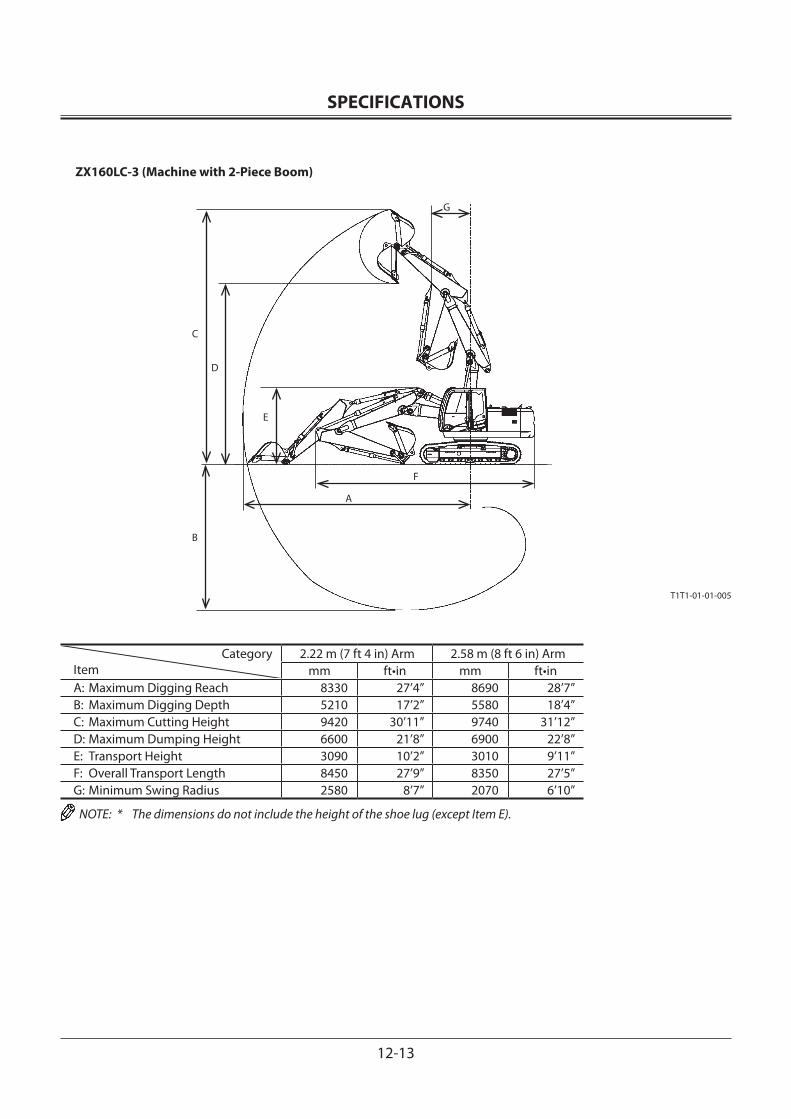
SPECIFICATIONS
12-13
ZX160LC-3 (Machine with 2-Piece Boom)
CategoryItem
2.22 m (7 ft 4 in) Arm 2.58 m (8 ft 6 in) Armmm ft•in mm ft•in
A: Maximum Digging Reach 8330 27’4” 8690 28’7”B: Maximum Digging Depth 5210 17’2” 5580 18’4”C: Maximum Cutting Height 9420 30’11” 9740 31’12”D: Maximum Dumping Height 6600 21’8” 6900 22’8”E: Transport Height 3090 10’2” 3010 9’11”F: Overall Transport Length 8450 27’9” 8350 27’5”G: Minimum Swing Radius 2580 8’7” 2070 6’10”
NOTE: * The dimensions do not include the height of the shoe lug (except Item E).
T1T1-01-01-005
C
B
D
E
F
A
G
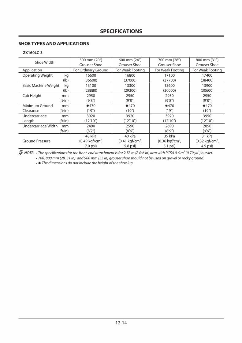
SPECIFICATIONS
12-14
SHOE TYPES AND APPLICATIONS
ZX160LC-3
Shoe Width 500 mm (20”)Grouser Shoe
600 mm (24”)Grouser Shoe
700 mm (28”)Grouser Shoe
800 mm (31”)Grouser Shoe
Application For Ordinary Ground For Weak Footing For Weak Footing For Weak FootingOperating Weight kg (lb)
16600(36600)
16800(37000)
17100(37700)
17400(38400)
Basic Machine Weight kg (lb)
13100(28880)
13300(29300)
13600(30000)
13900(30600)
Cab Height mm (ft•in)
2950(9’8”)
2950(9’8”)
2950(9’8”)
2950(9’8”)
Minimum Ground mmClearance (ft•in)
470(19”)
470(19”)
470(19”)
470(19”)
Undercarriage mmLength (ft•in)
3920(12’10”)
3920(12’10”)
3920(12’10”)
3950(12’10”)
Undercarriage Width mm (ft•in)
2490(8’2”)
2590(8’6”)
2690(8’9”)
2890(9’6”)
Ground Pressure48 kPa
(0.49 kgf/cm2, 7.0 psi)
40 kPa(0.41 kgf/cm2,
5.8 psi)
35 kPa(0.36 kgf/cm2,
5.1 psi)
31 kPa(0.32 kgf/cm2,
4.5 psi)
NOTE: • The specifications for the front-end attachment is for 2.58 m (8 ft 6 in) arm with PCSA 0.6 m3 (0.79 yd3) bucket. • 700, 800 mm (28, 31 in) and 900 mm (35 in) grouser shoe should not be used on gravel or rocky ground. • The dimensions do not include the height of the shoe lug.
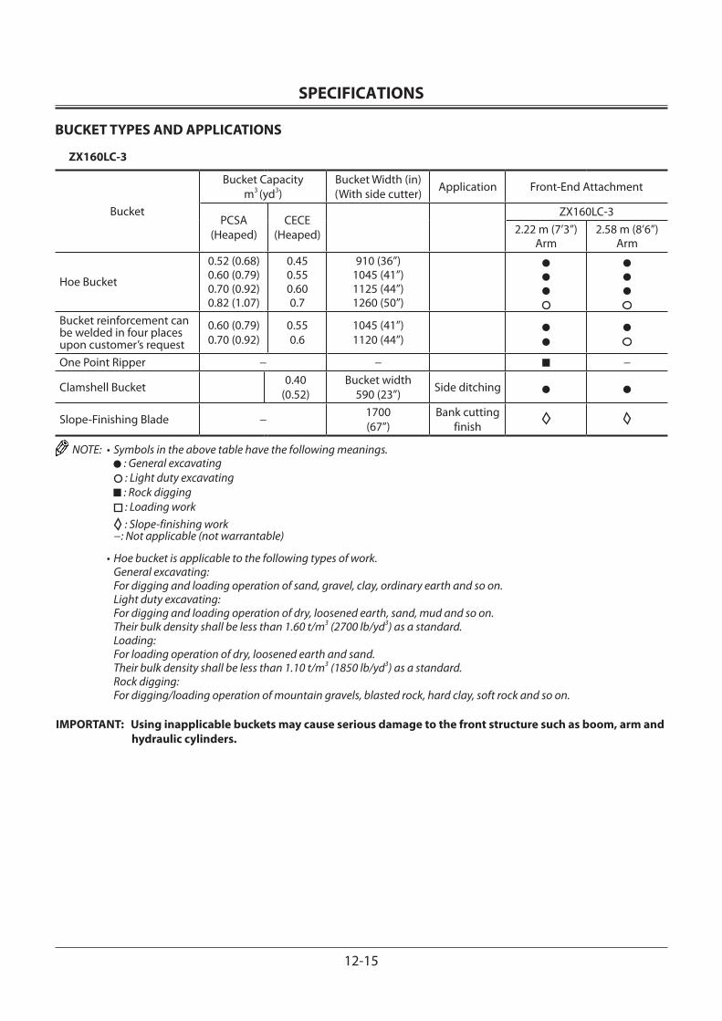
SPECIFICATIONS
12-15
BUCKET TYPES AND APPLICATIONS
ZX160LC-3
Bucket
Bucket Capacitym3 (yd3)
Bucket Width (in)(With side cutter) Application Front-End Attachment
PCSA(Heaped)
CECE(Heaped)
ZX160LC-32.22 m (7’3”)
Arm2.58 m (8’6”)
Arm
Hoe Bucket
0.52 (0.68)0.60 (0.79)0.70 (0.92)0.82 (1.07)
0.450.550.600.7
910 (36”)1045 (41”)1125 (44”)1260 (50”)
Bucket reinforcement can be welded in four places upon customer’s request
0.60 (0.79)0.70 (0.92)
0.550.6
1045 (41”)1120 (44”)
One Point Ripper − − −
Clamshell Bucket 0.40(0.52)
Bucket width590 (23”) Side ditching
Slope-Finishing Blade − 1700(67”)
Bank cutting finish
NOTE: • Symbols in the above table have the following meanings. : General excavating : Light duty excavating : Rock digging : Loading work
: Slope-finishing work −: Not applicable (not warrantable)
• Hoe bucket is applicable to the following types of work. General excavating: For digging and loading operation of sand, gravel, clay, ordinary earth and so on.
Light duty excavating: For digging and loading operation of dry, loosened earth, sand, mud and so on. Their bulk density shall be less than 1.60 t/m3 (2700 lb/yd3) as a standard.
Loading: For loading operation of dry, loosened earth and sand. Their bulk density shall be less than 1.10 t/m3 (1850 lb/yd3) as a standard.
Rock digging: For digging/loading operation of mountain gravels, blasted rock, hard clay, soft rock and so on.
IMPORTANT: Using inapplicable buckets may cause serious damage to the front structure such as boom, arm and hydraulic cylinders.
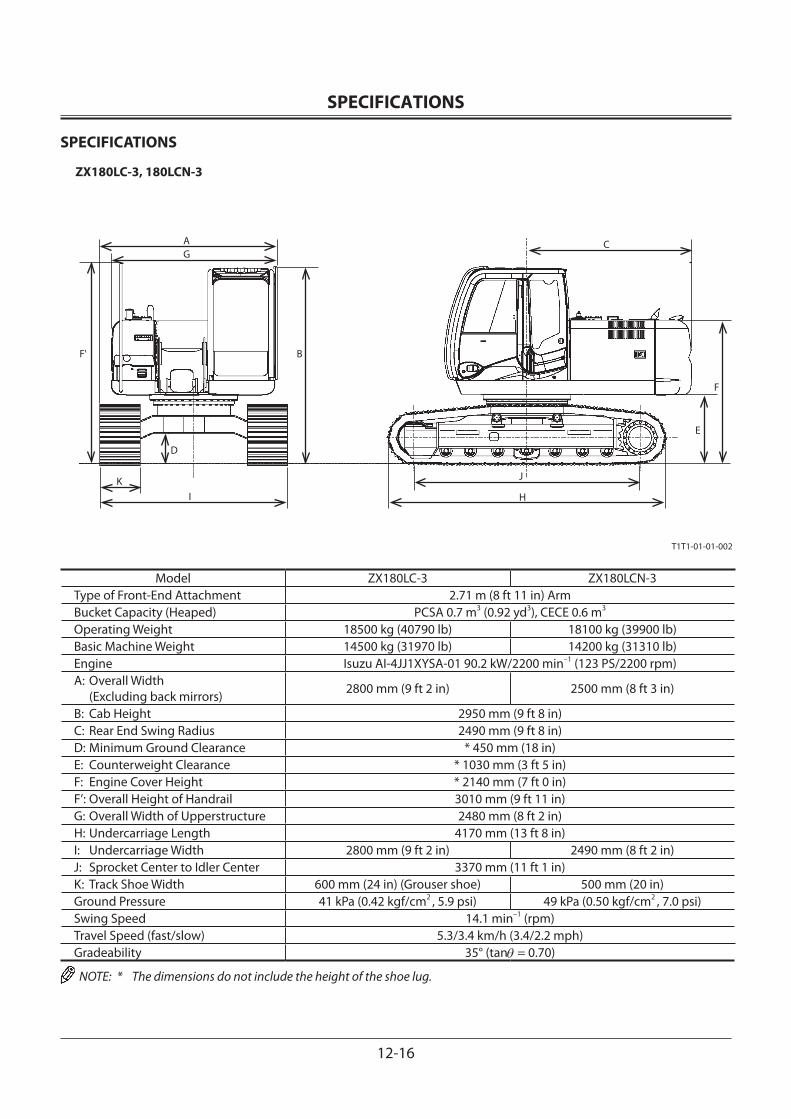
SPECIFICATIONS
12-16
SPECIFICATIONS
ZX180LC-3, 180LCN-3
Model ZX180LC-3 ZX180LCN-3Type of Front-End Attachment 2.71 m (8 ft 11 in) ArmBucket Capacity (Heaped) PCSA 0.7 m3 (0.92 yd3), CECE 0.6 m3
Operating Weight 18500 kg (40790 lb) 18100 kg (39900 lb)Basic Machine Weight 14500 kg (31970 lb) 14200 kg (31310 lb)Engine Isuzu AI-4JJ1XYSA-01 90.2 kW/2200 min–1 (123 PS/2200 rpm)A: Overall Width (Excluding back mirrors) 2800 mm (9 ft 2 in) 2500 mm (8 ft 3 in)
B: Cab Height 2950 mm (9 ft 8 in)C: Rear End Swing Radius 2490 mm (9 ft 8 in)D: Minimum Ground Clearance * 450 mm (18 in)E: Counterweight Clearance * 1030 mm (3 ft 5 in)F: Engine Cover Height * 2140 mm (7 ft 0 in)F’: Overall Height of Handrail 3010 mm (9 ft 11 in)G: Overall Width of Upperstructure 2480 mm (8 ft 2 in)H: Undercarriage Length 4170 mm (13 ft 8 in)I: Undercarriage Width 2800 mm (9 ft 2 in) 2490 mm (8 ft 2 in)J: Sprocket Center to Idler Center 3370 mm (11 ft 1 in)K: Track Shoe Width 600 mm (24 in) (Grouser shoe) 500 mm (20 in)Ground Pressure 41 kPa (0.42 kgf/cm2 , 5.9 psi) 49 kPa (0.50 kgf/cm2 , 7.0 psi)Swing Speed 14.1 min–1 (rpm)Travel Speed (fast/slow) 5.3/3.4 km/h (3.4/2.2 mph)Gradeability 35° (tanθ = 0.70)
NOTE: * The dimensions do not include the height of the shoe lug.
T1T1-01-01-002
AG
B
D
KI
C
F
E
J
H
F'
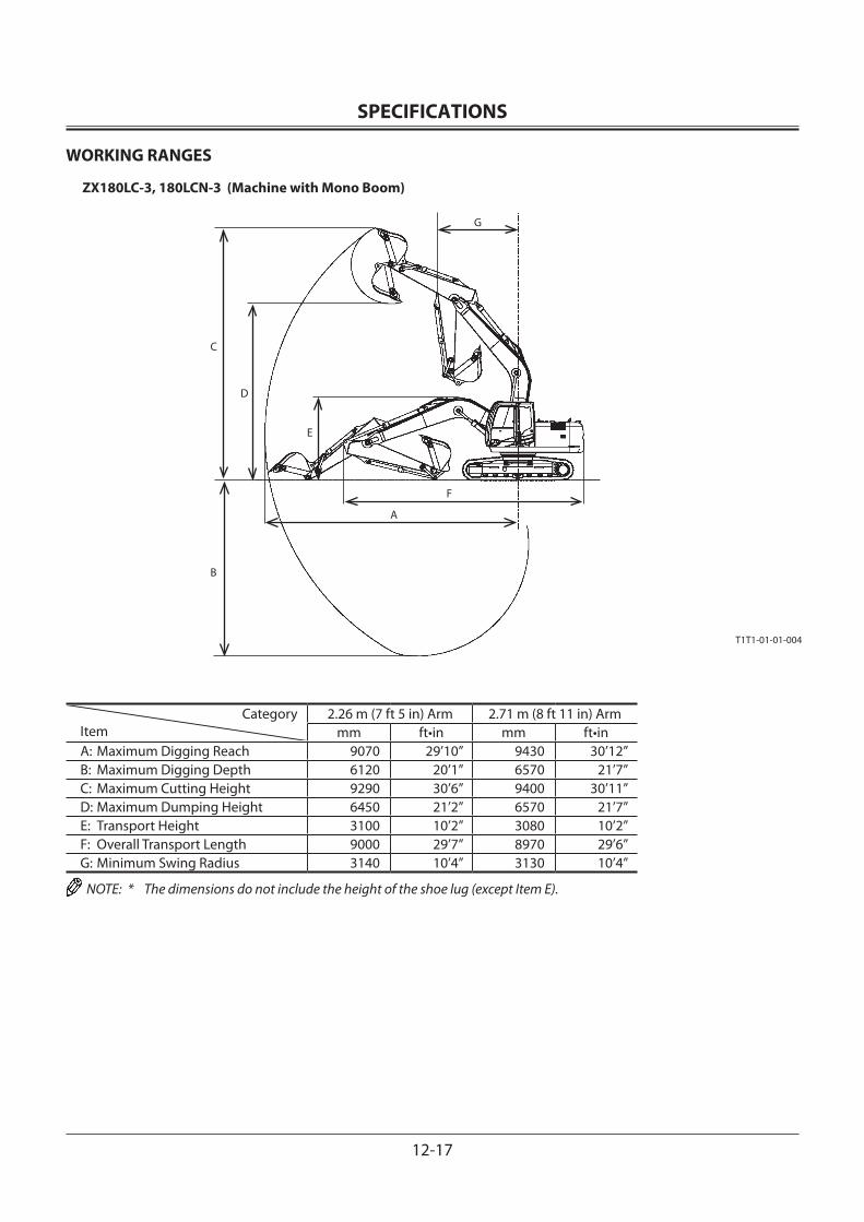
SPECIFICATIONS
12-17
WORKING RANGES
ZX180LC-3, 180LCN-3 (Machine with Mono Boom)
CategoryItem
2.26 m (7 ft 5 in) Arm 2.71 m (8 ft 11 in) Armmm ft•in mm ft•in
A: Maximum Digging Reach 9070 29’10” 9430 30’12”B: Maximum Digging Depth 6120 20’1” 6570 21’7”C: Maximum Cutting Height 9290 30’6” 9400 30’11”D: Maximum Dumping Height 6450 21’2” 6570 21’7”E: Transport Height 3100 10’2” 3080 10’2”F: Overall Transport Length 9000 29’7” 8970 29’6”G: Minimum Swing Radius 3140 10’4” 3130 10’4”
NOTE: * The dimensions do not include the height of the shoe lug (except Item E).
T1T1-01-01-004
G
C
B
A
F
E
D

SPECIFICATIONS
12-18
ZX180LC-3, 180LCN-3 (Machine with 2-Piece Boom)
CategoryItem
2.26 m (7 ft 5 in) Arm 2.71 m (8 ft 11 in) Armmm ft•in mm ft•in
A: Maximum Digging Reach 8980 29’6” 9350 30’9”B: Maximum Digging Depth 5640 18’6” 6050 19’11”C: Maximum Cutting Height 10260 33’8” 10530 34’7”D: Maximum Dumping Height 7320 24’1” 7590 24’11”E: Transport Height 3030 9’12” 3030 9’12”F: Overall Transport Length 8850 29’1” 8840 29’0”G: Minimum Swing Radius 2280 7’6” 2230 7’4”
NOTE: * The dimensions do not include the height of the shoe lug (except Item E).
T1T1-01-01-006
C
B
D
E
F
A
G
SPECIFICATIONS
12-19
SHOE TYPES AND APPLICATIONS
ZX180LC-3
Shoe Width 600 mm (24”)Grouser Shoe
700 mm (28”)Grouser Shoe
800 mm (31”)Grouser Shoe
900 mm (35”)Grouser Shoe
Application For Ordinary Ground For Weak Footing For Weak Footing For Weak FootingOperating Weight kg (lb)
18500(40800)
18700(41200)
19000(41900)
19300(42500)
Basic Machine Weight kg (lb)
14500(32000)
14800(32600)
15000(33000)
15300(33700)
Cab Height mm (ft•in)
2950(9’8”)
2950(9’8”)
2950(9’8”)
2950(9’8”)
Minimum Ground mmClearance (ft•in)
450(18”)
450(18”)
450(18”)
450(18”)
Undercarriage mmLength (ft•in)
4170(13’8”)
4170(13’8”)
4170(13’8”)
4170(13’8”)
Undercarriage Width mm (ft•in)
2800(9’2”)
2900(9’6”)
3000(9’10”)
3100(10’2”)
Ground Pressure41 kPa
(0.42 kgf/cm2, 6.0 psi)
36 kPa(0.37 kgf/cm2,
5.1 psi)
31 kPa(0.32 kgf/cm2,
4.5 psi)
28 kPa(0.29 kgf/cm2,
4.1 psi)
ZX180LCN-3
Shoe Width 500 mm (20”)Grouser Shoe
600 mm (24”)Grouser Shoe
700 mm (28”)Grouser Shoe
Application For Ordinary Ground For Ordinary Ground For Weak FootingOperating Weight kg (lb)
18100(39900)
18400(40600)
18600(41000)
Basic Machine Weight kg (lb)
14200(31300)
14500(32000)
14700(32400)
Cab Height mm (ft•in)
2950(9’8”)
2950(9’8”)
2950(9’8”)
Minimum Ground mmClearance (ft•in)
450(18”)
450(18”)
450(18”)
Undercarriage mmLength (ft•in)
4170(13’8”)
4170(13’8”)
4170(13’8”)
Undercarriage Width mm (ft•in)
2490(8’2”)
2590(8’6”)
2690(8’10”)
Ground Pressure49 kPa
(0.50 kgf/cm2,7.1 psi)
41 kPa(0.42 kgf/cm2,
6.0 psi)
35 kPa(0.36 kgf/cm2,
5.1 psi)
NOTE: • The specifications for the front-end attachment is for 2.71 m (8 ft 11 in) arm with PCSA 0.70 m3 (0.92 yd3) bucket. • 700, 800 mm (28, 31 in) and 900 mm (35 in) grouser shoe should not be used on gravel or rocky ground. • The dimensions do not include the height of the shoe lug.
SPECIFICATIONS
12-20
BUCKET TYPES AND APPLICATIONS
ZX180LC-3, 180LCN-3
Bucket
Bucket Capacitym3 (yd3)
Bucket Width (in)(With side cutter) Application Front-End Attachment
PCSA(Heaped)
CECE(Heaped)
ZX180LC-3, 180LCN-32.26 m (7’5”)
Arm2.71 m (8’11”)
Arm
Hoe Bucket
0.51 (0.67)0.70 (0.92)0.80 (1.05)0.91 (1.19)1.10 (1.44)1.20 (1.57)
0.450.60.70.80.91.0
830 (33”)1010 (40”)1140 (45”)1260 (50”)1440 (57”)1450 (57”)
(Without side cutter)
−−
Bucket reinforcement can be welded in four places upon customer’s request
0.70 (0.92)0.80 (1.05)0.91 (1.19)
0.60.70.8
1010 (40”)1140 (45”)1260 (50”)
V-Type Bucket − 90° ExcavatingV-trenches
Ripper Bucket 0.60 (0.79) 0.50 800 (31.5”)(Without side cutter) −
One Point Ripper − − −
Clamshell Bucket 0.60 Bucket width 940 (37”) Side ditching
Slope-Finishing Blade − 1800(70”)
Bank cutting finish
NOTE: • Symbols in the above table have the following meanings. : General excavating : Light duty excavating : Rock digging : Loading work
: Slope-finishing work −: Not applicable (not warrantable)
• Hoe bucket is applicable to the following types of work. General excavating: For digging and loading operation of sand, gravel, clay, ordinary earth and so on.
Light duty excavating: For digging and loading operation of dry, loosened earth, sand, mud and so on. Their bulk density shall be less than 1.60 t/m3 (2700 lb/yd3) as a standard.
Loading: For loading operation of dry, loosened earth and sand. Their bulk density shall be less than 1.10 t/m3 (1850 lb/yd3) as a standard.
Rock digging: For digging/loading operation of mountain gravels, blasted rock, hard clay, soft rock and so on.
IMPORTANT: Using inapplicable buckets may cause serious damage to the front structure such as boom, arm and hydraulic cylinders.
SPECIFICATIONS
12-21
SPECIFICATIONS
ZX210-3, 210LC-3
T1V1-01-01-006
Model ZX210-3 ZX210LC-3Type of Front-End Attachment 2.91 m (9 ft 7 in) ArmBucket Capacity (Heaped) PCSA 0.80 m3 (1.05 yd3), CECE 0.7 m3
Operating Weight 20300 kg (44800 lb) 20900 kg (46100 lb)Basic Machine Weight 15900 kg (35100 lb) 16500 kg (36400 lb)Engine Isuzu AI-4HK1XYSA-02 122 kW/2000 min–1 (166 PS/2000 rpm)A: Overall Width (Excluding back mirrors) 2860 mm (9 ft 5 in) 2990 mm (9 ft 10 in)
B: Cab Height 2950 mm (9 ft 8 in)C: Rear End Swing Radius 2750 mm (9 ft 0 in)D: Minimum Ground Clearance * 450 mm (18 in)E: Counterweight Clearance * 1030 mm (3 ft 5 in)F: Engine Cover Height * 2270 mm (7 ft 5 in)G: Overall Width of Upperstructure 2710 mm (8 ft 11 in)H: Undercarriage Length 4170 mm (13 ft 8 in) 4470 mm (14 ft 8 in)I: Undercarriage Width 2800 mm (9 ft 2 in) 2990 mm (9 ft 10 in)J: Sprocket Center to Idler Center 3370 mm (11 ft 1 in) 3660 mm (12 ft 0 in)K: Track Shoe Width 600 mm (24 in) (Grouser shoe)Ground Pressure 45 kPa (0.46 kgf/cm2 , 6.5 psi) 43 kPa (0.44 kgf/cm2 , 6.3 psi)Swing Speed 13.3 min–1 (rpm)Travel Speed (fast/slow) 5.5/3.5 km/h (3.4/2.2 mph)Gradeability 35° (tan θ= 0.70)
NOTE: * The dimensions do not include the height of the shoe lug.

SPECIFICATIONS
12-22
WORKING RANGES
ZX210-3, 210LC-3
Category
Item
2.03 m (6 ft 8 in) Arm 2.42 m (7 ft 11 in) Arm 2.91 m (9 ft 7 in) ArmBackhoe Backhoe Backhoe
mm ft•in mm ft•in mm ft•inA: Maximum Digging Reach 9230 30’3” 9430 30’11” 9920 32’7”B: Maximum Digging Depth *5800 *19’0” *6180 *20’3” *6670 *21’11”C: Maximum Cutting Height *9850 *32’4” *9670 *31’9” *10040 *32’11”D: Maximum Dumping Height *6940 *22’9” *6830 *22’5” *7180 *23’7”E: Transport Height 3150 10’4” 3180 10’5” 2940 9’8”F: Overall Transport Length 9680 31’9” 9680 31’9” 9520 31’5”G: Minimum Swing Radius 3410 11’2” 3280 10’9” 3180 10’5”
NOTE: * The dimensions do not include the height of the shoe lug.
T1V1-01-01-002Backhoe
SPECIFICATIONS
12-23
SHOE TYPES AND APPLICATIONS
ZX210-3
Shoe Width 600 mm (24”)Grouser Shoe
700 mm (28”)Grouser Shoe
800 mm (31”)Grouser Shoe
900 mm (35”)Grouser Shoe
Application For Ordinary Ground For Weak Footing For Weak Footing For Weak FootingOperating Weight kg (lb)
20300(44800)
20700(45600)
21000(46300)
21500(47400)
Basic Machine Weight kg (lb)
15900(35100)
16300(35900)
16600(36600)
17000(37500)
Cab Height mm (ft•in)
2950(9’8”)
2950(9’8”)
2950(9’8”)
2950(9’8”)
Minimum Ground mmClearance (ft•in)
450(18”)
450(18”)
450(18”)
450(18”)
Undercarriage mmLength (ft•in)
4170(13’8”)
4170(13’8”)
4170(13’8”)
4170(13’8”)
Undercarriage Width mm (ft•in)
2800(9’2”)
2900(9’6”)
3000(9’10”)
3100(10’2”)
Ground Pressure45 kPa
(0.46 kgf/cm2, 6.5 psi)
40 kPa(0.41 kgf/cm2,
5.8 psi)
35 kPa(0.36 kgf/cm2,
5.1 psi)
32 kPa(0.33 kgf/cm2,
4.7 psi)
ZX210LC-3
Shoe Width 600 mm (24”)Grouser Shoe
700 mm (28”)Grouser Shoe
800 mm (31”)Grouser Shoe
900 mm (35”)Grouser Shoe
Application For Ordinary Ground For Weak Footing For Weak Footing For Weak FootingOperating Weight kg (lb)
20900(46100)
21300(47000)
21600(47600)
22100(48700)
Basic Machine Weight kg (lb)
16500(36400)
16900(37300)
17100(37700)
17600(38800)
Cab Height mm (ft•in)
2950(9’8”)
2950(9’8”)
2950(9’8”)
2950(9’8”)
Minimum Ground mmClearance (ft•in)
450(18”)
450(18”)
450(18”)
450(18”)
Undercarriage mmLength (ft•in)
4470(14’8”)
4470(14’8”)
4470(14’8”)
4470(14’8”)
Undercarriage Width mm (ft•in)
2990(9’10”)
3090(10’2”)
3190(10’6”)
3290(10’10”)
Ground Pressure43 kPa
(0.44 kgf/cm2,6.3 psi)
38 kPa(0.39 kgf/cm2,
5.5 psi)
33 kPa(0.34 kgf/cm2,
4.8 psi)
30 kPa(0.31 kgf/cm2,
4.4 psi)
NOTE: • The specifications for the front-end attachment is for 2.58 m (8 ft 6 in) arm with PCSA 0.6 m3 (0.79 yd3) bucket. • 700, 800 mm (28, 31 in) and 900 mm (35 in) grouser shoe should not be used on gravel or rocky ground. • The dimensions do not include the height of the shoe lug.
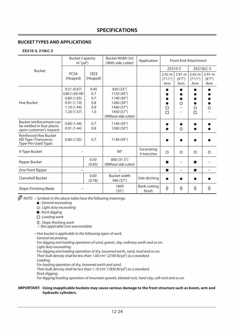
SPECIFICATIONS
12-24
BUCKET TYPES AND APPLICATIONS
ZX210-3, 210LC-3
Bucket
Bucket Capacitym3 (yd3)
Bucket Width (in)(With side cutter) Application Front-End Attachment
PCSA(Heaped)
CECE(Heaped)
ZX210-3 ZX210LC-32.42 m (7’11”)
Arm
2.91 m (9’7”)Arm
2.42 m (7’11”)
Arm
2.91 m (9’7”)Arm
Hoe Bucket
0.51 (0.67)0.80 (1.05) HD
0.80 (1.05)0.91 (1.19)1.10 (1.44)1.20 (1.57)
0.450.70.70.80.91.0
830 (33”)1150 (45”)1140 (45”)1260 (50”)1440 (57”)1450 (57”)
(Without side cutter)
−− −
Bucket reinforcement can be welded in four places upon customer’s request
0.80 (1.44)0.91 (1.44)
0.70.8
1140 (45”)1260 (50”)
Reinforced Hoe Bucket HD Type (Transverse-Type-Pin-Used Type)
0.80 (1.05) 0.7 1140 (45”)
V-Type Bucket − 90° ExcavatingV-trenches
Ripper Bucket 0.50(0.65)
800 (31.5”)(Without side cutter) − −
One Point Ripper − − − −
Clamshell Bucket 0.60(0.78)
Bucket width940 (37”) Side ditching
Slope-Finishing Blade − 1800(70”)
Bank cutting finish
NOTE: • Symbols in the above table have the following meanings. : General excavating : Light duty excavating : Rock digging : Loading work
: Slope-finishing work −: Not applicable (not warrantable)
• Hoe bucket is applicable to the following types of work. General excavating: For digging and loading operation of sand, gravel, clay, ordinary earth and so on.
Light duty excavating: For digging and loading operation of dry, loosened earth, sand, mud and so on. Their bulk density shall be less than 1.60 t/m3 (2700 lb/yd3) as a standard.
Loading: For loading operation of dry, loosened earth and sand. Their bulk density shall be less than 1.10 t/m3 (1850 lb/yd3) as a standard.
Rock digging: For digging/loading operation of mountain gravels, blasted rock, hard clay, soft rock and so on.
IMPORTANT: Using inapplicable buckets may cause serious damage to the front structure such as boom, arm and hydraulic cylinders.
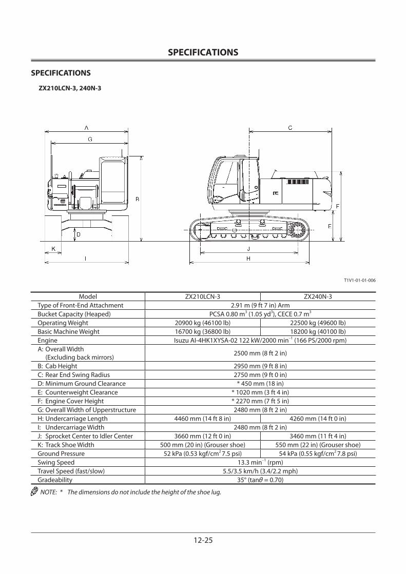
SPECIFICATIONS
12-25
SPECIFICATIONS
ZX210LCN-3, 240N-3
Model ZX210LCN-3 ZX240N-3Type of Front-End Attachment 2.91 m (9 ft 7 in) ArmBucket Capacity (Heaped) PCSA 0.80 m3 (1.05 yd3), CECE 0.7 m3
Operating Weight 20900 kg (46100 lb) 22500 kg (49600 lb)Basic Machine Weight 16700 kg (36800 lb) 18200 kg (40100 lb)Engine Isuzu AI-4HK1XYSA-02 122 kW/2000 min–1 (166 PS/2000 rpm)A: Overall Width (Excluding back mirrors) 2500 mm (8 ft 2 in)
B: Cab Height 2950 mm (9 ft 8 in)C: Rear End Swing Radius 2750 mm (9 ft 0 in)D: Minimum Ground Clearance * 450 mm (18 in)E: Counterweight Clearance * 1020 mm (3 ft 4 in)F: Engine Cover Height * 2270 mm (7 ft 5 in)G: Overall Width of Upperstructure 2480 mm (8 ft 2 in)H: Undercarriage Length 4460 mm (14 ft 8 in) 4260 mm (14 ft 0 in)I: Undercarriage Width 2480 mm (8 ft 2 in)J: Sprocket Center to Idler Center 3660 mm (12 ft 0 in) 3460 mm (11 ft 4 in)K: Track Shoe Width 500 mm (20 in) (Grouser shoe) 550 mm (22 in) (Grouser shoe)Ground Pressure 52 kPa (0.53 kgf/cm2 7.5 psi) 54 kPa (0.55 kgf/cm2 7.8 psi)Swing Speed 13.3 min–1 (rpm)Travel Speed (fast/slow) 5.5/3.5 km/h (3.4/2.2 mph)Gradeability 35° (tanθ = 0.70)
NOTE: * The dimensions do not include the height of the shoe lug.
T1V1-01-01-006
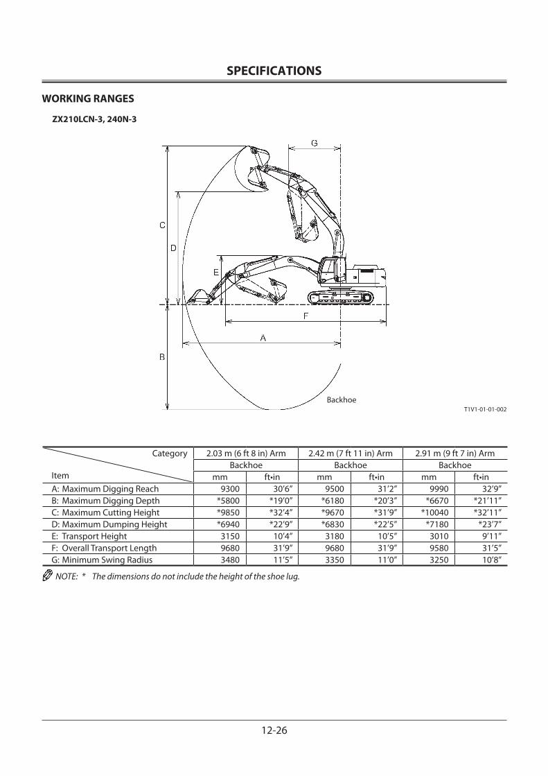
SPECIFICATIONS
12-26
WORKING RANGES
ZX210LCN-3, 240N-3
Category
Item
2.03 m (6 ft 8 in) Arm 2.42 m (7 ft 11 in) Arm 2.91 m (9 ft 7 in) ArmBackhoe Backhoe Backhoe
mm ft•in mm ft•in mm ft•inA: Maximum Digging Reach 9300 30’6” 9500 31’2” 9990 32’9”B: Maximum Digging Depth *5800 *19’0” *6180 *20’3” *6670 *21’11”C: Maximum Cutting Height *9850 *32’4” *9670 *31’9” *10040 *32’11”D: Maximum Dumping Height *6940 *22’9” *6830 *22’5” *7180 *23’7”E: Transport Height 3150 10’4” 3180 10’5” 3010 9’11”F: Overall Transport Length 9680 31’9” 9680 31’9” 9580 31’5”G: Minimum Swing Radius 3480 11’5” 3350 11’0” 3250 10’8”
NOTE: * The dimensions do not include the height of the shoe lug.
T1V1-01-01-002Backhoe
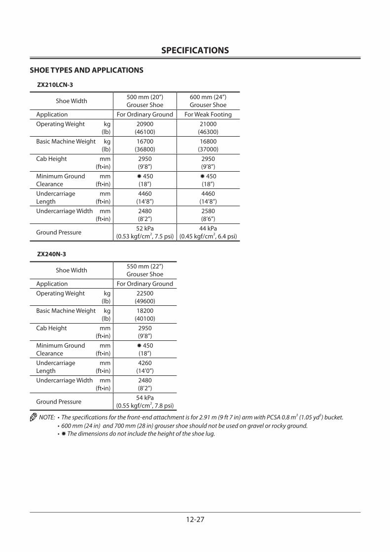
SPECIFICATIONS
12-27
SHOE TYPES AND APPLICATIONS
ZX210LCN-3
Shoe Width 500 mm (20”)Grouser Shoe
600 mm (24”)Grouser Shoe
Application For Ordinary Ground For Weak FootingOperating Weight kg (lb)
20900(46100)
21000(46300)
Basic Machine Weight kg (lb)
16700(36800)
16800(37000)
Cab Height mm (ft•in)
2950(9’8”)
2950(9’8”)
Minimum Ground mmClearance (ft•in)
450(18”)
450(18”)
Undercarriage mmLength (ft•in)
4460(14’8”)
4460(14’8”)
Undercarriage Width mm (ft•in)
2480(8’2”)
2580(8’6”)
Ground Pressure 52 kPa(0.53 kgf/cm2, 7.5 psi)
44 kPa(0.45 kgf/cm2, 6.4 psi)
ZX240N-3
Shoe Width 550 mm (22”)Grouser Shoe
Application For Ordinary GroundOperating Weight kg (lb)
22500(49600)
Basic Machine Weight kg (lb)
18200(40100)
Cab Height mm (ft•in)
2950(9’8”)
Minimum Ground mmClearance (ft•in)
450(18”)
Undercarriage mmLength (ft•in)
4260(14’0”)
Undercarriage Width mm (ft•in)
2480(8’2”)
Ground Pressure 54 kPa(0.55 kgf/cm2, 7.8 psi)
NOTE: • The specifications for the front-end attachment is for 2.91 m (9 ft 7 in) arm with PCSA 0.8 m3 (1.05 yd3) bucket. • 600 mm (24 in) and 700 mm (28 in) grouser shoe should not be used on gravel or rocky ground. • The dimensions do not include the height of the shoe lug.
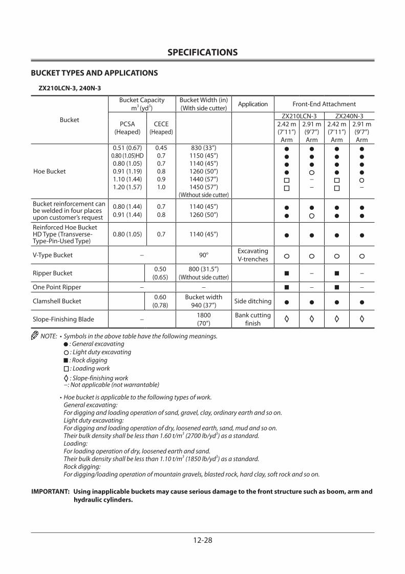
SPECIFICATIONS
12-28
BUCKET TYPES AND APPLICATIONS
ZX210LCN-3, 240N-3
Bucket
Bucket Capacitym3 (yd3)
Bucket Width (in)(With side cutter) Application Front-End Attachment
PCSA(Heaped)
CECE(Heaped)
ZX210LCN-3 ZX240N-32.42 m (7’11”)
Arm
2.91 m (9’7”)Arm
2.42 m (7’11”)
Arm
2.91 m (9’7”)Arm
Hoe Bucket
0.51 (0.67)0.80 (1.05)HD0.80 (1.05)0.91 (1.19)1.10 (1.44)1.20 (1.57)
0.450.70.70.80.91.0
830 (33”)1150 (45”)1140 (45”)1260 (50”)1440 (57”)1450 (57”)
(Without side cutter)
−− −
Bucket reinforcement can be welded in four places upon customer’s request
0.80 (1.44)0.91 (1.44)
0.70.8
1140 (45”)1260 (50”)
Reinforced Hoe Bucket HD Type (Transverse-Type-Pin-Used Type)
0.80 (1.05) 0.7 1140 (45”)
V-Type Bucket − 90° ExcavatingV-trenches
Ripper Bucket 0.50(0.65)
800 (31.5”)(Without side cutter) − −
One Point Ripper − − − −
Clamshell Bucket 0.60(0.78)
Bucket width940 (37”) Side ditching
Slope-Finishing Blade − 1800(70”)
Bank cutting finish
NOTE: • Symbols in the above table have the following meanings. : General excavating : Light duty excavating : Rock digging : Loading work
: Slope-finishing work −: Not applicable (not warrantable)
• Hoe bucket is applicable to the following types of work. General excavating: For digging and loading operation of sand, gravel, clay, ordinary earth and so on.
Light duty excavating: For digging and loading operation of dry, loosened earth, sand, mud and so on. Their bulk density shall be less than 1.60 t/m3 (2700 lb/yd3) as a standard.
Loading: For loading operation of dry, loosened earth and sand. Their bulk density shall be less than 1.10 t/m3 (1850 lb/yd3) as a standard.
Rock digging: For digging/loading operation of mountain gravels, blasted rock, hard clay, soft rock and so on.
IMPORTANT: Using inapplicable buckets may cause serious damage to the front structure such as boom, arm and hydraulic cylinders.
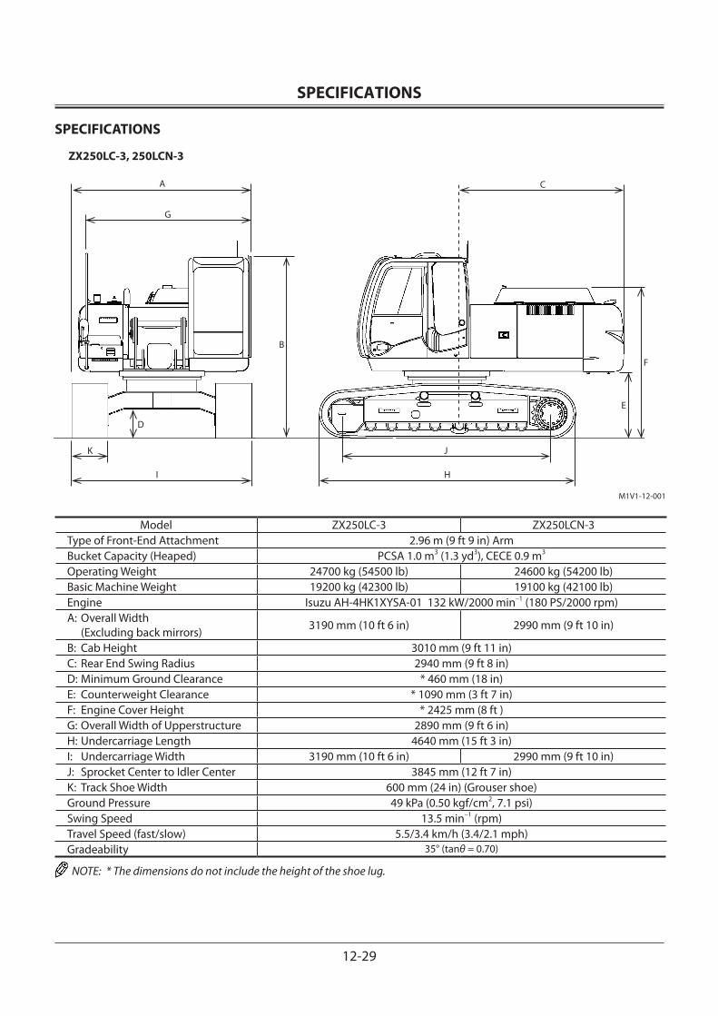
SPECIFICATIONS
12-29
SPECIFICATIONS
ZX250LC-3, 250LCN-3
Model ZX250LC-3 ZX250LCN-3Type of Front-End Attachment 2.96 m (9 ft 9 in) ArmBucket Capacity (Heaped) PCSA 1.0 m3 (1.3 yd3), CECE 0.9 m3
Operating Weight 24700 kg (54500 lb) 24600 kg (54200 lb)Basic Machine Weight 19200 kg (42300 lb) 19100 kg (42100 lb)Engine Isuzu AH-4HK1XYSA-01 132 kW/2000 min–1 (180 PS/2000 rpm)A: Overall Width (Excluding back mirrors) 3190 mm (10 ft 6 in) 2990 mm (9 ft 10 in)
B: Cab Height 3010 mm (9 ft 11 in)C: Rear End Swing Radius 2940 mm (9 ft 8 in)D: Minimum Ground Clearance * 460 mm (18 in)E: Counterweight Clearance * 1090 mm (3 ft 7 in)F: Engine Cover Height * 2425 mm (8 ft )G: Overall Width of Upperstructure 2890 mm (9 ft 6 in)H: Undercarriage Length 4640 mm (15 ft 3 in)I: Undercarriage Width 3190 mm (10 ft 6 in) 2990 mm (9 ft 10 in)J: Sprocket Center to Idler Center 3845 mm (12 ft 7 in)K: Track Shoe Width 600 mm (24 in) (Grouser shoe)Ground Pressure 49 kPa (0.50 kgf/cm2, 7.1 psi)Swing Speed 13.5 min–1 (rpm)Travel Speed (fast/slow) 5.5/3.4 km/h (3.4/2.1 mph)Gradeability 35° (tanθ = 0.70)
NOTE: * The dimensions do not include the height of the shoe lug.
M1V1-12-001
A
G
B
D
K
I
C
F
E
J
H
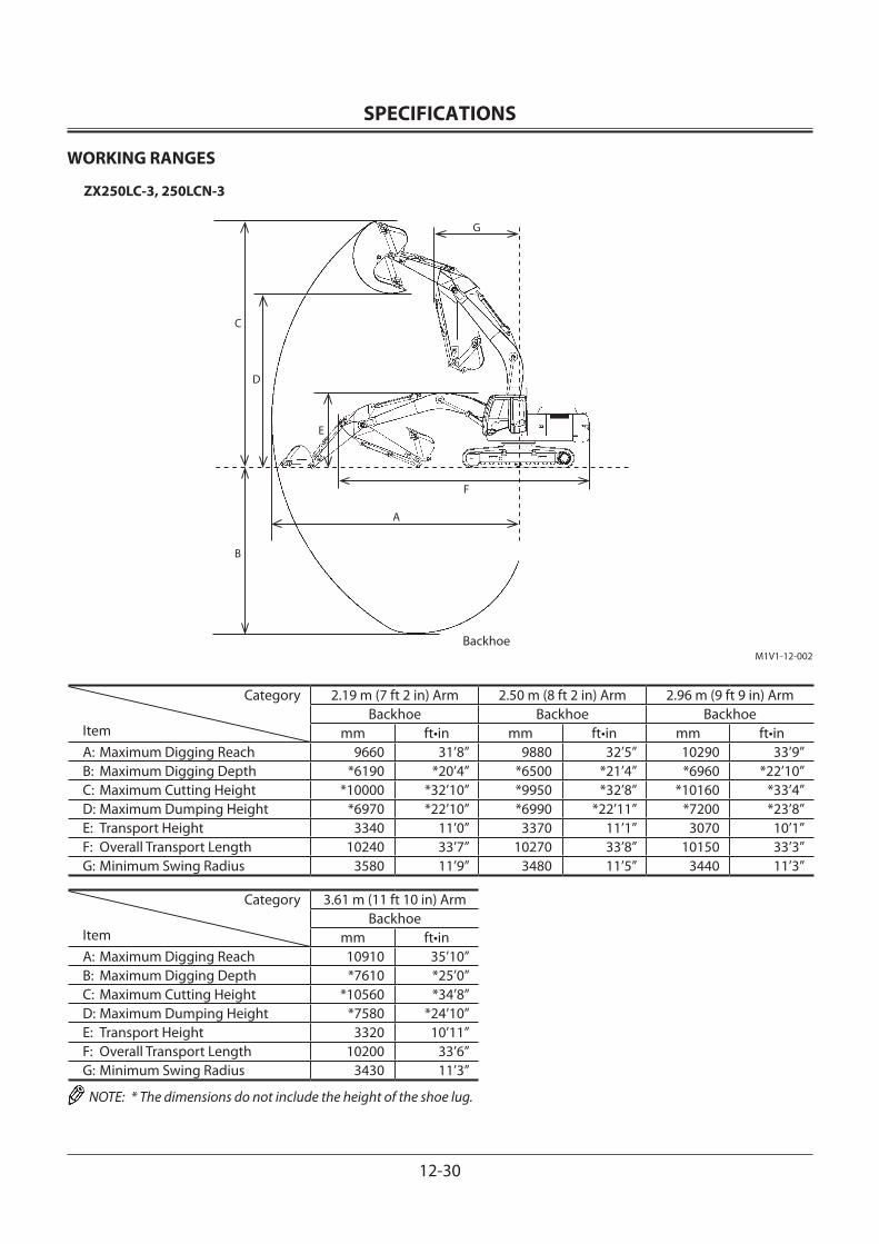
SPECIFICATIONS
12-30
WORKING RANGES
ZX250LC-3, 250LCN-3
Category
Item
2.19 m (7 ft 2 in) Arm 2.50 m (8 ft 2 in) Arm 2.96 m (9 ft 9 in) ArmBackhoe Backhoe Backhoe
mm ft•in mm ft•in mm ft•inA: Maximum Digging Reach 9660 31’8” 9880 32’5” 10290 33’9”B: Maximum Digging Depth *6190 *20’4” *6500 *21’4” *6960 *22’10”C: Maximum Cutting Height *10000 *32’10” *9950 *32’8” *10160 *33’4”D: Maximum Dumping Height *6970 *22’10” *6990 *22’11” *7200 *23’8”E: Transport Height 3340 11’0” 3370 11’1” 3070 10’1”F: Overall Transport Length 10240 33’7” 10270 33’8” 10150 33’3”G: Minimum Swing Radius 3580 11’9” 3480 11’5” 3440 11’3”
Category
Item
3.61 m (11 ft 10 in) ArmBackhoe
mm ft•inA: Maximum Digging Reach 10910 35’10”B: Maximum Digging Depth *7610 *25’0”C: Maximum Cutting Height *10560 *34’8”D: Maximum Dumping Height *7580 *24’10”E: Transport Height 3320 10’11”F: Overall Transport Length 10200 33’6”G: Minimum Swing Radius 3430 11’3”
NOTE: * The dimensions do not include the height of the shoe lug.
M1V1-12-002
A
G
B
D
C
F
Backhoe
E
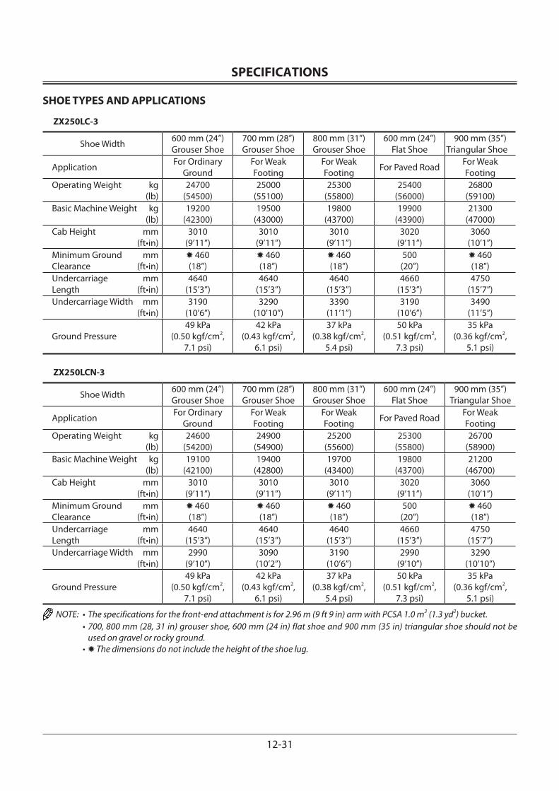
SPECIFICATIONS
12-31
SHOE TYPES AND APPLICATIONS
ZX250LC-3
Shoe Width 600 mm (24”)Grouser Shoe
700 mm (28”)Grouser Shoe
800 mm (31”)Grouser Shoe
600 mm (24”)Flat Shoe
900 mm (35”)Triangular Shoe
Application For Ordinary Ground
For Weak Footing
For Weak Footing For Paved Road For Weak
FootingOperating Weight kg (lb)
24700(54500)
25000(55100)
25300(55800)
25400(56000)
26800(59100)
Basic Machine Weight kg (lb)
19200(42300)
19500(43000)
19800(43700)
19900(43900)
21300(47000)
Cab Height mm (ft•in)
3010(9’11”)
3010(9’11”)
3010(9’11”)
3020(9’11”)
3060(10’1”)
Minimum Ground mmClearance (ft•in)
460(18”)
460(18”)
460(18”)
500(20”)
460(18”)
Undercarriage mmLength (ft•in)
4640(15’3”)
4640(15’3”)
4640(15’3”)
4660(15’3”)
4750(15’7”)
Undercarriage Width mm (ft•in)
3190(10’6”)
3290(10’10”)
3390(11’1”)
3190(10’6”)
3490(11’5”)
Ground Pressure49 kPa
(0.50 kgf/cm2,7.1 psi)
42 kPa(0.43 kgf/cm2,
6.1 psi)
37 kPa(0.38 kgf/cm2,
5.4 psi)
50 kPa(0.51 kgf/cm2,
7.3 psi)
35 kPa(0.36 kgf/cm2,
5.1 psi)
ZX250LCN-3
Shoe Width 600 mm (24”)Grouser Shoe
700 mm (28”)Grouser Shoe
800 mm (31”)Grouser Shoe
600 mm (24”)Flat Shoe
900 mm (35”)Triangular Shoe
Application For Ordinary Ground
For Weak Footing
For Weak Footing For Paved Road For Weak
FootingOperating Weight kg (lb)
24600(54200)
24900(54900)
25200(55600)
25300(55800)
26700(58900)
Basic Machine Weight kg (lb)
19100(42100)
19400(42800)
19700(43400)
19800(43700)
21200(46700)
Cab Height mm (ft•in)
3010(9’11”)
3010(9’11”)
3010(9’11”)
3020(9’11”)
3060(10’1”)
Minimum Ground mmClearance (ft•in)
460(18”)
460(18”)
460(18”)
500(20”)
460(18”)
Undercarriage mmLength (ft•in)
4640(15’3”)
4640(15’3”)
4640(15’3”)
4660(15’3”)
4750(15’7”)
Undercarriage Width mm (ft•in)
2990(9’10”)
3090(10’2”)
3190(10’6”)
2990(9’10”)
3290(10’10”)
Ground Pressure49 kPa
(0.50 kgf/cm2,7.1 psi)
42 kPa(0.43 kgf/cm2,
6.1 psi)
37 kPa(0.38 kgf/cm2,
5.4 psi)
50 kPa(0.51 kgf/cm2,
7.3 psi)
35 kPa(0.36 kgf/cm2,
5.1 psi)
NOTE: • The specifications for the front-end attachment is for 2.96 m (9 ft 9 in) arm with PCSA 1.0 m3 (1.3 yd3) bucket. • 700, 800 mm (28, 31 in) grouser shoe, 600 mm (24 in) flat shoe and 900 mm (35 in) triangular shoe should not be
used on gravel or rocky ground. • The dimensions do not include the height of the shoe lug.
SPECIFICATIONS
12-32
BUCKET TYPES AND APPLICATIONS
ZX250LC-3, 250LCN-3
Bucket
Bucket Capacity m3 (yd3)
Bucket Width (in) (With side cutter) Application Front-End Attachment
PCSA(Heaped)
CECE(Heaped)
ZX250LC-3, 250LCN-32.19 m (7’2”) Arm
2.50 m (8’2”) Arm
2.96 m (9’9”)
Standard Arm
3.61m (11’10”)
Arm
Hoe Bucket
0.80 (1.05)1.00 (1.31)1.15 (1.50)1.25 (1.64)1.40 (1.83)
0.700.901.001.101.20
1080 (42.5”)1300 (51.2”)1410 (55.6”)1520 (59.8”)1490 (58.7”)
(Without side cutter)— — —
Bucket reinforce-ment can be welded in four places upon customer’s request
1.00 (1.31) 0.90 1300 (51.2”)
1.15 (1.50) 1.00 1410 (55.6”)
Reinforced Hoe Bucket (HD Type) 1.00 (1.31) 0.90 1300 (51.2”)
Reinforced Hoe Bucket HD Type (Transverse-Type-Pin-Used Type)
1.00 (1.31) 0.90 1300 (51.2”)
Rock Bucket 0.92 (1.20) 0.80 1210 (47.6”)
Ripper Bucket 0.80 (1.05) 0.70(0.92)
1000 (39.4”)(Without side cutter) —
One Point Ripper — — —
Clamshell Bucket 0.60(0.78)
Bucket width870 (34”)
Side ditching —
NOTE: • Symbols in the above table have the following meanings. : General excavating : Light duty excavating : Rock digging : Loading work
—: Not applicable (not warrantable)
• Hoe bucket is applicable to the following types of work.General excavating:For digging and loading operation of sand, gravel, clay, ordinary earth and so on.Light duty excavating:For digging and loading operation of dry, loosened earth, sand, mud and so on.Their bulk density shall be less than 1.60 t/m3 (2700 lb/yd3) as a standard.Loading:For loading operation of dry, loosened earth and sand.Their bulk density shall be less than 1.10 t/m3 (1850 lb/yd3) as a standard.Rock digging:For digging/loading operation of mountain gravels, blasted rock, hard clay, soft rock and so on.
IMPORTANT: Using inapplicable buckets may cause serious damage to the front structure such as boom, arm and hydraulic cylinders.
SPECIFICATIONS
12-33
SPECIFICATIONS
ZX280LC-3, 280LCN-3
Model ZX280LC-3 ZX280LCN-3Type of Front-End Attachment 3.11 m (10 ft 2 in) ArmBucket Capacity (Heaped) PCSA 1.1 m3 (1.44 yd3), CECE 1.0 m3
Operating Weight 28200 kg (62200 lb) 28000 kg (61700 lb)Basic Machine Weight 22000 kg (48500 lb) 21800 kg (48100 lb)Engine Isuzu AH-4HK1XSA-03 140 kW/2100 min–1 (190 PS/2100 rpm)A: Overall Width (Excluding back mirrors) 3190 mm (10 ft 6 in) 3000 mm (9 ft 10 in)
B: Cab Height 3100 mm (10 ft 2 in)C: Rear End Swing Radius 2940 mm (9 ft 8 in)D: Minimum Ground Clearance * 510 mm (20 in)E: Counterweight Clearance * 1180 mm (3 ft 10 in)F: Engine Cover Height * 2515 mm (8 ft 3 in)G: Overall Width of Upperstructure 2890 mm (9 ft 6 in)H: Undercarriage Length 4940 mm (16 ft 3 in)I: Undercarriage Width 3190 mm (10 ft 6 in) 3000 mm (9 ft 10 in)J: Sprocket Center to Idler Center 4052 mm (13 ft 3 in)K: Track Shoe Width 600 mm (24 in) (Grouser shoe)Ground Pressure 53 kPa (0.54 kgf/cm2, 7.7 psi) 52 kPa (0.53 kgf/cm2, 7.5 psi)Swing Speed 12.6 min–1 (rpm)Travel Speed (fast/slow) 5.5/3.3 km/h (3.4/2.0 mph)Gradeability 35° (tanθ = 0.70)
NOTE: * The dimensions do not include the height of the shoe lug.
M1V1-12-001
A
G
B
D
K
I
C
F
E
J
H
SPECIFICATIONS
12-34
WORKING RANGES
ZX280LC-3, 280LCN-3
Category
Item
2.42 m (7 ft 10 in) Arm 3.11 m (10 ft 2 in) Arm 3.76 m (12 ft 4 in) ArmBackhoe Backhoe Backhoe
mm ft•in mm ft•in mm ft•inA: Maximum Digging Reach 10060 33’0” 10710 35’2” 11270 37’0”B: Maximum Digging Depth *6540 *21’5” *7230 *23’9” 7880 25’10”C: Maximum Cutting Height *9890 *32’5” *10260 *33’8” 10460 34’4”D: Maximum Dumping Height *6970 *22’10” *7310 *24’0” 7520 24’8”E: Transport Height 3410 11’2” 3170 10’5” 3310 10’10”F: Overall Transport Length 10440 34’3” 10340 33’11” 10390 34’1”G: Minimum Swing Radius 4070 13’4” 3910 12’10” 3900 12’10”
NOTE: * The dimensions do not include the height of the shoe lug.
M1V1-12-002
A
G
B
D
C
F
Backhoe
E
SPECIFICATIONS
12-35
SHOE TYPES AND APPLICATIONS
ZX280LC-3
Shoe Width 600 mm (24”)Grouser Shoe
700 mm (28”)Grouser Shoe
800 mm (31”)Grouser Shoe
600 mm (24”)Flat Shoe
Application For Ordinary Ground For Weak Footing For Weak Footing For Paved RoadOperating Weight kg (lb)
28200(62200)
28800(63500)
29100(64200)
29100(64200)
Basic Machine Weight kg (lb)
22000(48500)
22600(49800)
22900(50500)
22900(50500)
Cab Height mm (ft•in)
3100(10’2”)
3100(10’2”)
3100(10’2”)
3260(10’8”)
Minimum Ground mmClearance (ft•in)
510(20”)
510(20”)
510(20”)
550(22”)
Undercarriage mmLength (ft•in)
4940(16’2”)
4940(16’2”)
4940(16’2”)
4940(16’2”)
Undercarriage Width mm (ft•in)
3190(10’6”)
3290(10’10”)
3390(11’1”)
3190(10’6”)
Ground Pressure53 kPa
(0.54 kgf/cm2,7.7 psi)
46 kPa(0.47 kgf/cm2,
6.7 psi)
41 kPa(0.42 kgf/cm2,
6.0 psi)
55 kPa(0.56 kgf/cm2,
8.0 psi)
ZX280LCN-3
Shoe Width 600 mm (24”)Grouser Shoe
700 mm (28”)Grouser Shoe
800 mm (31”)Grouser Shoe
600 mm (24”)Flat Shoe
Application For Ordinary Ground For Weak Footing For Weak Footing For Paved RoadOperating Weight kg (lb)
28000(61700)
28600(63100)
29000(63900)
29000(63900)
Basic Machine Weight kg (lb)
21800(48100)
22400(49400)
22800(50300)
22800(50300)
Cab Height mm (ft•in)
3100(10’2”)
3100(10’2”)
3100(10’2”)
3260(10’8”)
Minimum Ground mmClearance (ft•in)
510(20”)
510(20”)
510(20”)
550(22”)
Undercarriage mmLength (ft•in)
4940(16’2”)
4940(16’2”)
4940(16’2”)
4940(16’2”)
Undercarriage Width mm (ft•in)
3000(9’10”)
3100(10’2”)
3200(10’6”)
3000(9’10”)
Ground Pressure52 kPa
(0.53 kgf/cm2,7.5 psi)
46 kPa(0.47 kgf/cm2,
6.7 psi)
41 kPa(0.42 kgf/cm2,
6.0 psi)
54 kPa(0.55 kgf/cm2,
7.8 psi)
NOTE: • The specifications for the front-end attachment is for 3.11 m (10 ft 2 in) arm with PCSA 1.1 m3 (1.44 yd3) bucket. • 700, 800 mm (28, 31 in) grouser shoe and 600 mm (24 in) flat shoe should not be used on gravel or rocky ground. • The dimensions do not include the height of the shoe lug.
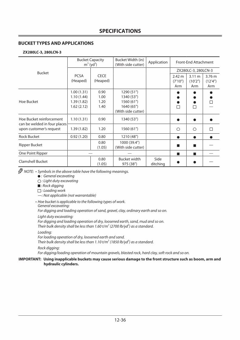
SPECIFICATIONS
12-36
BUCKET TYPES AND APPLICATIONS
ZX280LC-3, 280LCN-3
Bucket
Bucket Capacity m3 (yd3)
Bucket Width (in) (With side cutter) Application Front-End Attachment
PCSA(Heaped)
CECE(Heaped)
ZX280LC-3, 280LCN-32.42 m (7’10”)
Arm
3.11 m (10’2”)
Arm
3.76 m (12’4”)
Arm
Hoe Bucket
1.00 (1.31)1.10 (1.44)1.39 (1.82)1.62 (2.12)
0.901.001.201.40
1290 (51”)1340 (53”)1560 (61”)1640 (65”)
(With side cutter)—
Hoe Bucket reinforcement can be welded in four places upon customer’s request
1.10 (1.31) 0.90 1340 (53”)
1.39 (1.82) 1.20 1560 (61”)
Rock Bucket 0.92 (1.20) 0.80 1210 (48”)
Ripper Bucket 0.80(1.05)
1000 (39.4”)(With side cutter) —
One Point Ripper — — —
Clamshell Bucket 0.80(1.05)
Bucket width975 (38”)
Side ditching —
NOTE: • Symbols in the above table have the following meanings. : General excavating : Light duty excavating : Rock digging : Loading work
—: Not applicable (not warrantable)
• Hoe bucket is applicable to the following types of work.General excavating:For digging and loading operation of sand, gravel, clay, ordinary earth and so on.Light duty excavating:For digging and loading operation of dry, loosened earth, sand, mud and so on.Their bulk density shall be less than 1.60 t/m3 (2700 lb/yd3) as a standard.Loading:For loading operation of dry, loosened earth and sand.Their bulk density shall be less than 1.10 t/m3 (1850 lb/yd3) as a standard.Rock digging:For digging/loading operation of mountain gravels, blasted rock, hard clay, soft rock and so on.
IMPORTANT: Using inapplicable buckets may cause serious damage to the front structure such as boom, arm and hydraulic cylinders.
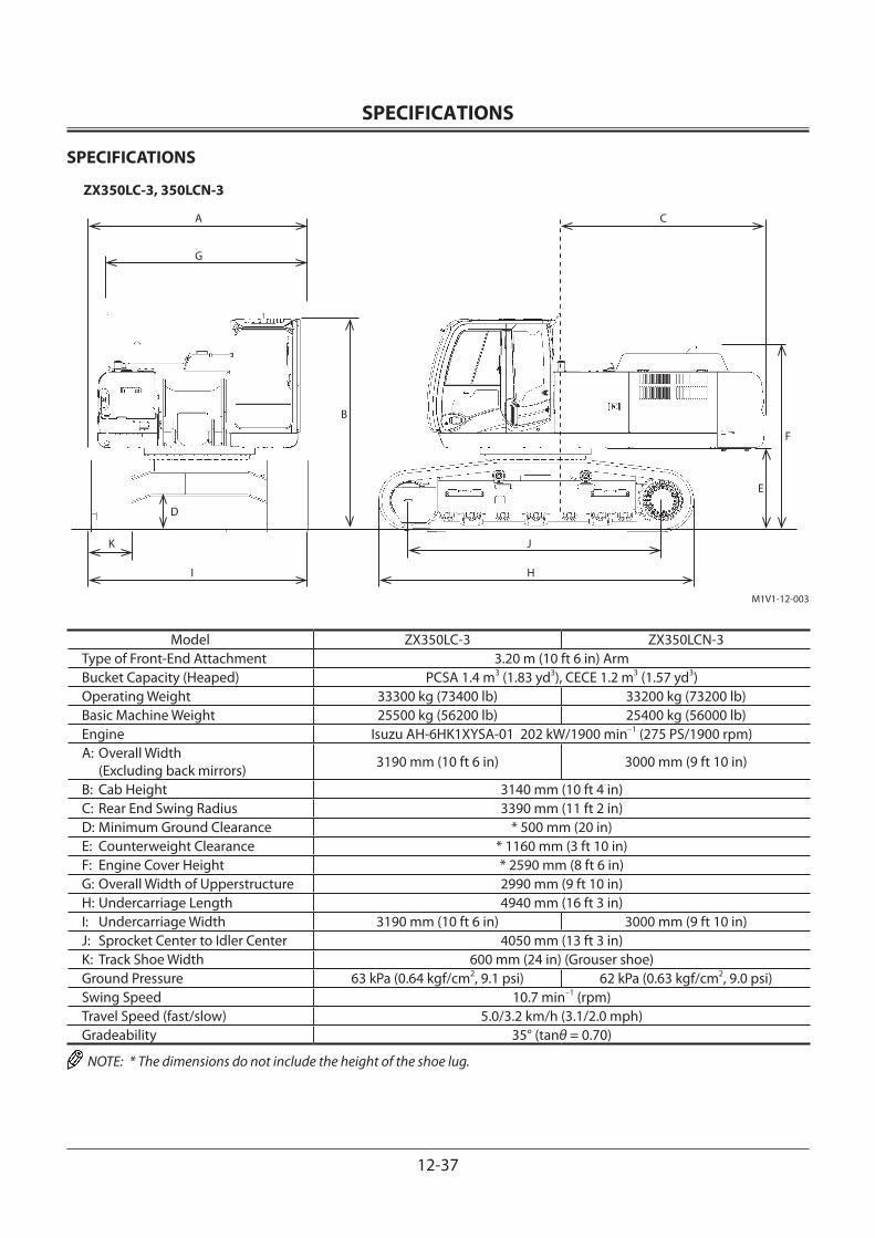
SPECIFICATIONS
12-37
SPECIFICATIONS
ZX350LC-3, 350LCN-3
Model ZX350LC-3 ZX350LCN-3Type of Front-End Attachment 3.20 m (10 ft 6 in) ArmBucket Capacity (Heaped) PCSA 1.4 m3 (1.83 yd3), CECE 1.2 m3 (1.57 yd3)Operating Weight 33300 kg (73400 lb) 33200 kg (73200 lb)Basic Machine Weight 25500 kg (56200 lb) 25400 kg (56000 lb)Engine Isuzu AH-6HK1XYSA-01 202 kW/1900 min–1 (275 PS/1900 rpm)A: Overall Width (Excluding back mirrors) 3190 mm (10 ft 6 in) 3000 mm (9 ft 10 in)
B: Cab Height 3140 mm (10 ft 4 in)C: Rear End Swing Radius 3390 mm (11 ft 2 in)D: Minimum Ground Clearance * 500 mm (20 in)E: Counterweight Clearance * 1160 mm (3 ft 10 in)F: Engine Cover Height * 2590 mm (8 ft 6 in)G: Overall Width of Upperstructure 2990 mm (9 ft 10 in)H: Undercarriage Length 4940 mm (16 ft 3 in)I: Undercarriage Width 3190 mm (10 ft 6 in) 3000 mm (9 ft 10 in)J: Sprocket Center to Idler Center 4050 mm (13 ft 3 in)K: Track Shoe Width 600 mm (24 in) (Grouser shoe)Ground Pressure 63 kPa (0.64 kgf/cm2, 9.1 psi) 62 kPa (0.63 kgf/cm2, 9.0 psi)Swing Speed 10.7 min–1 (rpm)Travel Speed (fast/slow) 5.0/3.2 km/h (3.1/2.0 mph)Gradeability 35° (tanθ = 0.70)
NOTE: * The dimensions do not include the height of the shoe lug.
M1V1-12-003
A
G
B
D
K
I
C
F
E
J
H
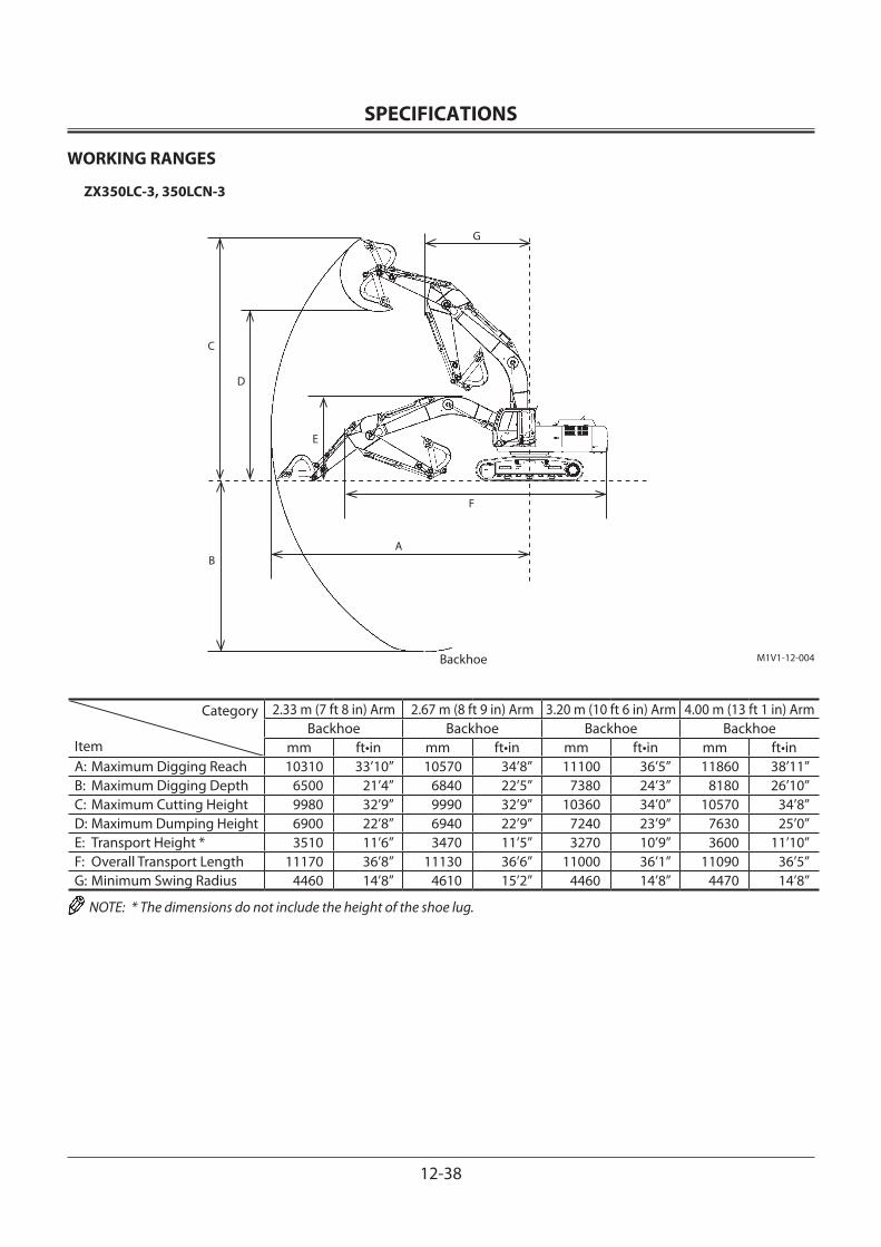
SPECIFICATIONS
12-38
WORKING RANGES
ZX350LC-3, 350LCN-3
Category
Item
2.33 m (7 ft 8 in) Arm 2.67 m (8 ft 9 in) Arm 3.20 m (10 ft 6 in) Arm 4.00 m (13 ft 1 in) ArmBackhoe Backhoe Backhoe Backhoe
mm ft•in mm ft•in mm ft•in mm ft•inA: Maximum Digging Reach 10310 33’10” 10570 34’8” 11100 36’5” 11860 38’11”B: Maximum Digging Depth 6500 21’4” 6840 22’5” 7380 24’3” 8180 26’10”C: Maximum Cutting Height 9980 32’9” 9990 32’9” 10360 34’0” 10570 34’8”D: Maximum Dumping Height 6900 22’8” 6940 22’9” 7240 23’9” 7630 25’0”E: Transport Height * 3510 11’6” 3470 11’5” 3270 10’9” 3600 11’10”F: Overall Transport Length 11170 36’8” 11130 36’6” 11000 36’1” 11090 36’5”G: Minimum Swing Radius 4460 14’8” 4610 15’2” 4460 14’8” 4470 14’8”
NOTE: * The dimensions do not include the height of the shoe lug.
M1V1-12-004
A
G
B
D
C
F
Backhoe
E
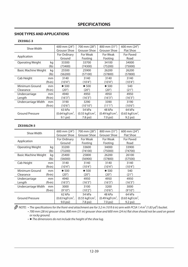
SPECIFICATIONS
12-39
SHOE TYPES AND APPLICATIONS
ZX350LC-3
Shoe Width 600 mm (24”)Grouser Shoe
700 mm (28”)Grouser Shoe
800 mm (31”)Grouser Shoe
600 mm (24”)Flat Shoe
Application For Ordinary Ground
For Weak Footing
For Weak Footing
For Paved Road
Operating Weight kg (lb)
33300(73400)
33700(74300)
34100(75200)
34000(75000)
Basic Machine Weight kg (lb)
25500(56200)
25900(57100)
26200(57800)
26200(57800)
Cab Height mm (ft•in)
3140(10’4”)
3140(10’4”)
3140(10’4”)
3140(10’4”)
Minimum Ground mmClearance (ft•in)
500(20”)
500(20”)
500(20”)
540(21”)
Undercarriage mmLength (ft•in)
4940(16’3”)
4950(16’3”)
4950(16’3”)
4950(16’3”)
Undercarriage Width mm (ft•in)
3190(10’6”)
3290(10’10”)
3390(11’1”)
3190(10’6”)
Ground Pressure63 kPa
(0.64 kgf/cm2,9.1 psi)
54 kPa(0.55 kgf/cm2,
7.8 psi)
48 kPa(0.49 kgf/cm2,
7.0 psi)
64 kPa(0.65 kgf/cm2,
9.2 psi)
ZX350LCN-3
Shoe Width 600 mm (24”)Grouser Shoe
700 mm (28”)Grouser Shoe
800 mm (31”)Grouser Shoe
600 mm (24”)Flat Shoe
Application For Ordinary Ground
For Weak Footing
For Weak Footing
For Paved Road
Operating Weight kg (lb)
33200(73200)
33600(74100)
34000(75000)
33900(74700)
Basic Machine Weight kg (lb)
25400(56000)
25800(56900)
26200(57800)
26100(57500)
Cab Height mm (ft•in)
3140(10’4”)
3140(10’4”)
3140(10’4”)
3140(10’4”)
Minimum Ground mmClearance (ft•in)
500(20”)
500(20”)
500(20”)
540(21”)
Undercarriage mmLength (ft•in)
4940(16’3”)
4950(16’3”)
4950(16’3”)
4950(16’3”)
Undercarriage Width mm (ft•in)
3000(9’10”)
3100(10’2”)
3200(10’6”)
3000(9’10”)
Ground Pressure62 kPa
(0.63 kgf/cm2,9.0 psi)
54 kPa(0.55 kgf/cm2,
7.8 psi)
48 kPa(0.49 kgf/cm2,
7.0 psi)
64 kPa(0.65 kgf/cm2,
9.2 psi)
NOTE: • The specifications for the front-end attachment are for 3.2 m (10 ft 6 in) arm with PCSA 1.4 m3 (1.83 yd3) bucket. • 700 mm (28 in) grouser shoe, 800 mm (31 in) grouser shoe and 600 mm (24 in) flat shoe should not be used on gravel
or rocky ground. • The dimensions do not include the height of the shoe lug.
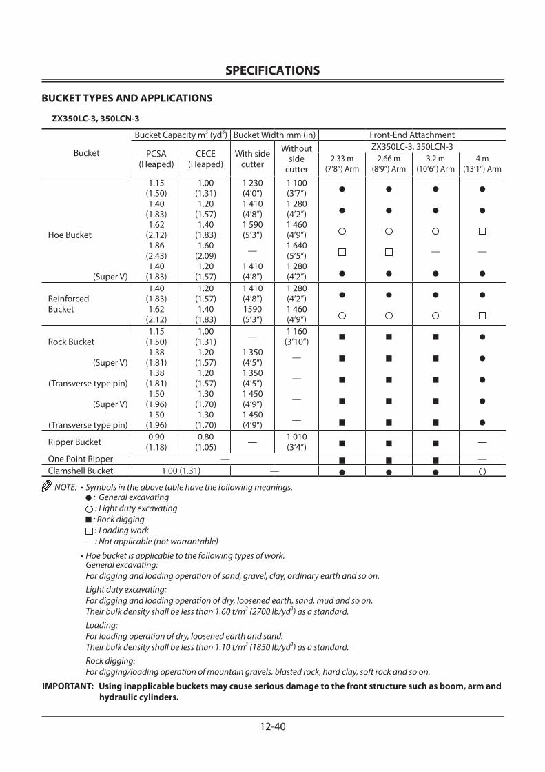
SPECIFICATIONS
12-40
BUCKET TYPES AND APPLICATIONS
ZX350LC-3, 350LCN-3
Bucket
Bucket Capacity m3 (yd3) Bucket Width mm (in) Front-End Attachment
PCSA(Heaped)
CECE(Heaped)
With side cutter
Without side
cutter
ZX350LC-3, 350LCN-32.33 m
(7’8”) Arm2.66 m
(8’9”) Arm3.2 m
(10’6”) Arm4 m
(13’1”) Arm
Hoe Bucket
(Super V)
1.15 (1.50)1.40
(1.83)1.62
(2.12)1.86
(2.43)1.40
(1.83)
1.00(1.31)1.20
(1.57)1.40
(1.83)1.60
(2.09)1.20
(1.57)
1 230(4’0”)1 410(4’8”)1 590(5’3”)
—
1 410(4’8”)
1 100(3’7”)1 280(4’2”)1 460(4’9”)1 640(5’5”)1 280(4’2”)
— —
Reinforced Bucket
1.40 (1.83)1.62
(2.12)
1.20(1.57)1.40
(1.83)
1 410(4’8”)1590(5’3”)
1 280(4’2”)1 460(4’9”)
Rock Bucket
(Super V)
(Transverse type pin)
(Super V)
(Transverse type pin)
1.15(1.50)1.38
(1.81)1.38
(1.81)1.50
(1.96)1.50
(1.96)
1.00(1.31)1.20
(1.57)1.20
(1.57)1.30
(1.70)1.30
(1.70)
—
1 350(4’5”)1 350(4’5”)1 450(4’9”)1 450(4’9”)
1 160(3’10”)
—
—
—
—
Ripper Bucket 0.90(1.18)
0.80(1.05) — 1 010
(3’4”) —
One Point Ripper — —Clamshell Bucket 1.00 (1.31) —
NOTE: • Symbols in the above table have the following meanings. : General excavating : Light duty excavating : Rock digging : Loading work
—: Not applicable (not warrantable)
• Hoe bucket is applicable to the following types of work.General excavating:For digging and loading operation of sand, gravel, clay, ordinary earth and so on.Light duty excavating:For digging and loading operation of dry, loosened earth, sand, mud and so on.Their bulk density shall be less than 1.60 t/m3 (2700 lb/yd3) as a standard.Loading:For loading operation of dry, loosened earth and sand.Their bulk density shall be less than 1.10 t/m3 (1850 lb/yd3) as a standard.Rock digging:For digging/loading operation of mountain gravels, blasted rock, hard clay, soft rock and so on.
IMPORTANT: Using inapplicable buckets may cause serious damage to the front structure such as boom, arm and hydraulic cylinders.

SPECIFICATIONS
12-41
SOUND LEVEL RESULTS (2000/14/EC)
LwA: sound-power level of airborne noiseLpA: sound level at operator’s station
Unit: dB(A)LwA LpA
ZX110-3, 110M-3 99 68ZX130-3, 130LCN-3 99 69ZX160LC-3 101 70ZX180LC-3, 180LCN-3 102 70ZX210-3, 210LC-3 101 69ZX210LCN-3, 240N-3 102 72ZX250LC-3, 250LCN-3 103 72ZX280LC-3, 280LCN-3 103 72ZX350LC-3, 350LCN-3 105 72
VIBRATION LEVEL
Hands/Arms: The acceleration to which the operator's hands and arms will be exposed is lower than 2.5 m/s2.
Entire body: The acceleration to which the operator's entire body will be exposed is lower than 0.5 m/s2.
NOTE: The acceleration is measured in accordance with ISO 2631/1; ISO 5349 and SAE J1166.

SPECIFICATIONS
12-42
MEMO...................................................................................................................................................................................................................................................
...................................................................................................................................................................................................................................................
...................................................................................................................................................................................................................................................
...................................................................................................................................................................................................................................................
...................................................................................................................................................................................................................................................
...................................................................................................................................................................................................................................................
...................................................................................................................................................................................................................................................
...................................................................................................................................................................................................................................................
...................................................................................................................................................................................................................................................
...................................................................................................................................................................................................................................................
...................................................................................................................................................................................................................................................
...................................................................................................................................................................................................................................................
...................................................................................................................................................................................................................................................
...................................................................................................................................................................................................................................................
...................................................................................................................................................................................................................................................
...................................................................................................................................................................................................................................................
...................................................................................................................................................................................................................................................
...................................................................................................................................................................................................................................................
...................................................................................................................................................................................................................................................
...................................................................................................................................................................................................................................................
...................................................................................................................................................................................................................................................
...................................................................................................................................................................................................................................................
...................................................................................................................................................................................................................................................
...................................................................................................................................................................................................................................................
...................................................................................................................................................................................................................................................
...................................................................................................................................................................................................................................................
...................................................................................................................................................................................................................................................
...................................................................................................................................................................................................................................................
...................................................................................................................................................................................................................................................
...................................................................................................................................................................................................................................................
...................................................................................................................................................................................................................................................
...................................................................................................................................................................................................................................................
...................................................................................................................................................................................................................................................
...................................................................................................................................................................................................................................................
...................................................................................................................................................................................................................................................
...................................................................................................................................................................................................................................................
...................................................................................................................................................................................................................................................
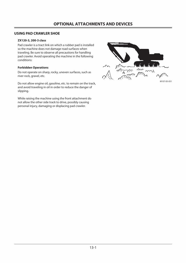
OPTIONAL ATTACHMENTS AND DEVICES
13-1
USING PAD CRAWLER SHOE
ZX120-3, 200-3 classPad crawler is a tract link on which a rubber pad is installed so the machine does not damage road surfaces when traveling. Be sure to observe all precautions for handling pad crawler. Avoid operating the machine in the following conditions:
Forbidden OperationsDo not operate on sharp, rocky, uneven surfaces, such as river rock, gravel, etc.
Do not allow engine oil, gasoline, etc. to remain on the track, and avoid traveling in oil in order to reduce the danger of slipping.
While raising the machine using the front attachment do not allow the other side track to drive, possibly causing personal injury, damaging or displacing pad crawler.
M107-05-051
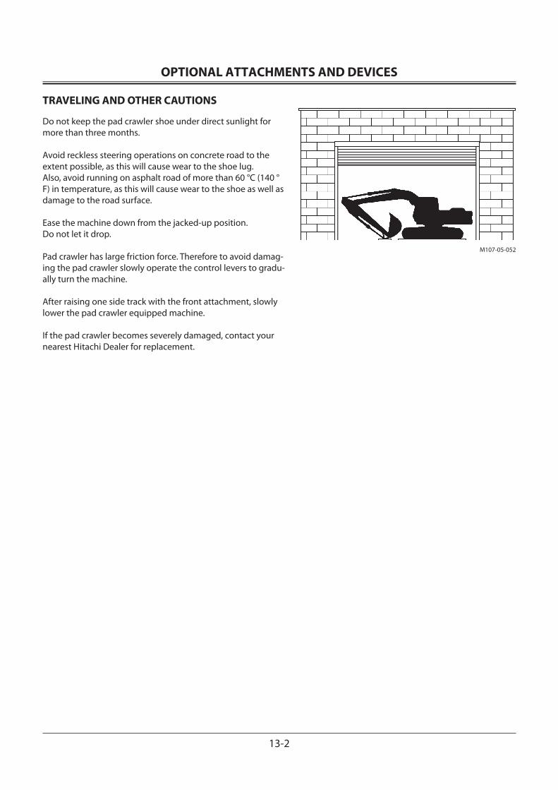
OPTIONAL ATTACHMENTS AND DEVICES
13-2
TRAVELING AND OTHER CAUTIONS
Do not keep the pad crawler shoe under direct sunlight for more than three months.
Avoid reckless steering operations on concrete road to the extent possible, as this will cause wear to the shoe lug. Also, avoid running on asphalt road of more than 60 °C (140 °F) in temperature, as this will cause wear to the shoe as well as damage to the road surface.
Ease the machine down from the jacked-up position. Do not let it drop.
Pad crawler has large friction force. Therefore to avoid damag-ing the pad crawler slowly operate the control levers to gradu-ally turn the machine.
After raising one side track with the front attachment, slowly lower the pad crawler equipped machine.
If the pad crawler becomes severely damaged, contact your nearest Hitachi Dealer for replacement.
M107-05-052
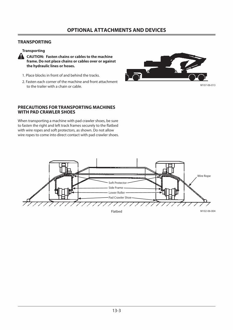
OPTIONAL ATTACHMENTS AND DEVICES
13-3
M107-06-013
TRANSPORTING
Transporting CAUTION: Fasten chains or cables to the machine
frame. Do not place chains or cables over or against the hydraulic lines or hoses.
1. Place blocks in front of and behind the tracks.
2. Fasten each corner of the machine and front attachment to the trailer with a chain or cable.
PRECAUTIONS FOR TRANSPORTING MACHINES WITH PAD CRAWLER SHOES
When transporting a machine with pad crawler shoes, be sure to fasten the right and left track frames securely to the flatbed with wire ropes and soft protectors, as shown. Do not allow wire ropes to come into direct contact with pad crawler shoes.
M102-06-004Flatbed
Soft Protector
Wire Rope
Side Frame
Lower Roller
Pad Crawler Shoe
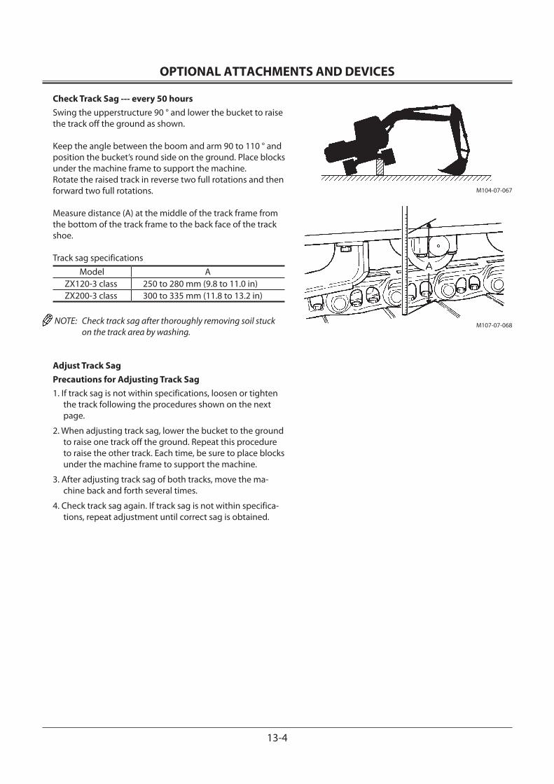
OPTIONAL ATTACHMENTS AND DEVICES
13-4
M104-07-067
Check Track Sag --- every 50 hoursSwing the upperstructure 90 ° and lower the bucket to raise the track off the ground as shown.
Keep the angle between the boom and arm 90 to 110 ° and position the bucket’s round side on the ground. Place blocks under the machine frame to support the machine.Rotate the raised track in reverse two full rotations and then forward two full rotations.
Measure distance (A) at the middle of the track frame from the bottom of the track frame to the back face of the track shoe.
Track sag specificationsModel A
ZX120-3 class 250 to 280 mm (9.8 to 11.0 in)ZX200-3 class 300 to 335 mm (11.8 to 13.2 in)
NOTE: Check track sag after thoroughly removing soil stuck on the track area by washing.
Adjust Track SagPrecautions for Adjusting Track Sag1. If track sag is not within specifications, loosen or tighten
the track following the procedures shown on the next page.
2. When adjusting track sag, lower the bucket to the ground to raise one track off the ground. Repeat this procedure to raise the other track. Each time, be sure to place blocks under the machine frame to support the machine.
3. After adjusting track sag of both tracks, move the ma-chine back and forth several times.
4. Check track sag again. If track sag is not within specifica-tions, repeat adjustment until correct sag is obtained.
M107-07-068
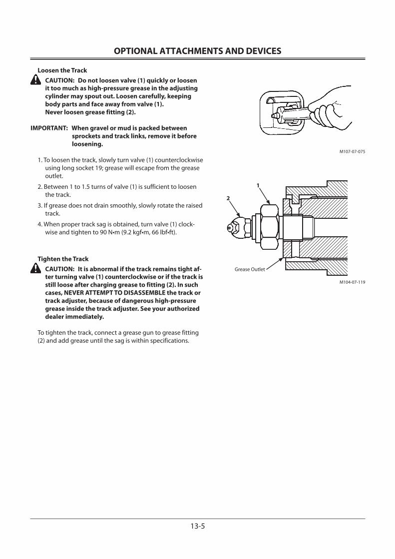
OPTIONAL ATTACHMENTS AND DEVICES
13-5
M107-07-075
M104-07-119
Grease Outlet
1
2
Loosen the Track CAUTION: Do not loosen valve (1) quickly or loosen
it too much as high-pressure grease in the adjusting cylinder may spout out. Loosen carefully, keeping body parts and face away from valve (1). Never loosen grease fitting (2).
IMPORTANT: When gravel or mud is packed between sprockets and track links, remove it before loosening.
1. To loosen the track, slowly turn valve (1) counterclockwise using long socket 19; grease will escape from the grease outlet.
2. Between 1 to 1.5 turns of valve (1) is sufficient to loosen the track.
3. If grease does not drain smoothly, slowly rotate the raised track.
4. When proper track sag is obtained, turn valve (1) clock-wise and tighten to 90 N•m (9.2 kgf•m, 66 lbf•ft).
Tighten the Track CAUTION: It is abnormal if the track remains tight af-
ter turning valve (1) counterclockwise or if the track is still loose after charging grease to fitting (2). In such cases, NEVER ATTEMPT TO DISASSEMBLE the track or track adjuster, because of dangerous high-pressure grease inside the track adjuster. See your authorized dealer immediately.
To tighten the track, connect a grease gun to grease fitting(2) and add grease until the sag is within specifications.
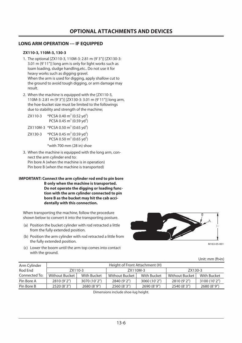
OPTIONAL ATTACHMENTS AND DEVICES
13-6
M163-05-001
LONG ARM OPERATION --- IF EQUIPPED
ZX110-3, 110M-3, 130-31. The optional [ZX110-3, 110M-3: 2.81 m (9’ 3”)] [ZX130-3:
3.01 m (9’ 11”)] long arm is only for light works such as loam loading, sludge handling,etc.. Do not use it for heavy works such as digging gravel. When the arm is used for digging, apply shallow cut to the ground to avoid tough digging, or arm damage may result.
2. When the machine is equipped with the [ZX110-3, 110M-3: 2.81 m (9’ 3”)] [ZX130-3: 3.01 m (9’ 11”)] long arm, the hoe-bucket size must be limited to the followings due to stability and strength of the machine;
ZX110-3 *PCSA 0.40 m3 (0.52 yd3) PCSA 0.45 m3 (0.59 yd3)
ZX110M-3 *PCSA 0.50 m3 (0.65 yd3)
ZX130-3 *PCSA 0.45 m3 (0.59 yd3) PCSA 0.50 m3 (0.65 yd3)
*with 700 mm (28 in) shoe
3. When the machine is equipped with the long arm, con-nect the arm cylinder end to: Pin bore A (when the machine is in operation) Pin bore B (when the machine is transported)
IMPORTANT: Connect the arm cylinder rod end to pin bore B only when the machine is transported. Do not operate the digging or loading func-tion with the arm cylinder connected to pin bore B as the bucket may hit the cab acci-dentally with this connection.
When transporting the machine, follow the procedureshown below to convert it into the transporting posture.
(a) Position the bucket cylinder with rod retracted a little from the fully extended position.
(b) Position the arm cylinder with rod retracted a little from the fully extended position.
(c) Lower the boom until the arm top comes into contact with the ground.
Unit: mm (ft•in)
Arm Cylinder Rod End Connected To:
Height of Front Attachment (H) ZX110-3 ZX110M-3 ZX130-3
Without Bucket With Bucket Without Bucket With Bucket Without Bucket With Bucket Pin Bore A 2810 (9’ 2”) 3070 (10’ 2”) 2840 (9’ 2”) 3060 (10’ 2”) 2810 (9’ 2”) 3100 (10’ 2”) Pin Bore B 2520 (8’ 3”) 2680 (8’ 9”) 2560 (8’ 3”) 2690 (8’ 9”) 2540 (8’ 3”) 2680 (8’ 9”)
Dimensions include shoe-lug height.
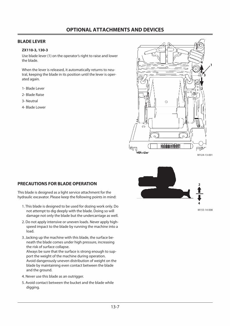
OPTIONAL ATTACHMENTS AND DEVICES
13-7
M1U4-13-001
M155-14-008
1
2
4
2
4
3
BLADE LEVER
ZX110-3, 130-3Use blade lever (1) on the operator’s right to raise and lower the blade.
When the lever is released, it automatically returns to neu-tral, keeping the blade in its position until the lever is oper-ated again.
1- Blade Lever
2- Blade Raise
3- Neutral
4- Blade Lower
PRECAUTIONS FOR BLADE OPERATION
This blade is designed as a light service attachment for the hydraulic excavator. Please keep the following points in mind:
1. This blade is designed to be used for dozing work only. Do not attempt to dig deeply with the blade. Doing so will damage not only the blade but the undercarriage as well.
2. Do not apply intensive or uneven loads. Never apply high-speed impact to the blade by running the machine into a load.
3. Jacking up the machine with this blade, the surface be-neath the blade comes under high pressure, increasing the risk of surface collapse. Always be sure that the surface is strong enough to sup-port the weight of the machine during operation. Avoid dangerously uneven distribution of weight on the blade by maintaining even contact between the blade and the ground.
4. Never use this blade as an outrigger.
5. Avoid contact between the bucket and the blade while digging.
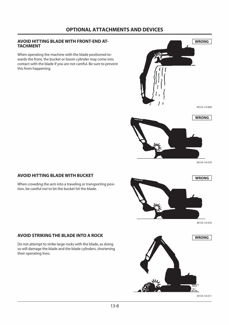
OPTIONAL ATTACHMENTS AND DEVICES
13-8
AVOID HITTING BLADE WITH FRONT-END AT-TACHMENT
When operating the machine with the blade positioned to-wards the front, the bucket or boom cylinder may come into contact with the blade if you are not careful. Be sure to prevent this from happening.
AVOID HITTING BLADE WITH BUCKET
When crowding the arm into a traveling or transporting posi-tion, be careful not to let the bucket hit the blade.
AVOID STRIKING THE BLADE INTO A ROCK
Do not attempt to strike large rocks with the blade, as doing so will damage the blade and the blade cylinders, shortening their operating lives.
WRONG
WRONG
WRONG
M155-14-009
M155-14-010
WRONG
M155-14-010
M155-14-011
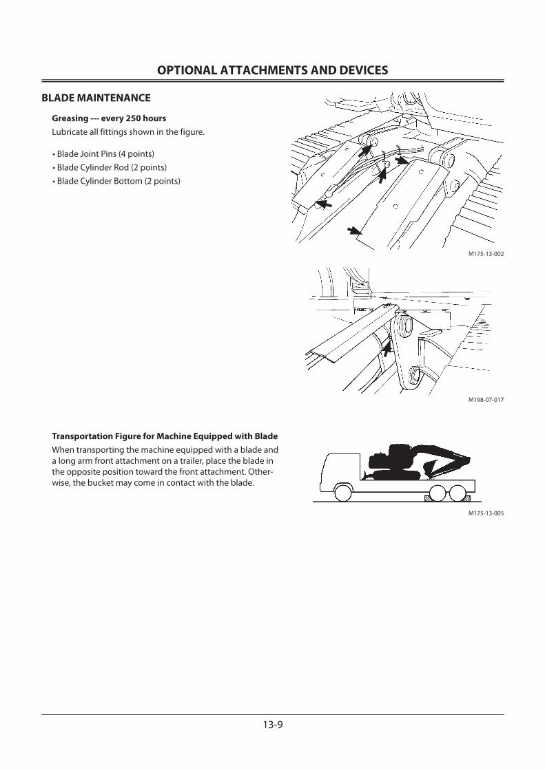
OPTIONAL ATTACHMENTS AND DEVICES
13-9
M175-13-002
M198-07-017
BLADE MAINTENANCE
Greasing --- every 250 hoursLubricate all fittings shown in the figure.
• Blade Joint Pins (4 points)• Blade Cylinder Rod (2 points)• Blade Cylinder Bottom (2 points)
Transportation Figure for Machine Equipped with BladeWhen transporting the machine equipped with a blade and a long arm front attachment on a trailer, place the blade in the opposite position toward the front attachment. Other-wise, the bucket may come in contact with the blade.
M175-13-005
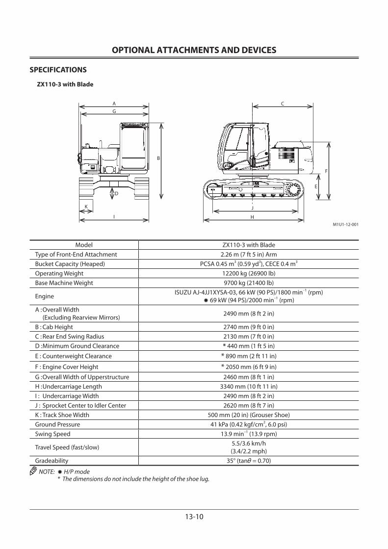
OPTIONAL ATTACHMENTS AND DEVICES
13-10
SPECIFICATIONS
ZX110-3 with Blade
M1U1-12-001
AG
D
K
I
B
C
E
F
J
H
Model ZX110-3 with BladeType of Front-End Attachment 2.26 m (7 ft 5 in) ArmBucket Capacity (Heaped) PCSA 0.45 m3 (0.59 yd3), CECE 0.4 m3
Operating Weight 12200 kg (26900 lb)Base Machine Weight 9700 kg (21400 lb)
Engine ISUZU AJ-4JJ1XYSA-03, 66 kW (90 PS)/1800 min–1 (rpm)✹ 69 kW (94 PS)/2000 min–1 (rpm)
A : Overall Width (Excluding Rearview Mirrors) 2490 mm (8 ft 2 in)
B : Cab Height 2740 mm (9 ft 0 in)C : Rear End Swing Radius 2130 mm (7 ft 0 in)D : Minimum Ground Clearance * 440 mm (1 ft 5 in)
E : Counterweight Clearance * 890 mm (2 ft 11 in)
F : Engine Cover Height * 2050 mm (6 ft 9 in)
G : Overall Width of Upperstructure 2460 mm (8 ft 1 in)H : Undercarriage Length 3340 mm (10 ft 11 in)I : Undercarriage Width 2490 mm (8 ft 2 in)J : Sprocket Center to Idler Center 2620 mm (8 ft 7 in)K : Track Shoe Width 500 mm (20 in) (Grouser Shoe)Ground Pressure 41 kPa (0.42 kgf/cm2, 6.0 psi)Swing Speed 13.9 min–1 (13.9 rpm)
Travel Speed (fast/slow) 5.5/3.6 km/h (3.4/2.2 mph)
Gradeability 35° (tanθ = 0.70)
NOTE: ✹ H/P mode * The dimensions do not include the height of the shoe lug.

OPTIONAL ATTACHMENTS AND DEVICES
13-11
WORKING RANGES
ZX110-3 with Blade
Model ZX110-3 with BladeCategory
Item 1.96 m (6 ft 5 in) Arm 2.26 m (7 ft 5 in) Arm 2.81 m (9 ft 3 in) Arm
A: Maximum Digging Reach mm (ft•in)
7490 (24' 7”)
7760(25' 6”)
8240(27' 0”)
*1 B: Maximum Digging Depth mm (ft•in)
4780(15' 8”)
5080(16' 8”)
5630(18' 6”)
*1 C: Maximum Cutting Height mm (ft•in)
7940(26' 1”)
8110(26' 7”)
8360(27' 5”)
*1 D: Maximum Dumping Height mm (ft•in)
5530(18' 2”)
5700(18' 8”)
5960(19' 7”)
E: Transport Height mm (ft•in)
2740(9' 0”)
2740(9' 0”)
*2 2740 (9' 0”)
F: Overall Transport Length mm (ft•in)
7280(23' 11”)
7280(23' 11”)
*2 7300 (23' 11”)
G: Minimum Swing Radius mm (ft•in)
2370(7' 9”)
2400(7' 11”)
2660(8' 9”)
H: Max. Raising Height mm (ft•in)
480(1' 7”)
I: Max. Digging Depth mm (ft•in)
510(1' 8”)
J: Blade Angle degree 25
NOTE: *1 The dimensions do not include the height of the shoe lug. *2 The dimensions asterisked are for transport pin position.
M1U1-12-004
C
B
D
A
F
E
G
JH
I
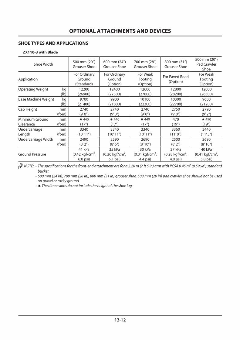
OPTIONAL ATTACHMENTS AND DEVICES
13-12
SHOE TYPES AND APPLICATIONS
ZX110-3 with Blade
Shoe Width 500 mm (20”)Grouser Shoe
600 mm (24”)Grouser Shoe
700 mm (28”)Grouser Shoe
800 mm (31”)Grouser Shoe
500 mm (20”)Pad Crawler
Shoe
ApplicationFor Ordinary
Ground (Standard)
For Ordinary Ground (Option)
For Weak Footing (Option)
For Paved Road (Option)
For Weak Footing (Option)
Operating Weight kg (lb)
12200(26900)
12400(27300)
12600(27800)
12800(28200)
12000(26500)
Base Machine Weight kg (lb)
9700(21400)
9900(21800)
10100(22300)
10300(22700)
9600(21200)
Cab Height mm (ft•in)
2740 (9’ 0”)
2740 (9’ 0”)
2740 (9’ 0”)
2750 (9’ 0”)
2790 (9’ 2”)
Minimum Ground mmClearance (ft•in)
✹ 440 (17”)
✹ 440(17”)
✹ 440(17”)
470(19”)
✹ 490(19”)
Undercarriage mmLength (ft•in)
3340(10’ 11”)
3340(10’ 11”)
3340(10’ 11”)
3360(11’ 0”)
3440(11’ 3”)
Undercarriage Width mm (ft•in)
2490(8’ 2”)
2590(8’ 6”)
2690(8’ 10”)
2500(8’ 2”)
2690(8’ 10”)
Ground Pressure41 kPa
(0.42 kgf/cm2,6.0 psi)
35 kPa(0.36 kgf/cm2,
5.1 psi)
30 kPa(0.31 kgf/cm2,
4.4 psi)
27 kPa(0.28 kgf/cm2,
4.0 psi)
40 kPa(0.41 kgf/cm2,
5.8 psi)
NOTE: • The specifications for the front-end attachment are for a 2.26 m (7 ft 5 in) arm with PCSA 0.45 m3 (0.59 yd3) standard bucket.
• 600 mm (24 in), 700 mm (28 in), 800 mm (31 in) grouser shoe, 500 mm (20 in) pad crawler shoe should not be used on gravel or rocky ground.
• ✹ The dimensions do not include the height of the shoe lug.
OPTIONAL ATTACHMENTS AND DEVICES
13-13
SPECIFICATIONS
ZX130-3 with Blade
M1U1-12-001
AG
D
K
I
B
C
E
F
J
H
Model ZX130-3 with BladeType of Front-End Attachment 2.52 m (8 ft 3 in) ArmBucket Capacity (Heaped) PCSA 0.50 m3 (0.65 yd3), CECE 0.45 m3
Operating Weight 13600 kg (30000 lb)Base Machine Weight 10900 kg (24000 lb)
Engine ISUZU AJ-4JJ1XYSA-03, 66 kW (90 PS)/1800 min–1 (rpm)✹ 69 kW (94 PS)/2000 min–1 (rpm)
A : Overall Width (Excluding Rearview Mirrors) 2490 mm (8 ft 2 in)
B : Cab Height 2740 mm (9 ft 0 in)C : Rear End Swing Radius 2130 mm (7 ft 0 in)D : Minimum Ground Clearance * 440 mm (1 ft 5 in)
E : Counterweight Clearance * 890 mm (2 ft 11 in)
F : Engine Cover Height * 2050 mm (6 ft 9 in)
G : Overall Width of Upperstructure 2460 mm (8 ft 1 in)H : Undercarriage Length 3580 mm (11 ft 9 in)I : Undercarriage Width 2490 mm (8 ft 2 in)J : Sprocket Center to Idler Center 2880 mm (9 ft 5 in)
K : Track Shoe Width 500 mm (Grouser Shoe) (20 in)
Ground Pressure 43 kPa (0.44 kgf/cm2, 6.3 psi)Swing Speed 13.7 min–1 (13.7 rpm)
Travel Speed (fast/slow) 5.5/3.4 km/h (3.4/2.1 mph)
Gradeability 35° (tanθ = 0.70)
NOTE: ✹ H/P mode * The dimensions do not include the height of the shoe lug.
OPTIONAL ATTACHMENTS AND DEVICES
13-14
WORKING RANGES
ZX130-3 with Blade
Model ZX130-3 with BladeCategory
Item 2.10 m (6 ft 11 in) Arm 2.52 m (8 ft 3 in) Arm 3.01 m (9 ft 11 in) Arm
A: Maximum Digging Reach mm (ft•in)
7960 (26' 1”)
8320(27' 4”)
8790(28' 10”)
*1 B: Maximum Digging Depth mm (ft•in)
5150(16' 11”)
5570(18' 3”)
6060(19' 11”)
*1 C: Maximum Cutting Height mm (ft•in)
8370(27' 6”)
8570(28' 1”)
8900(29' 2”)
*1 D: Maximum Dumping Height mm (ft•in)
5960(19' 7”)
6160(20' 3”)
6490(21' 4”)
E: Transport Height mm (ft•in)
2740(9' 0”)
2740(9' 0”)
*2 2740 (9' 0”)
F: Overall Transport Length mm (ft•in)
7660(25' 2”)
7660(25' 2”)
*2 7670 (25' 2”)
G: Minimum Swing Radius mm (ft•in)
2370(7' 9”)
2390(7' 10”)
2640(8' 8”)
H: Max. Raising Height mm (ft•in)
480(1' 7”)
I: Max. Digging Depth mm (ft•in)
510(1' 8”)
J: Blade Angle degree 25
NOTE: *1 The dimensions do not include the height of the shoe lug. *2 The dimensions asterisked are for transport pin position.
M1U1-12-004
C
B
D
A
F
E
G
JH
I
OPTIONAL ATTACHMENTS AND DEVICES
13-15
SHOE TYPES AND APPLICATIONS
ZX130-3 with Blade
Shoe Width 500 mm (20”)Grouser Shoe
600 mm (24”)Grouser Shoe
700 mm (28”)Grouser Shoe
800 mm (31”)Grouser Shoe
Application For Ordinary Ground (Standard)
For Ordinary Ground (Option)
For Weak Footing (Option)
For Weak Footing (Option)
Operating Weight kg (lb)
13600(30000)
13800(30400)
14000(30900)
14300(31500)
Base Machine Weight kg (lb)
10900(24000)
11100(24500)
11400(25100)
11600(25600)
Cab Height mm (ft•in)
2740(9' 0”)
2740(9' 0”)
2740(9' 0”)
2740(9' 0”)
Minimum Ground mmClearance (ft•in)
✹ 440(1' 5”)
✹ 440(1' 5”)
✹ 440(1' 5”)
✹ 440(1' 5”)
Undercarriage mmLength (ft•in)
3580(11' 9”)
3580(11' 9”)
3580(11' 9”)
3580(11' 9”)
Undercarriage Width mm (ft•in)
2490(8' 2”)
2590(8' 6”)
2690(8' 10”)
2790(8' 2”)
Ground Pressure 43 kPa(0.44 kgf/cm2, 6.3 psi)
36 kPa(0.37 kgf/cm2, 5.3 psi)
31 kPa(0.32 kgf/cm2, 4.6 psi)
28 kPa(0.29 kgf/cm2, 4.1 psi)
Shoe Width 500 mm (20")Pad Crawler Shoe
Application For Paved Road (Option)
Operating Weight kg (lb)
13500(29800)
Base Machine Weight kg (lb)
10800(23800)
Cab Height mm (ft•in)
2780(9' 1”)
Minimum Ground mmClearance (ft•in)
500(1' 8”)
Undercarriage mmLength (ft•in)
3660(12' 0”)
Undercarriage Width mm (ft•in)
2490(8' 2”)
Ground Pressure 42 kPa(0.43 kgf/cm2, 6.1 psi)
NOTE: • The specifications for the front-end attachment are for a 2.52 m (8 ft 3 in) arm with PCSA 0.50 m3 (0.65 yd3) standard bucket.
• 600 mm (24 in), 700 mm (28 in), 800 mm (31 in) grouser shoe, 500 mm (20 in) pad crawler shoe should not be used on gravel or rocky ground.
• ✹ The dimensions do not include the height of the shoe lug.
OPTIONAL ATTACHMENTS AND DEVICES
13-16
OFFSET ARM FRONT
ZX110-3, 110M-3Offset Control PedalPedal (1) is located at the operator’s right foot. When pressed forward, it moves the arm to the right offset posi-tion. When pushed backward, it moves the arm to the left offsetposition.
(2) Right Offset Position(3) Left Offset Position
When traveling or using the arm in the center position, fix pedal (1) in the lock position with stopper (4) as illustrated here.
The center position of the arm (offset 0) can be confirmedby consulting the gauge at the top end of the boom.
M178-13-001
1
3
2
M201-05-007
1
4
Unlock lock
Pedal
M175-13-006Offset Guage
M175-13-009
(Offset 0)
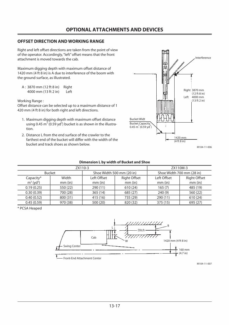
OPTIONAL ATTACHMENTS AND DEVICES
13-17
OFFSET DIRECTION AND WORKING RANGE
Right and left offset directions are taken from the point of view of the operator. Accordingly, “left” offset means that the front attachment is moved towards the cab.
Maximum digging depth with maximum offset distance of 1420 mm (4 ft 8 in) is A due to interference of the boom with the ground surface, as illustrated.
A : 3870 mm (12 ft 8 in) Right 4000 mm (13 ft 2 in) Left
Working Range :Offset distance can be selected up to a maximum distance of 1 420 mm (4 ft 8 in) for both right and left directions.
1. Maximum digging depth with maximum offset distance using 0.45 m3 (0.59 yd3) bucket is as shown in the illustra-tion.
2. Distance L from the end surface of the crawler to the farthest end of the bucket will differ with the width of the bucket and track shoes as shown below.
Dimension L by width of Bucket and ShoeZX110-3 ZX110M-3
Bucket Shoe Width 500 mm (20 in) Shoe Width 700 mm (28 in)Capacity* m3 (yd3)
Width mm (in)
Left Offset mm (in)
Right Offset mm (in)
Left Offset mm (in)
Right Offset mm (in)
0.19 (0.25) 550 (22) 290 (11) 610 (24) 165 (7) 485 (19) 0.30 (0.39) 700 (28) 365 (14) 685 (27) 240 (9) 560 (22) 0.40 (0.52) 800 (31) 415 (16) 735 (29) 290 (11) 610 (24) 0.45 (0.59) 970 (38) 500 (20) 820 (32) 375 (15) 695 (27)
* PCSA Heaped
M104-11-006
Interference
1420 mm (4 ft 8 in)
Bucket WidtBucket Capacity0.45 m
3 (0.59 yd
3)
Right 3870 mm (12 ft 8 in)Left 4000 mm (13 ft 2 in)
M104-11-007
Swing Center
1420 mm (4 ft 8 in)
160 mm (4.7 in)
Front-End Attachment Center
Cab
DitchB
W
L
OPTIONAL ATTACHMENTS AND DEVICES
13-18
PRECAUTIONS FOR OPERATING WITH THE OFF-SET FUNCTION
CAUTION: Never jack up the machine with the front in the offset position. This is extremely dangerous, as the machine is unstable.
IMPORTANT: • Never use a hydraulic breaker when the front is in the offset position, as this will damage the lower and upper booms.
• Do not perform heavy duty work, or dig gravel with the front in the offset position. Do not perform tamping work with a slope-finishing bucket attached. These operation will damage the lower and upper booms.
1. When digging with the front in the offset position, the bucket will come in contact with the track link if the arm is crowded. Even if bucket does not touch the track link, watch for the bucket digging under the track, as this will cause instabil-ity.
2. Be sure to follow the precautions shown below.
(1) Do not use the 2.26 m (7’ 5”) arm and 2.81 m (9’ 3”) arm as it will interfere with the cab when in the offset position.
(2) Do not use the bucket as a pile driver with the boom in the offset position.
(3) When digging with the boom in offset position, be careful not to damage the cylinder stay.
3. In order to prevent the offset pins from getting rusty, op-erate the offset function regularly. Check offset function operation every time before starting work.
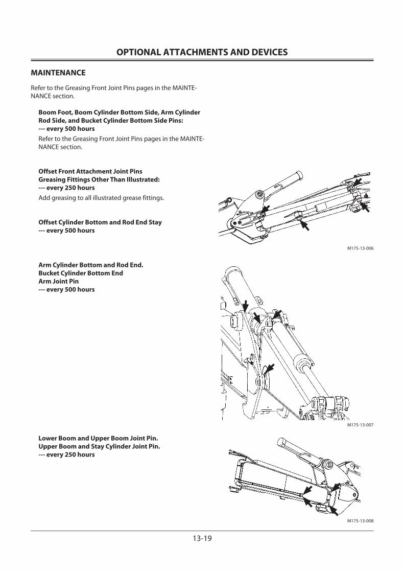
OPTIONAL ATTACHMENTS AND DEVICES
13-19
MAINTENANCE
Refer to the Greasing Front Joint Pins pages in the MAINTE-NANCE section.
Boom Foot, Boom Cylinder Bottom Side, Arm Cylinder Rod Side, and Bucket Cylinder Bottom Side Pins: --- every 500 hoursRefer to the Greasing Front Joint Pins pages in the MAINTE-NANCE section.
Offset Front Attachment Joint Pins Greasing Fittings Other Than Illustrated: --- every 250 hoursAdd greasing to all illustrated grease fittings.
Offset Cylinder Bottom and Rod End Stay --- every 500 hours
Arm Cylinder Bottom and Rod End. Bucket Cylinder Bottom End Arm Joint Pin --- every 500 hours
Lower Boom and Upper Boom Joint Pin. Upper Boom and Stay Cylinder Joint Pin. --- every 250 hours
M175-13-006
M175-13-007
M175-13-008
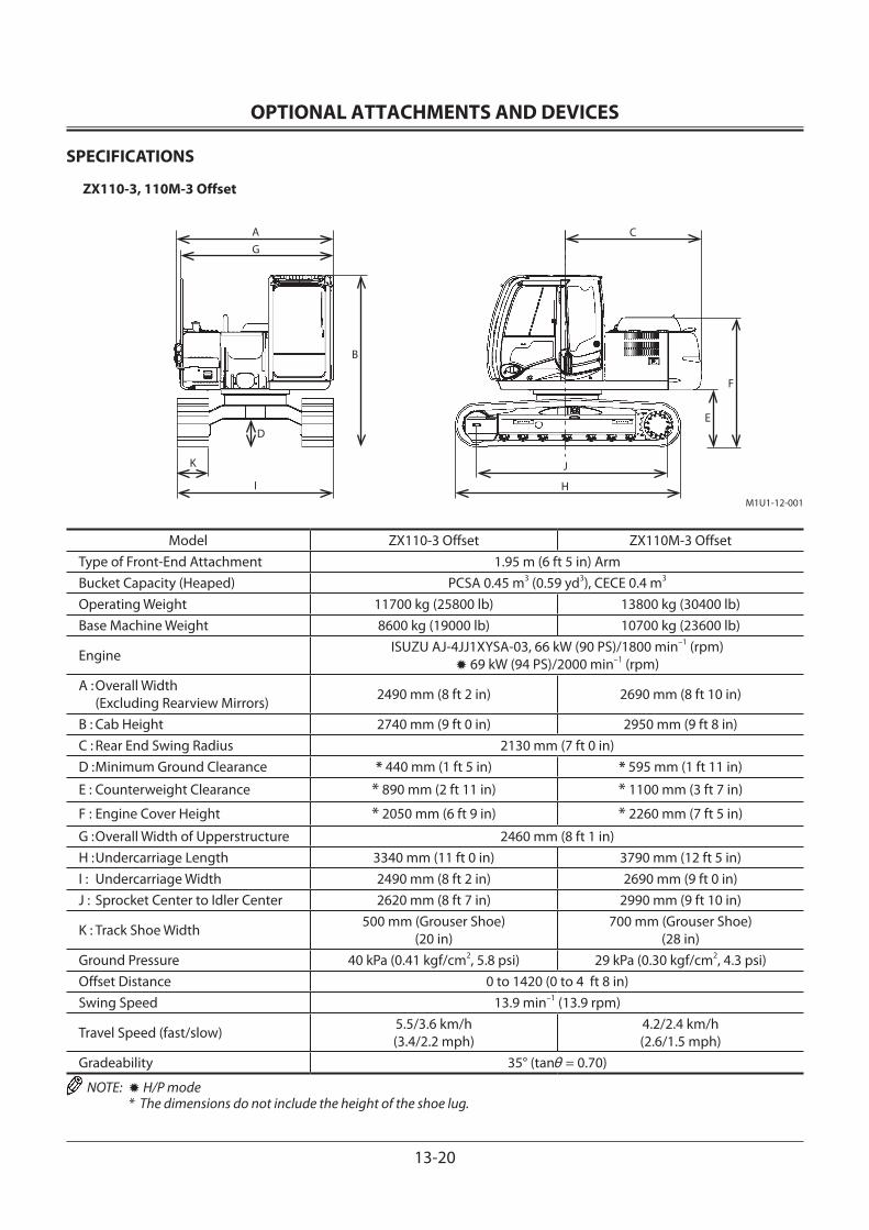
OPTIONAL ATTACHMENTS AND DEVICES
13-20
SPECIFICATIONS
ZX110-3, 110M-3 Offset
M1U1-12-001
AG
D
K
I
B
C
E
F
J
H
Model ZX110-3 Offset ZX110M-3 OffsetType of Front-End Attachment 1.95 m (6 ft 5 in) ArmBucket Capacity (Heaped) PCSA 0.45 m3 (0.59 yd3), CECE 0.4 m3
Operating Weight 11700 kg (25800 lb) 13800 kg (30400 lb)Base Machine Weight 8600 kg (19000 lb) 10700 kg (23600 lb)
Engine ISUZU AJ-4JJ1XYSA-03, 66 kW (90 PS)/1800 min–1 (rpm)✹ 69 kW (94 PS)/2000 min–1 (rpm)
A : Overall Width (Excluding Rearview Mirrors) 2490 mm (8 ft 2 in) 2690 mm (8 ft 10 in)
B : Cab Height 2740 mm (9 ft 0 in) 2950 mm (9 ft 8 in)C : Rear End Swing Radius 2130 mm (7 ft 0 in)D : Minimum Ground Clearance * 440 mm (1 ft 5 in) * 595 mm (1 ft 11 in)
E : Counterweight Clearance * 890 mm (2 ft 11 in) * 1100 mm (3 ft 7 in)
F : Engine Cover Height * 2050 mm (6 ft 9 in) * 2260 mm (7 ft 5 in)
G : Overall Width of Upperstructure 2460 mm (8 ft 1 in)H : Undercarriage Length 3340 mm (11 ft 0 in) 3790 mm (12 ft 5 in)I : Undercarriage Width 2490 mm (8 ft 2 in) 2690 mm (9 ft 0 in)J : Sprocket Center to Idler Center 2620 mm (8 ft 7 in) 2990 mm (9 ft 10 in)
K : Track Shoe Width 500 mm (Grouser Shoe) (20 in)
700 mm (Grouser Shoe) (28 in)
Ground Pressure 40 kPa (0.41 kgf/cm2, 5.8 psi) 29 kPa (0.30 kgf/cm2, 4.3 psi)Offset Distance 0 to 1420 (0 to 4 ft 8 in)Swing Speed 13.9 min–1 (13.9 rpm)
Travel Speed (fast/slow) 5.5/3.6 km/h (3.4/2.2 mph)
4.2/2.4 km/h (2.6/1.5 mph)
Gradeability 35° (tanθ = 0.70)
NOTE: ✹ H/P mode * The dimensions do not include the height of the shoe lug.
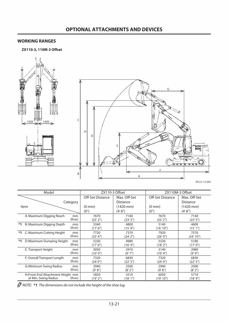
OPTIONAL ATTACHMENTS AND DEVICES
13-21
WORKING RANGES
ZX110-3, 110M-3 Offset
Model ZX110-3 Offset ZX110M-3 Offset
CategoryItem
Off-Set Distance
(0 mm)(0”)
Max. Off-Set Distance(1420 mm)(4' 8”)
Off-Set Distance
(0 mm)(0”)
Max. Off-Set Distance(1420 mm)(4' 8”)
A: Maximum Digging Reach mm (ft•in)
7670 (25' 2”)
7140(23' 5”)
7670(25' 2”)
7140(23' 5”)
*1 B: Maximum Digging Depth mm (ft•in)
5340 (17' 6”)
4800 (15' 9”)
5140 (16' 10”)
4600 (15' 1”)
*1 C: Maximum Cutting Height mm (ft•in)
7720 (25' 4”)
7370 (24' 2”)
7920 (26' 0”)
7570 (24' 10”)
*1 D: Maximum Dumping Height mm (ft•in)
5330 (17' 6”)
4980 (16' 4”)
5530 (18' 2”)
5180 (17' 0”)
E: Transport Height mm (ft•in)
3050 (10' 0”)
2910 (9' 7”)
3140 (10' 4”)
2980 (9' 9”)
F: Overall Transport Length mm (ft•in)
7320(24’ 0”)
6830(22' 5”)
7320(24' 0”)
6830(22' 5”)
G: Minimum Swing Radius mm (ft•in)
2940(9' 8”)
2500(8' 2”)
2940(9' 8”)
2500(8' 2”)
H: Front-End Attachment Height mm at Min. Swing Radius (ft•in)
5850 (19' 2”)
5510 (18' 1”)
6050 (19' 10”)
5710 (18' 9”)
NOTE: *1 The dimensions do not include the height of the shoe lug.
M1U1-12-002
C
B
D
A
F
E
G
1420 1420
H
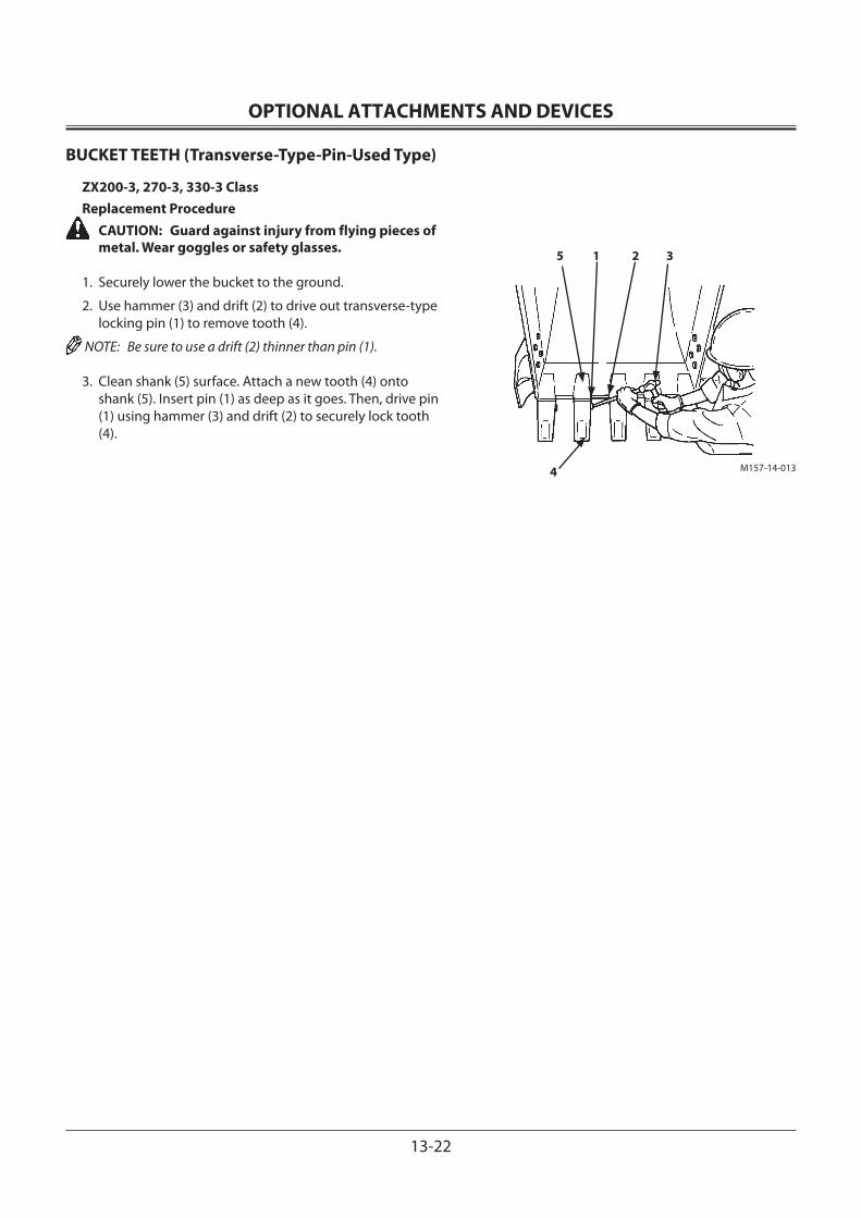
OPTIONAL ATTACHMENTS AND DEVICES
13-22
BUCKET TEETH (Transverse-Type-Pin-Used Type)
ZX200-3, 270-3, 330-3 ClassReplacement Procedure
CAUTION: Guard against injury from flying pieces of metal. Wear goggles or safety glasses.
1. Securely lower the bucket to the ground.
2. Use hammer (3) and drift (2) to drive out transverse-type locking pin (1) to remove tooth (4).
NOTE: Be sure to use a drift (2) thinner than pin (1).
3. Clean shank (5) surface. Attach a new tooth (4) onto shank (5). Insert pin (1) as deep as it goes. Then, drive pin (1) using hammer (3) and drift (2) to securely lock tooth (4).
M157-14-013
5 1 2 3
4
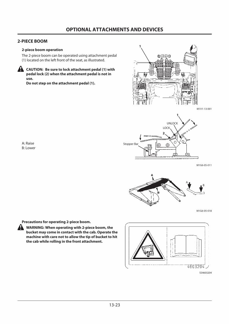
OPTIONAL ATTACHMENTS AND DEVICES
13-23
2-PIECE BOOM
2-piece boom operationThe 2-piece boom can be operated using attachment pedal (1) located on the left front of the seat, as illustrated.
CAUTION: Be sure to lock attachment pedal (1) with pedal lock (2) when the attachment pedal is not in use. Do not step on the attachment pedal (1).
A: RaiseB: Lower
Precautions for operating 2-piece boom. WARNING: When operating with 2-piece boom, the
bucket may come in contact with the cab. Operate the machine with care not to allow the tip of bucket to hit the cab while rolling in the front attachment.
1
M1V1-13-001
Stopper Bar
LOCKUNLOCK
M1G6-05-011
M1G6-05-018
AB
SS4603204
1
2
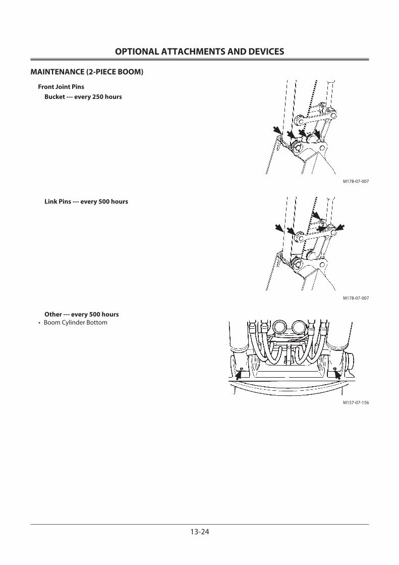
OPTIONAL ATTACHMENTS AND DEVICES
13-24
MAINTENANCE (2-PIECE BOOM)
Front Joint PinsBucket --- every 250 hours
Link Pins --- every 500 hours
Other --- every 500 hours• Boom Cylinder Bottom
M178-07-007
M178-07-007
M157-07-156
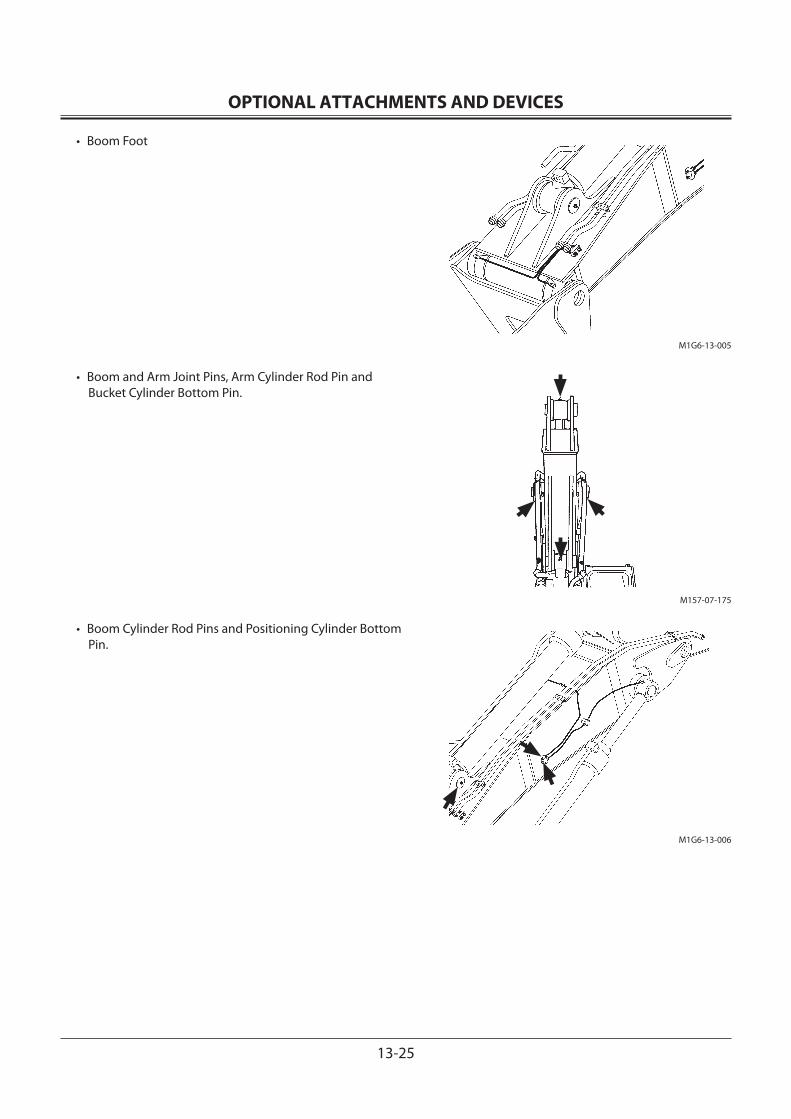
OPTIONAL ATTACHMENTS AND DEVICES
13-25
• Boom Foot
• Boom and Arm Joint Pins, Arm Cylinder Rod Pin and Bucket Cylinder Bottom Pin.
• Boom Cylinder Rod Pins and Positioning Cylinder Bottom Pin.
M1G6-13-005
M157-07-175
M1G6-13-006
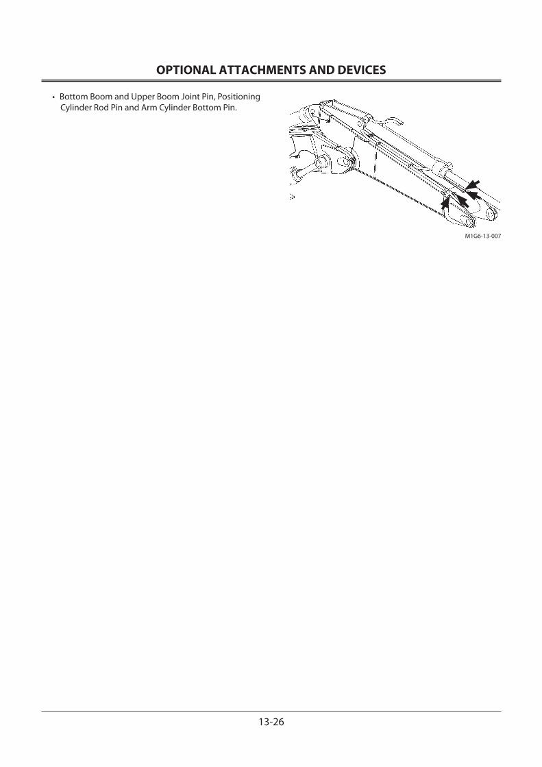
OPTIONAL ATTACHMENTS AND DEVICES
13-26
• Bottom Boom and Upper Boom Joint Pin, Positioning Cylinder Rod Pin and Arm Cylinder Bottom Pin.
M1G6-13-007
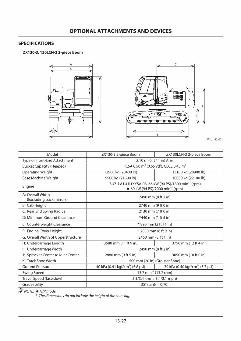
OPTIONAL ATTACHMENTS AND DEVICES
13-27
SPECIFICATIONS
ZX130-3, 130LCN-3 2-piece Boom
Model ZX130-3 2-piece Boom ZX130LCN-3 2-piece BoomType of Front-End Attachment 2.10 m (6 ft 11 in) ArmBucket Capacity (Heaped) PCSA 0.50 m3 (0.65 yd3), CECE 0.45 m3
Operating Weight 12900 kg (28400 lb) 13100 kg (28900 lb)Base Machine Weight 9900 kg (21600 lb) 10000 kg (22100 lb)
Engine ISUZU AJ-4JJ1XYSA-03, 66 kW (90 PS)/1800 min–1 (rpm)✹ 69 kW (94 PS)/2000 min–1 (rpm)
A: Overall Width (Excluding back mirrors) 2490 mm (8 ft 2 in)
B: Cab Height 2740 mm (9 ft 0 in)C: Rear End Swing Radius 2130 mm (7 ft 0 in)
D: Minimum Ground Clearance *440 mm (1 ft 5 in)
E: Counterweight Clearance * 890 mm (2 ft 11 in)
F: Engine Cover Height * 2050 mm (6 ft 9 in)
G: Overall Width of Upperstructure 2460 mm (8 ft 1 in)H: Undercarriage Length 3580 mm (11 ft 9 in) 3750 mm (12 ft 4 in)I: Undercarriage Width 2490 mm (8 ft 2 in)J: Sprocket Center to Idler Center 2880 mm (9 ft 5 in) 3050 mm (10 ft 0 in)K: Track Shoe Width 500 mm (20 in) (Grouser Shoe) Ground Pressure 40 kPa (0.41 kgf/cm2) (5.8 psi) 39 kPa (0.40 kgf/cm2) (5.7 psi)Swing Speed 13.7 min–1 (13.7 rpm)Travel Speed (fast/slow) 5.5/3.4 km/h (3.4/2.1 mph)Gradeability 35° (tanθ = 0.70)
NOTE: ✹ H/P mode * The dimensions do not include the height of the shoe lug.
M1U1-12-001
AG
D
K
I
B
C
E
F
J
H
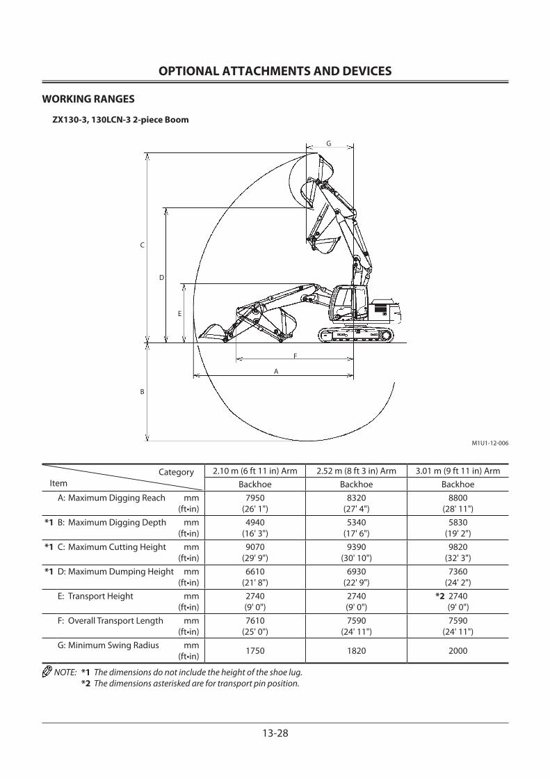
OPTIONAL ATTACHMENTS AND DEVICES
13-28
WORKING RANGES
ZX130-3, 130LCN-3 2-piece Boom
CategoryItem
2.10 m (6 ft 11 in) Arm 2.52 m (8 ft 3 in) Arm 3.01 m (9 ft 11 in) ArmBackhoe Backhoe Backhoe
A: Maximum Digging Reach mm (ft•in)
7950(26' 1")
8320(27' 4")
8800(28' 11")
*1 B: Maximum Digging Depth mm (ft•in)
4940(16' 3")
5340(17' 6")
5830(19' 2")
*1 C: Maximum Cutting Height mm (ft•in)
9070(29' 9")
9390(30' 10")
9820(32' 3")
*1 D: Maximum Dumping Height mm (ft•in)
6610(21' 8")
6930(22' 9")
7360(24' 2")
E: Transport Height mm (ft•in)
2740(9' 0")
2740(9' 0")
*2 2740 (9' 0")
F: Overall Transport Length mm (ft•in)
7610(25' 0")
7590(24' 11")
7590(24' 11")
G: Minimum Swing Radius mm (ft•in) 1750 1820 2000
NOTE: *1 The dimensions do not include the height of the shoe lug. *2 The dimensions asterisked are for transport pin position.
M1U1-12-006
A
G
C
D
E
F
B

OPTIONAL ATTACHMENTS AND DEVICES
13-29
SHOE TYPES AND APPLICATIONS
ZX130-3 2-piece Boom
Shoe Width 500 mm (20”)Grouser Shoe
600 mm (24”)Grouser Shoe
700 mm (28”)Grouser Shoe
800 mm (31”)Grouser Shoe
Application For Ordinary Ground (Standard)
For Ordinary Ground (Option)
For Weak Footing (Option)
For Weak Footing (Option)
Operating Weight kg (lb)
12900 (28400)
13100 (28900)
13300 (29300)
13600 (30000)
Base Machine Weight kg (lb)
9900 (21600)
10100 (22300)
10300 (22700)
10500 (23200)
Cab Height mm (ft•in)
2740(9' 0”)
2740(9' 0”)
2740(9' 0”)
2740(9' 0”)
Minimum Ground mmClearance (ft•in)
✹ 440(1' 5”)
✹ 440(1' 5”)
✹ 440(1' 5”)
✹ 440(1' 5”)
Undercarriage mmLength (ft•in)
3580(11' 9”)
3580(11' 9”)
3580(11' 9”)
3580(11' 9”)
Undercarriage Width mm (ft•in)
2490(8' 2”)
2590(8' 6”)
2690(8' 10”)
2790(8' 2”)
Ground Pressure 40 kPa(0.41 kgf/cm2, 5.8 psi)
34 kPa(0.35 kgf/cm2, 5.0 psi)
29 kPa(0.30 kgf/cm2, 4.3 psi)
26 kPa(0.27 kgf/cm2, 3.8 psi)
Shoe Width 500 mm (20”)Pad Crawler Shoe
Application For Paved Road (Option)
Operating Weight kg (lb)
12800(28200)
Base Machine Weight kg (lb)
9700(21800)
Cab Height mm (ft•in)
2780(9' 1")
Minimum Ground mmClearance (ft•in)
500(1' 8")
Undercarriage mmLength (ft•in)
3660(12' 0")
Undercarriage Width mm (ft•in)
2490(8' 2")
Ground Pressure 40 kPa(0.41 kgf/cm2, 5.8 psi)
NOTE: • The specifications for the front-end attachment are for a 2.10 m (6 ft 11 in) arm with PCSA 0.50 m3 (0.65 yd3) stan-dard bucket.
• 600 mm (24 in), 700 mm (28 in), 800 mm (31 in) grouser shoe, 500 mm (20 in) pad crawler shoe should not be used on gravel or rocky ground.
• ✹ The dimensions do not include the height of the shoe lug.
OPTIONAL ATTACHMENTS AND DEVICES
13-30
SHOE TYPES AND APPLICATIONS
ZX130LCN-3 2-piece Boom (without Blade)
Shoe Width 500 mm (20”)Grouser Shoe
600 mm (24”)Grouser Shoe
700 mm (28”)Grouser Shoe
800 mm (31”)Grouser Shoe
Application For Ordinary Ground (Standard)
For Ordinary Ground (Option)
For Weak Footing (Option)
For Weak Footing (Option)
Operating Weight kg (lb)
13100(28900)
13300(29300)
13500(29800)
13700(30200)
Base Machine Weight kg (lb)
10000(22100)
10200(22700)
10400(23200)
10700(23600)
Cab Height mm (ft•in)
2740(9' 0”)
2740(9' 0”)
2740(9' 0”)
2740(9' 0”)
Minimum Ground mmClearance (ft•in)
✹ 440(1' 5”)
✹ 440(1' 5”)
✹ 440(1' 5”)
✹ 440(1' 5”)
Undercarriage mmLength (ft•in)
3750(12' 4”)
3750(12' 4”)
3750(12' 4”)
3750(12' 4”)
Undercarriage Width mm (ft•in)
2490(8' 2”)
2590(8' 6”)
2690(8' 10”)
2790(8' 2”)
Ground Pressure 39 kPa(0.40 kgf/cm2, 5.7 psi)
33 kPa(0.34 kgf/cm2, 4.8 psi)
28 kPa(0.29 kgf/cm2, 4.1 psi)
25 kPa(0.25 kgf/cm2, 3.6 psi)
Shoe Width 500 mm (20”)Pad Crawler Shoe
Application For Ordinary Ground (Option)
Operating Weight kg (lb)
12900(28400)
Base Machine Weight kg (lb)
9900(22300)
Cab Height mm (ft•in)
2780(9' 1")
Minimum Ground mmClearance (ft•in)
500(1' 8")
Undercarriage mmLength (ft•in)
3830(12' 7")
Undercarriage Width mm (ft•in)
2490(8' 2")
Ground Pressure 38 kPa(0.39 kgf/cm2, 5.5 psi)
NOTE: • The specifications for the front-end attachment are for a 2.10 m (6 ft 11 in) arm with PCSA 0.50 m3 (0.65 yd3) stan-dard bucket.
• 600 mm (24 in), 700 mm (28 in), 800 mm (31 in) grouser shoe, 500 mm (20 in) pad crawler shoe should not be used on gravel or rocky ground.
• ✹ The dimensions do not include the height of the shoe lug.
OPTIONAL ATTACHMENTS AND DEVICES
13-31
SPECIFICATIONS
ZX210-3, 210LC-3 2-piece Boom
T1V1-01-01-006
Model ZX210-3 2-piece Boom ZX210LC-3 2-piece BoomType of Front-End Attachment 2.91 m (9 ft 7 in) ArmBucket Capacity (Heaped) PCSA 0.80 m3 (1.05 yd3), CECE 0.7 m3
Operating Weight 20900 kg (46100 lb) 21500 kg (47400 lb)Base Machine Weight 15900 kg (35100 lb) 16500 kg (36400 lb)Engine Isuzu AI-4HK1XYSA-02 122 kW/2000 min–1 (166 PS/2000 rpm)A: Overall Width (Excluding back mirrors) 2860 mm (9 ft 5 in) 2990 mm (9 ft 10 in)
B: Cab Height 2950 mm (9 ft 8 in)C Rear End Swing Radius 2750 mm (9 ft 0 in)D: Minimum Ground Clearance *450 mm (18 in) E: Counterweight Clearance * 1030 mm (3 ft 5 in) F: Engine Cover Height * 2270 mm (7 ft 5 in) G: Overall Width of Upperstructure 2710 mm (8 ft 11 in)H: Undercarriage Length 4170 mm (13 ft 8 in) 4470 mm (14 ft 8 in)I: Undercarriage Width 2800 mm (9 ft 2 in) 2990 mm (9 ft 10 in)J: Sprocket Center to Idler Center 3370 mm (11 ft 1 in) 3660 mm (12 ft 0 in)K: Track Shoe Width 600 mm (24 in) (Grouser shoe)Ground Pressure 47 kPa (0.48 kgf/cm2, 6.8 psi) 44 kPa (0.45 kgf/cm2, 6.4 psi)Swing Speed 13.3 min–1 (rpm)Travel Speed (fast/slow) 5.5/3.5 km/h (3.4/2.2 mph)Gradeability 35° (tanθ = 0.70)
NOTE: * The dimensions do not include the height of the shoe lug.

OPTIONAL ATTACHMENTS AND DEVICES
13-32
WORKING RANGES
ZX210-3, 210LC-3 2-piece Boom
CategoryItem
2.03 m (6 ft 8 in) Arm 2.42 m (7 ft 11 in) Arm 2.91 m (9 ft 7 in) ArmBackhoe Backhoe Backhoe
mm ft•in mm ft•in mm ft•in A: Maximum Digging Reach 9210 30’3” 9430 30’11” 9930 32’7” *B: Maximum Digging Depth *5420 *17’9” *5720 *18’9” *6230 *20’5” *C: Maximum Cutting Height *10590 *34’9” *10640 *34’11” *11080 *36’4” *D: Maximum Dumping Height *7670 *25’2” *7700 *25’3” *8150 *26’9” E: Transport Height 3020 9’11” 3060 10’0” 3010 9’11” F: Overall Transport Length 9650 31’8” 9620 31’7” 9560 31’4” G: Minimum Swing Radius 2630 8’8” 2630 8’8” 2320 7’7”
NOTE: * The dimensions do not include the height of the shoe lug.
M1V1-13-003
A
G
B
D
C
F
E
Backhoe
OPTIONAL ATTACHMENTS AND DEVICES
13-33
SHOE TYPES AND APPLICATIONS
ZX210-3 2-piece Boom
Shoe Width 600 mm (24”)Grouser Shoe
700 mm (28”)Grouser Shoe
800 mm (31”)Grouser Shoe
900 mm (35”)Grouser Shoe
Application For Ordinary Ground For Weak Footing For Weak Footing For Weak Footing
Operating Weight kg (lb)
20900(46100)
21300(47000)
21600(47600)
22200(48900)
Base Machine Weight kg (lb)
15900(35100)
16300(35900)
16600(36600)
17000(37500)
Cab Height mm (ft•in)
2950(9’8”)
2950(9’8”)
2950(9’8”)
2950(9’8”)
Minimum Ground mmClearance (ft•in)
✹ 450(18”)
✹ 450(18”)
✹ 450(18”)
✹ 450(18”)
Undercarriage mmLength (ft•in)
4170(13’8”)
4170(13’8”)
4170(13’8”)
4170(13’8”)
Undercarriage Width mm (ft•in)
2800(9’2”)
2900(9’6”)
3000(9’10”)
3100(10’2”)
Ground Pressure47 kPa
(0.48 kgf/cm2,6.8 psi)
41 kPa(0.42 kgf/cm2,
6.0 psi)
36 kPa(0.37 kgf/cm2,
5.3 psi)
32 kPa(0.33 kgf/cm2,
4.7 psi)
ZX210LC-3 2-piece Boom
Shoe Width 600 mm (24”)Grouser Shoe
700 mm (28”)Grouser Shoe
800 mm (31”)Grouser Shoe
900 mm (35”)Grouser Shoe
Application For Ordinary Ground For Weak Footing For Weak Footing For Weak Footing
Operating Weight kg (lb)
21500(47400)
21900(48300)
22100(48700)
22600(49800)
Base Machine Weight kg (lb)
16500(36400)
16900(37300)
17100(37700)
17600(38800)
Cab Height mm (ft•in)
2950(9’8”)
2950(9’8”)
2950(9’8”)
2950(9’8”)
Minimum Ground mmClearance (ft•in)
✹ 450(18”)
✹ 450(18”)
✹ 450(18”)
✹ 450(18”)
Undercarriage mmLength (ft•in)
4460(14’8”)
4460(14’8”)
4460(14’8”)
4460(14’8”)
Undercarriage Width mm (ft•in)
2990(9’14”)
3090(10’2”)
3190(10’6”)
3290(10’10”)
Ground Pressure44 kPa
(0.45 kgf/cm2,6.4 psi)
39 kPa(0.40 kgf/cm2,
5.7 psi)
34 kPa(0.35 kgf/cm2,
5.0 psi)
31 kPa(0.32 kgf/cm2,
4.6 psi)
NOTE: • The specifications for the front-end attachment is for 2.91 m (9 ft 7 in) arm with PCSA 0.8 m3 (1.05 yd3) bucket. • 700, 800 mm (28, 31 in) and 900 mm (35 in) grouser shoe should not be used on gravel or rocky ground. • ✹ The dimensions do not include the height of the shoe lug.
OPTIONAL ATTACHMENTS AND DEVICES
13-34
SPECIFICATIONS
ZX210LCN-3, 240N-3 2-piece Boom
T1V1-01-01-006
Model ZX210LCN-3 2-piece Boom ZX240N-3 2-piece BoomType of Front-End Attachment 2.91 m (9 ft 7 in) ArmBucket Capacity (Heaped) PCSA 0.80 m3 (1.05 yd3), CECE 0.7 m3
Operating Weight 21700 kg (47800 lb) 23200 kg (51100 lb)Base Machine Weight 16700 kg (36800 lb) 18200 kg (40100 lb)Engine Isuzu AI-4HK1XYSA-02 122 kW/2000 min–1 (166 PS/2000 rpm)A: Overall Width (Excluding back mirrors) 2500 mm (8 ft 2 in)
B: Cab Height 2950 mm (9 ft 8 in)C Rear End Swing Radius 2750 mm (9 ft 0 in)D: Minimum Ground Clearance *450 mm (18 in) E: Counterweight Clearance * 1020 mm (3 ft 4 in) F: Engine Cover Height * 2270 mm (7 ft 5 in) G: Overall Width of Upperstructure 2480 mm (8 ft 2 in)H: Undercarriage Length 4460 mm (14 ft 8 in) 4260 mm (14 ft 0 in)I: Undercarriage Width 2480 mm (8 ft 2 in)J: Sprocket Center to Idler Center 3660 mm (12 ft 0 in) 3460 mm (11 ft 4 in)K: Track Shoe Width 500 mm (20 in) (Grouser shoe) 550 mm (22 in) (Grouser shoe)Ground Pressure 54 kPa (0.55 kgf/cm2, 7.8 psi) 55 kPa (0.56 kgf/cm2, 8.0 psi)Swing Speed 13.3 min–1 (rpm)Travel Speed (fast/slow) 5.5/3.5 km/h (3.4/2.2 mph)Gradeability 35° (tanθ = 0.70)
NOTE: * The dimensions do not include the height of the shoe lug.
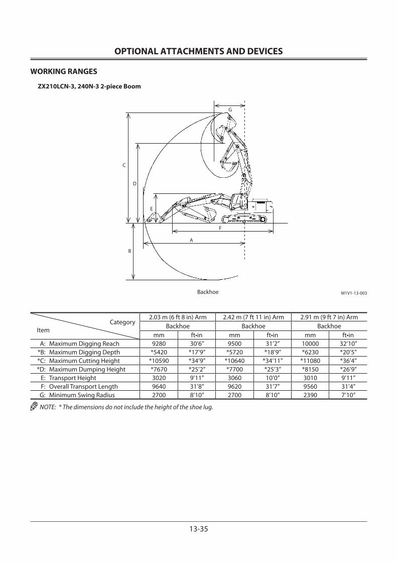
OPTIONAL ATTACHMENTS AND DEVICES
13-35
WORKING RANGES
ZX210LCN-3, 240N-3 2-piece Boom
CategoryItem
2.03 m (6 ft 8 in) Arm 2.42 m (7 ft 11 in) Arm 2.91 m (9 ft 7 in) ArmBackhoe Backhoe Backhoe
mm ft•in mm ft•in mm ft•in A: Maximum Digging Reach 9280 30’6” 9500 31’2” 10000 32’10” *B: Maximum Digging Depth *5420 *17’9” *5720 *18’9” *6230 *20’5” *C: Maximum Cutting Height *10590 *34’9” *10640 *34’11” *11080 *36’4” *D: Maximum Dumping Height *7670 *25’2” *7700 *25’3” *8150 *26’9” E: Transport Height 3020 9’11” 3060 10’0” 3010 9’11” F: Overall Transport Length 9640 31’8” 9620 31’7” 9560 31’4” G: Minimum Swing Radius 2700 8’10” 2700 8’10” 2390 7’10”
NOTE: * The dimensions do not include the height of the shoe lug.
M1V1-13-003
A
G
B
D
C
F
E
Backhoe
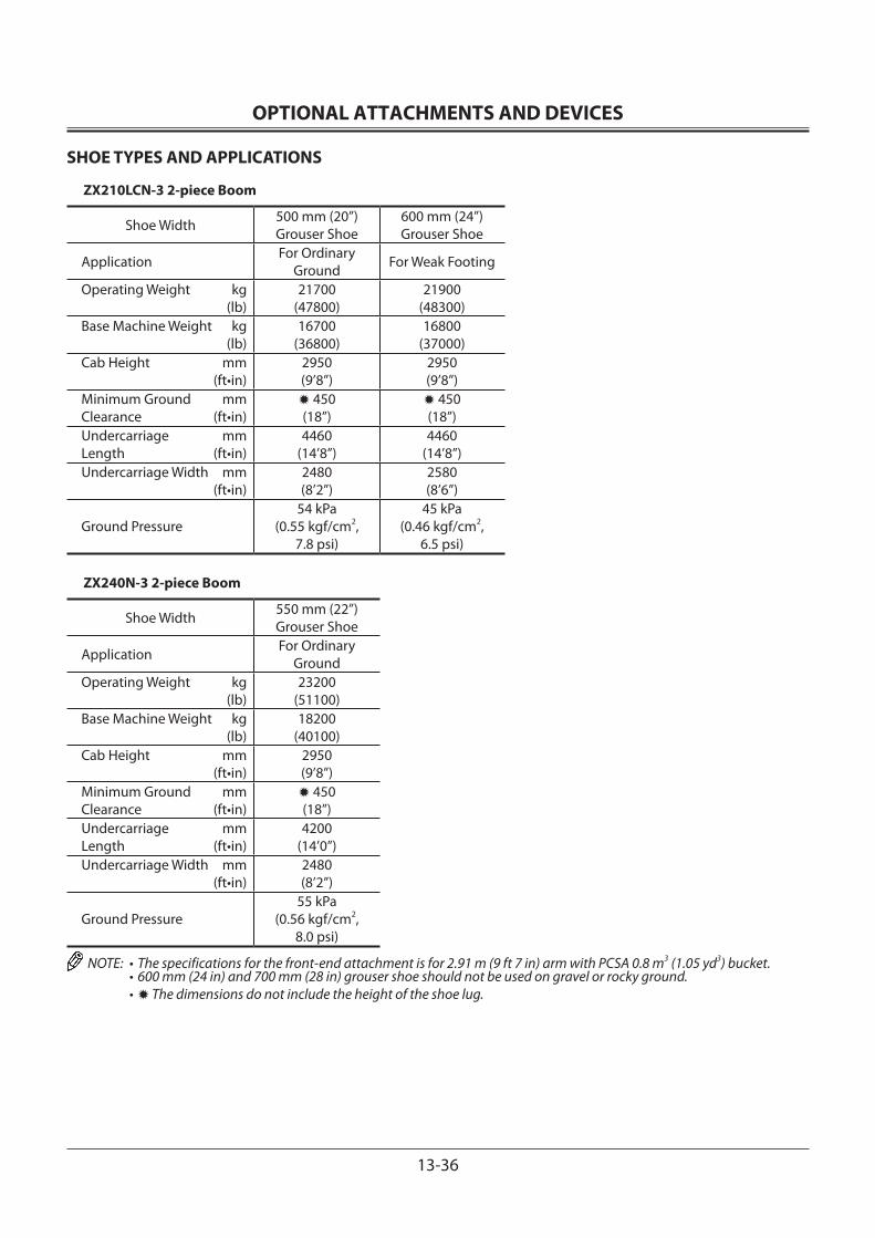
OPTIONAL ATTACHMENTS AND DEVICES
13-36
SHOE TYPES AND APPLICATIONS
ZX210LCN-3 2-piece Boom
Shoe Width 500 mm (20”)Grouser Shoe
600 mm (24”)Grouser Shoe
Application For Ordinary Ground For Weak Footing
Operating Weight kg (lb)
21700(47800)
21900(48300)
Base Machine Weight kg (lb)
16700(36800)
16800(37000)
Cab Height mm (ft•in)
2950(9’8”)
2950(9’8”)
Minimum Ground mmClearance (ft•in)
✹ 450(18”)
✹ 450(18”)
Undercarriage mmLength (ft•in)
4460(14’8”)
4460(14’8”)
Undercarriage Width mm (ft•in)
2480(8’2”)
2580(8’6”)
Ground Pressure54 kPa
(0.55 kgf/cm2,7.8 psi)
45 kPa(0.46 kgf/cm2,
6.5 psi)
ZX240N-3 2-piece Boom
Shoe Width 550 mm (22”)Grouser Shoe
Application For Ordinary Ground
Operating Weight kg (lb)
23200(51100)
Base Machine Weight kg (lb)
18200(40100)
Cab Height mm (ft•in)
2950(9’8”)
Minimum Ground mmClearance (ft•in)
✹ 450(18”)
Undercarriage mmLength (ft•in)
4200(14’0”)
Undercarriage Width mm (ft•in)
2480(8’2”)
Ground Pressure55 kPa
(0.56 kgf/cm2,8.0 psi)
NOTE: • The specifications for the front-end attachment is for 2.91 m (9 ft 7 in) arm with PCSA 0.8 m3 (1.05 yd3) bucket. • 600 mm (24 in) and 700 mm (28 in) grouser shoe should not be used on gravel or rocky ground. • ✹ The dimensions do not include the height of the shoe lug.

OPTIONAL ATTACHMENTS AND DEVICES
13-37
M1V1-12-001
A
G
B
D
K
I
C
F
E
J
H
SPECIFICATIONS
ZX250LC-3, 250LCN-3 2-piece Boom
Model ZX250LC-3 2-piece Boom ZX250LCN-3 2-piece BoomType of Front-End Attachment 2.19 m (9 ft 9 in) ArmBucket Capacity (Heaped) PCSA 1.0 m3 (1.3 yd3), CECE 0.9 m3
Operating Weight 25600 kg (56400 lb) 25500 kg (56200 lb)Base Machine Weight 19600 kg (43200 lb) 19500 kg (43000 lb)Engine Isuzu AH-4HK1XYSA-01 132 kW/2000 min–1 (180 PS/2000 rpm)A: Overall Width (Excluding back mirrors) 3190 mm (10 ft 6 in) 2990 mm (9 ft 10 in)
B: Cab Height 3010 mm (9 ft 11 in)C Rear End Swing Radius 2940 mm (9 ft 8 in)D: Minimum Ground Clearance *460 mm (18 in) E: Counterweight Clearance * 1090 mm (3 ft 7 in) F: Engine Cover Height * 2425 mm (8 ft) G: Overall Width of Upperstructure 2890 mm (9 ft 6 in)H: Undercarriage Length 4640 mm (15 ft 3 in)I: Undercarriage Width 3190 mm (10 ft 6 in) 2990 mm (9 ft 10 in)J: Sprocket Center to Idler Center 3845 mm (12 ft 7 in)K: Track Shoe Width 600 mm (24 in) (Grouser shoe)Ground Pressure 51 kPa (0.52 kgf/cm2, 7.4 psi)Swing Speed 13.5 min–1 (rpm)Travel Speed (fast/slow) 5.5/3.4 km/h (3.4/2.1 mph)Gradeability 35° (tanθ = 0.70)
NOTE: * The dimensions do not include the height of the shoe lug.
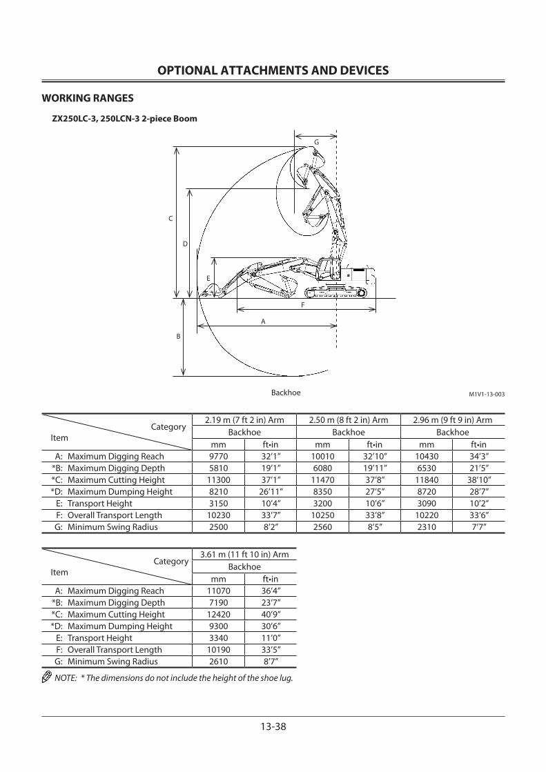
OPTIONAL ATTACHMENTS AND DEVICES
13-38
WORKING RANGES
ZX250LC-3, 250LCN-3 2-piece Boom
CategoryItem
2.19 m (7 ft 2 in) Arm 2.50 m (8 ft 2 in) Arm 2.96 m (9 ft 9 in) ArmBackhoe Backhoe Backhoe
mm ft•in mm ft•in mm ft•in A: Maximum Digging Reach 9770 32’1” 10010 32’10” 10430 34’3” *B: Maximum Digging Depth 5810 19’1” 6080 19’11” 6530 21’5” *C: Maximum Cutting Height 11300 37’1” 11470 37’8” 11840 38’10” *D: Maximum Dumping Height 8210 26’11” 8350 27’5” 8720 28’7” E: Transport Height 3150 10’4” 3200 10’6” 3090 10’2” F: Overall Transport Length 10230 33’7” 10250 33’8” 10220 33’6” G: Minimum Swing Radius 2500 8’2” 2560 8’5” 2310 7’7”
CategoryItem
3.61 m (11 ft 10 in) ArmBackhoe
mm ft•in A: Maximum Digging Reach 11070 36’4” *B: Maximum Digging Depth 7190 23’7” *C: Maximum Cutting Height 12420 40’9” *D: Maximum Dumping Height 9300 30’6” E: Transport Height 3340 11’0” F: Overall Transport Length 10190 33’5” G: Minimum Swing Radius 2610 8’7”
NOTE: * The dimensions do not include the height of the shoe lug.
M1V1-13-003
A
G
B
D
C
F
E
Backhoe
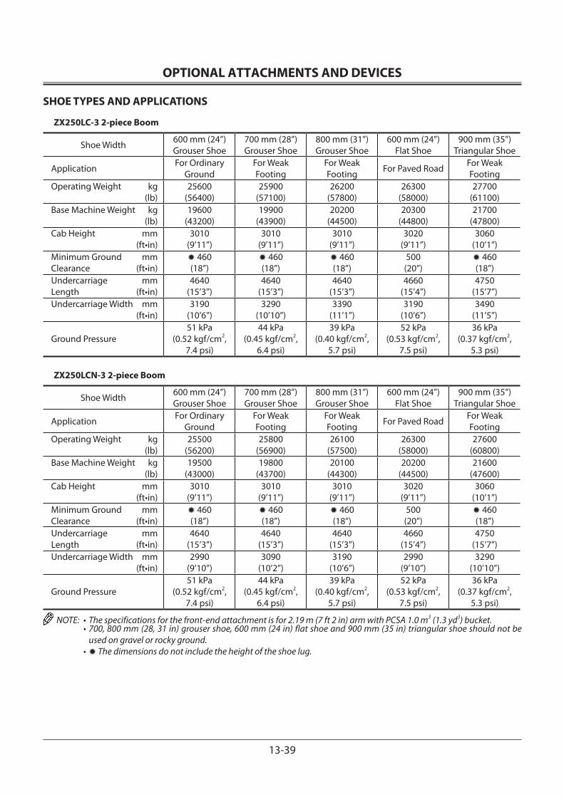
OPTIONAL ATTACHMENTS AND DEVICES
13-39
SHOE TYPES AND APPLICATIONS
ZX250LC-3 2-piece Boom
Shoe Width 600 mm (24”)Grouser Shoe
700 mm (28”)Grouser Shoe
800 mm (31”)Grouser Shoe
600 mm (24”)Flat Shoe
900 mm (35”)Triangular Shoe
Application For Ordinary Ground
For Weak Footing
For Weak Footing For Paved Road For Weak
FootingOperating Weight kg (lb)
25600(56400)
25900(57100)
26200(57800)
26300(58000)
27700(61100)
Base Machine Weight kg (lb)
19600(43200)
19900(43900)
20200(44500)
20300(44800)
21700(47800)
Cab Height mm (ft•in)
3010(9’11”)
3010(9’11”)
3010(9’11”)
3020(9’11”)
3060(10’1”)
Minimum Ground mmClearance (ft•in)
✹ 460(18”)
✹ 460(18”)
✹ 460(18”)
500(20”)
✹ 460(18”)
Undercarriage mmLength (ft•in)
4640(15’3”)
4640(15’3”)
4640(15’3”)
4660(15’4”)
4750(15’7”)
Undercarriage Width mm (ft•in)
3190(10’6”)
3290(10’10”)
3390(11’1”)
3190(10’6”)
3490(11’5”)
Ground Pressure51 kPa
(0.52 kgf/cm2,7.4 psi)
44 kPa(0.45 kgf/cm2,
6.4 psi)
39 kPa(0.40 kgf/cm2,
5.7 psi)
52 kPa(0.53 kgf/cm2,
7.5 psi)
36 kPa(0.37 kgf/cm2,
5.3 psi)
ZX250LCN-3 2-piece Boom
Shoe Width 600 mm (24”)Grouser Shoe
700 mm (28”)Grouser Shoe
800 mm (31”)Grouser Shoe
600 mm (24”)Flat Shoe
900 mm (35”)Triangular Shoe
Application For Ordinary Ground
For Weak Footing
For Weak Footing For Paved Road For Weak
FootingOperating Weight kg (lb)
25500(56200)
25800(56900)
26100(57500)
26300(58000)
27600(60800)
Base Machine Weight kg (lb)
19500(43000)
19800(43700)
20100(44300)
20200(44500)
21600(47600)
Cab Height mm (ft•in)
3010(9’11”)
3010(9’11”)
3010(9’11”)
3020(9’11”)
3060(10’1”)
Minimum Ground mmClearance (ft•in)
✹ 460(18”)
✹ 460(18”)
✹ 460(18”)
500(20”)
✹ 460(18”)
Undercarriage mmLength (ft•in)
4640(15’3”)
4640(15’3”)
4640(15’3”)
4660(15’4”)
4750(15’7”)
Undercarriage Width mm (ft•in)
2990(9’10”)
3090(10’2”)
3190(10’6”)
2990(9’10”)
3290(10’10”)
Ground Pressure51 kPa
(0.52 kgf/cm2, 7.4 psi)
44 kPa(0.45 kgf/cm2,
6.4 psi)
39 kPa(0.40 kgf/cm2,
5.7 psi)
52 kPa(0.53 kgf/cm2,
7.5 psi)
36 kPa(0.37 kgf/cm2,
5.3 psi)
NOTE: • The specifications for the front-end attachment is for 2.19 m (7 ft 2 in) arm with PCSA 1.0 m3 (1.3 yd3) bucket. • 700, 800 mm (28, 31 in) grouser shoe, 600 mm (24 in) flat shoe and 900 mm (35 in) triangular shoe should not be
used on gravel or rocky ground. • ✹ The dimensions do not include the height of the shoe lug.
OPTIONAL ATTACHMENTS AND DEVICES
13-40
SPECIFICATIONS
ZX280LC-3, 280LCN-3 2-piece Boom
Model ZX280LC-3 2-piece Boom ZX280LCN-3 2-piece BoomType of Front-End Attachment 3.11 m (10 ft 2 in) ArmBucket Capacity (Heaped) PCSA 1.1 m3 (1.44 yd3), CECE 1.0 m3
Operating Weight 28500 kg (62800 lb) 28300 kg (62400 lb)Base Machine Weight 22400 kg (49400 lb) 22200 kg (48900 lb)Engine Isuzu AH-4HK1XSA-03 140 kW/2100 min–1 (190 PS/2100 rpm)A: Overall Width (Excluding back mirrors) 3190 mm (10 ft 6 in) 3000 mm (9 ft 10 in)
B: Cab Height 3100 mm (10 ft 2 in)C Rear End Swing Radius 2940 mm (9 ft 8 in)D: Minimum Ground Clearance *510 mm (20 in) E: Counterweight Clearance * 1180 mm (3 ft 10 in) F: Engine Cover Height * 2515 mm (8 ft 3 in) G: Overall Width of Upperstructure 2890 mm (9 ft 6 in)H: Undercarriage Length 4940 mm (16 ft 3 in)I: Undercarriage Width 3190 mm (10 ft 6 in) 3000 mm (9 ft 10 in)J: Sprocket Center to Idler Center 4052 mm (13 ft 4 in)K: Track Shoe Width 600 mm (24 in) (Grouser shoe)Ground Pressure 53 kPa (0.54 kgf/cm2, 7.7 psi)Swing Speed 12.6 min–1 (rpm)Travel Speed (fast/slow) 5.5/3.3 km/h (3.4/2.0 mph)Gradeability 35° (tanθ = 0.70)
NOTE: * The dimensions do not include the height of the shoe lug.
M1V1-12-001
A
G
B
D
K
I
C
F
E
J
H
OPTIONAL ATTACHMENTS AND DEVICES
13-41
WORKING RANGES
ZX280LC-3, 280LCN-3 2-piece Boom
M1V1-13-003
A
G
B
D
C
F
E
Backhoe
CategoryItem
2.42 m (7 ft 10 in) Arm 3.11 m (10 ft 2 in) Arm 3.76 m (12 ft 4 in) ArmBackhoe Backhoe Backhoe
mm ft•in mm ft•in mm ft•in A: Maximum Digging Reach 10070 33’1” 10740 35’3” 11330 37’2” *B: Maximum Digging Depth 6020 19’9” 6690 21’11” 7330 24’ 1” *C: Maximum Cutting Height 11500 37’9” 12080 39’8” 12550 41’2” *D: Maximum Dumping Height 8390 27’6” 8960 29’5” 9430 30’11” E: Transport Height 3220 10’7” 3150 10’4” 3380 11’1” F: Overall Transport Length 10330 33’11” 10300 33’10” 10310 33’10” G: Minimum Swing Radius 2820 9’3” 2580 8’6” 2740 9’0”
NOTE: * The dimensions do not include the height of the shoe lug.
OPTIONAL ATTACHMENTS AND DEVICES
13-42
SHOE TYPES AND APPLICATIONS
ZX280LC-3 2-piece Boom
Shoe Width 600 mm (24”)Grouser Shoe
700 mm (28”)Grouser Shoe
800 mm (31”)Grouser Shoe
600 mm (24”)Flat Shoe
Application For Ordinary Ground
For Weak Footing
For Weak Footing
For Paved Road
Operating Weight kg (lb)
28500(62800)
29100(64200)
29400(64800)
29400(64800)
Base Machine Weight kg (lb)
22400(49400)
23000(50700)
23300(51400)
23300(51400)
Cab Height mm (ft•in)
3100(10’2”)
3100(10’2”)
3100(10’2”)
3160(10’4”)
Minimum Ground mmClearance (ft•in)
✹ 510(20”)
✹ 510(20”)
✹ 510(20”)
550(22”)
Undercarriage mmLength (ft•in)
4940(16’3”)
4940(16’3”)
4940(16’3”)
4940(16’3”)
Undercarriage Width mm (ft•in)
3190(10’6”)
3290(10’10”)
3390(11’1”)
3190(10’6”)
Ground Pressure53 kPa
(0.54 kgf/cm2,7.7 psi)
47 kPa(0.48 kgf/cm2,
6.8 psi)
41 kPa(0.42 kgf/cm2,
6.0 psi)
55 kPa(0.56 kgf/cm2,
8.0 psi)
ZX280LCN-3 2-piece Boom
Shoe Width 600 mm (24”)Grouser Shoe
700 mm (28”)Grouser Shoe
800 mm (31”)Grouser Shoe
600 mm (24”)Flat Shoe
Application For Ordinary Ground
For Weak Footing
For Weak Footing
For Paved Road
Operating Weight kg (lb)
28300(62400)
28900(63700)
29300(64600)
29300(64400)
Base Machine Weight kg (lb)
22200(48900)
22800(50300)
23200(51100)
23200(51100)
Cab Height mm (ft•in)
3100(10’2”)
3100(10’2”)
3100(10’2”)
3260(10’8”)
Minimum Ground mmClearance (ft•in)
✹ 510(20”)
✹ 510(20”)
✹ 510(20”)
550(21”)
Undercarriage mmLength (ft•in)
4940(16’3”)
4940(16’3”)
4940(16’3”)
4940(16’4”)
Undercarriage Width mm (ft•in)
3000(10’6”)
3100(10’10”)
3200(11’1”)
3000(10’6”)
Ground Pressure53 kPa
(0.54 kgf/cm2,7.7 psi)
46 kPa(0.47 kgf/cm2,
6.7 psi)
41 kPa(0.42 kgf/cm2,
6.0 psi)
55 kPa(0.56 kgf/cm2,
8.0 psi)
NOTE: • The specifications for the front-end attachment is for 2.40 m (7 ft 10 in) arm with PCSA 1.1 m3 (1.44 yd3) bucket. • 700, 800 mm (28, 31 in) grouser shoe and 600 mm (24 in) flat shoe should not be used on gravel or rocky ground. • ✹ The dimensions do not include the height of the shoe lug.
OPTIONAL ATTACHMENTS AND DEVICES
13-43
SPECIFICATIONS
ZX350LC-3, 350LCN-3 2-piece Boom
M1V1-12-003
A
G
B
D
K
I
C
F
E
J
H
Model ZX350LC-3 2-piece Boom ZX350LCN-3 2-piece BoomType of Front-End Attachment 3.20 m (10 ft 6 in) ArmBucket Capacity (Heaped) PCSA 1.4 m3 (1.83 yd3), CECE 1.2 m3 (1.57 yd3)Operating Weight 32900 kg (72500 lb) 32800 kg (72300 lb)Base Machine Weight 25500 kg (56200 lb) 25400 kg (56000 lb)Engine Isuzu AH-6HK1XYSA-01 202 kW/1900 min–1 (275 PS/1900 rpm)A: Overall Width (Excluding back mirrors) 3190 mm (10 ft 6 in) 3000 mm (9 ft 10 in)B: Cab Height 3140 mm (10 ft 4 in)C: Rear End Swing Radius 3390 mm (11 ft 2 in)D: Minimum Ground Clearance *500 mm (20 in)E: Counterweight Clearance * 1160 mm (3 ft 10 in)F: Engine Cover Height * 2590 mm (8 ft 6 in)G: Overall Width of Upperstructure 2990 mm (9 ft 10 in)H: Undercarriage Length 4940 mm (16 ft 3 in)I: Undercarriage Width 3190 mm (10 ft 6 in) 3000 mm (9 ft 10 in)J: Sprocket Center to Idler Center 4050 mm (13 ft 3 in)K: Track Shoe Width 600 mm (24 in) (Grouser shoe)
Ground Pressure 66 kPa (0.67 kgf/cm2, 9.6 psi)
Swing Speed 10.7 min–1 (rpm)Travel Speed (fast/slow) 5.0/3.2 km/h (3.1/2.0 mph)Gradeability 35° (tanθ = 0.70)
NOTE: * The dimensions do not include the height of the shoe lug.
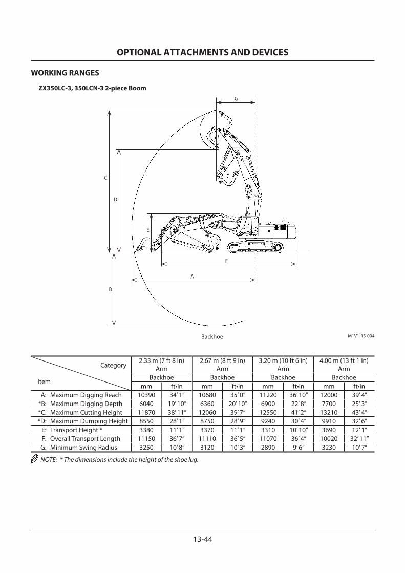
OPTIONAL ATTACHMENTS AND DEVICES
13-44
WORKING RANGES
ZX350LC-3, 350LCN-3 2-piece Boom
M1V1-13-004Backhoe
A
G
B
D
C
F
E
Category
Item
2.33 m (7 ft 8 in) Arm
2.67 m (8 ft 9 in) Arm
3.20 m (10 ft 6 in) Arm
4.00 m (13 ft 1 in) Arm
Backhoe Backhoe Backhoe Backhoemm ft•in mm ft•in mm ft•in mm ft•in
A: Maximum Digging Reach 10390 34’ 1” 10680 35’ 0” 11220 36’ 10” 12000 39’ 4” *B: Maximum Digging Depth 6040 19’ 10” 6360 20’ 10” 6900 22’ 8” 7700 25’ 3” *C: Maximum Cutting Height 11870 38’ 11” 12060 39’ 7” 12550 41’ 2” 13210 43’ 4” *D: Maximum Dumping Height 8550 28’ 1” 8750 28’ 9” 9240 30’ 4” 9910 32’ 6” E: Transport Height * 3380 11’ 1” 3370 11’ 1” 3310 10’ 10” 3690 12’ 1” F: Overall Transport Length 11150 36’ 7” 11110 36’ 5” 11070 36’ 4” 10020 32’ 11” G: Minimum Swing Radius 3250 10’ 8” 3120 10’ 3” 2890 9’ 6” 3230 10’ 7”
NOTE: * The dimensions include the height of the shoe lug.
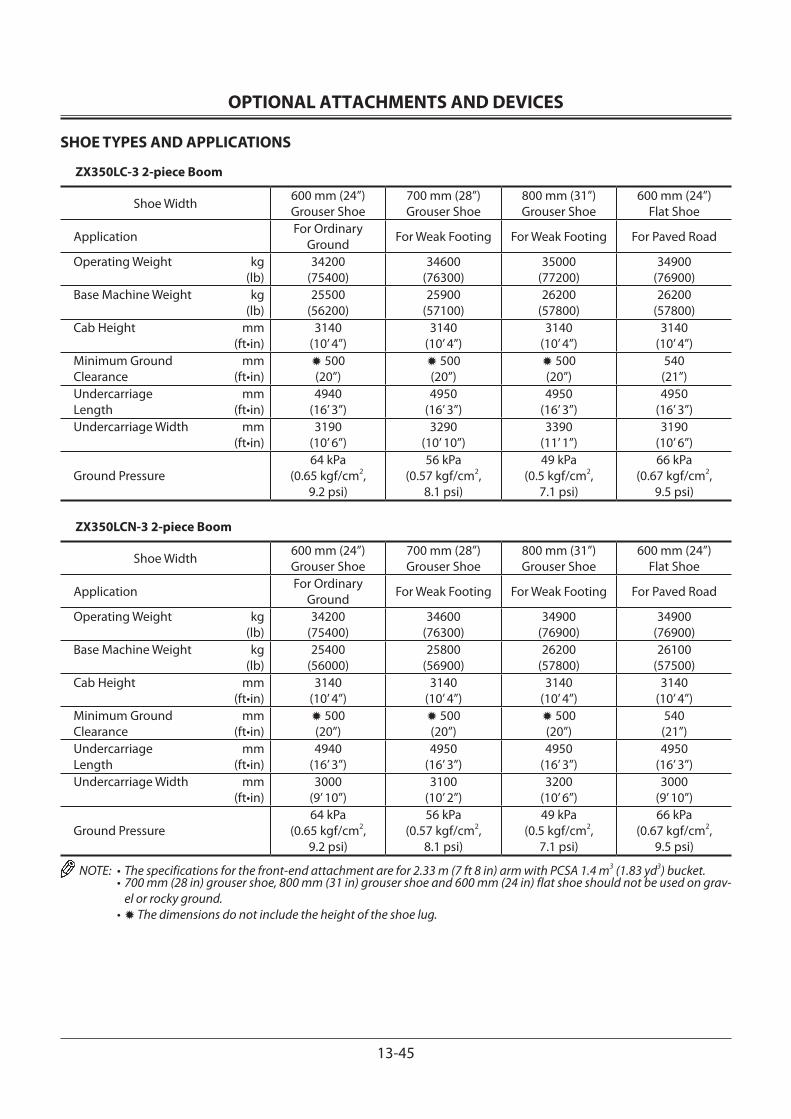
OPTIONAL ATTACHMENTS AND DEVICES
13-45
SHOE TYPES AND APPLICATIONS
ZX350LC-3 2-piece Boom
Shoe Width 600 mm (24”)Grouser Shoe
700 mm (28”)Grouser Shoe
800 mm (31”)Grouser Shoe
600 mm (24”)Flat Shoe
Application For Ordinary Ground For Weak Footing For Weak Footing For Paved Road
Operating Weight kg (lb)
34200(75400)
34600(76300)
35000(77200)
34900(76900)
Base Machine Weight kg (lb)
25500(56200)
25900(57100)
26200(57800)
26200(57800)
Cab Height mm (ft•in)
3140(10’ 4”)
3140(10’ 4”)
3140(10’ 4”)
3140(10’ 4”)
Minimum Ground mmClearance (ft•in)
✹ 500(20”)
✹ 500(20”)
✹ 500(20”)
540(21”)
Undercarriage mmLength (ft•in)
4940(16’ 3”)
4950(16’ 3”)
4950(16’ 3”)
4950(16’ 3”)
Undercarriage Width mm (ft•in)
3190(10’ 6”)
3290(10’ 10”)
3390(11’ 1”)
3190(10’ 6”)
Ground Pressure64 kPa
(0.65 kgf/cm2,9.2 psi)
56 kPa(0.57 kgf/cm2,
8.1 psi)
49 kPa(0.5 kgf/cm2,
7.1 psi)
66 kPa(0.67 kgf/cm2,
9.5 psi)
ZX350LCN-3 2-piece Boom
Shoe Width 600 mm (24”)Grouser Shoe
700 mm (28”)Grouser Shoe
800 mm (31”)Grouser Shoe
600 mm (24”)Flat Shoe
Application For Ordinary Ground For Weak Footing For Weak Footing For Paved Road
Operating Weight kg (lb)
34200(75400)
34600(76300)
34900(76900)
34900(76900)
Base Machine Weight kg (lb)
25400(56000)
25800(56900)
26200(57800)
26100(57500)
Cab Height mm (ft•in)
3140(10’ 4”)
3140(10’ 4”)
3140(10’ 4”)
3140(10’ 4”)
Minimum Ground mmClearance (ft•in)
✹ 500(20”)
✹ 500(20”)
✹ 500(20”)
540(21”)
Undercarriage mmLength (ft•in)
4940(16’ 3”)
4950(16’ 3”)
4950(16’ 3”)
4950(16’ 3”)
Undercarriage Width mm (ft•in)
3000(9’ 10”)
3100(10’ 2”)
3200(10’ 6”)
3000(9’ 10”)
Ground Pressure64 kPa
(0.65 kgf/cm2,9.2 psi)
56 kPa(0.57 kgf/cm2,
8.1 psi)
49 kPa(0.5 kgf/cm2,
7.1 psi)
66 kPa(0.67 kgf/cm2,
9.5 psi)
NOTE: • The specifications for the front-end attachment are for 2.33 m (7 ft 8 in) arm with PCSA 1.4 m3 (1.83 yd3) bucket. • 700 mm (28 in) grouser shoe, 800 mm (31 in) grouser shoe and 600 mm (24 in) flat shoe should not be used on grav-
el or rocky ground. • ✹ The dimensions do not include the height of the shoe lug.
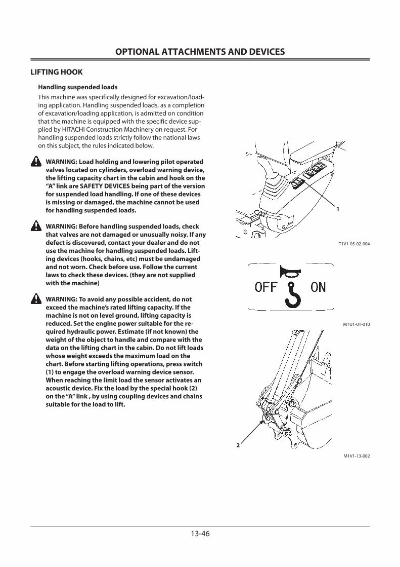
OPTIONAL ATTACHMENTS AND DEVICES
13-46
LIFTING HOOK
Handling suspended loadsThis machine was specifically designed for excavation/load-ing application. Handling suspended loads, as a completion of excavation/loading application, is admitted on condition that the machine is equipped with the specific device sup-plied by HITACHI Construction Machinery on request. For handling suspended loads strictly follow the national laws on this subject, the rules indicated below.
WARNING: Load holding and lowering pilot operated valves located on cylinders, overload warning device, the lifting capacity chart in the cabin and hook on the “A” link are SAFETY DEVICES being part of the version for suspended load handling. If one of these devices is missing or damaged, the machine cannot be used for handling suspended loads.
WARNING: Before handling suspended loads, check that valves are not damaged or unusually noisy. If any defect is discovered, contact your dealer and do not use the machine for handling suspended loads. Lift-ing devices (hooks, chains, etc) must be undamaged and not worn. Check before use. Follow the current laws to check these devices. (they are not supplied with the machine)
WARNING: To avoid any possible accident, do not exceed the machine’s rated lifting capacity. If the machine is not on level ground, lifting capacity is reduced. Set the engine power suitable for the re-quired hydraulic power. Estimate (if not known) the weight of the object to handle and compare with the data on the lifting chart in the cabin. Do not lift loads whose weight exceeds the maximum load on the chart. Before starting lifting operations, press switch (1) to engage the overload warning device sensor. When reaching the limit load the sensor activates an acoustic device. Fix the load by the special hook (2) on the “A” link , by using coupling devices and chains suitable for the load to lift.
1
M1U1-01-010
T1V1-05-02-004
2
M1V1-13-002
OPTIONAL ATTACHMENTS AND DEVICES
13-47
WARNING: Lifting devices (hooks, chains, etc) must be undamaged and not worn: check them. Follow the current laws to check these devices (they are not supplied with machine). Do not lift objects fixed to the ground. Do not use this device to tow, uproot or tear out. In order to limit load oscillations, do not use too long ropes and/or chains to sling it. Check the working area and be sure there are no obstacles on the load run. To avoid sudden load oscillations, lift the load slowly and avoid any sharp movement. Keep the load close to the machine to improve stability and operate preferably on its longitudinal axis rather than its transversal axis. Lift the load to the bare minimum.
WARNING: Lifted loads can oscillate or rotate in any direction: it is possible that they hit persons or the machine’s cabin. Keep everybody away from the machine range and handle the load slowly in order to avoid danger. If the load starts oscillating or rotating, slacken and stop, place it carefully on firm ground and correct the way it was hooked up.
WARNING: When the lifting hook is used, the maxi-mum allowable lifting load is as follows.
Model Maximum allowable lifting loadZX120-3 class 4.0 tZX160LC-3 5.5 tZX180LC-3, 180LCN-3 ZX200-3 class 8.0 t
ZX270-3 class 10.0 t

OPTIONAL ATTACHMENTS AND DEVICES
13-48
LIFTING CAPACITIES
NOTE: 1. Lifting capacity of the ZX series does not exceed 75% of tipping load with the machine on firm, level ground or 87 % of full hydraulic capacity. (ISO 10567)
2. * Indicates load limited by hydraulic capacity.
A
CB
M1G6-13-013
METRIC MEASURE
ZX110-3 Monoblock boom, Arm 1.96 m, G 500 mm Unit; kg
B: Load Point
Heightm
A: Load radius Max.1.5 m 3.0 m 4.5 m 6.0 m 7.5 mREACH
m6.04.5 3160* 2890* 2120* 2110 5.423.0 4980* 4980* 3650* 2760 2320 1760 2080* 1740 6.051.5 0 0 3490 2600 2270 1710 2130 1600 6.260 6360* 4500 3360 2480 2220 1670 2180 1640 6.09
-1.5 4850* 4850* 6470 4500 3340 2460 2510 1880 5.51-3.0 5370* 4630 3490* 2680 4.34-4.5
ZX110-3 Monoblock boom, Arm 2.26 m, G 500 mm Unit; kg
B: Load Point
Heightm
A: Load radius Max.1.5 m 3.0 m 4.5 m 6.0 m 7.5 mREACH
m6.04.5 2920* 2920 1790* 1790* 5.733.0 4530* 4530* 3450* 2790 2340 1780 1760* 1620 6.331.5 6580* 4760 3510 2610 2270 1710 1860* 1500 6.530 6470 4500 3370 2480 2220 1660 2040 1530 6.37
-1.5 4500* 4500* 6430 4480 3320 2440 2310 1730 5.81-3.0 8500* 8500* 5800* 4580 3380 2500 3160 2350 4.73-4.5
ZX110-3 Monoblock boom, Arm 2.81 m, G 500 mm Unit; kg Unit; kg
B: Load Point
Heightm
A: Load radius Max.1.5 m 3.0 m 4.5 m 6.0 m 7.5 mREACH
m6.04.5 2480* 2480* 2070* 1830 1550* 1550* 6.273.0 3600* 3600* 3030* 2840 2360 1790 1540* 1440 6.821.5 5830* 4880 3540 2640 2270 1710 1620* 1340 7.010 6470 4500 3360 2470 2200 1640 1810 1350 6.86
-1.5 4030* 4030* 6350 4400 3270 2390 2160 1600 2000 1490 6.35-3.0 6960* 6960* 6380* 4450 3290 2410 2560 1900 5.37-4.5
NOTE: When the lifting hook is used, the maximum allowable lifting load is 4 tons.
A: Load radiusB: Load point heightC: Lifting capacity

OPTIONAL ATTACHMENTS AND DEVICES
13-49
LIFTING CAPACITIES
NOTE: 1. Lifting capacity of the ZX series does not exceed 75% of tipping load with the machine on firm, level ground or 87 % of full hydraulic capacity. (ISO 10567)
2. * Indicates load limited by hydraulic capacity.
A
CB
M1G6-13-013
METRIC MEASURE
ZX110-3 Blade (Down), Monoblock boom, Arm 1.96 m, G 500 mm Unit; kg
B: Load Point
Heightm
A: Load radius Max.1.5 m 3.0 m 4.5 m 6.0 m 7.5 mREACH
m6.04.5 3160* 3160* 2119* 2119* 5.423.0 4980* 4980* 3650* 3070 2370* 1970 2077* 1948 6.051.5 4330* 2910 3400* 1920 2193* 1808 6.260 6360* 5050 4730* 2790 3250* 1880 2501* 1847 6.09
-1.5 4850* 4850* 6880* 5050 4590* 2760 3207* 2116 5.51-3.0 5370* 5180 3491* 3005 4.34-4.5
ZX110-3 Blade (Down), Monoblock boom, Arm 2.26 m, G 500 mm Unit; kg Unit; kg
B: Load Point
Heightm
A: Load radius Max.1.5 m 3.0 m 4.5 m 6.0 m 7.5 mREACH
m6.04.5 2920* 2920* 1790* 1790* 5.733.0 4530* 4530* 3450* 3100 2840* 1990 1760* 1760* 6.331.5 6580* 5310 4170* 2920 3300* 1930 1860* 1700 6.530 6790* 5050 4670* 2790 3470* 1870 2100* 1730 6.37
-1.5 4500* 4500* 7070* 5030 4660* 2750 2640* 1950 5.81-3.0 8500* 8500* 5800* 5130 3740* 2810 3420* 2640 4.73-4.5
ZX110-3 Blade (Down), Monoblock boom, Arm 2.81 m, G 500 mm Unit; kg
B: Load Point
Heightm
A: Load radius Max.1.5 m 3.0 m 4.5 m 6.0 m 7.5 mREACH
m6.04.5 2480* 2480* 2070* 2050 1550* 1550* 6.273.0 3600* 3600* 3030* 3030* 2760* 2010 1540* 1540* 6.821.5 5830* 5430 3830* 2950 3080* 1930 1620* 1520 7.010 7140* 5050 4480* 2780 3360* 1850 1820* 1530 6.86
-1.5 4030* 4030* 7240* 4950 4680* 2700 3370* 1820 2240* 1690 6.35-3.0 6960* 6960* 6380* 5000 4200* 2720 3250* 2150 5.37-4.5
NOTE: When the lifting hook is used, the maximum allowable lifting load is 4 tons.
A: Load radiusB: Load point heightC: Lifting capacity
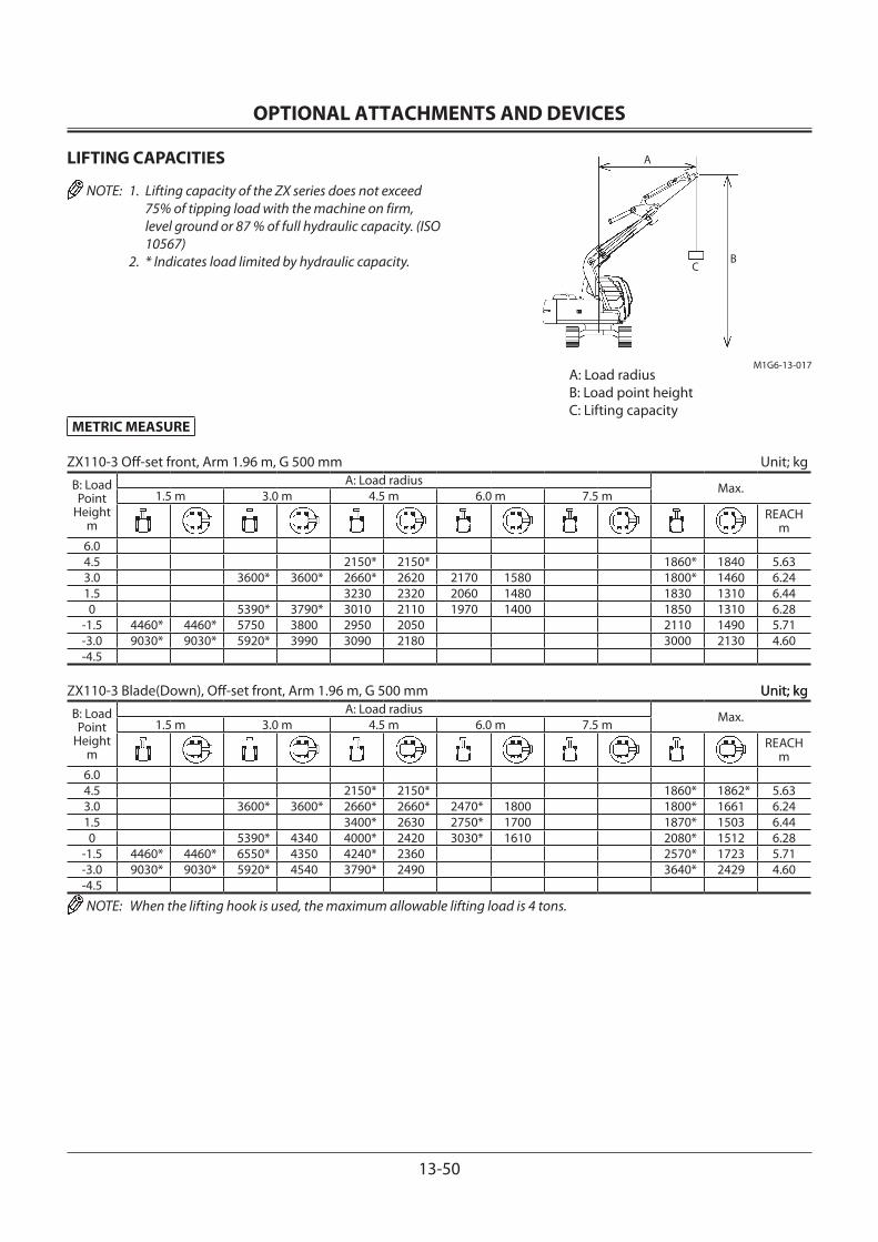
OPTIONAL ATTACHMENTS AND DEVICES
13-50
LIFTING CAPACITIES
NOTE: 1. Lifting capacity of the ZX series does not exceed 75% of tipping load with the machine on firm, level ground or 87 % of full hydraulic capacity. (ISO 10567)
2. * Indicates load limited by hydraulic capacity.
A
CB
M1G6-13-017A: Load radiusB: Load point heightC: Lifting capacity
METRIC MEASURE
ZX110-3 Off-set front, Arm 1.96 m, G 500 mm Unit; kg
B: Load Point
Heightm
A: Load radius Max.1.5 m 3.0 m 4.5 m 6.0 m 7.5 mREACH
m6.04.5 2150* 2150* 1860* 1840 5.633.0 3600* 3600* 2660* 2620 2170 1580 1800* 1460 6.241.5 3230 2320 2060 1480 1830 1310 6.440 5390* 3790* 3010 2110 1970 1400 1850 1310 6.28
-1.5 4460* 4460* 5750 3800 2950 2050 2110 1490 5.71-3.0 9030* 9030* 5920* 3990 3090 2180 3000 2130 4.60-4.5
ZX110-3 Blade(Down), Off-set front, Arm 1.96 m, G 500 mm Unit; kg Unit; kg
B: Load Point
Heightm
A: Load radius Max.1.5 m 3.0 m 4.5 m 6.0 m 7.5 mREACH
m6.04.5 2150* 2150* 1860* 1862* 5.633.0 3600* 3600* 2660* 2660* 2470* 1800 1800* 1661 6.241.5 3400* 2630 2750* 1700 1870* 1503 6.440 5390* 4340 4000* 2420 3030* 1610 2080* 1512 6.28
-1.5 4460* 4460* 6550* 4350 4240* 2360 2570* 1723 5.71-3.0 9030* 9030* 5920* 4540 3790* 2490 3640* 2429 4.60-4.5
NOTE: When the lifting hook is used, the maximum allowable lifting load is 4 tons.
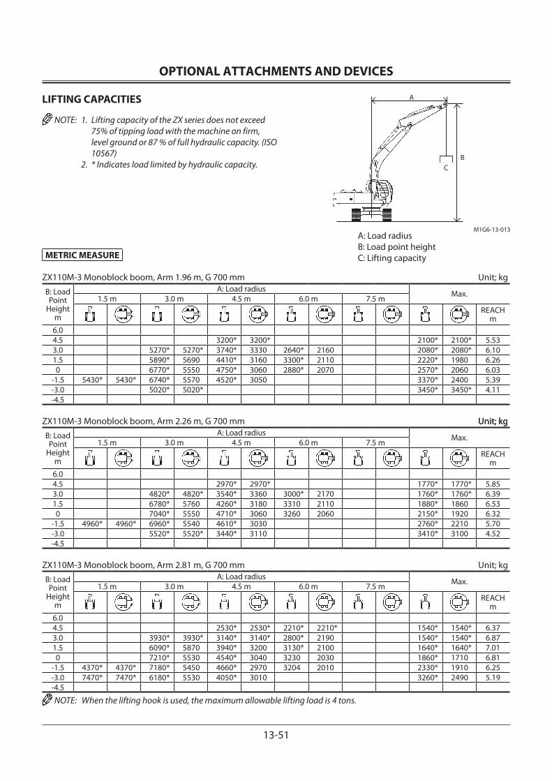
OPTIONAL ATTACHMENTS AND DEVICES
13-51
LIFTING CAPACITIES
NOTE: 1. Lifting capacity of the ZX series does not exceed 75% of tipping load with the machine on firm, level ground or 87 % of full hydraulic capacity. (ISO 10567)
2. * Indicates load limited by hydraulic capacity.
A
CB
M1G6-13-013
METRIC MEASURE
ZX110M-3 Monoblock boom, Arm 1.96 m, G 700 mm Unit; kg
B: Load Point
Heightm
A: Load radius Max.1.5 m 3.0 m 4.5 m 6.0 m 7.5 mREACH
m6.04.5 3200* 3200* 2100* 2100* 5.533.0 5270* 5270* 3740* 3330 2640* 2160 2080* 2080* 6.101.5 5890* 5690 4410* 3160 3300* 2110 2220* 1980 6.260 6770* 5550 4750* 3060 2880* 2070 2570* 2060 6.03
-1.5 5430* 5430* 6740* 5570 4520* 3050 3370* 2400 5.39-3.0 5020* 5020* 3450* 3450* 4.11-4.5
ZX110M-3 Monoblock boom, Arm 2.26 m, G 700 mm Unit; kg Unit; kg
B: Load Point
Heightm
A: Load radius Max.1.5 m 3.0 m 4.5 m 6.0 m 7.5 mREACH
m6.04.5 2970* 2970* 1770* 1770* 5.853.0 4820* 4820* 3540* 3360 3000* 2170 1760* 1760* 6.391.5 6780* 5760 4260* 3180 3310 2110 1880* 1860 6.530 7040* 5550 4710* 3060 3260 2060 2150* 1920 6.32
-1.5 4960* 4960* 6960* 5540 4610* 3030 2760* 2210 5.70-3.0 5520* 5520* 3440* 3110 3410* 3100 4.52-4.5
ZX110M-3 Monoblock boom, Arm 2.81 m, G 700 mm Unit; kg
B: Load Point
Heightm
A: Load radius Max.1.5 m 3.0 m 4.5 m 6.0 m 7.5 mREACH
m6.04.5 2530* 2530* 2210* 2210* 1540* 1540* 6.373.0 3930* 3930* 3140* 3140* 2800* 2190 1540* 1540* 6.871.5 6090* 5870 3940* 3200 3130* 2100 1640* 1640* 7.010 7210* 5530 4540* 3040 3230 2030 1860* 1710 6.81
-1.5 4370* 4370* 7180* 5450 4660* 2970 3204 2010 2330* 1910 6.25-3.0 7470* 7470* 6180* 5530 4050* 3010 3260* 2490 5.19-4.5
NOTE: When the lifting hook is used, the maximum allowable lifting load is 4 tons.
A: Load radiusB: Load point heightC: Lifting capacity
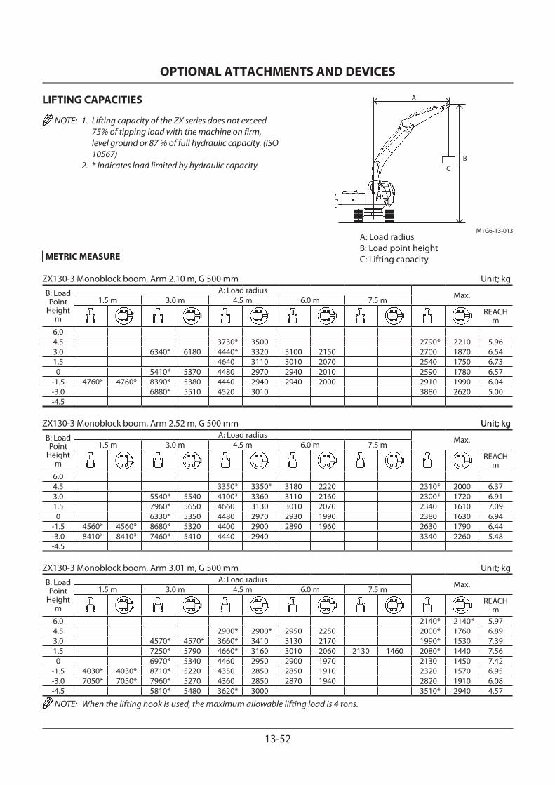
OPTIONAL ATTACHMENTS AND DEVICES
13-52
LIFTING CAPACITIES
NOTE: 1. Lifting capacity of the ZX series does not exceed 75% of tipping load with the machine on firm, level ground or 87 % of full hydraulic capacity. (ISO 10567)
2. * Indicates load limited by hydraulic capacity.
A
CB
M1G6-13-013
METRIC MEASURE
ZX130-3 Monoblock boom, Arm 2.10 m, G 500 mm Unit; kg
B: Load Point
Heightm
A: Load radius Max.1.5 m 3.0 m 4.5 m 6.0 m 7.5 mREACH
m6.04.5 3730* 3500 2790* 2210 5.963.0 6340* 6180 4440* 3320 3100 2150 2700 1870 6.541.5 4640 3110 3010 2070 2540 1750 6.730 5410* 5370 4480 2970 2940 2010 2590 1780 6.57
-1.5 4760* 4760* 8390* 5380 4440 2940 2940 2000 2910 1990 6.04-3.0 6880* 5510 4520 3010 3880 2620 5.00-4.5
ZX130-3 Monoblock boom, Arm 2.52 m, G 500 mm Unit; kg Unit; kg
B: Load Point
Heightm
A: Load radius Max.1.5 m 3.0 m 4.5 m 6.0 m 7.5 mREACH
m6.04.5 3350* 3350* 3180 2220 2310* 2000 6.373.0 5540* 5540 4100* 3360 3110 2160 2300* 1720 6.911.5 7960* 5650 4660 3130 3010 2070 2340 1610 7.090 6330* 5350 4480 2970 2930 1990 2380 1630 6.94
-1.5 4560* 4560* 8680* 5320 4400 2900 2890 1960 2630 1790 6.44-3.0 8410* 8410* 7460* 5410 4440 2940 3340 2260 5.48-4.5
ZX130-3 Monoblock boom, Arm 3.01 m, G 500 mm Unit; kg
B: Load Point
Heightm
A: Load radius Max.1.5 m 3.0 m 4.5 m 6.0 m 7.5 mREACH
m6.0 2140* 2140* 5.974.5 2900* 2900* 2950 2250 2000* 1760 6.893.0 4570* 4570* 3660* 3410 3130 2170 1990* 1530 7.391.5 7250* 5790 4660* 3160 3010 2060 2130 1460 2080* 1440 7.560 6970* 5340 4460 2950 2900 1970 2130 1450 7.42
-1.5 4030* 4030* 8710* 5220 4350 2850 2850 1910 2320 1570 6.95-3.0 7050* 7050* 7960* 5270 4360 2850 2870 1940 2820 1910 6.08-4.5 5810* 5480 3620* 3000 3510* 2940 4.57
NOTE: When the lifting hook is used, the maximum allowable lifting load is 4 tons.
A: Load radiusB: Load point heightC: Lifting capacity

OPTIONAL ATTACHMENTS AND DEVICES
13-53
LIFTING CAPACITIES
NOTE: 1. Lifting capacity of the ZX series does not exceed 75% of tipping load with the machine on firm, level ground or 87 % of full hydraulic capacity. (ISO 10567)
2. * Indicates load limited by hydraulic capacity.
A
CB
M1G6-13-013
METRIC MEASURE
ZX130-3 Blade (Down), Monoblock boom, Arm 2.10 m, G 500 mm Unit; kg
B: Load Point
Heightm
A: Load radius Max.1.5 m 3.0 m 4.5 m 6.0 m 7.5 mREACH
m6.04.5 3730* 3730* 2790* 2430 5.963.0 6340* 6340* 4440* 3630 3770* 2370 2750* 2070 6.541.5 5300* 3420 4090* 2290 2890* 1940 6.730 5410* 5410* 5800* 3280 4280* 2220 3240* 1970 6.57
-1.5 4760* 4760* 8390* 5930 5690* 3250 4010* 2220 3960* 2200 6.04-3.0 6880* 6060 4680* 3310 3940* 2890 5.00-4.5
ZX130-3 Blade (Down), Monoblock boom, Arm 2.52 m, G 500 mm Unit; kg Blade (Down), Monoblock boom, Arm 2.52 m, G 500 mm Unit; kg Monoblock boom, Arm 2.52 m, G 500 mm Unit; kg Unit; kg
B: Load Point
Heightm
A: Load radius Max.1.5 m 3.0 m 4.5 m 6.0 m 7.5 mREACH
m6.04.5 3350* 3350* 3310* 2440 2310* 2200 6.373.0 5540* 5540* 4100* 3670* 3540* 2380 2300* 1900 6.911.5 7960* 6200 5040* 3440 3920* 2290 2430* 1790 7.090 6330* 5900 5680* 3280 4210* 2210 2710* 1810 6.94
-1.5 4560* 4560* 8680* 5870 5750* 3210 4150* 2180 3290* 1990 6.44-3.0 8410* 8410* 7460* 5960 5070* 3250 3830* 2500 5.44-4.5
ZX130-3 Blade (Down), Monoblock boom, Arm 3.01 m, G 500 mm Unit; kg
B: Load Point
Heightm
A: Load radius Max.1.5 m 3.0 m 4.5 m 6.0 m 7.5 mREACH
m6.0 2140* 2140* 5.974.5 2900* 2900* 2950* 2470 2000* 1940 6.893.0 4570* 4570* 3660* 3660* 3240* 2390 1990* 1700 7.391.5 7250* 6330 4660* 3460 3690* 2280 2330* 1620 2080* 1600 7.560 6970* 5890 5450* 3260 4060* 2180 2290* 1610 7.42
-1.5 4030* 4030* 8710* 5770 5720* 3160 4170* 2130 2710* 1750 6.95-3.0 7050* 7050* 7960* 5820 5330* 3160 3660* 2150 3560* 2120 6.08-4.5 5810* 5810* 3620* 3310 3510* 3240 4.57
NOTE: When the lifting hook is used, the maximum allowable lifting load is 4 tons.
A: Load radiusB: Load point heightC: Lifting capacity

OPTIONAL ATTACHMENTS AND DEVICES
13-54
LIFTING CAPACITIES
NOTE: 1. Lifting capacity of the ZX series does not exceed 75% of tipping load with the machine on firm, level ground or 87 % of full hydraulic capacity. (ISO 10567)
2. * Indicates load limited by hydraulic capacity.C B
M1G6-13-018
A
A: Load radiusB: Load point heightC: Lifting capacity
METRIC MEASURE
ZX130-3 2-piece boom, Arm 2.10 m, G 500 mm Unit; kgB: Load Point
Heightm
A: Load radius Max.1.5 m 3.0 m 4.5 m 6.0 m 7.5 mREACH
m7.5 4620* 4620* 2.596.0 4810* 4810* 4230* 3580 3140* 3100 4.864.5 5050* 5050* 4340* 3680 2800* 2200 5.963.0 10750* 10750* 7800* 6500 4860* 3590 3160 2180 2700 1850 6.541.5 8690* 8690* 8730* 6270 4870 3480 3090 2120 2530 1720 6.730 8870* 8870* 9000* 5980 4830 3250 2990 2020 2580 1750 6.57
-1.5 13320* 13320* 9140* 5680 4600 3040 2940 1980 2920 1970 6.03-3.0 16530* 16530* 7660* 5580 3690* 3000 2980* 2790 4.74-4.5
ZX130-3 2-piece boom, Arm 2.52 m, G 500 mm Unit; kgB: Load Point
Heightm
A: Load radius Max.1.5 m 3.0 m 4.5 m 6.0 m 7.5 mREACH
m7.5 4180* 4180* 3360* 3360* 3.466.0 3870* 3870* 3870* 3670 2560* 2560* 5.364.5 3900* 3900* 4090* 3670 3210 2250 2330* 1980 6.373.0 7070* 6540 4560* 3610 3210 2240 2300* 1690 6.911.5 10590* 10590* 8750* 6320 4870 3550 3130 2160 2330 1580 7.090 9120* 9120* 8940* 6090 4880 3290 3010 2050 2370 1600 6.95
-1.5 11930* 11930* 9030* 5700 4630 3070 2920 1960 2630 1770 6.44-3.0 15200* 15200* 8520* 5560 4500 2950 2530* 2280 5.42-4.5
ZX130-3 2-piece boom, Arm 3.01 m, G 500 mm Unit; kg Unit; kgB: Load Point
Heightm
A: Load radius Max.1.5 m 3.0 m 4.5 m 6.0 m 7.5 mREACH
m7.5 2680* * 4.37 6.0 3330* 3330* 2180* 2180* 5.98 4.5 3470* 3470* 3130* 2320 2010* 1740 6.903.0 4480* 4480* 4230* 3620 3220 2310 1980* 1510 7.401.5 11090* 11090* 8360* 6320* 4860 3480 3150 2220 2130 1440 2060* 1410 7.57 0 9920* 9920* 8840* 6230 4740 3340 3050 2080 2120 1420 7.43
-1.5 10990* 10990* 8890* 5720 4680 3110 2910 1950 2310 1540 6.96 -3.0 14010* 14010* 8990* 5540 4480 2920 2590* 1920 2310* 1880 6.09-4.5 11510* 11510* 5220* 5220 4390* 4390* 3.34
NOTE: When the lifting hook is used, the maximum allowable lifting load is 4 tons.

OPTIONAL ATTACHMENTS AND DEVICES
13-55
LIFTING CAPACITIES
NOTE: 1. Lifting capacity of the ZX series does not exceed 75% of tipping load with the machine on firm, level ground or 87 % of full hydraulic capacity. (ISO 10567)
2. * Indicates load limited by hydraulic capacity.C B
M1G6-13-018
A
A: Load radiusB: Load point heightC: Lifting capacity
METRIC MEASURE
ZX130-3 Blade(Down), 2-piece boom, Arm 2.10 m, G 500 mm Unit; kgB: Load Point
Heightm
A: Load radius Max.1.5 m 3.0 m 4.5 m 6.0 m 7.5 mREACH
m7.5 4620* 4620* 2.59 6.0 4810* 4810* 4230* 3880 3140* 3140* 4.86 4.5 5050* 5050* 4340* 3950 2800* 2410 5.96 3.0 10750* 10750* 7800* 6950 4860* 3860 3690* 2390 2740* 2040 6.54 1.5 8690* 8690* 8730* 6760 5740* 3790 3970* 2330 2840* 1910 6.73 0 8870* 8870* 9000* 6530 5790* 3560 4220* 2240 3150* 1940 6.57
-1.5 13320* 13320* 9140* 6230 5820* 3350 3080* 2190 2990* 2180 6.03 -3.0 16530* 16530* 7660* 6130 3690* 3310 2980* 2980* 4.74 -4.5
ZX130-3 Blade(Down), 2-piece boom, Arm 2.52 m, G 500 mm Unit; kgB: Load Point
Heightm
A: Load radius Max.1.5 m 3.0 m 4.5 m 6.0 m 7.5 mREACH
m7.5 4180* 4180* 3360* 3360* 3.46 6.0 3870* 3870* 3870* 3870* 2560* 2560* 5.36 4.5 3900* 3900* 4090* 3970 2330* 2180 6.37 3.0 7070* 7000 4560* 3890 3270* 2460 2300* 1880 6.91 1.5 10590* 10590* 8750* 6790 5420* 3770* 3490* 2460 2390* 1760 7.09 0 9120* 9120* 8940* 6640 5750* 3600 3790* 2380 2640* 1780 6.95
-1.5 11930* 11930* 9030* 6240 5810* 3380 4170* 2260 2950* 1960 6.44 -3.0 15200* 15200* 8520* 6110 4760* 3260 3850* 2170 2530* 2520 5.42 -4.5
ZX130-3 Blade(Down), 2-piece boom, Arm 3.01 m, G 500 mm Unit; kg Unit; kgB: Load Point
Heightm
A: Load radius Max.1.5 m 3.0 m 4.5 m 6.0 m 7.5 mREACH
m7.5 2680* 2680* 4.37 6.0 3330* 3330* 2180* 2180* 5.98 4.5 3470* 3470* 3130* 2530 2010* 1920 6.90 3.0 4480* 4480* 4230* 3890 3270* 2520 1980* 1670 7.40 1.5 11090* 11090* 8360* 6760 5060* 3750 3570* 2430 2360* 1600 2060* 1570 7.57 0 9920* 9920* 8840* 6570 5690* 3650 3960* 2300 2240* 1580 7.43
-1.5 10990* 10990* 8890* 6270 5700* 3420 4120* 2170 2610* 1720 6.96 -3.0 14010* 14010* 8990* 6090 5440* 3230 2590* 2130 2310* 2100 6.09 -4.5 11510* 11510* 5220* 5220* 4390* 4390* 3.34
NOTE: When the lifting hook is used, the maximum allowable lifting load is 4 tons.
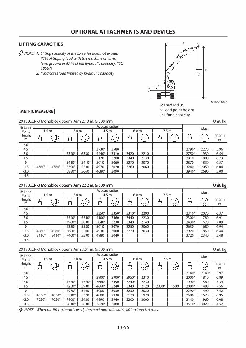
OPTIONAL ATTACHMENTS AND DEVICES
13-56
LIFTING CAPACITIES
NOTE: 1. Lifting capacity of the ZX series does not exceed 75% of tipping load with the machine on firm, level ground or 87 % of full hydraulic capacity. (ISO 10567)
2. * Indicates load limited by hydraulic capacity.
A
CB
M1G6-13-013
METRIC MEASURE
ZX130LCN-3 Monoblock boom, Arm 2.10 m, G 500 mm Unit; kg
B: Load Point
Heightm
A: Load radius Max.1.5 m 3.0 m 4.5 m 6.0 m 7.5 mREACH
m6.04.5 3730* 3580 2790* 2270 5.96 3.0 6340* 6330 4440* 3410 3420 2210 2750* 1930 6.54 1.5 5170 3200 3340 2130 2810 1800 6.73 0 5410* 5410* 5010 3060 3270 2070 2870 1830 6.57
-1.5 4760* 4760* 8390* 5530 4970 3020 3260 2060 3240 2050 6.04 -3.0 6880* 5660 4680* 3090 3940* 2690 5.00 -4.5
ZX130LCN-3 Monoblock boom, Arm 2.52 m, G 500 mm Unit; kgLCN-3 Monoblock boom, Arm 2.52 m, G 500 mm Unit; kg-3 Monoblock boom, Arm 2.52 m, G 500 mm Unit; kg Unit; kg
B: Load Point
Heightm
A: Load radius Max.1.5 m 3.0 m 4.5 m 6.0 m 7.5 mREACH
m6.04.5 3350* 3350* 3310* 2290 2310* 2070 6.37 3.0 5540* 5540* 4100* 3460 3440 2230 2300* 1780 6.91 1.5 7960* 5830 5040* 3230 3340 2140 2430* 1670 7.09 0 6330* 5530 5010 3070 3250 2060 2630 1680 6.94
-1.5 4560* 4560* 8680* 5500 4930 3000 3220 2030 2920 1860 6.44 -3.0 8410* 8410* 7460* 5590 4980 3040 3720 2340 5.48 -4.5
ZX130LCN-3 Monoblock boom, Arm 3.01 m, G 500 mm Unit; kg
B: Load Point
Heightm
A: Load radius Max.1.5 m 3.0 m 4.5 m 6.0 m 7.5 mREACH
m6.0 2140* 2140* 5.97 4.5 2900* 2900* 2950* 2310 2000* 1810 6.89 3.0 4570* 4570* 3660* 3490 3240* 2230 1990* 1580 7.39 1.5 7250* 5930 4660* 3240 3340 2120 2330* 1500 2080* 1480 7.56 0 6970* 5490 5000 3030 3230 2020 2290* 1490 7.42
-1.5 4030* 4030* 8710* 5370 4880 2930 3170 1970 2580 1620 6.95 -3.0 7050* 7050* 7960* 5420 4890 2940 3200 2000 3140 1960 6.08 -4.5 5810* 5630 3620* 3080 3510* 3020 4.57
NOTE: When the lifting hook is used, the maximum allowable lifting load is 4 tons.
A: Load radiusB: Load point heightC: Lifting capacity
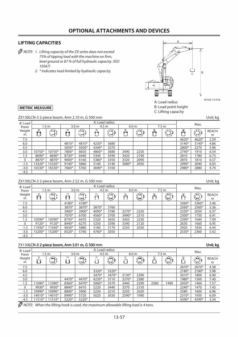
OPTIONAL ATTACHMENTS AND DEVICES
13-57
LIFTING CAPACITIES
NOTE: 1. Lifting capacity of the ZX series does not exceed 75% of tipping load with the machine on firm, level ground or 87 % of full hydraulic capacity. (ISO 10567)
2. * Indicates load limited by hydraulic capacity.C B
M1G6-13-018
A
A: Load radiusB: Load point heightC: Lifting capacity
METRIC MEASURE
ZX130LCN-3 2-piece boom, Arm 2.10 m, G 500 mm Unit; kgB: Load Point
Heightm
A: Load radius Max.1.5 m 3.0 m 4.5 m 6.0 m 7.5 mREACH
m7.5 4620* 4620* 2.59 6.0 4810* 4810* 4230* 3680 3140* 3140* 4.86 4.5 5050* 5050* 4340* 3370 2800* 2270 5.96 3.0 10750* 10750* 7800* 6650 4860* 3680 3490 2250 2740* 1910 6.54 1.5 8690* 8690* 8730* 6440 5340 3590 3420 2190 2810 1780 6.73 0 8870* 8870* 9000* 6160 5380* 3350 3320 2090 2870 1810 6.57
-1.5 13320* 13320* 9140* 5860 5140 3140 3080* 2050 2990* 2040 6.03 -3.0 16530* 16530* 7660* 5760 3690* 3100 2980* 2880 4.74 -4.5
ZX130LCN-3 2-piece boom, Arm 2.52 m, G 500 mm Unit; kgB: Load Point
Heightm
A: Load radius Max.1.5 m 3.0 m 4.5 m 6.0 m 7.5 mREACH
m7.5 4180* 4180* 3360* 3360* 3.46 6.0 3870* 3870* 3870* 3760 2560* 2560* 5.36 4.5 3900* 3900* 4090* 3780 3270* 2320 2330* 2050 6.37 3.0 7070* 6700 4560* 3700 3490* 2310 2300* 1750 6.91 1.5 10590* 10590* 8750* 6470 5320 3650 3450 2230 2390* 1640 7.09 0 9120* 9120* 8940* 6270 5250 3390 3340 2120 2630 1660 6.95
-1.5 11930* 11930* 9030* 5880 5180 3170 3250 2030 2920 1830 6.44 -3.0 15200* 15200* 8520* 5740 4760* 3050 2530* 2360 5.42 -4.5
ZX130LCN-3 2-piece boom, Arm 3.01 m, G 500 mm Unit; kgLCN-3 2-piece boom, Arm 3.01 m, G 500 mm Unit; kg-3 2-piece boom, Arm 3.01 m, G 500 mm Unit; kg Unit; kgB: Load Point
Heightm
A: Load radius Max.1.5 m 3.0 m 4.5 m 6.0 m 7.5 mREACH
m7.5 2670* 2670* 4.38 6.0 3320* 3320* 2180* 2180* 5.98 4.5 3470* 3470* 3130* 2390 2010* 1800 6.90 3.0 4470* 4470* 4230* 3710 3270* 2380 1980* 1560 7.40 1.5 11090* 11090* 8360* 6470* 5060* 3570 3440 2290 2360 1490 2050* 1460 7.57 0 9930* 9930* 8840* 6410 5220 3440 3370 2150 2240* 1470 7.43
-1.5 10990* 10990* 8890* 5900 5230 3210 3250 2020 2580 1600 6.96 -3.0 14010* 14010* 8990* 5720 5020 3030 2590* 1990 2310* 1950 6.09 -4.5 11510* 11510* 5220* 5220* 4390* 4390* 3.34
NOTE: When the lifting hook is used, the maximum allowable lifting load is 4 tons.
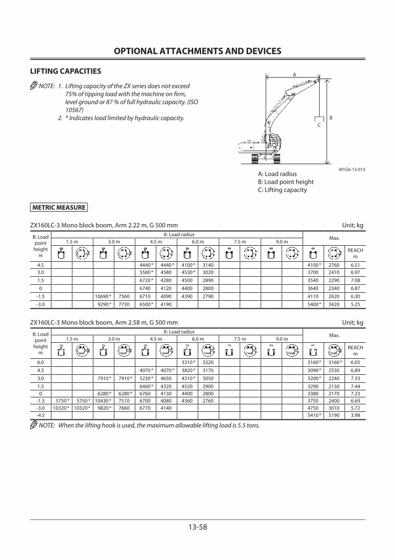
OPTIONAL ATTACHMENTS AND DEVICES
13-58
LIFTING CAPACITIES
NOTE: 1. Lifting capacity of the ZX series does not exceed 75% of tipping load with the machine on firm, level ground or 87 % of full hydraulic capacity. (ISO 10567)
2. * Indicates load limited by hydraulic capacity.
A
CB
M1G6-13-013
METRIC MEASURE
ZX160LC-3 Mono block boom, Arm 2.22 m, G 500 mm Unit; kg
B: Load point
heightm
A: Load radiusMax.
1.5 m 3.0 m 4.5 m 6.0 m 7.5 m 9.0 m
REACH m
4.5 4440 * 4440 * 4100 * 3140 4100 * 2760 6.513.0 5580 * 4580 4530 * 3020 3700 2410 6.97
1.5 6720 * 4280 4500 2890 3540 2290 7.08
0 6740 4120 4400 2800 3640 2340 6.87
-1.5 10690 * 7560 6710 4090 4390 2790 4110 2620 6.30
-3.0 9290 * 7730 6500 * 4190 5400 * 3420 5.25
ZX160LC-3 Mono block boom, Arm 2.58 m, G 500 mm Unit; kg
B: Load point
heightm
A: Load radiusMax.
1.5 m 3.0 m 4.5 m 6.0 m 7.5 m 9.0 m
REACH m
6.0 3310 * 3220 3160 * 3160 * 6.05
4.5 4070 * 4070 * 3820 * 3170 3090 * 2530 6.89
3.0 7910 * 7910 * 5230 * 4650 4310 * 3050 3200 * 2240 7.33
1.5 6460 * 4320 4520 2900 3290 2130 7.440 6280 * 6280 * 6760 4130 4400 2800 3380 2170 7.23
-1.5 5750 * 5750 * 10430 * 7510 6700 4080 4360 2760 3750 2400 6.69-3.0 10320 * 10320 * 9820 * 7660 6770 4140 4750 3010 5.72-4.5 5410 * 5190 3.98
NOTE: When the lifting hook is used, the maximum allowable lifting load is 5.5 tons.
A: Load radiusB: Load point heightC: Lifting capacity
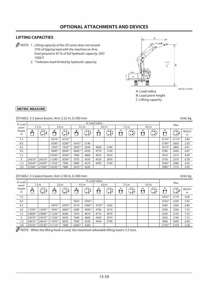
OPTIONAL ATTACHMENTS AND DEVICES
13-59
LIFTING CAPACITIES
NOTE: 1. Lifting capacity of the ZX series does not exceed 75% of tipping load with the machine on firm, level ground or 87 % of full hydraulic capacity. (ISO 10567)
2. * Indicates load limited by hydraulic capacity.
METRIC MEASURE
ZX160LC-3 2-piece boom, Arm 2.22 m, G 500 mm Unit; kg
B: Load point
heightm
A: Load radiusMax.
1.5 m 3.0 m 4.5 m 6.0 m 7.5 m 9.0 m
REACH m
7.5 6510 * 6510 * 6110 * 6110 * 3.84
6.0 6290 * 6290 * 5410 * 5140 5140 * 3650 5.504.5 7620 * 7620 * 5820 * 5040 4830 3180 4310 * 2800 6.413.0 8440 * 8440 * 6640 * 4930 4770 3140 3780 2440 6.87
1.5 10540 * 8540 * 7060 4860 4670 3010 3610 2310 6.99
0 24510 * 24510 * 11390 * 8290 * 7070 4550 4520 2870 3730 2370 6.78-1.5 24540 * 24540 * 11550 * 7990 6980 4270 4430 2790 4240 * 2680 6.20-3.0 21560 * 21560 * 10330 * 7880 5670 * 4220 5980 * 3710 4.95
ZX160LC-3 2-piece boom, Arm 2.58 m, G 500 mm Unit; kg
B: Load point
heightm
A: Load radiusMax.
1.5 m 3.0 m 4.5 m 6.0 m 7.5 m 9.0 m
REACH m
7.5 5410 * 5170 4.46
6.0 5050 5050 * 4750 * 3240 5.95
4.5 6970 * 6970 * 5510 5060 * 4730 * 3260 3940 2560 6.80
3.0 13390 * 13390 * 9500 * 8800 * 6380 4940 * 4760 3210 3500 2260 7.24
1.5 23800 * 23800 * 11220 * 8580 7070 4810 4710 3070 3350 2150 7.350 24370 * 24370 * 11350 * 8420 7040 4600 4560 2910 3450 2190 7.15
-1.5 24610 * 24610 * 11470 * 8030 7040 4330 4430 2790 3860 2440 6.60-3.0 23230 * 23230 * 11110 * 7890 6580 * 4200 3730 * 3120 5.58
NOTE: When the lifting hook is used, the maximum allowable lifting load is 5.5 tons.
C B
A
A: Load radiusB: Load point heightC: Lifting capacity
M1G6-13-018
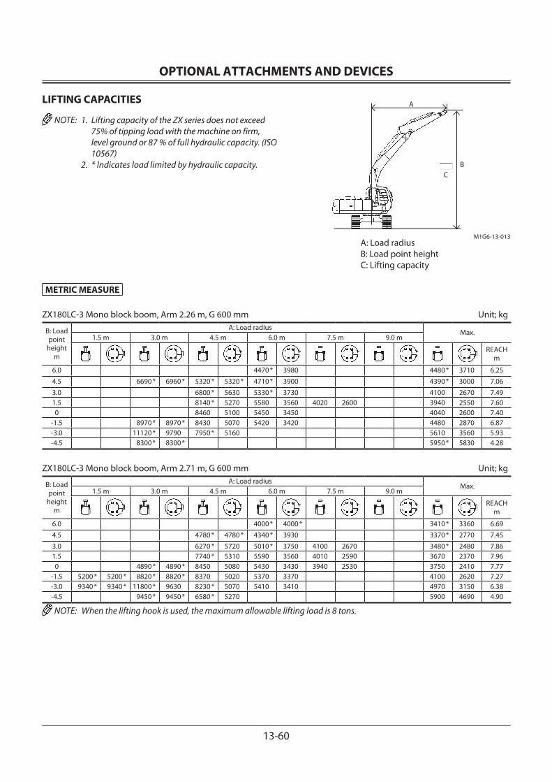
OPTIONAL ATTACHMENTS AND DEVICES
13-60
LIFTING CAPACITIES
NOTE: 1. Lifting capacity of the ZX series does not exceed 75% of tipping load with the machine on firm, level ground or 87 % of full hydraulic capacity. (ISO 10567)
2. * Indicates load limited by hydraulic capacity.
METRIC MEASURE
ZX180LC-3 Mono block boom, Arm 2.26 m, G 600 mm Unit; kg
B: Load point
heightm
A: Load radiusMax.
1.5 m 3.0 m 4.5 m 6.0 m 7.5 m 9.0 m
REACH m
6.0 4470 * 3980 4480 * 3710 6.25
4.5 6690 * 6960 * 5320 * 5320 * 4710 * 3900 4390 * 3000 7.06
3.0 6800 * 5630 5330 * 3730 4100 2670 7.491.5 8140 * 5270 5580 3560 4020 2600 3940 2550 7.600 8460 5100 5450 3450 4040 2600 7.40
-1.5 8970 * 8970 * 8430 5070 5420 3420 4480 2870 6.87-3.0 11120 * 9790 7950 * 5160 5610 3560 5.93-4.5 8300 * 8300 * 5950 * 5830 4.28
ZX180LC-3 Mono block boom, Arm 2.71 m, G 600 mm Unit; kg
B: Load point
heightm
A: Load radiusMax.
1.5 m 3.0 m 4.5 m 6.0 m 7.5 m 9.0 m
REACH m
6.0 4000 * 4000 * 3410 * 3360 6.69
4.5 4780 * 4780 * 4340 * 3930 3370 * 2770 7.45
3.0 6270 * 5720 5010 * 3750 4100 2670 3480 * 2480 7.861.5 7740 * 5310 5590 3560 4010 2590 3670 2370 7.960 4890 * 4890 * 8450 5080 5430 3430 3940 2530 3750 2410 7.77
-1.5 5200 * 5200 * 8820 * 8820 * 8370 5020 5370 3370 4100 2620 7.27-3.0 9340 * 9340 * 11800 * 9630 8230 * 5070 5410 3410 4970 3150 6.38-4.5 9450 * 9450 * 6580 * 5270 5900 4690 4.90
NOTE: When the lifting hook is used, the maximum allowable lifting load is 8 tons.
A
CB
A: Load radiusB: Load point heightC: Lifting capacity
M1G6-13-013

OPTIONAL ATTACHMENTS AND DEVICES
13-61
LIFTING CAPACITIES
NOTE: 1. Lifting capacity of the ZX series does not exceed 75% of tipping load with the machine on firm, level ground or 87 % of full hydraulic capacity. (ISO 10567)
2. * Indicates load limited by hydraulic capacity.
METRIC MEASURE
ZX180LC-3 2-piece boom, Arm 2.26 m, G 600 mm Unit; kg
B: Load point
heightm
A: Load radiusMax.
1.5 m 3.0 m 4.5 m 6.0 m 7.5 m 9.0 m
REACH m
7.5 5620 * 5620 * 4980 * 4980 * 4.726.0 5930 * 5930 * 6350 * 6350 * 5020 * 3970 4400 * 3790 6.144.5 9660 * 9660 * 7020 * 6260 5770 * 4040 4260 * 3020 6.963.0 11630 * 11630 * 11020 * 10890 8010 * 6120 * 5870 3950 4160 2670 7.401.5 12360 * 10800 * 8660 * 6090 5840 3770 3990 2540 3990 2540 7.510 11840 * 11840 13430 * 10510 8650 5660 5640 3560 4100 2590 7.31
-1.5 17060 * 17060 13640 * 10050 8800 5300 5470 3410 4530 * 2870 6.77-3.0 20820 * 20820 12610 * 9860 7570 * 5150 3850 * 3600 5.81
ZX180LC-3 2-piece boom, Arm 2.71 m, G 600 mm Unit; kg
B: Load point
heightm
A: Load radiusMax.
1.5 m 3.0 m 4.5 m 6.0 m 7.5 m 9.0 m
REACH m
9.0 5020 * 5020 * 2.80
7.5 4870 * 4870 * 3670 * 3670 * 5.29
6.0 5200 * 5200 * 4640 * 4080 3330 * 3300 * 6.594.5 6600 * 6600 * 6390 * 6280 5490 * 4120 3250 * 2780 7.36
3.0 14090 * 14090 * 11390 * 10950 7650 * 6110 * 5860 4040 4110 2650 3330 * 2470 7.771.5 12000 * 12000 * 12150 * 10740 8490 * 6040 5790 3860 4030 2570 3570 * 2350 7.880 11550 * 11550 * 13210 * 10720 8590 5740 5700 3610 3930 2480 3780 2380 7.69
-1.5 14890 * 14890 * 13480 * 10100 8700 5360 5480 3410 4150 2600 7.18-3.0 17230 * 17230 * 13310 * 9840 8240 * 5110 4820 * 3360 3970 * 3170 6.28-4.5 8240 * 8240 * 6480 * 6480 * 3.56
NOTE: When the lifting hook is used, the maximum allowable lifting load is 8 tons.
A: Load radiusB: Load point heightC: Lifting capacity
C B
M1G6-13-018
A

OPTIONAL ATTACHMENTS AND DEVICES
13-62
LIFTING CAPACITIES
NOTE: 1. Lifting capacity of the ZX series does not exceed 75% of tipping load with the machine on firm, level ground or 87 % of full hydraulic capacity. (ISO 10567)
2. * Indicates load limited by hydraulic capacity.
METRIC MEASURE
ZX180LCN-3 Mono block boom, Arm 2.26 m, G 500 mm Unit; kg
B: Load point
heightm
A: Load radiusMax.
1.5 m 3.0 m 4.5 m 6.0 m 7.5 m 9.0 m
REACH m
6.0 4470 * 3580 4480 * 3340 6.25
4.5 6960 * 6960 * 5320 * 5320 * 4710 * 3500 4390 * 2690 7.06
3.0 6800 * 5010 5330 * 3340 4040 2390 7.491.5 8140 * 4660 5500 3170 3960 2320 3890 2280 7.600 8340 4490 5370 3060 3990 2320 7.40
-1.5 8970 * 8300 8310 4470 5340 3030 4420 2550 6.87-3.0 11120 * 8460 7950 * 4550 5530 3160 5.93-4.5 8300 * 8300 * 5950 * 5160 4.28
ZX180LCN-3 Mono block boom, Arm 2.71 m, G 500 mm Unit; kg
B: Load point
heightm
A: Load radiusMax.
1.5 m 3.0 m 4.5 m 6.0 m 7.5 m 9.0 m
REACH m
6.0 4000 * 3640 3410 * 3020 6.69
4.5 4780 * 4780 * 4340 * 3540 3370 * 2480 7.45
3.0 6270 * 5090 5010 * 3360 4040 2390 3480 * 2220 7.861.5 7740 * 4700 5510 3170 3950 2310 3620 2110 7.960 4890 * 4890 * 8340 4480 5360 3040 3880 2240 3690 2140 7.77
-1.5 5200 * 5200 * 8820 * 8160 * 8260 4410 5290 2980 4040 2320 7.27-3.0 9340 * 9340 * 11800 * 8300 8230 * 4460 5340 3020 4900 2800 6.38-4.5 9450 * 8610 6580 * 4660 5900 4160 4.90
NOTE: When the lifting hook is used, the maximum allowable lifting load is 8 tons.
A: Load radiusB: Load point heightC: Lifting capacity
A
CB
M1G6-13-013
OPTIONAL ATTACHMENTS AND DEVICES
13-63
LIFTING CAPACITIES
NOTE: 1. Lifting capacity of the ZX series does not exceed 75% of tipping load with the machine on firm, level ground or 87 % of full hydraulic capacity. (ISO 10567)
2. * Indicates load limited by hydraulic capacity.
METRIC MEASURE
ZX180LCN-3 2-piece boom, Arm 2.26 m, G 500 mm Unit; kg
B: Load point
heightm
A: Load radiusMax.
1.5 m 3.0 m 4.5 m 6.0 m 7.5 m 9.0 m
REACH m
7.5 5620 * 5620 * 4980 * 4980 * 4.726.0 5930 * 5930 * 6350 * 5880 5020 * 3610 4400 * 3440 6.144.5 9660 * 9660 * 7010 * 5760 5770 * 3670 4260 * 2730 6.963.0 11630 * 11630 * 11020 * 9910 8010 * 5640 * 5860 3950 4150 2400 7.401.5 12360 * 9830 * 8660 * 5500 5830 3410 3990 2280 3980 2280 7.510 11840 * 11840 * 13430 * 9230 8650 * 5080 5620 3200 4090 2320 7.31
-1.5 17060 * 17060 * 13640 * 8790 8780 4740 5460 3050 4530 * 2570 6.77-3.0 20820 * 20820 * 12610 * 8620 7570 * 4590 3850 * 3230 5.81
ZX180LCN-3 2-piece boom, Arm 2.71 m, G 500 mm Unit; kg
B: Load point
heightm
A: Load radiusMax.
1.5 m 3.0 m 4.5 m 6.0 m 7.5 m 9.0 m
REACH m
9.0 5020 * 5020 * 2.80
7.5 4870 * 4870 * 3670 * 3670 * 5.29
6.0 5200 * 5200 * 4640 * 3730 3330 * 3100 6.594.5 6600 * 6600 * 6390 * 5780 5490 * 3770 3250 * 2510 7.36
3.0 14090 * 14090 * 11390 * 9960 7650 * 5630 5840 * 3690 4110 2390 3330 * 2220 7.771.5 12000 * 12000 * 12150 * 9780 * 8490 * 5570 5780 3490 4020 2310 3570 * 2110 7.880 11550 * 11550 * 13210 * 9420 8580 * 5160 5690 3250 3920 2220 3770 2130 7.69
-1.5 14890 * 14890 * 13480 * 8840 8690 4790 5470 3060 4140 2330 7.18-3.0 17230 * 17230 * 13310 * 8590 8240 * 4550 4820 * 3010 3970 * 2840 6.28-4.5 8240 * 6480 * 6480 * 3.56
NOTE: When the lifting hook is used, the maximum allowable lifting load is 8 tons.
A: Load radiusB: Load point heightC: Lifting capacity
C B
M1G6-13-018
A

OPTIONAL ATTACHMENTS AND DEVICES
13-64
LIFTING CAPACITIES
NOTE: 1. Lifting capacity of the ZX series does not exceed 75% of tipping load with the machine on firm, level ground or 87 % of full hydraulic capacity. (ISO 10567)
2. * Indicates load limited by hydraulic capacity.
METRIC MEASURE
ZX210-3 Mono block boom, Arm 2.91 m, G 600 mm Unit; kg
B: Load point
heightm
A: Load radiusMax.
1.5 m 3.0 m 4.5 m 6.0 m 7.5 m 9.0 m
REACH m
6.0 4954 * 4817 4047 * 3456 7.32
4.5 6274 * 6274 * 5437 * 4658 4881 3281 3993 * 2937 8.013.0 8079 * 6700 6294 * 4426 4771 3180 4023 2677 8.371.5 9717 * 6218 6455 4193 4648 3067 3903 2579 8.450 4848 * 4848 * 9736 5957 6272 4030 4556 2982 3988 2621 8.25
-1.5 5484 * 5484 * 9103 * 9103 * 9651 5885 6194 3960 4527 2956 4331 2836 7.76-3.0 9973 * 9973 * 13611 * 11285 9670 * 5944 6231 3993 5137 3347 6.90-4.5 10626 * 10626 * 7669 * 6148 5899 * 4666 5.52
ZX210-3 Mono block boom, Arm 2.42 m, G 600 mm Unit; kg
B: Load point
heightm
A: Load radiusMax.
1.5 m 3.0 m 4.5 m 6.0 m 7.5 m 9.0 m
REACH m
6.0 5451 * 4744 5478 * 3910 6.74
4.5 6955 * 6955 * 5901 * 4597 4850 3252 7.48
3.0 8722 * 6555 6654 4375 4747 3161 4410 2936 7.871.5 9929 6126 6418 4164 4644 3066 4268 2823 7.950 9710 5940 6268 4030 4576 3003 4382 2882 7.74
-1.5 9909 * 9909 * 9687 5921 6227 3993 4828 3159 7.21-3.0 12496 * 11444 9195 * 6023 6316 4073 5930 3849 6.28
-4.5 6488 * 6310 6077 5924 4.71
NOTE: When the lifting hook is used, the maximum allowable lifting load is 8 tons.
A: Load radiusB: Load point heightC: Lifting capacity
A
CB
M1G6-13-013

OPTIONAL ATTACHMENTS AND DEVICES
13-65
LIFTING CAPACITIES
NOTE: 1. Lifting capacity of the ZX series does not exceed 75% of tipping load with the machine on firm, level ground or 87 % of full hydraulic capacity. (ISO 10567)
2. * Indicates load limited by hydraulic capacity.
METRIC MEASURE
ZX210-3 Mono block boom, Arm 2.03 m, G 600 mm Unit; kg
B: Load point
heightm
A: Load radiusMax.
1.5 m 3.0 m 4.5 m 6.0 m 7.5 m 9.0 m
REACH m
6.0 6251 * 6251 * 5880 * 4701 5955 * 4102 6.504.5 7491 * 7005 6246 * 4575 5059 3392 7.27
3.0 9244 * 6491 6640 4370 4752 3170 4593 3065 7.671.5 6431 4183 4670 3095 4456 2958 7.75
0 9770 6001 6311 4075 4628 3056 4600 3039 7.54
-1.5 9788 6016 6298 4063 5116 3365 6.99
-3.0 11571 * 11571 * 8787 * 6144 6205 * 4197 6138 * 4177 6.03
NOTE: When the lifting hook is used, the maximum allowable lifting load is 8 tons.
A: Load radiusB: Load point heightC: Lifting capacity
A
CB
M1G6-13-013

OPTIONAL ATTACHMENTS AND DEVICES
13-66
LIFTING CAPACITIES
NOTE: 1. Lifting capacity of the ZX series does not exceed 75% of tipping load with the machine on firm, level ground or 87 % of full hydraulic capacity. (ISO 10567)
2. * Indicates load limited by hydraulic capacity.
METRIC MEASURE
ZX210-3 2-piece boom, Arm 2.91 m, G 600 mm Unit; kg
B: Load point
heightm
A: Load radiusMax.
1.5 m 3.0 m 4.5 m 6.0 m 7.5 m 9.0 m
REACH m
9.0 5426 * 5426 * 4.30
7.5 6088 * 6088 5066 * 4822 4432 * 4432 * 6.206.0 6219 * 6219 5431 * 4990 4096 * 3410 7.324.5 8240 * 8240 7319 * 7319 5417 * 4935 4789 * 3303 4010 * 2883 8.013.0 10980 * 10980 13613 * 12843 9102 * 7176 6341 * 4793 4876 3248 4000 2618 8.371.5 8834 * 8834 14176 * 12664 10113 * 6963 6698 * 4622 4759 3127 3876 2518 8.450 11176 * 11176 15792 * 12329 10083 6674 6593 4347 4614 2993 3963 2560 8.25
-1.5 15159 * 15159 16399 * 11724 10257 6319 6397 4086 4523 2909 4311 2777 7.76-3.0 19211 * 19211 16471 * 11581 9965 6071 6273 3975 4411 * 3295 6.91-4.5 20979 * 20979 12128 * 11611 6770 * 6107 6594 * 5976 4.57
ZX210-3 2-piece boom, Arm 2.42 m, G 600 mm Unit; kg
B: Load point
heightm
A: Load radiusMax.
1.5 m 3.0 m 4.5 m 6.0 m 7.5 m 9.0 m
REACH m
9.0 9084 * 9084 * 8694 * 8694 * 3.19
7.5 6865 * 6865 * 5893 * 5436 5.50
6.0 6982 * 6982 * 5803 * 4850 4970 * 3866 6.744.5 11542 * 11542 * 7922 * 7333 6059 * 4865 4590 * 3197 7.49
3.0 12969 * 12762 * 9737 * 7173 6716 * 4738 4785 3153 4387 2875 7.871.5 14641 * 12681 * 10113 7054 6700 4504 4681 3057 4242 2759 7.950 12345 * 12345 * 16257 * 12065 10149 * 6567 6562 4238 4572 2957 4357 2819 7.74
-1.5 18413 * 18413 * 16548 * 11648 10191 6268 6342 4040 4810 3099 7.21-3.0 24611 * 24611 * 15840 * 11586 9788 * 6063 5589 * 4021 4640 * 3821 6.25
NOTE: When the lifting hook is used, the maximum allowable lifting load is 8 tons.
A: Load radiusB: Load point heightC: Lifting capacity
C B
M1G6-13-018
A

OPTIONAL ATTACHMENTS AND DEVICES
13-67
LIFTING CAPACITIES
NOTE: 1. Lifting capacity of the ZX series does not exceed 75% of tipping load with the machine on firm, level ground or 87 % of full hydraulic capacity. (ISO 10567)
2. * Indicates load limited by hydraulic capacity.
METRIC MEASURE
ZX210-3 2-piece boom, Arm 2.03 m, G 600 mm Unit; kg
B: Load point
heightm
A: Load radiusMax.
1.5 m 3.0 m 4.5 m 6.0 m 7.5 m 9.0 m
REACH m
9.0 11812 * 11812 * 2.56
7.5 7398 * 7398 6657 * 5898 5.17
6.0 7947 * 7947 7395 * 7395 6206 * 4744 5472 * 4075 6.484.5 10924 * 10924 8461 * 7331 6369 * 4789 4994 * 3347 7.25
3.0 12514 * 12514 10091 * 7167 6827 4678 4748 3124 4586 3012 7.651.5 14734 * 12818 10176 6967 6729 4474 4673 3055 4446 2903 7.730 11097 * 11097 16471 * 11978 10258 * 6534 6559 4242 4607 2994 4595 2987 7.52
-1.5 19564 * 19564 16723 * 11691 10215 6298 6386 4087 5018 * 3322 6.97-3.0 29453 * 29453 15218 * 11751 9217 * 6167 5136 * 4353 5.77
NOTE: When the lifting hook is used, the maximum allowable lifting load is 8 tons.
A: Load radiusB: Load point heightC: Lifting capacity
C B
M1G6-13-018
A

OPTIONAL ATTACHMENTS AND DEVICES
13-68
LIFTING CAPACITIES
NOTE: 1. Lifting capacity of the ZX series does not exceed 75% of tipping load with the machine on firm, level ground or 87 % of full hydraulic capacity. (ISO 10567)
2. * Indicates load limited by hydraulic capacity.
METRIC MEASURE
ZX210LC-3 Mono block boom, Arm 2.91 m, G 600 mm Unit; kg
B: Load point
heightm
A: Load radiusMax.
1.5 m 3.0 m 4.5 m 6.0 m 7.5 m 9.0 m
REACH m
6.0 4954 * 4954 * 4047 * 3848 7.32
4.5 6274 * 6274 * 5437 * 5185 5107 * 3660 3993 * 3282 8.013.0 8079 * 7532 6294 * 4948 5435 3557 4103 * 3001 8.371.5 9717 * 7036 7119 * 4711 5310 3443 4381 * 2898 8.450 4848 * 4848 * 10525 * 6767 7228 4544 5215 3356 4558 2950 8.25
-1.5 5484 * 5484 * 9103 * 9103 * 10490 * 6693 7147 4473 5185 3329 4956 3193 7.76-3.0 9973 * 9973 * 13611 * 13094 9670 * 6753 7176 * 4506 5890 3767 6.90-4.5 10626 * 10626 * 7669 * 6964 8396 5253 5.52
ZX210LC-3 Mono block boom, Arm 2.42 m, G 600 mm Unit; kg
B: Load point
heightm
A: Load radiusMax.
1.5 m 3.0 m 4.5 m 6.0 m 7.5 m 9.0 m
REACH m
6.0 5451 * 5272 5478 * 4351 6.74
4.5 6955 * 6955 * 5901 * 5122 5500 * 3630 7.48
3.0 8722 * 7381 6660 * 4895 5410 3537 5024 3288 7.871.5 10148 * 6940 7378 4680 5304 3441 4870 3168 7.950 10637 * 6748 7223 4543 5234 3377 5009 3240 7.74
-1.5 9909 * 9909 * 10318 * 6729 7180 4506 5528 3554 7.21-3.0 12496 * 12496 * 9195 * 6834 6765 4587 6302 * 4330 6.28
-4.5 6488 * 6488 6077 * 6077 * 4.71
NOTE: When the lifting hook is used, the maximum allowable lifting load is 8 tons.
A: Load radiusB: Load point heightC: Lifting capacity
A
CB
M1G6-13-013

OPTIONAL ATTACHMENTS AND DEVICES
13-69
LIFTING CAPACITIES
NOTE: 1. Lifting capacity of the ZX series does not exceed 75% of tipping load with the machine on firm, level ground or 87 % of full hydraulic capacity. (ISO 10567)
2. * Indicates load limited by hydraulic capacity.
METRIC MEASURE
ZX210LC-3 Mono block boom, Arm 2.03 m, G 600 mm Unit; kg
B: Load point
heightm
A: Load radiusMax.
1.5 m 3.0 m 4.5 m 6.0 m 7.5 m 9.0 m
REACH m
6.0 6251 * 6251 * 5880 * 5226 5955 * 4566 6.504.5 7491 * 7491 * 6246 * 5098 5756 3786 7.27
3.0 9244 * 7313 6955 * 4889 5413 3546 5232 3429 7.671.5 7389 4698 5329 3469 5082 3315 7.75
0 10705 * 6810 7264 4588 5286 3430 5253 3411 7.54
-1.5 10168 * 6825 7251 4576 5853 3777 6.99
-3.0 11571 * 11571 * 8787 * 6957 6205 * 4712 6138 * 4689 6.03
NOTE: When the lifting hook is used, the maximum allowable lifting load is 8 tons.
A: Load radiusB: Load point heightC: Lifting capacity
A
CB
M1G6-13-013
OPTIONAL ATTACHMENTS AND DEVICES
13-70
LIFTING CAPACITIES
NOTE: 1. Lifting capacity of the ZX series does not exceed 75% of tipping load with the machine on firm, level ground or 87 % of full hydraulic capacity. (ISO 10567)
2. * Indicates load limited by hydraulic capacity.
METRIC MEASURE
ZX210LC-3 2-piece boom, Arm 2.91 m, G 600 mm Unit; kg
B: Load point
heightm
A: Load radiusMax.
1.5 m 3.0 m 4.5 m 6.0 m 7.5 m 9.0 m
REACH m
9.0 5428 * 5428 * 4.30
7.5 6091 * 6091 * 5068 * 5068 * 4435 * 4435 * 6.206.0 6222 * 6222 * 5435 * 5435 * 4098 * 3814 7.324.5 8244 * 8244 * 7323 * 7323 * 5719 * 5396 4794 * 3694 4012 * 3239 8.013.0 10981 * 10981 * 13624 * 13624 * 9110 * 7874 6347 * 5267 * 5045 * 3639 4009 * 2953 8.371.5 8835 * 8835 * 14189 * 14061 10304 * 7725 7266 * 5106 5401 * 3516 4085 * 2848 8.450 11177 * 11177 * 15794 * 14165 10454 * 7527 7448 4883 5293 3381 4340 * 2901 8.25
-1.5 15160 * 15160 * 16413 * 13600 10526 * 7162 7382 4618 5200 3296 4856 * 3146 7.76-3.0 19212 * 19212 * 16483 * 13448 10428 * 6908 6910 * 4505 4418 * 3728 6.91-4.5 20980 * 20980 * 12140 * 12140 * 6779 * 6779 * 6603 * 6603 * 4.57
ZX210LC-3 2-piece boom, Arm 2.42 m, G 600 mm Unit; kg
B: Load point
heightm
A: Load radiusMax.
1.5 m 3.0 m 4.5 m 6.0 m 7.5 m 9.0 m
REACH m
9.0 9085 * 9085 * 8696 * 8696 * 3.19
7.5 6869 * 6869 * 5896 * 5896 * 5.50
6.0 6985 * 6985 * 5807 * 5394 4974 * 4320 6.744.5 11550 * 11550 * 7927 * 7927 * 6064 * 5373 4594 * 3587 7.49
3.0 12980 * 12980 * 9745 * 7858 6722 * 5240 5328 * 3542 4484 * 3239 7.871.5 14654 * 14106 * 10479 * 7678 7484 5042 5360 3445 4581 * 3117 7.940 12347 * 12347 * 16271 * 13957 10497 * 7416 7500 4772 5249 3344 4904 * 3189 7.74
-1.5 18415 * 18415 * 16562 * 13518 10644 * 7109 7324 4571 5194 * 3507 7.21-3.0 24612 * 24612 * 15852 * 13452 9798 * 6898 5597 * 4552 4647 * 4321 6.25
NOTE: When the lifting hook is used, the maximum allowable lifting load is 8 tons.
A: Load radiusB: Load point heightC: Lifting capacity
C B
M1G6-13-018
A

OPTIONAL ATTACHMENTS AND DEVICES
13-71
LIFTING CAPACITIES
NOTE: 1. Lifting capacity of the ZX series does not exceed 75% of tipping load with the machine on firm, level ground or 87 % of full hydraulic capacity. (ISO 10567)
2. * Indicates load limited by hydraulic capacity.
METRIC MEASURE
ZX210LC-3 2-piece boom, Arm 2.03 m, G 600 mm Unit; kg
B: Load point
heightm
A: Load radiusMax.
1.5 m 3.0 m 4.5 m 6.0 m 7.5 m 9.0 m
REACH m
9.0 11814 * 11814 * 2.56
7.5 7401 * 7401 * 6660 * 6581 5.17
6.0 7949 * 7949 * 7399 * 7399 * 6210 * 5284 5476 * 4554 6.484.5 10932 * 10932 * 8467 * 8043 6374 * 5330 4998 * 3754 7.25
3.0 12526 * 12526 * 10101 * 7895 7051 * 5218 5414 * 3512 4844 * 3389 7.651.5 14747 * 14223 10581 * 7825 7541 * 5010 5351 3442 4925 * 3274 7.730 11098 * 11098 * 16485 * 13863 10599 * 7381 7546 4775 5283 3381 5255 * 3372 7.52
-1.5 19565 * 19565 * 16737 * 13560 10823 * 7138 7367 4617 5025 * 3750 6.97-3.0 29452 * 29452 * 15230 * 13621 9227 * 7004 5144 * 4916 5.77
NOTE: When the lifting hook is used, the maximum allowable lifting load is 8 tons.
A: Load radiusB: Load point heightC: Lifting capacity
C B
M1G6-13-018
A
OPTIONAL ATTACHMENTS AND DEVICES
13-72
METRIC MEASURE
ZX210LCN-3 Mono block boom, Arm 2.91 m, G 600 mm Unit; kg
B: Load point
heightm
A: Load radiusMax.
1.5 m 3.0 m 4.5 m 6.0 m 7.5 m 9.0 m
REACH m
6.0 4956 * 4808 4047 * 3417 7.39
4.5 6328 * 6328 * 5499 * 4649 5115 * 3297 3993 * 2915 8.083.0 8207 * 6612 6349 * 4416 5476 * 3194 4103 * 2662 8.441.5 9900 * 6136 7201 * 4184 5566 3080 4381 * 2566 8.520 4514 * 4514 * 10713 * 5885 7571 4022 5469 2994 4726 2608 8.32
-1.5 5426 * 5426 * 8804 * 8804 * 10659 * 5819 7490 3954 5437 2966 5134 2815 7.83-3.0 9865 * 9865 * 13855 * 10893 9813 * 5878 7275 * 3985 5903 * 3309 6.97-4.5 10797 * 10797 * 7788 * 6075 5899 * 4566 5.59
ZX210LCN-3 Mono block boom, Arm 2.42 m, G 600 mm Unit; kg
B: Load point
heightm
A: Load radiusMax.
1.5 m 3.0 m 4.5 m 6.0 m 7.5 m 9.0 m
REACH m
6.0 5456 * 4738 5478 * 3855 6.81
4.5 7028 * 7001 5933 * 4589 5501 * 3258 5500 * 3221 7.553.0 8874 * 6468 6722 * 4366 5670 3176 5197 2914 7.941.5 10343 * 6047 7473 * 4155 5560 3079 5043 2804 8.020 10819 * 5870 7566 4023 5487 3014 5186 2861 7.81
-1.5 9559 * 9559 * 10473 * 5856 7523 3986 5716 3129 7.28-3.0 12683 * 11049 9325 * 5956 6874 * 4062 6302 * 3791 6.35
-4.5 6614 * 6230 6077 * 5746 4.78
NOTE: When the lifting hook is used, the maximum allowable lifting load is 8 tons.
LIFTING CAPACITIES
NOTE: 1. Lifting capacity of the ZX series does not exceed 75% of tipping load with the machine on firm, level ground or 87 % of full hydraulic capacity. (ISO 10567)
2. * Indicates load limited by hydraulic capacity.
A: Load radiusB: Load point heightC: Lifting capacity
A
CB
M1G6-13-013
OPTIONAL ATTACHMENTS AND DEVICES
13-73
METRIC MEASURE
ZX210LCN-3 Mono block boom, Arm 2.03 m, G 600 mm Unit; kg
B: Load point
heightm
A: Load radiusMax.
1.5 m 3.0 m 4.5 m 6.0 m 7.5 m 9.0 m
REACH m
6.0 6281 * 6281 * 5883 * 4698 5955 * 4041 6.574.5 7581 * 6917 6283 * 4568 5892 * 3358 7.34
3.0 9418 * 6405 7023 * 4362 5674 3187 5410 3041 7.741.5 7695 * 4175 5585 3109 5259 2937 7.82
0 10877 * 5934 7608 4068 5537 3066 5435 3016 7.61
-1.5 10311 * 5952 7594 4056 6046 3330 7.06
-3.0 11710 * 11271 8907 * 6076 6363 * 4179 6138 * 4107 6.10
NOTE: When the lifting hook is used, the maximum allowable lifting load is 8 tons.
LIFTING CAPACITIES
NOTE: 1. Lifting capacity of the ZX series does not exceed 75% of tipping load with the machine on firm, level ground or 87 % of full hydraulic capacity. (ISO 10567)
2. * Indicates load limited by hydraulic capacity.
A: Load radiusB: Load point heightC: Lifting capacity
A
CB
M1G6-13-013

OPTIONAL ATTACHMENTS AND DEVICES
13-74
METRIC MEASURE
ZX210LCN-3 2-piece boom, Arm 2.91 m, G 600 mm Unit; kg
B: Load point
heightm
A: Load radiusMax.
1.5 m 3.0 m 4.5 m 6.0 m 7.5 m 9.0 m
REACH m
9.0 5428 * 5428 * 4.37
7.5 6090 * 6090 * 5176 * 4817 4435 * 4431 6.276.0 6214 * 6214 * 5475 * 4971 4098 * 3363 7.394.5 8245 * 8245 * 7424 * 7292 5775 * 4916 4844 * 3321 4012 * 2854 8.083.0 9230 * 9230 * 13741 * 12509 9311 * 7093 6432 * 4775 5087 * 3261 4009 * 2597 8.441.5 8030 * 8030 * 14414 * 12338 10486 * 6877 * 7395 * 4636 5475 * 3141 4085 * 2500 8.520 10863 * 10863 * 16122 * 11816 10632 * 6567 7690 * 4337 5551 3005 4340 * 2541 8.32
-1.5 14854 * 14854 * 16848 * 11255 10707 * 6221 7729 4076 5449 2915 4856 * 2750 7.83-3.0 18816 * 18816 * 16901 * 11126 10636 * 5992 7072 * 3962 4418 * 3249 6.98-4.5 20439 * 20439 * 12466 * 11166 7000 * 6018 6603 * 5768 4.64
ZX210LCN-3 2-piece boom, Arm 2.42 m, G 600 mm Unit; kg
B: Load point
heightm
A: Load radiusMax.
1.5 m 3.0 m 4.5 m 6.0 m 7.5 m 9.0 m
REACH m
9.0 9200 * 9200 * 8696 * 8696 * 3.26
7.5 6927 * 6927 * 5896 * 5290 5.57
6.0 7056 * 7056 * 5845 * 4841 4974 * 3801 6.814.5 11644 * 11644 * 8052 * 7254 6126 * 4853 4751 * 3203 4594 * 3158 7.563.0 13131 * 12439 * 9911 * 7094 6818 * 4727 5389 * 3170 4484 * 2847 7.941.5 14901 * 12382 10661 * 6941 7693 * 4495 5620 3070 4581 * 2735 8.020 12100 * 12100 * 16653 * 11569 10676 * 6463 7745 * 4228 5504 2968 4904 * 2792 7.81
-1.5 18078 * 18078 * 17000 * 11187 10823 * 6182 7667 4028 5194 * 3062 7.28-3.0 24096 * 24096 * 16274 * 11146 9990 * 5978 5816 * 4002 4647 * 3753 6.32
NOTE: When the lifting hook is used, the maximum allowable lifting load is 8 tons.
LIFTING CAPACITIES
NOTE: 1. Lifting capacity of the ZX series does not exceed 75% of tipping load with the machine on firm, level ground or 87 % of full hydraulic capacity. (ISO 10567)
2. * Indicates load limited by hydraulic capacity.
A: Load radiusB: Load point heightC: Lifting capacity
C B
M1G6-13-018
A
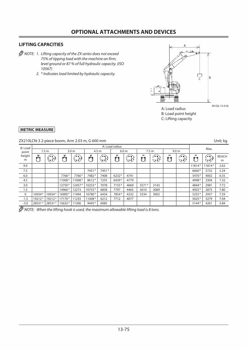
OPTIONAL ATTACHMENTS AND DEVICES
13-75
METRIC MEASURE
ZX210LCN-3 2-piece boom, Arm 2.03 m, G 600 mm Unit; kg
B: Load point
heightm
A: Load radiusMax.
1.5 m 3.0 m 4.5 m 6.0 m 7.5 m 9.0 m
REACH m
9.0 11814 * 11814 * 2.63
7.5 7451 * 7451 * 6660 * 5725 5.24
6.0 7766 * 7766 * 7482 * 7408 6232 * 4741 5476 * 4002 6.554.5 11008 * 11008 * 8612 * 7255 6439 * 4779 4998 * 3304 7.32
3.0 12750 * 12457 * 10253 * 7078 7155 * 4669 5571 * 3143 4844 * 2981 7.721.5 14966 * 12273 10753 * 6858 7797 4465 5610 3069 4925 * 2875 7.800 10934 * 10934 * 16900 * 11494 10780 * 6434 7854 * 4232 5534 3002 5255 * 2957 7.59
-1.5 19212 * 19212 * 17170 * 11235 11008 * 6212 7712 4077 5025 * 3279 7.04-3.0 28531 * 28531 * 15632 * 11306 9445 * 6085 5144 * 4261 5.84
NOTE: When the lifting hook is used, the maximum allowable lifting load is 8 tons.
LIFTING CAPACITIES
NOTE: 1. Lifting capacity of the ZX series does not exceed 75% of tipping load with the machine on firm, level ground or 87 % of full hydraulic capacity. (ISO 10567)
2. * Indicates load limited by hydraulic capacity.
A: Load radiusB: Load point heightC: Lifting capacity
C B
M1G6-13-018
A

OPTIONAL ATTACHMENTS AND DEVICES
13-76
METRIC MEASURE
ZX240N-3 Mono block boom, Arm 2.91 m, G 600 mm Unit; kg
B: Load point
heightm
A: Load radiusMax.
1.5 m 3.0 m 4.5 m 6.0 m 7.5 m 9.0 m
REACH m
6.0 4956 * 4956 * 4047 * 3550 7.39
4.5 6328 * 6328 * 5499 * 4819 5115 * 3428 3993 * 3035 8.083.0 8207 * 6857 6349 * 4586 5476 * 3325 4103 * 2776 8.441.5 9900 * 6382 7201 * 4355 5438 3211 4381 * 2679 8.520 4514 * 4514 * 10713 * 6131 7353 4193 5342 3125 4626 2723 8.32
-1.5 5426 * 5426 * 8804 * 8804 * 10659 * 6064 7274 4124 5311 3096 5019 2940 7.83-3.0 9865 * 9865 * 13855 * 11330 9813 * 6123 775 * 4156 5903 * 3452 6.97-4.5 10797 * 10797 * 7788 * 6320 5899 * 4752 5.59
ZX240N-3 Mono block boom, Arm 2.42 m, G 600 mm Unit; kg
B: Load point
heightm
A: Load radiusMax.
1.5 m 3.0 m 4.5 m 6.0 m 7.5 m 9.0 m
REACH m
6.0 5456 * 4908 5478 * 4001 6.81
4.5 7028 * 7028 * 5933 * 4759 5501 * 3389 5500 * 3350 7.553.0 8874 * 6713 6722 * 4536 5541 3306 5085 3037 7.941.5 10343 * 6292 7473 * 4326 5433 3210 4935 2925 8.020 10819 * 6116 7348 4193 5361 3145 5072 2986 7.81
-1.5 9559 * 9559 * 10473 * 6101 7306 4157 5581 3264 7.28-3.0 12683 * 11486 9325 * 6201 6874 * 4232 6302 * 3950 6.35
-4.5 6614 * 6475 6077 * 5972 4.78
NOTE: When the lifting hook is used, the maximum allowable lifting load is 8 tons.
LIFTING CAPACITIES
NOTE: 1. Lifting capacity of the ZX series does not exceed 75% of tipping load with the machine on firm, level ground or 87 % of full hydraulic capacity. (ISO 10567)
2. * Indicates load limited by hydraulic capacity.
A: Load radiusB: Load point heightC: Lifting capacity
A
CB
M1G6-13-013

OPTIONAL ATTACHMENTS AND DEVICES
13-77
METRIC MEASURE
ZX240N-3 Mono block boom, Arm 2.03 m, G 600 mm Unit; kg
B: Load point
heightm
A: Load radiusMax.
1.5 m 3.0 m 4.5 m 6.0 m 7.5 m 9.0 m
REACH m
6.0 6281 * 6281 * 5883 * 4869 5955 * 4194 6.574.5 7581 * 7163 6283 * 4738 5804 3492 7.34
3.0 9418 * 6650 7023 * 4532 5546 3318 5291 3167 7.741.5 7514 4345 5459 3239 5144 3061 7.82
0 10877 * 6180 7391 4239 5412 3197 5313 3144 7.61
-1.5 10311 * 6198 7377 4227 5900 3470 7.60
-3.0 11710 * 11708 8907 * 6322 6363 * 4350 6138 * 4274 6.10
NOTE: When the lifting hook is used, the maximum allowable lifting load is 8 tons.
LIFTING CAPACITIES
NOTE: 1. Lifting capacity of the ZX series does not exceed 75% of tipping load with the machine on firm, level ground or 87 % of full hydraulic capacity. (ISO 10567)
2. * Indicates load limited by hydraulic capacity.
A: Load radiusB: Load point heightC: Lifting capacity
A
CB
M1G6-13-013
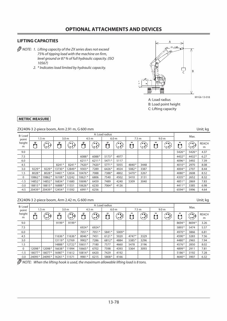
OPTIONAL ATTACHMENTS AND DEVICES
13-78
METRIC MEASURE
ZX240N-3 2-piece boom, Arm 2.91 m, G 600 mm Unit; kg
B: Load point
heightm
A: Load radiusMax.
1.5 m 3.0 m 4.5 m 6.0 m 7.5 m 9.0 m
REACH m
9.0 5426 * 5426 * 4.37
7.5 6088 * 6088 * 5173 * 4977 4432 * 4432 * 6.276.0 6211 * 6211 * 5471 * 5117 4096 * 3492 7.394.5 8241 * 8241 * 7420 * 7420 * 5771 * 5055 4840 * 3448 4010 * 2970 8.083.0 9229 * 9229 * 13730 * 12849 * 9303 * 7289 6426 * 4924 5082 * 3387 4004 * 2707 8.441.5 8028 * 8028 * 14401 * 12654 10476 * 7088 7388 * 4802 5470 * 3267 4080 * 2608 8.520 10862 * 10862 * 16108 * 12242 10621 * 6806 7540 4502 5410 3131 4335 * 2652 8.32
-1.5 14852 * 14852 * 16834 * 11680 10696 * 6459 7489 4240 5309 3040 4851 * 2869 7.83-3.0 18815 * 18815 * 16888 * 11551 10626 * 6230 7064 * 4126 4411 * 3385 6.98-4.5 20439 * 20439 * 12454 * 11592 6991 * 6256 6594 * 5996 4.64
ZX240N-3 2-piece boom, Arm 2.42 m, G 600 mm Unit; kg
B: Load point
heightm
A: Load radiusMax.
1.5 m 3.0 m 4.5 m 6.0 m 7.5 m 9.0 m
REACH m
9.0 9199 * 9199 * 8694 * 8694 * 3.26
7.5 6924 * 6924 * 5893 * 5474 5.57
6.0 7051 * 7051 * 5841 * 5009 * 4970 * 3866 6.814.5 11636 * 11636 * 8046 * 7451 6121 * 5020 4747 * 3329 4590 * 3283 7.563.0 13119 * 12769 9902 * 7286 6812 * 4884 5385 * 3296 4480 * 2965 7.941.5 14888 * 12722 * 10651 * 7180 7577 4660 5478 3196 4576 * 2850 8.020 12098 * 12098 * 16638 * 11994 10665 * 6702 7598 4393 5364 3093 4899 * 2911 7.81
-1.5 18077 * 18077 * 16987 * 11612 10814 * 6420 7429 4192 5186 * 3192 7.28-3.0 24095 * 24095 * 16261 * 11571 9981 * 6215 5808 * 4166 4640 * 3907 6.32
NOTE: When the lifting hook is used, the maximum allowable lifting load is 8 tons.
LIFTING CAPACITIES
NOTE: 1. Lifting capacity of the ZX series does not exceed 75% of tipping load with the machine on firm, level ground or 87 % of full hydraulic capacity. (ISO 10567)
2. * Indicates load limited by hydraulic capacity.
A: Load radiusB: Load point heightC: Lifting capacity
C B
M1G6-13-018
A
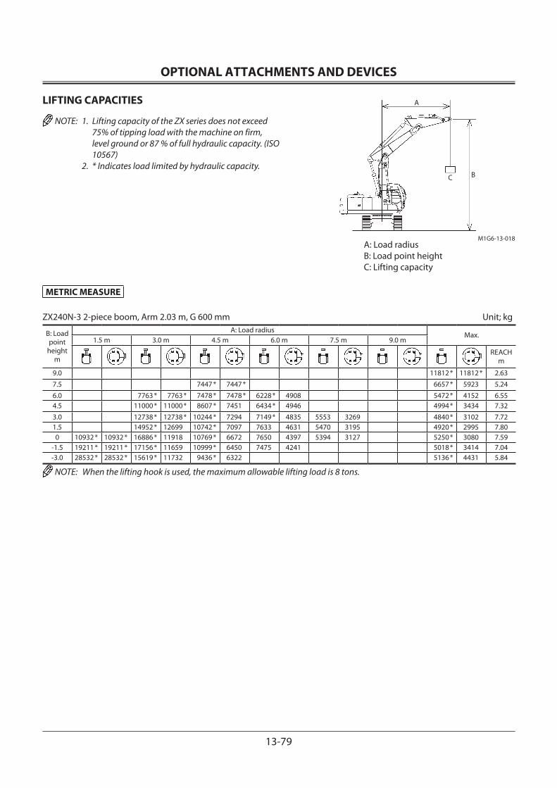
OPTIONAL ATTACHMENTS AND DEVICES
13-79
METRIC MEASURE
ZX240N-3 2-piece boom, Arm 2.03 m, G 600 mm Unit; kg
B: Load point
heightm
A: Load radiusMax.
1.5 m 3.0 m 4.5 m 6.0 m 7.5 m 9.0 m
REACH m
9.0 11812 * 11812 * 2.63
7.5 7447 * 7447 * 6657 * 5923 5.24
6.0 7763 * 7763 * 7478 * 7478 * 6228 * 4908 5472 * 4152 6.554.5 11000 * 11000 * 8607 * 7451 6434 * 4946 4994 * 3434 7.32
3.0 12738 * 12738 * 10244 * 7294 7149 * 4835 5553 3269 4840 * 3102 7.721.5 14952 * 12699 10742 * 7097 7633 4631 5470 3195 4920 * 2995 7.800 10932 * 10932 * 16886 * 11918 10769 * 6672 7650 4397 5394 3127 5250 * 3080 7.59
-1.5 19211 * 19211 * 17156 * 11659 10999 * 6450 7475 4241 5018 * 3414 7.04-3.0 28532 * 28532 * 15619 * 11732 9436 * 6322 5136 * 4431 5.84
NOTE: When the lifting hook is used, the maximum allowable lifting load is 8 tons.
LIFTING CAPACITIES
NOTE: 1. Lifting capacity of the ZX series does not exceed 75% of tipping load with the machine on firm, level ground or 87 % of full hydraulic capacity. (ISO 10567)
2. * Indicates load limited by hydraulic capacity.
A: Load radiusB: Load point heightC: Lifting capacity
C B
M1G6-13-018
A
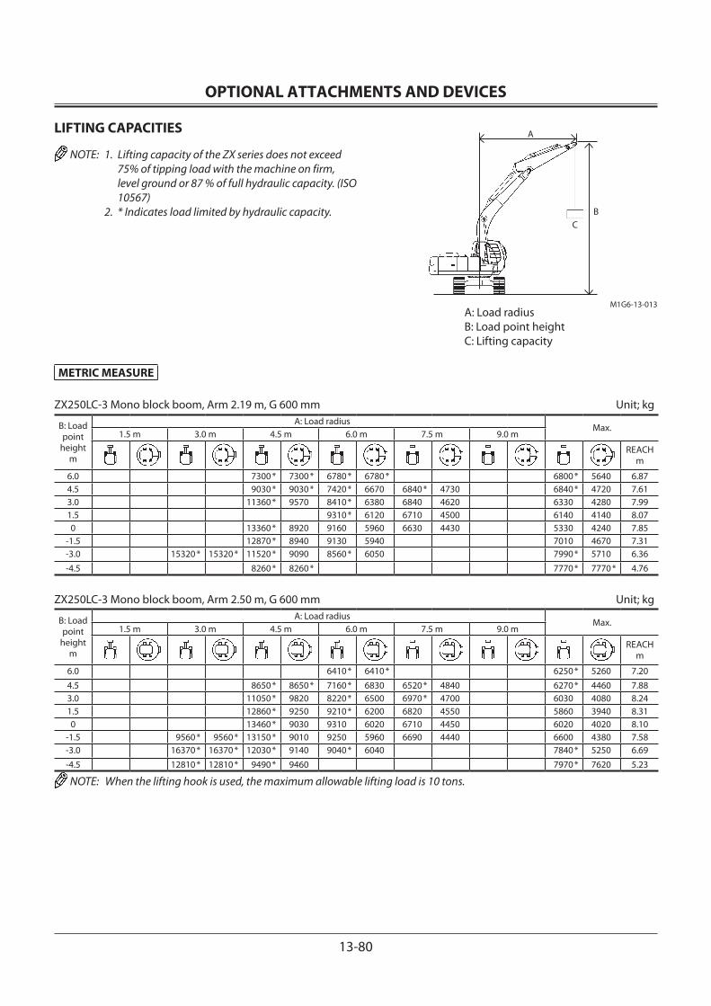
OPTIONAL ATTACHMENTS AND DEVICES
13-80
METRIC MEASURE
ZX250LC-3 Mono block boom, Arm 2.19 m, G 600 mm Unit; kg
B: Load point
heightm
A: Load radiusMax.
1.5 m 3.0 m 4.5 m 6.0 m 7.5 m 9.0 m
REACH m
6.0 7300 * 7300 * 6780 * 6780 * 6800 * 5640 6.874.5 9030 * 9030 * 7420 * 6670 6840 * 4730 6840 * 4720 7.613.0 11360 * 9570 8410 * 6380 6840 4620 6330 4280 7.991.5 9310 * 6120 6710 4500 6140 4140 8.070 13360 * 8920 9160 5960 6630 4430 5330 4240 7.85
-1.5 12870 * 8940 9130 5940 7010 4670 7.31-3.0 15320 * 15320 * 11520 * 9090 8560 * 6050 7990 * 5710 6.36
-4.5 8260 * 8260 * 7770 * 7770 * 4.76
ZX250LC-3 Mono block boom, Arm 2.50 m, G 600 mm Unit; kg
B: Load point
heightm
A: Load radiusMax.
1.5 m 3.0 m 4.5 m 6.0 m 7.5 m 9.0 m
REACH m
6.0 6410 * 6410 * 6250 * 5260 7.20
4.5 8650 * 8650 * 7160 * 6830 6520 * 4840 6270 * 4460 7.883.0 11050 * 9820 8220 * 6500 6970 * 4700 6030 4080 8.241.5 12860 * 9250 9210 * 6200 6820 4550 5860 3940 8.310 13460 * 9030 9310 6020 6710 4450 6020 4020 8.10
-1.5 9560 * 9560 * 13150 * 9010 9250 5960 6690 4440 6600 4380 7.58-3.0 16370 * 16370 * 12030 * 9140 9040 * 6040 7840 * 5250 6.69
-4.5 12810 * 12810 * 9490 * 9460 7970 * 7620 5.23
NOTE: When the lifting hook is used, the maximum allowable lifting load is 10 tons.
LIFTING CAPACITIES
NOTE: 1. Lifting capacity of the ZX series does not exceed 75% of tipping load with the machine on firm, level ground or 87 % of full hydraulic capacity. (ISO 10567)
2. * Indicates load limited by hydraulic capacity.
A: Load radiusB: Load point heightC: Lifting capacity
A
CB
M1G6-13-013
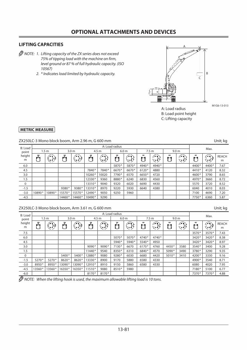
OPTIONAL ATTACHMENTS AND DEVICES
13-81
METRIC MEASURE
ZX250LC-3 Mono block boom, Arm 2.96 m, G 600 mm Unit; kg
B: Load point
heightm
A: Load radiusMax.
1.5 m 3.0 m 4.5 m 6.0 m 7.5 m 9.0 m
REACH m
6.0 5870 * 5870 * 4940 * 4940 * 4400 * 4400 * 7.674.5 7840 * 7840 * 6670 * 6670 * 6120 * 4880 4410 * 4120 8.323.0 10260 * 10020 7790 * 6570 6650 * 4720 4600 * 3790 8.651.5 12330 * 9360 8880 * 6240 6830 4560 4970 * 3660 8.720 13310 * 9040 9320 6020 6690 4430 5570 3720 8.52
-1.5 9380 * 9380 * 13310 * 8970 9220 5930 6640 4380 6040 4010 8.03-3.0 10890 * 10890 * 15570 * 15570 * 12490 * 9050 9250 5960 7100 4690 7.20-4.5 14460 * 14460 * 10490 * 9290 7750 * 6360 5.87
ZX250LC-3 Mono block boom, Arm 3.61 m, G 600 mm Unit; kg
B: Load point
heightm
A: Load radiusMax.
1.5 m 3.0 m 4.5 m 6.0 m 7.5 m 9.0 m
REACH m
7.5 3570 * 3570 * 7.436.0 5070 * 5070 * 4740 * 4740 * 3420 * 3420 * 8.384.5 5940 * 5940 * 5540 * 4950 3420 * 3420 * 8.973.0 9090 * 9090 * 7130 * 6670 6170 * 4760 4450 * 3580 3540 * 3400 9.281.5 11440 * 9540 8350 * 6310 6840 * 4570 5090 * 3490 3780 * 3290 9.350 5400 * 5400 * 12880 * 9080 9280 * 6030 6680 4420 5010 * 3410 4200 * 3330 9.16
-1.5 5270 * 5270 * 8620 * 8620 * 13330 * 8900 9170 5880 6580 4330 4900 * 3540 8.71-3.0 8950 * 8950 * 13090 * 13090 * 12910 * 8910 9150 5860 6580 4330 6080 4020 7.95-4.5 13560 * 13560 * 16350 * 16350 * 11510 * 9080 8510 * 5980 7180 * 5100 6.77-6.0 8170 * 8170 * 7370 * 7370 * 4.88
NOTE: When the lifting hook is used, the maximum allowable lifting load is 10 tons.
LIFTING CAPACITIES
NOTE: 1. Lifting capacity of the ZX series does not exceed 75% of tipping load with the machine on firm, level ground or 87 % of full hydraulic capacity. (ISO 10567)
2. * Indicates load limited by hydraulic capacity.
A: Load radiusB: Load point heightC: Lifting capacity
A
CB
M1G6-13-013

OPTIONAL ATTACHMENTS AND DEVICES
13-82
METRIC MEASURE
ZX250LCN-3 Mono block boom, Arm 2.19 m, G 600 mm Unit; kg
B: Load point
heightm
A: Load radiusMax.
1.5 m 3.0 m 4.5 m 6.0 m 7.5 m 9.0 m
REACH m
6.0 7300 * 7300 * 6780 * 6360 6800 * 5210 6.874.5 9030 * 9030 * 7420 * 6150 6840 * 4360 6840 * 4350 7.613.0 11360 * 8720 8410 * 5860 6820 4260 6310 3950 7.991.5 9310 5610 6690 4140 6130 3810 8.070 13360 * 8090 9140 5460 6610 4070 6310 3900 7.85
-1.5 12870 * 8110 9110 5430 6990 4290 7.31-3.0 15320 * 15320 * 11520 * 8250 8560 * 5540 7990 * 5240 6.36
-4.5 8260 * 8260 * 7770 * 7770 * 4.76
ZX250LCN-3 Mono block boom, Arm 2.50 m, G 600 mm Unit; kg
B: Load point
heightm
A: Load radiusMax.
1.5 m 3.0 m 4.5 m 6.0 m 7.5 m 9.0 m
REACH m
6.0 6410 * 6410 * 6250 * 4860 7.20
4.5 8650 * 8650 * 7160 * 6290 6520 * 4460 6270 * 4120 7.883.0 11050 * 8940 8220 * 5970 6960 4320 6020 3750 8.241.5 12860 * 8380 9210 * 5680 6800 4180 5850 3620 8.310 13460 * 8170 9290 5500 6690 4080 6010 3690 8.10
-1.5 9560 * 9560 * 13150 * 8160 9230 5450 6680 4070 6580 4020 7.58-3.0 16370 * 16180 12030 * 8280 9040 * 5520 7840 * 4810 6.69
-4.5 12810 * 12810 * 9490 * 8590 7970 * 6960 5.23
NOTE: When the lifting hook is used, the maximum allowable lifting load is 10 tons.
LIFTING CAPACITIES
NOTE: 1. Lifting capacity of the ZX series does not exceed 75% of tipping load with the machine on firm, level ground or 87 % of full hydraulic capacity. (ISO 10567)
2. * Indicates load limited by hydraulic capacity.
A: Load radiusB: Load point heightC: Lifting capacity
A
CB
M1G6-13-013

OPTIONAL ATTACHMENTS AND DEVICES
13-83
METRIC MEASURE
ZX250LCN-3 Mono block boom, Arm 2.96 m, G 600 mm Unit; kg
B: Load point
heightm
A: Load radiusMax.
1.5 m 3.0 m 4.5 m 6.0 m 7.5 m 9.0 m
REACH m
6.0 5870 * 5870 * 4940 * 4590 4400 * 4400 * 7.674.5 7840 * 7840 * 6670 * 6370 6120 * 4500 4410 * 3800 8.323.0 10260 * 9130 7790 * 6030 6650 * 4350 4600 * 3480 8.651.5 12330 * 8500 8880 * 5720 6810 4190 4970 * 3360 8.720 13310 * 8190 9300 5500 6670 4060 5560 3410 8.52
-1.5 9380 * 9380 * 13310 * 8110 9190 5410 6620 4010 6020 3680 8.03-3.0 10890 * 10890 * 15570 * 15570 * 12490 * 8190 9230 5440 7080 4290 7.20-4.5 14460 * 14460 * 10490 * 8430 7750 * 5820 5.87
ZX250LCN-3 Mono block boom, Arm 3.61 m, G 600 mm Unit; kg
B: Load point
heightm
A: Load radiusMax.
1.5 m 3.0 m 4.5 m 6.0 m 7.5 m 9.0 m
REACH m
7.5 3570 * 3570 * 7.436.0 5070 * 5070 * 4740 * 4690 3420 * 3420 * 8.384.5 5940 * 5940 * 5540 * 4570 3420 * 3380 8.973.0 9090 * 9090 * 7130 * 6140 6170 * 4390 4450 * 3290 3540 * 3120 9.281.5 11440 * 8660 8350 * 5780 6830 4200 5090 * 3200 3780 * 3020 9.350 5400 * 5400 * 12880 * 8220 9280 * 5510 6660 4050 5010 * 3130 4200 * 3050 9.16
-1.5 5270 * 5270 * 8620 * 8620 * 13330 * 8040 9150 5360 6560 3960 4900 * 3240 8.71-3.0 8950 * 8950 * 13090 * 13090 * 12910 * 8050 9120 5340 6270 3960 6070 3680 7.95-4.5 13560 * 13560 * 16350 * 16010 11510 * 8220 8510 * 5460 7180 * 4660 6.77-6.0 8170 * 8170 * 7370 * 7370 * 4.88
NOTE: When the lifting hook is used, the maximum allowable lifting load is 10 tons.
LIFTING CAPACITIES
NOTE: 1. Lifting capacity of the ZX series does not exceed 75% of tipping load with the machine on firm, level ground or 87 % of full hydraulic capacity. (ISO 10567)
2. * Indicates load limited by hydraulic capacity.
A: Load radiusB: Load point heightC: Lifting capacity
A
CB
M1G6-13-013
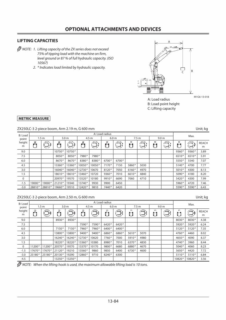
OPTIONAL ATTACHMENTS AND DEVICES
13-84
METRIC MEASURE
ZX250LC-3 2-piece boom, Arm 2.19 m, G 600 mm Unit; kg
B: Load point
heightm
A: Load radiusMax.
1.5 m 3.0 m 4.5 m 6.0 m 7.5 m 9.0 m
REACH m
9.0 10750 * 10750 * 9360 * 9360 * 3.89
7.5 8050 * 8050 * 7980 * 7980 * 6510 * 6510 * 5.91
6.0 8670 * 8670 * 8380 * 8380 * 6700 * 6700 * 5550 * 5540 7.07
4.5 13360 * 13360 * 10050 * 10050 * 7170 * 7150 5860 * 5030 5140 * 4700 7.77
3.0 16040 * 16040 * 12730 * 10670 8120 * 7050 6160 * 4970 5010 * 4300 8.131.5 18610 * 18610 * 13460 * 10720 9360 * 7010 6610 * 4840 5090 * 4180 8.20
0 20970 * 19570 13520 * 10180 9910 * 6690 7060 4710 5420 * 4300 7.99
-1.5 19000 * 19000 * 21210 * 19340 13740 * 9930 9900 6450 5960 * 4720 7.46-3.0 28810 * 28810 * 19660 * 19510 12420 * 9810 7440 * 6420 5590 * 5590 * 6.43
ZX250LC-3 2-piece boom, Arm 2.50 m, G 600 mm Unit; kg
B: Load point
heightm
A: Load radiusMax.
1.5 m 3.0 m 4.5 m 6.0 m 7.5 m 9.0 m
REACH m
9.0 8930 * 8930 * 8030 * 8030 * 4.38
7.5 7590 * 7590 * 6420 * 6420 * 5920 * 5920 * 6.246.0 7150 * 7150 * 7960 * 7960 * 6400 * 6400 * 5120 * 5120 * 7.35
4.5 13800 * 13800 * 9400 * 9400 * 6860 * 6860 * 5610 * 5070 4760 * 4460 8.02
3.0 16240 * 16240 * 12730 * 10620 7760 * 7000 5910 * 4980 4650 * 4090 8.37
1.5 18220 * 18220 * 13360 * 10380 8980 * 7010 6370 * 4830 4740 * 3960 8.440 11200 * 11200 * 20570 * 19570 13370 * 10170 9800 * 6680 6880 * 4670 5040 * 4060 8.23
-1.5 17670 * 17670 * 21120 * 19210 13560 * 9860 9850 6400 6730 * 4600 5650 * 4420 7.72-3.0 25180 * 25180 * 20130 * 19290 12860 * 9710 8240 * 6300 5110 * 5110 * 6.84-4.5 13250 * 13250 * 10820 * 10820 * 3.56
NOTE: When the lifting hook is used, the maximum allowable lifting load is 10 tons.
LIFTING CAPACITIES
NOTE: 1. Lifting capacity of the ZX series does not exceed 75% of tipping load with the machine on firm, level ground or 87 % of full hydraulic capacity. (ISO 10567)
2. * Indicates load limited by hydraulic capacity.
A: Load radiusB: Load point heightC: Lifting capacity
C B
M1G6-13-018
A

OPTIONAL ATTACHMENTS AND DEVICES
13-85
METRIC MEASURE
ZX250LC-3 2-piece boom, Arm 2.96 m, G 600 mm Unit; kg
B: Load point
heightm
A: Load radiusMax.
1.5 m 3.0 m 4.5 m 6.0 m 7.5 m 9.0 m
REACH m
9.0 6360 * 6360 * 5430 * 5430 * 5.177.5 6110 * 6110 * 5840 * 5840 * 4680 * 4680 * 6.816.0 5010 * 5010 * 6500 * 6500 * 6050 * 6050 * 5020 * 5020 * 4400 * 4400 * 7.844.5 13800 * 13800 * 8650 * 8650 * 6500 * 6500 * 5300 * 5160 4300 * 4110 8.473.0 13670 * 13670 * 16390 * 16390 * 11450 * 10640 7340 * 7000 * 5630 * 5080 4210 * 3790 8.801.5 17600 * 17600 * 13300 * 10410 8530 * 7100 6100 * 4910 4280 * 3670 8.870 10390 * 10390 * 19860 * 19650 * 13310 * 10290 9740 6760 6630 * 4720 4530 * 3750 8.67
-1.5 15040 * 15040 * 20980 * 19260 13420 * 9890 9780 6450 6930 4580 5030 * 4040 8.19-3.0 20080 * 20080 * 20690 * 19180 13400 * 9720 9170 * 6280 5060 * 4710 7.37-4.5 23600 * 23600 * 16330 * 16330 * 9730 * 9700 6670 * 6670 5.39
ZX250LC-3 2-piece boom, Arm 3.61 m, G 600 mm Unit; kg
B: Load point
heightm
A: Load radiusMax.
1.5 m 3.0 m 4.5 m 6.0 m 7.5 m 9.0 m
REACH m
10.5 5540 * 5540 * 3.759.0 5160 * 5160 * 4490 * 4490 * 4100 * 4100 * 6.217.5 4590 * 4590 * 4840 * 4840 * 3950 * 3950 * 3620 * 3620 * 7.636.0 4650 * 4650 * 5070 * 5070 * 4720 * 4720 * 3430 * 3430 * 8.554.5 5230 * 5230 * 6100 * 6100 * 5980 * 5980 * 4940 * 4940 * 3810 * 3760 3380 * 3380 * 9.143.0 15480 * 15480 * 16850 * 16850 * 9870 * 9870 * 6770 * 6770 * 5270 * 5080 4280 * 3730 3450 * 3400 9.441.5 8750 * 8750 * 17010 * 17010 * 12940 * 10440 7880 * 6850 5740 * 4970 4560 * 3640 3630 * 3300 9.500 9780 * 9780 * 18860 * 18860 * 13230 * 10480 9170 * 6850 6280 * 4820 4660 * 3540 3920 * 3350 9.32
-1.5 13060 * 13060 * 20600 * 19380 13260 * 9950 9690 * 6550 6800 * 4610 4290 * 3570 8.88-3.0 16960 * 16960 * 20970 * 19070 13510 * 9710 9730 6280 6760 * 4510 4900 * 4050 8.13-4.5 20670 * 20670 * 19250 * 19240 11970 * 9590 7450 * 6240 5100 * 5100 * 6.73
NOTE: When the lifting hook is used, the maximum allowable lifting load is 10 tons.
LIFTING CAPACITIES
NOTE: 1. Lifting capacity of the ZX series does not exceed 75% of tipping load with the machine on firm, level ground or 87 % of full hydraulic capacity. (ISO 10567)
2. * Indicates load limited by hydraulic capacity.
A: Load radiusB: Load point heightC: Lifting capacity
C B
M1G6-13-018
A
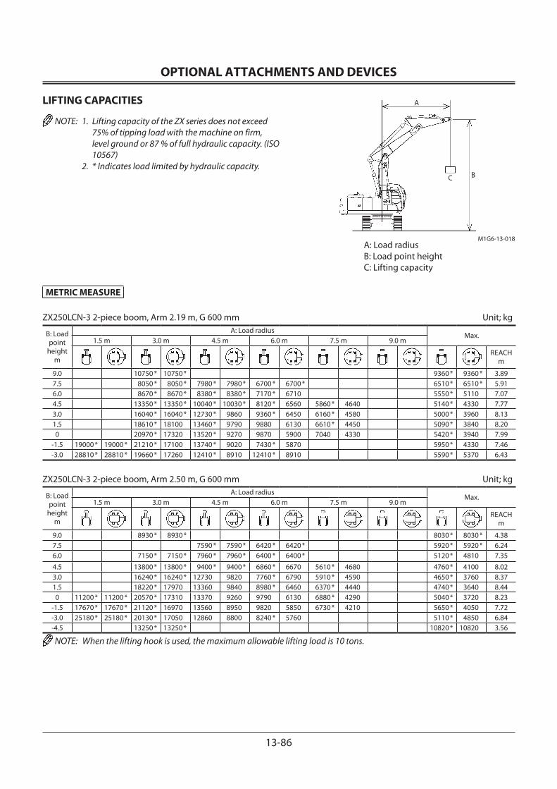
OPTIONAL ATTACHMENTS AND DEVICES
13-86
METRIC MEASURE
ZX250LCN-3 2-piece boom, Arm 2.19 m, G 600 mm Unit; kg
B: Load point
heightm
A: Load radiusMax.
1.5 m 3.0 m 4.5 m 6.0 m 7.5 m 9.0 m
REACH m
9.0 10750 * 10750 * 9360 * 9360 * 3.897.5 8050 * 8050 * 7980 * 7980 * 6700 * 6700 * 6510 * 6510 * 5.916.0 8670 * 8670 * 8380 * 8380 * 7170 * 6710 5550 * 5110 7.074.5 13350 * 13350 * 10040 * 10030 * 8120 * 6560 5860 * 4640 5140 * 4330 7.773.0 16040 * 16040 * 12730 * 9860 9360 * 6450 6160 * 4580 5000 * 3960 8.131.5 18610 * 18100 13460 * 9790 9880 6130 6610 * 4450 5090 * 3840 8.200 20970 * 17320 13520 * 9270 9870 5900 7040 4330 5420 * 3940 7.99
-1.5 19000 * 19000 * 21210 * 17100 13740 * 9020 7430 * 5870 5950 * 4330 7.46-3.0 28810 * 28810 * 19660 * 17260 12410 * 8910 12410 * 8910 5590 * 5370 6.43
ZX250LCN-3 2-piece boom, Arm 2.50 m, G 600 mm Unit; kg
B: Load point
heightm
A: Load radiusMax.
1.5 m 3.0 m 4.5 m 6.0 m 7.5 m 9.0 m
REACH m
9.0 8930 * 8930 * 8030 * 8030 * 4.387.5 7590 * 7590 * 6420 * 6420 * 5920 * 5920 * 6.246.0 7150 * 7150 * 7960 * 7960 * 6400 * 6400 * 5120 * 4810 7.35
4.5 13800 * 13800 * 9400 * 9400 * 6860 * 6670 5610 * 4680 4760 * 4100 8.023.0 16240 * 16240 * 12730 9820 7760 * 6790 5910 * 4590 4650 * 3760 8.371.5 18220 * 17970 13360 9840 8980 * 6460 6370 * 4440 4740 * 3640 8.440 11200 * 11200 * 20570 * 17310 13370 9260 9790 6130 6880 * 4290 5040 * 3720 8.23
-1.5 17670 * 17670 * 21120 * 16970 13560 8950 9820 5850 6730 * 4210 5650 * 4050 7.72-3.0 25180 * 25180 * 20130 * 17050 12860 8800 8240 * 5760 5110 * 4850 6.84-4.5 13250 * 13250 * 10820 * 10820 3.56
NOTE: When the lifting hook is used, the maximum allowable lifting load is 10 tons.
LIFTING CAPACITIES
NOTE: 1. Lifting capacity of the ZX series does not exceed 75% of tipping load with the machine on firm, level ground or 87 % of full hydraulic capacity. (ISO 10567)
2. * Indicates load limited by hydraulic capacity.
A: Load radiusB: Load point heightC: Lifting capacity
C B
M1G6-13-018
A
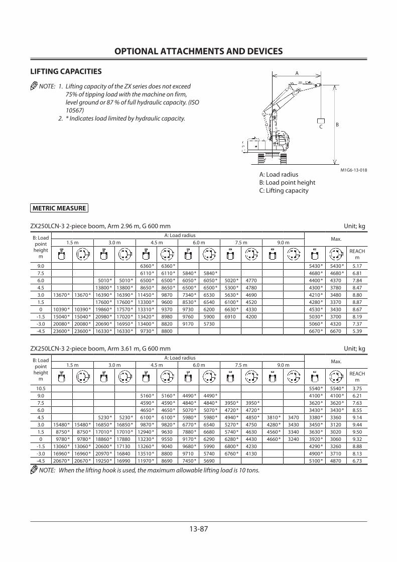
OPTIONAL ATTACHMENTS AND DEVICES
13-87
METRIC MEASURE
ZX250LCN-3 2-piece boom, Arm 2.96 m, G 600 mm Unit; kg
B: Load point
heightm
A: Load radiusMax.
1.5 m 3.0 m 4.5 m 6.0 m 7.5 m 9.0 m
REACH m
9.0 6360 * 6360 * 5430 * 5430 * 5.177.5 6110 * 6110 * 5840 * 5840 * 4680 * 4680 * 6.816.0 5010 * 5010 * 6500 * 6500 * 6050 * 6050 * 5020 * 4770 4400 * 4370 7.844.5 13800 * 13800 * 8650 * 8650 * 6500 * 6500 * 5300 * 4780 4300 * 3780 8.473.0 13670 * 13670 * 16390 * 16390 * 11450 * 9870 7340 * 6530 5630 * 4690 4210 * 3480 8.801.5 17600 * 17600 * 13300 * 9600 8530 * 6540 6100 * 4520 4280 * 3370 8.870 10390 * 10390 * 19860 * 17570 * 13310 * 9370 9730 6200 6630 * 4330 4530 * 3430 8.67
-1.5 15040 * 15040 * 20980 * 17020 * 13420 * 8980 9760 5900 6910 4200 5030 * 3700 8.19-3.0 20080 * 20080 * 20690 * 16950 * 13400 * 8820 9170 5730 5060 * 4320 7.37-4.5 23600 * 23600 * 16330 * 16330 * 9730 * 8800 6670 * 6670 5.39
ZX250LCN-3 2-piece boom, Arm 3.61 m, G 600 mm Unit; kg
B: Load point
heightm
A: Load radiusMax.
1.5 m 3.0 m 4.5 m 6.0 m 7.5 m 9.0 m
REACH m
10.5 5540 * 5540 * 3.759.0 5160 * 5160 * 4490 * 4490 * 4100 * 4100 * 6.217.5 4590 * 4590 * 4840 * 4840 * 3950 * 3950 * 3620 * 3620 * 7.636.0 4650 * 4650 * 5070 * 5070 * 4720 * 4720 * 3430 * 3430 * 8.554.5 5230 * 5230 * 6100 * 6100 * 5980 * 5980 * 4940 * 4850 * 3810 * 3470 3380 * 3360 9.143.0 15480 * 15480 * 16850 * 16850 * 9870 * 9820 * 6770 * 6540 5270 * 4750 4280 * 3430 3450 * 3120 9.441.5 8750 * 8750 * 17010 * 17010 * 12940 * 9630 7880 * 6680 5740 * 4630 4560 * 3340 3630 * 3020 9.500 9780 * 9780 * 18860 * 17880 13230 * 9550 9170 * 6290 6280 * 4430 4660 * 3240 3920 * 3060 9.32
-1.5 13060 * 13060 * 20600 * 17130 13260 * 9040 9680 * 5990 6800 * 4230 4290 * 3260 8.88-3.0 16960 * 16960 * 20970 * 16840 13510 * 8800 9710 5740 6760 * 4130 4900 * 3710 8.13-4.5 20670 * 20670 * 19250 * 16990 11970 * 8690 7450 * 5690 5100 * 4870 6.73
NOTE: When the lifting hook is used, the maximum allowable lifting load is 10 tons.
LIFTING CAPACITIES
NOTE: 1. Lifting capacity of the ZX series does not exceed 75% of tipping load with the machine on firm, level ground or 87 % of full hydraulic capacity. (ISO 10567)
2. * Indicates load limited by hydraulic capacity.
A: Load radiusB: Load point heightC: Lifting capacity
C B
M1G6-13-018
A

OPTIONAL ATTACHMENTS AND DEVICES
13-88
METRIC MEASURE
ZX280LC-3 Mono block boom, Arm 2.42 m, G 600 mm Unit; kg
B: Load point
heightm
A: Load radiusMax.
1.5 m 3.0 m 4.5 m 6.0 m 7.5 m 9.0 m
REACH m
6.0 6740 * 5440 7.464.5 9590 * 9590 * 6870 * 4670 8.113.0 12340 * 10580 8950 * 7060 6860 4290 8.441.5 10050 * 6730 8050 4950 6700 4160 8.490 14720 * 9810 10690 * 6530 7920 4840 6900 4250 8.27
-1.5 10360 * 10360 * 14390 * 9830 10750 * 6480 7900 4820 7560 4640 7.75-3.0 18020 * 18020 * 13290 * 9980 10040 * 6580 8470 * 5530 6.86-4.5 14540 * 14540 * 10790 * 10340 8710 * 7920 5.42
ZX280LC-3 Mono block boom, Arm 3.11 m, G 600 mm Unit; kg
B: Load point
heightm
A: Load radiusMax.
1.5 m 3.0 m 4.5 m 6.0 m 7.5 m 9.0 m
REACH m
6.0 5960 * 5960 * 5910 * 5520 4730 * 4730 8.194.5 8240 * 8240 * 6940 * 6940 * 6330 * 5370 4730 * 4140 8.783.0 11000 * 10940 8240 * 7180 6990 * 5170 5560 * 3900 4890 * 3830 9.091.5 13310 * 10180 9500 * 6800 7690 * 4970 6130 3800 5220 * 3720 9.140 14450 * 9820 10380 * 6540 7900 4810 5800 * 3780 8.93
-1.5 6820 * 6820 * 10250 * 10250 * 14590 * 9730 10730 * 6420 7820 4740 6610 4060 8.45-3.0 11900 * 11900 * 16480 * 16480 * 13930 * 9820 10410 * 6450 7870 4790 7670 4680 7.65-4.5 16970 * 16970 * 12190 * 10070 8980 * 6640 8170 * 6120 6.39
NOTE: When the lifting hook is used, the maximum allowable lifting load is 10 tons.
LIFTING CAPACITIES
NOTE: 1. Lifting capacity of the ZX series does not exceed 75% of tipping load with the machine on firm, level ground or 87 % of full hydraulic capacity. (ISO 10567)
2. * Indicates load limited by hydraulic capacity.
A: Load radiusB: Load point heightC: Lifting capacity
A
CB
M1G6-13-013

OPTIONAL ATTACHMENTS AND DEVICES
13-89
METRIC MEASURE
ZX280LC-3 Mono block boom, Arm 3.76 m, G 600 mm Unit; kg
B: Load point
heightm
A: Load radiusMax.
1.5 m 3.0 m 4.5 m 6.0 m 7.5 m 9.0 m
REACH m
7.5 5160 * 5160 * 3950 * 3950 * 7.946.0 5250 * 5250 * 3810 * 3810 * 8.824.5 6160 * 6160 * 5750 * 5460 5250 * 4040 3820 * 3760 9.373.0 9700 * 9700 * 7520 * 7330 6480 * 5240 5950 * 3930 3950 * 3500 9.661.5 12320 * 10410 8910 * 6890 7270 * 5000 6150 3810 4210 * 3390 9.700 6510 * 6510 * 13940 * 9890 9990 * 6570 7900 4810 6040 3710 4640 * 3430 9.51
-1.5 6490 * 6490 * 9930 * 9930 * 14540 * 9680 10570 * 6390 7780 4700 5880 * 3670 5360 * 3640 9.06-3.0 10280 * 10280 * 14500 * 14500 * 14280 * 9680 10570 * 6360 7760 4680 6650 * 4100 8.32-4.5 14880 * 14880 * 18780 * 18780 * 13080 * 9860 9740 * 6470 7700 * 5090 7.18-6.0 14480 * 14480 * 10220 * 10220 * 8160 * 7850 5.41
NOTE: When the lifting hook is used, the maximum allowable lifting load is 10 tons.
LIFTING CAPACITIES
NOTE: 1. Lifting capacity of the ZX series does not exceed 75% of tipping load with the machine on firm, level ground or 87 % of full hydraulic capacity. (ISO 10567)
2. * Indicates load limited by hydraulic capacity.
A: Load radiusB: Load point heightC: Lifting capacity
A
CB
M1G6-13-013

OPTIONAL ATTACHMENTS AND DEVICES
13-90
METRIC MEASURE
ZX280LCN-3 Mono block boom, Arm 2.42 m, G 600 mm Unit; kg
B: Load point
heightm
A: Load radiusMax.
1.5 m 3.0 m 4.5 m 6.0 m 7.5 m 9.0 m
REACH m
6.0 6740 * 4990 7.464.5 9590 * 9590 * 6870 * 4270 8.113.0 12340 * 9550 8950 * 6430 6820 3920 8.441.5 10050 * 6110 7990 4510 6660 3790 8.490 14720 * 8810 10690 * 5920 7870 4400 6850 3870 8.27
-1.5 10360 * 10360 * 14390 * 8820 10750 * 5870 7850 4390 7510 4220 7.75-3.0 18020 * 17680 13290 * 8970 10040 * 5960 8470 * 5030 6.86-4.5 14540 * 14540 * 10790 * 9320 8710 * 7190 5.42
ZX280LCN-3 Mono block boom, Arm 3.11 m, G 600 mm Unit; kg
B: Load point
heightm
A: Load radiusMax.
1.5 m 3.0 m 4.5 m 6.0 m 7.5 m 9.0 m
REACH m
6.0 5960 * 5960 * 5910 * 5070 4730 * 4340 8.194.5 8240 * 8240 * 6940 * 6940 * 6330 * 4930 4730 * 3790 8.783.0 11000 * 9900 8240 * 6550 6990 * 4730 5560 * 3550 4890 * 3500 9.091.5 13310 * 9160 9500 * 6180 7690 * 4520 6090 3460 5220 * 3390 9.140 14450 * 8820 10380 * 5920 7850 4370 5800 * 3440 8.93
-1.5 6820 * 6820 * 10250 * 10250 * 14590 * 8730 10730 * 5810 7770 4300 6570 3690 8.45-3.0 11900 * 11900 * 16480 * 16480 * 13930 * 8810 10410 * 5830 7820 4350 7620 4250 7.65-4.5 16970 * 16970 * 12190 * 9060 8980 * 6030 8170 * 5560 6.39
NOTE: When the lifting hook is used, the maximum allowable lifting load is 10 tons.
LIFTING CAPACITIES
NOTE: 1. Lifting capacity of the ZX series does not exceed 75% of tipping load with the machine on firm, level ground or 87 % of full hydraulic capacity. (ISO 10567)
2. * Indicates load limited by hydraulic capacity.
A: Load radiusB: Load point heightC: Lifting capacity
A
CB
M1G6-13-013

OPTIONAL ATTACHMENTS AND DEVICES
13-91
METRIC MEASURE
ZX280LCN-3 Mono block boom, Arm 3.76 m, G 600 mm Unit; kg
B: Load point
heightm
A: Load radiusMax.
1.5 m 3.0 m 4.5 m 6.0 m 7.5 m 9.0 m
REACH m
7.5 5160 * 5160 * 3950 * 3950 * 7.946.0 5250 * 5180 3810 * 3810 * 8.824.5 6160 * 6160 * 5750 * 5010 5250 * 3700 3820 * 3440 9.373.0 9700 * 9700 * 7520 * 6690 6480 * 4790 5950 * 3590 3950 * 3190 9.661.5 12320 * 9830 8910 * 6270 7270 4560 6110 3470 4210 * 3080 9.700 6510 * 6510 * 13940 * 8870 9990 * 5950 7850 4370 6000 3370 4640 * 3120 9.51
-1.5 6490 * 6490 * 9930 * 9930 * 14540 * 8680 10570 * 5780 7730 4260 5880 * 3330 5360 * 3300 9.06-3.0 10280 * 10280 * 14500 * 14500 * 14280 * 8680 10570 * 5740 7710 4250 6650 * 3720 8.32-4.5 14880 * 14880 * 18780 * 17350 13080 * 8850 9740 * 5850 7700 * 4620 7.18-6.0 14480 * 14480 * 10220 * 9250 8160 * 7120 5.41
NOTE: When the lifting hook is used, the maximum allowable lifting load is 10 tons.
LIFTING CAPACITIES
NOTE: 1. Lifting capacity of the ZX series does not exceed 75% of tipping load with the machine on firm, level ground or 87 % of full hydraulic capacity. (ISO 10567)
2. * Indicates load limited by hydraulic capacity.
A: Load radiusB: Load point heightC: Lifting capacity
A
CB
M1G6-13-013

OPTIONAL ATTACHMENTS AND DEVICES
13-92
METRIC MEASURE
ZX280LC-3 2-piece boom, Arm 2.42 m, G 600 mm Unit; kg
B: Load point
heightm
A: Load radiusMax.
1.5 m 3.0 m 4.5 m 6.0 m 7.5 m 9.0 m
REACH m
9.0 7600 * 7600 * 4.657.5 5680 * 5680 * 6.416.0 10270 * 10270 * 4930 * 4930 * 7.474.5 14010 * 14010 * 9660 * 9660 * 4590 * 4590 * 8.123.0 17660 * 17660 * 13700 * 11560 7850 * 7580 4490 * 4450 8.451.5 20300 * 20300 * 14720 * 11480 * 9150 * 7710 6100 * 5190 4580 * 4330 8.500 14100 * 14100 * 22820 * 21610 14760 * 11180 10450 * 7350 6900 * 5120 4870 * 4450 8.28
-1.5 21280 * 21280 * 23320 * 21300 14970 * 10870 10860 * 7070 6490 * 5070 5470 * 4860 7.76-3.0 28680 * 28680 * 22250 * 21450 14250 * 10750 9260 * 8980 5970 * 5870 6.83
ZX280LC-3 2-piece boom, Arm 3.11 m, G 600 mm Unit; kg
B: Load point
heightm
A: Load radiusMax.
1.5 m 3.0 m 4.5 m 6.0 m 7.5 m 9.0 m
REACH m
10.5 8490 * 8490 * 8410 * 8410 * 3.039.0 7040 * 7040 * 5800 * 5800 * 5.797.5 6740 * 6740 * 5730 * 5730 * 4690 * 4690 * 7.276.0 7220 * 7220 * 5840 * 5840 * 4980 * 4980 * 4170 * 4170 * 8.224.5 13710 * 13710 * 8460 * 8460 * 6320 * 6320 * 5130 * 5130 * 3920 * 3920 * 8.813.0 14810 * 14810 * 17730 * 17730 * 11390 * 11390 * 7200 * 7200 * 5480 * 5480 4230 * 4060 3840 * 3840 * 9.121.5 19260 * 19260 * 14570 * 11380 8440 * 7850 5980 * 5410 4500 * 3980 3910 * 3860 9.160 12260 * 12260 * 21690 * 21650 14650 * 11370 9800 * 7460 6530 * 5250 4130 * 3940 8.96
-1.5 16950 * 16950 * 23070 * 21370 14750 * 10910 10760 * 7160 7060 * 5070 4570 * 4250 8.48-3.0 21690 * 21690 * 23030 * 21260 14960 * 10770 10500 * 6940 6460 * 5060 5390 * 4910 7.68-4.5 24450 * 24450 * 19470 * 19470 * 11960 * 10710 7070 * 7070 * 5.87
NOTE: When the lifting hook is used, the maximum allowable lifting load is 10 tons.
LIFTING CAPACITIES
NOTE: 1. Lifting capacity of the ZX series does not exceed 75% of tipping load with the machine on firm, level ground or 87 % of full hydraulic capacity. (ISO 10567)
2. * Indicates load limited by hydraulic capacity.
A: Load radiusB: Load point heightC: Lifting capacity
C B
M1G6-13-018
A
OPTIONAL ATTACHMENTS AND DEVICES
13-93
METRIC MEASURE
ZX280LC-3 2-piece boom, Arm 3.76 m, G 600 mm Unit; kg
B: Load point
heightm
A: Load radiusMax.
1.5 m 3.0 m 4.5 m 6.0 m 7.5 m 9.0 m
REACH m
10.5 5820 * 5820 * 5710 * 5710 * 4.549.0 5420 * 5420 * 4490 * 4490 * 6.697.5 5300 * 5300 * 4580 * 4580 * 4010 * 4010 * 8.006.0 6120 * 6120 * 5420 * 5420 * 4610 * 4610 * 3620 * 3620 * 8.874.5 7700 * 7700 * 7550 * 7550 * 5850 * 5850 * 4790 * 4790 * 4100 * 4100 * 3430 * 3430 * 9.423.0 15390 * 15390 * 18590 * 18590 * 9750 * 9750 * 6630 * 6630 * 5130 * 5130 * 4280 * 4170 3370 * 3370 * 9.711.5 11420 * 11420 * 18660 * 18660 * 13930 * 11400 7780 * 7430 5620 * 5400 4520 * 4060 3420 * 3420 * 9.750 11990 * 11990 * 20660 * 20660 * 14580 * 11590 9140 * 7570 6180 * 5300 4790 * 3930 3600 * 3570 9.56
-1.5 15210 * 15210 * 22620 * 21530 14600 * 11000 10430 * 7230 6740 * 5120 4400 * 3860 3950 * 3790 9.11-3.0 18770 * 18770 * 23160 * 21170 14870 * 10730 10700 * 6960 7180 * 4990 4570 * 4290 8.38-4.5 21110 * 21110 * 21920 * 21360 13750 * 10600 9030 * 6880 5580 * 5490 7.08
NOTE: When the lifting hook is used, the maximum allowable lifting load is 10 tons.
LIFTING CAPACITIES
NOTE: 1. Lifting capacity of the ZX series does not exceed 75% of tipping load with the machine on firm, level ground or 87 % of full hydraulic capacity. (ISO 10567)
2. * Indicates load limited by hydraulic capacity.
A: Load radiusB: Load point heightC: Lifting capacity
C B
M1G6-13-018
A

OPTIONAL ATTACHMENTS AND DEVICES
13-94
METRIC MEASURE
ZX280LCN-3 2-piece boom, Arm 2.42 m, G 600 mm Unit; kg
B: Load point
heightm
A: Load radiusMax.
1.5 m 3.0 m 4.5 m 6.0 m 7.5 m 9.0 m
REACH m
9.0 7600 * 7600 * 4.657.5 5680 * 5680 * 6.416.0 10270 * 10270 * 4930 * 4930 * 7.474.5 14010 * 14010 * 9660 * 9660 * 4590 * 4420 8.123.0 17660 * 17660 * 13700 * 10640 7850 * 7050 * 4490 * 4070 8.451.5 20300 * 19810 14720 * 10730 9150 * 7060 6100 * 4740 4580 * 3960 8.500 14100 * 14100 * 22820 * 19020 14760 * 10130 10450 * 6730 6900 * 4680 4870 * 4060 8.28
-1.5 21280 * 21280 * 23320 * 18730 14970 * 9830 10860 * 6440 6490 * 4630 5470 * 4440 7.76-3.0 28680 * 28680 * 22250 * 18870 14250 * 9710 9260 * 6350 5970 * 5350 6.83
ZX280LCN-3 2-piece boom, Arm 3.11 m, G 600 mm Unit; kg
B: Load point
heightm
A: Load radiusMax.
1.5 m 3.0 m 4.5 m 6.0 m 7.5 m 9.0 m
REACH m
10.5 8490 * 8490 * 8410 * 8410 * 3.039.0 7040 * 7040 * 5800 * 5800 * 5.797.5 6740 * 6740 * 5730 * 5730 * 4690 * 4690 * 7.276.0 7220 * 7220 * 5840 * 5840 * 4980 * 4980 * 4170 * 4170 * 8.224.5 13710 * 13710 * 8460 * 8460 * 6320 * 6320 * 5130 * 5130 * 3920 * 3910 8.813.0 14810 * 14810 * 17730 * 17730 * 11390 * 10670 * 7200 * 7040 5480 * 5130 4230 * 3710 3840 * 3620 9.121.5 19260 * 19260 * 14570 * 10440 8440 * 7200 5980 * 5010 4500 * 3640 3910 * 3530 9.160 12260 * 12260 * 21690 * 19410 14650 * 10310 9800 * 6820 6530 * 4800 4130 * 3600 8.96
-1.5 16950 * 16950 * 23070 * 18790 14750 * 9870 10760 * 6530 7060 * 4630 4570 * 3870 8.48-3.0 21690 * 21690 * 23030 * 18690 14960 * 9730 10500 * 6310 6460 * 4610 5390 * 4480 7.68-4.5 24450 * 24450 * 19470 * 18950 11960 * 9670 7070 * 6590 5.87
NOTE: When the lifting hook is used, the maximum allowable lifting load is 10 tons.
LIFTING CAPACITIES
NOTE: 1. Lifting capacity of the ZX series does not exceed 75% of tipping load with the machine on firm, level ground or 87 % of full hydraulic capacity. (ISO 10567)
2. * Indicates load limited by hydraulic capacity.
A: Load radiusB: Load point heightC: Lifting capacity
C B
M1G6-13-018
A

OPTIONAL ATTACHMENTS AND DEVICES
13-95
METRIC MEASURE
ZX280LCN-3 2-piece boom, Arm 3.76 m, G 600 mm Unit; kg
B: Load point
heightm
A: Load radiusMax.
1.5 m 3.0 m 4.5 m 6.0 m 7.5 m 9.0 m
REACH m
10.5 5820 * 5820 * 5710 * 5710 * 4.549.0 5420 * 5420 * 4490 * 4490 * 6.697.5 5300 * 5300 * 4580 * 4580 * 4010 * 4010 * 8.006.0 6210 * 6210 * 5420 * 5420 * 4610 * 4610 * 3620 * 3620 * 8.874.5 7700 * 7700 * 7550 * 7550 * 5850 * 5850 * 4790 * 4790 * 4100 * 3890 3430 * 3430 * 9.423.0 15390 * 15390 * 18590 * 18590 * 9750 * 9750 * 6630 * 6630 * 5130 * 5110 4280 * 3830 3370 * 3290 9.711.5 11420 * 11420 * 18660 * 18660 * 13930 * 10480 7780 * 7140 * 5620 * 5020 4520 * 3710 3420 * 3200 9.750 11990 * 11990 * 20660 * 19640 14580 * 10520 9140 * 6930 6180 * 4900 4790 * 3590 3600 * 3250 9.56
-1.5 15210 * 15210 * 22620 * 18940 14600 * 9950 10430 * 6600 6740 * 4670 4400 * 3510 3950 * 3460 9.11-3.0 18770 * 18770 * 23160 * 18600 14870 * 9690 10700 * 6330 7180 * 4540 4570 * 3910 8.38-4.5 21110 * 21110 * 21920 * 18780 13750 * 9560 9030 * 6250 5580 * 5000 7.08
NOTE: When the lifting hook is used, the maximum allowable lifting load is 10 tons.
LIFTING CAPACITIES
NOTE: 1. Lifting capacity of the ZX series does not exceed 75% of tipping load with the machine on firm, level ground or 87 % of full hydraulic capacity. (ISO 10567)
2. * Indicates load limited by hydraulic capacity.
A: Load radiusB: Load point heightC: Lifting capacity
C B
M1G6-13-018
A
OPTIONAL ATTACHMENTS AND DEVICES
13-96
METRIC MEASURE
ZX350LC-3 Mono block boom, Arm 2.33m, G 600 mm Unit; kg
B: Load point
heightm
A: Load radiusMax.
1.5 m 3.0 m 4.5 m 6.0 m 7.5 m 9.0 m
REACH m
6.0 10400 * 9500 9650 * 6640 9640 * 6350 7.704.5 15120 * 13830 11640 * 9050 10030 * 6480 8610 5510 8.303.0 13060 * 8540 9880 6250 8020 5100 8.601.5 13450 8140 9640 6030 7870 4980 8.620 13220 7940 9500 5900 8130 5110 8.38
-1.5 18040 * 12010 13190 7910 9500 5900 8950 5600 7.84-3.0 19520 * 19520 * 15800 * 12240 12270 * 8060 10080 * 6710 6.93-4.5 11560 * 11560 * 9190 * 9190 * 5.47
ZX350LC-3 Mono block boom, Arm 2.67 m, G 600 mm Unit; kg
B: Load point
heightm
A: Load radiusMax.
1.5 m 3.0 m 4.5 m 6.0 m 7.5 m 9.0 m
REACH m
6.0 9890 * 9580 9180 * 6690 9120 * 6000 8.00
4.5 14260 * 14040 11160 * 9110 9670 * 6500 8190 5240 8.583.0 17540 * 12790 12660 * 8570 9890 6240 7640 4860 8.871.5 13460 8140 9620 6000 7490 4730 8.89
0 19400 * 11840 13170 7890 9450 5850 7720 4840 8.65-1.5 13890 * 13890 * 18430 * 11870 13090 7820 9400 5810 8420 5250 8.13-3.0 21190 * 21190 * 16450 * 12060 12700 * 7930 9930 * 6190 7.26
-4.5 16110 * 16110 * 12770 * 12480 9480 * 8520 5.88
LIFTING CAPACITIES
NOTE: 1. Lifting capacity of the ZX series does not exceed 75% of tipping load with the machine on firm, level ground or 87 % of full hydraulic capacity. (ISO 10567)
2. * Indicates load limited by hydraulic capacity.
A: Load radiusB: Load point heightC: Lifting capacity
A
CB
M1G6-13-013
OPTIONAL ATTACHMENTS AND DEVICES
13-97
METRIC MEASURE
ZX350LC-3 Mono block boom, Arm 3.20 m, G 600 mm Unit; kg
B: Load point
heightm
A: Load radiusMax.
1.5 m 3.0 m 4.5 m 6.0 m 7.5 m 9.0 m
REACH m
6.0 8530 * 6790 6300 * 5380 8.584.5 10430 * 9260 9130 * 6570 7470 * 4880 6330 * 4760 9.123.0 16340 * 13160 12030 * 8700 9940 6290 7490 4760 6550 * 4440 9.391.5 18730 * 12240 13410 * 8210 9640 6020 7340 4620 6860 4320 9.420 19450 * 11840 13190 7890 9430 5820 7240 4530 7030 4400 9.19
-1.5 13320 * 13320 * 18940 * 11770 13040 7760 9330 5740 7580 4730 8.70-3.0 15640 * 15640 * 21080 * 21080 * 17380 * 11900 13090 7810 9390 5790 8760 5440 7.90-4.5 18960 * 18960 * 14380 * 12230 10830 * 8050 9210 * 7030 6.66
ZX350LC-3 Mono block boom, Arm 4.00 m, G 600 mm Unit; kg
B: Load point
heightm
A: Load radiusMax.
1.5 m 3.0 m 4.5 m 6.0 m 7.5 m 9.0 m
REACH m
7.5 5030 * 5030 8.636.0 7590 * 6950 6810 * 5080 4880 * 4660 9.424.5 8300 * 6700 7730 4970 4890 * 4190 9.913.0 14430 * 13730 10970 * 8920 9230 * 6390 7550 4810 5030 * 3920 10.161.5 17460 * 12580 12610 * 8350 9710 6070 7360 4630 5320 * 3820 10.180 8070 * 8070 * 19040 * 11930 13250 7930 9430 5820 7210 4490 5810 * 3870 9.98
-1.5 8110 * 8110 * 12220 * 12220 * 19260 * 11670 12990 7710 9260 5670 7130 4420 6590 4100 9.53-3.0 12710 * 12710 * 17660 * 17660 * 18360 * 11680 12930 7660 9230 5640 7400 4590 8.80-4.5 18220 * 18220 * 22520 * 22520 * 16220 * 11900 12270 * 7790 9150 * 5780 8680 * 5590 7.71-6.0 16250 * 16250 * 12050 * 12050 * 8450 * 8190 8280 * 8080 6.06
LIFTING CAPACITIES
NOTE: 1. Lifting capacity of the ZX series does not exceed 75% of tipping load with the machine on firm, level ground or 87 % of full hydraulic capacity. (ISO 10567)
2. * Indicates load limited by hydraulic capacity.
A: Load radiusB: Load point heightC: Lifting capacity
A
CB
M1G6-13-013
OPTIONAL ATTACHMENTS AND DEVICES
13-98
METRIC MEASURE
ZX350LCN-3 Mono block boom, Arm 2.33 m, G 600 mm Unit; kg
B: Load point
heightm
A: Load radiusMax.
1.5 m 3.0 m 4.5 m 6.0 m 7.5 m 9.0 m
REACH m
6.0 10400 * 8780 9650 * 6140 9640 * 5870 7.704.5 15120 * 12630 11640 * 8340 10030 * 5980 8600 5090 8.303.0 13060 * 7830 9860 5750 8000 4700 8.601.5 13430 7450 9620 5540 7850 4570 8.620 13190 7250 9480 5410 8120 4700 8.38
-1.5 18040 * 10870 13160 7220 9480 5410 8930 5140 7.84-3.0 19520 * 19520 * 15800 * 11090 12270 * 7370 10080 * 6150 6.93-4.5 11560 * 11550 9190 * 8820 5.47
ZX350LCN-3 Mono block boom, Arm 2.67 m, G 600 mm Unit; kg
B: Load point
heightm
A: Load radiusMax.
1.5 m 3.0 m 4.5 m 6.0 m 7.5 m 9.0 m
REACH m
6.0 9890 * 8850 9180 * 6190 9120 * 5540 8.004.5 14260 * 12830 11160 * 8400 9670 * 6000 8170 4830 8.583.0 17540 * 11620 12660 * 7870 9870 5750 7630 4470 8.871.5 13430 7440 9600 5510 7480 4340 8.890 19400 * 10710 13140 7200 9430 5360 7700 4440 8.65
-1.5 13890 * 13890 * 18430 * 10730 13070 7130 9380 5320 8400 4820 8.13-3.0 21190 * 21190 * 16450 * 10920 12700 * 7240 9930 * 5680 7.26-4.5 16110 * 16110 * 12770 * 11320 9480 * 7800 5.88
LIFTING CAPACITIES
NOTE: 1. Lifting capacity of the ZX series does not exceed 75% of tipping load with the machine on firm, level ground or 87 % of full hydraulic capacity. (ISO 10567)
2. * Indicates load limited by hydraulic capacity.
A: Load radiusB: Load point heightC: Lifting capacity
A
CB
M1G6-13-013

OPTIONAL ATTACHMENTS AND DEVICES
13-99
METRIC MEASURE
ZX350LCN-3 Mono block boom, Arm 3.20 m, G 600 mm Unit; kg
B: Load point
heightm
A: Load radiusMax.
1.5 m 3.0 m 4.5 m 6.0 m 7.5 m 9.0 m
REACH m
6.0 8530 * 6280 6300 * 4960 8.584.5 10430 * 8540 9130 * 6060 7470 * 4490 6330 * 4380 9.123.0 16340 * 11980 12030 * 7990 9920 5790 7470 4370 6550 * 4080 9.391.5 18730 * 11080 13410 * 7510 9620 5520 7330 4240 6850 3970 9.420 19450 * 10700 13160 7200 9410 5330 7230 4150 7020 4040 9.19
-1.5 13320 * 13320 * 18940 * 10630 13010 7080 9310 5250 7560 4330 8.70-3.0 15640 * 15640 * 21080 * 21080 * 17380 * 10760 13060 7120 9370 5300 8740 4980 7.90-4.5 18960 * 18960 * 14380 * 11080 10830 * 7360 9210 * 6440 6.66
ZX350LCN-3 Mono block boom, Arm 4.00 m, G 600 mm Unit; kg
B: Load point
heightm
A: Load radiusMax.
1.5 m 3.0 m 4.5 m 6.0 m 7.5 m 9.0 m
REACH m
7.5 5030 * 5030 * 8.636.0 7590 * 6440 6810 * 4690 4880 * 4300 9.424.5 8300 * 6200 7720 4590 4890 * 3850 9.913.0 14430 * 12530 10970 * 8210 9230 * 5890 7540 4420 5030 * 3600 10.161.5 17460 * 11410 12610 * 7650 9690 5570 7350 4250 5320 * 3500 10.180 8070 * 8070 * 19040 * 10780 13220 7240 9410 5330 7190 4110 5810 * 3540 9.98
-1.5 8110 * 8110 * 12220 * 12220 * 19260 * 10540 12960 7020 9240 5180 7110 4040 6580 3750 9.53-3.0 12710 * 12710 * 17660 * 17660 * 18360 * 10550 12900 6970 9210 5150 7380 4200 8.80-4.5 18220 * 18220 * 22520 * 21120 16220 * 10750 12270 * 7090 9150 5290 8680 * 5120 7.71-6.0 16250 * 16250 * 12050 * 11220 8450 * 7490 8280 * 7400 6.06
LIFTING CAPACITIES
NOTE: 1. Lifting capacity of the ZX series does not exceed 75% of tipping load with the machine on firm, level ground or 87 % of full hydraulic capacity. (ISO 10567)
2. * Indicates load limited by hydraulic capacity.
A: Load radiusB: Load point heightC: Lifting capacity
A
CB
M1G6-13-013
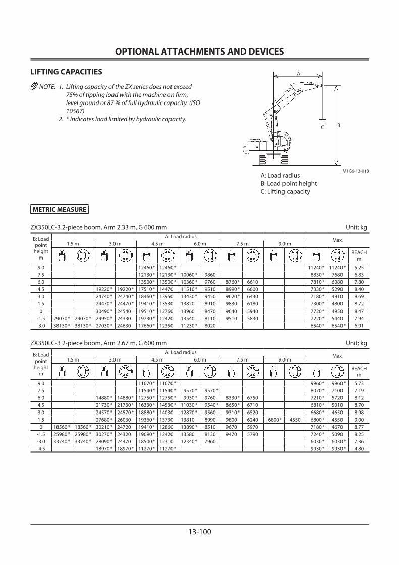
OPTIONAL ATTACHMENTS AND DEVICES
13-100
METRIC MEASURE
ZX350LC-3 2-piece boom, Arm 2.33 m, G 600 mm Unit; kg
B: Load point
heightm
A: Load radiusMax.
1.5 m 3.0 m 4.5 m 6.0 m 7.5 m 9.0 m
REACH m
9.0 12460 * 12460 * 11240 * 11240 * 5.257.5 12130 * 12130 * 10060 * 9860 8830 * 7680 6.836.0 13500 * 13500 * 10360 * 9760 8760 * 6610 7810 * 6080 7.804.5 19220 * 19220 * 17510 * 14470 11510 * 9510 8990 * 6600 7330 * 5290 8.403.0 24740 * 24740 * 18460 * 13950 13430 * 9450 9620 * 6430 7180 * 4910 8.691.5 24470 * 24470 * 19410 * 13530 13820 8910 9830 6180 7300 * 4800 8.720 30490 * 24540 19510 * 12760 13960 8470 9640 5940 7720 * 4950 8.47
-1.5 29070 * 29070 * 29950 * 24330 19730 * 12420 13540 8110 9510 5830 7220 * 5440 7.94-3.0 38130 * 38130 * 27030 * 24630 17660 * 12350 11230 * 8020 6540 * 6540 * 6.91
ZX350LC-3 2-piece boom, Arm 2.67 m, G 600 mm Unit; kg
B: Load point
heightm
A: Load radiusMax.
1.5 m 3.0 m 4.5 m 6.0 m 7.5 m 9.0 m
REACH m
9.0 11670 * 11670 * 9960 * 9960 * 5.737.5 11540 * 11540 * 9570 * 9570 * 8070 * 7100 7.196.0 14880 * 14880 * 12750 * 12750 * 9930 * 9760 8330 * 6750 7210 * 5720 8.124.5 21730 * 21730 * 16330 * 14530 * 11030 * 9540 * 8650 * 6710 6810 * 5010 8.703.0 24570 * 24570 * 18880 * 14030 12870 * 9560 9310 * 6520 6680 * 4650 8.981.5 27680 * 26030 19360 * 13730 13810 8990 9800 6240 6800 * 4550 6800 * 4550 9.000 18560 * 18560 * 30210 * 24720 19410 * 12860 13890 * 8510 9670 5970 7180 * 4670 8.77
-1.5 25980 * 25980 * 30270 * 24320 19690 * 12420 13580 8130 9470 5790 7240 * 5090 8.25-3.0 33740 * 33740 * 28090 * 24470 18500 * 12310 12340 * 7960 6030 * 6030 * 7.36-4.5 18970 * 18970 * 11270 * 11270 * 9930 * 9930 * 4.80
LIFTING CAPACITIES
NOTE: 1. Lifting capacity of the ZX series does not exceed 75% of tipping load with the machine on firm, level ground or 87 % of full hydraulic capacity. (ISO 10567)
2. * Indicates load limited by hydraulic capacity.
A: Load radiusB: Load point heightC: Lifting capacity
C B
M1G6-13-018
A

OPTIONAL ATTACHMENTS AND DEVICES
13-101
METRIC MEASURE
ZX350LC-3 2-piece boom, Arm 3.20 m, G 600 mm Unit; kg
B: Load point
heightm
A: Load radiusMax.
1.5 m 3.0 m 4.5 m 6.0 m 7.5 m 9.0 m
REACH m
10.5 9340 * 9340 * 4.389.0 9110 * 9110 * 7290 * 7290 * 6.557.5 8930 * 8930 * 7690 * 6840 6540 * 6180 7.866.0 11680 * 11680 * 9310 * 9310 * 7800 * 6970 6220 * 5120 8.724.5 23490 * 23490 * 14430 * 14430 * 10300 * 9580 * 8180 * 6870 6820 * 4820 6060 * 4540 9.253.0 19720 * 19720 * 24350 * 24350 * 18690 * 14100 11990 * 9670 * 8830 * 6670 7240 * 4740 5960 * 4240 9.521.5 26540 * 26180 19300 * 14040 13750 * 9130 9670 * 6390 7380 4600 6050 * 4150 9.540 29250 * 25050 19260 * 13020 13620 8580 9650 6060 7240 4470 6350 * 4240 9.32
-1.5 30340 * 24300 19450 * 12440 13690 8220 9490 5800 6930 * 4570 8.84-3.0 29230 * 24220 19270 * 12260 13350 7920 8650 * 5730 5700 * 5270 8.05-4.5 29960 * 29960 * 23730 * 23730 * 14790 * 12240 8440 * 8000 7230 * 7230 * 6.26
ZX350LC-3 2-piece boom, Arm 4.00 m, G 600 mm Unit; kg
B: Load point
heightm
A: Load radiusMax.
1.5 m 3.0 m 4.5 m 6.0 m 7.5 m 9.0 m
REACH m
10.5 6570 * 6570 * 5.919.0 8220 * 8220 * 6320 * 6320 * 5500 * 5500 * 7.657.5 8140 * 8140 * 7060 * 7060 * 5030 * 5030 * 8.806.0 8500 * 8500 * 7170 * 7090 6240 * 5090 4810 * 4420 9.574.5 11450 * 11450 * 12100 * 12100 * 9340 * 9340 * 7560 * 6960 6410 * 5070 4750 * 3980 10.063.0 15070 * 15070 * 24830 * 24830 * 16760 * 14310 * 10810 * 9380 8200 * 6760 6700 * 4940 4820 * 3740 10.301.5 13290 * 13290 * 25400 * 25400 * 19120 * 13800 12890 * 9430 9030 * 6650 7100 * 4750 5030 * 3650 10.320 14890 * 14890 * 27760 * 26030 19170 * 13440 13620 8790 9610 6280 7320 4550 5390 * 3720 10.12
-1.5 18720 * 18720 * 29890 * 24650 19220 * 12630 13760 * 8310 9530 5910 7170 4390 5820 * 3950 9.68-3.0 22880 * 22880 * 30130 * 24150 19500 * 12240 13460 8010 9380 5690 5670 * 4440 8.96-4.5 25900 * 25900 * 27710 * 24330 17920 * 12150 12050 * 7840 6570 * 5730 5630 * 5570 7.69-6.0 16970 * 16970 * 12010 * 12010 * 4.02
LIFTING CAPACITIES
NOTE: 1. Lifting capacity of the ZX series does not exceed 75% of tipping load with the machine on firm, level ground or 87 % of full hydraulic capacity. (ISO 10567)
2. * Indicates load limited by hydraulic capacity.
A: Load radiusB: Load point heightC: Lifting capacity
C B
M1G6-13-018
A

OPTIONAL ATTACHMENTS AND DEVICES
13-102
METRIC MEASURE
ZX350LCN-3 2-piece boom, Arm 2.33 m, G 600 mm Unit; kg
B: Load point
heightm
A: Load radiusMax.
1.5 m 3.0 m 4.5 m 6.0 m 7.5 m 9.0 m
REACH m
9.0 12460 * 12460 * 11240 * 10910 5.257.5 12130 * 12130 * 10060 * 9140 8830 * 7080 6.836.0 13500 * 13500 * 10360 * 9120 8760 * 6100 7810 * 5600 7.804.5 19220 * 19220 * 17510 * 13410 11510 * 8870 8990 * 6090 7330 * 4860 8.403.0 24740 * 24220 18460 * 13460 13430 * 8710 9620 * 5920 7180 * 4500 8.691.5 24470 * 22420 19410 * 12320 13800 8180 9820 5680 7300 * 4390 8.720 30490 * 21620 19510 * 11570 13930 7760 9620 5440 7720 * 4530 8.47
-1.5 29070 * 29070 * 29950 * 21420 19730 * 11240 13510 7400 9490 5330 7220 * 4970 7.94-3.0 38130 * 38130 * 27030 * 21700 17660 * 11180 11230 * 7320 6540 * 6090 6.91
ZX350LCN-3 2-piece boom, Arm 2.67 m, G 600 mm Unit; kg
B: Load point
heightm
A: Load radiusMax.
1.5 m 3.0 m 4.5 m 6.0 m 7.5 m 9.0 m
REACH m
9.0 11670 * 11670 * 9960 * 9590 5.737.5 11540 * 11540 * 9570 * 9280 8070 * 6550 7.206.0 14880 * 14880 * 12750 * 12750 * 9930 * 9160 8330 * 6240 7210 * 5260 8.124.5 21730 * 21730 * 16330 * 13500 * 11030 * 8900 8650 * 6200 6810 * 4600 8.703.0 24570 * 24240 18880 * 12950 12870 * 8820 9310 * 6000 6680 * 4260 8.981.5 27680 * 23020 19360 * 12510 13790 8260 9780 * 5730 6800 * 4160 6800 * 4160 9.000 18560 * 18560 * 30210 * 21790 19410 * 11670 13890 * 7790 9650 5460 7180 * 4270 8.77
-1.5 25980 * 25980 * 30270 * 21410 19690 * 11250 13550 7420 9460 5290 7240 * 4650 8.25-3.0 33740 * 33740 * 28090 * 21560 18500 * 11140 12340 * 7250 6030 * 5530 7.36-4.5 18970 * 18970 * 11270 * 11270 * 9930 * 9930 * 4.80
LIFTING CAPACITIES
NOTE: 1. Lifting capacity of the ZX series does not exceed 75% of tipping load with the machine on firm, level ground or 87 % of full hydraulic capacity. (ISO 10567)
2. * Indicates load limited by hydraulic capacity.
A: Load radiusB: Load point heightC: Lifting capacity
C B
M1G6-13-018
A
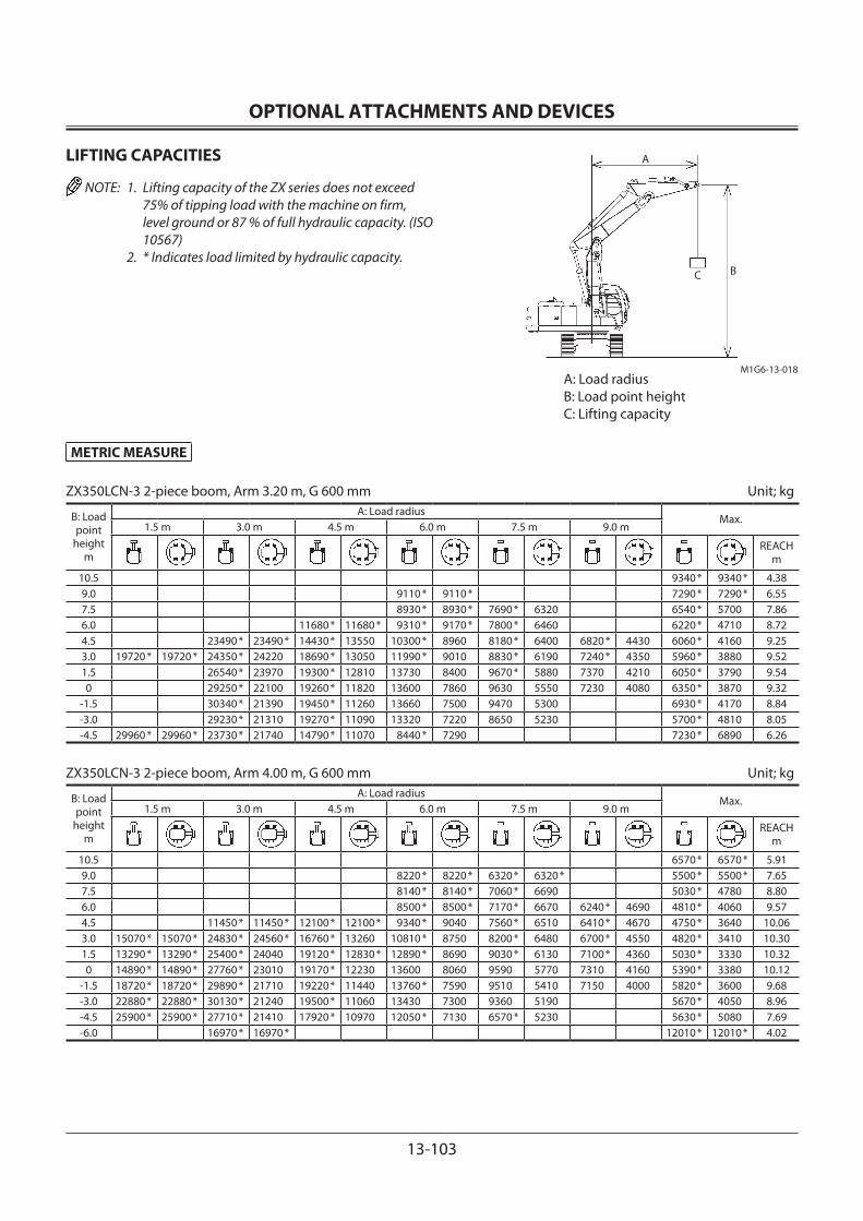
OPTIONAL ATTACHMENTS AND DEVICES
13-103
METRIC MEASURE
ZX350LCN-3 2-piece boom, Arm 3.20 m, G 600 mm Unit; kg
B: Load point
heightm
A: Load radiusMax.
1.5 m 3.0 m 4.5 m 6.0 m 7.5 m 9.0 m
REACH m
10.5 9340 * 9340 * 4.389.0 9110 * 9110 * 7290 * 7290 * 6.557.5 8930 * 8930 * 7690 * 6320 6540 * 5700 7.866.0 11680 * 11680 * 9310 * 9170 * 7800 * 6460 6220 * 4710 8.724.5 23490 * 23490 * 14430 * 13550 10300 * 8960 8180 * 6400 6820 * 4430 6060 * 4160 9.253.0 19720 * 19720 * 24350 * 24220 18690 * 13050 11990 * 9010 8830 * 6190 7240 * 4350 5960 * 3880 9.521.5 26540 * 23970 19300 * 12810 13730 8400 9670 * 5880 7370 4210 6050 * 3790 9.540 29250 * 22100 19260 * 11820 13600 7860 9630 5550 7230 4080 6350 * 3870 9.32
-1.5 30340 * 21390 19450 * 11260 13660 7500 9470 5300 6930 * 4170 8.84-3.0 29230 * 21310 19270 * 11090 13320 7220 8650 5230 5700 * 4810 8.05-4.5 29960 * 29960 * 23730 * 21740 14790 * 11070 8440 * 7290 7230 * 6890 6.26
ZX350LCN-3 2-piece boom, Arm 4.00 m, G 600 mm Unit; kg
B: Load point
heightm
A: Load radiusMax.
1.5 m 3.0 m 4.5 m 6.0 m 7.5 m 9.0 m
REACH m
10.5 6570 * 6570 * 5.919.0 8220 * 8220 * 6320 * 6320 * 5500 * 5500 * 7.657.5 8140 * 8140 * 7060 * 6690 5030 * 4780 8.806.0 8500 * 8500 * 7170 * 6670 6240 * 4690 4810 * 4060 9.574.5 11450 * 11450 * 12100 * 12100 * 9340 * 9040 7560 * 6510 6410 * 4670 4750 * 3640 10.063.0 15070 * 15070 * 24830 * 24560 * 16760 * 13260 10810 * 8750 8200 * 6480 6700 * 4550 4820 * 3410 10.301.5 13290 * 13290 * 25400 * 24040 19120 * 12830 * 12890 * 8690 9030 * 6130 7100 * 4360 5030 * 3330 10.320 14890 * 14890 * 27760 * 23010 19170 * 12230 13600 8060 9590 5770 7310 4160 5390 * 3380 10.12
-1.5 18720 * 18720 * 29890 * 21710 19220 * 11440 13760 * 7590 9510 5410 7150 4000 5820 * 3600 9.68-3.0 22880 * 22880 * 30130 * 21240 19500 * 11060 13430 7300 9360 5190 5670 * 4050 8.96-4.5 25900 * 25900 * 27710 * 21410 17920 * 10970 12050 * 7130 6570 * 5230 5630 * 5080 7.69-6.0 16970 * 16970 * 12010 * 12010 * 4.02
LIFTING CAPACITIES
NOTE: 1. Lifting capacity of the ZX series does not exceed 75% of tipping load with the machine on firm, level ground or 87 % of full hydraulic capacity. (ISO 10567)
2. * Indicates load limited by hydraulic capacity.
A: Load radiusB: Load point heightC: Lifting capacity
C B
M1G6-13-018
A

OPTIONAL ATTACHMENTS AND DEVICES
13-104
MEMO...................................................................................................................................................................................................................................................
...................................................................................................................................................................................................................................................
...................................................................................................................................................................................................................................................
...................................................................................................................................................................................................................................................
...................................................................................................................................................................................................................................................
...................................................................................................................................................................................................................................................
...................................................................................................................................................................................................................................................
...................................................................................................................................................................................................................................................
...................................................................................................................................................................................................................................................
...................................................................................................................................................................................................................................................
...................................................................................................................................................................................................................................................
...................................................................................................................................................................................................................................................
...................................................................................................................................................................................................................................................
...................................................................................................................................................................................................................................................
...................................................................................................................................................................................................................................................
...................................................................................................................................................................................................................................................
...................................................................................................................................................................................................................................................
...................................................................................................................................................................................................................................................
...................................................................................................................................................................................................................................................
...................................................................................................................................................................................................................................................
...................................................................................................................................................................................................................................................
...................................................................................................................................................................................................................................................
...................................................................................................................................................................................................................................................
...................................................................................................................................................................................................................................................
...................................................................................................................................................................................................................................................
...................................................................................................................................................................................................................................................
...................................................................................................................................................................................................................................................
...................................................................................................................................................................................................................................................
...................................................................................................................................................................................................................................................
...................................................................................................................................................................................................................................................
...................................................................................................................................................................................................................................................
...................................................................................................................................................................................................................................................
...................................................................................................................................................................................................................................................
...................................................................................................................................................................................................................................................
...................................................................................................................................................................................................................................................
...................................................................................................................................................................................................................................................
...................................................................................................................................................................................................................................................
INDEX
14-1
2-piece Boom ...............................................................................13-23
AAdjust Bucket Linkage ................................................................7-74Adjust the Operator’s Seat ...........................................................S-5Adjusting Console Height .........................................................1-79Adjusting the Air-suspension Seat (Optional) ...................1-77Adjusting the Seat .......................................................................1-75After the First 100 Hours .............................................................. 2-1After the First 50 Hours ................................................................ 2-1Air Cleaner ......................................................................................7-53Alarm Light ....................................................................................... 1-9Alarm Occurrence Screen ..........................................................1-15AM/FM Radio Operation ............................................................1-68Attachment Connection Parts .................................................5-30Attachment Pedal (Hydraulic Breaker) (Optional) .............. 5-2Attachment Pedal (Hydraulic Crusher) (Optional) .............. 5-3Attachment Selection (Only Machines Equipped with Optional Parts) .........1-20Attachment .....................................................................................5-26Auto Air Conditioner ...................................................................1-58Auto-idle Switch ...........................................................................1-46Auto-idle ............................................................................................ 5-7Avoid Abusive Operation ..........................................................5-13Avoid Applying Heat to Lines Containing Flammable Fluids .................................................................. S-28Avoid Heating Near Pressurized Fluid Lines ....................... S-28Avoid High-pressure Fluids ....................................................... S-25Avoid Hitting Blade with Bucket .............................................13-8Avoid Hitting Blade with Front-end Attachment..............13-8Avoid Injury from Back-over and Swing Accidents .......... S-14Avoid Injury from Rollaway Accidents .................................. S-13Avoid Power Lines ........................................................................ S-18Avoid Striking The Blade Into a Rock .....................................13-8Avoid Tipping ................................................................................. S-16Avoid Undercutting ..................................................................... S-15
BBack Monitor Selector................................................................... 1-8Back Monitor Settings ................................................................1-34Before Starting Engine ................................................................. 3-2Beware of Asbestos Dust ........................................................... S-29Beware of Exhaust Fumes.......................................................... S-27Blade Lever .....................................................................................13-7Blade Maintenance ......................................................................13-9Breaker Maintenance .......................................................5-23, 7-29Bucket Teeth (Transverse-type-pin-used Type) ...............13-22Bucket Types and Applications (ZX110-3, 110M-3) ..........12-5Bucket Types and Applications (ZX130-3, 130LCN-3) ...12-10Bucket Types and Applications (ZX160LC-3) ....................12-15Bucket Types and Applications (ZX180LC-3, 180LCN-3) ......................................................12-20Bucket Types and Applications (ZX210-3, 210LC-3) .......12-24Bucket Types and Applications (ZX210LCN-3, 240N-3) ......................................................12-28
Bucket Types and Applications (ZX250LC-3, 250LCN-3) ......................................................12-32Bucket Types and Applications (ZX280LC-3, 280LCN-3) ......................................................12-36Bucket Types and Applications (ZX350LC-3, 350LCN-3) ......................................................12-40
CCab Door Release Lever .............................................................1-70Cab Features ..................................................................................... 1-2Cab Heater (Optional) .................................................................1-65Cab Heater Operation ....................................................... 1-62,1-66Cab Light .........................................................................................1-55Change Bucket ..............................................................................7-72Change Coolant ............................................................................7-60Change Engine Oil .......................................................................7-21Change Hydraulic Oil ..................................................................7-31Check and Adjust Fan Belt Tension (ZX120-3, 180-3 Class) ..........................................................7-58Check and Adjust Fan Belt Tension (ZX200-3, ZX270-3, ZX330-3 Class) .................................7-59Check and Replace EGR Device ...............................................7-83Check and Replace Seat Belt Check .......................................7-75Check Bucket Teeth .....................................................................7-68Check Coolant Level ....................................................................7-57Check Fuel Hoses ..........................................................................7-52Check Hoses and Lines ...............................................................7-37Check Hydraulic Oil Level ..........................................................7-30Check Instruments After Starting ............................................. 3-7Check Starter and Alternator ...................................................7-83Check Air Conditioner.................................................................7-81Check the Hour Meter Regularly ............................................... 7-2Check Tightening Torque of Bolts and Nuts .......................7-84Check Track Sag ............................................................................7-77Check Windshield Washer Fluid Level ...................................7-76Cigar Lighter ...................................................................................1-54Clean Air Conditioner Condenser ...........................................7-61Clean Air Conditioner Front Screen (Opt.) ..........................7-61Clean and Replace Air Conditioner Filter .............................7-79Clean Cab Floor .............................................................................7-82Clean Fuel Oil Cooler ..................................................................7-61Clean Fuel Solenoid Pump Strainer .......................................7-51Clean Oil Cooler, Radiator and Inter Cooler Front Screen ..............................................................7-61Clean Radiator Interior ...............................................................7-60Clean Radiator, Oil Cooler Core and Inter Cooler Outside ....................................................7-61Clean Air Cleaner Outer Element ............................................7-53Clock Setting ..................................................................................1-19Clock.................................................................................................... 1-8Closing Upper Front Window ...................................................1-71Components Name ....................................................................... 1-1Confirm Direction of Machine to Be Driven ........................ S-10Contents of Alarms ......................................................................1-17Control Lever (Iso Pattern) .......................................................... 5-1
INDEX
14-2
Control Levers ................................................................................11-9Convert Bucket Connection Into Face Shovel ....................7-73Coolant Temperature Gauge ....................................................1-10Cooling Operation .......................................................................1-62Cooling System .............................................................................7-55Correct Maintenance and Inspection Procedures .............. 7-1
DDefroster Operation .......................................................... 1-63,1-67Dig with Caution ........................................................................... S-17Digital Clock Setting Procedure ..............................................1-69Displaying Operating Conditions ...........................................1-25Dispose of Waste Properly ......................................................... S-30Drain Fuel Filter .............................................................................7-45Drain Fuel Tank Sump ................................................................7-44Drive Machine Safely ................................................................... S-11Drive the Machine Carefully ....................................................... 4-1
EElectrical Circuit .............................................................................. 8-2Electrical Diagram .......................................................................... 8-3Electrical System ................................................................7-62, 11-6Emergency Boom Lowering Procedure (Without hose-rupture safety valve) ..............................5-33Emergency Exit .............................................................................1-74Engine ....................................................................................7-20, 11-2Engine Control Dial ......................................................................1-46Engine Oil Level ............................................................................7-20Engine Speed Control ................................................................... 5-6Engine Stop Switch ......................................................................1-56Ensure Safety Before Rising from or Leaving Operator’s Seat .........................................................S-5Equipment of Head Guard, Rops, Fops ................................. S-10Evacuating in Case of Fire .......................................................... S-27Every 8 Hours or Daily ................................................................... 2-1
FFace Shovel Operation................................................................5-13Fasten Your Seat Belt ......................................................................S-6Follow Safety Instructions ............................................................S-2Front Joint Pins ..............................................................................7-16Fuel Gauge ........................................................................................ 1-8Fuel Rate Display/No Display ...................................................1-26Fuel System .....................................................................................7-42Fuse Box ...........................................................................................1-57
GGeneral Precautions for Cab ........................................................S-4Grading Operation .......................................................................5-12Greasing ...........................................................................................7-16
HHandle Chemical Products Safely ........................................... S-30Handle Fluids Safely−Avoid Fires............................................ S-19Handle Starting Aids Safely .........................................................S-6
Hood and Access Covers (ZX120-3, 180-3 Class) ................ 7-7Hood and Access Covers (ZX200-3, 270-3, 330-3 Class) ... 7-8Horn Switch ....................................................................................1-53Hour Meter ........................................................................................ 1-8Hydraulic Breaker and Hydraulic Crusher ............................5-15Hydraulic Circuit ............................................................................. 8-1Hydraulic System ...............................................................7-27, 11-9
IImpossible to Start the Engine ................................................11-1Inspect and Adjust Valve Clearance .......................................7-83Inspect Machine ..............................................................................S-4Inspect Machine Daily Before Starting ................................... 3-1Inspection and Maintenance of Hydraulic Equipment ...7-27Installing Fire Extinguisher (Optional) ..................................1-55Investigate Job Site Beforehand ................................................S-9
JJump Starting ...................................................................................S-7
KKeep Person Clear from Working Area.................................. S-15Keep Riders Off Machine ..............................................................S-7Key Switch .......................................................................................1-53
LLanguage Settings .......................................................................1-43Layout ................................................................................................. 7-3Lifting Capacities ........................................................................13-48Lifting Hook ..................................................................................13-46Loading/unloading on a Trailer ................................................. 6-1Long Arm Operation --- If Equipped ......................................13-6
MMachine Lifting Procedure .......................................................... 6-5Mail (Optional) ...............................................................................1-41Maintenance ................................................................................13-19Maintenance (2-piece Boom) .................................................13-24Maintenance Guide .....................................................................7-10Maintenance Guide Table ............................................................ 7-4Maintenance Settings .................................................................1-36Maintenance Under Special Environmental Conditions .................................................................................. 9-1Measure Engine Compression Pressure ...............................7-83Menu Key........................................................................................... 1-9Menu Screen (23) ........................................................................... 1-7Miscellaneous ...............................................................................7-68Mode Selection .............................................................................11-8Move and Operate Machine Safely ...........................................S-6Multi Function Monitor ................................................................ 1-3
NNever Position Bucket Over Anyone ..................................... S-15Never Undercut a High Bank .................................................... S-16
INDEX
14-3
OObject Handling --- If Equipped ..............................................5-35Object Handling ........................................................................... S-18Observe Engine Operation Closely .......................................... 2-1Offset Arm Front .........................................................................13-16Offset Direction and Working Range ..................................13-17Opening Side Windows ..............................................................1-72Opening Upper Front Window ................................................1-70Opening/Closing Overhead Window ....................................1-73Operate Only from Operator’s Seat ..........................................S-7Operate with Caution ................................................................. S-17Operating Backhoe ......................................................................5-12Operating in Water or Mud ......................................................... 4-7Operating on Soft Ground .......................................................... 4-5Operating Status Icon Display .................................................1-10Operating Tips ...............................................................................5-14Optional Function Display ......................................................... 1-9Optional Function Key .................................................................. 1-9Outline ................................................................................................ 1-4Overnight Storage Instructions ...............................................5-32
PPark Machine Safely ..................................................................... S-19Parking the Machine on Slopes ................................................. 4-8Parking the Machine ..................................................................... 4-8Periodic Replacement of Parts ................................................... 7-9Pilot Control Shut-off Lever ..............................................1-56, 5-4Pipings for Breaker and Crusher ..............................................5-16Power Boost ...................................................................................5-10Power Boost Switch .....................................................................1-53Power Mode ..................................................................................5-11Power Mode Switch ....................................................................1-47Practice Safe Maintenance ........................................................ S-21Precaution for Arm Roll-in/Bucket Roll-in Combined Operation --- If Headguard-Integrated Cab or Rainguard is Equipped ..........................................5-31Precautions for Blade Operation .............................................13-7Precautions for Breaker Operation .........................................5-20Precautions for Crusher Operation ........................................5-24Precautions for Lightning .......................................................... S-18Precautions for Operating with The Offset Function .....13-18Precautions for Operations ..........................................................S-8Precautions for Transporting Machines with Pad Crawler Shoes .......................................................13-3Precautions for Welding and Grinding ................................. S-27Prepare for Emergencies ...............................................................S-3Prepare Machine for Maintenance ........................................... 7-6Prevent Battery Explosions ....................................................... S-29Prevent Burns ................................................................................. S-24Prevent Fires ................................................................................... S-26Prevent Parts from Flying .......................................................... S-23Protect Against Flying Debris .................................................. S-19Protect Against Noise ....................................................................S-3Provide Signals for Jobs Involving Multiple Numbers of Machines ........................................ S-10
Pump 2 Flow Rate Adjustment (Only Machines Equipped with Optional Parts) .........1-24Pump Transmission ......................................................................7-23
RRaise One Track Using Boom and Arm ................................... 4-5Recognize Safety Information ....................................................S-1Remove and Installing Battery ................................................7-66Remove Paint Before Welding or Heating ........................... S-28Remove Travel Levers ..................................................................7-75Removing and Storing Lower Front Window .....................1-72Removing the Machine from Storage ...................................10-2Replace Air Breather Element ..................................................7-36Replace Batteries ..........................................................................7-65Replace Engine Oil Filter ............................................................7-21Replace Fuel Main Filter Element ...........................................7-49Replace Fuel Pre-Filter Element .............................................7-50Replace Hydraulic Tank Oil Filter .............................................7-34Replace Pilot Oil Filter .................................................................7-35Replace Rubber Hoses Periodically ........................................ S-24Replace Air Cleaner Outer and Inner Elements .................7-53Replacing Fuses ............................................................................7-66Retighten Cylinder Head Bolt ..................................................7-83Return to Basic Screen Key ......................................................... 1-9
SSafety Signs .................................................................................... S-31Seat Belt ...........................................................................................1-80Seat with a Built-in Heater............................................... 1-76,1-78Secondary Relief Pressure Adjustment ................................5-18Select Correct Track Shoes ........................................................5-14Service Air Conditioning System Safely ............................... S-29Service Recommendations for Hydraulic Fittings ............7-40Shackle Hole Usage .....................................................................5-32Shoe Types and Applications (ZX110-3) ..................................................................................12-3 (ZX110M-3) ..............................................................................12-4Shoe Types and Applications (ZX110-3 with Blade) ......13-12Shoe Types and Applications (ZX130-3 with Blade) ......13-15Shoe Types and Applications (ZX130-3)...............................12-8Shoe Types and Applications ZX130-3 (2-piece Boom) ...................................................13-29 ZX130LCN-3 (2-piece Boom) ...........................................13-30Shoe Types and Applications (ZX130LCN-3) ......................12-9Shoe Types and Applications (ZX160LC-3) ........................12-14Shoe Types and Applications (ZX180LC-3, 180LCN-3) ......................................................12-19Shoe Types and Applications (ZX210-3, 210LC-3) ..............................................................12-23Shoe Types and Applications ZX210-3 (2-piece Boom) ...................................................13-33 ZX210LC-3 (2-piece Boom) ..............................................13-33Shoe Types and Applications (ZX210LCN-3, 240N-3) .......................................................12-27
INDEX
14-4
Shoe Types and Applications ZX210LCN-3 (2-piece Boom) ...........................................13-36 ZX240N-3 (2-piece Boom) ................................................13-36Shoe Types and Applications (ZX250LC-3, 250LCN-3) ......................................................12-31Shoe Types and Applications ZX250LC-3 (2-piece Boom) ..............................................13-39 ZX250LCN-3 (2-piece Boom) ...........................................13-39Shoe Types and Applications (ZX280LC-3, 280LCN-3) ......................................................12-35Shoe Types and Applications ZX280LC-3 (2-piece Boom) ..............................................13-42 ZX280LCN-3 (2-piece Boom) ...........................................13-42Shoe Types and Applications (ZX350LC-3, 350LCN-3) ......................................................12-39Shoe Types and Applications ZX350LC-3 (2-piece Boom) ..............................................13-45 ZX350LCN-3 (2-piece Boom) ...........................................13-45Sound Level Results (2000/14/EC) .......................................12-41Specifications (ZX110-3 with Blade) ....................................13-10Specifications (ZX110-3, 110M-3 Offset) ............................13-20Specifications (ZX110-3, 110M-3) ...........................................12-1Specifications (ZX130-3 with Blade) ....................................13-13Specifications ZX130-3, 130LCN-3 (2-piece Boom) ..............................13-27Specifications (ZX130-3, 130LCN-3) .......................................12-6Specifications (ZX160LC-3) .....................................................12-11Specifications (ZX180LC-3, 180LCN-3) ................................12-16Specifications (ZX210-3, 210LC-3) ........................................12-21Specifications (ZX210LCN-3, 240N-3) .................................12-25Specifications ZX210LCN-3, 240N-3 (2-piece Boom) ...........................13-34Specifications ZX210-3, 210LC-3 (2-piece Boom) .................................13-31Specifications (ZX250LC-3, 250LCN-3) ................................12-29Specifications ZX250LC-3, 250LCN-3 (2-piece Boom) .........................13-37Specifications (ZX280LC-3, 280LCN-3) ................................12-33Specifications ZX280LC-3, 280LCN-3 (2-piece Boom) .........................13-40Specifications (ZX350LC-3, 350LCN-3) ................................12-37Starting in Cold Weather.............................................................. 3-5Starting the Engine in Ordinary Temperature ...................... 3-3Stay Clear of Moving Parts ........................................................ S-22Steering the Machine Using Levers ......................................... 4-3Steering the Machine Using Pedals ......................................... 4-2Stopping the Engine ...................................................................3-10Store Attachments Safely .......................................................... S-23Storing the Machine ....................................................................10-1Suction Filter Cleaning ...............................................................7-31Support Machine Properly ........................................................ S-22Swing Bearing ................................................................................7-18Swing Internal Gear .....................................................................7-19Swing Reduction Gear ................................................................7-24Switch Panel (Optional) ..............................................................1-51Switch Panel ...................................................................................1-45
TTips for Optimal Air Conditioner Usage ...............................1-64Towing Machine a Short Distance ............................................ 4-6Transmission ..................................................................................7-23Transport Safely ............................................................................ S-20Transporting ...................................................................................13-3Transporting By Road ................................................................... 6-1Travel Alarm (Optional) ................................................................ 4-4Travel Mode Switch .............................................................1-47, 4-4Travel Reduction Gear ................................................................7-25Traveling and Other Cautions ..................................................13-2
UUnderstand Signal Words .............................................................S-1Use Correct Fuels and Lubricants ............................................. 7-2Use Handholds and Steps ............................................................S-5Using Booster Batteries ................................................................ 3-8Using Pad Crawler Shoe .............................................................13-1Vibration Level .............................................................................12-41
WWarn Others of Service Work ................................................... S-22Wear Protective Clothing..............................................................S-3When Installing an Attachment Longer Than Standard Bucket ..........................................................5-31Wiper/Washer Switch ..................................................................1-49Work Light Switch ........................................................................1-48Work Mode ....................................................................................... 5-8Work Mode Select .......................................................................... 5-9Working Ranges (ZX110-3 with Blade) ...............................13-11Working Ranges (ZX110-3, 110M-3 Offset) .......................13-21Working Ranges (ZX110-3, 110M-3) ......................................12-2Working Ranges (ZX130-3 with Blade) ...............................13-14Working Ranges (ZX130-3, 130LCN-3) ..................................12-7Working Ranges (ZX160LC-3) ................................................12-12Working Ranges (ZX180LC-3, 180LCN-3) ...........................12-17Working Ranges (ZX210-3, 210LC-3) ...................................12-22Working Ranges (ZX210LCN-3, 240N-3).............................12-26Working Ranges (ZX250LC-3, 250LCN-3) ...........................12-30Working Ranges (ZX280LC-3, 280LCN-3) ...........................12-34Working Ranges (ZX350LC-3, 350LCN-3) ...........................12-38Working Ranges ZX130-3, 130LCN-3 (2-piece Boom) ..............................13-28Working Ranges ZX210-3, 210LC-3 (2-piece Boom) .................................13-32Working Ranges ZX210LCN-3, 240N-3 (2-piece Boom) ...........................13-35Working Ranges ZX250LC-3, 250LCN-3 (2-piece Boom) .........................13-38Working Ranges ZX280LC-3, 280LCN-3 (2-piece Boom) .........................13-41 ZX350LC-3, 350LCN-3 (2-piece Boom) .........................13-43 ZX350LC-3, 350LCN-3 (2-piece Boom) .........................13-44