70/140 mhz satellite modem
TRANSCRIPT

IMPORTANT NOTE: The information contained in this document supersedes all previously published information regarding this product. Product specifications are subject to change without prior notice.
Part Number MN-CDM570A / CD-CDM570A Revision 5
CDM-570A 70/140 MHz Satellite Modem
CDM-570AL L-Band Satellite Modem
CDMR-570AL Reduced Chassis Depth L-Band Satellite Modem
Satellite Modem with Optional High Performance
Packet Processor Installation and Operation Manual For Firmware Version 1.5.2 or higher


Copyright © 2017 Comtech EF Data. All rights reserved. Printed in the USA. Comtech EF Data, 2114 West 7th Street, Tempe, Arizona 85281 USA, 480.333.2200, FAX: 480.333.2161
Part Number MN-CDM570A / CD-CDM570A
Revision 5
CDM-570A 70/140 MHz Satellite Modem
CDM-570AL L-Band Satellite Modem
CDMR-570AL Reduced Chassis Depth L-Band Satellite Modem
Satellite Modem with Optional High Performance
Packet Processor Installation and Operation Manual For Firmware Version 1.5.2 or higher

CDM-570A/570AL Satellite Modem with Optional Packet Processor Revision 5
Table of Contents ii MN-CDM570A
Revision History
Rev Description
- Initial Release.
1 Incorporated IP Packet Processor.
2 Incorporated information for firmware version 1.3.1.
3 Updated FAST demo mode operation and incorporated Errata’s into the manual.
4 Incorporated VersaFEC-2 and Carrier ID for firmware version 1.5.2. Also added RADIUS Appendix I.
5 Revised Tables B-6 and B-7. Updated manual header and footer formatting. Added Revision History and Acronym tables.

CDM-570A/570AL Satellite Modem with Optional Packet Processor Revision 5
Table of Contents iii MN-CDM570A
TABLE OF CONTENTS Chapter 1. INTRODUCTION .............................................................................................................. 1–1
1.1 Overview .............................................................................................................................. 1–1 1.1.1 Modem Features Overview ................................................................................................................. 1–1 1.1.2 Functional Description .......................................................................................................................... 1–2
1.2 Features ............................................................................................................................... 1–4 1.2.1 Physical Description .............................................................................................................................. 1–4
1.2.1.1 Standard Assemblies ........................................................................................................................ 1–4 1.2.1.2 Optional Assemblies ......................................................................................................................... 1–4
1.2.2 Dimensional Envelope .......................................................................................................................... 1–5 1.2.3 Physical Features ................................................................................................................................... 1–6
1.2.3.1 Front Panel Features ........................................................................................................................ 1–6 1.2.3.2 Rear Panel Features.......................................................................................................................... 1–7
1.2.3.2.1 Rear Panel Standard Features..................................................................................... 1–7 1.2.3.2.2 Rear Panel Optional Features ..................................................................................... 1–9
1.2.4 Standard Data Interfaces ...................................................................................................................... 1–9 1.2.5 Verification ............................................................................................................................................ 1–9 1.2.6 AUPC .................................................................................................................................................... 1–10 1.2.7 EDMAC ................................................................................................................................................. 1–10 1.2.8 Updating Modem Firmware .............................................................................................................. 1–10 1.2.9 Fully Accessible System Topology (FAST) .......................................................................................... 1–11 1.2.10 Supporting Hardware and Software .................................................................................................. 1–14
1.2.10.1 CDM-570AL/CDMR-570AL L-Band Redundancy .......................................................................... 1–14 1.2.10.2 CDM-570A 70/140 MHz Redundancy .......................................................................................... 1–14 1.2.10.3 Support Software ........................................................................................................................... 1–14
1.3 Summary of Specifications .................................................................................................. 1–15 1.3.1 Modulator............................................................................................................................................ 1–15 1.3.2 Demodulator ....................................................................................................................................... 1–18
1.3.2.1 BER Performance Specification ..................................................................................................... 1–18 1.3.3 Standard AUPC (Automatic Uplink Power Control) ......................................................................... 1–21 1.3.4 DoubleTalk® Carrier- in-Carrier® (CnC) .............................................................................................. 1–22 1.3.5 Data and Miscellaneous Interfaces ................................................................................................... 1–23 1.3.6 Data Rate Ranges ................................................................................................................................ 1–24 1.3.7 VersaFEC Adaptive Coding and Modulation (ACM) ......................................................................... 1–25
1.3.7.1 VersaFEC ACM (IP-ACM) ................................................................................................................ 1–25 1.3.7.2 VersaFEC-2 ACM (V2-ACM) ........................................................................................................... 1–26
1.3.8 Power ................................................................................................................................................... 1–27 1.3.9 Physical Properties .............................................................................................................................. 1–27 1.3.10 Miscellaneous ...................................................................................................................................... 1–28 1.3.11 Approvals ............................................................................................................................................. 1–28
CHAPTER 2. INSTALLATION AND STARTUP .................................................................... 2–1

CDM-570A/570AL Satellite Modem with Optional Packet Processor Revision 5
Table of Contents iv MN-CDM570A
2.1 Unpack and Inspect the Shipment......................................................................................... 2–1
2.2 Install the Modem into a Rack Enclosure .............................................................................. 2–2 2.2.1 Install the Optional Rear Support Brackets Kit ................................................................................... 2–4
2.3 Configure the Modem ........................................................................................................... 2–5
2.4 Verify Operation (IF Loopback Test) ...................................................................................... 2–5
2.5 Connect the External Cables ................................................................................................. 2–6
CHAPTER 3. REAR PANEL CONNECTORS AND PINOUTS ............................................. 3–1
3.1 Overview – Cabling Connection Types ................................................................................... 3–1 3.1.1 Coaxial Cable Connections ................................................................................................................... 3–2
3.1.1.1 Type ‘BNC’ ......................................................................................................................................... 3–3 3.1.1.2 Type ‘TNC’ ......................................................................................................................................... 3–3 3.1.1.3 Type ‘N’ ............................................................................................................................................. 3–3 3.1.1.4 Type ‘F’ .............................................................................................................................................. 3–3 3.1.1.5 Type ‘SMA’ (Subminiature Version ‘A’) ........................................................................................... 3–3
3.1.2 D-Subminiature Cable Connections .................................................................................................... 3–4 3.1.3 RJ-XX Cable Connections ...................................................................................................................... 3–4
3.2 Modem Cabling Connections ................................................................................................ 3–5 3.2.1 IF Connections Group ........................................................................................................................... 3–6
3.2.1.1 Rx IF Connectors ............................................................................................................................... 3–6 3.2.1.2 Tx IF Connectors ............................................................................................................................... 3–6
3.2.2 Terrestrial Data Connections Group .................................................................................................... 3–7 3.2.2.1 Data Interface Connector, DB-25F .................................................................................................. 3–7 3.2.2.2 10/100 Ethernet | Traffic 100 Port, RJ-45 (w/Optional Packet Processor only) .......................... 3–8 3.2.2.3 G.703 Connections ........................................................................................................................... 3–9
3.2.2.3.1 Unbal E1 Out/In G.703 Connectors (Tx/Rx), 75Ω BNC ................................................ 3–9 3.2.2.3.2 Balanced E1/T1 G.703 Connector, DB-15F ................................................................. 3–9 3.2.2.3.3 G.703 RJ-48 Connection via Balanced E1/T1 Interface Connector ........................... 3–10
3.2.3 Utility Connections Group .................................................................................................................. 3–11 3.2.3.1 10/100 Ethernet | M&C 100 Port, RJ-45 (Standard) ................................................................... 3–11 3.2.3.2 Remote Control Connector, DB-9M .............................................................................................. 3–11 3.2.3.3 Alarms (Form-C Traffic Alarms) Connector, DB-15M .................................................................. 3–11 3.2.3.4 1:1 Control Connector, DB-9F ........................................................................................................ 3–12 3.2.3.5 Ext Ref In/Out Connector, BNC ..................................................................................................... 3–13 3.2.3.6 Console Port, RJ-11 (w/Optional Packet Processor only) ............................................................ 3–13
3.3 Modem Ground, Power, and Fuse Connections................................................................... 3–14 3.3.1 Chassis Ground Interface ................................................................................................................... 3–14 3.3.2 Standard Alternating Current (AC) Power and Fusing Interfaces .................................................... 3–15
3.3.2.1 AC Operation – Standard or Available Accessories ..................................................................... 3–15 3.3.2.2 AC Operation – Chassis Power and Fusing ................................................................................... 3–16
3.3.2.2.1 AC Operation – Apply Power .................................................................................... 3–17

CDM-570A/570AL Satellite Modem with Optional Packet Processor Revision 5
Table of Contents v MN-CDM570A
3.3.2.2.2 AC Operation – Replace the Fuses ............................................................................ 3–17 3.3.3 Modem Optional -24V or -48V DC Power Interfaces ....................................................................... 3–18
3.3.3.1 Optional DC Operation – Available Accessories ........................................................................... 3–18 3.3.3.2 Optional -24V or -48V DC Chassis Power and Fusing .................................................................. 3–19
3.3.3.2.1 Optional DC Operation – Apply Power ..................................................................... 3–19 3.3.3.2.2 Optional DC Operation – Replace the DC Power Fuses ............................................ 3–20
3.3.3.3 CDMR-570AL Reduced Chassis Depth Modem -24 or -48V DC Power and Fuse ...................... 3–21 3.3.3.3.1 CDMR-570AL – Apply DC Power ............................................................................... 3–21
3.3.3.4 CDMR-570AL – Replace the DC Power Fuse ................................................................................ 3–22
CHAPTER 4. UPDATING FIRMWARE ................................................................................. 4–1
4.1 Overview .............................................................................................................................. 4–1 4.1.1 About Firmware Files, Naming, Versions, and Archive Formats ....................................................... 4–2
4.2 Ethernet FTP Upload Procedure ............................................................................................ 4–3 4.2.1 Getting Started: Prepare for the Firmware Download ...................................................................... 4–3 4.2.2 Download and Extract the Firmware Update ..................................................................................... 4–8 4.2.3 Perform the Ethernet FTP Upload Procedure .................................................................................. 4–10
CHAPTER 5. FAST ACTIVATION PROCEDURE................................................................. 5–1
5.1 Overview .............................................................................................................................. 5–1
5.2 FAST Activation Procedure .................................................................................................... 5–2 5.2.1 FAST Activation via the Modem Front Panel ...................................................................................... 5–2 5.2.2 FAST Activation via the CDM-570A HTTP Interface ........................................................................... 5–4
CHAPTER 6. FRONT PANEL OPERATION ......................................................................... 6–1
6.1 Overview .............................................................................................................................. 6–1 6.1.1 LED Indicators ........................................................................................................................................ 6–2 6.1.2 Keypad ................................................................................................................................................... 6–3 6.1.3 Vacuum Fluorescent Display (VFD) ..................................................................................................... 6–3
6.1.3.1 Screen Saver ...................................................................................................................................... 6–4 6.1.3.2 Opening Screen ................................................................................................................................ 6–4
6.2 Compatible Mode Operation (CDM-570A/570AL vs. CDM-570/570L) .................................... 6–5
6.3 Front Panel Operation .......................................................................................................... 6–6 6.3.1 SELECT: (Main) Menu ........................................................................................................................... 6–7 6.3.2 (SELECT:) Config (Configuration) Menus ............................................................................................. 6–8
6.3.2.1 CONFIG: Rem (Remote Control) ...................................................................................................... 6–9 6.3.2.1.1 (CONFIG: Remote Control) Serial ................................................................................ 6–9 6.3.2.1.2 (CONFIG:) Remote Control: Ethernet ....................................................................... 6–10
6.3.2.2 CONFIG: All ...................................................................................................................................... 6–13 6.3.2.3 CONFIG: Tx (Transmit) .................................................................................................................... 6–14
6.3.2.3.1 (CONFIG: Tx) FEC (FEC Encoder Type) ....................................................................... 6–15

CDM-570A/570AL Satellite Modem with Optional Packet Processor Revision 5
Table of Contents vi MN-CDM570A
6.3.2.3.2 (CONFIG: Tx) Mod (Modulation Type) ...................................................................... 6–17 6.3.2.3.3 (CONFIG: Tx) Code (Code Rate)................................................................................. 6–17 6.3.2.3.4 (CONFIG: Tx) Data (Data Rate) .................................................................................. 6–18 6.3.2.3.5 (CONFIG: Tx) Symb (IP-ACM or V2-ACM Modes Only) ............................................. 6–22 6.3.2.3.6 (CONFIG: Tx) Frq (Frequency) ................................................................................... 6–22 6.3.2.3.7 (CONFIG: Tx) On/Off ................................................................................................. 6–23 6.3.2.3.8 (CONFIG: Tx) Pwr (Power) ......................................................................................... 6–23 6.3.2.3.9 (CONFIG: Tx) Scr (Scrambling) ................................................................................... 6–25 6.3.2.3.10 (CONFIG: Tx) Clk (Clock Source) .............................................................................. 6–26 6.3.2.3.11 (CONFIG: Tx) Inv (Inversion Functions) ................................................................... 6–26 6.3.2.3.12 (Config: Tx) α (Tx Alpha Filter Rolloff Factor) .......................................................... 6–27
6.3.2.4 CONFIG: Rx (Receive) ..................................................................................................................... 6–27 6.3.2.4.1 (CONFIG: Rx) FEC (FEC Decoder Type) ...................................................................... 6–28 6.3.2.4.2 (CONFIG: Rx) Dem (Demodulation Type) .................................................................. 6–30 6.3.2.4.3 (CONFIG: Rx) Code (Code Rate) ................................................................................ 6–30 6.3.2.4.4 (CONFIG: Rx) Data (Data Rate) .................................................................................. 6–31 6.3.2.4.5(CONFIG: Rx) Symb (IP-ACM (VersaFEC ACM) or V2-ACM (VersaFEC-2 ACM) Modes
Only) .............................................................................................................................. 6–31 6.3.2.4.6 (CONFIG: Rx) Frq (Frequency) ................................................................................... 6–32 6.3.2.4.7 (CONFIG: Rx) Acq (Acquisition Range) ...................................................................... 6–32 6.3.2.4.8 (CONFIG: Rx) Descram (Descrambling) ..................................................................... 6–33 6.3.2.4.9 (CONFIG: Rx) Buf (Buffer) .......................................................................................... 6–33 6.3.2.4.10 (CONFIG: Rx) Inv (Inversion Functions) ................................................................... 6–34 6.3.2.4.11 (CONFIG: Rx) Eb/No ................................................................................................ 6–34 6.3.2.4.12 (CONFIG: Rx) SNR (IP-ACM (VersaFEC ACM) or V2-ACM (VersaFEC-2 ACM) Modes
Only) .............................................................................................................................. 6–35 6.3.2.4.13 (Config: Rx) α (Rx Alpha Filter Rolloff Factor) ......................................................... 6–35
6.3.2.5 CONFIG: CEx (G.703 Clock Extension) ........................................................................................... 6–35 6.3.2.6 CONFIG: Frame (Framing Mode) ................................................................................................... 6–36
6.3.2.6.1 (CONFIG: Framing Mode) EDMAC or EDMAC-2 ........................................................ 6–36 6.3.2.7 CONFIG: TI (Data Traffic Interface) ................................................................................................ 6–38
6.3.2.7.1 (CONFIG: TI) RS422 or V.35 or RS232 ....................................................................... 6–38 6.3.2.7.2 (CONFIG: TI) IP .......................................................................................................... 6–38 6.3.2.7.3 (CONFIG: TI) G.703 .................................................................................................... 6–38 6.3.2.7.4 IP-ACM (VersaFEC ACM) ........................................................................................... 6–39 6.3.2.7.5 V2-ACM (VersaFEC-2 ACM) ....................................................................................... 6–40
6.3.2.8 CONFIG: Ref (Reference) ................................................................................................................ 6–42 6.3.2.9 CONFIG: Msk (Alarm Masking) ...................................................................................................... 6–43
6.3.2.9.1 (CONFIG: Alarm Mask) Transmit ............................................................................... 6–43 6.3.2.9.2 (CONFIG: Alarm Mask) Receive ................................................................................. 6–43 6.3.2.9.3 (CONFIG: Alarm Mask) Ref ........................................................................................ 6–44 6.3.2.9.4 (CONFIG: Alarm Mask) BUC (CDM/R-570AL L-Band Units ONLY) ............................. 6–44 6.3.2.9.5 (CONFIG: Alarm Mask) LNB (CDM/R-570AL L-Band Units ONLY) ............................. 6–44
6.3.2.10 CONFIG: CnC ................................................................................................................................... 6–45 6.3.2.10.1 (CONFIG: CnC) Mode .............................................................................................. 6–45 6.3.2.10.3 (CONFIG: CnC) Search-Delay ................................................................................... 6–46
6.3.2.11 CONFIG: ODU (CDM/R-570AL L-Band Units ONLY) ..................................................................... 6–46 6.3.3 SELECT: Monitor .................................................................................................................................. 6–47

CDM-570A/570AL Satellite Modem with Optional Packet Processor Revision 5
Table of Contents vii MN-CDM570A
6.3.3.1 MONITOR: Alarms .......................................................................................................................... 6–47 6.3.3.1.1 (MONITOR: Live Alarms) Unit ................................................................................... 6–48 6.3.3.1.2 (MONITOR: Live Alarms) Receive (Receive Traffic Status) ........................................ 6–48 6.3.3.1.3 (MONITOR: Live Alarms) Transmit (Transmit Traffic Status) .................................... 6–48
6.3.3.2 MONITOR: Rx .................................................................................................................................. 6–48 6.3.3.3 Monitor: ACM ................................................................................................................................. 6–49 6.3.3.4 MONITOR: Event (Stored Events) ................................................................................................. 6–50
6.3.3.4.1 (MONITOR: Stored Events) View .............................................................................. 6–50 6.3.3.4.2 (MONITOR: Stored Events) Clear-All ......................................................................... 6–50
6.3.3.5 MONITOR: Stats (Link Statistics) .................................................................................................... 6–51 6.3.3.5.1 (MONITOR: Stats (Link Statistics)) View .................................................................... 6–51 6.3.3.5.2 (MONITOR: Stats (Link Statistics)) Clear-All .............................................................. 6–53 6.3.3.5.3 (MONITOR: Stats (Link Statistics)) Config (Configure) .............................................. 6–53
6.3.3.6 MONITOR: AUPC ............................................................................................................................ 6–54 6.3.3.7 MONITOR: CnC ............................................................................................................................... 6–55 6.3.3.8 MONITOR: ODU (CDM/R-570AL L-Band Units ONLY) ................................................................. 6–55
6.3.4 SELECT: TEST ........................................................................................................................................ 6–55 6.3.4.1 TEST: Mode ..................................................................................................................................... 6–56 6.3.4.2 TEST: BERT ....................................................................................................................................... 6–58
6.3.5 SELECT: Info ......................................................................................................................................... 6–59 6.3.5.1 INFO: All ........................................................................................................................................... 6–59 6.3.5.2 INFO: Tx (Transmit) ......................................................................................................................... 6–59 6.3.5.3 INFO: Rx (Receive) .......................................................................................................................... 6–60 6.3.5.4 INFO: Buf (Buffer) ........................................................................................................................... 6–60 6.3.5.5 INFO: Frame (Framing and EDMAC) ............................................................................................. 6–60 6.3.5.6 INFO: Intfc (Interface) ..................................................................................................................... 6–61 6.3.5.7 INFO: Rem (Remote Control) ......................................................................................................... 6–61 6.3.5.8 INFO: Msk (Alarm Mask) ................................................................................................................ 6–61 6.3.5.9 INFO: Ref (Frequency Reference) .................................................................................................. 6–62 6.3.5.10 INFO: ID ........................................................................................................................................... 6–62 6.3.5.11 INFO: 1:1 (1:1 Redundancy) ........................................................................................................... 6–62
6.3.6 SELECT: Save/Load .............................................................................................................................. 6–62 6.3.6.1 (Save/Load Configuration:) Save ................................................................................................... 6–62 6.3.6.2 (Save/Load Configuration:) Load ................................................................................................... 6–63
6.3.7 SELECT: Util (Utility) ............................................................................................................................ 6–64 6.3.7.1 UTIL: Buf (Buffer Re-CENTER) ........................................................................................................ 6–64 6.3.7.2 UTIL: Clock (Set Real-time Clock) ................................................................................................... 6–64 6.3.7.3 UTIL: Ref (Reference) ..................................................................................................................... 6–64
6.3.7.3.1 (Internal Freq Ref:) Adjust ........................................................................................ 6–65 6.3.7.3.2 (Internal Freq Ref:) Warm-up Delay ......................................................................... 6–65
6.3.7.4 UTIL: CMO ....................................................................................................................................... 6–66 6.3.7.5 UTIL: ID (Circuit ID).......................................................................................................................... 6–66
6.3.7.5.1 UTIL: 1:1 (Manual 1:1 Switchover) ............................................................................ 6–66 6.3.7.6 UTIL: VFD (Video Fluorescent Display Brightness) ....................................................................... 6–67 6.3.7.7 UTIL: FW (Firmware Images) ......................................................................................................... 6–67
6.3.7.7.1 (UTIL: FW Images) Info .............................................................................................. 6–67 6.3.7.7.2 (UTIL: FW Images) Select .......................................................................................... 6–68
6.3.7.8 UTIL: FAST (FAST Code Options) .................................................................................................... 6–68

CDM-570A/570AL Satellite Modem with Optional Packet Processor Revision 5
Table of Contents viii MN-CDM570A
6.3.7.8.1 (UTIL: FAST) Cnfg (FAST Configuration) .................................................................... 6–69 6.3.7.8.2 (UTIL: FAST) View ...................................................................................................... 6–69
6.3.7.9 UTIL: CID (Carrier ID)....................................................................................................................... 6–71 6.3.7.9.1 UTIL: CID (Carrier ID) Latitude ................................................................................... 6–71 6.3.7.9.2 UTIL: CID (Carrier ID) Longitude ................................................................................ 6–71 6.3.7.9.3 UTIL: CID (Carrier ID) Phone# .................................................................................... 6–72 6.3.7.9.4 UTIL: CID (Carrier ID) Message .................................................................................. 6–72
6.3.8 SELECT: ODU (CDM-570A 70/140 MHz Unit ONLY) ......................................................................... 6–72
CHAPTER 7. ETHERNET-BASED REMOTE PRODUCT MANAGEMENT ......................... 7–1
7.1 Overview .............................................................................................................................. 7–1 7.1.1 Ethernet Management Interface Protocols ........................................................................................ 7–2
7.2 SNMP Interface .................................................................................................................... 7–2 7.2.1 Management Information Base (MIB) Files ........................................................................................ 7–3 7.2.2 SNMP Community Strings .................................................................................................................... 7–3 7.2.3 SNMP Traps ........................................................................................................................................... 7–4 7.2.4 MIB-II ...................................................................................................................................................... 7–5 7.2.5 Private MIB ............................................................................................................................................ 7–6 7.3.1 Telnet Operation via HyperTerminal ................................................................................................... 7–6
7.4 CDM-570A HTTP (Web Server) Interface ............................................................................... 7–8 7.4.1 Operational Features ............................................................................................................................ 7–8
7.4.1.1 User Login.......................................................................................................................................... 7–8 7.4.1.2 Navigation ......................................................................................................................................... 7–9 7.4.1.3 Page Sections .................................................................................................................................... 7–9 7.4.1.4 Action Buttons ................................................................................................................................ 7–10 7.4.1.5 Drop-down Lists .............................................................................................................................. 7–10 7.4.1.6 Text or Data Entry ........................................................................................................................... 7–10
7.4.2 CDM-570A HTTP Interface – Menu Tree .......................................................................................... 7–10 7.4.2.1 HTTP Interface – IMPORTANT Conditional Operating Notes ...................................................... 7–11
7.4.3 CDM-570A HTTP Interface Page Descriptions .................................................................................. 7–13 7.4.3.1 Home Pages .................................................................................................................................... 7–13
7.4.3.1.1 Home | Home ........................................................................................................... 7–13 7.4.3.1.2 Home | Contact ........................................................................................................ 7–14 7.4.3.1.3 Home | Support ........................................................................................................ 7–15
7.4.3.2 Admin Pages ................................................................................................................................... 7–16 7.4.3.2.1 Admin | Access ......................................................................................................... 7–16 7.4.3.2.2 Admin | SNMP .......................................................................................................... 7–18 7.4.3.2.3 Admin | Working Mode ............................................................................................ 7–19 7.4.3.2.4 Admin | PaP Features ............................................................................................... 7–20 7.4.3.2.5 Admin | Firmware ..................................................................................................... 7–21
7.4.3.2.5.1 Admin | Firmware | Modem ............................................................................. 7–21 7.4.3.2.5.2 Admin | Firmware | Packet Processor............................................................... 7–23
7.4.3.2.6 Admin | FAST ............................................................................................................ 7–23 7.4.3.2.7 Admin | Remote Authentication Dial In User Service (RADIUS) ............................... 7–25 7.4.3.2.8 Admin | PaP Save ...................................................................................................... 7–26

CDM-570A/570AL Satellite Modem with Optional Packet Processor Revision 5
Table of Contents ix MN-CDM570A
7.4.3.2.9 Admin | Reboot ........................................................................................................ 7–27 7.4.3.3 Configuration Pages ....................................................................................................................... 7–28
7.4.3.3.1 Configuration | Modem ............................................................................................ 7–28 7.4.3.3.2 Configuration | LAN .................................................................................................. 7–33 7.4.3.3.3 Configuration | ARP .................................................................................................. 7–35 7.4.3.3.4 Configuration | Routing Pages .................................................................................. 7–36
7.4.3.3.6.2 Configuration | WAN | Compression ................................................................ 7–51 7.4.3.3.6.3 Configuration | WAN | HDLC ............................................................................. 7–52
7.4.3.3.7 Configuration | Overhead ......................................................................................... 7–53 7.4.3.3.8 Configuration | Utilities | Utilities 1 ......................................................................... 7–55
7.4.3.3.8.1 Configuration | Utilities | Carrier ID (MetaCarrier) ........................................... 7–58 7.4.3.3.9 Configuration | BUC (CDM/R-570AL Only) ............................................................... 7–59 7.4.3.3.10 Configuration | LNB (CDM/R-570AL Only) ............................................................. 7–60
7.4.3.4 Status Pages .................................................................................................................................... 7–61 7.4.3.4.1 Status | Modem Status ............................................................................................. 7–61 7.4.3.4.2 Status | System Logs | Modem ................................................................................ 7–63 7.4.3.4.3 Status | Modem Info ................................................................................................. 7–65 7.4.3.4.4 Status | Traffic Statistics Pages ................................................................................. 7–66
7.4.3.4.4.1 Status | Traffic Statistics | Ethernet .................................................................. 7–66 7.4.3.4.4.2 Status | Traffic Statistics | Router ..................................................................... 7–68 7.4.3.4.4.3 Status | Traffic Statistics | WAN ........................................................................ 7–70 7.4.3.4.4.4 Status | Traffic Statistics | Compression ........................................................... 7–71 7.4.3.4.4.5 Status | Traffic Statistics | QoS .......................................................................... 7–72 7.4.3.4.4.6 Status | Traffic Statistics | Clear Counter .......................................................... 7–73
7.4.3.4.5 Status | Performance ................................................................................................ 7–73 7.4.3.4.6 Status | Graph Pages ................................................................................................ 7–74
7.4.3.4.6.1 Status | Graph | Constellation ........................................................................... 7–74 7.4.3.4.6.2 Status | Graph | Spectrum ................................................................................ 7–75
7.4.3.5 ODU Pages Summary (CDM-570A Only) ...................................................................................... 7–76 7.4.3.6 Redundancy Page ........................................................................................................................... 7–77
CHAPTER 8. SERIAL-BASED REMOTE PRODUCT MANAGEMENT ................................ 8–1
8.1 Overview .............................................................................................................................. 8–1
8.2 EIA-485 ................................................................................................................................. 8–1
8.3 EIA-232 ................................................................................................................................. 8–2
8.4 Basic Protocol ....................................................................................................................... 8–2 8.4.1 Packet Structure .................................................................................................................................... 8–3
8.4.1.1 Start of Packet ................................................................................................................................... 8–4 8.4.1.2 Target Address .................................................................................................................................. 8–4 8.4.1.3 Address Delimiter ............................................................................................................................. 8–4 8.4.1.4 Instruction Code ............................................................................................................................... 8–4 8.4.1.5 Instruction Code Qualifier ................................................................................................................ 8–4 8.4.1.6 Optional Message Arguments ......................................................................................................... 8–6 8.4.1.7 End of Packet .................................................................................................................................... 8–6

CDM-570A/570AL Satellite Modem with Optional Packet Processor Revision 5
Table of Contents x MN-CDM570A
8.5 Remote Commands and Queries ........................................................................................... 8–7 8.5.1 Table Indexes ......................................................................................................................................... 8–7 8.5.2 Transmit (Tx) Parameter Commands and Queries ........................................................................... 8–10 8.5.3 Receive (Rx) Parameter Commands and Queries ............................................................................ 8–18 8.5.4 Unit Parameter Commands and Queries .......................................................................................... 8–24 8.5.5 Bulk Configuration Commands and Queries .................................................................................... 8–39 8.5.6 Modem Information Commands and Queries ................................................................................. 8–43 8.5.7 Modem Performance Information .................................................................................................... 8–49 8.5.8 BUC (L-Band Block Up Converter) Commands and Queries (CDM/R-570AL ONLY) ..................... 8–58 8.5.9 LNB (L-Band Low-noise Block Down Converter) Commands and Queries (CDM/R-570AL ONLY)8–61
CHAPTER 9. OPTIONAL PACKET PROCESSOR – SERIAL/TELNET CLI OPERATION . 9–1
9.1 Overview .............................................................................................................................. 9–1 9.1.1 Access to the CLI.................................................................................................................................... 9–1
9.1.1.1 Connect to the Serial CLI .................................................................................................................. 9–2 9.1.1.2 Connect to the Telnet CLI ................................................................................................................. 9–3
9.2 Command Line Interface (CLI) ............................................................................................... 9–4 9.2.1 CLI Menus – Common Navigation and Operation Features .............................................................. 9–5
9.3 CLI Operations ...................................................................................................................... 9–7 9.3.1 CLI Main Menu ...................................................................................................................................... 9–7 9.3.2 Administration....................................................................................................................................... 9–8
9.3.2.1 Administration > Name/Password Configuration .......................................................................... 9–9 9.3.2.2 Administration > Access Lists ......................................................................................................... 9–10 9.3.2.3 Administration > Feature Configuration ....................................................................................... 9–11
9.3.2.3.1 Administration > Feature Configuration >RADIUS Configuration ............................. 9–14 9.3.2.4 Administration > 3xDES Configuration ......................................................................................... 9–15 9.3.2.5 Administration > SNMP Configuration ......................................................................................... 9–15 9.3.2.6 Administration > Working Mode .................................................................................................. 9–16 9.3.2.7 Administration > Managed Switch Multicast Option .................................................................. 9–17 9.3.2.8 Administration > Header Compression Refresh Rates ................................................................ 9–17 9.3.2.9 Administration > Payload Compression Refresh Rate ................................................................. 9–17 9.3.2.10 Administration > Telnet Timeout .................................................................................................. 9–18
9.3.3 Interface Configuration ...................................................................................................................... 9–19 9.3.3.1 Interface Configuration > Ethernet Interface ............................................................................... 9–19
9.3.3.1.1 Interface Configuration > Ethernet Interface (Managed Switch Mode) ................... 9–20 9.3.3.1.1.1 Interface Configuration > Ethernet Interface > VLAN Table .............................. 9–22
9.3.3.1.2 Ethernet Interface (Router Mode) ............................................................................ 9–23 9.3.3.2 Interface Configuration > Satellite/HDLC Interface ..................................................................... 9–25 9.3.3.3 Interface Configuration > Receive HDLC Channel Addresses ..................................................... 9–25
9.3.4 QoS (Quality of Service) Configuration .............................................................................................. 9–26 9.3.4.1 QoS Configuration > QoS Rules Configuration ............................................................................. 9–27
9.3.4.1.1 QoS Rules Configuration (Max/Priority Mode) ......................................................... 9–27 9.3.4.1.2 QoS Rules Configuration (Min/Max Mode) .............................................................. 9–29
9.3.4.2 QoS Configuration > DiffServ Rules Configuration ....................................................................... 9–30 9.3.5 Route Table Configuration ................................................................................................................. 9–31

CDM-570A/570AL Satellite Modem with Optional Packet Processor Revision 5
Table of Contents xi MN-CDM570A
9.3.5.1 Route Table > Per Route Configuration ........................................................................................ 9–33 9.3.6 Protocol Configuration ....................................................................................................................... 9–34
9.3.6.1 Protocol Configuration > IGMP Information ................................................................................ 9–34 9.3.6.2 Protocol Configuration > ARP Table Utilities ................................................................................ 9–37 9.3.6.3 Protocol Configuration > Brouter Configuration .......................................................................... 9–38
9.3.7 Vipersat Configuration ........................................................................................................................ 9–40 9.3.8 Satellite Modem .................................................................................................................................. 9–41
9.3.8.1 Satellite Modem > Configuration .................................................................................................. 9–41 9.3.8.1.1 Satellite Modem > Configuration > Tx Configuration ............................................... 9–42 9.3.8.1.2 Satellite Modem > Configuration > Rx Configuration ............................................... 9–46 9.3.8.1.3 Satellite Modem > Configuration > Framing Mode Configuration ........................... 9–49 9.3.8.1.4 Satellite Modem > Configuration > Data Interface Configuration ............................ 9–50 9.3.8.1.5 Satellite Modem > Configuration > Reference Configuration .................................. 9–50 9.3.8.1.6 Satellite Modem > Configuration > Alarm Mask Configuration ............................... 9–51 9.3.8.1.7 Satellite Modem > Configuration > BUC (Block Up Converter) Configuration ......... 9–52 9.3.8.1.8 Satellite Modem > Configuration > LNB (Low Noise Block Converter)
Configuration ............................................................................................................ 9–53 9.3.8.1.9 Satellite Modem > Configuration > CnC Configuration ............................................ 9–54 9.3.8.1.10 Satellite Modem > Configuration > BERT Configuration......................................... 9–55
9.3.8.2 Satellite Modem > Monitor ........................................................................................................... 9–56 9.3.8.2.1 Satellite Modem > Monitor > Stored Events ............................................................ 9–57 9.3.8.2.2 Satellite Modem > Monitor > Link Statistics ............................................................. 9–58 9.3.8.2.3 Satellite Modem > Monitor > BUC Status ................................................................. 9–59 9.3.8.2.4 Satellite Modem > Monitor > LNB Monitor .............................................................. 9–59 9.3.8.2.5 Satellite Modem > Monitor > CnC Monitor .............................................................. 9–60
9.3.8.3 Satellite Modem > Information ..................................................................................................... 9–60 9.3.8.4 Satellite Modem > Utilities ............................................................................................................ 9–61
9.3.8.4.1 Satellite Modem > Utilities > Carrier ID Configuration ............................................. 9–62 9.3.10.2.1 Operations and Maintenance > Statistics Menu> IP Statistics ............................... 9–69
9.3.10.2.1.1 Operations and Maintenance > Statistics Menu> IP Statistics > Filter/Drop Statistics ........................................................................................................... 9–70
9.3.10.2.2 Operations and Maintenance > Statistics Menu> QoS Statistics ............................ 9–73 9.3.10.2.3 Operations and Maintenance > Statistics Menu> Ethernet Statistics .................... 9–74 9.3.10.2.4 Operations and Maintenance > Statistics Menu> WAN Statistics .......................... 9–76 9.3.10.2.5 Operations and Maintenance > Statistics Menu> Compression Statistics ............. 9–78 9.3.10.2.6 Operations and Maintenance > Statistics Menu> CPU Statistics ........................... 9–79 9.3.10.2.7 Operations and Maintenance > Statistics Menu> VLAN Statistics ......................... 9–79 9.3.10.2.8 Operations and Maintenance > Statistics Menu> Active Flow Statistics ................ 9–80
9.3.10.3 Operations and Maintenance > Event Log ................................................................................... 9–80 9.3.10.4 Operations and Maintenance > Database Operations ................................................................ 9–83 9.3.10.5 Operations and Maintenance > Diagnostics ................................................................................ 9–84
CHAPTER 10. ODU (TRANSCEIVER, BUC, LNB) M&C OPERATIONS ........................... 10–1
10.1 Overview ............................................................................................................................ 10–1 10.1.1 CDM-570A/570AL Front Panel Operation – Overview .................................................................... 10–2 10.1.2 CDM-570A HTTP Interface – Overview ............................................................................................. 10–2 10.1.3 CDM-570A/570AL Serial Remote Control – Overview ..................................................................... 10–3

CDM-570A/570AL Satellite Modem with Optional Packet Processor Revision 5
Table of Contents xii MN-CDM570A
10.2 Transceiver M&C via the CDM-570A (70/140 MHz) Satellite Modem .................................. 10–5 10.2.1 Transceiver M&C via the CDM-570A Front Panel ............................................................................ 10–5
10.2.1.1 0BSELECT: (Main) Menu ..................................................................................................................... 10–6 10.2.1.2 1B(SELECT:) ODU ................................................................................................................................. 10–6
10.2.1.2.1 (SELECT:) ODU – CSAT-5060 Transceiver Operation ............................................... 10–7 10.2.1.2.1.1 (ODU: Transceiver Control) Enable .................................................................. 10–7
10.2.1.2.1.1.1 COMMON ‘ODU SELECT’ SUBMENU ....................................................... 10–10 10.2.1.2.1.1.1.1 (ODU SELECT:) Config ....................................................................... 10–10 10.2.1.2.1.1.1.2 (ODU SELECT:) Info (Information) .................................................... 10–14 10.2.1.2.1.1.1.3 (ODU SELECT:) Monitor .................................................................... 10–15 10.2.1.2.1.1.1.4 (ODU SELECT:) Alarms ...................................................................... 10–16
10.2.1.2.2 (SELECT:) ODU – KST-2000A/B Transceiver Operation ......................................... 10–17 10.2.1.2.2.1 (ODU: Transceiver Control) Enable ................................................................ 10–18
10.2.1.2.2.1.1 (KST SELECT:) Config (KST Configuration) ............................................... 10–18 10.2.1.2.2.1.1.1 (KST SELECT: KST CONFIG:) Transmitter ..................................... 10–18 10.2.1.2.2.1.1.2 (KST SELECT: KST CONFIG:) Receiver ........................................... 10–19 10.2.1.2.2.1.1.3 (KST SELECT: KST CONFIG:) Misc (Miscellaneous) ...................... 10–21
10.2.1.2.2.1.2 (KST SELECT:) INFO (Information) ........................................................... 10–21 10.2.1.2.2.1.3 (KST SELECT:) Status ................................................................................ 10–24
10.2.2 Transceiver M&C via the CDM-570A’s HTTP Interface .................................................................. 10–25 10.2.2.1 2BODU Pages .................................................................................................................................... 10–25
10.2.2.1.1 ODU | Enable ........................................................................................................ 10–26 10.2.2.1.2 ODU | Config Pages .............................................................................................. 10–27
10.2.2.1.2.1 ODU | Config (CSAT-5060) ............................................................................. 10–27 10.2.2.1.2.2 ODU | Config (KST-2000A/B) ......................................................................... 10–29
10.2.2.1.3 ODU | Status Pages ............................................................................................... 10–30 10.2.2.1.3.1 ODU | Status (CSAT-5060) ............................................................................. 10–30 10.2.2.1.3.2 ODU | Status (KST-2000A/B) .......................................................................... 10–31
10.2.2.1.4 ODU | Utilities Pages ............................................................................................ 10–32 10.2.2.1.4.1 ODU | Utilities (CSAT-5060) ........................................................................... 10–32 10.2.2.1.4.2 ODU | Utilities (KST-2000A/B) ....................................................................... 10–34
10.2.3 Transceiver M&C via CDM-570A Serial Remote Control ............................................................... 10–35 10.2.3.1 3BCDM-570A Transceiver Remote Control Address Setup ........................................................... 10–35 10.2.3.2 4BCDM-570A Transceiver Serial Remote Control Commands / Queries ..................................... 10–36
10.3 BUC and LNB M&C via the CDM/R-570AL (L-Band) Satellite Modem .................................. 10–37 10.3.1 BUC and LNB M&C via the CDM/R-570AL Front Panel .................................................................. 10–37
10.3.1.1 5BSELECT: (Main) Menu ................................................................................................................... 10–38 10.3.1.1.1 (SELECT:) Config (Configuration) ........................................................................... 10–38
10.3.1.1.1.1 CONFIG: Msk (Alarm Masking) ...................................................................... 10–38 10.3.1.1.1.2 (CONFIG: Alarm Mask) BUC ........................................................................... 10–38 10.3.1.1.1.3 (CONFIG: Alarm Mask) LNB ............................................................................ 10–39
10.3.1.1.2 CONFIG: ODU (Outdoor Unit) ............................................................................... 10–39 10.3.1.1.2.1 (CONFIG: ODU) BUC ....................................................................................... 10–39
10.3.1.1.2.1.1 (CONFIG: ODU) BUC: M&C-FSK ............................................................... 10–39 10.3.1.1.2.1.2 (CONFIG: ODU) BUC: DC-Power .............................................................. 10–40 10.3.1.1.2.1.3 (CONFIG: ODU) BUC: 10MHz .................................................................. 10–40 10.3.1.1.2.1.4 (CONFIG: ODU) BUC: Alarm .................................................................... 10–40

CDM-570A/570AL Satellite Modem with Optional Packet Processor Revision 5
Table of Contents xiii MN-CDM570A
10.3.1.1.2.1.5 (CONFIG: ODU) BUC: LO .......................................................................... 10–41 10.3.1.1.2.1.6 (CONFIG: ODU) BUC: Mix ........................................................................ 10–41
10.3.1.1.2.2 (CONFIG: ODU) LNB ....................................................................................... 10–41 10.3.1.1.2.2.1 (CONFIG: ODU) LNB: DC-Voltage ............................................................ 10–41 10.3.1.1.2.2.2 (CONFIG: ODU) LNB: 10MHz ................................................................... 10–41 10.3.1.1.2.2.3 (CONFIG: ODU) LNB: Alarm ..................................................................... 10–42 10.3.1.1.2.2.4 (CONFIG: ODU) LNB: LO .......................................................................... 10–42 10.3.1.1.2.2.5 (CONFIG: ODU) LNB: Mix ........................................................................ 10–43
10.3.1.2 6B(SELECT:) Monitor ......................................................................................................................... 10–43 10.3.1.2.1 MONITOR: Alarms ................................................................................................. 10–43
10.3.1.2.1.1 (MONITOR: Live Alarms) ODU........................................................................ 10–44 10.3.1.2.2 MONITOR: ODU .................................................................................................... 10–44
10.3.1.2.2.1 (MONITOR: Outdoor Unit Monitor) BUC ....................................................... 10–44 10.3.1.2.2.2 (MONITOR: Outdoor Unit Monitor) LNB ....................................................... 10–45
10.3.2 BUC and LNB M&C via the CDM-570A HTTP Interface .................................................................. 10–45 10.3.2.1 7BODU (BUC, LNB) Pages ................................................................................................................. 10–46
10.3.2.1.1 Configuration | BUC .............................................................................................. 10–46 10.3.2.1.2 Configuration | LNB .............................................................................................. 10–47
10.3.3 CDM/R-570AL BUC and LNB M&C via Serial Remote Control Commands/Queries ................... 10–48
APPENDIX A. CABLE DRAWINGS ..................................................................................... A–1
A.1 Overview ....................................................................................................................................... A–1 A.1.1 EIA-530 to EIA-422/449 Data Cable ..................................................................................................... A–2 A.1.2 EIA-530 to V.35 DCE Conversion Cable ............................................................................................... A–3
APPENDIX B. FEC (FORWARD ERROR CORRECTION) OPTIONS ................................. B–1
B.1 Overview ....................................................................................................................................... B–1
B.2 Viterbi ............................................................................................................................................ B–2
B.3 Reed-Solomon (RS) Outer Codec .................................................................................................. B–3 B.3.1 Closed Network Modes ........................................................................................................................ B–3
B.4 Trellis Coding Modulation (TCM) (FAST Option) ........................................................................... B–4
B.5 Turbo Product Codec (FAST Option) ............................................................................................. B–5 B.5.1 TPC Overview ........................................................................................................................................ B–5
B.6 VersaFEC (Short-block LDPC) ......................................................................................................... B–7 B.6.1 VersaFEC Extensions ............................................................................................................................. B–8
B.6.1.1 Extended CCM Codes ....................................................................................................................... B–8 B.6.1.2 Ultra-Low-Latency (ULL) Codes ....................................................................................................... B–9
B.7 VersaFEC-2 .................................................................................................................................. B–10 B.7.1 Field Upgrade Procedure – VersaFEC-2 Option Card ....................................................................... B–15
B.7.1.1 Overview ......................................................................................................................................... B–15

CDM-570A/570AL Satellite Modem with Optional Packet Processor Revision 5
Table of Contents xiv MN-CDM570A
B.7.1.2 Requirements for Field Upgrade ................................................................................................... B–15 B.7.1.3 Field Upgrade Procedure ............................................................................................................... B–16
B.8 Uncoded Operation (No FEC) ...................................................................................................... B–19
APPENDIX C. OFFSET QPSK OPERATION ....................................................................... C–1
APPENDIX D. OPTIONAL HIGH-PERFORMANCE PACKET PROCESSOR .................... D–1
D.1 Overview ....................................................................................................................................... D–1 D.1.1 Operational Requirements ................................................................................................................... D–2
D.1.1.1 Major Assemblies ............................................................................................................................. D–2 D.1.1.2 Interoperability Compatibility/Limitations ..................................................................................... D–2 D.1.1.3 High-Performance Packet Processor Field Upgrade Procedure ................................................... D–3
D.1.1.3.1 Overview ..................................................................................................................... D–3 D.1.1.3.2 Requirements for Field Upgrade ................................................................................ D–3 D.1.1.3.3 Field Upgrade Procedure ............................................................................................ D–4
D.1.2 High-Performance Packet Processor Features ................................................................................... D–9 D.1.2.1 10/100 BaseT Ethernet Interface .................................................................................................... D–9 D.1.2.2 Network-Based Management ....................................................................................................... D–10
D.1.2.2.1 Remote Software/Firmware Upgrade via FTP ..........................................................D–10 D.1.2.2.2 Configuration Backup and Restore via FTP ..............................................................D–10 D.1.2.2.3 Event Logging to Capture All Packet Processor Activity ...........................................D–11 D.1.2.2.4 Detailed Statistics of IP Traffic ..................................................................................D–12
D.1.2.3 Static IP Routing for Unicast and Multicast .................................................................................. D–12 D.1.2.4 IGMP Support for Multicast ........................................................................................................... D–12 D.1.2.5 Managed Switch Mode .................................................................................................................. D–12
D.1.2.5.1 Managed Switch Mode Operation ...........................................................................D–12 D.1.2.5.2 Combined Working Mode ........................................................................................D–14
D.1.2.6 Adaptive Coding and Modulation (ACM) ..................................................................................... D–15 D.1.2.7 High-Performance Packet Processor Optional FAST Features .................................................... D–15
D.1.2.7.1 CDM-570A/570AL-Packet Processor in Demo Mode ...............................................D–15 D.1.2.7.2 Header and Payload Compression ...........................................................................D–16
D.1.2.7.2.1 IP Header Compression .....................................................................................D–16 D.1.2.7.2.2 Payload Compression ........................................................................................D–17 D.1.2.7.2.3 ALDC vs. LZS Compression Comparison Table ...................................................D–17
D.1.2.8 Advanced Quality of Service (QoS) ................................................................................................ D–18 D.1.2.9 Vipersat / VFS .................................................................................................................................. D–18 D.1.2.10 3xDES Encryption with Ability to Change Keys ............................................................................. D–18
D.1.3 CDM-570A/570AL-IP – Operation and Control ................................................................................ D–19 D.1.3.1 Front Panel Operation .................................................................................................................... D–19 D.1.3.2 Ethernet-based Remote Product Management .......................................................................... D–19 D.1.3.3 SNMP Interface ............................................................................................................................... D–19 D.1.3.4 Telnet Interface .............................................................................................................................. D–20 D.1.3.5 CDM-570A HTTP (Web Server) Interface ..................................................................................... D–21
D.1.4 High-Performance Packet Processor Specifications – Supported RFCs (Requests for Comment) and Protocols ...................................................................................................................................... D–22

CDM-570A/570AL Satellite Modem with Optional Packet Processor Revision 5
Table of Contents xv MN-CDM570A
D.2 High-Performance Packet Processor – Quick Start Guide ..........................................................D–23 D.2.1 Getting Started .................................................................................................................................... D–23
D.2.1.1 Equipment List ................................................................................................................................ D–23 D.2.1.2 Equipment Setup ............................................................................................................................ D–23
D.2.5 Configuring a Managed Switch Point-to-Point System .................................................................... D–25 D.2.5.1 Configure User PCs ......................................................................................................................... D–26 D.2.5.2 Configure CDM-IP 1, CDM-IP 2 – Set IP Address(es) .................................................................... D–26
D.2.6 Configuring a Router Mode Point-to-Point System ......................................................................... D–27 D.2.6.1 Configure User PCs ......................................................................................................................... D–28 D.2.6.2 Set CDM-IP Modems to Router Mode Operation ....................................................................... D–28 D.2.6.3 Set IP Address(es) ........................................................................................................................... D–29 D.2.6.4 Set Route Table Entries .................................................................................................................. D–29
D.2.7 Troubleshooting High-Performance Packet Processor Operation .................................................. D–31 D.2.7.1 Managed Switch Mode Troubleshooting ..................................................................................... D–31 D.2.7.2 Router Mode Troubleshooting ...................................................................................................... D–33
D.3 High-Performance Packet Processor – Typical Operational Setups ...........................................D–34 D.3.1.1 High-Performance Packet Processor Working Modes ................................................................ D–34
D.3.1.1.1 Working Modes – HDLC Encapsulation ....................................................................D–34 D.3.1.1.2 Managed Switch Mode .............................................................................................D–36 D.3.1.1.3 Router Modes ...........................................................................................................D–37
D.3.1.1.3.1 Router Mode – Point-to-Point ...........................................................................D–37 D.3.1.1.3.2 Router Mode – Point-to-MultiPoint ..................................................................D–38 D.3.1.1.3.3 Router Mode (Brouter Enabled) – Point-to-MultiPoint with VLAN
Matching Filters .................................................................................................D–39 D.3.1.1.3.3.1 Brouter Mode with VLAN Filtering Configuration ......................................D–40
APPENDIX E. AUPC (AUTOMATIC UPLINK POWER CONTROL) .................................... E–1
E.1 Overview ....................................................................................................................................... E–1
E.2 Setting AUPC Parameters .............................................................................................................. E–1 E.2.1 Target-Eb/No ..........................................................................................................................................E–2 E.2.2 Max-Range .............................................................................................................................................E–2 E.2.3 Alarm .......................................................................................................................................................E–2 E.2.4 DemodUnlock ........................................................................................................................................E–3
E.3 Compensation Rate ....................................................................................................................... E–3
E.4 Monitoring .................................................................................................................................... E–3
APPENDIX F. CLOCKING MODES ...................................................................................... F–1
F.1 Overview ....................................................................................................................................... F–1
F.2 Transmit Clocking .......................................................................................................................... F–1 F.2.1 Internal Clock .......................................................................................................................................... F–1 F.2.2 TX Terrestrial .......................................................................................................................................... F–2

CDM-570A/570AL Satellite Modem with Optional Packet Processor Revision 5
Table of Contents xvi MN-CDM570A
F.2.3 RX Loop-Timed, RX=TX .......................................................................................................................... F–2 F.2.4 RX Loop-Timed, RX<>TX (Asymmetric Loop Timing) ........................................................................... F–2
F.3 Receive Clocking ............................................................................................................................ F–4 F.3.1 Buffer Disabled (RX Satellite) ................................................................................................................ F–4 F.3.2 Buffer Enabled, TX=RX ........................................................................................................................... F–4 F.3.3 Buffer Enabled, RX<>TX ......................................................................................................................... F–4
F.4 X.21 Notes ..................................................................................................................................... F–6
F.5 G.703 Clock Extension ................................................................................................................... F–6 F.5.1 Clock Extension Mode 1 ........................................................................................................................ F–7 F.5.2 Clock Extension Mode 2 ........................................................................................................................ F–8 F.5.3 Clock Extension Mode 3 ........................................................................................................................ F–8
APPENDIX G. DOUBLETALK CARRIER-IN-CARRIER OPTION ....................................... G–1
G.1 Overview ...................................................................................................................................... G–1
G.2 What is DoubleTalk Carrier-in-Carrier? ........................................................................................ G–1
G.3 Application Requirements ........................................................................................................... G–2 G.3.1 Operational Recommendations .......................................................................................................... G–4
G.4 System Functionality and Operational Considerations ................................................................ G–5 G.4.1 DoubleTalk Carrier-in-Carrier Cancellation Process ........................................................................... G–8 G.4.2 Margin Requirements ........................................................................................................................... G–9 G.4.4 Carrier-in-Carrier and Adaptive Coding and Modulation................................................................. G–10 G.4.5 Carrier-in-Carrier Link Design ............................................................................................................. G–10
G.4.5.1 Symmetric Data Rate Link .............................................................................................................. G–10 G.4.5.2 Asymmetric Data Rate Link ............................................................................................................ G–14 G.4.5.3 Power Limited Links ....................................................................................................................... G–15 G.4.5.4 Commission and Deploy Carrier-in-Carrier ................................................................................... G–17
G.4.6 Validate Carrier-in-Carrier Performance ........................................................................................... G–18
G.5 Operational References ............................................................................................................. G–20 G.5.1 Calculate Carrier-in-Carrier Link Budget ............................................................................................ G–20 G.5.2 Estimate PSD Ratio .............................................................................................................................. G–21
G.5.2.1 Estimate PSD Ratio from LST ......................................................................................................... G–21 G.5.2.2 Estimate PSD Ratio from Satmaster .............................................................................................. G–22
G.6 Carrier-in-Carrier Automatic Power Control (CnC-APC) ............................................................ G–23 G.6.1 Overview .............................................................................................................................................. G–23 G.6.2 AUPC and Carrier-in-Carrier in the CDM-570A/AL ........................................................................... G–23 G.6.3 The CnC Automatic Power Control Algorithm .................................................................................. G–23 G.6.4 CnC-APC Framing ................................................................................................................................ G–26 G.6.5 Solving the Problem of Self-Locking .................................................................................................. G–26 G.6.6 CnC-APC Response Time .................................................................................................................... G–27

CDM-570A/570AL Satellite Modem with Optional Packet Processor Revision 5
Table of Contents xvii MN-CDM570A
G.6.7 CnC-APC Setup .................................................................................................................................... G–27 G.6.8 CnC-APC Redundancy Support Notes ............................................................................................... G–32
G.7 DoubleTalk Carrier-in-Carrier Specifications .............................................................................. G–33
G.8 Carrier-in-Carrier Summary........................................................................................................ G–34
G.9 Glossary ...................................................................................................................................... G–34
APPENDIX H. EB/N0 MEASUREMENT ................................................................................ H–1
APPENDIX I. RADIUS CLIENT .............................................................................................. I–1
I.1 Overview ........................................................................................................................................ I–1 I.1.1 RADIUS List of Supported RFCs (Requests for Comment) ................................................................... I–1
I.2 Service Types .................................................................................................................................. I–2
I.3 RADIUS Client ................................................................................................................................. I–2
I.4 RADIUS Operation and Configuration ............................................................................................ I–4 I.4.1 RADIUS M&C using the CDM-570A/570AL HTTP (Web Server) Interface ......................................... I–5 I.4.2 RADIUS M&C Using Telnet ..................................................................................................................... I–6
APPENDIX J. EDMAC CHANNEL ........................................................................................ J–1
J.1 Theory of Operation ....................................................................................................................... J–1 J.1.1 EDMAC, EDMAC-2 ................................................................................................................................. J–1
J.2 M&C Connection ............................................................................................................................ J–2
J.3 Setup Summary .............................................................................................................................. J–3
APPENDIX K. GPS MODE ................................................................................................... K–1
K.1 Overview ....................................................................................................................................... K–1
K.2 Hardware Setup ............................................................................................................................ K–1
K.3 Remote Commands ....................................................................................................................... K–2
APPENDIX L. ADVANCED QUALITY OF SERVICE (QOS) OPTION .................................. L–1
L.1 Overview ....................................................................................................................................... L–1 L.1.1 Max/Pri (Maximum Bandwidth/Priority) QoS Mode .......................................................................... L–2
L.1.1.1 Max/Pri QoS Mode Example ............................................................................................................ L–5 L.1.2 Min/Max (Minimum/Maximum Bandwidth) QoS Mode ................................................................... L–5
L.1.2.1 Min/Max QoS Mode Example .......................................................................................................... L–6

CDM-570A/570AL Satellite Modem with Optional Packet Processor Revision 5
Table of Contents xviii MN-CDM570A
L.1.3 DiffServ QoS Mode ................................................................................................................................ L–8 L.1.3.1 DiffServ QoS Mode Example ............................................................................................................ L–9
L.1.4 VLAN – Priority/Max (VLAN-based Layer 2) QoS Mode .................................................................... L–11
L.2 QoS with ACM (Adaptive Coding and Modulation) .................................................................... L–12 L.2.1 Maximum Clipping ............................................................................................................................... L–12 L.2.2 Minimum Data Rate ............................................................................................................................ L–12 L.2.3 DiffServ w/ACM QoS Example ............................................................................................................ L–12
L.3 Glossary of Terms ........................................................................................................................ L–13
L.4 QoS List of Supported RFCs (Requests for Comment) ................................................................ L–14
APPENDIX M. TRANSMIT SPECTRUM FILTERING OPTIONS ......................................... M–1
M.1 Overview ...................................................................................................................................... M–1
M.2 Observations and Recommendations .......................................................................................... M–1
APPENDIX N. 1:1 IP REDUNDANCY .................................................................................. N–1
N.1 Overview ...................................................................................................................................... N–1
N.2 Serial/Telnet CLI Operation Quick Reference .............................................................................. N–2
N.3 CRS-XXX 1:1 Redundancy Switch Functional Description ............................................................ N–4 N.3.1 CRS-180 70/140 MHz 1:1 Redundancy Switch ................................................................................... N–4 N.3.2 CRS-170A L-Band 1:1 Redundancy Switch .......................................................................................... N–4
N.4 CDM-570A/570AL-IP 1:1 IP Data Switching Functional Description ............................................ N–6
N.5 CDM-570A/570AL-IP 1:1 IP Redundancy Configuration .............................................................. N–8
N.6 Cabling the CDM-570A-IP .......................................................................................................... N–10
N.7 Cabling the CDM/R-570AL-IP ..................................................................................................... N–11
APPENDIX P. ADAPTIVE CODING AND MODULATION (ACM) OPTION ......................... P–1
P.1 Overview ....................................................................................................................................... P–1
P.2 Background ................................................................................................................................... P–2
P.3 Requirements for ACM ................................................................................................................. P–3
P.4 An Existing Satellite ACM Scheme ................................................................................................ P–7
P.5 Disadvantages of DVB-S2 .............................................................................................................. P–7

CDM-570A/570AL Satellite Modem with Optional Packet Processor Revision 5
Table of Contents xix MN-CDM570A
P.6 VersaFEC ACM (IP-ACM) ............................................................................................................... P–8 P.6.1 VersaFEC ACM Latency ......................................................................................................................... P–8 P.6.2 Configuring VersaFEC ACM ................................................................................................................ P–10 P.6.3 Switch Points ....................................................................................................................................... P–11
P.7 Versa FEC-2 ACM (V2-ACM) ........................................................................................................ P–12 P.7.1 VersaFEC-2 ACM Latency ................................................................................................................... P–12 P.7.2 Configuring VersaFEC-2 ACM ............................................................................................................. P–13
P.8 Monitoring ACM Performance .................................................................................................... P–16
P.9 Notes and Recommendations ..................................................................................................... P–16
P.10 Summary of Specifications .......................................................................................................... P–19 P.10.1 VersaFEC ACM ..................................................................................................................................... P–19 P.10.2 VersaFEC-2 ACM ................................................................................................................................. P–20
APPENDIX Q. DEDICATED MANAGEMENT PORT FEATURE ......................................... Q–1
Q.1 Overview ...................................................................................................................................... Q–1
Q.2 Dedicated Management Port – Description ................................................................................ Q–2 Q.2.1 Configure Dedicated Management Port ............................................................................................. Q–2
Q.3 Working Mode = Managed Switch Mode .................................................................................... Q–4 Q.3.1 Managed Switch Mode – Local ONLY Mode ...................................................................................... Q–5 Q.3.2 Managed Switch Mode – Local & Remote Mode .............................................................................. Q–6
Q.4 Working Mode = Router Mode (Point-to-Multipoint / Point-to-Point / Vipersat) ...................... Q–7 Q.4.1 Configure Router Mode ........................................................................................................................ Q–7
Q.5 Dedicated Management Port and 1:1 Redundancy Operation ................................................. Q–10 Q.5.1 1:1 Redundancy in Managed Switch Mode ...................................................................................... Q–10 Q.5.2 1:1 Redundancy in Router Mode ....................................................................................................... Q–11
APPENDIX R. CARRIER ID (DVB-CID METACARRIER®) .................................................. R–1
R.1 Overview ....................................................................................................................................... R–1
R.2 About MetaCarrier ........................................................................................................................ R–1
R.3 Functional Description .................................................................................................................. R–2
R.4 Configuring the CDM-570A/570AL for Carrier ID Operation ........................................................ R–3 R.4.1 Enabling Carrier ID Operation .............................................................................................................. R–3
R.4.1.1 Enabling Operation via the CDM-570A/570AL Front Panel and VFD ........................................... R–3

CDM-570A/570AL Satellite Modem with Optional Packet Processor Revision 5
Table of Contents xx MN-CDM570A
LIST OF TABLES Table 1-1. Standard vs. FAST and FAST-accessible Hardware Options ............................................... 1–12 Table 3-1. Rear Panel External Cabling Connections .............................................................................. 3–5 Table 3-2. Data Interface Connector Pin Assignments ............................................................................. 3–7 Table 3-3. Typical Ethernet Port Pin Assignments ................................................................................... 3–8 Table 3-4. Balanced E1/T1 G.703 Connector Pin Assignments ............................................................... 3–9 Table 3-5. Remote Control Connector Pin Assignments ........................................................................ 3–11 Table 3-6. Alarms Connector Pin Assignments ...................................................................................... 3–12 Table 3-7. 1:1 Control Connector Pin Assignments ................................................................................ 3–12 Table 3-8. Console Port Async-Serial Connection Pin Assignments ..................................................... 3–13 Table B-1. Viterbi Decoding Summary ...................................................................................................... B–2 Table B-2. 8-PSK/TCM Coding Summary ................................................................................................ B–4 Table B-3. The VersaFEC ModCod Set .................................................................................................... B–7 Table B-4. Extended CCM Codes ............................................................................................................. B–8 Table B-5. ULL Codes ............................................................................................................................... B–9 Table B-6. VersaFEC-2 ModCod Set – Long Block ................................................................................ B–11 Table B-7. VersaFEC-2 ModCod Set – Short Block ............................................................................... B–12 Table D-1. ALDC vs. LZS Compression Comparison ............................................................................ D–17 Table G-1. Spectral Efficiency using DoubleTalk Carrier-in-Carrier ........................................................ G–7 Table L-1. 802.1q to Layer 2 QoS Priority Conversion ........................................................................... L–11 Table P-1. VersaFEC Implementation of ACM – 100 ksymbols/sec Example Case ................................ P–8 Table P-2. VersaFEC-2 End-to-End Latency @ 100 ksps ...................................................................... P–12
LIST OF FIGURES Figure 1-1. CDM-570A and CDM-570AL Satellite Modems ..................................................................... 1–1 Figure 1-2. Modem Dimensional Envelope (Shown w/Optional Packet Processor) ................................. 1–5 Figure 1-3. Modem Front Panel View (CDM-570A Shown) ...................................................................... 1–6 Figure 1-4. Modem Rear Panel View (Shown w/Optional Packet Processor) .......................................... 1–7 Figure 2-1. Unpack and Inspect the Shipment.......................................................................................... 2–1 Figure 2-2. Install the Modem into a Rack Enclosure ............................................................................... 2–3 Figure 2-3. Install the Optional Rear Support Brackets Kit ....................................................................... 2–4 Figure 3-1. Coaxial Connector Examples ................................................................................................. 3–2 Figure 3-2. D-Subminiature Connector Examples .................................................................................... 3–4 Figure 3-3. Modem Rear Panel (CDM-570AL-IP Shown) ......................................................................... 3–5 Figure 3-4. CN-0000268 DB-15M RJ-48F Adapter for Balanced E1/T1 G.703 Operation ................ 3–10 Figure 3-5. Modem Chassis Ground Interface (CDM-570AL-IP Shown) ................................................ 3–14 Figure 3-6. Modem Standard AC Chassis (CDM-570AL-IP Shown) ...................................................... 3–16 Figure 3-7. Apply AC Power to the Modem ............................................................................................ 3–17 Figure 3-8. Replace the AC Chassis Fuses ............................................................................................ 3–17 Figure 3-9. Modem Optional DC Chassis (CDM-570AL-IP shown) ........................................................ 3–19 Figure 3-10. Apply Power to the Optional DC Chassis ........................................................................... 3–19 Figure 3-11. Replace the Optional DC Chassis Fuses ........................................................................... 3–20 Figure 3-12. CDMR-570AL Reduced Chassis Depth Modem -24 or -48V DC Power
(CDMR-570AL-IP Shown) .................................................................................................. 3–21 Figure 3-13. Apply DC Power to the CDMR-570AL ................................................................................ 3–21 Figure 3-14. Replace the CDMR-570AL DC Power Fuse ...................................................................... 3–22 Figure 5-1. CDM-570A HTTP Interface – Admin | FAST Page ................................................................ 5–4 Figure 6-1. Modem Front Panel Operation Features (CDM-570A shown) ............................................... 6–1 Figure 6-2. CDM-570A/570AL Principle Menu Tree ................................................................................. 6–6 Figure 6-3. Loopback Test Modes .......................................................................................................... 6–57 Figure 7-1. CDM-570A HTTP Interface Menu Tree ................................................................................ 7–11

CDM-570A/570AL Satellite Modem with Optional Packet Processor Revision 5
Table of Contents xxi MN-CDM570A
Figure 7-2. CDM-570A/570AL Satellite Modem Home Page ................................................................. 7–13 Figure 7-3. Home | Contact Page ........................................................................................................... 7–14 Figure 7-4. Home | Support Page ........................................................................................................... 7–15 Figure 7-5. Admin | Access Page ............................................................................................................ 7–16 Figure 7-6. Admin | SNMP Page ............................................................................................................. 7–18 Figure 7-7. Admin | Working Mode Page ................................................................................................ 7–19 Figure 7-8. Admin | PaP Features Page ................................................................................................. 7–20 Figure 7-9. Admin | Firmware | Modem Page ......................................................................................... 7–22 Figure 7-10. Admin | Firmware | Packet Processor Page ....................................................................... 7–23 Figure 7-11. Admin | FAST Page ............................................................................................................ 7–24 Figure 7-12. Admin | RADIUS Page........................................................................................................ 7–25 Figure 7-13. Admin | PaP Save Page ..................................................................................................... 7–26 Figure 7-14. Admin | Reboot Page ......................................................................................................... 7–27 Figure 7-15. Configuration | Modem Page (Non-ACM Modes) ............................................................... 7–28 Figure 7-16. Configuration | Modem | IP-ACM (VersaFEC ACM) Page ................................................. 7–29 Figure 7-17. Configuration | Modem | VersaFEC-2-ACM (V2-ACM) Page ............................................. 7–30 Figure 7-18. Configuration | LAN Page ................................................................................................... 7–33 Figure 7-19. Configuration | ARP Page .................................................................................................. 7–35 Figure 7-20. Configuration | Routing | Routes Page ............................................................................... 7–37 Figure 7-21. Configuration | Routing | IGMP Page ................................................................................. 7–38 Figure 7-22. Configuration | Routing | DHCP Page ................................................................................ 7–40 Figure 7-23. Configuration | Managed Switch Page ............................................................................... 7–41 Figure 7-24. Configuration | WAN | QoS Pages ..................................................................................... 7–43 Figure 7-25. Configuration | WAN | QoS Pages (cont.) .......................................................................... 7–44 Figure 7-26. Configuration | WAN | QoS Pages (cont.) .......................................................................... 7–45 Figure 7-27. Configuration | WAN | Compression Page ......................................................................... 7–51 Figure 7-28. Configuration | WAN | HDLC Page ..................................................................................... 7–52 Figure 7-29. Configuration | Overhead Page .......................................................................................... 7–53 Figure 7-30. Configuration | Utilities | Utilities 1 Page ............................................................................. 7–55 Figure 7-31. Configuration | Utilities | Carrier ID Page ............................................................................ 7–59 Figure 7-32. Configuration | BUC Page .................................................................................................. 7–60 Figure 7-33. Configuration | LNB Page ................................................................................................... 7–60 Figure 7-34. Status | Modem Status Page (VersaFEC ACM (IP-ACM) or VersaFEC-2 ACM (V2-ACM)
Mode Not Active) ............................................................................................................................. 7–61 Figure 7-35. Status | Modem Status Page (VersaFEC ACM (IP-ACM) or VersaFEC-2 ACM (V2-ACM)
Mode Active) ................................................................................................................................... 7–62 Figure 7-36. Status | System Logs | Modem Page ................................................................................. 7–63 Figure 7-37. Status | Modem Info Page .................................................................................................. 7–65 Figure 7-38. Status | Traffic Statistics | Ethernet Page (upper section) .................................................. 7–66 Figure 7-39. Status | Traffic Statistics | Ethernet Page (lower section) .................................................. 7–67 Figure 7-40. Status | Traffic Statistics | Router Page (upper section) ..................................................... 7–68 Figure 7-41. Status | Traffic Statistics | Router Page (lower section) ..................................................... 7–69 Figure 7-42. Status | Traffic Statistics | WAN Page ................................................................................ 7–70 Figure 7-43. Status | Traffic Statistics | Compression Page ................................................................... 7–71 Figure 7-44. Status | Traffic Statistics | QoS Page ................................................................................. 7–72 Figure 7-45. Status | Traffic Statistics | Clear Counter Page .................................................................. 7–73 Figure 7-46. Status | Performance Page ................................................................................................ 7–73 Figure 7-47. Status | Graph | Constellation Page ................................................................................... 7–74 Figure 7-48. Status | Graphs | Spectrum Page ....................................................................................... 7–75 Figure 7-49. ODU Page Examples (Enable, Config, Status, and Utilities) ............................................. 7–76 Figure 7-50. Redundancy Page .............................................................................................................. 7–77 Figure 9-1. Login Using the Windows Telnet Client Program ................................................................... 9–4 Figure 9-2. Main Menu .............................................................................................................................. 9–7 Figure 9-3. Administration ......................................................................................................................... 9–8 Figure 9-4. Name/Password Configuration ............................................................................................... 9–9 Figure 9-5. Access Lists .......................................................................................................................... 9–10

CDM-570A/570AL Satellite Modem with Optional Packet Processor Revision 5
Table of Contents xxii MN-CDM570A
Figure 9-6. Feature Configuration ........................................................................................................... 9–11 Figure 9-7. RADIUS Configuration .......................................................................................................... 9–14 Figure 9-8. 3xDES Configuration ............................................................................................................ 9–15 Figure 9-9. SNMP Configuration ............................................................................................................. 9–15 Figure 9-10. Interface Configuration ....................................................................................................... 9–19 Figure 9-11. Ethernet Interface in Managed Switch Mode ..................................................................... 9–20 Figure 9-12. VLAN Table ........................................................................................................................ 9–22 Figure 9-13. Ethernet Interface in Router Mode ..................................................................................... 9–23 Figure 9-14. Satellite/HDLC Interface ..................................................................................................... 9–25 Figure 9-15. Receive HDLC Channel Addresses ................................................................................... 9–25 Figure 9-16. QoS Configuration .............................................................................................................. 9–26 Figure 9-17. QoS Rules Configuration (Max/Priority Mode) ................................................................... 9–27 Figure 9-18. QoS Rules Configuration (Min/Max Mode) ......................................................................... 9–29 Figure 9-19. DiffServ Rules Configuration .............................................................................................. 9–30 Figure 9-20. Assured Forwarding Rules ................................................................................................. 9–30 Figure 9-21. Route Table Configuration .................................................................................................. 9–31 Figure 9-22. Route Table Configuration | Per Route .............................................................................. 9–33 Figure 9-23. Protocol Configuration ........................................................................................................ 9–34 Figure 9-24. IGMP Information ............................................................................................................... 9–34 Figure 9-25. ARP Table Utilities .............................................................................................................. 9–37 Figure 9-26. Brouter Configuration ......................................................................................................... 9–38 Figure 9-27. Vipersat Configuration ........................................................................................................ 9–40 Figure 9-28. Modem Parameters ............................................................................................................ 9–41 Figure 9-29. Modem Configuration ......................................................................................................... 9–41 Figure 9-30. Tx (Transmit Modem) Configuration ................................................................................... 9–42 Figure 9-31. Rx (Receive Modem) Configuration ................................................................................... 9–46 Figure 9-32. Framing Mode Configuration .............................................................................................. 9–49 Figure 9-33. Data Interface Configuration ............................................................................................... 9–50 Figure 9-34. Reference Configuration ..................................................................................................... 9–50 Figure 9-35. Alarm Mask Configuration .................................................................................................. 9–51 Figure 9-36. BUC (Block Up Converter) Configuration ........................................................................... 9–52 Figure 9-37. LNB (Low Noise Block Converter) Configuration ............................................................... 9–53 Figure 9-38. CnC Configuration .............................................................................................................. 9–54 Figure 9-39. BERT (Bit Error Rate Test) Configuration .......................................................................... 9–55 Figure 9-40. Monitor ................................................................................................................................ 9–56 Figure 9-41. Stored Events ..................................................................................................................... 9–57 Figure 9-42. Link Statistics ...................................................................................................................... 9–58 Figure 9-43. BUC Status ......................................................................................................................... 9–59 Figure 9-44. LNB Monitor (Per LNB) ....................................................................................................... 9–59 Figure 9-45. CnC Monitor ........................................................................................................................ 9–60 Figure 9-46. Satellite Modem Information ............................................................................................... 9–60 Figure 9-47. Satellite Modem > Utilities .................................................................................................. 9–61 Figure 9-48. Carrier ID Configuration ...................................................................................................... 9–62 Figure 9-49. 1:1 Redundancy Configuration ........................................................................................... 9–63 Figure 9-50. Operations and Maintenance ............................................................................................. 9–64 Figure 9-51. Unit Information .................................................................................................................. 9–66 Figure 9-52. Statistics Menu ................................................................................................................... 9–67 Figure 9-53. IP Routing Statistics ........................................................................................................... 9–69 Figure 9-54. Filter/Drop Statistics ........................................................................................................... 9–70 Figure 9-55. QoS Statistics ..................................................................................................................... 9–73 Figure 9-56. Ethernet Statistics – Initial Page ......................................................................................... 9–74 Figure 9-57. Ethernet Statistics – Expanded Page ................................................................................. 9–75 Figure 9-58. WAN Statistics .................................................................................................................... 9–76 Figure 9-59. Compression Statistics ....................................................................................................... 9–78 Figure 9-60. CPU Statistics ..................................................................................................................... 9–79 Figure 9-61. VLAN Statistics ................................................................................................................... 9–79

CDM-570A/570AL Satellite Modem with Optional Packet Processor Revision 5
Table of Contents xxiii MN-CDM570A
Figure 9-62. Active Flow Statistics .......................................................................................................... 9–80 Figure 9-63. Event Log ............................................................................................................................ 9–80 Figure 9-64. Event Log – View Log ......................................................................................................... 9–81 Figure 9-65. Database Operations .......................................................................................................... 9–83 Figure 9-66. Diagnostics ......................................................................................................................... 9–84 Figure 10-1. CDM-570A/570AL Front Panel Features ........................................................................... 10–2 Figure 10-2. CDM-570A Menu Tree – ODU Operation .......................................................................... 10–5 Figure 10-3. ODU: CSAT-5060 Transceiver Menu Tree ........................................................................ 10–7 Figure 10-4. ODU: KST-2000A/B Transceiver Menu Tree ................................................................... 10–17 Figure 10-5. CDM-570A HTTP Interface – ODU CSAT/KST Transceiver Menu Tree ......................... 10–25 Figure 10-6. ODU | Config Page (CSAT-5060) ..................................................................................... 10–26 Figure 10-7. ODU | Config Page (CSAT-5060) ..................................................................................... 10–27 Figure 10-8. ODU | Config Page (KST-2000A/B) ................................................................................. 10–29 Figure 10-9. ODU | Status Page (CSAT-5060) ..................................................................................... 10–30 Figure 10-10. ODU | Status Page (KST-2000A/B) ................................................................................ 10–31 Figure 10-11. ODU | Utilities Page (CSAT-5060) ................................................................................. 10–32 Figure 10-12. ODU | Utilities Page (KST-2000A/B) .............................................................................. 10–34 Figure 10-13. CDM/R-570AL Menu Tree – ODU Operation ................................................................. 10–37 Figure 10-14. CDM-570A HTTP Interface – ODU BUC/LNB Menu Tree ............................................. 10–45 Figure 10-15. Configuration | BUC Page .............................................................................................. 10–46 Figure 10-16. Configuration | LNB Page ............................................................................................... 10–47 Figure A-1. EIA-530 to EIA-422/449 DCE Conversion Cable (CEFD P/N CA/WR12753-1) .................... A–2 Figure A-2. EIA-530 to V.35 DCE Conversion Cable (CEFD P/N CA/WR12685-1) ................................. A–3 Figure B-1. VersaFEC Codes versus Shannon Capacity ......................................................................... B–8 Figure B-2. VersaFEC-2 Codes vs. Constrained Capacity (Typical Values Shown) .............................. B–13 Figure B-3. Viterbi Decoding ................................................................................................................... B–21 Figure B-4. Viterbi with Concatenated RS 220, 200 Outer Code ........................................................... B–22 Figure B-5. 8-PSK/TCM Rate 2/3 Decoding with/without Concatenated RS 219, 201 Outer Code ....... B–23 Figure B-6. 16-QAM Rates 3/4 and 7/8 with Concatenated RS 220,200 Outer Code ............................ B–24 Figure B-7. Turbo Product Code Rate 5/16 BPSK ................................................................................. B–25 Figure B-8. Turbo Product Codec Rate 21/44 BPSK/QPSK/OQPSK ..................................................... B–26 Figure B-9. Turbo Product Codec Rate 3/4 QPSK/OQPSK, 8-PSK/8-QAM, and 16-QAM .................... B–27 Figure B-10. Turbo Product Codec Rate 7/8 QPSK/OQPSK, 8-PSK/8-QAM, and 16-QAM .................. B–28 Figure B-11. Turbo Product Codec Rate 0.95 QPSK/OQPSK and 8-PSK/Q-QAM ................................ B–29 Figure B-12. VersaFEC Codec Rate 0.488 BPSK .................................................................................. B–30 Figure B-13. VersaFEC Codec Rates 0.533, 0.631, 0.706, and 0.803 QPSK ....................................... B–31 Figure B-14. VersaFEC Codec Rates 0.642, 0.711, and 0.780 8-QAM ................................................. B–32 Figure B-15. VersaFEC Codec Rates 0.731, 0.780, 0.829, and 0.853 16-QAM .................................... B–33 Figure B-16. VersaFEC Codec Extended CCM Rate 0.576 8-QAM and Rate 0.644 16-QAM .............. B–34 Figure B-17. ULL Codec Rate 0.493 BPSK/QPSK and Rates 0.654 and 0.734 QPSK ......................... B–35 Figure B-18. VersaFEC-2 Long Block ..................................................................................................... B–37 Figure B-19. VersaFEC-2 Short Block .................................................................................................... B–38 Figure B-20. Differential Encoding – No FEC, No Scrambling ............................................................... B–39 Figure D-1. CDM-570A/570AL-IP Telnet Interfaces (Serial Remote / CLI) ........................................... D–20 Figure D-2. CDM-570A HTTP (Web Server) Interface Home Page ...................................................... D–21 Figure D-3. Managed Switch Point-to-Point System Configuration ....................................................... D–26 Figure D-4. Router Mode Point-to-Point System Configuration ............................................................. D–27 Figure D-5. Managed Switch Mode ....................................................................................................... D–36 Figure D-6. Router Point-to-Point Working Mode .................................................................................. D–37 Figure D-7. Router Point-to-MultiPoint Working Mode w/HDLC ............................................................ D–38 Figure D-8. Brouter Point-to-MultiPoint Working Mode w/VLAN Filtering ............................................. D–41 Figure F-1. TX Clock Modes ..................................................................................................................... F–3 Figure F-2. RX Clock Modes ..................................................................................................................... F–5 Figure F-3. G.703 Clock Extension Mode 1 .............................................................................................. F–9 Figure F-4. G.703 Clock Extension Mode 2 ............................................................................................ F–10 Figure F-5. G.703 Clock Extension Mode 3 ............................................................................................ F–11

CDM-570A/570AL Satellite Modem with Optional Packet Processor Revision 5
Table of Contents xxiv MN-CDM570A
Figure G-1. Conceptual Block Diagram ................................................................................................... G–3 Figure G-2. Conventional FDMA Link ...................................................................................................... G–5 Figure G-3. Same Link Using CDM-570A with DoubleTalk Carrier-in-Carrier ......................................... G–6 Figure G-4. Duplex Link Optimization ...................................................................................................... G–6 Figure G-5. DoubleTalk Carrier-in-Carrier Signals................................................................................... G–8 Figure G-6. Carrier-in-Carrier Signal Processing Block Diagram ............................................................ G–9 Figure I-1. RADIUS Authentication Process .............................................................................................. I–2 Figure I-2. CDM-570A/570AL HTTP (Web Server) Interface Admin | RADIUS Page ............................... I–5 Figure L-1. IEEE 802.1q VLAN Priority ................................................................................................... L–11 Figure N-1. Serial/Telnet CLI Main Menu ................................................................................................ N–2 Figure N-2. CDM-570A/570AL-IP 1:1 IP Redundancy Example (Router Mode Shown, Modem ‘A’ Online)
......................................................................................................................................................... N–6 Figure N-3. CDM-570A/570AL-IP 1:1 IP Redundancy Switchover Example (Router Mode Shown, Modem
‘B’ Online) ......................................................................................................................................... N–7 Figure N-4. CDM-570A-IP and CRS-180 Interconnect .......................................................................... N–10 Figure N-5. CDM/R-570AL-IP and CRS-170A Interconnect .................................................................. N–11 Figure P-1. ACM-over-Satellite – Generic Example ................................................................................. P–5 Figure P-2. CDM-570A/570AL-IP ACM ModCod Switch Points ............................................................. P–11 Figure Q-1. CDM-570A/570AL Advanced Satellite Modem ..................................................................... Q–1 Figure Q-2. CDM-570A/570AL Dedicated Management Port Operation ................................................. Q–2 Figure Q-3. CDM-570A/570AL Dedicated Management Port Configuration ........................................... Q–3 Figure Q-4. CDM-570A/570AL Working Mode Configuration .................................................................. Q–4 Figure Q-5. CDM-570A/570AL Operation – Local ONLY Mode .............................................................. Q–5 Figure Q-6. CDM-570A/570AL Operation – Local & Remote Mode ........................................................ Q–6 Figure Q-7. CDM-570A/570AL Router Mode IP Addresses .................................................................... Q–7 Figure Q-8. CDM-570A/570AL Router Mode – Assign IP Addresses ..................................................... Q–8 Figure Q-9. CDM-570A/570AL Route Tables .......................................................................................... Q–9 Figure Q-10. CDM-570A/570AL 1:1 Redundancy Operation ................................................................ Q–10 Figure Q-11. 1:1 Redundancy Configuration in Managed Switch Mode ............................................... Q–10

CDM-570A/570AL Satellite Modem with Optional Packet Processor Revision 5
Table of Contents xxv MN-CDM570A
Acronym List Acronym Description
ACM Adaptive Coding and Modulation
AFD Assured Forwarding Rules
AGC Automatic Gain Control
APC Automatic Power Control
ARP Address Resolution Protocol
ASFD Assured Forwarding
AUPC Automatic Uplink Power Control
AWG American Wire Gauge
BERT Bit Error Rate Test
BUC Block Up Converter
BW Bandwidth
CAPEX Capital Expenditure
CCM Constant Coding and Modulation
CLI Command Line Interface
CMOS Complementary Metal Oxide Semiconductor
CnC Carrier-in-Carrier
CnC-APC Carrier-in-Carrier Automatic Power Control
CR Carriage Return
CTRX CITRIX Protocol
DCE Data Circuit-termination Equipment
DHCP Dynamic Host Configuration Protocol
DSCP Differentiated Services Code Point
DTE Data Terminal Equipment
DVB Digital Video Broadcast
DVB-CID Digital Video Broadcast Carrier Identification or “MetaCarrier”
EDMAC Embedded Distant-end Monitor and Control
EIA Electronic Industries Association

CDM-570A/570AL Satellite Modem with Optional Packet Processor Revision 5
Table of Contents xxvi MN-CDM570A
Acronym Description
EMC Electro Magnetic Compatibility
ERM Electromagnetic Compatibility and Radio Spectrum Matters
ESA EDMAC Slave Address
ESD Electrostatic Discharge
FAST Fully Accessible System Topology
FEC Forward Error Correction
FIFO First In First Out
FPGA Field-programmable Gate Array
FPL Front Panel Lockout
FSK Frequency Shift Keying
FTP File Transfer Protocol
GPS Global Positioning System
HDLC High-level Data Link Control
HTTP Hypertext Transfer Protocol
ICMP Internet Control Message Protocol
IEC International Electrotechnical Commission
IGMP Internet Group Management Protocol
IP Internet Protocol
IPA IP Address
LDPC Low Density Parity Check Coding
LED Light Emitting Diode
LF Line Feed
LNB Low-noise Block Down Converter
LO Local Oscillator
LRS Local Remote Status
LVD Low Voltage Directive
M&C Monitor and Control
MIB Management Information Base

CDM-570A/570AL Satellite Modem with Optional Packet Processor Revision 5
Table of Contents xxvii MN-CDM570A
Acronym Description
MLC Management Link Configuration
N-IP Non-Internet Protocol
NMS Network Management System
ODU Out Door Unit
OID Object Identifier
OPEX Operating Expenses
OQPSK Offset Quadrature Phase Shift Key
ORCL ORACLE Protocol
OXCO Oven-Controlled Crystal Oscillator
PARAM Parameters
PCB Printed Circuit Board
PEB Power Equivalent Bandwidth
PHP Per Hop Behavior
PSD Power Spectral Density
QEF Quasi Error Free
QOS Quality of Service
QPSK Quadrature Phase Shift Key
R&TTE Radio and Telecommunications Terminal Equipment
RADIUS Remote Authentication Dial In User Service
RD Receive Data
RFC Request for Comment
RISC Reduced Instruction Set Computing
RoHS Restriction of Hazardous Substances
RS Recommended Standard
R-S Reed Solomon
RSL Receive Signal Level
RT Receive Timing
RTP Real Time Protocol

CDM-570A/570AL Satellite Modem with Optional Packet Processor Revision 5
Table of Contents xxviii MN-CDM570A
Acronym Description
RTPS Real Time Protocol Signaling
SAP Service Announcement Protocol
SAR Segmentation and Reassembly
SatMac Satellite System Monitor and Control
SAW Surface Acoustic Wave
SD Send Data
SE Spectral Efficiency
SMTP Simple Mail Transfer Protocol
SNMP Simple Network Management Protocol
SNR Signal to Noise Ratio
SQL Structured Query Language
ST Send Timing
TCC Turbo Convolution Codes
TCM Trellis Coding Modulation
TCP Transmission Control Protocol
TELN Telnet Protocol
TOS Type of Service
TPC Turbo Product Code
TT Terminal Timing
UART Universal Asynchronous Receiver Transmitter
UDP User Datagram Protocol
UHF Ultra High Frequency
ULL Ultra Low Latency
VDEO Video Real Time Protocol
VFD Vacuum Fluorescent Display
VLAN Virtual Local Area Network
VMS Vipersat Management System
WAN Wide Area Network

CDM-570A/570AL Satellite Modem with Optional Packet Processor Revision 5
Table of Contents xxix MN-CDM570A
Acronym Description
WRED Weighted Random Early Detection

CDM-570A/570AL Satellite Modem with Optional Packet Processor Revision 5
Table of Contents xxx MN-CDM570A
BLANK PAGE

CDM-570A/570AL Satellite Modem with Optional Packet Processor Revision 5
Preface xxxi MN-CDM570A
PREFACE
About this Manual
This manual provides installation and operation information for the Comtech EF Data CDM-570AL, CDMR-570AL, and CDM-570A Satellite Modems with or without the optional High-Performance Packet Processor. These modems are essentially identical in their operation, with these differences:
• The L-Band unit, available in standard (CDM-570AL) and reduced chassis depth (CDMR-570AL) versions, includes support for externally connected Block Up Converters (BUCs) and Low-Noise Block Down Converters (LNBs).
• The CDM-570A 70/140MHz IF band unit includes support for externally connected Comtech EF Data Transceivers (CSAT-5060, KST-2000A/B);
Unless otherwise specified, these products are referred to collectively throughout this manual as “the modem”. When equipped with the optional High-Performance Packet Processor, the modem may also be referred to as the CDM-570A-IP, CDM-570AL-IP, CDM-570A/570AL-IP, or simply the CDM-IP.
This is an informational document intended for the persons responsible for the operation and maintenance of the modem.

CDM-570A/570AL Satellite Modem with Optional Packet Processor Revision 5
Preface xxxii MN-CDM570A
Conventions and References
Patents and Trademarks
See all of Comtech EF Data's Patents and Patents Pending at http://patents.comtechefdata.com. Comtech EF Data acknowledges that all trademarks are the property of the trademark owners.
• DoubleTalk® is licensed from “Raytheon Applied Signal Technology”.
• DoubleTalk® is a registered trademark of “Raytheon Applied Signal Technology”.
• Carrier-in-Carrier® is a registered trademark of Comtech EF Data.
Warnings, Cautions, and Notes
A WARNING GIVES INFORMATION ABOUT A POSSIBLE HAZARD THAT MAY CAUSE DEATH OR SERIOUS INJURY.
A CAUTION gives information about a possible hazard that MAY CAUSE INJURY or PROPERTY DAMAGE.
A NOTE gives important information about a task or the equipment.
A REFERENCE directs you to additional information about a task or the equipment.
Examples of Multi-Hazard Notices
Recommended Standard Designations
The Electronic Industries Association (EIA) designations supersede the Recommended Standard (RS) designations. References to the old designations may be shown when depicting actual text (e.g., RS-232) displayed on Web Server pages, serial remote interfaces, Telnet Command Line Interfaces (CLIs), or unit rear panels. All other references in the manual refer to EIA designations.
CAUTION – YOU SHOULD CAREFULLY REVIEW THE FOLLOWING INFORMATION.

CDM-570A/570AL Satellite Modem with Optional Packet Processor Revision 5
Preface xxxiii MN-CDM570A
Safety and Compliance
Electrical Safety and Compliance
The unit complies with the EN 60950 Safety of Information Technology Equipment (Including Electrical Business Machines) safety standard.
CAUTION – IF THE MODEM IS OPERATED IN A VEHICLE OR MOVABLE INSTALLATION, MAKE SURE THE UNIT IS STABLE. OTHERWISE, EN 60950 SAFETY IS NOT GUARANTEED.
Sect. 3.3 Ground and Power Connections
Electrical Installation
CAUTION – CONNECT THE MODEM TO A POWER SYSTEM THAT HAS SEPARATE GROUND, LINE AND NEUTRAL CONDUCTORS. DO NOT CONNECT THE UNIT WITHOUT A DIRECT CONNECTION TO GROUND.
The modem is rated for operation over the range 100 to 240 volts AC. It has a maximum power consumption of 250 Watts (when equipped with a 150W BUC power supply), and draws a maximum of 2.5 Amps. The installation and connection to the line supply must be made in compliance to local or national wiring codes and regulations. The unit is shipped with a line inlet cable suitable for use in the country of operation. If it is necessary to replace this cable, ensure the replacement has an equivalent specification. Examples of acceptable ratings for the cable include HAR, BASEC and HOXXX-X. Examples of acceptable connector ratings include VDE, NF-USE, UL, CSA, OVE, CEBEC, NEMKO, DEMKO, BS1636A, BSI, SETI, IMQ, KEMA-KEUR and SEV.
Fuses
CAUTION – FOR CONTINUED OPERATOR SAFETY, ALWAYS REPLACE THE FUSES WITH THE CORRECT TYPE AND RATING.
The 115/230 volt AC-powered modem is fitted with two 20mm T3.15A (P/N 3.15ASB-IEC) Slo-Blo fuses – one each for line and neutral connections. They are contained within a fuse holder that is press-fit into the body of the IEC power module. Optional -48V DC Units: These units are fitted with two 20mm Slo-Blo fuses – one each for positive and negative connections. They are contained within a fuse holder that is press-fit into the body of the IEC power module.
• For 42 to 60 volt DC operation, use T5.0A fuses if the modem has no BUC power supply.
• For 42 to 60 volt DC operation, use T8.0A fuses if the modem is fitted with an internal BUC power supply.

CDM-570A/570AL Satellite Modem with Optional Packet Processor Revision 5
Preface xxxiv MN-CDM570A
Optional -24V DC Units: The 24 volt DC-powered modems are fitted with two 20mm Slo-Blo fuses – one each for positive and negative connections. They are contained within a fuse holder that is press-fit into the body of the IEC power module.
• For 20 to 36 volt DC operation, use a T5.0A fuse if the modem has no BUC power supply.
• For 20 to 36 volt DC operation, use a T6.3A fuse if the modem is fitted with an internal BUC power supply.
CDMR-570AL Reduced Chassis Depth -48V or -24V DC L-Band units: This unit is fitted with one Type TR5 Slo-Blo fuse contained within a screw-in receptacle located to the left of the terminal block.
• For 42 to 60 volt DC operation, use TR5 6.3A fuses if the modem has no BUC power supply.
Grounding
CAUTION – CORRECT GROUNDING PROTECTION IS REQUIRED TO PREVENT PERSONAL INJURY AND EQUIPMENT DAMAGE. THIS MODEM IS DESIGNED FOR CONNECTION TO A POWER SYSTEM THAT HAS SEPARATE GROUND, LINE, AND NEUTRAL CONDUCTORS. THE EQUIPMENT IS NOT DESIGNED FOR CONNECTION TO A POWER SYSTEM THAT HAS NO DIRECT CONNECTION TO GROUND. IT IS THEREFORE IMPERATIVE DURING INSTALLATION, CONFIGURATION, AND OPERATION THAT YOU PROPERLY GROUND THE MODEM USING THE GROUND STUD PROVIDED ON THE MODEM REAR PANEL AND THAT THE MODEM IS ALWAYS CONNECTED TO THE PROTECTIVE EARTH. • IN FINLAND: "LAITE ON LIITETTÄVÄ SUOJAMAADOITUSKOSKETTIMILLA
VARUSTETTUUN PISTORASIAAN."
• IN NORWAY: “APPARATET MÅ TILKOPLES JORDET STIKKONTAKT.”
• IN SWEDEN: “APPARATEN SKALL ANSLUTAS TILL JORDAT UTTAG.”

CDM-570A/570AL Satellite Modem with Optional Packet Processor Revision 5
Preface xxxv MN-CDM570A
Operating Environment
CAUTION – DO NOT OPERATE THE UNIT IN ANY OF THESE EXTREME OPERATING CONDITIONS: • AMBIENT TEMPERATURES LESS THAN 0°C (32°F) OR MORE THAN 50°C
(122°F). (MAXIMUM STORAGE TEMPERATURE ALLOWED IS -25°C (-13°F) TO 85°C (185°F)).
• PRECIPITATION, CONDENSATION, OR HUMID ATMOSPHERES OF MORE
THAN 95% RELATIVE HUMIDITY.
• UNPRESSURIZED ALTITUDES OF MORE THAN 2000 METRES (6561.7 FEET) ABOVE MEAN SEA LEVEL (AMSL).
• EXCESSIVE DUST.
• FLAMMABLE GASES OR EXPLOSIVE ATMOSPHERES.
• CORROSIVE ENVIRONMENTS (INCLUDING SALT SPRAY) – ALL EXTERNAL
CHASSIS HARDWARE MUST MEET CORROSION-RESISTENT SPECIFICATIONS OF RTCA/ DO-160G (ENVIRONMENTAL CONDITIONS AND TEST PROCEDURES FOR AIRBORNE EQUIPMENT), CATEGORY ‘S’ – SPECIFCALLY:
Hardware Type Material Plating
Lockwasher Phosphor Bronze Electroless Nickel
Nut Brass
European Union Radio Equipment and Telecommunications Terminal Equipment (R&TTE) Directive (1999/5/EC) and EN 301 489-1
Independent testing verifies that the modem complies with the European Union R&TTE Directive, its reference to EN 301 489-1 (Electromagnetic compatibility and Radio spectrum Matters [ERM]; ElectroMagnetic Compatibility [EMC] standard for radio equipment and services, Part 1: Common technical requirements), and the Declarations of Conformity for the applicable directives, standards, and practices that follow:
European Union Electromagnetic Compatibility (EMC) Directive (2004/108/EC)
• Emissions: EN 55022 Class B – Limits and Methods of Measurement of Radio Interference Characteristics of Information Technology Equipment.
• Immunity: EN 55024 – Information Technology Equipment: Immunity Characteristics, Limits, and Methods of Measurement.
• EN 61000-3-2 – Harmonic Currents Emission
• EN 61000-3-3 – Voltage Fluctuations and Flicker.

CDM-570A/570AL Satellite Modem with Optional Packet Processor Revision 5
Preface xxxvi MN-CDM570A
• Federal Communications Commission Federal Code of Regulation FCC Part 15, Subpart B.
CAUTION – TO ENSURE THAT THE MODEM COMPLIES WITH THESE STANDARDS, OBEY THESE INSTRUCTIONS:
• Use coaxial cable that is of good quality (e.g., RG58/U (50Ω) or RG59/U (75Ω)) for connections to the IF Tx and Rx (transmit and receive) BNC female connectors.
• Use Type 'D' connectors that have back-shells with continuous metallic shielding. Type ‘D’ cabling must have a continuous outer shield (either foil or braid, or both). The shield must be bonded to the back-shell.
• Operate the modem with its cover on at all times.
European Union Low Voltage Directive (LVD) (2006/95/EC)
Symbol Description
<HAR> Type of power cord required for use in the European Community.
!
CAUTION: Double-pole/Neutral Fusing ACHTUNG: Zweipolige bzw. Neutralleiter-Sicherung
International Symbols
Symbol Definition Symbol Definition Alternating Current Protective Earth
Fuse Chassis Ground
For additional symbols, refer to Warnings, Cautions and Notes listed earlier in this Preface.
European Union RoHS Directive (2002/95/EC)
This unit satisfies (with exemptions) the requirements specified in the European Union Directive on the Restriction of Hazardous Substances in Electrical and Electronic Equipment (EU RoHS, Directive 2002/95/EC).
European Union Telecommunications Terminal Equipment Directive (91/263/EEC)
In accordance with the European Union Telecommunications Terminal Equipment Directive 91/263/EEC, do not directly connect the modem to the Public Telecommunications Network.
CE Mark
Comtech EF Data declares that the modem meets the necessary requirements for the CE Mark.

CDM-570A/570AL Satellite Modem with Optional Packet Processor Revision 5
Preface xxxvii MN-CDM570A
Product Support
For all product support, please call: +1.240.243.1880 +1.866.472.3963 (toll free USA)
Comtech EF Data Headquarters
http://www.comtechefdata.com Comtech EF Data Corp. 2114 West 7th Street Tempe, Arizona USA 85281 +1.480.333.2200
Warranty Policy
Comtech EF Data products are warranted against defects in material and workmanship for a specific period from the date of shipment, and this period varies by product. In most cases, the warranty period is two years. During the warranty period, Comtech EF Data will, at its option, repair or replace products that prove to be defective. Repairs are warranted for the remainder of the original warranty or a 90 day extended warranty, whichever is longer. Contact Comtech EF Data for the warranty period specific to the product purchased. For equipment under warranty, the owner is responsible for freight to Comtech EF Data and all related customs, taxes, tariffs, insurance, etc. Comtech EF Data is responsible for the freight charges only for return of the equipment from the factory to the owner. Comtech EF Data will return the equipment by the same method (i.e., Air, Express, Surface) as the equipment was sent to Comtech EF Data. All equipment returned for warranty repair must have a valid RMA number issued prior to return and be marked clearly on the return packaging. Comtech EF Data strongly recommends all equipment be returned in its original packaging. Comtech EF Data Corporation’s obligations under this warranty are limited to repair or replacement of failed parts, and the return shipment to the buyer of the repaired or replaced parts.
Limitations of Warranty
The warranty does not apply to any part of a product that has been installed, altered, repaired, or misused in any way that, in the opinion of Comtech EF Data Corporation, would affect the reliability or detracts from the performance of any part of the product, or is damaged as the result of use in a way or with equipment that had not been previously approved by Comtech EF Data Corporation.

CDM-570A/570AL Satellite Modem with Optional Packet Processor Revision 5
Preface xxxviii MN-CDM570A
The warranty does not apply to any product or parts thereof where the serial number or the serial number of any of its parts has been altered, defaced, or removed. The warranty does not cover damage or loss incurred in transportation of the product. The warranty does not cover replacement or repair necessitated by loss or damage from any cause beyond the control of Comtech EF Data Corporation, such as lightning or other natural and weather related events or wartime environments. The warranty does not cover any labor involved in the removal and or reinstallation of warranted equipment or parts on site, or any labor required to diagnose the necessity for repair or replacement. The warranty excludes any responsibility by Comtech EF Data Corporation for incidental or consequential damages arising from the use of the equipment or products, or for any inability to use them either separate from or in combination with any other equipment or products. A fixed charge established for each product will be imposed for all equipment returned for warranty repair where Comtech EF Data Corporation cannot identify the cause of the reported failure.
Exclusive Remedies
Comtech EF Data Corporation’s warranty, as stated is in lieu of all other warranties, expressed, implied, or statutory, including those of merchantability and fitness for a particular purpose. The buyer shall pass on to any purchaser, lessee, or other user of Comtech EF Data Corporation’s products, the aforementioned warranty, and shall indemnify and hold harmless Comtech EF Data Corporation from any claims or liability of such purchaser, lessee, or user based upon allegations that the buyer, its agents, or employees have made additional warranties or representations as to product preference or use. The remedies provided herein are the buyer’s sole and exclusive remedies. Comtech EF Data shall not be liable for any direct, indirect, special, incidental, or consequential damages, whether based on contract, tort, or any other legal theory.

CDM-570A/570AL Satellite Modem with Optional Packet Processor Revision 5
Introduction 1–1 MN-CDM570A
Chapter 1. INTRODUCTION
1.1 Overview
Unless otherwise specified, these products are collectively referred to throughout this manual as “the modem”. When equipped with the optional High-Performance Packet Processor, the modem may also be referred to as the CDM-570A-IP, CDM-570AL-IP, CDMR-570AL-IP, or simply the CDM-IP.
Figure 1-1. CDM-570A and CDM-570AL Satellite Modems
Comtech EF Data’s CDM-570AL and CDMR-570AL Satellite Modems are intended for L-Band closed network applications. The CDM-570A Satellite Modem is the 70/140 MHz version of the same modem. Either frequency version serves as a drop-in replacement for the CDM-570L/CDMR-570L (L-Band) or CDM-570 (70/140 MHz) Satellite Modems. Apart from the IF frequency band, the modems are essentially identical. The modem is 100% backwards compatible with its predecessors, but incorporates new features and expansion capabilities.
1.1.1 Modem Features Overview
• The CDM-570AL provides an L-Band IF frequency range from 950 to 2250 MHz.
• The CDM-570A provides a 70/140 MHz IF frequency range from 50 to 90 MHz and 100 to 180 MHz.
• The CDM-570AL consumes only 29 Watts (typical, without any option cards).

CDM-570A/570AL Satellite Modem with Optional Packet Processor Revision 5
Introduction 1–2 MN-CDM570A
• The CDM-570A/570AL may be equipped with the optional High-Performance Packet
Processor card for 10/100 BaseT Ethernet operation that, in addition to providing Layers 3-5 functionality, incorporates a number of key features for Wide Area Network (WAN) bandwidth optimization: very low overhead High-level Data Link Control (HDLC); Header and Payload Compression; Advanced Quality of Service (QoS); and Triple DES (3XDES) Encryption.
• The CDM-570A/570AL offers variable data rates from 2.4 kbps to 10.239 Mbps, in BPSK, QPSK, Offset QPSK, 8-PSK, 8-QAM, 16-QAM modes.
• The CDM-570A/570AL supports an entirely new family of waveforms - VersaFEC-2®.
(both short and long block Low-density Parity Check Coding (LDPC)) with variable data rates in BPSK, QPSK, 8-ARY, 16-ARY, and 32-ARY modes.
• The CDM-570A/570AL provides, as Forward Error Correction (FEC) options: Viterbi, concatenated Reed-Solomon (R-S), Trellis Coded Modulation (TCM), Turbo Product Coding (TPC, IESS-315 compliant), ULL (Ultra Low Latency), VersaFEC® (a short-block, low latency LDPC), and VersaFEC-2.
• The CDM-570A/570AL provides a full range of built-in interface types, including G.703 T1 and E1 and, when the modem is equipped with the optional Packet Processor, Ethernet.
• The CDM-570A/570AL is compact – it is 1RU high, with a depth of 16 inches for the CDM-570AL, 11 inches for the CDMR-570AL Reduced Chassis Depth unit, and 13.13 inches for the CDM-570A.
• The CDM-570A/570AL features a front panel Vacuum Fluorescent Display (VFD), and six-button keypad for local Monitor and Control (M&C).
• The CDM-570A/570AL features an integrated 10/100 BaseT Ethernet interface for network-based remote product M&C – including SNMP, HTTP (non-secure Web server), and Telnet.
• The CDM-570AL supports external Block Up Converters (BUCs) and Low-noise Block Down Converters (LNBs). An optional BUC power supply, either 90 Watts or 150 Watts @ 50°C, may be installed internally. 10 MHz reference signals are available to drive both BUC and LNB. LNB power and Frequency Shift Keying (FSK) for ‘smart’ BUCs is standard.
1.1.2 Functional Description
The modem has two fundamentally different types of interface – IF and data:
• The IF interface provides a bidirectional link with the satellite via the uplink and downlink equipment.
• The data interface is a bidirectional path that connects the modem (assumed to be the Data Circuit-terminating Equipment (DCE)) to the customer’s equipment (assumed to be the Data Terminal Equipment (DTE)).
Transmit data is received by the terrestrial interface where line receivers convert the clock and data signals to CMOS levels for further processing. A small First In First Out (FIFO) follows the terrestrial interface to facilitate the various clocking and framing options. If framing is enabled, the transmit clock and data output from the FIFO pass through the framer, where the Embedded Distant-end Monitor and Control (EDMAC) overhead data is added to the main data; otherwise, the clock and data are passed directly to the FEC encoder.

CDM-570A/570AL Satellite Modem with Optional Packet Processor Revision 5
Introduction 1–3 MN-CDM570A
In the FEC encoder, the data is differentially encoded, scrambled, and then convolutionally encoded. Following the encoder, the data is fed to the transmit digital filters, which perform spectral shaping on the data signals. The resultant I and Q signals are then fed to the BPSK, QPSK/OQPSK, 8-PSK, or 16-QAM modulator. The carrier is generated by a frequency synthesizer, and the I and Q signals directly modulate this carrier to produce an IF output signal. In both L-Band and 70/140 MHz operation, receive signals are first converted to a Ultra High Frequency (UHF) for Surface Acoustic Wave (SAW) filtering, and are then down converted to a lower IF frequency for direct sampling in a high speed A/D converter. An Automatic Gain Control (AGC) circuit controls the signal level presented to the A/D converter. Digital signal processing performs the final quadrature conversion to baseband followed by Nyquist filtering, carrier recovery, and symbol timing recovery. The resultant demodulated signal is fed, in soft decision form, to the selected FEC decoder (which can be Viterbi, TCM, Reed-Solomon, Turbo, VersaFEC, or VersaFEC-2, if installed). After decoding, the recovered clock and data pass to the de-framer (if EDMAC framing is enabled) where the overhead information is removed. Following this, the data either passes or bypasses the Plesiochronous/Doppler buffer, which has a programmable size. From here, the receive clock and data signals are routed to the terrestrial interface, and are passed to the externally connected DTE equipment. The modem signal processing functions are performed in a single, large Field-Programmable Gate Array (FPGA), which permits rapid implementation of changes, additions and enhancements in the field. These signal processing functions are controlled and monitored by a 32-bit Reduced Instruction Set Computing (RISC) microprocessor, which also controls all front panel, serial and Ethernet interfaces.

CDM-570A/570AL Satellite Modem with Optional Packet Processor Revision 5
Introduction 1–4 MN-CDM570A
1.2 Features
1.2.1 Physical Description
The modem is constructed as a 1RU-high rack-mounting chassis, which can be free-standing if desired. Rack handles at the front facilitate removal from and placement into a rack. Physically, the modem is comprised of a single Printed Circuit Board (PCB) assembly with three expansion slots: one dedicated to Carrier-in-Carrier (CnC), and two others for FEC codecs and other option cards.
1.2.1.1 Standard Assemblies
Assembly Description
PL-0021514 AC Chassis – CDM-570AL (L-Band)
PL-0021177 Modem Board – CDM-570AL (L-Band)
PL-0021511 AC Chassis – CDM-570A (70/140 MHz)
PL-0021176 Modem Board – CDM-570A (70/140 MHz)
1.2.1.2 Optional Assemblies
Assembly Description
PL-0021515 -48V DC Chassis – CDM-570AL (L-Band)
PL-0021516 -24V DC Chassis – CDM-570AL (L-Band)
PL-0021512 -48V DC Chassis – CDM-570A (70/140 MHz)
PL-0021513 -24V DC Chassis – CDM-570A (70/140 MHz)
PL-0021412 0.95 Turbo Product Codec Card
PL-0021357 DoubleTalk Carrier-in-Carrier (CnC) Card
PL-0021625 Packet Processor Card
PL-0022376 VersaFEC-2 Option Card

CDM-570A/570AL Satellite Modem with Optional Packet Processor Revision 5
Introduction 1–5 MN-CDM570A
1.2.2 Dimensional Envelope
Figure 1-2. Modem Dimensional Envelope (Shown w/Optional Packet Processor)

CDM-570A/570AL Satellite Modem with Optional Packet Processor Revision 5
Introduction 1–6 MN-CDM570A
1.2.3 Physical Features
1.2.3.1 Front Panel Features
• Chapter 2. INSTALLATION • Chapter 6. FRONT PANEL OPERATION
The Light-emitting Diode (LED) indicators, keypad, and the Vacuum Fluorescent Display (VFD) (Figure 1-3) are described in detail in Chapter 6. FRONT PANEL OPERATION.
Figure 1-3. Modem Front Panel View (CDM-570A Shown)
1 LED Indicators The LEDs show a summary status of modem operation.
2 Keypad
The keypad has six individual keys. The keys have a positive ‘click’ action that gives tactile feedback. Use the keypad to enter data.
3 VFD
The VFD shows data, menus, prompts and messages. The VFD is an active display with adjustable brightness. It shows two lines of 24 characters each. Nested menus show all available options and prompts that guide you in carrying out required actions.
4 Rack Handles
In a rack enclosure, these handles help you install and remove the modem.
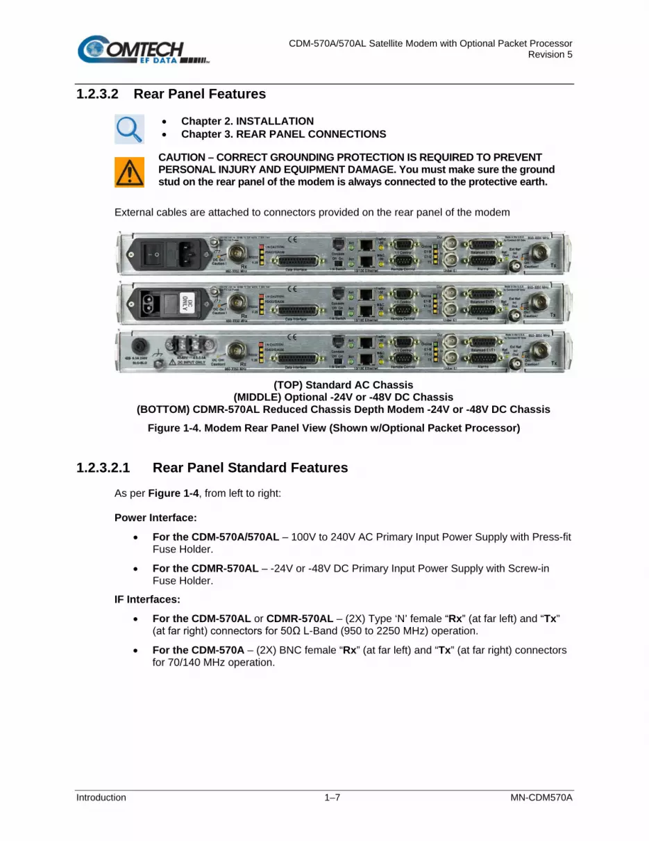
CDM-570A/570AL Satellite Modem with Optional Packet Processor Revision 5
Introduction 1–7 MN-CDM570A
1.2.3.2 Rear Panel Features
• Chapter 2. INSTALLATION • Chapter 3. REAR PANEL CONNECTIONS
CAUTION – CORRECT GROUNDING PROTECTION IS REQUIRED TO PREVENT PERSONAL INJURY AND EQUIPMENT DAMAGE. You must make sure the ground stud on the rear panel of the modem is always connected to the protective earth.
External cables are attached to connectors provided on the rear panel of the modem
(TOP) Standard AC Chassis
(MIDDLE) Optional -24V or -48V DC Chassis (BOTTOM) CDMR-570AL Reduced Chassis Depth Modem -24V or -48V DC Chassis
Figure 1-4. Modem Rear Panel View (Shown w/Optional Packet Processor)
1.2.3.2.1 Rear Panel Standard Features
As per Figure 1-4, from left to right: Power Interface:
• For the CDM-570A/570AL – 100V to 240V AC Primary Input Power Supply with Press-fit Fuse Holder.
• For the CDMR-570AL – -24V or -48V DC Primary Input Power Supply with Screw-in Fuse Holder.
IF Interfaces:
• For the CDM-570AL or CDMR-570AL – (2X) Type ‘N’ female “Rx” (at far left) and “Tx” (at far right) connectors for 50Ω L-Band (950 to 2250 MHz) operation.
• For the CDM-570A – (2X) BNC female “Rx” (at far left) and “Tx” (at far right) connectors for 70/140 MHz operation.

CDM-570A/570AL Satellite Modem with Optional Packet Processor Revision 5
Introduction 1–8 MN-CDM570A
LED Interfaces – Depending on the frequency, up to 14 LEDs are available:
• For the CDM-570AL or CDMR-570AL – A red LED labeled “DC On! Caution!” is provided for the “Rx” (at far left) and the “Tx” (at far right) Type ‘N’ connectors, each indicating the presence of DC voltage.
• Six LEDs, all orange, indicate the active data interface type: RS422/EIA530, RS232, V.35, E1-B (G.703 E1 Balanced, E1-U (G.703 E1 Unbalanced), or T1 (G.703 T1).
• A green LED labeled “ACT” and an orange LED labeled “M&C 100” indicate operational status and the passing of 10/100 BaseT Ethernet-based remote product management data.
• For systems in an optional redundant configuration:
o When the modem is connected to a 1:N switch, a red LED labeled “1:N Caution!” indicates that there may be DC voltages and other control signals present on certain pins on the 25-pin Data Interface connector.
o A green LED labeled “Online” indicates the Online/Offline status of the modem.
o A slide switch provides Off/On selection of the 1:N mode.
Utility and Traffic Data Interfaces:
• (1X) “Data Interface” DB-25F connector for serial-based synchronous data input/output.
• (1X) “Remote Control” DB-9M connector for EIA-232/-485 serial-based remote product management.
• (1X) “10/100 Ethernet | M&C 100” RJ-45 modular port for Ethernet-based remote product management.
• (1X each) “Unbal E1 | In” and “Unbal E1 | Out” BNC connectors for unbalanced G.703 E1 traffic.
• (1X) “Balanced E1/T1” DB-15F connector for balanced G.703 E1/T1 traffic.
• (1X) “Alarms” DB-15M connector for user access to the Form-C relay contacts that indicate the modem alarms/fault status.
• (1X) “Ext Ref In/Out” BNC female connector for External Reference.

CDM-570A/570AL Satellite Modem with Optional Packet Processor Revision 5
Introduction 1–9 MN-CDM570A
1.2.3.2.2 Rear Panel Optional Features
As per Figure 1-4, from left to right: Power Interfaces:
• -24V DC or -48V DC Primary Input Power Supply with Screw-in Fuse Holders.
• 24V DC 90 Watt BUC Power Supply (AC Input or DC Input versions).
• 48V DC 150 Watt BUC Power Supply (AC Input or DC Input versions).
Utility and Traffic Data Interfaces:
• (1X) “Console” RJ-11 modular jack. When equipped with the optional Packet Processor, this port provides access to the Serial CLI (Command Line Interface).
• (1X) “Ethernet 10/100 | Traffic 100” RJ-45 modular port. When equipped with the optional Packet Processor, this port processes 10/100 BaseT Ethernet-based traffic.
• (1X) “1:1 Control” DB-9F connector for to connect the modem only to a CRS-170A (L-Band) or CRS-180 (70/140 MHz) switch in optional 1:1 redundancy configurations.
Mounting Tabs for Rear Panel Rack Support Brackets Kits:
• KT/6228-2 4” Rear-Mounting Support Brackets Kit.
• KT/6228-3 10” Rear-Mounting Support Brackets Kit.
1.2.4 Standard Data Interfaces
The modem includes, as standard, a universal data interface that eliminates the need to exchange interface cards for different applications. The interfaces offered include:
• EIA-422 (EIA-530) DCE (at rates up to 10.239 Mbps)
• X.21 DTE and DCE (at rates up to 9.98 Mbps)
• V.35 DCE (at rates up to 9.98 Mbps)
• Synchronous EIA-232 DCE (at rates up to 300 kbps)
• G.703 E1 (2048 kbps), balanced and unbalanced
• G.703 T1 (1544 kbps), balanced
1.2.5 Verification
The modem includes many test modes and loopbacks for rapid verification of correct modem function. The IF loopback, in particular, permits execution of a quick diagnostic test without disturbing external cabling. During the loopback, all the receive configuration parameters temporarily change to match the transmit side, and an internal RF switch connects the modulator output to the demodulator input. All of the previous values are restored once normal operation is again selected.

CDM-570A/570AL Satellite Modem with Optional Packet Processor Revision 5
Introduction 1–10 MN-CDM570A
1.2.6 AUPC
APPENDIX E. AUPC (AUTOMATIC UPLINK POWER CONTROL)
AUPC (Automatic Uplink Power Control) is an important feature that enables the modem to automatically adjust its output power to maintain as constant the Eb/N0 of the remote end of the satellite link. This provides protection against rain fading, a particularly severe problem with Ku-Band links. Note that you can simultaneously use both EDMAC and AUPC. A benefit of AUPC is that, whenever you select EDMAC/AUPC operation, you can view the remote demodulator’s Eb/N0 from the front panel display of the local modem. To accomplish AUPC, you must use the framed EDMAC mode of operation. The distant end modem constantly sends back information about the demodulator Eb/N0 using reserved bytes in the overhead structure. The local modem uses the Eb/N0 to adjust its output power and create a closed-loop feedback system over the satellite link.
1.2.7 EDMAC
Appendix J. EDMAC CHANNEL
EDMAC facilitates network management for small networks. In this mode, an additional 5% overhead is combined with the traffic data, (1.6% in Turbo BPSK modes, Turbo Rate 21/44 QPSK/OQPSK, and all data rates greater than 2 Mbps). M&C information is added transparently, allowing access to the distant-end modem. Additionally, EDMAC-2 uses 1.6% overhead in all modes for those applications where the 5% overhead is excessive. The EDMAC and EDMAC-2 modes do not require any additional cabling at either the local or the distant-end modems. The standard M&C control port provides access to EDMAC. Full monitor and control is possible, and you may control the on/off status at the distant-end carrier.
1.2.8 Updating Modem Firmware
Chapter 4. UPDATING FIRMWARE
The modem uses ‘flash memory’ technology internally. This simplifies firmware updating. You may perform the firmware update, without opening the modem, remotely over satellite (when the modem is equipped with the optional Packet Processor), or by directly connecting a user-supplied Microsoft Windows-based PC to the modem ‘Ethernet 10/100 | M&C 100’ port (for modems without the optional Packet Processor) or the ‘Ethernet 10/100 | Traffic 100’ port (for modems equipped with the optional Packet Processor).

CDM-570A/570AL Satellite Modem with Optional Packet Processor Revision 5
Introduction 1–11 MN-CDM570A
1.2.9 Fully Accessible System Topology (FAST)
Chapter 5. FAST ACTIVATION PROCEDURE
The modem incorporates a number of optional features. In order to permit a lower initial cost, you may purchase the modem enabled with only the desired features. If you wish to upgrade the functionality of a modem at a later date, Comtech EF Data provides FAST, which permits the purchase and activation of options through special authorization codes. You may contact Comtech EF Data Product Support to purchase these unique, register-specific FAST Access Codes, and then load these codes into the modem using the front panel keypad. See Table 1-1 for the standard (base modem) versus FAST and FAST-accessible hardware options available for the modem. You may order hardware options for basic modems for installation either at the factory or in the field. You can easily activate these options in the field.

CDM-570A/570AL Satellite Modem with Optional Packet Processor Revision 5
Introduction 1–12 MN-CDM570A
Table 1-1. Standard vs. FAST and FAST-accessible Hardware Options
Option Description and Comments Install Method
Forward Error Correction
Viterbi BASE UNIT VersaFEC Codec FAST VersaFEC-2 Codec HW Reed-Solomon (RS) Codec for CCM FAST 2nd Generation Turbo Product Codec (TPC) for CCM (IESS-315 compliant) – Rate 5/16, 21/44, 3/4 and 7/8 FAST
2nd Generation Turbo Product Codec (TPC) Plug-in card for CCM – Rate 5/16, 21/44, 3/4, 7/8, and 0.95 HW
Data Rate
Modem Data Rate for CCM
Data rate 2.4 kbps to 512 kbps BASE UNIT Data rate 2.4 kbps to 1.1 Mbps FAST Data rate 2.4 kbps to 2.5 Mbps (minimum required for G.703 operation) FAST Data rate 2.4 kbps to 5 Mbps FAST Data rate 2.4 kbps to 10.239 Mbps FAST
VersaFEC Codec Data Rate for CCM
Tx Data Rate up to 512 kbps (Rx up to Modem Data Rate) FAST Tx Data Rate up to 1.1 Mbps (Rx up to Modem Data Rate) FAST Tx Data Rate up to 2.5 Mbps (Rx up to Modem Data Rate) FAST Tx Data Rate up to 5 Mbps (Rx up to Modem Data Rate) FAST Tx Data Rate up to 10.239 Mbps (Rx up to Modem Data Rate) FAST
Modulation Type
Standard (BPSK, QPSK, OQPSK) BASE UNIT Standard + 8PSK (requires RS or TPC), 8-QAM (requires TPC or VersaFEC) FAST
Standard + 16QAM (requires RS or TPC or VersaFEC) FAST Standard + 8PSK and 8-QAM + 16-QAM (requires RS or TPC or VersaFEC) FAST
DoubleTalk Carrier-in-Carrier (CnC)
CnC Plug-in Card
Full Operation HW Fractional Operation HW
CnC Data Rate
Full Operation
512 kbps FAST 1.1 Mbps FAST 2.5 Mbps FAST 5 Mbps FAST 10.239 Mbps FAST
Fractional Operation 2.5 Mbps FAST 5 Mbps FAST 0.239 Mbps FAST
CnC-APC CnC Automatic Power Control FAST
VersaFEC Adaptive Coding and Modulation (ACM)
Symbol rate up to 375 ksps FAST Symbol rate up to 750 ksps FAST Symbol rate up to 1500 ksps FAST Symbol rate up to 2000 ksps FAST
Packet Processor
Card Packet Processor daughter card HW Payload Comp Symbol rate up to 3000 ksps (VersaFEC ACM) FAST Header Comp Symbol rate up to 3000 ksps (VersaFEC ACM) FAST
3XDES Tx Packet Encryption / Rx Packet Decryption Available as EN model

CDM-570A/570AL Satellite Modem with Optional Packet Processor Revision 5
Introduction 1–13 MN-CDM570A
Option Description and Comments Install Method Advanced QoS Advanced Quality of Service FAST
Carrier ID Carrier ID FAST G.703 G.703 Clock Extension FAST
Optimized Transmit Filter Rolloff (5%, 10%, 15%, 20%, 25%)
Up to 512 kbps for CCM FAST Up to 1.1 Mbps for CCM FAST Up to 2.5 Mbps for CCM FAST Up to 5 Mbps for CCM FAST Up to 10.239 Mbps for CCM FAST
Primary Input Power Supplies (without BUC P/S)
100 to 240V AC HW -24V DC HW -48V DC HW
Primary Input Power Supplies (with BUC P/S)
100 to 240V AC w/24V DC 90W @50°C BUC P/S HW 100 to 240V AC w/48V DC 150W @50°C BUC P/S HW -24V DC w/24V DC 90W @50°C BUC P/S HW -48V DC w/24V DC 90W @50°C BUC P/S HW -48V DC w/48V DC 150W @50°C BUC P/S HW

CDM-570A/570AL Satellite Modem with Optional Packet Processor Revision 5
Introduction 1–14 MN-CDM570A
1.2.10 Supporting Hardware and Software
1.2.10.1 CDM-570AL/CDMR-570AL L-Band Redundancy
For 1:1 applications, the modem is supported by the low-cost external CRS-170A L-Band 1:1 Redundancy Switch. For Hub applications, the modem is supported by the low-cost external CRS-300 1:N Redundancy Switch coupled with the CRS-280L (L-Band) Redundancy Switch.
1.2.10.2 CDM-570A 70/140 MHz Redundancy
For 1:1 applications, the modem is supported by the low-cost external CRS-180 70/140MHz 1:1 Redundancy Switch. For Hub applications, the modem is supported by the low-cost external CRS-300 1:N Redundancy Switch coupled with the CRS-280 IF (70/140 MHz) Switch.
1.2.10.3 Support Software
The modem is supported by Comtech EF Data’s Satellite system Monitor and Control (SatMac) Version 4.7 software, a WindowsTM-based application that provides a ‘point and click’ interface for the complete system of Comtech EF Data equipment (comprising Modems, Transceivers, and Redundancy Switches). Contact Comtech EF Data Product Support for more information or to order a free demo disk. SatMac is also available for download from the M&C Utilities link on Comtech EF Data’s website.

CDM-570A/570AL Satellite Modem with Optional Packet Processor Revision 5
Introduction 1–15 MN-CDM570A
1.3 Summary of Specifications
1.3.1 Modulator
Parameter Specification Modulation BPSK, QPSK, OQPSK, 8-PSK, 8-QAM, and 16-QAM
Symbol Rate Range 4.8 ksps to 3000 ksps Data Rate Range See Section 1.3.6 Operating Modes • Transparent, Closed Network, IESS-315 (VSAT Turbo)
• Proprietary EDMAC framed mode: o 5% overhead – EDMAC (data rates < 2.048 Mbps all modes except BPSK Turbo, Rate 21/44 QPSK
Turbo) o 1.6% overhead – EDMAC-2 (data rates >2.048 Mbps and all Rate 21/44, 5/16 Turbo)
• R-S Outer Codec o 220,200 outer code (transparent mode) o 200,180 outer code (EDMAC modes)
• Turbo Product Codec – 2nd Generation Rates 21/44, 5/16, 21/44, 3/4, 7/8, and 0.95 (optional plug-in module for rate 0.95)
• VersaFEC® Codec (short-block, low latency and ultra-low-latency LDPC) • VersaFEC-2 Codec (optional plug-in module, long-block, short-block) • VersaFEC-2 Adaptive Coding and Modulation – IP interface only – maximum symbol rate = 3.0 Msps • Automatic Uplink Power Control (AUPC) mode • DoubleTalk® Carrier-in-Carrier® mode (optional plug-in module)
FEC
• None: Uncoded BPSK/QPSK/OQPSK • Viterbi: k=7, per IESS-308/309
o BPSK: Rate 1/2 o QPSK/OQPSK: Rate 1/2, Rate 3/4 and Rate 7/8 o 16-QAM: Rate 3/4 and Rate 7/8 (requires Reed-Solomon)
• Reed-Solomon (Closed Network): o 220,200 outer code (transparent mode) o 200,180 outer code (EDMAC modes) o Interleaver depth = 4
• 8-PSK/TCM Rate 2/3 (Trellis) with concatenated Reed-Solomon: CLOSED NETWORK - NOT IESS-310 COMPATIBLE
• Turbo Product Codec: o Rate 5/16 BPSK – 2 dimensional o Rate 21/44 BPSK – 3 dimensional o Rate 21/44 QPSK/OQPSK – 3 dimensional o Rate 3/4 QPSK/OQPSK/8-PSK/8-QAM/16-QAM – 2 dimensional o Rate 7/8 QPSK/OQPSK/8-PSK/8-QAM/16-QAM – 2 dimensional o Rate 0.95 (optional plug-in card) QPSK/OQPSK/8-QAM/8-PSK – 2 dimensional eTPC (exact
Code Rate is actually 17/18, or 0.944) • VersaFEC Codec (FAST Option):
o Rate 0.488 BPSK (also 0.493 BPSK Ultra-Low-Latency o Rate 0.533, 0.631, 0.706, 0.803 QPSK (0.493, 0.654, 0.734 Ultra-Low-Latency o Rate 0.642, 0.711, 0.780 8-QAM (also 0.576 8-QAM Extended CCM o Rate 0.731, 0.780, 0.829, 0.853 16-QAM (also 0.644 16-QAM Extended CCM
• VersaFEC-2® Long-Block Codec (Optional plug-in card – low latency LDPC): o Rate 0.489 BPSK o Rate 0.489, 0.537, 0.586, 0.611, 0.635, 0.660, 0.684, 0.733 QPSK o Rate 0.521, 0.537, 0.562, 0.586, 0.611, 0.635, 0.660, 0.684, 0.708, 0.733 8-ARY o Rate 0.586, 0.611, 0.635, 0.660, 0.684, 0.708, 0.733, 0.757, 0.782 16-ARY o Rate 0.660, 0.684, 0.708, 0.733, 0.757, 0.782, 0.801, 0.831, 0.855, 0.879 32-ARY

CDM-570A/570AL Satellite Modem with Optional Packet Processor Revision 5
Introduction 1–16 MN-CDM570A
Parameter Specification FEC (cont.) • VersaFEC-2® Short-Block Codec (Optional plug-in card – low latency LDPC):
o Rate 0.489 BPSK o Rate 0.489, 0.537, 0.586, 0.611, 0.635, 0.660, 0.684, 0.733 QPSK o Rate 0.521, 0.537, 0.562, 0.586, 0.611, 0.635, 0.660, 0.684, 0.708, 0.733 8-ARY o Rate 0.586, 0.611, 0.635, 0.660, 0.684, 0.708, 0.733, 0.757, 0.782 16-ARY o Rate 0.660, 0.684, 0.708, 0.733, 0.757, 0.782, 0.801, 0.831 32-ARY
Harmonics and Spurious -60 dBC/4 kHz from 600 to 2600 MHz (L-Band) and from 1 to 400 MHz (IF) Transmit Filtering Per Intelsat IESS-308 (FIR digital filter implementation)
Root-Raised Cosine, alpha = 0.05, 0.10, 0.15, 0.20, 0.25, and 0.35 roll-off Transmit On/Off Ratio 55 dB minimum Scrambling • Transparent, Closed Network mode, no R-S or Turbo coding - per ITU V.35 (Intelsat variant)
• EDMAC mode, no R-S coding - externally frame synchronized - proprietary • Turbo Product Code mode - externally frame synchronized - proprietary • All R-S modes - externally frame synchronized per IESS-308/309/310 • All VersaFEC and VersaFEC-2 modes use IESS-315/V.35
Clocking Options • Internal – CDM-570AL or CDMR-570AL (L-Band)±0.06 ppm (SCT); CDM-570A (70/140 MHz) ±1.0 ppm (SCT)
• External – Locking over a ±100 ppm range (TT) • Loop timing (Rx satellite clock) – Supports asymmetric operation; Rx and Tx data rates do not need to be
identical External TX Carrier Off By TTL 'low' signal or external contact closure – hardware function automatically over-rides processor, or by
RTS signal on main data interface Output Impedance CDM-570AL or CDMR-570AL (L-Band): 50Ω, >17 dB from 950 to 2250 MHz and >19 dB from 1000 to 1900
MHz minimum return loss
CDM-570A (70/140 MHz): Compatible with 50Ω or 75Ω,17 dB minimum return loss Output Connector CDM-570AL or CDMR-570AL (L-Band):Type ‘N’ female
CDM-570A (70/140 MHz): BNC female Output Frequency
CDM-570AL or CDMR-570AL (L-Band): 950 to 2250 MHz, 100 Hz resolution Stability ±0.06 ppm (±6 x 10⁻⁸) 0 to 50°C (32 to 122°F), when using internal reference CDM-570A (70/140 MHz): 50 to 90 MHz, and 100 to 180 MHz, 100 Hz resolution Stability ±1.0 ppm (±1 x 10⁻⁶) 0 to 50°C (32 to 122°F), when using internal reference
Output Phase Noise CDM-570AL or CDMR-570AL (L-Band): <1.2° RMS double-sided, 100 Hz to 1 MHz for CDM-570AL and CDM-570AL-IP CDM-570A (70/140 MHz): <0.75° RMS double-sided, 100 Hz to 1 MHz for CDM-570A and CDM-570A-IP
Output Power
CDM-570AL or CDMR-570AL (L-Band):0 to -40 dBm, 0.1 dB steps - manual mode. Also – see Sect. 1.2.6 for Automatic Uplink Power Control. CDM-570A (70/140 MHz): 0 to -25 dBm, 0.1 dB steps - manual mode. Also – see Sect. 1.2.6 for Automatic Uplink Power Control.
Power Accuracy CDM-570AL or CDMR-570AL (L-Band): ±1.0 dB over frequency, data rate, modulation type and temperature CDM-570A (70/140 MHz): ±0.5 dB over frequency, data rate, modulation type and temperature
BUC Reference (10 MHz)
CDM-570AL or CDMR-570AL: On center conductor of L-Band output connector; 10.0 MHz ± 0.06 ppm* (Optional 1 ppm) -1.0 dBm, ± 4 dBm; programmable ON/OFF *Source: Selected as Internal.
Phase Noise dB/Hz -110 -135 -140
Frequency Offset 10 Hz 100 Hz 1 kHz

CDM-570A/570AL Satellite Modem with Optional Packet Processor Revision 5
Introduction 1–17 MN-CDM570A

CDM-570A/570AL Satellite Modem with Optional Packet Processor Revision 5
Introduction 1–18 MN-CDM570A
1.3.2 Demodulator
Data Rate Range, Operating modes, Descrambling, Input Impedance/Return Loss, etc. are as specified in Section 1.3.1.
Parameter Specification Input Power Range CDM-570AL or CDMR-570AL (L-Band) Desired Carrier: -130 + 10log (Symbol Rate) to -90 + 10log (Symbol
Rate); +40 dBc maximum composite, up to -10 dBm, absolute max. CDM-570A (70/140 MHz) Desired Carrier: -30 to -60 dBm. +35 dBc maximum composite, up to -5 dBm, absolute max.
FEC • Viterbi: 3 bit soft decision • Trellis: Pragmatic TCM/8-PSK with closed network concatenated Reed-Solomon • Reed-Solomon (Closed Network): Proprietary • Turbo Product Codec: 4 bit soft decision, proprietary • VersaFEC: 6 bit soft decision, proprietary • VersaFEC-2: 8 bit soft decision, proprietary
Acquisition Range ±1 to ±32 kHz, programmable in 1 kHz increments, for symbol rates below 625 ksymbols/sec ±1 to ±200 kHz, 1 kHz increments, for symbol rates above 625 ksymbols/sec, L-Band only
Acquisition Time Highly dependent on data rate, FEC rate, and demodulator acquisition range. Examples: 120 ms average at 64 kbps, R1/2 QPSK, ±10 kHz acquisition sweep range, 6dB Eb/N0 3.5 s average at 9.6 kbps, R1/2 QPSK, ±10 kHz, 6dB Eb/No Note: Reed-Solomon and TPC increases acquisition time, due to the additional time taken for the R-S/TPC decoder to declare synchronization.
Clock Tracking Range ± 100 ppm min Plesiochronous/ Doppler Buffer
Selectable size of ± 128, 256, 512, 1024, 2048, 4096, 8192, 16384 and 32768 bits Size selection is displayed in bits and milliseconds. Supports asymmetric operation – when buffer is clocked from Tx clock, Rx and Tx rates do not need to be identical.
Monitor Functions Eb/No estimate, 2 to 16 dB (± 0.25 dB accuracy) Corrected Bit Error Rate, 1E-3 to 1E-9 Frequency offset, ± 200 kHz range, 100 Hz resolution Buffer fill state, in percent Receive signal level monitor accuracy: ± 5 dB for CDM-570AL L-Band, ± 3 dB for CDM–570A over specified min to max signal range
1.3.2.1 BER Performance Specification
BER Description For BER=
Rate Guaranteed Eb/No ((typical value in parentheses)
VITERBI (Met in the presence of two adjacent carriers, each 7 dB higher than the desired carrier)
10-5 10-6 10-7
½ (BPSK, QPSK, OQPSK) 5.4 dB (4.9 dB) 6.0 dB (5.5 dB) 6.7 dB (6.2 dB)
¾ (QPSK, OPQSK) 6.8 dB (6.3 dB) 7.4 dB (6.9 dB) 8.2 dB (7.7 dB)
7/8 (QPSK, OPQSK) 7.7 dB (7.2 dB) 8.4 dB (7.9 dB) 9.0 dB (8.6 dB)
VITERBI and R-S 220,200 or 200,180 Outer Code (With two adjacent carriers, each 7 dB higher than the desired carrier)
10-5 10-6 10-7
½(BPSK, QPSK, OQPSK) 4.3 dB (4.0 dB) 4.4 dB (4.1 dB) 4.5 dB (4.2 dB)
¾ (QPSK, OPQSK) 5.6 dB (4.7 dB) 5.8 dB (4.8 dB) 6.0 dB (5.2 dB)
7/8 (QPSK, OPQSK) 6.5 dB (6.0 dB)
6.7 dB (6.2 dB) 6.9 dB (6.5 dB)
8-PSK/TCM/R-S CODEC (With two adjacent carriers, each 7 dB higher than the desired carrier)
10-5 10-7 10-8
2/3 8-PSK/TCM/R-S 6.3 dB (5.4 dB) 6.7 dB (5.8 dB) 6.9 dB (6.0 dB)

CDM-570A/570AL Satellite Modem with Optional Packet Processor Revision 5
Introduction 1–19 MN-CDM570A
BER Description For BER=
Rate Guaranteed Eb/No ((typical value in parentheses)
TURBO PRODUCT CODEC Rate 21/44 QPSK Rate 21/44 BPSK Rate 5/16 BPSK (With two adjacent carriers, each 7 dB higher than the desired carrier)
10-6 10-7 10-8
21/44 (QPSK, OQPSK) 2.9 dB (2.6 dB) 3.1 dB (2.7 dB) 3.3 dB (2.8 dB)
21/44 (BPSK) 2.8 dB (2.5dB) 3.1 dB (2.8 dB) 3.3 dB (2.90dB)
5/16 (BPSK) 2.4 dB (2.1dB) 2.6 dB (2.3dB) 2.7 dB (2.4dB)
TURBO PRODUCT CODEC Rate ¾ QPSK Rate ¾ 8-PSK Rate ¾ 16-QAM (With two adjacent carriers, each 7 dB higher than the desired carrier)
10-6 10-7 10-8
¾ (QPSK, OPQSK) 3.8dB (3.4dB) 4.1dB (3.7dB) 4.4dB (4.0dB)
¾ (8-PSK) 6.2 dB (5.8 dB) 6.4 dB (6.0 dB) 6.8 dB (6.3 dB)
Rate ¾ (16-QAM) 7.4dB (7.0 dB) 7.8 dB (7.3 dB) 8.2 dB (7.7 dB)
TURBO PRODUCT CODEC Rate 7/8 QPSK Rate 7/8 8-PSK Rate 7/8 16-QAM (With two adjacent carriers, each 7 dB higher than the desired carrier)
10-6 10-7 10-8
Rate 7/8 (QPSK, OPQSK) 4.3 dB (4.0 dB) 4.4 dB (4.1 dB) 4.5 dB (4.2 dB)
Rate 7/8 (8-PSK) 7.0 dB (6.6 dB) 7.1 dB (6.7 dB) 7.2 dB (6.8 dB)
Rate 7/8 (16-QAM) 8.1 dB (7.7 dB) 8.2 dB (7.8 dB) 8.3 dB (7.9 dB)
TURBO PRODUCT CODEC Rate 0.95 QPSK Rate 0.95 8-PSK (With two adjacent carriers, each 7 dB higher than the desired carrier)
10-6 10-7
B10-8
Rate 0.95 (QPSK, OPQSK) 6.4 dB (6.0 dB) 6.7 dB (6.3 dB) 6.9 dB (6.5 dB)
Rate 0.95 (8-PSK) 9.3 dB (8.9 dB) 9.8 dB (9.4 dB)
10.3 dB (9.9 dB)
TURBO PRODUCT CODEC Rate ¾ 8-QAM Rate 7/8 8-QAM Rate 0.95 8-QAM (With two adjacent carriers, each 7 dB higher than the desired carrier)
10-6 10-7 10-8
Rate ¾ (8-QAM) 6.5 dB (6.1 dB)
6.8 dB (6.4 dB) 7.2 dB (6.8 dB)
Rate 7/8 (8-QAM) 6.6 dB (6.2 dB) 6.7 dB (6.3 dB) 6.8 dB (6.4 dB)
Rate 0.95 (8-QAM) 9.6 dB (9.2 dB)
10.1 dB (9.7 dB) 10.6 dB (10.2 dB)
16-QAM VITERBI/R-S (With two adjacent carriers, each 7 dB higher than the desired carrier)
10-6 10-8
¾Viterbi/R-S (16-QAM) 8.1 dB (7.5 dB) 8.6 dB (8.0 dB)
7/8 Viterbi/R-S (16-QAM) 9.5 dB (9.0 dB) 10.1 dB (9.5 dB)
VersaFEC CODEC BPSK (With two adjacent carriers, each 7 dB higher than the desired carrier)
10-5 10-8
0.488 (BPSK) 2.4 dB (2.1 dB) 2.7 dB (2.4 dB)
VersaFEC CODEC QPSK (With two adjacent carriers, each 7 dB higher than the desired carrier)
10-5 10-8
0.533 (QPSK) 2.3 dB (2.0 dB) 2.5 dB (2.2 dB)
0.631 (QPSK) 2.8 dB (2.5 dB) 3.0 dB (2.7 dB)
0.706 (QPSK) 3.3 dB (3.0 dB) 3.7 dB (3.4 dB)
0.803 (QPSK) 3.8 dB (3.5 dB) 4.1 dB (3.8 dB)
VersaFEC CODEC 8-QAM (With two adjacent carriers, each 7 dB higher than the desired carrier)
10-5 10-8
0.642 (8-QAM) 4.6 dB (4.3 dB) 4.9 dB (4.6 dB)
0.711 (8-QAM) 5.2 dB (4.9 dB) 5.5 dB (5.2 dB)
0.780 (8-QAM) 5.6 dB (5.3 dB) 6.0 dB (5.7 dB)
VersaFEC CODEC 16-QAM (With two adjacent carriers, each 7 dB higher than the desired carrier)
10-5 10-8
0.731 (16-QAM) 6.6 dB (6.3 dB) 6.8 dB (6.5 dB)
0.780 (16-QAM) 7.1 dB (6.8 dB) 7.4 dB (7.1 dB)
0.829 (16-QAM) 7.7 dB (7.4 dB) 8.0 dB (7.7 dB)
0.853 (16-QAM) 8.1 dB (7.8 dB) 8.4 dB (8.1 dB)
VersaFEC CODEC – Extended CCM (With two adjacent carriers, each 7 dB higher than the desired carrier)
10-5 10-8
0.576 (8-QAM) 4.5 dB (4.2 dB) 4.9 dB (4.6 dB)
0.644 (16-QAM) 6.4 dB (6.1 dB) 6.9 dB (6.6 dB)
VersaFEC-2 Long Block CODEC BPSK (With two adjacent carriers, each 7 dB higher than the desired carrier)
10-4 10-8
0.489 BPSK 1.8 dB (1.5 dB) 2.1 dB (1.8 dB)

CDM-570A/570AL Satellite Modem with Optional Packet Processor Revision 5
Introduction 1–20 MN-CDM570A
BER Description For BER=
Rate Guaranteed Eb/No ((typical value in parentheses)
VersaFEC-2 Long Block CODEC BPSK (With two adjacent carriers, each 7 dB higher than thedesired carrier)
10-4 10-8
0.489 QPSK 1.7 dB (1.4 dB) 1.9 dB (1.6 dB)
0.537 QPSK 1.8 dB (1.5 dB) 2.0 dB (1.7 dB)
0.586 QPSK 2.0 dB (1.7 dB) 2.2 dB (1.9 dB)
0.611 QPSK 2.1 dB (1.8 dB) 2.2 dB (1.9 dB)
10-4 10-8
0.635 QPSK 2.3 dB (2.0 dB) 2.5 dB (2.2 dB)
0.660 QPSK 2.4 dB (2.1 dB) 2.6 dB (2.3 dB)
0.684 QPSK 2.4 dB (2.1 dB) 2.6 dB (2.3 dB)
0.733 QPSK 2.8 dB (2.5 dB) 3.0 dB (2.7 dB)
VersaFEC-2 Long Block CODEC 8-ARY (With two adjacent carriers, each 7 dB higher than the desired carrier)
10-4 10-8
0.521 8-ARY 3.2 dB (2.9 dB) 3.5 dB (3.2 dB)
0.537 8-ARY 3.2 dB (2.9 dB) 3.6 dB (3.3 dB)
0.562 8-ARY 3.3 dB (3.0 dB) 3.6 dB (3.6 dB)
0.586 8-ARY 3.3 dB (3.0 dB) 3.6 dB (3.6 dB)
10-4 10-8
0.611 8-ARY 3.4 dB (3.1 dB) 3.7 dB (3.4 dB)
0.635 8-ARY 3.5 dB (3.2 dB) 3.7 dB (3.4 dB)
0.660 8-ARY 3.7 dB (3.4 dB) 3.8 dB (3.5 dB)
0.684 8-ARY 3.9 dB (3.6 dB) 4.1 dB (3.8 dB)
10-4 10-8
0.708 8-ARY 4.0 dB (3.7 dB) 4.2 dB (3.9 dB)
0.733 8-ARY 4.3 dB (4.0 dB) 4.4 dB (4.1 dB)
VersaFEC-2 Long Block CODEC 16-ARY (With two adjacent carriers, each 7 dB higher than the desired carrier)
10-4 10-8
0.586 16-ARY 4.4 dB (4.1 dB) 4.7 dB (4.4 dB)
0.611 16-ARY 4.7 dB (4.4 dB) 5.0 dB (4.7 dB)
0.635 16-ARY 4.9 dB (4.6 dB) 5.2 dB (4.9 dB)
0.660 16-ARY 5.1 dB (4.8 dB) 5.3 dB (5.0 dB)
10-4 10-8
0.684 16-ARY 5.3 dB (5.0 dB) 5.5 dB (5.2 dB)
0.708 16-ARY 5.6 dB (5.3 dB) 5.8 dB (5.5 dB)
0.733 16-ARY 5.9 dB (5.6 dB) 6.1 dB (5.8 dB)
0.757 16-ARY 6.2 dB (5.9 dB) 6.4 dB (6.1 dB)
10-4 10-8
0.782 16-ARY 6.5 dB (6.2 dB) 6.7 dB (6.4 dB)
VersaFEC-2 Long Block CODEC 32-ARY (With two adjacent carriers, each 7 dB higher than the desired carrier)
10-4 10-8
0.660 32-ARY 6.8 dB (6.5 dB) 7.1 dB (6.8 dB)
0.684 32-ARY 7.2 dB (6.9 dB) 7.5 dB (7.2 dB)
0.708 32-ARY 7.4 dB (7.1 dB) 7.7 dB (7.4 dB)
0.733 32-ARY 7.7 dB (7.4 dB) 8.0 dB (7.7 dB)
10-4 10-8
0.757 32-ARY 8.0 dB (7.7 dB) 8.2 dB (7.9 dB)
0.782 32-ARY 8.4 dB (8.1 dB) 8.6 dB (8.3 dB)
0.801 32-ARY 8.8 dB (8.5 dB) 9.0 dB (8.7 dB)
0.831 32-ARY 9.1 dB (8.8 dB) 9.3 dB (9.0 dB)
10-4 10-8
0.855 32-ARY 9.8 dB (9.5 dB) 10.0 dB (9.7 dB)
0.879 32-ARY 10.4 dB (10.1 dB) 10.6 dB (10.3 dB)
VersaFEC-2 Short Block CODEC BPSK (With two adjacent carriers, each 7 dB higher than the desired carrier)
10-4 10-8
0.489 BPSK 2.6 dB (2.3 dB) 3.2 dB (2.9 dB)
VersaFEC-2 Short Block CODEC QPSK (With two adjacent carriers, each 7 dB higher than the desired carrier)
10-4 10-8
0.489 QPSK 2.3 dB (1.4 dB) 2.7 dB (1.6 dB)
0.537 QPSK 2.4 dB (2.1 dB) 2.0 dB (1.7 dB)
0.586 QPSK 2.5 dB (2.2 dB) 3.0 dB (2.7 dB)
0.611 QPSK 2.6 dB (2.3 dB) 3.1 dB (2.8 dB)
10-4 10-8
0.635 QPSK 2.8 dB (2.5 dB) 3.2 dB (2.9 dB)
0.660 QPSK 2.9 dB (2.6 dB) 3.3 dB (3.0 dB)
0.684 QPSK 3.0 dB (2.7 dB) 3.4 dB (3.1 dB)
0.733 QPSK 3.4 dB (3.1 dB) 3.8 dB (3.5 dB)

CDM-570A/570AL Satellite Modem with Optional Packet Processor Revision 5
Introduction 1–21 MN-CDM570A
BER Description For BER=
Rate Guaranteed Eb/No ((typical value in parentheses)
VersaFEC-2 Short Block CODEC 8-ARY (With two adjacent carriers, each 7 dB higher than the desired carrier)
10-4 10-8
0.521 8-ARY 3.5 dB (3.2 dB) 4.0 dB (3.7 dB)
0.537 8-ARY 3.5 dB (3.2 dB) 4.1 dB (3.8 dB)
0.562 8-ARY 3.6 dB (3.6 dB) 4.2 dB (3.9 dB)
0.586 8-ARY 3.7 dB (3.4 dB) 4.2 dB (3.9 dB)
10-4 10-8
0.611 8-ARY 3.9 dB (3.6 dB) 4.3 dB (4.0 dB)
0.635 8-ARY 3.9 dB (3.6 dB) 4.4 dB (4.1 dB)
0.660 8-ARY 4.1 dB (3.8 dB) 4.5 dB (4.2 dB)
0.684 8-ARY 4.4 dB (4.1 dB) 4.7 dB (4.4 dB)
10-4 10-8
0.708 8-ARY 4.5 dB (4.2 dB) 4.8 dB (4.5 dB)
0.733 8-ARY 4.8 dB (4.5 dB) 5.2 dB (4.9 dB)
VersaFEC-2 Short Block CODEC 16-ARY (With two adjacent carriers, each 7 dB higher than the desired carrier)
10-4 10-8
0.586 16-ARY 4.8 dB (4.5 dB) 5.3 dB (5.0 dB)
0.611 16-ARY 5.0 dB (4.7 dB) 5.4 dB (5.1 dB)
0.635 16-ARY 5.3 dB (5.0 dB) 5.6 dB (5.3 dB)
0.660 16-ARY 5.5 dB (5.2 dB) 5.8 dB (5.5 dB)
10-4 10-8
0.684 16-ARY 5.7 dB (5.4 dB) 6.2 dB (5.9 dB)
0.708 16-ARY 6.1 dB (5.8 dB) 6.5 dB (6.2 dB)
0.733 16-ARY 6.2 dB (5.9 dB) 6.6 dB (6.3 dB)
0.757 16-ARY 6.7 dB (6.4 dB) 7.1 dB (6.8 dB)
10-4 10-8
0.782 16-ARY 7.0 dB (6.7 dB) 7.5 dB (7.2 dB)
VersaFEC-2 Short Block CODEC 32-ARY (With two adjacent carriers, each 7 dB higher than the desired carrier)
10-4 10-8
0.660 32-ARY 7.3 dB (7.0 dB) 7.9 dB (7.6 dB)
0.684 32-ARY 7.5 dB (7.2 dB) 8.1 dB (7.8 dB)
0.708 32-ARY 7.7 dB (7.4 dB) 8.2 dB (7.9 dB)
0.733 32-ARY 8.2 dB (7.9 dB) 8.7 dB (8.4 dB)
10-4 10-8
0.757 32-ARY 8.4 dB (8.1 dB) 8.9 dB (8.6 dB)
0.782 32-ARY 8.7 dB (8.4 dB) 9.2 dB (8.9 dB)
0.801 32-ARY 9.1 dB (8.8 dB) 9.5 dB (9.2 dB)
0.831 32-ARY 9.5 dB (9.2 dB) 9.9 dB (9.6 dB)
ULL CODEC (With two adjacent carriers, each 7 dB higher than the desired carrier)
10-5 10-8
0.493 (BPSK) 3.1 dB (2.8 dB) 3.7 dB (3.4 dB)
0.493 (QPSK) 3.1 dB (2.8 dB) 3.7 dB (3.4 dB)
0.654 (QPSK) 3.6 dB (3.3 dB) 4.2 dB (3.9 dB)
0.734 (QPSK) 4.1 dB (3.8 dB) 4.7 dB (4.4 dB)
1.3.3 Standard AUPC (Automatic Uplink Power Control)
Parameter Specification Operating Mode Requires Closed Network Framed mode for transport of Eb/No information from remote modem
(EDMAC can be enabled or disabled) Target Eb/No Range 0 to 14.9 dB at remote demod (default is 4.0 dB) Max AUPC Range 0 to 9 dB (default is 3 dB) Monitor Functions Remote demod Eb/No and Tx power level increase (front panel or via remote control interface)

CDM-570A/570AL Satellite Modem with Optional Packet Processor Revision 5
Introduction 1–22 MN-CDM570A
1.3.4 DoubleTalk® Carrier- in-Carrier® (CnC)
Parameter Specification Operating Mode Requires the two links to share a common carrier frequency (Outbound and Inbound symbol rates do
not have to be equal) Power Spectral Density Ratio and CnC Ratio
BSPK/QPSK/8PSK/8-QAM: –7 dB to +11 dB (ratio of power spectral density, outbound interferer to desired inbound) 16-QAM: –7 dB to +7 dB (ratio of power spectral density, outbound interferer to desired inbound) Note: With asymmetric carriers, the absolute power ratio (or CnC ratio) would be different, depending on the ratio of the symbol rates. Example: Outbound interferer = 1 Msymbols/sec Desired Inbound = 500 ksymbols/sec Ratio of power spectral density = +7 dB Absolute power ratio (CnC Ratio) = +7dB + (10log Outbound/desired symbol rate) = +10 dB
Maximum Symbol Rate Ratio 3:1 (TX:RX or RX:TX) Inbound/Outbound frequency uncertainty
Within the normal acquisition range of the demod, as follows: CDM-570AL or CDMR-570AL (L-Band): Below 64 ksymbols/sec: ±1 to ±(Rs/2) kHz, where Rs = symbol rate in ksymbols/sec Between 64 and 625 ksymbols/sec: ±1 up to a maximum of ±32kHz. Above 625 ksymbols/sec: ±1 to ±(0.1Rs) kHz, up to a maximum of ±200 kHz CDM-570A (70/140 MHz): Below 64 ksymbols/sec: ±1 to ±(Rs/2) kHz, where Rs = symbol rate in ksymbols/sec Equal to 64 ksymbols/sec and above: ±1 up to a maximum of ±32kHz.
Delay range 0-330 ms Eb/No Degradation (equal Inbound/Outbound power spectral density)
BPSK = 0.3dB QPSK = 0.3dB OQPSK = 0.3dB 8PSK = 0.5dB 8-QAM = 0.4dB 16-QAM = 0.6dB For +10 dB power spectral density ratio (outbound interferer 10 dB higher than desired inbound) add an additional 0.3 dB
Monitor Functions Delay, in milliseconds Frequency offset (between outbound interferer and desired inbound). 100 Hz resolution CnC Power Ratio, in 0.1 dB (ratio of absolute power, outbound interferer to desired inbound) Power Spectral Density Ratio, in 0.1 dB
CnC Monitor Accuracy ±0.2 dB for symmetric symbol rate
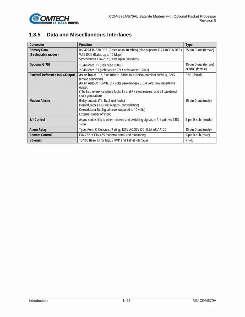
CDM-570A/570AL Satellite Modem with Optional Packet Processor Revision 5
Introduction 1–23 MN-CDM570A
1.3.5 Data and Miscellaneous Interfaces
Connector Function Type Primary Data (3 selectable modes)
RS-422/EIA-530 DCE (Rates up to 10 Mbps) (also supports X.21 DCE & DTE) V.35 DCE (Rates up to 10 Mbps) Synchronous EIA-232 (Rates up to 300 kbps)
25-pin D-sub (female)
Optional G.703 1.544 Mbps T1 (Balanced 100Ω) 2.048 Mbps E1 (unbalanced 75Ω or balanced 120Ω)
15-pin D-sub (female) or BNC (female)
External Reference Input/Output As an input: 1, 2, 5 or 10MHz -6dBm to +10dBm (nominal 50/75 Ω, BNC female connector) As an output: 10MHz, 2.7 volts peak-to-peak ± 0.4 volts, low impedance output (The Ext. reference phase locks Tx and Rx synthesizers, and all baseband clock generation)
BNC (female)
Modem Alarms Relay outputs (Tx, Rx & unit faults) Demodulator I & Q test outputs (constellation) Demodulator Rx Signal Level output (0 to 10 volts) External carrier off input
15-pin D-sub (male)
1:1 Control Async serials link to other modem, and switching signals in 1:1 pair, via CRS-170A
9-pin D-sub (female)
Alarm Relay Type: Form C Contacts. Rating: 125V AC/30V DC, 0.3A AC/1A DC 15-pin D-sub (male) Remote Control EIA-232 or EIA-485 modem control and monitoring 9-pin D-sub (male) Ethernet 10/100 Base Tx for http, SNMP and Telnet interfaces RJ-45

CDM-570A/570AL Satellite Modem with Optional Packet Processor Revision 5
Introduction 1–24 MN-CDM570A
1.3.6 Data Rate Ranges
FEC Type Modulation Code Rate Data Rate Range EDMAC limited? Lower Limit (kbps) Upper Limit (Mbps)
None BPSK Uncoded 4.8 3.000
Yes – see “Important Note” below
QPSK/OQPSK Uncoded 9.6 5.000
Viterbi
BPSK 1/2 2.4 1.500
QPSK/OQPSK 1/2 4.8 3.000 3/4 7.2 4.500 7/8 8.4 5.250
Viterbi + R-S
BPSK 1/2 2.4 1.363
QPSK/OQPSK 1/2 4.3 2.727 3/4 6.5 4.091 7/8 7.5 4.666
16-QAM 3/4 13.0 4.000 7/8 16.8 4.666
TCM + R-S 8-PSK 2/3 8.7 4.400
Turbo
BPSK 5/16 2.4 0.937
21/44 2.4 1.430
QPSK/OQPSK
21/44 4.8 2.860 3/4 7.2 4.500 7/8 8.4 5.250 0.95 9.1 5.666
8-PSK/8-QAM 3/4 10.8 6.750
No 7/8 13.6 7.875 0.95 15.3 8.500
16-QAM 3/4 14.4 9.000 7/8 16.8 9.980
VersaFEC
BPSK 0.488 2.4 1.462
No
QPSK
0.533 5.2 3.200 0.631 6.1 3.785 0.706 6.8 4.233 0.803 7.8 4.818
8-QAM
0.576 8.3 5.179 0.642 9.3 5.782 0.711 10.3 6.401 0.780 11.3 7.021
16-QAM
0.644 12.4 7.726 0.731 14.1 8.776 0.780 15.0 9.361 0.829 16.0 9.946 0.853 16.4 10.239
Ultra-Low Latency (ULL)
BPSK 0.493 2.4 1.480
QPSK 0.493 4.7 2.960 0.654 6.3 3.924 0.734 7.0 4.405
VersaFEC Adaptive Coding and Modulation
(IP-ACM) See Section 1.3.7.1

CDM-570A/570AL Satellite Modem with Optional Packet Processor Revision 5
Introduction 1–25 MN-CDM570A
FEC Type Modulation Code Rate Data Rate Range
EDMAC limited? Lower Limit (kbps) Upper Limit (Mbps) VersaFEC-2
Adaptive Coding and Modulation
(V2-ACM) See Section 1.3.7.2
Important Note – where noted in this table: If EDMAC framing is employed, the upper data rate will be reduced by 5% for data rates up to 2.048 Mbps, and by 1.6% for data rates above 2.048 Mbps where EDMAC2 framing is used, or for Rate 21/44 BPSK/QPSK Turbo, or Rate 5/16 BPSK Turbo.
1.3.7 VersaFEC Adaptive Coding and Modulation (ACM)
1.3.7.1 VersaFEC ACM (IP-ACM)
System Type Adaptive Coding and Modulation, using BPSK, QPSK, 8-QAM , 16-QAM and VersaFEC short-block LDPC coding – total of 12 ModCods
Symbol Rate Range 37-3000 ksps Interface 10/100 Base T Ethernet, with auto-negotiated Congestion Control
Remote SNR Reporting Automatically reported from remote modem – built in function at the physical layer – requires no additional overhead
Max Span of Data Rate 7:1 over range of adaptation Switch Point (decreasing SNR) Corresponds to SNR (Eb/No) that gives BER = 5 x 10⁻⁸ Switch Point Hysteresis 0.3 dB Max Fading Rate Approximately 1 dB/second (higher if Target Eb/No margin >1 dB) Max ModCod Update Rate One update every two seconds (no restriction on distance between ModCods)
Configurable Parameters • Minimum and Maximum ModCod (ModCod0 through ModCod11) • Remote Demod Unlock Action: Maintain current ModCod
Go to minimum ModCod • Target Eb/No margin (0-4.5 dB, 0.5 dB steps)
System Latency 54 ms max. (for a system operating at 100 ksps, and assuming a WAN buffer of 20 ms, not including satellite path)
Monitored Parameters
• Tx and Rx ModCods • Local and Remote SNR
(-3.0 to +22.0dB, 0.1dB resolution, ±0.5 dB accuracy) • Config and monitor menus displaying data rate, modulation and code rate update
dynamically with ModCod List of ModCods See Appendix B, Table B-3

CDM-570A/570AL Satellite Modem with Optional Packet Processor Revision 5
Introduction 1–26 MN-CDM570A
1.3.7.2 VersaFEC-2 ACM (V2-ACM)
System Type Adaptive Coding and Modulation, using BPSK, QPSK, 8-ARY, 16-ARY, 32-ARY and VersaFEC-2 Short-block and Long Block LDPC coding - total of 74 ModCods
Symbol Rate Range 37.0 ksps to 3.0 Msps for the Long block. However, the Short block is limited to 2.0 Mbps (CCM) and 1.0 Msps (ACM).
Interface 10/100 Base T Ethernet, with auto-negotiated Congestion Control
Remote SNR Reporting Automatically reported from remote modem – built in function at the physical layer – requires no additional overhead
Max Span of Data Rate 9:1 over range of adaptation Switch Point (decreasing SNR) Corresponds to SNR (Es/No) that gives BER = 1 x 10⁻⁸ (margin set to 0 dB)
Switch Point Hysteresis 0.3 dB Max Fading Rate Approximately 1 dB/second (higher if Target Eb/No margin > 1 dB) Max ModCod Update Rate 1 update every 1.7 seconds
Configurable Parameters
• Maximum ModCod (ModCod00 through ModCod37, Long Block) • Maximum ModCod (ModCod00 through ModCod35, Short Block) • Remote Demod Unlock Action: Go to minimum ModCod • Target SNR margin (0 to 4.5 dB, 0.5 dB steps)
System Latency @ 100 ksps Long Block - 205 milliseconds max (not including WAN buffer or satellite path) Short Block – 40.4 milliseconds max (not including WAN buffer or satellite path)
Monitored Parameters
• Tx and Rx ModCods • Local and Remote SNR
(-3.0 dB to +22.0dB, 0.1dB resolution, +/- 0.5 dB accuracy) • Config and monitor menus displaying data rate, modulation and code rate
update dynamically with ModCod
List of ModCods See Appendix B, Tables B-6 and B-7

CDM-570A/570AL Satellite Modem with Optional Packet Processor Revision 5
Introduction 1–27 MN-CDM570A
1.3.8 Power
Parameter Specification AC Input Power CDM-570AL (L-Band):
• Without Optional Packet Processor, CnC, or BUC Power Supply: 29W typical, 32W maximum • With Optional Packet Processor; without CnC or BUC Power Supply: 42W typical • With Optional Packet Processor and CnC; without BUC Power Supply: 48W maximum • With Optional Packet Processor, CnC, and 150W @50°C or 180W @30°C BUC Power supply: 250W
(maximum) CDM-570A (70/140 MHz): • Without Optional Packet Processor or CnC: 29W typical, 32W maximum • With Optional Packet Processor; without CnC: 42W typical • With Optional Packet Processor and CnC: 48W maximum
Typical measured VA, Power Factor and Power Data: CDM-570AL (L-Band): 240V 50 Hz Power Factor = 0.44, 65VA, 29W 110V 60 Hz Power Factor = 0.55, 50VA, 28W CDM-570A (70/140 MHz): 240V 50 Hz Power Factor = 0.33, 87VA, 29W 110V 60 Hz Power Factor = 0.53, 51VA, 28W
DC Input Power • Without any option cards: 29W typical, 32W maximum
Operating Voltage Standard AC Power Supplies CDM-570A (70/140MHz) or CDM-570AL (L-Band): 100-240V AC, +6%/-10% – autosensing (total absolute max. range is 90-254V AC) DC Power Supplies: • (Optional) CDM-570A (70/140MHz) or CDM-570AL (L-Band): Modular -24V DC (range is 20-36V) or -
48V DC (range is 43-60V) • CDMR-570AL (L-Band): Terminal block -24V DC (range is 20-36V) or -48V DC (range is 43-60V)
1.3.9 Physical Properties
Parameter Specification Dimensions CDM-570AL (L-Band): 1RU high x 19 inches (482.6 mm) wide x 16 inches (406 mm) deep
CDMR-570AL (L-Band):1RU high x 19 inches (482.6 mm) wide x 11 inches (279 mm) deep CDM-570A (70/140 MHz): 1RU high x 19 inches (482.6 mm) wide x 13 inches (330 mm) deep
Weight CDM-570AL (L-Band): • With TPC, CnC, no BUC: 7.2 lbs (3.27 kg) • With TPC, CnC, 24V BUC: 8.2 lbs (3.70 kg) • With TPC, CnC, 48V BUC: 8.4 lbs (3.81 kg)
CDMR-570AL: 6.9 lbs (3.12 kg) CDM-570A (70/140 MHz) (with TPC, CnC): 6.3 lbs (2.84 kg)
Operating Temperature 0 to 50oC (32 to 122oF)

CDM-570A/570AL Satellite Modem with Optional Packet Processor Revision 5
Introduction 1–28 MN-CDM570A
1.3.10 Miscellaneous
Front Panel Tactile keypad, 6 keys (Up/Down, Left/Right, Enter/Clear) Vacuum Fluorescent Display (blue) - 2 lines of 24 characters
Loopbacks Internal IF loopback, RF loopback, digital loopback, and inward/outward loopback Fault Relays Hardware fault, Rx and Tx Traffic Alarms M&C Interface EIA-232 and EIA-485 (addressable multidrop, 2-wire or 4-wire) Ethernet 10/100 Base Tx for http:, SNMP and Telnet interfaces M&C Software SatMac Ver. 4.7
1.3.11 Approvals
“CE” as follows:
EN 55022 Class B (Emissions) EN 50082-1 (Immunity) EN 60950 (Safety)
EN 61000-3-2 EN 61000-3-3 EN 61000-4-2 EN 61000-4-4 EN 61000-4-5
EN 61000-4-6 EN 61000-4-8 EN 61000-4-9 EN 61000-4-11 EN 61000-4-13
FCC FCC Part 15 Class B

CDM-570A/570AL Satellite Modem with Optional Packet Processor Revision 5
Installation and Startup 2–1 MN-CDM570A
Chapter 2. INSTALLATION AND STARTUP
2.1 Unpack and Inspect the Shipment
Figure 2-1. Unpack and Inspect the Shipment
The CDM-570A/570AL Satellite Modem, its optional Installation and Operation Manual (otherwise available online at http://www.comtechefdata.com), and its power cord were packaged and shipped in a reusable cardboard carton containing protective foam spacing (Figure 2-1).
CAUTION – THIS EQUIPMENT CONTAINS PARTS AND ASSEMBLIES SENSITIVE TO DAMAGE BY ELECTROSTATIC DISCHARGE (ESD). USE ESD PRECAUTIONARY PROCEDURES WHEN HANDLING THE EQUIPMENT.

CDM-570A/570AL Satellite Modem with Optional Packet Processor Revision 5
Installation and Startup 2–2 MN-CDM570A
Once opened, inspect the shipment:
Step Task
1 Keep all shipping materials.
2 Check the packing list to make sure the shipment is complete.
3 Inspect the equipment for damage. If damage exists, immediately contact the carrier and Comtech EF Data to submit a damage report.
4 Read the manual.
2.2 Install the Modem into a Rack Enclosure
Install the modem in its assigned position in the rack enclosure (Figure 2-2). Use, as required:
• A standard rack-mounted shelf;
• User-supplied screws to secure the front panel to the rack enclosure threaded front mounting rails;
• Comtech EF Data’s optional KT/6228-2 (4”) or KT/6228-3 (10”) Rear Support Brackets Kit
For information about custom rack enclosures, contact Comtech EF Data Product Support.
• CAUTION – PROPER GROUNDING PROTECTION IS REQUIRED TO PREVENT PERSONAL INJURY AND EQUIPMENT DAMAGE. You must make sure the ground stud on the rear panel of the modem is always connected to the protective earth.
• SUFFICIENT AIR VENTILATION IS REQUIRED: The modem CANNOT have rack slides mounted to the sides of the modem. Cooling fans and exhaust vents are provided here – air flow must not be impeded. Make sure there is adequate air ventilation clearance inside the enclosure, especially at the sides. In a rack system where there is high heat discharge, provide forced-air cooling with top- or bottom-mounted fans or blowers.
• MAXIMUM AIR TEMPERATURE: Make sure the air temperature inside the
enclosure never exceeds 50°C (122°F).

CDM-570A/570AL Satellite Modem with Optional Packet Processor Revision 5
Installation and Startup 2–3 MN-CDM570A
Feature Description
1 Custom Rack Enclosure 2 CDM-570A/570AL Satellite Modem 3 Standard Rack Shelving 4 Rack Enclosure Threaded Front Rail (typical) 5 Modem Front Panel 6 User-supplied Screws
Figure 2-2. Install the Modem into a Rack Enclosure

CDM-570A/570AL Satellite Modem with Optional Packet Processor Revision 5
Installation and Startup 2–4 MN-CDM570A
2.2.1 Install the Optional Rear Support Brackets Kit
Detail Description
1 Back of Modem 2 Rack Enclosure Threaded Rear Mounting Rail (typical)
Item Kit / Quantity
Part Number Description KT/6228-2 KT/6228-3
1 2 2 HW/10-32SHLDR Shoulder Screw, #10 2 4 4 HW/10-32FLT Flat Washer, #10 3 2 2 HW/10-32SPLIT Lock Washer, #10 4 2 2 HW/10-32HEXNUT Hex Nut, #10 5 4 4 HW/10-32x1/2RK Bolt, #10, Rear Support Bracket
6 2 – FP/6138-2 Bracket, Rear Support – 4” – 2 FP/6138-3 Bracket, Rear Support – 10”
Figure 2-3. Install the Optional Rear Support Brackets Kit The following tools are required to install the optional KT/6228-2 (4”) or KT/6228-3 (10”) Rear Support Brackets Kit:
• A medium Phillips screwdriver
• A 5/32-inch SAE Allen Wrench
• An adjustable Crescent wrench

CDM-570A/570AL Satellite Modem with Optional Packet Processor Revision 5
Installation and Startup 2–5 MN-CDM570A
Do these steps to install the kit (Figure 2-3):
1. Use the #10 flat washers, #10 split washers, and #10 hex nut to secure the #10 shoulder screws to the modem chassis through the rear right and left side mounting slots as shown.
2. Mount the Rear Support Brackets to the rack enclosure threaded rear mounting rails using the #10 Rack Bracket Bolts.
3. Slide the modem into the front of the rack enclosure. Make sure that the #10 Shoulder Screws properly engage into the slots of the Rear Support Brackets.
2.3 Configure the Modem
The modem ships with a default 64 kbps, QPSK, Rate 1/2 configuration. There are no internal jumpers to configure, no interface cards to install, and no other options to install. All configurations are carried out entirely via software. Configure the modem locally using the front panel keypad and display. See Chapter 6. FRONT PANEL OPERATION for details on how to fully configure the modem for the desired operating parameters.
The auto-sensing AC power supply does not require any adjustment. Simply plug in the supplied line cord, and then turn on the switch on the rear panel.
2.4 Verify Operation (IF Loopback Test)
Verify proper operation of the modem, without the need for externally connected equipment by using the front panel keypad and display. Do these steps:
1. From the top-level SELECT: menu: Use the arrow keys to first select the TEST menu branch, and then press ENTER.
2. From the TEST menu, use the arrow keys to first select Mode, and then IF↓ (IF Loopback). Press ENTER to execute the test.
See Chapter 6. FRONT PANEL OPERATION for detailed information on using Test modes.
The demodulator should synchronize, and the Rx TRAFFIC LED indicator on the front panel should illuminate green. If the modem does not pass this test, contact Comtech EF Data Product Support for further assistance.

CDM-570A/570AL Satellite Modem with Optional Packet Processor Revision 5
Installation and Startup 2–6 MN-CDM570A
2.5 Connect the External Cables
Once the desired configuration settings have been made, and proper operation has been verified using the IF Loopback test mode, proceed to connect all external cables to the connectors outlined in the next chapter (Chapter 3. REAR PANEL CONNECTORS AND PINOUTS). Should difficulties occur, call Comtech EF Data Product Support for assistance.

CDM-570A/570AL Satellite Modem with Optional Packet Processor Revision 5
Rear Panel Connectors and Pinouts 3–1 MN-CDM570A
Chapter 3. REAR PANEL CONNECTORS AND PINOUTS
3.1 Overview – Cabling Connection Types
The CDM-570A/570AL and CDMR-570AL Satellite Modems, with or without the optional High-Performance Packet Processor, use a number of different cables. Each cable type is typically dedicated to a specific mode of operation.
1. Not all of these operational interface types may be available.
2. The European EMC Directive (EN55022, EN50082-1) requires using properly shielded cables for DATA I/O. These cables must be double-shielded from end-to-end, ensuring a continuous ground shield.

CDM-570A/570AL Satellite Modem with Optional Packet Processor Revision 5
Rear Panel Connectors and Pinouts 3–2 MN-CDM570A
3.1.1 Coaxial Cable Connections
Figure 3-1 show the coaxial cables (plugs) and their mating connectors (jacks/sockets) that Comtech EF Data uses with their products: ‘BNC’, ‘TNC’, ‘N’, ‘F’, and ‘SMA’.
Coupling Type Connector Type
Plug (Male) Jack (Female)
Bayonet (Type ‘BNC’ Shown)
Threaded (Type ‘N’ Shown)
Figure 3-1. Coaxial Connector Examples
These connectors are available in two coupling styles – Bayonet or Threaded:
• Bayonet Coupling Style – The jack has a pair of guideposts that accommodate the plug’s lockdown slots. This lockdown design provides secure assembly without over-tightening the connection.
• Threaded Coupling Style – The jack features external threads. The plug shell features internal threads, and has either a knurled outer surface to permit hand-tightening of the connection, or hex flats to accommodate torqued installation.
Connection Instructions:
• Bayonet Coupling Connections: Use the plug slots to guide, then slide the plug onto the jack posts. Then, turn the plug clockwise until the jack posts are fully seated within the plug slot.
• Threaded Coupling Connections: Engage the plug onto the jack threads, and then turn the plug clockwise until it is fully threaded onto the jack. Do not over-tighten the connection.

CDM-570A/570AL Satellite Modem with Optional Packet Processor Revision 5
Rear Panel Connectors and Pinouts 3–3 MN-CDM570A
3.1.1.1 Type ‘BNC’
BNC connectors feature a Bayonet Coupling design.
3.1.1.2 Type ‘TNC’
TNC connectors feature a Threaded Coupling design similar to Type ‘N’, Type ‘F,’ and Type ‘SMA’ connectors.
3.1.1.3 Type ‘N’
Type ‘N’ connectors feature a Threaded Coupling design similar to Type ‘TNC’, Type ‘F’, and Type ‘SMA’ connectors.
3.1.1.4 Type ‘F’
Type ‘F’ connectors feature a Threaded Coupling design similar to Type ‘TNC’, Type ‘N’, and Type ‘SMA’ connectors.
3.1.1.5 Type ‘SMA’ (Subminiature Version ‘A’)
Type ‘SMA’ connectors feature a Threaded Coupling design similar to Type ‘TNC’, Type ‘N’, and Type ‘F’ connectors.

CDM-570A/570AL Satellite Modem with Optional Packet Processor Revision 5
Rear Panel Connectors and Pinouts 3–4 MN-CDM570A
3.1.2 D-Subminiature Cable Connections
Type ‘D’ Connection Type Example
Chassis Receptacles: (TOP) Female
(BOTTOM) Male
Type ‘D’ Cable With Jack Screws (Female Shown)
Figure 3-2. D-Subminiature Connector Examples
D-Subminiature connectors are also called Type ‘D’ or ‘D-Sub’ connectors. The connector pair features multiple rows of pins (male side) coupled to mating sockets (female side). The cable plug and chassis receptacle each feature a D-shaped profile that interlock to ensure proper pin orientation and connector seating. Either chassis receptacle gender features two jack nuts for secure assembly of the cable plug to the chassis receptacle. Whether its gender is male or female, the cable plug features two jack screws for secure connection to the jack nuts provided on the mating chassis receptacle. The jack screws may be hand tightened or tightened with a standard flat-blade screwdriver. Connection Instructions: Orient the plug to the receptacle in the proper position. Press firmly into place. Use the jack screws to secure the plug to the receptacle jack nuts. Do not over-tighten. About connector pinout tables: Figure 3-2 identifies the Pin 1 location for either gender connector. Unless noted otherwise, the connector pinout tables provided in this manual arrange/order information (i.e., the Pin # column/row) based on this orientation.
3.1.3 RJ-XX Cable Connections
The plug for an RJ-11, RJ-45, or RJ-48 cable features a flexible tab. The mating port features a slot to accept the tab. This design configuration assures proper installation and pin orientation. Connection Instructions: Press down the tab on the cable plug, and then insert the plug into the port. The connection is complete when the tab ‘clicks’ in place inside the port.

CDM-570A/570AL Satellite Modem with Optional Packet Processor Revision 5
Rear Panel Connectors and Pinouts 3–5 MN-CDM570A
3.2 Modem Cabling Connections
The modem rear panel connectors, shown here in 0H0HFigure 3-1 and summarized in Table 3-1, provide all necessary external connections between the modem and other equipment. See Sect. 3.3 for information about the modem’s power and ground connections.
(TOP) Standard AC Chassis
(MIDDLE) Optional -24V or -48V DC Chassis (BOTTOM) CDMR-570AL Reduced Chassis Depth Modem -24V or -48V DC Chassis
Figure 3-3. Modem Rear Panel (CDM-570AL-IP Shown)
Table 3-1. Rear Panel External Cabling Connections
Connector Group (Sect. Ref.) Name Connector Type Function
IF (Sect. 3.2.1) Rx
CDM-570AL/CDMR-570AL: Type ’N’ female IF Input CDM-570A: BNC female
Tx CDM-570AL/CDMR-560AL: Type ’N’ female IF Output CDM-570A: BNC female
Terrestrial Data (Sect. 3.2.2)
Data Interface 25-pin Type ‘D’ female Serial synchronous data Input/Output
G.703 Data
Balanced 15-pin Type ‘D’ female G.703 T1 (1544 kbps) / E1 (2048 kbps)
Unbalanced Out BNC 75Ω female Receive G.703 E1 (2048 kbps) Unbalanced In BNC 75Ω female Transmit G.703 E1 (2048 kbps)
10/100 Ethernet
M&C 100 RJ-45 female 10/100 BaseT management and data Traffic 100 RJ-45 female (w/optional Packet Processor) Ethernet Traffic
Utility (Sect. 3.2.3)
Remote Control 9-pin Type ‘D’ male Serial Remote Interface (EIA-232/-485) Alarms 15-pin Type ‘D’ male Form C Alarms (relay closures) 1:1 Control 9-pin Type ‘D’ female Connection to External 1:1 Controller External Reference BNC female Input/Output
Console RJ-11 female (w/optional Packet Processor) EIA-232 Serial Console for Packet Processor management

CDM-570A/570AL Satellite Modem with Optional Packet Processor Revision 5
Rear Panel Connectors and Pinouts 3–6 MN-CDM570A
3.2.1 IF Connections Group
CAUTION – THERE MAY BE DC VOLTAGES PRESENT ON THE TYPE ‘N’ RX AND TX IF CONNECTORS, UP TO A MAXIMUM OF 48 VOLTS.
CDM-570AL or CDMR-570AL: The IF port connectors are both 50Ω ‘N’ female types. The return loss on these ports is greater than 17 dB (typically better than 20 dB). If there is a need to connect to a 75Ω system, you may use an inexpensive ‘N’ to ‘F’ type adapter. While there will be a reduction in return loss when doing this, the effect in most systems will be imperceptible. CDM-570A: The IF port connectors are both BNC female types. The return loss on these ports is 17 dB minimum for BOTH 50Ω and 75Ω systems.
3.2.1.1 Rx IF Connectors
Connector Type Description Direction CDM-570AL: Type ‘N’ (Shown at left) Rx IF signal, L- Band
In CDM-570A: BNC (Shown at right) Rx IF signal, 70/140 MHz band
3.2.1.2 Tx IF Connectors
Connector Type Description Direction CDM-570AL: Type ‘N’ (Shown at left) Tx IF signal, L- Band
Out CDM-570A: BNC (Shown at right) Tx IF signal, 70/140 MHz band

CDM-570A/570AL Satellite Modem with Optional Packet Processor Revision 5
Rear Panel Connectors and Pinouts 3–7 MN-CDM570A
3.2.2 Terrestrial Data Connections Group
3.2.2.1 Data Interface Connector, DB-25F
This 25-pin ‘D’ type female (DB-25F) Data Interface connector conducts data input and output breakout panel switching protection. This connector conforms to the EIA-530 pinout, which allows for connection of different electrical standards, including EIA-422, V.35, and EIA-232.
Shielded connectors resolve EMC problems unlike sometimes-used V.35 Winchester connectors.
THE MODEM IS ALWAYS ASSUMED TO BE DCE
Table 3-2. Data Interface Connector Pin Assignments
Pin # Generic Signal Description Direction EIA-422
EIA-530 V.35 EIA-232 Circuit #
2 Transmit Data A DTE to Modem SD A SD A BA 103 14 Transmit Data B DTE to Modem SD B SD B - 103 24 Transmit Clock A DTE to Modem TT A SCTE A DA 113 11 Transmit Clock B DTE to Modem TT B SCTE B - 113 15 Internal Tx Clock A Modem to DTE ST A SCT A DB 114 12 Internal Tx Clock B Modem to DTE ST B SCT B - 114 3 Receive Data A Modem to DTE RD A RD A BB 104 16 Receive Data B Modem to DTE RD B RD B - 104 17 Receive Clock A Modem to DTE RT A SCR A DD 115 9 Receive Clock B Modem to DTE RT B SCR B - 115 8 Receiver Ready A Modem to DTE RR A RLSD CF 109 10 Receiver Ready B Modem to DTE RR B - - 109 5 Clear to Send A * Modem to DTE CS A CTS CB 106 13 Clear to Send B * Modem to DTE CS B - - 106 4 Request to Send A * DTE to Modem RS A RTS CA 105 19 Request to Send B * DTE to Modem RS B - - 105 6 Data Set Ready A * Modem to DTE DM A DSR CC 107 22 Data Set Ready B * Modem to DTE DM B - - 107 7 Signal Ground - SG SG AB 102 1 Shield - Shield FG AN 101
1. This table is ordered by “Generic Signal Description” and not by connector pin orientation.
2. When the rear-panel switch marked “1:N Switch” is in the OFF position, all of the signals shown above are available and functional. In addition, pins not shown are not connected, and therefore no damage will occur if other signals are connected to the additional pins.
3. When the rear-panel switch marked “1:N Switch” is in the ON position, the highlighted signals, plus pins 18, 20, 21, 22, 23 and 25 are reserved for use by the 1:N system. DO NOT connect signals to any of these pins in this mode. Certain pins have DC voltages present that may damage equipment other than a Comtech EF Data redundancy switch.
4. For X.21 operation, use the EIA-422 pins, but ignore Receive Clock if the Modem is DTE, and ignore Transmit Clocks if the Modem is DCE.

CDM-570A/570AL Satellite Modem with Optional Packet Processor Revision 5
Rear Panel Connectors and Pinouts 3–8 MN-CDM570A
3.2.2.2 10/100 Ethernet | Traffic 100 Port, RJ-45 (w/Optional Packet Processor only)
This 8-pin RJ-45 modular port is present only if the optional High-Performance Packet Processor is installed. Use a CAT5 cable to connect this port to an Ethernet hub, router, switch, PC, etc. for Ethernet data traffic, M&C of base modem and Packet Processor functions via Telnet/HTTP/ SNMP, and to update the Packet Processor firmware.
Table 3-3. Typical Ethernet Port Pin Assignments
Pin # Function 1 Tx+ 2 Tx- 3 Rx+ 4 N/C 5 N/C 6 Rx- 7 N/C 8 N/C

CDM-570A/570AL Satellite Modem with Optional Packet Processor Revision 5
Rear Panel Connectors and Pinouts 3–9 MN-CDM570A
3.2.2.3 G.703 Connections
3.2.2.3.1 Unbal E1 Out/In G.703 Connectors (Tx/Rx), 75Ω BNC
Two female 75Ω BNC connectors are provided for G.703 unbalanced operation at the E1 data rate (2.048 Mbps):
BNC Connector Description Direction
Unbal E1 |Out Rx G.703 (Unbalanced E1) Out Unbal E1 | In Tx G.703 (Unbalanced E1) In
3.2.2.3.2 Balanced E1/T1 G.703 Connector, DB-15F
This 15-pin ‘D’ type female (DB-15F) connector is used for G.703 balanced operation at the data rates of E1 (2.048 Mbps) or T1 (1.544 Mbps).
Table 3-4. Balanced E1/T1 G.703 Connector Pin Assignments
Pin # Signal Function Name Direction 8 Not Used --- ---
15 Not Used --- --- 7 Not Used --- ---
14 Not Used --- --- 6 Not Used --- ---
13 Not Used --- --- 5 Not Used --- ---
12 Not Used --- --- 4 Ground GND ---
11 Rx G.703 + Rx G.703 Out Out 3 Rx G.703 - Rx G.703 Out Out
10 Not Used --- --- 2 Ground GND ---
9 Tx G.703 + Tx G.703 In In 1 Tx G.703 - Tx G.703 In In

CDM-570A/570AL Satellite Modem with Optional Packet Processor Revision 5
Rear Panel Connectors and Pinouts 3–10 MN-CDM570A
3.2.2.3.3 G.703 RJ-48 Connection via Balanced E1/T1 Interface Connector
The optional CN-0000268 Adapter (Figure 3-4) is available for purchase from Comtech EF Data Product Support. Use this accessory to adapt the DB-15F Balanced E1/T1 G.703 interface connector to an RJ-48 female user interface.
Figure 3-4. CN-0000268 DB-15M RJ-48F Adapter for Balanced E1/T1 G.703 Operation
CN-0000268 Adapter Pin Assignments
Signal Name Pin # RJ-48 (User Side) DB-15M (Modem Side)
Tx+ 1 9 Tx- 2 1
GND 3 2 Rx+ 4 11 Rx- 5 3
GND 6 4
1. This table is ordered by “Signal Name” and not by connector pin orientation.
2. Pins 7 and 8 on the RJ-48 User Side and pins 5-8, 10, and 12-15 on the DB-15 Modem Side are not used.

CDM-570A/570AL Satellite Modem with Optional Packet Processor Revision 5
Rear Panel Connectors and Pinouts 3–11 MN-CDM570A
3.2.3 Utility Connections Group
3.2.3.1 10/100 Ethernet | M&C 100 Port, RJ-45 (Standard)
This 8-pin RJ-45 modular port is present on the base modem assembly. Use a CAT5 cable to connect this port to an Ethernet hub, router, switch, PC, etc. for M&C purposes and to update the base modem firmware.
See Table 3-3 for the typical port pinouts.
3.2.3.2 Remote Control Connector, DB-9M
Use this 9-pin type ‘D’ male (DB-9M) connector to connect the modem to an M&C computer, or terminal device. This interface is user-selectable for either EIA-232 or EIA-485.
Table 3-5. Remote Control Connector Pin Assignments
Pin # Description Direction 1 Ground ---
6 EIA-485 Receive Data B** In 2 EIA-232 Transmit Data Out
7 EIA-485 Receive Data A** In 3 EIA-232 Receive Data In
8 EIA-485 Transmit Data B Out 4 Reserved - do not connect to this pin ---
9 EIA-485 Transmit Data A Out 5 Ground ---
**Use for EIA-485 2-Wire operation
3.2.3.3 Alarms (Form-C Traffic Alarms) Connector, DB-15M
Use this 15-pin type 'D' male (DB-15M) connector to provide user access to the Form-C relay contacts that indicate the unit alarms/fault status. These contacts typically connect to the external fault monitoring system often found in satellite earth stations.
This connector also provides:
• The receive ‘I’ and ‘Q’ demodulator samples. Connecting these signals to an oscilloscope in X,Y mode will provide the receive signal constellation diagram, which is a useful diagnostic aid.
• A pin that can mute the transmit carrier; this requires that the pin be shorted to ground or a TTL ‘low’, or that an EIA-232 ‘high’ signal be applied.
• An analog AGC signal (Pin 2) as an aid to antenna pointing or for driving step-track equipment.

CDM-570A/570AL Satellite Modem with Optional Packet Processor Revision 5
Rear Panel Connectors and Pinouts 3–12 MN-CDM570A
Table 3-6. Alarms Connector Pin Assignments
Pin # Signal Function Name 1 Ground GND
9 EXT Carrier OFF EXT-OFF 2 AGC Voltage (Rx signal level, 0 to 10 volts) AGC
10 No Connection N/C 3 Rx Q Channel (Constellation monitor) RX-Q
11 Rx I Channel (Constellation monitor) RX-I 4 Unit Fault UNIT-COM
12 Unit Fault (Energized, No Fault) UNIT-NO 5 Unit Fault (De-energized, Faulted) UNIT-NC
13 Tx Traffic TX-COM 6 Tx Traffic (Energized, No Fault) TX-NO
14 Tx Traffic (De-energized, Faulted) TX-NC 7 Rx Traffic RX-COM
15 Rx Traffic (Energized, No Fault) RX-NO 8 Rx Traffic (De-energized, Faulted) RX-NC
3.2.3.4 1:1 Control Connector, DB-9F
Use this 9-pin type ‘D’ female connector (DB-9F) to connect the modem only to a CRS-170A (L-Band) or CRS-180 (70/140 MHz) switch in 1:1 redundancy configurations.
Table 3-7. 1:1 Control Connector Pin Assignments
Pin # Description Direction 5 Ground ---
9 Fused +12 volt Out 4 Redundancy In 2 In
8 Redundancy Out 2 Out 3 Redundancy In 1 In
7 Redundancy Out 1 Out 2 Receive Serial Data – auxiliary channel In
6 Transmit Serial Data – auxiliary channel Out 1 Ground ---

CDM-570A/570AL Satellite Modem with Optional Packet Processor Revision 5
Rear Panel Connectors and Pinouts 3–13 MN-CDM570A
3.2.3.5 Ext Ref In/Out Connector, BNC
The Ext Ref In/Out connector is a BNC female connector. The signal here is user-supplied for phase-locking the internal 10MHz reference oscillator, and can be 1, 2, 5, 10 or 20 MHz. The impedance is matched for 50/75Ω, and requires a level in the range -6 to +10 dBm.
Connector Type Description Direction BNC External Reference In/Out
3.2.3.6 Console Port, RJ-11 (w/Optional Packet Processor only)
This asynchronous/serial 6-pin RJ-11 modular port is an EIA-232 DCE interface. You must use an adapter cable (e.g., CEFD P/N PL/9396-1, available for purchase from Comtech EF Data Product Support) to connect the User PC to this port, for operation of the Packet Processor Serial CLI (Command Line Interface).
The CLI provides M&C of modem and Packet Processor functions via a user-provided terminal emulator (e.g., TeraTerm, PuTTY, or HyperTerminal). See Chapter 9. OPTIONAL PACKET PROCESSOR – SERIAL/TELNET CLI OPERATION
Table 3-8. Console Port Async-Serial Connection Pin Assignments
Pin # Function 1 Ground 2 Rx 3 Tx 4 Ground 5 Not used 6 Not used

CDM-570A/570AL Satellite Modem with Optional Packet Processor Revision 5
Rear Panel Connectors and Pinouts 3–14 MN-CDM570A
3.3 Modem Ground, Power, and Fuse Connections
3.3.1 Chassis Ground Interface
CAUTION – CORRECT GROUNDING PROTECTION IS REQUIRED TO PREVENT PERSONAL INJURY AND EQUIPMENT DAMAGE. THIS MODEM IS DESIGNED FOR CONNECTION TO A POWER SYSTEM THAT HAS SEPARATE GROUND, LINE, AND NEUTRAL CONDUCTORS. THE EQUIPMENT IS NOT DESIGNED FOR CONNECTION TO A POWER SYSTEM THAT HAS NO DIRECT CONNECTION TO GROUND. IT IS THEREFORE IMPERATIVE DURING INSTALLATION, CONFIGURATION, AND OPERATION THAT YOU PROPERLY GROUND THE MODEM USING THE GROUND STUD PROVIDED ON THE MODEM REAR PANEL AND THAT THE MODEM IS ALWAYS CONNECTED TO THE PROTECTIVE EARTH.
(TOP) Standard AC Chassis
(MIDDLE) Optional -24V or -48V DC Chassis (BOTTOM) CDMR-570AL Reduced Chassis Depth Modem -24V or -48V DC Chassis
Figure 3-5. Modem Chassis Ground Interface (CDM-570AL-IP Shown)
Use the #10-32 stud, located adjacent to the power interface module or terminal block, for connecting a common chassis ground among equipment.
The AC power interface provides the safety ground.

CDM-570A/570AL Satellite Modem with Optional Packet Processor Revision 5
Rear Panel Connectors and Pinouts 3–15 MN-CDM570A
3.3.2 Standard Alternating Current (AC) Power and Fusing Interfaces
3.3.2.1 AC Operation – Standard or Available Accessories
Contact Comtech EF Data Product Support to purchase any of these available accessories:
CEFD P/N Description
PS-0000075 AC Primary Input Power Supply: 100-240 VAC, 65W
KT-0020593 AC Primary Input Power Supply Kit: 100-240 VAC w/required cables
KT/9640-3 L-Band BUC Power Supply: 24V DC 90 Watt (50° C) (100-240V AC Input)
KT-0000029 L-Band BUC Power Supply: 48V DC 150 Watt (50° C) (100-240V AC Input)
CA/17725 AC Power Cord, Standard (IEC-60320 Type C13) – USA
CA/90025-5FT AC Power Jumper Cord, Standard (IEC-60320 Type C13)
KT/11633-1 AC Power Cord Retainer Kit (for any AC Cord)
CA/17850 AC Power Cord – European / French
CA/PWR83221 AC Power Cord – United Kingdom
WI/86516035-AUS AC Power Cord – Australian / Chinese
PP-0000097 AC Power Cord – Japanese
PP-0020556 AC Power Cord – India

CDM-570A/570AL Satellite Modem with Optional Packet Processor Revision 5
Rear Panel Connectors and Pinouts 3–16 MN-CDM570A
3.3.2.2 AC Operation – Chassis Power and Fusing
Feature Description 1 On / Off Switch 2 Press-fit Fuse Holder 3 IEC Three-prong Connector
Figure 3-6. Modem Standard AC Chassis (CDM-570AL-IP Shown)
AC Power Specifications
AC Consumption
CDM-570AL L-Band: • Without Optional Packet Processor, CnC, or BUC Power Supply: 29 Watts typical,
32 Watts maximum • With Optional Packet Processor; without CnC or BUC Power Supply: 42 Watts
typical • With Optional Packet Processor and CnC; without BUC Power Supply: 48 Watts
maximum • With Optional Packet Processor, CnC, and 150 Watt @50°C, 180 Watt @30°C
BUC Power supply: 250 Watts (maximum) CDM-570A 70/140 MHz: • Without Optional Packet Processor or CnC: 29 Watts typical, 32 Watts maximum • With Optional Packet Processor; without CnC: 42 Watts typical • With Optional Packet Processor and CnC: 48 Watts maximum
Typical measured VA, Power Factor and power data: CDM-570AL L-Band: 240V 50 Hz Power Factor = 0.44, 65VA, 29 Watts 10V 60 Hz Power Factor = 0.55, 50VA, 28 Watts CDM-570A 70/140 MHz: 40V 50 Hz Power Factor = 0.33, 87VA, 29 Watts 110V 60 Hz Power Factor = 0.53, 51VA, 28 Watts
Operating Voltage Standard AC operation (CDM-570A or CDM-570AL only): 100-240 volts AC, +6%/-10% – autosensing (total absolute max. range is 90-254 volts AC)
Modem Connector Type IEC-60320 Type C14
Mating Connector IEC-60320 Type C13
Fuse Protection Use two (2X) 3.15A 5mm x 20mm Slo-Blo fuses for line and neutral fusing (115V AC operation). Fuses are contained within a fuse holder that is press-fit into the body of the IEC power module.

CDM-570A/570AL Satellite Modem with Optional Packet Processor Revision 5
Rear Panel Connectors and Pinouts 3–17 MN-CDM570A
3.3.2.2.1 AC Operation – Apply Power
Figure 3-7. Apply AC Power to the Modem
Do these steps (Figure 3-7):
1. Plug the provided AC power cord female end into the modem.
2. Plug the AC power cord male end into the user-supplied power source.
3. Switch the unit ON.
3.3.2.2.2 AC Operation – Replace the Fuses
Figure 3-8. Replace the AC Chassis Fuses
Do these steps (Figure 3-8):
WARNING! DISCONNECT THE POWER SUPPLY BEFORE PROCEEDING!
1. Unseat the fuse holder from the IEC power module:
• Use the slot to pry the holder outward from the module. • Pull the holder straight out, and then swing the holder away from the module.
2. Remove and replace the 3.15A 5mm x 20mm Slo-Blo fuses as needed for 115V AC
operation.
CAUTION – FOR CONTINUED OPERATOR SAFETY, ALWAYS REPLACE THE FUSES WITH THE CORRECT TYPE AND RATING.
3. Reseat the fuse holder in the IEC power module.

CDM-570A/570AL Satellite Modem with Optional Packet Processor Revision 5
Rear Panel Connectors and Pinouts 3–18 MN-CDM570A
3.3.3 Modem Optional -24V or -48V DC Power Interfaces
3.3.3.1 Optional DC Operation – Available Accessories
Contact Comtech EF Data Product Support to purchase any of these available accessories:
CEFD P/N Description
PS-0020503 -24V DC Primary Input Power Supply
PS-0020502 -48V DC Primary Input Power Supply
KT-0020656 -48V DC Primary Input Power Supply: w/required cables
KT/9640-5 L-Band BUC Power Supply: 24V DC 90W (50° C) (-48V DC Input)
KT/9640-6 L-Band BUC Power Supply: 48V DC 150W (50° C) (-48V DC Input)
KT-0020715 70/140 MHz AC to -48V DC Conversion Kit
KT-0020716 L-Band AC to -48V DC Conversion Kit
KT-0020717 70/140 MHz AC to -24V DC Conversion Kit
KT-0020718 L-Band AC to -24V DC Conversion Kit
KT-0020692 DC Primary Power Supply Kit: -48V DC, w/required cables
PS-0020519 DC 48V 120W Power Supply
PS-0020504 DC 24V 120W Power Supply
CA/WR10327-1 48V DC Power Cord
CA-0000455 DC Pigtail Adapter

CDM-570A/570AL Satellite Modem with Optional Packet Processor Revision 5
Rear Panel Connectors and Pinouts 3–19 MN-CDM570A
3.3.3.2 Optional -24V or -48V DC Chassis Power and Fusing
Feature Description 1 Power Cord Connector 2 Press Fit Fuse Holder
Figure 3-9. Modem Optional DC Chassis (CDM-570AL-IP shown)
DC Power Specifications
Input Power -48V • Without optional Packet Processor or CnC: 29W typical, 32W maximum
• With optional Packet Processor, without CnC: 42W typical • With optional Packet Processor and CnC: 48W maximum -24V
Input Voltage -48V 48V DC nominal (43-60V) -24V 24V DC nominal (20-36V)
Modem Connector Type Corcom PS series User Mating Connector Corcom GA210 or Molex 03-12-1026
Fuse Protection
Use two (2X) 20mm Slo-Blo fuses for positive and return fusing. Fuses are contained within a fuse holder that is press-fit into the body of the IEC power module: • Use T5.0A fuses for units without a BUC • Use T8A fuses for units with a BUC
3.3.3.2.1 Optional DC Operation – Apply Power
Figure 3-10. Apply Power to the Optional DC Chassis

CDM-570A/570AL Satellite Modem with Optional Packet Processor Revision 5
Rear Panel Connectors and Pinouts 3–20 MN-CDM570A
Do these steps (Figure 3-10):
WARNING! ENSURE THAT THE POWER IS REMOVED FROM THE DC CIRCUIT BEFORE PROCEEDING!
1. Plug the user-supplied, male keyed DC power lead connector into the mating female
connector until the lock tab engages. Number 18 AWG minimum wires are recommended.
2. Connect the user-supplied DC power leads to the power source.
3. Energize the DC power source to turn the modem ON.
3.3.3.2.2 Optional DC Operation – Replace the DC Power Fuses
For optional DC operation, the modem requires two different fuses that are contained within the press-fit fuse holder.
Figure 3-11. Replace the Optional DC Chassis Fuses
Do these steps (Figure 3-11):
WARNING! DISCONNECT THE POWER SUPPLY BEFORE PROCEEDING!
1. Unseat the fuse holder from the IEC power module:
• Pry the holder outward from the module.
• Pull the holder straight out, and then swing the holder away from the module.
2. Remove and replace the 20mm Slo-Blo fuses as needed.
CAUTION – FOR CONTINUED OPERATOR SAFETY, ALWAYS REPLACE THE FUSES WITH THE CORRECT TYPE AND RATING.
• Use T3.15A fuses for units without a BUC
• Use T8A fuses for units with a BUC.
3. Reseat the fuse holder in the IEC power module.
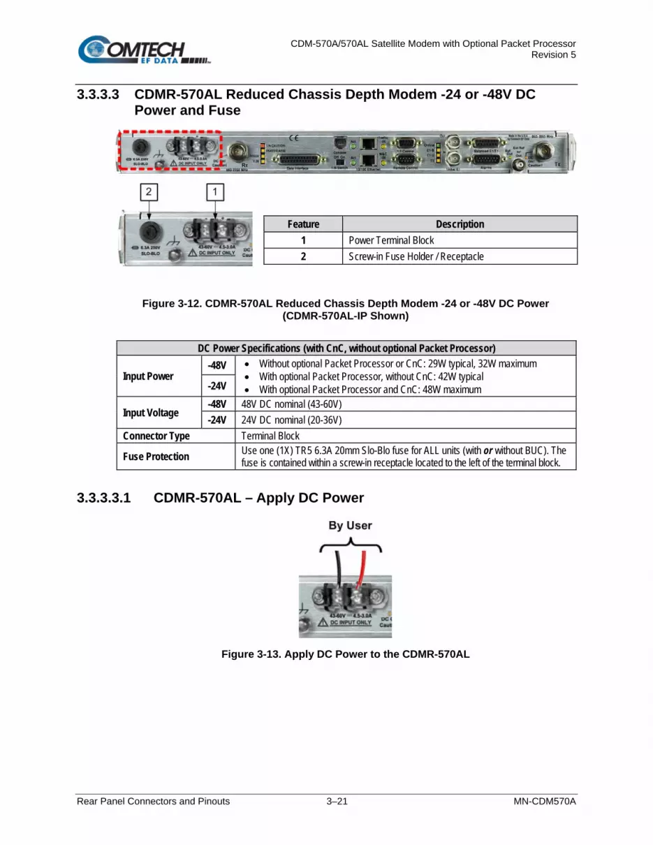
CDM-570A/570AL Satellite Modem with Optional Packet Processor Revision 5
Rear Panel Connectors and Pinouts 3–21 MN-CDM570A
3.3.3.3 CDMR-570AL Reduced Chassis Depth Modem -24 or -48V DC Power and Fuse
Figure 3-12. CDMR-570AL Reduced Chassis Depth Modem -24 or -48V DC Power (CDMR-570AL-IP Shown)
DC Power Specifications (with CnC, without optional Packet Processor)
Input Power -48V • Without optional Packet Processor or CnC: 29W typical, 32W maximum
• With optional Packet Processor, without CnC: 42W typical • With optional Packet Processor and CnC: 48W maximum -24V
Input Voltage -48V 48V DC nominal (43-60V) -24V 24V DC nominal (20-36V)
Connector Type Terminal Block
Fuse Protection Use one (1X) TR5 6.3A 20mm Slo-Blo fuse for ALL units (with or without BUC). The fuse is contained within a screw-in receptacle located to the left of the terminal block.
3.3.3.3.1 CDMR-570AL – Apply DC Power
Figure 3-13. Apply DC Power to the CDMR-570AL
Feature Description 1 Power Terminal Block 2 Screw-in Fuse Holder / Receptacle

CDM-570A/570AL Satellite Modem with Optional Packet Processor Revision 5
Rear Panel Connectors and Pinouts 3–22 MN-CDM570A
Do these steps (Figure 3-13):
WARNING! ENSURE THAT THE POWER IS REMOVED FROM THE DC CIRCUIT BEFORE PROCEEDING!
1. Use a screwdriver to affix the user-supplied DC power leads to their respective terminals.
Number 18 AWG minimum wires are recommended.
2. Connect the user-supplied DC power leads to the power source.
3. Energize the DC power source to turn the modem ON.
3.3.3.4 CDMR-570AL – Replace the DC Power Fuse
Figure 3-14. Replace the CDMR-570AL DC Power Fuse
The CDMR-570AL Reduced Chassis Depth Modem requires a single fuse that is contained within the screw-in receptacle that is located to the left of the terminal block. Do these steps (Figure 3-14):
WARNING! ENSURE THAT THE POWER IS REMOVED FROM THE DC CIRCUIT BEFORE PROCEEDING!
1. Unscrew the fuse holder from its receptacle.
2. Remove and replace the modem fuse. Use a TR5 6.3A fuse (with or without a BUC).
CAUTION – FOR CONTINUED OPERATOR SAFETY, ALWAYS REPLACE THE FUSE WITH THE CORRECT TYPE AND RATING.
3. Screw the fuse holder back into its receptacle.

CDM-570A/570AL Satellite Modem with Optional Packet Processor Revision 5
Updating Firmware 4–1 MN-CDM570A
Chapter 4. UPDATING FIRMWARE
4.1 Overview
1. MAKE SURE to operate the CDM-570A/570AL with its latest available firmware.
2. Ethernet IP Functionality is available only when the cdm-570A/570AL is equipped with the optional HIGH PERFORMANCE Packet Processor.
The CDM-570A/570AL Satellite Modem is factory-shipped with its latest version of operating firmware. If you need to update the modem firmware, you may download the update from the Comtech EF Data Web site (www.comtechefdata.com). You may also receive the firmware update archive file via e-mail from Comtech EF Data Product Support. You may perform the firmware update, without opening the CDM-570A/570AL, remotely over satellite (when the unit is equipped with the optional High Performance Packet Processor), or by directly connecting a user-supplied Microsoft Windows-based PC to the CDM-570A/570AL ‘Ethernet 10/100 | M&C 100’ port (for units without the optional Packet Processor) or the ‘Ethernet 10/100 | Traffic 100’ port (for units equipped with the optional Packet Processor). In this order:
• Download the firmware update archive file via the Internet, or acquire the file from Comtech EF Data Product Support, and transfer the files to the User PC.
• Use Windows Command-line to transfer, via File Transfer Protocol (FTP), the extracted firmware files from the User PC to the CDM-570A/570AL standby firmware image.
• Use the CDM-570A/570AL front panel or the CDM-570A HTTP Interface to configure the modem to operate using the updated firmware image.

CDM-570A/570AL Satellite Modem with Optional Packet Processor Revision 5
Updating Firmware 4–2 MN-CDM570A
4.1.1 About Firmware Files, Naming, Versions, and Archive Formats
Comtech EF Data’s Web site catalogues its firmware update files by product type (e.g., modem, converter, etc.) and specific model/optional configuration. For example, the Base Modem bulk firmware download hyperlink appears as F0020683*_V### (where ‘###’ indicates the firmware version number, and ‘*’ is the revision letter of that version). In addition to this Base Modem bulk firmware archive file, downloads are available for the CDM-570A/570AL’s optional Packet Processor. Firmware updates are available from Comtech EF Data as follows:
Web Hyperlink EXE/ZIP Filename Contains Image File ( where ‘ * ‘ denotes revision letter and ‘#.#.#’ or ‘#_#_#’ denotes FW Version number)
F0020683*_V### FW-0020683* FW-0020683*_#.#.#.bin Base modem firmware
F0020781*_V### FW-0020781* FW-0020781*_CDM570A_PaP_#_#_#.bin Packet Processor Module option without 3XDES Encryption. (3XDES Encryption is a future offering.)
The firmware download files are available from Comtech EF Data in two archive file formats: *.exe (self extracting) and *.zip (compressed). Some firewalls will not allow the downloading of *.exe files; in this case, download the *.zip file instead. If applicable, one version prior to the current release is also available for download.
For additional help with "zipped" file types, refer to the help files provided with the "PKZIP for Windows", "WinZip", or "ZipCentral" file archiving programs. “PKZIP for Command-line” is not supported due to file naming conventions.
To verify the correct firmware number, see Step 1(d) in Sect. 4.2.1 Getting Started: Prepare for the Firmware Download.

CDM-570A/570AL Satellite Modem with Optional Packet Processor Revision 5
Updating Firmware 4–3 MN-CDM570A
4.2 Ethernet FTP Upload Procedure
4.2.1 Getting Started: Prepare for the Firmware Download
Do these steps:
1. First, identify the CDM-570A/570AL firmware (number/revision letter/version number) and the assigned Ethernet Traffic IP Address.
User-supplied items needed:
• A Microsoft Windows-based PC, equipped with available serial and Ethernet ports; a
compatible Web browser (e.g., Internet Explorer); and a terminal emulator program (e.g., Tera Term, HyperTerminal, or PutTY).
• A 9-pin serial cable and a standard CAT5 Ethernet cable to connect the CDM-570A/ 570AL to the User PC.
a. Use the 9-pin serial cable to connect the CDM-570A/570AL ‘Remote Control’ port to a serial port on the User PC.
Use an Ethernet hub, switch, or a direct CAT5 Ethernet cable connection to connect the User PC to the CDM-570A/570AL ‘10/100 Ethernet | M&C 100’ port (for units without the optional Packet Processor) or the ‘10/100 Ethernet | Traffic 100’ port (for units equipped with the optional Packet Processor).
b. On the PC – Open the terminal emulator program.
Refer to your terminal emulator program HELP feature or user guide for operating and configuration instructions.
Configure the utility program serial port communication and terminal display operation:
• 38400 bps (Baud Rate) • 8 Data Bits • 1 Stop Bit • Parity=NO • Port Flow Control=NONE • Display New line Rx/Tx: CR • Local Echo=ON
c. On the CDM-570A/570AL – Turn on/connect the power source.
(LEFT) Standard CDM-570A/570AL AC Unit (RIGHT) Optional CDM-570A/570AL -48V DC Unit

CDM-570A/570AL Satellite Modem with Optional Packet Processor Revision 5
Updating Firmware 4–4 MN-CDM570A
d. Identify the firmware information and Ethernet Traffic (M&C) IP Address using one of the following methods:
• Chapter 6. FRONT PANEL OPERATION • Chapter 7. ETHERNET-BASED REMOTE PRODUCT
MANAGEMENT • Chapter 8. SERIAL-BASED REMOTE PRODUCT
MANAGEMENT
Using the CDM-570A/570AL Front Panel menus:
• Base Modem Firmware Info – Use the SELECT: UTIL Firmware Info Image#1 or Image#2 Bulk menu branches, as shown in this example:
Bulk#1: MM/DD/YY FW-0020683* #.#.#
• Packet Processor Firmware Info – Use the SELECT: UTIL Firmware
Info PaP menu branches, as shown in this example:
PaP: MM/DD/YY FW-0020781* #.#.#
• Ethernet IP Address – Use the CONFIG: Rem Ethernet Address
menu branch, as shown in this example:
Ether IP Address/Range: 192.168.001.011/24 ,

CDM-570A/570AL Satellite Modem with Optional Packet Processor Revision 5
Updating Firmware 4–5 MN-CDM570A
Using the CDM-570A HTTP Interface (via the User PC Web Browser – this assumes that you have already noted the Traffic/Management IP Address, which was previously required to open the CDM-570A HTTP Interface):
• Base Modem Firmware Info – Use the ‘Admin | Firmware | Modem’ page,
as shown in this example:
• Packet Processor Firmware Info – Use the ‘Admin | Firmware | Packet Processor’ page, as shown in this example:
• Ethernet IP Address – Use the ‘Configuration | LAN’ page to view the IP Address/Mask, as shown in this example:

CDM-570A/570AL Satellite Modem with Optional Packet Processor Revision 5
Updating Firmware 4–6 MN-CDM570A
Using the CDM-570A/570AL Serial Remote Interface (via the User PC / terminal emulator program):
• Firmware Info – Use the <0/SWR? (condensed) or <0/FRW? (detailed)
remote query.
• Ethernet Traffic IP Address – Use the <0/IPA? remote query.
2. Next, create a temporary folder (subdirectory) on the User PC for the firmware archive
download.
• Drive letter “c:” is used in these examples. Any valid, writable drive letter can be used.
• Typical for all tasks: Type the command without quotes, and then press Enter to execute.
There are several ways to create a temporary folder on a Windows-based PC:
a. Use the Windows Desktop to create and rename the temporary folder.
• Right-click anywhere on the desktop to open the popup submenu, and then
select New > Folder to create a temporary folder on the desktop.
• Right-click on the new folder and then select “Rename” from the popup submenu. Rename this folder to "temp" or some other convenient, unused name.

CDM-570A/570AL Satellite Modem with Optional Packet Processor Revision 5
Updating Firmware 4–7 MN-CDM570A
b. Use Windows Explorer to create and rename the temporary folder.
• Select File > New > Folder to create a temporary folder. This creates the new folder in the active folder.
• Right-click the “New Folder” folder name, and then rename this folder to "temp" or some other convenient, unused name:
c. Use the ‘Run’ and ‘Browse’ windows to create and rename the temporary folder.
• Select [Start] on the Windows taskbar, and then click the Run... icon. This opens the ‘Run’ window.
• Click [Browse] in the ‘Run’ window. This opens the ’Browse’ window.
• Click the Create New Folder icon in the ‘Browse’ window. This creates the new folder.
• Right-click the “New Folder” folder name, and then rename this folder to “temp” or some other convenient, unused name:
d. Use Windows Command-line to create the temporary folder.
• First, click [Start] on the Windows taskbar, and then click the Run... icon (or, depending on Windows OS versions prior to Windows 95, click the MS-DOS Prompt icon from the Main Menu).
• Next, open a Command-line window…
o For Windows 95 or Windows 98, type “command” (or, for any Windows OS versions later than Windows 98, type “cmd” or “command”):

CDM-570A/570AL Satellite Modem with Optional Packet Processor Revision 5
Updating Firmware 4–8 MN-CDM570A
o Alternately, from [Start], select All Programs > Accessories > Command Prompt.
o Finally, from the Command-line prompt (c:\>), type “mkdir temp” or “md temp” (mkdir and md stand for make directory), and then click [OK]:
There should now be a "temp" folder created and available for placement of the firmware file download.
4.2.2 Download and Extract the Firmware Update
Do these steps:
1. First, download the firmware update file from the Comtech EF Data Web site: a. Go online to www.comtechefdata.com.
b. On the Main page – under Support Information or the Support tab, select the Software Downloads hyperlink.
c. On the Software Downloads page – click Download Flash and Software Update Files.
d. On the Flash & Software Update Files page – select the (Select a Product Line) Satellite Modems hyperlink.
e. On the Satellite Modems product page – select the CDM-570A & CDM-570AL products hyperlink.
f. Select the appropriate firmware archive EXE or ZIP file download hyperlink.
Sect. 0 About Firmware Numbers, File Versions, and Formats
g. Download the archive file to the temporary folder.
• Once the EXE or ZIP hyperlink is selected, the ‘File Download’ window opens
and prompts selection of [Open] or [Save]:
o Click [Open] to turn over file extraction to the user-supplied utility program. Be sure to extract the firmware files to the “temp” folder created earlier.

CDM-570A/570AL Satellite Modem with Optional Packet Processor Revision 5
Updating Firmware 4–9 MN-CDM570A
o Click [Save] to open the ‘Save As’ window. Be sure to select and [Save] the archive *.exe or *.zip file to the “temp” folder created earlier.
o Otherwise, click [Cancel] to quit and exit the file download process.
2. Next, extract the firmware files from the archive file.
• (If not already done with File Download > [Open]) Extract the firmware files from the downloaded *.exe or *.zip archive file with the user-supplied utility program:
o Double-click on the archive file name, and then follow the prompts provided by
the user-supplied utility program. Extract, at a minimum, two files:
For the Base Modem firmware update (where ‘*’ is the revision letter and ‘#.#.#’ is the firmware version number):
FW-0020683*_#.#.#.bin – the Firmware Bulk image file, and CDM-570A_FW-0020683*_ReleaseNotes_v#.#.#.pdf – the Firmware
Release Notes PDF file.
For the Packet Processor firmware update (where ‘*’ is the revision letter and ‘#_#_#’ is the firmware version number):
FW-0020781*_CDM-570A_PaP_#_#_#.bin
CDM-570A_PaP_Release_Notes_v#.#.#.pdf (or a variation of this filename,
where ‘*’ is the revision letter and ‘#.#.#’ is the firmware version).
3. Confirm availability of the firmware files in the temporary folder. There are several ways you may view the contents of the temporary folder on a Windows-based PC:
a. From the Windows Desktop:
• Double-left-click the “temp” folder saved to the Windows Desktop.
• Use Windows Explorer to locate, and then double-left-click the “temp” folder.
• Use the Browse window ([Start] > ...Run > [Browse]) to locate, and then
double-click the “c:\temp” folder.
b. Using Command-line:
• Type “cd c:\temp” at the Command-line prompt to change to the temporary directory created earlier using Command-line.

CDM-570A/570AL Satellite Modem with Optional Packet Processor Revision 5
Updating Firmware 4–10 MN-CDM570A
• Type “dir” to list the files extracted to the temporary directory from the
downloaded archive file. The firmware files have been successfully downloaded and are now available for transfer to the CDM-570A/570AL.
4.2.3 Perform the Ethernet FTP Upload Procedure
Proceed with the firmware update procedure once the following items have been completed.
1. Verify the following items have been completed before doing the firmware update
procedure. • The CDM-570A/570AL is connected to a user-supplied, Windows-based PC,
and:
o The PC serial port is connected to the CDM-570A/570AL “Remote Control” port with a standard user serial cable.
o The PC Ethernet port is connected to the CDM-570A/570AL Packet Processor “10/100 Ethernet | Traffic 100” Ethernet port with a user-supplied hub, switch, or direct Ethernet cable connection.
o The PC is running a terminal emulation program (for operation of the CDM-570A/570AL’s Serial Interface) and a compatible Web browser (for operation of the CDM-570A HTTP Interface).
• The CDM-570A/570AL firmware and Ethernet Traffic/Management IP Address
have been noted using either the CDM-570A/570AL’s Serial Interface or the CDM-570A HTTP Interface ‘Admin | Firmware | Base Modem’ / ‘Admin | Firmware | Packet Processor’ and ‘Configuration | LAN’ pages, respectively.
• The latest firmware files have been downloaded or otherwise received from Comtech EF Data and are available on the User PC in an accessible temporary folder.
2. Modem redundancy features must be disabled prior to update.
3. When updating firmware on modems equipped with the Packet Processor, you
must upload both the Base Modem and Packet Processor firmware files, and select the firmware slots prior to rebooting the modem.
Before you can transfer the firmware files from the User PC to the CDM-570A/570AL, you must first use Command-line to “ping” the modem to confirm proper connection and communication between the User PC and the modem:
• Type “ping xxx.xxx.xxx.xxx” at the Command-line prompt (where ‘xxx.xxx.xxx.xxx’ is the unit Ethernet Traffic/Management IP Address). The response should confirm whether the unit is properly connected and communicating.
You may proceed once you have verified User PC-to-Modem communications.

CDM-570A/570AL Satellite Modem with Optional Packet Processor Revision 5
Updating Firmware 4–11 MN-CDM570A
Do these steps:
1. Use Command-line to transfer (FTP) the files from the User PC to the CDM-570A/570AL:
a. Type "ftp xxx.xxx.xxx.xxx" (where ‘xxx.xxx.xxx.xxx’ is the CDM-570A/570AL Ethernet Traffic/Management IP Address).
b. The Admin User Name and Password when prompted. The default User Name and Password is “comtech”.
c. Type “bin” to set the binary transfer mode.
d. Type “prompt” and then “hash” to facilitate the file upload.
• To begin the file transfer, transfer file FW-0020683*_#.#.#.bin (where ‘*’ is the revision letter and ‘#.#.#’ is the version number):
o If the Packet Processor is not installed:
Type "put FW-0020683*_#.#.#.bin a:\bulk.bin:" to begin the file transfers – the destination “a:\bulk.bin” must be all lower case.
o If the Packet Processor is installed:
Type “put FW-0020683*_#.#.#.bin” (make sure you do not type the destination “a:\bulk.bin” as was done for the previous upload option).
For either option, it will take several minutes to transfer the file and update the firmware image.
e. Once the file transfers, Command-line displays the upload result, similar to:
ftp: XXXXXXX bytes sent in XX.XXSeconds XXX.XXXKbytes/sec.
In the event you receive the “Connection closed by remote host.” message, wait another minute before continuing. The firmware upload sometimes takes longer than the FTP client allows.
f. Once the FTP upload is complete, as the upgrade process continues, the modem
front panel displays:
UPGRADING FIRMWARE Please Wait...
The process sequences through several blocks – this will take several minutes. Once the update process is complete, the modem returns you to the previously active menu screen.
g. Type "bye" to terminate the FTP session, and then close the Command-line window.
2. Use the modem front panel menus, the CDM-570A HTTP Interface ‘Admin | Firmware | Modem’ page, or issue the Serial Remote Interface <0/SWR? or <0/FRW? query, as shown previously, to verify that the PC-to-Modem FTP file transfer was successful.

CDM-570A/570AL Satellite Modem with Optional Packet Processor Revision 5
Updating Firmware 4–12 MN-CDM570A
If you are a Base Modem user, the CDM-570A/570AL is now operating with its latest firmware and you may skip to Step 6. However, if you are running a CDM-570A/570AL with the optional Packet Processor installed, do NOT reboot at this time – once you have uploaded the Base Modem firmware you must proceed to the next step (Step 3) to upload the Packet Processor firmware.
3. Before you can upload the Packet Processor firmware, you must first specify which
firmware slot will receive the firmware update file transfer.
• On the CDM-570A HTTP Interface ‘Admin | Firmware | Packet Processor’ page, use the ‘Upgrade To’ drop-down list to select Latest, Image 1, or Image 2.
• Click [Submit] to save.
Proceed once you have specified the file transfer destination slot. 4. Use Command-line to initiate the FTP session with the modem.
a. Type "ftp xxx.xxx.xxx.xxx" (where ‘xxx.xxx.xxx.xxx’ is the CDM-570A/570AL
Ethernet Traffic/Management IP Address).
b. Enter the Admin User Name and Password to complete login.
c. Type "bin" to set the binary transfer mode.
d. Type "prompt", and then type "hash" to facilitate the file upload.
e. Type “put FW-0020781*_CDM-570A_PaP_#_#_#.bin” to begin the file upload. It will take several minutes to transfer and write the files to flash memory. Once the file transfers, Command-line displays the upload result, similar to:
200 Port OK 150 Opening data connection 226 Packet Processor upgrade complete – Safe to reboot. ftp: XXXXXXXX bytes sent in X.XXSeconds XXXX.XXKbytes/sec.
f. Once the FTP upload is complete, as the upgrade process continues, the modem
front panel displays:
IP OPTION CARD UPGRADING ..PLEASE WAIT
g. The process sequences through several blocks – this will take several minutes. Once
the update process is complete, the modem front panel displays:
Upgrade finished Press CLEAR to continue.
Press the modem front panel CLEAR key as prompted.
h. Type "bye" to terminate the FTP session, and then close the Command-line window.

CDM-570A/570AL Satellite Modem with Optional Packet Processor Revision 5
Updating Firmware 4–13 MN-CDM570A
5. Use the modem front panel menus or the CDM-570A HTTP Interface ‘Admin | Firmware
| Packet Processor’ page to verify that the PC-to-Modem Packet Processor firmware FTP file transfer was successful.
6. Use the modem front panel menus and/or the CDM-570A HTTP Interface ‘Admin |
Firmware | Modem’ page and, as applicable, the ‘Admin | Firmware | Packet Processor’ page to select the desired firmware images to boot from:
a. Using the modem front panel menus:
• First, to select the desired Boot Image, make sure that you are operating in LOCAL mode (CONFIG: Remote Local).
• For the Base Modem firmware image, go to the SELECT: Utilities Firmware Select menu branch and use the arrow keys to select the Next Reboot Image as 1 or 2. Press the front panel ENTER key when done.
b. Using the CDM-570A HTTP Interface:
• For the Base Modem firmware, go to the ‘Admin | Firmware | Modem’ page. Use the ‘Next Reboot, will use’ drop-down list to select Latest, Image#1 or Image#2. Click [Submit] to save.
• For the Packet Processor firmware, go to the ‘Admin | Firmware | Packet Processor’ page. Use the ‘Boot From’ drop-down list to select Latest, Image#1 or Image#2. Click [Submit] to save.
7. Reboot the CDM-570A/570AL. You may perform a ‘soft reboot’ or a ‘hard reboot’ as
follows:
• For a soft reboot, use the CDM-570A HTTP Interface ‘Admin| Reboot’ page. Click [Reboot Now]. Both the web page and the modem front panel will display messages similar to “Rebooting, Please wait...” as reboot commences.
• For a hard reboot, from CDM-570A/570AL rear panel, turn off or otherwise disconnect, and then turn on/reconnect the power source to execute reboot of the modem.
The system reboot is complete once the modem front panel displays the top-level “splash” screen:
Comtech CDM-570AL Modem Firmware Version: #.#.#
Log in to a new Web session at this time. The CDM-570A HTTP Interface ‘Home’ page will serve to verify that the new firmware version is active, as shown in this example:

CDM-570A/570AL Satellite Modem with Optional Packet Processor Revision 5
Updating Firmware 4–14 MN-CDM570A
The CDM-570A/570AL is now operating with its latest firmware. The firmware update process is now complete.

CDM-570A/570AL Satellite Modem with Optional Packet Processor Revision 5
FAST Activation Procedure 5–1 MN-CDM570A
Chapter 5. FAST ACTIVATION PROCEDURE
5.1 Overview
The CDM-570A/570AL Satellite Modem incorporates a number of optional features. In order to permit a lower initial cost, you may purchase the unit enabled with only the desired features. If you wish to upgrade the functionality of a unit at a later date, Comtech EF Data provides Fully Accessible System Topology (FAST), which permits the purchase and activation of options through special authorization codes. You may contact Comtech EF Data Product Support to purchase these unique, register-specific Fast Access Codes, and then load these codes into the unit using either the front panel keypad or the CDM-570A HTTP (Web Server) Interface.
See Table 1-1 in Chapter 1. INTRODUCTION or Sect. 6.3.7.7.2 in Chapter 6. FRONT PANEL OPERATION for listings of the available FAST and FAST-accessible hardware options.
FAST System Theory: FAST facilitates on-site upgrade of the operating feature set without removing a unit from the setup. FAST technology allows you to order a unit precisely tailored for the initial application. When your service requirements change, you can upgrade the topology of the unit to meet these requirements within minutes. This accelerated upgrade is possible because of FAST’s extensive use of the programmable logic devices incorporated into Comtech EF Data products. FAST Implementation: Comtech EF Data implements the FAST system in the modem at the factory. All FAST features are available through the basic platform unit at the time of order. You have the ability to “demo” all FAST features on a trial basis, for up to 30 days, through the Demo Mode that is available via the CDM-570A/570AL front panel or the CDM-570A HTTP Interface. FAST allows immediate activation of available options, after confirmation by Comtech EF Data, through the CDM-570A HTTP Interface. FAST Accessible Options: You may order hardware options for installation either at the factory, or you can install and activate them on-site. The FAST Access Code that you purchase from Comtech EF Data enables configuration of the available hardware. The base CDM-570A/570AL unit is equipped with Viterbi codec. It offers BPSK, QPSK, and OQPSK modulation types, and data rates from 2.4 kbps to 512 kbps (FAST-upgradable to 10.24 Mbps). While it is limited to Closed Network operation, it also includes EDMAC and AUPC.

CDM-570A/570AL Satellite Modem with Optional Packet Processor Revision 5
FAST Activation Procedure 5–2 MN-CDM570A
5.2 FAST Activation Procedure
5.2.1 FAST Activation via the Modem Front Panel
See Chapter 6. FRONT PANEL OPERATION for complete information about using this interface.
Do these steps:
1. Before you contact Comtech EF Data Product Support to order FAST feature upgrades, you must retrieve the modem’s motherboard serial number:
a. From the front panel main menu, SELECT: FAST, and then press ENTER.
The modem’s 9-digit “Baseboard S/N” is displayed on the bottom line, to the left, as shown in this example:
FAST:Cnfg View (HW0.XXX) MainBoard S/N: 123456789
b. Write down the Serial Number: ______________________________________
The MainBoard S/N (Serial Number) is a unique identifier for the FAST upgrade process and is different from the Chassis Serial Number.
2. View the currently installed FAST features:
a. From the front panel main menu (shown in Step 1A), use the arrow keys to
select View, and then press ENTER. b. Use the arrow keys to scroll through the list of available FAST options. Options
are identified as ‘Y’ (Installed) or ‘N’ (not installed) as shown in the following example:
View Options: 06 ( ) TPC 0.95 Card Present Y
Any option labeled “N” may be purchased as a FAST upgrade.
3. Contact Comtech EF Data Product Support to order features:
a. Provide the unit Serial Number to the Product Support representative.
b. Identify and purchase the desired FAST option(s).
c. Obtain the invoice, the register-specific 20-digit FAST Access Code(s), and the
FAST option activation instructions.

CDM-570A/570AL Satellite Modem with Optional Packet Processor Revision 5
FAST Activation Procedure 5–3 MN-CDM570A
When a FAST Access Code is obtained from Comtech EF Data, it will be for a specific option register. The FAST options are linked to two option registers:
• Register1 is for Data Rate, L-Band, and Framing options.
• Register2 is for Modulation type and Packet Processor options.
4. Activate your purchased FAST features.
a. You must make sure you are active in the proper register. From the SELECT: FAST
Cnfg submenu, use the arrow keys to select Edit Code. Press ENTER.
Fast Configuration: Edit Code Demo Mode
Use the arrow keys to toggle Register 1 or 2.
Fast: Set register 2 00000000000000000000 ENT
b. Next, use the arrow keys to jump to the bottom line. There, use the
arrow keys to carefully enter each digit for your register-specific 20-character FAST Access Code. Press ENTER. The modem responds with “Configured Successfully” if the FAST upgrade is accepted; the modem then resets to its newly-incorporated default configuration. However, if an invalid code is entered, the following message displays:
Fast Code Rejected! (ENTER or CLEAR)
Repeat the FAST Access Code entry procedure. Should the code entry error persist, contact Comtech EF Data Product Support for further assistance.

CDM-570A/570AL Satellite Modem with Optional Packet Processor Revision 5
FAST Activation Procedure 5–4 MN-CDM570A
5.2.2 FAST Activation via the CDM-570A HTTP Interface
See Chapter 7. ETHERNET-BASED REMOTE PRODUCT MANAGEMENT for complete information about using this interface.
Figure 5-1. CDM-570A HTTP Interface – Admin | FAST Page
Use the CDM-570A HTTP Interface ‘Admin | FAST’ page (Figure 5-1) for complete management of FAST Features. This page provides FAST code entry/option activation control, and srollable list boxes that display availability and activation status for all FAST options. Do these steps:
1. Before you contact Comtech EF Data Product Support to order FAST feature upgrades, you must retrieve the modem’s motherboard serial number. Use the front panel SELECT: FAST menu, as explained in Sect. 5.2.1 Step 1, to obtain and record the modem’s motherboard serial number.
Write down the Serial Number: ______________________________________
2. Use the ‘Admin | FAST’ page to view the currently installed or available FAST features. Any options that appear in the scrollable Options – Not Installed list box may be purchased as a FAST upgrade.

CDM-570A/570AL Satellite Modem with Optional Packet Processor Revision 5
FAST Activation Procedure 5–5 MN-CDM570A
3. Contact Comtech EF Data Product Support to order features:
a. Provide the unit Serial Number to the Product Support representative.
b. Identify and purchase the desired FAST option(s).
c. Obtain the invoice, the register-specific 20-digit FAST Access Code(s), and the FAST option activation instructions.
When a FAST Access Code is obtained from Comtech EF Data, it will be for a specific option register. The FAST options are linked to two option registers:
• Register1 is for Data Rate, L-Band, and Framing options.
• Register2 is for Modulation type and Packet Processor options.
4. Activate your purchased FAST features.
a. In the FAST code section of the ‘Admin | FAST’ page, carefully enter the register-
specific 20-character FAST Access Code into its designated text box (Register 1 or Register 2) (each FAST Access Code is submitted separately). Click [Submit].
b. The message “Configured Successfully” appears at the top of the FAST code section if the FAST upgrade is accepted; the modem then resets to its newly-incorporated default configuration. However, if an invalid code is entered, either of the following messages may appear instead:
Repeat the FAST Access Code entry procedure. Should the code entry error persist, contact Comtech EF Data Product Support for further assistance.

CDM-570A/570AL Satellite Modem with Optional Packet Processor Revision 5
FAST Activation Procedure 5–6 MN-CDM570A
Notes:

CDM-570A/570AL Satellite Modem with Optional Packet Processor Revision 5
Front Panel Operation 6–1 MN-CDM570A
Chapter 6. FRONT PANEL OPERATION
6.1 Overview
Figure 6-1 identifies the key features of the CDM-570AL/CDMR-570AL (L-Band) or CDM-570A (70/140 MHz) Satellite Modem front panels. The front panel features (from left) eight Light-Emitting Diode (LED) Indicators, a six-button keypad, and a Vacuum Fluorescent Display (VFD). The LED Indicators, keypad, and VFD allow you to fully control and monitor the CDM-570A/ 570AL’s operation. Refer to the pertinent chapter section for detailed information about the function and behavior of these features.
Figure 6-1. Modem Front Panel Operation Features (CDM-570A shown)
1 LED Indicators
The LEDs show a summary status of modem operation. See Sect. 6.1.1.
2 Keypad The keypad has six individual keys. The keys have a positive ‘click’ action that gives tactile feedback. Use the keypad to enter data. See Sect. 6.1.2.
3 VFD
The VFD shows data, menus, prompts and messages. The VFD is an active display with adjustable brightness. It shows two lines of 40 characters each. Nested menus show all available options and prompts that guide you in carrying out required actions. See Sect. 6.1.3.

CDM-570A/570AL Satellite Modem with Optional Packet Processor Revision 5
Front Panel Operation 6–2 MN-CDM570A
6.1.1 LED Indicators
In general, the alarm relay state reflects the state of the Front Panel LEDs. For example, if the Unit Status LED is red, the Unit Alarm relay is active. This does not apply to the Transmit Traffic relay, which activates only if a Tx Traffic Fault exists – it does not reflect the state of the Tx carrier.
FRONT PANEL LED INDICATORS FUNCTIONAL DESCRIPTION
LED Condition Description
UNIT STATUS Red A Unit Fault exists (Example: PSU fault) Orange No Unit Faults, but a Traffic Fault, or ODU (BUC or LNB) fault exists Green No Unit Faults, or Traffic Faults
Tx TRAFFIC Green No Tx Traffic Faults Off A Tx Traffic fault exists OR the Tx Carrier is in OFF state
Rx TRAFFIC Green No Rx Traffic Faults (demod and Viterbi decoder are locked, everything is
OK)
Off An Rx Traffic fault exists (the demod may still be OK – check the fault status of the modem from the Monitor menu).
ONLINE Green The modem is On Line, and carrying traffic
Off The modem is Off Line (standby) - forced by externally connected 1:1 or 1:N redundancy system
STORED EVENT Orange There is a Stored Event in the log, which can be viewed from the front panel,
or retrieved via the remote control interface Off There are no Stored Events
REMOTE
Orange The modem is in Remote Mode - local monitoring is possible, but no local control
Off The modem is in Local Mode - remote monitoring is possible, but no remote control
Flashing ODU FSK control is enabled and there is a communications fault
EDMAC MODE Orange Framing on, EDMAC on, and unit defined as Slave - local monitoring is
possible, but no local control
Off The modem is either in Transparent mode (no framing), or the framing is selected but in AUPC-only mode or EDMAC Master configuration
TEST MODE Orange A Test Mode is selected (Example: IF Loopback) Off There is no Test Mode currently selected

CDM-570A/570AL Satellite Modem with Optional Packet Processor Revision 5
Front Panel Operation 6–3 MN-CDM570A
6.1.2 Keypad
The keypad has an auto-repeat feature. When you hold down a key for more than 1 second, the key action repeats at the rate of 15 keystrokes per second. This is particularly useful when editing numeric fields with many numbers, such as frequency or data rate.
ENTER key – You may use the ENTER key as follows:
• From the opening screen, press ENTER once to go to the SELECT: (main) menu.
• Press ENTER to access the nested menu for a selected function, or to execute (save) a
configuration change. CLEAR key – You may use the CLEAR key as follows:
• From the opening screen, press CLEAR once to go to the SELECT: (main) menu.
• Press CLEAR to back out of a selection or to cancel a configuration change that you have not yet executed using ENTER.
• Press CLEAR to return to the previous menu screen.
• Press CLEAR repeatedly to return to the opening screen. Left, Right keys – On any menu screen, press the left or right key to move among available selections, or to move the cursor position Up, Down keys – Press the up or down key to scroll through settings that are available at the cursor position. You may also use the up or down key to change the alphanumeric selection at the cursor position. Alphanumeric selections typically include numbers for configuration data and letters for text strings.
6.1.3 Vacuum Fluorescent Display (VFD)
The modem features a VFD, which is an active display showing two lines of 24 characters each. It produces a blue light with user-adjustable brightness. Compared to a LCD, it has greatly superior viewing characteristics and does not
suffer problems of viewing angle or contrast. On most menu screens, a flashing solid block cursor blinks at a once-per-second rate. This indicates the currently selected item, digit, or field. Where it might obscure the item under edit (e.g., a numeric field), the solid block cursor automatically changes to an underline cursor.

CDM-570A/570AL Satellite Modem with Optional Packet Processor Revision 5
Front Panel Operation 6–4 MN-CDM570A
6.1.3.1 Screen Saver
----------- Unit Label -- any key.... Demod not lock If you were to leave the operating unit displaying the same screen for weeks at a time, the VFD could become ‘burnt’ with this image. To prevent such burn-in, a screen saver feature activates after 1 hour. The screen saver message scrolls from right to left across the screen, and then wraps around. The user-configurable unit label, or Circuit ID, displays on the VFD top line, while the bottom line displays the demod lock state (i.e., ‘Demod not locked’ or the circuit Eb/N0 value if the demod is locked) and the prompt ‘Press any key...’ Press any key to return to the previous screen.
6.1.3.2 Opening Screen
The opening screen displays once you first apply power to the modem. Press CLEAR from any other nested menu until this screen appears. Press any other key to advance to the Select: (Main) menu screen. When you disable the Internal Reference warm-up delay feature (see Section 6.3.7.3.2), depending on the modem type, one of the following screens displays: CDM/R-570AL(L-Band) unit: CDM-570A (70/140 MHz) unit:
If, however, you enable the Internal Reference warm-up delay feature, one of the following screens displays: CDM/R-570AL(L-Band) unit: CDM-570A (70/140 MHz) unit:
The bottom line counts down, in seconds, the time remaining for the warm-up period. During this period, the modem deliberately mutes the Tx Carrier. At the end of the warm-up period, the bottom line reverts to the ‘normal’ opening screen display (i.e., it displays the modem Firmware version), and the modem ENTERs into its normal operational state. X
Bypass (override) the warm-up period at any time by pressing the CLEAR key.
Comtech CDM-570A Modem Ref Warming-up: 045
Comtech CDM/R-570ALModem Ref Warming-up: 045
Comtech CDM-570A Modem Firmware Version #.#.#
Comtech CDM/R-570AL Modem Firmware Version #.#.#

CDM-570A/570AL Satellite Modem with Optional Packet Processor Revision 5
Front Panel Operation 6–5 MN-CDM570A
6.2 Compatible Mode Operation (CDM-570A/570AL vs. CDM-570/570L)
Certain features of the CDM-570A/570AL Satellite Modem are not backward compatible with the CDM-570 (70/140 MHz) and CDM/R-570L (L-Band) Satellite Modems. The CDM-570A/570AL provides a “compatibility mode” that is intended for use only in an existing network of CDM-570/570Ls. CDM/R-570AL (L-Band) unit: CDM-570A (70/140 MHz) unit:
To set up your CDM-570A/570AL Satellite Modem in CDM-570 Compatible Mode: From the SELECT: UTIL menu branch, use the arrow keys to select CMO. Press ENTER. Then, use the arrow keys once again to set Compatible Mode as CDM-570. Press ENTER.
Be sure to take the following operational conditions into consideration when using CDM-570 Compatible Mode operation:
1. Use of CDM-570 Compatible Mode is required ONLY when the CDM-570A/570AL is a
component in an existing network of CDM-570/570L modems. Otherwise, this mode should NOT be used, as it will make new (CDM-570A/570AL) features unavailable.
2. Certain features become disabled and unavailable, and the cursor skips over that selection, while the modem is set to CDM-570 Compatible Mode. For further information, see: • CONFIG: Tx → Pwr (Output Power Level Mode) → CnC-APC (Section F.6) • CONFIG: Tx → Inv → Clock (Tx Clock Invert) (Section 6.3.2.3.11) • CONFIG: Rx → Inv → Clock (Rx Clock Invert) (Section 6.3.2.4.10) • CONFIG: CnC (Carrier-in-Carrier) (Section 6.3.2.10) • SELECT: TEST → BERT (Section 6.3.4.2)
3. Certain feature options becomes disabled and unavailable, and the cursor skips over that option, while the modem is set to CDM-570 Compatible Mode. For further information, see: • CONFIG: Tx → FEC (VFEC, VF2L, VF2S, ULL) (Section 6.3.2.3.1) • CONFIG: Tx → α (Tx Alpha Filter Rolloff) (Section 0) • CONFIG: Rx → FEC (VFEC, VF2L, VF2S, ULL) (Section 6.3.2.4.1) • CONFIG: Rx → α (Rx Alpha Filter Rolloff) (Section6.3.2.4.13)
4. Certain operational settings will reset to a default or fallback value when the modem is set to CDM-570 Compatible Mode. You must be sure to reconfigure the modem to your previously configured settings. For further information, see: • (CDM/R-570AL ONLY, above 2000 MHz) CONFIG: Tx → Frq (Section 6.3.2.3.5) • (CDM/R-570AL ONLY, above 2000 MHz) CONFIG: Rx → Frq (Section. 6.3.2.4.5) • CONFIG: Ref (Section 6.3.2.8)
Compatible Mode: CDM-570 CDM-570A ( ,ENT)
UTIL: Buf Clock Ref CMO ID 1:1 VFD Firmware FAST

CDM-570A/570AL Satellite Modem with Optional Packet Processor Revision 5
Front Panel Operation 6–6 MN-CDM570A
6.3 Front Panel Operation
Figure 6-2 shows the hierarchal structure of the CDM-570A/570AL principle menu tree from the SELECT: menu on down.
Figure 6-2. CDM-570A/570AL Principle Menu Tree

CDM-570A/570AL Satellite Modem with Optional Packet Processor Revision 5
Front Panel Operation 6–7 MN-CDM570A
6.3.1 SELECT: (Main) Menu
CDM-570AL/CDMR-570AL: CDM-570A: SELECT: Config Monitor Test Info Save/Load Util
SELECT: Config Test Info Monitor Save/Ld Util ODU
Press ENTER or CLEAR to immediately access the SELECT: menu screen from the opening screen. From any nested menu, press CLEAR repeatedly until this screen reappears. The table that follows identifies each menu branch available from the SELECT: menu and its content section in this chapter. Functionality of each menu sub branch is further explained in the subsequent chapter sections. Note that the selection order and naming differs between the two unit interfaces.
Menu Branch Sect. Function
Main 6.3.1 (Main) Menu
Config 6.3.2 (Configuration) Used to fully configure the modem.
Monitor 0 Used to monitor the current status of the modem and to view the log of stored events for the modem.
Test 6.3.4 Used to configure the modem into one of several test modes, and to configure/monitor the Bit Error Rate Tester (BERT).
Info 6.3.5 (Information) Used to view information on the modem, without having to access configuration screens.
Save/Load (CDM-570AL) Save/Ld (CDM-570A) 6.3.6 Used to save (store) or load (retrieve) up to 10 different modem
configurations.
Util 6.3.7 (Utility) Used to perform miscellaneous functions, such as setting the real-time clock, adjusting the display brightness, etc.
ODU (CDM-570A, summary only)
0
(Outdoor Unit) For the CDM-570A only – Used to monitor and control a Comtech EF Data RF Transceiver (CSAT-5060 or KST-2000A/B), if connected. See Chapter 10. CDM-570A/570AL ODU (TRANSCEIVER, BUC, LNB) M&C OPERATIONS for full details.
The actual choices that display in the submenus may vary according to which FAST options have been enabled. When a menu selection is dependent on the enabling of a FAST option, this is indicated in the descriptive text.
Use the arrow keys to select a menu branch available from the top-level SELECT: menu. Press ENTER to continue.

CDM-570A/570AL Satellite Modem with Optional Packet Processor Revision 5
Front Panel Operation 6–8 MN-CDM570A
6.3.2 (SELECT:) Config (Configuration) Menus
CDM-570AL/CDMR-570AL: CDM-570A: CONFIG: Rem All Tx Rx CEx Frame TI Ref Msk CnC ODU
CONFIG:Rem All Tx Rx CEx Frame TI Ref Msk CnC
Use the arrow keys to select a submenu choice available from the SELECT: Config menu branch. Press ENTER.
Submenu Sect. Function
Rem 6.3.2.1 (Remote Control) Used to define whether the modem is being controlled locally, or remotely.
All 6.3.2.2 This submenu is highly recommended for new users, as it leads you through the complete modem configuration process on a step-by-step basis.
Tx 6.3.2.3 (Transmit) Used to define, on a per-parameter basis, the Tx configuration of the unit. These menu submenu branches would be used if you wished to change, for example, just the Tx Frequency..
Rx 6.3.2.4 (Receive) Used to define, on a per-parameter basis, the Rx configuration of the unit. These menu submenu branches would be used if you wished to change, for example, just the Rx data rate.
CEx 6.3.2.5 (Clock Extension) Used to define the G.703 Clock Extension interface.
Frame 6.3.2.6 (Framing) Used to define operation in a transparent mode (no framing) or in a framed mode. In the framed mode, an overhead of 5% or 1.6% is added to the rate transmitted over the satellite so that M&C and AUPC information may be passed to the distant end.
TI 6.3.2.7
(Data Traffic Interface) Used to define RS422, IP, RS232, V.35, G.703, or IP-ACM data traffic interfaces.
IP, VersaFEC ACM (IP-ACM), and VersaFEC-2 ACM (V2-ACM) are available only when the optional High-Performance Packet Processor is installed.
Ref 6.3.2.8 (Reference) Used to define whether the modem should use its own internal 10MHz reference, or phase lock to an externally applied reference and, if so, at what frequency.
Msk 6.3.2.9 (Alarm Mask) Used to mask certain alarms that may cause operational problems.
CnC 6.3.2.10 Used to select DoubleTalk Carrier-in-Carrier (CnC) options.
Appendix G. DOUBLETALK CARRIER-IN-CARRIER (CNC)
ODU (CDM-570AL, summary only)
6.3.2.11
(Outdoor Unit) For the CDM/R-570AL only – Used to configure a BUC (Block Up Converter) or LNB (Low-Noise Block Down Converter), if connected.
Chapter 10. CDM-570A/570AL ODU (TRANSCEIVER, BUC, LNB) M&C OPERATIONS

CDM-570A/570AL Satellite Modem with Optional Packet Processor Revision 5
Front Panel Operation 6–9 MN-CDM570A
6.3.2.1 CONFIG: Rem (Remote Control)
Remote Control: Local Serial Ethernet( ,ENT) Use the arrow keys to select a parameter. Press ENTER.
When you select Local mode, this disables remote control, although remote monitoring is still possible.
6.3.2.1.1 (CONFIG: Remote Control) Serial
In Serial mode, in addition to enabling Serial M&C, this mode also allows Telnet connection, which enables Telnet M&C for modems configured for redundant operation.
When you select Serial from the Remote Control submenu and you do not define the modem as an EDMAC SLAVE, the modem displays the following menu: Serial Config: Interface Baudrate ( ,ENTER)
(CONFIG: Remote Control) Serial: Interface
M&C Bus Interface: RS232 RS485-2W RS485-4W ( ) Use the arrow keys to select a parameter. Press ENTER.
(CONFIG: Remote Control) Serial: Interface RS232
The modem displays this read-only screen when you select RS232: In RS232 Mode the Bus Address is fixed at 0000
(CONFIG: Remote Control) Serial: Interface RS485-2W or -4W
The modem prompts you to edit the bus address when you select either RS485 mode: RS485 Bus Address: 0245 ( , ,ENTER)
The valid range of addresses is from 0001 to 9999. To edit the address, use the arrow keys to select a digit, and then use the arrow keys to change that digit. Press ENTER.

CDM-570A/570AL Satellite Modem with Optional Packet Processor Revision 5
Front Panel Operation 6–10 MN-CDM570A
(CONFIG: Remote Control) Serial: Baudrate
Local M&C Bus Baud Rate: 19200 Baud ( ,ENTER) Valid baud rates (in bps) are 2400, 4800, 9600, 19200, 38400, or 57600. Use the arrow keys to select the baud rate of the remote M&C bus that is connected locally to the User PC, bps. Press ENTER.
The asynchronous character format is FIXED at 8 data bits, 1 stop bit, no parity (8-N-1).
6.3.2.1.2 (CONFIG:) Remote Control: Ethernet
In Ethernet mode, Serial monitoring is allowed; however, Serial control is not allowed except for use of the LRS (Local/Remote Status) and FPL (Front Panel Lockout) commands and queries.
Ethernet Config: Gateway Address MAC SNMP ( ) Use the arrow keys to select a parameter. Press ENTER.
(CONFIG: Remote Control) Ethernet: Gateway
Ethernet IP Gateway: 192.168.001.002 ( , ) To edit the modem ‘M&C’ Ethernet port IP Gateway Address, use the arrow keys to select a digit, and then use the arrow keys to change that digit. Press ENTER.
(CONFIG: Remote Control) Ethernet: Address
Ether IP Address/Range: 192.168.001.002/24( , ) To edit the modem ‘M&C’ Ethernet port management and data traffic IP Address and Range, use the arrow keys to select a digit, and then use the arrow keys to change that digit. Press ENTER.
(CONFIG: Remote Control) Ethernet: MAC
M&C Port MAC Address: 00-06-B0-00-01-06 (ENTER) This read-only screen displays the unit MAC Address. Press ENTER or CLEAR to exit this menu.

CDM-570A/570AL Satellite Modem with Optional Packet Processor Revision 5
Front Panel Operation 6–11 MN-CDM570A
(CONFIG: Remote Control) Ethernet: SNMP
SNMP: Communities Traps ( , ENT) Use the arrow keys to select a parameter. Press ENTER.
(CONFIG: Remote Control) Ethernet: SNMP Communities
SNMP Communities: Read Write ( , ENT)
Use the arrow keys to select a parameter. Press ENTER.
(CONFIG: Remote Control) Ethernet: SNMP Communities Read
Read Community: ( , ) public
(CONFIG: Remote Control) Ethernet: SNMP Communities Write
Write Community: ( , ) private To edit the SNMP Read or Write Community strings, use the arrow keys to select a character to edit. Then, use the arrow keys to edit that character. Note that only the first 20 characters on the bottom line are available. All printable ASCII characters are available with the exception of the backslash ‘/’ (ASCII code 92) and tilde ‘~’ (ASCII code 126). Press ENTER once you compose the string – the modem removes all trailing spaces from the string upon entry.
(CONFIG: Remote Control) Ethernet: SNMP Traps
Traps: Community Version IP Addr#1 IP Addr#2 ( ) Use the arrow keys to select a parameter. Press ENTER.
(CONFIG: Remote Control) Ethernet: SNMP Traps Community
Trap Community: ( , ) comtech

CDM-570A/570AL Satellite Modem with Optional Packet Processor Revision 5
Front Panel Operation 6–12 MN-CDM570A
To edit the SNMP Trap Read or Write Community strings, use the arrow keys to select a character to edit. Then, use the arrow keys to edit that character. Note that only the first 20 characters on the bottom line are available. All printable ASCII characters are available with the exception of the backslash ‘/’ (ASCII code 92) and tilde ‘~’ (ASCII code 126). Press ENTER once you compose the string – the modem removes all trailing spaces from the string upon entry.
(CONFIG: Remote Control) Ethernet: SNMP Traps Version
Trap Version: SNMPv1 SNMPv2 ( ,ENT) Use the arrow keys to select the SNMP Trap Version as SNMPv1 or SNMPv2. Press ENTER.
(CONFIG: Remote Control) Ethernet: SNMP Traps IP Addr#1 or Addr#2
Trap IP #X: ( , ) 000.000.000.000 Where ‘X’ indicates Trap IP #1 or Trap IP #2: To edit the Trap Destination IP Address, use the arrow keys to select a digit, and then use the arrow keys to change that digit. Press ENTER.
If you define both Trap IP Addresses as 000.000.000.000, this disables the Traps.

CDM-570A/570AL Satellite Modem with Optional Packet Processor Revision 5
Front Panel Operation 6–13 MN-CDM570A
6.3.2.2 CONFIG: All
Comtech EF Data highly recommends use of this menu branch for new users, as it allows step-by-step configuration of unit operations in their entirety. Each configuration screen provides access to specific operations and their submenus. To execute:
• Use the and arrow keys as needed to select an operational submenu or to edit parameters on the active screen.
• Press ENTER to proceed to the next configuration screen.
• Press CLEAR to discontinue and return to the CONFIG: menu.
The availability of configuration screens and related submenus is dependent on the active operational settings. For example, the first available configuration screen under CONFIG: All is the Framing Mode menu: Framing Mode: Unframed EDMAC EDMAC-2 ( ,ENT) If Unframed is the active setting and you press ENTER, the unit takes you to the next available configuration screen – Data Interface: Data Interface: RS422 IP V.35 RS232 G.703 IP-ACM However, if EDMAC or EDMAC-2 framing is active, the unit instead displays the nested Framing Mix menu: Framing Mix: AUPC-only AUPC+EDMAC ( ,ENTER) In turn, selection of AUPC+EDMC from this submenu then displays the nested EDMAC MODE: (Master/Slave) menu. If AUPC-only is active, however, upon pressing ENTER the unit displays the Data Interface screen the next screen in this comprehensive configuration process (as shown previously).

CDM-570A/570AL Satellite Modem with Optional Packet Processor Revision 5
Front Panel Operation 6–14 MN-CDM570A
6.3.2.3 CONFIG: Tx (Transmit)
Tx:FEC Mod Code Data Frq On/Off Pwr Scr Clk Inv α With VersaFEC ACM (IP-ACM) or VersaFEC-2 ACM (V2-ACM) modes selected: Tx:FEC Mod Code Symb Frq On/Off Pwr Scr Clk Inv α Use the arrow keys to select a Tx setting. Press ENTER. Parameter Sect. Description
FEC 6.3.2.3.1 (FEC) Select the method of FEC used for transmission (Viterbi, TPC, etc). FEC type takes the highest configuration priority.
Mod 6.3.2.3.2 (Modulation) Select the modulation type used for transmission (BPSK, QPSK, 8-PSK, etc.). The choice of modulation will depend on the FEC type chosen.
Code 6.3.2.3.3 (FEC Code Rate) Select the FEC Code Rate used for transmission (Rate 1/2, Rate 3/4, etc.). The choice of Code Rate will depend on both the FEC type and Modulation selected.
Data 6.3.2.3.4 (Data Rate) Select the transmit data rate, in steps of 1 bps. The choice of Data Rate will depend on the FEC type, Modulation, and Code Rate selected. NOTE: This parameter is not available when VersaFEC ACM (IP-ACM) or VersaFEC-2 ACM (V2-ACM) is selected.
Symb 6.3.2.3.5 (Symbol Rate) Used with VersaFEC ACM (IP-ACM) or VersaFEC-2 ACM (V2-ACM) modes only. When either ACM mode is active, the CONFIG: Tx menu changes the Data option to Symb.
Frq 6.3.2.3.6 (Frequency) Select the transmit frequency, in steps of 100Hz. • CDM/R-570AL (L-Band) range: 950 MHz to 2250 MHz • CDM-570A (70/140 MHz) range: 50 to 90 MHz and 100 to 180 MHz
On/Off 6.3.2.3.7 Select to control the output state of the transmit carrier.
Pwr 6.3.2.3.8 (Output Power level) Select to control the output level of transmit carrier, either manually or by using the AUPC (Automatic Uplink Power Control) feature.
Scr 6.3.2.3.9 (Scrambler) Select whether or not data scrambling is used.
Clk 6.3.2.3.10 (Clock Source) Select the clock source for transmission. This can be from the CDM-570AL’s high stability internal source, from an external source, or from the distant-end of the satellite link (loop timed).
Inv 6.3.2.3.11 (Inversion) Set to invert the sense of the transmitted spectrum or transmitted baseband data.
α 6.3.2.3.12 Tx Alpha Filter Rolloff Factor dictates how fast the spectral edges of the carrier attenuate beyond the 3 dB bandwidth.
VERY IMPORTANT NOTE – The FEC type takes the highest configuration priority, and the selection here depends on what, if any, optional plug-in codecs are installed. The choice of FEC type then determines what modulation types, code rates, and data rates are available. The order of hierarchy is therefore:

CDM-570A/570AL Satellite Modem with Optional Packet Processor Revision 5
Front Panel Operation 6–15 MN-CDM570A
FEC type (Highest) Modulation type Code Rate Data Rate (Lowest) When you change a parameter within this hierarchy, the other parameters may become invalid. In this case, the firmware changes those other parameters to ensure that the configuration remains valid at all times. Example: Suppose you select Viterbi + Reed-Solomon, QPSK, Rate 1/2. Then, you change the modulation type from QPSK to 16-QAM. In this case, Rate 1/2 is no longer a valid code rate, and so it automatically changes to the nearest valid code rate (Rate 3/4).
6.3.2.3.1 (CONFIG: Tx) FEC (FEC Encoder Type)
TxFEC: Vit Vit-RS TCM-RS TPC VF ULL VF2L VF2S Unc With VersaFEC ACM (IP-ACM) mode selected: Tx FEC: Fixed VFEC (ACM) With VersaFEC-2 ACM (V2-ACM) mode selected, only VF2L or VF2S can be selected: TxFEC: Vit Vit-RS TCM-RS TPC VF Ull VF2L VF2S Unc
IMPORTANT NOTE – All selections are always viewable. If a Hardware or FAST option is either uninstalled or invalid, the cursor will skip past the unavailable choice. The VFEC (VersaFEC), ULL (Ultra Low Latency), VF2L (VersaFEC-2 Long Block), and VF2S (VersaFEC-2 Short Block) Tx FEC types and their available Tx Modulation Types, Codes, and Data Rates are UNAVAILABLE when operating in CDM-570 Compatible Mode. If the Tx FEC Type is VFEC, ULL, VF2L, or VF2S when CDM-570 Compatible Mode is selected, then the Tx FEC Type will be reset to Viterbi and the Modulation and Code Rate will also be reset to appropriate values. See Section 6.2 for further information.

CDM-570A/570AL Satellite Modem with Optional Packet Processor Revision 5
Front Panel Operation 6–16 MN-CDM570A
Tx FEC Encoder Selection Available Tx Modulation Type Available Tx Code Rate
Viterbi BPSK Fixed at 1/2 QPSK
1/2, 3/4, 7/8 OQPSK
Vit-RS (Viterbi + Concatenated Reed-Solomon)
BPSK Fixed at 1/2 QPSK
1/2, 3/4, 7/8 OQPSK 16-QAM (FAST) 3/4, 7/8
TCM-RS (Trellis Coded Modulation + Concatenated Reed-Solomon) 8-PSK (FAST) Fixed at 2/3
TPC (Turbo Product Codec)
BPSK 5/16, 21/44 QPSK
21/44, 3/4, 7/8, 0.95 OQPSK 8-PSK (FAST)
3/4, 7/8, 0.95 8-QAM (FAST) 16-QAM (FAST) 3/4, 7/8
VFEC (VersaFEC)
BPSK Fixed at .488 QPSK .533, .631, .706, .803 8-QAM (FAST) .576, .642, .711, .780 16-QAM (FAST) .644, .731, .780, .829, .853
VF2L (VersaFEC-2 Long Block)
BPSK 0.489
QPSK 0.489, 0.537, 0.586, 0.611, 0.635, 0.660, 0.684, 0.733
8-ARY 0.521, 0.537, 0.562, 0.586, 0.611, 0.635, 0.660, 0.684, 0.708, 0.733
16-ARY 0.586, 0.611, 0.635, 0.660, 0.684, 0.708, 0.733, 0.757, 0.782
32-ARY 0.660, 0.684, 0.708, 0.733, 0.757, 0.782, 0.801, 0.831, 0.855, 0.879
VF2S (VersaFEC-2 Short Block)
BPSK 0.489
QPSK 0.489, 0.537, 0.586, 0.611, 0.635, 0.660, 0.684, 0.733
8-ARY 0.521, 0.537, 0.562, 0.586, 0.611, 0.635, 0.660, 0.684, 0.708, 0.733
16-ARY 0.586, 0.611, 0.635, 0.660, 0.684, 0.708, 0.733, 0.757, 0.782
32-ARY 0.660, 0.684, 0.708, 0.733, 0.757, 0.782, 0.801, 0.831
ULL (Ultra Low Latency) BPSK Fixed at .493 QPSK .493, .654, .734
Unc (Uncoded) BPSK
Fixed at 1:1 QPSK OQPSK

CDM-570A/570AL Satellite Modem with Optional Packet Processor Revision 5
Front Panel Operation 6–17 MN-CDM570A
Use the arrow keys to select the FEC Encoder type. Press ENTER. Refer to the preceding table, the “Tx FEC Encoder Selection” which shows the “Available Tx Modulation Type” and “Available Tx Code Rate” choices.
6.3.2.3.2 (CONFIG: Tx) Mod (Modulation Type)
Modulation: BPSK QPSK 8-ARY 16-ARY 32-ARY Use the arrow keys to select the Tx Modulation Type. Press ENTER. Refer to the table in Section 6.3.2.3.1, the “Tx FEC Encoder Selection” which shows the “Available Tx Modulation Type” and “Available Tx Code Rate” choices. With VersaFEC ACM (IP-ACM) or VersaFEC-2 ACM (V2-ACM) modes selected: Modulation: Controlled by ACM When VersaFEC ACM (IP-ACM) or VersaFEC-2 ACM (V2-ACM) mode is selected, the Modulation Type is controlled by ACM.
6.3.2.3.3 (CONFIG: Tx) Code (Code Rate)
Tx Code Rate: .488 Use the arrow keys to select the Tx Code Rate. Press ENTER. Refer to the table in Section 6.3.2.3.1, the “Tx FEC Encoder Selection” which shows the “Available Tx Modulation Type” and “Available Tx Code Rate” choices. With VersaFEC ACM (IP-ACM) or VersaFEC-2 ACM (V2-ACM) modes selected: Tx Code Rate: Controlled by ACM When VersaFEC ACM (IP-ACM) or VersaFEC-2 ACM (V2-ACM) mode is selected, the Tx Code Rate is controlled by ACM.

CDM-570A/570AL Satellite Modem with Optional Packet Processor Revision 5
Front Panel Operation 6–18 MN-CDM570A
6.3.2.3.4 (CONFIG: Tx) Data (Data Rate)
The VersaFEC ACM (IP-ACM) or VersaFEC-2 ACM (V2-ACM) modes change the (CONFIG: Tx) Data (Data Rate) to (CONFIG:Tx) Symb (Symbol Rate) when active. Refer to Section 6.3.2.3.5 for details.
TxDataRate:00031.139kbps 0063.866ksps ( , ,ENT)
The Tx Data Rates associated with selection of the VFEC (VersaFEC), ULL (Ultra Low Latency), Tx FEC types are UNAVAILABLE when operating in CDM-570 Compatible Mode. See Section 6.2 for further information. The overall range of data rates is from 2.4 to 10239 kbps. The overall range of symbol rates is from 37 to 3000 ksps. The minimum and maximum data rates are dependent on modulation type and FEC encoder rate. If you change the modulation or FEC type and the currently selected data rate is no longer supported, the modem then automatically adjusts the data rate up or down, keeping the symbol rate constant. The bottom line of the display shows the symbol rate, based on FEC type, Modulation type, FEC Code Rate, and Data Rate. The table that follows lists the valid range of data rates. If G.703 is the current interface type, the data rate is automatically set to either 1544 kbps (T1) or 2048 kbps (E1). IMPORTANT NOTE – Where noted in the following table, if EDMAC framing is employed, the upper data rate is reduced by 5% for data rates up to 2.048 Mbps, and by 1.6% for data rates above 2.048 Mbps, where EDMAC2 framing is used, or for Rate 21/44 BPSK/QPSK TPC, or Rate 5/16 BPSK TPC.
FEC Type Modulation Code Rate Data Rate Range
EDMAC limited? Lower Limit (kbps)
Upper Limit (Mbps)
Viterbi
BPSK 1/2 2.4 1.500
Yes – see preceding “IMPORTANT” Note 4
QPSK/OQPSK 1/2 4.8 3.000 3/4 7.2 4.500 7/8 8.4 5.250
Viterbi + R-S
BPSK 1/2 2.4 1.363
QPSK/OQPSK 1/2 4.3 2.727 3/4 6.5 4.091 7/8 7.5 4.666
16-QAM 3/4 13.0 4.000 7/8 16.8 4.666

CDM-570A/570AL Satellite Modem with Optional Packet Processor Revision 5
Front Panel Operation 6–19 MN-CDM570A
FEC Type Modulation Code Rate Data Rate Range
EDMAC limited? Lower Limit (kbps)
Upper Limit (Mbps)
TCM + R-S 8-PSK 2/3 8.7 4.400
Yes – see preceding “IMPORTANT” Note 4
Turbo
BPSK 5/16 2.4 0.937 21/44 2.4 1.430
QPSK/OQPSK
21/44 4.8 2.860 3/4 7.2 4.500 7/8 8.4 5.250 0.95 9.1 5.666
8-PSK/8-QAM 3/4 10.8 6.750
No 7/8 13.6 7.875 0.95 15.3 8.500
16-QAM 3/4 14.4 9.000 7/8 16.8 9.980
VersaFEC
BPSK 0.488 2.4 1.462
No
QPSK
0.533 5.2 3.200 0.631 6.1 3.785 0.706 6.8 4.233 0.803 7.8 4.818
8-QAM
0.576 8.3 5.179 0.642 9.3 5.782 0.711 10.3 6.401 0.780 11.3 7.021
16-QAM
0.644 12.4 7.726 0.731 14.1 8.776 0.780 15.0 9.361 0.829 16.0 9.946 0.853 16.4 10.239
Ultra-Low Latency (ULL)
BPSK 0.493 2.4 1.480
No QPSK 0.493 4.7 2.960 0.654 6.3 3.924 0.734 7.0 4.405

CDM-570A/570AL Satellite Modem with Optional Packet Processor Revision 5
Front Panel Operation 6–20 MN-CDM570A
FEC Type Modulation Code Rate Data Rate Range
EDMAC limited? Lower Limit (kbps)
Upper Limit (Mbps)
VersaFEC-2 Long Block
BPSK 0.489 18.1 1.469
No
QPSK
0.489 36.2 2.938 0.537 39.8 3.225 0.586 43.4 3.518 0.611 45.2 3.664 0.635 47.0 3.811 0.660 48.8 3.958 0.684 50.6 4.104 0.733 54.2 4.397
8-ARY
0.521 93.8 4.691 0.537 96.7 4.837 0.562 101.1 5.057 0.585 105.5 5.277 0.611 109.9 5.497 0.635 114.3 5.717 0.660 118.7 5.936 0.684 123.1 6.156 0.708 127.5 6.376 0.733 131.9 6.596
16-ARY
0.586 234.5 7.036 0.611 244.3 7.329 0.635 254.1 7.622 0.660 263.8 7.915 0.684 273.6 8.208 0.708 283.4 8.502 0.733 293.2 8.795 0.757 302.9 9.088 0.782 312.7 9.381
32-ARY
0.660 824.5 9.894 0.684 855.0 10.239 0.708 885.6 10.239 0.733 916.1 10.239 0.757 946.7 10.239 0.782 977.2 10.239 0.801 1001.6 10.239 0.831 1038.3 10.239 0.855 1068.8 10.239 0.879 1099.3 10.239

CDM-570A/570AL Satellite Modem with Optional Packet Processor Revision 5
Front Panel Operation 6–21 MN-CDM570A
FEC Type Modulation Code Rate Data Rate Range
EDMAC limited? Lower Limit (kbps)
Upper Limit (Mbps)
VersaFEC-2 Short Block
BPSK 0.489 18.1 0.490
No
QPSK
0.489 36.2 0.979 0.537 39.8 1.075 0.586 43.4 1.173 0.611 45.2 1.221 0.635 47.0 1.270 0.660 48.8 1.319 0.684 50.6 1.368 0.733 54.2 1.466
8-ARY
0.521 93.8 1.564 0.537 96.7 1.612 0.562 101.1 1.686 0.585 105.5 1.759 0.611 109.9 1.832 0.635 114.3 1.906 0.660 118.7 1.979 0.684 123.1 2.000 0.708 127.5 2.000 0.733 131.9 2.000
16-ARY
0.586 234.5 2.000 0.611 244.3 2.000 0.635 254.1 2.000 0.660 263.8 2.000 0.684 273.6 2.000 0.708 283.4 2.000 0.733 293.2 2.000 0.757 302.9 2.000 0.782 312.7 2.000
32-ARY
0.660 824.5 2.000 0.684 855.1 2.000 0.708 885.6 2.000 0.733 916.1 2.000 0.757 946.7 2.000 0.782 977.2 2.000 0.801 1001.6 2.000 0.831 1038.3 2.000
None (Uncoded) BPSK Uncoded 4.8 3.000 Yes – see preceding “IMPORTANT” Note 4 QPSK/OQPSK Uncoded 9.6 5.000

CDM-570A/570AL Satellite Modem with Optional Packet Processor Revision 5
Front Panel Operation 6–22 MN-CDM570A
6.3.2.3.5 (CONFIG: Tx) Symb (IP-ACM or V2-ACM Modes Only)
Verify that (CONFIG: TI) IP-ACM or (CONFIG: TI) V2-ACM is selected to continue with this section. The IP-ACM (VersaFEC ACM) mode requires the appropriate FAST codes for the maximum operating symbol rate.
Appendix P. ADAPTIVE CODING and MODULATION (ACM) OPTION
TxSymRate: 00031.139ksps 00031.139kbps( , ,ENT) It is important that you understand that the use of VersaFEC ACM (IP-ACM) or VersaFEC-2 ACM (V2-ACM) modes represent fundamental departures from the way you would typically configure the modem. When either ACM mode is active, the CONFIG: Tx menu changes the Data option to Symb. On the top line – Edit the Tx Symbol Rate by using the arrow keys to select the digit to edit. Then, use the arrow keys to change that digit. Press ENTER.
6.3.2.3.6 (CONFIG: Tx) Frq (Frequency)
Tx IF Freq:1156.3456 MHz ( , ,ENT) To edit, use the arrow keys to select a digit, and then use the arrow keys to change that digit. Press ENTER. For the CDM/R-570AL only: The valid range of frequencies is from 950 to 2250 MHz, in steps of 100 Hz.
If the Tx IF Frequency is set above 2000 MHz, and you then set the modem to CDM-570 Compatible Mode, the Tx IF Frequency will be reset to 1201 MHz. Be sure to reconfigure your Tx IF Frequency as needed.
Note that, if using the CONFIG: ODUBUC menus and you select a BUC LO frequency other than zero, and you define whether the mix is high-side or low-side, then the display changes to include the calculated Transmit RF frequency of the modem/BUC combination. Also, note that as you edit the Tx IF frequency, the RF frequency updates automatically: Tx IF Freq:1156.3456 MHz RF=14156.3456( , ,ENT)

CDM-570A/570AL Satellite Modem with Optional Packet Processor Revision 5
Front Panel Operation 6–23 MN-CDM570A
For the CDM-570A only: The allowable range of frequencies is from 50 to 90 MHz and from 100 to 180 MHz, in steps of 100 Hz, as this example shows (note that the modem displays leading zeros to maintain compatibility with the L-Band firmware): Tx IF Freq:0085.1234 MHz ( , ,ENT)
6.3.2.3.7 (CONFIG: Tx) On/Off
Tx Output State: Off On Rx-Tx Inhibit( ,ENTER) Use the arrow keys to select Off, On, or Rx-Tx Inhibit. Press ENTER.
(CONFIG:Tx) Off/On Rx-Tx Inhibit
RTI-Timeout Value: 10s 7s 4s 2s 1s ( ,ENTER)
Use the arrow keys to select the RTI Timeout value (in seconds) as 10s, 7s, 4s, 2s, or 1s. Press ENTER.
CAUTION – USE THE Rx-Tx INHIBIT FEATURE WITH EXTREME CARE! RTI means RECEIVE/TRANSMIT INHIBIT. When you select this feature, the modem prevents transmission of the Tx carrier until the demodulator is locked. To prevent the Tx Carrier from turning off when the demodulator loses lock for a very short period of time, you must instruct the demodulator to unlock continuously for a selected time period (10, 7, 4, 2, or 1 seconds) before the mode inhibits the transmit carrier. Enabling the RTI feature does not affect the internal IF loopback feature. Be aware, however, that if you attempt an external IF loopback (by connecting an external cable from the Tx IF output to the Rx IF input), then this will not work! The Tx carrier cannot turn on until the demod locks, and the demod cannot lock because the Tx output is off. The net result is that the demod will not lock and the Tx carrier will not turn on.
6.3.2.3.8 (CONFIG: Tx) Pwr (Power)
Output Power Level Mode: Manual AUPC CnC-APC Use the arrow keys to set the output power level mode. Press ENTER.
(CONFIG: Tx) Output Power Level Mode: Manual
Tx Output Power Level: -03.9 dBm ( , ENT)

CDM-570A/570AL Satellite Modem with Optional Packet Processor Revision 5
Front Panel Operation 6–24 MN-CDM570A
To edit the Tx Output Power Level, use the arrow keys to select a digit, and then use the arrow keys to change that digit. Press ENTER. Note the following:
• For the CDM-570AL, the valid range of output power is from 0 dBm to –40 dBm. • For the CDM-570A, the valid range of output power is from 0 dBm to –25 dBm.
(CONFIG: Tx) Output Power Level Mode: AUPC
Appendix E. AUPC (AUTOMATIC UPLINK POWER CONTROL)
• If you do not select ‘Framed’ or ‘IP-ACM’ mode, and you then attempt to select
AUPC, the modem displays the following message: Warning! AUPC needs Framed Mode or ACM Mode This indicates Manual mode is active. Press ENTER or CLEAR to return to the previous menu.
• If you select IP, IP-ACM or V2-ACM, and then select (Config: Tx) Pwr AUPC, the modem displays the AUPC submenu as follows:
Max-Range Tx-Alarm DemodUnlock ( )
Use the arrow keys to select a parameter. Press ENTER.
(CONFIG: Tx) Output Power Level Mode: AUPC Max-Range
Maximum-permitted Power increase: 3.0dB(,ENT)
Use the arrow keys to change the value of maximum permitted increase in power level (when in AUPC mode). Press ENTER. The default value is 1 dB, and the upper limit is 9 dB.
(CONFIG: Tx) Output Power Level Mode: AUPC Tx-Alarm
Tx Alarm: None MaxPower MinModcod To set the action that occurs if the AUPC causes the maximum output power level to be reached, use the arrow keys to select None, MaxPower, or MinModcod. Press ENTER.
(CONFIG: Tx) Output Power Level Mode: AUPC DemodUnlock
Action when Remote Demod unlocks: Nom Max Hold

CDM-570A/570AL Satellite Modem with Optional Packet Processor Revision 5
Front Panel Operation 6–25 MN-CDM570A
To set the action that occurs if the remote demod is unlocked, use the arrow keys to select Nom, Max, or Hold. Press ENTER.
Parameter Description
Nom (Nominal Power) The output level reverts to the nominal power level set under Manual.
Max (Maximum Power) The output level changes to the maximum permitted. Hold Only available in ACM mode. Power level remains the same when unlock occurs.
(CONFIG: Tx) Output Power Level Mode: CnC-APC
See Section G.6.7 CnC-APC Setup in Appendix G. DOUBLE TALK CARRIER-IN-CARRIER OPTION.
6.3.2.3.9 (CONFIG: Tx) Scr (Scrambling)
IMPORTANT NOTE – All selections are always viewable. If a Hardware or FAST option is either uninstalled or invalid, the cursor will skip past the unavailable choice.
Tx Scrambling:Default-On IESS-315-On Off ( ,ENT) Use the arrow keys to select a parameter. Press ENTER.
Parameter Description
Default-On
The appropriate scrambler type is automatically selected.
The default scrambler types are: • Uncoded – ITU V.35 (Intelsat variant) • Viterbi, no framing – ITU V.35 (Intelsat variant) • Viterbi, EDMAC frame – Comtech proprietary, frame synchronized • Viterbi +RS or TCM/RS – Per IESS-308, frame synchronized • TPC – Comtech proprietary, frame synchronized • 8-QAM TPC – ITU V.35 (Intelsat variant) • VF or ULL – ITU V.35 (Intelsat variant) • VF2S or VF2L – ITU V.35 (Intelsat variant)
Off No scrambling
NOTE: In legacy CDM-570 Compatible mode, IESS-315 is not available for all FEC types.
However, in CDM-570A mode, IESS-315 is a permitted choice for all FEC types. When IESS-315 is selected, the ITU V.35 scrambler specified in IESS-315 takes priority over all “Default-On” scramblers and is used instead. Therefore, for many operating modes, the two scrambler selections are redundant.
When using Carrier-in-Carrier, the IESS-315 (V.35) scrambler is the only permitted choice.

CDM-570A/570AL Satellite Modem with Optional Packet Processor Revision 5
Front Panel Operation 6–26 MN-CDM570A
6.3.2.3.10 (CONFIG: Tx) Clk (Clock Source)
Tx Clocking Mode: Int Ext Loop-Timed ( ,ENT) Use the arrow keys to select Int, Ext, or Loop-Timed. Press ENTER.
Parameter Description
Int (Internal) Indicates that the modem will supply a clock to the DTE, which is derived from its internal frequency reference.
Ext (External) Indicates that the modem expects to receive a clock from the DTE, to which the modem can phase-lock its internal circuits. (If G.703 is selected as the Interface type, the firmware will force the clock mode to External.)
Loop-Timed
Indicates that the transmit timing source should be the receive clock, from the direction of the satellite. This is a useful mode, in that no external connection needs to be made in this mode. If the demodulator loses lock, or if there is no receive signal present, the internal clock is substituted. Note also that this mode will work even with asymmetric Rx and Tx data rates.
6.3.2.3.11 (CONFIG: Tx) Inv (Inversion Functions)
Tx Inversion functions: Spectrum Data Clock Use the arrow keys to select Spectrum, Data, or Clock. Press ENTER. Typical for each screen, use the arrow keys to select Normal or Inverted. Press ENTER.
(CONFIG: Tx) Tx Inversion functions: Spectrum
Tx Spectrum: Normal Inverted ( ,ENTER)
(CONFIG: Tx) Tx Inversion functions: Data
Tx Data Sense: Normal Inverted ( ,ENTER)
(CONFIG: Tx) Tx Inversion functions: Clock
This feature is UNAVAILABLE when operating in CDM-570 Compatible Mode. See Section 6.2 for further information.
Tx Clock Invert: Normal Inverted ( ,ENTER)

CDM-570A/570AL Satellite Modem with Optional Packet Processor Revision 5
Front Panel Operation 6–27 MN-CDM570A
6.3.2.3.12 (Config: Tx) α (Tx Alpha Filter Rolloff Factor)
Txα: .35 .25 .20 .15 .10 .05 ( ,ENT)
Use the arrow keys to select a Tx Alpha Filter Rolloff Factor (Txα) of .35, .25, .20, .15, .10, or .05. Press ENTER.
• .35 is the default Tx Alpha Filter Rolloff Factor (Txα). • Set the Rx Alpha Filter Rolloff Factor (Rxα) to .35 when the Txα of the received
signal is .25 or .35. • Set the Rxα to .12 when the Txα of the received signal is .05, .10, .15, or .20. • When operating in CDM-570 Compatible Mode, the Txα is fixed to the default
value of .35. Selection of this feature and its options becomes disabled and unavailable. See Section 6.2 for further information.
6.3.2.4 CONFIG: Rx (Receive)
Rx:FEC Dem Code Data Frq Acq Descr Buf Inv EbNo α Use the arrow keys to select an Rx parameter. Press ENTER.
Parameter Sect. Description
FEC 6.3.2.4.1 (FEC) Select the method of FEC used for reception (Viterbi, TPC, etc.). FEC type takes the highest configuration priority.
Dem 6.3.2.4.2 (Demodulation) Select the demodulation type used for reception (BPSK, QPSK, 8-PSK, etc.). The choice of demodulation will depend on the FEC type chosen.
Code 6.3.2.4.3 (FEC Code Rate) Select the FEC Code Rate used for reception (Rate 1/2, Rate 3/4, etc.). The choice of Code Rate will depend on both the FEC type and Demodulation selected.
Data 6.3.2.4.4 (Data Rate) Select the receive data rate, in steps of 1 bps. The choice of data rate will depend on the FEC type, Demodulation, and Code Rate selected. NOTE: This parameter is not available when VersaFEC ACM (IP-ACM) or VersaFEC-2 ACM (V2-ACM) is selected.
Symb 6.3.2.4.5 (Symbol Rate) Used with VersaFEC ACM (IP-ACM) or VersaFEC-2 ACM (V2-ACM) modes only. When either ACM mode is active, the CONFIG:Rx menu changes the Data option to Symb.
Frq 6.3.2.4.6 (Frequency) Select the transmit frequency, in steps of 100Hz. • CDM/R-570AL(L-Band) range: 950 MHz to 2250 MHz • CDM-570A (70/140 MHz) range: 50 to 90 MHz and 100 to 180 MHz
Acq 6.3.2.4.7 (Acquisition) Set the amount of frequency uncertainty the demodulator will search over in order to find and lock to an incoming carrier.
Descr 6.3.2.4.8 (Descrambler) Select whether or not data descrambling is used.

CDM-570A/570AL Satellite Modem with Optional Packet Processor Revision 5
Front Panel Operation 6–28 MN-CDM570A
Parameter Sect. Description
Buf 6.3.2.4.9 (Buffer) Select whether or not the Plesiochronous/Doppler buffer is used, and if so, the size of that buffer.
Inv 6.3.2.4.10
(Inversion) Invert the sense of the received spectrum or the received baseband data.
EbNo 6.3.2.4.11
(Eb/N0 Alarm threshold) Set the Eb/N0 alarm threshold. NOTE: This parameter is not available when VersaFEC ACM (IP-ACM) or VersaFEC-2 ACM (V2-ACM) is selected.
SNR 6.3.2.4.12
(SNR) Used with VersaFEC ACM (IP-ACM) or VersaFEC-2 ACM (V2-ACM) modes only. When either ACM mode is active, the CONFIG:Rx menu changes the EbNo option to SNR.
α 6.3.2.4.13
Rx Alpha Filter Rolloff Factor dictates how fast the spectral edges of the carrier attenuate beyond the 3 dB bandwidth.
VERY IMPORTANT NOTE – The FEC type takes the highest configuration priority, and the selection here depends on what, if any, optional plug-in codecs are installed. The choice of FEC type then determines what demodulation types, code rates, and data rates are available. The order of hierarchy is therefore: FEC type (Highest) Demodulation type Code Rate Data Rate (Lowest) When you change a parameter within this hierarchy, the other parameters may become invalid. In this case, the firmware will change those other parameters to ensure that the configuration remains valid at all times. Example: Suppose you have selected Viterbi + Reed-Solomon, QPSK, Rate 1/2. Then, you change the demodulation type from QPSK to 16-QAM. In this case, Rate 1/2 is no longer a valid code rate, so it is automatically changed to the nearest valid code rate (Rate 3/4).
6.3.2.4.1 (CONFIG: Rx) FEC (FEC Decoder Type)
RxFEC: Vit Vit-RS TCM-RS TPC VF ULL VF2L VF2S Unc With VersaFEC ACM (IP-ACM) mode active: Rx FEC: Fixed VFEC (ACM) With VersaFEC-2 ACM (V2-ACM) mode active, only VF2L or VF2S can be selected: RxFEC: Vit Vit-RS TCM-RS TPC VF ULL VF2L VF2S Unc Use the arrow keys to select the FEC Decoder type. Press ENTER.

CDM-570A/570AL Satellite Modem with Optional Packet Processor Revision 5
Front Panel Operation 6–29 MN-CDM570A
IMPORTANT NOTE – All selections are always viewable. If a Hardware or FAST option is either uninstalled or invalid, the cursor will skip past the unavailable choice. The VFEC (VersaFEC), ULL (Ultra Low Latency), VF2L (VersaFEC-2 Long Block), and VF2S (VersaFEC-2 Short Block) Rx FEC types and their available Rx Demodulation Types, Codes, and Data Rates are UNAVAILABLE when operating in CDM-570 Compatible Mode. If the Rx FEC Type is VFEC or ULL when CDM-570 Compatible Mode is selected, then the Rx FEC Type will be reset to Viterbi and the Demodulation and Code Rate will also be reset to appropriate values. See Section 6.2 for further information.
Rx FEC Decoder Selection Available Rx Demodulation Type Available Rx Code Rate
Viterbi BPSK Fixed at 1/2 QPSK 1/2, 3/4, 7/8 OQPSK
Vit-RS (Viterbi + Concatenated Reed- Solomon)
BPSK Fixed at 1/2 QPSK 1/2, 3/4, 7/8 OQPSK 16-QAM (FAST) 3/4, 7/8
TCM-RS (Trellis Coded Modulation + Concatenated Reed-Solomon) 8-PSK (FAST) Fixed at 2/3
TPC (Turbo Product Codec)
BPSK 5/16, 21/44 QPSK 21/44, 3/4, 7/8, 0.95 OQPSK 8-PSK (FAST) 3/4, 7/8, 0.95 8-QAM (FAST) 16-QAM (FAST) 3/4, 7/8
VFEC (VersaFEC)
BPSK Fixed at .488 QPSK .533, .631, .706, .803 8-QAM (FAST) .576, .642, .711, .780 16-QAM (FAST) .644, .731, .780, .829, .853
VF2L (VersaFEC-2 Long Block)
BPSK 0.489
QPSK 0.489, 0.537, 0.586, 0.611, 0.635, 0.660, 0.684, 0.733
8-ARY 0.521, 0.537, 0.562, 0.586, 0.611, 0.635, 0.660, 0.684, 0.708, 0.733
16-ARY 0.586, 0.611, 0.635, 0.660, 0.684, 0.708, 0.733, 0.757, 0.782
32-ARY 0.660, 0.684, 0.708, 0.733, 0.757, 0.782, 0.801, 0.831, 0.855, 0.879

CDM-570A/570AL Satellite Modem with Optional Packet Processor Revision 5
Front Panel Operation 6–30 MN-CDM570A
Rx FEC Decoder Selection Available Rx Demodulation Type Available Rx Code Rate
VF2S (VersaFEC-2 Short Block)
BPSK 0.489
QPSK 0.489, 0.537, 0.586, 0.611, 0.635, 0.660, 0.684, 0.733
8-ARY 0.521, 0.537, 0.562, 0.586, 0.611, 0.635, 0.660, 0.684, 0.708, 0.733
16-ARY 0.586, 0.611, 0.635, 0.660, 0.684, 0.708, 0.733, 0.757, 0.782
32-ARY 0.660, 0.684, 0.708, 0.733, 0.757, 0.782, 0.801, 0.831
ULL (Ultra Low Latency) BPSK Fixed at .493 QPSK .493, .654, .734
Unc (Uncoded) BPSK
Fixed at 1:1 QPSK OQPSK
Refer to the preceding table, the “Rx FEC Decoder Selection” which shows the “Available Rx Demodulation Type” and “Available Rx Code Rate” choices.
6.3.2.4.2 (CONFIG: Rx) Dem (Demodulation Type)
With VersaFEC (IP) mode selected: Demod: BPSK QPSK OQPSK 8-PSK 16-QAM 8-QAM With VersaFEC-2 (VF2) mode selected: Demodulation: BPSK QPSK 8-ARY 16-ARY 32-ARY Use the arrow keys to select the Rx Demodulation Type, and then press ENTER. The “Rx FEC Decoder Selection” shows the “Available Rx Demodulation Type” and “Available Rx Code Rate” choices. See Section 6.3.2.4.1.
6.3.2.4.3 (CONFIG: Rx) Code (Code Rate)
Rx Code Rate: 5/16 21/44 1/2 2/3 3/4 7/8 0.95 Unc Use the arrow keys to select the Rx Code Rate. Press ENTER. Refer to the table in Section 6.3.2.4.1, the “Rx FEC Decoder Selection” which shows the “Available Rx Demodulation Type” and “Available Rx Code Rate” choices.

CDM-570A/570AL Satellite Modem with Optional Packet Processor Revision 5
Front Panel Operation 6–31 MN-CDM570A
6.3.2.4.4 (CONFIG: Rx) Data (Data Rate)
Rx Dat Rate:5000.000kbps 2500.000ksym ( , ,ENT)
1. The Rx Data Rates associated with selection of the VFEC (VersaFEC), ULL (Ultra Low Latency), VF2L (VersaFEC-2 Long Block), and VF2S (VersaFEC-2 Short Block) FEC types are UNAVAILABLE when operating in CDM-570 Compatible Mode. See Section 6.2 for further information.
2. The overall range of data rates is from 2.4 to 10239 kbps. The overall range of symbol rates is from 4.8 to 3000 ksymbols/second. The minimum and maximum data rates are dependent on modulation type and FEC encoder rate. If you change the modulation or FEC type and the currently selected data rate is no longer supported, the modem then automatically adjusts the data rate up or down, keeping the symbol rate constant. The bottom line of the display shows symbol rate, based on FEC type, modulation, FEC Code Rate, and Data Rate.
3. If G.703 is the current interface type, the data rate is fixed either at 1544 kbps (T1) or 2048 kbps (E1).
4. *IMPORTANT – Where noted in the following table: If EDMAC framing is employed, the upper data rate is reduced by 5% for data rates up to 2.048 Mbps, and by 1.6% for data rates above 2.048 Mbps, where EDMAC2 framing is used, or for Rate 21/44 BPSK/QPSK TPC, or Rate 5/16 BPSK TPC.
6.3.2.4.5 (CONFIG: Rx) Symb (IP-ACM (VersaFEC ACM) or V2-ACM (VersaFEC-2 ACM) Modes Only)
Appendix P. ADAPTIVE CODING and MODULATION (ACM) OPTION
IP-ACM (VersaFEC ACM) modes require the appropriate FAST codes for the maximum operating symbol rate.
RxSymRate: 0065.066ksps 00031.204kbps( , ,ENT) When either ACM mode is active, the CONFIG:Rx menu changes the Data option to Symb. On the top line – Edit the Rx Symbol Rate by using the arrow keys to select the digit to edit. Then, use the arrow keys to change that digit. Press ENTER. Note that asymmetric operation is supported – transmit and receive symbol rates do not have to be equal.

CDM-570A/570AL Satellite Modem with Optional Packet Processor Revision 5
Front Panel Operation 6–32 MN-CDM570A
6.3.2.4.6 (CONFIG: Rx) Frq (Frequency)
Rx IF Freq:1156.3456 MHz ( , ,ENT) To edit the Receive IF Frequency, use the arrow keys to select a digit, and then use the arrow keys to change that digit. Press ENTER. For the CDM/R-570ALonly: The valid range of frequencies is from 950 to 2250 MHz, in steps of 100 Hz.
If the Rx IF Frequency is set above 2000 MHz, and you then set the modem to CDM-570 Compatible Mode, the Rx IF Frequency will be reset to 1201 MHz. Be sure to reconfigure your Tx IF Frequency as needed.
Note that, if using the CONFIG: ODULNB menus and you select an LNB frequency other than zero and define whether the mix is high-side or low-side, the display changes to include the calculated Transmit RF frequency of the modem/LNB combination. Also, note that as you edit Rx IF frequency, the RF frequency updates automatically: Rx IF Freq:1156.3456 MHz RF=14156.3456( , ,ENT) For the CDM-570A only: The range of frequencies permitted is from 50 to 90 MHz and from 100 to 180 MHz, in steps of 100 Hz, as this example shows (note that the modem displays leading zeros to maintain compatibility with the L-Band firmware): Rx IF Freq:0075.9876 MHz ( , ,ENT)
6.3.2.4.7 (CONFIG: Rx) Acq (Acquisition Range)
Demod Acquisition Range: +/- 010 kHz ( ,ENTER) The Demod Acquisition Range determines the amount of frequency uncertainty the demodulator will search over in order to find and lock to an incoming carrier. To edit the search range value, use the arrow keys to select a digit, and then use the arrow keys to change that digit. Press ENTER. For the CDM-570AL, the range varies according to the symbol rate:
• From ±1 kHz to ±32 kHz for rates less than or equal to 625 ksymbols/sec.
• From ±1 kHz to ±200 kHz for rates greater than 625 ksymbols/sec.
For the CDM-570A, the range is from ±1 kHz to ±32 kHz.
CAUTION MUST BE EXCERCISED at low data rates where the acquisition range is greater than the symbol rate of the desired carrier. In this situation, you could inadvertently acquire lock on an adjacent (and hence undesired) carrier if that carrier has identical characteristics (modulation, FEC, code rate, data rate, etc.) to the carrier of interest.

CDM-570A/570AL Satellite Modem with Optional Packet Processor Revision 5
Front Panel Operation 6–33 MN-CDM570A
6.3.2.4.8 (CONFIG: Rx) Descram (Descrambling)
IMPORTANT NOTE – All selections are always viewable. If a Hardware or FAST option is either uninstalled or invalid, the cursor will skip past the unavailable choice.
Descrambling: Default-On IESS-315-On Off ( ,ENT) Use the arrow keys to select a parameter. Press ENTER.
Parameter Description
Default-On
The appropriate scrambler type is automatically selected.
The default scrambler types are: • Uncoded – ITU V.35 (Intelsat variant) • Viterbi, no framing – ITU V.35 (Intelsat variant) • Viterbi, EDMAC frame – Comtech proprietary, frame synchronized • Viterbi +RS or TCM/RS – Per IESS-308, frame synchronized • TPC – Comtech proprietary, frame synchronized • 8-QAM TPC – ITU V.35 (Intelsat variant) • VF or ULL – ITU V.35 (Intelsat variant) • VF2S or VF2L – ITU V.35 (Intelsat variant)
Off No scrambling
NOTE: In legacy CDM-570 Compatible mode, IESS-315 is not available for all FEC types.
However, in CDM-570A mode, IESS-315 is a permitted choice for all FEC types. When IESS-315 is selected, the ITU V.35 scrambler specified in IESS-315 takes priority over all “Default-On” scramblers and is used instead. Therefore, for many operating modes, the two scrambler selections are redundant.
When using Carrier-in-Carrier, the IESS-315 (V.35) scrambler is the only permitted choice.
6.3.2.4.9 (CONFIG: Rx) Buf (Buffer)
Rx Buffer: +/-32768 Bits (13.1ms) ( , ENTER) When you select a value other than Disabled, this enables the Plesiochronous/Doppler Buffer, set to its selected size as per the preceding example. The available size selections, in bits, are (+/-)00128, 00256, 00512, 01024, 02048, 04096, 08192, 16384, or 32768. While it is only possible to select the size in bits, the corresponding total buffer size displays in ms (which varies in inverse proportion to the data rate). Use the arrow keys to select the desired bit size. Press ENTER. The buffer’s input is the signal from the satellite, with any clock offsets and jitter. The buffer’s output is derived from the local TRANSMIT clock. In this way, the receive data is perfectly synchronous with this local clock.

CDM-570A/570AL Satellite Modem with Optional Packet Processor Revision 5
Front Panel Operation 6–34 MN-CDM570A
The modem can operate with independent receive and transmit data rates. Even in this configuration, where Rx data rate < > Tx data rate, the buffer’s output clock is phase locked to the transmit clock. When you select Disabled, this disables the Plesiochronous/Doppler Buffer: Rx Buffer: Disabled (Loop Timing Mode)( , ENTER) The modem then derives the receive clock from the satellite signal, and is therefore subject to clock offsets relative to the local transmit clock. This is due, in part, to the originating clock being slightly different from the local clock (a so-called plesiochronous offset), and to the motion of the satellite (a Doppler offset).
6.3.2.4.10 (CONFIG: Rx) Inv (Inversion Functions)
Rx Inversion functions: Spectrum Data Clock Use the arrow keys to select Spectrum, Data, or Clock. Press ENTER. Typical for each screen, use the arrow keys to select Normal or Inverted. Press ENTER.
(CONFIG: Rx) Rx Inversion functions: Spectrum
Rx Spectrum: Normal Inverted ( ,ENTER)
(CONFIG: Rx) Rx Inversion functions: Data
Rx Data Sense: Normal Inverted ( ,ENTER)
(CONFIG: Rx) Rx Inversion functions: Clock
This feature is UNAVAILABLE when operating in CDM-570 Compatible Mode. See Section 6.2 for further information.
Rx Data Sense: Normal Inverted ( ,ENTER)
6.3.2.4.11 (CONFIG: Rx) Eb/No
The VersaFEC ACM (IP-ACM) or VersaFEC-2 ACM (V2-ACM) change the (CONFIG: Rx) Eb/No to (CONFIG:Rx) SNR when active. Refer to Section 6.3.2.4.12 for details.
Eb/No Alarm Point: 02.0 dB ( , ,ENTER)
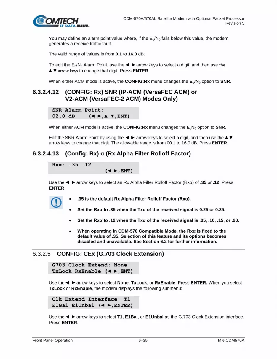
CDM-570A/570AL Satellite Modem with Optional Packet Processor Revision 5
Front Panel Operation 6–35 MN-CDM570A
You may define an alarm point value where, if the Eb/N0 falls below this value, the modem generates a receive traffic fault. The valid range of values is from 0.1 to 16.0 dB. To edit the Eb/N0 Alarm Point, use the arrow keys to select a digit, and then use the arrow keys to change that digit. Press ENTER. When either ACM mode is active, the CONFIG:Rx menu changes the Eb/N0 option to SNR.
6.3.2.4.12 (CONFIG: Rx) SNR (IP-ACM (VersaFEC ACM) or V2-ACM (VersaFEC-2 ACM) Modes Only)
SNR Alarm Point: 02.0 dB ( , ,ENT) When either ACM mode is active, the CONFIG:Rx menu changes the EbN0 option to SNR. Edit the SNR Alarm Point by using the arrow keys to select a digit, and then use the arrow keys to change that digit. The allowable range is from 00.1 to 16.0 dB. Press ENTER.
6.3.2.4.13 (Config: Rx) α (Rx Alpha Filter Rolloff Factor)
Rxα: .35 .12 ( ,ENT) Use the arrow keys to select an Rx Alpha Filter Rolloff Factor (Rxα) of .35 or .12. Press ENTER.
• .35 is the default Rx Alpha Filter Rolloff Factor (Rxα).
• Set the Rxα to .35 when the Txα of the received signal is 0.25 or 0.35.
• Set the Rxα to .12 when the Txα of the received signal is .05, .10, .15, or .20.
• When operating in CDM-570 Compatible Mode, the Rxα is fixed to the default value of .35. Selection of this feature and its options becomes disabled and unavailable. See Section 6.2 for further information.
6.3.2.5 CONFIG: CEx (G.703 Clock Extension)
G703 Clock Extend: None TxLock RxEnable ( ,ENT) Use the arrow keys to select None, TxLock, or RxEnable. Press ENTER. When you select TxLock or RxEnable, the modem displays the following submenu: Clk Extend Interface: T1 E1Bal E1Unbal ( ,ENTER) Use the arrow keys to select T1, E1Bal, or E1Unbal as the G.703 Clock Extension interface. Press ENTER.

CDM-570A/570AL Satellite Modem with Optional Packet Processor Revision 5
Front Panel Operation 6–36 MN-CDM570A
6.3.2.6 CONFIG: Frame (Framing Mode)
Appendix J. EDMAC CHANNEL
Framing Mode: Unframed EDMAC EDMAC-2 ( ,ENT) Use the arrow keys to select a parameter. Press ENTER.
Parameter Description
Unframed No framing is selected, no overhead is added, and the modem is with other manufacturers’ equipment when operating in a ‘standard’ configuration.
EDMAC Comtech EF Data’s proprietary framing is added. The framing permits the bi-directional passing of M&C and AUPC data between local and distant-end units. EDMAC-2
6.3.2.6.1 (CONFIG: Framing Mode) EDMAC or EDMAC-2
EDMAC is backward compatible with the CDM-500, CDM-550/T, CDM-570/570L, and CDM-600/L modems. EDMAC-2 is a reduced overhead version of EDMAC. While it is not completely backward compatible with the modems mentioned here, it is backward compatible in some modes (for example, in TPC BPSK modes and at rates above 2.048 Mbps). When you select EDMAC or EDMAC-2, the modem displays the following submenu: Framing mix: AUPC-Only AUPC+EDMAC ( ,ENTER)
When you enable EDMAC or EDMAC-2 framing, the modem automatically enables AUPC but the specific EDMAC feature (passing M&C data from a local to a distant-end unit) requires further configuration.
Use the arrow keys to select AUPC-Only or AUPC+EDMAC. Press ENTER.
Parameter Description
AUPC-Only (Default) None of the EDMAC features are available, even though framing is still enabled.
AUPC+EDMAC The system further prompts whether to select the modem as an EDMAC Master or an EDMAC Slave.
(CONFIG: Framing Mode) EDMAC or EDMAC-2: AUPC+EDMAC
EDMAC Mode: Master Slave ( ,ENTER)

CDM-570A/570AL Satellite Modem with Optional Packet Processor Revision 5
Front Panel Operation 6–37 MN-CDM570A
Use the arrow keys to select Master or Slave. Press ENTER. Parameter Description
Master An EDMAC Master is a unit that is local to the M&C computer, and which passes messages, via the overhead, to a distant-end modem.
Slave An EDMAC Slave is a unit that is not local to the M&C computer; it is located at the distant-end of a satellite link.
(CONFIG: Framing Mode) EDMAC or EDMAC-2: AUPC+EDMAC Master
Distant-end Base Address 0240 ( , ,ENTER)
The valid range of addresses is from 0010 to 9990, in increments of 10 only. To edit the address of the distant-end modem to which this unit will pass messages, use the arrow keys to select a digit, and then use the arrow keys to change that digit. Press ENTER.
You may not edit the last digit of the address; this is implemented so that a single Master may pass messages for up to 10 devices at the distant end.
(CONFIG: Framing Mode) EDMAC or EDMAC-2: AUPC+EDMAC Slave
Address of this Slave Unit: 0241 ( , ,ENT) The valid range of addresses is from 1 to 9999, although ‘base 10' values are automatically skipped. To edit the address of this Slave unit, use the arrow keys to select a digit, and then use the arrow keys to change that digit. Press ENTER.
The Slave EDMAC address always ends in ‘1’. Keep in mind that this is a unit that is intended for location at the distant-end of a link, and is therefore under the control of a Master at the other end. This is the equivalent of putting the modem into Remote Control mode; no local control is possible.

CDM-570A/570AL Satellite Modem with Optional Packet Processor Revision 5
Front Panel Operation 6–38 MN-CDM570A
6.3.2.7 CONFIG: TI (Data Traffic Interface)
Data Intf: RS422 IP V.35 RS232 G703 IP-ACM V2-ACM Use the arrow keys to select a parameter. Press ENTER.
6.3.2.7.1 (CONFIG: TI) RS422 or V.35 or RS232
RTS/CTS Operation: ( ) RTS/CTS Loop, No Action For RS422, V.35, or RS232, the modem displays this typical submenu. Use the arrow keys to select an option. Press ENTER.
Parameter Description
Ignore RTS, Assert CTS RTS is ignored and CTS is asserted unconditionally.
Loop, RTS Controls Tx Out
RTS and CTS are looped, so that CTS echoes the state of RTS, and RTS controls the ON/OFF state of the carrier (in other words, the modem will not bring up its TX carrier until RTS is asserted).
RTS/CTS Loop, No Action
RTS and CTS are looped, so that CTS echoes the state of RTS, but RTS does not control the ON/OFF state of the carrier.
N/A - 1:N system in use If the 1:N switch on the rear panel is active, then RTS/CTS are not supported; the pins are assigned to redundancy functions.
6.3.2.7.2 (CONFIG: TI) IP
This selection is functional only when the optional Packet Processor is installed.
Select IP to toggle the optional Packet Processor operation. Once you select IP, the modem returns you to the SELECT: Config menu branch.
6.3.2.7.3 (CONFIG: TI) G.703
G.703 is not available when in IP mode.
G.703 Type: T1 E1-Bal E1-Unbal( ,ENT) Use the arrow keys to select T1, E1-Bal, or E1-Unbal. Press ENTER.

CDM-570A/570AL Satellite Modem with Optional Packet Processor Revision 5
Front Panel Operation 6–39 MN-CDM570A
(CONFIG: TI) G703 T1
T1 Configuration: Length Line-Code ( ,ENTER) Use the arrow keys to select Length or Line Code. Press ENTER.
(CONFIG: TI) G.703: T1 Length
T1 Line Length: 000-133 feet ( ,ENTER)
The valid length spans, in feet, are 0-133, 133-266, 266-399, 399-533, or 533-655. Use the arrow keys to select the desired span. Press ENTER.
(CONFIG: TI) G.703: T1 Line-Code
T1 Line Code (B8ZS): On Off(AMI) ( ,ENTER)
Use the arrow keys to select On or Off. Press ENTER.
(CONFIG: TI) G.703 E1-Bal or E1-Unbal
E1 Line Code (HDB3): On Off ( ,ENTER) When you select E1-Bal or E1-Unbal, the modem displays this typical submenu. Use the arrow keys to set operation as On or Off. Press ENTER.
6.3.2.7.4 IP-ACM (VersaFEC ACM)
This selection is functional only when the optional Packet Processor is installed.
ACM:ModCod Unlock-Action Target-SNR-Margin Use the arrow keys to select a parameter. Press ENTER.
(CONFIG: TI) IP-ACM ModCod
Min ModCod:00 16QAM .488 Max ModCod:11 16QAM .853

CDM-570A/570AL Satellite Modem with Optional Packet Processor Revision 5
Front Panel Operation 6–40 MN-CDM570A
Use the arrow keys to select the Min(imum) (on the top line) or Max(imum) ModCod range setting (on the bottom line). Then, use the arrow keys to define the range of ModCods (00-11) over which the system will operate. Press ENTER. ModCod 00 is BPSK Rate 0.488 (0.49 bps/Hz), while ModCod 11 is 16-QAM Rate 0.853 (3.41bps/Hz).
If you wish to constrain the system to run at a fixed ModCod, set the Min and Max ModCod values to be equal. The value of Max ModCod may be limited by other FAST codes installed. For example, suppose the 4100 ksps FAST option is installed, and the symbol rate set to 4100 ksps, the theoretical maximum data rate would be 14 Mbps at ModCod 11. However, if CnC is being used, with a 10 Mbps FAST limit the ACM Max ModCod will be limited to ModCod 7, or 9.6 Mbps.
(CONFIG: TI) IP-ACM Unlock-Action
Distant-end loses lock: Go to Min Tx Modcod( ) Use this submenu to establish the desired action when the remote demod loses lock. This is important, as the ACM system depends on the feedback of the SNR metric from the remote demod to determine the optimum ModCod. Use the arrow keys to select Go to min Tx ModCod (recommended) or Maintain Tx ModCod. Press ENTER.
(CONFIG: TI) IP-ACM Target-SNR-Margin
Target SNR Margin: 1.0 dB (0.0 – 4.5) ( ) Use the arrow keys to select a margin value from 0.0 to 4.5 dB, in 0.5 dB increments. Press ENTER.
The ACM system is designed to switch based on thresholds that correspond to a BER of 5 x 10⁻⁸ for each ModCod. However, in order to prevent oscillation around two ModCods at this exact value, 0.3 dB of hysteresis has been added.
6.3.2.7.5 V2-ACM (VersaFEC-2 ACM)
This selection is functional only when the optional Packet Processor is installed.
ACM:ModCod Unlock-Action Target-SNR-Margin Use the arrow keys to select a parameter. Press ENTER.

CDM-570A/570AL Satellite Modem with Optional Packet Processor Revision 5
Front Panel Operation 6–41 MN-CDM570A
(CONFIG: TI) V2-ACM ModCod
Min ModCod:00 BPSK .489 Max ModCod:37 32ARY .879
Use the arrow keys to select the Min(imum) (on the top line) or Max(imum) ModCod range setting (on the bottom line). Then, use the arrow keys to define the range of ModCods (00-37) over which the system will operate. Press ENTER. The minimum setting for VF2S (VersaFEC-2 Short Block) and VF2L (VersaFEC-2 Long Block) is fixed at ModCod 00 (BPSK Rate 0.489 (0.49 bps/Hz)).
• For VF2S, the maximum selectable ModCod 35 is 32-ARY Rate 0.831 (4.153 bps/Hz)
• For VF2L, the maximum selectable ModCod 37 is 32-ARY Rate 0.879 (4.397 bps/Hz)
Press ENTER.
If you wish to constrain the system to run at a fixed ModCod, set the Min and Max ModCod values to be equal. The value of Max ModCod may be limited by other FAST codes installed.
(CONFIG: TI) V2-ACM Unlock-Action
This screen is read-only. Press ENTER or CLEAR to return to the previous menu. Distant-end loses lock: Go to Min Tx Modcod( )
(CONFIG: TI) V2-ACM Target-SNR-Margin
Target SNR Margin: 1.0 dB (0.0 – 4.5) ( )
Use the arrow keys to select a margin value from 0.0 to 4.5 dB, in 0.5 dB increments. Press ENTER.
The ACM system is designed to switch based on thresholds that correspond to a BER of 5 x 10⁻⁸ for each ModCod. However, in order to prevent oscillation around two ModCods at this exact value, 0.3 dB of hysteresis has been added.

CDM-570A/570AL Satellite Modem with Optional Packet Processor Revision 5
Front Panel Operation 6–42 MN-CDM570A
6.3.2.8 CONFIG: Ref (Reference)
1. IMPORTANT NOTE – The modem can accept an externally supplied frequency reference via the rear panel BNC connector. Rather than bypassing the internal reference and substituting the external signal, the modem instead uses the internal reference in a low-bandwidth (~ 2 Hz) phase-locked loop (PLL), so the modem actually phase locks to the reference external signal. There are distinct advantages to this scheme: • This scheme permits hitless switching between the operation of internal
and external reference. There are no sudden discontinuities of frequency and phase in the transmitted carrier.
• Due to the very low bandwidth of the PLL, this scheme permits the
external reference to employ an inferior phase noise characteristic instead of the internal reference of the modem. The narrow loop essentially ‘cleans up’ the external signal. This is particularly important if you use the CDM/R-570ALto supply a 10MHz reference to a BUC or LNB.
2. If Internal+O/P is your active Frequency Reference setting, and you then set the modem to CDM-570 Compatible Mode, the modem will reset this feature to Internal 10 MHz. Reconfigure your setting as needed. See Sect. 6.2 for further information.
Use the arrow keys to select Internal+O/P, Internal 10 MHz, External 01 MHz, External 02 MHz, External 05 MHz, or External 10 MHz. Press ENTER. Examples include: Frequency Reference: Internal 10 MHz( ,ENT) Frequency Reference: Internal+O/P ( ,ENT)

CDM-570A/570AL Satellite Modem with Optional Packet Processor Revision 5
Front Panel Operation 6–43 MN-CDM570A
6.3.2.9 CONFIG: Msk (Alarm Masking)
CDM/R-570AL(L-Band) unit: CDM-570A (70/140 MHz) unit:
Use the arrow keys to select Transmit, Receive, Ref, BUC (CDM/R-570ALonly), or LNB (CDM/R-570ALonly). Press ENTER.
6.3.2.9.1 (CONFIG: Alarm Mask) Transmit
Tx Alarm Mask: Tx-FIFO G703BPV TxAIS G703LOS Use the arrow keys to select a parameter. Press ENTER. Each choice displays a submenu similar to the TX-FIFO submenu: Tx-FIFO Alarm: Active Masked ( ,ENT) Typical for each Tx Alarm submenu, use the arrow keys to select Active or Masked. Press ENTER. When you select Masked, the modem generates no alarm. When you select Active, the modem generates a fault. For example, for the preceding TX-FIFO Tx Alarm Mask, with the mask set to Active the modem generates a Transmit Traffic fault whenever the transmitter sees that the Transmit FIFO has slipped.
6.3.2.9.2 (CONFIG: Alarm Mask) Receive
Rx Alarm Mask: AGC Eb/No Rx-AIS Buffer ( ,ENT) Use the arrow keys to select AGC, Eb/N0, Rx-AIS, or Buffer. Press ENTER. Each choice displays a submenu similar to the AGC submenu: AGC Alarm: Active Masked ( ,ENT)
Typical for each Rx Alarm submenu, use the arrow keys to select Active or Masked. Press ENTER. When you select Masked, the modem generates no alarm. When you select Active, the modem generates a fault. For example, for the preceding AGC Alarm Mask, with the mask set to Active the modem generates a Receive Traffic fault whenever the demodulator sees that the composite input level being applied causes compression in the IF stages, and consequently degrades the performance of the demodulator.
Alarm Mask: Transmit Receive Ref ( )
Alarm Mask: Transmit Receive Ref BUC LNB ( )

CDM-570A/570AL Satellite Modem with Optional Packet Processor Revision 5
Front Panel Operation 6–44 MN-CDM570A
6.3.2.9.3 (CONFIG: Alarm Mask) Ref
Reference Alarm: Active Masked ( ,ENT) Use the arrow keys to select Active or Masked. Press ENTER. When you select Active, the modem generates a Transmit Traffic fault whenever it sees that:
• External Reference is selected, and
• There is no signal activity at the External Reference port.
When you select Masked, the modem generates no alarm.
6.3.2.9.4 (CONFIG: Alarm Mask) BUC (CDM/R-570AL L-Band Units ONLY)
See Chapter 10. CDM-570A/570AL ODU (TRANSCEIVER, BUC, LNB) M&C OPERATIONS for complete details about using this modem-specific menu branch.
BUC Alarm: Active Masked ( ,ENT) Use the arrow keys to set the alarm as Active or Masked for the BUC, if connected.
6.3.2.9.5 (CONFIG: Alarm Mask) LNB (CDM/R-570AL L-Band Units ONLY)
See Chapter 10. CDM-570A/570AL ODU (TRANSCEIVER, BUC, LNB) M&C OPERATIONS for complete details about using this modem-specific menu branch.
LNB Alarm: Active Masked ( ,ENT) Use the arrow keys to set the alarm as Active or Masked for the LNB, if connected.

CDM-570A/570AL Satellite Modem with Optional Packet Processor Revision 5
Front Panel Operation 6–45 MN-CDM570A
6.3.2.10 CONFIG: CnC
1. CnC operation requires that you purchase one of several available FAST options to provide capability to a maximum of 10.239 Mbps.
2. This feature is UNAVAILABLE when operating in CDM-570 Compatible Mode. See Sect. 6.2 for further information.
• Appendix G. DoubleTalk Carrier-in-Carrier OPTION • For more information about purchasing FAST options:
o Sect. 6.2.8 SELECT: FAST menus o Sect. 1.3.10 Fully Accessible System Topology (FAST) o Chapter 5. FAST ACTIVATION PROCEDURE
CnC: Mode Freq-Offset Search-Delay ( ,ENTER) Use the arrow keys to select a parameter. Press ENTER.
6.3.2.10.1 (CONFIG: CnC) Mode
CDM/R-570AL unit: CDM-570A unit: CnC Mode: Off On APC Action ( ,ENTER)
Mode: Off
For either unit: the available CnC mode selections are: • Off • APC,Side-A,C-Band • APC,Side-B,C-Band • On (normal) • APC,Side-A,X-Band • APC,Side-B,X-Band
• APC,Side-A,Ku-Band • APC,Side-B,Ku-Band • APC,Side-A,Ka-Band • APC,Side-B,Ka-Band
For the CDM/R-570AL only: Use the arrow keys to select CnC Mode as Off or On. (For CnC-APC controls, select APC.) For the CDM-570A only: Use the arrow keys to select CnC Mode as Off or On. (Continued use of the arrow keys entails selection of CnC-APC controls.) Press ENTER.
See Sect. G.6 Carrier-in-Carrier Automatic Power Control (CnC-APC) in Appendix G. DoubleTalk Carrier-in-Carrier OPTION for complete details about, and setup of, the CnC-APC feature.

CDM-570A/570AL Satellite Modem with Optional Packet Processor Revision 5
Front Panel Operation 6–46 MN-CDM570A
6.3.2.10.2 (CONFIG: CnC) Freq-Offset
CnC Freq-Offset Range: +/- 010 kHz ( ,ENTER) Use this menu to ENTER the maximum expected frequency offset between the outbound interferer and the desired inbound. It normally corresponds to the demod acquisition range. Use the arrow keys to edit the CnC Frequency Offset value. Press ENTER. This range is pre-calculated. The Rx symbol rate determines the CnC Frequency Offset:
• From 16 to 64 ksymbols/sec (ksps): ±1 to the symbol rate (ksps/2)
• 64 ksps and above: ±1 to 32kHz
NOTE: CnC operation with symmetrical links requires the Symbol Rate to be offset by 0.1% or higher on one of the links when the IP Data Interface is selected.
6.3.2.10.3 (CONFIG: CnC) Search-Delay
CnC Search Delay: Min: 240 ms Max: 300 ms To reduce the time taken for the CnC algorithm to converge, you may apply restrictions to the range of delay used by the search. During initial link testing, you should set the delay to a minimum of 240 ms and a maximum of 300 ms. Once CnC has found the exact delay, the value can be further reduced but care should be taken to allow sufficient range to accommodate changes in path delay due to Doppler.
If bench-testing CnC with two units in a back-to-back configuration, you should set the minimum delay to 0 ms, and the maximum delay to 20 ms. This takes into account the lack of satellite delay.
To edit the Min or Max delay, use the arrow keys to select a digit, and then use the arrow keys to change that digit. Press ENTER.
6.3.2.11 CONFIG: ODU (CDM/R-570AL L-Band Units ONLY)
See Chapter 10. CDM-570A/570AL ODU (TRANSCEIVER, BUC, LNB) M&C OPERATIONS for complete details about using this modem-specific menu branch.
ODU (Outdoor Unit): BUC LNB ( ,ENTER) Use the arrow keys to configure a BUC or LNB, if connected.

CDM-570A/570AL Satellite Modem with Optional Packet Processor Revision 5
Front Panel Operation 6–47 MN-CDM570A
6.3.3 SELECT: Monitor
MONITOR: Alarms Rx ACM Event Stats AUPC CnC ODU Use the arrow keys to select a parameter (ODU is available only with the CDM-570AL). Press ENTER.
6.3.3.1 MONITOR: Alarms
IMPORTANT NOTE – The CDM/R-570ALuses a system of Fault Prioritization, where the modem will display only the highest priority fault in a designated category. This cuts down significantly on unwanted and irrelevant fault reporting. For example, if the demodulator is unlocked, then it is irrelevant if there are other Rx faults present. However, if the demodulator then locks while a lower-priority fault is present, then the modem will display that fault. This also applies for faults reported via remote control.
For CDM/R-570ALunits with ODUs, see Chapter 10. CDM-570A/570AL ODU (TRANSCEIVER, BUC, LNB) M&C OPERATIONS for details on selecting this submenu and the listing of prioritized ODU faults.
Live Alarms:Unit Receive Transmit ODU ( ,ENTER) For 70/140 MHz or L-Band modems without ODUs, use the arrow keys to select Unit, Receive, or Transmit. Press ENTER.
LIST OF PRIORITIZED FAULTS Unit Faults Tx Traffic Status Rx Traffic Status
1) Power supply fault, +5 volts 2) Power supply fault, +12 volts 3) Power supply fault, –5 volts 4) Power supply fault, –12 volts 5) Tx synthesizer lock 6) Rx 1st LO synthesizer lock 7) Rx 2nd LO synthesizer lock 8) Reference PLL lock 9) PaP Heartbeat
1) No clock from terrestrial interface 2) Tx PaP ETH Link Down 3) Tx FIFO slip 4) Loss of Signal on G.703 interface 5) Loss of External Reference 6) AUPC upper limit reached 7) AIS detected on incoming data
(from terrestrial direction) 8) Bipolar violation on G.703 interface 9) BUC Alarm (if attached)
1) Demodulator unlocked 2) AGC Alarm - signal out of range 3) APC Frame sync alarm 4) EDMAC Frame sync alarm 5) APC Band mismatch alarm 6) Buffer Underflow 6) Buffer Overflow 7) Eb/N0 alarm 8) LNB Alarm (if attached) 9) AIS detected on incoming data (from satellite direction)

CDM-570A/570AL Satellite Modem with Optional Packet Processor Revision 5
Front Panel Operation 6–48 MN-CDM570A
6.3.3.1.1 (MONITOR: Live Alarms) Unit
Unit Fault: -12 Volt PSU is Under-Voltage (ENT) This screen displays Unit Faults. If none are present, it displays ‘None’. Press ENTER to return to the previous menu.
6.3.3.1.2 (MONITOR: Live Alarms) Receive (Receive Traffic Status)
Rx Traffic: AGC Alarm - Reduce Input level (ENT) This screen displays Receive Traffic Faults. If none are present, it displays ‘None’. Press ENTER to return to the previous menu.
6.3.3.1.3 (MONITOR: Live Alarms) Transmit (Transmit Traffic Status)
Tx Traffic: No Tx Clock from Terrestrial (ENT) This screen displays Transmit Traffic Faults. If none are present, it displays ‘None’. Press ENTER to return to the previous menu.
6.3.3.2 MONITOR: Rx
EbNo>16.0dB BER=0.0E-9 ΔF=0.0k Buf=50 RSL=-42 With VersaFEC ACM (IP-ACM) or VersaFEC-2 ACM (V2-ACM) mode active: SNR=22.0dB BER=0.0E-9 ΔF=+0.0k Buf=50 RSL=-49

CDM-570A/570AL Satellite Modem with Optional Packet Processor Revision 5
Front Panel Operation 6–49 MN-CDM570A
If the demodulator is locked, information displays as follows:
Parameter Description
EbNo= This shows the value of Eb/N0 calculated by the demodulator. The value referred to here is the energy per information bit (Ebi), divided by the noise spectral density (N0).
SNR This replaces “Eb/N0” when VersaFEC ACM (IP-ACM) or VersaFEC-2 ACM (V2-ACM) mode is active. In ACM, SNR is the preferred metric. Remember that: SNR = Eb/No +10log (spectral efficiency).
BER= This shows an estimate of the corrected BER.
∆F= This shows the frequency offset of the received carrier, in kHz, in steps of 100 Hz.
Buf= (Buffer fill state) This shows the fill state, in percent, of the receive Buffer. After a reset, it will read 50. A value below 50 indicates that the buffer is emptying, and above 50 indicates that it is filling.
RSL= (Receive Signal Level) This shows the value, in dBm, of the desired carrier’s input power as seen by the demodulator. If the signal level is below the AGC range of the demod, this displays RSL <-99.
Otherwise, if the demodulator is not locked, the message ‘Demod: Not Locked’ displays, but the screen continues to display the receive signal level, as this example shows: Demod: Not Locked RSL=-64
Press ENTER or CLEAR to return to the previous menu.
6.3.3.3 Monitor: ACM
This screen is viewable only when the optional Packet Processor is installed.
TMC00 BP.489 RmSNR=99.9 RMC00 BP.489 LcSNR=99.9 This read-only screen displays the active VersaFEC ACM (IP-ACM) or VersaFEC-2 ACM (V2-ACM) mode information, as follows:
Setting Function
TxModCod Displays the Tx ModCod: 00-11 (VersaFEC); 00-35 (VersaFEC 2 Short Block (VF2S)); 00-37 (VersaFEC-2 Long Block (VF2L)).
RemoteSNR Displays the SNR reported by the remote modem.
RxModCod Displays the Rx ModCod: 00-11 (VersaFEC); 00-35 (VersaFEC 2 Short Block (VF2S)); 00-37 (VersaFEC-2 Long Block (VF2L)).
LocalSNR Displays the SNR of the local unit. When you attempt to access this display when the modem is not in VersaFEC ACM (IP-ACM) or VersaFEC-2 ACM (V2-ACM) mode, the following message appears: ACM Parameter is not avail

CDM-570A/570AL Satellite Modem with Optional Packet Processor Revision 5
Front Panel Operation 6–50 MN-CDM570A
6.3.3.4 MONITOR: Event (Stored Events)
Stored Events: View Clear-All ( ,ENTER) Use the arrow keys to select View or Clear-All. Press ENTER.
6.3.3.4.1 (MONITOR: Stored Events) View
Log23: 30/11/02 10:37:32 Fault - Demod Lock ( ) When a fault condition occurs, the modem date- and time-stamps the fault, and enters it into the Stored Events Log. The modem also records when the fault condition clears, as this example shows: Log240:30/11/97 10:37:35 Clear – Demod Lock( ) The Stored Events Log stores up to 255 events. Use the arrow keys to browse through the available entries. Press ENTER or CLEAR to return to the previous menu.
6.3.3.4.2 (MONITOR: Stored Events) Clear-All
Clear all Stored Events? No Yes ( , ENTER) Use the arrow keys to select No or Yes. Press ENTER. When you select Yes, the modem clears the event log and returns you to the previous menu. However, if a fault persists, the modem re-stamps the fault and generates a new log entry.
In accordance with European convention, the date appears in DAY-MONTH-YEAR format.

CDM-570A/570AL Satellite Modem with Optional Packet Processor Revision 5
Front Panel Operation 6–51 MN-CDM570A
6.3.3.5 MONITOR: Stats (Link Statistics)
If you change your operating mode between IP-ACM Mode and any mode other than IP-ACM Mode, Comtech EF Data recommends that you first execute Clear-All from the MONITOR: Stats screen before you attempt to retrieve any further statistics.
Link Statistics: View Clear-All Config( ,ENT) Use the arrow keys to select View, Clear-All, or Config. Press ENTER.
6.3.3.5.1 (MONITOR: Stats (Link Statistics)) View
Sta198:11/02/15 10:37:32 16.0, 16.0, 9.0, 9.0( ) The Link Statistics Log stores up to 255 events. Typical for all operating modes, the top line indicates the log entry number, and the time and date of the entry. Use the arrow keys to browse through the available entries. Press ENTER or CLEAR to return to the previous menu.
In accordance with European convention, the date appears in DAY-MONTH-YEAR format.
In any operating mode other than VersaFEC ACM (IP-ACM) / VersaFEC-2 ACM (V2-ACM) Mode: The bottom line shows the measured and recorded statistics data: Minimum Eb/N0; Average Eb/N0; Maximum TPLI; and Average TPLI.
TPLI = Transmit Power Level Increase – you must enable AUPC to review TPLI.
The meaning and format of the numbers is as follows:
• Once you define a measurement interval (see MONITOR: Stats Config), the modem observes Eb/N0 and TPLI at a once-per-second rate during this interval. At the end of the interval, the modem calculates and records the average Eb/N0 and the minimum value seen during the interval. Similarly, the modem calculates the TPLI along with the highest value seen during the interval.
If the demod loses lock during the measurement interval, the minimum Eb/N0 shows ‘Loss’ rather than indicates a value. However, the average value (while the demod was locked) will still be calculated and shown. If, on the other hand, you unlock the demodulator for the entire measurement interval, the average Eb/N0 will also show ‘Loss’. (The display shows ‘Loss, Loss’.)
• If the measured values are greater than or equal to 16.0 dB, the display shows ‘16.0’.

CDM-570A/570AL Satellite Modem with Optional Packet Processor Revision 5
Front Panel Operation 6–52 MN-CDM570A
• When you do not enable AUPC, both maximum and average TPLI shows ‘0.0'.
Examples: 08.0,13.5,2.5,1.8 means: Minimum Eb/N0 observed in the measurement interval = 8.0 dB Average Eb/N0 observed in the measurement interval = 13.5 dB Maximum TPLI observed in the measurement interval = 2.5 dB Average TPLI observed in the measurement interval = 1.8 dB Loss,04.5,0.0,0.0 means: There was a loss of demod lock during the measurement interval Average Eb/N0 observed in the measurement interval = 4.5 dB Maximum TPLI observed in the measurement interval = AUPC disabled Average TPLI observed in the measurement interval = AUPC disabled
The presentation of statistics information varies slightly when in VersaFEC ACM (IP-ACM) or VersaFEC-2 ACM (V2-ACM) mode. In VersaFEC ACM (IP-ACM) mode: Sta198:02/11/13 10:37:32 16.0,16.0,2,4,0,0 ( ) The bottom line calculates and then displays statistics data as follows: Example: 16.0,16.0,2,4,0,0 means: Minimum Eb/N0 observed in the measurement interval = 16.0 dB
Average Eb/N0 observed in the measurement interval = 16.0 dB The Rx ModCod, in hex format, that was current when the entry was logged = 2 Maximum Rx ModCod, in hex format, during the measurement interval = 4 Minimum Rx ModCod, in hex format, during the measurement interval = 0 Number of Rx ModCod changes, in hex format, during the measurement interval = 0

CDM-570A/570AL Satellite Modem with Optional Packet Processor Revision 5
Front Panel Operation 6–53 MN-CDM570A
In VersaFEC-2 ACM (V2-ACM) Mode: Sta198:02/11/13 10:37:32 22.0, 22.0, 36, 00 ( ) The modem calculates and then displays, on the top line from left to right, statistics data as follows:
• (22.0, 22.0) First, the SNR is calculated: The minimum SNR value observed in the measurement interval is provided first, and then the average SNR observed value follows. The screen dislays 16.0 only if the measured values are ≥16.0 dB.
• (37) Maximum Rx ModCod, in decimal format, during the measurement interval.
• (37) Minimum Rx ModCod, in decimal format, during the measurement interval.
6.3.3.5.2 (MONITOR: Stats (Link Statistics)) Clear-All
Clear all Stored Stats? No Yes ( , ENTER) Use the arrow keys to choose No or Yes. Press ENTER. When you select Yes, the modem clears the Link Statistics Log and returns you to the previous menu.
6.3.3.5.3 (MONITOR: Stats (Link Statistics)) Config (Configure)
Stats Logging Interval: Disabled ( ,ENTER) Valid logging interval settings (i.e., the time span, in minutes, over which the link statistics are measured) are Disabled, 10, 20, 30, 40, 50, 60, 70, 80, or 90. To select a logging interval the arrow keys to select your desired interval setting. Press ENTER. Once set, the display reflects the selected interval: Stats Logging Interval: 30 minutes ( ,ENTER)

CDM-570A/570AL Satellite Modem with Optional Packet Processor Revision 5
Front Panel Operation 6–54 MN-CDM570A
6.3.3.6 MONITOR: AUPC
Appendix E. AUPC (AUTOMATIC UPLINK POWER CONTROL)
When you select AUPC and the modem is not in ‘Framed’ or VersaFEC ACM (IP-ACM) mode, the modem displays the following message: Warning! AUPC needs Frame Mode or IP-ACM When you select AUPC and the modem is in ‘Framed’ mode, the screen appears as follows: AUPC:Remote EbNo =Unlock TX Power Increase =0.00dB
• The top line displays the value of Eb/N0 of the demodulator at the distant end of the
satellite link. The Eb/N0 displays Unlock if the remote demod is unlocked.
• The bottom line shows how much the AUPC system has increased the output power. If you do not enable AUPC, the value of Tx Power Increase shows as 0.0 dB.
For VersaFEC ACM (IP-ACM) modes only:
AUPC:Modem is in IP-ACM TX Power Increase =0.0dB
For VersaFEC-2 ACM (V2-ACM) modes only:
AUPC:Modem is in V2-ACM TX Power Increase =0.0dB
• The top line message directs you to consult the Monitor: ACM menu for the Remote and Local SNR values that are available in place of Remote Eb/N0 data.
• The bottom line shows how much the AUPC system has increased the output power. If you do not enable AUPC, the value of Tx Power Increase shows as 0.0 dB.
Press ENTER or CLEAR to return to the previous menu.

CDM-570A/570AL Satellite Modem with Optional Packet Processor Revision 5
Front Panel Operation 6–55 MN-CDM570A
6.3.3.7 MONITOR: CnC
Appendix G. DOUBLETALK CARRIER-IN-CARRIER OPTION
When you select CnC and the demod is not locked, the modem displays the following message: CnC: Demod Not Locked When CnC is enabled and the demod is locked, the screen displays the CnC performance data. This read-only display updates once every second: PR=+01.1dB PSDR=+01.1dB ΔF=-002.3kHz Dly=249.6ms
6.3.3.8 MONITOR: ODU (CDM/R-570AL L-Band Units ONLY)
See Chapter 10. CDM-570A/570AL ODU (TRANSCEIVER, BUC, LNB) M&C OPERATIONS for complete details about this modem-specific menu branch.
Outdoor Unit Monitor: BUC LNB ( ,ENTER) For the CDM/R-570AL only: Use this menu branch to monitor a BUC or LNB, if connected. Use the arrow keys to select BUC or LNB. Press ENTER to continue or CLEAR to return to the previous menu.
6.3.4 SELECT: TEST
TEST: Mode BERT Use the arrow keys to select Mode or BERT. Press ENTER.

CDM-570A/570AL Satellite Modem with Optional Packet Processor Revision 5
Front Panel Operation 6–56 MN-CDM570A
6.3.4.1 TEST: Mode
TEST: Norm IF↓ Dig↓ I/O↓ RF↓ Tx-CW Tx-1,0( ,ENT) Use this menu branch to execute a variety of test modes. Use the arrow keys to select a Test Mode. Press ENTER.
Mode Description
Norm (Normal) This clears any test modes or loopbacks, and places the modem back into an operational state.
IF↓
(IF Loopback) This test mode invokes an internal IF loop. This is a particularly useful feature, as it is used to perform a quick diagnostic test without having to disturb external cabling. Furthermore, all of the receive configuration parameters are temporarily changed to match those of the transmit side. During an IF Loop, the Tx carrier continues to be transmitted. See Figure 6-3. When Norm is again selected, all previous values are restored.
Dig↓ (Digital Loopback) This test mode invokes a digital loopback, which loops data at the output of the framer/scrambler on the transmit side and back into the deframer/descrambler on the receive side. If concatenated Reed-Solomon FEC is being used, this is also included in the digital loop. See Figure 6-3.
I/O↓
(Inward/Outward loopback) This test mode invokes two distinct loopbacks: • The Inward Loop takes data being received from the satellite direction and passes it directly to the
modulator. • Simultaneously, the Outward Loop is invoked, whereby data being fed to the transmit data interface
is routed directly back out of the receive data interface. See Figure 6-3.
RF↓
(RF Loopback) Useful for performing a satellite loopback, this test mode is almost identical to the IF loop mode: All receive configuration parameters are temporarily changed to match those of the transmit side; however, no internal connection is made. When Norm is again selected, all previous values are restored.
TX-CW
(Transmit CW) Used for measuring phase noise, this test mode forces the modulator to transmit a pure carrier (unmodulated).
TX-1,0
(Transmit an alternating 1,0,1,0 pattern) Used to check the carrier suppression of the Modulator. This test mode forces the modulator to transmit a carrier modulated with an alternating 1,0,1,0 pattern, at the currently selected symbol rate. This causes two discrete spectral lines to appear, spaced at +/- half the symbol rate, about the carrier frequency. If OQPSK is selected as the modulation type, the test produces a spectral pattern suitable for the measurement of SSB rejection – useful in determining the phase and amplitude accuracy of the modulator.

CDM-570A/570AL Satellite Modem with Optional Packet Processor Revision 5
Front Panel Operation 6–57 MN-CDM570A
Figure 6-3. Loopback Test Modes

CDM-570A/570AL Satellite Modem with Optional Packet Processor Revision 5
Front Panel Operation 6–58 MN-CDM570A
6.3.4.2 TEST: BERT
This feature is UNAVAILABLE when operating in CDM-570 Compatible Mode. See Section 6.2 for further information.
BERT: Config Monitor Use the arrow keys to select Config or Monitor. Press ENTER.
6.3.4.2.1 (TEST: BERT) Config
Tx: Off Pat: 1:1 Rx: On Pat: 2047 Use the arrow keys to select the BERT operational setting, and then use the arrow keys to set the operational setting. BERT configuration options are as follows:
Parameter Description
Tx: or Rx: Off or On
Pat (Pattern Options) Space, Mark, 1:1, 2047, 215-1, 223-1
6.3.4.2.2 (TEST: BERT) Monitor
Errs=00000000 Sync: OK BER=3.35E-07 Reset 1Err This screen displays the ongoing BERT as follows:
Display Line Parameter Description
Top Errs Displays the number of errors currently tallied in BERT.
Sync Displays as OK or Loss.
Bottom Reset Select to reset the Errors (Errs) counter to 00000000.
1Err Select to insert a 1-bit error in the Tx test pattern. If you attempt to select Monitor from the (TEST: BERT) Config screen, and Rx, or both is Off, then the modem displays the following message: BERT machine is OFF Press CLEAR to exit Press CLEAR to return to the TEST: BERT menu, and then use the Config: menu

CDM-570A/570AL Satellite Modem with Optional Packet Processor Revision 5
Front Panel Operation 6–59 MN-CDM570A
6.3.5 SELECT: Info
INFO:All Tx Rx Buf Frame Intfc Rem Msk Ref ID 1:1 Use this menu branch to review information on the modem’s current configuration. The information provided on these screens is viewable on a read-only basis – no editing is possible. Use the arrow keys to select a parameter. Press ENTER. Typical for all nested Info screens, press ENTER or CLEAR to return to the SELECT: Info menu.
6.3.5.1 INFO: All
This screen set allows review and configuration of the modem in its entirety. Once a specific screen displays, press ENTER to continue through the remaining displays. To discontinue and return to the CONFIG: menu, press CLEAR. As it is with the CONFIG: All menu, the availability of information screens is dependent on the active operational settings.
6.3.5.2 INFO: Tx (Transmit)
Tx:1140.000 5000.000 TUR 8P 0.95 S EXT -20.0 ON I
This screen displays Transmit information as follows:
Display Line Description
Top Line (from left)
• Transmit Frequency and Data Rate (NOTE: Due to space limitations, the resolution of displayed frequency is limited to 1 kHz, and data rate to 10 bps)
• FEC Encoder type (VIT = Viterbi, VRS=Viterbi + Reed-Solomon, TCM = Trellis Coded + Reed-Solomon, TUR = TPC, VFEC = VersaFEC, VersaFEC-2 (Long) = VF2L, VersaFEC-2 (Short) = VF2S, ULL = Ultra Low Latency, UNC = uncoded)
Bottom Line (from left)
• Modulation type (Q = QPSK, OQ= OQPSK, B = BPSK, 8P = 8-PSK, 8Q = 8QAM, 16=16-QAM, 8-ARY, 16-ARY, 32-ARY)
• Code Rate (Unc = Uncoded, 2144 = 21/44, then 5/16, 1/2, 2/3, 3/4, 7/8, 0.95) • Scrambler state (S = Scrambler on, N = Scrambler off, I = IESS-315 On) • Clocking Mode (INT = internal, EXT = external, LOP = loop, CXE = internal & Clock
Extend TxLock E1 mode, CXT = internal & Clock Extend TxLock T1 mode) • Output power level • Transmit output state (ON = on, OF = off, EO= external off, RT= Rx-Tx Inhibit) • TSI state (I = Transmit Spectral Inversion on, N = off)

CDM-570A/570AL Satellite Modem with Optional Packet Processor Revision 5
Front Panel Operation 6–60 MN-CDM570A
6.3.5.3 INFO: Rx (Receive)
Rx:1140.000 5000.000 TUR 8P 0.95 D BUF +/-32k I This screen displays Receive information as follows:
Display Line Description
Top Line (from left)
• Receive Frequency and Data Rate (NOTE: Due to space limitations, the resolution of displayed frequency is limited to 1 kHz, and data rate to 10Hz,)
• FEC Decoder type (VIT = Viterbi, VRS=Viterbi + Reed-Solomon, TCM = Trellis Coded + Reed-Solomon, TUR = TPC, VFEC = VersaFEC, VersaFEC-2 (Long) = VF2L, VersaFEC-2 (Short) = VF2S, ULL = Ultra Low Latency, UNC = uncoded)
Bottom Line (from left)
• Demodulation type (Q = QPSK, OQ= OQPSK, B = BPSK, 8P = 8-PSK, 8Q = 8QAM, 16=16-QAM, 8-ARY, 16-ARY, 32-ARY).
• Code Rate (Unc = Uncoded, 2144 = 21/44, then 5/16, 1/2, 2/3, 3/4, 7/8, 0.95) • Descrambler state (D = Descrambler on, N = Descrambler off, I = IESS-315 On) • Clocking Mode (SAT = buffer disabled, BUF = buffer enabled, CXE = internal & Clock
Extend RxEnable E1 mode, CXT = internal & Clock Extend RxEnable T1 mode) • Demod Sweep Acquisition range • RSI state (I = Receive Spectral Inversion on, N = off)
6.3.5.4 INFO: Buf (Buffer)
Buffer: Enabled (Tx=Rx) Size:+/-04096 bits (ENT) This screen reports if the buffer is Enabled or Disabled; shows the exact clocking mode (Tx=Rx, or Tx< > Rx); and displays the buffer size.
6.3.5.5 INFO: Frame (Framing and EDMAC)
This screen displays the framing mode and whether the modem is EDMAC Master or Slave, with the appropriate address. Examples are as follows: Framing: Disabled (ENTER or CLEAR) Framing: AUPC-Only,EDMAC2 (ENTER or CLEAR) Framing: AUPC+EDMAC2 Master,0240 (ENT or CLR)
Framing: AUPC+EDMAC Slave, 0241 (ENT or CLR)

CDM-570A/570AL Satellite Modem with Optional Packet Processor Revision 5
Front Panel Operation 6–61 MN-CDM570A
6.3.5.6 INFO: Intfc (Interface)
This screen displays details of the main data port’s electrical interface type. When you select RS422, V.35, or RS232, the screen also indicates RTC/CTS operation. Examples are as follows: Interface: RS422 (ENT) RTS/CTS Loop, No Action Interface:G.703 E1-Unbal HDB3 (ENTER or CLEAR) Interface: G.703 T1 B8ZS 533-655 feet(ENT or CLR)
6.3.5.7 INFO: Rem (Remote Control)
This screen reports whether the modem is in Local or Remote mode; identifies the selected electrical interface type; reports the unit’s address; shows the selected baud rate, etc. Examples are as follows: Remote M&C: Monitor Only (Local Control only) Remote M&C: RS485-4Wire Address: 0001 19200 Baud
Remote M&C: 100BaseTx IP Addr: 255.255.255.255 Press ENTER or CLEAR to return to the previous menu.
6.3.5.8 INFO: Msk (Alarm Mask)
Mask: FIFO BPV TAIS RAIS AGC EbNo BUF Ref BUC LNB This screen displays, in the same format as the CONFIG: Mask submenu, which alarms are currently masked. If an alarm is not masked, the display substitutes a blank space at the relevant screen position assigned that item.
When in G.703 Clock Extended Mode (CEx), “BPV” appears in place of “LOS” to indicate the alarm mask of G703 Loss of Signal.

CDM-570A/570AL Satellite Modem with Optional Packet Processor Revision 5
Front Panel Operation 6–62 MN-CDM570A
6.3.5.9 INFO: Ref (Frequency Reference)
Frequency Reference: Internal 10 MHz (ENTER) This screen displays the configured external frequency reference source for the modem.
6.3.5.10 INFO: ID
Circuit ID: (ENTER) 24 CHARACTER TST MESSAGE This screen displays the user-defined Circuit ID string that you can compose via the UTIL: ID submenu.
6.3.5.11 INFO: 1:1 (1:1 Redundancy)
Redundancy State:Standby Serial 1:1 Link: Active
• On the top line: This screen displays the Redundancy State (1:1 or 1:N) as Online or Standby
• On the bottom line: This screen indicates the status of the serial link between the two units as Active or Idle.
6.3.6 SELECT: Save/Load
Save/Load Configuration: Save Load ( ,ENTER) This menu branch allows the saving (storage) or loading (retrieval) of up to 10 different modem configurations (0 through 9) in the non-volatile memory of the modem. Use the arrow keys to select Save or Load. Press ENTER.
6.3.6.1 (Save/Load Configuration:) Save
Use the arrow keys to select the location you wish to Save (store) the current configuration. Press ENTER. Locations 0 through 9 are available. Using Location 9 as an example: If you select Save and the chosen location is empty, the screen appears as follows: Save Config to Loc: 9 Empty ( )

CDM-570A/570AL Satellite Modem with Optional Packet Processor Revision 5
Front Panel Operation 6–63 MN-CDM570A
If the selected location already contains data, then the time and date stamp of the previously stored configuration displays for identification purposes, as this example shows: Save Config to Loc: 9 11:10:29 23/12/13 ( ) If the selected location does not contain a previously stored configuration, the screen appears as this example shows: Your Configuration has been Saved to Loc 9 (ENT) Press ENTER or CLEAR to return to the previous menu. If the selected location does contain a previously stored configuration, the modem prompts you to overwrite the location. The screen appears as this example shows: Loc 9 Contains Data! Overwrite? NO YES ( ) Use the arrow keys to select No or Yes. Press ENTER. Select Yes, if prompted, to overwrite the selected location’s existing configuration. Once you properly save a modem configuration, press ENTER or CLEAR to return to the previous menu.
6.3.6.2 (Save/Load Configuration:) Load
Use the arrow keys to select the location of the modem configuration that is to be retrieved for loading. Press ENTER. Locations 0 through 9 are available. Using Location 9 as an example: If you select Load and a configuration is stored at the chosen location, the time and date stamp of the previously stored configuration displays for identification purposes, as this example shows: Load Config from Loc: 9 11:10:29 23/12/13 ( ) If the selected location contains no configuration data, the screen appears as this example shows: Load Config from Loc 9 Empty ( ) Use the arrow keys to select another location from which to load a configuration (e.g., Location 8). Press ENTER. If the newly selected location contains valid data, the display appears as this example shows: New Config has been Loaded from Loc 8 (ENT) Once you properly load a modem configuration, press ENTER or CLEAR to return to the previous menu.

CDM-570A/570AL Satellite Modem with Optional Packet Processor Revision 5
Front Panel Operation 6–64 MN-CDM570A
6.3.7 SELECT: Util (Utility)
UTIL: Buf Clock Ref CMO ID 1:1 VFD FW FAST CID Use the arrow keys to select a parameter. Press ENTER.
See Sect. 0 for use of the CMO (CDM-570 Compatible Mode) feature.
6.3.7.1 UTIL: Buf (Buffer Re-CENTER)
Press ENTER to Re-CENTER the Receive Buffer Press ENTER to force re-centering of the Plesiochronous/Doppler buffer.
6.3.7.2 UTIL: Clock (Set Real-time Clock)
Edit Real-Time Clock: 12:00:00 24/04/13( , ) To edit the time and date settings of the real-time clock, use the arrow keys to select the digit to edit. Then, use the arrow keys to change that digit. Press ENTER.
In accordance with European convention, the date appears in DAY-MONTH-YEAR format.
6.3.7.3 UTIL: Ref (Reference)
Internal Freq Ref:Adjust Warm-up delay ( ,ENTER) Use the arrow keys to select Adjust or Warm-up delay. Press ENTER.

CDM-570A/570AL Satellite Modem with Optional Packet Processor Revision 5
Front Panel Operation 6–65 MN-CDM570A
6.3.7.3.1 (Internal Freq Ref:) Adjust
Internal 10 MHz Freq Ref Fine Adjust:+017( , ) For fine adjustment of the Internal 10 MHz reference oscillator, use the arrow keys to edit the value. The valid range of values is from –999 to +999.
In order to facilitate adjustment, the value updates in real time as the digits increment/decrement. You do not need to Press the ENTER key. The numbers displayed here do not correspond to an exact frequency increment. You should perform this fine adjustment while using an external frequency counter, connected either for:
• The internal 10 MHz reference, if you have internal access to the
equipment, or • The Tx Output, set for CW, 0 dBm output level, and an exact center
frequency (e.g., 1000 MHz).
6.3.7.3.2 (Internal Freq Ref:) Warm-up Delay
Warm-up delay: Disable Enable ( ,ENTER) Because the modem uses a high-stability oven-controlled 10 MHz reference Oven-controlled Crystal Oscillator (OCXO), the modem requires a finite time period for the oven to reach operating temperature. Consequently, when the modem first powers up, a frequency error as great as 2 x 10⁻⁶ will occur, and it may take up to 2 minutes before the frequency settles to its correct value. This affects the Tx synthesizer (and hence the Tx output frequency), the Rx synthesizers, and the generation of the Internal Tx baseband clock. For a modem operating on its own, this may not be a problem, but if you use the 10 MHz reference signal to drive an externally connected BUC, the frequency error at the RF output may be large, particularly at Ku- or Ka-Band. In order to avoid this problem, you may choose to enable a warm-up delay, which suspends normal operation of the modem until the operating temperature of the OCXO stabilizes. Warm-up delay is not fixed. Instead, the modem uses an intelligent algorithm to minimize this delay, under all circumstances. The modem uses its internal temperature sensor and knowledge of how long you have powered down the modem to determine the duration of the warm-up delay period. For example: The worst case occurs when the modem has been powered down sufficiently long that the modem has achieved ambient temperature, and the external temperature is at the lowest value possible. Under such conditions, the modem will take two minutes to warm-up. If the external temperature is hot, and you power down the modem only to power up again a short time later, the warm-up period is very short, perhaps only several seconds.

CDM-570A/570AL Satellite Modem with Optional Packet Processor Revision 5
Front Panel Operation 6–66 MN-CDM570A
Use the arrow keys to Disable or Enable the warm-up delay feature. Press ENTER. If you select Disable, the modem powers up, and goes into normal operational service without delay. If you select Enable, one of the following screens displays when the modem powers up: CDM/R-570ALunit: CDM-570A unit:
The bottom line counts down, in seconds, the time remaining for the warm-up period. During this period, the Tx Carrier is deliberately muted. At the end of the warm-up period, the bottom line reverts to the ‘normal’ opening screen display (i.e., it displays the Firmware version), and the modem ENTERs into its normal operational state.
Bypass (override) the warm-up period at any time by pressing the CLEAR key.
6.3.7.4 UTIL: CMO
Compatible Mode: CDM-570 CDM-570A ( ,ENTER) Use the arrow keys to select the modem model type. Press ENTER.
6.3.7.5 UTIL: ID (Circuit ID)
Edit Circuit ID:( , ) ------------------------- A 24-character Circuit ID string may be composed on the bottom line only. To compose the Circuit ID string, first use the arrow keys to select a character to edit. Then, use the arrow keys to edit that character. Press ENTER. Use the following characters to compose a Circuit ID string or (a maximum length of 24 characters of allowed):
[Space] ( ) * + - . / 0 through 9 and A through Z.
6.3.7.5.1 UTIL: 1:1 (Manual 1:1 Switchover)
1:1 Manual/Auto Force If this modem is the online unit in a 1:1 redundant configuration, press ENTER to force the unit into Standby mode. Otherwise, press CLEAR to exit this menu and return to the previous menu without causing the switchover.
Comtech CDM-570A Modem Ref Warming-up: 045
Comtech CDM/R-570ALModem Ref Warming-up: 045

CDM-570A/570AL Satellite Modem with Optional Packet Processor Revision 5
Front Panel Operation 6–67 MN-CDM570A
6.3.7.6 UTIL: VFD (Video Fluorescent Display Brightness)
Edit Display Brightness: 100% ( ,ENTER) To adjust the display brightness, use the arrow keys to select 25%, 50%, 75%, or 100%. Press ENTER when the brightness is suitable.
6.3.7.7 UTIL: FW (Firmware Images)
Chapter 4. UPDATING FIRMWARE
THESE MENUS ARE INTENDED FOR DIAGNOSTIC PURPOSES ONLY. DO NOT CHANGE AN IMAGE UNLESS OTHERWISE INSTRUCTED BY COMTECH EF DATA PRODUCT SUPPORT.
Firmware Images: Info Select ( ,ENTER) The modem can store two complete firmware images. This series of submenus display information about the modem internal firmware, and allows selection of which firmware image loads upon the next unit reboot. Use the arrow keys to select Info or Select. Press ENTER.
6.3.7.7.1 (UTIL: FW Images) Info
The screen shots that follow are provided for example only. Your displays may differ depending on your active firmware loads.
Firmware Info: Bootrom Image#1 Image#2 PaP Use the arrow keys to select a parameter. Press ENTER.
(UTIL: FW Info) Bootrom
Bootrom: MM/DD/YY FW-0020684* #.#.#
(UTIL: FW Info) PaP
PaP: MM/DD/YY FW-0020781* #.#.#
This screen is available only when the optional Packet Processor is installed:

CDM-570A/570AL Satellite Modem with Optional Packet Processor Revision 5
Front Panel Operation 6–68 MN-CDM570A
For Image#1 or Image #2, each image is further broken down to display component-level firmware information.
(UTIL: FW Info) Image #X
Where Image#X denotes Image#1 or Image#2: Image#X: Bulk Main-FPGA App Legacy-FPGA CnC-FPGA
Use the arrow keys to select a parameter, and then press ENTER to display that firmware component’s information. For example, when you select Bulk, a screen similar to the following displays:
Bulk#X: 10/17/14 FW-0020683C 1.2.1
6.3.7.7.2 (UTIL: FW Images) Select
Current Active Image: #1 Next Reboot Image: #1 #2 The top line displays the currently loaded (active) image. On the bottom line, use the arrow keys to select the image that will be loaded and active upon the next unit reboot.
6.3.7.8 UTIL: FAST (FAST Code Options)
Chapter 5. FAST ACTIVATION PROCEDURE
FAST:Cnfg View (HW0.XXX) MainBoard S/N: 123456789 FAST (Fully Accessible System Topology) provides the means to enable new options in the modem. Contact Comtech EF Data during normal business hours to obtain the FAST Access Code for the desired option. The FAST menu allows you to configure (enter) a new FAST Access Code into the modem, view which options are currently installed, and enable Demo Mode. This screen also identifies the Hardware Revision Number on the top line, and the Main Board Serial Number on the bottom line.
The MainBoard Serial Number is a unique identifier for the FAST upgrade process and is different from the Chassis Serial Number. This number is required in order to obtain a new FAST Access Code from Comtech EF Data Product Support.
Use the arrow keys to select Cnfg or View. Press ENTER.

CDM-570A/570AL Satellite Modem with Optional Packet Processor Revision 5
Front Panel Operation 6–69 MN-CDM570A
6.3.7.8.1 (UTIL: FAST) Cnfg (FAST Configuration)
FAST Configuration: Edit Code Demo Mode Use the arrow keys to select Edit Code or Demo Mode. Press ENTER.
(UTIL: FAST) FAST Configuration Edit Code
See Chapter 5. FAST ACTIVATION PROCEDURE for further information.
FAST: Edit register 2 00000000000000000000 ENT
(UTIL: FAST) FAST Configuration Demo Mode
FAST Demo Mode: Off On 2592000 seconds remain Use the arrow keys to select FAST Demo Mode as Off or On. Press ENTER. Demo Mode allows access to ALL modem FAST options for 2592000 seconds (30 calendar days). Once you turn Demo Mode On, the available time decrements and the bottom line of the display shows the number of available seconds remaining for the free Demo Mode. You may turn Demo Mode Off and On as needed until this time expires. When the Demo period expires, the following message displays: FAST Demo Mode: Off On Demo Period Expired
IF THE DEMO MODE STATE (OFF/ON) IS CHANGED, OR IF DEMO MODE IS ENABLED AND THE TIMER EXPIRES, THE MODEM FIRMWARE WILL REBOOT AUTOMATICALLY AFTER 5 SECONDS. NOTE THAT VALIDATION OF AUTHORIZED FAST OPTIONS OCCURS ON AUTO-REBOOT; IF AN INVALID CONFIGURATION IS FOUND, THE MODEM CONFIGURATION WILL RESET TO ITS FAXTORY DEFAULT VALUES.
6.3.7.8.2 (UTIL: FAST) View View Options: 03 ( ) 150W BPSU Not Installed Use the arrow keys to view which FAST options are currently installed or available. The top line displays the Option Number.

CDM-570A/570AL Satellite Modem with Optional Packet Processor Revision 5
Front Panel Operation 6–70 MN-CDM570A
The bottom line provides a self-explanatory description for that option, along with its current operational status (“Y” (Installed) or “N” (Not Installed)). Options listed as “N” are available for purchase from Comtech EF Data.
AVAILABLE FAST OPTIONS Option Number Display Message Option Type
01 150W BUC Power Supply HARDWARE 02 100W BUC Power Supply HARDWARE 03 10.239 Mbps data rate FAST 04 RS Codec FAST 05 TPC Codec FAST 06 TPC 0.95 Card Present HARDWARE 07 RESERVED – 08 Tx VFEC 10.239 Mbps FAST 09 8PSK/8QAM FAST 10 16-QAM FAST 11 Tx ROF 10.239 Mbps FAST 12 G.703 Clock Extension FAST 13 Carrier ID FAST 14 CnC Card Present HARDWARE 15 Full CnC 10.239 Mbps FAST 16 Frac CnC datarate FAST 17 CnC APC FAST 18 PaP Card Present HARDWARE 19 IP 3xDES Encryption FAST 20 IP Header Compression FAST 21 IP Payload Compression FAST 22 IP QoS FAST 23 Vipersat FAST 24 VFS (Vipersat File Streamer) FAST 25 IP-ACM 3000 ksps FAST
26 Expansion Card (VsaFEC2 is displayed when VF2 card is installed) HARDWARE

CDM-570A/570AL Satellite Modem with Optional Packet Processor Revision 5
Front Panel Operation 6–71 MN-CDM570A
6.3.7.9 UTIL: CID (Carrier ID)
Appendix R. CARRIER ID (DVB-CID METACARRIER®)
BEFORE USING CARRIER ID, BE SURE TO USE THIS MENU TO FIRST CREATE A METACARRIER CUSTOM MESSAGE OF 24 CHARACTERS OR LESS. Note that in accordance with the DVB specification, Carrier ID is only available when the Transmit symbol is greater than, or equal to 128 ksps.
Use the arrow keys to select the Carrier ID (MetaCarrier) function as OFF or ON.
CarrierID: Off
After selecting ON, the appearance of this menu screen updates as follows:
CarrierID: On Lat Long Phone# Message
Use the arrow keys to select a parameter. Press ENTER.
6.3.7.9.1 UTIL: CID (Carrier ID) Latitude
CarrierID Lattitude: 33°25.32’N (, ENT)
Set the Carrier ID Latitudinal Coordinate by using the arrow keys to select an alphanumeric character space. Then, use the arrow keys to change that character. Press ENTER. The unit limits the selection of available alphanumeric characters as shown:
6.3.7.9.2 UTIL: CID (Carrier ID) Longitude
CarrierID Longitude: 111°58.28’W (,ENT)
Set the Carrier ID Longitudinal Coordinate by using the arrow keys to select an alphanumeric character space. Then, use the arrow keys to change that character. Press ENTER. The unit limits the selection of available alphanumeric characters as shown:

CDM-570A/570AL Satellite Modem with Optional Packet Processor Revision 5
Front Panel Operation 6–72 MN-CDM570A
6.3.7.9.3 UTIL: CID (Carrier ID) Phone#
CarrierID Phone #: +15555555555
Edit the Carrier ID unit Phone Number on the bottom line, by using the arrow keys to select an alphanumeric character space. Then, use the arrow keys to change that character. Press ENTER. The unit limits the Telephone Number to 18 alphanumeric characters or less, and limits the selection of available characters as follows:
[Space] 0-9 and x
6.3.7.9.4 UTIL: CID (Carrier ID) Message
CarrierID Message: Custom CarrierID Message
Compose a MetaCarrier Custom Message on the bottom line by using the arrow keys to select an alphanumeric character space. Then, use the arrow keys to change that character. Press ENTER. You may use all printable ASCII characters, from [Space](0x20) through tilde ~ (0x7E), to compose a MetaCarrier Custom Message of 24 characters or less.
6.3.8 SELECT: ODU (CDM-570A 70/140 MHz Unit ONLY)
See Chapter 10. CDM-570A/570AL ODU (TRANSCEIVER, BUC, LNB) M&C OPERATIONS for complete details about this modem-specific menu branch.
Transceiver Control: Disable Enable( ,ENTER) Use this menu branch to monitor and control a Comtech EF Data RF Transceiver (CSAT-5060 or KST-2000A/B), if connected.

CDM-570A/570AL Satellite Modem with Optional Packet Processor Revision 5
Ethernet-based Remote Product Management 7–1 MN-CDM570A
Chapter 7. ETHERNET-BASED REMOTE PRODUCT
MANAGEMENT
7.1 Overview
Ethernet-based Remote Product Management of the CDM-570A/570AL is available using one of two rear panel RJ-45 10/100 BaseT Ethernet ports:
• The ‘M&C 100’ 10/100 Ethernet port (for units
without the optional High-Performance Packet Processor)
–or–
• The ‘Traffic 100’ 10/100 Ethernet port (for units equipped with the optional Packet Processor).
1. YOU MAY PROCEED WITH ETHERNET-BASED REMOTE PRODUCT MANAGEMENT (SNMP, TELNET, OR WEB SERVER) ASSUMING THAT:
• The CDM-570A/570AL is operating with the latest version firmware files.
• The CDM-570A/570AL is connected to a user-supplied, Windows-based
PC, and: o The PC serial port is connected to the CDM-570A/570AL rear panel
‘Remote Control’ port with a user-supplied 9-pin serial cable.
o The PC Ethernet port is connected either to the CDM-570A/570AL rear panel ‘M&C 100’ or the ‘Traffic 10/100’ BaseT Ethernet port with a user-supplied hub, switch, or direct Ethernet cable connection.
o The user PC is running a terminal emulation program (for operation
of the CDM-570A/570AL Serial Interface or Telnet CLI) and a compatible Web browser (for operation of the CDM-570A HTTP (Web Server) Interface).

CDM-570A/570AL Satellite Modem with Optional Packet Processor Revision 5
Ethernet-based Remote Product Management 7–2 MN-CDM570A
o The CDM-570A/570AL Ethernet Traffic IP Address has been noted and the firmware has been identified using either the CDM-570A/570AL Serial Interface or the CDM-570A HTTP Interface ‘Admin | Access’ page, respectively.
2. USE OF THE ETHERNET-BASED SNMP INTERFACE IS RECOMMENDED
ONLY FOR ADVANCED USERS. ALL OTHER USERS ARE STRONGLY ENCOURAGED TO USE THE CDM-570A HTTP INTERFACE FOR MONITOR AND CONTROL (M&C) OF THE CDM-570A/570AL.
3. Unless otherwise specified, “CDM-570A/570AL” is used throughout this chapter to refer to the CDM-570A (70/140 MHz) and CDM-570AL or CDMR-570AL (L-Band) Satellite Modems.
7.1.1 Ethernet Management Interface Protocols
The user PC facilitates access to Ethernet-based remote monitor and control (M&C) of the CDM-570A/570AL through separately-operated protocols:
• Simple Network Management Protocol (SNMP). This non-secure interface requires a user-supplied Network Management System (NMS) and a user-supplied Management Information Base (MIB) File Browser.
• Telnet Interface. This requires use of a user-supplied terminal emulation program such as HyperTerminal (recommended for use with the serial-based remote control protocol) or PuTTY (recommended for use for use with the Packet Processor Telnet Command Line Interface), installed on the user PC.
• The CDM-570A HTTP (Web Server) Interface. This non-secure interface requires a compatible user-supplied Web browser such as Internet Explorer.
7.2 SNMP Interface
An SNMP is an Internet-standard protocol for managing devices on IP networks. An SNMP managed network consists of three key components:
• The managed device. This includes the CDM-570A/570AL Satellite Modem.
• The SNMP Agent. The software that runs on the CDM-570A/570AL. The CDM-570A SNMP Agent supports both SNMPv1 and SNMPv2c.
• The user-supplied NMS. The software that runs on the manager.

CDM-570A/570AL Satellite Modem with Optional Packet Processor Revision 5
Ethernet-based Remote Product Management 7–3 MN-CDM570A
7.2.1 Management Information Base (MIB) Files
MIB files are used for SNMP remote management of a unique device. A MIB file consists of a tree of nodes called Object Identifiers (OIDs). Each OID provides remote management of a particular function. These MIB files should be compiled in a user-supplied MIB Browser or SNMP Network Monitoring System server. The following MIB files are associated with the CDM-570A/570AL:
MIB File/Name (where ‘x’ is revision letter) Description
FW10874-2x.mib ComtechEFData MIB file
ComtechEFData MIB file gives the root tree for ALL Comtech EF Data products and consists of only the following OID: Name: comtechEFData Type: MODULE-IDENTITY OID: 1.3.6.1.4.1.6247 Full path: iso(1).org(3).dod(6).internet(1).private(4).enterprises(1).comtechEFData(6247) Module: ComtechEFData
FW-0020760x.mib CDM-570A MIB file -or- FW-0020761x.mib CDM/R-570AL MIB file
MIB file consists of all of the OIDs for management of the CDM-570A/570AL modem functions
FW-0020786x.mib CDM-570A/570AL Packet Processor MIB file
MIB file consists of all of the OIDs for management of the CDM-570A/570AL optional Packet Processor functions
FW-0020762x.mib CDM-570A Traps MIB file -or- FW-0020763x.mib CDM/R-570AL Traps MIB file
Trap MIB file is provided for SNMPv1 traps common for base modems.
FW10874-6x.mib CDM/R-570AL BUC/LNB MIB file
L-Band unit MIB file consists of all of the OIDs for management of the BUC and LNB.
FW10874-7x.mib CDM/R-570AL BUC/LNB Traps MIB file
L-Band unit Trap MIB file is provided for BUC and LNB SNMPv1 traps
FW10874-8x.mib CSAT-5060 MIB file
MIB file consists of all the OIDs for management of the CSAT-5060 Transceiver connected to the CDM-570A modem through FSK.
FW10874-9x.mib KST-2000A/B MIB file
MIB file consists of all the OIDs for management of the KST-2000A/B Transceiver connected to the CDM-570A modem through FSK.
7.2.2 SNMP Community Strings
CAUTION – In SNMP v1/v2c, the SNMP Community String is sent unencrypted in the SNMP packets. Caution must be taken by the network administrator to ensure that SNMP packets travel only over a secure and private network if security is a concern.
The CDM-570A/570AL uses Community Strings as a password scheme that provides authentication before gaining access to the CDM-570A/570AL Agent MIBs. They are used to authenticate users and determine access privileges to the SNMP Agent.

CDM-570A/570AL Satellite Modem with Optional Packet Processor Revision 5
Ethernet-based Remote Product Management 7–4 MN-CDM570A
Type the SNMP Community String into the user-supplied MIB Browser or Network Node Management software. Three Community Strings are defined for SNMP access:
• Read Community default = public
• Write Community default = private
• Trap Community default = comtech
1. For proper SNMP operation, the CDM-570A MIB files must be used with the associated version of the CDM-570A/570AL Satellite Modem M&C. Refer to the CDM-570A FW Release Notes for information on the required FW/SW compatibility.
2. Maximum number of characters for community strings shall not exceed 20. All printable ASCII characters, except ’\’ and ‘~’ are allowed. No trailing spaces are permitted for community strings.
7.2.3 SNMP Traps
The CDM-570A/570AL has the ability to send out SNMP traps when certain events occur in the modem. For example, when the CDM-570A/570AL boots it sends out a coldstart trap and three linkup traps, one for each interface that is brought up. The CDM-570A/570AL also sends out traps when an alarm or a fault occurs in the modem. These include unit faults, TX faults, and RX faults. A trap is sent both when a fault occurs and is cleared. The CDM-570A/570AL supports both SNMPv1 traps and SNMPv2 notifications. The style of traps that is sent by the CDM-570A/570AL sends can be configured using the cdmipSnmpTrapVersion OID. The following tables list the MIB-II v1traps/v2 notifications that the modem supports:
CDM-570A/570AL MIB-II SNMPv1 traps:
Cold Start 1
Link Up 4
Authentication Failure 5
CDM-570A/570AL MIB-II SNMPv2 notifications:
Cold Start 1.3.6.1.6.3.1.1.5.1
Link Up 1.3.6.1.6.3.1.1.5.4
Authentication Failure 1.3.6.1.6.3.1.1.5.5

CDM-570A/570AL Satellite Modem with Optional Packet Processor Revision 5
Ethernet-based Remote Product Management 7–5 MN-CDM570A
The following tables list the Alarms and Faults v1 traps / v2 notifications that the modem supports.
CDM-570A/570AL Alarms and Faults SNMPv1 traps:
cdm570aUnitAlarm 6247241
cdm570aTxTrafficAlarm 6247242
cdm570aRxTrafficAlarm 6247243
cdm570aLODUAlarm 6247244
CDM-570A/570AL Alarms and Faults SNMPv2 notifications:
cdm570aUnitAlarm 1.3.6.1.4.1.6247.85.1.3.1.1
cdm570aTxTrafficAlarm 1.3.6.1.4.1.6247.85.1.3.1.2
cdm570aRxTrafficAlarm 1.3.6.1.4.1.6247.85.1.3.1.3
cdm570aLODUAlarm 1.3.6.1.4.1.6247.85.1.3.1.4
The SNMP agent supports both SNMPv1 and SNMPv2c. The “Traps” file only needs to be compiled if SNMPv1 traps are to be used.
7.2.4 MIB-II
The CDM-570A/570AL agent implements RFC 1213 (Request for Comment No. 1213, Management Information Base for Network Management of TCP/IP-based Internets: MIB-II, McCloughrie/ Rose, March 1991). This is known as “MIB-II” or “Public MIB support.” The agent implements the following groups:
Group Comments System Group Mandatory for RFC 1213 Interface Mandatory for RFC 1213 IP Mandatory for RFC 1213 ICMP Mandatory for RFC 1213 TCP Mandatory for RFC 1213 UDP Mandatory for RFC 1213 SNMP Mandatory for RFC 1213 Address Translation Group Implemented but depreciated in MIB-II EGP Not applicable
For detailed OID information please refer to the actual MIB file.

CDM-570A/570AL Satellite Modem with Optional Packet Processor Revision 5
Ethernet-based Remote Product Management 7–6 MN-CDM570A
7.2.5 Private MIB
The CDM-570A SNMP implements common modem MIBs that contain all the modem specific parameters common to the CDM-570A/570AL. In addition, the L-Band SNMP also implements a BUC and LNB MIB for RF parameters. Whenever modifying the Modulator or Demodulator parameters by SNMP, it is
important that the variables must be executed in the following order:
1. FEC 2. Modulation or Demodulation 3. Code Rate 4. Data Rate
For detailed OID information, refer to the actual MIB file.
7.3 Telnet Interface
Telnet connection is allowed in both Serial remote mode and Ethernet remote mode. The Telnet interface requires login at the Administrator and Read/Write User Access Levels. Once logged into the Telnet interface as the Administrator, the modem provides a Telnet interface for two primary functions:
• M&C of equipment (e.g., modem, ODU (transceiver, BUC, LNB)) via Remote Control protocol commands and queries.
Chapter 8. SERIAL-BASED REMOTE PRODUCT MANAGEMENT
• When the optional Packet Processor is INSTALLED, M&C using the Packet Processor Serial or Telnet Command Line Interface (CLI).
Chapter 9. OPTIONAL PACKET PROCESSOR – SERIAL/TELNET CLI OPERATION
7.3.1 Telnet Operation via HyperTerminal
There is a disadvantage when using Windows Command-line as a Telnet client. Since Command-line cannot translate a ‘\r’ (i.e., carriage return or “CR”) to a ‘\r\n’ (i.e., CR+line feed “LF”) for the messages coming from Telnet Server, any multi-line Target-to-Controller response (e.g., the response to the FRW? query) will be displayed as one line, with the latter lines overwriting the previous lines. In order to view the full response messages, Comtech EF Data recommends use of the HyperTerminal terminal emulation program, configured as a Telnet client.

CDM-570A/570AL Satellite Modem with Optional Packet Processor Revision 5
Ethernet-based Remote Product Management 7–7 MN-CDM570A
Configure HyperTerminal as follows: • Make sure that your connection is
made using TCP/IP (Winsock) instead of COM1 or COM2, as shown at the near right.
• The Host address is the modem’s Traffic/Management IP Address in the form xxx.xxx.xxx.xxx.
• The Port number must be 23 when the optional Packet 0Processor is INSTALLED, or 7023 when using a Base Modem without Packet Processor.
• ASCII Setup (File Properties Settings ASCII Setup): Check the "Send line ends with line feeds" option in the ASCII Sending section, and the "Append line feeds to incoming line ends" option in the ASCII Receiving section, as shown at the far right.
An example of login and remote command/query execution, when using HyperTerminal as the Telnet interface, is shown here:

CDM-570A/570AL Satellite Modem with Optional Packet Processor Revision 5
Ethernet-based Remote Product Management 7–8 MN-CDM570A
7.4 CDM-570A HTTP (Web Server) Interface
A user-supplied Web browser allows the full M&C of the CDM-570A/570AL from its HTTP Interface. This non-secure embedded Web application is designed for, and works best with, Microsoft Internet Explorer Version 7.0 or higher.
7.4.1 Operational Features
7.4.1.1 User Login
Type the CDM-570A/570AL Ethernet Traffic IP Address (shown in this example as http://192.168.1.11) into the Address area of the user PC Web browser:
The login window, similar to the example shown here, opens. Enter the assigned User Name and Password. The CDM-570A HTTP Interface default user names and passwords are as follows:
• Admin comtech/comtech • Read/Write opcenter/1234 • Read-only monitor/1234
HTTP Login User Access Levels are further defined as follows:
Admin User Read/Write User Read-only User
Full Access to all web pages
No Access to Admin pages No Access to Admin pages Full Access for all other web pages View Only Access for all other web pages
If login is attempted and remote control is set to either Local or Remote mode, access is prohibited and the following error message displays in the browser window:
To properly access the CDM-570A HTTP Interface, configure remote control access for the unit to Ethernet mode. Click [Enable Ethernet Mode].
Alternately, from the CDM-570A/570AL front panel, use the and arrow keys to first navigate to the remote control configuration menu, and then select Ethernet mode (press ENTER when done):
SELECT: CONFIG Rem Ethernet

CDM-570A/570AL Satellite Modem with Optional Packet Processor Revision 5
Ethernet-based Remote Product Management 7–9 MN-CDM570A
Once remote control access is configured and login is successful, the CDM-570A 70/140 MHz or L-Band HTTP Interface “splash page” appears:
7.4.1.2 Navigation
The CDM-570A HTTP Interface features navigation tabs located at the top of each page. After you click a navigation tab, you may click an available primary page tab. In turn, any nested tabs appear for further selection. This manual uses a naming format for all pages to indicate the depth of navigation needed to view the subject page: “Top Level Tab | Primary Page Tab (where needed) | Nested Page Tab”. For example, “Admin | SNMP” instructs you to “first click the top-level ‘Admin’ navigation tab; then, click the nested ‘SNMP’ page tab.
7.4.1.3 Page Sections
Each page features one or more sections. The title at the top of each page or page section indicates its function. Each section can feature editable fields, action buttons, and read-only displays that are specific to that function. This manual explains each Web page on a per-page, per-section basis.

CDM-570A/570AL Satellite Modem with Optional Packet Processor Revision 5
Ethernet-based Remote Product Management 7–10 MN-CDM570A
7.4.1.4 Action Buttons
Action buttons are important in the CDM-570A HTTP Interface. Click an action button to do one of these tasks:
• Reset changed parameters to remove unsaved changes.
• Permanently save changes.
• Refresh the page with current data.
If you edit a field, make sure to click the action button before you leave the page. If you go to another page without first clicking the action button, your changes are not saved.
7.4.1.5 Drop-down Lists
A drop-down list lets you choose from a list of selections. Left-click the drop-down button to open the list. Then, left-click on an item to select that choice.
When an optional FAST feature is not available, its associated drop-down list appears dimmed and is non-selectable.
7.4.1.6 Text or Data Entry
Text boxes let you type data into a field. An action button may be associated with a single text box, or a group of text boxes. For any text box, left-click anywhere inside the box, type the desired information into that field, and be sure to press [ENTER] when done. Click the related action button to save the data.
If you edit any field, make sure to click the action button before you leave the page. If you go to another page without first clicking the action button, your changes are not saved.
7.4.2 CDM-570A HTTP Interface – Menu Tree
Figure 7-1 shows the HTTP Interface common to both the CDM-570A and CDM/R-570AL modems. Beyond the top-level row of navigation tabs (shown in blue), available nested navigation tabs (shown in green or yellow) afford more specific functionality.

CDM-570A/570AL Satellite Modem with Optional Packet Processor Revision 5
Ethernet-based Remote Product Management 7–11 MN-CDM570A
Make sure to read the important notes that follow in Sect. 7.4.2.1 for conditions that may apply to the availability and operation of these individual pages. Such operational restrictions are also noted through the remainder of this chapter.
Figure 7-1. CDM-570A HTTP Interface Menu Tree
7.4.2.1 HTTP Interface – IMPORTANT Conditional Operating Notes
REFERRING TO Figure 7-1 – CAREFULLY REVIEW THESE HTTP INTERFACE USAGE NOTES: • The navigation tabs and/or nested pages marked (1) in this diagram are
associated with the optional High-Performance Packet Processor. They are non-functional when this optional hardware is not installed. If you attempt to select a page requiring the presence of the optional Packet Processor, and this hardware is not installed, the following page displays:

CDM-570A/570AL Satellite Modem with Optional Packet Processor Revision 5
Ethernet-based Remote Product Management 7–12 MN-CDM570A
When the optional Packet Processor is INSTALLED, in addition to saving operational parameters on an active page associated with Packet Processor operation, unless otherwise noted you must also open the ‘Admin | Pap Save’ page (see Sect. 7.4.3.2.8) and immediately click [Save PaP Parameters].
• The pages marked (2) in this diagram are functional only when the FAST option is purchased and activated for operation. Some features, while listed, are future offerings and not available at this time (e.g., Encryption).
See Chapter 5. FAST ACTIVATION PROCEDURE for detailed information on managing FAST options.
• The navigation tabs and/or nested pages marked (3) in this diagram are provided for monitor and control of a Comtech EF Data BUC (Block Up Converter) or LNB (Low-Noise Block Down Converter). They are functional only when such products are connected to the CDM/R-570AL (L-Band) Satellite Modem.
Similarly, the navigation tabs and/or nested pages marked (4) are provided for monitor and control of a Comtech EF Data RF Transceiver (CSAT-5060 or KST-2000A/B). They are functional only when such products are connected to the CDM-570A (70/140 MHz) Satellite Modem.
See Chapter 10. CDM-570A/570AL ODU (TRANSCEIVER, BUC, LNB) M&C OPERATION for detailed information on managing these products over the available remote product management interfaces.
• The navigation tab and page marked (5) in this diagram is provided for monitor and control of a Comtech EF Data Redundancy Switch. This page is functional only when such products are connected to the CDM-570A/570AL in a redundant configuration:
o 1:1 Redundancy is supported using either a CRS-170A L-Band 1:1 Redundancy Switch (when using CDM/R-570AL modems) or a CRS-180 70/140 MHz 1:1 Redundancy Switch (when using CDM-570A modems), and a user-provided, off-the-shelf Ethernet switch.
o 1:N Redundancy is supported using a CRS-300/CRS-280L 1:10 Redundancy Switch (when using CDM/R-570AL modems) or a CRS-300/CRS-280 1:10 Redundancy Switch (when using CDM-570A modems).
Refer to the pertinent switch Installation and Operation Manual for detailed information on setting up and using the CDM-570A/570AL in redundant operations.

CDM-570A/570AL Satellite Modem with Optional Packet Processor Revision 5
Ethernet-based Remote Product Management 7–13 MN-CDM570A
7.4.3 CDM-570A HTTP Interface Page Descriptions
Access to and availability of certain CDM-570A HTTP Interface pages is dependent upon the FAST options purchased for operation as well as the detected presence of optional or auxiliary products (e.g., the optional Packet Processor, LNBs or BUCs, Redundancy Switch, etc.) installed and configured for use with the CDM-570A/570AL. Such operational restrictions are noted through the remainder of this chapter.
7.4.3.1 Home Pages
7.4.3.1.1 Home | Home
Click the Home tab from any location within the CDM-570A HTTP Interface to return to this top-level page. Note that the Packet Processor Firmware information does not appear on this page when the optional Packet Processor is not installed.
Figure 7-2. CDM-570A/570AL Satellite Modem Home Page

CDM-570A/570AL Satellite Modem with Optional Packet Processor Revision 5
Ethernet-based Remote Product Management 7–14 MN-CDM570A
7.4.3.1.2 Home | Contact
For all product support, please contact: Sales
• E-Mail: [email protected] • Phone: +1.480.333-2177 • Fax: +1.480-333-2540
Service
• E-Mail: [email protected] • Phone: +1.866.472.3963 (toll free USA) • Fax: +1.480.333.2500
To Request a CD-ROM
• E-Mail: sales @comtechefdata.com • Phone: +1.480-333-2473
Figure 7-3. Home | Contact Page

CDM-570A/570AL Satellite Modem with Optional Packet Processor Revision 5
Ethernet-based Remote Product Management 7–15 MN-CDM570A
7.4.3.1.3 Home | Support
Complete the Contact Information and Problem Support, then Click [Submit] to send the information to Comtech EF Data.
Figure 7-4. Home | Support Page

CDM-570A/570AL Satellite Modem with Optional Packet Processor Revision 5
Ethernet-based Remote Product Management 7–16 MN-CDM570A
7.4.3.2 Admin Pages
1. The Admin pages are available only when you have logged in using the Administrator Name and Password.
2. Certain page tabs are available only when you install the optional Packet
Processor. The Administrator may use these pages to set up user names, passwords, the e-mail server, and the host IP Addresses as required to establish communication with the CDM-570A HTTP Interface. Click, where available, the Access, SNMP, Working Mode, PaP Features, Firmware, FAST, PaP Save, or Reboot tab to continue.
7.4.3.2.1 Admin | Access
This page is available only when you log in with the Administrator Name and Password.
Figure 7-5. Admin | Access Page

CDM-570A/570AL Satellite Modem with Optional Packet Processor Revision 5
Ethernet-based Remote Product Management 7–17 MN-CDM570A
System Account Access Information • Read-only, Read/Write, Admin Names and Passwords – The factory defaults for these
user names and passwords are as follows:
Description Factory Default User Name / Password Typical Parameters read-only monitor / 1234 Name and Password fields can be any
alphanumeric combination with a maximum length of 10 characters.
Read/Write opcenter / 1234 Admin comtech / comtech
• SMTP Server – Specify the mail server IP Address from where e-mail may be sent.
• SMTP Domain Name / Destination – The Administrator can assign the SMTP Domain
Name and Destination. This is required if the e-mail feature of the ‘Home | Support’ page is to be used.
o For SMTP Domain Name, specify the domain of the e-mail server (usually found to
the right of the @ symbol in an e-mail address).
o For SMTP Domain Destination, specify the e-mail recipient name (usually found to the left of the @ symbol in an e-mail address).
Host Access List • IP (#) / Mask – Use the Host Access List to define which remote clients can connect
when the Access List is Enabled. Each entry allows access to a unique class of machines. Enter an IP address and a subnet mask.
For example, if it is desired to grant access to a PC with an IP Address of 10.10.10.1, and any PC on a subnet of 192.168.10.xxx, then the Access List would be defined as:
IP 1 / Mask: 10.10.10.1/32 IP 2 / Mask: 192.168.10.0/24
For IP 3 / Mask and IP 4 / Mask, make sure they are not 0.0.0.0/0. An entry with 0.0.0.0/0 simply means any machine is allowed access.
• Access List – Use the Access List to grant access via HTTP and SNMP to a well-
defined list of client machines. Use the drop-down list to select Enable or Disable. If Disabled, then any client machine can connect via HTTP and SNMP.
Click [Submit Admin] to save.

CDM-570A/570AL Satellite Modem with Optional Packet Processor Revision 5
Ethernet-based Remote Product Management 7–18 MN-CDM570A
7.4.3.2.2 Admin | SNMP
• Chapter 6. FRONT PANEL OPERATION • Sect. 7.3 SNMP INTERFACE
The Administrator must use this page to set and return administration information for the CDM-570A SNMP (Simple Network Management Protocol) feature.
Figure 7-6. Admin | SNMP Page
SNMP • Simple Network Management – Use the drop-down list to select as Disabled or
Enabled.
• Enable Authentication Trap – Use the drop-down list to select as Disabled or Enabled.
• Trap IP 1 / Trap IP 2 – Assign up to two SNMP Trap IP Addresses.
• Trap Version – Use the drop-down list to select SNMPv1 or SNMPv2.
• SNMP Read/Write/Trap Community Strings, SNMP Contact/Name/Location – Create or edit these alphanumeric text strings as follows:
Setting Factory Default Typical Parameters
Read Community String public The Read, Write, and Trap Community Strings can be any alphanumeric combination with a maximum length of 4 to 15 characters.
Write Community String private
Trap Community String comtech
SNMP Contact N/A The SNMP Contact, Name, and Location strings can be any alphanumeric combination with a maximum length of 0 to 20 characters.
SNMP Name N/A
SNMP Location N/A
Click [Submit Admin] to save.

CDM-570A/570AL Satellite Modem with Optional Packet Processor Revision 5
Ethernet-based Remote Product Management 7–19 MN-CDM570A
7.4.3.2.3 Admin | Working Mode
1. This page is available only when you install the optional Packet Processor.
2. WHEN YOU CHANGE WORKING MODE: Once you click the [Submit] tab the modem undergoes forced reboot. You will need to log in to your Web session once again after the modem reboots.
Use this page to specify how the modem/Packet Processor is to function in Vipersat or non-Vipersat working modes. Once the role of a particular modem in the network is determined, this single point of configuration is intended to simplify deployment.
Figure 7-7. Admin | Working Mode Page
Working Mode Use the drop-down list to select the Working Mode:
• Router – Small Network Mode – This mode supports up to 253 remotes, as allowed using HDLC addressing. Select this mode to set the modem to be on independent IP subnets; this mode requires adding static routes to pass traffic between them.
• Router – Large Network Mode – This mode is similar to Small Network Mode, the exception being that a maximum of 32,766 remotes are allowed on a single shared satellite outbound carrier.
• Router – Point-to-Point Mode – This this mode is for use in a Point-to-Point SCPC link where there are different IP subnets on either side of the link.
• Router – Vipersat Mode
• VMS v3.x.x VIPERSAT Management System User Guide (CEFD P/N MN/22156)
• Vipersat CDM-570/570L Satellite Network Modem User Guide (CEFD P/N MN/22125)
• Managed Switch – This mode functions as a learning bridge with VLAN support. Optional supported features include QoS, Header Comp, Payload Comp, and 3xDES. No routes are required in this mode.

CDM-570A/570AL Satellite Modem with Optional Packet Processor Revision 5
Ethernet-based Remote Product Management 7–20 MN-CDM570A
About Managed Switch Mode: Managed Switch Mode is Comtech’s IP modem intelligent networking solution. It is intended primarily for operation in a point-to-point topology. It allows a link to be set up with minimal configuration (no specific routes need to be configured).
When the optional Packet Processor is not installed, Managed Switch Mode provides support for Layer 2 QoS, and Dedicated Management Port or Virtual Local Area Network (VLAN). When you install the optional Packet Processor, advanced features such as Layer 3/4/5 (Advanced) QoS, Header and Payload Compression are available. Most are accessible only under “Admin” user access.
Sect. 7.4.3.3.5 Config | Managed Switch
7.4.3.2.4 Admin | PaP Features
1. This page is available only when you install the optional Packet Processor.
2. If you submit any changes to this page, you must also open the ‘Admin | Pap Save’ page (see Sect. 7.4.3.2.8) and immediately click [Save PaP Parameters].
Figure 7-8. Admin | PaP Features Page
Features – Standard Use the drop-down lists to set operation as Enabled or Disabled: • Telnet • Ping Reply • Managed Switch Multicast Option • LAN-to-LAN Routing • L2 Tx Header Compression • L2 Rx Header Compression • Downlink Route All Available Multicast
Click [Submit] to save.

CDM-570A/570AL Satellite Modem with Optional Packet Processor Revision 5
Ethernet-based Remote Product Management 7–21 MN-CDM570A
Features – Optional
• Chapter 5. FAST ACTIVATION PROCEDURE • Sect. 7.3 Admin | FAST Page
When an optional FAST feature is not available, its associated drop-down list appears dimmed and is non-selectable.
Use the drop-down lists to set operation as Enabled or Disabled: • IGMP • L3/L4/L5 Rx Header Compression • Vipersat Management • Vipersat STDMA • Vipersat File Streamer • Vipersat Auto Switching
• VMS v3.x.x VIPERSAT Management System User Guide (CEFD P/N MN/22156)
• Vipersat CDM-570/570L Satellite Network Modem User Guide (CEFD P/N MN/22125)
Click [Submit] to save.
Features – CDM-570A Payload Comp Type – At present, ALDC is the only payload compression type available. Number of System Flows – Use the drop-down list to select 20,000 or 64,000. Click [Submit] to save.
Make sure to also click [Save PaP Parameters] on the ‘Admin | PaP Save’ page before proceeding further.
7.4.3.2.5 Admin | Firmware
Chapter 4. UPDATING FIRMWARE
Click the Modem or Packet Processor tab to continue.
7.4.3.2.5.1 Admin | Firmware | Modem
This page displays read-only information sections about the base modem’s Boot (Bootrom) and two operational firmware images.

CDM-570A/570AL Satellite Modem with Optional Packet Processor Revision 5
Ethernet-based Remote Product Management 7–22 MN-CDM570A
Figure 7-9. Admin | Firmware | Modem Page
Boot This section identifies the firmware number, version, and release date that is loaded upon power-up/boot up of the unit.
Image 1 / Image 2 These scrollable, read-only windows identify the Firmware numbers, versions, and release dates that comprise the aggregate image load.
Currently Running (read-only) The current running image is identified here.
Next Reboot, will use Use the drop-down list to select Image 1 or Image 2 as the firmware image to use upon next reboot. Click [Submit] to save.

CDM-570A/570AL Satellite Modem with Optional Packet Processor Revision 5
Ethernet-based Remote Product Management 7–23 MN-CDM570A
7.4.3.2.5.2 Admin | Firmware | Packet Processor
1. This page is available only when you install the optional Packet Processor.
2. If you submit any changes to this page, you must also open the ‘Admin | Pap Save’ page (see Sect. 7.4.3.2.8) and immediately click [Save PaP Parameters].
This page displays read-only information about the optional Packet Processor’s Bootrom and two operational firmware images, and allows you to select the firmware image to boot from upon modem reboot.
Figure 7-10. Admin | Firmware | Packet Processor Page
Boot From Use the drop-down list to select Latest, Image 1, or Image 2 as the image to load upon reboot. Click [Submit] to save.
Make sure to also click [Save PaP Parameters] on the ‘Admin | PaP Save’ page before proceeding further.
7.4.3.2.6 Admin | FAST
• Chapter 5. FAST ACTIVATION PROCEDURE • Chapter 6. FRONT PANEL OPERATION
The CDM-570A/570AL has a number of optional features that may be activated after the unit’s purchase. FAST Access Codes are register-specific authorization codes that allow you to unlock these enhanced features. Contact Comtech EF Data Product Support to purchase the desired options and obtain your unique FAST Access Codes. You may then use this page to enter the codes and activate your purchased features.

CDM-570A/570AL Satellite Modem with Optional Packet Processor Revision 5
Ethernet-based Remote Product Management 7–24 MN-CDM570A
Figure 7-11. Admin | FAST Page
FAST code When you obtain a FAST Access Code from Comtech EF Data, it will be for a specific option register. Carefully enter each register-specific 20-character FAST Access Code. Click [Submit] in sequence when done. A message will display at the top of this section that states whether or not the codes are accepted or if the upgrade is successful.
Demo Time Remaining: XX days XX hours XX minutes Demo Mode allows access to ALL CDM-570A/570AL FAST options for up to 30 calendar days. You may use the drop-down list to select Demo Mode as Enabled or Disabled. Click [Submit] to execute the selection, and then reboot the modem to activate Demo Mode. The time will decrement until the 30 days has expired.
Equipment ID This read-only section displays the operational status for a number of FAST-enabled features.
Options – Installed This scrollable, read-only list box displays the installed and presently operational FAST-enabled features.

CDM-570A/570AL Satellite Modem with Optional Packet Processor Revision 5
Ethernet-based Remote Product Management 7–25 MN-CDM570A
Options – Not Installed This scrollable, read-only list box displays the uninstalled FAST-enabled features that are available for purchase and activation from Comtech EF Data.
7.4.3.2.7 Admin | Remote Authentication Dial In User Service (RADIUS)
Appendix I. CDM-570A/570L RADIUS CLIENT
The RADIUS operation is available only when the operating mode is set to IP, VersaFEC ACM (IP-ACM), or VersaFEC-2 ACM (V2-ACM).
Figure 7-12. Admin | RADIUS Page
• RADIUS Client – Use the drop-down list to set RADIUS operation as Enabled or Disabled.
• Server Password Type – Use the drop-down list to select the authentication protocol as
PAP (Password Authentication Protocol) or CHAP (Challenge-Handshake Authentication Protocol).
• Primary / Secondary Server IP Address – Enter the pertinent Server IP Addresses in the
form xxx.xxx.xxx.xxx. • Server Shared Secret – Carefully enter the word to be used (64 characters maximum) as
the ”shared secret” between the RADIUS Client Server and the networked device (CDM-570A). The interface conceals this entry for security purposes.
• Server Port – Enter a valid port number from 1 to 65535 (the default is 1812). Click [Submit] to save.

CDM-570A/570AL Satellite Modem with Optional Packet Processor Revision 5
Ethernet-based Remote Product Management 7–26 MN-CDM570A
7.4.3.2.8 Admin | PaP Save
This page is available only when you install the optional Packet Processor.
Figure 7-13. Admin | PaP Save Page
You must click [Save PaP Parameters] on this page, in addition to changes made to the following CDM-570A HTTP Interface pages:
CDM-570A HTTP Interface Page Section
Admin | Pap Features 7.4.3.2.4
Admin | Firmware | Packet Processor 7.4.3.2.5.2
Configuration | LAN (only when the optional Packet Processor is INSTALLED) 7.4.3.3.2
Configuration | ARP 7.4.3.3.3
Any nested Configuration | Routing page 7.4.3.3.4
Configuration | Managed Switch 7.4.3.3.5
Any nested Configuration | WAN page 0
Redundancy (only when the optional Packet Processor is INSTALLED) 7.4.3.6
Note that the modem reboots automatically if any changes are submitted to the ‘Admin | Working Mode’ page (see Sect. 7.4.3.2.3).
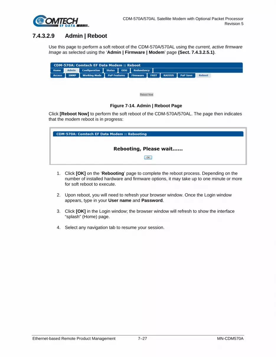
CDM-570A/570AL Satellite Modem with Optional Packet Processor Revision 5
Ethernet-based Remote Product Management 7–27 MN-CDM570A
7.4.3.2.9 Admin | Reboot
Use this page to perform a soft reboot of the CDM-570A/570AL using the current, active firmware Image as selected using the ‘Admin | Firmware | Modem’ page (Sect. 7.4.3.2.5.1).
Figure 7-14. Admin | Reboot Page
Click [Reboot Now] to perform the soft reboot of the CDM-570A/570AL. The page then indicates that the modem reboot is in progress:
1. Click [OK] on the ‘Rebooting’ page to complete the reboot process. Depending on the number of installed hardware and firmware options, it may take up to one minute or more for soft reboot to execute.
2. Upon reboot, you will need to refresh your browser window. Once the Login window
appears, type in your User name and Password. 3. Click [OK] in the Login window; the browser window will refresh to show the interface
“splash” (Home) page. 4. Select any navigation tab to resume your session.

CDM-570A/570AL Satellite Modem with Optional Packet Processor Revision 5
Ethernet-based Remote Product Management 7–28 MN-CDM570A
7.4.3.3 Configuration Pages
Use the nested ‘Configuration’ pages to configure all operating parameters for the CDM-570A/570AL, including the optional Packet Processor, and ODUs when connected. Click, as applicable, the Modem, LAN, ARP, Routing, Managed Switch, WAN, Overhead, Utilities, BUC, or LNB tab to continue.
7.4.3.3.1 Configuration | Modem
• Chapter 6. FRONT PANEL OPERATION • Appendix P. ADAPTIVE CODING AND MODULATION (ACM) OPTION
Figure 7-15. Configuration | Modem Page (Non-ACM Modes)

CDM-570A/570AL Satellite Modem with Optional Packet Processor Revision 5
Ethernet-based Remote Product Management 7–29 MN-CDM570A
Figure 7-16. Configuration | Modem | IP-ACM (VersaFEC ACM) Page

CDM-570A/570AL Satellite Modem with Optional Packet Processor Revision 5
Ethernet-based Remote Product Management 7–30 MN-CDM570A
Figure 7-17. Configuration | Modem | VersaFEC-2-ACM (V2-ACM) Page
Use the ‘Configuration | Modem’ page to configure these modem operating parameters:
• Unit Interface and Framing Mode* • Tx Power Level
• Tx / Rx Operating Parameters • Carrier-in-Carrier (CnC) Parameters • VersaFEC ACM (IP-ACM) or VersaFEC-2 ACM
(V2-ACM) Parameters
* Unit Interface Type and Framing Mode have higher priority and should be configured before setting other parameters.
The page appearances change with your selection of the operating mode. Figure 7-15 shows this page as it appears when any non-ACM operating mode is active. When you select IP-ACM (VersaFEC ACM) shown in Figure 7-16, or VersaFEC2-ACM (V2-ACM) shown in Figure 7-17, the page displays the addition of the pertinent ACM section, to the right of the CnC section.

CDM-570A/570AL Satellite Modem with Optional Packet Processor Revision 5
Ethernet-based Remote Product Management 7–31 MN-CDM570A
Interface / Framing Use the drop-down lists to select the appropriate Unit Interface Type and Unit Framing Mode. Click [Submit] to save.
Transmit Set all Tx parameters as needed. Click [Config Tx] to save.
When CDM-570 Compatible Mode is selected using the ‘Configuration | Utilities’ page (Sect. 7.4.3.3.8): 1. The VersaFEC and ULL (Ultra Low Latency) Tx FEC types and their available
Tx Modulation Types, Codes, and Data Rates become UNAVAILABLE. The Tx FEC Type will be reset to Viterbi and the Modulation and Code Rate will also be reset to appropriate values.
2. If the Frequency is set >2000 MHz, then it will be reset to 1201 MHz. Be sure to reconfigure your Tx IF Frequency as needed.
3. Clock Invert becomes UNAVAILABLE.
4. Tx Filter Rolloff Factor becomes FIXED at 0.35
Receive Set all Rx parameters as needed. Click [Config Rx] to save.
When CDM-570 Compatible Mode is selected using the ‘Configuration | Utilities’ page (Sect. 7.4.3.3.8): 1. The VersaFEC and ULL Rx FEC types and their available Rx Demodulation
Types, Codes, and Data Rates become UNAVAILABLE. The Rx FEC Type will be reset to Viterbi and the Demodulation and Code Rate will also be reset to appropriate values.
2. If the Frequency is set >2000 MHz, then it will be reset to 1201 MHz. Be sure to reconfigure your Rx IF Frequency as needed.
3. Clock Invert becomes UNAVAILABLE.
4. Rx Filter Rolloff Factor becomes FIXED at 0.35
Tx Power Level Enter a Tx Power Level, in dBm, and then [Config Power Level] to save this setting.

CDM-570A/570AL Satellite Modem with Optional Packet Processor Revision 5
Ethernet-based Remote Product Management 7–32 MN-CDM570A
Carrier-in-Carrier (CnC)
Appendix G. DOUBLETALK CARRIER-IN-CARRIER (CnC) OPTION
When CDM-570 Compatibility Mode is selected using the ‘Configuration | Utilities’ page (Sect. 7.4.3.3.8), CnC is UNAVAILABLE and this page section becomes nonfunctional.
• Mode – Use the drop-down list to set your desired CnC operating mode (Off,
Normal, or CnC-APC variants).
• Search Delay Range – Enter minimum and maximum values, in ms.
To reduce the time taken for the CnC algorithm to converge, you may apply restrictions to the range of delay used by the search. During initial link testing, you should set the delay to a minimum of 240 ms and a maximum of 300 ms. Once CnC has found the exact delay, the value can be further reduced but care should be taken to allow sufficient range to accommodate changes in path delay due to Doppler.
If bench-testing CnC with two units in a back-to-back configuration, you should set the minimum delay to 0 ms, and the maximum delay to 20 ms. This takes into account the lack of satellite delay.
• Freq Offset Range – This range is pre-calculated. The Rx symbol rate determines the CnC Frequency Offset:
o From 16 to 64 ksymbols/sec (ksps): ±1 to the symbol rate (ksps/2)
o 64 ksps and above: ±1 to 32kHz
Click [Submit] to save.

CDM-570A/570AL Satellite Modem with Optional Packet Processor Revision 5
Ethernet-based Remote Product Management 7–33 MN-CDM570A
7.4.3.3.2 Configuration | LAN
If you submit any changes to this page when the optional Packet Processor is INSTALLED, you must also open the ‘Admin | Pap Save’ page (see Sect. 7.4.3.2.8) and immediately click [Save PaP Parameters].
Figure 7-18. Configuration | LAN Page
Network Configuration (Typical with or without Packet Processor) • IP Address/Mask – Use this field to configure the modem’s Management IP Address.
• Managed Switch Gateway IP – Use this field to configure this IP Address.
• Traffic UP Address/Mask (not applicable in Managed Switch Mode) – Use this field to
configure the modem’s Traffic IP Address. Note that this address is assigned automatically when the modem is running in Managed Switch Mode.
• MAC Address – This parameter is read-only and cannot be changed. • Dedicated Management Port – This feature is available when the optional Packet Processor
is INSTALLED, but it is unavailable when VLAN Mode is Enabled.
Appendix Q. DEDICATED MANAGEMENT PORT FEATURE
• Traffic MAC Address – This parameter is read-only and cannot be changed. Click [Submit] to save.

CDM-570A/570AL Satellite Modem with Optional Packet Processor Revision 5
Ethernet-based Remote Product Management 7–34 MN-CDM570A
Port Configuration (with optional Packet Processor INSTALLED) • Port – This column identifies the active/available IP ports.
• Mode and Speed – Use the drop-down list to select the speed for the active port as
Auto, 10 Mbps Half Duplex, 100 Mbps Half Duplex, 10 Mbps Full duplex, or 100 Mbps Full Duplex.
Click [Submit Port Cnfg] to save.
• Actual Negotiated Port Speed – This column identifies the port’s current operational
speed and send/receive settings.
VLAN Brouter (with optional Packet Processor INSTALLED) VLAN Brouter mode operation is special mode of operation where VLAN traffic is bridged and non-VLAN traffic in routed using static route table information.
When Brouter mode is used in a hub-spoke network, the remote routers receives the whole outbound traffic transmitted by the hub. Since VLAN traffic is transmitted to the remote routers using a broadcast HDLC address, the receiver FPGA in the remote CDM-570A/570ALs will forward all the traffic to the CPU. In addition to the hub receiving traffic the remote routers shall also forward the return link (remote to hub) traffic.
• Typical for VLAN Brouter Mode, VLAN Brouter Tx Payload Compression, VLAN Remote Mode, and VLAN Filtering – Use the drop-down lists to Enable or Disable operation.
• VLAN Brouter Next Hop MAC Address – Enter the desired Next Hop IP Address for toEth routes. Note that no Next Hop entry is needed for toSat routes.
• VLAN ID 1 through VLAN ID 10 – You may assign up to 10 VLAN ID addresses within the range from 0001 to 4095.
Click [Submit Changes] to save.
Make sure to also click [Save PaP Parameters] on the ‘Admin | PaP Save’ page before proceeding further .

CDM-570A/570AL Satellite Modem with Optional Packet Processor Revision 5
Ethernet-based Remote Product Management 7–35 MN-CDM570A
7.4.3.3.3 Configuration | ARP
1. This page is available only to Admin users and when you install the optional Packet Processor.
2. If you submit any changes to this page, you must also open the ‘Admin | Pap Save’ page (see Sect. 7.4.3.2.8) and immediately click [Save PaP Parameters].
ARP (Address Resolution Protocol) is a technique by which the HTTP Interface in Router Mode on a given network answers the ARP queries for a network address that is not on this network, but is reachable via the Packet Processor Interface. Use this page to configure the modem’s ARP parameters.
Figure 7-19. Configuration | ARP Page
ARP Table (Edit) This section displays the current Static and Dynamic ARP entries and, when more than one ARP entry exists, allows you to directly edit the current Static ARP entries:
Column Description
Index This is the internal table index that is automatically assigned and cannot be edited.
IP IP Address, in the format XXX.XXX.XXX.XXX.
MAC MAC Address, in the format YY:YY:YY:YY:YY:YY.
Type This column identifies the ARP Type as Static or Dynamic. It cannot be edited. Click [Submit Changes] to save.

CDM-570A/570AL Satellite Modem with Optional Packet Processor Revision 5
Ethernet-based Remote Product Management 7–36 MN-CDM570A
Add Static ARP This section allows you to directly add a static ARP entry. Note that the index number will automatically increment to the next available number. Click [Add Entry] to save.
Delete Static ARP Enter Entry Index to Delete, and then click [Delete Entry]. The entry will then be deleted from the ARP table.
Flush Dynamic ARPs Click [Flush ARP Table] to delete all dynamically learned ARP entries.
Make sure to also click [Save PaP Parameters] on the ‘Admin | PaP Save’ page before proceeding further.
7.4.3.3.4 Configuration | Routing Pages
1. These pages are available only to Admin users and when you install the optional Packet Processor.
2. If you submit any changes to these pages, you must also open the ‘Admin | Pap Save’ page (see Sect. 7.4.3.2.8) and immediately click [Save PaP Parameters].
Click the Routes, IGMP, or DHCP tab to continue.
7.4.3.3.4.1 Configuration | Routing | Routes
Use this page to enter static routes into the Packet Processor to route IP traffic over the satellite or to another device on the local LAN.

CDM-570A/570AL Satellite Modem with Optional Packet Processor Revision 5
Ethernet-based Remote Product Management 7–37 MN-CDM570A
Figure 7-20. Configuration | Routing | Routes Page
Route Table (Edit) This section displays and allows you to edit all current Route Table entries. From left to right:
Column Description
Index This is the internal table index that is automatically assigned and cannot be edited.
Name This label helps to maintain the network. Enter a label string in this text box. The assigned name must be unique and cannot contain any whitespace.
Dest.IP/Mask Enter a Destination IP Address/Mask in the form XXX.XXX.XXX.XXX/YY.
Interf. Use the drop-down list to select the Interface as toEth or toSat.
Next Hop IP Enter the desired Next Hop IP Address for toEth routes. Note that no Next Hop entry is needed for toSat routes.
Next Hop HDLC
Displays the desired Next Hop HDLC IP Address for traffic to be sent over the satellite, within the following ranges: • Point-to-Point: No HDLC address • Small Network: 0x1 – 0xFE • Large Network: 0x1 – 0x7FFE
Multicast Options
Use the drop-down list to select the Multicast Option as noRouting, ethToSatRouting, satToEthRouting, or satToEthAndEthToSatRouting.
Header Comp. When the optional Header Compression FAST feature is available, use the drop-down list to Disable or Enable operations.
Payload Comp. When the optional Payload Compression FAST feature is available, use the drop-down list to Disable or Enable operations.

CDM-570A/570AL Satellite Modem with Optional Packet Processor Revision 5
Ethernet-based Remote Product Management 7–38 MN-CDM570A
Column Description
Encryption
3xDES Encryption is a future offering and is not available in this firmware release. Encryption
Key Click [Submit Changes] to save.
Add New Route This section allows you to directly add a route entry using text boxes and drop-down lists as described previously for the Route Table (Edit) section. Click [Add Entry] to save. Note that, when you add a new route, the index number will automatically increment to the next available number.
Delete Route Enter Route Index to Delete, and then click [Delete Entry]. The specified route entry will then be deleted from the route table.
Make sure to also click [Save PaP Parameters] on the ‘Admin | PaP Save’ page before proceeding further.
7.4.3.3.4.2 Configuration | Routing | IGMP
This page permits use of Internet Group Management Protocol (IGMP) with configured multicast routes. IGMP, when enabled, responds to IGMP queries for the configured multicast routes on the transmit side and generates IGMP queries on the receive side. If there are no active IGMP receivers on the LAN, it will stop forwarding the multicast traffic (received from the satellite) to the LAN.
Figure 7-21. Configuration | Routing | IGMP Page

CDM-570A/570AL Satellite Modem with Optional Packet Processor Revision 5
Ethernet-based Remote Product Management 7–39 MN-CDM570A
CDM-570A as Client • Recognize IGMP Queries – Use the drop-down list to select No or Yes.
• IGMP Version for Unsolicited Reports – Use the drop-down list to select V1 or V2.
• Unsolicited Report Interval – This is the maximum response time inserted into group-specific queries that are set in response to Leave Group messages, and it is also the amount of time between group-specific query messages. This value may be tuned to modify the "leave latency" of the network; a reduced value results in reduced time to detect the loss of the last member of a group.
Enter a value, in seconds, from 1 to 25 (default = 1 second).
• Force Router Alert Option Sending V1 Reports – Use the drop-down list to select No
or Yes.
CDM-570A as Server • Enable IGMP – Use the drop-down list to select No or Yes.
• IGMP Version for Unsolicited Reports – Use the drop-down list to select V1 or V2.
• IGMP Query Period – This is the interval between general queries sent by the modem. By varying the query interval, a modem administrator may tune the number of IGMP messages on the subnet; note that larger numbers cause the IGMP queries to be sent less often.
Enter a value, in seconds, from 1 to 600.
• IGMP Maximum Response Time – This is the maximum response time inserted into the periodic general queries. By varying the Query Response Interval, a modem administrator may tune the “burstiness” of IGMP messages on the subnet; note that larger values make the traffic less “bursty” as host responses are spread out over a large interval.
Enter a value, in seconds, from 1 to 30.
The number of seconds assigned to the Query Response Interval must be less than the Query Interval.
Click [Submit] to save.
IGMP Table This read-only table displays the Multicast Routes that are active on the modem. Click [Refresh] to update this section with its latest available information.
Make sure to also click [Save PaP Parameters] on the ‘Admin | PaP Save’ page before proceeding further.

CDM-570A/570AL Satellite Modem with Optional Packet Processor Revision 5
Ethernet-based Remote Product Management 7–40 MN-CDM570A
7.4.3.3.4.3 Configuration | Routing | DHCP
Use this page to set up the DHCP (Dynamic Host Configuration Protocol) Relay feature. DHCP allows a device to be configured automatically – eliminating the need for intervention by a network administrator – and provides a server located at the hub for keeping track of devices that are connected to the network. This prevents two devices from accidentally being configured with the same IP Address.
Figure 7-22. Configuration | Routing | DHCP Page
DHCP Relay • DHCP Server IP Address – Enter the IP Address to be used for the DHCP server at the
hub in the form XXX.XXX.XXX.XXX. Enter 0.0.0.0 to disable this feature. Click [Submit] to save.
Make sure to also click [Save PaP Parameters] on the ‘Admin | PaP Save’ page before proceeding further.

CDM-570A/570AL Satellite Modem with Optional Packet Processor Revision 5
Ethernet-based Remote Product Management 7–41 MN-CDM570A
7.4.3.3.5 Configuration | Managed Switch
1. This page is available only to Admin users and when you install the optional Packet Processor.
2. If you submit any changes to this page, you must also open the ‘Admin | Pap Save’ page (see Sect. 7.4.3.2.8) and immediately click [Save PaP Parameters].
Managed Switch Mode is primarily intended for operation in a point-to-point topology. It supports VLAN as well as advanced features such as QoS, Header Compression, and Payload Compression.
Figure 7-23. Configuration | Managed Switch Page
Managed Switch Configuration • Tx Payload Compression, or L3/L4/L5 Tx Header Compression – When these
features are available, use the drop-down lists to select operation as Disabled, Enabled, or Per Route.
3xDES Encryption is a future offering and is not available in this firmware release. This drop-down list is therefore non-functional at this time.
Click [Submit] to save.
Make sure to also click [Save PaP Parameters] on the ‘Admin | PaP Save’ page before proceeding further.

CDM-570A/570AL Satellite Modem with Optional Packet Processor Revision 5
Ethernet-based Remote Product Management 7–42 MN-CDM570A
7.4.3.3.6 Configuration | WAN Pages
1. These nested pages are available only to Admin users and when you install the optional Packet Processor.
2. 3xDES Encryption is a future offering and is not available in this firmware release. The nested Encryption page, while selectable and viewable, is therefore non-functional at this time.
3. If you submit any changes to these pages, you must also open the ‘Admin | Pap Save’ page (see Sect. 7.4.3.2.8) and immediately click [Save PaP Parameters].
Click the QoS, Compression, or HDLC tab to continue.

CDM-570A/570AL Satellite Modem with Optional Packet Processor Revision 5
Ethernet-based Remote Product Management 7–43 MN-CDM570A
7.4.3.3.6.1 Configuration | WAN | QoS Pages
Appendix N. QUALITY of SERVICE (QoS)
The appearance of this page, and its availability of features, is dependent on the selected QoS Mode.
(TOP) QoS Feature = Disable (BOTTOM) QoS Control Mode = Rule – Max/Priority Mode (Banner, Menu Bar not shown)
Figure 7-24. Configuration | WAN | QoS Pages
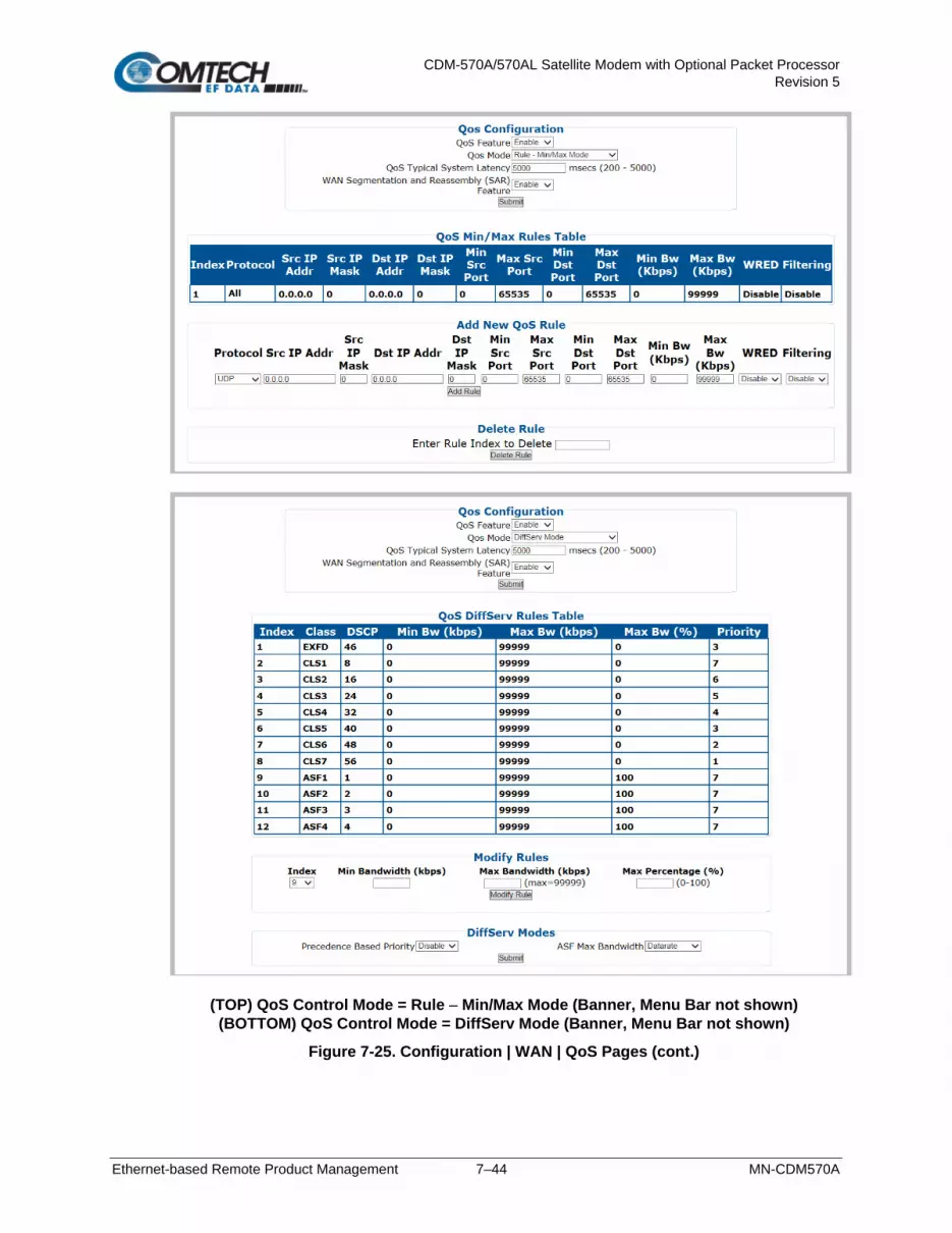
CDM-570A/570AL Satellite Modem with Optional Packet Processor Revision 5
Ethernet-based Remote Product Management 7–44 MN-CDM570A
(TOP) QoS Control Mode = Rule – Min/Max Mode (Banner, Menu Bar not shown) (BOTTOM) QoS Control Mode = DiffServ Mode (Banner, Menu Bar not shown)
Figure 7-25. Configuration | WAN | QoS Pages (cont.)

CDM-570A/570AL Satellite Modem with Optional Packet Processor Revision 5
Ethernet-based Remote Product Management 7–45 MN-CDM570A
QoS Control Mode = VLAN – Priority/Max Mode (Banner, Menu Bar not shown)
Figure 7-26. Configuration | WAN | QoS Pages (cont.)
QoS Configuration
This page section’s appearance and function is typical for all selected QoS Modes.
• QoS Feature – Use the drop-down list to Enable or Disable QoS operation.
Be sure to click [Submit] once you Enable operation; otherwise, all other operations on this page will be inaccessible.
• QoS Mode – Use the drop-down list to set the QoS Mode as Rule – Max/Priority Mode,
Rule – Min/Max Mode, DiffServ Mode, or VLAN – Priority/Max Mode.
• QoS Typical System Latency – Enter a value, in milliseconds, from 200 to 5000.
WAN Segmentation and Reassembly (SAR) – Use the drop-down list to Disable or Enable WAN SAR operation. WAN SAR is an adaptive process that triggers only when the packet latency exceeds 25 msec. WAN SAR is needed, when running small-speed (i.e., <700 kbps) links, to keep latency and jitter within the 25 msec latency/10 msec jitter specification high priority queue when the lower priority queue contains large packets.
Click [Submit] to save.

CDM-570A/570AL Satellite Modem with Optional Packet Processor Revision 5
Ethernet-based Remote Product Management 7–46 MN-CDM570A
The information that follows is applicable only when QoS Mode = Rule – Max/Priority Mode
QoS Max/Priority Rules Table
This section displays all existing QoS Max/Priority Rules Table entries. From left to right:
Column Description Index This is the internal table index that is automatically assigned and cannot be edited. Protocol Specifies the protocol for the specific rule. Src IP Addr Identifies the Source IP Address in the form XXX.XXX.XXX.XXX. Src IP Mask Identifies the Source IP Mask in the form YY. Src IP Addr Identifies the Destination IP Address in the form XXX.XXX.XXX.XXX. Dest IP Mask Identifies the Destination IP Mask in the form YY. Min Src Port Specifies the Minimum Source Port. Max Src Port Specifies the Maximum Source Port. Min Dst Port Specifies the Minimum Destination Port. Max Dst Port Specifies the Maximum Destination Port. Max BW (Kbps) Specifies the Maximum Bandwidth value in kilobits per second. Priority Specifies the priority established for the specific rule (1-8). WRED Specifies the WRED (Weighted Random Early Detection) setting for the specific rule as
Disable or Enable. Filtering Specifies the flow filter setting for the specific rule as Disable or Enable.
Add New Max/Priority QoS Rule
This section allows you to directly add a new Max/Priority QoS Rule.
• Protocol / Priority / WRED / Filtering – Use the drop-down list to select the desired operation.
• Src IP Mask / Dst IP Addr and Mask / Min and Max Src Port / Min and Max Dst Port / Max BW (Kbps) – Entire the desired value parameter as needed.
Click [Add Rule] to save. When you add a new rule to the QoS Max/Priority Rules Table, the modem automatically assigns an internal table index number to the table.

CDM-570A/570AL Satellite Modem with Optional Packet Processor Revision 5
Ethernet-based Remote Product Management 7–47 MN-CDM570A
QoS Max/Priority Delete Rule
Enter Rule Index to Delete, and then click [Delete Rule] to execute removal of the specified rule from the QoS Max/Priority Rules Table.
The information that follows is applicable only when QoS Mode = Rule – Min/Max Mode
QoS Min/Max Rules Table
This section displays all existing QoS Min/Max Rules Table entries. From left to right:
Column Description Index This is the internal table index that is automatically assigned and cannot be edited. Protocol Specifies the protocol for the specific rule. Src IP Addr Identifies the Source IP Address in the form XXX.XXX.XXX.XXX. Src IP Mask Identifies the Source IP Mask in the form YY. Src IP Addr Identifies the Destination IP Address in the form XXX.XXX.XXX.XXX. Dest IP Mask Identifies the Destination IP Mask in the form YY. Min Src Port Specifies the Minimum Source Port. Max Src Port Specifies the Maximum Source Port. Min Dst Port Specifies the Minimum Destination Port. Max Dst Port Specifies the Maximum Destination Port. Min BW (Kbps) Specifies the Minimum Bandwidth value in kilobits per second. Max BW (Kbps) Specifies the Maximum Bandwidth value in kilobits per second. WRED Specifies the WRED (Weighted Random Early Detection) setting for the specific rule as
Disable or Enable. Filtering Specifies the flow filter setting for the specific rule as Disable or Enable.

CDM-570A/570AL Satellite Modem with Optional Packet Processor Revision 5
Ethernet-based Remote Product Management 7–48 MN-CDM570A
Add New Min/Max QoS Rule
This section allows you to directly add a new Min/Max QoS Rule:
• Protocol / Priority / WRED / Filtering – Use the drop-down list to select the desired operational state.
• Src IP Mask / Dst IP Addr and Mask / Min and Max Src Port / Min and Max Dst Port / Max BW (Kbps) – Entire the desired parameter as needed.
Click [Add Rule] to save. When you add a new rule to the QoS Max/Priority Rules Table, the modem automatically assigns an internal table index number.
QoS Min/Max Delete Rule
Enter Rule Index to Delete, and then click [Delete Rule] to execute removal of the specified rule from the QoS Min/Max Rules Table.
The information that follows is applicable only when QoS Mode = DiffServ Mode

CDM-570A/570AL Satellite Modem with Optional Packet Processor Revision 5
Ethernet-based Remote Product Management 7–49 MN-CDM570A
QoS DiffServ Rules Table
This section displays all existing QoS DiffServ (Differentiated Services) Rules Table entries. From left to right:
Column Description Index This is the internal table index that is automatically assigned and cannot be edited. Class Specifies the DSCP Class Selector Precedence type (Expedited Forwarding, Assured
Forwarding, etc.) DSCP Specifies the Class Selector DiffServ Code Point (DSCP) value in the Type of Service (ToS)
byte within the IP header . Min Bw (kbps) Specifies the Minimum Bandwidth value in kilobits per second. Max Bw (kpbs) Specifies the Maximum Bandwidth value in kilobits per second. Max Bw (%) Specifies the Maximum Bandwidth (%) value. This is useful where the uppermost bandwidth
limit must be scaled as a percentage of the Tx bandwidth of the modem, when the modem bandwidth changes over time due to ACM or DSCPC in Vipersat Mode
Priority Specifies the priority established for the specific rule (1-8).
QoS DiffServ Modify Rules
This section allows you to modify an existing DiffServ QoS Rule:
• Index – Use the drop-down list to select the rule to modify.
• Min Bandwidth (kpbs) / Max Bandwidth (kbps) / Max Percentage (%) – Entire the desired parameter as needed.
Click [Modify Rule] to update the existing rule.

CDM-570A/570AL Satellite Modem with Optional Packet Processor Revision 5
Ethernet-based Remote Product Management 7–50 MN-CDM570A
QoS DiffServ Modes
• Precedence Based on Priority – Use the drop-down list to Disable or Enable the
Packet Processor’s prioritization of traffic based upon the DSCP Class Selector Precedence.
• ASF Max Bandwidth – Applicable to Assured Forwarding, this defines the value that is used to restrict the maximum bandwidth that any particular flow will utilize. Use the drop-down list to select Datarate or Percentage.
Click [Submit] to save.
The information that follows is applicable only when QoS Mode = VLAN –Priority/Max Mode
QoS: VLAN – Priority/Max Rules Table
This section displays and permits you to modify all existing QoS VLAN – Priority/Max Rules Table entries. From left to right:
Column Description Index This is the internal table index that is automatically assigned and cannot be edited. VLAN Priority Specifies the VLAN Priority established for the specific rule (0-7). Max Bw (kpbs) Specifies the Maximum Bandwidth value in kilobits per second. WRED Specifies the WRED (Weighted Random Early Detection) setting for the specific rule as Yes
or No. Click [Submit Changes] to update the specified rule.
Make sure to also click [Save PaP Parameters] on the ‘Admin | PaP Save’ page before proceeding further.

CDM-570A/570AL Satellite Modem with Optional Packet Processor Revision 5
Ethernet-based Remote Product Management 7–51 MN-CDM570A
7.4.3.3.6.2 Configuration | WAN | Compression
Use this page to configure the optional Payload and Header Compression, when this FAST feature is enabled.
Figure 7-27. Configuration | WAN | Compression Page
Compression • Header Comp. Refresh Rate for UDP/RTP1 – Enter the number of packets, from 1 to
600, required to trigger the Header Compression’s User Datagram Protocol/Real Time Protocol refresh rate.
• Header Comp. Refresh Rate for UDP – Enter the number of packets, from 1 to 600, required to trigger the Header Compression’s User Datagram Protocol refresh rate.
• Header Comp. Refresh Rate for all others – Enter the number of packets, from 1 to 600, required to trigger the Header Compression’s Default Protocol refresh rate.
• Payload Comp. Refresh Rate – Enter the number of packets, from 1 to 600, required to trigger the Payload Compression’s refresh rate.
Click [Submit] to save.
Make sure to also click [Save PaP Parameters] on the ‘Admin | PaP Save’ page before proceeding further.

CDM-570A/570AL Satellite Modem with Optional Packet Processor Revision 5
Ethernet-based Remote Product Management 7–52 MN-CDM570A
7.4.3.3.6.3 Configuration | WAN | HDLC
This page allows configuration of HDLC encapsulation parameters.
Figure 7-28. Configuration | WAN | HDLC Page
HDLC Identifies the HDLC Address Mode that was defined using the ‘Admin | Working Mode’ page (Sect. 7.4.3.2.3): Small Network Mode, Large Network Mode, Point-to-Point Mode, Vipersat Mode, or Managed Switch mode.
Receive HDLC Addresses Enter the Network Mode Address Range for Channels 1 through 4 here. Note that the valid Small Network Mode address range is from 1 to 254, and the Large Network Mode address range is from 1 to 32766. Click [Submit] to save.
Delete HDLC Address Use the drop-down list to delete an HDLC Address on a per-channel basis (1, 2, 3, or 4); otherwise, choose “Select 1…4 to delete” to delete all assigned addresses. Click [Delete] to execute your choice.
Make sure to also click [Save PaP Parameters] on the ‘Admin | PaP Save’ page before proceeding further.

CDM-570A/570AL Satellite Modem with Optional Packet Processor Revision 5
Ethernet-based Remote Product Management 7–53 MN-CDM570A
7.4.3.3.7 Configuration | Overhead
Chapter 6. FRONT PANEL OPERATION
(TOP) CnC-APC Mode Disabled/De-activated (BOTTOM) CnC-APC Mode Enabled/Activated (Banner, Menu Bar not shown)
Figure 7-29. Configuration | Overhead Page

CDM-570A/570AL Satellite Modem with Optional Packet Processor Revision 5
Ethernet-based Remote Product Management 7–54 MN-CDM570A
Use this page to configure the following interfaces:
• AUPC (when Carrier-in-Carrier Automatic Power Control is disabled/de-activated).
Appendix E. AUPC (AUTOMATIC UPLINK POWER CONTROL)
• EDMAC Framing Mode and Slave Address
Appendix J. EDMAC CHANNEL
• CnC-APC (Carrier-in-Carrier Automatic Power Control)
Appendix G. DOUBLETALK CARRIER-IN-CARRIER OPTION
When CDM-570 Compatibility Mode is selected using the ‘Configuration | Utilities’ page (Sect. 7.4.3.3.8), CnC-APC is UNAVAILABLE and this page section is not visible.
Click [Submit] to save.

CDM-570A/570AL Satellite Modem with Optional Packet Processor Revision 5
Ethernet-based Remote Product Management 7–55 MN-CDM570A
7.4.3.3.8 Configuration | Utilities | Utilities 1
Figure 7-30. Configuration | Utilities | Utilities 1 Page

CDM-570A/570AL Satellite Modem with Optional Packet Processor Revision 5
Ethernet-based Remote Product Management 7–56 MN-CDM570A
Compatibility Mode Because certain features of the CDM-570A/570AL Satellite Modem are not backward-compatible with the CDM-570 (70/140 MHz) and CDM-570L (L-Band) Satellite Modems, the CDM-570A/570AL provides a “compatibility mode” that is intended for use in existing networks that commingle operations of the CDM-570A/570AL and the CDM-570/L. Use the option buttons top select CDM-570A Mode or CDM-570 Mode. Click [Submit] to execute the selection. Be sure to take the following operational conditions into consideration when using Compatibility Mode operation: 1. Use of CDM-0570 Compatibility Mode is NOT required if the CDM-570A/570AL
is a component in a new or existing network that does NOT include CDM-570/L modems.
2. Certain page functionality becomes disabled or inaccessible while the modem is set to CDM-570 Compatibility Mode:
• ‘Configuration | Modem’ page (Sect. 7.4.3.3.1)
o Transmit section: Tx Clock Invert o Receive section: Rx Clock Invert o Carrier-in-Carrier (CnC) section (including APC settings)
• ‘Configuration | Overhead’ page (Sect. 7.4.3.3.7)
o CnC-APC section
• ‘Configuration | Utilities’ page (this section) o BERT Config section o BERT Monitor section
3. Certain feature options becomes disabled and unavailable while the modem
is set to CDM-570 Compatibility Mode.
• ‘Configuration | Modem’ page (Sect. 7.4.3.3.1) o Transmit section:
Tx FEC Type – VersaFEC and ULL unavailable* Tx Filter Rolloff Factor – Becomes fixed at 0.35
o Receive section: Rx FEC Type – VersaFEC and ULL unavailable* Rx Filter Rolloff Factor – Becomes fixed at 0.35
(*FEC Type defaults to Viterbi; Modulation/Demodulation Types, FEC Code Rates, and Data Rates all adjust accordingly)
4. Certain operational settings will reset to a default or fallback value when the
modem is set to CDM-570 Compatibility Mode. You must be sure to reconfigure the modem to your previously configured settings.
• ‘Configuration | Modem’ page (CDM/R-570AL only) (Sect. 7.4.3.3.1)
o Transmit section: Frequency value >2000 MHz resets to 1201 MHz o Receive section: Frequency value >2000 MHz resets to 1201 MHz
• ‘Configuration | Utilities’ page (this section)
5. Clocks section: If Internal plus output selected, resets to Internal.

CDM-570A/570AL Satellite Modem with Optional Packet Processor Revision 5
Ethernet-based Remote Product Management 7–57 MN-CDM570A
Re-Center Buffer Click [Re-Center Buffer] to force the re-centering of the Plesiochronous/Doppler buffer.
Unit Use the drop-down lists provided in this section to configure Test Mode, Stats Sample Interval, Front Panel Lockout, RTS/CTS Control, and HSSI Handshake Control. Click [Submit Unit Utilities] to save.
Clocks Use the drop-down lists provided in this section to configure Tx / Rx Clock Sources, Rx Buffer Size, External Clock, External Frequency Reference, and G.703 Clock Extended Mode / Interface.
If “Internal plus output” is your active External Frequency Reference setting, and you then set the modem to CDM-570 Compatibility Mode, the modem will reset this feature to “Internal”. Reconfigure your setting as needed.
Click [Submit Clocks] to save.
Circuit ID
It is IMPORTANT to understand that Circuit ID is a distinct feature of the CDM-570A/570AL. Read your documentation carefully.
Enter a Circuit ID string of up to 24 characters. You may use the following characters to compose either string:
[Space] ( ) * + - , . / 0-9 and A-Z.
Date & Time • Enter a date using DD/MM/YY format
(where DD = day [01 to 31], MM = month [01 to 12], and YY = year [00 to 99]).
• Enter a time using HH:MM:SS format (where HH = hour [00 to 23], MM = minutes [00 to 59], and SS = seconds [00 to 59]).
Click [Enter Date/Time] once you set the desired date and time.

CDM-570A/570AL Satellite Modem with Optional Packet Processor Revision 5
Ethernet-based Remote Product Management 7–58 MN-CDM570A
BERT Config Use the drop-down lists provided in this section to configure BERT for Tx or Rx as On or Off; configure the pattern for Tx or Rx; and set Error Insertion as either Off or 10E-3. Click [Submit BERT] once you select the desired BERT settings.
Use of this feature is UNAVAILABLE when operating in CDM-570 Compatibility Mode. See Sect. 7.4.3.3.8 for further information.
BERT Monitor This read-only section displays the ongoing BERT. Click [Restart] to restart the BERT Monitor, or [Update] to refresh a test already in progress.
Use of this feature is UNAVAILABLE when operating in CDM-570 Compatibility Mode. See Sect. 7.4.3.3.8 for further information.
Save / Load (Save takes precedence over Load) As a safeguard, to prevent any inadvertent action the Save Location and Load Location drop-down lists’ default selections are Don’t Save and Don’t Load, respectively. Otherwise:
• Save Location / Load Location – Use the drop-down lists to save or load up to 10 different modem configurations – 0 through 9. An empty location is noted on its menu line as Available.
Click [Submit Save/Load] to save.
7.4.3.3.8.1 Configuration | Utilities | Carrier ID (MetaCarrier)
It is IMPORTANT to understand that Carrier ID is a distinct feature of the CDM-570A/570AL. Read your documentation carefully. Note that in accordance with the DVB specifications, Carrier ID is only available when the Transmit symbol rate is greater than, or equal to 128 ksps.
Appendix R. CARRIER ID (MetaCarrier)

CDM-570A/570AL Satellite Modem with Optional Packet Processor Revision 5
Ethernet-based Remote Product Management 7–59 MN-CDM570A
Figure 7-31. Configuration | Utilities | Carrier ID Page
• MAC Address – This parameter is read-only and cannot be changed.
• Latitude – Enter a value, for degrees, from 0 to 90. Enter a value, for minutes, from 00.00 to 59.99. Use the drop-down list to select N (North) or S (South).
• Longitude – Enter a value, for degrees, from 0 to 180. Enter a value, for minutes, from 00.00 to 59.99. Use the drop-down list to select E (East) or W (West).
• Telephone Number – Enter a phone number. Valid characters are +, x, 0-9.
• Custom Message – Enter a MetaCarrier Custom Message as needed, up to 24 characters. You may use the following characters to compose tis string:
[Space] ( ) * + - , . / 0-9 and A-Z.
The MetaCarrier Custom Message, as created here, also appears in the title bar of compatible web browsers for easy unit identification.
• Carrier ID State – Use the drop-down list to set Carrier ID operation as ON or OFF. Click [Submit] to save.
7.4.3.3.9 Configuration | BUC (CDM/R-570AL Only)
Chapter 10. CDM-570A/570AL ODU (TRANSCEIVER, BUC, LNB) M&C Operation
When a BUC is connected to a CDM/R-570AL (L-Band) Satellite Modem, you may use this page to configure its operating parameters and to view the BUC operational status.

CDM-570A/570AL Satellite Modem with Optional Packet Processor Revision 5
Ethernet-based Remote Product Management 7–60 MN-CDM570A
Figure 7-32. Configuration | BUC Page
7.4.3.3.10 Configuration | LNB (CDM/R-570AL Only)
Chapter 10. CDM-570A/570AL ODU (TRANSCEIVER, BUC, LNB) M&C Operation
When a LNB is connected to a CDM/R-570AL (L-Band) Satellite Modem, you may use this page to configure its operating parameters and to view the LNB operational status.
Figure 7-33. Configuration | LNB Page

CDM-570A/570AL Satellite Modem with Optional Packet Processor Revision 5
Ethernet-based Remote Product Management 7–61 MN-CDM570A
7.4.3.4 Status Pages
The Status pages provide you with status, event logging, and operational statistics windows. Click the Modem Status, System Logs, Modem Info, Traffic Statistics, Performance, or Graph tab to continue.
7.4.3.4.1 Status | Modem Status
Use this page to view read-only status window pertaining to: • Alarms • Rx Parameters • ACM (not active for
RS422, IP, V.35, RS232, and G703)
• CnC • AUPC • Fractional CnC Counters • General Status
Figure 7-34. Status | Modem Status Page (VersaFEC ACM (IP-ACM) or
VersaFEC-2 ACM (V2-ACM) Mode Not Active)
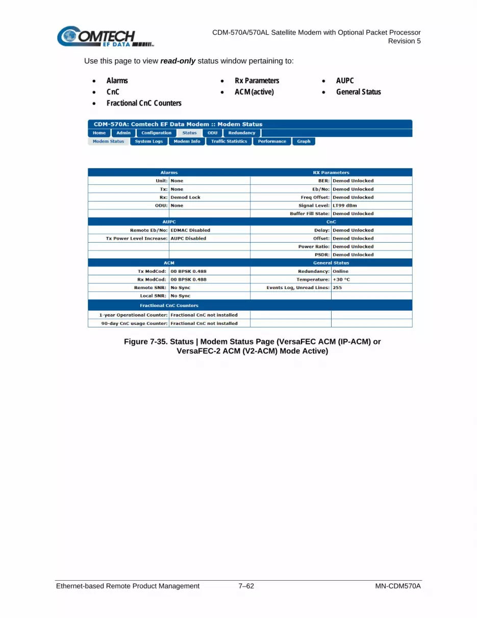
CDM-570A/570AL Satellite Modem with Optional Packet Processor Revision 5
Ethernet-based Remote Product Management 7–62 MN-CDM570A
Use this page to view read-only status window pertaining to: • Alarms • Rx Parameters • AUPC • CnC • ACM (active) • General Status • Fractional CnC Counters
Figure 7-35. Status | Modem Status Page (VersaFEC ACM (IP-ACM) or
VersaFEC-2 ACM (V2-ACM) Mode Active)

CDM-570A/570AL Satellite Modem with Optional Packet Processor Revision 5
Ethernet-based Remote Product Management 7–63 MN-CDM570A
7.4.3.4.2 Status | System Logs | Modem
Chapter 6. FRONT PANEL OPERATION
Use this page to review logged operational events and statistics, and to control how the fault, statistics, and alarm masking parameters are processed by the modem.
Figure 7-36. Status | System Logs | Modem Page

CDM-570A/570AL Satellite Modem with Optional Packet Processor Revision 5
Ethernet-based Remote Product Management 7–64 MN-CDM570A
Events Log • Read Next Five Events – Click to buffer the next group of five stored events into the
scrollable, read-only events window.
• Clear Events Log – Click to erase all entries from the stored events log.
• Initialize Events Pointer – Click to reset the Event Log’s internal pointer. Click [Submit] to save.
• Unread Events – This scrollable, read-only window displays the total number of unread
stored events. As stored event groups are displayed, the counter decrements accordingly.
Statistics Log
If you change your operating mode between Non-ACM and ACM (VersaFEC ACM (IP-ACM) or VersaFEC-2 ACM (V2-ACM)) mode, Comtech EF Data recommends that you execute the Clear Statistics Log feature before retrieving any further statistics.
• Read Next Five Statistics – Click to buffer the next group of five stored events into the
scrollable, read-only statistics window.
• Clear Statistics Log – Click to erase all entries from the stored Statistics Log.
• Initialize Statistics Pointer – Click to reset the Statistics Log’s internal pointer.
Click [Submit] to save.
• Unread Statistics – This scrollable, read-only window displays the total number of unread stored statistics. As stored statistics are displayed, the counter decrements accordingly.
Alarm Mask Use the available option buttons to designate an alarm as Masked or Active. Click [Submit Alarm Mask] to save.

CDM-570A/570AL Satellite Modem with Optional Packet Processor Revision 5
Ethernet-based Remote Product Management 7–65 MN-CDM570A
7.4.3.4.3 Status | Modem Info
This page displays read-only information about the currently configured modem:
• General Information
• Equipment ID
• Scrollable windows listing Options – Installed and the available Options – Not Installed.
Figure 7-37. Status | Modem Info Page

CDM-570A/570AL Satellite Modem with Optional Packet Processor Revision 5
Ethernet-based Remote Product Management 7–66 MN-CDM570A
7.4.3.4.4 Status | Traffic Statistics Pages
These pages are available only when the optional Packet Processor is INSTALLED. Click the Ethernet, Router, WAN, Compression, QoS, or Clear Counter tab to continue.
7.4.3.4.4.1 Status | Traffic Statistics | Ethernet
Use this page to review the cumulative Transmit/Receive Statistics, Performance, and Errors for the active Ethernet ports.
Figure 7-38. Status | Traffic Statistics | Ethernet Page (upper section)

CDM-570A/570AL Satellite Modem with Optional Packet Processor Revision 5
Ethernet-based Remote Product Management 7–67 MN-CDM570A
Figure 7-39. Status | Traffic Statistics | Ethernet Page (lower section)
Clear Ethernet Statistics
Click [Clear] to erase all existing information and reset the statistics compilation buffer. Otherwise, click [Refresh] to update the page with the latest polled data.

CDM-570A/570AL Satellite Modem with Optional Packet Processor Revision 5
Ethernet-based Remote Product Management 7–68 MN-CDM570A
7.4.3.4.4.2 Status | Traffic Statistics | Router
Use this page to review the cumulative routed, dropped, or filtered packets as processed by the modem while in Router Mode.
Figure 7-40. Status | Traffic Statistics | Router Page (upper section)

CDM-570A/570AL Satellite Modem with Optional Packet Processor Revision 5
Ethernet-based Remote Product Management 7–69 MN-CDM570A
Figure 7-41. Status | Traffic Statistics | Router Page (lower section)
Clear Statistics
Click [Clear] to erase all existing information and reset the statistics counters. Otherwise, click [Refresh] to update the page with the latest polled data.

CDM-570A/570AL Satellite Modem with Optional Packet Processor Revision 5
Ethernet-based Remote Product Management 7–70 MN-CDM570A
7.4.3.4.4.3 Status | Traffic Statistics | WAN
Use this page to review the cumulative WAN statistics.
Figure 7-42. Status | Traffic Statistics | WAN Page
Clear Statistics Click [Clear] to erase all existing information and reset the statistics counters. Otherwise, click [Refresh] to update the page with the latest polled data.

CDM-570A/570AL Satellite Modem with Optional Packet Processor Revision 5
Ethernet-based Remote Product Management 7–71 MN-CDM570A
7.4.3.4.4.4 Status | Traffic Statistics | Compression
When this FAST option is available, use this page to review the cumulative Header and Payload Compression statistics.
Figure 7-43. Status | Traffic Statistics | Compression Page
Clear Compression Counters Click [Clear] to erase all existing information and reset the statistics counters. Otherwise, click [Refresh] to update the page with the latest polled data.

CDM-570A/570AL Satellite Modem with Optional Packet Processor Revision 5
Ethernet-based Remote Product Management 7–72 MN-CDM570A
7.4.3.4.4.5 Status | Traffic Statistics | QoS
The appearance of this page depends on whether you enable or disable the QoS Feature operation using the ‘Configuration | WAN | QoS’ page (Sect. 7.4.3.3.6.1).
(TOP) QoS Feature = Disable (BOTTOM) QoS Feature = Enable
Figure 7-44. Status | Traffic Statistics | QoS Page
Clear QoS Counters Click [Clear] to erase all existing information and reset the statistics counters. Otherwise, click [Refresh] to update the page with the latest polled data.

CDM-570A/570AL Satellite Modem with Optional Packet Processor Revision 5
Ethernet-based Remote Product Management 7–73 MN-CDM570A
7.4.3.4.4.6 Status | Traffic Statistics | Clear Counter
Figure 7-45. Status | Traffic Statistics | Clear Counter Page
Click [Clear] to erase all existing information and reset the statistics compilation buffers from all Traffic Statistics pages (Ethernet, Router, WAN, Compression, and QoS).
7.4.3.4.5 Status | Performance
Figure 7-46. Status | Performance Page
CPU Usage This read-only page displays IP Module CPU Utilization as a percentage(%).

CDM-570A/570AL Satellite Modem with Optional Packet Processor Revision 5
Ethernet-based Remote Product Management 7–74 MN-CDM570A
7.4.3.4.6 Status | Graph Pages
The Graph pages provide you with real-time visual monitoring of modem signal operation. Click the Constellation or Spectrum tab to continue.
7.4.3.4.6.1 Status | Graph | Constellation
(TOP) Constellation Graph “PICK A COLOR” = (RED) (BOTTOM) Constellation Graph “PICK A COLOR” = (GREEN) (Banner, Menu Bar not shown)
Figure 7-47. Status | Graph | Constellation Page
Use this page to display the real-time Ethernet Rx IQ constellation monitor:
• First, configure the graph appearance in the upper right-hand side (“PICK A COLOR”). Click the red box to display a red constellation pattern on a black/gray grid. Click the green box to display a green constellation pattern on a gray/blue grid.
• Then, click [START] to activate or [STOP] to pause the Constellation monitoring function.

CDM-570A/570AL Satellite Modem with Optional Packet Processor Revision 5
Ethernet-based Remote Product Management 7–75 MN-CDM570A
7.4.3.4.6.2 Status | Graph | Spectrum
(TOP) Spectrum Graph “PICK A COLOR” = (RED), AVERAGING=High, RESOLUTION=High, BAND=Narrow
(BOTTOM) Spectrum Graph “PICK A COLOR” = (GREEN), AVERAGING=Low, RESOLUTION=High, BAND=Wide (Banner, Menu Bar not shown)
Figure 7-48. Status | Graphs | Spectrum Page
Use this page to display the real-time Spectrum Analyzer. Customize the display as follows: Feature Description Setting “PICK A COLOR” Click RED or GREEN to define the
overall appearance of the graph. • RED waveform on a BLACK/GRAY grid • GREEN waveform on a GRAY/BLUE grid
AVERAGING Allows you to select the averaging of the FFT spectrum.
Select Off, Low, Medium, or High
RESOLUTION Allows you to adjust the output resolution.
Select Low, Medium, or High
BAND Allows you to select the bandwidth span. Select Narrow or Wide Click [START] to activate or [STOP] to pause the Spectrum Analyzer function.

CDM-570A/570AL Satellite Modem with Optional Packet Processor Revision 5
Ethernet-based Remote Product Management 7–76 MN-CDM570A
7.4.3.5 ODU Pages Summary (CDM-570A Only)
After enabling ODU Comms operations, you may use the ‘ODU’ pages to control and monitor the CSAT-5060 or KST-2000A/B Outdoor Unit that is connected via FSK to the CDM-570A (70/140 MHz) Satellite Modem.
See Chapter 10. CDM-570A/570AL ODU (TRANSCEIVER, BUC, LNB) M&C Operation for complete details on using the HTTP Interface for ODU operations.
Figure 7-49. ODU Page Examples (Enable, Config, Status, and Utilities)

CDM-570A/570AL Satellite Modem with Optional Packet Processor Revision 5
Ethernet-based Remote Product Management 7–77 MN-CDM570A
7.4.3.6 Redundancy Page
1. This page is functional only when a Comtech EF Data Redundancy Switch is connected to the CDM-570A/570AL in a redundant configuration:
• 1:1 Redundancy is supported using either a CRS-170A L-Band 1:1
Redundancy Switch (when using CDM/R-570AL modems) or a CRS-180 70/140 MHz 1:1 Redundancy Switch (when using CDM-570A modems), and a user-provided, off-the-shelf Ethernet switch.
• 1:N Redundancy is supported only for serial data using a CRS-300/CRS-280L 1:10 Redundancy Switch (when using CDM/R-570AL modems) or a CRS-300/CRS-280 1:10 Redundancy Switch (when using CDM-570A modems).
2. Refer to your actual Comtech EF Data Switch Installation and Operation Manual for detailed information on setting up and using the CDM-570A/570AL in a redundancy configuration.
3. If you submit any changes to this page when the optional Packet Processor is INSTALLED, you must also open the ‘Admin | Pap Save’ page (see Sect. 7.4.3.2.8) and immediately click [Save PaP Parameters].
Figure 7-50. Redundancy Page
1:1 Redundancy Control • Redundancy Mode – Use the drop-down list to set Redundancy mode as Auto or
Manual.
• Packet Processor Redundancy – When the optional Packet Processor is INSTALLED, Use the drop-down list to set operation as Disabled or Enabled.
Click [Submit] to save.

CDM-570A/570AL Satellite Modem with Optional Packet Processor Revision 5
Ethernet-based Remote Product Management 7–78 MN-CDM570A
Make sure to also click [Save PaP Parameters] on the ‘Admin | PaP Save’ page before proceeding further.
Force 1:1 switch (Only applies to Online modem) This page section is valid for use with the Online unit in a 1:1 pair. When you are using redundant modems and this active unit is currently the Online unit, click [Force 1:1 Switch] to force a switchover – i.e., to place this unit into Offline (standby) mode.
Redundancy Monitor This page section automatically updates every five seconds. You may otherwise click [Refresh] to manually update the section. It provides real-time monitoring of the redundancy setup. This read-only section displays:
• The status of the active modem (i.e., Online or Offline)
• The detected presence of a redundancy switch
• The configured IP Addresses and Masks. When Packet Processor Redundancy is active, this section additionally displays the Local Unit and Redundant Unit IP Addresses and Masks in addition to the Traffic IP Address/Mask.

CDM-570A/570AL Satellite Modem with Optional Packet Processor Revision 5
Serial-based Remote Product Management 8–1 MN-CDM570A
Chapter 8. SERIAL-BASED REMOTE PRODUCT MANAGEMENT
8.1 Overview
The CDM-570A/570AL Satellite Modem serial remote product management interface is an electrical interface that is either an EIA-485 multi-drop bus (for the control of multiple devices) or an EIA-232 connection (for the control of a single device). The interface transmits data in asynchronous serial form, using ASCII characters. This data consists of control and status information, transmitted in packets of variable length in accordance with the structure and protocol explained later in this chapter.
8.2 EIA-485
For applications where multiple devices are to be monitored and controlled, a full-duplex (or 4-wire plus ground) EIA-485 is preferred. Half-duplex (2-wire plus ground) EIA-485 is possible, but is not preferred. In full-duplex EIA-485 communication, there are two separate, isolated, independent, differential-mode twisted pairs, each handling serial data in different directions. It is assumed that a 'Controller' device (a PC or dumb terminal) transmits data in a broadcast mode via one of the pairs. Multiple 'Target' devices are connected to this pair, and all simultaneously receive data from the Controller. The Controller is the only device with a line-driver connected to this pair – the Target devices have only line-receivers connected. In the other direction, on the other pair each Target has a tri-state line driver connected, and the Controller has a line-receiver connected. All the line drivers are held in high-impedance mode until one (and only one) Target transmits back to the Controller. Each Target has a unique address, and each time the Controller transmits, the address of the intended recipient Target is included in a framed 'packet' of data. All of the Targets receive the packet, but only one (the intended) will reply. The Target enables its output line driver and transmits its return data packet back to the Controller in the other direction, on the physically separate pair.

CDM-570A/570AL Satellite Modem with Optional Packet Processor Revision 5
Serial-based Remote Product Management 8–2 MN-CDM570A
EIA-485 (full duplex) summary:
Two differential pairs One pair for Controller-to-Target, one pair for Target-to-Controller.
Controller-to-Target pair One line driver (Controller), and all Targets have line receivers.
Target-to-Controller Pair One line receiver (Controller), and all Targets have Tri-State drivers.
8.3 EIA-232
This is a much simpler configuration in which the Controller device is connected directly to the Target via a two-wire-plus-ground connection. Controller-to-Target data is carried, via EIA-232 electrical levels on one conductor, and Target-to-Controller data is carried in the other direction on the other conductor.
8.4 Basic Protocol
Whether in EIA-232 or EIA-485 mode, all data is transmitted as asynchronous serial characters, suitable for transmission and reception by a Universal Asynchronous Receiver/Transmitter (UART). The asynchronous character format is 8-N-1 (8 data bits, no parity, 1 stop bit). The baud rate may vary from 1200 to 57600 baud. All data is transmitted in framed packets. The Controller is in charge of the process of monitor and control, and is the only device that is permitted to initiate, at will, the transmission of data. Targets are only permitted to transmit when they have been specifically instructed to do so by the Controller. All bytes within a packet are printable ASCII characters, less than ASCII code 127. In this context, the Carriage Return and Line Feed characters are considered printable. All messages from Controller-to-Target require a response, with one exception: This will be either to return data that has been requested by the Controller, or to acknowledge reception of an instruction to change the configuration of the Target. The exception to this is when the Controller broadcasts a message (such as Set Time/Date) using Address 0, when the Target is set to EIA-485 mode.

CDM-570A/570AL Satellite Modem with Optional Packet Processor Revision 5
Serial-based Remote Product Management 8–3 MN-CDM570A
8.4.1 Packet Structure
The exchange of information is transmitted, Controller-to-Target and Target-to-Controller, in ‘packets’. Each packet contains a finite number of bytes consisting of printable ASCII characters, excluding ASCII code 127 (DELETE). In this context, the Carriage Return and Line Feed characters are considered printable. With one exception, all messages from Controller-to-Target require a response – this will be either to return data that has been requested by the Controller, or to acknowledge reception of an instruction to change the configuration of the Target.
Controller-to-Target Start of Packet Target Address Address Delimiter Instruction Code Code Qualifier Optional Arguments End of Packet
< ASCII code 60 (1 character)
(4 characters)
/ ASCII code 47 (1 character)
(3 characters)
= or ? ASCII codes 61 or 63
(1 character)
(n characters)
Carriage Return ASCII code 13 (1 character)
Packet “issued command” example: <0000/RSW=32[cr] Packet “issued query” example: <0000/RSW?[cr]
Target-to-Controller Start of Packet Target Address Address Delimiter Instruction Code Code Qualifier Optional Arguments End of Packet
> ASCII code 62
(1 character)
(4 characters)
/ ASCII code 47
(1 character)
(3 characters)
=, ?, !, or * ASCII codes
61, 63, 33, or 42 (1 character)
(From 0 to n characters)
Carriage Return, Line Feed
ASCII codes 13,10 (2 characters)
Packet example – response received for issued query: >0000/RSW=32[cr][lf] Detailed description of the packet components follow.

CDM-570A/570AL Satellite Modem with Optional Packet Processor Revision 5
Serial-based Remote Product Management 8–4 MN-CDM570A
8.4.1.1 Start of Packet
Controller-to-Target This is the character ‘<’ (ASCII code 60).
Target-to-Controller This is the character ‘>’ (ASCII code 62).
The ‘<’ and ‘>’ characters indicate the start of packet. They may not appear anywhere else within the body of the message.
8.4.1.2 Target Address
Up to 9999 devices can be uniquely addressed. In EIA-232 applications this value is set to 0000. In EIA-485 applications, the permissible range of values is 0001 to 9999. It is programmed into a Target unit using the front panel keypad.
The Target Address designates the packet destination. The Controller does not have its own address. After the Controller sends a packet with the designated Target Address, the Target responds to the Controller, using this same address, to indicate the source of the packet.
8.4.1.3 Address Delimiter
This is the “forward slash” character '/ ' (ASCII code 47).
8.4.1.4 Instruction Code
This is a three-character alphanumeric sequence that identifies the message subject. Uppercase alphabetic characters (‘A’ to ‘Z’, ASCII Codes 65 to 90) and the numbers ‘0’ to ‘9’ *ASCII Codes 48 to 57) may be used. Wherever possible, each instruction code is named to serve as a mnemonic for its intended operation. This helps you interpret the code function, should it be shown in its raw ASCII form. For example: MLC for Management Link Configuration, IPA for Management IP Address, etc.
8.4.1.5 Instruction Code Qualifier
This is a single character that further qualifies the preceding instruction code.

CDM-570A/570AL Satellite Modem with Optional Packet Processor Revision 5
Serial-based Remote Product Management 8–5 MN-CDM570A
1. From Controller-to-Target, the only permitted values are:
Symbol Function
= (ASCII Code 61)
The ‘=’ code is used as the Assignment Operator (AO). It establishes that the Instruction Code that precedes it is issued as a command to assign or configure operation. The instruction set that follows serves to assign the Target’s new parameter setting or operational value. For example: From Controller-to-Target, <0/IG1=aaa.bbb.ccc.ddd/yy means “set the ‘ETHERNET | TRAFFIC |GE’ port IP Address to aaa.bbb.ccc.ddd/yy”
? (ASCII Code 63)
The ‘?’ code is used as the Query Operator (QO). It establishes that the Instruction Code that precedes it is issued as a query that returns the Target’s current configured parameter setting or operational value. For example: From Controller-to-Target, <0/IG1? means “what is the current ‘ETHERNET | TRAFFIC |GE’ port IP Address?”
2. From Target-to-Controller, the only permitted values are:
Symbol Function
= (ASCII Code 61)
This code is used in two ways: 1. If the Controller sends a query to the Target.
For example: <0/TFQ? (meaning “what is the current value of the transmit frequency?”) – the Target responds with >0000/TFQ=xxxx.xxxx, the value for that queried parameter.
2. If the Controller sends an instruction to set a parameter to a particular value, and the value sent is valid, the Target acknowledges the message and responds with, for example, >0000/TFQ = (with no message arguments).
? (ASCII Code 63)
If the Controller issues a command to set a parameter to a particular value, and the value sent is not valid, the Target then acknowledges the message and responds with ‘?’. This indicates that there was an error in the message sent by the Controller. For example: >0000/TFQ? (with no message arguments).
! (ASCII Code 33)
If the Controller issues a command that the Target does not recognize, the Target responds by echoing the invalid instruction code, followed by ‘!’. For example: >0000/ABC!
* (ASCII Code 42)
If the Controller issues a command to set a parameter to a particular value, and the value sent is valid, but the modem will not permit that particular parameter to be changed at present, the Target responds by echoing the valid instruction code, followed by ‘*’. For example: >0000/TFQ* (with message arguments)
# (ASCII Code 35)
If the Controller sends a correctly formatted command, but the Target is not in Remote Mode, the unit does not allow reconfiguration and responds by echoing the valid instruction code, followed by ‘#’. For example: >0000/TFQ#

CDM-570A/570AL Satellite Modem with Optional Packet Processor Revision 5
Serial-based Remote Product Management 8–6 MN-CDM570A
Symbol Function
~ (ASCII Code 126)
If a message is sent via a local modem to a distant-end device or ODU, the message was transmitted transparently through the local modem. In the event of the distant-end device not responding, the local modem wil generate a response. For example: >0000/RET~ (indicating that it has finished waiting for a response and is now ready for further comms).
+ (ASCII Code 43)
This character warns the user that the command was accepted, but that other parameters were additionally changed.
^ (ASCII Code 94)
This code indicates that the modem is in Remote mode, so serial remote control is not possible. There are two exceptions to this: 1. The LRS (Local/Remote Status) command is still active, and may be used to change the operating mode to local or to serial remote
control. 2. For the CDM/R-570AL, the FPL (Front Panel Lockout) command is active, and may be used to configure the Front Panel Lockout to
be “No lockout” or “Active.”
8.4.1.6 Optional Message Arguments
Arguments are not required for all messages. Comma ‘,’ (ASCII Code 44), period ‘.’ (ASCII Code 46), the numbers ‘0’ to ‘9’ (ASCII Codes 48 to 57), and the uppercase alphabetic characters ‘A’ to ‘Z’ (ASCII Codes 65 to 90) may be used.
8.4.1.7 End of Packet
Controller-to-Target This is the ‘Carriage Return’ ([CR]) character (ASCII code 13).
Target-to-Controller This is the two-character sequence ‘Carriage Return’, ‘Line Feed’ ([cr][lf]) (ASCII codes 13 and 10). Both indicate the valid termination of a packet.

CDM-570A/570AL Satellite Modem with Optional Packet Processor Revision 5
Serial-based Remote Product Management 8–7 MN-CDM570A
8.5 Remote Commands and Queries
8.5.1 Table Indexes
Notes: 1. The remote commands and queries are arranged as subsections of this chapter as follows:
• Sect. 8.5.2 Transmit (Tx) Commands and Queries • Sect. 8.5.3 Receive (Rx) Commands and Queries • Sect. 8.5.4 Unit Parameter Commands and Queries • Sect. 8.5.5 Bulk Configuration Commands and Queries • Sect. 8.5.6 Modem Information Commands and Queries • Sect. 8.5.7 Modem Performance Commands and Queries • Sect. 8.5.8 BUC (L-Band Block Up Converter) Commands and Queries (CDM/R-570AL ONLY) • Sect. 8.5.9 LNB (L-Band Low-noise Block Down Converter) Commands and Queries (CDM/R-570AL ONLY)
Commands/queries that are unique either to a specific unit (CDM-570A 70/140 MHz versus CDM/R-570AL L-Band modems) or to a specific mode of operation (‘CDM-570 Compatible Mode (CMO=0)’ versus ‘CDM-570A Compatible Mode (CMO=1)’ are noted accordingly (e.g., “CDM-570A ONLY”, “CDM/R-570AL ONLY”, “Valid only in CDM-570A Compatible Mode (CMO=1)” etc.).
2. Typical for Sections 8.5.2 through 8.5.9, as per Section 8.4.1.5, the following codes are used in the ‘Response to Command’ column: = Command OK. ? Command accepted, but invalid arguments found. ! Invalid command/query. * Command accepted, but not permitted in current mode. # Command accepted, but unit is not in Remote mode. ~ Time out of an EDMAC pass-through message. ^ (For any command/query other than LRS or FPL) Unit is in Remote Mode – no serial remote control is possible. + Warning: Command accepted, but other parameters were additionally changed.
3. Typical for the Sectio 8.5.1 tabulation index notes:
• Where Column ‘C’ = Command, and Column ‘Q’ = Query: Columns marked ‘X’ designate the instruction code as Command only, Query only, or Command or Query.
• Where CODE = XXX, this indicates that the item is a priority command/query. • Where CODE =XXXAL, this indicates that the item is specific to CDM/R-570AL L-Band operation.
The tabulation indices for Sections 8.5.2 through 8.5.9 are as follows:

CDM-570A/570AL Satellite Modem with Optional Packet Processor Revision 5
Serial-based Remote Product Management 8–8 MN-CDM570A
Sect. 8.5.2 Transmit (Tx) Parameter Commands and Queries: CODE C Q PAGE CODE C Q PAGE CODE C Q PAGE CODE C Q PAGE CODE C Q PAGE APP X X 8–16 REB — X 8–17 TDR X X 8–14 TSC X X 8–15 TXO X X 8–15 AUP X X 8–16 TCI X X 8–17 TFQ X X 8–14 TSI X X 8–14 FRM X X 8–10 TCK X X 8–17 TFT X X 8–11 TSR X X 8–14 ITF X X 8–10 TCR X X 8–12 TMD X X 8–11 TTF — X 8–17 PLI — X 8–17 TDI X X 8–14 TPL X X 8–15 TXA X X 8–15
Sect. 8.5.3 Receive (Rx) Parameter Commands and Queries: CODE C Q PAGE CODE C Q PAGE CODE C Q PAGE CODE C Q PAGE CODE C Q PAGE RBS X X 8–23 RCR X X 8–19 RDS X X 8–22 RMD X X 8–18 RSW X X 8–22 RCB X X 8–23 RDI X X 8–21 RFQ X X 8–49 RSI X X 8–21 RXA X X 8–22 RCI X — 8–21 RDR X X 8–21 RFT X X 8–18 RSR — X 8–21 TRF — X 8–23
Sect. 8.5.4 Unit Parameter Commands and Queries CODE C Q PAGE CODE C Q PAGE CODE C Q PAGE CODE C Q PAGE CODE C Q PAGE ACM X X 8–36 CAS X — 8–29 DMM X X 8–37 ISP X — 8–29 PHN X X 8–37 ADJ X X 8–26 CCF X X 8–33 EFM X X 8–25 LAT X X 8–37 RBP X X 8–35 ASW X X 8–30 CEX X X 8–34 ERF X X 8–26 LBO X X 8–34 RNE — X 8–28 BKE X — 8–35 CID X X 8–24 ESA X X 8–25 LNG X X 8–37 RNS — X 8–29 BRE — X 8–35 CLD X — 8–36 FPL X X 8–24 LRS X X 8–24 RTS X X 8–32 BRM X — 8–35 CMO X X 8–24 FRB X — 8–37 MAC — X 8–31 SSI X X 8–29 BRR — X 8–36 CNM X X 8–32 FSW X — 8–30 MSG X X 8–38 TBP X X 8–35 BRX X X 8–34 CSD X X 8–33 IEP X — 8–28 MSK X X 8–27 TIM X X 8–25 BTX X X 8–34 CST X — 8–37 IMG X X 8–24 NUE — X 8–27 TST X X 8–27 CAE X — 8–28 CTD X X 8–26 IPA X X 8–31 NUS — X 8–29 WUD X X 8–26 CAI X X 8–37 DAY X X 8–25 IPG X X 8–31 ODU X X 8–31
Sect. 8.5.5 Bulk Configuration Commands and Queries CODE C Q PAGE CODE C Q PAGE CODE C Q PAGE MGCA X X 8–39 MGC X X 8–41 OGC X X 8–39

CDM-570A/570AL Satellite Modem with Optional Packet Processor Revision 5
Serial-based Remote Product Management 8–9 MN-CDM570A
Sect. 8.5.6 Modem Information Commands and Queries CODE C Q PAGE CODE C Q PAGE CODE C Q PAGE CODE C Q PAGE EIDA — X 8–43 FCC — X 8–48 FRW — X 8–47 SWR — X 8–47 EID — X 8–46 FCF — X 8–48 SNO — X 8–47
Sect. 8.5.7 Modem Performance Information Commands and Queries CODE C Q PAGE CODE C Q PAGE CODE C Q PAGE CODE C Q PAGE CODE C Q PAGE ABE — X 8–55 APC X — 8–55 CDM — X 8–54 FLT — X 8–51 RSL — X 8–49 ABR X — 8–55 APL X X 8–57 CFF — X 8–54 OUS — X 8–50 RSN — X 8–50 AFE — X 8–55 APS — X 8–56 CPR — X 8–54 PSD — X 8–54 SNR — X 8–50 AFR X — 8–55 BER — X 8–49 CRM — X 8–53 RED — X 8–50 TMP — X 8–50 AHS X X 8–57 BFS — X 8–49 EBN — X 8–50 RFO — X 8–49
Sect. 8.5.8 BUC (L-Band Block Up Converter) Commands and Queries (CDM/R-570AL ONLY) CODE C Q PAGE CODE C Q PAGE CODE C Q PAGE CODE C Q PAGE CODE C Q PAGE ABA X X 8–58 BCH X X 8–58 BDV — X 8–58 BOE X X 8–59 BPC X X 8–59 BAD X X 8–58 BCL X X 8–58 BFR X X 8–59 BOL — X 8–59 BSV — X 8–60 BCE X X 8–58 BDC — X 8–58 BLO X X 8–59 BPA — X 8–59 BUT — X 8–60
Sect. 8.5.9 LNB (L-Band Low-noise Block Down Converter) Commands and Queries (CDM/R-570AL ONLY) CODE C Q PAGE CODE C Q PAGE CODE C Q PAGE CODE C Q PAGE ALA X X 8–61 LCL X X 8–61 LDV — X 8–61 LLO X X 8–62 LCH X X 8–61 LDC — X 8–61 LFR X X 8–61 LPC X X 8–62

CDM-570A/570AL Satellite Modem with Optional Packet Processor Revision 5
Serial-based Remote Product Management 8–10 MN-CDM570A
8.5.2 Transmit (Tx) Parameter Commands and Queries
Tx Priority System = ITF (Highest priority), FRM, TFT, TMD, TCR, TDR, and TSR (Lowest Priority), indicated by shading. Any change to a higher priority parameter will override any of the lower priority parameters.
Parameter Type
Command (Instruction Code and Qualifier)
Arguments for Command or Response to
Query Description of Arguments Response to
Command Query
(Instruction Code and Qualifier)
Response to Query
Unit Interface Type
ITF= 1 byte, value of 0 thru 8
Command or Query. Sets or returns Terrestrial interface type in the form x, where:
0=EIA-422/EIA530 DCE 1=V.35 DCE 2=EIA-232 (sync). 3= G.703 T1 AMI (forces Rx and Tx data rates to 1544 kbps) 4= G.703 T1 B8ZS (forces Rx and Tx data rates to 1544 kbps) 5= G.703 E1 Unbal AMI (forces Rx and Tx rates to 2048 kbps) 6= G.703 E1 Unbal HDB3 (forces Rx and Tx rates to 2048 kbps) 7= G.703 E1 Bal AMI (forces Rx and Tx rates to 2048 kbps) 8= G.703 E1 Bal HDB3 (forces Rx and Tx rates to 2048 kbps) 9 = IP Interface A = IP-ACM (valid only in CDM-570A Compatibility Mode (CMO=1)) B = VersaFEC-2 ACM (requires VFEC-2 option card)
Example: <0/ITF=2 (V.35) Note: When ITF is set as G.703, Clock Extension Mode is automatically set as 0=None. Response=ITF+
ITF= ITF? ITF* ITF# ITF+
ITF? ITF=x (see Description of Arguments)
Unit Framing Mode
FRM= 1 byte, value of 0 or 1
Command or Query. Sets or returns unit operating mode in theform x, where:
0=Unframed 1= EDMAC Framing 2= EDMAC-2 Framing
Example: <0/FRM=1 (EDMAC Framing)
FRM= FRM? FRM* FRM# FRM+
FRM? FRM=x (see Description of Arguments)

CDM-570A/570AL Satellite Modem with Optional Packet Processor Revision 5
Serial-based Remote Product Management 8–11 MN-CDM570A
Parameter Type
Command (Instruction Code and Qualifier)
Arguments for Command or Response to
Query Description of Arguments Response to
Command Query
(Instruction Code and Qualifier)
Response to Query
Tx FEC Type TFT= 1 byte, value of 0 thru 9, A to B
Command or Query. Sets or returns Tx FEC coding type in the form x, where:
0 = None (uncoded – no FEC) (forces TCR=7 Rate 1/1) with differential encoding ON
1 = Viterbi 2 = Viterbi + Reed-Solomon 3 = Reserved – do not use 4 = Reserved – do not use 5 = TCM + Reed-Solomon (Forces TCR=3 Rate 2/3) 6 = Turbo 7 = Reserved 8 = VersaFEC CCM or ACM (fixed in IP-ACM) (see note) 9 = VersaFEC ULL (see note) A = VersaFEC-2 Long (see note) B = VersaFEC-2 Short (see note)
Note: Entries 8 through B are valid only in CDM-570A Compatible Mode (CMO=1). Example: <0/TFT=1 (Viterbi coding)
TFT= TFT? TFT* TFT# TFT+
TFT? TFT=x (see Description of Arguments)
Tx Modulation Type
TMD= 1 byte, value of 0 thru 8
Command or Query. Sets or returns Tx Modulation type in the form x, where:
0 = BPSK 1 = QPSK 2 = OQPSK 3 = 8PSK 4 = 16-QAM 5 = 8-QAM (TPC/LDPC only) (Need Codec & FAST option) 6 = 8-ARY (VersaFEC-2 only) 7 = 16-ARY (VersaFEC-2 only) 8 = 32-ARY (VersaFEC-2 only)
Note: Selection availability depends on the active FEC type. Example: <0/TMD=2 (OQPSK)
TMD= TMD? TMD* TMD# TMD+
TMD? TMD=x (see Description of Arguments)

CDM-570A/570AL Satellite Modem with Optional Packet Processor Revision 5
Serial-based Remote Product Management 8–12 MN-CDM570A
Parameter Type
Command (Instruction Code and Qualifier)
Arguments for Command or Response to
Query Description of Arguments Response to
Command Query
(Instruction Code and Qualifier)
Response to Query
Tx FEC Code Rate
TCR= 1 byte, value of 0 thru 7, A toR, V to
Command or Query. (Query only in ACM) Sets or returns Tx Code Rate in the form x, where:
0 = Rate 5/16 (Turbo Only) 1 = Rate 21/44 (Turbo Only) 2 = Rate 1/2 3 = Rate 2/3 (8-PSK TCM or 8-QAM only) 4 = Rate 3/4 5 = Rate 7/8 6 = Rate 0.95 (Turbo Only) 7 = Rate 1/1 (Uncoded or No FEC) 8 = Reserved 9 = Reserved
(The remaining entries are valid only in CDM-570A Compatible Mode (CMO=1)): A = VersaFEC CCM – BPSK Rate 0.488 B = VersaFEC CCM – QPSK Rate 0.533 C = VersaFEC CCM – QPSK Rate 0.631 D = VersaFEC CCM – QPSK Rate 0.706 E = VersaFEC CCM – QPSK Rate 0.0803 F = VersaFEC CCM – 8-QAM Rate 0.576 G = VersaFEC CCM – 8-QAM Rate 0.642 H = VersaFEC CCM – 8-QAM Rate 0.711 I = VersaFEC CCM – 8-QAM Rate 0.780 J = VersaFEC CCM – 16-QAM Rate 0.644 K = VersaFEC CCM – 16-QAM Rate 0.731 L = VersaFEC CCM – 16-QAM Rate 0.780 M = VersaFEC CCM – 16-QAM Rate 0.829 N = VersaFEC CCM –16-QAM Rate 0.853 O = VersaFEC CCM ULL– BPSK Rate 0.493 P = VersaFEC CCM ULL– QPSK Rate 0.493 Q = VersaFEC CCM ULL– QPSK Rate 0.654 R = VersaFEC CCM ULL– QPSK Rate 0.734 S = Reserved T = Reserved U = Reserved V = VersaFEC-2 ModCod 0 – BPSK 0.489 W = VersaFEC-2 ModCod 1 – QPSK 0.489 X = VersaFEC-2 ModCod 2 – QPSK 0.537
TCR= TCR? TRC* TRC# TRC+
TCR? TCR=x (see Description of Arguments)

CDM-570A/570AL Satellite Modem with Optional Packet Processor Revision 5
Serial-based Remote Product Management 8–13 MN-CDM570A
Parameter Type
Command (Instruction Code and Qualifier)
Arguments for Command or Response to
Query Description of Arguments Response to
Command Query
(Instruction Code and Qualifier)
Response to Query
Tx FEC Code Rate (continued)
Y = VersaFEC-2 ModCod 3 – QPSK 0.586 Z = VersaFEC-2 ModCod 4 – QPSK 0.611 a = VersaFEC-2 ModCod 5 – QPSK 0.635 b = VersaFEC-2 ModCod 6 – QPSK 0.660 c = VersaFEC-2 ModCod 7 – QPSK 0.684 d = VersaFEC-2 ModCod 8 – QPSK 0.733 e = VersaFEC-2 ModCod 9 – 8-ARY 0.521 f = VersaFEC-2 ModCod 10 – 8-ARY 0.537 g = VersaFEC-2 ModCod 11 – 8-ARY 0.562 h = VersaFEC-2 ModCod 12 – 8-ARY 0.586 I = VersaFEC-2 ModCod 13 – 8-ARY 0 .611 j = VersaFEC-2 ModCod 14 – 8-ARY 0.635 k = VersaFEC-2 ModCod 15 – 8-ARY 0.660 l = VersaFEC-2 ModCod 16 – 8-ARY 0.684 m = VersaFEC-2 ModCod 17 – 8-ARY 0.708 n = VersaFEC-2 ModCod 18 – 8-ARY 0.733 o = VersaFEC-2 ModCod 19 – 16-ARY 0.586 p = VersaFEC-2 ModCod 20 – 16-ARY 0.611 q = VersaFEC-2 ModCod 21 – 16-ARY 0.635 r = VersaFEC-2 ModCod 22 – 16-ARY 0.660 s = VersaFEC-2 ModCod 23 – 16-ARY 0.684 t = VersaFEC-2 ModCod 24 – 16-ARY 0.708 u = VersaFEC-2 ModCod 25 – 16-ARY 0.733 v = VersaFEC-2 ModCod 26 – 16-ARY 0.757 w = VersaFEC-2 ModCod 27 – 16-ARY 0.782 x = VersaFEC-2 ModCod 28 – 32-ARY 0.660 y = VersaFEC-2 ModCod 29 – 32-ARY 0.684 z = VersaFEC-2 ModCod 30 – 32-ARY 0.708 “ = VersaFEC-2 ModCod 31 – 32-ARY 0.733 & = VersaFEC-2 ModCod 32 – 32-ARY 0.757 @ = VersaFEC-2 ModCod 33 – 32-ARY 0.782 [ = VersaFEC-2 ModCod 34 – 32-ARY 0.801 ] = VersaFEC-2 ModCod 35 – 32-ARY 0.831 = VersaFEC-2 ModCod 36 – 32-ARY 0.855 (Long Block only) = VersaFEC-2 ModCod 37 – 32-ARY 0.879 (Long Block only)
Note: Selection availability depends on the active FEC and Modulation type. Example: <0/TCR=4 (Rate 3/4)

CDM-570A/570AL Satellite Modem with Optional Packet Processor Revision 5
Serial-based Remote Product Management 8–14 MN-CDM570A
Parameter Type
Command (Instruction Code and Qualifier)
Arguments for Command or Response to
Query Description of Arguments Response to
Command Query
(Instruction Code and Qualifier)
Response to Query
Tx Data Rate TDR= CDM-570A Compatible Mode: 9 bytes CDM-570 Compatible Mode: 8 bytes
Command or Query. (Query only in ACM) Sets or returns Tx Data rate in the form xxxxx.xxx, where:
xxxxx.xxx = value from 2.4 kbps to 10240 kbps Resolution = 1 bps. Examples: 1) <0/TDR=02047.999 (2047.999 kbps in CDM-570A Compatible Mode) 2) <0/TDR=2047.999 (2047.999 kbps in CDM-570 Compatible Mode)
TDR= TDR? TDR* TDR#
TDR? TDR=xxxxx.xxx (see Description of Arguments)
Tx Symbol Rate TSR= 8 bytes Query only. (Command or Query in VersaFEC ACM (IP-ACM) or VersaFEC-2 ACM) Sets or returns Tx Symbol rate in the form xxxx.xxx, where:
xxxx.xxx = ksymbols/sec, from 4.8 ksps to 3.00 Msps Resolution = 1 sps. Note: Symbol Rate ranges in IP-ACM from 37ksps to 3000ksps Example: <0/TSR=2047.999 (2047.999 ksymbols/sec)
TSR= TSR? TSR* TSR#
TSR? TSR=xxxx.xxx (see Description of Arguments)
Tx Frequency TFQ= 9 bytes Command or Query. Sets or returns Tx Frequency in the form xxxx.xxxx, where: For CDM/R-570AL – 950 to 2250 MHz in CDM-570A Compatible Mode (CMO=1) and 950 to 2000 MHz in CDM-570 Compatible Mode (CMO=0) For CDM-570A – 50 to 90 and 100 - 180 MHz Resolution=100 Hz Examples: 1) <0/TFQ=0950.9872 2) <0/TFQ=0073.4528
TFQ= TFQ? TFQ* TFQ#
TFQ? TFQ=xxxx.xxxx (see Description of Arguments)
Tx Data Invert TDI= 1 byte, value 0 or 1
Command or Query. Sets or returns Invert Transmit Data in the form x, where:
0=Normal 1=Inverted
Example: <0/TDI=1 (selects Inverted TX Data)
TDI= TDI? TDI* TDI#
TDI? TDI=x (see Description of Arguments)
Tx Spectrum Invert
TSI= 1 byte, value of 0 or 1
Command or Query. Sets or returns Tx Spectrum Invert selection in the form x, where:
0=Normal, 1=Tx Spectrum Inverted
Example: <0/TSI=0 (normal)
TSI= TSI? TSI* TSI#
TSI? TSI=x (see Description of Arguments)

CDM-570A/570AL Satellite Modem with Optional Packet Processor Revision 5
Serial-based Remote Product Management 8–15 MN-CDM570A
Parameter Type
Command (Instruction Code and Qualifier)
Arguments for Command or Response to
Query Description of Arguments Response to
Command Query
(Instruction Code and Qualifier)
Response to Query
Tx Scrambler TSC= 1 byte, value of 0, 1 or 2
Command or Query. Sets or returns Tx Scrambler state in the form x, where:
0=Off 1=On (default scrambler type) 2 = On – IESS-315
Note: When CnC mode is ON, Tx Scrambler state is fixed as IESS-315. Example: <0/TSC=1 (Scrambler On)
TSC= TSC? TSC* TSC#
TSC? TSC=x (see Description of Arguments)
Tx Power Level TPL= 4 bytes Command or Query. Sets or returns Tx Output power level in the form xx.x, where: For CDM/R-570AL – 0 to –40 dBm (minus sign assumed). For CDM-570A – 0 to –25 dBm (minus sign assumed). Example: <0/TPL=13.4 Notes: 1) In AUPC mode, command is not valid. Response= TPL*. 2) When APC is active, Response = TPL=99.9.
TPL= TPL? TPL* TPL#
TPL? TPL=xx.x (see Description of Arguments)
Tx Carrier State TXO= 1 byte, value 0 thru 9
Command or Query. Sets or returns Tx Carrier State in the form xx.x, where:
0 = OFF due to front panel or remote command 1 = ON 2 = RTI (receive/transmit inhibit) 3 = OFF due to ext H/W Tx Carrier Off command (not a valid argument when used as a command) 4 = OFF due to BUC warm up delay (not a valid argument in a command format.) 6 = RTI (receive/transmit inhibit), timeout = 1 second 7 = RTI (receive/transmit inhibit), timeout = 2 seconds 8 = RTI (receive/transmit inhibit), timeout = 4 seconds 9 = RTI (receive/transmit inhibit), timeout = 7 seconds
Example: <0/TXO=1 (Tx Carrier ON)
TXO= TXO? TXO* TXO#
TXO? TXO=x (see Description of Arguments)
Tx Alpha TXA= 1 byte, value 0 thru 5
Command or Query. Valid only in CDM-570A Compatible Mode (CMO=1). Sets or returns Tx Filter Rolloff Factor in the form x, where:
0 = 0.35 1= 0.25 2= 0.20 3 = 0.15 4 = 0.10 5 = 0.05
Example: <0/TXA=0 (Tx filter rolloff factor is 0.35)
TXA= TXA? TXA#
TXA? TXA=x (see Description of
Arguments)

CDM-570A/570AL Satellite Modem with Optional Packet Processor Revision 5
Serial-based Remote Product Management 8–16 MN-CDM570A
Parameter Type
Command (Instruction Code and Qualifier)
Arguments for Command or Response to
Query Description of Arguments Response to
Command Query
(Instruction Code and Qualifier)
Response to Query
Power Level Mode
AUP= 1 byte, value of 0, 1, 2
Command or Query. Sets or returns Power level mode in the form x, where:
0 = MANUAL mode (Normal power mode) 1 = AUPC enabled. 2 = CnC APC enabled
Notes: 1. EDMAC framing and/or IP-ACM must be selected for the AUPC feature to work. 2. CnC APC will be forced to enable when CnC is in APC mode (CNM=2 ..9) Example: <0/AUP=1
AUP= AUP? AUP* AUP#
AUP?
AUP=x (see Description of Arguments)
AUPC Parameters APP= 6 bytes Command or Query. Not valid in Manual mode. Sets or returns AUPC operating parameters, in the form abc.cd, where:
a = Defines action on max. power condition. 0 = do nothing 1 = generate Tx alarm
b = Defines action on remote demod unlock. 0 = go to nominal power 1 = go to max power
c = Target Eb/N0 value, for remote demod, from 0.0 to 14.9 dB, where numbers >9.9 use hex representation for the 1 st character, i.e., 14.9 is coded as E.9.
d = Max increase in Tx Power permitted, from 0 to 9 dB Example: <0/APP=015.67 (Sets no alarm, max power, 5.6 dB Target and 7 dB power increase.) In IP-ACM mode:
a=Defines action on max. power condition. 0 = do nothing 1 = generate Tx alarm 2=generate Tx alarm when mimimum ModCod is reached
b=Defines action on remote demod unlock. 0 = go to nominal power 1 = go to max power 2=hold
c = Max increase in Tx Power permitted, from 0.0 to 9.9 dB OR when CnC mode is on, from 0.0 to 3.0 dB d = unsued (always 0)
APP= APP? APP* APP#
APP? APP=abc.cd (see Description of Arguments)

CDM-570A/570AL Satellite Modem with Optional Packet Processor Revision 5
Serial-based Remote Product Management 8–17 MN-CDM570A
Parameter Type
Command (Instruction Code and Qualifier)
Arguments for Command or Response to
Query Description of Arguments Response to
Command Query
(Instruction Code and Qualifier)
Response to Query
Remote Eb/No N/A 4 bytes Query only. Returns the value of Eb/No of the remote demod in the form xx.x, where:
xx.x = 02.0 to 16.0 Response is 99.9 if remote demod unlocked. Response is xx.x if EDMAC is disabled. Example: <0/REB? >0/REB=12.4 Note: For values >16.0 dB, the response = 16.0
N/A REB? REB=xx.x (see Description of Arguments)
Tx Power Level Increase
N/A 3 bytes Query only. Returns the increase in Tx power level, in dB (from the nominal setting) due to the action of AUPC. Range is 0.0 to 9.9 dB Example: <0/PLI? >0/PLI=2.3 Note: Response is ds x.x if AUPC is disabled.
N/A PLI? PLI=x.x (see Description of Arguments)
Tx Clock Source TCK= 1 byte, value of 0, 1, or 2
Command or Query. Sets or returns Tx Clock Source in the form x, where:
0 = Internal 1 = Tx Terrestrial 2 = Loop-Timed
Note: When TCK is changed from Internal to Non-Internal, Clock Extension Mode automatically changes to 0=None if it was 1=TxLock. Reply: TCK+ Example: <0/TCK=0 (selects Internal)
TCK= TCK? TCK* TCK#
TCK? TCK=x (see Description of Arguments)
Tx Clock Invert TCI= 1 byte, value 0 or 1
Command or Query. Sets or returns Invert Transmit Data Clock in the form x, where:
0 = Normal 1 = Invert
TCI= TCI? TCI* TCI#
TCI? TCI=x (see Description of Arguments)
Terminal Tx Frequency
N/A 10 bytes Query only – CDM/R-570AL only. Returns Terminal Tx Frequency in the form xxxxx.xxxx , where:
xxxxx.xxxx = frequency (BUC LO ± TFQ) Resolution = 100 Hz Returns 00000.0000 if LNB LO is zero Example: <0/TTF? >0/TTF=14250.9872
N/A TTF? TTF=xxxxx.xxxx (see Description of Arguments)

CDM-570A/570AL Satellite Modem with Optional Packet Processor Revision 5
Serial-based Remote Product Management 8–18 MN-CDM570A
8.5.3 Receive (Rx) Parameter Commands and Queries
Rx Priority System = RFT (Highest priority), RMD, RCR, RDR, and RSR (Lowest Priority), indicated by shading. Any change to a higher priority parameter will override any of the lower priority parameters.
Parameter Type
Command (Instruction Code and Qualifier)
Arguments for Command or Response to
Query Description of Arguments Response to
Command Query
(Instruction Code and Qualifier)
Response to Query
Rx FEC Type RFT= 1 byte, value of 0 thru 9, A and B
Command or Query. (Query only in ACM) Sets or returns Rx FEC Type in the form x, where:
0 = None (uncoded – no FEC) with differential encoding ON 1 = Viterbi 2 = Viterbi + Reed-Solomon 3 = Reserved – do not use 4 = Reserved – do not use 5 = TCM + Reed-Solomon 6 = Turbo 7 = Reserved 8 = VersaFEC CCM or ACM (fixed in IP-ACM) (see note) 9 = VersaFEC ULL (see note) A = VersaFEC-2 Long B = VersaFEC-2 Short
Note: Entries 8 through B are valid only in CDM-570A Compatible Mode (CMO=1). Example: <0/RFT=1 (Viterbi only)
RFT= RFT? RFT* RFT# RFT+
RFT? RFT=x (same format as command argument)
Rx Demod type RMD= 1 byte, value of 0 thru 8
Command or Query. Sets or returns Rx Demodulation in the form x, where:
0 = BPSK 1 = QPSK 2 = OQPSK 3 = 8PSK 4 = 16QAM 5 = 8-QAM (TPC/LDPC only) (Need Codec & FAST option) 6 = 8-ARY (VersaFEC-2 only) 7 = 16-ARY (VersaFEC-2 only) 8 = 32-ARY (VersaFEC-2 only)
Note: Selection availability depends on the active FEC type. Example: <0/RMD=2 (OQPSK)
RMD= RMD? RMD* RMD# RMD+
RMD? RMD=x (see Description of Arguments)

CDM-570A/570AL Satellite Modem with Optional Packet Processor Revision 5
Serial-based Remote Product Management 8–19 MN-CDM570A
Parameter Type
Command (Instruction Code and Qualifier)
Arguments for Command or Response to
Query Description of Arguments Response to
Command Query
(Instruction Code and Qualifier)
Response to Query
Rx FEC Code Rate
RCR= 1 byte, value of 0 thru 7, A to R, V to
Command or Query. (Query only in ACM) Sets or returns Rx FEC Code Rate in the form x, where:
0 = Rate 5/16 (Turbo Only) 1 = Rate 21/44 (Turbo Only) 2 = Rate 1/2 3 = Rate 2/3 (8-PSK TCM or 8-QAM only) 4 = Rate 3/4 5 = Rate 7/8 6 = Rate 0.95 (Turbo Only) 7 = Rate 1/1 (Uncoded or No FEC) 8 = Reserved 9 = Reserved
The remaining entries are valid only in CDM-570A Compatible Mode (CMO=1):
A = VersaFEC CCM – BPSK Rate 0.488 B = VersaFEC CCM – QPSK Rate 0.533 C = VersaFEC CCM – QPSK Rate 0.631 D = VersaFEC CCM – QPSK Rate 0.706 E = VersaFEC CCM – QPSK Rate 0.0803 F = VersaFEC CCM – 8-QAM Rate 0.576 G = VersaFEC CCM – 8-QAM Rate 0.642 H = VersaFEC CCM – 8-QAM Rate 0.711 I = VersaFEC CCM – 8-QAM Rate 0.780 J = VersaFEC CCM – 16-QAM Rate 0.644 K = VersaFEC CCM – 16-QAM Rate 0.731 L = VersaFEC CCM – 16-QAM Rate 0.780 M = VersaFEC CCM – 16-QAM Rate 0.829 N = VersaFEC CCM – 16-QAM Rate 0.853 O = VersaFEC CCM ULL– BPSK Rate 0.493 P = VersaFEC CCM ULL– QPSK Rate 0.493 Q = VersaFEC CCM ULL– QPSK Rate 0.654 R = VersaFEC CCM ULL– QPSK Rate 0.734 S = Reserved T = Reserved U = Reserved V = VersaFEC-2 ModCod 0 – BPSK 0.489 W = VersaFEC-2 ModCod 1 – QPSK 0.489
RCR= RCR? RCR* RCR# RCR+
RCR? RCR=x (see Description of Arguments)

CDM-570A/570AL Satellite Modem with Optional Packet Processor Revision 5
Serial-based Remote Product Management 8–20 MN-CDM570A
Parameter Type
Command (Instruction Code and Qualifier)
Arguments for Command or Response to
Query Description of Arguments Response to
Command Query
(Instruction Code and Qualifier)
Response to Query
Rx FEC Code Rate (continued)
X = VersaFEC-2 ModCod 2 – QPSK 0.537 Y = VersaFEC-2 ModCod 3 – QPSK 0.586 Z = VersaFEC-2 ModCod 4 – QPSK 0.611 a = VersaFEC-2 ModCod 5 – QPSK 0.635 b = VersaFEC-2 ModCod 6 – QPSK 0.660 c = VersaFEC-2 ModCod 7 – QPSK 0.684 d = VersaFEC-2 ModCod 8 – QPSK 0.733 e = VersaFEC-2 ModCod 9 – 8-ARY 0.521 f = VersaFEC-2 ModCod 10 – 8-ARY 0.537 g = VersaFEC-2 ModCod 11 – 8-ARY 0.562 h = VersaFEC-2 ModCod 12 – 8-ARY 0.586 I = VersaFEC-2 ModCod 13 – 8-ARY 0 .611 j = VersaFEC-2 ModCod 14 – 8-ARY 0.635 k = VersaFEC-2 ModCod 15 – 8-ARY 0.660 l = VersaFEC-2 ModCod 16 – 8-ARY 0.684 m = VersaFEC-2 ModCod 17 – 8-ARY 0.708 n = VersaFEC-2 ModCod 18 – 8-ARY 0.733 o = VersaFEC-2 ModCod 19 – 16-ARY 0.586 p = VersaFEC-2 ModCod 20 – 16-ARY 0.611 q = VersaFEC-2 ModCod 21 – 16-ARY 0.635 r = VersaFEC-2 ModCod 22 – 16-ARY 0.660 s = VersaFEC-2 ModCod 23 – 16-ARY 0.684 t = VersaFEC-2 ModCod 24 – 16-ARY 0.708 u = VersaFEC-2 ModCod 25 – 16-ARY 0.733 v = VersaFEC-2 ModCod 26 – 16-ARY 0.757 w = VersaFEC-2 ModCod 27 – 16-ARY 0.782 x = VersaFEC-2 ModCod 28 – 32-ARY 0.660 y = VersaFEC-2 ModCod 29 – 32-ARY 0.684 z = VersaFEC-2 ModCod 30 – 32-ARY 0.708 “ = VersaFEC-2 ModCod 31 – 32-ARY 0.733 & = VersaFEC-2 ModCod 32 – 32-ARY 0.757 @ = VersaFEC-2 ModCod 33 – 32-ARY 0.782 [ = VersaFEC-2 ModCod 34 – 32-ARY 0.801 ] = VersaFEC-2 ModCod 35 – 32-ARY 0.831 = VersaFEC-2 ModCod 36 – 32-ARY 0.855 (Long Block only) = VersaFEC-2 ModCod 37 – 32-ARY 0.879 (Long Block only)
Note: Selection availability depends on the active FEC and demodulation type. Example: <0/RCR=1 (Rate 3/4)

CDM-570A/570AL Satellite Modem with Optional Packet Processor Revision 5
Serial-based Remote Product Management 8–21 MN-CDM570A
Parameter Type
Command (Instruction Code and Qualifier)
Arguments for Command or Response to
Query Description of Arguments Response to
Command Query
(Instruction Code and Qualifier)
Response to Query
Rx Data Rate RDR= 9 bytes Command or Query. (Query only in ACM) Sets or returns Rx Data Rate in the form xxxxx.xx, where: xxxxx.xx = value from 2.4 kbps to 10240 kbps Resolution = 1 bps Example: <0/RDR=2047.999
RDR= RDR? RDR* RDR#
RDR? RDR=xxxxx.xxx (see Description of Arguments)
Rx Symbol Rate RSR= 8 bytes Query only. (Command or Query in VersaFEC ACM (IP-ACM) or VersaFEC2-ACM) Sets or returns Rx Symbol rate in the form xxxx.xxx, where:
xxxx.xxx = value, in ksymbols/sec, from 4.8 ksps to 3.00 Msps Resolution = 1 sps.
Note: Symbol Rate ranges in IP-ACM from 37ksps to 3000ksps Example: <0/RSR=2047.999 (2047.999 ksymbols/sec)
N/A RSR? RSR=xxxx.xxx (see Description of Arguments)
Rx Frequency RFQ= 9 bytes Command or Query. Sets or returns Rx Frequency in the form xxxx.xxxx, where: For CDM/R-570AL: 950 to 2250 MHz in CDM-570A Compatible Mode (CMO=1) and 950 to 2000 MHz in CDM-570 Compatible Mode (CMO=0) For CDM-570A: 50 to 90 and 100 to 180 MHz Resolution = 100 Hz Examples: 1) <0/RFQ=0950.9872 2) <0/RFQ=0073.4528
RFQ= RFQ? RFQ* RFQ#
RFQ? RFQ=xxxx.xxxx (see Description of Arguments)
Rx Data Invert RDI= 1 byte, 0 or 1
Command or Query. Sets or returns Invert Receive Data in the form x, where:
0 = Normal 1 = Inverted
Example: <0/RDI=1 (selects Inverted RX Data)
RDI= RDI? RDI* RDI#
RDI? RDI=x (see Description of Arguments)
Rx Spectrum Invert RSI= 1 byte, value of 0 or 1
Command or Query. Sets or returns Rx Spectrum Invert in the form x, where:
0 = Normal 1 = Rx Spectrum Invert
Example: <0/RSI=0 (selects Normal)
RSI= RSI? RSI* RSI#
RSI? RSI=x (see Description of Arguments)
Rx Clock Invert RCI= 1 btyte, value 0 or 1
Command or Query. Sets or returns Invert Receive Clock in the form x, where
0 = Normal 1 = Rx Spectrum Invert
RCI= RCI? RCI* RCI#
RCI? RCI=x (see Description of Arguments)

CDM-570A/570AL Satellite Modem with Optional Packet Processor Revision 5
Serial-based Remote Product Management 8–22 MN-CDM570A
Parameter Type
Command (Instruction Code and Qualifier)
Arguments for Command or Response to
Query Description of Arguments Response to
Command Query
(Instruction Code and Qualifier)
Response to Query
Rx Descrambler RDS= 1 byte, value of 0, 1, or 2
Command or Query. Sets or returns Rx Descrambler state in th form x, where:
0 = Off 1 = On (default descrambler type) 2 = On – IESS-315
Note: When CnC mode is ON, Rx Descrambler state is fixed as IESS-315. Example: <0/RDS=1 (Scrambler On)
RDS= RDS? RDS* RDS#
RDS? RDS=x (see Description of Arguments)
Rx Demod Acquisition Sweep Width
RSW= 3 bytes Command or Query. Sets or returns Rx ± acquisition sweep range of demodulator in the form xxx, where: xxx = value, in kHz... For CDM-570A – From ±1 to ±32 kHz (rates<625 ksym/second) For CDM/R-570AL – From ±1 to ±200 kHz (rates ≥625 ksym/second) Note: When the modem is in CNC mode (CNM>0) and Rx Symbol Rate<64ksps, acquisition sweep range is limited from ±1 to ±(Rx_Symbol Rate / 2) kHz Example: <0/RSW=009 (±9 kHz)
RSW= RSW? RSW* RSW#
RSW? RSW=xxx (see Description of Arguments)
Rx Alpha RXA= 1 byte, value of 0 or 1
Command or Query. Valid only in CDM-570A Compatible Mode (CMO=1). Sets or returns Rx Filter Rolloff Factor in the form x, where:
0 = 0.35 1 = 0.12
Example: <0/RXA=0 (0.35 Tx filter rolloff factor)
RXA= RXA? RXA#
RXA? RXA=x (see Description of Arguments)

CDM-570A/570AL Satellite Modem with Optional Packet Processor Revision 5
Serial-based Remote Product Management 8–23 MN-CDM570A
Parameter Type
Command (Instruction Code and Qualifier)
Arguments for Command or Response to
Query Description of Arguments Response to
Command Query
(Instruction Code and Qualifier)
Response to Query
Rx Buffer Size RBS= 1 byte, value of 0 thru 9
Command or Query. Sets or returns Rx buffer size in the form x, where:
0 = Buffer disabled (Clock mode = Rx satellite) 1 = ±1024 bits 2 = ±2048 bits 3 = ±4096 bits 4 = ±8192 bits 5 = ±16384 bits 6 = ±32768 bits 7 = ±128 bits 8 = ±256 bits 9 = ±512 bits
Example: <0/RBS=0
RBS= RBS? RBS* RBS#
RBS? RBS=x (same format as command argument)
ReCenter Buffer RCB= None Command only. Forces the software to recenter the receive Plesiochronous/Doppler buffer. This command takes no arguments. Example: <0/RCB=
RCB= RCB? RCB* RCB#
N/A N/A
Terminal Rx Frequency
N/A 10 bytes Query only – CDM/R-570AL only. Returns the Terminal Rx Frequency in the form xxxxx.xxxx, where:
xxxxx.xxxx = frequency (LNB LO ± RFQ) Resolution = 100 Hz Returns 00000.0000 if LNB LO is zero Example: <0/TRF? >0/TRF=11650.2249
N/A TRF? TRF=xxxxx.xxxx (see Description of Arguments)

CDM-570A/570AL Satellite Modem with Optional Packet Processor Revision 5
Serial-based Remote Product Management 8–24 MN-CDM570A
8.5.4 Unit Parameter Commands and Queries
Parameter Type
Command (Instruction Code and Qualifier)
Arguments for Command or Response to
Query Description of Arguments Response to
Command Query
(Instruction Code and Qualifier)
Response to Query
Compatible Mode CMO= 1 byte, value of 0 or 1
Command or Query. Sets or returns the CDM-570/CDM-570A compatible status in the form x, where:
0 = CDM-570 Compatible Mode 1 = CDM-570A Compatible Mode
Example: <0/CMO=1 (CDM-570A Compatible Mode)
CMO= CMO? CMO* CMO#
CMO? CMO=x (see Description of Arguments)
Local/Remote Status
LRS= 1 byte, value of 0, 1 or 3
Command or Query. Sets or returns Local/Remote status in the form x, where:
0 = Local 1 = Serial Remote 3 = Ethernet Remote
Example: <0/LRS=1 (Serial Remote)
LRS= LRS? LRS* LRS# LRS+
LRS? LRS=x (see Description of Arguments)
Front Panel Lockout
FPL= 1 byte, value of 0 or 1
Command or Query. Sets or returns the front panel lockout state in the form x, where:
0 = no lockout 1 = front panel lockout active
Disable the lockout by either FPL=0, or by setting into local mode using LRS=0 (response is LRS+ meaning FPL is disabled at the same time) Note: When using the Optional Packet Processor Command Line Interface (CLI), to verify CLI lockout:
<0/FPL? >0/FPL=0 (Lockout disabled) or >0/FPL=1 (Lockout enabled)
FPL= FPL? FPL* FPL#
FPL? FPL=x (see Description of Arguments)
Software Image IMG= 1 byte, value of 1 or 2
Command or Query. Sets or returns Current Active software image in the form x, where:
1 = Bulk Image # 1 currently active 2 = Bulk Image # 2 currently active
Example: <0/IMG=1 (Image #1 active)
IMG= IMG? IMG* IMG#
IMG? IMG=x (see Description of Arguments)
Circuit ID String CID= 24 bytes Command or Query. Sets or returns the user-defined Circuit ID string. Note: Circuit ID string is a fixed length of up to 24 characters. Valid characters include: [Space] ( ) * + – , . / 0 thru 9 and A thru Z
CID= CID? CID* CID#
CID? CID=xxxxxxxxxxxxxxxxxxxxxxxx (see Description of Arguments)

CDM-570A/570AL Satellite Modem with Optional Packet Processor Revision 5
Serial-based Remote Product Management 8–25 MN-CDM570A
Parameter Type
Command (Instruction Code and Qualifier)
Arguments for Command or Response to
Query Description of Arguments Response to
Command Query
(Instruction Code and Qualifier)
Response to Query
RTC Date DAY= 6 bytes Command or Query. Sets or returns the date in the form ddmmyy, where
dd = day of the month (01 to 31), mm = month (01 to 12) yy = year (00 to 99)
Example: <0/DAY=240457 (April 24, 2057)
DAY= DAY? DAY* DAY#
DAY? DAY=ddmmyy (see Description of Arguments)
RTC Time TIM= 6 bytes Command or Query. Sets or returns the time, from midnight, in the form hhmmss, where:
hh = hours (00 to 23) mm = minutes (00 to 59) ss = seconds (00 to 59)
Example: <0/TIM=231259 (23 hours:12 minutes:59 seconds)
TIM= TIM? TIM* TIM#
TIM? TIM=hhmmss (see Description of Arguments)
EDMAC Framing Mode
EFM= 1 byte, value of 0, 1 or 2
Command or Query. Sets or returns EDMAC mode in the form x, where:
0 = EDMAC OFF (Framing is on, AUPC active) 1 = EDMAC MASTER 2 = EDMAC SLAVE (Query Only)
Example: <0/EFM=1 (EDMAC Enabled as Master)
EFM= EFM? EFM* EFM#
EFM? EFM=x (see Description of Arguments)
EDMAC Slave Address Range
ESA= 4 bytes Command or Query. Valid only for an EDMAC Master. Sets or returns EDMAC Slave Address Range, where: As a command, sets the range of addresses of distant-end units (modems or transceivers) for which this unit, as the Master, forwards messages. Example: <0/ESA=0090 As a query, it may be sent to an EDMAC slave, which responds with the appropriate address. Note: Only values that are integer multiples of ten are permitted. (0010, 0020, 0030, 0040, etc.).
ESA= ESA? ESA* ESA#
ESA? ESA=xxxx (see Description of Arguments)

CDM-570A/570AL Satellite Modem with Optional Packet Processor Revision 5
Serial-based Remote Product Management 8–26 MN-CDM570A
Parameter Type
Command (Instruction Code and Qualifier)
Arguments for Command or Response to
Query Description of Arguments Response to
Command Query
(Instruction Code and Qualifier)
Response to Query
External Reference Frequency
ERF= 1 byte, value of 0 thru 5
Command or Query. Sets or returns External Reference Frequency in the form x, where:
0 = Internal 1 = External 1 MHz 2 = External 2 MHz 3 = External 5 MHz 4 = External 10 MHz 5 = Internal 10MHz plus output (the Reference is available on the “Ext Ref” rear connector (small rear-panel LED indicates when ON))
Example: <0/ERF=0 (External reference not used – uses internal)
ERF= ERF? ERF * ERF #
ERF? ERF = x (see Description of Arguments)
Internal 10MHz Reference Adjustment
ADJ= 4 bytes, numeric
Command or Query. Sets or returns fine adjustment of the modem Internal 10MHz Reference in the form sddd, where:
s = sign (+ or –), and ddd = value from 000 to 999
ADJ= ADJ? ADJ* ADJ#
ADJ? ADJ=sddd (see Description of Arguments)
Warm-up Delay WUD= 1 byte, value 0 or 1
Command or Query. Sets or returns Warm-up Delay for internal frequency reference (OCXO) in the form x, where:
0 = Disabled (instant on – no delay for OCXO to reach temperature) 1 = Enabled (unit waits until OCXO reaches correct temperature)
Example: <0/WUD=1 (selects Warm-up Delay)
WUD= WUD? WUD* WUD#
WUD? WUD=x (see Description of Arguments)
Countdown CTD= 3 bytes Command or Query. As a command, only takes the argument 000. Truncates the Warm-up delay period to zero and forces the unit into ‘instant-on’ mode. For example, CTD=000 terminates the warm-up delay. As a query, returns the Warm-up Delay countdown, in seconds remaining. Range is from 000 to 200 seconds. Example: <0/CTD?
>0/CTD=067 (means the unit will wait another 67 seconds before it enters its operational state)
CTD= CTD? CTD* CTD#
CTD? CTD=xxx (see Description of Arguments)

CDM-570A/570AL Satellite Modem with Optional Packet Processor Revision 5
Serial-based Remote Product Management 8–27 MN-CDM570A
Parameter Type
Command (Instruction Code and Qualifier)
Arguments for Command or Response to
Query Description of Arguments Response to
Command Query
(Instruction Code and Qualifier)
Response to Query
Unit Test Mode TST= 1 byte, value of 0 thru 6
Command or Query. Sets or returns the CDM/R-570AL Test Mode, where:
0 = Normal Mode (no test) 1 = IF Loopback 2 = Digital Loopback 3 = I/O Loopback 4 = RF Loopback 5 = Tx CW 6 = Tx Alternating 1,0 Pattern
Example: <0/TST=1 (IF Loopback)
TST= TST? TST* TST#
TST? TST=x (see Description of Arguments)
Number of Unread stored Events
N/A 3 bytes Query only. Returns the number, in the form xxx, of stored events which remain unread over the remote interface. Example: <0/NUE? >0/NUE=126
N/A NUE? NUE=xxx (see Description of Arguments)
Unit Alarm Mask MSK= 12 bytes Command or Query. Sets or returns Alarm Mask conditions in the form abcdefghijkl, where:
a = Tx FIFO b = G.703 BPV c = Tx-AIS d = Rx AGC Alarm e = Eb/No Alarm f = Rx-AIS g = Buffer slip h = Ext Reference alarm i = BUC alarm j = LNB alarm k = G.703 Loss of Signal alarm (0 = unmasked, 1 = masked) l = spare
Notes: 1) Query response of 0 (unmasked/active) or 1 (masked) is provided for each
parameter. 2) For argument k, if G703 CEx FAST option is not installed or Tx clock is not
Internal, only 1(masked) is allowed. Example: <0/MSK=1110011100
MSK= MSK? MSK* MSK#
MSK? MSK=abcdefghijkl (see Description of Arguments)

CDM-570A/570AL Satellite Modem with Optional Packet Processor Revision 5
Serial-based Remote Product Management 8–28 MN-CDM570A
Parameter Type
Command (Instruction Code and Qualifier)
Arguments for Command or Response to
Query Description of Arguments Response to
Command Query
(Instruction Code and Qualifier)
Response to Query
Retrieve next 5 unread Stored Events
N/A 75 bytes Query only. Returns the oldest 5 Stored Events which have not yet been read over the remote interface. Reply format: CRSub-bodyCRSub-bodyCRSub-bodyCRSub-bodyCRSub-body, where Sub-body= ABCddmmyyhhmmss, A being the fault/clear indicator, where:
F = Fault C = Clear I = Info
B being the fault type, where: 1 = Unit 2 = Rx Traffic 3 = Tx Traffic 4 = ODU 5 = Power on/off, or log cleared
C is Fault Code numbers, as in FLT? or Info Code, where: 0 = Power Off 1 = Power On 2 = Log Cleared 3 = Global Config Change 4 = Redundancy Config Change
Notes: 1) If less than 5 events are to be retrieved, the remaining positions are padded with
zeros. 2) If there are no new events, the response is RNE*.
N/A RNE? RNE=CRABCddmmyyhhmmssCRABCddmmyyhhmmssCRABCddmmyyhhmmssCRABCddmmyyhhmmss CRABCddmmyyhhmmss (see Description of Arguments)
Clear All Stored Events
CAE= None Command only. This command takes no arguments. Forces the software to clear the software events log.
CAE= CAE? CAE* CAE#
N/A N/A
Initialize Events Pointer
IEP= None Command only. This command takes no arguments. Resets internal pointer to allow RNE? queries to start at the beginning of the stored events log.
IEP= IEP#
N/A N/A

CDM-570A/570AL Satellite Modem with Optional Packet Processor Revision 5
Serial-based Remote Product Management 8–29 MN-CDM570A
Parameter Type
Command (Instruction Code and Qualifier)
Arguments for Command or Response to
Query Description of Arguments Response to
Command Query
(Instruction Code and Qualifier)
Response to Query
Statistics Sample Interval
SSI= 1 byte, numerical
Command or Query. Sets or returns the sample interval for the Statistics Logging Function in the form x, where:
x = 0 to 9 in 10 minute steps. Note: Setting this parameter to 0 disables the statistics logging function. Example: <0/SSI=3 (30 minutes)
SSI= SSI? SSI* SSI#
SSI? SSI=x (see Description of Arguments)
Number of Unread stored Statistics
N/A 3 bytes Query only. Returns the number of stored statistics that remain unread over the remote interface in the form xxx. Example: <0/NUS? >0/NUS=247
N/A NUS? NUS=xxx (see Description of Arguments)
Clear All Stored Statistics
CAS= None Command only. This command takes no arguments. Forces the software to clear the software statistics log
CAS= CAS? CAS* CAS#
N/A N/A
Initialize Statistics Pointer
ISP= None Command only. This command takes no arguments. Resets internal pointer to allow RNS? queries to start at the beginning of the statistics log.
ISP= ISP#
N/A N/A
Retrieve Next 5 unread stored Statistics
N/A 130 bytes Query only. Returns the oldest 5 Stored Statistics that remain unread over the remote interface in the forms: For non-IP-ACM modes: CRSub-bodyCRSub-bodyCRSub-bodyCRSubbodyCRSub-body where Sub-body = AA.ABB.BC.CD.Dddmmyyhhmmss:
AA.A=Minimum Eb/No during sample period. BB.B=Average Eb/No during sample period. C.C=Max. Tx Power Level Increase during sample period. D.D=Average Tx Power Level Increase during sample period. ddmmyyhhmmss = date/time stamp.
N/A RNS? RNS=CRAA.ABB.BC.CD.DddmmyyhhmmssCRAA.ABB.BC.CD.DddmmyyhhmmssCRAA.ABB.BC.CD.DddmmyyhhmmssCRAA.ABB.BC.CD.DddmmyyhhmmssCRAA.ABB.BC.CD.Dddmmyyhhmmss (see Description of Arguments)

CDM-570A/570AL Satellite Modem with Optional Packet Processor Revision 5
Serial-based Remote Product Management 8–30 MN-CDM570A
Parameter Type
Command (Instruction Code and Qualifier)
Arguments for Command or Response to
Query Description of Arguments Response to
Command Query
(Instruction Code and Qualifier)
Response to Query
Retrieve Next 5 unread stored Statistics (continued)
For IP-ACM mode: CRSub-bodyCRSub-bodyCRSub-bodyCRSubbodyCRSub-body where Sub-body = AA.ABB.BC,DE,Fddmmyyhhmmss:
AA.A=Minimum Eb/No during sample period. BB.B=Average Eb/No during sample period. C=IP-ACM Rx ModCod that was current at time the statistic entry was logged. D=Maximum Rx ModCod in hex during sample period. E=Minimum Rx ModCod in hex during sample period. ddmmyyhhmmss = date/time stamp.
Notes: 1) If there are no new events, the unit response is RNS*. 2) If less than 5 statistics are to be retrieved, the remaining positions are padded
with zeros. 3) If you change your operating mode between non-IP-ACM and IP-ACM modes,
Comtech EF Data recommends that you execute the Clear All stored Statistics (CAS=) command before retrieving any further statistics.
1:1 Operational Mode
ASW= 1 byte, value of 0 or 1
Command or Query. Sets or returns 1:1 operational mode in the form x, where
0 = Unit is in Manual Mode 1 = Unit is in Auto Mode
Note: In Manual Mode, all fault relays are forced to the non-faulted condition. This allows the online unit to be configured without an unintended switchover to the backup unit.
ASW= ASW? ASW* ASW#
ASW? ASW=x (see Description of Arguments)
Force 1:1 Switch FSW= None Command only. This command takes no arguments. Forces the unit to toggle the Unit Fail relay to the ‘fail’ state for approximately 500ms. If the unit is part of a 1:1 pair and it is currently the ‘On Line’ unit, this forces a switchover, so the unit is then be in ‘Standby’ mode. Notes: 1) The 1:1 redundancy system must be installed. 2) Both online and offline units must be in Manual Mode for this command to
function. 3) If the 1:1 redundancy system is not installed, then the command returns FSW? 4) If the unit is offline, then the command will return FSW?
FSW= (message OK)
N/A N/A

CDM-570A/570AL Satellite Modem with Optional Packet Processor Revision 5
Serial-based Remote Product Management 8–31 MN-CDM570A
Parameter Type
Command (Instruction Code and Qualifier)
Arguments for Command or Response to
Query Description of Arguments Response to
Command Query
(Instruction Code and Qualifier)
Response to Query
Outdoor Unit Comms Enable
ODU= 1 byte, value of 0 or 1
Command or Query – CDM-570A Only. Enables or disables communications, via the FSK link, with a Comtech EF Data transceiver (ODU) in the form x, where:
0 = Disabled 1 = Enabled
Example: <0/ODU=0 (ODU disabled)
ODU= ODU? ODU* ODU#
ODU? ODU=x (see Description of Arguments)
IP Address IPA= 18 bytes, numerical
Command or Query. Sets or returns the IP address and network prefix for the ‘10/100 M&C’ 10/100 BaseT Ethernet management port, in the form xx.xxx.xxx.xxx.yy, where: xxx.xxx.xxx.xxx is the IP address yy is the network prefix (from 8 to 30) Example: <0/IPA=010.006.030.001.24
IPA= IPA? IPA* IPA#
IPA? IPA= xxx.xxx.xxx.xxx.yy (see Description of Arguments)
IP Gateway IPG= 15 bytes numerical
Command or Query. Sets or returns the IP Gateway Address for the Ethernet management port, in the form aaa.bbb.ccc.ddd, where permitted ranges (all zeroes are not permitted) are:
aaa = 0–223 bbb = 0–255 ccc = 0–255 ddd = 0–255
Example: <0/IPG=010.006.030.001
IPG= IPG? IPG* IPG#
IPG?
IPG= xxx.xxx.xxx.xxx (see Description of Arguments)
MAC Address N/A 12 bytes, Alphanumerical
Query only. Returns the unique MAC Address for the modem. Example: <0/MAC? >0/MAC=0006B00001C2
N/A MAC? MAC=aabbccddeeff (see Description of Arguments)

CDM-570A/570AL Satellite Modem with Optional Packet Processor Revision 5
Serial-based Remote Product Management 8–32 MN-CDM570A
Parameter Type
Command (Instruction Code and Qualifier)
Arguments for Command or Response to
Query Description of Arguments Response to
Command Query
(Instruction Code and Qualifier)
Response to Query
Request to Send RTS= 1 byte, value of 0 thru 3
Command or Query. Sets or returns how RTS/CTS operates at the main data interface in the form x, where:
0 = RTS/CTS Loop, No Action RTS and CTS are looped, so that CTS echoes the state of RTS, but RTS does not control the ON/OFF state of the carrier
1 = Loop, RTS Controls Tx O/P RTS and CTS are looped, so that CTS echoes the state of RTS, and RTS controls the ON/OFF state of the carrier (in other words, the modem will not bring up its TX carrier until RTS is asserted.)
2 = Ignore RTS, Assert CTS 3 = 1:N system in use.
RTS/CTS ignored (Query only) RTS is ignored, and CTS is asserted unconditionally.
Example: <0/RTS=0 (RTS/CTS Loop, No Action).
RTS= RTS? RTS* RTS#
RTS? RTS=x (see Description of Arguments)
DoubleTalk Carrier-in- Carrier (CnC) Mode
CNM= 1 byte, value of 0 to 9
Command or Query. Valid only in CDM-570A Compatible Mode (CMO=1). Sets or returns CnC Mode in the form x, where:
0 = Off 1 = On (normal) 2 = APC, C-Band, Side A 3 = APC, X-Band, Side A 4 = APC, Ku-Band, Side A 5 = APC, Ka-Band, Side A 6 = APC, C-Band, Side B 7 = APC, X-Band, Side B 8 = APC, Ku-Band, Side B 9 = APC, Ka-Band, Side B
CNM= CNM? CNM* CNM#
CNM? CNM=x (see Description of Arguments)

CDM-570A/570AL Satellite Modem with Optional Packet Processor Revision 5
Serial-based Remote Product Management 8–33 MN-CDM570A
Parameter Type
Command (Instruction Code and Qualifier)
Arguments for Command or Response to
Query Description of Arguments Response to
Command Query
(Instruction Code and Qualifier)
Response to Query
DoubleTalk Carrier-in- Carrier (CnC) Mode (continued)
Notes: 1) CnC may be enabled only if: • The optional plug-in hardware CnC card is installed AND a CnC FAST option
is unlocked. • The range of permitted data rates is controlled by a FAST feature code.
(Read EID to decode the installed options for the modem) 2) If CnC-APC is active (APS=22), key transmission/reception (Modulation, FEC
type, Code Rate, Framing, Data Rate, Interface) cannot be modified until CnC-APC is suspended. (Use APC command to suspend or activate.)
3) If CNM=2..9, AUP is forced to 3. 4) Entries 1 to 9 are not valid if Tx or Rx Symbol Rate is <16ksps.
CnC Frequency Range/offset
CCF= 3 bytes Command or Query. Valid only in CDM-570A Compatible Mode (CMO=1). Sets or returns the maximum value that may be entered, in the form xxx, as the CnC Sweep frequency range; depends on the Rx symbol rate as follows:
16ksps to 64ksps: ±1 to the symbol rate (ksps)/2 64ksps and above: ±1 to 32 kHz
Example: <0/CCF=030
CCF= CCF? CCF* CCF#
CCF? CCF=xxx (see Description of Arguments)
CnC Min/Max Search Delay
CSD= 6 bytes Command or Query. Valid only in CDM-570A Compatible Mode (CMO=1). Sets or returns CnC min/max delay value in milliseconds, in the form xxxyyy, where:
xxx = minimum delay yyy = maximum delay
Maximum allowable value is 300ms Example: <0/CSD=010225
CSD= CSD? CSD* CSD#
CSD? CSD=xxxyyy (see Description of Arguments)

CDM-570A/570AL Satellite Modem with Optional Packet Processor Revision 5
Serial-based Remote Product Management 8–34 MN-CDM570A
Parameter Type
Command (Instruction Code and Qualifier)
Arguments for Command or Response to
Query Description of Arguments Response to
Command Query
(Instruction Code and Qualifier)
Response to Query
G.703 Clock Extension
CEX 2 byte Command or Query. Sets or returns G.703 Clock Extension in the form ab, where:
a = G.703 Clock Extension Mode (0=None; 1=TxLock; 2=RxEnable) b = G.703 Clock Extension Interface (0=T1; 1=E1Bal; 2=E1Unbal)
Notes: 1) Not all CEX modes are valid all the time. 2) For argument a: • When Data Interface (ITF) is set to be G.703, Clock Extension Mode is
automatically set to be 0=None. Response is ITF+ • When Tx Clock (TCK) is changed from Internal to Non-Internal, Clock
Extension Mode will be automatically changed to 0=None if it was 1=TxLock. Response is TCK+
Example: <0/CEX=12 (Sets Tx Lock to E1 Unbalanced)
CEX= CEX? CEX* CEX#
CEX? CEX=ab (see Description of Arguments)
T1 Line Build-Out
LBO= 1 byte, value of 0 thru 4
Command or Query. Valid only for T1 interface (in all modes other thanT1, this is a don’t care), Sets or returns T1 Line build-out in the form x, where
0 = 0-133 feet 1 = 133-266 feet 2 = 266-399 feet 3 = 399-533 feet 4 = 533-655 feet
Example: <0/LBO=2
LBO= LBO? LBO * LBO #
LBO? LBO=x (see Description of Arguments)
Tx BERT State
BTX= 1 byte, value of 0 or 1
Command or Query. Valid only in CDM-570A Compatible Mode (CMO=1). Sets or returns Tx BERT State in the form x, where:
0 = Off 1 = On
Example: <0/BTX=1 (Tx BERT On)
BTX= BTX? BTX#
BTX? BTX=x (see Description of Arguments)
Rx BERT State
BRX=
1 byte, value of 0 or 1
Command or Query. Valid only in CDM-570A Compatible Mode (CMO=1). Sets or returns Rx BERT State in the form x, where:
0 = Off 1 = On
Example: <0/BRX=1 (Rx BERT On)
BRX= BRX? BRX#
BRX? BRX=x (see Description of Arguments)

CDM-570A/570AL Satellite Modem with Optional Packet Processor Revision 5
Serial-based Remote Product Management 8–35 MN-CDM570A
Parameter Type
Command (Instruction Code and Qualifier)
Arguments for Command or Response to
Query Description of Arguments Response to
Command Query
(Instruction Code and Qualifier)
Response to Query
Tx BERT Pattern
TBP= 1 byte Command or Query. Valid only in CDM-570A Compatible Mode (CMO=1). Sets or returns Tx BERT Pattern, in the form x, where:
0=1:1 1=2047 2=2^15-1 3=2^23-1
Example: <0/TBP=1 (Tx BERT Pattern is 2047)
TBP= TBP? TBP#
TBP? TBP=x (see Description of Arguments)
Rx BERT Pattern
RBP= 1 byte Command or Query. Valid only in CDM-570A Compatible Mode (CMO=1). Sets or returns Rx BERT Pattern, in the form x, where:
0=1:1 1=2047 2=2^15-1 3=2^23-1
Example: <0/RBP=1 (Rx BERT Pattern is 2047)
RBP= RBP? RBP#
RBP? RBP=x (see Description of Arguments)
BERT Error Insert BKE= 1 byte, value of 0 or 1
Command only. Valid only in CDM-570A Compatible Mode (CMO=1). Inserts 1 error in the form x, where:
x=1 Example: <0/BKE=1
BKE= BKE? BKE#
N/A BKE=x (see Description of Arguments)
BERT Restart Monitor
BRM= None Command only. Valid only in CDM-570A Compatible Mode (CMO=1). This command takes no arguments. Restarts the BERT Monitor. Example: <0/BRM=
BRM= N/A N/A
BERT Result in bit errors
N/A 8 bytes Query only. Valid only in CDM-570A Compatible Mode (CMO=1). Returns BERT monitor results in bit errors, in the form x.xxE+yy Example: <0/BRE? >0/BRE=8.70E+05
N/A BRE? BRE=x.xxE+yy

CDM-570A/570AL Satellite Modem with Optional Packet Processor Revision 5
Serial-based Remote Product Management 8–36 MN-CDM570A
Parameter Type
Command (Instruction Code and Qualifier)
Arguments for Command or Response to
Query Description of Arguments Response to
Command Query
(Instruction Code and Qualifier)
Response to Query
BERT Result in average BER
N/A 9 bytes Query only. Valid only in CDM-570A Compatible Mode (CMO=1). Returns the value of the average BER in the form x.xxEsyyl, where:
First 8 bytes are the value. Last byte is the indicator of Sync Loss. A ‘*’ in last byte means there was a loss of pattern synchronization since last restart, but now is synchronized. A ‘_’ (space) in last byte means pattern synchronization is achieved.
Returns 999999999 if there’s no sync in BERT monitor. Examples: <0/BRR? 1) >0/BRR=2.80E-07 (BER is 2.80 x 10⁻⁷, in sync) 2) >/BRR=3.40E-05* (BER is 3.40 x 10⁻⁵, and there was a Sync Loss)
N/A BRR? BRR=x.xxEsyyl
ACM parameters
ACM= 4 bytes Command or Query. Valid only in CDM-570A Compatible Mode (CMO=1). Sets or returns ACM operating parameters in the form mMAT, where: VersaFEC ACM (IP-ACM):
m=Minimum ModCod, range is 0 to 9, and A (for ModCod=10) or B (for ModCod=11) M= Minimum ModCod, range is 0 to 9, and A (for ModCod=10)or B (for ModCod=11) A= Defines action on remote demod unlock
0 = go to minimum Tx ModCod 1 = maintain Tx ModCod
T=Target Eb/No Margin, from 0 to 9 that is two times the Eb/No in dB (from 0.0dB to 4.5dB).
VersaFEC-2 ACM (V2-ACM):
mM=Maximum Tx ModCod in decimal, range is 00-37 for Long block, and 00-35 for Short Block. A=Action on remote demod unlock (0=go to Tx ModCod 0) T=Target Eb/No Margin, from 0 through 9 that is two times the Eb/No in dB (from 0.0dB to 4.5dB).
Example: <0/ACM=0B12 (Sets min ModCod=0; max ModCod =11; maintains Tx ModCod when remote demod unlocks; sets Target Eb/No at 1.0dB.)
ACM= ACM? ACM#
ACM? ACM=mMAT (see Description of Arguments)
Configuration Load CLD= 1 byte Command only. Directs the CDM570AL to retrieve a previously stored modem configuration from the Configuration Memory location 0 through 9. Example: <0/CLD=4 (retrieves modem configuration from location 4)
CLD= CLD? CLD* CLD#
N/A N/A

CDM-570A/570AL Satellite Modem with Optional Packet Processor Revision 5
Serial-based Remote Product Management 8–37 MN-CDM570A
Parameter Type
Command (Instruction Code and Qualifier)
Arguments for Command or Response to
Query Description of Arguments Response to
Command Query
(Instruction Code and Qualifier)
Response to Query
Configuration Save CST= 1 byte Command only. Directs the CDM570AL to store the current modem configuration into the Configuration Memory location 0 through 9. Example: <0/CST=4 (stores the current configuration in location 4)
CST= CST? CST* CST#
N/A N/A
Force Reboot FRB= None Command only. Forces a hard reset of the unit in 5 seconds.
FRB= FRB? FRB* FRB#
N/A N/A
Demo Mode DMM= 1 byte, value of 0 thru 2
Command or Query. Demo Mode Enable/Disable in the form of x, where:
0 = Disabled 1 = Enabled 2 = Expired
Note: Changing value from 0 to 1, or 1 to 0, causes the modem to turn off carrier output and reboot.
DMM= DMM? DMM* DMM#
DMM? DMM=x (see Description of Arguments)
Carrier ID State CAI= 1 byte, 0 or 1
Command or Query. Sets or returns Carrier ID On/Off State in the form x, where:
0=Off 1=On
CAI= CAI? CAI * CAI #
CAI? CAI =x (see Description of Arguments)
Carrier ID Latitude LAT= 8 bytes Command or Query. Sets or returns the Carrier ID Latitude, in the form ddaaamm.mmbbbD, where:
dd=degrees Latitude, aaa=fixed value “deg”. mm.mm=decimal minutes of the Latitude. Bbb=fixed value “min”. D=direction (N (North) or S (South)).
EXAMPLE: <0/LAT=33deg59.99minN (Latitude is 33º59.99΄N)
LAT= LAT?
LAT? LAT=ddaaamm.mmbbbD (see Description of Arguments)
Carrier ID Longitude
LNG= 9 bytes Command or Query. Sets or returns the Carrier ID Longitude, in the form dddaaamm.mmbbbD, where:
ddd=degrees Longitude, aaa=fixed value “deg”. mm.mm=decimal minutes of the Longitude. bbb=fixed value “min”. D=direction (E (East) or W (West)).
EXAMPLE: <0/LNG=111deg59.99minE (Longitude is 111º59.99΄E)
LNG= LNG?
LNG? LNG=dddaaamm.mmbbbD (see Description of Arguments)
Carrier ID Telephone Number
PHN= Up to 18 bytes Command or Query. Sets or returns the Carrier ID Telephone Number (maximum length is 18 characters). EXAMPLE: <0/PHN=18664723963
PHN= PHN?
PHN? PHN=x (see Description of Arguments)

CDM-570A/570AL Satellite Modem with Optional Packet Processor Revision 5
Serial-based Remote Product Management 8–38 MN-CDM570A
Parameter Type
Command (Instruction Code and Qualifier)
Arguments for Command or Response to
Query Description of Arguments Response to
Command Query
(Instruction Code and Qualifier)
Response to Query
Carrier ID Custom Message
MSG= Up to 24 bytes Command or Query. Sets or returns the Carrier ID Custom Message (maximum length is 24 characters). Valid characters include printable ASCII characters from space (0x20) through ~(0x7E) EXAMPLE: <0/MSG=Comtech EF Data
MSG= MSG?
MSG? MSG=x (see Description of Arguments

CDM-570A/570AL Satellite Modem with Optional Packet Processor Revision 5
Serial-based Remote Product Management 8–39 MN-CDM570A
8.5.5 Bulk Configuration Commands and Queries
Parameter Type
Command (Instruction Code and Qualifier)
Arguments for Command or Response to
Query Description of Arguments Response to
Command Query
(Instruction Code and Qualifier)
Response to Query
OGC Outdoor Unit Global Configuration
OGC= 50 Bytes Command or Query – CDM/R-570AL only. Sets or returns ODU Global Configuration of CDM/R-570AL in the form aabcdexxxxhhhhiiiijjjjjkxxxxxxlmnnnooopppppqxxxxxx, where:
OGC= OGC? OGC* OGC#
OGC? OGC?n
OGC=aabcdfxxxhhhhiiiijjjjjkxxxxxxlmnnnooopppppqxxxxxx Where n=0 to 9 returns the OGC portion of 1 of 10 stored configs (see Description of Arguments)
aa = BUC Address b = BUC FSK comms enable c = BUC Power Control d = BUC 10MHz Frequency Reference enable e = BUC Tx Output Enable xxxx = expansion bytes hhhh = BUC Low Alarm Limit iiii = BUC High Alarm Limit jjjjjk = BUC LO frequency, mix sign xxxxxx = expansion bytes l = LNB Power Control m = LNB 10MHz Frequency Reference enable nnn = LNB Low Alarm Limit ooo = LNB High Alarm Limit pppppq = LNB LO Frequency, mix sign xxxxxx = expansion bytes Any unavailable parameters will be filled with xxx.
same as BAD same as BCE same as BPC same as BFR same as BOE same as BCL same as BCH same as BLO same as LPC same as LFR same as LCL same as LCH same as LLO
Global Configuration in CDM-570A Compatible Mode (CMO=1)
MGC= 200 bytes, with numerical entries, fixed values, and delimiters.
Command or Query. Sets or returns Global Configuration of CDM570AL, in CDM-570A Compatible Mode (CMO=1), in the form shown in Response to Query column, where: a = Unit Interface Type same as ITF b = T1 Line build-out same as LBO c = Unit Framing mode same as FRM dddd.dddd = Tx Frequency same as TFQ e = Tx FEC Type same as TFT f = Tx Modulation type same as TMD g = Tx FEC Rate same as TCR hhhhh.hhh = Tx Data Rate same as TDR i = Tx Spectrum Inversion same as TSI
MGC= MGC? MGC* MGC#
MGC? MGC?n
MGC=abcdddd.ddddefghhhhh.hhhijkk.klmnoppp.ppqrrstxxxAAAA.AAAABCDEEEEE.EEEFGHIIIJJ.JKLMxxxxxxNOPPPPQRRRRRRRRRRRRSTUVxxxxxxmMATrrrr.rrrssss.sssabxcedfffgggGGGhxxxxxxxxxxxxxxxxxxxxxxxxxxxxxxxxxxxxxxxxxxxxxxx

CDM-570A/570AL Satellite Modem with Optional Packet Processor Revision 5
Serial-based Remote Product Management 8–40 MN-CDM570A
Parameter Type
Command (Instruction Code and Qualifier)
Arguments for Command or Response to
Query Description of Arguments Response to
Command Query
(Instruction Code and Qualifier)
Response to Query
Global Configuration in CDM-570A Compatible Mode (CMO=1) (continued)
j = Tx Scrambler State kk.k = Tx Power Level l = Tx Clock Source m = Tx Data Invert n = Tx Carrier Stat o = AUPC Enable ppp.pp = AUPC parameter setup q = Warm-up delay rr = G.703 Clock Extension s = Tx Alpha t = Tx Clock Invert xxx = 3 expansion bytes AAAA.AAAA = Rx Frequency B = Rx FEC Type C = Rx Modulation Type D= Rx FEC Rate EEEEE.EEE = Rx Data Rate F = Rx Spectrum Inversion G = Rx Descrambler state H = Rx Data Invert III = Rx Sweep Width JJ.J = Eb/No Alarm Point K = Rx Buffer Size L = Rx Alpha M = Rx Clock Invert xxxxxx = 6 expansion bytes N = External Reference Frequency O = EDMAC Framing Mode PPPP = EDMAC Slave Address Q = Unit test Mode (Read only) RRRRRRRRRRRR = Unit Alarm Mask S=RTS/CTS Control T = Statistics Sampling Interval U = Attach BUC Alarm to Tx Alarm V = Attach LNB Alarm to Rx Alarm xxxxxx = 6 expansion bytes mMAT= ACM parameters
same as TSC same as TPL same as TCK same as TDI same as TXO same as AUP same as APP same as WUD same as CEX same as TXA same as TCI same as RFQ same as RFT same as RMD same as RCR same as RDR same as RSI same as RDS same as RDI same as RSW same as EBA same as RBS same as RXA same as RCI same as ERF same as EFM same as ESA same as TST same as MSK same as RTS same as SSI same as ABA same as ALA same as ACM
(see Description of Arguments) Where n=0 to 9 Returns the MGC portion of 1 of 10 stored configurations (see Description of Arguments)

CDM-570A/570AL Satellite Modem with Optional Packet Processor Revision 5
Serial-based Remote Product Management 8–41 MN-CDM570A
Parameter Type
Command (Instruction Code and Qualifier)
Arguments for Command or Response to
Query Description of Arguments Response to
Command Query
(Instruction Code and Qualifier)
Response to Query
Global Configuration in CDM-570A Compatible Mode (CMO=1) (continued)
rrrr.rrr = Tx Symbol Rate ssss.sss = Rx Symbol Rate a = Tx BERT State b = Tx BERT Pattern x = expansion bytes c = Rx BERT State d = Rx BERT Pattern x = expansion bytes c = Rx BERT State d = Rx BERT Pattern e = CnC mode fff = CnC Frequency Offset gggGGG= CnC Search Delays h = Carrier ID State xxxxxxxxxxxxxxxxxxxxxxxxxxxxxxxxxxxxxxxxxxxxxxx = 47 expansion bytes Fill unused expansion bytes with ‘x’
same as TSR same as RSR same as BTX same as TBP same as RTX same as RBP same as RTX same as RBP same as CNM same as CCF same as CSD same as CAI
Global Configuration in CDM-570 Compatible Mode (CMO=0)
MGC= 115 bytes, with numerical entries, fixed values and delimiters
Command or Query. Sets or returns Global Configuration of CDM570AL, in CDM-570 Compatible Mode (CMO=0), in the form shown in the Response to Query column, where: a = Unit Interface Type b = T1 Line build-out c = Unit Framing mode dddd.dddd = Tx Frequency e = Tx FEC Type f = Tx Modulation type g = Tx FEC Rate hhhh.hhh = Tx Data Rate i = Tx Spectrum Inversion j = Tx Scrambler State kk.k = Tx Power Level l = Tx Clock Source m = Tx Data Invert n = Tx Carrier State o = AUPC Enable ppp.pp = AUPC parameter setup q = Warm-up delay
same as ITF same as LBO same as FRM same as TFQ same as TFT same as TMD same as TCR same as TDR same as TSI same as TSC same as TPL same as TCK same as TDI same as TXO same as AUP same as APP same as WUD
MGC= MGC? MGC* MGC#
MGC? MGC?n
MGC=abcdddd.ddddefghhhhh.hhijkk.klmnoppp.ppqrrstxxxAAAA.AAAABCDEEEE.EEEFGHIIIJJ.JKLMxxxxxxNOPPPPQRRRRRRRRRRRRSTUVVVVVV (see Description of Arguments) Where n=0 to 9 Returns the MGC portion of 1 of 10 stored configurations (see Description of Arguments)

CDM-570A/570AL Satellite Modem with Optional Packet Processor Revision 5
Serial-based Remote Product Management 8–42 MN-CDM570A
Parameter Type
Command (Instruction Code and Qualifier)
Arguments for Command or Response to
Query Description of Arguments Response to
Command Query
(Instruction Code and Qualifier)
Response to Query
Global Configuration in CDM-570 Compatible Mode (CMO=0) (continued)
rr = G.703 Clock Extension sssss = expansion bytes AAAA.AAAA = Rx Frequency B = Rx FEC Typ C = Rx Modulation Type D= Rx FEC Rate EEEE.EEE = Rx Data Rate F = Rx Spectrum Inversion G = Rx Descrambler state H = Rx Data Invert III = Rx Sweep Width JJ.J = Eb/No Alarm Point K = Rx Buffer Size LLLLLLLL = expansion bytes M = External Reference Frequency N = EDMAC Framing Mode OOOO = EDMAC Slave Address P = Unit test Mode (Read only) QQQQQQQQQQQQ = Unit Alarm Mask R=RTS/CTS Control S = Statistics Sampling Interval T = Attach BUC Alarm to Tx Alarm U = Attach LNB Alarm to Rx Alarm VVVVVV = expansion bytes Fill unused expansion bytes with ‘x’
same as CEX same as RFQ same as RFT same as RMD same as RCR same as RDR same as RSI same as RDS same as RDI same as RSW same as EBA same as RBS same as ERF same as EFM same as ESA same as TST same as MSK same as RTS same as SSI same as ABA same as ALA

CDM-570A/570AL Satellite Modem with Optional Packet Processor Revision 5
Serial-based Remote Product Management 8–43 MN-CDM570A
8.5.6 Modem Information Commands and Queries
Parameter Type
Command (Instruction Code and Qualifier)
Arguments for Command or Response to
Query Description of Arguments Response to
Command Query
(Instruction Code and Qualifier)
Response to Query
Equipment ID in CDM-570A Compatible Mode (CMO=1)
N/A 36 bytes Query only. Returns information concerning the equipment identification and the option field,in CDM-570A Compatible Mode (CMO=1), in the form abbbcdefghi; where (Sofware FAST options): c = Reed-Solomon codec option:
0 = None 1 = Installed
bbb defines the modem model number: 570 = CDM-570A, 571 = CDM/R-570AL a = Turbo option:
0 = None, 1 = All Turbo code rate but 0.95 2 = All Turbo code rate
d = Tx VersaFEC codec data rate option: 0 = None 1 = up to 512 kbps 2 = up to 1100 kbps 3 = up to 2500 kbps 4 = up to 5000 kbps 5 = up to 10239 kbps
e = Data Rate Option: 0 = Base (512 kbps) 1 = up to 1100 kbps 2 = up to 2500 kbps 3 = up to 5000 kbps 4 = up to 10239 kbps
f = Higher-order modulation: 0 = None 1 = 8-PSK/8-QAM 2 = 16QAM 3 = 8-PSK/8-QAM and 16QAM 4 = 8-PSK/8-QAM, 16QAM, 8-ARY, 16-ARY, and 32-ARY
N/A EID? EID= cbbbadefghijklmnopqrstABCDuuuuuuuuuu (see Description of Arguments)

CDM-570A/570AL Satellite Modem with Optional Packet Processor Revision 5
Serial-based Remote Product Management 8–44 MN-CDM570A
Parameter Type
Command (Instruction Code and Qualifier)
Arguments for Command or Response to
Query Description of Arguments Response to
Command Query
(Instruction Code and Qualifier)
Response to Query
Equipment ID in CDM-570A Compatible Mode (CMO=1) (continued)
g = Tx Roll Off Factor (5%, 10%, 15%, 20%, 25%) data rate option: 0 = None 1 = up to 512 kbps 2 = up to 1100 kbps 3 = up to 2500 kbps 4 = up to 5000 kbps
5 = up to 10239 kbps h = CnC Datarate option: 0 = None 1 = full up to 512 kbps 2 = full up to 1100 kbps 3 = full up to 2500 kbps 4 = full up to 5000 kbps 5 = full up to 10239 kbps 6 = fractional up to 2500 kbps 7 = fractional up to 5000 kbps 8 = fractional up to 10239 kbps
i = CnC APC option: 0 = None 1 = Installed
j = Carrier ID option: 0 = None 1 = Installed
k = spare (0): l = BUC option:
0 = None 1 = 100 Watt 2 = 150 Watt
m = G.703 Clock Extension: 0 = None 1 = Installed
n = VersaFEC ACM symbol rate option: 0 = None 1 = up to 375ksps 2 = up to 750ksps 3 = up to 1500ksps 4 = up to 2000ksps 5 = up to 3000ksps

CDM-570A/570AL Satellite Modem with Optional Packet Processor Revision 5
Serial-based Remote Product Management 8–45 MN-CDM570A
Parameter Type
Command (Instruction Code and Qualifier)
Arguments for Command or Response to
Query Description of Arguments Response to
Command Query
(Instruction Code and Qualifier)
Response to Query
Equipment ID in CDM-570A Compatible Mode (CMO=1) (continued)
o = 3xDES Encryption option: 0 = None 1 = Installed
p = IP Header Compression option: 0 = None 1 = Installed
q = IP Payload Compression option: 0 = None
1 = Installed r = IP QoS option: 0 = None 1 = Installed
s = Vipersat option: 0 = None 1 = Installed
t = VFS data rate option: 0 = None 1 = full 512 kbps 2= full 1100 kbps 3 = full 2500 kbps
Installed Hardware: A = TPC 0.95 card
0 = None 1 = Installed
B = CnC card 0 = None 1 = Installed
C = Expansion card 0 = None 1 = Installed
D = Packet Processor card 0 = None 1 = Installed
uuuuuuuuuu = spares (0)

CDM-570A/570AL Satellite Modem with Optional Packet Processor Revision 5
Serial-based Remote Product Management 8–46 MN-CDM570A
Parameter Type
Command (Instruction Code and Qualifier)
Arguments for Command or Response to
Query Description of Arguments Response to
Command Query
(Instruction Code and Qualifier)
Response to Query
Equipment ID in CDM-570 Compatible Mode (CMO=0)
N/A 11 bytes Query only. Returns information concerning the equipment identification and the option field, in CDM-570 Compatible Mode (CMO=0), in the form abbbcdefghi; where: a = Turbo option:
0 = None, 1 = Turbo
bbb defines the modem model number: 570 = CDM-570A, 571 = CDM/R-570AL c = Expansion slot:
0 = None 1 = Reed-Solomon codec installed
d = Data Rate Option: 0 = Base (512 kbps) 1 = up to 2048 kbps 2 = up to 5000 kbps 3 = up to 10239 kbps
e = Higher-order modulation: 0 = None 1 = 8-PSK/8-QAM 2 = 16QAM 3 = 8-PSK/8-QAM and 16QAM
f = Packet Processor: 0 = None 1 = IP Mod_v1 2 = IP Mod_v2
g = BUC option: 0 = None 1 = 100 Watt 2 = 150 Watt
h = G.703 Clock Extension: 0 = None 1 = Installed
i= G.703 Line Interface 0 = None 1 = Installed
N/A EID? EID= abbbcdefghi (see Description of Arguments) 570 is the CDM-570A 571 is the CDM-570A L-Band

CDM-570A/570AL Satellite Modem with Optional Packet Processor Revision 5
Serial-based Remote Product Management 8–47 MN-CDM570A
Parameter Type
Command (Instruction Code and Qualifier)
Arguments for Command or Response to
Query Description of Arguments Response to
Command Query
(Instruction Code and Qualifier)
Response to Query
Equipment ID in CDM-570 Compatible Mode (CMO=0) (continued)
Example: <0/EID? >0/EID=1571013111x means Turbo, CDM/R-570AL, no RS codec, up to 2048bps, 8-PSK/8-QAM and 16-QAM, Packet Processor installed, 100 Watt BUC supply installed, G.703 Clock Extension option installed
Software Information
N/A variable Query only. Returns the unit’s complete software information. Example: <0/FRW?
>0/FRW=Boot: FW-0020684-,1.1.1 ,07/12/13 Bulk1: FW-0020683-,1.1.1,03/17/14 FW-0020685-,1.1.1,03/17/14 FW-0020686-,1.2.8,02/14/14 FW-0020687-,1.1.22,11/08/13 FW-0020688-,1.1.5 ,11/05/13 FW-0000516-,1.1.1 ,19/01/11 Bulk2: FW-0020683-,1.1.1 ,02/14/14 FW-0020685-,1.1.1 ,02/14/14 FW-0020686-,1.2.7 ,01/28/14 FW-0020687-,1.1.22,11/08/13 FW-0020688-,1.1.5 ,11/05/13 FW-0000516-,1.1.1 ,19/01/11
N/A FRW? FRW=x….x (see Description of Arguments)
Software Revision N/A 34-37 bytes Query only. Returns the value of the internal software revision installed in the unit, in the form: Boot:x.y.z Bulk1:x.y.z Bulk2:x.y.z or Boot:x.y.zz Bulk1:x.y.zz Bulk2:x.y.zz
N/A SWR? SWR=Boot:x.y.zz Bulk1:x.y.zz Bulk2:x.y.zz (see description of arguments)
Serial Number N/A 9 bytes Query only. Returns the unit’s 9-digit serial number. Example: <0/SNO? >0/SNO=176500143
N/A SNO? SNO=xxxxxxxxx (see Description of Arguments)

CDM-570A/570AL Satellite Modem with Optional Packet Processor Revision 5
Serial-based Remote Product Management 8–48 MN-CDM570A
Parameter Type
Command (Instruction Code and Qualifier)
Arguments for Command or Response to
Query Description of Arguments Response to
Command Query
(Instruction Code and Qualifier)
Response to Query
Fractional CnC 90-day Counter
N/A 7 bytes Query Only. Returns the number of seconds that Fractional CnC license has been used in 1 year period since the last time the CnC counter was reset to 0. Example: <0/FCC? >0/FCC=0000455 (indicating 455 seconds)
N/A FCC? =xxxxxxx (see Description of Arguments)
Modem Operational Full Year Counter
N/A 8 bytes Query Only. Returns the number of seconds that the unit has been powered on since last reset of the counter. The counter resets to 0 when it reaches 31536000 seconds (seconds in 365 days). Example: <0/SFCF? >0/FCF=00001342 (indicating 1342 seconds)
N/A FCF? =xxxxxxxx (see Description of Arguments)

CDM-570A/570AL Satellite Modem with Optional Packet Processor Revision 5
Serial-based Remote Product Management 8–49 MN-CDM570A
8.5.7 Modem Performance Information
Parameter Type
Command (Instruction Code and Qualifier)
Arguments for Command or Response to
Query Description of Arguments Response to
Command Query
(Instruction Code and Qualifier)
Response to Query
Rx Signal Level N/A 4 bytes Query Only. Returns the value of the Rx signal level, in dBm, from –5 to –99 dBm, in the form ccxx, where:
cc = code (GT= greater than; LT = less than, == is ‘equal to’) xx = value (the ‘-‘ sign is implied)
Examples: <0/RSL? 1) >0/RSL=LT99 (Rx signal level is less than -99 dBm) 2) >0/RSL===41 (Rx signal level is equal to -41 dBm)
N/A RSL? RSL=ccxx (see description of arguments)
Rx Frequency Offset
N/A 6 bytes Query only. Returns the value of the measured frequency offset of the carrier being demodulated, range from ±0 to ±32 kHz, in the form sxxx.x, where:
s = sign (+ or –) xxx.x = value
Resolution = 100 Hz Unit returns +999.9 if the demodulator is unlocked. Note: The maximum Rx Frequency Offset corresponds to the Receive Sweep
Width (RSW) Example: <0/RFO? >0/RFO=+002.3 (+2.3 kHz)
N/A RFO? RFO=sxxx.x (See Description of Arguments)
Buffer Fill State
N/A 2 bytes Query only. Unit returns the value of the buffer fill state, from 1 to 99%. Returns 00 if demodulator is unlocked. Example: <0/BFS? >0/BFS=33 (33%)
N/A BFS? BFS=xx (See Description of Arguments)
Rx BER N/A 5 bytes Query only. Returns the value of the estimated corrected BER in the form a.bE-c where:
a.b = value E-c = exponent.
Returns 99999 if the demodulator is unlocked. Example: <0/BER? >0/BER=4.8E3 (BER = 4.8 x 10⁻³)
N/A BER? BER=a.bEc (see description of arguments)

CDM-570A/570AL Satellite Modem with Optional Packet Processor Revision 5
Serial-based Remote Product Management 8–50 MN-CDM570A
Parameter Type
Command (Instruction Code and Qualifier)
Arguments for Command or Response to
Query Description of Arguments Response to
Command Query
(Instruction Code and Qualifier)
Response to Query
Rx Eb/N0 N/A 4 bytes Query only. Returns the value of Eb/N0, from 0 to 16 dB, in the form xxxx, resolution= 0.1 dB. Returns 99.9 if demod is unlocked. For values >16.0 dB, Response = EBN=+016 Example: <0/EBN? >0/EBN=12.3 (Eb/N0 = 12.3 dB)
N/A EBN? EBN=xxxx (see Description of Arguments)
Redundancy State
N/A 1 bytes, 0 or 1 Query only. Returns the redundancy state of the unit in the form x, where:
0 = Offline 1 = Online
Example: <0/RED? >0/RED=1 (selects Online)
N/A RED? RED=x (See Description of Arguments)
Temperature N/A 3 bytes Query only. Returns the unit internal temperature, in degrees C, in the form sxx, where:
s = sign (+ or –) xx = value
Example: <0/TMP? >0/TMP=+26
N/A TMP? TMP=sxx (see Description of Arguments)
Offline Unit Status
N/A 6 bytes Query only. (1:1 set-up) Sent to the online modem of a 1:1 pair. Returns the fault status information (FLT?) of the offline modem in the form abcdef, where:
abcdef = The FLT? response information from the offline unit Note: This is the only way to interrogate the status of an offline modem at the distant-end of a link.
N/A OUS? OUS=abcdef (see Description of Arguments)
ACM Remote Signal Noise Ratio
N/A 4 bytes Query only. Returns the value of SNR of the remote demod in the form xx.x, where: 99.9=Demod is unlocked. xx.x=Not in ACM. EXAMPLE: <0/RSN? >0/RSN=12.4
N/A RSN? RSN=xx.x (see Description of Arguments)
ACM Local Signal Noise Ratio
N/A 4 bytes Query only. Returns the value of Local Signal Noise Ratio in the form xx.x, where: 99.9=demod is unlocked. EXAMPLE: <0/SNR? >0/SNR=12.3 (indicates SNR @12.3 dB)
N/A SNR? SNR=xx.x (see Description of Arguments)

CDM-570A/570AL Satellite Modem with Optional Packet Processor Revision 5
Serial-based Remote Product Management 8–51 MN-CDM570A
Parameter Type
Command (Instruction Code and Qualifier)
Arguments for Command or Response to
Query Description of Arguments Response to
Command Query
(Instruction Code and Qualifier)
Response to Query
Faults and Status
N/A 6 bytes Query only. Returns the current highest-priority fault and status codes for the Unit (hardware), Tx Traffic, Rx Traffic and ODU in the form abcdef, where:
a = Unit faults: 0 = No faults 1 = Power supply fault, +5 volts 2 = Power supply fault , +12 volts 3 = Power supply fault, –5 volts 4 = Reserved 5 = Power supply fault, –12 volts 6 = Tx synthesizer lock 7 = Rx 1st LO synthesizer lock 8 = Rx 2nd LO synthesizer Lock 9 = Ref PLL lock
A = Reserved B = Reserved C = Reserved D = Reserved E = Packet Processor F = Reserved
b = Tx Traffic status: 0 = Tx traffic OK 1 = No clock from terrestrial interface 2 = Tx PaP ETH Link Down 3 = Tx FIFO slip 4 = G.703 Loss of Signal (valid only in Clock Extend Mode) 5 = Loss of External Reference 6 = Reserved 7 = AUPC upper limit reached 8 = Reserved 9 = AIS detected on incoming data
A = Reserved B = Bipolar violation on G.703 interface C = Reserved D = Reserved E = Reserved F = BUC Alarm (if attached)
N/A FLT? FLT=abcdef (see Description of Arguments)

CDM-570A/570AL Satellite Modem with Optional Packet Processor Revision 5
Serial-based Remote Product Management 8–52 MN-CDM570A
Parameter Type
Command (Instruction Code and Qualifier)
Arguments for Command or Response to
Query Description of Arguments Response to
Command Query
(Instruction Code and Qualifier)
Response to Query
Faults and Status (continued)
c = Rx Traffic status: 0 = Rx Traffic OK 1 = Demodulator unlocked 2 = Reserved 3 = AGC Alarm - signal out of range 4 = Reserved 5 = RS Frame sync alarm 6 = Reserved 7 = EDMAC Frame sync alarm 8 = APC Band mismatch alarm
A = Buffer Underflow B = Buffer Overflow D = Eb/No alarm E = LNB Alarm (if attached) F = AIS detected on incoming data
9 = Reserved A = Buffer Underflow B = Buffer Overflow C = Reserved D = Eb/No alarm E = LNB Alarm (if attached) F = AIS detected on incoming data

CDM-570A/570AL Satellite Modem with Optional Packet Processor Revision 5
Serial-based Remote Product Management 8–53 MN-CDM570A
Parameter Type
Command (Instruction Code and Qualifier)
Arguments for Command or Response to
Query Description of Arguments Response to
Command Query
(Instruction Code and Qualifier)
Response to Query
Faults and Status (continued)
d = ODU status: 0 = No ODU faults 1 = BUC PLL 2 = Reserved 3 = BUC current 4 = Reserved 5 = BUC voltage 6 = Reserved 7 = LNB current 8 = Reserved 9 = LNB voltage
A = Reserved B = BUC temperature C = Reserved D = BUC software checksum E = Reserved
F = Reserved e = Change in fault status since last poll:
0 = No fault changes since last poll 1 = Faults have occurred
f = Change in unit configuration since last poll: 0 = No configuration changes since last poll 1 = Configuration changes have occurred
CnC Ratio Monitor
N/A 4 bytes Query only. Valid only in CDM-570A Compatible Mode (CMO=1). Monitors the ratio, in dB, between the interferer and the desired power when CnC is enabled and the modem is locked. Examples: <0/CRM? 1) >0/CRM=+02 (interferer>desired) (format = sdd) 2) >0/CRM=LT11 (less than –11 dB) 3) >0/CRM=GT11 (greater than +11 dB) 4) >0/CRM=99.9 (CnC not locked or CnC not enabled) 5) >0/CRM=AUTO (in CnC-APC mode) 6) >0/CRM=88.8 (In CnC mode, but Tx carrier is off)
N/A CRM? CRM=xxxx (see Description of Arguments)

CDM-570A/570AL Satellite Modem with Optional Packet Processor Revision 5
Serial-based Remote Product Management 8–54 MN-CDM570A
Parameter Type
Command (Instruction Code and Qualifier)
Arguments for Command or Response to
Query Description of Arguments Response to
Command Query
(Instruction Code and Qualifier)
Response to Query
CnC Delay Monitor
N/A 6 bytes Query only. Valid only in CDM-570A Compatible Mode (CMO=1). Monitors the delay, in microseconds, of the interferer when CnC is enabled and the modem is locked. Examples: <0/CDM? 1) >0/CDM=229500 (229.5 ms) 2) >0/CDM=999999 (CnC not locked or CnC not enabled) 3) >0/CDM=888888 (In CnC mode, but Tx carrier is off)
N/A CDM? CDM=xxxxxx (see Description of Arguments)
CnC Freq Offset Monitor
N/A 6 bytes Query only. Valid only in CDM-570A Compatible Mode (CMO=1). Calculates an estimated frequency offset, in kHz, between the interferer and the desired power when CnC is enabled. Examples: <0/CFF? 1) >0/CFF=+001.0 (1 kHz) 2) >0/CFF=9999.9 (CnC not locked or CnC not enabled) 3) >0/CFF=8888.8 (In CnC mode, but Tx carrier is off)
N/A CFF? CFF=xxxxxx (see Description of Arguments)
CnC Power Ratio Monitor
N/A 6 bytes Query only. Valid only in CDM-570A Compatible Mode (CMO=1). When CnC is enabled and the modem is locked, ratio (in dB) between the interferer and the desired power is monitored, with 0.1dB resolution. Examples: <0/CPR? 1) >0/CPR=+02.8 (interferer>desired) (format = sdd.d) 2) >0/CPR=LT11.0 (less than –11.0 dB) 3) >0/CPR=GT19.0 (greater than +19.0 dB) 4) >0/CPR=9999.9 (not locked or CnC not enabled) 5) >0/CPR=AUTO (in CnC-APC mode)
N/A CPR? CPR=xxxxxx (see Description of Arguments)
CnC PSDR N/A 5 bytes Query only. Valid only in CDM-570A Compatible Mode (CMO=1). When CnC is enabled and the modem is locked, ratio (in dB) between the interferer and the desired power is monitored, with 0.1 dB resolution. Examples: <0/PSD? 1) >0/PSD=+02.8 (interferer>desired) (format = sdd.d) 2) >0/PSD=999.9 (not locked or CnC not enabled) 3) >0/PSD=AUTO (in CnC-APC mode)
N/A PSD? PSD=xxxxx (see Description of Arguments)

CDM-570A/570AL Satellite Modem with Optional Packet Processor Revision 5
Serial-based Remote Product Management 8–55 MN-CDM570A
Parameter Type
Command (Instruction Code and Qualifier)
Arguments for Command or Response to
Query Description of Arguments Response to
Command Query
(Instruction Code and Qualifier)
Response to Query
CnC-APC Bit Error Rate
N/A 4 bytes Query only. Valid only in CDM-570A Compatible Mode (CMO=1). Returns the value of CnC-APC BER in the form xE-c, where:
x = value E-c = Exponent.
Returns 9999 if unit is not in CnC-APC mode or if there is an APC frame sync error. BER is measured in frame UW. Example: <0/ABE? >0/ABE=8E-5
N/A ABE? ABE= xE-c (see Description of Arguments)
CnC-APC BER Reset
ABR= None Command only. Valid only in CDM-570A Compatible Mode (CMO=1). This command takes no arguments. Restarts CnC-APC BER measurement.
ABR= N/A N/A
CnC-APC Frame Error Rate
N/A 4 bytes
Query only. Valid only in CDM-570A Compatible Mode (CMO=1). Returns the value of CnC-APC FER in the form xE-c, where:
x = value E-c = Exponent.
Returns 9999 if modem is not in CnC-APC mode or if there is an APC frame sync error. Example: <0/AFE? >0/AFE=8E-2
N/A AFE? AFE= xE- c (see Description of Arguments)
CnC-APC FER Reset
AFR= None Command only. Valid only in CDM-570A Compatible Mode (CMO=1). This command takes no arguments. Restarts CnC-APC FER measurement.
AFR= N/A N/A
CnC-APC Activate/Suspend
APC= 1 byte, 0 thru 2 Command only. Valid only in CDM-570A Compatible Mode (CMO=1). Activates or suspends APC operation in the form x, where:
0 = no action 1 = Activate APC 2 = Suspend APC
APC= N/A N/A

CDM-570A/570AL Satellite Modem with Optional Packet Processor Revision 5
Serial-based Remote Product Management 8–56 MN-CDM570A
Parameter Type
Command (Instruction Code and Qualifier)
Arguments for Command or Response to
Query Description of Arguments Response to
Command Query
(Instruction Code and Qualifier)
Response to Query
CnC-APC State N/A 2 bytes Query only. Valid only in CDM-570A Compatible Mode (CMO=1). Returns the state of APC operation in form xx, where: 00 = APC is not active 01 = No Solution 02 = OK - ReBalance Done 03 = OK(Partial): CnC Ratio approaches limit 04 = OK(Partial): Local power approaches miminum value (-25 dBm for IF band) 05 = OK(Partial): Local power approaches minimum value (-40 dBm for L-Band) 06 = OK(Partial): Local power approaches maximum value (0 dBm) 07 = OK(Partial): Local power approaches limit set by max power level increase 08 = OK(Partial): Distant power approaches miminum value (-25 dBm for IF band) 09 = OK(Partial): Distant power approaches minimum value (-40 dBm for L-Band) 10 = OK(Partial): Distant power approaches maximum value (0 dBm) 11 = OK(Partial): Distant power approaches limit set by max power level increase 12 = OK(Partial): Incomplete 13 = No APC Frame Sync 14 = CnC Ratio Problem 15 = Local EbNo too high 16 = Distant EbNo too high 17 = Distant End ReBalance failed 18 = Distant End NoResponse 19 = Fail-Calculate Mismatch 20 = CnC Ratio too high 21 = Please run again 22 = APC is active 23 = Local margin too low 24 = Distant margin too low 25 = Rx Data Rate<64kbps 26 = Tx Data Rate<64kbps 27 = Local RSL too low 28 = Distant RSL too low
N/A APS? APS=xx (see Description of Arguments)

CDM-570A/570AL Satellite Modem with Optional Packet Processor Revision 5
Serial-based Remote Product Management 8–57 MN-CDM570A
Parameter Type
Command (Instruction Code and Qualifier)
Arguments for Command or Response to
Query Description of Arguments Response to
Command Query
(Instruction Code and Qualifier)
Response to Query
CnC-APC Max Power Level Increase
APL= 3 bytes Command or Query. Valid only in CDM-570A Compatible Mode (CMO=1). Sets or returns CnC-APC maximum power level increase, limited by Tx power level, in the form xx.x, where:
xx.x = value from 0.0 to 9.9 dB,. Example: <0/APL=3.9 (APC max power level increase is 3.9 dB.)).
APL= APL? APL* APL#
APL?
APL=xx.x (see Description of Arguments)
CnC-APC Home State
AHS= 12 bytes Command or Query. Valid only in CDM-570A Compatible Mode (CMO=1). Note: Command is only for Offline unit, sent by switch in a 1:N Redundancy system, or Online unit in a 1:1 Redundancy system. Returns CnC-APC home state parameters in the form a,bbb,cc,ddd, where:
a = APC state. (1 = APC is active, 0 = APC is not active) bbb = APC home state Tx power, in 0.1dB. (minus sign assumed) cc = APC home state max power level increase, in 0.1 dB. ddd = APC Tx power threshold, in 0.1 dB. (minus sign assumed)
Example: <0/AHS=1,100,60,085 (APC is active, home state power is -10.0 dB, home state max power level increase is 6.0 dB, power threshold is -8.5 dB)
AHS= AHS? AHS* AHS#
AHS? AHS=a,bbb,cc,ddd (see Description of Arguments)

CDM-570A/570AL Satellite Modem with Optional Packet Processor Revision 5
Serial-based Remote Product Management 8–58 MN-CDM570A
8.5.8 BUC (L-Band Block Up Converter) Commands and Queries (CDM/R-570AL ONLY)
Parameter Type
Command (Instruction Code and Qualifier)
Arguments for Command or Response to
Query Description of Arguments Response to
Command Query
(Instruction Code and Qualifier)
Response to Query
Attach summary BUC fault to Tx FLT status
ABA= 1 byte, 0 or 1
Command or Query. Sets or returns BUC fault-to-Tx fault disposition in the form x, where:
0 = Tx FLT status unaffected by BUC fault 1 = Attach a summary BUC fault to Tx FLT status
ABA= ABA? ABA* ABA#
ABA? ABA=x (see Description of Arguments)
BUC Address BAD= 2 bytes, value of 01 to 15
Command or Query. Sets or returns the BUC Address, in the form xx, where:
xx = address from 01 to 15. Example: <0/BAD=03
BAD = BAD? BAD * BAD #
BAD? BAD=xx (see Description of Arguments)
BUC Comms enable
BCE= 1 byte, value of 0 or 1
Command or Query. Sets or returns communications, via the FSK link, with an externally connected Block Up Converter (BUC) in the form x, where:
0 = Disabled 1 = Enabled
Example: <0/BCE=0 (Disabled)
BCE= BCE? BCE* BCE#
BCE? BCE=x (see Description of Arguments)
BUC High Current Limit
BCH= 4 bytes Command or Query. Sets or returns BUC High Current Limit, in mA, the form xxxx, where:
xxxx = value from 500 to 4000 Example: <0/BCH=3100
BCH= BCH? BCH* BCH#
BCH? BCH=xxxx (see Description of Arguments)
BUC Low Current Limit
BCL= 4 bytes Command or Query. Sets or returns BUC Low Current Limit, in mA, the form xxxx, where:
xxxx = value from 0 to 3000 Example: <0/BCL=0600
BCL= BCL? BCL* BCL#
BCL? BCL=xxxx (see Description of Arguments)
BUC Current N/A 4 bytes Query only. Returns BUC Current, in mA, in the form xxxx, where: xxxx = value from 0 to 9999 When unavailable, response is 0000. Example: <0/BDC=3100
N/A BDC? BDC=xxxx (see Description of Arguments)
BUC Voltage N/A 4 bytes Query only. Returns BUC Voltage, in the form xx.x, where:
xx.x = value from 0 to 64.0 When unavailable, response is 00.0. Example: <0/BDV=43.6 (BUC DC voltage is 43.6 volts)
N/A BDV? BDV=xx.x (see Description of Arguments)

CDM-570A/570AL Satellite Modem with Optional Packet Processor Revision 5
Serial-based Remote Product Management 8–59 MN-CDM570A
Parameter Type
Command (Instruction Code and Qualifier)
Arguments for Command or Response to
Query Description of Arguments Response to
Command Query
(Instruction Code and Qualifier)
Response to Query
BUC 10 MHz Reference
BFR= 1 byte, value of 0 or 1
Command or Query. Sets or returns BUC 10 MHz frequency reference, where:
0 = Disabled 1 = Enabled
Example: <0/BFR=0 (BUC 10MHz reference disabled)
BFR= BFR? BFR* BFR#
BFR? BFR=x (see Description of Arguments)
BUC LO Frequency BLO= 6 bytes Command or Query. Sets or returns BUC Tx LO frequency information in the form xxxxxs, where:
xxxxx = LO frequency, in the range from 3000 to 65000 MHz.( All 0’s (000000) disables the feature)
s = sign for the mix (+ or –) Note: Terminal Frequency = BUC LO ± TFQ Example: <0/BLO = 12000+ (BUC LO is 12 GHz, low-side mix)
BLO= BLO? BLO* BLO#
BLO? BLO=xxxxxs (see Description of Arguments)
BUC Output Enable
BOE= 1 byte, value of 0 or 1
Command or Query. Sets or returns BUC Output in ther form x, where:
0 = Off (output disabled) 1 = On (output enabled)
Example: <0/BOE=1 (BUC output is enabled)
BOE= BOE? BOE* BOE#
BOE? BOE=x (see Description of Arguments)
BUC Output Power Level
N/A 4 bytes Query only. Returns BUC Output Power Level, in Watts, in the form xx.x. Returns 00.0 when FSK and BUC power are not enabled. Example: <0/BOL? >0/BOL=08.3 (BUC reports output power is 8.3 Watts)
N/A BOL? BOL=xx.x (see Description of Arguments)
BUC PLL Alarm N/A 1 byte, value of 0 or 1
Query only. Returns BUC PLL lock state in the form x, where:
1 = Unlocked 0 = Locked
When unavailable, response is 9. Note: Command valid only when the FSK and BUC power are turned On. Example: <0/BPA? <0/BPA=0 (BUC PLL is locked)
N/A BPA? BPA=x (see Description of Arguments)
BUC Power Control BPC= 1 byte, value of 0 or 1
Command or Query – CDM-570L only. 0 = Disable BUC DC Power 1 = Enable BUC DC Power
Example: <0/BPC=0 (BUC DC power disabled)
BPC= BPC? BPC* BPC#
BPC? BPC=x (see Description of Arguments)

CDM-570A/570AL Satellite Modem with Optional Packet Processor Revision 5
Serial-based Remote Product Management 8–60 MN-CDM570A
Parameter Type
Command (Instruction Code and Qualifier)
Arguments for Command or Response to
Query Description of Arguments Response to
Command Query
(Instruction Code and Qualifier)
Response to Query
BUC Software Version
N/A 2 bytes Query only. Returns the BUC software version in the form xx. When unavailable, response is 00 Note: Command valid only when the FSK and BUC power are turned On. Example: <0/BSV? >0/BSV=05 (Software version 05)
N/A BSV? BSV=xx (see Description of Arguments)
BUC Temperature N/A 3 bytes Query only. Returns BUC temperature is returned, in the form sxx, where:
s = sign (+ or –) xx = value
When unavailable, response is –99 Note: This query is valid only when the FSK and BUC power are turned On. Example: <0/BUT? >0/BUT=–13 (BUC temperature is –13 degrees C)
N/A BUT? BUT=sxx (see Description of Arguments)

CDM-570A/570AL Satellite Modem with Optional Packet Processor Revision 5
Serial-based Remote Product Management 8–61 MN-CDM570A
8.5.9 LNB (L-Band Low-noise Block Down Converter) Commands and Queries (CDM/R-570AL ONLY)
Parameter Type
Command (Instruction Code and Qualifier)
Arguments for Command or Response to
Query Description of Arguments Response to
Command Query
(Instruction Code and Qualifier)
Response to Query
Attach LNB Alarm to Rx Alarm
ALA= 1 byte, value of 0 or 1
Command or Query. Sets or returns LNB Alarm-to-Rx Alarm attachment, where:
0 = No 1 = Yes
Example: <0/ALA=1 (Attach LNB Alarm to Rx Alarm)
ALA= ALA? ALA#
ALA? ALA=x (see Description of Arguments)
LNB High current limit
LCH= 3 bytes Command or Query. Sets or returns LNB upper alarm limit for current, in mA, in the form xxx, where:
xxx = current value from 50 to 600 Example: <0/LCH=450
LCH= LCH? LCH* LCH#
LCH? LCH=xxx (see Description of Arguments)
LNB Low current limit
LCL= 3 bytes Command or Query. Sets or returns LNB lower alarm limit for current, in mA, in the form xxx, where:
xxx = current value from 10 to 400 Example: <0/LCL=050
LCL= LCL? LCL* LCL#
LCL? LCL=xxx (see Description of Arguments)
LNB Current N/A 3 bytes Query only. Returns the value of the LNB Current, in mA, in the form xxx, where:
xxx = current value from 0 to 999 When unavailable, response is 000. Example: <0/LDC? >0/LDC=210 (LNB DC current is 210 mA)
N/A LDC? LDC=xxx (see Description of Arguments)
LNB Voltage N/A 4 bytes Query only. Returns the value of LNB Voltage in the form xx.x, where:
xx.x = voltage value from 0 to 30.0 When unavailable, response is 00.0. Example: <0/LDV? >0/LDV=24.2 (LNB DC voltage is 24.2 volts)
N/A LDV? LDV=xx.x (see Description of Arguments)
LNB Frequency Reference enable
LFR= 1 byte, value of 0 or 1
Command or Query. Sets or returns LNB Frequency Reference controls in the form x, where:
0 = Disable LNB Reference 1 = Enable LNB Reference
Example: <0/LFR? >0/LFR=0 (LNB 10 MHz reference off)
LFR= LFR? LFR* LFR#
LFR? LFR=x (see Description of Arguments)

CDM-570A/570AL Satellite Modem with Optional Packet Processor Revision 5
Serial-based Remote Product Management 8–62 MN-CDM570A
Parameter Type
Command (Instruction Code and Qualifier)
Arguments for Command or Response to
Query Description of Arguments Response to
Command Query
(Instruction Code and Qualifier)
Response to Query
LNB LO Frequency LLO= 6 bytes Command or Query. Sets or returns LNB Receive LO frequency in the form xxxxxs, where:
xxxxx = LO frequency, from 3000 to 65000 MHz (all 0’s (000000) disables the feature) s = sign for the mix (high-side + or low-side – )
Note: Terminal Frequency = LNB LO ± RFQ Example: <0/LLO=06000+ (LO is 6 GHz, high-side mix)
LLO= LLO? LLO* LLO#
LLO? LLO=xxxxxs (see Description of Arguments)
LNB Power Control LPC= 1 byte, value of 0 thru 2
Command or Query. Sets or returns LNB Power Control in the form x, where
0 = Off 1 = On, 13V LNB Voltage 2 = On, 18V LNB Voltage
Example: <0/LPC=1 (LNB power is On, 13 volts)
LPC= LPC? LPC* LPC#
LPC? LPC=x (see Description of Arguments)

CDM-570A/570AL Satellite Modem with Optional Packet Processor Revision 5
Optional Packet Processor - Serial/Telnet CLI Operation 9–1 MN-CDM570A
Chapter 9. OPTIONAL PACKET PROCESSOR – SERIAL/TELNET
CLI OPERATION
9.1 Overview
The Serial/Telnet CLI is a user menu system that allows configuration and monitor and control (M&C) of the CDM-570A/570AL Satellite Modem and its optional High-Performance Packet Processor through use of a user-supplied terminal emulator (e.g., HyperTerminal, TeraTerm, PuTTY, etc.) or Windows Telnet Client.
The CLI allows full configuration and M&C of the CDM-570A/570AL in addition to using the front panel menus or the CDM-570A HTTP (Web Server) Interface. See these chapters for further explanations of available modem operations:
• Chapter 6. FRONT PANEL OPERATION • Chapter 7. ETHERNET-BASED REMOTE PRODUCT MANAGEMENT
Certain configuration menu selections (e.g., CnC) are functional only when that FAST feature has been purchased and enabled for operation. This chapter documents the CLI as if all available options are installed – your configuration may or may not provide the level of functionality as described in this chapter.
9.1.1 Access to the CLI
• For Serial connection via a terminal emulator – You must physically connect the User PC’s 9-pin serial port to the RJ-11 ‘Console’ port of the Packet Processor.
You must configure the user-supplied terminal emulator to match the ‘Console’ port settings.
See Sect. 9.1.1.1 for further details.
• For Ethernet connection via Telnet Client – You must physically connect the User PC’s RJ-45 Ethernet/Network Interface Card port to the modem Packet Processor. This connectivity can be via a local LAN using the modem’s ‘Ethernet 10/100 | Traffic 100’ or ‘M&C 100’ BaseT Ethernet port, or remotely via a satellite link from another IP modem.
See Sect. 9.1.1.2 for further details.

CDM-570A/570AL Satellite Modem with Optional Packet Processor Revision 5
Optional Packet Processor - Serial/Telnet CLI Operation 9–2 MN-CDM570A
• Serial or Telnet CLI User Access Levels – Note the following:
CLI Interface User Login Access Level Serial CLI (using the RJ-11 ‘Console’ port) Full Access – NO LOGIN REQUIRED.
Telnet CLI (using the RJ-45 ‘Traffic 100’ or ‘M&C 100’ port)
• Admin User – FULL ACCESS TO ALL MENUS. • Read/Write User – No access to the Administration menu; full access
to all other menus. • Read Only User – NO ACCESS PERMITTED.
9.1.1.1 Connect to the Serial CLI
Do these steps:
1. Use an adapter cable such as the Comtech EF Data DB-9 to RJ-11 Console Cable (CEFD P/N PL/9396-1, available for purchase from Comtech EF Data Product Support) to connect the Packet Processor RJ-11 ‘Console’ port to a 9-pin serial port on the User PC:
2. If you choose to use a terminal emulator program as your CLI portal, refer to your program’s HELP feature or user guide for operating and configuration instructions. Default communications and terminal display settings are: • 38400 bps (Baud Rate)
• 8 data bits
• 1 stop bit
• Parity = NO
• Port Flow Control = NO
• Local Echo = ON
• Display New Line Rx/Tx: CR
3. Turn the modem ON. Once bootup is complete, press Enter. The CLI Main Menu should appear – no login is required to use the Serial CLI.
4. Use the CLI Main Menu Interface Configuration Ethernet Interface page to configure the Ethernet Traffic and Management IP Addresses. See Sect. 9.3.3.1 for further details.

CDM-570A/570AL Satellite Modem with Optional Packet Processor Revision 5
Optional Packet Processor - Serial/Telnet CLI Operation 9–3 MN-CDM570A
9.1.1.2 Connect to the Telnet CLI
Do these steps:
1. You must use an Ethernet hub, switch, or a direct CAT5 Ethernet cable connection to connect the User PC’s RJ-45 Ethernet/Network Interface Card port to the Packet Processor ‘Ethernet 10/100 | Traffic 100’ or ‘M&C 100’ RJ-45 BaseT Ethernet port.
The ‘M&C 100’ port can be used only if the “Dedicated Management Port” option is ‘Enabled’. See Sect. 9.3.3.1.1 for further details.
2. Turn the modem ON. Once bootup is complete, use Windows Command-line to “ping”
the modem to confirm proper connection and communication between the User PC and the modem.
• First, open a Command-line window…
o For Windows 98, type “command” (or, for any Windows OS versions later than Windows 98, type “cmd” or “command”):
o Alternately, from [Start], select All Programs > Accessories > Command
Prompt.
• Then, from the Command-line prompt (c:\>), type “ping xxx.xxx.xxx.xxx” (where ‘xxx.xxx.xxx.xxx’ is the modem Traffic/Management IP Address). The response should confirm whether the unit is properly connected and communicating.
3. As shown in Figure 9-1 – You may use the Windows Telnet Client to establish
connectivity with the Packet Processor Telnet CLI. From the Command-line prompt (c:\>), type “telnet xxx.xxx.xxx.xxx” (where ‘xxx.xxx.xxx.xxx’ is the Traffic/Management IP Address).
You will be prompted for the User Name and Password. The factory defaults for user names/passwords are:
User Level User Name/Password
Admin comtech/comtech
Read/Write opcenter/1234
Read Only monitor/1234

CDM-570A/570AL Satellite Modem with Optional Packet Processor Revision 5
Optional Packet Processor - Serial/Telnet CLI Operation 9–4 MN-CDM570A
Figure 9-1. Login Using the Windows Telnet Client Program
4. Use the CLI Main Menu Interface Configuration Ethernet Interface page to
configure the Ethernet Traffic and Management IP Addresses. See Sect. 9.3.3.1 for further details.
9.2 Command Line Interface (CLI)
1. The Packet Processor does not allow concurrent access to the menu via Telnet and the ‘Console’ port. If you connect via Telnet, the Packet Processor automatically disables the ‘Console’ port for the duration of the Telnet session. All Telnet CLI menu pages allow a Telnet logout to end a Telnet session. Also, the Packet Processor automatically ends a Telnet session after a predefined period of inactivity (configurable from 1 to 60 minutes).
2. Any changes made to the base modem and Packet Processor will be lost if the Packet Processor is reset or loses power unless the changes are saved to permanent storage. This applies to all of the Packet Processor parameters. The parameters can be saved by selecting “S”, available on any CLI/Telnet Menu page.
3. All parameters for the modem are stored in the Packet Processor parameter file. This provides a single file to store the entire configuration of the modem.
4. All base modem parameter changes (e.g., frequency, datarate, coderate etc) for the modem will be automatically saved by default. This applies to any changes made from the front panel or any other user interface (Web/CLI/SNMP, etc.).

CDM-570A/570AL Satellite Modem with Optional Packet Processor Revision 5
Optional Packet Processor - Serial/Telnet CLI Operation 9–5 MN-CDM570A
9.2.1 CLI Menus – Common Navigation and Operation Features
The CLI organizes operation under a hierarchy of Configuration and Information functions. You may access any nested configuration or information page (e.g., Administration, Route Table, etc.) from this top-level menu by typing an available “Hot Key”. The chapter subsections that follow provide “screen shots” of the available menu pages and a table detailing the available operational selections, the available Hot Keys, and a brief description of functionality for each screen item. The information for each menu page is tabulated, as per the above table, as follows:
• Selection – This is the function or command as it appears on the menu page.
• Hot Key – This is the letter or number assigned as the keystroke/mnemonic for execution of a menu function or command.
Where this column specifies [RO], this means that this line item is a read-only (informational) feature. No user input is available. • Description – This is the detailed explanation of the function or command. You are
instructed to take a specific action here:
o When you are instructed to “set” a feature, this means that you are prompted to type the numerical value for that feature. Press [Enter] to execute configuration. User guidance to “set” a value within a permitted range (from a minimum value to a maximum value) is commonly provided in parentheses or brackets.
o When you are instructed to “select” a feature, this means that a numbered list of choices is commonly provided. Type the number to execute your operational selection. Press [Enter] to execute configuration.
o When you are instructed to “toggle” a feature, this generally means that pressing the Hot Key executes one of two operating states for that feature (e.g., Enabled or Disabled, On or Off, Auto or Manual, etc.). The feature line will dynamically update to display, in brackets, its updated and current operating state.

CDM-570A/570AL Satellite Modem with Optional Packet Processor Revision 5
Optional Packet Processor - Serial/Telnet CLI Operation 9–6 MN-CDM570A
• Common Interface Options/Fields – The bottom of each primary and nested page
provides menu functions are that are typical throughout the CLI:
Selection Hot Key Description
Save Parameters to permanent storage S
Saves the current configuration of the Packet Processor to permanent storage. This configuration is restored on each successive power cycle.
Exit X Exits the current menu and returns to the parent menu. You may alternately press the Esc key to perform the same action.
Telnet Logout L (TELNET CLI ONLY) When you press ‘L’, the modem terminates the Telnet session/exits the CLI, closes the terminal emulator application, and returns control to the serial interface.
• The Packet Processor does not allow
concurrent access to the menu via Telnet and the ‘Console’ port. Upon connection via Telnet, the Packet Processor automatically disables the ‘Console’ port for the duration of the Telnet session.
• All Telnet CLI pages provide the means to end/log out of a Telnet session.
• The Packet Processor automatically ends a Telnet session after a predefined period of inactivity (configurable from 1 to 60 minutes).
Except for Figure 9-2, the screen shots provided for the CLI through the remainder of this chapter exclude these functions for the purpose of brevity.

CDM-570A/570AL Satellite Modem with Optional Packet Processor Revision 5
Optional Packet Processor - Serial/Telnet CLI Operation 9–7 MN-CDM570A
9.3 CLI Operations
Figure 9-2 show use of HyperTerminal as configured for Telnet CLI. The appearance of this interface may vary across individual user configurations. The remainder of this chapter shows the CLI pages as they appear with any user-supplied terminal emulator.
9.3.1 CLI Main Menu
Figure 9-2. Main Menu
Selection Hot Key Description
Administration A Provides a basic set of standard administrative functions to the Packet Processor. When connected via Telnet, navigation to this menu is restricted to the Admin user. See Section 9.3.2.
Interface Configuration I Configures the Ethernet and Satellite interfaces. See Section 9.3.3.
QoS Configuration Q Defines QoS rules for up to 32 different types of flows. See Section 9.3.4.
Route Table R Defines how the Packet Processor will route packets that it receives on its Ethernet and Satellite interfaces. See Section 9.3.5.
Protocol Configuration P Configures various protocols – including ARP, IGMP, DHCP, and BRouter – used by the Packet Processor. See Section 9.3.6.
Vipersat Configuration V Only displays when the Vipersat option is installed. See Section 0.
Satellite Modem Configuration M Displays menus that are used to configure and monitor the Base Satellite Modem. See Section 9.3.8.
Redundancy Configuration E Configures 1:1 IP Redundancy.
Operations and Maintenance O Configures various options for system control and maintenance; provides Statistics and diagnostic tools for troubleshooting purposes.

CDM-570A/570AL Satellite Modem with Optional Packet Processor Revision 5
Optional Packet Processor - Serial/Telnet CLI Operation 9–8 MN-CDM570A
9.3.2 Administration
Access to the Administration page is restricted to the Admin user when connecting via the Telnet CLI or HTTP interfaces. The Administration page is available via the Serial CLI connection because this interface requires no user login.
Open the Administration page from the Main Menu.
Figure 9-3. Administration
Selection Hot Key Description
Name/Password Configuration P Use this page to define the User Name and Passwords that are required in order to access the management interfaces. See Section 9.3.2.1.
Access Lists A Use this page to restrict access to the management interfaces based upon the requester’s IP address. See Section 9.3.2.2.
Feature Configuration F Use this page to access the Feature Configuration options. See Section 9.3.2.3.
3xDES Configuration D Use this page to access the 3xDEC Configuration options. See Section 9.3.2.4.
SNMP Configuration N Use this page to configure the SNMP Configuration options. See Section 9.3.2.5.
Working Mode C Use this page to set the Working Mode. See Appendix D for additional information. See Section 9.3.2.6.
Managed Switch Multicast Option E Select E to toggle [Enabled] or [Disabled]. See Section 9.3.2.7.
Header comp refresh rate (in pkts) for UDP/RTP1 H See Section 9.3.2.8.
Header comp refresh rate (in pkts) for UDP U See Section 9.3.2.8.
Header comp refresh rate (in pkts) for all others O See Section 9.3.2.8.
Payload comp refresh rate (in pkts) Q See Section 9.3.2.9. Telnet Timeout T See Section 9.3.2.10.

CDM-570A/570AL Satellite Modem with Optional Packet Processor Revision 5
Optional Packet Processor - Serial/Telnet CLI Operation 9–9 MN-CDM570A
9.3.2.1 Administration > Name/Password Configuration
Open the nested Name/Password Configuration page from the Administration page. Use this page to define the passwords required to access via HTTP, FTP, and Telnet.
Figure 9-4. Name/Password Configuration
• All Usernames and Passwords are case sensitive.
• There is a minimum of 1 and maximum of 11 characters.
• You may remove any or all of the Usernames and Passwords by typing “NONE NONE” after each selection.
• Removing all Usernames and Passwords allows access only to the IP functions when connecting via the Terminal Emulator serial connection (because there is no log in).
• FTP access is restricted to Admin Username/Password only. FTP is only used to update the Packet Processor firmware or to load or retrieve the IP Parameter or IP Event log files.
Selection Hot Key Description
Admin User/Password A Set the User Name and Password with a space delimiter. Example: <user> <password> Type NONE NONE to erase.
Read/Write User/Password W
Read Only User/Password R

CDM-570A/570AL Satellite Modem with Optional Packet Processor Revision 5
Optional Packet Processor - Serial/Telnet CLI Operation 9–10 MN-CDM570A
9.3.2.2 Administration > Access Lists
Open the nested Access Lists page from the Administration page. Use this page to limit monitor and control access to the unit from a specified list of authorized clients.
Figure 9-5. Access Lists
If connecting to the IP modem remotely, be sure to include the IP address of the machine used to manage the IP modem in the Access List.
Selection Hot Key Description
AccessClient1 – AccessClient4 1 – 4 Defines which remote clients can connect when the Access List Enforcement is Enabled. Use each entry to specify an IP Address or a subnet mask to define a unique class of machines that are allowed access. For example, to grant access to a PC with an IP Address of 10.10.10.1 and any PC on a subnet of 192.168.10.xxx, define the Access List as:
AccessClient1 …[10.10.10.1/32] AccessClient2…. [192.168.10.0/24]
Access List Enforcement E Grants the defined list of client machines access via ping, Telnet, HTTP, FTP, and SNMP. Toggle [Enabled] or [Disabled]: • When Enabled, only those machines specified in the Access
Client List are allowed to connect via ping, Telnet, HTTP, and SNMP.
• When Disabled, any client machine is able to connect via ping, Telnet, HTTP, FTP, and SNMP.

CDM-570A/570AL Satellite Modem with Optional Packet Processor Revision 5
Optional Packet Processor - Serial/Telnet CLI Operation 9–11 MN-CDM570A
9.3.2.3 Administration > Feature Configuration
Open the nested Feature Configuration page from the Administration page.
Figure 9-6. Feature Configuration
The Feature Configuration page communicates the current availability for each of the features. If a feature is marked “Unavailable” then the item is a FAST feature. Contact Comtech EF Data Product Support to purchase FAST features.
Selection Hot Key Description Ping Reply P Toggle [Enabled] or [Disabled]:
• When Enabled, the Packet Processor responds to ping requests directed to the Packet Processor Ethernet Interface.
• When Disabled, the Packet Processor does not respond to ping requests. Use this as a security feature to prevent unauthorized parities from determining if a device exists via the ping utility.
Telnet E Toggle [Enabled] or [Disabled], only through the serial connection. SNMP N Toggle [Enabled] or [Disabled]:
• When Enabled, the Packet Processor responds to SNMP requests against the private and public MIB.
• When Disabled, the Packet Processor does not respond to SNMP requests against the private and public MIB.

CDM-570A/570AL Satellite Modem with Optional Packet Processor Revision 5
Optional Packet Processor - Serial/Telnet CLI Operation 9–12 MN-CDM570A
Selection Hot Key Description IGMP I Use the IGMP protocol to regulate Multicast traffic on a LAN segment to
prevent information of no interest from consuming bandwidth on the LAN. Toggle [Enabled] or [Disabled]: • When Enabled, the Packet Processor reports an interest to join a
Multicast group on an IGMP server: o The receive portion of the Packet Processor is utilized as an
IGMP server. o The transmit portion of the Packet Processor is utilized as an
IGMP client. Downlink Route All Available Multicast
M Toggle [Enabled] or [Disabled]: • When Enabled, the Packet Processor routes all Multicast packets
coming from the Satellite interface to the Ethernet LAN regardless of the Route Table entries.
• When Disabled, the Packet Processor does not automatically forward all Multicast packets. The Packet Processor will forward Multicast traffic received from the satellite to the Ethernet port only if the Multicast route exists in the Route Table.
Quality of Service (QoS) Q This FAST feature must be purchased. Toggle [Enabled] or [Disabled]: • When Enabled, the Packet Processor applies configured QoS rules
on all packets going out the Satellite Interface. • When Disabled, the Packet Processor does not apply QoS rules for
outgoing packets. Transmit 3xDES Encryption T Toggle [Enabled] or [Disabled] Receive 3XDES Decryption [RO] This will show [Available] if the FAST feature was purchased on the unit. L3/L4/L5 Tx Header Compression
H Toggle [Enabled] or [Disabled] This option compresses L3/L4/L5 headers. Headers available for compression can be referenced in the IP Header Compression section. Note that: • In Managed Switch mode, all L2 Ethernet Headers are compressed
whether or not this feature is Enabled. • In Router mode, this screen shows compression as Available, and the
option must be Enabled per route using the Route Table page.

CDM-570A/570AL Satellite Modem with Optional Packet Processor Revision 5
Optional Packet Processor - Serial/Telnet CLI Operation 9–13 MN-CDM570A
Selection Hot Key Description L3/L4/L5 Rx Header Compression
K Toggle [Enabled] or [Disabled] This option tells the system to expect received streams to be Header compressed. A modem must receive all streams Header compressed or not Header compressed. The modem has no way to distinguish between compressed or not compressed. For this reason, when enabling Header Compression on a live satellite link, you must always first enable the option on the remote modem. If a modem has TX Header Compression Enabled, the receiving modem will not be able to receive any data unless RX Header Compression is also Enabled. For example: Step1. Enable remote modem TX Header Comp (data link will be lost). Step 2. Enable local modem RX Header Compression (data link will be restored). Step 3. Enable remote modem RX Header Comp (data link will be lost). Step 4. Enable local modem TX Header Compression (data link will be restored).
Tx Payload Compression C Toggle [Enabled] or [Disabled] Allows a stream of traffic to be payload compressed. Payload is considered everything inside the HDLC satellite frame; therefore, IP headers could be compressed as well. Note that: • In Managed Switch Mode, the option is Enabled or Disabled for all
traffic. • In Router mode, Payload compression displays as Available, and you
must set the option Per Route in Routing table. Rx Payload Compression [RO] This option is always Available when purchased and activated. It is
auto-sensed by a bit carried in packet headers. Rx Payload Compression allows a unit receiving a stream of data that has been payload compressed to be correctly uncompressed.
FAST Feature Code 1 1 When you purchase a Register 1-specific FAST option, set the FAST Access Code here to activate your purchase.
FAST Feature Code 2 2 When you purchase a Register 2-specific FAST option, set the FAST Access Code here to activate your purchase.
Vipersat Feature Codes [RO] Displays the Vipersat features enable code that has been provided by Comtech Vipersat for the modem configured to operate under VMS control.
Vipersat Management [RO]
VMS v3.x.x VIPERSAT Management System User Guide (CEFD P/N MN/22156) Vipersat File Streamer [RO]

CDM-570A/570AL Satellite Modem with Optional Packet Processor Revision 5
Optional Packet Processor - Serial/Telnet CLI Operation 9–14 MN-CDM570A
Selection Hot Key Description LAN-to-LAN Routing B Toggle as [Enabled] or [Disabled].
In response to the prompt, “Configuring LAN-to-LAN Routing disable the ICMP redirect Messages. Do you want to continue (Y/N) [Enter :No]” Type Y to enable. Otherwise, press [Enter] to maintain this feature as disabled.
Payload Comp Type [RO] This feature is fixed, at present, to display ALDC (Adaptive Lossless Data Compression) as the sole and default payload compression type. Future firmware versions will allow the use of Hot Key ‘A’ for toggling between ALDC and other available compression types.
Number of System Flows F In response to the prompt, “System Flows should match with peer modem’s Config. Do you want to continue (Y/N) [Enter :No]” Type ‘Y’ to toggle between 20,000 (CDM-570 Compatibility Mode) or 64,000. Otherwise, press [Enter] to maintain this feature as configured.
RADIUS Configuration Y Select to enter the RADIUS Configuration. See Section 9.3.2.3.1.
9.3.2.3.1 Administration > Feature Configuration >RADIUS Configuration
Figure 9-7. RADIUS Configuration
Selection Hot Key Description
RADIUS Client E Toggle [Enabled] or [Disabled]:
Server Password Type T Toggle to select [PAP] or [CHAP]
Primary Server IP Address 1 Select to enter the Primary Server IP Address.
Secondary Server IP Address 2 Select to enter the Secondary Server IP Address.
Server Shared Secret C Select to enter the Server Shared Secret.
Server Port P Select to enter the Server Port.
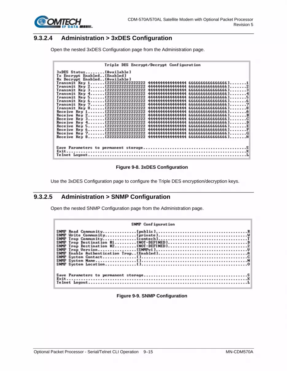
CDM-570A/570AL Satellite Modem with Optional Packet Processor Revision 5
Optional Packet Processor - Serial/Telnet CLI Operation 9–15 MN-CDM570A
9.3.2.4 Administration > 3xDES Configuration
Open the nested 3xDES Configuration page from the Administration page.
Figure 9-8. 3xDES Configuration
Use the 3xDES Configuration page to configure the Triple DES encryption/decryption keys.
9.3.2.5 Administration > SNMP Configuration
Open the nested SNMP Configuration page from the Administration page.
Figure 9-9. SNMP Configuration

CDM-570A/570AL Satellite Modem with Optional Packet Processor Revision 5
Optional Packet Processor - Serial/Telnet CLI Operation 9–16 MN-CDM570A
Selection Hot Key Description SNMP Read Community R Select to enter community string (20 characters max). SNMP Write Community W Select to enter community string (20 characters max). SNMP Trap Community T Select to enter community string (20 characters max). SNMP Trap Destination #1 D Select to enter a value for the SNMP Trap Destination #1. Enter the
IP address in aaa.bbb.ccc.ddd format. SNMP Trap Destination # 2 2 Select to enter a value for the SNMP Trap Destination #2. Enter the
IP address in aaa.bbb.ccc.ddd format. SNMP Trap Version V Select to toggle between [SNMPv1] and [SNMPv2]. SNMP Enable Authentication Trap
A Select to toggle [Enabled] or [Disabled]:
SNMP System Contact C Select to enter text. SNMP System Name N Select to enter text. SNMP System Location O Select to enter text.
9.3.2.6 Administration > Working Mode
See Appendix D.
1. When you select Hot Key ‘C’ you are first prompted with: “Changing Modem working mode requires system Reboot. Do you want to continue (Y/N)[Enter :No]” Press Y to continue; otherwise press N, [Enter], or [Esc] to quit and return to the Administration page.
2. Working Mode is disabled when Brouter Mode VLAN Filtering is enabled. If you attempt to select this item while configured as such, the following error message displays: “Can’t change Modem Working Mode when Brouter VLAN Filter is Enabled”
Once you elect to continue with configuration, you are prompted to select the active Working Mode:
Selection Description 1 – Router – Small Network Router uses 1 byte HDLC addresses 2 – Router – Large Network Router mode using 2 byte HDLC addresses 3 – Router – Point to Point Router mode uses 0 HDLC addresses to save satellite bandwidth 4 – Router – Vipersat Router mode when running in a Vipersat Network 5 – Managed Switch Default operating mode, and operates at 10/100BaseT. In this mode the Packet
Processor will forward both IP and non-IP datagrams over satellite without any defined routes.

CDM-570A/570AL Satellite Modem with Optional Packet Processor Revision 5
Optional Packet Processor - Serial/Telnet CLI Operation 9–17 MN-CDM570A
9.3.2.7 Administration > Managed Switch Multicast Option
If the Working Mode is Managed Switch and Multicast traffic is intended to pass across a pair of modems, this option must be enabled on both modems.
The Managed Switch Multicast Option allows Multicast to be either transmitted or received through the modem. This applies to Managed Switch Mode only. Managed Switch Mode will normally filter Multicast traffic.
9.3.2.8 Administration > Header Compression Refresh Rates
Managed Switch Mode automatically uses L2 Header Compression (even if the Header Compression option has not been purchased). Because of this, some of the initial traffic sent between two devices is not received over the satellite until a full Header is transmitted. For example, the default Header Compression Refresh Rate is 50 packets. When a ping is sent over the satellite, it times out until the full Header packet is sent. The Header Compression Refresh Rate on the Administration page can be reduced to minimize the amount of traffic lost when traffic is first sent between two devices. Once communication between two devices has been established, both modems are able to receive all traffic, unless one modem is power cycled or reset.
The Header Compression Refresh Rates are configured from the Administration page when Header Compression is Enabled. The Header Compression Refresh Rates determines how many compressed header packets are sent before a single full header packet is sent. Some compressed header traffic could be lost during deteriorated satellite link conditions. Sending a full header packet will allow the return of the traffic stream. The Refresh Rate can be decreased for poor satellite link conditions, or increased to further reduce overhead. You may select refresh rates, from 1 to 600, individually for UDP/RTP1, UDP, or all other IP headers. The default rate of 50 provides the best performance and efficiency for typical satellite links.
9.3.2.9 Administration > Payload Compression Refresh Rate
The Payload Compression Refresh Rates determines how many compressed payload packets are sent before a single full payload packet is sent. Some compressed payload traffic could be lost during deteriorated satellite link conditions. Sending a full payload packet will allow the return of the traffic stream. You may select a Refresh Rate from 1 to 600. The Refresh Rate can be decreased for poor satellite link conditions or increased to further reduce overhead.

CDM-570A/570AL Satellite Modem with Optional Packet Processor Revision 5
Optional Packet Processor - Serial/Telnet CLI Operation 9–18 MN-CDM570A
9.3.2.10 Administration > Telnet Timeout
The Packet Processor does not allow concurrent access to the CLI via Telnet and the ‘Console’ port. If you connect via Telnet, the Packet Processor automatically disables the ‘Console’ port for the duration of the Telnet session. You may use Hot Key ‘L’ (Telnet Logout) from any CLI page to end a Telnet session.
You may configure the Packet Processor to automatically end a Telnet session after a specified period of inactivity (configurable from 1 to 60 minutes).

CDM-570A/570AL Satellite Modem with Optional Packet Processor Revision 5
Optional Packet Processor - Serial/Telnet CLI Operation 9–19 MN-CDM570A
9.3.3 Interface Configuration
Open the Interface Configuration page from the Main Menu.
Figure 9-10. Interface Configuration
Selection Hot Key Description
Ethernet Interface E Displays the Ethernet Interface page.
See Sect. 9.3.3.1.1 for the Ethernet Interface page when in Managed Switch Mode, and Sect. 9.3.3.1.2 for the Ethernet Interface page when in Router Mode.
Satellite/HDLC Interface H Displays the Satellite/HDLC Interface page.
9.3.3.1 Interface Configuration > Ethernet Interface
Open the Ethernet Interface page from the Interface Configuration page. Note that selections differ based on the active Working Mode – Managed Switch or Router Mode (see Sect. 9.3.2).

CDM-570A/570AL Satellite Modem with Optional Packet Processor Revision 5
Optional Packet Processor - Serial/Telnet CLI Operation 9–20 MN-CDM570A
9.3.3.1.1 Interface Configuration > Ethernet Interface (Managed Switch Mode)
(TOP) Dedicated Management Port = DISABLED, Hot Key ‘D’ selected (CENTER) Dedicated Management Port = Local ONLY Mode
(BOTTOM) Dedicated Management Port = Local & Remote Mode
Figure 9-11. Ethernet Interface in Managed Switch Mode

CDM-570A/570AL Satellite Modem with Optional Packet Processor Revision 5
Optional Packet Processor - Serial/Telnet CLI Operation 9–21 MN-CDM570A
You must set the Traffic Port Speed/Mode to match the Ethernet port settings of the connected device port to avoid experiencing significant performance degradation. For example, if the connected device port is set for Auto Negotiate, then you must also set the Packet Processor to Auto Negotiate. Comtech EF Data recommends that you use Auto Negotiate mode, unless the connected device port does not support Auto Negotiate. In such cases, both Ethernet ports must be set to the same Manual settings (i.e., 100 Mbps Full Duplex).
Selection Hot Key Description Mgmt MAC Address [RO] This is the hardware destination MAC Address that is used when an
Ethernet packet is destined for the Packet Processor M&C Ethernet Interface. This address is unique and has been assigned permanently at the factory.
Traffic Port Speed/Mode E This is a configurable parameter and, as such, its exact setting can vary between specific installations. The default setting allows the Ethernet port to auto-negotiate its link speed on power-up. Selections are: 1 – Auto (default) 2 – 10 MB/sec Half Duplex 3 – 100 MB/sec Half Duplex 4 – 10 MB/sec Full Duplex 5 – 100 MB/sec Full Duplex
Mgmt IP Address I Select this to assign the IP Address for the Ethernet M&C Interface. Set the IP address in aaa.bbb.ccc.ddd format
Subnet Prefix Length M Select this to define the Subnet Mask assigned to the Ethernet Traffic Interface. Set the subnet mask prefix length (8...30)
DM/Red Traffic MAC Address [RO] This is the hardware destination MAC Address that is used when an Ethernet packet is destined for the Packet Processor Traffic Ethernet Interface. This address is unique and has been assigned permanently at the factory.
Traffic Port Actual Speed [RO] This displays the current speed and duplex of the Packet Processor Traffic port.
Managed Switch MAC Learning
A Select this to disable MAC Learning on packets received on the Ethernet Interface, so that all packets are sent to the satellite.
Managed Switch Gateway IP G Select this to define a Gateway so that the Packet Processor is accessible from an outside network when in Managed Switch Mode
Dedicated Management Port D Select this to disable or enable Dedicated Management Port operation. When Working Mode = Managed Switch, selections are: 1 – Disabled (default) 2 – Local ONLY mode 3 – Local & Remote Mode
Appendix Q. DEDICATED MANAGEMENT PORT FEATURE
VLAN V Select this to enable VLAN support functions VLAN Table T Select this to create VLAN Table entries – see Sect. 9.3.3.1.1.1

CDM-570A/570AL Satellite Modem with Optional Packet Processor Revision 5
Optional Packet Processor - Serial/Telnet CLI Operation 9–22 MN-CDM570A
9.3.3.1.1.1 Interface Configuration > Ethernet Interface > VLAN Table
Open the nested VLAN Table from the Ethernet Interface page (Managed Switch Mode only).
Figure 9-12. VLAN Table
Selection Hot Key Description VLAN01 – VLAN08 1 – 8 Type a VLAN ID (1 through 4094). Delete VLAN Entry D Set the VLAN Entry number (1 to 8) to delete that entry from the table. Base [#] B Select Base and then type a number to display or edit a different set of
eight of up to 4093 definable VLAN ID entries. Example 1 – If you have eight existing VLAN entries: Type ‘9’ to create a new VLAN ID 9. The VLAN Table page will refresh and now display VLAN Entries 9-16. Example 2 – If you want to edit VLAN IDs 32-40: Type ‘B’, and then type ‘32’ to select the Base value of 32. The VLAN Table page will refresh to display VLAN IDs 32 through 40.
In the default VLAN Table, Figure 9-12 shows where there is a Native VLAN and a Management VLAN (default VLAN ID 1). These can be changed to other VLAN IDs, but they cannot be deleted. If an untagged packet arrives at the Packet Processor, it will egress as a tagged packet with the defined Native VLAN ID. You may add VLAN entries into the VLAN Table, and forward VLANs over the satellite. You also need a VLAN entry on the receiving CDM-570A/570AL to receive the VLAN traffic – they will egress as tagged VLANs. When a tagged packet arrives at the Ethernet port, it is forwarded only if there is a matching VLAN entry in the VLAN Table; it will egress as tagged. If there is no matching VLAN in the VLAN Table, then the tagged packet is dropped.

CDM-570A/570AL Satellite Modem with Optional Packet Processor Revision 5
Optional Packet Processor - Serial/Telnet CLI Operation 9–23 MN-CDM570A
9.3.3.1.2 Ethernet Interface (Router Mode)
(TOP) Dedicated Management Port = DISABLED (BOTTOM) Dedicated Management Port = ENABLED
Figure 9-13. Ethernet Interface in Router Mode

CDM-570A/570AL Satellite Modem with Optional Packet Processor Revision 5
Optional Packet Processor - Serial/Telnet CLI Operation 9–24 MN-CDM570A
You must set the Traffic Port Speed/Mode to match the Ethernet port settings of the connected device port to avoid experiencing significant performance degradation. For example, if the connected device port is set for Auto Negotiate, then you must also set the Packet Processor to Auto Negotiate. Comtech EF Data recommends that you use Auto Negotiate mode, unless the connected device port does not support Auto Negotiate. In such cases, both Ethernet ports must be set to the same Manual settings (i.e., 100 Mbps Full Duplex).
Selection Hot Key Description
Mgmt MAC Address [RO] This is the hardware destination MAC Address that is used when an Ethernet packet is destined for the Packet Processor M&C Ethernet Interface. This address is unique and has been assigned permanently at the factory.
Traffic Port Speed/Mode E This is a configurable parameter and, as such, its exact setting can vary between specific installations. The default setting allows the Ethernet port to auto-negotiate its link speed on power-up. Selections are: 1 – Auto (default) 2 – 10 MB/sec Half Duplex 3 – 100 MB/sec Half Duplex 4 – 10 MB/sec Full Duplex 5 – 100 MB/sec Full Duplex
Mgmt IP Address I Select this to assign the IP Address for the Ethernet M&C Interface. Set the IP address in aaa.bbb.ccc.ddd format
Subnet Prefix Length M Select this to define the Subnet Mask assigned to the Ethernet Traffic Interface. Set the subnet mask prefix length (8...30)
DM/Red Traffic MAC Address [RO] This is the hardware destination MAC Address that is used when an Ethernet packet is destined for the Packet Processor Traffic Ethernet Interface. This address is unique and has been assigned permanently at the factory.
DM/Red Traffic IP Addr In Managed Switch Mode, this entry is not applicable. In Router mode this parameter can be configured when either Redundancy is Enabled Or Dedicated Management Port is Enabled.
DM/Red Traffic Subnet Prefix In Managed Switch Mode, this entry is not applicable. In Router mode, this parameter can be configured when either Redundancy is Enabled Or Dedicated Management Port is Enabled.
Traffic Port Actual Speed [RO] This displays the current speed and duplex of the Packet Processor Traffic port.
Dedicated Management Port D Select this to disable or enable Dedicated Management Port operation. When Working Mode = Router, selections are: 1 – Disabled (default) 2 – Enabled

CDM-570A/570AL Satellite Modem with Optional Packet Processor Revision 5
Optional Packet Processor - Serial/Telnet CLI Operation 9–25 MN-CDM570A
9.3.3.2 Interface Configuration > Satellite/HDLC Interface
Open the nested Satellite/HDLC Interface page from the Interface Configuration page.
Figure 9-14. Satellite/HDLC Interface
Selection Hot Key Description
HDLC Addr Mode [RO] • HDLC Address Mode – This mode is configured via the Working Mode, which is found on the Administration page.
• Point-To-Point Mode – In this mode of operation, no HDLC address is transmitted over the satellite link. The restrictions on using this mode are that it can only be used for pure Point-to-Point configurations.
• Small Network Mode (up to 254 addresses) – In this mode of operation a single byte HDLC address is transmitted over the satellite link (0x1 – 0xFE).
• Large Network Mode (up to 32766 addresses) – In this mode of operation a two byte HDLC address is transmitted over the satellite link (0x1 – 0xFFFE).
Receive HDLC Channel Addresses
H Displays the Receiver HDLC Channel Addresses page.
9.3.3.3 Interface Configuration > Receive HDLC Channel Addresses
Open the nested Receive HDLC Channel Addresses page from the Satellite/HDLC Interface page. Use this page to define up to four HDLC addresses that can carry user information on the Satellite Interface.
Figure 9-15. Receive HDLC Channel Addresses
Selection Hot Key Description HDLC Addr 1 – HDLC Addr 4
1 – 4 HDLC address in hex <1 – FFFE, enter = 0001> Note that HDLC addresses are not used in Point-To-Point Mode. • Small Network Mode (up to 254 addresses) – Limited to valid
addresses between the values of 0x01 and 0xFE. • Large Network Mode (up to 32766 addresses) – Limited to valid
addresses between the values of 0x0001 and 0x7FFF. Delete HDLC Addr D Set the HDLC entry to delete <1...4>

CDM-570A/570AL Satellite Modem with Optional Packet Processor Revision 5
Optional Packet Processor - Serial/Telnet CLI Operation 9–26 MN-CDM570A
9.3.4 QoS (Quality of Service) Configuration
Open the QoS Configuration page from the Main Menu.
Figure 9-16. QoS Configuration
Selection Hot Key Description
QoS Mode M Select: 1 – Rule-Max/Pri Mode 2 – Rule-Min/Max Mode 3 – DiffServ Mode 4 – VLAN Priority/Max Mode
QoS Rules Configuration Q Defines QoS rules for Max/Pri Mode or Min/Max Mode. See Section 9.3.4.1.
DiffServ Rules Configuration D Defines QoS rules for DiffServ Mode. See Section 9.3.4.2.
Maximum System Latency (msecs)
A Select this to specify the maximum depth of the QoS queue, from 200 to 5000 milliseconds of traffic that is destined to go over the satellite. This defines the maximum duration that a packet will sit in a QoS queue before being aged out and dropped. Lower priority packets are dropped first until there is enough room to send the higher priority packets.
Enable WAN Segmentation and Reassembly (SAR)
R Toggle Packet Segmentation and Reassembly (SAR) as Enabled or Disabled. SAR is automatically Enabled while QoS is Enabled. However, SAR is an adaptive process; it will trigger only if the packet latency exceeds the threshold value (default to 20 msecs). Latency value is calculated based on the satellite transmission bandwidth. There is no minimum segment size; however, if the last segment is less than 16 bytes, then it is appended to the previous segment – excluding satellite HDLC header – in order to avoid satellite overhead and consumption of CPU cycles.

CDM-570A/570AL Satellite Modem with Optional Packet Processor Revision 5
Optional Packet Processor - Serial/Telnet CLI Operation 9–27 MN-CDM570A
9.3.4.1 QoS Configuration > QoS Rules Configuration
9.3.4.1.1 QoS Rules Configuration (Max/Priority Mode)
Open the nested QoS Rules Configuration page from the QoS Configuration page.
Figure 9-17. QoS Rules Configuration (Max/Priority Mode)
Selection Hot Key Description
RL01 through RL32 (The current eight of up to 32 definable QoS Rules).
1 – 8 Assign Max/Pri QoS to up to 32 different types of definable flows. Define flows by any combination of Protocol, Priority, Source/Destination IP Addresses (specific or range), and/or Layer 3 Source and Destination Ports. FOR RULE ASSIGNMENT OR EDIT PROCESS, SEE “Assign or Edit a QoS Rule”
Delete D Set the QoS Rule to delete, from 1 to 32. Base [#] B Select Base to display or edit a different group of eight of up to 32 QoS
Rules. For example, if you want to edit QoS Rule 9: Type ‘B’, and then type ‘9’ to select the Base value of 9. The QoS Rules Configuration page will refresh to display RL09 through RL16.
QoS [ ] [RO] This line displays state of the QoS option as Unavailable, Enabled, or Disabled. If available, QoS is Enabled or Disabled from the Administrator Features page.

CDM-570A/570AL Satellite Modem with Optional Packet Processor Revision 5
Optional Packet Processor - Serial/Telnet CLI Operation 9–28 MN-CDM570A
Assign or Edit a QoS Rule When you select a rule to create or edit (Hot Key 1 through 8), the CLI prompts you to assign parameters in this order:
Screen Prompt Action Specify Protocol for the rule
Specify your desired rule protocol: 1 for UDP (User Datagram Protocol) 2 for TCP (Transmission Control Protocol) 3 for ICMP (Internet Control Message Protocol) 4 for RTP (Real Time Protocol (includes all RTP – VOCE, VDEO, and RTPS)) 5 for VOCE (Voice RTP) 6 for VDEO (Video RTP) 7 for RTPS (RTP Signaling) 8 for FTP (File Transfer Protocol only) 9 for HTTP (Hypertext Transfer Protocol) 10 for TELN (Telnet) 11 for SMPT (Simple Mail Transfer Protocol) 12 for SNMP (Network Management Protocol) 13 for SAP (Service Announcement Protocol) 14 for ORCL (Oracle application traffic) 15 for CTRX (Citrix application traffic) 16 for SQL (Structured Query Language) 17 for IP (Internet Protocol (all inclusive)) 18 for N-IP (Non-Internet Protocol (all inclusive))
Specify priority for the rule Where Priority 1 = Highest, and Priority 8 = Lowest: 1 for QoS Priority-1 2 for QoS Priority-2 3 for QoS Priority-3 4 for QoS Priority-4 5 for QoS Priority-5 6 for QoS Priority-6 7 for QoS Priority-7 8 for QoS Priority-8
Maximum bandwidth in kbps <0-99999, enter = 99999>:
Type your Maximum Bandwidth, in kbps, from 0 to 99999. If you desire no such parameter, press [Enter] – the bandwidth defaults to ‘99999’.
Source IP address <enter = 0.0.0.0>:
Type your Source IP Address in the form XXX.XXX.XXX.XXX. If you desire no Source IP Address, press [Enter] – the address displays as ‘***’.
Number of Source subnet bits <0,8-32, enter = 0>:
Type your Source subnet bits value, from 8 to 32. If you desire no Source subnet. type ‘0’ or press [Enter] – the subnet displays as ‘/*’.
Destination IP address <enter = 0.0.0.0>:
Type your Destination IP Address in the form XXX.XXX.XXX.XXX. If you desire no Destination IP Address, press [Enter] – the address displays as ‘***’.
Number of Destination subnet bits <0,8-32, enter = 0>:
Type your Destination subnet bits value, from 8 to 32. If you desire no Destination subnet. type ‘0’ or press [Enter] – the subnet displays as ‘/*’.
Specify TCP/UDP source port [MIN] (1-65535) <Enter: ***>
Set the minimum TCP/UDP source port in your range, from 1 to 65535. If you desire no minimum TCP/UDP source port, press [Enter] – the port displays as ‘***’.
Specify TCP/UDP source port [MAX] (1-65535) <Enter: ***>
This prompt will not display if you do not select a MIN TCP/UDP source port. Set the maximum TCP/UDP source port in your range, from 1 to 65535.
Specify TCP/UDP destination port [MIN] (1-65535) <Enter: ***>
Set the minimum TCP/UDP destination port in your range, from 1 to 65535. If you desire no minimum TCP/UDP destination port, press [Enter] – the port displays as ‘***’.
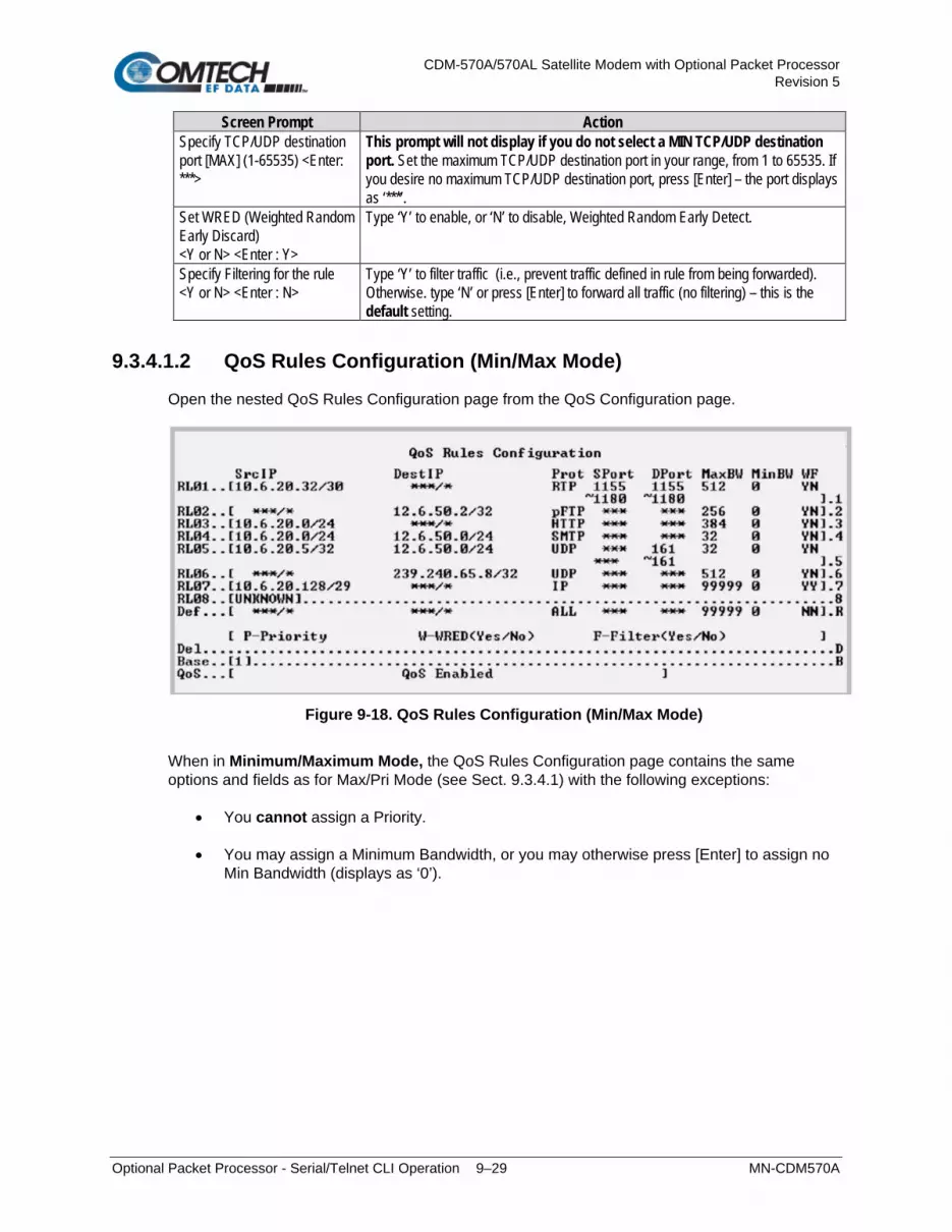
CDM-570A/570AL Satellite Modem with Optional Packet Processor Revision 5
Optional Packet Processor - Serial/Telnet CLI Operation 9–29 MN-CDM570A
Screen Prompt Action Specify TCP/UDP destination port [MAX] (1-65535) <Enter: ***>
This prompt will not display if you do not select a MIN TCP/UDP destination port. Set the maximum TCP/UDP destination port in your range, from 1 to 65535. If you desire no maximum TCP/UDP destination port, press [Enter] – the port displays as ‘***’.
Set WRED (Weighted Random Early Discard) <Y or N> <Enter : Y>
Type ‘Y’ to enable, or ‘N’ to disable, Weighted Random Early Detect.
Specify Filtering for the rule <Y or N> <Enter : N>
Type ‘Y’ to filter traffic (i.e., prevent traffic defined in rule from being forwarded). Otherwise. type ‘N’ or press [Enter] to forward all traffic (no filtering) – this is the default setting.
9.3.4.1.2 QoS Rules Configuration (Min/Max Mode)
Open the nested QoS Rules Configuration page from the QoS Configuration page.
Figure 9-18. QoS Rules Configuration (Min/Max Mode)
When in Minimum/Maximum Mode, the QoS Rules Configuration page contains the same options and fields as for Max/Pri Mode (see Sect. 9.3.4.1) with the following exceptions:
• You cannot assign a Priority.
• You may assign a Minimum Bandwidth, or you may otherwise press [Enter] to assign no Min Bandwidth (displays as ‘0’).

CDM-570A/570AL Satellite Modem with Optional Packet Processor Revision 5
Optional Packet Processor - Serial/Telnet CLI Operation 9–30 MN-CDM570A
9.3.4.2 QoS Configuration > DiffServ Rules Configuration
Open the nested DiffServ Rules Configuration page from the QoS Configuration page.
Figure 9-19. DiffServ Rules Configuration
Figure 9-20. Assured Forwarding Rules
In DiffServ Mode, the Packet Processor prioritizes all traffic by the DSCP value contained within the IP header of each packet. All packets that do not have a DSCP value are placed in the Default Queue and have a Priority of 9 (Figure 9-19). Configuration of DiffServ Rules is allowed only for Assured Forwarding Classes 1-4 (Rule 9-12), where a Minimum and Maximum Bandwidth can be assigned. Use Base 8 to modify the Assured Forwarding Rules (AFD)(Figure 9-20).

CDM-570A/570AL Satellite Modem with Optional Packet Processor Revision 5
Optional Packet Processor - Serial/Telnet CLI Operation 9–31 MN-CDM570A
9.3.5 Route Table Configuration
Open the Route Table Configuration page from the Main Menu.
Figure 9-21. Route Table Configuration
Selection Hot Key Description
Route001 through Route256 (The current group of eight of up to 256 definable routes are displayed here)
1 – 8 Defines how to route received Packet Processor packets. Assigning an entry in this table is similar to using the 'route add' command of machines that support that command. For each route, the CLI prompts you to define the following: • Assign a name to reference the route. The assigned name cannot
contain any whitespace and must be unique.
• The destination address of an Packet of interest. The number of network addresses that are governed by the selected destination entry, i.e., subnet mask.
• The Next Hop IP address: This is the IP where the packet is routed
for further processing. The Next Hop IP Address for traffic to be sent over the satellite will be the desired HDLC:
Point-to-Point – no HDLC address Small Network – 0x1 – 0xFE Large Network – 0x1 – 0xFFFE
Also, a route can be defined to have Packet Processor send traffic to another IP address on the same subnet as the Ethernet interface. • Optionally: If a Multicast address (224.0.0.0-239.255.255.255) is
provided as the destination IP address, then the following parameters will be requested:

CDM-570A/570AL Satellite Modem with Optional Packet Processor Revision 5
Optional Packet Processor - Serial/Telnet CLI Operation 9–32 MN-CDM570A
Selection Hot Key Description o Route Multicast packets from Ethernet to Satellite? [y/n]
Specifies if Multicast packets that match the provided IP address are routed from the Ethernet to Satellite. “No” means that the packets are discarded.
o Route Multicast packets from Satellite to Ethernet? [y/n] Specifies if Multicast packets that match the provided IP address are routed from the Satellite to Ethernet. “No” means that the packets are discarded. Multicast Routes always have a subnet length of 32 and the next hop is 0.0.0.0 because it is not applicable.
Note: The Packet Processor does allow the specification of one and only one default route. Destination IP = 0.0.0.0 Subnet Length = 0. The default route can be defined to send traffic to either the Satellite or Ethernet interface. This will cause all packets that do not match any other route to be sent to the destination that has been defined for further processing.
Base [#] B Set a value, from 1 to 249, to display or edit the group of eight of up to 256 definable QoS Routes. For example, if you want to edit Routes 32-40: Type ‘B’, and then type ‘32’ to select the Base value of 32. The QoS Configuration page will refresh to display Route032 through Route040.
Delete Route D Set the number of the Route Name (1 through 8) you want to delete. Display P Displays all of the routes that are currently defined in the system. This
includes automatically generated routes that are provided to simplify provisioning of the system. The information displayed is: Route Name, DestIP/Snet Bits, Next Hop, HDLC, and Flags.
PerRoute E Use to enable Header Compression, Payload Compression on a Per Route basis.
Downlink Mcast [RO] Displays the status of Downlink Multicast as [Enabled] or [Disabled]. This feature is configured on the Administrator Feature page.

CDM-570A/570AL Satellite Modem with Optional Packet Processor Revision 5
Optional Packet Processor - Serial/Telnet CLI Operation 9–33 MN-CDM570A
9.3.5.1 Route Table > Per Route Configuration
Open the nested “Configuring Per Route Capabilities” page from the Route Table Configuration page.
Figure 9-22. Route Table Configuration | Per Route
Select the Route Number to configure Header Compression (HdrComp) and Payload Compression (PayloadComp)) on a per Route basis.
Selection Hot Key Description Route001 through Route256 (The current group of eight of up to 256 definable are displayed here)
1 – 8 For each route, the CLI prompts you to select the operational states in this order:
3xDES Encryption is a future offering and is not available in this firmware release. The 3xDES selections are non-functional at this time. Press Enter to skip these selections.
“Specify Header compression for this route (Y or N)<Enter : N>” Type ‘Y’ or ‘N’ to toggle, or press [Enter] to disable header compression for this route. “Specify Payload compression for this route (Y or N)<Enter : N>” Type ‘Y’ or ‘N’ to toggle, or press [Enter] to disable payload compression for this route.
Base [#] B Set a value, from 1 to 249, to display or edit a group of eight of up to 256 definable Routes. For example, if you want to edit Routes 32-40: Type ‘B’, and then type ‘32’ to select the Base value of 32. The table will refresh and display Route032 through Route040.
Transmit Encrypt [RO] Displays the current operational state for TX Encrypt as “Per Route” or “Disabled”.

CDM-570A/570AL Satellite Modem with Optional Packet Processor Revision 5
Optional Packet Processor - Serial/Telnet CLI Operation 9–34 MN-CDM570A
9.3.6 Protocol Configuration
Open the Protocol Configuration Page from the Main Menu.
Figure 9-23. Protocol Configuration
Selection Hot Key Description
IGMP I Displays the IGMP page. See Section 9.3.6.1.
ARP A Displays the ARP Table Utilities page. See Section 9.3.6.2.
DHCP Server IP Address R Allows entry of the DHCP server IP address. Allows hosts on a remote LAN to send DHCP request packets to the DHCP server so that the DHCP server can dynamically assign IP addresses to remote hosts.
Brouter Mode B Displays the Brouter Configuration page. See Section 9.3.6.3.
9.3.6.1 Protocol Configuration > IGMP Information
Open the nested IGMP Information page from the Protocol Configuration page. Use this page to view the IGMP clients that are actively listening to content being provided by the Packet Processor. It also allows you to determine how the Ethernet Interface is configured either to receive requests to join IGMP groups or announce groups for others to join.
Figure 9-24. IGMP Information

CDM-570A/570AL Satellite Modem with Optional Packet Processor Revision 5
Optional Packet Processor - Serial/Telnet CLI Operation 9–35 MN-CDM570A
Selection Hot Key Description IGMP [RO] Displays IGMP status as [Enabled] or [Disabled].
View IGMP Table V This table reports the content that clients have subscribed to the Packet Processor using the IGMP protocol. This helps determine which services are being used and the minimum time before a service is terminated.
Modem as Server: IGMP query period
Q Set a value, in seconds, from 1 to 600. This defines the time interval in which the IGMP protocol requests that a server periodically publish to users on the LAN the Multicast IP Addresses that it can service. The IGMP query period defines the time interval between each of these queries for membership.
Modem as Server: IGMP max. response time
R Set a value, in seconds, from 1 to 598. This defines the time interval for the IGMP max response time that the Packet Processor should wait before it assumes that no parties are interested in the content published via an IGMP query. The max response time that is accepted by the Packet Processor should a value that is less than the Query period minus 1.
Modem as Server: Number of missed responses before leaving IGMP group
M Set a value, from 1 to 30. This defines the number of membership queries that go unanswered from LAN clients before the Ethernet Interface no longer forwards data for that IGMP group. For example, for an Packet Processor that has the IGMP query period set to 60 seconds and the number of missed responses is set to 3: If a client joins an IGMP group, then the service to that group will not be discontinued until no clients respond to a query from the Packet Processor for a period of 60*3 = 180 seconds.
Modem as Client: Recognize IGMP queries
C Toggle to set as ‘Y’ (Yes) or ‘N’ (No): • If you toggle YES, the Packet Processor responds to an IGMP query by
requesting to join a Multicast Group published by the server that is defined in the Packet Processor’s route table.
• If you toggle NO, the Packet Processor does not respond to IGMP queries from a server. In this type of configuration, you may configure the Packet Processor to unconditionally request to join an IGMP group at an interval specified by the “Unsolicited Report Interval” option from the Transmitter IGMP Client Configuration Page.
Modem as Client: Router Alert Option for V1 report
A Toggle to set as ‘Y’ (Yes) or ‘N’ (No): Some Routers may require the definition of a Router Alert Option to recognize a report from a Client to join a Multicast group. The IP Router Alert Option is defined in RFC2113 and was introduced by Cisco. While this option is not part of the IGMP standard, most IGMP V2 implementations contain this option. However, most implementations of IGMP V1 do not contain this option. This parameter is defined to prevent possible conflicts in networks in which a Cisco Router is configured as an IGMP V1 server. • When you toggle YES, the Packet Processor generates IGMP reports to
join Multicast groups as specifically required by some Cisco Router configurations.
• When you toggle NO, the Packet Processor generates IGMP reports to join Multicast groups as defined and implemented by most IGMP servers.

CDM-570A/570AL Satellite Modem with Optional Packet Processor Revision 5
Optional Packet Processor - Serial/Telnet CLI Operation 9–36 MN-CDM570A
Selection Hot Key Description Modem as Client: IGMP Version used for Unsolicited Reports
U Toggle to set as ‘V1’ or ‘V2’. This defines which version of the IGMP protocol should be followed when attempting to join a group on a Multicast Server via an unsolicited report. When the Packet Processor is configured to Recognize IGMP Queries, the Packet Processor will respond to a query in the same version that the server used to initiate the query. • When you toggle V1, the CLI configures the Packet Processor to use the
IGMP Version 1 protocol to join a Multicast Group available on an IGMP Server in response to an IGMP Query.
• When you toggle V2, the CLI configures the Packet Processor to use the IGMP Version 2 protocol to join a Multicast Group available on an IGMP Server in response to an IGMP Query.
Modem as Client: Unsolicited Report Interval, sec
I Set a value, in seconds, to configure the time interval for the Packet Processor to generate unsolicited reports to join a Multicast Group. A value of zero implies that no unsolicited reports to join a Multicast group should be generated by the Packet Processor. Each unsolicited report to join a Multicast group will use the version of the IGMP protocol as specified by the IGMP Version used for Unsolicited Reports option.

CDM-570A/570AL Satellite Modem with Optional Packet Processor Revision 5
Optional Packet Processor - Serial/Telnet CLI Operation 9–37 MN-CDM570A
9.3.6.2 Protocol Configuration > ARP Table Utilities
Open the nested ARP Table Utilities page from the Protocol Configuration Page. Use this page to view and edit the ARP table defined by the Packet Processor. It allows up to 256 static IP> MAC ARP entries.
Figure 9-25. ARP Table Utilities
Selection Hot Key Description Entry0001 through Entry0256 (The current group of eight of up to 256 definable static ARP entries are displayed here)
1 – 8 Defines up to 256 static ARP definitions on the Packet Processor. Use this table to operate/view up to eight of these definitions at a time. An ARP definition is defined as: • Unicast IP Address.
This IP Address is used as a lookup into the ARP table when the Packet Processor needs to resolve a MAC or HDLC Address. Restrictions: o IP Address must be on the same subnet as the Ethernet Interface.
o IP Address must be a valid Unicast address (Not Multicast,
broadcast, etc.) • MAC Address
The MAC Address defines the hardware destination MAC Address that is used when an Ethernet packet is destined for an IP machine from the Packet Processor. At the prompt, type ‘M’ to add an IP to MAC ARP entry.
Delete ARP Entry D Prompts you to Set the IP address of the ARP entry you want to delete. Display ARP Tbl A Displays the entire IP to MAC ARP table in blocks of 10 entries. Includes the
Static as well as dynamic ARP entries. Press the Enter key to display the next 10 entries; otherwise, press the Esc (Escape) key to return to ARP Table Utilities page.
Flush ARP Table F Allows the entire ARP table to be cleared. This is equivalent to performing the standard UNIX command “arp –d” on each address reported in an “arp –a” command. The command only flushes the dynamic ARP entries. The static ARP entries will not be removed.

CDM-570A/570AL Satellite Modem with Optional Packet Processor Revision 5
Optional Packet Processor - Serial/Telnet CLI Operation 9–38 MN-CDM570A
Selection Hot Key Description Base [#] B Set a value, from 1 to 249, to display or edit a group of eight of up to 256
definable static ARP entries. For example, if you want to view or edit static ARP Entries 32-40: Type ‘B’, and then type ‘32’ to select a Base value of 32. The table will refresh and display Entry0032 through Entry0040.
9.3.6.3 Protocol Configuration > Brouter Configuration
Open the nested Brouter Configuration page from the Protocol Configuration Page.
Figure 9-26. Brouter Configuration
Selection Hot Key Description
VLAN Brouter Mode B Toggle as [Enabled] or [Disabled]: When you toggle Enabled, any packet arriving at the Ethernet interface with a VLAN header is automatically forwarded to the WAN interface. In this mode ALL VLAN packets are sent – there is no filtering of any kind.
Brouter Mode may be disabled only when both Brouter Remote Mode and VLAN Filtering are also disabled. If selection is attempted while either or both of these features are enabled, the following message displays:
“Disable VLAN-Filter & Remote Mode, And Then Disabled Brouter Mode”
VLAN Brouter Tx Payload Compression
P Toggle Payload Compression for all "Brouted" VLAN packets as [Enabled] or [Disabled].
VLAN Brouter Next Hop MAC
N On the downlink side, this allows the definition of the MAC of the next hop router to which all of the Brouted packets must be sent. This permits the Brouter feature to bypass the need to send an ARP packet for packets that could potentially have the same IP address.

CDM-570A/570AL Satellite Modem with Optional Packet Processor Revision 5
Optional Packet Processor - Serial/Telnet CLI Operation 9–39 MN-CDM570A
Selection Hot Key Description VLAN Brouter Remote Mode Enable
R Toggle as [Enabled] or [Disabled]. In this mode, IP traffic received from the WAN interface will not be forwarded back to the WAN interface, even though the route table matches.
Each remote modem must have Remote Mode enabled, indicating this is a distant-end modem.
VLAN Filtering F Toggle bridging for all "Brouted" VLAN destination packets and routing of non-VLAN traffic as [Enabled] or [Disabled].
VLAN ID 1 through 10 0001 thru 4094
Assign a numeric VLAN ID in the range from 0001 to 4094.
The VLAN ID is a 12-bit field in the Ethernet packet that contains the IEEE-802.1Q tag. • VLAN ID 0001 is reserved and used for normal switch
operation. • A maximum of 10 VLAN ID matches are supported.
Unused VLAN ID match fields must be set to values that DO NOT match any network VLAN IDs.

CDM-570A/570AL Satellite Modem with Optional Packet Processor Revision 5
Optional Packet Processor - Serial/Telnet CLI Operation 9–40 MN-CDM570A
9.3.7 Vipersat Configuration
VMS v3.x.x VIPERSAT Management System User Guide (CEFD P/N MN/22156)
This page displays only if the optional Vipersat feature is enabled.
Open the Vipersat Configuration page from the Main Menu.
Figure 9-27. Vipersat Configuration
Selection Hot Key Description
STDMA Mode T Used only when CDM-570A/570AL is used in a Vipersat Management System (VMS). See the VMS v3.x.x VIPERSAT Management System User Guide (CEFD P/N MN/22156)for complete information.
Automatic Switching A Unit Role R Expansion Unit E Bandwidth Group ID B Unit Name N Multicast Management IP Address M
Multicast VMS Management IP Address V
Managing IP Address I Path Loss Data Multicast (PLDM) P
Dynamic Power Control Config C Set Home State Parameters H

CDM-570A/570AL Satellite Modem with Optional Packet Processor Revision 5
Optional Packet Processor - Serial/Telnet CLI Operation 9–41 MN-CDM570A
9.3.8 Satellite Modem
Open the Satellite Modem page from the Main Menu.
Figure 9-28. Modem Parameters
Selection Hot Key Description Modem Type [RO] Identifies the Modem Type – CDM-570A or CDM-570AL.
Configuration C Displays the Modem Configuration page. See Section 9.3.8.1.
Monitor M Displays the Modem Monitor page. See Section 9.3.8.2.
Information I Displays the Modem Information page. See Section 9.3.8.3.
Utilities U Displays the Modem Utilities page. See Section 9.3.8.4.
9.3.8.1 Satellite Modem > Configuration
Open the nested Configuration page from the Satellite Modem page.
Figure 9-29. Modem Configuration

CDM-570A/570AL Satellite Modem with Optional Packet Processor Revision 5
Optional Packet Processor - Serial/Telnet CLI Operation 9–42 MN-CDM570A
Selection Hot Key Description Tx Configuration T Displays the Tx Configuration page.
See Section 9.3.8.1.1. Rx Configuration R Displays the Rx Configuration page.
See Section 9.3.8.1.2. Framing Mode Configuration F Displays the Framing Mode Configuration page.
See Section 9.3.8.1.3. Data Interface Configuration I Displays the Data Interface Configuration page.
See Section 9.3.8.1.4. Reference Configuration E Displays the Reference Configuration page.
See Section 9.3.8.1.5. Alarm Mask Configuration A Displays the Alarm Mask Configuration page.
See Section 9.3.8.1.6. BUC Configuration B Displays the BUC (Block Up Converter) Configuration page.
See Section 9.3.8.1.7. LNB Configuration N Displays the LNB (Low Noise Block Down Converter) Configuration
page. See Section 9.3.8.1.8.
CnC Configuration C Displays the CnC (DoubleTalk Carrier-in-Carrier) Configuration page. See Section 9.3.8.1.9.
BERT Configuration D Displays the BERT (Bit Error Rate Test) Configuration page. See Section 9.3.8.1.10.
9.3.8.1.1 Satellite Modem > Configuration > Tx Configuration
Open the nested Tx (Modulation) Configuration page from the Configuration page.
Figure 9-30. Tx (Transmit Modem) Configuration

CDM-570A/570AL Satellite Modem with Optional Packet Processor Revision 5
Optional Packet Processor - Serial/Telnet CLI Operation 9–43 MN-CDM570A
Turbo FEC selections are displayed only if the optional Turbo card is installed.
Selection Hot Key Description
Tx Frequency Q Set the Tx frequency – valid ranges are: • From 50 to 180 MHz for the CDM-570A (IF); • From 950 to 1950 MHz for the CDM-570AL (L-Band).
Tx Data Rate D Set the rate at which the Modem will send traffic over the Satellite Interface: • Valid range is from 2.4 to 9980 kbps. • Up to 5000 kbps and 9980 kbps are options that must be purchased.
Tx Symbol Rate [RO] Displays the corresponding Symbol Rate for the currently selected data rate, encoder, rate, and modulation scheme.
Tx FEC T Select the Tx FEC type: 1 -- Uncoded 2 -- Viterbi 3 -- Vit+RS 4 -- TCM+RS 5 -- Turbo 6 – VersaFEC 7 -- ULL 8 -- VersaFEC-2 Long 9 -- VersaFEC-2 Short
Tx Code Rate
R Select the Tx code rate: 1 – 5/16 2 – 21/44 3 – 1/2 4 – 2/3 5 – 3/4 6 – 7/8 7 – 0.95 8 – 1/1 9 – VersaFEC CCM BPSK 0.488 10 – VersaFEC CCM QPSK 0.533 11 – VersaFEC CCM QPSK 0.631 12 – VersaFEC CCM QPSK 0.706 13 – VersaFEC CCM QPSK 0.803 14 – VersaFEC CCM 8-QAM 0.576 15 – VersaFEC CCM 8-QAM 0.642 16 – VersaFEC CCM 8-QAM 0.711 17 – VersaFEC CCM 8-QAM 0.780 18 – VersaFEC CCM 16-QAM 0.644 19 – VersaFEC CCM 16-QAM 0.731 20 – VersaFEC CCM 16-QAM 0.780 21 – VersaFEC CCM 16-QAM 0.829 22 – VersaFEC CCM 16-QAM 0.853 23 – VersaFEC ULL BPSK 0.493 24 – VersaFEC ULL QPSK 0.493

CDM-570A/570AL Satellite Modem with Optional Packet Processor Revision 5
Optional Packet Processor - Serial/Telnet CLI Operation 9–44 MN-CDM570A
Selection Hot Key Description TX Code Rate (continued)
25 – VersaFEC ULL QPSK 0.654 26 – VersaFEC ULL QPSK 0.734 27 – VersaFEC-2 ModCod_0 – BPSK 0.489 28 – VersaFEC-2 ModCod_1 – QPSK 0.489 29 – VersaFEC-2 ModCod_2 – QPSK 0.537 30 – VersaFEC-2 ModCod_3 – QPSK 0.586 31 – VersaFEC-2 ModCod_4 – QPSK 0.611 32 – VersaFEC-2 ModCod_5 – QPSK 0.635 33 – VersaFEC-2 ModCod_6 – QPSK 0.660 34 – VersaFEC-2 ModCod_7 – QPSK 0.684 35 – VersaFEC-2 ModCod_8 – QPSK 0.733 36 – VersaFEC-2 ModCod_9 – 8_ARY 0.521 37 – VersaFEC-2 ModCod_10 – 8_ARY 0.537 38 – VersaFEC-2 ModCod_11 – 8_ARY 0.562 39 – VersaFEC-2 ModCod_12 – 8_ARY 0.586 40 – VersaFEC-2 ModCod_13 – 8_ARY 0.611 41 – VersaFEC-2 ModCod_14 – 8_ARY 0.635 42 – VersaFEC-2 ModCod_15 – 8_ARY 0.660 43 – VersaFEC-2 ModCod_16 – 8_ARY 0.684 44 – VersaFEC-2 ModCod_17 – 8_ARY 0.708 45 – VersaFEC-2 ModCod_18 – 8_ARY 0.733 46 – VersaFEC-2 ModCod_19 – 16_ARY 0.586
47 – VersaFEC-2 ModCod_20 – 16_ARY 0.611 48 – VersaFEC-2 ModCod_21 – 16_ARY 0.635 49 – VersaFEC-2 ModCod_22 – 16_ARY 0.660 50 – VersaFEC-2 ModCod_23 – 16_ARY 0.684 51 – VersaFEC-2 ModCod_24 – 16_ARY 0.708 52 – VersaFEC-2 ModCod_25 – 16_ARY 0.733 53 – VersaFEC-2 ModCod_26 – 16_ARY 0.757 54 – VersaFEC-2 ModCod_27 – 16_ARY 0.782 55 – VersaFEC-2 ModCod_28 – 32_ARY 0.660 56 – VersaFEC-2 ModCod_29 – 32_ARY 0.684 57 – VersaFEC-2 ModCod_30 – 32_ARY 0.708 58 – VersaFEC-2 ModCod_31 – 32_ARY 0.733 59 – VersaFEC-2 ModCod_32 – 32_ARY 0.757 60 – VersaFEC-2 ModCod_33 – 32_ARY 0.782 61 – VersaFEC-2 ModCod_34 – 32_ARY 0.801 62 – VersaFEC-2 ModCod_35 – 32_ARY 0.831 63 – VersaFEC-2 ModCod_36 – 32_ARY 0.855 64 – VersaFEC-2 ModCod_37 – 32_ARY 0.879

CDM-570A/570AL Satellite Modem with Optional Packet Processor Revision 5
Optional Packet Processor - Serial/Telnet CLI Operation 9–45 MN-CDM570A
Selection Hot Key Description Tx Modulation M Select the Tx modulation type:
1 -- BPSK 2 -- QPSK 3 -- OQPSK 4 -- 8-PSK 5 -- 16-QAM 6 -- 8-QAM 7 -- 8-ARY (VersaFEC-2) 8 -- 16-ARY (VersaFEC-2) 9 -- 32-ARY (VersaFEC-2)
Tx Spectrum Inversion U Select the Tx spectral inversion type: 1 – Normal 2 – Inverted
Tx Data Inversion I Select the Tx data inversion type: 1 – Normal 2 – Inverted
Tx Scrambling B Select the Tx scrambling type: 1 – Off 2 – On-Default 3 – On-IESS-315
Tx Output Power P Set a valid output power from 0.0 to 40.0 dBm (minus sign assumed). Tx Carrier C Select the Tx carrier operation:
1 – OFF 2 – ON 3 – Rx-Tx Inhibit (turns off the transmitter if the Rx is not locked) NOTE: In a 1:1 Redundant system, the standby modem will display [External Control].
Tx Clock Source [RO] Displays the configured Tx Clock Source. Tx Clock Inversion A Select the Tx clock inversion type:
1 – Normal 2 – Inverted
Tx Filter Rolloff E Select the Tx alpha filter rolloff: 1 – 0.35 2 – 0.25 3 – 0.20 4 – 0.15 5 – 0.10 6 – 0.05

CDM-570A/570AL Satellite Modem with Optional Packet Processor Revision 5
Optional Packet Processor - Serial/Telnet CLI Operation 9–46 MN-CDM570A
9.3.8.1.2 Satellite Modem > Configuration > Rx Configuration
Open the nested Rx (Demodulation) Configuration page from the Configuration page.
Figure 9-31. Rx (Receive Modem) Configuration
Turbo FEC selections are displayed only if the optional Turbo card is installed.
Selection Hot Key Description
Rx Frequency Q Set the Rx frequency – valid ranges are: • From 50 to 180 MHz for the CDM-570A (IF); • From 950 to 1950 MHz for the CDM-570AL (L-Band).
Rx Data Rate D Set the rate at which the Modem will receive traffic from the Satellite Interface: • Valid range is from 2.4 to 9980 kbps. • Up to 5000 kbps and 9980 kbps are options that must be purchased.
Rx Symbol Rate [RO] Displays the corresponding Symbol Rate for the currently selected data rate, decoder, rate, and demodulation scheme.
Rx FEC T Select the Rx FEC type: 1 -- Uncoded 2 -- Viterbi 3 -- Vit+RS 4 -- TCM+RS 5 -- Turbo 6 -- VersaFEC 7 -- ULL 8 -- VersaFEC-2 Long 9 -- VersaFEC-2 Short
Rx Code Rate
R Select the Rx Code Rate: 1 – 5/16 2 – 21/44 3 – 1/2

CDM-570A/570AL Satellite Modem with Optional Packet Processor Revision 5
Optional Packet Processor - Serial/Telnet CLI Operation 9–47 MN-CDM570A
Selection Hot Key Description RX Code Rate (continued)
4 – 2/3 5 – 3/4 6 – 7/8 7 – 0.95 8 – 1/1 9 – VersaFEC CCM BPSK 0.488 10 – VersaFEC CCM QPSK 0.533 11 – VersaFEC CCM QPSK 0.631 12 – VersaFEC CCM QPSK 0.706 13 – VersaFEC CCM QPSK 0.803 14 – VersaFEC CCM 8-QAM 0.576 15 – VersaFEC CCM 8-QAM 0.642 16 – VersaFEC CCM 8-QAM 0.711 17 – VersaFEC CCM 8-QAM 0.780 18 – VersaFEC CCM 16-QAM 0.644 19 – VersaFEC CCM 16-QAM 0.731 20 – VersaFEC CCM 16-QAM 0.780 21 – VersaFEC CCM 16-QAM 0.829 22 – VersaFEC CCM 16-QAM 0.853 23 – VersaFEC ULL BPSK 0.493 24 – VersaFEC ULL QPSK 0.493 25 – VersaFEC ULL QPSK 0.654 26 – VersaFEC ULL QPSK 0.734 27 – VersaFEC-2 ModCod_0 – BPSK 0.489 28 – VersaFEC-2 ModCod_1 – QPSK 0.489 29 – VersaFEC-2 ModCod_2 – QPSK 0.537 30 – VersaFEC-2 ModCod_3 – QPSK 0.586 31 – VersaFEC-2 ModCod_4 – QPSK 0.611 32 – VersaFEC-2 ModCod_5 – QPSK 0.635 33 – VersaFEC-2 ModCod_6 – QPSK 0.660 34 – VersaFEC-2 ModCod_7 – QPSK 0.684 35 – VersaFEC-2 ModCod_8 – QPSK 0.733 36 – VersaFEC-2 ModCod_9 – 8_ARY 0.521 37 – VersaFEC-2 ModCod_10 – 8_ARY 0.537 38 – VersaFEC-2 ModCod_11 – 8_ARY 0.562 39 – VersaFEC-2 ModCod_12 – 8_ARY 0.586 40 – VersaFEC-2 ModCod_13 – 8_ARY 0.611 41 – VersaFEC-2 ModCod_14 – 8_ARY 0.635 42 – VersaFEC-2 ModCod_15 – 8_ARY 0.660 43 – VersaFEC-2 ModCod_16 – 8_ARY 0.684 44 – VersaFEC-2 ModCod_17 – 8_ARY 0.708 45 – VersaFEC-2 ModCod_18 – 8_ARY 0.733 46 – VersaFEC-2 ModCod_19 – 16_ARY 0.586 47 – VersaFEC-2 ModCod_20 – 16_ARY 0.611 48 – VersaFEC-2 ModCod_21 – 16_ARY 0.635 49 – VersaFEC-2 ModCod_22 – 16_ARY 0.660 50 – VersaFEC-2 ModCod_23 – 16_ARY 0.684 51 – VersaFEC-2 ModCod_24 – 16_ARY 0.708

CDM-570A/570AL Satellite Modem with Optional Packet Processor Revision 5
Optional Packet Processor - Serial/Telnet CLI Operation 9–48 MN-CDM570A
Selection Hot Key Description RX Code Rate (continued)
52 – VersaFEC-2 ModCod_25 – 16_ARY 0.733 53 – VersaFEC-2 ModCod_26 – 16_ARY 0.757 54 – VersaFEC-2 ModCod_27 – 16_ARY 0.782 55 – VersaFEC-2 ModCod_28 – 32_ARY 0.660 56 – VersaFEC-2 ModCod_29 – 32_ARY 0.684 57 – VersaFEC-2 ModCod_30 – 32_ARY 0.708 58 – VersaFEC-2 ModCod_31 – 32_ARY 0.733 59 – VersaFEC-2 ModCod_32 – 32_ARY 0.757 60 – VersaFEC-2 ModCod_33 – 32_ARY 0.782 61 – VersaFEC-2 ModCod_34 – 32_ARY 0.801 62 – VersaFEC-2 ModCod_35 – 32_ARY 0.831 63 – VersaFEC-2 ModCod_36 – 32_ARY 0.855 64 – VersaFEC-2 ModCod_37 – 32_ARY 0.879
Rx Demodulation M Select the Rx Demodulation type: 1 – BPSK 2 – QPSK 3 – OQPSK 4 – 8-PSK 5 – 16-QAM 6 – 8-QAM 7 – 8-ARY 8 – 16-ARY 9 – 32-ARY
Rx Spectrum Inversion U Select the Rx spectral inversion type: 1 – Normal 2 – Inverted
Rx Data Inversion I Select the Rx data inversion type: 1 – Normal 2 – Inverted
Rx Descrambling B Select the Rx descrambling type: 1 – Off 2 – On-Default 3 – On-IESS-315
Rx Acquisition Range W Set an acquisition value in the range from 0 to 200 kHz (1 to 32 kHz if symbol rate < 625 Ksymbol) (“∀” is implied).
Eb/No Alarm Point F Set an alarm point value in the range from 0.1 to 16.0 dB. If the Eb/N0 falls below this value, the modem generates a receive traffic fault.
Recenter Rx Buffer C Select to force re-centering of the Plesiochronous/Doppler buffer. Rx Clock Inversion A Select the Rx clock inversion type:
1 – Normal 2 – Inverted
Rx Filter Rolloff E Select the Rx alpha filter rolloff: 1 – 0.35 2 – 0.25

CDM-570A/570AL Satellite Modem with Optional Packet Processor Revision 5
Optional Packet Processor - Serial/Telnet CLI Operation 9–49 MN-CDM570A
9.3.8.1.3 Satellite Modem > Configuration > Framing Mode Configuration
Open the nested Framing Mode Configuration page from the Configuration page.
Figure 9-32. Framing Mode Configuration
Selection Hot Key Description
Framing Mode F Select the Framing Mode: 1 – Unframed 2 – EDMAC Framing 3 – EDMAC-2 Framing
EDMAC Mode D Select the EDMAC Framing Mode: 1 – Unframed 2 – EDMAC Framing 3 – EDMAC-2 Framing
EDMAC Slave Address Range V Set a value from 10 to 9990 in multiples of ten. AUPC A Select the AUPC operation:
1 – Enable 2 – Disable
Max Power Reached Action R Select the action: 1 – No_Action 2 – Generate_TX_Alarm
Remote Demod Unlock Action U Select the action: 1 – Nominal_Power 2 – Maximum_Power
Target Eb/N0 of Remote Demod (db)
E Set a value from 0.0 to 9.9.
Maximum Power Limit M Set a value from 0 to 9.

CDM-570A/570AL Satellite Modem with Optional Packet Processor Revision 5
Optional Packet Processor - Serial/Telnet CLI Operation 9–50 MN-CDM570A
9.3.8.1.4 Satellite Modem > Configuration > Data Interface Configuration
Open the nested Data Interface Configuration page from the Configuration page.
Figure 9-33. Data Interface Configuration
Selection Hot Key Description
Data Interface I Select the Data Interface: 1 – EAI-422/EAI-530 DCE 2 – V.35 DCE 3 – EAI-232(sync) 4 – G.703 T1 AMI 5 – G.703 T1 B8ZS 6 – G.703 E1 Unbal AMI 7 – G.703 E1 Unbal HDB3 8 – G.703 E1 Bal AMI 9 – G.703 E1 Bal HDB3 10 – IP Interface 11 – IP-ACM NOTE: You must set the data interface as 10 – IP Interface or 11 – IP-ACM for IP traffic to pass over the satellite.
9.3.8.1.5 Satellite Modem > Configuration > Reference Configuration
Open the nested Reference Configuration page from the Configuration page.
Figure 9-34. Reference Configuration

CDM-570A/570AL Satellite Modem with Optional Packet Processor Revision 5
Optional Packet Processor - Serial/Telnet CLI Operation 9–51 MN-CDM570A
Selection Hot Key Description Frequency Reference R Select the Frequency Reference:
1 – Internal 10 MHz 2 – External 1 MHz 3 – External 2 MHz 4 – External 5 MHz 5 – External 10 MHz 6 – Internal Plus Output
Test Mode T Select the Test Mode: 1 – Normal 2 – IF_loopback 3 – Digital_loopback 4 – I/O_Loopback 5 – RF Loopback 6 – Tx_CW 7 – TX_alt_101010
9.3.8.1.6 Satellite Modem > Configuration > Alarm Mask Configuration
Open the nested Alarm Mask Configuration page from the Configuration page.
Figure 9-35. Alarm Mask Configuration
Selection Hot Key Description
Tx FIFO A Toggle to set alarm masking as Masked or Unmasked. NOTE: These settings should always be set as Masked when IP is the active data interface.
G.703 BPV B Tx AIS C RX AGC D Eb/N0 E
Toggle to set alarm masking as Masked or Unmasked. Rx AIS F Buffer Slip G Toggle to set alarm masking as Masked or Unmasked.
NOTE: This setting should always be set as Masked when IP is the active data interface.
External Reference H Toggle to set alarm masking as Masked or Unmasked. BUC I
LNB J

CDM-570A/570AL Satellite Modem with Optional Packet Processor Revision 5
Optional Packet Processor - Serial/Telnet CLI Operation 9–52 MN-CDM570A
9.3.8.1.7 Satellite Modem > Configuration > BUC (Block Up Converter) Configuration
Open the nested Block Up Converter (BUC) Configuration page from the Configuration page.
Figure 9-36. BUC (Block Up Converter) Configuration
Selection Hot Key Description
BUC Address A Set an address for the BUC in the range from 1 to 15. BUC Communications M
Toggle to set operation as Enabled or Disabled. BUC RF Output R BUC DC Power W BUC 10 MHz Reference P BUC Current Alarm Upper Limit (mA)
H Set a value in the range from 500 to 4000.
BUC Current Alarm Lower Limit (mA)
C Set a value in the range from 0 to 3000.
BUC LO Frequency (MHz) F Set a value in the range from 3000 to 65000. Set this value to 0 to disable.

CDM-570A/570AL Satellite Modem with Optional Packet Processor Revision 5
Optional Packet Processor - Serial/Telnet CLI Operation 9–53 MN-CDM570A
9.3.8.1.8 Satellite Modem > Configuration > LNB (Low Noise Block Converter) Configuration
Open the nested Low Noise Block (Down) Converter (LNB) Configuration page from the Configuration page.
Figure 9-37. LNB (Low Noise Block Converter) Configuration
Selection Hot Key Description
LNB DC Supply Voltage P Select the voltage value: 1 – Off 2 – 13 Volts 3 – 18 Volts 4 – 24 Volts
LNB 10MHz Reference R Toggle operation as On or Off. LNB Current Alarm Upper Limit (mA) H Set a value, in mA, in the range from 50 to 600.
LNB Current Alarm Lower Limit (mA) C Set a value, in mA, in the range from 10 to 400.
LNB LO Frequency (MHz) F Set a value in the range from 3000 to 65000. Set this value to 0 to disable.

CDM-570A/570AL Satellite Modem with Optional Packet Processor Revision 5
Optional Packet Processor - Serial/Telnet CLI Operation 9–54 MN-CDM570A
9.3.8.1.9 Satellite Modem > Configuration > CnC Configuration
Open the nested CnC Configuration page from the Configuration page.
Figure 9-38. CnC Configuration
Selection Hot Key Description CnC Mode M Select the CnC operating mode:
1 – Off 2 – On 3 – APC, Side-A, C-Band 4 – APC, Side-A, X-Band 5 – APC, Side-A, Ku-Band 6 – APC, Side-A, Ka-Band 7 – APC, Side-B, C-Band 8 – APC, Side-B, X-Band 9 – APC, Side-B, Ku-Band 10 – APC, Side-A, Ka-Band
CnC Freq Range/Offset F This value is set depending on the Rx symbol rate as follows: • 16ksps to 64ksps: ±1 to the symbol rate (ksps)/2 • 64ksps and above: ±1 to 32 kHz
CnC Min/Max Search Delay
D At the prompts, set the minimum and maximum search delay values, in milliseconds, in the range from 0 to 300.
CnC-APC Max Power Level Increase P Set a value in the range from 0.0 to 9.9.
CnC-APC Home State H
See the “AHS” Remote Command/Query in Chapter 8. SERIAL-BASED REMOTE PRODUCT MANAGEMENT for details on using this feature.
CnC-APC BER Reset B Toggle to reset. CnC-APC FER Reset R Toggle to reset. CnC-APC Activate A Toggle to activate CnC-APC. CnC-APC Suspend U Toggle to suspend CnC-APC.

CDM-570A/570AL Satellite Modem with Optional Packet Processor Revision 5
Optional Packet Processor - Serial/Telnet CLI Operation 9–55 MN-CDM570A
9.3.8.1.10 Satellite Modem > Configuration > BERT Configuration
Open the nested BERT Configuration page from the Configuration page.
Figure 9-39. BERT (Bit Error Rate Test) Configuration
Selection Hot Key Description
BERT Tx State A Select the BERT Tx or Rx operating mode: 1 – Off 2 – On BERT Rx State B
BERT Tx Pattern C Select the BERT Tx or Rx pattern: 1 – 1:1 2 – 2047 3 – 2^15-1 4 – 2^23-1
BERT Rx Pattern D
Error Insert I Select to insert an error into the ongoing BERT. Restart Monitor R Select to restart the BERT Monitor.

CDM-570A/570AL Satellite Modem with Optional Packet Processor Revision 5
Optional Packet Processor - Serial/Telnet CLI Operation 9–56 MN-CDM570A
9.3.8.2 Satellite Modem > Monitor
Open the nested Monitor page from the Satellite Modem page.
Figure 9-40. Monitor
Selection Hot Key Description
Rx Parameters R Review Rx Parameters: EbNo, Signal Level, Frequency Offset, BER, Bit Errors, and Average BER.
Stored Events E Review logged operational events (i.e., alarms). See Section 9.3.8.2.1.
Link Statistics T Review current operating link statistics. See Section 9.3.8.2.2.
BUC Status B Displays the BUC operational status when a Block Up Converter is connected to a CDM-570AL (L-Band) Satellite Modem. See Section 9.3.8.2.3.
LNB Status N Displays the LNB operational status when a Low Noise Block Down Converter is connected to a CDM-570AL (L-Band) Satellite Modem. See Section 9.3.8.2.4.
CnC Monitor C Displays the current Carrier-in-Carrier configuration and operational information. See Section 9.3.8.2.5.

CDM-570A/570AL Satellite Modem with Optional Packet Processor Revision 5
Optional Packet Processor - Serial/Telnet CLI Operation 9–57 MN-CDM570A
9.3.8.2.1 Satellite Modem > Monitor > Stored Events
Open the nested Stored Events page from the Monitor page.
Figure 9-41. Stored Events
Selection Hot Key Description
Number of Unviewed Stored Events [RO] Displays the total number of unread stored events. As stored event
groups are displayed, the counter decrements accordingly.
Jump To First Stored Event J Upon selection, sets the listings for Hot Key ‘V’ to the first event that was stored subsequent to the latest buffer reset.
View Next 5 Stored Events V Buffers the next group of five stored events into the events window. Event information is presented as shown in Figure 9-41.
Clear All Stored Events C Erases all entries from the stored events logging buffer.

CDM-570A/570AL Satellite Modem with Optional Packet Processor Revision 5
Optional Packet Processor - Serial/Telnet CLI Operation 9–58 MN-CDM570A
9.3.8.2.2 Satellite Modem > Monitor > Link Statistics
Open the nested Link Statistics page from the Monitor page.
Figure 9-42. Link Statistics
Selection Hot Key Description
Number of Unviewed Link Statistic [RO] Displays the total number of unread Link Statistics. As statistics groups
are displayed, the counter decrements accordingly.
Jump To First Link Statistic J Upon selection, sets the listings for Hot Key ‘V’ to the first link statistic that was stored subsequent to the latest buffer reset.
View Next 5 Link Statistics V Buffers the next group of five stored link statistics into the events window. Information is presented as shown in Figure 9-42.
Clear All Link Statistics C Erases all entries from the Link Statistics logging buffer. Statistics Sample Interval (min)
I Select a time interval, in minutes, in which the modem is polled for link statistics: 1 – 10 2 – 20 3 – 30 4 – 40 5 – 50 6 – 60 7 – 70 8 – 80 9 – 90 10 – Off

CDM-570A/570AL Satellite Modem with Optional Packet Processor Revision 5
Optional Packet Processor - Serial/Telnet CLI Operation 9–59 MN-CDM570A
9.3.8.2.3 Satellite Modem > Monitor > BUC Status
Open the nested BUC Status page from the Monitor page.
Figure 9-43. BUC Status
Selection Hot Key Description
BUC Voltage (volts) [RO] Displays voltage, in volts. BUC Current (mA) [RO] Displays current, in milliamps, from 0 to 4000. BUC Firmware Version [RO] Displays the unit running firmware version. BUC Temperature (deg C) [RO] Displays the unit temperature, in degrees Celsius. BUC PLL Alarm [RO] Displays the Phase Lock Loop alarm status (e.g., Locked, Unlocked).
9.3.8.2.4 Satellite Modem > Monitor > LNB Monitor
Open the nested LNB page from the Monitor page.
Figure 9-44. LNB Monitor (Per LNB)
Selection Hot Key Description
LNB Voltage (volts) [RO] Displays voltage, in volts. LNB Current (mA) [RO] Displays current, in milliamps, from 0 to 4000.

CDM-570A/570AL Satellite Modem with Optional Packet Processor Revision 5
Optional Packet Processor - Serial/Telnet CLI Operation 9–60 MN-CDM570A
9.3.8.2.5 Satellite Modem > Monitor > CnC Monitor
Open the nested CnC Monitor page from the Monitor page.
Figure 9-45. CnC Monitor
9.3.8.3 Satellite Modem > Information
Open the nested Information page from the Satellite Modem page.
Figure 9-46. Satellite Modem Information

CDM-570A/570AL Satellite Modem with Optional Packet Processor Revision 5
Optional Packet Processor - Serial/Telnet CLI Operation 9–61 MN-CDM570A
9.3.8.4 Satellite Modem > Utilities
Open the nested Utilities page from the Satellite Modem page.
Figure 9-47. Satellite Modem > Utilities
Selection Hot Key Description
Time T Set the time in MM:HH:SS format. Date D Set the date in DD/MM/YY format.
Circuit ID I Set a 24-character Circuit ID (unit label). Allowable characters are: [Space] ( ) * + - . / 0 through 9 and A through Z
Local/Remote State R
Select the operating state: 1 – Local 2 – Remote-Serial 3 – Remote-Ethernet
Compatibility Mode C Select the Compatibility Mode: 1 – CDM-570 Mode 2 – CDM-570A Mode
Demo Mode M
Select the Demo Mode: 1 – Disabled 2 – Enabled 3 – Expired The time remaining for the 30-day demonstration period decrements until the time is Expired.
Load Configuration G Load or Store (save) one of 10 different modem configurations – 0 through 9. Store Configuration O
Carrier ID Configuration A Select to configure the Carrier ID. See Section 0.

CDM-570A/570AL Satellite Modem with Optional Packet Processor Revision 5
Optional Packet Processor - Serial/Telnet CLI Operation 9–62 MN-CDM570A
9.3.8.4.1 Satellite Modem > Utilities > Carrier ID Configuration
Note that in accordance with the DVB specification, Carrier ID is only available when the Transmit symbol rate is greater than, or equal to 128 ksps.
Figure 9-48. Carrier ID Configuration
Selection Hot Key Description
Embed Carrier ID E Toggle [Enabled] or [Disabled] Latitude T Select to edit Latitude. Longitude G Selet to edit Longitude. Phone P Select to edit phone number. Carrier ID Message M Select to edit Carrier ID message.

CDM-570A/570AL Satellite Modem with Optional Packet Processor Revision 5
Optional Packet Processor - Serial/Telnet CLI Operation 9–63 MN-CDM570A
9.3.9 Redundancy Configuration
Appendix N. IP REDUNDANCY
Open the Redundancy Configuration page from the Main Menu.
Figure 9-49. 1:1 Redundancy Configuration
Selection Hot Key Description
1:1 Redundancy R Toggle [Enabled] or [Disabled]. NOTE: Only enable Redundancy when connected with another CDM-570A/570AL via a CRS-180 or CRS-170A redundancy switch.
1:1 Redundancy State [RO] • If standalone CDM-570A/570AL – displays state as Online. • If Redundant CDM-570A/570AL – displays state as Online or Offline
Traffic IP Address [RO] • If standalone CDM-570A/570AL – not used. • If Online Redundant CDM-570A/570AL – sets Traffic IP (read/write). • If Offline Redundant CDM-570A/570AL – displays Traffic IP (read-
only). Traffic Subnet Prefix Length
[RW] [RO]
• If standalone CDM-570A/570AL – not used. • If Online Redundant CDM-570A/570AL – sets Traffic Subnet
(read/write). • If Offline Redundant CDM-570A/570AL – displays Traffic Subnet
(read-only). Management IP Address (Local Unit)
[RO] • If standalone CDM-570A/570AL – not used. • If Online Redundant CDM-570A/570AL – displays Local Management
IP • If Offline Redundant CDM-570A/570AL – displays Local Management
IP Management Subnet Prefix Length (Local Unit)
[RO] • If standalone CDM-570A/570AL – not used. • If Online Redundant CDM-570A/570AL – displays Local Management
Subnet • If Offline Redundant CDM-570A/570AL – displays Local Management
Subnet

CDM-570A/570AL Satellite Modem with Optional Packet Processor Revision 5
Optional Packet Processor - Serial/Telnet CLI Operation 9–64 MN-CDM570A
Selection Hot Key Description Management IP Address (Redundant Unit)
[RO] • If standalone CDM-570A/570AL – not used. • If Online Redundant CDM-570A/570AL – displays Redundant
Management IP Address • If Offline Redundant CDM-570A/570AL – displays Redundant
Management IP Address Management Subnet Prefix Length (Redundant Unit)
[RO] • If standalone CDM-570A/570AL – not used. • If Online Redundant CDM-570A/570AL – displays Redundant
Management Subnet • If Offline Redundant CDM-570A/570AL – displays Redundant
Management Subnet Force Unit Offline F When this is active, unit is currently the Online unit, select to force a
switchover – i.e., place this unit into Offline (standby) mode. Redundancy Mode A Toggle mode as [Auto] or [Manual].
9.3.10 Operations and Maintenance
Open the Operations and Maintenance page from the Main Menu.
Figure 9-50. Operations and Maintenance

CDM-570A/570AL Satellite Modem with Optional Packet Processor Revision 5
Optional Packet Processor - Serial/Telnet CLI Operation 9–65 MN-CDM570A
Selection Hot Key Description
Unit Uptime [RO] Displays – in days, hours, mins, and secs – the lapsed time since the modem and Packet Processor were last rebooted.
Unit Information I Displays the operating firmware information page. IP Module Boot From B Select which Packet Processor firmware image (includes Application,
FPGA, and FFPGA) is loaded upon bootup: 0 – Latest: Boot the newer firmware image based upon date. 1 – Image1: Boot the firmware image loaded into the first slot in permanent storage. 2 – Image2: Boot the firmware image loaded into the second slot in permanent storage.
Upgrade To U Select which Packet Processor or Base Modem firmware image (includes Application, FPGA, and FFPGA) is overwritten in the Firmware Update FTP process:
0 – Oldest: Updates the older firmware image based upon date. 1 – Image1: Updates the firmware image loaded into the first slot in permanent storage. 2 – Image2: Updates the firmware image loaded into the second slot in permanent storage.
Base Modem Boot From A Select which Base Modem firmware image is loaded upon bootup. The possible options are:
0 – Latest: Boot the newer firmware package based upon date. 1- Image1: Boot the firmware image loaded into the first slot in permanent storage. 2 – Image2: Boot the firmware image loaded into the second slot in permanent storage.
Codecast Multicast Address M Set the Multicast address used by VLOAD to upgrade the modem firmware and param file via streaming Multicast. Must match the address specified in VLOAD.
PARAM Image C Select the PARAM file that is loaded on bootup: 1 – Last saved Parameter file 2 -Factory – uses the internal, hard-coded factory default parameters.
Statistics T Displays the Statistics page. Event Log E Displays the Event Log page. Database Operations D Displays the Database Operations page. Reset R Reboots the modem (including the Packet Processor). It has the same
logical effect of power-cycling the unit. Diagnostics G Displays the Diagnostics page. M&C Interface F Allows base modem communications debugging.

CDM-570A/570AL Satellite Modem with Optional Packet Processor Revision 5
Optional Packet Processor - Serial/Telnet CLI Operation 9–66 MN-CDM570A
9.3.10.1 Operations and Maintenance > Unit Information
Open the Unit Information page from the Operations and Maintenance page.
Figure 9-51. Unit Information
Info Set Item Description
1 System time DAY MONTH DATE TIME (hh:mm:ss) YEAR
2
Temperature Displays, in degrees Celsius, the unit temperature. Image # that the Packet Processor is currently booted from
By default displays Latest, unless “Packet Processor Boot From” is set to Image #1 or Image #2
Image # that the base modem is currently booted from.
By default displays Latest, unless “Base Modem Boot From” is set to Image #1 or Image #2
Parameter (PARAM) file that the Packet Processor is currently configured from
Displays PARAM file from Flash or Factory Default if no parameter file is found in flash memory.

CDM-570A/570AL Satellite Modem with Optional Packet Processor Revision 5
Optional Packet Processor - Serial/Telnet CLI Operation 9–67 MN-CDM570A
Info Set Item Description
3
Currently Loaded Packet Processor and Base Modem firmware:
• Boot • IP Bulk #1 • IP Bulk #2 • EVENTLOG • PARAM • BaseBoot • Base Bulk #1
Base Bulk #2
• Displays Build Date, CEFD FW#, Revision #, and size of each Packet Processor and Base Modem firmware file:
• Boot file for the Packet Processor and the Base Modem. • Bulk file contains all of the SW files for the Packet
Processor and Base Modem and there are two slots available.
• Displays the date/time that the EVENTLOG file was last updated.
• Displays the date/time that the PARAM1 file was last updated. Also shows what user interface was used to last update the PARAM file. o From CLI, displays ‘console’ o From Web, displays ‘http’ o From Telnet, displays the Telnet user login name o From SNMP, displays ‘snmp’
9.3.10.2 Operations and Maintenance > Statistics Menu
Open the nested Statistics Menu page from the Operations and Maintenance page.
Figure 9-52. Statistics Menu

CDM-570A/570AL Satellite Modem with Optional Packet Processor Revision 5
Optional Packet Processor - Serial/Telnet CLI Operation 9–68 MN-CDM570A
All Statistics information refreshes once every 6 seconds.
Selection Hot Key Description IP Statistics R Displays and controls the statistics for IP Routing.
See Section 9.3.10.2.1. QoS Statistics Q Displays and controls the statistics for QoS.
See Section 9.3.10.2.2. Ethernet Statistics E Displays and controls the statistics for the Ethernet Port.
See Section 9.3.10.2.3. WAN Statistics W Displays and controls the statistics for the WAN (HDLC) Port.
See Section 9.3.10.2.4. Compression Statistics H Displays and controls the statistics for Header & Payload Compression.
See Section 9.3.10.2.5. CPU Statistics U Displays CPU Usage % (percentage).
See Section 9.3.10.2.6. VLAN Statistics V Displays and controls the statistics for the VLAN entries.
See Section 9.3.10.2.7. Active Flow Statistics F Displays the number of active output flows, output low overhead flows, and
input flows. See Section 9.3.10.2.8. Clear all statistics C Globally resets all statistics counters.

CDM-570A/570AL Satellite Modem with Optional Packet Processor Revision 5
Optional Packet Processor - Serial/Telnet CLI Operation 9–69 MN-CDM570A
9.3.10.2.1 Operations and Maintenance > Statistics Menu> IP Statistics
Open the nested Statistics for IP Routing/EasyConnect page from the Statistics page. This page displays counts of the number of packets routed in the Packet Processor.
Figure 9-53. IP Routing Statistics
Selection Hot Key Description From Ethernet – Total [RO] Ethernet Statistics Page, Rx Good Frames To Ethernet – Total Ethernet Statistics Page, Tx Good Frames To Ethernet – Unicasts Unicast packets to LAN To Ethernet – Multicasts Multicast packets to LAN To Ethernet – Broadcasts Broadcast packets to LAN From Satellite – Total WAN Statistics Page, Rx HDLC Packet Count To Satellite – Total WAN Statistics Page, Tx HDLC Packet Count To Satellite – Unicasts Unicast packets to WAN To Satellite – Multicasts Multicast packets to WAN To Satellite – Broadcasts Broadcast packets to WAN From Endstation – Total Packets sent from Packet Processor To Endstation – Total Packets directed to Packet Processor Received IGMP Packets Internet Group Management Packets received (used for management of
Multicast traffic). Received IP Options Packets Number of IP Options packets received. Reset All Counters C Clears and resets all WAN, Ethernet and IP Routing statistics. Filter/Drop Statistics F Displays the Filter Statistics page.

CDM-570A/570AL Satellite Modem with Optional Packet Processor Revision 5
Optional Packet Processor - Serial/Telnet CLI Operation 9–70 MN-CDM570A
9.3.10.2.1.1 Operations and Maintenance > Statistics Menu> IP Statistics > Filter/Drop Statistics
Open the nested Filter/Drop Statistics page from the Statistics for IP Routing/EasyConnect page. This page displays counts of the number of packets filtered or dropped in the Packet Processor.
Figure 9-54. Filter/Drop Statistics
Selection Hot Key Description
Reset All Counters C Clears and resets the Filter/Drop statistics buffer.

CDM-570A/570AL Satellite Modem with Optional Packet Processor Revision 5
Optional Packet Processor - Serial/Telnet CLI Operation 9–71 MN-CDM570A
The page provides these read-only statistics for Filtered or Dropped Packets:
Packet Type Feature Description
Filtered
Boot Packets are filtered while booting.
Flow Descriptor
• Packets are Filtered due to a Multicast packet classified as UNICAST packet.
• Packets are filtered due to offline modem receiving packet from WAN port.
Unknown Reason Code Packets dropping due to reasons not listed here.
Flow Correlator Packet are filtered due to improper establishing SAT-to-SAT traffic (This counter generally is seen on outbounding Hub modem in point-to-multipoint setup)
Management Path Not used.
Wan scaling Internal Error occurred during WAN scaling sub process in processing packet.
Ping Ping packets were received but PING feature was Disabled.
Access Control Packets are received while “Access List” control is Enabled but IP address does not match the access list database.
Vipersat MCP Internal Error occurred while processing Vipersat Multi-command messages.
Vipersat UCP Internal Error occurred while processing Vipersat Uni-command messages.
Codeload Internal error occurred while processing Codeload messages. Multicast A Multicast packet is received but no application is associated with it.
Bad Packet Malformed packet is received. This may be due to internal or external error
Route Applies to Vipersat Remote only – when a packet is received from the WAN and the Route Table contains a route to transmit that packet to the WAN, the packet is filtered to prevent a routing loop.
Vipersat Remote Packets are filtered due to Vipersat Remote mode (a modem configured as a Vipersat Remote Expansion unit and default route set to 0.0.0.0/0).
QoS Rule Packet filtered due to QoS Rule configured to filter. Vipersat Loop Packets are filtered due to WAN loop in Vipersat Remote mode Bad Header Len Filtered due to packets received with less than 14 bytes of L2 header. Bad Data Ptr Internal error occurred while accessing the packet data. MAC Split Err Not currently used. L3Type Err Not currently used.
Local Destination Packet received with destination MAC as modem MAC and destination IP is not modem IP while modem is operating in bridge mode (Managed Switch)
Redundancy Err
Applies to Offline modem in 1:1 Redundancy Packets are received on the WAN port by the both Offline unit and Online unit, only Online unit is allowed to forward the packets. Indicates packets received by Offline unit from WAN port that were filtered because unit is Offline.
ICMP Filter This is the same as “Filtered Ping”, except this will update in Managed Switch mode.
Port Err Non-IP or ARP packets are targeted to End-station. (End-station will not allow any non-Packets).

CDM-570A/570AL Satellite Modem with Optional Packet Processor Revision 5
Optional Packet Processor - Serial/Telnet CLI Operation 9–72 MN-CDM570A
Packet Type Feature Description
Filtered (cont.)
Per port route rule
• In 1:1 Redundancy Managed Switch mode – a packet received with modem destination MAC, but the IP does not match the traffic IP or management IP.
• In Router mode – per port WAN filtered mode is ON.
VLAN Mismatch Packets filtered due to VLAN Tag not matching the port's VLAN membership
VLANTag/Untaging Failed Packets filtered due to errors while tagging or untagging a packet. Total Total Filtered Packets
Dropped Bad IP Header Checksum Total Dropped Packets due to incorrect IP Header Checksum.
Bad Buffer Length IP length (as specified in packet header) was greater than payload received in the Ethernet packet. This would indicate the packet was truncated before arriving.
Bad IP Version Total Dropped IP Version 6 Packets (Packet Processor only supports IP Version 4).
TTL Expired Total Dropped Packets due to Time To Live counter expired (TTL limits the number of hops, or seconds, before a packet reaches its destination).
No Route
Total Dropped Packets due to no Route for the destination in the Packet Processor Route Table. These are packets that are directed to the Packet Processor’s MAC address and the Packet Processor will reply to the sender with an ICMP ‘Destination net unreachable’ message.
No ARP Entry
Total Dropped Packets due to no ARP entry in Packet Processor ARP Table. For example, if an Packet Processor receives packets from the satellite for a host that is not in the ARP table, the Packet Processor will send an ARP request. If there is no response, the packets are dropped.
Filtered Multicast Total Dropped Multicast Packets received from the satellite due to no SAT→LAN or
Multicast Disable Group Multicast packet was dropped because, although route existed, IGMP is being used, and there is no client requesting forwarding of this traffic or due to an IGMP “leave group” message.
EasyConnect Multicast Option Total Dropped Multicast Packets received from the satellite due to the ‘Managed Switch Multicast Option’ feature not being Enabled in Managed Switch Mode.
Router Queue Full Indicates that the router task is dropping packets due to being full. Represents a graceful drop process when the processor performance is being overdriven.
Total Total Dropped Packets

CDM-570A/570AL Satellite Modem with Optional Packet Processor Revision 5
Optional Packet Processor - Serial/Telnet CLI Operation 9–73 MN-CDM570A
9.3.10.2.2 Operations and Maintenance > Statistics Menu> QoS Statistics
Open the nested QoS Statistics page from the Statistics page. This page displays the statistics for the number of Packets routed, based upon the defined QoS Rules, by the Packet Processor.
Figure 9-55. QoS Statistics
In DiffServ QoS Mode, statistics for the various DiffServ DSCP Classes are in the following Queues:
Queue01 Expedited Forwarding Queue02 Class 1 Precedence Queue03 Class 2 Precedence Queue04 Class 3 Precedence Queue05 Class 4 Precedence Queue06 Class 5 Precedence Queue07 Class 6 Precedence Queue08 Class 7 Precedence Queue09 Assured Forwarding Class 1 Queue10 Assured Forwarding Class 2 Queue11 Assured Forwarding Class 3 Queue12 Assured Forwarding Class 4
Selection Hot Key Description
ClrAll A Clears all QoS statistics and resets the buffer. Clear C Allows a reset of the statistics in a specific Queue.
Base [#] B Select Base and then type a number to display a different set of eight of up to 32 available queues. For example, if you want to view QoS Queues 16-24: Type ‘16’.

CDM-570A/570AL Satellite Modem with Optional Packet Processor Revision 5
Optional Packet Processor - Serial/Telnet CLI Operation 9–74 MN-CDM570A
9.3.10.2.3 Operations and Maintenance > Statistics Menu> Ethernet Statistics
Open the nested Ethernet Statistics page from the Statistics pages. These read-only pages present the total packets received and transmitted for the Ethernet Port of the Packet Processor.
Figure 9-56. Ethernet Statistics – Initial Page
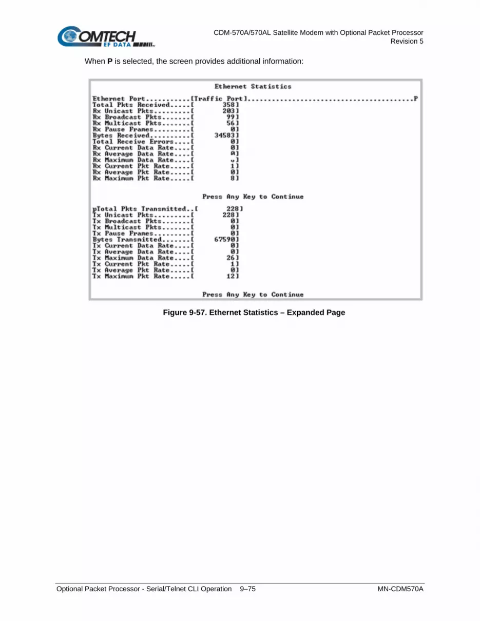
CDM-570A/570AL Satellite Modem with Optional Packet Processor Revision 5
Optional Packet Processor - Serial/Telnet CLI Operation 9–75 MN-CDM570A
When P is selected, the screen provides additional information:
Figure 9-57. Ethernet Statistics – Expanded Page

CDM-570A/570AL Satellite Modem with Optional Packet Processor Revision 5
Optional Packet Processor - Serial/Telnet CLI Operation 9–76 MN-CDM570A
9.3.10.2.4 Operations and Maintenance > Statistics Menu> WAN Statistics
Open the nested WAN Statistics page from the Statistics page. This page displays counts of the number of packets routed or dropped in the Packet Processor Satellite interface.
Figure 9-58. WAN Statistics
Selection Hot Key Description CLEAR C Clears and resets the WAN statistics buffer.
The page provides these read-only statistics:
Item Description WAN Rx Bad Addr Count Packets dropped due to HDLC Address mismatch
WAN Rx Pkt Proc CRC Error Count Count of received frames that failed packet processor CRC check. Indicates that a Payload Compressed Packet was received that could not be decompressed.
WAN Rx Abort/Octet Error Count Count of aborted frames and octet error frames.
WAN Rx Overrun Count Count of received frames that exceeded max frame length of 2K bytes in length (Or) overflowed the HDLC buffer.
WAN Rx HDLC CRC Error Count Number of received frames that failed HDLC CRC check. Indicates that a corrupted packet was received and is usually due to a marginal satellite link.

CDM-570A/570AL Satellite Modem with Optional Packet Processor Revision 5
Optional Packet Processor - Serial/Telnet CLI Operation 9–77 MN-CDM570A
Item Description
WAN Rx HDLC Payload Bytes The count of payload bytes that were received over satellite link excluding any frame overhead.
WAN Rx HDLC Header Bytes The count of HDLC header bytes received over satellite link including control, HDLC address, Flow ID, and CRC.
WAN Rx HDLC Packet Count Number of packets received over satellite link. WAN Rx HDLC HW Payload Bytes Payload Bytes received by WAN Receive Interface (Hardware) WAN Rx HDLC HW Header Bytes HDLC Header Bytes received by WAN Receive Interface (Hardware) WAN Rx HDLC HW Packet Count Number of packets received by WAN Receive Interface (Hardware)
WAN Rx HDLC Address Match Packet Count
Number of packets received that matched any of the 4 RX HDLC Addresses defined in the Satellite interface (not used with version 1.7.# and later).
WAN Rx HDLC Address Filtered Packet Count
Number of packets received that did not match any of the 4 RX HDLC Addresses defined in the Satellite interface (not used with version 1.7.# and later).
WAN Rx Err Invalid Flow ID Number of packets which the flow identifier has been corrupted, does not fall into the range of acceptable values.
WAN Rx Err SAR Reassemble Number of packets unable to correctly reassemble a segmented packet.
WAN Rx Err Hdr Decomp Number of packets unable to correctly decompress the header information.
WAN Rx Err Mem Alignment Number of packets discarded (caused by memory corruption). WAN Rx Err Bad Crc Number of corrupted packets indicated by CRC check. WAN Rx DMA Reclaim Number of times Receive DMA Reclaim Errors have occurred. WAN TX Err – No Flow Number of packets dropped due to missing flow association. WAN Tx Err – No Route
Internal Traffic Statistics used for Factory Troubleshooting
WAN TX Err – Pkt Start WAN TX Err – Pkt Front Length WAN TX Err – Pkt End Length WAN TX Err – Pkt Invalid Length WAN TX Err – PktDropped – Sat overdriven WAN Tx DMA Reclaim Number of times Transmit DMA Reclaim Errors have occurred.
WAN Tx HDLC Header Bytes This counter keeps track of number of HDLC header bytes transmitted over satellite link.
WAN Tx HDLC Payload Bytes Number of payload bytes transmitted over satellite link. WAN Tx HDLC Packet Count Count of packets transmitted over satellite link.
WAN Utilization Percentage of current TX data rate being used for IP traffic (after compression and framing)
Ethernet traffic destined to go over WAN (kbps) Bandwidth required to forward Ethernet traffic before compression.
Actual Satellite traffic (kbps) Current satellite bandwidth being used.
Percentage of WAN Bandwidth saved Displays percent of bandwidth being saved as a result of Header and/or Payload Compression, and optimized satellite framing.

CDM-570A/570AL Satellite Modem with Optional Packet Processor Revision 5
Optional Packet Processor - Serial/Telnet CLI Operation 9–78 MN-CDM570A
9.3.10.2.5 Operations and Maintenance > Statistics Menu> Compression Statistics
Open the nested Compression Statistics page from the Statistics page. This page displays counts of the number of bytes before and after Header and Payload Compression. For Header Compression, the percentage of bandwidth savings displays. For Payload Compression, the effective compression ratio displays.
Figure 9-59. Compression Statistics
Although the QoS option is not required to use Header or Payload Compression, the Compression Statistics are displayed by QoS Rule flow Queues. If QoS is not Enabled, all the Compression Statistics will fall within the Global Queue.
Selection Hot Key Description
Queue01 through Queue32
[RO] Displays statistics, in goups of eight queues per screen, in table format showing, by column: • Pre-Header Comp Bytes • Post-Header Comp Bytes • Header Comp % Savings • Pre-Payload Comp Bytes • Post-Payload Comp Bytes • Payload Compression Ratio
DefQue [RO] Compression Statistics of packets traversed through Default QoS Queue. Global [RO] All traffic that does not fall within a defined QoS Rule is indicated in the
‘Global’ (Default Rule Queue). CLEAR C Allows a reset of the statistics of a specific rule index. ClrAll A Resets all Compression Statistics. ClrDefQ D Clear the Compression statistics of Default QoS Queue. Base [#] B Select Base and then type a number to display a different set of eight of up
to 32 available queues. For example, if you want to view Queues 16-24: Type ‘16’.

CDM-570A/570AL Satellite Modem with Optional Packet Processor Revision 5
Optional Packet Processor - Serial/Telnet CLI Operation 9–79 MN-CDM570A
9.3.10.2.6 Operations and Maintenance > Statistics Menu> CPU Statistics
Open the nested CPU Statistics page from the Statistics page. This page displays Packet Processor CPU Utilization as a percentage(%).
Figure 9-60. CPU Statistics
9.3.10.2.7 Operations and Maintenance > Statistics Menu> VLAN Statistics
Open the nested VLAN Statistics page from the Statistics page. This page displays VLAN packets to and from the WAN (satellite) and to and from Ethernet (LAN) by VLAN ID. It also displays VLAN packets from and to the Management VLAN of the Packet Processor.
Figure 9-61. VLAN Statistics
Selection Hot Key Description
Clear C Allows a reset of the Statistics of a specific Queue. Base [#] B Select Base and then type a number to display a different set of eight of up
to 32 available entries. For example, if you want to view VLANStats 16-24: Type ‘16’.

CDM-570A/570AL Satellite Modem with Optional Packet Processor Revision 5
Optional Packet Processor - Serial/Telnet CLI Operation 9–80 MN-CDM570A
9.3.10.2.8 Operations and Maintenance > Statistics Menu> Active Flow Statistics
Figure 9-62. Active Flow Statistics
9.3.10.3 Operations and Maintenance > Event Log
Open the nested Event Log page from the Operations and Maintenance page. Use this page to view all logged Packet Processor events.
Figure 9-63. Event Log
Selection Hot Key Description
Logging Feature F Toggle event logging as [Enabled] or [Disabled]. Logging Level E Select the type of reported information:
1 – Errors Only 2 – Errors and Warnings 3 – All Information
View log V Select to view the most recent events. The top of the screen displays the most recently logged event. As shown in the Figure 9-63 example, the events log displays: • Type – Error, Warning, or Information • Date/Time – NOTE: During bootup, multiple Boot Events are created,
but a Date/Time will only be seen when the bootup has completed. • Category – Boot, Database, FTP logins, upgrade file transfers, Ethernet
Link status change, Redundancy status. • Description – Event details Press any key to scroll through events or [Esc] to exit.
Clear log C Select to clear log contents.

CDM-570A/570AL Satellite Modem with Optional Packet Processor Revision 5
Optional Packet Processor - Serial/Telnet CLI Operation 9–81 MN-CDM570A
Select V to view the most recent events:
Figure 9-64. Event Log – View Log

CDM-570A/570AL Satellite Modem with Optional Packet Processor Revision 5
Optional Packet Processor - Serial/Telnet CLI Operation 9–82 MN-CDM570A
The full Event log file can be retrieved by FTP. Use Admin login, then Set the command ‘get eventlog’. The entire Event log can then be viewed with a text viewer, as per the following example:
54 Information 05/21/2004 10:12:04 C:/Comtech/ftp/ftpCallbacks.c 1041 FTP FTP Connected – 'User: comtech' logged in 53 Information 05/21/2004 09:07:40 C:/Comtech/cimmib/cimMib.c 520 Database Set system clock to FRI MAY 21 09:07:40 2004 52 Information Unknown Unknown C:/Comtech/startup/usrAppInit.c 534 Boot Configuring router using PARAM file 51 Information Unknown Unknown C:/Comtech/startup/usrAppInit.c 364 Boot Detected Framer Module II. 50 Information 05/21/2004 08:57:42 C:/Comtech/cimmib/cimMib.c 520 Database Set system clock to FRI MAY 21 08:57:42 2004 49 Information Unknown Unknown C:/Comtech/startup/usrAppInit.c 534 Boot Configuring router using PARAM file 48 Information Unknown Unknown C:/Comtech/startup/usrAppInit.c 364 Boot Detected Framer Module II. 47 Information 05/21/2004 08:13:02 C:/Comtech/ftp/ftpCallbacks.c 180 FTP Disconnected FTP 46 Information 05/21/2004 07:58:06 C:/Comtech/ftp/ftpCallbacks.c 540 FTP FTP Transfer complete 45 Information 05/21/2004 07:58:04 C:/Comtech/ftp/ftpCallbacks.c 863 FTP Image has been saved to FLASH 44 Information 05/21/2004 07:57:40 C:/Comtech/ftp/ftpCallbacks.c 1041 FTP FTP Connected – 'User: comtech' logged in 43 Information 05/21/2004 06:55:14 C:/Comtech/Telnetd/Telnetd.c 421 Telnet Telnet disconnected 42 Information 05/21/2004 06:54:26 C:/Comtech/Telnetd/Telnetd.c 385 Telnet Connected host 10.6.6.94 41 Information 05/21/2004 06:38:02 C:/Comtech/ftp/ftpCallbacks.c 180 FTP Disconnected FTP 40 Information 05/21/2004 06:23:07 C:/Comtech/ftp/ftpCallbacks.c 540 FTP FTP Transfer complete 39 Information 05/21/2004 06:23:06 C:/Comtech/ftp/ftpCallbacks.c 863 FTP Image has been saved to FLASH

CDM-570A/570AL Satellite Modem with Optional Packet Processor Revision 5
Optional Packet Processor - Serial/Telnet CLI Operation 9–83 MN-CDM570A
9.3.10.4 Operations and Maintenance > Database Operations
Open the nested Database Operations page from the Operations and Maintenance page. Use this page to view, save, or erase an existing user configuration of the Packet Processor. An Packet Processor uses these types of configuration files to initialize itself on power-up.
Figure 9-65. Database Operations
The modem uses the User Configuration File to overwrite the values defined in the Factory Configuration file. This allows full customization of an Packet Processor without erasing the factory-defined parameters set.
The User Configuration File can also be retrieved or overwritten via FTP by specifying the filename ‘param1’.
Selection Hot Key Description
Restore Factory Default R Restores the Packet Processor configured settings to “safe” values as established at the factory.
Load Parameters from permanent storage P
If you answer “Y” from the prompt, “Are you sure you want to load parameters [Y/N]?”,this overwrites the current configuration of the Packet Processor with the configuration last saved to permanent storage. This performs an “undo” type operation if the user puts the Packet Processor into an undesirable state.
Automatically Save PARAM after CONFIG change
A Toggle “Yes” to automatically save any configuration changes, including changes made from the modem front panel.

CDM-570A/570AL Satellite Modem with Optional Packet Processor Revision 5
Optional Packet Processor - Serial/Telnet CLI Operation 9–84 MN-CDM570A
9.3.10.5 Operations and Maintenance > Diagnostics
Open the nested Diagnostics Page from the Operations and Maintenance page.
Figure 9-66. Diagnostics
Using Dump Packets Diagnostics Utilities 1. The Dump Packet Utilities will display a hexadecimal representation of
each packet and should not be used when the Packet Processor is on a “live” network.
2. Type the Hot Key a second time to terminate the dump operation. Each selection toggles the value of the dump engine.
Selection Hot Key Description
Dump Packets transmitted to Satellite Interface
T Toggle [Yes] to force the Packet Processor to dump a hexadecimal representation of each packet transmitted over the Satellite Interface.
Dump Packets received from Satellite Interface
R Toggle [Yes] to force the Packet Processor to dump a hexadecimal representation of each packet received from the Satellite Interface.
Dump Packets transmitted to Ethernet Interface
U Toggle [Yes] to force the Packet Processor to dump a hexadecimal representation of each packet transmitted to the Ethernet Interface.
Dump Packets received from Ethernet Interface
V Toggle [Yes] to force the Packet Processor to dump a hexadecimal representation of each packet received from the Ethernet Interface.
Dump Packets received by Router
B Toggle [Yes] to force the Packet Processor to dump a hexadecimal representation of each packet received by the routing engine. Note: Does not apply when in Managed Switch Mode.
Dump Packets sent to EndStation
G Toggle [Yes] to force the Packet Processor to dump a hexadecimal representation of each packet received by and destined for this modem. This traffic includes Pings, SNMP, Telnet, HTTP, and FTP traffic types.
Dump Packets received from EndStation
H Toggle [Yes] to force the Packet Processor to dump a hexadecimal representation of each packet sourced from this modem and destined for some other device. Select this to see what type of packets this modem is generating internally.
Ping P Set the IP address in aaa.bbb.ccc.ddd format, set the number of pings to be sent. Reports percentage of packet loss and round trip time (RTT) in msec (min/avg/max).
Traceroute A Set the IP address in aaa.bbb.ccc.ddd format. Reports min/avg/max RTT for each hop in path.
Command Line Debug Prompt
D This is reserved for Customer Service and engineering use. Type your password to access the debug command line.

CDM-570A/570AL Satellite Modem with Optional Packet Processor Revision 5
ODU (Transceiver, BUC, LNB) Operation 10–1 MN-CDM570A
Chapter 10. ODU (TRANSCEIVER, BUC, LNB) M&C OPERATIONS
10.1 Overview
Unless otherwise specified, this chapter uses “CDM-570A/570AL” to refer to the CDM-570A (70/140 MHz) and CDM-570AL or CDMR-570AL (L-Band) Satellite Modems.
The CDM-570A/570AL Satellite Modem permits configuration, monitoring, and control of Comtech EF Data Outdoor Units (ODUs) either in standalone or 1:1 redundant configuration. These ODUs are compatible under CDM-570A (70/140 MHz) operation:
CSAT-5060 series (5 to 25, 50 & 100 Watts) C-Band Transceivers
KST-2000A (LNA) Ku-Band Satellite Transceiver
KST-2000B (LNB) Ku-Band Satellite Transceiver
These ODUs are compatible under CDM/R-570AL (L-Band) operation:
Comtech EF Data Block Up Converter (BUC) products
Comtech EF Data Low-Noise Block Down Converter (LNB) products
You can fully monitor and control ODU operations as follows:
By using the CDM-570A/570AL front panel keypad and VFD. The Front Panel ODU menu branch allows you to configure power supplies, a 10 MHz reference, and low/high current alarm thresholds for the CDM/R-570AL BUC and LNB M&C. LO (Local Oscillator) menus allow you to set up the upconversion and downconversion settings for the BUC and LNB so that you can view the satellite frequencies as well as the modem IF input/output frequencies.
By using the CDM-570A HTTP (Web Server) Interface.
By using the SNMP Interface with the CDM-570A CSAT-5060 or KST-2000A/B Transceiver MIB, or the CDM/R-570AL BUC or LNB MIB.
By using Serial-based Remote Product Management to issue ODU remote commands and queries.

CDM-570A/570AL Satellite Modem with Optional Packet Processor Revision 5
ODU (Transceiver, BUC, LNB) Operation 10–2 MN-CDM570A
10.1.1 CDM-570A/570AL Front Panel Operation – Overview
See Chapter 6. FRONT PANEL OPERATION for an in-depth explanation of the function and operation of the CDM-570A/570AL front panel.
Figure 10-1. CDM-570A/570AL Front Panel Features
1 LED Indicators The LEDs show a summary status of modem operation. See Sect. 6.1.1.
2 Keypad
The keypad has six individual keys. The keys have a positive ‘click’ action that gives tactile feedback. Use the keypad to enter data. See Sect. 6.1.2.
3 Vacuum Fluorescent Display (VFD)
The VFD shows data, menus, prompts and messages. The VFD is an active display with adjustable brightness. It shows two lines of 40 characters each. Nested menus show all available options and prompts that guide you in carrying out required actions. See Sect. 6.1.3.
10.1.2 CDM-570A HTTP Interface – Overview
See Chapter 7. ETHERNET-BASED REMOTE PRODUCT MANAGEMENT for in-depth explanations of the function and operation of the CDM-570A HTTP Interface.
Ethernet-based Remote Product Management of the CDM-570A/570AL is available using one of two rear panel RJ-45 10/100 BaseT Ethernet ports:
The ‘M&C 100’ 10/100 Ethernet port (for units without the optional IP Packet Processor)
–or–
The ‘Traffic 100’ 10/100 Ethernet port (for units equipped
with the optional IP Packet Processor).
YOU MAY PROCEED WITH ETHERNET-BASED REMOTE PRODUCT MANAGEMENT (WEB SERVER OR SNMP) UNDER THE ASSUMPTIONS THAT:
A compatible ODU is connected to the CDM-570A/570AL.
The CDM-570A/570AL is operating with the latest version firmware files.
The CDM-570A/570AL is connected to a user-supplied, Windows-based PC, and:

CDM-570A/570AL Satellite Modem with Optional Packet Processor Revision 5
ODU (Transceiver, BUC, LNB) Operation 10–3 MN-CDM570A
o The PC serial port is connected to the CDM-570A/570AL rear panel ‘Remote Control’ port with a user-supplied 9-pin serial cable.
o The PC Ethernet port is connected to the CDM-570A rear panel ‘M&C 100’ 10/100 or ‘Traffic 100’ BaseT Ethernet port with a user-supplied hub, switch, or direct Ethernet cable connection.
o The user PC is running a terminal emulation program (for operation of the CDM-570A/570AL Serial Interface) and a compatible Web browser (for operation of the CDM-570A HTTP Interface).
o The CDM-570A/570AL Ethernet Traffic IP Address has been noted and the firmware has been identified using either the CDM-570A/570AL Serial Interface or the CDM-570A HTTP Interface ‘Configuration | LAN’ and ‘Admin | Firmware’ pages, respectively.
10.1.3 CDM-570A/570AL Serial Remote Control – Overview
See Chapter 8. SERIAL-BASED REMOTE PRODUCT MANAGEMENT for an in-depth explanation of the use of remote commands and queries over the CDM-570A/570AL Serial Remote Control Interface.
The CDM-570A/570AL Satellite Modem’s serial remote product management interface is an electrical interface that is either an EIA-485 multi-drop bus (for the control of multiple devices) or an EIA-232 connection (for the control of a single device). The interface uses ASCII characters in asynchronous serial form to transmit data between the Controller (e.g., a User PC) and Target (e.g., the modem and ODU). This data consists of control and status information, transmitted in packets of variable length in accordance with the structure and protocol explained in detail in Chapter 8. The Controller is in charge of the process of monitor and control, and is the only device that is permitted to initiate, at will, the transmission of data. Targets are only permitted to transmit when they have been specifically instructed to do so by the Controller. The exchange of information is transmitted, Controller-to-Target and Target-to-Controller, in ‘packets’. Each packet contains a finite number of bytes consisting of printable ASCII characters, excluding ASCII code 127 (DELETE). In this context, the Carriage Return and Line Feed characters are considered printable. With one exception, all messages from Controller-to-Target require a response – this will be either to return data that has been requested by the Controller, or to acknowledge reception of an instruction to change the configuration of the Target.

CDM-570A/570AL Satellite Modem with Optional Packet Processor Revision 5
ODU (Transceiver, BUC, LNB) Operation 10–4 MN-CDM570A
Controller-to-Target
Start of Packet
Target Address
Address Delimiter
Instruction Code
Code Qualifier
Optional Arguments
End of Packet
< ASCII code 60
(1 character)
(4 characters)
/ ASCII code 47
(1 character)
(3 characters)
= or ? ASCII codes
61 or 63
(1 character)
(n characters)
Carriage Return
ASCII code 13
(1 character)
Example: <0135/TFQ=70.2345CR
Target-to-Controller
Start of Packet
Target Address
Address Delimiter
Instruction Code
Code Qualifier
Optional Arguments
End of Packet
> ASCII code 62
(1 character)
(4 characters)
/ ASCII code 47
(1 character)
(3 characters)
=, ?, !, or * ASCII codes 61, 63, 33, or
42
(1 character)
(From 0 to n characters)
Carriage Return, Line
Feed ASCII codes
13,10
(2 characters)
Example: >0654/RSW=32CRLF

CDM-570A/570AL Satellite Modem with Optional Packet Processor Revision 5
ODU (Transceiver, BUC, LNB) Operation 10–5 MN-CDM570A
10.2 Transceiver M&C via the CDM-570A (70/140 MHz) Satellite Modem
10.2.1 Transceiver M&C via the CDM-570A Front Panel
Chapter 6. FRONT PANEL OPERATION
The nested ODU menu branches are accessible from the CDM-570A front panel menu only when the presence of an ODU is detected. Note that operations differ based on the ODU product recognized by the CDM-570A (i.e., menu function specific to the CSAT-5060 or KST-2000A/B ODUs). Refer to the appropriate chapter subsection specified in this figure for the remainder of the available menu trees.
Figure 10-2. CDM-570A Menu Tree – ODU Operation
Figure 10-2 identifies the basic CDM-570A front panel menu hierarchy as it pertains selectively to configuration, monitor and control of a CSAT-5060, KST-2000A, or KST-2000B ODU. This figure identifies only the menu branches allocated to ODU operation.

CDM-570A/570AL Satellite Modem with Optional Packet Processor Revision 5
ODU (Transceiver, BUC, LNB) Operation 10–6 MN-CDM570A
10.2.1.1 0B0BSELECT: (Main) Menu
SELECT: Config Test Info
Monitor Save/Ld Util ODU
The table that follows identifies the commands comprising the CDM-570A main menu, and the content section in this manual where explicit information may be referenced, either in this chapter or in Chapter 6. FRONT PANEL OPERATION:
Menu Branch Chapter Sect. Description
Config 6.3.2 Use this menu branch to fully configure the modem.
Monitor 6.3.3 Use this menu branch to monitor the alarm status of the modem, to view the log of stored events, and to display the Receive Parameters screen.
Test 6.3.4 Use this menu branch to invoke one of several test modes (loopbacks, for example).
Info 6.3.5 (Information) Use this menu branch to view information on the modem, without having to go into configuration screens.
Save/Ld 6.3.6 Use this menu branch to save (store) and to load (retrieve) up to 10 different modem configurations.
Util 6.3.7 (Utility) Use this menu branch to perform miscellaneous functions, such as setting the real-time clock, adjusting the display brightness, etc.
ODU 10.2.1.2 10.2.1.2.1 (CSAT) 10.2.1.2.2 (KST)
(Outdoor Unit) Use this CDM-570A menu branch to monitor and control a Comtech EF Data RF Transceiver (CSAT-5060 or KST-2000A/B), if connected.
For ODU operation, use the arrow keys to select ODU, and then press ENTER.
10.2.1.2 1B1B(SELECT:) ODU
Transceiver Control:
Disable Enable ( ,ENT)
Use the arrow keys to select Disable or Enable, and then press ENTER. Note the following:
Disable This menu item turns OFF the FSK link to the ODU
Enable
This menu item turns ON the FSK link to the ODU.
The message “ATTEMPTING COMMUNICATION WITH ODU... PLEASE WAIT” displays while the the CDM-570A senses and connects with the active ODU model. If no ODU is present, the process aborts and the modem returns to the SELECT: ODU menu screen.
Otherwise, once a CSAT-5060 or KST2000A/B Transceiver successfully connects with the modem via the FSK link, sections 10.2.1.2.1 and 10.2.1.2.2 in this chapter address the pertinent front panel operation functionality. See Figure 10-3 and Figure 10-4 for the ODU-specific CDM-570A menu tree diagrams.

CDM-570A/570AL Satellite Modem with Optional Packet Processor Revision 5
ODU (Transceiver, BUC, LNB) Operation 10–7 MN-CDM570A
10.2.1.2.1 (SELECT:) ODU – CSAT-5060 Transceiver Operation
Figure 10-3 identifies the CDM-570A front panel menu hierarchy as it specifically addresses CSAT-5060 ODU operation.
Figure 10-3. ODU: CSAT-5060 Transceiver Menu Tree
10.2.1.2.1.1 (ODU: Transceiver Control) Enable
Select ODU System Type:
Standalone 1:1 ( ,ENT)
Use the arrow keys to select Standalone or 1:1, and then press ENTER. Note the following:
Select Standalone when the modem is linked via the Rx IF cable to a single Comtech EF Data CSAT-5060 ODU.
Select 1:1 when the modem is linked to a redundant CSAT-5060 system via connection between the Rx IF and the ODU Redundancy Controller Box.

CDM-570A/570AL Satellite Modem with Optional Packet Processor Revision 5
ODU (Transceiver, BUC, LNB) Operation 10–8 MN-CDM570A
When you make any of the following menu selections:
(ODU Transceiver Control) Enable Standalone (ODU Transceiver Control) Enable 1:1 CSAT#1 (ODU Transceiver Control) Enable 1:1 CSAT#2
The modem directs you to a common ODU SELECT submenu:
ODU SELECT: Config Info
Monitor Alarms ( ,ENT)
See Sect. 10.2.1.2.1.1.1 for details about this common submenu.
(ODU: Transceiver Control) Enable Standalone
ODU SELECT: Config Info
Monitor Alarms ( ,ENT)
Use the arrow keys to select Config, Info, Monitor, or Alarms, and then press ENTER. The selections for this common submenu branch are defined in detail in Sect. .
(ODU: Transceiver Control) Enable 1:1
Monitor/Control: CSAT#1
CSAT#2 Red-Box ( ,ENT)
For monitor/control of a redundant CSAT-5060 system: Use the arrow keys to select CSAT#1, CSAT#2, or Red-Box, and then press ENTER.
(ODU: Transceiver Control) Enable 1:1 CSAT#1 or CSAT#2
ODU SELECT: Config Info
Monitor Alarms ( ,ENT)
Use the arrow keys to select Config, Info, Monitor, or Alarms, and then press ENTER. The selections for this common submenu branch are defined in detail in Sect. K.3.3.1.1.1.1.
(ODU: Transceiver Control) Enable 1:1 Red-Box
Redundancy Box: Online
Mode Switches Voltages
Use the arrow keys to select Online, Mode, Switches, or Voltages, and then press ENTER.
(ODU: Transceiver Control) Enable 1:1 Redundancy Box Online
Online Unit:
CSAT#1 CSAT#2 ( ,ENT)
This display indicates the ODU currently online. The cursor will be flashing under CSAT#1 or CSAT#2. If the need arises to change the Online unit, use the arrow keys to move the cursor position to the desired unit, and then press ENTER.

CDM-570A/570AL Satellite Modem with Optional Packet Processor Revision 5
ODU (Transceiver, BUC, LNB) Operation 10–9 MN-CDM570A
If the ODU Redundancy system is in AUTO mode, a ‘forced switch-over’ can only occurs if the currently Offline unit is fault-free.
(ODU: Transceiver Control) Enable 1:1 Redundancy Box Mode
Operating Mode:
Manual Auto ( ,ENT)
This screen indicates the current operating mode of the 1:1 ODU system. The cursor will be flashing under Manual or Auto. If the need arises to change the operating mode of the 1:1 system, use the arrow keys to move the cursor position to the desired operating mode, and then press ENTER.
(ODU: Transceiver Control) Enable 1:1 Redundancy Box Switches
Waveguide Switch Status:
Tx=OK Rx=OK (ENT or CLR)
This read-only screen shows status for both the Tx and Rx Waveguide Transfer Switches. If either Switch reports an ambiguity from the commanded position, “OK” will
change to “FT” to indicate a switch fault.
(ODU: Transceiver Control) Enable 1:1 Redundancy Box Voltages
Redundancy Box Voltages:
5V= 5.0 12V=12.0 (ENT)
This read-only screen allows you to troubleshooting system problems. It monitors and displays the voltages inside the Redundancy Controller Box.

CDM-570A/570AL Satellite Modem with Optional Packet Processor Revision 5
ODU (Transceiver, BUC, LNB) Operation 10–10 MN-CDM570A
10.2.1.2.1.1.1 COMMON ‘ODU SELECT’ SUBMENU
(ODU: Transceiver Control) EnableStandalone
(ODU: Transceiver Control) Enable1:1 CSAT#1
(ODU: Transceiver Control) Enable1:1 CSAT#2
ODU SELECT: Config Info
Monitor Alarms ( ,ENT)
Use the arrow keys to select Config, Info, Monitor, or Alarms, and then press ENTER.
10.2.1.2.1.1.1.1 (ODU SELECT:) Config
ODU CONFIG: Transmitter
Receiver Misc ( ,ENT)
Use the arrow keys to select Transmitter, Receiver, or Misc, and then press ENTER.
(ODU CONFIG:) Transmitter
ODU TX: Frequency Atten
Amplifier Mute Slope
Use the arrow keys to select Frequency, Atten, Amplifier, Mute, or Slope, and then press ENTER.
(ODU CONFIG ODU TX:) Frequency
ODU Tx Frequency:
5912.5 MHz ( , ,ENT)
To edit the transmit frequency: First, use the arrow keys to select a digit, and then use the arrow keys to change the value of that digit. Press ENTER when done.
(ODU CONFIG ODU TX:) Atten (Attenuation)
ODU Tx Attenuation:
15.00 dB ( , ,ENT)
To edit the transmit attenuation: First, use the arrow keys to select a digit, and then use the arrow keys to change the value of that digit. Press ENTER when done.
(ODU CONFIG ODU TX:) Amplifier
ODU Tx Amp State:
On Off ( ,ENT)
Use the arrow keys to select On or Off, and then press ENTER.

CDM-570A/570AL Satellite Modem with Optional Packet Processor Revision 5
ODU (Transceiver, BUC, LNB) Operation 10–11 MN-CDM570A
(ODU CONFIG ODU TX:) Mute
ODU Tx Mute State:
Muted Unmuted ( ,ENT)
Use the arrow keys to select Muted or Unmuted, and then press ENTER.
(ODU CONFIG ODU TX:) Slope
ODU Tx Slope Mode:
Manual Calibrated ( )
Use the the arrow keys to select Manual or Calibrated, and then press ENTER.
(ODU CONFIG ODU TX:) Slope Manual
ODU Tx Slope:
0.0 ( ,ENT)
Use the arrow keys to edit the transmit slope setting, and then press ENTER.
(ODU CONFIG ODU TX:) Slope Calibrated
Calibrate TX Slope?
Cal Exit ( ,ENT)
Use the arrow keys to select Cal or Exit, and then press ENTER.
(ODU CONFIG:) Receiver
ODU RX: Frequency Atten
Mute Slope ( ,ENT)
Use the the arrow keys to select Frequency, Atten, Mute, or Slope, and then press
ENTER.
(ODU CONFIG ODU RX:) Frequency
ODU Rx Frequency:
5912.5 MHz ( , ,ENT)
To edit the receiver frequency: First, use the arrow keys to select a digit, and then use the arrow keys to change the value of that digit. Press ENTER when done.
(ODU CONFIG ODU RX:) Atten (Attenuation)
ODU Rx Attenuation:
15.00 dB ( , ,ENT)
To edit the receiver attenuation: First, use the arrow keys to select a digit, and then use the arrow keys to change the value of that digit. Press ENTER when done.

CDM-570A/570AL Satellite Modem with Optional Packet Processor Revision 5
ODU (Transceiver, BUC, LNB) Operation 10–12 MN-CDM570A
(ODU CONFIG ODU RX:) Mute
ODU Rx Mute State:
Muted Unmuted ( ,ENT)
Use the arrow keys to select Muted or Unmuted, and then press ENTER.
(ODU CONFIG ODU RX:) Slope
ODU Rx Slope Mode:
Manual Calibrated ( )
Use the arrow keys select Manual or Calibrated, and then press ENTER.
(ODU CONFIG ODU RX:) Slope Manual
ODU Rx Slope:
0.0 ( ,ENT)
Use the arrow keys to edit the ODU Rx Slope setting, and then press ENTER.
(ODU CONFIG ODU RX:) Slope Calibrated
Calibrate RX Slope?
Cal Exit ( ,ENT)
Use the arrow keys to select Cal or Exit, and then press ENTER.
(ODU CONFIG): Misc
MISC: Cold-Start AFR LNA
XRef Ref-Adjust RTC ( )
Use the arrow keys to select Cold-Start, AFR, LNA, XRef, Ref-Adjust, or RTC, and then press ENTER.
(ODU CONFIG MISC:) Cold-Start
Cold-Start State:
Enabled Disabled ( )
Use the arrow keys to select Enabled or Disabled, and then press ENTER.
(ODU CONFIG MISC:) AFR (Auto Fault Recovery)
Auto Fault Recovery:
Enabled Disabled ( )
Use the arrow keys to select Enabled or Disabled, and then press ENTER.

CDM-570A/570AL Satellite Modem with Optional Packet Processor Revision 5
ODU (Transceiver, BUC, LNB) Operation 10–13 MN-CDM570A
(ODU CONFIG MISC:) LNA
LNA: State Curr-Window
Cal Fault-Logic ( ,ENT)
Use the arrow keys to select State, Curr-Window, Cal, or Fault-Logic, and then press ENTER.
(ODU CONFIG MISC:) LNA State
ODU LNA State:
On Off ( ,ENT)
Use this menu to control whether or not the CSAT provides LNA POWER via the Receive RF Cable. Use the arrow keys to select On or Off, and then press ENTER.
(ODU CONFIG MISC:) LNA Curr-Window
LNA Current Window:
99 % ( ,ENT)
Use this menu to define the allowable LNA current change before declaring a fault. Edit the LNA Current Window setting as follows:
Use the arrow keys to select a value – the value scrolls from 20% to 50%.
Select 99% to disable the LNA Current Window function.
Press ENTER when done.
(ODU CONFIG MISC:) LNA Cal (Calibrate)
Calibrate LNA Current?
Cal Exit ( ,ENT)
Use this menu to calibrate the LNA current for use with the LNA Current-Window function (described previously). Use the arrow keys to select Cal or Exit, and then press ENTER.
(ODU CONFIG MISC:) LNA Fault-Logic
LNA: State Curr-Window
Cal Fault-Logic ( ,ENT)
Use the arrow keys to select State, Curr-Window, Cal, or Fault-Logic, and then press ENTER.

CDM-570A/570AL Satellite Modem with Optional Packet Processor Revision 5
ODU (Transceiver, BUC, LNB) Operation 10–14 MN-CDM570A
(ODU CONFIG MISC:) XRef (External Reference)
ExternalRef Fault Logic:
Summary No-Summary ( )
Use the arrow keys to select Summary or No-Summary, and then press ENTER.
The CSAT automatically locks to an external 5 or 10 MHz reference independent of the state of this selection. This selection determines whether or not the Summary Fault Relay is activated if the CSAT loses lock with the external reference.
(ODU CONFIG MISC:) Ref-Adjust
Internal Ref Adjustment:
087 ( ,ENT)
Use the arrow keys to select an Internal 10MHz Reference setting value from 000 to 255. Press ENTER when done.
The Internal Reference is adjusted in the factory to be very accurate with the default setting of 087. Use this feature as needed to compensate for the long-term frequency drift of the oscillator.
(ODU CONFIG MISC:) RTC (Real-Time Clock)
Sync ODU RTC to Lcl RTC:
Yes No ( ,ENT)
Use the arrow keys to select Yes to cause the CSAT RTC (Real Time Clock) to synchronize with the modem RTC, or No. Press ENTER when done.
10.2.1.2.1.1.1.2 (ODU SELECT:) Info (Information)
INFO: Model Transmitter
Receiver LNA Misc ( )
For read-only information on the ODU as currently configured for operation, use the arrow keys to select Model, Transmitter, Receiver, LNA, or Misc. Press ENTER when done.
The read-only screen shots that follow depict sample configurations – the actual values and settings will vary and they are dependent on the ODU configuration in use. Typical for all nested screens, press ENTER or CLEAR to return to the ODU SELECT: Info menu.
(ODU SELECT INFO): Model
CSAT-5060/010 V2.09
SERIAL # 00225 (ENT)
This screen shows the model and serial number for the ODU in use.

CDM-570A/570AL Satellite Modem with Optional Packet Processor Revision 5
ODU (Transceiver, BUC, LNB) Operation 10–15 MN-CDM570A
(ODU SELECT INFO):Transmitter
Tx: ON 5845.0MHz 10.00dB
AMP:ON Unmuted Sl:0.0
This screen shows information on the CSAT transmitter status: Tx operating state (ON or OFF); Tx Frequency; Tx Attenuation; Amplifier state (ON or OFF); Tx Mute state (Muted or Unmuted); and Tx Slope adjustment.
(ODU SELECT INFO): Receiver
Rx: ON 3570.0MHz 10.00dB
Unmuted Sl:0.0
This screen shows information on the CSAT receiver status: Rx operating state (ON or OFF); Rx Frequency; Rx Attenuation; Rx Mute state (Muted or Unmuted); and Rx Slope adjustment.
(ODU SELECT INFO): LNA
LNA: On Window: 99%
Fault Logic: No-Summary
This screen shows the current state of the LNA functions: the LNA operating status (ON or OFF); the Current Window; and Fault-Logic settings (Summary or No-Summary).
(ODU SELECT INFO): Misc
Cold Start: Off
Auto Fault Recovery: On
This screen shows the current state of the Cold Start and Auto Fault Recovery functions as ON or OFF.
10.2.1.2.1.1.1.3 (ODU SELECT:) Monitor
ODU MONITOR: Tx Rx Misc
Pwr-Supp1 Pwr-Supp2 ( )
For access to real-time information displays on the ODU currently in operation, use the arrow keys to select Tx, Rx, Misc, Pwr-Supp1, or Pwr-Supp2. Press ENTER when done.
The read-only screen shots that follow depict sample configurations – the actual values and settings will vary and they are dependent on the ODU configuration in use. Typical for all nested screens, press ENTER or CLEAR to return to the ODU SELECT: Monitor menu.
(ODU SELECT ODU MONITOR:) Tx
TX: SynTune=04.8 Pwr=040
IFLO = 10.7 Temp = 27 oC
This screen shows the Tx Synthesizer and IFLO tuning voltages, the RF Output Power in dBm and the Transmitter temperature.

CDM-570A/570AL Satellite Modem with Optional Packet Processor Revision 5
ODU (Transceiver, BUC, LNB) Operation 10–16 MN-CDM570A
(ODU SELECT ODU MONITOR:) Rx
RX: Synth Tune = 03.1
IFLO = 10.9 Temp = 28 oC
This screen shows the Rx Synthesizer and IFLO tuning voltages and the Receiver temperature.
(ODU SELECT ODU MONITOR:) Misc
MISC: Ref Tune = 03.0
LNA=000.0mA FAN=568.0mA
This screen shows the Internal Reference Oscillator tuning voltages, the LNA Current in milliamps and the Fan Current in milliamps.
(ODU SELECT ODU MONITOR:) Pwr-Supp1
PS: 24V=23.8 20V=22.6
12V=13.0 10V=10.1
This screen monitors the first four of the six internal power supplies.
(ODU SELECT ODU MONITOR:) Pwr-Supp2
PS: +5V=5.5 -5V=-4.9
This screen monitors the remaining two internal power supplies.
10.2.1.2.1.1.1.4 (ODU SELECT:) Alarms
ALARMS: Current Stored
( ,ENT)
Use the arrow keys to select Current or Stored, and then press ENTER.
(ODU SELECT ALARMS:) Current
TX = OK RX = OK
PWR SUP = OK MISC = OK
This screen summarizes the CSAT’s current operational status. If any item displays “FT”
instead of “OK” then that feature is faulted. View the Stored Events Log for further details.
(ODU SELECT ALARMS:) Stored
Stored Events: View
Clear All ( ,ENT)
Use the arrow keys to select View or Clear All, and then press ENTER.

CDM-570A/570AL Satellite Modem with Optional Packet Processor Revision 5
ODU (Transceiver, BUC, LNB) Operation 10–17 MN-CDM570A
(ODU SELECT ALARMS:) Stored View
LOG 02:11/13/99 10:42:47
OK- REF LOCK ( )
Per the example shown, use the arrow keys to sequentially view the individual entries in the Stored Events Log. Otherwise, press CLEAR to return to the previous menu.
(ODU SELECT ALARMS:) Stored Clear All
PRESS ENT TO
CLEAR THE EVENTS LOG
Press ENTER to clear the Stored Events Log. Otherwise, press CLEAR to return to the previous menu.
10.2.1.2.2 (SELECT:) ODU – KST-2000A/B Transceiver Operation
Figure 10-4 identifies the CDM-570A front panel menu hierarchy as it pertains specifically to operation of the KST-2000A (LNA) or KST-2000B (LNB) ODU.
Figure 10-4. ODU: KST-2000A/B Transceiver Menu Tree

CDM-570A/570AL Satellite Modem with Optional Packet Processor Revision 5
ODU (Transceiver, BUC, LNB) Operation 10–18 MN-CDM570A
10.2.1.2.2.1 (ODU: Transceiver Control) Enable
KST SELECT: Config Info
Status ( ,ENT)
Use the arrow keys to select Config, Info, or Status, and then press ENTER.
10.2.1.2.2.1.1 (KST SELECT:) Config (KST Configuration)
KST CONFIG: Transmitter
Receiver Misc ( ,ENT)
Use the arrow keys to select Transmitter, Receiver, or Misc, and then press ENTER.
10.2.1.2.2.1.1.1 (KST SELECT: KST CONFIG:) Transmitter
KST TX: Frequency Atten
Output HPA ( ,ENT)
Use the arrow keys to select Frequency, Atten, Output, or HPA, and then press ENTER.
(KST CONFIG: KST TX:) Frequency
ODU Tx Frequency:
14500.0 MHz ( , ,ENT)
To edit the transmit frequency, first use the arrow keys to select a digit, and then use the arrow keys to change the value of that digit. The frequency limits of the KST-2000A are known and the frequency values are constrained accordingly. Press ENTER when done.
(KST CONFIG: KST TX:) Atten (Attenuation)
ODU Tx Attenuation:
15 dB ( , ,ENT)
To edit the transmit attenuation, first use the arrow keys to select a digit, and then use the arrow keys to change the value of that digit. Press ENTER when done.
(KST CONFIG: KST TX:) Output
KST Tx Output:
Off On Warm ( ,ENT)
Use the arrow keys to select OFF, ON, or WARM, and then press ENTER. Note the following:
WARM is OFF, if COLD.
WARM is ON, if warm and NO FAULTS.
If FAULTS are present, stays WARM and OFF indefinitely.

CDM-570A/570AL Satellite Modem with Optional Packet Processor Revision 5
ODU (Transceiver, BUC, LNB) Operation 10–19 MN-CDM570A
(KST CONFIG: KST TX:) HPA
HPA: State Fault-Logic
( ,ENT)
Use the arrow keys to select State or Fault-Logic, and then press ENTER.
(KST CONFIG: KST TX:) HPA State
KST HPA State:
On Off ( ,ENT)
Use the arrow keys to select On or Off, and then press ENTER.
If the HPA power is Off, it cannot report errors, answer messages, provide serial numbers, etc.
(KST CONFIG: KST TX:) HPA Fault-Logic
HPA Fault Logic: Summary
No-Summary ( ,ENT)
To control whether or not HPA fault will activate the SUMMARY FAULT RELAY, use the arrow keys to select Summary or No-Summary. Press ENTER when done.
10.2.1.2.2.1.1.2 (KST SELECT: KST CONFIG:) Receiver
KST RX: Frequency Atten
LNA ( ,ENT)
KST RX: Frequency Atten
LNB ( ,ENT)
Use the arrow keys to select Frequency, Atten, or LNA/LNB, and then press ENTER.
(KST CONFIG: KST RX:) Frequency
ODU Rx Frequency:
10950.0 MHz ( , ,ENT)
To edit the receive frequency, first use the arrow keys to select a digit, and then use the arrow keys to change the value of that digit. Press ENTER when done.
(KST CONFIG: KST RX:) Atten (Attenuation)
ODU Rx Attenuation:
15 dB ( , ,ENT)
To edit the receive attenuation, first use the arrow keys to select a digit, and then use the arrow keys to change the value of that digit. Press ENTER when done.
(Displayed when ODU is a KST-2000A unit) (Displayed when ODU is a KST-2000B unit)

CDM-570A/570AL Satellite Modem with Optional Packet Processor Revision 5
ODU (Transceiver, BUC, LNB) Operation 10–20 MN-CDM570A
(KST CONFIG: KST RX:) LNA
LNA: State Fault-Logic
Calibrate ( ,ENT)
Use the arrow keys to select State, Fault-Logic, or Calibrate, and then press ENTER.
(KST CONFIG: KST RX:) LNA State
ODU LNA State:
On Off ( ,ENT)
To control whether or not the ODU provides LNA POWER via the Receive RF Cable, use the arrow keys to select ON or OFF. Press ENTER when done.
(KST CONFIG: KST RX:) LNA Fault-Logic
LNA Fault Logic: Summary
No-Summary ( ,ENT)
To control whether or not an LNA fault will activate the SUMMARY FAULT RELAY, use the arrow keys to select Summary or No-Summary. Press ENTER when done.
(KST CONFIG: KST RX:) LNA Calibrate
Calibrate LNA Current?
Cal Exit ( ,ENT)
Calibration allows the system to determine nominal LNA power consumption. This need only be performed at initial installation.
Use the arrow keys to select Cal or Exit, and then press ENTER.
(KST CONFIG: KST RX:) LNB
LNB: State Fault-Logic
Calibrate Band ( ,ENT)
Use the arrow keys to select State, Fault-Logic, Calibrate, or Band, and then press ENTER.
(KST CONFIG: KST RX:) LNB State
(KST CONFIG: KST RX:) LNB Fault-Logic
(KST CONFIG: KST RX:) LNB Calibrate
The State, Fault-Logic, and Calibrate commands operate identically to those used for the LNA (KST-2000A) unit.
(Displayed when ODU is a KST-2000A unit)
(Displayed when ODU is KST-2000B unit)

CDM-570A/570AL Satellite Modem with Optional Packet Processor Revision 5
ODU (Transceiver, BUC, LNB) Operation 10–21 MN-CDM570A
Additionally:
(KST CONFIG: KST RX:) LNB Band
LNB Rx Band:
A B C ( ,ENT)
Use the arrow keys to select A, B, or C, and then press ENTER.
10.2.1.2.2.1.1.3 (KST SELECT: KST CONFIG:) Misc (Miscellaneous)
KST MISC: AGC Ref-Adjust
( ,ENT)
Use the arrow keys to select AGC or Ref-Adjust, and then press ENTER.
(KST CONFIG: KST MISC:) AGC
AGC MODE:
Off On Burst ( ,ENT)
Use the arrow keys to select OFF, ON or BURST, and then press ENTER.
(KST CONFIG: KST MISC:) Ref-Adjust
Internal Ref Adjustment:
087 ( ,ENT)
To edit the INT 10MHz REF setting: Use the arrow keys to select a value – the values scroll from 000 to 255 – then press ENTER.
The INT REF is adjusted in the factory to be very accurate with the default setting of 028. Use this feature as needed to compensate for the long-term frequency drift of the oscillator.
10.2.1.2.2.1.2 (KST SELECT:) INFO (Information)
INFO:TX RX HPA LNA Equip
Assembly+SN FW ( ,ENT)
For access to real-time, read-only information displays on the ODU currently in operation: Use the arrow keys to select TX, RX, HPA, LNA, Equip, Assembly+SN, or FW, and then press ENTER.
(Displayed when ODU is KST-2000B unit)

CDM-570A/570AL Satellite Modem with Optional Packet Processor Revision 5
ODU (Transceiver, BUC, LNB) Operation 10–22 MN-CDM570A
The read-only screen shots that follow depict sample configurations – the actual values and settings will vary and they are dependent on the ODU configuration in use. Typical for all nested screens, press ENTER or CLEAR to return to the (ODU: Enable: KST SELECT:) INFO menu.
(KST SELECT: INFO:) TX (TRANSMITTER)
TX: ON 14500.0MHz 19dB
AGC: OFF
This screen shows the KST-2000A transmitter status: Tx operating state (ON or OFF); Tx Frequency; Tx Attenuation; and AGC state (ON or OFF).
(KST SELECT: INFO:) RX (RECEIVER)
RX: ON 10950.0MHz 15dB
Ref-Adjust: 228
This screen shows the KST-2000A receiver status: Rx operating state (ON or OFF); Rx Frequency; Rx Attenuation; and Internal Reference adjustment.
(KST SELECT: INFO:) HPA
HPA: On
Fault Logic: No Summary
This screen shows the current HPA configuration: HPA (ON or OFF) and Fault Logic (Summary or No Summary).
(KST SELECT: INFO:) LNA
LNA: On
Fault Logic: No Summary
This screen shows the current LNA configuration: LNA (ON or OFF) and Fault Logic (Summary or No Summary).
(KST SELECT: INFO:) Equip (Equipment)
EQUIP-TYPE: KST-2000A
HPA-TYPE: CEFD-SSPA
This screen shows the currently installed ODUs: The transceiver, high-power amplifier, and solid-state power amplifier.

CDM-570A/570AL Satellite Modem with Optional Packet Processor Revision 5
ODU (Transceiver, BUC, LNB) Operation 10–23 MN-CDM570A
(KST SELECT: INFO:) Assembly+SN
ASSEMBLY INFO: M&C
AS:11565-4 SN:001370891
The blinking cursor is on the M&C. Use the arrow keys to view additional assembly and S/N information for the Up Converter, Down Converter, and HPA.
(KST SELECT: INFO:) FW (Firmware)
FIRMWARE INFO: M&C
FW:10303-1D VER:01.01.05
The blinking cursor is on the M&C. Use the arrow keys to view additional assembly and S/N information for the Up Converter, Down Converter, and HPA.

CDM-570A/570AL Satellite Modem with Optional Packet Processor Revision 5
ODU (Transceiver, BUC, LNB) Operation 10–24 MN-CDM570A
10.2.1.2.2.1.3 (KST SELECT:) Status
STATUS:PS:OK RF:OK UC:OK
LNA:OK AG:OK HP:OK DC:OK
Use the arrow keys to select a feature, and then press ENTER to view more detailed status information. The nested screens provide continually-updated, read-only operational summary information, as follows:
Feature (Selection)
Designates Detailed Status Display Example
PS Power Supplies P/Supplies: 7V:OK 17V:OK
-7V:OK 12V:OK
RF Reference REF:WARM 72M:OK RANGE:NA
SRC:INT XLK:NA PHASE:NA
UC Up Converter UPCONV STATUS: OVRTMP:OK
SSYN:OK KSYN:OK PRG:OK
LNA Low Noise Amplifier
A detailed status display screen is not available for this selection.
AG AGC Status AGC STATUS: EIP:OK
LOOP:OK IIP:OK
HP HPA Status HPA: OVERTMP:OK 9.75V:OK
-5V:OK BIAS:OK PRG:OK
DC Down Converter DNCONV STATUS: OVRTMP:OK
LSYN:OK KSYN:OK PRG:OK
For each detailed status display, the available status indications are as follows:
Summary Status Designates
OK OK – No Fault
FT Fault
NA Not Applicable
Typical for all nested screens, press ENTER or CLEAR to return to the ODU: Enable Status submenu.

CDM-570A/570AL Satellite Modem with Optional Packet Processor Revision 5
ODU (Transceiver, BUC, LNB) Operation 10–25 MN-CDM570A
10.2.2 Transceiver M&C via the CDM-570A’s HTTP Interface
Chapter 7. ETHERNET-BASED REMOTE PRODUCT MANAGEMENT
Figure 10-5 shows the menu tree for ODU-accessible features when using the CDM-570A (70/140 MHz) Satellite Modem. Modem operations not specific to CDM-570A CSAT/KST Transceiver operation appear dimmed in this diagram and are explained in Chapter 7. This menu tree depicts the CDM-570A HTTP Interface as it appears with all FAST Features activated, and the optional IP Packet Processor installed and active. See Sect. 10.3.2 for ODU operations applicable to the CDM/R-570AL (L-Band) Satellite Modem and it use with Comtech EF Data BUCs and LNBs.
Figure 10-5. CDM-570A HTTP Interface – ODU CSAT/KST Transceiver Menu Tree
10.2.2.1 2B2BODU Pages
ODU Comms must be enabled using the ‘ODU | Enable’ page (see Sect. 10.2.2.1.1) in order to fully access the ‘ODU | Config’, ‘ODU | Status’, and ‘ODU | Utilities’ pages.
M&C of the CSAT-5060 or KST-2000A/B ODU that is connected via FSK to the CDM-570A is possible using the pages nested under the ‘ODU’ tab. These pages are accessible only when an ODU is configured for operation with the CDM-570A. All three levels of user login permit viewing of all ODU pages. However, only a user with Administrative or Read/Write privileges can submit changes to the ‘ODU | Config’ and ‘ODU | Utilities’ pages. If you attempt to access the ODU pages without properly establishing communications parameters on the CDM-570A end, the HTTP Interface displays this error page:

CDM-570A/570AL Satellite Modem with Optional Packet Processor Revision 5
ODU (Transceiver, BUC, LNB) Operation 10–26 MN-CDM570A
As this page indicates, you must first enable ODU Comms via the ‘ODU | Enable’ page. For situations where other communications issues arise, e.g., a problem exists with communication between the installed ODU and the CDM-570A, the HTTP Interface displays this error page:
Refer to the pertinent ODU Installation and Operation Manual to troubleshoot the issue, or contact Comtech EF Data Product Support for further assistance.
10.2.2.1.1 ODU | Enable
Figure 10-6. ODU | Config Page (CSAT-5060)
ODU Comms
Use the drop-down list to select ODU communications as Disabled or Enabled, and then click [Submit]. Once ODU Comms have been properly enabled, from anywhere in the interview you may click the ‘ODU’ tab, and then click the Config, Status, or Utilities tab to continue.

CDM-570A/570AL Satellite Modem with Optional Packet Processor Revision 5
ODU (Transceiver, BUC, LNB) Operation 10–27 MN-CDM570A
10.2.2.1.2 ODU | Config Pages
The appearance of the ‘ODU | Config’ page changes depending on which type of ODU has been recognized via FSK link for operation with the CDM-570A. Use this page to configure various ODU operating parameters.
10.2.2.1.2.1 ODU | Config (CSAT-5060)
Figure 10-7 shows the ‘ODU | Config’ page as it appears with the CSAT-5060 configured as the ODU. Use this page to configure the primary CSAT-5060 Transmit and Receive Parameters.
Figure 10-7. ODU | Config Page (CSAT-5060)
ODU Selection
When using redundant ODUs, you may toggle the page between the Online and Offline units by selecting CSAT #1 or CSAT #2, and then clicking Select ODU. A message identifies the active unit as ‘ONLINE’ in the right-hand side of the box.

CDM-570A/570AL Satellite Modem with Optional Packet Processor Revision 5
ODU (Transceiver, BUC, LNB) Operation 10–28 MN-CDM570A
Upconverter Parameters
Frequency – Enter a value in MHz.
Attenuation – Enter a value in dB.
Slope Mode – Select Manual or Calibrated from the drop-down list.
Slope Adjust (Manual Mode Only) – Select the desired setting from the drop-down list.
Mute – Select Enabled or Disabled from the drop-down list.
Gain Offset (1:1 Redundancy Only) – Select the desired setting from the drop-down list.
Amplifier – Select On or Off from the drop-down list.
Downconverter Parameters
Frequency – Enter a value in MHz.
Attenuation – Enter a value in dB.
Slope Mode – Select Manual or Calibrated from the drop-down list.
Slope Adjust (Manual Mode Only) – Select the desired setting from the drop-down list.
Mute – Select Enabled or Disabled from the drop-down list.
Gain Offset (1:1 Redundancy Only) – Select the desired setting from the drop-down list.
Unit Parameters
Mute Mode – Select Muted (after frequency change) or Unmuted (after frequency change) from the drop-down list.
Auto Fault Recovery or Cold Start – Select Enabled or Disabled from the drop-down lists.
Ext Reference Fault Logic – Select Summary or No Summary from the drop-down list.
Reference Oscillator Adjust – Enter a value from 0 to 255.
LNA Parameters
Current Alarm Window – Enter a value from 20 to 50, or 99 to disable this feature.
Current Source – Select Enabled or Disabled from the drop-down list.
Fault Logic – Select Summary or No Summary from the drop-down list.

CDM-570A/570AL Satellite Modem with Optional Packet Processor Revision 5
ODU (Transceiver, BUC, LNB) Operation 10–29 MN-CDM570A
ODU Circuit Identification
Enter an ODU Circuit Identification name of up to 24 alphanumeric characters. Click [Submit] to save any changes made to this page.
10.2.2.1.2.2 ODU | Config (KST-2000A/B)
Figure 10-8 shows the ‘ODU | Config’ page with the KST-2000A/B configured as the ODU. Use this page to configure the primary KST-2000A/B Transmit and Receive Parameters.
Figure 10-8. ODU | Config Page (KST-2000A/B)
Upconverter Parameters
Frequency – Enter a value in MHz.
Attenuation – Enter a value in dB.
Output – Select On or Off from the drop-down list.
Downconverter Parameters
Frequency – Enter a value in MHz.
Attenuation – Enter a value in dB.
Rx Band (For KST-2000B Only): Select band A (10950 to 11700 MHz), band B (11700 to 12200 MHz), or band C (12250 to 12750 MHz) from the drop-down list.
HPA Parameters
HPA Power Enable – Select On or Off from the drop-down list.
HPA Fault Logic – Select Summary or No Summary from the drop-down list.

CDM-570A/570AL Satellite Modem with Optional Packet Processor Revision 5
ODU (Transceiver, BUC, LNB) Operation 10–30 MN-CDM570A
LNA Parameters
LNA Power Enable – Select On or Off from the drop-down list.
LNA Fault Logic – Select Summary or No Summary from the drop-down list.
Unit Parameters
AGC (Automatic Gain Control) – Select On or Off from the drop-down list.
Reference Oscillator Adjust – Enter a value from 0 to 255.
Circuit ID – Enter a Circuit Identification name of up to 24 alphanumeric characters.
Lock Mode – Select On or Off from the drop-down list. Click [Submit] to save any changes made to this page.
10.2.2.1.3 ODU | Status Pages
The appearance of the ‘ODU | Status’ page changes depending on which type of ODU has been recognized via FSK link for operation with the CDM-570A. These pages provide read-only status windows pertaining to the current operating condition for either the CSAT-5060 or the KST-2000A/B ODUs.
10.2.2.1.3.1 ODU | Status (CSAT-5060)
Figure 10-9 shows the ‘ODU | Status’ page as it appears with the CSAT-5060 configured as the ODU. Use this page to review read-only status information pertaining to the CSAT-5060 Maintenance Parameters; ODU Alarms; and the number of Unread Events in the Events Log.
Figure 10-9. ODU | Status Page (CSAT-5060)

CDM-570A/570AL Satellite Modem with Optional Packet Processor Revision 5
ODU (Transceiver, BUC, LNB) Operation 10–31 MN-CDM570A
ODU Selection
If redundant ODUs are used, the CSAT-5060 ‘ODU | Status’ page can toggle between the Online and Offline units. Use the drop-down list to select CSAT #1 or CSAT #2, and then click [Select ODU]. The page displays the current active unit in the right-hand side of the ODU Selection page section.
10.2.2.1.3.2 ODU | Status (KST-2000A/B)
Figure 10-10 shows the ‘ODU | Status’ page as it appears with the KST-2000A/B configured as the ODU. The message bar at top identifies the ODU Type and HPA Type (in this example, KST-2000A and CEFD-SSPA, respectively). Use this page to review read-only status information that summarizes the fault status of the KST-2000A/B configuration:
Common Equipment AGC Up Converter
Reference HPA Down Converter
Figure 10-10. ODU | Status Page (KST-2000A/B)

CDM-570A/570AL Satellite Modem with Optional Packet Processor Revision 5
ODU (Transceiver, BUC, LNB) Operation 10–32 MN-CDM570A
10.2.2.1.4 ODU | Utilities Pages
The appearance of the ‘ODU | Utilities’ page changes depending on which type of ODU has been recognized via FSK link for operation with the CDM-570A. Use this page to configure various ODU utility functions.
10.2.2.1.4.1 ODU | Utilities (CSAT-5060)
Figure 10-11 shows the ‘ODU | Utilities’ page as it appears with the CSAT-5060 configured as the ODU.
Figure 10-11. ODU | Utilities Page (CSAT-5060)
ODU Selection
If redundant ODUs are used, the CSAT-5060 ‘ODU | Status’ page can toggle between the Online and Offline units. Use the drop-down list to select CSAT #1 or CSAT #2, and then click [Select ODU]. The page displays the current active unit in the right-hand side of the ODU Selection page section.
Force 1:1 Switch
If redundant ODUs are used and the selected unit is currently the ‘ONLINE’ unit, click [Force 1:1 Switch] to force the switchover of the ‘ONLINE’ unit into ‘STANDBY’ mode. This command is only valid for the ‘ONLINE’ unit in a 1:1 pair.

CDM-570A/570AL Satellite Modem with Optional Packet Processor Revision 5
ODU (Transceiver, BUC, LNB) Operation 10–33 MN-CDM570A
Re-Calibrate LNA Current
Click to recalibrate the LNA Current.
Redundancy Box Mode
Use the radio button to select Automatic or Manual, and then click [Submit] to execute.
ODU Date and Time
Use the international format HH:MM:SS to enter the time (where HH = hour [00 to 23], MM = minutes [00 to 59], and SS = seconds [00 to 59]).
Use the European continental format DD/MM/YY to enter the date (where DD = day [01 to 31], MM = month [01 to 12], and YY = year [00 to 99]).
Click [Enter Date/Time] to save any changes made to this section.
ODU Stored Events
This window provides a visual record of the ODU stored events in a scrollable window. Use the radio buttons as follows:
Read Next Five Events – Click to buffer the next group of five stored events into the Events window.
Clear Stored Events – Click to wipe clean the stored events log.
Initialize Events Pointer – Click to reset the log’s internal pointer. Click [Submit] to save any changes made to this section.
Unread Events – The scrolling Events window displays the total number of unread stored events. As stored entries are displayed, this number decrements accordingly.

CDM-570A/570AL Satellite Modem with Optional Packet Processor Revision 5
ODU (Transceiver, BUC, LNB) Operation 10–34 MN-CDM570A
10.2.2.1.4.2 ODU | Utilities (KST-2000A/B)
Figure 10-12 shows the ‘ODU | Utilities’ page, as it appears with the KST-2000A/B configured as the ODU. The message bar at top identifies the ODU Type and HPA Type (in this example, KST-2000A and CEFD-SSPA, respectively). Use this page to review the read-only status information that identifies the configured ODU chassis’ installed component assembly numbers, serial numbers, firmware numbers, and firmware versions.
Figure 10-12. ODU | Utilities Page (KST-2000A/B)

CDM-570A/570AL Satellite Modem with Optional Packet Processor Revision 5
ODU (Transceiver, BUC, LNB) Operation 10–35 MN-CDM570A
10.2.3 Transceiver M&C via CDM-570A Serial Remote Control
Chapter 8. SERIAL-BASED REMOTE PRODUCT MANAGEMENT
10.2.3.1 3B3BCDM-570A Transceiver Remote Control Address Setup
Appendix J. EDMAC CHANNEL
The ODU, as connected to a CDM-570A through FSK, can be remotely monitored and controlled through the use of ODU commands and queries issued via serial remote control. The address of the ODU is set up as follows:
For Local-End ODUs: o Use the Modem’s RC Address + 1 for the Standalone or Online Unit in a 1:1
Redundancy System; o Use the Modem’s RC Address + 2 for the Offline Unit in a 1:1 Redundancy System.
For Distant-End ODUs in an EDMAC setup: o Use the EDMAC Slave Address (ESA) Range +4 for Standalone Unit or the Online
Unit in a 1:1 Redundancy System;
o Use the EDMAC Slave Address (ESA) Range +5 for the Offline Unit in a 1:1 Redundancy System.

CDM-570A/570AL Satellite Modem with Optional Packet Processor Revision 5
ODU (Transceiver, BUC, LNB) Operation 10–36 MN-CDM570A
10.2.3.2 4B4BCDM-570A Transceiver Serial Remote Control Commands / Queries
Chapter 8. SERIAL-BASED REMOTE PRODUCT MANAGEMENT
The operands available through CDM-570A Serial-based Remote Product Management are identified in the following table – details on using these ODU-specific remote commands and queries are explicitly defined in Chapter 8.
Operand Description
AUP Command or Query – Use to configure EDMAC AUPC power level mode.
EFM Command or Query – Use to configure EDMAC Framing Mode (Off, Master, Slave).
ESA
Command or Query – (For EDMAC Master only) When used as a query, it retrieves EDMAC slave address.
When used as a command, it sets the EDMAC Slave Address range.
FLT Query only – The unit returns the current highest-priority fault and status codes for the unit (hardware), Tx Traffic, Rx Traffic and ODU.
FRM Command or Query – Configure the unit’s framing mode (Unframed, EDMAC, EDMAC-2).
ODU Command or Query – Enable or disable communications, via the FSK link, with a Comtech EF Data transceiver.
REB Query only – Returns the value of Eb/No of the remote demod
RNE Query only – Unit returns the oldest 5 Stored Events which have not yet been read over the remote control.

CDM-570A/570AL Satellite Modem with Optional Packet Processor Revision 5
ODU (Transceiver, BUC, LNB) Operation 10–37 MN-CDM570A
10.3 BUC and LNB M&C via the CDM/R-570AL (L-Band) Satellite Modem
10.3.1 BUC and LNB M&C via the CDM/R-570AL Front Panel
Chapter 6. FRONT PANEL OPERATION
The ODU menu branch is accessible from the CDM/R-570AL front panel menu only when the presence of an ODU is detected.
Figure 10-13 identifies the CDM/R-570AL front panel menu hierarchies allocated to the configuration, monitor and control of a BUC or LNB. More specifically, menu branches that incorporate ODU operations are shown in bold; menu branches dedicated to ODU operations is additionally italicized.
Figure 10-13. CDM/R-570AL Menu Tree – ODU Operation

CDM-570A/570AL Satellite Modem with Optional Packet Processor Revision 5
ODU (Transceiver, BUC, LNB) Operation 10–38 MN-CDM570A
10.3.1.1 5B5BSELECT: (Main) Menu
SELECT: Config Monitor
Test Info Save/Load Util
The table that follows identifies the commands comprising the CDM/R-570AL main menu, and the content section in this manual where explicit information may be referenced, either in this chapter or in Chapter 6. FRONT PANEL OPERATION:
Menu Branch Chapter
Sect. Function
Config 6.3.2,
10.3.3.1 Use to fully configure the modem and the ODU.
Monitor 6.3.3,
10.3.1.3 Used to monitor the alarm status of the modem and the ODU, to view the log of stored events, and to display the Receive Parameters screen.
Test 6.3.4 Used to invoke one of several test modes (loopbacks, for example).
Info 6.3.5 (Information) Used to view information on the modem, without having to go into configuration screens.
Save/Load 6.3.6 Used to save (store) and to load (retrieve) up to 10 different modem configurations.
Util 6.3.7 (Utility) Used to perform miscellaneous functions, such as setting the real-time clock, adjusting the display brightness, etc.
For ODU operation, use the arrow keys to select Config or Monitor, and then press ENTER.
10.3.1.1.1 (SELECT:) Config (Configuration)
CONFIG: Rem All Tx Rx CEx
Frame TI Ref Msk CnC ODU
For ODU operations, use the arrow keys to select Msk or ODU, and then press ENTER.
10.3.1.1.1.1 CONFIG: Msk (Alarm Masking)
Alarm Mask: Transmit
Receive Ref BUC LNB ()
For ODU operations, use the arrow keys to select BUC or LNB, and then press ENTER.
10.3.1.1.1.2 (CONFIG: Alarm Mask) BUC
BUC Alarm:
Active Masked ( ,ENT)
Use the arrow keys to select Active or Masked, and then press ENTER. By selecting Masked, no alarm will be generated.

CDM-570A/570AL Satellite Modem with Optional Packet Processor Revision 5
ODU (Transceiver, BUC, LNB) Operation 10–39 MN-CDM570A
10.3.1.1.1.3 (CONFIG: Alarm Mask) LNB
LNB Alarm:
Active Masked ( ,ENT)
Use the arrow keys to select Active or Masked, and then press ENTER. By selecting Masked, no alarm will be generated.
10.3.1.1.2 CONFIG: ODU (Outdoor Unit)
ODU (Outdoor Unit):
BUC LNB ( ,ENTER)
Use the arrow keys to choose between controlling and monitoring a BUC or an LNB. Press ENTER when done
10.3.1.1.2.1 (CONFIG: ODU) BUC
BUC: M&C-FSK DC-Power
10MHz Alarm LO Mix ( )
Use the arrow keys to select M&C-FSK, DC-Power, 10MHz, Alarm, LO, or Mix, and then press ENTER.
10.3.1.1.2.1.1 (CONFIG: ODU) BUC: M&C-FSK
BUC M&C(FSK): FSK-Comms
Address Tx-On/Off ( )
When an FSK-capable BUC is employed, use this menu to define, control and monitor the FSK setup. Use the arrow keys to select Comms, Address, or Tx-On/Off. Press ENTER when done
(CONFIG: ODU) BUC: M&C-FSK FSK-Comms
BUC M&C FSK Comms:
On Off ( ,ENTER)
Use the arrow keys to select FSK communications between the modem and BUC as On or Off. Press ENTER when done.
(CONFIG: ODU) BUC: M&C-FSK Address
BUC FSK Address: 01
( ,ENTER)
To enter the logical address of the BUC: Use the arrow keys to edit the value of the address – the valid range is from 01 to 15 – and then press ENTER.

CDM-570A/570AL Satellite Modem with Optional Packet Processor Revision 5
ODU (Transceiver, BUC, LNB) Operation 10–40 MN-CDM570A
(CONFIG: ODU) BUC: M&C-FSK TX-On/Off
BUC RF Output:
On Off ( ,ENTER)
Use the arrow keys to select the BUC RF Output as On or Off. Press ENTER when done.
10.3.1.1.2.1.2 (CONFIG: ODU) BUC: DC-Power
BUC DC Power:
On Off ( ,ENTER)
Use the arrow keys to select the BUC DC Power as On or Off. Press ENTER when done.
10.3.1.1.2.1.3 (CONFIG: ODU) BUC: 10MHz
BUC 10MHz Reference:
On Off ( ,ENTER)
Use the arrow keys to select the BUC 10 MHz Frequency Reference as On or Off. Press ENTER when done.
10.3.1.1.2.1.4 (CONFIG: ODU) BUC: Alarm
Set BUC Current Alarm:
Upper Lower ( ,ENTER)
Use this menu to define the upper and lower limits of the BUC current ‘window.’ If the measured BUC current falls outside this window, an alarm is generated.
Use the arrow keys to select Upper or Lower, and then press ENTER.
(CONFIG: ODU) BUC: Set BUC Current Alarm Upper
BUC Current Alarm Upper
Limit:1200mA ( , ,ENT)
To edit the BUC Current Alarm Upper Limit: First, use the arrow keys to select a digit to edit, and then use the arrow keys to change the value of that digit. The valid range of current is from 500 to 4000 mA. Press ENTER when done.
(CONFIG: ODU) BUC: Set BUC Current Alarm Lower
BUC Current Alarm Lower
Limit:1200mA ( , ,ENT)
To edit the BUC Current Alarm Lower Limit: First, use the arrow keys to select a digit to edit, and then use the arrow keys to change the value of that digit. The valid range of current is from 0 to 3000 mA. Press ENTER when done.

CDM-570A/570AL Satellite Modem with Optional Packet Processor Revision 5
ODU (Transceiver, BUC, LNB) Operation 10–41 MN-CDM570A
10.3.1.1.2.1.5 (CONFIG: ODU) BUC: LO
BUC LO Frequency:
12000 MHz ( , ,ENTER)
To edit the value of the BUC LO (Lockout) Frequency: First, use the arrow keys to select a digit to edit, and then use the arrow keys to change the value of that digit. The valid range is from 3000 to 65000 MHz. Press ENTER when done.
This value is used to display the RF frequency of the modem/BUC combination. If the default value of 00000 is entered here, then no RF frequency will be displayed on the CONFIG: Tx Frq (Tx Frequency) menu.
10.3.1.1.2.1.6 (CONFIG: ODU) BUC: Mix
BUC Frequency Mix:
High-Side Low-Side ( )
Use the arrow keys to define the sense of the frequency translation as High-Side or Low-Side. Press ENTER when done.
10.3.1.1.2.2 (CONFIG: ODU) LNB
LNB: DC-Voltage 10MHz
Alarm LO Mix ( , ENT)
Use the arrow keys to select DC-Voltage, 10MHz, Alarm, LO, or Mix, and then press ENTER.
10.3.1.1.2.2.1 (CONFIG: ODU) LNB: DC-Voltage
LNB DC Supply Voltage:
13 volts ( ,ENTER)
Use the arrow keys to select the value of the LNB DC power supply output voltage as 13 volts, 18 volts, 24 volts, or Power OFF. Press ENTER when done.
10.3.1.1.2.2.2 (CONFIG: ODU) LNB: 10MHz
LNB 10MHz Reference:
On Off ( ,ENTER)
Use the arrow keys to select the 10MHz frequency reference for the LNB as On or Off. Press ENTER when done.

CDM-570A/570AL Satellite Modem with Optional Packet Processor Revision 5
ODU (Transceiver, BUC, LNB) Operation 10–42 MN-CDM570A
10.3.1.1.2.2.3 (CONFIG: ODU) LNB: Alarm
Set LNB Current Alarm:
Upper Lower ( ,ENTER)
Use this menu to define the upper and lower limits of the LNB current ‘window.’ If the measured LNB current falls outside this window, an alarm is generated. Use the arrow keys to select Upper or Lower. Press ENTER when done.
(CONFIG: ODU) LNB: Set LNB Current Alarm Upper
LNB Current Alarm Upper
Limit: 200mA ( , ,ENT)
To edit the LNB Current Alarm Upper Limit: First, use the arrow keys to select a digit to edit, and then use the arrow keys to change the value of that digit. The valid range of current is from 50 to 600 mA. Press ENTER when done.
(CONFIG: ODU) LNB: Set LNB Current Alarm Lower
LNB Current Alarm Lower
Limit: 050mA ( , ,ENT)
To edit the LNB Current Alarm Lower Limit: First, use the arrow keys to select a digit to edit, and then use the arrow keys to change the value of that digit. The valid range of current is from 10 to 400 mA. Press ENTER when done.
10.3.1.1.2.2.4 (CONFIG: ODU) LNB: LO
BUC LO Frequency:
12000 MHz ( , ,ENTER)
To edit the value of the LNB LO (Lockout) Frequency: First, use the arrow keys to select a digit to edit, and then use the arrow keys to change the value of that digit. The valid range is from 3000 to 65000 MHz. Press ENTER when done.
This value is used to display the RF frequency of the modem/BUC combination. If the default value of 00000 is entered here, then no RF frequency will be displayed on the CONFIG: Rx Frq (Rx FREQUENCY) menu.

CDM-570A/570AL Satellite Modem with Optional Packet Processor Revision 5
ODU (Transceiver, BUC, LNB) Operation 10–43 MN-CDM570A
10.3.1.1.2.2.5 (CONFIG: ODU) LNB: Mix
LNB Frequency Mix:
High-Side Low-Side ( )
Use the arrow keys to define the sense of the frequency translation as High-Side or Low-Side. Press ENTER when done.
10.3.1.2 6B6B(SELECT:) Monitor
MONITOR: Alarms Rx-Params
Event-Log Stats AUPC ODU
For ODU operation, use the arrow keys to select Alarms or ODU, and then press ENTER.
10.3.1.2.1 MONITOR: Alarms
Live Alarms:Unit Receive
Transmit ODU ( ,ENTER)
The CDM/R-570AL uses a system of Fault Prioritization. This system cuts down significantly on unwanted and irrelevant fault reporting. Only the highest priority fault is displayed in each category. For example, if the demodulator is unlocked, it is irrelevant if there are other Rx faults present. If the demodulator then locks, but there is a fault of a lower priority present, this will then be displayed. This also holds true for the faults reported via the remote control.
SUMMARY OF PRIORITIZED ODU FAULTS
ODU Status 1) BUC PLL lock fault
2) BUC Current Out of Limits
3) BUC Voltage Out of Limits
4) LNB Current Out of Limits
5) LNB Voltage Out of Limits
6) BUC Temperature Alarm
7) BUC Software Checksum Error
For ODU Live Alarms, use the arrow keys to select ODU, and then press ENTER.

CDM-570A/570AL Satellite Modem with Optional Packet Processor Revision 5
ODU (Transceiver, BUC, LNB) Operation 10–44 MN-CDM570A
10.3.1.2.1.1 (MONITOR: Live Alarms) ODU
ODU Alarms: BUC Current
Out of Limits (ENT)
ODU Alarms: None
(ENT)
This read-only screen indicates if there are any ODU Alarms present. If a prioritized fault is present it is displayed here (as per the SUMMARY OF PRIORITIZED ODU FAULTS table). If
not, the screen displays ‘None’.
Press ENTER or CLEAR to return to the previous menu.
10.3.1.2.2 MONITOR: ODU
Outdoor Unit Monitor:
BUC LNB ( ,ENTER)
The screen shots that follow depict sample configurations – the actual values and settings will vary and they are dependent on the ODU configuration in use. Typical for all nested screens, press ENTER or CLEAR to return to the Outdoor Unit Monitor submenu.
Use the arrow keys to select BUC or LNB, and then press ENTER.
10.3.1.2.2.1 (MONITOR: Outdoor Unit Monitor) BUC
BUC:DC=47.8V,3.25A SW=05
T=+38C PLL=Flt Pwr=02.1W
This read-only screen displays the following parameters:
Display Line Item Description
Top DC (DC Power) If a BUC supply is installed, menu displays measured BUC supply voltage and load current, measured at the Tx-IF connector.
SW If BUC FSK is enabled, menu displays the M&C software version of the BUC.
Bottom T (Temperature) If BUC FSK is enabled, menu displays BUC ambient
temperature in C.
PLL If BUC FSK is enabled, menu displays the fault status of the BUC PLL synthesizers.
Pwr (Output Power) If BUC FSK is enabled, menu displays the output power as measured by the BUC power monitor.

CDM-570A/570AL Satellite Modem with Optional Packet Processor Revision 5
ODU (Transceiver, BUC, LNB) Operation 10–45 MN-CDM570A
10.3.1.2.2.2 (MONITOR: Outdoor Unit Monitor) LNB
LNB Voltage: 13.1 volts
LNB Current: 235 mA(ENT)
This read-only screen displays the LNB Voltage and LNB Current parameters.
10.3.2 BUC and LNB M&C via the CDM-570A HTTP Interface
Chapter 7. ETHERNET-BASED REMOTE PRODUCT MANAGEMENT
Figure 10-14 shows the menu tree for ODU-accessible features when using the CDM/R-570AL (L-Band) Satellite Modem. Modem operations not specific to CDM/R-570AL BUC or LNB operation appear dimmed in this diagram and are explained in Chapter 7. This menu tree depicts the CDM-570A HTTP Interface as it appears with all FAST Features activated, and the optional IP Packet Processor installed and active. See Sect. 10.2.2 for ODU operations applicable to the CDM-570A (70/140 MHz) and it use with Comtech EF Data CSAT/KST Transceivers.
Figure 10-14. CDM-570A HTTP Interface – ODU BUC/LNB Menu Tree

CDM-570A/570AL Satellite Modem with Optional Packet Processor Revision 5
ODU (Transceiver, BUC, LNB) Operation 10–46 MN-CDM570A
10.3.2.1 7B7BODU (BUC, LNB) Pages
When properly configured to operate with a BUC or LNB, the ‘Configuration | BUC’ and ‘Configuration LNB’ pages allow configuration of the operating parameters specific to the active unit. Click the ‘Configuration’ tab, and then click the ‘BUC’ or ‘LNB’ tab to continue.
10.3.2.1.1 Configuration | BUC
Use this page to configure BUC parameters, and to display the BUC status for L-Band operation.
Figure 10-15. Configuration | BUC Page
BUC Configuration
Use the drop-down lists to set BUC Power Enable, 10 MHz Ref Enable, and Output Power Enable operations as ON or OFF.
Assign the BUC Low Current Limit and High Current Limit values ranging from 0 to 4000 mA.
Assign the Tx Lockout Frequency and designate the value as a HIGH (+) or LOW (-) limit.
Assign a BUC Address from 0 to 15. Click [Submit BUC Controls] to save any changes made to this section.
BUC Status
The values displayed in this section are read-only and cannot be changed. This information automatically updates every 10 seconds.

CDM-570A/570AL Satellite Modem with Optional Packet Processor Revision 5
ODU (Transceiver, BUC, LNB) Operation 10–47 MN-CDM570A
10.3.2.1.2 Configuration | LNB
Use this page to configure LNB parameters, and to display the LNB status for L-Band operation.
Figure 10-16. Configuration | LNB Page
LNB Control
Use the drop-down lists to set BUC LNB DC Power and LNB Reference Enable operations as ON or OFF.
Assign the LNB Low Current Threshold and High Current Threshold values ranging from 0 to 500 mA.
Assign the Rx Lockout Frequency and designate the value as a HIGH (+) or LOW (–) limit. Click [Submit LNB Controls] to save any changes made to this section.
LNB Status
The values displayed in this section are read-only and cannot be changed. This information automatically updates every 5 seconds.

CDM-570A/570AL Satellite Modem with Optional Packet Processor Revision 5
ODU (Transceiver, BUC, LNB) Operation 10–48 MN-CDM570A
10.3.3 CDM/R-570AL BUC and LNB M&C via Serial Remote Control Commands/Queries
Chapter 8. SERIAL-BASED REMOTE PRODUCT MANAGEMENT
The operands available through CDM/R-570AL Serial-based Remote Product Management are identified in the following table – details on using these ODU-specific remote commands and queries are explicitly defined in Chapter 8.
Operand Description
RNE Query only – the unit returns the oldest 5 Stored Events which have not yet been read over the remote control.
OGC Command or Query – ODU Global Configuration of CDM/R-570AL
FLT Query only – Unit returns the current highest-priority fault and status codes for the unit (hardware), Tx Traffic, Rx Traffic and ODU

CDM-570A/570AL Satellite Modem with Optional Packet Processor Revision 5
Cable Drawings A–1 MN-CDM570A
Appendix A. CABLE DRAWINGS
A.1 Overview
The CDM-570A/570AL’s available EIA-530 standard pinout is popular in many applications. However, for some existing EIA-422/449 and V.35 users, conversion is necessary. For these situations:
• Figure A-1 shows the line detail for a EIA-530 to EIA-422/449 DCE conversion cable (Comtech EF Data part number CA/WR12753-x)
• Figure A-2 shows the line detail for a EIA-530 to V.35 DCE conversion cable (Comtech EF Data part number CA/WR12685-x)

CDM-570A/570AL Satellite Modem with Optional Packet Processor Revision 5
Cable Drawings A–2 MN-CDM570A
A.1.1 EIA-530 to EIA-422/449 Data Cable
Figure A-1. EIA-530 to EIA-422/449 DCE Conversion Cable (CEFD P/N CA/WR12753-1)

CDM-570A/570AL Satellite Modem with Optional Packet Processor Revision 5
Cable Drawings A–3 MN-CDM570A
A.1.2 EIA-530 to V.35 DCE Conversion Cable
Figure A-2. EIA-530 to V.35 DCE Conversion Cable (CEFD P/N CA/WR12685-1)

CDM-570A/570AL Satellite Modem with Optional Packet Processor Revision 5
Cable Drawings A–4 MN-CDM570A
Notes:

CDM-570A/570AL Satellite Modem with Optional Packet Processor Revision 5
FEC (Forward Error Correction) Options B–1 MN-CDM570A
Appendix B. FEC (FORWARD ERROR CORRECTION) OPTIONS
B.1 Overview The CDM-570A/570AL Satellite Modem is equipped with VersaFEC (short-block LDPC), Turbo Product Code (TPC), Viterbi, Reed-Solomon (Closed Network), and Trellis with concatenated Reed-Solomon Forward Error Correction encoders/decoders. The constraint lengths and encoding polynomials are Closed Network compatible with the vast majority of existing modems from other manufacturers. Comtech EF Data has performed compatibility testing to ensure inter-operability. Turbo Product 0.95 Code Rate (TPC) is available via an optional plug-in card. While the performance of LDPC is exceptional in terms of coding gain, its higher latency is considered disadvantageous in some applications. For this reason, Comtech EF Data and Comtech AHA Enterprise Products Group have jointly developed a family of short-block LDPC codes called VersaFEC®. (The name VersaFEC is a trademark registered to Comtech AHA Enterprise Products Group.) VersaFEC is ideal for lower data rates that demand the shortest possible latency, and is available as a FAST option. It represents the best Forward Error Correction (FEC) technology currently available, and is offered with a sufficient range of code rates and modulation types that link performance can be optimized under almost any conditions.

CDM-570A/570AL Satellite Modem with Optional Packet Processor Revision 5
FEC (Forward Error Correction) Options B–2 MN-CDM570A
B.2 Viterbi The combination of convolutional coding and Viterbi decoding has become an almost universal standard for satellite communications. The CDM-570A/570AL complies with the Intelsat IESS 308/309 standards for Viterbi decoding with a constraint length of seven. This is a de facto standard, even in a closed network environment, which means almost-guaranteed interoperability with other manufacturer’s equipment. It provides very useful levels of coding gain, and its short decoding delay and error-burst characteristics make it particularly suitable for low data rate coded voice applications. It has a short constraint length, fixed at 7, for all code rates. (The constraint length is defined as the number of output symbols from the encoder that are affected by a single input bit.) By choosing various coding rates (Rate 1/2, 3/4 or 7/8) the user can trade off coding gain for bandwidth expansion. Rate 1/2 coding gives the best improvement in error rate, but doubles the transmitted data rate, and hence doubles the occupied bandwidth of the signal. Rate 7/8 coding, at the other extreme, provides the most modest improvement in performance, but only expands the transmitted bandwidth by 14%. A major advantage of the Viterbi decoding method is that the performance is independent of data rate, and does not display a pronounced threshold effect (i.e., does not fail rapidly below a certain value of Eb/No). Note that, in BPSK mode, the CDM-570A/570AL only permits a coding rate of 1/2. Because the method of convolutional coding used with Viterbi, the encoder does not preserve the original data intact, and is called non-systematic.
Table B-1. Viterbi Decoding Summary
FOR AGAINST
• Good BER performance – very useful coding gain.
Higher coding gain possible with other methods.
• Almost universally used, with de facto standards for constraint length and coding polynomials.
• Shortest decoding delay (~100 bits) of any FEC scheme – good for coded voice, VOIP, etc.
• Short constraint length produce small error bursts – good for coded voice.
• No pronounced threshold effect – fails gracefully.
• Coding gain independent of data rate.

CDM-570A/570AL Satellite Modem with Optional Packet Processor Revision 5
FEC (Forward Error Correction) Options B–3 MN-CDM570A
B.3 Reed-Solomon (RS) Outer Codec The concatenation of an outer Reed-Solomon (RS) Codec with Viterbi decoder first became popular when it was introduced by Intelsat in the early 1990s. It permits significant improvements in error performance without significant bandwidth expansion. The coding overhead added by the RS outer Codec is typically around 10%, which translates to a 0.4 dB power penalty for a given link. RS codes are block codes – as opposed to Viterbi, which is convolutional; in order to be processed correctly, the data must be framed and de-framed. Additionally, RS codes are limited in how well they can correct errors that occur in bursts. This, unfortunately, is the nature of the uncorrected errors from Viterbi decoders, which produce clusters of errors that are multiples of half the constraint length. For this reason, the data must be interleaved following RS encoding, and is then de-interleaved prior to decoding. This ensures that a single burst of errors leaving the Viterbi decoder is spread out over a number of interleaving frames, so errors entering the RS decoder do not exceed its capacity to correct those errors.
B.3.1 Closed Network Modes A 220,200 code is used in transparent closed network modes, and a 200,180 code is used in framed (EDMAC) modes. (220,200 means that data is put into blocks of 220 bytes, of which 200 bytes are data, and 20 bytes are FEC overhead.) When Viterbi decoding is used as the primary FEC, an interleaver depth of 4 is used. The increase in coding gain is at the expense of delay. The interleaving/de-interleaving delay and the delay through the decoder itself can be as high as 25 kbits. At very low data rates, this equates to several seconds, making it highly unsuitable for voice applications. Additionally, the de-interleaver frame synchronization method can add significantly to the time taken for the demodulator to declare acquisition.

CDM-570A/570AL Satellite Modem with Optional Packet Processor Revision 5
FEC (Forward Error Correction) Options B–4 MN-CDM570A
B.4 Trellis Coding Modulation (TCM) (FAST Option)
Trellis Coding Modulation requires the 8-PSK/8-QAM FAST option.
In the other FEC methods described here, the processes of coding and modulation are independent – the FEC codec has no knowledge of, or interaction with the modulator. However, there are schemes in which the coding and modulation are combined together, where the encoder places FEC symbols in a precise manner into the signal constellation. This can yield an overall improvement in performance, and is used in higher-order modulation schemes, such as 8-PSK, 16-PSK, 16-QAM, etc. When convolution coding is used, the overall coded modulation approach is referred to as Trellis Coded Modulation (TCM). Ungerboeck was an early pioneer and developed optimum mapping and decoding schemes. However, the decoding scheme was seen as complex and expensive, and Qualcomm Inc. developed a variation on the theme that uses a Viterbi decoder at the core, surrounded by adjunct processing. The scheme, called pragmatic Trellis Coded Modulation, is able to achieve performance very close to the optimum Ungerboeck method, but with far less complexity. As more and more high power transponders are put in to service, Intelsat recognized that the transponders are no longer power limited, but bandwidth limited. In order to maximize transponder capacity, 8-PSK was looked at as a method of reducing the occupied bandwidth of a carrier, and Qualcomm’s pragmatic TCM, at Rate 2/3, was adopted. A Rate 2/3 8-PSK/TCM carrier occupies only 50% of the bandwidth of a Rate 1/2 QPSK carrier. However, the overall coding gain of the scheme is not adequate by itself, so Intelsat’s IESS-310 specification requires that the scheme be concatenated with an outer RS codec. When combined, there is a threshold value of Eb/No of around 6 dB and, above approximately 7 dB, the bit error rate is better than 1 x 10⁻⁸. The detractions of the concatenated RS approach apply here also, along with more stringent requirements for phase noise and group delay distortion – the natural consequences of the higher-order modulation. The CDM-570A/570AL implements a Closed Network version of Rate 2/3 8-PSK/TCM/RS, using either the 220, 200 or 200,180 Reed-Solomon outer codes. Although not compatible, it provides identical performance to the Open Network IESS-310 standard.
Table B-2. 8-PSK/TCM Coding Summary
FOR AGAINST
Exceptionally bandwidth efficient compared to QPSK.
• Needs concatenated RS outer codec to give acceptable coding gain performance.
• Demod acquisition threshold much higher than for QPSK. • 8-PSK is more sensitive to phase noise and group delay
distortion than QPSK.

CDM-570A/570AL Satellite Modem with Optional Packet Processor Revision 5
FEC (Forward Error Correction) Options B–5 MN-CDM570A
B.5 Turbo Product Codec (FAST Option) Turbo coding is an FEC technique, developed within the last few years, which delivers significant performance improvements compared to more traditional techniques. Two general classes of Turbo Codes have been developed, Turbo Convolutional Codes (TCC), and Turbo Product Codes (TPC, a block coding technique). Comtech EF Data has chosen to implement an FEC codec based on TPC. A Turbo Product Code is a 2 or 3 dimensional array of block codes. Encoding is relatively straightforward, but decoding is a very complex process requiring multiple iterations of processing for maximum performance to be achieved. Unlike the popular method of concatenating an RS codec with a primary FEC codec, Turbo Product Coding is an entirely stand-alone method. It does not require the complex interleaving/ de-interleaving of the RS approach, and consequently, decoding delays are significantly reduced. Furthermore, the traditional concatenated RS schemes exhibit a very pronounced threshold effect – a small reduction in Eb/No can result in total loss of demod and decoder synchronization. TPC does not suffer from this problem – the demod and decoder remain synchronized down to the point where the output error rate becomes unusable. This is considered to be a particularly advantageous characteristic in a fading environment. Typically, in QPSK, 8-PSK and 16-QAM TPC modes the demod and decoder can remain synchronized 2 – 3 dB below the Viterbi/Reed-Solomon or TCM cases.
B.5.1 TPC Overview In the past few years there has been an unprecedented resurgence in interest in FEC technology. The start of this new interest has its origins in the work done by Claude Berrou et al, and the 1993 landmark paper, Near Shannon Limit Error Correcting Coding and Decoding – Turbo Codes. FEC is considered an essential component in all wireless and satellite communications in order to reduce the power and bandwidth requirements for reliable data transmission. Claude Shannon, considered by many to be the father of modern communications theory, first established the concept of Channel Capacity in his 1948 paper A Mathematical Theory of Communication. This places an absolute limit on how fast it is possible to transmit error-free data within a channel of a given bandwidth, and with given noise conditions within that channel. He concluded that it would only be possible to approach this limit through the use of source encoding – what is familiar today as FEC. Shannon postulated that if it were possible to store every possible message in the receiver, finding the stored message that most closely matched the incoming message would yield an optimum decoding method. However, for all but the shortest bit sequences, the memory required for this, and the time taken to perform the comparisons, makes this approach impractical. For all practical purposes, the memory requirement and the decoding latency become infinite. For many years, there were few advances in the quest to approach the Shannon Limit. The Viterbi algorithm heralded a major step forward, followed in the early 1990s by the concatenation of a Viterbi decoder with Reed-Solomon hard-decision block codes. It remained clear, however, that the Shannon Limit was still an elusive target. Berrou’s work on Turbo Codes showed, through the use of an ingeniously simple approach (multiple, or iterative decoding passes) that it is possible to achieve performance close to the Shannon Limit. Berrou’s early work dealt exclusively with iteratively-decoded convolutional codes (Turbo Convolutional Coding, or TCC), but in time the iterative approach was applied to a particular class of block codes called Product Codes – hence Turbo Product Coding (TPC). TPC exhibits inherently low decoding latency compared with TCC, and so is considered much more desirable for 2-way, interactive satellite communications applications.

CDM-570A/570AL Satellite Modem with Optional Packet Processor Revision 5
FEC (Forward Error Correction) Options B–6 MN-CDM570A
In August 1999, Comtech became the first company in the world to offer satellite modems that incorporate TPC. Since its inception, Comtech has continued to develop and refine its implementation of TPC in its products, and now offers a comprehensive range of code rates (from Rate 5/16 to Rate 0.95) and modulations (from BPSK to 16-QAM).

CDM-570A/570AL Satellite Modem with Optional Packet Processor Revision 5
FEC (Forward Error Correction) Options B–7 MN-CDM570A
B.6 VersaFEC (Short-block LDPC) VersaFEC is a system of short-block LDPC codes that have been designed as a low-latency alternative to both Comtech’s existing LDPC codes, and to the system set forth in the DVB-S2 specification (EN 302307) ratified by ETSI. Since the introduction of Comtech’s LDPC, considerable research has been carried out to find ways to reduce the block size of LDPC (and hence its latency) while preserving the coding gain performance very close to the Shannon bound. The set of VersaFEC codes was developed with two distinct purposes:
1. To provide an expanded choice of combinations of modulation and coding that maintain the same coding gain performance as Comtech’s existing LDPC, while significantly reducing latency. The existing LDPC approach (and DVB-S2 short-block) uses blocks that are 16 kbits in length. VersaFEC, on the other hand, uses block sizes that vary between 2k and 8.2 kbits, and at the same time reduces latency still further through a novel design approach.
2. To provide combinations of modulation and coding (ModCods) that are suitable not only for Constant Coding and Modulation (CCM) applications, but are also the basis for Comtech Comtech EF Data and Comtech AHA Enterprise Products Group’s patent-pending Adaptive Coding and Modulation (ACM) system. The VersaFEC ACM feature requires activation of the appropriate FAST codes.
Appendix P.6. ADAPTIVE CODING AND MODULATION OPTION
There are 12 ModCods in the VersaFEC set (see Table B-3).The modulation types (BPSK, QPSK, 8-QAM and 16-QAM) and the code rates have been chosen to give a continuous progression of performance in terms of both Eb/No and spectral efficiency – an essential aspect of a well-engineered ACM system.
Table B-3. The VersaFEC ModCod Set
ModCod Modulation Code Rate
Spectral efficiency,
bps/Hz Block
size, bits Typical
Eb/No, for BER = 5 x 10⁻⁸
Latency at 64 kbps, in
milliseconds Min. Data
Rate (kbps) Max. Data
Rate (Mbps)
00 BPSK 0.488 0.49 2k 2.4 dB 26 2.4 1.462 01 QPSK 0.533 1.07 4.1k 2.2 dB 53 5.2 3.200 02 QPSK 0.631 1.26 4.1k 2.7 dB 59 6.1 3.785 03 QPSK 0.706 1.41 4.1k 3.4 dB 62 6.8 4.233 04 QPSK 0.803 1.61 4.1k 3.8 dB 66 7.8 4.818 05 8-QAM 0.642 1.93 6.1k 4.6 dB 89 9.3 5.782 06 8-QAM 0.711 2.13 6.1k 5.2 dB 93 10.3 6.401 07 8-QAM 0.780 2.34 6.1k 5.6 dB 97 11.3 7.021 08 16-QAM 0.731 2.93 8.2k 6.3 dB 125 14.1 8.776 09 16-QAM 0.780 3.12 8.2k 7.0 dB 129 15.0 9.361 10 16-QAM 0.829 3.32 8.2k 7.5 dB 131 16.0 9.946 11 16-QAM 0.853 3.41 8.2k 8.0 dB 132 16.4 10.239

CDM-570A/570AL Satellite Modem with Optional Packet Processor Revision 5
FEC (Forward Error Correction) Options B–8 MN-CDM570A
As a comparison, looking at LDPC Rate 2/3 8-QAM and VersaFEC Rate 0.642 8-QAM essentially identical spectral efficiency and Eb/No performance. However, at 64 kbps, the latency has been reduced from 350 milliseconds to 89 milliseconds – a factor of 4 reduction. The performance of the VersaFEC codes compared with the Shannon bound is shown in Figure B-1. This puts the performance of VersaFEC at or near the DVB-S2 performance with 16 kbit blocks.
Figure B-1. VersaFEC Codes versus Shannon Capacity
Note that SNR is defined as Eb/No + 10log (Spectral Efficiency).
B.6.1 VersaFEC Extensions
B.6.1.1 Extended CCM Codes Two additional rates are available with the VersaFEC family of codes. Note that these are CCM (Constant Coding and Modulation) only – they are NOT included in the ACM set of ModCods. These two codes (see Table B-4) have been added to fill in perceived gaps in the progression of spectral efficiency versus SNR. They do not, in fact, provide any discernible improvement in Eb/No performance (compared with their nearest neighbors in the initial VersaFEC family), but exhibit a modest SNR improvement.
Table B-4. Extended CCM Codes
Modulation Code Rate
Spectral efficiency, bps/Hz
Typical Eb/No, for
BER = 5 x 10⁻⁸
Latency at 64 kbps, in
milliseconds Min. Data Rate,
CCM Mode (kbps) Max. Data Rate, CCM
Mode (Mbps)
8-QAM 0.576 1.73 4.5 dB 87 8.3 5.179 16-QAM 0.644 2.58 6.5 dB 121 12.4 7.726

CDM-570A/570AL Satellite Modem with Optional Packet Processor Revision 5
FEC (Forward Error Correction) Options B–9 MN-CDM570A
B.6.1.2 Ultra-Low-Latency (ULL) Codes Four additional ultra-short block LDPC codes address the needs of users with applications requiring even lower latency than the ‘standard’ VersaFEC code set. These codes, limited to BPSK and QPSK only (see Table B-5), use significantly shorter code blocks than ‘standard’ VersaFEC. As a result, the coding gain is slightly reduced. However, in terms of latency, the performance is exceptional – far lower than any other FEC method ever offered, with the exception of Viterbi.
Table B-5. ULL Codes
Modulation Code Rate
Spectral efficiency,
bps/Hz
Typical Eb/No, for
BER = 5 x 10⁻⁸
Latency at 64 kbps, in
milliseconds Min. Data Rate
(kbps) Max. Data Rate
(Mbps)
BPSK 0.493 0.49 3.3 dB 18 2.4 1.479
QPSK 0.493 0.99 3.3 dB 19 4.8 2.959
QPSK 0.654 1.30 3.8 dB 21 6.3 3.923
QPSK 0.734 1.47 4.3 dB 23 7.0 4.405

CDM-570A/570AL Satellite Modem with Optional Packet Processor Revision 5
FEC (Forward Error Correction) Options B–10 MN-CDM570A
B.7 VersaFEC-2 Comtech EF Data’s second generation VersaFEC-2 comprises 38 new ModCods, with a family of constellations. This new functionality requiresthe plug-in VersaFEC-2 Option Card, Firmware Version 1.5.2 or higher, and activation of the appropriate FAST codes.
• VersaFEC-2 has two modes:
o Long Block – Maximum coding gain with higher latency.
38 ModCods – BPSK to 32-ARY modulation, 9600 symbol block size.
Spectral efficiency up to 4.4 bps/Hz for Long Block Versa FEC-2.
o Short Block – Slightly lower coding gain with much more latency.
36 Mod Cods – BPSK to 32-ARY modulation, 1600 symbol block size.
Short Block performance is overall considerably better than 1st generation VersaFEC with similary latency performance.
Short Block deliberately limits throughput to 2 Mbps in CCM and 1 Msps in ACM. Above these limits, latency is no longer an issue, and Long Block is preferred.
Spectral efficiency up to 4.15 bps/Hz for Short Block VersaFEC-2.
• CCM and point-to-point ACM are supported in both modes.
Appendix P.7. ADAPTIVE CODING AND MODULATION OPTION
• In CCM, links can be run with VersaFEC-2 in one direction, and any other supported FEC type in the other.
Example: Rx = VersaFEC-2, Tx = TPC
• In ACM, the range of rate bit rate adaption is approximately 9:1.
• In ACM, both sides need to be VersaFEC-2, but Tx and Rx can be Short or Long – no restrictions (but NOT compatible in any way with 1st generation VersaFEC).
• If VersaFEC-2 is used on both sides of the link, even in CCM operation, the remote modem’s Eb/No can be seen on the front panel display/web pages, etc., of the local modem.
• VersaFEC-2 provides five modulation types – BPSK, QPSK, 8-ARY, 16-ARY, and 32-ARY.
• VersaFEC-2 adds new circular or quasi-circular constellations for higher-order modulations (above QPSK) to replace the square VersaFEC constellations.
• Es/No span from -1.3 dB (ModCod 0) to 16.7 dB (ModCod 37), giving an average of approximately 0.45 dB per ModCod, and a 17.6 dB total span.
• The overhead associated with AUPC is eliminated. (A framed mode such as EDMAC is normally required.)
• Combined AUPC and ACM operation is possible – VersaFEC-2 permits up to 10 dB of AUPC power increase, followed by 17.6 dB of ACM range, for a total of 27.6 dB of fade protection.

CDM-570A/570AL Satellite Modem with Optional Packet Processor Revision 5
FEC (Forward Error Correction) Options B–11 MN-CDM570A
Table B-6. VersaFEC-2 ModCod Set – Long Block
ModCod Mod Code Rate
Spectral Efficiency(bps/Hz)
Block Size (bits)
Typical * Es/No
(SNR), for BER = 1 x 10⁻⁸
(dB)
Latency (@ X
Kbps/Mbps (ms))
Min. Data Rate, CCM Mode
(kbps)
Max. Data Rate, CCM Mode
(Mbps)
Min Sym Rate, ACM
Mode (ksps)
Max Sym Rate, ACM
Mode (Msps)
00 BPSK 0.489599 0.489 4800 -1.3 79 @ 128 kbps 18.1 1.469 37 3.0 01 QPSK 0.489599 0.977 9600 1.5 153 @ 128 kbps 36.2 2.938 37 3.0 02 QPSK 0.537459 1.075 10560 2.0 170 @ 128 kbps 39.8 3.225 37 3.0 03 QPSK 0.586319 1.173 11520 2.6 185 @ 128 kbps 43.4 3.518 37 3.0 04 QPSK 0.610749 1.221 12000 2.8 193 @ 128 kbps 45.2 3.664 37 3.0 05 QPSK 0.635179 1.270 12480 3.2 200 @ 128 kbps 47.0 3.811 37 3.0 06 QPSK 0.659609 1.319 12960 3.5 208 @ 128 kbps 48.8 3.958 37 3.0 07 QPSK 0.684039 1.368 13440 3.7 215 @ 128 kbps 50.6 4.104 37 3.0 08 QPSK 0.732899 1.466 14400 4.4 231 @ 128 kbps 54.2 4.397 37 3.0 09 8-ARY 0.521173 1.564 15360 5.1 246 @ 128 kbps 93.8 4.691 60 3.0 10 8-ARY 0.537459 1.612 15840 5.4 254 @ 128 kbps 96.7 4.837 60 3.0 11 8-ARY 0.561889 1.686 16560 5.6 265 @ 128 kbps 101.1 5.057 60 3.0 12 8-ARY 0.586319 1.759 17280 5.8 276 @ 128 kbps 105.5 5.277 60 3.0 13 8-ARY 0.610749 1.832 18000 6.0 287 @ 128 kbps 109.9 5.497 60 3.0 14 8-ARY 0.635179 1.906 18720 6.2 299 @ 128 kbps 114.3 5.717 60 3.0 15 8-ARY 0.659609 1.979 19440 6.5 311 @ 128 kbps 118.7 5.936 60 3.0 16 8-ARY 0.684039 2.052 20160 6.9 322 @ 128 kbps 123.1 6.156 60 3.0 17 8-ARY 0.708469 2.125 20880 7.2 333 @ 128 kbps 127.5 6.376 60 3.0 18 8-ARY 0.732899 2.199 21600 7.5 173 @ 256 kbps 131.9 6.596 60 3.0 19 16-ARY 0.586319 2.345 23040 8.1 184 @ 256 kbps 234.5 7.036 100 3.0 20 16-ARY 0.610749 2.443 24000 8.6 192 @ 256 kbps 244.3 7.329 100 3.0 21 16-ARY 0.635179 2.541 24960 8.9 199 @ 256 kbps 254.1 7.622 100 3.0 22 16-ARY 0.659609 2.638 25920 9.2 104 @ 512 kbps 263.8 7.915 100 3.0 23 16-ARY 0.684039 2.736 26880 9.6 108 @ 512 kbps 273.6 8.208 100 3.0 24 16-ARY 0.708469 2.834 27840 10.0 111@ 512 kbps 283.4 8.502 100 3.0 25 16-ARY 0.732899 2.932 28800 10.5 115 @ 512 kbps 293.2 8.795 100 3.0 26 16-ARY 0.757329 3.029 29760 10.9 119 @ 512 kbps 302.9 9.088 100 3.0 27 16-ARY 0.781759 3.127 30720 11.4 123 @ 512 kbps 312.7 9.381 100 3.0 28 32-ARY 0.659609 3.298 32400 12.0 65 @ 1 Mbps 824.5 9.894 250 3.0 29 32-ARY 0.684039 3.420 33600 12.5 67 @ 1 Mbps 855.0 10.239 250 3.0 30 32-ARY 0.708469 3.542 34800 12.9 70 @ 1 Mbps 885.6 10.239 250 2.9 31 32-ARY 0.732899 3.664 36000 13.3 72 @ 1 Mbps 916.1 10.239 250 2.8 32 32-ARY 0.757329 3.787 37200 13.7 74 @ 1 Mbps 946.7 10.239 250 2.7 33 32-ARY 0.781759 3.909 38400 14.2 77 @ 2 Mbps 977.2 10.239 250 2.6 34 32-ARY 0.801303 4.007 39360 14.7 39 @ 2 Mbps 1001.6 10.239 250 2.6 35 32-ARY 0.830619 4.153 40800 15.2 41 @ 2 Mbps 1038.3 10.239 250 2.5 36 32-ARY 0.855049 4.275 42000 16.0 42 @ 2 Mbps 1068.8 10.239 250 2.4 37 32-ARY 0.879479 4.397 43200 16.7 43 @ 2 Mbps 1099.3 10.239 250 2.3

CDM-570A/570AL Satellite Modem with Optional Packet Processor Revision 5
FEC (Forward Error Correction) Options B–12 MN-CDM570A
Table B-7. VersaFEC-2 ModCod Set – Short Block
ModCod Mod Code Rate
Spectral Efficiency(bps/Hz)
Block Size (bits)
Typical * Es/No
(SNR), for BER = 1 x 10⁻⁸
(dB)
Latency (@ X
Kbps/Mbps (ms))
Min. Data Rate, CCM Mode
(kbps)
Max. Data Rate, CCM Mode
(Mbps)
Min Sym Rate, ACM
Mode (ksps)
Max Sym Rate, ACM
Mode (Msps)
00 BPSK 0.489599 0.489 800 -0.2 16 @ 128 kbps 18.1 0.490 37 1.0 01 QPSK 0.489599 0.977 1600 2.3 30 @ 128 kbps 36.2 0.979 37 1.0 02 QPSK 0.537459 1.075 1760 2.8 33 @ 128 kbps 39.8 1.075 37 1.0 03 QPSK 0.586319 1.173 1920 3.4 36 @ 128 kbps 43.4 1.173 37 1.0 04 QPSK 0.610749 1.221 2000 3.7 37 @ 128 kbps 45.2 1.221 37 1.0 05 QPSK 0.635179 1.270 2080 3.9 38 @ 128 kbps 47.0 1.270 37 1.0 06 QPSK 0.659609 1.319 2160 4.2 39 @ 128 kbps 48.8 1.319 37 1.0 07 QPSK 0.684039 1.368 2240 4.5 41 @ 128 kbps 50.6 1.368 37 1.0 08 QPSK 0.732899 1.466 2400 5.2 43 @ 128 kbps 54.2 1.466 37 1.0 09 8-ARY 0.521173 1.564 2560 5.6 46 @ 128 kbps 93.8 1.564 60 1.0 10 8-ARY 0.537459 1.612 2640 5.9 47 @ 128 kbps 96.7 1.612 60 1.0 11 8-ARY 0.561889 1.686 2760 6.2 49 @ 128 kbps 101.1 1.686 60 1.0 12 8-ARY 0.586319 1.759 2880 6.4 51 @ 128 kbps 105.5 1.759 60 1.0 13 8-ARY 0.610749 1.832 3000 6.6 53 @ 128 kbps 109.9 1.832 60 1.0 14 8-ARY 0.635179 1.906 3120 6.9 55 @ 128 kbps 114.3 1.906 60 1.0 15 8-ARY 0.659609 1.979 3240 7.2 57 @ 128 kbps 118.7 1.979 60 1.0 16 8-ARY 0.684039 2.052 3360 7.5 59 @ 128 kbps 123.1 2.000 60 1.0 17 8-ARY 0.708469 2.125 3480 7.8 61 @ 128 kbps 127.5 2.000 60 0.9 18 8-ARY 0.732899 2.199 3600 8.3 32 @ 256 kbps 131.9 2.000 60 0.9 19 16-ARY 0.586319 2.345 3840 8.7 34 @ 256 kbps 234.5 2.000 100 0.9 20 16-ARY 0.610749 2.443 4000 9.0 35 @ 256 kbps 244.3 2.000 100 0.8 21 16-ARY 0.635179 2.541 4160 9.3 37 @ 256 kbps 254.1 2.000 100 0.8 22 16-ARY 0.659609 2.638 4320 9.7 19 @ 512 kbps 263.8 2.000 100 0.8 23 16-ARY 0.684039 2.736 4480 10.3 20 @ 512 kbps 273.6 2.000 100 0.7 24 16-ARY 0.708469 2.834 4640 10.7 21 @ 512 kbps 283.4 2.000 100 0.7 25 16-ARY 0.732899 2.932 4800 11.0 22 @ 512 kbps 293.2 2.000 100 0.7 26 16-ARY 0.757329 3.029 4960 11.6 22 @ 512 kbps 302.9 2.000 100 0.7 27 16-ARY 0.781759 3.127 5120 12.2 23 @ 512 kbps 312.7 2.000 100 0.6 28 32-ARY 0.659609 3.298 5400 12.8 12 @ 1 Mbps 824.5 2.000 250 0.6 29 32-ARY 0.684039 3.420 5600 13.1 12 @ 1 Mbps 855.0 2.000 250 0.6 30 32-ARY 0.708469 3.542 5800 13.4 13 @ 1 Mbps 885.6 2.000 250 0.6 31 32-ARY 0.732899 3.664 6000 14.0 13 @ 1 Mbps 916.1 2.000 250 0.5 32 32-ARY 0.757329 3.787 6200 14.4 14 @ 1 Mbps 946.7 2.000 250 0.5 33 32-ARY 0.781759 3.909 6400 14.8 14 @ 1 Mbps 977.2 2.000 250 0.5 34 32-ARY 0.801303 4.007 6560 15.2 7 @ 2 Mbps 1001.6 2.000 250 0.5 35 32-ARY 0.830619 4.153 6800 15.8 7 @ 2 Mbps 1038.3 2.000 250 0.5
Notes: 1. *Typical Es/Lo values are shown – guaranteed values are 0.3 dB higher.
2. Es/N0 (SNR) is used in place of Eb/N0, a convention for comparing ACM ModCods. SNR is defined as: Es/N0 = Eb/N0 + 10 * 10log (Spectral Efficiency)

CDM-570A/570AL Satellite Modem with Optional Packet Processor Revision 5
FEC (Forward Error Correction) Options B–13 MN-CDM570A
Figure B-2. VersaFEC-2 Codes vs. Constrained Capacity (Typical Values Shown)

CDM-570A/570AL Satellite Modem with Optional Packet Processor Revision 5
FEC (Forward Error Correction) Options B–14 MN-CDM570A
BLANK PAGE

CDM-570A/570AL Satellite Modem with Optional Packet Processor Revision 5
FEC (Forward Error Correction) Options B–15 MN-CDM570A
B.7.1 Field Upgrade Procedure – VersaFEC-2 Option Card
B.7.1.1 Overview This section describes the field upgrade procedure you will need to follow to retrofit your CDM-570A/570AL with the optional VersaFEC-2 Option Card.
B.7.1.2 Requirements for Field Upgrade • CDM-570A/570AL Satellite Modem
• Medium Phillips screwdriver
• CEFD P/N KT-0021134 VersaFEC-2 Option Card, containing:
CEFD Part Number QTY Description
PL-0022376 1 CDM-570A/570AL VersaFEC-2 Option Card HW/SEM440X1/4PH 1 Screw, S.S., 4-40 x 1/4 LG, Pan Head Phillips

CDM-570A/570AL Satellite Modem with Optional Packet Processor Revision 5
FEC (Forward Error Correction) Options B–16 MN-CDM570A
B.7.1.3 Field Upgrade Procedure
CAUTION – Obey precautions for handling electrostatic-sensitive devices.
Step Task
1 Turn off the CDM-570A/570AL and disconnect the modem’s power cord from its power source. Next, use the screwdriver to remove all of the top cover mounting hardware (18 screws on top). Remove the cover from the CDM-570A/570AL chassis. IMPORTANT: Be sure to retain the top cover mounting hardware for cover re-installation once you have installed the VersaFEC-2 Field Upgrade Kit.

CDM-570A/570AL Satellite Modem with Optional Packet Processor Revision 5
FEC (Forward Error Correction) Options B–17 MN-CDM570A
Step Task
2 Align the VerseFEC-2 Option Card connector with the middle slot located on the modem board.
3 (A) Plug the card firmly into the receptacle – take care not to
damage any top-mounted components. Similarly, be sure not to damage the bottom of the card during this task.
(B) Snap the spring-loaded capture tabs into place. They are
located at both sides of the card. (C) Use the screwdriver to secure the provided card mounting
screw (CEFD P/N HW/SEM4-40X1/4PH) to its mating mounting boss.
A
B B
C

CDM-570A/570AL Satellite Modem with Optional Packet Processor Revision 5
FEC (Forward Error Correction) Options B–18 MN-CDM570A
Step Task
4 Use the screwdriver to reinstall the top cover onto the CDM-570A/570AL chassis with its existing mounting hardware. Plug the modem’s power cord back into its power source.
5 The CDM-570A/570AL VersaFEC-2 Option Card upgrade is now complete. You may turn on and resume use of the modem. Before continuing, it is important that you make sure you are running the latest available firmware, and that you have activated the necessary VersaFEC-2 FAST options. See Step 6 below.
NOTE: The modem must have firmware version 1.5.2 or greater installed in both slots to use the VersaFEC-2 option.
6
• Chapter 4. UPDATING FIRMWARE Follow the steps below to make sure the CDM-570A/570AL has both slots upgraded correctly with Firmware version 1.5.2.
Required Action Base Modem Slot 1 FW Version Base Modem Slot 2 FW Version a. Initial Setup. 1.4.3 (Running) 1.4.3 b. Upgrade alternate Slot 2 to firmware
version 1.5.2. 1.4.3 (Running) 1.5.2
c. Select Base to Boot from Slot 2. 1.4.3 1.5.2 (Running) d. Upgrade alternate Slot 1 to firmware
version 1.5.2. 1.5.2 1.5.2 (Running)
e. Select Base to Boot from Slot 1. 1.5.2 (Running) 1.5.2 f. Upgrade to alternate Slot 2. 1.5.2 (Running) 1.5.2 (Overwritten)

CDM-570A/570AL Satellite Modem with Optional Packet Processor Revision 5
FEC (Forward Error Correction) Options B–19 MN-CDM570A
B.8 Uncoded Operation (No FEC) CAUTION – Comtech EF Data strongly cautions users when using uncoded
operation. If the acquisition sweep width exceeds one quarter of the symbol rate, there is a very high probability that the demodulator will false lock. Example: If selecting 64 kbps QPSK, uncoded, the symbol rate will be half of this rate, or 32 ksymbols/second. One quarter of this equals 8 kHz. Therefore, the absolute maximum acquisition sweep range that should be considered is ± 8 kHz. If there is any frequency uncertainty on the incoming carrier, this should be subtracted from the sweep width. The problem becomes progressively better with increasing symbol rate. Comtech EF Data cannot be held responsible for incorrect operation if the user does not adhere to these guidelines when using uncoded operation.
There are occasions where a user may wish to operate a satellite link with no forward error correction of any kind. For this reason, the CDM-570A/570AL offers this uncoded mode for three modulation types – BPSK, QPSK, and OQPSK. However, the user should be aware of some of the implications of using this approach. PSK demodulators have two inherent undesirable features. The first, known as ‘phase ambiguity’, is due to the fact the demodulator does not have any absolute phase reference and, in the process of carrier recovery, the demodulator can lock up in any of K phase states where K = 2 for BPSK, K = 4 for QPSK. Without the ability to resolve these ambiguous states, there would be a 1-in-2 chance that the data at the output of the demodulator would be wrong in the case of BPSK. For QPSK, the probability would be 3-in-4. The problem is solved in the case of BPSK by differentially encoding the data prior to transmission, then performing the inverse decoding process. This is a very simple process, but has the disadvantage that it doubles the receive BER. For every bit error the demodulator produces, the differential decoder produces two. The problem for QPSK is more complex, as there are four possible lock states leading to four ambiguities. When FEC is employed, the lock state of the FEC decoder can be used to resolve two of the four ambiguities, and the remaining two can be resolved using serial differential encoding/decoding. However, when no FEC is being used, an entirely different scheme must be used. Therefore, in QPSK, a parallel differential encoding/decoding technique is used, but has the disadvantage that it again doubles the receive BER. OQPSK is a different situation again, where the ambiguities result not only from not having an absolute phase reference, but also not knowing which of the two parallel paths in the demod, I or Q, contains the half-symbol delay. Another type of differential encoding is used, but yet again the error rate is doubled, compared to ideal. NOTE: Whenever uncoded operation is selected, the modem offers the choice between enabling
and disabling the differential encoder/decoder appropriate for the modulation type. The second problem inherent in PSK demodulators is that of ‘data false locking’. In order to accomplish the task of carrier recovery, the demodulator must use a non-linear process. A second-order non-linearity is used for BPSK, and a fourth-order non-linearity is used for QPSK. When data at a certain symbol rate is used to modulate the carrier, the demodulator can lock at incorrect frequencies, spaced at intervals of one-quarter of the symbol rate away from the carrier. Fortunately, when FEC decoding is used, the decoder synchronization state can be used to verify the correct lock point has been achieved, and to reject the false locks.

CDM-570A/570AL Satellite Modem with Optional Packet Processor Revision 5
FEC (Forward Error Correction) Options B–20 MN-CDM570A
However, if uncoded operation is used, there is no way to recognize a data false lock. The demodulator will indicate that it is correctly locked, but the data out will not be correct.

CDM-570A/570AL Satellite Modem with Optional Packet Processor Revision 5
FEC (Forward Error Correction) Options B–21 MN-CDM570A
Figure B-3. Viterbi Decoding
1E-9
1E-8
1E-7
1E-6
1E-5
1E-4
1E-3
1E-2
1E-11 2 3 4 5 6 7 8 9 10 11 12
Eb/No in dB
Specificationlimit Rate 1/2
Coding
Uncoded BPSK/QPSK
TypicalPerformance
Specificationlimit, Rate 3/4
Coding
1 2 3 4 5 6 7 8 9 10 11 12
Specificationlimit, Rate 7/8
Coding
BER
ViterbiDecoding

CDM-570A/570AL Satellite Modem with Optional Packet Processor Revision 5
FEC (Forward Error Correction) Options B–22 MN-CDM570A
Figure B-4. Viterbi with Concatenated RS 220, 200 Outer Code
1E-9
1E-8
1E-7
1E-6
1E-5
1E-4
1E-3
1E-2
1E-11 2 3 4 5 6 7 8 9 10 11 12
Eb/No in dB
SpecificationLimit Rate 1/2and 220,200Outer Code
Uncoded BPSK/QPSK
1 2 3 4 5 6 7 8 9 10 11 12BER
Viterbi withconcatenated
RS 220,200Outer Code
Combined syncthreshold, demod
and ViterbiDecoder, Rate 1/2
Syncthreshold,Rate 3/4
SpecificationLimit Rate 3/4and 220,200Outer Code
SpecificationLimit Rate 7/8and 220,200Outer Code
Syncthreshold,Rate 7/8
Typical performance

CDM-570A/570AL Satellite Modem with Optional Packet Processor Revision 5
FEC (Forward Error Correction) Options B–23 MN-CDM570A
Figure B-5. 8-PSK/TCM Rate 2/3 Decoding with/without Concatenated RS 219, 201 Outer Code
1E-9
1E-8
1E-7
1E-6
1E-5
1E-4
1E-3
1E-2
1E-11 2 3 4 5 6 7 8 9 10 11 12
Eb/No in dB
Specification limitRate 2/3 Coding and
219, 201 RS Outer Code
Uncoded BPSK/QPSK
TypicalPerformance
Specificationlimit, Rate 2/3
Coding
1 2 3 4 5 6 7 8 9 10 11 12BER
8-PSK/TCM Rate 2/3Decoding, with andwithout 219, 201 RS
Outer Code

CDM-570A/570AL Satellite Modem with Optional Packet Processor Revision 5
FEC (Forward Error Correction) Options B–24 MN-CDM570A
Figure B-6. 16-QAM Rates 3/4 and 7/8 with Concatenated RS 220,200 Outer Code
1E-9
1E-8
1E-7
1E-6
1E-5
1E-4
1E-3
1E-2
1E-11 2 3 4 5 6 7 8 9 10 11 12
Eb/No in dB
Specification limit Rate3/4 Viterbi and 220,200
RS Outer Code
Uncoded BPSK/QPSK
TypicalPerformance
Specificationlimit Rate 7/8
Viterbi and220,200 RSOuter Code
1 2 3 4 5 6 7 8 9 10 11 12BER
16-QAM Viterbi, Rate 3/4 and Rate 7/8with 220,200 RS Outer Code
Uncoded 16-QAM

CDM-570A/570AL Satellite Modem with Optional Packet Processor Revision 5
FEC (Forward Error Correction) Options B–25 MN-CDM570A
1E-9
1E-8
1E-7
1E-6
1E-5
1E-4
1E-3
1E-2
1E-11 2 3 4 5 6 7 8 9 10 11 12
Eb/No in dB
UncodedBPSK/QPSK
Comtech Turbo Product CodecRate 5/16 BPSK
1 2 3 4 5 6 7 8 9 10 11 12BER
Spec limitRate 5/16
BPSK
Typical performance
Figure B-7. Turbo Product Code Rate 5/16 BPSK

CDM-570A/570AL Satellite Modem with Optional Packet Processor Revision 5
FEC (Forward Error Correction) Options B–26 MN-CDM570A
Figure B-8. Turbo Product Codec Rate 21/44 BPSK/QPSK/OQPSK
1E-9
1E-8
1E-7
1E-6
1E-5
1E-4
1E-3
1E-2
1E-11 2 3 4 5 6 7 8 9 10 11 12
Eb/No in dB
UncodedBPSK/QPSK
Comtech Turbo Product CodecRate 21/44 BPSK/QPSK/OQPSK
1 2 3 4 5 6 7 8 9 10 11 12BER
Spec limitRate 21/44
B/Q/OQPSK
Typical performance
* Rate 21/44 QPSK isshown as R1/2 on the
front panel
* The OQPSK acquisitionand tracking thresholdsare approx. 1 dB worse
than the QPSK case
Notes:

CDM-570A/570AL Satellite Modem with Optional Packet Processor Revision 5
FEC (Forward Error Correction) Options B–27 MN-CDM570A
Figure B-9. Turbo Product Codec Rate 3/4 QPSK/OQPSK, 8-PSK/8-QAM, and 16-QAM
1E-9
1E-8
1E-7
1E-6
1E-5
1E-4
1E-3
1E-2
1E-11 2 3 4 5 6 7 8 9 10 11 12
Eb/No in dB
UncodedBPSK/QPSK
Comtech Turbo Product CodecRate 3/4 QPSK/OQPSK,
8-PSK/8-QAM and 16-QAM
1 2 3 4 5 6 7 8 9 10 11 12BER
Spec limitRate 3/416-QAM
Spec limitRate 3/4
8-PSK/8-QAM
Spec limit -Rate 3/4
QPSK/OQPSK
Typical performance
Uncoded8-PSK
Uncoded16-QAM

CDM-570A/570AL Satellite Modem with Optional Packet Processor Revision 5
FEC (Forward Error Correction) Options B–28 MN-CDM570A
Figure B-10. Turbo Product Codec Rate 7/8 QPSK/OQPSK, 8-PSK/8-QAM, and 16-QAM
1E-9
1E-8
1E-7
1E-6
1E-5
1E-4
1E-3
1E-2
1E-11 2 3 4 5 6 7 8 9 10 11 12
Eb/No in dB
UncodedBPSK/QPSK
Comtech Turbo Product CodecRate 7/8 QPSK/OQPSK,
8-PSK/8-QAM and 16-QAM
1 2 3 4 5 6 7 8 9 10 11 12BER
Spec limitRate 7/816-QAM
Spec limitRate 7/88-PSK8-QAM
Spec limit -Rate 7/8
QPSK/OQPSK
Typical performance
Uncoded8-PSK
Uncoded16-QAM

CDM-570A/570AL Satellite Modem with Optional Packet Processor Revision 5
FEC (Forward Error Correction) Options B–29 MN-CDM570A
Figure B-11. Turbo Product Codec Rate 0.95 QPSK/OQPSK and 8-PSK/Q-QAM
1E-9
1E-8
1E-7
1E-6
1E-5
1E-4
1E-3
1E-2
1E-11 2 3 4 5 6 7 8 9 10 11 12
Eb/No in dB
UncodedBPSK/QPSK
Comtech Turbo Product CodecRate 0.95 QPSK/OQPSK
and 8-PSK/8-QAM
1 2 3 4 5 6 7 8 9 10 11 12BER
Spec limitRate 0.95
8-PSK8-QAM
Spec limitRate 0.95
QPSK/OQPSK
Typical performance
Uncoded8-PSK

CDM-570A/570AL Satellite Modem with Optional Packet Processor Revision 5
FEC (Forward Error Correction) Options B–30 MN-CDM570A
Figure B-12. VersaFEC Codec Rate 0.488 BPSK
1E-9
1E-8
1E-7
1E-6
1E-5
1E-4
1E-3
1E-2
1E-11 2 3 4 5 6 7 8 9 10 11 12
Eb/No in dB
UncodedBPSK/QPSK
Comtech VersaFEC® CodecRate 0.488 BPSK
1 2 3 4 5 6 7 8 9 10 11 12BER
Rate 0.488BPSK
Typical performance shown - guaranteed performance curve
is 0.3 dB to the right

CDM-570A/570AL Satellite Modem with Optional Packet Processor Revision 5
FEC (Forward Error Correction) Options B–31 MN-CDM570A
Figure B-13. VersaFEC Codec Rates 0.533, 0.631, 0.706, and 0.803 QPSK
1E-9
1E-8
1E-7
1E-6
1E-5
1E-4
1E-3
1E-2
1E-11 2 3 4 5 6 7 8 9 10 11 12
Eb/No in dB
UncodedBPSK/QPSK
Comtech VersaFEC® CodecRate 0.533, 0.631, 0.706,
and 0.803 QPSK
1 2 3 4 5 6 7 8 9 10 11 12BER
Rate 0.533QPSK
Typical performance shown - guaranteed performance curves
are 0.3 dB to the right
Rate 0.631QPSK
Rate0.706QPSK
Rate0.803QPSK

CDM-570A/570AL Satellite Modem with Optional Packet Processor Revision 5
FEC (Forward Error Correction) Options B–32 MN-CDM570A
Figure B-14. VersaFEC Codec Rates 0.642, 0.711, and 0.780 8-QAM
1E-9
1E-8
1E-7
1E-6
1E-5
1E-4
1E-3
1E-2
1E-11 2 3 4 5 6 7 8 9 10 11 12
Eb/No in dB
UncodedBPSK/QPSK
Comtech VersaFEC® CodecRate 0.642, 0.711, 0.780
8-QAM
1 2 3 4 5 6 7 8 9 10 11 12BER
Rate0.711
8-QAM
Rate0.642
8-QAM
Typical performance show -guaranteed performance curves
are 0.3 dB to the right
Uncoded8-PSK
Rate0.780
8-QAM

CDM-570A/570AL Satellite Modem with Optional Packet Processor Revision 5
FEC (Forward Error Correction) Options B–33 MN-CDM570A
Figure B-15. VersaFEC Codec Rates 0.731, 0.780, 0.829, and 0.853 16-QAM
1E-9
1E-8
1E-7
1E-6
1E-5
1E-4
1E-3
1E-2
1E-11 2 3 4 5 6 7 8 9 10 11 12
Eb/No in dB
Rate0.780
16-QAM
Uncoded BPSK/QPSK
Typical Performance shown - guaranteed performance curves
are 0.3dB to the right
Rate0.731
16-QAM
1 2 3 4 5 6 7 8 9 10 11 12BER
Comtech VersaFEC® CodecRate 0.731, 0.780, 0.829
and 0.853 16-QAM
Uncoded 16-QAMRate0.829
16-QAM
Rate0.853
16-QAM

CDM-570A/570AL Satellite Modem with Optional Packet Processor Revision 5
FEC (Forward Error Correction) Options B–34 MN-CDM570A
Figure B-16. VersaFEC Codec Extended CCM Rate 0.576 8-QAM and Rate 0.644 16-QAM
1E-9
1E-8
1E-7
1E-6
1E-5
1E-4
1E-3
1E-2
1E-11 2 3 4 5 6 7 8 9 10 11 12
Eb/No in dB
UncodedBPSK/QPSK
Comtech VersaFEC® Codec - Extended CCM
0.576 8-QAM and 0.644 16-QAM
1 2 3 4 5 6 7 8 9 10 11 12BER
Rate0.576
8-QAM
Typical performance show -guaranteed performance
curves are 0.3 dB to the right
Uncoded8-PSK
Rate0.644
16-QAM
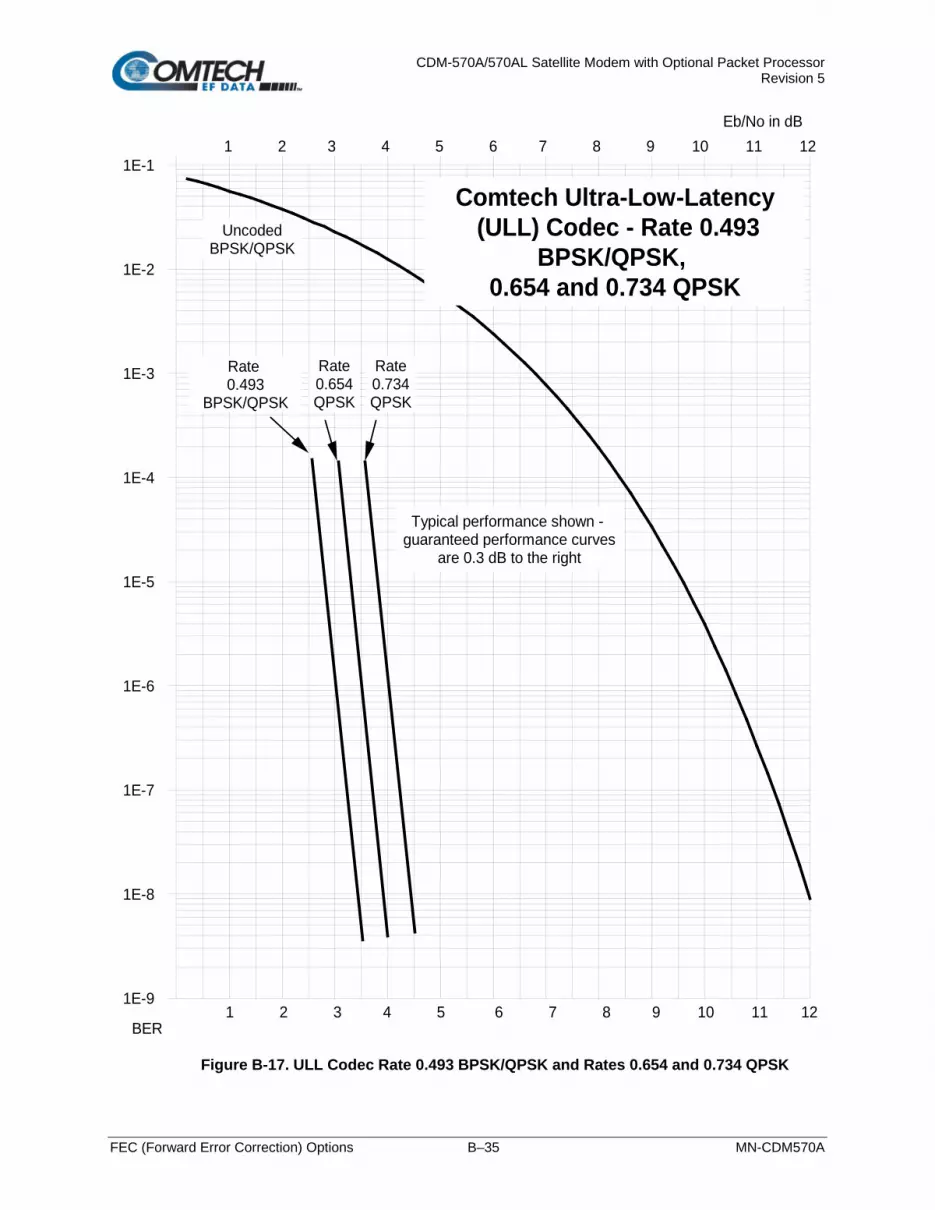
CDM-570A/570AL Satellite Modem with Optional Packet Processor Revision 5
FEC (Forward Error Correction) Options B–35 MN-CDM570A
Figure B-17. ULL Codec Rate 0.493 BPSK/QPSK and Rates 0.654 and 0.734 QPSK
1E-9
1E-8
1E-7
1E-6
1E-5
1E-4
1E-3
1E-2
1E-11 2 3 4 5 6 7 8 9 10 11 12
Eb/No in dB
UncodedBPSK/QPSK
Comtech Ultra-Low-Latency (ULL) Codec - Rate 0.493
BPSK/QPSK, 0.654 and 0.734 QPSK
1 2 3 4 5 6 7 8 9 10 11 12BER
Rate 0.493
BPSK/QPSK
Typical performance shown - guaranteed performance curves
are 0.3 dB to the right
Rate0.654QPSK
Rate0.734QPSK

CDM-570A/570AL Satellite Modem with Optional Packet Processor Revision 5
FEC (Forward Error Correction) Options B–36 MN-CDM570A
BLANK PAGE

CDM-570A/570AL Satellite Modem with Optional Packet Processor Revision 5
FEC (Forward Error Correction) Options B–37 MN-CDM570A
Figure B-18. VersaFEC-2 Long Block

CDM-570A/570AL Satellite Modem with Optional Packet Processor Revision 5
FEC (Forward Error Correction) Options B–38 MN-CDM570A
Figure B-19. VersaFEC-2 Short Block

CDM-570A/570AL Satellite Modem with Optional Packet Processor Revision 5
FEC (Forward Error Correction) Options B–39 MN-CDM570A
Figure B-20. Differential Encoding – No FEC, No Scrambling
1E-9
1E-8
1E-7
1E-6
1E-5
1E-4
1E-3
1E-2
1E-11 2 3 4 5 6 7 8 9 10 11 12
Eb/No in dB
Uncoded BPSK/QPSK
DifferentialEncoding -No FEC, noscrambling
1 2 3 4 5 6 7 8 9 10 11 12BER

CDM-570A/570AL Satellite Modem with Optional Packet Processor Revision 5
FEC (Forward Error Correction) Options B–40 MN-CDM570A
BLANK PAGE

CDM-570A/570AL Satellite Modem with Optional Packet Processor Revision 5
Offset QPSK Operation C–1 MN-CDM570A
Appendix C. OFFSET QPSK OPERATION
Offset Quadrature Phase Shift Keying (OQPSK) modulation is a variation of normal QPSK that is offered in the CDM-570A/570AL Satellite Modem. Normal band-limited QPSK produces an RF signal envelope that necessarily goes through a point of zero amplitude when the modulator transitions through non-adjacent phase states. This is not considered to be a problem in most communication systems, as long as the entire signal processing chain is linear. However, when band-limited QPSK is passed through a non-linearity (e.g., a saturated power amplifier), there is a tendency for the carefully filtered spectrum to degrade. This phenomenon is termed spectral regrowth, and at the extreme (hard limiting), the original unfiltered sin(x)/x spectrum would result. In most systems, this would cause an unacceptable level of interference to adjacent carriers, and would cause degradation of the BER performance of the corresponding demodulator. To overcome the problem of the envelope collapsing to a point of zero amplitude, Offset QPSK places a delay between I and Q channels of exactly 1/2 symbol. Now, the modulator cannot transition through zero when faced with non-adjacent phase states; the result is that there is far less variation in the envelope of the signal, and non-linearities do not cause the same level of degradation. The demodulator must realign the I and Q symbol streams before the process of carrier recovery can take place. For various reasons, this makes the process of acquisition more difficult. In the CDM-570A/570AL, the two consequences of this are:
1. Demodulator acquisition may be longer than standard QPSK, especially at low symbol rates.
2. The acquisition threshold is slightly higher than for normal QPSK. This effect is only an issue for LDPC Rate 1/2 and TPC Rate 21/44 code rates, where the Eb/No values are typically less than 2 dB. In this case, the acquisition and tracking threshold is approximately 1dB higher than for QPSK.

CDM-570A/570AL Satellite Modem with Optional Packet Processor Revision 5
Offset QPSK Operation C–2 MN-CDM570A
Notes:

CDM-570L/570AL Satellite Modem with Optional Packet Processor Revision 5
Optional High Performance Packet Processor D–1 MN-CDM570A
Appendix D. OPTIONAL HIGH-PERFORMANCE PACKET
PROCESSOR
D.1 Overview
The High-Performance Packet Processor is available as a factory-installed option or as a field-upgradeable option (see Sect. D.1.1.3).
The optional High-Performance Packet Processor makes the CDM-570A/570AL a high-performance, low-cost, IP-centric satellite modem that is well-suited for point-to-point and point-to-multipoint applications. (This appendix identifies this optionally-equipped modem as the CDM-570A/570AL-IP. The CDM-570A/570AL-IP and other compatible, IP-centric Comtech EF Data modems may also be generically referred to throughout this appendix as the CDM-IP.) In addition to providing both Layer 2/Layer 3 functionality, the CDM-570A/570AL-IP incorporates a number of key features for Wide Area Network (WAN) bandwidth optimization, including Header Compression, Payload compression, and Advanced Quality of Service (QoS). The CDM-570A/570AL-IP enables efficient IP networking and transport over satellite, in either Router Mode or Managed Switch Mode, by adding routing capability with very low overhead encapsulation, header compression, payload compression, and QoS. The Advanced QoS combined with header and payload compression ensures the highest quality of service with minimal jitter and latency for real-time traffic, priority treatment of mission critical applications and maximum bandwidth efficiency. The CDM-570A/570AL-IP can be used in a Vipersat Management System (VMS).
Vipersat CDM-570/570L Satellite Network Modem User Guide (CEFD P/N MN/22125)

CDM-570L/570AL Satellite Modem with Optional Packet Processor Revision 5
Optional High Performance Packet Processor D–2 MN-CDM570A
D.1.1 Operational Requirements
D.1.1.1 Major Assemblies
Assembly Description PL-0021625 High-Performance Packet Processor Card (factory-installed) KT-0020931 High-Performance Packet Processor Retrofit (Field Upgrade) Kit – See Sect.
D.1.1.3
D.1.1.2 Interoperability Compatibility/Limitations
• CDM-570A/570AL-IP CDM-570A/570AL-IP Interoperability: The CDM-570A/570AL-IP is not interoperable for IP/Ethernet Traffic with a CDM-570A/570AL that is not equipped with the optional Packet Processor.
• Modem Compatibility: The CDM-570A/570AL-IP is compatible with other Comtech EF Data IP (CDM-IP) modems, provided the modems have similar operating modes and IP options when the CDM-570A/570AL-IP is configured to operate in CDM-570 Compatibility Mode.
The following Comtech EF Data IP products are compatibile with the CDM-570A/570AL-IP:
Comtech EF Data IP Product IP Module (HDLC Versions ONLY)* Additional Restrictions
CDM-570/L Satellite Modem with IP Module Version 1.6.9 or later No restrictions CDD-564/L Quad Demodulator with IP Module Version 1.6.9 or later No restrictions
CDD-562L Quad Demodulator with IP Module Version 1.6.9 or later No restrictions
• CDM-570A/570AL-IP CDM-570/L-IP or CDD-564/L IP Quad Demodulator
Interoperability: A CDM-570A/570AL-IP is interoperable with the CDM-570/L-IP (CDM-570/L Satellite Modem w/Optional IP Module) and/or the CDD-564/L Quad Demodulator with IP Module using HDLC and compatible modulation, Forward Error Correction (FEC), symbol rate, etc.
*The CDM-570A/570AL-IP is NOT compatible with the Streamline Encapsulation (SLE) version of the CDM-570/L, CDD-564/L, and CDD-562/L products.

CDM-570L/570AL Satellite Modem with Optional Packet Processor Revision 5
Optional High Performance Packet Processor D–3 MN-CDM570A
D.1.1.3 High-Performance Packet Processor Field Upgrade Procedure
D.1.1.3.1 Overview
This section describes the field upgrade procedure you need to follow to retrofit your CDM-570A/570AL Satellite Modem with the optional Packet Processor card. See Section D.1.1.2 in this appendix for the requirements and limitations of using the Packet Processor with the CDM-570A/570AL.
D.1.1.3.2 Requirements for Field Upgrade
• CDM-570A/570AL Satellite Modem
• Medium Phillips screwdriver
• CEFD P/N KT-0020931 Packet Processor Upgrade Kit, containing:
CEFD Part Number QTY Description PL-0021625 1 CDM-570A/570AL-Packet Processor Card HW/SEM440X1/4PH 4 Screw, S.S., 4-40 x 1/4 LG, Pan Head Phillips

CDM-570L/570AL Satellite Modem with Optional Packet Processor Revision 5
Optional High Performance Packet Processor D–4 MN-CDM570A
D.1.1.3.3 Field Upgrade Procedure
Step Task
1 Turn off the CDM-570A/570AL and disconnect the modem’s power cord from its power source. Next, use the screwdriver to remove the top cover mounting hardware. Remove the cover from the CDM-570A/570AL chassis. IMPORTANT: Be sure to retain the top cover mounting hardware for cover re-installation once you have installed the Packet Processor Card.
2 The illustration at right identifies the features within
the chassis for assembly of the Packet Processor Card onto the chassis-mounted card bosses.

CDM-570L/570AL Satellite Modem with Optional Packet Processor Revision 5
Optional High Performance Packet Processor D–5 MN-CDM570A
Step Task
3 Prepare the Packet Processor Card for installation by aligning its receptacle with the mating connector on the modem’s framing board. Tilt the board slightly, in a downward angle, to align the RJ-45 and RJ-11 ports with their mating chassis rear panel cutouts. Then, plug the card firmly into the connector – take care not to damage any top- or bottom-mounted components. Similarly, be sure not to damage the bottom of the card on the chassis’ mounting bosses while plugging the card receptacle into its mating connector. Installation is complete once the the card receptable is fully engaged within its mating connector, and the mounting holes at the front and rear of the card are aligned with the mounting boss threaded holes.

CDM-570L/570AL Satellite Modem with Optional Packet Processor Revision 5
Optional High Performance Packet Processor D–6 MN-CDM570A
Step Task
4 Use the screwdriver to secure the Packet Processor card to the chassis with its provided mounting hardware (4X 4-40 x 1/4 pan head screws).

CDM-570L/570AL Satellite Modem with Optional Packet Processor Revision 5
Optional High Performance Packet Processor D–7 MN-CDM570A
Step Task
5 Use the screwdriver to reinstall the top cover onto the CDM-570A/570AL chassis with its existing mounting hardware. Plug the modem’s power cord back into its power source.
The High-Performance Packet Processor upgrade is now complete. You may turn on and resume use of the modem.

CDM-570L/570AL Satellite Modem with Optional Packet Processor Revision 5
Optional High Performance Packet Processor D–8 MN-CDM570A
Notes:

CDM-570L/570AL Satellite Modem with Optional Packet Processor Revision 5
Optional High Performance Packet Processor D–9 MN-CDM570A
D.1.2 High-Performance Packet Processor Features
• 10/100BaseT Ethernet Interface
• Network-Based Management:
o HTTP Interface for complete product management
o SNMP with public and private MIB
o Console Port interface for local network management
o Telnet interface for remote product M&C
o Remote software/firmware upgrade via FTP
o Configuration Backup and Restore via FTP
o Event Logging to Capture all Packet Processor Activity
o Detailed Statistics of IP traffic
• Header Compression (Layer 2 only)
• IGMP Support for Multicast
• Static IP Routing for Unicast and Multicast
• Managed Switch Mode with VLAN
• Adaptive Coding and Modulation (ACM)
D.1.2.1 10/100 BaseT Ethernet Interface
In Router Mode operation, the 10/100BaseT Ethernet Interface is used for routing IP traffic to be transmitted over the satellite or routed to another device on the local LAN. In Managed Switch Mode, the Ethernet Interface is used to forward IP and non-IP traffic over the satellite. Local or remote management of all CDM-570A/570AL-IP (w/Packet Processor-related functions) is also available via Telnet, HTTP, or SNMP.

CDM-570L/570AL Satellite Modem with Optional Packet Processor Revision 5
Optional High Performance Packet Processor D–10 MN-CDM570A
D.1.2.2 Network-Based Management
Use any of the following methods to configure, operate, and monitor the CDM-570A/570AL-IP:
User Interface Connection Modem Functions
Packet Processor Functions
Manual Reference
Front Panel Local - Keypad ALL IP Address/Subnet Mask only Chapter 6
SNMP Local or remote - Ethernet via 10/100 BaseT Traffic interface ALL ALL Chapter 7.2
Telnet Local or remote - Ethernet via 10/100 BaseT Traffic interface ALL ALL Chapter 7.3
HTTP (Web Server) Local or remote - Ethernet via 10/100 BaseT Traffic interface ALL ALL Chapter 7.4
Serial Remote Control
Local - Serial RS-232/RS-485 via Remote Control Port ALL IP Address/Subnet
Mask only Chapter 8
Command Line Interface (CLI)
Local - Serial RS-232 via Console Port
ALL ALL Chapter 9 Remote – Ethernet via 10/100 Base T Traffic Interface
D.1.2.2.1 Remote Software/Firmware Upgrade via FTP
The Packet Processor uses ‘flash memory’ technology internally. This simplifies firmware updating, and updates can be obtained over the Internet or through e-mail from Comtecgh EF Data Product Support. New firmware can be uploaded by FTP to the Packet Processor from a user-supplied PC without opening the unit or having to be in the same physical location.
D.1.2.2.2 Configuration Backup and Restore via FTP
All Base Modem and Packet Processor configuration parameters are stored in a simple text file named “param1”. This parameter file can easily be retrieved locally or remotely by FTP. The file can then be used to quickly configure a replacement modem if needed. Packet Processor configuration file – The “param1” file can be modified with a text editor (e.g., WordPad). After downloading this file from the CDM-570A/570AL-IP Modem to the User PC, edit the desired configuration settings and save the file under a name that identifies the modem’s network role (e.g., HUB570A_param1.txt). Do these steps: 1. Once you verify User PC-to-Modem communications, you may use Command-line to transfer
(FTP) the configuration file from the CDM-570A/570AL-IP to the User PC: a. Type "ftp xxx.xxx.xxx.xxx" (where ‘xxx.xxx.xxx.xxx’ is the
CDM-570A/570AL-IP Ethernet Traffic/Management IP Address).
b. Type the Admin User Name and Password when prompted. The default User Name and Password is “comtech”.

CDM-570L/570AL Satellite Modem with Optional Packet Processor Revision 5
Optional High Performance Packet Processor D–11 MN-CDM570A
c. At the “ftp >” prompt, type “get param1” to download the parameter file.
d. Type “bye” to close the FTP session. 2. Use a text editor (e.g., WordPad) to edit the downloaded param1 text file file and save it to a
unique name.
3. Use FTP to upload the configuration settings file from the User PC into another CDM-570A/570AL-IP Modem:
a. Type "ftp xxx.xxx.xxx.xxx" (where ‘xxx.xxx.xxx.xxx’ is the CDM-570A/570AL-IP
Ethernet Traffic/Management IP Address).
b. Type the Admin User Name and Password when prompted. The default User Name and Password is “comtech”.
c. At the “ftp >” prompt, type “put param1” (i.e., the name of your custom configuration file) to upload the parameter file from the User PC to the CDM-570A/570AL.
d. Type “bye” to close the FTP session.
D.1.2.2.3 Event Logging to Capture All Packet Processor Activity
All Packet Processor activity is stored in a simple text file named “eventlog”. This easy-to-read Event Log can be retrieved locally or remotely by FTP. Do these steps: 1. Once you verify User PC-to-Modem communications, you may use Command-line to transfer
(FTP) the Event Log file from the CDM-570A/570AL-IP to the User PC: a. Type "ftp xxx.xxx.xxx.xxx" (where ‘xxx.xxx.xxx.xxx’ is the CDM-570A/570AL-IP
Ethernet Traffic/Management IP Address).
b. Type the Admin User Name and Password when prompted. The default User Name and Password is “comtech”.
c. At the “ftp >” prompt, type “get eventlog” to download the file.
d. Type “bye” to close the FTP session. 2. Use a text editor (e.g., WordPad) to open and review the Event Log.

CDM-570L/570AL Satellite Modem with Optional Packet Processor Revision 5
Optional High Performance Packet Processor D–12 MN-CDM570A
D.1.2.2.4 Detailed Statistics of IP Traffic
IP traffic statistics are continuously updated and allow detailed performance analysis or can be used to identify traffic problems. The statistics are available through the Serial Console locally, or can be gathered remotely by Telnet, HTTP, or SNMP.
D.1.2.3 Static IP Routing for Unicast and Multicast
Up to 256 static routes can be entered into the Packet Processor to direct IP traffic over the satellite or to another device on the local LAN. These 256 routes could be in any combination of unicast and multicast.
D.1.2.4 IGMP Support for Multicast
IGMP is a standard feature in the Packet Processor. If enabled, it responds to IGMP queries for the configured multicast routes on the transmit side and generates IGMP queries on the receive side. If there are no active IGMP receivers on the LAN, it will stop forwarding the multicast traffic (received from the satellite) to the LAN.
D.1.2.5 Managed Switch Mode
Managed Switch Mode is the Comtech EF Data IP modem intelligent networking solution that allows a link to be setup with minimal configuration (no specific routes need to be configured). The Packet Processor also supports non-IP traffic with Managed Switch Mode. All IP traffic will be subject to user-configured QoS restrictions.
D.1.2.5.1 Managed Switch Mode Operation
1. Managed Switch Mode will automatically use Header Compression for compressing Layer 2 (even if Header Compression option has not been purchased). Because of this, some of the initial traffic sent between two devices will not be received over the satellite until a full Header is transmitted. For example, the default Header Compression Refresh Rate is 50 packets. If a ping is sent over the satellite, then it will time out until the full Header packet is sent. The Header Compression Refresh Rate on the Administration Menu can be reduced to minimize the amount of traffic lost when traffic is first sent between two devices. Once communication between two devices has been established, both IP modems will be able to receive all traffic, unless one IP modem is power cycled or reset. Header Compression feature should be enabled for compressing Layer 3, Layer 4 and Layer 5.

CDM-570L/570AL Satellite Modem with Optional Packet Processor Revision 5
Optional High Performance Packet Processor D–13 MN-CDM570A
2. Do not enable IF Loopback (or link the TX to RX by a BNC cable or satellite) on an IP modem operating in Managed Switch Mode when connected to a LAN. In this configuration, Managed Switch Mode will resend all Layer 2 broadcast packets and cause a “broadcast storm” on the LAN. To perform a loop test to verify the modem or satellite link, do one of the following:
a. Reconfigure the CDM-570A/570AL-IP interface selection: From the front panel, select Config Intfc, and then select RS422, V.35, or RS232. - OR –
b. Set the Packet Processor to Router Mode. Information about the function of Managed Switch Mode, as well as a detailed description for the setup and configuration of a Managed Switch Mode pair, is as follows:
• Because Managed Switch Mode is a “smart wire,” the devices attached to it on either side of the satellite should be on the same subnet and should not configure a next hop address to be the CDM-570A/570AL-IP address (as should be done with router mode). For purposes of configuration, Managed Switch Mode should be viewed to function in much the same way as a bridge (however, without spanning tree protocol).
• All of the features that groom and optimize the satellite link in router mode are also available in Managed Switch Mode.
• Managed Switch Mode Multicast Option – Multicast packets in Managed Switch Mode are identified using multicast MAC address. These identified multicast packets are either routed or dropped based on the Managed Switch Mode multicast option.
• Managed Switch Mode uses Layer 2 (MAC) addresses to learn where to send packets. In comparison, router mode uses the destination IP address in the packet in conjunction with the route table to determine where to forward the packets.
• The Packet Processor in Managed Switch Mode is configured to be in promiscuous mode with a data rate of 10/100BaseT Half Duplex/Full Duplex. The Packet Processor needs to be in promiscuous mode in order to learn the attached networking devices.
• Since Managed Switch Mode does not use a routing table, the determination of where to send a packet is made by a learning process. When the system is powered-up, all packets from each subnet (local and remote) will be sent over the satellite interface. However, as each Packet Processor learns which devices are attached to their local Ethernet interfaces, the Packet Processor begins to filter packets which it has learned are locally attached to its Ethernet interface.
• The Managed Switch Mode learning/forwarding algorithm is as follows:
o If the packet is destined for the Packet Processor, then process it locally.
o If the packet is from the Packet Processor Interface, then send it to the Satellite interface; OR if the destination Layer 2 (MAC) address of the packets matches the source Layer 2 address for a packet we have already seen, then the destination MAC address of this packet is on our local subnet; so why send it over the satellite interface. In this case, the Packet Processor will drop the packet.
o If the packet is from the satellite interface, then send it out the Ethernet interface.

CDM-570L/570AL Satellite Modem with Optional Packet Processor Revision 5
Optional High Performance Packet Processor D–14 MN-CDM570A
• Managed Switch Mode also supports VLAN’s and when VLAN Mode is enabled, will forward traffic as follows:
o If an untagged packet arrives at the Packet Processor, it will egress as a tagged packet with the defined Native VLAN ID.
o VLAN entries can be added into the VLAN Table and to forward VLAN's over the satellite. A VLAN entry is also needed on the receiving CDM-570A to receive the VLAN traffic and they will egress as tagged VLAN's.
o If a tagged packet arrives at the Ethernet port, it will only be forwarded if there is a matching VLAN entry in the VLAN Table and it will egress as tagged. If there is no matching VLAN in the VLAN Table, the tagged packet will be dropped.
• VLAN operation in the CDM-570A/570AL-IP also includes full 802.1Q VLAN QoS support. With the QoS Option enabled, the Packet Processor will read the 802.1Q VLAN Priority (7 through 0) that is in the VLAN Header in each VLAN frame received and will prioritize traffic accordingly.
D.1.2.5.2 Combined Working Mode
In order greatly simply the configuration complexity, the working modes operation of modem have been centralized in the single Working Mode configuration parameter, which in turn offer the following functional parameters:
Mode Selection Function
Managed Switch Managed switch with support for VLAN as well as advanced features such as QoS, Header Compression and Payload Compression. Primarily intended for operation in a point-to-point topology.
Router – Small Network Mode Hub side router in a Point-to-Multipoint network. Allows Sat-to-sat.
Router – Large Network Mode Remote Router in a Point-to-Multipoint network. Packets from the WAN are not allowed to be sent to the WAN. No longer requires HDLC receive addresses to be configured.
Router – Point to Point Point-to-Point router in Point-to-Point configurations. Router – Vipersat Hub router in a Vipersat Network.
The Vipersat “Unit Role” and “Expansion Role” parameters are not read-only.

CDM-570L/570AL Satellite Modem with Optional Packet Processor Revision 5
Optional High Performance Packet Processor D–15 MN-CDM570A
D.1.2.6 Adaptive Coding and Modulation (ACM)
Appendix P. ADAPTIVE CODING and MODULATION (ACM) OPTION
Comtech EF Data’s VersaFEC® Adaptive Coding and Modulation (ACM) feature is a patents-pending technology wholly owned and developed by Comtech EF Data and Comtech AHA Enterprise Products Group. It can be used with the Packet Processor to maximize throughput. ACM converts available link margin into additional throughput, thereby maximizing throughput under all conditions, including rain fade, inclined orbit satellite operation, antenna mispointing, interference and other impairments.
D.1.2.7 High-Performance Packet Processor Optional FAST Features
• Chapter 5. FAST ACTIVATION PROCEDURE • Sect. 6.3.7.7 UTIL: FAST (FAST Code Options) (Chapter 6. FRONT PANEL
OPERATION) If you wish to upgrade the CDM-570A/570AL’s optional Packet Processor functionality, Comtech EF Data provides Fully Accessible System Topology (FAST). FAST technology permits the purchase and installation of options through special authorization codes. These unique Fast Access Codes may be purchased from Comtech EF Data Product Support, and then loaded into the unit using the front panel keypad.
All IP FAST Options may be temporarily enabled using the 30-day Demo Mode.
Optional FAST Features are:
• IP Header Compression
• Payload Compression
• Advanced Quality of Service (QoS)
• Vipersat (VMS – Vipersat Management System)
• VFS (Vipersat File Streaming)
D.1.2.7.1 CDM-570A/570AL-Packet Processor in Demo Mode
Demo Mode temporarily enables the IP optional FAST features listed in Sect. D.1.2.7. Demo Mode has a cumulative counter that can be stopped and started at any time, for a total time duration of up to 30 calendar days. You may control Demo Mode operation from either the CDM-570A/570AL-IP front panel or the CDM-570A HTTP (Web Server) Interface: From the CDM-570A/570AL-IP front panel – Select (UTIL: FAST) FAST Configuration Demo Mode ON. Press ENTER. The Demo Mode Timer decrements from 2592000 seconds (30 calendar days) but can be stopped at any time by setting Demo Mode to OFF.

CDM-570L/570AL Satellite Modem with Optional Packet Processor Revision 5
Optional High Performance Packet Processor D–16 MN-CDM570A
From CDM-570A HTTP Interface – Use the Admin | FAST page Demo Mode drop-down list to set operation as Enabled, and then click [Submit]. The Demo Mode timer decrements via the Demo Time Remaining: XX days XX hours XX minutes banner. To stop Demo Mode at any time, use the drop-down list to set operation as Disabled.
Make sure to reboot the unit any time you turn Demo Mode ON (Enabled) or OFF (Disabled).
D.1.2.7.2 Header and Payload Compression
D.1.2.7.2.1 IP Header Compression
The Packet Processor incorporates industry-leading header compression for IP traffic. Header compression can reduce the 40-byte IP/UDP/RTP header to as little as 1 byte; for TCP/IP, the 40-byte header is reduced to as little as 3 bytes. For applications such as Voice-over-IP (VoIP), header compression can provide bandwidth savings exceeding 60%. For example, the 8 kbps G.729 voice codec requires 24 kbps of IP bandwidth once encapsulated into an IP/UDP/RTP datagram. Using IP/UDP/RTP Header Compression, the same traffic only needs 10.8 kbps total WAN satellite bandwidth to cross the link. A total maximum of 64 simultaneous VoIP calls can be compressed. Normal HTTP (Web) traffic can be reduced an additional 10% via IP/TCP header compression. In addition, bandwidth requirements for typical Web/HTTP traffic can be reduced by 10% or more with TCP/IP header compression. The Packet Processor supports Header Compression for the following Ethernet and Layer 3, 4 & 5 Headers:
Supported Ethernet Headers Supported Layer 3 & 4 Headers Ethernet 2.0 IP Ethernet 2.0 + VLAN-tag TCP Ethernet 2.0 + MPLS UDP 802.3-raw RTP (Codec Independent) 802.3-raw + VLAN-tag 802.3 + 802.2 802.3 + 802.2 + VLAN-tag 802.3 + 802.2 + SNAP 802.3 + 802.2 + SNAP + VLAN-tag 802.3 + 802.2 + SNAP + MPLS
Note the following:
• Header Compression Configuration is completely independent from QoS, and there is no configuration required except enabling the Header Compression feature on both the sending and receiving Comtech EF Data IP modem. Packets with a Header Compression supported header will automatically be identified for compression. The only configuration consideration is the Header Compression Refresh Rate. This is how many compressed header packets will be sent before a single full header packet is sent. Some compressed header traffic could be lost during deteriorated satellite link conditions. Sending a full header packet will allow the return of the traffic stream. The Refresh Rate can be increased for poor satellite link conditions or decreased to further reduce overhead.

CDM-570L/570AL Satellite Modem with Optional Packet Processor Revision 5
Optional High Performance Packet Processor D–17 MN-CDM570A
• Header Compression Statistics will display the total bytes of the pre-compressed and post-compressed traffic and effective compression ratio.
D.1.2.7.2.2 Payload Compression
The Packet Processor features industry-leading payload compression for IP traffic. Implemented in the hardware for maximum throughput and efficiency, payload compression can reduce the required satellite bandwidth by as much as 40–50%. Traffic optimization through Payload Compression is an optional feature of the Packet Processor. Note the following:
• Available as a FAST feature
• Uses AHA chip
• Compression algorithm applied to all data (HDLC header excluded)
• Compression statistics are fed back to QoS in order to maximize WAN utilization while maintaining priority, jitter and latency
• 1024 simultaneous compression sessions to maximize compression across multiple distinct traffic flows
• Compression algorithm not applied to RTP streams because this traffic is already compressed and would only INCREASE the sat bandwidth if compressed again
• Additional statistics have been added to the compression statistics menu in order to provide feedback on the compression efficiency that has been achieved
• Payload Compression is selectable on a per route basis
D.1.2.7.2.3 ALDC vs. LZS Compression Comparison Table
The numbers in Table D-1 were compiled using a test program created in-house by Comtech EF Data. This program takes the target benchmark files and splits the files into payload-sized chunks, then compresses each chunk in a separate invocation of the compression algorithm. This is important to note because most compression algorithms are applied to the entire file data set as a single invocation of the compression algorithm, which is easier for other types of compression algorithms (LZS, GZip specifically). This, of course, does not apply to streamed packet data across an IP network (e.g., FTP transfer).
Table D-1. ALDC vs. LZS Compression Comparison
Algorithm Payload size File Set Ratio Algorithm Payload
size File Set Ratio
ALDC
1472
Calgary
1.76
LZS
1472
Calgary
1.66 1000 1.76 1000 1.66 500 1.77 500 1.68 100 2.09 100 1.97 1472
Canterbury
1.71 1472
Canterbury
1.61 1000 1.72 1000 1.62 500 1.74 500 1.63 100 2.04 100 1.91

CDM-570L/570AL Satellite Modem with Optional Packet Processor Revision 5
Optional High Performance Packet Processor D–18 MN-CDM570A
D.1.2.8 Advanced Quality of Service (QoS)
Appendix L. ADVANCED QUALITY OF SERVICE (QoS)
Advanced QoS is an optional feature of the Packet Processor. Advanced QoS enables a network to use WAN bandwidth more efficiently by managing delay, jitter (delay variation), throughput, and packet loss. It is based on OSI model to Layer 7 protocol header parameters. Advanced QoS requires that the optional Packet Processor is installed and active, and requires that you purchase and activate the Advanced QoS FAST Option. Contact Comtech EF Data Product Support for further information. The CDM-570A/570AL-IP incorporates four Per Hop Behavior (PHP) QoS modes of operation:
• Max/Pri Mode – QoS Rules based on Maximum Bandwidth and Priority.
This mode provides multi-level traffic prioritization with the ability to limit maximum traffic per priority class.
• Min/Max Mode – QoS Rules based on Minimum and Maximum Bandwidth.
This mode provides a Committed Information Rate (CIR) to each user-defined class of traffic with the ability to allow a higher burstable rate depending on availability
• DiffServ Mode – Differentiated Services.
This mode incorporates the industry-standard method of providing QoS, enabling seamless co-existence in networks that implement DiffServ.
• VLAN Priority Max Mode – VLAN 802.1q
When using rule-based QoS, you can configure up to 32 different rules based on:
• Source IP address and subnet mask;
• Source Port;
• Protocols (well known);
• Destination IP address and subnet mask;
• Destination Port;
• Priority.
D.1.2.9 Vipersat / VFS
For specific information about CDM-570A/570AL-Packet Processor operation when deployed in a Vipersat satellite bandwidth management system, see adjunct Comtech EF Data publication Vipersat CDM-570/570L Satellite Network Modem User Guide (CEFD P/N MN/22125)
D.1.2.10 3xDES Encryption with Ability to Change Keys
Future releases of the Packet Processor will optionally support 3xDES-128 (using NIST certified 3x core) encryption and decryption, for the highest level security for link encryption.

CDM-570L/570AL Satellite Modem with Optional Packet Processor Revision 5
Optional High Performance Packet Processor D–19 MN-CDM570A
D.1.3 CDM-570A/570AL-IP – Operation and Control
Functionality and selection of the CDM-570A/570AL-IP features, modes of operation, and monitor and control (M&C) is seamless via these operational interfaces.
D.1.3.1 Front Panel Operation
Chapter 6. FRONT PANEL OPERATION
Using the keypad on the front panel, you may access a variety of nested menus to configure the options available whenever the CDM-570A/570AL is equipped with the optional Packet Processor.
D.1.3.2 Ethernet-based Remote Product Management
Chapter 7. ETHERNET-BASED REMOTE PRODUCT MANAGEMENT
The CDM-570A/570AL 10/100 BaseT Ethernet Management Interface supports three management protocols for remote monitor and control (M&C) of the modem:
• Simple Network Management Protocol (SNMP) – This requires a user-supplied Network Management System (NMS) and a user-supplied Management Information Base (MIB) File Browser.
• Telnet Interface – This requires use of a user-supplied terminal emulation program installed on the user PC, such as HyperTerminal (for use with the remote control protocol) or PuTTY (for use with the Telnet Command Line Interface).
• CDM-570A HTTP (Web Server) Interface – This requires a compatible user-supplied web browser such as Internet Explorer.
D.1.3.3 SNMP Interface
Sect. 7.2 SNMP Interface (Chapter 7. ETHERNET-BASED REMOTE PRODUCT MANAGEMENT)
The Simple Network Management Protocol (SNMP) is an Internet-standard protocol for managing devices on IP networks. An SNMP-managed network consists of three key components:
• The managed device – This includes the CDM-570A/570AL-IP.
• The SNMP Agent – The software that runs on the CDM-570A/570AL. The CDM-570A/570AL-IP SNMP Agent supports both SNMPv1 and SNMPv2c.
• The user-supplied Network Management System (NMS) – The software that runs on the manager.
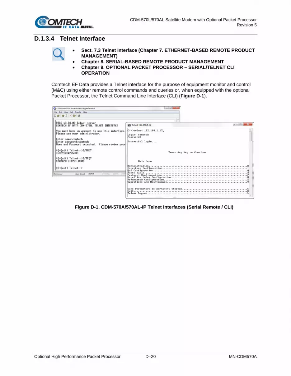
CDM-570L/570AL Satellite Modem with Optional Packet Processor Revision 5
Optional High Performance Packet Processor D–20 MN-CDM570A
D.1.3.4 Telnet Interface
• Sect. 7.3 Telnet Interface (Chapter 7. ETHERNET-BASED REMOTE PRODUCT MANAGEMENT)
• Chapter 8. SERIAL-BASED REMOTE PRODUCT MANAGEMENT • Chapter 9. OPTIONAL PACKET PROCESSOR – SERIAL/TELNET CLI
OPERATION Comtech EF Data provides a Telnet interface for the purpose of equipment monitor and control (M&C) using either remote control commands and queries or, when equipped with the optional Packet Processor, the Telnet Command Line Interface (CLI) (Figure D-1).
Figure D-1. CDM-570A/570AL-IP Telnet Interfaces (Serial Remote / CLI)

CDM-570L/570AL Satellite Modem with Optional Packet Processor Revision 5
Optional High Performance Packet Processor D–21 MN-CDM570A
D.1.3.5 CDM-570A HTTP (Web Server) Interface
Sect. 7.4 CDM-570A HTTP (Web Server) Interface (Chapter 7. ETHERNET-BASED REMOTE PRODUCT MANAGEMENT)
The embedded HTTP application (Figure D-2) provides an easy-to-use interface designed for optimal performance when using Microsoft’s Internet Explorer Version 9.0 or higher. The interface features enhanced functionality when the CDM-570A/570AL is equipped with the Packet Processor.
Figure D-2. CDM-570A HTTP (Web Server) Interface Home Page

CDM-570L/570AL Satellite Modem with Optional Packet Processor Revision 5
Optional High Performance Packet Processor D–22 MN-CDM570A
D.1.4 High-Performance Packet Processor Specifications – Supported RFCs (Requests for Comment) and Protocols
RFC No. Description 768 User Datagram Protocol 791 Internet Protocol 792 Internet Control Message Protocol 793 Transmission Control Protocol 826 Ethernet Address Resolution Protocol 856 Telnet Binary Transmission 862 Echo Protocol 894 A Standard for the Transmission of IP Datagrams over Ethernet Networks 919 Broadcasting Internet Datagrams 922 Broadcasting Internet Datagrams in the Presence of Subnets 950 Internet Standard Subnetting Procedure 951 Bootstrap Protocol (BOOTP) 959 File Transfer Protocol 1071 Computing the Internet Checksum 1112 Host Extensions for IP Multicasting 1213 Management Information Base for Network Management of TCP/IP-based internet: MIB-II 1350 The TFTP Protocol 1700 Assigned Numbers 1812 Requirements for IP Version 4 Routers 2045 Multipurpose Internet Mail Extensions (MIME) 2236 Internet Group Management Protocol, Volume 2 2474 Definition of the Differentiated Services Field (DS Field) in the IPv4 and IPv6 Headers 2475 An Architecture for Differentiated Services 2578 Structure of Management Information Version 2 (SMIv2) 2597 Assured Forwarding PHB 2598 An Expedited Forwarding PHB 2616 Hypertext Transfer Protocol – HTTP/1.1 2821 Simple Mail Transfer Protocol 2933 Internet Group Management Protocol MIB 3412 Message Processing and Dispatching for the Simple Network Management Protocol (SNMP) 3416 Version 2 of the Protocol Operations for the Simple Network Management Protocol (SNMP) 3418 Management Information Base (MIB) for the Simple Network Management Protocol (SNMP) 4293 Management Information Base for the Internet Protocol (IP)

CDM-570L/570AL Satellite Modem with Optional Packet Processor Revision 5
Optional High Performance Packet Processor D–23 MN-CDM570A
D.2 High-Performance Packet Processor – Quick Start Guide
This section serves to guide you through the steps needed to pass IP traffic within minutes of initial installation and setup (i.e., starting from factory default settings), using a pair of CDM-570A/570AL-IPs. This section refers generically to any Comtech EF Data IP-centric modem as the CDM-IP. This section assumes operator familiarity with configuration of base modem ooperations.
D.2.1 Getting Started
D.2.1.1 Equipment List
Use the following equipment:
Description Qty Comments CDM-IP Modem 2 CDM-570A/570AL Satellite Modem w/optional Packet Processor and/or
any other compatible, IP-centric Comtech EF Data modem. Note: You may need to provide equipment to convert 70 MHz IF to L-Band for a duplex connection, depending upon modems.
Layer 2 Ethernet Switch or Hub 2 Supplied by User. Note: RJ-45 crossover Ethernet cables can be substituted to directly connect the User PC to the CDM-IP Modem without the use of a hub.
Windows-based PC with Network Interface Card (NIC), terminal emulation program, and compatible Web browser
2 Supplied by User.
Console cable (DB-9 to RJ-11) 1 Supplied by Comtech EF Data (CEFD P/N PL/9396-1). Ethernet cables (CAT5) 4 Supplied by User. IF Coaxial cables 2 Supplied by User to interconnect Tx-Rx between both CDM-IP modems.
D.2.1.2 Equipment Setup
Do these steps:
Step Task 1 Use CAT5 Ethernet cables to connect each CDM-IP rear panel “Traffic 100” port to the User PC via the
Ethernet hub or switch. 2 Use coaxial cables to connect the Tx IF on CDM-IP 1 to Rx IF of CDM-IP 2, and the Rx IF on CDM-IP 1 to
the Tx IF of CDM-IP 2. 3 Connect the DB-9 end of the CEFD P/N PL/9396-1 console cable to the COM1 or COM2 port of the User
PC, and the RJ-11 end to the CDM-IP 1 rear panel Console port. 4 Connect the CDM-IP 1 and CDM-IP 2 to suitable power supplies and turn them ON.

CDM-570L/570AL Satellite Modem with Optional Packet Processor Revision 5
Optional High Performance Packet Processor D–24 MN-CDM570A
D.2.2 Transmit and Receive IF Configuration
Do these steps: Step Task
1 Use the CDM-IP 1 and CDM-IP 2 front panels to configure the Tx and Rx IF parameters. Note: The IF parameters can also be set via Console CLI, Telnet, HTTP (Web Server) Interface and SNMP. For this procedure, however, it is recommended that you use the modem front panel.
2 Set the TxPower to minimum level. 3 Before proceeding to next step, make sure that each CDM-IP is appropriately carrier-locked to the other
CDM-IP.
D.2.3 Command Line Interface (CLI) Configuration
Chapter 9. OPTIONAL PACKET PROCESSOR – SERIAL/TELNET CLI OPERATION
Do these steps:
Step Task 1 Launch the user-supplied terminal emulation program (e.g., HyperTerminal). 2 Select the appropriate COM port to which the DB-9 end of the console cable is connected, and configure
the port as follows: 38400 bps 8 data bits No parity
1 stop bit No hardware flow control
3 Press Enter to bring up the CLI login prompt, and then the CLI Main Menu. The default User Name and Password is comtech.
D.2.3.1 Telnet CLI Operation Quick Reference
The CLI operates under a hierarchy of Configuration and Information functions. You may access any nested configuration or information page (e.g., Administration, Route Table, etc.) from this top-level menu by typing an available “Hot Key”, commonly provided at the right side of the screen.
• Common Interface Options/Fields – The bottom of each primary and nested page provides three menu functions are that are typical throughout the CLI:
Selection Hot Key Description
Save Parameters to permanent storage S
Saves the current configuration of the Packet Processor to permanent storage. This configuration is restored on each successive power cycle.
Exit X Exits the current menu and returns to the parent menu. You may alternately press the Esc key to perform the same action.
Telnet Logout L Exits the CLI and closes the terminal emulator application.

CDM-570L/570AL Satellite Modem with Optional Packet Processor Revision 5
Optional High Performance Packet Processor D–25 MN-CDM570A
M&C is accomplished as follows:
• Selection – This is the function or command as it appears on the menu page.
• Hot Key – This is the letter or number assigned as the keystroke/mnemonic for execution of a menu function or command. Where this column specifies [RO], this means that this line item is a read-only (informational) feature. No user input is available.
• Description – This is the detailed explanation of the function or command. You are instructed to take a specific action here:
o When you are instructed to “set” a feature, this means that you are prompted to type the numerical value for that feature. Press [Enter] to execute configuration. User guidance to “set” a value within a permitted ranges (from a minimum value to a maximum value) is commonly provided in parentheses or brackets.
o When you are instructed to “select” a feature, this means that a numbered list of choices is commonly provided. Type the number to execute your operational selection. Press [Enter] to execute configuration.
o When you are instructed to “toggle” a feature, this generally means that pressing the Hot Key executes one of two operating states for that feature (e.g., Enabled or Disabled, On or Off, Auto or Manual, etc.). The feature line will dynamically update to display, in brackets, its updated and current operating state.
D.2.4 Restoring Factory Default Configuration
The configuration procedures provided in this chapter assume that the CDM-IP is still in factory default configuration for IP. If this is not the case, the factory default configuration can be restored from the CLI menu. Do these steps (the applicable CLI “hot key” is shown in brackets [#]):
Step Task 1 From the CLI Main Menu:
Select Operations and Maintenance submenu [O]. 2 From the Operations and Maintenance menu:
Select Database Operations submenu [D]. 3 From the Database Operations menu:
Select Restore Factory Default option [R]. 4 The following prompt appears:
Are you sure you want to restore factory default settings? WARNING: Choosing Yes will restore factory defaults and then reboot..
Type ‘y’ to confirm. This erases user configurations and restores CDM-IP factory default configuration. 5 Proceed either to Sec. D.2.5 to perform the Managed Switch Mode configuration, or to Sect. D.2.6 to
perform the Router Mode configuration.
D.2.5 Configuring a Managed Switch Point-to-Point System
The procedures outlined in this section result in the configuration shown in Figure D-3.

CDM-570L/570AL Satellite Modem with Optional Packet Processor Revision 5
Optional High Performance Packet Processor D–26 MN-CDM570A
Figure D-3. Managed Switch Point-to-Point System Configuration
D.2.5.1 Configure User PCs
Do these steps:
Step Task 1 For User PC 1:
• Set the IP Address to 172.16.10.11; • Set the mask to 255.255.255.0.
2 For User PC 2: • Set the IP Address to 172.16.10.12; • Set the mask to 255.255.255.0.
3 Reboot the PCs (if required).
D.2.5.2 Configure CDM-IP 1, CDM-IP 2 – Set IP Address(es)
Do these steps (the applicable CLI “hot key” is shown in brackets [#]):
Step Task 1 From the CLI Main Menu:
Select the Interface Configuration submenu [ I ]. 2 From the Interface Configuration Menu:
Select the Ethernet Interface submenu [ E ]. 3 Set Ethernet IP Address [ I ]:
• Set CDM-IP 1 to 172.16.10.1 • Set CDM-IP 2 to 172.16.10.2
4 Set the Ethernet Subnet Prefix Length [ M ] to 24.
All other parameters can be left at their factory default settings. At this point, the basic configuration is complete. You should now be able to use Windows Command-line to confirm that communications are active between the user PCs and the CDM-IP modems.

CDM-570L/570AL Satellite Modem with Optional Packet Processor Revision 5
Optional High Performance Packet Processor D–27 MN-CDM570A
Do these steps to finish:
Step Task 5 From User PC 1:
• Ping 172.16.10.1 (CDM-IP 1); • Ping 172.16.10.2 (CDM-IP 2); • Ping 172.16.10.12 (User PC 2).
6 From User PC 2: • Ping 172.16.10.2 (CDM-IP 2); • Ping 172.16.10.1 (CDM-IP 1); • Ping 172.16.10.11 (User PC 1).
Do not enable IF Loopback (or link the Tx to Rx by a BNC cable or satellite link) on a CDM-IP modem operating in Managed Switch Mode when connected to a LAN. In this configuration, Managed Switch Mode will resend all Layer 2 broadcast packets and cause a “broadcast storm” on the LAN.
D.2.6 Configuring a Router Mode Point-to-Point System
The procedures outlined in this section result in the configuration shown in Figure D-4.
Figure D-4. Router Mode Point-to-Point System Configuration

CDM-570L/570AL Satellite Modem with Optional Packet Processor Revision 5
Optional High Performance Packet Processor D–28 MN-CDM570A
D.2.6.1 Configure User PCs
Do these steps:
Step Task 1 For User PC 1:
• Set the IP Address to 172.17.10.11; • Set the mask to 255.255.255.0; • Set the PC Gateway IP Address to 172.17.10.1.
2 For User PC 2: • Set the IP Address to 172.16.10.11; • Set the mask to 255.255.255.0; • Set the PC Gateway IP Address to 172.16.10.1.
3 Reboot the PCs (if required).
D.2.6.2 Set CDM-IP Modems to Router Mode Operation
Do these steps on CDM-IP 1 (the applicable CLI “hot key” is shown in brackets [#]):
Step Task 1 From the CLI Main Menu:
Select the Administration [A] submenu. 2 From the Administration menu:
Select CDM-IP Working Mode [C]. 3 When the following prompt is displayed:
Changing Modem working mode requires system Reboot. Do you want to continue(Y/N)[Enter :No]
• Confirm when prompted by typing ‘y’. • Select [3] Router-Point to Point for IP SW version 1.6.x or earlier . • Select [4] Router-Point to Point for IP SW version 1.7.x or later.
4 Allow CDM-IP to reboot.
Both CDM-IP modems are now in Router-Point to Point Mode, which means that the CDM-IP modems will be on independent IP subnets and will require adding static routes to pass traffic between them.

CDM-570L/570AL Satellite Modem with Optional Packet Processor Revision 5
Optional High Performance Packet Processor D–29 MN-CDM570A
D.2.6.3 Set IP Address(es)
Do these steps (the applicable CLI “hot key” is shown in brackets [#]):
Step Task 1 From the CLI Main Menu:
Select the Interface Configuration submenu [I]. 2 From the Interface Configuration Menu:
Select Ethernet Interface submenu [E]. 3 Set Ethernet IP Address [I].
• CDM-IP 1 to 172.17.10.1 • CDM-IP 2 to 172.16.10.1
4 Set the Ethernet Subnet Prefix Length [M] to 24.
D.2.6.4 Set Route Table Entries
First, do these steps on CDM-IP 1 (the applicable CLI “hot key” is shown in brackets [#]):
Step Task 1 From the CLI Main Menu:
Select the Route Table [R] submenu. 2 Enter 1 to configure the first route. 3 Enter a suitable name. 4 Set IP Address to 172.16.10.0 5 Set Number of Subnet Bits to 24.
6 For Interface to which route is destined to <E-Ethernet S-Satellite Enter : S> select S. 7 The CDM-IP 1 Route Table should display the following:
Route Name Dest IP/SNet Bits Next Hop MultiCast State Route001...[test 172.16.10.0/24 POINT-TO-POINT N/A toSat]

CDM-570L/570AL Satellite Modem with Optional Packet Processor Revision 5
Optional High Performance Packet Processor D–30 MN-CDM570A
Next, do these steps on CDM-IP 2 (the applicable CLI “hot key” is shown in brackets [#]):
Step Task 8 From Transmitter Configuration Main Menu submenu select Route Table [R] submenu. 9 Enter 1 to configure the first route. 10 Enter a suitable name 11 Set IP Address to 172.17.10.0 12 Set Number of Subnet Bits to 24 13 For Interface to which route is destined to <E-Ethernet S-Satellite Enter : S> select S 14 CDM-IP 2 Route Table should display the following:
Route Name Dest IP/SNet Bits Next Hop MultiCast State Route001...[test 172.17.10.0/24 POINT-TO-POINT N/A toSat]
At this point the basic configuration is complete and you should be able to:
• Ping User PC 1 from User PC 2, and User PC 2 from User PC 1;
• Ping CDM-IP 2 from User PC 1, and User PC 1 from CDM-IP 2;
• Pass any other data between the 2 PCs
Do these steps to finish:
Step Task 15 From PC1:
• Ping 172.17.10.1 (CDM-IP 1) • Ping 172.16.10.1 (CDM-IP 2) • Ping 172.16.10.11 (PC 2)
16 From PC2: • Ping 172.16.10.1 (CDM-IP 2) • Ping 172.17.10.1 (CDM-IP 1) • Ping 172.17.10.11 (PC 1)

CDM-570L/570AL Satellite Modem with Optional Packet Processor Revision 5
Optional High Performance Packet Processor D–31 MN-CDM570A
D.2.7 Troubleshooting High-Performance Packet Processor Operation
The CDM-IP comes with a variety of diagnostic tools to aid in identifying the traffic path going into and out of the CDM-IP modem. This troubleshooting section shows how to use some of these tools and also identifies several problem scenarios commonly encountered when first setting up two CDM-IP modems. If following these troubleshooting steps fails to resolve the problem, contact Comtech EF Data Product Support for further assistance:
+1.240.243.1880 +1.866.472.3963 (toll free USA)
D.2.7.1 Managed Switch Mode Troubleshooting
Follow these troubleshooting steps if unable to successfully send traffic in Managed Switch Mode: Scenario Problem Action
1 No Ping response from the locally connected PC to the CDM-IP Ethernet port. ICMP response is: Request timed out
A. Verify correct IP Address/subnet on PC and CDM-IP.
B. Verify Ethernet connection – cables, PC, Layer 2 hub or switch, and CDM-IP should have Ethernet activity LED lit.
Note: A PC must be connected to the CDM-IP using a Layer 2 hub or switch, or an RJ45 crossover cable. When the CDM-IP Ethernet port senses an Ethernet connection, the CLI displays:
Ethernet Interface UP If the connection is broken, the CLI displays:
Ethernet Interface DOWN
2 No Ping response from the locally connected PC to the remote CDM-IP or remote PC. ICMP response is: Request timed out
A. Verify both CDM-IP’s are in Managed Switch Mode.
B. Verify IF link between modems for proper settings and carrier quality (Rx signal level, Eb/N0, etc.). It is possible that there is a spectrum inversion, particularly if you are using the CDM-IP with RF converter equipment. If this is the case, the signal level & Eb/N0 may be OK, but no data will be received. To correct this, invert the Tx and Rx Spectrum on one of the CDM-IPs.
C. Use Windows Command-line to send a constant ping from the
User PC 1 ‘ping 172.16.10.2 –t’ to User PC 2.
From the CLI Main Menu: Select the Operations and Maintenance page [I], and then select the Diagnostics page [G].

CDM-570L/570AL Satellite Modem with Optional Packet Processor Revision 5
Optional High Performance Packet Processor D–32 MN-CDM570A
2 (cont.) (2C cont.) Toggle [T] to enable Dump Packets transmitted to Satellite Interface. Verify that the pings are being transmitted by observing 1 packet on CLI every second. If not displayed, re-verify User PC 1 and CDM-IP 1 settings. Toggle [T] to disable Dump Packets transmitted to Satellite Interface.
D. Continue pinging from User PC 1 to User PC 2. From the CDM-IP 2: From the CLI Main Menu: Select the Operations and Maintenance page [I], and then select the Diagnostics page [G]. Toggle [R] to enable Dump Packets received from Satellite Interface. Verify that the pings are being received by observing 1 packet on CLI every second. If not displayed, re-verify User PC 2 and CDM-IP 2 settings. Toggle [R] to disable Dump Packets received from Satellite Interface. Note: All pings transmitted will require a reply to be transmitted from the target host. Use the Diagnostics page ‘Dump Packets’ tools to isolate where packets are lost in the CDM-IP duplex paths. Also, always disable ‘Dump Packets’ before sending live traffic.

CDM-570L/570AL Satellite Modem with Optional Packet Processor Revision 5
Optional High Performance Packet Processor D–33 MN-CDM570A
D.2.7.2 Router Mode Troubleshooting
Follow these troubleshooting steps if unable to successfully send traffic in Router Mode. Scenario Problem Action
1 No Ping response from the locally connected PC to the CDM-IP Ethernet port. ICMP response is: Request timed out
A. Verify correct IP Address/subnet on PC and CDM-IP.
B. Verify Ethernet connection – cables, PC, Layer 2 hub or switch, and CDM-IP should have Ethernet activity LED lit.
Note: A PC must be connected to the CDM-IP using a Layer 2 hub or switch, or an RJ45 crossover cable. When the CDM-IP Ethernet port senses an Ethernet connection, the CLI displays:
Ethernet Interface UP If the connection is broken, the CLI displays:
Ethernet Interface DOWN 2 No Ping response from the
locally connected PC to the remote CDM-IP or remote PC. ICMP response is: Request timed out
A. Verify both CDM-IPs are in Router-Point to Point mode.
B. Verify the PC’s Gateways are set to local CDM-IP Address.
C. Verify IF link between modems for proper settings and carrier quality (Rx signal level, Eb/N0, etc.).
It is possible that there is a spectrum inversion, particularly if you are using the CDM-IP with RF converter equipment. If this is the case, the signal level and Eb/N0 may be OK, but no data will be received. To correct this, invert the Tx and Rx Spectrum on one of the CDM-IPs.
3 No Ping response from User PC 1 to User PC 2 or vice versa. ICMP response is: Reply from 172.XXX.10.1 - Destination net unreachable
Verify CDM-IP Route Tables are correct.

CDM-570L/570AL Satellite Modem with Optional Packet Processor Revision 5
Optional High Performance Packet Processor D–34 MN-CDM570A
D.3 High-Performance Packet Processor – Typical Operational Setups
The CDM-570A/570AL-IP Satellite Modem (referred to hereafter as the CDM-IP) has several modes of operation. To determine the best mode of operation for the appropriate network topology and Ethernet traffic environment, this appendix illustrates typical operational setup examples for the CDM-IP.
D.3.1.1 High-Performance Packet Processor Working Modes
Two Packet Processor Working Modes are available: Managed Switch Mode (formerly easyConnectTM) and Router Mode.
D.3.1.1.1 Working Modes – HDLC Encapsulation
COMPATIBILITY NOTE – HDLC Encapsulation is available only in CDM-570/L or CDD-564/L IP Module V1/MPP-50 Firmware Ver. 1.6.# and earlier, and IP Module V2/MPP-70 Firmware Ver. 2.1.# and earlier.
Three HDLC Addressing Modes serve to minimize the HDLC overhead transmitted over the satellite based upon the size of their network. These modes are:
• Point-to-Point • Small Network • Large Network In order to optimize Comtech EF Data IP modems in the network (based upon Network Topology and Ethernet Traffic requirements), note the following:
• In Router/Point-to-Point Mode, no HDLC address is transmitted.
• Router/Small Network Mode transmits 1 byte.
• Router/Large Network Mode transmits 2 bytes as part of the HDLC header for each packet; non-IP traffic is not supported in Router Mode.
The Working Mode and HDLC Addressing Mode of the Comtech EF Data IP modems must be identical to pass traffic between modems. Changing the Working Mode or HDLC Addressing Mode of the IP modem requires the Packet Processor to be rebooted. Before selecting a different mode, the Packet Processor issues a notice that the mode change will require a reboot.
Working Mode
HDLC Addressing Mode Network Topology Ethernet Traffic
Managed Switch Mode Point-to-Point
Point-to-Point only Both sites on same LAN subnet IP v4 and/or non-IP
Router Mode Point-to-Point
Point-to-Point only Both sites on different LAN subnet IP v4 only
Router Mode Point-to-Point or Point-to-MultiPoint (up to 254 sites) IP v4 only
Small Network All sites on different LAN subnet

CDM-570L/570AL Satellite Modem with Optional Packet Processor Revision 5
Optional High Performance Packet Processor D–35 MN-CDM570A
Working Mode HDLC Addressing Mode Network Topology Ethernet Traffic
Router Mode Point-to-Point or Point-to-MultiPoint (up to 32766 sites) IP v4 only
Large Network All sites on different LAN subnet
Router + Brouter Point-to-Point – Large Network IP v4 + VLAN
Feature Support – The Packet Processor has several standard and optional features to further optimize security, performance and efficiency. These features are supported in the two working modes as follows:
Feature Managed Switch Mode Router Mode
HDLC Addressing Mode Point-to-Point Only Point-to-Point, Small Network, Large Network (can be Point-to-MultiPoint)
10/100 BaseT Operation 10 or 100 BaseT Ethernet Half or Full Duplex
10 or 100 BaseT Ethernet Half or Full Duplex
Access Lists None Four Clients by IP or IP Subnet
Quality of Service Min/Max; Max/Priority; DiffServ Min/Max; Max/Priority; DiffServ
Header Compression Yes – Layer 2 is always compression. Applied to all Layers 3, 4, and 5 traffic when enabled
Yes – applied on a per route basis
Payload Compression Yes - applied to all traffic when enabled Yes – applied on a per route basis
Multicast Select either all or no Multicast, Uplink or Downlink
All or specific Multicast streams, Uplink or Downlink
IGMP No Yes
Remote upgrade by FTP Yes Yes

CDM-570L/570AL Satellite Modem with Optional Packet Processor Revision 5
Optional High Performance Packet Processor D–36 MN-CDM570A
D.3.1.1.2 Managed Switch Mode
Managed Switch Mode will automatically use Layer 2 Header Compression, even if the Header Compression option has not been purchased. Because of this, some of the initial traffic sent between two devices will not be received over the satellite until a full header is transmitted. For example, the default Header Compression Refresh Rate is 50 packets. If a ping is sent over the satellite, it will time out until the full Header packet is sent. The Header Compression Refresh Rate on the Administration Menu can be reduced to minimize the amount of traffic lost when traffic is first sent between two devices. Once communication between two devices has been established, both modems will be able to receive all traffic, unless one modem is power-cycled or reset.
Figure D-5. Managed Switch Mode
Managed Switch Mode is the default working mode for the optional Packet Processor. This mode allows the modem to be set up with minimal configuration (no specific routes need to be configured). Managed Switch only operates in Point-to-Point Mode, meaning that it is communicating with only one other CDM-IP. In this mode, the Packet Processor is acting as a “smart wire” over a satellite link between two CDM-IPs. This allows the optional Packet Processor to simultaneously forward IP traffic and non-IP traffic such as IPX. Figure D-5 shows a 256 kbps Point-to-Point duplex link in Managed Switch Mode. Note that both sides of the link are on the same IP subnet – 10.10.0.0/16. There are no routes or HDLC addresses to configure. When the system is powered-up, all packets from each subnet (local and remote) will be sent over the satellite interface. Each CDM-IP learns which devices are attached to their local Ethernet interfaces and will only send packets over the satellite that are not destined for the locally attached devices.

CDM-570L/570AL Satellite Modem with Optional Packet Processor Revision 5
Optional High Performance Packet Processor D–37 MN-CDM570A
D.3.1.1.3 Router Modes
D.3.1.1.3.1 Router Mode – Point-to-Point
Figure D-6. Router Point-to-Point Working Mode
Figure D-6 shows a 256 kbps Point-to-Point duplex link in Router Mode. For this case:
• Each side of the link has different IP subnets – 10.10.0.0/16 and 10.20.0.0/16.
• Each CDM-IP has a static route defined for the distant CDM-IP subnet.
• The Next Hop is automatically defined as Point-to-Point, and there are no HDLC addresses to configure; all that is required to send traffic between the PCs on each subnet is to define the local CDM-IP as the PC default gateway.
• The CDM-IPs will only pass traffic over the satellite link by the ToSat routes configured in the Route Table.

CDM-570L/570AL Satellite Modem with Optional Packet Processor Revision 5
Optional High Performance Packet Processor D–38 MN-CDM570A
D.3.1.1.3.2 Router Mode – Point-to-MultiPoint
Figure D-7. Router Point-to-MultiPoint Working Mode w/HDLC
Figure D-7 shows a Point-to-MultiPoint configuration (also referred to as a “STAR Network”). The Hub CDM-IP is transmitting a common 2.048 Mbps link to THREE remote CDM-IPs. All three remote CDM-IPs are transmitting a 256 kbps link back to the Hub CDD-564/L IP Quad Demodulator. Since this is a Point-to-MultiPoint configuration, HDLC addressing is used so that the traffic not intended for a particular destination can be filtered. For Unicast traffic, it is best to associate a unique HDLC address for each site in the network. For this case:
• The Hub Site is HDLC 0x01;
• Remote ‘A’ is HDLC 0x02;
• Remote ‘B’ is 0x03;
• Remote ‘C’ is 0x04.
Router Point-to-MultiPoint Working Mode with HDLC Addressing only applies to CDM-IPs and CDD-564/L IPs operating with CDM-IP Modem(s).

CDM-570L/570AL Satellite Modem with Optional Packet Processor Revision 5
Optional High Performance Packet Processor D–39 MN-CDM570A
Each CDM-IP would select the HDLC address associated with its site as a RX HDLC Address. Therefore, for this case:
• The Hub CDD-564/L Demodulators 1, 2, and 3 would have 0x01 as the first RX HDLC Address;
• Remote ‘A’ CDM-IP would have 0x02;
• Remote ‘B’ CDM-IP would have 0x03;
• Remote ‘C’ CDM-IP would have 0x04.
The Hub CDM-IP 1 has static routes defined for each of the remote CDM-IP subnets with the Next Hop HDLC address being the HDLC address associated with the remote site. All three remote CDM-IP modems have default routes to the satellite with the Next Hop HDLC address being 0x01. The Hub CDD-564/L Demodulator has a default route (ToEth) to the Hub CDM-IP modem because all outbound traffic will go through the CDM-IP modem. Additional remote sites can be added through a dedicated demodulator at the hub for each remote.
D.3.1.1.3.3 Router Mode (Brouter Enabled) – Point-to-MultiPoint with VLAN Matching Filters
1. COMPATIBILITY NOTE – Brouter Point-to-MultiPoint Mode with VLAN Matching Filters applies only to CDM-IPs and CDD-564/Ls. The entire network must be configured to operate in the same mode – either entirely configured to use VLAN Matching Filters, or entirely configured with Filtering Disabled.
2. As the CDM-570A/570AL-IP can process six times (6X) the number of packets more than the CDM-570/L, you may not need to use Brouter Mode.
In previous network configurations, ALL remote CDM-IP modems were required to process all VLAN packets, and then decide whether to forward or discard. In some user applications, this could result in very high processor utilization numbers and possibly result in ‘overdriving’ the processor. The Brouter (Bridged + Router Traffic) Working Mode with VLAN Filtering is a special mode of operation where VLAN traffic is bridged and non-VLAN traffic is routed using static route table information. This allows the user to optimally configure the networks to ensure that the remote modem’s Packet Processor is not ‘overdriven’.

CDM-570L/570AL Satellite Modem with Optional Packet Processor Revision 5
Optional High Performance Packet Processor D–40 MN-CDM570A
D.3.1.1.3.3.1 Brouter Mode with VLAN Filtering Configuration
1. Use of the VLAN Filtering feature requires operation in Large Network Mode to support the full 12-bit VLAN IDs field.
2. A maximum of 10 VLAN ID matches are supported. Unused VLAN ID match fields must be set to values that DO NOT match any network VLAN IDs.
To configure Brouter Working Mode in a Point-To-MultiPoint network using VLAN Filtering with CDM-IP modems and the CDD-564/L IP Quad Demodulator:
• At the Hub side, the only new configuration item required for the CDM-IP Hub Modem is to enable VLAN Filtering. When enabled, the CDM-IP Hub Modem will transfer the first VLAN ID to the 2-byte HDLC field.
• At each CDM-IP Remote Modem, VLAN Filtering must be enabled and the appropriate VLAN IDs entered into the Match table.
•
• Figure D-8 shows a network comprised of a managed Hub Site and three Remote sites. In this service, Remote Sites ‘A’ and ‘B’ share a common corporate service (Service ‘B’ Network) – a typical requirement in the oil and gas industry. All three sites employ a Shared Voice Service. Sites ‘B’ and ‘C’ employ a Shared Internet Service. Each site additionally has services (VLAN networks) that are exclusive to that site. The services provided in this network are defined as follows:
Service Description VLAN ID Sites in Service
Shared Voice Services 0911 A, B, C
Shared Internet Services 1111 B, C
Management Services 1200 A, B, C
Corporate Network ‘A’ 0080 A
Corporate Network ‘B’ 0081 A, B
Corporate Network ‘C’ 0090 B
Corporate Network ‘D’ 0100 C
Corporate Network ‘E’ 0101 C

CDM-570L/570AL Satellite Modem with Optional Packet Processor Revision 5
Optional High Performance Packet Processor D–41 MN-CDM570A
Figure D-8. Brouter Point-to-MultiPoint Working Mode w/VLAN Filtering

CDM-570L/570AL Satellite Modem with Optional Packet Processor Revision 5
Optional High Performance Packet Processor D–42 MN-CDM570A
BLANK PAGE

CDM-570L/570AL Satellite Modem with Optional Packet Processor Revision 5
Optional High Performance Packet Processor D–43 MN-CDM570A
Each Comtech EF Data product, as depicted in this network example, is configured as follows:
Hub Site – CDM-IP Modem
IP Address: 10.10.1.1 VLAN Match Filter – Enabled
Hub Site – CDD-564/L Quad Demodulator ((Demodulator #1 shown)
IP Address: 10.10.1.2 VLAN Match Filter – Enabled
Remote Site ‘A’ – CDM-IP Remote Modem ‘A’
IP Address: 10.10.1.3 VLAN Match Filter – Enabled

CDM-570L/570AL Satellite Modem with Optional Packet Processor Revision 5
Optional High Performance Packet Processor D–44 MN-CDM570A
Remote Site ‘B’ – CDM-IP Remote Modem ‘B’
IP Address: 10.10.1.4 VLAN Match Filter – Enabled
Remote Site ‘C’ – CDM-IP Remote Modem ‘C’
IP Address: 10.10.1.5 VLAN Match Filter – Enabled
Note that, in this configuration, the management of the CDM-IP modems can either be included in VLAN 1200 or left outside of all VLANs, since all remotes process all non-VLAN traffic.
Chapter 9. OPTIONAL PACKET PROCESSOR – SERIAL/TELNET CLI OPERATION

CDM-570A/570AL Satellite Modem with Optional Packet Processor Revision 5
AUPC (Automatic Uplink Power Control) E–1 MN-CDM570A
Appendix E. AUPC (AUTOMATIC UPLINK POWER CONTROL)
E.1 Overview
WARNING! YOU MUST OBTAIN PERMISSION FROM THE SATELLITE OPERATOR TO USE THIS FEATURE. IMPROPER USE OF THIS FEATURE COULD RESULT IN A TRANSMITTING TERMINAL SERIOUSLY EXCEEDING ITS ALLOCATED FLUX DENSITY ON THE OPERATOR’S SATELLITE. THIS COULD PRODUCE INTERFERENCE TO OTHER CARRIERS, AND COULD CAUSE TRANSPONDER SATURATION PROBLEMS.
The Automatic Uplink Power Control (AUPC) feature permits a local CDM-570A/570AL to adjust its own output power level in order to attempt to maintain the Eb/No at the remote CDM-570A/570AL. To accomplish this, you must use the EDMAC or EDMAC-2 framing type. The remote modem constantly sends back information about the demodulator Eb/No using reserved bytes in the overhead structure. The local modem then compares this value of Eb/No with a pre-defined target value. If the Remote Eb/No is below the target, the local modem will increase its output power, creating a closed-loop feedback system over the satellite link. A particularly attractive benefit of this feature is that, whenever framed operation is selected, the remote demodulator’s Eb/No can be viewed from the front panel display of the local modem. Note that both EDMAC and AUPC can be used simultaneously with either framing type. There are several important parameters associated with this mode of operation. You must understand how the AUPC feature works, and what the implications are for setting these parameters.
E.2 Setting AUPC Parameters
You must enable EDMAC framing. Do these steps:
1. Use the SELECT: Config Frame EDMAC or EDMAC-2 menu to select EDMAC+AUPC framing. You may then define the unit as an EDMAC Master or Slave.
2. Verify that the remote modem also has EDMAC framing enabled.
3. Set the nominal output power of the modem: Use the SELECT: Config Tx Pwr (Power) menu to select MANUAL mode, and then edit the displayed Tx output power level.
4. Select AUPC as the operating mode. At this point, you are prompted to define four key parameters: Target-Eb/No, Max-Range, Alarm, and DemodUnlock.

CDM-570A/570AL Satellite Modem with Optional Packet Processor Revision 5
AUPC (Automatic Uplink Power Control) E–2 MN-CDM570A
E.2.1 Target-Eb/No
Set the Eb/No values that you need to keep constant at the remote modem. Do these steps:
1. Enter a minimum value of 0.0 dB. If the Eb/No falls below this value, the AUPC control will increase the Tx output power, but will never exceed the value determined by the parameter Max-Range.
2. Enter a maximum value of 14.9 dB. If the Eb/No exceeds this value, the AUPC control will reduce the Tx output power, but will never drop below the nominal value set.
• The default value is 3.0 dB.
• The resolution is 0.1 dB.
E.2.2 Max-Range
Set how much the modem is permitted to increase the output level, under AUPC control. Do these steps:
1. Enter a minimum value of 0 dB.
2. Enter a maximum value of 9 dB.
• The default value is 1 dB.
• The resolution is 1 dB.
E.2.3 Alarm
Set the modem behavior when the maximum power limit is reached while under AUPC control. The two choices are:
• None (no action) – default setting.
• TxALARM (generate a Tx alarm).

CDM-570A/570AL Satellite Modem with Optional Packet Processor Revision 5
AUPC (Automatic Uplink Power Control) E–3 MN-CDM570A
E.2.4 DemodUnlock
Set the action the modem will take if the remote demodulator loses lock. The two choices are:
• Nom-Pwr reduces the Tx Output Power to the nominal value – default setting.
• Max-Pwr increases the Tx Output Power to the maximum value permitted by the parameter Max-Range.
If the local demod loses lock, then the modem automatically moves its output power to the nominal value.
E.3 Compensation Rate
As with any closed-loop control system, you must choose loop parameters that ensure stability at all times. Several features ensure that the AUPC system does overshoot, or oscillate:
• First, corrections for which the output power can be made are fixed at the rate of once every four seconds. This takes into account the round trip delay over the satellite link, the time taken for a power change to be reflected in the remote demodulator’s value of Eb/No, and other processing delays in the modems.
• Second, if the comparison of actual and target Eb/No yields a result that requires a change in output power, to avoid the possibility of overshoot the first correction made will be at 80% of the calculated step. Subsequent corrections are made until the difference is less than 0.5 dB. At this point, the output power is only changed in increments of 0.1 dB to avoid ‘hunting’ around the correct set point.
E.4 Monitoring
CAUTION – Comtech EF Data strongly cautions against the use of large values of permitted power level increase under AUPC control. Users should consider using the absolute minimum range necessary to improve rain-fade margin.
The remote demodulator’s value of Eb/No can be monitored at all times, either from the front panel (SELECT: Monitor AUPC) or via the remote control interface. The resolution of the reading is 0.2 dB. For all values greater than or equal to 16 dB, a value of 16.0 dB will be displayed. As long as framing is enabled, the value will still be available, even though AUPC may be disabled. The current value of Tx power increase is also displayed. If EDMAC framing is enabled but AUPC is disabled, this will indicate 0.0 dB. This value is also available via the remote control interface.

CDM-570A/570AL Satellite Modem with Optional Packet Processor Revision 5
AUPC (Automatic Uplink Power Control) E–4 MN-CDM570A
Notes:

CDM-570A/570AL Satellite Modem with Optional Packet Processor Revision 5
Clocking Modes F–1 MN-CDM570A
Appendix F. CLOCKING MODES
F.1 Overview
When dealing with satellite modems, the subject of clocking can be a complex issue. This chapter describes the various clocking options that are available with the CDM-570A/570AL. The CDM-570A/570AL provides two fundamentally different interfaces:
• Synchronous clock and data interfaces (EIA-422, V.35, etc.) that permit great flexibility concerning the source and direction of clocks. These cause the most confusion.
• G.703 interfaces, in which the clock and data are combined into a single signal (and are
referred to as self-clocking). In their basic form, these are less flexible and therefore easier to understand. However, when used with Drop and Insert operation, the subject again becomes more complex.
F.2 Transmit Clocking
There are four transmit clocking modes in the CDM-570A/570AL. Figure F-1 illustrates these modes. Note that while EIA-422/449 signal mnemonics are used in this figure, the description applies equally to V.35 and synchronous EIA-232
F.2.1 Internal Clock
In this mode, the modem, assumed always to be the DCE, supplies the clock to the DTE. (The EIA-422/449 name for this signal is Send Timing, or ST.) The DTE then clocks from this source, and gives the modem transmit data (Send Data, or SD) that is synchronous with this clock. It is optional whether the DTE also returns the clock (Terminal Timing, or TT) – the modem can accept it if it is present, but uses ST if it is not. At rates above 2 Mbps, Comtech EF Data highly recommends that you return TT to ensure the correct clock/data relationship. G.703: The internal clock mode does not apply; the clock is always recovered from the incoming signal, and the modem locks its modulator clocks to this. G.703 Clock extension: This is a special case of Internal Tx Clock, where the internal clock generator is perfectly locked to an externally applied G.703 (T1 or E1) signal. See Section F.1 for detailed information.

CDM-570A/570AL Satellite Modem with Optional Packet Processor Revision 5
Clocking Modes F–2 MN-CDM570A
F.2.2 TX Terrestrial
In this mode, the modem expects to see the DTE provide the clock so that it can phase-lock its internal circuits. In this case, the modem does not provide any signal on ST, but instead requires a clock signal on TT that is synchronous with the data. If no clock is present, an alarm will be generated and the modem will substitute its internal clock. G.703: This is the ‘natural’ clock mode.
F.2.3 RX Loop-Timed, RX=TX
In certain circumstances, a terminal at the distant-end of a satellite link may be required to provide a clock to the DTE equipment that is locked to the receive satellite signal. This is similar to Internal Clock mode in that the modem will source ST to the DTE, but now the timing is derived from the demodulator. The DTE then clocks from this source and gives the modem transmit data (SD) that is synchronous with this clock. It is optional whether the DTE also returns the clock (TT) – the modem can accept it, if it is present, but uses ST if it is not. If the demodulator loses lock, the modem’s internal clock will be substituted, so an accurate and stable clock is present on ST rather than a clock that may jitter and wander in a random fashion. G.703: Does not apply.
F.2.4 RX Loop-Timed, RX<>TX (Asymmetric Loop Timing)
The CDM-570A/570AL incorporates circuitry that permits loop timing when the TX and RX data rates are not the same. In this case, the clock frequency appearing at ST will be whatever the TX data rate is programmed to, but will be phase-locked to the demodulator’s receive symbol clock. In all other respects, the operation is the same as for ‘standard’ loop timing. G.703: Does not apply.
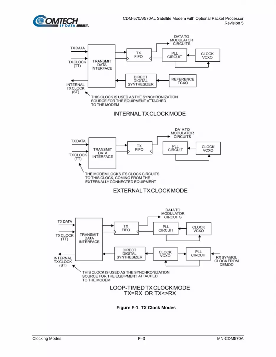
CDM-570A/570AL Satellite Modem with Optional Packet Processor Revision 5
Clocking Modes F–3 MN-CDM570A
Figure F-1. TX Clock Modes

CDM-570A/570AL Satellite Modem with Optional Packet Processor Revision 5
Clocking Modes F–4 MN-CDM570A
F.3 Receive Clocking
There are three receive clocking modes in the CDM-570A/570AL: Buffer Disabled (RX Satellite), Buffer Enabled (TX=RX), and Buffer Enabled (RX< >TX). An additional setting used only for Drop and Insert is described in further detail later in this chapter. Figure F-2 provides a graphic depiction of these modes.
F.3.1 Buffer Disabled (RX Satellite)
When the buffer is disabled, the receive clock (Receive Timing, or RT) is derived directly from the demodulator, and will therefore be subject to plesiochronous and Doppler offsets. This may acceptable in certain instances. There is still a minimum buffer in use to de-jitter the effects of removing overhead framing. G.703: Applicable.
F.3.2 Buffer Enabled, TX=RX
In this instance, it is required that buffer be enabled, so that the clock and data appearing on Receive Timing (RT) and Receive Data (RD) are synchronous with the transmit clock or the internal (SCT) clock. This is a relatively simple case, as the output clock for the buffer is derived directly from ST, TT, or the external source. G.703: Applicable.
F.3.3 Buffer Enabled, RX<>TX
This is an uncommon case, where the receive data rate does not equal the transmit or external reference. The modem will generate a phase-locked buffer output clock that uses the selected reference, regardless of its frequency in relation to the receive data rate. G.703: Applicable.

CDM-570A/570AL Satellite Modem with Optional Packet Processor Revision 5
Clocking Modes F–5 MN-CDM570A
Figure F-2. RX Clock Modes

CDM-570A/570AL Satellite Modem with Optional Packet Processor Revision 5
Clocking Modes F–6 MN-CDM570A
F.4 X.21 Notes
The central feature of X.21 is that the DCE supplies the clock for both directions. Therefore, the first requirement is that TX and RX data rates are the same. Because the DCE doesn’t get an input clock moving in the same direction as its input data, the several nanoseconds of delay through long cables and the modem’s data transceivers can cause the clock phase to change relative to the data. This is why X.21 is not recommended above 2048 kbps. If Modem = DCE (normal assumption), then X.21 mode is just a matter of ignoring ST and TT and, instead, using RT to run both directions. Using the clock settings TX Clk = Loop and RX Buffer Clk = RX assumes that the desired timing is coming from the far-end modem. The modem’s ST is forced to be a copy of RT, because the latter assumes use by the terrestrial DTE to drive SD data into the modem. If, instead, the local modem supplies the timing, the clock settings should be TX Clk = Int and RX Buffer Clk = TX or Int. These settings instead force RT to be a copy of ST. In either case, it is SD that has an uncertain phase relationship to the clock due to round-trip delays, so the modem’s TX clock invert feature may be necessary to avoid clocking in SD on its transitions. If Modem = DTE, then ST and RT are ignored, and TT from the terrestrial DCE is used. The correct modem settings are TX Clk = TT and RX Buffer Clk = TX. These settings force RT (which drives out the modem’s RD) to be a copy of TT. It is now RD that has an uncertain phase relationship to the clock, so the modem’s RX clock invert may be necessary to please the terrestrial DCE.
F.5 G.703 Clock Extension
There are some applications where it becomes necessary, at the distant end of a satellite link, to provide a high-stability G.703 timing reference for timing equipment connected to the modem. For example, in cellular backhaul applications, the BTS equipment may require such a reference even though the satellite link itself may be operating at a data rate other than 1.544 Mbps or 2.048 Mbps. This is sometimes accomplished by adding a specialized GPS receiver at the distant end, which then provides the G.703 synchronizing signal. However, with the G.703 clock extension mode this may become unnecessary, as the CDM-570A/570AL – operating at either end of the link, where the local modem has access to a high-stability G.703 signal – can provide an almost perfect copy of this signal at the distant end. The presence of Doppler shift on the link is the only factor affecting the overall accuracy. If Doppler shift were not present, the copy of the clock would be perfect. This is accomplished by the use of a novel frequency synthesis and phase locking scheme. This feature of the CDM-570A/570AL permits the distant end to generate a G.703 synchronizing signal that, depending on a sufficiently accurate local reference, has short term accuracy to within parts in 10-8, and is solely dependent on link Doppler shift. The subsections and figures that follow illustrate three possible G.703 clock extension modes. Details of how to set up the modems for these various operating modes are given in Chapter 6. FRONT PANEL OPERATION.

CDM-570A/570AL Satellite Modem with Optional Packet Processor Revision 5
Clocking Modes F–7 MN-CDM570A
F.5.1 Clock Extension Mode 1
Figure F-3 shows Clock Extension Mode 1. The local modem is assumed to be operating on INTERNAL clock. A T1 or E1 G.703 signal is applied to the rear panel connector of the modem, where the clock is recovered.
The G.703 signal is not intended to convey data – its function is only to provide a synchronizing clock. The data is transferred using the EIA-530/V.35 serial interface.
The internal clock reference generator locks – in both frequency and phase – to this recovered clock, and a special synthesizer generates an ST clock of ANY ARBITRARY FREQUENCY over the range 2.4 kHz to 9.98 MHz with a resolution of 1 Hz. The synthesis is exact – there is no approximation or residual error. For example, if you select 168.231 kbps as the transmit data rate, and an E1 reference, there will be exactly 168,231 clock cycles generated for every 2,048,000 cycles of the E1 reference. The internal ST clock is now used, as in the standard Internal Clock mode, to provide the timing reference for the externally-connected equipment. The data is then transmitted at the desired data rate to the distant end (or distant ends – this works for broadcast applications as well). Now, at the distant end modem (timing mode: RX Satellite), the RX signal is received, demodulated, and the clock is recovered. A second synthesizer, very similar to the one used at the local modem, is now used to generate an E1 or T1 timing signal. Again, it should be emphasized that the synthesis is exact. The net result is that the E1 or T1 timing signal used at the local end is reproduced at the distant end, regardless of the link data rate. The only thing that affects the overall accuracy and stability of the copy of the clock is the Doppler shift of the link itself. This will be very dependent on the particular satellite used, and the accuracy of the orbital station keeping (often referred to as orbital inclination). Typically the Doppler variations are in the order of parts in 10-8, but more importantly it should be recognized that, over a 24 hour period, the net error would be zero due to a fundamental characteristics of geostationary orbits. The T1 or E1 signal, available on the rear panel of the modem on the G.703 connectors, is now used to provide a synchronizing source for equipment connected to the modem. The form of this is an ‘all ones’ signal, which provides the maximum transition density in the AMI signal.
This scheme is sufficiently flexible to permit an E1 signal to be used at the local end, and a T1 signal to be reproduced at the distant end, or vice versa.

CDM-570A/570AL Satellite Modem with Optional Packet Processor Revision 5
Clocking Modes F–8 MN-CDM570A
F.5.2 Clock Extension Mode 2
Figure F-4 shows Clock Extension Mode 2. This is for situations where clock extension needs to be performed, but there is no local G.703 reference. In this case, the local modem now operates in an EXTERNAL clock mode and the accuracy of the TX Clock is determined solely by the accuracy of the equipment connected to the modem. At the distant end, an E1 or T1 synchronizing signal is generated regardless of the link data rate, as in Mode 1.
F.5.3 Clock Extension Mode 3
Figure F-5 shows Clock Extension Mode 3. This is very similar to Mode 1 but now, instead of the EIA-530/V.35 serial interface being used, everything is based around the 10/100 Base T Ethernet interface. At the distant end, an E1 or T1 synchronizing signal is generated regardless of the link data rate, as in Mode 1
.

CDM-570A/570AL Satellite Modem with Optional Packet Processor Revision 5
Clocking Modes F–9 MN-CDM570A
Figure F-3. G.703 Clock Extension Mode 1
CDM-570A/570AL CDM-570A/570AL

CDM-570A/570AL Satellite Modem with Optional Packet Processor Revision 5
Clocking Modes F–10 MN-CDM570A
Figure F-4. G.703 Clock Extension Mode 2
CDM-570A/570AL CDM-570A/570AL

CDM-570A/570AL Satellite Modem with Optional Packet Processor Revision 5
Clocking Modes F–11 MN-CDM570A
Figure F-5. G.703 Clock Extension Mode 3
CDM-570A/570AL CDM-570A/570AL

CDM-570A/570AL Satellite Modem with Optional Packet Processor Revision 5
Clocking Modes F–12 MN-CDM570A
BLANK PAGE

CDM-570A/570AL Satellite Modem with Optional Packet Processor Revision 5
DoubleTalk Carrier-in-Carrier Option G–1 MN-CDM570A
Appendix G. DOUBLETALK CARRIER-IN-CARRIER OPTION
G.1 Overview
Space segment costs are typically the most significant operating expense for any satellite-based service, having a direct impact on the viability and profitability of the service. For a satellite transponder that has finite resources in terms of bandwidth and power, the leasing costs are determined by bandwidth and power used. Therefore, a satellite circuit should be designed for optimal utilization to use a similar share of transponder bandwidth and power.
The traditional approach to balancing a satellite circuit – once the satellite and earth station parameters are fixed – involves trade-off between modulation and coding. A lower order modulation requires less transponder power while using more bandwidth; conversely, higher order modulation reduces required bandwidth, albeit at a significant increase in power.
Comtech EF Data has added a new dimension to satellite communication optimization: DoubleTalk Carrier-in-Carrier.
G.2 What is DoubleTalk Carrier-in-Carrier?
The DoubleTalk Carrier-in-Carrier (CnC) option uses a patented signal processing algorithm developed by Raytheon Applied Signal Technology that allows both the forward and reverse carriers of a full duplex link to share the same segment of transponder bandwidth, using patented “Adaptive Cancellation.” Raytheon Applied Signal Technology uses the term DoubleTalk, and Comtech EF Data refers to it as DoubleTalk Carrier-in-Carrier (CnC)1.
1 DoubleTalk® is licensed from Raytheon Applied Signal Technology. DoubleTalk® is a registered trademark of Raytheon Applied Signal Technology.
WARNING! BEFORE ATTEMPTING TO COMMISSION A SATELLITE LINK USING CARRIER-IN-CARRIER, YOU MUST ENSURE THAT THE LINK IS ROBUST ENOUGH FOR NORMAL OPERATION. ONLY WHEN THIS HAS BEEN DONE – AND ALL SYSTEM ISSUES (E.G., ANTENNA-POINTING, CABLING, TERRESTRIAL INTERFERENCE, SATELLITE INTERFERENCE, ETC.) HAVE BEEN RESOLVED – SHOULD YOU ATTEMPT THE USE OF CARRIER-IN-CARRIER.
DoubleTalk Carrier-in-Carrier (CnC) and Carrier-in-Carrier Automatic Power Control (CnC-APC) are UNAVAILABLE and DISABLED when the CDM-570A/AL is configured to run in CDM-570 Compatible Mode.

CDM-570A/570AL Satellite Modem with Optional Packet Processor Revision 5
DoubleTalk Carrier-in-Carrier Option G–2 MN-CDM570A
CnC was first introduced in Comtech EF Data’s CDM-Qx Satellite Modem. CnC is now available on manyComtech EF Data products, including the CDM-625/A, CDM-760, CDM-750, DMD20, DMD2050E, and SLM-5650A. CnC is also available as a standalone product on the CLO-10 Link Optimizer.
This innovative technology provides a significant improvement in bandwidth and power utilization, beyond what is possible with FEC and modulation alone, allowing users to achieve unprecedented savings. When combined with advanced modulation and FEC, it allows for multi- dimensional optimization:
• Reduced operating expense (OPEX) – e.g., Occupied Bandwidth & Transponder Power;
• Reduced capital expenditure (CAPEX) – e.g., Block Up Converter/High-Power Amplifier (BUC/HPA) size and/or antenna size;
• Increased throughput without using additional transponder resources;
• Increased link availability (margin) without using additional transponder resources;
• A combination of any of the above to meet different objectives.
Summary: When carriers share common bandwidth, up to 50% savings in transponder utilization is possible.
G.3 Application Requirements
The following conditions are necessary in order to operate DoubleTalk Carrier-in-Carrier:
• Link must be full duplex.
• A CDM-570A/AL must be used at the end of the link where the cancellation needs to take place.
• The transponder is operated as Loopback. That is, each end of the link must be able to see a copy of its own signal in the return (downlink) path from the satellite. The looped back signal is then subtracted which leaves the signal from the distant end of the link. DoubleTalk Carrier-in-Carrier cannot be used in spot beam systems.
• The transponder needs to be “bent-pipe” – meaning no on-board processing, demodulation, regeneration can be employed. Demodulation/remodulation does not preserve the linear combination of the forward and return signals and the resulting reconstituted waveform prevents recovery of the original constituent signals.
Figure G-1 shows a simplified conceptual block diagram of CnC processing. The two ends of the link are denoted ‘A’ and ‘B’ and the uplink and downlink are shown.
Carrier-in-Carrier® is a registered trademark of Comtech EF Data.

CDM-570A/570AL Satellite Modem with Optional Packet Processor Revision 5
DoubleTalk Carrier-in-Carrier Option G–3 MN-CDM570A
Figure G-1. Conceptual Block Diagram
This performance is achieved through advanced signal processing algorithms that provide superior cancellation while tracking and compensating for the following common link impairments:
1. Time varying delay: In addition to the static delays of the electronics and the round-trip delay associated with propagation to the satellite and back, there is a time-varying component due to movement of the satellite. The CnC module tracks and compensates for this variation.
2. Frequency offset and drift: Common sources are satellite Doppler shift, up and down converter frequency uncertainties, and other drift associated with the electronics in the CDM-570A/AL itself. The CnC module tracks and compensates for this frequency offset and drift.
3. Atmospheric effects: Fading and scintillation can affect amplitude, phase, and spectral composition of the signal and the degree to which it correlates with the original signal. The CnC module tracks and compensates for these atmospheric related impairments.

CDM-570A/570AL Satellite Modem with Optional Packet Processor Revision 5
DoubleTalk Carrier-in-Carrier Option G–4 MN-CDM570A
4. Link Asymmetries: Various asymmetries in the forward and return link can produce differences in the relative power of the two received signal components. These can be both deterministic (static) or random (and time varying). An example of the former would be the differences resulting from antenna size/gain variations between the two ends of the link. An example of the latter would be transient power differences due to different levels of atmospheric fading in the uplinks. CnC compensates for the asymmetries, up to a certain extent.
In a number of ways, CnC carriers behave similar to conventional carriers in satellite links. They are both exposed to adjacent carriers, cross-polarization and rain fade, and exhibit impairments when any of these become too great. In addition, CnC operates in an environment where:
• Carriers intentionally occupy the same spectral slot;
• Performance depends upon desired and co-located interfering carrier.
G.3.1 Operational Recommendations
The rules for CnC operation are summarized as follows:
• Both earth stations share the same footprint so each sees both carriers
• CnC carriers are operated in pairs
• One outbound with multiple return carriers is not allowed
• Asymmetric data rates are allowed (no restrictions)
• The ratio of power spectral density is normally less than 11 dB
• CnC operates with modems – not modulators only or demodulators only
To minimize ‘false’ acquisition, also observe the following:
• Use of IESS-315 V.35 Scrambler is highly recommended
• Keep the search delay range as narrow as possible – once the modem has reported the search delay, narrow the search delay range to the nominal reported value ±5 ms – for example, if the modem reported delay is 245 ms, narrow the search range to say 240-250 ms.
• Use external data source (e.g. Firebird) or internal BER tester when testing Carrier-in-Carrier performance.
• To prevent self-locking in case the desired carrier is lost, it is recommended that the two carriers have some configuration difference – for example, use different settings for Spectrum Inversion.

CDM-570A/570AL Satellite Modem with Optional Packet Processor Revision 5
DoubleTalk Carrier-in-Carrier Option G–5 MN-CDM570A
G.4 System Functionality and Operational Considerations
Figure G-2 illustrates a conventional, full duplex satellite link where two carriers are placed in non-overlapping channels. Figure G-3 shows the same link using the CDM-570A/AL equipped with the DoubleTalk Carrier-in-Carrier option. Note that only 50% of the bandwidth is being used, as both carriers are now occupying the same bandwidth.
The transponder downlinks the composite signal containing both carriers on the same band to the CDM-570A/AL which then translates the signal to near baseband where it can be filtered (decimated) and then processed as a complex envelope signal. The CDM-570A/AL then suppresses the version of the near end carrier on the downlink side and then passes the desired carrier to the demodulator for normal processing.
To further illustrate, as shown in Figure G-4, without DoubleTalk Carrier-in-Carrier, the two carriers in a typical full duplex satellite link are adjacent to each other. With DoubleTalk Carrier-in-Carrier, only the composite signal is visible when observed on a spectrum analyzer. Carrier 1 and Carrier 2, shown here for reference only, are overlapping, thus sharing the same spectrum.
Figure G-2. Conventional FDMA Link

CDM-570A/570AL Satellite Modem with Optional Packet Processor Revision 5
DoubleTalk Carrier-in-Carrier Option G–6 MN-CDM570A
Figure G-3. Same Link Using CDM-570A with DoubleTalk Carrier-in-Carrier
Figure G-4. Duplex Link Optimization
The CDM-570A/AL CnC module operates on the near-zero signal before the demodulator, and is waveform agnostic. This means that no prior knowledge of the underlying modulation, FEC, or any other waveform specific parameter is required in order to perform the signal suppression operation. The only caveat to this is that the waveform must be sufficiently random.

CDM-570A/570AL Satellite Modem with Optional Packet Processor Revision 5
DoubleTalk Carrier-in-Carrier Option G–7 MN-CDM570A
Because acquiring the delay and frequency offset of the interfering carrier is fundamentally a correlation operation, anything deterministic in the interfering carrier (within the correlation window of the algorithm) will potentially produce false correlation peaks and result in incorrect delays and/or frequency. Normally, this is not a problem, since energy dispersal techniques are utilized in the vast majority of commercial and military modems. However, it is something that must be kept in mind when troubleshooting a system that utilizes the DoubleTalk Carrier-in-Carrier technique for signal suppression.
One possible way to mitigate false peaks is to narrow the correlation window. For example, if the delay is known to be around 240ms, set the minimum search delay to 230ms and the maximum search delay to 250ms.
As all advances in modem technologies – including advanced modulation and FEC techniques – approach their theoretical limits of power and bandwidth efficiencies, DoubleTalk Carrier-in-Carrier allows satellite users to achieve spectral efficiencies (bps/Hz) that cannot be achieved with modulation and FEC alone. Table G-1 illustrates how DoubleTalk Carrier-in-Carrier, when used with 16-QAM, approaches the bandwidth efficiency of 256-QAM (8bps/Hz).
Table G-1. Spectral Efficiency using DoubleTalk Carrier-in-Carrier
Modulation and Code Rate
Spectral Efficiency (bps/Hz)
TraditionalSCPC Carrier-in-Carrier
BPSK 1/2 0.50 1.00
QPSK 1/2 1.00 2.00
QPSK 3/4 1.50 3.00
QPSK 7/8 1.75 3.50
8-QAM 3/4 2.25 4.50
8-QAM 7/8 2.63 5.25
16-QAM 3/4 3.00 6.00
16-QAM 7/8 3.50 7.00
As shown here, DoubleTalk Carrier-in-Carrier allows equivalent spectral efficiency using a lower order modulation and/or FEC Code Rate; CAPEX is therefore reduced by allowing the use of a smaller BUC/HPA and/or antenna. And, as DoubleTalk Carrier-in-Carrier can be used to save transponder bandwidth and/or transponder power, it can be successfully deployed in bandwidth-limited as well as power-limited scenarios.

CDM-570A/570AL Satellite Modem with Optional Packet Processor Revision 5
DoubleTalk Carrier-in-Carrier Option G–8 MN-CDM570A
G.4.1 DoubleTalk Carrier-in-Carrier Cancellation Process
The state-of-the-art signal processing technology employed via DoubleTalk Carrier-in-Carrier continually estimates and tracks all parametric differences between the local uplink signal and its image within the downlink. Through advanced adaptive filtering and phase locked loop implementations, it dynamically compensates for these differences by appropriately adjusting the delay, frequency, phase and amplitude of the sampled uplink signal, resulting in excellent cancellation performance.
When a full duplex satellite connection is established between two sites, separate satellite channels are allocated for each direction. If both directions transmitted on the same channel, each side would normally find it impossible to extract the desired signal from the aggregate due to interference originating from its local modulator. However since this interference is produced locally, it is possible to estimate and remove its influence prior to demodulation of the data transmitted from the remote location.
For the DoubleTalk Carrier-in-Carrier cancellation, it is necessary to provide each demodulator with a copy of its local modulator’s output.
Refer to Figure G-5: Modem 1 and Modem 2 transmit signals S1 and S2 respectively. The satellite receives, translates, and retransmits the composite signal. The downlink signals S1* and S2*, received at Modem 1 and Modem 2 differ from the transmit signals primarily in terms of phase, frequency, and delay offsets.
Figure G-5. DoubleTalk Carrier-in-Carrier Signals
Refer to Figure G-6: For round trip delay estimation, a search algorithm is utilized that correlates the received satellite signal to a stored copy of the local modulator’s transmitted signal. The interference cancellation algorithm uses the composite signal and the local copy of S1 to estimate the necessary parameters of scaling (complex gain/phase), delay offset and frequency offset. The algorithm continuously tracks changes in these parameters as they are generally time-varying in a satellite link.

CDM-570A/570AL Satellite Modem with Optional Packet Processor Revision 5
DoubleTalk Carrier-in-Carrier Option G–9 MN-CDM570A
Figure G-6. Carrier-in-Carrier Signal Processing Block Diagram
The resulting estimate of the unwanted interfering signal is then subtracted from the composite signal. In practical applications, the estimate of the unwanted signal can be extremely accurate. Unwanted interfering signal suppression of 30 dB or more has been achieved in commercial products with minimal degradation of the demodulator performance.
G.4.2 Margin Requirements
Typical interfering signal cancellation is 28 to 35 dB (depending on the product). The residual interfering signal appears as noise causing a slight degradation of the Eb/No. To compensate for the residual noise, a small amount of additional link margin is required to maintain the BER. Margin requirements depend on the product, modulation and power ratios:
For the CDM-570A/AL, the additional margin requirements are as follows:
Modulation Nominal Margin*
BPSK 0.3 dB
QPSK/OQPSK 0.3 dB
8-PSK 0.5 dB
8-QAM 0.4 dB
16-QAM 0.6 dB
8-ARY 0.6 dB
16-ARY 0.8 dB
32-ARY 1.0 dB
* Equal power and equal symbol rate for the interfering carrier and the desired carrier, i.e., 0 dB PSD ratio. Measured at IF with AWGN, +10 dBc Adjacent Carriers, 1.3 spacing.

CDM-570A/570AL Satellite Modem with Optional Packet Processor Revision 5
DoubleTalk Carrier-in-Carrier Option G–10 MN-CDM570A
G.4.3 Carrier-in-Carrier Latency
Carrier-in-Carrier has no measurable impact on circuit latency.
G.4.4 Carrier-in-Carrier and Adaptive Coding and Modulation
Carrier-in-Carrier will be fully compatible with the VersaFEC Adaptive Coding and Modulation (ACM) mode of operation that will be available in future releases of the CDM-570A/AL.
Carrier-in-Carrier combined with VersaFEC ACM can provide a 100-200% increase in average throughput compared to to a traditional side-by-side link without ACM.
G.4.5 Carrier-in-Carrier Link Design
Carrier-in-Carrier link design involves finding the FEC and modulation combination that provides optimal bandwidth utilization. Just like conventional link design, it is an iterative process that involves trying different FEC and modulation combinations with Carrier-in-Carrier until an optimal combination is found.
For optimal Carrier-in-Carrier performance, it is recommended that the two carriers have similar symbol rate and power. This can be achieved by selecting appropriate ModCods as shown in following sections.
G.4.5.1 Symmetric Data Rate Link
NOTE: CnC operation with symmetrical links requires the Symbol Rate to be offset by 0.1% or higher on one of the links when the IP Data Interface is selected.
Consider the following example:
Satellite & Transponder IS-901 @ 342º W, 22/22 (EH/EH)
Earth Station 1 Africa – 4.5 m
Earth Station 2 Africa – 3.0 m
Data Rate 1.0 Mbps / 1.0 Mbps
The traditional link was based on QPSK TPC 7/8, and required 1.6 MHz of leased bandwidth (BW).

CDM-570A/570AL Satellite Modem with Optional Packet Processor Revision 5
DoubleTalk Carrier-in-Carrier Option G–11 MN-CDM570A
The LST (Intelsat Lease Transmission Plan Program) summary for the traditional link is as follows:
Link Analysis Description
Multicarrier Transponder Lease Number of Links: 2 Link 1 Link 2
Modulation QPSK QPSK
Information Rate (kbit/s) 1000.0 1000.0
FEC Code Rate .875 .875
R-S Code Rate N/A N/A
Clear Sky Eb/No Available 6.3 6.0
Number of Assigned Carriers 1 1
Transmit ES Code HUB REMOTE
Transmit ES Size (m) 4.5 3.0
Receive ES Code REMOTE HUB
Receive ES Size (m) 3.0 4.5
Receive ES G/T (dB/K) 21.5 25.3
Total Leased Resource Usage
LST Calculated (MultiCarrier Transponder Lease)
Total BW Allocated 1.6000 MHz
TotalBW PEB* 1.5937 MHz
Total EIRP Utilized 15.0 dBw Total BW Utilized 1.6000 MHz
Total EIRP Available 15.0 dBw Total BW Available 1.6000 MHz
Margin (available-utilized) .0 dBw Margin (available-utilized) 0.0000 MHz
*PEB = Power Equivalent Bandwidth
Allocated BW = 1.6 MHz
PEB = 1.5937 MHz
Leased BW = 1.6 MHz

CDM-570A/570AL Satellite Modem with Optional Packet Processor Revision 5
DoubleTalk Carrier-in-Carrier Option G–12 MN-CDM570A
Carrier-in-Carrier link design involved trying different Modulation & FEC Code Rates to find the optimal combination (the CDM-570A/AL also offers 5% to 35% transmit filter rolloffs that can be used in addition to Modulation and FEC for link optimization):
• QPSK, VersaFEC 0.706 with Carrier-in-Carrier
• QPSK, VersaFEC 0.631 with Carrier-in-Carrier
• QPSK, VersaFEC 0.533 with Carrier-in-Carrier
Link parameters and LST summary, for QPSK, VersaFEC 0.533 with Carrier-in-Carrier, is as follows:
Includes IF-RF Margin and CnC Margin

CDM-570A/570AL Satellite Modem with Optional Packet Processor Revision 5
DoubleTalk Carrier-in-Carrier Option G–13 MN-CDM570A
Link Analysis Description Multicarrier Transponder Lease
Number of Links: 2 Link 1 Link 2
Modulation QPSK QPSK
Information Rate (kbit/s) 1000.0 1000.0
FEC Code Rate .5330 .5330
R-S Code Rate N/A N/A
Clear Sky Eb/No Available (dB) 4.3 4.1
Number of Assigned Carriers 1 1
Transmit ES Code HUB REMOTE
Transmit ES Size (m) 4.5 3.0
Receive ES Code REMOTE HUB
Receive ES Size (m) 3.0 4.5
Receive ES G/T (dB/K) 21.5 25.3
Total Leased Resource Usage
LST Calculated (MultiCarrier Transponder Lease)
Total BW Allocated 1.0319 MHz
TotalBW PEB* .9755 MHz
Total EIRP Utilized 12.8 dBw Total BW Utilized 1.0319 MHz
Total EIRP Available 13.3 dBw Total BW Available 1.1000 MHz
Margin (available-utilized) .5 dBw Margin (available-utilized) 0.681 MHz
*PEB = Power Equivalent Bandwidth CnC Allocated BW = 1.0319 MHz
CnC PEB = 0.9755 MHz
CnC Leased BW = 1.03196 MHz
The link budget summary for the different ModCod combinations is as follows:
S.No. Modulation & FEC (CnC Carrier) Allocated
BW (MHz)
PEB (MHz)
Leased BW
(MHz)
CnC Leased
BW Savings
PSD Ratio (dB)
1 QPSK, VersaFEC 0.533, 10% ROF 1.0319 0.9755 1.0319 36% 2.2 2 QPSK, VersaFEC 0.631, 15% ROF 0.9113 1.1069 1.1069 31% 2.2 3 QPSK, VersaFEC 0.706, 25% ROF 0.8859 1.3223 1.3223 17% 2.2

CDM-570A/570AL Satellite Modem with Optional Packet Processor Revision 5
DoubleTalk Carrier-in-Carrier Option G–14 MN-CDM570A
Based on this analysis, QPSK, VersaFEC 0.533 with Carrier-in-Carrier provides savings of 36%. In addition to this 36% reduction in Leased Bandwidth, using Carrier-in-Carrier also reduced the BUC requirement from 10W to 5W:
BUC Size Traditional Link (QPSK, TPC 7/8)
CnC Link (QPSK, VersaFEC 0.533) BUC Size Reduction
BUC @ 4.5 m 10 W 5 W 50%
BUC @ 3.0 m 10 W 5 W 50%
G.4.5.2 Asymmetric Data Rate Link
As occupied (or allocated) bandwidth of a Carrier-in-Carrier circuit is dictated by the larger of the two carriers, it is strongly recommended that the smaller carrier be spread as much as possible using a lower order modulation and/or FEC, while meeting the PSD ratio spec. Spreading the smaller carrier using a lower order modulation has multiple benefits:
• Lower order modulation is always more robust;
• Lower order modulation uses less transponder power – this reduces total transponder, and increases available link margin;
• Lower order modulation uses less transmit power on the ground – this can significantly reduce the BUC/SSPA size by not only reducing the transmit EIRP, but also reducing the BUC/SSPA backoff.
Consider the following example:
Satellite & Transponder IS-901 @ 342º W, 22/22 (EH/EH)
Earth Station 1 Africa – 4.5 m
Earth Station 2 Africa – 3.0 m
Data Rate 3 Mbps / 1 Mbps
While the traditional link was based on QPSK, TPC 3/4 for the Hub to Remote and QPSK TPC 7/8 for Remote to Hub and required 4.0 MHz of leased bandwidth, the Carrier-in-Carrier link was based on QPSK, VersaFEC 0.631 and QPSK, VersaFEC 0.533 and required 2.9 MHz of leased bandwidth.

CDM-570A/570AL Satellite Modem with Optional Packet Processor Revision 5
DoubleTalk Carrier-in-Carrier Option G–15 MN-CDM570A
The savings summary is as follows:
Item
Original Link
With Carrier-in-Carrier and VersaFEC Savings / Reduction
Hub to Remote
Remote to Hub Total Hub to
Remote Remote to
Hub Total
Data Rate (kbps) 3000 1000 3000 1000
Modulation QPSK QPSK QPSK QPSK
FEC TPC 3/4 TPC 7/8 VersaFEC 0.631
VersaFEC 0.533
Occupied BW (MHZ) 2.8 1.2 4.0 2.9 1.4 2.9
Power Eq. BW (MHz) 3.2 0.7 3.9 2.3 0.5 2.8
Leased BW (MHz) 4.0 2.9 28.7%
Hub BUC (W) 30 20 33%
Remote BUC (W) 20 10 33%
G.4.5.3 Power Limited Links
Carrier-in-Carrier can provide substantial savings even when the original link is power limited. Spreading the carrier by using a lower modulation and/or FEC along with latest FEC such as VersaFEC can substantially reduce the total power, which can then be traded with bandwidth using Carrier-in-Carrier. The concept is illustrated with the following examples:
The conventional link is using 8-PSK, TPC 3/4:
Switching to VersaFEC and using a lower order modulation – e.g., QPSK, VersaFEC 0.803 increases the total occupied bandwidth, while reducing the total power equivalent bandwidth:
Now using DoubleTalk Carrier-in-Carrier, the second QPSK, VersaFEC 0.803 carrier can be moved over the first carrier – thereby significantly reducing the total occupied bandwidth and total power equivalent bandwidth when compared to the original side-by-side 8PSK, TPC 3/4 carriers:

CDM-570A/570AL Satellite Modem with Optional Packet Processor Revision 5
DoubleTalk Carrier-in-Carrier Option G–16 MN-CDM570A
To continue, consider this example:
Satellite & Transponder
IS-901 @ 342º W, 22/22 (EH/EH)
Earth Station 1 Africa – 9.2 m
Earth Station 2 Africa – 4.5 m
Data Rate 2.048 Mbps / 2.048 Mbps
Whereas the original link used 8-PSK TPC 3/4, the Carrier-in-Carrier link used QPSK VersaFEC 0.803.
The savings summary is as follows:
Item
Original Link
With Carrier-in-Carrier and VersaFEC
Savings
Hub to Remote
Remote to Hub Total Hub to
Remote Remote to
Hub Total
Data Rate (kbps) 2048 2048 2048 2048
Modulation 8-PSK 8-PSK QPSK QPSK
FEC TPC 3/4 TPC 3/4 VersaFEC 0.803
VersaFEC 0.803
Occupied BW (MHZ) 1.3 1.3 2.6 1.8 1.8 1.8
Power Eq. BW (MHz) 2.2 1.0 3.2 1.1 0.5 1.6
Leased BW (MHz) 3.2 1.8 44%
Hub BUC (W) 5 2 60%
Remote BUC (W) 20 5 75%
Using Carrier-in-Carrier and VersaFEC reduced the leased bandwidth by almost 44% and the BUC size by 60% at the Hub and 75% at the Remote.

CDM-570A/570AL Satellite Modem with Optional Packet Processor Revision 5
DoubleTalk Carrier-in-Carrier Option G–17 MN-CDM570A
G.4.5.4 Commission and Deploy Carrier-in-Carrier
Prior to commissioning a Carrier-in-Carrier link, it is critical that the link is fully tested in non Carrier-in-Carrier mode and all system issues including external interference, antenna pointing, cabling, SSPA backoff are resolved. Only after the link is robust, should you attempt turning on Carrier-in-Carrier. The following steps are recommended for Carrier-in-Carrier commissioning and deployment:
Step Task
1 Turn ON the carrier at Site A. Carrier from Site B is OFF. CnC function is OFF at both sites.
Using a spectrum analyzer, measure Co+No/No at the input to the modem at Site A.
Using a spectrum analyzer, measure Co+No/No at the input to the modem at Site B.
Measure/record Eb/No at Site B. Make sure there is sufficient margin to account for CnC.
Measure/record Receive Signal Level (RSL) at Site B.
2 Turn OFF the carrier at Site A. Turn ON the carrier at Site B. CnC function is OFF at both sites.
Using a spectrum analyzer, measure Co+No/No at the input to the modem at Site A.
Using a spectrum analyzer, measure Co+No/No at the input to the modem at Site B.
Measure/record Eb/No at Site A. Make sure there is sufficient margin to account for CnC.
Measure/record RSL at Site B.
3 Using Co+No/No readings calculate PSD ratio at Site A and Site B. If it is not within specification, make necessary adjustments to bring it within specification and repeat measurements in Step (1) and (2).
Also verify that the RSL is within spec.
4 Now without changing the transmit power levels, turn ON both the carriers (on the same frequency) and turn CnC ON.
Measure/record Eb/No at Site A and B.
Measure/record RSL at Site A and B.
Now compare Eb/No in presence of 2 over lapping carriers with CnC with Eb/No when only 1 carrier was ON. Eb/No variation should be within spec for that modulation, FEC and PSD ratio.
5 The test can be repeated for different PSD ratio and Eb/No.

CDM-570A/570AL Satellite Modem with Optional Packet Processor Revision 5
DoubleTalk Carrier-in-Carrier Option G–18 MN-CDM570A
G.4.6 Validate Carrier-in-Carrier Performance
Carrier-in-Carrier performance can be easily validated by verifying that Eb/No degradation due to Carrier-in-Carrier is within published specification for the observed Power Spectral Density Ratio.
Comtech EF Data recommends the following steps for validating Carrier-in-Carrier performance:
Step Task
1 Setup a conventional side-by-side link of the desired Eb/No:
Carrier-in-Carrier should be OFF.
Record the Eb/No as displayed by the Modems.
Observe the 2 carriers on a spectrum analyzer and record the PSD ratio.
Example Link:
• Full duplex 512 kbps, QPSK, VersaFEC 0.631 circuit between 4.6 m and 2.4 m antennas
• Recorded Eb/No = 2.7 dB (at both modems)
• PSD Ratio = 1.2 dB (measured at larger Antenna)
2 Now relocate one of the carriers on top of the other carrier:
Enable Carrier-in-Carrier.
Record the Eb/No as displayed by the Modems.

CDM-570A/570AL Satellite Modem with Optional Packet Processor Revision 5
DoubleTalk Carrier-in-Carrier Option G–19 MN-CDM570A
Step Task
3 Calculate change in Eb/No and verify against specification.
Example Link:
• Recorded Eb/No = 2.5 dB
• Change in Eb/No = 0.2 dB
• Eb/No Degradation (Spec.) at 1.2 dB PSD = 0.3 dB
• Modem performance is within spec

CDM-570A/570AL Satellite Modem with Optional Packet Processor Revision 5
DoubleTalk Carrier-in-Carrier Option G–20 MN-CDM570A
G.5 Operational References
G.5.1 Calculate Carrier-in-Carrier Link Budget
You must follow these steps to calculate the link budget for a Carrier-in-Carrier Link: Eb/NO.
Step Task
1 Calculate the link budget for both carriers in the duplex link, with required CnC margin:
2 Verify that the PDS ration is within spec for the CDM-570A/AL.
3 Calculate the Allocated Bandwidth (BW) and Power Equivalent Bandwidth (PEB) for the duplex link:
• BWDuplex Link = Greater of (BWCarrier 1, BWCarrier 2)
• PEBDuplex Link = PEBCarrier 1 + PEBCarrier 2
• Leased BWDuplex Link = Greater of (BWDuplex Link, PEBDuplex Link)
4 For an optimal link, the Leased Bandwidth and the Power Equivalent Bandwidth should be equal / nearly equal.
5 Repeat the link budget process by selecting different Modulation and FEC, until the BW and PEB is nearly balanced.
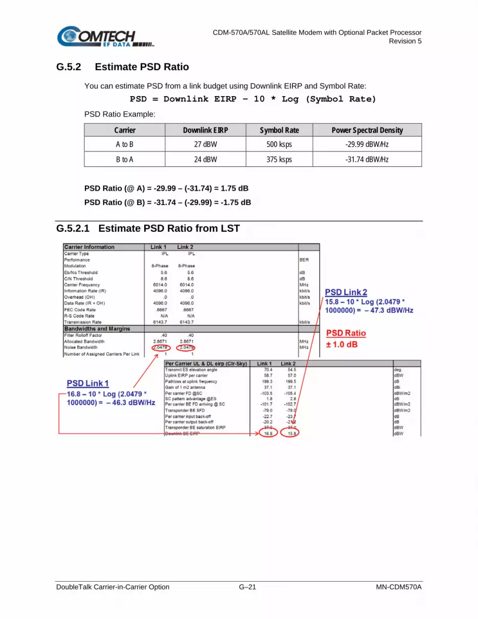
CDM-570A/570AL Satellite Modem with Optional Packet Processor Revision 5
DoubleTalk Carrier-in-Carrier Option G–21 MN-CDM570A
G.5.2 Estimate PSD Ratio
You can estimate PSD from a link budget using Downlink EIRP and Symbol Rate: PSD = Downlink EIRP – 10 * Log (Symbol Rate)
PSD Ratio Example:
Carrier Downlink EIRP Symbol Rate Power Spectral Density
A to B 27 dBW 500 ksps -29.99 dBW/Hz
B to A 24 dBW 375 ksps -31.74 dBW/Hz
PSD Ratio (@ A) = -29.99 – (-31.74) = 1.75 dB
PSD Ratio (@ B) = -31.74 – (-29.99) = -1.75 dB
G.5.2.1 Estimate PSD Ratio from LST

CDM-570A/570AL Satellite Modem with Optional Packet Processor Revision 5
DoubleTalk Carrier-in-Carrier Option G–22 MN-CDM570A
G.5.2.2 Estimate PSD Ratio from Satmaster
G.5.2.3 Use a Spectrum Analyzer to Estimate PSD Ratio
You can also estimate PSD Ratio or CnC Ratio by using a Spectrum Analyzer capable of integrating the signal power in a given bandwidth.
• CnC Ratio (in dB) = PowerC1 (in dBm) – PowerC2 (in dBm)
• PSD Ratio (in dB) = (PowerC1 – 10 log BWC1 (in Hz)) – (PowerC2 – 10 log BWC2 (in Hz))
= CnC Ratio – 10 log (BWC1 / BWC2)
If the two carriers have same Symbol Rate / Bandwidth, then the CnC Ratio is same as the PSD Ratio.
Carrier A to B
Carrier B to A
CnC Ratio
± 2.46 dB
PSD (Carrier A->B)= 24.34 – 10 * log(2.3441 x 10⁻⁶)= – 39.36 dBW/Hz
PSD (Carrier B->A)= 21.88 – 10 * log(2.3441 x 10⁻⁶)= – 41.82 dBW/Hz
PSD Ratio± 2.46 dB

CDM-570A/570AL Satellite Modem with Optional Packet Processor Revision 5
DoubleTalk Carrier-in-Carrier Option G–23 MN-CDM570A
G.6 Carrier-in-Carrier Automatic Power Control (CnC-APC)
G.6.1 Overview
A number of Comtech EF Data modems, including the CDM-570A/AL, offer Automatic Uplink Power Control (AUPC) to mitigate the effects of rain fading and other link impairments.
It is important to note that the simple system employed in AUPC (whereby distant-end Eb/No is monitored, and local power is increased when a degraded link is detected) has an undesirable characteristic, which leads to some operators not permitting its use on their transponders: The inability of ‘classic’ AUPC to determine at which side of link the fade (or other impairment) has occurred. More specifically:
• If the fade is at the local side, all is well – the drop in Eb/No at the distant site corresponds exactly to the drop in power (due to excess attenuation) on the local uplink; when uplink power is increased, the power at the transponder does not exceed its clear-sky value.
• Conversely, if the fade occurs at the distant side, the AUPC system increases power in exactly the same way – but now, there is no excess uplink attenuation and, as a result, the clear-sky power at the satellite will be exceeded.
In a transponder with many carriers using AUPC, a fade event at the ‘wrong’ side can cause many carriers to simultaneously increase power beyond their authorized maximums, leading to intermod problems, adjacent channel interference (ACI) issues, and in some extreme cases, saturation of the transponder.
When considering power control in the Carrier-in-Carrier case, not only must the issue of exceeding allocated power limits be respected, but the problem of driving CnC ratios outside working limits during fading must also be taken into account.
G.6.2 AUPC and Carrier-in-Carrier in the CDM-570A/AL
The CDM-570A/AL currently permits ‘classic’ AUPC when Carrier-in-Carrier mode is in operation, but this does nothing to stop the problem of exceeding power limits when the fade is on the ‘wrong’ side. To limit the impact of this, you are constrained to 3 dB of permitted power increase. Depending on the satellite band, and the depth and rapidity of the fade, this constraint may curtail the effectiveness of the system.
G.6.3 The CnC Automatic Power Control Algorithm
In addressing the shortcomings of ‘classic’ AUPC, from its studies of the unique problems of power control in CnC systems, Comtech EF Data has determined that there is sufficient information available (CnC ratio, power level, Eb/No, RSL, etc.) on the local and distant sides to control power at each end without exceeding the total composite power allocated to each carrier in the CnC pair. Furthermore, the power control algorithm developed by Comtech EF Data ensures that the CnC ratio remains within the correct working range.

CDM-570A/570AL Satellite Modem with Optional Packet Processor Revision 5
DoubleTalk Carrier-in-Carrier Option G–24 MN-CDM570A
To recap, consider the following diagram:
Whenever you adjust power on Carrier 1, you need to adjust the power in Carrier 2 so the composite carrier power remains constant (or does not exceed its allocated limit), while keeping the CnC ratio within limits.
There are two distinct phases to the CnC-APC algorithm:
1. In order for the CnC-APC algorithm to work effectively, it must first analyze the CnC Ratio and Eb/No margins on each side of the link, and based on the starting conditions, re-distribute power between the two ends so that good protection against fades can be achieved. This process is referred as re-balancing, and is done so that total composite power (TCP) in the two carriers remains constant (within ±0.5 dB).
In this process, both sides of the link calculate power changes, based on their ability to see not only local parameters, including CnC Ratio, Eb/No, Receive signal level, power level and max power increase, but those of the modem at the other end of the link. After these calculations are performed, a comparison of the results is performed, and if they are in close agreement, the power changes are implemented.
It may not always be possible to drive the powers to an optimum point. The calculations take into account:
• The minimum and maximum power levels possible in the modem (which is affected by the operating band – 70/140 MHz IF versus L-Band).
• If the user-programmed value that determines the maximum permitted increase in Tx power for the terminal would be exceeded. This is a very important value, and you must know exactly how far from compression his transmit RF chain is operating. As an example, if, under normal clear sky conditions, you determine that the backoff from compression is -3 dB, and under no circumstances must the RF chain ever go past -1 dB, the maximum power increase that can be permitted is 2 dB. You enter this into the CDM-570A/AL as a setup parameter. If this value is ignored, or incorrectly entered, compression or saturation could occur, either during the initial re-balance, or during a fade event. This parameter is referred to as TPLImax (Transmit Power Level Increase, max).
• If the power changes calculated would put the CnC Ratio out of its working range.
• If the Rx signal level is above its minimum level – if it is not, the CnC Ratio monitor will not be accurate, which is essential correct calculations.

CDM-570A/570AL Satellite Modem with Optional Packet Processor Revision 5
DoubleTalk Carrier-in-Carrier Option G–25 MN-CDM570A
• If the power change would result in the Eb/No margin on either side becoming negative (see below).
At the end of the re-balance procedure, the modem will display the result:
• Full re-balance.
• Partial re-balance.
• Some issue was found that prevents a re-balance.
In the case of a partial or no re-balance, the modem displays the reason for this result; you can then adjust an operating parameter and try again.
CAUTION – READ THESE IMPORTANT NOTES:
• You should be aware that after the re-balance has been carried out, it is very likely that the CnC Ratio will not be at 0dB, and the Eb/No margins will not be equal. This is particularly true for cases where there is an asymmetry in antenna size, terminal G/T, symbol rate etc. This is an inherent function of the re-balancing algorithm, and is not a cause for concern.
• You should only attempt to do a re-balance if it is known with certainty that there are CLEAR SKY conditions at BOTH SIDES OF THE LINK.
It is not necessary for there to be a person at each end – the re-balance can be initiated from either side, with the other side unattended.
Following the re-balance, the CDM-570A/AL stores key parameters, such as Tx Power level, that are referred to as the Home State. In the event of a loss of communication between the two sides, the modem will revert to Home State, which is a known safe condition that will not cause TCP to be exceeded. Once the link conditions have improved so that communication is re-established, CnC-APC will automatically re-activate.
2. In the second phase of the algorithm, Eb/No, CnC ratio, and RSL are continuously monitored. For every combination of the modulation, FEC type and FEC code rate, the modem calculates an Eb/No margin. An Eb/No margin of 0 dB is arbitrarily determined to be the Eb/No value that produces a BER of 1 x 10⁻⁷ at the output of the decoder, plus 1 dB. If the algorithm senses that Eb/No margin is dropping, power is increased at one or both ends of the link, but in a manner that ensures that TCP is not exceeded. In the vast majority of cases the TCP during a fade will not exceed its clear-sky value by more than +0.5 dB.
The algorithm uses a number of inputs, from both sides of the link, including a knowledge of the satellite band in use (which you are required to know at the time of set-up). The characteristics of rain fading changes with frequency, and there are different models for C-Band, X-Band, Ku-Band, and Ka-Band. Not only does downlink attenuation vary as a function rain rate, but in some cases (depending on the G/T of the terminals at each end, and the satellite transponder itself) may be dominated by an increase in receive noise temperature when the antenna is pointing through rain and clouds, rather than ‘cold’ sky.

CDM-570A/570AL Satellite Modem with Optional Packet Processor Revision 5
DoubleTalk Carrier-in-Carrier Option G–26 MN-CDM570A
The depth of fade that the CnC-APC algorithm can tolerate is highly dependent on a number of factors, including:
• The CnC Ratio and Eb/No margins following a re-balance. In general, with a highly asymmetric link, where CnC Ratio is not close to zero, the tolerance to fade depth on one side will be less than the other.
• The maximum permitted level of power increase that you have defined. If, for example, you have programmed a TPLImax value of 2 dB (because that’s the only headroom the RF chain has) you should not expect the link to tolerate a fast 10 dB fade at Ku-Band.
G.6.4 CnC-APC Framing
In order to provide a two-way communications link between the two ends, CnC-APC requires an overhead channel (very much like EDMAC, or one of its variants, which is used in AUPC).
Recognizing that this overhead needs to have a minimal impact on occupied bandwidth and Eb/No performance, the overhead has been kept as low as possible:
• The overhead rate is fixed at 0.5%, causing the symbol rate of the carrier to grow by an almost imperceptible amount (no need to re-calculate channel spacing) and causing a loss of Eb/No performance of only 0.02dB.
• This choice of overhead rate effectively gives you the functionality of the CnC-APC channel without having to pay a penalty in power or bandwidth – it’s essentially free.
The CnC-APC channel constantly passes a number of metrics and parameters, including CnC Ratio, Eb/No, Receive signal level, power level and max power increase, as well as information required for the initial set-up, including the modem operating band (L-Band or 70/140 MHz), and the satellite band in use.
In addition to the information fields in the frame, there is a control field that permits commands to be sent from one side or the other during initial re-balancing, and re-balancing during fade events.
Note that the CnC-APC frame size (and the latency associated with it) limits the lower end of the range of bit rates that are supported to 64 kbps. If you select the CnC-APC mode at a data rate below 64 kbps, an error message will be generated if a re-balance operation is requested.
G.6.5 Solving the Problem of Self-Locking
Self-locking is a problem that has been previously reported to Comtech EF Data Product Support on CnC links that have identical data rates, FEC and modulation.
In the case where both ends of the link are up and running, the CnC canceller performs as intended. However, if the carrier at the remote side stops transmitting a carrier, the CnC canceller will still cancel the interferer (its own outbound Tx signal), but the cancelation is not perfect (it may be in the order -30 dB) and hence a weak signal appears at the input to the demodulator that, because of the correct settings of data rate, FEC and modulation, is sometimes acquired by the demod. This can sometimes be an issue because, although the Tx carrier from the distant side is not transmitting, no demodulator alarm is generated and hence the local end is not alerted – and data being transmitted is looped back to the receiver, and back into the network.

CDM-570A/570AL Satellite Modem with Optional Packet Processor Revision 5
DoubleTalk Carrier-in-Carrier Option G–27 MN-CDM570A
The use of CnC-APC framing provides the means to eliminate the self-locking problem. Rather than having an identical framing structure for the local and distant sides of the link, by designating each side as Side A and Side B, each side has a different framing structure and is therefore non-identical and incompatible. This makes it impossible for a modem in this CnC mode to lock to itself. With this approach, there is no ‘master-slave’ relationship – both sides are peers, and either side can be designated as A or B.
G.6.6 CnC-APC Response Time
After CnC-APC is activated, power may be modified at a rate that does exceed once every 1.75 seconds. This rate has been determined by taking into account the round trip satellite delay, the time taken to accurately determine CnC Ratio and Eb/No following a power adjustment, and the latency of the CnC-APC frame itself. The overall response time of the control system is therefore limited by these factors, and deep fading events that exceed approximately 1 dB/second are likely to be too fast for CnC-APC (or any other ‘classic’ scheme) to respond to. Users should bear in mind that these limitations in response time are inherent in schemes involving round-trip delays from geostationary satellites.
G.6.7 CnC-APC Setup
To set up CnC-APC, carefully follow and understand the steps as presented here.
CAUTION – This procedure should be done only when there are CLEAR SKY conditions at both ends of the link.
1. Set up the CnC link in ‘normal’ mode according to the instructions earlier in this appendix, and according to an appropriately calculated link budget.
The initial selection of CnC-APC normally requires that a person be present at both ends, to coordinate the change of CnC from ‘normal’ to CnC-APC mode. Alternately, if an IP connection is available to the distant end that does not depend on the satellite link for primary connectivity, the setup can be performed remotely.
Once the link is established, a further re-balance, activation or suspension does not require another person to be present, or independent remote IP access.
2. Once the ‘normal’ CnC link has been established, determine that the link is stable and that it has an acceptable link margin at both ends.
3. Decide, arbitrarily, which is Side A, and which is Side B.

CDM-570A/570AL Satellite Modem with Optional Packet Processor Revision 5
DoubleTalk Carrier-in-Carrier Option G–28 MN-CDM570A
4. From the CDM-570A/AL front panel, select the CONFIG: CnC Mode submenu. The appearance of the submenu differs as follows:
CDM-570AL (L-Band): CDM-570A (70/140 MHz):
CnC Mode: Off On APC
Action ( ,ENTER) Mode: Off
For either unit, the available CnC selections are:
• Off • APC,Side-A,C-Band • APC,Side-B,C-Band
• On (normal) • APC,Side-A,X-Band • APC,Side-B,X-Band
• APC,Side-A,Ku-Band • APC,Side-B,Ku-Band
• APC,Side-A,Ka-Band • APC,Side-B,Ka-Band
If it is not known which satellite band is in use, do not attempt to engage CnC-APC.
For the CDM-570AL only: First, use the arrow keys to select CnC Mode as APC. Do not select Action at this time. Press ENTER when done. The nested APC screen appears:
APC: SideA C,X,Ku,Ka-band
SideB C,X,Ku,Ka-band
On the top line: Use the arrow keys to select the operating frequency for Side A: C, X, Ku, or Ka-band.
On the bottom line: Use the arrow keys to select the operating frequency for Side B: C, X, Ku, or Ka-band.
Press ENTER when done.
For the CDM-570A only: On the top line, use the arrow keys to select the specific CnC-APC mode – the screen appearance updates accordingly:
Mode: APC,Side-A, C-band
Act?N APC is not active
Press ENTER after selecting the Side A frequency, and then repeat the process to select the Side B frequency. Do not select Act? (Activate) as Y (Yes) at this time. Note the following:
• If Side A is selected at both sides, or Side B is selected at both sides, both modems will display a Frame Sync fault (under Rx faults). No further action is possible until this error has been corrected.

CDM-570A/570AL Satellite Modem with Optional Packet Processor Revision 5
DoubleTalk Carrier-in-Carrier Option G–29 MN-CDM570A
• If different satellite bands are selected on each side (for instance, Side A is Ku-Band, while side B is C-Band) the modem will display an APC Band Mismatch fault (under Rx faults). No further action is possible until this error has been corrected.
Based on the known RF terminal equipment in use, determine a value for the maximum allowed power increase (TPLImax) and then set this value. From the CDM-570A front panel, select the CONFIG Tx Pwr menu:
Output Power Level Mode:
Manual AUPC CnC-APC
With APC mode activated, CnC-APC is the only selectable mode. Press ENTER to continue to edit the Tx Pwr Level:
Tx Pwr Level: -35.0dBm
Max Pwr increase: 2.5dB
To edit the power output level and the maximum permitted increase in power level when in CnC-APC Mode: On the top line, use the arrow keys to select the value (in dB) as -00.0, -10.0, -20.0, or -25.0. Press ENTER when done.
Note that when APC is in an active state, the power level on the bottom line will read ‘AUTO’.
5. Go back to the SELECT: CONFIG: CnC MODE menu.
For the CDM-570AL only: On the bottom line, select Action and then press ENTER. Then, use the arrow keys to select select Activate.
CnC Mode: Off On APC
Action (
,ENTER)
CnC-APC:Activate Suspend
APC is not active
Press ENTER when done.
For the CDM-570A only: On the bottom line, select use use the arrow keys to select set Act? (Activate?) as Y or N (where Y? N is equivalent to Suspend for L-Band units).
Mode: APC,Side-A, C-band
Act?Y APC is not active
Press ENTER when done.

CDM-570A/570AL Satellite Modem with Optional Packet Processor Revision 5
DoubleTalk Carrier-in-Carrier Option G–30 MN-CDM570A
For either unit, the message on the bottom line can be any one of the following:
Displayed Message Expanded Meaning
OK-ReBalance Done Full re-balance was achieved
OK(P)CnCRatioLim Partial re-balance, limited by CnC ratio approaching its working limit
OK(P)-LocalPwrMin Partial re-balance, limited by local power approaching its lower limit
OK(P)-LocalPwrMax Partial re-balance, limited by local power approaching its upper limit
OK(P)-LocalPwrLim Partial re-balance, limited by local power approaching TPLImax
OK(P)-DistPwrMin Partial re-balance, limited by distant power approaching its lower limit
OK(P)-DistPwrMax Partial re-balance, limited by distant power approaching its upper limit
OK(P)-DistPwrLim Partial re-balance, limited by local power approaching TPLImax
OK(P)-Incomplete Partial re-balance, algorithm did not fully converge
No APC Frame Sync Communication not possible – no APC frame sync
Locl EbNo too high The local Eb/No is too high (>16 dB) to determine re-balance params
Dist EbNo too high The distant Eb/No is too high (>16 dB) to determine re-balance params
DistEnd ReBal fail The distant end failed to re-balance
DistEnd NoResponse The distant end failed to respond
Fail-CalcMismatch No Re-balance - the solution calculated by each end does not match
CnC Ratio too high The CnC ratio is too high (>9 dB) for re-balancing to be attempted
LoclMargin too low There is insufficient local Eb/No margin for an APC re-balance
DistMargin too low There is insufficient local Eb/No margin for an APC re-balance
Rx DataRate<64kbps The Rx data rate needs to be 64 kbps or higher for APC
Rx DataRate<64kbps The Tx data rate needs to be 64 kbps or higher for APC
Local RSL too low The local RSL is below the minimum for the operating symbol rate
Dist RSL too low The distant RSL is below the minimum for the operating symbol rate

CDM-570A/570AL Satellite Modem with Optional Packet Processor Revision 5
DoubleTalk Carrier-in-Carrier Option G–31 MN-CDM570A
If the message shown begins with OK, then after approximately 5 seconds, the display changes as per the following example:
CnC-APC:Activate Suspend
No APC Frame Sync
At this point, as indicated on the bottom line of the display, CnC-APC is active.
To suspend CnC-APC at any time:
CDM-570AL (L-Band): CDM-570A (70/140 MHz):
CnC-APC:Activate Suspend
No APC Frame Sync
Mode: APC,Side-A, C-band
Act?N APC is not active
For the CDM-570AL only: On the top line, use the arrow keys to select Suspend, and then press ENTER.
For the CDM-570A only: On the bottom line, use the arrow keys to select Act? (Activate?) as N(No), and then press ENTER.
The CnC-APC status message on the bottom line of the display will update accordingly, as per the following example:
Mode: APC,Side-A, C-band
Act?N APC is not active
Note that, when CnC-APC is suspended, it is de-activated on both sides.
If a message other than OK is displayed after attempting to perform a re-balance, the CnC-APC system will not activate, and you should correct the link conditions before re-attempting to activate it.
CAUTION – READ THIS IMPORTANT NOTE:
YOU ARE NOT ALLOWED TO CHANGE CONFIGURATION PARAMETERS (MODULATION TYPE, FEC TYPE, CODE RATE, FRAMING, ETC) THAT POTENTIALLY AFFECT THE OPERATION OF CNC-APC WHILE CNC-APC IS ACTIVE. IF YOU ATTEMPT TO CHANGE ONE OF THESE PARAMETERS EITHER LOCALLY OR REMOTELY WHEN CNC-APC IS ACTIVE, THE MODEM REJECTS THE CHANGE. TO CHANGE THESE CONFIGURATION PARAMETERS, YOU MUST FIRST SUSPEND CNC-APC OPERATION. FOLLOWING ANY CHANGES, YOU MUST RE-ACTIVATE CNC-APC. BE AWARE THAT A NEW RE-BALANCE OPERATION PRECEDES CNC-APC RE-ACTIVATION.

CDM-570A/570AL Satellite Modem with Optional Packet Processor Revision 5
DoubleTalk Carrier-in-Carrier Option G–32 MN-CDM570A
G.6.8 CnC-APC Redundancy Support Notes
1. The CnC-APC feature fully supports 1:1 redundancy.
2. At this time, 1:N redundancy in the CRS-300/CRS-500 is not yet supported – a firmware update for these switches will be available in the future. Please consult Comtech EF Data Product Support for updated information.

CDM-570A/570AL Satellite Modem with Optional Packet Processor Revision 5
DoubleTalk Carrier-in-Carrier Option G–33 MN-CDM570A
G.7 DoubleTalk Carrier-in-Carrier Specifications
Operating Mode Requires the two links to share a common carrier frequency (Outbound and Inbound symbol rates do not have to be equal)
Power Spectral Density Ratio and CnC Ratio
BSPK/QPSK/8-PSK/8-QAM: –7 dB to +11 dB (ratio of power spectral density, outbound interferer to desired inbound)
16-QAM: –7 dB to +7 dB (ratio of power spectral density, outbound interferer to desired inbound)
Note: With asymmetric carriers the absolute power ratio (or CnC ratio) would be different, depending on the ratio of the symbol rates.
Example:
• Outbound interferer = 1 Msymbols/sec
• Desired Inbound = 500 ksymbols/sec
• Ratio of power spectral density = +7 dB
Absolute power ratio (CnC Ratio) = +7dB + (10 log Outbound/desired symbol rate) = +10 dB
Maximum Symbol Rate Ratio 3:1 (TX:RX or RX:TX)
Inbound/Outbound frequency uncertainty
Within the normal acquisition range of the demod, as follows:
• Below 64 ksymbols/sec: ±1 to ±(Rs/2) kHz, where Rs = symbol rate in ksymbols/sec
• Between 64 and 389 ksymbols/sec: ± 1up to a maximum of ± 32kHz
• Above 389 ksymbols/sec: ±1 to ± (0.1Rs) kHz, up to a maximum of ± 200 kHz
Delay range 0-330 ms
Eb/No Degradation
(equal Inbound/Outbound power spectral density)
• BPSK = 0.3dB • QPSK = 0.3dB • OQPSK = 0.3dB
• 8-PSK = 0.5dB • 8-QAM = 0.4dB • 16-QAM = 0.6dB
For +10 dB power spectral density ratio (outbound interferer 10 dB higher than desired inbound) add an additional 0.3 dB
Monitor Functions • Delay, in milliseconds
• Frequency offset (between outbound interferer and desired inbound). 100 Hz resolution
• CnC ratio, in dB (ratio of absolute power, outbound interferer to desired inbound)
CnC Monitor Accuracy ±0.2 dB for symmetric symbol rate

CDM-570A/570AL Satellite Modem with Optional Packet Processor Revision 5
DoubleTalk Carrier-in-Carrier Option G–34 MN-CDM570A
G.8 Carrier-in-Carrier Summary
Comtech EF Data’s DoubleTalk Carrier-in-Carrier can provide significant savings in operational expenses. The following should be considered when evaluating DoubleTalk Carrier-in-Carrier:
• DoubleTalk Carrier-in-Carrier can only be used for full duplex links where the transmitting earth station is able to receive itself.
• DoubleTalk Carrier-in-Carrier can be used in both bandwidth limited and power limited situations.
• The maximum savings is generally achieved when the original link is symmetric in data rate.
G.9 Glossary
Bandwidth, Allocated or Occupied
Bandwidth or Allocated Bandwidth or Occupied Bandwidth is the frequency space required by a carrier on a transponder.
For example: A 5 Mbps Carrier with 8QAM Modulation, FEC Rate 0.78 and 1.1 Spacing requires:
• Allocated BW = (DR / SE) * CSF [(Data Rate / Spectral Efficiency) * Carrier Spacing Factor]
• Allocated BW = 2.35 MHz = (5 / 2.34) * 1.1
For a 36 MHz transponder, 2.53 MHz corresponds to 6.53% Bandwidth Utilization.
Bandwidth, Leased (LBW)
Almost all satellite operators charge for the Leased Bandwidth (LBW). Leased Bandwidth or Leased Resource is the greater of the Allocated Bandwidth and Power Equivalent Bandwidth.
For example: If a carrier requires 2 MHz of Allocated BW and 4.1 MHz of PEB, the Leased Bandwidth is 4.1 MHz
Bandwidth, Power Equivalent (PEB)
Power Equivalent Bandwidth (PEB) is the transponder power used by a carrier, represented as bandwidth equivalent.
PEB Calculation Example:
• Transponder EIRP = 37 dBW
• Output Backoff (OBO) = 4 dB
• Available EIRP = 37 – 4 = 33 dBW = 103.3 = 1995.26 Watts
• Transponder Bandwidth = 36 MHz
• Power Available / MHz = 1995.26 / 36 = 55.424 W
• If a carrier uses 21 dBW, its PEB = 102.1 / 55.424 = 2.271 MHz
This corresponds to 6.31% of available transponder power.

CDM-570A/570AL Satellite Modem with Optional Packet Processor Revision 5
DoubleTalk Carrier-in-Carrier Option G–35 MN-CDM570A
CnC Ratio
Ratio of Interfering Carrier Power to Desired Carrier Power (unit in dB).
The Interfering Carrier is the Tx Carrier from local modulator; the Desired Carrier is the carrier from the distant end received by the local demodulator.
At the station transmitting C1: CnC Ratio (in dB) = PowerC1 (in dBm) – PowerC2 (in dBm)
Eb/No
Ratio of Energy per bit (Eb) to Noise density (No) (unit in dB):
• Eb/No = C/No – 10log(DR) [where DR is the Data Rate]
• Eb/No = Es/No – 10log(SE) [where SE is Spectral Efficiency]
Es/No
Ratio of Energy per symbol (Es) to Noise density (No) (unit in dB):
• Es/No = C/No – 10log(SR) [where SR is the Symbol Rate]
• Es/No = Eb/No + 10log(SE) [where SE is Spectral Efficiency]
C/N
Ratio of Carrier Power (C) to Noise (N) (unit in dB):
Equivalent to Es/No when calculated in the Symbol Rate bandwidth.
C/No
Ratio of Carrier Power (C) to Noise Density (No) (unit in dBHz)
Co+No/No
Ratio of Carrier Density (Co) + Noise (No) to Noise Density (No) (unit in dB):
C/N = C/No – 10log(B) [where B is bandwidth in Hz]
Eb/No = C/No – 10log(DR) [where DR is data rate in bits/sec]
= C/N + 10log(B) – 10log(DR)
= C/N – 10log(SE) [where SE is Spectral Efficiency]
Eb/No = 10log (10 ((Co+No/No)/10) – 1) – 10log(SE) [where SE is Spectral Efficiency]
[Note: Spectral Efficiency is in bps / Hz]

CDM-570A/570AL Satellite Modem with Optional Packet Processor Revision 5
DoubleTalk Carrier-in-Carrier Option G–36 MN-CDM570A
Power Spectral Density (PSD)
Power Spectral Density (PSD) is the signal power per unit bandwidth: dBW / Hz or dBm / Hz
For example: Signal power = 20 dBm
Signal bandwidth = 2.5 MHz
PSD = 20 – 10 *log (2,500,000) = -43.98 dBm / Hz
PSD Ratio
Ratio of Power Spectral Density (PSD) of the interfering carrier to the desired carrier.
If looking at the two carriers side-by-side on a spectrum analyzer:
Quasi Error Free (QEF)
Quasi Error Free (QEF) corresponds to PER ~10-7
[Note: PER (packet error rate) is based upon a 188-byte MPEG frame size]
Spectral Efficiency (SE)
Ratio of the Data Rate to the Symbol Rate.
Symbol Rate & Data Rate
Symbol Rate and Data Rate are related:
• DR = SR * SE [Data Rate = Symbol Rate * Spectral Efficiency]
• SR = DR / SE [Symbol Rate = Data Rate / Spectral Efficiency]

CDM-570A/570AL Satellite Modem with Optional Packet Processor Revision 5
Eb/No Measurement H–1 MN-CDM570A
Appendix H. Eb/N0 MEASUREMENT
Although the CDM-570A/570AL calculates and displays the value of receive Eb/N0 on the front panel of the unit, it is sometimes useful to measure the value using a spectrum analyzer, if one is available. The idea is to accurately measure the value of (Co+No)/No (Carrier density + Noise density/Noise density). This is accomplished by tuning the center frequency of the Spectrum analyzer to the signal of interest, and measuring the difference between the peak spectral density of the signal (the flat part of the spectrum shown) and the noise density. To make this measurement:
• Use a vertical scale of 1 or 2 dB/division.
• Set the Resolution Bandwidth of the Spectrum Analyzer to < 20% of the symbol rate.
• Use video filtering and/or video averaging to reduce the variance in the displayed trace to a low enough level that the difference can be measured to within 0.2 dB.
• Place a marker on the flat part of the signal of interest, then use the MARKER DELTA function to put a second marker on the noise to the side of the carrier. This value is (Co+No)/No, in dB.
• Use this value of (Co+No)/No in the table on the following page to determine the Eb/N0. You will need to know the operating mode to read from the appropriate column.
• If the (Co+No)/No value measured does not correspond to an exact table entry, interpolate using the two nearest values.
The accuracy of this method degrades significantly at low values of (Co+No)/No (approximately less than 6 dB).

CDM-570A/570AL Satellite Modem with Optional Packet Processor Revision 5
Eb/No Measurement H–2 MN-CDM570A
Example: In the above diagram, the (Co+No)/No measured is 4.6 dB. If Rate 1/2 QPSK is being used, this would correspond to an Eb/N0 of approximately 2.6 dB. The exact relationship used to derive the table values is as follows: Eb/N0 = 10 log10 (10 (Co+No/No )/10) -1) - 10 log10 (FEC Code Rate) - 10 log10 (bits/symbol)
Where:
• Eb/N0 and (Co+No)/No are expressed in dB
• Bits/symbol = 1 for BPSK
• Bits/symbol = 2 for QPSK
• Bits/symbol = 3 for 8-PSK/8-QAM
• Bits/symbol = 4 for 16-QAM
• Code Rate for ‘uncoded’ = 1
Pay close attention to the sign of the middle term.
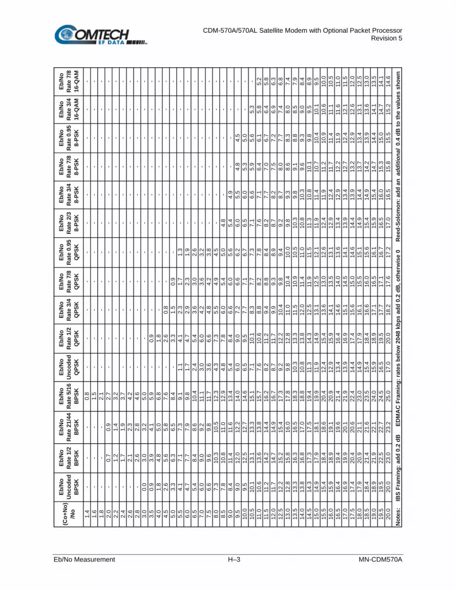
CDM-570A/570AL Satellite Modem with Optional Packet Processor Revision 5
Eb/No Measurement H–3 MN-CDM570A
(Co+
No)
/No
Eb/N
o
Unc
oded
B
PSK
Eb/N
o R
ate
1/2
BPS
K
Eb/N
o R
ate
21/4
4 B
PSK
Eb/N
o R
ate
5/16
B
PSK
Eb/N
o U
ncod
ed
QPS
K
Eb/N
o R
ate
1/2
QPS
K
Eb/N
o R
ate
3/4
QPS
K
Eb/N
o R
ate
7/8
QPS
K
Eb/N
o R
ate
0.95
Q
PSK
Eb/N
o R
ate
2/3
8-
PSK
Eb/N
o
Rat
e 3/
4
8-
PSK
Eb/N
o R
ate
7/8
8-
PSK
Eb/N
o R
ate
0.95
8-
PSK
Eb/N
o R
ate
3/4
16
-QA
M
Eb/N
o R
ate
7/8
16-Q
AM
1.4
--
-0.
8-
--
--
--
--
--
1.6
--
-1.
5-
--
--
--
--
--
1.8
--
-2.
1-
--
--
--
--
--
2.0
-0.
70.
92.
7-
--
--
--
--
--
2.2
-1.
21.
43.
2-
--
--
--
--
-2.
4-
1.7
1.9
3 .7
--
--
--
--
--
-2.
6-
2.1
2.3
4.2
--
--
--
--
--
-2.
8-
2.6
2.8
4.6
--
--
--
--
--
-3.
00.
03.
03.
25.
0-
--
--
--
--
--
3.5
0.9
3.9
4.1
5.9
-0.
9-
--
--
--
--
4.0
1.8
4.8
5.0
6.8
-1.
8-
--
--
--
--
4.5
2.6
5.6
5.8
7.6
-2.
60.
8-
--
--
--
-5.
03.
36.
36.
58.
4-
3.3
1.5
0.9
--
--
--
-5.
54.
17.
17.
39.
11.
14.
12.
31.
71.
3-
--
--
-6.
04.
77.
77.
99.
81.
74.
72.
92.
31.
9-
--
--
-6.
55.
48.
48.
610
.42.
45.
43.
63.
02.
6-
--
--
-7.
06.
09.
09.
211
.13.
06.
04.
23.
63.
2-
--
--
-7.
56.
69.
69.
811
.73.
66.
64.
84.
23.
8-
--
--
-8.
07.
310
.310
.512
.34.
37.
35.
54.
94.
5-
--
--
-8.
57.
810
.811
.012
.94.
87.
86.
05.
45.
04.
8-
--
--
9.0
8.4
11.4
11.6
13.4
5.4
8.4
6.6
6.0
5.6
5.4
4.9
--
--
9.5
9.0
12.0
12.2
14.0
6.0
9.0
7.2
6.6
6.2
6.0
5.5
4.8
4.5
--
10.0
9.5
12.5
12.7
14.6
6.5
9.5
7.7
7.1
6.7
6.5
6.0
5.3
5.0
--
10.5
10.1
13.1
13.3
15.1
7.1
10.1
8.3
7.7
7.3
7.1
6.6
5.9
5.6
5.3
-11
.010
.613
.613
.815
.77.
610
.68.
88.
27.
87.
67.
16.
46.
15.
85.
211
.511
.214
.214
.416
.28.
211
.29.
48.
88.
48.
27.
77.
06.
76.
45.
812
.011
.714
.714
.916
.78 .
711
.79.
99.
38.
98.
78.
27.
57.
26.
96.
312
.512
.215
.215
.417
.39.
212
.210
.49.
89.
49.
28.
78.
07.
77.
46.
813
.012
.815
.816
.017
.89.
812
.811
.010
.410
.09.
89.
38.
68.
38.
07.
413
.513
.316
.316
.518
.310
.313
.311
.510
.910
.510
.39.
89.
18.
88.
57.
914
.013
.816
.817
.018
.810
.813
.812
.011
.41 1
. 010
.810
.39.
69.
39.
08.
414
.514
.317
.317
.519
.411
.314
.312
.511
.911
.511
.310
.810
.19.
89.
58.
915
.014
.917
.918
.119
.911
.914
.913
.112
.512
.111
.911
.410
.710
.410
.19.
515
.515
.418
.418
.620
.412
.415
.413
.613
.012
.612
.411
.911
.210
.910
.610
.016
.015
.918
.919
.120
.912
.915
. 91 4
. 113
.513
.112
.912
.411
.711
.411
.110
.516
.516
.41 9
.419
.621
.413
.416
.414
.614
.013
.613
.412
.912
.211
.911
.611
.017
.016
.919
.920
.121
.913
.916
.915
.114
.514
.113
.913
.412
.712
.412
.111
.517
.517
.420
.420
.622
.414
.417
.415
.615
.014
.614
.413
.913
.212
.912
.612
.018
.017
.920
.921
.123
.014
.917
.916
.115
.515
.114
.91 4
.413
.713
.41 3
.11 2
.518
.518
.421
.421
.623
.515
.418
.416
.616
.015
.615
.414
.914
.213
.913
.613
.019
.018
.921
.922
.124
.015
.918
.917
.116
.516
.115
.915
.414
.714
.414
.113
.519
.519
.522
.522
.724
.516
.519
.517
.717
.116
.716
.516
.015
.315
.014
.714
.120
.020
.023
.023
.225
.017
.020
.018
.217
.617
.217
.016
.515
.815
.515
.214
.6
Not
es:
IB
S Fr
amin
g: a
dd 0
.2 d
B
ED
MA
C F
ram
ing:
rate
s be
low
204
8 kb
ps a
dd 0
.2 d
B, o
ther
wis
e 0
R
eed-
Solo
mon
: add
an
addi
tiona
l 0.
4 dB
to th
e va
lues
sho
wn

CDM-570A/570AL Satellite Modem with Optional Packet Processor Revision 5
Eb/No Measurement H–4 MN-CDM570A
Notes:

CDM-570A/570AL Satellite Modem with Optional Packet Processor Revision 5
RADIUS Client I–1 MN-CDM570A
Appendix I. RADIUS CLIENT
I.1 Overview
Ethernet-based remote monitor and control (M&C) of the CDM-570A/570AL Satellite Modem is available through the CDM-570A/570AL HTTP (Web Server) Interface, SNMP, and through the issuance of remote commands and queries via Telnet. For CDM-570A/570AL Satellite Modems that are equipped with the Optional IP Packet Processor, additional remote M&C access is available via the Telnet Command Line Interface (CLI). Remote Authentication Dial In User Service (RADIUS) is a networking protocol that provides centralized access authentication, authorization, and management for CDM-570A/570AL Satellite Modems.
I.1.1 RADIUS List of Supported RFCs (Requests for Comment)
RFC No. Description
2865 “Remote Authentication Dial In User Service (RADIUS)” Rigby, C., Willens, S., Rubens, A., Simpson, W., June 2000
1334 “PPP Authentication Protocols” Llloyd, B., Simpson, W.,October 1992
1994 “PPP Challenge Handshake Authentication Protocol (CHAP)” Simpson, W., August 1996
2759 “Microsoft PPP CHAP Extensions, Version 2” Zorn, G., January 2000
2548 “Microsoft Vendor-specific RADIUS Attributes” Zorn, G., March 1999

CDM-570A/570AL Satellite Modem with Optional Packet Processor Revision 5
RADIUS Client I–2 MN-CDM570A
I.2 Service Types
“Service Type” is the attribute field in the “RADIUS Access Request and RADIUS Access Response” message as defined in RFC 2865. This attribute indicates the type of service the user has requested, or the type of service to be provided. CDM-570A/570AL RADIUS client recognizes the following value fields, as assigned to the service type attribute in RADIUS: Access-Accept messages received from the RADIUS server, and sets access levels accordingly:
Value Description Access Level
6 Administrative Admin Read write
7 NAS Prompt Read -only
11 Callback Administrative Read/Write access
Some RADIUS Servers might need to be reconfigured with the above service type values for corresponding user access levels.
I.3 RADIUS Client
Figure I-1. RADIUS Authentication Process
Figure I-1 shows the typical RADIUS connectivity with the CDM-570A/570AL Satellite Modem. Remote monitor and control of the CDM-570A/570AL Satellite Modem is accomplished with the User PC. The Modem connects to the RADIUS Server for user credential authentication. The authentication process, as shown here, permits use of the HTTP (Web Server) Interface for remote M&C of the CDM-570A/570AL. This basic messaging sequence is the same for M&C access to the CDM-570A/570AL over the Telnet user interface:

CDM-570A/570AL Satellite Modem with Optional Packet Processor Revision 5
RADIUS Client I–3 MN-CDM570A
Step Action
1 The User PC transmits the “HTTP GET” request.
2 Upon receiving the “HTTP GET” request, the CDM-570A/570AL checks whether the user has been authenticated. If not, the CDM-570A/570AL returns “HTTP 401 Unauthorized” message to the User PC.
3 The User PC transmits the login credentials to the CDM-570A/570AL using the “HTTP GET” message.
4 The CDM-570A/570AL receives the login credentials and performs the following steps:
A. It validates the login credentials against the locally stored Admin credentials. If the credentials match, the modem allows Read/Write access (including Admin configuration pages); it does not grant RADIUS access.
B. If there is no match for the system user credentials, then the modem transmits the RADIUS: Access-Request message to the Primary RADIUS Server.
C. If the Primary RADIUS Server is not available, then the modem transmits the RADIUS: Access-
Request message to the Secondary RADIUS Server.
D. If the Secondary RADIUS Server is not available, then the modem transmits the HTTP: Access Denied message (error page) to the User PC.
5 The RADIUS Server, upon receiving the RADIUS:Access-Req message, authenticates the user credentials and does one of the following:
A. It transmits the RADIUS: Access-Accept message with the appropriate user access level – e.g., Read-only or Read/Write.
B. It transmits the RADIUS:Access-Reject message upon credential mismatch.
C. It transmits the RADIUS: Access-Challenge for further validation.
6 The CDM-570A/570AL, upon receiving one of the above responses from the RADIUS server, then does one of the following:
A. Upon receiving the RADIUS:Access-Accept message, it transmits the “HTTP 201 OK” message to the User PC.
B. Upon receiving the RADIUS: Accept-Reject message, it transmits the “Access Denied” message to the User PC.
C. Upon receiving the RADIUS: Access-Challenge message, it transmits the “PAP/CHAP challenge
response” message to the Radius Server.
7
Upon receiving the “HTTP 201 OK” message, the user can browse the CDM-570A/570AL HTTP (Web Server) Interface pages.
Depending on the user access rights received from the RADIUS server, the CDM-570A/570AL allows the user Read-only or Read-Write access to the interface.

CDM-570A/570AL Satellite Modem with Optional Packet Processor Revision 5
RADIUS Client I–4 MN-CDM570A
I.4 RADIUS Operation and Configuration
RADIUS is available only when you configure the CDM-570A/570AL for IP or IP-ACM operating mode. Enabling and disabling of RADIUS is possible only through:
• The CDM-570A/570AL front panel;
• The CDM-570A/570AL HTTP (Web Server) Interface Admin | Access page;
• Issuance of Telnet remote commands. With RADIUS enabled, any login attempt through the HTTP, Telnet, or Telnet CLI interfaces results in the modem first contacting the RADIUS Client Server for authentication and authorization before granting remote user access. Comtech EF Data provides three levels of user access/login – Admin, Read/Write, and Read Only. Access to operations is controlled as follows:
User Access Login Level Access Restriction(s) Admin User (system*) Full read/write access to all remote commands and queries via Telnet, Telnet CLI
(when unit is equipped with the Optional IP Packet Processor), and web pages (including RADIUS configuration and control using the Admin | Access web page),
Read/Write User • No Access to Admin- or IP Packet Processor-related Telnet remote commands and queries, Telnet CLI, and web pages.
• Full read/write access to all modem configuration and monitoring web pages (except Admin).
Read-Only User • No Access to Admin or IP Packet Processor-related web pages, Telnet remote commands and queries, or Telnet CLI.
• Read Only Access for all other web pages.
• RADIUS does not control user access to the CDM-570A/570AL Front Panel, serial-based remote product management, or the SNMP user interface.
• *System administration under the Admin User login privilege does not require RADIUS.
• Admin User credentials are stored in the modem, so login as Admin User does not require the RADIUS Server connectivity.
• SNMP access can be disabled using System Admin access.

CDM-570A/570AL Satellite Modem with Optional Packet Processor Revision 5
RADIUS Client I–5 MN-CDM570A
Configuration of RADIUS features is possible only through the HTTP (Web Server) Interface Admin | Access page, or by issuance of remote commands via Telnet. No configuration of RADIUS is available from the CDM-570A/570AL front panel or through serial-based remote commands, SNMP, or the Telnet CLI. The modem is configurable with primary and secondary RADIUS server addresses. In the event that the primary server is unavailable, the secondary server will be used to validate the user name and password. Read/write and read-only user credentials are managed via the RADIUS Client Server – the RADIUS Client Server cannot grant Admin level access. The modem locally stores one Admin-level user name and password. If the RADIUS client is disabled or the modem cannot access the primary and the secondary server, any user trying to access the modem will be authenticated with the locally stored username and password, which provides full Admin access.
• All user credentials are verified by the RADIUS server, when the client has connectivity to either the primary or secondary RADIUS servers.
• In the absence of primary or secondary RADIUS server connectivity, or when RADIUS is disabled, the locally stored Admin credentials are used for modem access.
I.4.1 RADIUS M&C using the CDM-570A/570AL HTTP (Web Server) Interface
Chapter 7. ETHERNET-BASED REMOTE PRODUCT MANAGEMENT
The Admin pages are available only if you log in using the Administrator Name and Password.
Figure I-2. CDM-570A/570AL HTTP (Web Server) Interface Admin | RADIUS Page

CDM-570A/570AL Satellite Modem with Optional Packet Processor Revision 5
RADIUS Client I–6 MN-CDM570A
• RADIUS Client – Use the drop-down list to set RADIUS operation as Enabled or Disabled.
• Server Password Type – Use the drop-down list to select the authentication protocol as PAP (Password Authentication Protocol) or CHAP (Challenge-Handshake Authentication Protocol).
• Primary / Secondary Server IP Address – Enter the pertinent Server IP Addresses in the
form xxx.xxx.xxx.xxx. • Server Shared Secret – Carefully enter the word to be used (64 characters maximum) as
the ”shared secret” between the RADIUS Client Server and the networked device (CDM-570A/570AL). The interface conceals this entry for security purposes.
• Server Port – Enter a valid port number from 1 to 65535 (the default is 1812). Click [Submit Radius] to save. • RADIUS Log – This scrollable window displays the last 20 users who have logged onto the
RADIUS server.
I.4.2 RADIUS M&C Using Telnet
• Chapter 7. ETHERNET-BASED REMOTE PRODUCT MANAGEMENT • Chapter 8. SERIAL-BASED REMOTE PRODUCT MANAGEMENT
The RADIUS commands/queries are available only if you log in to the Telnet Remote Control Interface (not to be confused with the Telnet CLI – Command Line Interface) using the Administrator Name and Password.
Command/Query Function RAE Enables/Disables RADIUS operation RAA Assigns the Primary RADIUS Client Server IP Address RAB Assigns the Secondary RADIUS Client Server IP Address RAP Assigns the RADIUS Server Port Address RAT Defines the RADIUS Client Server password authentication protocol RAS Assigns the RADIUS Client Server shared secret

CDM-570A/570AL Satellite Modem with Optional Packet Processor Revision 5
EDMAC Channel J–1 MN-CDM570A
Appendix J. EDMAC CHANNEL
J.1 Theory of Operation
J.1.1 EDMAC, EDMAC-2
The Embedded Distant-end Monitor And Control (EDMAC) feature permits user access to the M&C features of modems that are at the distant-end of a satellite link. This is accomplished by adding extra information to your data, but in a manner that is otherwise transparent. On the transmit side: The data is split into frames – each frame containing 1008 bits (except Rate 21/44 BPSK Turbo, or when the data rates exceed 2048 kbps, where the frame length is 2928 bits, and Rate 5/16 BPSK Turbo where the frame length is 3072 bits). There are 48 bits in each frame are overhead, and the rest of these bits are user data. This increases the rate of transmission by 5% (approximately 1.5% for the Turbo BPSK cases, and for all data rates greater than 2.048 Mbps). For example, if the user data rate is 64 kbps, the actual transmission rate will now be at 67.2 kbps. Note that you may also select EDMAC-2 framing, which always uses a 2928 bit frame, and yields a 1.6% overhead for all modulation types and data rates. At the start of each frame, a 12-bit synchronization word is added. This allows the demodulator to find and lock to the start of frame. At regular intervals throughout the frame, additional data bytes and flag bits are added (a further 36 bits in total). It is these additional bytes that convey the M&C data. When framing is used, the normal V.35 scrambler is no longer used. This V.35 approach is called ‘self synchronizing’ because no external information is required in the receiver in order for the de-scrambling process to recover the original data. The disadvantage of this method is that it multiplies errors. On average, if one bit error is present at the input of the descrambler, three output errors are generated. However, there is an alternative when the data is in a framed format: in this case, a different class of scrambler may be used – one that uses the start of frame information to start the scrambling process at an exact known state. In the receiver, having synchronized to the frame, the de-scrambler can begin its processing at exactly the right time. This method does not multiply errors, and therefore has a clear advantage over V.35 scrambling. This is fortunate, as there is a penalty to be paid for adding the framing: by adding the extra 5% to the transmitted data rate, the effective Eb/No that is seen will degrade by a factor of 10log(1.05), or 0.21 dB (0.07dB in the case of the two BPSK Turbo rates or EDMAC-2).

CDM-570A/570AL Satellite Modem with Optional Packet Processor Revision 5
EDMAC Channel J–2 MN-CDM570A
The use of an externally synchronized scrambler and descrambler almost exactly compensates for this degradation. The net effect is that you will see effectively identical BER performance, whether or not framing is used. On the receive side: When the demodulator locks to the incoming carrier, it must go through the additional step of searching for and locking to the synchronization word. This uniquely identifies the start of frame, and permits the extraction of the overhead bytes and flag bits at the correct position within the frame. Additionally, the start of frame permits the de-scrambler to correctly recover the data: your data is extracted and sent through additional processing in the normal manner. The extracted overhead bytes are examined to determine if they contain valid M&C bytes.
J.2 M&C Connection
Data to be transmitted to the distant-end is sent to a local unit via the remote control port. A message for the distant-end is indistinguishable from a ‘local’ message – it has the same structure and content, only the address will identify it as being for a distant-end unit. Before the M&C data can be successfully transmitted and received, pairs of units must be split into EDMAC Masters and EDMAC Slaves. Masters are local to the M&C Computer, and Slaves are distant-end. Now, a unit that has been designated an EDMAC master not only responds to its own unique bus address, but it will also be configured to listen for the address that corresponds to its EDMAC Slave. When a complete message packet has been received by the EDMAC Master, it will begin to transmit this packet over the satellite channel, using the overhead bytes that become available.
The ‘normal’ protocol for the message packet is not used over the satellite path, as it is subject to errors. For this reason, a much more robust protocol is used which incorporates extensive error checking.
At the distant-end, the EDMAC slave, configured for the correct address, receives these bytes, and when a complete packet has been received, it will take the action requested, and then send the appropriate response to the EDMAC Master, using the return overhead path on the satellite link. The EDMAC Master assembles the complete packet, and transmits the response back to the M&C Computer. Apart from the round-trip satellite delay, the M&C Computer does not see any difference between local and distant-end units – it sends out a packet, addressed to a particular unit, and gets back a response. It can be seen that the EDMAC Master simply acts as forwarding service, in a manner that is completely transparent. This approach does not require any additional cabling; connection is made using the normal M&C remote port, which is completely independent from the modem data port. Consequently, you do not have to worry about configuring the baud rate of the M&C connection to match the lowest data rate modem in the system. It should be pointed out that, at 2.4 kbps, the effective throughput of the overhead channel is only 14 asynchronous characters/second. For a message of 24 bytes, the time between sending a poll request and receiving a response will be around 1.7 seconds. (Note that, when EDMAC-2 or either of the BPSK Turbo rates is in use, the overhead rate is reduced by a factor of three, and therefore the minimum response time will be around 5 seconds.)

CDM-570A/570AL Satellite Modem with Optional Packet Processor Revision 5
EDMAC Channel J–3 MN-CDM570A
J.3 Setup Summary
To access a distant-end unit:
• Designate a Master/Slave pair: Master at the local-end, Slave at the distant-end.
• On the local-end unit, enable framing and EDMAC, define the unit as MASTER, then enter the bus address. This is constrained to be ‘base 10' meaning that only addresses such as 10, 20, 30, 40 etc, are allowed.
• Choose a unique bus address for the distant-end. This should normally be set to the ‘base 10' address + 1. For example, if the MASTER unit is set to 30, choose 31 for the distant-end unit.
• On the distant-end unit, enable framing and EDMAC, define the unit as SLAVE, then enter the bus address. The orange EDMAC Mode LED on the modem front panel should be illuminated.
• Set the local-end unit to RS485 remote control, and set the bus address of this local unit. The orange Remote Mode LED on the modem front panel should be illuminated.
• Once the satellite link has been established, connect the M&C Computer, and begin communications with both the local and distant end units.
EDMAC modes are fully compatible with AUPC modes.

CDM-570A/570AL Satellite Modem with Optional Packet Processor Revision 5
EDMAC Channel J–4 MN-CDM570A
Notes:

CDM-570A/570AL Satellite Modem with Optional Packet Processor Revision 5
GPS Mode K–1 MN-CDM570A
Appendix K. GPS MODE
K.1 Overview
This appendix summarizes the CDM-570A/570AL firmware feature that permits connection of a Furuno GP-320B Global Positioning System (GPS) receiver to a distant-end modem, and for the local end to query – via the EDMAC channel – the output from the GPS receiver. To do this, the local modem is set as MASTER, and the distant-end is set as SLAVE. The Furuno GP-320B GPS receiver is then connected to the rear panel “Remote Control” serial port of the distant end modem.
If ‘standard’ EDMAC framing is used, the MASTER can be a CDM-550, CDM-600/600L, CDM-570/570L, or CDM-570A/570AL. However, if EDMAC-2 framing is used, both ends of the link need to be CDM-570A/570ALs.
Send remote commands to the SLAVE modem to retrieve GPS data sentences. The modem has a circular buffer to contain the most recent 1000 characters received from the GPS receiver – about 2 to 3 seconds of data. The method of searching for the correct sentence is to simply look for the first match in the buffer. This gives about two seconds’ delay time in the worst case at the SLAVE end, plus any delay added by the EDMAC channel. When a query is actively taking place, the CDM-570A/570AL temporarily suspends the placing of new GPS data into the buffer.
K.2 Hardware Setup
Step Task 1 Make sure to set the serial remote control type for the SLAVE modem to RS232.
2 Follow the Setup sequence of EDMAC described in Appendix G. EDMAC CHANNEL. The SLAVE Modem must be a CDM-570 or CDM-570L, and the MASTER modem can be any modem compatible with the SLAVE modem.
3 Connect the GP-320B GPS receiver to the SLAVE modem’s serial port. The YELLOW wire in the Furuno GPS cable (RDA) should be connected to pin 3 of the CDM-570L serial remote control port (9-pin Type ‘D’ male – see Chapter 3. REAR PANEL CONNECTORS AND PINOUTS). Connect the ground wire from the GPS to Pin 1.
4 Establish an RF link between the SLAVE and MASTER modems, and once satisfied that both demods are locked, set up a serial communications session via the serial port of the MASTER modem, and begin sending EDMAC messages to the distant-end SLAVE.

CDM-570A/570AL Satellite Modem with Optional Packet Processor Revision 5
GPS Mode K–2 MN-CDM570A
K.3 Remote Commands
For more information about using remote commands and queries, see Chapter 8. SERIAL-BASED REMOTE PRODUCT MANAGEMENT.
Several remote commands are available to enable the GPS Mode and retrieve GPS information. These commands are for the SLAVE modem ONLY, which means the address field must be the address of the Slave unit (e.g., 0021).
• GPS – GPS Mode, Query and Command 0 = Disabled 1 = Enabled
Note: When the GPS mode is enabled, the SLAVE modem’s serial’s Baud Rate is changed to 4800 to receive data from GP-320B. To go back to normal serial operation mode, disable the GPS Mode.
• DTM? – Retrieve GPDTM data sentence • GGA? – Retrieve GPGGA data sentence • ZDA? – Retrieve GPZDA data sentence • GLL? – Retrieve GPGLL data sentence • VTG? – Retrieve GPVTG data sentence • RMC? – Retrieve GPRMC data sentence
Example capture of the remote commands: <0021/GPS? Queries current GPS status >0021/GPS=0[cr][lf] SLAVE responds that GPS is disabled <0021/GPS=1 SLAVE is commanded to enable GPS >0021/GPS=[cr][lf] SLAVE confirms that GPS is enabled <0021/DTM? SLAVE is commanded to return GPDTM data sentence >0021/DTM=$GPDTM,W84,,00.0000,N,00.0000,W,,W84*53[cr][lf] <0021/GGA? >0021/GGA=$GPGGA,222830,3325.4268,N,11158.2640,W,0,01,00.00,000293.6,M,-026.2,M,,*7F[cr][lf] <0021/ZDA? >0021/ZDA=$GPZDA,223145,14,10,2005,+00,00*63[cr][lf] <0021/GLL? >0021/GLL=$GPGLL,3325.4268,N,11158.2640,W,222830,V,N*47[cr][lf] <0021/VTG? >0021/VTG=$GPVTG,,T,,M,,N,,K,N*2C[cr][lf] <0021/RMC? >0021/RMC=$GPRMC,222830,V,3325.4268,N,11158.2640,W,,,141005,011.8,E,N*12[cr][lf] <0021/GPS=0 SLAVE is commanded to disable GPS >0021/GPS=[cr][lf] SLAVE confirms that GPS is disabled <0021/RMC? SLAVE is commanded to return GPRMC data sentence >0021/RMC*[cr][lf] SLAVE responds that data is not available

CDM-570A/570AL Satellite Modem with Optional Packet Processor Revision 5
Advanced Quality of Service (QoS) Option L–1 MN-CDM570A
Appendix L. ADVANCED QUALITY OF SERVICE (QoS)
OPTION
L.1 Overview
Advanced Quality of Service (QoS) enables a network to use WAN bandwidth more efficiently by managing delay, jitter (delay variation), throughput, and packet loss. It is based on OSI model to Layer 7 protocol header parameters. Advanced QoS requires that you install the optional IP Packet Processor, and that you purchase and activate the Advanced QoS FAST Option. Contact Comtech EF Data Product Support for further information. QoS scheduling operates on modem Tx bandwidth with 1-byte resolution, so there is no further trimming or clipping data rate after the QoS scheduler. QoS is implemented with at least one 1-second burst at maximum data rate. QoS systems use a strict priority QoS scheduling algorithm. Excluding the default queue, the QoS system has up to 32 QoS queues with eight configurable priorities rules. The QoS system creates a separate queue for each rule to store the incoming stream of packets. (In this appendix, ‘QoS rules’ and ‘QoS queues’ are interchangeable). QoS systems incorporates Weighted Random Early Detection (WRED) based congestion avoidance algorithm in addition to tail drop. The CDM-570A/L-IP incorporates four Per Hop Behavior (PHP) QoS modes of operation:
• Mode 1 – Max/Pri (QoS Rules based on Maximum Bandwidth and Priority)
• Mode 2 – Min/Max (QoS Rules based on Minimum and Maximum Bandwidth)
• Mode 3 – DiffServ (Differentiated Services)
• Mode 4 – VLAN – Priority/Max (VLAN 802.1q)

CDM-570A/570AL Satellite Modem with Optional Packet Processor Revision 5
Advanced Quality of Service (QoS) Option L–2 MN-CDM570A
L.1.1 Max/Pri (Maximum Bandwidth/Priority) QoS Mode
In Max/Pri mode, up to 32 QoS rules can be configurable using source IP subnet, destination IP subnet, source port range, destination port range, and protocol. For each created rule, you can also set the QoS treatments such as priority, limiting the maximum bandwidth, WRED enable or disable, and filter enable or disable. Priority – The IP Packet Processor classifies each packet that is to be forwarded over the satellite; the packet is then assigned a Priority Number (Priority level from 1 to 8) according to the defined QoS Rules:
• The lower the Priority Number, the higher that priority is (i.e., Priority 1 = highest priority;
Priority 9 = lowest priority).
• Any latency critical traffic such as VoIP/RTP should always be assigned Priority 1.
• Priority 1 packets are forwarded immediately; Priority 2 packets are forwarded as soon as there are no Priority 1 packets in the Queue; and so on through Priority 8.
• Any packet that does not meet a QoS Rule is assigned to the Default Rule with Priority = 9.
Maximum Bandwidth – This can also be assigned to a flow to restrict the Maximum Bandwidth that any particular flow will utilize; otherwise, the default of no bandwidth restriction can be selected. Filtering – QoS allows specific flows to be designated as “filtered” – this instructs the IP Packet Processor to discard traffic that is otherwise not wanted for forwarding over a satellite link. When you enable the FILTER option for a rule, QoS provides the ability to filter the packet completely. QoS Rule Hierarchy – It is quite possible to have traffic that meets the definitions of several QoS Rules. All traffic will be classified into the first QoS Rule that is a match, or fall into the Default Rule. The most specific QoS Rule will always be first. For example, a QoS Rule that identified a Source and Destination IP Address would be assigned ahead of a rule that just defined RTP protocol.

CDM-570A/570AL Satellite Modem with Optional Packet Processor Revision 5
Advanced Quality of Service (QoS) Option L–3 MN-CDM570A
QoS Rules having the same amount of defined variables are sorted as follows:
1. Having a Protocol defined: Protocol Priority Protocol Priority
CTRX CITRIX Protocol SAP Service Announcement Protocol FTP File Transfer Protocol SMTP Simple Mail Transfer Protocol HTTP Hypertext Transfer Protocol SNMP Simple Network Management Protocol ICMP Internet Control Message Protocol SQL Structured Query Language Protocol IP All Internet Protocol TCP Transmission Control Protocol N-IP All Non-Internet Protocol TELN Telnet Protocol ORCL ORACLE Protocol UDP User Datagram Protocol RTP All Real Time Protocol VDEO Video Real Time Protocol RTPS Real Time Protocol Signaling + Voice Real Time Protocol
2. Source IP Address or subnet defined.
3. Destination IP Address or subnet defined.
4. Source Port defined (lowest Port number first).
5. Destination Port defined (lowest Port number first).
The IP Packet Processor will sort each QoS rule as they are added and the QoS Configuration display will be updated to reflect the order with which rules are matched. QoS Statistics – Every defined QoS Rule can be monitored to see the traffic flow for each queue. These statistics display the traffic sent in each queue, the amount of dropped traffic, and the number of Active Flows. Protocol and Port Number Considerations – When defining QoS Rules, it is important to be aware of specifics of the traffic for which the rule is intended. When selecting a protocol for a QoS Rule, be aware that the IP Packet Processor allows for a very broad selection (such as IP) or a very specific protocol. For example, RTP traffic can consist of UDP portion (for voice or video) and a TCP portion (for RTP signaling). These could have separate QoS Rules created or all be included in a single Rule by selecting RTP as the protocol.

CDM-570A/570AL Satellite Modem with Optional Packet Processor Revision 5
Advanced Quality of Service (QoS) Option L–4 MN-CDM570A
This diagram shows where each protocol selection resides:
Selection of Source/Destination Ports should be done only if you are aware of the port usage of the desired protocol or application. There are well known ports for various protocols, but often only the ‘command’ messaging is transacted on these ports and the ‘data’ is transferred through a negotiated port. Use this table as a reference for some well-known port numbers:
Port Description Port Description 1 TCP Port Service Multiplexer (TCPMUX) 118 SQL Services 7 ECHO 119 Newsgroup (NNTP)
20 FTP - Data 137 NetBIOS Name Service 21 FTP - Control 139 NetBIOS Datagram Service 22 SSH Remote Login Protocol 150 NetBIOS Session Service 23 Telnet 156 SQL Server 25 Simple Mail Transfer Protocol (SMTP) 161 SNMP 42 Host Name Server (Nameserv) 179 Border Gateway Protocol (BGP) 53 Domain Name System (DNS) 190 Gateway Access Control Protocol (GACP) 69 Trivial File Transfer Protocol (TFTP) 197 Directory Location Service (DLS) 70 Gopher Services 396 Novell Netware over IP 80 HTTP 443 HTTPS 108 SNA Gateway Access Server 444 Simple Network Paging Protocol (SNPP) 109 POP2 546 DHCP Client 110 POP3 547 DHCP Server 115 Simple File Transfer Protocol (SFTP) 1080 Socks
Once the QoS Rules are defined, each type of traffic flow should be isolated and sent to verify that it is being sent in the intended QoS Rule.
WRED – When WRED is enabled for a specific queue, QoS randomly drops packets after reaching 50% of the QoS queue.
RTP RTPS
UDP
TCP
VOCE
VDEO
FTP HTTP
TELN SMTP SAP
ORCL
CTRX SQL
SNMP
Non IP
IP

CDM-570A/570AL Satellite Modem with Optional Packet Processor Revision 5
Advanced Quality of Service (QoS) Option L–5 MN-CDM570A
L.1.1.1 Max/Pri QoS Mode Example
Dop these steps:
1. Select Max/Pri QoS mode.
2. Set Modem Tx bandwidth to 2048 Kbps (E1 rate).
3. Configure the Max/Pri QoS rules as follows:
Index Protocol Src IP/ mask
Dest IP/
mask
Min Src Port
Max Src Port
Min Dst Port
Max Dst Port
Max BW Priority Filter WRED
1 UDP ***/* ***/* 0 65535 0 65535 644 1 N N 2 TCP ***/* ***/* 0 65535 0 65535 99999 2 N N 3 HTTP ***/* ***/* 0 65535 0 65535 99999 3 N N 4 Def ****/* ***/* 0 65535 0 65535 99999 9 N N
The input data streams are as follows.
Stream Protocol Src IP Dest IP Src Port Dest Port Steam Data Rate
1 UDP ***/* ***/* *** *** 1024
2 TCP ***/* ***/* *** *** 1024
3 HTTP ***/* ***/* *** *** 1024
4 IP ***/* ***/* *** *** 64 QUESTION: What are the total output data rates and the individual stream data rates?
ANSWER: The individual stream data rates are as follows.
QoS Rule QoS Priority Input Data Rate QoS Output Data Rate
Remain Data Rate (After Serving the Priority
Queue) 1 1 1024 Kbps 644 Kbps
due to max clipping 1404 Kbps
2 2 1024 Kbps 1024 Kbps 304 Kbps 3 3 1024 Kbps 380Kbps 0 Kbps 4 9 64 Kbps 0 0 Kbps
Total N/A 3136 Kbps 2048 Kbps 0 Kbps
L.1.2 Min/Max (Minimum/Maximum Bandwidth) QoS Mode
In Min/Max mode, up to 32 QoS rules can be configured using source/destination IP subnet, Layer 3 source/destination port range, and protocol (FTP, UDP, RTP, etc.). For each created rule, you can also set the QoS treatment, such as guaranteed minimum bandwidth, maximum clipping bandwidth, WRED enable or disable, and filter rule.

CDM-570A/570AL Satellite Modem with Optional Packet Processor Revision 5
Advanced Quality of Service (QoS) Option L–6 MN-CDM570A
Minimum Bandwidth – Minimum specification that allows a committed information rate (CIR) to be applied to user-defined classes of traffic; otherwise, the default of no minimum bandwidth can be selected. Maximum Bandwidth – This can be assigned to a flow to restrict the Maximum Bandwidth that any particular flow will utilize; otherwise, the default of no bandwidth restriction can be selected. WRED – The Min/Max QoS mode allows selection of Weighted Random Early Detection (WRED). When WRED is enabled for a specific queue, QoS randomly drops packets after reaching 50% of the QoS queue. Filtering – Any specific flow can be designated as filtered (see Max/Pri QoS Mode). When the FILTER option is enabled for a rule, QoS provides the ability to filter the packet completely. QoS Rule Hierarchy – The QoS Rule Hierarchy is the same as Maximum Bandwidth/Priority QoS. QoS Statistics – QoS Statistics are displayed as Maximum Bandwidth/Priority QoS.
L.1.2.1 Min/Max QoS Mode Example
Do these steps:
1. Select Min/Max QoS mode.
2. Set Modem Tx bandwidth to 20 Mbps.
3. Configure the Min/Max QoS rules as follows:
Index Protocol Src IP/ mask
Dest IP/ mask
Min Src Port
Max Src Port
Min Dst Port
Max Dst Port
Min BW
Max BW Filter WRED
1 UDP ***/* ***/* 0 65535 0 65535 2500 4000 N N
2 TCP ***/* ***/* 0 65535 0 65535 2500 99999 N N
3 HTTP ***/* ***/* 0 65535 0 65535 0 99999 N N
4 Def ****/* ***/* 0 65535 0 65535 0 9999 N N
The input data streams are as follows:
Stream Protocol Src IP Dest IP Src Port Dest Port Steam Data Rate
1 UDP ***/* ***/* *** *** 10000 Kbps
2 TCP ***/* ***/* *** *** 5000 Kbps
3 HTTP ***/* ***/* *** *** 7000 Kbps
4 def ***/* ****/* *** *** 10000 Kbps

CDM-570A/570AL Satellite Modem with Optional Packet Processor Revision 5
Advanced Quality of Service (QoS) Option L–7 MN-CDM570A
QUESTION: What are the total output data rates and the individual stream data rates? ANSWER:
• In Min-Max QoS mode, other than the default rule, which is configured as Priority 9, all QoS rules are configured as Priority 8.
• In this mode, the minimum bandwidth for all rules – the excluding the default rule – will be served first in round robin fashion. In this example, the total minimum BW for Rules 1 and 2 is 5000 Kbps. Since the total bandwidth is 20 Mbps, it has enough bandwidth to serve.
• After serving the minimum bandwidth, the leftover bandwidth is 15 Mbps (20,000 Kbps– 5000 Kbps).
• Leftover bandwidth will be served among all rules in round robin fashion until it hits maximum bandwidth limitations.
• Each rule’s bandwidth is 15/3 = 5000 Kbps.
• Since Rule 1 maximum clipping was set to 4000 Kbps, and minimum bandwidth has already taken 2500 bytes, it will use 1500 Kbps more before reaching the maximum clipping. The leftover 3500 Kbps (5000-1500=3500) is again given to the main pool.
• Rule 2 does not have enough traffic coming in, so it will use only 2500 kbps (5000-2500); the remaining bandwidth (5000-2500=2500) is again given to the main pool.
• Rule 3’s input stream is 7000 bytes; it will take its share of the 5000 allocation. Still, it needs 7000-5000=2000).
• After serving the fair share, the total leftover bandwidth is 6000 kbps (3500+2500=6000).
• Since Rule 3 needs the bandwidth, the leftover bandwidth is applied to that rule.
• After serving Rule 3, the leftover bandwidth 4000 Kbps will be applied to the default queue.
• The default rule will see the data rate of4000 Kbps.
The individual rule’s data rates are as follows:
QoS Rule QoS Priority Input Data Rate QoS Output Data Rate
1 1 1000 Kbps 4000 Kbps
2 2 5000 Kbps 5000 Kbps
3 3 7000 Kbps 7000 Kbps
4 9 10000 Kbps 4000 Kbps
Total NA 3136 Kbps 20000 Kbps

CDM-570A/570AL Satellite Modem with Optional Packet Processor Revision 5
Advanced Quality of Service (QoS) Option L–8 MN-CDM570A
L.1.3 DiffServ QoS Mode
The IP Packet Processor QoS can be set to DiffServ Mode to make it fully compliant to the Differential Services QoS RFC standards. When the QoS mode is set to DiffServ, the system automatically configures the rules with DSCP code points, priority values, and WRED. You can only configure the service rate and drop precedence levels for Assured Forwarding (ASFD) classes. Class Selector DiffServ Code Points (DSCP) – Some implementations of DiffServ will prioritize traffic by Class Selector assignment. This is defined in the DSCP within the IP header. The first three bits of the DSCP define the Class Selector Precedence (or Priority):
Class Selector DSCP IP Packet Processor
Priority Class Selector DSCP
IP Packet Processor
Priority Precedence 1 001 000 7 Precedence 5 101 000 3 Precedence 2 010 000 6 Precedence 6 110 000 2 Precedence 3 011 000 5 Precedence 7 111 000 1 Precedence 4 100 000 4 Default 000 000 9
The IP Packet Processor will prioritize the traffic based upon the DSCP Class Selector Precedence. All traffic that does not have the DSCP Class Selector Precedence defined
(000 000) will be placed in the Default Queue and have a Precedence of 9. Expedited Forwarding and Assured Forwarding DSCP – Another implementation of DiffServ uses all six bits of the DSCP to define Expedited and Assured Forwarding:
DiffServ Type Class Selector DSCP IP Packet Processor Priority Expedited Forwarding Precedence 1 101 110 3
Assured Forwarding – Class 1 Precedence 8 001 xx0 7 Assured Forwarding – Class 2 Precedence 8 010 xx0 7 Assured Forwarding – Class 3 Precedence 8 011 xx0 7 Assured Forwarding – Class 4 Precedence 8 100 xx0 7
Expedited Forwarding (EF) DSCP – This defines premium service and is recommended for real time traffic applications such as VoIP and video conferencing. Assured Forwarding (AF) DSCP – This defines four service levels and also uses the last three bits of the DSCP to define the Drop Precedence (Low, Medium, or High). The Drop Precedence determines which packets will most likely be dropped during periods of over congestion, similar to WRED. As a result, each of the four AF service levels also have three Drop Precedence levels for which the IP Packet Processor provides 12 separate queues. Minimum Bandwidth (AF only) – Minimum specification that allows a committed information rate (CIR) to be applied to user-defined classes of traffic, or the default of no minimum bandwidth can be selected. Maximum Bandwidth (AF only) – This can be assigned to a flow to restrict the maximum bandwidth that any particular flow will utilize, or the default of no bandwidth restriction can be selected.

CDM-570A/570AL Satellite Modem with Optional Packet Processor Revision 5
Advanced Quality of Service (QoS) Option L–9 MN-CDM570A
1. Minimum and maximum bandwidth is only configurable for each of the four Assured Forwarding classes.
2. Typically, DiffServ is implemented using exclusively Class Selector DSCP or exclusively Expedited and Assured Forwarding DSCP. The IP Packet Processor is fully DiffServ compliant and will work with either DiffServ implementation, or with a combination of both.
WRED – The QoS system supports WRED-based congestion avoidance. WRED can be enable or disabled on any queue. When WRED is disabled, upon overdriving the queue the packets will be tail dropped.
L.1.3.1 DiffServ QoS Mode Example
Do these steps:
1. Select DiffServ QoS mode.
2. Set the modem Tx bandwidth to 10 Mbps.
The input streams to the modem are as follows:
Stream Priority PHB / DSCP Code Service Rate Drop Precedence Data Rate
Management 1 CS7 / b111000 NA NA 200 Kbps Networking
Control 2 CS6 / b110000 NA NA 800 Kbps
Voice 3 EXFD / b101110 NA NA 1Mbps Video 3 CS5 / b101000 NA NA 4 Mbps Data-1 4 CS4 / b100000 NA NA 550 Kbps Data-2 5 CS3 / b011000 NA NA 1450 Kbps Data-3 7 ASFD4 / b100010 100 low 1 Mbps Data-4 7 ASFD3 / b011010 400 low 1 Mbps Data-5 7 ASFD2 / b010010 500 low 1 Mbps Data-6 7 ASFD1 / b001010 800 low 1 Mbps Data-7 8 BE / bXXXXXX NA NA 2 Mbps

CDM-570A/570AL Satellite Modem with Optional Packet Processor Revision 5
Advanced Quality of Service (QoS) Option L–10 MN-CDM570A
QUESTION: What is the total output data rate and what are the individual port output data rates? ANSWER:
• The QoS system first drains Priority 1 traffic. Since the management data stream is only 200 Kbps, after serving Priority 1 traffic, QoS still has 9.8 Mbps (10.0-0.2=9.8).
• QoS next drains Priority 2’s 800 Kbps traffic. After the end of the Priority 2 traffic, QoS still has 9 Mbps traffic available (9.8-0.8=9).
• Similarly, QoS walks through all priorities until it hits the ASFD classes: o The beginning of ASFD Classes QoS leftover bandwidth is 2 Mbps. o All ASFD classes have the same Priority of 7, with different service rates. o ASFD service rate is a Committed Information Rate (CIR), except serviced if
bandwidth available after serving all high priority queues. In this case, 2 Mbps bandwidth is available, serving all service rates first. The total of all ASFD service rates are 1.6 Mbps, which is less than the 2 Mbps leftover bandwidth.
o After serving the service rates, the leftover bandwidth is 400 Kbps. This 400 Kbps will be distributed to all ASFD classes equally in round robin fashion until either there is no more bandwidth, or the input streams have no data.
The resulting individual data rates are as follows:
Stream Priority PHB / DSCP Code Service Rate Drop Precedence Data Rate
Management 1 CS7 / b111000 200 Kbps 9.8 Mbps 200 Kbps Networking Control 2 CS6 / b110000 800 Kbps 9.0 Mbps 800 Kbps
Voice 3 EXFD / b101110 1 Mbps 8.0 Mbps 1Mbps Video 3 CS5 / b101000 4 Mbps 4.0 Mbps 4 Mbps Data-1 4 CS4 / b100000 550 Kbps 3450 Kbps 550 Kbps Data-2 5 CS3 / b011000 1450 2000 Kbps 1450 Kbps Data-3 7 ASFD4 / b100010 1 Mbps NA 100 + 100 Kbps Data-4 7 ASFD3 / b011010 1 Mbps NA 400 + 100 Kbps Data-5 7 ASFD2 / b010010 1 Mbps NA 500 + 100 Kbps Data-6 7 ASFD1 / b001010 1 Mbps NA 800 + 100 Kbps Data-7 8 BE / bXXXXXX 2 Mbps NA 0 Kbps Total N/A N/A 14 Mbps 0 Kbps 10 Mbps

CDM-570A/570AL Satellite Modem with Optional Packet Processor Revision 5
Advanced Quality of Service (QoS) Option L–11 MN-CDM570A
L.1.4 VLAN – Priority/Max (VLAN-based Layer 2) QoS Mode
When selecting VLAN-based Layer 2 QoS, the priority field is extracted from the 802.1q VLAN tag as shown in Figure L-1. The VLAN tag priority field is 3 bits, so the 802.1q protocol supports eight priorities, from 0 to 7. However, because Layer 2 QoS has only four priorities as mentioned previously, as shown in Table L-1 these eight VLAN priorities are automatically mapped to four internal priories. Similar to the Port-based scheduler, VLAN-based QoS also observes strict priority-based scheduling. Should overdriving of VLAN priority traffic occur, the packet will be dropped and drop stats will be incremented against that port.
Dest MAC6 bytes
SRC MAC6 bytes Data FCS
4 bytes
Type(0x8100)2 bytes
Priority3bits
CFI1 bit
VLANid12 bits
VLAN Tag
Figure L-1. IEEE 802.1q VLAN Priority
Table L-1. 802.1q to Layer 2 QoS Priority Conversion
802.1q VLAN Priority Field Layer 2 QoS Priority 7 (b111) Priority 1 6 (b110) Priority 2 5 (b101) Priority 3 4 (b100) Priority 4 3 (b011) Priority 5 2 (b010) Priority 6 1 (b001) Priority 7 0 (b000) Priority 8
Even though it is not necessary to configure multiple ports with VLANs, the VLAN QoS will not look in the port information when classifying the packets into queue.
In case VLAN Q-in-Q (double VLAN tag), the L2 VLAN QoS considers first VLAN tag priority field only for traffic prioritization.

CDM-570A/570AL Satellite Modem with Optional Packet Processor Revision 5
Advanced Quality of Service (QoS) Option L–12 MN-CDM570A
L.2 QoS with ACM (Adaptive Coding and Modulation)
When ACM is enabled, the modem is configured with symbol rate. However, while the QoS system recognizes data rate, both Layer 2 QoS and Layer 3 QoS operate on data rate. Therefore, while the symbol rate will be constant in ACM mode, the data rate will not be constant. As a result, the modem’s data rate can vary "on-the-fly” based on the EbNo. The data rate can be more or less than when QoS was first configured, or when the modems first boots.
L.2.1 Maximum Clipping
Due to ACM, when in QoS Max-Pri mode and the data rate’s available bandwidth exceeds the maximum clipping rate, the QoS system limits the output rate of that rule to configured maximum clipping rate. When the available data rate is less than the maximum clipping rate, the QoS system has nothing to clip, since it has not exceeded the defined maximum bandwidth rate.
L.2.2 Minimum Data Rate
Due to ACM, when the data rate’s available bandwidth exceeds the minimum data rate (per QoS Min-Max and DiffServ modes’ ASFD classes), the QoS system operates as normal; since the minimum has been met, the available bandwidth is shared among all other same priorities in round robin fashion. When the available data rate is less than the minimum data rate, then the QoS system shares equally among all same priority queues in a round robin fashion until either minimum bandwidth is met, or no more data is available to drain.
L.2.3 DiffServ w/ACM QoS Example
Do these steps:
1. Select DiffServ Layer 3 QoS mode.
2. Enable ACM.
3. The data rate of the modem drops down from 10 Mbps to 8.7 Mbps due to EbNo.
Input data streams are as follows:
Stream Protocol Src IP Dest IP Src Port Dest Port Steam Data Rate 1 UDP ***/* ***/* *** *** 10000 Kbps 2 TCP ***/* ***/* *** *** 5000 Kbps 3 HTTP ***/* ***/* *** *** 7000 Kbps 4 def ***/* ****/* *** *** 10000 Kbps

CDM-570A/570AL Satellite Modem with Optional Packet Processor Revision 5
Advanced Quality of Service (QoS) Option L–13 MN-CDM570A
QUESTION: What will be the total data rate and what will be the individual data rates? ANSWER:
• After serving all high priority queues, only 500 Kbps is left for ASFD classes.
• This leftover bandwidth is less than the total minimum bandwidth; it must therefore share the residual 500 Kbps among all four ASFD classes equally - i.e., 500/4=175 Kbps per class.
• Since ASFD4 has the service rate 100 Kbps, the excess 75 Kbps will be given the other queues where the service rate not met.
• In this case the 75 Kbps again will share equally among ASFD3, ASFD2, and ASFD1 since these service rates were not met.
The resulting individual data rate is as follows:
Stream Priority PHB / DSCP Code Input Data rate Leftover BW (After
Serving the Queue) QoS output Data rate
Management 1 CS7 / b111000 200 Kbps 9.8 Mbps 200 Kbps Networking Control 2 CS6 / b110000 800 Kbps 9.0 Mbps 800 Kbps
Voice 3 EXFD / b101110 1 Mbps 8.0 Mbps 1Mbps Video 3 CS5 / b101000 4 Mbps 4.0 Mbps 4 Mbps Data-1 4 CS4 / b100000 550 Kbps 3450 Kbps 550 Kbps Data-2 5 CS3 / b011000 1450 2000 Kbps 1450 Kbps Data-3 7 ASFD4 / b100010 1 Mbps NA 100 Kbps Data-4 7 ASFD3 / b011010 1 Mbps NA 175 + 25 Kbps Data-5 7 ASFD2 / b010010 1 Mbps NA 175 + 25 Kbps Data-6 7 ASFD1 / b001010 1 Mbps NA 175 + 25 Kbps Data-7 8 BE / bXXXXXX 2 Mbps NA 0 Kbps TOTAL N/A N/A 14 Mbps 0 Kbps 8.7 Mbps
L.3 Glossary of Terms
Filtering – QoS allows specific flows to be designated as “filtered,” whereby the IP Packet Processor discards traffic that is otherwise not wanted for forwarding over a satellite link. Jitter – Measured in milliseconds, this is the amount of variation between two consequent frames at the receiving end. Latency – This is the amount of delay, measured in milliseconds, from Ethernet interface of the near -end modem to the Ethernet interface of the far-end modem. Maximum Bandwidth – This value can be assigned to a flow to restrict the Maximum Bandwidth that any particular flow will utilize; otherwise, the default of no bandwidth restriction can be selected.

CDM-570A/570AL Satellite Modem with Optional Packet Processor Revision 5
Advanced Quality of Service (QoS) Option L–14 MN-CDM570A
Minimum Bandwidth – This is also known as Committed Information Rate (CIR). It is the minimum guaranteed value allocated per that rule. Minimum bandwidth is given to the rule only if the total minimum bandwidth is greater than the total modem bandwidth, and ingress traffic on that rule is greater than the configured minimum bandwidth. In cases where ingress traffic is less than the configured minimum bandwidth, then the unused bandwidth will given to the other queues in that priority. In cases where ingress traffic is more than the minimum bandwidth and the total bandwidth is less than the total modem data rate, then all the minimum data rates will be scaled down. QoS Segmentation and Reassembly (SAR) – Packet Segmentation and Reassembly (SAR) is enabled automatically while QoS is enabled. However, SAR is an adaptive process; it will trigger only if the packet latency exceeds the threshold value (default to 25 msec). Latency value is calculated based on the satellite transmission bandwidth. There is no minimum segment size. However if the last segment is less than 16 bytes, then it will be appended to the previous segment excluding satellite HDLC header in order to avoid satellite overhead and consumption of CPU cycles. System Latency – This is used to define the maximum duration that a packet will stay in a QoS queue. Rather than waste satellite bandwidth on invalid packets, this mechanism serves to ensure that old packets are “aged” out of the system. Weighted Random Early Detection (WRED) – WRED allows for more graceful dropping of packets as QoS queues get full. Typically, without WRED, packets are dropped based upon a simple tail drop algorithm that is applied to packets as they are being added to the QoS queues. This can result in large numbers of contiguous packets being dropped, which causes many protocols such as RTP and TCP to ungracefully degrade performance in an over-consumed or bursty scenario. WRED applies a randomization, which means that the percentage change to drop packets increases as the queue becomes full, and minimizes the chances of global synchronization. Thus, WRED allows the transmission line to be used fully at all times. The Max/Pri and Min/Max QoS modes allow enabling or disabling of the WRED option. In DiffServ mode, WRED is applicable to Assured forwarding only; however, the WRED option can be changed.
L.4 QoS List of Supported RFCs (Requests for Comment)
RFC No. Description
2474 “Definition of the Differentiated Services Field (DS Field) in the IPv4 and IPv6 Headers” Nichols, K., Blake, S., Baker, F. and D. Black, December 1998
2475 “An Architecture for Differentiated Services” Blake, S., Black, D., Carlson, M., Davies, E., Wang, Z. and Weiss, W., December 1998
2597 “Assured Forwarding PHB” Heinanen, J., Baker, F., Weiss, W. and J. Wrocklawski, June 1999
2598 “An Expedited Forwarding PHB” Jacobson, V., Nichols, K. and K. Poduri, June 1999

CDM-570A/570A Satellite Modem with Optional Packet Processor Revision 5
Transmit Spectrum Filtering Options M–1 MN-CDM570A
Appendix M. TRANSMIT SPECTRUM FILTERING OPTIONS
M.1 Overview
The CDM-570/570L Satellite Modem offered transmit filtering per Intelsat IESS-308. The CDM-570A/570AL Satellite Modem now provides Transmit Alpha Filter Rolloff Factors (Tx alpha, or simply Txα) of 0.05, 0.10, 0.15, 0.20, 0.25, or 0.35.
See “Section 1.4.1 Modulator” for detailed spectral density plots for all values of Txα.
M.2 Observations and Recommendations
• In a perfectly linear channel with tightly controlled RF carrier frequencies, there is no penalty when using tighter rolloffs (smaller Txα). The benefit of this is that more carriers can be fitted into a given amount of transponder bandwidth. You should, however, consider that in many cases, transponders are power limited, not bandwidth limited, leading to the conclusion that for power limited cases, tighter rolloffs do not provide an obvious benefit. If, on the other hand, the assumptions of linearity and/or frequency stability are not true, then you should be aware of the potential degradations that can be caused by using lower values of Txα.
• As the rolloff decreases, the peak-to-average power ratio of the waveform increases, and if an SSPA (or any other element in the link) is approaching compression, the carrier will be more prone to spectral regrowth, and depending on the exact modulation type, this may cause additional degradation due to compression of outer constellation points (particularly with non-round constellations). A White Paper that is to be published by Comtech EF Data will offer precise guidelines on the amount of additional output backoff (OBO) that is required for these new rolloffs. For now, Comtech EF Data recommends that, given a Txα of 0.20 or 0.15, you use an additional OBO of at least 0.5 dB; for a Txα of 0.10 or 0.05, use an additional OBO of at least 1.0 dB.
• The recommended minimum carrier spacing equals(1 + Txα) x symbol rate, assuming equal symbol rates for all carriers and zero frequency error between carriers.

CDM-570A/570A Satellite Modem with Optional Packet Processor Revision 5
Transmit Spectrum Filtering Options M–2 MN-CDM570A
• At lower symbol rates, particular care needs to be taken with the frequency accuracy and stability of the RF carriers. It is your responsibility to determine if sufficient guard band is built into the frequency plan to avoid carriers moving towards each other and overlapping at the edges.
Now that you can choose between six different values of Txα, it now becomes important to match the Rx Alpha (Rxα) accordingly. Comtech EF Data has analyzed the effect of mismatching Txα and Rxα, and has concluded that there is little benefit in providing six values of Rxα. It has been determined that just two values of Rxα – 0.35 and 0.12 – are required to match all six Tx cases.
In order to correctly set Rxα – this assumes that you have knowledge of the Txα being transmitted – follow these guidelines:
• For a Txα of 0.05, 0.10, 0.15, or 0.20, use Rxα = 0.12. • For a Txα of 0.25 or 0.35, use Rxα = 0.35.
If these rules are followed, then the amount of degradation due to mismatch will be < 0.05 dB. If these rules are not followed, then the amount of degradation due to mismatch can be > 0.3 dB.
In Chapter 6. FRONT PANEL OPERATION, see: • Sect. 6.3.2.3.11 (Config: Tx) α (Tx Alpha Filter Rolloff Factor) • Sect. 6.3.2.4.11 (Config: Rx) α (Rx Alpha Filter Rolloff Factor)

CDM-570A/570AL Satellite Modem with Optional Packet Processor Revision 5
1:1 IP Redundancy N–1 MN-CDM570A
Appendix N. 1:1 IP REDUNDANCY
N.1 Overview
CAUTION – This equipment contains parts and assemblies sensitive to damage by Electrostatic Discharge (ESD). Use ESD precautionary procedures when touching, removing, or inserting Printed Circuit Boards (PCBs).
• Chapter 9. OPTIONAL PACKET PROCESSOR – SERIAL/TELNET CLI OPERATION
• Appendix D. OPTIONAL HIGH-PERFORMANCE PACKET PROCESSOR
The CDM-570AL and CDMR-570AL L-Band Satellite Modems may be referred to throughout this appendix, collectively, as the CDM/R-570AL. This appendix also identifies the CDM-570A, CDM-570AL, or CDMR-570AL Satellite Modems, as equipped with the optional High-Performance Packet Processor, collectively as the CDM-570A/570AL-IP. The CDM-570A/570AL-IP and other compatible, IP-centric Comtech EF Data modems may also be generically referred to throughout this appendix as the CDM-IP.
The CDM-570A/570AL-IP can be configured for 1:1 IP Redundancy as a standard feature when used with a Comtech EF Data CRS-180 (70/140 MHz IF) or CRS-170A (L-Band) 1:1 Redundancy Switch:
Modem Type CRS Switch Model CDM-570A-IP (70-140 MHz IF) CRS-180 CDM/R-570AL-IP (L-Band) CRS-170A
This appendix describes CDM-570A/570AL-IP 1:1 IP Redundancy configuration and operation using either of these switches.

CDM-570A/570AL Satellite Modem with Optional Packet Processor Revision 5
1:1 IP Redundancy N–2 MN-CDM570A
N.2 Serial/Telnet CLI Operation Quick Reference
Chapter 9. OPTIONAL PACKET PROCESSOR – SERIAL/TELNET CLI OPERATION
You must use the Serial/Telnet Command Line Interface (CLI) to execute most of the procedures specified in this chapter. These configuration steps are required to set up a CDM-570A-IP 1:1 Redundant IP System, using either a CRS-180 70/140 MHz (for the CDM-570A) or CRS-170A L-Band (for the CDM/R-570AL) 1:1 Redundancy Switch: TheSerial/Telnet CLI operates under a hierarchy of Configuration and Information functions. You may access any nested configuration or information page (e.g., Administration, Route Table, etc.) from this top-level menu by typing an available “Hot Key”, commonly provided at the right side of the screen.
Figure N-1. Serial/Telnet CLI Main Menu
• Common Interface Options/Fields – The bottom of each primary and nested page provides three menu functions are that are typical throughout the CLI:
Selection Hot Key Description
Save Parameters to permanent storage S
Saves the current configuration of the Packet Processor to permanent storage. This configuration is restored on each successive power cycle.
Exit X Exits the current menu and returns to the parent menu. You may alternately press the Esc key to perform the same action.
Telnet Logout L Exits the CLI and closes the terminal emulator application.
CDM-570A/570AL Satellite Modem with Optional Packet Processor Revision 5
1:1 IP Redundancy N–3 MN-CDM570A
M&C is accomplished as follows:
• Selection – This is the function or command as it appears on the menu page.
• Hot Key – This is the letter or number assigned as the keystroke/mnemonic for execution of a menu function or command. Where this column specifies [RO], this means that this line item is a read-only (informational) feature. No user input is available.
• Description – This is the detailed explanation of the function or command. You are instructed to take a specific action here:
o When you are instructed to “set” a feature, this means that you are prompted to type
the numerical value for that feature. Press [Enter] to execute configuration. User guidance to “set” a value within a permitted range (from a minimum value to a maximum value) is commonly provided in parentheses or brackets.
o When you are instructed to “select” a feature, this means that a numbered list of choices is commonly provided. Type the number to execute your operational selection. Press [Enter] to execute configuration.
o When you are instructed to “toggle” a feature, this generally means that pressing the Hot Key executes one of two operating states for that feature (e.g., Enabled or Disabled, On or Off, Auto or Manual, etc.). The feature line will dynamically update to display, in brackets, its updated and current operating state.

CDM-570A/570AL Satellite Modem with Optional Packet Processor Revision 5
1:1 IP Redundancy N–4 MN-CDM570A
N.3 CRS-XXX 1:1 Redundancy Switch Functional Description
N.3.1 CRS-180 70/140 MHz 1:1 Redundancy Switch
See the CRS-180 70/140 MHz 1:1 Redundancy Switch Installation and Operation Manual (CEFD P/N MN/CRS180.IOM) for detailed information on CRS-180 operation.
The CRS-180 70/140 MHz 1:1 Redundancy Switch performs the transmit and receive coaxial switching required for redundant modem operation. It switches both the Tx and Rx coaxial cables simultaneously. Select Unit Faults only, Unit Faults or Receive Traffic Faults, or Unit Faults or Transmit Traffic Faults, or all three for the switchover criteria with the two switches on top of the unit. This selection provides a great deal of flexibility in the operation of the switch. Green LEDs on the antenna side of the CRS-180 indicate which modem is online. The control cable from each modem to the CRS-180 also includes +12V power to operate the CRS-180. Power from both modems is diode OR’ed so that the switch remains active if power is lost from one of the modems. The CRS-180 provides IF redundancy. On the Tx side, it switches the Tx IF signal. The Rx IF signal from the RF equipment is split in a power divider to continuously drive both the online and offline demodulator. The offline demodulator can then maintain lock so that it is ready to quickly assume online status for receive traffic when a switchover is required.
N.3.2 CRS-170A L-Band 1:1 Redundancy Switch
See the CRS-170A L-Band 1:1 Redundancy Switch Installation and Operation Manual (CEFD P/N MN/CRS170A.IOM) for detailed information on CRS-170A operation.
The CRS-170A L-Band 1:1 Redundancy Switch performs the Tx and Rx coaxial switching required for redundant modem operation with an outdoor BUC and LNB. It switches all of the BUC and LNB interface signals that are multiplexed onto the Tx and Rx coaxial cables:
• Tx and Rx L-Band signals
• 10 MHz reference to BUC and LNB
• DC Power to BUC and LNB
• FSK signaling to the BUC Select Unit Faults only, Unit Faults or Receive Traffic Faults, or Unit Faults or Transmit Traffic Faults, or all three for the switchover criteria. This selection provides a great deal of flexibility in the operation of the switch. Green LEDs on the antenna side of the CRS-170A indicate which modem is online. The control cable from each CDM/R-570AL-IP modem to the CRS-170A also includes +12V power to operate the CRS-170A. Power from both modems is diode OR’d so that the switch remains active if power is lost from one of the modems.

CDM-570A/570AL Satellite Modem with Optional Packet Processor Revision 5
1:1 IP Redundancy N–5 MN-CDM570A
The CRS-170A provides L-Band redundancy, but when switching occurs, it accommodates more than just the L-Band signals. On the Tx side, it switches the Tx L-Band signal, the 10 MHz reference to the BUC, DC power to the BUC, and FSK signaling to the BUC. On the Rx side, it switches the 10 MHz reference to the LNB, and DC power to the LNB. The Rx L-Band signal from the LNB is split in a power divider to continuously drive both the online and offline demodulator. The offline demodulator can then maintain lock so that it is ready to quickly assume online status for receive traffic when a switchover is required.

CDM-570A/570AL Satellite Modem with Optional Packet Processor Revision 5
1:1 IP Redundancy N–6 MN-CDM570A
N.4 CDM-570A/570AL-IP 1:1 IP Data Switching Functional Description
When the CDM-570A/570AL-IP modem is using a serial data interface (for example, RS.422 or V.35), the paired modems are connected to a CRS-180 (or CRS-170A) 1:1 Redundancy Switch with an adapter Y-cable. When the CDM-570A/570AL-IP is using the optional Packet Processor as the data interface, as shown in Figure N-2, you may use a standard Ethernet Layer 2 Switch or Hub (it is recommended that you use a Layer 2 Switch).
Figure N-2. CDM-570A/570AL-IP 1:1 IP Redundancy Example (Router Mode Shown, Modem ‘A’ Online)
For CDM-570A/570AL-IP IP 1:1 redundancy operation, both CDM-570A/570AL-IP s are assigned a unique M&C IP address on the same subnet (in Figure N-2, 172,18.10.21/24 and 172.18.10.22/24). A Traffic IP address on the subnet is also assigned (172.18.10.20/24). Whichever modem is online also assumes the Traffic IP. When there is a switchover to the backup modem, this modem now assumes the Traffic IP. It also broadcasts a “Gratuitous ARP” that tells all local devices to now associate a new MAC address for the Traffic IP 172.18.10.20. Each device updates their ARP tables, traffic virtually resumes instantaneously.

CDM-570A/570AL Satellite Modem with Optional Packet Processor Revision 5
1:1 IP Redundancy N–7 MN-CDM570A
Figure N-3. CDM-570A/570AL-IP 1:1 IP Redundancy Switchover Example
(Router Mode Shown, Modem ‘B’ Online)
All configuration changes can only be made to the Online CDM-570A/570AL-IP and will require a “Save Parameters to permanent storage” so that the configuration change is also applied to the Backup CDM-570A/570AL.

CDM-570A/570AL Satellite Modem with Optional Packet Processor Revision 5
1:1 IP Redundancy N–8 MN-CDM570A
N.5 CDM-570A/570AL-IP 1:1 IP Redundancy Configuration
Do these steps:
1. First, you need to establish an Ethernet connection between the CDM-570A/570AL-IP pair. You can do this by using a standard Ethernet Layer 2 Switch or Hub (it is recommended that you use a Layer 2 Switch).
2. Before you can connect the CDM-570A/570AL-IP s to the CRS-XXX 1:1 switch, you must first use the CLI to configure the following CDM-570A/570AL-IP Packet Processor settings. From the CLI Main Menu (the applicable “hot key” is shown in brackets [#]):
• You must disable 1:1 Redundancy on both modems:
Administration [A] Redundancy Configuration [E] 1:1 Redundancy [R] Toggle 1:1 Redundancy State as DISABLED;
• You must set both modems to the same Working Mode; Administration [A] Working Mode [C]
• You must configure both modems with the same IP Option Features. Administration [A] Feature Configuration [F]
3. On both modems, enter a unique IP Address that is on the same subnet:
Interface Configuration [I] Ethernet Interface [E] IP Address [I] Verify that you can ping from one CDM-570A/570AL-IP to the other: Operations and Maintenance [O] Diagnostics [G] Ping [P]
4. Enable 1:1 Redundancy on both modems: Administration [A] Redundancy Configuration [E] 1:1 Redundancy [R]: Toggle 1:1 Redundancy State as ENABLED. Save Parameters to Permanent Storage [S] and power down both modems.
5. Connect the CDM-570A/570AL-IP to the1:1 switch: • See Sect. P.4 for cabling the CDM-570A-IP to the CRS-180;
• See Sect. P.5 for cabling the CDM/R-570AL-IP to the CRS-170A.

CDM-570A/570AL Satellite Modem with Optional Packet Processor Revision 5
1:1 IP Redundancy N–9 MN-CDM570A
6. While monitoring the CLIs for both modems, observe the following after powering on both modems at the same time (also observe the switch Online LEDs to see which modem is the Online modem).
• Online modem CLI will display:
1:1 Redundancy (Auto Detected) Redundancy: PARAM File Connection Established. Redundancy: Sending PARAM File...
• Offline modem will display:
1:1 Redundancy (Auto Detected) Redundancy: Received PARAM File... Writing 5447 bytes to PARAM file on Flash
7. On the Online modem, select the Redundancy Configuration menu [R] from the CLI Main Menu. Observe that the correct IP Addresses/Masks are displayed for the Local and Redundant Units. You must then set the Traffic IP Address/Mask (this also needs to be in the same subnet as the Management IP addresses):
All configuration changes can only be made to the Online CDM-570A/570AL-IP and require that you “Save Parameters to permanent storage [S]” so that the configuration change is also applied to the Backup CDM-570A/570AL.

CDM-570A/570AL Satellite Modem with Optional Packet Processor Revision 5
1:1 IP Redundancy N–10 MN-CDM570A
N.6 Cabling the CDM-570A-IP
Figure N-4 shows connections of a pair of CDM-570A-IP s to the CRS-180 70/140 MHz 1:1 Redundancy Switch. The table provided here lists cable assemblies that may be supplied with the CRS-180.
Quantity Part # Description 2 CA/WR9378-4 Control Cable, Universal, DB9 Male to Male, 4’ 4 PL/0946-1 IF (Tx/Rx) Coax Cable, 50Ω Type ‘BNC’, 4’
Figure N-4. CDM-570A-IP and CRS-180 Interconnect It is essential that you correctly make the control and Rx/Tx IF cable connections. For example, the Tx IF from Modem ‘A’ connects to the Tx IF port ‘A’ on the CRS-180, and Modem ‘B’ connects to the Tx IF Port ‘B’ (and the same for the Rx IF connections). Failure to observe this cabling requirement will result in system malfunction. When connecting the control cables between the CRS-180 and the modems,
make sure that the screw locks on the Type ‘D’ connectors are securely fastened. This prevents the accidental unmating of the cable, particularly if a standby unit must be removed or replaced.

CDM-570A/570AL Satellite Modem with Optional Packet Processor Revision 5
1:1 IP Redundancy N–11 MN-CDM570A
N.7 Cabling the CDM/R-570AL-IP
Figure N-5 shows connection of a pair of CDM/R-570AL-IP s to the CRS-170A L-Band 1:1 Redundancy Switch. The table provided here lists cable assemblies that may be supplied with the CRS-170A.
Quantity Part # Description 2 CA/WR9378-4 Control Cable, Universal, DB9 Male to Male, 4’ 4 CA/RF10453-4 RoHS-Compliant Cable – IF (Tx/Rx), 50Ω Type ‘N’, 4’
Figure N-5. CDM/R-570AL-IP and CRS-170A Interconnect
It is essential that you correctly make the control and Rx/Tx IF cable connections. For example, the Tx IF from Modem ‘A’ connects to the Tx IF port ‘A’ on the CRS-170A, and Modem ‘B’ connects to the Tx IF Port ‘B’ (and the same for the Rx IF connections). Failure to observe this cabling requirement will result in system malfunction. When connecting the control cables between the CRS-170A and the modems,
make sure that the screw locks on the Type ‘D’ connectors are securely fastened. This prevents the accidental unmating of the cable, particularly if a standby unit must be removed or replaced.

CDM-570A/570AL Satellite Modem with Optional Packet Processor Revision 5
1:1 IP Redundancy N–12 MN-CDM570A
Notes:

CDM-570A/570AL Satellite Modem with Optional Packet Processor Revision 5
Adaptive Coding and Modulation (ACM) Option P–1 MN-CDM570A
Appendix P. ADAPTIVE CODING AND MODULATION (ACM) OPTION
P.1 Overview
VersaFEC and VersaFEC-2 are technologies that are wholly owned and developed by Comtech EF Data and Comtech AHA Enterprise Products Group. VersaFEC is a registered trademark of Comtech AHA Enterprise Products Group.
The VersaFEC Adaptive Coding and Modulation (ACM) is a significant feature in the CDM-570A/570AL. It may be used with either VersaFEC, or for modems running Firmware Version 1.5.2 or later, with a VersaFEC-2 plug-in Option Card. The ACM serves as an operational enhancement for the CDM-570A/570AL-IP Satellite Modem (so named when the CDM-570A, CDM-570AL, or CDMR-570AL modem is equipped with the optional High-Performance Packet Processor):
• ACM turns fade margin into increased link capacity – gains of 100% or more are possible, compared to traditional Constant Coding and Modulation (CCM). This is accomplished by automatically adapting the modulation type and FEC code rate to give highest possible throughput.
• ACM maximizes throughput regardless of link conditions (noise or other impairments, clear sky, rain fade, etc). Initial setup is easy, and then requires no further user intervention.
• With CCM systems, severe rain fading can cause the total loss of the link, and zero throughput. ACM keeps the link up (with lower throughput) – and can yield much higher system availability.
• ACM in the CDM-570A/570AL-IP is used in conjunction with VersaFEC and is currently for IP traffic only.
The VersaFEC ACM feature requires activation of the appropriate FAST codes.
Chapter 5. FAST ACTIVATION PROCEDURE

CDM-570A/570AL Satellite Modem with Optional Packet Processor Revision 5
Adaptive Coding and Modulation (ACM) Option P–2 MN-CDM570A
P.2 Background
ACM is not a new concept. It has been used for some time in wireless communications, including terrestrial microwave applications and, more recently, over satellite links. Its primary function is to optimize throughput in a wireless data link, by adapting the modulation order used and the Forward Error Correction code rate – both of which directly affect spectral efficiency (expressed in bits per second per Hertz) according to the noise conditions (or other impairments) on the link. Implicit in this concept is that the symbol rate (and power) of the wireless communication system must remain constant. This ensures that the bandwidth allocated for a particular link is never exceeded. Given that the symbol rate does not change, if modulation and coding are changed, the data rate must therefore be modified. This is expressed in the simple equation: Symbol rate = bit rate / (modulation order * code rate)
For example, for Rate 3/4 QPSK (where modulation order = 2):
Symbol rate = bit rate * 0.666
Re-arranging: Bit rate = symbol rate * modulation order * code rate So, in changing to a higher modulation order or code rate, the bit rate is increased, and in changing to a lower modulation order or code rate, the bit rate is reduced. However, some important factors must be considered:
• The digital communications system must be able to tolerate a change in bit rate.
Synchronous serial interfaces (such as G.703 E1, which operated at a fixed data rate of 2.048 Mbps) are totally unsuitable in a scheme where data rate is changing. The only practical application for this scheme is a packet-based scheme that will tolerate a change in data rate, and which has mechanisms within its protocols to recognize when increased or reduced bandwidth is available. The best example of this is Ethernet, and this discussion is limited to schemes that employ it.
• The bit rate cannot be changed arbitrarily. The link noise conditions, described in terms of Eb/No or SNR, must be able to support reliable communications for the given modulation order and code rate. This is a key point, as in fact, the link SNR is the input that drives the adaptation.

CDM-570A/570AL Satellite Modem with Optional Packet Processor Revision 5
Adaptive Coding and Modulation (ACM) Option P–3 MN-CDM570A
P.3 Requirements for ACM
A generic example of ACM-over-Satellite is shown in Figure P-1. The essential requirements for enabling this scheme as as follows:
• A modulator and FEC encoder that can instantaneously, when commanded, change either modulation type (order) or FEC encoder rate, or both. This needs to be accomplished without the corruption of data anywhere in the path. Block FEC codes are considered to be the most practical in achieving the required synchronization. Recently, a specific nomenclature has emerged to describe a combination of a modulation type and code rate – namely, ModCod (also referred to as Mod/Code). The modulator is required to send the value of ModCod at the start of each code block to signal the demodulator/decoder how to configure for the correct modulation type and FEC code rate.
• A receiver that is capable of demodulating and decoding the signal transmitted by a) without any a priori knowledge of when a change has taken place, but based purely on the value of ModCod seen at the start of each FEC block. Again, this needs to be accomplished without the corruption of data anywhere in the path.
• The receiver in b) needs to derive an estimate of the link quality (in terms of Eb/No, SNR, etc) and then communicate this estimate, via a return channel, to the modulator in a).
• The modulator in a) needs to able to process the link quality metric from the demodulator in b), and then, based upon a pre-determined algorithm, adapt the data rate and change the ModCod sent to the receiver at the distant end. Thus, the data rate on the link can be maximized, given the current link noise conditions.

CDM-570A/570AL Satellite Modem with Optional Packet Processor Revision 5
Adaptive Coding and Modulation (ACM) Option P–4 MN-CDM570A
BLANK PAGE

CDM-570A/570AL Satellite Modem with Optional Packet Processor Revision 5
Adaptive Coding and Modulation (ACM) Option P–5 MN-CDM570A
Figure P-1. ACM-over-Satellite – Generic Example

CDM-570A/570AL Satellite Modem with Optional Packet Processor Revision 5
Adaptive Coding and Modulation (ACM) Option P–6 MN-CDM570A
BLANK PAGE

CDM-570A/570AL Satellite Modem with Optional Packet Processor Revision 5
Adaptive Coding and Modulation (ACM) Option P–7 MN-CDM570A
P.4 An Existing Satellite ACM Scheme
The best-known scheme for ACM-over-Satellite is covered in the DVB-S2 specification (EN 302307) ratified by ETSI in March 2005. While primarily for digital video broadcast, the DVB-S2 specification also encompasses two-way interactive services. A summary of the main transmission aspects follows:
• Four modulation types are defined: QPSK, 8PSK, 16APSK and 32APSK.
• The primary FEC type is low-density parity check coding (LDPC), concatenated with a short BCH code.
• The 8PSK, 16APSK, and 32APSK modulation types use interleaving.
• There are ten code rates defined: 1/4, 1/3, 2/5, 1/2, 3/5, 2/3, 3/4, 4/5, 5/6, 8/9 and 9/10, which depend on the modulation type and other system requirements.
• A single FEC block may be 64800 bits (normal, referred to as 64k blocks) or 16200 bits (short, referred to as 16k blocks)
• Adaptive coding and modulation is defined for optimizing satellite transponder capacity.
Hughes Network Systems (Germantown, MD) have commercially deployed DVB-S2 with ACM over satellite.
P.5 Disadvantages of DVB-S2
While the scheme defined by DVB-S2 is undoubtedly very effective for many broadcast and higher data rate applications, it is definitely not a ‘one size fits all’ solution. Some of the disadvantages are as follows:
• Excessive latency. The so-called short blocks are too long for low latency IP applications at low data rates. This is exacerbated by the addition of interleaving.
• Overly complex in its implementation. The design of DVB-S2 dictated that all FEC blocks should be constant in bits. This means that for each ModCod, there are a varying number of symbols. This then makes the task of synchronization a much more demanding task. Also, because of the limitations of tracking the higher-order modulations in a very low SNR environment, so-called pilot symbols were added in order to aid tracking.
• Concatenated BCH code added to mitigate the problem of error rate ‘flaring’ and ‘flooring’. This is no longer necessary. Since the introduction of the original LDPC/BCH scheme, an enormous amount of research has been done on the design of LDPC codes. Most importantly, however, LDPC codes can now be designed that yield almost equivalent coding gain, but with considerably shorter block lengths.
• In an ACM mode, no overhead channel was defined by DVB-S2 for the purpose of reporting SNR metrics to the originating end. It has been left to individual equipment manufacturers to decide their own method. This illustrates that all ACM systems, DVB-S2 or not, are proprietary. In addition, it implies that additional bandwidth needs to be consumed for the SNR reporting, and this is not accounted for in the code rate.

CDM-570A/570AL Satellite Modem with Optional Packet Processor Revision 5
Adaptive Coding and Modulation (ACM) Option P–8 MN-CDM570A
P.6 VersaFEC ACM (IP-ACM)
Appendix B.6. FEC (FORWARD ERROR CORRECTION) OPTIONS
P.6.1 VersaFEC ACM Latency
In an ACM system that has a number of ModCods, each having a different latency, what defines the overall system latency? The answer is simple – the latency of the worst-case ModCod. (This may not seem obvious to some, and it is beyond the scope of this chapter to provide a rigorous defense of this statement. It is, however, a correct statement despite certain believers in non-causal systems and encoders that possess the magical quality of negative latency…) Examining the data in Table P-1, latency for each ModCod is shown for the example of VersaFEC ACM at a fixed 100 ksymbols/second rate. Of particular note is that even though the ModCods span a 7:1 variation in throughput, the latency is only varying between 25 and 34 milliseconds. A careful analysis will show that this is a consequence of using a constant number of symbols per block. In the example shown the worst-case latency for this ACM scheme is 34 milliseconds, + WAN Buffer delay (which is configurable, with a minimum value of 20ms).
Table P-1. VersaFEC Implementation of ACM – 100 ksymbols/sec Example Case
ModCod Modulation Code Rate Spectral efficiency, bps/Hz Bit rate (throughput)
Minimum Latency, In milliseconds,
for each ModCod 0 BPSK 0.488 0.49 49 kbps 34 + WAN BUFFER 1 QPSK 0.533 1.07 107 kbps 32 + WAN BUFFER 2 QPSK 0.631 1.26 126 kbps 30 + WAN BUFFER 3 QPSK 0.706 1.41 141 kbps 28 + WAN BUFFER 4 QPSK 0.803 1.61 161 kbps 26 + WAN BUFFER 5 8-QAM 0.642 1.93 193 kbps 30 + WAN BUFFER 6 8-QAM 0.711 2.13 213 kbps 28 + WAN BUFFER 7 8-QAM 0.780 2.34 234 kbps 27 + WAN BUFFER 8 16-QAM 0.731 2.93 293 kbps 27 + WAN BUFFER 9 16-QAM 0.780 3.12 312 kbps 26 + WAN BUFFER 10 16-QAM 0.829 3.32 332 kbps 25 + WAN BUFFER 11 16-QAM 0.853 3.41 341 kbps 25 + WAN BUFFER
OVERALL SYSTEM LATENCY = Worst-case ModCod (ModCod0) Latency = 34 milliseconds + WAN Buffer delay
By way of comparison, consider the same 100 ksymbols/second rate, but this time using DVB-S2. It becomes clear that there is an unintended penalty (besides demodulator complexity) to having a constant number of bits per block. Each time the ModCod is lowered and the throughput is reduced, the latency grows accordingly due to the block size being related to data rate, not symbol rate.

CDM-570A/570AL Satellite Modem with Optional Packet Processor Revision 5
Adaptive Coding and Modulation (ACM) Option P–9 MN-CDM570A
Remembering that, for the ACM case, the system latency is equal to the latency of the worst-case ModCod, DVB-S2 shows a severe penalty. For 16k short blocks, this calculates to be 329 milliseconds (+ WAN Buffer delay) versus 34 milliseconds (+ WAN Buffer delay) for VersaFEC ACM. For 64k block DVB-S2, the core latency is 4 times higher. Assuming a WAN Buffer of 20 milliseconds:
• Latency for 64k block DVB-S2 ACM at 100 ksps = 1336 milliseconds
• Latency for 16k block DVB-S2 ACM at 100 ksps = 349 milliseconds
• Latency for VersaFEC ACM at 100 ksps = 54 milliseconds
• For the example shown, the latency for a 16k block DVB-S2 ACM scheme is approximately 7 times higher than VersaFEC ACM.
• The latency for a 64k block DVB-S2 ACM scheme is approximately 25 times higher than VersaFEC ACM.

CDM-570A/570AL Satellite Modem with Optional Packet Processor Revision 5
Adaptive Coding and Modulation (ACM) Option P–10 MN-CDM570A
P.6.2 Configuring VersaFEC ACM
Chapter 6. FRONT PANEL OPERATION
VersaFEC ACM requires the appropriate FAST code for the maximum operating symbol rate.
The ACM system is designed to switch based on thresholds that correspond to a BER of 5 x 10⁻⁸ for each ModCod. However, in order to prevent oscillation around two ModCods at this exact value, 0.3 dB of hysteresis has been added.
Do these steps to configure the CDM-570A/570AL for VersaFEC ACM operation from the CDM-570A/570AL front panel:
Step Task Front Panel VFD Mnemonic
1 (SELECT) CONFIG: TI Use the arrow keys to select a parameter. Press ENTER to set the mode as IP-ACM.
Data Intf: RS422 IP V.35 RS232 G703 IP-ACM V2-ACM
2 (SELECT) CONFIG: TI IP-ACM ACM Use the arrow keys to select a parameter. Press ENTER to set the mode as
• ModCod • Unlock-Action • Target-SNR-Margin
ACM:ModCod Unlock-Action Target-SNR-Margin
2a. (SELECT) CONFIG: TI IP-ACM ModCod Use the arrow keys to select the Min(imum) (on the top line) or Max(imum) ModCod range setting (on the bottom line). Then, use the arrow keys to define the range of ModCods (00-11) over which the system will operate. Press ENTER. ModCod 00 is BPSK Rate 0.488 (0.49 bps/Hz), while ModCod 11 is 16-QAM Rate 0.853 (3.41bps/Hz).
Min Modcod: 00 BPSK .488 Max Modcod: 11 16QAM .853
To constrain the system to run at a fixed ModCod, set the Min and Max ModCod values to be equal. The value of Max ModCod may be limited by other FAST codes installed. For example, suppose the 4100 ksps FAST option is installed, and the symbol rate set to 4100 ksps, the theoretical maximum data rate would be 14 Mbps at ModCod 11. However, if CnC is being used, with a 10 Mbps FAST limit the ACM Max ModCod will be limited to ModCod 7, or 9.6 Mbps.
2b. (SELECT) CONFIG: TI IP-ACM Unlock-Action Use this submenu to establish the desired action when the remote demod loses lock. This is important, as the ACM system depends on the feedback of the SNR metric from the remote demod to determine the optimum ModCod. Use the arrow keys to select Go to min Tx ModCod (recommended) or Maintain Tx ModCod. Press ENTER.
Distant-end loses lock: Go to min Tx ModCod( )

CDM-570A/570AL Satellite Modem with Optional Packet Processor Revision 5
Adaptive Coding and Modulation (ACM) Option P–11 MN-CDM570A
Step Task Front Panel VFD Mnemonic
2c. (SELECT) CONFIG: TI IP-ACM Target SNR Margin Use the arrow keys to select a margin value from 0.0 to 4.5 dB, in 0.5 dB increments. Press ENTER. This is a VERY important parameter. The ACM system is designed to switch based on thresholds that correspond to a BER of 5 x 10⁻⁸ for each ModCod. However, in order to prevent oscillation around two ModCods at this exact value, 0.3 dB of hysteresis has been added. The switch points and the hysteresis are shown in Figure P-2.
Target SNR Margin: 1.0 dB (0.0 – 4.5) ( )
P.6.3 Switch Points
Figure P-2 shows the switch points with the Target Eb/No margin set to 0 dB. However, the switch points can be moved (increased) by configuring the Target Eb/No margin parameter, which can vary from 0 to 4.5 dB, in 0.5 dB steps. In a fading environment, it is strongly recommended to add sufficient margin to maintain an adequate link quality (and to maintain demod lock) during the interval between the Eb/No degrading and the ACM controller responding by lowering the ModCod. See Secion P.9, Notes and Recommendations.
Figure P-2. CDM-570A/570AL-IP ACM ModCod Switch Points

CDM-570A/570AL Satellite Modem with Optional Packet Processor Revision 5
Adaptive Coding and Modulation (ACM) Option P–12 MN-CDM570A
P.7 Versa FEC-2 ACM (V2-ACM)
Appendix B.7. FEC (FORWARD ERROR CORRECTION) OPTIONS
P.7.1 VersaFEC-2 ACM Latency
Section P.6.1 addresses latency in VersaFEC ACM mode. The analysis for VersaFEC-2 is proceeds identically. The following table shows a summary for both VersaFEC-2 Long and Short Block modes:
Table P-2. VersaFEC-2 End-to-End Latency @ 100 ksps
Min Throughput @ 100 ksps
Max Throughput @ 100 ksps End-to-end Latency
VersaFEC-2 Short Block 48.9 kbps 415.3 kbps 40.4 ms VersaFEC-2 Long Block 48.9 kbps 439.7 kbps 205 ms
As explained in Section P.6.1, these figures do not include the WAN buffer latency (where used).

CDM-570A/570AL Satellite Modem with Optional Packet Processor Revision 5
Adaptive Coding and Modulation (ACM) Option P–13 MN-CDM570A
P.7.2 Configuring VersaFEC-2 ACM
Chapter 6. FRONT PANEL OPERATION
VersaFEC-2 ACM requires the plug-in Option Card , and the appropriate FAST code for the maximum operating symbol rate.
Do these steps to configure the CDM-570A/570AL for VersaFEC-2 ACM operation from the CDM-570A/570AL front panel:
Step Task Front Panel VFD Mnemonic
1 (SELECT) CONFIG: TI Use the arrow keys to select a parameter. Press ENTER to set the mode as V2-ACM..
Data Intf: RS422 IP V.35 RS232 G703 IP-ACM V2-ACM
2 (SELECT) CONFIG: TX FEC Use the arrow keys to select a parameter. Set the Tx FEC type as:
• VF2L (VersaFEC-2 Long Block), or • VF2S (VersaFEC-2 Short Block)
TxFEC: Vit Vit-RS TCM-RS TPC VF ULL VF2L VF2S Unc
3 (SELECT) CONFIG: TX SYMB Use the and arrow keys to enter the desired transmit symbol rate. Note that this is a fundamental departure from the way in which the modem is typically configured.
TxSymRate: 00031.139kbps 00031.139kbps( , ,ENT)
The Transmit symbol rate is limited by the ACM FAST code installed. There are five options: • 37 ksps to 375 ksps • 37 ksps to 750 ksps • 37 ksps to 1500 ksps • 37 ksps to 2000 ksps • 37 ksps to 3000 ksps
4 (SELECT) CONFIG: TX POWER se the arrow keys to select a parameter. Set the Power as:
• Manual • AUPC • CnC-APC
If Manual mode is selected, enter the desired transmit output level. This will also be the Nominal Power value if AUPC is selected.
Output Power Level Mode: Manual AUPC CnC-APC
If AUPC mode is selected without first selecting IP, IP-ACM, or V2-ACM mode, this message appears:
Warning! AUPC needs Framed Mode or ACM Mode

CDM-570A/570AL Satellite Modem with Optional Packet Processor Revision 5
Adaptive Coding and Modulation (ACM) Option P–14 MN-CDM570A
Step Task Front Panel VFD Mnemonic
4 cont
If AUPC mode is selected with the IP, IP-ACM, or V2-ACM mode previously selected,additional choices are presented:
• Max-Range • Tx-Alarm • DemodUnlock
Max-Range Tx-Alarm DemodUnlock ( )
In all case except MEO (which is a very unusual mode) the mode is fixed at Normal. Enter the maximum permitted power increase, between 0.0 and 9.9 dB.
Maximum-permitted Power increase: 3.0dB( ,ENT)
Select an alarm when the max power or minimum ModCod has been reached, or not at all. The choices are:
• None • Max Power • Mini Modcod
Tx Alarm: None MaxPower MiniModcod
5 (SELECT) CONFIG: RX FEC Use the arrow keys to select a parameter. Set the Rx FEC type as:
• VF2L (VersaFEC-2 Long) • VF2S (VersaFEC-2 Short) Block
Note that this does not have to match the Tx FEC type.
RxFEC: Vit Vit-RS TCM-RS TPC VF Ull VF2L VF2S Unc
6 (SELECT) CONFIG: RX SYMB Use the and arrow keys to enter the desired receive symbol rate. Note that asymmetric operation is supported – transmit and receive symbol rates do not have to be equal.
RxSymRate: 0065.066ksps 00031.204kbps( , ,ENT)
7 (SELECT) CONFIG: TI Use the arrow keys to select a parameter. Press ENTER to set the mode as V2-ACM.
Data Intf: RS422 IP V.35 RS232 G703 IP-ACM V2-ACM
8 (SELECT) CONFIG: TI V2-ACM ACM Use the arrow keys to select a parameter. Press ENTER to set the mode as
• ModCod • Unlock-Action • Target-SNR-Margin
ACM:ModCod Unlock-Action Target-SNR-Margin

CDM-570A/570AL Satellite Modem with Optional Packet Processor Revision 5
Adaptive Coding and Modulation (ACM) Option P–15 MN-CDM570A
Step Task Front Panel VFD Mnemonic
8a. (SELECT) CONFIG: TI V2-ACM ModCod Use the arrow keys to select the Min(imum) (on the top line) or Max(imum) ModCod range setting (on the bottom line). Then, use the arrow keys to define the range of ModCods over which the system will operate. Press ENTER. The minimum setting for VF2S (VersaFEC-2 Short Block) and VF2L (VersaFEC-2 Long Block) is fixed at ModCod 00 (BPSK Rate 0.489 (0.49 bps/Hz)).
• For VF2S, the maximum selectable ModCod 35 is 32-ARY Rate 0.831 (4.153 bps/Hz)
• For VF2L, the maximum selectable ModCod 37 is 32-ARY Rate 0.879 (4.397 bps/Hz)
Min ModCod:00 BPSK .489 Max ModCod:37 32ARY .879
In VersaFEC-2, the Minimum ModCod is fixed at 00, and the user cannot change it.
CAUTION – The value of Max ModCod may be limited by other FAST codes installed. For example, suppose the 3000 ksps FAST option is installed, and the symbol rate set to 3000 ksps, the theoretical maximum data rate would be 10.239 Mbps at ModCod 27. However, if CnC is being used, with a 5 Mbps FAST limit, the ACM Max ModCod will be limited to ModCod 10, or 4.8 Mbps.
8b. (SELECT) CONFIG: TI V2-ACM Unlock-Action This screen is read-only. Press ENTER or CLEAR to return to the previous menu. In the event that the distant-end demod loses lock, the Tx ModCod will automatically go to ModCod 0.
Distant-end loses lock: Go to Min Tx Modcod( )
8c. (SELECT) CONFIG: TI IP-ACM Target SNR Margin Use the arrow keys to select a margin value from 0.0 to 4.5 dB, in 0.5 dB increments. Press ENTER. This is a VERY important parameter. The ACM system is designed to switch based on thresholds that correspond to a BER of 1 x 10⁻⁸ for each ModCod. However, in order to prevent oscillation around two ModCods at this exact value, 0.3 dB of hysteresis has been added.
Target SNR Margin: 1.0 dB (0.0 – 4.5) ( )
CDM-570A/570AL Satellite Modem with Optional Packet Processor Revision 5
Adaptive Coding and Modulation (ACM) Option P–16 MN-CDM570A
P.8 Monitoring ACM Performance
The CDM-570A/570AL-IP provides several ways to determine the current state of the ACM system. Use the front panel menu to select MONITOR: ACM. The current Tx and Rx ModCod, along with the Local and Remote SNR, are displayed here. The SNR displays values between -3.0 dB and +22.0 dB, with a resolution of 0.1 dB. If either the local or remote demod is unlocked, the SNR will show ‘No Sync’. Of course, under MONITOR: Rx PARAMETERS, the Eb/No continues to be displayed corrected for modulation type and code rate, in case you do not wish to deal with SNR values. If you wish to see the exact detail of the ModCod (data rate, modulation, code rate), then these parameters can be seen under INFO: TX or INFO: Rx. Furthermore, if you are in a CONFIG: TX or CONFIG: RX screen, both the symbol rate and data rate are displayed. All of these screens update dynamically, so if a ModCod changes, the parameters are refreshed. This information is also available through the Remote Control (serial interface), as well as the Web Server, SNMP and Telnet interfaces. If you wish to use the ‘Constellation over Ethernet’ application that comes with the released code, it is also informative to see the demodulator changing type ‘on the fly’. With no noise, and a modem in a loop on itself, you may wish to experiment with Min and Max ModCod values to drive the adaptation. Alternately, if you have access to an Oscilloscope in X-Y mode, the Alarms connector provides analog voltages to monitor the constellation. This has the advantage that it will show a change in modulation type instantaneously, unlike the ‘Constellation over Ethernet’ application, which only updates once per second. If you wish to verify that link performance is meeting the required level, the internal BERT tester is an excellent tool. When using the IP interface it is not an easy matter to verify BER performance, but the internal BERT will not only do this, but is also tolerant of the change in bit rate that accompanies a change in ModCod. The BERT can be used to confirm that there are no sync losses or bursts of bit errors when a ModCod changes.
P.9 Notes and Recommendations
• VersaFEC and VersaFEC-2 ACM are for point-to-point applications. It is required that both directions on the link run in IP-ACM mode, although the symbol rates do not need to be equal. If you wish to constrain one direction to run in CCM, simply set the Min and Max ModCod to be equal. Note, however, that VersaFEC and VersaFEC-2 cannot be mixed on the same bi-directional link.
• ACM constitutes a closed-loop control system (similar in concept to AUPC) and it should be remembered that like all control systems, the speed at which the system can react is governed by a number of factors, including the time taken to estimate SNR to the required accuracy, and the transport delay over the satellite. Realistically, it can cope with fading and other link impairments that do not exceed 1dB/second (more if Target Eb/No margin is increased).

CDM-570A/570AL Satellite Modem with Optional Packet Processor Revision 5
Adaptive Coding and Modulation (ACM) Option P–17 MN-CDM570A
• The ACM controller algorithm that resides in the CDM-570A/570AL-IP does not have to switch through ModCods sequentially – it can change, if needed, directly from ModCod0 to ModCod11 (or vice versa). When the demod first locks at ModCod0 the ACM controller will examine the SNR from the remote end and switch directly to the ModCod that maximizes throughput.
• While ACM can do remarkable things, the fundamentals still apply. Don’t expect the demod to run at a 16-QAM ModCod if the SNR instantaneously drops to 0dB – the demod will lose lock and the system will recover by switching to ModCod0 (if so configured).
For VersaFEC to achieve the most robust link performance, Comtech EF Data strongly recommends that you set the Minimum ModCod to 0 (the ModCod of last resort) and set the Unlock Action to ‘Go to minimum ModCod’. This allows the most robust link performance. VersaFEC-2 automatically fixes the minimum ModCod to 0, and the Unlock action is fixed to force the Tx side to automatically go to ModCod 0.
• For VersaFEC running in ACM mode, the demodulator is performing blind acquisition –
meaning that it has no a priori knowledge of the modulation type or code rate. For this reason the demodulator acquisition time will be slower than in CCM mode. However, the acquisition time is typically under 1 second for all symbol rates and noise conditions.
For VersaFEC-2 running in AMC mode, acquisition is always at ModCod 0, so acquisition time is considerably quicker than VersaFEC.
• Running the ACM link with the Target Eb/No Margin set to 0 dB will give the best utilization of link power, but in conditions of fast fading may cause demod unlock events, or highly degraded BER just prior to the switch to a lower ModCod. In order to mitigate this, we recommend a Target Eb/No Margin of at least 1dB – more if the fading events are particularly severe and/or frequent.
• For VersaFEC, the value of Max ModCod may be limited by other FAST codes installed in the CDM-570A/570AL. For example, suppose the 3000 ksps FAST option is installed, and the symbol rate set to 3000 ksps, the theoretical maximum data rate would be 10.239 Mbps at ModCod 11. However, if CnC is being used with a 5 Mbps FAST limit, then ACM Max ModCod will be limited to ModCod 4, or 4.83 Mbps. Therefore, if it is not possible to set the Maximum ModCod to the desired value for a given symbol rate, you should check to determine what other FAST codes may be limiting it. The same applies for VersaFEC-2.
• The BER versus Eb/No performance of the ModCods is identical to the VersaFEC CCM modes described in the FEC Options Chapter.
• SNR is the preferred metric for driving the adaptation – this is the value displayed on the monitor screens. If you want to convert this to Eb/No then remember that the relationship is simply Eb/No = SNR - 10log (Spectral Efficiency).
• To achieve minimum latency, set the WAN buffer to the smallest practical value. This will depend on how well the connected equipment implements rate limiting, and the variation in IP packet size. The default setting is 20 ms for VersaFEC, and 100 ms for VersaFEC-2.
• ACM and AUPC are supported at the same time.
• All IP features that are available in the CDM-570A/570AL-IP (VLAN, QoS, etc) are available when in IP-ACM mode. The Sub-Mux feature, however, is not available.
• VersaFEC ACM and VersaFEC-2 are 100% compatible with Carrier-in-Carrier (CnC).

CDM-570A/570AL Satellite Modem with Optional Packet Processor Revision 5
Adaptive Coding and Modulation (ACM) Option P–18 MN-CDM570A
• If required, VersaFEC ACM may be used in conjunction with any of the EDMAC codes, eiher for serial remote control of the remote modem, or for SNMP proxy. It should be emphasized, however, that unlike AUPC, a framing mode is not required for SNR reporting.
• ACM maximizes throughput not only when Eb/No varies due to atmospheric conditions, but will also mitigate the effects of other impairments, such as antenna pointing error, excessive phase noise and certain types of interference. However, rapidly fluctuating impairments (~ less than 1 second) such as scintillation at low antenna look-angles at C-band will generally not be improved by ACM.
• VersaFEC ACM modes are not compatible with VersaFEC CCM modes, due to differences in frame preambles. However, VersaFEC-2 ACM and CCM modes are compatible.

CDM-570A/570AL Satellite Modem with Optional Packet Processor Revision 5
Adaptive Coding and Modulation (ACM) Option P–19 MN-CDM570A
P.10 Summary of Specifications
P.10.1 VersaFEC ACM
System Type Adaptive Coding and Modulation, using BPSK, QPSK, 8-QAM , 16-QAM and VersaFEC short-block LDPC coding – total of 12 ModCods
Symbol Rate Range 37-3000 ksps Interface 10/100 Base T Ethernet, with auto-negotiated Congestion Control
Remote SNR Reporting Automatically reported from remote modem – built in function at the physical layer – requires no additional overhead
Max Span of Data Rate 7:1 over range of adaptation Switch Point (decreasing SNR) Corresponds to SNR (Eb/No) that gives BER = 5 x 10⁻⁸ Switch Point Hysteresis 0.3 dB Max Fading Rate Approximately 1 dB/second (higher if Target Eb/No margin >1 dB) Max ModCod Update Rate One update every two seconds (no restriction on distance between ModCods)
Configurable Parameters • Minimum and Maximum ModCod (ModCod0 through ModCod11) • Remote Demod Unlock Action: Maintain current ModCod
Go to minimum ModCod • Target Eb/No margin (0-4.5 dB, 0.5 dB steps)
System Latency 54 ms max. (for a system operating at 100 ksps, and assuming a WAN buffer of 20 ms, not including satellite path)
Monitored Parameters
• Tx and Rx ModCods • Local and Remote SNR
(-3.0 to +22.0dB, 0.1dB resolution, ±0.5 dB accuracy) • Config and monitor menus displaying data rate, modulation and code rate update
dynamically with ModCod List of ModCods See Appendix B, Table B-3

CDM-570A/570AL Satellite Modem with Optional Packet Processor Revision 5
Adaptive Coding and Modulation (ACM) Option P–20 MN-CDM570A
P.10.2 VersaFEC-2 ACM
System Type Adaptive Coding and Modulation, using BPSK, QPSK, 8-ARY, 16-ARY, 32-ARY and VersaFEC-2 Short-block and Long Block LDPC coding - total of 74 ModCods
Symbol Rate Range 5 ksps to 3.0 Msps (Long)
Interface 10/100 Base T Ethernet, with auto-negotiated Congestion Control
Remote SNR Reporting Automatically reported from remote modem – built in function at the physical layer – requires no additional overhead
Max Span of Data Rate 9:1 over range of adaptation Switch Point (decreasing SNR) Corresponds to SNR (Es/No) that gives BER = 1 x 10⁻⁸ (margin set to 0 dB) Switch Point Hysteresis 0.3 dB Max Fading Rate Approximately 1 dB/second (higher if Target Eb/No margin > 1 dB) Max ModCod Update Rate 1 update every 1.7 seconds
Configurable Parameters
• Maximum ModCod (ModCod00 through ModCod37, Long Block) • Maximum ModCod (ModCod00 through ModCod35, Short Block) • Remote Demod Unlock Action: Go to minimum ModCod • Target SNR margin (0 to 4.5 dB, 0.5 dB steps)
System Latency @ 100 ksps Long Block - 205 milliseconds max (not including WAN buffer, or satellite path) Short Block – 40.4 milliseconds max (not including WAN buffer, or satellite path)
Monitored Parameters
• Tx and Rx ModCods • Local and Remote SNR
(-3.0 dB to +22.0dB, 0.1dB resolution, +/- 0.5 dB accuracy) • Config and monitor menus displaying data rate, modulation and code rate update
dynamically with ModCod
List of ModCods See Appendix B, Tables B-6 and B-7

CDM-570A/570A Satellite Modem with Optional Packet Processor Revision 5
Dedicated Management Port Feature Q–1 MN-CDM570A
Appendix Q. DEDICATED MANAGEMENT PORT FEATURE
Q.1 Overview
Figure Q-1. CDM-570A/570AL Advanced Satellite Modem
The CDM-570A/570AL Advanced Satellite Modem (Figure Q-1) provides a “Dedicated Management Port” function. When you use a single Ethernet port for both modem management (referred to as monitor and control, or M&C) and user data traffic, this not only causes many security issues, it also creates difficulties when converging two networks to a single port. Dedicated Management Port operation mitigates these issues. Dedicated Management Port is available in the Managed Switch, Router Point-to-Point, and Router Point-to-Multipoint working modes when the optional High-Performance Packet Processor is installed and enabled. With Dedicated Management Port, the CDM-570A/570AL uses the modem’s onboard ‘10/100 Ethernet | M&C 100’ port (Figure Q-1, Item 1) for M&C access, and the Packet Processor ‘10/100 Ethernet | Traffic 100’ port (Figure Q-1, Item 2) for Ethernet data traffic. This allows you to separate the M&C and traffic networks, and restricts user access for modem M&C to the “dedicated” port.

CDM-570A/570A Satellite Modem with Optional Packet Processor Revision 5
Dedicated Management Port Feature Q–2 MN-CDM570A
Q.2 Dedicated Management Port – Description
Dedicated Management Port operation must be enabled at both ends of the network in order to work properly!
Figure Q-2. CDM-570A/570AL Dedicated Management Port Operation
Figure Q-2 shows the local and distant-end (remote) networks with Dedicated Management Port operation enabled. As shown here, the modem on the local M&C network can access both local and distant-end modem M&C without compromise by packet mixing from the Ethernet traffic network. Similarly, packets from the traffic network can only be routed or bridged to the remote end without compromising packet mix from the management network.
Q.2.1 Configure Dedicated Management Port
By default, Dedicated Management Port operation is disabled. You may enable or disable Dedicated Management Port operation only by using the Serial Command Line Interface (CLI). All other configuration parameters associated with enabled Dedicated Management Port operation are available through the other available M&C interfaces.
1. The configuration instructions and examples that follow address modem M&C via the CDM-570A/570AL Serial CLI. See your CDM-570A/570AL Installation and Operation Manual (CEFD P/N MN-CDM570A) for detailed instructions on using the CLI and other M&C interfaces.
2. Make sure that you save any parameter changes before you access a different CLI screen. Press ‘S’ to “Save Parameters to permanent storage” otherwise your changes will be lost.
As shown in Figure Q-3, the Ethernet Interface page appearance differs depending on the active Working Mode – Managed Switch Mode (see Sect. Q.3) versus Router Mode (see Sect. Q.4). Do these steps:
1. From the Serial CLI Main Menu, press ‘I’ to open the Interface Configuration menu.
2. On the Interface Configuration menu, press ‘E’ to open the Ethernet Configuration
menu. 3. On the Ethernet Configuration menu, press ‘D’ to set Dedicated Management Port
operation. Your available choices depend on your active Working Mode:

CDM-570A/570A Satellite Modem with Optional Packet Processor Revision 5
Dedicated Management Port Feature Q–3 MN-CDM570A
a. If you are in Managed Switch Mode, press ‘2’ to enable Dedicated Management Port in Local ONLY Mode, or ‘3’ to enable Dedicated Management Port in Local & Remote Mode.
b. If you are in Router Mode, press ‘2’ to enable Dedicated Management Port operation.
Figure Q-3. CDM-570A/570AL Dedicated Management Port Configuration

CDM-570A/570A Satellite Modem with Optional Packet Processor Revision 5
Dedicated Management Port Feature Q–4 MN-CDM570A
Q.3 Working Mode = Managed Switch Mode
Figure Q-4. CDM-570A/570AL Working Mode Configuration
The Figure Q-4 example shows the active Working Mode as Router – Point to Point. You must change your active Working Mode to Managed Switch.
1. To change your active Working Mode:
• From the Serial CLI Main Menu, press ‘A’ to open the Administration Menu.
• On the Administration menu, press ‘C’ to display the Working Mode choices. Press ‘5’
to select Managed Switch Working Mode.
2. Enable your specific mode of Managed Switch Dedicated Management Port operation. As shown previously in Figure Q-3:
• On the Ethernet Interface menu, press ‘D’ to display the Dedicated Management Port
operation choices; then, press ‘2’ for Local ONLY Mode, or press ‘3’ for Local & Remote Mode.
In Managed Switch Mode, Dedicated Management Port operation does not require any additional configuration. The previously configured Management IP Address will be assigned to the ‘10/100 Ethernet | M&C 100’ (Dedicated Management) port. The ‘10/100 Ethernet | Traffic 100’ port, in Managed Switch Mode, does not require an IP address.

CDM-570A/570A Satellite Modem with Optional Packet Processor Revision 5
Dedicated Management Port Feature Q–5 MN-CDM570A
Q.3.1 Managed Switch Mode – Local ONLY Mode
Figure Q-5. CDM-570A/570AL Operation – Local ONLY Mode
Local ONLY Mode limits modem M&C access only through the ‘10/100 Ethernet | M&C 100’ (Dedicated Management) port. It will not allow modem M&C access over the WAN interface (i.e., the ‘10/100 Ethernet | Traffic 100’ port). As shown in Figure Q-5, Local ONLY Mode:
• Allows local modem M&C access only through the local modem’s ‘10/100 Ethernet | M&C 100’ (Dedicated Management) port:
o 1a. Dedicated Management permits User PC M&C access to the local modem
‘10/100 Ethernet | M&C 100’ port.
o 1b. The local modem accepts M&C communication from the User PC and responds accordingly.
• Does not allow M&C access to the local modem through the ‘10/100 Ethernet | Traffic 100’ port.
• Does not allow M&C access to the distant-end modem over the WAN: o 2. Packets transmitted via Dedicated Management Port to the distant-end modem will
be dropped by the local modem.
• Does not allow M&C access to the local modem from the distant-end modem, whether or not either modem is in Dedicated Management mode:
o 3. Packets received, by the local modem (intended for local modem M&C access),
from the distant-end modem will be dropped.

CDM-570A/570A Satellite Modem with Optional Packet Processor Revision 5
Dedicated Management Port Feature Q–6 MN-CDM570A
Q.3.2 Managed Switch Mode – Local & Remote Mode
Figure Q-6. CDM-570A/570AL Operation – Local & Remote Mode
In Local & Remote Mode, you can access M&C for both the local and distant-end modems. As shown in Figure Q-6, Local & Remote Mode:
• Allows modem access through the ‘10/100 Ethernet | M&C 100’ (Dedicated Management) port for both the local and distant-end modems: o 1a. The ‘10/100 Ethernet | M&C 100’ (Dedicated Management) port permits User PC
M&C access to the local modem.
o 1b. The local modem accepts M&C communication from the User PC and responds accordingly.
o 2a. Packets destined to the distant-end modem from the local modem will be transmitted.
o 2b. M&C requests transmitted by the distant-end modem to the local modem will be forwarded back to the local User PC.
o 3a. Packets received by the distant-end modem for M&C access from the local modem will be accepted.
o 3b. The local modem will transmit a response to the distant-end modem.
• Does not allow M&C access to the local or distant-end modem through the ‘10/100 Ethernet | Traffic 100’ Ethernet port.

CDM-570A/570A Satellite Modem with Optional Packet Processor Revision 5
Dedicated Management Port Feature Q–7 MN-CDM570A
Q.4 Working Mode = Router Mode (Point-to-Multipoint / Point-to-Point / Vipersat)
Q.4.1 Configure Router Mode
Do these steps:
1. Use the CDM-570A/570AL Serial CLI to set your active Router Working Mode. As shown previously in Figure Q-4 from the Administration menu, press ‘C’ to display the available choices:
Press For Router Mode: Description
1 Small Network Router uses 1 byte HDLC addresses 2 Large Network Router mode using 2 byte HDLC addresses 3 Point to Point Router mode uses 0 HDLC addresses to save satellite bandwidth 4 Vipersat Router mode when running in a Vipersat Network 5 Managed Switch N/A (see Sect. Q.3)
2. Enable Dedicated Management Port operation. As shown previously in Figure Q-3, on
the Ethernet Interface menu, press ‘D’ to display the Dedicated Management Port operation choices; then, press ‘2’ to Enable.
3. Dedicated Management Port, when used in Router Mode, requires two IP Addresses (Figure Q-7):
• One for M&C (management) – the ‘10/100 Ethernet | M&C 100’ port;
• One for Traffic (Ethernet data) – the Traffic 100 port.
Figure Q-7. CDM-570A/570AL Router Mode IP Addresses
When Dedicated Management Port is disabled, the existing Management IP Address is used for both M&C and traffic.
When you first enable Dedicated Management Port, the existing single IP Address is assigned automatically as the Management IP Address – you are required to configure the Traffic IP Address(es) (Figure Q-8):

CDM-570A/570A Satellite Modem with Optional Packet Processor Revision 5
Dedicated Management Port Feature Q–8 MN-CDM570A
a. From the Serial CLI Main Menu, press ‘I’ to open the Interface Configuration menu. Then, press ‘E’ to open the Ethernet Configuration menu.
b. On the Ethernet Configuration menu, press ‘I’ or ‘G’ to assign the Management and Managed Switch Gateway IP Addresses, respectively.
c. On the Ethernet Configuration menu, press ‘L’ or ‘B’ to assign the IP Address and the Subnet Prefix, respectively, for the ‘10/100 Ethernet | Traffic 100’ port. Make sure the Management IP Address and Traffic IP Address are NOT in the same subnet.
Figure Q-8. CDM-570A/570AL Router Mode – Assign IP Addresses

CDM-570A/570A Satellite Modem with Optional Packet Processor Revision 5
Dedicated Management Port Feature Q–9 MN-CDM570A
4. When in Router Mode, you must use Route Tables to allow local and remote M&C access (Figure Q-9). To restrict M&C access as Local ONLY, you must either delete the existing route, or not configure a route, destined to remote unit’s M&C subnet.
a. From the Serial CLI Main Menu, press ‘R’ to open the Route Table menu.
b. On Route Table menu, press a number (e.g., ‘3’) to edit an assigned Route, or press
‘D’ to delete an assigned route.
Figure Q-9. CDM-570A/570AL Route Tables

CDM-570A/570A Satellite Modem with Optional Packet Processor Revision 5
Dedicated Management Port Feature Q–10 MN-CDM570A
Q.5 Dedicated Management Port and 1:1 Redundancy Operation
Figure Q-10. CDM-570A/570AL 1:1 Redundancy Operation
For 1:1 Redundancy with Dedicated Management Port disabled, you must connect the online and standby modem ‘10/100 Ethernet | Traffic 100’ ports to the same external switch. However, for 1:1 Redundancy with Dedicated Management Port enabled, you must use separate external switches for the Ethernet data ‘10/100 Ethernet | Traffic 100’ ports (blue) and the ‘10/100 Ethernet | M&C 100’ ports (red). These switches can be either separate physical or logical switches.
Q.5.1 1:1 Redundancy in Managed Switch Mode
In Managed Switch Mode, no special configuration is required for: • Enabling 1:1 Redundancy when Dedicated Management Port is enabled;
• Enabling Dedicated Management Port when 1:1 Redundancy is enabled.
(TOP) Dedicated Management Port = DISABLED
(BOTTOM) Dedicated Management Port = ENABLED
Figure Q-11. 1:1 Redundancy Configuration in Managed Switch Mode
CDM-570A/570A Satellite Modem with Optional Packet Processor Revision 5
Dedicated Management Port Feature Q–11 MN-CDM570A
Q.5.2 1:1 Redundancy in Router Mode
In Router Mode: • If Dedicated Management Port is enabled before 1:1 Redundancy is
enabled, no special configuration is required. 1:1 Redundancy will use the Management IP Address for redundancy communications between the online and standby modems. The Traffic IP Address will be used as the Traffic IP Address only – the online modem configures the Traffic IP Address.
• If 1:1 Redundancy is enabled before Dedicated Management Port is enabled, no special configuration is required. Dedicated Management Port will use the Management IP Address as the Management IP Address. The Traffic IP Address will be used as the Traffic IP Address.
Whether only Dedicated Management is enabled, or only 1:1 Redundancy is enabled, or both are enabled, you are required to configure both the Management and Traffic IP Addresses. Both Dedicated Management Port and 1:1 Redundancy use the Management IP Address for M&C traffic, and the Traffic IP Address for Ethernet data traffic. No special configuration is otherwise required.

CDM-570A/570A Satellite Modem with Optional Packet Processor Revision 5
Dedicated Management Port Feature Q–12 MN-CDM570A
Notes:

CDM-570A/570AL Satellite Modem with Optional Packet Processor Revision 5
Carrier ID (DVB-CID MetaCarrier) R–1 MN-CDM570A
Appendix R. CARRIER ID (DVB-CID METACARRIER®)
R.1 Overview
CDM-570A/570AL Satellite Modems incorporate a patent-pending carrier identification (CID) technique that uses MetaCarrier® spread spectrum technology to embed a unique carrier identification sequence for the transmitted carrier. The CDM-570A/570AL with MetaCarrier® is used in tandem with the Comtech EF Data MCDD-100 MetaCarrier® Detection Device to provide a complete MetaCarrier embedding and decoding solution. Since the initial release of this technology in the CDM-570A/570AL, the European Telecommunications Standards Institute (ETSI) has adopted a modified version of Comtech’s original scheme, which is defined in ETSI TS 103 129 – Digital Video Broadcasting (DVB) Framing Structure, Channel Coding and Modulation of a Carrier Identification System (DVB-CID) for Satellite Transmission. CDM-570A/570ALs running Firmware Version 1.5.2 or later fully comply with this new ETSI specification.
R.2 About MetaCarrier
The DVB-CID (MetaCarrier) concept employs a low-speed data sequence containing identifying information about a host carrier that is spread using Direct Sequence Spread Spectrum (DSSS), and then combined, at a low power level, directly underneath that host carrier. The composite signal therefore carries its own embedded identification. The power level and bandwidth of the MetaCarrier is sufficiently low that it is completely hidden below the host carrier, and has minimal effect on system Eb/No (approximately 0.1 dB). DVB-CID operates independent of the modulation and Forward Error Correction (FEC) rate of the host carrier. In configurations where the carrier is encrypted or uses cryptographic technologies, the information carried in the DVB-CID is not affected. Traditionally, the method for identifying an interfering carrier involves using a geo-location system that, in turn, uses the phase offset from an adjacent satellite to triangulate the approximate location on the surface of the earth where the interference is being generated. While such “tried-and-true” geo-locating methods have proven beneficial to satellite operators and service providers, they are nevertheless imprecise. For example, to find the exact location of the transmission source in a densely populated area, you must dispatch a helicopter equipped with a feed horn and spectrum analyzer; the time and cost associated with such methods are significant.

CDM-570A/570AL Satellite Modem with Optional Packet Processor Revision 5
Carrier ID (DVB-CID MetaCarrier) R–2 MN-CDM570A
By contrast, Comtech EF Data’s DVB-CID provides you with the interference source’s identification information within seconds. Once you identify the offending carrier, you may then contact the uplinking station and request that the station shut down or otherwise remove the identified transmission from service.
R.3 Functional Description
In a typical network, there can be many CDM-570A/570ALs with DVB-CID, and one (or more) MCDD-100 MetaCarrier Detection Devices to verify the presence of the DVB-CID on each carrier. In an interference situation, the MCDD-100 may be used to decode the DVB-CID of an interfering carrier that may not be part of one’s own transmission network, as long as the interfering carrier has an embedded DVB-CID. The CDM-570A/570AL creates a composite carrier by first sizing the appropriate MetaCarrier, and then by adding the spread spectrum CID (at a highly reduced power spectral density compared with that of the host carrier). The size of the MetaCarrier is determined based purely on symbol rate and is totally independent of modulation and coding, resulting in two (2) discrete sizes of MetaCarrier being combined with the host carrier. The MetaCarrier parameters are shown below:
Host Carrier Embedded DVB-CID MetaCarrier DVB-CID psd relative to host carrier psd
128 ksps to < 512 ksps 112 kchips per sec * -27.5 dB 512 ksps to < 2048 ksps 224 kchips per sec -27.5 dB 2048 ksps to < 4096 ksps 224 kchips per sec -24.5 dB 4096 ksps to < 8192 ksps 224 kchips per sec -21.5 dB 8192 ksps to 12500 ksps 224 kchips per sec -18.5 dB
*kchips per sec refers to the direct sequence spread spectrum chipping rate As shown here, the bandwidth of the host carrier is always wider than the MetaCarrier, the worst case being a 112 kcps MetaCarrier underneath a 128 ksps host carrier. In all configurations of the combined carrier, the MetaCarrier raises the transmission power less than 0.1 dB above the original carrier.
Note that in accordance with the DVB specification, Carrier ID is only available when the Transmit symbol rate is greater than, or equal to 128 ksps.
The CID message is composed of the following information: • CDM-570A/570AL MAC Address • Latitude and Longitude • Contact Telephone Number • Custom Message

CDM-570A/570AL Satellite Modem with Optional Packet Processor Revision 5
Carrier ID (DVB-CID MetaCarrier) R–3 MN-CDM570A
R.4 Configuring the CDM-570A/570AL for Carrier ID Operation
Carrier ID operation requires that you first enable Carrier ID feature operation, and then create a MetaCarrier Custom Message. All other parameters (center frequency, symbol rate, and the CDM-570A/570AL’s MAC address) are set automatically. The CDM-570A/570AL provides several means for configuring Carrier ID operation:
• Local Control via the CDM-570A/570AL Front Panel keypad and VFD.
• Remote Control with a user-supplied PC via the
o CDM-570A/570AL HTTP (Web Server) Interface using a compatible Web browser.
o Serial-based or Telnet-based Remote Control Interface using a terminal emulation program or Windows Command-line.
o Ethernet-based Simple Network Management Protocol (SNMP) using a Network Management System (NMS) and Management Information Base (MIB) File Browser.
USE OF THE SERIAL-BASED REMOTE CONTROL INTERFACE, THE TELNET-BASED REMOTE CONTROL INTERFACE, AND THE ETHERNET-BASED SNMP INTERFACE ARE RECOMMENDED ONLY FOR ADVANCED USERS. COMTECH EF DATA STRONGLY ENCOURAGES USE OF THE CDM-570A/570AL FRONT PANEL OR HTTP (WEB SERVER) INTERFACE FOR MONITOR AND CONTROL (M&C) OF THE CDM-570A/570AL.
R.4.1 Enabling Carrier ID Operation
R.4.1.1 Enabling Operation via the CDM-570A/570AL Front Panel and VFD
Sect. 6.3.7.9 UTIL: CID (Carrier ID) (Chapter 6. FRONT PANEL OPERATION)
From the front panel main (SELECT:) menu, use the arrow keys to select the Utility menu branch, and then press ENTER. Then, from the Utilities: screen, use the arrow keys to select the CID submenu. Press ENTER to continue (the flashing solid block indicates the cursor position upon navigation to that display item):
SELECT: Config Monitor Test Info Save/Load Util
UTIL: Buf Clock Ref CMO ID 1:1 VFD FW FAST CID
CarrierID: Off

CDM-570A/570AL Satellite Modem with Optional Packet Processor Revision 5
Carrier ID (DVB-CID MetaCarrier) R–4 MN-CDM570A
Use the arrow keys to select Carrier ID (MetaCarrier) operation as On, and then press ENTER.
CarrierID: On Lat Long Phone# Message
You are then prompted to enter user supplied data, as follows:
CarrierID Lattitude:
33°25.32’N (, ENT)
Edit the latitude (in the form shown – degrees and decimal minutes, North or South) of the location where the CDM-570A/570AL is located using the arrow keys, then press ENTER.
CarrierID Longitude: 111°58.28’W (,ENT)
Edit the longitude (in the form shown – degrees and decimal minutes, East or West) of the location where the CDM-570A/570AL is located using the arrow keys, then press ENTER.
CarrierID Phone #: +15555555555
Enter the telephone number of the person or entity to be contacted in the event that there is an interference problem, using the arrow keys, then press ENTER.
CarrierID Message: Custom CarrierID Message
Enter the custom message that you want to be associated with the particular CDM-570A/570AL satellite link, using the arrow keys, then press ENTER.