5g modem - d-link
TRANSCRIPT
Section 1 – Product Overview
⚫
⚫
⚫
⚫
⚫
⚫
⚫
⚫
⚫
⚫
⚫
⚫
Section 1 – Product Overview
Section 1 – Product Overview

Section 1 – Product Overview
Section 2 – Installation
Section 2 – Installation
Section 2 – Installation

Section 2 – Installation

Section 3 – Configuration
Section 3 – Configuration
Section 3 – Configuration
Section 3 – Configuration
Section 3 – Configuration
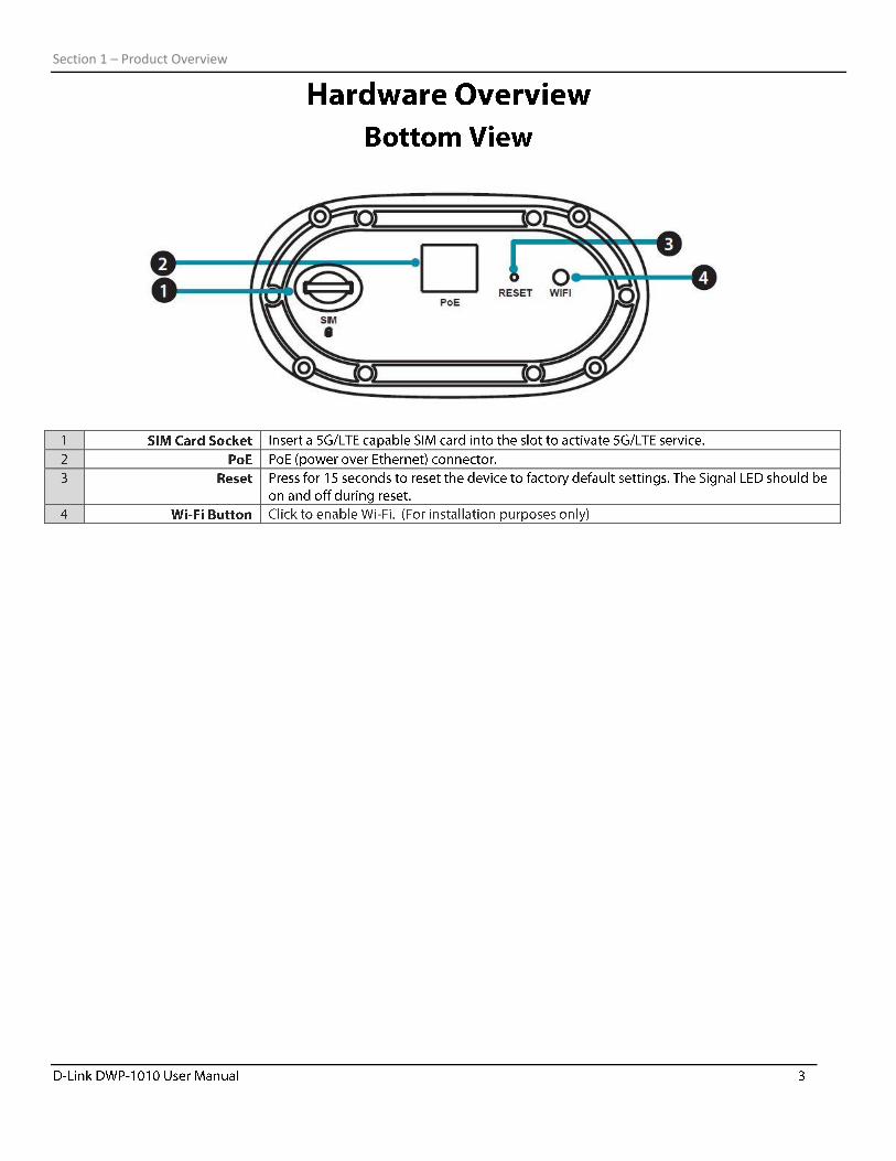
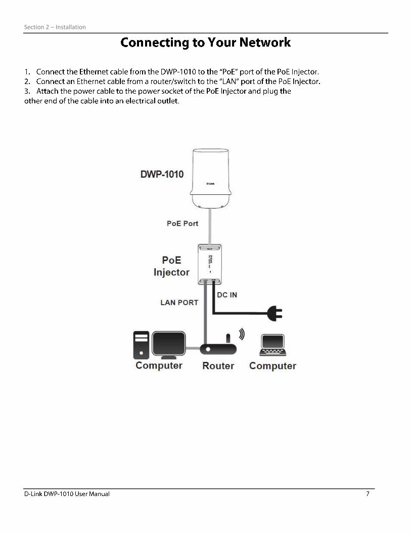
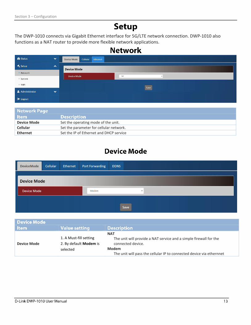
The DWP-1010 connects via Gigabit Ethernet interface for 5G/LTE network connection. DWP-1010 also functions as a NAT router to provide more flexible network applications.
Device Mode Set the operating mode of the unit.
Cellular Set the parameter for cellular network.
Ethernet Set the IP of Ethernet and DHCP service
Device Mode
1. A Must-fill setting
2. By default Modem is
selected
NAT The unit will provide a NAT service and a simple firewall for the connected device.
Modem The unit will pass the cellular IP to connected device via ethernnet
Section 3 – Configuration
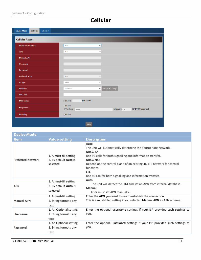
Preferred Network 1. A must-fill setting 2. By default Auto is selected
Auto The unit will automatically determine the appropriate network. NR5G-SA Use 5G cells for both signalling and information transfer. NR5G-NSA Depend on the control plane of an existing 4G LTE network for control functions. LTE Use 4G LTE for both signalling and information transfer.
APN
1. A must-fill setting
2. By default Auto is
selected
Auto The unit will detect the SIM and set an APN from internal database.
Manual User must set APN manually.
Manual APN
1. A must-fill setting
2. String format : any
text
Enter the APN you want to use to establish the connection. This is a must-filled setting if you selected Manual APN as APN scheme.
Username
1. An Optional setting
2. String format : any
text
Enter the optional username settings if your ISP provided such settings to you.
Password
1. An Optional setting
2. String format : any
text
Enter the optional Password settings if your ISP provided such settings to you.
Section 3 – Configuration
Authentication 1. A must-fill setting 2. By default Auto is selected
Select PAP (Password Authentication Protocol) and use such protocol to be authenticated with the carrier’s server. Select CHAP (Challenge Handshake Authentication Protocol) and use such protocol to be authenticated with the carrier’s server. When Auto is selected, it means it will authenticate with the server either PAP or CHAP.
IP Type 1. A must-fill setting 2. By default IPv4 is selected
Specify the IP type of the network service provided by your 5G/LTE network. It can be IPv4, IPv6, or IPv4v6.
IP Mode
1. A must-fill setting
2. By default Dynamic IP
is selected
Dynamic IP The unit will get IP from cellular service.
Static IP The unit will set IP according to Static IP Config.
PIN Code 1. An Optional setting 2. String format : interger
Enter the PIN (Personal Identification Number) code if it needs to unlock your SIM card.
MTU Setup 1. An Optional setting 2. Uncheck by default
Check the Enable box to enable the MTU (Maximum Transmission Unit) limit and specify the MTU for the 5G/LTE connection. MTU refers to Maximum Transmission Unit. It specifies the largest packet size permitted for Internet transmission. Value Range: 68 - 1500.
Keep Alive
1. An optional setting
2. Box is unchecked by
default
Check the Enable box to activate the keep alive function. Input IP Address and interval to send an ICMP packet to check the network status.
Roaming 1. An optional setting 2. Box is unchecked by default
Check the Enable box to activate roaming.
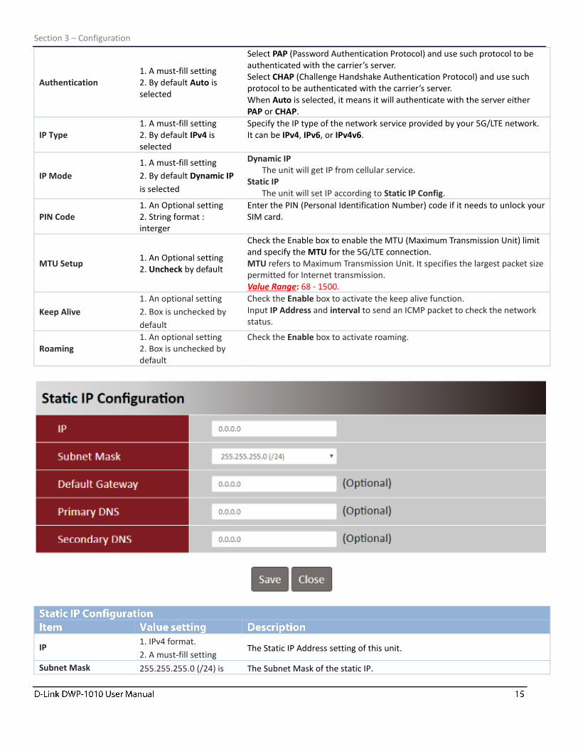
IP 1. IPv4 format.
2. A must-fill setting The Static IP Address setting of this unit.
Subnet Mask 255.255.255.0 (/24) is The Subnet Mask of the static IP.
Section 3 – Configuration
set by default
Default Gateway 1. IPv4 format.
2. An Optional setting The gateway setting of the static IP.
Primary DNS 1. IPv4 format.
2. An Optional setting Assigned DNS server of the static IP.
Secondary DNS 1. IPv4 format.
2. An Optional setting Assigned DNS server of the static IP.
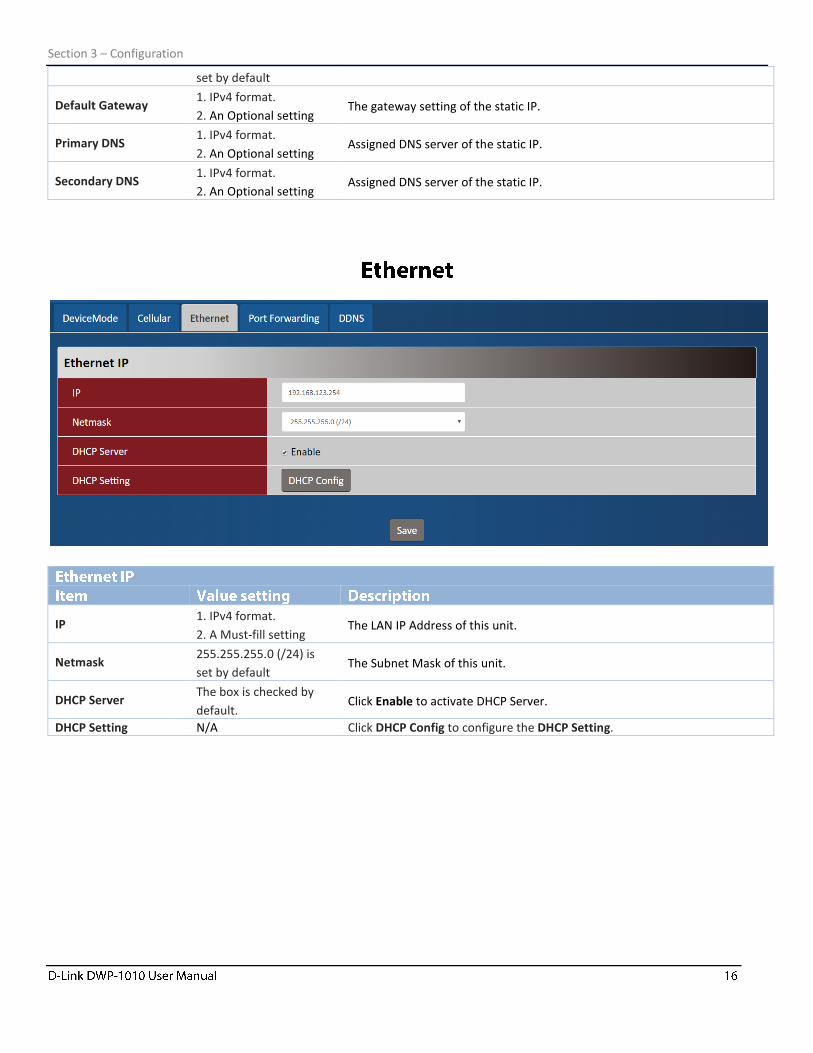
IP 1. IPv4 format.
2. A Must-fill setting The LAN IP Address of this unit.
Netmask 255.255.255.0 (/24) is
set by default The Subnet Mask of this unit.
DHCP Server The box is checked by
default. Click Enable to activate DHCP Server.
DHCP Setting N/A Click DHCP Config to configure the DHCP Setting.
Section 3 – Configuration
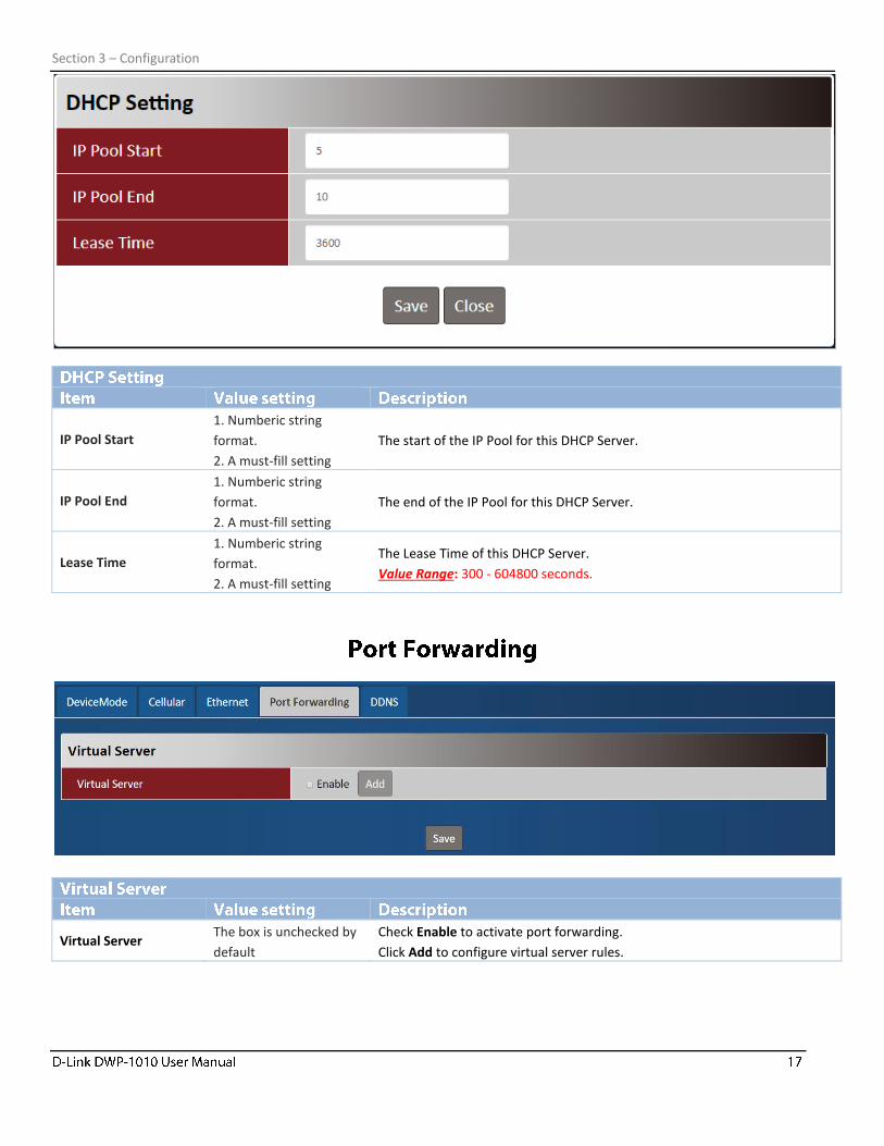
IP Pool Start
1. Numberic string
format.
2. A must-fill setting
The start of the IP Pool for this DHCP Server.
IP Pool End
1. Numberic string
format.
2. A must-fill setting
The end of the IP Pool for this DHCP Server.
Lease Time
1. Numberic string
format.
2. A must-fill setting
The Lease Time of this DHCP Server.
Value Range: 300 - 604800 seconds.
Virtual Server The box is unchecked by
default
Check Enable to activate port forwarding.
Click Add to configure virtual server rules.
Section 3 – Configuration
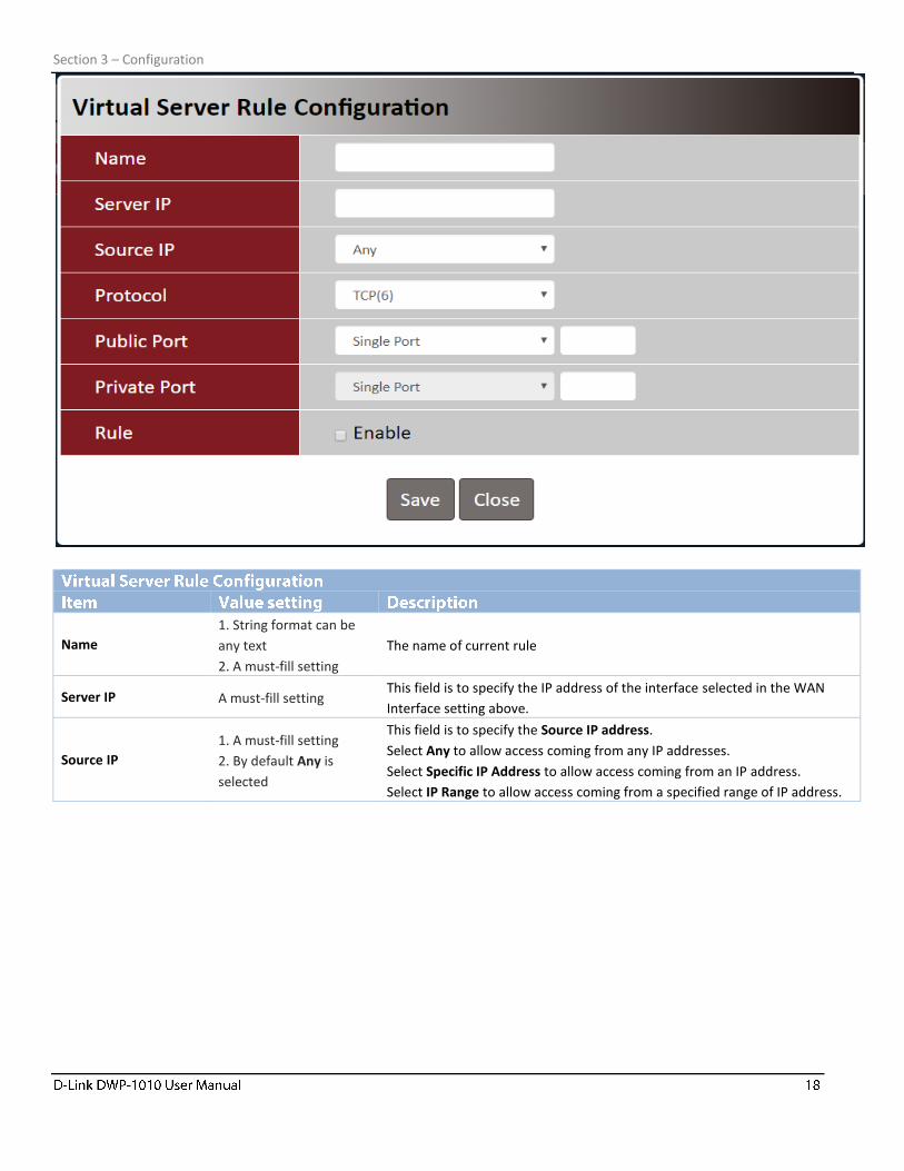
Name
1. String format can be
any text
2. A must-fill setting
The name of current rule
Server IP A must-fill setting This field is to specify the IP address of the interface selected in the WAN
Interface setting above.
Source IP
1. A must-fill setting
2. By default Any is
selected
This field is to specify the Source IP address.
Select Any to allow access coming from any IP addresses.
Select Specific IP Address to allow access coming from an IP address.
Select IP Range to allow access coming from a specified range of IP address.
Section 3 – Configuration
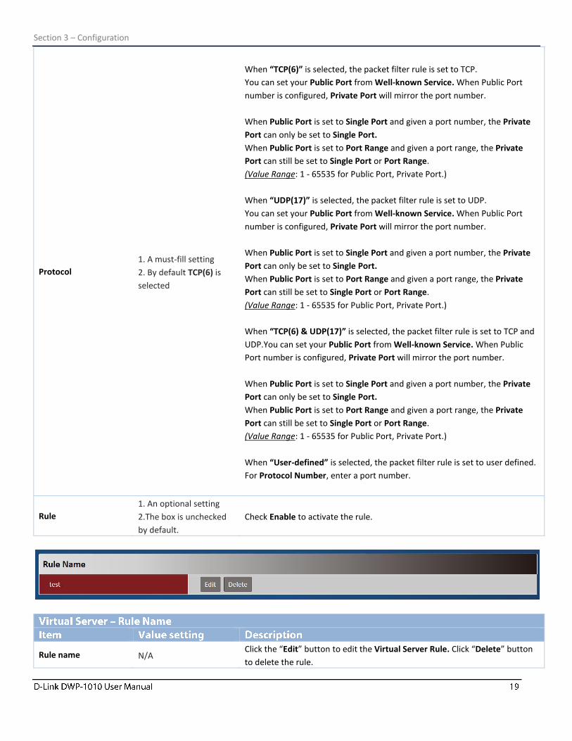
Protocol
1. A must-fill setting
2. By default TCP(6) is
selected
When “TCP(6)” is selected, the packet filter rule is set to TCP.
You can set your Public Port from Well-known Service. When Public Port
number is configured, Private Port will mirror the port number.
When Public Port is set to Single Port and given a port number, the Private
Port can only be set to Single Port.
When Public Port is set to Port Range and given a port range, the Private
Port can still be set to Single Port or Port Range.
(Value Range: 1 - 65535 for Public Port, Private Port.)
When “UDP(17)” is selected, the packet filter rule is set to UDP.
You can set your Public Port from Well-known Service. When Public Port
number is configured, Private Port will mirror the port number.
When Public Port is set to Single Port and given a port number, the Private
Port can only be set to Single Port.
When Public Port is set to Port Range and given a port range, the Private
Port can still be set to Single Port or Port Range.
(Value Range: 1 - 65535 for Public Port, Private Port.)
When “TCP(6) & UDP(17)” is selected, the packet filter rule is set to TCP and
UDP.You can set your Public Port from Well-known Service. When Public
Port number is configured, Private Port will mirror the port number.
When Public Port is set to Single Port and given a port number, the Private
Port can only be set to Single Port.
When Public Port is set to Port Range and given a port range, the Private
Port can still be set to Single Port or Port Range.
(Value Range: 1 - 65535 for Public Port, Private Port.)
When “User-defined” is selected, the packet filter rule is set to user defined.
For Protocol Number, enter a port number.
Rule
1. An optional setting
2.The box is unchecked
by default.
Check Enable to activate the rule.
Rule name N/A Click the “Edit” button to edit the Virtual Server Rule. Click “Delete” button
to delete the rule.
Section 3 – Configuration
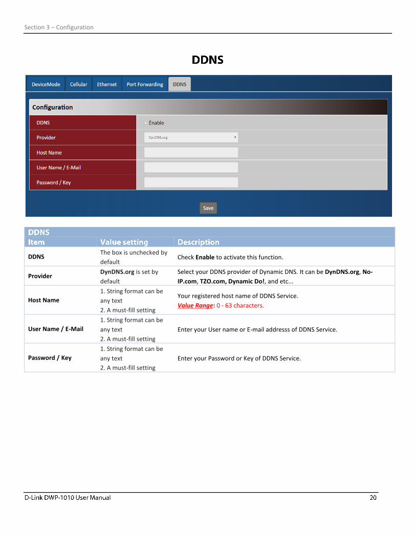
DDNS The box is unchecked by
default Check Enable to activate this function.
Provider DynDNS.org is set by
default
Select your DDNS provider of Dynamic DNS. It can be DynDNS.org, No-
IP.com, TZO.com, Dynamic Do!, and etc...
Host Name
1. String format can be
any text
2. A must-fill setting
Your registered host name of DDNS Service.
Value Range: 0 - 63 characters.
User Name / E-Mail
1. String format can be
any text
2. A must-fill setting
Enter your User name or E-mail addresss of DDNS Service.
Password / Key
1. String format can be
any text
2. A must-fill setting
Enter your Password or Key of DDNS Service.
Section 3 – Configuration
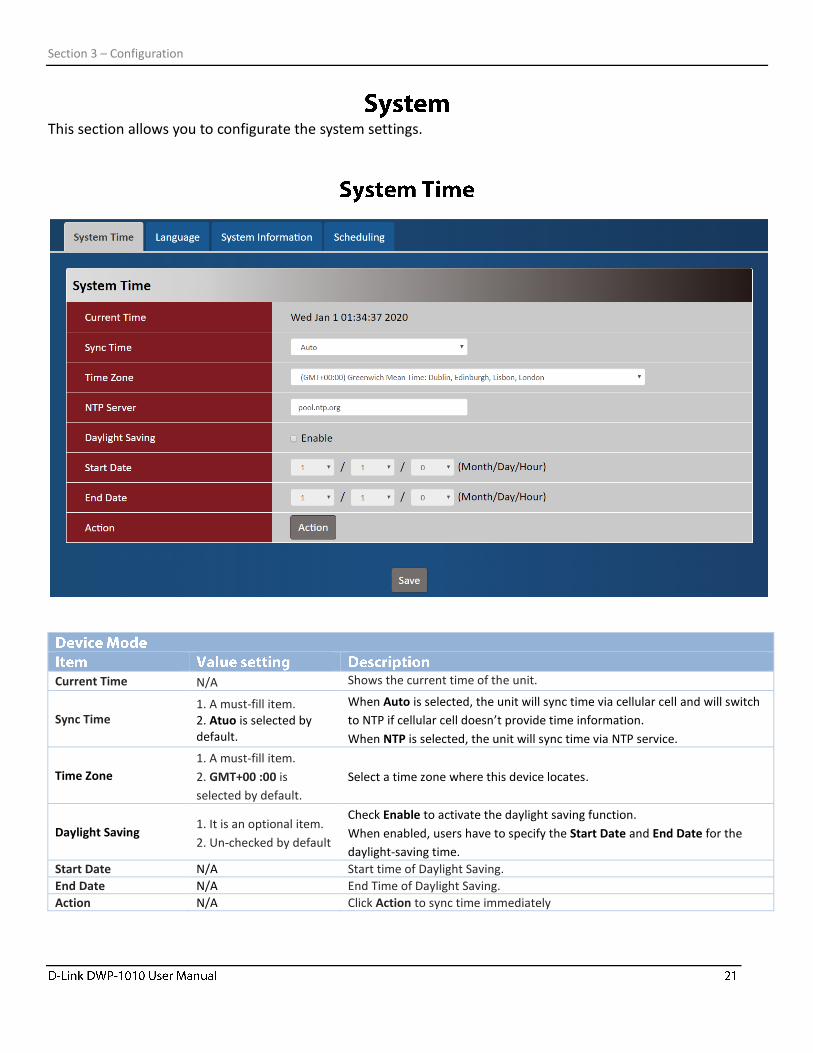
This section allows you to configurate the system settings.
Current Time N/A Shows the current time of the unit.
Sync Time 1. A must-fill item. 2. Atuo is selected by default.
When Auto is selected, the unit will sync time via cellular cell and will switch
to NTP if cellular cell doesn’t provide time information.
When NTP is selected, the unit will sync time via NTP service.
Time Zone
1. A must-fill item.
2. GMT+00 :00 is
selected by default.
Select a time zone where this device locates.
Daylight Saving 1. It is an optional item.
2. Un-checked by default
Check Enable to activate the daylight saving function.
When enabled, users have to specify the Start Date and End Date for the
daylight-saving time.
Start Date N/A Start time of Daylight Saving.
End Date N/A End Time of Daylight Saving.
Action N/A Click Action to sync time immediately
Section 3 – Configuration
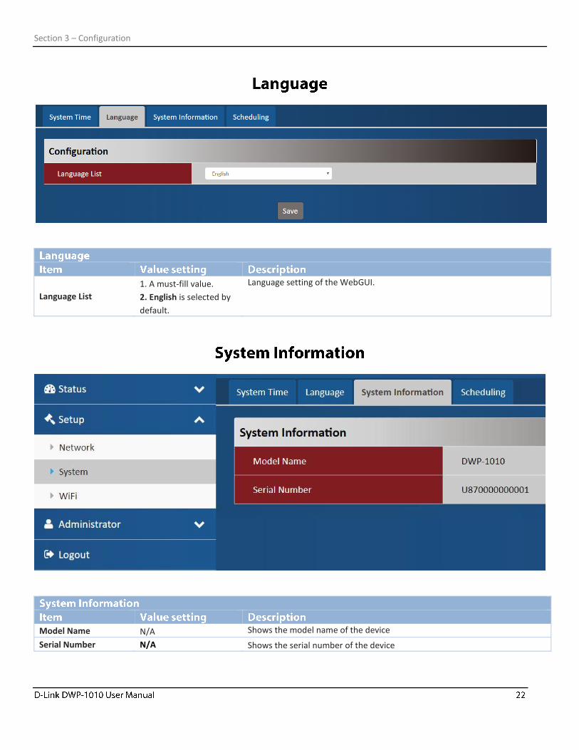
Language List
1. A must-fill value.
2. English is selected by
default.
Language setting of the WebGUI.
Model Name N/A Shows the model name of the device
Serial Number N/A Shows the serial number of the device
Section 3 – Configuration
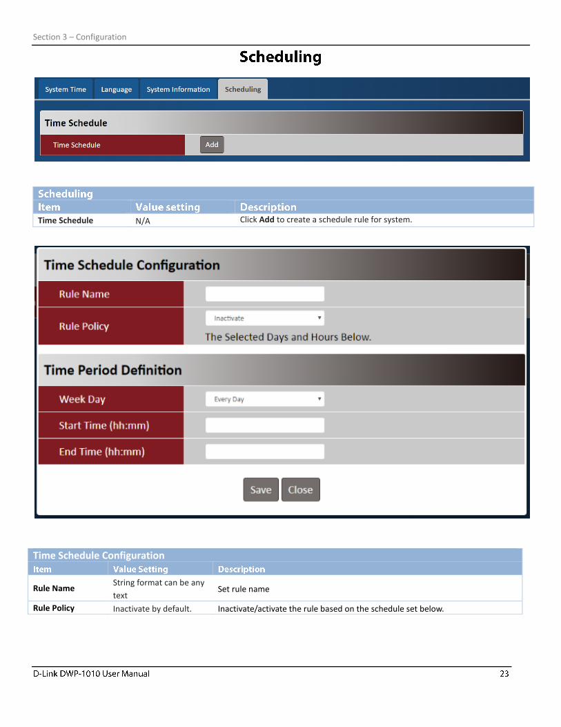
Time Schedule N/A Click Add to create a schedule rule for system.
Time Schedule Configuration
Rule Name String format can be any
text Set rule name
Rule Policy Inactivate by default. Inactivate/activate the rule based on the schedule set below.
Section 3 – Configuration
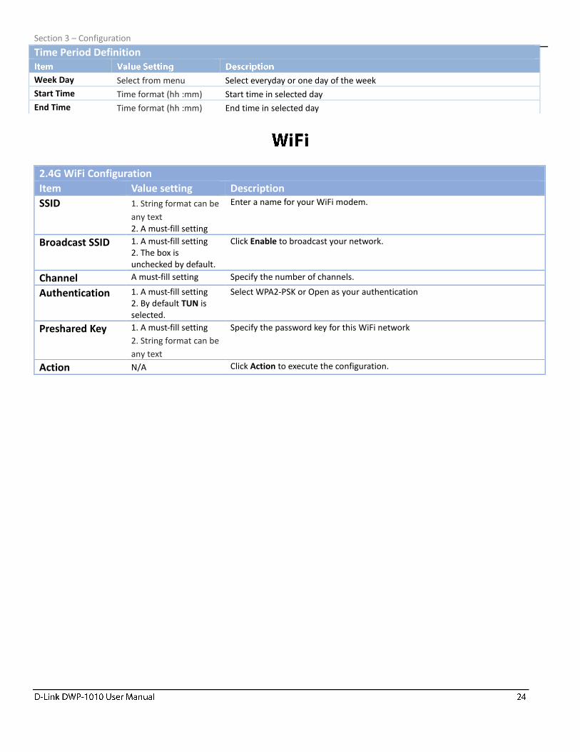
2.4G WiFi Configuration
Item Value setting Description
SSID 1. String format can be
any text 2. A must-fill setting
Enter a name for your WiFi modem.
Broadcast SSID 1. A must-fill setting 2. The box is unchecked by default.
Click Enable to broadcast your network.
Channel A must-fill setting Specify the number of channels.
Authentication 1. A must-fill setting 2. By default TUN is selected.
Select WPA2-PSK or Open as your authentication
Preshared Key 1. A must-fill setting
2. String format can be
any text
Specify the password key for this WiFi network
Action N/A Click Action to execute the configuration.
Time Period Definition
Week Day Select from menu Select everyday or one day of the week
Start Time Time format (hh :mm) Start time in selected day
End Time Time format (hh :mm) End time in selected day
Section 3 – Configuration
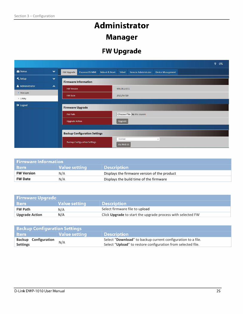
FW Version N/A Displays the firmware version of the product
FW Date N/A Displays the build time of the firmware
Backup Configuration Settings
N/A Select “Download” to backup current configuration to a file. Select “Upload” to restore configuration from selected file.
FW Path N/A Select firmware file to upload
Upgrade Action N/A Click Upgrade to start the upgrade process with selected FW

Section 3 – Configuration
Username
Item Value setting Description
Username N/A Displays the current username.
New Username String format can be any text
Enter the new username. Click Save when you’re done.
Old Password
1. String format can be
any text 2. The default password for web-based MMI is ‘admin’.
Enter the current password first to change password.
New Password String format can be any
text Enter new password
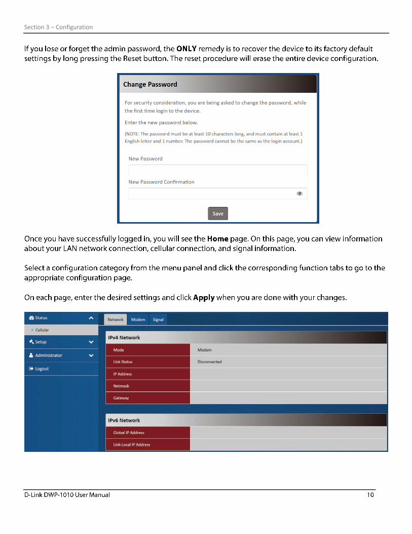
New Password Confirmation
String format can be any
text Enter new password again to confirm
Save N/A Click Save button to save the settings
Section 3 – Configuration
Login 3 times is set by default
Enter a value for max failed login attempts.
Value Range: 3 - 10.
If someone tries to login the web GUI with incorrect password for more than
the defined value, a warning message “Already reaching maximum
Password-Guessing times, please wait a few seconds!” will be displayed and
subsequent logins will be ignored.
Login Timeout
Login Timeout is enabled
and set to 300 by
default.
Enable to activate the auto logout function. Specify the maximum idle time.
Value Range: 30 - 65535.
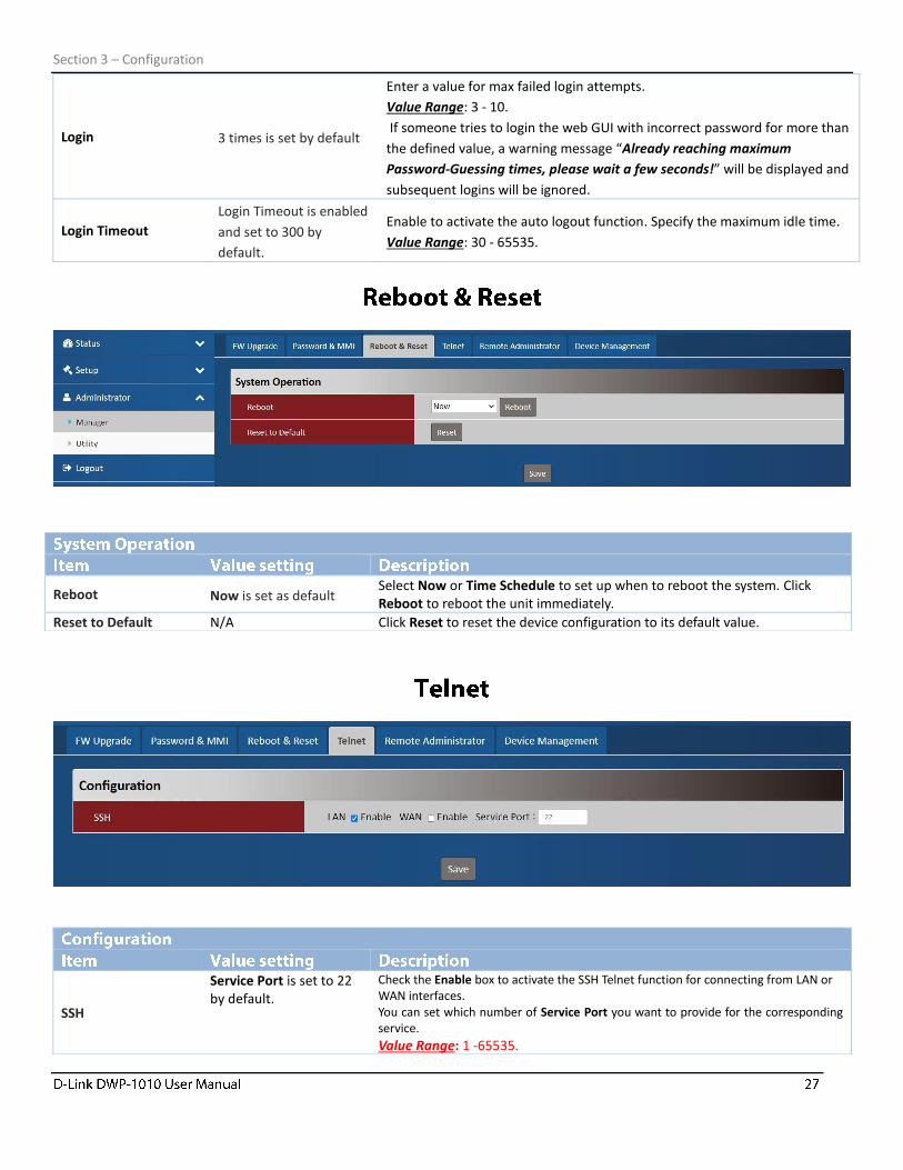
Reboot Now is set as default Select Now or Time Schedule to set up when to reboot the system. Click Reboot to reboot the unit immediately.
Reset to Default N/A Click Reset to reset the device configuration to its default value.
SSH
Service Port is set to 22 by default.
Check the Enable box to activate the SSH Telnet function for connecting from LAN or WAN interfaces. You can set which number of Service Port you want to provide for the corresponding service.
Value Range: 1 -65535.
Section 3 – Configuration
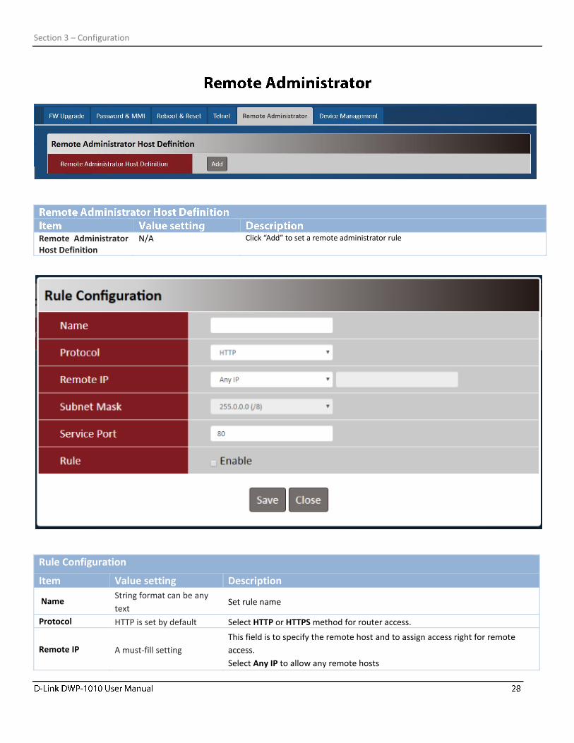
Remote Administrator Host Definition
N/A Click “Add” to set a remote administrator rule
Rule Configuration
Item Value setting Description
Name String format can be any
text Set rule name
Protocol HTTP is set by default Select HTTP or HTTPS method for router access.
Remote IP A must-fill setting
This field is to specify the remote host and to assign access right for remote
access.
Select Any IP to allow any remote hosts
Section 3 – Configuration
Select Specific IP to allow the remote host coming from a specific subnet.
Subnet Mask N/A If a specific IP is entered, in the dropdown menu of Subnet Mask, select a
subnet.
Service Port
1. 80 for HTTP by default
2. 443 for HTTPS by
default
This field is to specify a Service Port to HTTP or HTTPS connection.
Value Range: 1 - 65535.
Rule The box is unchecked by
default. Click Enable to activate this rule.
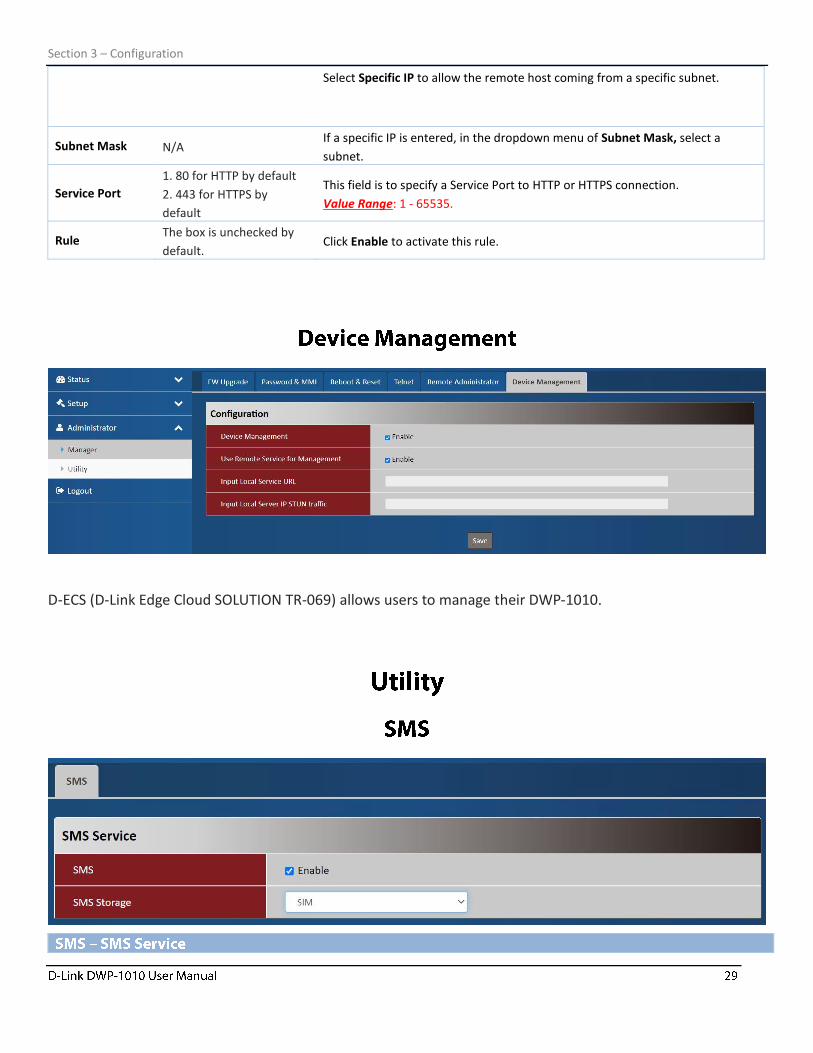
D-ECS (D-Link Edge Cloud SOLUTION TR-069) allows users to manage their DWP-1010.
Section 3 – Configuration
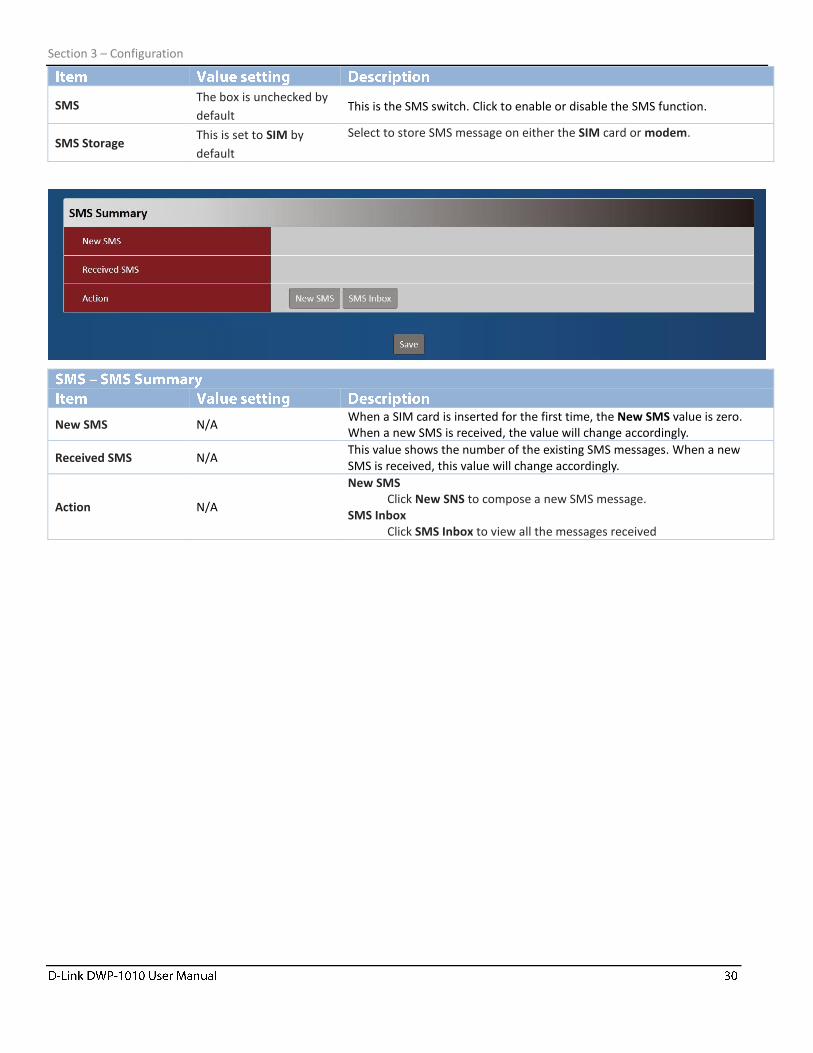
SMS The box is unchecked by
default This is the SMS switch. Click to enable or disable the SMS function.
SMS Storage This is set to SIM by
default
Select to store SMS message on either the SIM card or modem.
New SMS N/A When a SIM card is inserted for the first time, the New SMS value is zero. When a new SMS is received, the value will change accordingly.
Received SMS N/A This value shows the number of the existing SMS messages. When a new SMS is received, this value will change accordingly.
Action N/A
New SMS Click New SNS to compose a new SMS message.
SMS Inbox Click SMS Inbox to view all the messages received
Section 3 – Configuration
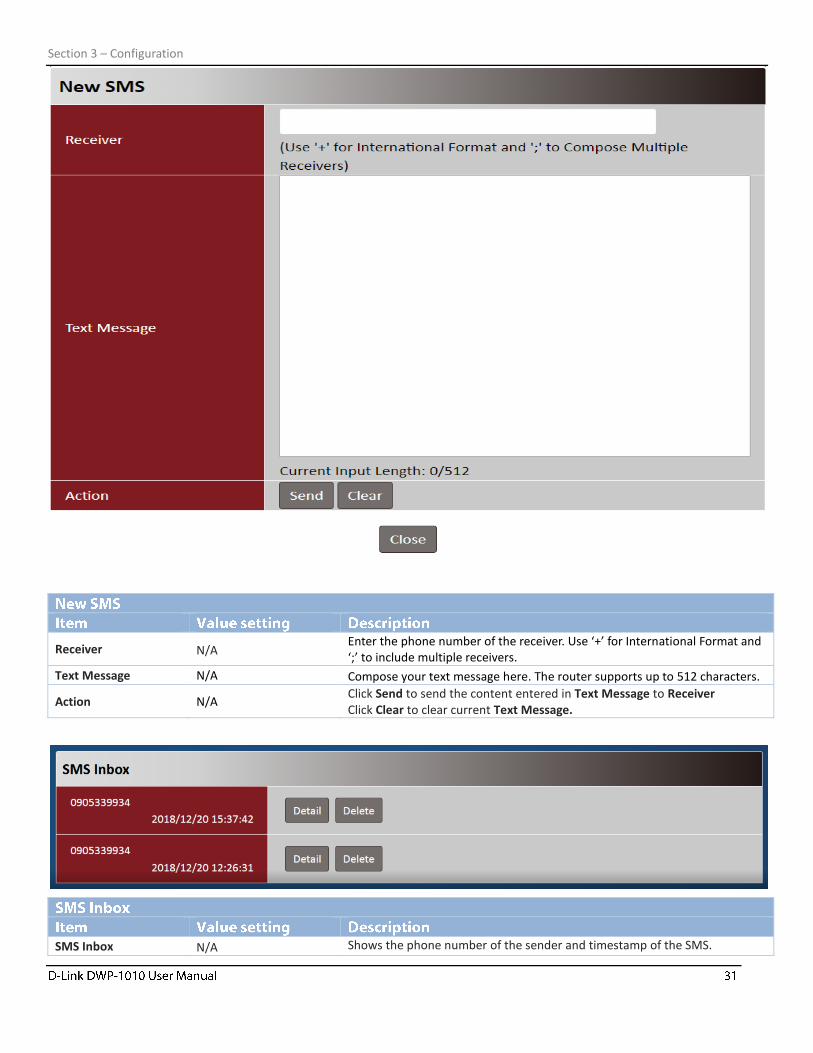
Receiver N/A Enter the phone number of the receiver. Use ‘+’ for International Format and ‘;’ to include multiple receivers.
Text Message N/A Compose your text message here. The router supports up to 512 characters.
Action N/A Click Send to send the content entered in Text Message to Receiver Click Clear to clear current Text Message.
SMS Inbox N/A Shows the phone number of the sender and timestamp of the SMS.
Section 3 – Configuration
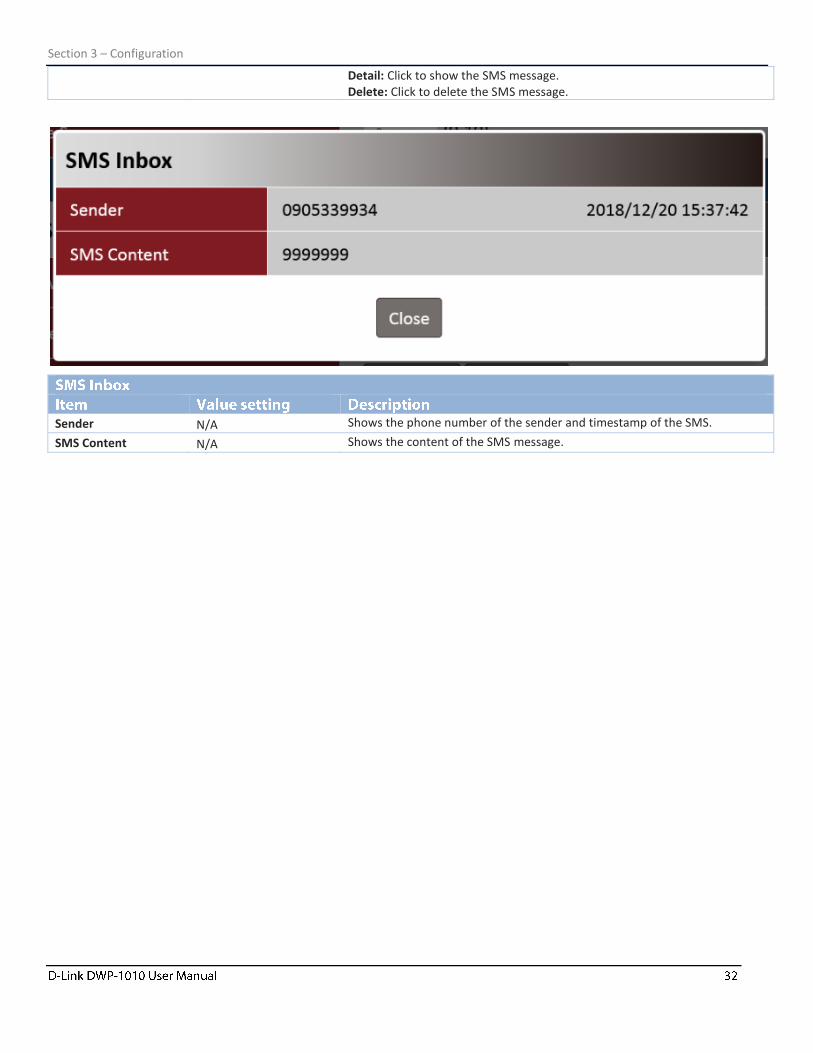
Detail: Click to show the SMS message. Delete: Click to delete the SMS message.
Sender N/A Shows the phone number of the sender and timestamp of the SMS.
SMS Content N/A Shows the content of the SMS message.

Section 4 – Specifications
Technical Specifications /DWP-1010
General
Device Interfaces 1 x 1 Gbps GE Ethernet port, LED indicator, Wi-Fi button, 1 x Micro SIM slot (push-push), Reset button
Antenna Type 6 x Internal 5G/LTE antennas
Standards IEEE 802.3i, IEEE 802.3u, IEEE 802.3at
5G/LTE Chipset Qualcomm SDX55
5G/LTE Standards ⚫ 5G NR Sub-6 GHz ⚫ Release 15, Cat.20
5G/LTE Frequency Support ⚫ 5G Mode
Downlink: Up to 4 Gbps
Uplink: Up to 620 Mbps
⚫ LTE Mode
Downlink: Up to 2 Gbps
Uplink: Up to 150 Mbps
5G/LTE Throughput ⚫ 5G: n1, n3, n20, n28, n78, n88 ⚫ LTE: B1, B3, B7, B8, B20, B28, B38
Physical
Hardware Version A1
Dimension 210.4*144.8*105.4 mm
Weight 760g
Enclosure IP67
Power Protection ± 4kV
Power Consumption 48V Power over Ethernet
Operating Temperature -30 to 50 °C
Storage Temperature -40 to 70 °C
Humidity 10% to 95% non-condensing
Certification CE
Order Information
DWP-1010 5G/LTE Outdoor CPE
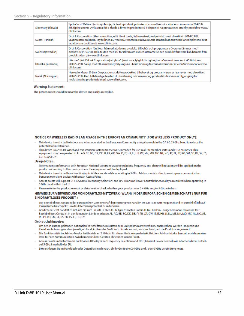
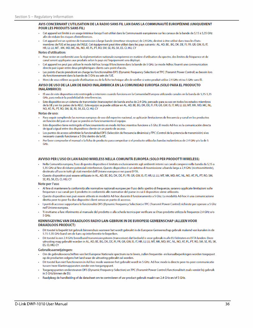
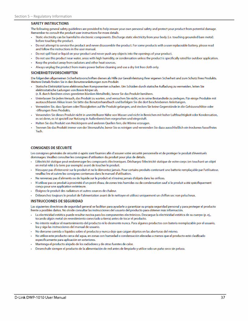
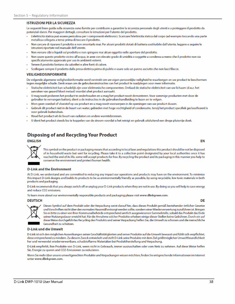
Section 5 – Regulatory Information
Section 5 – Regulatory Information
Section 5 – Regulatory Information
Section 5 – Regulatory Information
Section 5 – Regulatory Information
Section 5 – Regulatory Information
Section 5 – Regulatory Information
Section 5 – Regulatory Information