5g ppp architecture white paper
TRANSCRIPT
5GPPP Architecture Working Group
View on 5G Architecture
Version 4.0, August 2021
Date: 2021-08-02 Status: Public Consultation
5GPPP Architecture Working Group 5G Architecture White Paper
Dissemination level: Public Page 2 / 194
Abstract
The overall goal of the Architecture Working Group (WG) within the 5GPPP Initiative is to
consolidate the main technology enablers and the bleeding-edge design trends in the context of
the 5G Architecture. As a result, it provides a consolidated view of the architectural efforts
developed in the projects part the 5GPPP initiative and other research efforts, including
standardization. This effort serves not only to review the current state of the art, but also to identify
promising trends towards the next generation of mobile and wireless communication networks,
namely, 6G.
This is the fourth release of this white paper, whose beginning dates back in July 2016, when the
first version was released. Since then, this effort continuously captured the technology trends as
developed by the different phases of 5GPPP projects: the first phase (Phase I), that lied the
foundation of the network slicing aware operation we are seeing in these days; the second one
(Phase II) which provided the first proof of concepts; and the third one (Phase III) that has targeted
the first large scale platforms. All these efforts were captured in the subsequent releases of the
white paper (version 2 in January 2018 and version 3 in February 2020).
This current version 4 of the white paper hence is focusing on the output of the Phase III projects,
thus, discussing the latest findings in terms of the integration of large infrastructure and vertical
industries, aka verticals, the long-term evolution of the 5G technologies including and the service-
specific features. The view consolidated in this white paper presents the current overview on the
5G Architecture as developed by European research efforts.

5GPPP Architecture Working Group 5G Architecture White Paper
Dissemination level: Public Page 3 / 194
Table of Contents
Abstract ........................................................................................................................................ 2
Table of Contents ........................................................................................................................ 3
1 Introduction........................................................................................................................... 8
2 Overall Architecture ............................................................................................................. 9
2.1 Stakeholders in the 5G ecosystem ............................................................................... 11
2.1.1 Impact of Non-Public Networks on the actor role model ....................................... 12
2.2 Verticals requirements on extended architecture ......................................................... 13
2.2.1 Requirements for private networking for verticals ................................................. 16
2.2.2 Requirements for digital mobility services and related KPIs ................................. 17
2.2.3 Requirements considering vertical 3rd party AFs/VNFs, edge deployment and
orchestration ........................................................................................................... 19
2.3 Architecture extensions................................................................................................ 20
2.3.1 Architecture extensions introduced by 3GPP Release 16 ....................................... 20
2.3.2 Telco-oriented cloud native orchestration of 5GC and vertical applications.......... 22
2.4 Security Architecture ................................................................................................... 23
2.4.1 Overall security architecture ................................................................................... 23
2.4.2 High level architecture for security in B5G/6G networks ...................................... 24
2.5 Service layer evolution ................................................................................................ 25
2.5.1 Service Layer for verticals ...................................................................................... 26
2.5.2 Integrating and customizing 5G-as-a-Service APIs ................................................ 27
2.5.3 Vertical industry service migration and deployment to 5G NSA/SA edge ............ 27
2.5.4 Service layer information, data models, and exposure mechanisms ...................... 28
2.5.5 SBA-enabled unified platform hosting 5GC and vertical applications................... 29
2.6 Vertical specific architecture extensions ..................................................................... 29
2.6.1 Architecture extensions for private networking for verticals ................................. 30
2.6.2 Extended layered network architectures for high-speed rail transportation
facilities .................................................................................................................. 31
2.6.3 Network slices for service delivery in rail transportation environments ................ 33
2.6.4 E2E network architecture extension for digital mobility services related KPIs ..... 34
2.6.5 Architecture for professional content production ................................................... 36
2.6.6 Intent-based E2E network slice deployment for verticals ...................................... 37
2.6.7 NetApp principles and implementation aspects ...................................................... 37
2.7 Public-Private Network Interoperation ........................................................................ 40
2.8 References .................................................................................................................... 41
3 Radio and Edge Architecture ............................................................................................ 44
5GPPP Architecture Working Group 5G Architecture White Paper
Dissemination level: Public Page 4 / 194
3.1 RAN architectures ....................................................................................................... 44
3.1.1 Multi-technology Wireless Access Network .......................................................... 45
3.1.2 Enhanced ATSSS.................................................................................................... 46
3.1.3 RIS and AI based Radio Access Optimization ....................................................... 47
3.1.3.1 RAN with Smart Surfaces ................................................................................. 47
3.1.3.2 Deployment scenarios ....................................................................................... 49
3.1.4 O-RAN Alliance xApps .......................................................................................... 50
3.1.5 Integration of 5G RAN with Audio Capture Devices and Production Site ............ 52
3.1.6 Intra and inter slice scheduling algorithm............................................................... 53
3.2 Edge architectures ........................................................................................................ 54
3.2.1 EDGE - Cloud classification .................................................................................. 55
3.2.2 Autonomous EDGE computing .............................................................................. 56
3.2.3 Machine learning for edge resilience ...................................................................... 57
3.2.4 Edge computing for CAM applications .................................................................. 58
3.2.5 On-premise edge computing ................................................................................... 59
3.2.6 Kubernetes based MEC platform ............................................................................ 61
3.3 Positioning Methods .................................................................................................... 62
3.3.1 Localisation enablers .............................................................................................. 63
3.3.1.1 Advanced localisation techniques in 5G ........................................................... 63
3.3.1.2 Localisation based on non-3GPP technologies.................................................. 64
3.3.1.3 Device-free localization ..................................................................................... 64
3.3.2 Positioning technologies for Industry 4.0 ............................................................... 64
3.3.3 Enhanced vehicle localization solutions ................................................................. 66
3.4 References .................................................................................................................... 68
4 Core & Transport Architecture ........................................................................................ 71
4.1 Introduction .................................................................................................................. 71
4.2 5G Core Network ......................................................................................................... 71
4.2.1 Cloud Principles in 5G Systems ............................................................................. 71
4.2.1.1 Adopting Cloud Principles throughout 5G System ........................................... 72
4.2.1.2 5GC NFs Transitioning to Cloud Native NFs ................................................... 72
4.2.2 5G Multicast ........................................................................................................... 72
4.2.2.1 Multicast extensions for 5GC ............................................................................ 73
4.2.2.2 Opportunistic Multicast ..................................................................................... 73
4.2.3 5GLAN ................................................................................................................... 75
4.2.4 5G Network data Analytics Services ...................................................................... 76
5GPPP Architecture Working Group 5G Architecture White Paper
Dissemination level: Public Page 5 / 194
4.2.4.1 Monitoring & Analytics .................................................................................... 76
4.2.4.2 Localization Analytics as a Service ................................................................... 80
4.2.5 Services exposure – Application: localization ........................................................ 81
4.3 Transport Architecture ................................................................................................. 83
4.3.1 Transport network supporting user mobility .......................................................... 83
4.3.2 Transport network supporting user plane resilience ............................................... 87
4.3.3 Integration of satellite backhaul in 5G .................................................................... 91
4.3.4 Backhaul automation .............................................................................................. 92
4.3.5 Integration of transport and radio management for THz fronthaul links ................ 95
4.4 References .................................................................................................................... 96
5 Automated Management & Orchestration Architecture .............................................. 100
5.1 State of the art of 5G M&O Architecture Design ...................................................... 100
5.2 Enhanced Slice Management ..................................................................................... 101
5.2.1 Vertical-driven slice management ........................................................................ 102
5.2.1.1 Slice ordering architecture and Lifecycle Management .................................. 102
5.2.1.2 Slice Manager .................................................................................................. 103
5.2.1.3 Composition and sharing of end-to-end network slices for vertical service
arbitration ........................................................................................................ 104
5.2.2 E2E Slice Management......................................................................................... 105
5.2.2.1 Orchestration hierarchy ................................................................................... 105
5.2.2.2 E2E slice management and orchestration approach focused on scalability ..... 107
5.2.2.3 Service Slicing ................................................................................................. 109
5.2.3 Integration of transport networks .......................................................................... 110
5.2.3.1 Integration with WAN Infrastructure Manager ............................................... 110
5.2.3.2 Network management aspects for integrating transport and radio
management for THz fronthaul links ............................................................... 111
5.3 Service and Network Automation .............................................................................. 112
5.3.1 Automated SLA Assurance .................................................................................. 113
5.3.1.1 AI-driven closed-loop control of vertical service SLA management .............. 113
5.3.1.2 ML-based SLA assurance through flexible orchestration ............................... 114
5.3.2 AIML Adoption .................................................................................................... 115
5.3.2.1 AI-based orchestration ..................................................................................... 116
5.3.2.2 AIML integration in the context of vertical service SLA management .......... 118
5.3.2.3 Autonomous profiling and E2E service provisioning and monitoring using
AIML ............................................................................................................... 120
5.3.2.4 Training and Deployment Pipelines in dynamic environments with changing
location ............................................................................................................ 123
5GPPP Architecture Working Group 5G Architecture White Paper
Dissemination level: Public Page 6 / 194
5.4 Cloudification ............................................................................................................ 125
5.4.1 Standards and architecture for 5G Cloudification ................................................ 125
5.4.2 Containers and ETSI MEC ................................................................................... 127
5.4.3 Service Function Virtualization ............................................................................ 128
5.4.3.1 Orchestration and Lifecycle Management ....................................................... 129
5.4.3.2 Routing ............................................................................................................ 130
5.4.3.3 Packaging ........................................................................................................ 130
5.4.4 Automated deployment of a containerized 5G Core Network .............................. 130
5.5 Monitoring and Data Management ............................................................................ 131
5.5.1 Integrated software-based monitoring framework for 5G networks ..................... 132
5.5.2 Vertical oriented monitoring ................................................................................. 132
5.5.3 Data Aggregation .................................................................................................. 135
5.6 Evolution of MANO Design Principles ..................................................................... 137
5.6.1 Distributed Management Autonomy .................................................................... 138
5.6.2 Service Based Management Architecture ............................................................. 139
5.6.3 Service Function Virtualization ............................................................................ 142
5.7 References .................................................................................................................. 143
6 Cross-Domain Aspects ...................................................................................................... 149
6.1 Introduction ................................................................................................................ 149
6.1.1 Multi-domain Orchestration Architecture ............................................................ 149
6.1.1.1 Cross-Facility Orchestration (5G-VICTORI, 5G-VINNI) .............................. 149
6.1.1.2 Multi- and Inter-domain Interactions: Resource and Services Federation ...... 152
6.1.2 Inter-domain management for Vertical Services .................................................. 153
6.1.2.1 Network Service Life Cycle Management across domains ............................. 153
6.1.2.2 Vertical Service Decomposition across domains ............................................ 155
6.2 Mobility Management in cross-domain environments .............................................. 156
6.2.1 Cross-border service/session continuity ............................................................... 157
6.2.2 Cross-border handover (Inter-PLMN handover) .................................................. 158
6.2.3 Inter-PLMN Roaming Latency ............................................................................. 159
6.2.4 Traffic Roaming.................................................................................................... 161
6.3 Cross-domain Service Assurance .............................................................................. 162
6.3.1 Analytics-driven service automation .................................................................... 163
6.3.2 QoS Prediction for application adaptation ............................................................ 164
6.3.3 5G AIOps with Operational Data Lake ................................................................ 165
6.4 Cross-domain slicing ................................................................................................. 166
5GPPP Architecture Working Group 5G Architecture White Paper
Dissemination level: Public Page 7 / 194
6.4.1 Inter-operator slice configuration ......................................................................... 166
6.4.2 Multi-domain Orchestration and Slice Management ............................................ 168
6.5 5G Decentralized Marketplace .................................................................................. 169
6.5.1 Resource / Service Trading ................................................................................... 170
6.5.2 Cross domain Identity & Permissions Management ............................................. 172
6.6 References .................................................................................................................. 174
7 Arch Instantiations and Validations ............................................................................... 178
7.1 Architecture Instantiation .......................................................................................... 178
7.1.1 E2E Network of Multiple Sites Interworking ....................................................... 178
7.1.2 Service-based Architecture ................................................................................... 180
7.1.3 Large Scale Deployment of 5G Infrastructure ...................................................... 181
7.2 Network Architecture Validation ............................................................................... 183
7.2.1 E2E Service Validation......................................................................................... 183
7.2.2 Adoption of Testing-as-a-Service ......................................................................... 184
7.2.3 5G SA with MEC for a multi-slice UE ................................................................. 186
7.2.4 Dynamic E2E Service Slicing .............................................................................. 187
7.2.5 VNF based UHFM Video broadcasting and on demand delivery service ............ 188
7.3 References .................................................................................................................. 190
8 Conclusions and Outlook ................................................................................................. 192
9 List of Contributors .......................................................................................................... 193

5GPPP Architecture Working Group 5G Architecture White Paper
Dissemination level: Public Page 8 / 194
1 Introduction
The 5G system (5GS) is now openly and widely available in major urban areas, and the coverage
is planned to reach less populated areas in the next few years. So, the superior performance of 5G
in terms of mobile broadband, unperceivable latency, and massive connectivity for the internet of
things (IoT) will be soon available to the majority of European citizens. In parallel, 5G was also
developed in relevant industrial scenarios, where new use cases enabled by 5G connectivity
improved the productivity and the performance of the production chain, e.g., industrial IoT (IIoT).
Meanwhile, the standardization efforts proceed at full steam: the third release of 5G (Rel. 17) has
progressed substantially, and new topics of interest are currently being discussed for the next one,
which will mark the start of 5G Advanced. The overall architecture, which has been continuously
improved since its first release to include new aspects such as the integration of vertical services
for IIoT and enhanced ultra-reliable and low-latency communications (URLLC). Currently,
trends are targeting the goal of network automation, with the exposure of analytics between
network functions (NFs) to automatize as much as possible the operation, especially with the use
of artificial intelligence (AI) and Machine Learning (ML) algorithms. Initially stemming from the
core network (CN), this trend was captured by other domains, as well, such as the management
and orchestration (MANO).
Also, the quest for improved performance has put into the spotlight the need for edge technologies
besides the radio access network (RAN), with the goal of providing lower latencies for very
specific services, such as the automotive applications. Finally, besides the pure performance point
of view, the recent advances in 5G also targeted the easiness of integration between the vertical
service providers and the network operators, through the usage of NetApps and a specific Service
Layer for verticals. The goal of this white paper is hence to summarize the findings from the
European research landscape, including the first large scale evaluation of the 5G technologies.
The white paper is organized as follows. The overall architecture description in Chapter 2
discusses the new stakeholders in the mobile network ecosystem and how the architectural work
is taking into account their requirements in all the domains of the network. Then, we move to the
new findings into the specific network domains, starting from Chapter 3, which details the RAN
architecture and how the new technology is supporting very low latency services at the edge.
Chapter 4 describes the CN architectural aspects, with the added support to new technologies such
as multicast and precise positioning. We move to the discussion of the MANO aspects in
Chapter 5, with a specific view on how to provide autonomous management of network slices
over a softwarized network. Chapter 6 collectively discusses new technology enablers that cannot
be bounded to one domain only, targeting specific infrastructure deployments at all levels, i.e.,
across network domains. In particular, the very important trend set by non-public networks
(NPNs), aka private networks, is discussed here. Finally, Chapter 7 briefly discusses the different
projects’ efforts in bringing such new architectures into practice, describing how new use cases
and solutions can be effectively provided by specific architectural instantiations.

5GPPP Architecture Working Group 5G Architecture White Paper
Dissemination level: Public Page 9 / 194
2 Overall Architecture
The third version of the 5GPPP architecture whitepaper [2-1], focused on the underlying
technology including service creation. To this extend it covered the 5G System (5GS) as a whole
and discussed end-to-end (E2E) network slicing, service-based architecture, Software-Defined
Networking (SDN), Network Functions Virtualisation (NFV), Management & orchestration, and
E2E service operations & lifecycle management as the fundamental pillars to support the 5G Key
Performance Indicators (KPIs). Given the new requirements coming from new stakeholders in
the 5G ecosystem that will be described in Section 2.1, the recent advances in the softwarization
of the mobile network ecosystem as well as the recent releases of the relevant standards for access,
core, management and orchestration, we can draw architectural trends that are captured in this
version of the white paper. A further trend that is newly introduced and that is quite intrinsic is
the concept of Non-Public Networks (NPN). Sometimes called a private network, an NPN
provides 5G network services to a clearly defined user organisation or group of organisations and
is deployed on the organisation’s defined premises, such as a campus or a factory.
Owing to this architectural representation of the third version of the 5GPPP architecture
whitepaper [2-1], we integrated the trends that form novel architectural aspects and which became
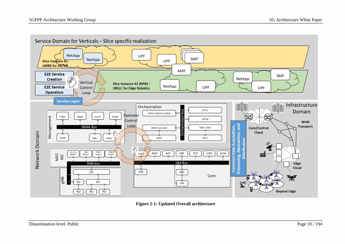
very influential in the implementation of phase III projects of the 5GPPP. The updated
architecture is depicted in Figure 2-1 below, and comprises three main areas: the verticals, the
network, and the infrastructure. These can be easily mapped to the stakeholders’ ecosystem
discussed in Section 2.1 below.
The Service Domain for Verticals includes all architectural innovations that help to include the
business-related considerations to the offered services (among others, e-health, robotics, or
enhanced video streaming services). Here, the key role is played by two innovations which have
been considered in the recent 5GPPP projects, namely: the service layer and the concept of
NetApps. The service layer, which is described in Section 2.5, provides a common interface
towards the management and the operation of the network, enabling the interaction between the
service intelligence and the underlying network. The concept of NetApps comprises all 5G
network empowered applications that build a network service, through the usage of network slices.
Slices are then used to provide such network services, and encompass different network functions
(including core and access functions), possibly orchestrated over different clouds.
The different functions are operated in the Network Domain, arranged in different slices
according to the KPIs that they have to provide. Within this domain, innovations come from four
areas, namely: Access (Chapter 3), Core (Chapter 4), Management and Orchestration (Chapter 5)
as well as cross-domain deployment aspects (Chapter 6). While each area presents specific
innovations that are discussed in the related sections, one major challenge that is currently targeted
by research effort is to achieve a flexible data exchange among them.
Innovations in the Infrastructure domain are captured in the context of specific fields such as
the NPN or drone-based access. Finally, in Chapter 7, we present architecture instantiations and
network architecture validation examples.
The architecture shall natively support the quest for network automation that is achieved through
control loops and the usage of artificial intelligence algorithms (the interested reader is referred
to the AI/ML Whitepaper [2-30] for more details). Specifically, we identified two main loops: the
first loop enabled by the service layer that is leveraged by the service provider through the
NetApps to steer the behaviour of the network and the second loop that happens within the
network domain, with specific modules such as the network data analytics function (NWDAF) or
the management data analytics function (MDAF) designed for this purpose.
5GPPP Architecture Working Group 5G Architecture White Paper
Dissemination level: Public Page 10 / 194
Figure 2-1: Updated Overall architecture
5GPPP Architecture Working Group 5G Architecture White Paper
Dissemination level: Public Page 11 / 194
2.1 Stakeholders in the 5G ecosystem
Version 3.0 of the 5GPPP architecture whitepaper [2-1] described the basic stakeholder roles for
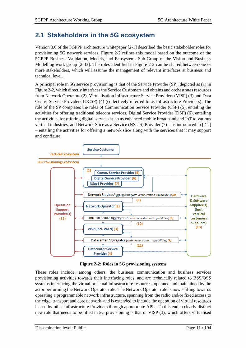
provisioning 5G network services. Figure 2-2 refines this model based on the outcome of the
5GPPP Business Validation, Models, and Ecosystems Sub-Group of the Vision and Business
Modelling work group [2-33]. The roles identified in Figure 2-2 can be shared between one or
more stakeholders, which will assume the management of relevant interfaces at business and
technical level.
A principal role in 5G service provisioning is that of the Service Provider (SP), depicted as (1) in
Figure 2-2, which directly interfaces the Service Customers and obtains and orchestrates resources
from Network Operators (2), Virtualisation Infrastructure Service Providers (VISP) (3) and Data
Centre Service Providers (DCSP) (4) (collectively referred to as Infrastructure Providers). The
role of the SP comprises the roles of Communication Service Provider (CSP) (5), entailing the
activities for offering traditional telecom services, Digital Service Provider (DSP) (6), entailing
the activities for offering digital services such as enhanced mobile broadband and IoT to various
vertical industries, and Network Slice as a Service (NSaaS) Provider (7) – as introduced in [2-2]
– entailing the activities for offering a network slice along with the services that it may support
and configure.
Figure 2-2: Roles in 5G provisioning systems
These roles include, among others, the business communication and business services
provisioning activities towards their interfacing roles, and are technically related to BSS/OSS
systems interfacing the virtual or actual infrastructure resources, operated and maintained by the
actor performing the Network Operator role. The Network Operator role is now shifting towards
operating a programmable network infrastructure, spanning from the radio and/or fixed access to
the edge, transport and core network, and is extended to include the operation of virtual resources
leased by other Infrastructure Providers through appropriate APIs. To this end, a clearly distinct
new role that needs to be filled in 5G provisioning is that of VISP (3), which offers virtualised
5GPPP Architecture Working Group 5G Architecture White Paper
Dissemination level: Public Page 12 / 194
network or cloud/edge computing resources available through APIs, and DCSP (4) which offers
raw computing resources. In the IT world, these roles correspond to cloud and data centre
providers, respectively.
Additional roles can be identified, such as the Service Aggregators at various layers, i.e., the
Network Service Aggregator, the Infrastructure Aggregator and the Datacentre Aggregator (8),
or the Spectrum Aggregator, having business relationships with several spectrum license owners
in order to share spectrum more cost efficiently and in a flexible way. The role of Network Service
Aggregator can undertake the activities of service provisioning across multiple network operators
required, e.g., in cross border, or in multiple private and public network environments.
A high interaction is expected between pure IT and Systems’ roles, namely the roles of HW and
SW suppliers (13) and Operation Support Providers (12) and the roles of 5G resource provisioning,
(1) to (11), as presented in Figure 2-2. Finally, and since 5G resource provisioning will be
performed on a per vertical application and service deployment basis, the roles of Application
Provider (AP) and System Provider to vertical customers (included in (12) and (13)) are
considered part of the 5G ecosystem.
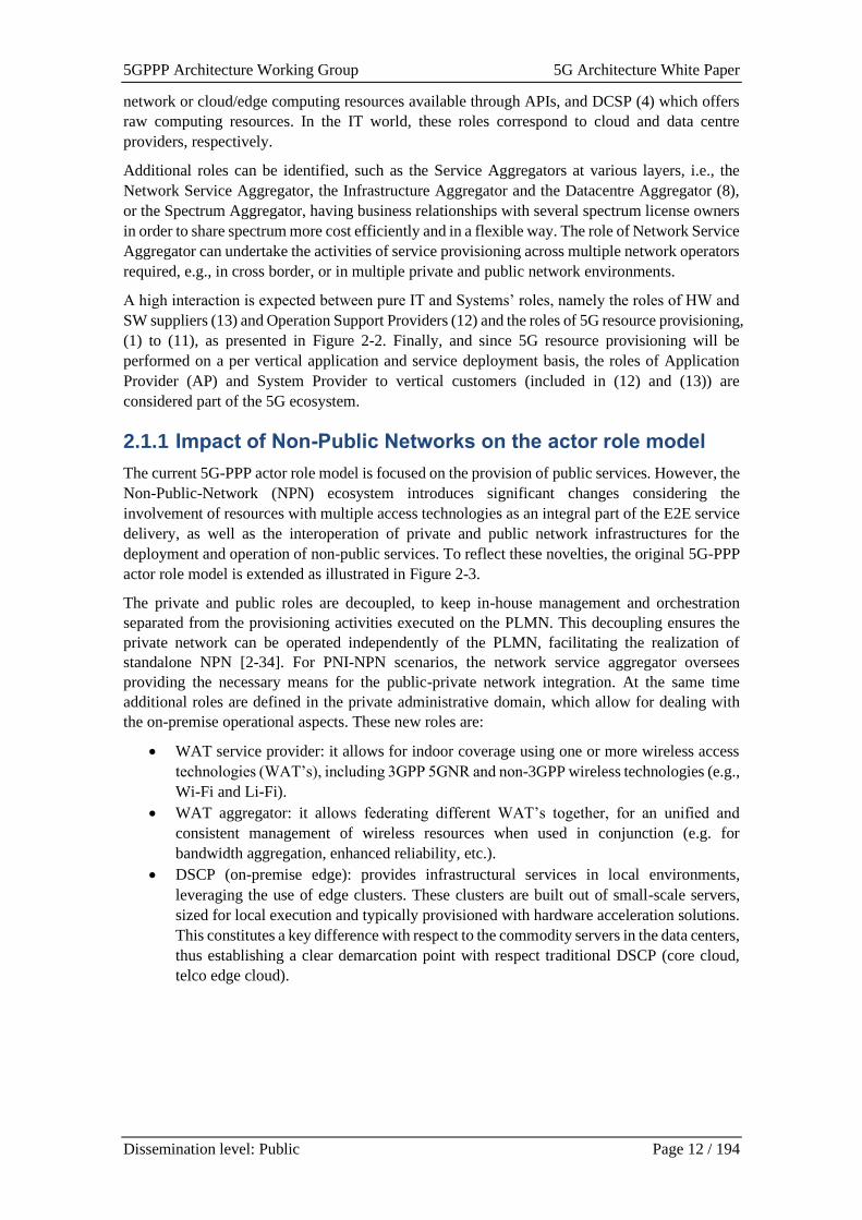
2.1.1 Impact of Non-Public Networks on the actor role model
The current 5G-PPP actor role model is focused on the provision of public services. However, the
Non-Public-Network (NPN) ecosystem introduces significant changes considering the
involvement of resources with multiple access technologies as an integral part of the E2E service
delivery, as well as the interoperation of private and public network infrastructures for the
deployment and operation of non-public services. To reflect these novelties, the original 5G-PPP
actor role model is extended as illustrated in Figure 2-3.
The private and public roles are decoupled, to keep in-house management and orchestration
separated from the provisioning activities executed on the PLMN. This decoupling ensures the
private network can be operated independently of the PLMN, facilitating the realization of
standalone NPN [2-34]. For PNI-NPN scenarios, the network service aggregator oversees
providing the necessary means for the public-private network integration. At the same time
additional roles are defined in the private administrative domain, which allow for dealing with
the on-premise operational aspects. These new roles are:
• WAT service provider: it allows for indoor coverage using one or more wireless access
technologies (WAT’s), including 3GPP 5GNR and non-3GPP wireless technologies (e.g.,
Wi-Fi and Li-Fi).
• WAT aggregator: it allows federating different WAT’s together, for an unified and
consistent management of wireless resources when used in conjunction (e.g. for
bandwidth aggregation, enhanced reliability, etc.).
• DSCP (on-premise edge): provides infrastructural services in local environments,
leveraging the use of edge clusters. These clusters are built out of small-scale servers,
sized for local execution and typically provisioned with hardware acceleration solutions.
This constitutes a key difference with respect to the commodity servers in the data centers,
thus establishing a clear demarcation point with respect traditional DSCP (core cloud,
telco edge cloud).
5GPPP Architecture Working Group 5G Architecture White Paper
Dissemination level: Public Page 13 / 194
Figure 2-3: Extension of the 5G actor role model for NPN support
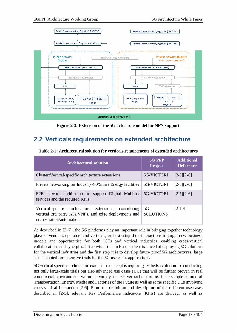
2.2 Verticals requirements on extended architecture
Table 2-1: Architectural solution for verticals requirements of extended architectures
Architectural solution 5G PPP
Project
Additional
Reference
Cluster/Vertical-specific architecture extensions 5G-VICTORI [2-5][2-6]
Private networking for Industry 4.0/Smart Energy facilities 5G-VICTORI [2-5][2-6]
E2E network architecture to support Digital Mobility
services and the required KPIs
5G-VICTORI [2-5][2-6]
Vertical-specific architecture extensions, considering
vertical 3rd party AFs/VNFs, and edge deployments and
orchestration/automation
5G-
SOLUTIONS
[2-10]
As described in [2-6] , the 5G platforms play an important role in bringing together technology
players, vendors, operators and verticals, orchestrating their interactions to target new business
models and opportunities for both ICTs and vertical industries, enabling cross-vertical
collaborations and synergies. It is obvious that in Europe there is a need of deploying 5G solutions
for the vertical industries and the first step it is to develop future proof 5G architectures, large
scale adapted for extensive trials for the 5G use cases applications.
5G vertical specific architecture extensions concept is requiring testbeds evolution for conducting
not only large-scale trials but also advanced use cases (UC) that will be further proven in real
commercial environment within a variety of 5G vertical’s area as for example a mix of
Transportation, Energy, Media and Factories of the Future as well as some specific UCs involving
cross-vertical interaction [2-6]. From the definition and description of the different use-cases
described in [2-5], relevant Key Performance Indicators (KPIs) are derived, as well as
5GPPP Architecture Working Group 5G Architecture White Paper
Dissemination level: Public Page 14 / 194
requirements on the underlying network performance are identified, which in the definition of
relevant architecture approaches and technology solution to be used.
The relevant use case described in [2-5] include Enhanced Mobile broadband under high-speed
mobility, Vertical: Transportation – Rail, Digital Mobility, Cross-Vertical – Transportation and
Media, Critical services for railway systems, Vertical: Rail, Smart Energy Metering, Cross-
Vertical: Energy and Rail, Digitization of Power Plants, Vertical: Smart Factory, and CDN
services in dense, static and mobile environments, Vertical: Media
The architecture extension and roadmap of 5G clusters implementation [2-6] is captured through
several activities, starting with (1) an initial high-level facility planning, (2) the network requiring
capturing for use case dimensioning, (3) network needs coverage and mobility,(4) proper
hardware and software identification, (5) infrastructure dimensioning(cloud, virtualization,
automation), (6) architecture design and review and (7) 5G network and application onboarding,
deploying and testing.
A list of network components and technologies supporting the cluster architecture evolution is
identified and split through several domains [2-6], to support the vertical’s use cases:
• Applications and use case experimentations, deploying and instantiation of various
services, including MEC servers, various APIs to signal deployment on the edge,
orchestrators for network slicing deployment and various KPIs monitoring.
• Physical 5G infrastructure, hardware/PNFs and compute resources
• Virtualized infrastructures, SDNs, VIM and platform monitoring tools
• Network slices and services resources orchestrators, inventories and services catalogues,
multi-site orchestrators and inventories, mobility management and profiling, VNFs life
cycle management
• Use case service design tools
• Monitoring and data analytics systems, data visualization, KPIs analysis and data
analytics outputs exposure to dashboards for further visualization
• Evaluate applications KPIs focused on availability, reliability, mobility, broadband
connectivity, latency, coverage, QoS experimentation, service optimization
5G is the Software Based Architecture model targeting to serve “X as a service” [2-6] concept,
where X can be infrastructure, software or platform, the network slicing being applied in order to
meet the customized specific combination of the services and network functions components. The
5G system can be flexibly extended and customized to serve the needs of the vertical industries,
for overall RAN architecture, extended MEC hosting infrastructures and NFVI overlay, data plane
network infrastructure and transport networks. The multi-domain management involves
interaction between E2E services operations for all involved management domains [2-6], as the
orchestration framework is designed for a holistic approach in the 5G ecosystem, relying on the
separation of network services that support the developed applications and specific management
infrastructure slices. The architecture extension involved also the DevOps, the integration of the
development and operation of complex software systems and NFV orchestration. The DevOps
approach affects the entire structure of the systems by introducing multiple stages at the
deployment time, pre-deployment time and runtime.
5GPPP Architecture Working Group 5G Architecture White Paper
Dissemination level: Public Page 15 / 194
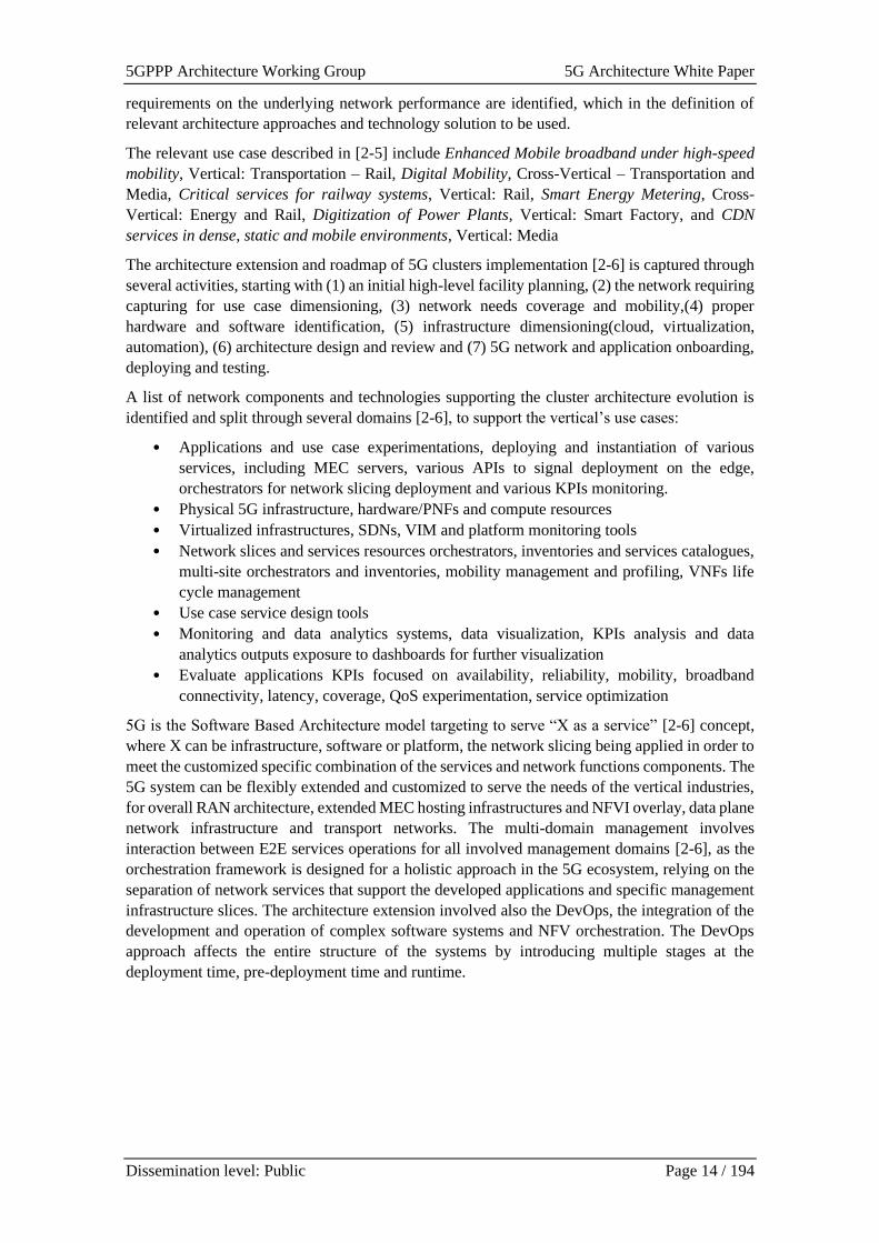
Figure 2-4: Reference architecture for common large scale field trials [2-5]
According to the overall 5G system architecture described in Figure 2-4, the relevant proposed
architecture and extensions have to provide the vertical optimised common platform to address
the requirements and business needs of the vertical industries. The E2E platform across multiple
facility sites provides facility interworking, creating a common integrated infrastructure of
networks and usable resources, the resources being able to be managed and accessed on demand
by services and applications, enhancing the resource utilization efficiency and providing
measurable benefits for the verticals in terms of cost, scalability, sustainability and management
specification. Another important aspect is the service composition over infrastructures, achievable
through the creation of repositories, comprising programable hardware and software components
also as vertical specific NFs. Programable network functions are created for the vertical’s
industries communication needs, the common framework and construction elements being
deployed to support the dynamic and on demand allocation of the demanding variety of resources
for service provisioning, multi-site and multi-tenancy capable. This capability can be facilitated
through the creation of infrastructure slices that can be independently provided to the entities,
flexible service provisioning over cross-platforms slices relying on orchestration and NF service
chaining over integrated programable infrastructures.
5GPPP Architecture Working Group 5G Architecture White Paper
Dissemination level: Public Page 16 / 194
2.2.1 Requirements for private networking for verticals
A Non-Public Network (NPN) is the infrastructure that is used exclusively by devices authorised
by the end user organisation. It is deployed in one or more specific locations of the customer, with
devices assigned to the end user organisation only, with no limitation of the number that can be
connected. The functionality of a private/non-public network extends beyond capacity and
coverage into areas like security and integration with other industrial systems. The most common
use case for a virtualised NPN mobile network industrial deployment scope is the deployment of
5G network slicing over the public mobile network. In this case the enterprise can obtain most of
the advantages avoiding the cost or complexity involved in installing and operating on-site
dedicated wireless infrastructure. One of the key business drivers which 5G NPN delivers for
Smart Energy facilities, but also for Industry 4.0 overall is the high reliability, critical monitoring
and control of applications supporting real-time decision making by combining smart technology
including sensors, high interconnectivity, automation, machine learning and real-time processing.
The NPN requirements are very different from the conventional network requirements of public
mobile networks. High reliability service with guaranteed SLA is required expressed through
network performance attributes such as latency, reliability together with functional and
operational requirements such as data traffic feeding, high-precision positioning, real-time
monitoring. The traffic model for NPN use cases are different from the conventional consumer
mobile network services requiring QoS flexibility such as uplink / downlink different bandwidth
ratio. Strict data isolation should be provided within customer premises between services data
related user plane / control plane communications but also between customers, if they share the
same infrastructure. Here edge computing along with network slicing fulfils the strict data
isolation or localisation use cases requirements. Security and privacy are one of the key
requirements for an NPN requesting strong privacy and security framework to protect customer
from various potential attacks. The most cost-effective way for customers to focus on their core
business and offload the complexity of deploying and managing enterprise connectivity is to
handover it toward mobile network operators. Therefore, the decoupling of operation and
management is required.
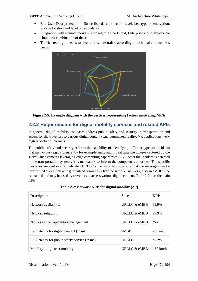
The dedicated white paper on NPNs [2-34] provides a detailed analysis of several use cases and
the motivation for the customer to deploy and NPN. The range of requirements is wide, whereas
each requirement is typically not a single killer motivation for NPN. However, the combination
of several requirements can be as is illustrated by spider diagrams like in the example in figure.
In general, the NPN white paper identified the following areas that are the main source for
requirements for NPN1:
• Coverage – The level and availability of coverage, including redundancy coverage
• Guaranteed QoS – Including Latency, Jitter and Throughput or a combination of them.
The probability that the network is able to provide the required value at any time
• Customisation – Refers to the features needed by the enterprise to meet its business needs,
including but not limited to time synchronization, localization accuracy, 5GLAN support,
etc.
• Network Control –E2E control over network management, resources and services
encompassing information, data, operations and communication technology
1 It should be noted that the list of requirements for NPN and the spider diagram are a preliminary indication and will
be updated after the consultation phase for this whitepaper and once the NPN paper – being prepared in parallel – is
published.
5GPPP Architecture Working Group 5G Architecture White Paper
Dissemination level: Public Page 17 / 194
• End User Data protection – Subscriber data protection level, i.e., type of encryption,
storage location and level of redundancy
• Integration with Remote cloud – referring to Telco Cloud, Enterprise cloud, hyperscale
cloud or a combination of these
• Traffic steering – means to steer and isolate traffic according to technical and business
needs.
Figure 2-5: Example diagram with the vertices representing factors motivating NPNs
2.2.2 Requirements for digital mobility services and related KPIs
In general, digital mobility use cases address public safety and security in transportation and
access for the travellers to various digital content (e.g., augmented reality, VR applications, very
high broadband Internet).
The public safety and security refer to the capability of identifying different types of incidents
that may occur (e.g., violence) by for example analysing in real time the images captured by the
surveillance cameras leveraging edge computing capabilities [2-7]. After the incident is detected
in the transportation systems, it is mandatory to inform the competent authorities. The specific
messages are sent over a dedicated URLLC slice, in order to be sure that the messages can be
transmitted over a link with guaranteed resources. Over the same 5G network, also an eMBB slice
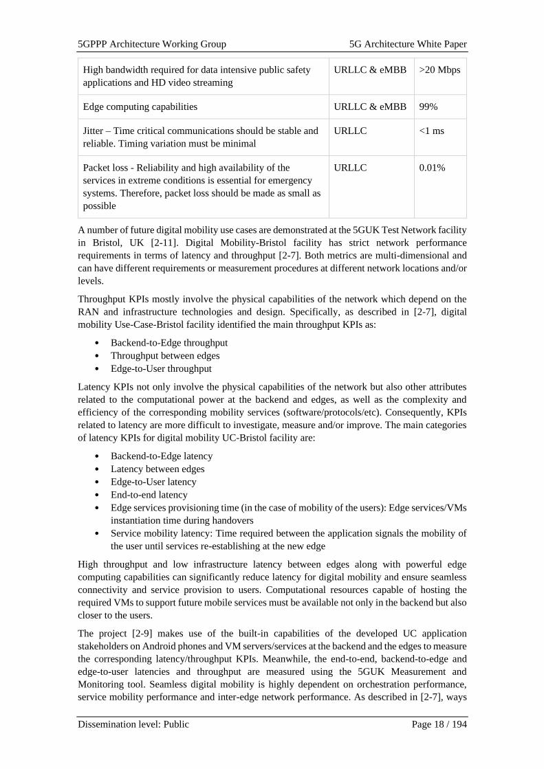
is enabled and may be used by travellers to access various digital content. Table 2-2 lists the main
KPIs.
Table 2-2: Network KPIs for digital mobility [2-7]
Description Slice KPIs
Network availability URLLC & eMBB 99.9%
Network reliability URLLC & eMBB 99.9%
Network slice capabilities/management URLLC & eMBB Yes
E2E latency for digital content (in ms) eMBB <30 ms
E2E latency for public safety service (in ms) URLLC <5 ms
Mobility – high user mobility URLLC & eMBB <50 km/h
5GPPP Architecture Working Group 5G Architecture White Paper
Dissemination level: Public Page 18 / 194
High bandwidth required for data intensive public safety
applications and HD video streaming
URLLC & eMBB >20 Mbps
Edge computing capabilities URLLC & eMBB 99%
Jitter – Time critical communications should be stable and
reliable. Timing variation must be minimal
URLLC <1 ms
Packet loss - Reliability and high availability of the
services in extreme conditions is essential for emergency
systems. Therefore, packet loss should be made as small as
possible
URLLC 0.01%
A number of future digital mobility use cases are demonstrated at the 5GUK Test Network facility
in Bristol, UK [2-11]. Digital Mobility-Bristol facility has strict network performance
requirements in terms of latency and throughput [2-7]. Both metrics are multi-dimensional and
can have different requirements or measurement procedures at different network locations and/or
levels.
Throughput KPIs mostly involve the physical capabilities of the network which depend on the
RAN and infrastructure technologies and design. Specifically, as described in [2-7], digital
mobility Use-Case-Bristol facility identified the main throughput KPIs as:
• Backend-to-Edge throughput
• Throughput between edges
• Edge-to-User throughput
Latency KPIs not only involve the physical capabilities of the network but also other attributes
related to the computational power at the backend and edges, as well as the complexity and
efficiency of the corresponding mobility services (software/protocols/etc). Consequently, KPIs
related to latency are more difficult to investigate, measure and/or improve. The main categories
of latency KPIs for digital mobility UC-Bristol facility are:
• Backend-to-Edge latency
• Latency between edges
• Edge-to-User latency
• End-to-end latency
• Edge services provisioning time (in the case of mobility of the users): Edge services/VMs
instantiation time during handovers
• Service mobility latency: Time required between the application signals the mobility of
the user until services re-establishing at the new edge
High throughput and low infrastructure latency between edges along with powerful edge
computing capabilities can significantly reduce latency for digital mobility and ensure seamless
connectivity and service provision to users. Computational resources capable of hosting the
required VMs to support future mobile services must be available not only in the backend but also
closer to the users.
The project [2-9] makes use of the built-in capabilities of the developed UC application
stakeholders on Android phones and VM servers/services at the backend and the edges to measure
the corresponding latency/throughput KPIs. Meanwhile, the end-to-end, backend-to-edge and
edge-to-user latencies and throughput are measured using the 5GUK Measurement and
Monitoring tool. Seamless digital mobility is highly dependent on orchestration performance,
service mobility performance and inter-edge network performance. As described in [2-7], ways
5GPPP Architecture Working Group 5G Architecture White Paper
Dissemination level: Public Page 19 / 194
are investigated for improving the digital mobility performance, aiming at a better end-user
experience within the context of digital mobility.
2.2.3 Requirements considering vertical 3rd party AFs/VNFs,
edge deployment and orchestration
This section addresses requirements for vertical-specific application integration and architecture
extensions, considering vertical 3rd party virtualized network application functions, edge cloud
deployments and orchestration/automation. With the promises of advanced 5G services towards
verticals it is important to capture and accommodate the needs of the different verticals, whether
addressing capabilities that should be commonly applicable across many verticals or the
requirements are targeting specific needs of a given vertical. The requirements are considered in
the context of the fundamental and baseline service offering, that of the logical network service
offering toward Vertical Enterprise Customers (VEC) as well as specialized connectivity services
on-demand offered to Online Application service Providers (OAP). Around such a Logical
Network as a Service (LNaaS) offering, there are multiple topics to consider for proper service
life-cycle management and support. Further elaboration on the service modelling concepts and
exposure capabilities are considered in Section 2.5.4 below.
The LNaaS offering must go beyond today’s virtual private network (VPN) service offerings and
SD-WAN solutions that are foreseen in the near term. The logical network (LN) concept must
enable and support a variety of 5G NPN configurations, including various ways of integrating
with the public network, including the so-called public-network-integrated NPN (PNI-NPN). A
VEC specific LN can be interconnected to other partner LNs as well as reaching end-points
addressable on the public Internet or other future specialized public services networks. Hence,
there is a need for supporting a verity of topologies and underlaying network technologies. An
example of this need is the support of requesting Specialized Connectivity Service on-demand
(SCS), from the LN of the VAC and any of its point of interconnection with other LNs or public
network, to any other end-points in these reachable networks. Application on-boarding,
deployment (including setup of connectivity properties into advanced network conditions and
topologies) and application service activation must provide:
• Service SLA, management of robustness levels and abstracted resilience mechanisms
(e.g., related to high availability cloud properties).
• Support for self-service portals.
• Service monitoring
• Support for sandbox and trials
• Support for testing as a service
• Support for migration from sandbox, to acceptance testing and eventually commercial
operations
5GPPP Architecture Working Group 5G Architecture White Paper
Dissemination level: Public Page 20 / 194
2.3 Architecture extensions
Table 2-3: Architecture extension
Architectural solution 5G PPP
Project
Additional
Reference
Architectural extension on baseline to release 16 5G-VICTORI [2-5]
Telco-oriented cloud native orchestration of 5GC and
vertical applications
FUDGE-5G [2-21]
2.3.1 Architecture extensions introduced by 3GPP Release 16
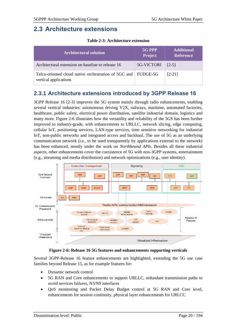
3GPP Release 16 [2-3] improves the 5G system mainly through radio enhancements, enabling
several vertical industries: autonomous driving V2X, railways, maritime, automated factories,
healthcare, public safety, electrical power distribution, satellite industrial domain, logistics and
many more. Figure 2-6 illustrates how the versatility and reliability of the 5GS has been further
improved to industry-grade, with enhancements to URLLC, network slicing, edge computing,
cellular IoT, positioning services, LAN-type services, time sensitive networking for industrial
IoT, non-public networks and integrated access and backhaul. The use of 5G as an underlying
communication network (i.e., to be used transparently by applications external to the network)
has been enhanced, mostly under the work on Northbound APIs. Besides all these industrial
aspects, other enhancements cover the coexistence of 5G with non-3GPP systems, entertainment
(e.g., streaming and media distribution) and network optimizations (e.g., user identity).
Figure 2-6: Release 16 5G features and enhancements supporting verticals
Several 3GPP-Release 16 feature enhancements are highlighted, extending the 5G use case
families beyond Release 15, as for example features for:
• Dynamic network control
• 5G RAN and Core enhancements to support URLLC, redundant transmission paths to
avoid services failures, N3/N9 interfaces
• QoS monitoring and Packet Delay Budget control at 5G RAN and Core level,
enhancements for session continuity, physical layer enhancements for URLCC
5GPPP Architecture Working Group 5G Architecture White Paper
Dissemination level: Public Page 21 / 194
• 5G NR enhancements for IoT, PDPC packet multiplication for increased reliability, CA,
multi-connectivity for PDU sessions, efficient gNB scheduling, logical uplink resources
prioritization at UE level
• NR mobility enhancement’s, inter-band CA and for 2/3 bands DL and x UL (x=1,2), 256
QAM FR2 support, NR-NR dual connectivity and NR CA, dynamic spectrum sharing
and power saving
• NR in un-licensed spectrum and non-3GPP system coexistence
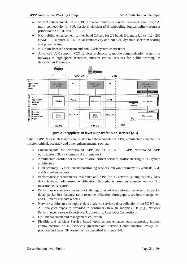
• Advanced V2X support, V2X services architecture, mobile communication system for
railways in high-speed scenarios, mission critical services for public warning, as
described in Figure 2-7.
Figure 2-7: Application layer support for V2X services [2-3]
Other 3GPP Release 16 features are related to enhancements for APIs, architectures enabled for
mission critical, accuracy and other enhancements, such as:
• Enhancements for Northbound APIs for SCEF, NEF, 3GPP Northbound APIs
optimization, 3GPP Common API framework,
• Architecture enabled for vertical mission critical services, traffic steering in 5G system
architecture
• High accuracy 5G location and positioning services, relevant for many 5G verticals, 5GC
and NR enhancements
• Performance measurements, assurance and KPIs for 5G network slicing as delay, loss,
drop, latency, radio resource utilization, throughputs, sessions management and UE
measurements reports
• Performance assurance for network slicing, thresholds monitoring services, E2E packet
delay, packet loss, latency, radio resource utilization, throughputs, sessions management
and UE measurements reports
• Network architecture to support data analytics services, data collection from 5G NF and
AF, analytics exposure provided to consumers through analytics IDs (e.g., Network
Performance, Service Experience, UE mobility, User Data Congestion)
• QoE management and management collection
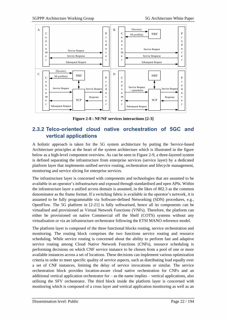
• Flexible and efficient Service Based Architecture, enhancements supporting indirect
communication of NF services (intermediate Service Communication Proxy, NF
producer indicates NF consumer), as described in Figure 2-8.
5GPPP Architecture Working Group 5G Architecture White Paper
Dissemination level: Public Page 22 / 194
P
r
o
d
u
c
e
r
C
o
n
s
u
m
e
r
Service Request
Service Response
Subsequent Request
P
r
o
d
u
c
e
r
C
o
n
s
u
m
e
r
Service Response
Subsequent Request
NRF
Discovery
NF profile(s)
P
r
o
d
u
c
e
r
C
o
n
s
u
m
e
r
Service Request
Response
Subsequent Request
Discovery
NF profile(s) NRF
SCP
P
r
o
d
u
c
e
r
C
o
n
s
u
m
e
r
Service Request
+ parameters
Response
NRF
SCP
A
C
B
D
Service RequestService Request
Subsequent Request
Service Request
Figure 2-8 : NF/NF services interactions [2-3]
2.3.2 Telco-oriented cloud native orchestration of 5GC and
vertical applications
A holistic approach is taken for the 5G system architecture by putting the Service-based
Architecture principles at the heart of the system architecture which is illustrated in the figure
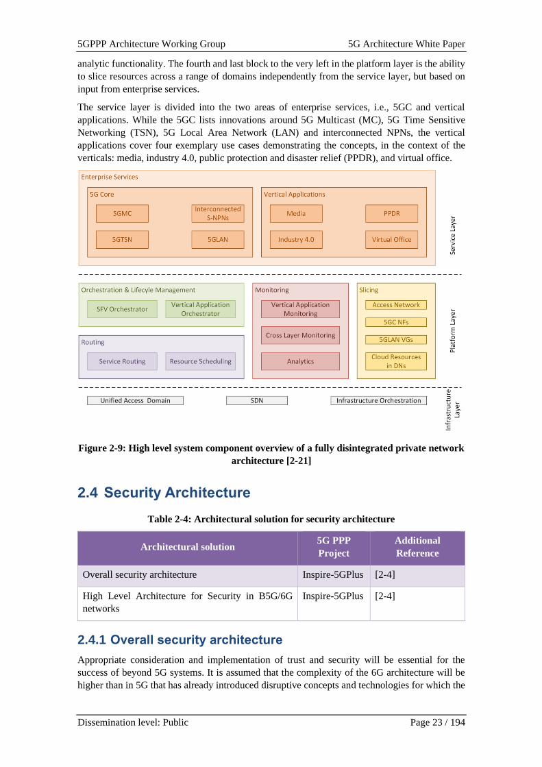
below as a high-level component overview. As can be seen in Figure 2-9, a three-layered system
is defined separating the infrastructure from enterprise services (service layer) by a dedicated
platform layer that implements unified service routing, orchestration and lifecycle management,
monitoring and service slicing for enterprise services.
The infrastructure layer is concerned with components and technologies that are assumed to be
available in an operator’s infrastructure and exposed through standardised and open APIs. Within
the infrastructure layer a unified access domain is assumed, in the likes of 802.3 as the common
denominator as the frame format. If a switching fabric is available in the operator’s network, it is
assumed to be fully programmable via Software-defined Networking (SDN) procedures, e.g.,
OpenFlow. The 5G platform in [2-21] is fully softwarised, hence all its components can be
virtualised and provisioned as Virtual Network Functions (VNFs). Therefore, the platform can
either be provisioned on native Commercial off the Shelf (COTS) systems without any
virtualisation or via an infrastructure orchestrator following the ETSI MANO reference model.
The platform layer is composed of the three functional blocks routing, service orchestration and
monitoring. The routing block comprises the two functions service routing and resource
scheduling. While service routing is concerned about the ability to perform fast and adaptive
service routing among Cloud Native Network Functions (CNFs), resource scheduling is
performing decisions on which CNF service instance to be chosen from a pool of one or more
available instances across a set of locations. These decisions can implement various optimization
criteria in order to meet specific quality of service aspects, such as distributing load equally over
a set of CNF instances, limiting the delay of service invocations or similar. The service
orchestration block provides location-aware cloud native orchestration for CNFs and an
additional vertical application orchestrator for – as the name implies – vertical applications, also
utilising the SFV orchestrator. The third block inside the platform layer is concerned with
monitoring which is composed of a cross layer and vertical application monitoring as well as an
5GPPP Architecture Working Group 5G Architecture White Paper
Dissemination level: Public Page 23 / 194
analytic functionality. The fourth and last block to the very left in the platform layer is the ability
to slice resources across a range of domains independently from the service layer, but based on
input from enterprise services.
The service layer is divided into the two areas of enterprise services, i.e., 5GC and vertical
applications. While the 5GC lists innovations around 5G Multicast (MC), 5G Time Sensitive
Networking (TSN), 5G Local Area Network (LAN) and interconnected NPNs, the vertical
applications cover four exemplary use cases demonstrating the concepts, in the context of the
verticals: media, industry 4.0, public protection and disaster relief (PPDR), and virtual office.
Figure 2-9: High level system component overview of a fully disintegrated private network
architecture [2-21]
2.4 Security Architecture
Table 2-4: Architectural solution for security architecture
Architectural solution 5G PPP
Project
Additional
Reference
Overall security architecture Inspire-5GPlus [2-4]
High Level Architecture for Security in B5G/6G
networks
Inspire-5GPlus [2-4]
2.4.1 Overall security architecture
Appropriate consideration and implementation of trust and security will be essential for the
success of beyond 5G systems. It is assumed that the complexity of the 6G architecture will be
higher than in 5G that has already introduced disruptive concepts and technologies for which the
5GPPP Architecture Working Group 5G Architecture White Paper
Dissemination level: Public Page 24 / 194
resulting risks are still not fully known, e.g., softwarisation, virtualisation, and cloudification,
even though they have positively impacted the flexibility and adaptive capabilities of networks.
Nevertheless, security management, often being conservative and requiring a significant level of
situation awareness, is still sensitive to the increased complexity of novel concepts.
The integration of disruptive technologies requires on the one hand to ensure these technologies
are securely used, i.e., not jeopardising the overall system security, but on the other hand taking
benefit of the advantages of these innovative technologies and applying them for implementing
security functions in the network, and for reaching consistency with systems properties. In order
to reach the required scalability and dynamism levels of security, security services should be as
much as possible following the “as a service” model, softwarised, and based on virtualised
technologies. Management and control of security should remain aligned to these innovative
paradigms making of smart orchestration, chaining, and AI the enablers of concomitant
deployment of security to provide an intelligent distribution of security functions across the
systems. This intelligence is essential for a protect-detect-react loop that ensures a compliance
with security policies and SSLAs, optimizes detection of known attacks or anomalies, and
dynamically deploys the required mitigation. Deception and Moving Target Defence (MTD) are
examples of promising techniques to influence the way security is delivered and operated.
The smart control of 6G networks needs to be driven through Artificial Intelligence capabilities
which at the same time are a source for new attack vectors, but applying these technologies in the
security domain enable more intelligent security solutions. AI relies on data quality, either for
users' data or system data. Data protection becomes a major concern so that data-centric security
technologies such as homomorphic encryption or Multi-Party Computation will become
mandatory. Two further main elements will impact the attack surface of future networks: The first
one is linked to the IoT raising issues related to security distribution, and the second one is linked
to the software life cycle. Moreover, the security architecture may be subject to entirely new
paradigms taking benefits of the fundamentals of the physics, as e.g., quantum infrastructures.
The main aspect for enabling security will be too deeply root protection and resilience in the
architecture, so that attacks become harder to carry out and easier to manage. This requires that
trust anchors are put in place and resilient configuration patterns are deployed, so that service
networks can resist attacks. This requires a disruption of traditional approaches where security
concerns are often expressed late to even go beyond the” by-design” paradigm with solutions
2.4.2 High level architecture for security in B5G/6G networks
In beyond 5G and 6G, a fully automated network and service management and operation will
need to be included from the initial design phase. However, a major challenge and risk of
introducing full automation is that small isolated errors or cybersecurity attacks, which are
expected to become an unprecedented challenge in beyond 5G and 6G, might propagate and
replicate rapidly and bear the risk of endangering the entire critical ecosystem. What is needed is
a fully automated – zero-touch – end-to-end smart network and service security management
framework that empowers not only protection but addresses also trustworthiness and liability in
managing virtualized network infrastructures across multiple domains.
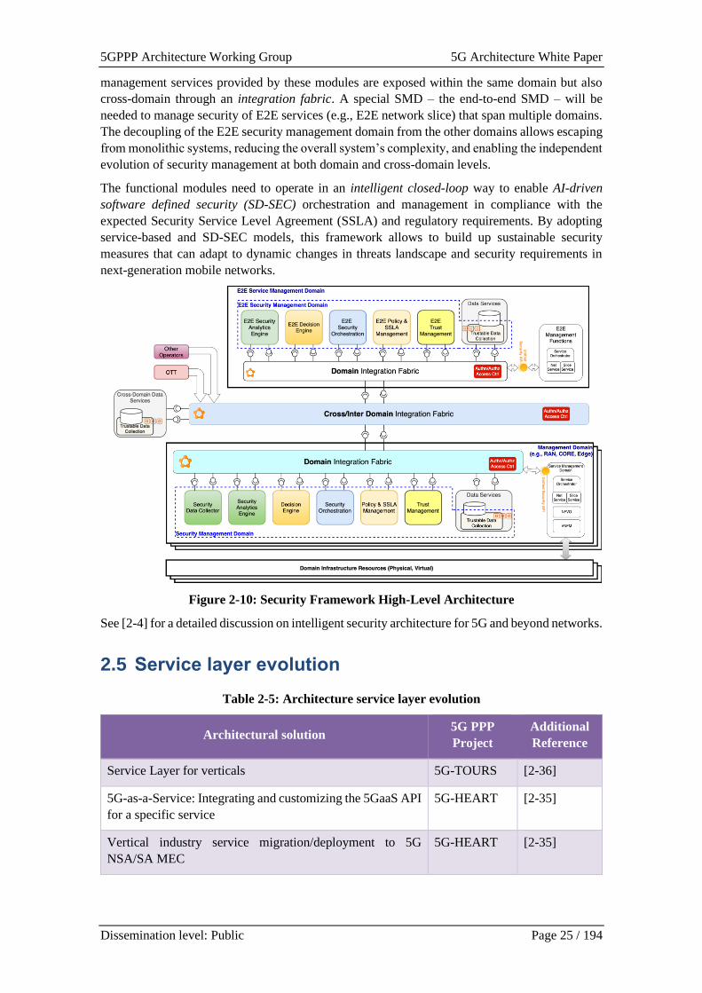
The security architecture in 6G should be split into several security management domains (SMDs),
for robustness, but also to support the separation of security management concerns, e.g., for the
Radio Access Network (RAN), Edge or Core Network. The principal design and functional
components of SMDs should be the same in all domains. Each SMD is responsible for intelligent
security automation of resources and services within its scope, and comprises a set of functional
modules, e.g., a Security Data Collector, a Security Analytics Engine, Decision Engine, Security
orchestration, Trust Management as well as Policy and SSLA Management. The various security
5GPPP Architecture Working Group 5G Architecture White Paper
Dissemination level: Public Page 25 / 194
management services provided by these modules are exposed within the same domain but also
cross-domain through an integration fabric. A special SMD – the end-to-end SMD – will be
needed to manage security of E2E services (e.g., E2E network slice) that span multiple domains.
The decoupling of the E2E security management domain from the other domains allows escaping
from monolithic systems, reducing the overall system’s complexity, and enabling the independent
evolution of security management at both domain and cross-domain levels.
The functional modules need to operate in an intelligent closed-loop way to enable AI-driven
software defined security (SD-SEC) orchestration and management in compliance with the
expected Security Service Level Agreement (SSLA) and regulatory requirements. By adopting
service-based and SD-SEC models, this framework allows to build up sustainable security
measures that can adapt to dynamic changes in threats landscape and security requirements in
next-generation mobile networks.
Figure 2-10: Security Framework High-Level Architecture
See [2-4] for a detailed discussion on intelligent security architecture for 5G and beyond networks.
2.5 Service layer evolution
Table 2-5: Architecture service layer evolution
Architectural solution 5G PPP
Project
Additional
Reference
Service Layer for verticals 5G-TOURS [2-36]
5G-as-a-Service: Integrating and customizing the 5GaaS API
for a specific service
5G-HEART [2-35]
Vertical industry service migration/deployment to 5G
NSA/SA MEC
5G-HEART [2-35]
5GPPP Architecture Working Group 5G Architecture White Paper
Dissemination level: Public Page 26 / 194
Service Layer for verticals 5G-
SOLUTIONS
[2-10]
Unified Service-based Architecture placing service
registration, routing, orchestration and resource control at the
platform level with 5GC and vertical applications as 5G
services on top of platform
FUDGE-5G [2-21]
2.5.1 Service Layer for verticals
In order to meet the needs of the vertical customers, the 5G architecture has to include a service
layer that provides them with a suitable northbound interface which has to be aligned with the
incipient efforts on Exposure Governance Management Function (EGMF) [2-12] at 3GPP. Yet,
its scope may go much beyond that of the standard.
This service layer [2-13] has to perform the following operation, as needed by verticals,
considering tailored requirements for the network slice lifecycle management:
• Instantiation: When a tenant needs a network slice, it has to issue a request to the
infrastructure indicating information such as: (i) the geographical area that needs to be
covered by the network slice, (ii) the Key Performance Indicators (KPIs) such as the
capacity, maximum latency or reliability, that needs to be supported, (iii) the user
equipment that belong to the slice, etc.
• Orchestration of application-layer virtualized functions: Sometimes the tenant needs to
run some of its application layer functions within the network infrastructure employing
e.g., MEC technology. Hence the service layer has to support this feature, indicating e.g.,
the capacity of the underlying infrastructure.
• Monitoring and runtime management: Once the slice has been instantiated, the service
layer shall provide monitoring capabilities for SLA assurance purposes. In this way the
tenant can monitor the service provided by the network slice and see if the obtained
performance matches the requested one. Based on this information, the service layer shall
support re-shaping of the slice. For instance, if the slice’s load increases, a larger slice
may be requested.
• Operate the network slice: The tenant needs to be able to perform some configurations
on a running network slice, such as adding new users to the slice, increasing its coverage,
changing the requirements or the load, re-orchestrating application-layer virtualized
functions, etc.
Given the openness of the 5G ecosystem, it is likely that many of the tenants employing a network
slice are players which may not have the skills and expertise to manage mobile network services.
As the ultimate goal is to allow such players to be part of the network slicing market without
imposing a steep learning curve (i.e., employing a sort of Network Slice as a Service platform), it
is very important that such service layer can manage most of the low-level burden. Additionally,
this service layer may have two possible implementations, as a programmatic API or a web
interface that can be used to perform the aforementioned operations manually. This approach
could be coupled with intent-based approaches, where the policies coming from vertical tenants
are specified with ‘business intent’, declaring high-level service policies rather than specifying
detailed networking configuration. Alternatively, verticals may use other solutions such as GSMA
NEST [2-14] templates.
The service layer is of particular importance in the context of NPN: empowering the vertical with
the ability of performing the aforementioned operation in a more trustworthy environment such
as the one envisioned by NPNs will effectively enable the user to network to service continuum,
5GPPP Architecture Working Group 5G Architecture White Paper
Dissemination level: Public Page 27 / 194
ideally joining the service intelligence with the network one. The service layer can thus be
customized according to the specific use case envisioned by the vertical, as discussed in Section
2.6.
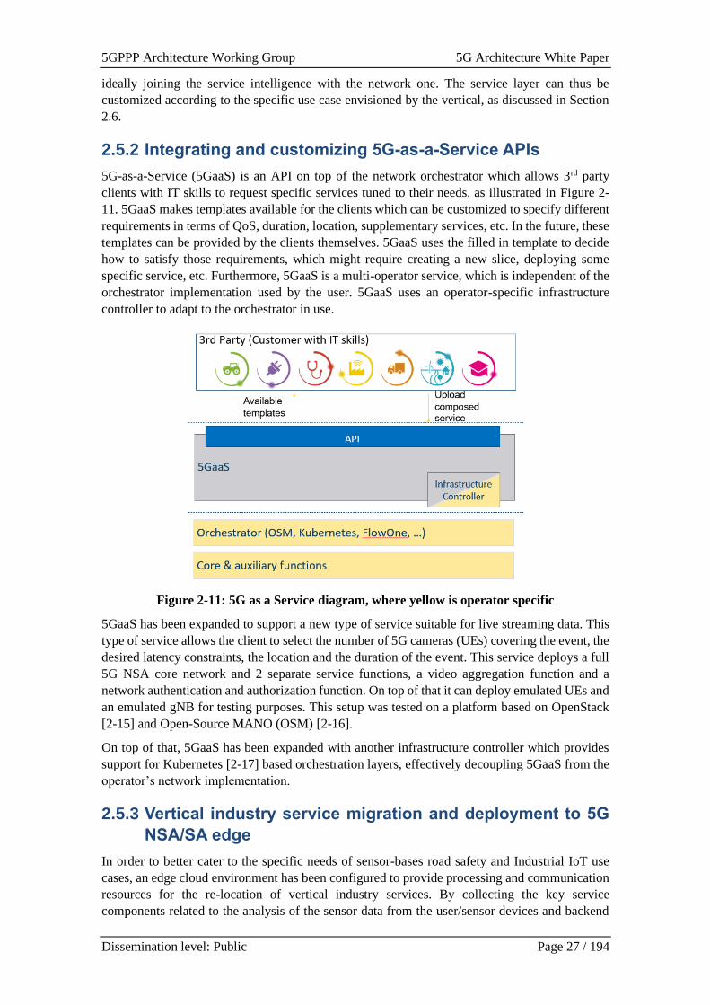
2.5.2 Integrating and customizing 5G-as-a-Service APIs
5G-as-a-Service (5GaaS) is an API on top of the network orchestrator which allows 3rd party
clients with IT skills to request specific services tuned to their needs, as illustrated in Figure 2-
11. 5GaaS makes templates available for the clients which can be customized to specify different
requirements in terms of QoS, duration, location, supplementary services, etc. In the future, these
templates can be provided by the clients themselves. 5GaaS uses the filled in template to decide
how to satisfy those requirements, which might require creating a new slice, deploying some
specific service, etc. Furthermore, 5GaaS is a multi-operator service, which is independent of the
orchestrator implementation used by the user. 5GaaS uses an operator-specific infrastructure
controller to adapt to the orchestrator in use.
Figure 2-11: 5G as a Service diagram, where yellow is operator specific
5GaaS has been expanded to support a new type of service suitable for live streaming data. This
type of service allows the client to select the number of 5G cameras (UEs) covering the event, the
desired latency constraints, the location and the duration of the event. This service deploys a full
5G NSA core network and 2 separate service functions, a video aggregation function and a
network authentication and authorization function. On top of that it can deploy emulated UEs and
an emulated gNB for testing purposes. This setup was tested on a platform based on OpenStack
[2-15] and Open-Source MANO (OSM) [2-16].
On top of that, 5GaaS has been expanded with another infrastructure controller which provides
support for Kubernetes [2-17] based orchestration layers, effectively decoupling 5GaaS from the
operator’s network implementation.
2.5.3 Vertical industry service migration and deployment to 5G
NSA/SA edge
In order to better cater to the specific needs of sensor-bases road safety and Industrial IoT use
cases, an edge cloud environment has been configured to provide processing and communication
resources for the re-location of vertical industry services. By collecting the key service
components related to the analysis of the sensor data from the user/sensor devices and backend
5GPPP Architecture Working Group 5G Architecture White Paper
Dissemination level: Public Page 28 / 194
server to the network edge, data fusion between the real-time and already post-processed
historical sensor data can be performed in a centralised manner for a restricted operational
environment such as a section of road or production facility/site. By moving away from the
traditional distributed processing at the user devices or centralised processing at the remote cloud,
and providing a hybrid approach at the network edge, more accurate monitoring and safety
services can be provided with adequately low end-to-end latencies for a variety of scenarios
requiring a combination of mMTC and URLLC capabilities from the utilised communication
platform.
The initial implementation of the edge cloud environment has been made by configuring and
deploying an MQTT broker and local database to serve a selected trial site. All user/sensor devices
in the area publish their raw data to the broker. The broker is responsible for collecting the sensor
data and passing it to a common local database for analysis with the historical data received from
the remote service cloud through a dedicated API. Possible warnings and alarms triggered by the
analysed data are pushed forward directly to other users/sensor or monitoring systems subscribed
to receive such messages from the MQTT broker. In order to facilitate the deployment of
alternative distribution methods for the messages triggered by the analysed sensor data as well as
the extension of the service capabilities, a VM template for the deployment of additional service
components has been defined for the edge cloud.
2.5.4 Service layer information, data models, and exposure
mechanisms
The key service concept for vertical enterprise customers is Network as a Service, typically this
is a Logical NaaS. In general, the NaaS can be based on public network infrastructure or a
combination of public and private network infrastructure. The NaaS must also reflect various
ways and means of interconnection with other networks, and may also be related to other NaaS
instances. The Logical Network as a Service, Service information model (and data models for
implementation) is at the core of service layer exposure, as perceived by the enterprise customer
(e.g. industry SME and their industry partners). An evolutionary approach must be supported, in
order to abstract the topology, referencing underlaying abstracted network entities and elements
as relevant to the service offered. Also, the service layer is based on the exposing of wireless and
fixed connectivity, as well as computing resources for dynamic application function deployment
and supporting of the interconnection to (other) public and/or private networks, cloud networks
or other partner networks (partner of the enterprise customer). Several service layer capabilities
for verticals are taken into consideration, as service layer features:
• Resilience and robustness support
• Exposure via suitable, standardized, and customizable (B2B) APIs, supporting Customer
User interface and Vertical Application solution providers
• Vertical private network operations (managed service providers)
• Enables and supports customer self-management of the overall NaaS and underlaying
service entities and corresponding elements
• Customer device / UE management and configuration
• Managed connectivity to/from and between various end-points or destination regions
o Managed quality path level (traffic aggregates), to/from tunnel end-points, or to
destination regions
o Connectivity on-demand (connectivity session level, matching application
sessions), including Specialized Connectivity Service on-demand (SCS).
• Management of service availability and robustness properties
• Enabling and supporting Service Assurance, QoS and QoE models and management
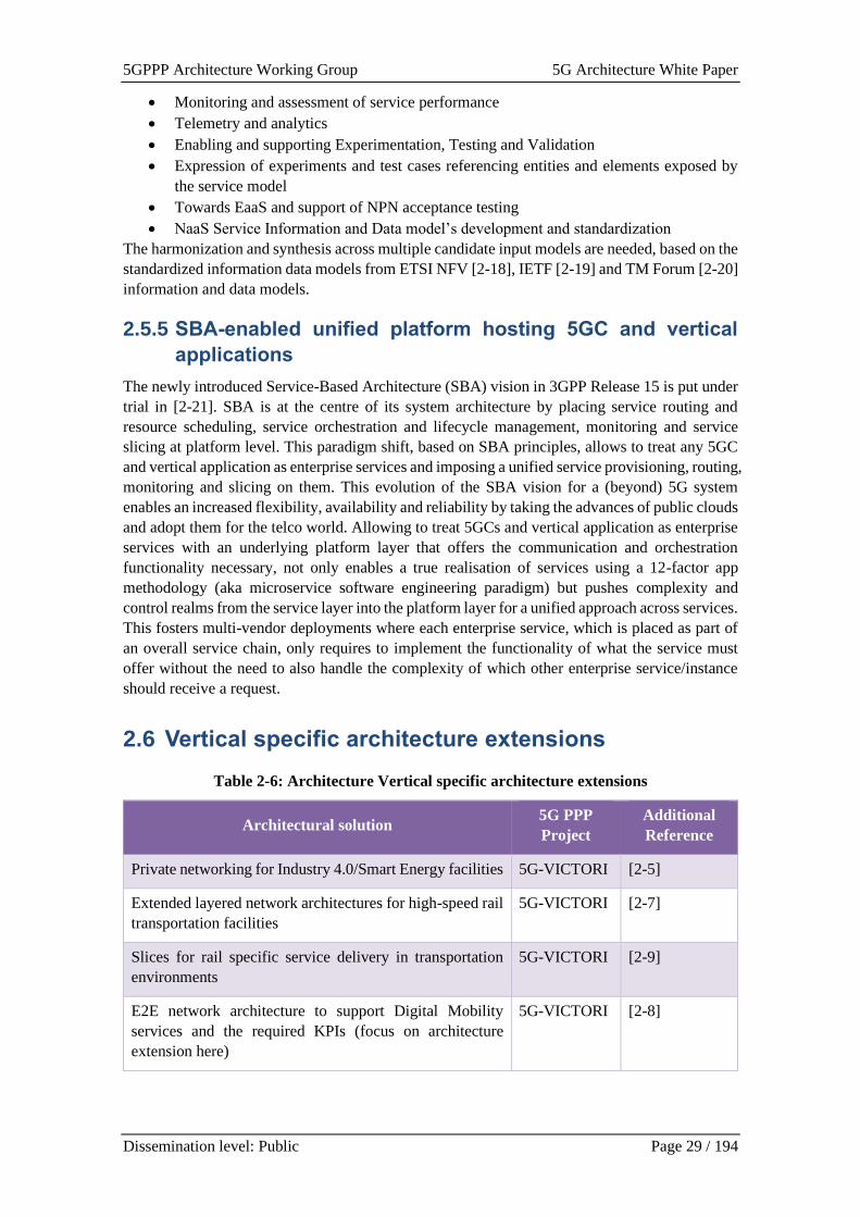
5GPPP Architecture Working Group 5G Architecture White Paper
Dissemination level: Public Page 29 / 194
• Monitoring and assessment of service performance
• Telemetry and analytics
• Enabling and supporting Experimentation, Testing and Validation
• Expression of experiments and test cases referencing entities and elements exposed by
the service model
• Towards EaaS and support of NPN acceptance testing
• NaaS Service Information and Data model’s development and standardization
The harmonization and synthesis across multiple candidate input models are needed, based on the
standardized information data models from ETSI NFV [2-18], IETF [2-19] and TM Forum [2-20]
information and data models.
2.5.5 SBA-enabled unified platform hosting 5GC and vertical
applications
The newly introduced Service-Based Architecture (SBA) vision in 3GPP Release 15 is put under
trial in [2-21]. SBA is at the centre of its system architecture by placing service routing and
resource scheduling, service orchestration and lifecycle management, monitoring and service
slicing at platform level. This paradigm shift, based on SBA principles, allows to treat any 5GC
and vertical application as enterprise services and imposing a unified service provisioning, routing,
monitoring and slicing on them. This evolution of the SBA vision for a (beyond) 5G system
enables an increased flexibility, availability and reliability by taking the advances of public clouds
and adopt them for the telco world. Allowing to treat 5GCs and vertical application as enterprise
services with an underlying platform layer that offers the communication and orchestration
functionality necessary, not only enables a true realisation of services using a 12-factor app
methodology (aka microservice software engineering paradigm) but pushes complexity and
control realms from the service layer into the platform layer for a unified approach across services.
This fosters multi-vendor deployments where each enterprise service, which is placed as part of
an overall service chain, only requires to implement the functionality of what the service must
offer without the need to also handle the complexity of which other enterprise service/instance
should receive a request.
2.6 Vertical specific architecture extensions
Table 2-6: Architecture Vertical specific architecture extensions
Architectural solution 5G PPP
Project
Additional
Reference
Private networking for Industry 4.0/Smart Energy facilities 5G-VICTORI [2-5]
Extended layered network architectures for high-speed rail
transportation facilities
5G-VICTORI [2-7]
Slices for rail specific service delivery in transportation
environments
5G-VICTORI [2-9]
E2E network architecture to support Digital Mobility
services and the required KPIs (focus on architecture
extension here)
5G-VICTORI [2-8]
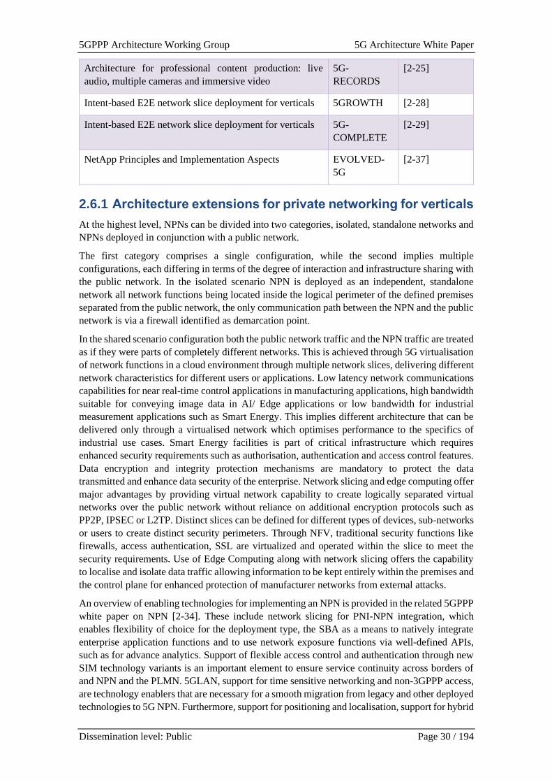
5GPPP Architecture Working Group 5G Architecture White Paper
Dissemination level: Public Page 30 / 194
Architecture for professional content production: live
audio, multiple cameras and immersive video
5G-
RECORDS
[2-25]
Intent-based E2E network slice deployment for verticals 5GROWTH [2-28]
Intent-based E2E network slice deployment for verticals 5G-
COMPLETE
[2-29]
NetApp Principles and Implementation Aspects EVOLVED-
5G
[2-37]
2.6.1 Architecture extensions for private networking for verticals
At the highest level, NPNs can be divided into two categories, isolated, standalone networks and
NPNs deployed in conjunction with a public network.
The first category comprises a single configuration, while the second implies multiple
configurations, each differing in terms of the degree of interaction and infrastructure sharing with
the public network. In the isolated scenario NPN is deployed as an independent, standalone
network all network functions being located inside the logical perimeter of the defined premises
separated from the public network, the only communication path between the NPN and the public
network is via a firewall identified as demarcation point.
In the shared scenario configuration both the public network traffic and the NPN traffic are treated
as if they were parts of completely different networks. This is achieved through 5G virtualisation
of network functions in a cloud environment through multiple network slices, delivering different
network characteristics for different users or applications. Low latency network communications
capabilities for near real-time control applications in manufacturing applications, high bandwidth
suitable for conveying image data in AI/ Edge applications or low bandwidth for industrial
measurement applications such as Smart Energy. This implies different architecture that can be
delivered only through a virtualised network which optimises performance to the specifics of
industrial use cases. Smart Energy facilities is part of critical infrastructure which requires
enhanced security requirements such as authorisation, authentication and access control features.
Data encryption and integrity protection mechanisms are mandatory to protect the data
transmitted and enhance data security of the enterprise. Network slicing and edge computing offer
major advantages by providing virtual network capability to create logically separated virtual
networks over the public network without reliance on additional encryption protocols such as
PP2P, IPSEC or L2TP. Distinct slices can be defined for different types of devices, sub-networks
or users to create distinct security perimeters. Through NFV, traditional security functions like
firewalls, access authentication, SSL are virtualized and operated within the slice to meet the
security requirements. Use of Edge Computing along with network slicing offers the capability
to localise and isolate data traffic allowing information to be kept entirely within the premises and
the control plane for enhanced protection of manufacturer networks from external attacks.
An overview of enabling technologies for implementing an NPN is provided in the related 5GPPP
white paper on NPN [2-34]. These include network slicing for PNI-NPN integration, which
enables flexibility of choice for the deployment type, the SBA as a means to natively integrate
enterprise application functions and to use network exposure functions via well-defined APIs,
such as for advance analytics. Support of flexible access control and authentication through new
SIM technology variants is an important element to ensure service continuity across borders of
and NPN and the PLMN. 5GLAN, support for time sensitive networking and non-3GPPP access,
are technology enablers that are necessary for a smooth migration from legacy and other deployed
technologies to 5G NPN. Furthermore, support for positioning and localisation, support for hybrid
5GPPP Architecture Working Group 5G Architecture White Paper
Dissemination level: Public Page 31 / 194
cloud constellations and support for various flavours of interconnection services between
decentralised NPNs of the same administrative domain are essential enablers responding to
business requirements and supporting the decision process for migration. Finally, the flexibility
to construct a small-scale NPN via integrated solutions like “5G network in a box” may provide
economic incentives for wide deployment of NPN solutions.
2.6.2 Extended layered network architectures for high-speed rail
transportation facilities
In modern railway transportation facilities, there is a demand for a broad range of novel on-board
services addressing various end-users, in particular applications for passengers, critical services
and emergency services to stakeholders engaged in train operation, as well as complementary
services related to optimization of train operation. These services are collectively denoted as
FRMCS services. A prototype network and associated deployment to facilitate train operations
and services considering the FRMCS service definition is developed in [2-9]. The project
evaluates the performance of FRMCS service over the Patras 5G facility – a testing infrastructure,
deployed at operational railway environment. In particular, it tests and demonstrates
representative Business, Performance and Critical services.
The architecture proposed should ensure that services are provided while the train moves through
Patras city centre, through heterogenous technologies, establishing high capacity low latency
connections at high speed mobility. High capacity is needed for the former services, in order to
provide high quality of service to passengers, whereas for the latter low latency/ ultra-reliable
connections are needed in order to transmit data obtained from various sources in real-time to the
train operations, driver and control centre. However, FRMCS service requirements, pose stringent
requirements for access network coverage. Applying common network planning principles that
ensures high-capacity coverage implies identifying the characteristics of the area under study.
These may vary from remote, isolated areas, with challenging terrain for radio coverage (e.g.,
mountainous, with many curves, tunnels, etc.) to metropolitan areas (e.g., with high buildings,
with many curves, tunnels etc.), along the railway tracks. Considering the access network capacity,
at least 300Mbps-1Gbps are required at train level, and in cases that this is not possible, data rates
of 1-1.5 Gbps are required at places where the train remains for some time, e.g., at platforms, at
train depots, etc. Furthermore, high speed mobility invokes impairments and fast fading effects
that cannot be pre-evaluated. Apparently, there is no single solution to address such environment.
At the same time in order to adhere to technology neutrality requirements, solutions comprising
various technologies, and aggregating backhaul traffic from multiple technologies access network
nodes at transport network segments are being considered.
To address the above-mentioned requirements, the deployed solution in [2-9] is based on a joint
flexible backhaul/fronthaul (FH/BH) network realized over heterogeneous wireless technologies,
to support dedicated disaggregated virtualized access nodes on top of high-speed moving trains.
A layered network architecture that integrates existing core network functionalities with
extensions is proposed that provides the flexibility required in this high speed, variable and
service-oriented environment. The integration takes place at four levels, with the fourth layer
laying at the Control Centre (edge) Data Centre.
At lower level lies a train on-board network. This consists of several compute and network
elements, all interconnected by fibre network. The proposed on-board network comprises a 10
Gbps Ethernet LAN with SDN-capable switches, connecting Sub-6 and mmWave antenna
modules to be installed on the roof of the train, and software-based 5G-NR and Wi-Fi APs to be
placed inside the train. The train-internal wireless part of the on-board segment comprises of SW-
based solutions for 5G NR and Wi-Fi, provided over an aggregation environment augmenting the
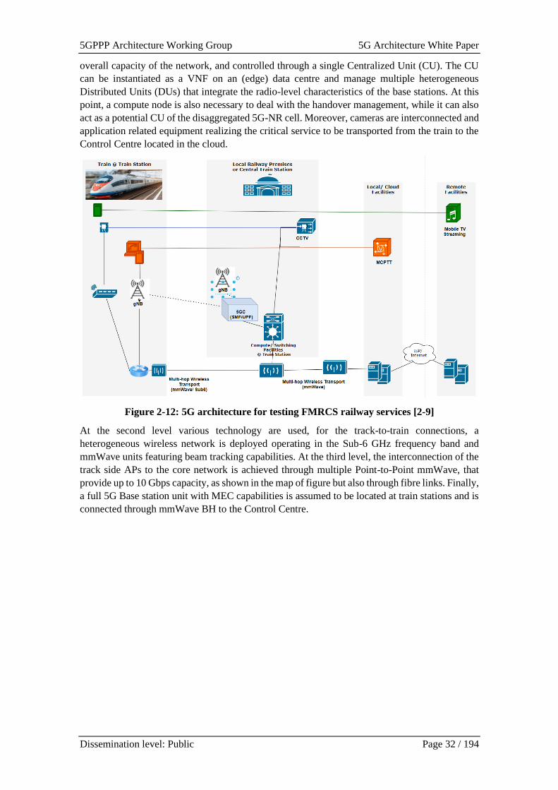
5GPPP Architecture Working Group 5G Architecture White Paper
Dissemination level: Public Page 32 / 194
overall capacity of the network, and controlled through a single Centralized Unit (CU). The CU
can be instantiated as a VNF on an (edge) data centre and manage multiple heterogeneous
Distributed Units (DUs) that integrate the radio-level characteristics of the base stations. At this
point, a compute node is also necessary to deal with the handover management, while it can also
act as a potential CU of the disaggregated 5G-NR cell. Moreover, cameras are interconnected and
application related equipment realizing the critical service to be transported from the train to the
Control Centre located in the cloud.
Figure 2-12: 5G architecture for testing FMRCS railway services [2-9]
At the second level various technology are used, for the track-to-train connections, a
heterogeneous wireless network is deployed operating in the Sub-6 GHz frequency band and
mmWave units featuring beam tracking capabilities. At the third level, the interconnection of the
track side APs to the core network is achieved through multiple Point-to-Point mmWave, that
provide up to 10 Gbps capacity, as shown in the map of figure but also through fibre links. Finally,
a full 5G Base station unit with MEC capabilities is assumed to be located at train stations and is
connected through mmWave BH to the Control Centre.
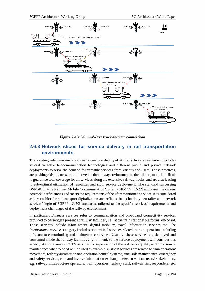
5GPPP Architecture Working Group 5G Architecture White Paper
Dissemination level: Public Page 33 / 194
Figure 2-13: 5G mmWave track-to-train connections
2.6.3 Network slices for service delivery in rail transportation
environments
The existing telecommunications infrastructure deployed at the railway environment includes
several versatile telecommunication technologies and different public and private network
deployments to serve the demand for versatile services from various end-users. These practices,
are pushing existing networks deployed in the railway environment to their limits, make it difficult
to guarantee total coverage for all services along the extensive railway tracks, and are also leading
to sub-optimal utilization of resources and slow service deployment. The standard succussing
GSM-R, Future Railway Mobile Communication System (FRMCS) [2-22] addresses the current
network inefficiencies and meets the requirements of the aforementioned services. It is considered
as key enabler for rail transport digitalization and reflects the technology neutrality and network
services’ logic of 3GPPP 4G/5G standards, tailored to the specific services’ requirements and
deployment challenges of the railway environment
In particular, Business services refer to communication and broadband connectivity services
provided to passengers present at railway facilities, i.e., at the train stations/ platforms, on-board.
These services include infotainment, digital mobility, travel information services etc. The
Performance services category includes non-critical services related to train operation, including
infrastructure monitoring and maintenance services. Usually, these services are deployed and
consumed inside the railway facilities environment, so the service deployment will consider this
aspect, like for example CCTV services for supervision of the rail tracks quality and provision of
maintenance when needed will be used as example. Critical services are related to train operation/
movement, railway automation and operation control systems, trackside maintenance, emergency
and safety services, etc., and involve information exchange between various users/ stakeholders,
e.g. railway infrastructure operators, train operators, railway staff, railway first responders, etc.
5GPPP Architecture Working Group 5G Architecture White Paper
Dissemination level: Public Page 34 / 194
Usually, these services are deployed and consumed inside the railway facilities environment, so
also in this case the service deployment will take this aspect into consideration. Examples of these
are Mission-Critical Push-to-Talk (MCPTT) and Mission Critical Data (e.g. between the
controller(s) at the train/ operations centre and the driver/ on-board staff etc.)
The on-board hosted services correspond to three different slices, which are instantiated
concurrently for providing the required network substrate to the hosted services. The three
services correspond to three different slices; 1) an eMBB slice, for providing on-board users with
high-speed Internet connectivity and video streaming services, 2) an eMBB and URLLC slice,
for providing a low-latency and high-bandwidth connection for the track-monitoring service to
the cloud, and 3) a URLLC slice for providing low-latency communications for a MCPTT service
needed for the operation control of the railway system.
Regarding the first slice instantiation, it spans the entire network from the Data Centre to the train
on-board, across several of the deployed components. It focuses on providing seamless
connection as the train crosses the different track-side stanchions, facilitated by a mobility
management solution, and focuses on providing high-speed network connectivity to the cloud.
The components across which the eMBB slice is instantiated comprise all backhaul and fronthaul
elements and mobility management modules and functions.
Regarding the second slice instantiation, it relies on high-speed and low-latency communications
for transmitting the track video footage in real time to the rail Operation Control Centre (OCC).
As the OCC is instantiated in the data centre, the slice spans the entire network as well (on-board,
track-to-train, track-to-cloud) and adopts characteristics of both eMBB and URLLC. The
components comprising the slice for the second service comprise all technology elements together
with application specific modules.
Finally, for the MCPTT service running on-board, the network is requested to provide a URLLC
slice. The MCPTT service that is used does not have stringent requirements in terms of
throughput, but relies on low-latency connections that ensure the smooth operation of the system.
As MCPTT relies on a server instantiation for managing the connections among terminals, the
server is instantiated in the data centre. Therefore, the URLLC slice will span the entire network
from the cloud to on-board train.
2.6.4 E2E network architecture extension for digital mobility
services related KPIs
5GUK Test Network [2-11] has integrated multi-vendor, multi-architectural and multi-RAT
designs in order to enhance current telecommunications services for a number of futuristic digital
mobility use case demonstrations incorporating three different applications: APP1, APP2 and
APP3. These applications have been defined according to the requirements set by the Digital
Mobility UC-Bristol [2-5], as follows:
• APP1 provides immersive media and VR services to travellers arriving at MShed. A
synchronous 360° tour guide at specific geolocations is given to a group of users with 5G
connectivity. In order to support user mobility, the facility at Bristol provides seamless
connectivity to users when they are moving from one location to another, even during a
boat trip. Edge synchronization and streaming server services need to follow user
mobility and move to different edges accordingly. By doing so, a seamless virtual tour
guide is realised along the demonstration route in the city of Bristol.
• APP2 implements a remote training class taking place at the University of Bristol. Users
with access to the 5GUK test network or the network at University of Patras can stream
the 360° VR camera feed in real-time and at any location covered by the 5GUK test
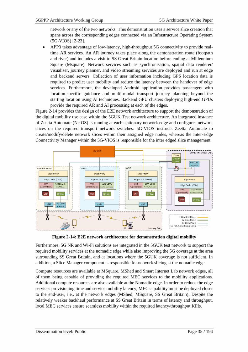
5GPPP Architecture Working Group 5G Architecture White Paper
Dissemination level: Public Page 35 / 194
network or any of the two networks. This demonstration uses a service slice creation that
spans across the corresponding edges connected via an Infrastructure Operating System
(5G-VIOS) [2-23].
• APP3 takes advantage of low-latency, high-throughput 5G connectivity to provide real-
time AR services. An AR journey takes place along the demonstration route (footpath
and river) and includes a visit to SS Great Britain location before ending at Millennium
Square (Msquare). Network services such as synchronisation, spatial data renderer/
visualiser, journey planner, and video streaming services are deployed and run at edge
and backend servers. Collection of user information including GPS location data is
required to predict user mobility and reduce the latency between the handover of edge
services. Furthermore, the developed Android application provides passengers with
location-specific guidance and multi-modal transport journey planning beyond the
starting location using AI techniques. Backend GPU clusters deploying high-end GPUs
provide the required AR and AI processing at each of the edges.
Figure 2-14 provides the design of the E2E network architecture to support the demonstration of
the digital mobility use case within the 5GUK Test network architecture. An integrated instance
of Zeetta Automate (NetOS) is running at each stationary network edge and configures network
slices on the required transport network switches. 5G-VIOS instructs Zeetta Automate to
create/modify/delete network slices within their assigned edge nodes, whereas the Inter-Edge
Connectivity Manager within the 5G-VIOS is responsible for the inter edged slice management.
Figure 2-14: E2E network architecture for demonstration digital mobility
Furthermore, 5G NR and Wi-Fi solutions are integrated in the 5GUK test network to support the
required mobility services at the nomadic edge while also improving the 5G coverage at the area
surrounding SS Great Britain, and at locations where the 5GUK coverage is not sufficient. In
addition, a Slice Manager component is responsible for network slicing at the nomadic edge.
Compute resources are available at MSquare, MShed and Smart Internet Lab network edges, all
of them being capable of providing the required MEC services to the mobility applications.
Additional compute resources are also available at the Nomadic edge. In order to reduce the edge
services provisioning time and service mobility latency, MEC capability must be deployed closer
to the end-user, i.e., at the network edges (MShed, MSquare, SS Great Britain). Despite the
relatively weaker backhaul performance at SS Great Britain in terms of latency and throughput,
local MEC services ensure seamless mobility within the required latency/throughput KPIs.
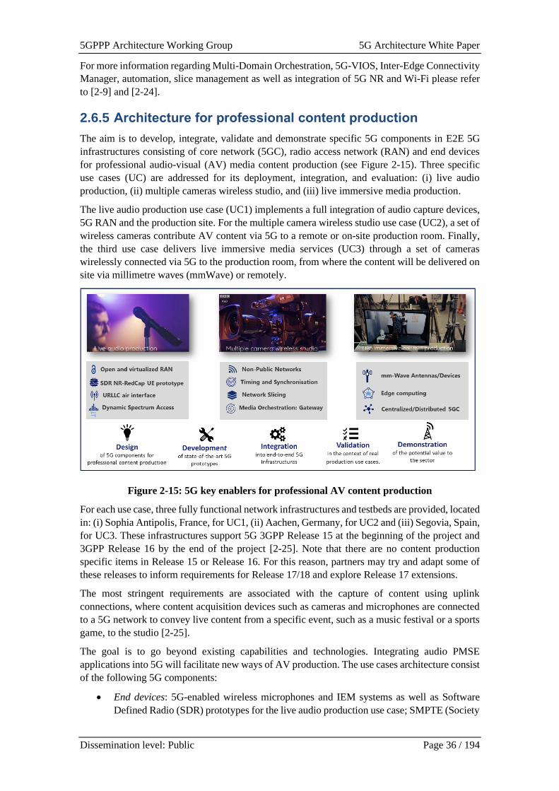
5GPPP Architecture Working Group 5G Architecture White Paper
Dissemination level: Public Page 36 / 194
For more information regarding Multi-Domain Orchestration, 5G-VIOS, Inter-Edge Connectivity
Manager, automation, slice management as well as integration of 5G NR and Wi-Fi please refer
to [2-9] and [2-24].
2.6.5 Architecture for professional content production
The aim is to develop, integrate, validate and demonstrate specific 5G components in E2E 5G
infrastructures consisting of core network (5GC), radio access network (RAN) and end devices
for professional audio-visual (AV) media content production (see Figure 2-15). Three specific
use cases (UC) are addressed for its deployment, integration, and evaluation: (i) live audio
production, (ii) multiple cameras wireless studio, and (iii) live immersive media production.
The live audio production use case (UC1) implements a full integration of audio capture devices,
5G RAN and the production site. For the multiple camera wireless studio use case (UC2), a set of
wireless cameras contribute AV content via 5G to a remote or on-site production room. Finally,
the third use case delivers live immersive media services (UC3) through a set of cameras
wirelessly connected via 5G to the production room, from where the content will be delivered on
site via millimetre waves (mmWave) or remotely.
Figure 2-15: 5G key enablers for professional AV content production
For each use case, three fully functional network infrastructures and testbeds are provided, located
in: (i) Sophia Antipolis, France, for UC1, (ii) Aachen, Germany, for UC2 and (iii) Segovia, Spain,
for UC3. These infrastructures support 5G 3GPP Release 15 at the beginning of the project and
3GPP Release 16 by the end of the project [2-25]. Note that there are no content production
specific items in Release 15 or Release 16. For this reason, partners may try and adapt some of
these releases to inform requirements for Release 17/18 and explore Release 17 extensions.
The most stringent requirements are associated with the capture of content using uplink
connections, where content acquisition devices such as cameras and microphones are connected
to a 5G network to convey live content from a specific event, such as a music festival or a sports
game, to the studio [2-25].
The goal is to go beyond existing capabilities and technologies. Integrating audio PMSE
applications into 5G will facilitate new ways of AV production. The use cases architecture consist
of the following 5G components:
• End devices: 5G-enabled wireless microphones and IEM systems as well as Software
Defined Radio (SDR) prototypes for the live audio production use case; SMPTE (Society
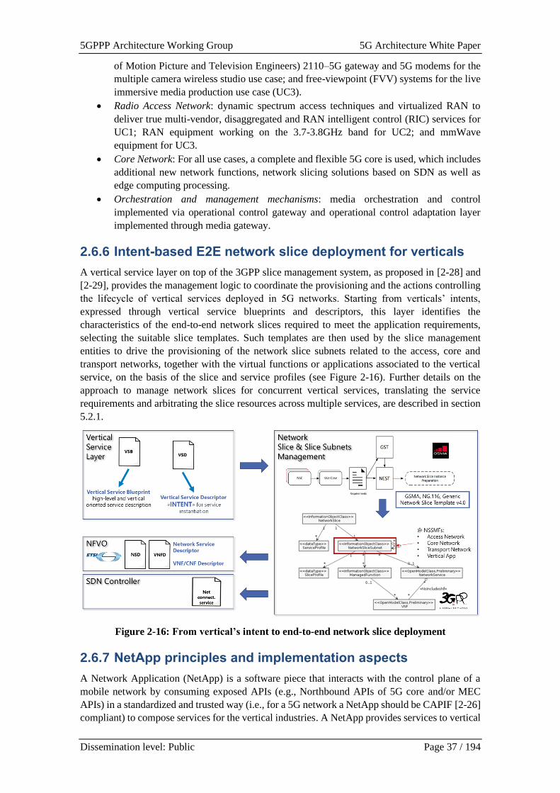
5GPPP Architecture Working Group 5G Architecture White Paper
Dissemination level: Public Page 37 / 194
of Motion Picture and Television Engineers) 2110–5G gateway and 5G modems for the
multiple camera wireless studio use case; and free-viewpoint (FVV) systems for the live
immersive media production use case (UC3).
• Radio Access Network: dynamic spectrum access techniques and virtualized RAN to
deliver true multi-vendor, disaggregated and RAN intelligent control (RIC) services for
UC1; RAN equipment working on the 3.7-3.8GHz band for UC2; and mmWave
equipment for UC3.
• Core Network: For all use cases, a complete and flexible 5G core is used, which includes
additional new network functions, network slicing solutions based on SDN as well as
edge computing processing.
• Orchestration and management mechanisms: media orchestration and control
implemented via operational control gateway and operational control adaptation layer
implemented through media gateway.
2.6.6 Intent-based E2E network slice deployment for verticals
A vertical service layer on top of the 3GPP slice management system, as proposed in [2-28] and
[2-29], provides the management logic to coordinate the provisioning and the actions controlling
the lifecycle of vertical services deployed in 5G networks. Starting from verticals’ intents,
expressed through vertical service blueprints and descriptors, this layer identifies the
characteristics of the end-to-end network slices required to meet the application requirements,
selecting the suitable slice templates. Such templates are then used by the slice management
entities to drive the provisioning of the network slice subnets related to the access, core and
transport networks, together with the virtual functions or applications associated to the vertical
service, on the basis of the slice and service profiles (see Figure 2-16). Further details on the
approach to manage network slices for concurrent vertical services, translating the service
requirements and arbitrating the slice resources across multiple services, are described in section
5.2.1.
Figure 2-16: From vertical’s intent to end-to-end network slice deployment
2.6.7 NetApp principles and implementation aspects
A Network Application (NetApp) is a software piece that interacts with the control plane of a
mobile network by consuming exposed APIs (e.g., Northbound APIs of 5G core and/or MEC
APIs) in a standardized and trusted way (i.e., for a 5G network a NetApp should be CAPIF [2-26]
compliant) to compose services for the vertical industries. A NetApp provides services to vertical

5GPPP Architecture Working Group 5G Architecture White Paper
Dissemination level: Public Page 38 / 194
applications either as an integrated part of the vertical application or by exposing APIs, which are
referred to as business APIs.
The NetApp ecosystem is more than the introduction of new vertical applications that have 5G-
interaction capabilities; it refers to the request for a separated middleware layer that will simplify
the implementation and deployment of vertical systems at large scale (considering also the
adaptation needed for Non-Public 5G Network – 5G NPN deployments). This is the same request
that triggered the development of Vertical Application Enablers (VAE) by 3GPP SA6 [2-27].
Considering the level of interaction and trust, the NetApps are classified to:
• Third-party NetApp. NetApp that resides at a trusted third-party domain. A third-party
NetApp consumes Northbound APIs and, also, supports trust mechanisms and security
policies defined by the network for the verticals.
• Operator NetApp. NetApps that reside at the operator domain, considering mainly NPN
deployments, and, potentially, it can have further access to 5G network capabilities,
beyond those provided through the Northbound APIs (e.g., vertical specific functionality
at the OSS for slice management) and are available in a third-party NetApp.
Considering the way that the services are provided to verticals, the NetApps are classified to:
• Standalone NetApp that provides complete services to one or more vertical industries,
either directly or through its integration to a vertical application. A NetApp that is
integrated into a vertical application, enhances the functionality of the application by
adding network management and monitoring capabilities exposed by the 5G network.
• Non-Standalone NetApp that operates as a wrapper of Northbound APIs to expose
services through Business APIs. It is an auxiliary non-standalone software piece (in the
sense that it becomes functional when its business APIs are consumed by an app). A Non-
Standalone NetApp allows vertical applications to be developed/upgraded (and take
advantage of the 5G exposure capabilities) without changing integral parts of their
software, i.e., only by consuming the business APIs.
Figure 2-17: Third-party Standalone NetApp representation
Figure 2-18: Third-party Non-standalone NetApp representation
From architectural perspective, a NetApp is part of the Vertical Application Server (VAS) as
defined by [2-27].
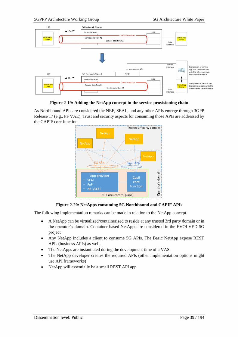
5GPPP Architecture Working Group 5G Architecture White Paper
Dissemination level: Public Page 39 / 194
Figure 2-19: Adding the NetApp concept in the service provisioning chain
As Northbound APIs are considered the NEF, SEAL, and any other APIs emerge through 3GPP
Release 17 (e.g., FF VAE). Trust and security aspects for consuming those APIs are addressed by
the CAPIF core function.
Figure 2-20: NetApps consuming 5G Northbound and CAPIF APIs
The following implementation remarks can be made in relation to the NetApp concept.
• A NetApp can be virtualized/containerized to reside at any trusted 3rd party domain or in
the operator’s domain. Container based NetApps are considered in the EVOLVED-5G
project
• Any NetApp includes a client to consume 5G APIs. The Basic NetApp expose REST
APIs (business APIs) as well.
• The NetApps are instantiated during the development time of a VAS.
• The NetApp developer creates the required APIs (other implementation options might
use API frameworks)
• NetApp will essentially be a small REST API app
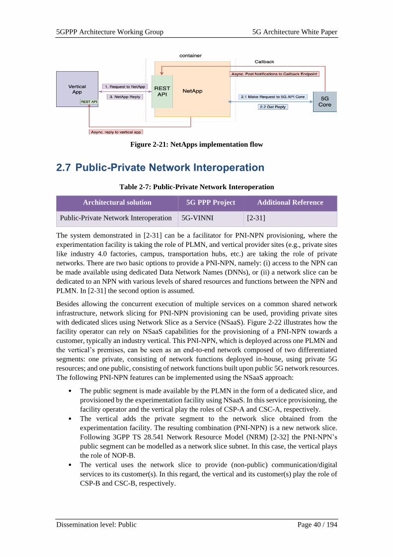
5GPPP Architecture Working Group 5G Architecture White Paper
Dissemination level: Public Page 40 / 194
Figure 2-21: NetApps implementation flow
2.7 Public-Private Network Interoperation
Table 2-7: Public-Private Network Interoperation
Architectural solution 5G PPP Project Additional Reference
Public-Private Network Interoperation 5G-VINNI [2-31]
The system demonstrated in [2-31] can be a facilitator for PNI-NPN provisioning, where the
experimentation facility is taking the role of PLMN, and vertical provider sites (e.g., private sites
like industry 4.0 factories, campus, transportation hubs, etc.) are taking the role of private
networks. There are two basic options to provide a PNI-NPN, namely: (i) access to the NPN can
be made available using dedicated Data Network Names (DNNs), or (ii) a network slice can be
dedicated to an NPN with various levels of shared resources and functions between the NPN and
PLMN. In [2-31] the second option is assumed.
Besides allowing the concurrent execution of multiple services on a common shared network
infrastructure, network slicing for PNI-NPN provisioning can be used, providing private sites
with dedicated slices using Network Slice as a Service (NSaaS). Figure 2-22 illustrates how the
facility operator can rely on NSaaS capabilities for the provisioning of a PNI-NPN towards a
customer, typically an industry vertical. This PNI-NPN, which is deployed across one PLMN and
the vertical’s premises, can be seen as an end-to-end network composed of two differentiated
segments: one private, consisting of network functions deployed in-house, using private 5G
resources; and one public, consisting of network functions built upon public 5G network resources.
The following PNI-NPN features can be implemented using the NSaaS approach:
• The public segment is made available by the PLMN in the form of a dedicated slice, and
provisioned by the experimentation facility using NSaaS. In this service provisioning, the
facility operator and the vertical play the roles of CSP-A and CSC-A, respectively.
• The vertical adds the private segment to the network slice obtained from the
experimentation facility. The resulting combination (PNI-NPN) is a new network slice.
Following 3GPP TS 28.541 Network Resource Model (NRM) [2-32] the PNI-NPN’s
public segment can be modelled as a network slice subnet. In this case, the vertical plays
the role of NOP-B.
• The vertical uses the network slice to provide (non-public) communication/digital
services to its customer(s). In this regard, the vertical and its customer(s) play the role of
CSP-B and CSC-B, respectively.
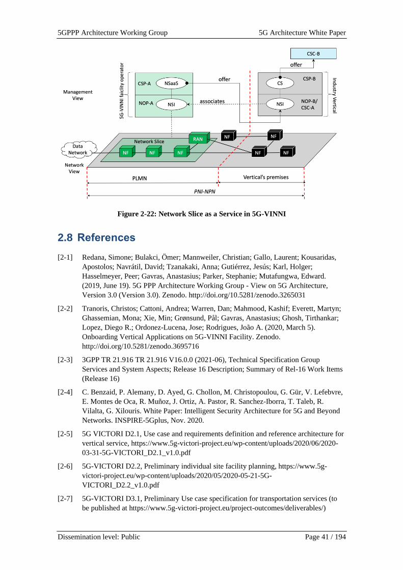
5GPPP Architecture Working Group 5G Architecture White Paper
Dissemination level: Public Page 41 / 194
Figure 2-22: Network Slice as a Service in 5G-VINNI
2.8 References
[2-1] Redana, Simone; Bulakci, Ömer; Mannweiler, Christian; Gallo, Laurent; Kousaridas,
Apostolos; Navrátil, David; Tzanakaki, Anna; Gutiérrez, Jesús; Karl, Holger;
Hasselmeyer, Peer; Gavras, Anastasius; Parker, Stephanie; Mutafungwa, Edward.
(2019, June 19). 5G PPP Architecture Working Group - View on 5G Architecture,
Version 3.0 (Version 3.0). Zenodo. http://doi.org/10.5281/zenodo.3265031
[2-2] Tranoris, Christos; Cattoni, Andrea; Warren, Dan; Mahmood, Kashif; Everett, Martyn;
Ghassemian, Mona; Xie, Min; Grønsund, Pål; Gavras, Anastasius; Ghosh, Tirthankar;
Lopez, Diego R.; Ordonez-Lucena, Jose; Rodrigues, João A. (2020, March 5).
Onboarding Vertical Applications on 5G-VINNI Facility. Zenodo.
http://doi.org/10.5281/zenodo.3695716
[2-3] 3GPP TR 21.916 TR 21.916 V16.0.0 (2021-06), Technical Specification Group
Services and System Aspects; Release 16 Description; Summary of Rel-16 Work Items
(Release 16)
[2-4] C. Benzaid, P. Alemany, D. Ayed, G. Chollon, M. Christopoulou, G. Gür, V. Lefebvre,
E. Montes de Oca, R. Muñoz, J. Ortiz, A. Pastor, R. Sanchez-Iborra, T. Taleb, R.
Vilalta, G. Xilouris. White Paper: Intelligent Security Architecture for 5G and Beyond
Networks. INSPIRE-5Gplus, Nov. 2020.
[2-5] 5G VICTORI D2.1, Use case and requirements definition and reference architecture for
vertical service, https://www.5g-victori-project.eu/wp-content/uploads/2020/06/2020-
03-31-5G-VICTORI_D2.1_v1.0.pdf
[2-6] 5G-VICTORI D2.2, Preliminary individual site facility planning, https://www.5g-
victori-project.eu/wp-content/uploads/2020/05/2020-05-21-5G-
VICTORI_D2.2_v1.0.pdf
[2-7] 5G-VICTORI D3.1, Preliminary Use case specification for transportation services (to
be published at https://www.5g-victori-project.eu/project-outcomes/deliverables/)
5GPPP Architecture Working Group 5G Architecture White Paper
Dissemination level: Public Page 42 / 194
[2-8] 5G-VICTORI D3.3 Preliminary Use case specification for Media Services (to be
published at https://www.5g-victori-project.eu/project-outcomes/deliverables/)
[2-9] 5G-VICTORI project, Vertical demos over common large scale field trials for rail,
energy and media industries, https://www.5g-victori-project.eu/
[2-10] 5G-SOLUTIONS project, 5G - Solutions for European Citizens,
https://5gsolutionsproject.eu/
[2-11] 5GUK Test Network, http://www.bristol.ac.uk/engineering/research/smart/5guk/
[2-12] 3GPP TS 28.533 v16.0.0, “Management and orchestration of networks and network
slicing; Management and orchestration architecture (Release 16),” June 2019.
[2-13] A. Banchs, D. M. Gutierrez-Estevez, M. Fuentes, M. Boldi and S. Provvedi, "A 5G
Mobile Network Architecture to Support Vertical Industries," in IEEE Communications
Magazine, vol. 57, no. 12, pp. 38-44, December 2019, doi:
10.1109/MCOM.001.1900258.
[2-14] https://www.gsma.com/newsroom/wp-content/uploads//NG.116-v4.0-2.pdf
[2-15] OpenStack: Open Source Cloud Computing Infrastructure, Online:
https://www.openstack.org/
[2-16] OSM – Open-Source Management and Orchestration (MANO) , Online:
https://osm.etsi.org/
[2-17] Kubernetes (K8s) – Open-Source system for automating deployment, scaling, and
management of containerized applications, Online: https://kubernetes.io/
[2-18] ETSI GS NFV-SOL 009 V3.5.1 (2021-06), ETSI GS NFV-SOL 009 V3.5.1 (2021-06)
Network Functions Virtualisation (NFV) Release 3; Protocols and Data Models;
RESTful protocols specification for the management of NFV-MANO
[2-19] IETF I2NSF Capability YANG Data Model, draft-ietf-i2nsf-capability-data-model-16 ,
Online: https://datatracker.ietf.org/doc/html/draft-ietf-i2nsf-capability-data-model
[2-20] TMForum, Data Model, Online:
https://www.tmforum.org/resources/specification/tmf625-ode-data-model-r14-5-1/
[2-21] FUDGE-5G project, Fully Disintegrated private networks for 5G verticals, Online:
https://fudge-5g.eu
[2-22] Mesogiti I. et al. (2021) 5G-VICTORI: Future Railway Communications Requirements
Driving 5G Deployments in Railways. In: Maglogiannis I., Macintyre J., Iliadis L. (eds)
Artificial Intelligence Applications and Innovations. AIAI 2021 IFIP WG 12.5
International Workshops. AIAI 2021. IFIP Advances in Information and
Communication Technology, vol 628. Springer, Cham. https://doi.org/10.1007/978-3-
030-79157-5_2
[2-23] 5G VICTORI D2.5, Infrastructure Operating System (5G-VIOS) – Initial Design
Specification, Online: https://www.5g-victori-project.eu/wp-
content/uploads/2020/10/2020-07-31-5G-VICTORI_D2.5_v1.0.pdf
[2-24] 5G-VICTORI D4.1, Field trials methodology and guidelines, Online: https://www.5g-
victori-project.eu/wp-content/uploads/2020/10/2020-09-25-5G
VICTORI_D4.1_v1.0_Website_Version.pdf
[2-25] 5G-RECORDS project, 5G kex technology enablers for emerging media content
production services, Online: https://www.5g-records.eu/
5GPPP Architecture Working Group 5G Architecture White Paper
Dissemination level: Public Page 43 / 194
[2-26] 3GPP TS 23.222 V17.5.0 (2021-06); Functional architecture and information flows to
support Common API Framework for 3GPP Northbound APIs; Stage 2 (Release 17)
[2-27] 3GPP SA6 - Mission-critical applications, Online: https://www.3gpp.org/specifications-
groups/sa-plenary/sa6-mission-critical-applications
[2-28] 5GROWTH deliverable D2.3, “Final design and evaluation of the innovations of the 5G
end-to-end service platform”, May 2021
[2-29] 5G-COMPLETE deliverable D5.1, “Initial report on the development of 5G-
COMPLETE orchestration framework”, June 2021
[2-30] A. Kaloxylos, A. Gavras, D. Camps Mur, M. Ghoraishi, and H. Hrasnica, (2020,
December 1). AI and ML – Enablers for Beyond 5G Networks. Zenodo.
http://doi.org/10.5281/zenodo.4299895
[2-31] Project 5G-VINNI, Online: https://www.5g-vinni.eu/
[2-32] 3GPP TS 28.541, Management and orchestration; 5G Network Resource Model
(NRM); Stage 2 and 3, 2018
[2-33] 5G IA, Vision and Societal Challenges, Business Validation, Models, and Ecosystems
Sub-Group, “5G ecosystems” (August 2021), doi: 10.5281/zenodo.5094340
[2-34] 5G PPP whitepaper, “Non-Public-Networks – State of the art and way forward”, doi:
10.5281/zenodo.5118839, https://doi.org/10.5281/zenodo. 5118839
[2-35] Project 5G-HEART, Online: https://5gheart.org/
[2-36] Project 5G-TOURS, Online: https://5gtours.eu/
[2-37] Project Evolved-5G, Online: https://evolved-5g.eu/
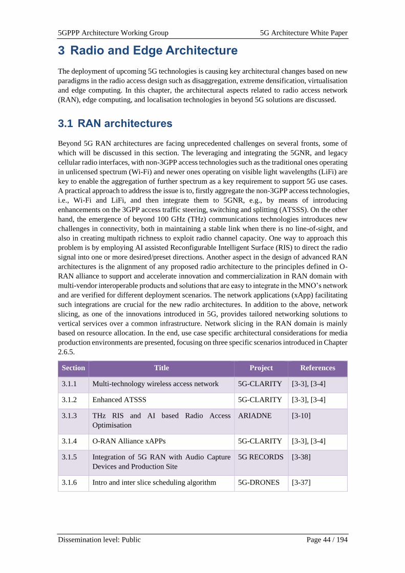
5GPPP Architecture Working Group 5G Architecture White Paper
Dissemination level: Public Page 44 / 194
3 Radio and Edge Architecture
The deployment of upcoming 5G technologies is causing key architectural changes based on new
paradigms in the radio access design such as disaggregation, extreme densification, virtualisation
and edge computing. In this chapter, the architectural aspects related to radio access network
(RAN), edge computing, and localisation technologies in beyond 5G solutions are discussed.
3.1 RAN architectures
Beyond 5G RAN architectures are facing unprecedented challenges on several fronts, some of
which will be discussed in this section. The leveraging and integrating the 5GNR, and legacy
cellular radio interfaces, with non-3GPP access technologies such as the traditional ones operating
in unlicensed spectrum (Wi-Fi) and newer ones operating on visible light wavelengths (LiFi) are
key to enable the aggregation of further spectrum as a key requirement to support 5G use cases.
A practical approach to address the issue is to, firstly aggregate the non-3GPP access technologies,
i.e., Wi-Fi and LiFi, and then integrate them to 5GNR, e.g., by means of introducing
enhancements on the 3GPP access traffic steering, switching and splitting (ATSSS). On the other
hand, the emergence of beyond 100 GHz (THz) communications technologies introduces new
challenges in connectivity, both in maintaining a stable link when there is no line-of-sight, and
also in creating multipath richness to exploit radio channel capacity. One way to approach this
problem is by employing AI assisted Reconfigurable Intelligent Surface (RIS) to direct the radio
signal into one or more desired/preset directions. Another aspect in the design of advanced RAN
architectures is the alignment of any proposed radio architecture to the principles defined in O-
RAN alliance to support and accelerate innovation and commercialization in RAN domain with
multi-vendor interoperable products and solutions that are easy to integrate in the MNO’s network
and are verified for different deployment scenarios. The network applications (xApp) facilitating
such integrations are crucial for the new radio architectures. In addition to the above, network
slicing, as one of the innovations introduced in 5G, provides tailored networking solutions to
vertical services over a common infrastructure. Network slicing in the RAN domain is mainly
based on resource allocation. In the end, use case specific architectural considerations for media
production environments are presented, focusing on three specific scenarios introduced in Chapter
2.6.5.
Section Title Project References
3.1.1 Multi-technology wireless access network 5G-CLARITY [3-3], [3-4]
3.1.2 Enhanced ATSSS 5G-CLARITY [3-3], [3-4]
3.1.3 THz RIS and AI based Radio Access
Optimisation
ARIADNE [3-10]
3.1.4 O-RAN Alliance xAPPs 5G-CLARITY [3-3], [3-4]
3.1.5 Integration of 5G RAN with Audio Capture
Devices and Production Site
5G RECORDS [3-38]
3.1.6 Intro and inter slice scheduling algorithm 5G-DRONES [3-37]
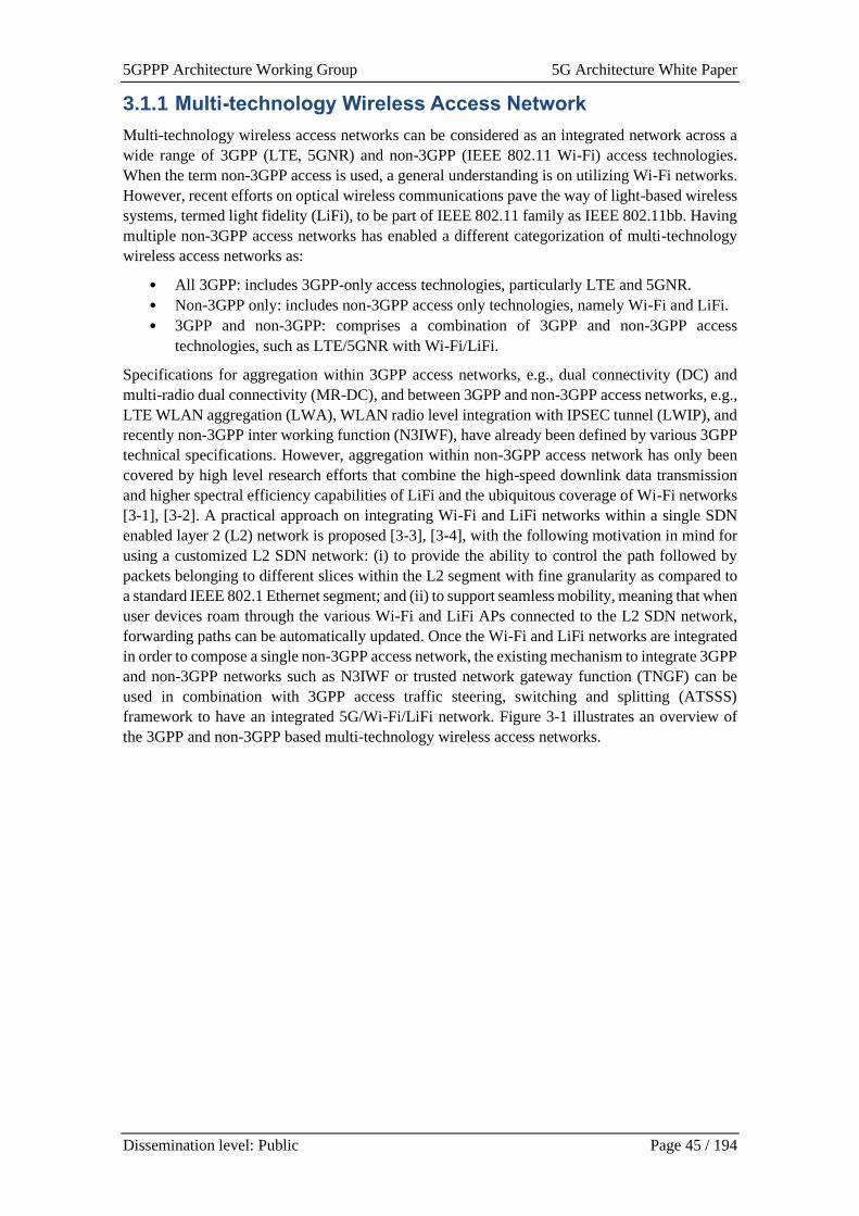
5GPPP Architecture Working Group 5G Architecture White Paper
Dissemination level: Public Page 45 / 194
3.1.1 Multi-technology Wireless Access Network
Multi-technology wireless access networks can be considered as an integrated network across a
wide range of 3GPP (LTE, 5GNR) and non-3GPP (IEEE 802.11 Wi-Fi) access technologies.
When the term non-3GPP access is used, a general understanding is on utilizing Wi-Fi networks.
However, recent efforts on optical wireless communications pave the way of light-based wireless
systems, termed light fidelity (LiFi), to be part of IEEE 802.11 family as IEEE 802.11bb. Having
multiple non-3GPP access networks has enabled a different categorization of multi-technology
wireless access networks as:
• All 3GPP: includes 3GPP-only access technologies, particularly LTE and 5GNR.
• Non-3GPP only: includes non-3GPP access only technologies, namely Wi-Fi and LiFi.
• 3GPP and non-3GPP: comprises a combination of 3GPP and non-3GPP access
technologies, such as LTE/5GNR with Wi-Fi/LiFi.
Specifications for aggregation within 3GPP access networks, e.g., dual connectivity (DC) and
multi-radio dual connectivity (MR-DC), and between 3GPP and non-3GPP access networks, e.g.,
LTE WLAN aggregation (LWA), WLAN radio level integration with IPSEC tunnel (LWIP), and
recently non-3GPP inter working function (N3IWF), have already been defined by various 3GPP
technical specifications. However, aggregation within non-3GPP access network has only been
covered by high level research efforts that combine the high-speed downlink data transmission
and higher spectral efficiency capabilities of LiFi and the ubiquitous coverage of Wi-Fi networks
[3-1], [3-2]. A practical approach on integrating Wi-Fi and LiFi networks within a single SDN
enabled layer 2 (L2) network is proposed [3-3], [3-4], with the following motivation in mind for
using a customized L2 SDN network: (i) to provide the ability to control the path followed by
packets belonging to different slices within the L2 segment with fine granularity as compared to
a standard IEEE 802.1 Ethernet segment; and (ii) to support seamless mobility, meaning that when
user devices roam through the various Wi-Fi and LiFi APs connected to the L2 SDN network,
forwarding paths can be automatically updated. Once the Wi-Fi and LiFi networks are integrated
in order to compose a single non-3GPP access network, the existing mechanism to integrate 3GPP
and non-3GPP networks such as N3IWF or trusted network gateway function (TNGF) can be
used in combination with 3GPP access traffic steering, switching and splitting (ATSSS)
framework to have an integrated 5G/Wi-Fi/LiFi network. Figure 3-1 illustrates an overview of
the 3GPP and non-3GPP based multi-technology wireless access networks.
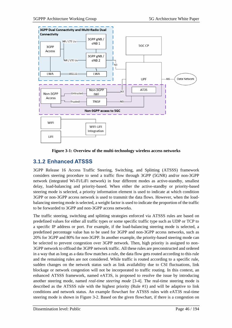
5GPPP Architecture Working Group 5G Architecture White Paper
Dissemination level: Public Page 46 / 194
Figure 3-1: Overview of the multi-technology wireless access networks
3.1.2 Enhanced ATSSS
3GPP Release 16 Access Traffic Steering, Switching, and Splitting (ATSSS) framework
considers steering procedure to send a traffic flow through 3GPP (5GNR) and/or non-3GPP
network (integrated Wi-Fi/LiFi network) in four different modes as active-standby, smallest
delay, load-balancing and priority-based. When either the active-standby or priority-based
steering mode is selected, a priority information element is used to indicate at which condition
3GPP or non-3GPP access network is used to transmit the data flows. However, when the load-
balancing steering mode is selected, a weight factor is used to indicate the proportion of the traffic
to be forwarded to 3GPP and non-3GPP access networks.
The traffic steering, switching and splitting strategies enforced via ATSSS rules are based on
predefined values for either all traffic types or some specific traffic type such as UDP or TCP to
a specific IP address or port. For example, if the load-balancing steering mode is selected, a
predefined percentage value has to be used for 3GPP and non-3GPP access networks, such as
20% for 3GPP and 80% for non-3GPP. In another example, the priority-based steering mode can
be selected to prevent congestion over 3GPP network. Then, high priority is assigned to non-
3GPP network to offload the 3GPP network traffic. All these rules are preconstructed and ordered
in a way that as long as a data flow matches a rule, the data flow gets routed according to this rule
and the remaining rules are not considered. While traffic is routed according to a specific rule,
sudden changes on the network status such as link availability due to CSI fluctuations, link
blockage or network congestion will not be incorporated to traffic routing. In this context, an
enhanced ATSSS framework, named eAT3S, is proposed to resolve the issue by introducing
another steering mode, named real-time steering mode [3-4]. The real-time steering mode is
described as the ATSSS rule with the highest priority (Rule #1) and will be adaptive to link
conditions and network status. An example flowchart for ATSSS rules with eAT3S real-time
steering mode is shown in Figure 3-2. Based on the given flowchart, if there is a congestion on
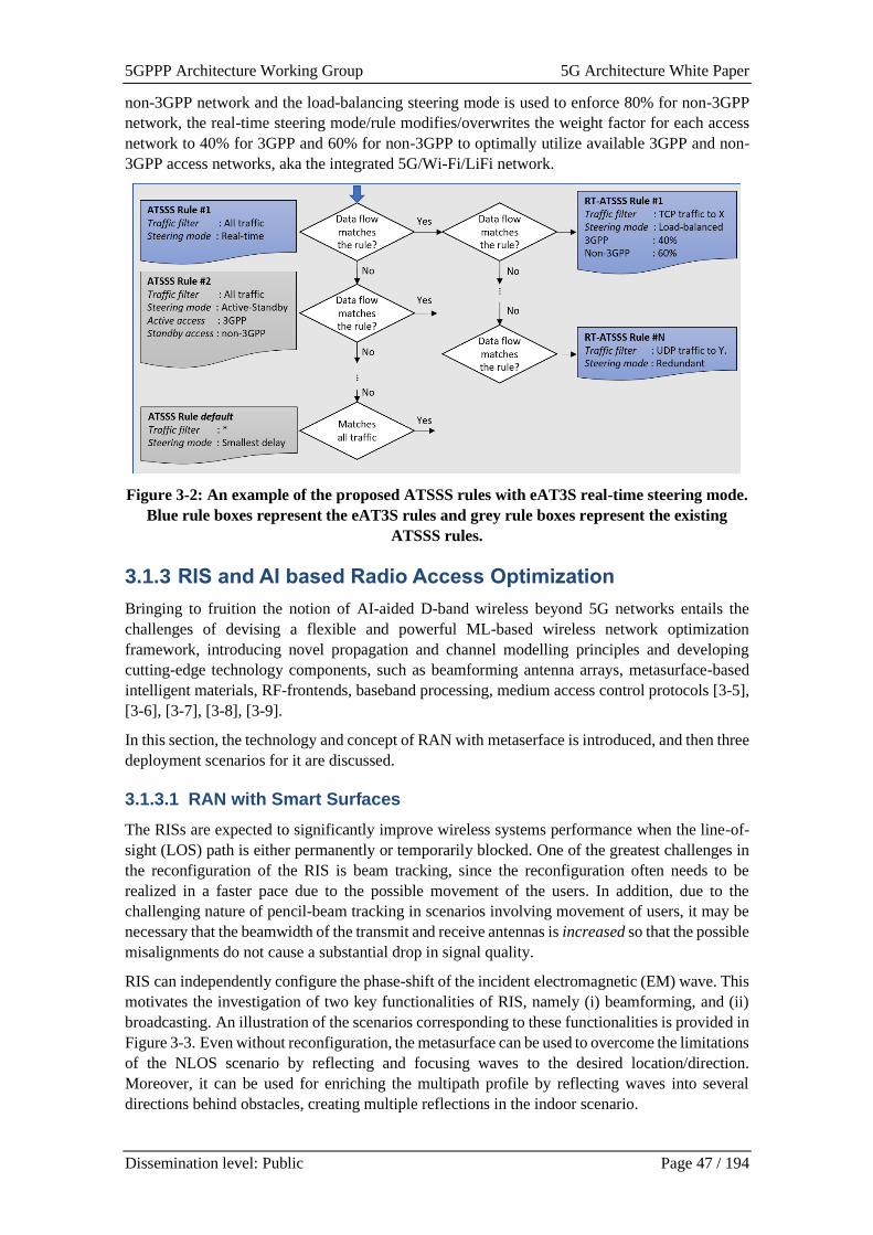
5GPPP Architecture Working Group 5G Architecture White Paper
Dissemination level: Public Page 47 / 194
non-3GPP network and the load-balancing steering mode is used to enforce 80% for non-3GPP
network, the real-time steering mode/rule modifies/overwrites the weight factor for each access
network to 40% for 3GPP and 60% for non-3GPP to optimally utilize available 3GPP and non-
3GPP access networks, aka the integrated 5G/Wi-Fi/LiFi network.
Figure 3-2: An example of the proposed ATSSS rules with eAT3S real-time steering mode.
Blue rule boxes represent the eAT3S rules and grey rule boxes represent the existing
ATSSS rules.
3.1.3 RIS and AI based Radio Access Optimization
Bringing to fruition the notion of AI-aided D-band wireless beyond 5G networks entails the
challenges of devising a flexible and powerful ML-based wireless network optimization
framework, introducing novel propagation and channel modelling principles and developing
cutting-edge technology components, such as beamforming antenna arrays, metasurface-based
intelligent materials, RF-frontends, baseband processing, medium access control protocols [3-5],
[3-6], [3-7], [3-8], [3-9].
In this section, the technology and concept of RAN with metaserface is introduced, and then three
deployment scenarios for it are discussed.
3.1.3.1 RAN with Smart Surfaces
The RISs are expected to significantly improve wireless systems performance when the line-of-
sight (LOS) path is either permanently or temporarily blocked. One of the greatest challenges in
the reconfiguration of the RIS is beam tracking, since the reconfiguration often needs to be
realized in a faster pace due to the possible movement of the users. In addition, due to the
challenging nature of pencil-beam tracking in scenarios involving movement of users, it may be
necessary that the beamwidth of the transmit and receive antennas is increased so that the possible
misalignments do not cause a substantial drop in signal quality.
RIS can independently configure the phase-shift of the incident electromagnetic (EM) wave. This
motivates the investigation of two key functionalities of RIS, namely (i) beamforming, and (ii)
broadcasting. An illustration of the scenarios corresponding to these functionalities is provided in
Figure 3-3. Even without reconfiguration, the metasurface can be used to overcome the limitations
of the NLOS scenario by reflecting and focusing waves to the desired location/direction.
Moreover, it can be used for enriching the multipath profile by reflecting waves into several
directions behind obstacles, creating multiple reflections in the indoor scenario.
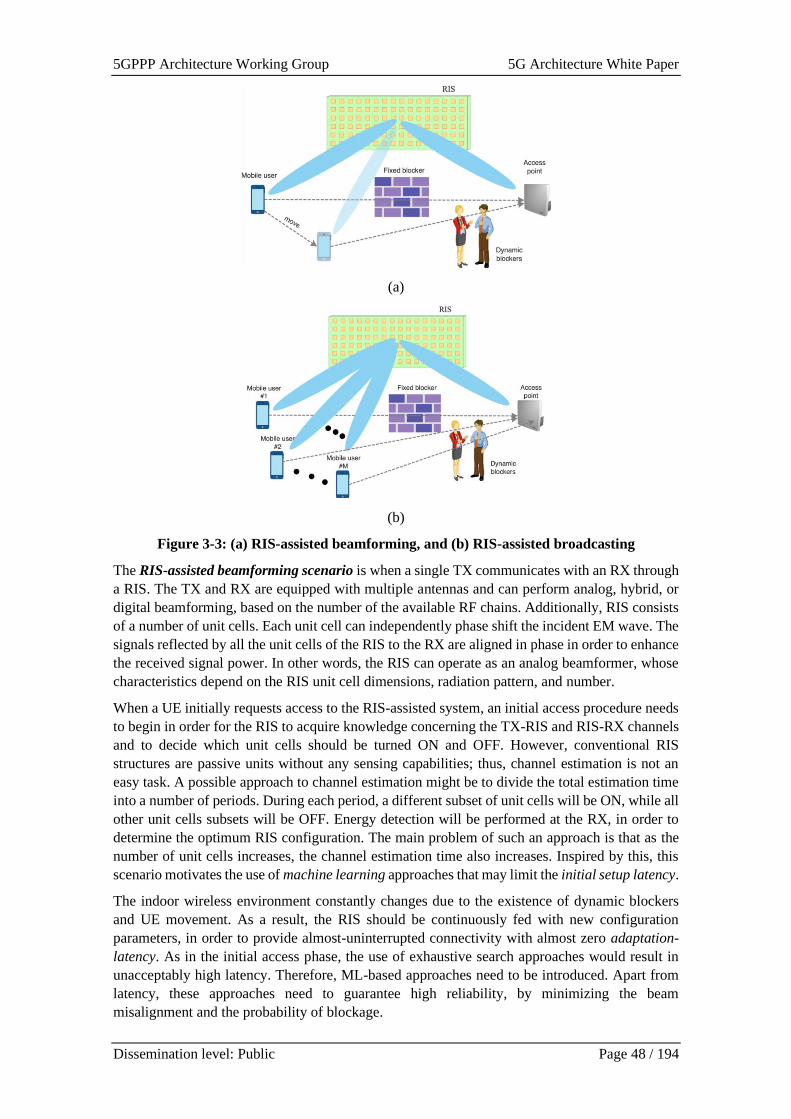
5GPPP Architecture Working Group 5G Architecture White Paper
Dissemination level: Public Page 48 / 194
(a)
(b)
Figure 3-3: (a) RIS-assisted beamforming, and (b) RIS-assisted broadcasting
The RIS-assisted beamforming scenario is when a single TX communicates with an RX through
a RIS. The TX and RX are equipped with multiple antennas and can perform analog, hybrid, or
digital beamforming, based on the number of the available RF chains. Additionally, RIS consists
of a number of unit cells. Each unit cell can independently phase shift the incident EM wave. The
signals reflected by all the unit cells of the RIS to the RX are aligned in phase in order to enhance
the received signal power. In other words, the RIS can operate as an analog beamformer, whose
characteristics depend on the RIS unit cell dimensions, radiation pattern, and number.
When a UE initially requests access to the RIS-assisted system, an initial access procedure needs
to begin in order for the RIS to acquire knowledge concerning the TX-RIS and RIS-RX channels
and to decide which unit cells should be turned ON and OFF. However, conventional RIS
structures are passive units without any sensing capabilities; thus, channel estimation is not an
easy task. A possible approach to channel estimation might be to divide the total estimation time
into a number of periods. During each period, a different subset of unit cells will be ON, while all
other unit cells subsets will be OFF. Energy detection will be performed at the RX, in order to
determine the optimum RIS configuration. The main problem of such an approach is that as the
number of unit cells increases, the channel estimation time also increases. Inspired by this, this
scenario motivates the use of machine learning approaches that may limit the initial setup latency.
The indoor wireless environment constantly changes due to the existence of dynamic blockers
and UE movement. As a result, the RIS should be continuously fed with new configuration
parameters, in order to provide almost-uninterrupted connectivity with almost zero adaptation-
latency. As in the initial access phase, the use of exhaustive search approaches would result in
unacceptably high latency. Therefore, ML-based approaches need to be introduced. Apart from
latency, these approaches need to guarantee high reliability, by minimizing the beam
misalignment and the probability of blockage.

5GPPP Architecture Working Group 5G Architecture White Paper
Dissemination level: Public Page 49 / 194
The RIS-assisted broadcasting scenario, a single AP is used to serve several UEs through a RIS.
This setup can be used for both uplink and downlink applications. Especially, a possible
application in the downlink might be for a scenario in which the same content needs to be
delivered to several UEs. We assume that the AP and the nth UE can perform analogue, hybrid,
or digital beamforming, based on the number of RF chains. Additionally, RIS consists of a number
of similar unit cells. Both the AP and the UEs point at the RIS. Initial access and localisation
procedures are performed for each UE, in order for the AP to acquire knowledge concerning the
UE positions and channels. As in the previous scenario, this procedure will require the use of ML.
Next, a clustering problem is formulated and solved by the AP. The solution of this problem is
the RIS configuration that determines the RIS half power beamwidth. This setup is of high interest
since it can enable access schemes, such as frequency division multiple access (FDMA) and non-
orthogonal multiple access (NOMA).
3.1.3.2 Deployment scenarios
To realize this vision, the presented discussions is focused on carefully devised deployment
architectures, which reflect the B5G requirements and expectations as described in Figure 3.4.
Figure 3.4 Reconfigurable surfaces deployment scenarios
The first deployment scenario to be considered is “outdoor backhaul/fronthaul networks of
fixed topology”. Due to the forecasted exponential data rate increase, next-generation wireless
backhaul/fronthaul networks will need to migrate towards the beyond 100 GHz spectrum in order
to accommodate, through the higher offered bandwidth, the ever-increasing data-rate demands of
mobile users. Hence, D-band comes as a solution to the expected capacity bottleneck of current
outdoor backhaul/fronthaul networks. This deployment scenario can be considered as any of the
following:
• Long-range LOS rooftop point-to-point backhauling
• Street-level point-to-point and point-to-multipoint backhauling/fronthauling
In the street-level scenario, the corresponding backhaul/fronthaul nodes are mounted on street
objects, such as lampposts, or next to small-cell and remote radio head (RRH) nodes. Such
communication can be either LOS or NLOS through RISs. In the latter case, when the LOS link
between a transmitter and its intended receiver is blocked, the communication is assisted through
an RIS acting as a reflector that is mounted on some nearby surface.
In the second deployment scenario, the “advanced NLOS connectivity based on metasurfaces”,
a dynamically reconfigured RIS is used to track slowly-moving users. This reconfiguration occurs
at a much higher pace than in the corresponding scenarios discussed for the outdoor
backhaul/fronthaul networks of fixed topology, which introduces substantial challenges regarding
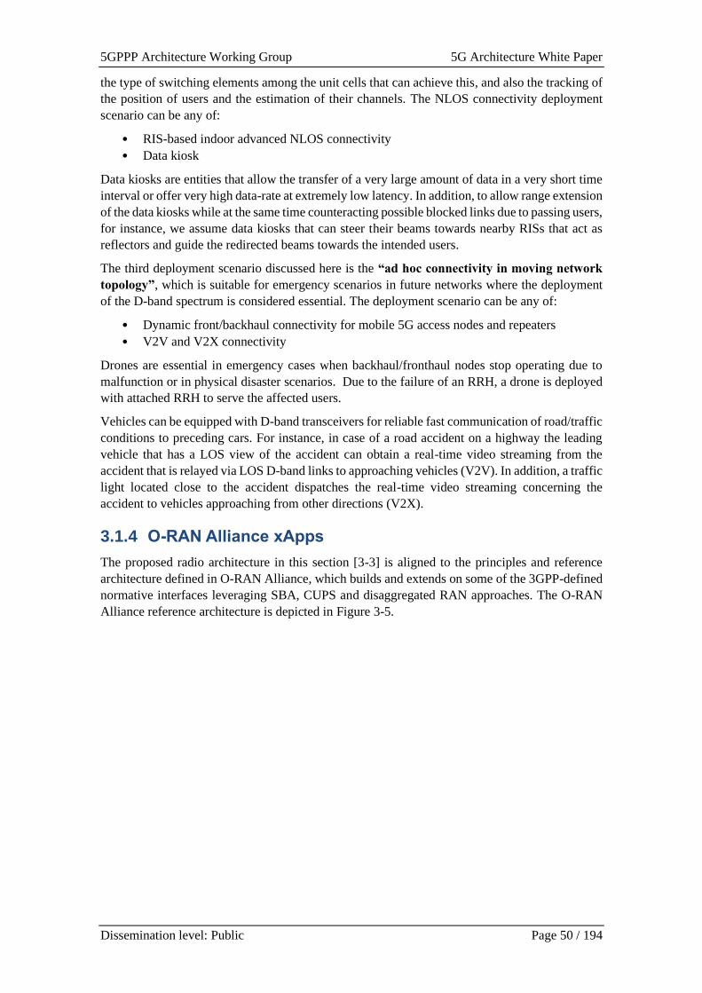
5GPPP Architecture Working Group 5G Architecture White Paper
Dissemination level: Public Page 50 / 194
the type of switching elements among the unit cells that can achieve this, and also the tracking of
the position of users and the estimation of their channels. The NLOS connectivity deployment
scenario can be any of:
• RIS-based indoor advanced NLOS connectivity
• Data kiosk
Data kiosks are entities that allow the transfer of a very large amount of data in a very short time
interval or offer very high data-rate at extremely low latency. In addition, to allow range extension
of the data kiosks while at the same time counteracting possible blocked links due to passing users,
for instance, we assume data kiosks that can steer their beams towards nearby RISs that act as
reflectors and guide the redirected beams towards the intended users.
The third deployment scenario discussed here is the “ad hoc connectivity in moving network
topology”, which is suitable for emergency scenarios in future networks where the deployment
of the D-band spectrum is considered essential. The deployment scenario can be any of:
• Dynamic front/backhaul connectivity for mobile 5G access nodes and repeaters
• V2V and V2X connectivity
Drones are essential in emergency cases when backhaul/fronthaul nodes stop operating due to
malfunction or in physical disaster scenarios. Due to the failure of an RRH, a drone is deployed
with attached RRH to serve the affected users.
Vehicles can be equipped with D-band transceivers for reliable fast communication of road/traffic
conditions to preceding cars. For instance, in case of a road accident on a highway the leading
vehicle that has a LOS view of the accident can obtain a real-time video streaming from the
accident that is relayed via LOS D-band links to approaching vehicles (V2V). In addition, a traffic
light located close to the accident dispatches the real-time video streaming concerning the
accident to vehicles approaching from other directions (V2X).
3.1.4 O-RAN Alliance xApps
The proposed radio architecture in this section [3-3] is aligned to the principles and reference
architecture defined in O-RAN Alliance, which builds and extends on some of the 3GPP-defined
normative interfaces leveraging SBA, CUPS and disaggregated RAN approaches. The O-RAN
Alliance reference architecture is depicted in Figure 3-5.
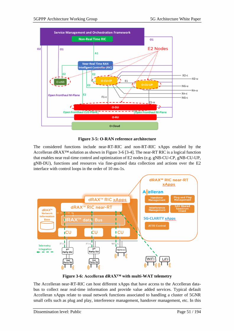
5GPPP Architecture Working Group 5G Architecture White Paper
Dissemination level: Public Page 51 / 194
Figure 3-5: O-RAN reference architecture
The considered functions include near-RT-RIC and non-RT-RIC xApps enabled by the
Accelleran dRAX™ solution as shown in Figure 3-6 [3-4]. The near-RT RIC is a logical function
that enables near real-time control and optimization of E2 nodes (e.g. gNB-CU-CP, gNB-CU-UP,
gNB-DU), functions and resources via fine-grained data collection and actions over the E2
interface with control loops in the order of 10 ms-1s.
Figure 3-6: Accelleran dRAX™ with multi-WAT telemetry
The Accelleran near-RT-RIC can host different xApps that have access to the Accelleran data-
bus to collect near real-time information and provide value added services. Typical default
Accelleran xApps relate to usual network functions associated to handling a cluster of 5GNR
small cells such as plug and play, interference management, handover management, etc. In this
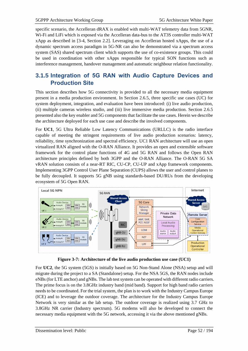
5GPPP Architecture Working Group 5G Architecture White Paper
Dissemination level: Public Page 52 / 194
specific scenario, the Accelleran dRAX is enabled with multi-WAT telemetry data from 5GNR,
Wi-Fi and LiFi which is exposed via the Accelleran data-bus to the AT3S controller multi-WAT
xApp as described in [3-4, Section 2.2]. Leveraging on Accelleran hosted xApps, the use of a
dynamic spectrum access paradigm in 5G-NR can also be demonstrated via a spectrum access
system (SAS) shared spectrum client which supports the use of co-existence groups. This could
be used in coordination with other xApps responsible for typical SON functions such as
interference management, handover management and automatic neighbour relation functionality.
3.1.5 Integration of 5G RAN with Audio Capture Devices and
Production Site
This section describes how 5G connectivity is provided to all the necessary media equipment
present in a media production environment. In Section 2.6.5, three specific use cases (UC) for
system deployment, integration, and evaluation have been introduced: (i) live audio production,
(ii) multiple cameras wireless studio, and (iii) live immersive media production. Section 2.6.5
presented also the key enabler and 5G components that facilitate the use cases. Herein we describe
the architecture deployed for each use case and describe the involved components.
For UC1, 5G Ultra Reliable Low Latency Communications (URLLC) is the radio interface
capable of meeting the stringent requirements of live audio production scenarios: latency,
reliability, time synchronization and spectral efficiency. UC1 RAN architecture will use an open
virtualized RAN aligned with the O-RAN Alliance. It provides an open and extensible software
framework for the control plane functions of 4G and 5G RAN and follows the Open RAN
architecture principles defined by both 3GPP and the O-RAN Alliance. The O-RAN 5G SA
vRAN solution consists of a near-RT RIC, CU-CP, CU-UP and xApp framework components.
Implementing 3GPP Control User Plane Separation (CUPS) allows the user and control planes to
be fully decoupled. It supports 5G gNB using standards-based DU/RUs from the developing
ecosystem of 5G Open RAN.
Figure 3-7: Architecture of the live audio production use case (UC1)
For UC2, the 5G system (5GS) is initially based on 5G Non-Stand Alone (NSA) setup and will
migrate during the project to a SA (Standalone) setup. For the NSA 5GS, the RAN nodes include
eNBs (for LTE anchor) and gNBs. The lab test system can be operated with different radio carriers.
The prime focus is on the 3.8GHz industry band (mid band). Support for high band radio carriers
needs to be coordinated. For the trial system, the plan is to work with the Industry Campus Europe
(ICE) and to leverage the outdoor coverage. The architecture for the Industry Campus Europe
Network is very similar as the lab setup. The outdoor coverage is realized using 3.7 GHz to
3.8GHz NR carrier (Industry spectrum). 5G modems will also be developed to connect the
necessary media equipment with the 5G network, accessing it via the above mentioned gNBs.
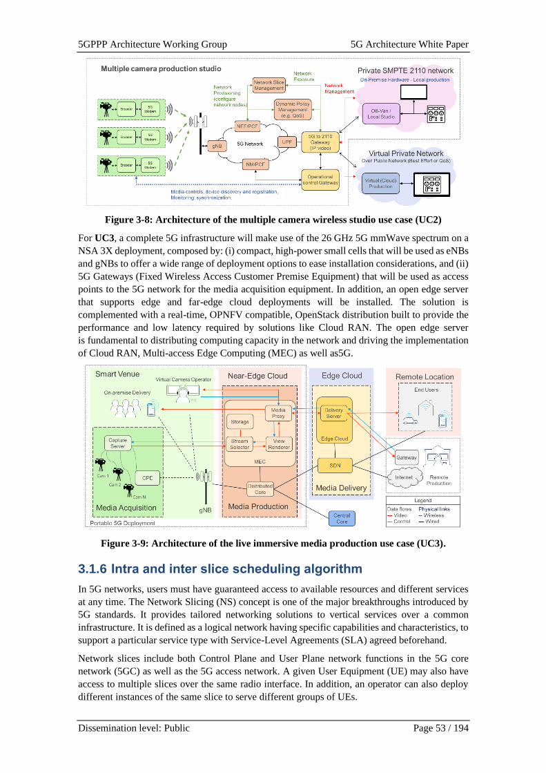
5GPPP Architecture Working Group 5G Architecture White Paper
Dissemination level: Public Page 53 / 194
Figure 3-8: Architecture of the multiple camera wireless studio use case (UC2)
For UC3, a complete 5G infrastructure will make use of the 26 GHz 5G mmWave spectrum on a
NSA 3X deployment, composed by: (i) compact, high-power small cells that will be used as eNBs
and gNBs to offer a wide range of deployment options to ease installation considerations, and (ii)
5G Gateways (Fixed Wireless Access Customer Premise Equipment) that will be used as access
points to the 5G network for the media acquisition equipment. In addition, an open edge server
that supports edge and far-edge cloud deployments will be installed. The solution is
complemented with a real-time, OPNFV compatible, OpenStack distribution built to provide the
performance and low latency required by solutions like Cloud RAN. The open edge server
is fundamental to distributing computing capacity in the network and driving the implementation
of Cloud RAN, Multi-access Edge Computing (MEC) as well as5G.
Figure 3-9: Architecture of the live immersive media production use case (UC3).
3.1.6 Intra and inter slice scheduling algorithm
In 5G networks, users must have guaranteed access to available resources and different services
at any time. The Network Slicing (NS) concept is one of the major breakthroughs introduced by
5G standards. It provides tailored networking solutions to vertical services over a common
infrastructure. It is defined as a logical network having specific capabilities and characteristics, to
support a particular service type with Service-Level Agreements (SLA) agreed beforehand.
Network slices include both Control Plane and User Plane network functions in the 5G core
network (5GC) as well as the 5G access network. A given User Equipment (UE) may also have
access to multiple slices over the same radio interface. In addition, an operator can also deploy
different instances of the same slice to serve different groups of UEs.
5GPPP Architecture Working Group 5G Architecture White Paper
Dissemination level: Public Page 54 / 194
In the RAN domain, network slicing is mainly based on resource allocation algorithms. Their role
is to make sure that every slice has enough radio resources to meet the agreed SLA, and to ensure
isolation between all slices. Slice isolation is an important requirement, because it enhances both
slice security and slice privacy, by ensuring that the performance of each slice is not affected by
the others.
Therefore, the performance of RAN slicing, in terms of resource utilization, mainly depends on
scheduling algorithms conception. The objective of this scheduling is to perform the most
efficient allocation by minimizing the number of unused resource blocks. For example, the
architecture could implement two levels of scheduling: inter-slice and intra-slice. The inter-slice
algorithm is responsible for allocating resource blocks to each slice depending on their needs and
the allocation policy. This allocation can be fixed, in that case, the computational cost will be low,
but resource blocks can be unused, or the algorithm can be run periodically to ensure a more
dynamic and thus more efficient allocation. Intra-slice algorithms are responsible for allocating
resources to users inside each slice.
In order to optimize resource allocation in the RAN, we propose a dynamic scheduling algorithm,
capable of offering the required quality of service to the slices on the radio segment, in an efficient
way. The goal is to treat differently each type of service: eMBB, URLLC and mMTC defined in
5G standards for example or any other type of service, in order to meet their respective
requirements.
On the inter-slice level, the algorithm will first allocate the minimal resources requested by each
slice. If there is not enough available resources to satisfy minimal demands, slice priorities will
be taken in account. After this first step, remaining resources will be put aside in a “resource pool”.
Then, based on their level of priority, each slice will be able to take resource blocks from the pool,
until it is empty. Different metrics will be used to set slices priorities, like required throughput
and latency for example.
On the intra-slice level, each algorithm will be adapted to the type of service associated. For
example, in a URLLC slice where the critical requirement is low latency, allocation will favor
users with close deadline packets.
This algorithm is designed to be more dynamic and adaptive to user requirements, in order to
provide an efficient allocation and a maximal resource utilization.
3.2 Edge architectures
The relevance of edge-based RAN architecture to enable mobile/multi-access edge computing in
order to provide latency, throughput and reliability requirements of 5G and B5G solutions was
discussed in the previous white paper [3-11]. As noted in that white paper, there is no single edge-
based RAN architecture that can provide various requirements from every vertical. Therefore,
this section extends the edge architecture options and provides detailed deployment concepts for
different vertical use cases. Specifically, as different services have different requirements on
location, performance, security and availability, which calls for various types of edge clouds, a
classification of the Edge Cloud is presented. Then the concept of autonomous edge (AE), to be
a method to optimise the data processing at the edge but near the source of data, is introduced.
Use cases for such deployments are characterised by specific requirements and options. One
further challenge is on management and configuration of the physically distributed infrastructure,
e.g., via introducing the Cloud RAN, which can be addressed by using AI and ML algorithms.
One of the use cases where Edge computing could play a crucial role is in connected and
automated mobility (CAM) services where, for instance, the end-to-end latency and reliability
across MNOs is a requirement. On the other hand, in case extreme low-latency and stringent legal
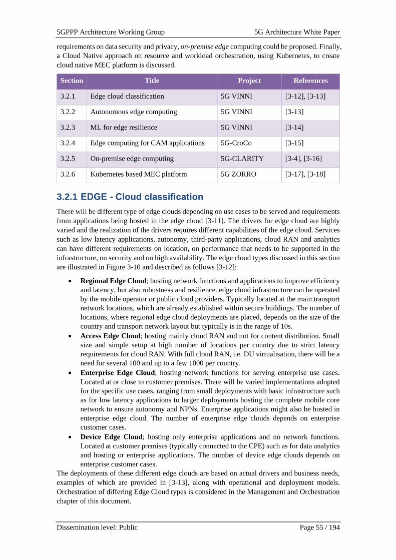
5GPPP Architecture Working Group 5G Architecture White Paper
Dissemination level: Public Page 55 / 194
requirements on data security and privacy, on-premise edge computing could be proposed. Finally,
a Cloud Native approach on resource and workload orchestration, using Kubernetes, to create
cloud native MEC platform is discussed.
Section Title Project References
3.2.1 Edge cloud classification 5G VINNI [3-12], [3-13]
3.2.2 Autonomous edge computing 5G VINNI [3-13]
3.2.3 ML for edge resilience 5G VINNI [3-14]
3.2.4 Edge computing for CAM applications 5G-CroCo [3-15]
3.2.5 On-premise edge computing 5G-CLARITY [3-4], [3-16]
3.2.6 Kubernetes based MEC platform 5G ZORRO [3-17], [3-18]
3.2.1 EDGE - Cloud classification
There will be different type of edge clouds depending on use cases to be served and requirements
from applications being hosted in the edge cloud [3-11]. The drivers for edge cloud are highly
varied and the realization of the drivers requires different capabilities of the edge cloud. Services
such as low latency applications, autonomy, third-party applications, cloud RAN and analytics
can have different requirements on location, on performance that needs to be supported in the
infrastructure, on security and on high availability. The edge cloud types discussed in this section
are illustrated in Figure 3-10 and described as follows [3-12]:
• Regional Edge Cloud; hosting network functions and applications to improve efficiency
and latency, but also robustness and resilience. edge cloud infrastructure can be operated
by the mobile operator or public cloud providers. Typically located at the main transport
network locations, which are already established within secure buildings. The number of
locations, where regional edge cloud deployments are placed, depends on the size of the
country and transport network layout but typically is in the range of 10s.
• Access Edge Cloud; hosting mainly cloud RAN and not for content distribution. Small
size and simple setup at high number of locations per country due to strict latency
requirements for cloud RAN. With full cloud RAN, i.e. DU virtualisation, there will be a
need for several 100 and up to a few 1000 per country.
• Enterprise Edge Cloud; hosting network functions for serving enterprise use cases.
Located at or close to customer premises. There will be varied implementations adopted
for the specific use cases, ranging from small deployments with basic infrastructure such
as for low latency applications to larger deployments hosting the complete mobile core
network to ensure autonomy and NPNs. Enterprise applications might also be hosted in
enterprise edge cloud. The number of enterprise edge clouds depends on enterprise
customer cases.
• Device Edge Cloud; hosting only enterprise applications and no network functions.
Located at customer premises (typically connected to the CPE) such as for data analytics
and hosting or enterprise applications. The number of device edge clouds depends on
enterprise customer cases.
The deployments of these different edge clouds are based on actual drivers and business needs,
examples of which are provided in [3-13], along with operational and deployment models.
Orchestration of differing Edge Cloud types is considered in the Management and Orchestration
chapter of this document.
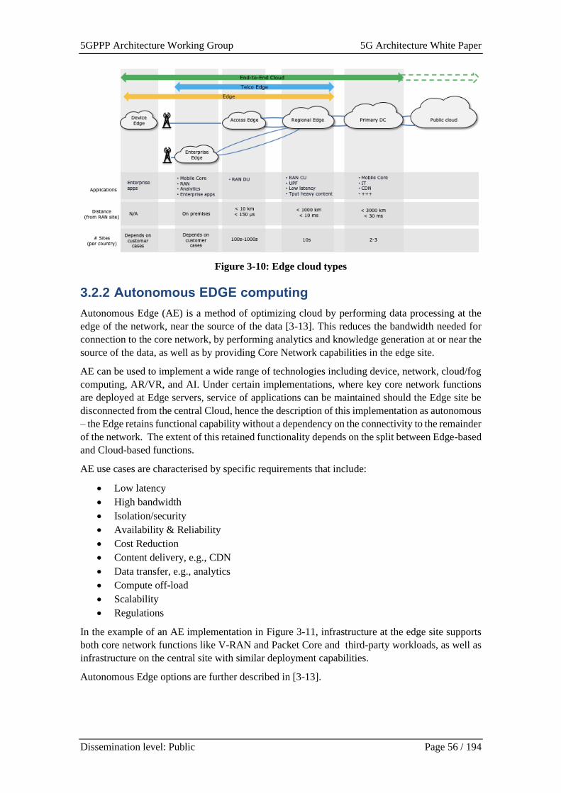
5GPPP Architecture Working Group 5G Architecture White Paper
Dissemination level: Public Page 56 / 194
Figure 3-10: Edge cloud types
3.2.2 Autonomous EDGE computing
Autonomous Edge (AE) is a method of optimizing cloud by performing data processing at the
edge of the network, near the source of the data [3-13]. This reduces the bandwidth needed for
connection to the core network, by performing analytics and knowledge generation at or near the
source of the data, as well as by providing Core Network capabilities in the edge site.
AE can be used to implement a wide range of technologies including device, network, cloud/fog
computing, AR/VR, and AI. Under certain implementations, where key core network functions
are deployed at Edge servers, service of applications can be maintained should the Edge site be
disconnected from the central Cloud, hence the description of this implementation as autonomous
– the Edge retains functional capability without a dependency on the connectivity to the remainder
of the network. The extent of this retained functionality depends on the split between Edge-based
and Cloud-based functions.
AE use cases are characterised by specific requirements that include:
• Low latency
• High bandwidth
• Isolation/security
• Availability & Reliability
• Cost Reduction
• Content delivery, e.g., CDN
• Data transfer, e.g., analytics
• Compute off-load
• Scalability
• Regulations
In the example of an AE implementation in Figure 3-11, infrastructure at the edge site supports
both core network functions like V-RAN and Packet Core and third-party workloads, as well as
infrastructure on the central site with similar deployment capabilities.
Autonomous Edge options are further described in [3-13].
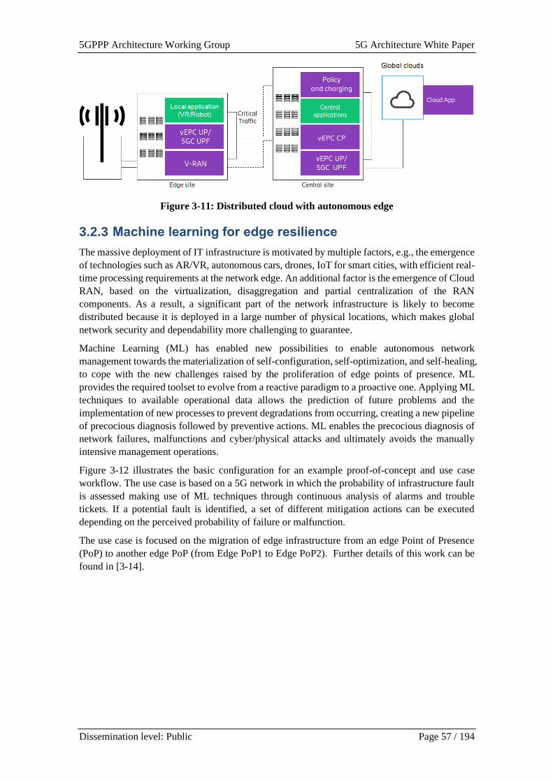
5GPPP Architecture Working Group 5G Architecture White Paper
Dissemination level: Public Page 57 / 194
Figure 3-11: Distributed cloud with autonomous edge
3.2.3 Machine learning for edge resilience
The massive deployment of IT infrastructure is motivated by multiple factors, e.g., the emergence
of technologies such as AR/VR, autonomous cars, drones, IoT for smart cities, with efficient real-
time processing requirements at the network edge. An additional factor is the emergence of Cloud
RAN, based on the virtualization, disaggregation and partial centralization of the RAN
components. As a result, a significant part of the network infrastructure is likely to become
distributed because it is deployed in a large number of physical locations, which makes global
network security and dependability more challenging to guarantee.
Machine Learning (ML) has enabled new possibilities to enable autonomous network
management towards the materialization of self-configuration, self-optimization, and self-healing,
to cope with the new challenges raised by the proliferation of edge points of presence. ML
provides the required toolset to evolve from a reactive paradigm to a proactive one. Applying ML
techniques to available operational data allows the prediction of future problems and the
implementation of new processes to prevent degradations from occurring, creating a new pipeline
of precocious diagnosis followed by preventive actions. ML enables the precocious diagnosis of
network failures, malfunctions and cyber/physical attacks and ultimately avoids the manually
intensive management operations.
Figure 3-12 illustrates the basic configuration for an example proof-of-concept and use case
workflow. The use case is based on a 5G network in which the probability of infrastructure fault
is assessed making use of ML techniques through continuous analysis of alarms and trouble
tickets. If a potential fault is identified, a set of different mitigation actions can be executed
depending on the perceived probability of failure or malfunction.
The use case is focused on the migration of edge infrastructure from an edge Point of Presence
(PoP) to another edge PoP (from Edge PoP1 to Edge PoP2). Further details of this work can be
found in [3-14].
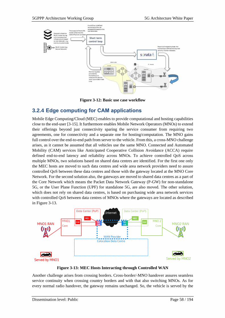
5GPPP Architecture Working Group 5G Architecture White Paper
Dissemination level: Public Page 58 / 194
Figure 3-12: Basic use case workflow
3.2.4 Edge computing for CAM applications
Mobile Edge Computing/Cloud (MEC) enables to provide computational and hosting capabilities
close to the end-user [3-15]. It furthermore enables Mobile Network Operators (MNOs) to extend
their offerings beyond just connectivity sparing the service consumer from requiring two
agreements, one for connectivity and a separate one for hosting/computation. The MNO gains
full control over the end-to-end path from server to the vehicle. From this, a cross-MNO challenge
arises, as it cannot be assumed that all vehicles use the same MNO. Connected and Automated
Mobility (CAM) services like Anticipated Cooperative Collision Avoidance (ACCA) require
defined end-to-end latency and reliability across MNOs. To achieve controlled QoS across
multiple MNOs, two solutions based on shared data centres are identified. For the first one only
the MEC hosts are moved to such data centres and wide area network providers need to assure
controlled QoS between these data centres and those with the gateway located at the MNO Core
Network. For the second solution also, the gateways are moved to shared data centres as a part of
the Core Network which means the Packet Data Network Gateway (P-GW) for non-standalone
5G, or the User Plane Function (UPF) for standalone 5G, are also moved. The other solution,
which does not rely on shared data centres, is based on purchasing wide area network services
with controlled QoS between data centres of MNOs where the gateways are located as described
in Figure 3-13.
Figure 3-13: MEC Hosts Interacting through Controlled WAN
Another challenge arises from crossing borders. Cross-border/-MNO handover assures seamless
service continuity when crossing country borders and with that also switching MNOs. As for
every normal radio handover, the gateway remains unchanged. So, the vehicle is served by the
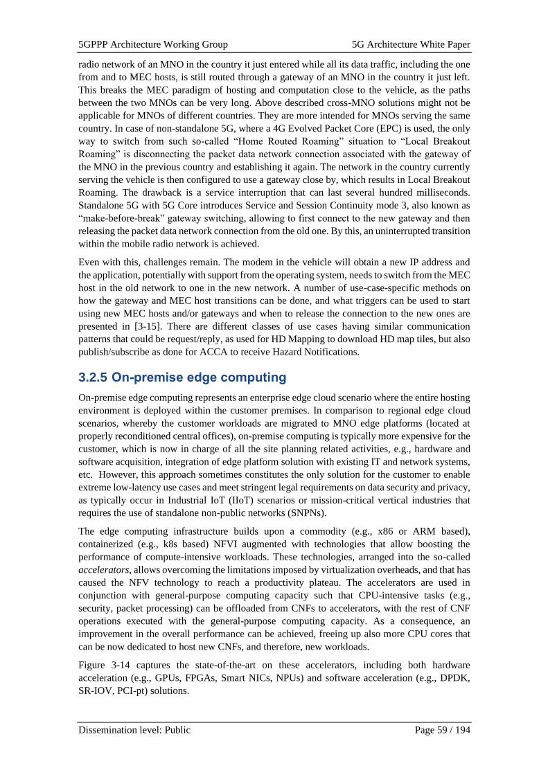
5GPPP Architecture Working Group 5G Architecture White Paper
Dissemination level: Public Page 59 / 194
radio network of an MNO in the country it just entered while all its data traffic, including the one
from and to MEC hosts, is still routed through a gateway of an MNO in the country it just left.
This breaks the MEC paradigm of hosting and computation close to the vehicle, as the paths
between the two MNOs can be very long. Above described cross-MNO solutions might not be
applicable for MNOs of different countries. They are more intended for MNOs serving the same
country. In case of non-standalone 5G, where a 4G Evolved Packet Core (EPC) is used, the only
way to switch from such so-called “Home Routed Roaming” situation to “Local Breakout
Roaming” is disconnecting the packet data network connection associated with the gateway of
the MNO in the previous country and establishing it again. The network in the country currently
serving the vehicle is then configured to use a gateway close by, which results in Local Breakout
Roaming. The drawback is a service interruption that can last several hundred milliseconds.
Standalone 5G with 5G Core introduces Service and Session Continuity mode 3, also known as
“make-before-break” gateway switching, allowing to first connect to the new gateway and then
releasing the packet data network connection from the old one. By this, an uninterrupted transition
within the mobile radio network is achieved.
Even with this, challenges remain. The modem in the vehicle will obtain a new IP address and
the application, potentially with support from the operating system, needs to switch from the MEC
host in the old network to one in the new network. A number of use-case-specific methods on
how the gateway and MEC host transitions can be done, and what triggers can be used to start
using new MEC hosts and/or gateways and when to release the connection to the new ones are
presented in [3-15]. There are different classes of use cases having similar communication
patterns that could be request/reply, as used for HD Mapping to download HD map tiles, but also
publish/subscribe as done for ACCA to receive Hazard Notifications.
3.2.5 On-premise edge computing
On-premise edge computing represents an enterprise edge cloud scenario where the entire hosting
environment is deployed within the customer premises. In comparison to regional edge cloud
scenarios, whereby the customer workloads are migrated to MNO edge platforms (located at
properly reconditioned central offices), on-premise computing is typically more expensive for the
customer, which is now in charge of all the site planning related activities, e.g., hardware and
software acquisition, integration of edge platform solution with existing IT and network systems,
etc. However, this approach sometimes constitutes the only solution for the customer to enable
extreme low-latency use cases and meet stringent legal requirements on data security and privacy,
as typically occur in Industrial IoT (IIoT) scenarios or mission-critical vertical industries that
requires the use of standalone non-public networks (SNPNs).
The edge computing infrastructure builds upon a commodity (e.g., x86 or ARM based),
containerized (e.g., k8s based) NFVI augmented with technologies that allow boosting the
performance of compute-intensive workloads. These technologies, arranged into the so-called
accelerators, allows overcoming the limitations imposed by virtualization overheads, and that has
caused the NFV technology to reach a productivity plateau. The accelerators are used in
conjunction with general-purpose computing capacity such that CPU-intensive tasks (e.g.,
security, packet processing) can be offloaded from CNFs to accelerators, with the rest of CNF
operations executed with the general-purpose computing capacity. As a consequence, an
improvement in the overall performance can be achieved, freeing up also more CPU cores that
can be now dedicated to host new CNFs, and therefore, new workloads.
Figure 3-14 captures the state-of-the-art on these accelerators, including both hardware
acceleration (e.g., GPUs, FPGAs, Smart NICs, NPUs) and software acceleration (e.g., DPDK,
SR-IOV, PCI-pt) solutions.
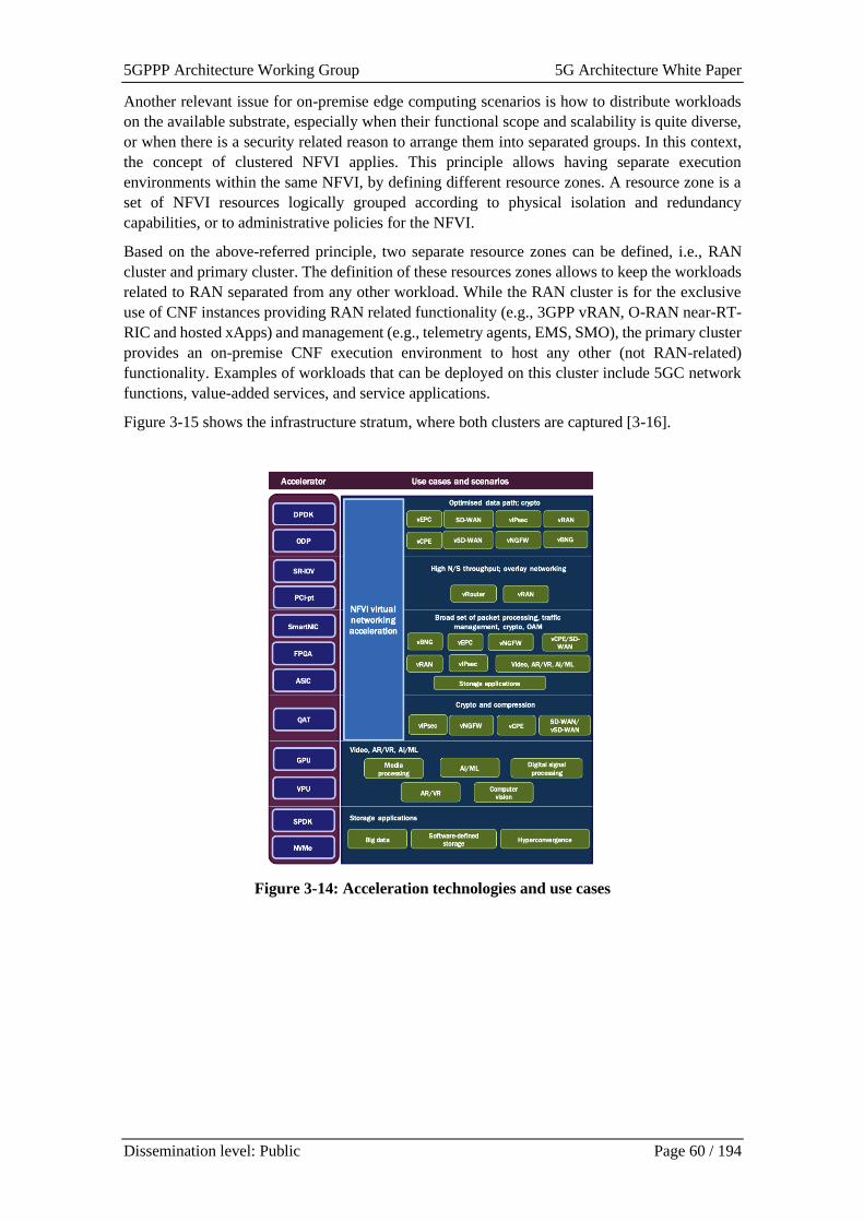
5GPPP Architecture Working Group 5G Architecture White Paper
Dissemination level: Public Page 60 / 194
Another relevant issue for on-premise edge computing scenarios is how to distribute workloads
on the available substrate, especially when their functional scope and scalability is quite diverse,
or when there is a security related reason to arrange them into separated groups. In this context,
the concept of clustered NFVI applies. This principle allows having separate execution
environments within the same NFVI, by defining different resource zones. A resource zone is a
set of NFVI resources logically grouped according to physical isolation and redundancy
capabilities, or to administrative policies for the NFVI.
Based on the above-referred principle, two separate resource zones can be defined, i.e., RAN
cluster and primary cluster. The definition of these resources zones allows to keep the workloads
related to RAN separated from any other workload. While the RAN cluster is for the exclusive
use of CNF instances providing RAN related functionality (e.g., 3GPP vRAN, O-RAN near-RT-
RIC and hosted xApps) and management (e.g., telemetry agents, EMS, SMO), the primary cluster
provides an on-premise CNF execution environment to host any other (not RAN-related)
functionality. Examples of workloads that can be deployed on this cluster include 5GC network
functions, value-added services, and service applications.
Figure 3-15 shows the infrastructure stratum, where both clusters are captured [3-16].
Figure 3-14: Acceleration technologies and use cases

5GPPP Architecture Working Group 5G Architecture White Paper
Dissemination level: Public Page 61 / 194
Figure 3-15: Infrastructure stratum [3-16]
3.2.6 Kubernetes based MEC platform
The realization of vCDN use cases requires MEC platform at telco edge to deploy and operate
vCDN components in slice data-path [3-17]. Such use cases require dynamic spawning and
decommissioning of vCDN components based on where and when the demand for specific
content goes up and down over time. The need for 5G slices is thus envisioned to be able to
dynamically scale up and down, expanding to additional MEC locations as needed, as shown in
Figure 3-16 where MEC host in one location is not enough to handle all the demand and the slice
is extended to additional, sometimes third-party MEC host.
A proposed architecture supports slice elasticity through combining several approaches and
technologies [3-18]. Here the emphasis in on adapting Cloud Native approach for resource and
workload orchestration. This approach is intent-based and is embodied by Kubernetes (k8s) which
can be extended through an operator framework to create the Cloud Native MEC Platform
(CNMP). In addition, k8s and Argo workflow engine [3-19] can be used as a basis for the
Intelligent Slice and Service Manager (ISSM), as shown Figure 3-17.
Figure 3-16: vCDN use-case with elastic MEC-enabled slices [3-17]
COTS Hardware
Virtualization Virtualization
RAN Cluster (CNF hosting) Primary Cluster (CNF hosting)
Transport
Network
DevicesIn
fras
tru
ctu
re S
trat
um Access nodes
Customer premises
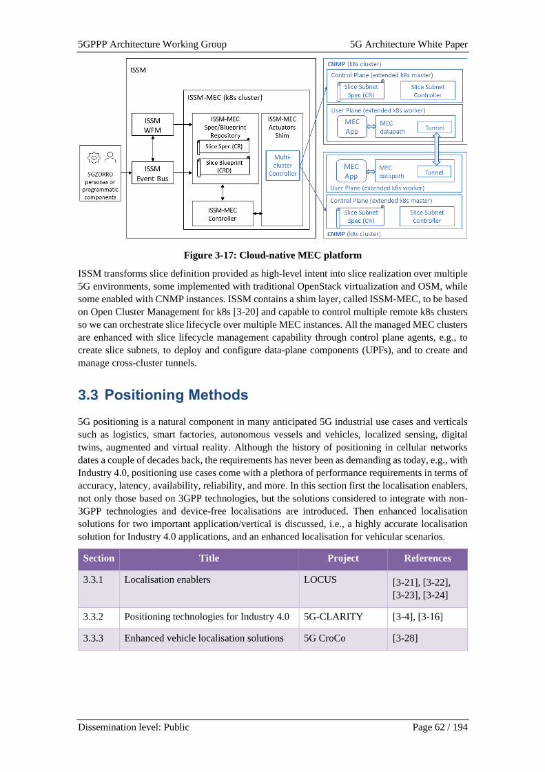
5GPPP Architecture Working Group 5G Architecture White Paper
Dissemination level: Public Page 62 / 194
Figure 3-17: Cloud-native MEC platform
ISSM transforms slice definition provided as high-level intent into slice realization over multiple
5G environments, some implemented with traditional OpenStack virtualization and OSM, while
some enabled with CNMP instances. ISSM contains a shim layer, called ISSM-MEC, to be based
on Open Cluster Management for k8s [3-20] and capable to control multiple remote k8s clusters
so we can orchestrate slice lifecycle over multiple MEC instances. All the managed MEC clusters
are enhanced with slice lifecycle management capability through control plane agents, e.g., to
create slice subnets, to deploy and configure data-plane components (UPFs), and to create and
manage cross-cluster tunnels.
3.3 Positioning Methods
5G positioning is a natural component in many anticipated 5G industrial use cases and verticals
such as logistics, smart factories, autonomous vessels and vehicles, localized sensing, digital
twins, augmented and virtual reality. Although the history of positioning in cellular networks
dates a couple of decades back, the requirements has never been as demanding as today, e.g., with
Industry 4.0, positioning use cases come with a plethora of performance requirements in terms of
accuracy, latency, availability, reliability, and more. In this section first the localisation enablers,
not only those based on 3GPP technologies, but the solutions considered to integrate with non-
3GPP technologies and device-free localisations are introduced. Then enhanced localisation
solutions for two important application/vertical is discussed, i.e., a highly accurate localisation
solution for Industry 4.0 applications, and an enhanced localisation for vehicular scenarios.
Section Title Project References
3.3.1 Localisation enablers LOCUS [3-21], [3-22],
[3-23], [3-24]
3.3.2 Positioning technologies for Industry 4.0 5G-CLARITY [3-4], [3-16]
3.3.3 Enhanced vehicle localisation solutions 5G CroCo [3-28]
5GPPP Architecture Working Group 5G Architecture White Paper
Dissemination level: Public Page 63 / 194
3.3.1 Localisation enablers
The 3GPP defines positioning architectures and methods to fulfil regulatory requirements and
provide added value services to the end users. Current 5G localisation solutions rely on single-
value metrics such as uplink time-difference-of-arrival (UL-TDoA), downlink time-difference-
of-arrival (DL-TDoA), received signal strength indicator (RSSI), and angle-of-arrival (AoA).
Localisation accuracy depends heavily on the quality of such estimates, which degrades in harsh
propagation environments. Advanced localisation techniques in the form of architectural
components are discussed in this section, called “localisation enablers”, that apart from being
based solely on 3GPP (5G) technology they consider integration with non-3GPP technologies and
device-free localisation. Localisation enablers provide the localisation mechanisms by utilizing
the properties of radio signals associated with a given UE (or the user). More specifically, the
enablers are divided into the following categories (detailed information can be found in [3-21]-
[3-24]):
3.3.1.1 Advanced localisation techniques in 5G
The requirements and constraints of diverse mobile terminals (smartphones, wearables, cars, etc.)
as well as the three main service classes enabled by the 5G technology are:
• Machine Type Communication (mMTC): two possible single value metrics have been
proposed in 3GPP for mMTC and IoT scenarios, i.e., modified Observed Time Difference Of
Arrival (OTDOA) and/or Uplink Time Difference of Arrival (UTDOA). The techniques for
UTDOA estimation that comply with the network communication constraints of the mMTC
service class are proposed. Also, it is preferable to use energy and bandwidth-efficient
alternatives to OTDOA and UTDOA that provide additional mobility detection capabilities
with increased robustness against Doppler impairments [3-22].
• Ultra-Reliable Low-Latency Communications (URLLC): the ability to allocate mini-slots for
URLLC-based applications in 5G-NR complicates the design of PRS and TRS reference
signals for OTDOA. Solutions to reduce the localisation service response time to a few
milliseconds for URLLC applications are of interest. The combined use of fast time-based
and angle-based methods to provide key breakthroughs for ultra-fast localisation need to be
investigated.
• Enhanced Mobile Broadband (eMBB): lightweight mmWave localisation algorithms,
which exploit the specific capabilities and beam patterns of analog/hybrid beamforming
antennas of mmWave cellular systems, could be useful.
In order to increase the localisation accuracy, efficient and scalable Bayesian filtering algorithms
are employed for localizing multiple and fast-moving terminals [3-23]. A further improvement in
terms of localisation accuracy can be achieved by relying on localisation algorithms that fuse
different metrics, e.g., using joint likelihood functions that account for the correlation among
different metrics and mitigate the impairments caused by multipath and NLOS conditions.
In addition to localisation accuracy, the update rate of information as well as privacy and security
will be critical application-driven requirements. For example, developing localisation enablers to
support the emergencies is a key area. In particular, 3D indoor localisation represents a vital tool
for the emergency and security services in case of events like multi-store building fire, kidnap
and terrorism incidents, as well as indoor medical emergencies. In developing such enablers, the
use of quickly deployed drones at different heights has to be considered that can provide increased
3D localisation accuracy with the support of the fixed 4G/5G network infra-structure.
5GPPP Architecture Working Group 5G Architecture White Paper
Dissemination level: Public Page 64 / 194
3.3.1.2 Localisation based on non-3GPP technologies
The observables that can be extracted with non-3GPP technologies (e.g., 802.11 with multiuser
MIMO and fine time measurements) serve as input for technology-agnostic and low-complexity
algorithms for heterogeneous data fusion. In addition, dimensionality reduction techniques are
complemented with machine learning and deep neural networks to extract the main features from
a rich and heterogeneous set of measurements with diverse sources of noise. Moreover, the need
to investigate communication protocols to support the integration of diverse technologies has to
be identified [3-24].
3.3.1.3 Device-free localization
In addition, increasing attention is recently being devoted to device-free localization, i.e., the
capability of detecting and tracking objects that do not communicate within the localisation
infrastructure. These technologies rely on the signal designed for target detection and localisation
(active radar) or on signals emitted by other sources of opportunity (passive radar) that are
exploited for localisation. Signals for backscatter (illuminator of opportunity) can be both 5G
gNBs as well as transmitters already deployed in the environment for other purposes. In contrast
to 5G terminal localisation, device-free localisation can take advantage of any modulated signal
at any frequency of operation. In this respect, a network of receivers (gNBs as well as community-
based deployments of spectrum sensors) could be exploited, whose frequency configuration is
adapted to the accuracy requirements of the specific scenario. The challenge in this domain is the
design of novel, optimized, low-complexity algorithms that allow to develop a flexible and
reconfigurable passive localisation system integrating 3GPP cellular localisation with non-3GPP
technologies.
3.3.2 Positioning technologies for Industry 4.0
High accurate positioning is of essential significance for many industry verticals, which are highly
dependent on the 5G technology. These industry verticals increasingly rely on the combination
of communication capabilities together with high accuracy positioning services offered by 5G
technologies [3-25], [3-26].
In the last decade, global navigation satellite systems (GNSSs) were able to fulfil the needs of
many applications requiring high accuracy UE positioning. Additionally, with the latest
developments in this field, including real time kinematics (RTK), a centimetre-level UE
positioning is possible. Nevertheless, this is limited to outdoor environments, where line-of-sight
(LOS) reception of the satellite signals is possible.
The 3GPP Rel-15 introduced the 5GNR technology and also RAT-independent positioning
capabilities. RAT-dependent positioning capabilities were first introduced in Release 16, which
considers, as well, positioning capabilities for commercial use cases, such as:
• Horizontal positioning error < 3m for 80% of UEs in indoor deployment scenarios.
• Vertical positioning error < 3m for 80% of UEs in indoor deployment scenarios.
• End to end latency < 1 second, etc.
For many use cases from the industry verticals these requirements would not be sufficient.
Therefore, according to 3GPP Rel-17 “Study on NR Positioning Enhancements”, sub-meter
positioning accuracy is required for general commercial use cases, and the positioning accuracy
should be better than 0.2 meters for IIoT use cases. The required latency should be better than
100 ms and for some IIoT use cases even in the order of 10 ms.
Automated guided vehicles (AGVs) are used in factories and warehouses to move materials and
products from place to place. The use of these systems in industrial environments demands more
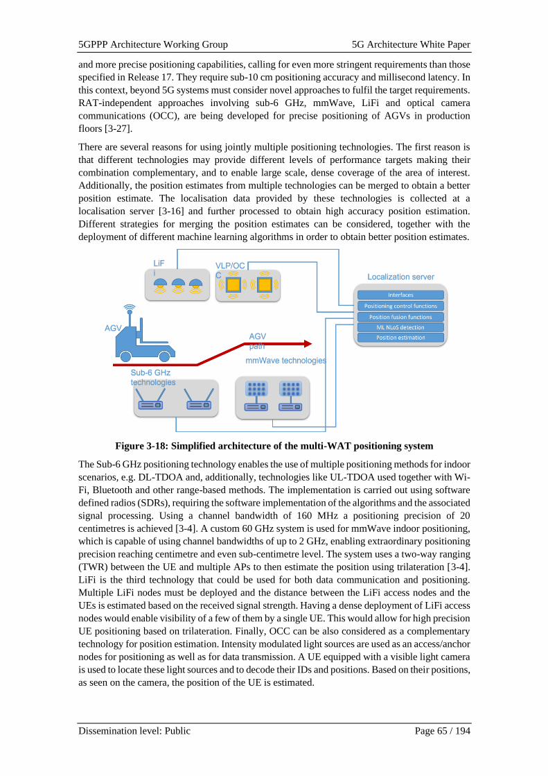
5GPPP Architecture Working Group 5G Architecture White Paper
Dissemination level: Public Page 65 / 194
and more precise positioning capabilities, calling for even more stringent requirements than those
specified in Release 17. They require sub-10 cm positioning accuracy and millisecond latency. In
this context, beyond 5G systems must consider novel approaches to fulfil the target requirements.
RAT-independent approaches involving sub-6 GHz, mmWave, LiFi and optical camera
communications (OCC), are being developed for precise positioning of AGVs in production
floors [3-27].
There are several reasons for using jointly multiple positioning technologies. The first reason is
that different technologies may provide different levels of performance targets making their
combination complementary, and to enable large scale, dense coverage of the area of interest.
Additionally, the position estimates from multiple technologies can be merged to obtain a better
position estimate. The localisation data provided by these technologies is collected at a
localisation server [3-16] and further processed to obtain high accuracy position estimation.
Different strategies for merging the position estimates can be considered, together with the
deployment of different machine learning algorithms in order to obtain better position estimates.
Figure 3-18: Simplified architecture of the multi-WAT positioning system
The Sub-6 GHz positioning technology enables the use of multiple positioning methods for indoor
scenarios, e.g. DL-TDOA and, additionally, technologies like UL-TDOA used together with Wi-
Fi, Bluetooth and other range-based methods. The implementation is carried out using software
defined radios (SDRs), requiring the software implementation of the algorithms and the associated
signal processing. Using a channel bandwidth of 160 MHz a positioning precision of 20
centimetres is achieved [3-4]. A custom 60 GHz system is used for mmWave indoor positioning,
which is capable of using channel bandwidths of up to 2 GHz, enabling extraordinary positioning
precision reaching centimetre and even sub-centimetre level. The system uses a two-way ranging
(TWR) between the UE and multiple APs to then estimate the position using trilateration [3-4].
LiFi is the third technology that could be used for both data communication and positioning.
Multiple LiFi nodes must be deployed and the distance between the LiFi access nodes and the
UEs is estimated based on the received signal strength. Having a dense deployment of LiFi access
nodes would enable visibility of a few of them by a single UE. This would allow for high precision
UE positioning based on trilateration. Finally, OCC can be also considered as a complementary
technology for position estimation. Intensity modulated light sources are used as an access/anchor
nodes for positioning as well as for data transmission. A UE equipped with a visible light camera
is used to locate these light sources and to decode their IDs and positions. Based on their positions,
as seen on the camera, the position of the UE is estimated.
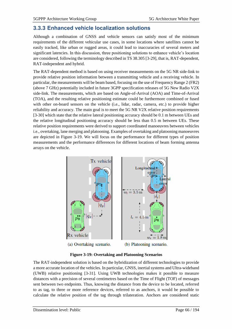
5GPPP Architecture Working Group 5G Architecture White Paper
Dissemination level: Public Page 66 / 194
3.3.3 Enhanced vehicle localization solutions
Although a combination of GNSS and vehicle sensors can satisfy most of the minimum
requirements of the different vehicular use cases, in some locations where satellites cannot be
easily tracked, like urban or rugged areas, it could lead to inaccuracies of several meters and
significant latencies. In this discussion, three positioning solutions to enhance vehicle’s location
are considered, following the terminology described in TS 38.305 [3-29], that is, RAT-dependent,
RAT-independent and hybrid.
The RAT-dependent method is based on using receiver measurements on the 5G NR side-link to
provide relative position information between a transmitting vehicle and a receiving vehicle. In
particular, the measurements will be beam based, focusing on the use of Frequency Range 2 (FR2)
(above 7 GHz) potentially included in future 3GPP specification releases of 5G New Radio V2X
side-link. The measurements, which are based on Angle-of-Arrival (AOA) and Time-of-Arrival
(TOA), and the resulting relative positioning estimate could be furthermore combined or fused
with other on-board sensors on the vehicle (i.e., lidar, radar, camera, etc.) to provide higher
reliability and accuracy. The main goal is to meet the 5G NR V2X relative position requirements
[3-30] which state that the relative lateral positioning accuracy should be 0.1 m between UEs and
the relative longitudinal positioning accuracy should be less than 0.5 m between UEs. These
relative position requirements were derived to support coordinated manoeuvres between vehicles
i.e., overtaking, lane merging and platooning. Examples of overtaking and platooning manoeuvres
are depicted in Figure 3-19. We will focus on the performance for different types of position
measurements and the performance differences for different locations of beam forming antenna
arrays on the vehicle.
Figure 3-19: Overtaking and Platooning Scenarios
The RAT-independent solution is based on the hybridization of different technologies to provide
a more accurate location of the vehicles. In particular, GNSS, inertial systems and Ultra-wideband
(UWB) relative positioning [3-31]. Using UWB technologies makes it possible to measure
distances with a precision of several centimetres based on the Time of Flight (TOF) of messages
sent between two endpoints. Thus, knowing the distance from the device to be located, referred
to as tag, to three or more reference devices, referred to as anchors, it would be possible to
calculate the relative position of the tag through trilateration. Anchors are considered static
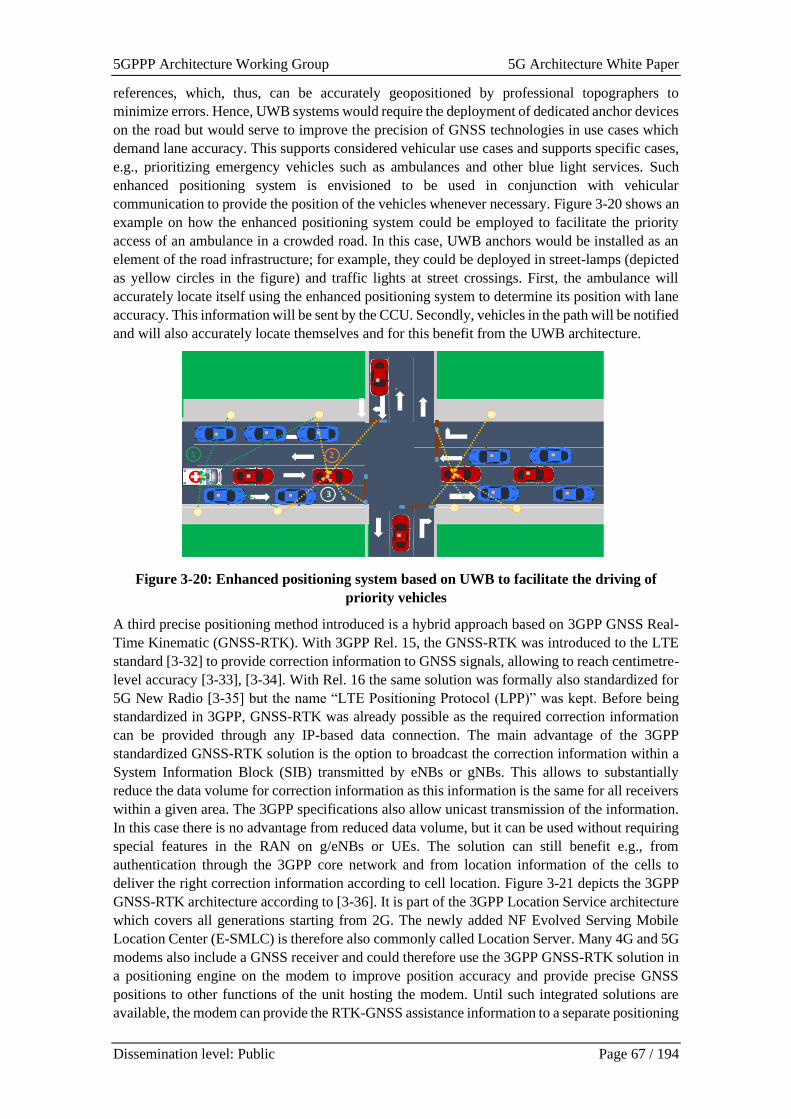
5GPPP Architecture Working Group 5G Architecture White Paper
Dissemination level: Public Page 67 / 194
references, which, thus, can be accurately geopositioned by professional topographers to
minimize errors. Hence, UWB systems would require the deployment of dedicated anchor devices
on the road but would serve to improve the precision of GNSS technologies in use cases which
demand lane accuracy. This supports considered vehicular use cases and supports specific cases,
e.g., prioritizing emergency vehicles such as ambulances and other blue light services. Such
enhanced positioning system is envisioned to be used in conjunction with vehicular
communication to provide the position of the vehicles whenever necessary. Figure 3-20 shows an
example on how the enhanced positioning system could be employed to facilitate the priority
access of an ambulance in a crowded road. In this case, UWB anchors would be installed as an
element of the road infrastructure; for example, they could be deployed in street-lamps (depicted
as yellow circles in the figure) and traffic lights at street crossings. First, the ambulance will
accurately locate itself using the enhanced positioning system to determine its position with lane
accuracy. This information will be sent by the CCU. Secondly, vehicles in the path will be notified
and will also accurately locate themselves and for this benefit from the UWB architecture.
Figure 3-20: Enhanced positioning system based on UWB to facilitate the driving of
priority vehicles
A third precise positioning method introduced is a hybrid approach based on 3GPP GNSS Real-
Time Kinematic (GNSS-RTK). With 3GPP Rel. 15, the GNSS-RTK was introduced to the LTE
standard [3-32] to provide correction information to GNSS signals, allowing to reach centimetre-
level accuracy [3-33], [3-34]. With Rel. 16 the same solution was formally also standardized for
5G New Radio [3-35] but the name “LTE Positioning Protocol (LPP)” was kept. Before being
standardized in 3GPP, GNSS-RTK was already possible as the required correction information
can be provided through any IP-based data connection. The main advantage of the 3GPP
standardized GNSS-RTK solution is the option to broadcast the correction information within a
System Information Block (SIB) transmitted by eNBs or gNBs. This allows to substantially
reduce the data volume for correction information as this information is the same for all receivers
within a given area. The 3GPP specifications also allow unicast transmission of the information.
In this case there is no advantage from reduced data volume, but it can be used without requiring
special features in the RAN on g/eNBs or UEs. The solution can still benefit e.g., from
authentication through the 3GPP core network and from location information of the cells to
deliver the right correction information according to cell location. Figure 3-21 depicts the 3GPP
GNSS-RTK architecture according to [3-36]. It is part of the 3GPP Location Service architecture
which covers all generations starting from 2G. The newly added NF Evolved Serving Mobile
Location Center (E-SMLC) is therefore also commonly called Location Server. Many 4G and 5G
modems also include a GNSS receiver and could therefore use the 3GPP GNSS-RTK solution in
a positioning engine on the modem to improve position accuracy and provide precise GNSS
positions to other functions of the unit hosting the modem. Until such integrated solutions are
available, the modem can provide the RTK-GNSS assistance information to a separate positioning
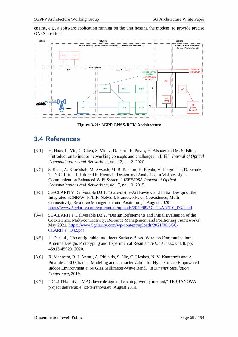
5GPPP Architecture Working Group 5G Architecture White Paper
Dissemination level: Public Page 68 / 194
engine, e.g., a software application running on the unit hosting the modem, to provide precise
GNSS positions
Figure 3-21: 3GPP GNSS-RTK Architecture
3.4 References
[3-1] H. Haas, L. Yin, C. Chen, S. Videv, D. Parol, E. Poves, H. Alshaer and M. S. Islim,
“Introduction to indoor networking concepts and challenges in LiFi,” Journal of Optical
Communications and Networking, vol. 12, no. 2, 2020.
[3-2] S. Shao, A. Khreishah, M. Ayyash, M. B. Rahaim, H. Elgala, V. Jungnickel, D. Schulz,
T. D. C. Little, J. Hilt and R. Freund, “Design and Analysis of a Visible-Light-
Communication Enhanced WiFi System,” IEEE/OSA Journal of Optical
Communications and Networking, vol. 7, no. 10, 2015.
[3-3] 5G-CLARITY Deliverable D3.1, “State-of-the-Art Review and Initial Design of the
Integrated 5GNR/Wi-Fi/LiFi Network Frameworks on Coexistence, Multi-
Connectivity, Resource Management and Positioning”, August 2020.
https://www.5gclarity.com/wp-content/uploads/2020/09/5G-CLARITY_D3.1.pdf
[3-4] 5G-CLARITY Deliverable D3.2, “Design Refinements and Initial Evaluation of the
Coexistence, Multi-connectivity, Resource Management and Positioning Frameworks”,
May 2021. https://www.5gclarity.com/wp-content/uploads/2021/06/5GC-
CLARITY_D32.pdf
[3-5] L. D. e. al., "Reconfigurable Intelligent Surface-Based Wireless Communication:
Antenna Design, Prototyping and Experimental Results," IEEE Access, vol. 8, pp.
45913-45923, 2020.
[3-6] R. Mehrotra, R. I. Ansari, A. Pitilakis, S. Nie, C. Liaskos, N. V. Kantartzis and A.
Pitsilides, "3D Channel Modeling and Characterization for Hypersurface Empowered
Indoor Environment at 60 GHz Millimeter-Wave Band," in Summer Simulation
Conference, 2019.
[3-7] "D4.2 THz-driven MAC layer design and caching overlay method," TERRANOVA
project deliverable, ict-terranova.eu, August 2019.
5GPPP Architecture Working Group 5G Architecture White Paper
Dissemination level: Public Page 69 / 194
[3-8] M. S. Elbamby, C. Perfecto, M. Bennis and K. Doppler, "Toward Low-Latency and
Ultra-Reliable Virtual Reality," IEEE Networks, vol. 32, no. 2, pp. 78-84, March-April
2018.
[3-9] S. Dang, O. Amin, B. Shihada, et al. "What should 6G be?," Nature Electronics, vol. 3,
pp. 20-29, January 2020.
[3-10] ARIADNE Project: https://www.ict-ariadne.eu/ (Deliverables: https://www.ict-
ariadne.eu/deliverables/ )
[3-11] 5G PPP 5G Architecture White Paper v03, available: https://5g-ppp.eu/wp-
content/uploads/2020/02/5G-PPP-5G-Architecture-White-Paper_final.pdf
[3-12] 5G-VINNI Project (deliverables) available: https://www.5g-vinni.eu/deliverables/
[3-13] 5G-VINNI D1.4, “Design of infrastructure architecture and subsystems v2”, Zenodo,
Oct. 2020. doi: 10.5281/zenodo.4066381
[3-14] 5G-VINNI D1.5, “5G-VINNI E2E Network Slice Implementation and Further Design
Guidelines”, Zenodo, Oct. 2020. doi: 10.5281/zenodo.4067793.
[3-15] 5GCroco D3.2, ‘Intermediate E2E, MEC & Positioning Architecture’, January 2021.
Available: https://5gcroco.eu/images/templates/rsvario/images/5GCroCo_D3_2.pdf
[3-16] 5G-CLARITY Deliverable D2.2, “Primary System Architecture”, October 2020.
https://www.5gclarity.com/wp-content/uploads/2020/12/5G-CLARITY_D22.pdf
[3-17] 5G ZORRO Deliverable, D2.1, “Use Cases and Requirements Definition”
[3-18] Alexios Lekidis et.al., “Dynamic Slice Scaling Mechanisms for 5G Multi-domain
Environments”, 2021 4th International Workshop on Advances in Slicing for
Softwarized Infrastructures (S4SI 2021).
[3-19] https://argoproj.github.io/
[3-20] https://github.com/open-cluster-management
[3-21] N. Blefari-Melazzi et al., "LOCUS: Localisation and analytics on-demand embedded in
the 5G ecosystem," 2020 European Conference on Networks and Communications
(EuCNC), 2020, pp. 170-175, doi: 10.1109/EuCNC48522.2020.9200961.
[3-22] LOCUS Deliverables D2.1, D2.6, “Scenarios, Use Cases, Requirements preliminary
and final version”
[3-23] LOCUS Deliverables, D2.4, D2,5, “System Architecture, preliminary and final version”
[3-24] LOCUS WP3 Deliverables D3.1-D2.8, Confidential.
[3-25] 5G Innovations for new Business Opportunities, https://5g-ppp.eu/wp-
content/uploads/2017/03/5GPPP-brochure-final-web-MWC.pdf
[3-26] 5G empowering vertical industries (https://5g-ppp.eu/wp-
content/uploads/2016/02/BROCHURE_5PPP_BAT2_PL.pdf
[3-27] 5G-CLARITY Deliverable, D5.1, “Specification of Use Cases and Demonstration
Plan”, February 2021. https://www.5gclarity.com/wp-content/uploads/2021/02/5G-
CLARITY_D51.pdf
[3-28] 5G CroCo Deliverables, https://5gcroco.eu/publications/deliverables.html
[3-29] 3GPP TS 38.305, “NG Radio Access Network (NG-RAN); Stage 2 functional
specification of User Equipment (UE) positioning in NG-RAN,” April, 2020.
5GPPP Architecture Working Group 5G Architecture White Paper
Dissemination level: Public Page 70 / 194
[3-30] 3GPP, “TS 22.186 v16.2.0 Service requirements for enhanced V2X scenarios (Release
16),” 2019.
[3-31] Z. Sahinoglu, Ultra-wideband positioning systems., Cambridge university press, 2008.
[3-32] 3GPP, “TS 36.355 v15.0.0 Evolved Universal Terrestrial Radio Access (E-UTRA);
LTE Positioning Protocol (LPP),” 2018.
[3-33] 3GPP, “R1-1903022, GNSS-RTK and Hybrid Positioning for NG-RAN,” 2019.
[3-34] 3GPP, “R1-1902549, TP on hybrid positioning and GNSS enhancements for TR
38.855,” 2019.
[3-35] 3GPP, “TS 37.355 v16.0.0 LTE Positioning Protocol (LPP),” 2020.
[3-36] 3GPP, “TS 23.271 v15.2.0 Functional stage 2 description of Location Services (LCS),”
2019.
[3-37] 5G!Drones Deliverables, https://5gdrones.eu/deliverables/
[3-38] 5G RECORDS, Deliverable, D2.1, “Use cases, requirements and KPIs”
5GPPP Architecture Working Group 5G Architecture White Paper
Dissemination level: Public Page 71 / 194
4 Core & Transport Architecture
4.1 Introduction
With the increased complexity of 5G networks, the demand of having an intelligent, automated
coordination between the RAN, the mobile core network and the transport network seems the
reasonable choice. With 5G (and later 6G) providing a tremendous increase in capacity, along
with more stringent requirements in terms of performance, the requirements must not only be met
by the 5G system but also by the underlying transport network. Particularly for the latter, apart
from capacity increase and interface density requirements in the RAN, disaggregation in both
RAN and core network can have impact in the transport network architecture [4-1]. This
architecture needs to be highly scalable and future proof, to enable deployment and operation of
new revenue generating services, being the transport network key to provide the required
interfaces and performance in an intelligent and coordinated way.
To reap 5G’s full benefits, the 5G Core should migrate to a cloud native approach, as the network
needs to be established as a valuable and agile platform for value creation where new services, to
a large extent, are conceived through collaboration and co-creation through partnerships or
ecosystems. The 5G Core will enable new use cases and innovation in areas such as ultra-low
latency and mission critical networks that were not addressed in detail so far.
Multicast and broadcast services have been provided by several operators over their mobile
networks to efficiently deliver multimedia content to multiple users while consuming a minimum
of radio and network resources. The support of multicast, broadcast and integrated data analytics
framework in the 5GS is relevant.
4.2 5G Core Network
The new 5G core network (5GC) can accompany this radio flexibilization through the support for
slicing, enabling operators to set up different flavours of core network functions and to add novel
network functions to flexibly control user sessions in a variety of ways from the same core
network. Such creation and addition of new serving instances is explicitly supported by the
dynamic resolution of the serving instance by dedicated functions e.g., network repository
functions (NRF) in the novel Service Based Architecture (SBA) of 5GC.
4.2.1 Cloud Principles in 5G Systems
“Cloud-Native” is the name of an approach to designing, building and running applications/virtual
functions fully exploiting the cloud delivery model. Cloud-Native approach is the way
applications are created and deployed, not where they are executed. The 5G-PPP Software
Networks Work Group highlights the value and challenges of becoming Cloud-Native in [4-2].
Cloud-Native applications are developed with tools that allow them to take full advantage of cloud
benefits, meaning they can be built and changed more quickly, are more agile and scalable, are
more easily connected with other apps. New operational tools and services like continuous
integration, container engines and orchestrators are pillars of this transformation.
Cloud native stands in stark contrast to a before-5G telco-world, where concepts around NFV and
the provisioning of network functions (NFs) as VNFs have seen some adoption especially after
the adoption of softwarisation concepts to decouple the function from the hardware it is supposed
to run.
5GPPP Architecture Working Group 5G Architecture White Paper
Dissemination level: Public Page 72 / 194
Architectural solution 5G PPP
Project
Additional
Reference
Adopting Cloud Principles throughout 5G System FUDGE-5G [4-3], [4-4]
5GC NFs Transitioning to Cloud Native NFs FUDGE-5G [4-5]
4.2.1.1 Adopting Cloud Principles throughout 5G System
The microservice engineering methodology, commonly known as the 12-factor app methodology
[4-3], goes beyond the concept of softwarising functions. It describes architectural concepts on
how an application must be realised in order to run in a cloud native system that focuses on scaling
cloud-native containerized network functions (CNFs). Most importantly, CNFs are stateless
software components that can be freely scaled up and down in the number of instances to cope
with an increase in requests enabling the economy-at-scale.
Cloud native orchestration encompasses three main areas:
• The logic to decide how many CNF instances are required in which lifecycle state and -
if multiple physical locations are available - also where they are being instantiated
• The translation of application KPI or Service Level Agreement (SLA) requirements into
monitoring policies to trigger the logic described above
Descriptor definitions and information models that allow humans or machines to interact with the
orchestration layer through well-defined programmable APIs.
4.2.1.2 5GC NFs Transitioning to Cloud Native NFs
One of the key design choices when realising an application in a cloud native fashion is the
separation of packet routing, application monitoring and analytics (M&A), and service
orchestration from the actual application whose sole objective must focus on processing incoming
requests and returning a response. The naming ontology of services over the internet, i.e., Fully
Qualified Domain Names (FQDNs), is being used to allow the logical separation of functions
which form the application. Thus, each client is fully aware about the FQDN of the next function
(server), which can serve the request the client aims to issue.
However, how an application – which is decomposed into a set of functions realised as
microservices – is initially orchestrated and lifecycle managed at run time must not become part
of the application. This allows a truly cloud native realisation of the application where testing,
staging and production environments can use the same code base without any modifications.
Furthermore, and most importantly for telecommunication systems, how requests are being routed
to the instance which can serve them, and which particular instance to choose in the first place,
must be also fully decoupled from the actual application. This capability, commonly referred to
as “service routing”, is baked into all microservice management systems via sidecars and load
balancers. However, those systems are operating within their own realm only and do not offer
service routing across multiple islands, as this would require a system-wide understanding of the
network, its resources and current state.
4.2.2 5G Multicast
5G Multicast is the first Third Generation Partnership Project (3GPP) technology that enables
point-to-multipoint communications inside the 5G Core Network and the 5G RAN [4-11]. It
increases the efficiency in the network resources used, avoiding possible congestion occurring
inside the transport network.
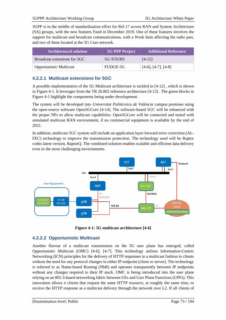
5GPPP Architecture Working Group 5G Architecture White Paper
Dissemination level: Public Page 73 / 194
3GPP is in the middle of standardisation effort for Rel-17 across RAN and System Architecture
(SA) groups, with the new features fixed in December 2019. One of these features involves the
support for multicast and broadcast communications, with a Work Item affecting the radio part,
and two of them located at the 5G Core network.
Architectural solution 5G PPP Project Additional Reference
Broadcast extensions for 5GC 5G-TOURS [4-12]
Opportunistic Multicast FUDGE-5G [4-6], [4-7], [4-8]
4.2.2.1 Multicast extensions for 5GC
A possible implementation of the 5G Multicast architecture is tackled in [4-12] , which is shown
in Figure 4-1. It leverages from the TR 26.802 reference architecture [4-13] . The green blocks in
Figure 4-1 highlight the components being under development.
The system will be developed into Universitat Politècnica de València campus premises using
the open-source software Open5GCore [4-14]. The software-based 5GC will be enhanced with
the proper NFs to allow multicast capabilities. Open5GCore will be connected and tested with
simulated multicast RAN environment, if no commercial equipment is available by the end of
2021.
In addition, multicast 5GC system will include an application layer forward error correction (AL-
FEC) technology to improve the transmission protection. The technology used will be Raptor
codes latest version, RaptorQ. The combined solution enables scalable and efficient data delivery
even in the most challenging environments.
Figure 4-1: 5G multicast architecture [4-6]
4.2.2.2 Opportunistic Multicast
Another flavour of a multicast transmission on the 5G user plane has emerged, called
Opportunistic Multicast (OMC) [4-6], [4-7]. This technology utilises Information-Centric
Networking (ICN) principles for the delivery of HTTP responses in a multicast fashion to clients
without the need for any protocol changes in either IP endpoint (client or server). The technology
is referred to as Name-based Routing (NbR) and operates transparently between IP endpoints
without any changes required to their IP stack. OMC is being introduced into the user plane
relying on an 802.3-based networking fabric between UEs and User Plane Functions (UPFs). This
innovation allows n clients that request the same HTTP resource, at roughly the same time, to
receive the HTTP response as a multicast delivery through the network over L2. If all clients of
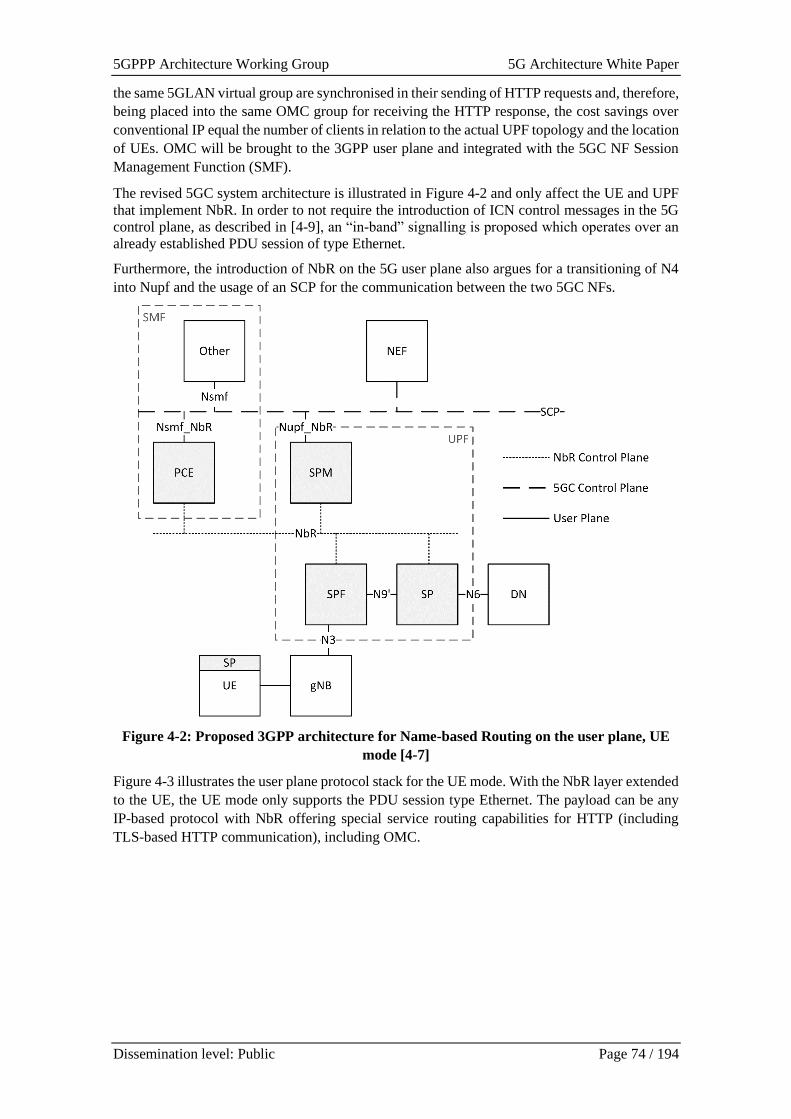
5GPPP Architecture Working Group 5G Architecture White Paper
Dissemination level: Public Page 74 / 194
the same 5GLAN virtual group are synchronised in their sending of HTTP requests and, therefore,
being placed into the same OMC group for receiving the HTTP response, the cost savings over
conventional IP equal the number of clients in relation to the actual UPF topology and the location
of UEs. OMC will be brought to the 3GPP user plane and integrated with the 5GC NF Session
Management Function (SMF).
The revised 5GC system architecture is illustrated in Figure 4-2 and only affect the UE and UPF
that implement NbR. In order to not require the introduction of ICN control messages in the 5G
control plane, as described in [4-9], an “in-band” signalling is proposed which operates over an
already established PDU session of type Ethernet.
Furthermore, the introduction of NbR on the 5G user plane also argues for a transitioning of N4
into Nupf and the usage of an SCP for the communication between the two 5GC NFs.
Figure 4-2: Proposed 3GPP architecture for Name-based Routing on the user plane, UE
mode [4-7]
Figure 4-3 illustrates the user plane protocol stack for the UE mode. With the NbR layer extended
to the UE, the UE mode only supports the PDU session type Ethernet. The payload can be any
IP-based protocol with NbR offering special service routing capabilities for HTTP (including
TLS-based HTTP communication), including OMC.
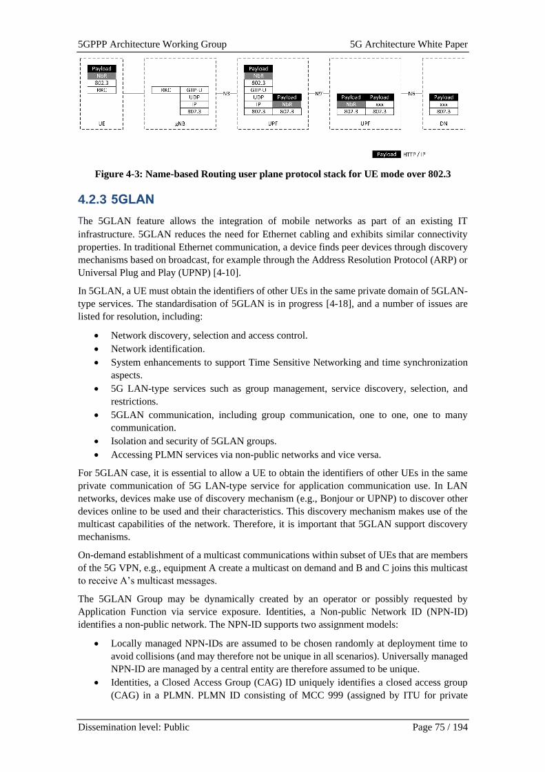
5GPPP Architecture Working Group 5G Architecture White Paper
Dissemination level: Public Page 75 / 194
Figure 4-3: Name-based Routing user plane protocol stack for UE mode over 802.3
4.2.3 5GLAN
The 5GLAN feature allows the integration of mobile networks as part of an existing IT
infrastructure. 5GLAN reduces the need for Ethernet cabling and exhibits similar connectivity
properties. In traditional Ethernet communication, a device finds peer devices through discovery
mechanisms based on broadcast, for example through the Address Resolution Protocol (ARP) or
Universal Plug and Play (UPNP) [4-10].
In 5GLAN, a UE must obtain the identifiers of other UEs in the same private domain of 5GLAN-
type services. The standardisation of 5GLAN is in progress [4-18], and a number of issues are
listed for resolution, including:
• Network discovery, selection and access control.
• Network identification.
• System enhancements to support Time Sensitive Networking and time synchronization
aspects.
• 5G LAN-type services such as group management, service discovery, selection, and
restrictions.
• 5GLAN communication, including group communication, one to one, one to many
communication.
• Isolation and security of 5GLAN groups.
• Accessing PLMN services via non-public networks and vice versa.
For 5GLAN case, it is essential to allow a UE to obtain the identifiers of other UEs in the same
private communication of 5G LAN-type service for application communication use. In LAN
networks, devices make use of discovery mechanism (e.g., Bonjour or UPNP) to discover other
devices online to be used and their characteristics. This discovery mechanism makes use of the
multicast capabilities of the network. Therefore, it is important that 5GLAN support discovery
mechanisms.
On-demand establishment of a multicast communications within subset of UEs that are members
of the 5G VPN, e.g., equipment A create a multicast on demand and B and C joins this multicast
to receive A’s multicast messages.
The 5GLAN Group may be dynamically created by an operator or possibly requested by
Application Function via service exposure. Identities, a Non-public Network ID (NPN-ID)
identifies a non-public network. The NPN-ID supports two assignment models:
• Locally managed NPN-IDs are assumed to be chosen randomly at deployment time to
avoid collisions (and may therefore not be unique in all scenarios). Universally managed
NPN-ID are managed by a central entity are therefore assumed to be unique.
• Identities, a Closed Access Group (CAG) ID uniquely identifies a closed access group
(CAG) in a PLMN. PLMN ID consisting of MCC 999 (assigned by ITU for private
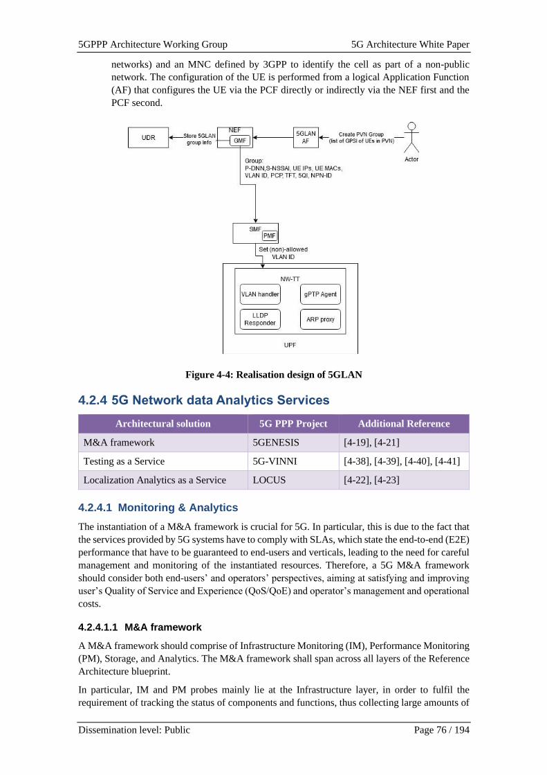
5GPPP Architecture Working Group 5G Architecture White Paper
Dissemination level: Public Page 76 / 194
networks) and an MNC defined by 3GPP to identify the cell as part of a non-public
network. The configuration of the UE is performed from a logical Application Function
(AF) that configures the UE via the PCF directly or indirectly via the NEF first and the
PCF second.
Figure 4-4: Realisation design of 5GLAN
4.2.4 5G Network data Analytics Services
Architectural solution 5G PPP Project Additional Reference
M&A framework 5GENESIS [4-19], [4-21]
Testing as a Service 5G-VINNI [4-38], [4-39], [4-40], [4-41]
Localization Analytics as a Service LOCUS [4-22], [4-23]
4.2.4.1 Monitoring & Analytics
The instantiation of a M&A framework is crucial for 5G. In particular, this is due to the fact that
the services provided by 5G systems have to comply with SLAs, which state the end-to-end (E2E)
performance that have to be guaranteed to end-users and verticals, leading to the need for careful
management and monitoring of the instantiated resources. Therefore, a 5G M&A framework
should consider both end-users’ and operators’ perspectives, aiming at satisfying and improving
user’s Quality of Service and Experience (QoS/QoE) and operator’s management and operational
costs.
4.2.4.1.1 M&A framework
A M&A framework should comprise of Infrastructure Monitoring (IM), Performance Monitoring
(PM), Storage, and Analytics. The M&A framework shall span across all layers of the Reference
Architecture blueprint.
In particular, IM and PM probes mainly lie at the Infrastructure layer, in order to fulfil the
requirement of tracking the status of components and functions, thus collecting large amounts of
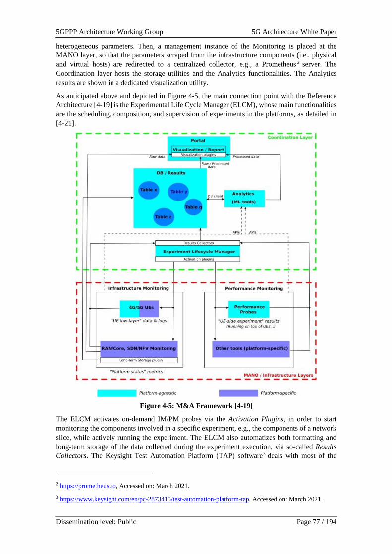
5GPPP Architecture Working Group 5G Architecture White Paper
Dissemination level: Public Page 77 / 194
heterogeneous parameters. Then, a management instance of the Monitoring is placed at the
MANO layer, so that the parameters scraped from the infrastructure components (i.e., physical
and virtual hosts) are redirected to a centralized collector, e.g., a Prometheus 2 server. The
Coordination layer hosts the storage utilities and the Analytics functionalities. The Analytics
results are shown in a dedicated visualization utility.
As anticipated above and depicted in Figure 4-5, the main connection point with the Reference
Architecture [4-19] is the Experimental Life Cycle Manager (ELCM), whose main functionalities
are the scheduling, composition, and supervision of experiments in the platforms, as detailed in
[4-21].
Figure 4-5: M&A Framework [4-19]
The ELCM activates on-demand IM/PM probes via the Activation Plugins, in order to start
monitoring the components involved in a specific experiment, e.g., the components of a network
slice, while actively running the experiment. The ELCM also automatizes both formatting and
long-term storage of the data collected during the experiment execution, via so-called Results
Collectors. The Keysight Test Automation Platform (TAP) software3 deals with most of the
2 https://prometheus.io, Accessed on: March 2021.
3 https://www.keysight.com/en/pc-2873415/test-automation-platform-tap, Accessed on: March 2021.
5GPPP Architecture Working Group 5G Architecture White Paper
Dissemination level: Public Page 78 / 194
ELCM operations, being the Activation Plugins TAP Plugins, while the Result Collectors are TAP
Result Listeners.
A full-chain M&A framework for a reliable validation of 5G KPIs has been developed in [4-19].
The framework enables the analysis of experimental data collected by dedicated monitoring
probes. This in turn allows to pinpoint the interdependencies between network configurations,
scenarios and environmental conditions, and QoS and QoE KPIs, ultimately leading to the
derivation of optimized management policies for further improvement of users’, verticals’, and
operators’ performance.
The M&A framework includes several Monitoring tools and both statistical and ML-based
Analytics. It comprises three main blocks:
• Infrastructure Monitoring (IM), which focuses on the collection of data on the status of
infrastructure components, e.g., User Equipment (UE), radio access and core networks,
Software Defined Network / Network Function Virtualization (SDN/NFV) environments,
and distributed edge units;
• Performance Monitoring (PM), which is devoted to the active measure of E2E QoS/QoE
KPIs. These include traditional indicators, such as throughput and latency, but also other
indicators tailored on specific use cases and applications (e.g., mission critical services
and massive communications);
• Storage and Analytics, which enables the efficient management of large amounts of
heterogeneous data, and drives the discovery of hidden values, correlation, and causality
among them.
Among others, the M&A framework aims at providing the following Analytics functionalities:
1) KPI Validation, i.e., the execution of the KPI statistical analysis for validating a KPI [4-
20];
2) Time series management, which allows to coherently merge the data coming from
different probes, in order to perform further analyses. In an M&A system, this task is
needed for several reasons. First, different sampling rates might be used by different
probes. For example, QoS/QoE KPIs might be collected at higher sampling rates as
compared to infrastructure data. Second, the probes might be not perfectly synchronized.
Hence, time synchronization can be applied when the time series collected from different
probes present similar sampling rates, while interpolation better suits situations where the
probes use different sampling rates;
3) Outlier detection, in order to eliminate data obtained under incorrect functioning of the
probes, which may negatively affect the analyses;
4) Feature selection, which allows to simplify the analyses by eliminating some of the
collected parameters. As a matter of fact, 5G networks include a huge number of
components. Hence, using ML and Artificial Intelligence (AI) approaches for network
management and optimization could be challenged by the large amount of data that can
be potentially collected; some of these data might be not useful and could negatively
affect the analyses. Hence, feature selection algorithms can be used to remove redundant
features, making the next analyses computationally simpler and faster. In general, feature
selection allows to train ML algorithms faster, reduce model complexity and overfitting,
and improve model accuracy;
5) Correlation analysis, which allows to highlight how system configurations and network
conditions, collected via IM probes, are correlated and affect QoS/QoE KPIs, collected
via PM tools. Revealing the correlation between IM and PM parameters allows to
improve network management and derive better configuration policies for assuring SLAs.
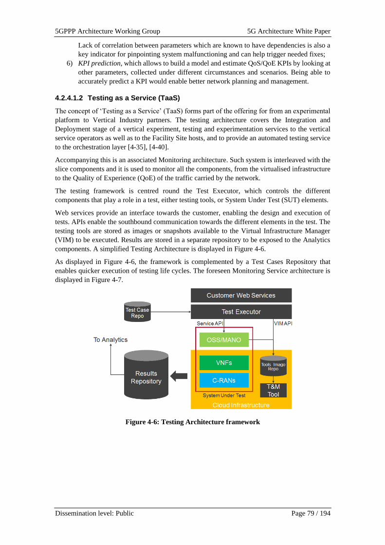
5GPPP Architecture Working Group 5G Architecture White Paper
Dissemination level: Public Page 79 / 194
Lack of correlation between parameters which are known to have dependencies is also a
key indicator for pinpointing system malfunctioning and can help trigger needed fixes;
6) KPI prediction, which allows to build a model and estimate QoS/QoE KPIs by looking at
other parameters, collected under different circumstances and scenarios. Being able to
accurately predict a KPI would enable better network planning and management.
4.2.4.1.2 Testing as a Service (TaaS)
The concept of ‘Testing as a Service’ (TaaS) forms part of the offering for from an experimental
platform to Vertical Industry partners. The testing architecture covers the Integration and
Deployment stage of a vertical experiment, testing and experimentation services to the vertical
service operators as well as to the Facility Site hosts, and to provide an automated testing service
to the orchestration layer [4-35], [4-40].
Accompanying this is an associated Monitoring architecture. Such system is interleaved with the
slice components and it is used to monitor all the components, from the virtualised infrastructure
to the Quality of Experience (QoE) of the traffic carried by the network.
The testing framework is centred round the Test Executor, which controls the different
components that play a role in a test, either testing tools, or System Under Test (SUT) elements.
Web services provide an interface towards the customer, enabling the design and execution of
tests. APIs enable the southbound communication towards the different elements in the test. The
testing tools are stored as images or snapshots available to the Virtual Infrastructure Manager
(VIM) to be executed. Results are stored in a separate repository to be exposed to the Analytics
components. A simplified Testing Architecture is displayed in Figure 4-6.
As displayed in Figure 4-6, the framework is complemented by a Test Cases Repository that
enables quicker execution of testing life cycles. The foreseen Monitoring Service architecture is
displayed in Figure 4-7.
Figure 4-6: Testing Architecture framework
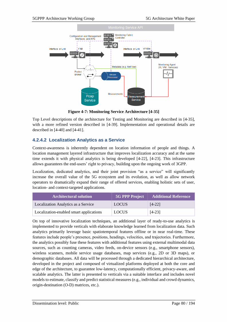
5GPPP Architecture Working Group 5G Architecture White Paper
Dissemination level: Public Page 80 / 194
Figure 4-7: Monitoring Service Architecture [4-35]
Top Level descriptions of the architecture for Testing and Monitoring are described in [4-35],
with a more refined version described in [4-39]. Implementation and operational details are
described in [4-40] and [4-41].
4.2.4.2 Localization Analytics as a Service
Context-awareness is inherently dependent on location information of people and things. A
location management layered infrastructure that improves localization accuracy and at the same
time extends it with physical analytics is being developed [4-22], [4-23]. This infrastructure
allows guarantees the end-users’ right to privacy, building upon the ongoing work of 3GPP.
Localization, dedicated analytics, and their joint provision “as a service” will significantly
increase the overall value of the 5G ecosystem and its evolution, as well as allow network
operators to dramatically expand their range of offered services, enabling holistic sets of user,
location- and context-targeted applications.
Architectural solution 5G PPP Project Additional Reference
Localization Analytics as a Service LOCUS [4-22]
Localization-enabled smart applications LOCUS [4-23]
On top of innovative localization techniques, an additional layer of ready-to-use analytics is
implemented to provide verticals with elaborate knowledge learned from localization data. Such
analytics primarily leverage basic spatiotemporal features offline or in near real-time. These
features include people’s presence, positions, headings, velocities, and trajectories. Furthermore,
the analytics possibly fuse these features with additional features using external multimodal data
sources, such as counting cameras, video feeds, on-device sensors (e.g., smartphone sensors),
wireless scanners, mobile service usage databases, map services (e.g., 2D or 3D maps), or
demographic databases. All data will be processed through a dedicated hierarchical architecture,
developed in the project and composed of virtualized platforms deployed at both the core and
edge of the architecture, to guarantee low-latency, computationally efficient, privacy-aware, and
scalable analytics. The latter is presented to verticals via a suitable interface and includes novel
models to estimate, classify and predict statistical measures (e.g., individual and crowd dynamics,
origin-destination (O-D) matrices, etc.).
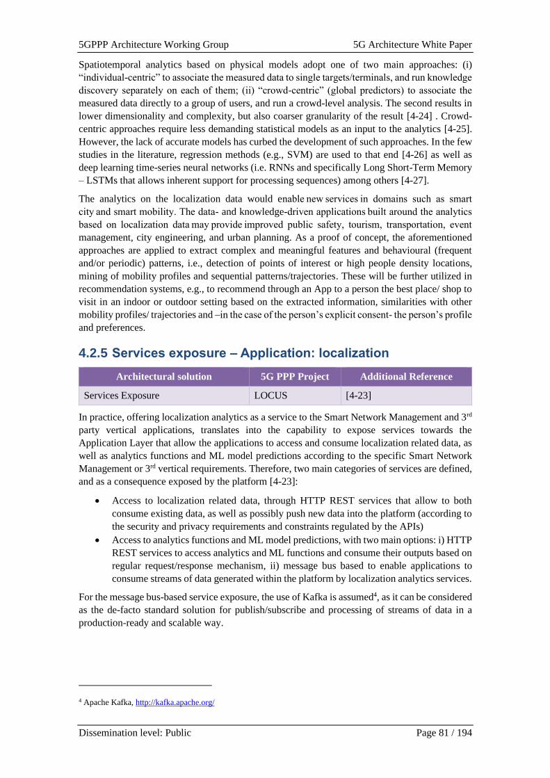
5GPPP Architecture Working Group 5G Architecture White Paper
Dissemination level: Public Page 81 / 194
Spatiotemporal analytics based on physical models adopt one of two main approaches: (i)
“individual-centric” to associate the measured data to single targets/terminals, and run knowledge
discovery separately on each of them; (ii) “crowd-centric” (global predictors) to associate the
measured data directly to a group of users, and run a crowd-level analysis. The second results in
lower dimensionality and complexity, but also coarser granularity of the result [4-24] . Crowd-
centric approaches require less demanding statistical models as an input to the analytics [4-25].
However, the lack of accurate models has curbed the development of such approaches. In the few
studies in the literature, regression methods (e.g., SVM) are used to that end [4-26] as well as
deep learning time-series neural networks (i.e. RNNs and specifically Long Short-Term Memory
– LSTMs that allows inherent support for processing sequences) among others [4-27].
The analytics on the localization data would enable new services in domains such as smart
city and smart mobility. The data- and knowledge-driven applications built around the analytics
based on localization data may provide improved public safety, tourism, transportation, event
management, city engineering, and urban planning. As a proof of concept, the aforementioned
approaches are applied to extract complex and meaningful features and behavioural (frequent
and/or periodic) patterns, i.e., detection of points of interest or high people density locations,
mining of mobility profiles and sequential patterns/trajectories. These will be further utilized in
recommendation systems, e.g., to recommend through an App to a person the best place/ shop to
visit in an indoor or outdoor setting based on the extracted information, similarities with other
mobility profiles/ trajectories and –in the case of the person’s explicit consent- the person’s profile
and preferences.
4.2.5 Services exposure – Application: localization
Architectural solution 5G PPP Project Additional Reference
Services Exposure LOCUS [4-23]
In practice, offering localization analytics as a service to the Smart Network Management and 3rd
party vertical applications, translates into the capability to expose services towards the
Application Layer that allow the applications to access and consume localization related data, as
well as analytics functions and ML model predictions according to the specific Smart Network
Management or 3rd vertical requirements. Therefore, two main categories of services are defined,
and as a consequence exposed by the platform [4-23]:
• Access to localization related data, through HTTP REST services that allow to both
consume existing data, as well as possibly push new data into the platform (according to
the security and privacy requirements and constraints regulated by the APIs)
• Access to analytics functions and ML model predictions, with two main options: i) HTTP
REST services to access analytics and ML functions and consume their outputs based on
regular request/response mechanism, ii) message bus based to enable applications to
consume streams of data generated within the platform by localization analytics services.
For the message bus-based service exposure, the use of Kafka is assumed4, as it can be considered
as the de-facto standard solution for publish/subscribe and processing of streams of data in a
production-ready and scalable way.
4 Apache Kafka, http://kafka.apache.org/
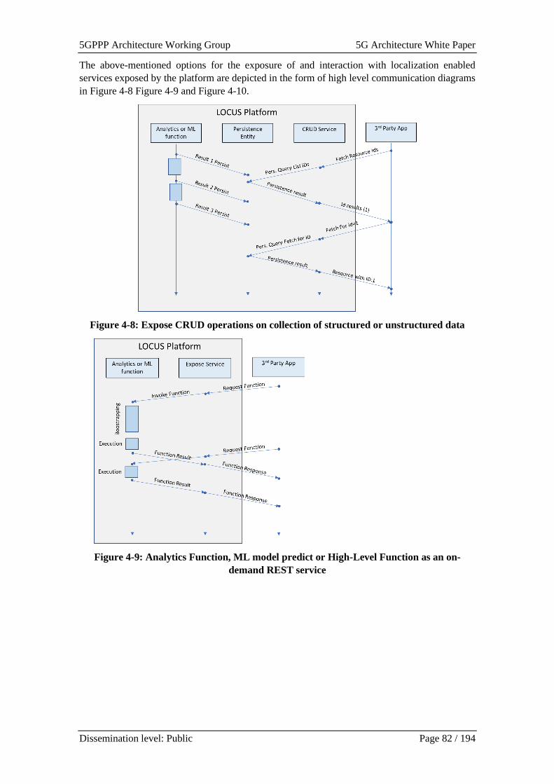
5GPPP Architecture Working Group 5G Architecture White Paper
Dissemination level: Public Page 82 / 194
The above-mentioned options for the exposure of and interaction with localization enabled
services exposed by the platform are depicted in the form of high level communication diagrams
in Figure 4-8 Figure 4-9 and Figure 4-10.
Figure 4-8: Expose CRUD operations on collection of structured or unstructured data
Figure 4-9: Analytics Function, ML model predict or High-Level Function as an on-
demand REST service
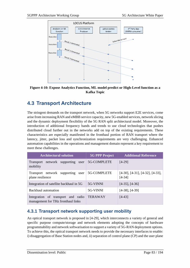
5GPPP Architecture Working Group 5G Architecture White Paper
Dissemination level: Public Page 83 / 194
Figure 4-10: Expose Analytics Function, ML model predict or High-Level function as a
Kafka Topic
4.3 Transport Architecture
The stringent demands on the transport network, when 5G networks support E2E services, come
arise from increasing RAN and eMBB service capacity, new 5G-enabled services, network slicing
and the dynamic deployment flexibility of the 5G RAN split architectural model. Moreover, the
introduction of additional frequency bands and trends to use cloud technologies that pushes
distributed cloud further out in the networks add on top of the existing requirements. These
characteristics are especially manifested in the fronthaul portion of RAN transport where the
latency, jitter, packet loss and synchronization requirements are very challenging. Enhanced
automation capabilities in the operations and management domain represent a key requirement to
meet these challenges.
Architectural solution 5G PPP Project Additional Reference
Transport network supporting user
mobility
5G-COMPLETE [4-29]
Transport network supporting user
plane resilience
5G-COMPLETE [4-30], [4-31], [4-32], [4-33],
[4-34]
Integration of satellite backhaul in 5G 5G-VINNI [4-35], [4-36]
Backhaul automation 5G-VINNI [4-38], [4-39]
Integration of transport and radio
management for THz fronthaul links
TERAWAY [4-43]
4.3.1 Transport network supporting user mobility
An optical transport network is proposed in [4-29], which interconnects a variety of general and
specific purpose compute/storage and network elements adopting the concepts of hardware
programmability and network softwarisation to support a variety of 5G-RAN deployment options.
To achieve this, the optical transport network needs to provide the necessary interfaces to enable:
i) disaggregation of Base Station nodes and, ii) separation of control plane (CP) and the user plane
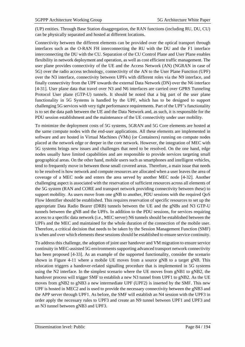
5GPPP Architecture Working Group 5G Architecture White Paper
Dissemination level: Public Page 84 / 194
(UP) entities. Through Base Station disaggregation, the RAN functions (including RU, DU, CU)
can be physically separated and hosted at different locations.
Connectivity between the different elements can be provided over the optical transport through
interfaces such as the O-RAN FH interconnecting the RU with the DU and the F1 interface
interconnecting the DU with the CU. Separation of the CU Control Plane and User Plane enables
flexibility in network deployment and operation, as well as cost efficient traffic management. The
user plane provides connectivity of the UE and the Access Network (AN) (NGRAN in case of
5G) over the radio access technology, connectivity of the AN to the User Plane Function (UPF)
over the N3 interface, connectivity between UPFs with different roles via the N9 interface, and
finally connectivity from the UPF towards the external Data Network (DN) over the N6 interface
[4-31]. User plane data that travel over N3 and N6 interfaces are carried over GPRS Tunneling
Protocol User plane (GTP-U) tunnels. It should be noted that a big part of the user plane
functionality in 5G Systems is handled by the UPF, which has to be designed to support
challenging 5G services with very tight performance requirements. Part of the UPF’s functionality
is to set the data path between the UE and the Data Network and, as such, it is responsible for the
PDU session establishment and the maintenance of the UE connectivity under user mobility.
To minimize the deployment costs of 5G systems, 5GRAN and 5G Core elements are hosted at
the same compute nodes with the end-user applications. All these elements are implemented in
software and are hosted in Virtual Machines (VMs) (or Containers) running on compute nodes
placed at the network edge or deeper in the core network. However, the integration of MEC with
5G systems brings new issues and challenges that need to be resolved. On the one hand, edge
nodes usually have limited capabilities and are responsible to provide services targeting small
geographical areas. On the other hand, mobile users such as smartphones and intelligent vehicles,
tend to frequently move in between those small covered areas. Therefore, a main issue that needs
to be resolved is how network and compute resources are allocated when a user leaves the area of
coverage of a MEC node and enters the area served by another MEC node [4-32]. Another
challenging aspect is associated with the reservation of sufficient resources across all elements of
the 5G system (RAN and CORE and transport network providing connectivity between these) to
support mobility. As users move from one gNB to another, PDU sessions with the required QoS
Flow Identifier should be established. This requires reservation of specific resources to set up the
appropriate Data Radio Bearer (DRB) tunnels between the UE and the gNBs and N3 GTP-U
tunnels between the gNB and the UPFs. In addition to the PDU sessions, for services requiring
access to a specific data network (i.e., MEC server) N6 tunnels should be established between the
UPFs and the MEC and maintained for the whole duration of the connection of the mobile user.
Therefore, a critical decision that needs to be taken by the Session Management Function (SMF)
is when and over which elements these sessions should be established to ensure service continuity.
To address this challenge, the adoption of joint user handover and VM migration to ensure service
continuity in MEC-assisted 5G environments supporting advanced transport network connectivity
has been proposed [4-33]. As an example of the supported functionality, consider the scenario
shown in Figure 4-11 where a mobile UE moves from a source gNB to a target gNB. This
relocation triggers a handover-related signalling procedure that is implemented in 5G systems
using the N2 interface. In the simplest scenario where the UE moves from gNB1 to gNB2, the
handover process will trigger SMF to establish a new N3 tunnel from UPF1 to gNB2. As the UE
moves from gNB2 to gNB3 a new intermediate UPF (UPF2) is inserted by the SMF. This new
UPF is hosted in MEC2 and is used to provide the necessary connectivity between the gNB3 and
the APP server through UPF1. As before, the SMF will establish an N4 session with the UPF3 in
order apply the necessary rules to UPF3 and create an N9 tunnel between UPF1 and UPF3 and
an N3 tunnel between gNB3 and UPF3.
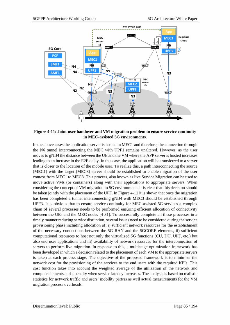
5GPPP Architecture Working Group 5G Architecture White Paper
Dissemination level: Public Page 85 / 194
Regional cloud
VM synch path
3
s2
MEC server
s1
1
MEC server
UPF2
MEC2
N3
N9
UPF3
N3
1MEC1
App
N6
N3
MEC3
App
N6
1 2 3 4
PCF
AMF1
N2N2
N4SMF1
N4
5G-Core
UPF1
N3
Figure 4-11: Joint user handover and VM migration problem to ensure service continuity
in MEC-assisted 5G environments.
In the above cases the application server is hosted in MEC1 and therefore, the connection through
the N6 tunnel interconnecting the MEC with UPF1 remains unaltered. However, as the user
moves to gNB4 the distance between the UE and the VM where the APP server is hosted increases
leading to an increase in the E2E delay. In this case, the application will be transferred to a server
that is closer to the location of the mobile user. To realize this, a path interconnecting the source
(MEC1) with the target (MEC3) server should be established to enable migration of the user
context from MEC1 to MEC3. This process, also known as live Service Migration can be used to
move active VMs (or containers) along with their applications to appropriate servers. When
considering the concept of VM migration in 5G environments it is clear that this decision should
be taken jointly with the placement of the UPF. In Figure 4-11 it is shown that once the migration
has been completed a tunnel interconnecting gNB4 with MEC3 should be established through
UPF3. It is obvious that to ensure service continuity for MEC-assisted 5G services a complex
chain of several processes needs to be performed ensuring efficient allocation of connectivity
between the UEs and the MEC nodes [4-31]. To successfully complete all these processes in a
timely manner reducing service disruption, several issues need to be considered during the service
provisioning phase including allocation of: i) sufficient network resources for the establishment
of the necessary connections between the 5G RAN and the 5GCORE elements, ii) sufficient
computational resources to host not only the virtualized 5G functions (CU, DU, UPF, etc.) but
also end user applications and iii) availability of network resources for the interconnection of
servers to perform live migration. In response to this, a multistage optimization framework has
been developed in which a decision related to the placement of each VM to the appropriate servers
is taken at each process stage. The objective of the proposed framework is to minimize the
network cost for the provisioning of the services to the end users with the required KPIs. This
cost function takes into account the weighted average of the utilization of the network and
compute elements and a penalty when service latency increases. The analysis is based on realistic
statistics for network traffic and users’ mobility patters as well actual measurements for the VM
migration process overheads.
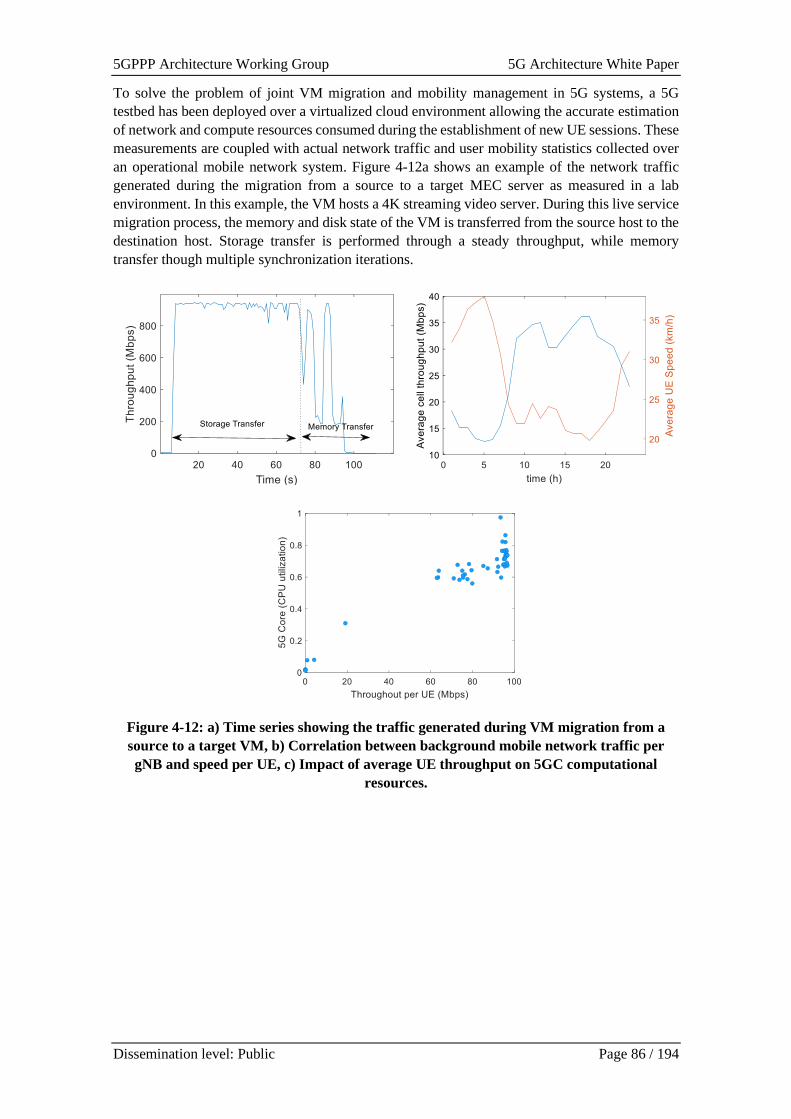
5GPPP Architecture Working Group 5G Architecture White Paper
Dissemination level: Public Page 86 / 194
To solve the problem of joint VM migration and mobility management in 5G systems, a 5G
testbed has been deployed over a virtualized cloud environment allowing the accurate estimation
of network and compute resources consumed during the establishment of new UE sessions. These
measurements are coupled with actual network traffic and user mobility statistics collected over
an operational mobile network system. Figure 4-12a shows an example of the network traffic
generated during the migration from a source to a target MEC server as measured in a lab
environment. In this example, the VM hosts a 4K streaming video server. During this live service
migration process, the memory and disk state of the VM is transferred from the source host to the
destination host. Storage transfer is performed through a steady throughput, while memory
transfer though multiple synchronization iterations.
Figure 4-12: a) Time series showing the traffic generated during VM migration from a
source to a target VM, b) Correlation between background mobile network traffic per
gNB and speed per UE, c) Impact of average UE throughput on 5GC computational
resources.
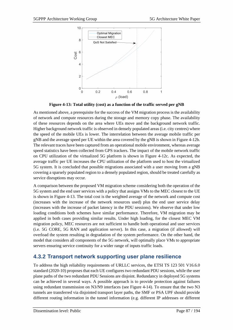
5GPPP Architecture Working Group 5G Architecture White Paper
Dissemination level: Public Page 87 / 194
Figure 4-13: Total utility (cost) as a function of the traffic served per gNB
As mentioned above, a prerequisite for the success of the VM migration process is the availability
of network and compute resources during the storage and memory copy phase. The availability
of these resources depends on the area where UEs move and the background network traffic.
Higher background network traffic is observed in densely populated areas (i.e. city centres) where
the speed of the mobile UEs is lower. The interrelation between the average mobile traffic per
gNB and the average speed per UE within the area covered by the gNB is shown in Figure 4-12b.
The relevant traces have been captured from an operational mobile environment, whereas average
speed statistics have been collected from GPS trackers. The impact of the mobile network traffic
on CPU utilization of the virtualized 5G platform is shown in Figure 4-12c. As expected, the
average traffic per UE increases the CPU utilization of the platform used to host the virtualized
5G system. It is concluded that possible migrations associated with a user moving from a gNB
covering a sparsely populated region to a densely populated region, should be treated carefully as
service disruptions may occur.
A comparison between the proposed VM migration scheme considering both the operation of the
5G system and the end user services with a policy that assigns VMs to the MEC closest to the UE
is shown in Figure 4-13. The total cost is the weighted average of the network and compute cost
(increases with the increase of the network resources used) plus the end user service delay
(increases with the increase of packet latency in the PDU sessions). We observe that under low
loading conditions both schemes have similar performance. Therefore, VM migration may be
applied in both cases providing similar results. Under high loading, for the closest MEC VM
migration policy, MEC resources are not sufficient to handle both operational and user services
(i.e. 5G CORE, 5G RAN and application server). In this case, a migration (if allowed) will
overload the system resulting in degradation of the system performance. On the other hand, the
model that considers all components of the 5G network, will optimally place VMs to appropriate
servers ensuring service continuity for a wider range of inputs traffic loads.
4.3.2 Transport network supporting user plane resilience
To address the high reliability requirements of URLLC services, the ETSI TS 123 501 V16.6.0
standard (2020-10) proposes that each UE configures two redundant PDU sessions, while the user
plane paths of the two redundant PDU Sessions are disjoint. Redundancy in deployed 5G systems
can be achieved in several ways. A possible approach is to provide protection against failures
using redundant transmission on N3/N9 interfaces (see Figure 4-14). To ensure that the two N3
tunnels are transferred via disjointed transport layer paths, the SMF or PSA UPF should provide
different routing information in the tunnel information (e.g. different IP addresses or different
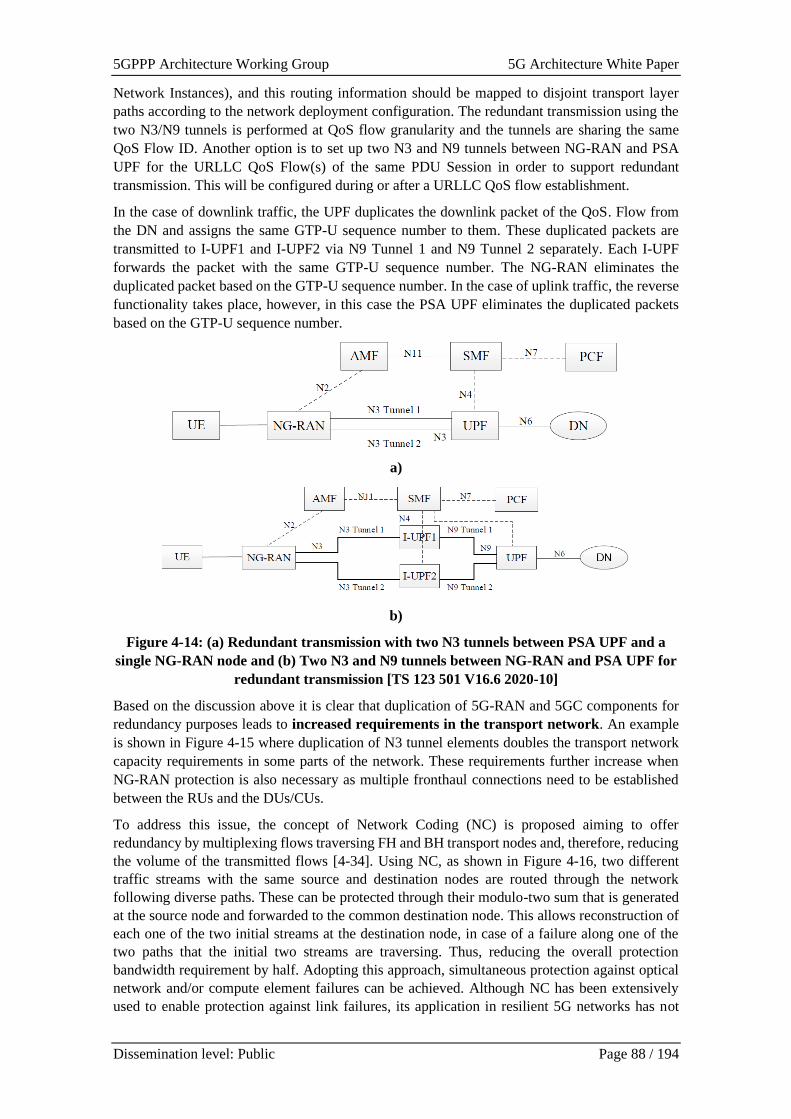
5GPPP Architecture Working Group 5G Architecture White Paper
Dissemination level: Public Page 88 / 194
Network Instances), and this routing information should be mapped to disjoint transport layer
paths according to the network deployment configuration. The redundant transmission using the
two N3/N9 tunnels is performed at QoS flow granularity and the tunnels are sharing the same
QoS Flow ID. Another option is to set up two N3 and N9 tunnels between NG-RAN and PSA
UPF for the URLLC QoS Flow(s) of the same PDU Session in order to support redundant
transmission. This will be configured during or after a URLLC QoS flow establishment.
In the case of downlink traffic, the UPF duplicates the downlink packet of the QoS. Flow from
the DN and assigns the same GTP-U sequence number to them. These duplicated packets are
transmitted to I-UPF1 and I-UPF2 via N9 Tunnel 1 and N9 Tunnel 2 separately. Each I-UPF
forwards the packet with the same GTP-U sequence number. The NG-RAN eliminates the
duplicated packet based on the GTP-U sequence number. In the case of uplink traffic, the reverse
functionality takes place, however, in this case the PSA UPF eliminates the duplicated packets
based on the GTP-U sequence number.
a)
b)
Figure 4-14: (a) Redundant transmission with two N3 tunnels between PSA UPF and a
single NG-RAN node and (b) Two N3 and N9 tunnels between NG-RAN and PSA UPF for
redundant transmission [TS 123 501 V16.6 2020-10]
Based on the discussion above it is clear that duplication of 5G-RAN and 5GC components for
redundancy purposes leads to increased requirements in the transport network. An example
is shown in Figure 4-15 where duplication of N3 tunnel elements doubles the transport network
capacity requirements in some parts of the network. These requirements further increase when
NG-RAN protection is also necessary as multiple fronthaul connections need to be established
between the RUs and the DUs/CUs.
To address this issue, the concept of Network Coding (NC) is proposed aiming to offer
redundancy by multiplexing flows traversing FH and BH transport nodes and, therefore, reducing
the volume of the transmitted flows [4-34]. Using NC, as shown in Figure 4-16, two different
traffic streams with the same source and destination nodes are routed through the network
following diverse paths. These can be protected through their modulo-two sum that is generated
at the source node and forwarded to the common destination node. This allows reconstruction of
each one of the two initial streams at the destination node, in case of a failure along one of the
two paths that the initial two streams are traversing. Thus, reducing the overall protection
bandwidth requirement by half. Adopting this approach, simultaneous protection against optical
network and/or compute element failures can be achieved. Although NC has been extensively
used to enable protection against link failures, its application in resilient 5G networks has not

5GPPP Architecture Working Group 5G Architecture White Paper
Dissemination level: Public Page 89 / 194
been proposed before. This can be attributed mainly to the overhead that the application of the
modulo-two sum and the replication operations of NC introduce in practical systems, which may
degrade the performance of 5G system. At the same time, flows arriving from different source
nodes at the decode nodes should be synchronized.
Figure 4-15: Protection of a 5G network from failures of compute and/or network
elements through a) redundancy of N3 tunnels b) redundancy of UPF functions
RU
RU/DU
gNB
1/10G
O-FH (NGFI-I)
F1 (NGFI-II)
N3
RU
RU/DU
gNB
10/40G
O-FH (NGFI-I)
F1 (NGFI-II)
N3
CU
UPF
MEC
Access Transport Network - Aggregation
FTN
BTN
FTN
BTN
FTN
BTN
FTN
BTN
CU
UPF
MEC
Main N3 tunnel
Protection N3 tunnel
Main N3 tunnel
Protection N3 tunnel
FTN
BTN
FTN
BTN
RU
RU/DU
gNB
1/10G
O-FH (NGFI-I)
F1 (NGFI-II)
N3
RU
RU/DU
gNB
10/40G
O-FH (NGFI-I)
F1 (NGFI-II)
N3
CU
UPF
MEC
Access Transport Network - Aggregation
FTN
BTN
FTN
BTN
FTN
BTN
FTN
BTN
CU
UPF
MEC
Main N3 tunnel
Protection N3 tunnel
Main N3 tunnel
Protection N3 tunnel
FTN
BTN
FTN
BTN
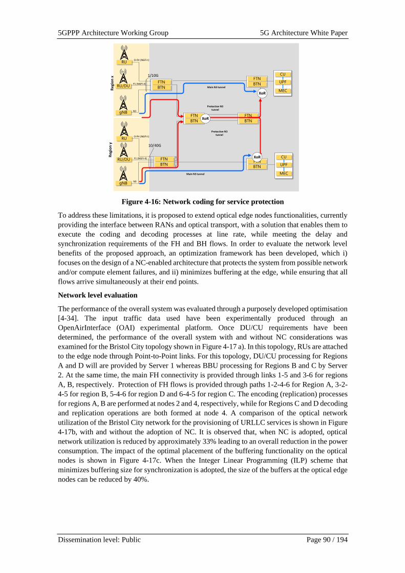
5GPPP Architecture Working Group 5G Architecture White Paper
Dissemination level: Public Page 90 / 194
Figure 4-16: Network coding for service protection
To address these limitations, it is proposed to extend optical edge nodes functionalities, currently
providing the interface between RANs and optical transport, with a solution that enables them to
execute the coding and decoding processes at line rate, while meeting the delay and
synchronization requirements of the FH and BH flows. In order to evaluate the network level
benefits of the proposed approach, an optimization framework has been developed, which i)
focuses on the design of a NC-enabled architecture that protects the system from possible network
and/or compute element failures, and ii) minimizes buffering at the edge, while ensuring that all
flows arrive simultaneously at their end points.
Network level evaluation
The performance of the overall system was evaluated through a purposely developed optimisation
[4-34]. The input traffic data used have been experimentally produced through an
OpenAirInterface (OAI) experimental platform. Once DU/CU requirements have been
determined, the performance of the overall system with and without NC considerations was
examined for the Bristol City topology shown in Figure 4-17 a). In this topology, RUs are attached
to the edge node through Point-to-Point links. For this topology, DU/CU processing for Regions
A and D will are provided by Server 1 whereas BBU processing for Regions B and C by Server
2. At the same time, the main FH connectivity is provided through links 1-5 and 3-6 for regions
A, B, respectively. Protection of FH flows is provided through paths 1-2-4-6 for Region A, 3-2-
4-5 for region B, 5-4-6 for region D and 6-4-5 for region C. The encoding (replication) processes
for regions A, B are performed at nodes 2 and 4, respectively, while for Regions C and D decoding
and replication operations are both formed at node 4. A comparison of the optical network
utilization of the Bristol City network for the provisioning of URLLC services is shown in Figure
4-17b, with and without the adoption of NC. It is observed that, when NC is adopted, optical
network utilization is reduced by approximately 33% leading to an overall reduction in the power
consumption. The impact of the optimal placement of the buffering functionality on the optical
nodes is shown in Figure 4-17c. When the Integer Linear Programming (ILP) scheme that
minimizes buffering size for synchronization is adopted, the size of the buffers at the optical edge
nodes can be reduced by 40%.
RU
RU/DU
gNB
1/10G
O-FH (NGFI-I)
F1 (NGFI-II)
N3
RU
RU/DU
gNB
10/40G
O-FH (NGFI-I)
F1 (NGFI-II)
N3
CU
UPF
MEC
Access Transport Network - Aggregation
FTN
BTN
FTN
BTN
FTN
BTN
FTN
BTN
CU
UPF
MEC
Main N3 tunnel
Protection N3 tunnel
Main N3 tunnel
Protection N3 tunnel
FTN
BTN
FTN
BTNXoR
XoR
XoR
Reg
ion
xR
egio
n y
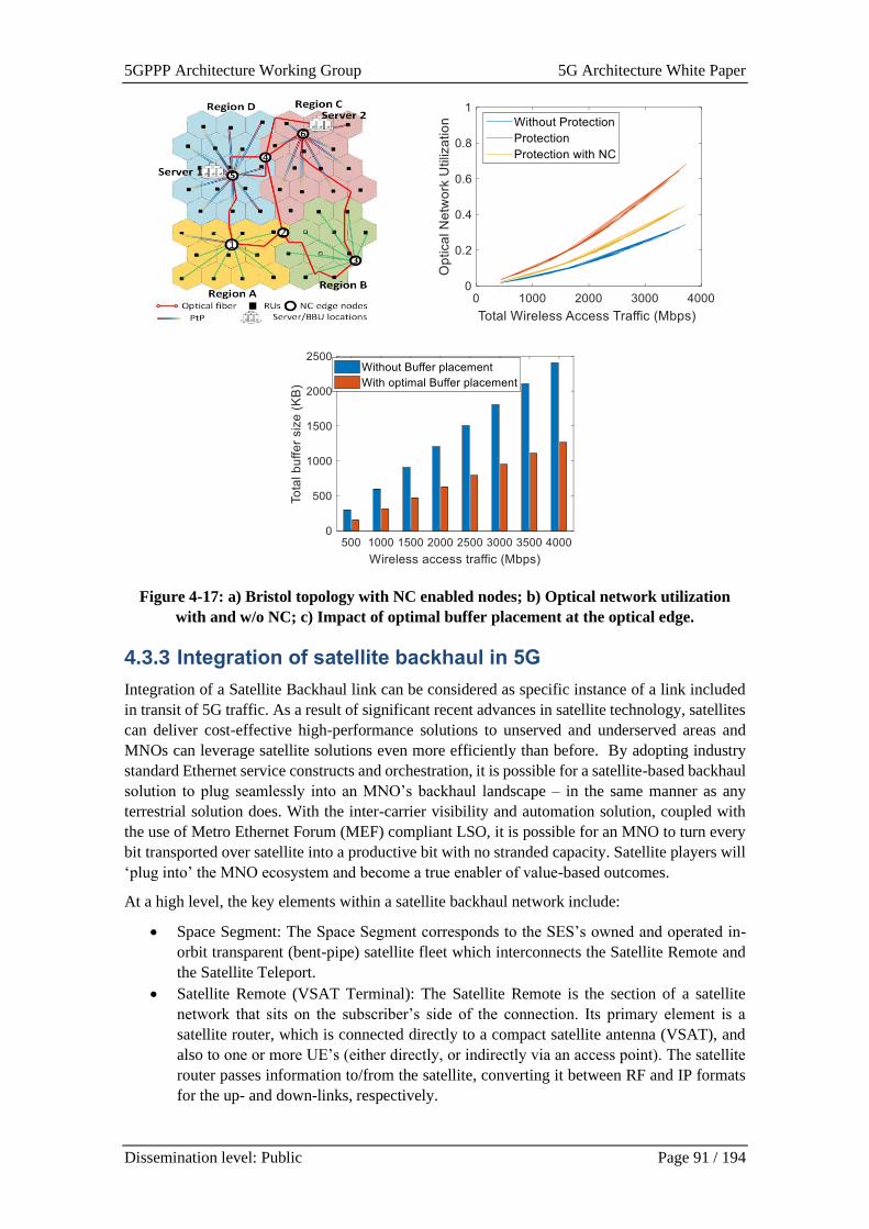
5GPPP Architecture Working Group 5G Architecture White Paper
Dissemination level: Public Page 91 / 194
Figure 4-17: a) Bristol topology with NC enabled nodes; b) Optical network utilization
with and w/o NC; c) Impact of optimal buffer placement at the optical edge.
4.3.3 Integration of satellite backhaul in 5G
Integration of a Satellite Backhaul link can be considered as specific instance of a link included
in transit of 5G traffic. As a result of significant recent advances in satellite technology, satellites
can deliver cost-effective high-performance solutions to unserved and underserved areas and
MNOs can leverage satellite solutions even more efficiently than before. By adopting industry
standard Ethernet service constructs and orchestration, it is possible for a satellite-based backhaul
solution to plug seamlessly into an MNO’s backhaul landscape – in the same manner as any
terrestrial solution does. With the inter-carrier visibility and automation solution, coupled with
the use of Metro Ethernet Forum (MEF) compliant LSO, it is possible for an MNO to turn every
bit transported over satellite into a productive bit with no stranded capacity. Satellite players will
‘plug into’ the MNO ecosystem and become a true enabler of value-based outcomes.
At a high level, the key elements within a satellite backhaul network include:
• Space Segment: The Space Segment corresponds to the SES’s owned and operated in-
orbit transparent (bent-pipe) satellite fleet which interconnects the Satellite Remote and
the Satellite Teleport.
• Satellite Remote (VSAT Terminal): The Satellite Remote is the section of a satellite
network that sits on the subscriber’s side of the connection. Its primary element is a
satellite router, which is connected directly to a compact satellite antenna (VSAT), and
also to one or more UE’s (either directly, or indirectly via an access point). The satellite
router passes information to/from the satellite, converting it between RF and IP formats
for the up- and down-links, respectively.
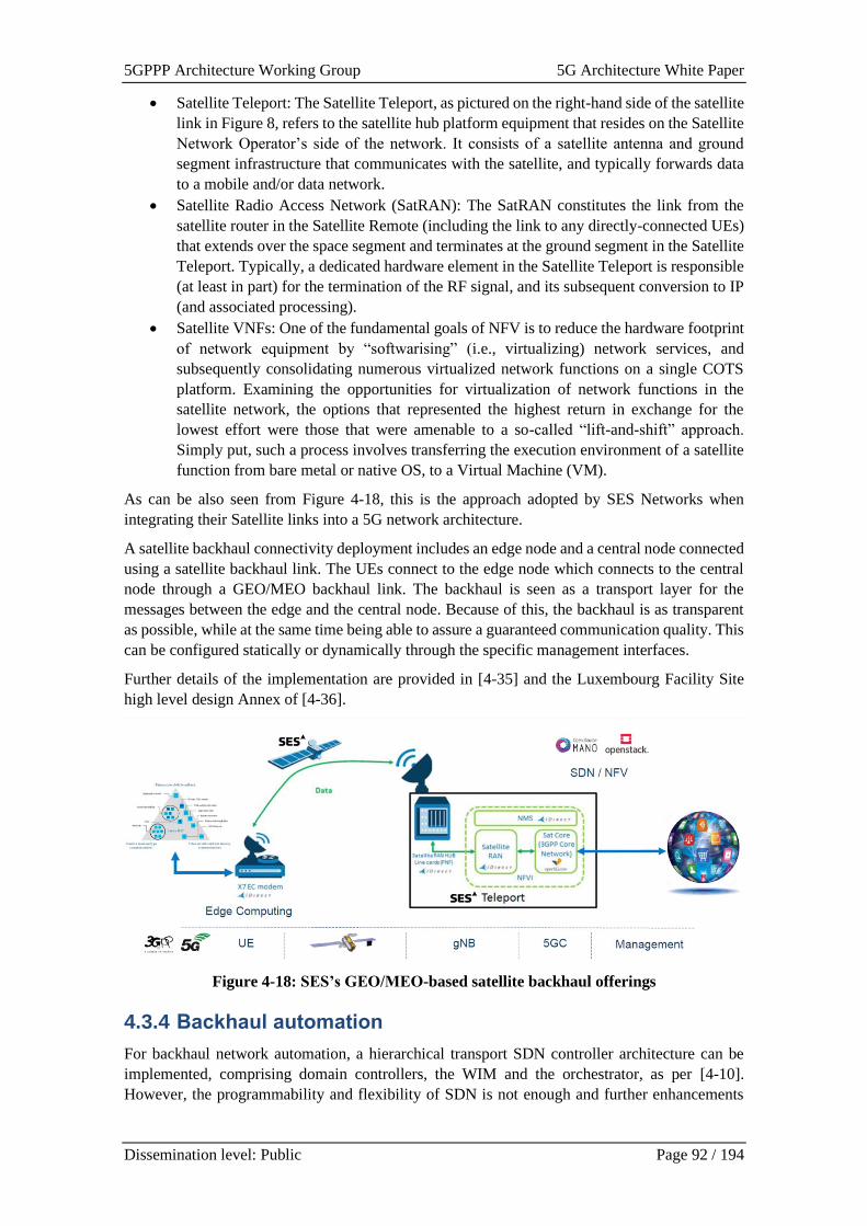
5GPPP Architecture Working Group 5G Architecture White Paper
Dissemination level: Public Page 92 / 194
• Satellite Teleport: The Satellite Teleport, as pictured on the right-hand side of the satellite
link in Figure 8, refers to the satellite hub platform equipment that resides on the Satellite
Network Operator’s side of the network. It consists of a satellite antenna and ground
segment infrastructure that communicates with the satellite, and typically forwards data
to a mobile and/or data network.
• Satellite Radio Access Network (SatRAN): The SatRAN constitutes the link from the
satellite router in the Satellite Remote (including the link to any directly-connected UEs)
that extends over the space segment and terminates at the ground segment in the Satellite
Teleport. Typically, a dedicated hardware element in the Satellite Teleport is responsible
(at least in part) for the termination of the RF signal, and its subsequent conversion to IP
(and associated processing).
• Satellite VNFs: One of the fundamental goals of NFV is to reduce the hardware footprint
of network equipment by “softwarising” (i.e., virtualizing) network services, and
subsequently consolidating numerous virtualized network functions on a single COTS
platform. Examining the opportunities for virtualization of network functions in the
satellite network, the options that represented the highest return in exchange for the
lowest effort were those that were amenable to a so-called “lift-and-shift” approach.
Simply put, such a process involves transferring the execution environment of a satellite
function from bare metal or native OS, to a Virtual Machine (VM).
As can be also seen from Figure 4-18, this is the approach adopted by SES Networks when
integrating their Satellite links into a 5G network architecture.
A satellite backhaul connectivity deployment includes an edge node and a central node connected
using a satellite backhaul link. The UEs connect to the edge node which connects to the central
node through a GEO/MEO backhaul link. The backhaul is seen as a transport layer for the
messages between the edge and the central node. Because of this, the backhaul is as transparent
as possible, while at the same time being able to assure a guaranteed communication quality. This
can be configured statically or dynamically through the specific management interfaces.
Further details of the implementation are provided in [4-35] and the Luxembourg Facility Site
high level design Annex of [4-36].
Figure 4-18: SES’s GEO/MEO-based satellite backhaul offerings
4.3.4 Backhaul automation
For backhaul network automation, a hierarchical transport SDN controller architecture can be
implemented, comprising domain controllers, the WIM and the orchestrator, as per [4-10].
However, the programmability and flexibility of SDN is not enough and further enhancements

5GPPP Architecture Working Group 5G Architecture White Paper
Dissemination level: Public Page 93 / 194
are needed to augment the current automation scheme. Several new challenges are created as a
result, as follows:
a) Automating complex human-dependent decision-making processes (e.g., managing and
optimizing network and system configuration processes) by providing system and
network intelligence tools and services.
b) Determining which services are offered, and which services are in danger of not meeting
their SLAs, as a function of changing context.
c) Providing an experiential architecture (i.e., an architecture that uses Artificial Intelligence
(AI) and other mechanisms to improve its understanding of the environment, and hence
the operator experience, over time).
d) Improving infrastructure utilization and agility (response to real-time changes) while
maintaining SLAs. The deployed networks and systems likely need to be aware of the
needs of Services and Applications, and handle environmental changes in an automated
way without human involvement.
e) Improving operator's personnel efficiency through improved management and
automation, while providing increased visibility and a simplified interface between the
operator and the networks and networked applications; this reduces errors and makes
human-directed commands more efficient and intuitive.
A solution for these challenges can be based upon work in the ETSI’s Experiential Networked
Intelligence Industry Specification Group (ISG ENI).
Figure 4-19: High-Level Functional Architecture of ENI when an API Broker is used
The Experiential Networked Intelligence (ENI) System is an innovative, policy-based, model-
driven functional entity that improves operator’s experience. ENI can be deployed as an external
AI/ML entity, outside of an existing “Assisted System”. Four classes of Assisted Systems are
anticipated – from those capable of communicating with the operator only, to those where some
information can be shared directly with ENI while the other has to go through the operator or
other existing management tools. The Assisted System may also already have closed-loop control
5GPPP Architecture Working Group 5G Architecture White Paper
Dissemination level: Public Page 94 / 194
or is a hybrid system where some modules enjoy the benefits of a closed-loop control while others
do not, ENI can be directly coupled to influence the overall closed-loop control of the combined
system.
A high-level Functional Block diagram that includes the use of an API Broker is shown in Figure
4-19, and defined in ETSI GS ENI 005 [4-37].
Each functional block is made up of specific capabilities as defined below.
Input processing
Data Ingestion Functional Block - The purpose of the Data Ingestion Functional Block is to
collect data from multiple input sources and implement common data processing techniques to
enable ingested data to be further processed and analysed by other ENI Functional Blocks.
Normalization Functional Block - The purpose of the Normalization Functional Block is to
process and translate data received from the Data Ingestion Functional Block into a form that
other ENI Functional Blocks are able to understand and use. Different data models are likely to
be used by different ENI Functional Blocks. Each such data model typically uses different data
structures, objects, and protocols to represent its concepts.
Analysis
Knowledge Representation and management - The purpose of the Knowledge Representation and
Management Functional Block is to represent information about both the ENI System as well as
the system being managed. Knowledge representation is fundamental to all disciplines of
modelling and AI. It also enables machine learning and reasoning –without a formal and
consensual representation of knowledge, algorithms cannot be defined that reason about the
knowledge.
Context-Awareness Management - The purpose of the Context-Aware Management Functional
Block is to describe the state and environment in which an entity exists or has existed. Context
consists of measured and inferred knowledge and may change over time.
Situational Awareness Management - The purpose of the Situation Awareness Functional Block
is for the ENI system to be aware of events and behaviour that are relevant to the environment of
the system that it is managing or assisting. This includes the ability to understand how information,
events, and recommended commands given by the ENI system will impact the management and
operational goals and behaviour, both immediately and in the near future. Situation awareness is
especially important in environments where the information flow is high, and poor decisions may
lead to serious consequences (e.g., violation of SLAs).
Cognition Management - The purpose of the Cognition Management Functional Block is to
enable the ENI System to understand normalized ingested data and information, as well as the
context that defines how those data were produced. Once that understanding is achieved, the
Cognition Management Functional Block then evaluates the meaning of the data and determines
if any actions need to be taken to ensure that the goals and objectives of the system are met. This
includes improving or optimizing different metrics such as performance, reliability, and/or
availability.
Policy-based Management - Policy is a set of rules that is used to manage and control the changing
and/or maintaining of the state of one or more managed objects.
There are three different types of policies that are defined for an ENI system:
• Imperative policy: a type of policy that uses statements to explicitly change the state of a
set of targeted objects. Hence, the order of statements that make up the policy is explicitly
defined.
5GPPP Architecture Working Group 5G Architecture White Paper
Dissemination level: Public Page 95 / 194
• Declarative policy: a type of policy that uses statements to express the goals of the policy,
but not how to accomplish those goals. Hence, state is not explicitly manipulated, and the
order of statements that make up the policy is irrelevant. In this document, Declarative
Policy will refer to policies that execute as theories of a formal logic.
• Intent policy: a type of policy that uses statements to express the goals of the policy, but
not how to accomplish those goals. Each statement in an Intent Policy may require the
translation of one or more of its terms to a form that another managed functional entity
can understand.
Model Driven Engineering Functional Block - The purpose of the Model Driven Engineering
Functional Block is to use a set of domain models that collectively abstract all important concepts
for managing the behaviour of objects in the system(s) governed by the ENI System.
Output Generation
Denormalization Functional Block - The purpose of the Denormalization Functional Block is to
process and translate data received from other Functional Blocks of the ENI System into a form
that facilitates subsequent translation to a form that a set of targeted entities are able to understand.
For example, different data models are likely to be used by different ENI Functional Blocks. Each
such data model typically uses different data structures, objects, and protocols to represent its
concepts.
Output Generation Functional Block -The purpose of the Output Generation Functional Blocks
is to convert data received by the Denormalization Functional Block into a form that the Assisted
System (or its Designated Entity) is able to understand.
This forms the basis of further work on Backhaul Automation as described in [4-38].
4.3.5 Integration of transport and radio management for THz
fronthaul links
The terahertz (THz) frequency band is envisioned as a promising candidate to support ultra-
broadband for beyond 5G (B5G) networks. The need for huge capacity at very low latencies
highlights the need for making use of higher frequencies of the electromagnetic spectrum, where
much larger bandwidths are available.
To integrate multi-transport technologies, including fixed and radio links, requires a novel design
of a comprehensive SDN management architecture for joint optimization of radio and network
resources. In this context, the proposed architecture [4-43] obtains the most added value out of
use of THz technology integrated with SDN for mobile network beyond 5G. A seamless service
and network management system that automatically guarantees the required level of quality has
to leverage optical concepts and photonic integration techniques for an ultra-wideband and
broadband wireless system as part of agnostic transport layer.
B5G networks will be adding new set of resources to be managed when including radio modules
that will provide radio link within an existing transport network. Thus, the existing network
functions will not only have to allocate resources to existing RAN and transport, but they will
also have to manage the resources of transport nodes, i.e., fixed switches and radio modems that
bring additional capacity to the transport. Moreover, the radio nodes would be added on need
basis, thus the resources available would change depending on whether THz radio modems are
integrated into the existing transport network. Therefore, x-Haul transport brings a new paradigm
into the concept of dynamic on-the fly resource management that should combine not only RAN
but also fixed and THz transport networks.
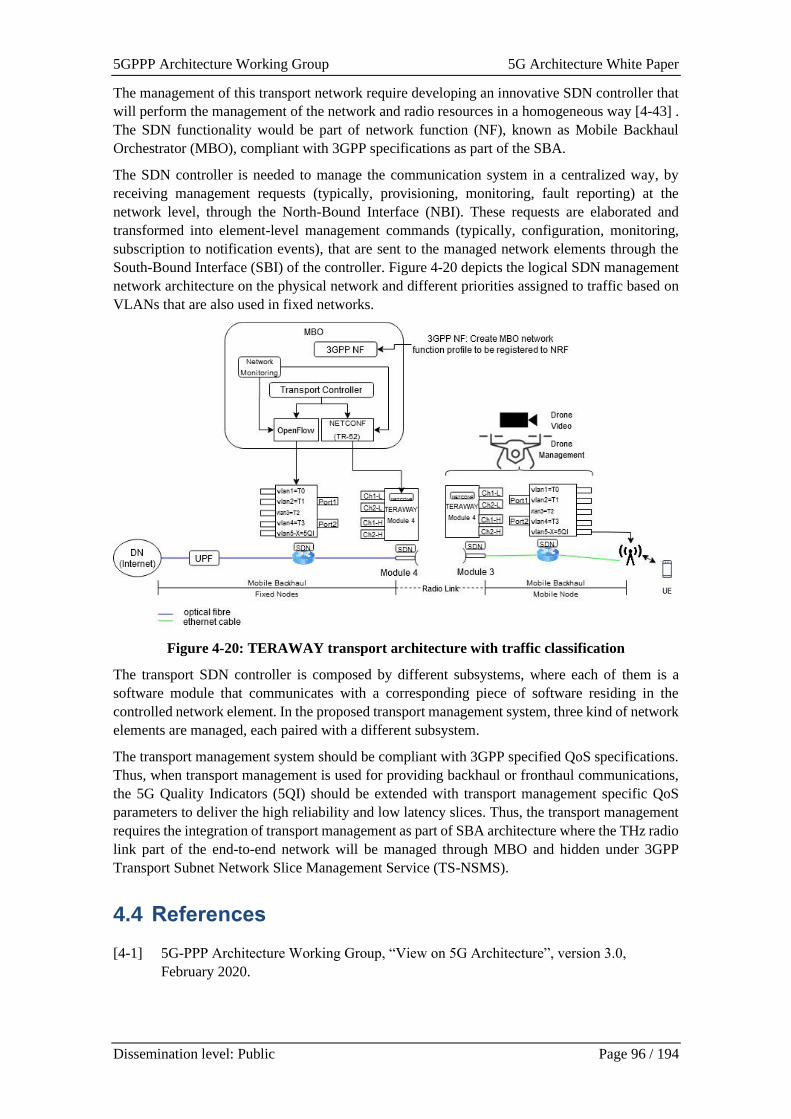
5GPPP Architecture Working Group 5G Architecture White Paper
Dissemination level: Public Page 96 / 194
The management of this transport network require developing an innovative SDN controller that
will perform the management of the network and radio resources in a homogeneous way [4-43] .
The SDN functionality would be part of network function (NF), known as Mobile Backhaul
Orchestrator (MBO), compliant with 3GPP specifications as part of the SBA.
The SDN controller is needed to manage the communication system in a centralized way, by
receiving management requests (typically, provisioning, monitoring, fault reporting) at the
network level, through the North-Bound Interface (NBI). These requests are elaborated and
transformed into element-level management commands (typically, configuration, monitoring,
subscription to notification events), that are sent to the managed network elements through the
South-Bound Interface (SBI) of the controller. Figure 4-20 depicts the logical SDN management
network architecture on the physical network and different priorities assigned to traffic based on
VLANs that are also used in fixed networks.
Figure 4-20: TERAWAY transport architecture with traffic classification
The transport SDN controller is composed by different subsystems, where each of them is a
software module that communicates with a corresponding piece of software residing in the
controlled network element. In the proposed transport management system, three kind of network
elements are managed, each paired with a different subsystem.
The transport management system should be compliant with 3GPP specified QoS specifications.
Thus, when transport management is used for providing backhaul or fronthaul communications,
the 5G Quality Indicators (5QI) should be extended with transport management specific QoS
parameters to deliver the high reliability and low latency slices. Thus, the transport management
requires the integration of transport management as part of SBA architecture where the THz radio
link part of the end-to-end network will be managed through MBO and hidden under 3GPP
Transport Subnet Network Slice Management Service (TS-NSMS).
4.4 References
[4-1] 5G-PPP Architecture Working Group, “View on 5G Architecture”, version 3.0,
February 2020.
5GPPP Architecture Working Group 5G Architecture White Paper
Dissemination level: Public Page 97 / 194
[4-2] B. Sayadi et al. “Cloud-Native and Verticals' services”, 5G-PPP White Paper, 2020,
https://5g-ppp.eu/wp-content/uploads/2020/02/5G-PPP-SN-WG-5G-and-Cloud-
Native.pdf
[4-3] Adam Wiggins, “The Twelve-Factor App”. Online: https://12factor.net
[4-4] Microsoft, “Define Cloud Native”, 2021. Online: https://docs.microsoft.com/en-
us/dotnet/architecture/cloud-native/definition
[4-5] FUDGE 5G Deliverable 1.1, “Technical Blueprint for Vertical Use Cases and
Validation Framework”, 2021, https://fudge-5g.eu/download-
file/365/sq6G3zIXkRBOFWRM3bqO
[4-6] Dirk Trossen, Sebastian Robitzsch, Mays Al-Naday, Janne Riihijarvi, “Internet Services
over ICN in 5G LAN Environments”, IRTF Internet Draft (individual), 2020. Online:
https://datatracker.ietf.org/doc/draft-trossen-icnrg-internet-icn-5glan/
[4-7] FUDGE-5G, “D1.2: FUDGE-5G Platform Architecture: Components and Interfaces
“, 2021. Online: https://www.fudge-5g.eu/en/deliverables
[4-8] ITU-T, “FG-NET2030-Arch, Network 2030 – Architecture Framework”, Technical
Report, 2020. Online: https://www.itu.int/dms_pub/itu-t/opb/fg/T-FG-NET2030-2020-
3-PDF-E.pdf
[4-9] R. Ravindran, P. Suthar, D. Trossen, C. Wang, G. White, “Enabling ICN in 3GPP's 5G
NextGen Core Architecture “, IRTF Internet Draft, 2019. Online:
https://tools.ietf.org/id/draft-ravi-icnrg-5gc-icn-04.html
[4-10] 5G PPP whitepaper, “Non-Public-Networks – State of the art and way forward”, doi:
10.5281/zenodo.5118839, https://doi.org/10.5281/zenodo. 5118839
[4-11] 3GPP, "TR 23.757: Study on architectural enhancements for 5G multicast-broadcast
services," 2020. [Online]
[4-12] 5G-TOURS D3.3 “Deliverable D3.3 Technologies, architecture and deployment
advanced progress”
[4-13] 3GPP, "TR 26.802: 5G Multimedia Streaming (5GMS); Multicast architecture," 2020.
[Online].
[4-14] Open5GCore – The Next Mobile Core Network Testbed Platform,
https://www.open5gcore.org/
[4-15] Enabling ICN in 3GPP's 5G NextGen Core Architecture, https://tools.ietf.org/id/draft-
ravi-icnrg-5gc-icn-04.html
[4-16] 3GPP TR 23.734; Study on enhancement of 5G System (5GS) for vertical and Local
Area Network (LAN) services (Release 16)
[4-17] D. Gómez-Barquero, J. Giménez and R. Beutler, "3GPP Enhancements for Television
Services: LTE‐Based 5G Terrestrial Broadcast," in Wiley Encyclopedia of Electrical
and Electronics Engineering, 2020.
[4-18] 3GPP, "RP-193248: New Work Item on NR support of Multicast and Broadcast
Services," 2020. [Online].
[4-19] 5GENESIS, Deliverable D3.5 “Monitoring and Analytics (Release A)” [Online],
https://5genesis.eu/wp-content/uploads/2019/10/5GENESIS_D3.5_v1.0.pdf, Accessed
on: March 2021.
5GPPP Architecture Working Group 5G Architecture White Paper
Dissemination level: Public Page 98 / 194
[4-20] 5GENESIS, Deliverable D6.1 “Trials and Experimentations (Cycle 1)” [Online],
https://5genesis.eu/wp-content/uploads/2019/08/5GENESIS_D6.1_v1.00.pdf, Accessed
on: March 2021.
[4-21] 5GENESIS, Deliverable D3.15 “Experiment and Lifecycle Manager (Release A)”
[Online], https://5genesis.eu/wp-content/uploads/2019/10/5GENESIS_D3.15_v1.0.pdf,
Accessed on March 2021.
[4-22] N. Blefari-Melazzi et al., "LOCUS: Localization and analytics on-demand embedded in
the 5G ecosystem," 2020 European Conference on Networks and Communications
(EuCNC), 2020, pp. 170-175, doi: 10.1109/EuCNC48522.2020.9200961.
[4-23] LOCUS, Deliverable D2.4 “Deliverable D2.4 “System Architecture: Preliminary
Version” [Online], https://www.locus-project.eu/wp-
content/uploads/2021/02/Deliverables-officially-submitted_D2.4_D2.4-9-8-20-nbm-
final.pdf, Accessed on March 2021.
[4-24] K. K. Mada, H. Wu and S. S. Iyengar, “Efficient and robust EM algorithm for multiple
wideband source localization,” IEEE Trans. Veh. Technol., vol. 58, no. 6, pp. 3071-
3075, Jul. 2009.
[4-25] S. Bartoletti, A. Conti and M. Z. Win, “Device-free counting via wideband signals,”
IEEE J. Sel. Areas Commun., vol. 35, no. 5, pp. 1163-1174, May 2017.
[4-26] K. Y. Chan, T. S. Dillon, J. Singh and E. Chang, “Neural-networkbased models for
short-term traffic flow forecasting using a hybrid exponential smoothing and
Levenberg–Marquardt algorithm,” IEEE Trans. Intell. Transp. Syst., vol. 13, no. 2, pp.
644–654, Jun. 2012.
[4-27] V. Kulkarni et al., “On the inability of Markov models to capture criticality in human
mobility,” 2019 Int. Conf. Artificial Neural Networks (ICANN), Munich, Germany,
2018, pp. 484-497.
[4-28] LOCUS Deliverables D3.1-D3.8, Confidential
[4-29] 5G-COMPLETE deliverable D2.1
[4-30] M. Anastasopoulos, A. Tzanakaki, A. F. Beldachi, D. Simeonidou, “Network Coding
Enabling Resilient 5G Networks”, invited paper, ECOC 2019
[4-31] I. Leyva-Pupo et al., “Dynamic Scheduling and Optimal Reconfiguration of UPF
Placement in 5G Networks”, In Proc. of MSWiM '20, 2020 NY, USA, 103–111
[4-32] A. Tzanakaki et al., "Wireless-Optical Network Convergence: Enabling the 5G
Architecture to Support Operational and End-User Services," IEEE Comms. Mag, vol.
55, no. 10, pp. 184-192,.2017
[4-33] A. Tzanakaki, M. Anastasopoulos, a. Manolopoulos and D. Simeonidou, “Mobility
aware Dynamic Resource management in 5G Systems and Beyond”, ONDM2021,
invited paper
[4-34] M. Anastasopoulos, A. Tzanakaki, A. F. Beldachi, D. Simeonidou, “Network Coding
Enabling Resilient 5G Networks”, invited paper, ECOC 2019
[4-35] 5G-VINNI deliverable D1.1, “Design of infrastructure architecture and subsystems v1”,
Zenodo, Dec. 2018. doi: 10.5281/zenodo.2668754.
[4-36] 5G-VINNI D2.1: “5G-VINNI Solution Facility-sites High Level Design (HLD)”,
Zenodo, Mar. 2019. doi: 10.5281/zenodo.2668791.
5GPPP Architecture Working Group 5G Architecture White Paper
Dissemination level: Public Page 99 / 194
[4-37] ETSI GS ENI 005: “Experimental Networked Intelligence (ENI); System Architecture”
[4-38] 5G-VINNI D1.4: “Design of infrastructure architecture and subsystems v2”, Zenodo,
Oct. 2020. doi: 10.5281/zenodo.4066381
[4-39] 5G-VINNI White Paper, “Onboarding Vertical Applications on 5G-VINNI Facility”,
Zenodo, Mar. 05, 2020. doi: 10.5281/zenodo.3695716.
[4-40] 5G-VINNI deliverable D4.1, “Initial report on test-plan creation and methodology, and
development of test orchestration framework”, Zenodo, Jul. 2019. doi:
10.5281/zenodo.3345626.
[4-41] 5G-VINNI D4.2: “Intermediate report on test-plan creation and methodology, and
development of test orchestration framework”, Zenodo, Oct. 2020. doi:
10.5281/zenodo.5113103.
[4-42] 3GPP TR 38.801, Study of new radio access technology: Radio access architecture and
interfaces
[4-43] Jose Costa-Requena, Abraham Afriyie, Konstantinos P. Chartsias, Eleni Karasoula,
Dimitrios Kritharidis, Nicola Carapellese, & Eduardo Yusta Padilla. (2021). SDN-
enabled THz Wireless X-Haul for B5G. Presented at the 2021 Joint EuCNC & 6G
Summit (EuCNC2021)
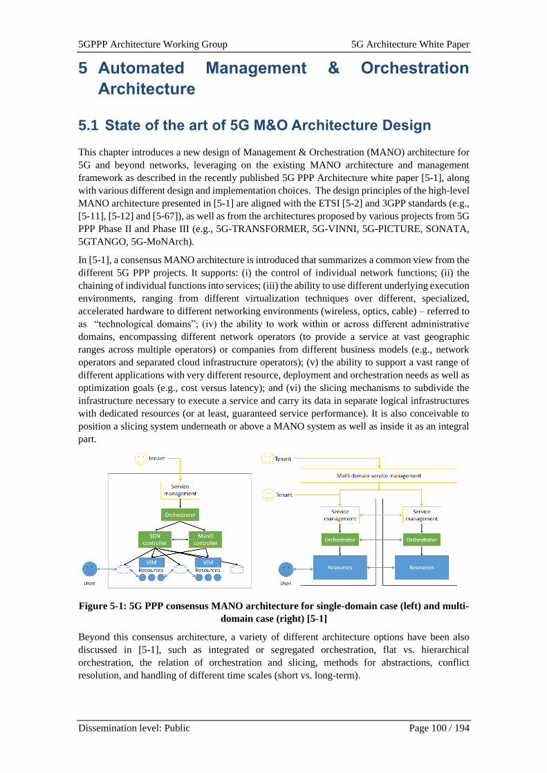
5GPPP Architecture Working Group 5G Architecture White Paper
Dissemination level: Public Page 100 / 194
5 Automated Management & Orchestration
Architecture
5.1 State of the art of 5G M&O Architecture Design
This chapter introduces a new design of Management & Orchestration (MANO) architecture for
5G and beyond networks, leveraging on the existing MANO architecture and management
framework as described in the recently published 5G PPP Architecture white paper [5-1], along
with various different design and implementation choices. The design principles of the high-level
MANO architecture presented in [5-1] are aligned with the ETSI [5-2] and 3GPP standards (e.g.,
[5-11], [5-12] and [5-67]), as well as from the architectures proposed by various projects from 5G
PPP Phase II and Phase III (e.g., 5G-TRANSFORMER, 5G-VINNI, 5G-PICTURE, SONATA,
5GTANGO, 5G-MoNArch).
In [5-1], a consensus MANO architecture is introduced that summarizes a common view from the
different 5G PPP projects. It supports: (i) the control of individual network functions; (ii) the
chaining of individual functions into services; (iii) the ability to use different underlying execution
environments, ranging from different virtualization techniques over different, specialized,
accelerated hardware to different networking environments (wireless, optics, cable) – referred to
as “technological domains”; (iv) the ability to work within or across different administrative
domains, encompassing different network operators (to provide a service at vast geographic
ranges across multiple operators) or companies from different business models (e.g., network
operators and separated cloud infrastructure operators); (v) the ability to support a vast range of
different applications with very different resource, deployment and orchestration needs as well as
optimization goals (e.g., cost versus latency); and (vi) the slicing mechanisms to subdivide the
infrastructure necessary to execute a service and carry its data in separate logical infrastructures
with dedicated resources (or at least, guaranteed service performance). It is also conceivable to
position a slicing system underneath or above a MANO system as well as inside it as an integral
part.
Figure 5-1: 5G PPP consensus MANO architecture for single-domain case (left) and multi-
domain case (right) [5-1]
Beyond this consensus architecture, a variety of different architecture options have been also
discussed in [5-1], such as integrated or segregated orchestration, flat vs. hierarchical
orchestration, the relation of orchestration and slicing, methods for abstractions, conflict
resolution, and handling of different time scales (short vs. long-term).
5GPPP Architecture Working Group 5G Architecture White Paper
Dissemination level: Public Page 101 / 194
In terms of the implementation patters of the MANO, different options were presented. One is
that of the monolithic orchestrator. In the reference architecture, an orchestrator has a lot of
responsibilities. Realizing all these in a single, monolithic piece of software might be feasible, but
at the cost of jeopardizing maintainability, dependability, and performance. Hence, more suitable
implementation patterns are needed. To improve flexibility and to ease implementation of such a
complex piece of software, the software engineering community has developed multiple
approaches. One of these approaches is based on the notion of microservices, connected by a
software bus that realizes a publish/subscribe paradigm between its components. Such a
microservice-based orchestrator is not tied to a single machine. Provided that a suitable, well
performing sub system is available, it becomes easy to distribute the orchestrator’s components
across multiple machines for improved dependability and performance.
To define a service or a slice, different types of descriptions have been proposed for many types
of artefacts: from infrastructure, to functions, services, slices, policies, SLAs, tests, and possibly
also to business objectives. This also includes a vertical mapping of defining vertical service
blueprints and vertical service descriptors (VSD) to describe vertical services including their SLA
requirements. Moreover, [5-1] also discussed a few additional aspects of Monitoring and DevOps
for a continuous integration and continuous development of the Orchestration as well as the
validation tools.
The design ideas and methods presented in [5-1] have built the fundamental basis for the MANO
design for 5G. Based on the design in [5-1], this chapter aims to introduce architecture extensions
and new concepts for the evolution of MANO architecture for the 5G and beyond networks,
focusing on new approaches and methods for the enhanced slice management (Sec. 5.2), service
and network automation (Sec 5.3), cloudification techniques (Sec. 5.4), enhanced monitoring and
data management framework (Sect 5.5), and evolution of MANO design (Sec 5.6). It is important
to point out, the architectures presented in this chapter have been defined in different projects and
their terminology can be slightly different. Terms like platform, orchestrator, slice manager etc.
must be contextualized in the scope of each particular architecture.
5.2 Enhanced Slice Management
The concept of network slices allows efficient sharing of 5G infrastructures among multiple
tenants, building multiple logical networks over a common physical infrastructure in a flexible
and customized manner. Slice management is a key feature of the 5G management system, to
enhance the dynamicity and the efficiency of the network operation and to guarantee
differentiated QoS levels on the basis of vertical services intents and requirements. Indeed, the
management of network slices is tightly correlated to the dynamicity and the characteristics of the
vertical services running on top of them, and their lifecycle management and automation is driven
by the service demands. This leads to architectural solutions where vertical service and network
slice management are strictly bound and their functionalities are coordinated in a cooperative
manner, as proposed in Section 5.2.1.
Another major challenge for the slice management is the coordination of the end-to-end (E2E)
network slice elements in virtualized environments, combining the orchestration of access and
core network functions across edge and cloud domains, as analysed in Section 5.2.2. However,
the orchestration of access and core virtual network functions, often combined with the
provisioning of service level virtual applications, needs to be integrated with a proper
configuration of the underlying transport network. This is critical to guarantee the
interconnectivity among the virtual functions composing the E2E network slices and it requires
the same level of dynamicity and deep integration with the overall resource orchestration
strategies. Potential solutions relying on the Software Defining Networking (SDN) paradigm are
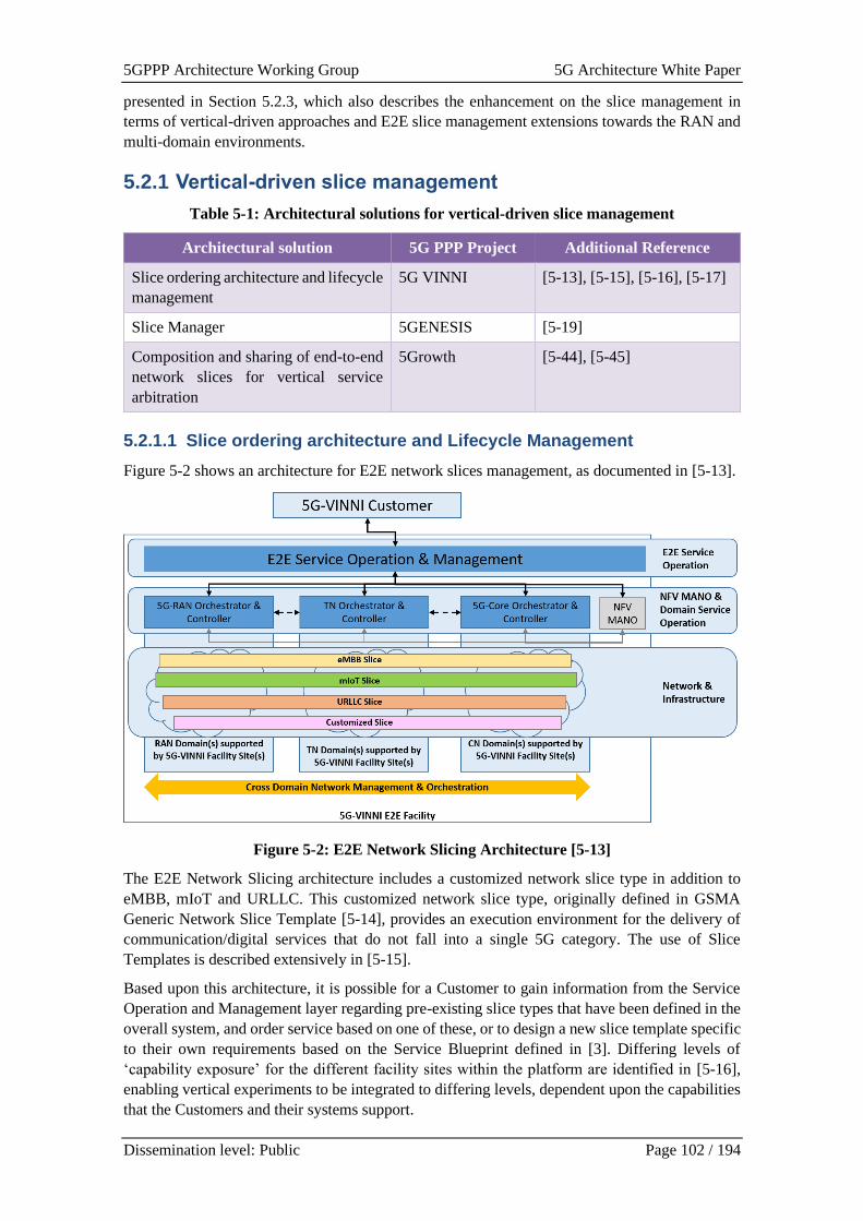
5GPPP Architecture Working Group 5G Architecture White Paper
Dissemination level: Public Page 102 / 194
presented in Section 5.2.3, which also describes the enhancement on the slice management in
terms of vertical-driven approaches and E2E slice management extensions towards the RAN and
multi-domain environments.
5.2.1 Vertical-driven slice management
Table 5-1: Architectural solutions for vertical-driven slice management
Architectural solution 5G PPP Project Additional Reference
Slice ordering architecture and lifecycle
management
5G VINNI [5-13], [5-15], [5-16], [5-17]
Slice Manager 5GENESIS [5-19]
Composition and sharing of end-to-end
network slices for vertical service
arbitration
5Growth [5-44], [5-45]
5.2.1.1 Slice ordering architecture and Lifecycle Management
Figure 5-2 shows an architecture for E2E network slices management, as documented in [5-13].
Figure 5-2: E2E Network Slicing Architecture [5-13]
The E2E Network Slicing architecture includes a customized network slice type in addition to
eMBB, mIoT and URLLC. This customized network slice type, originally defined in GSMA
Generic Network Slice Template [5-14], provides an execution environment for the delivery of
communication/digital services that do not fall into a single 5G category. The use of Slice
Templates is described extensively in [5-15].
Based upon this architecture, it is possible for a Customer to gain information from the Service
Operation and Management layer regarding pre-existing slice types that have been defined in the
overall system, and order service based on one of these, or to design a new slice template specific
to their own requirements based on the Service Blueprint defined in [3]. Differing levels of
‘capability exposure’ for the different facility sites within the platform are identified in [5-16],
enabling vertical experiments to be integrated to differing levels, dependent upon the capabilities
that the Customers and their systems support.
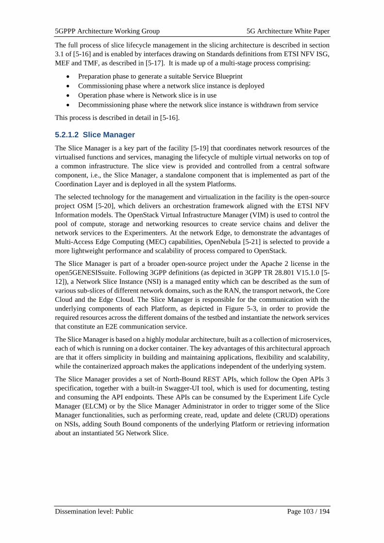
5GPPP Architecture Working Group 5G Architecture White Paper
Dissemination level: Public Page 103 / 194
The full process of slice lifecycle management in the slicing architecture is described in section
3.1 of [5-16] and is enabled by interfaces drawing on Standards definitions from ETSI NFV ISG,
MEF and TMF, as described in [5-17]. It is made up of a multi-stage process comprising:
• Preparation phase to generate a suitable Service Blueprint
• Commissioning phase where a network slice instance is deployed
• Operation phase where is Network slice is in use
• Decommissioning phase where the network slice instance is withdrawn from service
This process is described in detail in [5-16].
5.2.1.2 Slice Manager
The Slice Manager is a key part of the facility [5-19] that coordinates network resources of the
virtualised functions and services, managing the lifecycle of multiple virtual networks on top of
a common infrastructure. The slice view is provided and controlled from a central software
component, i.e., the Slice Manager, a standalone component that is implemented as part of the
Coordination Layer and is deployed in all the system Platforms.
The selected technology for the management and virtualization in the facility is the open-source
project OSM [5-20], which delivers an orchestration framework aligned with the ETSI NFV
Information models. The OpenStack Virtual Infrastructure Manager (VIM) is used to control the
pool of compute, storage and networking resources to create service chains and deliver the
network services to the Experimenters. At the network Edge, to demonstrate the advantages of
Multi-Access Edge Computing (MEC) capabilities, OpenNebula [5-21] is selected to provide a
more lightweight performance and scalability of process compared to OpenStack.
The Slice Manager is part of a broader open-source project under the Apache 2 license in the
open5GENESISsuite. Following 3GPP definitions (as depicted in 3GPP TR 28.801 V15.1.0 [5-
12]), a Network Slice Instance (NSI) is a managed entity which can be described as the sum of
various sub-slices of different network domains, such as the RAN, the transport network, the Core
Cloud and the Edge Cloud. The Slice Manager is responsible for the communication with the
underlying components of each Platform, as depicted in Figure 5-3, in order to provide the
required resources across the different domains of the testbed and instantiate the network services
that constitute an E2E communication service.
The Slice Manager is based on a highly modular architecture, built as a collection of microservices,
each of which is running on a docker container. The key advantages of this architectural approach
are that it offers simplicity in building and maintaining applications, flexibility and scalability,
while the containerized approach makes the applications independent of the underlying system.
The Slice Manager provides a set of North-Bound REST APIs, which follow the Open APIs 3
specification, together with a built-in Swagger-UI tool, which is used for documenting, testing
and consuming the API endpoints. These APIs can be consumed by the Experiment Life Cycle
Manager (ELCM) or by the Slice Manager Administrator in order to trigger some of the Slice
Manager functionalities, such as performing create, read, update and delete (CRUD) operations
on NSIs, adding South Bound components of the underlying Platform or retrieving information
about an instantiated 5G Network Slice.
5GPPP Architecture Working Group 5G Architecture White Paper
Dissemination level: Public Page 104 / 194
Figure 5-3: Slice Manager Architecture
5.2.1.3 Composition and sharing of end-to-end network slices for vertical
service arbitration
The delivery and management of vertical services is tightly coupled with the orchestration of the
network slices hosting these services. A joint lifecycle management approach, which considers
the combination of vertical service elements and their mobile communications, allows to
coordinate the allocation of network and computing resources along the whole chain, from the
radio access interconnecting the UEs up to the distributed servers where the virtual applications
are running. In 5G architectures, an E2E network slice is thus considered as the composition of
virtual functions constituting the access and core networks, which enable the mobile connectivity,
with additional virtual applications instantiated at the edge and/or cloud domains and
implementing the vertical-oriented logic of the service, while interconnection is provided at the
transport network level. In this scenario, the management of the virtualized networking elements
related to access, core and transport domains, typically performed through a Network Slice
Management Function (NSMF), must be driven and complemented by the orchestration of the
virtual application functions, taking into account their profiles in terms of QoS, isolation and
security requirements, resource consumptions, dynamicity and service interdependencies.
Following this concept, the Vertical Slicer is an architectural element introduced in the 5G
architecture proposed in [5-47] as an extended Network Slice Management Function that
integrates vertical service management functionalities. It acts as coordinator for the lifecycle
management of all virtual entities composing the E2E network slice. Such entities are organized
in network slice subnets that are instantiated on-demand, optionally across multiple domains, and
automatically sized, configured, customized and scaled on the basis of the vertical service
requirements and dynamicity.
In this context, the Vertical Slicer introduces two features that, on the one hand, facilitate the
verticals in the process of deploying their services in a 5G infrastructure and, on the other hand,
5GPPP Architecture Working Group 5G Architecture White Paper
Dissemination level: Public Page 105 / 194
allow to optimize the resource utilization on the basis of the service demands applying service-
driven sharing strategies at the network slice level.
The vertical-oriented definition of a service, which drives its deployment in a 5G environment,
exploits the concept of vertical service blueprints. A service blueprint exposes a simplified and
abstracted view of the service, mostly expressed from the vertical’s perspective, identifying its
components, their interconnectivity, metrics and configuration parameters. The blueprint
minimizes the networking and 5G technology details, usually difficult to manage for a vertical,
but offers enough flexibility to declare application-level customizations and configurations that
are then automatically translated into network slice parameters. The translation process,
implemented internally at the Vertical Slicer level, hides the complexity of the network slice
structure. Verticals can define their service in terms of application components only, providing
just high-level connectivity requirements of the mobile traffic, e.g., expressed through pre-defined
service categories, or selecting a slice type and related parameters. Starting from this abstraction,
the system composes the E2E network slice, identifying its networking and application
components, as well as the associated slice profile. These inputs are then used to drive the
orchestration of the network services associated to each slice subnet, which can be deployed in
different domains, and the configuration of the radio access resources.
The service-driven optimization of the slice resources is based on the coupling between vertical
service and slice management, which allows to manage the slices’ lifecycle on the basis of the
evolution of the associated vertical services. Modifications at the vertical service level, which can
be triggered manually or through closed-loop automations on the basis of application
performances, are reflected on the network slices adjusting dynamically their dimension and their
resources. Network slice sharing strategies are adopted to share common virtual functions or slice
subnets among different service instances, in compliance with their isolation requirements and
QoS requirements. An arbitration function at the Vertical Slicer handles the concurrency of co-
existing vertical services, within shared or different slices, according to the service level
agreements established with the tenants. In case of scarce resources, services with lower priority
are automatically moved to alternative slices to potentially share existing components, scaled
down or even terminated, according to the active policies.
5.2.2 E2E Slice Management
Table 5-2: Architectural solutions for end-to-end slice management
Architectural solution 5G PPP Project Additional Reference
Orchestration hierarchy 5G-CARMEN [5-82] [5-83]
E2E slice management and
orchestration approach focused on
scalability
MonB5G [5-30]
Service slicing FUDGE-5G [5-79]
5.2.2.1 Orchestration hierarchy
The architecture in [5-82] and [5-83] extends the 5G cellular system with orchestrated distributed
network edge resources in support of connected cars, which leverage infrastructure services from
topologically close service instances. Whereas various past solutions were based on E2E
orchestration, taking network domain orchestrations in the central offices, the transport network,
as well as the RAN into account, the proposed solution focuses on the management and
orchestration of decentralized automotive services, which are provided at network edge resources.
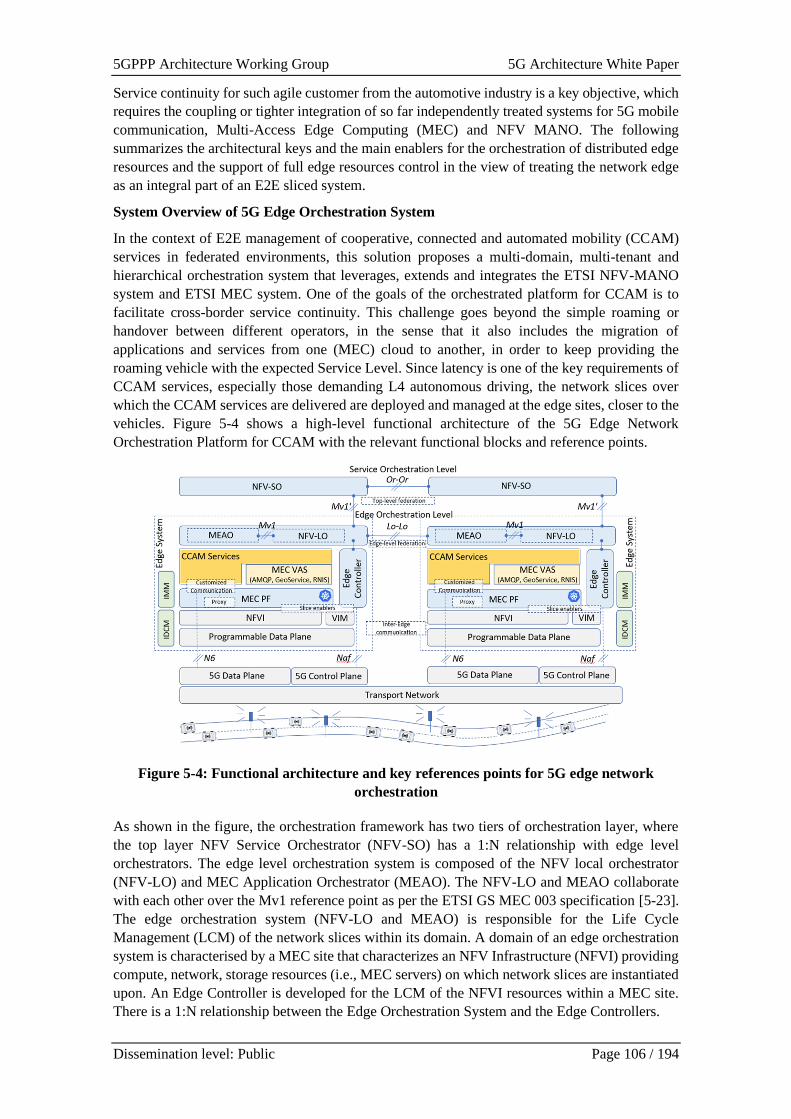
5GPPP Architecture Working Group 5G Architecture White Paper
Dissemination level: Public Page 106 / 194
Service continuity for such agile customer from the automotive industry is a key objective, which
requires the coupling or tighter integration of so far independently treated systems for 5G mobile
communication, Multi-Access Edge Computing (MEC) and NFV MANO. The following
summarizes the architectural keys and the main enablers for the orchestration of distributed edge
resources and the support of full edge resources control in the view of treating the network edge
as an integral part of an E2E sliced system.
System Overview of 5G Edge Orchestration System
In the context of E2E management of cooperative, connected and automated mobility (CCAM)
services in federated environments, this solution proposes a multi-domain, multi-tenant and
hierarchical orchestration system that leverages, extends and integrates the ETSI NFV-MANO
system and ETSI MEC system. One of the goals of the orchestrated platform for CCAM is to
facilitate cross-border service continuity. This challenge goes beyond the simple roaming or
handover between different operators, in the sense that it also includes the migration of
applications and services from one (MEC) cloud to another, in order to keep providing the
roaming vehicle with the expected Service Level. Since latency is one of the key requirements of
CCAM services, especially those demanding L4 autonomous driving, the network slices over
which the CCAM services are delivered are deployed and managed at the edge sites, closer to the
vehicles. Figure 5-4 shows a high-level functional architecture of the 5G Edge Network
Orchestration Platform for CCAM with the relevant functional blocks and reference points.
Figure 5-4: Functional architecture and key references points for 5G edge network
orchestration
As shown in the figure, the orchestration framework has two tiers of orchestration layer, where
the top layer NFV Service Orchestrator (NFV-SO) has a 1:N relationship with edge level
orchestrators. The edge level orchestration system is composed of the NFV local orchestrator
(NFV-LO) and MEC Application Orchestrator (MEAO). The NFV-LO and MEAO collaborate
with each other over the Mv1 reference point as per the ETSI GS MEC 003 specification [5-23].
The edge orchestration system (NFV-LO and MEAO) is responsible for the Life Cycle
Management (LCM) of the network slices within its domain. A domain of an edge orchestration
system is characterised by a MEC site that characterizes an NFV Infrastructure (NFVI) providing
compute, network, storage resources (i.e., MEC servers) on which network slices are instantiated
upon. An Edge Controller is developed for the LCM of the NFVI resources within a MEC site.
There is a 1:N relationship between the Edge Orchestration System and the Edge Controllers.
5GPPP Architecture Working Group 5G Architecture White Paper
Dissemination level: Public Page 107 / 194
For the E2E management of network slices that span across multiple edge domains, even crossing
administrative and country domains, the 5G edge network orchestration platform realizes
federation interfaces over the multiple reference points. These are the Or-Or reference point
between the NFV-SOs belonging to different domains, and the Lo-Lo reference point between
the NFV-LOs belonging to different administrative domains. An interface for the inter-edge
communication is also realized which will be explained later. The Or-Or reference point is based
on the ETSI GS NFV-IFA 030 specification [5-22], while the Lo-Lo reference point inherits from
the Or-Or reference point but its scope is limited to establishing direct federation between the
edge orchestration domains to directly inter-coordinate the LCM of multi-site network edge slices
bypassing the NFV-SO. In other words, the NFV-SO as being the top-level orchestrator has full
administrative control of the edge orchestration system but it can delegate management tasks to
the edge orchestration system via a novel concept of Management Level Agreement (MLA) that
is negotiated between the NFV-SO and the NFV-LO over the Mv1’ reference point. The MV1’
reference point is also inherited from the Mv1 reference point between the NFV-LO and the
MEAO mentioned above. For well-coordinated management of multi-site network edge slices,
the MLA is also negotiated between the NFV-LOs over the Lo-Lo reference point, after the scope
of the MLA has been agreed between the NFV-SOs of the respective domains over the Or-Or
reference point.
5.2.2.2 E2E slice management and orchestration approach focused on
scalability
The orchestration and management architecture proposed in [5-30] aims to provide a new
framework for the concurrent provisioning of high numbers of network slices as envisioned in 5G
and beyond. The primary goal of this approach is to achieve scalable and automated management
of network slices in multiple orchestration domains. The framework adopts the management
system decomposition proposed by ITU-T [5-24] and uses the MAPE (Monitor-Analyze-Plan-
Execute) paradigm [5-25] as the basis, implemented through AI-driven operations. The
framework allows for the creation of a “management slice” that can be used for run-time
management of multiple slice instances of the same template (Management as a Service - MaaS).
The OSS/BSS of each orchestration domain focuses on the lifecycle management (LCM) of slices
and resource management, but it is agnostic to slices. Each slice can be seen as a service with its
own management platform, called embedded or In-Slice Management (ISM). The ISM is part of
a slice and is implemented as a set of VNFs; therefore, the resources scaling mechanism can
contribute to its performance and new management services can be dynamically
deployed/updated during the slice lifetime. The approach provides isolation of management
planes of slices (not provided by ETSI NFV MANO [5-27] nor 3GPP). The ISM of each slice
(i.e., slice OSS/BSS) may act as a service orchestrator. AI can be applied at multiple levels of the
architecture hierarchy, having their relevant entities of Monitoring System (MS), Analytic Engine
(AE) and Decision Engine (DE). The sets of interacting MSs, AEs and DEs are instantiated at the
OSS/BSS level (for E2E slice management and orchestration in orchestration domain (for slice
admission control, allocation of resources to slices and domain FCAPS), global, cross-slice, and
cross-domain optimizations), inside the virtualized infrastructure, within slices (responsible for
each slice FCAPS management), or as a part of each node/function (autonomic Element Manager)
and thus enable FCAPS management in a distributed and automated manner. Due to the embedded
management, the cooperation is based on a minimized exchange of information between the
management system components. It typically uses KPIs to achieve the goal. All subsystems use
MS/AE/DE triplets to perform specific, control loop-based optimization and communicate over
the intent-based interfaces.
The details of the framework are presented in Figure 5-5. The MonB5G Portal is used by Slice
Tenants, Slice Management Providers and Infrastructure Providers to request slice LCM. It
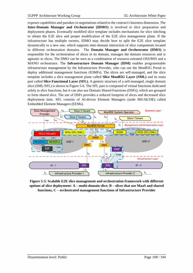
5GPPP Architecture Working Group 5G Architecture White Paper
Dissemination level: Public Page 108 / 194
exposes capabilities and partakes in negotiations related to the contract's business dimension. The
Inter-Domain Manager and Orchestrator (IDMO) is involved in slice preparation and
deployment phases. Eventually modified slice template includes mechanisms for slice stitching
to obtain the E2E slice and proper modification of the E2E slice management plane. If the
infrastructure has multiple owners, IDMO may decide how to split the E2E slice template
dynamically to a new one, which supports inter-domain interaction of slice components located
in different orchestration domains. The Domain Manager and Orchestrator (DMO) is
responsible for the orchestration of slices in its domain, manages the domain resources and is
agnostic to slices. The DMO can be seen as a combination of resource-oriented OSS/BSS and a
MANO orchestrator. The Infrastructure Domain Manager (IDM) enables programmable
infrastructure management by the Infrastructure Provider, who can use the MonB5G Portal to
deploy additional management functions (IOMFs). The slices are self-managed, and the slice
template includes a slice management plane called Slice MonB5G Layer (SML) and its main
part called Slice Functional Layer (SFL). A generic structure of a self-managed, single domain
slice (SML/SFL) is shown in Figure 5-6. The SFL part is composed of virtual functions dedicated
solely to slice functions, but it can also use Domain Shared Functions (DSFs), which are grouped
to form shared slice. The use of DSFs provides a reduced footprint of slices and decreased slice
deployment time. SFL consists of AI-driven Element Managers (node MS/AE/DE) called
Embedded Element Managers (EEMs).
DMO
NS1a (SFL/SML)
DMO
IDMO
IDSM1
SOD-1 SOD-2
Infrastructure Layer
Slice 1 Tenant
NS2,3 (MLaaS)
NS2(SFL) NS3(SFL)
NS1b (SFL/SML)
MonB5G Portal
Slice 3 Tenant
Slice 2 Tenant
MonB5G System OperatorSlice Management
Provider
Business Layer
Management and Orchestration Layer
unsp.
Iop
Itp
ItpItp
Imt
Imt
Imp
Its
unsp.
unsp. unsp.
Iid
Ipi
Iid
Idr
Iii Iii
Idr
unsp.
DSF
Infrastructure Provider 1Itp Infrastructure Provider 2 Itp
ID - 1 ID - 2IDM
unsp.unsp.
IOMF
IDM
unsp.
B
A
C
Figure 5-5: Scalable E2E slice management and orchestration framework with different
options of slice deployment: A – multi-domain slice; B – slices that use MaaS and shared
functions, C – orchestrated management functions of Infrastructure Provider
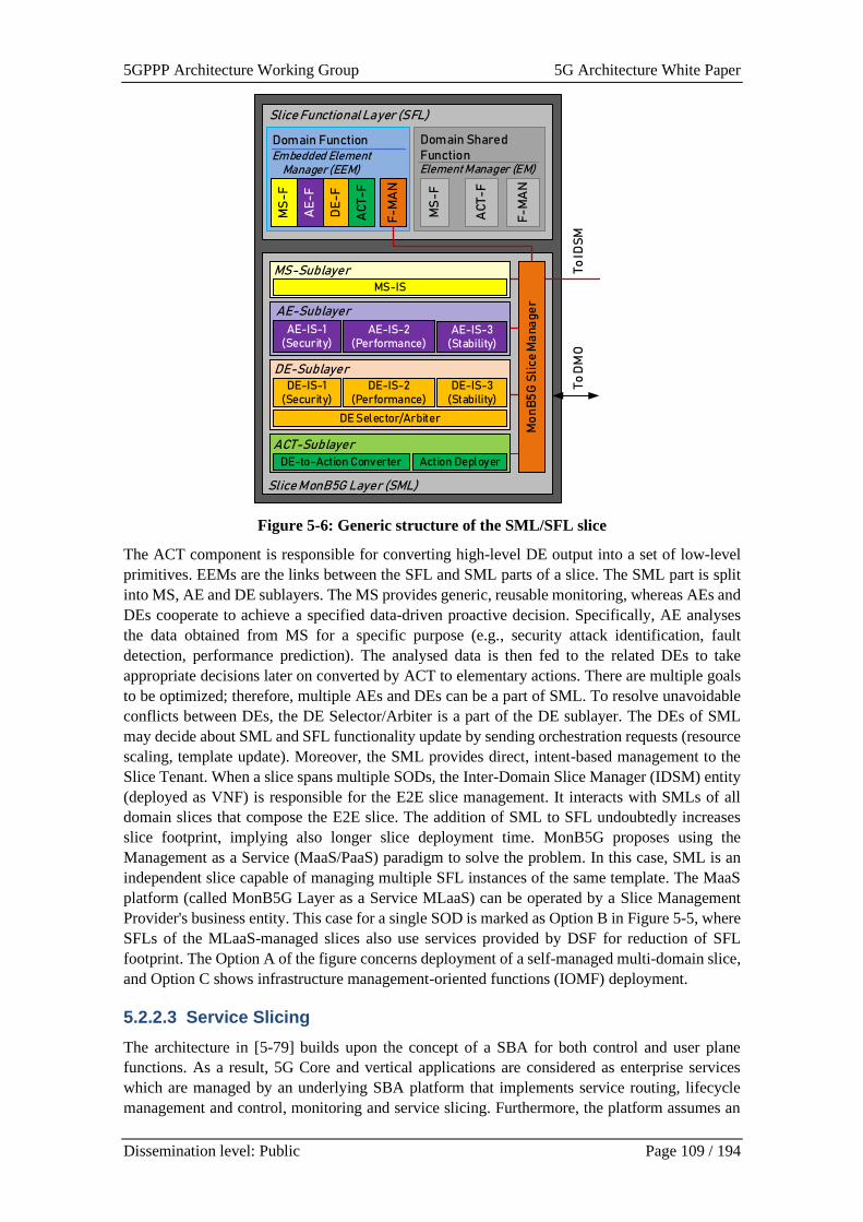
5GPPP Architecture Working Group 5G Architecture White Paper
Dissemination level: Public Page 109 / 194
Slice Functional Layer (SFL)
To ID
SM
Domain Shared Function
MS
-F
AC
T-F
F-M
AN
Element Manager (EM)
To D
MO
Slice MonB5G Layer (SML)
DE-to-Action Converter Action Deployer
ACT-Sublayer
DE-IS-1(Security)
DE Selector/Arbiter
DE-SublayerDE-IS-3
(Stability)DE-IS-2
(Performance)
AE-IS-1 (Security)
AE-IS-2 (Performance)
AE-Sublayer
AE-IS-3 (Stability)
MS-IS
MS-Sublayer
Mo
nB
5G
Sli
ce M
ana
ge
r
Domain FunctionEmbedded Element
Manager (EEM)
DE
-F
AC
T-F
MS
-F
AE
-F
F-M
AN
Figure 5-6: Generic structure of the SML/SFL slice
The ACT component is responsible for converting high-level DE output into a set of low-level
primitives. EEMs are the links between the SFL and SML parts of a slice. The SML part is split
into MS, AE and DE sublayers. The MS provides generic, reusable monitoring, whereas AEs and
DEs cooperate to achieve a specified data-driven proactive decision. Specifically, AE analyses
the data obtained from MS for a specific purpose (e.g., security attack identification, fault
detection, performance prediction). The analysed data is then fed to the related DEs to take
appropriate decisions later on converted by ACT to elementary actions. There are multiple goals
to be optimized; therefore, multiple AEs and DEs can be a part of SML. To resolve unavoidable
conflicts between DEs, the DE Selector/Arbiter is a part of the DE sublayer. The DEs of SML
may decide about SML and SFL functionality update by sending orchestration requests (resource
scaling, template update). Moreover, the SML provides direct, intent-based management to the
Slice Tenant. When a slice spans multiple SODs, the Inter-Domain Slice Manager (IDSM) entity
(deployed as VNF) is responsible for the E2E slice management. It interacts with SMLs of all
domain slices that compose the E2E slice. The addition of SML to SFL undoubtedly increases
slice footprint, implying also longer slice deployment time. MonB5G proposes using the
Management as a Service (MaaS/PaaS) paradigm to solve the problem. In this case, SML is an
independent slice capable of managing multiple SFL instances of the same template. The MaaS
platform (called MonB5G Layer as a Service MLaaS) can be operated by a Slice Management
Provider's business entity. This case for a single SOD is marked as Option B in Figure 5-5, where
SFLs of the MLaaS-managed slices also use services provided by DSF for reduction of SFL
footprint. The Option A of the figure concerns deployment of a self-managed multi-domain slice,
and Option C shows infrastructure management-oriented functions (IOMF) deployment.
5.2.2.3 Service Slicing
The architecture in [5-79] builds upon the concept of a SBA for both control and user plane
functions. As a result, 5G Core and vertical applications are considered as enterprise services
which are managed by an underlying SBA platform that implements service routing, lifecycle
management and control, monitoring and service slicing. Furthermore, the platform assumes an
5GPPP Architecture Working Group 5G Architecture White Paper
Dissemination level: Public Page 110 / 194
underlying NFV- and SDN-enabled infrastructure with a unified access domain for UEs to
communicate with the cellular telecommunication system. In this context, slicing is the task of
resource isolation and QoS enforcement with E2E perspective including all possible resource
domains across the control and user plane, i.e., access domain, 5GC CP and UP, and DNs. The
resulting Service Slicing vision demands slicing operations at run-time in a programmable and
service-centric fashion. It becomes apparent that each of these domains have their own set of
properties and objectives that have to be sliced, thus creating a multi-dimensional challenge. The
realisation and demonstration of established concepts around the creation of 5GLAN Virtual
Groups, RAN slicing and cloud slicing. Additionally, the architecture provides an SBA-driven
approach for slicing 5GC control plane functions that has been already made public in its concept
in the eSBA group of NGMN [5-31]. This - so called - Service Slicing approach offers
programmable APIs for enterprise services to communicate preferences for the slicing operations
across the aforementioned slicing domains. Linking the independent domains together into an
E2E fashion in order to form a logical “slice” is the key challenge and is an ongoing architectural
task within the project.
Further to the Service Slicing capabilities, the proposed platform operates as a VNF-based
platform within a pre-defined and configured wholesale slice within an existing infrastructure
respecting existing APIs and technologies around ETSI NFV MANO (e.g., OpenStack, OpenShift)
and SDN (e.g., OpenFlow and/or existing controllers such as Floodlight, OpenDayLight or
ONOS). The provisioning of the platform is utilising a Platform-as-a-Service toolchain, called
Agnostic platfoRm DEploymeNt orchesTrator (ARDENT) [5-32], allowing the automation of the
provisioning and management of the SBA platform across multiple sites.
5.2.3 Integration of transport networks
Table 5-3: Architectural solutions for integration of transport networks
Architectural solution 5G PPP Project Additional Reference
Integration with WAN Infrastructure
Manager
TeraFlow [5-33]
Network management aspects for
integrating transport and radio
management for THz fronthaul links
Teraway [5-41]
5.2.3.1 Integration with WAN Infrastructure Manager
Together with NFV, Software Defined Networking (SDN) is a key enabler for the
telecommunication industry transformation. SDN provides the necessary network transformation
bringing network functions and APIs, easing the convergence of the telecom and the IT industries
[5-33] [5-34].
SDN has been demonstrated as an enabler for NFV architectures, integrating network services
and associated resources. [5-35] distinguishes between SDN resources and SDN controllers. SDN
resources might be located in the NFV architecture as: a) physical switch or router; b) virtual
switch or router; c) e-switch, software based SDN enabled switch in a server NIC; and d) switch
or router as a VNF. Moreover, an SDN controller can be located in different positions: 1) merged
with the Virtualised Infrastructure Manager functionality; 2) virtualised as a VNF; 3) part of the
NFVI and is not a VNF; 4) part of the OSS/BSS; and 5) being a PNF.
This flexibility provides a clear benefit for NFV architecture to include SDN enablers. Particularly,
the inter-connection of NFV infrastructure points-of-presence (NFVI-PoP) through WAN
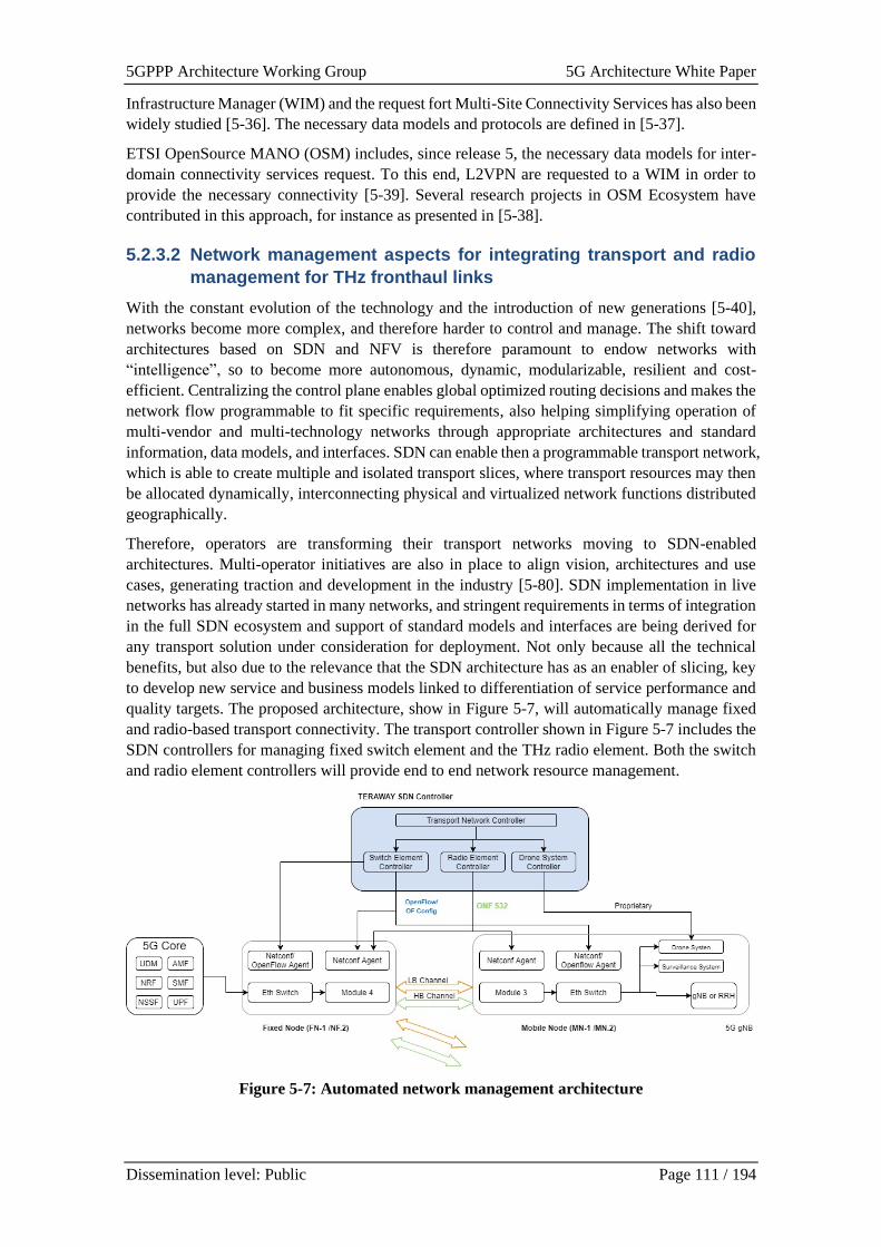
5GPPP Architecture Working Group 5G Architecture White Paper
Dissemination level: Public Page 111 / 194
Infrastructure Manager (WIM) and the request fort Multi-Site Connectivity Services has also been
widely studied [5-36]. The necessary data models and protocols are defined in [5-37].
ETSI OpenSource MANO (OSM) includes, since release 5, the necessary data models for inter-
domain connectivity services request. To this end, L2VPN are requested to a WIM in order to
provide the necessary connectivity [5-39]. Several research projects in OSM Ecosystem have
contributed in this approach, for instance as presented in [5-38].
5.2.3.2 Network management aspects for integrating transport and radio
management for THz fronthaul links
With the constant evolution of the technology and the introduction of new generations [5-40],
networks become more complex, and therefore harder to control and manage. The shift toward
architectures based on SDN and NFV is therefore paramount to endow networks with
“intelligence”, so to become more autonomous, dynamic, modularizable, resilient and cost-
efficient. Centralizing the control plane enables global optimized routing decisions and makes the
network flow programmable to fit specific requirements, also helping simplifying operation of
multi-vendor and multi-technology networks through appropriate architectures and standard
information, data models, and interfaces. SDN can enable then a programmable transport network,
which is able to create multiple and isolated transport slices, where transport resources may then
be allocated dynamically, interconnecting physical and virtualized network functions distributed
geographically.
Therefore, operators are transforming their transport networks moving to SDN-enabled
architectures. Multi-operator initiatives are also in place to align vision, architectures and use
cases, generating traction and development in the industry [5-80]. SDN implementation in live
networks has already started in many networks, and stringent requirements in terms of integration
in the full SDN ecosystem and support of standard models and interfaces are being derived for
any transport solution under consideration for deployment. Not only because all the technical
benefits, but also due to the relevance that the SDN architecture has as an enabler of slicing, key
to develop new service and business models linked to differentiation of service performance and
quality targets. The proposed architecture, show in Figure 5-7, will automatically manage fixed
and radio-based transport connectivity. The transport controller shown in Figure 5-7 includes the
SDN controllers for managing fixed switch element and the THz radio element. Both the switch
and radio element controllers will provide end to end network resource management.
Figure 5-7: Automated network management architecture
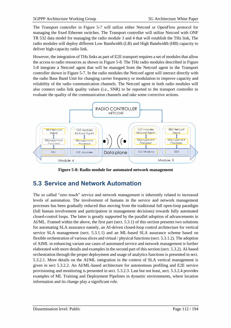
5GPPP Architecture Working Group 5G Architecture White Paper
Dissemination level: Public Page 112 / 194
The Transport controller in Figure 5-7 will utilize either Netconf or OpenFlow protocol for
managing the fixed Ethernet switches. The Transport controller will utilize Netconf with ONF
TR 532 data model for managing the radio module 3 and 4 that will establish the THz link, The
radio modules will deploy different Low Bandwidth (LB) and High Bandwidth (HB) capacity to
deliver high-capacity radio link.
However, the integration of THz links as part of E2E transport requires a set of modules that allow
the access to radio resources as shown in Figure 5-8. The THz radio modules described in Figure
5-8 integrate a Netconf agent that will be managed from the Netconf agent in the Transport
controller shown in Figure 5-7. In the radio modules the Netconf agent will interact directly with
the radio Base Band Unit for changing carrier frequency or modulation to improve capacity and
reliability of the radio communication channels. The Netconf agent in both radio modules will
also connect radio link quality values (i.e., SNR) to be reported to the transport controller to
evaluate the quality of the communication channels and take some corrective actions.
Figure 5-8: Radio module for automated network management
5.3 Service and Network Automation
The so called “zero touch” service and network management is inherently related to increased
levels of automation. The involvement of humans in the service and network management
processes has been gradually reduced thus moving from the traditional full open-loop paradigm
(full human involvement and participation in management decisions) towards fully automated
closed-control loops. The latter is greatly supported by the parallel adoption of advancements in
AI/ML. Framed within the above, the first part (sect. 5.3.1) of this section presents two solutions
for automating SLA assurance namely, an AI-driven closed-loop control architecture for vertical
service SLA management (sect. 5.3.1.1) and an ML-based SLA assurance scheme based on
flexible orchestration of various slices and virtual / physical functions (sect. 5.3.1.2). The adoption
of AIML in enhancing variant use cases of automated service and network management is further
elaborated with more details and examples in the second part of this section (sect. 5.3.2). AI-based
orchestration through the proper deployment and usage of analytics functions is presented in sect.
5.3.2.1. More details on the AI/ML integration in the context of SLA vertical management is
given in sect 5.3.2.2. An AI/ML-based architecture for autonomous profiling and E2E service
provisioning and monitoring is presented in sect. 5.3.2.3. Last but not least, sect. 5.3.2.4 provides
examples of ML Training and Deployment Pipelines in dynamic environments, where location
information and its change play a significant role.
5GPPP Architecture Working Group 5G Architecture White Paper
Dissemination level: Public Page 113 / 194
5.3.1 Automated SLA Assurance
Table 5-4: Architectural solutions for Automated SLA Assurance
Architectural solution 5G PPP Project Additional Reference
AI-driven closed-loop control of
vertical service SLA management
5Growth [5-44], [5-47], [5-48], [5-49]
ML-based SLA assurance through
flexible orchestration
5G SOLUTIONS [5-81]
5.3.1.1 AI-driven closed-loop control of vertical service SLA management
Automation is a key aspect to build full E2E autonomous networks. To this aim, ETSI has defined
a Zero-touch and Service management (ZSM) framework that aims to have all operational
processes and tasks executed automatically. This can happen through the new architecture design
of closed-loop automation and embedding intelligence with data-driven AI/ML algorithms, which
are the key enablers for self-managing capabilities, with lower operational costs, accelerated time-
to-value, and reduced risk of human error.
Aligned with the design concept of the ETSI ZSM closed-loop automation framework, a closed-
loop architecture design for vertical service lifecycle management is proposed ([5-47], [5-48]).
This closed-loop includes the process of collecting monitoring data from the services and
networks, performing real-time data analytics for identifying events to handle, and taking proper
decisions for optimization and re-configuration of the system, such as auto-scaling, self-healing
and fault-tolerance, anomaly detection and automated troubleshooting, automated authentication
and traffic management.
Figure 5-9 explains the concept of this closed-loop design integrated with the stack proposed in
[5-47], which is composed of three core building blocks, namely Vertical Slicer (5Gr-VS),
Service Orchestrator (5Gr-SO), and Resource Layer (5Gr-RL). The stack presents the service
MANO platform, which interacts with the Vertical-oriented Monitoring System (5Gr-VoMS) and
the AI/ML Platform (5Gr-AIMLP). The 5Gr-VoMS integrates application-level monitoring
probes and provides enhanced monitoring to support innovative mechanisms related to reliability
(via self-healing and auto-scaling), control-loop stability, and analytical features (such as,
forecasting and anomaly detection), and also to fully support data streaming as an enabler for the
efficient analysis of large data sets, required by AI/ML techniques. The 5Gr-AIMLP provides
AI/ML as a service to support the different layers to run AI/ML algorithms for their decision-
making processes. It handles online or offline training of selected AI models using either data
coming from the 5Gr-VoMS or external data. The decision-making entity (also called as agent)
is ultimately the entity that executes the model.
These building blocks interact with each other, creating a closed-loop control of the system. The
details of the workflow are introduced in [5-48] and have been demonstrated in [5-49]. The basic
logic for usual forecasting and classification problems is described in the following:
• The 5Gr-AIMLP exposes a catalogue of AI/ML models that can be tuned/chained to
compose more complex models.
• The 5Gr-AIMLP requests the 5Gr-VoMS for orchestration of monitoring probes and
retrieves on demand context information (e.g., current number of users) and performance
metrics (e.g., CPU consumption), to train a model or compute its reward.
• The 5Growth platform related layer (e.g., 5Gr-SO) configures all needed data pipeline
components to run the optimized model, which is passed down to the agent for online
execution by exploiting performance metrics coming from 5Gr-VoMS.

5GPPP Architecture Working Group 5G Architecture White Paper
Dissemination level: Public Page 114 / 194
Figure 5-9: Closed-loop Automation [5-47]
5.3.1.2 ML-based SLA assurance through flexible orchestration
The complexity of 5G networks is well understood, with a variety of elements adding to this
complexity, including the orchestration of various slices and virtual / physical functions,
constantly changing network conditions, etc. Systems have evolved over the years from reactive
to more proactive solutions, with a goal of ensuring uninterrupted service at defined SLA
requirements. Automatic solutions to support SLA assurance in the 5G network can be supported
by ML/AI methods.
One specific example to be investigated is the implementation of closed-loop automation to
support a 5G video streaming service in a cross-domain environment using ML performance
prediction algorithms [5-81]. ML methods such as cross-domain correlations and KPI prediction
form the learning basis of the data analysis. These methods are incorporated into a Zero Touch
Automation block, which in turn can send recommendations to the cross-domain orchestrator.
This mechanism and its associated architecture are represented in Figure 5-10.

5GPPP Architecture Working Group 5G Architecture White Paper
Dissemination level: Public Page 115 / 194
Figure 5-10: High-level architecture with multiple domain orchestration and closed-loop
Zero-touch Automation in [5-81]
In this specific example, ML methods such as cross-domain KPI correlations, as well as prediction
methods will be used. For example, methods such as Pearson, Kendall, Spearman are used to
detect correlations between network and service KPIs. This can give indications on which
network KPIs will influence service KPIs related to the SLAs, or can indicate undesired changes
between the two domains in the case when the correlation changes over time. Similarly,
regression-based prediction enables predicting service KPIs based on network KPIs. In addition
to this, time-series prediction methods are employed to proactively decide to change orchestration
parameters, in case network KPIs that influence service quality are predicted to go towards values
that would mean that the SLA can no longer be guaranteed. This decision is then passed to the
cross-domain orchestrator (Nokia’s CDSO in this case), which will communicate new parameters
to the respective domain orchestrator(s).
5.3.2 AIML Adoption
Table 5-5: Architectural solutions for AIML Adoption
Architectural solution 5G PPP Project Additional Reference
AI-based Orchestration 5G-TOURS [5-50] – [5-53]
AIML integration in the context of
vertical service SLA management
5Growth [5-44], [5-45], [5-48], [5-49]
Autonomous profiling and E2E service
provisioning and monitoring using
AIML
5G-VICTORI [5-54] – [5-60]
AIML-based M&O exploiting
localization
LOCUS [5-61] – [5-63]
Current work in the standardization of 5G Networks assumed a significant use of AI mechanisms
in service and network management and orchestration. The need to introduce AI arose from the
fact that, on the one hand, new virtualisation and slicing technologies open up the possibility of
efficient delivery of vertical services with a given level of quality on a shared infrastructure, and,
on the other hand, lead to high complexity of the entire system, which increases the requirements
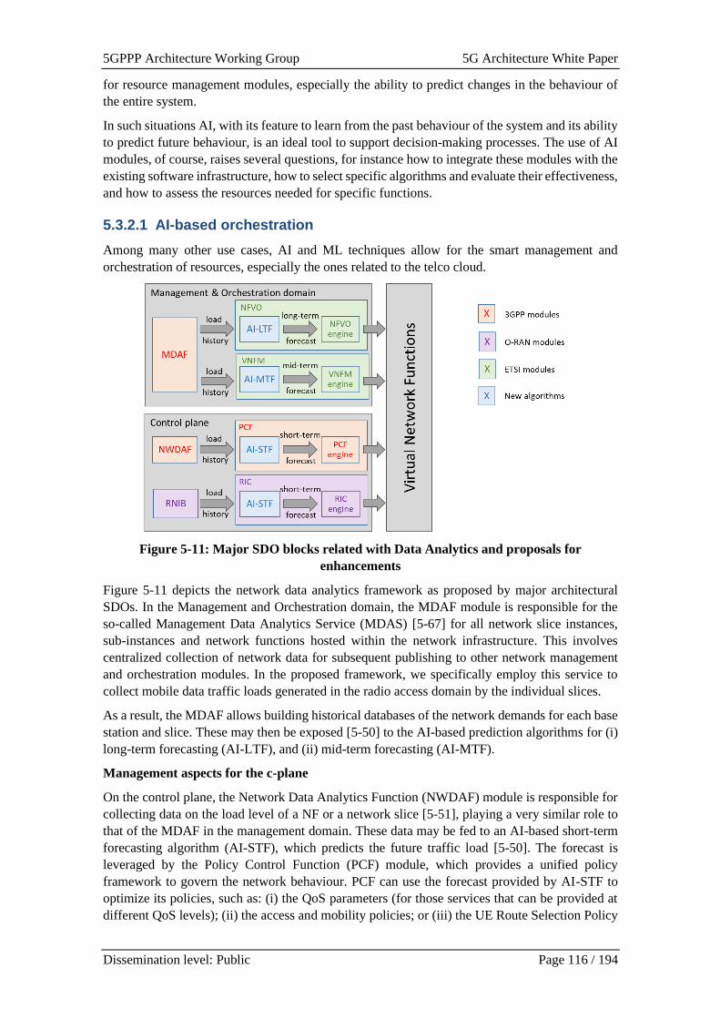
5GPPP Architecture Working Group 5G Architecture White Paper
Dissemination level: Public Page 116 / 194
for resource management modules, especially the ability to predict changes in the behaviour of
the entire system.
In such situations AI, with its feature to learn from the past behaviour of the system and its ability
to predict future behaviour, is an ideal tool to support decision-making processes. The use of AI
modules, of course, raises several questions, for instance how to integrate these modules with the
existing software infrastructure, how to select specific algorithms and evaluate their effectiveness,
and how to assess the resources needed for specific functions.
5.3.2.1 AI-based orchestration
Among many other use cases, AI and ML techniques allow for the smart management and
orchestration of resources, especially the ones related to the telco cloud.
Figure 5-11: Major SDO blocks related with Data Analytics and proposals for
enhancements
Figure 5-11 depicts the network data analytics framework as proposed by major architectural
SDOs. In the Management and Orchestration domain, the MDAF module is responsible for the
so-called Management Data Analytics Service (MDAS) [5-67] for all network slice instances,
sub-instances and network functions hosted within the network infrastructure. This involves
centralized collection of network data for subsequent publishing to other network management
and orchestration modules. In the proposed framework, we specifically employ this service to
collect mobile data traffic loads generated in the radio access domain by the individual slices.
As a result, the MDAF allows building historical databases of the network demands for each base
station and slice. These may then be exposed [5-50] to the AI-based prediction algorithms for (i)
long-term forecasting (AI-LTF), and (ii) mid-term forecasting (AI-MTF).
Management aspects for the c-plane
On the control plane, the Network Data Analytics Function (NWDAF) module is responsible for
collecting data on the load level of a NF or a network slice [5-51], playing a very similar role to
that of the MDAF in the management domain. These data may be fed to an AI-based short-term
forecasting algorithm (AI-STF), which predicts the future traffic load [5-50]. The forecast is
leveraged by the Policy Control Function (PCF) module, which provides a unified policy
framework to govern the network behaviour. PCF can use the forecast provided by AI-STF to
optimize its policies, such as: (i) the QoS parameters (for those services that can be provided at
different QoS levels); (ii) the access and mobility policies; or (iii) the UE Route Selection Policy
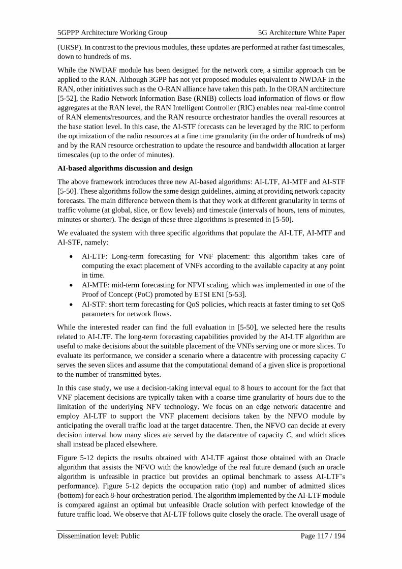
5GPPP Architecture Working Group 5G Architecture White Paper
Dissemination level: Public Page 117 / 194
(URSP). In contrast to the previous modules, these updates are performed at rather fast timescales,
down to hundreds of ms.
While the NWDAF module has been designed for the network core, a similar approach can be
applied to the RAN. Although 3GPP has not yet proposed modules equivalent to NWDAF in the
RAN, other initiatives such as the O-RAN alliance have taken this path. In the ORAN architecture
[5-52], the Radio Network Information Base (RNIB) collects load information of flows or flow
aggregates at the RAN level, the RAN Intelligent Controller (RIC) enables near real-time control
of RAN elements/resources, and the RAN resource orchestrator handles the overall resources at
the base station level. In this case, the AI-STF forecasts can be leveraged by the RIC to perform
the optimization of the radio resources at a fine time granularity (in the order of hundreds of ms)
and by the RAN resource orchestration to update the resource and bandwidth allocation at larger
timescales (up to the order of minutes).
AI-based algorithms discussion and design
The above framework introduces three new AI-based algorithms: AI-LTF, AI-MTF and AI-STF
[5-50]. These algorithms follow the same design guidelines, aiming at providing network capacity
forecasts. The main difference between them is that they work at different granularity in terms of
traffic volume (at global, slice, or flow levels) and timescale (intervals of hours, tens of minutes,
minutes or shorter). The design of these three algorithms is presented in [5-50].
We evaluated the system with three specific algorithms that populate the AI-LTF, AI-MTF and
AI-STF, namely:
• AI-LTF: Long-term forecasting for VNF placement: this algorithm takes care of
computing the exact placement of VNFs according to the available capacity at any point
in time.
• AI-MTF: mid-term forecasting for NFVI scaling, which was implemented in one of the
Proof of Concept (PoC) promoted by ETSI ENI [5-53].
• AI-STF: short term forecasting for QoS policies, which reacts at faster timing to set QoS
parameters for network flows.
While the interested reader can find the full evaluation in [5-50], we selected here the results
related to AI-LTF. The long-term forecasting capabilities provided by the AI-LTF algorithm are
useful to make decisions about the suitable placement of the VNFs serving one or more slices. To
evaluate its performance, we consider a scenario where a datacentre with processing capacity C
serves the seven slices and assume that the computational demand of a given slice is proportional
to the number of transmitted bytes.
In this case study, we use a decision-taking interval equal to 8 hours to account for the fact that
VNF placement decisions are typically taken with a coarse time granularity of hours due to the
limitation of the underlying NFV technology. We focus on an edge network datacentre and
employ AI-LTF to support the VNF placement decisions taken by the NFVO module by
anticipating the overall traffic load at the target datacentre. Then, the NFVO can decide at every
decision interval how many slices are served by the datacentre of capacity C, and which slices
shall instead be placed elsewhere.
Figure 5-12 depicts the results obtained with AI-LTF against those obtained with an Oracle
algorithm that assists the NFVO with the knowledge of the real future demand (such an oracle
algorithm is unfeasible in practice but provides an optimal benchmark to assess AI-LTF’s
performance). Figure 5-12 depicts the occupation ratio (top) and number of admitted slices
(bottom) for each 8-hour orchestration period. The algorithm implemented by the AI-LTF module
is compared against an optimal but unfeasible Oracle solution with perfect knowledge of the
future traffic load. We observe that AI-LTF follows quite closely the oracle. The overall usage of
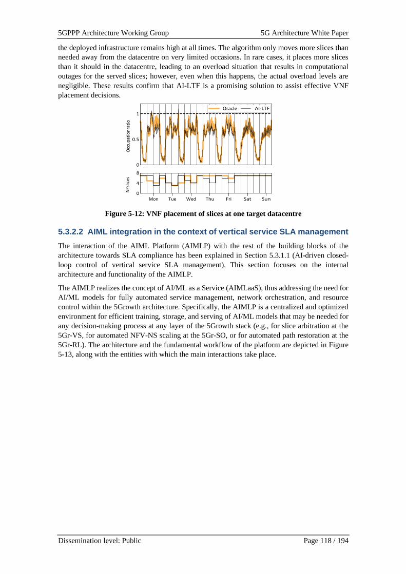
5GPPP Architecture Working Group 5G Architecture White Paper
Dissemination level: Public Page 118 / 194
the deployed infrastructure remains high at all times. The algorithm only moves more slices than
needed away from the datacentre on very limited occasions. In rare cases, it places more slices
than it should in the datacentre, leading to an overload situation that results in computational
outages for the served slices; however, even when this happens, the actual overload levels are
negligible. These results confirm that AI-LTF is a promising solution to assist effective VNF
placement decisions.
Figure 5-12: VNF placement of slices at one target datacentre
5.3.2.2 AIML integration in the context of vertical service SLA management
The interaction of the AIML Platform (AIMLP) with the rest of the building blocks of the
architecture towards SLA compliance has been explained in Section 5.3.1.1 (AI-driven closed-
loop control of vertical service SLA management). This section focuses on the internal
architecture and functionality of the AIMLP.
The AIMLP realizes the concept of AI/ML as a Service (AIMLaaS), thus addressing the need for
AI/ML models for fully automated service management, network orchestration, and resource
control within the 5Growth architecture. Specifically, the AIMLP is a centralized and optimized
environment for efficient training, storage, and serving of AI/ML models that may be needed for
any decision-making process at any layer of the 5Growth stack (e.g., for slice arbitration at the
5Gr-VS, for automated NFV-NS scaling at the 5Gr-SO, or for automated path restoration at the
5Gr-RL). The architecture and the fundamental workflow of the platform are depicted in Figure
5-13, along with the entities with which the main interactions take place.
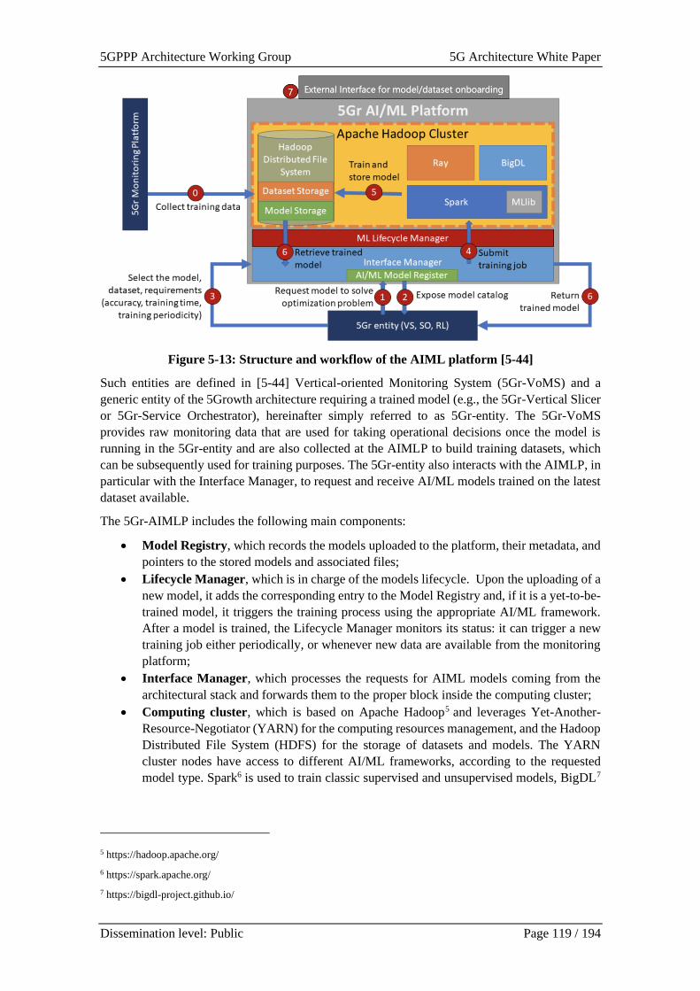
5GPPP Architecture Working Group 5G Architecture White Paper
Dissemination level: Public Page 119 / 194
Figure 5-13: Structure and workflow of the AIML platform [5-44]
Such entities are defined in [5-44] Vertical-oriented Monitoring System (5Gr-VoMS) and a
generic entity of the 5Growth architecture requiring a trained model (e.g., the 5Gr-Vertical Slicer
or 5Gr-Service Orchestrator), hereinafter simply referred to as 5Gr-entity. The 5Gr-VoMS
provides raw monitoring data that are used for taking operational decisions once the model is
running in the 5Gr-entity and are also collected at the AIMLP to build training datasets, which
can be subsequently used for training purposes. The 5Gr-entity also interacts with the AIMLP, in
particular with the Interface Manager, to request and receive AI/ML models trained on the latest
dataset available.
The 5Gr-AIMLP includes the following main components:
• Model Registry, which records the models uploaded to the platform, their metadata, and
pointers to the stored models and associated files;
• Lifecycle Manager, which is in charge of the models lifecycle. Upon the uploading of a
new model, it adds the corresponding entry to the Model Registry and, if it is a yet-to-be-
trained model, it triggers the training process using the appropriate AI/ML framework.
After a model is trained, the Lifecycle Manager monitors its status: it can trigger a new
training job either periodically, or whenever new data are available from the monitoring
platform;
• Interface Manager, which processes the requests for AIML models coming from the
architectural stack and forwards them to the proper block inside the computing cluster;
• Computing cluster, which is based on Apache Hadoop5 and leverages Yet-Another-
Resource-Negotiator (YARN) for the computing resources management, and the Hadoop
Distributed File System (HDFS) for the storage of datasets and models. The YARN
cluster nodes have access to different AI/ML frameworks, according to the requested
model type. Spark6 is used to train classic supervised and unsupervised models, BigDL7
5 https://hadoop.apache.org/
6 https://spark.apache.org/
7 https://bigdl-project.github.io/
5GPPP Architecture Working Group 5G Architecture White Paper
Dissemination level: Public Page 120 / 194
is used for Deep Neural Networks, and Ray8 can be used for Reinforcement Learning
models.
Finally, we underline that, through the web interface (marked as 7 in Figure 5-13), an authorized
external user can also onboard onto the AIML platform off-line trained ML models, as well as
ML models and the corresponding datasets, to be trained within the platform itself. For further
information, the reader is referred to [5-48] and [5-49].
5.3.2.3 Autonomous profiling and E2E service provisioning and monitoring
using AIML
Currently, a considerable effort has been applied towards the adaptation of ZSM to provide
complete E2E automation of network as well as NFV orchestration. With the upsurge of ML
methods, there has been a push in the telecom industries to adapt these techniques to reduce
human intervention and optimise the network and computing resource consumption for the next-
generation zero-touch NFV orchestrators. To achieve the ZSM goals, these next generation of
intelligent NFV orchestrators need deep knowledge about the performance of Network Services
(NSs) and Virtual Network Functions (VNFs) to assign optimised configuration of resources to
them in order to meet the performance goals, SLAs, and autonomously orchestrate them across
multiple edges. This chapter describes the profiling method defined in [5-54] , called NAP (Novel
Autonomous Profiling) [5-54], which will be used to autonomously monitor, profile, and generate
performance profiles of the NSs across multiple domains. Besides, the prediction models
generated by the NAP method will be used in the profiling component of 5G-VIOS (see Chapter
6 5G-VIOS High-Level Architecture) to instantiate NSs with the optimum amount of resource
configurations required to meet the given KPIs and SLAs.
Introduction:
Historically, the act of acquiring deep knowledge about a computer-centric system is known as
Profiling. The NFV systems that have profiling capabilities use the monitoring metrics to create
mathematical or computational models for the performance of NSs, known as profiles.
The outcome of executing the NFV profiling measurements can be categorised as:
1. Predicting the feasible metrics or performance KPIs under a given configuration of
resources.
2. Predicting configuration of resources for achieving the stated performance KPIs specified
in the use case SLAs.
The majority of the state-of-the art profiling articles provide methods to predict performance
metrics under given resources (First category introduced above) [5-55] - [5-59]. In contrast, less
work focus on the second category to predict the appropriate configuration of resources [5-57],
[5-59]. In addition, the latter works do not consider all resources simultaneously, for instance,
CPU, Memory and Network. However, when deploying an inter-domain NS comprising multiple
VNFs hosted at domains, various resources such as CPU, Memory, and Network should be
assigned to the involved VNFs to meet the required performance targets and SLAs specified by
the UCs. Considering both categories mentioned above at the same time, the leading role of an
autonomous profiling system should be to make a connection between the resource configurations,
service demands, and performance targets.
8 https://ray.io/

5GPPP Architecture Working Group 5G Architecture White Paper
Dissemination level: Public Page 121 / 194
Figure 5-14: Analogy between (a) classical control loop where C indicates a controller, A
indicates actuators and S indicates Sensors, and (b) next generation autonomous NFV
MANO systems that feed monitoring metrics into the Profile models [5-54]
To fulfil this capability, as indicated in Figure 5-14 (b), the Profiler can get the monitoring metrics
from the Monitoring tools, and by considering the given performance goals, it creates models for
the performance of VNFs (Profiles). Then by utilising these profiles and ML techniques, the
profiler can autonomously compute the optimum configuration of available resources to meet the
performance goals and SLAs for that VNF. By having this information and utilising the NAP
method [5-54], the autonomous inter-domain orchestrator can deploy the VNFs, Proactively, with
an optimum amount of resource configurations and at the same time meet the KPI and
performance goals. Moreover, during the life-cycle management (LCM) of the running VNFs,
the profiler can monitor the utilisation of the resources at VIMs and VNFs and, based on the
achieved performance metrics, can update the 5G-VIOS reactively to possibly derive LCM
decisions such as scaling or migration.
Figure 5-15: High-Level architecture of the autonomous profiling approach [5-54]
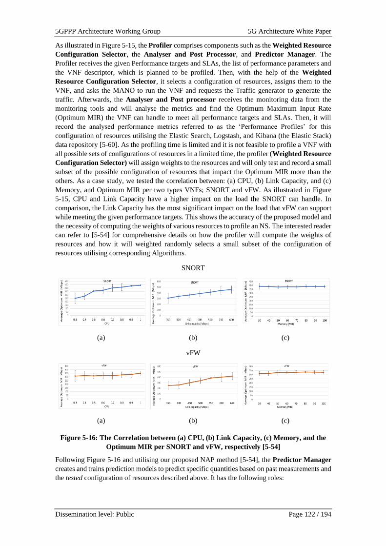
5GPPP Architecture Working Group 5G Architecture White Paper
Dissemination level: Public Page 122 / 194
As illustrated in Figure 5-15, the Profiler comprises components such as the Weighted Resource
Configuration Selector, the Analyser and Post Processor, and Predictor Manager. The
Profiler receives the given Performance targets and SLAs, the list of performance parameters and
the VNF descriptor, which is planned to be profiled. Then, with the help of the Weighted
Resource Configuration Selector, it selects a configuration of resources, assigns them to the
VNF, and asks the MANO to run the VNF and requests the Traffic generator to generate the
traffic. Afterwards, the Analyser and Post processor receives the monitoring data from the
monitoring tools and will analyse the metrics and find the Optimum Maximum Input Rate
(Optimum MIR) the VNF can handle to meet all performance targets and SLAs. Then, it will
record the analysed performance metrics referred to as the ‘Performance Profiles’ for this
configuration of resources utilising the Elastic Search, Logstash, and Kibana (the Elastic Stack)
data repository [5-60]. As the profiling time is limited and it is not feasible to profile a VNF with
all possible sets of configurations of resources in a limited time, the profiler (Weighted Resource
Configuration Selector) will assign weights to the resources and will only test and record a small
subset of the possible configuration of resources that impact the Optimum MIR more than the
others. As a case study, we tested the correlation between: (a) CPU, (b) Link Capacity, and (c)
Memory, and Optimum MIR per two types VNFs; SNORT and vFW. As illustrated in Figure
5-15, CPU and Link Capacity have a higher impact on the load the SNORT can handle. In
comparison, the Link Capacity has the most significant impact on the load that vFW can support
while meeting the given performance targets. This shows the accuracy of the proposed model and
the necessity of computing the weights of various resources to profile an NS. The interested reader
can refer to [5-54] for comprehensive details on how the profiler will compute the weights of
resources and how it will weighted randomly selects a small subset of the configuration of
resources utilising corresponding Algorithms.
SNORT
(a) (b) (c)
vFW
(a) (b) (c)
Figure 5-16: The Correlation between (a) CPU, (b) Link Capacity, (c) Memory, and the
Optimum MIR per SNORT and vFW, respectively [5-54]
Following Figure 5-16 and utilising our proposed NAP method [5-54], the Predictor Manager
creates and trains prediction models to predict specific quantities based on past measurements and
the tested configuration of resources described above. It has the following roles:
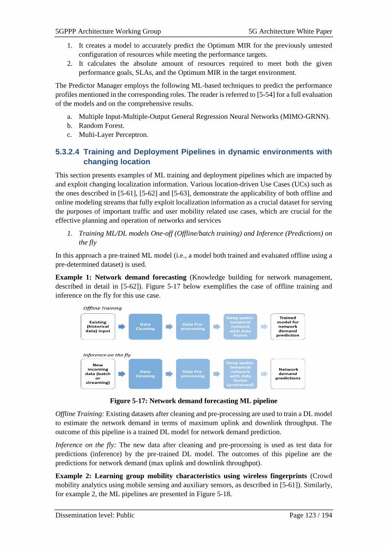
5GPPP Architecture Working Group 5G Architecture White Paper
Dissemination level: Public Page 123 / 194
1. It creates a model to accurately predict the Optimum MIR for the previously untested
configuration of resources while meeting the performance targets.
2. It calculates the absolute amount of resources required to meet both the given
performance goals, SLAs, and the Optimum MIR in the target environment.
The Predictor Manager employs the following ML-based techniques to predict the performance
profiles mentioned in the corresponding roles. The reader is referred to [5-54] for a full evaluation
of the models and on the comprehensive results.
a. Multiple Input-Multiple-Output General Regression Neural Networks (MIMO-GRNN).
b. Random Forest.
c. Multi-Layer Perceptron.
5.3.2.4 Training and Deployment Pipelines in dynamic environments with
changing location
This section presents examples of ML training and deployment pipelines which are impacted by
and exploit changing localization information. Various location-driven Use Cases (UCs) such as
the ones described in [5-61], [5-62] and [5-63], demonstrate the applicability of both offline and
online modeling streams that fully exploit localization information as a crucial dataset for serving
the purposes of important traffic and user mobility related use cases, which are crucial for the
effective planning and operation of networks and services
1. Training ML/DL models One-off (Offline/batch training) and Inference (Predictions) on
the fly
In this approach a pre-trained ML model (i.e., a model both trained and evaluated offline using a
pre-determined dataset) is used.
Example 1: Network demand forecasting (Knowledge building for network management,
described in detail in [5-62]). Figure 5-17 below exemplifies the case of offline training and
inference on the fly for this use case.
Figure 5-17: Network demand forecasting ML pipeline
Offline Training: Existing datasets after cleaning and pre-processing are used to train a DL model
to estimate the network demand in terms of maximum uplink and downlink throughput. The
outcome of this pipeline is a trained DL model for network demand prediction.
Inference on the fly: The new data after cleaning and pre-processing is used as test data for
predictions (inference) by the pre-trained DL model. The outcomes of this pipeline are the
predictions for network demand (max uplink and downlink throughput).
Example 2: Learning group mobility characteristics using wireless fingerprints (Crowd
mobility analytics using mobile sensing and auxiliary sensors, as described in [5-61]). Similarly,
for example 2, the ML pipelines are presented in Figure 5-18.
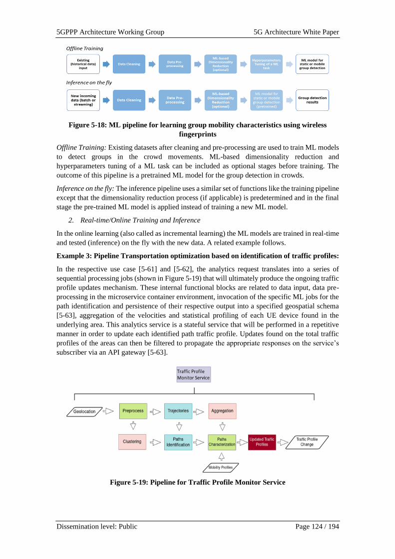
5GPPP Architecture Working Group 5G Architecture White Paper
Dissemination level: Public Page 124 / 194
Figure 5-18: ML pipeline for learning group mobility characteristics using wireless
fingerprints
Offline Training: Existing datasets after cleaning and pre-processing are used to train ML models
to detect groups in the crowd movements. ML-based dimensionality reduction and
hyperparameters tuning of a ML task can be included as optional stages before training. The
outcome of this pipeline is a pretrained ML model for the group detection in crowds.
Inference on the fly: The inference pipeline uses a similar set of functions like the training pipeline
except that the dimensionality reduction process (if applicable) is predetermined and in the final
stage the pre-trained ML model is applied instead of training a new ML model.
2. Real-time/Online Training and Inference
In the online learning (also called as incremental learning) the ML models are trained in real-time
and tested (inference) on the fly with the new data. A related example follows.
Example 3: Pipeline Transportation optimization based on identification of traffic profiles:
In the respective use case [5-61] and [5-62], the analytics request translates into a series of
sequential processing jobs (shown in Figure 5-19) that will ultimately produce the ongoing traffic
profile updates mechanism. These internal functional blocks are related to data input, data pre-
processing in the microservice container environment, invocation of the specific ML jobs for the
path identification and persistence of their respective output into a specified geospatial schema
[5-63], aggregation of the velocities and statistical profiling of each UE device found in the
underlying area. This analytics service is a stateful service that will be performed in a repetitive
manner in order to update each identified path traffic profile. Updates found on the total traffic
profiles of the areas can then be filtered to propagate the appropriate responses on the service’s
subscriber via an API gateway [5-63].
Figure 5-19: Pipeline for Traffic Profile Monitor Service
5GPPP Architecture Working Group 5G Architecture White Paper
Dissemination level: Public Page 125 / 194
5.4 Cloudification
The variety of vertical applications and services that current and future networks are expected to
serve require flexibility in the way such services are deployed. The move towards SBAs and
microservices, and the increasing importance of function deployment at the resource-constrained
edge that require lightweight deployments, make cloudification relevant in a 5G context. This
section presents a cloudification architectural overview starting with a generic discussion on the
integration of cloud native and container-based approaches (Section 5.4.1), following with how
they are managed and orchestrated at the edge (Section 5.4.2 and Section 5.4.3), and finally,
specific considerations in the use of containers for the deployment of 5G Cores and vertical
applications (Section 5.4.4). Table 5-6 presents a mapping of the features explained and projects
that deal with them, as well as additional references for the interested reader.
Table 5-6: Cloudification features
Cloudification feature 5G PPP Project Additional Reference
Standards-based cloudification 5G-VINNI [5-13] [5-16]
M&O of containers in ETSI MEC 5G-CARMEN [5-83]
Service Function Virtualization FUDGE-5G [5-79]
Automated deployment of containerized 5G
Core network
5G-HEART [5-64] [5-65]
5.4.1 Standards and architecture for 5G Cloudification
It has become apparent that VNF orchestration is being enhanced by the use of Cloud-based
Network Functions (CNF) often implemented using Containers [5-16]. Considering an
architecture where Kubernetes is used as the orchestration engine for CNFs, there is the potential
need for a dual mode NFVI, to enable VNF and CNF orchestration to co-exist. This raises a
number of new challenges for MANO, discussed extensively in ETSI GS NFV-EVE 004 [5-73].
The architecture based its integration of CNFs and Kubernetes on principles taken from Standards.
There are clear requirements related to Container Management and Orchestration, highlighted in
the ETSI NFV specifications, which have been adopted to guarantee an ETSI NFV Compliance:
• ETSI GS NFV-IFA 010: “Management and Orchestration; Functional requirements
specification” [5-74]
• ETSI GS NFV-IFA 036: “Specification of requirements for the management and
orchestration of container cluster nodes” [5-75]
• ETSI GS NFV-IFA 040: “Requirements for service interfaces and object model for OS
container management and orchestration specification” [5-76]
Additional high-level requirements are detailed in [5-16], to be taken into consideration for
including CNF capabilities in a Network Slice:
• Requirements on CISM/CIR (Container Infrastructure Service Management/Container
Image Registry) exposed service interfaces
• Requirements on M&O of virtualised containers
• CISM exposure of services to NFVO, these services being:
o OS container workload management
o OS container compute management
o OS container storage management
o OS container network management

5GPPP Architecture Working Group 5G Architecture White Paper
Dissemination level: Public Page 126 / 194
o OS container configuration management.
Container-based implementation is now being demonstrated in various 5G PPP projects (e.g., [5-
18]).
The above standards enable the orchestration of VNFs and CNFs to the edge resources following
the same functional architecture as for centralised VNFs. However, in terms of deployment, the
right trade-off between centralization and distribution needs to be analysed. In fact, there are two
extremes for Edge Cloud deployment that frame the spectrum of options - these being centralized
and distributed. Reference [5-16] considers the impact of the different levels of functionality and
orchestration capability that can be deployed in each scenario and varying options in between.
Figure 5-20 shows five possible levels of variance between a ‘Fully centralised’ and ‘fully
distributed’ model.
Where Edge Cloud is centralised, this offers support for eMBB services from a relatively low
number of physical sites. As the edge cloud becomes more distributed, the need for more
infrastructure and more physical edge locations increases. However, where an application
demands low latency or some degree of application processing to be performed very close to the
device, a distributed model becomes essential for the effective operation of the application. The
operator must balance between the require SLA of the application and the business case impact
of supporting greater or fewer physical edge instances.
This in turn has an impact on the relative levels of functional capability that should be supported
in each location, as shown in Figure 5-20.
Figure 5-20: Edge cloud deployment options
A number of Edge Cloud models have been deployed ([5-13], [5-18]), also described in the Radio
and Edge chapter of this white paper, and different implementation options for Edge Orchestration
layers have also been discussed, as per Figure 5-20. Note that within the figure, the App Manager,
Edge Resource Orchestration, Edge Virtualization and Edge Hardware could be owned and
operated by the Network Operator, a 3rd Party application provider or a Public Cloud Provider,
with all options potentially co-existing within a single network or even a single site.

5GPPP Architecture Working Group 5G Architecture White Paper
Dissemination level: Public Page 127 / 194
5.4.2 Containers and ETSI MEC
This section presents the management and orchestration architecture for an edge cloud when
applied to an ETSI MEC-based edge that executes automotive use cases.
Figure 5-21: Cloud-native design overview of the 5G Edge Orchestration Platform in an
ETSI MEC context [5-82]
The design of the 5G edge orchestration platform follows the cloud native principles, which
means that all functional elements are implemented as container-based pieces of software
rendering a highly modular design. The modularity enables a mix and match of different open
source software solutions. For instance, the NFV-SO is based on existing ETSI’s Open Source
MANO (OSM). On the other hand, interfaces between orchestration components (i.e., Or-Or, Lo-
Lo, Or-Lo, Mv1, and NFV-LO - Edge Controller, as presented in Figure 5-21) are implemented
following the SBA. These interfaces use REST-based communication. Furthermore, the
Kubernetes (k8s) platform was leveraged for the purpose of developing architecture elements. As
depicted in Figure 5-21, the MEAO & NFV-LO components of the Edge Orchestration System
are implemented as separate containers within a k8s Pod, thereby managing the MEC applications
and services via a message broker. Similarly, the MEC applications and services are implemented
as container applications in different k8s Pods within each MEC host. The on-boarding procedure
practically entails the preparation of Docker images for the MEC applications and services on all
required edges. Furthermore, the containerized applications consume MEC Value-added Services
(VASs) (e.g., geolocation services, Radio Network Information Service (RNIS), etc.) to enhance
their operation. Each Pod with an instance of a CCAM service application can be equipped with
one or multiple customized network interfaces, such as for service-based communication and data
sharing with other service instances, or for fast data plane I/O and associated low-latency
communication with other application instances or service clients. For enabling edge network
slices, the MEC applications and services are grouped in different namespaces to ensure isolation
for performance reasons. Moreover, a monitoring service comprising Prometheus and Grafana
are configured in a separate monitoring namespace for collecting real-time metrics and usage
statistics for all MEC hosts belonging to the edge domain and to be consumed by the orchestration
5GPPP Architecture Working Group 5G Architecture White Paper
Dissemination level: Public Page 128 / 194
entities. For the management and orchestration of the MEC applications/service an Edge
Controller is configured a separate namespace running as k8s Pod.
The NFV Service Orchestrator (SO) can select orchestrated edge resources according to a
deployment strategy and enforce the instantiation of an image of the requested CAM service at
the selected edge through an NFV Local Orchestrator (NFV-LO). For a large-scale deployment,
the NFV-SO can request multiple edge resources to deploy such service.
The NFV-LO and the MEAO treat the service deployment per its description in a Network Slice
Template and admit the enforcement of the service through an Edge Controller function. The
Edge Controller handles multiple distributed servers in one or multiple edge clouds, which are
denoted as worker nodes that provide the local hardware resources for the deployment of service
instances. The federation interfaces are sketched at the NFV-SO and the NFV-LO level to
accomplish roaming and cross-border scenarios. The additional roles of the Edge Controller
include: i) slice management, ii) connectivity management, iii) network programming for traffic
steering, as well as iv) interfacing with the 5G Core network for receiving client mobility related
event notifications, which may require re-configuration of services and traffic steering policies
within or between local edge clouds. In case more mobile clients access edge services from a
certain location, the orchestration system and the Edge Controller need to provide and re-
configure the associated local edge resources accordingly. To provide a mobile access to the
topologically closest edge service, and to distribute the load properly between all edge resources
utilized for a service, the transfer of a client’s session state might be needed, from a service
instance on one edge to an instance on another edge. Whereas the Edge Controller is in charge of
monitoring and controlling the edge worker node underneath, arrangement, deployment and
management of service instances beyond the scope of an Edge Controller is left to the
orchestration layers, to which the Edge Controller exposes an Open API.
5.4.3 Service Function Virtualization
The cloudification of the telco landscape is ongoing at a tremendous pace and there have been
significant changes done to key blocks of the system architecture. For instance, starting with
Release 14 in 3GPP a paradigm shift was induced adopting cloud principles, which resulted in
the definition of a SBA for the 5G system. In essence, the majority of 5G Core (5GC) Network
Functions (NFs) embed service-based interfaces (SBI) and the communication pattern has been
upgraded to the stateless application protocol HTTP/2 SBI-enabled NFs. This enabled the
realisation of these 5GC NFs as microservices following the 12-factor app methodology [5-77]
allowing the adoption of cloud concepts to meet demand, to increase availability and reliability
as well as flexibility. This cloudification of the 5GC poses the question on introducing
standardised cloud native methodologies to provision microservices through well-defined APIs.
While ETSI MANO released their first take on a reference architecture for microservices [5-76],
the standard landscape on descriptor definitions, programmable and open APIs enabling the
provisioning and lifecycle management are rather scattered with limited applicability to the need
of the telco world, which has a rather strong notion of geographical or topological-driven
decisions when it comes to the distribution and instantiation of 5GC NF instances across the
network. Based on this observation, the usage of Kubernetes as the de-facto implementation for
microservice orchestration may have limited application in some contexts, as it may neither
support fine-grained (down to the service instance level) location-aware lifecycle management or
a (across locations) federated policy-driven SLA assurance approach. In these cases, there is an
attempt to take on this challenge and propose an evolution of NFV, called Service Function
Virtualisation (SFV). It follows an information model, which is derived from Service Function
Chaining (SFC) in its terminology. This model, illustrated in Figure 5-22, is categorised into
orchestration, lifecycle management, routing and packaging.
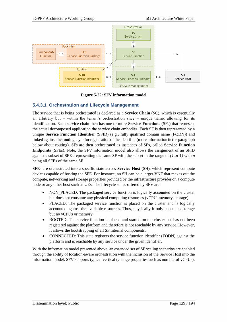
5GPPP Architecture Working Group 5G Architecture White Paper
Dissemination level: Public Page 129 / 194
Figure 5-22: SFV information model
5.4.3.1 Orchestration and Lifecycle Management
The service that is being orchestrated is declared as a Service Chain (SC), which is essentially
an arbitrary but – within the tenant’s orchestration slice – unique name, allowing for its
identification. Each service chain then has one or more Service Functions (SFs) that represent
the actual decomposed application the service chain embodies. Each SF is then represented by a
unique Service Function Identifier (SFID) (e.g., fully qualified domain name (FQDN)) and
linked against the routing layer for registration of the identifier (more information in the paragraph
below about routing). SFs are then orchestrated as instances of SFs, called Service Function
Endpoints (SFEs). Note, the SFV information model also allows the assignment of an SFID
against a subset of SFEs representing the same SF with the subset in the range of {1..n-1} with n
being all SFEs of the same SF.
SFEs are orchestrated into a specific state across Service Host (SH), which represent compute
devices capable of hosting the SFE. For instance, an SH can be a larger VNF that maxes out the
compute, networking and storage properties provided by the infrastructure provider on a compute
node or any other host such as UEs. The lifecycle states offered by SFV are:
• NON_PLACED: The packaged service function is logically accounted on the cluster
but does not consume any physical computing resources (vCPU, memory, storage).
• PLACED: The packaged service function is placed on the cluster and is logically
accounted against the available resources. Thus, physically it only consumes storage
but no vCPUs or memory.
• BOOTED: The service function is placed and started on the cluster but has not been
registered against the platform and therefore is not reachable by any service. However,
it allows the bootstrapping of all SF internal components.
• CONNECTED: This state registers the service function identifier (FQDN) against the
platform and is reachable by any service under the given identifier.
With the information model presented above, an extended set of SF scaling scenarios are enabled
through the ability of location-aware orchestration with the inclusion of the Service Host into the
information model. SFV supports typical vertical (change properties such as number of vCPUs),
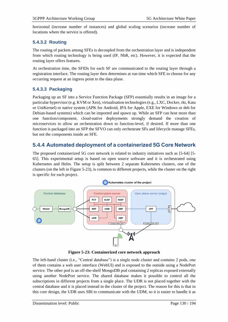
5GPPP Architecture Working Group 5G Architecture White Paper
Dissemination level: Public Page 130 / 194
horizontal (increase number of instances) and global scaling scenarios (increase number of
locations where the service is offered).
5.4.3.2 Routing
The routing of packets among SFEs is decoupled from the orchestration layer and is independent
from which routing technology is being used (IP, NbR, etc). However, it is expected that the
routing layer offers features.
At orchestration time, the SFIDs for each SF are communicated to the routing layer through a
registration interface. The routing layer then determines at run time which SFE to choose for any
occurring request at an ingress point to the data plane.
5.4.3.3 Packaging
Packaging up an SF into a Service Function Package (SFP) essentially results in an image for a
particular hypervisor (e.g. KVM or Xen), virtualisation technologies (e.g., LXC, Docker, rkt, Kata
or UniKernel) or native system (APK for Android, IPA for Apple, EXE for Windows or deb for
Debian-based systems) which can be imported and spawn up. While an SFP can host more than
one function/component, cloud-native deployments strongly demand the creation of
microservices to allow an orchestration down to function-level, if desired. If more than one
function is packaged into an SFP the SFVO can only orchestrate SFs and lifecycle manage SFEs,
but not the components inside an SFE.
5.4.4 Automated deployment of a containerized 5G Core Network
The proposed containerized 5G core network is related to industry initiatives such as [5-64] [5-
65]. This experimental setup is based on open source software and it is orchestrated using
Kubernetes and Helm. The setup is split between 2 separate Kubernetes clusters, one of the
clusters (on the left in Figure 5-23), is common to different projects, while the cluster on the right
is specific for each project.
Figure 5-23: Containerized core network approach
The left-hand cluster (i.e., “Central database”) is a single node cluster and contains 2 pods, one
of them contains a web user interface (WebUI) and is exposed to the outside using a NodePort
service. The other pod is an off-the-shelf MongoDB pod containing 2 replicas exposed externally
using another NodePort service. The shared database makes it possible to control all the
subscriptions in different projects from a single place. The UDR is not placed together with the
central database and it is placed instead in the cluster of the project. The reason for this is that in
this core design, the UDR uses SBI to communicate with the UDM, so it is easier to handle it as
5GPPP Architecture Working Group 5G Architecture White Paper
Dissemination level: Public Page 131 / 194
part of the internal Kubernetes services. On top of that, other functions like the PCF and the NRF
bypass the UDR and access the MongoDB instance directly, so MongoDB needs to be exposed
in either case.
The right hand cluster (i.e. “Project cluster”) is a 2- (or more) node cluster. In its minimal setup,
there is a control plane node responsible for 5G control plane tasks and doubles as the Kubernetes
master. The other nodes are responsible for user plane tasks and can be placed next to the control
plane node or in edge servers to enable MEC. The internal networks (SBI between control plane
functions and N4 between the SMF and the UPF) are handled by simple Kubernetes services. The
PCF, NRF and UDR can reach the MongoDB in the central database by accessing the NodePort
in the central database. For the remaining interfaces Multus is used to create secondary interfaces.
The AMF gets a secondary interface with a fixed IP address in the core access network which is
accessible for the gNB, and it is used for NGAP/N2. The UPF gets 2 secondary interfaces, one in
the core access network (this doesn’t need a fixed IP address) for GTP-U/N3 and another in the
SGI network for the N6 interface and functions as the default route for all the traffic coming from
the UEs.
The configuration of the Kubernetes cluster, the configuration of the gNB and registering UEs in
the database remain as manual processes. Conversely, the configuration of the 5G core network
is automated using Helm charts. This allows the user to configure the secondary interfaces, the
external database, supported slices and more from a single file, and deploy the whole core with a
single command.
5.5 Monitoring and Data Management
Flexible and scalable monitoring systems are fundamental enablers for the automated
orchestration of 5G networks, enabling the collection, distribution and storage of metrics and
KPIs that feed the management and orchestration logic. This section presents the frameworks
proposed by some 5G PPP projects, focusing on specific aspects of monitoring in 5G networks.
The software-based monitoring solution presented in Section 5.5.1 addresses the dynamic nature
of 5G infrastructures, introducing a flexible monitoring framework that instantiates and re-
configures analysers and measurement probes during the network operation. The Vertical-
oriented monitoring system described in Section 5.5.2 focuses on the monitoring of network KPIs,
application metrics and logs for vertical service instances deployed in the 5G network, as input
for their SLA management. Finally, Section 5.5.3 presents a data aggregation framework for the
unified collection, distribution, storage, analysis and visualization of monitoring data generated
from heterogeneous data sources. Table 5-7 summarizes the monitoring and data management
aspects analysed in this section and their mapping with the 5G PPP projects where they have been
investigated.
Table 5-7: Monitoring and data management features
Monitoring feature 5G PPP Project Additional Reference
Integrated software-based monitoring
framework for 5G networks
5G-HEART [5-42], [5-43]
Vertical-oriented monitoring 5Growth [5-44], [5-45]
Monitoring data aggregation 5Growth [5-46]
5GPPP Architecture Working Group 5G Architecture White Paper
Dissemination level: Public Page 132 / 194
5.5.1 Integrated software-based monitoring framework for 5G
networks
A flexibly re-configurable monitoring framework is needed for dynamic software-based network
architectures. In order to guarantee visibility into the network during and after architectural
changes performed on the fly to adapt the system to the temporally changing requirements, the
monitoring framework must be able to adapt as well. For this purpose, a passive monitoring
approach based on distributed software probes measuring the traffic in selected locations within
the network architecture, and a centralised analysis component processing the collected
measurement data and managing the measurement probes, can be used. This approach is well
suited for integration to a constantly changing monitoring environment such as a 5G network,
where the software-based VNF and service function chains are dynamically activated, re-
configured and deactivated during different phases of the network slice life cycle. Based on the
monitoring needs of the different types of network slices and services running on top of these
slices, a varying amount of software probes can be placed to different virtualised network
functions and interfaces to achieve the desired monitoring granularity.
As mentioned above, the monitoring framework comprises of two different types of software
components, i.e., measurement probes and analysers. The analyser component is responsible for
gathering, analysing and visualising the results, but it is not part of the measurement path and
requires only network connection to one of the deployed measurements probes. It is also possible
to use the analyser component only for the gathering of the measurement data from the probes
and forward it to external databases for further analysis and visualisation. The measurement
probes are installed and run in the network functions or nodes that serve as endpoints of the
measured network path. The data traffic passes through the probes, which perform passive packet-
by-packet measurements and log the results in the form of quantitative network KPI or QoS
metrics.
By changing the placement of the analyser components and measurement probes, the monitoring
framework can be optimised to capture the performance of a single user or service running in the
network or to provide an overview of the performance of the whole network or a network segment.
As both the analyser and measurement probe components are fully software-based, the
measurement framework can be reconfigured at any time during network operation. Moreover,
by preinstalling measurement probes to the deployed network functions, they can be activated,
e.g., based on the high-level monitoring results and user for automatic troubleshooting when E2E
network performance issues are detected. Some examples of analyser and measurement probe
placement for the monitoring of vertical trial services can be found from [5-42] and [5-43].
When separate analyser and measurement probe instances are configured for the downlink and
uplink directions of the monitored network path, accurate one-way delays can be included in the
set of captured network KPIs. In such configuration, there is an additional requirement for
accurate time synchronisation between all analyser and measurement probe components for time
stamping purpose. For 5G network latencies, there are basically two commonly available
synchronisation methods providing the required accuracy, i.e., precision time protocol (PTP) or
global positioning system (GPS) –based time. Within in single network domain, a common PTP
server machine providing the reference time to all network functions with low delay and jitter is
a possible approach. For a measurement paths spanning over multiple network domains, a GPS-
based synchronisation approach is usually the only viable option.
5.5.2 Vertical oriented monitoring
The Vertical-oriented Monitoring System (VoMS), integrated with the management and
orchestration stack, enables the monitoring of the performance of vertical services deployed in
5GPPP Architecture Working Group 5G Architecture White Paper
Dissemination level: Public Page 133 / 194
5G infrastructures. These performance data can be used as input for different kinds of
orchestration decisions that combine network KPIs with service-level metrics. The VoMS is a
conglomerate of the software components and logical processes, combined under a single
architecture, that serves the purpose to observe and gather logs and metrics from the vertical
application’s workloads.
The VoMS is responsible for the following functionalities:
• Collecting VNF logs and metrics;
• Holding, tracking and providing metrics and logs to other orchestration components;
• Measuring KPIs.
The VoMS architecture and its interaction with the other orchestration components is shown in
Figure 5-24, showing a potential implementation in terms of software building blocks.
The Monitoring Manager, integrated in the overall Service Orchestrator, triggers activation and
configuration of monitoring jobs during the service lifecycle. In particular, it is the component in
charge of translating requests for high-level monitoring jobs referred to NFV service instances
into low-level requests related to the monitoring of resource-level parameters, identifying the
particular metrics to be collected by the VoMS.
In the example reported in the picture, the alerts generated from the VoMS feed the SLA
Manager, which handles the procedures for SLA assurance at the service orchestration level (e.g.,
triggering automated scaling actions to deal with underperforming conditions). However, the data
collected by the VoMS can be consumed by a variety of additional orchestration entities,
including AI/ML platforms, forecasting platforms, etc. The SLA Manager keeps track of KPIs or
real-time measurements mirroring the load of the resources and interacts with the VoMS
following a subscription-notification paradigm, to promptly react to any alert associated with the
target monitoring data.
The VoMS architecture consists of three functional blocks: the Config Manager, the Metrics block
and the Logs block. The Config Manager is responsible for coordinating the configuration of the
various VoMS components when new monitoring jobs are dynamically activated or modified
during the lifecycle of vertical services and related network slices. In particular, the Config
Manager triggers the installation and configuration of monitoring probes in the remote Virtual
Machines (VMs) running the vertical service applications or the virtual network functions to be
monitored. The Metrics block and the Logs block are responsible for the collection, storage,
visualization and processing of metrics and logs respectively, including the generation of alerts.
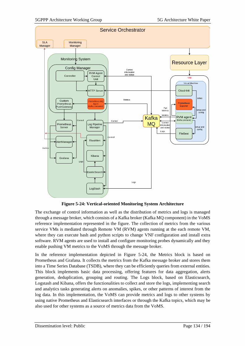
5GPPP Architecture Working Group 5G Architecture White Paper
Dissemination level: Public Page 134 / 194
Figure 5-24: Vertical-oriented Monitoring System Architecture
The exchange of control information as well as the distribution of metrics and logs is managed
through a message broker, which consists of a Kafka broker (Kafka MQ component) in the VoMS
reference implementation represented in the figure. The collection of metrics from the various
service VMs is mediated through Remote VM (RVM) agents running at the each remote VM,
where they can execute bash and python scripts to change VNF configuration and install extra
software. RVM agents are used to install and configure monitoring probes dynamically and they
enable pushing VM metrics to the VoMS through the message broker.
In the reference implementation depicted in Figure 5-24, the Metrics block is based on
Prometheus and Grafana. It collects the metrics from the Kafka message broker and stores them
into a Time Series Database (TSDB), where they can be efficiently queries from external entities.
This block implements basic data processing, offering features for data aggregation, alerts
generation, deduplication, grouping and routing. The Logs block, based on Elasticsearch,
Logstash and Kibana, offers the functionalities to collect and store the logs, implementing search
and analytics tasks generating alerts on anomalies, spikes, or other patterns of interest from the
log data. In this implementation, the VoMS can provide metrics and logs to other systems by
using native Prometheus and Elasticsearch interfaces or through the Kafka topics, which may be
also used for other systems as a source of metrics data from the VoMS.
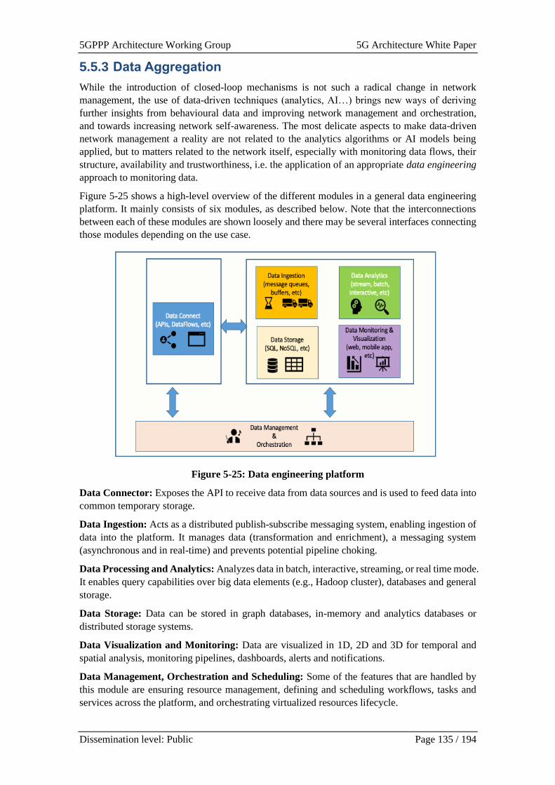
5GPPP Architecture Working Group 5G Architecture White Paper
Dissemination level: Public Page 135 / 194
5.5.3 Data Aggregation
While the introduction of closed-loop mechanisms is not such a radical change in network
management, the use of data-driven techniques (analytics, AI…) brings new ways of deriving
further insights from behavioural data and improving network management and orchestration,
and towards increasing network self-awareness. The most delicate aspects to make data-driven
network management a reality are not related to the analytics algorithms or AI models being
applied, but to matters related to the network itself, especially with monitoring data flows, their
structure, availability and trustworthiness, i.e. the application of an appropriate data engineering
approach to monitoring data.
Figure 5-25 shows a high-level overview of the different modules in a general data engineering
platform. It mainly consists of six modules, as described below. Note that the interconnections
between each of these modules are shown loosely and there may be several interfaces connecting
those modules depending on the use case.
Figure 5-25: Data engineering platform
Data Connector: Exposes the API to receive data from data sources and is used to feed data into
common temporary storage.
Data Ingestion: Acts as a distributed publish-subscribe messaging system, enabling ingestion of
data into the platform. It manages data (transformation and enrichment), a messaging system
(asynchronous and in real-time) and prevents potential pipeline choking.
Data Processing and Analytics: Analyzes data in batch, interactive, streaming, or real time mode.
It enables query capabilities over big data elements (e.g., Hadoop cluster), databases and general
storage.
Data Storage: Data can be stored in graph databases, in-memory and analytics databases or
distributed storage systems.
Data Visualization and Monitoring: Data are visualized in 1D, 2D and 3D for temporal and
spatial analysis, monitoring pipelines, dashboards, alerts and notifications.
Data Management, Orchestration and Scheduling: Some of the features that are handled by
this module are ensuring resource management, defining and scheduling workflows, tasks and
services across the platform, and orchestrating virtualized resources lifecycle.
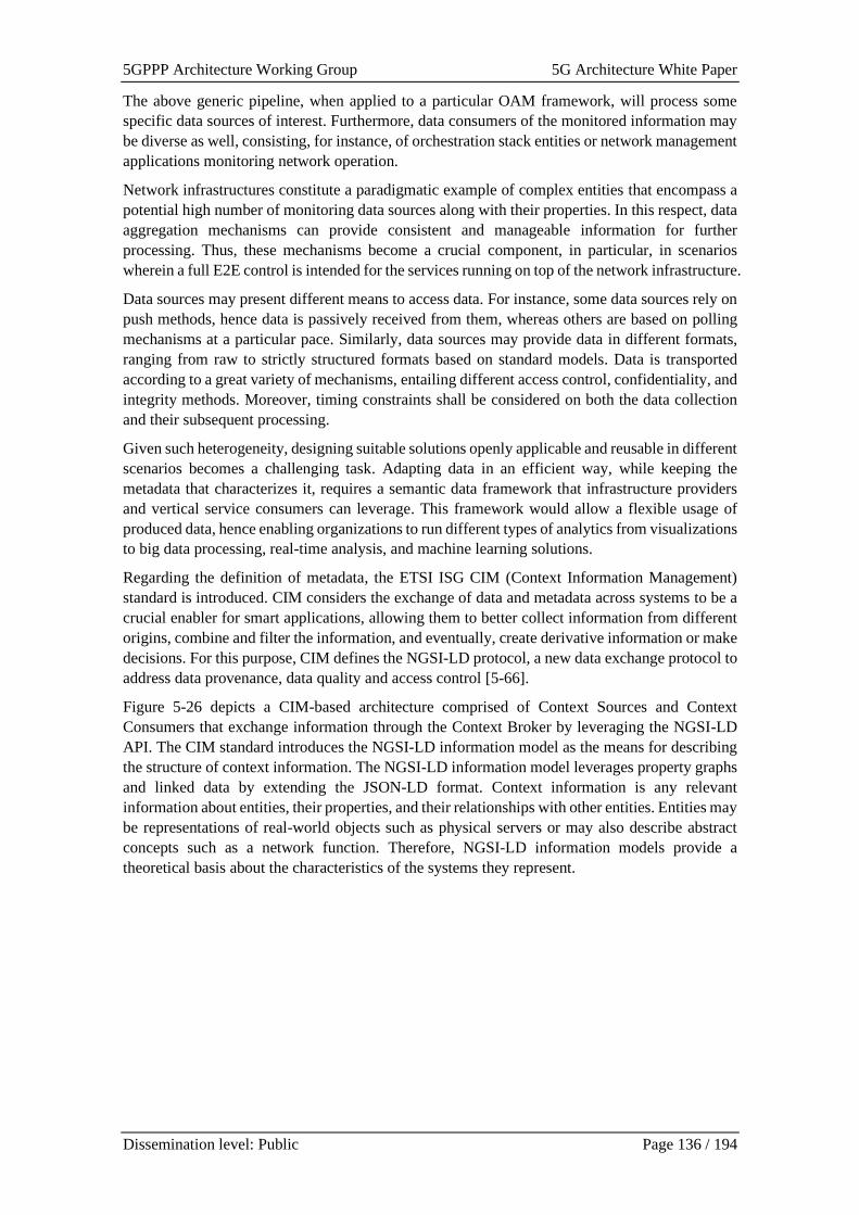
5GPPP Architecture Working Group 5G Architecture White Paper
Dissemination level: Public Page 136 / 194
The above generic pipeline, when applied to a particular OAM framework, will process some
specific data sources of interest. Furthermore, data consumers of the monitored information may
be diverse as well, consisting, for instance, of orchestration stack entities or network management
applications monitoring network operation.
Network infrastructures constitute a paradigmatic example of complex entities that encompass a
potential high number of monitoring data sources along with their properties. In this respect, data
aggregation mechanisms can provide consistent and manageable information for further
processing. Thus, these mechanisms become a crucial component, in particular, in scenarios
wherein a full E2E control is intended for the services running on top of the network infrastructure.
Data sources may present different means to access data. For instance, some data sources rely on
push methods, hence data is passively received from them, whereas others are based on polling
mechanisms at a particular pace. Similarly, data sources may provide data in different formats,
ranging from raw to strictly structured formats based on standard models. Data is transported
according to a great variety of mechanisms, entailing different access control, confidentiality, and
integrity methods. Moreover, timing constraints shall be considered on both the data collection
and their subsequent processing.
Given such heterogeneity, designing suitable solutions openly applicable and reusable in different
scenarios becomes a challenging task. Adapting data in an efficient way, while keeping the
metadata that characterizes it, requires a semantic data framework that infrastructure providers
and vertical service consumers can leverage. This framework would allow a flexible usage of
produced data, hence enabling organizations to run different types of analytics from visualizations
to big data processing, real-time analysis, and machine learning solutions.
Regarding the definition of metadata, the ETSI ISG CIM (Context Information Management)
standard is introduced. CIM considers the exchange of data and metadata across systems to be a
crucial enabler for smart applications, allowing them to better collect information from different
origins, combine and filter the information, and eventually, create derivative information or make
decisions. For this purpose, CIM defines the NGSI-LD protocol, a new data exchange protocol to
address data provenance, data quality and access control [5-66].
Figure 5-26 depicts a CIM-based architecture comprised of Context Sources and Context
Consumers that exchange information through the Context Broker by leveraging the NGSI-LD
API. The CIM standard introduces the NGSI-LD information model as the means for describing
the structure of context information. The NGSI-LD information model leverages property graphs
and linked data by extending the JSON-LD format. Context information is any relevant
information about entities, their properties, and their relationships with other entities. Entities may
be representations of real-world objects such as physical servers or may also describe abstract
concepts such as a network function. Therefore, NGSI-LD information models provide a
theoretical basis about the characteristics of the systems they represent.
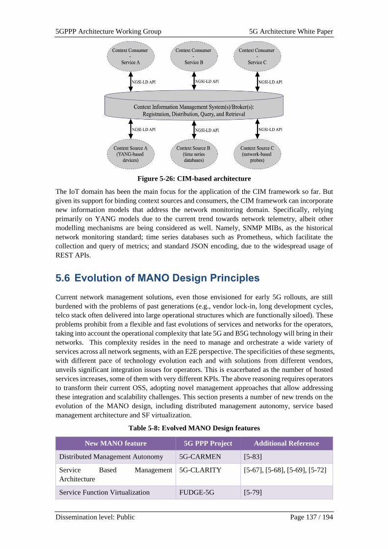
5GPPP Architecture Working Group 5G Architecture White Paper
Dissemination level: Public Page 137 / 194
Figure 5-26: CIM-based architecture
The IoT domain has been the main focus for the application of the CIM framework so far. But
given its support for binding context sources and consumers, the CIM framework can incorporate
new information models that address the network monitoring domain. Specifically, relying
primarily on YANG models due to the current trend towards network telemetry, albeit other
modelling mechanisms are being considered as well. Namely, SNMP MIBs, as the historical
network monitoring standard; time series databases such as Prometheus, which facilitate the
collection and query of metrics; and standard JSON encoding, due to the widespread usage of
REST APIs.
5.6 Evolution of MANO Design Principles
Current network management solutions, even those envisioned for early 5G rollouts, are still
burdened with the problems of past generations (e.g., vendor lock-in, long development cycles,
telco stack often delivered into large operational structures which are functionally siloed). These
problems prohibit from a flexible and fast evolutions of services and networks for the operators,
taking into account the operational complexity that late 5G and B5G technology will bring in their
networks. This complexity resides in the need to manage and orchestrate a wide variety of
services across all network segments, with an E2E perspective. The specificities of these segments,
with different pace of technology evolution each and with solutions from different vendors,
unveils significant integration issues for operators. This is exacerbated as the number of hosted
services increases, some of them with very different KPIs. The above reasoning requires operators
to transform their current OSS, adopting novel management approaches that allow addressing
these integration and scalability challenges. This section presents a number of new trends on the
evolution of the MANO design, including distributed management autonomy, service based
management architecture and SF virtualization.
Table 5-8: Evolved MANO Design features
New MANO feature 5G PPP Project Additional Reference
Distributed Management Autonomy 5G-CARMEN [5-83]
Service Based Management
Architecture
5G-CLARITY [5-67], [5-68], [5-69], [5-72]
Service Function Virtualization FUDGE-5G [5-79]
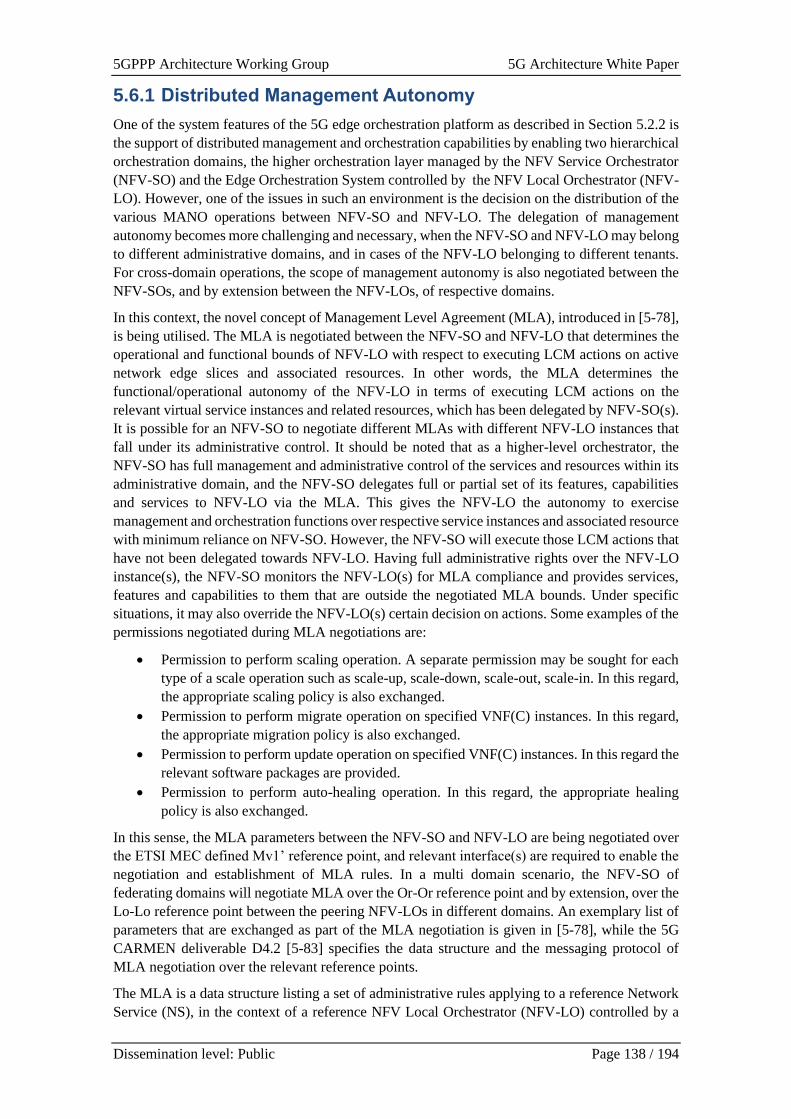
5GPPP Architecture Working Group 5G Architecture White Paper
Dissemination level: Public Page 138 / 194
5.6.1 Distributed Management Autonomy
One of the system features of the 5G edge orchestration platform as described in Section 5.2.2 is
the support of distributed management and orchestration capabilities by enabling two hierarchical
orchestration domains, the higher orchestration layer managed by the NFV Service Orchestrator
(NFV-SO) and the Edge Orchestration System controlled by the NFV Local Orchestrator (NFV-
LO). However, one of the issues in such an environment is the decision on the distribution of the
various MANO operations between NFV-SO and NFV-LO. The delegation of management
autonomy becomes more challenging and necessary, when the NFV-SO and NFV-LO may belong
to different administrative domains, and in cases of the NFV-LO belonging to different tenants.
For cross-domain operations, the scope of management autonomy is also negotiated between the
NFV-SOs, and by extension between the NFV-LOs, of respective domains.
In this context, the novel concept of Management Level Agreement (MLA), introduced in [5-78],
is being utilised. The MLA is negotiated between the NFV-SO and NFV-LO that determines the
operational and functional bounds of NFV-LO with respect to executing LCM actions on active
network edge slices and associated resources. In other words, the MLA determines the
functional/operational autonomy of the NFV-LO in terms of executing LCM actions on the
relevant virtual service instances and related resources, which has been delegated by NFV-SO(s).
It is possible for an NFV-SO to negotiate different MLAs with different NFV-LO instances that
fall under its administrative control. It should be noted that as a higher-level orchestrator, the
NFV-SO has full management and administrative control of the services and resources within its
administrative domain, and the NFV-SO delegates full or partial set of its features, capabilities
and services to NFV-LO via the MLA. This gives the NFV-LO the autonomy to exercise
management and orchestration functions over respective service instances and associated resource
with minimum reliance on NFV-SO. However, the NFV-SO will execute those LCM actions that
have not been delegated towards NFV-LO. Having full administrative rights over the NFV-LO
instance(s), the NFV-SO monitors the NFV-LO(s) for MLA compliance and provides services,
features and capabilities to them that are outside the negotiated MLA bounds. Under specific
situations, it may also override the NFV-LO(s) certain decision on actions. Some examples of the
permissions negotiated during MLA negotiations are:
• Permission to perform scaling operation. A separate permission may be sought for each
type of a scale operation such as scale-up, scale-down, scale-out, scale-in. In this regard,
the appropriate scaling policy is also exchanged.
• Permission to perform migrate operation on specified VNF(C) instances. In this regard,
the appropriate migration policy is also exchanged.
• Permission to perform update operation on specified VNF(C) instances. In this regard the
relevant software packages are provided.
• Permission to perform auto-healing operation. In this regard, the appropriate healing
policy is also exchanged.
In this sense, the MLA parameters between the NFV-SO and NFV-LO are being negotiated over
the ETSI MEC defined Mv1’ reference point, and relevant interface(s) are required to enable the
negotiation and establishment of MLA rules. In a multi domain scenario, the NFV-SO of
federating domains will negotiate MLA over the Or-Or reference point and by extension, over the
Lo-Lo reference point between the peering NFV-LOs in different domains. An exemplary list of
parameters that are exchanged as part of the MLA negotiation is given in [5-78], while the 5G
CARMEN deliverable D4.2 [5-83] specifies the data structure and the messaging protocol of
MLA negotiation over the relevant reference points.
The MLA is a data structure listing a set of administrative rules applying to a reference Network
Service (NS), in the context of a reference NFV Local Orchestrator (NFV-LO) controlled by a
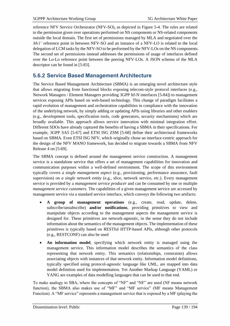
5GPPP Architecture Working Group 5G Architecture White Paper
Dissemination level: Public Page 139 / 194
reference NFV Service Orchestrator (NFV-SO), as depicted in Figure 5-4. The rules are related
to the permission given over operations performed on NS components or NS-related components
outside the local domain. The first set of permissions managed by MLA and negotiated over the
Mv1’ reference point in between NFV-SO and an instance of a NFV-LO is related to the local
delegation of LCM tasks by the NFV-SO to be performed by the NFV-LOs on the NS components.
The second set of permissions instead addresses the permissions of usage of interfaces defined
over the Lo-Lo reference point between the peering NFV-LOs. A JSON schema of the MLA
descriptor can be found in [5-83].
5.6.2 Service Based Management Architecture
The Service Based Management Architecture (SBMA) is an emerging novel architecture style
that allows migrating from functional blocks exposing telecom-style protocol interfaces (e.g.,
Network Managers / Element Managers providing 3GPP Itf-N interfaces [5-84]) to management
services exposing APIs based on web-based technology. This change of paradigm facilitates a
rapid evolution of management and orchestration capabilities in compliance with the innovation
of the underlying network, by simply adding or updating APIs using libraries and other enablers
(e.g., development tools, specification tools, code generators, security mechanisms) which are
broadly available. This approach allows service innovation with minimal integration effort.
Different SDOs have already captured the benefits of having a SBMA in their specifications. For
example, 3GPP SA5 [5-67] and ETSI ISG ZSM [5-68] define their architectural frameworks
based on SBMA. Even ETSI ISG NFV, which originally chose an interface-centric approach for
the design of the NFV MANO framework, has decided to migrate towards a SBMA from NFV
Release 4 on [5-69].
The SBMA concept is defined around the management service construction. A management
service is a standalone service that offers a set of management capabilities for innovation and
communication purposes within a well-defined environment. The scope of this environment
typically covers a single management aspect (e.g., provisioning, performance assurance, fault
supervision) on a single network entity (e.g., slice, network service, etc.). Every management
service is provided by a management service producer and can be consumed by one or multiple
management service customers. The capabilities of a given management service are accessed by
management service via a standard service interface, which conveys the following two artifacts:
• A group of management operations (e.g., create, read, update, delete,
subscribe/unsubscribe) and/or notifications, providing primitives to view and
manipulate objects according to the management aspects the management service is
designed for. These primitives are network-agnostic, in the sense they do not include
information about the semantics of the management objects. The implementation of these
primitives is typically based on RESTful HTTP-based APIs, although other protocols
(e.g., RESTCONF) can also be used
• An information model, specifying which network entity is managed using the
management service. This information model describes the semantics of the class
representing that network entity. This semantics (relationships, constraints) allows
associating objects with instances of that network entity. Information model definitions,
typically specified using protocol-agnostic language like UML, are mapped into data
model definition used for implementation. Yet Another Markup Language (YAML) or
YANG are examples of data modelling languages that can be used to that end.
To make analogy to SBA, where the concepts of “NF” and “NF” are used (NF means network
function), the SBMA also makes use of “MF” and “MF service” (MF means Management
Function). A “MF service” represents a management service that is exposed by a MF (playing the
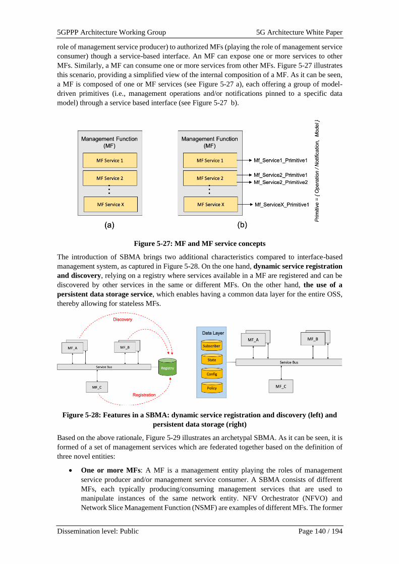
5GPPP Architecture Working Group 5G Architecture White Paper
Dissemination level: Public Page 140 / 194
role of management service producer) to authorized MFs (playing the role of management service
consumer) though a service-based interface. An MF can expose one or more services to other
MFs. Similarly, a MF can consume one or more services from other MFs. Figure 5-27 illustrates
this scenario, providing a simplified view of the internal composition of a MF. As it can be seen,
a MF is composed of one or MF services (see Figure 5-27 a), each offering a group of model-
driven primitives (i.e., management operations and/or notifications pinned to a specific data
model) through a service based interface (see Figure 5-27 b).
Figure 5-27: MF and MF service concepts
The introduction of SBMA brings two additional characteristics compared to interface-based
management system, as captured in Figure 5-28. On the one hand, dynamic service registration
and discovery, relying on a registry where services available in a MF are registered and can be
discovered by other services in the same or different MFs. On the other hand, the use of a
persistent data storage service, which enables having a common data layer for the entire OSS,
thereby allowing for stateless MFs.
Figure 5-28: Features in a SBMA: dynamic service registration and discovery (left) and
persistent data storage (right)
Based on the above rationale, Figure 5-29 illustrates an archetypal SBMA. As it can be seen, it is
formed of a set of management services which are federated together based on the definition of
three novel entities:
• One or more MFs: A MF is a management entity playing the roles of management
service producer and/or management service consumer. A SBMA consists of different
MFs, each typically producing/consuming management services that are used to
manipulate instances of the same network entity. NFV Orchestrator (NFVO) and
Network Slice Management Function (NSMF) are examples of different MFs. The former
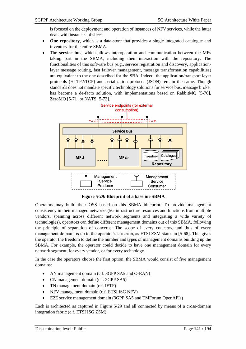
5GPPP Architecture Working Group 5G Architecture White Paper
Dissemination level: Public Page 141 / 194
is focused on the deployment and operation of instances of NFV services, while the latter
deals with instances of slices.
• One repository, which is a data-store that provides a single integrated catalogue and
inventory for the entire SBMA.
• The service bus, which allows interoperation and communication between the MFs
taking part in the SBMA, including their interaction with the repository. The
functionalities of this software bus (e.g., service registration and discovery, application-
layer message routing, fast failover management, message transformation capabilities)
are equivalent to the one described for the SBA. Indeed, the application/transport layer
protocols (HTTP2/TCP) and serialization protocol (JSON) remain the same. Though
standards does not mandate specific technology solutions for service bus, message broker
has become a de-facto solution, with implementations based on RabbitMQ [5-70],
ZeroMQ [5-71] or NATS [5-72].
Figure 5-29: Blueprint of a baseline SBMA
Operators may build their OSS based on this SBMA blueprint. To provide management
consistency in their managed networks (5G infrastructure resources and functions from multiple
vendors, spanning across different network segments and integrating a wide variety of
technologies), operators can define different management domains out of this SBMA, following
the principle of separation of concerns. The scope of every concerns, and thus of every
management domain, is up to the operator’s criterion, as ETSI ZSM states in [5-68]. This gives
the operator the freedom to define the number and types of management domains building up the
SBMA. For example, the operator could decide to have one management domain for every
network segment, for every vendor, or for every technology.
In the case the operators choose the first option, the SBMA would consist of five management
domains:
• AN management domain (c.f. 3GPP SA5 and O-RAN)
• CN management domain (c.f. 3GPP SA5)
• TN management domain (c.f. IETF)
• NFV management domain (c.f. ETSI ISG NFV)
• E2E service management domain (3GPP SA5 and TMForum OpenAPIs)
Each is architected as captured in Figure 5-29 and all connected by means of a cross-domain
integration fabric (c.f. ETSI ISG ZSM).
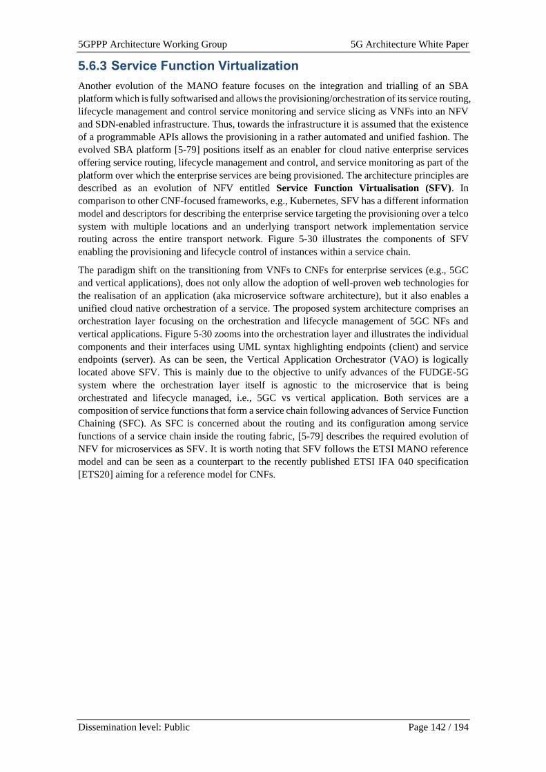
5GPPP Architecture Working Group 5G Architecture White Paper
Dissemination level: Public Page 142 / 194
5.6.3 Service Function Virtualization
Another evolution of the MANO feature focuses on the integration and trialling of an SBA
platform which is fully softwarised and allows the provisioning/orchestration of its service routing,
lifecycle management and control service monitoring and service slicing as VNFs into an NFV
and SDN-enabled infrastructure. Thus, towards the infrastructure it is assumed that the existence
of a programmable APIs allows the provisioning in a rather automated and unified fashion. The
evolved SBA platform [5-79] positions itself as an enabler for cloud native enterprise services
offering service routing, lifecycle management and control, and service monitoring as part of the
platform over which the enterprise services are being provisioned. The architecture principles are
described as an evolution of NFV entitled Service Function Virtualisation (SFV). In
comparison to other CNF-focused frameworks, e.g., Kubernetes, SFV has a different information
model and descriptors for describing the enterprise service targeting the provisioning over a telco
system with multiple locations and an underlying transport network implementation service
routing across the entire transport network. Figure 5-30 illustrates the components of SFV
enabling the provisioning and lifecycle control of instances within a service chain.
The paradigm shift on the transitioning from VNFs to CNFs for enterprise services (e.g., 5GC
and vertical applications), does not only allow the adoption of well-proven web technologies for
the realisation of an application (aka microservice software architecture), but it also enables a
unified cloud native orchestration of a service. The proposed system architecture comprises an
orchestration layer focusing on the orchestration and lifecycle management of 5GC NFs and
vertical applications. Figure 5-30 zooms into the orchestration layer and illustrates the individual
components and their interfaces using UML syntax highlighting endpoints (client) and service
endpoints (server). As can be seen, the Vertical Application Orchestrator (VAO) is logically
located above SFV. This is mainly due to the objective to unify advances of the FUDGE-5G
system where the orchestration layer itself is agnostic to the microservice that is being
orchestrated and lifecycle managed, i.e., 5GC vs vertical application. Both services are a
composition of service functions that form a service chain following advances of Service Function
Chaining (SFC). As SFC is concerned about the routing and its configuration among service
functions of a service chain inside the routing fabric, [5-79] describes the required evolution of
NFV for microservices as SFV. It is worth noting that SFV follows the ETSI MANO reference
model and can be seen as a counterpart to the recently published ETSI IFA 040 specification
[ETS20] aiming for a reference model for CNFs.
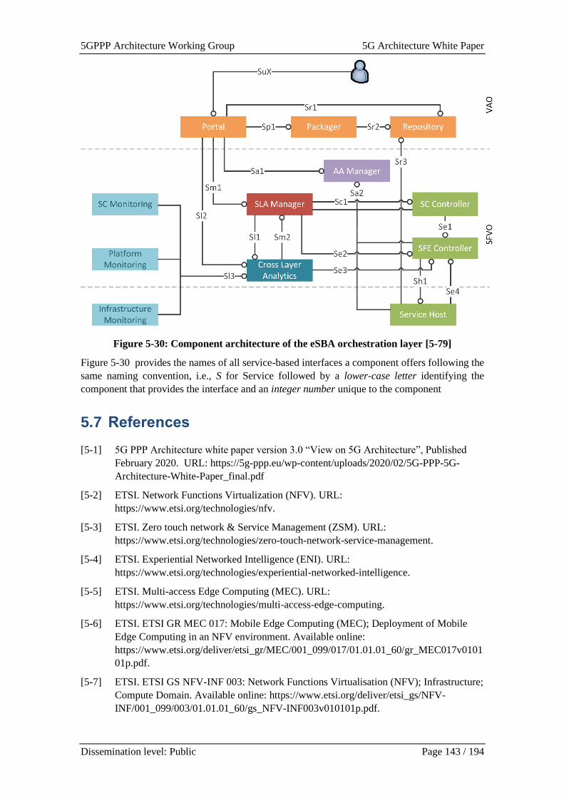
5GPPP Architecture Working Group 5G Architecture White Paper
Dissemination level: Public Page 143 / 194
Figure 5-30: Component architecture of the eSBA orchestration layer [5-79]
Figure 5-30 provides the names of all service-based interfaces a component offers following the
same naming convention, i.e., S for Service followed by a lower-case letter identifying the
component that provides the interface and an integer number unique to the component
5.7 References
[5-1] 5G PPP Architecture white paper version 3.0 “View on 5G Architecture”, Published
February 2020. URL: https://5g-ppp.eu/wp-content/uploads/2020/02/5G-PPP-5G-
Architecture-White-Paper_final.pdf
[5-2] ETSI. Network Functions Virtualization (NFV). URL:
https://www.etsi.org/technologies/nfv.
[5-3] ETSI. Zero touch network & Service Management (ZSM). URL:
https://www.etsi.org/technologies/zero-touch-network-service-management.
[5-4] ETSI. Experiential Networked Intelligence (ENI). URL:
https://www.etsi.org/technologies/experiential-networked-intelligence.
[5-5] ETSI. Multi-access Edge Computing (MEC). URL:
https://www.etsi.org/technologies/multi-access-edge-computing.
[5-6] ETSI. ETSI GR MEC 017: Mobile Edge Computing (MEC); Deployment of Mobile
Edge Computing in an NFV environment. Available online:
https://www.etsi.org/deliver/etsi_gr/MEC/001_099/017/01.01.01_60/gr_MEC017v0101
01p.pdf.
[5-7] ETSI. ETSI GS NFV-INF 003: Network Functions Virtualisation (NFV); Infrastructure;
Compute Domain. Available online: https://www.etsi.org/deliver/etsi_gs/NFV-
INF/001_099/003/01.01.01_60/gs_NFV-INF003v010101p.pdf.
5GPPP Architecture Working Group 5G Architecture White Paper
Dissemination level: Public Page 144 / 194
[5-8] ETSI. ETSI GS NFV-INF 004: Network Functions Virtualisation (NFV); Infrastructure;
Hypervisor Domain. Available online: https://www.etsi.org/deliver/etsi_gs/NFV-
INF/001_099/004/01.01.01_60/gs_nfv-inf004v010101p.pdf.
[5-9] ETSI. ETSI GS NFV-INF 005: Network Functions Virtualisation (NFV); Infrastructure;
Network Domain. Available online: https://www.etsi.org/deliver/etsi_gs/NFV-
INF/001_099/005/01.01.01_60/gs_NFV-INF005v010101p.pdf.
[5-10] ETSI. ETSI GR NFV-EVE 012: Network Functions Virtualisation (NFV) Release 3;
Evolution and Ecosystem; Report on Network Slicing Support with ETSI NFV
Architecture Framework. Available online: https://www.etsi.org/deliver/etsi_gr/NFV-
EVE/001_099/012/03.01.01_60/gr_NFV-EVE012v030101p.pdf.
[5-11] 3GPP TS 23.501, “System Architecture for the 5G System”. Available online:
https://www.3gpp.org/DynaReport/23501.htm.
[5-12] 3GPP TS 28.801, “Telecommunication management; Study on management and
orchestration of network slicing for next generation network”. Available online:
https://www.3gpp.org/DynaReport/28801.htm.
[5-13] 5G-VINNI deliverable D1.5, “5G-VINNI E2E Network Slice Implementation and
Further Design Guidelines”, Zenodo, Oct. 2020. doi: 10.5281/zenodo.4067793.
[5-14] GSMA “Generic Network Slice Template v2.0”
[5-15] 5G-VINNI deliverable D3.1, “Specification of services delivered by each of the 5G-
VINNI facilities”, Zenodo, Jun. 2019. doi: 10.5281/zenodo.3345612.
[5-16] 5G-VINNI D1.6, “Operation, Management and Orchestration of Network Slices”,
Zenodo, Jan. 2021. doi: 10.5281/zenodo.5113059.
[5-17] 5G-VINNI D1.4, “Design of infrastructure architecture and subsystems v2”, Zenodo,
Oct. 2020. doi: 10.5281/zenodo.4066381.
[5-18] 5G-VINNI D2.1: “5G-VINNI Solution Facility-sites High Level Design (HLD)”,
Zenodo, Mar. 2019. doi: 10.5281/zenodo.2668791.
[5-19] 5GENESIS Deliverable D3.4, Slice Management (Release B). March 2021. Available
online: https://5genesis.eu/wp-content/uploads/2021/05/5GENESIS_D3.4_v1.0.pdf
[5-20] OpenSource MANO web-site. Available online: https://osm.etsi.org/
[5-21] OpenNebula web-site. Available online: https://opennebula.io/
[5-22] ETSI. ETSI GS NFV-IFA 030: Network Functions Virtualisation (NFV) Release 3;
Management and Orchestration; Multiple Administrative Domain Aspects Interfaces
Specification. Available online: https://www.etsi.org/deliver/etsi_gs/nfv-
ifa/001_099/030/03.01.01_60/gs_nfv-ifa030v030101p.pdf
[5-23] ETSI. ETSI GS MEC 003: Multi-access Edge Computing (MEC); Framework and
Reference Architecture. Available online:
https://www.etsi.org/deliver/etsi_gs/MEC/001_099/003/02.02.01_60/gs_MEC003v020
201p.pdf
[5-24] ITU-T, “Overview of TMN Recommendations”, ITU-T M.3000 (02/00), Feb. 2000.
[5-25] IBM, “Autonomic Computing White Paper: An architectural blueprint for autonomic
computing”, 3rd edition, 2006.
5GPPP Architecture Working Group 5G Architecture White Paper
Dissemination level: Public Page 145 / 194
[5-26] Kukliński S., Tomaszewski L., “DASMO: A scalable approach to network slices
management and orchestration.”, IEEE/IFIP Network Operations and Management
Symposium, pp. 1-6, 2018. https://doi.org/10.1109/NOMS.2018.8406279
[5-27] ETSI, “Network Functions Virtualisation (NFV); Management and Orchestration”,
ETSI GS NFV-MAN 001 V1.1.1, Dec. 2014.
[5-28] ETSI, “Network Functions Virtualisation (NFV); Management and Orchestration;
Report on Architectural Options”, ETSI GS NFV-IFA 009, V1.1.1, Jul. 2016.
[5-29] ETSI, “Report on the Enhancements of the NFV architecture towards Cloud-native and
PaaS”, ETSI GR NFV-IFA 029, V3.3.1, Nov. 2019.
[5-30] S. Kukliński, R. Kołakowski, L. Tomaszewski, L. Sanabria-Russo, C. Verikoukis, C-T.
Phan, L. Zanzi, F. Devoti, A. Ksentini, C. Tselios, G. Tsolis, H. Chergui; MonB5G:
AI/ML-Capable Distributed Orchestration and Management Framework for Network
Slices, IEEE MeditCom 2021, Athens/hybrid, 7-10 September 2021.
[5-31] NGMN, “Service Based Architecture (Phase 3)”, Online: https://www.ngmn.org/work-
programme/project-portfolio.html
[5-32] https://github.com/InterDigitalInc/ARDENT
[5-33] Project TeraFlow: https://www.teraflow-h2020.eu/
[5-34] ONF TR-522, SDN Architecture for Transport Networks, March 15, 2016.
[5-35] ETSI NFV EVE 005, Report on SDN Usage in NFV Architectural Framework, 2015.
[5-36] ETSI NFV IFA 032, Interface and Information Model Specification for Multi-Site
Connectivity Services, April 2019.
[5-37] ETSI NFV SOL 017, Report on protocol and data model solutions for Multi-site
Connectivity Services, April 2021.
[5-38] “TERAFLOW Relationship with OSM Ecosystem”, available online:
https://www.teraflow-h2020.eu/sites/teraflow-h2020.eu/files/public/content-
files/2021/teraflow_OSM_Ecosystem_Day_March2021.pdf
[5-39] IETF RFC 8466, A YANG Data Model for Layer 2 Virtual Private Network (L2VPN)
Service Delivery, October 2018.
[5-40] B Raaf et Al. "Key technology advancements driving mobile communications from
generation to generation"; Intel Technology Journal Vol.18, issue 1, 2014.
[5-41] J. Costa-Requena, A. Afriyie, D. Kritharidis, K. Chartsias, E. Karasoula, N.
Carapellese, E. Yusta Padilla, ‘SDN-enabled THz Wireless X-Haul for B5G’, 2021
Joint EuCNC & 6G Summit, 2021
[5-42] 5G-HEART deliverable D3.2, “Initial solution and verification of healthcare use case
trials,” May 2020.
[5-43] 5G-HEART deliverable D4.2, “Initial solution and verification of transport use case
trials,” May 2020.
[5-44] 5Growth deliverable D2.3, “Final design and evaluation of the innovations of the 5G
end-to-end service platform”, May 2021.
[5-45] 5Growth deliverable D2.4, “Final implementation of 5G end-to-end service platform”,
May 2021.
5GPPP Architecture Working Group 5G Architecture White Paper
Dissemination level: Public Page 146 / 194
[5-46] 5Growth deliverable D4.2, “Verification methodology and tool design”, November
2020.
[5-47] X. Li et al., “5Growth: An End-to-End Service Platform for Automated Deployment
and Management of Vertical Services over 5G Networks,” IEEE Communications
Magazine, vol. 59, no. 3, pp. 84–90, March 2021.
[5-48] J. Baranda , J. Mangues-Bafalluy , Engin Zeydan , L. Vettori , R. Martínez , Xi Li, A.
Garcia-Saavedra, C.F. Chiasserini, C. Casetti, K. Tomakh, O. Kolodiazhnyi, C. J.
Bernardos “On the Integration of AI/ML-based scaling operations in the 5Growth
platform.” IEEE NFV-SDN 2020, pp. 105–109.
[5-49] 5Growth. “ML-Driven Scaling of Digital Twin Service in 5Growth (detailed description
- long version).” Available at: https://youtu.be/K5GyrAD7h_Q
[5-50] D. Bega, M. Gramaglia, R. Perez, M. Fiore, A. Banchs and X. Costa-Perez, "AI-Based
Autonomous Control, Management, and Orchestration in 5G: From Standards to
Algorithms," in IEEE Network, vol. 34, no. 6, pp. 14-20, November/December 2020,
doi: 10.1109/MNET.001.2000047.
[5-51] Ref to 3GPP TS 23.288 v16.1.0, “Architecture Enhancements for 5G System (5GS) to
Support Network Data Analytics Services (Release 16),” Jun. 2019
[5-52] O-RAN Alliance White Paper, “O-RAN: Towards an Open and Smart RAN,” 2018.
[5-53] https://eniwiki.etsi.org/index.php?title=Poc_09:_Autonomous_Network_Slice_Manage
ment_for_5G_Vertical_Services
[5-54] S. Moazzeni et al., “A Novel Autonomous Profiling Method for the Next Generation
NFV Orchestrators,” IEEE Trans. Netw. Serv. Manag., 2020.
[5-55] V. Sciancalepore, F. Z. Yousaf, and X. Costa-Perez, “Z-TORCH: An automated NFV
orchestration and monitoring solution,” arXiv, vol. 15, no. 4, pp. 1292–1306, 2018.
[5-56] M. Peuster and H. Karl, “Understand Your Chains and Keep Your Deadlines :
Introducing Time-constrained Profiling for NFV,” no. Cnsm, pp. 240–246, 2018.
[5-57] A. Mestres, E. Alarcon, and A. Cabellos, “A machine learning-based approach for
virtual network function modeling,” 2018 IEEE Wirel. Commun. Netw. Conf. Work.
WCNCW 2018, pp. 237–241, 2018.
[5-58] F. Beye, Y. Shinohara, and H. Shimonishi, “Towards Accurate and Scalable
Performance Prediction for Automated Service Design in NFV,” 2019 16th IEEE Annu.
Consum. Commun. Netw. Conf. CCNC 2019, 2019.
[5-59] S. van Rossem, W. Tavernier, D. Colle, M. Pickavet, and P. Demeester, “Profile-Based
Resource Allocation for Virtualized Network Functions,” arXiv, vol. 16, no. 4, pp.
1374–1388, 2019.
[5-60] “Elasticsearch, Elastic Stack.” [Online]. Available: https://www.elastic.co/elasticsearch.
[Accessed: 30-Mar-2021].
[5-61] LOCUS, Deliverable D2.1 “Deliverable D2.1 “Scenarios, Use Cases, Requirements
preliminary version” [Online], https://www.locus-project.eu/wp-
content/uploads/2021/02/Deliverables-officially-submitted_D2.1_D2.1-27-5-20-nbm-
final.pdf Accessed on June 2021
[5-62] LOCUS, Deliverable D2.6 “Deliverable D2.6 “S Scenarios, Use Cases, Requirements
final version” [Online], https://www.locus-project.eu/wp-
5GPPP Architecture Working Group 5G Architecture White Paper
Dissemination level: Public Page 147 / 194
content/uploads/2021/05/Deliverables-officially-submitted_D2.6_D2.6_nbm_5-3-
21.pdf, Accessed on June 2021
[5-63] LOCUS, Deliverable D2.4 “Deliverable D2.4 “System Architecture: Preliminary
Version” [Online], https://www.locus-project.eu/wp-
content/uploads/2021/02/Deliverables-officially-submitted_D2.4_D2.4-9-8-20-nbm-
final.pdf, Accessed on March 2021.
[5-64] Intel, White paper, “Why Use Containers and Cloud-Native Functions Anyway?”
https://www.intel.com/content/dam/www/public/us/en/documents/white-papers/
containers-and-cloud-native-functions-white-paper.pdf
[5-65] Ericsson, Building a cloud native 5G Core: the guide series, https://www.ericsson.com/
en/blog/2020/10/building-a-cloud-native-5g-core-the-guide-series
[5-66] ETSI White Paper No.31, “NGSI-LD API: for Context Information Management”,
January 2019. ISBN: 979-10-92620-27-6
[5-67] 3GPP TS 28.533, “5G; Management and Orchestration; Architecture framework”
[5-68] ETSI GS ZSM 002, “Zero-touch network and Service Management (ZSM); Reference
Architecture”
[5-69] ETSI NFV web site, “Standards for NFV”. [Online]. Available:
https://www.etsi.org/technologies/nfv
[5-70] RabbitMQ: “An open-source message broker” [Online]
https://www.rabbitmq.com/getstarted.html [Accessed April 2020]
[5-71] ZeroMQ: “An open-source universal messaging library” [Online] https://zeromq.org
[Accessed April 2020]
[5-72] NATS: A simple, secure and high performance open-source messaging system”
[Online] https://docs.nats.io [Accessed April 2020].
[5-73] ETSI GS NFV-EVE 004: “Report on the application of Different Virtualisation
Technologies in the NFV Framework”
[5-74] ETSI GS NFV-IFA 010: “Management and Orchestration; Functional requirements
specification”
[5-75] ETSI GS NFV-IFA 036: “Specification of requirements for the management and
orchestration of container cluster nodes”
[5-76] ETSI GS NFV-IFA 040: “Requirements for service interfaces and object model for OS
container management and orchestration specification”
[5-77] Adam Wiggins, “The Twelve-Factor App”, Available at: https://12factor.net/
[5-78] F. Z. Yousaf, V. Sciancalepore, M. Liebsch and X. Costa-Perez, "MANOaaS: A Multi-
Tenant NFV MANO for 5G Network Slices," in IEEE Communications Magazine, vol.
57, no. 5, pp. 103-109, May 2019, doi: 10.1109/MCOM.2019.1800898.
[5-79] The FUDGE-5G consortium, “D1.2: FUDGE-5G Platform Architecture: Components
and Interfaces “, Project Deliverable, 2021. [Online] https://www.fudge-
5g.eu/en/deliverables
[5-80] TIP project - Open Transport SDN Architecture Whitepaper. [Online]
https://cdn.brandfolder.io/D8DI15S7/at/jh6nnbb6bjvn7w7t5jbgm5n/OpenTransportArc
hitecture-Whitepaper_TIP_Final.pdf
5GPPP Architecture Working Group 5G Architecture White Paper
Dissemination level: Public Page 148 / 194
[5-81] 5G-SOLUTIONS Deliverable D2.3A, “Zero-touch automation mechanisms for 5G
service lifecycle (v1.0),” January 2020. [Online] https://5gsolutionsproject.eu/wp-
content/uploads/2020/03/Deliverable_D2.3A_-
_Zero_touch_automation_mechanisms_for_5G_service_lifecycle-final_29Jan2020-
LMI.pdf
[5-82] 5G-CARMEN Deliverable D4.1, “Design of the secure, cross-border and multi-domain
service orchestration platform”. [Online] https://5gcarmen.eu/wp-
content/uploads/2020/11/5G_CARMEN_D4.1_FINAL.pdf
[5-83] 5G-CARMEN Deliverable D4.2, “Advanced prototype for secure, cross-border and
multi-domain service orchestration”. [Online] https://5gcarmen.eu/publications/
[5-84] 3GPPP TR 32.861: “Telecommunication management; Study on application and
partitioning of Interface N (Itf-N)”.
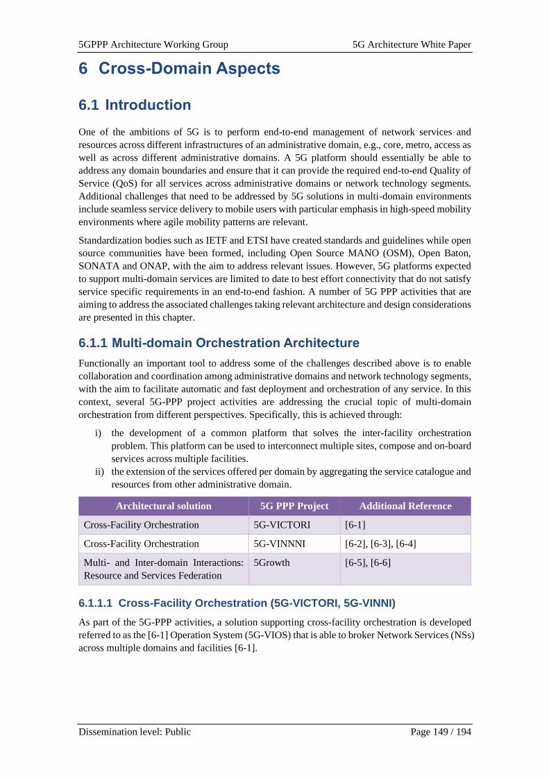
5GPPP Architecture Working Group 5G Architecture White Paper
Dissemination level: Public Page 149 / 194
6 Cross-Domain Aspects
6.1 Introduction
One of the ambitions of 5G is to perform end-to-end management of network services and
resources across different infrastructures of an administrative domain, e.g., core, metro, access as
well as across different administrative domains. A 5G platform should essentially be able to
address any domain boundaries and ensure that it can provide the required end-to-end Quality of
Service (QoS) for all services across administrative domains or network technology segments.
Additional challenges that need to be addressed by 5G solutions in multi-domain environments
include seamless service delivery to mobile users with particular emphasis in high-speed mobility
environments where agile mobility patterns are relevant.
Standardization bodies such as IETF and ETSI have created standards and guidelines while open
source communities have been formed, including Open Source MANO (OSM), Open Baton,
SONATA and ONAP, with the aim to address relevant issues. However, 5G platforms expected
to support multi-domain services are limited to date to best effort connectivity that do not satisfy
service specific requirements in an end-to-end fashion. A number of 5G PPP activities that are
aiming to address the associated challenges taking relevant architecture and design considerations
are presented in this chapter.
6.1.1 Multi-domain Orchestration Architecture
Functionally an important tool to address some of the challenges described above is to enable
collaboration and coordination among administrative domains and network technology segments,
with the aim to facilitate automatic and fast deployment and orchestration of any service. In this
context, several 5G-PPP project activities are addressing the crucial topic of multi-domain
orchestration from different perspectives. Specifically, this is achieved through:
i) the development of a common platform that solves the inter-facility orchestration
problem. This platform can be used to interconnect multiple sites, compose and on-board
services across multiple facilities.
ii) the extension of the services offered per domain by aggregating the service catalogue and
resources from other administrative domain.
Architectural solution 5G PPP Project Additional Reference
Cross-Facility Orchestration 5G-VICTORI [6-1]
Cross-Facility Orchestration 5G-VINNNI [6-2], [6-3], [6-4]
Multi- and Inter-domain Interactions:
Resource and Services Federation
5Growth [6-5], [6-6]
6.1.1.1 Cross-Facility Orchestration (5G-VICTORI, 5G-VINNI)
As part of the 5G-PPP activities, a solution supporting cross-facility orchestration is developed
referred to as the [6-1] Operation System (5G-VIOS) that is able to broker Network Services (NSs)
across multiple domains and facilities [6-1].
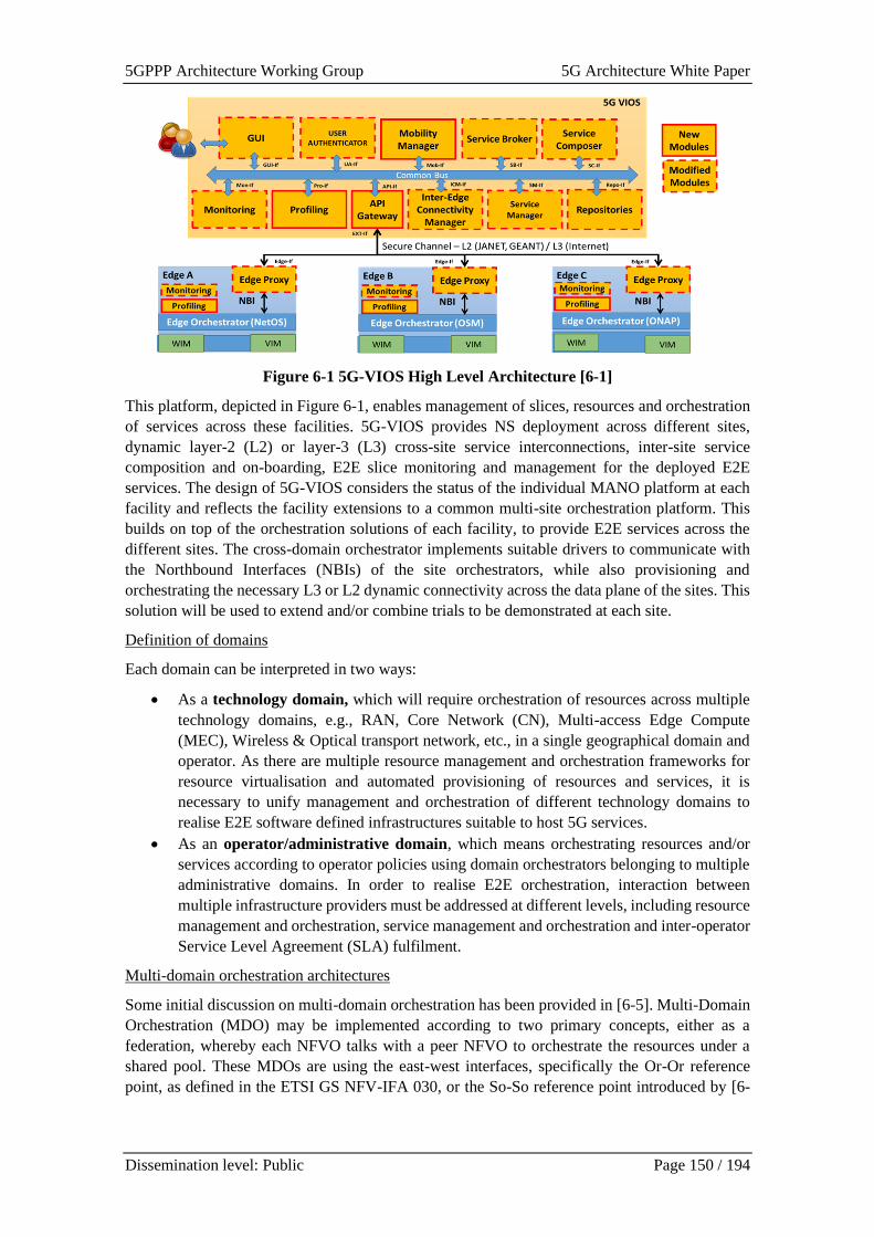
5GPPP Architecture Working Group 5G Architecture White Paper
Dissemination level: Public Page 150 / 194
Figure 6-1 5G-VIOS High Level Architecture [6-1]
This platform, depicted in Figure 6-1, enables management of slices, resources and orchestration
of services across these facilities. 5G-VIOS provides NS deployment across different sites,
dynamic layer-2 (L2) or layer-3 (L3) cross-site service interconnections, inter-site service
composition and on-boarding, E2E slice monitoring and management for the deployed E2E
services. The design of 5G-VIOS considers the status of the individual MANO platform at each
facility and reflects the facility extensions to a common multi-site orchestration platform. This
builds on top of the orchestration solutions of each facility, to provide E2E services across the
different sites. The cross-domain orchestrator implements suitable drivers to communicate with
the Northbound Interfaces (NBIs) of the site orchestrators, while also provisioning and
orchestrating the necessary L3 or L2 dynamic connectivity across the data plane of the sites. This
solution will be used to extend and/or combine trials to be demonstrated at each site.
Definition of domains
Each domain can be interpreted in two ways:
• As a technology domain, which will require orchestration of resources across multiple
technology domains, e.g., RAN, Core Network (CN), Multi-access Edge Compute
(MEC), Wireless & Optical transport network, etc., in a single geographical domain and
operator. As there are multiple resource management and orchestration frameworks for
resource virtualisation and automated provisioning of resources and services, it is
necessary to unify management and orchestration of different technology domains to
realise E2E software defined infrastructures suitable to host 5G services.
• As an operator/administrative domain, which means orchestrating resources and/or
services according to operator policies using domain orchestrators belonging to multiple
administrative domains. In order to realise E2E orchestration, interaction between
multiple infrastructure providers must be addressed at different levels, including resource
management and orchestration, service management and orchestration and inter-operator
Service Level Agreement (SLA) fulfilment.
Multi-domain orchestration architectures
Some initial discussion on multi-domain orchestration has been provided in [6-5]. Multi-Domain
Orchestration (MDO) may be implemented according to two primary concepts, either as a
federation, whereby each NFVO talks with a peer NFVO to orchestrate the resources under a
shared pool. These MDOs are using the east-west interfaces, specifically the Or-Or reference
point, as defined in the ETSI GS NFV-IFA 030, or the So-So reference point introduced by [6-
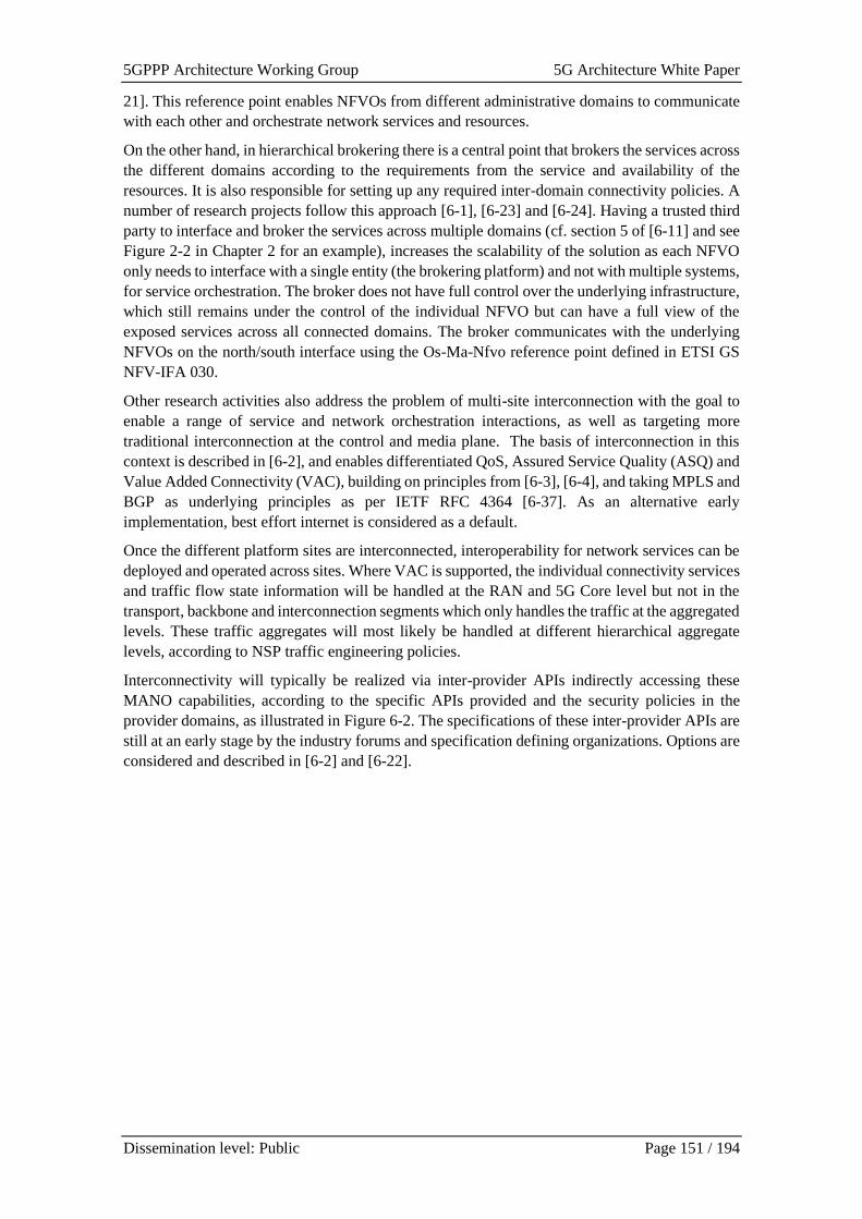
5GPPP Architecture Working Group 5G Architecture White Paper
Dissemination level: Public Page 151 / 194
21]. This reference point enables NFVOs from different administrative domains to communicate
with each other and orchestrate network services and resources.
On the other hand, in hierarchical brokering there is a central point that brokers the services across
the different domains according to the requirements from the service and availability of the
resources. It is also responsible for setting up any required inter-domain connectivity policies. A
number of research projects follow this approach [6-1], [6-23] and [6-24]. Having a trusted third
party to interface and broker the services across multiple domains (cf. section 5 of [6-11] and see
Figure 2-2 in Chapter 2 for an example), increases the scalability of the solution as each NFVO
only needs to interface with a single entity (the brokering platform) and not with multiple systems,
for service orchestration. The broker does not have full control over the underlying infrastructure,
which still remains under the control of the individual NFVO but can have a full view of the
exposed services across all connected domains. The broker communicates with the underlying
NFVOs on the north/south interface using the Os-Ma-Nfvo reference point defined in ETSI GS
NFV-IFA 030.
Other research activities also address the problem of multi-site interconnection with the goal to
enable a range of service and network orchestration interactions, as well as targeting more
traditional interconnection at the control and media plane. The basis of interconnection in this
context is described in [6-2], and enables differentiated QoS, Assured Service Quality (ASQ) and
Value Added Connectivity (VAC), building on principles from [6-3], [6-4], and taking MPLS and
BGP as underlying principles as per IETF RFC 4364 [6-37]. As an alternative early
implementation, best effort internet is considered as a default.
Once the different platform sites are interconnected, interoperability for network services can be
deployed and operated across sites. Where VAC is supported, the individual connectivity services
and traffic flow state information will be handled at the RAN and 5G Core level but not in the
transport, backbone and interconnection segments which only handles the traffic at the aggregated
levels. These traffic aggregates will most likely be handled at different hierarchical aggregate
levels, according to NSP traffic engineering policies.
Interconnectivity will typically be realized via inter-provider APIs indirectly accessing these
MANO capabilities, according to the specific APIs provided and the security policies in the
provider domains, as illustrated in Figure 6-2. The specifications of these inter-provider APIs are
still at an early stage by the industry forums and specification defining organizations. Options are
considered and described in [6-2] and [6-22].
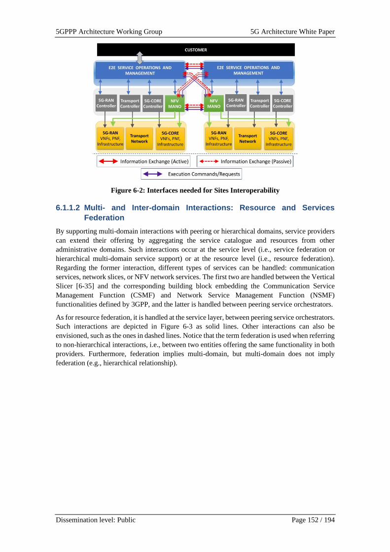
5GPPP Architecture Working Group 5G Architecture White Paper
Dissemination level: Public Page 152 / 194
Figure 6-2: Interfaces needed for Sites Interoperability
6.1.1.2 Multi- and Inter-domain Interactions: Resource and Services
Federation
By supporting multi-domain interactions with peering or hierarchical domains, service providers
can extend their offering by aggregating the service catalogue and resources from other
administrative domains. Such interactions occur at the service level (i.e., service federation or
hierarchical multi-domain service support) or at the resource level (i.e., resource federation).
Regarding the former interaction, different types of services can be handled: communication
services, network slices, or NFV network services. The first two are handled between the Vertical
Slicer [6-35] and the corresponding building block embedding the Communication Service
Management Function (CSMF) and Network Service Management Function (NSMF)
functionalities defined by 3GPP, and the latter is handled between peering service orchestrators.
As for resource federation, it is handled at the service layer, between peering service orchestrators.
Such interactions are depicted in Figure 6-3 as solid lines. Other interactions can also be
envisioned, such as the ones in dashed lines. Notice that the term federation is used when referring
to non-hierarchical interactions, i.e., between two entities offering the same functionality in both
providers. Furthermore, federation implies multi-domain, but multi-domain does not imply
federation (e.g., hierarchical relationship).
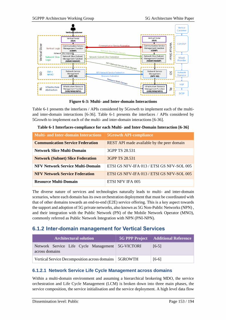
5GPPP Architecture Working Group 5G Architecture White Paper
Dissemination level: Public Page 153 / 194
Figure 6-3: Multi- and Inter-domain Interactions
Table 6-1 presents the interfaces / APIs considered by 5Growth to implement each of the multi-
and inter-domain interactions [6-36]. Table 6-1 presents the interfaces / APIs considered by
5Growth to implement each of the multi- and inter-domain interactions [6-36].
Table 6-1 Interfaces-compliance for each Multi- and Inter-Domain Interaction [6-36]
Multi- and Inter-domain Interactions 5Growth API-compliance
Communication Service Federation REST API made available by the peer domain
Network Slice Multi-Domain 3GPP TS 28.531
Network (Subnet) Slice Federation 3GPP TS 28.531
NFV Network Service Multi-Domain ETSI GS NFV-IFA 013 / ETSI GS NFV-SOL 005
NFV Network Service Federation ETSI GS NFV-IFA 013 / ETSI GS NFV-SOL 005
Resource Multi-Domain ETSI NFV IFA 005
The diverse nature of services and technologies naturally leads to multi- and inter-domain
scenarios, where each domain has its own orchestration deployment that must be coordinated with
that of other domains towards an end-to-end (E2E) service offering. This is a key aspect towards
the support and adoption of 5G private networks, also known as 5G Non-Public Networks (NPN) ,
and their integration with the Public Network (PN) of the Mobile Network Operator (MNO),
commonly referred as Public Network Integration with NPN (PNI-NPN).
6.1.2 Inter-domain management for Vertical Services
Architectural solution 5G PPP Project Additional Reference
Network Service Life Cycle Management
across domains
5G-VICTORI [6-5]
Vertical Service Decomposition across domains 5GROWTH [6-6]
6.1.2.1 Network Service Life Cycle Management across domains
Within a multi-domain environment and assuming a hierarchical brokering MDO, the service
orchestration and Life Cycle Management (LCM) is broken down into three main phases, the
service composition, the service initialisation and the service deployment. A high level data flow
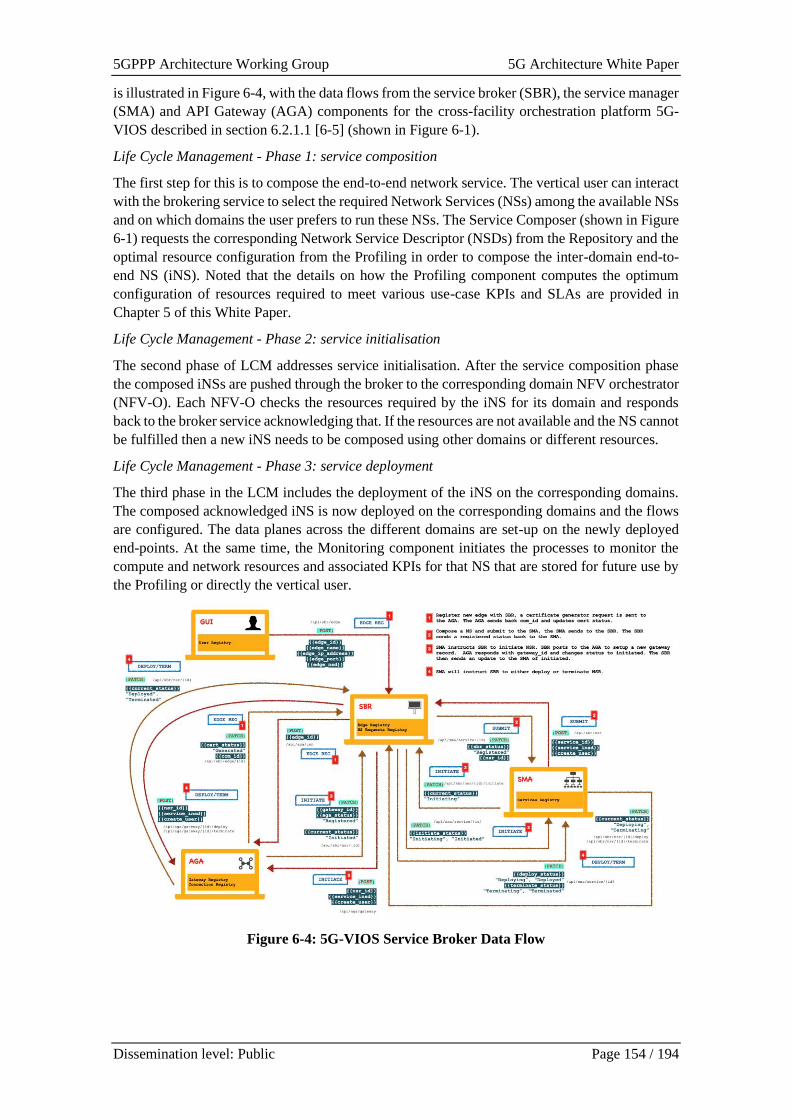
5GPPP Architecture Working Group 5G Architecture White Paper
Dissemination level: Public Page 154 / 194
is illustrated in Figure 6-4, with the data flows from the service broker (SBR), the service manager
(SMA) and API Gateway (AGA) components for the cross-facility orchestration platform 5G-
VIOS described in section 6.2.1.1 [6-5] (shown in Figure 6-1).
Life Cycle Management - Phase 1: service composition
The first step for this is to compose the end-to-end network service. The vertical user can interact
with the brokering service to select the required Network Services (NSs) among the available NSs
and on which domains the user prefers to run these NSs. The Service Composer (shown in Figure
6-1) requests the corresponding Network Service Descriptor (NSDs) from the Repository and the
optimal resource configuration from the Profiling in order to compose the inter-domain end-to-
end NS (iNS). Noted that the details on how the Profiling component computes the optimum
configuration of resources required to meet various use-case KPIs and SLAs are provided in
Chapter 5 of this White Paper.
Life Cycle Management - Phase 2: service initialisation
The second phase of LCM addresses service initialisation. After the service composition phase
the composed iNSs are pushed through the broker to the corresponding domain NFV orchestrator
(NFV-O). Each NFV-O checks the resources required by the iNS for its domain and responds
back to the broker service acknowledging that. If the resources are not available and the NS cannot
be fulfilled then a new iNS needs to be composed using other domains or different resources.
Life Cycle Management - Phase 3: service deployment
The third phase in the LCM includes the deployment of the iNS on the corresponding domains.
The composed acknowledged iNS is now deployed on the corresponding domains and the flows
are configured. The data planes across the different domains are set-up on the newly deployed
end-points. At the same time, the Monitoring component initiates the processes to monitor the
compute and network resources and associated KPIs for that NS that are stored for future use by
the Profiling or directly the vertical user.
Figure 6-4: 5G-VIOS Service Broker Data Flow
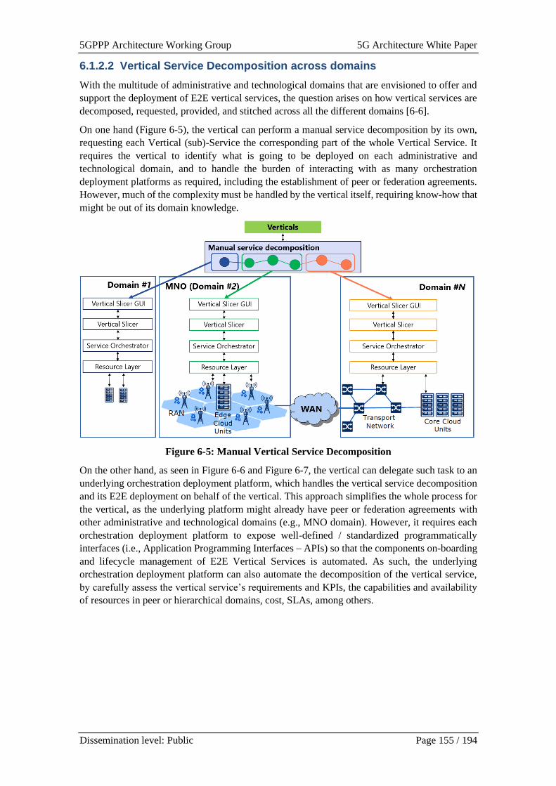
5GPPP Architecture Working Group 5G Architecture White Paper
Dissemination level: Public Page 155 / 194
6.1.2.2 Vertical Service Decomposition across domains
With the multitude of administrative and technological domains that are envisioned to offer and
support the deployment of E2E vertical services, the question arises on how vertical services are
decomposed, requested, provided, and stitched across all the different domains [6-6].
On one hand (Figure 6-5), the vertical can perform a manual service decomposition by its own,
requesting each Vertical (sub)-Service the corresponding part of the whole Vertical Service. It
requires the vertical to identify what is going to be deployed on each administrative and
technological domain, and to handle the burden of interacting with as many orchestration
deployment platforms as required, including the establishment of peer or federation agreements.
However, much of the complexity must be handled by the vertical itself, requiring know-how that
might be out of its domain knowledge.
Figure 6-5: Manual Vertical Service Decomposition
On the other hand, as seen in Figure 6-6 and Figure 6-7, the vertical can delegate such task to an
underlying orchestration deployment platform, which handles the vertical service decomposition
and its E2E deployment on behalf of the vertical. This approach simplifies the whole process for
the vertical, as the underlying platform might already have peer or federation agreements with
other administrative and technological domains (e.g., MNO domain). However, it requires each
orchestration deployment platform to expose well-defined / standardized programmatically
interfaces (i.e., Application Programming Interfaces – APIs) so that the components on-boarding
and lifecycle management of E2E Vertical Services is automated. As such, the underlying
orchestration deployment platform can also automate the decomposition of the vertical service,
by carefully assess the vertical service’s requirements and KPIs, the capabilities and availability
of resources in peer or hierarchical domains, cost, SLAs, among others.
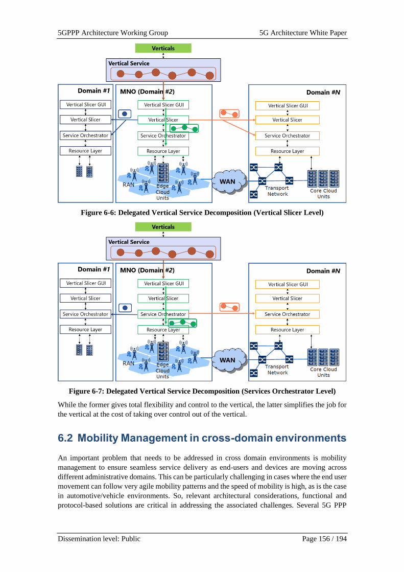
5GPPP Architecture Working Group 5G Architecture White Paper
Dissemination level: Public Page 156 / 194
Figure 6-6: Delegated Vertical Service Decomposition (Vertical Slicer Level)
Figure 6-7: Delegated Vertical Service Decomposition (Services Orchestrator Level)
While the former gives total flexibility and control to the vertical, the latter simplifies the job for
the vertical at the cost of taking over control out of the vertical.
6.2 Mobility Management in cross-domain environments
An important problem that needs to be addressed in cross domain environments is mobility
management to ensure seamless service delivery as end-users and devices are moving across
different administrative domains. This can be particularly challenging in cases where the end user
movement can follow very agile mobility patterns and the speed of mobility is high, as is the case
in automotive/vehicle environments. So, relevant architectural considerations, functional and
protocol-based solutions are critical in addressing the associated challenges. Several 5G PPP
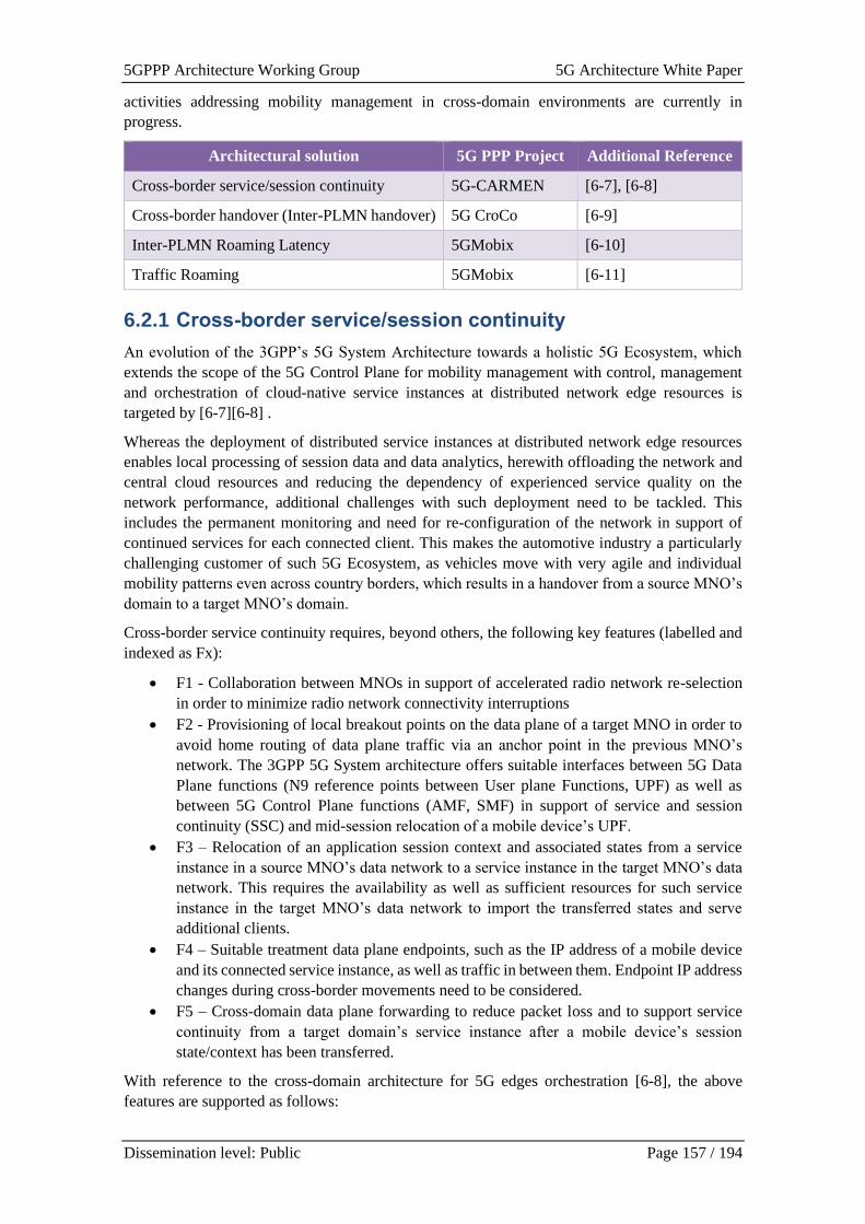
5GPPP Architecture Working Group 5G Architecture White Paper
Dissemination level: Public Page 157 / 194
activities addressing mobility management in cross-domain environments are currently in
progress.
Architectural solution 5G PPP Project Additional Reference
Cross-border service/session continuity 5G-CARMEN [6-7], [6-8]
Cross-border handover (Inter-PLMN handover) 5G CroCo [6-9]
Inter-PLMN Roaming Latency 5GMobix [6-10]
Traffic Roaming 5GMobix [6-11]
6.2.1 Cross-border service/session continuity
An evolution of the 3GPP’s 5G System Architecture towards a holistic 5G Ecosystem, which
extends the scope of the 5G Control Plane for mobility management with control, management
and orchestration of cloud-native service instances at distributed network edge resources is
targeted by [6-7][6-8] .
Whereas the deployment of distributed service instances at distributed network edge resources
enables local processing of session data and data analytics, herewith offloading the network and
central cloud resources and reducing the dependency of experienced service quality on the
network performance, additional challenges with such deployment need to be tackled. This
includes the permanent monitoring and need for re-configuration of the network in support of
continued services for each connected client. This makes the automotive industry a particularly
challenging customer of such 5G Ecosystem, as vehicles move with very agile and individual
mobility patterns even across country borders, which results in a handover from a source MNO’s
domain to a target MNO’s domain.
Cross-border service continuity requires, beyond others, the following key features (labelled and
indexed as Fx):
• F1 - Collaboration between MNOs in support of accelerated radio network re-selection
in order to minimize radio network connectivity interruptions
• F2 - Provisioning of local breakout points on the data plane of a target MNO in order to
avoid home routing of data plane traffic via an anchor point in the previous MNO’s
network. The 3GPP 5G System architecture offers suitable interfaces between 5G Data
Plane functions (N9 reference points between User plane Functions, UPF) as well as
between 5G Control Plane functions (AMF, SMF) in support of service and session
continuity (SSC) and mid-session relocation of a mobile device’s UPF.
• F3 – Relocation of an application session context and associated states from a service
instance in a source MNO’s data network to a service instance in the target MNO’s data
network. This requires the availability as well as sufficient resources for such service
instance in the target MNO’s data network to import the transferred states and serve
additional clients.
• F4 – Suitable treatment data plane endpoints, such as the IP address of a mobile device
and its connected service instance, as well as traffic in between them. Endpoint IP address
changes during cross-border movements need to be considered.
• F5 – Cross-domain data plane forwarding to reduce packet loss and to support service
continuity from a target domain’s service instance after a mobile device’s session
state/context has been transferred.
With reference to the cross-domain architecture for 5G edges orchestration [6-8], the above
features are supported as follows:
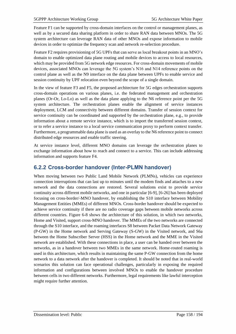
5GPPP Architecture Working Group 5G Architecture White Paper
Dissemination level: Public Page 158 / 194
Feature F1 can be supported by cross-domain interfaces on the control or management planes, as
well as by a secured data sharing platform in order to share RAN data between MNOs. The 5G
system architecture can leverage RAN data of other MNOs and expose information to mobile
devices in order to optimize the frequency scan and network re-selection procedure.
Feature F2 requires provisioning of 5G UPFs that can serve as local breakout points in an MNO’s
domain to enable optimized data plane routing and mobile devices to access to local resources,
which may be provided from 5G network edge resources. For cross-domain movements of mobile
devices, associated MNOs can leverage the 5G system’s N16 and N14 reference points on the
control plane as well as the N9 interface on the data plane between UPFs to enable service and
session continuity by UPF relocation even beyond the scope of a single domain.
In the view of feature F3 and F5, the proposed architecture for 5G edges orchestration supports
cross-domain operations on various planes, i.e. the federated management and orchestration
planes (Or-Or, Lo-Lo) as well as the data plane applying to the N6 reference point per the 5G
system architecture. The orchestration planes enable the alignment of service instances
deployment, LCM and connectivity between different domains. Transfer of session context for
service continuity can be coordinated and supported by the orchestration plane, e.g., to provide
information about a remote service instance, which is to import the transferred session context,
or to refer a service instance to a local service communication proxy to perform context transfer.
Furthermore, a programmable data plane is used as an overlay to the N6 reference point to connect
distributed edge resources and enable traffic steering.
At service instance level, different MNO domains can leverage the orchestration planes to
exchange information about how to reach and connect to a service. This can include addressing
information and supports feature F4.
6.2.2 Cross-border handover (Inter-PLMN handover)
When moving between two Public Land Mobile Network (PLMNs), vehicles can experience
connection interruptions that can last up to minutes until the modem finds and attaches to a new
network and the data connections are restored. Several solutions exist to provide service
continuity across different mobile networks, and one in particular [6-9], [6-26] has been deployed
focusing on cross-border/-MNO handover, by establishing the S10 interface between Mobility
Management Entities (MMEs) of different MNOs. Cross-border handover should be expected to
achieve service continuity if there are no radio coverage gaps between mobile networks across
different countries. Figure 6-8 shows the architecture of this solution, in which two networks,
Home and Visited, support cross-MNO handover. The MMEs of the two networks are connected
through the S10 interface, and the roaming interfaces S8 between Packet Data Network Gateway
(P-GW) in the Home network and Serving Gateway (S-GW) in the Visited network, and S6a
between the Home Subscriber Server (HSS) in the Home network and the MME in the Visited
network are established. With these connections in place, a user can be handed over between the
networks, as in a handover between two MMEs in the same network. Home-routed roaming is
used in this architecture, which results in maintaining the same P-GW connection from the home
network to a data network after the handover is completed. It should be noted that in real-world
scenarios this solution can face operational challenges, particularly in exposing the required
information and configurations between involved MNOs to enable the handover procedure
between cells in two different networks. Furthermore, legal requirements like lawful interception
might require further attention.
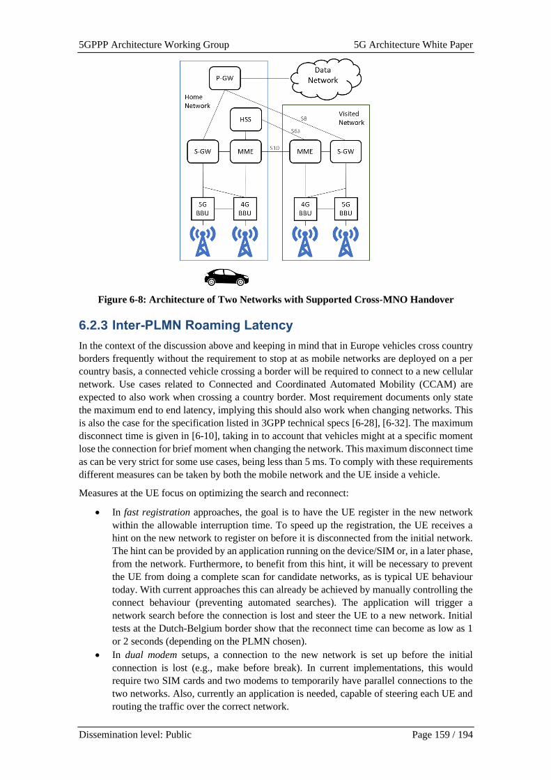
5GPPP Architecture Working Group 5G Architecture White Paper
Dissemination level: Public Page 159 / 194
Figure 6-8: Architecture of Two Networks with Supported Cross-MNO Handover
6.2.3 Inter-PLMN Roaming Latency
In the context of the discussion above and keeping in mind that in Europe vehicles cross country
borders frequently without the requirement to stop at as mobile networks are deployed on a per
country basis, a connected vehicle crossing a border will be required to connect to a new cellular
network. Use cases related to Connected and Coordinated Automated Mobility (CCAM) are
expected to also work when crossing a country border. Most requirement documents only state
the maximum end to end latency, implying this should also work when changing networks. This
is also the case for the specification listed in 3GPP technical specs [6-28], [6-32]. The maximum
disconnect time is given in [6-10], taking in to account that vehicles might at a specific moment
lose the connection for brief moment when changing the network. This maximum disconnect time
as can be very strict for some use cases, being less than 5 ms. To comply with these requirements
different measures can be taken by both the mobile network and the UE inside a vehicle.
Measures at the UE focus on optimizing the search and reconnect:
• In fast registration approaches, the goal is to have the UE register in the new network
within the allowable interruption time. To speed up the registration, the UE receives a
hint on the new network to register on before it is disconnected from the initial network.
The hint can be provided by an application running on the device/SIM or, in a later phase,
from the network. Furthermore, to benefit from this hint, it will be necessary to prevent
the UE from doing a complete scan for candidate networks, as is typical UE behaviour
today. With current approaches this can already be achieved by manually controlling the
connect behaviour (preventing automated searches). The application will trigger a
network search before the connection is lost and steer the UE to a new network. Initial
tests at the Dutch-Belgium border show that the reconnect time can become as low as 1
or 2 seconds (depending on the PLMN chosen).
• In dual modem setups, a connection to the new network is set up before the initial
connection is lost (e.g., make before break). In current implementations, this would
require two SIM cards and two modems to temporarily have parallel connections to the
two networks. Also, currently an application is needed, capable of steering each UE and
routing the traffic over the correct network.
5GPPP Architecture Working Group 5G Architecture White Paper
Dissemination level: Public Page 160 / 194
Measures from the network are focused on the steering of roaming and providing a handover
between bordering networks:
• Optimizing steering of roaming aims at selecting the best network selected for the UE and its
services. The Home Public Land Mobile Network (HPLMN) is responsible to set up the
roaming agreements with the Visited Public Land Mobile Network (VPLMNs) and allows
the UE to make use of them. The UE should always be steered to the most optimal network,
be it to utilize the specific services it requires or to benefit from the best (wholesale) roaming
business model and rates. Therefore, current technologies need to evolve from denying
services on non-preferred networks to steering the UE toward the preferred network.
• In inter-PLMN handover approaches, the well-known intra-PLMN handover is extended to
work across PLMN borders. In 4G, this involves introducing an S10 interface between MMEs
of the two bordering network operators. In 5G SA architectures, this translates to an N14
interface between the AMFs (potentially absorbed in the overall N32 interface between the
two operators’ SBA architectures in the control plane). As pointed out by earlier
measurements in trials by Ericsson [6-29] and as also stated [6-9], there is no noticeable
interruption because of the handover and the latency keeps well below 100 ms during such
inter-PLMN handovers. Currently the N14 interface has not yet been earmarked to be used as
a roaming interface. Although the inter-PLMN handover has been described since 2006 in
3GPP release 8, it has as of yet not been adopted by operators. This is probably due to the
lack of demand and the complex integration that is required.
Multi-SIM solutions
Multi-SIM solutions are promising many advantages including seamless connection, improved
coverage, improved bandwidth, and reduced end-to-end delay. Current solutions of multi-SIM
connectivity are mostly user-oriented, i.e., UE provides functionalities of using multiple SIMs,
without any support from networks. Two user-oriented multi-SIM solutions have been tested with
the main goal of identifying their benefits and weaknesses [6-25]. The first solution is a multi-
SIM OBU solution, which can switch over up to four 5G networks (NSA to NSA/SA modes).
The criterion to switch over multiple networks is primarily based on fixed connectivity metrics
such as signal strength, but the OBU allows to introduce additional different criteria. The second
user-oriented solution leverages the capabilities offered by an intelligent routing device. This
latter is equipped with multi-sim and multi modem capabilities and is integrated along the OBU.
The intelligent router allows for seamless handover and bonding between multiple 5G bearers
belonging to different mobile networks. A VPN connection allows for bearer bonding through the
paired intelligent router deployed at the server site, where the CCAM applications are installed.
A high-level diagram of this multi-SIM connectivity deployment is illustrated in Figure 6-9.
Figure 6-9: Multi-SIM 5G Connectivity solution being tested in the 5G-MOBIX project
5GPPP Architecture Working Group 5G Architecture White Paper
Dissemination level: Public Page 161 / 194
The contemporary multi-SIM solutions, such as, those being considered in 5G-MOBIX as
described in example above, are typically based on proprietary solutions, and implemented
without standardised support of multi-SIM feature from the associated 3GPP systems. In that case,
networks serving a particular multi-SIM device may do so with degraded performance on one or
more of the connections. In response to the increased adoption of multi-SIM devices, 3GPP has
included in Release 17 an ongoing work item for standardisation of enhanced support of multi-
SIM devices (physical or embedded SIMs) associated with multiple 3GPP systems (scope being
Evolved Packet System [EPS] or 5G System [5GS]) [6-27]. This includes study of system impacts
of legacy multi-SIM device implementations and potential enhancements on aspects, such as,
efficient monitoring of multiple paging channels (of each associated 3GPP system) by a multi-
SIM device and coordinated departure of the multi-SIM device from one of the 3GPP systems.
6.2.4 Traffic Roaming
Even upon completion of the HO process, roaming places significant challenges relating to the
routing of the traffic and associated performance. When roaming traffic is Home Routed (HR),
subscribers always obtain service from their home network i.e., traffic is routed to their current
location through a packet gateway at their home network. As the service is always managed
through the same gateway (Packet Gateway (PGW)/UPF), service continuity, while roaming, is
facilitated. However, this comes at the cost of increased latency due to the user plane traffic being
routed from the visited network to the home network, typically through the GRX (GPRS Roaming
Exchange)/IPX (IP exchange) networks. On the other hand, Local Break-Out (LBO) allows the
optimization of the roaming traffic path through the visited network PGW/UPF, at the cost of
potential service disruption since a new PDU session needs to be established at the visited
network.
The selection of roaming network mode obviously depends on: 1) the latency and service
continuity requirements of the services at hand i.e., sensitivity to latency and/or disruption, and
2) the actual latency or disruption delivered by each mode. The latter in turn depends on the
overall topology and dimensioning of the network. From [6-10] a wide range of use cases are
considered; efforts include the experimental assessment and comparison of HR and LBO
solutions for inter-PLMN. The evaluation will take place both between NSA and SA architectures,
offering significant insights regarding the expected benefits of the 5G Core (past of SA) in terms
of routing efficiency.
Commercial Mobile Network Operators use Internetwork Packet Exchange (IPX) networks for
signalling messages in order to support LTE roaming between their roaming partners. For each
peer to the IPX network only a single physical connection is required. On an IPX network, the
DIAMETER Edge Agent (DEA) must be deployed to support route addressing for Diameter
signalling between the visited and home networks. DEA will support connection from MME i.e.
S6a and PCRF S9 from the visited network towards the home network.
All roaming signalling messages are transmitted through DEA. This allows an operator network
to only send or receive signalling messages to or from DEAs deployed on other operator networks.
It no longer needs to learn the internal structure of other networks. In 4G/LTE roaming the UE
during attach procedure will be authenticated with home HSS using S6a interface between visited
MME and home HSS through the DEA in the IPX network. After the UE attach a PDP session is
established and visited PCRF checks with home PCRF using S9 interface through the DEA in the
IPX network.
The roaming connection is done through the DEA and operators can use flexible security policies
on the DEA to protect network security, such as controlling IP address access, restricting device
access, and deploying firewalls. The MME in NSA or AMF SA case needs to be configured with
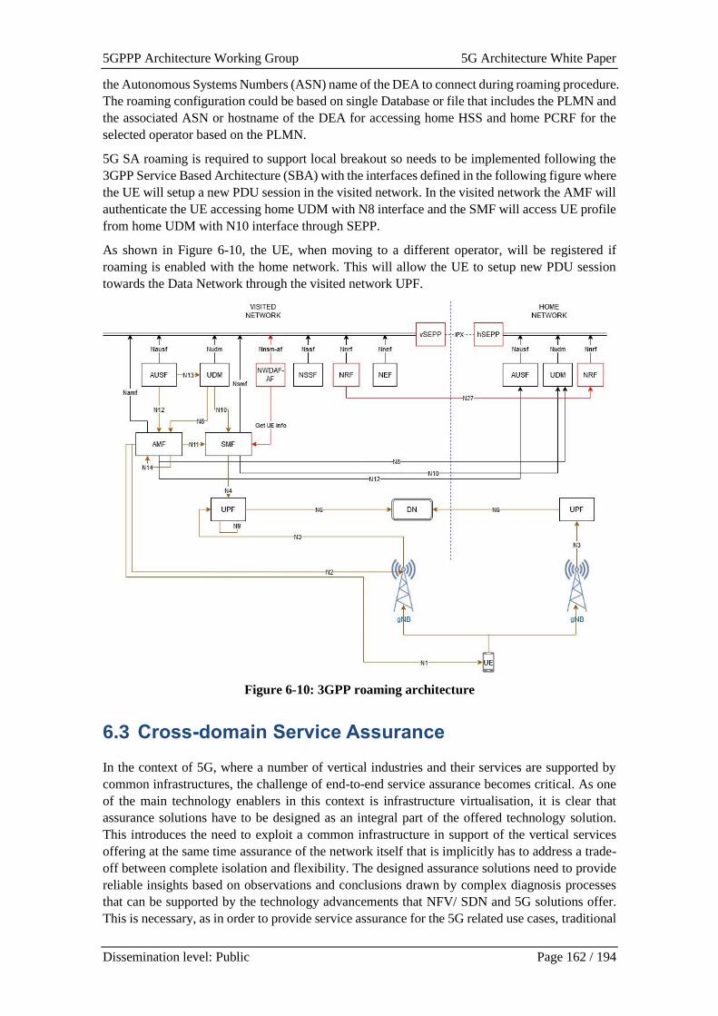
5GPPP Architecture Working Group 5G Architecture White Paper
Dissemination level: Public Page 162 / 194
the Autonomous Systems Numbers (ASN) name of the DEA to connect during roaming procedure.
The roaming configuration could be based on single Database or file that includes the PLMN and
the associated ASN or hostname of the DEA for accessing home HSS and home PCRF for the
selected operator based on the PLMN.
5G SA roaming is required to support local breakout so needs to be implemented following the
3GPP Service Based Architecture (SBA) with the interfaces defined in the following figure where
the UE will setup a new PDU session in the visited network. In the visited network the AMF will
authenticate the UE accessing home UDM with N8 interface and the SMF will access UE profile
from home UDM with N10 interface through SEPP.
As shown in Figure 6-10, the UE, when moving to a different operator, will be registered if
roaming is enabled with the home network. This will allow the UE to setup new PDU session
towards the Data Network through the visited network UPF.
Figure 6-10: 3GPP roaming architecture
6.3 Cross-domain Service Assurance
In the context of 5G, where a number of vertical industries and their services are supported by
common infrastructures, the challenge of end-to-end service assurance becomes critical. As one
of the main technology enablers in this context is infrastructure virtualisation, it is clear that
assurance solutions have to be designed as an integral part of the offered technology solution.
This introduces the need to exploit a common infrastructure in support of the vertical services
offering at the same time assurance of the network itself that is implicitly has to address a trade-
off between complete isolation and flexibility. The designed assurance solutions need to provide
reliable insights based on observations and conclusions drawn by complex diagnosis processes
that can be supported by the technology advancements that NFV/ SDN and 5G solutions offer.
This is necessary, as in order to provide service assurance for the 5G related use cases, traditional
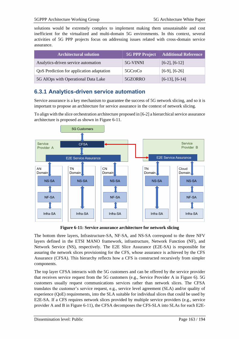
5GPPP Architecture Working Group 5G Architecture White Paper
Dissemination level: Public Page 163 / 194
solutions would be extremely complex to implement making them unsustainable and cost
inefficient for the virtualized and multi-domain 5G environments. In this context, several
activities of 5G PPP projects focus on addressing issues related with cross-domain service
assurance.
Architectural solution 5G PPP Project Additional Reference
Analytics-driven service automation 5G-VINNI [6-2], [6-12]
QoS Prediction for application adaptation 5GCroCo [6-9], [6-26]
5G AIOps with Operational Data Lake 5GZORRO [6-13], [6-14]
6.3.1 Analytics-driven service automation
Service assurance is a key mechanism to guarantee the success of 5G network slicing, and so it is
important to propose an architecture for service assurance in the context of network slicing.
To align with the slice orchestration architecture proposed in [6-2] a hierarchical service assurance
architecture is proposed as shown in Figure 6-11.
Figure 6-11: Service assurance architecture for network slicing
The bottom three layers, Infrastructure-SA, NF-SA, and NS-SA correspond to the three NFV
layers defined in the ETSI MANO framework, infrastructure, Network Function (NF), and
Network Service (NS), respectively. The E2E Slice Assurance (E2E-SA) is responsible for
assuring the network slices provisioning for the CFS, whose assurance is achieved by the CFS
Assurance (CFSA). This hierarchy reflects how a CFS is constructed recursively from simpler
components.
The top layer CFSA interacts with the 5G customers and can be offered by the service provider
that receives service request from the 5G customers (e.g., Service Provider A in Figure 6). 5G
customers usually request communications services rather than network slices. The CFSA
translates the customer’s service request, e.g., service level agreement (SLA) and/or quality of
experience (QoE) requirements, into the SLA suitable for individual slices that could be used by
E2E-SA. If a CFS requires network slices provided by multiple service providers (e.g., service
provider A and B in Figure 6-11), the CFSA decomposes the CFS-SLA into SLAs for each E2E-
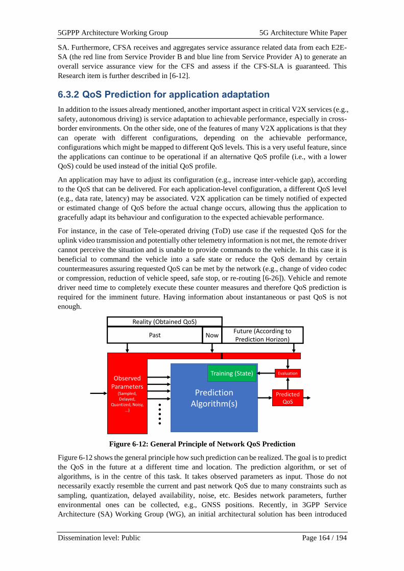
5GPPP Architecture Working Group 5G Architecture White Paper
Dissemination level: Public Page 164 / 194
SA. Furthermore, CFSA receives and aggregates service assurance related data from each E2E-
SA (the red line from Service Provider B and blue line from Service Provider A) to generate an
overall service assurance view for the CFS and assess if the CFS-SLA is guaranteed. This
Research item is further described in [6-12].
6.3.2 QoS Prediction for application adaptation
In addition to the issues already mentioned, another important aspect in critical V2X services (e.g.,
safety, autonomous driving) is service adaptation to achievable performance, especially in cross-
border environments. On the other side, one of the features of many V2X applications is that they
can operate with different configurations, depending on the achievable performance,
configurations which might be mapped to different QoS levels. This is a very useful feature, since
the applications can continue to be operational if an alternative QoS profile (i.e., with a lower
QoS) could be used instead of the initial QoS profile.
An application may have to adjust its configuration (e.g., increase inter-vehicle gap), according
to the QoS that can be delivered. For each application-level configuration, a different QoS level
(e.g., data rate, latency) may be associated. V2X application can be timely notified of expected
or estimated change of QoS before the actual change occurs, allowing thus the application to
gracefully adapt its behaviour and configuration to the expected achievable performance.
For instance, in the case of Tele-operated driving (ToD) use case if the requested QoS for the
uplink video transmission and potentially other telemetry information is not met, the remote driver
cannot perceive the situation and is unable to provide commands to the vehicle. In this case it is
beneficial to command the vehicle into a safe state or reduce the QoS demand by certain
countermeasures assuring requested QoS can be met by the network (e.g., change of video codec
or compression, reduction of vehicle speed, safe stop, or re-routing [6-26]). Vehicle and remote
driver need time to completely execute these counter measures and therefore QoS prediction is
required for the imminent future. Having information about instantaneous or past QoS is not
enough.
Figure 6-12: General Principle of Network QoS Prediction
Figure 6-12 shows the general principle how such prediction can be realized. The goal is to predict
the QoS in the future at a different time and location. The prediction algorithm, or set of
algorithms, is in the centre of this task. It takes observed parameters as input. Those do not
necessarily exactly resemble the current and past network QoS due to many constraints such as
sampling, quantization, delayed availability, noise, etc. Besides network parameters, further
environmental ones can be collected, e.g., GNSS positions. Recently, in 3GPP Service
Architecture (SA) Working Group (WG), an initial architectural solution has been introduced
Prediction Algorithm(s)
Training (State)
Reality (Obtained QoS)
NowFuture (According to Prediction Horizon)
Observed Parameters
(Sampled, Delayed,
Quantized, Noisy, …)
Predicted QoS
Evaluation
Past

5GPPP Architecture Working Group 5G Architecture White Paper
Dissemination level: Public Page 165 / 194
about the notifications on potential QoS change in 5G communication systems. The goal is to
enable 5G communication systems to provide analytics information regarding potential QoS
change upon request from a V2X Application Server (AS).
[6-9] provides some examples for QoS prediction algorithms and input data are provided in they
might require and how performance might change depending on input data availability and quality.
Different algorithms must be further evaluated to find a compromise between access to input data
and prediction performance, since access to input data might include certain effort or other issues
might exist, e.g., privacy. In addition, the realisation of QoS prediction in cross-border
environments (e.g., roaming and non-roaming cases) may require further investigation to make
sure that existing interfaces and signalling are adequate.
6.3.3 5G AIOps with Operational Data Lake
The AIOps approach is adopted in [6-14] to achieve zero-touch automated management of
network services. The approach is based on data-driven analytics and thus requires collecting and
processing massive amounts of operational data of different types, formats, semantics, etc.
5GZORRO puts forward the concept of Operational Data Lake, as an engine for all the data
processing as part of 5G AIOps, including both basic data processing such as data injection,
formatting, and aggregation, and also advanced data processing such as model building and
refining, learning, advanced inference, etc. The Operational Data Lake includes an event-driven
platform that can be easily extended with new data types and data sources as well with new
analytical methods and algorithms, through open APIs that allow composing custom data
processing pipelines, onboard them to the Data Lake, and operate them as part of the larger
platform [6-13], [6-14].
Figure 6-13: Multi-domain data sharing in Operational Data Lake
As shown in Figure 6-13, one of the major challenges we face while building the Operational
Data Lake [6-15] is the multi-domain nature of the environment the Data Lake should operate in.
First, we must address issues around multi-party data collection and sharing. When operational
data originates from devices and services owned by different players, not always willing to share
the data openly and not always using identical data models on formats to encode the data, there
is a need to provide additional tooling and support to ensure analytical pipelines have access to
all the data relevant for their computations, e.g. to ensure that SLA terms of the end-to-end service
are satisfied, it might be required to take into account data originated from multiple domains that
provide parts of this service. The strong focus of on security, privacy, and DLT based smart
contracts [6-16], allows to create a zero trust environment where each player’s data can be stored
5GPPP Architecture Working Group 5G Architecture White Paper
Dissemination level: Public Page 166 / 194
safely and privately, fully protected, so it can be retrieved and operated on only by parties and for
reasons the data owner has agreed to through the multi-party smart contracts [6-16]. In addition,
to facilitate analytics across multiple operators and technology domains, data received from
different sources must be enriched, contextualized, and sometimes translated into a unified format.
For this, [6-17] introduces and implements an extensible domain specific data model for 5G,
drawing inspiration from our target use cases and following industry standards, e.g. Generic
Network Slice Template by GSMA.
6.4 Cross-domain slicing
The concept of network slicing is not new, however legacy technologies including 4G suffered
inherent limitations in terms of flexibility, complexity and lack of automation. 5G solutions aim
at offering the technology enablers that allow dynamic and flexible creation of end-to-end slices
with guaranteed QoS. This will facilitate use-case-based and SLA-driven slice instantiation based
on the specific use case/service requirements. These network slices will run independently and in
isolation from each other spanning across different technology network segments and
administrative domains. To support this vision several 5G PPP project activities are focusing on
a number of relevant challenges.
Architectural solution 5G PPP Project Additional Reference
Inter-operator slice configuration 5G-VINNI [6-2], [6-18], [6-22]
Multi-domain Orchestration and Slice
Management
5GCroCo [6-9]
6.4.1 Inter-operator slice configuration
With the Architecture in Figure 6-2, the possibility for both hierarchical and peer-to-peer
orchestration exists. Underpinning both of these options is the principle of Network Slice
Federation. Hierarchical orchestration of a federated slice assumes the definition of a parent
orchestrator, sitting on top of multiple child orchestrators, coordinating their workflows and
providing translation of their information/data models. This introduces significant burdens in
management scalability, as the number of facilities connected to this master orchestrator increases.
Additionally, the scenario of having a network operator taking the broker role is unrealistic for
upcoming operational networks, as it would raise concerns with the rest of operators in terms of
privacy, auditability and non-repudiation. For this reason, the peering approach is preferred for
federating domains.
Considering the [6-2] and [6-22] facility site components, three options can be considered for
federation:
• Federation at Service Orchestration level (SO-SO): the SOs from different sites exchange
information and expose their capabilities across them.
• Federation at Network Orchestration level (NFVO-NFVO): the NFVOs from different
sites exchange information and expose their capabilities across them.
• Federation at different orchestration levels (SO-NFVO): the SO from one site
communicates with the NFVO from another site.
In [6-2] and [6-22], there are multiple facilities each making usage of a different orchestration
solution, and interoperability can only be achieved by means of standard interfaces. Table 1 gives
an insight into the three federation options. As seen, there exists at least one interface to implement
every federation option. For example, SOL011 [6-40] and SOL005 [6-41], which define RESTful
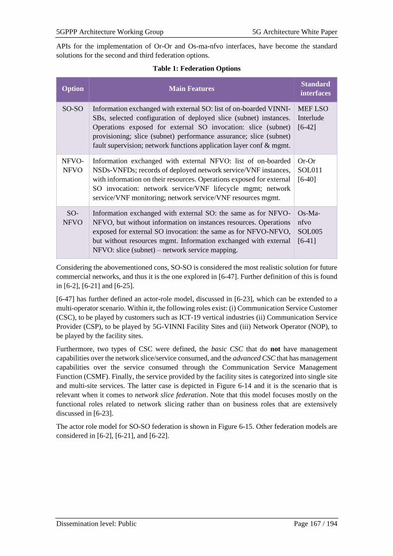
5GPPP Architecture Working Group 5G Architecture White Paper
Dissemination level: Public Page 167 / 194
APIs for the implementation of Or-Or and Os-ma-nfvo interfaces, have become the standard
solutions for the second and third federation options.
Table 1: Federation Options
Option Main Features Standard
interfaces
SO-SO Information exchanged with external SO: list of on-boarded VINNI-
SBs, selected configuration of deployed slice (subnet) instances.
Operations exposed for external SO invocation: slice (subnet)
provisioning; slice (subnet) performance assurance; slice (subnet)
fault supervision; network functions application layer conf & mgmt.
MEF LSO
Interlude
[6-42]
NFVO-
NFVO
Information exchanged with external NFVO: list of on-boarded
NSDs-VNFDs; records of deployed network service/VNF instances,
with information on their resources. Operations exposed for external
SO invocation: network service/VNF lifecycle mgmt; network
service/VNF monitoring; network service/VNF resources mgmt.
Or-Or
SOL011
[6-40]
SO-
NFVO
Information exchanged with external SO: the same as for NFVO-
NFVO, but without information on instances resources. Operations
exposed for external SO invocation: the same as for NFVO-NFVO,
but without resources mgmt. Information exchanged with external
NFVO: slice (subnet) – network service mapping.
Os-Ma-
nfvo
SOL005
[6-41]
Considering the abovementioned cons, SO-SO is considered the most realistic solution for future
commercial networks, and thus it is the one explored in [6-47]. Further definition of this is found
in [6-2], [6-21] and [6-25].
[6-47] has further defined an actor-role model, discussed in [6-23], which can be extended to a
multi-operator scenario. Within it, the following roles exist: (i) Communication Service Customer
(CSC), to be played by customers such as ICT-19 vertical industries (ii) Communication Service
Provider (CSP), to be played by 5G-VINNI Facility Sites and (iii) Network Operator (NOP), to
be played by the facility sites.
Furthermore, two types of CSC were defined, the basic CSC that do not have management
capabilities over the network slice/service consumed, and the advanced CSC that has management
capabilities over the service consumed through the Communication Service Management
Function (CSMF). Finally, the service provided by the facility sites is categorized into single site
and multi-site services. The latter case is depicted in Figure 6-14 and it is the scenario that is
relevant when it comes to network slice federation. Note that this model focuses mostly on the
functional roles related to network slicing rather than on business roles that are extensively
discussed in [6-23].
The actor role model for SO-SO federation is shown in Figure 6-15. Other federation models are
considered in [6-2], [6-21], and [6-22].
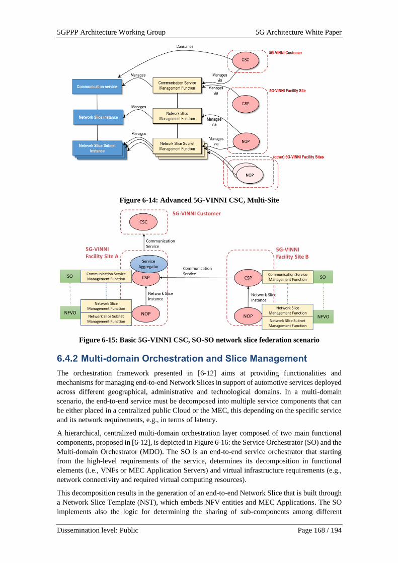
5GPPP Architecture Working Group 5G Architecture White Paper
Dissemination level: Public Page 168 / 194
Figure 6-14: Advanced 5G-VINNI CSC, Multi-Site
Figure 6-15: Basic 5G-VINNI CSC, SO-SO network slice federation scenario
6.4.2 Multi-domain Orchestration and Slice Management
The orchestration framework presented in [6-12] aims at providing functionalities and
mechanisms for managing end-to-end Network Slices in support of automotive services deployed
across different geographical, administrative and technological domains. In a multi-domain
scenario, the end-to-end service must be decomposed into multiple service components that can
be either placed in a centralized public Cloud or the MEC, this depending on the specific service
and its network requirements, e.g., in terms of latency.
A hierarchical, centralized multi-domain orchestration layer composed of two main functional
components, proposed in [6-12], is depicted in Figure 6-16: the Service Orchestrator (SO) and the
Multi-domain Orchestrator (MDO). The SO is an end-to-end service orchestrator that starting
from the high-level requirements of the service, determines its decomposition in functional
elements (i.e., VNFs or MEC Application Servers) and virtual infrastructure requirements (e.g.,
network connectivity and required virtual computing resources).
This decomposition results in the generation of an end-to-end Network Slice that is built through
a Network Slice Template (NST), which embeds NFV entities and MEC Applications. The SO
implements also the logic for determining the sharing of sub-components among different
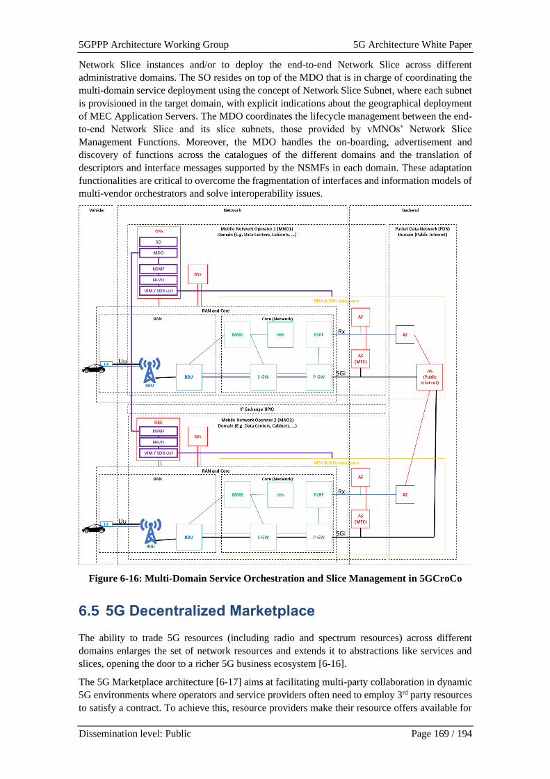
5GPPP Architecture Working Group 5G Architecture White Paper
Dissemination level: Public Page 169 / 194
Network Slice instances and/or to deploy the end-to-end Network Slice across different
administrative domains. The SO resides on top of the MDO that is in charge of coordinating the
multi-domain service deployment using the concept of Network Slice Subnet, where each subnet
is provisioned in the target domain, with explicit indications about the geographical deployment
of MEC Application Servers. The MDO coordinates the lifecycle management between the end-
to-end Network Slice and its slice subnets, those provided by vMNOs’ Network Slice
Management Functions. Moreover, the MDO handles the on-boarding, advertisement and
discovery of functions across the catalogues of the different domains and the translation of
descriptors and interface messages supported by the NSMFs in each domain. These adaptation
functionalities are critical to overcome the fragmentation of interfaces and information models of
multi-vendor orchestrators and solve interoperability issues.
Figure 6-16: Multi-Domain Service Orchestration and Slice Management in 5GCroCo
6.5 5G Decentralized Marketplace
The ability to trade 5G resources (including radio and spectrum resources) across different
domains enlarges the set of network resources and extends it to abstractions like services and
slices, opening the door to a richer 5G business ecosystem [6-16].
The 5G Marketplace architecture [6-17] aims at facilitating multi-party collaboration in dynamic
5G environments where operators and service providers often need to employ 3rd party resources
to satisfy a contract. To achieve this, resource providers make their resource offers available for

5GPPP Architecture Working Group 5G Architecture White Paper
Dissemination level: Public Page 170 / 194
sharing by advertising them through the 5G Marketplace. In general terms, the proposed
Marketplace enables the creation and acquisition of product offers that represent a variety of
exposed telco digital assets. These offers include individual resources such as infrastructure
components, VNFs and Cloud-Native Network Functions (CNFs); as well as composed bundles
in the form of services and slices.
The 5G Marketplace leverages the use of DLT and Smart Contracts technologies to enable the
trade of 5G resources. By leveraging a decentralized architecture, thus removing a single trusted
entity, stakeholders converge on a mutual trust in the distributed state of the application. However,
in addition to the foundational trust that underpins the marketplace, privacy, performance and the
capability to implement the necessary business rules are fundamental enterprise requirements
placed upon the supporting DLT infrastructure. Each Marketplace member will host a distributed
application (DApp) that interfaces with their domain’s DLT node, forming a peer-to-peer (P2P)
network consortium.
A decentralized Catalogue of product offers and the subsequent trading of these resources is a key
functional element of 5G Marketplace. Stakeholders only have sight of requests and all associated
transactions and state on a need-to-know basis. Smart Contracts facilitate a trusted negotiation
process between consumer, provider and– as needed – regulator, that aligns with agreed business
rules through an eventual agreement. Subsequent management of the workflows for resource
provisioning, set-up/teardown of SLA monitoring infrastructure, permissioned recording of SLA
violations & licensing actions (e.g., scaleup/down), and ultimate teardown of service agreements
and remuneration on completion of a contract is all automated thanks to Smart Contract execution.
5GZORRO Marketplace is ruled by Marketplace Administrators operating a decentralised
Governance platform to take decisions according to a Marketplace Governance Model. A major
Governance feature is the decentralized management of global (cross-domain) unique identifiers
that are compliant with the emerging W3C DID Working Group [6-45].
To support the 5G Marketplace in the 5G Architecture a new set of functional elements would be
required including a decentralized catalogue for 5G Resource offers and 5G Service offers,
decentralized repository for legal prose statements to be used in smart contracts and the life-cycle
management of smart contracts for offers and agreements between providers and consumers. See
in the next sections, more details about these new 5G functionalities.
Architectural solution 5G PPP Project Additional Reference
Resource / Service Trading 5GZORRO [6-43]
Cross domain Identity & Permissions
Management
5GZORRO [6-17], [6-42]
6.5.1 Resource / Service Trading
The 5G Marketplace enables the trading of 5G resources (including Radio Spectrum resources)
and services across different domains by using DLT Smart Contracts. Major Marketplace features
are decentralized catalogues for 5G Resource offers and 5G Service offers, decentralized
repository for legal prose statements to be used in smart contracts and the life-cycle management
of smart contracts for offers and agreements between providers and consumers.
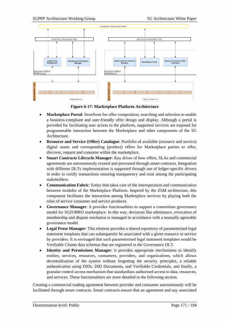
5GPPP Architecture Working Group 5G Architecture White Paper
Dissemination level: Public Page 171 / 194
Figure 6-17: Marketplace Platform Architecture
• Marketplace Portal: Storefront for offer composition, searching and selection to enable
a business-compliant and user-friendly offer design and display. Although a portal is
provided for facilitating user access to the platform, supported services are exposed for
programmable interaction between the Marketplace and other components of the 5G
Architecture.
• Resource and Service (Offer) Catalogue: Portfolio of available (resource and service)
digital assets and corresponding (product) offers for Marketplace parties to offer,
discover, request and consume within the marketplace.
• Smart Contracts Lifecycle Manager: Key driver of how offers, SLAs and commercial
agreements are autonomously created and processed through smart contracts. Integration
with different DLTs implementation is supported through use of ledger-specific drivers
in order to certify transactions ensuring transparency and trust among the participating
stakeholders.
• Communication Fabric: Entity that takes care of the interoperation and communication
between modules of the Marketplace Platform. Inspired by the ZSM architecture, this
component facilitates the interaction among Marketplace services by playing both the
roles of service consumer and service producer.
• Governance Manager: it provides functionalities to support a consortium governance
model for 5GZORRO marketplace. In this way, decisions like admittance, revocation of
membership and dispute resolution is managed in accordance with a mutually agreeable
governance model.
• Legal Prose Manager: This element provides a shared repository of parameterised legal
statement templates that can subsequently be associated with a given resource or service
by providers. It is envisaged that such parameterised legal statement templates would be
Verifiable Claims data schemas that are registered in the Governance DLT.
• Identity and Permissions Manager: it provides appropriate mechanisms to identify
entities, services, resources, consumers, providers, and organizations, which allows
decentralisation of the system without forgetting the security principles, a reliable
authentication using DIDs, DID Documents, and Verifiable Credentials, and finally, a
granular control access mechanism that standardises authorised access to data, resources,
and services. These functionalities are more detailed in the following section.
Creating a commercial trading agreement between provider and consumer autonomously will be
facilitated through smart contracts. Smart contracts ensure that an agreement and any associated
5GPPP Architecture Working Group 5G Architecture White Paper
Dissemination level: Public Page 172 / 194
actions on that agreement are processed in accordance with the agreed terms by validating any
transition of ledger state. What this means is that on entering into an agreement, whereby each
party agrees terms and signs the transaction, from that point on there is a commercial agreement
between the two legally identifiable entities backed by a legally enforceable contract (Ricardian
Contract [6-46]).
Smart Contract templates will be developed to capture both the broader general terms of an
agreement, and operational terms relating to a Service Level Objective (SLO), with specialized
templates to serve the needs of each resource type to be traded as necessary. These templates will
consist of parametrised legal prose to be utilised by stakeholders, crucially encapsulating real-
world legally ratified contracts. Smart contract templates will give rise to legally enforceable
smart contracts, but also the compelling improvement over existing working practices by
standardising contract terms across all stakeholders.
Resource and service business meta-data will comprise concrete instantiations of these templates,
producing a hierarchy of terms that outline the legal terms of the agreement, SLAs and their
associated SLOs.
These agreements will be deployed and managed by a component that manages the lifecycle
events of the contract. Smart Contracts will mirror that of the real-world contract and encapsulate
logic to automate the calculation of SLA compliance. On deployment of the contract to the ledger,
the autonomous set-up of monitoring and configuration of aggregation algorithms will be initiated
by the Smart Contract Lifecycle Manager. During the course of the contract’s lifetime, metrics
can be posted to the smart contract by the monitoring aggregation service and at frequencies as
agreed in the contract. Should a breach occur, the Smart Contract will enact any subsequent events,
which might simply be to record the breach until such time that a threshold is reached or trigger
the termination of the contract.
Smart contracts are ultimately providing autonomous near real-time execution of contract
lifecycle stages, from creation, monitoring & SLA enforcement through to settlement,
disbursement and finally termination.
6.5.2 Cross domain Identity & Permissions Management
Distributed trust models can allow network connections to be established between domains
reliably, avoiding possible connections that could endanger user data integrity or compromise the
security of service providers and end-users.
Key to the realisation of trust across domains is the use of decentralized identity management
(DIdM), which is based on Decentralized Identifiers (DIDs).
DIDs are a novel type of identifiers proposed by W3C (https://www.w3.org/TR/did-core/ ) that
allows associating any subjects such as stakeholders, resources, services, organizations, entities,
and so on, with a digital identity. DIDs are global identifiers which enable verifiable and
decentralized digital identity, allowing to uniquely identify any subject, e.g., a person,
organization, abstract entities, etc. To achieve this purpose, DIDs are associated with
cryptographic material, such as public keys, and service endpoints, making each DID globally
unique, resolvable with high availability, and cryptographically verifiable.
The usage of DIDs provides to an application of self-administered identity management, enabling
further self-managed capabilities such as authentication, authorization, role management, and
identity information exchange between two identity domains.
Another concept related to DIdM is Verifiable Credentials. A Verifiable Credential (VC) [6-17]
is a tamper-evident and privacy-preserving credential (set of claims) that can be demonstrated
5GPPP Architecture Working Group 5G Architecture White Paper
Dissemination level: Public Page 173 / 194
through a cryptographic process. Verifiable Credentials can represent the same information that
physical credentials represent in real life such as driving licenses, passports, health insurance card,
and so on. Therefore, Verifiable Credentials represent statements made by an issuer in a tamper-
evident and privacy-preserving manner.
The Identity Management is able to identify providers, consumers, services, resources,
organizations, etc., using Decentralised Identifiers (DIDs) associated with DID Documents. DIDs
are also used for authentication through Verifiable Credential linked to a DID Document. In the
case of Permissions Management, this allows setting up a secure layer that regulates the access to
resources, services, and delimited areas using a set of policies and rules. By means of policies and
rules, each domain can determine the amount of information exposed, the duration for which that
information is shared, what kind of information is shared, limiting resource capabilities, and so
on. Therefore, each domain must define its policies and rules based on its criteria such as
improving security, usability, availability, and cost-efficiency. In the end, Permissions
Management attempts to prevent unauthorised access to services, resources, and data, making
access control enforcement as granular as possible.
The Identity Management and Permissions Management functionalities are distributed across
different domains in DID Agent Functionalities, securely communicating among each other by
using P2P DID Communication protocols [6-45] and performing different DID Roles. Each DID
Agent holds an Identity and Trust DLT Wallet. There are three main types of DID Agents:
• Admin Issuer DID Agents have functionalities to issue Verifiable Credentials associated
with 5G Entities including Stakeholders Credentials and Marketplace Offers Credentials.
• Holder DID Agents communicate with Admin Agents to request the issue of Verifiable
Credentials. Issued credentials are stored and maintained by the Holder DID Agent.
• Verifier DID Agents communicate with Holder DID Agents to request presentation
proof of Verifiable Credentials.
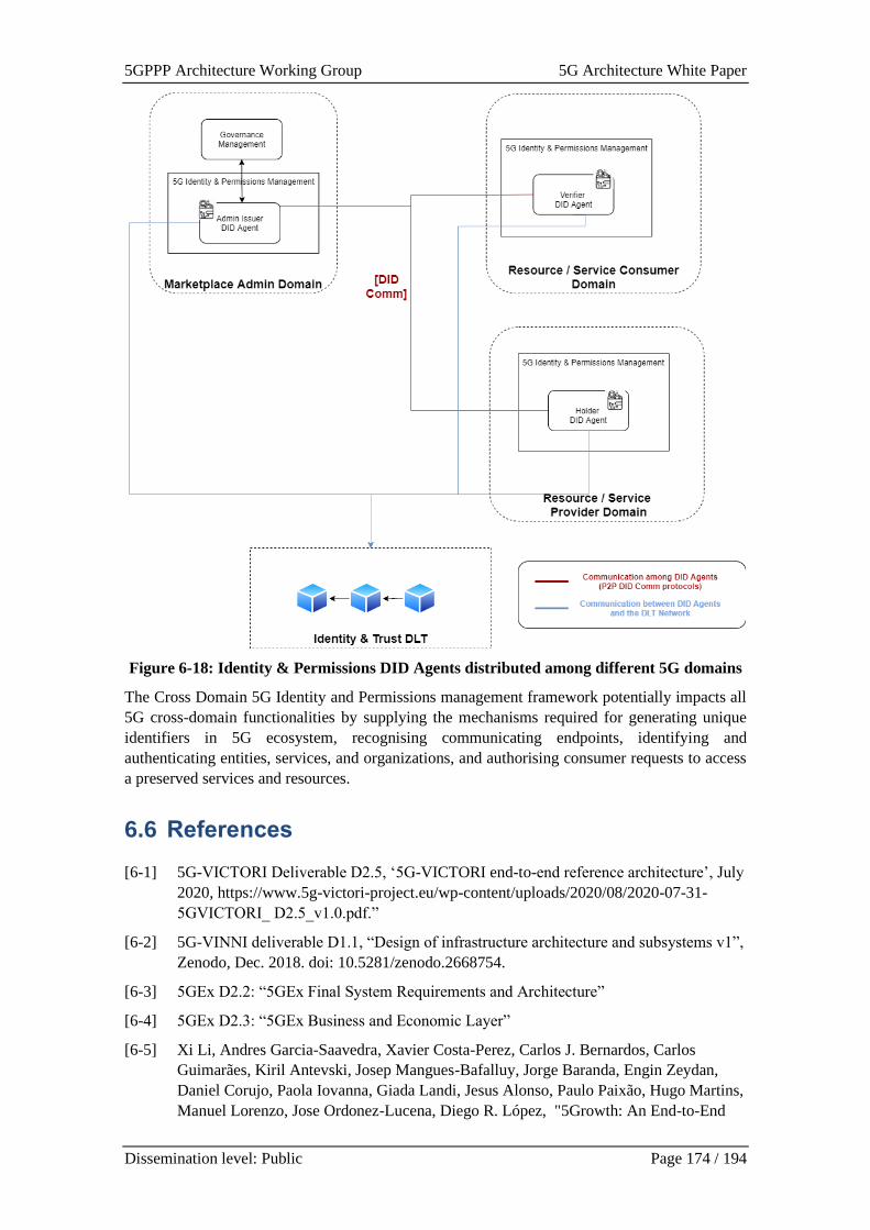
5GPPP Architecture Working Group 5G Architecture White Paper
Dissemination level: Public Page 174 / 194
Figure 6-18: Identity & Permissions DID Agents distributed among different 5G domains
The Cross Domain 5G Identity and Permissions management framework potentially impacts all
5G cross-domain functionalities by supplying the mechanisms required for generating unique
identifiers in 5G ecosystem, recognising communicating endpoints, identifying and
authenticating entities, services, and organizations, and authorising consumer requests to access
a preserved services and resources.
6.6 References
[6-1] 5G-VICTORI Deliverable D2.5, ‘5G-VICTORI end-to-end reference architecture’, July
2020, https://www.5g-victori-project.eu/wp-content/uploads/2020/08/2020-07-31-
5GVICTORI_ D2.5_v1.0.pdf.”
[6-2] 5G-VINNI deliverable D1.1, “Design of infrastructure architecture and subsystems v1”,
Zenodo, Dec. 2018. doi: 10.5281/zenodo.2668754.
[6-3] 5GEx D2.2: “5GEx Final System Requirements and Architecture”
[6-4] 5GEx D2.3: “5GEx Business and Economic Layer”
[6-5] Xi Li, Andres Garcia-Saavedra, Xavier Costa-Perez, Carlos J. Bernardos, Carlos
Guimarães, Kiril Antevski, Josep Mangues-Bafalluy, Jorge Baranda, Engin Zeydan,
Daniel Corujo, Paola Iovanna, Giada Landi, Jesus Alonso, Paulo Paixão, Hugo Martins,
Manuel Lorenzo, Jose Ordonez-Lucena, Diego R. López, "5Growth: An End-to-End
5GPPP Architecture Working Group 5G Architecture White Paper
Dissemination level: Public Page 175 / 194
Service Platform for Automated Deployment and Management of Vertical Services
over 5G Networks" in IEEE Communications Magazine, vol. 59, no. 3, March 2021.
[6-6] Xi Li, Carlos Guimarães, Giada Landi, Juan Brenes, Josep Mangues-Bafalluy, Jorge
Baranda, Daniel Corujo, Vitor Cunha, João Fonseca, João Alegria, Aitor Zabala Orive,
Jose Ordonez-Lucena, Paola Iovanna, Carlos J. Bernardos, Alain Mourad, Xavier
Costa-Perez, "Multi-Domain Solutions for the Deployment of Private 5G Networks",
IEEE Access, 2021. (in-press)
[6-7] “View on 5G Architecture”, 5G PPP Architecture Working Group, White Paper,
Version 3.0, February 2020.
[6-8] 5G PPP whitepaper, “Non-Public-Networks – State of the art and way forward”, doi:
10.5281/zenodo.5118839, https://doi.org/10.5281/zenodo. 5118839
[6-9] 5Growth deliverable D3.2 “Specification of ICT17 in-house deployment”, April 2020,
https://5growth.eu/wp-content/uploads/2019/06/D3.2-Specification_of_ICT17_in-
house_deployment_v1.0.1.pdf
[6-10] 5G-CARMEN Deliverable D4.1, “Design of the secure, cross-border and multi-domain
service orchestration platform”, https://5gcarmen.eu/wp-
content/uploads/2020/11/5G_CARMEN_D4.1_FINAL.pdf
[6-11] 5G-CARMEN Deliverable D4.2, “Advanced prototype for secure, cross-border and
multi-domain service orchestration”, https://5gcarmen.eu/publications/
[6-12] 5GCroco D3.2, ‘Intermediate E2E, MEC & Positioning Architecture’, January 2021,
[Online]. Available:
https://5gcroco.eu/images/templates/rsvario/images/5GCroCo_D3_2.pdf
[6-13] 5G-MOBIX deliverable D2.1, “5G-enabled CCAM use cases specifications”,
https://www.5g-mobix.com/assets/files/5G-MOBIX-D2.1-5G-enabled-CCAM-use-
cases-specifications-V2.0.pdf
[6-14] 5G-VICTORI Deliverable D2.1, “5G-VICTORI Use case and requirements definition
and reference architecture for vertical services”, March 2020, https://www.5g-victori-
project.eu/wp-content/uploads/2020/06/2020-03-31-5G-VICTORI_D2.1_v1.0.pdf
[6-15] 5G-VINNI D1.5: “E2E Network Slice Implementation and Further Design Guidelines”,
Zenodo, Oct. 2020. doi: 10.5281/zenodo.4067793.
[6-16] 5GZORRO deliverable D2.1 – “Use Cases and Requirements Definition”, May 2020
[6-17] 5GZORRO deliverable D2.2 – “Design of the 5GZORRO Platform for Security &
Trust”, Oct 2020
[6-18] 5GZORRO deliverable D3.1 – “Design of the evolved 5G Service layer solutions”,
January 2021.
[6-19] 5GZORRO deliverable D4.1 – “Design of Zero Touch Service Management with
Security & Trust Solutions”, January 2021.
[6-20] Sporny, M., Longleyy, D., and Chadwick, D. Verifiable Credentials Data Model 1.0.
Expressing verifiable information on the Web. W3C Recommendation 19 November
2019. Available online: https://www.w3.org/TR/vc-data-model/
[6-21] 5G-VINNI D1.6, “Design for systems and interfaces for slice operation v2”, Zenodo,
Jan. 2021. doi: 10.5281/zenodo.5113059.
5GPPP Architecture Working Group 5G Architecture White Paper
Dissemination level: Public Page 176 / 194
[6-22] 5G-VINNI D1.2: “Design of network slicing and supporting systems v1”, Zenodo, Mar.
2019. doi: 10.5281/zenodo.2668763.
[6-23] 5G-VINNI D5.1: “Ecosystem analysis and specification of B&E KPIs”, Zenodo, Jul.
2019. doi: 10.5281/zenodo.3345665.
[6-24] Deliverable D1.2 5G-TRANSFORMER initial system design http://5g-
transformer.eu/wp-content/uploads/2019/11/D1.2_5G-
TRANSFORMER_Initial_System_Design.pdf
[6-25] 5G-VINNI D3.1: “Specification of services delivered by each of the 5G-VINNI
facilities”, Zenodo, Jun. 2019. doi: 10.5281/zenodo.3345612.
[6-26] N. Uniyal et al., “5GUK Exchange: Towards sustainable end-to-end multi-domain
orchestration of softwarized 5G networks,” Comput. Networks, vol. 178, no. April,
2020.
[6-27] Project 5G-PICTURE “5G Programmable Infrastructure Converging disaggregated
neTwork and compUte REsources.” [Online]. Available: https://www.5g-picture-
project.eu/. [Accessed: 30-Mar-2021].
[6-28] 5G-MOBIX Deliverable “D3.3: Report on the 5G technologies integration and roll-out”
January 2021. https://www.5g-mobix.com/assets/files/5G-MOBIX-3.3-Report-on-the-
5G-technologies-integration-and-roll-out-v1.0.pdf
[6-29] 5GCroco D3.1, “Final Application Architecture”, January 2021, [Online]. Available:
https://5gcroco.eu/images/templates/rsvario/images/5GCroCo_D3_1.pdf
[6-30] 3GPP TR 23.761, “Study on system enablers for devices having multiple Universal
Subscriber Identity Modules (USIM)” V1.4.0, April 2021
[6-31] 3GPP TS22.186 Enhancement of 3GPP support for V2X scenarios
[6-32] 3GPP TS22.186 Enhancement of 3GPP support for V2X scenarios
[6-33] Blog Ericsson, ‘Keeping vehicles connected when they cross borders’ May 2019,
[Online]. Available: https://www.ericsson.com/en/blog/2019/5/connected-vehicle-cross-
border-service-coverage
[6-34] 3GPP TS23.501 System Architecture for the 5G System
[6-35] GSMA (December 2020 )Steering of Roaming Implementation Guidelines, Version 6.0
[6-36] 3GPP TS22.185 Service requirements for V2X services
[6-37] IETF RFC 4364: “BGP/MPLS IP Virtual Private Networks (VPNs)”
[6-38] X. Li et al., “5Growth: An End-to-End Service Platform for Automated Deployment
and Management of Vertical Services over 5G Networks,” IEEE Communications
Magazine, vol. 59, no. 3, pp. 84–90, March 2021.
[6-39] 5Growth deliverable D2.3 Final Design and Evaluation of the innovations of the 5G
End-to-End Service Platform, May 2021, https://5growth.eu/wp-
content/uploads/2019/06/D2.3-Final_Design_and_Evaluation_of_5G_End-to-
End_Service_Platform.pdf
[6-40] ETSI NFV SOL011: “Protocols and Data Models; RESTful protocols specification for
the Or-Or Reference Point”
[6-41] ETSI NFV SOL005: “Protocols and Data Models; RESTful protocols specification for
the Os-Ma-nfvo Reference Point”
5GPPP Architecture Working Group 5G Architecture White Paper
Dissemination level: Public Page 177 / 194
[6-42] MEF LSO Interlude: “https://www.mef.net/resources/technical-
specifications/download?id=44&fileid=file1” [Online].
[6-43] M. X. e. al., “Towards closed loop 5G service assurance architecture for network slices
as a service,” in EuCNC, 2019.
[6-44] Decentralized Identifiers (DIDs) v1.0. Drummond Reed; Manu Sporny; Markus
Sabadello; Dave Longley; Christopher Allen. W3C. 28 July 2020. W3C Working Draft.
Available online: https://www.w3.org/TR/did-core/
[6-45] DID Communication. Available online: https://identity.foundation/working-groups/did-
comm.html
[6-46] Ricardian contracts, [Online]. Available: http://webfunds.org/guide/ricardian.html
[6-47] Project 5G-VINNI, 5G Verticals Innovation Infrastructure, Online: https://5g-vinni.eu

5GPPP Architecture Working Group 5G Architecture White Paper
Dissemination level: Public Page 178 / 194
7 Arch Instantiations and Validations
This chapter describes the way 5G PPP [7-1] projects instantiate their proposed network
architectures to support vertical use cases based on 5G infrastructure. Particularly, three examples
of the network architecture are introduced: i) end-to-end (E2E) network including multiple sites
interworking; ii) service-based architecture to support vertical applications defined by SLAs
(service-level agreements); iii) large scale deployment to cover a large number of tourists visiting
historic places. This chapter also elaborates on performance evaluation from the E2E service
perspective. As a promising solution to reduce the testing efforts of the 5G infrastructure and
components, adoption of Testing-as-Service (TaaS) is investigated first. In addition, one network
architecture for 5G KPIs validation or for service performance assessment is studied. Then,
evaluation of the network slicing approaches is studied: i) a multi-slice UE in V2X networks, ii)
dynamic E2E slicing, and iii) multiple E2E network slicing for video media service.
Architectural Solution 5GPPP Project Additional Ref.
E2E Network of Multiple Sites Interworking 5G-VINNI [7-2], [7-7], [7-8]
Service-based Architecture FUDGE-5G [7-9], [7-10]
Large Scale Deployment of 5G Infrastructure 5G-TOURS [7-11]
E2E Service Validation 5GENESIS [7-13], [7-14], [7-15],
[7-16], [7-17]
Adoption of Testing-as-a-Service 5G-VINNI [7-18]
5G SA with MEC in multi-slice UE 5G-HEART [7-20], [7-21], [7-22]
Dynamic E2E service slicing FUDGE-5G [7-9], [7-23]
VNF based UHFM Video broadcasting and on
demand delivery service
5G-SOLUTIONS [7-25], [7-26]
7.1 Architecture Instantiation
7.1.1 E2E Network of Multiple Sites Interworking
Figure 7-1 depicts a high-level view of the conceptual E2E facility architecture and highlights the
key elements. The various building blocks are organized in three layers: the Resources and
Functional Level, the Service Level, and the Network Level as defined in the 5G PPP Architecture
white paper [7-3]. The Resources and Functional Level of the E2E facility are comprised of the
Radio Access Network (RAN), Backhaul, Mobile Core and Cloud Computing facilities. The
Resources and Functional Level provides the physical resources to host the Service Level and
Network Level elements such as the Virtual Network Functions (VNFs). These are interconnected
to build dedicated logical networks, customized to support services, such as eMBB, URLLC and
mMTC.
This modularity guarantees the highest degree of freedom of facility site configurations as well
as of E2E facility interworking. Any Service Level or Network Level VNF from any facility site
can be included within the logical network of another facility site. This creates an unbounded
capability to implement and test use cases using the consolidated shared capabilities of all
facilities, rather than limiting them to the capabilities of individual sites.
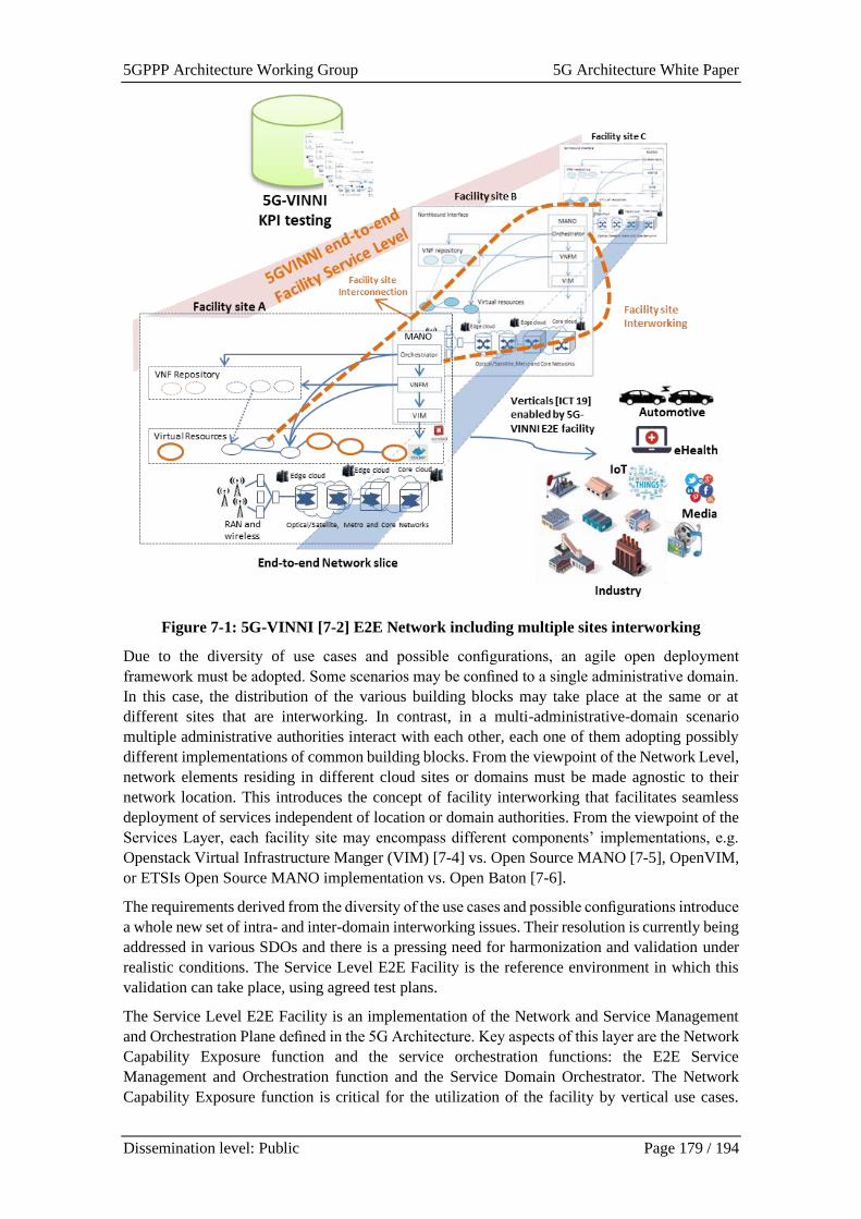
5GPPP Architecture Working Group 5G Architecture White Paper
Dissemination level: Public Page 179 / 194
Figure 7-1: 5G-VINNI [7-2] E2E Network including multiple sites interworking
Due to the diversity of use cases and possible configurations, an agile open deployment
framework must be adopted. Some scenarios may be confined to a single administrative domain.
In this case, the distribution of the various building blocks may take place at the same or at
different sites that are interworking. In contrast, in a multi-administrative-domain scenario
multiple administrative authorities interact with each other, each one of them adopting possibly
different implementations of common building blocks. From the viewpoint of the Network Level,
network elements residing in different cloud sites or domains must be made agnostic to their
network location. This introduces the concept of facility interworking that facilitates seamless
deployment of services independent of location or domain authorities. From the viewpoint of the
Services Layer, each facility site may encompass different components’ implementations, e.g.
Openstack Virtual Infrastructure Manger (VIM) [7-4] vs. Open Source MANO [7-5], OpenVIM,
or ETSIs Open Source MANO implementation vs. Open Baton [7-6].
The requirements derived from the diversity of the use cases and possible configurations introduce
a whole new set of intra- and inter-domain interworking issues. Their resolution is currently being
addressed in various SDOs and there is a pressing need for harmonization and validation under
realistic conditions. The Service Level E2E Facility is the reference environment in which this
validation can take place, using agreed test plans.
The Service Level E2E Facility is an implementation of the Network and Service Management
and Orchestration Plane defined in the 5G Architecture. Key aspects of this layer are the Network
Capability Exposure function and the service orchestration functions: the E2E Service
Management and Orchestration function and the Service Domain Orchestrator. The Network
Capability Exposure function is critical for the utilization of the facility by vertical use cases.
5GPPP Architecture Working Group 5G Architecture White Paper
Dissemination level: Public Page 180 / 194
Without effective exposure of network capabilities to vertical industry customers, the advance
service capabilities offered by 5G networks has little or no value. Network capabilities are not
limited to the capabilities that a single operator’s infrastructure provides. Following the 5G PPP
concept of recursion, a single service communication service provider’s capability may consist of
capabilities assembled from the services offered by other service providers. In these cases, the
E2E Service Management and Orchestration function plays an instrumental role, transparently
orchestrating the service life-cycle management across multiple service providers for a capability
exposed as a service by a single service provider.
7.1.2 Service-based Architecture
The FUDGE-5G project [7-9] takes a holistic approach for instantiating its service-based
architecture in an NFV-enabled (and if available SDN-enabled switching fabric) infrastructure
combined with a 5G-VINNI RAN solely focusing on Non-Public Networks (NPNs). FUDGE-5G
implements service routing and resource scheduling of the communication between 5G Core
(5GC) Network Functions (NFs), cloud native orchestration of 5GC NFs and their monitoring for
lifecycle management purposes inside their platform layer, as illustrated in Figure 7-2.
The platform is provisioned entirely as VNFs. Enterprise services such as 5G Core and vertical
applications are then orchestrated via RESTful and service-centric Application Programming
Interfaces (APIs) offered by the platform. It is worth noting that the infrastructure layer (in
particular the Network Function Virtualisation orchestrator (NFVO) is not involved in the
provisioning of any enterprise service. This layered concept is illustrated in Figure 7-2 where the
platform layer functionality implements the Service-based Architecture (SBA) functionalities.
The provisioning of FUDGE-5G’s SBA platform will be conducted over a range of NFVOs such
as OpenStack, OpenShift and Azure across five different use cases (and ten trials in total). The
open source ARDENT (Agnostic platfoRm DEploymeNt orchesTrator) [7-10] is being used for
abstracting the various NFVO APIs and offers the required automation to allow the automated
generation of NFVO resource descriptors. ARDENT can be conceptually seen as an extension to
the technologies Open Network Automation Platform (ONAP) or Open Source Mano (OSM) that
is slotted in between the NFVO and the VNF owners (i.e., the SBA platform).
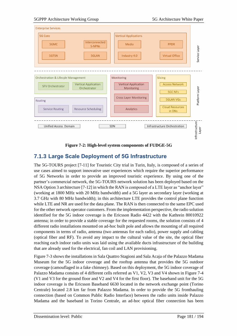
5GPPP Architecture Working Group 5G Architecture White Paper
Dissemination level: Public Page 181 / 194
Figure 7-2: High-level system components of FUDGE-5G
7.1.3 Large Scale Deployment of 5G Infrastructure
The 5G-TOURS project [7-11] for Touristic City trial in Turin, Italy, is composed of a series of
use cases aimed to support innovative user experiences which require the superior performance
of 5G Networks in order to provide an improved touristic experience. By using one of the
partner’s commercial network, the 5G-TOURS network solution has been deployed based on the
NSA Option 3 architecture [7-12] in which the RAN is composed of a LTE layer as “anchor layer”
(working at 1800 MHz with 20 MHz bandwidth) and a 5G layer as secondary layer (working at
3.7 GHz with 80 MHz bandwidth); in this architecture LTE provides the control plane function
while LTE and NR are used for the data plane. The RAN is then connected to the same EPC used
for the other network operator customers. From the implementation perspective, the radio solution
identified for the 5G indoor coverage is the Ericsson Radio 4422 with the Kathrein 80010922
antenna; in order to provide a stable coverage for the requested rooms, the solution consists of 4
different radio installations mounted on ad-hoc built pole and allows the mounting of all required
components in terms of radio, antenna (two antennas for each radio), power supply and cabling
(optical fiber and RF). To avoid any impact to the cultural value of the site, the optical fiber
reaching each indoor radio units was laid using the available ducts infrastructure of the building
that are already used for the electrical, fan coil and LAN provisioning.
Figure 7-3 shows the installations in Sala Quattro Stagioni and Sala Acaja of the Palazzo Madama
Museum for the 5G indoor coverage and the rooftop antenna that provides the 5G outdoor
coverage (camouflaged in a fake chimney). Based on this deployment, the 5G indoor coverage of
Palazzo Madama consists of 4 different cells referred as V1, V2, V3 and V4 shown in Figure 7-4
(V1 and V3 for the ground floor and V2 and V4 for the first floor). The baseband unit for the 5G
indoor coverage is the Ericsson Baseband 6630 located in the network exchange point (Torino
Centrale) located 2.8 km far from Palazzo Madama. In order to provide the 5G fronthauling
connection (based on Common Public Radio Interface) between the radio units inside Palazzo
Madama and the baseband in Torino Centrale, an ad-hoc optical fiber connection has been
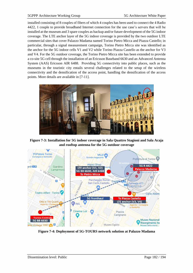
5GPPP Architecture Working Group 5G Architecture White Paper
Dissemination level: Public Page 182 / 194
installed consisting of 8 couples of fibers of which 4 couples has been used to connect the 4 Radio
4422, 1 couple to provide broadband Internet connection for the use case’s servers that will be
installed at the museum and 3 spare couples as backup and/or future development of the 5G indoor
coverage. The LTE anchor layer of the 5G indoor coverage is provided by the two outdoor LTE
commercial sites that cover Palazzo Madama named Torino Pietro Micca and Piazza Castello; in
particular, through a signal measurement campaign, Torino Pietro Micca site was identified as
the anchor for the 5G indoor cells V1 and V2 while Torino Piazza Castello as the anchor for V3
and V4. For the 5G outdoor coverage, the Torino Pietro Micca site has been extended to provide
a co-site 5G cell through the installation of an Ericsson Baseband 6630 and an Advanced Antenna
System (AAS) Ericsson AIR 6488. Providing 5G connectivity into public places, such as the
museums in the touristic city entails several challenges related to the setup of the wireless
connectivity and the densification of the access point, handling the densification of the access
points. More details are available in [7-11].
Figure 7-3: Installation for 5G indoor coverage in Sala Quattro Stagioni and Sala Acaja
and rooftop antenna for the 5G outdoor coverage
Figure 7-4: Deployment of 5G-TOURS network solution at Palazzo Madama
Torino Centrale

5GPPP Architecture Working Group 5G Architecture White Paper
Dissemination level: Public Page 183 / 194
7.2 Network Architecture Validation
7.2.1 E2E Service Validation
The 5GENESIS project [7-13] Facility provides a complete toolset to experimenters who wish to
make use of 5G platforms either for 5G KPIs validation or for performance assessment of their
services running on top of 5G. The three key layers of the experimentation facility are depicted
in Figure 7-5.
From the performance validation perspective, the Coordination Layer is the one that interacts with
the experimenter. Practically, the 5GENESIS Coordination Layer defines an entry point of a
MANO (management and orchestration) building block, through a MANO Wrapper that i)
manages all the experimentation requests in the Coordinator layer, and ii) performs the needed
operations before a Network Slice can be deployed in the Infrastructure. All these procedures
have been released as part of the open5GENESIS suite [7-14].
Figure 7-5: Three Layer architecture in 5GENESIS facility
Focusing on the experimentation process the 5GENESIS facility provides:
• ELCM: The Experiment Lifecycle Manager (ELCM) oversees the execution of an
experiment from the start until the end of the experiment. The ELCM is able to receive
execution requests generated by the 5GENESIS Portal in the form of the experiment
descriptor and is able to perform the execution of multiple experiments in parallel. By
sending requests to the Slice Manager’s REST API the ELCM is able to instantiate the
network services required by the experiment, and decommission them once the execution
finishes, freeing the resources for other experiments. More information about the
development and functionality of this component is provided in [7-15].
• PORTAL: The 5GENESIS web Portal allows the definition of experiments that can be
executed in the 5GENESIS Platform, and the visualization of the most important results
of an execution. The Portal provides a web-based user interface that experimenters
interact with in order to define and execute experiments in the 5GENESIS Platforms. The
Portal also allows experimenters to view a selection of the most relevant results generated
by their experiments in the form of custom Grafana dashboards. An Open API is
embedded as part of the Portal and the ELCM, which makes the communication between
these two components direct. More information about the Portal can be seen in [7-16].
An experimenter/vertical has two options for performing an experiment:
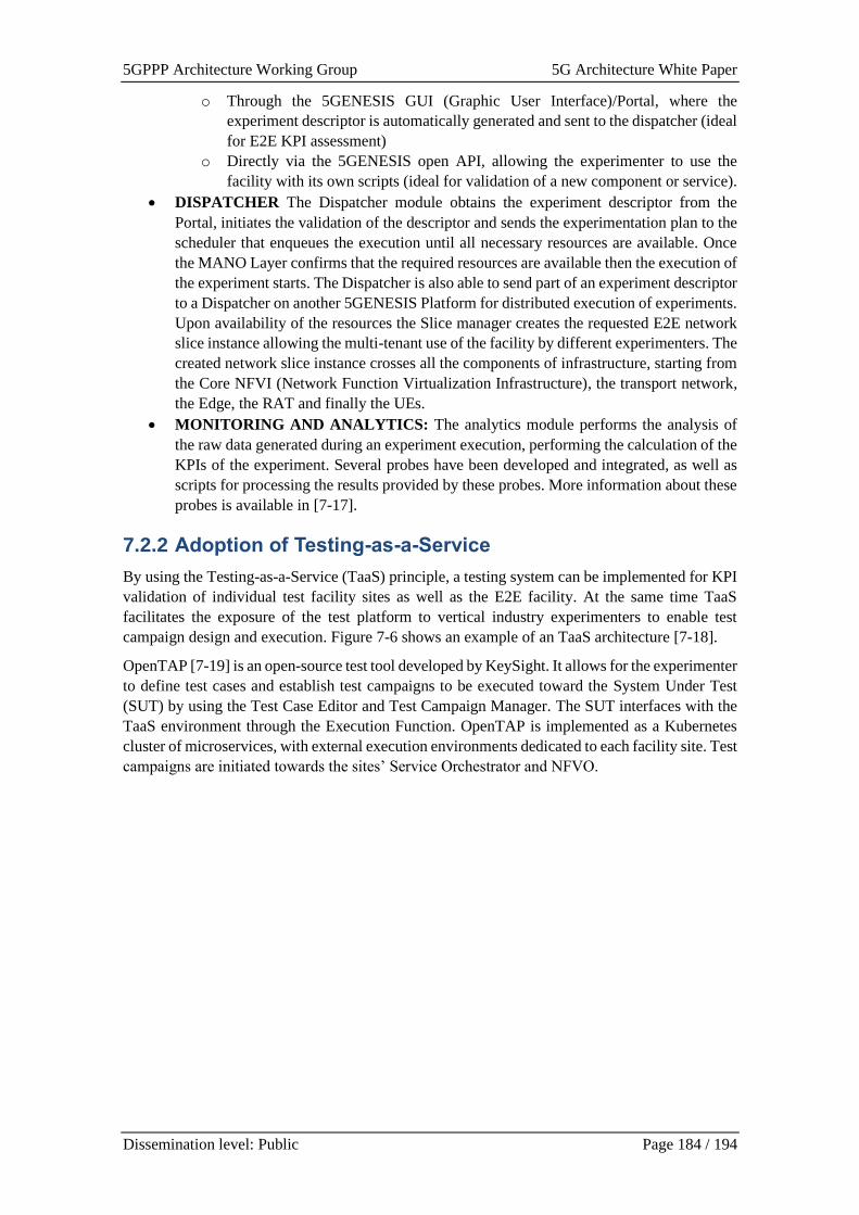
5GPPP Architecture Working Group 5G Architecture White Paper
Dissemination level: Public Page 184 / 194
o Through the 5GENESIS GUI (Graphic User Interface)/Portal, where the
experiment descriptor is automatically generated and sent to the dispatcher (ideal
for E2E KPI assessment)
o Directly via the 5GENESIS open API, allowing the experimenter to use the
facility with its own scripts (ideal for validation of a new component or service).
• DISPATCHER The Dispatcher module obtains the experiment descriptor from the
Portal, initiates the validation of the descriptor and sends the experimentation plan to the
scheduler that enqueues the execution until all necessary resources are available. Once
the MANO Layer confirms that the required resources are available then the execution of
the experiment starts. The Dispatcher is also able to send part of an experiment descriptor
to a Dispatcher on another 5GENESIS Platform for distributed execution of experiments.
Upon availability of the resources the Slice manager creates the requested E2E network
slice instance allowing the multi-tenant use of the facility by different experimenters. The
created network slice instance crosses all the components of infrastructure, starting from
the Core NFVI (Network Function Virtualization Infrastructure), the transport network,
the Edge, the RAT and finally the UEs.
• MONITORING AND ANALYTICS: The analytics module performs the analysis of
the raw data generated during an experiment execution, performing the calculation of the
KPIs of the experiment. Several probes have been developed and integrated, as well as
scripts for processing the results provided by these probes. More information about these
probes is available in [7-17].
7.2.2 Adoption of Testing-as-a-Service
By using the Testing-as-a-Service (TaaS) principle, a testing system can be implemented for KPI
validation of individual test facility sites as well as the E2E facility. At the same time TaaS
facilitates the exposure of the test platform to vertical industry experimenters to enable test
campaign design and execution. Figure 7-6 shows an example of an TaaS architecture [7-18].
OpenTAP [7-19] is an open-source test tool developed by KeySight. It allows for the experimenter
to define test cases and establish test campaigns to be executed toward the System Under Test
(SUT) by using the Test Case Editor and Test Campaign Manager. The SUT interfaces with the
TaaS environment through the Execution Function. OpenTAP is implemented as a Kubernetes
cluster of microservices, with external execution environments dedicated to each facility site. Test
campaigns are initiated towards the sites’ Service Orchestrator and NFVO.
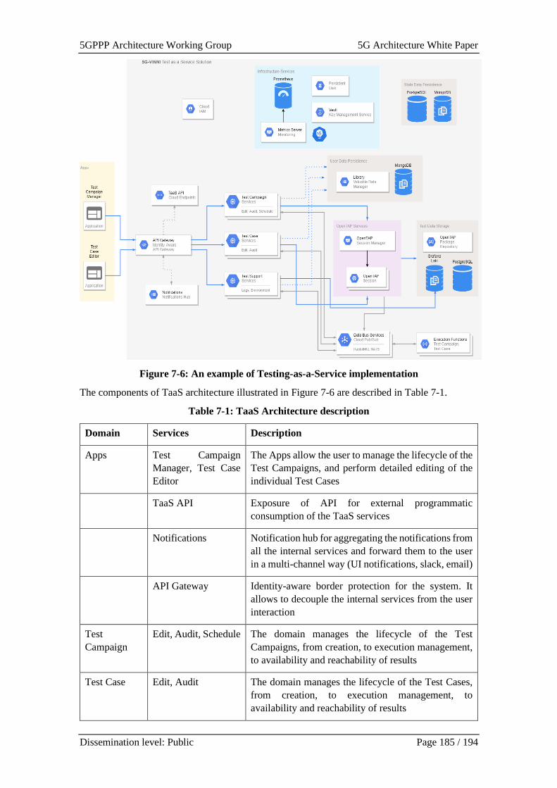
5GPPP Architecture Working Group 5G Architecture White Paper
Dissemination level: Public Page 185 / 194
Figure 7-6: An example of Testing-as-a-Service implementation
The components of TaaS architecture illustrated in Figure 7-6 are described in Table 7-1.
Table 7-1: TaaS Architecture description
Domain Services Description
Apps Test Campaign
Manager, Test Case
Editor
The Apps allow the user to manage the lifecycle of the
Test Campaigns, and perform detailed editing of the
individual Test Cases
TaaS API Exposure of API for external programmatic
consumption of the TaaS services
Notifications Notification hub for aggregating the notifications from
all the internal services and forward them to the user
in a multi-channel way (UI notifications, slack, email)
API Gateway Identity-aware border protection for the system. It
allows to decouple the internal services from the user
interaction
Test
Campaign
Edit, Audit, Schedule The domain manages the lifecycle of the Test
Campaigns, from creation, to execution management,
to availability and reachability of results
Test Case Edit, Audit The domain manages the lifecycle of the Test Cases,
from creation, to execution management, to
availability and reachability of results
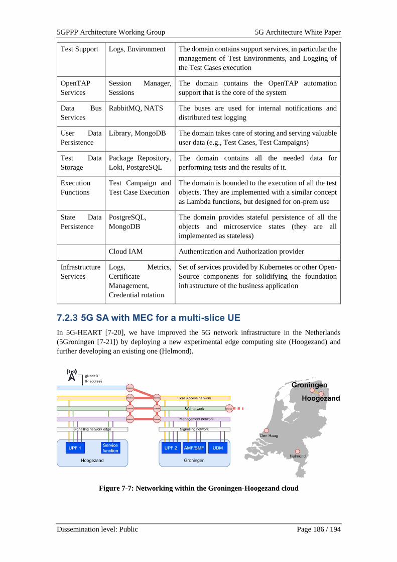
5GPPP Architecture Working Group 5G Architecture White Paper
Dissemination level: Public Page 186 / 194
Test Support Logs, Environment The domain contains support services, in particular the
management of Test Environments, and Logging of
the Test Cases execution
OpenTAP
Services
Session Manager,
Sessions
The domain contains the OpenTAP automation
support that is the core of the system
Data Bus
Services
RabbitMQ, NATS The buses are used for internal notifications and
distributed test logging
User Data
Persistence
Library, MongoDB The domain takes care of storing and serving valuable
user data (e.g., Test Cases, Test Campaigns)
Test Data
Storage
Package Repository,
Loki, PostgreSQL
The domain contains all the needed data for
performing tests and the results of it.
Execution
Functions
Test Campaign and
Test Case Execution
The domain is bounded to the execution of all the test
objects. They are implemented with a similar concept
as Lambda functions, but designed for on-prem use
State Data
Persistence
PostgreSQL,
MongoDB
The domain provides stateful persistence of all the
objects and microservice states (they are all
implemented as stateless)
Cloud IAM Authentication and Authorization provider
Infrastructure
Services
Logs, Metrics,
Certificate
Management,
Credential rotation
Set of services provided by Kubernetes or other Open-
Source components for solidifying the foundation
infrastructure of the business application
7.2.3 5G SA with MEC for a multi-slice UE
In 5G-HEART [7-20], we have improved the 5G network infrastructure in the Netherlands
(5Groningen [7-21]) by deploying a new experimental edge computing site (Hoogezand) and
further developing an existing one (Helmond).
Figure 7-7: Networking within the Groningen-Hoogezand cloud

5GPPP Architecture Working Group 5G Architecture White Paper
Dissemination level: Public Page 187 / 194
Hoogezand has servers with good computation capabilities, including a GPU (graphics processing
unit) for heavy matrix computations such as computer vision algorithms. The servers are managed
through VIO (VMware Integrated OpenStack) and are connected to another location in Groningen.
Both locations are managed as a single cloud, with each location being a different availability
zone. The locations are interconnected through a VPN (virtual private network). On top of that,
the core access networks, SGI networks, and management networks of each availability zone are
bridged together, providing connectivity between the locations seamlessly for the VMs, see
Figure 7-7.
Figure 7-8: Configurations of multi-slice UE in 5G SA with MEC
The 5G SA setup illustrated in Figure 7-8 corresponds to the Helmond setup, and it has been
evaluated in a real-world scenario using several slices simultaneously, one of them with mobile
edge computing (MEC), in the context of vehicular communication. The 5G SA-enabled UE is
placed on board of a vehicle and can connect to two slices in the core network simultaneously
where each slice has a separate SMF (session management function) and UPF (user plane
function). One of the UPFs is located in an edge server next to the antenna while the other UPF
is located together with the rest of the core network. The edge slice is used for vehicular
communication (e.g., for road/traffic information exchange) while the other slice is used for
general internet traffic (e.g., for entertainment by human users). Testing shows that the MEC slice
has less latency than the centrally routed traffic slice, which is an expected result. The details of
initial experiments can be found in [7-22].
For the core network, we use an open-source core network (Open5GS). In this setup, the different
core functions are deployed as services on several VMs in two different clouds (Den Haag and
Helmond) connected via VPN. In Den Haag, two separate VMs are in use, one of them contains
the central database and the other contains all the control plane function and a UPF. In Helmond,
two VMs are in use also, one of them holds the edge UPF while the other works as an edge
application server. For the radio configuration we use an Ericsson 4422 gNB with 5G SA and 5G
NSA capabilities.
7.2.4 Dynamic E2E Service Slicing
Generally speaking, slicing is the ability to isolate and enforce QoS for a set of predefined
resources. These resources can be physical resources (access to a medium either wired or wireless),
networking resources (throughput, latency), cloud resources (compute, memory, storage) or
5GPPP Architecture Working Group 5G Architecture White Paper
Dissemination level: Public Page 188 / 194
functional resources (service availability, responsiveness, etc.). What becomes apparent from the
holistic view on the E2E communication between UEs and services hosted in Data Networks (DN)
is that a 5G system has full control over resources on the 3GPP access network and the user plane
within the communication domain under control of the 5G Core (5GC). However, any resources
within the DN are not captured in the current 5G QoS enforcement domain except input by an
Application Function (AF) on steering traffic to a specific application. FUDGE-5G [7-9] takes a
holistic approach studying the opportunities for an SBA vision on the control and user plane to
address these boundaries through an orchestration component within the platform layer that
targets the service provisioning and lifecycle management and control of enterprise services, i.e.
5GC Network Functions (NF) and vertical applications, as illustrated in Figure 7-2. While
changes to how slices are requested and instantiated by UEs and 5GCs in a more dynamic ad-hoc
fashion are impossible to reduce to practise in the planned five trials due to the fact that modem
implementations cannot be changed by the project, FUDGE-5G utilises the concept of 5GLAN
Virtual Groups (VGs) by implementing and demonstrating this 3GPP Release 16 concept
allowing the logical grouping of UEs into the same Local Area Network (LAN) domain using a
dedicated 5GLAN VG manager.
In addition to demonstrating and validating the 5GLAN concept, FUDGE-5G offers a service
routing capability at platform layer implementing the Service Communication Proxy (SCP)
functionality, as introduced in 3GPP Release 15. The Name-based Routing (NbR) technology [7-
23], one of the three official SCP deployment options [7-24], routes traffic between 5GC
consumers and producers based on their HTTP header information (mainly FQDN and URI)
instead of using the IP address resolved by an DNS server. This allows the logical isolation (aka
slicing) between two independent 5GCs or a pinning of consumer and producer communication
to a subset of instances of a core triggered by UE slice requests. As FUDGE-5G’s SCP operates
at the granularity of HTTP transactions (request/response equals one completed transaction), the
decision which consumers and producer instances are logically grouped can be controlled and
changed transparently to the 5GC NFs for each new HTTP request a consumer issues. This
concept will be demonstrated and validated in FUDGE-5G as part of the proposed holistic
dynamic slicing approach.
7.2.5 VNF based UHFM Video broadcasting and on demand
delivery service
In order to test the potential of producing and distributing UHFM (Ultra High-Fidelity Media)
over emerging 5G networks, current and upcoming applications, content and services will be
provided to the 5G-SOLUTIONS project [7-25] University of Patras (UOP) 5G-VINNI testbed.
In addition, a set of comprehensive scenarios will be defined so to provide meaningful outcomes
to analyze technological, application and business aspects. The main aim is to measure latency in
a wide range of experiments using caching services running as a shared network service.
Additionally, quality guarantee services, density and mobility issues will be tested as well. The
key objective is to test unicast distribution of linear content to concurrent users stressing 5G radio
and network capabilities. This could be supported by the setup of specific QoS/SLA requirements
under a network slicing approach. Relevant service classes: eMBB, eMTC [7-26].
Specifically, E2E network slices are composed of multiple Network Slice Subnet Instances
(NSSI), which generally correspond to the RAN, Edge and Cloud Technological Domains (TD).
Resource policies applied to each NSSI and its horizontal stitching (i.e., logical interconnection)
realise the concept of an E2E network slice. Currently, Edge and Cloud TD can be easily stitched
together and provide system resources according to a determined policy. Moreover, given the
maturity of specifications and tools used at these TD (e.g. IEEE networking standards,
OpenStack) an administrator may easily embed specific configuration into NFV descriptor files
5GPPP Architecture Working Group 5G Architecture White Paper
Dissemination level: Public Page 189 / 194
at the NFV orchestrator [7-27]. Nevertheless, the integration of the RAN TD into this picture is
still under development.
Despite leveraging state-of-the-art open source and industry tools for 5G infrastructure (e.g.,
OpenStack, NetData, Prometheus, Amarisoft CallBox), lacking the ability to concurrently execute
multiple E2E network slices forces service owners to think about alternative ways for
implementation. Such alternatives should emulate a real E2E 5G infrastructure in a way which
could easily be ported to the final infrastructure once the aforementioned limitations are
circumvented. The following list gathers features not being able to be implemented given current
infrastructure limitations.
Table 7-2: Infrastructure limitations and Features not implemented
Use case Test goal Limitations
Ultra-High-
Fidelity
media
• Automatically setup live
streaming at orchestration time.
• Ensure system resources via
network slices.
• Leverage SNMP for remote
controlling encoders.
None. Current tools allow the
configuration of all TD, yielding the
collection of resources needed for the
successful implementation.
The challenge of emulating a virtual CDN (vCDN) with a limited set of nodes and clients (vCDN
nodes and UEs, respectively) can be achieved. Given the focus is to analyse how content should
be distributed among vCDN nodes in order to reduce latency for users, slices’ resources can well
be emulated leveraging a Platform as a Service (PaaS) as a Container Infrastructure System
Instance (CISI), which could easily be ported to 5G-VINNI. Such PaaS may contain the necessary
scenario to emulate content distribution, resources and user behaviour.
In Figure 7.9, an OSS/BSS (Operations Support System/Business Support System) emulating an
orchestration request can deploy a set of emulated vCDN nodes running on top of a Platform as
a Service (PaaS). An in-slice software component, referred to as Scenario Manager in the figure
proceeds to distribute subsets of a global content Library to such nodes. Later, random user
requests following commonly used distributions (e.g., Zipf, Normal) are directed toward the
vCDN deployment, which are then load-balanced among vCDN nodes. Failed requests,
successful hit counts (content requests matched at local vCDN node) and required content pulls
(from higher vCDN hierarchy, i.e., cloud) are gathered and analysed. Based on such analysis
different content replacement strategies (i.e., Least Recently Used (LRU), Windowed-LRU) are
applied in order to minimize the accumulated waiting time (i.e., due to failed cache) for a
determined distribution of Users and requests. In summary, such scenario leverages cloud-native
tools and recently standardized NFV objects (i.e., Kubernetes and PaaS via NFV IFA 029,
respectively) to emulate and develop new strategies for increasing caching efficiency in common
5G multimedia scenarios.
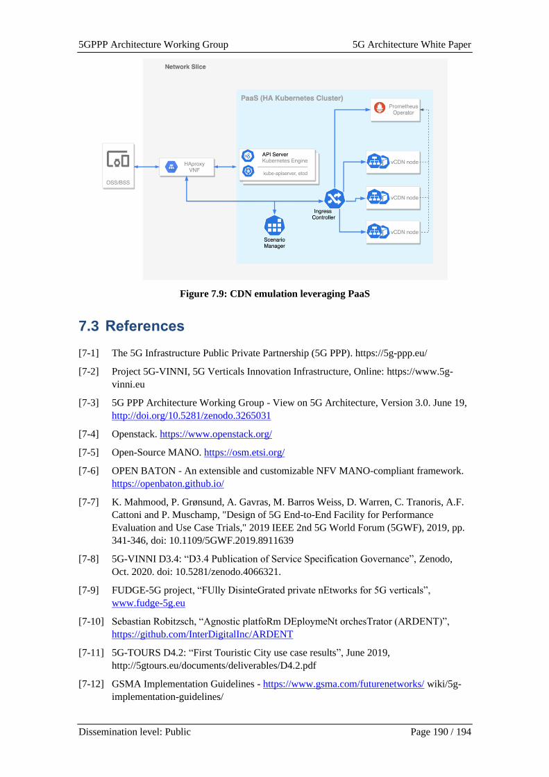
5GPPP Architecture Working Group 5G Architecture White Paper
Dissemination level: Public Page 190 / 194
Figure 7.9: CDN emulation leveraging PaaS
7.3 References
[7-1] The 5G Infrastructure Public Private Partnership (5G PPP). https://5g-ppp.eu/
[7-2] Project 5G-VINNI, 5G Verticals Innovation Infrastructure, Online: https://www.5g-
vinni.eu
[7-3] 5G PPP Architecture Working Group - View on 5G Architecture, Version 3.0. June 19,
http://doi.org/10.5281/zenodo.3265031
[7-4] Openstack. https://www.openstack.org/
[7-5] Open-Source MANO. https://osm.etsi.org/
[7-6] OPEN BATON - An extensible and customizable NFV MANO-compliant framework.
https://openbaton.github.io/
[7-7] K. Mahmood, P. Grønsund, A. Gavras, M. Barros Weiss, D. Warren, C. Tranoris, A.F.
Cattoni and P. Muschamp, "Design of 5G End-to-End Facility for Performance
Evaluation and Use Case Trials," 2019 IEEE 2nd 5G World Forum (5GWF), 2019, pp.
341-346, doi: 10.1109/5GWF.2019.8911639
[7-8] 5G-VINNI D3.4: “D3.4 Publication of Service Specification Governance”, Zenodo,
Oct. 2020. doi: 10.5281/zenodo.4066321.
[7-9] FUDGE-5G project, “FUlly DisinteGrated private nEtworks for 5G verticals”,
www.fudge-5g.eu
[7-10] Sebastian Robitzsch, “Agnostic platfoRm DEploymeNt orchesTrator (ARDENT)”,
https://github.com/InterDigitalInc/ARDENT
[7-11] 5G-TOURS D4.2: “First Touristic City use case results”, June 2019,
http://5gtours.eu/documents/deliverables/D4.2.pdf
[7-12] GSMA Implementation Guidelines - https://www.gsma.com/futurenetworks/ wiki/5g-
implementation-guidelines/
5GPPP Architecture Working Group 5G Architecture White Paper
Dissemination level: Public Page 191 / 194
[7-13] 5GENESIS project, https://5genesis.eu
[7-14] open5GENESIS suite, https://github.com/5genesis
[7-15] 5GENESIS D3.15: “Experiment and Lifecycle Manager, Oct. 2019,
https://5genesis.eu/wp-content/uploads/2019/10/5GENESIS_D3.15_v1.0.pdf
[7-16] 5GENESIS D3.7: “Open API, service-level functions and interfaces for verticals”, Oct.
2019, https://5genesis.eu/wp-content/uploads/2019/10/5GENESIS_D3.7_v1.0.pdf
[7-17] 5GENESIS D3.5: “Monitoring and analytics”, Oct. 2019, https://5genesis.eu/wp-
content/uploads/2019/10/5GENESIS_D3.5_v1.0.pdf
[7-18] 5G-VINNI D4.2: “Intermediate report on test-plan creation and methodology, and
development of test orchestration framework”, Zenodo, Oct. 2020. doi:
10.5281/zenodo.5113103.
[7-19] OpenTap, An Open-Source Project for Test Automation. https://www.opentap.io/
[7-20] 5G-HEART D2.1: “Use Case Description and Scenario Analysis”, Dec. 2019,
https://5gheart.org/wp-content/uploads/5G-HEART_D2.1.pdf
[7-21] 5Groningen, https://www.5groningen.nl/
[7-22] 5G-HEART D4.2: Initial Solution and Verification of Transport Use case Trials
[7-23] Dirk Trossen and Sebastian Robitzsch and Scott Hergenhan and Janne Riihijarvi and
Martin Reed and Mays Al-Naday, “Service-based Routing at the Edge”, 2019,
https://arxiv.org/abs/1907.01293
[7-24] 3GPP, “System architecture for the 5G System (5GS)”, TS23.501
[7-25] 5GSOLUTIONS project, https://5gsolutionsproject.eu
[7-26] 5G Media slice definition (Matrix pages 23-24) - https://bscw.5g-
ppp.eu/pub/bscw.cgi/d322688/NEM%20Networld2020%205G%20media%20slice%20
V1-2_24092019.pdf
[7-27] ETSI NFV IFA 029 - https://www.etsi.org/deliver/etsi_gr/NFV-
IFA/001_099/029/03.03.01_60/gr_NFV-IFA029v030301p.pdf
5GPPP Architecture Working Group 5G Architecture White Paper
Dissemination level: Public Page 192 / 194
8 Conclusions and Outlook
In this document, the current architectural trends and technology components for the 5G system
(5GS) have been presented in a very important transition phase, where the 5G is gaining market
share due to the already significant availability of both deployments and terminals. Nevertheless,
the research work is already discussing the beyond 5G technologies, as a fundamental
intermediate step needed to shape the next generation of wireless and mobile communications
system, namely 6G.
This white paper has been divided into three main technological domains (Access, Core, and
Management and Orchestration-MANO), and three transversal ones (Overall Architecture, Cross
Domain, and Architectural Instantiation), to capture all dimensions of the 5GPPP Projects,
Research, and Standardization works. In each of them, outstanding trends can be found which
will likely have a direct impact on the deployment of current technologies that will steer the
research trends during the next few years. Throughout the white paper, various aspects have been
analysed, such as the new stakeholders model, which is especially important in the context of the
Non Public Network (NPN), and the availability of the Service Layer to support Vertical
Operations.
Another area that is gaining a lot of traction is the edge and extreme edge technologies for the
radio access, with solutions based on reconfigurable intelligent surfaces (RIS) and THz bands that
are promising superior performance for ultra-reliable and low latency communications (URLLC).
Solutions based on those approaches are hence creating new requirements for the cloudified
environments.
Managing such heterogenous landscape (with novel aspects such as 5G LAN or multicast delivery)
certainly requires novel functionality in the MANO as discussed herein, e.g., network automation
based on Artificial Intelligence (AI) and Machine Learning (ML) are experiencing a vast adoption
and will be the starting point for the next generation network. This includes also aspects related
to network slicing management (over different infrastructure deployments), monitoring, and the
roaming aspects.
Finally, in this white paper, projects’ efforts in bringing the technology into practice have been
illustrated, validating the promises of enhanced KPIs and offering to verticals the availability of
the first trials for the 5G-empowered NetApps.
5GPPP Architecture Working Group 5G Architecture White Paper
Dissemination level: Public Page 193 / 194
9 List of Contributors
Name Company / Institute / University Country
Editorial Team
Overall Editors
Ömer Bulakci Nokia Germany
Marco Gramaglia UC3M Spain
Section 2 Editors
Marius Iordache Orange Romania
Anastasius Gavras Eurescom Germany
Section 3 Editors
Mir Ghoraishi Gigasys Solutions UK
Antonio Garcia Accelleran Ireland
Tezcan Cogalan InterDigital UK
Section 4 Editors
Jesus Gutiérrez IHP Microelectronics Spain
Anna Tzanakaki University of Bristol UK
Dan Warren Samsung UK
Section 5 Editors
Xi Li NEC Germany
Giada Landi Nextworks Italy
Josep Mangues CTTC Spain
Kostas Tsagkaris Incelligent Greece
Section 6 Editors
Anna Tzanakaki University of Bristol UK
Jesus Gutiérrez IHP Microelectronics Spain
Valerio Frascolla Intel Germany
5GPPP Architecture Working Group 5G Architecture White Paper
Dissemination level: Public Page 194 / 194
Section 7 Editor
Haeyoung Lee University of Surrey UK
Contributors
TBC