technical specification for - optcl
TRANSCRIPT
Page 1 of 95
ODISHA POWER TRANSMISSION CORPORATION LIMITED
TECHNICAL SPECIFICATION
FOR
40MVA, 132/33 KV POWER TRANSFORMER
Page 2 of 95
TECHNICAL SPECIFICATION
Sl. No. TITLE. 1.0 SCOPE. 2.0 Standards 3.0 Auxiliary Power Supply. 4.0 Principal Parameters. 5.0 General Technical Requirements. 5.1 Duty requirements. 5.2 Transformer Losses 5.3 Clearance. 5.4 Constructional Details. 5.4.1 Tank and Tank Accessories. 5.4.2 Valves and Location. 5.4.3 Joints and Gaskets. 5.4.4 Pressure relief device. 5.4.5 Earthing terminals. 5.4.6 Corrosion Protection. 5.4.7 Rating, diagram and valve plates. 5.4.8 Core. 5.4.9 Windings. 5.4.10 Gas and Oil actuated relays. 5.4.11 Temperature indicating devices and alarms. 5.4.12 Cooling equipment and its control. 5.4.13 Voltage selection and control. 5.4.14 Supervisory control. 5.4.15 Terminal and connection arrangements. 5.4.16 Specification for control cabinets. 5.4.17 Insulating Oil. 5.4.18 Cleaning, painting and tropicalisation. 5.4.19 Bolts and Nuts. 5.4.20 Wiring and cabling. 5.4.21 Fittings. 5.4.22 Limits of Temperature rise. 5.4.23 Motors & MCBs. 5.4.24 Spanners & Special tools. 5.4.25 List of Mandatory Spares. 6.0 INSPECTION AND TESTING. 6.1 Testing facilities 6.2 General 6.3 Stage Inspection. 6.4 Final Inspection 6.4.1 Type Tests & Special Tests 6.4.2 Routine Tests 6.4.3 Challenge Test 6.4.4 Tests on site 7.0 TEST REPORTS. 8.0 LIST OF TRANSFORMER ACCESSORIES AND
Page 3 of 95
TEST CERTIFICATES REQUIRED FOR THEM. 9.0 INSPECTION. 9.1 General. 9.2 Inspection Programme. 9.3 Pre-shipment check at supplier’s works. 9.4 Recommended commissioning checks. 10.0 QUALITY ASSURANCE PLAN. 11.0 DOCUMENTATION. 12.0 PACKING AND FORWARDING. 13.0 SUPERVISION OF ERECTION, TESTING
AND COMMISSIONING. 14.0 QUANTITY AND DELIVERY REQUIREMENTS. 15.0 VALUES QUOTED IN G.T.P. AND LOSS
CALCULATION. 16.0 METHOD OF TECHNICAL EVALUATION.
Page 4 of 95
ANNEXURES
No. Title. I. Quantity and Delivery Schedule. II. Maximum Flux Density and Core
Weight calculation. III. Details of Loss Calculations. IV. Guaranteed Technical Particulars. V. Additional Schedule of Informations. VI. Check list towards Type Test Reports. VII. Calibration Status of Testing
Instruments/Meters. VIII. Check list for Delivery Schedule. IX. Abstract of Terms & Conditions
(Technical).
N. B. : 1. Annexure-II to IX are to be filled up in complete shape by the bidders,.
Page 5 of 95
SECTION - IV. TECHNICAL SPECIFICATION
1.0 SCOPE: 1.1 This Specification provides for design, engineering, manufacture, assembly, stage
inspection, final inspection and testing before dispatch, packing and delivery at destination Sub-station by road transport, unloading at site and supervision of erection, testing and commissioning of 40MVA, 132/33KV Power Transformer complete with all fittings, accessories, associated equipments and spares, required for its satisfactory operation in any of the sub-stations of the State of Odisha.
1.2 The scope of supply includes the provision of training for Purchaser’s personnel. 1.3 The transformers shall conform in all respects to high standards of engineering, design,
workmanship and the latest revisions of relevant standards at the time of offer and Purchaser shall have the power to reject any work or material which, in his judgment, is not in full accordance therewith. The transformer(s), offered shall be complete with all components, necessary for their effective and trouble free operation. Such components shall be deemed to be within the scope of supply, irrespective of whether those are specifically brought out in this Specification and/or the commercial order or not.
1.4 The transformer(s), to be supplied against this specification shall be suitable for satisfactory continuous operation under the following Topographical and Meteorological conditions:- a) Maximum ambient air temperature (ºC) - 50 b) Minimum ambient air temperature (ºC)- 0 c) Average daily ambient air temperature (ºC)- 32 d) Relative humidity (%) - 100 e) Average rainfall per annum (cm)- 150 f) Maximum altitude above mean Sea level (m)- 1000 g) Maximum wind pressure (Kg/m²)- 80.84 h) Isoceraunic level (days/year)- 70 i) Seismic withstand factor(g) 0.3 j) Wind Velocity-(Wind Zone to IS875) (m/sec) 50 k) Pollution level to IEC815 Heavy l) Air-borne contamination, if any Highly Polluted
2.0 STANDARDS: 2.1 All transformers and associated equipments and accessories shall, except where
modified by this Specification, be designed, manufactured and tested in accordance with the latest editions of the relevant International (IEC), Indian (IS) and British (BS) standards. In case of conflict, the order of precedence shall be (1) IEC, (2) IS, (3) Other. Reference to particular standard or recommendation in this Specification does not relieve the Supplier of the necessity of providing goods and services, complying with other relevant standards or recommendations. The list of standards, provided in this Specification is not to be considered exhaustive and the supplier shall ensure that equipments, supplied under this contract meet the requirements of the relevant standard whether or not it is mentioned here.
IEC IS BS/other Title 60076 2026 171 Power Transformers
Page 6 of 95
P-1-2000 P-2-1993 P-3, 5-2000 P-6-1997 - - 6056 Methods of measurement of transformer
and Reactor sound levels - - 4360 Weldable structural steel - - 61 Threads for light gauge copper tube and
fittings - - 3600 Steel pipes and tubes for pressure purpose - - 4504 Flanges for pipes, valves and fittings 529 13947 EN60529 Enclosures for electrical apparatus (App.- 214 - 4571 On load tap changers 60137(1995) 2099 223 Bushings for alternating voltages above
1000V - 3347 - Dimensions for porcelain transformer
bushing for use in lightly polluted atmospheres 223 - 4963 Tests on hollow insulators 60354(1991) 6600 BSCP-0160 Loading guide for transformers 606 - - Application guide for power transformers 60296(Amd1-1986) 335 BS-14 Specification for unused mineral insulating oil
for Transformers and reactors 34 325 - Three phase Induction Motors 185 2705 - Current Transformers 518 - - Dimensional standardization of terminals
for HV Equipment 616 5578 - Terminal and tapping markings for Power (11353) Transformers - 1886 - Code of practice for installation and
maintenance of Transformers - 3639 - Fittings and accessories for power
transformers - 3637 - Gas operated relays - 6272 - Industrial cooling fans - 4691 - Degrees of protection provided by
enclosures for rotating electrical machines 186 3156 Specification for voltage transformers 617 - - Graphical Symbols for drawings - 2629 729 Galvanising - 2633 - Methods of testing uniformity for zinc
coated articles - 5 - Colours for ready mixed paints and
enamels - 2147 - Degrees of protection provided by
enclosures for Low voltage switchgears and control gears
Page 7 of 95
- 3401/1992 - Silicagel 9434 - Guide for sampling and analysis of
dissolved gas in oil filled equipment. 12676 - Oil impregnated paper insulated Bushing
Dimension and requirements. 60071, P-1-1993 - - Insulation Co-ordination P-2-1996
- 375 - Markings & Arrangements for switchgear Bus bars, Main connections and Auxiliary wiring
- 3638/1996 - Application Guide for Gas operated Relays. 60214(1989) 8468 - On-load Tap-changer. - 8269 - Methods for switching Impulse Test on
High Voltage Insulators. - 10028/1981 - Installation of Transformers. (Part-2) - 10028/1981 - Maintenance of Transformers. (Part-3) - 10561/1983 - Application Guide of Power Transformers. 60542, Amd 1-1988 8468/1997 - Application Guide for On-load Tap-changer. - 8263 - Method for Radio Interference Tests on
High Voltage Insulators. - 3202 - Code of practice for climate proofing of
Electrical Equipment. - 6702/1972 - Method for determination of Electric
strength of Insulating Oils. - 6103/1971 - Method of Test for specific Resistance of
Elect.Insulating Liquids. - 6262/1971 - Method of Test for power factor and
Dielectric Constant of Electrical Insulating Liquids.
- 6104/1971 - Method of Test for Interfacial Tension of oil against water by the Ring Method. 60034, P1-22(1972-2000) - - Rotating Electrical Machines. 60044, - - Instrument Transformers. Amd P1-2000, P-6-1992 60060, - - High Voltage Test Techniques. P-1-1989, Amd P-2-1996 60085 (1994) - - Thermal Evaluation and classification of
Elect. Insulation. 60270 (1981) - - Partial Discharge Measurements. 60404-8-7 (1998) - - Specification for Individual Materials-Cold
Rolled Grain oriented Electrical Steel sheet and strip delivered in fully processed state
60529 (Amd 1-1999) - - Degree of protection, provided by enclosures (IP-Code)
Page 8 of 95
60551(Amd 1-1995) - - Determination of Transformer and Reactor Sound Levels.
60567(1992) - - - Guide for sampling Gases and oil from oil-filled Electrical equipment for the analysis of free and Dissolved Gases
60599(1999) - - Mineral Oil-Impregnated Electrical Equipment in service-Guide to the Interpretation of Dissolved and Free Gases Analysis.
IS: 778 Gun metal gate,globe and check valves for general purpose
IS: 3401 Silicagel 60722 (1982) - - Guide to the Lightning and Switching
Impulse Testing of Power Transformers and Reactors.
60815 (1986) - - Guide for selection of Insulators in respect of polluted conditions.
60947, P-1-7 - - Low voltage switchgear & control gear. (l984-2000)
- IEEE C 57.93 IEEE Guides for Installation of Liquid Immersed
1995 Power Transformers. - - IEEE Std 80 Guide for safety and AC Sub-station Grounding. - - IEEE Std 979 Guide for Sub-station Fire protection. - - IEEE Std 980 Guide for containment and control of oil spills in Sub-stations. - - CBIP Pub.295/ Manual on Transformers. 2006 - - NFPA National Fire Protection Association. - - NEMA- - Standard No.1. - - Indian Electricity - Rules-1956.
2.2 The standards, mentioned above are available from: Standard: Name and Address: IS Bureau of Indian Standards, Manak Bhawan, 9-Bahadur Sahah Zafar Marg, New Delhi - 110001, India. IEC International Electro Technical Commission, Bureau Central dela Commission, Electro Technique International, 1-Ruede Verembe, Geneva, SWITZERLAND. 2.3 Transformer meeting with requirements of other authoritative International Standards
that ensure equal or better performance than the standards, mentioned above shall also be considered. When the transformer, offered by the supplier conforms to other standards, salient points of difference between standards adopted and the standards, specified in this specification shall be clearly brought out in the offer. Two copies of
Page 9 of 95
such standards with authentic translation in English shall be furnished along-with the offer.
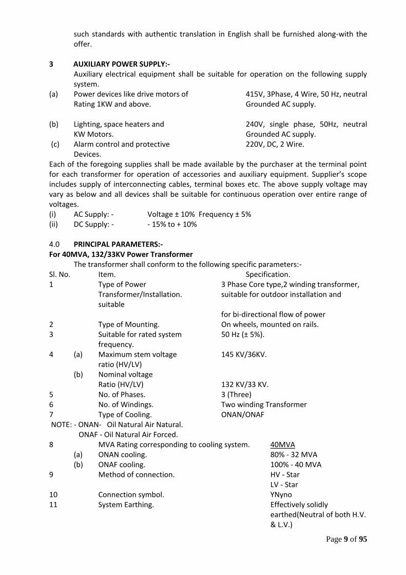
3 AUXILIARY POWER SUPPLY:-
Auxiliary electrical equipment shall be suitable for operation on the following supply system.
(a) Power devices like drive motors of 415V, 3Phase, 4 Wire, 50 Hz, neutral Rating 1KW and above. Grounded AC supply.
(b) Lighting, space heaters and 240V, single phase, 50Hz, neutral
KW Motors. Grounded AC supply. (c) Alarm control and protective 220V, DC, 2 Wire.
Devices. Each of the foregoing supplies shall be made available by the purchaser at the terminal point for each transformer for operation of accessories and auxiliary equipment. Supplier’s scope includes supply of interconnecting cables, terminal boxes etc. The above supply voltage may vary as below and all devices shall be suitable for continuous operation over entire range of voltages. (i) AC Supply: - Voltage ± 10% Frequency ± 5% (ii) DC Supply: - - 15% to + 10% 4.0 PRINCIPAL PARAMETERS:- For 40MVA, 132/33KV Power Transformer
The transformer shall conform to the following specific parameters:- Sl. No. Item. Specification. 1 Type of Power 3 Phase Core type,2 winding transformer,
Transformer/Installation. suitable for outdoor installation and suitable
for bi-directional flow of power 2 Type of Mounting. On wheels, mounted on rails. 3 Suitable for rated system 50 Hz (± 5%).
frequency. 4 (a) Maximum stem voltage 145 KV/36KV.
ratio (HV/LV) (b) Nominal voltage
Ratio (HV/LV) 132 KV/33 KV. 5 No. of Phases. 3 (Three) 6 No. of Windings. Two winding Transformer 7 Type of Cooling. ONAN/ONAF NOTE: - ONAN- Oil Natural Air Natural.
ONAF - Oil Natural Air Forced. 8 MVA Rating corresponding to cooling system. 40MVA
(a) ONAN cooling. 80% - 32 MVA (b) ONAF cooling. 100% - 40 MVA
9 Method of connection. HV - Star LV - Star
10 Connection symbol. YNyno 11 System Earthing. Effectively solidly
earthed(Neutral of both H.V. & L.V.)
Page 10 of 95
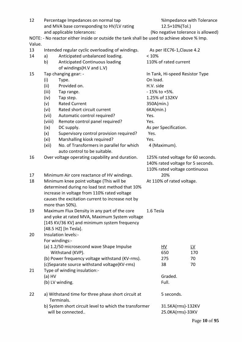
12 Percentage Impedances on normal tap %Impedance with Tolerance and MVA base corresponding to HV/LV rating 12.5+10%(Tol.) and applicable tolerances: (No negative tolerance is allowed)
NOTE: - No reactor either inside or outside the tank shall be used to achieve above % Imp. Value. 13 Intended regular cyclic overloading of windings. As per IEC76-1,Clause 4.2 14 a) Anticipated unbalanced loading. < 10%
b) Anticipated Continuous loading 110% of rated current of windings(H.V and L.V)
15 Tap changing gear: - In Tank, Hi-speed Resistor Type (i) Type. On load. (ii) Provided on. H.V. side (iii) Tap range. - 15% to +5%. (iv) Tap step. 1.25% of 132KV (v) Rated Current 350A(min.) (vi) Rated short circuit current 6KA(min.) (vii) Automatic control required? Yes. (viiii) Remote control panel required? Yes. (ix) DC supply. As per Specification. (x) Supervisory control provision required? Yes. (xi) Marshalling kiosk required? Yes. (xii) No. of Transformers in parallel for which 4 (Maximum).
auto control to be suitable. 16 Over voltage operating capability and duration. 125% rated voltage for 60 seconds.
140% rated voltage for 5 seconds. 110% rated voltage continuous
17 Minimum Air core reactance of HV windings. 20% 18 Minimum knee point voltage (This will be At 110% of rated voltage.
determined during no load test method that 10% increase in voltage from 110% rated voltage causes the excitation current to increase not by more than 50%).
19 Maximum Flux Density in any part of the core 1.6 Tesla and yoke at rated MVA, Maximum System voltage [145 KV/36 KV] and minimum system frequency [48.5 HZ] [In Tesla].
20 Insulation levels:- For windings:- (a) 1.2/50 microsecond wave Shape Impulse HV LV Withstand (KVP). 650 170 (b) Power frequency voltage withstand (KV-rms). 275 70 (c)Separate source withstand voltage(KV-rms) 38 70
21 Type of winding insulation:- (a) HV Graded. (b) LV winding. Full.
22 a) Withstand time for three phase short circuit at 5 seconds.
Terminals. b) System short circuit level to which the transformer 31.5KA(rms)-132KV
will be connected.. 25.0KA(rms)-33KV
Page 11 of 95
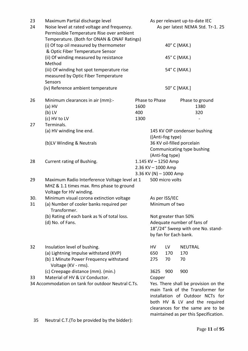
23 Maximum Partial discharge level As per relevant up-to-date IEC 24 Noise level at rated voltage and frequency. As per latest NEMA Std. Tr-1. 25 Permissible Temperature Rise over ambient
Temperature. (Both for ONAN & ONAF Ratings) (i) Of top oil measured by thermometer 40° C (MAX.)
& Optic Fiber Temperature Sensor (ii) Of winding measured by resistance 45° C (MAX.) Method (iii) Of winding hot spot temperature rise 54° C (MAX.) measured by Optic Fiber Temperature Sensors
(iv) Reference ambient temperature 50° C [MAX.] 26 Minimum clearances in air (mm):- Phase to Phase Phase to ground
(a) HV 1600 1380 (b) LV 400 320 (c) HV to LV 1300 -
27 Terminals. (a) HV winding line end. 145 KV OIP condenser bushing ((Anti-fog type) (b)LV Winding & Neutrals 36 KV oil-filled porcelain Communicating type bushing (Anti-fog type)
28 Current rating of Bushing. 1.145 KV – 1250 Amp 2.36 KV – 1000 Amp 3.36 KV (N) – 1000 Amp
29 Maximum Radio Interference Voltage level at 1 500 micro volts MHZ & 1.1 times max. Rms phase to ground Voltage for HV winding.
30. Minimum visual corona extinction voltage As per ISS/IEC 31 (a) Number of cooler banks required per Minimum of two
Transformer. (b) Rating of each bank as % of total loss. Not greater than 50% (d) No. of Fans. Adequate number of fans of
18”/24” Sweep with one No. stand-by fan for Each bank.
32 Insulation level of bushing. HV LV NEUTRAL
(a) Lightning Impulse withstand (KVP) 650 170 170 (b) 1 Minute Power Frequency withstand 275 70 70 Voltage (KV - rms). (c) Creepage distance (mm). (min.) 3625 900 900
33 Material of HV & LV Conductor. Copper 34 Accommodation on tank for outdoor Neutral C.Ts. Yes. There shall be provision on the
main Tank of the Transformer for installation of Outdoor NCTs for both HV & LV and the required clearances for the same are to be maintained as per this Specification.
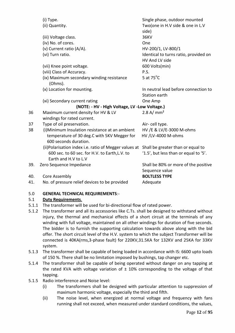
35 Neutral C.T.(To be provided by the bidder):
Page 12 of 95
(i) Type. Single phase, outdoor mounted (ii) Quantity. Two(one in H.V side & one in L.V
side) (iii) Voltage class. 36KV (iv) No. of cores. One (v) Current ratio (A/A). HV-200/1, LV-800/1 (vi) Turn ratio. Identical to turns ratio, provided on
HV And LV side (vii) Knee point voltage. 600 Volts(min) (viii) Class of Accuracy. P.S. (ix) Maximum secondary winding resistance 5 at 75oC (Ohms). (x) Location for mounting. In neutral lead before connection to Station earth (xi) Secondary current rating One Amp
(NOTE: - HV - High Voltage, LV -Low Voltage.) 36 Maximum current density for HV & LV 2.8 A/ mm²
windings for rated current. 37 Type of oil preservation. Air- cell type. 38 (i)Minimum Insulation resistance at an ambient HV /E & LV/E-3000 M-ohms
temperature of 30 deg.C with 5KV Megger for HV /LV-4000 M-ohms 600 seconds duration.
(ii)Polarisation index i.e. ratio of Megger values at Shall be greater than or equal to 600 sec. to 60 sec. for H.V. to Earth,L.V. to ‘1.5’, but less than or equal to ‘5’. Earth and H.V to L.V
39. Zero Sequence Impedance Shall be 80% or more of the positive Sequence value
40. Core Assembly BOLTLESS TYPE 41. No. of pressure relief devices to be provided Adequate 5.0 GENERAL TECHNICAL REQUIREMENTS:- 5.1 Duty Requirements. 5.1.1 The transformer will be used for bi-directional flow of rated power. 5.1.2 The transformer and all its accessories like C.Ts. shall be designed to withstand without
injury, the thermal and mechanical effects of a short circuit at the terminals of any winding with full voltage, maintained on all other windings for duration of five seconds. The bidder is to furnish the supporting calculation towards above along with the bid offer. The short circuit level of the H.V. system to which the subject Transformer will be connected is 40KA(rms,3-phase fault) for 220KV,31.5KA for 132KV and 25KA for 33KV system.
5.1.3 The transformer shall be capable of being loaded in accordance with IS: 6600 upto loads of 150 %. There shall be no limitation imposed by bushings, tap changer etc.
5.1.4 The transformer shall be capable of being operated without danger on any tapping at the rated KVA with voltage variation of ± 10% corresponding to the voltage of that tapping.
5.1.5 Radio interference and Noise level: (i) The transformers shall be designed with particular attention to suppression of
maximum harmonic voltage, especially the third and fifth. (ii) The noise level, when energized at normal voltage and frequency with fans
running shall not exceed, when measured under standard conditions, the values,
Page 13 of 95
specified in NEMA, TR-1. The transformer noise levels shall be measured as a routine test and in
accordance with IEC-60551:1981. 5.1.6 Transformer shall be capable of operating under the natural cooled condition upto the
specified load. The forced cooling equipment shall come into operation by preset contacts of winding temperature indicator and the transformer shall operate as a forced cooled unit, as ONAF. Cooling shall be so designed that during total failure of power supply to cooling fans, the transformer shall be able to operate at full load for at least ten (10) minutes without the calculated winding hot spot temperature exceeding 140 degree centigrade. Also stopping of one or two cooling fans should not have any effect on the cooling system. Transformers fitted with two coolers each capable of dissipating 50 percent of the loss at continuous maximum rating shall be capable of operating for 20 minutes in the event of failure of the blowers, associated with one cooler, without the calculated winding hot spot temperature exceeding 115 degree centigrade at continuous maximum rating.
5.1.7 Transformer shall be capable of withstanding thermal and mechanical stresses, caused by symmetrical or asymmetrical faults on any winding.
5.1.8 Transformer shall accept, without injurious heating, combined voltage and frequency fluctuation, which produces the following over fluxing condition: i) 125% for 1 minute. The base voltage and frequency refer
140% for 5 seconds. to those mentioned in Clause 4.0 (3& 4). ii) Over fluxing withstand characteristics upto 170% shall be submitted along with the bid.
5.2.0 TRANSFORMER LOSSES:- 5.2.1 The bidder shall indicate values of No load losses (iron losses), load losses (copper
losses) and auxiliary losses in his bid, which shall be firm. 5.2.2 Loss figure for evaluation of bid:
Loss figure for the transformers should not exceed as detailed below :- 40MVA, 132/33KV Power Transformer: i) No load losses- 16.00 KW ii) Load (Copper) losses including Auxiliary losses- 115.00KW. The transformer losses, guaranteed in the bid are to be supported by design calculations along with documentary evidences.
5.2.3 Liquidated damage for excessive losses:
On testing, if it is found that actual losses are more than the values, quoted in the bid, undisputed liquidated damages shall be recovered from the supplier at the following rates:- (i) For each KW of excess in ‘No Load losses… Rs.4,59,640.00/KW (ii) For each KW of excess in ‘Load losses’ Rs.2,75,784.00/KW and “auxiliary losses” For fractional of Kilowatt, penalties shall be applied on prorata basis. No bonus shall be payable for losses, which are less than those, stated in the Bid.
The purchaser reserves the right to reject the transformer(s), if on testing, the losses exceed the declared losses beyond tolerance limits as per I.S. or the temperature rise in oil and/or winding exceed the values, specified in technical particulars or impedance value differs from the guaranteed value including tolerance as per this specification and if any of the test results do not match with the values, given in the
Page 14 of 95
guaranteed technical particulars and as per technical specification. The purchaser reserves the right to retain the rejected transformer and take it into service until the supplier replaces it, at no extra cost to the purchaser by a new transformer. Alternatively, the supplier shall repair or replace the transformer in a reasonable period, as decided by the purchaser to purchaser’s satisfaction at no extra cost to the purchaser.
5.2.4 In case of failure of the transformer, the supplier shall take back the faulty transformer
from its plinth for repair at their own cost (or replace the transformer with a new transformer) and deliver, at their own cost, unload at the destination sub-station transformer plinth within three months period from the date of intimation of defects to the satisfaction of the owner, at free of cost. If the delivery after repair/replacement will not be completed within three months, then the supplier shall pay penalty @ 0.5% of the contract price for each calendar week of delay from the end of three months period from the date of intimation of defects. Also, the Purchaser reserves the right for forfeiture of the total Composite Bank Guarantee and all the Securities, available with OPTCL, in case the Supplier fails to pay the penalty by one month before the expiry of the guarantee period. Also, this will be taken as adverse in all future tenders.
5.3 CLEARANCE :
The overall dimensions of the transformer shall allow for sufficient clearances for installation in a 245/145 KV switchyard with bay width of 18000/10500 mm and boom height of 15/11 m.
5.4 CONSTRUCTIONAL DETAILS:
The features and constructional details of Power transformer shall be in accordance with the requirements, stated hereunder:-
5.4.1 TANK AND TANK ACCESSORIES: 5.4.1.1 TANK : -
(a) The transformer shall be enclosed in a suitably stiffened welded steel tank such that the transformer can be lifted and transported without permanent deformation or oil leakage. The construction shall employ weldable, low carbon, tested quality structural steel of an approved grade to BS: 4360. The transformer tank shall have rectangular shape. The minimum thickness of base and tank cover shall be 12mm. and that of sides is 8mm.
(b) The tank of the transformer shall be complete with all accessories and shall be designed so as to allow complete transformer in the tank and filled with oil, to be lifted by crane or jacks, transported by road or rail without over-straining any joint and without causing subsequent leakage of oil.
(c) All seams and those joints, not required to be opened at site shall be factory-welded and wherever possible they shall be double welded. After completion of tank construction and before painting, dye penetration test shall be carried out on welded parts of jacking bosses, lifting lugs and all load bearing members. Also radiographic tests shall be carried out on 5% of total weld length. The requirement of post-weld heat treatment for tank/stress relieving parts shall be based on recommendations of BS: 5500, Table 4.4.3.1.
(d) All necessary precautions shall be taken to prevent ingress of moisture between flange plates, around gaskets and O-rings, at insulator/flange interfaces etc. due to high humidity.
Page 15 of 95
(e) Tank stiffeners shall be provided, if required, for general rigidity and these shall be designed to prevent retention of water.
(f) The transformer tank shall be of conventional type construction. In case the joint is welded, it shall be provided with flanges, suitable for repeated welding. The joint shall be provided with a suitable gasket to prevent weld splatter inside the tank. Proper tank shielding shall be done to prevent excessive temperature rise of the joint.
(g) The main tank body excluding tap-changing compartments, radiators and coolers shall be capable of withstanding vacuums i.e. 100.64 KN/m² of gauge pressure, 760 mm of Hg.
(h) The tank shall be designed to withstand:- (i) Mechanical shocks during transportation. (ii) Vacuum filling of oil. (iii) Continuous internal pressure of 35 KN/m² over normal hydrostatic pressure of
oil. (iv) Short circuit forces. (i) Wherever possible, the transformer tank and its accessories shall be designed
without pockets wherein gas may collect. Where pockets cannot be avoided, pipes shall be provided to vent the gas into the main expansion pipe. The vent pipes shall have minimum inside diameter of 15 mm except for short branch pipes, which may be 6 mm minimum inside diameter.
(j) All joints other than those, which may have to be broken, shall be welded, when required, they shall be double-welded. All bolted joints to the tank shall be fitted with suitable oil-tight gaskets, which shall give a satisfactory service under the operating conditions and guaranteed temperature-rise conditions. Special attention shall be given to the methods of making hot oil tight joints between the tank and the cover as also between the cover and the bushing and all other outlets to ensure that the joints can be remade satisfactorily at site and with ease with the help of semi-skilled labour. If gasket is compressible, metallic stops shall be provided to prevent over compression.
(k) Adequate space shall be provided at the bottom of the tank for collection of sediments.
(l) The base of each tank shall be so designed that it shall be possible to move the complete unit by skidding in any direction without injury when using plates or rails.
(m) Tank shields shall be such that no magnetic fields shall exist outside the tank. They shall be of magnetically permeable material. If required, impermeable shields shall be provided at the coil ends. Tank shield shall not resonate when excited at the natural frequency of the equipment. Bidder may confirm use of tank shields in the schedule of additional information.
(n) Suitable guides shall be provided in the tank for positioning the core and coil assembly.
(o) The tank shall be designed such that it can be mounted on the plinth directly. (p) When the transformers are provided with separately mounted radiators, flexible
joints shall be provided in the main oil pipes, connecting the transformer tank to the radiator banks to reduce vibration and facilitate erection and dismantling.
(q) The transformer tank, fittings, radiators and all accessories shall be designed to withstand seismic acceleration, as specified.
(r) All connections, bolted to the tank shall be fitted with suitable gas oil resistant gaskets, made of such a material that no serious deterioration occurs under
Page 16 of 95
service conditions. Gaskets of nitrile rubber or equivalent shall be used to ensure perfect oil tightness. All gaskets shall be of closed design (without open ends) and shall be of one piece only. Rubber gaskets, used for flange connections of the various oil compartments shall be laid in grooves or in groove-equivalent retainers on both sides of the gaskets throughout their total length. Care shall be taken to secure uniformly distributed mechanical pressure over the gaskets and retainers throughout the total length. Gaskets of neoprene and/or any kind of impregnated/ bonded cork or cork only which can easily be damaged by over-pressing are not acceptable. Use of hemp as gasket material is also not acceptable.
5.4.1.2 LIFTING AND HAULAGE FACILITIES :-
The transformer tank shall be provided with: - (a) Lifting lugs, suitable for the weight of the transformer, including core and
windings, fittings and with the tank, filled with oil. (b) At least four jacking lugs and where required, with lugs suitably positioned for
transport on a beam transporter. (c) Haulage lugs to enable a steel rope to be used safely for haulage in any
direction. (d) The transformer must be provided with clearly marked locations for the fixing
of jacks. The free space between the bottom of the tank and the fixing for jacks must be must be 300 - 350 mm.
5.4.1.3 FOUNDATIONS, CABLE DUCTING ETC.: The Supplier will have to liaise with the Purchaser or its authorised contractor immediately after Design approval to finalize the detailed design of the following:-
Transformer main tank foundations.
Cooler bank foundations.
Marshalling kiosk/control cabinet location and foundation.
Cable ducting requirements.
Adequate bunding design for the complete containment of all oil spills.
Any other civil/electrical requirements for the installation of the transformer.
5.4.1.4 TANK COVER: (a) The tank cover shall be of adequate strength, shall not distort when lifted and
shall be provided with suitable flanges having sufficient and properly spaced bolts. At least two adequately sized inspection openings, one at each end of the tank shall be provided for easy access to the internal connections of bushings, winding connections and earthing links. The inspection covers shall not weigh more than 25 Kg. The inspection cover shall be provided with lifting handles.
(b) The tank and cover shall be designed in such a manner so as to leave no external pockets in which water can lodge, no internal pockets in which oil can remain when draining the tank or in which air can be trapped when filling the tank, and to provide easy access to all external surfaces for painting. The design of the tank cover should not present a safety hazard to personnel working on top of the unit.
(c) It must be possible to remove any bushing without removing the tank cover. (d) One pocket shall be provided for stem type thermometer in addition to those
for the bulbs of the oil temperature and winding temperature indicators. These
Page 17 of 95
pockets shall be located in the position of the maximum oil temperature and it must be possible to remove any bulb without lowering the oil level in the tank. Captive screwed caps shall be provided to prevent the ingress of water to the thermometer pockets when they are not in use.
(e) Bushings, turrets, covers of inspection opening, thermometer pockets etc. shall be designed to prevent ingress of water into or leakage of oil from the tank.
(f) All bolted connections shall be fitted with weather proof, hot oil resistant gasket in between for complete oil tightness. If gasket is compressible, metallic stops shall be provided to prevent over-compression.
(g) The top part of the tank cover shall be sloped to prevent retention of rain water and shall not distort when lifted.
(h) The tank cover and all covers for mounting, cleaning, man-holes, hand holes and inspection openings on tank etc. shall be earthed by suitable grounding conductors of the flexible type, having a cross-section of minimum 95 mm². Appropriate earthing studs with bolts and washers, made of stainless steel shall be provided.
5.4.1.5 AXLES AND WHEELS:
(a) The transformer shall be designed with flanged bi-directional wheels and axles of a suitable size to carry the full weight of the transformer, oil and accessories. These shall be so designed as not to deflect excessively to interfere with the movement of the transformer. Wheels, axles and bearings shall be fully corrosion - resistant and complete with fittings to facilitate lubrication.
(b) Suitable locking arrangement along with foundation bolts shall be provided for the wheels to prevent accidental movement of the transformer.
(c) The wheels are required to swivel and they shall be arranged so that they can be turned through an angle of 90 degrees when the tank is jacked up to clear of rails. Means shall be provided for locking the swivel movements in positions parallel to and at right angles to the longitudinal axis of the tank.
(d) The rail track gauge shall be 5’6” (1676 mm) along longer axis as well as along shorter axis.
(e) Foundation layout details will be furnished by the supplier during detailed Engineering.
5.4.1.6. ANTI-EARTHQUAKE CLAMPING DEVICE : To prevent transformer movement during earthquake, clamping device shall be provided for fixing the transformer to the foundation. The Bidder shall supply necessary bolts for embedding in the concrete foundation. The arrangements shall be such that the transformer can be fixed to or unfastened from these bolts, as desired. The fixing of the transformer to the foundation shall be designed to withstand seismic events to the extent that a static co-efficient of 0.3 g. applied in the direction of least resistance to that loading, will not cause the transformer or clamping devices as well as bolts to be overstressed. Special steps must be taken to prevent mal-operation of Buchholz relay in such conditions.
The details of the device used and its adequacy, suitability and design calculations to withstand seismic load shall be brought out in the additional information schedule.
5.4.1.7 CONSERVATOR VESSELS, OIL GAUGES AND BREATHERS: (a) A conservator, complete with sump and drain valve shall be provided in such a
position, so as not to obstruct the electrical connections to the transformer
Page 18 of 95
having a capacity between highest and lowest visible levels of 7½% of the total cold oil volume in the Transformer and the cooling equipment from minimum ambient temperature to 100 Degree C. The minimum indicated oil level shall be with the feed pipe from the main tank covered with not less than 15 mm depth of oil and the indicated range of oil level shall be minimum to maximum.
(b) If the sump is formed by extending the feeding pipe inside the conservator vessel, this extension shall be for at least 25 mm. The conservator shall be designed so that it can be completely drained by means of the drain valve provided, when mounted as in service.
(c) The conservator tank shall be bolted on to its support of mounting to allow for its removal for cleaning/repair. It shall be bolted onto the main tank to allow for its removal for cleaning/repair.
(d) The conservator for main tank shall be fitted with a magnetic oil level gauge with low oil level, electrically insulated alarm contacts. The indicator shall have the minimum and maximum levels, indicated along with the normal level at an oil temperature of 30° C. The temperature markings shall preferably be integral with the level-indicating device. The gauge should be readable from the transformer base level. Sight glasses of oil level indicators shall be of laminated security glass. Sight glasses of transparent plastics will not be accepted.
(e) Taps or valves shall not be fitted to oil gauge. (f) The oil connection from the transformer tank to the conservator vessel shall be
arranged at a rising angle of 3 to 9 degrees to the horizontal upto the Buchholz Relay and shall consist of 80 mm inside diameter pipes as per IS: 3639.
(g) A valve shall be provided at the conservator to cut off the oil supply to the transformer, after providing a straight run of pipe for at least a length of five times the internal diameter of the pipe on the tank side of the gas and oil-actuated relay and at least three times the internal diameter of the pipe on the conservator side of the gas and oil-actuated relay.
(h) The conservator tank shall be equipped with a nitrile rubber diaphragm or bag filled with dry air, which isolates the transformer oil space from the ambient air. The bag shall work satisfactorily and without damage at all anticipated oil temperatures.
(i) Provision shall be made for monitoring the integrity of rubber bag and giving an electrical alarm when the bag is damaged.
(j) The space inside the bag is to be connected to ambient air through a removable silica-gel type breather with oil trap and dust filter and mounted about 1400 mm above ground. No valve is to be placed between this breather and the conservator. The moisture absorption, indicated by change in colour of the tinted crystals inside the breather can be easily observed from distance. Minimum quantity of silica gel will be 1 Kg. for every 3500 ltrs. of oil in the tank. The containers for the dehydrating agent shall be of transparent plastics. The quality of plastic material shall be got approved from the purchaser.
(k) The conservator for the OLTC/diverter switch can be either an integral, but completely separated part of the main conservator or a separate oil tank. It shall have a prismatic or magnetic oil level gauge.
5.4.2 VALVES AND LOCATION: - 5.4.2.1 General: -
(a) Blank flanges, plates or captive screw caps shall be fitted to all valves and pipe ends, not normally connected in service.
Page 19 of 95
(b) The omission of any, or the provision of alternative arrangements to the listed requirements, which alter the functional nature of the valve system, will not be accepted.
(c) All valves upto and including 100 mm shall be of gun metal.. Larger valves may be of gun metal or may have cast iron bodies with gun metal fittings. They shall be of the full way type with internal screw and shall be opened by turning counter clockwise when facing the hand wheel.
(d) Means shall be provided for padlocking the valves in the open and closed positions. Provision is not required for locking individual radiator valves.
(e) Every valve shall be provided with an indicator to show clearly the position of the valve.
(f) All valves shall be provided with flanges having machined faces. (g) All valves shall be suitable for continuous operation with transformer oil at 100°
C. (h) Suitable valves shall be provided to take sample of oil from OLTC chamber
during Operation of the transformer. (i) Oil sampling valves shall have provision to fix rubber hose of 10 mm size to
facilitate oil sampling. (j) Each transformer shall be fitted with the valves, identified in the following Sub-
sections as a minimum requirement. 5.4.2.2 MAIN TANK:-
(a) One 50 mm (NW 50) bore filter valve located near to the top of the tank. (b) One 50 mm (NW 50) bore filter valve located near to the bottom of the tank and
diagonally opposite to the filter valve required against (a). Where design permits, this valve may be combined with item (c).
(c) One 50 mm (NW 50) drain valve with such arrangements as may be necessary inside the tank to ensure that the tank can be completely drained of oil as far as practicable. This valve shall also be provided with an approved oil sampling device.
(d) Two 25 mm (NW 25) oil valves for taking oil samples from the top and bottom of the tank. The top-oil sampling point shall be brought down to be accessible from ground level.
(e) A flanged 50 mm (NW 50) valve suitably positioned near the top of the main tank for the connection by the Purchaser of a ‘Hydran’ monitor.
(f) A 100 mm (NW 100) flange for the vacuum control switch tank will be provided on the tank cover.
5.4.2.3 CONSERVATOR:-
(a) One valve between the conservator and gas actuated relay for the main tank and, where appropriate, for the tap change diverter switch tank.
(b) One drain valve for oil conservator tank so arranged that the tank can be completely drained of all oil. It shall also be fitted with an oil-filling hole with cap.
5.4.2.4 TAP CHANGER/DIVERTER SWITCH :
50 mm filter and 50 mm (NW 50) drain valve where selector switches are contained in a separate tank.
5.4.2.5 RADIATORS AND COOLER BANKS:-
Page 20 of 95
Valves of adequate size as per ‘CBIP Manual on Transformers (Publication No. 275)’ at each point of connection to the tank shall be provided.
5.4.2.6 Air release plug(s) of adequate size shall be provided. 5.4.3 JOINTS AND GASKETS:-
(a) All joint faces shall be arranged to prevent the ingress of water or leakage of oil with a minimum of gasket surface exposed to the action of oil or air.
(b) Nitrile base cork or equivalent shall be used for gaskets. Oil resistant synthetic rubber gaskets are not permissible except where the synthetic rubber is used as a bonding medium for cork or similar material or where metal inserts are provided to limit compression.
(c) Gaskets shall be consistent with the provision of a good seal and full details of all gaskets sealing arrangement shall be shown on the drawings.
5.4.4 PRESSURE RELIEF DEVICE:-
(a) Adequate No. of pressure relief device(s) of sufficient size shall be provided for rapid release of any pressure that may be generated within the tank and which might result in damage to the equipment. It shall positively operate, at a pressure of 7+/-1PSi (48+/- 6.8KN/Sq.mm) and automatically reset when pressure falls below this value. There will be no leakage of oil after resetting of PRD. Means shall be provided to prevent the ingress of rain or dust. Pressure relief devices of the type mounted below normal oil level shall be of the resetting type once the dangerous pressure has been reduced to prevent unnecessary release of oil.
(b) Contacts shall be provided for alarm and trip and initiation on operation of the device. Baffles shall be provided when necessary to safely control the direction in which oil or gas is ejected.
(c) Unless otherwise approved, the pressure relief device(s) shall be mounted on the main tank and if on the cover, shall be fitted with a skirt projecting 25 mm. inside the tank to prevent gas accumulation.
(d) One of the following methods shall be used for relieving or equalising the pressures in the pressure relief device. (i) An equaliser pipe connecting the pressure relief device to the
conservator or (ii) The fitting of silicagel breather to the pressure relief device, the breather
being mounted in suitable position for access at ground level. (e) Loss of oil on operation of the relief device shall be contained within the
transformer oil retaining area. (f) The bidders shall furnish constructional, design details of pressure relief
device(s) and calculations along with the bids to prove that the size and setting of pressure relief device(s) is adequate, considering the rating of the transformer, the quantity of oil in the Transformer and the insulating oil will not catch fire in case of any short/ground fault inside the transformer,.
5.4.5 EARTHING TERMINALS:
Two substantial steel flag type terminals (each having two tapped holes with M10 bolts, plain and spring washers), capable of carrying for 5 seconds the full lower voltage short circuit current of the transformer and suitable for connection to 50 x 8 mm. Galvanised steel flat shall be located one on either side and near to the bottom of the transformer to facilitate connection to the local earthing system. The supplier shall provide earthing
Page 21 of 95
strips up to the ground level. Also each radiator, marshalling Kiosk, OLTC etc. shall be suitably earthed to the transformer tank or else have earthing terminals as appropriate.
5.4.6 CORROSION PROTECTION: 5.4.6.1 General:
(a) Bidders shall state clearly the corrosion protection, applied to aluminum and aluminum-alloy parts.
(b) Bidders shall draw attention to all exposed points in their equipment at which aluminum or aluminum- alloy parts are in contact with or in close proximity to other metals and shall state clearly the protection employed at each point to exclude air and moisture.
(c) A full description of the corrosion prevention system, proposed by the Bidder shall be given and this is subject to acceptance by the purchaser. This description shall include details of surface preparation, rust inhibition, and paint thickness, treatment of fasteners and painting of surfaces in contact with oil.
5.4.6.2 The minimum standards acceptable to the purchaser are:-
(a) Hot Rolled Steel: (i) Grit blasting to grade sa 2.5 of ISO 8501-1. (ii) Epoxy-base zinc primer. Coating thickness 25 micrometer. (iii) Zinc spraying of tank bottom. Thickness 100 micrometer. (iv) Epoxy-based micaceous iron-oxide paint. Coating thickness 40 micrometer. (v) Alkyd or phenolic-based micaceous iron-oxide paint. Coating thickness-40 micrometer.
(b) Radiators and Fasteners larger than 12 mm:- (i) Hot dip galvanized to IS: 2633. (ii) Cleaning and surface preparation followed by paint treatment as
specified above. (c) Smaller fasteners, cable clips:-
Use of non-ferrous material, stainless steel or appropriate plated components. 5.4.7 RATING, DIAGRAM AND VALVE PLATES:-
The following plates or an approved combined plate shall be fixed to each transformer Tank at an average height of 1500 mm above the ground level:- (a) A rating plate bearing the data, specified in IEC 76 Part - I. This place shall also
include: - (i) The short circuit current rating. (ii) Time factor for each winding measured. (iii) Measured no load current and no load losses at rated voltage and rated
frequency. (iv) Measured load losses at 75° C (Normal tap only). (v) D.C. resistance of each winding at 75° C.
(b) A diagram plate showing in an approved manner, the internal connections and the voltage vector relationship of the several windings, in accordance with IEC 76 Part-I with the transformer voltage ratio for each tap and, in addition, a plan view of the transformer giving the correct physical relationship of the terminals.
(c) A plate showing the location and function of all valves and air-release cocks or plugs. This plate shall also if necessary warn operators to refer to the Maintenance Instructions before applying vacuum.
(d) Current transformers Rating Plate.
Page 22 of 95
(e) Diagram plate, indicating the oil levels in the conservators dependent on the oil temperature.
(f) Loading plan plate, showing transport dimensions and masses. This plate shall also warn the erection staff not to remove any cover, before filling the tank with oil to such a level where the windings are not exposed to the atmosphere. This shall be fixed directly on to the transformer tank and shall not be removed for transport.
(g) Identification plates, alpha-numerical number in an approved manner, for all fans, marshalling cabinets, breathers, valves, cocks, accessories etc. (minimum size: 110mm x 50mm) rigidly fastened by rivets on corrosion proof base plates. In addition, the function (description) of the related devices shall be clearly indicated on these plates. The alphanumerical numbers on the identification plates shall be of such a size as to be clearly legible from the floor level.
(h) Plates, showing all control, measuring and monitoring circuits and terminal blocks. These plates shall be rigidly fixed at the inner side of the hinged door of the concerned marshalling kiosk.
(i) Plates, showing the control circuit/ block diagram of the OLTC. These plates shall be rigidly fixed at the inner side of the hinged door of the motor drive cubicle. Out door arranged plates are to be of polished stainless steel of top quality only (back ground clear, engraving black, depth of engraving 0.5mm) stainless steel, capable of withstanding the rigours of continuous outdoor service at site. Plates, arranged inside control and marshalling cubicles may be of material in accordance with manufacturer’s standard, e.g. glass -fibre reinforced synthetic resin (subject for approval). All plates other than those located on tank cover shall be easily and clearly legible from ground level.
5.4.8. CORE:
(a) The core shall be constructed from high grade non-ageing cold rolled supper grain oriented silicon steel laminations, known as HIB steel as trade name having high permeability and low hysteresis loss. B-H and specific loss curve shall be furnished in support of these materials. Laminations of one particular thickness i.e.0.23mm. or 0.27mm. or better(quoted grade and type) shall be used. Laminations of different grade(s) and different thickness(s) are not allowed to be used in any manner or under any circumstance.
(b) After being sheared, the lamination shall be treated to remove all burrs and shall be reannealed to remove all residual stress. The insulation of the lamination, which is to be stated in the tender, shall be inert to the action of the hot transformer oil and pressure.
(c) The design of the magnetic circuit shall be such as to achieve minimum possible active and reactive core losses during the entire life of the transformer.
(d) The design of the magnetic circuit shall be such as to avoid static discharges, development of short circuit paths within itself or to the earthed clamping structure and production of flux component at right angles to the plane of laminations, which may cause local heating. The joints of limbs and yokes shall be designed and constructed to keep the no-load losses and the hot spot temperature in the magnetic core as well as the noise level as low as possible.
(e) The core and winding shall be capable of withstanding the shock during transport, installation, service and adequate provision shall be made to prevent movement of core and winding relative to tank during these conditions and
Page 23 of 95
reduce vibrations to a minimum for all operating conditions. Care shall also be taken to secure uniformly distributed mechanical pressure over all the laminations to prevent setting of the core and to limit noise and vibration to a minimum under service conditions.
(f) The Transformer shall be of BOLTLESS core design. The Bidders shall furnish the following documentary evidence towards their experience and performance in such type of design. 1) Purchase order 2) Approved drawings & GTP 3) Any other documents related to boltless core design.
(g) All steel sections, used for supporting the core shall be thoroughly sandblasted after cutting, drilling and welding. Any non-magnetic or high resistance alloy shall be of established quality.
(h) When bell type construction is offered, suitable projecting guides shall be provided on core assembly to facilitate removal of tank. The supporting framework of core shall be so designed so as to avoid presence of pockets, which would prevent complete emptying of the tank through drain valve or cause trapping of air during oil filling.
(i) The core shall be provided with lugs suitable for lifting the complete core and coil assembly of the transformer.
(j) The core and coil shall be so fixed in the tank that shifting will not occur when the Transformer is moved or during a short circuit.
(k) Oil ducts shall be provided where necessary to ensure adequate cooling. The winding structure and major insulation shall not obstruct the free flow of oil through such ducts. Where the magnetic circuit is divided into pockets by cooling ducts parallel to the planes of laminations or by insulating material above 0.25 mm thick, tinned copper strip bridging pieces shall be inserted to maintain electrical continuity between pockets.
(l) The temperature gradient between the core and surrounding oil shall be maintained less than 20°C. The manufacturer shall demonstrate this either through a test (procedure to be mutually agreed) OR by a calculation.
(m) The transformer shall be designed in such a way that the maximum flux density in any part of the core and yoke at rated M.V.A, minimum frequency and highest system voltage shall not exceed 1.6 Tesla. The Tenderer shall establish this by calculation as per given format.
(n) Minimum knee point voltage is 110% of rated voltage. Accordingly, the operating flux density for design should be carefully chosen within the stipulated value to achieve the above minimum knee point voltage. The tenderer shall quote the practical achievable no load current at different percentages of rated voltage as per Guaranteed Technical Particulars along with a linear graph confirming the above said knee point voltage which will be verified during no load test method that 10% increase in voltage from 110% rated voltage causes the excitation current to increase not by more than 50%.
(o) The tenderer will offer the core for inspection and approval by the Purchaser during manufacturing stage. Tenderer’s notice for this purpose shall be accompanied with the following documents towards use of prime core. (i) Invoice of the supplier. (ii) Mill’s test certificates. (iii) Packing list. (iv) Bill of lading.
Page 24 of 95
(v) Bill of entry certificates by customs. (p) Core material shall be directly procured either from the manufacturer or
through their accredited marketing organizations of repute and not through any agent. All the core import documents must be in the name of the transformer manufacturer.
(q) The bidder should preferably have in-house core-cutting facility for proper monitoring and control on quality and also to avoid any possibility of mixing of prime material with defective/ second grade material. However, the core-cutting operation may be witnessed by OPTCL’s representatives) at the works of the manufacturer and specific loss, other tests will be conducted on samples of core materials, selected at random by OPTCL’s representative.
The following procedure is to be adopted for those manufacturers who
have no in-house core-cutting facility: (1) In the offer, against tender for transformers, the bidder should mention names
of at least three manufacturers of Transformer core material who have at least 5 (five) years experience in manufacturing of Transformer grade core. The Transformer manufacturer (TM) can purchase the core from such manufacturer(s) for which approval will be accorded by OPTCL.
(2) The bidder should specify the grade, thickness of core material in the offer along with submission of all graphs/ documents, relating to the grade of core material, offered by them.
(3) The documents, as mentioned against Sl. ‘0’ should be submitted to OPTCL, once the core materials are landed in any of the Indian ports and same should be offered to OPTCL for inspection. The representative, deputed by OPTCL for such inspection will record the following informations:- a) Purchase order No. & Date. b) No. of packed coils with package Nos. c) Gross weight. d) Net weight e) Port of loading. f) Port of discharge. g) Name of the ocean vessel. h) Grade and thickness of core material. i) Any other information, as mentioned on the body of packed coils.
(4) The bidder in its offer will mention the names of at least three Sub-vendors, to whom they intend to assign their core cutting. Such sub-vendors should have been approved by other Electricity Boards/ Electrical utilities and are accredited by some International recognised certification body like ISO: 9000 etc., to ensure that a minimum quality parameters and tolerances are maintained. The experience, the details of core-cutting facilities, finishing and testing facilities etc., as available with such sub-vendors should be clearly outlined in the bid.
(5) On award of contract, the TM is to assign the core-cutting to such sub-vendor(s) for which approval is to be given by OPTCL
(6) After the packed core coils are received by the OPTCL’s approved sub-vendors, the TM is to offer the same to OPTCL for deputing representative(s) to first note down the details as per SL (3) above and witness the cutting of cores and relevant tests on core samples.
(7) The TM will offer the core materials for inspection during assembly stage and
Page 25 of 95
witnessing the stage inspection and relevant tests. (8) Tenderer shall furnish along with the bid the calculation towards Air-core reactance
of H.V. winding and maximum peak value of magnetising in- rush current and shall justify that the transformer will not trip due to this during initial charging and subsequent chargings.
(9) Tenderer shall furnish along with the bid the calculation towards Air-core reactance of H.V. winding and maximum peak value of magnetising in- rush current and shall justify that the transformer will not trip due to this during initial charging and subsequent chargings.
5.4.8.1 EARTHING OF CORE CLAMPING STRUCTURE:
The top main core clamping structure shall be connected to the tank body by a copper strip. The bottom clamping structure shall be earthed by one or more of the following methods: - (a) By connection through vertical tie-rods to the top structure. (b) By direct-metal-to metal contact with the tank base maintained by the weight of
the core and windings. (c) By a connection to the top structure on the same side of the core as the main
earth connection to the tank. 5.4.8.2. EARTHING OF MAGNETIC CIRCUITS:
(a) The magnetic circuit shall be earthed to clamping structure at one point only through a removable link, placed in an accessible position just beneath an inspection opening in the tank cover and which, by disconnection, will enable the insulation between the core and clamping plates etc. to be tested at voltages upto 2.0KV(rms). The removable link shall have adequate section to carry ground fault current.
(b) When magnetic circuits are subdivided into separate isolated sections by ducts perpendiculars to the plane laminations, all such sections shall be earthed.
5.4.8.3 SIZE OF EARTHING CONNECTIONS:-
To be proposed by the manufacturer for the Purchaser’s approval. 5.4.9. WINDINGS:
(a) The supplier shall ensure that the windings of all EHV class transformers are made in dust proof, conditioned atmosphere. He shall furnish the facilities, available in this regard at his works along with the bid.
(b) The windings for system rated voltages of 132 KV shall have graded insulation, as defined in IEC-76 and IS-2026. The winding for 33 KV shall be fully insulated.
(c) All neutral points shall be insulated to withstand the applied test voltage as per above standards.
(d) The neutral ends of star connected three phase windings shall be connected at points, which are accessible from manholes in the cover and brought out via one bushing.
(e) The conductors for the windings and connecting leads shall be of electrolytic grade copper, free from scales and burrs and shall have properly rounded corners to reduce electrostatic flux concentration.
(f) The current density, adopted for all the windings shall not exceed 2.8 Ampere/sq.mm. The total net cross-sectional area of the strip conductors for calculating the current density for each winding shall be obtained after
Page 26 of 95
deducting the copper area, lost due to rounding up of the sharp edges of the rectangular conductors.
(g) The copper conductors, used in the coil structure shall be best suitable to the requirements and all permanent current carrying joints of the windings and the leads shall be welded or braced.
(h) The coils shall be supported between adjacent sections by insulating spacers and the barriers, bracings and other insulation, which shall be arranged to ensure a free circulation of the oil and to reduce hot spots in the windings. The stacks of windings shall receive adequate shrinkage treatment before final assembly. Adjustable devices shall be provided for taking up any possible shrinkage of coils in services.
(i) The transformer shall be designed to withstand impulse and power frequency test voltages as specified in IEC 76 and IS: 2026.
(j) The windings shall be capable of withstanding axial and radial forces during fault conditions as per clause No.5.1.2. of this specification. The detailed calculation towards the above should be furnished along with the bid.
(k) The short circuit temperature rise should not exceed the limits, fixed as per IS:2026. The calculation towards the above for 132 KV and 33 KV windings shall be furnished along with the bid.
(l) The insulation of transformer windings and connections shall be free from insulating compounds which are liable to soften, ooze out, shrink or collapse or be catalytic and chemically active in the hot transformer oil during service. The dielectric strength of winding insulation shall conform to the values, given in IS: 2026, as amended up to date.
(m) The coil clamping arrangement and the finished dimensions of any oil duct shall be such as will not impede the free circulation of oil through the ducts.
(n) No strip conductor wound on edge shall have a width exceeding six times its thickness.
(o) The conductors shall be transposed at sufficient intervals in order to minimize eddy currents and equalize the distribution of currents and temperatures along the windings.
(p) The windings and leads of all transformers shall be able to withstand the shocks, which may occur through rough handling and vibration during transport, switching and other transient service conditions including external short circuit. Adequate barriers shall be provided between windings and core and between windings. All leads or bars from the windings to the terminal boxes and bushings shall be rigidly supported. Stresses on coils and connections must be avoided.
(q) The windings shall be located in a manner, which will ensure that they remain electromagnetically balanced and their magnetic centres remain co-incident under all conditions of operations.
(r) Tappings shall be so arranged as to preserve the magnetic balance of the transformer at all voltage ratios.
(s) The coils should be made up, shaped and braced to provide for expansion and contraction due to temperature changes.
(t) Coil clamping rings, if provided, shall be of steel or of suitable insulating material.
(u) All threaded connections shall be provided with locking facilities. All leads from the winding to the terminal board and bushing shall be rigidly supported to prevent injury from vibration. Guide tubes shall be used, where practicable.
(v) The assembled core and windings shall be vacuum dried and suitably
Page 27 of 95
impregnated before removal from the treating tank. (w) Where coil-clamping rings are of metal at earth potential, each ring shall be
connected to the adjacent core clamping structure on the same side of the transformer as the main earth connection. However, same shall be proposed by the manufacturer for the Purchaser’s approval.
(x) Washers in contact with non-ferrous parts, which carry current, shall be of phosphorous bronze.
(y) The tenderer should have in house availability of vapour phase Drying (VPD) plant for proper drying of the insulation. In case VPD facility is not available, the bidder will prove that the method of drying adopted by them is equivalent or better than VPD in terms of level of dryness and other benefits of VPD.
(z) The air-core reactance of HV winding of Transformer shall not be less than 20%. (aa) The transformer shall be designed to withstand a DC current of 10A per phase
without injurious heating. (bb) Tan delta value for windings shall not be more than 0.007,corrected at 20 deg. C
but most preferred value is 0.005 or less, corrected at 20 deg.C. Temperature correction factor table shall be given by the manufacturer and shall form part of Test results.
(cc) The arrangement of the core and windings shall be in the following manner:- CORE-LV-HV-REGULATING
5.4.10. GAS AND OIL-ACTUATED RELAYS:- (a) Each transformer shall be fitted with gas and oil-actuated relay equipment
having alarm contacts, which close on collection of gas or low oil level, and tripping contacts which close following oil surge conditions. Separate relays shall be provided for on load tap changer.
(b) Each gas and oil-actuated relay shall be provided with a test cock to take a flexible pipe connection for checking the operation of the relay.
(c) Each relay shall be fitted with a calibrated glass window for indication of gas volume.
(d) To allow gas to be collected at ground level, a small bore pipe shall be connected to the gas release cock of the gas and oil-actuated relay and brought down to a point, approximately 1400 mm above ground level. Where it shall be terminated by a cock, which shall have provision for locking to prevent unauthorized operation.
(e) The design of the relay mounting arrangements, the associated pipe work and the cooling plant shall be such that mal-operation of the relay will not take place under normal service conditions.
(f) The pipe work shall be so arranged that all gas arising from the transformer will pass into the gas and oil-actuated relay. The oil circuit through the relay must not form a delivery path in parallel with any circulating oil pipe, nor is to be tied into or connected through the pressure relief vent. Sharp bends in the pipe work shall be avoided. For this reason, bushing turrets, if fitted shall have vent pipes, which will route any gas collection through the relay.
(g) A machined surface shall be provided on the top of each relay to facilitate the setting of the relays and to check the mounting angle in the expansion pipe and the cross level of the relay.
(h) A straight run of pipe work shall be provided for a length of five times the internal diameter of the pipe on the conservator side of the gas and oil-actuated relay.
Page 28 of 95
(i) The surge float contacts shall close at a rate of steady oil flow between the following limits. As far as possible, the limits shall also be met when the relay is subjected to oil surge conditions, produced by rapid opening of a lever operated gate valve.
(j) The relays shall be so located as to be easily accessible from the top of the tank. Oil Pipe Connection I.D. (mm) Operational Limits for Relay.
[Rising angles of 1° to 9°.] 25 700-1300 50 750 - 1400 75 900 - 1600
(k) The gas collection contacts shall operate within the angle limits, specified for test:
(l) When a transformer is provided with two conservators, the gas and oil - actuated relays shall be arranged as follows: (i) If the two conservators are connected to the transformer by a common
oil pipe, one relay shall be installed in the common pipe. (ii) If the two conservators are piped separately to the transformer, two
relays shall be installed, one in each pipe connection. (m) The clearance between oil pipe work and live metal shall be not less than the
minimum clearances as per standard practice. 5.4.11. TEMPERATURE INDICATING DEVICES AND ALARMS:
The Transformer shall be provided with approved devices for indicating the oil temperature and hot spot winding temperature of each winding. The devices shall have a dial type indicator and in addition, a pointer to register the highest temperature reached and re-setting device. Each temperature device shall have three separate contacts fitted, one of which shall be used to control the cooling plant motors, one to give an alarm and one to trip the associated circuit breakers. (a) Oil Temperature Indicator (OTI)
The thermometer for top oil temperature indication should be of 150mm. dial type. A temperature-sensing element, suitably located in a pocket on top oil shall be furnished. This shall be connected to the OTI by means of capillary tubing. Accuracy class of OTI shall be ± 1.5% or better. The temperature indicator dials shall have linear graduations to clearly read at least every 2 deg. C.
(b) Winding Temperature Indicator (WTI). A device for measuring the hot spot temperature of each of the HV/IV/LV windings shall be provided. It shall comprise of the following:- i) Temperature sensing element. ii) Image Coil. iii) Auxiliary CTS, if required to match the image coil, shall be provided and
mounted in the cooler control cabinet. For autotransformers, an additional CT is required in the lead to the primary terminal to give a true image of the temperature in the common/secondary winding. The current transformers shall be of class 1, and the rated primary current shall correspond to the rated current of the related transformer winding. The effective resulting rated secondary current shall be 2A. Matching units between current transformers and thermal replicas shall not be provided.
iv) 150 mm diameter local indicating instrument with maximum reading
Page 29 of 95
pointer, mounted in cooler control cabinet and with two adjustable electrically independent ungrounded contacts (besides that required for control of cooling equipment), one for high winding temperature alarm and one for trip. The temperature indicator dials shall have linear graduations to clearly read at least 2 deg. C
v) Calibration device. vi) In addition to the above, the following indication equipment shall be
provided for each winding for remote indication. 1) Conventional Remote winding temperature indicator & Remote Oil
temperature indicator: - It shall be suitable for flush mounting on RTCC panel. The difference between local and remote indication at any given time shall not exceed 1 deg. C.
2) Remote Optic Fibre temp. Indicators for winding (6 nos), oil (1no) & core (1no) temperature.
3) Auxiliary supply, if required, in RTCC panel, for above, shall be 220V DC only.
4) The drawing showing details of above shall be submitted to the purchaser. 5) Accuracy class of WTI & OTI shall be +/- 1.5% or better.
6) Any special cable(s), required for shielding purpose for connection between cooler control cabinet and remote winding temperature indicator control circuit shall be in Bidder’s scope.
(c) The winding temperature indicators shall be housed in the cooler control cabinet/marshalling kiosk. The tripping contacts of the winding temperature indicators shall be adjustable to close between 80°C and 150°C and to re-open when the temperature has fallen by not more than 10°C.
(d) The alarm contacts and the contacts used to control the cooling plant motors on the above devices shall be adjustable to close between 50°C and 100°C and to re-open when the temperature has fallen by a desired amount between 10° C and 15° C.
(e) All contacts shall be adjustable to a scale and must be accessible on removal of the relay cover. Alarm and trip circuit contacts shall be suitable for making or breaking 150 VA between the limits of 30 and 250 Volts AC or DC and of making 500 VA between the limits of 110 and 250 V DC. Cooler motor control contacts shall be suitable for operating the cooler contactors direct, or if necessary, through an interposing relay.
(f) The temperature indicators in the marshalling kiosk shall be so designed that it is possible to move the pointers by hand for the purpose of checking the operation of the contacts and associated equipment.
(g) The working parts of the instrument shall be made visible by the provision of cut-away dials and glass-fronted covers. All setting and error adjustment devices shall be easily accessible.
(h) Connections shall be brought from the device to terminal boards, placed inside the marshalling cubicle. (i) Terminals, links and a 63 mm moving iron ammeter shall be provided in
the marshalling kiosk for each WTI for: - (i) Checking the output of the current transformer. (ii) Testing the current transformer and thermal image characteristics. (iii) Disconnecting the bulb heaters from the current transformer secondary
circuit to enable the instrument to be used as an oil temperature
Page 30 of 95
indicator. (j) Sight glasses of temperature indicators shall be of laminated security glass. Sight
glasses of transparent plastics will not be accepted.
In addition to the above, ‘OPTIC FIBER TEMPERATURE SYSTEM’ of proven quality and performance in Indian Utilities shall be provided in each transformer for measurement of temperature of windings, oil and core. Bidders are required to state in their offers regarding performance of such Optic Fiber Temperature System along with the names of the end-users in India. The end-user’s certificates for such system will be furnished by the Bidders along with their Tender offers. Following is the criteria for temperature measurement of oil, windings and core by using Fiber Optic Sensors: - 1. System shall be with fiber optic sensors with proven and rugged technology. The probes shall be directly installed in each winding of both HV & LV of power transformer to measure the winding hot spot, top oil and core temperature. There will be minimum eight probes inside the transformer, out of which one probe should be installed in top of the transformer for the detection of top oil temperature. 2. The remaining Fiber Optic probes; one each shall be installed in each phase winding (both HV & LV)(6Nos.) at the hottest spot of each of the phase windings and the remaining one in hottest spot of the core. The locations of the probes shall be proposed by the Manufacturer and locations, to be finalized by agreement with the purchaser. 3. Probes shall be able to be completely immersed in hot transformer oil; they shall withstand exposure to hot kerosene vapour during the transformer insulation drying process. The probes shall meet the requirement to eliminate the possibility of partial discharge in high electrical stress areas in the transformer. 4. Temperature range of the system should be –30deg.C to +200deg.C and accuracy of +/-2deg.C with no recalibration required. 5. Probes shall be all silica, double PFA Teflon jacketed; Kevlar cabled fiber with perforated outer jacket to allow complete oil filling; and white Teflon protective Helix wrap having improved visibility and mechanical strength. 6. A microprocessor based monitoring and recording unit shall be a part of the system, having 8(eight) channels. System should include analog outputs for each measurement channel. Temperature resolution of the analog outputs shall be +/-0.1 deg. C and the system shall offer user programmable temperature alarm outputs with 6 relays, alarm lights and controller system status indicators. All inputs and outputs of the system shall meet the requirements of surge test of IEEE C37.90.1-1989 in which a 3000V surge is applied to all the inputs and outputs without permanent damage to the instrument. 7. The system shall be capable of retaining temperature data of a minimum of 90 days at one (1) reading/minute and should retain max temperature of each channel until reset. 8.The transformer manufacturer should submit data showing that the probes are located in the hottest point of the winding and oil, while submitting drawings for approval.
Page 31 of 95
9. The Fiber Optic cables are to be brought out of the main tank through tank wall penetrator feed through plate. The Feed through plate shall be welded on to the Tank. The external fiber optic extension cable shall then be run to main control cabinet, routed inside the conduits with large bend radius. Protective cover shall be provided for the Tank Wall Feed through Plate. 10. The controller shall be housed in cooler control cubicle or in a separate enclosure having degree of protection IP56 class, mounted on the transformer tank. The position shall be clearly indicated in the GA drawings. 11. Temperature Rise Test Measurement shall be made with the FO Thermometers. The Optic Fiber Temperature System shall be operational during temperature tests and be demonstrated during these tests. During probe verification, the hottest probes for each phase shall be identified and temperature data for all probes (hourly readings) recorded and reported in the test report. The hot spot temperature rise of the windings above ambient temperature shall not exceed 54 deg. C (both for ONAN & ONAF) and the top oil temperature rise above ambient temperature shall not exceed 40 deg. C(both for ONAN & ONAF) as per this specification. 12.For remote indications on RTCC panel, output of 4to 20mA shall be made available. Digital Temperature Indicators shall be provided in the RTCC Panel for indications of temperatures in each of the windings, top oil and core from the Optic Fiber Temperature Sensor Controller Unit. This shall also be demonstrated during temperature rise test. 13. The cooler control shall be made from shall be made from optic fibre temperature sensors and the oil temperature high & winding temperature high alarm & trip contacts shall be provided from the optic fibre temperature sensors.
5.4.12. COOLING EQUIPMENT AND ITS CONTROLS: 5.4.12.1. Cooling Equipment:
(a) The Cooler shall be designed using 2 x 50 % radiator banks. (b) Each radiator bank shall have its own cooling fans, shut off valves, lifting lugs,
top and bottom oil filling valves, air release plug, a drain valve and thermometer pocket, fitted with captive screw cap on the inlet and outlet oil pipes.
(c) One stand by fan of at least 20% capacity shall also be provided and identified with each radiator bank.
(d) Cooling fans shall not be directly mounted on radiator bank which may cause undue vibration.
(e) The exhaust airflow from cooling fan shall not be directed towards the main tank in any case.
(f) Cooling fans for each radiator bank shall be located so as to prevent ingress of rainwater.
(g) It shall be possible to remove the blower complete with motor without disturbing or dismantling the cooler structure framework.
(h) The blades of cooling fans shall be of galvanised steel or cast aluminum alloy unless otherwise approved. Thickness of galvanization shall be minimum 55 microns.
(i) Blower casings shall be made of galvanised steel of thickness not less than 2 mm or aluminum alloy and shall be suitably stiffened by angles or tees.
(j) Galvanised wire guards with mesh not exceeding 12.5 mm shall be provided to
Page 32 of 95
prevent accidental contact with the blades. Guards shall also be provided over all moving parts. Guards shall be designed such that blades and other moving parts can not be touched by test fingers to IEC - 529:1976 (BSEN60529). Direction of rotation shall be indicated.
(k) Cooling fan motors shall be suitable for operation from 415 volts, three phase and 50 Hz power supply and shall conform to IS: 325. The motor winding insulation shall be conventional class ‘B’ type. Motors shall have hose proof enclosure - equivalent to IP: 55 as per IS: 4691.
(l) Each cooling fan motor shall be provided with starter thermal overload and short circuit protection.
(m) Each radiator shall be provided with: - - One shut off valve at the top (80 mm size). - One shut-off valve at the bottom (80 mm size). -Air release device at the top. - Main and sampling device at the bottom. - Lifting lugs to lift entire cooling assembly. - Loose blanking plates for blanking off the main oil connections.
(n) Coolers shall be so designed as to be accessible for cleaning and painting to prevent accumulation of water on the outer surfaces to completely drain oil in the tank and to ensure against formation of gas pockets when the tank is being filled.
N. B.: - The omission of any or the provision of alternative arrangements to the above
requirements will not be accepted. (o) OIL PIPES AND FLANGES :
- All oil piping, necessary for connecting of each transformer to its conservator, cooler banks shall be supplied under this contract. - The oil piping shall be of approved material with machined flanged joints. - Copper pipe work is to comply with BS.61. - Dimensions of steel pipes shall be in accordance with BS. 3600: 1973 and the drilling of all pipe flanges shall comply with BS: 4504:1969. - An approved expansion piece shall be provided in each oil pipe connection between the transformer and each oil cooler bank. - All necessary pipe supports, foundation bolts and all other attachments are to be provided. - It shall be possible to drain any section of pipe work independently of the rest and drain valves or plugs shall be provided as necessary to meet this requirement
5.4.12.2. COOLING EQUIPMENT CONTROL (ONAN/ONAF COOLING):
(a) Automatic operation control (switching in and out) of fans/pumps shall be provided (with temperature change) from contacts of winding temperature indicator. The supplier shall recommend the setting of WTI for automatic change over of cooler control from ONAN to ONAF. The setting shall be such that hunting i.e., frequent start operations for small temperature differential do not occur.
(b) Suitable manual control facility for cooler fans with manual/automatic select or switches and push buttons shall be provided.
5.4.12.3.INDICATING DEVICES:
Page 33 of 95
Following lamp indications shall be provided in cooler control cabinet. -Fan ‘ON’ Fan ‘OFF’. - Cooling system ‘On Automatic Control’. - Cooling system ‘On Manual’. - Selector switch in ‘auto’ or ‘manual’ for each fan - 415 volts cooler supply auto changeover. - Cooler supply failure for each supply. -Cooling fan failure for each fan. - Control supply failure for main and stand by. - One potential free initiating contact for all the above indications shall be wired independently to the terminal blocks of cooler control cabinet exclusively for purchaser’s use. - A 12-window annunciator shall be provided in the RTCC panel for visual and audible signaling of important functions of cooling equipment and tap changer.
5.4.12.4. COOLER CONTROL CABINET:
(a) Each transformer unit shall be provided with a cooler control cabinet. (b) The cooler control cabinet shall have all necessary devices, meant for cooler
control and local temperature indicators. All the contacts of various protective devices, mounted on the transformer shall also be wired upto the terminal board in the cooler control cabinet. All the secondary terminals of the bushing CTs shall also be wired up to the terminal board at the cooler control cabinet.
(c) The cooler control cabinet shall have two (2) sections. One section shall have the control equipment, exclusively meant for cooler control. The other section shall house the temperature indicators, auxiliary CTs. and the terminal boards, meant for termination of various alarm and trip contacts as well as various bushing CT Secondaries. Alternatively, the two sections may be provided as two separate panels, depending on the standard practices of the supplier.
(d) The temperature indicators shall be so mounted that the dials are not more than 1600 mm from ground level. Glazed door of suitable size shall be provided for convenience of reading.
5.4.12.5. TERMINAL BLOCK:
(a) The terminal blocks (“ELMEX” Make, type – OAT 6 or equivalent) to be provided shall be fully enclosed with removable covers and made of moulded, non-inflammable plastic material with block and barriers, moulded integrally. Such block shall have washer and binding screws for external circuit wire connections, a white marking strip for circuit identification and moulded plastic cover. All terminals shall be clearly marked with identification numbers or letters to facilitate connection to external wiring.
(b) All internal wiring to be connected to the external equipment shall terminate on terminal blocks, preferably vertically mounted on the side of each panel. The terminal blocks shall be 1100 V grade and have 10 Amps continuous rating moulded piece, complete with insulated barriers, non-disconnecting stud type terminals, washers, nuts and lock nuts. Terminal block design shall include a white fibre-marking strip with clear plastic, slipon/clipon terminal cover. Markings on the terminal strips shall correspond to wire number and terminal numbers on the wiring diagrams.
(c) Terminal blocks for current transformer’s secondary leads shall be provided with test links and isolating facilities. Also current transformer secondary leads shall
Page 34 of 95
be provided with short-circuiting and earthing facilities. (d) At least 20% spare terminals shall be provided on each panel and these spare
terminals shall be uniformly distributed on all terminal blocks. (e) Unless otherwise specified, terminal blocks shall be suitable for connecting the
following conductors on each side. (i) For all circuits except current transformer circuits, minimum of two nos.
2.5 sq.mm copper. (ii) For all CT circuits, minimum of two nos. 4 sq. mm. copper.
(f) There shall be a minimum edge-to-edge clearance of 250 mm. between the first row of terminal block and the associated cable gland plate. Also the clearance between two rows of terminal blocks shall be minimum of 150 mm.
(g) Arrangement of the terminal block assemblies and the wiring channel within the enclosure shall be such that a row of terminal blocks is run parallel and in close proximity long each side of the wiring duct to be provided for convenient attachment of internal panel wiring. The side of the terminal block, opposite the wiring duct shall be reserved for the owner’s external cable connection. All adjacent terminal blocks shall also share this field-wiring corridor. A steel strip shall be connected between adjacent terminal block rows at 450 mm intervals for support of incoming cables.
(h) The number and sizes of the purchaser’s multi-core incoming cable will be furnished to the Bidder after placement of the order.
5.4.12.6 LABELS.
a) Labels shall be provided for all the apparatus such as relays, switches, fuses etc., contained in control cabinets/marshalling box.
b) Description labels for mounting indoor or inside control cabinets/marshalling box shall be of such material that will ensure permanence of lettering. A matt of satin finish shall be provided to avoid dazzle from reflected light. Labels, mounted on dark surfaces shall have white lettering on a black background. All plates shall be of a material, which will not get corroded.
c) Labeling shall be clear, concise and adequate. d) Labels shall be supplied as far as possible in the following four standard sizes
(i) Label for fuses and links shall measure approximately 28mm. to 45mm by 13mm. to 19mm. and lettering of 3mm to 6mm. shall be used according to the amount of inscription required. The lettering shall have strokes of approximately 1mm. width.
(ii) Labels for relays, contactors, thermal devices and similar apparatus shall measure 65mm. by 20mm. and shall have lettering as specified in (i) above.
(iii) Labels for controllers and changeover switches shall measure 70mm. by 30 mm and where practicable have 20 mm lettering with 1.5 mm strokes.
(iv) The labels for the doors of junction boxes, marshalling boxes and similar equipment shall measure 125 mm x 50 mm and have 13 mm, lettering with 1.5 mm wide strokes.
(e) The labels for mounting outdoor shall be weather and corrosion proof. The letters/diagrams thereon shall be framed by etching or other such process, which will ensure permanence of the lettering/marking.
(f) Labels shall be attached to panels with brass screws or with steel screws which have received rust preventive treatment.
Page 35 of 95
5.4.13 VOLTAGE SELECTION AND CONTROL : 5.4.13.1. On load tap changers: 5.4.13.1.1 General:
(a) The OLTC shall be of In Tank, Hi Speed Resistor type. (b) OLTC gear shall be motor-operated for local as well as remote electrical
operation. An external hand wheel/handle shall be provided for local manual operation.
(c) On-load tap-changer shall be sourced from reputed manufacturer and it should be type tested as per relevant IEC-60214 and test methods shall be in full conformance to the procedures, indicated in IEC-60214.
(d) The details of the method of diversion of the load current during tap-changing, the mechanical construction of the gear and control features of OLTC gear shall be submitted with the bid. Information regarding the service experience on the gear and a list of important users shall be furnished. The tap-changer shall change the effective transformation ratio without producing phase displacement.
(e) The current diverting contacts shall be housed in a separate oil chamber, not communicating with the oil in the main tank of the transformer. On load tap changer shall have maximum rated through current to meet the normal rated load as well as over-load as per standards. The OLTC should also be suitable for an occasional switching at 200% of the OLTC rating as per IEC-60214 which shall be validated with by the type test. The OLTC shall have BIL rating as per relevant IEC standards.
(f) All terminals shall be clearly and permanently marked with numbers corresponding to the cables connected thereto.
(g) Tap positions shall be numbered consecutively ranging from one upwards. Tap one being the highest voltage ratio.
(h) Current rating and voltage steps shall be as specified. (i) On-load tap changers shall comply with IEC 214:1976 and BS: 4571:1970 and
shall be suitable for power flow in both the directions. Only designs, which have been type tested in accordance with these standards will be accepted. All the type test certificates as per the above standards shall be submitted along with the tender bid.
(j) Current making and breaking switches, associated with the tap selectors shall be contained in a tank in which the head of oil is maintained by means, completely independent of that on the transformer itself.
(k) Details of maintaining oil separation, oil levels, oil draining/filling/sampling, and detection of oil surges and provision of alarm and trip contacts will be dependent on the design of tap-changer and be to the approval of the purchaser. However, a suitable pressure relief device shall be provided for all on-load tap changer compartments. It should be possible to inspect the diverter switch contacts without having to lower the oil in the transformer. Contact tips should be replaceable.
(l) Transformer on load tap changers shall be equipped with a fixed resistor network, capable of providing discrete voltage steps for input to the supervisory system.
(m) The Bidder shall indicate the safeguards in order to avoid harmful arcing at the current diverting contacts in the event of operation of the OLTC gear under
Page 36 of 95
overload conditions of the transformer. (n) Any ‘DROP DOWN’ tanks, associated with the tap changing apparatus shall be
fitted with guide rods to control the movements during lifting or lowering. (o) All relays and operating devices shall operate correctly at any voltage between
the limits specified. (p) The OLTC shall be suitably protected through oil surge relay. This surge relay
shall be tested for an oil flow velocity of 1.20 +/-0.20m/s. 5.4.13.1.2. MECHANISMS:
(a) The drive mechanism chamber shall be mounted on the tank in an accessible position. It should be adequately ventilated and provided with anti-condensation metal clad heaters with thermostatic control. All components inside shall be protected against corrosion, deterioration due to condensation, fungi etc. The door shall be pad-lockable.
(b) The tap change mechanism shall be designed in such a way that when a tap change has been initiated, it will be completed independently of the operation of the control relays and switches. If a failure of the auxiliary supply during tap change or any other contingency would result in that movement, not being completed, an approved means shall be provided to safeguard the transformer and its auxiliary equipment.
(c) Limit switches shall be provided to prevent over-running of the tap changing mechanism. These shall be directly connected in the operating motor circuit. In addition, mechanical stops shall be fitted to prevent over-running of the mechanism under any condition. For on-load tap change equipment, these stops shall withstand the full torque of the driving mechanism without damage to the tap change equipment. Limit switches may be connected in the control circuit of the operating motor, provided that a mechanical de-clutching mechanism is incorporated.
(d) Thermal devices or other approved means shall be provided to protect the motor and control circuit.
(e) A permanently legible lubrication chart shall be provided and fitted inside the tap- changing chamber.
5.4.13.1.3 TAP CHANGE CONTROL PHILOSOPHY: 5.4.13.1.3.1 General: The following operating conditions are applicable to the on-load tap changer controls:-
(a) It must not be possible to operate the electric drive when the manual operating gear is in use.
(b) It must not be possible for two electric control points to be in operation at the same time.
(c) Operation from a control switch shall cause one tap movement only unless the control switch is returned to the off position between successive operations. Subsequent tap changes shall be initiated only by a new or repeat command.
(d) It shall not be possible for any transformer operating in parallel with one or more other transformers in a group to be more than one tap out of step with the other transformers in the group. On load tap changers shall be equipped with a time delayed INCOMPLETE STEP alarm, consisting of a normally open contact which closes if the tap changer fails to make a complete tap change. The alarm shall not operate for momentary loss of auxiliary power.
(e) All electrical control switches and local manual operating gear shall be clearly
Page 37 of 95
labelled in an approved manner to indicate the direction of tap changing i.e., raise and lower tap number.
5.4.13.1.3.2. Manual Control:
(a) The cranking device for manual operation of the OLTC gear shall be removable and suitable for operation by a man, standing at ground level.
(b) The manual control shall be considered as back up to the motor operated control and shall be inter locked with the motor to block motor start up during manual operation. The manual operating mechanism shall be labeled to show the direction of operation for raising the terminal voltage and vice-versa.
(c) Manual tap position indicator which shall be complete with the following:- (i) Mechanical tap position indicator which shall be clearly visible from near
the transformer. (ii) A mechanical operation counter. (iii) Mechanical stops to prevent over-cranking of the mechanism beyond the
extreme tap positions. 5.4.13.1.3.3. Local and Remote Control:
Equipment for local, manual and electrical operation shall be provided in an outdoor cubicle. Electrical remote control equipment shall also be supplied on the tap changer. The following control facilities shall be provided: -
(a) ‘Local - Remote’ Selector Switch, mounted in the local OLTC, control cabinet. When the selector switch is in ‘local’ position, it shall be possible to operate the ‘raise-lower’ control switches, specified in (b) below. Remote control of the raise- lower functions shall be inhibited. When the selector switch is in ‘remote’ position, the local OLTC control cabinet mounted ‘raise-lower’ switch, specified in clause (b) below shall be inoperative. Remote control of the raise/lower function shall be possible from the remote control panel. The ‘local-remote’ selector switch shall have at least two spare contacts per position, which are closed in that position, but open in the other position.
(b) A ‘raise-lower’ control switch/push button shall be provided in the local OLTC control cabinet. This switch shall be operative only when ‘local-remote’ selector switch is in ‘local’ position.
(c) An ‘ON-OFF’ tap changer control switch shall be provided in the local OLTC control cabinet of the transformer. The tap changer shall be in operative in the ‘OFF’ position. The ‘OFF-ON’ switch shall have at least one spare contact per position, which is closed in that position, but open in the other position.
5.4.13.1.3.4. Remote group control:-
The offered OLTC control scheme shall have provision of remote electrical group control during the parallel operation of transformer. This is in addition to independent control of OLTC.
(a) A four position selector switch having ‘Master’, Follower’, ‘Independent’ and ‘Off’ position shall be provided in the remote OLTC control panel for each transformer. This shall be wired to enable operator to select operation of OLTC in either ‘Master’, ‘Follower’, ‘Independent’ or,’ Off’ mode.
(b) Out of step relays with timer contacts shall also be provided to give alarm and indication in case tap position in all the transformers under group control are not in same position.
Page 38 of 95
(c) Master Position: If the selector switch is in Master position, it shall be possible to control the OLTC units in the OLTC units in the follower mode by operating the controls of the master unit. Independent operation of the units under Follower mode shall be prevented. However, the units under Independent mode will be controlled independently.
(d) Follower Position: - If the selector switch is in follower mode, control of OLTC shall be possible only from panel of the Master Unit.
(e) Independent Position: - In this position of selector switch, control of OLTC of individual unit only shall be possible.
5.4.13.1.4. Control Circuits:- The control circuits shall comply with following conditions:-
(a) An interlock to cut off electrical control automatically upon recourse being taken to the manual control.
(b) Re-inforcement of the initiating impulse for a tap changer, ensuring a positive completion, once initiated to the next (higher or lower) tap.
(c) “Step-by-step” operation ensuring only one tap change from each tap changing impulse and a lockout of the mechanism if the control switch (or push button) remains in the “operation” position.
(d) An interlock to cut out electrical control when it tends to operate the gear beyond either of the extreme tap positions.
(e) An electrical interlock to cut-off a counter impulse for reverse step change being initiated during a progressing tap change and until the mechanism comes to rest and resets circuits for the new position.
(f) Tap change in progress indication shall be provided by means of an indicating lamp at the purchaser’s control panel. Necessary contacts for this and for remote tap position indicator at purchaser’s control panel shall be provided by the Bidder.
(g) Protective apparatus, considered essential by the Bidder according to specialties of the gear.
5.4.13.1.5. Indications:
Apparatus of an approved type shall be provided on each transformer:- (a) To give indication mechanically at the transformer and electrically at the remote
control point of the number of the tapping in use. (b) To give electrical indication, separate from that specified above, of tap position
at the remote supervisory point. Suitable tap position transducer to be incorporated for indication.
(c) To give indication at the remote control point and at the supervisory control point that a tap change is in progress, this indication to continue until the tap change is complete.
(d) To give indication at the remote control point and at the supervisory control point when transformers operating in parallel are out of step.
(e) To indicate at the tap change mechanism the number of operations, completed by the equipment. A six digit counter should be provided for this.
1.4.13.2 LOCAL CONTROL CABINET: -
The local OLTC control cabinet shall house all necessary devices, meant for OLTC control and indication. It shall be complete with the following: -
(a) A circuit breaker/contactor with thermal overload devices for controlling the
Page 39 of 95
A.C. auxiliary supply to the OLTC motor. (b) Cubicle light with door switch. (c) Space heaters to prevent condensation. (d) Padlocking arrangement for hinged door of cabinet. (e) Cable terminal glands for power and control cables to the OLTC gear.
5.4.13.3. REMOTE CONTROL PANELS: -
a) All controls, alarms and indications for transformers shall be incorporated within the appropriate switchgear control panels. The supplier shall provide all indications, relays, switches etc. for remote indication and operation of the transformer from the substation control room. Comprehensive and detailed instructions shall be provided to the purchaser regarding correct installation of this remote panel.
(b) The remote tap changer control panel shall be mounted in the purchaser’s control room. Size and colour of the panel shall be to the approval of the purchaser.
(c) Operation of remote control scheme shall be entirely suitable for the distance between the transformer and remote control panel. Details of the connection of the remote control panel to the transformer shall be provided by the supplier.
(d) The RTCC panel shall be compatible to SCADA operations. (e) The standard requirements (which may be varied to suit manufacturer’s design)
shall be out lined in the following sub-clauses: 5.4.13.3.1. INSTRUMENTS:
(a) Voltmeter (voltage at the low voltage terminals of the transformer). (b) Tap position indicator (c) Conventional winding & oil temperature indicator. (d) Optic fibre temperature indicators for winding(6 nos), Oil (1 no) and core(1 no).
5.4.13.3.2. RELAYS:
(a) Supervisory interface. 5.4.13.3.3. CONTROLS:
(a) Automatic/non-automatic voltage control selector switch. (b) Remote/supervisory tap change control selector switch. (c) Raise/lower push-buttons. (d) Independent/Master/Follower selector switch.
5.4.13.4.4. INDICATIONS AND ALARMS :
(a) Tap changer on manual control - white lamp. (b) Tap change in progress - white lamp. (c) Tap change out of step-alarm. (d) Cooling equipment running-white lamp. (e) Cooling equipment failure-alarm. (f) Tap changer supply voltage failure-alarm. (g) Tap change incomplete step-alarm.
5.4.13.4. AUXILIARY SUPPLY FOR OLTC CONTROL AND POWER CIRCUIT :-
Auxiliary supplies as indicated in the specification will be provided by the purchaser at any one place. All loads shall be fed by one of the two feeders
Page 40 of 95
through an electrically interlocked automatic transfer switch, housed in the marshalling Kiosk. The design feature for the transfer switch shall include the following: -
(a) Provision for the selection of one of the feeders as normal source and the other as standby.
(b) Upon failure of normal source, the loads shall be automatically transferred after an adjustable time delay to the stand by source.
(c) Indication for failure of the normal source and for transfer to standby source and also for failure to transfer shall be provided locally as well as at the remote control panel.
(d) Automatic re-transfers to normal source with an adjustable time delay following reenergisation of the normal source.
(e) Both the transfer and the re-transfer shall be dead transfers and AC feeders shall not be paralleled at any time.
(f) Necessary isolating switches, MCBs and other components for the above power supply transfer arrangement shall be provided by the supplier.
5.4.14. SUPERVISORY CONTROL:- 5.4.14.1 General:-
(a) Tap change control equipment shall be suitable for supervisory control and indication with make before break multi-may switch-having one potential free contact for each tap position. This switch shall be provided in addition to any other switch/switches, which may be required in remote tap position indication.
(b) Transformer on-load tap changer shall be equipped with a fixed resistor network, capable of providing discrete voltage steps for input to the supervisory system.
(c) Transformer tap change control will be effected from the sub-station control room with facilities for remote control from the supervisory control centre. Provision for such supervisory control shall be included in this contract.
(d) The supervisory facilities, outlined in the following sub-clauses will be required and control circuit design must make provision for these.
5.4.14.2. CONTROLS:
(a) Tap change control remote/supervisory select/deselect:- N.B.:- Selection of supervisory control shall render voltage control non-automatic. (b) Tap position Raise/lower.
5.4.14. 3 INDICATIONS AND ALARMS:
(a) Tap change remote/supervisory indication. (b) Tap position indication through appropriate transducer. (c) Tap change out of step alarm. (d) Tap changer auto/non-auto indication. (e) Independent/master/follower indication. (f) Tap change in progress indication. (g) AVR reference voltage failure alarm. (h) Tap changing incomplete (TCINCL). (i) Tap changer supply failure alarm. (j) Cooling equipment running indication. (k) Cooling equipment failure alarm. (l) All contacts for supervisory alarms and indications shall be potential free.
Page 41 of 95
5.4.15. TERMINAL AND CONNECTION ARRANGEMENTS : 5.4.15.1 RATING:
Current rating shall be 1.5 times the rated current of the transformer. 5.4.15.2. OUTDOOR BUSHINGS:
(a) The electrical and mechanical characteristics of bushings shall be in accordance with IS: 2099 & IS: 3347 (Part-III/Section-I). Bushings must have been type tested successfully as per IS: 2099/IEC-60137.
(b) Phase windings above 33KV shall have fully rated porcelain condenser anti - fog type bushings as per IEC-137. These shall be provided with: -
(i) Oil-level gauges, clearly readable from ground level. (ii) Oil filling plug and drain valve, if not hermetically sealed. (iii) Test taps for measurement of capacitance and tan delta. (iv) Bushings of identical rating shall be inter-hangeable.
(c) Neutral bushings shall be oil - filled, communicating type. (d) When bushings have an under-oil end of re-entrant form, the pull through lead
shall be fitted with a gas bubble deflector. (e) The bushings shall be removable without disturbing the turret type current
transformers. (f) Porcelain used in bushing manufacture shall be homogenous, free from
laminations, cavities and other flaws or imperfections that might affect the mechanical or dielectric quality and shall be thoroughly vitrified, tough and impervious to moisture.
(g) Glazing of porcelain and bushings shall be of uniform brown colour, free from blisters, burrs and other similar defects. Bushings shall be designed to have ample insulation mechanical strength and rigidity for the condition under which they will be used.
(h) Special precaution shall be taken to eliminate moisture from paper insulation during manufacture, assembly, transport and erection. The surface of all paper insulation shall be finished with non-hygroscopic varnish which can not be damaged easily.
(i) Suitable insulating cap (preferably of porcelain) shall be provided on the terminal of bushing of tertiary winding to avoid accidental external short circuit.
(j) No arcing horns shall be fitted to any bushing. (k) Bushing turrets shall be provided with vent pipes which shall be connected to
route any gas collection through the Buchholz relay. (l) The neutral ends of star connected windings shall be connected at points which
are from manholes in the cover and brought out via one outdoor bushing, rated as per IEC-76.
(m) Maximum Tan delta value for Bushings at 20 deg.C shall not exceed 0.007. 5.4.15.3. TERMINAL CONNECTORS:
(a) Bushing terminals shall be provided with terminal connectors of approved type and size for connection to external parts. Terminal connectors, offered must have been successfully type tested as per IS: 5561.
(b) (i) All castings shall be free from blow holes, surface blisters, cracks and cavities. All sharp edges and corners shall be blurred and rounded off. The aluminum alloy castings, if used, shall conform to designation A6 of IS: 617.
Page 42 of 95
(ii) No part of clamp shall be less than 10 mm. Thick. (iii) All ferrous parts shall be hot dip galvanised conforming to IS: 2633. Spring
washers and H.T. bolts shall be dectrogalvanised conforming to IS: 1573. (iv) For bimetallic clamp, copper alloy linear of minimum thickness of 2 mm. Shall be
cast integral with aluminum body. (v) Flexible connectors shall be made from tinned copper sheets. (vi) Size of terminal/conductor for which the clamp is suitable and rated current
under site conditions shall be embossed/punched on each component of the clamp, except hardware.
(vii) All current carrying parts shall be designed and manufactured to have minimum contact resistance.
(viii) The short time rating of terminal connector shall not be less than the short time rating of respective bushing.
(ix) Terminal connectors shall be subject to all type, routine and acceptance tests as per IS: 5561 (latest).
(x) Malleable cast iron for terminal connectors or any of its parts and accessories shall not be acceptable.
(xi) Bolts and Nuts used shall be of stainless steel or galvanized/passivated mild steel. 5.4.15.4. TERMINAL MARKING: Transformer terminals are to be provided with phase
markings to the requirements of IEC616 and are subject to the agreement of the purchaser. Transformer terminals shall be silver/tin-plated copper.
5.4.15.5 NEUTRAL EARTHING: The neutral terminals shall be brought to ground level by a brass or tinned copper grounding bar of approved size which shall be supported from the tank with porcelain insulators and connected to purchaser’s local earth grid. The supplier must liaise with the purchaser or its approved contractor to finalise the details of installation of this earthing and mounting of the outdoor neutral C.T. on this.
5.4.16. SPECIFICATION FOR CONTROL CABINETS:
(a) Control cabinets shall be of the free standing floor mounting type. (b) Control cabinet of the operating mechanism shall be made out of 3 mm thick
sheet steel or 10 mm thick aluminium plate or casting. Hinged door shall be provided with pad locking arrangement. Sloping rain hood shall be provided to cover all sides. 15 mm thick neoprene or better type of gaskets shall be provided to ensure degree of protection of at least IP-55 as per IS: 2147.
(c) Bus bars shall be of tinned copper of adequate cross-section to carry the normal current without exceeding the permissible temperature rise over an ambient temperature of 50 degree centigrade outside the cubicle. The buses shall be braced to withstand forces corresponding to short circuit current of 25KA.
(d) Motors rated 1 KW and above being controlled from the control cabinet would be suitable for operation on a 415V, 3 Phase, 50 HZ system. Fractional KW motors would be suitable for operation on a 240V, 1- Phase, 50 HZ supply system.
(e) Isolating switches shall be group operated units (3 pole for use on 3-MCBS phase supply systems and 2 pole for single phase supply systems) quick make quick break type, capable of breaking safely and without deterioration, the rated current of the associated circuit. Switch handle shall have provision for locking in both fully open and fully closed positions.
(f) Push button shall be rated for not less than 6 Amps. 415V A.C. or 2 Amps,
Page 43 of 95
220/110V D.C. and shall be flush mounted on the cabinet door and provided with appropriate nameplates. Red, Green and Amber indicating lamps shall be flush mounted.
(g) For motors upto 5 KW, contactors shall be direct-on-line, air break, single throw type and shall be suitable for making and breaking the stalled current of the associated motor which shall be assumed equal to 6.5 times the full load current of the motor at 0.2 p.f. For motors above 5 KW, automatic star delta type starters shall be provided. 3 Pole contactors shall be furnished for 3 Phase motors and 2 Pole contactors for single phase motors. Reversing contactors shall be provided with electrical interlocks between forward and reverse contactors. If possible, mechanical interlocks shall also be provided. Contactors shall be suitable for uninterrupted duty and shall be of duty category class AC4 as defined in IS: 2959. The main contacts of the contactors shall be silver plated and the insulation class for the coils shall be class E or better. The dropout voltage of the contactors shall not exceed 70% of the rated voltage.
(h) Contactors shall be provided with a three element positive acting, ambient temperature compensated, time lagged, hand reset type, thermal overload relay with adjustable setting. Hand reset button shall be flush with the front door of the cabinet and suitable for resetting with starter compartment door closed.
(i) Single phase preventer relay shall be provided for 3 Phase motors to provide positive protection against single phasing.
(j) Mini starters shall be provided with no volt coils, whenever required. (k) Purchaser’s power cables will be of 1100/650 Volts grade stranded aluminum
conductor PVC insulated, PVC sheathed, single steel wire armoured and PVC jacketed. All necessary cable terminating accessories such as glands, crimp type tinned copper lugs etc. for power as well as control cables shall be included in Bidder’s scope of supply. Suitable brass cable glands shall be provided for cable entry.
(l) Wiring for all control circuits shall be carried out with 1100/650 Volts grade PVC insulated tinned copper stranded conductors of sizes not smaller than 2.5 sq.mm. At least 20% spare terminal blocks for control wire termination shall be provided on each panel. The terminal blocks shall be of non-disconnecting stand type. All terminals shall be provided with ferrules, indelibly marked or numbered and these identifications shall correspond to the designations on the relevant wiring diagrams. The terminals shall be rated for adequate capacity which shall not be less than10Amps.
(m) Separate terminal blocks shall be provided for terminating circuits of various voltage classes. CT loads shall be terminated on a separate block and shall have provision for short circuiting the CT secondary terminals.
(n) Control cabinet shall be provided with 240V, 1 Phase, 50 HZ, 20 W fluorescent light fixture and a suitably rated 240 V, 1 Phase, 5 Amps, 3 Pin socket for hand lamps.
(o) Strip heaters shall be provided inside each cabinet complete with thermostat (preferably differential type) to prevent moisture condensation. Heaters shall be controlled by suitably rated double pole miniature circuit breakers.
(p) Signal lamps, provided shall be of neon screw type with series resistors, enclosed in bakelite body. Each signal lamp shall be provided with a fuse, integrally mounted in the lamp body.
(q) Electric measuring instruments shall be of moving iron type. Ammeters for measuring current upto 30 Amps shall be directly connected while those for
Page 44 of 95
measuring above 30 Amps shall be connected through suitable CTs. Ammeters shall be provided with selector switches.
(r) Items inside the cabinet, made of organic material shall be coated with a fungus resistant varnish.
5.4.17 INSULATING OIL:-
(a) The quality of the oil, supplied with the transformer shall conform to IEC 296 (Mineral oil class 1) and IS: 335 with latest amendment, if any. The percentage of Naphthenic content in the oil will be more than 40 percent and paraffinic content will be less than 56 percent. No oil shall be supplied or used at any stage of manufacture or test without a certificate, acceptable to the Purchaser that it has a PCB content of less than 2 mg/kg. No inhibitors shall be used in the oil. The oil samples will be drawn as follows:-
(i) Prior to filling. (ii) Before and after heat run test. (iii) Before energising.
All tests as per relevant IEC & ISS shall be conducted on all samples. (b) Sufficient quantity of oil, necessary for first filling of all tanks, coolers and
radiators at the proper level along with 10% extra oil for topping up shall be supplied in nonreturnable containers, suitable for outdoor storage.
(c) The supplier shall despatch the transformer, filled with oil or in an atmosphere of Nitrogen. In the former case, the Bidder shall take care of the weight limitation on transport and handling facility at site. In the latter case, necessary arrangement shall be ensured by the supplier to take care of pressure drop of nitrogen during transit and storage till completion of oil filling during erection. A gas pressure testing valve with necessary pressure gauge and adapter valve shall be provided.
(d) The transformer shall also be fitted with an impact recorder during transportation. This impact recorder is on returnable basis.
(e) The Bidders shall ensure that the oil supplied is in accordance with the latest editions of the following specifications with amendments, if any.
Sl. Characteristics Requirement. Method of Test. No. 1 Appearance The oil shall be clear and A representative sample
transparent & free from of oil shall be examined suspended matter or in a 100mm thick layer sediments. at ambient temperature.
2 Density at 27 deg.C (Max) 0.89 g/cu.cm. IS: 1448 3 Kinematic viscosity at 27Cst. IS: 1448 27 deg.C (max.) 4 Interfacial tension at 27 deg.C (min.) 0.04 N/m IS: 6104 5 Flashpoint penskey Marten
(closed) (min.) 140 deg.C IS: 1448 6 Pour point (max.) -6 deg.C IS: 1448 7 Neutralization value (max.)
(Total acidity). 0.03 mg KOH/g IS: 335 8 Corrosive Sulphur (In terms of
classification of copper strip) Non-corrosive IS: 335 (Appendix ‘B’) 9. Electric strength (break down
voltage) min.
Page 45 of 95
a) New unfiltered oil. 30 KV (rms) if the above IS: 6792. value is not attained, the oil shall be filtered)
b) After treatment. 60 KV (rms) 10 Di-Electric dissipation factor
(tan delta) at 90 deg.C (max.) 0.002 IS: 6262 11. Specific resistance (resistivity)
a) at 90 deg.C (min.) 35 x 10¹² Ohm-cm. IS: 6103 b) at 27 deg.C (min.) 1500 x 10¹² Ohm-cm.
12. Oxidation stability. a) Neutralization value after oxidation (max.) 0.4 mg KOH/g. b) Total Sludge after
oxidation (max.). 0.10% by weight. 13. `Presence of Oxidation inhibitor The oil shall not contain IS: 335
anti oxidant inhibitors. (Appendix ‘D’) 14. Water content (max.) a) Untreated and unfiltered
Oil- 50 ppm. IS: 2362 b) Before commissioning- 10 ppm.
15. Aging characteristics after 96 hrs. As per AS TMD/934/IS: 12177 with catalyst (Copper) a) Resistivity.
i) 27 deg.C 2.5 x (10)¹² Ohm-cm. ii) 90 deg.C 0.2 x (10)¹² Ohm-cm.
b) Tan delta at 90 deg.C 0.2 (max.). c) Total acidity. 0.05 mg KOH/gm (max.) d) Sludge content by weight. 0.05% (max.)
16. a) Napthenic content More than 40% Spectroscopic method or b) Paraffinic content Less than 56% any other prescribed method.
The Test certificates to conform the quality of the oil shall be submitted by the supplier. The purchaser at his discretion may depute his representative for witnessing the tests at the works of the supplier or its sub-vendor. The purchaser’s representative may recommend for testing of sample oil at CPRI/ERDA including ensuring the percentage of and paraffinic content in the offered oil. The cost for such testing shall be borne by the supplier. The purchaser at his discretion may also get the supplied oil, tested at Govt. approved laboratory for determination of quality, napthenic and paraffinic contents as per specification. 5.4.18 CLEANING, PAINTING AND TROPICALISATION:-
(a) All steel surfaces except galvanized surfaces or where otherwise specified, shall be shot blasted to remove all rust, scale and foreign matters from the surface. Oil, grease, dirt and swarf shall be thoroughly removed by emulsion cleaning. The surfaces shall then be chemically cleaned and surface treated by phosphating and dried in accordance with IS6005 - “Code of practice for phosphating of iron and steel”. Immediately after phosphating, the surfaces shall be given two coats of high quality zinc chromate primer.
(b) The interior surfaces of mechanism chambers, boxes and kiosks, after preparation, cleaning and priming shall be painted with one coat of zinc chromate primer, one coat of phenolic based undercoating, followed by two
Page 46 of 95
coats of phenolic based finishing paint to white colour, followed by a final coat of anti-condensation white paint of a type and make to the approval of the Purchaser. A minimum overall paint film thickness of 200 microns shall be maintained throughout.
(c) All steel work and metal work, after preparation and priming shall be painted with one coat zinc chromate primer, one coat of phenolic based under coating and two coats of micaceous iron oxide paint to an overall thickness of 200 microns to hard gloss finishing Light Grey Shade No. 697 of IS:5. Each successive coat of paint shall be of slightly different shade to enable inspection. The finished surface shall present a pleasing appearance free from dents or unevenness surfaces.
(d) It is the responsibility of the supplier to ensure that the quality of paints used shall withstand the tropical heat and extremes of weather conditions. The paint shall not peal-off, wrinkle, be removed by wind, storm and handling on site and the surface finish shall neither rust nor fade during the service life of the equipment.
(e) After erection at site, the interior surfaces of mechanism chambers and kiosks shall be thoroughly examined and any deteriorated or mechanically damaged surfaces of such shall be made good to the full specification, described above.
(f) After erection at site, all surfaces of steel works and metal works shall be thoroughly washed down and examined. Any deteriorated or otherwise faulty paint work shall be removed down to bare metal and made good to the full specification described above, then painted one further coat of phenolic based under coating and one coat phenolic based hard gloss finishing paint to provide an overall minimum paint film thickness of 200 microns.
(g) All paint work shall be left clean and perfect on completion of the site works. 5.4.19. BOLTS AND NUTS:-
(a) All bolts, studs, screw threads, pipe threads, bolt heads and nuts shall comply with the appropriate Indian Standards for metric threads, or the technical equivalent.
(b) Except for small wiring, current carrying terminal bolts or studs for mechanical reasons shall not be less than 6 mm in diameter.
(c) All nuts and pins shall be adequately locked. (d) Wherever possible, bolts shall be fitted in such a manner that in the event of
failure of locking resulting in the nuts working loose and falling off, the bolt will remain in position .
(e) All bolts, nuts and washers, placed in outdoor positions shall be treated to prevent corrosion, by hot dip galvanizing. Bolts and Nuts below M12 (12mm.) size shall be of stainless steel. Appropriate precautions shall be taken to prevent electrolytic action between dissimilar metals
(f) Where bolts are used on external horizontal surfaces and where water can collect, methods of preventing the ingress of moisture to the threads shall be provided.
(g) Each bolt or stud shall project at least one thread, but not more than three threads through the nut, except when otherwise approved for terminal board studs or relay stems. If bolts or nuts are placed so that they are inaccessible by means of ordinary spanners, special spanners shall be provided.
(h) The length of the screwed portion of the bolts shall be such that no screw thread may form part of a shear plane between members.
Page 47 of 95
(i) Taper washers shall be provided where necessary. (j) Protective washers of suitable material shall be provided front and back on the
securing screws. 5.4.20. WIRING AND CABLING:- 5.4.20. 1 (a) Cable box/sealing end shall be suitable for following types of cable.
i) 415 Volt Power 1100 Volt grade PVC Insulated aluminum conductor cable with armour.
ii) Control. 1100 Volt grade PVC insulated 7/0.737 mm stranded copper conductor cable with armour.
(b) Compression type cable connector shall be provided for termination of power and control cables.
(c) All controls, alarms, indicating and relaying devices, provided with the transformer shall be wired up to the terminal blocks inside the local control cabinets (both cooler and OLTC control cabinets)
(d) All devices and terminal blocks with the cooler control cabinet shall be clearly identified by symbols, corresponding to those used on applicable schematic or wiring diagrams.
5.4.20.2 EXCLUSION IN SCOPE OF CABLING:
Following cabling works are specifically excluded from the scope of the supplier. However, interconnection drawings for the same are to be submitted by the supplier (a) Cabling between Remote OLTC panel to cooler control cabinet. (b) Cabling between Remote OLTC panel to local OLTC cabinet. (c) Cabling between Remote OLTC to supplier’s panel. (d) Cabling between cooler control cabinet to supplier’s panel. (e) Cabling between local OLTC cabinet to supplier’s panel.
5.4.21. FITTINGS:
The following fittings shall be provided with each transformer, covered in this specification. (a) Conservator for main tank with oil filling hole and cap,air-cell, vacuum
application valve, vacuum equalizing valve, isolating valves, drain valve, shut off valve, magnetic oil level gauge with low level alarm contacts, dehydrating breather, with oil seal.
(b) Conservator for OLTC with drain valve, surge relay (oil flow operated), vacuum application valve, vacuum equalizing valve, magnetic type oil level gauge with low level alarm contacts, oil-level indicator and silica gel breathers.
(c) Oil preservation equipment. (d) Pressure relief devices with alarm/trip contacts.
(e) (i) Buchholz relay, double float/read type with isolating valves on both sides, bleeding pipe with pet cock at the end to collect gases and alarm and trip contacts (Rating 1 Amp. 220V DC) test cock, gas collection box and gas check valve at ground level.
(ii) Separate Buchholz relay with above features to be provided for OLTC chamber.
(f) Air release plug. (g) Inspection openings and covers.
Page 48 of 95
(h) Bushing with metal parts and gaskets to suit the termination arrangement. (i) Winding temperature indicators for local and remote mounting. One RWTI with
a four point selector switch shall be provided for three windings. (j) Top Oil temperature indicators with maximum pointer along with two sets of
contactors. (k) Cover lifting eyes, transformer lifting lugs, jacking pads, towing holes and core
and winding lifting lugs. (l) Protected type mercury or alcohol in glass thermometer. (m) Bottom and top filter valves with threaded male adoptors, bottom sampling
valve and drain valve. (n) Rating and diagram plates on transformers and auxiliary apparatus. (o) Earthing terminals. (p) Flanged bi-directional wheels. (q) Cooler Control Cabinet with pad locks. (r) On load tap changing equipment and OLTC control cabinet with pad locks. (s) Drain valve plugs shall be provided in order that each section of pipe work can
be drained independently. (t) Insulating Oil. (u) Terminal marking plate. (v) Jacking pads//lugs (w) Lifting bollards. (x) Haulage lugs. (y) Cover lifting lugs. (z) Valve schedule plate. (aa) Cooling fans (bb) Marshalling Box (cc) RTCC Panel (dd) Bushing Terminal Clamps & Connectors (ee) Valves, as indicated at Cl.No.5.4.2 of this Specification (ff) Wiring upto marshalling box with PVC SWA PVC copper cables, 1100Volts grade. (gg) Thermosyphon Filter (hh) 8(Eight) Probes & 8(eight) Channel Optic Fiber Temperature Sensor System as
per this specification Note: - The fittings listed above are only indicative and any other fittings which
generally are required for satisfactory operation of the above rated Power transformers are deemed to be included.
5.4.22. LIMITS OF TEMPERATURE RISE.:- The temperature rise on any part of equipment shall
not exceed the maximum temperature rise specified below under the conditions specified in test clauses. The permissible temperature rise indicated is for a maximum ambient temperature of 50 degree C. If the maximum ambient temperature rises, permissible values shall be reduced accordingly. For actual maximum temperature at the location of installation, refer perfect synopsis.
Sl. No. Nature of the part or of the liquid. Maximum value of:
Temperature. Temperature rise at a maximum ambient air temp. not exceeding 50 degree C.
1 Contacts in air, silver-faced copper, 95 40/45 copper alloy or aluminium alloy (see
Page 49 of 95
notes (i) & (ii). Bare copper of tinned aluminium alloy. 75 25
2 Contacts in oil: 90 40 Silver-faced copper, copper alloy or aluminium alloy [see note-(i)]. 80 30
3 Terminals to be connected to external 105 55 conductors by screws or bolts silver faced (see note (iii).
4 Metal parts acting as springs. (See note iv). (See note iv). 5 Metal parts in contact with insulation of
the following classes: Class Y: (for non-impregnated 90 40 materials). Class A: (for materials immersed in oil 100 50 or impregnated. Class E: in air 120 70 In oil 100 50 Class B: in air 130 80 In oil 100 50 Class F: in air 155 105 In oil 100 50 Enamel: oil base 100 50 Synthetic, in air 120 70 Synthetic, in oil 100 50
5 Any part of metal or of insulating 100 50 material in contact with coil, except contacts. 7 Oil 90 40
Notes: (i) When applying the temperature rise of 45° C, care should be taken to ensure that no damage is caused to the surrounding insulating materials.
(ii) The quality of the silver facing shall be such that a layer of silver remains at the points of contact after the mechanical endurance test. Otherwise, the contacts shall be regarded as ‘bare’.
(iii) The values of temperature and temperature rise are valid whether or not the conductor connected to the terminals is silver-faced.
(iv) The temperature shall not reach a value where the elasticity of the material is impaired. For pure copper, this implies a temperature limit of 75°C.
5.4.23. MOTORS & MCBS:
(a) All motors shall comply with IS: 325 and IEC 34 and dimensions with IEC-72. They shall be capable of operating continuously under actual service conditions without exceeding the specified temperature rises, determined by resistance, at any frequency between the voltage and frequency fluctuation, stated in this specification.
(b) All miniature circuit breakers shall be provided with auxiliary contacts for remote indication of circuit breaker operation. Means shall be provided to prevent the miniature circuit breakers, being inadvertently switched to the ‘OFF’ Position. Miniature circuit breakers shall be mounted in such a manner so as to give easily visible indication of breaker position and shall be grouped and spaced according to their function in order to facilitate identification and easy replacement.
Page 50 of 95
5.4.24. LIST OF MANDATORY SPARES FOR THE ENTIRE LOT OF TRANSFORMER i) The supplier shall provide the mandatory spares, detailed below and shall, where considered necessary, provide a list of recommended spare parts together with their individual prices. The purchaser may order all or any of the spare parts, listed at the time of contract award and the spare parts, so required by the purchaser, shall be supplied as part of this contract. Additional spares may be ordered at anytime during the contract at the rates, stated in the purchase order.
Sl.No. Description. Quantity.
1 HV Bushing with metal parts & gaskets 5 No
2 LV Bushing with metal parts & gaskets 5 No
3 HV Neutral Bushing with metal parts & gaskets 5 No
4 LV Neutral Bushing with metal parts & gaskets 5 No
5 Local & remote winding Temperature indicators with contacts 5 set
6 Oil Temperature indicators with contacts 5 set
7 Pressure Relief Device 5 No
8 Magnetic oil level gauge with low oil level alarm contacts 5 No
9 Cooler fan with motor 5 No
10 Buchholz relay 25 No
11 Tap position Indicator (Local & Remote) 5 No
12 Oil sampling bottles 75 nos
ii. Technical details of Oil sampling Bottle:-
a. Oil sampling bottle shall be suitable for collecting oil sample from transformer and shunt reactors for dissolved gas analysis. Bottles shall be robust enough so that no damage occurs during frequent transportation of samples.
b. Oil sampling bottle shall be made of Stainless Steel having capacity of ONE litre. c. Oil sampling bottle shall be capable of being sealed gas tight and shall be fitted with
cocks on both ends. d. The design of bottle & seal shall be such that loss of hydrogen shall not exceed 5% per
week. e. An impermeable oil proof transparent plastic or rubber tube of about 5 mm diameter
and of sufficient length shall also be provide with each bottle along with suitable connectors to fit the tube on to the oil sampling valves of the equipment and the oil collecting bottle respectively.
N.B.:- (a) The Supplier shall ensure that sufficient spare parts and consumable items are
available for his own use during commissioning of the transformer. The spares, provided with the transformer shall not be used by the supplier without the written consent of the Purchaser and any spares, used during the commissioning of the transformer shall be replaced by the supplier at his own expense.
(b) The Supplier shall provide a list in the schedule, of additional recommended spare parts together with their individual prices. The Purchaser may order at a later date, at a price, indicated on the schedule, such additional spare parts, listed at the time of contract award.
(c) Spares shall be available during the life of the equipment and the Supplier shall give 12 months notice of his or any Sub-Suppliers, intention to cease manufacture of any component used in the equipment.
Page 51 of 95
(d) Any spare apparatus, parts and tools shall be subject to the same Specification, tests and conditions as similar material, supplied under this contract. They shall be strictly interchangeable and suitable for use in place of the corresponding parts, supplied with the transformer and must be suitably marked and numbered for identification and prepared for storage by greasing and painting to prevent deterioration.
(e) All spare apparatus or materials, containing electrical insulation shall be packed and delivered in cases, suitable for storing such parts or material over a period of years without deterioration. Such cases shall have to be affixed to both the underside and topside of the lid a list detailing its contents. The case will remain as the property of the Purchaser.
5.5 CENTRE OF GRAVITY:
The center of gravity of assembled transformers shall be as low and as near the vertical center line as possible. The transformer shall be stable with and without oil. The location of the center of gravity, relative to track shall be clearly marked in the out line drawing, accompanying bid.
6 INSPECTION AND TESTING:- 6.1 TESTING FACILITIES: 6.1.1 Bidders shall submit along with the bid, the details of testing facilities, available at
their works for carrying out all the routine and type tests, as specified. 6.1.2 In case, the test facilities for any particular test are not available at the bidder’s
works, this shall be clearly brought out in the additional information schedule and proposed arrangement of carrying out that test shall be clearly indicated.
6.1.3 All the measuring systems, used for the tests have certified, traceable accuracy and are subjected to periodic calibration, according to the rules of 4.11 of ISO 9001[Ref-Cl.No.10 (Tests) of IEC-60076-1]
6.1.4 OPTCL at its discretion may use their own testing equipments or third party testing equipments such as Power Analyzer,Resistance meter etc during Routine test/Type test of the Transformers at the Bidder’s Works. The test results of OPTCL/Third party instrument will be accepted for the purpose of the contract. During testing & inspection, of the Transformer, it shall be ensured to the Inspecting Officers that there must be direct connections from the secondary of the unit auxiliary testing transformer and from the secondaries of the testing instrument transformers to the power analyzer without any termination or any other parallel connection what so ever. The measuring instruments with connections should be positioned in such a manner that there shall be easy access to the above instruments / equipments at the time of testing by Inspecting Officers.
6.2 GENERAL: Inspection and testing shall be carried out on the transformer as detailed here and generally in accordance with IEC 76 and IS: 2026. The Purchaser shall have the right to reject a transformer, if test results do not comply with the standards/values, specified and informations/data, given in the schedules. For the purpose of determining when type tests are required, a transformer is considered to be representative of others only if it is fully identical in design, rating and construction.
Before and after acceptance testing, samples of oil shall be taken from the transformer and analysed for dissolved gases, using the procedures, specified in IEC
Page 52 of 95
Publications 567 and 599. Results of the analysis of gases, dissolved in the oil shall be immediately submitted to the Purchaser and included in the Acceptance Test Report. On completion of acceptance testing, the Supplier shall provide the Purchaser with seven copies of the complete test reports. Full details of the proposed methods of testing including connection diagrams shall be submitted by the Supplier for approval at least one month before testing. All tests will be witnessed by the Purchaser. The Purchaser shall have full access at all times to the works and all other places of manufacture of the transformers. The Supplier shall report to the Purchaser monthly or other period, as agreed between the two on manufacturing progress. The Supplier shall give the Purchaser on award of contract a complete manufacturing inspection program to allow the Purchaser, at its discretion, to inspect at all stages of transformer manufacture.
6.3 STAGE INSPECTION: Stage inspection on core, windings, tank, OLTC and all other accessories etc. will be carried out by the Supplier in the presence of OPTCL’s representative on free of cost to OPTCL before tanking of the core and windings. All the measurements will be taken on the above components, so as to ensure their compliance to the above Specification and the Guaranteed Technical Particulars. The possible routine tests like measurement of D.C. resistance, no load current and no load loss, determination of Knee Point Voltage, specific core loss, tank tests etc. will be conducted during stage inspection. For determination of number of turns in the windings, the manufacturer shall provide dummy core, so as to accommodate the winding and determining the ratio between the unknown No. of turns (winding) and known No. of turns, wrapped around the winding. The purchaser’s representative at his discretion may choose small strips of core for testing at CPRI. Also,a small piece of conductor for each type of winding shall be made available to the purchaser’s representative. Apart from the above ,the purchaser at his discretion reserves the right to carry out the stage inspection at other stages also, for which advance intimation shall be given and all necessary co-operation shall be rendered by the manufacturer. The Supplier shall give at least three weeks notice in advance for deputing Inspecting Officer(s) to their works. Type Tests and routine tests on the transformer shall be conducted only if the stage inspection report and the pre-tanking tests are found to be in order as per this Specification.
6.4 FINAL INSPECTION& TESTING:- Before offering for final inspection, type tests and routine tests, the Supplier shall furnish the factory test results (except dielectric tests) of the offered transformer(s) along with list of equipments/meters/instruments, to be used, during testing (both routine and type tests) as per Annex of this Specification along with calibration certificates of measuring instruments. The Purchaser may direct the Supplier for use of better equipments/meters during inspection/testing. The calibration of all the meters/instruments to be used during testing should have been done in Government approved laboratory.
6.4.1 TYPE TESTS & SPECIAL TESTS: The followings shall be regarded as type tests and shall be carried out in presence of Purchaser’s representative on one unit out of the lot at the discretion of the purchaser. The charges for conducting each type test shall be quoted in the relevant price schedule.
Page 53 of 95
(a) Temperature Rise Test:- Test of temperature rise (IEC Publ. 76.2): This test shall be carried out on the tap giving the worst combination of loading on the transformer windings. The transformer shall be tested by feeding the tested losses or quoted losses, whichever is higher. The supplier, before carrying out such tests, shall submit detailed calculations, showing the alternatives possible on various taps and for the two different ratings (ONAN/ONAF) of the transformer and shall recommend the combination that results in highest temperature rise for the test. Temperature rise shall be measured at ONAN&ONAF ratings. Gas chromatographic analysis on oil shall be carried out before and after the temperature rise test and the results recorded in the test report. Sampling shall be in accordance with IEC 60567. For evaluation of the gas analysis in temperature rise test, the procedure shall be as per IS: 9434 (based on IEC: 60567) and the results will be interpreted as per IS: 10593 (based on IEC-60599).These results shall be treated as reference during future maintenance of Transformers. The calibration of OTI and WTI shall be done by transformer manufacturer and these calibrated OTI,WTI shall be used during testing of the transformer. The Sr.No. of WTI and OTI should be recorded during testing of the Transformer and only these OTI & WTI shall be supplied with the Transformer.
(b) Measurement of Zero Sequence Impedance: Measurement of open circuit and short circuit zero sequence impedances of the primary and secondary windings
(c) Auxiliary Power Consumption: Measurement of power taken by fan and oil pump motors.
(d) Vacuum Test: The transformer tank shall be subject to full vacuum and tested at an internal pressure of 3.33 KN/Sq.m. (25 Torr) for one hour. The permanent deflection of plates after the vacuum has been released shall not exceed the values, specified below and the performance of the transformers shall not be affected in any way. Horizontal length of Permanent deflection (mm.) flat plate (mm.) Upto and including 750 5.0 751 to 1250 6.5 1251 to 1750 8.0 1751 to 2000 9.5 2001 to 2250 11.0 2251 to 2500 12.5 2501 to 3000 16.0 Above 3000 19.0
The purchaser at his discretion may opt for vacuum test for the tanks of all the transformers, by paying extra cost to the supplier at their quoted price(s).
(e) Pressure Test: One transformer tank of each size together with its radiators, conservator vessel and other fittings shall be subjected to a pressure, corresponding to twice the normal head of oil or to the normal pressure plus 35KN/Sq.m. whichever is lower. The applied pressure shall be measured at the base of the tank and maintained for one hour. The permanent deflection of flat plates after excess pressure has been released shall not exceed the values, specified in (d).
The purchaser at his discretion may opt for pressure test for the tanks of
Page 54 of 95
all the transformers, by paying extra cost to the supplier at their quoted price(s). (f) IP-55 Test:
One cooler control cabinet and OLTC cabinet for each type of transformer shall be tested for IP-55 protection in accordance with IS-2147/IEC-529.
N.B.: -1) The transformer offered or higher capacity (Both MVA & voltage rating) should have been tested as per the above type tests [6.4.1(a) to (f)] and chopped Lightning Impulse tests, as prescribed in this specification in presence of authorized representative(s) of Government Utilities. The bidder shall furnish four sets of such type & special test reports including Lightning Impulse Test Report (chopped Impulse) (indicating therein the type and design details) along-with the offer without which the tender may be rejected. These tests should have been conducted not before five years from the date of opening of bid. 2) Test reports towards all type tests as per IEC-214: 1976 and BS: 4571:1970 for the offered OLTC along with approved drawings to be submitted. Purchaser at his discretion may insist on repetition of some or all the applicable type tests as per above IEC & BS, at supplier’s cost, if any discrepancy/deviation/deficiency is noticed in the type test reports. 3) If it is desired by the Purchaser that the ‘Short Circuit Test’ at CPRI, Bangalore/Bhopal needs to be conducted on any unit, randomly selected for ‘Short Circuit Test’, the firm will make all necessary arrangements for above Test and expenditure on above will be reimbursed by OPTCL on actual basis.
6.4.2. ROUTINE TESTS:- The followings shall be regarded as routine tests and shall be conducted on each transformer in the presence of purchaser’s representative. No extra cost shall be paid for these tests. (a) Measurement of winding resistance. (b) Voltage- ratio measurement and check of vector group. (c) Measurement of capacitance and dielectric dissipation factor. (Before and
after the series of dielectric tests). The capacitance test shall be carried out with the help of ampere turn bridge method on fully assembled transformer (filled with oil) to determine capacitance and tan delta between winding and earth as under: i) HV winding with LV winding and tank earthed. ii) LV winding with HV winding and tank earthed. iii) HV and LV windings with tank earthed.
(d) Measurement of Insulation Resistance and Determination of Polarisation Index:
This measurement shall be made with ten minute and one minute IR tests and should be repeated after all other tests.
(e) Impulse Test: (i) Full Wave Impulse Voltage withstand Test: - The test voltage shall be applied to
each line. The applied voltage shall be the relevant lightning impulse voltage, specified in the schedule of requirements. This test shall be applied to each HV & LV Phase terminal.
(ii) Chopped wave impulse voltage withstand test: - The test voltage shall be
Page 55 of 95
applied to each line terminal. The applied voltage shall be 100% of the specified relevant lightning impulse voltage. This test shall be applied to each HV & LV Phase terminal.
(iii) An impulse test on transformer neutrals as per IEC-76-3 Clause 12.3.2 shall be carried out. Tests (i) and (ii) shall be combined in a single sequence as follows for each line terminal:-
1 One reduced full impulse (calibration). 2 One 100% full impulse. 3 One or more reduced chopped impulse(s). 4 Two 100% chopped impulses. 5 Two 100% full impulses.
The sequence for test (iii) shall be as follows:- 1. One reduced full impulse at 50-75% of full level. 2. Three 100% full impulses.
In carrying out the above tests, the two extreme taps and another tap to be selected by the purchaser with each of the three phases, being tested on a different tap.
(f) Separate source voltage withstand test:-
The applied voltage shall be the specified/relevant power frequency voltage. (g) Induced over-voltage withstand test:-
This test shall be carried out as per IEC-76-3, clause 11.4 (Method 2). The firm shall have to submit the over-potential diagram with details of calculation and explanation alongwith the offer for inspection.
(h) Partial discharge test:- This test shall be carried out using a broadband instrument. The voltage time envelope shall be as described in clause 11.4 of IEC 76-3. The apparent charge (q) shall be in accordance with IEC 76-3.
(i) Measurement of Impedance voltage on all taps. (j) Measurement of the load loss at normal tap and extreme taps. (To be carried
out by three wattmeter method with low power factor wattmeters at full rated current). The voltage, current, wattage, power factor and frequency meter reading in individual phases (u, v, w) shall be recorded during testing and shall be reflected in the test report.
(k) Measurement of no load loss, no load current and determination of knee point
voltage:-
This test is to be carried out with three wattmeter method by using low power factor wattmeters, three power factor meters, phase sequence meters, three low range ammeters and three each of average value and RMS value voltmeters. The test voltage from 10% voltage to 121% voltage shall be applied and currents, voltages (Average value and RMS value), wattmeters, power factor and frequency meter readings in all the three phases are to be recorded during the test. A saturation characteristic curve between the no load voltage (rms) vs. Measured current is to be plotted on the graph sheet, so as to determine the
Page 56 of 95
voltage at which increasing voltage by 10% (ten percent), the excitation current shall not increase by more than 50% (fifty percent). The knee point voltage as per specification will be complied if the excitation current at 121% of rated no load voltage shall not exceed by not more than 50% over the excitation current, obtained at 110% of the rated no load voltage. During the no load test, supplier’s own generator set shall be used for feeding the above no load voltages at rated frequency. If the applied frequency is greater than the rated frequency, then proportionate voltage as per the rated frequency will be fed during the above no load test and following frequency correction formula along with the formula, stipulated at Clause No 16.5 of IS:2026 (Part-I) shall be used. K = 0.5 [(f/f 1) + (f/f 1)²] Where f = rated frequency and f 1 = applied frequency.
For Example: -If measured loss = X Watts, correction factor due to r.m.s. and average voltage as per ISS = K1 and frequency correction factor = K as per above formula, then corrected loss will be calculated as = measured loss • K1 • K. If applied frequency is less than the rated frequency, no frequency correction formula will be applied. Rated voltage at that frequency will be fed during the no load test.
N.B.:- 1) If power analyser is to be used for determination of no load loss, no load current, Impedance Voltage, short circuit losses etc., its manual of operation, calibration certificate and the relevant standard for its use shall be produced prior to one month of test offer for studying its feasibility and reliability.
2) C.Ts. and P.Ts. of accuracy class 0.2 or better as per IS: 2705 are to be used during determination of no load losses and short circuit losses which involves financial implication. The calibration certificates of these C.Ts. & P.Ts. from independent Government approved laboratory shall be produced along with the traceability while offering for inspection. The accuracy class of reference standard C.T. & P.T. used for determination of the errors of the above C.Ts. & P.Ts. shall be 0.05 or better as per Clause No.2.9 of IS : 1248 (Part-9).
(l) Measurement of Harmonic level (1st
to 24th
Harmonic) in no-load current in all three phases at 90%, 100% and 110% of no-load voltage. The magnitudes of no load currents for all the three phases at the above excitation levels shall also be recorded and reflected in the test report for measurement of harmonic levels.
(m) Measurement of capacitance and dielectric dissipation factor [Repeat © above).
(n) Measurement of polarisation Index (Repeat (d) above). (o) Tests on no-load tap-changer (as per IS: 2026) (p) Transformer noise measurement:-
Noise level measurement in accordance with IEC Publication 551 using a precision sound level meter conforming to IEC Publication 651.
(q) Auxiliary circuit tests:- All auxiliary circuits shall be subjected to application of 2KV (rms) withstand test voltage. Correct operation of all auxiliary control circuits will be tested.
(r) Core earth test:- A test voltage of 2KV shall be applied between the core and the earthed structural steel work to prove that the core is earthed through the removable link, at one point only.
(s) Oil BDV test. (t) Measurement of Neutral current during load loss test which shall not be more
Page 57 of 95
than 2% of the rated current of the transformer. (u) Magnetic balance test. (v) DGA test before and after all the tests. (w) Oil Leakage test on transformer tank:
All tanks and oil-filled compartments shall be tested for oil tightness by completely filling with oil of viscosity, not greater than that of insulating oil, conforming to IS: 335 at the ambient temperature and applying a pressure, equal to the normal pressure plus 35KN/Sq.m., measured at the base of the tank. This pressure shall be maintained for a period of not less than 12 hours, during which time, no leakage shall occur. Bidder shall arrange for witnessing the leakage test of each tank. (x) Pressure Relief Device Test:
The pressure relief device of each size shall be subjected to increasing oil pressure. It shall operate before reaching the test pressure, specified at Cl.No.5.4.4 of this specification. The operating pressure shall be recorded. The device shall seal off after the excess pressure has been relieved. The following functional checks shall be conducted as acceptance tests on each of the pressure relief devices. i) Air- Pressure Test. ii) Liquid Pressure Test. iii) Leakage Test. iv) Contact Test. v) Di-electric Test.
(y) Frequency Response Analysis (FRA) test:- The supplier shall conduct the test at the time of final testing of the transformer and record the amplitude and phase shift results on CDs for subsequent analysis. The test shall also be carried out by the supplier before commissioning at site and compare this result with the results, obtained before dispatching the transformer and submit the report along with the above results in CDs for future analysis. Each transformer is subjected to FRA test and frequency responses, recorded as above and analysed in any of the following:- i) Shift in the response of the winding. ii) ii) Differences between the responses of all the phases of the
transformer. (z) Dew point measurement test before dispatching:-
Positive Gas pressure is generally maintained at 0.175 Kg/m² during transportation and during storage. To ensure the same, dew point measurement shall also be carried out at site. The procedure and acceptance limits are as per CBIP Manual Pub. No.295 (2006) or latest.
Besides the above, the OLTC manufacturer shall conduct the following
routine tests fully in compliance with IEC:60214 on every unit, as given below, for which no extra cost will be payable by OPTCL.OPTCL may authorize its representative(s) for witnessing the said routine tests on any or some or all the OLTCs for the Transformers as per contract. It is the responsibility of the supplier to offer the OLTCs for following routine tests, to be conducted at the works of OLTC Manufacturer.
SL. IEC reference Test Description Acceptance level No. 01 60214 l. No.5.3.1 Mechanical Endurance Test Minimum 1000 operations 02 60214 Cl. No.5.3.2 Sequence Test Switching operation with timing less
Page 58 of 95
than 50m-sec. 03. 60214 Cl. No.5.3.4 Pressure Test 10PSI(0.7kg/sq.cm.) for 8hours at
room temperature. 04. 60214 Cl. No.5.3.4 Vacuum Test Vaccum level, as guaranteed by
Manufacturer 05. Special Test Gas tightness Test, Helium based or any other mutually
agreed method 06. 60214 Cl. No.5.3.4 Auxiliary Circuits Insulation Should withstand 2kV relative to
Test earth for 1 Minute. 07 Special Test Contact resistance < 2 milli Ohms. 08 Special Test Physical & Dimensional As per approved drawing.
Checks. All the relevant Test reports shall be submitted for OPTCL’s approval.
N: B- The Purchaser reserves the right to have the tests carried out on the transformer(s) at his own cost in an independent Government approved laboratory to ensure that the Transformer complies with the requirements of this Specification. 6.4.3 CHALLENGE TEST :
6.4.3(a) Any participating bidder can challenge whether the supplier has supplied the transformer as per the purchase order / tender technical specification or not. Challenge testing can be done on any one transformer of a supplier, out of the ordered quantity, during guarantee period from the date of dispatch instruction but before commissioning at site. 6.4.3(b)The challenger shall have to make written request to the Senior General Manager(CPC) for challenge testing giving details of manufacturer, purchase order and rating of transformer supplied by the party challenged along with the following : i) Demand draft / Banker’s cheque in favour of DDO,Head Qurter,OPTCL,Bhubaneswar amounting to Rs. 5,00,000/- (Rs. Five lacs only) towards chllenge testing (non refundable). ii) Demand draft / Banker’s cheque in fovour of the party challenged amounting to rs. 1,00,000/- (Rs. One lac only) to meet their contingencies which shall be handed over to the party challenged at the time of sealing of the selected transformer for testing. iii) Confirmation of test date from the test lab (CPRI / ERDA). The test date shall not be later than 6 moths from the date of submission of application for challenge testing. The test date at CPRI / ERDA is to be obtained by the challenger by deposit the required test charges. 6.4.3(c)All the expenses mentioned below during challenge testing shall be incurred by the challenger: i) Dismantling (if the transformer is already installed) and loading at site. ii) To & Fro transportation (including insurance) charges from site to testing
Page 59 of 95
platform and back to site (anywhere in ODISHA). The transformer lifted from site shall be fully insured against all the risk for the period starting from lifting of the transformer from the site till return back to site (anywhere in ODISHA) after testing. iii) Unloading and assembly at testing platform. iv) Dismantling after testing & loading from testing platform. v) Unloading at site. vi) Taxes, duties, levies, etc., during transportation of transformer from site to test lab & back to site, if any. vii) Re-installation charges of transformer at site, in case the selected transformer had already been installed. viii) Testing fee / charges demanded by CPRI / ERDA. All the arrangements in regards to above activities shall be exclusively made by the challenger. 6.4.3(d) The challenger shall intimate the proposed date of lifting of selected transformer to the Senior General Manager(CPC),OPTCl,Bhubaneswar,ODISHA at least, 15 days in advance, along with the following: i) Bank guarantee, in acceptable form of an amount equivalent to F.O.R. Destination cost of the selected transformer including entry tax as per purchase order, in lieu of security of selected transformer for challenge testing. The Bank Guarantee shall be valid initially for one year. ii) Insurance cover for full value of transformer against all the risk for the period starting from proposed date for lifting of the transformer from site till return back to site (anywhere in ODISHA) after testing. Thereafter, permission for lifting of the transformer shall be granted to the challenger. The challenger shall also intimate the proposed date of lifting of selected transformer simultaneously to the party challenged. 6.4.3(e) The selected sample shall be lifted after sealing the same in the presence of authorized representative (s) of the challenger, the party challenged and OPTCL within 45 days prior to the date of proposed testing. If the party challenged fails to depute its representative to seal / witness the lifting of the proposed transformer on the intimated date, the transformer shall be lifted for testing without waiting for their representative for sealing / witness and the absence of their representative will be treated as their consent about sealing as well as challenge testing. The sealed transformer shall be transported to CPRI / ERDA for testing in order to proceed as per reserved testing schedule. Both party i.e. challenger, the party challenged may accompany the truck during transportation of selected sample from site to CPRI / ERDA and back.
Page 60 of 95
6.4.3(f) The challenger, the party challenged and OPTCL shall witness the test. If any party i.e. challenger and / or the party challenged and / or OPTCL fails to attend / witness the testing, the sample shall be tested in their absence and all the parties have to accept the test results whatsoever. 6.4.3(g)The challenge testing would cover the following tests:- a) Measurement of No load losses (including confirmation on requirement of minimum knee-point voltage as per OPTCL’s Technical Specification). b) Measurement of load losses at rated full (100%) load at principal tap duly converted to 75 deg.C winding temperature. c) Temperature rise test. All the tests shall be conducted in above mentioned sequence. 6.4.3(h)If all the test results conform to the specification, action shall be taken as detailed below: a) The challenger will not be reimbursed the expenses incurred by him for challenge testing of the transformer. b) Since the challenge testing may take about 8 month’s period for which the transformer may not be in operation. In such case, the actual performance guarantee of the transformer will be available for lesser period than prescribed performance period i.e. 36 months from the date of receipt or 30 months from the date of commissioning whichever is earlier, as per contract. Therefore, after expiry of contractual performance guarantee period of the transformer, the party challenged (Transformer manufacturer) shall have to further guarantee the transformer equivalent to the period starting from the date of application for challenge testing till return back to site after testing. For this, the party challenged shall have to furnish bank guarantee equivalent to 10% of the cost of transformer towards performance for the period as stated above. c) The Bank Guarantee, equivalent to the cost of transformer furnished in lieu to security, will be released on receipt of certificate by the consignee / site in- charge regarding receipt of the transformer complete with all fittings and accessories anywhere in Rajasthan to the challenger after recovery of re-installation charges etc, if any. 6.4.3(i) If any of the test results does not conform to the specification, action shall be taken as detailed below: a) The party challenged shall be declared as unsuccessful manufacturer and would be debarred from participating in all future tenders of power transformers for the period of 5 years. Further, the order for balance quantity under that particular order shall be cancelled. b) The party challenged shall have to reimburse all the expenses as detailed
Page 61 of 95
at Clause No. 6.4.3(c)incurred by the challenger on challenge testing directly to the challenger on furnishing requisite documents towards the expenses incurred. The party challenged shall also have to reimburse Rs. 5,00,000/- (Rs. One lac only) to the challenger which had been incurred by the challenger as detailed at Clause No. 3.40.2 above. c) If the losses are found beyond guaranteed value then the penalty towards excess losses shall be recovered at twice the rate prescribed at Clause No. 5.2.2 of Specification for each supplied transformers in this order. d) If the transformer does not conform to the specification in temperature rise test, penalty @ 5% of F.O.R. Destination cost (including entry tax) of all the transformers supplied in that particular order till date shall be recovered. e) Any type of recoveries arising out due to challenge testing shall be recovered from the financial hold of the party challenged available with the OPTCL in any form in any order placed by the OPTCL. f) The Bank Guarantee(s) of the party challenged available with the Nigam against the purchase order shall be released after successful completion of performance guarantee period (including extended period as at Clause No. 3.40.8(b)) and recovery of all dues including the charges due to be reimbursed to the challenger.
6.4.4 TESTS ON SITE:- The following site tests shall be performed on all units:- (a) General mechanical checks. (b) Core and winding insulation tests (Earth fault check on arrival at site). (c) Ratio and HV magnetisation current tests. (d) Vector group check. (e) Motors - Overload protection tests. (f) Motor pumps and motor/fans - Direction of rotation check for correct flow. (g) Buchholz device tests. (h) Silicagel breather check. (i) Temperature instrument calibration and tests. (j) Operational tests on tap change equipment. (k) Electric strength tests on insulating oil. (l) Bushing tests. (m) Impedance voltage at highest, rated and lowest voltage taps. (n) Zero sequence impedance at rated voltage tap. (o) DC resistance at all voltage taps. (p) Correct operation of all C.Ts (q) On-load tests.
7.0 TEST REPORTS:-
(a) Six (6) sets of certified test reports and oscillograms shall be submitted for approval prior to the despatch of the equipment. The equipment shall be despatched only when all the required type and routine tests have been carried out and test reports have been approved by the Purchaser.
(b) Each test report shall contain the following informations:-
Page 62 of 95
(i) Complete identification, date, including serial number of the transformer.
(ii) Method of application, where applied, duration and interpretation of test results for each test.
(c) Four (4) copies of the test reports for the tests carried out on the ancillary apparatus be furnished to the Purchaser for approval prior to despatch.
(d) All auxiliary equipments/accessories shall be tested as per the relevant standards for the tests, as mentioned in this Specification. Test Certificates for the same shall be submitted to the Purchaser in four copies for scrutiny and record.
8.0 LIST OF TRANSFORMER ACCESSORIES AND TEST CERTIFICATES REQUIRED FOR THEM:-
Before offering for stage inspection of the Transformer, the supplier shall have to furnish the test certificates for the Transformer accessories, as enumerated below, wherever required.
Sl. Accessory Ref. Test Certificates required. No. Standard 1.. Condenser IS-2099 1. Appearance, construction and dimensional check.
Bushing 2. Test for leakage of internal filling at a pressure of 1.Kg/Cm² for 12h
3. Insulation resistance measurement with 2 KV megger. 4 Dry power frequency voltage withstand test. 5. Dry power frequency voltage withstand test for test tap insulation. 6. Partial discharge measurement upto 1.5UN/ 1.732KV 7. Measurement of tan delta and capacitance.
2. Bushings. IS-2099 1. Appearance, construction and dimensional check. 2. Insulation resistance measurement with 2 KV megger. 3. Dry power frequency voltage withstand test. 3. OLTC IS-8468 1. Oil tightness test for the diverter switch oil chamber at oil
pressure of 0.5 Kg/Cm² at 100 degree C for 1 h. 2. Mechanical operation test. 3. Operation sequence measurement. 4. Insulation resistance measurement using 2 KV Megger. 5. Power frequency voltage withstand test on diverter
switch to earth and between even and odd contacts 6. Power frequency voltage withstand test on tap selector
between maximum and minimum taps, between phases and supporting frames, between phases.
7. Operation test of complete tap changer. 8. Operation and dielectric test of driving mechanism. &
other tests, as stipulated at Cl. No.6.4.2 of this Specification.
4. Winding 1 Calibration test. temperature 2 Dielectric test at 2 KV for one minute indicator. 3 Accuracy test for indication and switch setting scales.
Page 63 of 95
4 Test for adjustability of switch setting. 5 Test for switch rating. 6 Measurement of temperature rise with respect to the heater coil current.
5. Oil 1 Calibration test temperature 2 Dielectric test of 2 KV for one minute.
indicator. 3 Accuracy test for indication and switch setting scales. 4. Test for adjustability of switch setting.
5 Test for switch rating. 6. Pressure 1 Functional test with compressed air to check bursting,
Relief pressure indication, flag operation and switch operation. Valve. 2. Dielectric tests at 2 KV for one minute. 3. Switch contact testing at 5A, 240V AC.
7. Cooling fan IS: 2312 1. Insulation resistance measurement. 2. Dielectric test at 2 KV between winding and body for 1 minute. 3. Operation check. 4. Appearance, construction and Dimensional check.
8.Buchholz ` Relay. IS-3637 1. Leak test with transformer oil at a pressure of 3 Kg./Cm² for 30 minutes at ambient temperature for relay casing.
2. Insulation resistance measurement with 500 V Megger.
3. Dielectric test at 2 KV for 1 minute. 4. Elements’ test at 1.75 Kg/ Cm² for 15 minute using
transformer oil at ambient temperature. 5. Loss of oil and surge test.
6. Gas volume test. 7. Mechanical strength test. 8. Velocity calibration test. 9. Appearance, construction and dimensional check.
9. Oil level 1 Test for oil levels.
Indicators. 2 Switch operations for low level alarm. 3 Switch contact test at 5A, 240V, A.C. 4 Dielectric tests at 2 KV for 1 minute 5 Appearance, construction and dimensional check.
10. Pressed Steel 1. Air pressure test at 2 Kg/ Cm² under water for 15 Radiators. minutes. 2. Appearance, construction and dimensional check. 11. OLTC 1 Appearance, construction and Dimensional check.
Control 2. Electrical operation. Cubicle/cooler 3. Insulation resistance measurement using 500 V megger control at ambient temperature.
cubicle. 4. Dielectric test at 2 KV for 1 minute. 12. Current IS-2705 1. Appearance, construction and
Transformer dimensional check. 2. Polarity check.
3. Measurement of insulation resistance. 4. High voltage power frequency test.
Page 64 of 95
5. Determination of ratio error and phase angle of measuring and protection CTS.
6. Determination of turns ratio error for PS Class CTS. 7. Inter-turn insulation withstand test. 8. Excitation current characteristic test. 9. Secondary winding resistance measurement. 10. Knee-point voltage measurement for PS Class CT.
9.0 INSPECTION:- 9.1 GENERAL:-
(i) The purchaser shall have access at all times to the works and all other places of manufacture where the transformer is being manufactured and the supplier shall provide all facilities for unrestricted inspection of the supplier’s works, raw materials, manufacture of all the accessories and for conducting necessary tests, as detailed herein.
(ii) The supplier shall keep the purchaser informed in advance of the time of starting and of the progress of the manufacture of the equipment in its various stages so that arrangements could be made for inspection.
(iii) No material shall be despatched from its point of manufacture unless the material has been satisfactorily inspected and tested.
(iv) The acceptance of the equipment shall in no way relieve the supplier of his responsibility for meeting all the requirements of this specification and shall not prevent subsequent rejection of such equipment, if found to be defective later.
9.2 INSPECTION PROGRAMME:-
(a) The supplier shall chalk out a detailed inspection and testing programme for manufacturing activities for the various components. An indicative programme of inspection as envisaged by the purchase is given below. This is not however intended to form a comprehensive programme, as it is supplier’s responsibility to draw up and carry out such a programme, duly approved by the Purchaser. Stage inspection on core and winding will be carried out before tanking of core. For this, the supplier shall give atleast three weeks notice in advance. The purchaser reserves the right to carry out the stage inspection, final inspection & testing by a third party.
(b) Additional tests, if required, are deemed to be included in the scope of work. (c) Stages of inspection and purchaser’s participation would be defined and tied up
at the time of award of contract within 15 days of issue of the Purchase order. (d) The supplier shall arrange all his tests in such a fashion that the inspection and
testing shall not exceed 5 (five) days for the above transformer. (e) On site testing, if any discrepancies will occur, the supplier will be asked
immediately for its rectification and the supplier shall depute his representative for rectification without any delay.
(f) At the time of final inspection, the supplier shall identify each & every item/accessories of the particular Transformer under testing. Unless all items are identified, the manufactures will not be treated as complete. Serial No. of bushings, Tap-changer, WTI, OTI and other details shall be entered into the Test reports to ensure that these items are not being applied to the subsequent Transformer units while testing. Various tests as per the specification shall be
Page 65 of 95
performed in the presence of OPTCL Engineers or when the inspection waiver has been given, in such a case, the testing as per the specification shall be done at the manufacturers works and same should be confirmed by documentary evidence by way of Test Certificate, which shall be got approved by OPTCL.
(g) In case, for any reason(s), inspection is not completed or the equipment is not found to be complete with all accessories as per confirmation, given with the inspection call, the purchaser reserves the right to recover the complete cost of deputation of inspection team to the works of the manufacturer.
(h) The supplier shall submit the test certificates of the bought-out items and Raw materials at the time of the routine testing of the fully assembled equipments.
(i) It may be noted that “ No change in any accessory or associated equipment after passing all the tests successfully shall be allowed and if this is subsequently detected, it shall be binding on the supplier to replace with the same item with which the initial tests were conducted at his works, failing which the entire test shall become null & void. The purchaser at his discretion may consider for rejection of the units, thus supplied. The entire cost for replacement of such rejected units, thus supplied and for repeating acceptance tests shall be borne by the suppliers.
9.2.1 TANK AND CONSERVATOR:-
(a) Certification of chemical analysis and material test of plates. (b) Welder’s qualification and welding procedure. (c) Testing of electrodes for quality of base materials and coatings. (d) Inspection of major weld preparation. (e) Crack detection of major strength weld seams by dye penetration test. (f) Measurement of film thickness of:
(i) Oil insoluble varnish. (ii) Zinc chromate paint. (iii) Finished coat.
(g) Check correct dimensions between wheels, demonstrate turning of wheels through 90 degree and further dimensional check.
(h) Check for physical properties of materials for lifting lugs, jacking pads etc. All load bearing welds including lifting lug welds shall be subjected to N.D.T.
(i) Leakage test of the conservator. (j) Certification of all test results.
9.2.2 CORE:
(a) Sample testing of core material for checking specific loss, bend properties, magnetisation characteristics and thickness.
(b) Check on quality of varnish, if used on the stampings. (i) Measurement of thickness and hardness of varnish on stamping. (ii) Solvent resistance test to check that varnish does not react in hot oil. (iii) Check overall quality of varnish by sampling to ensure uniform shining colour, no
bare spot, no over-burnt varnish layer and no bubbles on varnished surface. (c) Check on the amount of burrs. (d) Bow-check on stampings. (e) Check for overlapping of stampings, corners of the sheets are to be apart. (f) Visual and dimensional check during assembly stage. (g) Check for interlaminar insulation between core sections, before and after pressing. (h) Check on completed core for measurement of iron loss, determination of knee point
Page 66 of 95
voltage and check for any hot spot by exciting the core so as to induce the designed value of the flux density in the core.
(i) Visual and dimensional checks for straightness and roundness of core, thickness of limbs and suitability of clamps.
(j) High voltage test (2 KV for one minute) between core, its bolts and clamps. (k) Certification of all test result.
9.2.3 INSULATING MATERIAL. (a) Sampling check for physical properties of materials. (b) Check for dielectric strength. (c) Visual and dimensional check. (d) Check for the reaction of hot oil on insulating materials. (e) Dimensional stability test at high temperature for insulating material. (f) Tracking resistance test on insulating materials. (g) Certification of all tests results.
9.2.4 WINDING:
(a) Sample check on winding conductor for mechanical properties and electrical conductivity.
(b) Check insulating distance between high voltage connection, cables and earth and other live parts.
(c) Check insulating distance between low voltage connection and earth and other parts. (d) Check for proper cleanliness and absence of dust. (e) Visual dimensional checks on conductor for scratches, dent marks etc. (f) Sample check on insulating paper for PH value, electric strength. (g) Check for the bonding of insulating paper on the conductor. (h) Check for absence of short circuit between parallel strands. (i) Check for brazed joints wherever applicable. (j) Measurement of voltage ratio to be carried out when core/yoke is completely restacked
and all connections are ready. (k) Certification of all test results.
9.2.5 CHECKS BEFORE DRYING PROCESS:
(a) Check condition of insulation on the conductor and between the windings. (b) Check insulating distances between high voltage connections, cables and earth and
other live parts. (c) Check insulating distances between the low voltage connection and earth and other
parts. (d) Insulation test of core earthing. Insulation of the core shall be tested at 2 KV/min.
between core to clamp plates and core bolts. (e) Check for proper cleanliness and absence of dust etc. (f) Certification of all test results.
9.2.6 CHECKS DURING DRYING PROCESS:
(a) Measurement and recording of temperature, vacuum and drying time during vacuum treatment.
(b) Check for completeness of drying by measuring IR value and TAN DELTA. Polarisation index of the winding i.e., ratio of IR value taken at 10 minutes to 1 minute shall be taken. The P.I. Value should not be less than ‘1.5’ or more than ‘5’.
(c) Certification of all test results.
Page 67 of 95
9.2.7 ASSEMBLED TRANSFORMER: (a) Check completed transformer against approved out line drawings, provision for
all fittings finish level etc. (b) Jack test with oil on the assembled transformers. (c) DP test shall be carried out after jacking test.
9.2.8 OIL:
Site test shall be performed on oil samples before and after filling in the transformer. Oil parameters shall conform to relevant IEC & ISS prior to filling at site and oil samples taken from the tank top, bottom and cooling system after filing shall possess characteristics as per above standards. The supplier shall warrant that oil furnished is in accordance with the relevant clause of this specification.The purchaser at his discretion may send oil sample(s) to Govt. approved laboratory for determination of quality of oil including confirmation on percentages of napthenic and paraffinic content,as specified at Cl. No.5.4.17(a) of this Specification.
9.2.9 The makes of all major bought out items shall be subject to purchaser’s approval. The
supplier shall also prepare comprehensive inspection and testing programme for all bought-out/subcontracted items and shall submit the same to the purchaser for approval. Such programme shall include the following components. (a) Buchholz Relay. (b) Axles and wheels. (c) Winding temperature indicators for local and remote mounting. (d) Oil temperature indicators. (e) Bushings. (f) Neutral current transformers. (g) Cooler control cabinet. (h) Cooling equipments. (i) Fans/Air blowers. (j) Tap changing switch. (k) Terminal connectors. (l) Optic Fiber Temperature System as per this Specification
(m) Transformer Oil 9.3 PRE-SHIPMENT CHECK AT SUPPLIER’S WORKS:
(a) Check for proper packing and preservation of accessories like radiators, Bushings, explosion vent, dehydrating breather, rollers, Buchholz relay, fans, control cubicle, connecting pipes, conservator etc.
(b) Check for proper provision of bracing to arrest the movement of core and winding assembly inside the tank.
(c) Gas tightness test to conform tightness. (d) Deviation of leakage rate and ensure adequate reserve gas capacity.
9.4 RECOMMENDED COMMISSIONING CHECKS:
(a) Check the colour of sillicagel breather. (b) Check the oil level in the breather housing, conservator tanks, cooling system,
condenser bushing etc. (c) Check the bushing for conformity of connection to the lines etc. and tan delta test for
bushings at 10 KV (min.) (d) Check for correct operation of all protection and alarm.
Page 68 of 95
(i) Buchholz Relay. (ii) Excessive winding temperature. (iii) Excessive oil temperature. (iv) Low oil flow. (v) Low oil level indication. (vi) Fan failure protection.
(e) Check for the adequate protection of the electric circuit supplying the accessories. (f) Check resistance of all windings on all the taps. (g) Insulation resistance measurement of:
(i) Control wiring. (ii) Tap changer motor and control. (iii) Cooling system motor and control. (iv) Main windings.
(h) Check for cleanliness of the transformer and the surroundings. (i) Continuously observe the transformer operation at no load for 24 hours. (j) Gradually put the transformer on load, check and measure increase in temperature in
relation to the load and check the operation with respect to temperature rise, noise level etc.
(k) Phase sequence and vector group test. (l) Ratio tests on all taps. (m) Magnetising current test. (n) Tan delta measurement of windings.
10.0 QUALITY ASSURANCE PLAN: The Bidder shall invariably furnish following information alongwith his offer, failing which the offer shall be liable for rejection. (i) Statement giving list of important raw materials, names of Sub-suppliers for the raw
materials, list of standards according to which the raw materials are tested, list of tests normally carried out on raw material in presence of Bidder’s representative, copies of test certification.
(ii) Information and copies of test certificates as in (i) above in respect of bought out items. (iii) List of manufacturing facilities available. (iv) Level of automation achieved and list of areas where manual processing exists. (v) List of areas in manufacturing process, where stage inspections are normally carried out
for quality control and details of such tests and inspection. (vi) Special features provided in the equipment to make it maintenance free. (vii) List of testing equipments available with the Bidder for final testing of equipment
specified and test plant limitation, if any, vis-à-vis the type, special, acceptance and routine tests specified in the relevant standards. These limitations shall be very clearly brought out in ‘Schedule of Deviations’.
10.1 The supplier shall within 30 days of placement of order, submit the following
informations to the purchaser. (i) Name of the raw materials as well as bought- out accessories and the
names of sub-suppliers selected from those furnished along-with the offer.
(ii) Type test certificates of the raw material and bought out accessories. (iii) Quality Assurance Plan (QAP) with hold points for purchaser’s inspection. The
QAP and hold points shall be discussed between the purchaser and the supplier before the QAP is finalised. The QAP shall include all the quality checks as
Page 69 of 95
stipulated in this specification. 10.2 The supplier shall submit the routine test certificates of bought out items and raw
material at the time of routine testing of the fully assembled transformer. 11 DOCUMENTATION: 11.1 All drawings shall conform to relevant International Standards Organisation (ISO)
specification. All drawing shall be in ink and suitable for microfilming. All dimensions and data shall be in S.I.Units. All the drawings are to be submitted in AutoCAD format in addition to hard copy in PDF format.
11.2 The Bidder shall furnish along-with the bid dimensional drawings of transformer and all other accessories. These drawing shall include the following informations. (a) Dimensions. (b) Tolerances on dimensions. (c) Material designation used for different components with reference to
standards. (d) Fabrication details such as welds, finishes and coatings. (e) Catalogue or part members for each component and the total assembly with bill
of materials. (f) Identification marking. (g) Weight of individual components and total assembled weight.
11.3 11.3.1 The supplier shall, within 15 (fifteen) days of placement of order submit four sets of
final version of all the following drawings/ documents for purchaser’s approval. All Drawings and Designs in complete shape ( not in a piece-meal manner ) as per the specification and without any deviation should be submitted within 15 (Fifteen) days of placement of Purchase Order. The Design Engineer(s) of the firm should be present in the office of the Sr. G.M (CPC) to complete the Design Review and Drawing Approval as soon as possible a) Out line dimensional drawings of transformer and accessories. b) Table of fittings for OGA. c) Combined Rating and Diagram plate. d) OIP HV Bushing. e) LV Bushing. f) Neutral Bushings. g) Twin Bi-directional Roller. i) Valve schedule plate j) Foundation plan along with weights of foundations. k) Oil filling Instruction plate. l) Thermo Syphon Filter. m) Schematic control and wiring diagram for all auxiliary equipments including
OLTC cooler control etc. n) GA of Marshalling Kiosk. o)) General Arrangement of RTCC panel. p) Assembly of core with details of stacks, dimensions and weights etc. q) Details of winding arrangement, conductor cross-section & weights etc. r) CT rating plate. s) Schematic diagram showing the flow of oil in the cooling system as well as each
limb and winding Longitudinal and cross-sectional view showing the duct sizes, cooling pipes etc. for the transformer/ heat exchanger, drawn to scale shall be furnished.
Page 70 of 95
t) Inter connection-cabling diagram between transformer and all panels. u) Constructional details and sectional views of on-Load Tap Changer. v) Complete bill of materials. w) Detailed dimensions, assembly and description of auxiliaries. x) Constructional details of tank including material, dimensions thickness,
reinforcing members, used, if any. y) Galvanising and painting procedure. z) Factory Test procedures, lay-out of testing equipments/circuits and Test
schedules for tests. aa) Commissioning test procedure and report.
bb) Operation and Maintenance Manual. cc) QAP during manufacturing and during erection of the transformer. dd) Any other drawings(s) as required by the purchaser.
The purchaser shall communicate his comments/ approval on the drawings/documents to the supplier within reasonable period. The supplier shall, if necessary, modify the drawings and resubmit four copies of the modified drawings for purchaser’s approval within one week from the date of comments. After receipt of purchaser’s approval the bidder shall, within one week, submit 15 prints and one good quality reproducible of the approved drawings for purchaser’s use. 11.3.2 DESIGN REVIEW: 11.3.2.1.The Transformers shall be designed, manufactured and tested in accordance with the
best international Engineering Practices under strict Quality Control to meet the requirements, stipulated in the Technical specification. Adequate safety margin with respect to thermal, mechanical, dielectric, electrical stresses and electrical clearances shall be maintained during design, selection of raw materials, manufacturing process etc. so that the Transformer provides long life with least maintenance.
11.3.2.2. The design review will commence after placement of award with successful Bidder and shall be finalized before final drawing approval. The supplier shall depute their design engineer(s) to OPTCL for design review and finalisation of drawings. However, the entire responsibility of design shall rest with the manufacturer.
11.3.2.3 The representative of the purchaser may visit to the manufacturer’s works to inspect design, manufacturing and testing facilities.
11.3.2.4 The design review shall be conducted generally following the “Guidelines for conducting design reviews, prepared by CIGRE SC12 working Group 12.22.
11.3.2.5 The manufacturer shall provide all necessary informations and calculations during design review to demonstrate that the Transformer meets the requirements for short circuit strength and durability. The latest recommendations of IEC and CIGRE SC12 shall be applied for short circuit withstand evaluation.
11.3.2.6The manufacturer will be required to demonstrate the use of adequate safety margin for thermal, mechanical, dielectric and vibration etc. to take into account the uncertainties of his design and manufacturing processes.
11.3.2.7 The scope of such a design review shall atleast include the followings:- i) Core design ii) Winding, tapping and Insulation design iii) Short-circuit withstand capability iv) Electrical clearances between windings to core(both axially and radially)
between windings, outer windings to tank etc. v) Thermal design including areas,prone to hot spots. vi) Cooler design
Page 71 of 95
vii) Over-load capacity viii) Over-fluxing ix) Magnetising Inrush current x) Eddy current losses xi) Seismic design xii) Insulation co-ordination xiii) Tank &Accessories xiv) Bushings & barrier design xv) Tap-changer xvi) Protective devices xvii) Fans & radiators xviii) Oil & oil preservation system xix) Corrosion protection xx) Electrical and physical interfaces with sub-station xxi) Earthing xxii)Processing and assembly xxiii) Testing capabilities xxiv) Inspection and Test plan xxv) Transport and storage xxvi) Sensitivity of design to specified parameters xxvii) Accoustic noise xxviii) Spares, inter-changeability and standardization xxix)Maintainability xxx)Any other design aspect, as deemed necessary
11.4 The supplier shall also furnish five copies of bound manuals for each transformer covering erection, commissioning, operation and maintenance instructions and all relevant information and drawings pertaining to the main equipment as well as auxiliary devices. Marked erection drawings shall identify the component parts of the equipment as shipped to enable purchaser to carry out erection with his own personnel. Each manual shall also contain one set of all the approved drawings, type test reports as well as acceptance reports of the corresponding consignment despatched.
11.5 The manufacturing of the equipment shall be strictly in accordance with this Specification, approved drawings and no deviation shall be permitted without the written approval of the purchaser. All manufacturing and fabrication work in connection the equipment prior to the approval of the drawings shall be at the supplier’s risk.
However, approval of the drawings by the purchaser shall not relieve the supplier of his responsibility and liability for ensuring correctness and correct interpretation of the latest revision of applicable standards, rules and codes of practices. The Transformer shall conform in all respects to high standards of engineering, design, workmanship and latest revisions of relevant standards at the time of ordering and the purchaser shall have the power to reject any material, which in his judgement is not in full accordance therewith.
11.5.1 TEST REPORTS:
(i) Four copies of type test reports shall be furnished to the purchaser. One copy will be returned duly certified by the purchaser to the supplier.
(ii) Four copies of routine test reports shall be furnished to the purchaser. One copy will be returned duly certified by the purchaser and only thereafter shall the materials be dispatched.
(iii) All records of routine test reports shall be maintained by the supplier at his works for
Page 72 of 95
periodic inspection by the purchaser. (iv) All test reports for tests conducted during manufacture shall be maintained by the
supplier. These shall be produced for verification as and when requested for by the purchaser.
12.0 TRANSPORTATION, PACKING AND FORWARDING:- 12.1 The supplier shall dispatch the transformer, filled with oil or in an atmosphere of
nitrogen or dry air at positive pressure. In the former case, the supplier shall take care of the weight limitation on transport and handling facility at site. In the latter case, necessary arrangement shall be ensured by the supplier to take care of pressure drop of nitrogen or dry air during transit and at site of installation. The nitrogen or dry air cylinder, provided to maintain positive pressure can be taken back by the supplier after oil filling. A gas pressure testing valve with necessary pressure gauge and adapter valve shall be provided. Transformer shall also be fitted with at least one “Electronic Impact Recorder” (on returnable basis) during transportation to measure the magnitude and duration of the impact in all three directions. The acceptance criteria and limits of impact in all three directions, which can be withstood by the equipment during transportation and handling, shall be submitted by the supplier during detailed engineering. The recording shall commence in the factory before dispatch and must continue till the unit is received/installed at destination substation. The data of electronic impact recorder(s) shall be downloaded at site and a soft copy of it shall be handed over to Engineer-in-charge. Further, within three weeks, the supplier shall communicate the interpretation of the data.
12.2 The equipment shall be suitable for vertical/horizontal transport as the case may be and suitable to withstand handling during transport and outdoor storage during transit. The supplier shall be responsible for any damage to the equipment during transit, due to improper and inadequate handling during transfer, loading and unloading. The easily damageable material shall be carefully packed and marked with the appropriate caution symbol. Whenever necessary, proper arrangement for lifting, such as lifting hooks etc. shall be provided. Any material found short inside the packing cases shall be supplied by supplier without any extra cost.
12.3 Each consignment shall be accompanied by a detailed packing list containing the following Information:- (a) Name of the consignee. (b) Details of consignment. (c) Destination. (d) Total weight of consignment. (e) Sign showing upper/lower side of the crate. (f) Handling and unpacking instructions. (g) Bill of materials indicating contents of each package. (h) Two sets of approved copies of drawings, instruction and commissioning
manuals, approved test certificates and certificates of bought out items, approved copies of guarantee certificate.
12.4 The supplier shall ensure that the packing and bill of materials are approved by the purchaser before despatch.
13.0 SUPERVISION OF ERECTION, TESTING AND COMMISSIONING (ET&C):
The erection, testing and commissioning of the transformers shall be supervised by trained personnel (Engineer) of the supplier. The Engineer shall direct the sequence of
Page 73 of 95
ET& C. The Engineer shall correct in the field, any errors or omissions on the part of the supplier, in order to make the equipment and material properly perform in accordance with the intent of this specification. The Engineer shall also instruct the plant operators in the operation and maintenance of the commissioned equipment. The supplier shall be responsible for any damage to the equipment, on commissioning the same, if such damage results from faulty or improper ET&C procedure. Purchaser shall provide adequate number of skilled/semi-skilled workers as well as all ordinary tools and equipment and cranes required for equipment erection, at his own expenses. Apart from the above, the purchaser shall not be responsible for any other expenses such as Engineer’s salary, insurance against personal injuries to the Engineer etc. Special tools, if required for erection and commissioning, shall be arranged by the supplier at his cost and on commissioning, these shall be supplied to the purchaser, free of cost for future use. The supervision of erection, testing and commissioning charges will be borne by the Purchaser as per tender price schedule.
14.0 QUANTITY AND DELIVERY REQUIREMENTS: (i) This is set out in Annexure -I of this Specification. The firm will submit a ‘PERT
CHART’, indicating the manufacturing, inspection, testing and delivery schedule in details immediately after receipt of the Purchase Order.
(ii) The scope of supply shall also include supply of 2.5% extra quantity of bolts, nuts, washers, split pins, cotter pins and such other small loose items, free of cost in addition to the materials/equipments as spelt out in this specification.
15.0 Values quoted in the G.T.P. and in details of loss calculations shall not differ. In case if it differs, then values quoted in the G.T.P. will be taken as final for all purposes.
16.0 METHOD OF TECHNICAL EVALUATION : Bids will be evaluated in the following manner. (a) To check the flux density at the rated voltage i.e., 220KV/132KV/33KV rated frequency
i.e., 50 Hz and maximum stacking factor as 0.97. (b) To check the data furnished in the GTP as correct as per the Technical Specification. If
on calculation, GTP data will be different from the calculated data, then the bid will not be considered or owner may take any other decision. GTP furnished in incomplete shape will not be considered for evaluation.
(c) If HI-B grade sheet steel for core material has not been quoted and specific loss and B-H curve for the said material alongwith the materials name and test report has not been furnished, the bid will be rejected. Details of HIB core particulars like length, Breadth, thickness of each stack alongwith core dia., L.V., & H.V. No of turns and lamination thickness, weight of core shall be submitted alongwith the bid failing which tender will be liable for rejection.
(d) Bid will be rejected, if firm will not accept all the specified Technical terms and conditions.
(e) Bid will be rejected if Maximum Flux Density and Core weight calculation(As per Annex-II) and details of Loss calculations(As per Annex-III) will not be found to be in order and if there is any ambiguity/discrepancy, noticed in the above calculations.
(f) The Bidder shall submit alongwith the bid the graph depicting the saturation characteristic curve between the no load voltage (RMS) vs.-measured excitation current starting from 10% of rated no load voltage to 125% of the same, failing which the tender is liable for rejection. The knee point voltage shall have to satisfy the specified value as per the criteria stipulated at Clause No.4 (18) of this Specification.
Bidders are required to be careful in choosing the maximum flux density, best possible core materials (HIB or better) and type of corner joints of the core etc.so as to quote the practicable

Page 74 of 95
no-load current at different percentages of rated no-load voltage as per given GTP format and submit a linear graph along with the tender, confirming to achieve the specified minimum knee point voltage i.e110% of the rated voltage during no-load test as per the method, stipulated at CL.No.6.4.2 (k) of this Technical Specification, which will be confirmed through testing both during stage inspection and final inspection.
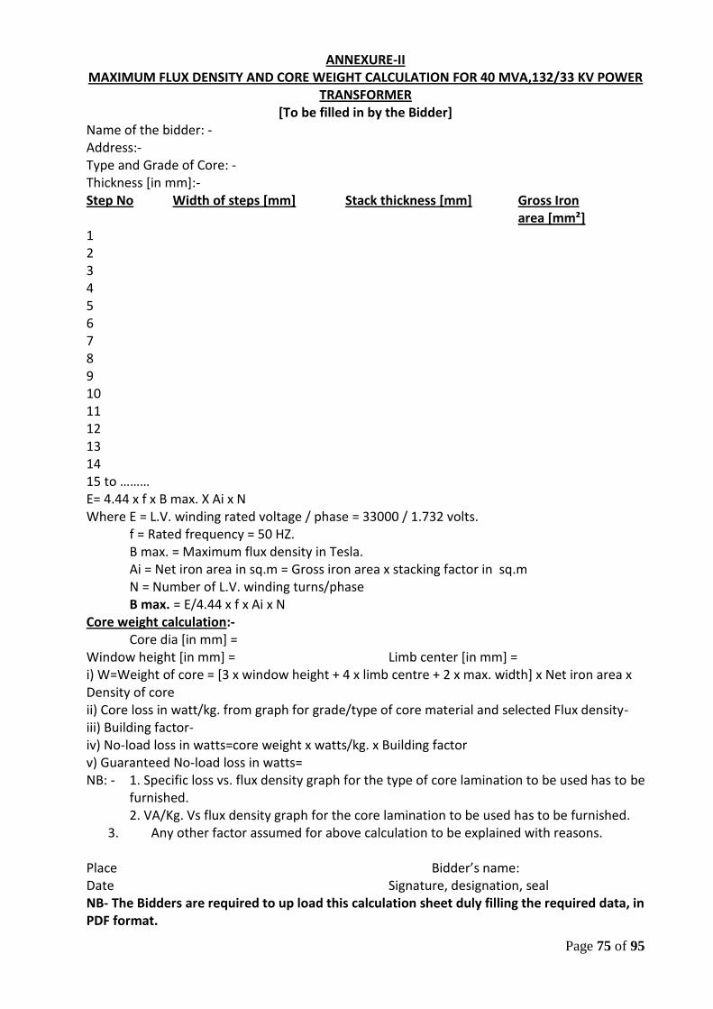
Page 75 of 95
ANNEXURE-II MAXIMUM FLUX DENSITY AND CORE WEIGHT CALCULATION FOR 40 MVA,132/33 KV POWER
TRANSFORMER [To be filled in by the Bidder]
Name of the bidder: - Address:- Type and Grade of Core: - Thickness [in mm]:- Step No Width of steps [mm] Stack thickness [mm] Gross Iron area [mm²] 1 2 3 4 5 6 7 8 9 10 11 12 13 14 15 to ……… E= 4.44 x f x B max. X Ai x N Where E = L.V. winding rated voltage / phase = 33000 / 1.732 volts.
f = Rated frequency = 50 HZ. B max. = Maximum flux density in Tesla. Ai = Net iron area in sq.m = Gross iron area x stacking factor in sq.m N = Number of L.V. winding turns/phase B max. = E/4.44 x f x Ai x N
Core weight calculation:- Core dia [in mm] =
Window height [in mm] = Limb center [in mm] = i) W=Weight of core = [3 x window height + 4 x limb centre + 2 x max. width] x Net iron area x Density of core ii) Core loss in watt/kg. from graph for grade/type of core material and selected Flux density- iii) Building factor- iv) No-load loss in watts=core weight x watts/kg. x Building factor v) Guaranteed No-load loss in watts= NB: - 1. Specific loss vs. flux density graph for the type of core lamination to be used has to be
furnished. 2. VA/Kg. Vs flux density graph for the core lamination to be used has to be furnished.
3. Any other factor assumed for above calculation to be explained with reasons. Place Bidder’s name: Date Signature, designation, seal NB- The Bidders are required to up load this calculation sheet duly filling the required data, in PDF format.
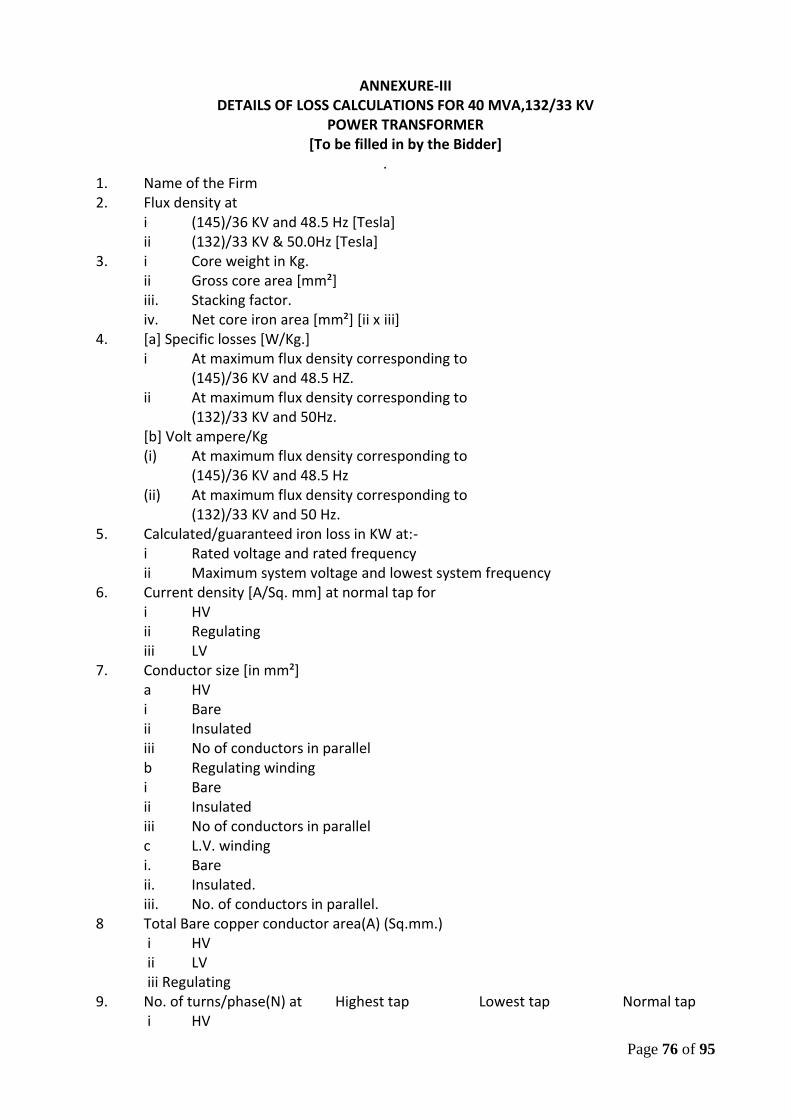
Page 76 of 95
ANNEXURE-III
DETAILS OF LOSS CALCULATIONS FOR 40 MVA,132/33 KV POWER TRANSFORMER
[To be filled in by the Bidder] .
1. Name of the Firm 2. Flux density at i (145)/36 KV and 48.5 Hz [Tesla] ii (132)/33 KV & 50.0Hz [Tesla] 3. i Core weight in Kg. ii Gross core area [mm²] iii. Stacking factor. iv. Net core iron area [mm²] [ii x iii] 4. [a] Specific losses [W/Kg.] i At maximum flux density corresponding to (145)/36 KV and 48.5 HZ. ii At maximum flux density corresponding to (132)/33 KV and 50Hz. [b] Volt ampere/Kg (i) At maximum flux density corresponding to (145)/36 KV and 48.5 Hz (ii) At maximum flux density corresponding to (132)/33 KV and 50 Hz. 5. Calculated/guaranteed iron loss in KW at:- i Rated voltage and rated frequency ii Maximum system voltage and lowest system frequency 6. Current density [A/Sq. mm] at normal tap for
i HV ii Regulating iii LV
7. Conductor size [in mm²] a HV
i Bare ii Insulated iii No of conductors in parallel b Regulating winding i Bare ii Insulated iii No of conductors in parallel c L.V. winding i. Bare ii. Insulated. iii. No. of conductors in parallel. 8 Total Bare copper conductor area(A) (Sq.mm.)
i HV ii LV iii Regulating
9. No. of turns/phase(N) at Highest tap Lowest tap Normal tap i HV
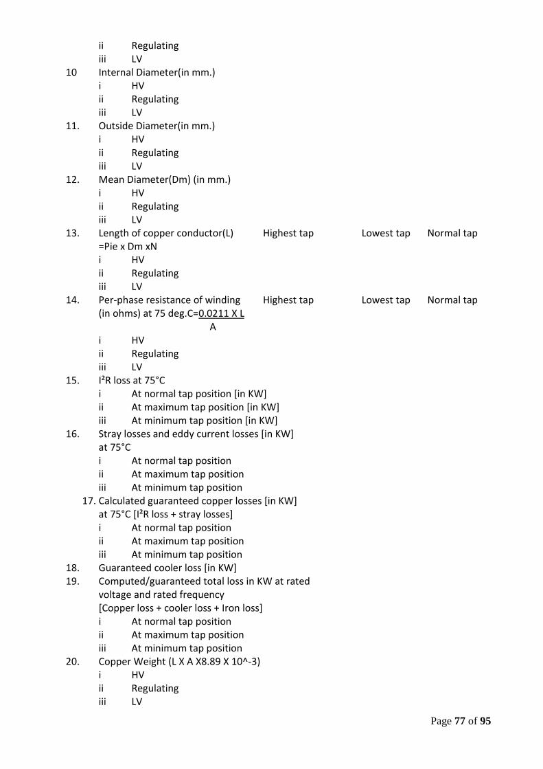
Page 77 of 95
ii Regulating iii LV
10 Internal Diameter(in mm.) i HV ii Regulating iii LV
11. Outside Diameter(in mm.) i HV ii Regulating iii LV
12. Mean Diameter(Dm) (in mm.) i HV ii Regulating iii LV
13. Length of copper conductor(L) Highest tap Lowest tap Normal tap =Pie x Dm xN i HV ii Regulating iii LV
14. Per-phase resistance of winding Highest tap Lowest tap Normal tap (in ohms) at 75 deg.C=0.0211 X L
A i HV ii Regulating iii LV
15. I²R loss at 75°C i At normal tap position [in KW] ii At maximum tap position [in KW] iii At minimum tap position [in KW]
16. Stray losses and eddy current losses [in KW] at 75°C i At normal tap position ii At maximum tap position iii At minimum tap position
17. Calculated guaranteed copper losses [in KW] at 75°C [I²R loss + stray losses] i At normal tap position ii At maximum tap position iii At minimum tap position
18. Guaranteed cooler loss [in KW] 19. Computed/guaranteed total loss in KW at rated
voltage and rated frequency [Copper loss + cooler loss + Iron loss] i At normal tap position ii At maximum tap position iii At minimum tap position
20. Copper Weight (L X A X8.89 X 10^-3) i HV ii Regulating iii LV
Page 78 of 95
iv For Tap connections, star connection and any other [please specify]
v Total copper weight [i]+[ii]+[iii]+[iv] NB: - 1 Approximate values in weight and losses etc. are not allowed. 2 Tolerance of +
5% in weights may be quoted without any approximation Place: Date Bidder’s name:
Signature, designation, seal NB- The Bidders are required to up load this calculation sheet duly filling the required data, in PDF format.
Page 79 of 95
ANNEXURE-IV GUARANTEED TECHNICAL PARTICULARS
[TO BE FILLED IN BY THE BIDDER, IN EXCEL FORMAT OF THE TECHNO COMMERCIAL BID SHEET]
Sl. Description 40MVA,132/33KV No 1 Name of the Manufacturer 2. Installation [indoor/outdoor] 3 Reference standards 4. Continuous Ratings a Type of cooling b Rating [MVA] i With ONAN cooling ii With ONAF cooling c Rated voltage i HV [KV rms.] ii LV [KV-rms.] d Highest system voltage i HV [KV rms.] ii LV [KV-rms.] e Rated frequency with ±% variation f Number of phases g Current at rated full load and on
principal tap i HV [Amps] ii LV [Amps] 5. Connections HV LV 6. Connection symbol and vector group 7. Temperature rise a Temperature rise of oil above
ambient temperature [by Thermometer & Optic Fiber Temperature Sensor]
i At full ONAN rating [°C] ii At full ONAF rating [°C]
b Temperature rise of windings above ambient temperature [By resistance method]
i At full ONAN rating [°C] ii At full ONAF rating [°C] c. Hot Spot Temperature rise of Windings above ambient
Temperature [By Optic Fiber Temperature Sensors] i At full ONAN rating [°C]
ii At full ONAF rating [°C] d. Temperature gradients between windings & oil.
e. Limit of Hot spot temperature for which the Transformer is designed [°C]
f. Period of operation of transformer at full load without calculated winding hot spot Temperature exceeding l40°C and with
Page 80 of 95
i 50% Coolers ii 100% Coolers
8 Type of ON load tap changing switch 9. Tapping on windings for i Constant flux/variable flux/combined regulation. ii Tapping provided at iii Number of steps iv Range of tapping for variation [+ percent to- percent] 10. i No load loss at rated voltage and frequency at principal tap [KW] ii No load loss at the voltage corresponding to highest tap [KW] 11. Load loss at rated output, rated frequency, ONAN ONAF corrected for 75 °C winding temperature at:- [Copper loss + cooler loss] i Principal tap [In KW] ii Highest tap [In KW] iii Lowest tap [In KW] 12 Auxiliary losses at rated output, normal ratio, rated voltage, rated frequency and ambient temperature [KW] 13. Total losses at normal ratio inclusive of auxiliary equipment losses [KW] 14. Positive sequence impedance on rated MVA base at rated current and frequency at 75° Centigrade winding temperature at i Principal tap [%] ii Highest tap [%] iii Lowest tap [%] 15. Zero sequence impedance at reference temperature of 75°C at principal tap [%] 16 % reactance at rated MVA base at rated current and rated frequency at i Principal tap [%] ii Highest tap [%] iii Lowest tap [%] 17. % resistance at rated MVA base at rated current and rated frequency at i Principal tap [%] ii Highest tap [%] iii Lowest tap [%] 18 % Impedance at rated MVA base at rated current and rated frequency at i Principal tap [%] ii Highest tap [%] iii Lowest tap [%] 19. a Polarisation index i.e. ratio of Megger values at 600 secs to 60 secs, (H.V. to E , L.V. to E,
Page 81 of 95
H.V. to L.V. b Regulation at full load and 75°C winding temperature expressed as a percentage of normal voltage i At unity power factor [%] ii At 0.8 power factor [lagging][%] 20 Efficiency at 75°C winding temperature as Unity power 0.8 Power derived from guaranteed loss figures and at factor factor a At full load [%] b At ¾ load [%] c At ½ load [%] 21 i Maximum efficiency [%] ii Load at which maximum efficiency occurs[% of full load] 22 Time in minutes for which the transformer can be run at full load without exceeding the maximum permissible temperature at reference ambient temperature when supply to:- i Fans are cut off 23. Short time thermal rating of i HV winding in KA and duration in seconds ii LV winding in KA and duration in seconds 24 Permissible over loading:- a HV winding b LV winding 25 Terminal arrangement a High voltage [HV] b Low voltage (LV) c Neutral 26 Insulating and cooling medium 27 [A] Test voltage HV LV i Lightning impulse withstand test voltage [KVP] ii Power frequency withstand test voltage [dry and wet][for 1 minute] [KV-rms.] 28 Partial discharge level as per relevant uptodate IEC 29 Noise level when energized at normal voltage, frequency without load and with all cooling fans in running condition. 30. External short circuit withstand capacity [MVA] and duration [seconds] 31 Over-fluxing withstand capability of the Transformer 32 DETAILS OF CORE a Type of core construction b Type of corner joints of the core
c. Maximum flux density at i Rated voltage [132/33 KV] & rated
frequency 50 Hz][in Tesla] ii Highest system voltage [145/36 KV] and
lowest system frequency [48.5Hz.][in Tesla]
Page 82 of 95
d No load current, no load loss and no load power factor at normal ratio and frequency [Amp/KW/p.f.]
i 10 percent of rated voltage ii 25percent of rated voltage iii 50 percent of rated voltage iv 85 percent of rated voltage v 100 percent of rated voltage vi 105percent of rated voltage vii 110 percent of rated voltage viii 112.5 percent of rated voltage ix 115 percent of rated voltage x 120 percent of rated voltage xi 121 percent of rated voltage xii 125 percent of rated voltage e Core laminations:- i Material of core lamination [HIB/Laser grade] ii Grade of core laminations iii Thickness of core lamination [mm] iv Specific loss [watt/Kg.] at rated voltage and
rated frequency v Specific loss [watt/Kg.] at highest system
voltage and lowest system frequency vi Whether specific core loss graph [flux density
vs. watt/Kg.submitted vii VA/Kg at rated voltage and rated frequency viii VA/Kg. at highest system voltage and lowest
system frequency ix Whether VA/Kg. Vs. flux density graph
submitted. x Insulation of core laminations f CORE ASSEMBLY:- i Core diameter [mm] ii Core window height [mm] iii Core leg centre [mm] iv Gross core cross-sectional area [m²] v. Whether details of core widths, stacks and
calculation furnished as per enclosed annexure vi Distance between centres [mm] vii Total height of core [mm] viii
1) Details of core belting. 2) Material, grade & type. 3) Width. 4) Thickness. 5) Fixing method.
ix. Details of top end frame. x Details of Bottom end frame. xi Details of clamp plate [Material, thickness, Insulation] xii Details of clamp plate [material, thickness, Insulation] xiii Total core weight [kg]
Page 83 of 95
xiv Core loss basing on core loss graph at operating flux density [rated voltage and rated frequency] [kw]
xv Core stacking factor xvi Net core area Sq. m. xvii Margin towards corner joints, cross fluxing etc [kw] xviii Total core loss at rated voltage and rated
frequency [xv+xviii] [kw] xix Dielectric loss at rated voltage and rated
frequency [KW] xx No load loss at rated voltage and rated
frequency [xix+xx] [KW] g Describe location/method of core grounding h Details of oil ducts in core i Peak value of magnetising
Inrush current (% of HV rated current). 33 DETAILS OF WINDINGS. HV LV a Type of winding
b Material of the winding conductor. c. Maximum current density of windings Conductor / Current area [cm²]
[at rated current] [Normal Tap] and density [A/cm²] Conductor area
i HV ii Regulating iii L.V d Whether HV windings are interleaved.
e Whether windings are pre-shrunk? f Whether adjustable coil clamps are provided for
H.V. and L.V. windings? g Whether steel rings are used for the windings?
If so, whether these are split? h Whether electrostatic shields are provided to
obtain uniform voltage distribution in the windings?
i Winding Insulation Type & class. Graded or i H.V. & Regulating ungraded ii LV
j Insulating material used for i H.V. & Regulating winding. ii L.V Winding iii For core bolts washers and end plates. iv Tapping connection. k Insulating material used between i H.V. and L.V. winding ii H.V. and Regulating winding. iii Core and L.V winding. iv H.V. to H.V.winding [between phases] l Type of axial coil supports. i H.V. winding ii LV winding
Page 84 of 95
iii Regulating winding m Type of radial coil supports i HV winding ii Regulating winding iii LV winding n Maximum allowable torque on coil clamping HV Regulating LV
bolts o Bare conductor size (mm). p Insulated conductor size (mm). q No. of conductors in parallel (Nos.). r No. of turns/phase s No. of discs/phase t No. of turns/disc u Gap between discs. (mm). v Inside diameter (mm). w Outside diameter (mm). x Axial height after shrinkage (mm). y D.C.RESISTANCE i L.V winding at 75 ° C (Ohms). ii HV winding and Regulating winding at normal
tap at 75° C (Ohms). iii HV winding and Regulating winding at highest
tap at 75° C (Ohms). iv HV winding and regulating winding at lowest
tap. (Ohms). v Total I²R losses at 75 ° C. for normal tap. (KW). vi Total I²R losses at 75 ° C. for highest tap. (KW) vii Total I²R losses at 75 ° C for lowest tap.(KW). viii Stray losses including eddy current losses in
winding at 75°C (KW). a Normal tap position b Highest tap position c Lowest tap position. d Any special measures taken to reduce eddy
current losses and stray losses, mention in details. z Load losses at 75°C [I²R + stray]. a Normal tap position [KW]. b Highest tap position [KW]. c Lowest tap position [KW].
aa Details of special arrangement provided to improve surge voltage distribution in the windings
bb Tan delta(power factor) of Windings(Max.) 34 BUSHINGS. HV LV HVN LVN
a Make and type i Rated voltage class [KV-rms.] ii Rated current [Amps.] b. Lightning Impulse withstand test voltage
[1.2/50 micro second][KVP]
Page 85 of 95
c Switching surge withstand test voltage [KVP] d Power frequency withstand test voltage i Wet for 1 minute [KV-rms] ii Dry for 1 minute [KV-rms] e. Power frequency visible corona discharge voltage [KV-rms.] f Partial discharge level [PC] g Minimum creepage distance in mm h Minimum creepage distance in mm [protected] i Whether test-tap is provided? j Quantity and grade of oil in bushing and
Specification of oil used [Kg.] k Weight of assembled bushing [Kg.] l Minimum clearance height for removal of
bushing [mm] m Under oil flashover or puncture impulse
voltage [KVP] n. Under oil flashover or puncture power frequency
voltage (KV-rms). o. Phase to earth clearance in air of live parts at
the top of bushings. p. Maximum tan delta value at 20 deg.C
35 Minimum clearance [mm] Between Phase to Windings ground
(A) Out of Oil HV LV
(B) In Oil (i) LV to Core (ii) LV to top yoke (iii) LV to bottom yoke (iv) LV to HV(radially) (v) HV to Regulating(radially) (vi) HV to top yoke (vii) HV to bottom yoke (viii) Regulating to top yoke (xii) Regulating to bottom yoke (xiii) Reg. winding to Reg. winding (xiv) Regulating winding to tank
(a) Length wise (b) Breadth wise (c) Width wise
N:B- Winding Arrangement-CORE-LV-HV-REGULATING 36 Weight [Tolerance + 5%]
[Approximate value is not allowed] a Core [Kg.] b Core with clamping [Kg.] c H.V. winding insulated conductor [Kg.] d L.V. winding insulated conductor [Kg.] e Regulating winding insulated conductor [Kg.] f Coils with insulation [Kg.]
Page 86 of 95
g Core and winding [Kg] i Oil required for first filling [Liter/Kg.] j Tank and fittings with accessories [Kg.] k Untanking weight [Kg.] l Total weight with oil and fittings
along with accessories [Kg.] 37 DETAILS OF TANK
a Material for Transformer tank b Type of tank c Thickness of sheet
[No approximate value to be mentioned] i Sides [mm] ii Bottom [mm] iii Cover [mm] iv Radiators [mm] d Inside dimensions of main tank
[No approximation in dimensions to be used] i Length [mm] ii Breadth [mm] iii Height [mm] e Outside dimensions of main tank
[No approximation in dimensions to be used] i Length [mm] ii Breadth [mm] iii Height [mm] f. Thickness of spray galvanisation of tank bottom. g. Vacuum recommended for hot oil circulation [torr] h. Vacuum to be maintained during oil filling in Transformer tank [torr] i. Vacuum to which the tank can be subjected without distortion [torr] j. No. of bi-directional wheels provided k. Track gauge required for the wheels i Transverse axis ii Longitudinal axis l Type and make of pressure relief device and Minimum pressure at which it operates [Kpa]
38 CONSERVATOR a Total volume [Liters] b Volume between the highest and lowest visible
oil levels [Litres] c Power required by heaters [if provided][KW] d Conservator sheet thickness (mm.) 39 OIL QUALITY a Governing standard b Density in gms/cu-cm c Kinematics viscosity in CST d Inter facial tension at 27°C in N/m e Flash point in °C f Pour point in °C g Acidity [neutralization value] in mg of
Page 87 of 95
KOH/gm h Corrosive sulfur in % i Electric strength [breakdown voltage] i As received [KV-rms.] ii After treatment [KV-rms.] j Dielectric dissipation factor [tan delta] at 90°C k Saponification value in mg of KOH/gm l Water content in ppm m Specific resistance i At 90°C [ohm-cm] ii At 27 °C [ohm-cm] n N- dm analysis CA% CM% CP% o Oxidation stability i Neutralization value after oxidation ii Total sludge after oxidation p Characteristic of oil after ageing test as per ASTMD-1934 i Specific resistance at 27°C [ohm-cms] 90°C [ohm-cms] ii Tan delta iii Sludge content
iv Neutralization number v Percentage of Napthenic content vi Percentage of paraffinic content vii Details of oil preserving equipment offered
40 RADIATORS a Overall dimensions lxbxh [mm] b Total weight with oil [Kg.] c Total weight without oil [Kg.] d Thickness of radiator tube [mm] e Types of mounting f Vacuum withstand capability g Total radiating surface in sq.m h Type and make of material used for the
radiators i Total number of radiators/Banks for
Transformer and dimensions of tubes. j Thickness of hot dip galvanization of radiators.
41 COOLING EQUIPMENT Fan motor a Make and type b No. of connected units c No. of stand -by units d Rated power input e Capacity [cu-m/min. or] [liters/min] f Rated voltage [volts] g Locked rotor current [Amps.]
Page 88 of 95
h Efficiency of motor at full load [%] i Temperature rise of motor at full load [°C] j BHP of driven equipment k Temperature range over which control is
adjustable [°C] l Whether the fans are suitable for
continuous operation at 85 % of their rated voltage.
m Estimated time constant in hours for i Natural cooling ii Forced air cooling
42 GAS AND OIL OPERATED RELAY a Make b Type c Size d Whether supervisory alarm and trip contacts
provided and their sizes and Nos. 43 [I] TEMPERATURE INDICATORS Oil Temp. Winding Temp. Indicator Indicator
a Make and type b Permissible setting ranges for alarm and trip c Number of contacts d Current rating of each contact e Whether supervisory alarm contacts provided? f Size [lxbxd] g Nos.
h Ratio and type of CT used for winding temperature indicators. [II] OPTIC FIBER TEMPERATURE SYSTEM a. MAKE & TYPE b. Whether the offered Optic Fiber Temperature
System fulfills the stipulations for the same as per this Specification
c. Whether the end-user’s certificate for offered Optic Fiber Temperature System, from Indian Utilities furnished d. Whether, the Bidder has got past experience of supply of Transformers with Optic Fiber Temperature System [YES/NO] e. If ‘YES’, please state the No. of such Transformers, supplied along with the name(s) of Organisation(s), to whom supplied with Make of the Optic Fiber Temperature System, supplied and performance of the same. 44 APPROXIMATE OVERALL DIMENSIONS OF TRANSFORMER INCLUDING COOLING SYSTEM, TAP CHANGING GEAR ETC. a Length [mm] b Breadth [mm] c Height [mm] 45 a Minimum clearance height for lifting core and winding from tank [mm] b Minimum clearance height for lifting tank cover
Page 89 of 95
[mm] 46 SHIPPING DETAILS
a Approximate weight of heaviest package [Kg.] b Approximate dimensions of largest
Package [Kg.] 47 Transformers will be transported with oil/gas. 48 Size of rail recommended for the track. 49 Details of Neutral Current Transformers a Quantity b Type and voltage class c No. of cores d Ratio e VA burden f Accuracy class g Minimum knee point voltage [volts] h Maximum magnetization current at minimum knee point voltage [mA] i Maximum secondary winding resistance at 75°C[ohms] 50 MARSHALLING KIOSK a Make and type b Details of apparatus proposed to be housed in the kiosk 51 Details of anti-earthquake device provided, if any 52 Separate conservator and Buchholz relay provided 53 TAP CHANGING EQUIPMENT [These details refer to the basic rating of O.L. T.C. as guaranteed by OLTC manufacturers] a Make b Type c Power flow [Uni.-directional/bi – directional/restricted bi-directional] d Rated voltage to earth [KV] e Rated current [Amps.] f Step voltage [volts] g Number of steps h Control - manual/local-electrical/remote- electrical i Voltage control [Automatic/Non -automatic] j Line drop compensation provided/not provided k Parallel operation l protective devices m Auxiliary supply details n Time for complete tap change [one step][Sec.] o Diverter selector switch transient time [cycles] p Value of maximum short circuit current [Amps] [minimum]alongwith duration q Maximum impulse withstand test voltage with 1.2/50 micro seconds full wave between switch
Page 90 of 95
assembly and ground [KVP] r Maximum power frequency test voltage between switch assembly and earth [KV-rms] s Maximum impulse withstand test voltage with 1.2/50 micro-seconds across the tapping range [KVP] t Approximate overall dimensions of tap changer [WxBxD] in mm. u Approximate overall weight [Kg.] v Approximate mass of oil [Kg.] w Particulars of the OLTC control panel for installation in control room 54 DRIVING MECHANISM BOX a Make and type b Details of apparatus proposed to be housed in the box 55 Types of terminal connectors and drawing No a HV b LV 56 Details of painting, galvanization conforms to this Specification [Yes/No] 57 Type of oil level indicator and whether Supervisory alarm contact for low oil level provided [Yes/No] 58 Type and size of thermostat to be used 59 No. of breathers provided [Nos.] 60 Type of dehydrating agent used for breathers 61 Valve sizes and numbers
a Drain valves- mm-Nos. b Filter valves- mm-Nos. c Sampling valves- mm-Nos. d Radiator valves- mm-Nos. e Other valves- mm-Nos.
62 a) Type and make of PRV. b) No. of each type of devices per transformer c) Min. pressure at which device operates.
63 Please enclose the list of accessories and fittings, being provided on transformer. Please confirm,
these are as stipulated in the tender. 64 Whether the transformer, covered is fully type tested
and if so, whether copies of type test certificates, enclosed with the tender.
65 Whether tenderer can supply transformer, wound on vertical coil winding machine. Preference shall be given to the tenderer who will ensure supply of transformer wound on vertical winding machines.
66 In case Sl.No.65 is not confirmed, what are the additional pre-cautions which shall be taken by the tenderer to justify that the coil, wound on horizontal machine shall be equivalent in all respects to that which
Page 91 of 95
are wound on vertical winding machine. 67 What are the arrangements, available for jointing the
winding. Preference shall be given to the tenderer using high-frequency brazing machines. In case other jointing techniques are used, adequacy of the same is to be recorded. Please note that bolted joints in the winding are not acceptable. This should be confirmed here
68 Please confirm that you will guarantee maximum Impedance variation between phases within the limit of 2% only.
69 a) Please confirm that the transformer shall be dried by vapour-phase drying method. Please specify level of dryness.
b) In case, other methods of drying are used, the level of dryness, so achieved should be identical to that by VPD. Adequacy of such system should be justified.
70 Please confirm whether the In-House facilities for all routine tests as per this Tender Specification are available with the tenderer
and the tenderer shall agree to conduct these tests on the transformer in the event of order.
71 Whether the Tenderer has got In-House core-cutting facility for
cutting core materials for the transformer ratings as offered. (YES/NO) 72 If ‘YES’, following informations/confirmations are required: -
a. Name of the manufacturer of HIB Grade core material from whom core materials will be directly imported or through their accredited marketing organization of repute. If
to be imported through the accredited Marketing Organisation, Please state the name of such Marketing Organisation and please enclose the relevant documents with the Tender Offer regarding
accreditation of the said Marketing Organisation by the manufacturer of the HIB core material.
b. Grade, Trade Name and Thickness of the core material, to be imported
c. Whether agreed for witnessing of core materials by OPTCL’s representative(s)
d. Whether, the Bidder has past experience towards direct import of core materials. If ‘YES’, the copies of recent past Import documents to be furnished with the Tender Offer (Please state, whether the said import documents are enclosed with the Tender Offer)
e. Whether, the Bidder has got In-House CNC Machine facility for cutting of core materials
f. Whether the Bidder is agreed to follow the procedures, as stipulated at Cl.No.5.4.8 (o), (p) &(q) of this Technical Specification, as applicable for those, who have got In-House core-cutting facility
Page 92 of 95
73 If the Bidder has no In-House core-cutting facility, the following informations/confirmations are required: - a. Name of the core manufacturer of core materials from
whom core materials will be directly imported or through their accredited marketing organization of repute. If
to be imported through the accredited Marketing Organisation, Please state the name of such Marketing Organisation and please enclose the relevant documents with the Tender Offer regarding
accreditation of the said Marketing Organisation by the manufacturer of the HIB core material.
b. Grade, Trade Name and Thickness of the core material, to be imported
c. Name of the core-cutting vendor and whether the said vendor has got In-House CNC Machine facility for cutting of core materials and whether the said vendor has been accredited by ISO
d. Whether, the Bidder has past experience towards direct import of core materials. If ‘YES’, the copies of recent past Import documents to be furnished with the Tender Offer (Please state, whether the said import documents are enclosed with the Tender Offer)
e. Whether the Bidder is agreed to follow the procedures, as stipulated at Cl.No.5.4.8 (o), (p) &(q)(1), (2), (3), (4), (5),(6) & (7) of this Technical Specification, as applicable for those, who have got no In-House core-cutting facility.
74. Please confirm that the facility for partial discharge test
Is available with the tenderer and the tenderer shall agree to conduct This test on transformer in the event of order.
Place Bidder’s name: Date Signature, Designation, Seal
Page 93 of 95
ANNEXURE - V.
ADDITIONAL SCHEDULE OF INFORMATIONS.
(To be furnished by the bidder along with the Tender Offer) Sl. No. Item. Remarks.
SIGNATURE OF THE TENDERER WITH SEAL AND DATE
NB- The Bidders are required to up load this calculation sheet duly filling the required data, in PDF format.
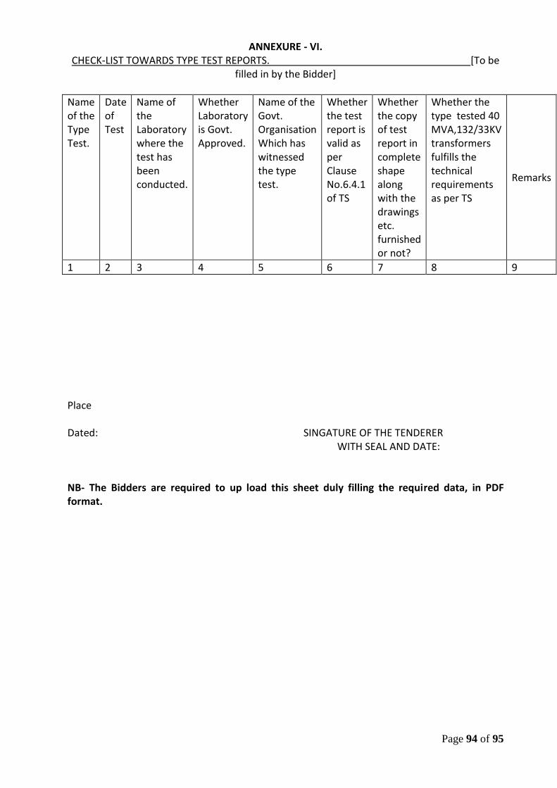
Page 94 of 95
ANNEXURE - VI. CHECK-LIST TOWARDS TYPE TEST REPORTS. [To be
filled in by the Bidder]
Name of the Type Test.
Date of Test
Name of the Laboratory where the test has been conducted.
Whether Laboratory is Govt. Approved.
Name of the Govt. Organisation Which has witnessed the type test.
Whether the test report is valid as per Clause No.6.4.1 of TS
Whether the copy of test report in complete shape along with the drawings etc. furnished or not?
Whether the type tested 40 MVA,132/33KV transformers fulfills the technical requirements as per TS
Remarks
1 2 3 4 5 6 7 8 9
Place Dated: SINGATURE OF THE TENDERER WITH SEAL AND DATE: NB- The Bidders are required to up load this sheet duly filling the required data, in PDF format.
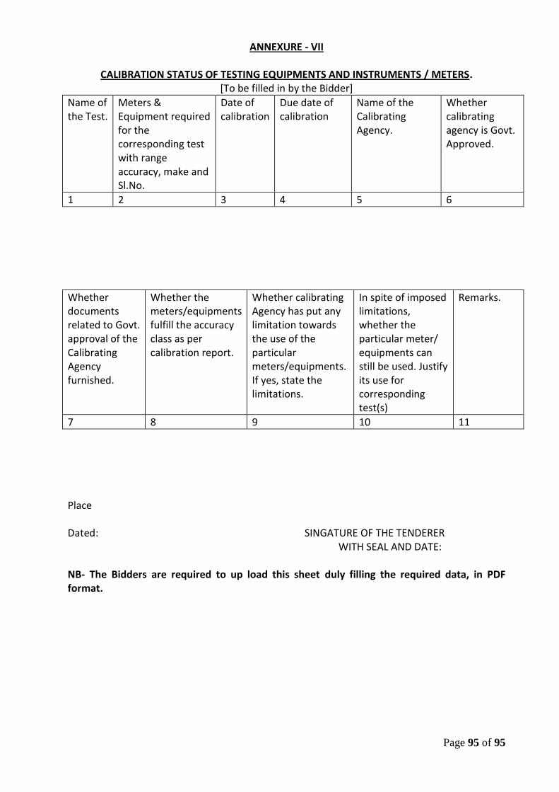
Page 95 of 95
ANNEXURE - VII
CALIBRATION STATUS OF TESTING EQUIPMENTS AND INSTRUMENTS / METERS. [To be filled in by the Bidder]
Name of the Test.
Meters & Equipment required for the corresponding test with range accuracy, make and Sl.No.
Date of calibration
Due date of calibration
Name of the Calibrating Agency.
Whether calibrating agency is Govt. Approved.
1 2 3 4 5 6
Whether documents related to Govt. approval of the Calibrating Agency furnished.
Whether the meters/equipments fulfill the accuracy class as per calibration report.
Whether calibrating Agency has put any limitation towards the use of the particular meters/equipments. If yes, state the limitations.
In spite of imposed limitations, whether the particular meter/ equipments can still be used. Justify its use for corresponding test(s)
Remarks.
7 8 9 10 11
Place Dated: SINGATURE OF THE TENDERER WITH SEAL AND DATE: NB- The Bidders are required to up load this sheet duly filling the required data, in PDF format.