specification project manual
TRANSCRIPT
SPECIFICATION PROJECT MANUAL
for:
VILLAGE OF NEWCOMERSTOWN NEW ADMINISTRATION BUILDING 308 S COLLEGE STREET NEWCOMERSTOWN, OH 43832 PROJECT #2029
Prepared for:
VILLAGE OF NEWCOMERSTOWN 124 WEST CHURCH STREET NEWCOMERSTOWN, OHIO 43832 DATED: 03/11/2022
Prepared by:
V2 ARCHITECTS, INC. ARCHITECTS 903 STEUBENVILLE AVENUE CAMBRIDGE, OHIO
TABLE OF CONTENTS 000005-1
TABLE OF CONTENTS BIDDING AND CONTRACT REQUIREMENTS 000006 LEGAL NOTICE 001000 INSTRUCTIONS TO BIDDERS 003100 FORM OF PROPOSAL BID GUARANTY AND CONTRACT BOND NON-COLLUSION AFFIDAVIT 008000 SUPPLEMENTARY CONDITIONS PREVAILING WAGE RATES 008220 SUPPLEMENTAL INSURANCE REQUIREMENTS DIVISION 1 - GENERAL REQUIREMENTS: 011000 SUMMARY 012100 ALLOWANCES 012200 UNIT PRICES 012500 SUBSTITUTION PROCEDURES 012600 CONTRACT MODIFICATION PROCEDURES 012900 PAYMENT PROCEDURES 013100 PROJECT MANAGEMENT AND COORDINATION 013200 CONSTRUCTION PROGRESS DOCUMENTATION 013300 SUBMITTAL PROCEDURES CADD/ELECTRIC FILE DISCLAIMER REQUEST FOR INFORMATION FORM SUBMITTAL FORM SUBSTITUTION REQUEST FORM 014000 QUALITY REQUIREMENTS 014200 REFERENCES 016000 PRODUCT REQUIREMENTS 017300 EXECUTION 017419 CONSTRUCTION WASTE MANAGEMENT AND DISPOSAL 017700 CLOSEOUT PROCEDURES HAZARDOUS MATERIALS CERTIFICATE G706 CONTRACTOR’S AFFIDAVIT OF PAYMENT OF DEBTS AND CLAIMS G706A CONTRACTOR’S AFFIDAVIT OF RELEASE OF LIENS G707 CONSENT OF SURETY TO FINAL PAYMENT 017823 OPERATION AND MAINTENANCE DATA 017900 DEMONSTRATION AND TRAINING DIVISION 2 – EXISTING CONDITIONS 024119 SELECTIVE DEMOLITION

TABLE OF CONTENTS 000005-2
DIVISION 4 – MASONRY 042000 UNIT MASONRY 047200 CAST STONE MASONRY DIVISION 6– WOOD, PLASTIC, AND COMPOSITES 061000 ROUGH CARPENTRY 064023 INTERIOR ARCHITECTURAL WOODWORK DIVISION 7 – THERMAL AND MOISTURE PROTECTION 079200 JOINT SEALANTS DIVISION 8 – OPENINGS 081113 HOLLOW METAL DOORS AND FRAMES 081416 FLUSH WOOD DOORS 084113 ALUMINUM FRAMED ENTRANCES AND STOREFRONTS 086650 SLIDING PASS WINDOWS 087100 DOOR HARDWARE 088000 GLAZING DIVISION 9 – FINISHES 092216 NON-STRUCTURAL METAL FRAMING 092900 GYPSUM BOARD 095113 ACOUSTICAL PANEL CEILINGS 096513 RESILIENT BASE AND ACCESSORIES 096520 RESLIIENT PLAN FLOORING (LVT) 096813 TILE CARPETING 099000 PAINTING DIVISION 10 – SPECIALTIES 101423 PANEL SIGNAGE 102800 TOILET BATH AND LAUNDRY ACCESSORIES 104413 FIRE PROTECTION CABINETS 104416 FIRE EXTINGUISHERS END OF SECTION 000005

LEGAL NOTICE 000006-1
LEGAL NOTICE Sealed bids will be received by the Village of Newcomerstown, Ohio (“Owner”) by the Fiscal Officer of said Village on Tuesday, April 5, 2022, at noon for all labor, material, and services necessary for the Village of Newcomerstown New Administration Building, 308 South College Street, Newcomerstown, OH 43832 in accordance with the Contract Documents prepared by V2 Architects, Inc., 903 Steubenville Avenue, Cambridge, Ohio 43725 (740-432-3976). Bids received after this time will not be accepted. Direct questions about the Project to Mr. Zach Van Wey AIA, V2 Architects, 903 Steubenville Avenue, Cambridge, Ohio 43725. Phone (740) 432-3976. This notice is posted on the village’s website at www.newcomerstownoh.com, under the “Bids” icon on the lefthand side of the homepage. A Pre-Bid Meeting will be conducted on Wednesday, March 23, 2022 at 10:00 a.m. local time, at the Project Site, 308 South College Street, Newcomerstown, OH 43832. The meeting is not mandatory, but prospective bidders are strongly encouraged to attend. The Contract Documents are available for purchase at cost, plus any applicable shipping charges from Key Blue Print, Inc. 195 East Livingston Avenue, Columbus, Ohio, phone 614-228-3285, fax 614-228-0687. To obtain drawings please visit www.keycompanies.com to order online or contact Key Blue Print, 614-228-3285, ext. 241 Sets of the Contract Documents may be viewed without charge during normal business hours at the following locations: Village of Newcomerstown, Mayor’s Office 124 West Church Street Newcomerstown, OH 43832 (740) 498-6313 V2 Architects, Inc, 903 Steubenville Avenue Cambridge, Ohio 43725 (740) 432-3976 Bids may be submitted in the following manners:
1) Sealed hard copy bids may be submitted to the Village of Newcomerstown, Mayor’s Office, 124 West Church Street, Newcomerstown, Ohio 43832 by the time provided above.
2) Electronic bids may be submitted via the village’s website at www.newcomerstownoh.com, by the time provided herein. Those wishing to submit online bids must pre-register on the village’s website. Follow the “Bids’ icon on the lefthand side of the home page for instructions. Call the village at (740) 498-6289 if assistance is required in registering.
Bids will be opened publicly and read immediately thereafter.
LEGAL NOTICE 000006-2
All bids must be accompanied by a Bid Guaranty in the form of either a Bid Guaranty and Contract Bond for the full amount of the bid (including all add alternates) or a certified check, cashier’s check, or an irrevocable letter of credit in an amount equal to 10% of the bid (including all add alternates), as described in the Instructions to Bidders. One Lump Sum Bid will be received for: BID PACKAGE OPINION OF PROBABLE COST #1 General Contract $ 426,000 This is a prevailing wage project. No Bidder may withdraw its bid within sixty (60) days after the bid opening. The Owner reserves the right to waive irregularities in bids, to reject any or all bids, and to conduct such investigation as necessary to determine the lowest and best bidder for each contract. By: Village of Newcomerstown 3/14/2022
INSTRUCTION TO BIDDERS 001000-1
DIVISION 0 - BIDDING AND CONTRACT REQUIREMENTS SECTION 001000 - INSTRUCTION TO BIDDERS The following documents are a part of the contract and are incorporated in their entirety as if bound hereafter. Copies may be examined at the Architect's office. CONTRACT: 1. Standard Form of Agreement Between Owner and Contractor: AIA Document
A101, latest Edition. 2. General Conditions: General Conditions of the Contract for Construction: AIA
Document A201. 3. Notice to Bidders. INSTRUCTION TO BIDDERS 1.1 PROJECT: VILLAGE OF NEWCOMERSTOWN NEW ADMINISTRATION BUILDING 308 S. COLLEGE STREET NEWCOMERSTOWN, oh 43832
OPINION OF PROBABLE COST:
Contract Opinion of Probable Cost Contract #1: $ 426,000.00 1.2 SECURING DOCUMENTS: A. Complete sets of the Bidding Documents may be inspected at the office of the
Architect, V2 Architects Inc., 903 Steubenville Ave, Cambridge, Ohio 43725, (740) 432-3976. The Contract Documents are available for purchase at cost, plus any applicable shipping charges from Key Blue Prints, Inc. 195 East Livingston Avenue, Columbus, Ohio. To obtain drawings please visit www.keycompanies.com to order online or contact Key Blue Print, 614-228-3285.
1.3 EXAMINATION OF DOCUMENTS AND SITE CONDITIONS: A. Before submitting a bid, each bidder shall examine the Drawings carefully, shall
read the Specifications and all other proposed Contract Documents, and shall visit the site of the Work. Each bidder shall fully inform himself prior to bidding as to existing conditions and limitations under which the Work is to be performed, and shall include in his bid a sum to cover the cost of items necessary to perform the Work as set forth in the proposed Contract Documents. No allowance will be made to a bidder because of lack of such examination or knowledge. The submission of a bid will be considered as conclusive evidence that the bidder has made such examination.
B. Direct written Request for Information (RFI) to the Architect; Clarifying
Addenda, which will become a part of the Contract Documents, will be printed

INSTRUCTION TO BIDDERS 001000-2
and distributed to all prime bidders. The Architect and Owner will not be responsible for oral clarifications.
1.4 STANDARDS AND SUBSTITUTIONS: A. Bid materials shown or specified. Bidder may make selection where option for
materials, manufacturers, or equipment is shown or specified. B. "Approved Equal": Bidder may submit in writing the “Substitution Request”
form at the end of Section 003100-Form of Proposal with manufacturer's literature and specifications attached to the architect for approval a minimum of 10 days before the bid date. If approval is not received in addendum, Bidder shall included specified item in Base Bid and "Equal" item as a Substitution.
C. Bidders may quote substitute materials, manufacturers, or equipment by listing
the same on the Substitution Sheet and attach to the bid with signature. The Owner reserves the right to accept or reject any or all proposed substitutions.
D. Should a proposed substitution cause a change in any service to equipment in
size, location, or type, or should it require a change in manner of installation, the extra cost to meet these requirements shall be paid for by the contractor proposing the substitution.
E. Submit substitution requests on forms included at the end of SECTION 003100 –
FORM OF PROPOSAL. 1.5 BID FORM: In order to receive consideration, make bids in strict accordance with the following. A. Make separate lump sum proposals upon the forms provided therefore, properly
signed and with all items filled out. Do not change the wording of the bid form, and do not add words to the bid form. Unauthorized conditions, limitations, or provisions attached to the bid will be cause for rejection of the bid.
B. In the case of Alternates and Unit Prices, the Contractor shall submit bids on all
of the items listed for each prime contract. C. No Telegraphic Bid Fax or telegraphic modification or fax of a bid will be
considered. No bids received after the time fixed for receiving them will be considered. Late bids will be returned to the bidder unopened.
D. Submit bids in one of the acceptable manners outlined in Section 000006 Legal
Notice. E. No bidder may withdraw his proposal within sixty (60) days after the actual date
of the bid opening.
INSTRUCTION TO BIDDERS 001000-3
1.6 BID SECURITY AND CONTRACT BOND: A. Each bid shall be accompanied by a BID GUARANTY and CONTRACT BOND
equal to One Hundred Percent (100%) of the bid amount including all add alternates; or a CERTIFIED CHECK or CASHIERS CHECK in the amount of Ten Percent (10%) of the bid amount including all add alternates. The successful bidder's security will be retained until he has signed the Contract and furnished the required Certificates of Insurance and Contract Bonds.
B. Bid Guaranty shall assure the Owner that the bidder will adhere to his proposal,
execute the Contract and furnish Contract Bond as specified. Within thirty (30) days after the execution of the Contract, the Owner will return the Bid Guaranty of the successful bidders. Should any bids be rejected, such Bid Guaranty shall be forthwith returned to the bidder.
C. The successful bidder shall provide a Contract Bond for 100% of the amount of
the Contract within fifteen (15) days of award of the Contract. D. Furnish bond with a surety qualified to conduct business in the State of Ohio and
acceptable to the Owner. E. Form of Bond - As permitted by the Ohio Revised Code. F. Should the successful bidder fail to execute the agreement or provide the required
bonds within thirty (30) days of the award of the Contract, he shall forfeit his Bid Guaranty the measure of damages for default being the difference between his bid and the next acceptable bid up to the maximum amount of bid guaranty.
1.7 CONSTRUCTION SCHEDULE:
A. CONSTRUCTION SCHEDULE: The agreements will include a stipulation that the
following schedules and completion dates will be strictly adhered to: 1. SUBSTANTIAL COMPLETION of the entire project shall be no later than 180
calendar days following award of contract or written notice to proceed.
2. FINAL COMPLETION of the entire project shall be no later than 240 calendar days following award of contract or written notice to proceed.
B. The contractor shall include in his proposal and be required to adequately man the project
and to properly schedule all work, whether it be standard or multiple shifts, regular or overtime pay, as required to complete the work in accordance with this predetermined schedule, and at NO ADDITIONAL COST TO THE OWNER.
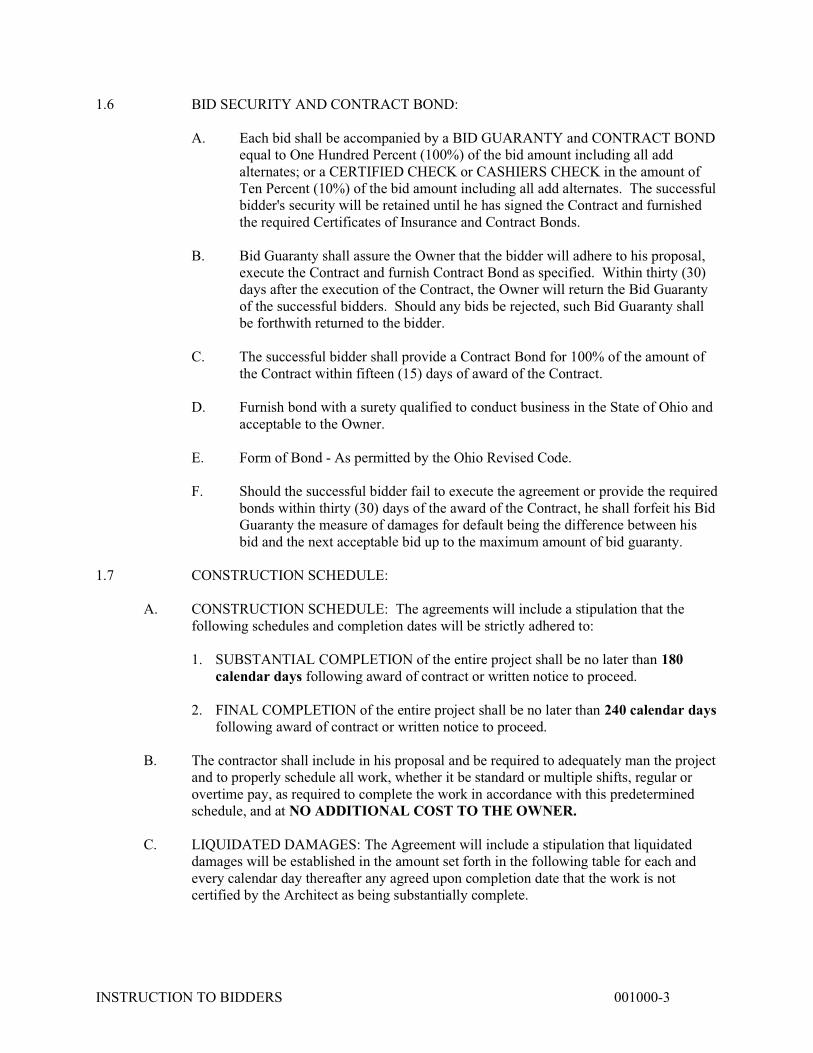
C. LIQUIDATED DAMAGES: The Agreement will include a stipulation that liquidated damages will be established in the amount set forth in the following table for each and every calendar day thereafter any agreed upon completion date that the work is not certified by the Architect as being substantially complete.
INSTRUCTION TO BIDDERS 001000-4
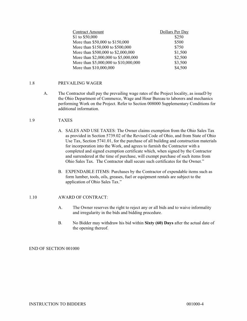
Contract Amount Dollars Per Day $1 to $50,000 $250 More than $50,000 to $150,000 $500 More than $150,000 to $500,000 $750 More than $500,000 to $2,000,000 $1,500 More than $2,000,000 to $5,000,000 $2,500 More than $5,000,000 to $10,000,000 $3,500 More than $10,000,000 $4,500 1.8 PREVAILING WAGER
A. The Contractor shall pay the prevailing wage rates of the Project locality, as issueD by the Ohio Department of Commerce, Wage and Hour Bureau to laborers and mechanics performing Work on the Project. Refer to Section 008000 Supplementary Conditions for additional information.
1.9 TAXES
A. SALES AND USE TAXES: The Owner claims exemption from the Ohio Sales Tax as provided in Section 5739.02 of the Revised Code of Ohio, and from State of Ohio Use Tax, Section 5741.01, for the purchase of all building and construction materials for incorporation into the Work, and agrees to furnish the Contractor with a completed and signed exemption certificate which, when signed by the Contractor and surrendered at the time of purchase, will exempt purchase of such items from Ohio Sales Tax. The Contractor shall secure such certificates for the Owner.”
B. EXPENDABLE ITEMS: Purchases by the Contractor of expendable items such as
form lumber, tools, oils, greases, fuel or equipment rentals are subject to the application of Ohio Sales Tax.”
1.10 AWARD OF CONTRACT: A. The Owner reserves the right to reject any or all bids and to waive informality
and irregularity in the bids and bidding procedure. B. No Bidder may withdraw his bid within Sixty (60) Days after the actual date of
the opening thereof. END OF SECTION 001000
VILLAGE OF NEWCOMERSTOWN NEW ADMINISTRATION BUIDLING PROJECT #2029 FORM OF PROPOSAL
FORM OF PROPOSAL 003100-1
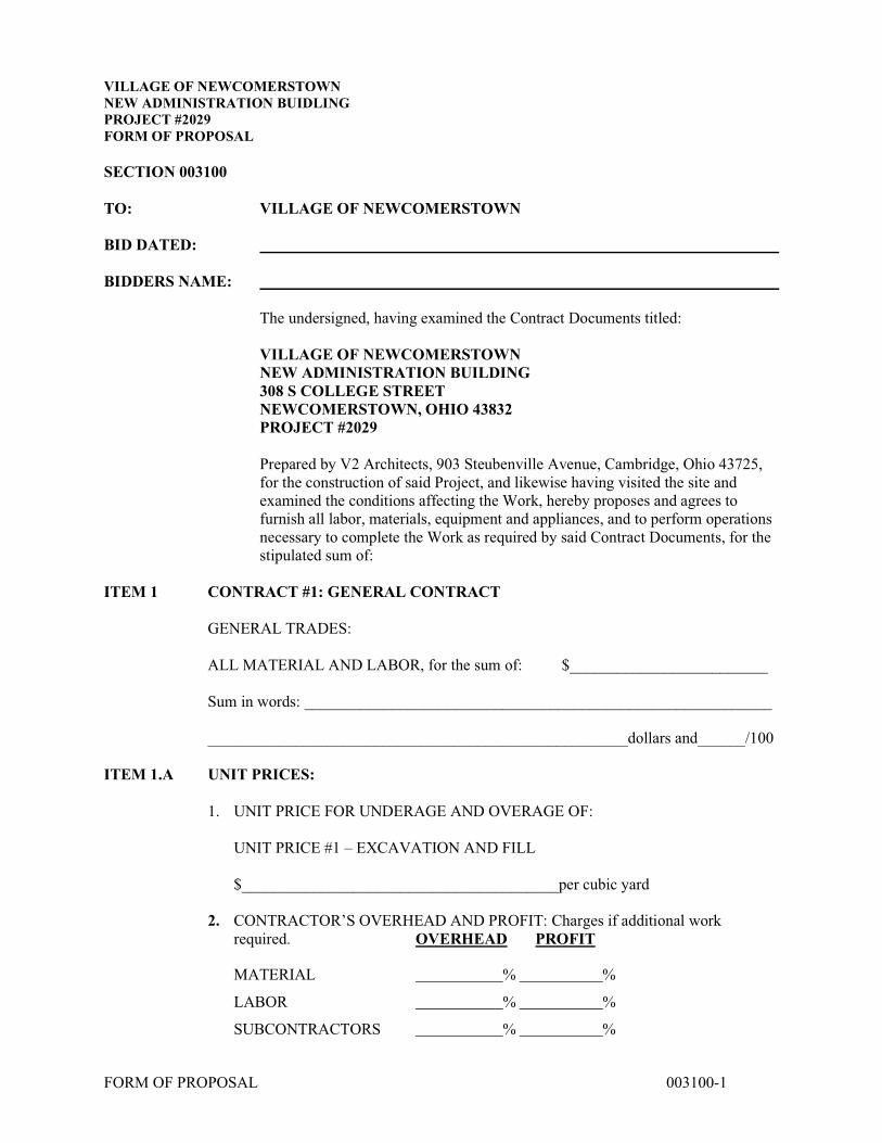
SECTION 003100 TO: VILLAGE OF NEWCOMERSTOWN BID DATED: BIDDERS NAME: The undersigned, having examined the Contract Documents titled: VILLAGE OF NEWCOMERSTOWN NEW ADMINISTRATION BUILDING 308 S COLLEGE STREET NEWCOMERSTOWN, OHIO 43832 PROJECT #2029 Prepared by V2 Architects, 903 Steubenville Avenue, Cambridge, Ohio 43725,
for the construction of said Project, and likewise having visited the site and examined the conditions affecting the Work, hereby proposes and agrees to furnish all labor, materials, equipment and appliances, and to perform operations necessary to complete the Work as required by said Contract Documents, for the stipulated sum of:
ITEM 1 CONTRACT #1: GENERAL CONTRACT GENERAL TRADES: ALL MATERIAL AND LABOR, for the sum of: $_________________________ Sum in words: ___________________________________________________________ _____________________________________________________dollars and______/100 ITEM 1.A UNIT PRICES:
1. UNIT PRICE FOR UNDERAGE AND OVERAGE OF:
UNIT PRICE #1 – EXCAVATION AND FILL
$________________________________________per cubic yard
2. CONTRACTOR’S OVERHEAD AND PROFIT: Charges if additional work required. OVERHEAD PROFIT
MATERIAL % %
LABOR % %
SUBCONTRACTORS % %

VILLAGE OF NEWCOMERSTOWN NEW ADMINISTRATION BUIDLING PROJECT #2029 FORM OF PROPOSAL
FORM OF PROPOSAL 003100-2
ITEM 2 The Undersigned understands and agrees to comply with and be bound by
Bidding and Contract Requirements, Addenda, General Conditions, Standards and Substitutions, Construction Schedule and Liquidated Damages, and all other provisions set forth herein.
ITEM 3 Enclosed with the bid is a Bid Guaranty in one of the forms permitted by Ohio
Revised Code Section 153.54 YES ____ .
BIDDER (Company): ADDRESS CITY STATE TELEPHONE NO. FAX NO. MAIN CONTACT NAME: EMAIL ADDRESS OF MAIN CONTACT FEDERAL ID # BY (authorized officer) (printed name) SIGNATURE TITLE DATE
BID GUARANTY AND CONTRACT BOND 003100b
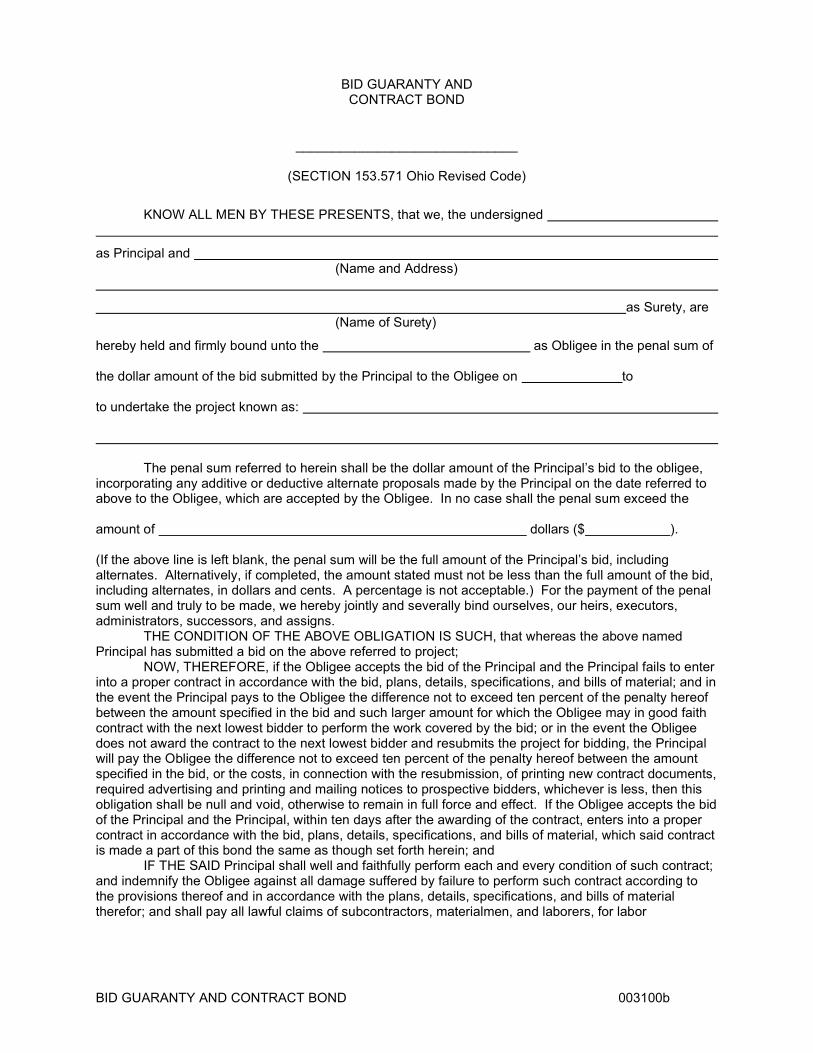
BID GUARANTY AND CONTRACT BOND
______________________________
(SECTION 153.571 Ohio Revised Code)
KNOW ALL MEN BY THESE PRESENTS, that we, the undersigned
as Principal and (Name and Address)
as Surety, are (Name of Surety)
hereby held and firmly bound unto the as Obligee in the penal sum of the dollar amount of the bid submitted by the Principal to the Obligee on to to undertake the project known as: The penal sum referred to herein shall be the dollar amount of the Principal’s bid to the obligee, incorporating any additive or deductive alternate proposals made by the Principal on the date referred to above to the Obligee, which are accepted by the Obligee. In no case shall the penal sum exceed the amount of dollars ($ ). (If the above line is left blank, the penal sum will be the full amount of the Principal’s bid, including alternates. Alternatively, if completed, the amount stated must not be less than the full amount of the bid, including alternates, in dollars and cents. A percentage is not acceptable.) For the payment of the penal sum well and truly to be made, we hereby jointly and severally bind ourselves, our heirs, executors, administrators, successors, and assigns. THE CONDITION OF THE ABOVE OBLIGATION IS SUCH, that whereas the above named Principal has submitted a bid on the above referred to project; NOW, THEREFORE, if the Obligee accepts the bid of the Principal and the Principal fails to enter into a proper contract in accordance with the bid, plans, details, specifications, and bills of material; and in the event the Principal pays to the Obligee the difference not to exceed ten percent of the penalty hereof between the amount specified in the bid and such larger amount for which the Obligee may in good faith contract with the next lowest bidder to perform the work covered by the bid; or in the event the Obligee does not award the contract to the next lowest bidder and resubmits the project for bidding, the Principal will pay the Obligee the difference not to exceed ten percent of the penalty hereof between the amount specified in the bid, or the costs, in connection with the resubmission, of printing new contract documents, required advertising and printing and mailing notices to prospective bidders, whichever is less, then this obligation shall be null and void, otherwise to remain in full force and effect. If the Obligee accepts the bid of the Principal and the Principal, within ten days after the awarding of the contract, enters into a proper contract in accordance with the bid, plans, details, specifications, and bills of material, which said contract is made a part of this bond the same as though set forth herein; and IF THE SAID Principal shall well and faithfully perform each and every condition of such contract; and indemnify the Obligee against all damage suffered by failure to perform such contract according to the provisions thereof and in accordance with the plans, details, specifications, and bills of material therefor; and shall pay all lawful claims of subcontractors, materialmen, and laborers, for labor
BID GUARANTY AND CONTRACT BOND 003100b
performed and materials furnished in the carrying forward, performing, or completing of said contract; we agreeing and assenting that this undertaking shall be for the benefit of any materialman or laborer having a just claim, as well as for the Obligee herein; then this obligation shall be void; otherwise the same shall remain in full force and effect; it being expressly understood and agreed that the liability of the Surety for any and all claims hereunder shall in no event exceed the penal amount of this obligation as herein stated. THE SAID Surety hereby stipulates and agrees that no modifications, omissions, or additions, in or to the terms of said contract or in or to the plans and specifications therefor shall in any wise affect the obligations of said Surety on its bond, and it does hereby waive notice of any such modifications, omissions or additions to the terms of the contract or to the work or to the specifications. SIGNED AND SEALED This day of , 20 . PRINCIPAL: BY: TITLE: SURETY: SURETY COMPANY ADDRESS: Street BY: ATTORNEY-IN-FACT City State Zip Telephone SURETY AGENT’S ADDRESS: Street City State Zip Telephone NOTE: Failure by any party to sign Bid Guaranty and contract Bond shall result in rejection of bid.

NON-COLLUSION AFFIDAVIT STATE OF: COUNTY OF: , being first deposes and says: (name of authorized individual making proposal) That he/she is of (title) (company name) which is the firm making certain proposal or bid; that he/she is the only party interested in the profits of said firm; that the said bidder has not directly or indirectly conspired, colluded, or connived with any bidder or person to fix any overhead, profit, or cost element of said bid price to secure an advantage against the VILLAGE OF NEWCOMERSTOWN or any person interested in the proposed contract; and that the said proposal or bid in genuine, non-collusive, and in all respects true and fair. Signature of Bidder: (if an Individual) (if a Partnership) (if a Corporation) Subscribed and sworn to me this day of , 20 . Notary Public My commission expires , 20 . This Affidavit is to be filled out and executed by the bidder; if the bid is made by a corporation, then by its Properly Authorized Agent.

SUPPLEMENTARY CONDITIONS 008000-1
DIVISION 0 - BIDDING AND CONTRACT REQUIREMENT SECTION 00800 - SUPPLEMENTARY CONDITIONS 1.0 GENERAL 1.1 CONTRACT: AIA DOCUMENT A101, Standard Form of Agreement Between Owner and
Contractor - Latest Edition is a part of this Contract. 1.2 GENERAL CONDITIONS: AIA Document A201, General Conditions of the Contract for
Construction, Latest Edition is a part of this Contract. 1.3 THE DOCUMENTS CAN be reviewed and/or obtained from the Architect's Office. 1.4 THE FOLLOWING SUPPLEMENTS and Rider, modify, delete from, and/or add to the Contract
and General Conditions. A. All Articles, or portions thereof, which are not specifically modified, deleted, or
superseded hereby, remain in full effect. B. The Contract and General Conditions also may be supplemented elsewhere in
the Contract Documents by provisions located in, but not necessarily limited to, Division 1 of the Specifications.
2.0 GENERAL CONDITIONS 2.1 ARTICLE 1 GENERAL PROVISIONS
1.2.1: CORRELATION & INTENT OF THE CONTRACT DOCUMENTS: Add the following Section 1.2.1.1 to Section 1.2.1
1.2.1.1 In the event of conflicts or discrepancies among the Contract Documents, interpretations will be based on the following priorities:
1. The Agreement. 2. Addenda, with those of later date having precedence over those of earlier date. 3. The Supplementary Conditions. 4. The General Conditions of the Contract for Construction. 5. Division 1 of the Specifications. 6. Drawings and Divisions 2-16 of the Specifications.
In the case of conflicts or discrepancies between Drawings and Divisions 2-16 of the Specifications or within either Document not clarified by Addendum, the Architect will determine which takes precedence in accordance with Section 4.2.11.
1.5: OWNERSHIP & USE OF DRAWINGS, SPECIFICATIONS & OTHER
INSTRUMENTS OF SERVICE: Add the following Section 1.5.2 to Section 1.5: 1.5.2 Contractor’s Use of Instruments of Service in Electronic Form.

SUPPLEMENTARY CONDITIONS 008000-2
1.5.2.1 The Architect may, with the concurrence of the Owner, furnish to the Contractor versions of Instruments of Service in electronic form. The Contract Documents executed or identified in accordance with Section 1.5.1 shall prevail in case of an inconsistency with subsequent versions made through manipulatable electronic means involving computers.
1.5.2.2 The Contractor shall not transfer or reuse Instruments of Service in electronic or
machine-readable form without the prior written consent of the Architect.
2.2 ARTICLE 3: CONTRACTOR: ADD THE FOLLOWING CLAUSES SUBPARAGRAPH:
3.2: REVIEW OF CONTRACT DOCUMENTS AND FIELD CONDITIONS BY CONTRACTOR:
3.2.5 Add the following Section 3.2.5 to Section 3.2:
The Owner shall be entitled to deduct from the Contract Sum amounts paid to the Architect for the Architect to evaluate and respond to the Contractor’s requests for interpretation, where such information was available to the Contractor from a careful study and comparison of the Contract Documents, field conditions, other Owner-provided information, Contractor-prepared coordination drawings, or prior Project correspondence or documentation.
3.4 LABOR AND MATERIAL
3.4.2 Delete Section 3.4.2 and substitute the following: After the Contract has been executed, the Owner and Architect will consider a formal request for the substitution of products in place of those specified only under the conditions set forth in the General Requirements (Division 1 of the Specifications). By making requests for substitutions, the Contractor:
1. Represents that the Contractor has personally investigated the proposed substitute
product and determined that it is equal or superior in all respects to that specified; 2. Represents that the Contractor will provide the same warranty for the substitution that
the Contractor would for that specified; 3. Certifies that the cost data presented is complete and includes all related costs under
this Contract except the Architect's redesign costs, and waives all claims for additional costs related to the substitution which subsequently become apparent; and
4. Will coordinate the installation of the accepted substitute, making such changes as may be required for the Work to be complete in all respects.
3.4.4 Add the following Section 3.4.4 to Section 3.4:
The Owner shall be entitled to deduct from the Contract Sum amounts paid to the Architect to evaluate the Contractor’s proposed substitutions and to make agreed-upon changes in the Drawings and Specifications made necessary by the Owner’s acceptance of such substitutions.

SUPPLEMENTARY CONDITIONS 008000-3
3.4.5 Add the following Section to Section 3.4.5: 3.4.5.1 Payment of Prevailing Wage Rates 3.4.5.1.1 The Contractor shall pay the prevailing wage rates of the Project locality,
as issued by the Ohio Department of Commerce, Wage and Hour Bureau to laborers and mechanics performing Work on the Project.
3.4.5.1.2 The Contractor shall comply with the provisions, duties, obligations, and is subject to the remedies and penalties of ORC Chapter 4115.
3.4.5.1.3 If the Contractor or its Subcontractors fail to comply with ORC Chapter 4115, the Contracting Authority may withhold payment. The Contractor is liable for violations committed by the Contractor or its Subcontractors to the extent provided in ORC Chapter 4115.
3.4.5.1.4 The Contractor shall submit all payroll reports for all of the employees of the Contractor and of the Contractor’s Subcontractors.
3.4.5.1.5 By executing a Contract, the Contractor certifies that it based its Bid upon prevailing rates of wages as ascertained by the Ohio Department of Commerce, Wage and Hour Bureau for the Project as provided in ORC Sections 4115.03 through 4115.14.
3.4.5.2 Prevailing Wage Rate Revisions 3.4.5.2.1 The Contracting Authority shall within 7 business days after receipt of a
notice of a change in the prevailing wage rates, notify the Contractor of the change. The prevailing wage rates are available at the Ohio Department of Commerce’s web site: http://com.state.oh.us/ .
3.4.5.2.2 The Contractor shall pay any revised wage rates issued during the term of the Contract.
3.4.5.3 Payroll Schedule 3.4.5.3.1 Within 10 days of the date of the Notice to Proceed, the Contractor shall
provide the Contracting Authority’s Prevailing Wage Coordinator a schedule of dates during the term of the Contract on which wages shall be paid to employees of the Project.
3.4.5.4 Payroll Reports 3.4.5.4.1 The Contractor shall submit payroll reports with each Contractor
Payment Request, which reports shall be certified by the Contractor that the payroll is correct and complete and the wage rates shown are not less than those required by the Contract. The Contractor is responsible for submitting all payroll reports of its Subcontractors.
3.4.5.4.2 Each payroll report shall indicate the period covered and include a list containing the name, address and social security number of each employee of the Contractor and its Subcontractors paid for the work.
3.4.5.4.3 Each payroll report shall list the number of hours each employee worked each day on the Project during the reporting period, the total hours each week on the Project, the employee’s hourly rate of pay, job classification, hourly rate of fringe benefits, and all deductions from wages and net pay.
3.4.5.4.4 Each payroll report shall list each fringe benefit and state if it is paid as cash to the employee or to a named plan.
3.4.5.4.5 The Contractor and its Subcontractors shall submit apprenticeship agreements for all apprentices utilized on the Project with the first

SUPPLEMENTARY CONDITIONS 008000-4
payroll report from the Contractor or its Subcontractor that includes apprentices.
3.4.6 Add the following Section 3.4.6 to Section 3.4: Nondiscrimination: 3.4.6.1 During the performance of the Contract, the Contractor agrees that in the hiring
of employees for the performance of work, including without limitation Work to be performed by a subcontractor, no Contractor or Subcontractor, and no person acting on behalf of the Contractor or Subcontractor, shall, by reason of race, religion, national origin, age, sex, disabilities, Vietnam era Veteran status, or color, discriminate against any citizen in the employment of labor or workers who are qualified and available to perform the Work to which the employment relates.
3.4.6.2 The Contractor further agrees that no Contractor or Subcontractor, and no person
acting on behalf of the Contractor or Subcontractor, shall, in any manner, discriminate against or intimidate any employee hired for the performance of Work on account of race, religion, national origin, age, sex, disability, Vietnam era Veteran status or color.
3.4.6.3 The Contractor agrees that the Contractor will fully cooperate with the State
Equal Opportunity Coordinator, with any other official or agency of the State or federal government which seeks to eliminate unlawful employment discrimination, and with all other State and federal efforts to assure equal employment practices under the Contract.
3.4.6.4 In the event of the Contractors noncompliance with the nondiscrimination
clauses, the Contract may be terminated or suspended in whole or in part, and the Contractor may be declared not responsive or responsible for further State contracts or such other sanctions as provided in Section 153.60, ORC.
3.4.6.5 Each Contractor must fully comply with the State’s Equal Employment
Opportunity in the Construction Industry rules set forth in Chapters 123:2-3 through 123:2-9, ORC.
3.4.6.6 The utilization goal for women workers in the performance of the Work in each
trade in all geographical areas is 6.9 percent of the work hours. 3.4.6.7 The Contractor’s good faith effort to comply with this goal shall be reviewed and
determined according to Chapters 123:2-1 through 123:2-9, ORC. 3.6 Taxes Add the following to Section 3.6: 3.6.1 The Owner claims exemption from the Ohio Sales Tax as provided in Section
5739.02 of the Revised Code of Ohio, and from State of Ohio Use Tax, Section 5741.01, for the purchase of all building and construction materials for incorporation into the Work, and agrees to furnish the Contractor with a completed and signed exemption certificate which, when signed by the Contractor and surrendered at the time of purchase, will exempt purchase of such
SUPPLEMENTARY CONDITIONS 008000-5
items from Ohio Sales Tax. The Contractor shall secure such certificates for the Owner.
3.6.2 Purchases by the Contractor of expendable items such as form lumber, tools,
oils, greases, fuel or equipment rentals are subject to the application of Ohio Sales Tax.
3.7 Permits, Fees and Notices 3.7.1 Add the following clause to Section 3.7.1: 3.7.1.1 The Owner will obtain, and pay for, the application for Building Plan Approval
from the Code Authority having jurisdiction. Fees associated with Plumbing Plan approval and all other local permits are the responsibility of the contractor.
3.10 CONTRACTOR'S CONSTRUCTION SCHEDULES: 3.10.4 Add the following Section 3.10.4 to Section 3.10: Responsibility and Authority of the General Trades Contractor: 3.10.4.1 The General Trades Contractor shall establish the regular working hours,
subject to approval by the Architect. 3.10.4.2 The General Trades Contractor shall coordinate the Work of all Contractors
with each other and with the activities and responsibilities of the Owner, to complete the Project in accordance with the Contract Documents.
3.10.4.2.1 Coordination of the Work of the Contractors by the General Trades
Contractor shall not relieve the other Contractors from the Contractor’s duty to supervise and direct the Contractor’s Work in accordance with the Contract documents.
3.10.4.3 The General Trades Contractor shall develop the Construction Schedule for
the Project and shall prepare and keep current, for the Architect’s approval, a schedule of submittals which is coordinated with the Construction Schedule.
3.10.4.3.1 The Construction Schedule shall not exceed the time limit specified in the
Notice to Proceed, shall provide for reasonable, efficient and economical execution of the Work and shall be related to the entire Project to the extent required by the Contract Documents.
3.10.4.3.2 The Construction Schedule shall be used to plan, organize and execute the
Work, record and report actual performance and progress and show how the General Trades Contractor plans to coordinate all remaining Work by Contract Completion.
3.10.4.4 The General Trades Contractor shall monitor the progress of the Work for
conformance with the Construction Schedule and shall initiate revisions of the Construction Schedule as required by the Contract Documents.
SUPPLEMENTARY CONDITIONS 008000-6
3.12 SHOP DRAWINGS, PRODUCT DATA & SAMPLES:
3.12.11 Add the following Section 3.12.11 to Section 3.12: The Architect's review of Contractor's submittals will be limited to
examination of an initial submittal and one (1) re-submittal. The Architect’s review of additional submittals will be made only with the consent of the Owner after notification by the Architect. The Owner shall be entitled to deduct from the Contract Sum amounts paid to the Architect for evaluation of such additional re-submittals.
2.3 ARTICLE 4: ARCHITECT
4.2: ADMINISTRATION OF THE CONTRACT:
4.2.2.1 Add the following Section 4.2.2.1 to Section 4.2.2: The Contractor shall reimburse the Owner for compensation paid to the Architect for additional site visits and administrative functions made necessary by delays to the construction schedule due to the fault, neglect or request of the Contractor.
2.4 ARTICLE 5: SUBCONTRACTORS
5.2.1 AWARD OF SUBCONTRACTS AND OTHER CONTRACTS FOR PORTIONS OF THE WORK:
5.2.1.1 Add the following Section 5.2.1.1 to Section 5.2.1:
Not later than thirty (30) days after the date of commencement of the Work, the Contractor shall furnish in writing to the Owner through the Architect the names of persons or entities proposed as sub-contractors, manufacturers, fabricators or material suppliers.
2.5 ARTICLE 8.2: PROGRESS AND COMPLETION: ADD THE FOLLOWING CLAUSE TO SUBPARAGRAPH 8.2.1: .1 CONSTRUCTION SCHEDULE: The agreements will include a stipulation that
the following schedules and completion dates will be strictly adhered to. A. SUBSTANTIAL COMPLETION: Refer to section 00100 Instruction to Bidders. B. THE CONTRACTOR SHALL include in his proposal and be required to
schedule all work, whether it be standard or multiple shifts, regular or overtime pay, as required to complete the work in accordance with this predetermined schedule, and at NO ADDITIONAL COST TO THE OWNER.
C. LIQUIDATED DAMAGES: Refer to Section 00100 Instruction to Bidders. 2.6 ARTICLE 9: PAYMENTS AND COMPLETION: 9.3 Application for Payment 9.3.1 Add the following Clauses to Subparagraph:
SUPPLEMENTARY CONDITIONS 008000-7
.1 The Contractor shall submit (3) copies of his Application for Payment to the
Architect on AIA Documents G-702 on or before the twenty-fifth day of each month for work completed to that date. Payment will be certified by the Architect and promptly submitted to the Owner on or before the first of the month following. Owner will issue payment to Contractor within thirty days from date of certification.
.2 Until the Contract is 50% complete, the Owner will pay 92% of the amount due
the Contractor on account of progress payments. All labor and material performed after the project is 50% complete will be paid at the rate of 100% of the amount due the Contractor.
.3 Upon Substantial Completion and acceptance of the project Completion and
acceptance of the project work, the retainage will be released and be paid to the Contractor.
9.3.3 Add the following Clauses to Subparagraph: .1 Every 30 days along with the Application for Payment and upon final
completion, the contractor is required to submit affidavits and waivers of lien for the previous pay period. Affidavits and waivers of lien shall be prepared on Forms in accordance with the requirements of the Ohio Legal Code.
9.6 Progress Payments 9.6.6 Add the following wording to Subparagraph: ... nor shall any such Certificate for Payment, payment, use or occupancy be
construed as constituting the completion of work by the Contractor.
9.8.3: SUBSTANTIAL COMPLETION: Add the following Section 9.8.3.1 to Section 9.8.3:
9.8.3.1 Except with the consent of the Owner, the Architect will perform no more than two (2) inspections to determine whether the Work or a designated portion thereof has attained Substantial Completion in accordance with the Contract Documents. The Owner shall be entitled to deduct from the Contract Sum amounts paid to the Architect for any additional inspections.
9.10.1: FINAL COMPLETION & FINAL PAYMENT: Add the following Section 9.10.1.1 to Section 9.10.1:
9.10.1.1 Except with the consent of the Owner, the Architect will perform no more than
two (2) inspections to determine whether the Work or a designated portion thereof has attained Final Completion in accordance with the Contract Documents. The Owner shall be entitled to deduct from the Contract Sum amounts paid to the Architect for any additional inspections.
SUPPLEMENTARY CONDITIONS 008000-8
2.7 ARTICLE 11: INSURANCE:
11.1 Contractor’s Liability Insurance
11.1.2 Add the following Clause to Subparagraph:
11.1.2.1 The minimum limits of liability for the required policies shall not be less than those specified in Section 008220 – Supplementary Insurance Requirements, unless a greater amount is required by law.
END OF SECTION 008000

3/14/22, 2:11 PM https://wagehour.com.ohio.gov//w3/webwh.nsf/PWDetermination?openform
https://wagehour.com.ohio.gov//w3/webwh.nsf/PWDetermination?openform 1/1
Prevailing Wage Determination Cover Letter
County: GUERNSEYDetermination Date: 03/14/2022Expiration Date: 06/14/2022
THE FOLLOWING PAGES ARE PREVAILING RATES OF WAGES ON PUBLIC IMPROVEMENTS FAIRLY ESTIMATED TOBE MORE THAN THE AMOUNT IN O.R.C. SEC. 4115.03 (b) (1) or (2), AS APPLICABLE.
Section 4115.05 provides, in part: “Where contracts are not awarded or construction undertaken within ninety days from thedate of the establishment of the prevailing wages, there shall be a redetermination of the prevailing rate of wages before thecontract is awarded.” The expiration date of this wage schedule is listed above for your convenience only. This wagedetermination is not intended as a blanket determination to be used for all projects during this period without prior approval ofthis Department.
Section 4115.04, Ohio Revised Code provides, in part: “Such schedule of wages shall be attached to and made a part of thespecifications for the work, and shall be printed on the bidding blanks where the work is done by contract...”
The contract between the letting authority and the successful bidder shall contain a statement requiring that mechanics andlaborers be paid a prevailing rate of wage as required in Section 4115.06, Ohio Revised Code.
The contractor or subcontractor is required to file with the contracting public authority upon completion of the project and priorto final payment therefore an affidavit stating that he has fully complied with Chapter 4115 of the Ohio Revised Code.
The wage rates contained in this schedule are the “Prevailing Wages” as defined by Section 4115.03, Ohio Revised Code (thebasic hourly rates plus certain fringe benefits). These rates and fringes shall be a minimum to be paid under a contractregulated by Chapter 4115 of the Ohio Revised Code by contractors and subcontractors. The prevailing wage rates containedin this schedule include the effective dates and wage rates currently on file. In cases where future effective dates are notincluded in this schedule, modifications to the wage schedule will be furnished to the Prevailing Wage Coordinator appointedby the public authority as soon as prevailing wage rates increases are received by this office.
“There shall be posted in a prominent and accessible place on the site of work a legible statement of the Schedule of WageRates specified in the contract to the various classifications of laborers, workmen, and mechanics employed, said statementto remain posted during the life of such contract.” Section 4115.07, Ohio Revised Code.
Apprentices will be permitted to work only under a bona fide apprenticeship program if such program exists and if suchprogram is registered with the Ohio Apprenticeship Council.
Section 4115.071 provides that no later than ten days before the first payment of wages is due to any employee of anycontractor or subcontractor working on a contract regulated by Chapter 4115, Ohio Revised Code, the contracting publicauthority shall appoint one of his own employees to act as the prevailing wage coordinator for said contract. The duties of theprevailing wage coordinator are outlined in Section 4115.071 of the Ohio Revised Code.
Section 4115.05 provides for an escalator in the prevailing wage rate. Each time a new rate is established, that rate isrequired to be paid on all ongoing public improvement projects.
A further requirement of Section 4115.05 of the Ohio Revised Code is: “On the occasion of the first pay date under a contract,the contractor shall furnish each employee not covered by a collective bargaining agreement or understanding betweenemployers and bona fide organizations of Labor with individual written notification of the job classification to which theemployee is assigned, the prevailing wage determined to be applicable to that classification, separated into the hourly rate ofpay and the fringe payments, and the identity of the prevailing wage Coordinator appointed by the public authority. Thecontractor or subcontractor shall furnish the same notification to each affected employee every time the job classification ofthe employee is changed.”
Work performed in connection with the installation of modular furniture may be subject to prevailing wage.
THIS PACKET IS NOT TO BE SEPARATED BUT IS TO REMAIN COMPLETE AS IT IS SUBMITTED TO YOU. (Referenceguidelines and forms are included in this packet to be helpful in the compliance of the Prevailing Wage law.)wh1500

Bureau of Wage and Hour Administration 6606 Tussing Road Reynoldsburg, OH 43068-9009
614-644-2239 Fax 614-728-8639
TTY/TDD 800-750-0750 com.ohio.gov An Equal Opportunity Employer and Service Provider
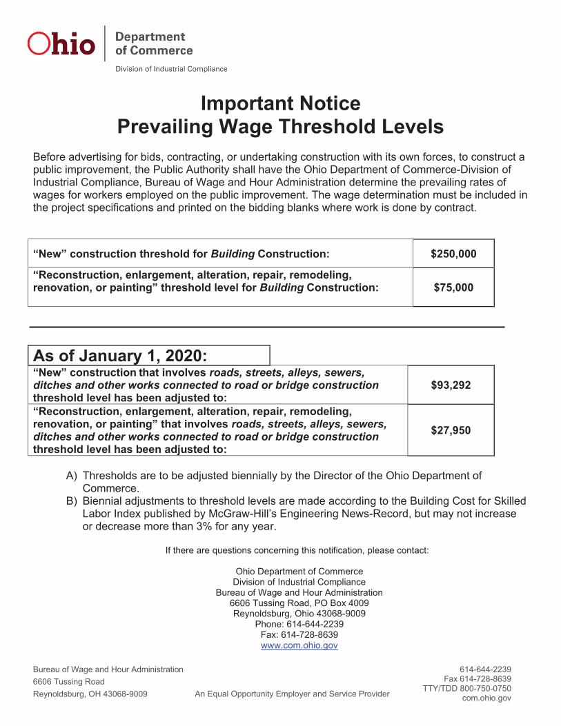
Important Notice Prevailing Wage Threshold Levels
Before advertising for bids, contracting, or undertaking construction with its own forces, to construct a public improvement, the Public Authority shall have the Ohio Department of Commerce-Division of Industrial Compliance, Bureau of Wage and Hour Administration determine the prevailing rates of wages for workers employed on the public improvement. The wage determination must be included in the project specifications and printed on the bidding blanks where work is done by contract.
“New” construction threshold for Building Construction: $250,000
“Reconstruction, enlargement, alteration, repair, remodeling, renovation, or painting” threshold level for Building Construction: $75,000
As of January 1, 2020: “New” construction that involves roads, streets, alleys, sewers, ditches and other works connected to road or bridge construction threshold level has been adjusted to:
$93,292
“Reconstruction, enlargement, alteration, repair, remodeling, renovation, or painting” that involves roads, streets, alleys, sewers, ditches and other works connected to road or bridge construction threshold level has been adjusted to:
$27,950
A) Thresholds are to be adjusted biennially by the Director of the Ohio Department of Commerce.
B) Biennial adjustments to threshold levels are made according to the Building Cost for Skilled Labor Index published by McGraw-Hill’s Engineering News-Record, but may not increase or decrease more than 3% for any year.
If there are questions concerning this notification, please contact:
Ohio Department of Commerce
Division of Industrial Compliance Bureau of Wage and Hour Administration
6606 Tussing Road, PO Box 4009 Reynoldsburg, Ohio 43068-9009
Phone: 614-644-2239 Fax: 614-728-8639 www.com.ohio.gov

3/14/22, 2:16 PM PW Rate Skilled LCN01-2018fbLoc207OH Page
https://wagehour.com.ohio.gov/w3/Webwh.nsf/$docUniqIDAll/852565B800706932852570FF00535D80?opendocument 1/2
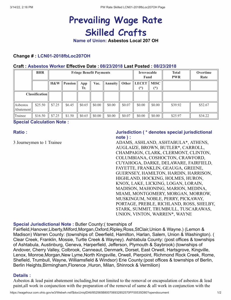
Prevailing Wage Rate
Skilled CraftsName of Union: Asbestos Local 207 OH
Change # : LCN01-2018fbLoc207OH
Craft : Asbestos Worker Effective Date : 08/23/2018 Last Posted : 08/23/2018BHR Fringe Benefit Payments Irrevocable
FundTotalPWR
OvertimeRate
H&W Pension AppTr.
Vac. Annuity Other LECET(*)
MISC(*)
Classification
Asbestos
Abatement
$25.50 $7.25 $6.45 $0.65 $0.00 $0.00 $0.07 $0.00 $0.00 $39.92 $52.67
Trainee $16.50 $7.25 $1.50 $0.65 $0.00 $0.00 $0.07 $0.00 $0.00 $25.97 $34.22
Special Calculation Note :
Ratio : Jurisdiction ( * denotes special jurisdictionalnote ) :
3 Journeymen to 1 Trainee ADAMS, ASHLAND, ASHTABULA*, ATHENS,AUGLAIZE, BROWN, BUTLER*, CARROLL,CHAMPAIGN, CLARK, CLERMONT, CLINTON,COLUMBIANA, COSHOCTON, CRAWFORD,CUYAHOGA, DARKE, DELAWARE, FAIRFIELD,FAYETTE, FRANKLIN, GEAUGA, GREENE,GUERNSEY, HAMILTON, HARDIN, HARRISON,HIGHLAND, HOCKING, HOLMES, HURON,KNOX, LAKE, LICKING, LOGAN, LORAIN,MADISON, MAHONING, MARION, MEDINA,MIAMI, MONTGOMERY, MORGAN, MORROW,MUSKINGUM, NOBLE, PERRY, PICKAWAY,PORTAGE, PREBLE, RICHLAND, ROSS, SHELBY,STARK, SUMMIT, TRUMBULL, TUSCARAWAS,UNION, VINTON, WARREN*, WAYNE
Special Jurisdictional Note : Butler County:( townships ofFairfield,Hanover,Liberty,Milford,Morgan,Oxford,Ripley,Ross,StClair,Union & Wayne.) (Lemon &Madison) Warren County: (townships of: Deerfield, Hamilton, Harlan, Salem, Union & Washington). (Clear Creek, Franklin, Mossie, Turtle Creek & Wayney). Ashtabula County: (post offices & townshipsof Ashtabula, Austinburg, Geneva, Harperfield, Jefferson, Plymouth & Saybrook) (townships ofAndover, Cherry Valley, Colbrook, Canneaut, Denmark, Dorset, East Orwell, Hartsgrove, Kingville,Lenox, Monroe,Morgan,New Lyme,North Kingsville, Orwell, Pierpoint, Richmond Rock Creek, Rome,Shefield, Trumbull, Wayne, Williamsfield & Windsor) Erie County:(post offices & townships of Berlin,Berlin Heights,Birmingham,Florence ,Huron, Milan, Shinrock & Vermilion)
Details :Asbestos & lead paint abatement including,but not limited to the removal or encapsulation of asbestos & leadpaint,all work in conjunction with the preparation of the removal of same & all work in conjunction with the

3/14/22, 2:16 PM PW Rate Skilled LCN01-2018fbLoc207OH Page
https://wagehour.com.ohio.gov/w3/Webwh.nsf/$docUniqIDAll/852565B800706932852570FF00535D80?opendocument 2/2
clean up after said removal.The removal of all insulation materials, whether they contain asbestos or not, frommechanical systems (pipes, boilers, ducts, flues, breaching, etc.) is recognized as being the exclusive work of theAsbestos Abatement Workers.
On all mechanical systems (pipes, boilers, ducts, flues, breaching, etc.) that are going to be demolished, theremoval of all insulating materials whether they contain asbestos or not shall be the exclusive work of theLaborers.An Abatement Journeyman is anyone who has more than 300 hours in the Asbestos Abatement field.

3/14/22, 2:17 PM PW Rate Skilled LCN01-2018fbLoc84 Page
https://wagehour.com.ohio.gov/w3/Webwh.nsf/$docUniqIDAll/852565B80070693285257E19005185E7?opendocument 1/1
Prevailing Wage Rate
Skilled CraftsName of Union: Asbestos Local 84 Heat & Frost Insulators
Change # : LCN01-2018fbLoc84
Craft : Asbestos Worker Effective Date : 06/06/2018 Last Posted : 06/06/2018BHR Fringe Benefit Payments Irrevocable
FundTotalPWR
OvertimeRate
H&W Pension AppTr.
Vac. Annuity Other LECET(*)
MISC(*)
Classification
Asbestos
Insulation
Worker
$31.47 $9.49 $8.36 $0.36 $0.00 $3.39 $0.24 $0.00 $0.00 $53.31 $69.04
Apprentice Percent
1st Year 50.00 $15.74 $9.49 $8.36 $0.36 $0.00 $3.39 $0.24 $0.00 $0.00 $37.58 $45.44
2nd Year 60.00 $18.88 $9.49 $8.36 $0.36 $0.00 $3.39 $0.24 $0.00 $0.00 $40.72 $50.16
3rd Year 70.00 $22.03 $9.49 $8.36 $0.36 $0.00 $3.39 $0.24 $0.00 $0.00 $43.87 $54.88
4th Year 80.00 $25.18 $9.49 $8.36 $0.36 $0.00 $3.39 $0.24 $0.00 $0.00 $47.02 $59.60
Special Calculation Note : Other is Industry and Labor Management Fund
Ratio : Jurisdiction ( * denotes special jurisdictionalnote ) :
3 Journeymen to 1 Apprentice per shop ASHLAND, ASHTABULA*, CARROLL,COLUMBIANA, COSHOCTON, ERIE*, HARRISON,HOLMES, MAHONING, MEDINA, PORTAGE,RICHLAND, STARK, SUMMIT, TRUMBULL,TUSCARAWAS, WAYNE
Special Jurisdictional Note : Ashtabula County: except for the townships of Ashtabula, Austinburg,Geneva, Harpersfield, Jefferson, Plymouth and Saybrook.Erie except Sandusky city limits.
Details :The removal of all insulation materials, whether they contain asbestos or not, from mechanical systems (pipes,boilers, ducts, flues, breaching, etc.) is recognized as being the exclusive work of the Asbestos Workers. On all mechanical systems (pipes, boilers, ducts, flues, breaching, etc.) that are going to be demolished, theremoval of all insulating materials whether they contain asbestos or not shall be the exclusive work of theLaborers.

3/14/22, 2:17 PM PW Rate Skilled LCNO1-2019fbLoc744 Page
https://wagehour.com.ohio.gov/w3/Webwh.nsf/$docUniqIDAll/852565B80070693285257521006112EB?opendocument 1/2
Prevailing Wage Rate
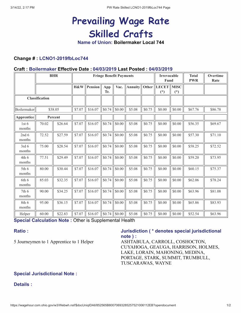
Skilled CraftsName of Union: Boilermaker Local 744
Change # : LCNO1-2019fbLoc744
Craft : Boilermaker Effective Date : 04/03/2019 Last Posted : 04/03/2019BHR Fringe Benefit Payments Irrevocable
FundTotalPWR
OvertimeRate
H&W Pension AppTr.
Vac. Annuity Other LECET(*)
MISC(*)
Classification
Boilermaker $38.05 $7.07 $16.07 $0.74 $0.00 $5.08 $0.75 $0.00 $0.00 $67.76 $86.78
Apprentice Percent
1st 6
months
70.02 $26.64 $7.07 $16.07 $0.74 $0.00 $5.08 $0.75 $0.00 $0.00 $56.35 $69.67
2nd 6
months
72.52 $27.59 $7.07 $16.07 $0.74 $0.00 $5.08 $0.75 $0.00 $0.00 $57.30 $71.10
3rd 6
months
75.00 $28.54 $7.07 $16.07 $0.74 $0.00 $5.08 $0.75 $0.00 $0.00 $58.25 $72.52
4th 6
months
77.51 $29.49 $7.07 $16.07 $0.74 $0.00 $5.08 $0.75 $0.00 $0.00 $59.20 $73.95
5th 6
months
80.00 $30.44 $7.07 $16.07 $0.74 $0.00 $5.08 $0.75 $0.00 $0.00 $60.15 $75.37
6th 6
months
85.03 $32.35 $7.07 $16.07 $0.74 $0.00 $5.08 $0.75 $0.00 $0.00 $62.06 $78.24
7th 6
months
90.00 $34.25 $7.07 $16.07 $0.74 $0.00 $5.08 $0.75 $0.00 $0.00 $63.96 $81.08
8th 6
months
95.00 $36.15 $7.07 $16.07 $0.74 $0.00 $5.08 $0.75 $0.00 $0.00 $65.86 $83.93
Helper 60.00 $22.83 $7.07 $16.07 $0.74 $0.00 $5.08 $0.75 $0.00 $0.00 $52.54 $63.96
Special Calculation Note : Other is Supplemental Health
Ratio : Jurisdiction ( * denotes special jurisdictionalnote ) :
5 Journeymen to 1 Apprentice to 1 Helper ASHTABULA, CARROLL, COSHOCTON,CUYAHOGA, GEAUGA, HARRISON, HOLMES,LAKE, LORAIN, MAHONING, MEDINA,PORTAGE, STARK, SUMMIT, TRUMBULL,TUSCARAWAS, WAYNE
Special Jurisdictional Note :
Details :

3/14/22, 2:17 PM PW Rate Skilled LCNO1-2019fbLoc744 Page
https://wagehour.com.ohio.gov/w3/Webwh.nsf/$docUniqIDAll/852565B80070693285257521006112EB?opendocument 2/2

3/14/22, 2:18 PM PW Rate Skilled LCN01-2021fbLoc6 Page
https://wagehour.com.ohio.gov/w3/Webwh.nsf/$docUniqIDAll/852565B800706932852566060051CA54?opendocument 1/2
Prevailing Wage Rate
Skilled CraftsName of Union: Bricklayer Local 6
Change # : LCN01-2021fbLoc6
Craft : Bricklayer Effective Date : 05/01/2021 Last Posted : 04/21/2021BHR Fringe Benefit Payments Irrevocable
FundTotalPWR
OvertimeRate
H&W Pension AppTr.
Vac. Annuity Other LECET(*)
MISC(*)
Classification
Bricklayer $29.64 $10.17 $7.73 $1.19 $0.00 $0.00 $0.05 $0.00 $0.00 $48.78 $63.60
Pointer
Caulker
Cleaner
$29.64 $10.17 $7.73 $1.19 $0.00 $0.00 $0.05 $0.00 $0.00 $48.78 $63.60
Stone
Mason
$29.64 $10.17 $7.73 $1.19 $0.00 $0.00 $0.05 $0.00 $0.00 $48.78 $63.60
Cement
Mason
$29.64 $10.17 $7.73 $1.19 $0.00 $0.00 $0.05 $0.00 $0.00 $48.78 $63.60
Plaster $29.64 $10.17 $7.73 $1.19 $0.00 $0.00 $0.05 $0.00 $0.00 $48.78 $63.60
Apprentice Percent
1st 6
months
55.00 $16.30 $10.17 $7.73 $1.19 $0.00 $0.00 $0.05 $0.00 $0.00 $35.44 $43.59
2nd 6
months
60.00 $17.78 $10.17 $7.73 $1.19 $0.00 $0.00 $0.05 $0.00 $0.00 $36.92 $45.82
3rd 6
months
65.00 $19.27 $10.17 $7.73 $1.19 $0.00 $0.00 $0.05 $0.00 $0.00 $38.41 $48.04
4th 6
months
70.00 $20.75 $10.17 $7.73 $1.19 $0.00 $0.00 $0.05 $0.00 $0.00 $39.89 $50.26
5th 6
months
75.00 $22.23 $10.17 $7.73 $1.19 $0.00 $0.00 $0.05 $0.00 $0.00 $41.37 $52.49
6th 6
months
80.00 $23.71 $10.17 $7.73 $1.19 $0.00 $0.00 $0.05 $0.00 $0.00 $42.85 $54.71
7th 6
months
90.00 $26.68 $10.17 $7.73 $1.19 $0.00 $0.00 $0.05 $0.00 $0.00 $45.82 $59.15
8th 6
months
95.00 $28.16 $10.17 $7.73 $1.19 $0.00 $0.00 $0.05 $0.00 $0.00 $47.30 $61.38
Special Calculation Note : OTHER IS DRUG TESTING
Ratio : Jurisdiction ( * denotes special jurisdictionalnote ) :
1 Journeymen to 1 Apprentice5 Journeymen to 2 Apprentice9 Journeymen to 3 Apprentice13 Journeymen to 4 Apprentice
CARROLL, STARK, TUSCARAWAS

3/14/22, 2:18 PM PW Rate Skilled LCN01-2021fbLoc6 Page
https://wagehour.com.ohio.gov/w3/Webwh.nsf/$docUniqIDAll/852565B800706932852566060051CA54?opendocument 2/2
Special Jurisdictional Note :
Details :
3/14/22, 2:18 PM PW Rate Skilled LCN1-2021fbLoc6 Page
https://wagehour.com.ohio.gov/w3/Webwh.nsf/$docUniqIDAll/852565B80070693285257BB20053251D?opendocument 1/2
Prevailing Wage Rate
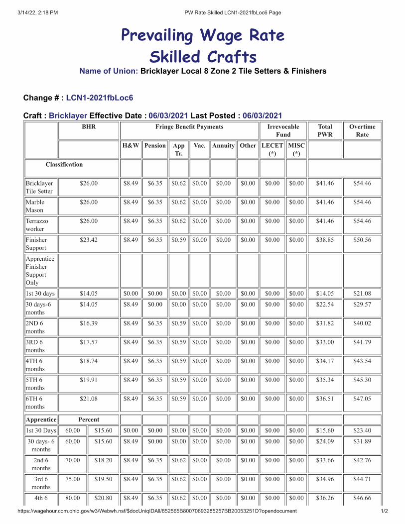
Skilled CraftsName of Union: Bricklayer Local 8 Zone 2 Tile Setters & Finishers
Change # : LCN1-2021fbLoc6
Craft : Bricklayer Effective Date : 06/03/2021 Last Posted : 06/03/2021BHR Fringe Benefit Payments Irrevocable
FundTotalPWR
OvertimeRate
H&W Pension AppTr.
Vac. Annuity Other LECET(*)
MISC(*)
Classification
Bricklayer
Tile Setter
$26.00 $8.49 $6.35 $0.62 $0.00 $0.00 $0.00 $0.00 $0.00 $41.46 $54.46
Marble
Mason
$26.00 $8.49 $6.35 $0.62 $0.00 $0.00 $0.00 $0.00 $0.00 $41.46 $54.46
Terrazzo
worker
$26.00 $8.49 $6.35 $0.62 $0.00 $0.00 $0.00 $0.00 $0.00 $41.46 $54.46
Finisher
Support
$23.42 $8.49 $6.35 $0.59 $0.00 $0.00 $0.00 $0.00 $0.00 $38.85 $50.56
Apprentice
Finisher
Support
Only
1st 30 days $14.05 $0.00 $0.00 $0.00 $0.00 $0.00 $0.00 $0.00 $0.00 $14.05 $21.08
30 days-6
months
$14.05 $8.49 $0.00 $0.00 $0.00 $0.00 $0.00 $0.00 $0.00 $22.54 $29.57
2ND 6
months
$16.39 $8.49 $6.35 $0.59 $0.00 $0.00 $0.00 $0.00 $0.00 $31.82 $40.02
3RD 6
months
$17.57 $8.49 $6.35 $0.59 $0.00 $0.00 $0.00 $0.00 $0.00 $33.00 $41.79
4TH 6
months
$18.74 $8.49 $6.35 $0.59 $0.00 $0.00 $0.00 $0.00 $0.00 $34.17 $43.54
5TH 6
months
$19.91 $8.49 $6.35 $0.59 $0.00 $0.00 $0.00 $0.00 $0.00 $35.34 $45.30
6TH 6
months
$21.08 $8.49 $6.35 $0.59 $0.00 $0.00 $0.00 $0.00 $0.00 $36.51 $47.05
Apprentice Percent
1st 30 Days 60.00 $15.60 $0.00 $0.00 $0.00 $0.00 $0.00 $0.00 $0.00 $0.00 $15.60 $23.40
30 days- 6
months
60.00 $15.60 $8.49 $0.00 $0.00 $0.00 $0.00 $0.00 $0.00 $0.00 $24.09 $31.89
2nd 6
months
70.00 $18.20 $8.49 $6.35 $0.62 $0.00 $0.00 $0.00 $0.00 $0.00 $33.66 $42.76
3rd 6
months
75.00 $19.50 $8.49 $6.35 $0.62 $0.00 $0.00 $0.00 $0.00 $0.00 $34.96 $44.71
4th 6 80.00 $20.80 $8.49 $6.35 $0.62 $0.00 $0.00 $0.00 $0.00 $0.00 $36.26 $46.66
3/14/22, 2:18 PM PW Rate Skilled LCN1-2021fbLoc6 Page
https://wagehour.com.ohio.gov/w3/Webwh.nsf/$docUniqIDAll/852565B80070693285257BB20053251D?opendocument 2/2
months
5th 6
months
85.00 $22.10 $8.49 $6.35 $0.62 $0.00 $0.00 $0.00 $0.00 $0.00 $37.56 $48.61
6th 6
months
90.00 $23.40 $8.49 $6.35 $0.62 $0.00 $0.00 $0.00 $0.00 $0.00 $38.86 $50.56
7th 6
months
95.00 $24.70 $8.49 $6.35 $0.62 $0.00 $0.00 $0.00 $0.00 $0.00 $40.16 $52.51
8th 6
months
95.00 $24.70 $8.49 $6.35 $0.62 $0.00 $0.00 $0.00 $0.00 $0.00 $40.16 $52.51
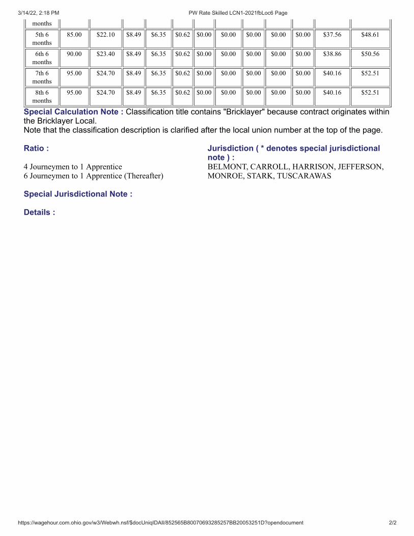
Special Calculation Note : Classification title contains "Bricklayer" because contract originates withinthe Bricklayer Local. Note that the classification description is clarified after the local union number at the top of the page.
Ratio : Jurisdiction ( * denotes special jurisdictionalnote ) :
4 Journeymen to 1 Apprentice6 Journeymen to 1 Apprentice (Thereafter)
BELMONT, CARROLL, HARRISON, JEFFERSON,MONROE, STARK, TUSCARAWAS
Special Jurisdictional Note :
Details :
3/14/22, 2:18 PM PW Rate Skilled LCN01-2021fbLocNEZone2B Page
https://wagehour.com.ohio.gov/w3/Webwh.nsf/$docUniqIDAll/852565B80070693285256B580071B784?opendocument 1/2
Prevailing Wage Rate
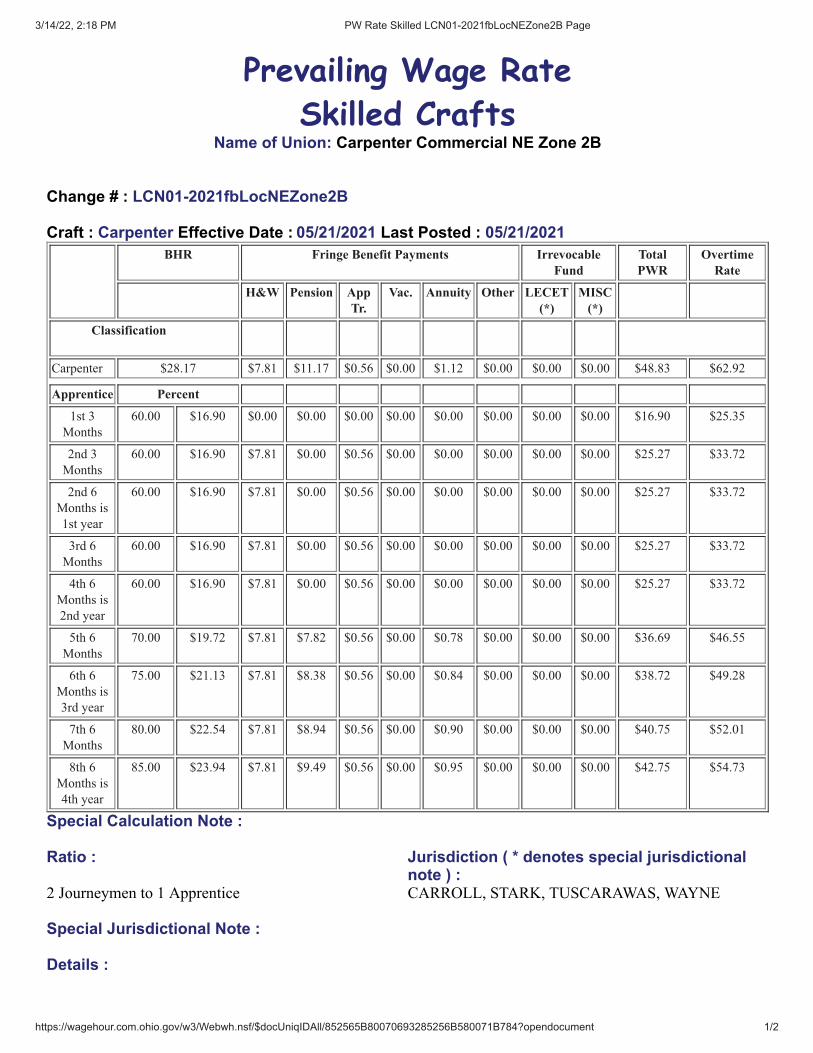
Skilled CraftsName of Union: Carpenter Commercial NE Zone 2B
Change # : LCN01-2021fbLocNEZone2B
Craft : Carpenter Effective Date : 05/21/2021 Last Posted : 05/21/2021BHR Fringe Benefit Payments Irrevocable
FundTotalPWR
OvertimeRate
H&W Pension AppTr.
Vac. Annuity Other LECET(*)
MISC(*)
Classification
Carpenter $28.17 $7.81 $11.17 $0.56 $0.00 $1.12 $0.00 $0.00 $0.00 $48.83 $62.92
Apprentice Percent
1st 3
Months
60.00 $16.90 $0.00 $0.00 $0.00 $0.00 $0.00 $0.00 $0.00 $0.00 $16.90 $25.35
2nd 3
Months
60.00 $16.90 $7.81 $0.00 $0.56 $0.00 $0.00 $0.00 $0.00 $0.00 $25.27 $33.72
2nd 6
Months is
1st year
60.00 $16.90 $7.81 $0.00 $0.56 $0.00 $0.00 $0.00 $0.00 $0.00 $25.27 $33.72
3rd 6
Months
60.00 $16.90 $7.81 $0.00 $0.56 $0.00 $0.00 $0.00 $0.00 $0.00 $25.27 $33.72
4th 6
Months is
2nd year
60.00 $16.90 $7.81 $0.00 $0.56 $0.00 $0.00 $0.00 $0.00 $0.00 $25.27 $33.72
5th 6
Months
70.00 $19.72 $7.81 $7.82 $0.56 $0.00 $0.78 $0.00 $0.00 $0.00 $36.69 $46.55
6th 6
Months is
3rd year
75.00 $21.13 $7.81 $8.38 $0.56 $0.00 $0.84 $0.00 $0.00 $0.00 $38.72 $49.28
7th 6
Months
80.00 $22.54 $7.81 $8.94 $0.56 $0.00 $0.90 $0.00 $0.00 $0.00 $40.75 $52.01
8th 6
Months is
4th year
85.00 $23.94 $7.81 $9.49 $0.56 $0.00 $0.95 $0.00 $0.00 $0.00 $42.75 $54.73
Special Calculation Note :
Ratio : Jurisdiction ( * denotes special jurisdictionalnote ) :
2 Journeymen to 1 Apprentice CARROLL, STARK, TUSCARAWAS, WAYNE
Special Jurisdictional Note :
Details :

3/14/22, 2:18 PM PW Rate Skilled LCN01-2021fbLocNEZone2B Page
https://wagehour.com.ohio.gov/w3/Webwh.nsf/$docUniqIDAll/852565B80070693285256B580071B784?opendocument 2/2
3/14/22, 2:19 PM PW Rate Skilled LCN01-2021fbLocNEZone2B Page
https://wagehour.com.ohio.gov/w3/Webwh.nsf/$docUniqIDAll/852565B80070693285257ED5005D99F6?opendocument 1/2
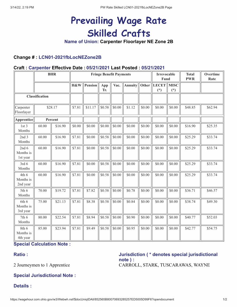
Prevailing Wage Rate
Skilled CraftsName of Union: Carpenter Floorlayer NE Zone 2B
Change # : LCN01-2021fbLocNEZone2B
Craft : Carpenter Effective Date : 05/21/2021 Last Posted : 05/21/2021BHR Fringe Benefit Payments Irrevocable
FundTotalPWR
OvertimeRate
H&W Pension AppTr.
Vac. Annuity Other LECET(*)
MISC(*)
Classification
Carpenter
Floorlayer
$28.17 $7.81 $11.17 $0.58 $0.00 $1.12 $0.00 $0.00 $0.00 $48.85 $62.94
Apprentice Percent
1st 3
Months
60.00 $16.90 $0.00 $0.00 $0.00 $0.00 $0.00 $0.00 $0.00 $0.00 $16.90 $25.35
2nd 3
Months
60.00 $16.90 $7.81 $0.00 $0.58 $0.00 $0.00 $0.00 $0.00 $0.00 $25.29 $33.74
2nd 6
Months is
1st year
60.00 $16.90 $7.81 $0.00 $0.58 $0.00 $0.00 $0.00 $0.00 $0.00 $25.29 $33.74
3rd 6
Months
60.00 $16.90 $7.81 $0.00 $0.58 $0.00 $0.00 $0.00 $0.00 $0.00 $25.29 $33.74
4th 6
Months is
2nd year
60.00 $16.90 $7.81 $0.00 $0.58 $0.00 $0.00 $0.00 $0.00 $0.00 $25.29 $33.74
5th 6
Months
70.00 $19.72 $7.81 $7.82 $0.58 $0.00 $0.78 $0.00 $0.00 $0.00 $36.71 $46.57
6th 6
Months is
3rd year
75.00 $21.13 $7.81 $8.38 $0.58 $0.00 $0.84 $0.00 $0.00 $0.00 $38.74 $49.30
7th 6
Months
80.00 $22.54 $7.81 $8.94 $0.58 $0.00 $0.90 $0.00 $0.00 $0.00 $40.77 $52.03
8th 6
Months is
4th year
85.00 $23.94 $7.81 $9.49 $0.58 $0.00 $0.95 $0.00 $0.00 $0.00 $42.77 $54.75
Special Calculation Note :
Ratio : Jurisdiction ( * denotes special jurisdictionalnote ) :
2 Journeymen to 1 Apprentice CARROLL, STARK, TUSCARAWAS, WAYNE
Special Jurisdictional Note :
Details :

3/14/22, 2:19 PM PW Rate Skilled LCN01-2021fbLocNEZone2B Page
https://wagehour.com.ohio.gov/w3/Webwh.nsf/$docUniqIDAll/852565B80070693285257ED5005D99F6?opendocument 2/2
3/14/22, 2:19 PM PW Rate Skilled LCN01-2021fbLocNEZone2B Page
https://wagehour.com.ohio.gov/w3/Webwh.nsf/$docUniqIDAll/852565B80070693285256BA70043E453?opendocument 1/1
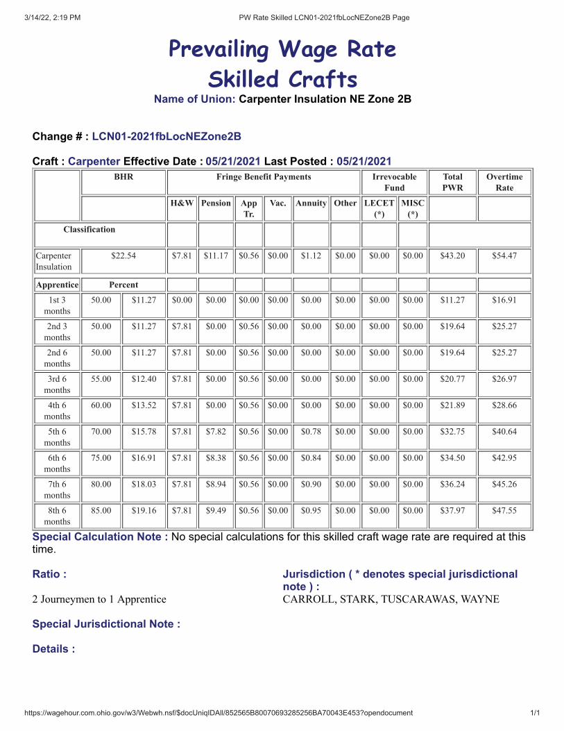
Prevailing Wage Rate
Skilled CraftsName of Union: Carpenter Insulation NE Zone 2B
Change # : LCN01-2021fbLocNEZone2B
Craft : Carpenter Effective Date : 05/21/2021 Last Posted : 05/21/2021BHR Fringe Benefit Payments Irrevocable
FundTotalPWR
OvertimeRate
H&W Pension AppTr.
Vac. Annuity Other LECET(*)
MISC(*)
Classification
Carpenter
Insulation
$22.54 $7.81 $11.17 $0.56 $0.00 $1.12 $0.00 $0.00 $0.00 $43.20 $54.47
Apprentice Percent
1st 3
months
50.00 $11.27 $0.00 $0.00 $0.00 $0.00 $0.00 $0.00 $0.00 $0.00 $11.27 $16.91
2nd 3
months
50.00 $11.27 $7.81 $0.00 $0.56 $0.00 $0.00 $0.00 $0.00 $0.00 $19.64 $25.27
2nd 6
months
50.00 $11.27 $7.81 $0.00 $0.56 $0.00 $0.00 $0.00 $0.00 $0.00 $19.64 $25.27
3rd 6
months
55.00 $12.40 $7.81 $0.00 $0.56 $0.00 $0.00 $0.00 $0.00 $0.00 $20.77 $26.97
4th 6
months
60.00 $13.52 $7.81 $0.00 $0.56 $0.00 $0.00 $0.00 $0.00 $0.00 $21.89 $28.66
5th 6
months
70.00 $15.78 $7.81 $7.82 $0.56 $0.00 $0.78 $0.00 $0.00 $0.00 $32.75 $40.64
6th 6
months
75.00 $16.91 $7.81 $8.38 $0.56 $0.00 $0.84 $0.00 $0.00 $0.00 $34.50 $42.95
7th 6
months
80.00 $18.03 $7.81 $8.94 $0.56 $0.00 $0.90 $0.00 $0.00 $0.00 $36.24 $45.26
8th 6
months
85.00 $19.16 $7.81 $9.49 $0.56 $0.00 $0.95 $0.00 $0.00 $0.00 $37.97 $47.55
Special Calculation Note : No special calculations for this skilled craft wage rate are required at thistime.
Ratio : Jurisdiction ( * denotes special jurisdictionalnote ) :
2 Journeymen to 1 Apprentice CARROLL, STARK, TUSCARAWAS, WAYNE
Special Jurisdictional Note :
Details :

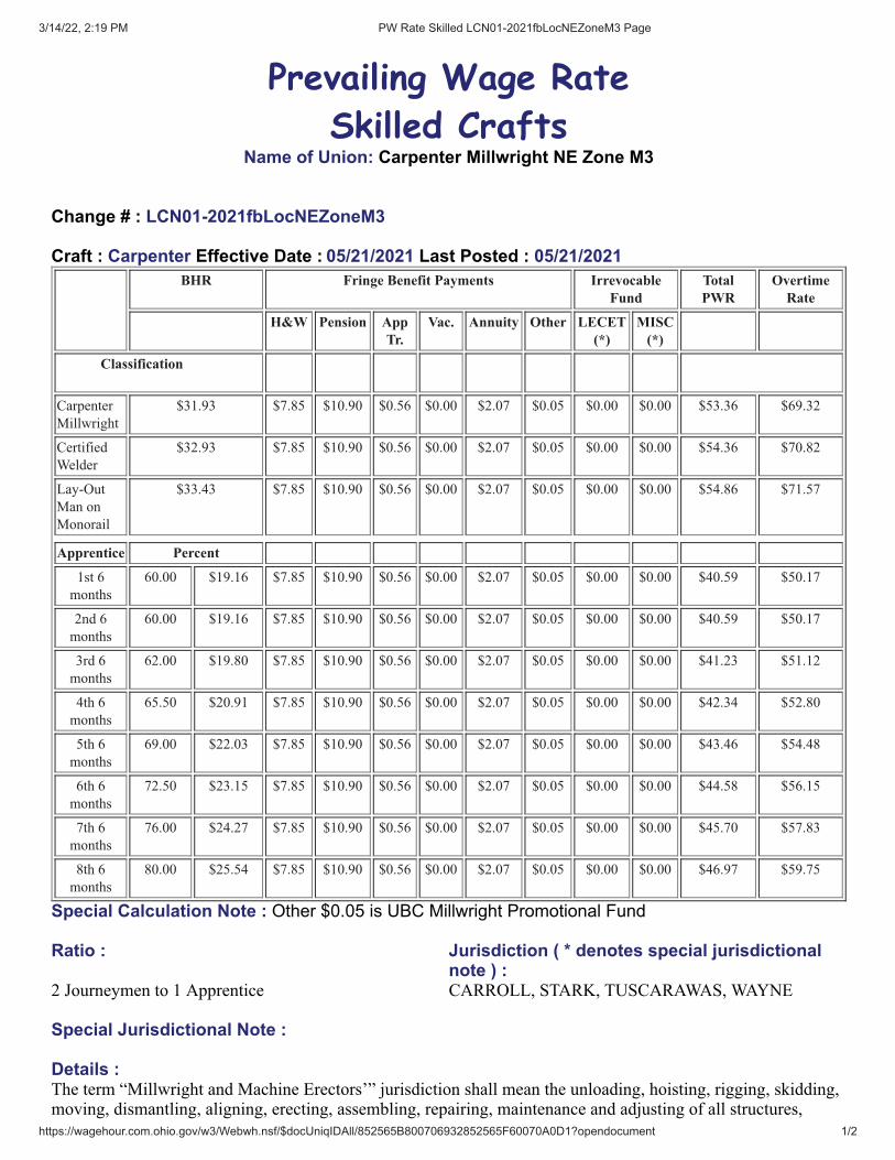
3/14/22, 2:19 PM PW Rate Skilled LCN01-2021fbLocNEZoneM3 Page
https://wagehour.com.ohio.gov/w3/Webwh.nsf/$docUniqIDAll/852565B800706932852565F60070A0D1?opendocument 1/2
Prevailing Wage Rate
Skilled CraftsName of Union: Carpenter Millwright NE Zone M3
Change # : LCN01-2021fbLocNEZoneM3
Craft : Carpenter Effective Date : 05/21/2021 Last Posted : 05/21/2021BHR Fringe Benefit Payments Irrevocable
FundTotalPWR
OvertimeRate
H&W Pension AppTr.
Vac. Annuity Other LECET(*)
MISC(*)
Classification
Carpenter
Millwright
$31.93 $7.85 $10.90 $0.56 $0.00 $2.07 $0.05 $0.00 $0.00 $53.36 $69.32
Certified
Welder
$32.93 $7.85 $10.90 $0.56 $0.00 $2.07 $0.05 $0.00 $0.00 $54.36 $70.82
Lay-Out
Man on
Monorail
$33.43 $7.85 $10.90 $0.56 $0.00 $2.07 $0.05 $0.00 $0.00 $54.86 $71.57
Apprentice Percent
1st 6
months
60.00 $19.16 $7.85 $10.90 $0.56 $0.00 $2.07 $0.05 $0.00 $0.00 $40.59 $50.17
2nd 6
months
60.00 $19.16 $7.85 $10.90 $0.56 $0.00 $2.07 $0.05 $0.00 $0.00 $40.59 $50.17
3rd 6
months
62.00 $19.80 $7.85 $10.90 $0.56 $0.00 $2.07 $0.05 $0.00 $0.00 $41.23 $51.12
4th 6
months
65.50 $20.91 $7.85 $10.90 $0.56 $0.00 $2.07 $0.05 $0.00 $0.00 $42.34 $52.80
5th 6
months
69.00 $22.03 $7.85 $10.90 $0.56 $0.00 $2.07 $0.05 $0.00 $0.00 $43.46 $54.48
6th 6
months
72.50 $23.15 $7.85 $10.90 $0.56 $0.00 $2.07 $0.05 $0.00 $0.00 $44.58 $56.15
7th 6
months
76.00 $24.27 $7.85 $10.90 $0.56 $0.00 $2.07 $0.05 $0.00 $0.00 $45.70 $57.83
8th 6
months
80.00 $25.54 $7.85 $10.90 $0.56 $0.00 $2.07 $0.05 $0.00 $0.00 $46.97 $59.75
Special Calculation Note : Other $0.05 is UBC Millwright Promotional Fund
Ratio : Jurisdiction ( * denotes special jurisdictionalnote ) :
2 Journeymen to 1 Apprentice CARROLL, STARK, TUSCARAWAS, WAYNE
Special Jurisdictional Note :
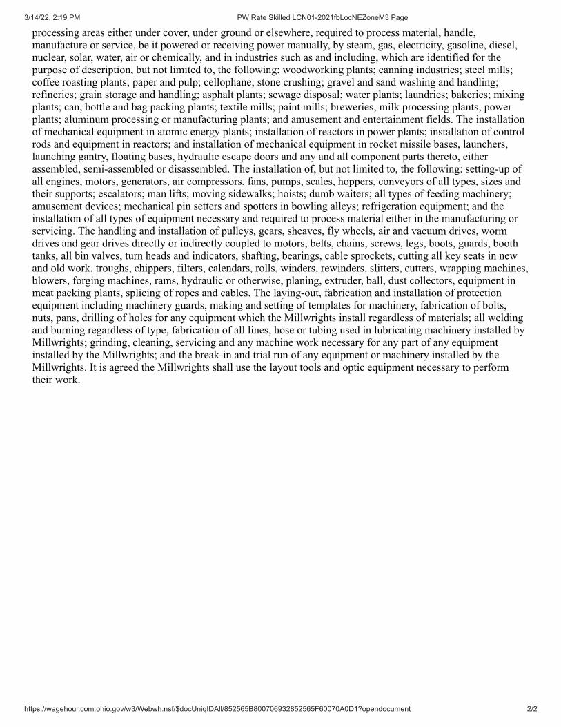
Details :The term “Millwright and Machine Erectors’” jurisdiction shall mean the unloading, hoisting, rigging, skidding,moving, dismantling, aligning, erecting, assembling, repairing, maintenance and adjusting of all structures,
3/14/22, 2:19 PM PW Rate Skilled LCN01-2021fbLocNEZoneM3 Page
https://wagehour.com.ohio.gov/w3/Webwh.nsf/$docUniqIDAll/852565B800706932852565F60070A0D1?opendocument 2/2
processing areas either under cover, under ground or elsewhere, required to process material, handle,manufacture or service, be it powered or receiving power manually, by steam, gas, electricity, gasoline, diesel,nuclear, solar, water, air or chemically, and in industries such as and including, which are identified for thepurpose of description, but not limited to, the following: woodworking plants; canning industries; steel mills;coffee roasting plants; paper and pulp; cellophane; stone crushing; gravel and sand washing and handling;refineries; grain storage and handling; asphalt plants; sewage disposal; water plants; laundries; bakeries; mixingplants; can, bottle and bag packing plants; textile mills; paint mills; breweries; milk processing plants; powerplants; aluminum processing or manufacturing plants; and amusement and entertainment fields. The installationof mechanical equipment in atomic energy plants; installation of reactors in power plants; installation of controlrods and equipment in reactors; and installation of mechanical equipment in rocket missile bases, launchers,launching gantry, floating bases, hydraulic escape doors and any and all component parts thereto, eitherassembled, semi-assembled or disassembled. The installation of, but not limited to, the following: setting-up ofall engines, motors, generators, air compressors, fans, pumps, scales, hoppers, conveyors of all types, sizes andtheir supports; escalators; man lifts; moving sidewalks; hoists; dumb waiters; all types of feeding machinery;amusement devices; mechanical pin setters and spotters in bowling alleys; refrigeration equipment; and theinstallation of all types of equipment necessary and required to process material either in the manufacturing orservicing. The handling and installation of pulleys, gears, sheaves, fly wheels, air and vacuum drives, wormdrives and gear drives directly or indirectly coupled to motors, belts, chains, screws, legs, boots, guards, boothtanks, all bin valves, turn heads and indicators, shafting, bearings, cable sprockets, cutting all key seats in newand old work, troughs, chippers, filters, calendars, rolls, winders, rewinders, slitters, cutters, wrapping machines,blowers, forging machines, rams, hydraulic or otherwise, planing, extruder, ball, dust collectors, equipment inmeat packing plants, splicing of ropes and cables. The laying-out, fabrication and installation of protectionequipment including machinery guards, making and setting of templates for machinery, fabrication of bolts,nuts, pans, drilling of holes for any equipment which the Millwrights install regardless of materials; all weldingand burning regardless of type, fabrication of all lines, hose or tubing used in lubricating machinery installed byMillwrights; grinding, cleaning, servicing and any machine work necessary for any part of any equipmentinstalled by the Millwrights; and the break-in and trial run of any equipment or machinery installed by theMillwrights. It is agreed the Millwrights shall use the layout tools and optic equipment necessary to performtheir work.
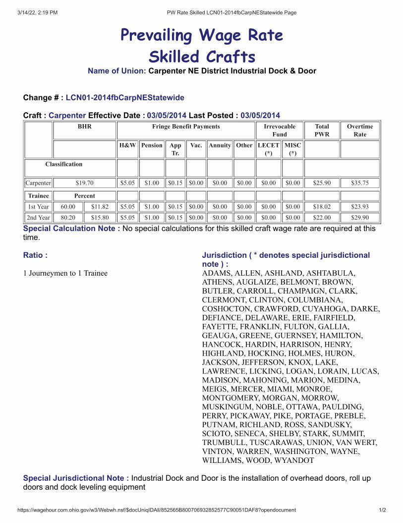
3/14/22, 2:19 PM PW Rate Skilled LCN01-2014fbCarpNEStatewide Page
https://wagehour.com.ohio.gov/w3/Webwh.nsf/$docUniqIDAll/852565B800706932852577C90051DAF8?opendocument 1/2
Prevailing Wage Rate
Skilled CraftsName of Union: Carpenter NE District Industrial Dock & Door
Change # : LCN01-2014fbCarpNEStatewide
Craft : Carpenter Effective Date : 03/05/2014 Last Posted : 03/05/2014BHR Fringe Benefit Payments Irrevocable
FundTotalPWR
OvertimeRate
H&W Pension AppTr.
Vac. Annuity Other LECET(*)
MISC(*)
Classification
Carpenter $19.70 $5.05 $1.00 $0.15 $0.00 $0.00 $0.00 $0.00 $0.00 $25.90 $35.75
Trainee Percent
1st Year 60.00 $11.82 $5.05 $1.00 $0.15 $0.00 $0.00 $0.00 $0.00 $0.00 $18.02 $23.93
2nd Year 80.20 $15.80 $5.05 $1.00 $0.15 $0.00 $0.00 $0.00 $0.00 $0.00 $22.00 $29.90
Special Calculation Note : No special calculations for this skilled craft wage rate are required at thistime.
Ratio : Jurisdiction ( * denotes special jurisdictionalnote ) :
1 Journeymen to 1 Trainee ADAMS, ALLEN, ASHLAND, ASHTABULA,ATHENS, AUGLAIZE, BELMONT, BROWN,BUTLER, CARROLL, CHAMPAIGN, CLARK,CLERMONT, CLINTON, COLUMBIANA,COSHOCTON, CRAWFORD, CUYAHOGA, DARKE,DEFIANCE, DELAWARE, ERIE, FAIRFIELD,FAYETTE, FRANKLIN, FULTON, GALLIA,GEAUGA, GREENE, GUERNSEY, HAMILTON,HANCOCK, HARDIN, HARRISON, HENRY,HIGHLAND, HOCKING, HOLMES, HURON,JACKSON, JEFFERSON, KNOX, LAKE,LAWRENCE, LICKING, LOGAN, LORAIN, LUCAS,MADISON, MAHONING, MARION, MEDINA,MEIGS, MERCER, MIAMI, MONROE,MONTGOMERY, MORGAN, MORROW,MUSKINGUM, NOBLE, OTTAWA, PAULDING,PERRY, PICKAWAY, PIKE, PORTAGE, PREBLE,PUTNAM, RICHLAND, ROSS, SANDUSKY,SCIOTO, SENECA, SHELBY, STARK, SUMMIT,TRUMBULL, TUSCARAWAS, UNION, VAN WERT,VINTON, WARREN, WASHINGTON, WAYNE,WILLIAMS, WOOD, WYANDOT
Special Jurisdictional Note : Industrial Dock and Door is the installation of overhead doors, roll updoors and dock leveling equipment

3/14/22, 2:19 PM PW Rate Skilled LCN01-2014fbCarpNEStatewide Page
https://wagehour.com.ohio.gov/w3/Webwh.nsf/$docUniqIDAll/852565B800706932852577C90051DAF8?opendocument 2/2
Details :10/27/10 New Contract jc
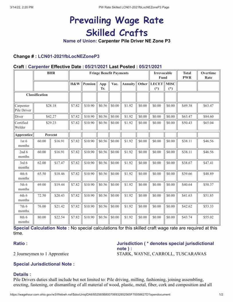
3/14/22, 2:20 PM PW Rate Skilled LCN01-2021fbLocNEZoneP3 Page
https://wagehour.com.ohio.gov/w3/Webwh.nsf/$docUniqIDAll/852565B800706932852565F70058627D?opendocument 1/2
Prevailing Wage Rate
Skilled CraftsName of Union: Carpenter Pile Driver NE Zone P3
Change # : LCN01-2021fbLocNEZoneP3
Craft : Carpenter Effective Date : 05/21/2021 Last Posted : 05/21/2021BHR Fringe Benefit Payments Irrevocable
FundTotalPWR
OvertimeRate
H&W Pension AppTr.
Vac. Annuity Other LECET(*)
MISC(*)
Classification
Carpenter
Pile Driver
$28.18 $7.82 $10.90 $0.56 $0.00 $1.92 $0.00 $0.00 $0.00 $49.38 $63.47
Diver $42.27 $7.82 $10.90 $0.56 $0.00 $1.92 $0.00 $0.00 $0.00 $63.47 $84.60
Certified
Welder
$29.23 $7.82 $10.90 $0.56 $0.00 $1.92 $0.00 $0.00 $0.00 $50.43 $65.04
Apprentice Percent
1st 6
months
60.00 $16.91 $7.82 $10.90 $0.56 $0.00 $1.92 $0.00 $0.00 $0.00 $38.11 $46.56
2nd 6
months
60.00 $16.91 $7.82 $10.90 $0.56 $0.00 $1.92 $0.00 $0.00 $0.00 $38.11 $46.56
3rd 6
months
62.00 $17.47 $7.82 $10.90 $0.56 $0.00 $1.92 $0.00 $0.00 $0.00 $38.67 $47.41
4th 6
months
65.50 $18.46 $7.82 $10.90 $0.56 $0.00 $1.92 $0.00 $0.00 $0.00 $39.66 $48.89
5th 6
months
69.00 $19.44 $7.82 $10.90 $0.56 $0.00 $1.92 $0.00 $0.00 $0.00 $40.64 $50.37
6th 6
months
72.50 $20.43 $7.82 $10.90 $0.56 $0.00 $1.92 $0.00 $0.00 $0.00 $41.63 $51.85
7th 6
months
76.00 $21.42 $7.82 $10.90 $0.56 $0.00 $1.92 $0.00 $0.00 $0.00 $42.62 $53.33
8th 6
months
80.00 $22.54 $7.82 $10.90 $0.56 $0.00 $1.92 $0.00 $0.00 $0.00 $43.74 $55.02
Special Calculation Note : No special calculations for this skilled craft wage rate are required at thistime.
Ratio : Jurisdiction ( * denotes special jurisdictionalnote ) :
2 Journeymen to 1 Apprentice STARK, WAYNE, CARROLL, TUSCARAWAS
Special Jurisdictional Note :
Details :Pile Drivers duties shall include but not limited to: Pile driving, milling, fashioning, joining assembling,erecting, fastening, or dismantling of all material of wood, plastic, metal, fiber, cork and composition and all

3/14/22, 2:20 PM PW Rate Skilled LCN01-2021fbLocNEZoneP3 Page
https://wagehour.com.ohio.gov/w3/Webwh.nsf/$docUniqIDAll/852565B800706932852565F70058627D?opendocument 2/2
other substitute materials: pile driving, cutting, fitting and placing of lagging, and the handling, cleaning,erecting, installing and dismantling of machinery, equipment and erecting pre-engineered metal buildings. PileDrivers work but not limited to: unloading, assembling, erection, repairs, operation, signaling, dismantling andreloading all equipment that is used for pile driving including pule butts is defined as sheeting or scrap piling.Underwater work that may be required in connection with the installation of piling. The driver and his tenderwork as a team and shall arrive at their own financial arrangements with the contractor. Any configuration ofwood, steel, concrete or composite that is jetted, driven or vibrated onto the ground by conventional pile drivingequipment for the purpose of supporting a future load that may be permanent or temporary. The construction ofall wharves and docks, including the fabrication and installation of floating docks. Driving bracing, plumbing,cutting off and capping of all piling whether wood, metal, pipe piling or composite, loading, unloading, erecting,framing, dismantling, moving and handling of pile driving equipment piling used in the construction and repairof all wharves, docks, piers, trestles, caissons, cofferdams and erection of all sea walls and breakwaters. Allunderwater and marine work on bulkheads, wharves, docks, shipyards, caissons, piers, bridges, pipeline, work,viaducts, marine cable and trestles, as well as salvage and reclamation work where divers are employed. Rateshall include carpenters, acoustic and ceiling installers, drywall installers, pile drivers and floorlayers.

3/14/22, 2:20 PM PW Rate Skilled LCN01-2021fbHvyHwy Page
https://wagehour.com.ohio.gov/w3/Webwh.nsf/$docUniqIDAll/852565B8007069328525709000576B31?opendocument 1/2
Prevailing Wage Rate
Skilled CraftsName of Union: Cement Mason Bricklayer Local 97 HevHwy A
Change # : LCN01-2021fbHvyHwy
Craft : Bricklayer Effective Date : 06/01/2021 Last Posted : 05/26/2021BHR Fringe Benefit Payments Irrevocable
FundTotalPWR
OvertimeRate
H&W Pension AppTr.
Vac. Annuity Other LECET(*)
MISC(*)
Classification
Cement
Mason
Bricklayer
Sewer
Water
Works A
$30.40 $9.50 $7.57 $0.48 $0.00 $0.00 $0.00 $0.00 $0.00 $47.95 $63.15
Apprentice Percent
1st year 50.00 $15.20 $9.50 $7.57 $0.48 $0.00 $0.00 $0.00 $0.00 $0.00 $32.75 $40.35
2nd year 70.00 $21.28 $9.50 $7.57 $0.48 $0.00 $0.00 $0.00 $0.00 $0.00 $38.83 $49.47
3rd year 90.00 $27.36 $9.50 $7.57 $0.48 $0.00 $0.00 $0.00 $0.00 $0.00 $44.91 $58.59
Special Calculation Note : NOT FOR BUILDING CONSTRUCTION.
Ratio : Jurisdiction ( * denotes special jurisdictionalnote ) :
3 Journeymen to 1 Apprentice6 Journeymen to 2 Apprentice9 Journeymen to 3 Apprentice12 Journeymen to 4 Apprentice15 Journeymen to 5 Apprentice
ADAMS, ALLEN, ASHLAND, ASHTABULA,ATHENS, AUGLAIZE, BELMONT, BROWN,BUTLER, CARROLL, CHAMPAIGN, CLARK,CLERMONT, CLINTON, COLUMBIANA,COSHOCTON, CRAWFORD, CUYAHOGA, DARKE,DEFIANCE, DELAWARE, ERIE, FAIRFIELD,FAYETTE, FRANKLIN, FULTON, GALLIA,GEAUGA, GREENE, GUERNSEY, HAMILTON,HANCOCK, HARDIN, HARRISON, HENRY,HIGHLAND, HOCKING, HOLMES, HURON,JACKSON, JEFFERSON, KNOX, LAKE,LAWRENCE, LICKING, LOGAN, LORAIN, LUCAS,MADISON, MAHONING, MARION, MEDINA,MEIGS, MERCER, MIAMI, MONROE,MONTGOMERY, MORGAN, MORROW,MUSKINGUM, NOBLE, OTTAWA, PAULDING,PERRY, PICKAWAY, PIKE, PORTAGE, PREBLE,PUTNAM, RICHLAND, ROSS, SANDUSKY,SCIOTO, SENECA, SHELBY, STARK, SUMMIT,TRUMBULL, TUSCARAWAS, UNION, VAN WERT,VINTON, WARREN, WASHINGTON, WAYNE

3/14/22, 2:20 PM PW Rate Skilled LCN01-2021fbHvyHwy Page
https://wagehour.com.ohio.gov/w3/Webwh.nsf/$docUniqIDAll/852565B8007069328525709000576B31?opendocument 2/2
Special Jurisdictional Note :
Details :(A) Highway Construction, Sewer, Waterworks And Utility Construction, Industrial & Building Site HeavyConstruction, Airport Construction Or Railroad Construction Work.(B) Power Plant, Tunnels, Amusement Park, Athletic Stadium Site Work ,Pollution Control,Sewer Plant, WastePlant, & Water Treatment Facilities, Construction.
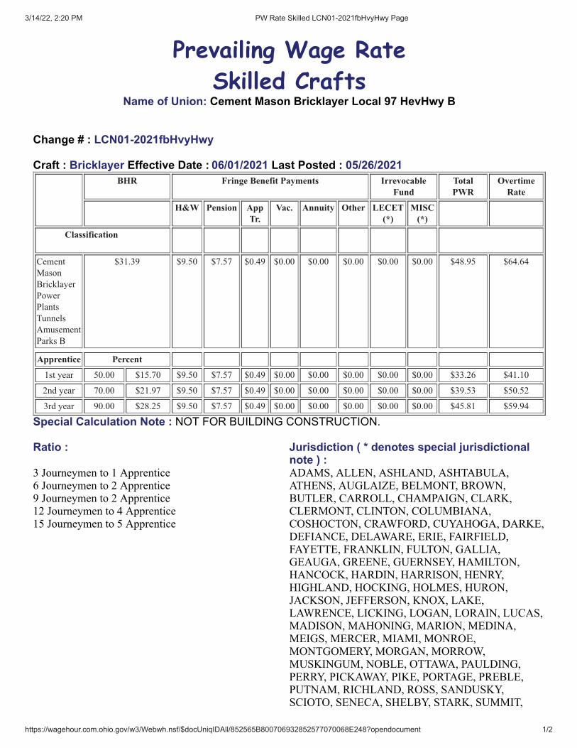
3/14/22, 2:20 PM PW Rate Skilled LCN01-2021fbHvyHwy Page
https://wagehour.com.ohio.gov/w3/Webwh.nsf/$docUniqIDAll/852565B800706932852577070068E248?opendocument 1/2
Prevailing Wage Rate
Skilled CraftsName of Union: Cement Mason Bricklayer Local 97 HevHwy B
Change # : LCN01-2021fbHvyHwy
Craft : Bricklayer Effective Date : 06/01/2021 Last Posted : 05/26/2021BHR Fringe Benefit Payments Irrevocable
FundTotalPWR
OvertimeRate
H&W Pension AppTr.
Vac. Annuity Other LECET(*)
MISC(*)
Classification
Cement
Mason
Bricklayer
Power
Plants
Tunnels
Amusement
Parks B
$31.39 $9.50 $7.57 $0.49 $0.00 $0.00 $0.00 $0.00 $0.00 $48.95 $64.64
Apprentice Percent
1st year 50.00 $15.70 $9.50 $7.57 $0.49 $0.00 $0.00 $0.00 $0.00 $0.00 $33.26 $41.10
2nd year 70.00 $21.97 $9.50 $7.57 $0.49 $0.00 $0.00 $0.00 $0.00 $0.00 $39.53 $50.52
3rd year 90.00 $28.25 $9.50 $7.57 $0.49 $0.00 $0.00 $0.00 $0.00 $0.00 $45.81 $59.94
Special Calculation Note : NOT FOR BUILDING CONSTRUCTION.
Ratio : Jurisdiction ( * denotes special jurisdictionalnote ) :
3 Journeymen to 1 Apprentice6 Journeymen to 2 Apprentice9 Journeymen to 2 Apprentice12 Journeymen to 4 Apprentice15 Journeymen to 5 Apprentice
ADAMS, ALLEN, ASHLAND, ASHTABULA,ATHENS, AUGLAIZE, BELMONT, BROWN,BUTLER, CARROLL, CHAMPAIGN, CLARK,CLERMONT, CLINTON, COLUMBIANA,COSHOCTON, CRAWFORD, CUYAHOGA, DARKE,DEFIANCE, DELAWARE, ERIE, FAIRFIELD,FAYETTE, FRANKLIN, FULTON, GALLIA,GEAUGA, GREENE, GUERNSEY, HAMILTON,HANCOCK, HARDIN, HARRISON, HENRY,HIGHLAND, HOCKING, HOLMES, HURON,JACKSON, JEFFERSON, KNOX, LAKE,LAWRENCE, LICKING, LOGAN, LORAIN, LUCAS,MADISON, MAHONING, MARION, MEDINA,MEIGS, MERCER, MIAMI, MONROE,MONTGOMERY, MORGAN, MORROW,MUSKINGUM, NOBLE, OTTAWA, PAULDING,PERRY, PICKAWAY, PIKE, PORTAGE, PREBLE,PUTNAM, RICHLAND, ROSS, SANDUSKY,SCIOTO, SENECA, SHELBY, STARK, SUMMIT,

3/14/22, 2:20 PM PW Rate Skilled LCN01-2021fbHvyHwy Page
https://wagehour.com.ohio.gov/w3/Webwh.nsf/$docUniqIDAll/852565B800706932852577070068E248?opendocument 2/2
TRUMBULL, TUSCARAWAS, UNION, VAN WERT,VINTON, WARREN, WASHINGTON, WAYNE
Special Jurisdictional Note :
Details :(A) Highway Construction, Sewer, Waterworks And Utility Construction, Industrial & Building Site HeavyConstruction, Airport Construction Or Railroad Construction Work.(B) Power Plant, Tunnels, Amusement Park, Athletic Stadium Site Work ,Pollution Control,Sewer Plant, WastePlant, & Water Treatment Facilities, Construction.
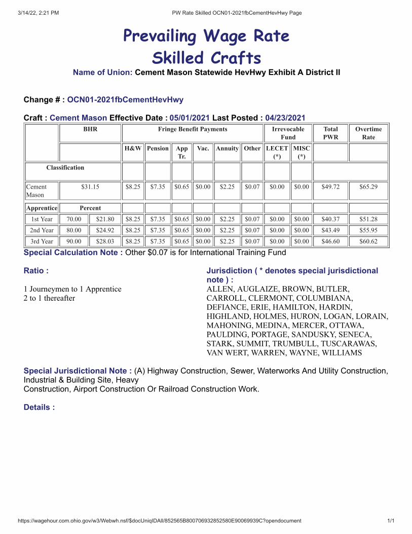
3/14/22, 2:21 PM PW Rate Skilled OCN01-2021fbCementHevHwy Page
https://wagehour.com.ohio.gov/w3/Webwh.nsf/$docUniqIDAll/852565B800706932852580E90069939C?opendocument 1/1
Prevailing Wage Rate
Skilled CraftsName of Union: Cement Mason Statewide HevHwy Exhibit A District II
Change # : OCN01-2021fbCementHevHwy
Craft : Cement Mason Effective Date : 05/01/2021 Last Posted : 04/23/2021BHR Fringe Benefit Payments Irrevocable
FundTotalPWR
OvertimeRate
H&W Pension AppTr.
Vac. Annuity Other LECET(*)
MISC(*)
Classification
Cement
Mason
$31.15 $8.25 $7.35 $0.65 $0.00 $2.25 $0.07 $0.00 $0.00 $49.72 $65.29
Apprentice Percent
1st Year 70.00 $21.80 $8.25 $7.35 $0.65 $0.00 $2.25 $0.07 $0.00 $0.00 $40.37 $51.28
2nd Year 80.00 $24.92 $8.25 $7.35 $0.65 $0.00 $2.25 $0.07 $0.00 $0.00 $43.49 $55.95
3rd Year 90.00 $28.03 $8.25 $7.35 $0.65 $0.00 $2.25 $0.07 $0.00 $0.00 $46.60 $60.62
Special Calculation Note : Other $0.07 is for International Training Fund
Ratio : Jurisdiction ( * denotes special jurisdictionalnote ) :
1 Journeymen to 1 Apprentice2 to 1 thereafter
ALLEN, AUGLAIZE, BROWN, BUTLER,CARROLL, CLERMONT, COLUMBIANA,DEFIANCE, ERIE, HAMILTON, HARDIN,HIGHLAND, HOLMES, HURON, LOGAN, LORAIN,MAHONING, MEDINA, MERCER, OTTAWA,PAULDING, PORTAGE, SANDUSKY, SENECA,STARK, SUMMIT, TRUMBULL, TUSCARAWAS,VAN WERT, WARREN, WAYNE, WILLIAMS
Special Jurisdictional Note : (A) Highway Construction, Sewer, Waterworks And Utility Construction,Industrial & Building Site, HeavyConstruction, Airport Construction Or Railroad Construction Work.
Details :
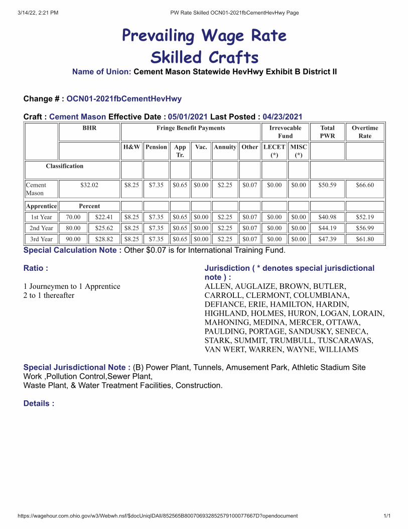
3/14/22, 2:21 PM PW Rate Skilled OCN01-2021fbCementHevHwy Page
https://wagehour.com.ohio.gov/w3/Webwh.nsf/$docUniqIDAll/852565B800706932852579100077667D?opendocument 1/1
Prevailing Wage Rate
Skilled CraftsName of Union: Cement Mason Statewide HevHwy Exhibit B District II
Change # : OCN01-2021fbCementHevHwy
Craft : Cement Mason Effective Date : 05/01/2021 Last Posted : 04/23/2021BHR Fringe Benefit Payments Irrevocable
FundTotalPWR
OvertimeRate
H&W Pension AppTr.
Vac. Annuity Other LECET(*)
MISC(*)
Classification
Cement
Mason
$32.02 $8.25 $7.35 $0.65 $0.00 $2.25 $0.07 $0.00 $0.00 $50.59 $66.60
Apprentice Percent
1st Year 70.00 $22.41 $8.25 $7.35 $0.65 $0.00 $2.25 $0.07 $0.00 $0.00 $40.98 $52.19
2nd Year 80.00 $25.62 $8.25 $7.35 $0.65 $0.00 $2.25 $0.07 $0.00 $0.00 $44.19 $56.99
3rd Year 90.00 $28.82 $8.25 $7.35 $0.65 $0.00 $2.25 $0.07 $0.00 $0.00 $47.39 $61.80
Special Calculation Note : Other $0.07 is for International Training Fund.
Ratio : Jurisdiction ( * denotes special jurisdictionalnote ) :
1 Journeymen to 1 Apprentice2 to 1 thereafter
ALLEN, AUGLAIZE, BROWN, BUTLER,CARROLL, CLERMONT, COLUMBIANA,DEFIANCE, ERIE, HAMILTON, HARDIN,HIGHLAND, HOLMES, HURON, LOGAN, LORAIN,MAHONING, MEDINA, MERCER, OTTAWA,PAULDING, PORTAGE, SANDUSKY, SENECA,STARK, SUMMIT, TRUMBULL, TUSCARAWAS,VAN WERT, WARREN, WAYNE, WILLIAMS
Special Jurisdictional Note : (B) Power Plant, Tunnels, Amusement Park, Athletic Stadium SiteWork ,Pollution Control,Sewer Plant,Waste Plant, & Water Treatment Facilities, Construction.
Details :
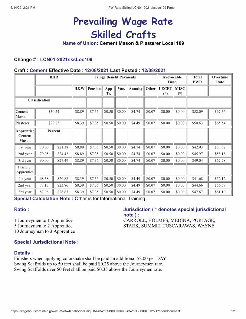
3/14/22, 2:21 PM PW Rate Skilled LCN01-2021sksLoc109 Page
https://wagehour.com.ohio.gov/w3/Webwh.nsf/$docUniqIDAll/852565B80070693285256C860048125D?opendocument 1/1
Prevailing Wage Rate
Skilled CraftsName of Union: Cement Mason & Plasterer Local 109
Change # : LCN01-2021sksLoc109
Craft : Cement Effective Date : 12/08/2021 Last Posted : 12/08/2021BHR Fringe Benefit Payments Irrevocable
FundTotalPWR
OvertimeRate
H&W Pension AppTr.
Vac. Annuity Other LECET(*)
MISC(*)
Classification
Cement
Mason
$30.54 $8.89 $7.35 $0.50 $0.00 $4.74 $0.07 $0.00 $0.00 $52.09 $67.36
Plasterer $29.83 $8.39 $7.35 $0.50 $0.00 $4.49 $0.07 $0.00 $0.00 $50.63 $65.54
ApprenticeCementMason
Percent
1st year 70.00 $21.38 $8.89 $7.35 $0.50 $0.00 $4.74 $0.07 $0.00 $0.00 $42.93 $53.62
2nd year 79.95 $24.42 $8.89 $7.35 $0.50 $0.00 $4.74 $0.07 $0.00 $0.00 $45.97 $58.18
3rd year 90.00 $27.49 $8.89 $7.35 $0.50 $0.00 $4.74 $0.07 $0.00 $0.00 $49.04 $62.78
Plasterer
Apprentice
1st year 68.38 $20.88 $8.39 $7.35 $0.50 $0.00 $4.49 $0.07 $0.00 $0.00 $41.68 $52.12
2nd year 78.13 $23.86 $8.39 $7.35 $0.50 $0.00 $4.49 $0.07 $0.00 $0.00 $44.66 $56.59
3rd year 87.98 $26.87 $8.39 $7.35 $0.50 $0.00 $4.49 $0.07 $0.00 $0.00 $47.67 $61.10
Special Calculation Note : Other is for International Training.
Ratio : Jurisdiction ( * denotes special jurisdictionalnote ) :
1 Journeymen to 1 Apprentice5 Journeymen to 2 Apprentice10 Journeyman to 3 Apprentice
CARROLL, HOLMES, MEDINA, PORTAGE,STARK, SUMMIT, TUSCARAWAS, WAYNE
Special Jurisdictional Note :
Details :Finishers when applying colorshake shall be paid an additional $2.00 per DAY.Swing Scaffolds up to 50 feet shall be paid $0.25 above the Journeymen rate.Swing Scaffolds over 50 feet shall be paid $0.35 above the Journeymen rate.

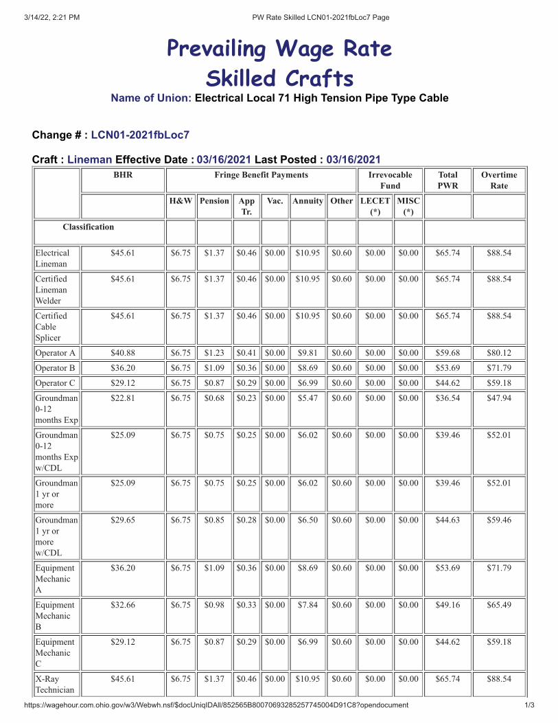
3/14/22, 2:21 PM PW Rate Skilled LCN01-2021fbLoc7 Page
https://wagehour.com.ohio.gov/w3/Webwh.nsf/$docUniqIDAll/852565B80070693285257745004D91C8?opendocument 1/3
Prevailing Wage Rate
Skilled CraftsName of Union: Electrical Local 71 High Tension Pipe Type Cable
Change # : LCN01-2021fbLoc7
Craft : Lineman Effective Date : 03/16/2021 Last Posted : 03/16/2021BHR Fringe Benefit Payments Irrevocable
FundTotalPWR
OvertimeRate
H&W Pension AppTr.
Vac. Annuity Other LECET(*)
MISC(*)
Classification
Electrical
Lineman
$45.61 $6.75 $1.37 $0.46 $0.00 $10.95 $0.60 $0.00 $0.00 $65.74 $88.54
Certified
Lineman
Welder
$45.61 $6.75 $1.37 $0.46 $0.00 $10.95 $0.60 $0.00 $0.00 $65.74 $88.54
Certified
Cable
Splicer
$45.61 $6.75 $1.37 $0.46 $0.00 $10.95 $0.60 $0.00 $0.00 $65.74 $88.54
Operator A $40.88 $6.75 $1.23 $0.41 $0.00 $9.81 $0.60 $0.00 $0.00 $59.68 $80.12
Operator B $36.20 $6.75 $1.09 $0.36 $0.00 $8.69 $0.60 $0.00 $0.00 $53.69 $71.79
Operator C $29.12 $6.75 $0.87 $0.29 $0.00 $6.99 $0.60 $0.00 $0.00 $44.62 $59.18
Groundman
0-12
months Exp
$22.81 $6.75 $0.68 $0.23 $0.00 $5.47 $0.60 $0.00 $0.00 $36.54 $47.94
Groundman
0-12
months Exp
w/CDL
$25.09 $6.75 $0.75 $0.25 $0.00 $6.02 $0.60 $0.00 $0.00 $39.46 $52.01
Groundman
1 yr or
more
$25.09 $6.75 $0.75 $0.25 $0.00 $6.02 $0.60 $0.00 $0.00 $39.46 $52.01
Groundman
1 yr or
more
w/CDL
$29.65 $6.75 $0.85 $0.28 $0.00 $6.50 $0.60 $0.00 $0.00 $44.63 $59.46
Equipment
Mechanic
A
$36.20 $6.75 $1.09 $0.36 $0.00 $8.69 $0.60 $0.00 $0.00 $53.69 $71.79
Equipment
Mechanic
B
$32.66 $6.75 $0.98 $0.33 $0.00 $7.84 $0.60 $0.00 $0.00 $49.16 $65.49
Equipment
Mechanic
C
$29.12 $6.75 $0.87 $0.29 $0.00 $6.99 $0.60 $0.00 $0.00 $44.62 $59.18
X-Ray
Technician
$45.61 $6.75 $1.37 $0.46 $0.00 $10.95 $0.60 $0.00 $0.00 $65.74 $88.54

3/14/22, 2:21 PM PW Rate Skilled LCN01-2021fbLoc7 Page
https://wagehour.com.ohio.gov/w3/Webwh.nsf/$docUniqIDAll/852565B80070693285257745004D91C8?opendocument 2/3
Apprentice Percent
1st 1000
hrs
60.00 $27.37 $6.75 $0.82 $0.27 $0.00 $6.57 $0.60 $0.00 $0.00 $42.38 $56.06
2nd 1000
hrs
65.00 $29.65 $6.75 $0.89 $0.30 $0.00 $7.12 $0.60 $0.00 $0.00 $45.31 $60.13
3rd 1000
hrs
70.00 $31.93 $6.75 $0.96 $0.32 $0.00 $7.66 $0.60 $0.00 $0.00 $48.22 $64.18
4th 1000
hrs
75.00 $34.21 $6.75 $1.03 $0.34 $0.00 $8.21 $0.60 $0.00 $0.00 $51.14 $68.24
5th 1000
hrs
80.00 $36.49 $6.75 $1.09 $0.36 $0.00 $8.76 $0.60 $0.00 $0.00 $54.05 $72.29
6th 1000
hrs
85.00 $38.77 $6.75 $1.16 $0.39 $0.00 $9.30 $0.60 $0.00 $0.00 $56.97 $76.35
7th 1000
hrs
90.00 $41.05 $6.75 $1.23 $0.41 $0.00 $9.85 $0.60 $0.00 $0.00 $59.89 $80.41
Special Calculation Note : Other is Health Retirement Account
Operator "A" John Henry Rock Drill, D-6 (or equivalent) and above, Trackhoe Digger, (320 Track excavator),Cranes (greater then 25 tons and less than 45 tons).
Operator "B" Cranes (greater than 6 tons and up to 25 tons), Backhoes, Road Tractor, Dozer up to D-5, PressureDigger- wheeled or tracked, all Tension wire Stringing equipment.
Operator "C"Trench, Backhoe, Riding type vibratory Compactor, Ground Rod Driver, Boom Truck (6 ton & below),Skid Steer Loaders, Material Handler.
*All Operators of cranes 45 ton or larger shall be paid the journeyman rate of pay. $0.30 is for HealthRetirement Account.
Ratio : Jurisdiction ( * denotes special jurisdictionalnote ) :
1 Journeyman to 1 Apprentice ADAMS, ASHLAND, ASHTABULA, ATHENS,AUGLAIZE, BELMONT, BROWN, BUTLER,CARROLL, CHAMPAIGN, CLARK, CLERMONT,CLINTON, COLUMBIANA, COSHOCTON,CRAWFORD, CUYAHOGA, DARKE, DELAWARE,FAIRFIELD, FAYETTE, FRANKLIN, GALLIA,GEAUGA, GREENE, GUERNSEY, HAMILTON,HARRISON, HIGHLAND, HOCKING, HOLMES,JACKSON, JEFFERSON, KNOX, LAKE,LAWRENCE, LICKING, LOGAN, LORAIN,MADISON, MAHONING, MARION, MEDINA,MEIGS, MERCER, MIAMI, MONROE,MONTGOMERY, MORGAN, MORROW,MUSKINGUM, NOBLE, PERRY, PICKAWAY, PIKE,PORTAGE, PREBLE, RICHLAND, ROSS, SCIOTO,SHELBY, STARK, SUMMIT, TRUMBULL,

3/14/22, 2:21 PM PW Rate Skilled LCN01-2021fbLoc7 Page
https://wagehour.com.ohio.gov/w3/Webwh.nsf/$docUniqIDAll/852565B80070693285257745004D91C8?opendocument 3/3
TUSCARAWAS, UNION, VINTON, WARREN,WASHINGTON, WAYNE
Special Jurisdictional Note :
Details :Heli - Arc Welding will be paid $.30 above Journeyman rate. Additional compensation of 10% over theJourneyman Lineman and Journeyman Technician for performing work on structures outside of buildings suchas water towers, smoke stacks, radio and television towers, more than 75' above the ground.


3/14/22, 2:22 PM PW Rate Skilled LCN01-2021fbLoc7 Page
https://wagehour.com.ohio.gov/w3/Webwh.nsf/$docUniqIDAll/852565B8007069328525823B004E0AFD?opendocument 1/3
Prevailing Wage Rate
Skilled CraftsName of Union: Electrical Local 71 Outside Utility Power
Change # : LCN01-2021fbLoc7
Craft : Lineman Effective Date : 03/16/2021 Last Posted : 03/16/2021BHR Fringe Benefit Payments Irrevocable
FundTotalPWR
OvertimeRate
H&W Pension AppTr.
Vac. Annuity Other LECET(*)
MISC(*)
Classification
Electrical
Lineman
$43.22 $6.75 $1.30 $0.43 $0.00 $10.37 $0.60 $0.00 $0.00 $62.67 $84.28
Substation
Technician
$43.22 $6.75 $1.30 $0.43 $0.00 $10.37 $0.60 $0.00 $0.00 $62.67 $84.28
Cable
Splicer
$45.26 $6.75 $1.36 $0.45 $0.00 $10.86 $0.60 $0.00 $0.00 $65.28 $87.91
Operator A $38.75 $6.75 $1.16 $0.39 $0.00 $9.30 $0.60 $0.00 $0.00 $56.95 $76.32
Operator B $34.27 $6.75 $1.03 $0.34 $0.00 $8.22 $0.60 $0.00 $0.00 $51.21 $68.34
Operator C $27.54 $6.75 $0.83 $0.28 $0.00 $6.61 $0.60 $0.00 $0.00 $42.61 $56.38
Groundman
0-12
months Exp
$21.61 $6.75 $0.65 $0.22 $0.00 $5.19 $0.60 $0.00 $0.00 $35.02 $45.82
Groundman
0-12
months Exp
w/CDL
$23.77 $6.75 $0.71 $0.24 $0.00 $5.70 $0.60 $0.00 $0.00 $37.77 $49.66
Groundman
1 yr or
more
$23.77 $6.75 $0.71 $0.24 $0.00 $5.70 $0.60 $0.00 $0.00 $37.77 $49.66
Groundman
1 yr or
more
w/CDL
$28.09 $6.75 $0.84 $0.28 $0.00 $6.74 $0.60 $0.00 $0.00 $43.30 $57.35
Equipment
Mechanic
A
$34.27 $6.75 $1.03 $0.34 $0.00 $8.22 $0.60 $0.00 $0.00 $51.21 $68.34
Equipment
Mechanic
B
$30.91 $6.75 $0.93 $0.31 $0.00 $7.42 $0.60 $0.00 $0.00 $46.92 $62.38
Equipment
Mechanic
C
$27.54 $6.75 $0.83 $0.28 $0.00 $6.61 $0.60 $0.00 $0.00 $42.61 $56.38
Line Truck
w/uuger
$30.44 $6.75 $0.91 $0.30 $0.00 $7.31 $0.60 $0.00 $0.00 $46.31 $61.53
Apprentice Percent

3/14/22, 2:22 PM PW Rate Skilled LCN01-2021fbLoc7 Page
https://wagehour.com.ohio.gov/w3/Webwh.nsf/$docUniqIDAll/852565B8007069328525823B004E0AFD?opendocument 2/3
1st 1000
hrs
60.00 $25.93 $6.75 $0.78 $0.26 $0.00 $6.22 $0.60 $0.00 $0.00 $40.54 $53.51
2nd 1000
hrs
65.00 $28.09 $6.75 $0.84 $0.28 $0.00 $6.74 $0.60 $0.00 $0.00 $43.30 $57.35
3rd 1000
hrs
70.00 $30.25 $6.75 $0.91 $0.30 $0.00 $7.26 $0.60 $0.00 $0.00 $46.07 $61.20
4th 1000
hrs
75.00 $32.42 $6.75 $0.97 $0.32 $0.00 $7.78 $0.60 $0.00 $0.00 $48.84 $65.04
5th 1000
hrs
80.00 $34.58 $6.75 $1.04 $0.35 $0.00 $8.30 $0.60 $0.00 $0.00 $51.62 $68.90
6th 1000
hrs
85.00 $36.74 $6.75 $1.10 $0.37 $0.00 $8.82 $0.60 $0.00 $0.00 $54.38 $72.75
7th 1000
hrs
90.00 $38.90 $6.75 $1.17 $0.39 $0.00 $9.34 $0.60 $0.00 $0.00 $57.15 $76.60
Special Calculation Note : Other is Health Retirement AccountOperator "A" John Henry Rock Drill, D-6 (or equivalent) and above, Trackhoe Digger, (320 Track excavator),Cranes (greater then 25 tons and less than 45 tons).
Operator "B" Cranes (greater than 6 tons and up to 25 tons), Backhoes, Road Tractor, Dozer up to D-5, PressureDigger- wheeled or tracked, all Tension wire Stringing equipment.
Operator "C"Trench, Backhoe, Riding type vibratory Compactor, Ground Rod Driver, Boom Truck (6 ton & below),Skid Steer Loaders, Material Handler.
Ratio : Jurisdiction ( * denotes special jurisdictionalnote ) :
(1) Journeyman Lineman to (1) Apprentice ADAMS, ASHLAND, ASHTABULA, ATHENS,AUGLAIZE, BELMONT, BROWN, BUTLER,CARROLL, CHAMPAIGN, CLARK, CLERMONT,CLINTON, COLUMBIANA, COSHOCTON,CRAWFORD, CUYAHOGA, DARKE, DELAWARE,FAIRFIELD, FAYETTE, FRANKLIN, GALLIA,GEAUGA, GREENE, GUERNSEY, HAMILTON,HARRISON, HIGHLAND, HOCKING, HOLMES,JACKSON, JEFFERSON, KNOX, LAKE,LAWRENCE, LICKING, LOGAN, LORAIN,MADISON, MAHONING, MARION, MEDINA,MEIGS, MERCER, MIAMI, MONROE,MONTGOMERY, MORGAN, MORROW,MUSKINGUM, NOBLE, PERRY, PICKAWAY, PIKE,PORTAGE, PREBLE, RICHLAND, ROSS, SCIOTO,SHELBY, STARK, SUMMIT, TRUMBULL,TUSCARAWAS, UNION, VINTON, WARREN,WASHINGTON, WAYNE
Special Jurisdictional Note : 0.30 is for Health Retirement Account.
Details :Heli - Arc Welding will be paid $.30 above Journeyman rate. Additional compensation of 10% over theJourneyman Lineman and Journeyman Technician for performing work on structures outside of buildings such

3/14/22, 2:22 PM PW Rate Skilled LCN01-2021fbLoc7 Page
https://wagehour.com.ohio.gov/w3/Webwh.nsf/$docUniqIDAll/852565B8007069328525823B004E0AFD?opendocument 3/3
as water towers, smoke stacks, radio and television towers, more than 75' above the ground.

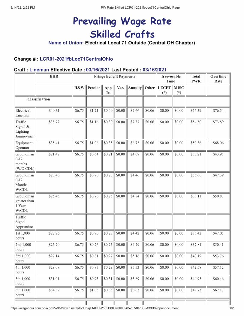
3/14/22, 2:22 PM PW Rate Skilled LCR01-2021fbLoc71CentralOhio Page
https://wagehour.com.ohio.gov/w3/Webwh.nsf/$docUniqIDAll/852565B80070693285257A07005A33B3?opendocument 1/2
Prevailing Wage Rate
Skilled CraftsName of Union: Electrical Local 71 Outside (Central OH Chapter)
Change # : LCR01-2021fbLoc71CentralOhio
Craft : Lineman Effective Date : 03/16/2021 Last Posted : 03/16/2021BHR Fringe Benefit Payments Irrevocable
FundTotalPWR
OvertimeRate
H&W Pension AppTr.
Vac. Annuity Other LECET(*)
MISC(*)
Classification
Electrical
Lineman
$40.31 $6.75 $1.21 $0.40 $0.00 $7.66 $0.06 $0.00 $0.00 $56.39 $76.54
Traffic
Signal &
Lighting
Journeyman
$38.77 $6.75 $1.16 $0.39 $0.00 $7.37 $0.06 $0.00 $0.00 $54.50 $73.89
Equipment
Operator
$35.41 $6.75 $1.06 $0.35 $0.00 $6.73 $0.06 $0.00 $0.00 $50.36 $68.06
Groundman
0-12
months
(W/O CDL)
$21.47 $6.75 $0.64 $0.21 $0.00 $4.08 $0.06 $0.00 $0.00 $33.21 $43.95
Groundman
0-12
Months
W/CDL
$23.46 $6.75 $0.70 $0.23 $0.00 $4.46 $0.06 $0.00 $0.00 $35.66 $47.39
Groundman
greater than
1 Year
W/CDL
$25.45 $6.75 $0.76 $0.25 $0.00 $4.84 $0.06 $0.00 $0.00 $38.11 $50.83
Traffic
Signal
Apprentices
1st 1,000
hours
$23.26 $6.75 $0.70 $0.23 $0.00 $4.42 $0.06 $0.00 $0.00 $35.42 $47.05
2nd 1,000
hours
$25.20 $6.75 $0.76 $0.25 $0.00 $4.79 $0.06 $0.00 $0.00 $37.81 $50.41
3rd 1,000
hours
$27.14 $6.75 $0.81 $0.27 $0.00 $5.16 $0.06 $0.00 $0.00 $40.19 $53.76
4th 1,000
hours
$29.08 $6.75 $0.87 $0.29 $0.00 $5.53 $0.06 $0.00 $0.00 $42.58 $57.12
5th 1,000
hours
$31.01 $6.75 $0.93 $0.31 $0.00 $5.89 $0.06 $0.00 $0.00 $44.95 $60.46
6th 1,000
hours
$34.89 $6.75 $1.05 $0.35 $0.00 $6.63 $0.06 $0.00 $0.00 $49.73 $67.17

3/14/22, 2:22 PM PW Rate Skilled LCR01-2021fbLoc71CentralOhio Page
https://wagehour.com.ohio.gov/w3/Webwh.nsf/$docUniqIDAll/852565B80070693285257A07005A33B3?opendocument 2/2
ApprenticeLineman
Percent
1st 1,000
Hours
60.00 $24.19 $6.75 $0.73 $0.24 $0.00 $4.60 $0.06 $0.00 $0.00 $36.57 $48.66
2nd 1,000
Hours
65.00 $26.20 $6.75 $0.79 $0.26 $0.00 $4.98 $0.06 $0.00 $0.00 $39.04 $52.14
3rd 1,000
Hours
70.00 $28.22 $6.75 $0.85 $0.28 $0.00 $5.36 $0.06 $0.00 $0.00 $41.52 $55.63
4th 1,000
Hours
75.00 $30.23 $6.75 $0.91 $0.30 $0.00 $5.74 $0.06 $0.00 $0.00 $43.99 $59.11
5th 1,000
Hours
80.00 $32.25 $6.75 $0.97 $0.32 $0.00 $6.13 $0.06 $0.00 $0.00 $46.48 $62.60
6th 1,000
Hours
85.00 $34.26 $6.75 $1.03 $0.34 $0.00 $6.51 $0.06 $0.00 $0.00 $48.95 $66.09
7th 1,000
Hours
90.00 $36.28 $6.75 $1.09 $0.36 $0.00 $6.89 $0.06 $0.00 $0.00 $51.43 $69.57
Special Calculation Note : Other is Safety & Education Fund.
Ratio : Jurisdiction ( * denotes special jurisdictionalnote ) :
1 Journeymen to 1 Apprentice ADAMS, ASHLAND, ATHENS, COSHOCTON,CRAWFORD, DELAWARE, FAIRFIELD, FAYETTE,FRANKLIN, GALLIA, GUERNSEY, HIGHLAND,HOCKING, JACKSON, KNOX, LAWRENCE,LICKING, MADISON, MARION, MEIGS, MONROE,MORGAN, MORROW, MUSKINGUM, NOBLE,PERRY, PICKAWAY, PIKE, RICHLAND, ROSS,SCIOTO, TUSCARAWAS, UNION, VINTON,WASHINGTON
Special Jurisdictional Note :
Details :A groundman when directed shall assist a Journeyman Lineman, Traffic Signal and Lighting Journeyman orEquipment Operator in the performance of his/her work on the ground, including the use of hand tools. Under nocircumstances shall this classification climb poles, towers, or work from an elevated platform or bucket truck.This classification shall not perform work normally assigned to an Apprentice.
No more than three (3) Groundmen shall work alone. Jobs with more that three Groundmen shall be supervisedby a Groundcrew Foreman, Journeyman Lineman, Journeyman Traffic Signal Technician or an EquipmentOperator.
Scope of Work: installation and maintenance of highway and street lighting, highway and street sign lighting,electronic message boards and traffic control systems, camera systems, traffic signal work, substation and lineconstruction including overhead and underground projects for private and industrial work as in accordance withthe IBEW Constitution. This Agreement includes the operation of all tools and equipment necessary for theinstallation of the above projects.
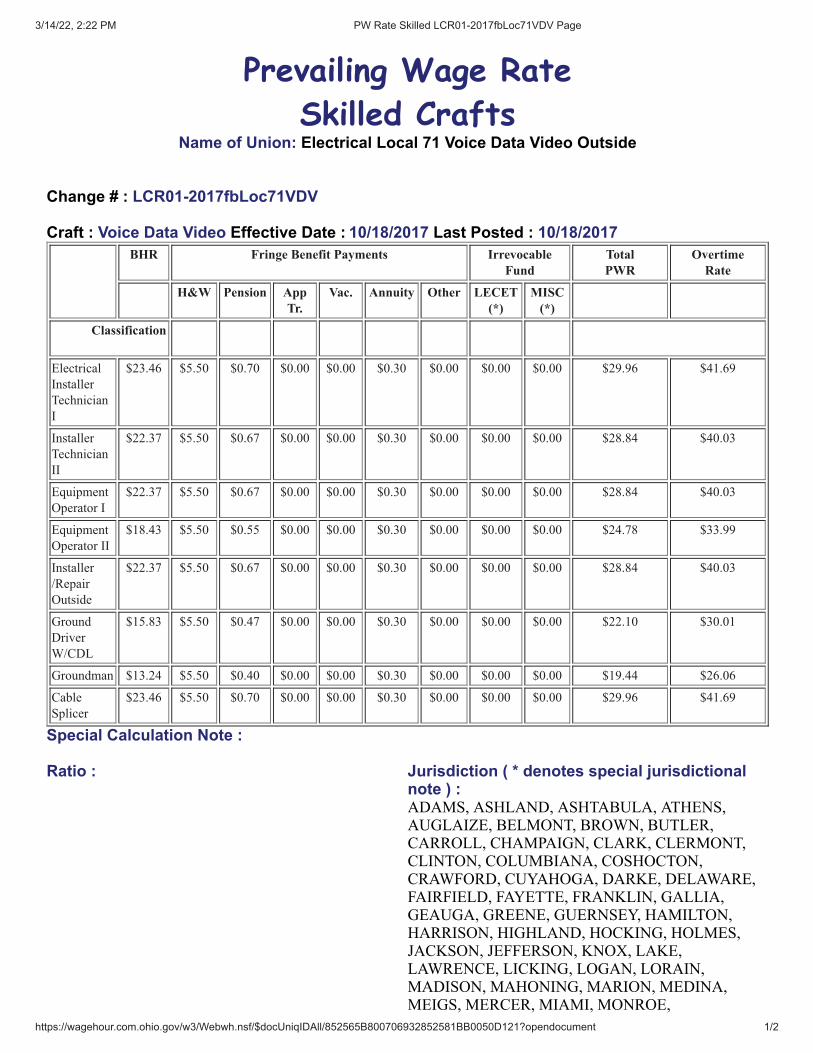
3/14/22, 2:22 PM PW Rate Skilled LCR01-2017fbLoc71VDV Page
https://wagehour.com.ohio.gov/w3/Webwh.nsf/$docUniqIDAll/852565B800706932852581BB0050D121?opendocument 1/2
Prevailing Wage Rate
Skilled CraftsName of Union: Electrical Local 71 Voice Data Video Outside
Change # : LCR01-2017fbLoc71VDV
Craft : Voice Data Video Effective Date : 10/18/2017 Last Posted : 10/18/2017BHR Fringe Benefit Payments Irrevocable
FundTotalPWR
OvertimeRate
H&W Pension AppTr.
Vac. Annuity Other LECET(*)
MISC(*)
Classification
Electrical
Installer
Technician
I
$23.46 $5.50 $0.70 $0.00 $0.00 $0.30 $0.00 $0.00 $0.00 $29.96 $41.69
Installer
Technician
II
$22.37 $5.50 $0.67 $0.00 $0.00 $0.30 $0.00 $0.00 $0.00 $28.84 $40.03
Equipment
Operator I
$22.37 $5.50 $0.67 $0.00 $0.00 $0.30 $0.00 $0.00 $0.00 $28.84 $40.03
Equipment
Operator II
$18.43 $5.50 $0.55 $0.00 $0.00 $0.30 $0.00 $0.00 $0.00 $24.78 $33.99
Installer
/Repair
Outside
$22.37 $5.50 $0.67 $0.00 $0.00 $0.30 $0.00 $0.00 $0.00 $28.84 $40.03
Ground
Driver
W/CDL
$15.83 $5.50 $0.47 $0.00 $0.00 $0.30 $0.00 $0.00 $0.00 $22.10 $30.01
Groundman $13.24 $5.50 $0.40 $0.00 $0.00 $0.30 $0.00 $0.00 $0.00 $19.44 $26.06
Cable
Splicer
$23.46 $5.50 $0.70 $0.00 $0.00 $0.30 $0.00 $0.00 $0.00 $29.96 $41.69
Special Calculation Note :
Ratio : Jurisdiction ( * denotes special jurisdictionalnote ) :ADAMS, ASHLAND, ASHTABULA, ATHENS,AUGLAIZE, BELMONT, BROWN, BUTLER,CARROLL, CHAMPAIGN, CLARK, CLERMONT,CLINTON, COLUMBIANA, COSHOCTON,CRAWFORD, CUYAHOGA, DARKE, DELAWARE,FAIRFIELD, FAYETTE, FRANKLIN, GALLIA,GEAUGA, GREENE, GUERNSEY, HAMILTON,HARRISON, HIGHLAND, HOCKING, HOLMES,JACKSON, JEFFERSON, KNOX, LAKE,LAWRENCE, LICKING, LOGAN, LORAIN,MADISON, MAHONING, MARION, MEDINA,MEIGS, MERCER, MIAMI, MONROE,
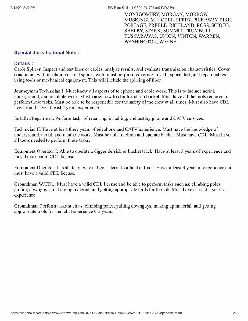
3/14/22, 2:22 PM PW Rate Skilled LCR01-2017fbLoc71VDV Page
https://wagehour.com.ohio.gov/w3/Webwh.nsf/$docUniqIDAll/852565B800706932852581BB0050D121?opendocument 2/2
MONTGOMERY, MORGAN, MORROW,MUSKINGUM, NOBLE, PERRY, PICKAWAY, PIKE,PORTAGE, PREBLE, RICHLAND, ROSS, SCIOTO,SHELBY, STARK, SUMMIT, TRUMBULL,TUSCARAWAS, UNION, VINTON, WARREN,WASHINGTON, WAYNE
Special Jurisdictional Note :
Details :Cable Splicer: Inspect and test lines or cables, analyze results, and evaluate transmission characteristics. Coverconductors with insulation or seal splices with moisture-proof covering. Install, splice, test, and repair cablesusing tools or mechanical equipment. This will include the splicing of fiber.
Journeyman Technician I: Must know all aspects of telephone and cable work. This is to include aerial,underground, and manhole work. Must know how to climb and run bucket. Must have all the tools required toperform these tasks. Must be able to be responsible for the safety of the crew at all times. Must also have CDLlicense and have at least 5 years experience.
Installer/Repairman: Perform tasks of repairing, installing, and testing phone and CATV services.
Technician II: Have at least three years of telephone and CATV experience. Must have the knowledge ofunderground, aerial, and manhole work. Must be able to climb and operate bucket. Must have CDL. Must haveall tools needed to perform these tasks.
Equipment Operator I: Able to operate a digger derrick or bucket truck. Have at least 5 years of experience andmust have a valid CDL license.
Equipment Operator II: Able to operate a digger derrick or bucket truck. Have at least 3 years of experience andmust have a valid CDL license.
Groundman W/CDL: Must have a valid CDL license and be able to perform tasks such as: climbing poles,pulling downguys, making up material, and getting appropriate tools for the job. Must have at least 5 year’sexperience.
Groundman: Perform tasks such as: climbing poles, pulling downguys, making up material, and gettingappropriate tools for the job. Experience 0-5 years.
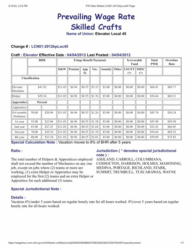
3/14/22, 2:23 PM PW Rate Skilled LCN01-2012kpLoc45 Page
https://wagehour.com.ohio.gov/w3/Webwh.nsf/$docUniqIDAll/852565B80070693285256CD300765494?opendocument 1/1
Prevailing Wage Rate
Skilled CraftsName of Union: Elevator Local 45
Change # : LCN01-2012kpLoc45
Craft : Elevator Effective Date : 04/04/2012 Last Posted : 04/04/2012BHR Fringe Benefit Payments Irrevocable
FundTotalPWR
OvertimeRate
H&W Pension AppTr.
Vac. Annuity Other LECET(*)
MISC(*)
Classification
Elevator
Mechanic
$41.92 $11.03 $6.96 $0.55 $3.35 $5.00 $0.00 $0.00 $0.00 $68.81 $89.77
Helper $29.34 $11.03 $6.96 $0.55 $1.76 $5.00 $0.00 $0.00 $0.00 $54.64 $69.31
Apprentice Percent
Apprentice
0-6 months
Probation
50.00 $20.96 $11.03 $6.96 $0.55 $1.26 $5.00 $0.00 $0.00 $0.00 $45.76 $56.24
1st year 55.00 $23.06 $11.03 $6.96 $0.55 $1.38 $5.00 $0.00 $0.00 $0.00 $47.98 $59.50
2nd year 65.00 $27.25 $11.03 $6.96 $0.55 $1.64 $5.00 $0.00 $0.00 $0.00 $52.43 $66.05
3rd year 70.00 $29.34 $11.03 $6.96 $0.55 $1.76 $5.00 $0.00 $0.00 $0.00 $54.64 $69.32
4th year 80.00 $33.54 $11.03 $6.96 $0.55 $2.01 $5.00 $0.00 $0.00 $0.00 $59.09 $75.85
Special Calculation Note : Vacation moves to 8% of BHR after 5 years
Ratio : Jurisdiction ( * denotes special jurisdictionalnote ) :
The total number of Helpers & Apprentices employedshall not exceed the number of Mechanics on any onejob, except on jobs where (2) teams or more areworking, (1) extra Helper or Apprentice may beemployed for the first (2) teams and an extra Helper orApprentice for each additional (3) teams.
ASHLAND, CARROLL, COLUMBIANA,COSHOCTON, HARRISON, HOLMES, MAHONING,MEDINA, PORTAGE, RICHLAND, STARK,SUMMIT, TRUMBULL, TUSCARAWAS, WAYNE
Special Jurisdictional Note :
Details :Vacation 6%/under 5 years based on regular hourly rate for all hours worked. 8%/over 5 years based on regularhourly rate for all hours worked.
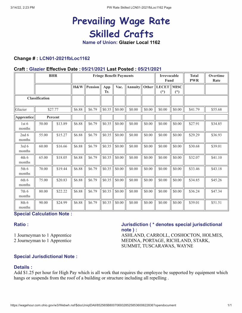
3/14/22, 2:23 PM PW Rate Skilled LCN01-2021fbLoc1162 Page
https://wagehour.com.ohio.gov/w3/Webwh.nsf/$docUniqIDAll/852565B8007069328525853600622836?opendocument 1/1
Prevailing Wage Rate
Skilled CraftsName of Union: Glazier Local 1162
Change # : LCN01-2021fbLoc1162
Craft : Glazier Effective Date : 05/21/2021 Last Posted : 05/21/2021BHR Fringe Benefit Payments Irrevocable
FundTotalPWR
OvertimeRate
H&W Pension AppTr.
Vac. Annuity Other LECET(*)
MISC(*)
Classification
Glazier $27.77 $6.88 $6.79 $0.35 $0.00 $0.00 $0.00 $0.00 $0.00 $41.79 $55.68
Apprentice Percent
1st 6
months
50.00 $13.89 $6.88 $6.79 $0.35 $0.00 $0.00 $0.00 $0.00 $0.00 $27.91 $34.85
2nd 6
months
55.00 $15.27 $6.88 $6.79 $0.35 $0.00 $0.00 $0.00 $0.00 $0.00 $29.29 $36.93
3rd 6
months
60.00 $16.66 $6.88 $6.79 $0.35 $0.00 $0.00 $0.00 $0.00 $0.00 $30.68 $39.01
4th 6
months
65.00 $18.05 $6.88 $6.79 $0.35 $0.00 $0.00 $0.00 $0.00 $0.00 $32.07 $41.10
5th 6
months
70.00 $19.44 $6.88 $6.79 $0.35 $0.00 $0.00 $0.00 $0.00 $0.00 $33.46 $43.18
6th 6
months
75.00 $20.83 $6.88 $6.79 $0.35 $0.00 $0.00 $0.00 $0.00 $0.00 $34.85 $45.26
7th 6
months
80.00 $22.22 $6.88 $6.79 $0.35 $0.00 $0.00 $0.00 $0.00 $0.00 $36.24 $47.34
8th 6
months
90.00 $24.99 $6.88 $6.79 $0.35 $0.00 $0.00 $0.00 $0.00 $0.00 $39.01 $51.51
Special Calculation Note :
Ratio : Jurisdiction ( * denotes special jurisdictionalnote ) :
1 Journeyman to 1 Apprentice2 Journeyman to 1 Apprentice
ASHLAND, CARROLL, COSHOCTON, HOLMES,MEDINA, PORTAGE, RICHLAND, STARK,SUMMIT, TUSCARAWAS, WAYNE
Special Jurisdictional Note :
Details :Add $1.25 per hour for High Pay which is all work that requires the employee be supported by equipment whichhangs or suspends from the roof of a building or structure including all repelling .
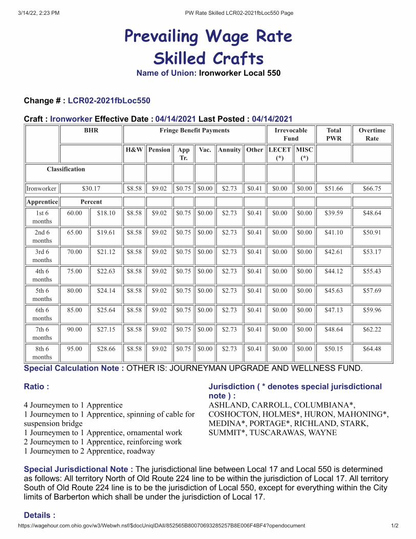
3/14/22, 2:23 PM PW Rate Skilled LCR02-2021fbLoc550 Page
https://wagehour.com.ohio.gov/w3/Webwh.nsf/$docUniqIDAll/852565B80070693285257B8E006F4BF4?opendocument 1/2
Prevailing Wage Rate
Skilled CraftsName of Union: Ironworker Local 550
Change # : LCR02-2021fbLoc550
Craft : Ironworker Effective Date : 04/14/2021 Last Posted : 04/14/2021BHR Fringe Benefit Payments Irrevocable
FundTotalPWR
OvertimeRate
H&W Pension AppTr.
Vac. Annuity Other LECET(*)
MISC(*)
Classification
Ironworker $30.17 $8.58 $9.02 $0.75 $0.00 $2.73 $0.41 $0.00 $0.00 $51.66 $66.75
Apprentice Percent
1st 6
months
60.00 $18.10 $8.58 $9.02 $0.75 $0.00 $2.73 $0.41 $0.00 $0.00 $39.59 $48.64
2nd 6
months
65.00 $19.61 $8.58 $9.02 $0.75 $0.00 $2.73 $0.41 $0.00 $0.00 $41.10 $50.91
3rd 6
months
70.00 $21.12 $8.58 $9.02 $0.75 $0.00 $2.73 $0.41 $0.00 $0.00 $42.61 $53.17
4th 6
months
75.00 $22.63 $8.58 $9.02 $0.75 $0.00 $2.73 $0.41 $0.00 $0.00 $44.12 $55.43
5th 6
months
80.00 $24.14 $8.58 $9.02 $0.75 $0.00 $2.73 $0.41 $0.00 $0.00 $45.63 $57.69
6th 6
months
85.00 $25.64 $8.58 $9.02 $0.75 $0.00 $2.73 $0.41 $0.00 $0.00 $47.13 $59.96
7th 6
months
90.00 $27.15 $8.58 $9.02 $0.75 $0.00 $2.73 $0.41 $0.00 $0.00 $48.64 $62.22
8th 6
months
95.00 $28.66 $8.58 $9.02 $0.75 $0.00 $2.73 $0.41 $0.00 $0.00 $50.15 $64.48
Special Calculation Note : OTHER IS: JOURNEYMAN UPGRADE AND WELLNESS FUND.
Ratio : Jurisdiction ( * denotes special jurisdictionalnote ) :
4 Journeymen to 1 Apprentice1 Journeymen to 1 Apprentice, spinning of cable forsuspension bridge1 Journeymen to 1 Apprentice, ornamental work2 Journeymen to 1 Apprentice, reinforcing work1 Journeymen to 2 Apprentice, roadway
ASHLAND, CARROLL, COLUMBIANA*,COSHOCTON, HOLMES*, HURON, MAHONING*,MEDINA*, PORTAGE*, RICHLAND, STARK,SUMMIT*, TUSCARAWAS, WAYNE
Special Jurisdictional Note : The jurisdictional line between Local 17 and Local 550 is determinedas follows: All territory North of Old Route 224 line to be within the jurisdiction of Local 17. All territorySouth of Old Route 224 line is to be the jurisdiction of Local 550, except for everything within the Citylimits of Barberton which shall be under the jurisdiction of Local 17.
Details :

3/14/22, 2:23 PM PW Rate Skilled LCR02-2021fbLoc550 Page
https://wagehour.com.ohio.gov/w3/Webwh.nsf/$docUniqIDAll/852565B80070693285257B8E006F4BF4?opendocument 2/2
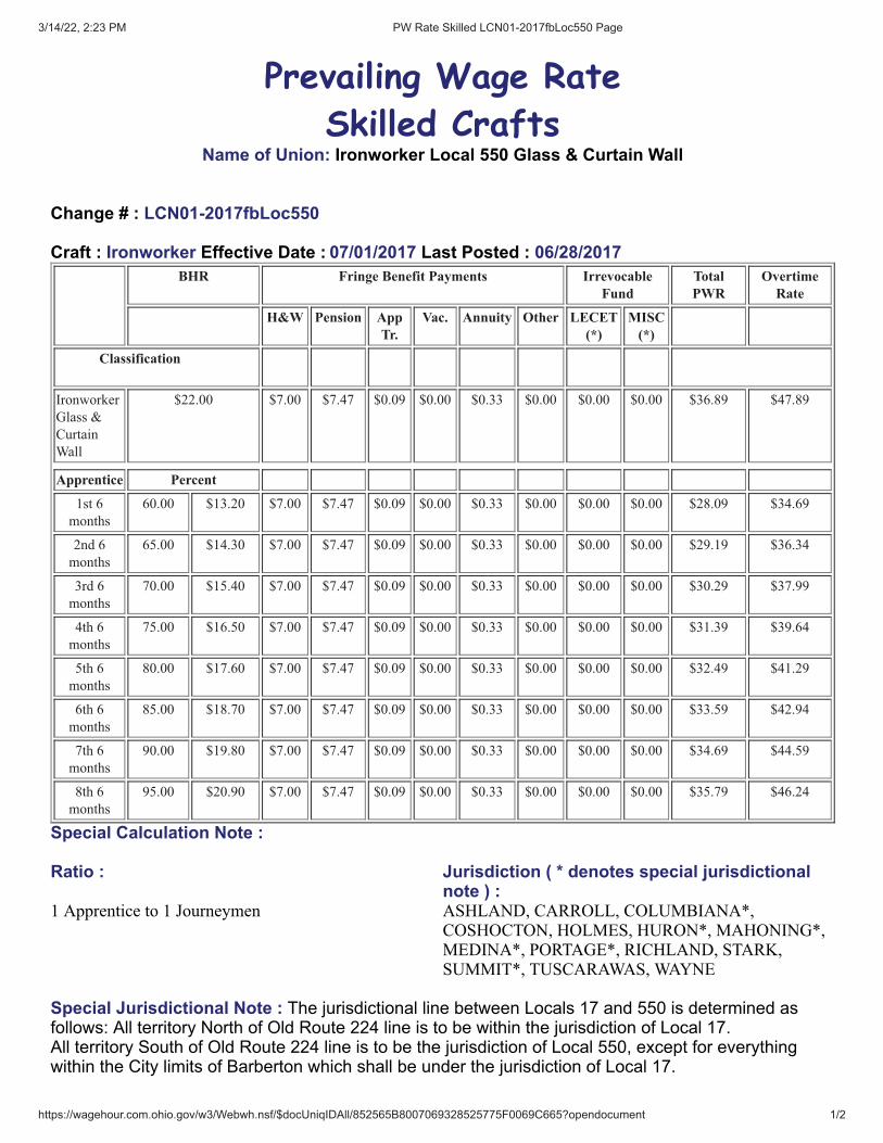
3/14/22, 2:23 PM PW Rate Skilled LCN01-2017fbLoc550 Page
https://wagehour.com.ohio.gov/w3/Webwh.nsf/$docUniqIDAll/852565B8007069328525775F0069C665?opendocument 1/2
Prevailing Wage Rate
Skilled CraftsName of Union: Ironworker Local 550 Glass & Curtain Wall
Change # : LCN01-2017fbLoc550
Craft : Ironworker Effective Date : 07/01/2017 Last Posted : 06/28/2017BHR Fringe Benefit Payments Irrevocable
FundTotalPWR
OvertimeRate
H&W Pension AppTr.
Vac. Annuity Other LECET(*)
MISC(*)
Classification
Ironworker
Glass &
Curtain
Wall
$22.00 $7.00 $7.47 $0.09 $0.00 $0.33 $0.00 $0.00 $0.00 $36.89 $47.89
Apprentice Percent
1st 6
months
60.00 $13.20 $7.00 $7.47 $0.09 $0.00 $0.33 $0.00 $0.00 $0.00 $28.09 $34.69
2nd 6
months
65.00 $14.30 $7.00 $7.47 $0.09 $0.00 $0.33 $0.00 $0.00 $0.00 $29.19 $36.34
3rd 6
months
70.00 $15.40 $7.00 $7.47 $0.09 $0.00 $0.33 $0.00 $0.00 $0.00 $30.29 $37.99
4th 6
months
75.00 $16.50 $7.00 $7.47 $0.09 $0.00 $0.33 $0.00 $0.00 $0.00 $31.39 $39.64
5th 6
months
80.00 $17.60 $7.00 $7.47 $0.09 $0.00 $0.33 $0.00 $0.00 $0.00 $32.49 $41.29
6th 6
months
85.00 $18.70 $7.00 $7.47 $0.09 $0.00 $0.33 $0.00 $0.00 $0.00 $33.59 $42.94
7th 6
months
90.00 $19.80 $7.00 $7.47 $0.09 $0.00 $0.33 $0.00 $0.00 $0.00 $34.69 $44.59
8th 6
months
95.00 $20.90 $7.00 $7.47 $0.09 $0.00 $0.33 $0.00 $0.00 $0.00 $35.79 $46.24
Special Calculation Note :
Ratio : Jurisdiction ( * denotes special jurisdictionalnote ) :
1 Apprentice to 1 Journeymen ASHLAND, CARROLL, COLUMBIANA*,COSHOCTON, HOLMES, HURON*, MAHONING*,MEDINA*, PORTAGE*, RICHLAND, STARK,SUMMIT*, TUSCARAWAS, WAYNE
Special Jurisdictional Note : The jurisdictional line between Locals 17 and 550 is determined asfollows: All territory North of Old Route 224 line is to be within the jurisdiction of Local 17. All territory South of Old Route 224 line is to be the jurisdiction of Local 550, except for everythingwithin the City limits of Barberton which shall be under the jurisdiction of Local 17.

3/14/22, 2:23 PM PW Rate Skilled LCN01-2017fbLoc550 Page
https://wagehour.com.ohio.gov/w3/Webwh.nsf/$docUniqIDAll/852565B8007069328525775F0069C665?opendocument 2/2
Details :
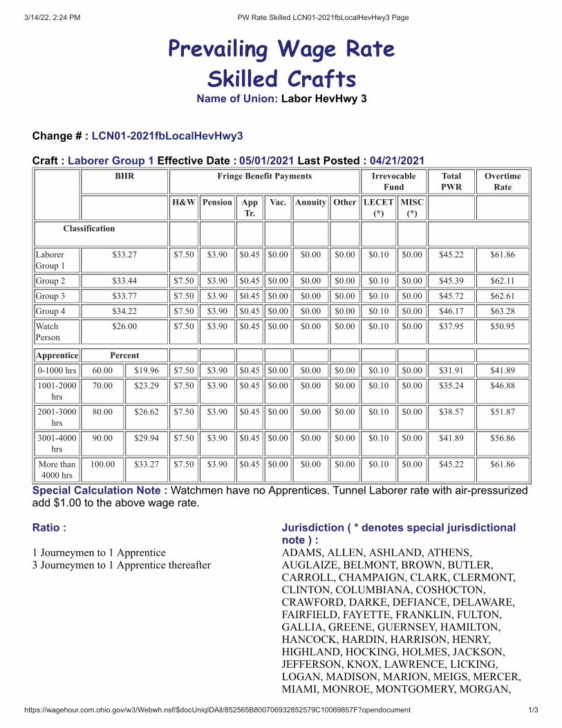
3/14/22, 2:24 PM PW Rate Skilled LCN01-2021fbLocalHevHwy3 Page
https://wagehour.com.ohio.gov/w3/Webwh.nsf/$docUniqIDAll/852565B800706932852579C10069857F?opendocument 1/3
Prevailing Wage Rate
Skilled CraftsName of Union: Labor HevHwy 3
Change # : LCN01-2021fbLocalHevHwy3
Craft : Laborer Group 1 Effective Date : 05/01/2021 Last Posted : 04/21/2021BHR Fringe Benefit Payments Irrevocable
FundTotalPWR
OvertimeRate
H&W Pension AppTr.
Vac. Annuity Other LECET(*)
MISC(*)
Classification
Laborer
Group 1
$33.27 $7.50 $3.90 $0.45 $0.00 $0.00 $0.00 $0.10 $0.00 $45.22 $61.86
Group 2 $33.44 $7.50 $3.90 $0.45 $0.00 $0.00 $0.00 $0.10 $0.00 $45.39 $62.11
Group 3 $33.77 $7.50 $3.90 $0.45 $0.00 $0.00 $0.00 $0.10 $0.00 $45.72 $62.61
Group 4 $34.22 $7.50 $3.90 $0.45 $0.00 $0.00 $0.00 $0.10 $0.00 $46.17 $63.28
Watch
Person
$26.00 $7.50 $3.90 $0.45 $0.00 $0.00 $0.00 $0.10 $0.00 $37.95 $50.95
Apprentice Percent
0-1000 hrs 60.00 $19.96 $7.50 $3.90 $0.45 $0.00 $0.00 $0.00 $0.10 $0.00 $31.91 $41.89
1001-2000
hrs
70.00 $23.29 $7.50 $3.90 $0.45 $0.00 $0.00 $0.00 $0.10 $0.00 $35.24 $46.88
2001-3000
hrs
80.00 $26.62 $7.50 $3.90 $0.45 $0.00 $0.00 $0.00 $0.10 $0.00 $38.57 $51.87
3001-4000
hrs
90.00 $29.94 $7.50 $3.90 $0.45 $0.00 $0.00 $0.00 $0.10 $0.00 $41.89 $56.86
More than
4000 hrs
100.00 $33.27 $7.50 $3.90 $0.45 $0.00 $0.00 $0.00 $0.10 $0.00 $45.22 $61.86
Special Calculation Note : Watchmen have no Apprentices. Tunnel Laborer rate with air-pressurizedadd $1.00 to the above wage rate.
Ratio : Jurisdiction ( * denotes special jurisdictionalnote ) :
1 Journeymen to 1 Apprentice3 Journeymen to 1 Apprentice thereafter
ADAMS, ALLEN, ASHLAND, ATHENS,AUGLAIZE, BELMONT, BROWN, BUTLER,CARROLL, CHAMPAIGN, CLARK, CLERMONT,CLINTON, COLUMBIANA, COSHOCTON,CRAWFORD, DARKE, DEFIANCE, DELAWARE,FAIRFIELD, FAYETTE, FRANKLIN, FULTON,GALLIA, GREENE, GUERNSEY, HAMILTON,HANCOCK, HARDIN, HARRISON, HENRY,HIGHLAND, HOCKING, HOLMES, JACKSON,JEFFERSON, KNOX, LAWRENCE, LICKING,LOGAN, MADISON, MARION, MEIGS, MERCER,MIAMI, MONROE, MONTGOMERY, MORGAN,

3/14/22, 2:24 PM PW Rate Skilled LCN01-2021fbLocalHevHwy3 Page
https://wagehour.com.ohio.gov/w3/Webwh.nsf/$docUniqIDAll/852565B800706932852579C10069857F?opendocument 2/3
MORROW, MUSKINGUM, NOBLE, PAULDING,PERRY, PICKAWAY, PIKE, PREBLE, PUTNAM,RICHLAND, ROSS, SCIOTO, SENECA, SHELBY,TUSCARAWAS, UNION, VAN WERT, VINTON,WARREN, WASHINGTON, WAYNE, WILLIAMS,WYANDOT
Special Jurisdictional Note : Hod Carriers and Common Laborers - Heavy, Highway, Sewer,Waterworks, Utility, Airport, Railroad, Industrial and Building Site, Sewer Plant, Waste WaterTreatment Facilities Construction
Details :Group 1Laborer (Construction); Plant Laborer or Yardman, Right-of-way Laborer, Landscape Laborer, HighwayLighting Worker, Signalization Worker, (Swimming) Pool Construction Laborer, Utility Man, *Bridge Man,Handyman, Joint Setter, Flagperson, Carpenter Helper, Waterproofing Laborer, Slurry Seal, Seal Coating,Surface Treatment or Road Mix Laborer, Riprap Laborer & Grouter, Asphalt Laborer, Dump Man (batch trucks),Guardrail & Fence Installer, Mesh Handler & Placer, Concrete Curing Applicator, Scaffold Erector, SignInstaller, Hazardous Waste (level D), Diver Helper, Zone Person and Traffic Control.
*Bridge Man will perfomr work as per the October 31, 1949, memorandum on concrete forms, byand betweenthe United Brotherhood of Caprpenters and Joiners of Americ and the Laborers' International Union of NorthAmerica, which states in; "the moving, cleaning, oiling and carrying to the next point of erection, and thestripping of forms which are not to be re-used, and forms on all flat arch work shall be done by memebers of theLaborers' International Union of North America."
Group 2Asphalt Raker, Screwman or Paver, Concrete Puddler, Kettle Man (pipeline), All Machine-Driven Tools (Gas,Electric, Air), Mason Tender, Brick Paver, Mortar Mixer, Skid Steer, Sheeting & Shoring Person, SurfaceGrinder Person, Screedperson, Water Blast, Hand Held Wand, Power Buggy or Power Wheelbarrow, PaintStriper, Plastic fusing Machine Operator, Rodding Machine Operator, Pug Mill Operator, Operator of AllVacuum Devices Wet or Dry, Handling of all Pumps 4 inches and under (gas, air or electric), Diver, Form Setter,Bottom Person, Welder Helper (pipeline), Concrete Saw Person, Cutting with Burning Torch, Pipe Layer, HandSpiker (railroad), Underground Person (working in sewer and waterline, cleaning, repairing and reconditioning).Tunnel Laborer (without air),Caisson, Cofferdam (below 25 feet deep), Air Track and Wagon Drill, SandblasterNozzle Person, Hazardous Waste (level B), ***Lead Abatement, Hazardous Waste (level C)
***Includes the erecting of structures for the removal, including the encapsulation and containment of Leadabatement process.
Group 3Blast and Powder Person, Muckers will be defined as shovel men working directly with the miners, Wrencher(mechanical joints & utility pipeline), Yarner, Top Lander, Hazardous Waste (level A), Concrete Specialist, CurbSetter and Cutter, Grade Checker, Concrete Crew in Tunnels. Utility pipeline Tappers, Waterline, Caulker, SignalPerson will receive the rate equal to the rate paid the Laborer classification for which the Laborer is signaling.
Group 4Miner,Welder, Gunite Nozzle Person
A.) The Watchperson shall be responsible to patrol and maintain a safe traffic zone including but not limited tobarrels, cones, signs, arrow boards, message boards etc.

3/14/22, 2:24 PM PW Rate Skilled LCN01-2021fbLocalHevHwy3 Page
https://wagehour.com.ohio.gov/w3/Webwh.nsf/$docUniqIDAll/852565B800706932852579C10069857F?opendocument 3/3
The responsibility of a watchperson is to see that the equipment, job and office trailer etc. are secure.

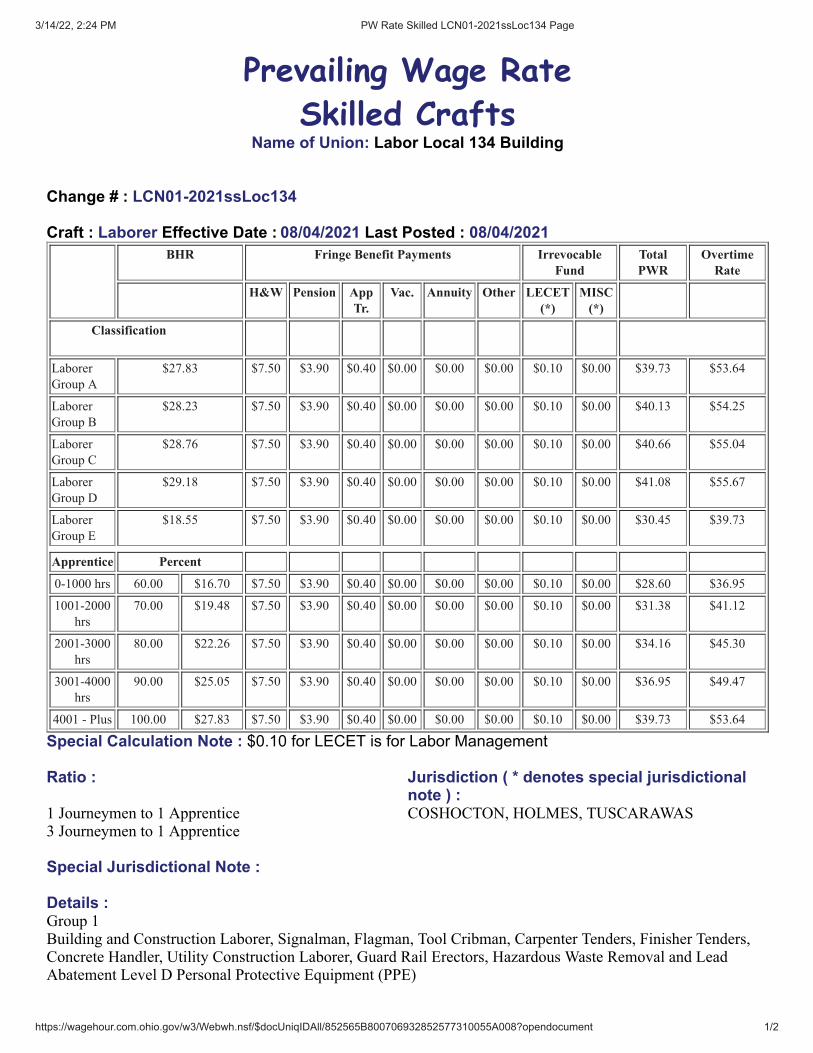
3/14/22, 2:24 PM PW Rate Skilled LCN01-2021ssLoc134 Page
https://wagehour.com.ohio.gov/w3/Webwh.nsf/$docUniqIDAll/852565B800706932852577310055A008?opendocument 1/2
Prevailing Wage Rate
Skilled CraftsName of Union: Labor Local 134 Building
Change # : LCN01-2021ssLoc134
Craft : Laborer Effective Date : 08/04/2021 Last Posted : 08/04/2021BHR Fringe Benefit Payments Irrevocable
FundTotalPWR
OvertimeRate
H&W Pension AppTr.
Vac. Annuity Other LECET(*)
MISC(*)
Classification
Laborer
Group A
$27.83 $7.50 $3.90 $0.40 $0.00 $0.00 $0.00 $0.10 $0.00 $39.73 $53.64
Laborer
Group B
$28.23 $7.50 $3.90 $0.40 $0.00 $0.00 $0.00 $0.10 $0.00 $40.13 $54.25
Laborer
Group C
$28.76 $7.50 $3.90 $0.40 $0.00 $0.00 $0.00 $0.10 $0.00 $40.66 $55.04
Laborer
Group D
$29.18 $7.50 $3.90 $0.40 $0.00 $0.00 $0.00 $0.10 $0.00 $41.08 $55.67
Laborer
Group E
$18.55 $7.50 $3.90 $0.40 $0.00 $0.00 $0.00 $0.10 $0.00 $30.45 $39.73
Apprentice Percent
0-1000 hrs 60.00 $16.70 $7.50 $3.90 $0.40 $0.00 $0.00 $0.00 $0.10 $0.00 $28.60 $36.95
1001-2000
hrs
70.00 $19.48 $7.50 $3.90 $0.40 $0.00 $0.00 $0.00 $0.10 $0.00 $31.38 $41.12
2001-3000
hrs
80.00 $22.26 $7.50 $3.90 $0.40 $0.00 $0.00 $0.00 $0.10 $0.00 $34.16 $45.30
3001-4000
hrs
90.00 $25.05 $7.50 $3.90 $0.40 $0.00 $0.00 $0.00 $0.10 $0.00 $36.95 $49.47
4001 - Plus 100.00 $27.83 $7.50 $3.90 $0.40 $0.00 $0.00 $0.00 $0.10 $0.00 $39.73 $53.64
Special Calculation Note : $0.10 for LECET is for Labor Management
Ratio : Jurisdiction ( * denotes special jurisdictionalnote ) :
1 Journeymen to 1 Apprentice3 Journeymen to 1 Apprentice
COSHOCTON, HOLMES, TUSCARAWAS
Special Jurisdictional Note :
Details :Group 1Building and Construction Laborer, Signalman, Flagman, Tool Cribman, Carpenter Tenders, Finisher Tenders,Concrete Handler, Utility Construction Laborer, Guard Rail Erectors, Hazardous Waste Removal and LeadAbatement Level D Personal Protective Equipment (PPE)

3/14/22, 2:24 PM PW Rate Skilled LCN01-2021ssLoc134 Page
https://wagehour.com.ohio.gov/w3/Webwh.nsf/$docUniqIDAll/852565B800706932852577310055A008?opendocument 2/2
Group 2Bottom Men, Scaffold Builders, Tunnel Laborers, Pipe Layers, Air and Power Driven Tools, Burner onDemolition Work, Swinging Scaffold, Mucker, Caisson Worker, Cofferdam Worker, Powder Men and DynamiteBlasters, Creosote Workers, Form Setter, Plasterer Tender, Hod Carrier, Laser Beam Set-up Man, All ConfinedSpace Work, Furnaces, Pickel Tubs, Acid Pits, and Hazardous Waste Removal and Lead Abatement Level CPersonal Protective Equipment. (PPE)
Group 3Mason Tender, Mortar Mixer, Stonemason Tender, Skid Steer Loader, Hazardous Waste Removal and LeadAbatement Level B Personal Protection Equipment (PPE)
Group 4Laborers performing work pertaining to or in connection to repair of stoves, stacks, annealing process, soakingpits, coke batteries, boilers, power houses, chemical plants and ethanol plants (under National MaintenanceAgreement) Gunnite Operator and Hazardous Waste Removal and Lead Abatement Level A Personal ProtectiveEquipment (PPE)
Group 5 Watchman - Paid a weekly rate with overtime over forty (40) hours at time and one half (1-1/2) plus Health andWelfare, Pension, Training and Upgrading & LECET.
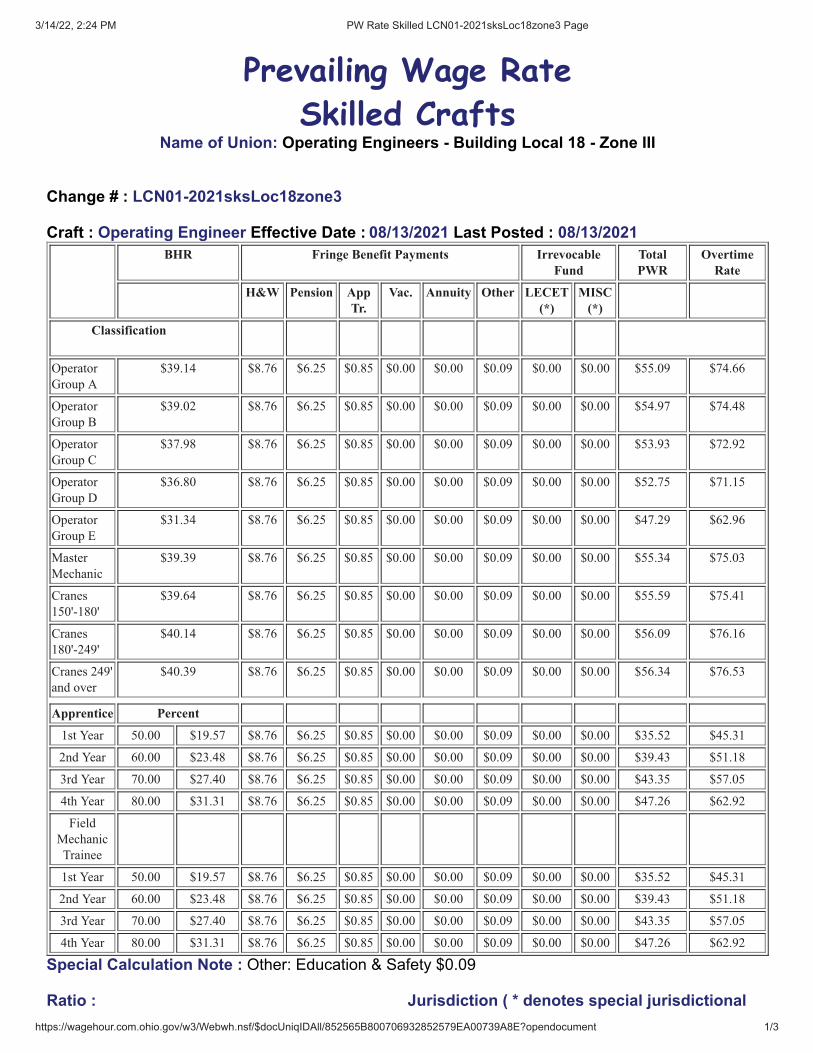
3/14/22, 2:24 PM PW Rate Skilled LCN01-2021sksLoc18zone3 Page
https://wagehour.com.ohio.gov/w3/Webwh.nsf/$docUniqIDAll/852565B800706932852579EA00739A8E?opendocument 1/3
Prevailing Wage Rate
Skilled CraftsName of Union: Operating Engineers - Building Local 18 - Zone III
Change # : LCN01-2021sksLoc18zone3
Craft : Operating Engineer Effective Date : 08/13/2021 Last Posted : 08/13/2021BHR Fringe Benefit Payments Irrevocable
FundTotalPWR
OvertimeRate
H&W Pension AppTr.
Vac. Annuity Other LECET(*)
MISC(*)
Classification
Operator
Group A
$39.14 $8.76 $6.25 $0.85 $0.00 $0.00 $0.09 $0.00 $0.00 $55.09 $74.66
Operator
Group B
$39.02 $8.76 $6.25 $0.85 $0.00 $0.00 $0.09 $0.00 $0.00 $54.97 $74.48
Operator
Group C
$37.98 $8.76 $6.25 $0.85 $0.00 $0.00 $0.09 $0.00 $0.00 $53.93 $72.92
Operator
Group D
$36.80 $8.76 $6.25 $0.85 $0.00 $0.00 $0.09 $0.00 $0.00 $52.75 $71.15
Operator
Group E
$31.34 $8.76 $6.25 $0.85 $0.00 $0.00 $0.09 $0.00 $0.00 $47.29 $62.96
Master
Mechanic
$39.39 $8.76 $6.25 $0.85 $0.00 $0.00 $0.09 $0.00 $0.00 $55.34 $75.03
Cranes
150'-180'
$39.64 $8.76 $6.25 $0.85 $0.00 $0.00 $0.09 $0.00 $0.00 $55.59 $75.41
Cranes
180'-249'
$40.14 $8.76 $6.25 $0.85 $0.00 $0.00 $0.09 $0.00 $0.00 $56.09 $76.16
Cranes 249'
and over
$40.39 $8.76 $6.25 $0.85 $0.00 $0.00 $0.09 $0.00 $0.00 $56.34 $76.53
Apprentice Percent
1st Year 50.00 $19.57 $8.76 $6.25 $0.85 $0.00 $0.00 $0.09 $0.00 $0.00 $35.52 $45.31
2nd Year 60.00 $23.48 $8.76 $6.25 $0.85 $0.00 $0.00 $0.09 $0.00 $0.00 $39.43 $51.18
3rd Year 70.00 $27.40 $8.76 $6.25 $0.85 $0.00 $0.00 $0.09 $0.00 $0.00 $43.35 $57.05
4th Year 80.00 $31.31 $8.76 $6.25 $0.85 $0.00 $0.00 $0.09 $0.00 $0.00 $47.26 $62.92
Field
Mechanic
Trainee
1st Year 50.00 $19.57 $8.76 $6.25 $0.85 $0.00 $0.00 $0.09 $0.00 $0.00 $35.52 $45.31
2nd Year 60.00 $23.48 $8.76 $6.25 $0.85 $0.00 $0.00 $0.09 $0.00 $0.00 $39.43 $51.18
3rd Year 70.00 $27.40 $8.76 $6.25 $0.85 $0.00 $0.00 $0.09 $0.00 $0.00 $43.35 $57.05
4th Year 80.00 $31.31 $8.76 $6.25 $0.85 $0.00 $0.00 $0.09 $0.00 $0.00 $47.26 $62.92
Special Calculation Note : Other: Education & Safety $0.09
Ratio : Jurisdiction ( * denotes special jurisdictional

3/14/22, 2:24 PM PW Rate Skilled LCN01-2021sksLoc18zone3 Page
https://wagehour.com.ohio.gov/w3/Webwh.nsf/$docUniqIDAll/852565B800706932852579EA00739A8E?opendocument 2/3
note ) :For every (3) Operating Engineer Journeymenemployed by the company there may be employed (1)Registered Apprentice or trainee Engineer through thereferral when they are available. An apprenice, whileemployed as part of a crew per Article VIII, paragraph78, will not be subject to the apprenticeship ratios inthis collective bargaining agreement
ADAMS, ALLEN, ASHLAND, ATHENS,AUGLAIZE, BELMONT, BROWN, BUTLER,CARROLL, CHAMPAIGN, CLARK, CLERMONT,CLINTON, COSHOCTON, CRAWFORD, DARKE,DEFIANCE, DELAWARE, FAIRFIELD, FAYETTE,FRANKLIN, FULTON, GALLIA, GREENE,GUERNSEY, HAMILTON, HANCOCK, HARDIN,HARRISON, HENRY, HIGHLAND, HOCKING,HOLMES, JACKSON, JEFFERSON, KNOX,LAWRENCE, LICKING, LOGAN, MADISON,MARION, MEIGS, MERCER, MIAMI, MONROE,MONTGOMERY, MORGAN, MORROW,MUSKINGUM, NOBLE, OTTAWA, PAULDING,PERRY, PICKAWAY, PIKE, PREBLE, PUTNAM,RICHLAND, ROSS, SANDUSKY, SCIOTO,SENECA, SHELBY, STARK, TUSCARAWAS,UNION, VAN WERT, VINTON, WARREN,WASHINGTON, WAYNE, WILLIAMS, WYANDOT
Special Jurisdictional Note :
Details :Note: There will be a 10% increase for the apprentices on top of the percentages listed above provided they areoperating mobile equipment. Mechanic Trainees will receive 10% increase if required to have CDL
Group A- Barrier Moving Machines; Boiler Operators or Compressor Operators, when compressor or boiler ismounted on crane (Piggyback Operation); Boom Trucks (all types); Cableways Cherry Pickers; Combination -Concrete Mixers & Towers; All Concrete Pumps with Booms; Cranes (all types); Compact Cranes, track orrubber over 4,000 pounds capacity; Cranes self-erecting, stationary, track or truck (all configurations); Derricks(all types); Draglines; Dredges (dipper, clam or suction) 3-man crew; Elevating Graders or Euclid Loaders;Floating Equipment; Forklift (rough terrain with winch/hoist); Gradalls; Helicopter Operators, hoisting buildingmaterials; Helicopter Winch Operators, Hoisting building materials; Hoes (All types); Hoists (with two or moredrums in use); Horizonal Directional Drill; Hydraulic Gantry (lift system); Laser Finishing Machines; LaserScreed and like equipment; Lift Slab or Panel Jack Operators; Locomotives (all types); MaintenanceOperator/Technician(Mechanic Operator/Technician and/or Welder); Mixers, paving (multiple drum); MobileConcrete Pumps, with booms; Panelboards, (all types on site); Pile Drivers; Power Shovels; Prentice Loader;Rail Tamper (with automatic lifting and aligning device); Rotary Drills (all), used on caissons for foundationsand sub-structure; Side Booms; Slip Form Pavers; Straddle Carriers (Building Construction on site); TrenchMachines (over 24” wide); Tug Boats.
Group B - Articulating/end dumps (minus $4.00/hour from Group B rate); Asphalt Pavers; Bobcat-type and/orskid steer loader with hoe attachment greater than 7000 lbs.; Bulldozers; CMI type Equipment; Concrete Saw,Vermeer-type; Endloaders; Hydro Milling Machine; Kolman-type Loaders (Dirt Loading); Lead Greasemen;Mucking Machines; Pettibone-Rail Equipment; Power Graders; Power Scoops; Power Scrapers; Push Cats;,Rotomills (all), grinders and planers of all types.
Group C - A-Frames; Air Compressors, Pressurizing Shafts or Tunnels; All Asphalt Rollers; Bobcat-type and/orSkid Steer Loader with or without attachments; Boilers (15 lbs. pressure and over); All Concrete Pumps (withoutbooms with 5 inch system); Fork Lifts (except masonry); Highway Drills - all types (with integral power);Hoists (with one drum); House Elevators (except those automatic call button controlled), Buck Hoists, TransportPlatforms, Construction Elevators; Hydro Vac/Excavator (when a second person is needed, the rate of pay willbe “Class E”); Man Lifts; Material hoist/elevators; Mud Jacks; Pressure Grouting; Pump Operators (installing oroperating Well Points or other types of Dewatering Systems); Pumps (4 inches and over discharge); Railroad Tie
3/14/22, 2:24 PM PW Rate Skilled LCN01-2021sksLoc18zone3 Page
https://wagehour.com.ohio.gov/w3/Webwh.nsf/$docUniqIDAll/852565B800706932852579EA00739A8E?opendocument 3/3
(Inserter/Remover); Rotovator (Lime-Soil Stabilizer); Submersible Pumps (4”and over discharge); Switch & TieTampers (without lifting and aligning device); Trench Machines (24” and under); Utility Operators.
Group D - Backfillers and Tampers; Ballast Re-locator; Batch Plant Operators; Bar and Joint InstallingMachines; Bull Floats; Burlap and Curing Machines; Clefplanes; Compressors, on building construction;Concrete Mixers, more than one bag capacity; Concrete Mixers, one bag capacity (side loaders); All ConcretePumps (without boom with 4” or smaller system); Concrete Spreader; Conveyors, used for handling buildingmaterials; Crushers; Deckhands; Drum Fireman (in asphalt plants); Farm type tractors pulling attachments;Finishing Machines; Form Trenchers; Generators: Gunite Machines; Hydro-seeders; Pavement Breakers(hydraulic or cable); Post Drivers; Post Hole Diggers; Pressure Pumps (over 1/2”) discharge); Road WideningTrenchers; Rollers (except asphalt); Self-propelled sub-graders; Shotcrete Machines; Tire Repairmen; Tractors,pulling sheepsfoot post roller or grader; VAC/ALLS; Vibratory Compactors, with integral power; Welders.
Group E – Allen Screed Paver (concrete); Boilers (less than 15 lbs. pressure); Cranes-Compact, track or rubber(under 4,000 pounds capacity); Directional Drill “Locator”; Fueling and greasing +$3.00; Inboard/outboardMotor Boat Launches; Light Plant Operators; Masonry Fork Lifts; Oilers/Helpers; Power Driven Heaters (oilfired); Power Scrubbers; Power Sweepers; Pumps (under 4 inch discharge); Signalperson, Submersible Pumps(under 4” discharge).
Master Mechanics - Master Mechanic
Cranes 150’ – 180’ - Boom & Jib 150 - 180 feet
Cranes 180’ – 249’ - Boom & Jib 180 - 249 feet
Cranes 250’ and over - Boom & Jib 250-feet or over

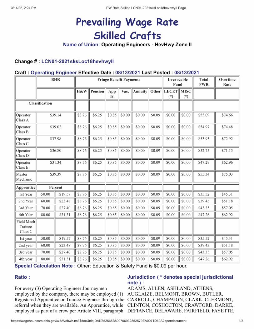
3/14/22, 2:24 PM PW Rate Skilled LCN01-2021sksLoc18hevhwyII Page
https://wagehour.com.ohio.gov/w3/Webwh.nsf/$docUniqIDAll/852565B800706932852579EA0071D69A?opendocument 1/3
Prevailing Wage Rate
Skilled CraftsName of Union: Operating Engineers - HevHwy Zone II
Change # : LCN01-2021sksLoc18hevhwyII
Craft : Operating Engineer Effective Date : 08/13/2021 Last Posted : 08/13/2021BHR Fringe Benefit Payments Irrevocable
FundTotalPWR
OvertimeRate
H&W Pension AppTr.
Vac. Annuity Other LECET(*)
MISC(*)
Classification
Operator
Class A
$39.14 $8.76 $6.25 $0.85 $0.00 $0.00 $0.09 $0.00 $0.00 $55.09 $74.66
Operator
Class B
$39.02 $8.76 $6.25 $0.85 $0.00 $0.00 $0.09 $0.00 $0.00 $54.97 $74.48
Operator
Class C
$37.98 $8.76 $6.25 $0.85 $0.00 $0.00 $0.09 $0.00 $0.00 $53.93 $72.92
Operator
Class D
$36.80 $8.76 $6.25 $0.85 $0.00 $0.00 $0.09 $0.00 $0.00 $52.75 $71.15
Operator
Class E
$31.34 $8.76 $6.25 $0.85 $0.00 $0.00 $0.09 $0.00 $0.00 $47.29 $62.96
Master
Mechanic
$39.39 $8.76 $6.25 $0.85 $0.00 $0.00 $0.09 $0.00 $0.00 $55.34 $75.03
Apprentice Percent
1st Year 50.00 $19.57 $8.76 $6.25 $0.85 $0.00 $0.00 $0.09 $0.00 $0.00 $35.52 $45.31
2nd Year 60.00 $23.48 $8.76 $6.25 $0.85 $0.00 $0.00 $0.09 $0.00 $0.00 $39.43 $51.18
3rd Year 70.00 $27.40 $8.76 $6.25 $0.85 $0.00 $0.00 $0.09 $0.00 $0.00 $43.35 $57.05
4th Year 80.00 $31.31 $8.76 $6.25 $0.85 $0.00 $0.00 $0.09 $0.00 $0.00 $47.26 $62.92
Field Mech
Trainee
Class 2
1st year 50.00 $19.57 $8.76 $6.25 $0.85 $0.00 $0.00 $0.09 $0.00 $0.00 $35.52 $45.31
2nd year 60.00 $23.48 $8.76 $6.25 $0.85 $0.00 $0.00 $0.09 $0.00 $0.00 $39.43 $51.18
3rd year 70.00 $27.40 $8.76 $6.25 $0.85 $0.00 $0.00 $0.09 $0.00 $0.00 $43.35 $57.05
4th year 80.00 $31.31 $8.76 $6.25 $0.85 $0.00 $0.00 $0.09 $0.00 $0.00 $47.26 $62.92
Special Calculation Note : Other: Education & Safety Fund is $0.09 per hour.
Ratio : Jurisdiction ( * denotes special jurisdictionalnote ) :
For every (3) Operating Engineer Journeymenemployed by the company, there may be employed (1)Registered Apprentice or Trainee Engineer through thereferral when they are available. An Apprentice, whileemployed as part of a crew per Article VIII, paragraph
ADAMS, ALLEN, ASHLAND, ATHENS,AUGLAIZE, BELMONT, BROWN, BUTLER,CARROLL, CHAMPAIGN, CLARK, CLERMONT,CLINTON, COSHOCTON, CRAWFORD, DARKE,DEFIANCE, DELAWARE, FAIRFIELD, FAYETTE,

3/14/22, 2:24 PM PW Rate Skilled LCN01-2021sksLoc18hevhwyII Page
https://wagehour.com.ohio.gov/w3/Webwh.nsf/$docUniqIDAll/852565B800706932852579EA0071D69A?opendocument 2/3
65 will not be subject to the apprenticeship ratios in thiscollective bargaining agreement
FRANKLIN, FULTON, GALLIA, GREENE,GUERNSEY, HAMILTON, HANCOCK, HARDIN,HARRISON, HENRY, HIGHLAND, HOCKING,HOLMES, HURON, JACKSON, JEFFERSON,KNOX, LAWRENCE, LICKING, LOGAN, LUCAS,MADISON, MARION, MEIGS, MERCER, MIAMI,MONROE, MONTGOMERY, MORGAN, MORROW,MUSKINGUM, NOBLE, OTTAWA, PAULDING,PERRY, PICKAWAY, PIKE, PREBLE, PUTNAM,RICHLAND, ROSS, SANDUSKY, SCIOTO,SENECA, SHELBY, STARK, TUSCARAWAS,UNION, VAN WERT, VINTON, WARREN,WASHINGTON, WAYNE, WILLIAMS, WOOD,WYANDOT
Special Jurisdictional Note :
Details :**Apprentices wilt receive a 10% increase on top of the percentages listed above provided they are operatingmobile equipment. Mechanic Trainees will receive 10% increase if they are required to have CDL.
Class A - Air Compressors on Steel Erection; Asphalt Plant Engineers (Cleveland District Only); BarrierMoving Machine; Boiler Operators, Compressor Operators, or Generators, when mounted on a rig; BoomTrucks (all types); Cableways; Cherry Pickers; Combination- Concrete Mixers & Towers; Concrete Plants (over4 yd capacity); Concrete Pumps; Cranes (all types); Compact Cranes track or rubber over 4,000 pounds capacity;Cranes self-erecting stationary, track or truck; Derricks (all types); Draglines; Dredges dipper, clam or suction;Elevating Graders or Euclid Loaders; Floating Equipment (all types); Gradalls; Helicopter Crew (Operator- hoistor winch); Hoes (all types); Hoisting Engines; Hoisting Engines, on shaft or tunnel work; Hydraulic Gantry(lifting system); Industrial-type Tractors; Jet Engine Dryer (D8 or D9) diesel Tractors; Locomotives (standardgauge); Maintenance Operators/Technicians (class A); Mixers, paving (single or double drum); MuckingMachines; Multiple Scrapers; Piledriving Machines (all types); Power Shovels, Prentice Loader; Quad 9 (doublepusher); Rail Tamper (with automatic lifting and aligning device); Refrigerating Machines (freezer operation);Rotary Drills, on caisson work; Rough Terrain Fork Lift with winch/hoist; Side Booms; Slip Form Pavers;Survey Crew Party Chiefs; Tower Derricks; Tree Shredders; Trench Machines (over 24” wide); Truck MountedConcrete Pumps; Tug Boats; Tunnel Machines and /or Mining Machines; Wheel Excavators.
Class B - Asphalt Pavers; Automatic Subgrade Machines, self-propelled (CMI-type); Bobcat-type and /or SkidSteer Loader with hoe attachment greater than 7000 lbs.; Boring Machine Operators (more than 48 inches);Bulldozers; Concrete Saws, Vermeer type; Endloaders; Horizontal Directional Drill (50,000 ft. lbs. thrust andover); Hydro Milling Machine; Kolman-type Loaders (production type-dirt); Lead Greasemen; Lighting andTraffic Signal Installation Equipment includes all groups or classifications; Maintenance Operators/Technicians,Class B; Material Transfer Equipment (shuttle buggy) Asphalt; Pettibone-Rail Equipment; Power Graders;Power Scrapers; Push Cats; Rotomills (all), Grinders and Planners of all types, Groovers (excluding walk-behinds); Trench Machines (24 inch wide and under).
Class C - A-Frames; Air Compressors, on tunnel work (low Pressure); Articulating/straight bed end dumps ifassigned (minus $4.00 per hour); Asphalt Plant Engineers (Portage and Summit Counties only); Bobcat-typeand/or skid steer loader with or without attachments; Drones; Highway Drills (all types); HydroVac/Excavator(when a second person is needed, the rate of pay will be “Class E”); Locomotives (narrow gauge); MaterialHoist/Elevators; Mixers, concrete (more than one bag capacity); Mixers, one bag capacity (side loader); PowerBoilers (over 15 lbs. pressure); Pump Operators (installing or operating well Points); Pumps (4 inch and overdischarge); Railroad Tie Inserter/Remover; Rollers, Asphalt; Rotovator (lime-soil Stabilizer); Switch & TieTampers (without lifting and aligning device); Utilities Operators, (small equipment); Welding Machines andGenerators.

3/14/22, 2:24 PM PW Rate Skilled LCN01-2021sksLoc18hevhwyII Page
https://wagehour.com.ohio.gov/w3/Webwh.nsf/$docUniqIDAll/852565B800706932852579EA0071D69A?opendocument 3/3
Class D – Backfillers and Tampers; Ballast Re-locator; Bar and Joint Installing Machines; Batch PlantOperators; Boring Machine Operators (48 inch or less); Bull Floats; Burlap and Curing Machines; ConcretePlants (capacity 4 yds. and under); Concrete Saws (multiple); Conveyors (highway); Crushers; Deckhands; Farmtype tractors, with attachments (highway); Finishing Machines; Firemen, Floating Equipment (all types); ForkLifts (highway), except masonry; Form Trenchers; Hydro Hammers; Hydro Seeders; Pavement Breakers(hydraulic or cable); Plant Mixers; Post Drivers; Post Hole Diggers; Power Brush Burners; Power FormHandling Equipment; Road Widening Trenchers; Rollers (brick, grade, macadam); Self-Propelled PowerSpreaders; Self-Propelled Sub-Graders; Steam Firemen; Survey Instrument men; Tractors, pulling sheepsfootrollers or graders; Vibratory Compactors, with integral power.
Class E - Compressors (portable, Sewer, Heavy and Highway); Cranes-Compact, track or rubber under 4,000pound capacity; Drum Firemen (asphalt plant); Fueling and greasing (Primary Operator with Specialized CDLEndorsement Add $3.00/hr); Generators; Inboard-Outboard Motor Boat Launches; Masonry Fork Lifts; OilHeaters (asphalt plant); Oilers/Helpers; Power Driven Heaters (oil fired); Power Scrubbers; Power Sweepers;Pumps (under 4 inch discharge); Signalperson; Survey Rodmen or Chairmen; Tire Repairmen; VAC/ALLS.Master Mechanic - Master Mechanic

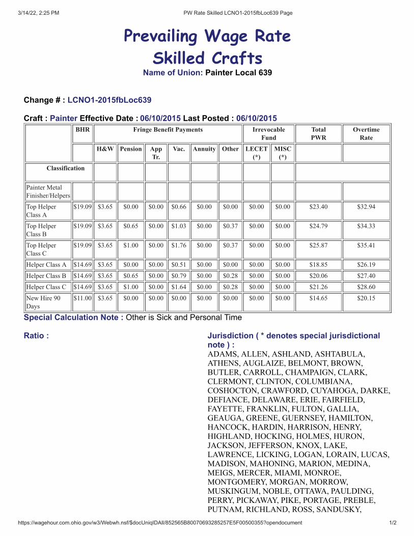
3/14/22, 2:25 PM PW Rate Skilled LCNO1-2015fbLoc639 Page
https://wagehour.com.ohio.gov/w3/Webwh.nsf/$docUniqIDAll/852565B80070693285257E5F00500355?opendocument 1/2
Prevailing Wage Rate
Skilled CraftsName of Union: Painter Local 639
Change # : LCNO1-2015fbLoc639
Craft : Painter Effective Date : 06/10/2015 Last Posted : 06/10/2015BHR Fringe Benefit Payments Irrevocable
FundTotalPWR
OvertimeRate
H&W Pension AppTr.
Vac. Annuity Other LECET(*)
MISC(*)
Classification
Painter Metal
Finisher/Helpers
Top Helper
Class A
$19.09 $3.65 $0.00 $0.00 $0.66 $0.00 $0.00 $0.00 $0.00 $23.40 $32.94
Top Helper
Class B
$19.09 $3.65 $0.65 $0.00 $1.03 $0.00 $0.37 $0.00 $0.00 $24.79 $34.33
Top Helper
Class C
$19.09 $3.65 $1.00 $0.00 $1.76 $0.00 $0.37 $0.00 $0.00 $25.87 $35.41
Helper Class A $14.69 $3.65 $0.00 $0.00 $0.51 $0.00 $0.00 $0.00 $0.00 $18.85 $26.19
Helper Class B $14.69 $3.65 $0.65 $0.00 $0.79 $0.00 $0.28 $0.00 $0.00 $20.06 $27.40
Helper Class C $14.69 $3.65 $1.00 $0.00 $1.64 $0.00 $0.28 $0.00 $0.00 $21.26 $28.60
New Hire 90
Days
$11.00 $3.65 $0.00 $0.00 $0.00 $0.00 $0.00 $0.00 $0.00 $14.65 $20.15
Special Calculation Note : Other is Sick and Personal Time
Ratio : Jurisdiction ( * denotes special jurisdictionalnote ) :ADAMS, ALLEN, ASHLAND, ASHTABULA,ATHENS, AUGLAIZE, BELMONT, BROWN,BUTLER, CARROLL, CHAMPAIGN, CLARK,CLERMONT, CLINTON, COLUMBIANA,COSHOCTON, CRAWFORD, CUYAHOGA, DARKE,DEFIANCE, DELAWARE, ERIE, FAIRFIELD,FAYETTE, FRANKLIN, FULTON, GALLIA,GEAUGA, GREENE, GUERNSEY, HAMILTON,HANCOCK, HARDIN, HARRISON, HENRY,HIGHLAND, HOCKING, HOLMES, HURON,JACKSON, JEFFERSON, KNOX, LAKE,LAWRENCE, LICKING, LOGAN, LORAIN, LUCAS,MADISON, MAHONING, MARION, MEDINA,MEIGS, MERCER, MIAMI, MONROE,MONTGOMERY, MORGAN, MORROW,MUSKINGUM, NOBLE, OTTAWA, PAULDING,PERRY, PICKAWAY, PIKE, PORTAGE, PREBLE,PUTNAM, RICHLAND, ROSS, SANDUSKY,

3/14/22, 2:25 PM PW Rate Skilled LCNO1-2015fbLoc639 Page
https://wagehour.com.ohio.gov/w3/Webwh.nsf/$docUniqIDAll/852565B80070693285257E5F00500355?opendocument 2/2
SCIOTO, SENECA, SHELBY, STARK, SUMMIT,TRUMBULL, TUSCARAWAS, UNION, VAN WERT,VINTON, WARREN, WASHINGTON, WAYNE,WILLIAMS, WOOD, WYANDOT
Special Jurisdictional Note :
Details :Top Helper: Shall perform the responsibilities of a Helper and be responsible for the setup, break down, safetyand quality of the company's product.Helper : Shall be responsible for performing tasks in refinishing, compliance with safety procedures, setting upand breaking down job sites, scaffolding and swing stages and preparing surfaces for refinishing including butnot limited to, masking and stripping and cleaning, oxidizing, polishing and scratch removal on various surfaces.Class A Workers: Less than 1 Year of Service.Class B Workers: More than 1 and less than 8 Years of Service.Class C Workers: More than 8 Years of Service.
Metal Polisher Scope of Work: Polishing, buffing, stripping, coloring, lacquering, spraying, cleaning andmaintenance of ornamental and architectural metals, iron, bronze, nickel, aluminum and stainless steel and inmental specialty work, various stone finishes, stone specialty work and any other work pertaining to thefinishing of metal, stones, woods, and any window washing/cleaning done in conjunction with this work, usingchemicals, solvents, coatings and hand applied lacquer thinner, removing scratches from mirrow finished metals,burnishing of bronze, statuary finishes on exterior and interior surfaces and the use of all tools required toperform such work, including but not limited to polishes, spray equipment and scaffolding.
Swing State Rate: All work on scaffold 4 sections or higher, including any boom lifts and swing stage scaffoldsincluding the rigging and derigging of hanging/suspended swing stage systems and rappelling/bolson chairwork, ADD $1.50 per hour.
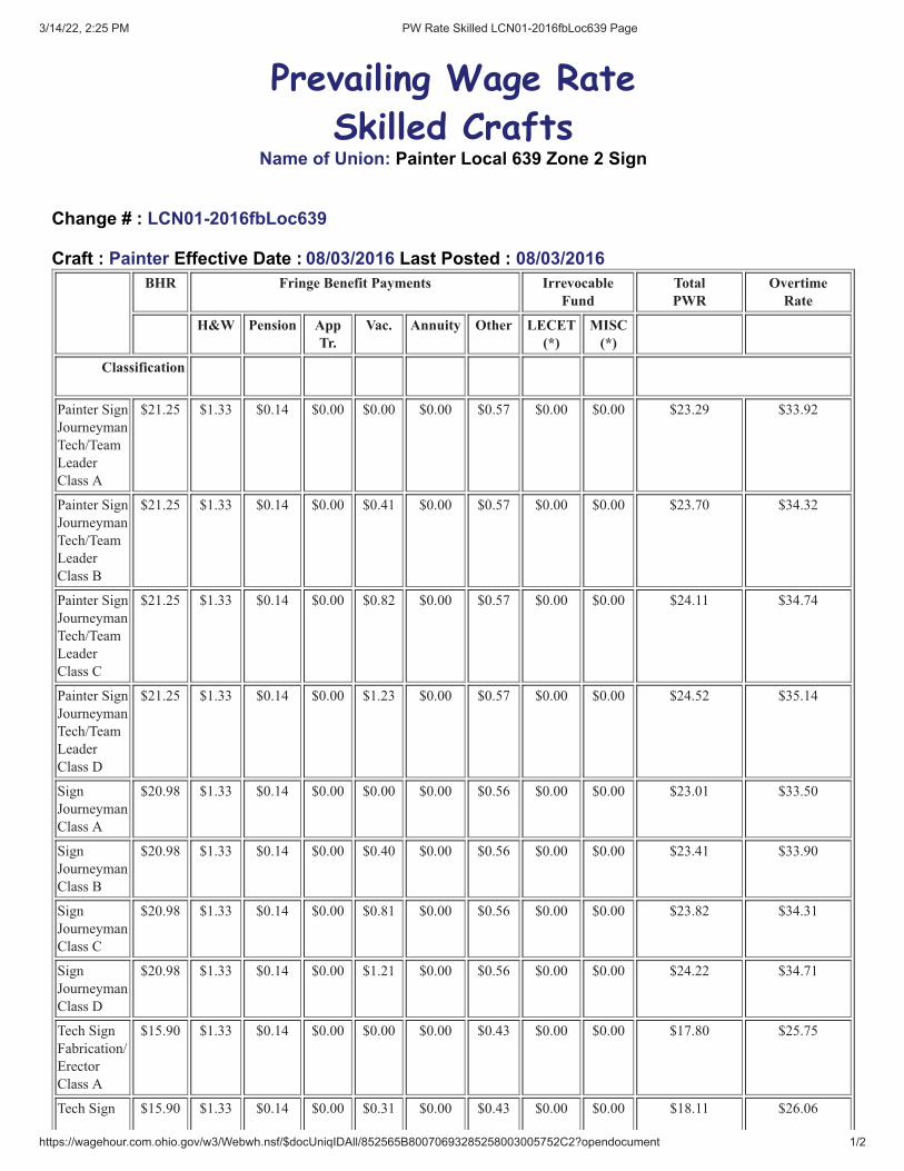
3/14/22, 2:25 PM PW Rate Skilled LCN01-2016fbLoc639 Page
https://wagehour.com.ohio.gov/w3/Webwh.nsf/$docUniqIDAll/852565B80070693285258003005752C2?opendocument 1/2
Prevailing Wage Rate
Skilled CraftsName of Union: Painter Local 639 Zone 2 Sign
Change # : LCN01-2016fbLoc639
Craft : Painter Effective Date : 08/03/2016 Last Posted : 08/03/2016BHR Fringe Benefit Payments Irrevocable
FundTotalPWR
OvertimeRate
H&W Pension AppTr.
Vac. Annuity Other LECET(*)
MISC(*)
Classification
Painter Sign
Journeyman
Tech/Team
Leader
Class A
$21.25 $1.33 $0.14 $0.00 $0.00 $0.00 $0.57 $0.00 $0.00 $23.29 $33.92
Painter Sign
Journeyman
Tech/Team
Leader
Class B
$21.25 $1.33 $0.14 $0.00 $0.41 $0.00 $0.57 $0.00 $0.00 $23.70 $34.32
Painter Sign
Journeyman
Tech/Team
Leader
Class C
$21.25 $1.33 $0.14 $0.00 $0.82 $0.00 $0.57 $0.00 $0.00 $24.11 $34.74
Painter Sign
Journeyman
Tech/Team
Leader
Class D
$21.25 $1.33 $0.14 $0.00 $1.23 $0.00 $0.57 $0.00 $0.00 $24.52 $35.14
Sign
Journeyman
Class A
$20.98 $1.33 $0.14 $0.00 $0.00 $0.00 $0.56 $0.00 $0.00 $23.01 $33.50
Sign
Journeyman
Class B
$20.98 $1.33 $0.14 $0.00 $0.40 $0.00 $0.56 $0.00 $0.00 $23.41 $33.90
Sign
Journeyman
Class C
$20.98 $1.33 $0.14 $0.00 $0.81 $0.00 $0.56 $0.00 $0.00 $23.82 $34.31
Sign
Journeyman
Class D
$20.98 $1.33 $0.14 $0.00 $1.21 $0.00 $0.56 $0.00 $0.00 $24.22 $34.71
Tech Sign
Fabrication/
Erector
Class A
$15.90 $1.33 $0.14 $0.00 $0.00 $0.00 $0.43 $0.00 $0.00 $17.80 $25.75
Tech Sign $15.90 $1.33 $0.14 $0.00 $0.31 $0.00 $0.43 $0.00 $0.00 $18.11 $26.06

3/14/22, 2:25 PM PW Rate Skilled LCN01-2016fbLoc639 Page
https://wagehour.com.ohio.gov/w3/Webwh.nsf/$docUniqIDAll/852565B80070693285258003005752C2?opendocument 2/2
Fabrication/
Erector
Class B
Tech Sign
Fabrication/
Erector
Class C
$15.90 $1.33 $0.14 $0.00 $0.61 $0.00 $0.43 $0.00 $0.00 $18.41 $26.36
Tech Sign
Fabrication/
Erector
Class D
$15.90 $1.33 $0.14 $0.00 $0.92 $0.00 $0.43 $0.00 $0.00 $18.72 $26.67
Special Calculation Note : Other is for paid holidays.
Ratio : Jurisdiction ( * denotes special jurisdictionalnote ) :ADAMS, ALLEN, AUGLAIZE, BROWN, BUTLER,CARROLL, CHAMPAIGN, CLARK, CLERMONT,CLINTON, COLUMBIANA, COSHOCTON,CRAWFORD, DARKE, DEFIANCE, DELAWARE,ERIE, FAIRFIELD, FAYETTE, FRANKLIN,FULTON, GREENE, HAMILTON, HANCOCK,HARDIN, HENRY, HIGHLAND, HOLMES, HURON,JACKSON, KNOX, LICKING, LOGAN, LORAIN,LUCAS, MADISON, MAHONING, MARION,MERCER, MIAMI, MONTGOMERY, MORROW,MUSKINGUM, OTTAWA, PAULDING, PERRY,PICKAWAY, PIKE, PREBLE, PUTNAM, ROSS,SANDUSKY, SCIOTO, SENECA, SHELBY, STARK,TRUMBULL, TUSCARAWAS, UNION, VAN WERT,WARREN, WAYNE, WILLIAMS, WOOD,WYANDOT
Special Jurisdictional Note :
Details :Class A: less that 1 year. Class B: 1-3 years.Class C; 3-10 years.Class D: More than 10 years.
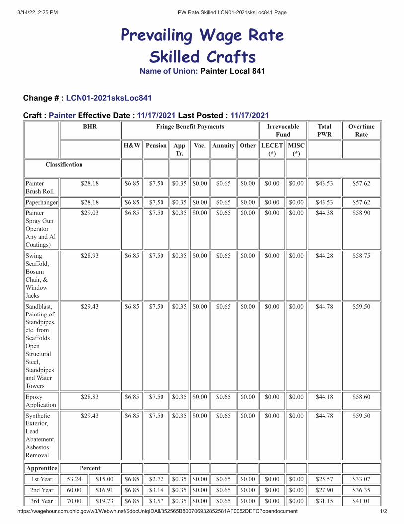
3/14/22, 2:25 PM PW Rate Skilled LCN01-2021sksLoc841 Page
https://wagehour.com.ohio.gov/w3/Webwh.nsf/$docUniqIDAll/852565B800706932852581AF0052DEFC?opendocument 1/2
Prevailing Wage Rate
Skilled CraftsName of Union: Painter Local 841
Change # : LCN01-2021sksLoc841
Craft : Painter Effective Date : 11/17/2021 Last Posted : 11/17/2021BHR Fringe Benefit Payments Irrevocable
FundTotalPWR
OvertimeRate
H&W Pension AppTr.
Vac. Annuity Other LECET(*)
MISC(*)
Classification
Painter
Brush Roll
$28.18 $6.85 $7.50 $0.35 $0.00 $0.65 $0.00 $0.00 $0.00 $43.53 $57.62
Paperhanger $28.18 $6.85 $7.50 $0.35 $0.00 $0.65 $0.00 $0.00 $0.00 $43.53 $57.62
Painter
Spray Gun
Operator
Any and Al
Coatings)
$29.03 $6.85 $7.50 $0.35 $0.00 $0.65 $0.00 $0.00 $0.00 $44.38 $58.90
Swing
Scaffold,
Bosum
Chair, &
Window
Jacks
$28.93 $6.85 $7.50 $0.35 $0.00 $0.65 $0.00 $0.00 $0.00 $44.28 $58.75
Sandblast,
Painting of
Standpipes,
etc. from
Scaffolds
Open
Structural
Steel,
Standpipes
and Water
Towers
$29.43 $6.85 $7.50 $0.35 $0.00 $0.65 $0.00 $0.00 $0.00 $44.78 $59.50
Epoxy
Application
$28.83 $6.85 $7.50 $0.35 $0.00 $0.65 $0.00 $0.00 $0.00 $44.18 $58.60
Synthetic
Exterior,
Lead
Abatement,
Asbestos
Removal
$29.43 $6.85 $7.50 $0.35 $0.00 $0.65 $0.00 $0.00 $0.00 $44.78 $59.50
Apprentice Percent
1st Year 53.24 $15.00 $6.85 $2.72 $0.35 $0.00 $0.65 $0.00 $0.00 $0.00 $25.57 $33.07
2nd Year 60.00 $16.91 $6.85 $3.14 $0.35 $0.00 $0.65 $0.00 $0.00 $0.00 $27.90 $36.35
3rd Year 70.00 $19.73 $6.85 $3.57 $0.35 $0.00 $0.65 $0.00 $0.00 $0.00 $31.15 $41.01
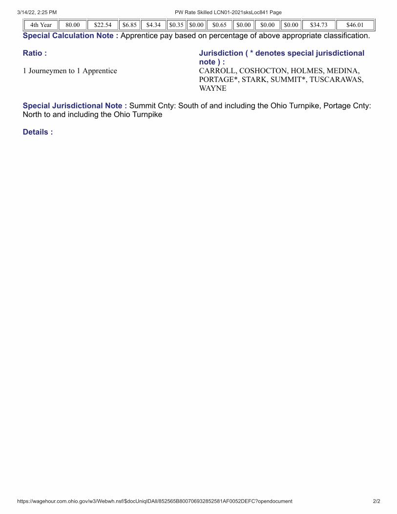
3/14/22, 2:25 PM PW Rate Skilled LCN01-2021sksLoc841 Page
https://wagehour.com.ohio.gov/w3/Webwh.nsf/$docUniqIDAll/852565B800706932852581AF0052DEFC?opendocument 2/2
4th Year 80.00 $22.54 $6.85 $4.34 $0.35 $0.00 $0.65 $0.00 $0.00 $0.00 $34.73 $46.01
Special Calculation Note : Apprentice pay based on percentage of above appropriate classification.
Ratio : Jurisdiction ( * denotes special jurisdictionalnote ) :
1 Journeymen to 1 Apprentice CARROLL, COSHOCTON, HOLMES, MEDINA,PORTAGE*, STARK, SUMMIT*, TUSCARAWAS,WAYNE
Special Jurisdictional Note : Summit Cnty: South of and including the Ohio Turnpike, Portage Cnty:North to and including the Ohio Turnpike
Details :
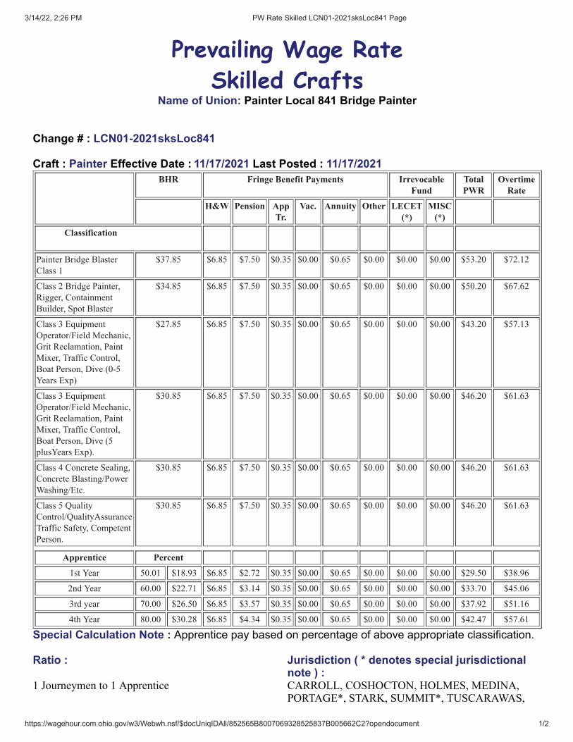
3/14/22, 2:26 PM PW Rate Skilled LCN01-2021sksLoc841 Page
https://wagehour.com.ohio.gov/w3/Webwh.nsf/$docUniqIDAll/852565B8007069328525837B005662C2?opendocument 1/2
Prevailing Wage Rate
Skilled CraftsName of Union: Painter Local 841 Bridge Painter
Change # : LCN01-2021sksLoc841
Craft : Painter Effective Date : 11/17/2021 Last Posted : 11/17/2021BHR Fringe Benefit Payments Irrevocable
FundTotalPWR
OvertimeRate
H&W Pension AppTr.
Vac. Annuity Other LECET(*)
MISC(*)
Classification
Painter Bridge Blaster
Class 1
$37.85 $6.85 $7.50 $0.35 $0.00 $0.65 $0.00 $0.00 $0.00 $53.20 $72.12
Class 2 Bridge Painter,
Rigger, Containment
Builder, Spot Blaster
$34.85 $6.85 $7.50 $0.35 $0.00 $0.65 $0.00 $0.00 $0.00 $50.20 $67.62
Class 3 Equipment
Operator/Field Mechanic,
Grit Reclamation, Paint
Mixer, Traffic Control,
Boat Person, Dive (0-5
Years Exp)
$27.85 $6.85 $7.50 $0.35 $0.00 $0.65 $0.00 $0.00 $0.00 $43.20 $57.13
Class 3 Equipment
Operator/Field Mechanic,
Grit Reclamation, Paint
Mixer, Traffic Control,
Boat Person, Dive (5
plusYears Exp).
$30.85 $6.85 $7.50 $0.35 $0.00 $0.65 $0.00 $0.00 $0.00 $46.20 $61.63
Class 4 Concrete Sealing,
Concrete Blasting/Power
Washing/Etc.
$30.85 $6.85 $7.50 $0.35 $0.00 $0.65 $0.00 $0.00 $0.00 $46.20 $61.63
Class 5 Quality
Control/QualityAssurance
Traffic Safety, Competent
Person.
$30.85 $6.85 $7.50 $0.35 $0.00 $0.65 $0.00 $0.00 $0.00 $46.20 $61.63
Apprentice Percent
1st Year 50.01 $18.93 $6.85 $2.72 $0.35 $0.00 $0.65 $0.00 $0.00 $0.00 $29.50 $38.96
2nd Year 60.00 $22.71 $6.85 $3.14 $0.35 $0.00 $0.65 $0.00 $0.00 $0.00 $33.70 $45.06
3rd year 70.00 $26.50 $6.85 $3.57 $0.35 $0.00 $0.65 $0.00 $0.00 $0.00 $37.92 $51.16
4th Year 80.00 $30.28 $6.85 $4.34 $0.35 $0.00 $0.65 $0.00 $0.00 $0.00 $42.47 $57.61
Special Calculation Note : Apprentice pay based on percentage of above appropriate classification.
Ratio : Jurisdiction ( * denotes special jurisdictionalnote ) :
1 Journeymen to 1 Apprentice CARROLL, COSHOCTON, HOLMES, MEDINA,PORTAGE*, STARK, SUMMIT*, TUSCARAWAS,

3/14/22, 2:26 PM PW Rate Skilled LCN01-2021sksLoc841 Page
https://wagehour.com.ohio.gov/w3/Webwh.nsf/$docUniqIDAll/852565B8007069328525837B005662C2?opendocument 2/2
WAYNE
Special Jurisdictional Note : Summit County: South of and including the Ohio Turnpike, PortageCounty: North to and including the Ohio Turnpike
Details :Class 1 – Abrasive blasting of any kindClass 2 – Bridge painting, coating applications of any kind. All steel surface preparation other than abrasiveblasting. All necessary rigging and containment building and all remedial/ spot blasting. Class 3 – Tend to all equipment including but not limited to abrasive blasting, power washing, spray painting,forklifts, hoists, truck, etc. Load and unloading trucks, handle materials, man safety boats, handle traffic control,clean up/ vacuum abrasive blast materials and related tasks. Class 4 – All aspects of concrete coating/ sealing including but not limited to preparation, containment, etc. Class 5 – Verify and record that all work is completed according to job specifications. Assure that all health andsafety standards are adhered to. Assure all traffic is safely handled.
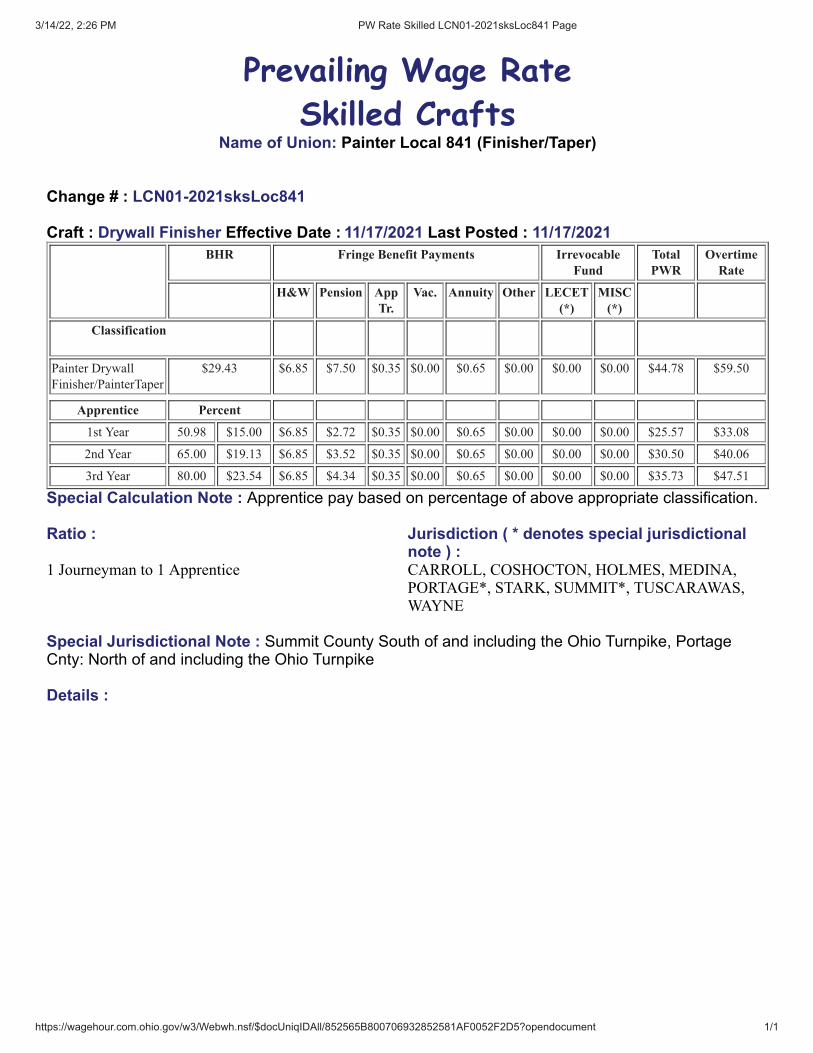
3/14/22, 2:26 PM PW Rate Skilled LCN01-2021sksLoc841 Page
https://wagehour.com.ohio.gov/w3/Webwh.nsf/$docUniqIDAll/852565B800706932852581AF0052F2D5?opendocument 1/1
Prevailing Wage Rate
Skilled CraftsName of Union: Painter Local 841 (Finisher/Taper)
Change # : LCN01-2021sksLoc841
Craft : Drywall Finisher Effective Date : 11/17/2021 Last Posted : 11/17/2021BHR Fringe Benefit Payments Irrevocable
FundTotalPWR
OvertimeRate
H&W Pension AppTr.
Vac. Annuity Other LECET(*)
MISC(*)
Classification
Painter Drywall
Finisher/PainterTaper
$29.43 $6.85 $7.50 $0.35 $0.00 $0.65 $0.00 $0.00 $0.00 $44.78 $59.50
Apprentice Percent
1st Year 50.98 $15.00 $6.85 $2.72 $0.35 $0.00 $0.65 $0.00 $0.00 $0.00 $25.57 $33.08
2nd Year 65.00 $19.13 $6.85 $3.52 $0.35 $0.00 $0.65 $0.00 $0.00 $0.00 $30.50 $40.06
3rd Year 80.00 $23.54 $6.85 $4.34 $0.35 $0.00 $0.65 $0.00 $0.00 $0.00 $35.73 $47.51
Special Calculation Note : Apprentice pay based on percentage of above appropriate classification.
Ratio : Jurisdiction ( * denotes special jurisdictionalnote ) :
1 Journeyman to 1 Apprentice CARROLL, COSHOCTON, HOLMES, MEDINA,PORTAGE*, STARK, SUMMIT*, TUSCARAWAS,WAYNE
Special Jurisdictional Note : Summit County South of and including the Ohio Turnpike, PortageCnty: North of and including the Ohio Turnpike
Details :
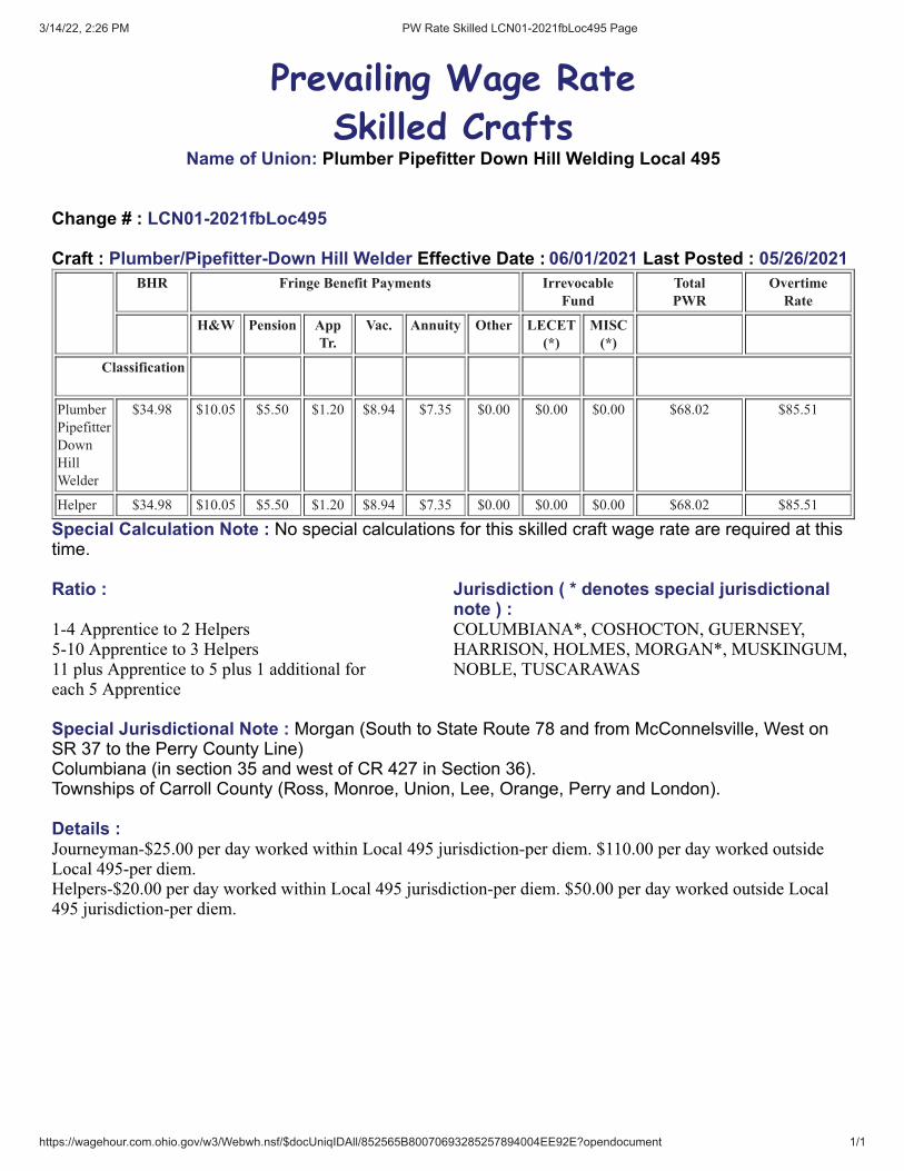
3/14/22, 2:26 PM PW Rate Skilled LCN01-2021fbLoc495 Page
https://wagehour.com.ohio.gov/w3/Webwh.nsf/$docUniqIDAll/852565B80070693285257894004EE92E?opendocument 1/1
Prevailing Wage Rate
Skilled CraftsName of Union: Plumber Pipefitter Down Hill Welding Local 495
Change # : LCN01-2021fbLoc495
Craft : Plumber/Pipefitter-Down Hill Welder Effective Date : 06/01/2021 Last Posted : 05/26/2021BHR Fringe Benefit Payments Irrevocable
FundTotalPWR
OvertimeRate
H&W Pension AppTr.
Vac. Annuity Other LECET(*)
MISC(*)
Classification
Plumber
Pipefitter
Down
Hill
Welder
$34.98 $10.05 $5.50 $1.20 $8.94 $7.35 $0.00 $0.00 $0.00 $68.02 $85.51
Helper $34.98 $10.05 $5.50 $1.20 $8.94 $7.35 $0.00 $0.00 $0.00 $68.02 $85.51
Special Calculation Note : No special calculations for this skilled craft wage rate are required at thistime.
Ratio : Jurisdiction ( * denotes special jurisdictionalnote ) :
1-4 Apprentice to 2 Helpers5-10 Apprentice to 3 Helpers 11 plus Apprentice to 5 plus 1 additional for each 5 Apprentice
COLUMBIANA*, COSHOCTON, GUERNSEY,HARRISON, HOLMES, MORGAN*, MUSKINGUM,NOBLE, TUSCARAWAS
Special Jurisdictional Note : Morgan (South to State Route 78 and from McConnelsville, West onSR 37 to the Perry County Line)Columbiana (in section 35 and west of CR 427 in Section 36). Townships of Carroll County (Ross, Monroe, Union, Lee, Orange, Perry and London).
Details :Journeyman-$25.00 per day worked within Local 495 jurisdiction-per diem. $110.00 per day worked outsideLocal 495-per diem.Helpers-$20.00 per day worked within Local 495 jurisdiction-per diem. $50.00 per day worked outside Local495 jurisdiction-per diem.

3/14/22, 2:26 PM PW Rate Skilled LCN01-2021fbLoc495 Page
https://wagehour.com.ohio.gov/w3/Webwh.nsf/$docUniqIDAll/852565B80070693285257E5F0067DFDD?opendocument 1/1
Prevailing Wage Rate
Skilled CraftsName of Union: Plumber Pipefitter Local 495
Change # : LCN01-2021fbLoc495
Craft : Plumber/Pipefitter Effective Date : 06/01/2021 Last Posted : 05/26/2021BHR Fringe Benefit Payments Irrevocable
FundTotalPWR
OvertimeRate
H&W Pension AppTr.
Vac. Annuity Other LECET(*)
MISC(*)
Classification
Plumber/
Piperfitter
Fabrication
Shop Fitter
and Welder
$32.00 $10.05 $5.10 $1.20 $10.00 $6.20 $0.00 $0.00 $0.00 $64.55 $80.55
Apprentice Percent
1st 6
months
50.00 $16.00 $10.05 $0.00 $1.20 $10.00 $0.00 $0.00 $0.00 $0.00 $37.25 $45.25
2nd 6
months
50.00 $16.00 $10.05 $5.10 $1.20 $10.00 $6.20 $0.00 $0.00 $0.00 $48.55 $56.55
2nd Year 60.00 $19.20 $10.05 $5.10 $1.20 $10.00 $6.20 $0.00 $0.00 $0.00 $51.75 $61.35
3rd year 70.00 $22.40 $10.05 $5.10 $1.20 $10.00 $6.20 $0.00 $0.00 $0.00 $54.95 $66.15
4th Year 80.00 $25.60 $10.05 $5.10 $1.20 $10.00 $6.20 $0.00 $0.00 $0.00 $58.15 $70.95
5th Year 90.00 $28.80 $10.05 $5.10 $1.20 $10.00 $6.20 $0.00 $0.00 $0.00 $61.35 $75.75
Special Calculation Note :
Ratio : Jurisdiction ( * denotes special jurisdictionalnote ) :
1 Journeyman to 1 Apprentice2 Journeyman to 1 Apprentices3 Journeyman to 1 Apprentices
CARROLL*, COLUMBIANA*, COSHOCTON,GUERNSEY, HARRISON, HOLMES, JEFFERSON,MORGAN*, MUSKINGUM, NOBLE,TUSCARAWAS
Special Jurisdictional Note : Morgan (South to State Route 78 and from McConnelsville, West onSR 37 to the Perry County Line)Columbiana (in section 35 and west of CR 427 in Section 36). Townships of Carroll County (Ross, Monroe, Union, Lee, Orange, Perry and London).
Details :

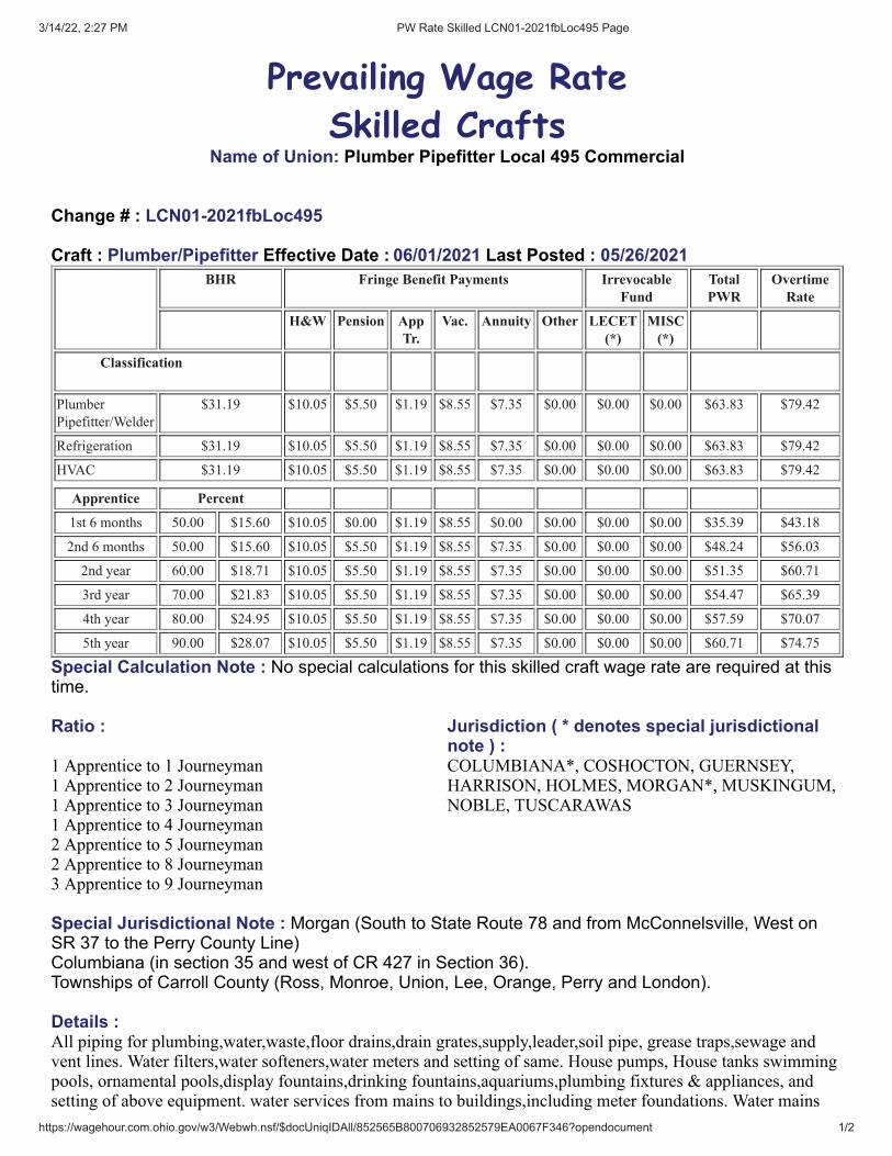
3/14/22, 2:27 PM PW Rate Skilled LCN01-2021fbLoc495 Page
https://wagehour.com.ohio.gov/w3/Webwh.nsf/$docUniqIDAll/852565B800706932852579EA0067F346?opendocument 1/2
Prevailing Wage Rate
Skilled CraftsName of Union: Plumber Pipefitter Local 495 Commercial
Change # : LCN01-2021fbLoc495
Craft : Plumber/Pipefitter Effective Date : 06/01/2021 Last Posted : 05/26/2021BHR Fringe Benefit Payments Irrevocable
FundTotalPWR
OvertimeRate
H&W Pension AppTr.
Vac. Annuity Other LECET(*)
MISC(*)
Classification
Plumber
Pipefitter/Welder
$31.19 $10.05 $5.50 $1.19 $8.55 $7.35 $0.00 $0.00 $0.00 $63.83 $79.42
Refrigeration $31.19 $10.05 $5.50 $1.19 $8.55 $7.35 $0.00 $0.00 $0.00 $63.83 $79.42
HVAC $31.19 $10.05 $5.50 $1.19 $8.55 $7.35 $0.00 $0.00 $0.00 $63.83 $79.42
Apprentice Percent
1st 6 months 50.00 $15.60 $10.05 $0.00 $1.19 $8.55 $0.00 $0.00 $0.00 $0.00 $35.39 $43.18
2nd 6 months 50.00 $15.60 $10.05 $5.50 $1.19 $8.55 $7.35 $0.00 $0.00 $0.00 $48.24 $56.03
2nd year 60.00 $18.71 $10.05 $5.50 $1.19 $8.55 $7.35 $0.00 $0.00 $0.00 $51.35 $60.71
3rd year 70.00 $21.83 $10.05 $5.50 $1.19 $8.55 $7.35 $0.00 $0.00 $0.00 $54.47 $65.39
4th year 80.00 $24.95 $10.05 $5.50 $1.19 $8.55 $7.35 $0.00 $0.00 $0.00 $57.59 $70.07
5th year 90.00 $28.07 $10.05 $5.50 $1.19 $8.55 $7.35 $0.00 $0.00 $0.00 $60.71 $74.75
Special Calculation Note : No special calculations for this skilled craft wage rate are required at thistime.
Ratio : Jurisdiction ( * denotes special jurisdictionalnote ) :
1 Apprentice to 1 Journeyman1 Apprentice to 2 Journeyman 1 Apprentice to 3 Journeyman1 Apprentice to 4 Journeyman2 Apprentice to 5 Journeyman2 Apprentice to 8 Journeyman3 Apprentice to 9 Journeyman
COLUMBIANA*, COSHOCTON, GUERNSEY,HARRISON, HOLMES, MORGAN*, MUSKINGUM,NOBLE, TUSCARAWAS
Special Jurisdictional Note : Morgan (South to State Route 78 and from McConnelsville, West onSR 37 to the Perry County Line)Columbiana (in section 35 and west of CR 427 in Section 36). Townships of Carroll County (Ross, Monroe, Union, Lee, Orange, Perry and London).
Details :All piping for plumbing,water,waste,floor drains,drain grates,supply,leader,soil pipe, grease traps,sewage andvent lines. Water filters,water softeners,water meters and setting of same. House pumps, House tanks swimmingpools, ornamental pools,display fountains,drinking fountains,aquariums,plumbing fixtures & appliances, andsetting of above equipment. water services from mains to buildings,including meter foundations. Water mains

3/14/22, 2:27 PM PW Rate Skilled LCN01-2021fbLoc495 Page
https://wagehour.com.ohio.gov/w3/Webwh.nsf/$docUniqIDAll/852565B800706932852579EA0067F346?opendocument 2/2
including fire hydrants. Down spouts and drainage areas catch basins,manholes,drains,gravel basins,storm watersewers,septic tanks,cesspools,water storage tanks.All lawn sprinkler work including piping,fittings,and heads.
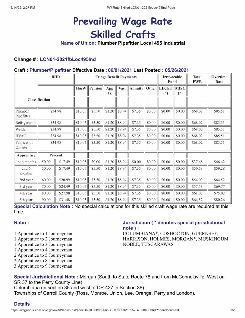
3/14/22, 2:27 PM PW Rate Skilled LCN01-2021fbLoc495Ind Page
https://wagehour.com.ohio.gov/w3/Webwh.nsf/$docUniqIDAll/852565B80070693285257B730060336B?opendocument 1/2
Prevailing Wage Rate
Skilled CraftsName of Union: Plumber Pipefitter Local 495 Industrial
Change # : LCN01-2021fbLoc495Ind
Craft : Plumber/Pipefitter Effective Date : 06/01/2021 Last Posted : 05/26/2021BHR Fringe Benefit Payments Irrevocable
FundTotalPWR
OvertimeRate
H&W Pension AppTr.
Vac. Annuity Other LECET(*)
MISC(*)
Classification
Plumber
Pipefitter
$34.98 $10.05 $5.50 $1.20 $8.94 $7.35 $0.00 $0.00 $0.00 $68.02 $85.51
Refrigeration $34.98 $10.05 $5.50 $1.20 $8.94 $7.35 $0.00 $0.00 $0.00 $68.02 $85.51
Welder $34.98 $10.05 $5.50 $1.20 $8.94 $7.35 $0.00 $0.00 $0.00 $68.02 $85.51
HVAC $34.98 $10.05 $5.50 $1.20 $8.94 $7.35 $0.00 $0.00 $0.00 $68.02 $85.51
Fabrication
On-site
$34.98 $10.05 $5.50 $1.20 $8.94 $7.35 $0.00 $0.00 $0.00 $68.02 $85.51
Apprentice Percent
1st 6 months 50.00 $17.49 $10.05 $0.00 $1.20 $8.94 $0.00 $0.00 $0.00 $0.00 $37.68 $46.42
2nd 6
months
50.00 $17.49 $10.05 $5.50 $1.20 $8.94 $7.35 $0.00 $0.00 $0.00 $50.53 $59.28
2nd year 60.00 $20.99 $10.05 $5.50 $1.20 $8.94 $7.35 $0.00 $0.00 $0.00 $54.03 $64.52
3rd year 70.00 $24.49 $10.05 $5.50 $1.20 $8.94 $7.35 $0.00 $0.00 $0.00 $57.53 $69.77
4th year 80.00 $27.98 $10.05 $5.50 $1.20 $8.94 $7.35 $0.00 $0.00 $0.00 $61.02 $75.02
5th year 90.00 $31.48 $10.05 $5.50 $1.20 $8.94 $7.35 $0.00 $0.00 $0.00 $64.52 $80.26
Special Calculation Note : No special calculations for this skilled craft wage rate are required at thistime.
Ratio : Jurisdiction ( * denotes special jurisdictionalnote ) :
1 Apprentice to 1 Journeyman1 Apprentice to 2 Journeyman 1 Apprentice to 3 Journeyman1 Apprentice to 4 Journeyman2 Apprentice to 5 Journeyman2 Apprentice to 8 Journeyman3 Apprentice to 9 Journeyman
COLUMBIANA*, COSHOCTON, GUERNSEY,HARRISON, HOLMES, MORGAN*, MUSKINGUM,NOBLE, TUSCARAWAS
Special Jurisdictional Note : Morgan (South to State Route 78 and from McConnelsville, West onSR 37 to the Perry County Line)Columbiana (in section 35 and west of CR 427 in Section 36). Townships of Carroll County (Ross, Monroe, Union, Lee, Orange, Perry and London).
Details :

3/14/22, 2:27 PM PW Rate Skilled LCN01-2021fbLoc495Ind Page
https://wagehour.com.ohio.gov/w3/Webwh.nsf/$docUniqIDAll/852565B80070693285257B730060336B?opendocument 2/2

3/14/22, 2:27 PM PW Rate Skilled LCN01-2021fbLoc495 Page
https://wagehour.com.ohio.gov/w3/Webwh.nsf/$docUniqIDAll/852565B80070693285257BB80060C877?opendocument 1/2
Prevailing Wage Rate
Skilled CraftsName of Union: Plumber Pipefitter Local 495 Light Commercial
Change # : LCN01-2021fbLoc495
Craft : Plumber/Pipefitter Effective Date : 06/01/2021 Last Posted : 05/26/2021BHR Fringe Benefit Payments Irrevocable
FundTotalPWR
OvertimeRate
H&W Pension AppTr.
Vac. Annuity Other LECET(*)
MISC(*)
Classification
Plumber
Pipefitter
$30.97 $10.05 $3.30 $1.15 $0.00 $4.85 $0.00 $0.00 $0.00 $50.32 $65.80
Tradesman $17.48 $10.05 $1.90 $0.00 $0.00 $0.00 $0.00 $0.00 $0.00 $29.43 $38.17
Tradesman
for1st 6
months
Probationary
$10.00 $0.00 $0.00 $0.00 $0.00 $0.00 $0.00 $0.00 $0.00 $10.00 $15.00
Apprentice Percent
1st 6 months 50.38 $15.60 $10.05 $0.00 $1.15 $0.00 $0.00 $0.00 $0.00 $0.00 $26.80 $34.60
2nd 6
months
50.38 $15.60 $10.05 $3.30 $1.15 $0.00 $4.85 $0.00 $0.00 $0.00 $34.95 $42.75
2rd Year 60.40 $18.71 $10.05 $3.30 $1.15 $0.00 $4.85 $0.00 $0.00 $0.00 $38.06 $47.41
3th Year 70.48 $21.83 $10.05 $3.30 $1.15 $0.00 $4.85 $0.00 $0.00 $0.00 $41.18 $52.09
4th Year 80.55 $24.95 $10.05 $3.30 $1.15 $0.00 $4.85 $0.00 $0.00 $0.00 $44.30 $56.77
5th Year 90.65 $28.07 $10.05 $3.30 $1.15 $0.00 $4.85 $0.00 $0.00 $0.00 $47.42 $61.46
Special Calculation Note : Please See Details for Description of Light Commercial Work
Ratio : Jurisdiction ( * denotes special jurisdictionalnote ) :
1-3Journeyman to 1 Apprentice CARROLL*, COLUMBIANA*, COSHOCTON,GUERNSEY, HARRISON, HOLMES, JEFFERSON,MORGAN*, MUSKINGUM, NOBLE,TUSCARAWAS
Special Jurisdictional Note : Morgan (South to State Route 78 and from McConnelsville, West onSR 37 to the Perry County Line)Columbiana (in section 35 and west of CR 427 in Section 36). Townships of Carroll County (Ross, Monroe, Union, Lee, Orange, Perry and London).
Details :Light Commercial Installation and Service Per Building or Structure Shall NOT Exceed the followingLimitations
A. Heating Systems up to 2,000.00 BTU Input for the building or structure

3/14/22, 2:27 PM PW Rate Skilled LCN01-2021fbLoc495 Page
https://wagehour.com.ohio.gov/w3/Webwh.nsf/$docUniqIDAll/852565B80070693285257BB80060C877?opendocument 2/2
B. Air Conditioning Single Systems Up to 50 TonsC. Commercial Installation of refrigeration Units, Meat Cases, Florist Boxes, Bottle Coolers, Food Freezers,Water Coolers, Units up to 35 H.P.D. Plumbing Installation not to Exceed 35 Fixtures, (Excluding roof and Floor Drains).E. Service and Maintenance of All Mechanical Equipment as Set Forth in the Installation WorkF. Installation of Sewer and Water, or other Utilities Applicable to All Site Preparation for BuildingG. Driving of Company Trucks to perform all Functions of Installation and Service. Any Materials Delivered toa Building Trades Job Will be Unloaded by Building Trades Journeymen.H. Any Work Done on the Property or Premises, Either New or Remodeling Work of Industrial, Production orManufacturing Complexes Will Be Done Under Building Trades Agreement
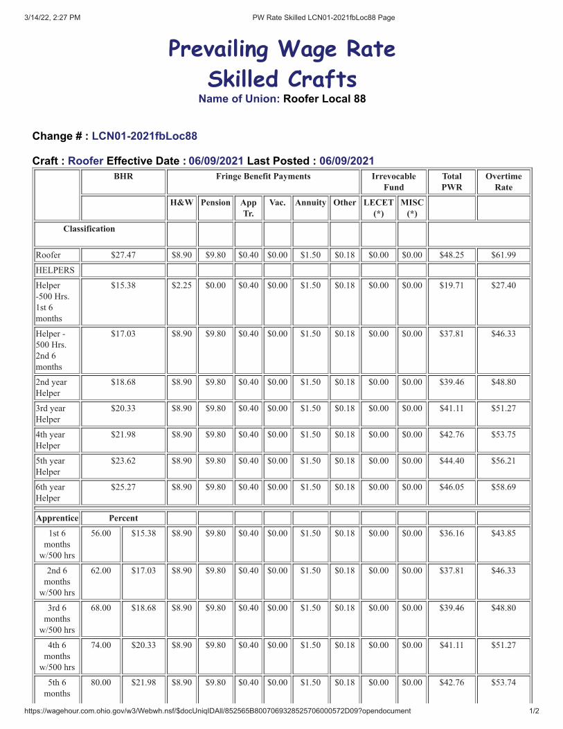
3/14/22, 2:27 PM PW Rate Skilled LCN01-2021fbLoc88 Page
https://wagehour.com.ohio.gov/w3/Webwh.nsf/$docUniqIDAll/852565B8007069328525706000572D09?opendocument 1/2
Prevailing Wage Rate
Skilled CraftsName of Union: Roofer Local 88
Change # : LCN01-2021fbLoc88
Craft : Roofer Effective Date : 06/09/2021 Last Posted : 06/09/2021BHR Fringe Benefit Payments Irrevocable
FundTotalPWR
OvertimeRate
H&W Pension AppTr.
Vac. Annuity Other LECET(*)
MISC(*)
Classification
Roofer $27.47 $8.90 $9.80 $0.40 $0.00 $1.50 $0.18 $0.00 $0.00 $48.25 $61.99
HELPERS
Helper
-500 Hrs.
1st 6
months
$15.38 $2.25 $0.00 $0.40 $0.00 $1.50 $0.18 $0.00 $0.00 $19.71 $27.40
Helper -
500 Hrs.
2nd 6
months
$17.03 $8.90 $9.80 $0.40 $0.00 $1.50 $0.18 $0.00 $0.00 $37.81 $46.33
2nd year
Helper
$18.68 $8.90 $9.80 $0.40 $0.00 $1.50 $0.18 $0.00 $0.00 $39.46 $48.80
3rd year
Helper
$20.33 $8.90 $9.80 $0.40 $0.00 $1.50 $0.18 $0.00 $0.00 $41.11 $51.27
4th year
Helper
$21.98 $8.90 $9.80 $0.40 $0.00 $1.50 $0.18 $0.00 $0.00 $42.76 $53.75
5th year
Helper
$23.62 $8.90 $9.80 $0.40 $0.00 $1.50 $0.18 $0.00 $0.00 $44.40 $56.21
6th year
Helper
$25.27 $8.90 $9.80 $0.40 $0.00 $1.50 $0.18 $0.00 $0.00 $46.05 $58.69
Apprentice Percent
1st 6
months
w/500 hrs
56.00 $15.38 $8.90 $9.80 $0.40 $0.00 $1.50 $0.18 $0.00 $0.00 $36.16 $43.85
2nd 6
months
w/500 hrs
62.00 $17.03 $8.90 $9.80 $0.40 $0.00 $1.50 $0.18 $0.00 $0.00 $37.81 $46.33
3rd 6
months
w/500 hrs
68.00 $18.68 $8.90 $9.80 $0.40 $0.00 $1.50 $0.18 $0.00 $0.00 $39.46 $48.80
4th 6
months
w/500 hrs
74.00 $20.33 $8.90 $9.80 $0.40 $0.00 $1.50 $0.18 $0.00 $0.00 $41.11 $51.27
5th 6
months
80.00 $21.98 $8.90 $9.80 $0.40 $0.00 $1.50 $0.18 $0.00 $0.00 $42.76 $53.74

3/14/22, 2:27 PM PW Rate Skilled LCN01-2021fbLoc88 Page
https://wagehour.com.ohio.gov/w3/Webwh.nsf/$docUniqIDAll/852565B8007069328525706000572D09?opendocument 2/2
w/500 hrs
6th 6
months
w/500 hrs
86.00 $23.62 $8.90 $9.80 $0.40 $0.00 $1.50 $0.18 $0.00 $0.00 $44.40 $56.22
7th 6
months
w/500 hrs
92.00 $25.27 $8.90 $9.80 $0.40 $0.00 $1.50 $0.18 $0.00 $0.00 $46.05 $58.69
Special Calculation Note : Roofers working in any form of coal tar pitch, whether hot or cold,installing and/or removing will be paid $.25 more per hour. Other $0.18 is for C.I.D.B.
Ratio : Jurisdiction ( * denotes special jurisdictionalnote ) :
No helper shall be used on any one job unless 1Journeymen, and 1 Apprentices are working on said job.One(1) Journeymen to One (1) Apprentice to One (1)Helper
ASHLAND, CARROLL, COSHOCTON,CRAWFORD, HOLMES, HURON, LORAIN*,MEDINA, PORTAGE, RICHLAND, STARK,SUMMIT, TUSCARAWAS, WAYNE
Special Jurisdictional Note : In Lorain County (South of the Turnpike)
Details :
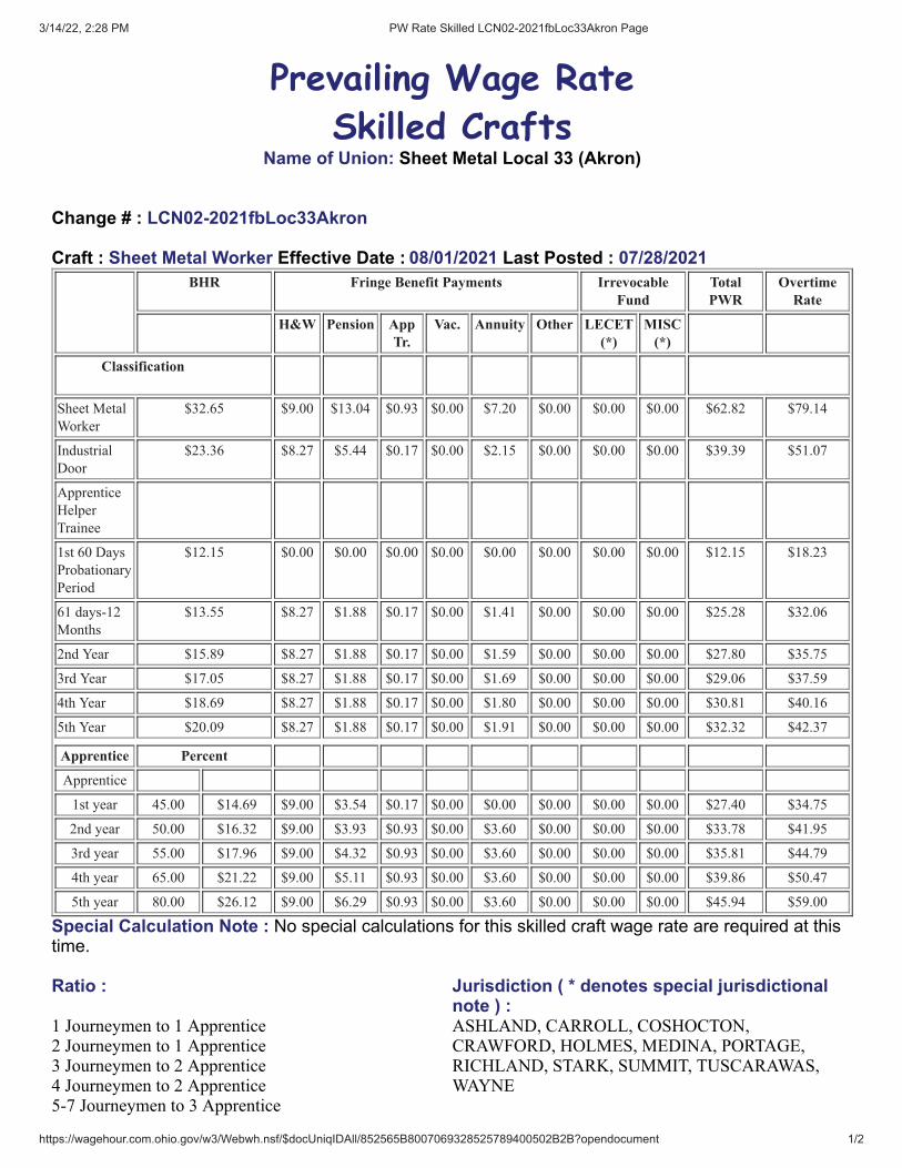
3/14/22, 2:28 PM PW Rate Skilled LCN02-2021fbLoc33Akron Page
https://wagehour.com.ohio.gov/w3/Webwh.nsf/$docUniqIDAll/852565B8007069328525789400502B2B?opendocument 1/2
Prevailing Wage Rate
Skilled CraftsName of Union: Sheet Metal Local 33 (Akron)
Change # : LCN02-2021fbLoc33Akron
Craft : Sheet Metal Worker Effective Date : 08/01/2021 Last Posted : 07/28/2021BHR Fringe Benefit Payments Irrevocable
FundTotalPWR
OvertimeRate
H&W Pension AppTr.
Vac. Annuity Other LECET(*)
MISC(*)
Classification
Sheet Metal
Worker
$32.65 $9.00 $13.04 $0.93 $0.00 $7.20 $0.00 $0.00 $0.00 $62.82 $79.14
Industrial
Door
$23.36 $8.27 $5.44 $0.17 $0.00 $2.15 $0.00 $0.00 $0.00 $39.39 $51.07
Apprentice
Helper
Trainee
1st 60 Days
Probationary
Period
$12.15 $0.00 $0.00 $0.00 $0.00 $0.00 $0.00 $0.00 $0.00 $12.15 $18.23
61 days-12
Months
$13.55 $8.27 $1.88 $0.17 $0.00 $1.41 $0.00 $0.00 $0.00 $25.28 $32.06
2nd Year $15.89 $8.27 $1.88 $0.17 $0.00 $1.59 $0.00 $0.00 $0.00 $27.80 $35.75
3rd Year $17.05 $8.27 $1.88 $0.17 $0.00 $1.69 $0.00 $0.00 $0.00 $29.06 $37.59
4th Year $18.69 $8.27 $1.88 $0.17 $0.00 $1.80 $0.00 $0.00 $0.00 $30.81 $40.16
5th Year $20.09 $8.27 $1.88 $0.17 $0.00 $1.91 $0.00 $0.00 $0.00 $32.32 $42.37
Apprentice Percent
Apprentice
1st year 45.00 $14.69 $9.00 $3.54 $0.17 $0.00 $0.00 $0.00 $0.00 $0.00 $27.40 $34.75
2nd year 50.00 $16.32 $9.00 $3.93 $0.93 $0.00 $3.60 $0.00 $0.00 $0.00 $33.78 $41.95
3rd year 55.00 $17.96 $9.00 $4.32 $0.93 $0.00 $3.60 $0.00 $0.00 $0.00 $35.81 $44.79
4th year 65.00 $21.22 $9.00 $5.11 $0.93 $0.00 $3.60 $0.00 $0.00 $0.00 $39.86 $50.47
5th year 80.00 $26.12 $9.00 $6.29 $0.93 $0.00 $3.60 $0.00 $0.00 $0.00 $45.94 $59.00
Special Calculation Note : No special calculations for this skilled craft wage rate are required at thistime.
Ratio : Jurisdiction ( * denotes special jurisdictionalnote ) :
1 Journeymen to 1 Apprentice2 Journeymen to 1 Apprentice3 Journeymen to 2 Apprentice4 Journeymen to 2 Apprentice5-7 Journeymen to 3 Apprentice
ASHLAND, CARROLL, COSHOCTON,CRAWFORD, HOLMES, MEDINA, PORTAGE,RICHLAND, STARK, SUMMIT, TUSCARAWAS,WAYNE

3/14/22, 2:28 PM PW Rate Skilled LCN02-2021fbLoc33Akron Page
https://wagehour.com.ohio.gov/w3/Webwh.nsf/$docUniqIDAll/852565B8007069328525789400502B2B?opendocument 2/2
8-10 Journeymen to 4 Apprentice11-13 Journeymen to 5 Apprentice14, 15 Journeymen to 6 Apprenticeand maintaining a three to one apprentice ratiothereafter.
Special Jurisdictional Note :
Details :Scope of Work: This Agreement covers the rates of pay and conditions of employment of all employees of theEmployer engaged in, but not limited to, the a) manufacture, fabrication, assembling, handling, erection,installation, dismantling, conditioning, adjustment, alteration, repairing and servicing of all ferrous or non-ferrous metal work and all other materials used in lieu thereof and of all HVAC systems, air-veyor systems,exhaust systems, and air handling systems regardless of material used, including the setting of all equipment andall reinforcements in connection therewith; (b) all lagging over insulation and all duct-lining; (c) testing,servicing, and balancing of all air-handling equipment and duct work; (d) the preparation of all shop and fieldsketches, whether manually drawn or computer assisted, used in fabrication and erection, including those takenfrom original architectural and engineering drawings or sketches, and (e) metal roofing; and (f) all other workincluded in the jurisdictional claims of Sheet Metal Worker's International Association.Industrial Door-Installation and service of overhead doors roll up doors, docks and dock leveling.

3/14/22, 2:28 PM PW Rate Skilled LCN01-2022sksLoc669 Page
https://wagehour.com.ohio.gov/w3/Webwh.nsf/$docUniqIDAll/852565B800706932852573300068D774?opendocument 1/2
Prevailing Wage Rate
Skilled CraftsName of Union: Sprinkler Fitter Local 669
Change # : LCN01-2022sksLoc669
Craft : Sprinkler Fitter Effective Date : 01/05/2022 Last Posted : 01/05/2022BHR Fringe Benefit Payments Irrevocable
FundTotalPWR
OvertimeRate
H&W Pension AppTr.
Vac. Annuity Other LECET(*)
MISC(*)
Classification
Sprinkler
Fitter
$41.87 $10.99 $7.10 $0.52 $0.00 $5.12 $0.00 $0.00 $0.00 $65.60 $86.53
ApprenticeIndenturedafter April
1, 2013
Percent
ClLASS 1 45.00 $18.84 $7.85 $0.00 $0.52 $0.00 $0.00 $0.00 $0.00 $0.00 $27.21 $36.63
CLASS 2 50.02 $20.94 $7.85 $0.00 $0.52 $0.00 $0.00 $0.00 $0.00 $0.00 $29.31 $39.79
CLASS 3 54.40 $22.78 $10.99 $7.10 $0.52 $0.00 $1.15 $0.00 $0.00 $0.00 $42.54 $53.93
CLASS 4 59.40 $24.87 $10.99 $7.10 $0.52 $0.00 $1.15 $0.00 $0.00 $0.00 $44.63 $57.07
CLASS 5 64.42 $26.97 $10.99 $7.10 $0.52 $0.00 $1.40 $0.00 $0.00 $0.00 $46.98 $60.47
CLASS 6 69.41 $29.06 $10.99 $7.10 $0.52 $0.00 $1.40 $0.00 $0.00 $0.00 $49.07 $63.60
CLASS 7 74.40 $31.15 $10.99 $7.10 $0.52 $0.00 $1.40 $0.00 $0.00 $0.00 $51.16 $66.74
CLASS 8 79.42 $33.25 $10.99 $7.10 $0.52 $0.00 $1.40 $0.00 $0.00 $0.00 $53.26 $69.89
CLASS 9 84.40 $35.34 $10.99 $7.10 $0.52 $0.00 $1.40 $0.00 $0.00 $0.00 $55.35 $73.02
CLASS 10 89.40 $37.43 $10.99 $7.10 $0.52 $0.00 $1.40 $0.00 $0.00 $0.00 $57.44 $76.16
Special Calculation Note :
Ratio : Jurisdiction ( * denotes special jurisdictionalnote ) :
1 Journeyman to 1 Apprentice ADAMS, ALLEN, ASHLAND, ASHTABULA,ATHENS, AUGLAIZE, BELMONT, BROWN,BUTLER, CARROLL, CHAMPAIGN, CLARK,CLERMONT, CLINTON, COLUMBIANA,COSHOCTON, CRAWFORD, DARKE, DEFIANCE,DELAWARE, ERIE, FAIRFIELD, FAYETTE,FRANKLIN, FULTON, GALLIA, GREENE,GUERNSEY, HAMILTON, HANCOCK, HARDIN,HARRISON, HENRY, HIGHLAND, HOCKING,HOLMES, HURON, JACKSON, JEFFERSON,KNOX, LAWRENCE, LICKING, LOGAN, LUCAS,MADISON, MAHONING, MARION, MEDINA,MEIGS, MERCER, MIAMI, MONROE,MONTGOMERY, MORGAN, MORROW,
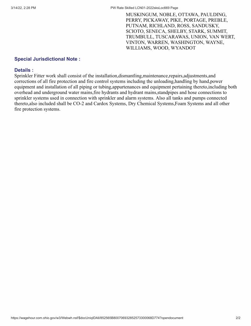
3/14/22, 2:28 PM PW Rate Skilled LCN01-2022sksLoc669 Page
https://wagehour.com.ohio.gov/w3/Webwh.nsf/$docUniqIDAll/852565B800706932852573300068D774?opendocument 2/2
MUSKINGUM, NOBLE, OTTAWA, PAULDING,PERRY, PICKAWAY, PIKE, PORTAGE, PREBLE,PUTNAM, RICHLAND, ROSS, SANDUSKY,SCIOTO, SENECA, SHELBY, STARK, SUMMIT,TRUMBULL, TUSCARAWAS, UNION, VAN WERT,VINTON, WARREN, WASHINGTON, WAYNE,WILLIAMS, WOOD, WYANDOT
Special Jurisdictional Note :
Details :Sprinkler Fitter work shall consist of the installation,dismantling,maintenance,repairs,adjustments,andcorrections of all fire protection and fire control systems including the unloading,handling by hand,powerequipment and installation of all piping or tubing,appurtenances and equipment pertaining thereto,including bothoverhead and underground water mains,fire hydrants and hydrant mains,standpipes and hose connections tosprinkler systems used in connection with sprinkler and alarm systems. Also all tanks and pumps connectedthereto,also included shall be CO-2 and Cardox Systems, Dry Chemical Systems,Foam Systems and all otherfire protection systems.
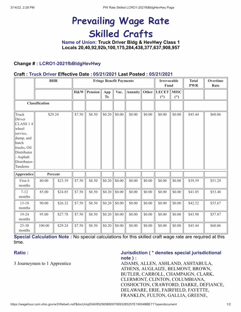
3/14/22, 2:28 PM PW Rate Skilled LCRO1-2021fbBldgHevHwy Page
https://wagehour.com.ohio.gov/w3/Webwh.nsf/$docUniqIDAll/852565B80070693285257E19004BBE71?opendocument 1/2
Prevailing Wage Rate
Skilled CraftsName of Union: Truck Driver Bldg & HevHwy Class 1Locals 20,40,92,92b,100,175,284,438,377,637,908,957
Change # : LCRO1-2021fbBldgHevHwy
Craft : Truck Driver Effective Date : 05/21/2021 Last Posted : 05/21/2021BHR Fringe Benefit Payments Irrevocable
FundTotalPWR
OvertimeRate
H&W Pension AppTr.
Vac. Annuity Other LECET(*)
MISC(*)
Classification
Truck
Driver
CLASS 1 4
wheel
service,
dump, and
batch
trucks, Oil
Distributor
- Asphalt
Distributor-
Tandems
$29.24 $7.50 $8.50 $0.20 $0.00 $0.00 $0.00 $0.00 $0.00 $45.44 $60.06
Apprentice Percent
First 6
months
80.00 $23.39 $7.50 $8.50 $0.20 $0.00 $0.00 $0.00 $0.00 $0.00 $39.59 $51.29
7-12
months
85.00 $24.85 $7.50 $8.50 $0.20 $0.00 $0.00 $0.00 $0.00 $0.00 $41.05 $53.48
13-18
months
90.00 $26.32 $7.50 $8.50 $0.20 $0.00 $0.00 $0.00 $0.00 $0.00 $42.52 $55.67
19-24
months
95.00 $27.78 $7.50 $8.50 $0.20 $0.00 $0.00 $0.00 $0.00 $0.00 $43.98 $57.87
25-30
months
100.00 $29.24 $7.50 $8.50 $0.20 $0.00 $0.00 $0.00 $0.00 $0.00 $45.44 $60.06
Special Calculation Note : No special calculations for this skilled craft wage rate are required at thistime.
Ratio : Jurisdiction ( * denotes special jurisdictionalnote ) :
3 Journeymen to 1 Apprentice ADAMS, ALLEN, ASHLAND, ASHTABULA,ATHENS, AUGLAIZE, BELMONT, BROWN,BUTLER, CARROLL, CHAMPAIGN, CLARK,CLERMONT, CLINTON, COLUMBIANA,COSHOCTON, CRAWFORD, DARKE, DEFIANCE,DELAWARE, ERIE, FAIRFIELD, FAYETTE,FRANKLIN, FULTON, GALLIA, GREENE,

3/14/22, 2:28 PM PW Rate Skilled LCRO1-2021fbBldgHevHwy Page
https://wagehour.com.ohio.gov/w3/Webwh.nsf/$docUniqIDAll/852565B80070693285257E19004BBE71?opendocument 2/2
GUERNSEY, HAMILTON, HANCOCK, HARDIN,HARRISON, HENRY, HIGHLAND, HOCKING,HOLMES, HURON, JACKSON, JEFFERSON,KNOX, LAWRENCE, LICKING, LOGAN, LORAIN,LUCAS, MADISON, MAHONING, MARION,MEDINA, MEIGS, MERCER, MIAMI, MONROE,MONTGOMERY, MORGAN, MORROW,MUSKINGUM, NOBLE, OTTAWA, PAULDING,PERRY, PICKAWAY, PIKE, PORTAGE, PREBLE,PUTNAM, RICHLAND, ROSS, SANDUSKY,SCIOTO, SENECA, SHELBY, STARK, SUMMIT,TRUMBULL, TUSCARAWAS, UNION, VAN WERT,VINTON, WARREN, WASHINGTON, WAYNE,WILLIAMS, WOOD, WYANDOT
Special Jurisdictional Note :
Details :** Asphalt - Oil spray bar man when operating from cab shall receive $0.20 cents per hour above their BasicHourly Rate.

3/14/22, 2:28 PM PW Rate Skilled LCRO1-2021fbBldgHevHwy Page
https://wagehour.com.ohio.gov/w3/Webwh.nsf/$docUniqIDAll/852565B800706932852573140053CFF2?opendocument 1/2
Prevailing Wage Rate
Skilled CraftsName of Union: Truck Driver Bldg & HevHwy Class 2Locals 20,40,92,92b,100,175,284,438,377,637,908,957
Change # : LCRO1-2021fbBldgHevHwy
Craft : Truck Driver Effective Date : 05/21/2021 Last Posted : 05/21/2021BHR Fringe Benefit Payments Irrevocable
FundTotalPWR
OvertimeRate
H&W Pension AppTr.
Vac. Annuity Other LECET(*)
MISC(*)
Classification
Truck Driver CLASS 2
Tractor Trailer-Semi
Tractor Trucks-Pole
Trailers-Ready Mix
Trucks-Fuel Trucks-
Asphalt-Oil Spray bar
men- 5 Axle & Over -
Belly Dumps-End
Dumps-Articulated
Dump Trucks- Low
boys-Heavy duty
Equipment(irrespective
of load carried) when
used exclusively for
transportation-Truck
Mechanics (when
needed)
$29.66 $7.50 $8.50 $0.20 $0.00 $0.00 $0.00 $0.00 $0.00 $45.86 $60.69
Apprentice Percent
First 6 months 80.00 $23.73 $7.50 $8.50 $0.20 $0.00 $0.00 $0.00 $0.00 $0.00 $39.93 $51.79
7-12 months 85.00 $25.21 $7.50 $8.50 $0.20 $0.00 $0.00 $0.00 $0.00 $0.00 $41.41 $54.02
13-18 months 90.00 $26.69 $7.50 $8.50 $0.20 $0.00 $0.00 $0.00 $0.00 $0.00 $42.89 $56.24
19-24 months 95.00 $28.18 $7.50 $8.50 $0.20 $0.00 $0.00 $0.00 $0.00 $0.00 $44.38 $58.47
25-30 months 100.00 $29.66 $7.50 $8.50 $0.20 $0.00 $0.00 $0.00 $0.00 $0.00 $45.86 $60.69
Special Calculation Note : No special calculations for this skilled craft wage rate are required at thistime.
Ratio : Jurisdiction ( * denotes special jurisdictionalnote ) :
3 Journeymen to 1 Apprentice ADAMS, ALLEN, ASHLAND, ASHTABULA,ATHENS, AUGLAIZE, BELMONT, BROWN,BUTLER, CARROLL, CHAMPAIGN, CLARK,CLERMONT, CLINTON, COLUMBIANA,COSHOCTON, CRAWFORD, DARKE, DEFIANCE,DELAWARE, ERIE, FAIRFIELD, FAYETTE,FRANKLIN, FULTON, GALLIA, GREENE,

3/14/22, 2:28 PM PW Rate Skilled LCRO1-2021fbBldgHevHwy Page
https://wagehour.com.ohio.gov/w3/Webwh.nsf/$docUniqIDAll/852565B800706932852573140053CFF2?opendocument 2/2
GUERNSEY, HAMILTON, HANCOCK, HARDIN,HARRISON, HENRY, HIGHLAND, HOCKING,HOLMES, HURON, JACKSON, JEFFERSON,KNOX, LAWRENCE, LICKING, LOGAN, LORAIN,LUCAS, MADISON, MAHONING, MARION,MEDINA, MEIGS, MERCER, MIAMI, MONROE,MONTGOMERY, MORGAN, MORROW,MUSKINGUM, NOBLE, OTTAWA, PAULDING,PERRY, PICKAWAY, PIKE, PORTAGE, PREBLE,PUTNAM, RICHLAND, ROSS, SANDUSKY,SCIOTO, SENECA, SHELBY, STARK, SUMMIT,TRUMBULL, TUSCARAWAS, UNION, VAN WERT,VINTON, WARREN, WASHINGTON, WAYNE,WILLIAMS, WOOD, WYANDOT
Special Jurisdictional Note :
Details :** Asphalt - Oil spray bar man when operating from cab shall receive $0.20 cents per hour above their BasicHourly Rate.
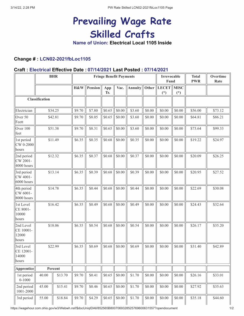
3/14/22, 2:28 PM PW Rate Skilled LCN02-2021fbLoc1105 Page
https://wagehour.com.ohio.gov/w3/Webwh.nsf/$docUniqIDAll/852565B8007069328525769600631557?opendocument 1/2
Prevailing Wage Rate
Skilled CraftsName of Union: Electrical Local 1105 Inside
Change # : LCN02-2021fbLoc1105
Craft : Electrical Effective Date : 07/14/2021 Last Posted : 07/14/2021BHR Fringe Benefit Payments Irrevocable
FundTotalPWR
OvertimeRate
H&W Pension AppTr.
Vac. Annuity Other LECET(*)
MISC(*)
Classification
Electrician $34.25 $9.70 $7.80 $0.65 $0.00 $3.60 $0.00 $0.00 $0.00 $56.00 $73.12
Over 50
Feett
$42.81 $9.70 $8.05 $0.65 $0.00 $3.60 $0.00 $0.00 $0.00 $64.81 $86.21
Over 100
feet
$51.38 $9.70 $8.31 $0.65 $0.00 $3.60 $0.00 $0.00 $0.00 $73.64 $99.33
1st period
CW 0-2000
hours
$11.49 $6.35 $0.35 $0.68 $0.00 $0.35 $0.00 $0.00 $0.00 $19.22 $24.97
2nd period
CW 2001-
4000 hours
$12.32 $6.35 $0.37 $0.68 $0.00 $0.37 $0.00 $0.00 $0.00 $20.09 $26.25
3rd period
CW 4001-
6000 hours
$13.14 $6.35 $0.39 $0.68 $0.00 $0.39 $0.00 $0.00 $0.00 $20.95 $27.52
4th period
CW 6001-
8000 hours
$14.78 $6.35 $0.44 $0.68 $0.00 $0.44 $0.00 $0.00 $0.00 $22.69 $30.08
1st Level
CE 8001-
10000
hours
$16.42 $6.35 $0.49 $0.68 $0.00 $0.49 $0.00 $0.00 $0.00 $24.43 $32.64
2nd Level
CE 10001-
12000
hours
$18.06 $6.35 $0.54 $0.68 $0.00 $0.54 $0.00 $0.00 $0.00 $26.17 $35.20
3rd Level
CE 12001-
14000
hours
$22.99 $6.35 $0.69 $0.68 $0.00 $0.69 $0.00 $0.00 $0.00 $31.40 $42.89
Apprentice Percent
1st period
0-1000
40.00 $13.70 $9.70 $0.41 $0.65 $0.00 $1.70 $0.00 $0.00 $0.00 $26.16 $33.01
2nd period
1001-2000
45.00 $15.41 $9.70 $0.46 $0.65 $0.00 $1.70 $0.00 $0.00 $0.00 $27.92 $35.63
3rd period 55.00 $18.84 $9.70 $4.29 $0.65 $0.00 $1.70 $0.00 $0.00 $0.00 $35.18 $44.60

3/14/22, 2:28 PM PW Rate Skilled LCN02-2021fbLoc1105 Page
https://wagehour.com.ohio.gov/w3/Webwh.nsf/$docUniqIDAll/852565B8007069328525769600631557?opendocument 2/2
2001-3500
4rh period
3501-5000
65.00 $22.26 $9.70 $5.07 $0.65 $0.00 $1.70 $0.00 $0.00 $0.00 $39.38 $50.51
5th period
5001-6500
70.00 $23.97 $9.70 $5.46 $0.65 $0.00 $1.70 $0.00 $0.00 $0.00 $41.49 $53.47
6th period
6501-8000
80.00 $27.40 $9.70 $6.24 $0.65 $0.00 $1.70 $0.00 $0.00 $0.00 $45.69 $59.39
Special Calculation Note : On ALL other jobs sites, CW/CE's CAN only be employed after anAPPRENTICE IS EMPLOYED on the job site.
Ratio : Jurisdiction ( * denotes special jurisdictionalnote ) :
1 to 3 Journeymen to 2 Apprentices 4 to 6 Journeymen to 4 Apprentices
COSHOCTON, GUERNSEY, KNOX*, LICKING,MUSKINGUM, PERRY, TUSCARAWAS*
Special Jurisdictional Note : In Knox County the following townships: Butler, Clay, College, Harrison,Hilliard, Jackson, Milford, Miller, Morgan and Pleasant. In Tuscarawas County the following townships:Auburn, Bucks, Clay, Jefferson, Oxford, Perry, Rush, Salem, Washington and York
Details :The Construction Wireman/Construction Electrician Classifications are applicable to all work except industrialfacilities, manufacturing facilities, colleges and universities within the geographical jurisdiction of Local UnionNo. 1105.
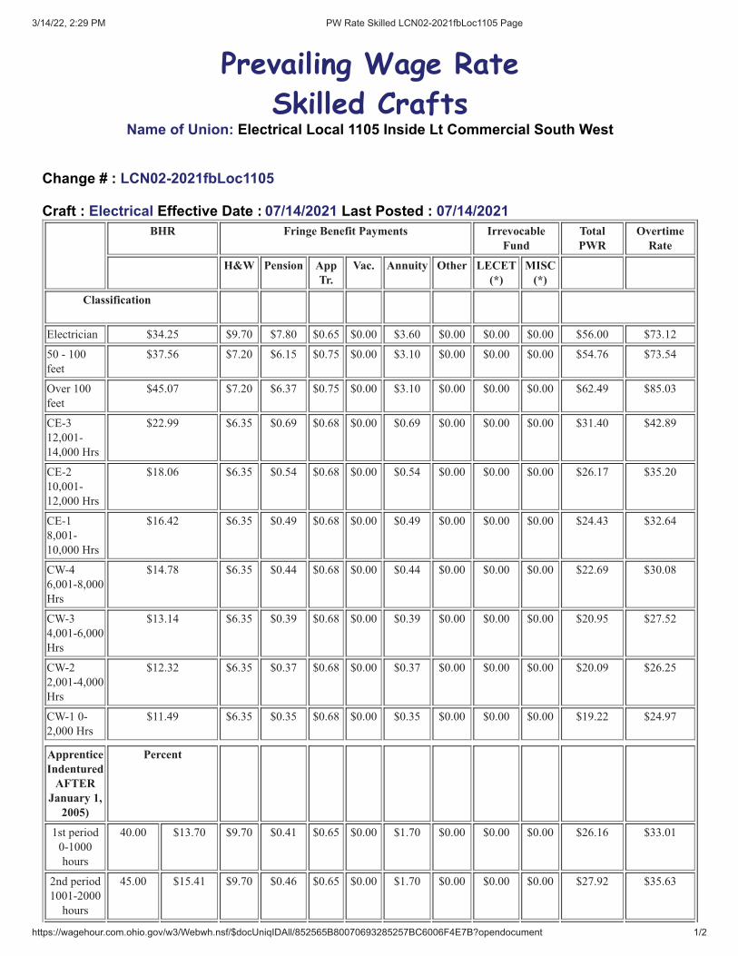
3/14/22, 2:29 PM PW Rate Skilled LCN02-2021fbLoc1105 Page
https://wagehour.com.ohio.gov/w3/Webwh.nsf/$docUniqIDAll/852565B80070693285257BC6006F4E7B?opendocument 1/2
Prevailing Wage Rate
Skilled CraftsName of Union: Electrical Local 1105 Inside Lt Commercial South West
Change # : LCN02-2021fbLoc1105
Craft : Electrical Effective Date : 07/14/2021 Last Posted : 07/14/2021BHR Fringe Benefit Payments Irrevocable
FundTotalPWR
OvertimeRate
H&W Pension AppTr.
Vac. Annuity Other LECET(*)
MISC(*)
Classification
Electrician $34.25 $9.70 $7.80 $0.65 $0.00 $3.60 $0.00 $0.00 $0.00 $56.00 $73.12
50 - 100
feet
$37.56 $7.20 $6.15 $0.75 $0.00 $3.10 $0.00 $0.00 $0.00 $54.76 $73.54
Over 100
feet
$45.07 $7.20 $6.37 $0.75 $0.00 $3.10 $0.00 $0.00 $0.00 $62.49 $85.03
CE-3
12,001-
14,000 Hrs
$22.99 $6.35 $0.69 $0.68 $0.00 $0.69 $0.00 $0.00 $0.00 $31.40 $42.89
CE-2
10,001-
12,000 Hrs
$18.06 $6.35 $0.54 $0.68 $0.00 $0.54 $0.00 $0.00 $0.00 $26.17 $35.20
CE-1
8,001-
10,000 Hrs
$16.42 $6.35 $0.49 $0.68 $0.00 $0.49 $0.00 $0.00 $0.00 $24.43 $32.64
CW-4
6,001-8,000
Hrs
$14.78 $6.35 $0.44 $0.68 $0.00 $0.44 $0.00 $0.00 $0.00 $22.69 $30.08
CW-3
4,001-6,000
Hrs
$13.14 $6.35 $0.39 $0.68 $0.00 $0.39 $0.00 $0.00 $0.00 $20.95 $27.52
CW-2
2,001-4,000
Hrs
$12.32 $6.35 $0.37 $0.68 $0.00 $0.37 $0.00 $0.00 $0.00 $20.09 $26.25
CW-1 0-
2,000 Hrs
$11.49 $6.35 $0.35 $0.68 $0.00 $0.35 $0.00 $0.00 $0.00 $19.22 $24.97
ApprenticeIndentured
AFTERJanuary 1,
2005)
Percent
1st period
0-1000
hours
40.00 $13.70 $9.70 $0.41 $0.65 $0.00 $1.70 $0.00 $0.00 $0.00 $26.16 $33.01
2nd period
1001-2000
hours
45.00 $15.41 $9.70 $0.46 $0.65 $0.00 $1.70 $0.00 $0.00 $0.00 $27.92 $35.63

3/14/22, 2:29 PM PW Rate Skilled LCN02-2021fbLoc1105 Page
https://wagehour.com.ohio.gov/w3/Webwh.nsf/$docUniqIDAll/852565B80070693285257BC6006F4E7B?opendocument 2/2
3rd period
2001-
3500 hours
55.00 $18.84 $9.70 $4.29 $0.65 $0.00 $1.70 $0.00 $0.00 $0.00 $35.18 $44.60
4th period
3501-
5000 hours
65.00 $22.26 $9.70 $5.07 $0.65 $0.00 $1.70 $0.00 $0.00 $0.00 $39.38 $50.51
5th period
5001-
6500 hours
70.00 $23.97 $9.70 $5.46 $0.65 $0.00 $1.70 $0.00 $0.00 $0.00 $41.49 $53.47
6th period
6501-
8000 hours
80.00 $27.40 $9.70 $6.24 $0.65 $0.00 $1.70 $0.00 $0.00 $0.00 $45.69 $59.39
Special Calculation Note : On ALL other job sites, CW/CE's CAN only be employed after anAPPRENTICE IS EMPLOYED on the job site.
Ratio : Jurisdiction ( * denotes special jurisdictionalnote ) :
1-3 Journeyman to 2 Apprentices4-6 Journeyman to 4 Apprentices
Construction Electrician and Construction WiremanRatioThere shall be a minimum ratio of one insideJourneyman to every (4) employees of differentclassification per jobsite. An inside JourneymanWireman is required on the project as the fifth (5th)worker or when apprentices are used.
COSHOCTON, GUERNSEY, KNOX*, LICKING,MUSKINGUM, PERRY, TUSCARAWAS*
Special Jurisdictional Note : In Knox County the following townships: Butler, Clay, College, Harrison,Hilliard, Jackson, Milford, Miller, Morgan and Pleasant. In Tuscarawas County the following townships:Auburn, Bucks, Clay, Jefferson, Oxford, Perry, Rush, Salem, Washington and York
The scope of work for the light commercial agreement shall apply to the following facilities not toexceed 200,000 square feet; office buildings, shopping centers, auto sales agencies and garages,churches, funeral homes, nursing homes, hotels, retail and wholesale facilities, small stand-alonemanufacturing facilities when free standing and not part of a larger facility (not to exceed 50,000square fee), solar projects (500 panels or less) unless otherwise covered under the agreement,lighting retrofits (when not associated with remodels involving branch re-circuiting) lighting retrofitsshall be defined as the changing of lamps and ballasts in existing light fixtures and shall also includethe one for one replacement of existing fixtures, warehouses, gas stations, food service centers,restaurants, entertainment facilities, hospitals, clinics, motels, residential buildings.
Details :

3/14/22, 2:29 PM PW Rate Skilled LCR01-2021bLoc1105VDV Page
https://wagehour.com.ohio.gov/w3/Webwh.nsf/$docUniqIDAll/852565B8007069328525760900643E53?opendocument 1/2
Prevailing Wage Rate
Skilled CraftsName of Union: Electrical Local 1105 Voice Data Video
Change # : LCR01-2021bLoc1105VDV
Craft : Voice Data Video Effective Date : 07/14/2021 Last Posted : 07/14/2021BHR Fringe Benefit Payments Irrevocable
FundTotalPWR
OvertimeRate
H&W Pension AppTr.
Vac. Annuity Other LECET(*)
MISC(*)
Classification
Electrical
Installer
Technician
B
$28.19 $9.70 $0.85 $0.70 $0.54 $0.95 $0.65 $0.00 $0.00 $41.58 $55.68
Installer
Technician
A
$29.19 $9.70 $0.88 $0.70 $0.56 $0.95 $0.67 $0.00 $0.00 $42.65 $57.25
Cable Puller $14.75 $9.70 $0.44 $0.70 $0.28 $0.95 $0.34 $0.00 $0.00 $27.16 $34.54
Apprentices Percent
1st Period 55.00 $15.50 $9.70 $0.47 $0.70 $0.30 $0.95 $0.36 $0.00 $0.00 $27.98 $35.74
2nd Period 60.00 $16.91 $9.70 $0.51 $0.70 $0.33 $0.95 $0.39 $0.00 $0.00 $29.49 $37.95
3rd Period 65.00 $18.32 $9.70 $0.55 $0.70 $0.35 $0.95 $0.42 $0.00 $0.00 $30.99 $40.16
4th Period 70.00 $19.73 $9.70 $0.59 $0.70 $0.38 $0.95 $0.46 $0.00 $0.00 $32.51 $42.38
5th Period 75.00 $21.14 $9.70 $0.64 $0.70 $0.41 $0.95 $0.49 $0.00 $0.00 $34.03 $44.60
6th Period 80.00 $22.55 $9.70 $0.68 $0.70 $0.43 $0.95 $0.52 $0.00 $0.00 $35.53 $46.81
Special Calculation Note : Other is for Holiday Pay. Vacation: Only applies to employees with one (1)continuous year of service with a firm.
Ratio : Jurisdiction ( * denotes special jurisdictionalnote ) :
1 Journeyman Installer to 1 Apprentice COSHOCTON, GUERNSEY, KNOX*, LICKING,MUSKINGUM, PERRY, TUSCARAWAS*
Special Jurisdictional Note : In Knox County: the following townships:Butler, Clay, College, Harrison,Hilliar, Jackson, Milford, Miller, Morgan, Pleasant In Tuscarawas County: the following townships:Auburn,Bucks, Clay, Jefferson, Oxford, Perry, Rush,Salem, Washington and York
Details :An employee who is required to wear an electronic device after hours will receive an additional 1.00 per hourfor all hours worked.
Holidays: Memorial Day - Fourth of July - Labor Day - Thanksgiving Day - Christmas Day - New Years Day

3/14/22, 2:29 PM PW Rate Skilled LCR01-2021bLoc1105VDV Page
https://wagehour.com.ohio.gov/w3/Webwh.nsf/$docUniqIDAll/852565B8007069328525760900643E53?opendocument 2/2
The following work is excluded from the Teledata Technician work scope:
The installation of computer systems in industrial applications such as assembly lines, robotics, computercontroller manufacturing systems.
The installation of conduit and/ or raceways shall be installed by Inside Wireman . On sites where there is noInside Wireman employed, the Teledata Technician may install raceway, or conduit not greater than 10 ft.
Fire Alarm work is excluded on all new construction sites or wherever the fire alarm system is installed inconduit
All HVAC control work.

3/14/22, 2:29 PM PW Rate Skilled LCN01-2022sksLoc540in Page
https://wagehour.com.ohio.gov/w3/Webwh.nsf/$docUniqIDAll/852565B80070693285257D960055A14A?opendocument 1/2
Prevailing Wage Rate
Skilled CraftsName of Union: Electrical Local 540 Inside
Change # : LCN01-2022sksLoc540in
Craft : Electrical Effective Date : 01/05/2022 Last Posted : 01/05/2022BHR Fringe Benefit Payments Irrevocable
FundTotalPWR
OvertimeRate
H&W Pension AppTr.
Vac. Annuity Other LECET(*)
MISC(*)
Classification
Electrician $35.28 $6.50 $10.00 $1.09 $3.53 $3.88 $1.16 $0.00 $0.00 $61.44 $79.08
Apprentice Percent
1st 1000
hrs
45.00 $15.88 $6.50 $0.00 $0.44 $0.00 $0.48 $0.48 $0.00 $0.00 $23.78 $31.71
2nd 1000
hrs
47.00 $16.58 $6.50 $0.00 $0.46 $0.00 $0.50 $0.50 $0.00 $0.00 $24.54 $32.83
3rd 1500
hrs
50.00 $17.64 $6.50 $2.50 $0.53 $1.41 $0.57 $0.57 $0.00 $0.00 $29.72 $38.54
4th 1500
hrs
60.00 $21.17 $6.50 $5.00 $0.64 $1.69 $0.69 $0.69 $0.00 $0.00 $36.38 $46.96
5th 1500
hrs
70.00 $24.70 $6.50 $7.50 $0.75 $1.98 $0.80 $0.80 $0.00 $0.00 $43.03 $55.37
6th 1500
hrs
80.00 $28.22 $6.50 $10.00 $0.85 $2.26 $0.91 $0.91 $0.00 $0.00 $49.65 $63.77
Special Calculation Note : OTHER = (NEBF) National Electrical Benefit Fund. Vacation contributionis equal to 8% of the gross weekly wages.
Ratio : Jurisdiction ( * denotes special jurisdictionalnote ) :
The first person assigned to any job site shall be a Journeyman Wireman. Ratio thereafter:
1-3 Journeymen to 2 Apprentices4 to 6 Journeymen up to 4 Apprentices7 to 9 Journeymen up to 6 Apprentices
CARROLL*, COLUMBIANA*, HOLMES,MAHONING*, STARK, TUSCARAWAS*, WAYNE*
Special Jurisdictional Note : Carroll County: North half including; Fox, Harrison, Rose andWashington Townships. Columbiana County: Knox Township only.Mahoning County: Smith Township only. Tuscarawas County: That portion North of Auburn, Clay, Rush and York Townships. Wayne County: That portion south of Baughman, Chester, Green and WayneTownships.
Details :

3/14/22, 2:29 PM PW Rate Skilled LCN01-2022sksLoc540in Page
https://wagehour.com.ohio.gov/w3/Webwh.nsf/$docUniqIDAll/852565B80070693285257D960055A14A?opendocument 2/2

3/14/22, 2:30 PM PW Rate Skilled LCN01-2022sksLoc540in Page
https://wagehour.com.ohio.gov/w3/Webwh.nsf/$docUniqIDAll/852565B8007069328525798F007519F9?opendocument 1/2
Prevailing Wage Rate
Skilled CraftsName of Union: Electrical Local 540 Inside Lt Commercial Northern
Change # : LCN01-2022sksLoc540in
Craft : Electrical Effective Date : 01/05/2022 Last Posted : 01/05/2022BHR Fringe Benefit Payments Irrevocable
FundTotalPWR
OvertimeRate
H&W Pension AppTr.
Vac. Annuity Other LECET(*)
MISC(*)
Classification
Electrician $35.28 $6.50 $10.00 $1.09 $3.53 $3.88 $1.16 $0.00 $0.00 $61.44 $79.08
CE-3
12,001-
14,000 Hrs
$26.88 $6.47 $0.00 $0.87 $0.00 $0.81 $0.81 $0.00 $0.10 $35.94 $49.38
CE-2
10,001-
12,000 Hrs
$21.12 $6.47 $0.00 $0.87 $0.00 $0.63 $0.63 $0.00 $0.10 $29.82 $40.38
CE-1
8,001-
10,000 Hrs
$19.20 $6.47 $0.00 $0.87 $0.00 $0.58 $0.58 $0.00 $0.10 $27.80 $37.40
CW-4
6,001-
8,000 Hrs
$17.28 $6.47 $0.00 $0.87 $0.00 $0.52 $0.52 $0.00 $0.10 $25.76 $34.40
CW-3
4,001-
6,000 Hrs
$15.36 $6.47 $0.00 $0.87 $0.00 $0.46 $0.46 $0.00 $0.10 $23.72 $31.40
CW-2
2,001-
4,000 Hrs
$14.40 $6.47 $0.00 $0.87 $0.00 $0.43 $0.43 $0.00 $0.10 $22.70 $29.90
CW-1 0-
2,000 Hrs
$13.44 $6.47 $0.00 $0.87 $0.00 $0.40 $0.40 $0.00 $0.10 $21.68 $28.40
Apprentice Percent
1st 1000
hrs
45.00 $15.88 $6.50 $0.00 $0.44 $0.00 $0.48 $0.48 $0.00 $0.00 $23.78 $31.71
2nd 1000
hrs
47.00 $16.58 $6.50 $0.00 $0.46 $0.00 $0.50 $0.50 $0.00 $0.00 $24.54 $32.83
3rd 1500
hrs
50.00 $17.64 $6.50 $2.50 $0.53 $1.41 $0.57 $0.57 $0.00 $0.00 $29.72 $38.54
4th 1500
hrs
60.00 $21.17 $6.50 $5.00 $0.64 $1.69 $0.69 $0.69 $0.00 $0.00 $36.38 $46.96
5th 1500
hrs
70.00 $24.70 $6.50 $7.50 $0.75 $1.98 $0.80 $0.80 $0.00 $0.00 $43.03 $55.37
6th 1500
hrs
80.00 $28.22 $6.50 $10.00 $0.85 $2.26 $0.91 $0.91 $0.00 $0.00 $49.65 $63.77

3/14/22, 2:30 PM PW Rate Skilled LCN01-2022sksLoc540in Page
https://wagehour.com.ohio.gov/w3/Webwh.nsf/$docUniqIDAll/852565B8007069328525798F007519F9?opendocument 2/2
Special Calculation Note : OTHER = (NEBF) National Electrical Benefit Fund
Ratio : Jurisdiction ( * denotes special jurisdictionalnote ) :
1 to 3 Journeymen to 2 Apprentices4 to 6 Journeymen up to 4 Apprentices7 to 9 Journeymen up to 6 Apprentices
Construction Electrician and Construction WiremanRatioThere shall be a minimum ratio of one insideJourneyman Wireman to every (4) employees ofdifferent classifications per jobsite. An InsideJourneyman Wireman is required on the project as thefifth (5th) worker or when apprentices are used.
CARROLL*, COLUMBIANA*, HOLMES,MAHONING*, STARK, TUSCARAWAS*, WAYNE*
Special Jurisdictional Note : Carroll County: North half including; Fox, Harrison, Rose andWashington Townships. Columbiana County: Knox Township only.Mahoning County: Smith Township only. Tuscarawas County: That portion North of Auburn, Clay, Rush and York Townships. Wayne County: That portion south of Baughman, Chester, Green, Wayne and Wooster Townships.
The scope of work for the light commercial agreement shall apply to the following small medicalclinics, stand-alone doctor and dentist offices with up to 600 amp service (not attached to a hospital),gas stations/convenience stores, fast food restaurants and franchised chain restaurants includingindependent bars and taverns, places of worship, funeral homes, nursing homes, assisted livingfacilities and day-care facilities under 15,000 sq ft, small office, retail/wholesale facilities under 15,000sq ft with less than 10 units attached, storage units, car washes, express hotels and motels (4 storiesor less) without conference or restaurants facilities, residential units (subject to Davis Bacon Rates)small stand-alone manufacturing facilities when free standing and not part of a larger facility (less than15,000 sq ft) solar projects (500 panels or less) unless other wise covered under this agreement,lighting retrofits (when not associated with remodels involving branch re-circuiting) Lighting retrofitsshall be defined as the changing of lamps and ballasts in existing light fixtures and shall also includethe one for one replacement of existing fixtures.
Details :
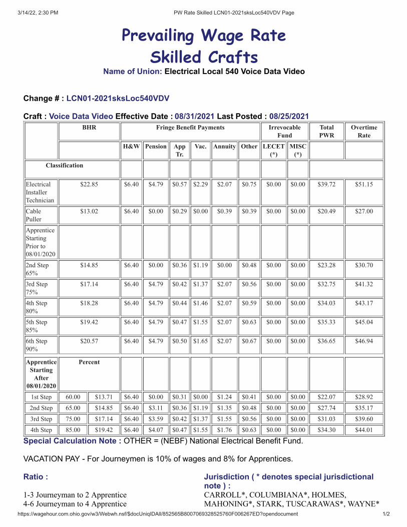
3/14/22, 2:30 PM PW Rate Skilled LCN01-2021sksLoc540VDV Page
https://wagehour.com.ohio.gov/w3/Webwh.nsf/$docUniqIDAll/852565B8007069328525760F006267ED?opendocument 1/2
Prevailing Wage Rate
Skilled CraftsName of Union: Electrical Local 540 Voice Data Video
Change # : LCN01-2021sksLoc540VDV
Craft : Voice Data Video Effective Date : 08/31/2021 Last Posted : 08/25/2021BHR Fringe Benefit Payments Irrevocable
FundTotalPWR
OvertimeRate
H&W Pension AppTr.
Vac. Annuity Other LECET(*)
MISC(*)
Classification
Electrical
Installer
Technician
$22.85 $6.40 $4.79 $0.57 $2.29 $2.07 $0.75 $0.00 $0.00 $39.72 $51.15
Cable
Puller
$13.02 $6.40 $0.00 $0.29 $0.00 $0.39 $0.39 $0.00 $0.00 $20.49 $27.00
Apprentice
Starting
Prior to
08/01/2020
2nd Step
65%
$14.85 $6.40 $0.00 $0.36 $1.19 $0.00 $0.48 $0.00 $0.00 $23.28 $30.70
3rd Step
75%
$17.14 $6.40 $4.79 $0.42 $1.37 $2.07 $0.56 $0.00 $0.00 $32.75 $41.32
4th Step
80%
$18.28 $6.40 $4.79 $0.44 $1.46 $2.07 $0.59 $0.00 $0.00 $34.03 $43.17
5th Step
85%
$19.42 $6.40 $4.79 $0.47 $1.55 $2.07 $0.63 $0.00 $0.00 $35.33 $45.04
6th Step
90%
$20.57 $6.40 $4.79 $0.50 $1.65 $2.07 $0.67 $0.00 $0.00 $36.65 $46.94
ApprenticeStarting
After08/01/2020
Percent
1st Step 60.00 $13.71 $6.40 $0.00 $0.31 $0.00 $1.24 $0.41 $0.00 $0.00 $22.07 $28.92
2nd Step 65.00 $14.85 $6.40 $3.11 $0.36 $1.19 $1.35 $0.48 $0.00 $0.00 $27.74 $35.17
3rd Step 75.00 $17.14 $6.40 $3.59 $0.42 $1.37 $1.55 $0.56 $0.00 $0.00 $31.03 $39.60
4th Step 85.00 $19.42 $6.40 $4.07 $0.47 $1.55 $1.76 $0.63 $0.00 $0.00 $34.30 $44.01
Special Calculation Note : OTHER = (NEBF) National Electrical Benefit Fund.
VACATION PAY - For Journeymen is 10% of wages and 8% for Apprentices.
Ratio : Jurisdiction ( * denotes special jurisdictionalnote ) :
1-3 Journeyman to 2 Apprentice4-6 Journeyman to 4 Apprentice
CARROLL*, COLUMBIANA*, HOLMES,MAHONING*, STARK, TUSCARAWAS*, WAYNE*
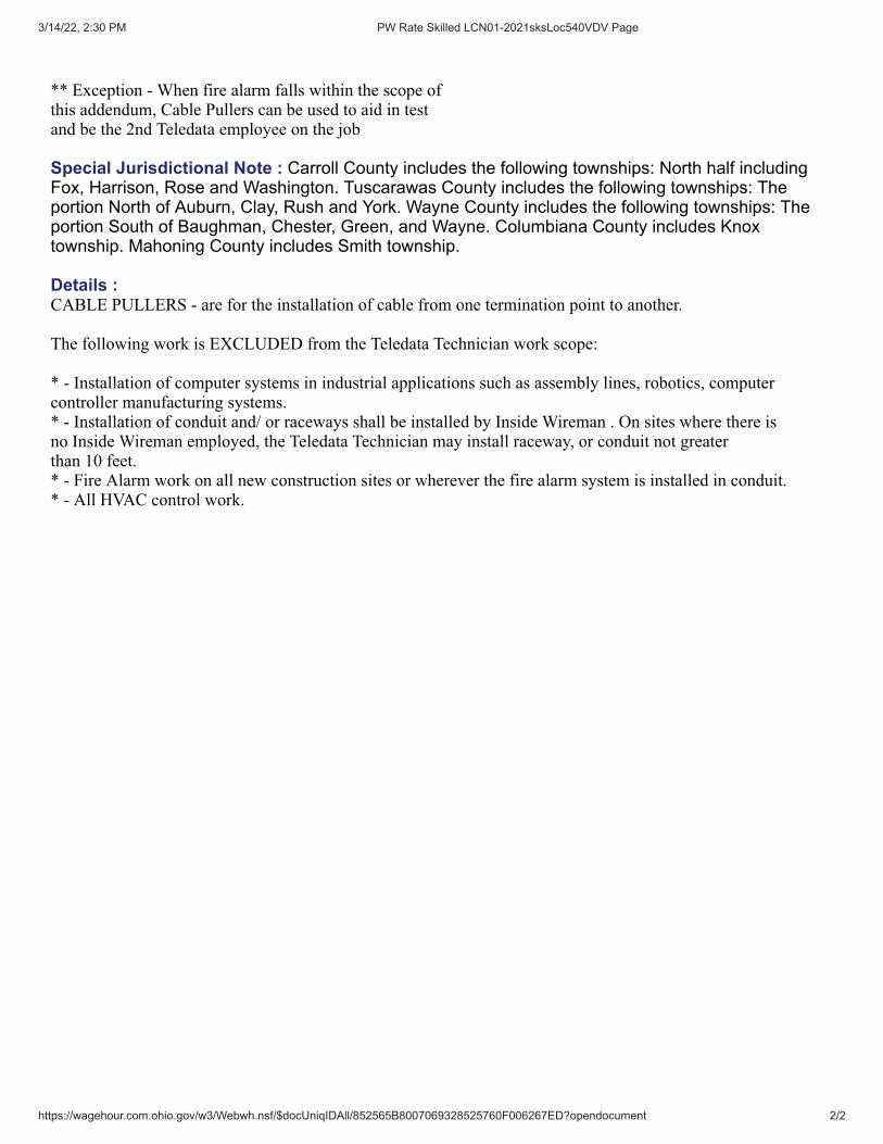
3/14/22, 2:30 PM PW Rate Skilled LCN01-2021sksLoc540VDV Page
https://wagehour.com.ohio.gov/w3/Webwh.nsf/$docUniqIDAll/852565B8007069328525760F006267ED?opendocument 2/2
** Exception - When fire alarm falls within the scope ofthis addendum, Cable Pullers can be used to aid in testand be the 2nd Teledata employee on the job
Special Jurisdictional Note : Carroll County includes the following townships: North half includingFox, Harrison, Rose and Washington. Tuscarawas County includes the following townships: Theportion North of Auburn, Clay, Rush and York. Wayne County includes the following townships: Theportion South of Baughman, Chester, Green, and Wayne. Columbiana County includes Knoxtownship. Mahoning County includes Smith township.
Details :CABLE PULLERS - are for the installation of cable from one termination point to another.
The following work is EXCLUDED from the Teledata Technician work scope:
* - Installation of computer systems in industrial applications such as assembly lines, robotics, computer controller manufacturing systems. * - Installation of conduit and/ or raceways shall be installed by Inside Wireman . On sites where there isno Inside Wireman employed, the Teledata Technician may install raceway, or conduit not greaterthan 10 feet.* - Fire Alarm work on all new construction sites or wherever the fire alarm system is installed in conduit.* - All HVAC control work.

SUPPLEMENTARY INSURANCE REQUIREMENTS 008220-1
SECTION 008220 - SUPPLEMENTARY INSURANCE REQUIREMENTS 1.1 GENERAL CONDITIONS A. Provide insurance as required by General Conditions, Article 11 in types amounts required
therein. 1. Unless specifically stated otherwise, the insurance provisions of the General Conditions
apply. B. The “Owner”, V2 Architects, Inc., and their consultants are to be included on all insurance
policies as additionally insured with respect to all work under these specifications at the project site(s).
1.2 CONTRACTOR'S LIABILITY INSURANCE A. Following minimum limits apply as described in Paragraph 11.1 of AIA Document A201, latest
Edition. 1. Workers' Compensation a. State: Statutory b. Applicable Federal: Statutory c. Employer's Liability: $1,000,000 2. Comprehensive General Liability (Including Premises-Operations; Independent
Contractors' Protective; Products and Completed Operations; Broad Form Property Damage):
a. General Aggregate: $1,000,000 (Except Products-Completed Operations) b. Products-Completed Operations Aggregate: $1,000,000 c. Personal and Advertising Injury: $1,000,000 (Per Person/Organization) d. Each Occurrence: $1,000,000 Bodily Injury and Property Damage e. Property Damage Liability Insurance will provide Explosion, Collapse, and
Underground Coverages, where applicable. f. Excess Liability General Aggregate: $1,000,000 Each Occurrence: $1,000,000
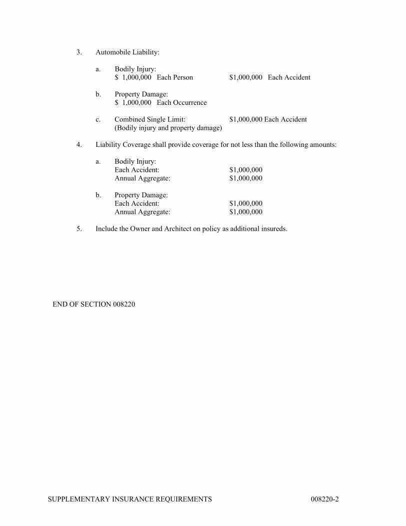
SUPPLEMENTARY INSURANCE REQUIREMENTS 008220-2
3. Automobile Liability: a. Bodily Injury: $ 1,000,000 Each Person $1,000,000 Each Accident b. Property Damage: $ 1,000,000 Each Occurrence
c. Combined Single Limit: $1,000,000 Each Accident (Bodily injury and property damage)
4. Liability Coverage shall provide coverage for not less than the following amounts:
a. Bodily Injury: Each Accident: $1,000,000 Annual Aggregate: $1,000,000
b. Property Damage: Each Accident: $1,000,000 Annual Aggregate: $1,000,000
5. Include the Owner and Architect on policy as additional insureds. END OF SECTION 008220

SUMMARY 011000 - 1
SECTION 011000 - SUMMARY
PART 1 - GENERAL
1.1 RELATED DOCUMENTS
A. Drawings and general provisions of the Contract, including General and Supplementary Conditions and other Division 01 Specification Sections, apply to this Section.
1.2 SUMMARY
A. Section Includes:
1. Project information. 2. Work covered by Contract Documents. 3. Contractor's use of site and premises. 4. Work restrictions. 5. Specification and Drawing conventions. 6. Miscellaneous provisions.
B. Related Requirements:
1. Section 015000 "Temporary Facilities and Controls" for limitations and procedures governing temporary use of Owner's facilities.
2. Section 017300 "Execution" for coordination of Owner-installed products.
1.3 DEFINITIONS
A. Work Package: A group of specifications, drawings, and schedules prepared by the design team to describe a portion of the Project Work for pricing, permitting, and construction.
1.4 PROJECT INFORMATION
A. Project Identification: Village of Newcomerstown, New Administration Building
1. Project Location: 308 S College Street, Newcomerstown, Ohio 43832
B. Owner: Village of Newcomerstown
1. Owner's Representative: Mayor Pat Cadle, 308 S. College Street, Newcomerstown, Ohio 43832
C. Architect: V2 Architects, 903 Steubenville Avenue, Cambridge, Ohio 43725.
1. Architect's Representative: Zach Van Wey, AIA (740) 432-3976
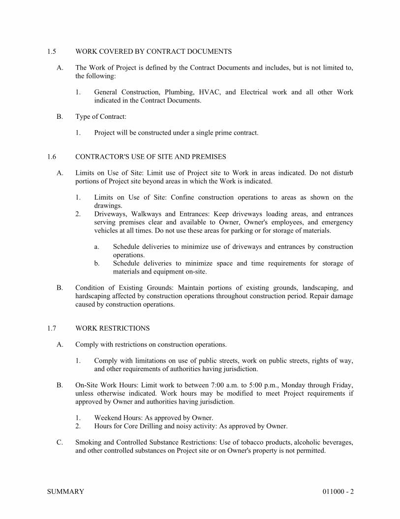
SUMMARY 011000 - 2
1.5 WORK COVERED BY CONTRACT DOCUMENTS
A. The Work of Project is defined by the Contract Documents and includes, but is not limited to, the following:
1. General Construction, Plumbing, HVAC, and Electrical work and all other Work indicated in the Contract Documents.
B. Type of Contract:
1. Project will be constructed under a single prime contract.
1.6 CONTRACTOR'S USE OF SITE AND PREMISES
A. Limits on Use of Site: Limit use of Project site to Work in areas indicated. Do not disturb portions of Project site beyond areas in which the Work is indicated.
1. Limits on Use of Site: Confine construction operations to areas as shown on the drawings.
2. Driveways, Walkways and Entrances: Keep driveways loading areas, and entrances serving premises clear and available to Owner, Owner's employees, and emergency vehicles at all times. Do not use these areas for parking or for storage of materials.
a. Schedule deliveries to minimize use of driveways and entrances by construction operations.
b. Schedule deliveries to minimize space and time requirements for storage of materials and equipment on-site.
B. Condition of Existing Grounds: Maintain portions of existing grounds, landscaping, and hardscaping affected by construction operations throughout construction period. Repair damage caused by construction operations.
1.7 WORK RESTRICTIONS
A. Comply with restrictions on construction operations.
1. Comply with limitations on use of public streets, work on public streets, rights of way, and other requirements of authorities having jurisdiction.
B. On-Site Work Hours: Limit work to between 7:00 a.m. to 5:00 p.m., Monday through Friday, unless otherwise indicated. Work hours may be modified to meet Project requirements if approved by Owner and authorities having jurisdiction.
1. Weekend Hours: As approved by Owner. 2. Hours for Core Drilling and noisy activity: As approved by Owner.
C. Smoking and Controlled Substance Restrictions: Use of tobacco products, alcoholic beverages, and other controlled substances on Project site or on Owner's property is not permitted.
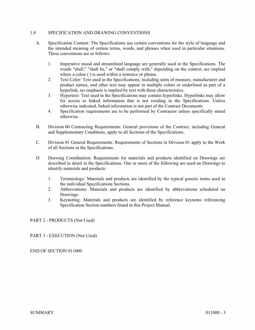
SUMMARY 011000 - 3
1.8 SPECIFICATION AND DRAWING CONVENTIONS
A. Specification Content: The Specifications use certain conventions for the style of language and the intended meaning of certain terms, words, and phrases when used in particular situations. These conventions are as follows:
1. Imperative mood and streamlined language are generally used in the Specifications. The words "shall," "shall be," or "shall comply with," depending on the context, are implied where a colon (:) is used within a sentence or phrase.
2. Text Color: Text used in the Specifications, including units of measure, manufacturer and product names, and other text may appear in multiple colors or underlined as part of a hyperlink; no emphasis is implied by text with these characteristics.
3. Hypertext: Text used in the Specifications may contain hyperlinks. Hyperlinks may allow for access to linked information that is not residing in the Specifications. Unless otherwise indicated, linked information is not part of the Contract Documents.
4. Specification requirements are to be performed by Contractor unless specifically stated otherwise.
B. Division 00 Contracting Requirements: General provisions of the Contract, including General and Supplementary Conditions, apply to all Sections of the Specifications.
C. Division 01 General Requirements: Requirements of Sections in Division 01 apply to the Work of all Sections in the Specifications.
D. Drawing Coordination: Requirements for materials and products identified on Drawings are described in detail in the Specifications. One or more of the following are used on Drawings to identify materials and products:
1. Terminology: Materials and products are identified by the typical generic terms used in the individual Specifications Sections.
2. Abbreviations: Materials and products are identified by abbreviations scheduled on Drawings.
3. Keynoting: Materials and products are identified by reference keynotes referencing Specification Section numbers found in this Project Manual.
PART 2 - PRODUCTS (Not Used)
PART 3 - EXECUTION (Not Used)
END OF SECTION 011000

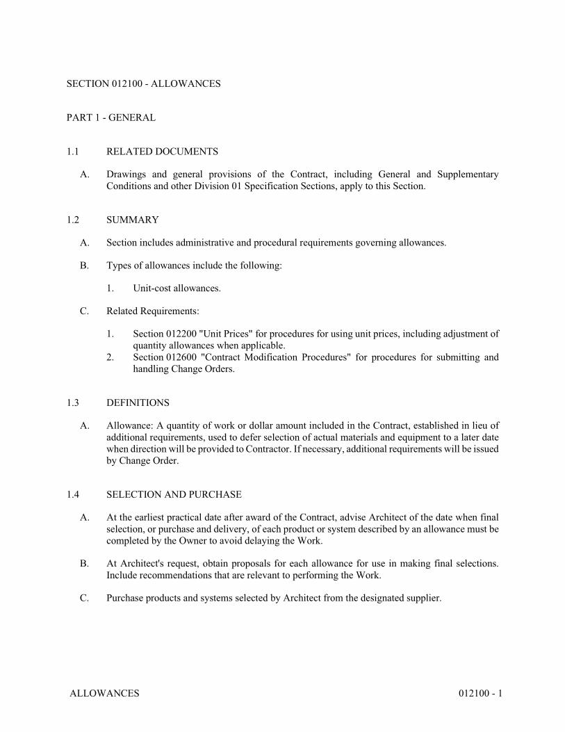
ALLOWANCES 012100 - 1
SECTION 012100 - ALLOWANCES
PART 1 - GENERAL
1.1 RELATED DOCUMENTS
A. Drawings and general provisions of the Contract, including General and Supplementary Conditions and other Division 01 Specification Sections, apply to this Section.
1.2 SUMMARY
A. Section includes administrative and procedural requirements governing allowances.
B. Types of allowances include the following:
1. Unit-cost allowances.
C. Related Requirements:
1. Section 012200 "Unit Prices" for procedures for using unit prices, including adjustment of quantity allowances when applicable.
2. Section 012600 "Contract Modification Procedures" for procedures for submitting and handling Change Orders.
1.3 DEFINITIONS
A. Allowance: A quantity of work or dollar amount included in the Contract, established in lieu of additional requirements, used to defer selection of actual materials and equipment to a later date when direction will be provided to Contractor. If necessary, additional requirements will be issued by Change Order.
1.4 SELECTION AND PURCHASE
A. At the earliest practical date after award of the Contract, advise Architect of the date when final selection, or purchase and delivery, of each product or system described by an allowance must be completed by the Owner to avoid delaying the Work.
B. At Architect's request, obtain proposals for each allowance for use in making final selections. Include recommendations that are relevant to performing the Work.
C. Purchase products and systems selected by Architect from the designated supplier.

ALLOWANCES 012100 - 2
1.5 ACTION SUBMITTALS
A. Submit proposals for purchase of products or systems included in allowances in the form specified for Change Orders.
1.6 INFORMATIONAL SUBMITTALS
A. Submit invoices or delivery slips to show actual quantities of materials delivered to the site for use in fulfillment of each allowance.
B. Submit time sheets and other documentation to show labor time and cost for installation of allowance items that include installation as part of the allowance.
C. Coordinate and process submittals for allowance items in same manner as for other portions of the Work.
1.7 UNIT-COST ALLOWANCES
A. Allowance shall include cost to Contractor of specific products and materials ordered by Owner or selected by Architect under allowance and shall include taxes, freight, and delivery to Project site.
B. Unless otherwise indicated, Contractor's costs for receiving and handling at Project site, labor, installation, overhead and profit, and similar costs related to products and materials ordered by Owner or selected by Architect under allowance shall be included as part of the Contract Sum and not part of the allowance.
C. Unused Materials: Return unused materials purchased under an allowance to manufacturer or supplier for credit to Owner, after installation has been completed and accepted.
1. If requested by Architect, retain and prepare unused material for storage by Owner. Deliver unused material to Owner's storage space as directed.
1.8 ADJUSTMENT OF ALLOWANCES
A. Allowance Adjustment: To adjust allowance amounts, prepare a Change Order proposal based on the difference between purchase amount and the allowance, multiplied by final measurement of work-in-place where applicable. If applicable, include reasonable allowances for cutting losses, tolerances, mixing wastes, normal product imperfections, required maintenance materials, and similar margins.
1. Include installation costs in purchase amount only where indicated as part of the allowance. 2. If requested, prepare explanation and documentation to substantiate distribution of
overhead costs and other markups. 3. Submit substantiation of a change in scope of Work, if any, claimed in Change Orders
related to unit-cost allowances. 4. Owner reserves the right to establish the quantity of work-in-place by independent quantity
survey, measure, or count.

ALLOWANCES 012100 - 3
B. Submit claims for increased costs due to a change in the scope or nature of the allowance described in the Contract Documents, whether for the purchase order amount or Contractor's handling, labor, installation, overhead, and profit.
1. Do not include Contractor's or subcontractor's indirect expense in the Change Order cost amount unless it is clearly shown that the nature or extent of Work has changed from what could have been foreseen from information in the Contract Documents.
2. No change to Contractor's indirect expense is permitted for selection of higher- or lower-priced materials or systems of the same scope and nature as originally indicated.
PART 2 - PRODUCTS (Not Used)
PART 3 - EXECUTION
3.1 EXAMINATION
A. Examine products covered by an allowance promptly on delivery for damage or defects. Return damaged or defective products to manufacturer for replacement.
3.2 PREPARATION
A. Coordinate materials and their installation for each allowance with related materials and installations to ensure that each allowance item is completely integrated and interfaced with related work.
3.3 SCHEDULE OF ALLOWANCES
A. Allowance No.1: Unit-Cost Allowance: Include the sum of $10.00 per square foot for luxury vinyl tile as specified in Section 096520 “Resilient Plan Flooring” and as shown on Drawings.
B. Allowance No.2: Unit-Cost Allowance: Include the sum of $45.00 per square yard for carpet, as specified in Section 096813 “Tile Carpet” and as shown on Drawings.
END OF SECTION 012100

UNIT PRICES 012200 - 1
SECTION 012200 - UNIT PRICES
PART 1 - GENERAL
1.1 RELATED DOCUMENTS
A. Drawings and general provisions of the Contract, including General and Supplementary Conditions and other Division 01 Specification Sections, apply to this Section.
1.2 SUMMARY
A. Section includes administrative and procedural requirements for unit prices.
B. Related Requirements:
1. Section 012600 "Contract Modification Procedures" for procedures for submitting and handling Change Orders.
2. Section 014000 "Quality Requirements" for general testing and inspecting requirements.
1.3 DEFINITIONS
A. Unit price is an amount incorporated in the Agreement, applicable during the duration of the Work as a price per unit of measurement for materials, equipment, or services, or a portion of the Work, added to or deducted from the Contract Sum by appropriate modification, if the scope of Work or estimated quantities of Work required by the Contract Documents are increased or decreased.
1.4 PROCEDURES
A. Unit prices include all necessary material, plus cost for delivery, installation, insurance, applicable taxes, overhead, and profit.
B. Measurement and Payment: See individual Specification Sections for work that requires establishment of unit prices. Methods of measurement and payment for unit prices are specified in those Sections.
C. Owner reserves the right to reject Contractor's measurement of work-in-place that involves use of established unit prices and to have this work measured, at Owner's expense, by an independent surveyor acceptable to Contractor.
D. List of Unit Prices: A schedule of unit prices is included in Part 3. Specification Sections referenced in the schedule contain requirements for materials described under each unit price.
UNIT PRICES 012200 - 2
PART 2 - PRODUCTS (Not Used)
PART 3 - EXECUTION
3.1 SCHEDULE OF UNIT PRICES
A. Unit Price 1 – Excavation and Fill: Removal of unsatisfactory soil and replacement with satisfactory soil material.
1. Description: Unsatisfactory soil excavation and disposal off site and replacement with satisfactory fill material or engineered fill from off site, as required, according to drawings.
2. Unit of Measurement: Cubic yard (Cubic meter) of soil excavated, based on survey of volume removed.
END OF SECTION 012200

SUBSTITUTION PROCEDURES 012500 - 1
SECTION 012500 - SUBSTITUTION PROCEDURES
PART 1 - GENERAL
1.1 RELATED DOCUMENTS
A. Drawings and general provisions of the Contract, including General and Supplementary Conditions and other Division 01 Specification Sections, apply to this Section.
1.2 SUMMARY
A. Section includes administrative and procedural requirements for substitutions.
B. Related Requirements:
1. Section 016000 "Product Requirements" for requirements for submitting comparable product submittals for products by listed manufacturers.
1.3 DEFINITIONS
A. Substitutions: Changes in products, materials, equipment, and methods of construction from those required by the Contract Documents and proposed by Contractor.
1. Substitutions for Cause: Changes proposed by Contractor that are required due to changed Project conditions, such as unavailability of product, regulatory changes, or unavailability of required warranty terms.
2. Substitutions for Convenience: Changes proposed by Contractor or Owner that are not required in order to meet other Project requirements but may offer advantage to Contractor or Owner.
1.4 ACTION SUBMITTALS
A. Substitution Requests: Submit three copies of each request for consideration. Identify product or fabrication or installation method to be replaced. Include Specification Section number and title and Drawing numbers and titles.
1. Substitution Request Form: Use form provided in Project Manual. 2. Documentation: Show compliance with requirements for substitutions and the following,
as applicable:
a. Statement indicating why specified product or fabrication or installation cannot be provided, if applicable.
b. Coordination information, including a list of changes or revisions needed to other parts of the Work and to construction performed by Owner and separate contractors that will be necessary to accommodate proposed substitution.
SUBSTITUTION PROCEDURES 012500 - 2
c. Detailed comparison of significant qualities of proposed substitution with those of the Work specified. Include annotated copy of applicable Specification Section. Significant qualities may include attributes such as performance, weight, size, durability, visual effect, sustainable design characteristics, warranties, and specific features and requirements indicated. Indicate deviations, if any, from the Work specified.
d. Product Data, including drawings and descriptions of products and fabrication and installation procedures.
e. Samples, where applicable or requested. f. Certificates and qualification data, where applicable or requested. g. List of similar installations for completed projects with project names and addresses
and names and addresses of architects and owners. h. Material test reports from a qualified testing agency indicating and interpreting test
results for compliance with requirements indicated. i. Research reports evidencing compliance with building code in effect for Project. j. Detailed comparison of Contractor's construction schedule using proposed
substitution with products specified for the Work, including effect on the overall Contract Time. If specified product or method of construction cannot be provided within the Contract Time, include letter from manufacturer, on manufacturer's letterhead, stating date of receipt of purchase order, lack of availability, or delays in delivery.
k. Cost information, including a proposal of change, if any, in the Contract Sum. l. Contractor's certification that proposed substitution complies with requirements in
the Contract Documents except as indicated in substitution request, is compatible with related materials, and is appropriate for applications indicated.
m. Contractor's waiver of rights to additional payment or time that may subsequently become necessary because of failure of proposed substitution to produce indicated results.
3. Architect's Action: If necessary, Architect will request additional information or documentation for evaluation within seven days of receipt of a request for substitution. Architect will notify Contractor of acceptance or rejection of proposed substitution within 15 days of receipt of request, or seven days of receipt of additional information or documentation, whichever is later.
a. Forms of Acceptance: Change Order, Construction Change Directive, or Architect's Supplemental Instructions for minor changes in the Work.
b. Use product specified if Architect does not issue a decision on use of a proposed substitution within time allocated.
1.5 QUALITY ASSURANCE
A. Compatibility of Substitutions: Investigate and document compatibility of proposed substitution with related products and materials. Engage a qualified testing agency to perform compatibility tests recommended by manufacturers.
SUBSTITUTION PROCEDURES 012500 - 3
1.6 PROCEDURES
A. Coordination: Revise or adjust affected work as necessary to integrate work of the approved substitutions.
PART 2 - PRODUCTS
2.1 SUBSTITUTIONS
A. Substitutions for Cause: Submit requests for substitution immediately on discovery of need for change, but not later than 15 days prior to time required for preparation and review of related submittals.
1. Conditions: Architect will consider Contractor's request for substitution when the following conditions are satisfied. If the following conditions are not satisfied, Architect will return requests without action, except to record noncompliance with these requirements:
a. Requested substitution is consistent with the Contract Documents and will produce indicated results.
b. Substitution request is fully documented and properly submitted. c. Requested substitution will not adversely affect Contractor's construction schedule. d. Requested substitution has received necessary approvals of authorities having
jurisdiction. e. Requested substitution is compatible with other portions of the Work. f. Requested substitution has been coordinated with other portions of the Work. g. Requested substitution provides specified warranty. h. If requested substitution involves more than one contractor, requested substitution
has been coordinated with other portions of the Work, is uniform and consistent, is compatible with other products, and is acceptable to all contractors involved.
B. Substitutions for Convenience: Not allowed.
PART 3 - EXECUTION (Not Used)
END OF SECTION 012500

CONTRACT MODIFICATION PROCEDURES 012600 - 1
SECTION 012600 - CONTRACT MODIFICATION PROCEDURES
PART 1 - GENERAL
1.1 RELATED DOCUMENTS
A. Drawings and general provisions of the Contract, including General and Supplementary Conditions and other Division 01 Specification Sections, apply to this Section.
1.2 SUMMARY
A. Section includes administrative and procedural requirements for handling and processing Contract modifications.
B. Related Requirements:
1. Section 012500 "Substitution Procedures" for administrative procedures for handling requests for substitutions made after the Contract award.
1.3 MINOR CHANGES IN THE WORK
A. Architect will issue supplemental instructions authorizing minor changes in the Work, not involving adjustment to the Contract Sum or the Contract Time, on Architect’s Supplemental Instructions (ASI) form.
1.4 PROPOSAL REQUESTS
A. Owner-Initiated Proposal Requests: Architect will issue a detailed description of proposed changes in the Work that may require adjustment to the Contract Sum or the Contract Time. If necessary, the description will include supplemental or revised Drawings and Specifications.
1. Work Change Proposal Requests issued by Architect are not instructions either to stop work in progress or to execute the proposed change.
2. Within 10 days after receipt of Proposal Request, submit a quotation estimating cost adjustments to the Contract Sum and the Contract Time necessary to execute the change.
a. Include a list of quantities of products required or eliminated and unit costs, with total amount of purchases and credits to be made. If requested, furnish survey data to substantiate quantities.
b. Indicate applicable taxes, delivery charges, equipment rental, and amounts of trade discounts.
c. Include costs of labor and supervision directly attributable to the change. d. Include an updated Contractor's construction schedule that indicates the effect of the
change, including, but not limited to, changes in activity duration, start and finish times, and activity relationship. Use available total float before requesting an extension of the Contract Time.

CONTRACT MODIFICATION PROCEDURES 012600 - 2
B. Contractor-Initiated Proposals: If latent or changed conditions require modifications to the Contract, Contractor may initiate a claim by submitting a request for a change to Architect.
1. Include a statement outlining reasons for the change and the effect of the change on the Work. Provide a complete description of the proposed change. Indicate the effect of the proposed change on the Contract Sum and the Contract Time.
2. Include a list of quantities of products required or eliminated and unit costs, with total amount of purchases and credits to be made. If requested, furnish survey data to substantiate quantities.
3. Indicate applicable taxes, delivery charges, equipment rental, and amounts of trade discounts.
4. Include costs of labor and supervision directly attributable to the change. 5. Include an updated Contractor's construction schedule that indicates the effect of the
change, including, but not limited to, changes in activity duration, start and finish times, and activity relationship. Use available total float before requesting an extension of the Contract Time.
6. Comply with requirements in Section 012500 "Substitution Procedures" if the proposed change requires substitution of one product or system for product or system specified.
1.5 ADMINISTRATIVE CHANGE ORDERS
A. Allowance Adjustment: See Section 012100 "Allowances" for administrative procedures for preparation of Change Order Proposal for adjusting the Contract Sum to reflect actual costs of allowances.
1.6 CHANGE ORDER PROCEDURES
A. On Owner's approval of a Work Changes Proposal Request, Architect will issue a Change Order for signatures of Owner and Contractor on AIA Document G701.
1.7 CONSTRUCTION CHANGE DIRECTIVE
A. Construction Change Directive: Architect may issue a Construction Change Directive on AIA Document G714. Construction Change Directive instructs Contractor to proceed with a change in the Work, for subsequent inclusion in a Change Order.
1. Construction Change Directive contains a complete description of change in the Work. It also designates method to be followed to determine change in the Contract Sum or the Contract Time.
B. Documentation: Maintain detailed records on a time and material basis of work required by the Construction Change Directive.
1. After completion of change, submit an itemized account and supporting data necessary to substantiate cost and time adjustments to the Contract.
CONTRACT MODIFICATION PROCEDURES 012600 - 3
PART 2 - PRODUCTS (Not Used)
PART 3 - EXECUTION (Not Used)
END OF SECTION 012600

PAYMENT PROCEDURES 012900 - 1
SECTION 012900 - PAYMENT PROCEDURES
PART 1 - GENERAL
1.1 RELATED DOCUMENTS
A. Drawings and general provisions of the Contract, including General and Supplementary Conditions and other Division 01 Specification Sections, apply to this Section.
1.2 SUMMARY
A. Section includes administrative and procedural requirements necessary to prepare and process Applications for Payment.
B. Related Requirements:
1. Section 012100 “Allowances” for procedural requirements governing the handling and processing of allowances.
2. Section 012200 "Unit Prices" for administrative requirements governing the use of unit prices.
3. Section 012600 "Contract Modification Procedures" for administrative procedures for handling changes to the Contract.
4. Section 013200 "Construction Progress Documentation" for administrative requirements governing the preparation and submittal of the Contractor's construction schedule.
1.3 DEFINITIONS
A. Schedule of Values: A statement furnished by Contractor allocating portions of the Contract Sum to various portions of the Work and used as the basis for reviewing Contractor's Applications for Payment.
1.4 SCHEDULE OF VALUES
A. Coordination: Coordinate preparation of the schedule of values with preparation of Contractor's construction schedule.
1. Coordinate line items in the schedule of values with items required to be indicated as separate activities in Contractor’s construction schedule.
2. Submit the schedule of values to Architect at earliest possible date, but no later than seven days before the date scheduled for submittal of initial Applications for Payment.
B. Format and Content: Use Project Manual table of contents as a guide to establish line items for the schedule of values. Provide at least one line item for each Specification Section.
1. Identification: Include the following Project identification on the schedule of values:
PAYMENT PROCEDURES 012900 - 2
a. Project name and location. b. Owner’s name. c. Name of Architect. d. Architect's project number. e. Contractor's name and address. f. Date of submittal.
2. Arrange schedule of values consistent with format of AIA Document G703. 3. Arrange the schedule of values in tabular form with separate columns to indicate the
following for each item listed:
a. Related Specification Section or Division. b. Description of the Work. c. Name of subcontractor. d. Name of manufacturer or fabricator. e. Name of supplier. f. Change Orders (numbers) that affect value. g. Dollar value of the following, as a percentage of the Contract Sum to nearest one-
hundredth percent, adjusted to total 100 percent.
1) Labor. 2) Materials. 3) Equipment.
4. Provide a breakdown of the Contract Sum in enough detail to facilitate continued evaluation of Applications for Payment and progress reports. Coordinate with Project Manual table of contents.
5. Provide a separate line item in the schedule of values for each part of the Work where Applications for Payment may include materials or equipment purchased or fabricated and stored, but not yet installed.
a. Differentiate between items stored on-site and items stored off-site. If required, include evidence of insurance.
6. Provide separate line items in the schedule of values for initial cost of materials, for each subsequent stage of completion, and for total installed value of that part of the Work.
7. Each item in the schedule of values and Applications for Payment shall be complete. Include total cost and proportionate share of general overhead and profit for each item.
8. Temporary facilities: Show cost of temporary facilities and other major cost items that are not direct cost of actual work-in-place as separate line items.
9. Closeout Costs: Include separate line items under Contractor and principal subcontracts for project closeout requirements in an amount totaling 5% of the Contract Sum and subcontract amount.
10. Schedule of Value Revisions: Revise the schedule of values when Change Orders or Construction Change Directives result in a change in the Contract Sum. Include at least one separate line item for each item.

PAYMENT PROCEDURES 012900 - 3
1.5 APPLICATIONS FOR PAYMENT
A. Each Application for Payment following the initial Application for Payment shall be consistent with previous applications and payments as certified by Architect and paid for by Owner.
B. Payment Application Times: The date for each progress payment is indicated in the Agreement between Owner and Contractor. The period of construction work covered by each Application for Payment is the period indicated in the Agreement.
1. Submit draft copy of Application for Payment seven days prior to due date for review by Architect.
C. Application for Payment Forms: Use AIA Document G702 and AIA Document G703 as form for Applications for Payment.
D. Application Preparation: Complete every entry on form. Notarize and execute by a person authorized to sign legal documents on behalf of Contractor. Architect will return incomplete applications without action.
1. Entries shall match data on the schedule of values and Contractor's construction schedule. Use updated schedules if revisions were made.
2. Include amounts for work completed following previous Application for Payment, whether or not payment has been received. Include only amounts for work completed at time of Application for Payment.
3. Include amounts of Change Orders and Construction Change Directives issued before last day of construction period covered by application.
4. Indicate separate amounts for work being carried out under Owner-requested project acceleration.
E. Stored Materials: Include in Application for Payment amounts applied for materials or equipment purchased or fabricated and stored, but not yet installed. Differentiate between items stored on-site and items stored off-site.
1. Provide certificate of insurance, evidence of transfer of title to Owner, and consent of surety to payment, for stored materials.
2. Provide supporting documentation that verifies amount requested, such as paid invoices. Match amount requested with amounts indicated on documentation; do not include overhead and profit on stored materials.
3. Provide summary documentation for stored materials indicating the following:
a. Value of materials previously stored and remaining stored as of date of previous Applications for Payment.
b. Value of previously stored materials put in place after date of previous Application for Payment and on or before date of current Application for Payment.
c. Value of materials stored since date of previous Application for Payment and remaining stored as of date of current Application for Payment.
F. Transmittal: Submit three signed and notarized original copies of each Application for Payment to Architect by a method ensuring receipt within 24 hours. One copy shall include waivers of lien and similar attachments if required.
PAYMENT PROCEDURES 012900 - 4
1. If acceptable to all parties, a signed and notarized copy of each Application for Payment can be submitted electronically to the Architect for processing.
G. Waivers of Mechanic's Lien: With each Application for Payment, submit waivers of mechanic's liens from subcontractors, sub-subcontractors, and suppliers for construction period covered by the previous application.
1. Submit partial waivers on each item for amount requested in previous application, after deduction for retainage, on each item.
2. When an application shows completion of an item, submit conditional final or full waivers. 3. Owner reserves the right to designate which entities involved in the Work must submit
waivers. 4. Submit final Application for Payment with or preceded by conditional final waivers from
every entity involved with performance of the Work covered by the application who is lawfully entitled to a lien.
5. Waiver Forms: Submit executed waivers of lien on forms, acceptable to Owner.
H. Initial Application for Payment: Administrative actions and submittals that must precede or coincide with submittal of first Application for Payment include the following:
1. List of subcontractors. 2. Schedule of values. 3. Contractor's construction schedule (preliminary if not final). 4. Schedule of unit prices. 5. List of Contractor's staff assignments. 6. List of Contractor's principal consultants. 7. Certificates of insurance and insurance policies. 8. Performance and payment bonds.
I. Application for Payment at Substantial Completion: After Architect issues the Certificate of Substantial Completion, submit an Application for Payment showing 100 percent completion for portion of the Work claimed as substantially complete.
1. Include documentation supporting claim that the Work is substantially complete and a statement showing an accounting of changes to the Contract Sum.
2. This application shall reflect Certificate(s) of Substantial Completion issued previously for Owner occupancy of designated portions of the Work.
J. Final Payment Application: After completing Project closeout requirements, submit final Application for Payment with releases and supporting documentation not previously submitted and accepted, including, but not limited, to the following:
1. Evidence of completion of Project closeout requirements. 2. Insurance certificates for products and completed operations where required and proof that
taxes, fees, and similar obligations were paid. 3. Updated final statement, accounting for final changes to the Contract Sum. 4. AIA Document G706, "Contractor's Affidavit of Payment of Debts and Claims." 5. AIA Document G706A, "Contractor's Affidavit of Release of Liens." 6. AIA Document G707, "Consent of Surety to Final Payment." 7. Evidence that claims have been settled.
PAYMENT PROCEDURES 012900 - 5
8. Final meter readings for utilities, a measured record of stored fuel, and similar data as of date of Substantial Completion or when Owner took possession of and assumed responsibility for corresponding elements of the Work.
9. Final liquidated damages settlement statement. 10. Waivers and releases.
PART 2 - PRODUCTS (Not Used)
PART 3 - EXECUTION (Not Used)
END OF SECTION 012900


PROJECT MANAGEMENT AND COORDINATION 013100 - 1
SECTION 013100 - PROJECT MANAGEMENT AND COORDINATION
PART 1 - GENERAL
1.1 RELATED DOCUMENTS
A. Drawings and general provisions of the Contract, including General and Supplementary Conditions and other Division 01 Specification Sections, apply to this Section.
1.2 SUMMARY
A. Section includes administrative provisions for coordinating construction operations on Project including, but not limited to, the following:
1. General coordination procedures. 2. Coordination drawings. 3. Requests for Information (RFIs). 4. Project meetings.
B. Each contractor shall participate in coordination requirements. Certain areas of responsibility are assigned to a specific contractor.
C. Related Requirements:
1. Section 013200 "Construction Progress Documentation" for preparing and submitting Contractor's construction schedule.
2. Section 017300 "Execution" for procedures for coordinating general installation and field-engineering services, including establishment of benchmarks and control points.
3. Section 017700 "Closeout Procedures" for coordinating closeout of the Contract.
1.3 DEFINITIONS
A. RFI: Request from Owner, Architect, or Contractor seeking information required by or clarifications of the Contract Documents.
1.4 INFORMATIONAL SUBMITTALS
A. Subcontract List: Prepare a written summary identifying individuals or firms proposed for each portion of the Work, including those who are to furnish products or equipment fabricated to a special design. Include the following information in tabular form:
1. Name, address, and telephone number of entity performing subcontract or supplying products.
2. Number and title of related Specification Section(s) covered by subcontract. 3. Drawing number and detail references, as appropriate, covered by subcontract.
PROJECT MANAGEMENT AND COORDINATION 013100 - 2
B. Key Personnel Names: Within 15 days of starting construction operations, submit a list of key personnel assignments, including superintendent and other personnel in attendance at Project site. Identify individuals and their duties and responsibilities; list addresses and telephone numbers, including home, office, and cellular telephone numbers and e-mail addresses. Provide names, addresses, and telephone numbers of individuals assigned as alternates in the absence of individuals assigned to Project.
1. Post copies of list in project meeting room, in temporary field office and by each temporary telephone. Keep list current at all times.
1.5 GENERAL COORDINATION PROCEDURES
A. Coordination: Coordinate construction operations included in different Sections of the Specifications to ensure efficient and orderly installation of each part of the Work
1. Schedule construction operations in sequence required to obtain the best results where installation of one part of the Work depends on installation of other components, before or after its own installation.
2. Coordinate installation of different components to ensure maximum performance and accessibility for required maintenance, service, and repair.
3. Make adequate provisions to accommodate items scheduled for later installation.
B. Coordination: Each contractor shall coordinate its construction operations with those of other contractors and entities to ensure efficient and orderly installation of each part of the Work.
1. Schedule construction operations in sequence required to obtain the best results where installation of one part of the Work depends on installation of other components, before or after its own installation.
2. Coordinate installation of different components with other contractors to ensure maximum performance and accessibility for required maintenance, service, and repair.
3. Make adequate provisions to accommodate items scheduled for later installation.
C. Prepare memoranda for distribution to each party involved, outlining special procedures required for coordination. Include such items as required notices, reports, and list of attendees at meetings.
1. Prepare similar memoranda for Owner and separate contractors if coordination of their Work is required.
D. Administrative Procedures: Coordinate scheduling and timing of required administrative procedures with other construction activities to avoid conflicts and to ensure orderly progress of the Work. Such administrative activities include, but are not limited to, the following:
1. Preparation of Contractor's construction schedule. 2. Preparation of the schedule of values. 3. Installation and removal of temporary facilities and controls. 4. Delivery and processing of submittals. 5. Progress meetings. 6. Preinstallation conferences. 7. Project closeout activities. 8. Startup and adjustment of systems.
PROJECT MANAGEMENT AND COORDINATION 013100 - 3
E. Conservation: Coordinate construction activities to ensure that operations are carried out with consideration given to conservation of energy, water, and materials. Coordinate use of temporary utilities to minimize waste.
1. Salvage materials and equipment involved in performance of, but not actually incorporated into, the Work. See other Sections for disposition of salvaged materials that are designated as Owner's property.
1.6 COORDINATION DRAWINGS
A. Coordination Drawings, General: Prepare coordination drawings according to requirements in individual Sections, and additionally where installation is not completely shown on Shop Drawings, where limited space availability necessitates coordination, or if coordination is required to facilitate integration of products and materials fabricated or installed by more than one entity.
1. Content: Project-specific information, drawn accurately to a scale large enough to indicate and resolve conflicts. Do not base coordination drawings on standard printed data. Include the following information, as applicable:
a. Use applicable Drawings as a basis for preparation of coordination drawings. Prepare sections, elevations, and details as needed to describe relationship of various systems and components.
b. Coordinate the addition of trade-specific information to the coordination drawings by multiple contractors in a sequence that best provides for coordination of the information and resolution of conflicts between installed components before submitting for review.
c. Indicate functional and spatial relationships of components of architectural, structural, civil, mechanical, and electrical systems.
d. Indicate space requirements for routine maintenance and for anticipated replacement of components during the life of the installation.
e. Show location and size of access doors required for access to concealed dampers, valves, and other controls.
f. Indicate required installation sequences. g. Indicate dimensions shown on the Drawings. Specifically note dimensions that
appear to be in conflict with submitted equipment and minimum clearance requirements. Provide alternate sketches to Architect indicating proposed resolution of such conflicts. Minor dimension changes and difficult installations will not be considered changes to the Contract.
B. Coordination Drawing Organization: Organize coordination drawings as follows:
1. Floor Plans and Reflected Ceiling Plans: Show architectural and structural elements, and mechanical, plumbing, fire-protection, fire-alarm, and electrical Work. Show locations of visible ceiling-mounted devices relative to acoustical ceiling grid. Supplement plan drawings with section drawings where required to adequately represent the Work.
2. Plenum Space: Indicate subframing for support of ceiling and wall systems, mechanical and electrical equipment, and related Work. Locate components within ceiling plenum to
PROJECT MANAGEMENT AND COORDINATION 013100 - 4
accommodate layout of light fixtures indicated on Drawings. Indicate areas of conflict between light fixtures and other components.
3. Mechanical Rooms: Provide coordination drawings for mechanical rooms showing plans and elevations of mechanical, plumbing, fire-protection, fire-alarm, and electrical equipment.
4. Structural Penetrations: Indicate penetrations and openings required for all disciplines. 5. Slab Edge and Embedded Items: Indicate slab edge locations and sizes and locations of
embedded items for metal fabrications, sleeves, anchor bolts, bearing plates, angles, door floor closers, slab depressions for floor finishes, curbs and housekeeping pads, and similar items.
6. Mechanical and Plumbing Work: Show the following:
a. Sizes and bottom elevations of ductwork, piping, and conduit runs, including insulation, bracing, flanges, and support systems.
b. Dimensions of major components, such as dampers, valves, diffusers, access doors, cleanouts and electrical distribution equipment.
c. Fire-rated enclosures around ductwork.
7. Electrical Work: Show the following:
a. Runs of vertical and horizontal conduit 1-1/4 inches (32 mm) in diameter and larger. b. Light fixture, exit light, emergency battery pack, smoke detector, and other fire-
alarm locations. c. Panel board, switch board, switchgear, transformer, busway, generator, and motor
control center locations. d. Location of pull boxes and junction boxes, dimensioned from column center lines.
8. Fire-Protection System: Show the following:
a. Locations of standpipes, mains piping, branch lines, pipe drops, and sprinkler heads.
9. Review: Architect will review coordination drawings to confirm that the Work is being coordinated, but not for the details of the coordination, which are Contractor's responsibility. If Architect determines that coordination drawings are not being prepared in sufficient scope or detail, or are otherwise deficient, Architect will so inform Contractor, who shall make changes as directed and resubmit.
10. Coordination Drawing Prints: Prepare coordination drawing prints according to requirements in Section 013300 "Submittal Procedures."
C. Coordination Digital Data Files: Prepare coordination digital data files according to the following requirements:
1. File Preparation Format: Same digital data software program, version, and operating system as original Drawings.
2. File Submittal Format: Submit or post coordination drawing files using Portable Data File (PDF) format.
PROJECT MANAGEMENT AND COORDINATION 013100 - 5
1.7 REQUESTS FOR INFORMATION (RFIs)
A. General: Immediately on discovery of the need for additional information or interpretation of the Contract Documents, Contractor shall prepare and submit an RFI in the form specified.
1. Architect will return RFIs submitted to Architect by other entities controlled by Contractor with no response.
2. Coordinate and submit RFIs in a prompt manner so as to avoid delays in Contractor's work or work of subcontractors.
B. Content of the RFI: Include a detailed, legible description of item needing information or interpretation and the following:
1. Project name. 2. Project number. 3. Date. 4. Name of Contractor. 5. Name of Architect. 6. RFI number, numbered sequentially. 7. RFI subject. 8. Specification Section number and title and related paragraphs, as appropriate. 9. Drawing number and detail references, as appropriate. 10. Field dimensions and conditions, as appropriate. 11. Contractor's suggested resolution. If Contractor's suggested resolution impacts the Contract
Time or the Contract Sum, Contractor shall state impact in the RFI. 12. Contractor's signature. 13. Attachments: Include sketches, descriptions, measurements, photos, Product Data, Shop
Drawings, coordination drawings, and other information necessary to fully describe items needing interpretation.
a. Include dimensions, thicknesses, structural grid references, and details of affected materials, assemblies, and attachments on attached sketches.
C. RFI Forms: Form bound in Project Manual.
1. Attachments shall be electronic files in Adobe Acrobat PDF format.
D. Architect's Action: Architect will review each RFI, determine action required, and respond. Allow seven working days for Architect's response for each RFI. RFIs received by Architect after 1:00 p.m. will be considered as received the following working day.
1. The following Contractor-generated RFIs will be returned without action:
a. Requests for approval of submittals. b. Requests for approval of substitutions. c. Requests for approval of Contractor's means and methods. d. Requests for coordination information already indicated in the Contract Documents. e. Requests for adjustments in the Contract Time or the Contract Sum. f. Requests for interpretation of Architect's actions on submittals.
PROJECT MANAGEMENT AND COORDINATION 013100 - 6
g. Incomplete RFIs or inaccurately prepared RFIs.
2. Architect's action may include a request for additional information, in which case Architect's time for response will date from time of receipt of additional information.
3. Architect's action on RFIs that may result in a change to the Contract Time or the Contract Sum may be eligible for Contractor to submit Change Proposal according to Section 012600 "Contract Modification Procedures."
a. If Contractor believes the RFI response warrants change in the Contract Time or the Contract Sum, notify Architect in writing within 10 days of receipt of the RFI response.
E. RFI Log: Prepare, maintain, and submit a tabular log of RFIs organized by the RFI number. Submit log weekly or at Project Construction Meetings. Include the following:
1. Project name. 2. Name and address of Contractor. 3. Name and address of Architect. 4. RFI number including RFIs that were returned without action or withdrawn. 5. RFI description. 6. Date the RFI was submitted. 7. Date Architect's response was received.
F. On receipt of Architect's action, update the RFI log and immediately distribute the RFI response to affected parties. Review response and notify Architect within seven days if Contractor disagrees with response.
1. Identification of related Minor Change in the Work, Construction Change Directive, and Proposal Request, as appropriate.
2. Identification of related Field Order, Work Change Directive, and Proposal Request, as appropriate.
1.8 PROJECT MEETINGS
A. General: Architect will schedule and conduct meetings and conferences at Project site unless otherwise indicated.
1. Attendees: Inform participants and others involved, and individuals whose presence is required, of date and time of each meeting. Notify Owner and Architect of scheduled meeting dates and times.
2. Agenda: Prepare the meeting agenda. Distribute the agenda to all invited attendees. 3. Minutes: Entity responsible for conducting meeting will record significant discussions and
agreements achieved. Distribute the meeting minutes to everyone concerned, including Owner and Architect, within three days of the meeting.
B. Preconstruction Conference: Architect will schedule and conduct a preconstruction conference before starting construction, at a time convenient to Owner and Architect, but no later than 15 days after execution of the Agreement.
1. Conduct the conference to review responsibilities and personnel assignments.
PROJECT MANAGEMENT AND COORDINATION 013100 - 7
2. Attendees: Authorized representatives of Owner, Architect, and their consultants; Contractor and its superintendent; major subcontractors; suppliers; and other concerned parties shall attend the conference. Participants at the conference shall be familiar with Project and authorized to conclude matters relating to the Work.
3. Agenda: Discuss items of significance that could affect progress, including the following:
a. Tentative construction schedule. b. Phasing. c. Critical work sequencing and long-lead items. d. Designation of key personnel and their duties. e. Lines of communications. f. Procedures for processing field decisions and Change Orders. g. Procedures for RFIs. h. Procedures for testing and inspecting. i. Procedures for processing Applications for Payment. j. Distribution of the Contract Documents. k. Submittal procedures. l. Sustainable design requirements. m. Preparation of record documents. n. Use of the premises and existing building. o. Work restrictions. p. Working hours. q. Owner's occupancy requirements. r. Responsibility for temporary facilities and controls. s. Procedures for moisture and mold control. t. Procedures for disruptions and shutdowns. u. Construction waste management and recycling. v. Parking availability. w. Office, work, and storage areas. x. Equipment deliveries and priorities. y. First aid. z. Security. aa. Progress cleaning.
4. Minutes: Entity responsible for conducting meeting will record and distribute meeting minutes.
C. Preinstallation Conferences: Conduct a preinstallation conference at Project site before each construction activity that requires coordination with other construction.
1. Attendees: Installer and representatives of manufacturers and fabricators involved in or affected by the installation and its coordination or integration with other materials and installations that have preceded or will follow, shall attend the meeting. Advise Architect of scheduled meeting dates.
2. Agenda: Review progress of other construction activities and preparations for the particular activity under consideration, including requirements for the following:
a. Contract Documents. b. Options. c. Related RFIs. d. Related Change Orders.
PROJECT MANAGEMENT AND COORDINATION 013100 - 8
e. Purchases. f. Deliveries. g. Submittals. h. Sustainable design requirements. i. Review of mockups. j. Possible conflicts. k. Compatibility requirements. l. Time schedules. m. Weather limitations. n. Manufacturer's written instructions. o. Warranty requirements. p. Compatibility of materials. q. Acceptability of substrates. r. Temporary facilities and controls. s. Space and access limitations. t. Regulations of authorities having jurisdiction. u. Testing and inspecting requirements. v. Installation procedures. w. Coordination with other work. x. Required performance results. y. Protection of adjacent work. z. Protection of construction and personnel.
3. Record significant conference discussions, agreements, and disagreements, including required corrective measures and actions.
4. Reporting: Distribute minutes of the meeting to each party present and to other parties requiring information.
5. Do not proceed with installation if the conference cannot be successfully concluded. Initiate whatever actions are necessary to resolve impediments to performance of the Work and reconvene the conference at earliest feasible date.
D. Project Closeout Conference: Schedule and conduct a project closeout conference, at a time convenient to Owner and Architect, but no later than 90 days prior to the scheduled date of Substantial Completion.
1. Conduct the conference to review requirements and responsibilities related to Project closeout.
2. Attendees: Authorized representatives of Owner, Architect, and their consultants; Contractor and its superintendent; major subcontractors; suppliers; and other concerned parties shall attend the meeting. Participants at the meeting shall be familiar with Project and authorized to conclude matters relating to the Work.
3. Agenda: Discuss items of significance that could affect or delay Project closeout, including the following:
a. Preparation of record documents. b. Procedures required prior to inspection for Substantial Completion and for final
inspection for acceptance. c. Submittal of written warranties. d. Requirements for completing sustainable design documentation. e. Requirements for preparing operations and maintenance data. f. Requirements for delivery of material samples, attic stock, and spare parts.
PROJECT MANAGEMENT AND COORDINATION 013100 - 9
g. Requirements for demonstration and training. h. Preparation of Contractor's punch list. i. Procedures for processing Applications for Payment at Substantial Completion and
for final payment. j. Submittal procedures. k. Coordination of separate contracts. l. Owner's partial occupancy requirements. m. Installation of Owner's furniture, fixtures, and equipment. n. Responsibility for removing temporary facilities and controls.
4. Minutes: Entity conducting meeting will record and distribute meeting minutes.
E. Progress Meetings: Architect will conduct progress meetings at biweekly intervals.
1. Coordinate dates of meetings with preparation of payment requests. 2. Attendees: In addition to representatives of Owner and Architect, each contractor,
subcontractor, supplier, and other entity concerned with current progress or involved in planning, coordination, or performance of future activities shall be represented at these meetings. All participants at the meeting shall be familiar with Project and authorized to conclude matters relating to the Work.
3. Agenda: Review and correct or approve minutes of previous progress meeting. Review other items of significance that could affect progress. Include topics for discussion as appropriate to status of Project.
a. Contractor's Construction Schedule: Review progress since the last meeting. Determine whether each activity is on time, ahead of schedule, or behind schedule, in relation to Contractor's construction schedule. Determine how construction behind schedule will be expedited; secure commitments from parties involved to do so. Discuss whether schedule revisions are required to ensure that current and subsequent activities will be completed within the Contract Time.
1) Review schedule for next period.
b. Review present and future needs of each entity present, including the following:
1) Interface requirements. 2) Sequence of operations. 3) Status of submittals. 4) Deliveries. 5) Off-site fabrication. 6) Access. 7) Site utilization. 8) Temporary facilities and controls. 9) Progress cleaning. 10) Quality and work standards. 11) Status of correction of deficient items. 12) Field observations. 13) Status of RFIs. 14) Status of proposal requests. 15) Pending changes. 16) Status of Change Orders.
PROJECT MANAGEMENT AND COORDINATION 013100 - 10
17) Pending claims and disputes. 18) Documentation of information for payment requests.
4. Minutes: Entity responsible for conducting the meeting will record and distribute the meeting minutes to each party present and to parties requiring information.
a. Schedule Updating: Revise Contractor's construction schedule after each progress meeting where revisions to the schedule have been made or recognized. Issue revised schedule concurrently with the report of each meeting.
F. Coordination Meetings: Conduct Project coordination meetings at weekly intervals. Project coordination meetings are in addition to specific meetings held for other purposes, such as progress meetings and preinstallation conferences.
1. Attendees: Each contractor, subcontractor, supplier, and other entity concerned with current progress or involved in planning, coordination, or performance of future activities shall be represented at these meetings. All participants at the meetings shall be familiar with Project and authorized to conclude matters relating to the Work.
2. Agenda: Review and correct or approve minutes of the previous coordination meeting. Review other items of significance that could affect progress. Include topics for discussion as appropriate to status of Project.
a. Combined Contractor's Construction Schedule: Review progress since the last coordination meeting. Determine whether each contract is on time, ahead of schedule, or behind schedule, in relation to combined Contractor's construction schedule. Determine how construction behind schedule will be expedited; secure commitments from parties involved to do so. Discuss whether schedule revisions are required to ensure that current and subsequent activities will be completed within the Contract Time.
b. Schedule Updating: Revise combined Contractor's construction schedule after each coordination meeting where revisions to the schedule have been made or recognized. Issue revised schedule concurrently with report of each meeting.
c. Review present and future needs of each contractor present, including the following:
1) Interface requirements. 2) Sequence of operations. 3) Resolution of BIM component conflicts. 4) Status of submittals. 5) Deliveries. 6) Off-site fabrication. 7) Access. 8) Site utilization. 9) Temporary facilities and controls. 10) Work hours. 11) Hazards and risks. 12) Progress cleaning. 13) Quality and work standards. 14) Change Orders.
3. Reporting: Record meeting results and distribute copies to everyone in attendance and to others affected by decisions or actions resulting from each meeting.
PROJECT MANAGEMENT AND COORDINATION 013100 - 11
G. Project Closeout Conference: Contractor shall schedule and conduct a project closeout conference, at a time convenient to Owner and Architect, but no later than 60 days prior to the scheduled date of Substantial Completion.
1. Conduct the conference to review requirements and responsibilities related to Project closeout.
2. Attendees: Authorized representatives of Owner, Architect, Contractor and its superintendent; major subcontractors; suppliers; and other concerned parties shall attend the meeting. Participants at the meeting shall be familiar with the Project and authorized to conclude matters relating to the Work.
3. Agenda: Discuss items of significance that could affect or delay Project closeout, including the following:
a. Preparation of record documents b. Procedures required prior to inspection for Substantial Completion and for final
inspection for acceptance. c. Submittal of written warranties. d. Requirements for preparing operations and maintenance data. e. Requirements for demonstration and training. f. Preparation of Contractor’s punch list. g. Owner’s partial occupancy requirements. h. Responsibility for removing temporary facilities and controls.
4. Minutes: Entity conducting meeting will record and distribute meeting minutes.
PART 2 - PRODUCTS (Not Used)
PART 3 - EXECUTION (Not Used)
END OF SECTION 013100


CONSTRUCTION PROGRESS DOCUMENTATION 013200 - 1
SECTION 013200 - CONSTRUCTION PROGRESS DOCUMENTATION
PART 1 - GENERAL
1.1 RELATED DOCUMENTS
A. Drawings and general provisions of the Contract, including General and Supplementary Conditions and other Division 01 Specification Sections, apply to this Section.
1.2 SUMMARY
A. Section includes administrative and procedural requirements for documenting the progress of construction during performance of the Work, including the following:
1. Startup construction schedule. 2. Contractor's construction schedule. 3. Construction schedule updating reports.
B. Related Requirements:
1. Section 011000 "Summary" for a summary of work and phasing requirements for the Contractor's construction schedule.
2. Section 013300 "Submittal Procedures" for submitting schedules and reports. 3. Section 014000 "Quality Requirements" for submitting a schedule of tests and inspections.
1.3 INFORMATIONAL SUBMITTALS
A. Contractor's Construction Schedule: Initial schedule, of size required to display entire schedule for entire construction period.
1. Submit a working electronic copy of schedule, using software indicated, and labeled to comply with requirements for submittals. Include type of schedule (initial or updated) and date on label.
1.4 QUALITY ASSURANCE
A. Prescheduling Conference: Conduct conference at Project site to comply with requirements in Section 013100 "Project Management and Coordination." Review methods and procedures related to the preliminary construction schedule and Contractor's construction schedule, including, but not limited to, the following:
1. Review software limitations and content and format for reports. 2. Discuss constraints, including phasing, work stages, area separations, interim milestones
and partial Owner occupancy. 3. Review delivery dates for Owner-furnished products. 4. Review schedule for work of Owner's separate contracts.
CONSTRUCTION PROGRESS DOCUMENTATION 013200 - 2
5. Review submittal requirements and procedures. 6. Review time required for review of submittals and resubmittals. 7. Review requirements for tests and inspections by independent testing and inspecting
agencies. 8. Review time required for Project closeout and Owner startup procedures, including
commissioning activities. 9. Review and finalize list of construction activities to be included in schedule. 10. Review procedures for updating schedule.
1.5 COORDINATION
A. Coordinate Contractor's construction schedule with the schedule of values, submittal schedule, progress reports, payment requests, and other required schedules and reports.
1. Secure time commitments for performing critical elements of the Work from entities involved.
2. Coordinate each construction activity in the network with other activities and schedule them in proper sequence.
PART 2 - PRODUCTS
2.1 CONTRACTOR'S CONSTRUCTION SCHEDULE, GENERAL
A. Time Frame: Extend schedule from date established for commencement of the Work to date of final completion.
1. Contract completion date shall not be changed by submission of a schedule that shows an early completion date, unless specifically authorized by Change Order.
B. Recovery Schedule: When periodic update indicates the work is 14 or more calendar days behind the current approved schedule, submit a separate recovery schedule indicating means by which the Contractor intends to regain compliance with the schedule. Indicate changes to working hours, working days, crew sizes, and equipment required to achieve compliance, and date by which recovery will be accomplished.
2.2 CONTRACTOR'S CONSTRUCTION SCHEDULE (GANTT CHART)
A. Gantt-Chart Schedule: Submit a comprehensive, fully developed, horizontal, Gantt-chart-type, Contractor's construction schedule within 15 days of date established for the Notice of Award. Base schedule on the startup construction schedule and additional information received since the start of Project.
B. Preparation: Indicate each significant construction activity separately. Identify first workday of each week with a continuous vertical line.
C. Site Condition Reports: Immediately on discovery of a difference between site conditions and the Contract Documents, prepare and submit a detailed report. Submit with a Request for
CONSTRUCTION PROGRESS DOCUMENTATION 013200 - 3
Information. Include a detailed description of the differing conditions, together with recommendations for changing the Contract Documents.
2.3 SPECIAL REPORTS
A. General: Submit special reports directly to Owner within one day(s) of an occurrence. Distribute copies of report to parties affected by the occurrence.
B. Reporting Unusual Events: When an event of an unusual and significant nature occurs at Project site, whether or not related directly to the Work, prepare and submit a special report. List chain of events, persons participating, response by Contractor's personnel, evaluation of results or effects, and similar pertinent information. Advise Owner in advance when these events are known or predictable.
PART 3 - EXECUTION
3.1 CONTRACTOR'S CONSTRUCTION SCHEDULE
A. Contractor's Construction Schedule Updating: At monthly intervals, update schedule to reflect actual construction progress and activities. Issue schedule one week before each regularly scheduled progress meeting.
1. Revise schedule immediately after each meeting or other activity where revisions have been recognized or made. Issue updated schedule concurrently with the report of each such meeting.
2. Include a report with updated schedule that indicates every change, including, but not limited to, changes in logic, durations, actual starts and finishes, and activity durations.
3. As the Work progresses, indicate final completion percentage for each activity.
B. Distribution: Distribute copies of approved schedule to Architect Owner, separate contractors, testing and inspecting agencies, and other parties identified by Contractor with a need-to-know schedule responsibility.
1. Post copies in Project meeting rooms and temporary field offices. 2. When revisions are made, distribute updated schedules to the same parties and post in the
same locations. Delete parties from distribution when they have completed their assigned portion of the Work and are no longer involved in performance of construction activities.
END OF SECTION 013200

SUBMITTAL PROCEDURES 013300 - 1
SECTION 013300 - SUBMITTAL PROCEDURES
PART 1 - GENERAL
1.1 RELATED DOCUMENTS
A. Drawings and general provisions of the Contract, including General and Supplementary Conditions and other Division 01 Specification Sections, apply to this Section.
1.2 SUMMARY
A. Section includes requirements for the submittal schedule and administrative and procedural requirements for submitting Shop Drawings, Product Data, Samples, and other submittals.
B. Related Requirements:
1. Section 012900 "Payment Procedures" for submitting Applications for Payment and the schedule of values.
2. Section 013200 "Construction Progress Documentation" for submitting schedules and reports, including Contractor's construction schedule.
3. Section 017823 "Operation and Maintenance Data" for submitting operation and maintenance manuals.
4. Section 017900 "Demonstration and Training" for submitting video recordings of demonstration of equipment and training of Owner's personnel.
1.3 DEFINITIONS
A. Action Submittals: Written and graphic information and physical samples that require Architect's responsive action. Action submittals are those submittals indicated in individual Specification Sections as "action submittals."
B. Informational Submittals: Written and graphic information and physical samples that do not require Architect's responsive action. Submittals may be rejected for not complying with requirements. Informational submittals are those submittals indicated in individual Specification Sections as "informational submittals."
C. File Transfer Protocol (FTP): Communications protocol that enables transfer of files to and from another computer over a network and that serves as the basis for standard Internet protocols. An FTP site is a portion of a network located outside of network firewalls within which internal and external users are able to access files.
D. Portable Document Format (PDF): An open standard file format licensed by Adobe Systems used for representing documents in a device-independent and display resolution-independent fixed-layout document format.
SUBMITTAL PROCEDURES 013300 - 2
1.4 ACTION SUBMITTALS
A. Submittal Schedule: Submit a schedule of submittals, arranged in chronological order by dates required by construction schedule. Include time required for review, ordering, manufacturing, fabrication, and delivery when establishing dates. Include additional time required for making corrections or revisions to submittals noted by Architect and additional time for handling and reviewing submittals required by those corrections.
1. Coordinate submittal schedule with list of subcontracts, the schedule of values, and Contractor's construction schedule.
2. Initial Submittal: Submit concurrently with startup construction schedule. Include submittals required during the first 60 days of construction. List those submittals required to maintain orderly progress of the Work and those required early because of long lead time for manufacture or fabrication.
3. Final Submittal: Submit concurrently with the first complete submittal of Contractor's construction schedule.
a. Submit revised submittal schedule to reflect changes in current status and timing for submittals.
4. Format: Arrange the following information in a tabular format:
a. Scheduled date for first submittal. b. Specification Section number and title. c. Submittal category: Action; informational. d. Name of subcontractor. e. Description of the Work covered. f. Scheduled date for Architect's final release or approval. g. Scheduled date of fabrication. h. Scheduled dates for purchasing. i. Scheduled dates for installation. j. Activity or event number.
1.5 SUBMITTAL ADMINISTRATIVE REQUIREMENTS
A. Architect's Digital Data Files: Electronic digital data files of the Contract Drawings will not be provided by Architect for Contractor's use in preparing submittals.
B. Coordination: Coordinate preparation and processing of submittals with performance of construction activities.
1. Coordinate each submittal with fabrication, purchasing, testing, delivery, other submittals, and related activities that require sequential activity.
2. Submit all submittal items required for each Specification Section concurrently unless partial submittals for portions of the Work are indicated on approved submittal schedule.
3. Submit action submittals and informational submittals required by the same Specification Section as separate packages under separate transmittals.
4. Coordinate transmittal of different types of submittals for related parts of the Work so processing will not be delayed because of need to review submittals concurrently for coordination.
SUBMITTAL PROCEDURES 013300 - 3
a. Architect reserves the right to withhold action on a submittal requiring coordination with other submittals until related submittals are received.
C. Processing Time: Allow time for submittal review, including time for resubmittals, as follows. Time for review shall commence on Architect's receipt of submittal. No extension of the Contract Time will be authorized because of failure to transmit submittals enough in advance of the Work to permit processing, including resubmittals.
1. Initial Review: Allow 15 days for initial review of each submittal. Allow additional time if coordination with subsequent submittals is required. Architect will advise Contractor when a submittal being processed must be delayed for coordination.
2. Intermediate Review: If intermediate submittal is necessary, process it in same manner as initial submittal.
3. Resubmittal Review: Allow 15 days for review of each resubmittal. 4. Sequential Review: Where sequential review of submittals by Architect's consultants,
Owner, or other parties is indicated, allow 21 days for initial review of each submittal.
D. Paper Submittals: Place a permanent label or title block on each submittal item for identification.
1. Indicate name of firm or entity that prepared each submittal on label or title block. 2. Provide a space approximately 4x4 inches on label or beside title block to record
Contractor's review and approval markings and action taken by Architect. 3. Additional Paper Copies: Unless additional copies are required for final submittal, and
unless Architect observes noncompliance with provisions in the Contract Documents, initial submittal may serve as final submittal.
4. Transmittal for Paper Submittals: Assemble each submittal individually and appropriately for transmittal and handling. Transmit each submittal using a transmittal form. Architect will return without review submittals received from sources other than Contractor.
E. Electronic Submittals: Identify and incorporate information in each electronic submittal file as follows:
1. Assemble complete submittal package into a single indexed file incorporating submittal requirements of a single Specification Section and transmittal form with links enabling navigation to each item.
2. Name file with submittal number or other unique identifier, including revision identifier.
a. File name shall use project identifier and Specification Section number followed by a decimal point and then a sequential number (e.g., LNHS-061000.01). Resubmittals shall include an alphabetic suffix after another decimal point (e.g., LNHS-061000.01.A).
3. Provide means for insertion to permanently record Contractor's review and approval markings and action taken by Architect.
4. Metadata: Include the following information as keywords in the electronic submittal file metadata: a. Project name. b. Number and title of appropriate Specification Section. c. Manufacturer name. d. Product name.
SUBMITTAL PROCEDURES 013300 - 4
F. Options: Identify options requiring selection by Architect.
G. Deviations and Additional Information: On an attached separate sheet, prepared on Contractor's letterhead, record relevant information, requests for data, revisions other than those requested by Architect on previous submittals, and deviations from requirements in the Contract Documents, including minor variations and limitations. Include same identification information as related submittal.
H. Resubmittals: Make resubmittals in same form and number of copies as initial submittal.
1. Note date and content of previous submittal. 2. Note date and content of revision in label or title block and clearly indicate extent of
revision. 3. Resubmit submittals until they are marked with approval notation from Architect's action
stamp.
PART 2 - PRODUCTS
2.1 SUBMITTAL PROCEDURES
A. General Submittal Procedure Requirements: Prepare and submit submittals required by individual Specification Sections. Types of submittals are indicated in individual Specification Sections.
1. Submit electronic submittals via email as PDF electronic files.
a. Architect will return annotated file. Annotate and retain one copy of file as an electronic Project record document file.
2. Action Submittals: Submit three paper copies of each submittal unless otherwise indicated. Architect will return two copies.
3. Informational Submittals: Submit two paper copies of each submittal unless otherwise indicated. Architect will not return copies.
4. Certificates and Certifications Submittals: Provide a statement that includes signature of entity responsible for preparing certification. Certificates and certifications shall be signed by an officer or other individual authorized to sign documents on behalf of that entity.
a. Provide a digital signature with digital certificate on electronically submitted certificates and certifications where indicated.
b. Provide a notarized statement on original paper copy certificates and certifications where indicated.
B. Product Data: Collect information into a single submittal for each element of construction and type of product or equipment.
1. If information must be specially prepared for submittal because standard published data are not suitable for use, submit as Shop Drawings, not as Product Data.
2. Mark each copy of each submittal to show which products and options are applicable. 3. Include the following information, as applicable:

SUBMITTAL PROCEDURES 013300 - 5
a. Manufacturer's catalog cuts. b. Manufacturer's product specifications. c. Standard color charts. d. Statement of compliance with specified referenced standards. e. Testing by recognized testing agency. f. Application of testing agency labels and seals. g. Notation of coordination requirements. h. Availability and delivery time information.
4. For equipment, include the following in addition to the above, as applicable:
a. Wiring diagrams showing factory-installed wiring. b. Printed performance curves. c. Operational range diagrams. d. Clearances required to other construction, if not indicated on accompanying Shop
Drawings.
5. Submit Product Data before or concurrent with Samples. 6. Submit Product Data in the following format:
a. PDF electronic file. b. SIX paper copies of Product Data unless otherwise indicated. Architect will return
two copies.
C. Shop Drawings: Prepare Project-specific information, drawn accurately to scale. Do not base Shop Drawings on reproductions of the Contract Documents or standard printed data.
1. Preparation: Fully illustrate requirements in the Contract Documents. Include the following information, as applicable:
a. Identification of products. b. Schedules. c. Compliance with specified standards. d. Notation of coordination requirements. e. Notation of dimensions established by field measurement. f. Relationship and attachment to adjoining construction clearly indicated. g. Seal and signature of professional engineer if specified.
2. Submit Shop Drawings in the following format:
a. PDF electronic file. Architect will return annotated file. Annotate and retain one copy of file as an electronic Project record document file.
b. Six opaque (bond) copies of each submittal. Architect will return two copies.
D. Samples: Submit Samples for review of kind, color, pattern, and texture for a check of these characteristics with other elements and for a comparison of these characteristics between submittal and actual component as delivered and installed.
1. Transmit Samples that contain multiple, related components such as accessories together in one submittal package.

SUBMITTAL PROCEDURES 013300 - 6
2. Identification: Attach label on unexposed side of Samples that includes the following:
a. Generic description of Sample. b. Product name and name of manufacturer. c. Sample source. d. Number and title of applicable Specification Section. e. Specification paragraph number and generic name of each item.
3. For projects where electronic submittals are required, provide corresponding electronic submittal of Sample transmittal, digital image file illustrating Sample characteristics, and identification information for record.
4. Disposition: Maintain sets of approved Samples at Project site, available for quality-control comparisons throughout the course of construction activity. Sample sets may be used to determine final acceptance of construction associated with each set.
a. Samples that may be incorporated into the Work are indicated in individual Specification Sections. Such Samples must be in an undamaged condition at time of use.
b. Samples not incorporated into the Work, or otherwise designated as Owner's property, are the property of Contractor.
5. Samples for Initial Selection: Submit manufacturer's color charts consisting of units or sections of units showing the full range of colors, textures, and patterns available.
a. Number of Samples: Submit one full set(s) of available choices where color, pattern, texture, or similar characteristics are required to be selected from manufacturer's product line. Architect will return submittal with options selected.
6. Samples for Verification: Submit full-size units or Samples of size indicated, prepared from same material to be used for the Work, cured and finished in manner specified, and physically identical with material or product proposed for use, and that show full range of color and texture variations expected. Samples include, but are not limited to, the following: partial sections of manufactured or fabricated components; small cuts or containers of materials; complete units of repetitively used materials; swatches showing color, texture, and pattern; color range sets; and components used for independent testing and inspection.
a. Number of Samples: Submit three sets of Samples. Architect will retain two Sample sets; remainder will be returned.
1) Submit a single Sample where assembly details, workmanship, fabrication techniques, connections, operation, and other similar characteristics are to be demonstrated.
2) If variation in color, pattern, texture, or other characteristic is inherent in material or product represented by a Sample, submit at least three sets of paired units that show approximate limits of variations.
E. Coordination Drawing Submittals: Comply with requirements specified in Section 013100 "Project Management and Coordination."
SUBMITTAL PROCEDURES 013300 - 7
F. Contractor's Construction Schedule: Comply with requirements specified in Section 013200 "Construction Progress Documentation."
G. Application for Payment and Schedule of Values: Comply with requirements specified in Section 012900 "Payment Procedures."
H. Test and Inspection Reports and Schedule of Tests and Inspections Submittals: Comply with requirements specified in Section 014000 "Quality Requirements."
I. Closeout Submittals and Maintenance Material Submittals: Comply with requirements specified in Section 017700 "Closeout Procedures."
J. Maintenance Data: Comply with requirements specified in Section 017823 "Operation and Maintenance Data."
PART 3 - EXECUTION
3.1 CONTRACTOR'S REVIEW
A. Action and Informational Submittals: Review each submittal and check for coordination with other Work of the Contract and for compliance with the Contract Documents. Note corrections and field dimensions. Mark with approval stamp before submitting to Architect.
B. Project Closeout and Maintenance Material Submittals: See requirements in Section 017700 "Closeout Procedures."
C. Approval Stamp: Stamp each submittal with a uniform, approval stamp. Include Project name and location, submittal number, Specification Section title and number, name of reviewer, date of Contractor's approval, and statement certifying that submittal has been reviewed, checked, and approved for compliance with the Contract Documents.
3.2 ARCHITECT'S ACTION
A. Action Submittals: Architect will review each submittal, make marks to indicate corrections or revisions required, and return it. Architect will stamp each submittal with an action stamp and will mark stamp appropriately to indicate action.
B. Informational Submittals: Architect will review each submittal and will not return it, or will return it if it does not comply with requirements. Architect will forward each submittal to appropriate party.
C. Incomplete submittals are unacceptable, will be considered nonresponsive, and will be returned for resubmittal without review.
D. Submittals not required by the Contract Documents may be returned by the Architect without action.
END OF SECTION 013300


CADD disclaimer Page 1 of 2
DISCLAIMER
CADD/Electronic File Transfer To Contractor
At your ( ) request, we will provide electronic files for your convenience and use in the preparation of shop drawings related to the Project, subject to the following terms and conditions: Our electronic files are compatible with: AutoCAD Release 2020. We make no representation as to the compatibility of these files with your hardware or your software beyond the specified release of the referenced specifications. Data contained on these electronic files are part of our instruments of service and shall not be used by you or anyone else receiving these data through or from you for any purpose other than as a convenience in the preparation of shop drawings for the referenced project. Any other use or reuse by you or by others will be at your sole risk and without liability or legal exposure to V2 ARCHITECTS. You agree to make no claim and hereby waive, to the fullest extent permitted by law, any claim or cause of action of any nature against us, our officers, directors, employees, agents or sub consultants that may arise out of, or in connection with your use of the electronic files. Furthermore, you shall, to the fullest extent permitted by law, indemnify and hold us harmless against all damages, liabilities or costs, including reasonable attorneys’ fees and defense costs, arising out of, or resulting from your use of these electronic files. These electronic files are not construction documents. Differences may exist between these electronic files and corresponding hard-copy construction documents. We make no representation regarding the accuracy or completeness of the electronic files you receive. In the event that a conflict arises between the signed or sealed hard copy, construction documents shall govern. You are responsible for determining if any conflict exists. By your use of these electronic files, you are not relieved of your duty to fully comply with the contract documents, including, and without limitation, the need to check, confirm and coordinate all dimensions and details, take field measurements, verify field conditions and coordinate our work with that of other contractors for the project.

CADD disclaimer Page 1 of 2
DISCLAIMER
Because information presented on the electronic files can be modified, unintentionally or otherwise, we reserve the right to remove all indicia of ownership and/or involvement from each electronic display. We will furnish you electronic files of the Architectural Backgrounds and Floor Plans of the previously named project. A service fee of $200.00 shall be remitted to us prior to delivery of the electronic files. Under no circumstances shall delivery of the electronic files for use by you, be deemed a sale by us, and we make no warranties, either express or implied, of merchantability and fitness for any particular purpose. In no event shall we be liable for any loss of profit or any consequential damages as a result of your use or reuse of these electronic files. ___________________________________ Contractor’s Signature ___________________________________ Firm Name ______________________________ Date
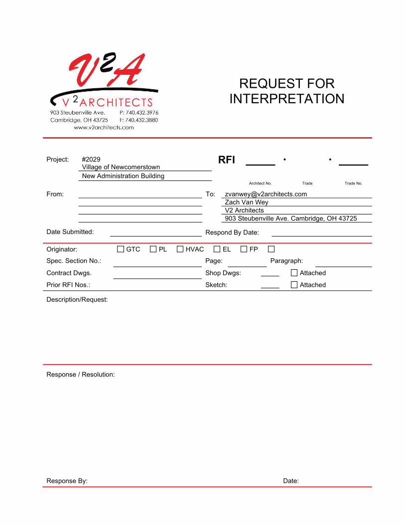
REQUEST FOR INTERPRETATION
RFI �� � Project: #2029 Village of Newcomerstown
New Administration Building Architect No. Trade Trade No.
From: To: [email protected] Zach Van Wey V2 Architects 903 Steubenville Ave. Cambridge, OH 43725
Date Submitted: Respond By Date:
Originator: GTC PL HVAC EL FP
Spec. Section No.: Page: Paragraph:
Contract Dwgs. Shop Dwgs: Attached
Prior RFI Nos.: Sketch: Attached
Description/Request:
Response / Resolution:
Response By: Date:

SUBMITTAL
Project: Village of Newcomerstown
New Administration Building Project #2029
Submittal
Number:
GT ��
Trade Trade No.
Architect: V2 Architects 903 Steubenville Ave. Cambridge, Ohio 43725
Submittal Type: Action Informational
Consultant: Transmitted via: UPS MAIL
Submittal from: Submittal to: Contractor Architect Consultant Owner
Drawing or Specifications section reference number:
# Copies Print, Sample, Product Data Description:
1st Submittal 2nd Submittal 3rd Submittal 4th Submittal
Contractor Comments: Contractor Signature: Date:
Consultant Comments: Consultant Signature: Date:
Architect Comments: Architect Signature: Date:

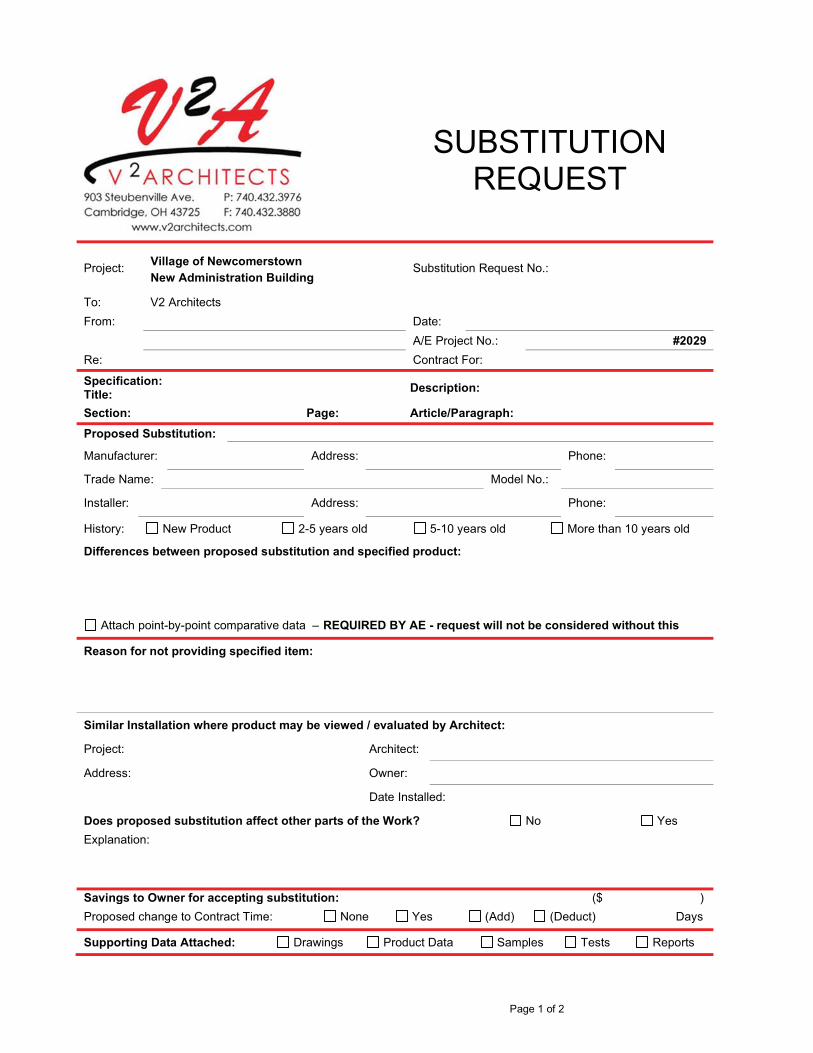
Page 1 of 2
SUBSTITUTION REQUEST
Project: Village of Newcomerstown
New Administration Building Substitution Request No.:
To: V2 Architects From: Date: A/E Project No.: #2029
Re: Contract For:
Specification: Title:
Description:
Section: Page: Article/Paragraph:
Proposed Substitution:
Manufacturer: Address: Phone:
Trade Name: Model No.:
Installer: Address: Phone:
History: New Product 2-5 years old 5-10 years old More than 10 years old
Differences between proposed substitution and specified product:
Attach point-by-point comparative data – REQUIRED BY AE - request will not be considered without this
Reason for not providing specified item: Similar Installation where product may be viewed / evaluated by Architect:
Project: Architect:
Address: Owner:
Date Installed:
Does proposed substitution affect other parts of the Work? No Yes Explanation: Savings to Owner for accepting substitution: ($ ) Proposed change to Contract Time: None Yes (Add) (Deduct) Days
Supporting Data Attached: Drawings Product Data Samples Tests Reports
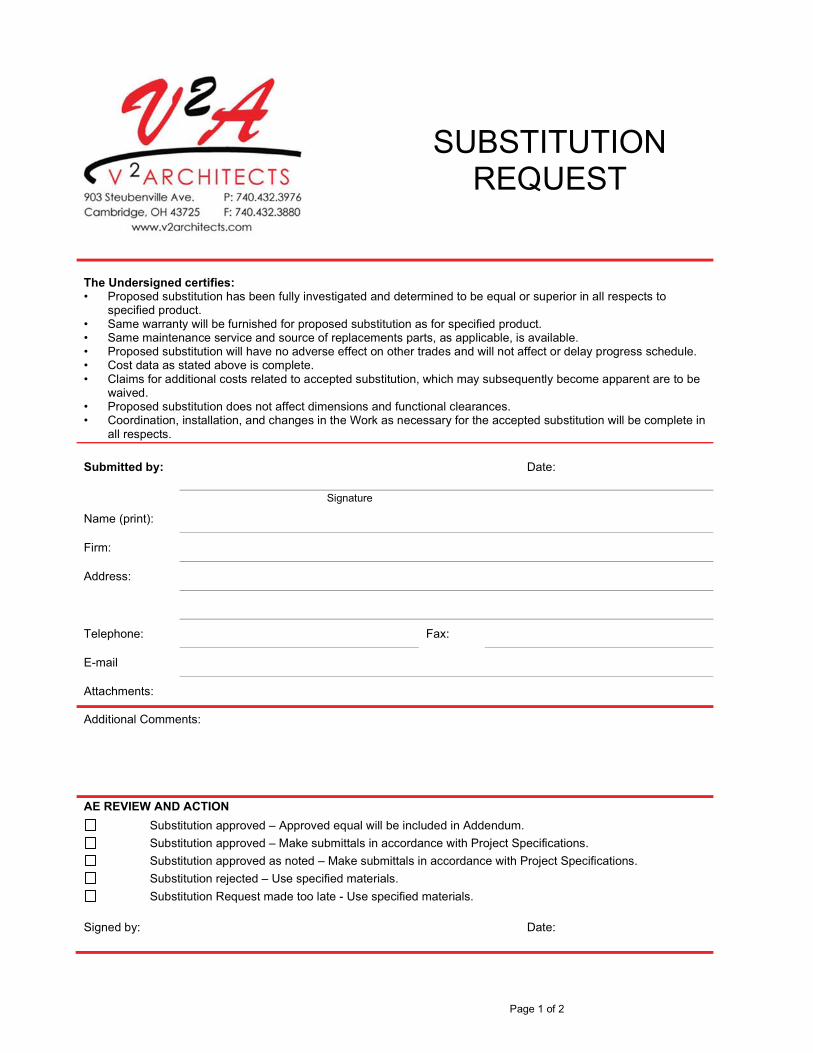
Page 1 of 2
SUBSTITUTION REQUEST
The Undersigned certifies: • Proposed substitution has been fully investigated and determined to be equal or superior in all respects to
specified product. • Same warranty will be furnished for proposed substitution as for specified product. • Same maintenance service and source of replacements parts, as applicable, is available. • Proposed substitution will have no adverse effect on other trades and will not affect or delay progress schedule. • Cost data as stated above is complete. • Claims for additional costs related to accepted substitution, which may subsequently become apparent are to be
waived. • Proposed substitution does not affect dimensions and functional clearances. • Coordination, installation, and changes in the Work as necessary for the accepted substitution will be complete in
all respects.
Submitted by: Date:
Signature
Name (print):
Firm:
Address:
Telephone: Fax:
Attachments:
Additional Comments:
AE REVIEW AND ACTION
Substitution approved – Approved equal will be included in Addendum. Substitution approved – Make submittals in accordance with Project Specifications. Substitution approved as noted – Make submittals in accordance with Project Specifications. Substitution rejected – Use specified materials. Substitution Request made too late - Use specified materials.
Signed by: Date:
QUALITY REQUIREMENTS 014000 - 1
SECTION 014000 - QUALITY REQUIREMENTS
PART 1 - GENERAL
1.1 RELATED DOCUMENTS
A. Drawings and general provisions of the Contract, including General and Supplementary Conditions and other Division 01 Specification Sections, apply to this Section.
1.2 SUMMARY
A. Section includes administrative and procedural requirements for quality assurance and quality control.
B. Testing and inspecting services are required to verify compliance with requirements specified or indicated. These services do not relieve Contractor of responsibility for compliance with the Contract Document requirements.
1. Specific quality-assurance and -control requirements for individual construction activities are specified in the Sections that specify those activities. Requirements in those Sections may also cover production of standard products.
2. Specified tests, inspections, and related actions do not limit Contractor's other quality-assurance and -control procedures that facilitate compliance with the Contract Document requirements.
3. Requirements for Contractor to provide quality-assurance and -control services required by Architect, Owner, or authorities having jurisdiction are not limited by provisions of this Section.
4. Specific test and inspection requirements are not specified in this Section.
1.3 DEFINITIONS
A. Quality-Assurance Services: Activities, actions, and procedures performed before and during execution of the Work to guard against defects and deficiencies and substantiate that proposed construction will comply with requirements.
B. Quality-Control Services: Tests, inspections, procedures, and related actions during and after execution of the Work to evaluate that actual products incorporated into the Work and completed construction comply with requirements. Services do not include contract enforcement activities performed by Architect.
C. Mockups: Full-size physical assemblies that are constructed on-site. Mockups are constructed to verify selections made under Sample submittals; to demonstrate aesthetic effects and, where indicated, qualities of materials and execution; to review coordination, testing, or operation; to show interface between dissimilar materials; and to demonstrate compliance with specified installation tolerances. Mockups are not Samples. Unless otherwise indicated, approved mockups establish the standard by which the Work will be judged.

QUALITY REQUIREMENTS 014000 - 2
D. Preconstruction Testing: Tests and inspections performed specifically for Project before products and materials are incorporated into the Work, to verify performance or compliance with specified criteria.
E. Product Testing: Tests and inspections that are performed by an NRTL, an NVLAP, or a testing agency qualified to conduct product testing and acceptable to authorities having jurisdiction, to establish product performance and compliance with specified requirements.
F. Source Quality-Control Testing: Tests and inspections that are performed at the source, e.g., plant, mill, factory, or shop.
G. Field Quality-Control Testing: Tests and inspections that are performed on-site for installation of the Work and for completed Work.
H. Testing Agency: An entity engaged to perform specific tests, inspections, or both. Testing laboratory shall mean the same as testing agency.
I. Installer/Applicator/Erector: Contractor or another entity engaged by Contractor as an employee, Subcontractor, or Sub-subcontractor, to perform a particular construction operation, including installation, erection, application, and similar operations.
1. Use of trade-specific terminology in referring to a trade or entity does not require that certain construction activities be performed by accredited or unionized individuals, or that requirements specified apply exclusively to specific trade(s).
J. Experienced: When used with an entity or individual, "experienced" means having successfully completed a minimum of five previous projects similar in nature, size, and extent to this Project; being familiar with special requirements indicated; and having complied with requirements of authorities having jurisdiction.
1.4 CONFLICTING REQUIREMENTS
A. Referenced Standards: If compliance with two or more standards is specified and the standards establish different or conflicting requirements for minimum quantities or quality levels, comply with the most stringent requirement. Refer conflicting requirements that are different, but apparently equal, to Architect for a decision before proceeding.
B. Minimum Quantity or Quality Levels: The quantity or quality level shown or specified shall be the minimum provided or performed. The actual installation may comply exactly with the minimum quantity or quality specified, or it may exceed the minimum within reasonable limits. To comply with these requirements, indicated numeric values are minimum or maximum, as appropriate, for the context of requirements. Refer uncertainties to Architect for a decision before proceeding.
QUALITY REQUIREMENTS 014000 - 3
1.5 INFORMATIONAL SUBMITTALS
A. Testing Agency Qualifications: For testing agencies specified in "Quality Assurance" Article to demonstrate their capabilities and experience. Include proof of qualifications in the form of a recent report on the inspection of the testing agency by a recognized authority.
B. Schedule of Tests and Inspections: Prepare in tabular form and include the following:
1. Specification Section number and title. 2. Entity responsible for performing tests and inspections. 3. Description of test and inspection. 4. Identification of applicable standards. 5. Identification of test and inspection methods. 6. Number of tests and inspections required. 7. Time schedule or time span for tests and inspections. 8. Requirements for obtaining samples. 9. Unique characteristics of each quality-control service.
1.6 REPORTS AND DOCUMENTS
A. Test and Inspection Reports: Prepare and submit certified written reports specified in other Sections. Include the following:
1. Date of issue. 2. Project title and number. 3. Name, address, and telephone number of testing agency. 4. Dates and locations of samples and tests or inspections. 5. Names of individuals making tests and inspections. 6. Description of the Work and test and inspection method. 7. Identification of product and Specification Section. 8. Complete test or inspection data. 9. Test and inspection results and an interpretation of test results. 10. Record of temperature and weather conditions at time of sample taking and testing and
inspecting. 11. Comments or professional opinion on whether tested or inspected Work complies with the
Contract Document requirements. 12. Name and signature of laboratory inspector. 13. Recommendations on retesting and reinspecting. 14. Statement whether conditions, products, and installation will affect warranty. 15. Other required items indicated in individual Specification Sections.
B. Permits, Licenses, and Certificates: For Owner's records, submit copies of permits, licenses, certifications, inspection reports, releases, jurisdictional settlements, notices, receipts for fee payments, judgments, correspondence, records, and similar documents, established for compliance with standards and regulations bearing on performance of the Work.

QUALITY REQUIREMENTS 014000 - 4
1.7 QUALITY ASSURANCE
A. General: Qualifications paragraphs in this article establish the minimum qualification levels required; individual Specification Sections specify additional requirements.
B. Installer Qualifications: A firm or individual experienced in installing, erecting, or assembling work similar in material, design, and extent to that indicated for this Project, whose work has resulted in construction with a record of successful in-service performance.
C. Specialists: Certain Specification Sections require that specific construction activities shall be performed by entities who are recognized experts in those operations. Specialists shall satisfy qualification requirements indicated and shall be engaged for the activities indicated.
1. Requirements of authorities having jurisdiction shall supersede requirements for specialists.
D. Testing Agency Qualifications: An NRTL, an NVLAP, or an independent agency with the experience and capability to conduct testing and inspecting indicated, as documented according to ASTM E 329; and with additional qualifications specified in individual Sections; and, where required by authorities having jurisdiction, that is acceptable to authorities.
1. NRTL: A nationally recognized testing laboratory according to 29 CFR 1910.7. 2. NVLAP: A testing agency accredited according to NIST's National Voluntary Laboratory
Accreditation Program.
E. Manufacturer's Technical Representative Qualifications: An authorized representative of manufacturer who is trained and approved by manufacturer to observe and inspect installation of manufacturer's products that are similar in material, design, and extent to those indicated for this Project.
F. Factory-Authorized Service Representative Qualifications: An authorized representative of manufacturer who is trained and approved by manufacturer to inspect installation of manufacturer's products that are similar in material, design, and extent to those indicated for this Project.
G. Preconstruction Testing: Where testing agency is indicated to perform preconstruction testing for compliance with specified requirements for performance and test methods, comply with the following:
1. Contractor responsibilities include the following:
a. Provide test specimens representative of proposed products and construction. b. Submit specimens in a timely manner with sufficient time for testing and analyzing
results to prevent delaying the Work. c. Provide sizes and configurations of test assemblies, mockups, and laboratory
mockups to adequately demonstrate capability of products to comply with performance requirements.
d. Build site-assembled test assemblies and mockups using installers who will perform same tasks for Project.
e. Build laboratory mockups at testing facility using personnel, products, and methods of construction indicated for the completed Work.

QUALITY REQUIREMENTS 014000 - 5
f. When testing is complete, remove test specimens, assemblies, and mockups; do not reuse products on Project.
2. Testing Agency Responsibilities: Submit a certified written report of each test, inspection, and similar quality-assurance service to Architect, with copy to Contractor. Interpret tests and inspections and state in each report whether tested and inspected work complies with or deviates from the Contract Documents.
H. Mockups: Before installing portions of the Work requiring mockups, build mockups for each form of construction and finish required to comply with the following requirements, using materials indicated for the completed Work:
1. Build mockups in location and of size indicated or, if not indicated, as directed by Architect.
2. Notify Architect seven days in advance of dates and times when mockups will be constructed.
3. Employ supervisory personnel who will oversee mockup construction. Employ workers that will be employed during the construction at Project.
4. Demonstrate the proposed range of aesthetic effects and workmanship. 5. Obtain Architect's approval of mockups before starting work, fabrication, or construction.
a. Allow seven days for initial review and each re-review of each mockup.
6. Maintain mockups during construction in an undisturbed condition as a standard for judging the completed Work.
7. Demolish and remove mockups when directed unless otherwise indicated.
1.8 QUALITY CONTROL
A. Owner Responsibilities: Where quality-control services are indicated as Owner's responsibility, Owner will engage a qualified testing agency to perform these services.
1. Owner will furnish Contractor with names, addresses, and telephone numbers of testing agencies engaged and a description of types of testing and inspecting they are engaged to perform.
2. Payment for these services will be made from testing and inspecting allowances, as authorized by Change Orders.
3. Costs for retesting and reinspecting construction that replaces or is necessitated by work that failed to comply with the Contract Documents will be charged to Contractor, and the Contract Sum will be adjusted by Change Order.
B. Contractor Responsibilities: Tests and inspections not explicitly assigned to Owner are Contractor's responsibility. Perform additional quality-control activities required to verify that the Work complies with requirements, whether specified or not.
1. Unless otherwise indicated, provide quality-control services specified and those required by authorities having jurisdiction. Perform quality-control services required of Contractor by authorities having jurisdiction, whether specified or not.
2. Where services are indicated as Contractor's responsibility, engage a qualified testing agency to perform these quality-control services.
QUALITY REQUIREMENTS 014000 - 6
a. Contractor shall not employ same entity engaged by Owner, unless agreed to in writing by Owner.
3. Notify testing agencies at least 24 hours in advance of time when Work that requires testing or inspecting will be performed.
4. Where quality-control services are indicated as Contractor's responsibility, submit a certified written report, in duplicate, of each quality-control service.
5. Testing and inspecting requested by Contractor and not required by the Contract Documents are Contractor's responsibility.
6. Submit additional copies of each written report directly to authorities having jurisdiction, when they so direct.
C. Manufacturer's Field Services: Where indicated, engage a factory-authorized service representative to inspect field-assembled components and equipment installation, including service connections. Report results in writing as specified in Section 013300 "Submittal Procedures."
D. Manufacturer's Technical Services: Where indicated, engage a manufacturer's technical representative to observe and inspect the Work. Manufacturer's technical representative's services include participation in preinstallation conferences, examination of substrates and conditions, verification of materials, observation of Installer activities, inspection of completed portions of the Work, and submittal of written reports.
E. Retesting/Reinspecting: Regardless of whether original tests or inspections were Contractor's responsibility, provide quality-control services, including retesting and reinspecting, for construction that replaced Work that failed to comply with the Contract Documents.
F. Testing Agency Responsibilities: Cooperate with Architect and Contractor in performance of duties. Provide qualified personnel to perform required tests and inspections.
1. Notify Architect and Contractor promptly of irregularities or deficiencies observed in the Work during performance of its services.
2. Determine the location from which test samples will be taken and in which in-situ tests are conducted.
3. Conduct and interpret tests and inspections and state in each report whether tested and inspected work complies with or deviates from requirements.
4. Submit a certified written report, in duplicate, of each test, inspection, and similar quality-control service through Contractor.
5. Do not release, revoke, alter, or increase the Contract Document requirements or approve or accept any portion of the Work.
6. Do not perform any duties of Contractor.
G. Associated Services: Cooperate with agencies performing required tests, inspections, and similar quality-control services, and provide reasonable auxiliary services as requested. Notify agency sufficiently in advance of operations to permit assignment of personnel. Provide the following:
1. Access to the Work. 2. Incidental labor and facilities necessary to facilitate tests and inspections. 3. Adequate quantities of representative samples of materials that require testing and
inspecting. Assist agency in obtaining samples.

QUALITY REQUIREMENTS 014000 - 7
4. Facilities for storage and field curing of test samples. 5. Delivery of samples to testing agencies. 6. Preliminary design mix proposed for use for material mixes that require control by testing
agency. 7. Security and protection for samples and for testing and inspecting equipment at Project
site.
H. Coordination: Coordinate sequence of activities to accommodate required quality-assurance and -control services with a minimum of delay and to avoid necessity of removing and replacing construction to accommodate testing and inspecting.
1. Schedule times for tests, inspections, obtaining samples, and similar activities.
I. Schedule of Tests and Inspections: Prepare a schedule of tests, inspections, and similar quality-control services required by the Contract Documents. Coordinate and submit concurrently with Contractor's construction schedule. Update as the Work progresses.
1. Distribution: Distribute schedule to Owner, Architect, testing agencies, and each party involved in performance of portions of the Work where tests and inspections are required.
1.9 SPECIAL TESTS AND INSPECTIONS
A. Special Tests and Inspections: Conducted by a qualified testing agency as required by authorities having jurisdiction, as indicated in individual Specification Sections, and as follows:
1. Verifying that manufacturer maintains detailed fabrication and quality-control procedures and reviews the completeness and adequacy of those procedures to perform the Work.
2. Notifying Architect and Contractor promptly of irregularities and deficiencies observed in the Work during performance of its services.
3. Submitting a certified written report of each test, inspection, and similar quality-control service to Architect with copy to Contractor and to authorities having jurisdiction.
4. Submitting a final report of special tests and inspections at Substantial Completion, which includes a list of unresolved deficiencies.
5. Interpreting tests and inspections and stating in each report whether tested and inspected work complies with or deviates from the Contract Documents.
6. Retesting and reinspecting corrected work.
PART 2 - PRODUCTS (Not Used)
PART 3 - EXECUTION
3.1 TEST AND INSPECTION LOG
A. Test and Inspection Log: Prepare a record of tests and inspections. Include the following:
1. Date test or inspection was conducted. 2. Description of the Work tested or inspected. 3. Date test or inspection results were transmitted to Architect.
QUALITY REQUIREMENTS 014000 - 8
4. Identification of testing agency or special inspector conducting test or inspection.
B. Maintain log at Project site. Post changes and revisions as they occur. Provide access to test and inspection log for Architect's reference during normal working hours.
3.2 REPAIR AND PROTECTION
A. General: On completion of testing, inspecting, sample taking, and similar services, repair damaged construction and restore substrates and finishes.
1. Provide materials and comply with installation requirements specified in other Specification Sections or matching existing substrates and finishes. Restore patched areas and extend restoration into adjoining areas with durable seams that are as invisible as possible. Comply with the Contract Document requirements for cutting and patching in Section 017300 "Execution."
B. Protect construction exposed by or for quality-control service activities.
C. Repair and protection are Contractor's responsibility, regardless of the assignment of responsibility for quality-control services.
END OF SECTION 014000

REFERENCES 014200 - 1
SECTION 014200 - REFERENCES
PART 1 - GENERAL
1.1 RELATED DOCUMENTS
A. Drawings and general provisions of the Contract, including General and Supplementary Conditions and other Division 01 Specification Sections, apply to this Section.
1.2 DEFINITIONS
A. General: Basic Contract definitions are included in the Conditions of the Contract.
B. "Approved": When used to convey Architect's action on Contractor's submittals, applications, and requests, "approved" is limited to Architect's duties and responsibilities as stated in the Conditions of the Contract.
C. "Directed": A command or instruction by Architect. Other terms including "requested," "authorized," "selected," "required," and "permitted" have the same meaning as "directed."
D. "Indicated": Requirements expressed by graphic representations or in written form on Drawings, in Specifications, and in other Contract Documents. Other terms including "shown," "noted," "scheduled," and "specified" have the same meaning as "indicated."
E. "Regulations": Laws, ordinances, statutes, and lawful orders issued by authorities having jurisdiction, and rules, conventions, and agreements within the construction industry that control performance of the Work.
F. "Furnish": Supply and deliver to Project site, ready for unloading, unpacking, assembly, installation, and similar operations.
G. "Install": Unload, temporarily store, unpack, assemble, erect, place, anchor, apply, work to dimension, finish, cure, protect, clean, and similar operations at Project site.
H. "Provide": Furnish and install, complete and ready for the intended use.
I. "Project Site": Space available for performing construction activities. The extent of Project site is shown on Drawings and may or may not be identical with the description of the land on which Project is to be built.
1.3 INDUSTRY STANDARDS
A. Applicability of Standards: Unless the Contract Documents include more stringent requirements, applicable construction industry standards have the same force and effect as if bound or copied directly into the Contract Documents to the extent referenced. Such standards are made a part of the Contract Documents by reference.
REFERENCES 014200 - 2
B. Publication Dates: Comply with standards in effect as of date of the Contract Documents unless otherwise indicated.
C. Copies of Standards: Each entity engaged in construction on Project should be familiar with industry standards applicable to its construction activity. Copies of applicable standards are not bound with the Contract Documents.
1. Where copies of standards are needed to perform a required construction activity, obtain copies directly from publication source.
PART 2 - EXECUTION (Not Used)
END OF SECTION 014200

PRODUCT REQUIREMENTS 016000 - 1
SECTION 016000 - PRODUCT REQUIREMENTS
PART 1 - GENERAL
1.1 RELATED DOCUMENTS
A. Drawings and general provisions of the Contract, including General and Supplementary Conditions and other Division 01 Specification Sections, apply to this Section.
1.2 SUMMARY
A. Section includes administrative and procedural requirements for selection of products for use in Project; product delivery, storage, and handling; manufacturers' standard warranties on products; special warranties; and comparable products.
B. Related Requirements:
1. Section 012100 "Allowances" for products selected under an allowance. 2. Section 012500 "Substitution Procedures" for requests for substitutions.
1.3 DEFINITIONS
A. Products: Items obtained for incorporating into the Work, whether purchased for Project or taken from previously purchased stock. The term "product" includes the terms "material," "equipment," "system," and terms of similar intent.
1. Named Products: Items identified by manufacturer's product name, including make or model number or other designation shown or listed in manufacturer's published product literature that is current as of date of the Contract Documents.
2. New Products: Items that have not previously been incorporated into another project or facility. Products salvaged or recycled from other projects are not considered new products.
3. Comparable Product: Product that is demonstrated and approved through submittal process to have the indicated qualities related to type, function, dimension, in-service performance, physical properties, appearance, and other characteristics that equal or exceed those of specified product.
B. Basis-of-Design Product Specification: A specification in which a specific manufacturer's product is named and accompanied by the words "basis-of-design product," including make or model number or other designation, to establish the significant qualities related to type, function, dimension, in-service performance, physical properties, appearance, and other characteristics for purposes of evaluating comparable products of additional manufacturers named in the specification.
PRODUCT REQUIREMENTS 016000 - 2
1.4 ACTION SUBMITTALS
A. Comparable Product Requests: Submit request for consideration of each comparable product. Identify product or fabrication or installation method to be replaced. Include Specification Section number and title and Drawing numbers and titles.
1. Include data to indicate compliance with the requirements specified in "Comparable Products" Article.
2. Architect's Action: If necessary, Architect will request additional information or documentation for evaluation within one week of receipt of a comparable product request. Architect will notify Contractor of approval or rejection of proposed comparable product request within 15 days of receipt of request, or seven days of receipt of additional information or documentation, whichever is later.
a. Form of Approval: As specified in Section 013300 "Submittal Procedures." b. Use product specified if Architect does not issue a decision on use of a comparable
product request within time allocated.
B. Basis-of-Design Product Specification Submittal: Comply with requirements in Section 013300 "Submittal Procedures." Show compliance with requirements.
1.5 QUALITY ASSURANCE
A. Compatibility of Options: If Contractor is given option of selecting between two or more products for use on Project, select product compatible with products previously selected, even if previously selected products were also options.
1. Each contractor is responsible for providing products and construction methods compatible with products and construction methods of other contractors.
2. If a dispute arises between contractors over concurrently selectable but incompatible products, Architect will determine which products shall be used.
1.6 PRODUCT DELIVERY, STORAGE, AND HANDLING
A. Deliver, store, and handle products using means and methods that will prevent damage, deterioration, and loss, including theft and vandalism. Comply with manufacturer's written instructions.
B. Delivery and Handling:
1. Schedule delivery to minimize long-term storage at Project site and to prevent overcrowding of construction spaces.
2. Coordinate delivery with installation time to ensure minimum holding time for items that are flammable, hazardous, easily damaged, or sensitive to deterioration, theft, and other losses.
3. Deliver products to Project site in an undamaged condition in manufacturer's original sealed container or other packaging system, complete with labels and instructions for handling, storing, unpacking, protecting, and installing.

PRODUCT REQUIREMENTS 016000 - 3
4. Inspect products on delivery to determine compliance with the Contract Documents and to determine that products are undamaged and properly protected.
C. Storage:
1. Store products to allow for inspection and measurement of quantity or counting of units. 2. Store materials in a manner that will not endanger Project structure. 3. Store products that are subject to damage by the elements, under cover in a weathertight
enclosure above ground, with ventilation adequate to prevent condensation. 4. Protect foam plastic from exposure to sunlight, except to extent necessary for period of
installation and concealment. 5. Comply with product manufacturer's written instructions for temperature, humidity,
ventilation, and weather-protection requirements for storage. 6. Protect stored products from damage and liquids from freezing. 7. Provide a secure location and enclosure at Project site for storage of materials and
equipment by Owner's construction forces. Coordinate location with Owner.
1.7 PRODUCT WARRANTIES
A. Warranties specified in other Sections shall be in addition to, and run concurrent with, other warranties required by the Contract Documents. Manufacturer's disclaimers and limitations on product warranties do not relieve Contractor of obligations under requirements of the Contract Documents.
1. Manufacturer's Warranty: Written warranty furnished by individual manufacturer for a particular product and specifically endorsed by manufacturer to Owner.
2. Special Warranty: Written warranty required by the Contract Documents to provide specific rights for Owner.
B. Special Warranties: Prepare a written document that contains appropriate terms and identification, ready for execution.
1. Manufacturer's Standard Form: Modified to include Project-specific information and properly executed.
2. Specified Form: When specified forms are included with the Specifications, prepare a written document using indicated form properly executed.
3. See other Sections for specific content requirements and particular requirements for submitting special warranties.
C. Submittal Time: Comply with requirements in Section 017700 "Closeout Procedures."
PART 2 - PRODUCTS
2.1 PRODUCT SELECTION PROCEDURES
A. General Product Requirements: Provide products that comply with the Contract Documents, are undamaged and, unless otherwise indicated, are new at time of installation.
PRODUCT REQUIREMENTS 016000 - 4
1. Provide products complete with accessories, trim, finish, fasteners, and other items needed for a complete installation and indicated use and effect.
2. Standard Products: If available, and unless custom products or nonstandard options are specified, provide standard products of types that have been produced and used successfully in similar situations on other projects.
3. Owner reserves the right to limit selection to products with warranties not in conflict with requirements of the Contract Documents.
4. Where products are accompanied by the term "as selected," Architect will make selection. 5. Descriptive, performance, and reference standard requirements in the Specifications
establish salient characteristics of products. 6. Or Equal: For products specified by name and accompanied by the term "or equal," or "or
approved equal," or "or approved," comply with requirements in "Comparable Products" Article to obtain approval for use of an unnamed product.
B. Product Selection Procedures:
1. Product: Where Specifications name a single manufacturer and product, provide the named product that complies with requirements. Comparable products or substitutions for Contractor's convenience will not be considered.
2. Manufacturer/Source: Where Specifications name a single manufacturer or source, provide a product by the named manufacturer or source that complies with requirements. Comparable products or substitutions for Contractor's convenience will not be considered.
3. Products:
a. Restricted List: Where Specifications include a list of names of both manufacturers and products, provide one of the products listed that complies with requirements. Comparable products or substitutions for Contractor's convenience will not be considered unless otherwise indicated.
b. Nonrestricted List: Where Specifications include a list of names of both available manufacturers and products, provide one of the products listed, or an unnamed product, that complies with requirements. Comply with requirements in "Comparable Products" Article for consideration of an unnamed product.
4. Manufacturers:
a. Restricted List: Where Specifications include a list of manufacturers' names, provide a product by one of the manufacturers listed that complies with requirements. Comparable products or substitutions for Contractor's convenience will not be considered unless otherwise indicated.
b. Nonrestricted List: Where Specifications include a list of available manufacturers, provide a product by one of the manufacturers listed, or a product by an unnamed manufacturer, that complies with requirements. Comply with requirements in "Comparable Products" Article for consideration of an unnamed manufacturer's product.
5. Basis-of-Design Product: Where Specifications name a product, or refer to a product indicated on Drawings, and include a list of manufacturers, provide the specified or indicated product or a comparable product by one of the other named manufacturers. Drawings and Specifications indicate sizes, profiles, dimensions, and other characteristics
PRODUCT REQUIREMENTS 016000 - 5
that are based on the product named. Comply with requirements in "Comparable Products" Article for consideration of an unnamed product by one of the other named manufacturers.
C. Visual Matching Specification: Where Specifications require "match Architect's sample", provide a product that complies with requirements and matches Architect's sample. Architect's decision will be final on whether a proposed product matches.
1. If no product available within specified category matches and complies with other specified requirements, comply with requirements in Section 012500 "Substitution Procedures" for proposal of product.
D. Visual Selection Specification: Where Specifications include the phrase "as selected by Architect from manufacturer's full range" or similar phrase, select a product that complies with requirements. Architect will select color, gloss, pattern, density, or texture from manufacturer's product line that includes both standard and premium items.
2.2 COMPARABLE PRODUCTS
A. Conditions for Consideration: Architect will consider Contractor's request for comparable product when the following conditions are satisfied. If the following conditions are not satisfied, Architect may return requests without action, except to record noncompliance with these requirements:
1. Evidence that the proposed product does not require revisions to the Contract Documents, that it is consistent with the Contract Documents and will produce the indicated results, and that it is compatible with other portions of the Work.
2. Detailed comparison of significant qualities of proposed product with those named in the Specifications. Significant qualities include attributes such as performance, weight, size, durability, visual effect, and specific features and requirements indicated.
3. Evidence that proposed product provides specified warranty. 4. List of similar installations for completed projects with project names and addresses and
names and addresses of architects and owners, if requested. 5. Samples, if requested.
PART 3 - EXECUTION (Not Used)
END OF SECTION 016000

EXECUTION 017300 - 1
SECTION 017300 - EXECUTION
PART 1 - GENERAL
1.1 RELATED DOCUMENTS
A. Drawings and general provisions of the Contract, including General and Supplementary Conditions and other Division 01 Specification Sections, apply to this Section.
1.2 SUMMARY
A. Section includes general administrative and procedural requirements governing execution of the Work including, but not limited to, the following:
1. Installation of the Work. 2. Cutting and patching. 3. Progress cleaning. 4. Starting and adjusting. 5. Protection of installed construction. 6. Correction of Work.
B. Related Requirements:
1. Section 011000 "Summary" for limits on use of Project site. 2. Section 013300 "Submittal Procedures" for submitting surveys. 3. Section 017700 "Closeout Procedures" for submitting final property survey with Project
Record Documents, recording of Owner-accepted deviations from indicated lines and levels, and final cleaning.
1.3 DEFINITIONS
A. Cutting: Removal of in-place construction necessary to permit installation or performance of other work.
B. Patching: Fitting and repair work required to restore construction to original conditions after installation of other work.
1.4 QUALITY ASSURANCE
A. Land Surveyor Qualifications: A professional land surveyor who is legally qualified to practice in jurisdiction where Project is located and who is experienced in providing land-surveying services of the kind indicated.
B. Cutting and Patching: Comply with requirements for and limitations on cutting and patching of construction elements.
EXECUTION 017300 - 2
1. Structural Elements: When cutting and patching structural elements, notify Architect of locations and details of cutting and await directions from Architect before proceeding. Shore, brace, and support structural elements during cutting and patching. Do not cut and patch structural elements in a manner that could change their load-carrying capacity or increase deflection
2. Operational Elements: Do not cut and patch operating elements and related components in a manner that results in reducing their capacity to perform as intended or that results in increased maintenance or decreased operational life or safety.
3. Other Construction Elements: Do not cut and patch other construction elements or components in a manner that could change their load-carrying capacity, that results in reducing their capacity to perform as intended, or that results in increased maintenance or decreased operational life or safety.
4. Visual Elements: Do not cut and patch construction in a manner that results in visual evidence of cutting and patching. Do not cut and patch exposed construction in a manner that would, in Architect's opinion, reduce the building's aesthetic qualities. Remove and replace construction that has been cut and patched in a visually unsatisfactory manner.
C. Cutting and Patching Conference: Before proceeding, meet at Project site with parties involved in cutting and patching, including mechanical and electrical trades. Review areas of potential interference and conflict. Coordinate procedures and resolve potential conflicts before proceeding.
D. Manufacturer's Installation Instructions: Obtain and maintain on-site manufacturer's written recommendations and instructions for installation of products and equipment.
PART 2 - PRODUCTS
2.1 MATERIALS
A. General: Comply with requirements specified in other Sections.
1. For projects requiring compliance with sustainable design and construction practices and procedures, use products for patching that comply with sustainable design requirements.
B. In-Place Materials: Use materials for patching identical to in-place materials. For exposed surfaces, use materials that visually match in-place adjacent surfaces to the fullest extent possible.
1. If identical materials are unavailable or cannot be used, use materials that, when installed, will provide a match acceptable to Architect for the visual and functional performance of in-place materials.

EXECUTION 017300 - 3
PART 3 - EXECUTION
3.1 EXAMINATION
A. Existing Conditions: The existence and location of underground and other utilities and construction indicated as existing are not guaranteed. Before beginning sitework, investigate and verify the existence and location of underground utilities, mechanical and electrical systems, and other construction affecting the Work.
1. Before construction, verify the location and invert elevation at points of connection of sanitary sewer, storm sewer, and water-service piping; underground electrical services, and other utilities.
2. Furnish location data for work related to Project that must be performed by public utilities serving Project site.
B. Examination and Acceptance of Conditions: Before proceeding with each component of the Work, examine substrates, areas, and conditions, with Installer or Applicator present where indicated, for compliance with requirements for installation tolerances and other conditions affecting performance. Record observations.
1. Examine roughing-in for mechanical and electrical systems to verify actual locations of connections before equipment and fixture installation.
2. Examine walls, floors, and roofs for suitable conditions where products and systems are to be installed.
3. Verify compatibility with and suitability of substrates, including compatibility with existing finishes or primers.
C. Written Report: Where a written report listing conditions detrimental to performance of the Work is required by other Sections, include the following:
1. Description of the Work. 2. List of detrimental conditions, including substrates. 3. List of unacceptable installation tolerances. 4. Recommended corrections.
D. Proceed with installation only after unsatisfactory conditions have been corrected. Proceeding with the Work indicates acceptance of surfaces and conditions.
3.2 PREPARATION
A. Existing Utility Information: Furnish information to Owner that is necessary to adjust, move, or relocate existing utility structures, utility poles, lines, services, or other utility appurtenances located in or affected by construction. Coordinate with authorities having jurisdiction.
B. Field Measurements: Take field measurements as required to fit the Work properly. Recheck measurements before installing each product. Where portions of the Work are indicated to fit to other construction, verify dimensions of other construction by field measurements before fabrication. Coordinate fabrication schedule with construction progress to avoid delaying the Work.
EXECUTION 017300 - 4
C. Space Requirements: Verify space requirements and dimensions of items shown diagrammatically on Drawings.
D. Review of Contract Documents and Field Conditions: Immediately on discovery of the need for clarification of the Contract Documents caused by differing field conditions outside the control of Contractor, submit a request for information to Architect according to requirements in Section 013100 "Project Management and Coordination."
3.3 INSTALLATION
A. General: Locate the Work and components of the Work accurately, in correct alignment and elevation, as indicated.
1. Make vertical work plumb and make horizontal work level. 2. Where space is limited, install components to maximize space available for maintenance
and ease of removal for replacement. 3. Conceal pipes, ducts, and wiring in finished areas unless otherwise indicated. 4. Maintain minimum headroom clearance of 96 inches (2440 mm) in occupied spaces and
90 inches (2300 mm) in unoccupied spaces.
B. Comply with manufacturer's written instructions and recommendations for installing products in applications indicated.
C. Install products at the time and under conditions that will ensure the best possible results. Maintain conditions required for product performance until Substantial Completion.
D. Conduct construction operations so no part of the Work is subjected to damaging operations or loading in excess of that expected during normal conditions of occupancy.
E. Sequence the Work and allow adequate clearances to accommodate movement of construction items on site and placement in permanent locations.
F. Tools and Equipment: Do not use tools or equipment that produce harmful noise levels.
G. Templates: Obtain and distribute to the parties involved templates for work specified to be factory prepared and field installed. Check Shop Drawings of other work to confirm that adequate provisions are made for locating and installing products to comply with indicated requirements.
H. Attachment: Provide blocking and attachment plates and anchors and fasteners of adequate size and number to securely anchor each component in place, accurately located and aligned with other portions of the Work. Where size and type of attachments are not indicated, verify size and type required for load conditions.
1. Mounting Heights: Where mounting heights are not indicated, mount components at heights directed by Architect.
2. Allow for building movement, including thermal expansion and contraction. 3. Coordinate installation of anchorages. Furnish setting drawings, templates, and directions
for installing anchorages, including sleeves, concrete inserts, anchor bolts, and items with integral anchors, that are to be embedded in concrete or masonry. Deliver such items to Project site in time for installation.

EXECUTION 017300 - 5
I. Joints: Make joints of uniform width. Where joint locations in exposed work are not indicated, arrange joints for the best visual effect. Fit exposed connections together to form hairline joints.
J. Hazardous Materials: Use products, cleaners, and installation materials that are not considered hazardous.
3.4 CUTTING AND PATCHING
A. Cutting and Patching, General: Employ skilled workers to perform cutting and patching. Proceed with cutting and patching at the earliest feasible time, and complete without delay.
1. Cut in-place construction to provide for installation of other components or performance of other construction, and subsequently patch as required to restore surfaces to their original condition.
B. Existing Warranties: Remove, replace, patch, and repair materials and surfaces cut or damaged during installation or cutting and patching operations, by methods and with materials so as not to void existing warranties.
C. Temporary Support: Provide temporary support of work to be cut.
D. Protection: Protect in-place construction during cutting and patching to prevent damage. Provide protection from adverse weather conditions for portions of Project that might be exposed during cutting and patching operations.
E. Adjacent Occupied Areas: Where interference with use of adjoining areas or interruption of free passage to adjoining areas is unavoidable, coordinate cutting and patching according to requirements in Section 011000 "Summary."
F. Existing Utility Services and Mechanical/Electrical Systems: Where existing services/systems are required to be removed, relocated, or abandoned, bypass such services/systems before cutting to prevent interruption to occupied areas.
G. Cutting: Cut in-place construction by sawing, drilling, breaking, chipping, grinding, and similar operations, including excavation, using methods least likely to damage elements retained or adjoining construction. If possible, review proposed procedures with original Installer; comply with original Installer's written recommendations.
1. In general, use hand or small power tools designed for sawing and grinding, not hammering and chopping. Cut holes and slots neatly to minimum size required, and with minimum disturbance of adjacent surfaces. Temporarily cover openings when not in use.
2. Finished Surfaces: Cut or drill from the exposed or finished side into concealed surfaces. 3. Concrete and Masonry: Cut using a cutting machine, such as an abrasive saw or a diamond-
core drill. 4. Excavating and Backfilling: Comply with requirements in applicable Sections where
required by cutting and patching operations. 5. Mechanical and Electrical Services: Cut off pipe or conduit in walls or partitions to be
removed. Cap, valve, or plug and seal remaining portion of pipe or conduit to prevent entrance of moisture or other foreign matter after cutting.
6. Proceed with patching after construction operations requiring cutting are complete.

EXECUTION 017300 - 6
H. Patching: Patch construction by filling, repairing, refinishing, closing up, and similar operations following performance of other work. Patch with durable seams that are as invisible as practicable. Provide materials and comply with installation requirements specified in other Sections, where applicable.
1. Inspection: Where feasible, test and inspect patched areas after completion to demonstrate physical integrity of installation.
2. Exposed Finishes: Restore exposed finishes of patched areas and extend finish restoration into retained adjoining construction in a manner that will minimize evidence of patching and refinishing.
a. Clean piping, conduit, and similar features before applying paint or other finishing materials.
b. Restore damaged pipe covering to its original condition.
3. Floors and Walls: Where walls or partitions that are removed extend one finished area into another, patch and repair floor and wall surfaces in the new space. Provide an even surface of uniform finish, color, texture, and appearance. Remove in-place floor and wall coverings and replace with new materials, if necessary, to achieve uniform color and appearance.
a. Where patching occurs in a painted surface, prepare substrate and apply primer and intermediate paint coats appropriate for substrate over the patch, and apply final paint coat over entire unbroken surface containing the patch. Provide additional coats until patch blends with adjacent surfaces.
4. Ceilings: Patch, repair, or rehang in-place ceilings as necessary to provide an even-plane surface of uniform appearance.
5. Exterior Building Enclosure: Patch components in a manner that restores enclosure to a weathertight condition and ensures thermal and moisture integrity of building enclosure.
I. Cleaning: Clean areas and spaces where cutting and patching are performed. Remove paint, mortar, oils, putty, and similar materials from adjacent finished surfaces.
3.5 PROGRESS CLEANING
A. General: Clean Project site and work areas daily, including common areas. Enforce requirements strictly. Dispose of materials lawfully.
1. Comply with requirements in NFPA 241 for removal of combustible waste materials and debris.
2. Do not hold waste materials more than seven days during normal weather or three days if the temperature is expected to rise above 80 deg F (27 deg C).
3. Containerize hazardous and unsanitary waste materials separately from other waste. Mark containers appropriately and dispose of legally, according to regulations.
a. Use containers intended for holding waste materials of type to be stored.
4. Coordinate progress cleaning for joint-use areas where Contractor and other contractors are working concurrently.
EXECUTION 017300 - 7
B. Site: Maintain Project site free of waste materials and debris.
C. Work Areas: Clean areas where work is in progress to the level of cleanliness necessary for proper execution of the Work.
1. Remove liquid spills promptly. 2. Where dust would impair proper execution of the Work, broom-clean or vacuum the entire
work area, as appropriate.
D. Installed Work: Keep installed work clean. Clean installed surfaces according to written instructions of manufacturer or fabricator of product installed, using only cleaning materials specifically recommended. If specific cleaning materials are not recommended, use cleaning materials that are not hazardous to health or property and that will not damage exposed surfaces.
E. Concealed Spaces: Remove debris from concealed spaces before enclosing the space.
F. Exposed Surfaces in Finished Areas: Clean exposed surfaces and protect as necessary to ensure freedom from damage and deterioration at time of Substantial Completion.
G. Waste Disposal: Do not bury or burn waste materials on-site. Do not wash waste materials down sewers or into waterways. Comply with waste disposal requirements in Section 017419 "Construction Waste Management and Disposal."
H. During handling and installation, clean and protect construction in progress and adjoining materials already in place. Apply protective covering where required to ensure protection from damage or deterioration at Substantial Completion.
I. Clean and provide maintenance on completed construction as frequently as necessary through the remainder of the construction period. Adjust and lubricate operable components to ensure operability without damaging effects.
J. Limiting Exposures: Supervise construction operations to assure that no part of the construction, completed or in progress, is subject to harmful, dangerous, damaging, or otherwise deleterious exposure during the construction period.
3.6 STARTING AND ADJUSTING
A. Start equipment and operating components to confirm proper operation. Remove malfunctioning units, replace with new units, and retest.
B. Adjust equipment for proper operation. Adjust operating components for proper operation without binding.
C. Test each piece of equipment to verify proper operation. Test and adjust controls and safeties. Replace damaged and malfunctioning controls and equipment.
D. Manufacturer's Field Service: Comply with qualification requirements in Section 014000 "Quality Requirements."
EXECUTION 017300 - 8
3.7 PROTECTION OF INSTALLED CONSTRUCTION
A. Provide final protection and maintain conditions that ensure installed Work is without damage or deterioration at time of Substantial Completion.
B. Comply with manufacturer's written instructions for temperature and relative humidity.
END OF SECTION 017300
CONSTRUCTION WASTE MANAGEMENT AND DISPOSAL 017419 - 1
SECTION 017419 - CONSTRUCTION WASTE MANAGEMENT AND DISPOSAL
PART 1 - GENERAL
1.1 RELATED DOCUMENTS
A. Drawings and general provisions of the Contract, including General and Supplementary Conditions and other Division 01 Specification Sections, apply to this Section.
1.2 SUMMARY
A. Section includes administrative and procedural requirements for the following:
1. Disposing of nonhazardous demolition and construction waste.
B. Related Requirements:
1. Section 042000 "Unit Masonry" for disposal requirements for masonry waste.
1.3 DEFINITIONS
A. Construction Waste: Building and site improvement materials and other solid waste resulting from construction, remodeling, renovation, or repair operations. Construction waste includes packaging.
B. Demolition Waste: Building and site improvement materials resulting from demolition or selective demolition operations.
C. Disposal: Removal off-site of demolition and construction waste and subsequent sale, recycling, reuse, or deposit in landfill or incinerator acceptable to authorities having jurisdiction.
D. Recycle: Recovery of demolition or construction waste for subsequent processing in preparation for reuse.
E. Salvage: Recovery of demolition or construction waste and subsequent sale or reuse in another facility.
F. Salvage and Reuse: Recovery of demolition or construction waste and subsequent incorporation into the Work.
1.4 PERFORMANCE REQUIREMENTS
A. General: Practice efficient waste management in the use of materials in the course of the Work. Use all reasonable means to divert construction and demolition waste from landfills and incinerators. Facilitate recycling and salvage of materials when possible.
CONSTRUCTION WASTE MANAGEMENT AND DISPOSAL 017419 - 2
PART 2 - PRODUCTS (Not Used)
PART 3 - EXECUTION
3.1 DISPOSAL OF WASTE
A. General: Except for items or materials to be salvaged, recycled, or otherwise reused, remove waste materials from Project site and legally dispose of them in a landfill or incinerator acceptable to authorities having jurisdiction.
1. Except as otherwise specified, do not allow waste materials that are to be disposed of accumulate on-site.
2. Remove and transport debris in a manner that will prevent spillage on adjacent surfaces and areas.
B. Burning: Do not burn waste materials.
C. Disposal: Remove waste materials and dispose of at designated spoil areas on Owner's property.
D. Disposal: Remove waste materials from Owner's property and legally dispose of them.
END OF SECTION 017419
CLOSEOUT PROCEDURES 017700 - 1
SECTION 017700 - CLOSEOUT PROCEDURES
PART 1 - GENERAL
1.1 RELATED DOCUMENTS
A. Drawings and general provisions of the Contract, including General and Supplementary Conditions and other Division 01 Specification Sections, apply to this Section.
1.2 SUMMARY
A. Section includes administrative and procedural requirements for contract closeout, including, but not limited to, the following:
1. Substantial Completion procedures. 2. Final completion procedures. 3. Warranties. 4. Final cleaning. 5. Repair of the Work.
B. Related Requirements:
1. Section 017300 "Execution" for progress cleaning of Project site. 2. Section 017823 "Operation and Maintenance Data" for operation and maintenance manual
requirements. 3. Section 017900 "Demonstration and Training" for requirements for instructing Owner's
personnel.
1.3 SUBSTANTIAL COMPLETION PROCEDURES
A. Contractor's List of Incomplete Items: Prepare and submit a list of items to be completed and corrected (Contractor's punch list), indicating the value of each item on the list and reasons why the Work is incomplete.
B. Submittals Prior to Substantial Completion: Complete the following a minimum of 10 days prior to requesting inspection for determining date of Substantial Completion. List items below that are incomplete at time of request.
1. Certificates of Release: Obtain and submit releases from authorities having jurisdiction permitting Owner unrestricted use of the Work and access to services and utilities. Include occupancy permits, operating certificates, and similar releases.
2. Submit closeout submittals specified in other Division 01 Sections, including project record documents, operation and maintenance manuals, final completion construction photographic documentation, damage or settlement surveys, property surveys, and similar final record information.
CLOSEOUT PROCEDURES 017700 - 2
3. Submit closeout submittals specified in individual Sections, including specific warranties, workmanship bonds, maintenance service agreements, final certifications, and similar documents.
4. Submit maintenance material submittals specified in individual Sections, including tools, spare parts, extra materials, and similar items, and deliver to location designated by Architect. Label with manufacturer's name and model number where applicable.
5. Submit test/adjust/balance records. 6. Submit changeover information related to Owner's occupancy, use, operation, and
maintenance.
C. Procedures Prior to Substantial Completion: Complete the following a minimum of 10 days prior to requesting inspection for determining date of Substantial Completion. List items below that are incomplete at time of request.
1. Advise Owner of pending insurance changeover requirements. 2. Make final changeover of permanent locks and deliver keys to Owner. Advise Owner's
personnel of changeover in security provisions. 3. Complete startup and testing of systems and equipment. 4. Perform preventive maintenance on equipment used prior to Substantial Completion. 5. Instruct Owner's personnel in operation, adjustment, and maintenance of products,
equipment, and systems. Submit demonstration and training video recordings specified in Section 017900 "Demonstration and Training."
6. Advise Owner of changeover in heat and other utilities. 7. Participate with Owner in conducting inspection and walkthrough with local emergency
responders. 8. Terminate and remove temporary facilities from Project site, along with mockups,
construction tools, and similar elements. 9. Complete final cleaning requirements, including touchup painting. 10. Touch up and otherwise repair and restore marred exposed finishes to eliminate visual
defects.
D. Inspection: Submit a written request for inspection to determine Substantial Completion a minimum of 10 days prior to date the work will be completed and ready for final inspection and tests. On receipt of request, Architect will either proceed with inspection or notify Contractor of unfulfilled requirements. Architect will prepare the Certificate of Substantial Completion after inspection or will notify Contractor of items, either on Contractor's list or additional items identified by Architect, that must be completed or corrected before certificate will be issued.
1. Reinspection: Request reinspection when the Work identified in previous inspections as incomplete is completed or corrected.
2. Results of completed inspection will form the basis of requirements for final completion.
1.4 FINAL COMPLETION PROCEDURES
A. Submittals Prior to Final Completion: Before requesting final inspection for determining final completion, complete the following:
1. Submit a final Application for Payment according to Section 012900 "Payment Procedures."
CLOSEOUT PROCEDURES 017700 - 3
2. Certified List of Incomplete Items: Submit certified copy of Architect's Substantial Completion inspection list of items to be completed or corrected (punch list), endorsed and dated by Architect. Certified copy of the list shall state that each item has been completed or otherwise resolved for acceptance.
3. Certificate of Insurance: Submit evidence of final, continuing insurance coverage complying with insurance requirements.
4. Submit pest-control final inspection report.
B. Inspection: Submit a written request for final inspection to determine acceptance a minimum of 10 days prior to date the work will be completed and ready for final inspection and tests. On receipt of request, Architect will either proceed with inspection or notify Contractor of unfulfilled requirements. Architect will prepare a final Certificate for Payment after inspection or will notify Contractor of construction that must be completed or corrected before certificate will be issued.
1. Reinspection: Request reinspection when the Work identified in previous inspections as incomplete is completed or corrected.
1.5 LIST OF INCOMPLETE ITEMS (PUNCH LIST)
A. Organization of List: Include name and identification of each space and area affected by construction operations for incomplete items and items needing correction including, if necessary, areas disturbed by Contractor that are outside the limits of construction.
1.6 SUBMITTAL OF PROJECT WARRANTIES
A. Time of Submittal: Submit written warranties on request of Architect for designated portions of the Work where commencement of warranties other than date of Substantial Completion is indicated, or when delay in submittal of warranties might limit Owner's rights under warranty.
B. Organize warranty documents into an orderly sequence based on the table of contents of Project Manual.
1. Bind warranties and bonds in heavy-duty, three-ring, vinyl-covered, loose-leaf binders, thickness as necessary to accommodate contents, and sized to receive 8-1/2-by-11-inch (215-by-280-mm) paper.
2. Provide heavy paper dividers with plastic-covered tabs for each separate warranty. Mark tab to identify the product or installation. Provide a typed description of the product or installation, including the name of the product and the name, address, and telephone number of Installer.
3. Identify each binder on the front and spine with the typed or printed title "WARRANTIES," Project name, and name of Contractor.
4. Warranty Electronic File: Scan warranties and bonds and assemble complete warranty and bond submittal package into a single indexed electronic PDF file with links enabling navigation to each item. Provide bookmarked table of contents at beginning of document.
C. Provide additional copies of each warranty to include in operation and maintenance manuals.
CLOSEOUT PROCEDURES 017700 - 4
1.7 CLOSOUT SUBMITTALS
A. Closeout Submittals: The items marked below are related specifically to this project and must be submitted at project completion. These include, but are not necessarily limited to the following:
1. Contractor's Affidavit of Payment of Debts and Claims: AIA G706. 2. Contractor's Affidavit of Release of Liens: AIA G706A. 3. Consent of Surety to Final Payment: AIA G707. 4. Prevailing Wage Affidavit. 5. Contractor’s (1) year guarantee on all material and workmanship: a. Unless otherwise specified, the Contractor shall guarantee all
materials and workmanship for a period of one (1) year from the date of acceptance of the building, and shall replace, without cost to the Owner, or interference with the Owner's operation, any defective workmanship materials. Additional replacements or repairs without limitations, shall be made by Contractor without cost to Owner until such time as all defective workmanship or materials have been corrected and the work completed in accordance with the Contract Documents even if the one (1) year period above mentioned has expired or if the Owner has given the Contractor notice of the original failure of compliance with the Contract Documents prior to the expiration of said period.
6. Manufacturer’s Warranties and Guarantees in warranty binder. 7. Operation and Maintenance Manuals. 8. Hazardous materials certification: a. The contractor shall certify that all products and equipment
incorporated into the project do not contain Asbestos, PCB or any additional hazardous materials. Provide additional product certification from manufacturers as required by the Owner.
b. Refer to sample at the end of this section. 9. Copy of Plumbing and Pressure Piping permit sticker signed by
Plumbing Inspector. 10. Record Documents: Refer to Section 017839 “Project Record
Documentation” for specific requirements. 11. State Approved Plans and Building Permit signed by the appropriate
state inspectors. 12. Sprinkler System and Equipment: NFPA Test Certification.
CLOSEOUT PROCEDURES 017700 - 5
15. Elevator Inspection & Test Permit. 16. Extra Stock Items: Itemized List. 17. Keys to be tested and documented by General Trade with Owner and
turned over to Owner with signed receipt copied to Architect. 18. Final Pay Application (Retainage must be submitted on separate Pay
Application) and all final waivers.
18. Clean all Areas of Dirt and Debris.
PART 2 - PRODUCTS
2.1 MATERIALS
A. Cleaning Agents: Use cleaning materials and agents recommended by manufacturer or fabricator of the surface to be cleaned. Do not use cleaning agents that are potentially hazardous to health or property or that might damage finished surfaces.
1. Use cleaning products that comply with Green Seal's GS-37, or if GS-37 is not applicable, use products that comply with the California Code of Regulations maximum allowable VOC levels.
PART 3 - EXECUTION
3.1 FINAL CLEANING
A. General: Perform final cleaning. Conduct cleaning and waste-removal operations to comply with local laws and ordinances and Federal and local environmental and antipollution regulations.
B. Cleaning: Employ experienced workers or professional cleaners for final cleaning. Clean each surface or unit to condition expected in an average commercial building cleaning and maintenance program. Comply with manufacturer's written instructions.
1. Complete the following cleaning operations before requesting inspection for certification of Substantial Completion for entire Project or for a designated portion of Project:
a. Clean Project site, yard, and grounds, in areas disturbed by construction activities, including landscape development areas, of rubbish, waste material, litter, and other foreign substances.
b. Sweep paved areas broom clean. Remove petrochemical spills, stains, and other foreign deposits.
c. Rake grounds that are neither planted nor paved to a smooth, even-textured surface. d. Remove tools, construction equipment, machinery, and surplus material from
Project site.
CLOSEOUT PROCEDURES 017700 - 6
e. Remove snow and ice to provide safe access to building. f. Clean exposed exterior and interior hard-surfaced finishes to a dirt-free condition,
free of stains, films, and similar foreign substances. Avoid disturbing natural weathering of exterior surfaces. Restore reflective surfaces to their original condition.
g. Remove debris and surface dust from limited access spaces, including roofs, plenums, shafts, trenches, equipment vaults, manholes, attics, and similar spaces.
h. Sweep concrete floors broom clean in unoccupied spaces. i. Vacuum carpet and similar soft surfaces, removing debris and excess nap; clean
according to manufacturer's recommendations if visible soil or stains remain. j. Clean transparent materials, including mirrors and glass in doors and windows.
Remove glazing compounds and other noticeable, vision-obscuring materials. Polish mirrors and glass, taking care not to scratch surfaces.
k. Remove labels that are not permanent. l. Wipe surfaces of mechanical and electrical equipment, elevator equipment, and
similar equipment. Remove excess lubrication, paint and mortar droppings, and other foreign substances.
m. Clean plumbing fixtures to a sanitary condition, free of stains, including stains resulting from water exposure.
n. Replace disposable air filters and clean permanent air filters. Clean exposed surfaces of diffusers, registers, and grills.
o. Clean ducts, blowers, and coils if units were operated without filters during construction or that display contamination with particulate matter on inspection.
1) Clean HVAC system in compliance with NADCA Standard 1992-01. Provide written report on completion of cleaning.
p. Clean light fixtures, lamps, globes, and reflectors to function with full efficiency. q. Leave Project clean and ready for occupancy.
C. Pest Control: Comply with pest control requirements in Section 015000 "Temporary Facilities and Controls." Prepare written report.
D. Construction Waste Disposal: Comply with waste disposal requirements in Section 017419 "Construction Waste Management and Disposal."
3.2 REPAIR OF THE WORK
A. Complete repair and restoration operations before requesting inspection for determination of Substantial Completion.
B. Repair or remove and replace defective construction. Repairing includes replacing defective parts, refinishing damaged surfaces, touching up with matching materials, and properly adjusting operating equipment. Where damaged or worn items cannot be repaired or restored, provide replacements. Remove and replace operating components that cannot be repaired. Restore damaged construction and permanent facilities used during construction to specified condition.
1. Remove and replace chipped, scratched, and broken glass, reflective surfaces, and other damaged transparent materials.
CLOSEOUT PROCEDURES 017700 - 7
2. Touch up and otherwise repair and restore marred or exposed finishes and surfaces. Replace finishes and surfaces that that already show evidence of repair or restoration.
a. Do not paint over "UL" and other required labels and identification, including mechanical and electrical nameplates. Remove paint applied to required labels and identification.
3. Replace parts subject to operating conditions during construction that may impede operation or reduce longevity.
4. Replace burned-out bulbs, bulbs noticeably dimmed by hours of use, and defective and noisy starters in fluorescent and mercury vapor fixtures to comply with requirements for new fixtures.
END OF SECTION 017700


Hazardous Materials Certificate
SAMPLE
HAZARDOUS MATERIALS CERTIFICATION We hereby certify that all products and equipment (Contractors Name) incorporated into , Project No. under (Project Name) General Construction do not contain asbestos, PCB, or any additional hazardous materials.
Date Signed Company Name Address (to be submitted on Contractor’s letterhead)

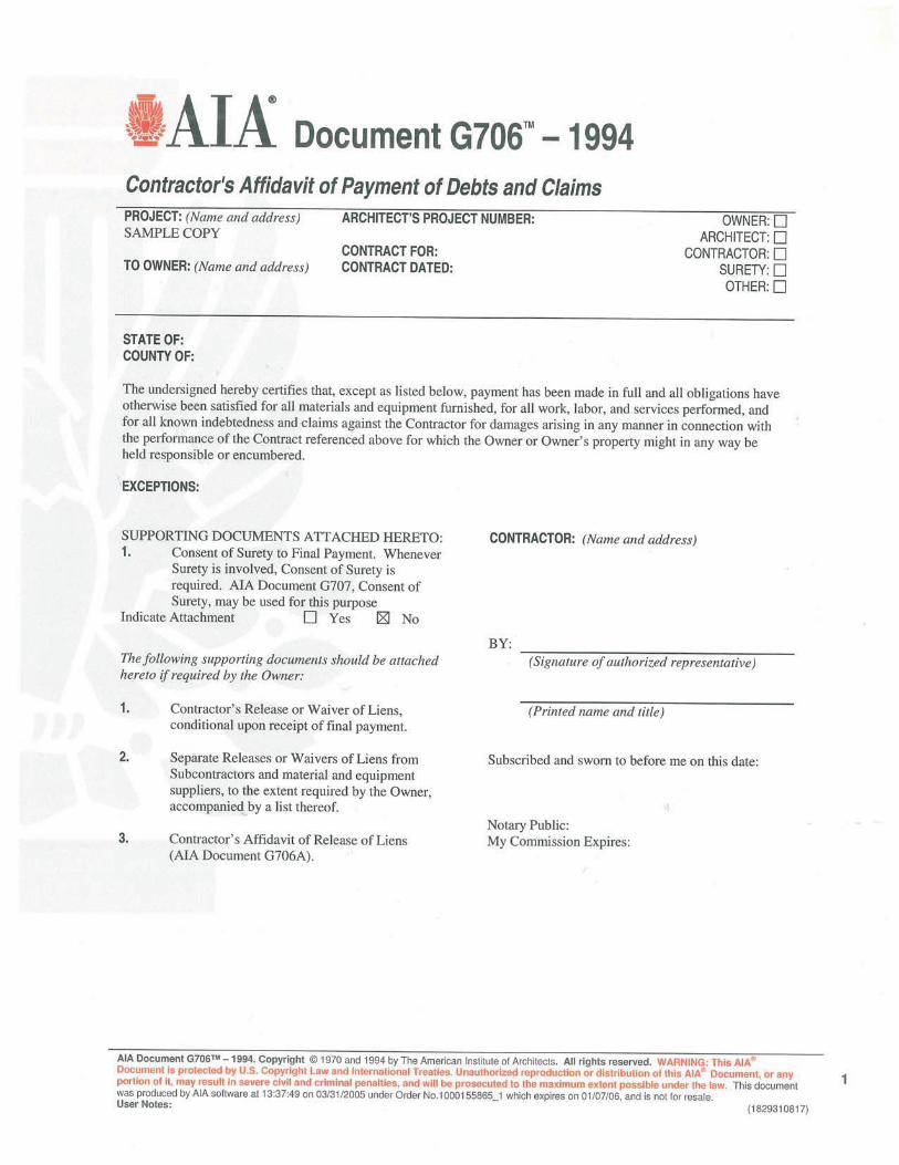

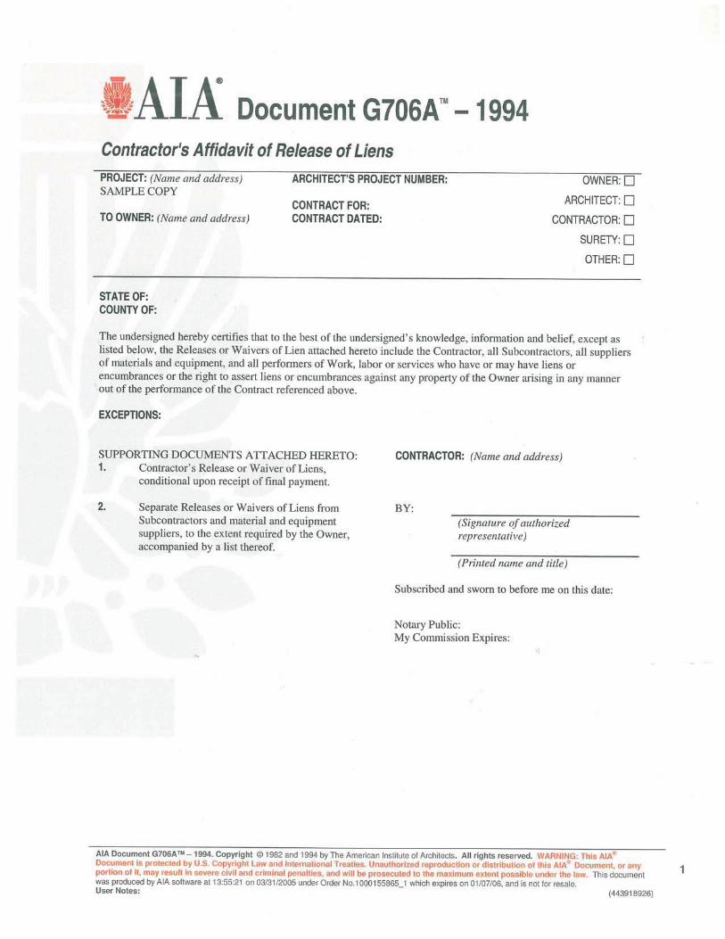

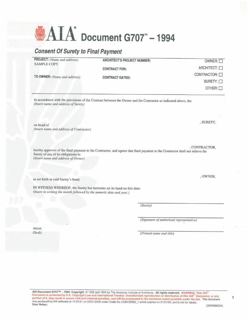

OPERATION AND MAINTENANCE DATA 017823 - 1
SECTION 017823 - OPERATION AND MAINTENANCE DATA
PART 1 - GENERAL
1.1 RELATED DOCUMENTS
A. Drawings and general provisions of the Contract, including General and Supplementary Conditions and other Division 01 Specification Sections, apply to this Section.
1.2 SUMMARY
A. Section includes administrative and procedural requirements for preparing operation and maintenance manuals, including the following:
1. Operation and maintenance documentation directory. 2. Emergency manuals. 3. Operation manuals for systems, subsystems, and equipment. 4. Product maintenance manuals. 5. Systems and equipment maintenance manuals.
B. Related Requirements:
1. Section 013300 "Submittal Procedures" for submitting copies of submittals for operation and maintenance manuals.
1.3 DEFINITIONS
A. System: An organized collection of parts, equipment, or subsystems united by regular interaction.
B. Subsystem: A portion of a system with characteristics similar to a system.
1.4 CLOSEOUT SUBMITTALS
A. Manual Content: Operations and maintenance manual content is specified in individual Specification Sections to be reviewed at the time of Section submittals. Submit reviewed manual content formatted and organized as required by this Section.
1. Architect will comment on whether content of operations and maintenance submittals are acceptable.
2. Where applicable, clarify and update reviewed manual content to correspond to revisions and field conditions.
B. Initial Manual Submittal: Submit (1) draft copy of each manual at least 30 days before requesting inspection for Substantial Completion. Include a complete operation and maintenance directory. Architect will return marked whether general scope and content of manual is acceptable.
OPERATION AND MAINTENANCE DATA 017823 - 2
C. Correct or revise each manual to comply with Architect’s and Engineer’s comments.
D. Final Manual Submittal: Submit (3) copies of each corrected manual in final form at least 15 days before commencing demonstration and training. Architect will return copy with comments.
1. If acceptable to the Owner, in lieu of (3) hard copies of each manual, contractor may submit (1) paper copy and one PDF electronic copy of the manual.
PART 2 - PRODUCTS
2.1 OPERATION AND MAINTENANCE DOCUMENTATION DIRECTORY
A. Directory: Prepare a single, comprehensive directory of emergency, operation, and maintenance data and materials, listing items and their location to facilitate ready access to desired information. Include a section in the directory for each of the following:
1. List of documents. 2. List of systems. 3. List of equipment. 4. Table of contents.
B. List of Systems and Subsystems: List systems alphabetically. Include references to operation and maintenance manuals that contain information about each system.
C. List of Equipment: List equipment for each system, organized alphabetically by system. For pieces of equipment not part of system, list alphabetically in separate list.
D. Tables of Contents: Include a table of contents for each emergency, operation, and maintenance manual.
E. Identification: In the documentation directory and in each operation and maintenance manual, identify each system, subsystem, and piece of equipment with same designation used in the Contract Documents. If no designation exists, assign a designation according to ASHRAE Guideline 4, "Preparation of Operating and Maintenance Documentation for Building Systems."
2.2 REQUIREMENTS FOR EMERGENCY, OPERATION, AND MAINTENANCE MANUALS
A. Organization: Unless otherwise indicated, organize each manual into a separate section for each system and subsystem, and a separate section for each piece of equipment not part of a system. Each manual shall contain the following materials, in the order listed:
1. Title page. 2. Table of contents. 3. Manual contents.
B. Title Page: Include the following information:
1. Subject matter included in manual.
OPERATION AND MAINTENANCE DATA 017823 - 3
2. Name and address of Project. 3. Name and address of Owner. 4. Date of submittal. 5. Name and contact information for Contractor. 6. Name and contact information for Construction Manager. 7. Name and contact information for Architect. 8. Name and contact information for Commissioning Authority. 9. Names and contact information for major consultants to the Architect that designed the
systems contained in the manuals. 10. Cross-reference to related systems in other operation and maintenance manuals.
C. Table of Contents: List each product included in manual, identified by product name, indexed to the content of the volume, and cross-referenced to Specification Section number in Project Manual.
1. If operation or maintenance documentation requires more than one volume to accommodate data, include comprehensive table of contents for all volumes in each volume of the set.
D. Manual Contents: Organize into sets of manageable size. Arrange contents alphabetically by system, subsystem, and equipment. If possible, assemble instructions for subsystems, equipment, and components of one system into a single binder.
E. Manuals, Paper Copy: Submit manuals in the form of hard copy, bound and labeled volumes.
1. Binders: Heavy-duty, three-ring, vinyl-covered, binders, in thickness necessary to accommodate contents, sized to hold 8-1/2-by-11-inch (215-by-280-mm) paper; with clear plastic sleeve on spine to hold label describing contents and with pockets inside covers to hold folded oversize sheets.
a. If two or more binders are necessary to accommodate data of a system, organize data in each binder into groupings by subsystem and related components. Cross-reference other binders if necessary to provide essential information for proper operation or maintenance of equipment or system.
b. Identify each binder on front and spine, with printed title "OPERATION AND MAINTENANCE MANUAL," Project title or name, and subject matter of contents, and indicate Specification Section number on bottom of spine. Indicate volume number for multiple-volume sets.
2. Dividers: Heavy-paper dividers with plastic-covered tabs for each section of the manual. Mark each tab to indicate contents. Include typed list of products and major components of equipment included in the section on each divider, cross-referenced to Specification Section number and title of Project Manual.
3. Protective Plastic Sleeves: Transparent plastic sleeves designed to enclose diagnostic software storage media for computerized electronic equipment.
4. Supplementary Text: Prepared on 8-1/2-by-11-inch (215-by-280-mm) white bond paper. 5. Drawings: Attach reinforced, punched binder tabs on drawings and bind with text.
a. If oversize drawings are necessary, fold drawings to same size as text pages and use as foldouts.
OPERATION AND MAINTENANCE DATA 017823 - 4
b. If drawings are too large to be used as foldouts, fold and place drawings in labeled envelopes and bind envelopes in rear of manual. At appropriate locations in manual, insert typewritten pages indicating drawing titles, descriptions of contents, and drawing locations.
2.3 EMERGENCY MANUALS
A. Content: Organize manual into a separate section for each of the following:
1. Type of emergency. 2. Emergency instructions. 3. Emergency procedures.
B. Type of Emergency: Where applicable for each type of emergency indicated below, include instructions and procedures for each system, subsystem, piece of equipment, and component:
1. Fire. 2. Flood. 3. Gas leak. 4. Water leak. 5. Power failure. 6. Water outage. 7. System, subsystem, or equipment failure. 8. Chemical release or spill.
C. Emergency Instructions: Describe and explain warnings, trouble indications, error messages, and similar codes and signals. Include responsibilities of Owner's operating personnel for notification of Installer, supplier, and manufacturer to maintain warranties.
D. Emergency Procedures: Include the following, as applicable:
1. Instructions on stopping. 2. Shutdown instructions for each type of emergency. 3. Operating instructions for conditions outside normal operating limits. 4. Required sequences for electric or electronic systems. 5. Special operating instructions and procedures.
2.4 OPERATION MANUALS
A. Content: In addition to requirements in this Section, include operation data required in individual Specification Sections and the following information:
1. System, subsystem, and equipment descriptions. Use designations for systems and equipment indicated on Contract Documents.
2. Performance and design criteria if Contractor has delegated design responsibility. 3. Operating standards. 4. Operating procedures. 5. Operating logs. 6. Wiring diagrams.

OPERATION AND MAINTENANCE DATA 017823 - 5
7. Control diagrams. 8. Piped system diagrams. 9. Precautions against improper use. 10. License requirements including inspection and renewal dates.
B. Descriptions: Include the following:
1. Product name and model number. Use designations for products indicated on Contract Documents.
2. Manufacturer's name. 3. Equipment identification with serial number of each component. 4. Equipment function. 5. Operating characteristics. 6. Limiting conditions. 7. Performance curves. 8. Engineering data and tests. 9. Complete nomenclature and number of replacement parts.
C. Operating Procedures: Include the following, as applicable:
1. Startup procedures. 2. Equipment or system break-in procedures. 3. Routine and normal operating instructions. 4. Regulation and control procedures. 5. Instructions on stopping. 6. Normal shutdown instructions. 7. Seasonal and weekend operating instructions. 8. Required sequences for electric or electronic systems. 9. Special operating instructions and procedures.
D. Systems and Equipment Controls: Describe the sequence of operation, and diagram controls as installed.
E. Piped Systems: Diagram piping as installed, and identify color-coding where required for identification.
2.5 PRODUCT MAINTENANCE MANUALS
A. Content: Organize manual into a separate section for each product, material, and finish. Include source information, product information, maintenance procedures, repair materials and sources, and warranties and bonds, as described below.
B. Source Information: List each product included in manual, identified by product name and arranged to match manual's table of contents. For each product, list name, address, and telephone number of Installer or supplier and maintenance service agent, and cross-reference Specification Section number and title in Project Manual and drawing or schedule designation or identifier where applicable.
C. Product Information: Include the following, as applicable:

OPERATION AND MAINTENANCE DATA 017823 - 6
1. Product name and model number. 2. Manufacturer's name. 3. Color, pattern, and texture. 4. Material and chemical composition. 5. Reordering information for specially manufactured products.
D. Maintenance Procedures: Include manufacturer's written recommendations and the following:
1. Inspection procedures. 2. Types of cleaning agents to be used and methods of cleaning. 3. List of cleaning agents and methods of cleaning detrimental to product. 4. Schedule for routine cleaning and maintenance. 5. Repair instructions.
E. Repair Materials and Sources: Include lists of materials and local sources of materials and related services.
F. Warranties and Bonds: Include copies of warranties and bonds and lists of circumstances and conditions that would affect validity of warranties or bonds.
1. Include procedures to follow and required notifications for warranty claims.
2.6 SYSTEMS AND EQUIPMENT MAINTENANCE MANUALS
A. Content: For each system, subsystem, and piece of equipment not part of a system, include source information, manufacturers' maintenance documentation, maintenance procedures, maintenance and service schedules, spare parts list and source information, maintenance service contracts, and warranty and bond information, as described below.
B. Source Information: List each system, subsystem, and piece of equipment included in manual, identified by product name and arranged to match manual's table of contents. For each product, list name, address, and telephone number of Installer or supplier and maintenance service agent, and cross-reference Specification Section number and title in Project Manual and drawing or schedule designation or identifier where applicable.
C. Manufacturers' Maintenance Documentation: Manufacturers' maintenance documentation including the following information for each component part or piece of equipment:
1. Standard maintenance instructions and bulletins. 2. Drawings, diagrams, and instructions required for maintenance, including disassembly and
component removal, replacement, and assembly. 3. Identification and nomenclature of parts and components. 4. List of items recommended to be stocked as spare parts.
D. Maintenance Procedures: Include the following information and items that detail essential maintenance procedures:
1. Test and inspection instructions. 2. Troubleshooting guide. 3. Precautions against improper maintenance.

OPERATION AND MAINTENANCE DATA 017823 - 7
4. Disassembly; component removal, repair, and replacement; and reassembly instructions. 5. Aligning, adjusting, and checking instructions. 6. Demonstration and training video recording, if available.
E. Maintenance and Service Schedules: Include service and lubrication requirements, list of required lubricants for equipment, and separate schedules for preventive and routine maintenance and service with standard time allotment.
1. Scheduled Maintenance and Service: Tabulate actions for daily, weekly, monthly, quarterly, semiannual, and annual frequencies.
2. Maintenance and Service Record: Include manufacturers' forms for recording maintenance.
F. Spare Parts List and Source Information: Include lists of replacement and repair parts, with parts identified and cross-referenced to manufacturers' maintenance documentation and local sources of maintenance materials and related services.
G. Maintenance Service Contracts: Include copies of maintenance agreements with name and telephone number of service agent.
H. Warranties and Bonds: Include copies of warranties and bonds and lists of circumstances and conditions that would affect validity of warranties or bonds.
1. Include procedures to follow and required notifications for warranty claims.
PART 3 - EXECUTION
3.1 MANUAL PREPARATION
A. Operation and Maintenance Documentation Directory: Prepare a separate manual that provides an organized reference to emergency, operation, and maintenance manuals.
B. Emergency Manual: Assemble a complete set of emergency information indicating procedures for use by emergency personnel and by Owner's operating personnel for types of emergencies indicated.
C. Product Maintenance Manual: Assemble a complete set of maintenance data indicating care and maintenance of each product, material, and finish incorporated into the Work.
D. Operation and Maintenance Manuals: Assemble a complete set of operation and maintenance data indicating operation and maintenance of each system, subsystem, and piece of equipment not part of a system.
1. Engage a factory-authorized service representative to assemble and prepare information for each system, subsystem, and piece of equipment not part of a system.
2. Prepare a separate manual for each system and subsystem, in the form of an instructional manual for use by Owner's operating personnel.
E. Manufacturers' Data: Where manuals contain manufacturers' standard printed data, include only sheets pertinent to product or component installed. Mark each sheet to identify each product or component incorporated into the Work. If data include more than one item in a tabular format,
OPERATION AND MAINTENANCE DATA 017823 - 8
identify each item using appropriate references from the Contract Documents. Identify data applicable to the Work and delete references to information not applicable.
1. Prepare supplementary text if manufacturers' standard printed data are not available and where the information is necessary for proper operation and maintenance of equipment or systems.
F. Drawings: Prepare drawings supplementing manufacturers' printed data to illustrate the relationship of component parts of equipment and systems and to illustrate control sequence and flow diagrams. Coordinate these drawings with information contained in record Drawings to ensure correct illustration of completed installation.
1. Do not use original project record documents as part of operation and maintenance manuals.
2. Comply with requirements of newly prepared record Drawings in Section 017839 "Project Record Documents."
G. Comply with Section 017700 "Closeout Procedures" for schedule for submitting operation and maintenance documentation.
END OF SECTION 017823
DEMONSTRATION AND TRAINING 017900 - 1
SECTION 017900 - DEMONSTRATION AND TRAINING
PART 1 - GENERAL
1.1 RELATED DOCUMENTS
A. Drawings and general provisions of the Contract, including General and Supplementary Conditions and other Division 01 Specification Sections, apply to this Section.
1.2 SUMMARY
A. Section includes administrative and procedural requirements for instructing Owner's personnel, including the following:
1. Demonstration of operation of systems, subsystems, and equipment. 2. Training in operation and maintenance of systems, subsystems, and equipment. 3. Demonstration and training video recordings.
1.3 QUALITY ASSURANCE
A. Facilitator Qualifications: A firm or individual experienced in training or educating maintenance personnel in a training program similar in content and extent to that indicated for this Project, and whose work has resulted in training or education with a record of successful learning performance.
B. Instructor Qualifications: A factory-authorized service representative, complying with requirements in Section 014000 "Quality Requirements," experienced in operation and maintenance procedures and training.
C. Pre-Instruction Conference: Conduct conference at Project site to comply with requirements in Section 013100 "Project Management and Coordination." Review methods and procedures related to demonstration and training including, but not limited to, the following:
1. Inspect and discuss locations and other facilities required for instruction. 2. Review and finalize instruction schedule and verify availability of educational materials,
instructors' personnel, audiovisual equipment, and facilities needed to avoid delays. 3. Review required content of instruction. 4. For instruction that must occur outside, review weather and forecasted weather conditions
and procedures to follow if conditions are unfavorable.
1.4 COORDINATION
A. Coordinate instruction schedule with Owner's operations. Adjust schedule as required to minimize disrupting Owner's operations and to ensure availability of Owner's personnel.
DEMONSTRATION AND TRAINING 017900 - 2
B. Coordinate instructors, including providing notification of dates, times, length of instruction time, and course content.
C. Coordinate content of training modules with content of approved emergency, operation, and maintenance manuals. Do not submit instruction program until operation and maintenance data has been reviewed and approved by Architect.
PART 2 - PRODUCTS
2.1 INSTRUCTION PROGRAM
A. Program Structure: Develop an instruction program that includes individual training modules for each system and for equipment not part of a system, as required by individual Specification Sections.
B. Training Modules: Develop a learning objective and teaching outline for each module. Include a description of specific skills and knowledge that participant is expected to master. For each module, include instruction for the following as applicable to the system, equipment, or component:
1. Basis of System Design, Operational Requirements, and Criteria: Include the following:
a. System, subsystem, and equipment descriptions. b. Performance and design criteria if Contractor is delegated design responsibility. c. Operating standards. d. Regulatory requirements. e. Equipment function. f. Operating characteristics. g. Limiting conditions. h. Performance curves.
2. Documentation: Review the following items in detail:
a. Emergency manuals. b. Operations manuals. c. Maintenance manuals. d. Project record documents. e. Identification systems. f. Warranties and bonds. g. Maintenance service agreements and similar continuing commitments.
3. Emergencies: Include the following, as applicable:
a. Instructions on meaning of warnings, trouble indications, and error messages. b. Instructions on stopping. c. Shutdown instructions for each type of emergency. d. Operating instructions for conditions outside of normal operating limits. e. Sequences for electric or electronic systems. f. Special operating instructions and procedures.
DEMONSTRATION AND TRAINING 017900 - 3
4. Operations: Include the following, as applicable:
a. Startup procedures. b. Equipment or system break-in procedures. c. Routine and normal operating instructions. d. Regulation and control procedures. e. Control sequences. f. Safety procedures. g. Instructions on stopping. h. Normal shutdown instructions. i. Operating procedures for emergencies. j. Operating procedures for system, subsystem, or equipment failure. k. Seasonal and weekend operating instructions. l. Required sequences for electric or electronic systems. m. Special operating instructions and procedures.
5. Adjustments: Include the following:
a. Alignments. b. Checking adjustments. c. Noise and vibration adjustments. d. Economy and efficiency adjustments.
6. Troubleshooting: Include the following:
a. Diagnostic instructions. b. Test and inspection procedures.
7. Maintenance: Include the following:
a. Inspection procedures. b. Types of cleaning agents to be used and methods of cleaning. c. List of cleaning agents and methods of cleaning detrimental to product. d. Procedures for routine cleaning e. Procedures for preventive maintenance. f. Procedures for routine maintenance. g. Instruction on use of special tools.
8. Repairs: Include the following:
a. Diagnosis instructions. b. Repair instructions. c. Disassembly; component removal, repair, and replacement; and reassembly
instructions. d. Instructions for identifying parts and components. e. Review of spare parts needed for operation and maintenance.
DEMONSTRATION AND TRAINING 017900 - 4
PART 3 - EXECUTION
3.1 INSTRUCTION
A. Engage qualified instructors to instruct Owner's personnel to adjust, operate, and maintain systems, subsystems, and equipment not part of a system.
B. Scheduling: Provide instruction at mutually agreed on times. For equipment that requires seasonal operation, provide similar instruction at start of each season.
1. Schedule training with Owner, through Architect, with at least seven days' advance notice.
C. Training Location and Reference Material: Conduct training on-site in the completed and fully operational facility using the actual equipment in-place. Conduct training using final operation and maintenance data submittals.
D. Evaluation: At conclusion of each training module, assess and document each participant's mastery of module by use of a demonstration performance-based test.
E. Cleanup: Collect used and leftover educational materials and give to Owner. Remove instructional equipment. Restore systems and equipment to condition existing before initial training use.
END OF SECTION 017900

SELECTIVE DEMOLITION 024119 - 1
SECTION 024119 - SELECTIVE DEMOLITION
PART 1 - GENERAL
1.1 RELATED DOCUMENTS
A. Drawings and general provisions of the Contract, including General and Supplementary Conditions and Division 01 Specification Sections, apply to this Section.
1.2 SUMMARY
A. Section Includes:
1. Demolition and removal of selected portions of building or structure. 2. Demolition and removal of selected site elements. 3. Salvage of existing items to be reused or recycled.
B. Related Requirements:
1. Section 011000 "Summary" for restrictions on use of the premises, Owner-occupancy requirements, and phasing requirements.
2. Section 017300 "Execution" for cutting and patching procedures.
1.3 DEFINITIONS
A. Remove: Detach items from existing construction and dispose of them off-site unless indicated to be salvaged or reinstalled.
B. Remove and Salvage: Detach items from existing construction, in a manner to prevent damage, and deliver to Owner ready for reuse.
C. Remove and Reinstall: Detach items from existing construction, in a manner to prevent damage, prepare for reuse, and reinstall where indicated.
D. Existing to Remain: Leave existing items that are not to be removed and that are not otherwise indicated to be salvaged or reinstalled.
E. Dismantle: To remove by disassembling or detaching an item from a surface, using gentle methods and equipment to prevent damage to the item and surfaces; disposing of items unless indicated to be salvaged or reinstalled.
1.4 MATERIALS OWNERSHIP
A. Unless otherwise indicated, demolition waste becomes property of Contractor.
SELECTIVE DEMOLITION 024119 - 2
B. Historic items, relics, antiques, and similar objects including, but not limited to, cornerstones and their contents, commemorative plaques and tablets, and other items of interest or value to Owner that may be uncovered during demolition remain the property of Owner.
1. Carefully salvage in a manner to prevent damage and promptly return to Owner.
1.5 PREINSTALLATION MEETINGS
A. Pre-demolition Conference: Conduct conference at Project site.
1. Inspect and discuss condition of construction to be selectively demolished. 2. Review structural load limitations of existing structure. 3. Review and finalize selective demolition schedule and verify availability of materials,
demolition personnel, equipment, and facilities needed to make progress and avoid delays.
4. Review requirements of work performed by other trades that rely on substrates exposed by selective demolition operations.
5. Review areas where existing construction is to remain and requires protection.
1.6 INFORMATIONAL SUBMITTALS
A. Proposed Protection Measures: Submit report, including Drawings, that indicates the measures proposed for protecting individuals and property, for environmental protection, for dust control and, for noise control. Indicate proposed locations and construction of barriers.
B. Schedule of Selective Demolition Activities: Indicate the following:
1. Detailed sequence of selective demolition and removal work, with starting and ending dates for each activity. Ensure Owner's on-site operations are uninterrupted.
2. Interruption of utility services. Indicate how long utility services will be interrupted. 3. Coordination for shutoff, capping, and continuation of utility services. 4. Coordination of Owner's continuing occupancy of portions of existing building and of
Owner's partial occupancy of completed Work.
1.7 CLOSEOUT SUBMITTALS
A. Inventory: Submit a list of items that have been removed and salvaged.
1.8 FIELD CONDITIONS
A. Conditions existing at time of inspection for bidding purpose will be maintained by Owner as far as practical.
B. Notify Architect of discrepancies between existing conditions and Drawings before proceeding with selective demolition.
C. Hazardous Materials: It is not expected that hazardous materials will be encountered in the Work.
SELECTIVE DEMOLITION 024119 - 3
1. If suspected hazardous materials are encountered, do not disturb; immediately notify
Architect and Owner. Hazardous materials will be removed by Owner under a separate contract.
D. Storage or sale of removed items or materials on-site is not permitted.
E. Utility Service: Maintain existing utilities indicated to remain in service and protect them against damage during selective demolition operations.
1.9 WARRANTY
A. Existing Warranties: Remove, replace, patch, and repair materials and surfaces cut or damaged during selective demolition, by methods and with materials and using approved contractors so as not to void existing warranties. Notify warrantor before proceeding. Existing warranties include the following:
1. Existing roof warranties.
B. Notify warrantor on completion of selective demolition, and obtain documentation verifying that existing system has been inspected and warranty remains in effect. Submit documentation at Project closeout.
1.10 COORDINATION
A. Arrange selective demolition schedule so as not to interfere with Owner's operations.
PART 2 - PRODUCTS
2.1 PERFORMANCE REQUIREMENTS
A. Regulatory Requirements: Comply with governing EPA notification regulations before beginning selective demolition. Comply with hauling and disposal regulations of authorities having jurisdiction.
B. Standards: Comply with ASSE A10.6 and NFPA 241.
PART 3 - EXECUTION
3.1 EXAMINATION
A. Verify that utilities have been disconnected and capped before starting selective demolition operations.
SELECTIVE DEMOLITION 024119 - 4
B. Perform an engineering survey of condition of building to determine whether removing any element might result in structural deficiency or unplanned collapse of any portion of structure or adjacent structures during selective building demolition operations.
1. Perform surveys as the Work progresses to detect hazards resulting from selective demolition activities.
C. Survey of Existing Conditions: Record existing conditions by use of preconstruction photographs or video.
1. Inventory and record the condition of items to be removed and salvaged. Provide photographs or video of conditions that might be misconstrued as damage caused by salvage operations.
3.2 UTILITY SERVICES AND MECHANICAL/ELECTRICAL SYSTEMS
A. Existing Services/Systems to Remain: Maintain services/systems indicated to remain and protect them against damage.
B. Existing Services/Systems to Be Removed, Relocated, or Abandoned: Locate, identify, disconnect, and seal or cap off utility services and mechanical/electrical systems serving areas to be selectively demolished.
1. Arrange to shut off utilities with utility companies. 2. If services/systems are required to be removed, relocated, or abandoned, provide
temporary services/systems that bypass area of selective demolition and that maintain continuity of services/systems to other parts of building.
3. Disconnect, demolish, and remove fire-suppression systems, plumbing, and HVAC systems, equipment, and components indicated on Drawings to be removed.
a. Piping to Be Removed: Remove portion of piping indicated to be removed and cap or plug remaining piping with same or compatible piping material.
b. Piping to Be Abandoned in Place: Drain piping and cap or plug piping with same or compatible piping material and leave in place.
c. Equipment to Be Removed: Disconnect and cap services and remove equipment. d. Equipment to Be Removed and Reinstalled: Disconnect and cap services and
remove, clean, and store equipment; when appropriate, reinstall, reconnect, and make equipment operational.
e. Equipment to Be Removed and Salvaged: Disconnect and cap services and remove equipment and deliver to Owner.
f. Ducts to Be Removed: Remove portion of ducts indicated to be removed and plug remaining ducts with same or compatible ductwork material.
g. Ducts to Be Abandoned in Place: Cap or plug ducts with same or compatible ductwork material and leave in place.
3.3 PROTECTION
A. Temporary Protection: Provide temporary barricades and other protection required to prevent injury to people and damage to adjacent buildings and facilities to remain.

SELECTIVE DEMOLITION 024119 - 5
1. Provide protection to ensure safe passage of people around selective demolition area and to and from occupied portions of building.
2. Provide temporary weather protection, during interval between selective demolition of existing construction on exterior surfaces and new construction, to prevent water leakage and damage to structure and interior areas.
3. Protect walls, ceilings, floors, and other existing finish work that are to remain or that are exposed during selective demolition operations.
4. Cover and protect furniture, furnishings, and equipment that have not been removed. 5. Comply with requirements for temporary enclosures, dust control, heating, and cooling
specified in Section 015000 "Temporary Facilities and Controls."
B. Temporary Shoring: Design, provide, and maintain shoring, bracing, and structural supports as required to preserve stability and prevent movement, settlement, or collapse of construction and finishes to remain, and to prevent unexpected or uncontrolled movement or collapse of construction being demolished.
1. Strengthen or add new supports when required during progress of selective demolition.
C. Remove temporary barricades and protections where hazards no longer exist.
3.4 SELECTIVE DEMOLITION, GENERAL
A. General: Demolish and remove existing construction only to the extent required by new construction and as indicated. Use methods required to complete the Work within limitations of governing regulations and as follows:
1. Proceed with selective demolition systematically, from higher to lower level. Complete selective demolition operations above each floor or tier before disturbing supporting members on the next lower level.
2. Neatly cut openings and holes plumb, square, and true to dimensions required. Use cutting methods least likely to damage construction to remain or adjoining construction. Use hand tools or small power tools designed for sawing or grinding, not hammering and chopping. Temporarily cover openings to remain.
3. Cut or drill from the exposed or finished side into concealed surfaces to avoid marring existing finished surfaces.
4. Do not use cutting torches until work area is cleared of flammable materials. At concealed spaces, such as duct and pipe interiors, verify condition and contents of hidden space before starting flame-cutting operations. Maintain portable fire-suppression devices during flame-cutting operations.
5. Maintain fire watch during and for at least 2 hours after flame-cutting operations. 6. Maintain adequate ventilation when using cutting torches. 7. Remove decayed, vermin-infested, or otherwise dangerous or unsuitable materials and
promptly dispose of off-site. 8. Remove structural framing members and lower to ground by method suitable to avoid
free fall and to prevent ground impact or dust generation. 9. Locate selective demolition equipment and remove debris and materials so as not to
impose excessive loads on supporting walls, floors, or framing. 10. Dispose of demolished items and materials promptly. Comply with requirements in
Section 017419 "Construction Waste Management and Disposal."
SELECTIVE DEMOLITION 024119 - 6
B. Site Access and Temporary Controls: Conduct selective demolition and debris-removal operations to ensure minimum interference with roads, streets, walks, walkways, and other adjacent occupied and used facilities.
C. Removed and Salvaged Items:
1. Clean salvaged items. 2. Pack or crate items after cleaning. Identify contents of containers. 3. Store items in a secure area until delivery to Owner. 4. Transport items to Owner's storage area on-site. 5. Protect items from damage during transport and storage.
D. Removed and Reinstalled Items:
1. Clean and repair items to functional condition adequate for intended reuse. 2. Pack or crate items after cleaning and repairing. Identify contents of containers. 3. Protect items from damage during transport and storage. 4. Reinstall items in locations indicated. Comply with installation requirements for new
materials and equipment. Provide connections, supports, and miscellaneous materials necessary to make item functional for use indicated.
E. Existing Items to Remain: Protect construction indicated to remain against damage and soiling during selective demolition. When permitted by Architect, items may be removed to a suitable, protected storage location during selective demolition and reinstalled in their original locations after selective demolition operations are complete.
3.5 SELECTIVE DEMOLITION PROCEDURES FOR SPECIFIC MATERIALS
A. Concrete: Demolish in small sections. Using power-driven saw, cut concrete to a depth of at least 3/4 inch (19 mm) at junctures with construction to remain. Dislodge concrete from reinforcement at perimeter of areas being demolished, cut reinforcement, and then remove remainder of concrete. Neatly trim openings to dimensions indicated.
B. Concrete: Demolish in sections. Cut concrete full depth at junctures with construction to remain and at regular intervals using power-driven saw, and then remove concrete between saw cuts.
C. Masonry: Demolish in small sections. Cut masonry at junctures with construction to remain, using power-driven saw, and then remove masonry between saw cuts.
D. Concrete Slabs-on-Grade: Saw-cut perimeter of area to be demolished, and then break up and remove.
E. Resilient Floor Coverings: Remove floor coverings and adhesive according to recommendations in RFCI's "Recommended Work Practices for the Removal of Resilient Floor Coverings." Do not use methods requiring solvent-based adhesive strippers.
F. Roofing: Remove no more existing roofing than what can be covered in one day by new roofing and so that building interior remains watertight and weathertight. See Section 075419 Polyvinyl-Chloride (PVC) Roofing for new roofing requirements.
SELECTIVE DEMOLITION 024119 - 7
1. Remove existing roof membrane, flashings, copings, and roof accessories. 2. Remove existing roofing system down to substrate.
3.6 DISPOSAL OF DEMOLISHED MATERIALS
A. Remove demolition waste materials from Project site and recycle or dispose of them according to Section 017419 "Construction Waste Management and Disposal."
1. Do not allow demolished materials to accumulate on-site. 2. Remove and transport debris in a manner that will prevent spillage on adjacent surfaces
and areas. 3. Remove debris from elevated portions of building by chute, hoist, or other device that
will convey debris to grade level in a controlled descent. 4. Comply with requirements specified in Section 017419 "Construction Waste
Management and Disposal."
B. Burning: Do not burn demolished materials.
3.7 CLEANING
A. Clean adjacent structures and improvements of dust, dirt, and debris caused by selective demolition operations. Return adjacent areas to condition existing before selective demolition operations began.
END OF SECTION 024119


UNIT MASONRY 042000 - 1
SECTION 042000 - UNIT MASONRY
PART 1 - GENERAL
1.1 RELATED DOCUMENTS
A. Drawings and general provisions of the Contract, including General and Supplementary Conditions and Division 01 Specification Sections, apply to this Section.
1.2 SUMMARY
A. Section Includes:
1. Concrete masonry units. 2. Mortar and grout. 3. Masonry-joint reinforcement. 4. Ties and anchors. 5. Miscellaneous masonry accessories.
1.3 DEFINITIONS
A. CMU(s): Concrete masonry unit(s).
B. Reinforced Masonry: Masonry containing reinforcing steel in grouted cells.
1.4 ACTION SUBMITTALS
A. Product Data: For each type of product.
1.5 DELIVERY, STORAGE, AND HANDLING
A. Store masonry units on elevated platforms in a dry location. If units are not stored in an enclosed location, cover tops and sides of stacks with waterproof sheeting, securely tied. If units become wet, do not install until they are dry.
B. Store cementitious materials on elevated platforms, under cover, and in a dry location. Do not use cementitious materials that have become damp.
C. Store aggregates where grading and other required characteristics can be maintained and contamination avoided.
D. Deliver preblended, dry mortar mix in moisture-resistant containers. Store preblended, dry mortar mix in delivery containers on elevated platforms in a dry location or in covered weatherproof dispensing silos.
UNIT MASONRY 042000 - 2
E. Store masonry accessories, including metal items, to prevent corrosion and accumulation of dirt and oil.
1.6 FIELD CONDITIONS
A. Protection of Masonry: During construction, cover tops of walls, projections, and sills with waterproof sheeting at end of each day's work. Cover partially completed masonry when construction is not in progress.
1. Extend cover a minimum of 24 inches (600 mm) down both sides of walls, and hold cover securely in place.
2. Where one wythe of multiwythe masonry walls is completed in advance of other wythes, secure cover a minimum of 24 inches (600 mm) down face next to unconstructed wythe, and hold cover in place.
B. Stain Prevention: Prevent grout, mortar, and soil from staining the face of masonry to be left exposed or painted. Immediately remove grout, mortar, and soil that come in contact with such masonry.
1. Protect base of walls from rain-splashed mud and from mortar splatter by spreading coverings on ground and over wall surface.
2. Protect sills, ledges, and projections from mortar droppings. 3. Protect surfaces of window and door frames, as well as similar products with painted and
integral finishes, from mortar droppings. 4. Turn scaffold boards near the wall on edge at the end of each day to prevent rain from
splashing mortar and dirt onto completed masonry.
C. Cold-Weather Requirements: Do not use frozen materials or materials mixed or coated with ice or frost. Do not build on frozen substrates. Remove and replace unit masonry damaged by frost or by freezing conditions. Comply with cold-weather construction requirements contained in TMS 602/ACI 530.1/ASCE 6.
1. Cold-Weather Cleaning: Use liquid cleaning methods only when air temperature is 40 deg F (4 deg C) and higher and will remain so until masonry has dried, but not less than seven days after completing cleaning.
D. Hot-Weather Requirements: Comply with hot-weather construction requirements contained in TMS 602/ACI 530.1/ASCE 6.
PART 2 - PRODUCTS
2.1 MANUFACTURERS
A. Source Limitations for Masonry Units: Obtain exposed masonry units of a uniform texture and color, or a uniform blend within the ranges accepted for these characteristics, from single source from single manufacturer for each product required.
UNIT MASONRY 042000 - 3
B. Source Limitations for Mortar Materials: Obtain mortar ingredients of a uniform quality, including color for exposed masonry, from single manufacturer for each cementitious component and from single source or producer for each aggregate.
2.2 UNIT MASONRY, GENERAL
A. Masonry Standard: Comply with TMS 602/ACI 530.1/ASCE 6, except as modified by requirements in the Contract Documents.
B. Defective Units: Referenced masonry unit standards may allow a certain percentage of units to contain chips, cracks, or other defects exceeding limits stated. Do not use units where such defects are exposed in the completed Work.
2.3 CONCRETE MASONRY UNITS
A. Shapes: Provide shapes indicated and as follows, with exposed surfaces matching exposed faces of adjacent units unless otherwise indicated.
1. Provide special shapes for lintels, corners, jambs, sashes, movement joints, headers, bonding, and other special conditions.
2. Provide bullnose units for outside corners unless otherwise indicated.
B. Integral Water Repellent: Provide units made with integral water repellent for exposed units and where indicated.
1. Integral Water Repellent: Liquid polymeric, integral water-repellent admixture that does not reduce flexural bond strength. Units made with integral water repellent, when tested according to ASTM E514/E514M as a wall assembly made with mortar containing integral water-repellent manufacturer's mortar additive, with test period extended to 24 hours, shall show no visible water or leaks on the back of test specimen.
C. CMUs: ASTM C90.
1. Unit Compressive Strength: Provide units with minimum average net-area compressive strength of 2150 psi (14.8 MPa).
2. Density Classification: Normal weight. 3. Size (Width): Manufactured to dimensions 3/8 inch (10 mm) less than nominal
dimensions. 4. Exposed Faces: Provide color and texture matching the range represented by Architect's
sample. 5. Faces to Receive Plaster: Where units are indicated to receive a direct application of
plaster, provide textured-face units made with gap-graded aggregates.
2.4 MORTAR AND GROUT MATERIALS
A. Portland Cement: ASTM C150/C150M, Type I or II, except Type III may be used for cold-weather construction. Provide natural color or white cement as required to produce mortar color indicated.
UNIT MASONRY 042000 - 4
1. Alkali content shall not be more than 0.1 percent when tested according to ASTM C114.
B. Hydrated Lime: ASTM C207, Type S.
C. Mortar Pigments: Natural and synthetic iron oxides and chromium oxides, compounded for use in mortar mixes and complying with ASTM C979/C979M. Use only pigments with a record of satisfactory performance in masonry mortar.
D. Colored Cement Products: Packaged blend made from portland cement and hydrated lime or masonry cement and mortar pigments, all complying with specified requirements, and containing no other ingredients.
1. Colored Portland Cement-Lime Mix:
a. Manufacturers: Subject to compliance with requirements, provide products by one of the following:
1) Essroc. 2) Lafarge North America Inc. 3) Lehigh Hanson; HeidelbergCement Group.
2. Colored Masonry Cement:
a. Manufacturers: Subject to compliance with requirements, provide products by one of the following:
1) Essroc. 2) Lafarge North America Inc. 3) Lehigh Hanson; HeidelbergCement Group.
3. Formulate blend as required to produce color indicated or, if not indicated, as selected from manufacturer's standard colors.
4. Pigments shall not exceed 10 percent of portland cement by weight. 5. Pigments shall not exceed 5 percent of masonry cement or mortar cement by weight.
E. Aggregate for Mortar: ASTM C144.
1. For mortar that is exposed to view, use washed aggregate consisting of natural sand or crushed stone.
2. For joints less than 1/4 inch (6 mm) thick, use aggregate graded with 100 percent passing the No. 16 (1.18-mm) sieve.
3. White-Mortar Aggregates: Natural white sand or crushed white stone. 4. Colored-Mortar Aggregates: Natural sand or crushed stone of color necessary to produce
required mortar color.
F. Aggregate for Grout: ASTM C404.
G. Cold-Weather Admixture: Nonchloride, noncorrosive, accelerating admixture complying with ASTM C494/C494M, Type C, and recommended by manufacturer for use in masonry mortar of composition indicated.
UNIT MASONRY 042000 - 5
H. Water-Repellent Admixture: Liquid water-repellent mortar admixture intended for use with CMUs containing integral water repellent from same manufacturer.
I. Water: Potable.
2.5 TIES AND ANCHORS
A. General: Ties and anchors shall extend at least 1-1/2 inches (38 mm) into veneer but with at least a 5/8-inch (16-mm) cover on outside face.
B. Corrugated-Metal Ties: Metal strips not less than 7/8 inch (22 mm) wide with corrugations having a wavelength of 0.3 to 0.5 inch (7.6 to 12.7 mm) and an amplitude of 0.06 to 0.10 inch (1.5 to 2.5 mm) made from 0.060-inch- (1.52-mm-)thick steel sheet, galvanized after fabrication.
2.6 MASONRY CLEANERS
A. Proprietary Acidic Cleaner: Manufacturer's standard-strength cleaner designed for removing mortar/grout stains, efflorescence, and other new construction stains from new masonry without discoloring or damaging masonry surfaces. Use product expressly approved for intended use by cleaner manufacturer and manufacturer of masonry units being cleaned.
2.7 MORTAR AND GROUT MIXES
A. General: Do not use admixtures, including pigments, air-entraining agents, accelerators, retarders, water-repellent agents, antifreeze compounds, or other admixtures unless otherwise indicated.
1. Do not use calcium chloride in mortar or grout. 2. Use portland cement-lime masonry cement or mortar cement] mortar unless otherwise
indicated. 3. Add cold-weather admixture (if used) at same rate for all mortar that will be exposed to
view, regardless of weather conditions, to ensure that mortar color is consistent.
B. Preblended, Dry Mortar Mix: Furnish dry mortar ingredients in form of a preblended mix. Measure quantities by weight to ensure accurate proportions, and thoroughly blend ingredients before delivering to Project site.
C. Mortar for Unit Masonry: Comply with ASTM C270, Proportion Specification. Provide the following types of mortar for applications stated unless another type is indicated or needed to provide required compressive strength of masonry.
1. For masonry below grade or in contact with earth, use Type M. 2. For reinforced masonry, use Type S. 3. For mortar parge coats, use Type N. 4. For exterior, above-grade, load-bearing and nonload-bearing walls and parapet walls; for
interior load-bearing walls; for interior nonload-bearing partitions; and for other applications where another type is not indicated, use Type S.
UNIT MASONRY 042000 - 6
5. For interior nonload-bearing partitions, Type N may be used instead of Type S.
D. Pigmented Mortar: Use colored cement product or select and proportion pigments with other ingredients to produce color required. Do not add pigments to colored cement products.
1. Pigments shall not exceed 10 percent of portland cement by weight. 2. Pigments shall not exceed 5 percent of masonry cement or mortar cement by weight. 3. Insert materials and proportions used for sample in first subparagraph below if known. 4. Mix to match Architect's sample. 5. Application: Use pigmented mortar for exposed mortar joints with the following units:
a. Clay face brick. b. Stone trim units.
E. Grout for Unit Masonry: Comply with ASTM C476.
1. Use grout of type indicated or, if not otherwise indicated, of type (fine or coarse) that will comply with TMS 602/ACI 530.1/ASCE 6 for dimensions of grout spaces and pour height.
2. Proportion grout in accordance with ASTM C476, Table 1 or paragraph 4.2.2 for specified 28-day compressive strength indicated, but not less than 2000 psi (14 MPa).
3. Provide grout with a slump of 8 to 11 inches (200 to 280 mm) 10 to 11 inches (250 to 280 mm) as measured according to ASTM C143/C143M.
PART 3 - EXECUTION
3.1 EXAMINATION
A. Examine conditions, with Installer present, for compliance with requirements for installation tolerances and other conditions affecting performance of the Work.
1. For the record, prepare written report, endorsed by Installer, listing conditions detrimental to performance of the Work.
2. Verify that foundations are within tolerances specified. 3. Verify that reinforcing dowels are properly placed. 4. Verify that substrates are free of substances that impair mortar bond.
B. Before installation, examine rough-in and built-in construction for piping systems to verify actual locations of piping connections.
C. Proceed with installation only after unsatisfactory conditions have been corrected.
3.2 INSTALLATION, GENERAL
A. Thickness: Build cavity and composite walls and other masonry construction to full thickness shown. Build single-wythe walls to actual widths of masonry units, using units of widths indicated.
B. Build chases and recesses to accommodate items specified in this and other Sections.
UNIT MASONRY 042000 - 7
C. Leave openings for equipment to be installed before completing masonry. After installing equipment, complete masonry to match construction immediately adjacent to opening.
D. Use full-size units without cutting if possible. If cutting is required to provide a continuous pattern or to fit adjoining construction, cut units with motor-driven saws; provide clean, sharp, unchipped edges. Allow units to dry before laying unless wetting of units is specified. Install cut units with cut surfaces and, where possible, cut edges concealed.
E. Select and arrange units for exposed unit masonry to produce a uniform blend of colors and textures. Mix units from several pallets or cubes as they are placed.
F. Matching Existing Masonry: Match coursing, bonding, color, and texture of existing masonry.
G. Wetting of Brick: Wet brick before laying if initial rate of absorption exceeds 30 g/30 sq. in. (30 g/194 sq. cm) per minute when tested according to ASTM C67. Allow units to absorb water so they are damp but not wet at time of laying.
3.3 TOLERANCES
A. Dimensions and Locations of Elements:
1. For dimensions in cross section or elevation, do not vary by more than plus 1/2 inch (12 mm) or minus 1/4 inch (6 mm).
2. For location of elements in plan, do not vary from that indicated by more than plus or minus 1/2 inch (12 mm).
3. For location of elements in elevation, do not vary from that indicated by more than plus or minus 1/4 inch (6 mm) in a story height or 1/2 inch (12 mm) total.
B. Lines and Levels:
1. For bed joints and top surfaces of bearing walls, do not vary from level by more than 1/4 inch in 10 feet (6 mm in 3 m), or 1/2-inch (12-mm) maximum.
2. For conspicuous horizontal lines, such as lintels, sills, parapets, and reveals, do not vary from level by more than 1/8 inch in 10 feet (3 mm in 3 m), 1/4 inch in 20 feet (6 mm in 6 m), or 1/2-inch (12-mm) maximum.
3. For vertical lines and surfaces, do not vary from plumb by more than 1/4 inch in 10 feet (6 mm in 3 m), 3/8 inch in 20 feet (9 mm in 6 m), or 1/2-inch (12-mm) maximum.
4. For conspicuous vertical lines, such as external corners, door jambs, reveals, and expansion and control joints, do not vary from plumb by more than 1/8 inch in 10 feet (3 mm in 3 m), 1/4 inch in 20 feet (6 mm in 6 m), or 1/2-inch (12-mm) maximum.
5. For lines and surfaces, do not vary from straight by more than 1/4 inch in 10 feet (6 mm in 3 m), 3/8 inch in 20 feet (9 mm in 6 m), or 1/2-inch (12-mm) maximum.
6. For vertical alignment of exposed head joints, do not vary from plumb by more than 1/4 inch in 10 feet (6 mm in 3 m), or 1/2-inch (12-mm) maximum.
7. If using Type FBS Rough brick or Type FBA brick, revise tolerance in subparagraph below to allow for variation in brick size.
8. For faces of adjacent exposed masonry units, do not vary from flush alignment by more than 1/16 inch (1.5 mm) except due to warpage of masonry units within tolerances specified for warpage of units.

UNIT MASONRY 042000 - 8
C. Joints:
1. For bed joints, do not vary from thickness indicated by more than plus or minus 1/8 inch (3 mm), with a maximum thickness limited to 1/2 inch (12 mm).
2. For exposed bed joints, do not vary from bed-joint thickness of adjacent courses by more than 1/8 inch (3 mm).
3. For head and collar joints, do not vary from thickness indicated by more than plus 3/8 inch (9 mm) or minus 1/4 inch (6 mm).
4. For exposed head joints, do not vary from thickness indicated by more than plus or minus 1/8 inch (3 mm).[ Do not vary from adjacent bed-joint and head-joint thicknesses by more than 1/8 inch (3 mm).]
5. For exposed bed joints and head joints of stacked bond, do not vary from a straight line by more than 1/16 inch (1.5 mm) from one masonry unit to the next.
3.4 MORTAR BEDDING AND JOINTING
A. Lay CMUs as follows:
1. Bed face shells in mortar and make head joints of depth equal to bed joints. 2. Bed webs in mortar in all courses of piers, columns, and pilasters. 3. Bed webs in mortar in grouted masonry, including starting course on footings. 4. Fully bed entire units, including areas under cells, at starting course on footings where
cells are not grouted. 5. Fully bed units and fill cells with mortar at anchors and ties as needed to fully embed
anchors and ties in mortar.
B. Lay solid masonry units with completely filled bed and head joints; butter ends with sufficient mortar to fill head joints and shove into place. Do not deeply furrow bed joints or slush head joints.
C. Tool exposed joints slightly concave when thumbprint hard, using a jointer larger than joint thickness unless otherwise indicated.
D. Cut joints flush for masonry walls to receive plaster or other direct-applied finishes (other than paint) unless otherwise indicated.
E. Cut joints flush where indicated to receive waterproofing and cavity wall insulation unless otherwise indicated.
3.5 ANCHORED MASONRY
A. Anchor new masonry to existing masonry with corrugated metal ties at 16” o.c. vertically.
3.6 LINTELS
A. Provide masonry lintels where shown and where openings of more than 12 inches (305 mm) for brick-size units and 24 inches (610 mm) for block-size units are shown without structural steel or other supporting lintels.
UNIT MASONRY 042000 - 9
B. Provide minimum bearing of 8 inches (200 mm) at each jamb unless otherwise indicated.
3.7 REPAIRING, POINTING, AND CLEANING
A. Remove and replace masonry units that are loose, chipped, broken, stained, or otherwise damaged or that do not match adjoining units. Install new units to match adjoining units; install in fresh mortar, pointed to eliminate evidence of replacement.
B. Pointing: During the tooling of joints, enlarge voids and holes, except weep holes, and completely fill with mortar. Point up joints, including corners, openings, and adjacent construction, to provide a neat, uniform appearance. Prepare joints for sealant application, where indicated.
C. In-Progress Cleaning: Clean unit masonry as work progresses by dry brushing to remove mortar fins and smears before tooling joints.
D. Final Cleaning: After mortar is thoroughly set and cured, clean exposed masonry as follows:
1. Remove large mortar particles by hand with wooden paddles and nonmetallic scrape hoes or chisels.
2. Test cleaning methods on sample wall panel; leave one-half of panel uncleaned for comparison purposes. Obtain Architect's approval of sample cleaning before proceeding with cleaning of masonry.
3. Delete first two subparagraphs below if cleaners are not specified in Part 2 or if cleaners are not allowed.
4. Protect adjacent stone and nonmasonry surfaces from contact with cleaner by covering them with liquid strippable masking agent or polyethylene film and waterproof masking tape.
5. Wet wall surfaces with water before applying cleaners; remove cleaners promptly by rinsing surfaces thoroughly with clear water.
6. Clean brick by bucket-and-brush hand-cleaning method described in BIA Technical Notes 20.
7. Clean concrete masonry by applicable cleaning methods indicated in NCMA TEK 8-4A. 8. Clean stone trim to comply with stone supplier's written instructions. 9. Clean limestone units to comply with recommendations in ILI's "Indiana Limestone
Handbook."
3.8 MASONRY WASTE DISPOSAL
A. Salvageable Materials: Unless otherwise indicated, excess masonry materials are Contractor's property. At completion of unit masonry work, remove from Project site.
B. Excess Masonry Waste: Remove excess clean masonry waste that cannot be used as fill, as described above or recycled, and other masonry waste, and legally dispose of off Owner's property.
END OF SECTION 042000

CAST STONE MASONRY 047200 - 1
SECTION 047200 - CAST STONE MASONRY
PART 1 - GENERAL
1.1 RELATED DOCUMENTS
A. Drawings and general provisions of the Contract, including General and Supplementary Conditions and Division 01 Specification Sections, apply to this Section.
1.2 SUMMARY
A. Section Includes:
1. Cast stone – masonry veneer units. 2. Cast-stone trim.
B. Related Sections:
1. Section 042000 "Unit Masonry" for installing cast-stone units in unit masonry.
1.3 ACTION SUBMITTALS
A. Product Data: For each type of product.
1. For cast-stone units, include construction details, material descriptions, dimensions of individual components and profiles, and finishes.
B. Shop Drawings: Show fabrication and installation details for cast-stone units. Include dimensions, details of reinforcement and anchorages if any, and indication of finished faces.
1. Include building elevations showing layout of units and locations of joints and anchors.
C. Samples for Initial Selection: For colored mortar.
D. Samples for Verification:
1. For each color and texture of cast stone required, 10 inches (250 mm) square in size. 2. For each trim shape required, 10 inches (250 mm) in length. 3. For colored mortar, make Samples using same sand and mortar ingredients to be used on
Project.
1.4 INFORMATIONAL SUBMITTALS
A. Qualification Data: For manufacturer.
CAST STONE MASONRY 047200 - 2
1. Include copies of material test reports for completed projects, indicating compliance of cast stone with ASTM C 1364.
1.5 QUALITY ASSURANCE
A. Manufacturer Qualifications: A qualified manufacturer of cast-stone units similar to those indicated for this Project, that has sufficient production capacity to manufacture required units, and is a plant certified by the Cast Stone Institute, the Architectural Precast Association, or, the Precast/Prestressed Concrete Institute for Group A, Category AT].
B. Mockups: Furnish cast stone for installation in mockups specified in Section 042000 "Unit Masonry."
1.6 DELIVERY, STORAGE, AND HANDLING
A. Coordinate delivery of cast stone with unit masonry work to avoid delaying the Work and to minimize the need for on-site storage.
B. Pack, handle, and ship cast-stone units in suitable packs or pallets.
1. Lift with wide-belt slings; do not use wire rope or ropes that might cause staining. Move cast-stone units if required, using dollies with wood supports.
2. Store cast-stone units on wood skids or pallets with nonstaining, waterproof covers, securely tied. Arrange to distribute weight evenly and to prevent damage to units. Ventilate under covers to prevent condensation.
C. Store cementitious materials on elevated platforms, under cover, and in a dry location. Do not use cementitious materials that have become damp.
D. Store mortar aggregates where grading and other required characteristics can be maintained and contamination can be avoided.
1.7 PROJECT CONDITIONS
A. Cold-Weather Requirements: Do not use frozen materials or materials mixed or coated with ice or frost. Do not build on frozen substrates. Comply with cold-weather construction requirements in TMS 602/ACI 530.1/ASCE 6.
1. Cold-Weather Cleaning: Use liquid cleaning methods only when air temperature is 40 deg F (4 deg C) and above and will remain so until cast stone has dried, but no fewer than seven days after completing cleaning.
B. Hot-Weather Requirements: Comply with hot-weather construction requirements in TMS 602/ACI 530.1/ASCE 6.
CAST STONE MASONRY 047200 - 3
PART 2 - PRODUCTS
2.1 MANUFACTURERS
A. Source Limitations for Cast Stone: Obtain cast-stone units from single source from single manufacturer.
B. Source Limitations for Mortar Materials: Obtain mortar ingredients of a uniform quality, including color, from one manufacturer for each cementitious component and from one source or producer for each aggregate.
2.2 CAST-STONE MATERIALS
A. General: Comply with ASTM C 1364.
B. Coarse Aggregates: Granite, quartz, or limestone complying with ASTM C 33/C 33M; gradation and colors as needed to produce required cast-stone textures and colors.
C. Fine Aggregates: Natural sand or crushed stone complying with ASTM C 33/C 33M, gradation and colors as needed to produce required cast-stone textures and colors.
D. Color Pigment: ASTM C 979/C 979M, synthetic mineral-oxide pigments or colored water-reducing admixtures; color stable,[ free of carbon black,] nonfading, and resistant to lime and other alkalis.
E. Admixtures: Use only admixtures specified or approved in writing by Architect.
1. Do not use admixtures that contain more than 0.1 percent water-soluble chloride ions by mass of cementitious materials. Do not use admixtures containing calcium chloride.
2. Use only admixtures that are certified by manufacturer to be compatible with cement and other admixtures used.
3. Air-Entraining Admixture: ASTM C 260/C 260M. Add to mixes for units exposed to the exterior at manufacturer's prescribed rate to result in an air content of 4 to 6 percent, except do not add to zero-slump concrete mixes.
4. Water-Reducing Admixture: ASTM C 494/C 494M, Type A. 5. Water-Reducing, Retarding Admixture: ASTM C 494/C 494M, Type D. 6. Water-Reducing, Accelerating Admixture: ASTM C 494/C 494M, Type E.
2.3 CAST-STONE UNITS
A. Basis-of-Design Product: Specifications are based on products as manufactured by Rockcast Custom Stone, Reading Rock, Inc., (800) 482-6466. Subject to compliance with project requirements and design intent, available manufacturers offering similar products that may be incorporated into the Work are as follows:
1. Continental Cast Stone. 2. Custom Cast Stone, Inc.
B. Cast stone – masonry veneer units:
CAST STONE MASONRY 047200 - 4
1. Nominal size: 3 5/8” x 7 5/8”, see drawings for length 2. Face finish: Smooth
C. Cast stone – trim units: 1. Stone Sills: SL440 2. Stone Band at top of cast stone section: Bullnose BN100 or equal.
D. Cast-Stone Units: Comply with ASTM C 1364.
1. Units shall be manufactured using the vibrant dry tamp or wet-cast method. 2. Units shall be resistant to freezing and thawing as determined by laboratory testing
according to ASTM C 666/C 666M, Procedure A, as modified by ASTM C 1364.
E. Fabricate units with sharp arris and accurately reproduced details, with indicated texture on all exposed surfaces unless otherwise indicated.
1. Slope exposed horizontal surfaces 1:12 to drain unless otherwise indicated. 2. Provide raised fillets at backs of sills and at ends indicated to be built into jambs. 3. Provide drips on projecting elements unless otherwise indicated.
F. Fabrication Tolerances:
1. Variation in Cross Section: Do not vary from indicated dimensions by more than 1/8 inch (3 mm).
2. Variation in Length: Do not vary from indicated dimensions by more than 1/360 of the length of unit or 1/8 inch (3 mm), whichever is greater, but in no case by more than 1/4 inch (6 mm).
3. Warp, Bow, and Twist: Not to exceed 1/360 of the length of unit or 1/8 inch (3 mm), whichever is greater.
4. Location of Grooves, False Joints, Holes, Anchorages, and Similar Features: Do not vary from indicated position by more than 1/8 inch (3 mm) on formed surfaces of units and 3/8 inch (10 mm) on unformed surfaces.
G. Cure Units as Follows:
1. Cure units in enclosed, moist curing room at 95 to 100 percent relative humidity and temperature of 100 deg F (38 deg C) for 12 hours or 70 deg F (21 deg C) for 16 hours.
2. Keep units damp and continue curing to comply with one of the following:
a. No fewer than five days at mean daily temperature of 70 deg F (21 deg C) or above.
b. No fewer than six days at mean daily temperature of 60 deg F (16 deg C) or above. c. No fewer than seven days at mean daily temperature of 50 deg F (10 deg C) or
above. d. No fewer than eight days at mean daily temperature of 45 deg F (7 deg C) or
above.
H. Acid etch units after curing to remove cement film from surfaces to be exposed to view.
I. Colors and Textures: As selected by Architect from manufacturer's full range.

CAST STONE MASONRY 047200 - 5
2.4 MORTAR MATERIALS
A. Portland Cement: ASTM C 150/C 150M, Type I or II, except Type III may be used for cold-weather construction. Provide natural color or white cement as required to produce mortar color indicated.
B. Hydrated Lime: ASTM C 207, Type S.
C. Portland Cement-Lime Mix: Packaged blend of portland cement and hydrated lime containing no other ingredients.
D. Masonry Cement: ASTM C 91/C 91M.
E. Mortar Pigments: Natural and synthetic iron oxides and chromium oxides, compounded for use in mortar mixes and complying with ASTM C 979/C 979M. Use only pigments with a record of satisfactory performance in masonry mortar.
F. Colored Cement Product: Packaged blend made from portland cement and hydrated lime, masonry cement, or mortar cement and mortar pigments, all complying with specified requirements, and containing no other ingredients. 1. Pigments shall not exceed 10 percent of portland cement by weight. 2. Pigments shall not exceed 5 percent of masonry cement or mortar cement by weight.
G. Aggregate for Mortar: ASTM C 144.
1. For mortar that is exposed to view, use washed aggregate consisting of natural sand or crushed stone.
2. For joints less than 1/4 inch (6 mm) thick, use aggregate graded with 100 percent passing the No. 16 (1.18-mm) sieve.
3. White-Mortar Aggregates: Natural white sand or crushed white stone. 4. Colored Aggregates: Natural sand or crushed stone of color necessary to produce
required mortar color.
H. Water: Potable.
2.5 ACCESSORIES
A. Proprietary Acidic Cleaner: Manufacturer's standard-strength cleaner designed for removing mortar/grout stains, efflorescence, and other new construction stains from new masonry without discoloring or damaging masonry surfaces. Use product expressly approved for intended use by cast-stone manufacturer and expressly approved by cleaner manufacturer for use on cast stone and adjacent masonry materials.
2.6 MORTAR MIXES
A. Do not use admixtures including pigments, air-entraining agents, accelerators, retarders, water-repellent agents, antifreeze compounds, or other admixtures unless otherwise indicated.
1. Do not use calcium chloride in mortar or grout.
CAST STONE MASONRY 047200 - 6
2. Use portland cement-lime, masonry cement, or mortar cement mortar unless otherwise indicated.
B. Comply with ASTM C 270, Proportion Specification.
1. For setting mortar, use Type N. 2. For pointing mortar, use Type N.
C. Pigmented Mortar: Use colored cement product[ or select and proportion pigments with other ingredients to produce color required. Do not add pigments to colored cement products].
1. Pigments shall not exceed 10 percent of portland cement by weight. 2. Pigments shall not exceed 5 percent of masonry cement or mortar cement by weight. 3. Mix to match Architect's sample. 4. Application: Use pigmented mortar for exposed mortar joints.
D. Colored-Aggregate Mortar: Produce required mortar color by using colored aggregates and natural color or white cement as necessary to produce required mortar color.
1. Mix to match Architect's sample. 2. Application: Use colored-aggregate mortar for exposed mortar joints.
2.7 SOURCE QUALITY CONTROL
A. Engage a qualified independent testing agency to sample and test cast-stone units according to ASTM C 1364.
1. Include one test for resistance to freezing and thawing.
PART 3 - EXECUTION
3.1 EXAMINATION
A. Examine substrates and conditions, with Installer present, for compliance with requirements for installation tolerances and other conditions affecting performance of the Work.
B. Proceed with installation only after unsatisfactory conditions have been corrected.
3.2 SETTING CAST STONE IN MORTAR
A. Install cast-stone units to comply with requirements in Section 042000 "Unit Masonry."
B. Set cast stone as indicated on Drawings. Set units accurately in locations indicated, with edges and faces aligned according to established relationships and indicated tolerances.
1. Install anchors, supports, fasteners, and other attachments indicated or necessary to secure units in place.
CAST STONE MASONRY 047200 - 7
2. Coordinate installation of cast stone with installation of flashing specified in other Sections.
C. Wet joint surfaces thoroughly before applying mortar or setting in mortar.
D. Set units in full bed of mortar with full head joints unless otherwise indicated.
1. Set units with joints 3/8 to 1/2 inch (10 to 13 mm) wide unless otherwise indicated. 2. Build anchors and ties into mortar joints as units are set. 3. Fill dowel holes and anchor slots with mortar. 4. Fill collar joints solid as units are set. 5. Build concealed flashing into mortar joints as units are set. 6. Keep head joints in copings and between other units with exposed horizontal surfaces
open to receive sealant. 7. Keep joints at shelf angles open to receive sealant.
E. Rake out joints for pointing with mortar to depths of not less than 3/4 inch (19 mm). Rake joints to uniform depths with square bottoms and clean sides. Scrub faces of units to remove excess mortar as joints are raked.
F. Point mortar joints by placing and compacting mortar in layers not greater than 3/8 inch (10 mm). Compact each layer thoroughly and allow it to become thumbprint hard before applying next layer.
G. Tool exposed joints slightly concave when thumbprint hard. Use a smooth plastic jointer larger than joint thickness.
H. Rake out joints for pointing with sealant to depths of not less than 3/4 inch (19 mm). Scrub faces of units to remove excess mortar as joints are raked.
I. Point joints with sealant to comply with applicable requirements in Section 079200 "Joint Sealants."
1. Prime cast-stone surfaces to receive sealant and install compressible backer rod in joints before applying sealant unless otherwise indicated.
J. Provide sealant joints at head joints of copings and other horizontal surfaces; at expansion, control, and pressure-relieving joints; and at locations indicated.
1. Keep joints free of mortar and other rigid materials. 2. Build in compressible foam-plastic joint fillers where indicated. 3. Form joint of width indicated, but not less than 3/8 inch (10 mm). 4. Prime cast-stone surfaces to receive sealant and install compressible backer rod in joints
before applying sealant unless otherwise indicated. 5. Prepare and apply sealant of type and at locations indicated to comply with applicable
requirements in Section 079200 "Joint Sealants."

CAST STONE MASONRY 047200 - 8
3.3 INSTALLATION TOLERANCES
A. Variation from Plumb: Do not exceed 1/8 inch in 10 feet (3 mm in 3 m), 1/4 inch in 20 feet (6 mm in 6 m), or 1/2 inch (12 mm) maximum.
B. Variation from Level: Do not exceed 1/8 inch in 10 feet (3 mm in 3 m), 1/4 inch in 20 feet (6 mm in 6 m), or 1/2 inch (12 mm) maximum.
C. Variation in Joint Width: Do not vary joint thickness more than 1/8 inch in 36 inches (3 mm in 900 mm) or one-fourth of nominal joint width, whichever is less.
D. Variation in Plane between Adjacent Surfaces (Lipping): Do not vary from flush alignment with adjacent units or adjacent surfaces indicated to be flush with units by more than 1/16 inch (1.5 mm), except where variation is due to warpage of units within tolerances specified.
3.4 ADJUSTING AND CLEANING
A. Remove and replace stained and otherwise damaged units and units not matching approved Samples. Cast stone may be repaired if methods and results are approved by Architect.
B. Replace units in a manner that results in cast stone matching approved Samples, complying with other requirements, and showing no evidence of replacement.
C. In-Progress Cleaning: Clean cast stone as work progresses.
1. Remove mortar fins and smears before tooling joints. 2. Remove excess sealant immediately, including spills, smears, and spatter.
D. Final Cleaning: After mortar is thoroughly set and cured, clean exposed cast stone as follows:
1. Remove large mortar particles by hand with wooden paddles and nonmetallic scrape hoes or chisels.
2. Test cleaning methods on sample; leave one sample uncleaned for comparison purposes. Obtain Architect's approval of sample cleaning before proceeding with cleaning of cast stone.
3. Protect adjacent surfaces from contact with cleaner by covering them with liquid strippable masking agent or polyethylene film and waterproof masking tape.
4. Wet surfaces with water before applying cleaners; remove cleaners promptly by rinsing thoroughly with clear water.
5. Clean cast stone by bucket-and-brush hand-cleaning method described in BIA Technical Notes 20.
6. Clean cast stone with proprietary acidic cleaner applied according to manufacturer's written instructions.
END OF SECTION 047200
ROUGH CARPENTRY 061000 - 1
SECTION 061000 - ROUGH CARPENTRY
PART 1 - GENERAL
1.1 RELATED DOCUMENTS
A. Drawings and general provisions of the Contract, including General and Supplementary Conditions and Division 01 Specification Sections, apply to this Section.
1.2 SUMMARY
A. Section Includes:
1. Framing with dimension lumber. 2. Framing with engineered wood products. 3. Wood sleepers.
1.3 DEFINITIONS
A. Boards or Strips: Lumber of less than 2 inches nominal (38 mm actual) size in least dimension.
B. Dimension Lumber: Lumber of 2 inches nominal (38 mm actual) size or greater but less than 5 inches nominal (114 mm actual) size in least dimension.
C. Exposed Framing: Framing not concealed by other construction.
D. OSB: Oriented strand board.
E. Timber: Lumber of 5 inches nominal (114 mm actual) size or greater in least dimension.
1.4 ACTION SUBMITTALS
A. Product Data: For each type of process and factory-fabricated product. Indicate component materials and dimensions and include construction and application details.
1. Include data for wood-preservative treatment from chemical treatment manufacturer and certification by treating plant that treated materials comply with requirements. Indicate type of preservative used and net amount of preservative retained.
2. Include data for fire-retardant treatment from chemical treatment manufacturer and certification by treating plant that treated materials comply with requirements. Include physical properties of treated materials based on testing by a qualified independent testing agency.
3. For fire-retardant treatments, include physical properties of treated lumber both before and after exposure to elevated temperatures, based on testing by a qualified independent testing agency according to ASTM D 5664.
ROUGH CARPENTRY 061000 - 2
4. For products receiving a waterborne treatment, include statement that moisture content of treated materials was reduced to levels specified before shipment to Project site.
B. Fastener Patterns: Full-size templates for fasteners in exposed framing.
1.5 INFORMATIONAL SUBMITTALS
A. Material Certificates: For dimension lumber specified to comply with minimum allowable unit stresses. Indicate species and grade selected for each use and design values approved by the ALSC Board of Review.
1.6 QUALITY ASSURANCE
A. Testing Agency Qualifications: For testing agency providing classification marking for fire-retardant treated material, an inspection agency acceptable to authorities having jurisdiction that periodically performs inspections to verify that the material bearing the classification marking is representative of the material tested.
1.7 DELIVERY, STORAGE, AND HANDLING
A. Stack wood products flat with spacers beneath and between each bundle to provide air circulation. Protect wood products from weather by covering with waterproof sheeting, securely anchored. Provide for air circulation around stacks and under coverings.
PART 2 - PRODUCTS
2.1 WOOD PRODUCTS, GENERAL
A. Lumber: DOC PS 20 and applicable rules of grading agencies indicated. If no grading agency is indicated, comply with the applicable rules of any rules-writing agency certified by the ALSC Board of Review. Grade lumber by an agency certified by the ALSC Board of Review to inspect and grade lumber under the rules indicated.
1. Factory mark each piece of lumber with grade stamp of grading agency. 2. For exposed lumber indicated to receive a stained or natural finish, omit grade stamp and
provide certificates of grade compliance issued by grading agency. 3. Dress lumber, S4S, unless otherwise indicated.
B. Maximum Moisture Content of Lumber: 15 percent unless otherwise indicated.
2.2 WOOD-PRESERVATIVE-TREATED LUMBER
A. Preservative Treatment by Pressure Process: AWPA U1; Use Category UC2 for interior construction not in contact with ground, Use Category UC3b for exterior construction not in contact with ground, and Use Category UC4a for items in contact with ground.

ROUGH CARPENTRY 061000 - 3
1. Preservative Chemicals: Acceptable to authorities having jurisdiction and containing no arsenic or chromium.
2. For exposed items indicated to receive a stained or natural finish, chemical formulations shall not require incising, contain colorants, bleed through, or otherwise adversely affect finishes.
B. Kiln-dry lumber after treatment to a maximum moisture content of 19 percent. Do not use material that is warped or that does not comply with requirements for untreated material.
C. Mark lumber with treatment quality mark of an inspection agency approved by the ALSC Board of Review.
1. For exposed lumber indicated to receive a stained or natural finish, omit marking and provide certificates of treatment compliance issued by inspection agency.
D. Application: Treat all rough carpentry items indicated on Drawings, and the following:
1. Wood cants, nailers, curbs, equipment support bases, blocking, stripping, and similar members in connection with roofing, flashing, vapor barriers, and waterproofing.
2. Wood sills, sleepers, blocking, furring, stripping, and similar concealed members in contact with masonry or concrete.
3. Wood framing and furring attached directly to the interior of below-grade exterior masonry or concrete walls.
4. Wood framing members that are less than 18 inches (460 mm) above the ground in crawlspaces or unexcavated areas.
5. Wood floor plates that are installed over concrete slabs-on-grade.
2.3 DIMENSION LUMBER FRAMING
A. Non-Load-Bearing Interior Partitions: Construction or No. 2 grade.
1. Application: All interior partitions. 2. Species:
a. Hem-fir (north); NLGA. b. Southern pine or mixed southern pine; SPIB. c. Spruce-pine-fir; NLGA. d. Hem-fir; WCLIB, or WWPA. e. Spruce-pine-fir (south); NeLMA, WCLIB, or WWPA. f. Northern species; NLGA. g. Eastern softwoods; NeLMA. h. Western woods; WCLIB or WWPA.
B. Exposed Framing Indicated to Receive a Stained or Natural Finish: Hand-select material for uniformity of appearance and freedom from characteristics, on exposed surfaces and edges, that would impair finish appearance, including decay, honeycomb, knot-holes, shake, splits, torn grain, and wane.
1. Species and Grade: As indicated above for load-bearing construction of same type.
ROUGH CARPENTRY 061000 - 4
2. Additional Restriction: Free of heart centers.
2.4 MISCELLANEOUS LUMBER
A. General: Provide miscellaneous lumber indicated and lumber for support or attachment of other construction, including the following:
1. Blocking. 2. Nailers. 3. Furring. 4. Grounds. 5. Utility shelving.
B. Dimension Lumber Items: Construction or No. 2grade lumber of any of the following species:
1. Hem-fir (north); NLGA. 2. Mixed southern pine or southern pine; SPIB. 3. Spruce-pine-fir; NLGA. 4. Hem-fir; WCLIB or WWPA. 5. Spruce-pine-fir (south); NeLMA, WCLIB, or WWPA. 6. Western woods; WCLIB or WWPA. 7. Northern species; NLGA. 8. Eastern softwoods; NeLMA.
C. Concealed Boards: 15 percent maximum moisture content.
D. For blocking not used for attachment of other construction, Utility, Stud, or No. 3 grade lumber of any species may be used provided that it is cut and selected to eliminate defects that will interfere with its attachment and purpose.
E. For blocking and nailers used for attachment of other construction, select and cut lumber to eliminate knots and other defects that will interfere with attachment of other work.
F. For furring strips for installing plywood or hardboard paneling, select boards with no knots capable of producing bent-over nails and damage to paneling.
2.5 PLYWOOD BACKING PANELS
A. Equipment Backing Panels: Plywood, DOC PS 1, Exposure 1, C-D Plugged in thickness indicated or, if not indicated, not less than 1/2-inch (13-mm) nominal thickness.
2.6 FASTENERS
A. General: Fasteners shall be of size and type indicated and shall comply with requirements specified in this article for material and manufacture.
1. Where rough carpentry is exposed to weather, in ground contact, pressure-preservative treated, or in area of high relative humidity, provide fasteners with hot-dip zinc coating complying with ASTM A 153/A 153M.
ROUGH CARPENTRY 061000 - 5
B. Nails, Brads, and Staples: ASTM F 1667.
C. Power-Driven Fasteners: Fastener systems with an evaluation report acceptable to authorities having jurisdiction, based on ICC-ES AC70.
D. Post-Installed Anchors: Fastener systems with an evaluation report acceptable to authorities having jurisdiction, based on ICC-ES AC01, ICC-ES AC58, ICC-ES AC193, or ICC-ES AC308 as appropriate for the substrate.
1. Material: Carbon-steel components, zinc plated to comply with ASTM B 633, Class Fe/Zn 5.
2. Material: Stainless steel with bolts and nuts complying with ASTM F 593 and ASTM F 594, Alloy Group 1 or 2 (ASTM F 738M and ASTM F 836M, Grade A1 or A4).
2.7 METAL FRAMING ANCHORS
A. Allowable design loads, as published by manufacturer, shall meet or exceed those of products of manufacturers listed. Manufacturer's published values shall be determined from empirical data or by rational engineering analysis and demonstrated by comprehensive testing performed by a qualified independent testing agency. Framing anchors shall be punched for fasteners adequate to withstand same loads as framing anchors.
B. Galvanized-Steel Sheet: Hot-dip, zinc-coated steel sheet complying with ASTM A 653/A 653M, G60 (Z180) coating designation.
1. Use for interior locations unless otherwise indicated.
C. Hot-Dip, Heavy-Galvanized Steel Sheet: ASTM A 653/A 653M; structural steel (SS), high-strength low-alloy steel Type A (HSLAS Type A), or high-strength low-alloy steel Type B (HSLAS Type B); G185 (Z550) coating designation; and not less than 0.036 inch (0.9 mm) thick.
1. Use for wood-preservative-treated lumber and where indicated.
2.8 MISCELLANEOUS MATERIALS
A. Sill-Sealer Gaskets: Glass-fiber-resilient insulation, fabricated in strip form, for use as a sill sealer; 1-inch (25-mm) nominal thickness, compressible to 1/32 inch (0.8 mm); selected from manufacturer's standard widths to suit width of sill members indicated.
B. Flexible Flashing: Composite, self-adhesive, flashing product consisting of a pliable, butyl rubber or rubberized-asphalt compound, bonded to a high-density polyethylene film, aluminum foil, or spunbonded polyolefin to produce an overall thickness of not less than 0.025 inch (0.6 mm).
C. Water-Repellent Preservative: NWWDA-tested and -accepted formulation containing 3-iodo-2-propynyl butyl carbamate, combined with an insecticide containing chloropyrifos as its active ingredient.

ROUGH CARPENTRY 061000 - 6
PART 3 - EXECUTION
3.1 INSTALLATION, GENERAL
A. Framing Standard: Comply with AF&PA's WCD 1, "Details for Conventional Wood Frame Construction," unless otherwise indicated.
B. Set rough carpentry to required levels and lines, with members plumb, true to line, cut, and fitted. Fit rough carpentry accurately to other construction. Locate furring, nailers, blocking, rounds, and similar supports to comply with requirements for attaching other construction.
C. Install plywood backing panels by fastening to studs; coordinate locations with utilities requiring backing panels.
D. Install metal framing anchors to comply with manufacturer's written instructions. Install fasteners through each fastener hole.
E. Install sill sealer gasket to form continuous seal between sill plates and foundation walls.
F. Do not splice structural members between supports unless otherwise indicated.
G. Provide blocking and framing as indicated and as required to support facing materials, fixtures, specialty items, and trim.
1. Provide metal clips for fastening gypsum board or lath at corners and intersections where framing or blocking does not provide a surface for fastening edges of panels. Space clips not more than 16 inches (406 mm) o.c.
H. Sort and select lumber so that natural characteristics do not interfere with installation or with fastening other materials to lumber. Do not use materials with defects that interfere with function of member or pieces that are too small to use with minimum number of joints or optimum joint arrangement.
I. Comply with AWPA M4 for applying field treatment to cut surfaces of preservative-treated lumber.
1. Use inorganic boron for items that are continuously protected from liquid water. 2. Use copper naphthenate for items not continuously protected from liquid water.
J. Where wood-preservative-treated lumber is installed adjacent to metal decking, install continuous flexible flashing separator between wood and metal decking.
K. Securely attach rough carpentry work to substrate by anchoring and fastening as indicated, complying with the following:
1. Table 2304.9.1, "Fastening Schedule," in ICC's International Building Code (IBC). 2. Table R602.3(1), "Fastener Schedule for Structural Members," and Table R602.3(2),
"Alternate Attachments," in ICC's International Residential Code for One- and Two-Family Dwellings.
3. ICC-ES evaluation report for fastener.
ROUGH CARPENTRY 061000 - 7
L. Use steel common nails unless otherwise indicated. Select fasteners of size that will not fully penetrate members where opposite side will be exposed to view or will receive finish materials. Make tight connections between members. Install fasteners without splitting wood. Drive nails snug but do not countersink nail heads unless otherwise indicated.
M. For exposed work, arrange fasteners in straight rows parallel with edges of members, with fasteners evenly spaced, and with adjacent rows staggered.
1. Comply with approved fastener patterns where applicable 2. Use finishing nails unless otherwise indicated. Countersink nail heads and fill holes with
wood filler. 3. Use common nails unless otherwise indicated. Drive nails snug but do not countersink nail
heads.
3.2 WALL AND PARTITION FRAMING INSTALLATION
A. General: Provide single bottom plate and double top plates using members of 2-inch nominal (38-mm actual) thickness whose widths equal that of studs, except single top plate may be used for non-load-bearing partitions and for load-bearing partitions where framing members bearing on partition are located directly over studs. Fasten plates to supporting construction unless otherwise indicated.
1. For exterior walls, provide 2-by-6-inch nominal- (38-by-140-mm actual-) size wood studs spaced 16 inches (406 mm)o.c. unless otherwise indicated.
2. For interior partitions and walls, provide 2-by-4-inch nominal- (38-by-89-mm actual) size wood studs spaced 16 inches (406 mm) o.c. unless otherwise indicated.
3. Provide continuous horizontal blocking at midheight of partitions more than 96 inches (2438 mm) high, using members of 2-inch nominal (38-mm actual) thickness and of same width as wall or partitions.
B. Construct corners and intersections with three or more studs, except that two studs may be used for interior non-load-bearing partitions.
C. Frame openings with multiple studs and headers. Provide nailed header members of thickness equal to width of studs. Support headers on jamb studs.
1. For non-load-bearing partitions, provide double-jamb studs and headers not less than 4-inch nominal (89-mm actual) depth for openings 48 inches (1200 mm) and less in width, 6-inch nominal (140-mm actual) depth for openings 48 to 72 inches (1200 to 1800 mm) in width, 8-inch nominal (184-mm actual) depth for openings 72 to 120 inches (1800 to 3000 mm) in width, and not less than 10-inch nominal (235-mm actual) depth for openings 10 to 12 feet (3 to 3.6 m) in width.
2. For load-bearing walls, provide double-jamb studs for openings 60 inches (1500 mm) and less in width, and triple-jamb studs for wider openings. Provide headers of depth indicated or, if not indicated, according to Table R502.5(1) or Table R502.5(2), as applicable, in ICC's International Residential Code for One- and Two-Family Dwellings.
ROUGH CARPENTRY 061000 - 8
3.3 PROTECTION
A. Protect wood that has been treated with inorganic boron (SBX) from weather. If, despite protection, inorganic boron-treated wood becomes wet, apply EPA-registered borate treatment. Apply borate solution by spraying to comply with EPA-registered label.
B. Protect rough carpentry from weather. If, despite protection, rough carpentry becomes wet enough that moisture content exceeds that specified, apply EPA-registered borate treatment. Apply borate solution by spraying to comply with EPA-registered label.
END OF SECTION 061000
INTERIOR ARCHITECTURAL WOODWORK 064023 - 1
SECTION 064023 - INTERIOR ARCHITECTURAL WOODWORK
PART 1 - GENERAL
1.1 RELATED DOCUMENTS
A. Drawings and general provisions of the Contract, including General and Supplementary Conditions and Division 01 Specification Sections, apply to this Section.
1.2 SUMMARY
A. This Section includes the following:
1. Plastic-laminate cabinets. 2. Plastic-laminate countertops.
1.3 SUBMITTALS
A. Product Data: For high-pressure decorative laminate, adhesive for bonding plastic laminate, solid-surfacing material, cabinet hardware and accessories and finishing materials and processes.
B. Shop Drawings: Show location of each item, dimensioned plans and elevations, large-scale details, attachment devices, and other components.
1. Show locations and sizes of furring, blocking, and hanging strips, including concealed blocking and reinforcement specified in other Sections.
2. Show locations and sizes of cutouts and holes for plumbing fixtures, faucets, soap dispensers and other items installed in architectural woodwork.
3. Apply WI-certified compliance label to first page of Shop Drawings.
C. Samples for Initial Selection:
1. Plastic laminates.
1.4 QUALITY ASSURANCE
A. Fabricator Qualifications: Shop that employs skilled workers who custom-fabricate products similar to those required for this Project and whose products have a record of successful in-service performance.
B. Installer Qualifications: Fabricator of products.
C. Source Limitations: Engage a qualified woodworking firm to assume undivided responsibility for production of interior architectural woodwork with sequence-matched wood veneers.
INTERIOR ARCHITECTURAL WOODWORK 064023 - 2
D. Quality Standard: Unless otherwise indicated, comply with AWI's "Architectural Woodwork Quality Standards" for grades of interior architectural woodwork indicated for construction, finishes, installation, and other requirements.
1. Provide AWI Quality Certification Program labels indicating that woodwork, complies with requirements of grades specified.
1.5 DELIVERY, STORAGE, AND HANDLING
A. Do not deliver cabinets until painting and similar operations that could damage cabinets have been completed in installation areas. If cabinets must be stored in other than installation areas, store only in areas where environmental conditions comply with requirements specified in "Project Conditions" Article.
1.6 PROJECT CONDITIONS
A. Environmental Limitations: Do not deliver or install cabinets until building is enclosed, wet work is complete, and HVAC system is operating and maintaining temperature between 60 and 90 deg F and relative humidity between 25 and 55 percent during the remainder of the construction period.
B. Field Measurements: Where cabinets are indicated to fit to other construction, verify dimensions of other construction by field measurements before fabrication, and indicate measurements on Shop Drawings. Coordinate fabrication schedule with construction progress to avoid delaying the Work.
1. Locate concealed framing, blocking, and reinforcements that support cabinets by field measurements before being enclosed, and indicate measurements on Shop Drawings.
2. Established Dimensions: Where field measurements cannot be made without delaying the Work, establish dimensions and proceed with fabricating cabinets without field measurements. Provide allowance for filler panels, and coordinate construction to ensure that actual dimensions correspond to established dimensions.
1.7 COORDINATION
A. Coordinate sizes and locations of framing, blocking, furring, reinforcements, and other related units of Work specified in other Sections to ensure that interior architectural woodwork can be supported and installed as indicated.
PART 2 - PRODUCTS
2.1 MATERIALS
A. General: Provide materials that comply with requirements of AWI's quality standard for each type of woodwork and quality grade specified, unless otherwise indicated.
B. Wood Products: Comply with the following:
INTERIOR ARCHITECTURAL WOODWORK 064023 - 3
1. Hardboard: AHA A135.4. 2. Medium-Density Fiberboard (MDF): ANSI A208.2, Grade MD made with binder
containing no urea formaldehyde. 3. Particleboard: ANSI A208.1, Grade M-2-Exterior Glue. 4. Softwood Plywood: DOC PS 1, Medium Density Overlay.
C. High-Pressure Decorative Laminate: NEMA LD 3, grades as indicated or, if not indicated, as required by woodwork quality standard.
1. Manufacturer: Subject to compliance with requirements, provide high-pressure decorative laminates by one of the following:
a. Formica Corporation. b. Lamin-Art, Inc. c. Wilsonart International; Div. of Premark International, Inc.
2.2 CABINET HARDWARE AND ACCESSORIES
A. General: Provide cabinet hardware and accessory materials associated with architectural cabinets, except for items specified in Division 08 Section "Door Hardware”.
B. Frameless Concealed Hinges (European Type): BHMA A156.9, B01602, 170 degrees of opening, self-closing.
C. Door/Drawer Pulls: Back mounted wire pulls, solid metal, 4 inches long, 5/16 inch in diameter
D. Adjustable Shelf Standards and Supports: BHMA A156.9, B0407; with shelf rests, B04081.
E. Shelf Rests: BHMA A156.9, B04013metal, two-pin type with shelf hold-down clip.
F. Drawer Slides: BHMA A156.9, B05091. 1. Box Drawer Slides: Grade 1HD-100: for drawers not more than 6 inches high and 24
inches wide. 2. File Drawer Slides: Grade 1HD-200; for drawers more than 6 inches high or 24 inches
wide.
G. Door Locks: BHMA A156.11, E07121.
H. Drawer Locks: BHMA A156.11, E07041.
I. Grommets for Cable Passage through Countertops: 2-inch OD, molded-plastic grommets and matching plastic caps with slot for wire passage.
J. Exposed Hardware Finishes: For exposed hardware, provide finish that complies with BHMA A156.18 for BHMA finish number indicated.
1. Satin Chromium Plated: BHMA 626 for brass or bronze base; BHMA 652 for steel base.
K. For concealed hardware, provide manufacturer's standard finish that complies with product class requirements in BHMA A156.9.

INTERIOR ARCHITECTURAL WOODWORK 064023 - 4
2.3 MISCELLANEOUS MATERIALS
A. Furring, Blocking, Shims, and Hanging Strips: Softwood or hardwood lumber, kiln dried to less than 15 percent moisture content.
B. Anchors: Select material, type, size, and finish required for each substrate for secure anchorage. Provide nonferrous-metal or hot-dip galvanized anchors and inserts on inside face of exterior walls and elsewhere as required for corrosion resistance. Provide toothed-steel or lead expansion sleeves for drilled-in-place anchors.
C. Adhesives, General: Do not use adhesives that contain urea formaldehyde.
D. VOC Limits for Installation Adhesives and Glues: Use installation adhesives that comply with the following limits for VOC content when calculated according to 40 CFR 59, Subpart D (EPA Method 24):
1. Wood Glues: 30 g/L. 2. Contact Adhesive: 250 g/L.
2.4 FABRICATION, GENERAL
A. Interior Woodwork Grade: Unless otherwise indicated, provide Premium-grade interior woodwork complying with referenced quality standard.
B. Wood Moisture Content: Comply with requirements of referenced quality standard for wood moisture content in relation to ambient relative humidity during fabrication and in installation areas.
C. Fabricate woodwork to dimensions, profiles, and details indicated. Ease edges to radius indicated for the following:
1. Corners of Cabinets and Edges of Solid-Wood (Lumber) Members and Rails: 1/16 inch.
D. Complete fabrication, including assembly, finishing, and hardware application, to maximum extent possible before shipment to Project site. Disassemble components only as necessary for shipment and installation. Where necessary for fitting at site, provide ample allowance for scribing, trimming, and fitting.
E. Shop-cut openings to maximum extent possible to receive hardware, appliances, plumbing fixtures, electrical work, and similar items. Locate openings accurately and use templates or roughing-in diagrams to produce accurately sized and shaped openings. Sand edges of cutouts to remove splinters and burrs.
1. Seal edges of openings in countertops with a coat of varnish.
2.5 PLASTIC-LAMINATE COUNTERTOPS
A. Grade: Custom.
B. High-Pressure Decorative Laminate Grade: HGS.
INTERIOR ARCHITECTURAL WOODWORK 064023 - 5
C. Colors, Patterns, and Finishes: Provide materials and products that result in colors and textures of exposed laminate surfaces complying with the following requirements: 1. As selected by Architect from manufacturer's full range.
D. Edge Treatment: Wood Full Bullnose as indicated on drawings.
E. Core Material: Particleboard or medium-density fiberboard.
F. Core Material at Sinks: Particleboard made with exterior glue.
G. Paper Backing: Provide paper backing on underside of countertop substrate.
PART 3 - EXECUTION
3.1 PREPARATION
A. Before installation, condition cabinets to average prevailing humidity conditions in installation areas.
B. Before installing architectural woodwork, examine shop-fabricated work for completion and complete work as required, including removal of packing and backpriming.
3.2 INSTALLATION
A. Cabinets: Install without distortion so doors and drawers fit openings properly and are accurately aligned. Adjust hardware to center doors and drawers in openings and to provide unencumbered operation. Complete installation of hardware and accessory items as indicated.
1. Install cabinets with no more than 1/8 inch in 96-inch sag, bow, or other variation from a straight line.
2. Maintain veneer sequence matching of cabinets with transparent finish. 3. Fasten wall cabinets through back, near top and bottom, at ends and not more than 16
inches o.c. with No. 10 wafer-head screws sized for 1-inch (25-mm) penetration into wood framing, blocking, or hanging strips.
B. Countertops: Anchor securely by screwing through corner blocks of base cabinets or other supports into underside of countertop.
1. Align adjacent solid-surfacing-material countertops and form seams to comply with manufacturer's written recommendations using adhesive in color to match countertop. Carefully dress joints smooth, remove surface scratches, and clean entire surface.
2. Install countertops with no more than 1/8 inch in 96-inch sag, bow, or other variation from a straight line.
3. Calk space between backsplash and wall with sealant specified in Division 07 Section "Joint Sealants."
C. Touch up finishing work specified in this Section after installation of woodwork. Fill nail holes with matching filler where exposed.

INTERIOR ARCHITECTURAL WOODWORK 064023 - 6
3.3 ADJUSTING AND CLEANING
A. Repair damaged and defective cabinets where possible, to eliminate functional and visual defects; where not possible to repair, replace woodwork. Adjust joinery for uniform appearance.
B. Clean, lubricate, and adjust hardware.
C. Clean cabinets on exposed and semiexposed surfaces. Touch up shop-applied finishes to restore damaged or soiled areas.
END OF SECTION 064023
JOINT SEALANTS 079200 - 1
SECTION 079200 - JOINT SEALANTS
PART 1 - GENERAL
1.1 RELATED DOCUMENTS
A. Drawings and general provisions of the Contract, including General and Supplementary Conditions and Division 01 Specification Sections, apply to this Section.
1.2 SUMMARY
A. Section Includes:
1. Silicone joint sealants. 2. Urethane joint sealants. 3. Latex joint sealants. 4. Acoustical joint sealants.
B. Related Sections:
1. Joint Sealants in mechanical and electrical work are specified in divisions 15 and 16, including firestopping sealants
1.3 PRECONSTRUCTION TESTING
A. Preconstruction Field-Adhesion Testing: Before installing sealants, field test their adhesion to Project joint substrates as follows:
1. Locate test joints as directed by Architect. 2. Conduct field tests for each application indicated below:
a. Each kind of sealant and joint substrate indicated.
3. Notify Architect seven days in advance of dates and times when test joints will be erected.
4. Arrange for tests to take place with joint-sealant manufacturer's technical representative present.
5. Report whether sealant failed to adhere to joint substrates or tore cohesively. Include data on pull distance used to test each kind of product and joint substrate. For sealants that fail adhesively, retest until satisfactory adhesion is obtained.
1.4 SUBMITTALS
A. Product Data: For each joint-sealant product indicated.
JOINT SEALANTS 079200 - 2
B. Samples for Initial Selection: Manufacturer's color charts consisting of strips of cured sealants showing the full range of colors available for each product exposed to view.
C. Samples for Verification: For each kind and color of joint sealant required, provide Samples with joint sealants in 1/2-inch- (13-mm-) wide joints formed between two 6-inch- (150-mm-) long strips of material matching the appearance of exposed surfaces adjacent to joint sealants.
D. Joint-Sealant Schedule: Include the following information:
1. Joint-sealant application, joint location, and designation. 2. Joint-sealant manufacturer and product name. 3. Joint-sealant formulation. 4. Joint-sealant color.
E. Qualification Data: For qualified Installer.
F. Product Certificates: For each kind of joint sealant and accessory, from manufacturer.
G. Warranties: Sample of special warranties.
1.5 QUALITY ASSURANCE
A. Installer Qualifications: Manufacturer's authorized representative who is trained and approved for installation of units required for this Project.
B. Source Limitations: Obtain each kind of joint sealant from single source from single manufacturer.
C. Product Testing: Test joint sealants using a qualified testing agency.
1. Testing Agency Qualifications: An independent testing agency qualified according to ASTM C 1021 to conduct the testing indicated.
1.6 PROJECT CONDITIONS
A. Do not proceed with installation of joint sealants under the following conditions:
1. When ambient and substrate temperature conditions are outside limits permitted by joint-sealant manufacturer or are below 40 deg F (5 deg C).
2. When joint substrates are wet. 3. Where joint widths are less than those allowed by joint-sealant manufacturer for
applications indicated. 4. Where contaminants capable of interfering with adhesion have not yet been removed
from joint substrates.

JOINT SEALANTS 079200 - 3
1.7 WARRANTY
A. Special Installer's Warranty: Manufacturer's standard form in which Installer agrees to repair or replace joint sealants that do not comply with performance and other requirements specified in this Section within specified warranty period.
1. Warranty Period: Two years from date of Substantial Completion.
B. Special Manufacturer's Warranty: Manufacturer's standard form in which joint-sealant manufacturer agrees to furnish joint sealants to repair or replace those that do not comply with performance and other requirements specified in this Section within specified warranty period.
1. Warranty Period: 20 years from date of Substantial Completion.
C. Special warranties specified in this article exclude deterioration or failure of joint sealants from the following:
1. Movement of the structure caused by structural settlement or errors attributable to design or construction resulting in stresses on the sealant exceeding sealant manufacturer's written specifications for sealant elongation and compression.
2. Disintegration of joint substrates from natural causes exceeding design specifications. 3. Mechanical damage caused by individuals, tools, or other outside agents. 4. Changes in sealant appearance caused by accumulation of dirt or other atmospheric
contaminants.
PART 2 - PRODUCTS
2.1 MATERIALS, GENERAL
A. Compatibility: Provide joint sealants, backings, and other related materials that are compatible with one another and with joint substrates under conditions of service and application, as demonstrated by joint-sealant manufacturer, based on testing and field experience.
B. VOC Content of Interior Sealants: Sealants and sealant primers used inside the weatherproofing system shall comply with the following limits for VOC content when calculated according to 40 CFR 59, Subpart D (EPA Method 24):
1. Architectural Sealants: 250 g/L. 2. Sealant Primers for Nonporous Substrates: 250 g/L. 3. Sealant Primers for Porous Substrates: 775 g/L
C. Liquid-Applied Joint Sealants: Comply with ASTM C 920 and other requirements indicated for each liquid-applied joint sealant specified, including those referencing ASTM C 920 classifications for type, grade, class, and uses related to exposure and joint substrates.
1. Suitability for Immersion in Liquids. Where sealants are indicated for Use I for joints that will be continuously immersed in liquids, provide products that have undergone testing according to ASTM C 1247. Liquid used for testing sealants is deionized water, unless otherwise indicated.
JOINT SEALANTS 079200 - 4
D. Stain-Test-Response Characteristics: Where sealants are specified to be nonstaining to porous substrates, provide products that have undergone testing according to ASTM C 1248 and have not stained porous joint substrates indicated for Project.
E. Suitability for Contact with Food: Where sealants are indicated for joints that will come in repeated contact with food, provide products that comply with 21 CFR 177.2600.
F. Colors of Exposed Joint Sealants: As selected by Architect from manufacturer's full range.
2.2 SILICONE JOINT SEALANTS
A. Mildew-Resistant, Single-Component, Nonsag, Neutral-Curing Silicone Joint Sealant: ASTM C 920, Type S, Grade NS, Class 25, for Use NT.
1. Products: Subject to compliance with requirements, provide one of the following
a. Pecora Corporation; 898 b. Tremco; Tremsil c. Sonneborn; Omniseal
2.3 URETHANE JOINT SEALANTS
A. Multicomponent, Nonsag, Urethane Joint Sealant: ASTM C 920, Type M, Grade NS, Class 25, for Use NT.
1. Products: Subject to compliance with requirements, provide one of the following:
a. BASF Building Systems; Sonolastic NP 2. b. May National Associates, Inc.; Bondaflex PUR 2 NS. c. Pecora Corporation; Dynatred. d. Tremco Incorporated; Vulkem 227.
B. Multicomponent, Nonsag, Traffic-Grade, Urethane Joint Sealant: ASTM C 920, Type M, Grade NS, Class 25, for Use T.
1. Products: Subject to compliance with requirements, provide one of the following:
a. BASF Building Systems; Sonolastic NP 2. b. Pecora Corporation; Dynatred. c. Tremco Incorporated; Vulkem 227.
C. Immersible Multicomponent, Nonsag, Traffic-Grade, Urethane Joint Sealant: ASTM C 920, Type M, Grade NS, Class 25, for Uses T and I.
1. Products: Subject to compliance with requirements, provide one of the following:
a. BASF Building Systems; Sonolastic NP 2. b. Pecora Corporation; Dynatred. c. Tremco Incorporated; Vulkem 227.
JOINT SEALANTS 079200 - 5
D. Immersible Multicomponent, Pourable, Traffic-Grade, Urethane Joint Sealant: ASTM C 920. Type M, Grade P, Class 25, for Use T and I.
1. Products: Subject to compliance with requirements, provide one of the following:
a. LymTal International, Inc.; Iso-Flex 880 GB. b. May National Associates, Inc.; Bondaflex PUR 2 SL. c. Tremco Incorporated; Vulkem 245
2.4 LATEX JOINT SEALANTS
A. Latex Joint Sealant: Acrylic latex or siliconized acrylic latex, ASTM C 834, Type OP, Grade NF.
1. Products: Subject to compliance with requirements, provide one of the following:
a. BASF Building Systems; Sonolac. b. Pecora Corporation; AC-20+. c. Tremco Incorporated; Tremflex 834.
2.5 ACOUSTICAL JOINT SEALANTS
A. Acoustical Joint Sealant: Manufacturer's standard nonsag, paintable, nonstaining latex sealant complying with ASTM C 834. Product effectively reduces airborne sound transmission through perimeter joints and openings in building construction as demonstrated by testing representative assemblies according to ASTM E 90.
1. Products: Subject to compliance with requirements, provide the following:
a. Pecora Corporation; AC-20 FTR b. USG Corporation; SHEETROCK Acoustical Sealant
2.6 JOINT SEALANT BACKING
A. General: Provide sealant backings of material that are nonstaining; are compatible with joint substrates, sealants, primers, and other joint fillers; and are approved for applications indicated by sealant manufacturer based on field experience and laboratory testing.
B. Cylindrical Sealant Backings: ASTM C 1330, Type C (closed-cell material with a surface skin) or as approved in writing by joint-sealant manufacturer for joint application indicated, and of size and density to control sealant depth and otherwise contribute to producing optimum sealant performance.
C. Bond-Breaker Tape: Polyethylene tape or other plastic tape recommended by sealant manufacturer for preventing sealant from adhering to rigid, inflexible joint-filler materials or joint surfaces at back of joint. Provide self-adhesive tape where applicable.
JOINT SEALANTS 079200 - 6
2.7 MISCELLANEOUS MATERIALS
A. Primer: Material recommended by joint-sealant manufacturer where required for adhesion of sealant to joint substrates indicated, as determined from preconstruction joint-sealant-substrate tests and field tests.
B. Cleaners for Nonporous Surfaces: Chemical cleaners acceptable to manufacturers of sealants and sealant backing materials, free of oily residues or other substances capable of staining or harming joint substrates and adjacent nonporous surfaces in any way, and formulated to promote optimum adhesion of sealants to joint substrates.
C. Masking Tape: Nonstaining, nonabsorbent material compatible with joint sealants and surfaces adjacent to joints.
PART 3 - EXECUTION
3.1 EXAMINATION
A. Examine joints indicated to receive joint sealants, with Installer present, for compliance with requirements for joint configuration, installation tolerances, and other conditions affecting joint-sealant performance.
B. Proceed with installation only after unsatisfactory conditions have been corrected.
3.2 PREPARATION
A. Surface Cleaning of Joints: Clean out joints immediately before installing joint sealants to comply with joint-sealant manufacturer's written instructions and the following requirements:
1. Remove all foreign material from joint substrates that could interfere with adhesion of joint sealant, including dust, paints (except for permanent, protective coatings tested and approved for sealant adhesion and compatibility by sealant manufacturer), old joint sealants, oil, grease, waterproofing, water repellents, water, surface dirt, and frost.
2. Clean porous joint substrate surfaces by brushing, grinding, mechanical abrading, or a combination of these methods to produce a clean, sound substrate capable of developing optimum bond with joint sealants. Remove loose particles remaining after cleaning operations above by vacuuming or blowing out joints with oil-free compressed air. Porous joint substrates include the following:
a. Concrete. b. Masonry. c. Unglazed surfaces of ceramic tile. d. Exterior insulation and finish systems.
3. Remove laitance and form-release agents from concrete.

JOINT SEALANTS 079200 - 7
4. Clean nonporous joint substrate surfaces with chemical cleaners or other means that do not stain, harm substrates, or leave residues capable of interfering with adhesion of joint sealants. Nonporous joint substrates include the following:
a. Metal. b. Glass. c. Porcelain enamel. d. Glazed surfaces of ceramic tile.
B. Joint Priming: Prime joint substrates where recommended by joint-sealant manufacturer or as indicated by preconstruction joint-sealant-substrate tests or prior experience. Apply primer to comply with joint-sealant manufacturer's written instructions. Confine primers to areas of joint-sealant bond; do not allow spillage or migration onto adjoining surfaces.
C. Masking Tape: Use masking tape where required to prevent contact of sealant or primer with adjoining surfaces that otherwise would be permanently stained or damaged by such contact or by cleaning methods required to remove sealant smears. Remove tape immediately after tooling without disturbing joint seal.
3.3 INSTALLATION OF JOINT SEALANTS
A. General: Comply with joint-sealant manufacturer's written installation instructions for products and applications indicated, unless more stringent requirements apply.
B. Sealant Installation Standard: Comply with recommendations in ASTM C 1193 for use of joint sealants as applicable to materials, applications, and conditions indicated.
C. Install sealant backings of kind indicated to support sealants during application and at position required to produce cross-sectional shapes and depths of installed sealants relative to joint widths that allow optimum sealant movement capability.
1. Do not leave gaps between ends of sealant backings. 2. Do not stretch, twist, puncture, or tear sealant backings. 3. Remove absorbent sealant backings that have become wet before sealant application and
replace them with dry materials.
D. Install bond-breaker tape behind sealants where sealant backings are not used between sealants and backs of joints.
E. Install sealants using proven techniques that comply with the following and at the same time backings are installed:
1. Place sealants so they directly contact and fully wet joint substrates. 2. Completely fill recesses in each joint configuration. 3. Produce uniform, cross-sectional shapes and depths relative to joint widths that allow
optimum sealant movement capability.

JOINT SEALANTS 079200 - 8
F. Tooling of Nonsag Sealants: Immediately after sealant application and before skinning or curing begins, tool sealants according to requirements specified in subparagraphs below to form smooth, uniform beads of configuration indicated; to eliminate air pockets; and to ensure contact and adhesion of sealant with sides of joint.
1. Remove excess sealant from surfaces adjacent to joints. 2. Use tooling agents that are approved in writing by sealant manufacturer and that do not
discolor sealants or adjacent surfaces. 3. Provide concave joint profile per Figure 8A in ASTM C 1193, unless otherwise
indicated. 4. Provide flush joint profile where indicated per Figure 8B in ASTM C 1193. 5. Provide recessed joint configuration of recess depth and at locations indicated per
Figure 8C in ASTM C 1193.
a. Use masking tape to protect surfaces adjacent to recessed tooled joints.
G. Installation of Preformed Silicone-Sealant System: Comply with the following requirements:
1. Apply masking tape to each side of joint, outside of area to be covered by sealant system. 2. Apply silicone sealant to each side of joint to produce a bead of size complying with
preformed silicone-sealant system manufacturer's written instructions and covering a bonding area of not less than 3/8 inch (10 mm). Hold edge of sealant bead 1/4 inch (6 mm) inside masking tape.
3. Within 10 minutes of sealant application, press silicone extrusion into sealant to wet extrusion and substrate. Use a roller to apply consistent pressure and ensure uniform contact between sealant and both extrusion and substrate.
4. Complete installation of sealant system in horizontal joints before installing in vertical joints. Lap vertical joints over horizontal joints. At ends of joints, cut silicone extrusion with a razor knife.
H. Installation of Preformed Foam Sealants: Install each length of sealant immediately after removing protective wrapping. Do not pull or stretch material. Produce seal continuity at ends, turns, and intersections of joints. For applications at low ambient temperatures, apply heat to sealant in compliance with sealant manufacturer's written instructions.
I. Acoustical Sealant Installation: At sound-rated assemblies and elsewhere as indicated, seal construction at perimeters, behind control joints, and at openings and penetrations with a continuous bead of acoustical sealant. Install acoustical sealant at both faces of partitions at perimeters and through penetrations. Comply with ASTM C 919 and with manufacturer's written recommendations.
3.4 CLEANING
A. Clean off excess sealant or sealant smears adjacent to joints as the Work progresses by methods and with cleaning materials approved in writing by manufacturers of joint sealants and of products in which joints occur.
JOINT SEALANTS 079200 - 9
3.5 PROTECTION
A. Protect joint sealants during and after curing period from contact with contaminating substances and from damage resulting from construction operations or other causes so sealants are without deterioration or damage at time of Substantial Completion. If, despite such protection, damage or deterioration occurs, cut out and remove damaged or deteriorated joint sealants immediately so installations with repaired areas are indistinguishable from original work.
3.6 JOINT-SEALANT SCHEDULE
A. Joint-Sealant Application: Exterior joints in vertical surfaces and horizontal nontraffic surfaces:
1. Joint Locations:
a. Joints between plant-precast architectural concrete units. b. Control and expansion joints in unit masonry. c. Joints in dimension stone cladding. d. Joints between different materials listed above. e. Perimeter joints between materials listed above and frames of doors, windows, and
louvers. 2. Urethane Joint Sealant: Multicomponent, nonsag, Class 25. 3. Joint-Sealant Color: As selected by Architect from manufacturer's full range of colors.
B. Joint-Sealant Application: Interior joints in vertical surfaces and horizontal nontraffic surfaces:
1. Joint Locations:
a. Control and expansion joints on exposed interior surfaces of exterior walls. b. Perimeter joints of exterior openings where indicated. c. Vertical joints on exposed surfaces of interior unit masonry walls and partitions. d. Perimeter joints between interior wall surfaces and frames of interior doors and
windows.
2. Joint Sealant: Latex 3. Joint-Sealant Color: As selected by Architect from manufacturer's full range of colors.
C. Joint-Sealant Application: Mildew-resistant interior joints in vertical surfaces and horizontal nontraffic surfaces:
1. Joint Sealant Location:
a. Joints between plumbing fixtures and adjoining walls, floors, and counters. b. Tile control and expansion joints.
2. Joint Sealant: Mildew resistant, single component, nonsag, neutral curing, Silicone. 3. Joint-Sealant Color: As selected by Architect from manufacturer's full range of colors.

JOINT SEALANTS 079200 - 10
D. Joint-Sealant Application: Interior joints in horizontal traffic surfaces.
1. Joint Locations:
a. Isolation joints in cast-in-place concrete slabs.
2. Urethane Joint Sealant: Multicomponent, nonsag, traffic grade, Class 25 3. Joint-Sealant Color: As selected by Architect from manufacturer's full range of colors.
E. Joint-Sealant Application: Interior acoustical joints in vertical surfaces and horizontal nontraffic surfaces.
1. Joint Location:
a. Acoustical joints where indicated. b. Other joints as indicated.
2. Joint Sealant: Acoustical. 3. Joint-Sealant Color: As selected by Architect from manufacturer's full range.
END OF SECTION 079200
HOLLOW METAL DOORS AND FRAMES 081113 - 1
SECTION 081113 - HOLLOW METAL DOORS AND FRAMES
PART 1 - GENERAL
1.1 RELATED DOCUMENTS
A. Drawings and general provisions of the Contract, including General and Supplementary Conditions and Division 01 Specification Sections, apply to this Section.
1.2 SUMMARY
A. Section includes hollow-metal work.
B. Related Requirements:
1. Section 087100 "Door Hardware" for door hardware for hollow-metal doors.
1.3 DEFINITIONS
A. Minimum Thickness: Minimum thickness of base metal without coatings according to NAAMM-HMMA 803 or SDI A250.8.
1.4 COORDINATION
A. Coordinate anchorage installation for hollow-metal frames. Furnish setting drawings, templates, and directions for installing anchorages, including sleeves, concrete inserts, anchor bolts, and items with integral anchors. Deliver such items to Project site in time for installation.
1.5 ACTION SUBMITTALS
A. Product Data: For each type of product.
1. Include construction details, material descriptions, core descriptions, fire-resistance ratings, temperature-rise ratings, and finishes.
B. Shop Drawings: Include the following:
1. Elevations of each door type. 2. Details of doors, including vertical- and horizontal-edge details and metal thicknesses. 3. Frame details for each frame type, including dimensioned profiles and metal thicknesses. 4. Locations of reinforcement and preparations for hardware. 5. Details of each different wall opening condition. 6. Details of anchorages, joints, field splices, and connections. 7. Details of accessories. 8. Details of moldings, removable stops, and glazing.

HOLLOW METAL DOORS AND FRAMES 081113 - 2
9. Details of conduit and preparations for power, signal, and control systems.
C. Schedule: Provide a schedule of hollow-metal work prepared by or under the supervision of supplier, using same reference numbers for details and openings as those on Drawings. Coordinate with final Door Hardware Schedule.
1.6 INFORMATIONAL SUBMITTALS
A. Product Test Reports: For each type of hollow-metal door and frame assembly, for tests performed by a qualified testing agency.
B. Oversize Construction Certification: For assemblies required to be fire rated and exceeding limitations of labeled assemblies.
1.7 DELIVERY, STORAGE, AND HANDLING
A. Deliver hollow-metal work palletized, packaged, or crated to provide protection during transit and Project-site storage. Do not use nonvented plastic.
1. Provide additional protection to prevent damage to factory-finished units.
B. Deliver welded frames with two removable spreader bars across bottom of frames, tack welded to jambs and mullions.
C. Store hollow-metal work vertically under cover at Project site with head up. Place on minimum 4-inch- (102-mm-) high wood blocking. Provide minimum 1/4-inch (6-mm) space between each stacked door to permit air circulation.
PART 2 - PRODUCTS
2.1 MANUFACTURERS
A. Manufacturers: Subject to compliance with requirements, provide products by one of the following:
1. Amweld International, LLC. 2. Ceco Door; ASSA ABLOY. 3. Curries Company; ASSA ABLOY. 4. Pioneer Industries. 5. Republic Doors and Frames. 6. Steelcraft; an Allegion brand.
B. Source Limitations: Obtain hollow-metal work from single source from single manufacturer.

HOLLOW METAL DOORS AND FRAMES 081113 - 3
2.2 REGULATORY REQUIREMENTS
A. Fire-Rated Assemblies: Complying with NFPA 80 and listed and labeled by a qualified testing agency acceptable to authorities having jurisdiction for fire-protection ratings and temperature-rise limits indicated, based on testing at positive pressure according to NFPA 252 or UL 10C.
1. Smoke- and Draft-Control Assemblies: Provide an assembly with gaskets listed and labeled for smoke and draft control by a qualified testing agency acceptable to authorities having jurisdiction, based on testing according to UL 1784 and installed in compliance with NFPA 105.
B. Fire-Rated, Borrowed-Lite Assemblies: Complying with NFPA 80 and listed and labeled by a testing and inspecting agency acceptable to authorities having jurisdiction for fire-protection ratings indicated, based on testing according to NFPA 257 or UL 9.
2.3 INTERIOR DOORS AND FRAMES
A. Construct interior doors and frames to comply with the standards indicated for materials, fabrication, hardware locations, hardware reinforcement, tolerances, and clearances, and as specified.
B. Extra-Heavy-Duty Doors and Frames: SDI A250.8, Level 3.
1. Physical Performance: Level A according to SDI A250.4. 2. Doors:
a. Type: As indicated in the Door and Frame Schedule. b. Thickness: 1-3/4 inches (44.5 mm). c. Face: Metallic-coated, cold-rolled steel sheet, minimum thickness of 0.053 inch
(1.3 mm). d. Edge Construction: Model 2, Seamless. e. Core: Manufacturer's standard kraft-paper honeycomb, polystyrene, polyurethane,
polyisocyanurate, mineral-board, or vertical steel-stiffener core at manufacturer's discretion.
3. Frames:
a. Materials: Metallic-coated, steel sheet, minimum thickness of 0.053 inch (1.3 mm). b. Sidelite Frames: Fabricated from same thickness material as adjacent door frame. c. Construction: Mitered and welded.
4. Exposed Finish: Prime.
2.4 EXTERIOR HOLLOW-METAL DOORS AND FRAMES
A. Construct exterior doors and frames to comply with the standards indicated for materials, fabrication, hardware locations, hardware reinforcement, tolerances, and clearances, and as specified.
B. Extra-Heavy-Duty Doors and Frames: SDI A250.8, Level 3.
HOLLOW METAL DOORS AND FRAMES 081113 - 4
1. Physical Performance: Level A according to SDI A250.4. 2. Doors:
a. Type: As indicated in the Door and Frame Schedule. b. Thickness: 1-3/4 inches (44.5 mm.) c. Face: Metallic-coated steel sheet, minimum thickness of 0.053 inch (1.3 mm), with
minimum A40 (ZF120) coating. d. Edge Construction: Model 2, Seamless e. Core: Polyisocyanurate.
1) Thermal-Rated Doors: Provide doors fabricated with thermal-resistance value (R-value) of not less than 2.1 deg F x h x sq. ft./Btu (0.370 K x sq. m/W) when tested according to ASTM C 1363.
3. Frames:
a. Materials: Metallic-coated steel sheet, minimum thickness of 0.053 inch (1.3 mm), with minimum A40 (ZF120) coating.
b. Construction: Mitered and welded.
4. Exposed Finish: Prime.
2.5 BORROWED LITES
A. Hollow-metal frames of metallic-coated steel sheet, minimum thickness of 0.053 inch (1.3 mm).
B. Construction: Mitered and welded.
2.6 FRAME ANCHORS
A. Jamb Anchors:
1. Masonry Type: Adjustable strap-and-stirrup or T-shaped anchors to suit frame size, not less than 0.042 inch (1.0 mm) thick, with corrugated or perforated straps not less than 2 inches (51 mm) wide by 10 inches (254 mm) long; or wire anchors not less than 0.177 inch (4.5 mm) thick.
2. Stud-Wall Type: Designed to engage stud, welded to back of frames; not less than 0.042 inch (1.0 mm) thick.
B. Floor Anchors: Formed from same material as frames, minimum thickness of 0.042 inch (1.0 mm), and as follows:
1. Monolithic Concrete Slabs: Clip-type anchors, with two holes to receive fasteners.
2.7 MATERIALS
A. Cold-Rolled Steel Sheet: ASTM A 1008/A 1008M, Commercial Steel (CS), Type B; suitable for exposed applications.
HOLLOW METAL DOORS AND FRAMES 081113 - 5
B. Hot-Rolled Steel Sheet: ASTM A 1011/A 1011M, Commercial Steel (CS), Type B; free of scale, pitting, or surface defects; pickled and oiled.
C. Metallic-Coated Steel Sheet: ASTM A 653/A 653M, Commercial Steel (CS), Type B.
D. Frame Anchors: ASTM A 879/A 879M, Commercial Steel (CS), 04Z (12G) coating designation; mill phosphatized.
1. For anchors built into exterior walls, steel sheet complying with ASTM A 1008/A 1008M or ASTM A 1011/A 1011M, hot-dip galvanized according to ASTM A 153/A 153M, Class B.
E. Inserts, Bolts, and Fasteners: Hot-dip galvanized according to ASTM A 153/A 153M.
F. Power-Actuated Fasteners in Concrete: Fastener system of type suitable for application indicated, fabricated from corrosion-resistant materials, with clips or other accessory devices for attaching hollow-metal frames of type indicated.
G. Grout: ASTM C 476, except with a maximum slump of 4 inches (102 mm), as measured according to ASTM C 143/C 143M.
H. Glazing: Comply with requirements in Section 088000 "Glazing."
I. Bituminous Coating: Cold-applied asphalt mastic, compounded for 15-mil (0.4-mm) dry film thickness per coat. Provide inert-type noncorrosive compound free of asbestos fibers, sulfur components, and other deleterious impurities.
2.8 FABRICATION
A. Fabricate hollow-metal work to be rigid and free of defects, warp, or buckle. Accurately form metal to required sizes and profiles, with minimum radius for metal thickness. Where practical, fit and assemble units in manufacturer's plant. To ensure proper assembly at Project site, clearly identify work that cannot be permanently factory assembled before shipment.
B. Hollow-Metal Doors:
1. Steel-Stiffened Door Cores: Provide minimum thickness 0.026 inch (0.66 mm), steel vertical stiffeners of same material as face sheets extending full-door height, with vertical webs spaced not more than 6 inches (152 mm) apart. Spot weld to face sheets no more than 5 inches (127 mm) o.c. Fill spaces between stiffeners with glass- or mineral-fiber insulation.
2. Fire Door Cores: As required to provide fire-protection and temperature-rise ratings indicated.
3. Vertical Edges for Single-Acting Doors: Provide beveled or square edges at manufacturer's discretion].
4. Top Edge Closures: Close top edges of doors with flush closures of same material as face sheets.
5. Bottom Edge Closures: Close bottom edges of doors end closures or channels of same material as face sheets.

HOLLOW METAL DOORS AND FRAMES 081113 - 6
6. Exterior Doors: Provide weep-hole openings in bottoms of exterior doors to permit moisture to escape. Seal joints in top edges of doors against water penetration.
7. Astragals: Provide overlapping astragal on one leaf of pairs of doors where required by NFPA 80 for fire-performance rating or where indicated. Extend minimum 3/4 inch (19 mm) beyond edge of door on which astragal is mounted or as required to comply with published listing of qualified testing agency.
C. Hollow-Metal Frames: Where frames are fabricated in sections due to shipping or handling limitations, provide alignment plates or angles at each joint, fabricated of same thickness metal as frames.
1. Sidelite Frames: Provide closed tubular members with no visible face seams or joints, fabricated from same material as door frame. Fasten members at crossings and to jambs by butt welding.
2. Provide countersunk, flat- or oval-head exposed screws and bolts for exposed fasteners unless otherwise indicated.
3. Grout Guards: Weld guards to frame at back of hardware mortises in frames to be grouted.
4. Floor Anchors: Weld anchors to bottoms of jambs with at least four spot welds per anchor; however, for slip-on drywall frames, provide anchor clips or countersunk holes at bottoms of jambs.
5. Jamb Anchors: Provide number and spacing of anchors as follows:
a. Masonry Type: Locate anchors not more than 16 inches (406 mm) from top and bottom of frame. Space anchors not more than 32 inches (813 mm) o.c., to match coursing, and as follows:
1) Two anchors per jamb up to 60 inches (1524 mm) high. 2) Three anchors per jamb from 60 to 90 inches (1524 to 2286 mm) high. 3) Four anchors per jamb from 90 to 120 inches (2286 to 3048 mm) high. 4) Four anchors per jamb plus one additional anchor per jamb for each 24
inches (610 mm) or fraction thereof above 120 inches (3048 mm) high.
b. Stud-Wall Type: Locate anchors not more than 18 inches (457 mm) from top and bottom of frame. Space anchors not more than 32 inches (813 mm) o.c. and as follows:
1) Three anchors per jamb up to 60 inches (1524 mm) high. 2) Four anchors per jamb from 60 to 90 inches (1524 to 2286 mm) high. 3) Five anchors per jamb from 90 to 96 inches (2286 to 2438 mm) high. 4) Five anchors per jamb plus one additional anchor per jamb for each 24
inches (610 mm) or fraction thereof above 96 inches (2438 mm) high.
c. Compression Type: Not less than two anchors in each frame. d. Postinstalled Expansion Type: Locate anchors not more than 6 inches (152 mm)
from top and bottom of frame. Space anchors not more than 26 inches (660 mm) o.c.
6. Head Anchors: Two anchors per head for frames more than 42 inches (1067 mm) wide and mounted in metal-stud partitions.

HOLLOW METAL DOORS AND FRAMES 081113 - 7
7. Door Silencers: Except on weather-stripped frames, drill stops to receive door silencers as follows. Keep holes clear during construction.
a. Single-Door Frames: Drill stop in strike jamb to receive three door silencers. b. Double-Door Frames: Drill stop in head jamb to receive two door silencers.
8. Terminated Stops: Terminate stops 6 inches (152 mm) above finish floor with a 90-degree angle cut, and close open end of stop with steel sheet closure. Cover opening in extension of frame with welded-steel filler plate, with welds ground smooth and flush with frame.
D. Fabricate concealed stiffeners and edge channels from either cold- or hot-rolled steel sheet.
E. Hardware Preparation: Factory prepare hollow-metal work to receive templated mortised hardware; include cutouts, reinforcement, mortising, drilling, and tapping according to SDI A250.6, the Door Hardware Schedule, and templates.
1. Reinforce doors and frames to receive nontemplated, mortised, and surface-mounted door hardware.
2. Comply with applicable requirements in SDI A250.6 and BHMA A156.115 for preparation of hollow-metal work for hardware.
F. Stops and Moldings: Provide stops and moldings around glazed lites and louvers where indicated. Form corners of stops and moldings with butted hairline joints.
1. Single Glazed Lites: Provide fixed stops and moldings welded on secure side of hollow-metal work.
2. Provide loose stops and moldings on inside of hollow-metal work. 3. Coordinate rabbet width between fixed and removable stops with glazing and installation
types indicated.
2.9 STEEL FINISHES
A. Prime Finish: Clean, pretreat, and apply manufacturer's standard primer.
1. Shop Primer: Manufacturer's standard, fast-curing, lead- and chromate-free primer complying with SDI A250.10; recommended by primer manufacturer for substrate; compatible with substrate and field-applied coatings despite prolonged exposure.
2.10 ACCESSORIES
A. Grout Guards: Formed from same material as frames, not less than 0.016 inch (0.4 mm) thick.
HOLLOW METAL DOORS AND FRAMES 081113 - 8
PART 3 - EXECUTION
3.1 EXAMINATION
A. Examine substrates, areas, and conditions, with Installer present, for compliance with requirements for installation tolerances and other conditions affecting performance of the Work.
B. Examine roughing-in for embedded and built-in anchors to verify actual locations before frame installation.
C. Proceed with installation only after unsatisfactory conditions have been corrected.
3.2 PREPARATION
A. Remove welded-in shipping spreaders installed at factory. Restore exposed finish by grinding, filling, and dressing, as required to make repaired area smooth, flush, and invisible on exposed faces.
B. Drill and tap doors and frames to receive nontemplated, mortised, and surface-mounted door hardware.
3.3 INSTALLATION
A. General: Install hollow-metal work plumb, rigid, properly aligned, and securely fastened in place. Comply with Drawings and manufacturer's written instructions.
B. Hollow-Metal Frames: Install hollow-metal frames for doors, transoms, sidelites, borrowed lites, and other openings, of size and profile indicated. Comply with SDI A250.11 or NAAMM-HMMA 840 as required by standards specified.
1. Set frames accurately in position; plumbed, aligned, and braced securely until permanent anchors are set. After wall construction is complete, remove temporary braces, leaving surfaces smooth and undamaged.
a. At fire-rated openings, install frames according to NFPA 80. b. Install frames with removable stops located on secure side of opening. c. Install door silencers in frames before grouting. d. Remove temporary braces necessary for installation only after frames have been
properly set and secured. e. Check plumb, square, and twist of frames as walls are constructed. Shim as
necessary to comply with installation tolerances. f. Field apply bituminous coating to backs of frames that will be filled with grout
containing antifreezing agents.
2. Floor Anchors: Provide floor anchors for each jamb and mullion that extends to floor, and secure with postinstalled expansion anchors.
a. Floor anchors may be set with power-actuated fasteners instead of postinstalled expansion anchors if so indicated and approved on Shop Drawings.
HOLLOW METAL DOORS AND FRAMES 081113 - 9
3. Metal-Stud Partitions: Solidly pack mineral-fiber insulation inside frames. 4. Masonry Walls: Coordinate installation of frames to allow for solidly filling space
between frames and masonry with grout. 5. Installation Tolerances: Adjust hollow-metal door frames for squareness, alignment,
twist, and plumb to the following tolerances:
a. Squareness: Plus or minus 1/16 inch (1.6 mm), measured at door rabbet on a line 90 degrees from jamb perpendicular to frame head.
b. Alignment: Plus or minus 1/16 inch (1.6 mm), measured at jambs on a horizontal line parallel to plane of wall.
c. Twist: Plus or minus 1/16 inch (1.6 mm), measured at opposite face corners of jambs on parallel lines, and perpendicular to plane of wall.
d. Plumbness: Plus or minus 1/16 inch (1.6 mm), measured at jambs at floor.
C. Hollow-Metal Doors: Fit hollow-metal doors accurately in frames, within clearances specified below. Shim as necessary.
1. Non-Fire-Rated Steel Doors:
a. Between Door and Frame Jambs and Head: 1/8 inch (3.2 mm) plus or minus 1/32 inch (0.8 mm).
b. Between Edges of Pairs of Doors: 1/8 inch (3.2 mm) to 1/4 inch (6.3 mm) plus or minus 1/32 inch (0.8 mm).
c. At Bottom of Door: 5/8 inch (15.8 mm) plus or minus 1/32 inch (0.8 mm). d. Between Door Face and Stop: 1/16 inch (1.6 mm) to 1/8 inch (3.2 mm) plus or
minus 1/32 inch (0.8 mm).
D. Glazing: Comply with installation requirements in Section 088000 "Glazing" and with hollow-metal manufacturer's written instructions.
1. Secure stops with countersunk flat- or oval-head machine screws spaced uniformly not more than 9 inches (230 mm) o.c. and not more than 2 inches (51 mm) o.c. from each corner.
3.4 ADJUSTING AND CLEANING
A. Final Adjustments: Check and readjust operating hardware items immediately before final inspection. Leave work in complete and proper operating condition. Remove and replace defective work, including hollow-metal work that is warped, bowed, or otherwise unacceptable.
B. Remove grout and other bonding material from hollow-metal work immediately after installation.
C. Prime-Coat Touchup: Immediately after erection, sand smooth rusted or damaged areas of prime coat and apply touchup of compatible air-drying, rust-inhibitive primer.
D. Metallic-Coated Surface Touchup: Clean abraded areas and repair with galvanizing repair paint according to manufacturer's written instructions.

HOLLOW METAL DOORS AND FRAMES 081113 - 10
E. Factory-Finish Touchup: Clean abraded areas and repair with same material used for factory finish according to manufacturer's written instructions.
F. Touchup Painting: Cleaning and touchup painting of abraded areas of paint are specified in painting Sections.
END OF SECTION 081113
FLUSH WOOD DOORS 081416 - 1
SECTION 081416 - FLUSH WOOD DOORS
PART 1 - GENERAL
1.1 RELATED DOCUMENTS
A. Drawings and general provisions of the Contract, including General and Supplementary Conditions and Division 01 Specification Sections, apply to this Section.
1.2 SUMMARY
A. Section Includes:
1. Solid-core doors with wood-veneer faces. 2. Factory finishing flush wood doors.
B. Related Requirements:
1. Section 088000 "Glazing" for glass view panels in flush wood doors.
1.3 PREINSTALLATION MEETINGS
A. Preinstallation Conference: Conduct conference at Project site.
1.4 ACTION SUBMITTALS
A. Product Data: For each type of door. Include details of core and edge construction and trim for openings. Include factory-finishing specifications.
B. Shop Drawings: Indicate location, size, and hand of each door; elevation of each kind of door; construction details not covered in Product Data; and the following:
1. Dimensions and locations of blocking. 2. Dimensions and locations of mortises and holes for hardware. 3. Dimensions and locations of cutouts. 4. Undercuts. 5. Requirements for veneer matching. 6. Doors to be factory finished and finish requirements. 7. Fire-protection ratings for fire-rated doors.
C. Samples for Initial Selection: For factory-finished doors.
D. Samples for Verification:
1. Factory finishes applied to actual door face materials, approximately 8 by 10 inches (200 by 250 mm), for each material and finish.

FLUSH WOOD DOORS 081416 - 2
2. Corner sections of doors, approximately 8 by 10 inches (200 by 250 mm), with door faces and edges representing actual materials to be used.
a. Provide Samples for each species of veneer and solid lumber required. b. Finish veneer-faced door Samples with same materials proposed for factory-
finished doors.
1.5 DELIVERY, STORAGE, AND HANDLING
A. Comply with requirements of referenced standard and manufacturer's written instructions.
B. Package doors individually in plastic bags or cardboard cartons.
C. Mark each door on bottom rail with opening number used on Shop Drawings.
1.6 FIELD CONDITIONS
A. Environmental Limitations: Do not deliver or install doors until spaces are enclosed and weathertight, wet work in spaces is complete and dry, and HVAC system is operating and maintaining ambient temperature and humidity conditions at occupancy levels during remainder of construction period.
1.7 WARRANTY
A. A. Special Warranty: Manufacturer agrees to repair or replace doors that fail in materials or workmanship within specified warranty period.
1. Failures include, but are not limited to, the following:
a. Warping (bow, cup, or twist) more than 1/4 inch (6.4 mm) in a 42-by-84-inch (1067-by-2134-mm) section.
b. Telegraphing of core construction in face veneers exceeding 0.01 inch in a 3-inch (0.25 mm in a 76.2-mm) span.
2. Warranty shall also include installation and finishing that may be required due to repair or replacement of defective doors.
3. Warranty Period for Solid-Core Interior Doors: Life of installation.
PART 2 - PRODUCTS
2.1 MANUFACTURERS
A. Manufacturers: Subject to compliance with requirements, provide products by one of the following:
1. Algoma Hardwoods, Inc. 2. Chappell Door Co.
FLUSH WOOD DOORS 081416 - 3
3. Eggers Industries. 4. Graham Wood Doors; ASSA ABLOY Group Company. 5. Mohawk Flush Doors, Inc. 6. VT Industries Inc.
B. Source Limitations: Obtain flush wood doors from single manufacturer.
2.2 FLUSH WOOD DOORS, GENERAL
A. Quality Standard: In addition to requirements specified, comply with AWI's, AWMAC's, and WI's "Architectural Woodwork Standards
1. Provide AWI Quality Certification Labels indicating that doors comply with requirements of grades specified.
2. Contract Documents contain selections chosen from options in quality standard and additional requirements beyond those of quality standard. Comply with those selections and requirements in addition to quality standard.
B. Particleboard-Core Doors:
1. Particleboard: ANSI A208.1, Grade LD-1 or Grade LD-2. 2. Blocking: Provide wood blocking in particleboard-core doors as needed to eliminate
through-bolting hardware and as follows:
a. 5-inch (125-mm) top-rail blocking, in doors indicated to have closers. b. 5-inch (125-mm) bottom-rail blocking, in exterior doors and doors indicated to
have kick, mop, or armor plates.
3. Provide doors with glued-wood-stave or structural-composite-lumber cores instead of particleboard cores for doors indicated to receive exit devices.
2.3 VENEER-FACED DOORS FOR TRANSPARENT FINISH
A. Interior Solid-Core Doors.
1. Grade: Grade A faces. 2. Species: ASI, Red Oak 3. Cut: Plain sliced. 4. Match between Veneer Leaves: Book match. 5. Assembly of Veneer Leaves on Door Faces: Running match. 6. Pair and Set Match: Provide for doors hung in same opening or separated only by
mullions. 7. Core: Particleboard 8. Construction: Five or seven plies. Stiles and rails are bonded to core, then entire unit is
abrasive planed before veneering. Faces are bonded to core using a hot press.
FLUSH WOOD DOORS 081416 - 4
2.4 LIGHT FRAMES AND LOUVERS
A. Wood Beads for Light Openings in Wood Doors: Provide manufacturer's standard wood beads unless otherwise indicated.
1. Wood Species: Same species as door faces. 2. Profile: Flush rectangular beads. 3. At wood-core doors with 20-minute fire-protection ratings, provide wood beads and
metal glazing clips approved for such use.
B. Wood-Veneered Beads for Light Openings in Fire-Rated Doors: Manufacturer's standard wood-veneered noncombustible beads matching veneer species of door faces and approved for use in doors of fire-protection rating indicated. Include concealed metal glazing clips where required for opening size and fire-protection rating indicated.
2.5 FABRICATION
A. Factory fit doors to suit frame-opening sizes indicated. Comply with clearance requirements of referenced quality standard for fitting unless otherwise indicated.
1. Comply with NFPA 80 requirements for fire-rated doors.
B. Factory machine doors for hardware that is not surface applied. Locate hardware to comply with DHI-WDHS-3. Comply with final hardware schedules, door frame Shop Drawings, BHMA-156.115-W, and hardware templates.
1. Coordinate with hardware mortises in metal frames to verify dimensions and alignment before factory machining.
C. Openings: Factory cut and trim openings through doors.
1. Light Openings: Trim openings with moldings of material and profile indicated. 2. Glazing: Factory install glazing in doors indicated to be factory finished. Comply with
applicable requirements in Section 088000 "Glazing."
2.6 FACTORY FINISHING
A. General: Comply with referenced quality standard for factory finishing. Complete fabrication, including fitting doors for openings and machining for hardware that is not surface applied, before finishing.
1. Finish faces, all four edges, edges of cutouts, and mortises. Stains and fillers may be omitted on top, bottom edges, edges of cutouts, and mortises.
B. Factory finish doors.
C. Transparent Finish:
1. Grade: Custom.
FLUSH WOOD DOORS 081416 - 5
2. Finish: AWI's, AWMAC's, and WI's "Architectural Woodwork Standards" System 5, conversion varnish; System 9, UV curable, acrylated epoxy, polyester, or urethane; System 10, UV curable, water based; or System 11, catalyzed polyurethane.
3. Staining: As selected by Architect from manufacturer's full range. 4. Effect: Open grain finish. 5. Sheen: Satin-medium rubbed effect.
PART 3 - EXECUTION
3.1 EXAMINATION
A. Examine doors and installed door frames, with Installer present, before hanging doors.
1. Verify that installed frames comply with indicated requirements for type, size, location, and swing characteristics and have been installed with level heads and plumb jambs.
2. Reject doors with defects.
B. Proceed with installation only after unsatisfactory conditions have been corrected.
3.2 INSTALLATION
A. Hardware: For installation, see Section 087100 "Door Hardware.".
B. Installation Instructions: Install doors to comply with manufacturer's written instructions and referenced quality standard, and as indicated.
1. Install fire-rated doors according to NFPA 80.
C. Job-Fitted Doors: Align and fit doors in frames with uniform clearances and bevels as indicated below; do not trim stiles and rails in excess of limits set by manufacturer or permitted for fire-rated doors. Machine doors for hardware. Seal edges of doors, edges of cutouts, and mortises after fitting and machining.
1. Clearances: Provide 1/8 inch (3.2 mm) at heads, jambs, and between pairs of doors. Provide 1/8 inch (3.2 mm) from bottom of door to top of decorative floor finish or covering unless otherwise indicated. Where threshold is shown or scheduled, provide1/4 inch (6.4 mm) from bottom of door to top of threshold unless otherwise indicated.
a. Comply with NFPA 80 for fire-rated doors. b. Bevel non-fire-rated doors 1/8 inch in 2 inches (3-1/2 degrees) at lock and hinge
edges.
2. Bevel fire-rated doors 1/8 inch in 2 inches (3-1/2 degrees) at lock edge; trim stiles and rails only to extent permitted by labeling agency.
D. Factory-Finished Doors: Restore finish before installation if fitting or machining is required at Project site.
FLUSH WOOD DOORS 081416 - 6
3.3 ADJUSTING
A. Operation: Rehang or replace doors that do not swing or operate freely.
B. Finished Doors: Replace doors that are damaged or that do not comply with requirements. Doors may be repaired or refinished if Work complies with requirements and shows no evidence of repair or refinishing.
END OF SECTION 081416
ALUMINUM-FRAMED ENTRANCES AND STOREFRONTS 084113 - 1
SECTION 084113 - ALUMINUM-FRAMED ENTRANCES AND STOREFRONTS
PART 1 - GENERAL
1.1 RELATED DOCUMENTS
A. Drawings and general provisions of the Contract, including General and Supplementary Conditions and Division 1 Specification Sections, apply to this Section.
1.2 SUMMARY
A. This Section includes the following:
1. Exterior and interior aluminum-framed storefronts. 2. Exterior and interior aluminum doors.
B. Related Sections include the following:
1. Division 7 Section "Building Insulation" for insulation materials field installed with aluminum-framed systems.
2. Division 8 Section "Door Hardware" for hardware to the extent not specified in this Section.
3. Division 8 Section "Glazing" for glazing requirements to the extent not specified in this Section.
1.3 PERFORMANCE REQUIREMENTS
A. General: Provide aluminum-framed systems, including anchorage, capable of withstanding, without failure, the effects of the following:
1. Structural loads. 2. Thermal movements. 3. Movements of supporting structure indicated on Drawings including, but not limited to,
story drift and deflection from uniformly distributed and concentrated live loads. 4. Dimensional tolerances of building frame and other adjacent construction. 5. Failure includes the following:
a. Deflection exceeding specified limits. b. Thermal stresses transferred to building structure. c. Framing members transferring stresses, including those caused by thermal and
structural movements, to glazing. d. Glazing-to-glazing contact. e. Noise or vibration created by wind and thermal and structural movements. f. Loosening or weakening of fasteners, attachments, and other components. g. Sealant failure. h. Failure of operating units to function properly.

ALUMINUM-FRAMED ENTRANCES AND STOREFRONTS 084113 - 2
B. Structural Loads:
1. Wind Loads: 90 mph or 25 lbs/sf.
C. Deflection of Framing Members:
1. Deflection Normal to Wall Plane: Limited to 1/175 of clear span for spans up to 13 feet 6 inches and to 1/240 of clear span plus 1/4 inch for spans greater than 13 feet 6 inches or an amount that restricts edge deflection of individual glazing lites to 3/4 inch, whichever is less.
2. Deflection Parallel to Glazing Plane: Limited to 1/360 of clear span or 1/8 inch, whichever is smaller
D. Structural-Test Performance: Provide aluminum-framed systems tested according to ASTM E 330 as follows:
1. When tested at 150 percent of positive and negative wind-load design pressures, systems,
including anchorage, do not evidence material failures, structural distress, and permanent deformation of main framing members exceeding 0.2 percent of span.
2. Test Durations: As required by design wind velocity but not less than 10 seconds. 3. Test Performance: Meeting criteria for passing based on building occupancy type when
tested according to AAMA 501.4 at design displacement and 1.5 times design displacement.
E. Thermal Movements: Provide aluminum-framed systems that allow for thermal movements resulting from the following maximum change (range) in ambient and surface temperatures. Base engineering calculation on surface temperatures of materials due to both solar heat gain and nighttime-sky heat loss.
1. Temperature Change (Range): 120 deg F, ambient; 180 deg F, material surfaces. 2. Test Performance: No buckling; stress on glass; sealant failure; excess stress on framing,
anchors, and fasteners; or reduction of performance when tested according to AAMA 501.5.
a. Test High Exterior Ambient-Air Temperature: That which produces an exterior metal-surface temperature of 180 deg F.
b. Test Low Exterior Ambient-Air Temperature: 0 deg F. c. Test Interior Ambient-Air Temperature: 75 deg F.
F. Air Infiltration: Provide aluminum-framed systems with maximum air leakage through fixed glazing and framing areas of 0.06 cfm/sq. ft. of fixed wall area when tested according to ASTM E 283 at a minimum static-air-pressure difference of 6.24 lbf/sq. ft.
G. Water Penetration Under Static Pressure: Provide aluminum-framed systems that do not evidence water penetration through fixed glazing and framing areas when tested according to ASTM E 331 at a minimum static-air-pressure difference of 20 percent of positive wind-load design pressure, but not less than 6.24 lbf/sq. ft.
H. Condensation Resistance: Provide aluminum-framed systems with fixed glazing and framing areas having condensation-resistance factor (CRF) of not less than 58 when tested according to AAMA 1503.
ALUMINUM-FRAMED ENTRANCES AND STOREFRONTS 084113 - 3
I. Average Thermal Conductance: Provide aluminum-framed systems with fixed glazing and framing areas having average U-factor of not more than 0.69 Btu/sq. ft. x h x deg F when tested according to AAMA 1503.
J. Sound Transmission: Provide aluminum-framed systems with fixed glazing and framing areas having minimum STC 38 according to ASTM E 413.
1.4 SUBMITTALS
A. Product Data: Include construction details, material descriptions, dimensions of individual components and profiles, and finishes for each type of product indicated.
B. Shop Drawings: For aluminum-framed systems. Include plans, elevations, sections, details, and attachments to other work.
1. Include structural analysis data signed and sealed by the qualified professional engineer responsible for their preparation.
2. Include details of provisions for system expansion and contraction and for draining moisture occurring within the system to the exterior.
3. For entrances, include hardware schedule and indicate operating hardware types, functions, quantities, and locations.
C. Samples for Initial Selection: For units with factory-applied color finishes.
D. Samples for Verification: For each type of exposed finish required, in manufacturer's standard sizes.
E. Fabrication Sample: Of each vertical-to-horizontal intersection of systems, made from 12-inch lengths of full-size components and showing details of the following:
1. Joinery. 2. Anchorage. 3. Expansion provisions. 4. Glazing. 5. Flashing and drainage.
F. Welding certificates.
G. Qualification Data: For Installer and testing agency.
H. Product Test Reports: Based on evaluation of comprehensive tests performed by a qualified testing agency, for aluminum-framed systems.
I. Field quality-control test and inspection reports.
J. Maintenance Data: For aluminum-framed systems to include in maintenance manuals.
K. Warranties: Special warranties specified in this Section.
ALUMINUM-FRAMED ENTRANCES AND STOREFRONTS 084113 - 4
1.5 QUALITY ASSURANCE
A. Installer Qualifications: Capable of assuming engineering responsibility and performing work of this Section and who is acceptable to manufacturer.
B. Testing Agency Qualifications: An independent agency qualified according to ASTM E 699 for testing indicated.
C. Product Options: Information on Drawings and in Specifications establishes requirements for systems' aesthetic effects and performance characteristics. Aesthetic effects are indicated by dimensions, arrangements, alignment, and profiles of components and assemblies as they relate to sightlines, to one another, and to adjoining construction. Performance characteristics are indicated by criteria subject to verification by one or more methods including preconstruction testing, field testing, and in-service performance.
1. Do not modify intended aesthetic effects, as judged solely by Architect, except with Architect's approval. If modifications are proposed, submit comprehensive explanatory data to Architect for review.
D. Accessible Entrances: Comply with the U.S. Architectural & Transportation Barriers Compliance Board's "Americans with Disabilities Act (ADA), Accessibility Guidelines for Buildings and Facilities (ADAAG)."
1.6 PROJECT CONDITIONS
A. Field Measurements: Verify actual locations of structural supports for aluminum-framed systems by field measurements before fabrication and indicate measurements on Shop Drawings.
1.7 WARRANTY
A. Special Assembly Warranty: Manufacturer's standard form in which manufacturer agrees to repair or replace components of aluminum-framed systems that do not comply with requirements or that deteriorate as defined in this Section within specified warranty period.
1. Total Storefront System Warranty.
2. Failures include, but are not limited to, the following:
a. Structural failures including, but not limited to, excessive deflection. b. Noise or vibration caused by thermal movements. c. Deterioration of metals, metal finishes, and other materials beyond normal
weathering. d. Adhesive or cohesive sealant failures. e. Water leakage through fixed glazing and framing areas. f. Failure of operating components to function properly.
3. Warranty Period: 10 years from date of Substantial Completion.
ALUMINUM-FRAMED ENTRANCES AND STOREFRONTS 084113 - 5
B. Special Finish Warranty: Manufacturer's standard form in which manufacturer agrees to repair or replace components on which finishes fail within specified warranty period. Warranty does not include normal weathering.
1. Warranty Period: 10 years from date of Substantial Completion.
PART 2 - PRODUCTS
2.1 MANUFACTURERS
A. Basis-of-Design Product: The design for aluminum-framed systems is based on Kawneer Company Inc.
1. Exterior window framing:
a. Trifab VG 451 T 2” x 4 1/2”-1” exterior, thermal aluminum framing system. b. Front plane glass application.
B. Subject to compliance with requirements, provide the named product or a comparable product by one of the following:
1. Capitol Aluminum and Glass 2. Arcadia 3. EFCO
2.2 MATERIALS
A. Aluminum: Alloy and temper recommended by manufacturer for type of use and finish indicated.
1. Sheet and Plate: ASTM B 209. 2. Extruded Bars, Rods, Profiles, and Tubes: ASTM B 221. 3. Extruded Structural Pipe and Tubes: ASTM B 429. 4. Structural Profiles: ASTM B 308/B 308M. 5. Welding Rods and Bare Electrodes: AWS A5.10/A5.10M.
B. Steel Reinforcement: With manufacturer's standard corrosion-resistant primer complying with SSPC-PS Guide No. 12.00 applied immediately after surface preparation and pretreatment. Select surface preparation methods according to recommendations in SSPC-SP COM and prepare surfaces according to applicable SSPC standard.
1. Structural Shapes, Plates, and Bars: ASTM A 36/A 36M. 2. Cold-Rolled Sheet and Strip: ASTM A 1008/A 1008M. 3. Hot-Rolled Sheet and Strip: ASTM A 1011/A 1011M.
ALUMINUM-FRAMED ENTRANCES AND STOREFRONTS 084113 - 6
2.3 FRAMING SYSTEMS
A. Framing Members: Manufacturer's standard extruded-aluminum framing members of thickness required and reinforced as required to support imposed loads.
B. Brackets and Reinforcements: Manufacturer's standard high-strength aluminum with nonstaining, nonferrous shims for aligning system components.
C. Fasteners and Accessories: Manufacturer's standard corrosion-resistant, nonstaining, nonbleeding fasteners and accessories compatible with adjacent materials.
1. Where fasteners are subject to loosening or turning out from thermal and structural movements, wind loads, or vibration, use self-locking devices.
2. Reinforce members as required to receive fastener threads. 3. Use exposed fasteners with countersunk Phillips screw heads, fabricated from stainless
steel.
D. Concrete and Masonry Inserts: Hot-dip galvanized cast-iron, malleable-iron, or steel inserts complying with ASTM A 123/A 123M or ASTM A 153/A 153M requirements.
E. Flashing: Manufacturer's standard corrosion-resistant, nonstaining, nonbleeding flashing compatible with adjacent materials. Form exposed flashing from sheet aluminum finished to match framing and of sufficient thickness to maintain a flat appearance without visible deflection.
F. Framing System Gaskets and Sealants: Manufacturer's standard recommended by manufacturer for joint type.
2.4 GLAZING SYSTEMS
A. Glazing: As specified in Division 8 Section "Glazing."
B. Glazing Gaskets: Manufacturer's standard compression types, replaceable, molded or extruded, that maintain uniform pressure and watertight seal.
C. Spacers and Setting Blocks: Manufacturer's standard elastomeric types.
2.5 ACCESSORY MATERIALS
A. Insulating Materials: As specified in Division 7 Section "Building Insulation."
B. Joint Sealants: For installation at perimeter of aluminum-framed systems, as specified in Division 7 Section "Joint Sealants."
C. Bituminous Paint: Cold-applied asphalt-mastic paint complying with SSPC-Paint 12 requirements except containing no asbestos, formulated for 30-mil thickness per coat.
2.6 FABRICATION
A. Form aluminum shapes before finishing.
ALUMINUM-FRAMED ENTRANCES AND STOREFRONTS 084113 - 7
B. Framing Members, General: Fabricate components that, when assembled, have the following characteristics:
1. Profiles that are sharp, straight, and free of defects or deformations. 2. Accurately fitted joints with ends coped or mitered. 3. Means to drain water passing joints, condensation occurring within framing members,
and moisture migrating within the system to exterior. 4. Physical and thermal isolation of glazing from framing members. 5. Accommodations for thermal and mechanical movements of glazing and framing to
maintain required glazing edge clearances. 6. Provisions for field replacement of glazing from interior. 7. Fasteners, anchors, and connection devices that are concealed from view to greatest
extent possible.
C. Mechanically Glazed Framing Members: Fabricate for flush glazing (without projecting stops).
D. Door Frames: Reinforce as required to support loads imposed by door operation and for installing hardware.
1. At exterior doors, provide compression weather stripping at fixed stops. 2. At interior doors, provide silencers at stops to prevent metal-to-metal contact. Install
three silencers on strike jamb of single-door frames and two silencers on head of frames for pairs of doors.
E. Doors: Reinforce doors as required for installing hardware.
1. At pairs of exterior doors, provide sliding weather stripping retained in adjustable strip mortised into door edge.
2. At exterior doors, provide weather sweeps applied to door bottoms.
F. After fabrication, clearly mark components to identify their locations in Project according to Shop Drawings.
G. Glazing:
1. All units shall be “dry glazed” with EPDM gasket on both exterior and interior.
2.7 ALUMINUM FINISHES
A. General: Comply with NAAMM's "Metal Finishes Manual for Architectural and Metal Products" for recommendations for applying and designating finishes.
B. Superior-Performance Organic Finish, Three-Coat PVDF: Fluoropolymer finish complying with AAMA 2605 and containing not less than 70 percent PVDF resin by weight in both color coat and clear topcoat.
1. Prepare, pretreat, and apply coating to exposed metal surfaces to comply with coating and resin manufacturers' written instructions[ for seacoast and severe environments].
2. Color and Gloss: As selected by Architect from manufacturer's full range.
ALUMINUM-FRAMED ENTRANCES AND STOREFRONTS 084113 - 8
a. Allow for maximum of (20 separate colors.
PART 3 - EXECUTION
3.1 EXAMINATION
A. Examine areas, with Installer present, for compliance with requirements for installation tolerances and other conditions affecting performance of work.
1. Proceed with installation only after unsatisfactory conditions have been corrected.
3.2 INSTALLATION
A. General:
1. Comply with manufacturer's written instructions. 2. Do not install damaged components. 3. Fit joints to produce hairline joints free of burrs and distortion. 4. Rigidly secure nonmovement joints. 5. Install anchors with separators and isolators to prevent metal corrosion and electrolytic
deterioration. 6. Seal joints watertight, unless otherwise indicated.
B. Metal Protection:
1. Where aluminum will contact dissimilar metals, protect against galvanic action by painting contact surfaces with primer or by applying sealant or tape or installing nonconductive spacers as recommended by manufacturer for this purpose.
2. Where aluminum will contact concrete or masonry, protect against corrosion by painting contact surfaces with bituminous paint.
C. Install components to drain water passing joints, condensation occurring within framing members, and moisture migrating within the system to exterior.
D. Set continuous sill members and flashing in full sealant bed as specified in Division 7 Section "Joint Sealants" and to produce weathertight installation.
E. Install components plumb and true in alignment with established lines and grades, without warp or rack.
F. Install glazing as specified in Division 8 Section "Glazing."
G. Entrances: Install to produce smooth operation and tight fit at contact points.
1. Exterior Entrances: Install to produce tight fit at weather stripping and weathertight closure.
2. Field-Installed Hardware: Install surface-mounted hardware according to hardware manufacturers' written instructions using concealed fasteners to greatest extent possible.

ALUMINUM-FRAMED ENTRANCES AND STOREFRONTS 084113 - 9
H. Install insulation materials as specified in Division 7 Section "Building Insulation."
I. Install perimeter joint sealants as specified in Division 7 Section "Joint Sealants" and to produce weathertight installation.
J. Erection Tolerances: Install aluminum-framed systems to comply with the following maximum tolerances:
1. Location and Plane: Limit variation from true location and plane to 1/8 inch in 12 feet; 1/4 inch over total length.
2. Alignment:
a. Where surfaces abut in line, limit offset from true alignment to 1/16 inch. b. Where surfaces meet at corners, limit offset from true alignment to 1/32 inch.
3. Diagonal Measurements: Limit difference between diagonal measurement to 1/8 inch.
3.3 FIELD QUALITY CONTROL
A. Repair or remove work where test results and inspections indicate that it does not comply with specified requirements.
B. Additional testing and inspecting, at Contractor's expense, will be performed to determine compliance of replaced or additional work with specified requirements.
3.4 ADJUSTING
A. Entrances: Adjust operating hardware for smooth operation according to hardware manufacturers' written instructions.
1. For doors accessible to people with disabilities, adjust closers to provide a 3-second closer sweep period for doors to move from a 70-degree open position to 3 inches from the latch measured to the leading door edge.
END OF SECTION 084113

SLIDING PASS WINDOWS 086650-1
SECTION 086650 – SLIDING PASS WINDOWS 1.0 GENERAL 1.1 DESCRIPTION: A. WORK INCLUDED: Provide sliding pass windows, framing and hardware where show
on the Drawings, as specified herein, and as needed for a complete and proper installation.
B. RELATED WORK: 1. Documents affecting work of this Section include, but are not necessarily limited
to, General Conditions, Supplementary Conditions, and Sections in Division 1 of these Specifications.
2. Glass and Glazing - 088000. 1.2 SUBMITTALS: A. COMPLY WITH PERTINENT provisions of Section 013300. B. PRODUCT DATA: Submit (6) copies. 1. Manufacturers specifications and other data needed to prove compliance with
specified requirements. 2. Shop Drawings showing details of each frame type, elevations and details of
construction, installation and anchorage. 3. Indicate coordination of glazing frames and stops with glass and glazing
requirements. 4. Finish samples required. 1.3 GUARANTEE: A. PROVIDE A (2) YEAR guarantee on all material and (1) year guarantee on installation. B. GUARANTEE SHALL BE commenced on the date of substantial completion. 2.0 PRODUCTS 2.1 MANUFACTURERS: A. BASIS OF DESIGN: “Florence Model D1039A Series Sliding Pass Through Window
System as manufactured by C.R. Laurence Company, (800) 421-6144”. 1. Glass: 3/8” thick tempered. 2. Provide manufacturers break metal covers to conceal operating hardware.
3. Provide all associated hardware, stops, rollers, etc. as required for a complete system.
SLIDING PASS WINDOWS 086650-2
B. Subject to compliance with specification requirements, manufacturers offering equal products are as follows:
1. Nissen & Company (626) 579-5666 2. EFCO Corporation (800) 221-4169 2.2 MATERIALS: A. ALUMINUM EXTRUSIONS: 1. Alloy and temper recommended by window manufacturer for strength, corrosion
resistance, and application of required finish. 2. Aluminum alloy used for colored anodic coating as required to produce specified
color. 2.3 SLIDING GLASS PASS WINDOWS: A. Provide pin tumbler lock and two keys. B. Provide glass with finger slot on vertical edge. C. Use concealed screws in assembly. D. Finish: Powder painted finish. Color as selected by Architect from manufacturer’s full
range of colors. 3.0 EXECUTION 3.1 INSTALLATION: A. Install in pass window opening level and plumb. B. Secure with screws in accordance with manufacturer’s recommendations. 1. Screw within 100 mm (4-inches) of ends. 2. Space screws not over 600 mm (24-inches) between end screws. C. Clean unit of dust and markings. 3.2 OPERATION: A. Adjust to roll smoothly and stay in position where stopped. END OF SECTION 086650
DOOR HARDWARE 087100 - 1
SECTION 087100 - DOOR HARDWARE
PART 1 - GENERAL
1.01 SUMMARY
A. Section includes:
1. Mechanical and electrified door hardware
B. Section excludes:
1. Windows 2. Cabinets (casework), including locks in cabinets 3. Signage 4. Toilet accessories
C. Related Sections:
1. Division 06 Section ''Rough Carpentry'' 2. Division 07 Section ''Joint Sealants'' for sealant requirements applicable to threshold
installation specified in this section. 3. Division 08 Sections:
a. ''Hollow Metal Doors and Frames'' b. ''Flush Wood Doors'' c. ''Aluminum-Framed Entrances and Storefronts''
1.02 REFERENCES
A. UL - Underwriters Laboratories
1. UL 10B - Fire Test of Door Assemblies 2. UL 10C - Positive Pressure Test of Fire Door Assemblies 3. UL 1784 - Air Leakage Tests of Door Assemblies 4. UL 305 - Panic Hardware
B. DHI - Door and Hardware Institute
1. Sequence and Format for the Hardware Schedule 2. Recommended Locations for Builders Hardware 3. Keying Systems and Nomenclature 4. Installation Guide for Doors and Hardware
C. NFPA – National Fire Protection Association
1. NFPA 70 – National Electric Code 2. NFPA 80 – 2016 Edition – Standard for Fire Doors and Other Opening Protectives 3. NFPA 101 – Life Safety Code
DOOR HARDWARE 087100 - 2
4. NFPA 105 – Smoke and Draft Control Door Assemblies 5. NFPA 252 – Fire Tests of Door Assemblies
D. ANSI - American National Standards Institute
1. ANSI A117.1 – 2017 Edition – Accessible and Usable Buildings and Facilities 2. ANSI/BHMA A156.1 - A156.29, and ANSI/BHMA A156.31 - Standards for Hardware
and Specialties 3. ANSI/BHMA A156.28 - Recommended Practices for Keying Systems 4. ANSI/WDMA I.S. 1A - Interior Architectural Wood Flush Doors 5. ANSI/SDI A250.8 - Standard Steel Doors and Frames
1.03 SUBMITTALS
A. General:
1. Submit in accordance with Conditions of Contract and Division 01 Submittal Procedures. 2. Prior to forwarding submittal:
a. Comply with procedures for verifying existing door and frame compatibility for new hardware, as specified in PART 3, ''EXAMINATION'' article, herein.
b. Review drawings and Sections from related trades to verify compatibility with specified hardware.
c. Highlight, encircle, or otherwise specifically identify on submittals: deviations from Contract Documents, issues of incompatibility or other issues which may detrimentally affect the Work.
B. Action Submittals:
1. Product Data: Submit technical product data for each item of door hardware, installation instructions, maintenance of operating parts and finish, and other information necessary to show compliance with requirements.
2. Riser and Wiring Diagrams: After final approval of hardware schedule, submit details of electrified door hardware, indicating:
a. Wiring Diagrams: For power, signal, and control wiring and including: 1) Details of interface of electrified door hardware and building safety and security
systems. 2) Schematic diagram of systems that interface with electrified door hardware. 3) Point-to-point wiring. 4) Risers.
3. Samples for Verification: If requested by Architect, submit production sample of requested door hardware unit in finish indicated and tagged with full description for coordination with schedule.
a. Samples will be returned to supplier. Units that are acceptable to Architect may, after final check of operations, be incorporated into Work, within limitations of key coordination requirements.
DOOR HARDWARE 087100 - 3
4. Door Hardware Schedule:
a. Submit concurrent with submissions of Product Data, Samples, and Shop Drawings. Coordinate submission of door hardware schedule with scheduling requirements of other work to facilitate fabrication of other work critical in Project construction schedule.
b. Submit under direct supervision of a Door Hardware Institute (DHI) certified Architectural Hardware Consultant (AHC) or Door Hardware Consultant (DHC) with hardware sets in vertical format as illustrated by Sequence of Format for the Hardware Schedule published by DHI.
c. Indicate complete designations of each item required for each opening, include: 1) Door Index: door number, heading number, and Architect's hardware set number. 2) Quantity, type, style, function, size, and finish of each hardware item. 3) Name and manufacturer of each item. 4) Fastenings and other pertinent information. 5) Location of each hardware set cross-referenced to indications on Drawings. 6) Explanation of all abbreviations, symbols, and codes contained in schedule. 7) Mounting locations for hardware. 8) Door and frame sizes and materials. 9) Degree of door swing and handing. 10) Operational Description of openings with electrified hardware covering egress,
ingress (access), and fire/smoke alarm connections.
5. Key Schedule:
a. After Keying Conference, provide keying schedule that includes levels of keying, explanations of key system's function, key symbols used, and door numbers controlled.
b. Use ANSI/BHMA A156.28 ''Recommended Practices for Keying Systems'' as guideline for nomenclature, definitions, and approach for selecting optimal keying system.
c. Provide 3 copies of keying schedule for review prepared and detailed in accordance with referenced DHI publication. Include schematic keying diagram and index each key to unique door designations.
d. Index keying schedule by door number, keyset, hardware heading number, cross keying instructions, and special key stamping instructions.
e. Provide one complete bitting list of key cuts and one key system schematic illustrating system usage and expansion. Forward bitting list, key cuts and key system schematic directly to Owner, by means as directed by Owner.
f. Prepare key schedule by or under supervision of supplier, detailing Owner's final keying instructions for locks.
C. Informational Submittals:
1. Provide Qualification Data for Supplier, Installer and Architectural Hardware Consultant. 2. Provide Product Data:
a. Certify that door hardware approved for use on types and sizes of labeled fire-rated doors complies with listed fire-rated door assemblies.
b. Include warranties for specified door hardware.
DOOR HARDWARE 087100 - 4
D. Closeout Submittals:
1. Operations and Maintenance Data: Provide in accordance with Division 01 and include:
a. Complete information on care, maintenance, and adjustment; data on repair and replacement parts, and information on preservation of finishes.
b. Catalog pages for each product. c. Final approved hardware schedule edited to reflect conditions as installed. d. Final keying schedule e. Copy of warranties including appropriate reference numbers for manufacturers to
identify project. f. As-installed wiring diagrams for each opening connected to power, both low voltage
and 110 volts.
E. Inspection and Testing:
1. Submit written reports to the Owner and Authority Having Jurisdiction (AHJ) of the results of functional testing and inspection for:
a. Fire door assemblies, in compliance with NFPA 80. b. Required egress door assemblies, in compliance with NFPA 101.
1.04 QUALITY ASSURANCE
A. Qualifications and Responsibilities:
1. Supplier: Recognized architectural hardware supplier with a minimum of 5 years documented experience supplying both mechanical and electromechanical door hardware similar in quantity, type, and quality to that indicated for this Project. Supplier to be recognized as a factory direct distributor by the manufacturer of the primary materials with a warehousing facility in the Project’s vicinity. Supplier to have on staff, a certified Architectural Hardware Consultant (AHC) or Door Hardware Consultant (DHC) available to Owner, Architect, and Contractor, at reasonable times during the Work for consultation.
2. Installer: Qualified tradesperson skilled in the application of commercial grade hardware with experience installing door hardware similar in quantity, type, and quality as indicated for this Project.
3. Architectural Hardware Consultant: Person who is experienced in providing consulting services for door hardware installations that are comparable in material, design, and extent to that indicated for this Project and meets these requirements:
a. For door hardware: DHI certified AHC or DHC. b. Can provide installation and technical data to Architect and other related
subcontractors. c. Can inspect and verify components are in working order upon completion of
installation. d. Capable of producing wiring diagram and coordinating installation of electrified
hardware with Architect and electrical engineers.
DOOR HARDWARE 087100 - 5
4. Single Source Responsibility: Obtain each type of door hardware from single manufacturer.
B. Certifications:
1. Electrified Door Hardware
a. Listed and labeled as defined in NFPA 70, Article 100, by testing agency acceptable to authorities having jurisdiction.
2. Accessibility Requirements:
a. Comply with governing accessibility regulations cited in ''REFERENCES'' article 087100, 1.02.D3 herein for door hardware on doors in an accessible route. This project must comply with all Federal Americans with Disability Act regulations and all Local Accessibility Regulations.
C. Pre-Installation Meetings
1. Keying Conference
a. Incorporate keying conference decisions into final keying schedule after reviewing door hardware keying system including: 1) Function of building, flow of traffic, purpose of each area, degree of security
required, and plans for future expansion. 2) Preliminary key system schematic diagram. 3) Requirements for key control system. 4) Requirements for access control. 5) Address for delivery of keys.
2. Pre-installation Conference
a. Review and finalize construction schedule and verify availability of materials, Installer's personnel, equipment, and facilities needed to make progress and avoid delays.
b. Inspect and discuss preparatory work performed by other trades. c. Inspect and discuss electrical roughing-in for electrified door hardware. d. Review sequence of operation for each type of electrified door hardware. e. Review required testing, inspecting, and certifying procedures. f. Review questions or concerns related to proper installation and adjustment of door
hardware.
3. Electrified Hardware Coordination Conference:
a. Prior to ordering electrified hardware, schedule and hold meeting to coordinate door hardware with security, electrical, doors and frames, and other related suppliers.
1.05 DELIVERY, STORAGE, AND HANDLING
DOOR HARDWARE 087100 - 6
A. Inventory door hardware on receipt and provide secure lock-up for hardware delivered to Project site. Promptly replace products damaged during shipping.
B. Tag each item or package separately with identification coordinated with final door hardware schedule, and include installation instructions, templates, and necessary fasteners with each item or package. Deliver each article of hardware in manufacturer's original packaging.
C. Maintain manufacturer-recommended environmental conditions throughout storage and installation periods.
D. Provide secure lock-up for door hardware delivered to Project. Control handling and installation of hardware items so that completion of Work will not be delayed by hardware losses both before and after installation.
E. Handle hardware in manner to avoid damage, marring, or scratching. Correct, replace or repair products damaged during Work. Protect products against malfunction due to paint, solvent, cleanser, or any chemical agent.
F. Deliver keys to manufacturer of key control system for subsequent delivery to Owner.
1.06 COORDINATION
A. Coordinate layout and installation of floor-recessed door hardware with floor construction. Cast anchoring inserts into concrete.
B. Installation Templates: Distribute for doors, frames, and other work specified to be factory or shop prepared. Check Shop Drawings of other work to confirm that adequate provisions are made for locating and installing door hardware to comply with indicated requirements.
C. Security: Coordinate installation of door hardware, keying, and access control with Owner's security consultant.
D. Electrical System Roughing-In: Coordinate layout and installation of electrified door hardware with connections to power supplies and building safety and security systems.
E. Existing Openings: Where existing doors, frames and/or hardware are to remain, field verify existing functions, conditions and preparations and coordinate to suit opening conditions and to provide proper door operation.
1.07 WARRANTY
A. Manufacturer's standard form in which manufacturer agrees to repair or replace components of door hardware that fail in materials or workmanship within published warranty period.
1. Warranty does not cover damage or faulty operation due to improper installation, improper use or abuse.
2. Warranty Period: Beginning from date of Substantial Completion, for durations indicated in manufacturer's published listings.
a. Mechanical Warranty 1) Locks
a) Schlage ALX Series: 3 years 2) Closers
a) LCN 1450 Series: 30 years
b. Electrical Warranty 1) Locks
a) Schlage: 1 year
DOOR HARDWARE 087100 - 7
1.08 MAINTENANCE
A. Furnish complete set of special tools required for maintenance and adjustment of hardware, including changing of cylinders.
B. Turn over unused materials to Owner for maintenance purposes.
PART 2 - PRODUCTS
2.01 MANUFACTURERS
A. Approval of manufacturers and/or products other than those listed as ''Scheduled Manufacturer'' or ''Acceptable Manufacturers'' in the individual article for the product category shall be in accordance with QUALITY ASSURANCE article, herein.
B. Approval of products from manufacturers indicated in ''Acceptable Manufacturers'' is contingent upon those products providing all functions and features and meeting all requirements of scheduled manufacturer's product.
C. Where specified hardware is not adaptable to finished shape or size of members requiring hardware, furnish suitable types having same operation and quality as type specified, subject to Architect's approval.
2.02 MATERIALS
A. Fabrication
1. Provide door hardware manufactured to comply with published templates generally prepared for machine, wood, and sheet metal screws. provide screws according to manufacturer’s recognized installation standards for application intended.
2. Finish exposed screws to match hardware finish, or, if exposed in surfaces of other work, to match finish of this other work including prepared for paint surfaces to receive painted finish.
3. Provide concealed fasteners wherever possible for hardware units exposed when door is closed. Coordinate with “Metal Doors and Frames”, “Flush Wood Doors”, “Stile and Rail Wood Doors” to ensure proper reinforcements. Advise the Architect where visible fasteners, such as thru bolts, are required.
B. Modification and Preparation of Existing Doors: Where existing door hardware is indicated to be removed and reinstalled.
1. Provide necessary fillers, Dutchmen, reinforcements, and fasteners, compatible with existing materials, as required for mounting new opening hardware and to cover existing door and frame preparations.
2. Use materials which match materials of adjacent modified areas. 3. When modifying existing fire-rated openings, provide materials permitted by NFPA 80 as
required to maintain fire-rating.
DOOR HARDWARE 087100 - 8
C. Provide screws, bolts, expansion shields, drop plates and other devices necessary for hardware installation.
1. Where fasteners are exposed to view: Finish to match adjacent door hardware material.
D. Cable and Connectors:
1. Where scheduled in the hardware sets, provide each item of electrified hardware and wire harnesses with number and gage of wires enough to accommodate electric function of specified hardware.
2. Provide Molex connectors that plug directly into connectors from harnesses, electric locking and power transfer devices.
3. Provide through-door wire harness for each electrified locking device installed in a door and wire harness for each electrified hinge, electrified continuous hinge, electrified pivot, and electric power transfer for connection to power supplies.
2.03 HINGES
A. Manufacturers and Products:
1. Scheduled Manufacturer:
a. Hager
2. Acceptable Manufacturers:
a. Ives b. Stanley
B. Requirements:
1. Provide hinges conforming to ANSI A8112 2. Provide five knuckle, ball bearing hinges. 3. 1-3/4 inch (44 mm) thick doors, up to and including 36 inches (914 mm) wide:
a. Exterior: Standard weight, bronze or stainless steel, 4-1/2 inches (114 mm) high b. Interior: Standard weight, steel, 4-1/2 inches (114 mm) high
4. 1-3/4 inch (44 mm) thick doors over 36 inches (914 mm) wide:
a. Exterior: Heavy weight, bronze/stainless steel, 5 inches (127 mm) high b. Interior: Heavy weight, steel, 5 inches (127 mm) high
5. 2 inches or thicker doors:
a. Exterior: Heavy weight, bronze or stainless steel, 5 inches (127 mm) high b. Interior: Heavy weight, steel, 5 inches (127 mm) high
6. Adjust hinge width for door, frame, and wall conditions to allow proper degree of opening.
DOOR HARDWARE 087100 - 9
7. Provide three hinges per door leaf for doors 90 inches (2286 mm) or less in height, and one additional hinge for each 30 inches (762 mm) of additional door height.
8. Where new hinges are specified for existing doors or existing frames, provide new hinges of identical size to hinge preparation present in existing door or existing frame.
9. Hinge Pins: Except as otherwise indicated, provide hinge pins as follows:
a. Steel Hinges: Steel pins b. Non-Ferrous Hinges: Stainless steel pins c. Out-Swinging Exterior Doors: Non-removable pins d. Out-Swinging Interior Lockable Doors: Non-removable pins e. Interior Non-lockable Doors: Non-rising pins
10. Provide hinges with electrified options as scheduled in the hardware sets. Provide with number and gage of wires enough to accommodate electric function of specified hardware. Locate electric hinge at second hinge from bottom or nearest to electrified locking component. Provide mortar guard for each electrified hinge specified.
2.04 FLUSH BOLTS
A. Manufacturers:
1. Scheduled Manufacturer:
a. Ives
2. Acceptable Manufacturers:
a. Rockwood b. Hager
B. Requirements:
1. Provide automatic, constant latching, and manual flush bolts with forged bronze or stainless-steel face plates, extruded brass levers, and with wrought brass guides and strikes. Provide 12 inch (305 mm) steel or brass rods at doors up to 90 inches (2286 mm) in height. For doors over 90 inches (2286 mm) in height increase top rods by 6 inches (152 mm) for each additional 6 inches (152 mm) of door height. Provide dust-proof strikes at each bottom flush bolt.
2.05 CYLINDERS
A. Exterior and Interior
1. Manufacturers and Products:
a. Scheduled Manufacturer: 1) Schlage
2.06 DOOR CLOSERS
DOOR HARDWARE 087100 - 10
A. Manufacturers and Products:
1. Scheduled Manufacturer and Product:
a. LCN
2. Acceptable Manufacturers and Products:
a. Corbin-Russwin b. Sargent
B. Requirements:
1. Provide door closers conforming to ANSI/BHMA A156.4 Grade 1 requirements by BHMA certified independent testing laboratory. ISO 9000 certify closers. Stamp units with date of manufacture code.
2. Provide door closers with fully hydraulic, full rack and pinion action with high strength cast iron cylinder, and full complement bearings at shaft.
3. Cylinder Body: 1-1/2-inch (38 mm) diameter with 5/8-inch (16 mm) diameter double heat-treated pinion journal.
4. Hydraulic Fluid: Fireproof, passing requirements of UL10C, and requiring no seasonal closer adjustment for temperatures ranging from 120 degrees F to -30 degrees F.
5. Spring Power: Continuously adjustable over full range of closer sizes, and providing reduced opening force as required by accessibility codes and standards.
6. Hydraulic Regulation: By tamper-proof, non-critical valves, with separate adjustment for latch speed, general speed, and backcheck.
7. Provide closers with solid forged steel main arms and factory assembled heavy-duty forged forearms for parallel arm closers.
8. Pressure Relief Valve (PRV) Technology: Not permitted. 9. Finish for Closer Cylinders, Arms, Adapter Plates, and Metal Covers: Powder coating
finish which has been certified to exceed 100 hours salt spray testing as described in ANSI Standard A156.4 and ASTM B117, or has special rust inhibitor (SRI).
10. Provide special templates, drop plates, mounting brackets, or adapters for arms as required for details, overhead stops, and other door hardware items interfering with closer mounting.
2.07 DOOR TRIM
A. Manufacturers:
1. Scheduled Manufacturer: a. Hager
2. Acceptable Manufacturers: a. Ives b. Rockwood
B. Requirements:
DOOR HARDWARE 087100 - 11
1. Provide push plates, push bars, pull plates, pulls, and hands-free reversible door pulls with diameter and length as scheduled.
2.08 DOOR STOPS AND HOLDERS
A. Manufacturers:
1. Scheduled Manufacturer:
a. Rockwood
2. Acceptable Manufacturers:
a. Burns b. Ives
B. Provide door stops at each door leaf:
1. Provide wall stops wherever possible. Provide concave type where lockset has a push button of thumbturn.
2. Where a wall stop cannot be used, provide universal floor stops. 3. Where wall or floor stop cannot be used, provide overhead stop. 4. Provide roller bumper where doors open into each other and overhead stop cannot be
used.
2.09 THRESHOLDS, SEALS, DOOR SWEEPS, AUTOMATIC DOOR BOTTOMS, AND GASKETING
A. Manufacturers:
1. Scheduled Manufacturer:
a. National Guard
2. Acceptable Manufacturers:
a. Zero International b. Legacy
B. Requirements:
1. Provide thresholds, weather-stripping, and gasketing systems as specified and per architectural details. Match finish of other items.
2. Smoke- and Draft-Control Door Assemblies: Where smoke- and draft-control door assemblies are required, provide door hardware that meets requirements of assemblies tested according to UL 1784 and installed in compliance with NFPA 105.
3. Provide door sweeps, seals, astragals, and auto door bottoms only of type where resilient or flexible seal strip is easily replaceable and readily available.
4. Size thresholds 1/2 inch (13 mm) high by 5 inches (127 mm) wide by door width unless otherwise specified in the hardware sets or detailed in the drawings.
DOOR HARDWARE 087100 - 12
2.10 SILENCERS
A. Manufacturers:
1. Scheduled Manufacturer:
a. Ives
2. Acceptable Manufacturers:
a. Rockwood b. Trimco
B. Requirements:
1. Provide ''push-in'' type silencers for hollow metal or wood frames. 2. Provide one silencer per 30 inches (762 mm) of height on each single frame, and two for
each pair frame. 3. Omit where gasketing is specified.
PART 3 - EXECUTION
3.01 EXAMINATION
A. Prior to installation of hardware, examine doors and frames, with Installer present, for compliance with requirements for installation tolerances, labeled fire-rated door assembly construction, wall and floor construction, and other conditions affecting performance. Verify doors, frames, and walls have been properly reinforced for hardware installation.
B. Field verify existing doors and frames receiving new hardware and existing conditions receiving new openings. Verify that new hardware is compatible with existing door and frame preparation and existing conditions.
C. Examine roughing-in for electrical power systems to verify actual locations of wiring connections before electrified door hardware installation.
D. Submit a list of deficiencies in writing and proceed with installation only after unsatisfactory conditions have been corrected.
3.02 INSTALLATION
A. Mount door hardware units at heights to comply with the following, unless otherwise indicated or required to comply with governing regulations.
1. Standard Steel Doors and Frames: ANSI/SDI A250.8. 2. Custom Steel Doors and Frames: HMMA 831. 3. Interior Architectural Wood Flush Doors: ANSI/WDMA I.S. 1A 4. Installation Guide for Doors and Hardware: DHI TDH-007-20
B. Install door hardware in accordance with NFPA 80, NFPA 101 and provide post-install inspection, testing as specified in section 1.03.E unless otherwise required to comply with governing regulations.
DOOR HARDWARE 087100 - 13
C. Install each hardware item in compliance with manufacturer's instructions and recommendations, using only fasteners provided by manufacturer.
D. Do not install surface mounted items until finishes have been completed on substrate. Protect all installed hardware during painting.
E. Set units level, plumb and true to line and location. Adjust and reinforce attachment substrate as necessary for proper installation and operation.
F. Drill and countersink units that are not factory prepared for anchorage fasteners. Space fasteners and anchors according to industry standards.
G. Install operating parts so they move freely and smoothly without binding, sticking, or excessive clearance.
H. Hinges: Install types and in quantities indicated in door hardware schedule but not fewer than quantity recommended by manufacturer for application indicated.
I. Wiring: Coordinate with Division 26, ELECTRICAL and Division 28 ELECTRONIC SAFETY AND SECURITY sections for:
1. Conduit, junction boxes and wire pulls. 2. Connections to and from power supplies to electrified hardware. 3. Connections to fire/smoke alarm system and smoke evacuation system. 4. Connection of wire to door position switches and wire runs to central room or area, as
directed by Architect. 5. Connections to panel interface modules, controllers, and gateways. 6. Testing and labeling wires with Architect's opening number.
J. Key Control System: Tag keys and place them on markers and hooks in key control system cabinet, as determined by final keying schedule.
K. Door Closers: Mount closers on room side of corridor doors, inside of exterior doors, and stair side of stairway doors from corridors. Mount closers so they are not visible in corridors, lobbies and other public spaces unless approved by Architect.
L. Closer/Holders: Mount closer/holders on room side of corridor doors, inside of exterior doors, and stair side of stairway doors.
M. Power Supplies: Locate power supplies as indicated or, if not indicated, above accessible ceilings or in equipment room, or alternate location as directed by Architect.
N. Thresholds: Set thresholds in full bed of sealant complying with requirements specified in Division 07 Section ''Joint Sealants.''
O. Stops: Provide floor stops for doors unless wall or other type stops are indicated in door hardware schedule. Do not mount floor stops where they may impede traffic or present tripping hazard.
P. Perimeter Gasketing: Apply to head and jamb, forming seal between door and frame. Q. Meeting Stile Gasketing: Fasten to meeting stiles, forming seal when doors are closed. R. Door Bottoms and Sweeps: Apply to bottom of door, forming seal with threshold when door
is closed.
3.03 ADJUSTING
A. Initial Adjustment: Adjust and check each operating item of door hardware and each door to ensure proper operation or function of every unit. Replace units that cannot be adjusted to operate as intended. Adjust door control devices to compensate for final operation of heating and ventilating equipment and to comply with referenced accessibility requirements.
DOOR HARDWARE 087100 - 14
1. Door Closers: Adjust sweep period to comply with accessibility requirements and requirements of authorities having jurisdiction.
B. Occupancy Adjustment: Approximately three to six months after date of Substantial Completion, examine and readjust each item of door hardware, including adjusting operating forces, as necessary to ensure function of doors and door hardware.
3.04 CLEANING AND PROTECTION
A. Clean adjacent surfaces soiled by door hardware installation. B. Clean operating items per manufacturer's instructions to restore proper function and finish. C. Provide final protection and maintain conditions that ensure door hardware is without damage
or deterioration at time of Substantial Completion.
3.05 DOOR HARDWARE SCHEDULE
A. The intent of the hardware specification is to specify the hardware for interior and exterior doors, and to establish a type, continuity, and standard of quality. However, it is the door hardware supplier's responsibility to thoroughly review existing conditions, schedules, specifications, drawings, and other Contract Documents to verify the suitability of the hardware specified.
B. Discrepancies, conflicting hardware, and missing items are to be brought to the attention of the architect with corrections made prior to the bidding process. Omitted items not included in a hardware set should be scheduled with the appropriate additional hardware required for proper application.
C. Hardware items are referenced in the following hardware schedule. Refer to the above specifications for special features, options, cylinders/keying, and other requirements.
D. Hardware Sets:
HARDWARE GROUP NO. 01
FOR USE ON DOOR #(S): 100.1 101.1
PROVIDE EACH OPENING WITH THE FOLLOWING:
QTY DESCRIPTION CATALOG NUMBER FINISH MFR 2 2
EA EA
MORTISE CYLINDER MASTER KEYED
20-013 1 1/8” MASTER KEYED
613
SCH MHKE
REUSE EXISTING HARDWARE. REPLACE MORTISE CYLINDER KEYED TO NEW SYSTEM
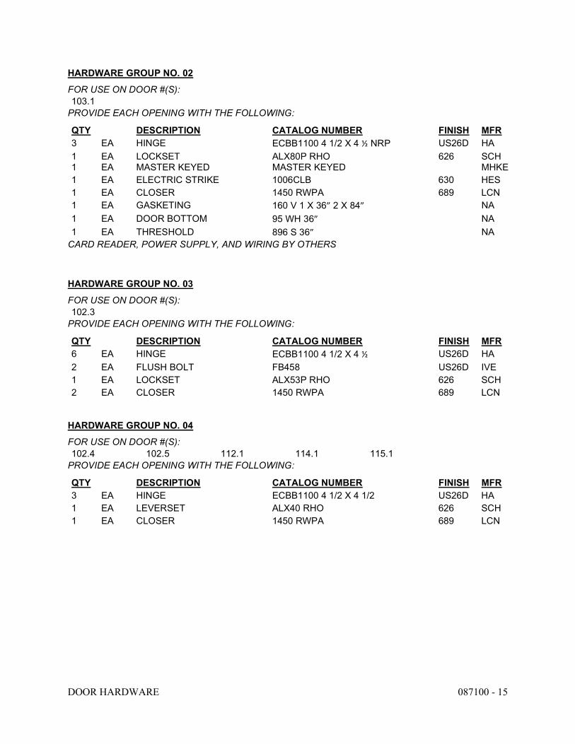
DOOR HARDWARE 087100 - 15
HARDWARE GROUP NO. 02
FOR USE ON DOOR #(S): 103.1
PROVIDE EACH OPENING WITH THE FOLLOWING:
QTY DESCRIPTION CATALOG NUMBER FINISH MFR 3 EA HINGE ECBB1100 4 1/2 X 4 ½ NRP US26D HA 1 1
EA EA
LOCKSET MASTER KEYED
ALX80P RHO MASTER KEYED
626 SCH MHKE
1 EA ELECTRIC STRIKE 1006CLB 630 HES 1 EA CLOSER 1450 RWPA 689 LCN 1 EA GASKETING 160 V 1 X 36” 2 X 84” NA 1 EA DOOR BOTTOM 95 WH 36” NA 1 EA THRESHOLD 896 S 36” NA
CARD READER, POWER SUPPLY, AND WIRING BY OTHERS
HARDWARE GROUP NO. 03
FOR USE ON DOOR #(S): 102.3
PROVIDE EACH OPENING WITH THE FOLLOWING:
QTY DESCRIPTION CATALOG NUMBER FINISH MFR 6 EA HINGE ECBB1100 4 1/2 X 4 ½ US26D HA 2 EA FLUSH BOLT FB458 US26D IVE 1 EA LOCKSET ALX53P RHO 626 SCH 2 EA CLOSER 1450 RWPA 689 LCN
HARDWARE GROUP NO. 04
FOR USE ON DOOR #(S): 102.4 102.5 112.1 114.1 115.1
PROVIDE EACH OPENING WITH THE FOLLOWING:
QTY DESCRIPTION CATALOG NUMBER FINISH MFR 3 EA HINGE ECBB1100 4 1/2 X 4 1/2 US26D HA 1 EA LEVERSET ALX40 RHO 626 SCH 1 EA CLOSER 1450 RWPA 689 LCN
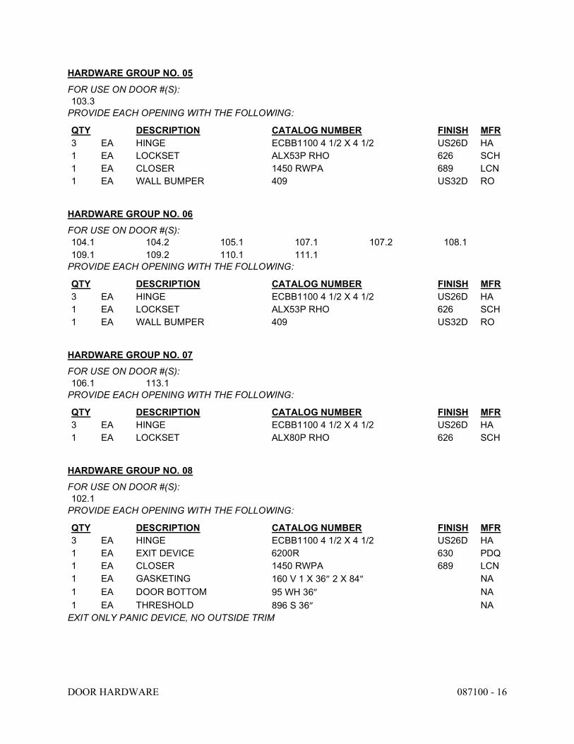
DOOR HARDWARE 087100 - 16
HARDWARE GROUP NO. 05
FOR USE ON DOOR #(S): 103.3
PROVIDE EACH OPENING WITH THE FOLLOWING:
QTY DESCRIPTION CATALOG NUMBER FINISH MFR 3 EA HINGE ECBB1100 4 1/2 X 4 1/2 US26D HA 1 EA LOCKSET ALX53P RHO 626 SCH 1 EA CLOSER 1450 RWPA 689 LCN 1 EA WALL BUMPER 409 US32D RO
HARDWARE GROUP NO. 06
FOR USE ON DOOR #(S): 104.1 104.2 105.1 107.1 107.2 108.1 109.1 109.2 110.1 111.1
PROVIDE EACH OPENING WITH THE FOLLOWING:
QTY DESCRIPTION CATALOG NUMBER FINISH MFR 3 EA HINGE ECBB1100 4 1/2 X 4 1/2 US26D HA 1 EA LOCKSET ALX53P RHO 626 SCH 1 EA WALL BUMPER 409 US32D RO
HARDWARE GROUP NO. 07
FOR USE ON DOOR #(S): 106.1 113.1
PROVIDE EACH OPENING WITH THE FOLLOWING:
QTY DESCRIPTION CATALOG NUMBER FINISH MFR 3 EA HINGE ECBB1100 4 1/2 X 4 1/2 US26D HA 1 EA LOCKSET ALX80P RHO 626 SCH
HARDWARE GROUP NO. 08
FOR USE ON DOOR #(S): 102.1
PROVIDE EACH OPENING WITH THE FOLLOWING:
QTY DESCRIPTION CATALOG NUMBER FINISH MFR 3 EA HINGE ECBB1100 4 1/2 X 4 1/2 US26D HA 1 EA EXIT DEVICE 6200R 630 PDQ 1 EA CLOSER 1450 RWPA 689 LCN 1 EA GASKETING 160 V 1 X 36” 2 X 84” NA 1 EA DOOR BOTTOM 95 WH 36” NA 1 EA THRESHOLD 896 S 36” NA
EXIT ONLY PANIC DEVICE, NO OUTSIDE TRIM
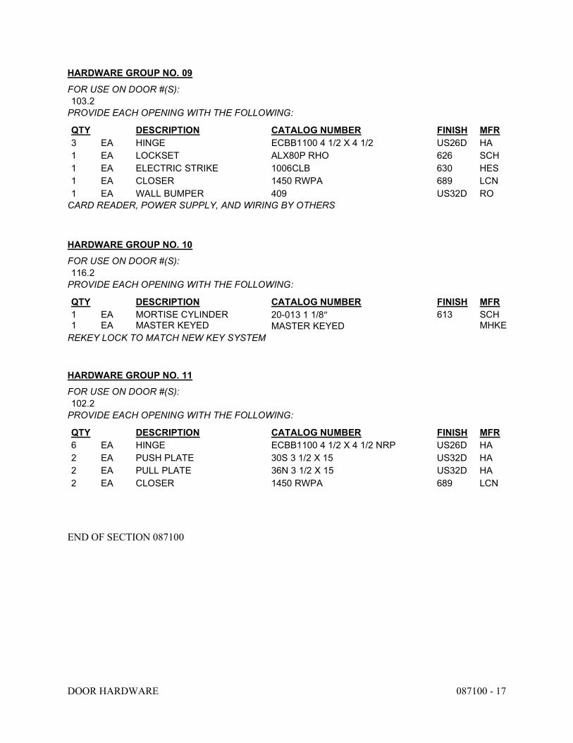
DOOR HARDWARE 087100 - 17
HARDWARE GROUP NO. 09
FOR USE ON DOOR #(S): 103.2
PROVIDE EACH OPENING WITH THE FOLLOWING:
QTY DESCRIPTION CATALOG NUMBER FINISH MFR 3 EA HINGE ECBB1100 4 1/2 X 4 1/2 US26D HA 1 EA LOCKSET ALX80P RHO 626 SCH 1 EA ELECTRIC STRIKE 1006CLB 630 HES 1 EA CLOSER 1450 RWPA 689 LCN 1 EA WALL BUMPER 409 US32D RO
CARD READER, POWER SUPPLY, AND WIRING BY OTHERS
HARDWARE GROUP NO. 10
FOR USE ON DOOR #(S): 116.2
PROVIDE EACH OPENING WITH THE FOLLOWING:
QTY DESCRIPTION CATALOG NUMBER FINISH MFR 1 1
EA EA
MORTISE CYLINDER MASTER KEYED
20-013 1 1/8” MASTER KEYED
613 SCH MHKE
REKEY LOCK TO MATCH NEW KEY SYSTEM
HARDWARE GROUP NO. 11
FOR USE ON DOOR #(S): 102.2
PROVIDE EACH OPENING WITH THE FOLLOWING:
QTY DESCRIPTION CATALOG NUMBER FINISH MFR 6 EA HINGE ECBB1100 4 1/2 X 4 1/2 NRP US26D HA 2 EA PUSH PLATE 30S 3 1/2 X 15 US32D HA 2 EA PULL PLATE 36N 3 1/2 X 15 US32D HA 2 EA CLOSER 1450 RWPA 689 LCN
END OF SECTION 087100

GLAZING 088000 - 1
SECTION 088000 - GLAZING
PART 1 - GENERAL
1.1 RELATED DOCUMENTS
A. Drawings and general provisions of the Contract, including General and Supplementary Conditions and Division 01 Specification Sections, apply to this Section.
1.2 SUMMARY
A. Section Includes glass and glazing for: 1. Window units that are not indicated as “pre-glazed”. 2. Interior doors and sidelights. 3. Exterior doors and sidelights. 4. Interior windows.
B. Related Requirements: 1. Section 081416 “Flush Wood Doors”. 2. Section 084113 “Aluminum-Framed Entrances and Storefronts”. 3. Section 086650 “Sliding Pass Windows”.
1.3 DEFINITIONS
A. Glass Manufacturers: Firms that produce primary glass, fabricated glass, or both, as defined in referenced glazing publications.
B. Glass Thicknesses: Indicated by thickness designations in millimeters in accordance with ASTM C1036.
C. IBC: International Building Code.
D. Interspace: Space between lites of an insulating-glass unit.
1.4 COORDINATION
A. Coordinate glazing channel dimensions to provide necessary bite on glass, minimum edge and face clearances, and adequate sealant thicknesses, with reasonable tolerances.
1.5 PREINSTALLATION MEETINGS
A. Preinstallation Conference: Conduct conference at Project site.
GLAZING 088000 - 2
1. Review and finalize construction schedule and verify availability of materials, Installer's personnel, equipment, and facilities needed to make progress and avoid delays.
2. Review temporary protection requirements for glazing during and after installation.
1.6 ACTION SUBMITTALS
A. Product Data: For each type of product.
B. Glass Samples: For each type of the following products; 12 inches (300 mm) square.
1. Tinted glass. 2. Insulating glass.
C. Glazing Schedule: List glass types and thicknesses for each size opening and location. Use same designations indicated on Drawings.
D. Delegated-Design Submittal: For glass indicated to comply with performance requirements and design criteria, including analysis data signed and sealed by qualified professional engineer responsible for their preparation.
1.7 INFORMATIONAL SUBMITTALS
A. Product Certificates: For glass.
B. Preconstruction adhesion and compatibility test report.
C. Sample Warranties: For special warranties.
1.8 QUALITY ASSURANCE
A. Fabricated-Glass Manufacturer Qualifications: A qualified manufacturer of fabricated glass units who is approved by primary glass manufacturer.
B. Installer Qualifications: A qualified glazing contractor for this Project who is certified under the North American Contractor Certification Program (NACC) for Architectural Glass & Metal (AG&M) contractors.
1.9 PRECONSTRUCTION TESTING
A. Preconstruction Adhesion and Compatibility Testing: Test each glass product, tape sealant, gasket, glazing accessory, and glass-framing member for adhesion to and compatibility with elastomeric glazing sealants.
1. Testing is not required if data are submitted based on previous testing of current sealant products and glazing materials matching those submitted.
2. Use ASTM C1087 to determine whether priming and other specific joint-preparation techniques are required to obtain rapid, optimum adhesion of glazing sealants to glass, tape sealants, gaskets, and glazing channel substrates.
GLAZING 088000 - 3
3. Test no fewer than four samples of each type of material, including joint substrates, shims, sealant backings, secondary seals, and miscellaneous materials.
4. Schedule enough time for testing and analyzing results to prevent delaying the Work. 5. For materials failing tests, submit sealant manufacturer's written instructions for
corrective measures including use of specially formulated primers.
1.10 DELIVERY, STORAGE, AND HANDLING
A. Protect glazing materials in accordance with manufacturer's written instructions. Prevent damage to glass and glazing materials from condensation, temperature changes, direct exposure to sun, or other causes.
B. Comply with insulating-glass manufacturer's written instructions for venting and sealing units to avoid hermetic seal ruptures due to altitude change.
1.11 FIELD CONDITIONS
A. Environmental Limitations: Do not proceed with glazing when ambient and substrate temperature conditions are outside limits permitted by glazing material manufacturers and when glazing channel substrates are wet from rain, frost, condensation, or other causes.
1. Do not install glazing sealants when ambient and substrate temperature conditions are outside limits permitted by sealant manufacturer or are below 40 deg F (4.4 deg C).
1.12 WARRANTY
A. Manufacturer's Special Warranty for Laminated Glass: Manufacturer agrees to replace laminated glass units that develop manufacturing defects within specified warranty period. Manufacturing defects are defined as edge separation or delamination which materially obstructs vision through glass.
1. Warranty Period: Manufacturer’s standard, but not less than (4) years from date of Substantial Completion.
B. Manufacturer's Special Warranty for Insulating Glass: Manufacturer agrees to replace insulating-glass units that deteriorate within specified warranty period. Deterioration of insulating glass is defined as failure of hermetic seal under normal use that is not attributed to glass breakage or to maintaining and cleaning insulating glass contrary to manufacturer's written instructions. Evidence of failure is obstruction of vision by dust, moisture, or film on interior surfaces of glass.
1. Warranty Period: (10) years from date of Substantial Completion.
C. Manufacturer's Special Warranty for Heat-Soaked Tempered Glass: Manufacturer agrees to replace heat-soaked tempered glass units that spontaneously break due to nickel sulfide (NiS) inclusions at a rate exceeding 0.3 percent (3/1000) within specified warranty period. Coverage for any other cause is excluded.
1. Warranty Period: 10 years from date of Substantial Completion.

GLAZING 088000 - 4
PART 2 - PRODUCTS
2.1 MANUFACTURERS
A. Source Limitations for Glass: Obtain glass from single source from single manufacturer.
B. Source Limitations for Glazing Accessories: For each product and installation method, obtain from single source from single manufacturer.
C. Subject to requirements, provide products from one of the following:
1. Manufacturers of Clear and Tinted Float Glass: a. Ford Glass Division, Southfield, MI b. Guardian Industries Corp., Louisville, KY c. LOF Glass, Inc.; Cincinnati / Cleveland, OH d. PPG Industries, Inc.; Pittsburg, PA
2. Manufacturers of Heat-Treated Glass: a. Falconer Glass Industries, Cincinnati, OH b. Ford Glass Division, Southfield, MI c. Guardian Industries Corp., Louisville, KY d. LOF Glass, Inc.; Cincinnati / Cleveland, OH e. PPG Industries, Inc.; Pittsburg, PA
3. Manufacturers of Insulated Glass: a. Falconer Glass Industries, Cincinnati, OH b. Ford Glass Division, Southfield, MI c. Guardian Industries Corp., Louisville, KY d. PPG Industries, Inc.; Pittsburg, PA
2.2 PERFORMANCE REQUIREMENTS
A. General: Installed glazing systems shall withstand normal thermal movement and wind and impact loads (where applicable) without failure, including loss or glass breakage attributable to defective manufacture, fabrication, or installation; failure of sealants or gaskets to remain watertight and airtight; deterioration of glazing materials; or other defects in construction.
B. Delegated Design: Engage a qualified professional engineer, as defined in Section 014000 "Quality Requirements," to design glazing.
C. Structural Performance: Glazing shall withstand the following design loads within limits and under conditions indicated determined in accordance with the IBC and ASTM E1300:
1. Design Wind Pressures: Determine design wind pressures applicable to Project in accordance with ASCE/SEI 7, based on heights above grade indicated on Drawings. a. Wind Design Data: As indicated on Drawings. b. Basic Wind Speed: 90 mph (40 m/s) c. Exposure Category: C.
GLAZING 088000 - 5
D. Safety Glazing: Where safety glazing is indicated, provide glazing that complies with 16 CFR 1201, Category II.
2.3 GLASS PRODUCTS, GENERAL
A. Glazing Publications: Comply with published recommendations of glass product manufacturers and organizations below unless more stringent requirements are indicated. See these publications for glazing terms not otherwise defined in this Section or in referenced standards.
1. NGA Publications: "Laminated Glazing Reference Manual" and "Glazing Manual." 2. IGMA Publication for Insulating Glass: SIGMA TM-3000, "North American Glazing
Guidelines for Sealed Insulating Glass Units for Commercial and Residential Use."
B. Safety Glazing Labeling: Where safety glazing is indicated, permanently mark glazing with certification label of the SGCC or another certification agency acceptable to authorities having jurisdiction. Label shall indicate manufacturer's name, type of glass, thickness, and safety glazing standard with which glass complies.
C. Insulating-Glass Certification Program: Permanently marked either on spacers or on at least one component lite of units with appropriate certification label of the IGCC.
D. Thickness: Where glass thickness is indicated, it is a minimum. Provide glass that complies with performance requirements and is not less than thickness indicated.
1. Minimum Glass Thickness for Exterior Lites: 6 mm 2. Thickness of Tinted Glass: Provide same thickness for each tint color indicated
throughout Project.
E. Strength: Where annealed float glass is indicated, provide annealed float glass, heat-strengthened float glass, or fully tempered float glass as needed to comply with "Performance Requirements" Article. Where heat-strengthened float glass is indicated, provide heat-strengthened float glass or fully tempered float glass as needed to comply with "Performance Requirements" Article. Where fully tempered float glass is indicated, provide fully tempered float glass.
2.4 GLASS USAGE:
A. Exterior Windows: 1 inch insulated glass with Low-E coating on the inner surface of the outer. pane.
B. Interior Windows: 1/4 inch thick clear, tempered glass.
2.5 GLASS PRODUCTS
A. Clear Annealed Float Glass: ASTM C1036, Type I, Class 1 (clear), Quality-Q3.
B. Tinted Annealed Float Glass: ASTM C1036, Type I, Class 2 (tinted), Quality-Q3.

GLAZING 088000 - 6
C. Fully Tempered Float Glass: ASTM C1048, Kind FT (fully tempered), Condition A (uncoated) unless otherwise indicated, Type I, Class 1 (clear) or Class 2 (tinted) as indicated, Quality-Q3.
1. Fabrication Process: By horizontal (roller-hearth) process with roll-wave distortion parallel to bottom edge of glass as installed unless otherwise indicated.
D. Reflective- and Low-E-Coated Vision Glass: ASTM C1376.
2.6 INSULATING GLASS
A. Insulating-Glass Units: Factory-assembled units consisting of sealed lites of glass separated by a dehydrated interspace, qualified in accordance with ASTM E2190.
1. Sealing System: Dual seal, with manufacturer's standard primary and secondary sealants. 2. Perimeter Spacer: Manufacturer's standard spacer material and construction.
3. Desiccant: Molecular sieve or silica gel, or a blend of both.
2.7 GLAZING SEALANTS
A. General:
1. Compatibility: Compatible with one another and with other materials they contact, including glass products, seals of insulating-glass units, and glazing channel substrates, under conditions of service and application, as demonstrated by sealant manufacturer based on testing and field experience.
2. Suitability: Comply with sealant and glass manufacturers' written instructions for selecting glazing sealants suitable for applications indicated and for conditions existing at time of installation.
3. Colors of Exposed Glazing Sealants: As selected by Architect from manufacturer's full range of industry colors.
4. Provide manufacturer’s standard chemically curing, elastomeric sealant of base polymer complying with ASTM C 920.
2.8 GLAZING TAPES
A. Back-Bedding Mastic Glazing Tapes: Preformed, butyl-based, 100 percent solids elastomeric tape; nonstaining and nonmigrating in contact with nonporous surfaces; with or without spacer rod as recommended in writing by tape and glass manufacturers for application indicated; and complying with ASTM C1281 and AAMA 800 for products indicated below:
1. AAMA 806.3 tape, for glazing applications in which tape is subject to continuous pressure.
2. AAMA 807.3 tape, for glazing applications in which tape is not subject to continuous pressure.
B. Expanded Cellular Glazing Tapes: Closed-cell, PVC foam tapes; factory coated with adhesive on both surfaces; and complying with AAMA 800 for the following types:
GLAZING 088000 - 7
1. AAMA 810.1, Type 1, for glazing applications in which tape acts as primary sealant. 2. AAMA 810.1, Type 2, for glazing applications in which tape is used in combination with
a full bead of liquid sealant.
2.9 MISCELLANEOUS GLAZING MATERIALS
A. General: Provide products of material, size, and shape complying with referenced glazing standard, recommended in writing by manufacturers of glass and other glazing materials for application indicated, and with a proven record of compatibility with surfaces contacted in installation.
B. Cleaners, Primers, and Sealers: Types recommended by sealant or gasket manufacturer.
C. Setting Blocks:
1. EPDM, Silicone, OR Neoprene with Shore A durometer hardness of 85, plus or minus 5. 2. Type recommended in writing by sealant or glass manufacturer.
D. Spacers:
1. Neoprene, EPDM, or Silicone blocks or continuous extrusions of hardness required by glass manufacturer to maintain glass lites in place for installation indicated.
2. Type recommended in writing by sealant or glass manufacturer.
E. Edge Blocks:
1. EPDM, Silicone, or Neoprene with Shore A durometer hardness per manufacturer's written instructions.
2. Type recommended in writing by sealant or glass manufacturer.
F. Cylindrical Glazing Sealant Backing: ASTM C1330, Type O (open-cell material), of size and density to control glazing sealant depth and otherwise produce optimum glazing sealant performance.
2.10 FABRICATION OF GLAZING UNITS
A. Fabricate glazing units in sizes required to fit openings indicated for Project, with edge and face clearances, edge and surface conditions, and bite complying with written instructions of product manufacturer and referenced glazing publications, to comply with system performance requirements.
1. Allow for thermal movements from ambient and surface temperature changes acting on glass framing members and glazing components.
a. Temperature Change: 120 deg F (67 deg C), ambient; 180 deg F (100 deg C), material surfaces.
B. Clean-cut or flat-grind vertical edges of butt-glazed monolithic lites to produce square edges with slight chamfers at junctions of edges and faces.
GLAZING 088000 - 8
C. Grind smooth and polish exposed glass edges and corners.
PART 3 - EXECUTION
3.1 EXAMINATION
A. Examine framing, glazing channels, and stops, with Installer present, for compliance with the following:
1. Manufacturing and installation tolerances, including those for size, squareness, and offsets at corners.
2. Presence and functioning of weep systems. 3. Minimum required face and edge clearances. 4. Effective sealing between joints of glass-framing members.
B. Proceed with installation only after unsatisfactory conditions have been corrected.
3.2 PREPARATION
A. Clean glazing channels and other framing members receiving glass immediately before glazing. Remove coatings not firmly bonded to substrates.
B. Examine glazing units to locate exterior and interior surfaces. Label or mark units as needed so that exterior and interior surfaces are readily identifiable. Do not use materials that leave visible marks in the completed Work.
3.3 GLAZING, GENERAL
A. Comply with combined written instructions of manufacturers of glass, sealants, gaskets, and other glazing materials, unless more stringent requirements are indicated, including those in referenced glazing publications.
B. Protect glass edges from damage during handling and installation. Remove damaged glass from Project site and legally dispose of off Project site. Damaged glass includes glass with edge damage or other imperfections that, when installed, could weaken glass, impair performance, or impair appearance.
C. Apply primers to joint surfaces where required for adhesion of sealants, as determined by preconstruction testing.
D. Install setting blocks in sill rabbets, sized and located to comply with referenced glazing publications, unless otherwise required by glass manufacturer. Set blocks in thin course of compatible sealant suitable for heel bead.
E. Do not exceed edge pressures stipulated by glass manufacturers for installing glass lites.
F. Provide spacers for glass lites where length plus width is larger than 50 inches (1270 mm).

GLAZING 088000 - 9
1. Locate spacers directly opposite each other on both inside and outside faces of glass. Install correct size and spacing to preserve required face clearances, unless gaskets and glazing tapes are used that have demonstrated ability to maintain required face clearances and to comply with system performance requirements.
2. Provide 1/8-inch- (3-mm-) minimum bite of spacers on glass and use thickness equal to sealant width. With glazing tape, use thickness slightly less than final compressed thickness of tape.
G. Provide edge blocking where indicated or needed to prevent glass lites from moving sideways in glazing channel, as recommended in writing by glass manufacturer and in accordance with requirements in referenced glazing publications.
H. Set glass lites in each series with uniform pattern, draw, bow, and similar characteristics.
I. Set glass lites with proper orientation so that coatings face exterior or interior as specified.
J. Where wedge-shaped gaskets are driven into one side of channel to pressurize sealant or gasket on opposite side, provide adequate anchorage so gasket cannot walk out when installation is subjected to movement.
K. Square cut wedge-shaped gaskets at corners and install gaskets in a manner recommended by gasket manufacturer to prevent corners from pulling away; seal corner joints and butt joints with sealant recommended in writing by gasket manufacturer.
3.4 TAPE GLAZING
A. Position tapes on fixed stops so that, when compressed by glass, their exposed edges are flush with or protrude slightly above sightline of stops.
B. Install tapes continuously, but not necessarily in one continuous length. Do not stretch tapes to make them fit opening.
C. Cover vertical framing joints by applying tapes to heads and sills first, then to jambs. Cover horizontal framing joints by applying tapes to jambs, then to heads and sills.
D. Place joints in tapes at corners of opening with adjoining lengths butted together, not lapped. Seal joints in tapes with compatible sealant approved by tape manufacturer.
E. Do not remove release paper from tape until right before each glazing unit is installed.
F. Apply heel bead of elastomeric sealant.
G. Center glass lites in openings on setting blocks, and press firmly against tape by inserting dense compression gaskets formed and installed to lock in place against faces of removable stops. Start gasket applications at corners and work toward centers of openings.
H. Apply cap bead of elastomeric sealant over exposed edge of tape.

GLAZING 088000 - 10
3.5 GASKET GLAZING (DRY)
A. Cut compression gaskets to lengths recommended by gasket manufacturer to fit openings exactly, with allowance for stretch during installation.
B. Insert soft compression gasket between glass and frame or fixed stop so it is securely in place with joints miter cut and bonded together at corners.
C. Installation with Drive-in Wedge Gaskets: Center glass lites in openings on setting blocks, and press firmly against soft compression gasket by inserting dense compression gaskets formed and installed to lock in place against faces of removable stops. Start gasket applications at corners and work toward centers of openings. Compress gaskets to produce a weathertight seal without developing bending stresses in glass. Seal gasket joints with sealant recommended in writing by gasket manufacturer.
D. Installation with Pressure-Glazing Stops: Center glass lites in openings on setting blocks, and press firmly against soft compression gasket. Install dense compression gaskets and pressure-glazing stops, applying pressure uniformly to compression gaskets. Compress gaskets to produce a weathertight seal without developing bending stresses in glass. Seal gasket joints with sealant recommended in writing by gasket manufacturer.
E. Install gaskets so they protrude past face of glazing stops.
3.6 SEALANT GLAZING (WET)
A. Install continuous spacers, or spacers combined with cylindrical sealant backing, between glass lites and glazing stops to maintain glass face clearances and to prevent sealant from extruding into glass channel and blocking weep systems until sealants cure. Secure spacers or spacers and backings in place and in position to control depth of installed sealant relative to edge clearance for optimum sealant performance.
B. Force sealants into glazing channels to eliminate voids and to ensure complete wetting or bond of sealant to glass and channel surfaces.
C. Tool exposed surfaces of sealants to provide a substantial wash away from glass.
3.7 CLEANING AND PROTECTION
A. Immediately after installation, remove nonpermanent labels and clean surfaces.
B. Protect glass from contact with contaminating substances resulting from construction operations. Examine glass surfaces adjacent to or below exterior concrete and other masonry surfaces at frequent intervals during construction, but not less than once a month, for buildup of dirt, scum, alkaline deposits, or stains.
1. If, despite such protection, contaminating substances do contact with glass, remove substances immediately as recommended in writing by glass manufacturer. Remove and replace glass that cannot be cleaned without damage to coatings.
C. Remove and replace glass that is damaged during construction period.

GLAZING 088000 - 11
D. Wash glass on both exposed surfaces not more than four days before date scheduled for inspections that establish date of Substantial Completion. Wash glass as recommended in writing by glass manufacturer.
END OF SECTION 088000

NON-STRUCTURAL METAL FRAMING 092216 - 1
SECTION 092216 - NON-STRUCTURAL METAL FRAMING
PART 1 - GENERAL
1.1 RELATED DOCUMENTS
A. Drawings and general provisions of the Contract, including General and Supplementary Conditions and Division 01 Specification Sections, apply to this Section.
1.2 SUMMARY
A. Section Includes:
1. Non-load-bearing steel framing systems for interior partitions.
1.3 ACTION SUBMITTALS
A. Product Data: For each type of product.
1. Studs and Runners: Provide documentation that framing members' certification is according to SIFA's "Code Compliance Certification Program for Cold-Formed Steel Structural and Non-Structural Framing Members."
PART 2 - PRODUCTS
2.1 PERFORMANCE REQUIREMENTS
A. Fire-Test-Response Characteristics: For fire-resistance-rated assemblies that incorporate non-load-bearing steel framing, provide materials and construction identical to those tested in assembly indicated, according to ASTM E 119 by an independent testing agency.
B. Horizontal Deflection: For wall assemblies, limited to 1/240 of the wall height based on horizontal loading of 5 lbf/sq. ft. (239 Pa).
2.2 FRAMING SYSTEMS
A. Framing Members, General: Comply with ASTM C 754 for conditions indicated.
1. Steel Sheet Components: Comply with ASTM C 645 requirements for metal unless otherwise indicated.
2. Protective Coating: ASTM A 653/A 653M, G40 (Z120) hot-dip galvanized unless otherwise indicated.
B. Studs and Runners: ASTM C 645.
NON-STRUCTURAL METAL FRAMING 092216 - 2
1. Steel Studs and Runners: a. Minimum Base-Metal Thickness: 0.0329 inch (0.836 mm). b. Depth: As indicated on Drawings.
C. Slip-Type Head Joints: At top of full height walls, provide the following: 1. Deflection Track: Steel sheet top runner manufactured to prevent cracking of finishes
applied to interior partition framing resulting from deflection of structure above; in thickness not less than indicated for studs and in width to accommodate depth of studs.
D. Cold-Rolled Channel Bridging: Steel, 0.0538-inch (1.367-mm) minimum base-metal thickness, with minimum 1/2-inch- (13-mm-) wide flanges. 1. Depth: 1-1/2 inches (38 mm). 2. Clip Angle: Not less than 1-1/2 by 1-1/2 inches (38 by 38 mm), 0.068-inch- (1.72-mm-)
thick, galvanized steel.
E. Hat-Shaped, Rigid Furring Channels: ASTM C 645. 1. Minimum Base-Metal Thickness: 0.0329 inch (0.836 mm) 2. Depth: As indicated on Drawings
F. Resilient Furring Channels: 1/2-inch- (13-mm-) deep, steel sheet members designed to reduce sound transmission.
2.3 AUXILIARY MATERIALS
A. General: Provide auxiliary materials that comply with referenced installation standards.
1. Fasteners for Metal Framing: Of type, material, size, corrosion resistance, holding power, and other properties required to fasten steel members to substrates.
PART 3 - EXECUTION
3.1 EXAMINATION
A. Examine areas and substrates, with Installer present, and including welded hollow-metal frames, cast-in anchors, and structural framing, for compliance with requirements and other conditions affecting performance of the Work.
B. Proceed with installation only after unsatisfactory conditions have been corrected.
3.2 PREPARATION
A. Suspended Assemblies: Coordinate installation of suspension systems with installation of overhead structure to ensure that inserts and other provisions for anchorages to building structure have been installed to receive hangers at spacing required to support the Work and that hangers will develop their full strength.
1. Furnish concrete inserts and other devices indicated to other trades for installation in advance of time needed for coordination and construction.
NON-STRUCTURAL METAL FRAMING 092216 - 3
3.3 INSTALLATION, GENERAL
A. Installation Standard: ASTM C 754.
1. Gypsum Board Assemblies: Also comply with requirements in ASTM C 840 that apply to framing installation.
B. Install framing and accessories plumb, square, and true to line, with connections securely fastened.
C. Install supplementary framing, and blocking to support fixtures, equipment services, heavy trim, grab bars, toilet accessories, furnishings, or similar construction.
D. Install bracing at terminations in assemblies.
E. Do not bridge building control and expansion joints with non-load-bearing steel framing members. Frame both sides of joints independently.
3.4 INSTALLING FRAMED ASSEMBLIES
A. Install framing system components according to spacings indicated, but not greater than spacings required by referenced installation standards for assembly types.
1. Single-Layer Application: As required by horizontal deflection performance requirements unless otherwise indicated.
2. Multilayer Application: As required by horizontal deflection performance requirements unless otherwise indicated.
3. Tile Backing Panels: As required by horizontal deflection performance requirements unless otherwise indicated.
B. Where studs are installed directly against exterior masonry walls or dissimilar metals at exterior walls, install isolation strip between studs and exterior wall.
C. Install studs so flanges within framing system point in same direction.
D. Install tracks (runners) at floors and overhead supports. Extend framing full height to structural supports or substrates above suspended ceilings except where partitions are indicated to terminate at suspended ceilings. Continue framing around ducts that penetrate partitions above ceiling.
1. Slip-Type Head Joints: Where framing extends to overhead structural supports, install to produce joints at tops of framing systems that prevent axial loading of finished assemblies.
2. Door Openings: Screw vertical studs at jambs to jamb anchor clips on door frames; install runner track section (for cripple studs) at head and secure to jamb studs. a. Install two studs at each jamb unless otherwise indicated. b. Install cripple studs at head adjacent to each jamb stud, with a minimum 1/2-inch
(13-mm) clearance from jamb stud to allow for installation of control joint in finished assembly.
c. Extend jamb studs through suspended ceilings and attach to underside of overhead structure.
NON-STRUCTURAL METAL FRAMING 092216 - 4
3. Other Framed Openings: Frame openings other than door openings the same as required for door openings unless otherwise indicated. Install framing below sills of openings to match framing required above door heads.
E. Direct Furring:
1. Attach to concrete, masonry or wood studs with stub nails, screws designed for masonry attachment, or powder-driven fasteners spaced 24 inches (610 mm) o.c.
F. Installation Tolerance: Install each framing member so fastening surfaces vary not more than 1/8 inch (3 mm) from the plane formed by faces of adjacent framing.
END OF SECTION 092216

GYPSUM BOARD 092900 - 1
SECTION 092900 - GYPSUM BOARD
PART 1 - GENERAL
1.1 RELATED DOCUMENTS
A. Drawings and general provisions of the Contract, including General and Supplementary Conditions and Division 01 Specification Sections, apply to this Section.
1.2 SUMMARY
A. Section Includes:
1. Interior gypsum board.
1.3 ACTION SUBMITTALS
A. Product Data: For each type of product.
1.4 DELIVERY, STORAGE AND HANDLING
A. Store materials inside under cover and keep them dry and protected against weather, condensation, direct sunlight, construction traffic, and other potential causes of damage. Stack panels flat and supported on risers on a flat platform to prevent sagging.
1.5 FIELD CONDITIONS
A. Environmental Limitations: Comply with ASTM C 840 requirements or gypsum board manufacturer's written instructions, whichever are more stringent.
B. Do not install paper-faced gypsum panels until installation areas are enclosed and conditioned.
C. Do not install panels that are wet, moisture damaged, and mold damaged.
1. Indications that panels are wet or moisture damaged include, but are not limited to, discoloration, sagging, or irregular shape.
2. Indications that panels are mold damaged include, but are not limited to, fuzzy or splotchy surface contamination and discoloration.
GYPSUM BOARD 092900 - 2
PART 2 - PRODUCTS
2.1 PERFORMANCE REQUIREMENTS
A. Fire-Resistance-Rated Assemblies: For fire-resistance-rated assemblies, provide materials and construction identical to those tested in assembly indicated according to ASTM E 119 by an independent testing agency.
B. STC-Rated Assemblies: For STC-rated assemblies, provide materials and construction identical to those tested in assembly indicated according to ASTM E 90 and classified according to ASTM E 413 by an independent testing agency.
2.2 GYPSUM BOARD, GENERAL
A. Size: Provide maximum lengths and widths available that will minimize joints in each area and that correspond with support system indicated.
2.3 INTERIOR GYPSUM BOARD
A. Gypsum Wallboard: ASTM C 1396/C 1396M.
1. Manufacturers: Subject to compliance with requirements, provide products by one of the following:
a. Georgia-Pacific Building Products. b. National Gypsum Company. c. United States Gypsum Company.
2. Thickness: 5/8. 3. Long Edges: Tapered
B. Gypsum Board, Type X: ASTM C 1396/C 1396M.
1. Manufacturers: Subject to compliance with requirements, provide products by one of the following:
a. Georgia-Pacific Building Products. b. National Gypsum Company. c. United States Gypsum Company.
2. Thickness: 5/8 inch (15.9 mm).
3. Long Edges: Tapered
C. Gypsum Ceiling Board: ASTM C 1396/C 1396M.
1. Manufacturers: Subject to compliance with requirements, provide products by one of the following:
GYPSUM BOARD 092900 - 3
a. Georgia-Pacific Building Products. b. National Gypsum Company. c. United States Gypsum Company.
2. Thickness: 1/2 inch (12.7 mm).
3. Long Edges: Tapered.
D. Abuse-Resistant Gypsum Board: ASTM C 1396/C 1396M gypsum board, tested according to ASTM C 1629/C 1629M.
1. Manufacturers: Subject to compliance with requirements, provide products by one of the following:
a. Georgia-Pacific Building Products. b. National Gypsum Company. c. United States Gypsum Company.
2. Core: 5/8 inch (15.9 mm), Type X.
3. Surface Abrasion: Meets or exceeds Level 3 requirements per ASTM C 1629/C 1629M. 4. Indentation: Meets or exceeds Level 2 requirements per ASTM C 1629/C 1629M 5. Soft-Body Impact: Meets or exceeds Level 3 requirements ASTM C 1629/C 1629M 6. Hard-Body Impact: Meets or exceeds Level 3 per ASTM C1629 Annex A.1, meets or 7. Long Edges: Tapered. 8. Mold Resistance: ASTM D 3273, score of 10 as rated according to ASTM D 3274.
E. Mold-Resistant Gypsum Board: ASTM C 1396/C 1396M. With moisture- and mold-resistant core and paper surfaces.
1. Manufacturers: Subject to compliance with requirements, provide products by one of the following:
a. Georgia-Pacific Building Products. b. National Gypsum Company. c. United States Gypsum Company.
2. Core: 5/8 inch (15.9 mm), Type X.
3. Long Edges: Tapered. 4. Mold Resistance: ASTM D 3273, score of 10 as rated according to ASTM D 3274.
2.4 TRIM ACCESSORIES
A. Interior Trim: ASTM C 1047.
1. Material: Galvanized or aluminum-coated steel sheet or rolled zinc 2. Shapes:
a. Cornerbead. b. Bullnose bead.
GYPSUM BOARD 092900 - 4
c. LC-Bead: J-shaped; exposed long flange receives joint compound. d. L-Bead: L-shaped; exposed long flange receives joint compound. e. U-Bead: J-shaped; exposed short flange does not receive joint compound. f. Expansion (control) joint. g. Curved-Edge Cornerbead: With notched or flexible flanges.
2.5 JOINT TREATMENT MATERIALS
A. General: Comply with ASTM C 475/C 475M.
B. Joint Tape:
1. Interior Gypsum Board: Paper. 2. Exterior Gypsum Soffit Board: Paper. 3. Glass-Mat Gypsum Sheathing Board: 10-by-10 glass mesh. 4. Tile Backing Panels: As recommended by panel manufacturer.
C. Joint Compound for Interior Gypsum Board: For each coat, use formulation that is compatible with other compounds applied on previous or for successive coats.
1. Prefilling: At open joints, rounded or beveled panel edges, and damaged surface areas, use setting-type taping compound.
2. Embedding and First Coat: For embedding tape and first coat on joints, fasteners, and trim flanges, use setting-type taping compound.
a. Use setting-type compound for installing paper-faced metal trim accessories.
3. Fill Coat: For second coat, use setting-type, sandable topping compound. 4. Finish Coat: For third coat, use setting-type, sandable topping compound. 5. Skim Coat: For final coat of Level 5 finish, use setting-type, sandable topping compound.
D. Joint Compound for Exterior Applications:
1. Exterior Gypsum Soffit Board: Use setting-type taping compound and setting-type, sandable topping compound.
2. Glass-Mat Gypsum Sheathing Board: As recommended by sheathing board manufacturer.
2.6 AUXILIARY MATERIALS
A. General: Provide auxiliary materials that comply with referenced installation standards and manufacturer's written instructions.
B. Laminating Adhesive: Adhesive or joint compound recommended for directly adhering gypsum panels to continuous substrate.
C. Steel Drill Screws: ASTM C 1002 unless otherwise indicated.
1. Use screws complying with ASTM C 954 for fastening panels to steel members from 0.033 to 0.112 inch (0.84 to 2.84 mm) thick.
GYPSUM BOARD 092900 - 5
2. For fastening cementitious backer units, use screws of type and size recommended by panel manufacturer.
D. Sound-Attenuation Blankets: ASTM C 665, Type I (blankets without membrane facing) produced by combining thermosetting resins with mineral fibers manufactured from glass, slag wool, or rock wool.
1. Fire-Resistance-Rated Assemblies: Comply with mineral-fiber requirements of assembly.
E. Acoustical Sealant: Manufacturer's standard nonsag, paintable, nonstaining latex sealant complying with ASTM C 834. Product effectively reduces airborne sound transmission through perimeter joints and openings in building construction as demonstrated by testing representative assemblies according to ASTM E 90.
F. Thermal Insulation: As specified in Section 072100 "Thermal Insulation."
PART 3 - EXECUTION
3.1 EXAMINATION
A. Examine areas and substrates including welded hollow-metal frames and support framing, with Installer present, for compliance with requirements and other conditions affecting performance of the Work.
B. Examine panels before installation. Reject panels that are wet, moisture damaged, and mold damaged.
C. Proceed with installation only after unsatisfactory conditions have been corrected.
3.2 APPLYING AND FINISHING PANELS, GENERAL
A. Comply with ASTM C 840.
B. Install ceiling panels across framing to minimize the number of abutting end joints and to avoid abutting end joints in central area of each ceiling. Stagger abutting end joints of adjacent panels not less than one framing member.
C. Install panels with face side out. Butt panels together for a light contact at edges and ends with not more than 1/16 inch (1.5 mm) of open space between panels. Do not force into place.
D. Locate edge and end joints over supports, except in ceiling applications where intermediate supports or gypsum board back-blocking is provided behind end joints. Do not place tapered edges against cut edges or ends. Stagger vertical joints on opposite sides of partitions. Do not make joints other than control joints at corners of framed openings.
E. Form control and expansion joints with space between edges of adjoining gypsum panels.
F. Cover both faces of support framing with gypsum panels in concealed spaces (above ceilings, etc.), except in chases braced internally.
GYPSUM BOARD 092900 - 6
1. Unless concealed application is indicated or required for sound, fire, air, or smoke ratings, coverage may be accomplished with scraps of not less than 8 sq. ft. (0.7 sq. m) in area.
2. Fit gypsum panels around ducts, pipes, and conduits. 3. Where partitions intersect structural members projecting below underside of floor/roof
slabs and decks, cut gypsum panels to fit profile formed by structural members; allow 1/4- to 3/8-inch- (6.4- to 9.5-mm-) wide joints to install sealant.
G. Isolate perimeter of gypsum board applied to non-load-bearing partitions at structural abutments. Provide 1/4- to 1/2-inch- (6.4- to 12.7-mm-) wide spaces at these locations and trim edges with edge trim where edges of panels are exposed. Seal joints between edges and abutting structural surfaces with acoustical sealant.
H. Attachment to Steel Framing: Attach panels so leading edge or end of each panel is attached to open (unsupported) edges of stud flanges first.
I. Install sound attenuation blankets before installing gypsum panels unless blankets are readily installed after panels have been installed on one side.
3.3 APPLYING INTERIOR GYPSUM BOARD
A. Install interior gypsum board in the following locations:
1. Wallboard Type: Vertical surfaces unless otherwise indicated. 2. Type X: Where required for fire-resistance-rated assembly. 3. Ceiling Type: As indicated on Drawings. 4. Abuse-Resistant Type: Install at the following locations:
a. Bottom 48” of all walls to receive gypsum board, and b. Full height of all walls where specifically noted on the drawings.
5. Glass-Mat Interior Type: As indicated on Drawings.
B. Single-Layer Application:
1. On ceilings, apply gypsum panels before wall/partition board application to greatest extent possible and at right angles to framing unless otherwise indicated.
2. On partitions/walls, apply gypsum panels horizontally (perpendicular to framing) unless otherwise indicated or required by fire-resistance-rated assembly, and minimize end joints.
a. Stagger abutting end joints not less than one framing member in alternate courses of panels.
b. At stairwells and other high walls, install panels horizontally unless otherwise indicated or required by fire-resistance-rated assembly.
3. On Z-shaped furring members, apply gypsum panels vertically (parallel to framing) with no end joints. Locate edge joints over furring members.
4. Fastening Methods: Apply gypsum panels to supports with steel drill screws.

GYPSUM BOARD 092900 - 7
3.4 INSTALLING TRIM ACCESSORIES
A. General: For trim with back flanges intended for fasteners, attach to framing with same fasteners used for panels. Otherwise, attach trim according to manufacturer's written instructions.
B. Control Joints: Install control joints according to ASTM C 840 and in specific locations approved by Architect for visual effect.
1. Maximum joint spacing: a. Without perimeter relief: 30 feet. b. With perimeter relief: 50 feet.
C. Interior Trim: Install in the following locations:
1. Cornerbead: Use at outside corners. 2. Bullnose Bead: Use at outside corners. 3. LC-Bead: Use at exposed panel edges. 4. L-Bead: Use where indicated. 5. U-Bead: Use at exposed panel edges. 6. Curved-Edge Cornerbead: Use at curved openings.
3.5 FINISHING GYPSUM BOARD
A. General: Treat gypsum board joints, interior angles, edge trim, control joints, penetrations, fastener heads, surface defects, and elsewhere as required to prepare gypsum board surfaces for decoration. Promptly remove residual joint compound from adjacent surfaces.
B. Prefill open joints, rounded or beveled edges, and damaged surface areas.
C. Apply joint tape over gypsum board joints, except for trim products specifically indicated as not intended to receive tape.
D. Gypsum Board Finish Levels: Finish panels to levels indicated below and according to ASTM C 840:
1. Level 1: Ceiling plenum areas, concealed areas, and where indicated.
2. Level 5: At all panel surfaces that will be exposed to view unless otherwise indicated.
E. Glass-Mat Gypsum Sheathing Board: Finish according to manufacturer's written instructions for use as exposed soffit board.
F. Glass-Mat Faced Panels: Finish according to manufacturer's written instructions.
3.6 PROTECTION
A. Protect adjacent surfaces from drywall compound and promptly remove from floors and other non-drywall surfaces. Repair surfaces stained, marred, or otherwise damaged during drywall application.
GYPSUM BOARD 092900 - 8
B. Protect installed products from damage from weather, condensation, direct sunlight, construction, and other causes during remainder of the construction period.
C. Remove and replace panels that are wet, moisture damaged, and mold damaged.
1. Indications that panels are wet or moisture damaged include, but are not limited to, discoloration, sagging, or irregular shape.
2. Indications that panels are mold damaged include, but are not limited to, fuzzy or splotchy surface contamination and discoloration.
END OF SECTION 092900
ACOUSTICAL PANEL CEILINGS 095113 - 1
SECTION 095113 - ACOUSTICAL PANEL CEILINGS
PART 1 - GENERAL
1.1 RELATED DOCUMENTS
A. Drawings and general provisions of the Contract, including General and Supplementary Conditions and Division 01 Specification Sections, apply to this Section.
1.2 SUMMARY
A. Section includes acoustical panels and exposed suspension systems for interior ceilings.
1.3 ACTION SUBMITTALS
A. Product Data: For each type of product.
B. Samples for Verification: For each component indicated and for each exposed finish required, prepared on Samples of sizes indicated below:
1. Acoustical Panels: Set of 6-inch- (150-mm-) square Samples of each type, color, pattern, and texture.
2. Exposed Suspension-System Members, Moldings, and Trim: Set of 6-inch- (150-mm-) long Samples of each type, finish, and color.
3. Clips: Full-size hold-down clips.
1.4 INFORMATIONAL SUBMITTALS
A. Qualification Data: For testing agency.
B. Product Test Reports: For each acoustical panel ceiling, for tests performed by manufacturer and witnessed by a qualified testing agency.
C. Evaluation Reports: For each acoustical panel ceiling suspension system and anchor and fastener type, from ICC-ES.
1.5 CLOSEOUT SUBMITTALS
A. Maintenance Data: For finishes to include in maintenance manuals.
1.6 MAINTENANCE MATERIAL SUBMITTALS
A. Furnish extra materials, from the same product run, that match products installed and that are packaged with protective covering for storage and identified with labels describing contents.
ACOUSTICAL PANEL CEILINGS 095113 - 2
1. Acoustical Ceiling Units: Full-size panels equal to 2 percent of quantity installed.
1.7 DELIVERY, STORAGE, AND HANDLING
A. Deliver acoustical panels, suspension-system components, and accessories to Project site and store them in a fully enclosed, conditioned space where they will be protected against damage from moisture, humidity, temperature extremes, direct sunlight, surface contamination, and other causes.
B. Before installing acoustical panels, permit them to reach room temperature and a stabilized moisture content.
1.8 FIELD CONDITIONS
A. Environmental Limitations: Do not install acoustical panel ceilings until spaces are enclosed and weathertight, wet-work in spaces is complete and dry, work above ceilings is complete, and ambient temperature and humidity conditions are maintained at the levels indicated for Project when occupied for its intended use.
1. Pressurized Plenums: Operate ventilation system for not less than 48 hours before beginning acoustical panel ceiling installation.
PART 2 - PRODUCTS
2.1 MANUFACTURERS
A. Source Limitations: Obtain each type of acoustical ceiling panel and its supporting suspension system from single source from single manufacturer.
2.2 PERFORMANCE REQUIREMENTS
A. Surface-Burning Characteristics: Comply with ASTM E 84; testing by a qualified testing agency. Identify products with appropriate markings of applicable testing agency.
1. Flame-Spread Index: Class B according to ASTM E 1264. 2. Smoke-Developed Index: 450 or less.
2.3 ACOUSTICAL PANELS
A. Basis-of-Design: Subject to compliance with project requirements, provide Armstrong World Industries, Inc., “Fine Fissured Square Lay-in panels”, or similar products by one of the following:
1. Celotex, 2. CertainTeed Corporation. 3. United States Gypsum Company.
ACOUSTICAL PANEL CEILINGS 095113 - 3
B. Basis-of-design products: 1. ACT-1: Armstrong Classic Fine Textured 954, 2’ x 2’ tile.
C. Acoustical Panel Standard: Provide manufacturer's standard panels according to ASTM E 1264 and designated by type, form, pattern, acoustical rating, and light reflectance unless otherwise indicated. 1. Color: White 2. Light Reflectance (LR): Not less than 0.85. 3. Ceiling Attenuation Class (CAC): Not less than 35. 4. Noise Reduction Coefficient (NRC): Not less than 0.70. 5. Edge/Joint Detail: Tegular Edge 6. Thickness: 3/4 inch 7. Antimicrobial Treatment: Manufacturer's standard broad spectrum, antimicrobial
formulation that inhibits fungus, mold, mildew, and gram-positive and gram-negative bacteria and showing no mold, mildew, or bacterial growth when tested according to ASTM D 3273, ASTM D 3274, or ASTM G 21 and evaluated according to ASTM D 3274 or ASTM G 21.
2.4 METAL SUSPENSION SYSTEM FOR ACT-1
A. Manufacturers: Subject to compliance with requirements, provide products by one of the following:
1. Armstrong World Industries, Inc. 2. CertainTeed Corporation. 3. Chicago Metallic Corporation. 4. United States Gypsum Company.
B. Metal Suspension-System Standard: Provide manufacturer's standard, direct-hung, metal suspension system and accessories according to ASTM C 635/C 635M and designated by type, structural classification, and finish indicated.
C. Wide-Face, Capped, Double-Web, Steel Suspension System: Main and cross runners roll formed from cold-rolled steel sheet; prepainted, electrolytically zinc coated, or hot-dip galvanized, G30 (Z90) coating designation; with prefinished 15/16-inch- (24-mm-) wide metal caps on flanges.
2.5 ACCESSORIES
A. Attachment Devices: Size for five times the design load indicated in ASTM C 635/C 635M, Table 1, "Direct Hung," unless otherwise indicated. Comply with seismic design requirements.
1. Power-Actuated Fasteners in Concrete: Fastener system of type suitable for application indicated, fabricated from corrosion-resistant materials, with clips or other accessory devices for attaching hangers of type indicated and with capability to sustain, without failure, a load equal to 10 times that imposed by ceiling construction, as determined by testing according to ASTM E 1190, conducted by a qualified testing and inspecting agency.
B. Wire Hangers, Braces, and Ties: Provide wires as follows:
ACOUSTICAL PANEL CEILINGS 095113 - 4
1. Zinc-Coated, Carbon-Steel Wire: ASTM A 641/A 641M, Class 1 zinc coating, soft temper. 2. Stainless-Steel Wire: ASTM A 580/A 580M, Type 304, nonmagnetic. 3. Nickel-Copper-Alloy Wire: ASTM B 164, nickel-copper-alloy UNS No. N04400. 4. Size: Wire diameter sufficient for its stress at three times hanger design load
(ASTM C 635/C 635M, Table 1, "Direct Hung") will be less than yield stress of wire, but not less than 0.106-inch- (2.69-mm-) diameter wire.
C. Hanger Rods: Mild steel, zinc coated or protected with rust-inhibitive paint.
D. Flat Hangers: Mild steel, zinc coated or protected with rust-inhibitive paint.
E. Angle Hangers: Angles with legs not less than 7/8 inch (22 mm) wide; formed with 0.04-inch- (1-mm-) thick, galvanized-steel sheet complying with ASTM A 653/A 653M, G90 (Z275) coating designation; with bolted connections and 5/16-inch- (8-mm-) diameter bolts.
F. Hold-Down Clips: Manufacturer's standard hold-down.
2.6 METAL EDGE MOLDINGS AND TRIM ACT-1
A. Manufacturers: Subject to compliance with requirements, provide products by one of the following:
1. Armstrong World Industries, Inc. 2. CertainTeed Corporation. 3. United States Gypsum Company.
B. Roll-Formed, Sheet-Metal Edge Moldings and Trim: Type and profile indicated or, if not indicated, manufacturer's standard moldings for edges and penetrations that comply with seismic design requirements; formed from sheet metal of same material, finish, and color as that used for exposed flanges of suspension-system runners.
1. Edge moldings shall fit acoustical panel edge details and suspension systems indicated and match width and configuration of exposed runners unless otherwise indicated.
PART 3 - EXECUTION
3.1 EXAMINATION
A. Examine substrates, areas, and conditions, including structural framing to which acoustical panel ceilings attach or abut, with Installer present, for compliance with requirements specified in this and other Sections that affect ceiling installation and anchorage and with requirements for installation tolerances and other conditions affecting performance of acoustical panel ceilings.
B. Examine acoustical panels before installation. Reject acoustical panels that are wet, moisture damaged, or mold damaged.
C. Proceed with installation only after unsatisfactory conditions have been corrected.
ACOUSTICAL PANEL CEILINGS 095113 - 5
3.2 PREPARATION
A. Measure each ceiling area and establish layout of acoustical panels to balance border widths at opposite edges of each ceiling. Avoid using less-than-half-width panels at borders unless otherwise indicated, and comply with layout shown on reflected ceiling plans.
B. Layout openings for penetrations centered on the penetrating items.
3.3 INSTALLATION
A. Install acoustical panel ceilings according to ASTM C 636/C 636M and manufacturer's written instructions.
B. Suspend ceiling hangers from building's structural members and as follows:
1. Install hangers plumb and free from contact with insulation or other objects within ceiling plenum that are not part of supporting structure or of ceiling suspension system.
2. Splay hangers only where required to miss obstructions; offset resulting horizontal forces by bracing, countersplaying, or other equally effective means.
3. Where width of ducts and other construction within ceiling plenum produces hanger spacings that interfere with location of hangers at spacings required to support standard suspension-system members, install supplemental suspension members and hangers in form of trapezes or equivalent devices.
4. Secure wire hangers to ceiling-suspension members and to supports above with a minimum of three tight turns. Connect hangers directly to structure or to inserts, eye screws, or other devices that are secure and appropriate for substrate and that will not deteriorate or otherwise fail due to age, corrosion, or elevated temperatures.
5. Do not support ceilings directly from permanent metal forms or floor deck. Fasten hangers to cast-in-place hanger inserts, postinstalled mechanical or adhesive anchors, or power-actuated fasteners that extend through forms into concrete.
6. When steel framing does not permit installation of hanger wires at spacing required, install carrying channels or other supplemental support for attachment of hanger wires.
7. Do not attach hangers to steel deck tabs. 8. Do not attach hangers to steel roof deck. Attach hangers to structural members. 9. Space hangers not more than 48 inches (1200 mm) o.c. along each member supported
directly from hangers unless otherwise indicated; provide hangers not more than 8 inches (200 mm) from ends of each member.
10. Size supplemental suspension members and hangers to support ceiling loads within performance limits established by referenced standards.
C. Secure bracing wires to ceiling suspension members and to supports with a minimum of four tight turns. Suspend bracing from building's structural members as required for hangers, without attaching to permanent metal forms, steel deck, or steel deck tabs. Fasten bracing wires into concrete with cast-in-place or postinstalled anchors.
D. Install edge moldings and trim of type indicated at perimeter of acoustical ceiling area and where necessary to conceal edges of acoustical panels.
1. Apply acoustical sealant in a continuous ribbon concealed on back of vertical legs of moldings before they are installed.

ACOUSTICAL PANEL CEILINGS 095113 - 6
2. Screw attach moldings to substrate at intervals not more than 16 inches (400 mm) o.c. and not more than 3 inches (75 mm) from ends. Miter corners accurately and connect securely.
3. Do not use exposed fasteners, including pop rivets, on moldings and trim.
E. Install suspension-system runners so they are square and securely interlocked with one another. Remove and replace dented, bent, or kinked members.
F. Install acoustical panels with undamaged edges and fit accurately into suspension-system runners and edge moldings. Scribe and cut panels at borders and penetrations to provide precise fit.
1. For tegular-edged panels, install panels with edges fully hidden from view by flanges of suspension-system runners and moldings.
2. Install hold-down clips in vestibules and in areas required by governing regulations; space according to panel manufacturer's written instructions unless otherwise indicated.
a. Hold-Down Clips: Space 24 inches (610 mm) o.c. on all cross runners. b. Install hold-down clips in vestibules and within 10’-0 of exterior doors.
3. Protect lighting fixtures and air ducts according to requirements indicated for fire-resistance-rated assembly.
3.4 ERECTION TOLERANCES
A. Suspended Ceilings: Install main and cross runners level to a tolerance of 1/8 inch in 12 feet (3 mm in 3.6 m) non-cumulative.
B. Moldings and Trim: Install moldings and trim to substrate and level with ceiling suspension system to a tolerance of 1/8 inch in 12 feet (3 mm in 3.6 m) non-cumulative.
3.5 CLEANING
A. Clean exposed surfaces of acoustical panel ceilings, including trim, edge moldings, and suspension-system members. Comply with manufacturer's written instructions for cleaning and touchup of minor finish damage.
B. Remove and replace ceiling components that cannot be successfully cleaned and repaired to permanently eliminate evidence of damage.
END OF SECTION 095113
RESILIENT BASE AND ACCESSORIES 096513 - 1
SECTION 096513 - RESILIENT BASE AND ACCESSORIES
PART 1 - GENERAL
1.1 RELATED DOCUMENTS
A. Drawings and general provisions of the Contract, including General and Supplementary Conditions and Division 01 Specification Sections, apply to this Section.
1.2 SUMMARY
A. Section Includes:
1. Vinyl base.
1.3 ACTION SUBMITTALS
A. Product Data: For each type of product.
B. Samples: For each exposed product and for each color and texture specified, not less than 12 inches (300 mm) long.
1.4 DELIVERY, STORAGE, AND HANDLING
A. Store resilient products and installation materials in dry spaces protected from the weather, with ambient temperatures maintained within range recommended by manufacturer, but not less than 50 deg F (10 deg C) or more than 90 deg F (32 deg C).
1.5 FIELD CONDITIONS
A. Maintain ambient temperatures within range recommended by manufacturer, but not less than 70 deg F (21 deg C) or more than [95 deg F (35 deg C), in spaces to receive resilient products during the following periods:
1. 48 hours before installation. 2. During installation. 3. 48 hours after installation.
B. After installation and until Substantial Completion, maintain ambient temperatures within range recommended by manufacturer, but not less than 55 deg F (13 deg C) or more than 95 deg F (35 deg C).
C. Install resilient products after other finishing operations, including painting, have been completed.
RESILIENT BASE AND ACCESSORIES 096513 - 2
PART 2 - PRODUCTS
2.1 VINYL BASE
A. Manufacturers: Subject to compliance with requirements, provide products by one of the following:
1. Armstrong World Industries, Inc. 2. Johnsonite; a Tarkett company. 3. Roppe Corporation, USA.
B. Product Standard: ASTM F1861, Type TV (vinyl, thermoplastic).
1. Group: I (solid, homogeneous) 2. Style:
a. Style B, Cove
C. Minimum Thickness: 0.125 inch (3.2 mm).
D. Height: 4 inches (102 mm).
E. Lengths: Coils in manufacturer's standard length.
F. Outside Corners: Preformed.
G. Inside Corners: Preformed.
H. Colors and Patterns: As selected my architect from manufacturer’s full range.
2.2 INSTALLATION MATERIALS
A. Trowelable Leveling and Patching Compounds: Latex-modified, portland-cement-based or blended hydraulic-cement-based formulation provided or approved by resilient-product manufacturer for applications indicated.
B. Adhesives: Water-resistant type recommended by resilient-product manufacturer for resilient products and substrate conditions indicated.
C. Stair-Tread Nose Filler: Two-part epoxy compound recommended by resilient stair-tread manufacturer to fill nosing substrates that do not conform to tread contours.
D. Floor Polish: Provide protective, liquid floor-polish products recommended by resilient stair-tread manufacturer.
RESILIENT BASE AND ACCESSORIES 096513 - 3
PART 3 - EXECUTION
3.1 EXAMINATION
A. Examine substrates, with Installer present, for compliance with requirements for maximum moisture content and other conditions affecting performance of the Work.
1. Verify that finishes of substrates comply with tolerances and other requirements specified in other Sections and that substrates are free of cracks, ridges, depressions, scale, and foreign deposits that might interfere with adhesion of resilient products.
B. Proceed with installation only after unsatisfactory conditions have been corrected.
1. Installation of resilient products indicates acceptance of surfaces and conditions.
3.2 PREPARATION
A. Prepare substrates according to manufacturer's written instructions to ensure adhesion of resilient products.
B. Fill cracks, holes, and depressions in substrates with trowelable leveling and patching compound; remove bumps and ridges to produce a uniform and smooth substrate.
C. Do not install resilient products until materials are the same temperature as space where they are to be installed.
1. At least 48 hours in advance of installation, move resilient products and installation materials into spaces where they will be installed.
D. Immediately before installation, sweep and vacuum clean substrates to be covered by resilient products.
3.3 RESILIENT BASE INSTALLATION
A. Comply with manufacturer's written instructions for installing resilient base.
B. Apply resilient base to walls, columns, pilasters, casework and cabinets in toe spaces, and other permanent fixtures in rooms and areas where base is required.
C. Install resilient base in lengths as long as practical without gaps at seams and with tops of adjacent pieces aligned.
D. Tightly adhere resilient base to substrate throughout length of each piece, with base in continuous contact with horizontal and vertical substrates.
E. Do not stretch resilient base during installation.
F. On masonry surfaces or other similar irregular substrates, fill voids along top edge of resilient base with manufacturer's recommended adhesive filler material.

RESILIENT BASE AND ACCESSORIES 096513 - 4
G. Preformed Corners: Install preformed corners before installing straight pieces.
3.4 CLEANING AND PROTECTION
A. Comply with manufacturer's written instructions for cleaning and protecting resilient products.
B. Perform the following operations immediately after completing resilient-product installation:
1. Remove adhesive and other blemishes from surfaces.
END OF SECTION 096513
RESILIENT PLANK FLOORING 096520 - 1
SECTION 096520 - RESILIENT PLANK FLOORING (LVT)
PART 1 - GENERAL
1.1 RELATED DOCUMENTS
A. Drawings and general provisions of the Contract, including General and Supplementary Conditions and Division 01 Specification Sections, apply to this Section.
1.2 SUMMARY
A. Section Includes:
1. Luxury Vinyl Tile (LVT).
1.3 ALLOWANCES
A. Refer to Section 012100 “Allowances” for general provisions relative to the selection of LVT provided through a unit cost allowance.
1.4 ACTION SUBMITTALS
A. Product Data: For each type of product.
B. Samples for Verification: Full-size units of each color and pattern of floor plank required.
C. Product Schedule: For floor tile. Use same designations indicated on Drawings.
1.5 CLOSEOUT SUBMITTALS
A. Maintenance Data: For each type of floor tile to include in maintenance manuals.
1.6 MAINTENANCE MATERIAL SUBMITTALS
A. Furnish extra materials that match products installed and that are packaged with protective covering for storage and identified with labels describing contents.
1. Floor Planks: Furnish one box for every 50 boxes or fraction thereof, of each type, color, and pattern of floor tile installed.
RESILIENT PLANK FLOORING 096520 - 2
1.7 QUALITY ASSURANCE
A. Installer Qualifications: A qualified installer who employs workers for this Project who are competent in techniques required by manufacturer for floor tile installation and seaming method indicated.
1. Engage an installer who employs workers for this Project who are trained or certified by floor tile manufacturer for installation techniques required.
1.8 DELIVERY, STORAGE, AND HANDLING
A. Store floor tile and installation materials in dry spaces protected from the weather, with ambient temperatures maintained within range recommended by manufacturer, but not less than 50 deg F (10 deg C) or more than 90 deg F (32 deg C). Store floor tiles on flat surfaces.
1.9 FIELD CONDITIONS
A. Maintain ambient temperatures within range recommended by manufacturer, but not less than 70 deg F (21 deg C) or more than 95 deg F (35 deg C) in spaces to receive floor tile during the following time periods:
1. 48 hours before installation. 2. During installation. 3. 48 hours after installation.
B. After installation and until Substantial Completion, maintain ambient temperatures within range recommended by manufacturer, but not less than 55 deg F (13 deg C) or more than [95 deg F (35 deg C).
C. Close spaces to traffic during floor tile installation.
D. Close spaces to traffic for 48 hours after floor tile installation.
E. Install floor tile after other finishing operations, including painting, have been completed.
PART 2 - PRODUCTS
2.1 PERFORMANCE REQUIREMENTS
A. Fire-Test-Response Characteristics: For resilient tile flooring, as determined by testing identical products according to ASTM E 648 or NFPA 253 by a qualified testing agency.
1. Critical Radiant Flux Classification: Class I, not less than 0.45 W/sq. cm.
2.2 Luxury Vinyl Tile Flooring (LVT)
A. Acceptable Manufacturers: J+J Flooring as follows:
RESILIENT PLANK FLOORING 096520 - 3
1. J+J Flooring 2. Mannington 3. Shaw Contract
2.3 INSTALLATION MATERIALS
A. Trowelable Leveling and Patching Compounds: Latex-modified, portland cement based or blended hydraulic-cement-based formulation provided or approved by floor tile manufacturer for applications indicated.
B. Water-Resistant Adhesive: Moisture Resistant Adhesive as recommended by LVT manufacturer and adhesive manufacturers to suit floor tile and substrate conditions indicated.
PART 3 - EXECUTION
3.1 EXAMINATION
A. Examine substrates, with Installer present, for compliance with requirements for maximum moisture content and other conditions affecting performance of the Work.
1. Verify that finishes of substrates comply with tolerances and other requirements specified in other Sections and that substrates are free of cracks, ridges, depressions, scale, and foreign deposits that might interfere with adhesion of floor tile.
B. Proceed with installation only after unsatisfactory conditions have been corrected.
3.2 PREPARATION
A. Prepare substrates according to floor tile manufacturer's written instructions to ensure adhesion of resilient products.
B. Concrete Substrates: Prepare according to ASTM F 710.
1. Verify that substrates are dry and free of curing compounds, sealers, and hardeners. 2. Remove substrate coatings and other substances that are incompatible with adhesives and
that contain soap, wax, oil, or silicone, using mechanical methods recommended by floor tile manufacturer. Do not use solvents.
3. Alkalinity and Adhesion Testing: Perform tests recommended by floor tile manufacturer. Proceed with installation only after substrate alkalinity falls within range on pH scale recommended by manufacturer in writing, but not less than 5 or more than 9 pH.
4. Moisture Testing: Proceed with installation only after substrates pass testing according to floor tile manufacturer's written recommendations, but not less stringent than the following:
a. Perform anhydrous calcium chloride test according to ASTM F 1869. Proceed with installation only after substrates have maximum moisture-vapor-emission rate of 3 lb of water/1000 sq. ft. (1.36 kg of water/92.9 sq. m) in 24 hours.

RESILIENT PLANK FLOORING 096520 - 4
b. Perform relative humidity test using in situ probes according to ASTM F 2170. Proceed with installation only after substrates have a maximum 75 percent relative humidity level.
5. When concrete moisture content exceeds limits recommended by tile and adhesive manufacturer, install a hydrophobic concrete sealer recommended by the tile and adhesive manufacture to reduce the moisture content to within allowable limits.
C. Fill cracks, holes, and depressions in substrates with trowelable leveling and patching compound; remove bumps and ridges to produce a uniform and smooth substrate.
D. Do not install floor tiles until they are the same temperature as the space where they are to be installed.
1. At least 48 hours in advance of installation, move resilient floor tile and installation materials into spaces where they will be installed.
E. Immediately before installation, sweep and vacuum clean substrates to be covered by resilient floor tile.
3.3 FLOOR TILE AND PLANK INSTALLATION
A. Comply with manufacturer's written instructions for installing floor tile.
B. Lay out flooring from center marks established with principal walls, discounting minor offsets, so tiles at opposite edges of room are of equal width. Adjust as necessary to avoid using cut widths that equal less than one-half tile at perimeter.
1. Lay flooring in patterns to be provided by architect.
C. Scribe, cut, and fit floor tiles and planks to butt neatly and tightly to vertical surfaces and permanent fixtures including built-in furniture, cabinets, pipes, outlets, and door frames.
D. Extend floor tiles and planks into toe spaces, door reveals, closets, and similar openings. Extend floor tiles to center of door openings.
E. Maintain reference markers, holes, and openings that are in place or marked for future cutting by repeating on floor tiles as marked on substrates. Use chalk or other nonpermanent marking device.
F. Install floor tiles and planks on covers for telephone and electrical ducts, building expansion-joint covers, and similar items in finished floor areas. Maintain overall continuity of color and pattern between pieces of tile installed on covers and adjoining tiles. Tightly adhere tile edges to substrates that abut covers and to cover perimeters.
G. Adhere floor tiles and planks to flooring substrates using a full spread of adhesive applied to substrate to produce a completed installation without open cracks, voids, raising and puckering at joints, telegraphing of adhesive spreader marks, and other surface imperfections.
RESILIENT PLANK FLOORING 096520 - 5
3.4 CLEANING AND PROTECTION
A. Comply with manufacturer's written instructions for cleaning and protecting floor tile.
B. Perform the following operations immediately after completing floor tile installation:
1. Remove adhesive and other blemishes from exposed surfaces. 2. Sweep and vacuum surfaces thoroughly. 3. Damp-mop surfaces to remove marks and soil.
C. Protect floor tile and planks from mars, marks, indentations, and other damage from construction operations and placement of equipment and fixtures during remainder of construction period.
D. Cover floor tile until Substantial Completion.
END OF SECTION 096520


TILE CARPETING 096813 - 1
SECTION 096813 - TILE CARPETING
PART 1 - GENERAL
1.1 RELATED DOCUMENTS
A. Drawings and general provisions of the Contract, including General and Supplementary Conditions and Division 01 Specification Sections, apply to this Section.
1.2 SUMMARY
A. Section includes modular carpet tile.
B. Related Requirements:
1. 012100 “Allowances” for general provisions for the selection of tile carpet under a unit-cost allowance.
2. Section 096513 "Resilient Base and Accessories" for resilient wall base and accessories installed with carpet tile.
1.3 ALLOWANCES
A. Refer to Section 012100 “Allowances” for general provisions relative to the selection of tile carpet provided through a unit cost allowance.
1.4 PREINSTALLATION MEETINGS
A. Preinstallation Conference: Conduct conference at Project site.
1. Review methods and procedures related to carpet tile installation including, but not limited to, the following:
a. Review delivery, storage, and handling procedures. b. Review ambient conditions and ventilation procedures.
1.5 ACTION SUBMITTALS
A. Product Data: For each type of product.
1. Include manufacturer's written data on physical characteristics, durability, and fade resistance.
2. Include manufacturer's written installation recommendations for each type of substrate.
TILE CARPETING 096813 - 2
B. Samples: For each of the following products and for each color and texture required. Label each Sample with manufacturer's name, material description, color, pattern, and designation indicated on Drawings and in schedules.
1. Carpet Tile: Full-size Sample. 2. Exposed Edge, Transition, and Other Accessory Stripping: 12-inch- (300-mm-) long
Samples.
1.6 CLOSEOUT SUBMITTALS
A. Maintenance Data: For carpet tiles to include in maintenance manuals. Include the following:
1. Methods for maintaining carpet tile, including cleaning and stain-removal products and procedures and manufacturer's recommended maintenance schedule.
2. Precautions for cleaning materials and methods that could be detrimental to carpet tile.
1.7 MAINTENANCE MATERIAL SUBMITTALS
A. Furnish extra materials, from the same product run, that match products installed and that are packaged with protective covering for storage and identified with labels describing contents.
1. Carpet Tile: Full-size units equal to 5 percent of amount installed for each type indicated, but not less than 10 sq. yd. (8.3 sq. m).
1.8 QUALITY ASSURANCE
A. Installer Qualifications: An experienced installer who is certified by the International Certified Floorcovering Installers Association at the Commercial II certification level.
1.9 DELIVERY, STORAGE, AND HANDLING
A. Comply with CRI's "CRI Carpet Installation Standard."
1.10 FIELD CONDITIONS
A. Comply with CRI's "CRI Carpet Installation Standard" for temperature, humidity, and ventilation limitations.
B. Environmental Limitations: Do not deliver or install carpet tiles until spaces are enclosed and weathertight, wet-work in spaces is complete and dry, and ambient temperature and humidity conditions are maintained at levels planned for building occupants during the remainder of the construction period.
C. Do not install carpet tiles over concrete slabs until slabs have cured and are sufficiently dry to bond with adhesive and concrete slabs have pH range recommended by carpet tile manufacturer.
TILE CARPETING 096813 - 3
D. Where demountable partitions or other items are indicated for installation on top of carpet tiles, install carpet tiles before installing these items.
1.11 WARRANTY
A. Special Warranty for Carpet Tiles: Manufacturer agrees to repair or replace components of carpet tile installation that fail in materials or workmanship within specified warranty period.
1. Warranty does not include deterioration or failure of carpet tile due to unusual traffic, failure of substrate, vandalism, or abuse.
2. Failures include, but are not limited to, the following:
a. More than 10 percent edge raveling, snags, and runs. b. Dimensional instability. c. Excess static discharge. d. Loss of tuft-bind strength. e. Loss of face fiber. f. Delamination.
3. Warranty Period: 2 years from date of Substantial Completion.
PART 2 - PRODUCTS
2.1 CARPET TILE
A. Minimum Carpet Specification for Carpet Tile: 1. Weave: Tufted. 2. Yarn Weight: 14 3. Pile Thickness: .168 4. Stitches: 10 per inch or higher. 5. Gage: 1/8 per inch. 6. Total Weight: 75 oz./ sq. yd for finished carpet. 7. Primary Backing: Woven polypropylene 8. Secondary Backing: Action back or Unitary back providing minimum 20lb. Tuft Bind.
No jute backing permitted. 9. Size: 18" x 18" or larger. 10. Antimicrobial Treatment: Manufacturer's standard material. 11. Flammability Rating: Passes DOC FF 1-70 Class 1 per ASTM standard method of test E-
648 12. Smoke Density Rating: A rating of less than 450 per ASTM standard method of Test E-
662 13. Static Rating: A rating less than 3.5 KV's when temperature is 70%F and humidity is a
20%
TILE CARPETING 096813 - 4
B. Applied Treatments:
1. Soil-Resistance Treatment: Manufacturer's standard treatment. 2. Antimicrobial Treatment: Manufacturer's standard treatment that protects carpet tiles as
follows:
a. Antimicrobial Activity: Not less than 2-mm halo of inhibition for gram-positive bacteria, not less than 1-mm halo of inhibition for gram-negative bacteria, and no fungal growth, according to AATCC 174.
2.2 INSTALLATION ACCESSORIES
A. Trowelable Leveling and Patching Compounds: Latex-modified, hydraulic-cement-based formulation provided or recommended by carpet tile manufacturer.
B. Adhesives: Water-resistant, mildew-resistant, nonstaining, pressure-sensitive type to suit products and subfloor conditions indicated, that comply with flammability requirements for installed carpet tile, and are recommended by carpet tile manufacturer for releasable installation.
PART 3 - EXECUTION
3.1 EXAMINATION
A. Examine substrates, areas, and conditions, with Installer present, for compliance with requirements for maximum moisture content, alkalinity range, installation tolerances, and other conditions affecting carpet tile performance.
B. Examine carpet tile for type, color, pattern, and potential defects.
C. Concrete Slabs: Verify that finishes comply with requirements specified in Section 033000 "Cast-in-Place Concrete" and that surfaces are free of cracks, ridges, depressions, scale, and foreign deposits.
1. Moisture Testing: Perform tests so that each test area does not exceed 1000 sq. ft. (304.8 sq. m) and perform no fewer than three tests in each installation area and with test areas evenly spaced in installation areas.
a. Anhydrous Calcium Chloride Test: ASTM F 1869. Proceed with installation only after substrates have maximum moisture-vapor-emission rate of 3 lb of water/1000 sq. ft. (1.36 kg of water/92.9 sq. m) in 24 hours.
b. Relative Humidity Test: Using in situ probes, ASTM F 2170. Proceed with installation only after substrates have a maximum 75 percent relative humidity level measurement.
c. Perform additional moisture tests recommended in writing by adhesive and carpet tile manufacturers. Proceed with installation only after substrates pass testing.
D. Proceed with installation only after unsatisfactory conditions have been corrected.
TILE CARPETING 096813 - 5
3.2 PREPARATION
A. General: Comply with CRI's "Carpet Installation Standards" and with carpet tile manufacturer's written installation instructions for preparing substrates indicated to receive carpet tile.
B. Use trowelable leveling and patching compounds, according to manufacturer's written instructions, to fill cracks, holes, depressions, and protrusions in substrates. Fill or level cracks, holes and depressions 1/8 inch (3 mm) wide or wider, and protrusions more than 1/32 inch (0.8 mm) unless more stringent requirements are required by manufacturer's written instructions.
C. Concrete Substrates: Remove coatings, including curing compounds, and other substances that are incompatible with adhesives and that contain soap, wax, oil, or silicone, without using solvents. Use mechanical methods recommended in writing by adhesive and carpet tile manufacturers.
D. Broom and vacuum clean substrates to be covered immediately before installing carpet tile.
3.3 INSTALLATION
A. General: Comply with CRI's "CRI Carpet Installation Standard," Section 18, "Modular Carpet" and with carpet tile manufacturer's written installation instructions.
B. Installation Method: As recommended in writing by carpet tile manufacturer.
C. Maintain dye-lot integrity. Do not mix dye lots in same area.
D. Maintain pile-direction patterns recommended in writing by carpet tile manufacturer.
E. Cut and fit carpet tile to butt tightly to vertical surfaces, permanent fixtures, and built-in furniture including cabinets, pipes, outlets, edgings, thresholds, and nosings. Bind or seal cut edges as recommended by carpet tile manufacturer.
F. Extend carpet tile into toe spaces, door reveals, closets, open-bottomed obstructions, removable flanges, alcoves, and similar openings.
G. Maintain reference markers, holes, and openings that are in place or marked for future cutting by repeating on carpet tile as marked on subfloor. Use nonpermanent, nonstaining marking device.
H. Install pattern parallel to walls and borders.
3.4 CLEANING AND PROTECTION
A. Perform the following operations immediately after installing carpet tile:
1. Remove excess adhesive and other surface blemishes using cleaner recommended by carpet tile manufacturer.
2. Remove yarns that protrude from carpet tile surface. 3. Vacuum carpet tile using commercial machine with face-beater element.
TILE CARPETING 096813 - 6
B. Protect installed carpet tile to comply with CRI's "Carpet Installation Standard," Section 20, "Protecting Indoor Installations."
C. Protect carpet tile against damage from construction operations and placement of equipment and fixtures during the remainder of construction period. Use protection methods indicated or recommended in writing by carpet tile manufacturer.
END OF SECTION 096813
PAINTING 099000-1
SECTION 099000 – PAINTING PART 1 - GENERAL
1.1 RELATED DOCUMENTS
1. Drawings and general provisions of the Contract, including General and Supplementary Conditions and Division 1 Specification Sections, apply to this Section.
1.2 SUMMARY
A. This Section includes surface preparation and the application of paint systems on the following interior substrates:
1. Steel. 2. Galvanized metal. 3. Concrete masonry units. 4. Wood. 5. Gypsum board.
B. Work includes field painting of exposed bare and covered pipes, and ducts, hangers exposed steel and iron work, and primed metal surfaces of equipment installed under mechanical and electrical work, except as otherwise indicated.
C. The architect shall not be limited to the number of colors selected for the complete project.
1. Allow for a (2) color scheme for each room.
D. Surfaces to be painted: Except where natural finish of material is specifically noted as a surface not to be painted, paint exposed surfaces whether or not colors are designated in the "finish schedules". Where items or surfaces are not specifically mentioned, paint the same as similar adjacent materials or areas. If color or finish is not designated, Architect will select these from standard colors or finishes available.
E. Open to Structure: Where drawings and/or schedule list rooms to be open to structure, all walls in the room are to be painted from floor to deck with wall color. All piping, duct work, equipment, structure, deck and any items suspended within the room are to be painted one color as selected by the Architect.
F. Section Includes: Surface preparation and field painting of exposed exterior and interior items and surfaces.
1. Surface preparation, priming, and finish coats specified in this Section are in addition to
shop priming and surface treatment specified in other Sections.
G. Paint exposed surfaces, except where these Specifications indicate that the surface or material is not to be painted or is to remain natural. If an item or a surface is not specifically mentioned, paint the item or surface the same as similar adjacent materials or surfaces. If a color of finish is not indicated, Architect will select from standard colors and finishes available.
PAINTING 099000-2
1. Painting includes field painting of exposed bare and covered pipes and ducts (including color coding), hangers, exposed steel and iron supports, and surfaces of mechanical and electrical equipment that do not have a factory-applied final finish.
H. Do not paint prefinished items, concealed surfaces, finished metal surfaces, operating parts, and labels.
1. Prefinished items include the following factory-finished components: a. Toilet enclosures. b. Finished mechanical and electrical equipment. c. Light fixtures.
2. Concealed surfaces include walls or ceilings in the following generally inaccessible spaces: a. Furred areas. b. Ceiling plenums. c. Utility tunnels. d. Pipe spaces. e. Duct shafts.
3. Finished metal surfaces include the following: a. Anodized aluminum. b. Stainless steel. c. Chromium plate. d. Copper and copper alloys. e. Bronze and brass.
4. Operating parts include moving parts of operating equipment and the following: a. Valve and damper operators. b. Linkages. c. Sensing devices. d. Motor and fan shafts.
5. Labels: Do not paint over UL, FMG, or other code-required labels or equipment name, identification, performance rating, or nomenclature plates.
I. Specified in Other Sections:
1. Structural Steel shop priming. 2. Metal Fabrications shop priming. 3. Interior Architectural Woodwork; for shop priming interior architectural woodwork. 4. Steel Doors and Frames factory priming. 5. Surface preparation of gypsum board.
1.3 DEFINITIONS A. General: Standard coating terms defined in ASTM D 16 apply to this Section.
PAINTING 099000-3
1. Flat refers to a lusterless or matte finish with a gloss range below 15 when measured at an 85-degree meter.
2. Eggshell refers to low-sheen finish with a gloss range between 20 and 35 when measured at a 60-degree meter.
3. Semigloss refers to medium-sheen finish with a gloss range between 35 and 70 when measured at a 60-degree meter.
4. Full gloss refers to high-sheen finish with a gloss range more than 70 when measured at a 60-degree meter.
1.4 SUBMITTALS A. Product Data: For each paint system indicated. Include block fillers and primers. 1. Material List: An inclusive list of required coating materials. Indicate each material and
cross-reference specific coating, finish system, and application. Identify each material by manufacturer's catalog number and general classification.
2. Manufacturer's Information: Manufacturer's technical information, including label analysis and instructions for handling, storing, and applying each coating material.
B. Samples for Initial Selection: For each type of finish-coat material indicated. C. Qualification Data: For Applicator.
1.5 QUALITY ASSURANCE A. Applicator Qualifications: A firm or individual experienced in applying paints and coatings
similar in material, design, and extent to those indicated for this Project, whose work has resulted in applications with a record of successful in-service performance.
B. Source Limitations: Obtain block fillers and primers for each coating system from the same
manufacturer as the finish coats.
1.6 DELIVERY, STORAGE, AND HANDLING A. Deliver materials to Project site in manufacturer's original, unopened packages and containers
bearing manufacturer's name and label and the following information: 1. Product name or title of material. 2. Product description (generic classification or binder type). 3. Manufacturer's stock number and date of manufacture. 4. Contents by volume, for pigment and vehicle constituents. 5. Thinning instructions. 6. Application instructions. 7. Color name and number. 8. VOC content. B. Store materials not in use in tightly covered containers in a well-ventilated area at a minimum
ambient temperature of 45 deg F. Maintain storage containers in a clean condition, free of foreign materials and residue.

PAINTING 099000-4
1. Protect from freezing. Keep storage area neat and orderly. Remove oily rags and waste
daily.
1.7 PROJECT CONDITIONS A. Apply waterborne paints only when temperatures of surfaces to be painted and surrounding air are
between 50 and 90 deg F. B. Apply solvent-thinned paints only when temperatures of surfaces to be painted and surrounding
air are between 45 and 95 deg F. C. Do not apply paint in snow, rain, fog, or mist; or when relative humidity exceeds 85 percent; or at
temperatures less than 5 deg F above the dew point; or to damp or wet surfaces. 1. Painting may continue during inclement weather if surfaces and areas to be painted are
enclosed and heated within temperature limits specified by manufacturer during application and drying periods.
1.8 EXTRA MATERIALS A. Furnish extra paint materials from the same production run as the materials applied and in the
quantities described below. Package with protective covering for storage and identify with labels describing contents. Deliver extra materials to Owner.
1. Quantity: Furnish Owner with an additional 3 percent, but not less than 1 gal. or 1 case, as
appropriate, of each material and color applied. PART 2 - PRODUCTS 2.1 MANUFACTURERS A. Manufacturers: Specifications are based on products manufactured by PPG Industries, Pittsburgh
Paints, Pittsburgh, PA. Subject to compliance with project requirements, approved manufacturers offering similar products are:
1. Pratt and Lambert (P&L) 2. ICI Paints. (ICI) 3. Devoe Paints 4. Sherwin-Williams Company (The). (SW)
2.2 PAINT MATERIALS, GENERAL A. Material Compatibility: Provide block fillers, primers, and finish-coat materials that are
compatible with one another and with the substrates indicated under conditions of service and application, as demonstrated by manufacturer based on testing and field experience.
B. Material Quality: Provide manufacturer's best-quality paint material of the various coating types
specified that are factory formulated and recommended by manufacturer for application indicated.
PAINTING 099000-5
Paint-material containers not displaying manufacturer's product identification will not be acceptable.
1. Proprietary Names: Use of manufacturer's proprietary product names to designate colors or
materials is not intended to imply that products named are required to be used to the exclusion of equivalent products of other manufacturers. Furnish manufacturer's material data and certificates of performance for proposed substitutions.
C. Colors: As selected by Architect from manufacturer's full range. 2.3 EXTERIOR A. Exterior concrete, stucco, masonry (non CMU) 1. For flat finish: 2 coats Pittsburgh Paints 72-45 Sun Proof Exterior Flat. 2. For satin finish: 2 coats Pittsburgh Paints 76-45 Sun Proof Exterior Satin. B. Exterior CMU 1. 1 coat Pittsburgh Paints 6-7 Latex Block Filler 2. For flat finish: 2 coats Pittsburgh Paints 72-45 Sun Proof Exterior Flat. 3. For satin finish: 2 coats Pittsburgh Paints 76-45 Sun Proof Exterior Satin. C. Exterior hollow metal doors and frames: Water Base 1. 1 coat Pittsburgh Paints 90-712 Pitt Tech Primer 2. 2 coats Pittsburgh Paints 90-374 Pitt Tech Gloss DTM Enamel
D. Exterior ferrous metal, structural lintels, etc.: Water Base 1. 1 coat Pittsburgh Paints 90-712 Pitt Tech Primer 2. 2 coats Pittsburgh Paints 90-374 Pitt Tech Gloss DTM Enamel
E. Exterior galvanized metal: 1. Clean with Great Lakes No-Rinse Cleaner 2. 1 coat Pittsburgh Paints 90-712 Pitt Tech Primer 3. 2 coats Pittsburgh Paints 90-374 Pitt Tech Gloss DTM Enamel F. Exterior wood painted: 1. 1 coat Pittsburgh Paints 72-1 Sun Proof Latex Primmer 2. For flat finish: 2 coats Pittsburgh Paints 72-45 Sun Proof Exterior Flat. 3. For satin finish: 2 coats Pittsburgh Paints 76-45 Sun Proof Exterior Satin. 2.4 INTERIOR A. Interior Concrete, Latex System: 1. 1 coat Pittsburgh Paints 6-2 Speedhide Latex Primer 2. 2 coats Pittsburgh Paints 6-411 Speedhide Latex interior eggshell B. Interior Concrete, Water Borne Epoxy System 1. 1 coat Pittsburgh Paints Permacrete 4-603 Latex Primer 2. 2 coats Pittsburgh Paints 16-551 Pitt Glaze WB water borne Acrylic Epoxy (Alkali
Resistant Finish). 2 – 3 mils per coat.
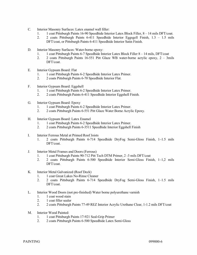
PAINTING 099000-6
C. Interior Masonry Surfaces: Latex enamel wall filler: 1. 1 coat Pittsburgh Paints 16-90 Speedhide Interior Latex Block Filler, 8 – 14 mils DFT/coat. 2. 2 coats Pittsburgh Paints 6-411 Speedhide Interior Eggsgell Finish, 1.3 – 1.5 mils
DFT/coat, or Pittsburgh Paints 6-411 Speedhide Interior Satin Finish. D. Interior Masonry Surfaces: Water-borne epoxy: 1. 1 coat Pittsburgh Paints 6-7 Speedhide Interior Latex Block Filler 8 – 14 mils, DFT/coat 2. 2 coats Pittsburgh Paints 16-551 Pitt Glaze WB water-borne acrylic epoxy, 2 – 3mils
DFT/coat. E. Interior Gypsum Board: Flat 1. 1 coat Pittsburgh Paints 6-2 Speedhide Interior Latex Primer. 2. 2 coats Pittsburgh Paints 6-70 Speedhide Interior Flat. F. Interior Gypsum Board: Eggshell 1. 1 coat Pittsburgh Paints 6-2 Speedhide Interior Latex Primer. 2. 2 coats Pittsburgh Paints 6-411 Speedhide Interior Eggshell Finish. G. Interior Gypsum Board: Epoxy 1. 1 coat Pittsburgh Paints 6-2 Speedhide Interior Latex Primer. 2. 2 coats Pittsburgh Paints 6-551 Pitt Glaze Water Borne Acrylic Epoxy. H. Interior Gypsum Board: Latex Enamel 1. 1 coat Pittsburgh Paints 6-2 Speedhide Interior Latex Primer. 2. 2 coats Pittsburgh Paints 6-3511 Speedhide Interior Eggshell Finish I. Interior Ferrous Metal at Primed Roof Joists 1. 2 coats Pittsburgh Paints 6-714 Speedhide DryFog Semi-Gloss Finish, 1–1.5 mils
DFT/coat. J. Interior Metal Frames and Doors (Ferrous) 1. 1 coat Pittsburgh Paints 90-712 Pitt Tech DTM Primer, 2 -3 mils DFT/coat 2. 2 coats Pittsburgh Paints 6-500 Speedhide Interior Semi-Gloss Finish, 1–1,2 mils
DFT/coat. K. Interior Metal Galvanized (Roof Deck) 1. 1 coat Great Lakes No-Rinse Cleaner 2. 2 coats Pittsburgh Paints 6-714 Speedhide DryFog Semi-Gloss Finish, 1–1.5 mils
DFT/coat. L. Interior Wood Doors (not pre-finished) Water borne polyurethane varnish 1. 1 coat wood stain 2. 1 coat filler sealer 2. 2 coats Pittsburgh Paints 77-49 REZ Interior Acrylic Urethane Clear, 1-1.2 mils DFT/coat M. Interior Wood Painted: 1. 1 coat Pittsburgh Paints 17-921 Seal-Grip Primer 2. 2 coats Pittsburgh Paints 6-500 Speedhide Latex Semi-Gloss
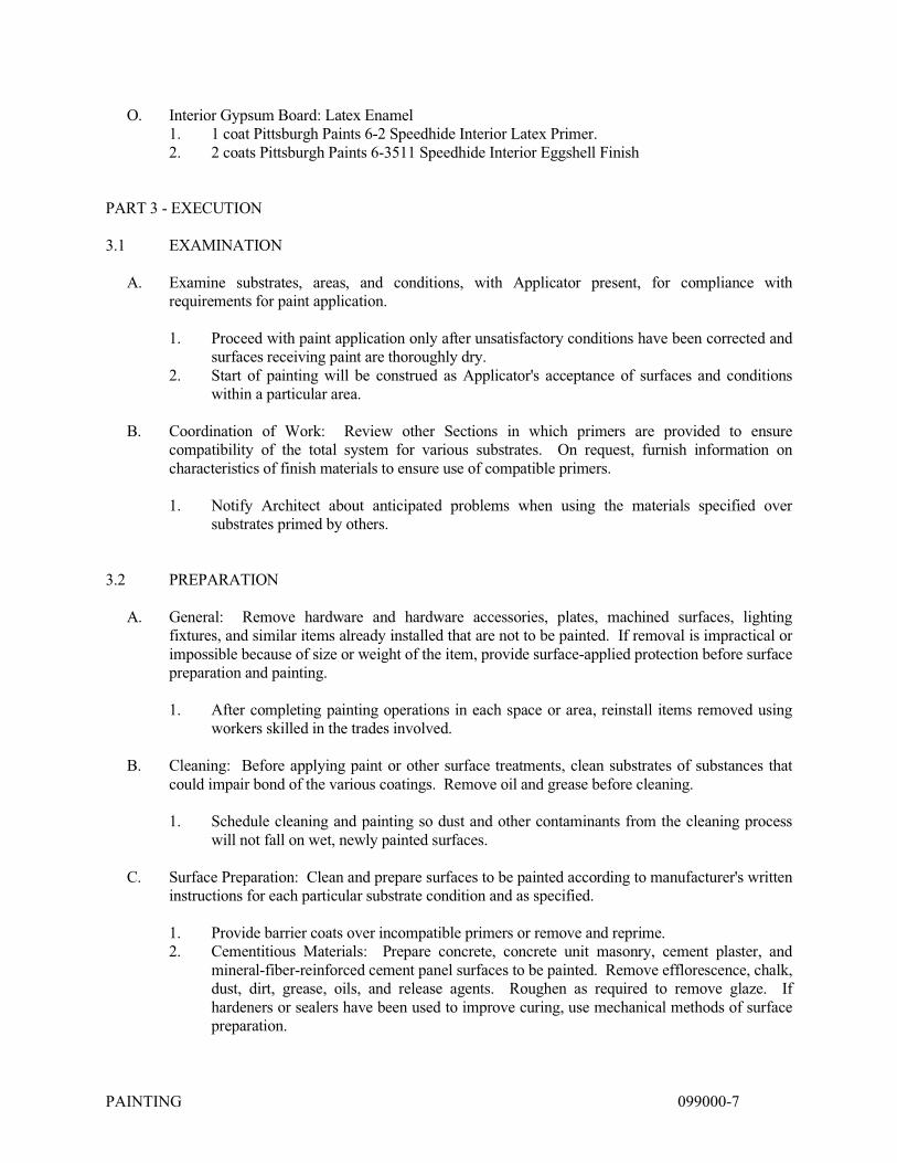
PAINTING 099000-7
O. Interior Gypsum Board: Latex Enamel 1. 1 coat Pittsburgh Paints 6-2 Speedhide Interior Latex Primer. 2. 2 coats Pittsburgh Paints 6-3511 Speedhide Interior Eggshell Finish PART 3 - EXECUTION 3.1 EXAMINATION A. Examine substrates, areas, and conditions, with Applicator present, for compliance with
requirements for paint application. 1. Proceed with paint application only after unsatisfactory conditions have been corrected and
surfaces receiving paint are thoroughly dry. 2. Start of painting will be construed as Applicator's acceptance of surfaces and conditions
within a particular area. B. Coordination of Work: Review other Sections in which primers are provided to ensure
compatibility of the total system for various substrates. On request, furnish information on characteristics of finish materials to ensure use of compatible primers.
1. Notify Architect about anticipated problems when using the materials specified over
substrates primed by others. 3.2 PREPARATION A. General: Remove hardware and hardware accessories, plates, machined surfaces, lighting
fixtures, and similar items already installed that are not to be painted. If removal is impractical or impossible because of size or weight of the item, provide surface-applied protection before surface preparation and painting.
1. After completing painting operations in each space or area, reinstall items removed using
workers skilled in the trades involved. B. Cleaning: Before applying paint or other surface treatments, clean substrates of substances that
could impair bond of the various coatings. Remove oil and grease before cleaning. 1. Schedule cleaning and painting so dust and other contaminants from the cleaning process
will not fall on wet, newly painted surfaces. C. Surface Preparation: Clean and prepare surfaces to be painted according to manufacturer's written
instructions for each particular substrate condition and as specified. 1. Provide barrier coats over incompatible primers or remove and reprime. 2. Cementitious Materials: Prepare concrete, concrete unit masonry, cement plaster, and
mineral-fiber-reinforced cement panel surfaces to be painted. Remove efflorescence, chalk, dust, dirt, grease, oils, and release agents. Roughen as required to remove glaze. If hardeners or sealers have been used to improve curing, use mechanical methods of surface preparation.

PAINTING 099000-8
a. Use abrasive blast-cleaning methods if recommended by paint manufacturer. b. Determine alkalinity and moisture content of surfaces by performing appropriate
tests. If surfaces are sufficiently alkaline to cause the finish paint to blister and burn, correct this condition before application. Do not paint surfaces if moisture content exceeds that permitted in manufacturer's written instructions.
3. Wood: Clean surfaces of dirt, oil, and other foreign substances with scrapers, mineral
spirits, and sandpaper, as required. Sand surfaces exposed to view smooth and dust off. a. Scrape and clean small, dry, seasoned knots, and apply a thin coat of white shellac or
other recommended knot sealer before applying primer. After priming, fill holes and imperfections in finish surfaces with putty or plastic wood filler. Sand smooth when dried.
4. Ferrous Metals: Clean ungalvanized ferrous-metal surfaces that have not been shop coated;
remove oil, grease, dirt, loose mill scale, and other foreign substances. Use solvent or mechanical cleaning methods that comply with SSPC's recommendations.
a. Blast steel surfaces clean as recommended by paint system manufacturer and
according to SSPC-SP 6/NACE No. 3. b. Touch up bare areas and shop-applied prime coats that have been damaged. Wire-
brush, clean with solvents recommended by paint manufacturer, and touch up with same primer as the shop coat.
5. Galvanized Surfaces: Clean galvanized surfaces with nonpetroleum-based solvents so
surface is free of oil and surface contaminants. Remove pretreatment from galvanized sheet metal fabricated from coil stock by mechanical methods.
D. Material Preparation: Mix and prepare paint materials according to manufacturer's written
instructions. 1. Maintain containers used in mixing and applying paint in a clean condition, free of foreign
materials and residue. 2. Stir material before application to produce a mixture of uniform density. Stir as required
during application. Do not stir surface film into material. If necessary, remove surface film and strain material before using.
3. Use only thinners approved by paint manufacturer and only within recommended limits. E. Tinting: Tint each undercoat a lighter shade to simplify identification of each coat when multiple
coats of same material are applied. Tint undercoats to match the color of the finish coat, but provide sufficient differences in shade of undercoats to distinguish each separate coat.
3.3 APPLICATION A. General: Apply paint according to manufacturer's written instructions. Use applicators and
techniques best suited for substrate and type of material being applied. 1. Paint colors, surface treatments, and finishes are indicated in the paint schedules. 2. Do not paint over dirt, rust, scale, grease, moisture, scuffed surfaces, or conditions
detrimental to formation of a durable paint film. 3. Provide finish coats that are compatible with primers used.

PAINTING 099000-9
4. The term "exposed surfaces" includes areas visible when permanent or built-in fixtures, grilles, convector covers, covers for finned-tube radiation, and similar components are in place. Extend coatings in these areas, as required, to maintain system integrity and provide desired protection.
5. Paint surfaces behind movable equipment and furniture the same as similar exposed surfaces. Before final installation of equipment, paint surfaces behind permanently fixed equipment or furniture with prime coat only.
6. Paint interior surfaces of ducts with a flat, nonspecular black paint where visible through registers or grilles.
7. Paint back sides of access panels and removable or hinged covers to match exposed surfaces.
8. Finish exterior doors on tops, bottoms, and side edges the same as exterior faces. 9. Sand lightly between each succeeding enamel or varnish coat. B. Scheduling Painting: Apply first coat to surfaces that have been cleaned, pretreated, or otherwise
prepared for painting as soon as practicable after preparation and before subsequent surface deterioration.
1. The number of coats and film thickness required are the same regardless of application method. Do not apply succeeding coats until previous coat has cured as recommended by manufacturer. If sanding is required to produce a smooth, even surface according to manufacturer's written instructions, sand between applications.
2. Omit primer over metal surfaces that have been shop primed and touchup painted. 3. If undercoats, stains, or other conditions show through final coat of paint, apply additional
coats until paint film is of uniform finish, color, and appearance. Give special attention to ensure that edges, corners, crevices, welds, and exposed fasteners receive a dry film thickness equivalent to that of flat surfaces.
4. Allow sufficient time between successive coats to permit proper drying. Do not recoat surfaces until paint has dried to where it feels firm, and does not deform or feel sticky under moderate thumb pressure, and until application of another coat of paint does not cause undercoat to lift or lose adhesion.
C. Application Procedures: Apply paints and coatings by brush, roller, spray, or other applicators
according to manufacturer's written instructions. 1. Brushes: Use brushes best suited for type of material applied. Use brush of appropriate
size for surface or item being painted. 2. Rollers: Use rollers of carpet, velvet-back, or high-pile sheep's wool as recommended by
manufacturer for material and texture required. 3. Spray Equipment: Use airless spray equipment with orifice size as recommended by
manufacturer for material and texture required. D. Minimum Coating Thickness: Apply paint materials no thinner than manufacturer's
recommended spreading rate to achieve dry film thickness indicated. Provide total dry film thickness of the entire system as recommended by manufacturer.
E. Mechanical and Electrical Work: Painting of mechanical and electrical work is limited to items
exposed in equipment rooms, storage rooms and occupied spaces.
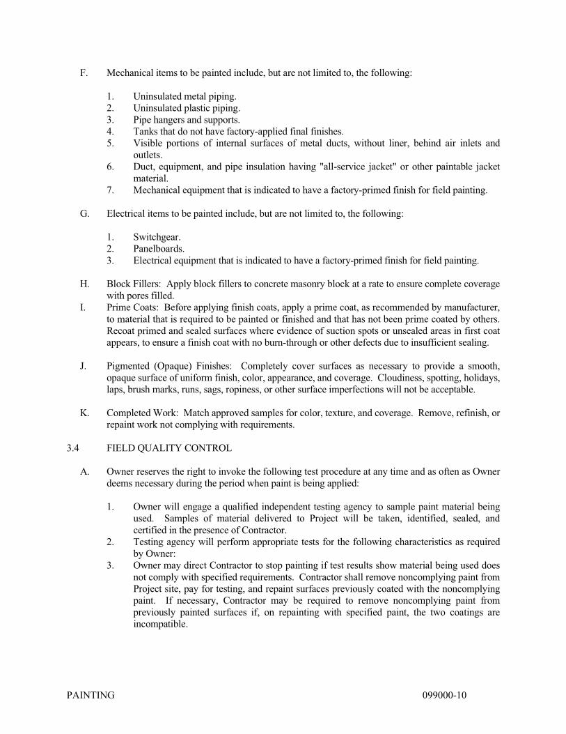
PAINTING 099000-10
F. Mechanical items to be painted include, but are not limited to, the following: 1. Uninsulated metal piping. 2. Uninsulated plastic piping. 3. Pipe hangers and supports. 4. Tanks that do not have factory-applied final finishes. 5. Visible portions of internal surfaces of metal ducts, without liner, behind air inlets and
outlets. 6. Duct, equipment, and pipe insulation having "all-service jacket" or other paintable jacket
material. 7. Mechanical equipment that is indicated to have a factory-primed finish for field painting. G. Electrical items to be painted include, but are not limited to, the following: 1. Switchgear. 2. Panelboards. 3. Electrical equipment that is indicated to have a factory-primed finish for field painting. H. Block Fillers: Apply block fillers to concrete masonry block at a rate to ensure complete coverage
with pores filled. I. Prime Coats: Before applying finish coats, apply a prime coat, as recommended by manufacturer,
to material that is required to be painted or finished and that has not been prime coated by others. Recoat primed and sealed surfaces where evidence of suction spots or unsealed areas in first coat appears, to ensure a finish coat with no burn-through or other defects due to insufficient sealing.
J. Pigmented (Opaque) Finishes: Completely cover surfaces as necessary to provide a smooth,
opaque surface of uniform finish, color, appearance, and coverage. Cloudiness, spotting, holidays, laps, brush marks, runs, sags, ropiness, or other surface imperfections will not be acceptable.
K. Completed Work: Match approved samples for color, texture, and coverage. Remove, refinish, or
repaint work not complying with requirements. 3.4 FIELD QUALITY CONTROL A. Owner reserves the right to invoke the following test procedure at any time and as often as Owner
deems necessary during the period when paint is being applied: 1. Owner will engage a qualified independent testing agency to sample paint material being
used. Samples of material delivered to Project will be taken, identified, sealed, and certified in the presence of Contractor.
2. Testing agency will perform appropriate tests for the following characteristics as required by Owner:
3. Owner may direct Contractor to stop painting if test results show material being used does not comply with specified requirements. Contractor shall remove noncomplying paint from Project site, pay for testing, and repaint surfaces previously coated with the noncomplying paint. If necessary, Contractor may be required to remove noncomplying paint from previously painted surfaces if, on repainting with specified paint, the two coatings are incompatible.
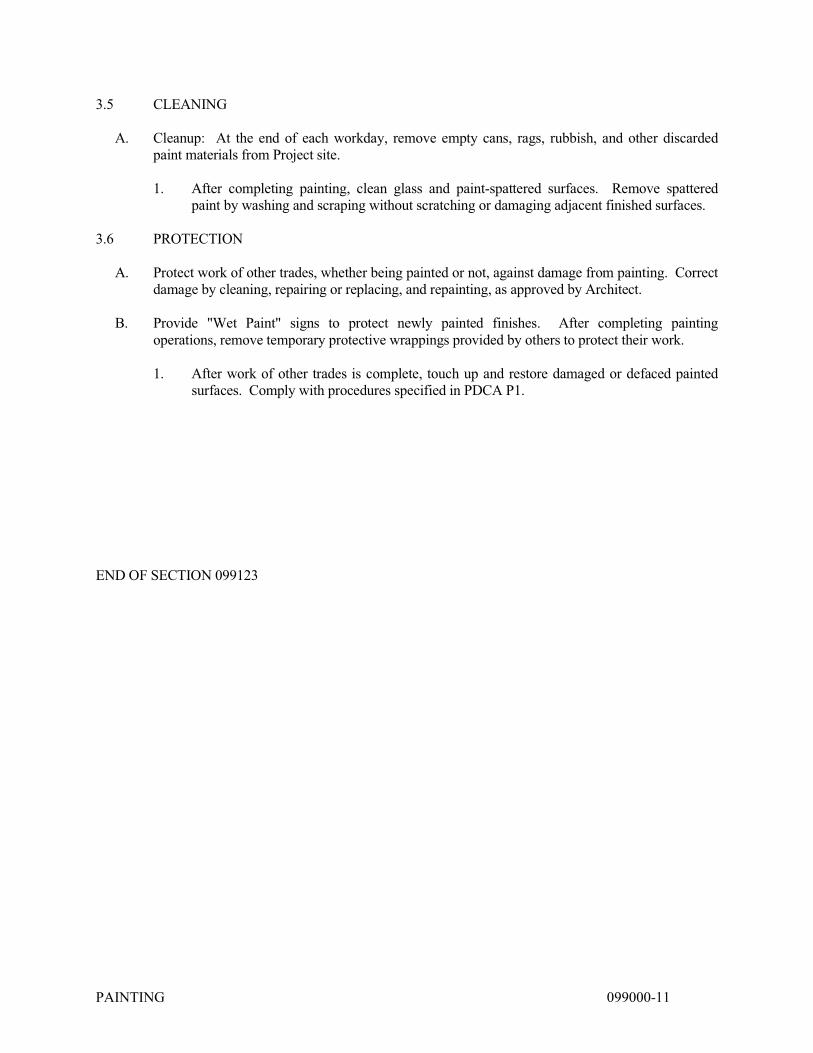
PAINTING 099000-11
3.5 CLEANING A. Cleanup: At the end of each workday, remove empty cans, rags, rubbish, and other discarded
paint materials from Project site. 1. After completing painting, clean glass and paint-spattered surfaces. Remove spattered
paint by washing and scraping without scratching or damaging adjacent finished surfaces. 3.6 PROTECTION A. Protect work of other trades, whether being painted or not, against damage from painting. Correct
damage by cleaning, repairing or replacing, and repainting, as approved by Architect. B. Provide "Wet Paint" signs to protect newly painted finishes. After completing painting
operations, remove temporary protective wrappings provided by others to protect their work. 1. After work of other trades is complete, touch up and restore damaged or defaced painted
surfaces. Comply with procedures specified in PDCA P1. END OF SECTION 099123

SIGNAGE 101423 - 1
SECTION 101423 – PANEL SIGNAGE
PART 1 - GENERAL
1.1 RELATED DOCUMENTS
A. Drawings and general provisions of the Contract, including General and Supplementary Conditions and Division 01 Specification Sections, apply to this Section.
1.2 SUMMARY
A. This Section includes the following:
1. Interior room-identification panel signs.
1.3 DEFINITIONS
A. ADA-ABA Accessibility Guidelines: U.S. Architectural & Transportation Barriers Compliance Board's "Americans with Disabilities Act (ADA) Accessibility Guidelines for Buildings and Facilities; Architectural Barriers Act (ABA) Accessibility Guidelines."
1.4 SUBMITTALS
A. Product Data: For each type of product indicated.
B. Shop Drawings: Show fabrication and installation details for signs. 1. Show sign mounting heights, locations of supplementary supports to be provided by others,
and accessories. 2. Provide message list, typestyles, graphic elements, including tactile characters and Braille,
and layout for each sign.
C. Samples for Initial Selection: Manufacturer's color charts consisting of actual units or sections of units showing the full range of colors available.
D. Samples for Verification: For each of the following products and for the full range of color, texture, and sign material indicated, of sizes indicated:
1.5 QUALITY ASSURANCE
A. Fabricator Qualifications: Shop that employs skilled workers who custom-fabricate products similar to those required for this Project and whose products have a record of successful in-service performance.
B. Source Limitations for Signs: Obtain each sign type indicated from one source from a single manufacturer.

SIGNAGE 101423 - 2
C. Regulatory Requirements: Comply with applicable provisions in ADA-ABA Accessibility Guidelines and ICC/ANSI A117.1.
1.6 PROJECT CONDITIONS
A. Weather Limitations: Proceed with installation only when weather conditions permit installation of signs in exterior locations to be performed according to manufacturers' written instructions and warranty requirements.
B. Field Measurements: Verify recess openings by field measurements before fabrication and indicate measurements on Shop Drawings.
1.7 COORDINATION
A. Coordinate placement of anchorage devices with templates for installing signs.
1.8 WARRANTY
A. Special Warranty: Manufacturer's standard form in which manufacturer agrees to repair or replace components of signs that fail in materials or workmanship within specified warranty period.
1. Failures include, but are not limited to, the following: a. Deterioration of metal and polymer finishes beyond normal weathering. b. Deterioration of embedded graphic image colors and sign lamination.
2. Warranty Period: Five years from date of Substantial Completion.
PART 2 - PRODUCTS
2.1 PANEL SIGNS
A. Basis-of-Design Product: Subject to compliance with requirements, provide signs from “ESC - Ellet Sign Company”, or comparable product by one of the following:
1. ASI Sign Systems, Inc. 2. Best Sign Systems, Inc. 3. Graphics 22 Signs, Inc.
B. Interior Panel Signs: Provide smooth sign panel surfaces constructed to remain flat under installed conditions within a tolerance of plus or minus 1/16 inch (1.5 mm) measured diagonally from corner to corner, complying with the following requirements: 1. Acrylic Sheet: 1/8" thick. 2. Laminated, Etched Photopolymer: Raised graphics with Braille 1/32 inch (0.8 mm) above
surface with contrasting colors as selected by Architect from manufacturer's full range and laminated to acrylic back.
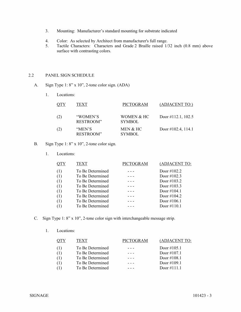
SIGNAGE 101423 - 3
3. Mounting: Manufacturer’s standard mounting for substrate indicated
4. Color: As selected by Architect from manufacturer's full range. 5. Tactile Characters: Characters and Grade 2 Braille raised 1/32 inch (0.8 mm) above
surface with contrasting colors.
2.2 PANEL SIGN SCHEDULE
A. Sign Type 1: 8” x 10”, 2-tone color sign. (ADA)
1. Locations:
QTY TEXT PICTOGRAM (ADJACENT TO:)
(2) “WOMEN’S WOMEN & HC Door #112.1, 102.5 RESTROOM” SYMBOL
(2) “MEN’S MEN & HC Door #102.4, 114.1 RESTROOM” SYMBOL
B. Sign Type 1: 8” x 10”, 2-tone color sign.
1. Locations:
QTY TEXT PICTOGRAM (ADJACENT TO:
(1) To Be Determined - - - Door #102.2 (1) To Be Determined - - - Door #102.3 (1) To Be Determined - - - Door #103.2 (1) To Be Determined - - - Door #103.3 (1) To Be Determined - - - Door #104.1 (1) To Be Determined - - - Door #104.2 (1) To Be Determined - - - Door #106.1 (1) To Be Determined - - - Door #110.1
C. Sign Type 1: 8” x 10”, 2-tone color sign with interchangeable message strip.
1. Locations:
QTY TEXT PICTOGRAM (ADJACENT TO:
(1) To Be Determined - - - Door #105.1 (1) To Be Determined - - - Door #107.1 (1) To Be Determined - - - Door #108.1 (1) To Be Determined - - - Door #109.1 (1) To Be Determined - - - Door #111.1
SIGNAGE 101423 - 4
2.3 FINISHES, GENERAL
A. Appearance of Finished Work: Variations in appearance of abutting or adjacent pieces are acceptable if they are within one-half of the range of approved Samples. Noticeable variations in the same piece are not acceptable. Variations in appearance of other components are acceptable if they are within the range of approved Samples and are assembled or installed to minimize contrast.
2.4 ACRYLIC SHEET FINISHES
A. Colored Coatings for Acrylic Sheet: For copy and background colors, provide colored coatings, including inks, dyes, and paints, that are recommended by acrylic manufacturers for optimum adherence to acrylic surface and that are UV and water resistant for five years for application intended.
PART 3 - EXECUTION
3.1 EXAMINATION
A. Examine substrates, areas, and conditions, with Installer present, for compliance with requirements for installation tolerances and other conditions affecting performance of work.
3.2 INSTALLATION
A. Locate signs and accessories where indicated, using mounting methods of types described and complying with manufacturer's written instructions.
1. Install signs level, plumb, and at heights indicated, with sign surfaces free of distortion and other defects in appearance.
2. Interior Wall Signs: Install signs on walls adjacent to latch side of door where applicable. Where not indicated or possible, such as double doors, install signs on nearest adjacent walls. Locate to allow approach within 3 inches (75 mm) of sign without encountering protruding objects or standing within swing of door.
B. Wall-Mounted Signs: Comply with sign manufacturer's written instructions except where more stringent requirements apply.
END OF SECTION 101400
TOILET, BATH, AND LAUNDRY ACCESSORIES 102800 - 1
SECTION 102800 - TOILET, BATH, AND LAUNDRY ACCESSORIES
PART 1 - GENERAL
1.1 RELATED DOCUMENTS
A. Drawings and general provisions of the Contract, including General and Supplementary Conditions and Division 01 Specification Sections, apply to this Section.
1.2 SUMMARY
A. Section Includes:
1. Public-use washroom accessories. 2. Custodial accessories.
1.3 COORDINATION
A. Coordinate accessory locations with other work to prevent interference with clearances required for access by people with disabilities, and for proper installation, adjustment, operation, cleaning, and servicing of accessories.
B. Deliver inserts and anchoring devices set into concrete or masonry as required to prevent delaying the Work.
1.4 ACTION SUBMITTALS
A. Product Data: For each type of product.
1. Include construction details, material descriptions, dimensions of individual components and profiles, and finishes.
2. Include anchoring and mounting requirements, including requirements for cutouts in other work and substrate preparation.
3. Include electrical characteristics.
B. Product Schedule: Indicating types, quantities, sizes, and installation locations by room of each accessory required.
1. Identify locations using room designations indicated. 2. Identify accessories using designations indicated.
1.5 INFORMATIONAL SUBMITTALS
A. Sample Warranty: For manufacturer's special warranty.
TOILET, BATH, AND LAUNDRY ACCESSORIES 102800 - 2
1.6 CLOSEOUT SUBMITTALS
A. Maintenance Data: For accessories to include in maintenance manuals.
1.7 WARRANTY
A. Manufacturer's Special Warranty for Mirrors: Manufacturer agrees to repair or replace mirrors that fail in materials or workmanship within specified warranty period.
1. Failures include, but are not limited to, visible silver spoilage defects. 2. Warranty Period: 15 years from date of Substantial Completion.
PART 2 - PRODUCTS
2.1 PERFORMANCE REQUIREMENTS
A. Electrical Components, Devices, and Accessories: Listed and labeled as defined in NFPA 70, by a qualified testing agency, and marked for intended location and application.
2.2 PUBLIC-USE WASHROOM ACCESSORIES
A. Source Limitations: Obtain public-use washroom accessories from single source from single manufacturer.
B. Basis-of-Design Product: Subject to compliance with requirements, provide product indicated, or comparable product by one of the following:
1. AJW Architectural Products. 2. American Specialties, Inc. 3. Bobrick Washroom Equipment, Inc. 4. Bradley Corporation. 5. Kimberly clarke
C. Toilet Tissue (Roll) Dispenser TP-1:
1. Product: Supplied by owner, installed by contractor. 2. Mounting: Surface mount. Provide solid blocking.
D. Paper Towel (Roll) Dispenser TD-1:
1. Product: Supplied by owner, installed by contractor. 2. Mounting: Surface mount. Provide solid blocking.
E. Soap Dispenser SD-1:
1. Product: Supplied by owner, installed by contractor. 2. Mounting: Surface mount. Provide solid blocking.

TOILET, BATH, AND LAUNDRY ACCESSORIES 102800 - 3
F. Grab Bar GB-1, GB-2, GB-3:
1. Basis-of-Design Product: Bobrick B-6806 Series 2. Product: Contractor to provide and install all grab bars. 3. Mounting: Flanges with concealed fasteners. 4. Material: Stainless steel, 0.05 inch (1.3 mm) thick.
a. Finish: Smooth, No. 4 finish (satin) on ends and slip-resistant texture in grip area.
5. Outside Diameter: 1-1/2 inches (38 mm). 6. Configuration and Length:
a. GB-1: 42” b. GB-2: 36” c. GB-3: 18” d. GB-4: Two wall shower compartment B-6861
G. Mirror Unit M-1:
1. Basis-of-Design Product: Bobrick B-165-2436 2. Product: Contractor to provide and install all mirrors. 3. Frame: Stainless-steel channel
a. Corners: Mitered and mechanically interlocked
4. Hangers: Produce rigid, tamper- and theft-resistant installation, using method indicated below.
a. One-piece, galvanized-steel, wall-hanger device with spring-action locking mechanism to hold mirror unit in position with no exposed screws or bolts.
5. Size: 24 X 36
2.3 MATERIALS
A. Stainless Steel: ASTM A 666, Type 304, 0.031-inch (0.8-mm) minimum nominal thickness unless otherwise indicated.
B. Brass: ASTM B 19, flat products; ASTM B 16/B 16M, rods, shapes, forgings, and flat products with finished edges; or ASTM B 30, castings.
C. Steel Sheet: ASTM A 1008/A 1008M, Designation CS (cold rolled, commercial steel), 0.036-inch (0.9-mm) minimum nominal thickness.
D. Galvanized-Steel Sheet: ASTM A 653/A 653M, with G60 (Z180) hot-dip zinc coating.
E. Galvanized-Steel Mounting Devices: ASTM A 153/A 153M, hot-dip galvanized after fabrication.
F. Fasteners: Screws, bolts, and other devices of same material as accessory unit and tamper-and-theft resistant where exposed, and of galvanized steel where concealed.
TOILET, BATH, AND LAUNDRY ACCESSORIES 102800 - 4
G. Chrome Plating: ASTM B 456, Service Condition Number SC 2 (moderate service).
H. Mirrors: ASTM C 1503, Mirror Glazing Quality, clear-glass mirrors, nominal 6.0 mm thick.
2.4 FABRICATION
A. General: Fabricate units with tight seams and joints, and exposed edges rolled. Hang doors and access panels with full-length, continuous hinges. Equip units for concealed anchorage and with corrosion-resistant backing plates.
B. Keys: Provide universal keys for internal access to accessories for servicing and resupplying. Provide minimum of six keys to Owner's representative.
PART 3 - EXECUTION
3.1 INSTALLATION
A. Install accessories according to manufacturers' written instructions, using fasteners appropriate to substrate indicated and recommended by unit manufacturer. Install units level, plumb, and firmly anchored in locations and at heights indicated.
B. Grab Bars: Install to withstand a downward load of at least 250 lbf (1112 N), when tested according to ASTM F 446.
3.2 ADJUSTING AND CLEANING
A. Adjust accessories for unencumbered, smooth operation. Replace damaged or defective items.
B. Remove temporary labels and protective coatings.
C. Clean and polish exposed surfaces according to manufacturer's written instructions.
END OF SECTION 102800
FIRE PROTECTION CABINETS 104413 - 1
SECTION 104413 - FIRE PROTECTION CABINETS
PART 1 - GENERAL
1.1 RELATED DOCUMENTS
A. Drawings and general provisions of the Contract, including General and Supplementary Conditions and Division 01 Specification Sections, apply to this Section.
1.2 SUMMARY
A. Section Includes:
1. Fire-protection cabinets for the following:
a. Portable fire extinguishers.
B. Related Requirements:
1. Section 104416 "Fire Extinguishers."
1.3 PREINSTALLATION CONFERENCE
A. Preinstallation Conference: Conduct conference at Project site.
1. Review methods and procedures related to fire-protection cabinets including, but not limited to, the following:
a. Schedules and coordination requirements.
1.4 ACTION SUBMITTALS
A. Product Data: For each type of product. Show door hardware, cabinet type, trim style, and panel style. Include roughing-in dimensions and details showing recessed-, semirecessed-, or surface-mounting method and relationships of box and trim to surrounding construction.
B. Shop Drawings: For fire-protection cabinets. Include plans, elevations, sections, details, and attachments to other work.
1.5 CLOSEOUT SUBMITTALS
A. Maintenance Data: For fire-protection cabinets to include in maintenance manuals.

FIRE PROTECTION CABINETS 104413 - 2
1.6 COORDINATION
A. Coordinate size of fire-protection cabinets to ensure that type and capacity of fire extinguishers indicated are accommodated.
B. Coordinate sizes and locations of fire-protection cabinets with wall depths.
PART 2 - PRODUCTS
2.1 PERFORMANCE REQUIREMENTS
A. Fire-Rated Fire-Protection Cabinets: Listed and labeled to comply with requirements in ASTM E 814 for fire-resistance rating of walls where they are installed.
2.2 FIRE-PROTECTION CABINET
A. Cabinet Type: Suitable for fire extinguisher.
1. Manufacturers: Subject to compliance with requirements, provide products by one of the following:
a. Fire-End & Croker Corporation. b. JL Industries, Inc.; a division of the Activar Construction Products Group. c. Larsens Manufacturing Company.
B. Cabinet Construction: 1-hour fire rated where installed in rated walls. No rating when installed in unrated walls.
1. Fire-Rated Cabinets: Construct fire-rated cabinets with double walls fabricated from 0.043-inch- (1.09-mm-) thick cold-rolled steel sheet lined with minimum 5/8-inch- (16-mm-) thick fire-barrier material. Provide factory-drilled mounting holes.
C. Cabinet Material: Cold-rolled enameled steel.
D. Semirecessed Cabinet: One-piece combination trim and perimeter door frame overlapping surrounding wall surface with exposed trim face and wall return at outer edge (backbend).
1. Square trim: 1 1/4” - 1 1/2” backbend depth.
E. Cabinet Trim Material: Same material and finish as door.
F. Door Material: Steel sheet.
G. Door Style: Vertical duo panel and frame.
H. Door Glazing: Tempered float glass (clear).
I. Door Hardware: Manufacturer's standard door-operating hardware of proper type for cabinet type, trim style, and door material and style indicated.
FIRE PROTECTION CABINETS 104413 - 3
1. Provide manufacturer's standard. 2. Provide continuous hinge, of same material and finish as trim, permitting door to open
180 degrees.
J. Accessories:
1. Mounting Bracket: Manufacturer's standard steel, designed to secure fire extinguisher to fire-protection cabinet, of sizes required for types and capacities of fire extinguishers indicated, with plated or baked-enamel finish.
2. Lettered Door Handle: One-piece, cast-iron door handle with the word "FIRE" embossed into face.
3. Identification: Lettering complying with authorities having jurisdiction for letter style, size, spacing, and location. Locate as directed by Architect.
a. Identify fire extinguisher in fire-protection cabinet with the words "FIRE EXTINGUISHER”
1) Location: Applied to cabinet door or cabinet glazing. 2) Application Process: Silk-screened.
K. Materials:
1. Cold-Rolled Steel: ASTM A 1008/A 1008M, Commercial Steel (CS), Type B.
a. Finish: Baked enamel or powder coat. b. Color: As selected by Architect from full range of industry colors and color
densities.
2. Tempered Float Glass: ASTM C 1048, Kind FT, Condition A, Type I, Quality q3, 3 mm thick, Class 1 (clear).
2.3 FABRICATION
A. Fire-Protection Cabinets: Provide manufacturer's standard box (tub) with trim, frame, door, and hardware to suit cabinet type, trim style, and door style indicated.
1. Weld joints and grind smooth. 2. Provide factory-drilled mounting holes. 3. Prepare doors and frames to receive locks. 4. Install door locks at factory.
B. Cabinet Doors: Fabricate doors according to manufacturer's standards, from materials indicated and coordinated with cabinet types and trim styles.
1. Fabricate door frames with tubular stiles and rails and hollow-metal design, minimum 1/2 inch (13 mm) thick.
2. Miter and weld perimeter door frames.
C. Cabinet Trim: Fabricate cabinet trim in one piece with corners mitered, welded, and ground smooth.
FIRE PROTECTION CABINETS 104413 - 4
2.4 GENERAL FINISH REQUIREMENTS
A. Comply with NAAMM's AMP 500, "Metal Finishes Manual for Architectural and Metal Products," for recommendations for applying and designating finishes.
B. Protect mechanical finishes on exposed surfaces of fire-protection cabinets from damage by applying a strippable, temporary protective covering before shipping.
C. Finish fire-protection cabinets after assembly.
D. Appearance of Finished Work: Noticeable variations in same piece are not acceptable. Variations in appearance of adjoining components are acceptable if they are within the range of approved Samples and are assembled or installed to minimize contrast.
PART 3 - EXECUTION
3.1 EXAMINATION
A. Examine walls and partitions for suitable framing depth and blocking where semirecessed cabinets will be installed.
B. Proceed with installation only after unsatisfactory conditions have been corrected.
3.2 PREPARATION
A. Prepare recesses for semirecessed fire-protection cabinets as required by type and size of cabinet and trim style.
3.3 INSTALLATION
A. General: Install fire-protection cabinets in locations and at mounting heights indicated or, if not indicated, at heights indicated below:
1. Fire-Protection Cabinets: 54 inches (1372 mm) above finished floor to top of cabinet.
B. Fire-Protection Cabinets: Fasten cabinets to structure, square and plumb.
1. Unless otherwise indicated, provide recessed fire-protection cabinets. If wall thickness is inadequate for recessed cabinets, provide semirecessed fire-protection cabinets.
2. Fasten mounting brackets to inside surface of fire-protection cabinets, square and plumb. 3. Fire-Rated Cabinets:
a. Install cabinet with not more than 1/16-inch (1.6-mm) tolerance between pipe OD and knockout OD. Center pipe within knockout.
b. Seal through penetrations with firestopping sealant as specified in Section 078413 "Penetration Firestopping."
FIRE PROTECTION CABINETS 104413 - 5
3.4 ADJUSTING AND CLEANING
A. Remove temporary protective coverings and strippable films, if any, as fire-protection cabinets are installed unless otherwise indicated in manufacturer's written installation instructions.
B. Adjust fire-protection cabinet doors to operate easily without binding. Verify that integral locking devices operate properly.
C. On completion of fire-protection cabinet installation, clean interior and exterior surfaces as recommended by manufacturer.
D. Touch up marred finishes, or replace fire-protection cabinets that cannot be restored to factory-finished appearance. Use only materials and procedures recommended or furnished by fire-protection cabinet and mounting bracket manufacturers.
E. Replace fire-protection cabinets that have been damaged or have deteriorated beyond successful repair by finish touchup or similar minor repair procedures.
END OF SECTION 104413

FIRE EXTINGUISHERS 104416 - 1
SECTION 104416 - FIRE EXTINGUISHERS
PART 1 - GENERAL
1.1 RELATED DOCUMENTS
A. Drawings and general provisions of the Contract, including General and Supplementary Conditions and Division 01 Specification Sections, apply to this Section.
1.2 SUMMARY
A. Section includes portable, hand-carried fire extinguishers and mounting brackets for fire extinguishers.
B. Related Requirements:
1. Section 104413 "Fire Protection Cabinets."
1.3 ACTION SUBMITTALS
A. Product Data: For each type of product. Include rating and classification, material descriptions, dimensions of individual components and profiles, and finishes for fire extinguisher and mounting brackets.
1.4 INFORMATIONAL SUBMITTALS
A. Warranty: Sample of special warranty.
1.5 CLOSEOUT SUBMITTALS
A. Operation and Maintenance Data: For fire extinguishers to include in maintenance manuals.
1.6 COORDINATION
A. Coordinate type and capacity of fire extinguishers with fire-protection cabinets to ensure fit and function.
PART 2 - PRODUCTS
2.1 PERFORMANCE REQUIREMENTS
A. NFPA Compliance: Fabricate and label fire extinguishers to comply with NFPA 10, "Portable Fire Extinguishers."
FIRE EXTINGUISHERS 104416 - 2
B. Fire Extinguishers: Listed and labeled for type, rating, and classification by an independent testing agency acceptable to authorities having jurisdiction.
2.2 PORTABLE, HAND-CARRIED FIRE EXTINGUISHERS
A. Fire Extinguishers: Type, size, and capacity for each fire-protection cabinet and mounting bracket indicated.
1. Manufacturers: Subject to compliance with requirements, provide products by one of the following:
a. Ansul Incorporated; Tyco International. b. Fire End & Croker Corporation. c. JL Industries, Inc.; a division of the Activar Construction Products Group. d. Larsens Manufacturing Company.
B. Multipurpose Dry-Chemical Type in Steel Container 4-A:60-B:C, 10-lb (4.5-kg) nominal capacity, with monoammonium phosphate-based dry chemical in enameled-steel container.
PART 3 - EXECUTION
3.1 EXAMINATION
A. Examine fire extinguishers for proper charging and tagging.
1. Remove and replace damaged, defective, or undercharged fire extinguishers.
B. Proceed with installation only after unsatisfactory conditions have been corrected.
3.2 INSTALLATION
A. General: Install fire extinguishers and mounting brackets in locations indicated and in compliance with requirements of authorities having jurisdiction.
1. Mounting Brackets: 54 inches (1372 mm) above finished floor to top of fire extinguisher.
B. Mounting Brackets: Fasten mounting brackets to surfaces, square and plumb, at locations indicated.
END OF SECTION 104416