soil mechanics-ch7-stresses in the ground
TRANSCRIPT
SOIL MECHANICS LECTURESFOR 3rd CLASS – CIVIL ENG. DEPT.
Asst. Prof. Dr. Mohammed Shaker Al Shakerchy
Ph.D. in Geotechnical EngineeringFaculty of Engineering / University of Kufa
1SOIL MECHANICS LECTURES by Dr. Mohammed Sh. M. Al Shakerchy
SOIL MECHANICS LECTURES – 3RD CLASS – CIVIL ENG. DEPT.
2
CHAPTER SEVENSTRESSES IN THE GROUND
SOIL MECHANICS LECTURES by Dr. Mohammed Sh. M. Al Shakerchy
Stresses in Soil Masses Stresses without Seepage (Hydrostatic)◦Total Stress, sT
◦Pore Water Stress, u◦Effective Stress, s’T
Stresses with Seepage◦Upwards & Downwards
Stresses Induced by external loads
SOIL MECHANICS- KCE3241 STRESSES IN THE GROUND
SOIL MECHANICS LECTURES by Dr. Mohammed Sh. M. Al Shakerchy
SOIL MECHANICS LECTURES by Dr. Mohammed Sh. M. Al Shakerchy 4
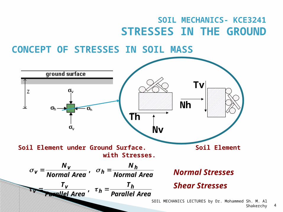
CONCEPT OF STRESSES IN SOIL MASS
NvTh
Nh
Tv
Soil Element under Ground Surface. Soil Element with Stresses.
AreaParallelT
AreaParallelT
AreaNormalN
AreaNormalN
hh
vv
hh
vv
ss
,
, Normal StressesShear Stresses
SOIL MECHANICS- KCE3241 STRESSES IN THE GROUND
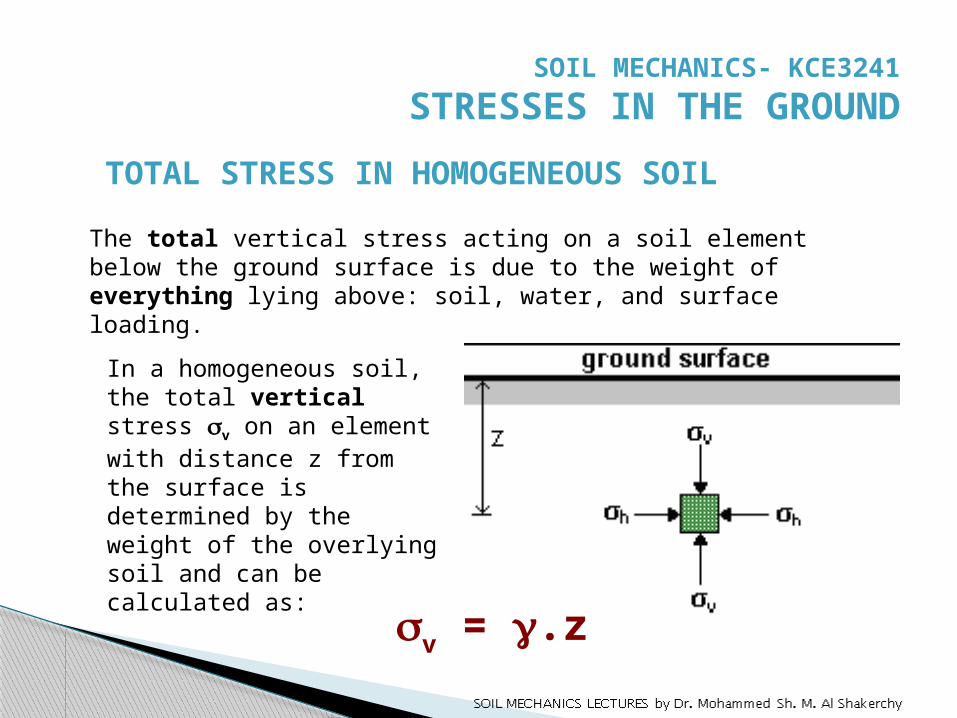
TOTAL STRESS IN HOMOGENEOUS SOIL
In a homogeneous soil, the total vertical stress sv on an element with distance z from the surface is determined by the weight of the overlying soil and can be calculated as:
The total vertical stress acting on a soil element below the ground surface is due to the weight of everything lying above: soil, water, and surface loading.
sv = g.z
SOIL MECHANICS- KCE3241 STRESSES IN THE GROUND
SOIL MECHANICS LECTURES by Dr. Mohammed Sh. M. Al Shakerchy 6
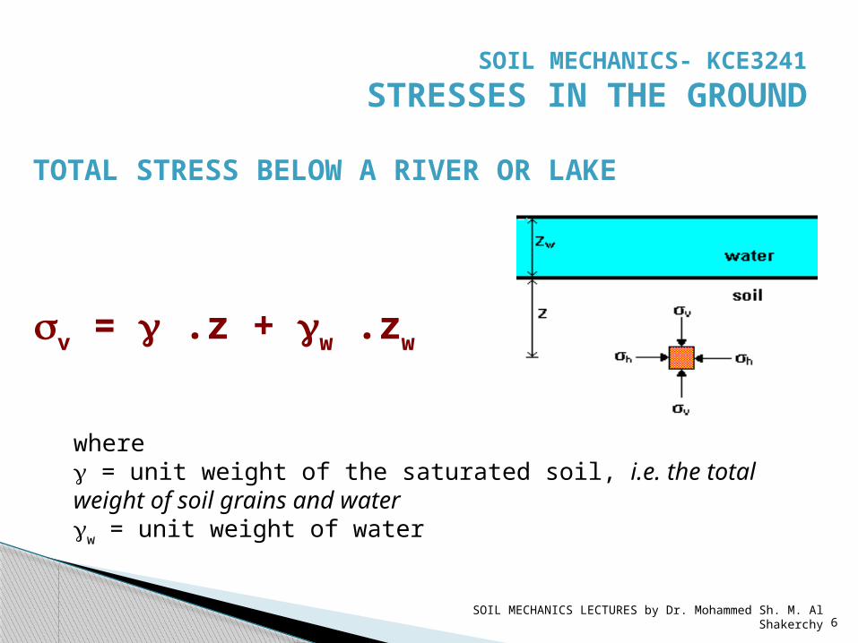
TOTAL STRESS BELOW A RIVER OR LAKE
sv = g .z + gw .zw
where g = unit weight of the saturated soil, i.e. the total weight of soil grains and water gw = unit weight of water
SOIL MECHANICS- KCE3241 STRESSES IN THE GROUND
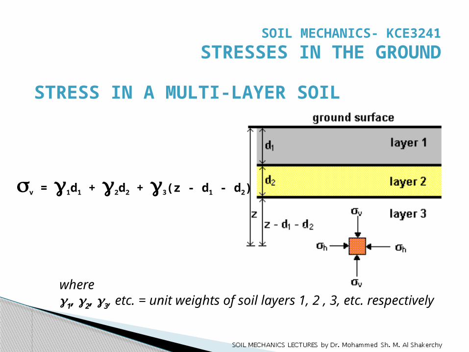
STRESS IN A MULTI-LAYER SOIL
sv = g1d1 + g2d2 + g3(z - d1 - d2)
where g1, g2, g3, etc. = unit weights of soil layers 1, 2 , 3, etc. respectively
SOIL MECHANICS- KCE3241 STRESSES IN THE GROUND
SOIL MECHANICS LECTURES by Dr. Mohammed Sh. M. Al Shakerchy 8
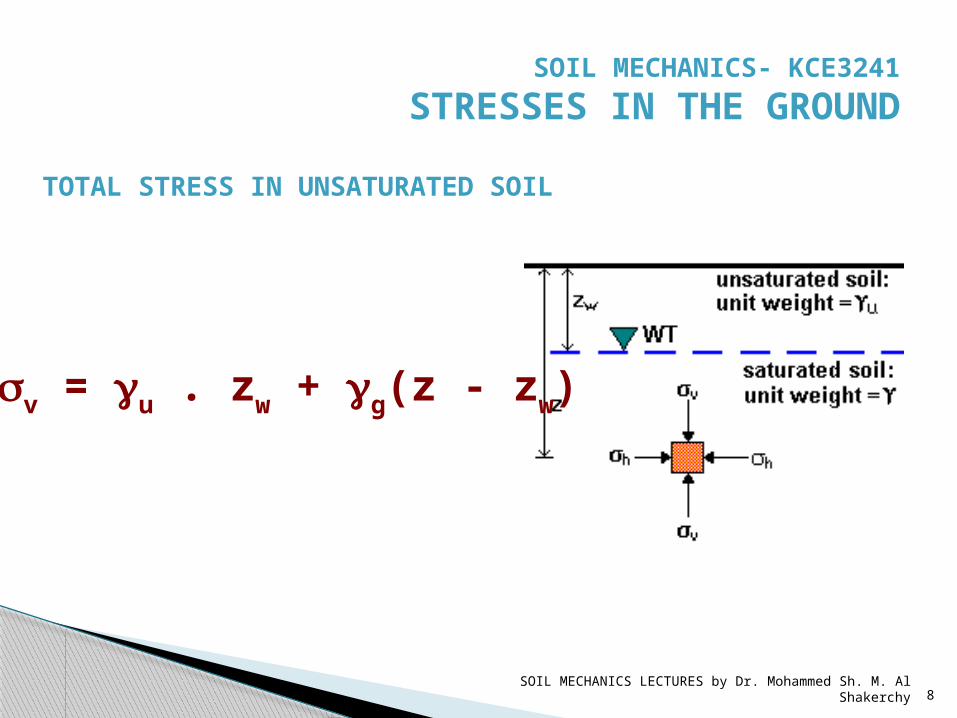
TOTAL STRESS IN UNSATURATED SOIL
sv = gu . zw + gg(z - zw)
SOIL MECHANICS- KCE3241 STRESSES IN THE GROUND
SOIL MECHANICS LECTURES by Dr. Mohammed Sh. M. Al Shakerchy 9
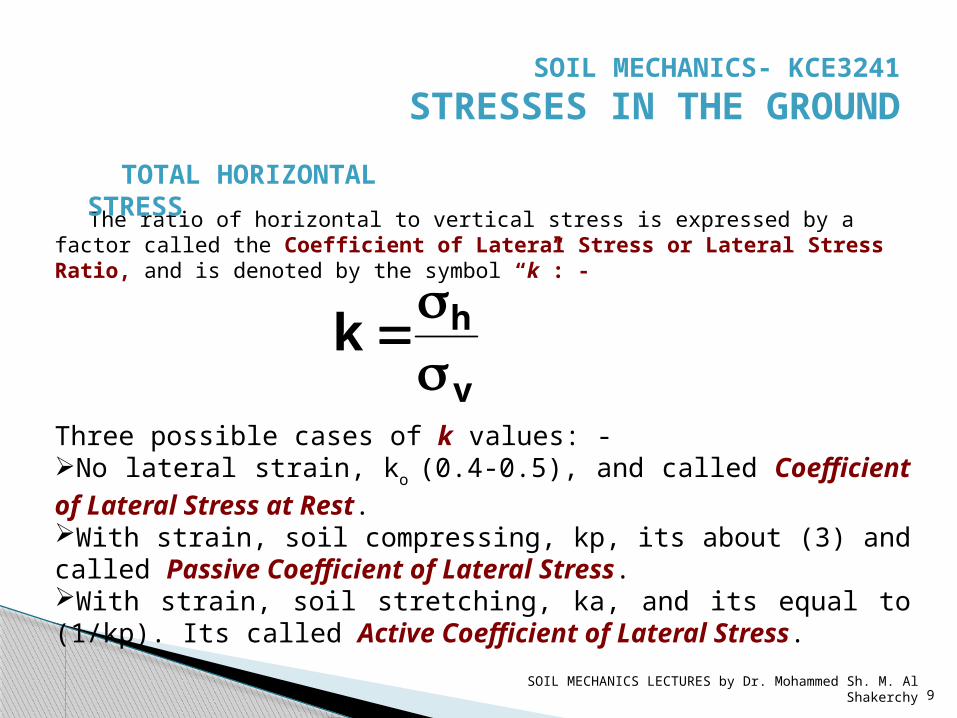
The ratio of horizontal to vertical stress is expressed by a factor called the Coefficient of Lateral Stress or Lateral Stress Ratio, and is denoted by the symbol “k”: -
v
hkss
Three possible cases of k values: -No lateral strain, ko (0.4-0.5), and called Coefficient of Lateral Stress at Rest.With strain, soil compressing, kp, its about (3) and called Passive Coefficient of Lateral Stress.With strain, soil stretching, ka, and its equal to (1/kp). Its called Active Coefficient of Lateral Stress.
TOTAL HORIZONTAL STRESS
SOIL MECHANICS- KCE3241 STRESSES IN THE GROUND
SOIL MECHANICS LECTURES by Dr. Mohammed Sh. M. Al Shakerchy 10
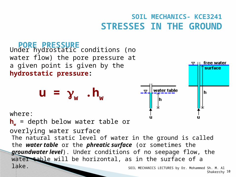
PORE PRESSUREUnder hydrostatic conditions (no water flow) the pore pressure at a given point is given by the hydrostatic pressure:
u = gw .hw where: hw = depth below water table or overlying water surface The natural static level of water in the ground is called the water table or the phreatic surface (or sometimes the groundwater level). Under conditions of no seepage flow, the water table will be horizontal, as in the surface of a lake.
SOIL MECHANICS- KCE3241 STRESSES IN THE GROUND
SOIL MECHANICS LECTURES by Dr. Mohammed Sh. M. Al Shakerchy 11
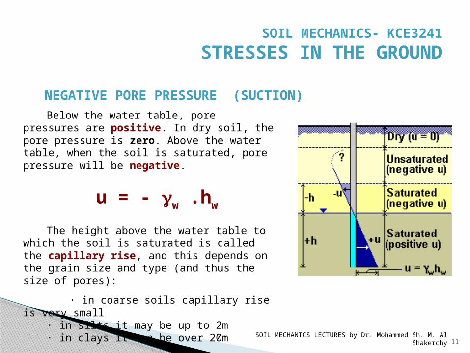
Below the water table, pore pressures are positive. In dry soil, the pore pressure is zero. Above the water table, when the soil is saturated, pore pressure will be negative.
u = - gw .hw The height above the water table to
which the soil is saturated is called the capillary rise, and this depends on the grain size and type (and thus the size of pores):
· in coarse soils capillary rise is very small
· in silts it may be up to 2m · in clays it can be over 20m
NEGATIVE PORE PRESSURE (SUCTION)
SOIL MECHANICS- KCE3241 STRESSES IN THE GROUND
SOIL MECHANICS LECTURES by Dr. Mohammed Sh. M. Al Shakerchy 12
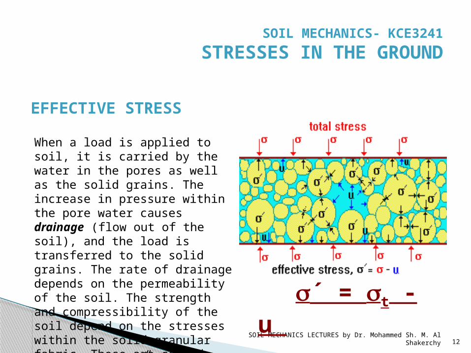
EFFECTIVE STRESS
When a load is applied to soil, it is carried by the water in the pores as well as the solid grains. The increase in pressure within the pore water causes drainage (flow out of the soil), and the load is transferred to the solid grains. The rate of drainage depends on the permeability of the soil. The strength and compressibility of the soil depend on the stresses within the solid granular fabric. These are called “Effective Stresses”.
s´ = st - u
SOIL MECHANICS- KCE3241 STRESSES IN THE GROUND
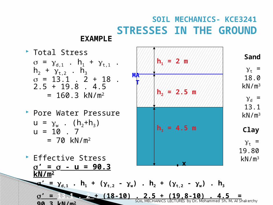
Total Stresss = gd,1 . h1 + gt,1 . h2 + gt,2 . h3s = 13.1 . 2 + 18 . 2.5 + 19.8 . 4.5 = 160.3 kN/m2
Pore Water Pressureu = gw . (h2+h3)u = 10 . 7 = 70 kN/m2
Effective Stresss’ = s - u = 90.3 kN/m2
s’ = gd,1 . h1 + (gt,2 - gw) . h2 + (gt,2 - gw) . h3
s’ = 13.1 . 2 + (18-10) . 2.5 + (19,8-10) . 4.5 = 90.3 kN/m2
MAT
Sandgt = 18.0 kN/m3
gd = 13.1 kN/m3
Claygt =
19.80 kN/m3
h1 = 2 m
h2 = 2.5 m
h3 = 4.5 m
x
EXAMPLE
SOIL MECHANICS- KCE3241 STRESSES IN THE GROUND

SOIL MECHANICS LECTURES by Dr. Mohammed Sh. M. Al Shakerchy 14
draw the variation of total vertical stress, pore water pressure, and effective stress for soil profile shown in figure.stotal = gsat.zu = gw.zs’ = stotal – u
5 m gsat = 19 kN/m3
Soil Surface
Depth
20 40 60 80 100
Stress
stotal
u
s’
EXAMPLE
SOIL MECHANICS- KCE3241 STRESSES IN THE GROUND

EFFECT OF CHANGING WATER TABLEChanges in water level below ground (water table
changes) result in changes in effective stresses below the water table. Changes in water level above ground (e.g. in lakes, rivers, etc.) do not cause changes in effective stresses in the ground below.
The figure shows soil layers on a site. The unit weight of the silty sand is 19.0 kN/m³ both above and below the water table. The water level is presently at the surface of the silty sand, it may drop or it may rise. The following calculations show the effects of this:
SOIL MECHANICS- KCE3241 STRESSES IN THE GROUND
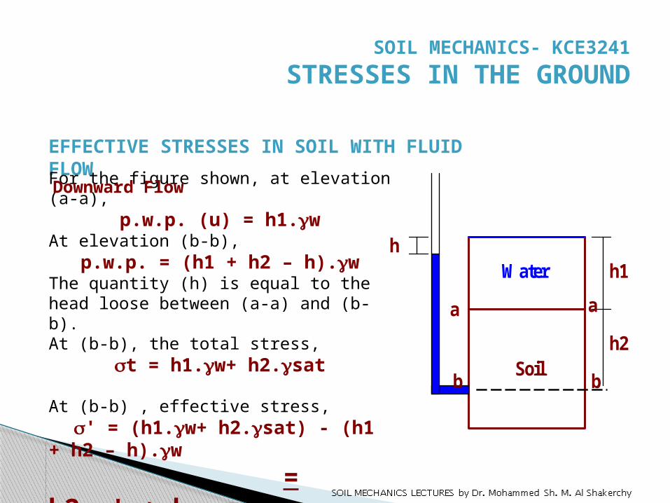
EFFECTIVE STRESSES IN SOIL WITH FLUID FLOW
W ater
Soil
h1
h2
h
a
b b
a
For the figure shown, at elevation (a-a),
p.w.p. (u) = h1.gwAt elevation (b-b),
p.w.p. = (h1 + h2 – h).gwThe quantity (h) is equal to the head loose between (a-a) and (b-b).At (b-b), the total stress,
st = h1.gw+ h2.gsat
At (b-b) , effective stress, s' = (h1.gw+ h2.gsat) - (h1 + h2 – h).gw = h2.g' + h.gw
SOIL MECHANICS- KCE3241 STRESSES IN THE GROUND
Downward Flow
SOIL MECHANICS LECTURES by Dr. Mohammed Sh. M. Al Shakerchy 17
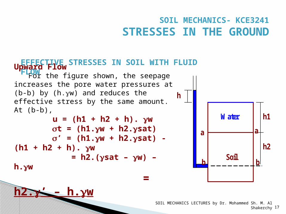
Upward FlowFor the figure shown, the seepage
increases the pore water pressures at (b-b) by (h.gw) and reduces the effective stress by the same amount.At (b-b), u = (h1 + h2 + h). gw st = (h1.gw + h2.gsat) s’ = (h1.gw + h2.gsat) - (h1 + h2 + h). gw = h2.(gsat – gw) – h.gw = h2.g’ – h.gw
EFFECTIVE STRESSES IN SOIL WITH FLUID FLOW
W ater
Soil
h1
h2
h
a
b b
a
SOIL MECHANICS- KCE3241 STRESSES IN THE GROUND
SOIL MECHANICS LECTURES by Dr. Mohammed Sh. M. Al Shakerchy 18
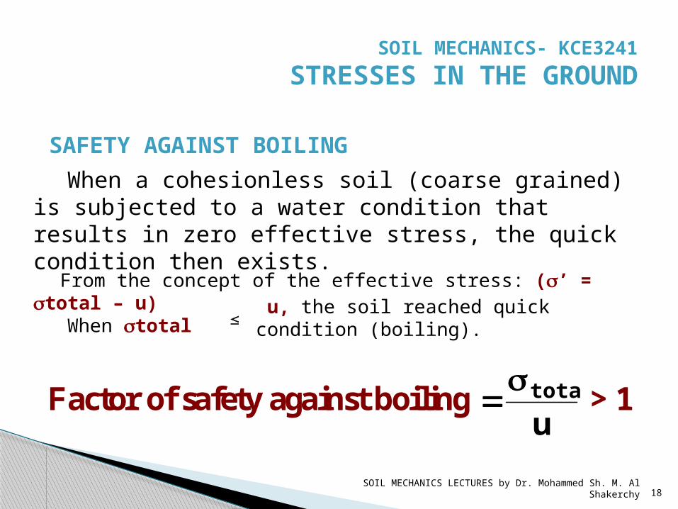
When a cohesionless soil (coarse grained) is subjected to a water condition that results in zero effective stress, the quick condition then exists.
SAFETY AGAINST BOILING
From the concept of the effective stress: (s’ = stotal – u)
When stotal u, the soil reached quick condition (boiling).
Factor of safety against boiling utotals
> 1
SOIL MECHANICS- KCE3241 STRESSES IN THE GROUND
SOIL MECHANICS LECTURES by Dr. Mohammed Sh. M. Al Shakerchy 19
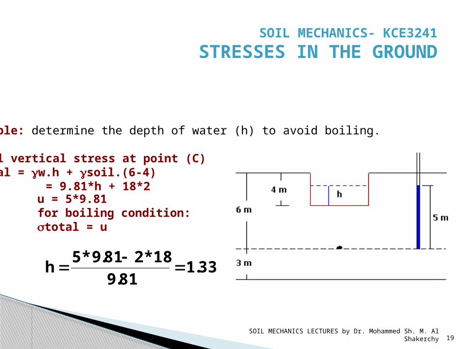
Example: determine the depth of water (h) to avoid boiling.
Total vertical stress at point (C)stotal = gw.h + gsoil.(6-4) = 9.81*h + 18*2
u = 5*9.81for boiling condition: stotal = u
33.181.918*281.9*5h
SOIL MECHANICS- KCE3241 STRESSES IN THE GROUND
SOIL MECHANICS LECTURES by Dr. Mohammed Sh. M. Al Shakerchy 20
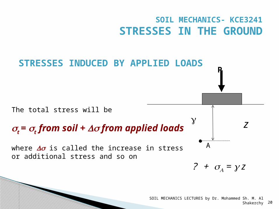
STRESSES INDUCED BY APPLIED LOADS
The total stress will be
st = st from soil + Ds from applied loads
where Ds is called the increase in stress or additional stress and so on
g z
A
P
sA = g z + ?
SOIL MECHANICS- KCE3241 STRESSES IN THE GROUND
SOIL MECHANICS LECTURES by Dr. Mohammed Sh. M. Al Shakerchy 21
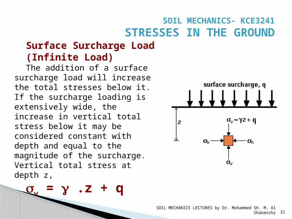
Surface Surcharge Load (Infinite Load)The addition of a surface
surcharge load will increase the total stresses below it. If the surcharge loading is extensively wide, the increase in vertical total stress below it may be considered constant with depth and equal to the magnitude of the surcharge. Vertical total stress at depth z, sv = g .z + q
SOIL MECHANICS- KCE3241 STRESSES IN THE GROUND
SOIL MECHANICS LECTURES by Dr. Mohammed Sh. M. Al Shakerchy 22
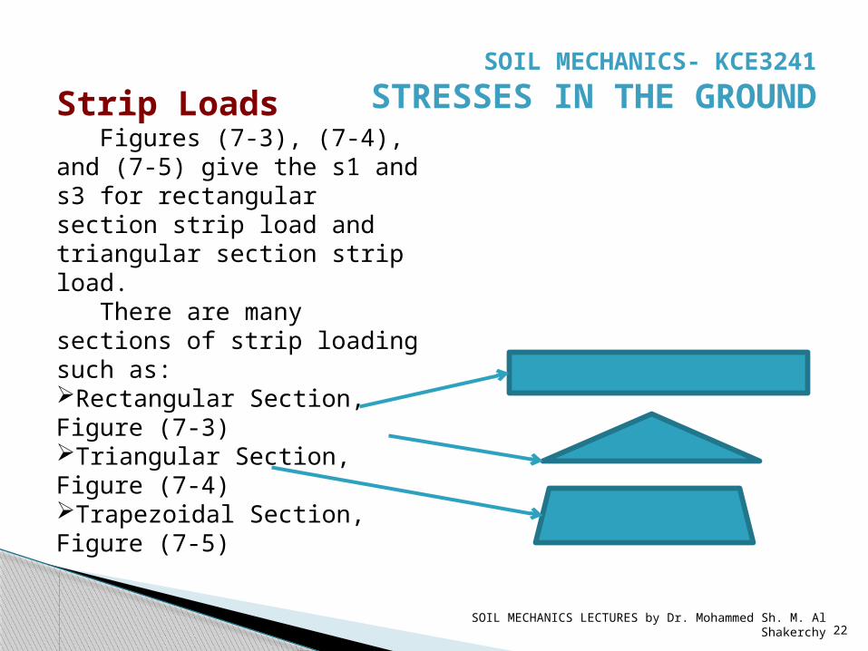
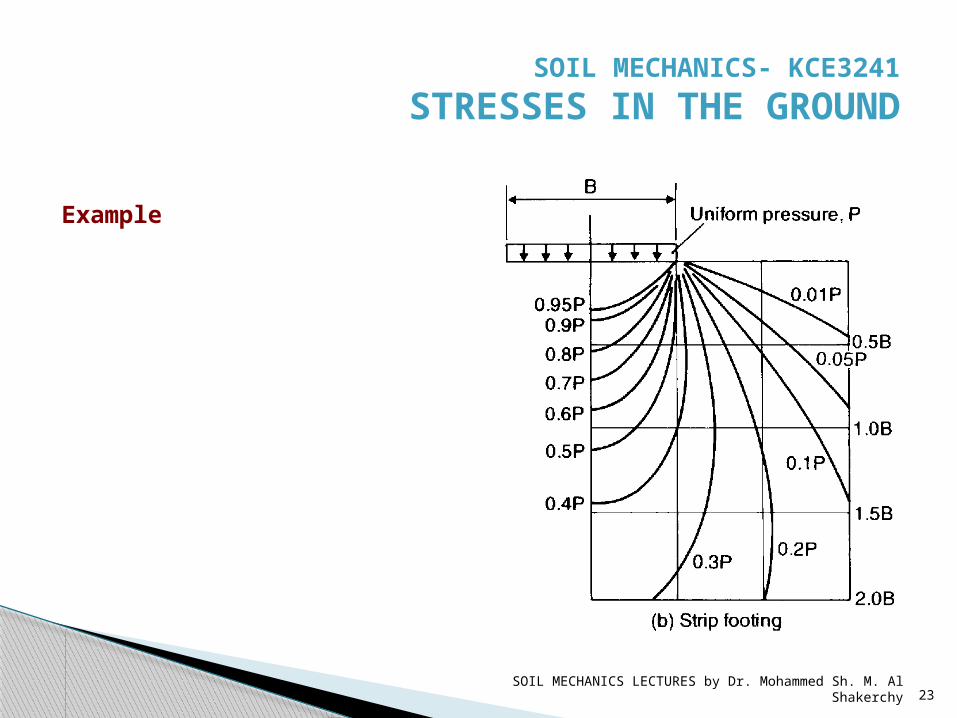
Strip LoadsFigures (7-3), (7-4),
and (7-5) give the s1 and s3 for rectangular section strip load and triangular section strip load.
There are many sections of strip loading such as:Rectangular Section, Figure (7-3)Triangular Section, Figure (7-4)Trapezoidal Section, Figure (7-5)
SOIL MECHANICS- KCE3241 STRESSES IN THE GROUND
SOIL MECHANICS LECTURES by Dr. Mohammed Sh. M. Al Shakerchy 23
Example
SOIL MECHANICS- KCE3241 STRESSES IN THE GROUND

SOIL MECHANICS LECTURES by Dr. Mohammed Sh. M. Al Shakerchy 24
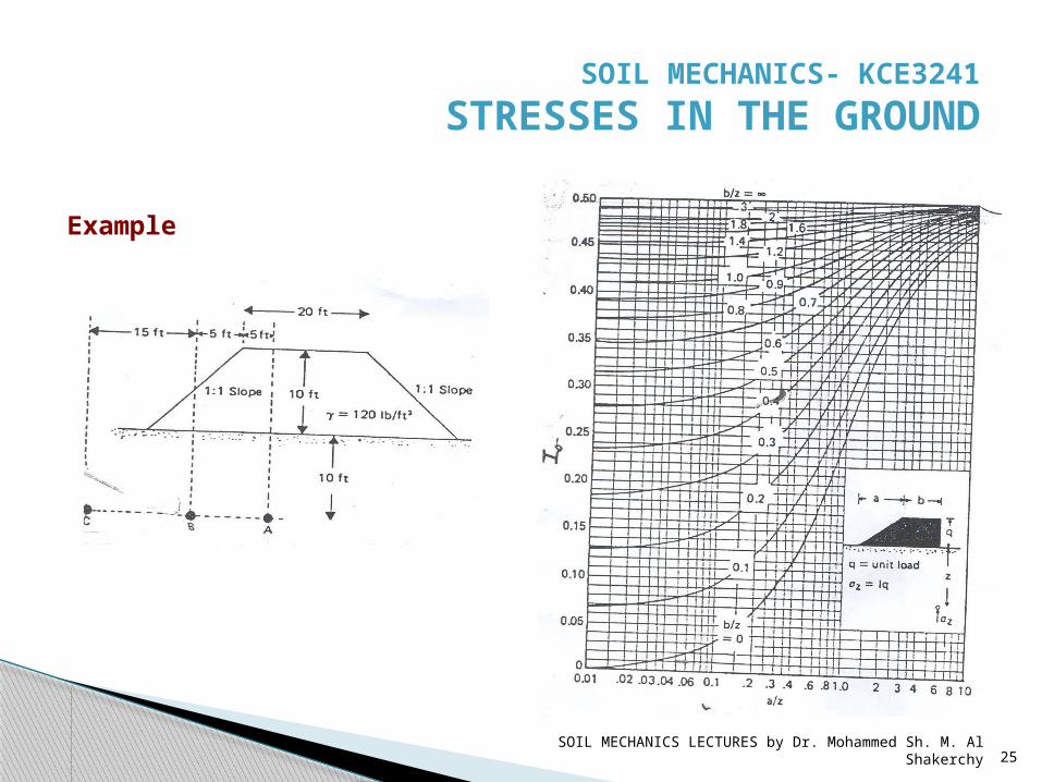
Example
SOIL MECHANICS- KCE3241 STRESSES IN THE GROUND
SOIL MECHANICS LECTURES by Dr. Mohammed Sh. M. Al Shakerchy 25
Example
SOIL MECHANICS- KCE3241 STRESSES IN THE GROUND
SOIL MECHANICS LECTURES by Dr. Mohammed Sh. M. Al Shakerchy 26
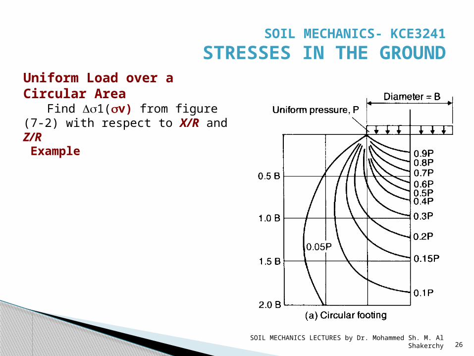
Uniform Load over a Circular Area
Find Ds1(sv) from figure (7-2) with respect to X/R and Z/R Example
SOIL MECHANICS- KCE3241 STRESSES IN THE GROUND

SOIL MECHANICS LECTURES by Dr. Mohammed Sh. M. Al Shakerchy 27
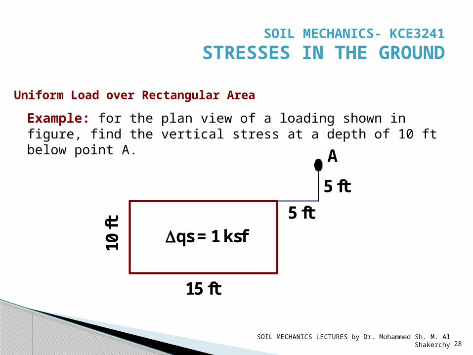
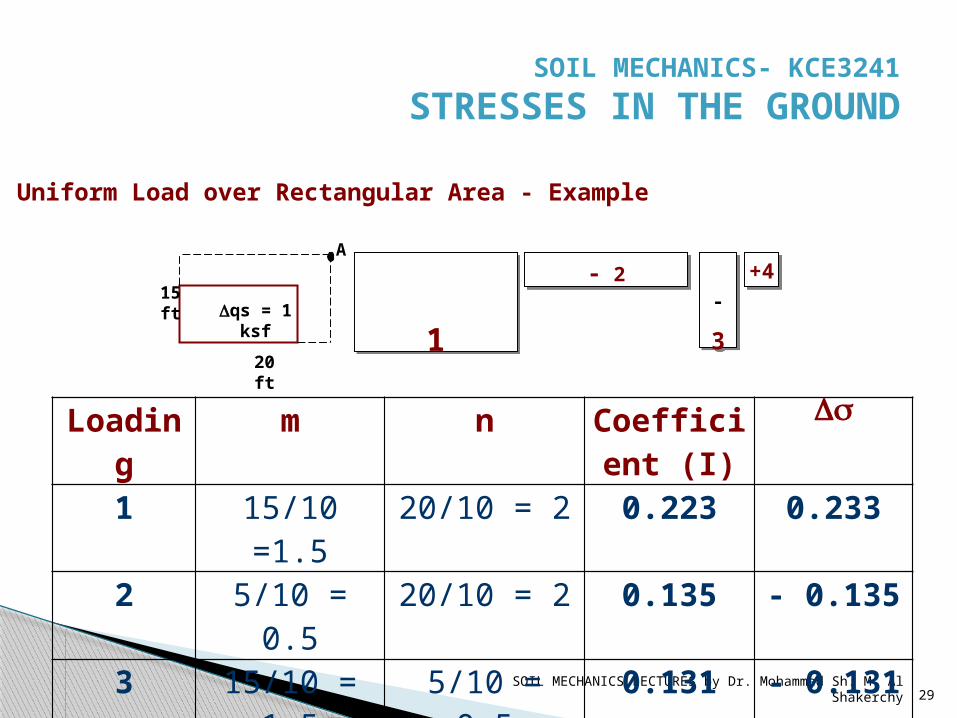
Uniform Load over Rectangular Area
Find coefficients which equal to Dsv/Dqs with respect to m and n from figure (7-1) by Fadum for the corner points only where: -
Dqs = additional stress from area on the soil surface.
Dsv = the induced vertical stress at certain depth (z) in the soil.
m = B/Zn = L/Z
SOIL MECHANICS- KCE3241 STRESSES IN THE GROUND
SOIL MECHANICS LECTURES by Dr. Mohammed Sh. M. Al Shakerchy 28
15 ft
10 ft
Dqs = 1 ksf
A 5 ft
5 ft
Example: for the plan view of a loading shown in figure, find the vertical stress at a depth of 10 ft below point A.
Uniform Load over Rectangular Area
SOIL MECHANICS- KCE3241 STRESSES IN THE GROUND
SOIL MECHANICS LECTURES by Dr. Mohammed Sh. M. Al Shakerchy 29
20 ft
15 ft Dqs = 1
ksf
A
1-
3
- 2 +4
Loading
m n Coefficient (I)
Ds
1 15/10 =1.5
20/10 = 2 0.223 0.233
2 5/10 = 0.5
20/10 = 2 0.135 - 0.135
3 15/10 = 1.5
5/10 = 0.5
0.131 - 0.131
4 5/10 = 0.5
5/10 = 0.5
0.085 0.085
Summation 0.042
Uniform Load over Rectangular Area - Example
SOIL MECHANICS- KCE3241 STRESSES IN THE GROUND
SOIL MECHANICS LECTURES by Dr. Mohammed Sh. M. Al Shakerchy 30
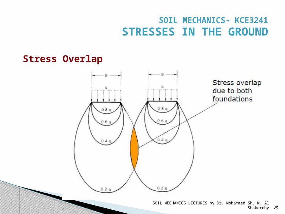
Stress Overlap
SOIL MECHANICS- KCE3241 STRESSES IN THE GROUND
SOIL MECHANICS LECTURES by Dr. Mohammed Sh. M. Al Shakerchy 31
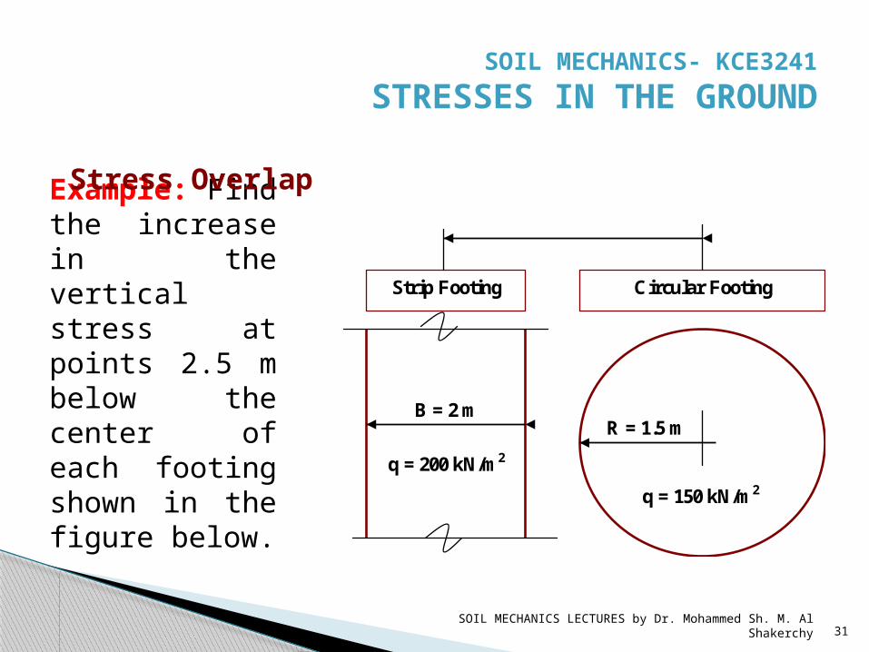
Example: Find the increase in the vertical stress at points 2.5 m below the center of each footing shown in the figure below.
Strip Footing
Circular Footing
B = 2 m R = 1.5 m
q = 200 kN/m 2 q = 150 kN/m 2
Stress Overlap
SOIL MECHANICS- KCE3241 STRESSES IN THE GROUND
SOIL MECHANICS LECTURES by Dr. Mohammed Sh. M. Al Shakerchy 32
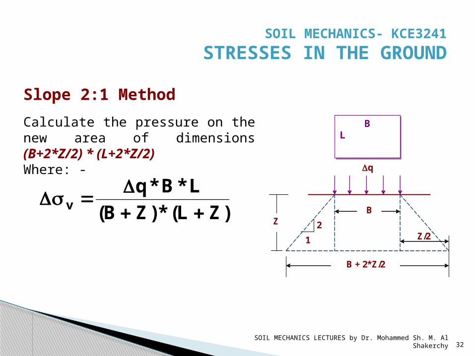
)ZL(*)ZB(L*B*q
v D
sD
Z B
2 1
B + 2*Z/2
Z/2
Dq
B L
Slope 2:1 MethodCalculate the pressure on the new area of dimensions (B+2*Z/2) * (L+2*Z/2)Where: -
SOIL MECHANICS- KCE3241 STRESSES IN THE GROUND

SOIL MECHANICS LECTURES by Dr. Mohammed Sh. M. Al Shakerchy 33
The plan of a footing carries a uniform pressure of 160 kN/m2 on the surface of soil as shown in the figure. Find the vertical stress increment due to the footing at a depth of 4 m below point C.
QUESTIONS
SOIL MECHANICS- KCE3241 STRESSES IN THE GROUND
SOIL MECHANICS LECTURES by Dr. Mohammed Sh. M. Al Shakerchy 34
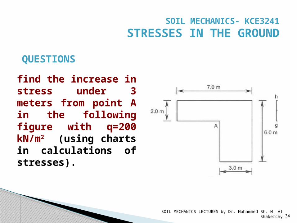
find the increase in stress under 3 meters from point A in the following figure with q=200 kN/m2 (using charts in calculations of stresses).
QUESTIONS
SOIL MECHANICS- KCE3241 STRESSES IN THE GROUND
SOIL MECHANICS LECTURES by Dr. Mohammed Sh. M. Al Shakerchy 35
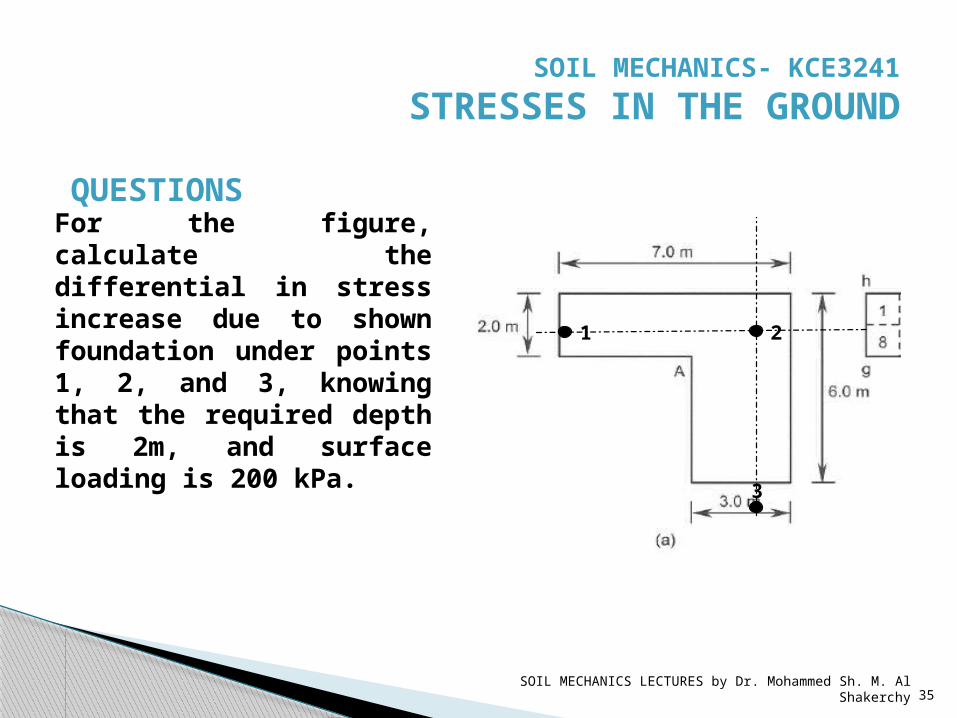
QUESTIONSFor the figure, calculate the differential in stress increase due to shown foundation under points 1, 2, and 3, knowing that the required depth is 2m, and surface loading is 200 kPa.
1 2
3
SOIL MECHANICS- KCE3241 STRESSES IN THE GROUND