state of stresses
TRANSCRIPT
2C H A P T E R
2.0 INTRODUCTIONStress and strain are most important concepts for a comprehension of the mechanics of solids. The load carrying capacity and sizing of the components depend on the behaviour of material under different kinds of loading. This chapter deals with behaviour of material under uniaxial, biaxial and triaxial states of stress under various combinations of loads. Concept of principal stress and strains is also illustrated for different combinations of loading conditions.
2.1 SIMPLE STRESSES AND STRAINS IN MACHINE ELEMENTS
2.1.1 StressWhen external loads act on a body, internal forces are set up which resist the external forces. This internal force per unit area at any section of the body is known as unit stress or simply stress. It is denoted by the Greek letter sigma (s). Mathematically,
s = =
Resisting forceCross-sectional area
FA
Thus, stress is defined as the internal resistance developed in the body due to external disturbances over an unit area of its cross section. Stress at a given point does not only depend on the location of the point but also on the plane passing through it. Therefore, it is a second-order tensor.
In SI units, stress is usually expressed in Pascal (Pa) such that 1 Pa = 1 N/m2. In actual practice, we use bigger units of stress, that is, megapascal (MPa) and gigapascal (GPa), such that
1 1 10 1 1 1 10 16 2 2 9 2/ / /MPa N m N mm and GPa N m kN= ¥ = = ¥ = //mm2
State of Stresses
24 Design of Machine Elements
When loads act perpendicular to the axis of the member, they are called normal loads and the corresponding stresses are called normal stresses. Normal stresses are caused by (i) direct loading (may be tensile or compressive) and (ii) bending (both tensile and compressive).
Poisson’s Ratio: When a deformable body is subjected to an axial tensile force, elongation as well as lateral contraction occurs. For example, if a metal bar is stretched, both the thickness and width decrease while the length increases. Likewise, the compressive force acting on a body causes it to contract in the direction of force and its sides expand laterally. Poisson’s ratio is the ratio of lateral strain to linear strain. In the elastic range, Poisson’s ratio lies between 0.25 and 0.33 for most engineering materials.
Typical values of Poisson’s ratio for some common materials are given in Table 1.1, p.11 of DDHB.
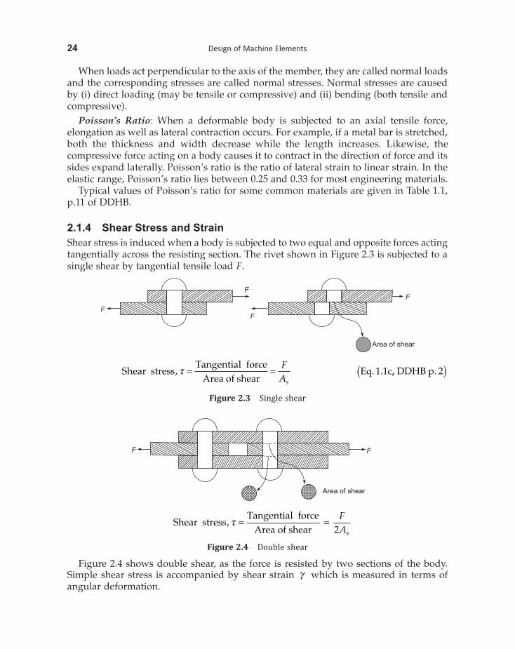
2.1.4 Shear Stress and StrainShear stress is induced when a body is subjected to two equal and opposite forces acting tangentially across the resisting section. The rivet shown in Figure 2.3 is subjected to a single shear by tangential tensile load F.
F
F
F
F
Area of shear
Shear stress
Tangential forceArea of shear
Eq. 1.1c, t = = FAs
,, DDHB p. 2( )
Figure 2.3 Single shear
FF
Area of shear
Shear stressTangential force
Area of shear, t = = F
As2
Figure 2.4 Double shear
Figure 2.4 shows double shear, as the force is resisted by two sections of the body. Simple shear stress is accompanied by shear strain g which is measured in terms of angular deformation.
State of Stresses 25
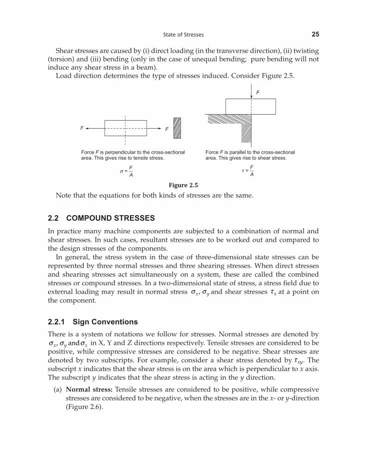
Shear stresses are caused by (i) direct loading (in the transverse direction), (ii) twisting (torsion) and (iii) bending (only in the case of unequal bending; pure bending will not induce any shear stress in a beam).
Load direction determines the type of stresses induced. Consider Figure 2.5.
F F
F
Force is perpendicular to the cross-sectionalarea. This gives rise to tensile stress.
F Force is parallel to the cross-sectionalarea. This gives rise to shear stress.
F
s =F
At =
F
A
Figure 2.5
Note that the equations for both kinds of stresses are the same.
2.2 COMPOUND STRESSES In practice many machine components are subjected to a combination of normal and shear stresses. In such cases, resultant stresses are to be worked out and compared to the design stresses of the components.
In general, the stress system in the case of three-dimensional state stresses can be represented by three normal stresses and three shearing stresses. When direct stresses and shearing stresses act simultaneously on a system, these are called the combined stresses or compound stresses. In a two-dimensional state of stress, a stress field due to external loading may result in normal stress s sx y, and shear stresses t x at a point on the component.
2.2.1 Sign Conventions There is a system of notations we follow for stresses. Normal stresses are denoted by s s sx y z, and in X, Y and Z directions respectively. Tensile stresses are considered to be positive, while compressive stresses are considered to be negative. Shear stresses are denoted by two subscripts. For example, consider a shear stress denoted by t xy. The subscript x indicates that the shear stress is on the area which is perpendicular to x axis. The subscript y indicates that the shear stress is acting in the y direction.
(a) Normal stress: Tensile stresses are considered to be positive, while compressive stresses are considered to be negative, when the stresses are in the x- or y-direction (Figure 2.6).
State of Stresses 27
Figure 2.6 Sign conventions for normal stresses
(b) Positive shear stress: If the shear force acting on x face produces counter-clockwise moment, then it is considered a positive shear stress (Figure 2.7).
Figure 2.7 Sign convention for shear
(c) Negative shear stress: If the shear force acting on x face produces clockwise moment, then it is considered a negative shear stress.
(d) Complimentary shear stress theory gives .
2.2.2 Unidirectional State of StressConsider an element subjected to uniaxial tensile force F giving rise to stress as shown in Figures 2.8 (a) and 2.8(b) .
Let the block be of unit depth, then considering the equilibrium of forces on the triangular portion mnp.
Resolving the forces perpendicular to mn,
Figure 2.8 Unidirectional state of stress
s s fn xmn pn¥ ¥ = ¥ ¥( ) ¥1 1 cos
s s f s fn x x
pnmn
= ¥ ¥ = ( )cos cos Eq a DDHB p2 1 6 4. . , , .
Now resolving forces parallel to mn
t s fn xmn pn¥ ¥ = ¥ ¥( ) ¥1 1 sin
t s fn xpnmn
= ¥ ¥ÊËÁ
ˆ¯
¥1 sin
. . ,t s f f s f fs
fn x xx= ¥( ) ¥ = ¥ ¥( ) ¥ =cos sin cos sin sin Eq b
22 2
2 1 6 DDDHB p, . 4( )
Maximum and minimum normal in uniaxial state of stressWe know that normal stress cos( ) .s s fn x= 2 Maximum normal stress (principal stress) s1 acts on cross-section normal to the axis of the bar that is when f = ( )0 1 6 4Eq d DDHB p. . , , .
Therefore, Maximum normal stress = Maximum principal stress = s1 = sx (Eq. 1.6c, DDHB, p. 4)
Minimum normal stress acts on the cross section parallel to the axis of the bar, that is, when f = 90
Therefore, Minimum normal stress = Minimum principal stress = s2 = 0 (Eq. 1.6c, DDHB, p. 4)
Shear stresses in uniaxial state of stress
Maximum shear stress occurs when sin or Eq f DDHB p2 1 45 1 6 4f f= = ∞ ( ). . , , .
Maximum shear stress sinmax, ts
fs s
= ¥ = =x x
22
2 21 EEq e DDHB p. . , , .1 6 4( )
That is, maximum shear stress induced in a body subjected to uniaxial stress is half of normal stress and is inclined at an angle of 45∞ with respect to reference axis (with vertical).
WORKED OUT PROBLEMS (UNIDIRECTIONAL STATE OF STRESS)
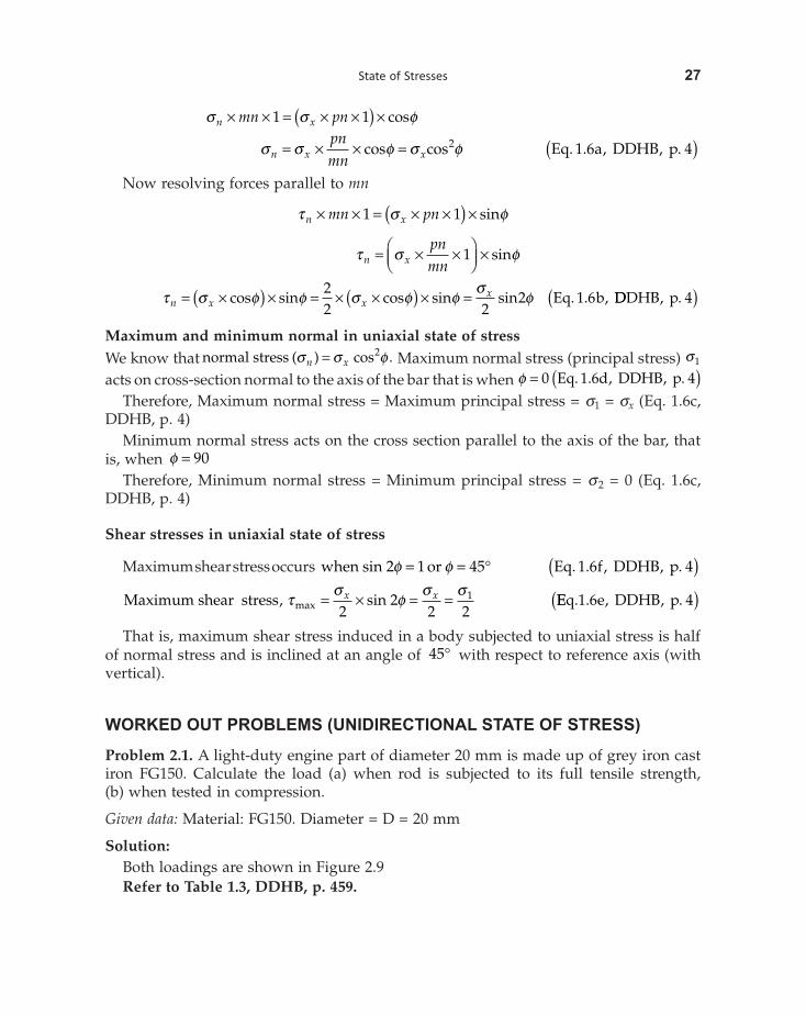
Problem 2.1. A light-duty engine part of diameter 20 mm is made up of grey iron cast iron FG150. Calculate the load (a) when rod is subjected to its full tensile strength, (b) when tested in compression.
Given data: Material: FG150. Diameter = D = 20 mm
Solution:Both loadings are shown in Figure 2.9Refer to Table 1.3, DDHB, p. 459.
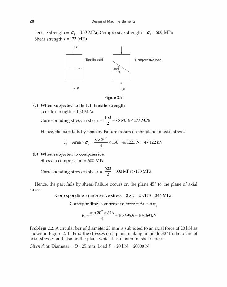
28 Design of Machine Elements
Tensile strength = s y = 150 MPa, Compressive strength = =s c 600 MPa
Shear strength t = 173 MPa
FF
F
45°
Tensile load Compressive load
Figure 2.9
(a) When subjected to its full tensile strength Tensile strength = 150 MPa
Corresponding stress in shear = 150
275 173= <MPa MPa
Hence, the part fails by tension. Failure occurs on the plane of axial stress.
Ft y= ¥ = ¥ ¥ = =Area N kNs p 204
150 471223 47 1222
.
(b) When subjected to compression Stress in compression = 600 MPa
Corresponding stress in shear = 600
2300 173= >MPa MPa
Hence, the part fails by shear. Failure occurs on the plane 45° to the plane of axial stress.
Corresponding compressive stress MPa= ¥ = ¥ =2 2 173 346t
Corresponding compressive force Area= ¥ s y
Fc kN= ¥ ¥ = =p 20 3464
108695 9 108 692
. .
Problem 2.2. A circular bar of diameter 25 mm is subjected to an axial force of 20 kN as shown in Figure 2.10. Find the stresses on a plane making an angle 30° to the plane of axial stresses and also on the plane which has maximum shear stress.
Given data: Diameter = D =25 mm, Load F = 20 kN = 20000 N
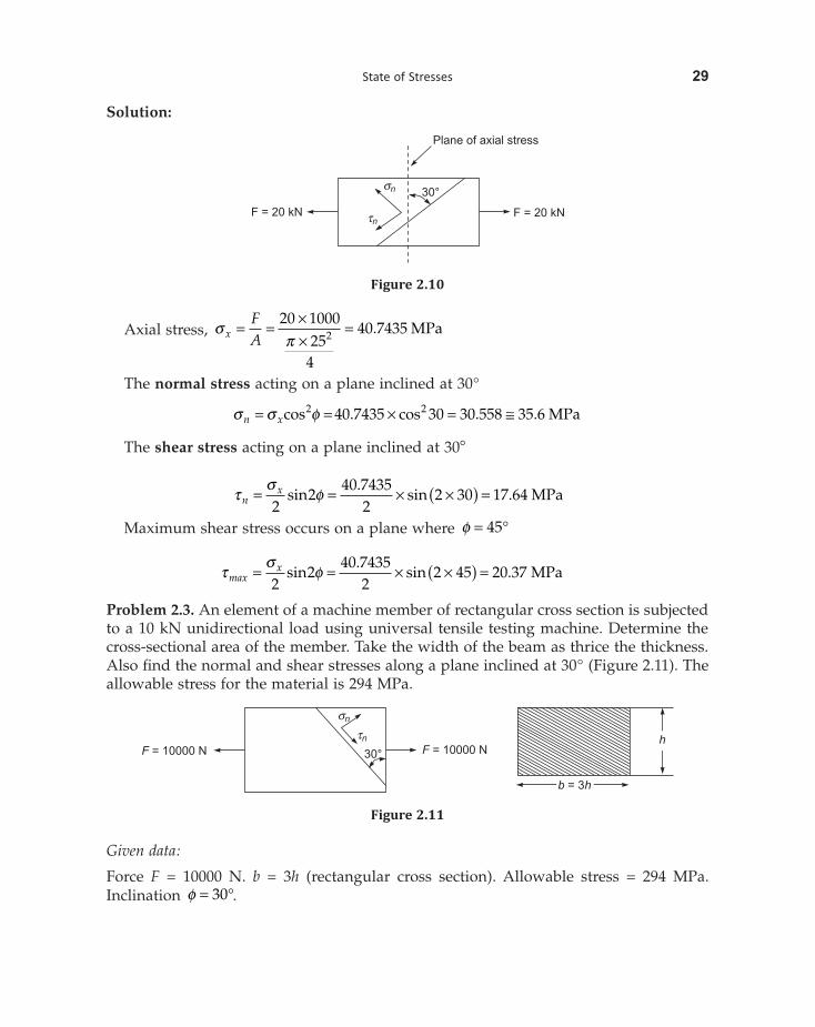
State of Stresses 29
Solution:
Plane of axial stress
F = 20 kN F = 20 kN
30°sn
tn
Figure 2.10
Axial stress, spx
FA
= = ¥¥
=20 100025
4
40 74352 . MPa
The normal stress acting on a plane inclined at 30°
s s fn x= = ¥ = @cos cos MPa2 240 7435 30 30 558 35 6. . .
The shear stress acting on a plane inclined at 30∞
t
sfn
x= = ¥ ¥( ) =2
240 7435
22 30 17 64sin sin MPa
..
Maximum shear stress occurs on a plane where f = ∞45
ts
fmaxx= = ¥ ¥( ) =
22
40 74352
2 45 20 37sin sin MPa.
.
Problem 2.3. An element of a machine member of rectangular cross section is subjected to a 10 kN unidirectional load using universal tensile testing machine. Determine the cross-sectional area of the member. Take the width of the beam as thrice the thickness. Also find the normal and shear stresses along a plane inclined at 30° (Figure 2.11). The allowable stress for the material is 294 MPa.
F = 10000 N F = 10000 N30°
sn
tn h
b h= 3
Figure 2.11
Given data:
Force F = 10000 N. b = 3h (rectangular cross section). Allowable stress = 294 MPa. Inclination f = ∞30 .
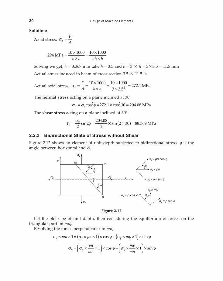
30 Design of Machine Elements
Solution:
Axial stress, s xFA
=
29410 1000 10 1000
3MPa = ¥
¥= ¥
¥b h h h
Solving we get, h = 3.367 mm take h = 3.5 and b = 3 ¥ h = 3 ¥ 3.5 = 11.5 mm
Actual stress induced in beam of cross section 3.5 ¥ 11.5 is
Actual axial stress, s xFA b h
= = ¥¥
= ¥¥
=10 1000 10 10003 3 5
272 12.. MPa
The normal stress acting on a plane inclined at 30°
s s fn x= = ¥ =cos cos MPa2 2272 1 30 204 08. .
The shear stress acting on a plane inclined at 30°
ts
fnx= = ¥ ¥( ) =
22
204 082
2 30 88 369sin sin MPa.
.
2.2.3 Bidirectional State of Stress without Shear Figure 2.12 shows an element of unit depth subjected to bidirectional stress. f is the angle between horizontal and sn.
pmY
sn
f
tn
f
sx x
sy
n
sx
f
sx pn cos¥ f
sx pn¥
sx pn sin¥ f
fsy mp cos f
sy mp sin f
sy
sy mp¥
Figure 2.12
Let the block be of unit depth, then considering the equilibrium of forces on the triangular portion mnp
Resolving the forces perpendicular to mn,
s s f s fn x ymn pn mp¥ ¥ = ¥ ¥( ) ¥ + ¥ ¥( ) ¥1 1 1cos sin
s s f s fn x ypnmn
mpmn
= ¥ ¥ÊËÁ
ˆ¯
¥ + ¥ ¥ÊËÁ
ˆ¯
¥1 1cos sin
32 Design of Machine Elements
2.2.4 Pure Shear Figure 2.13 shows an element subjected to pure shear. Since the applied and comple-mentary shears are of equal value on x and y planes, they are both given symbol t xy
pm
sn f
tn
f
txy
n
txy
txy mp¥
txy mp sin¥ f
ftxy pn cosftxy pn sin¥ f
txy
txy pn¥
txy
txy mp cos¥ f
f
Figure 2.13
f sis the angle between the horizontal and n.
Let the block be of unit depth, then considering the equilibrium of forces on the triangular portion mnp,
Resolving the normal to mn
s t f t fn xy xymn pn mp¥ ¥ = ¥ ¥( ) ¥ + ¥ ¥( ) ¥1 1 1sin cos
s t f t fn xy xypnmn
mpmn
= ¥ ¥ÊËÁ
ˆ¯
¥ + ¥ ¥ÊËÁ
ˆ¯
¥1 1sin cos
s t f f t f fn xy xy= +cos sin sin cos
s t fn xy= sin 2
Now resolving forces parallel to mn
cos sint t f t fn xy xymn pn mp¥ ¥ = - ¥ ¥( ) ¥ + ¥ ¥( ) ¥1 1 1
cos sint t f t fn xy xypnmn
mpmn
= - ¥ ¥ÊËÁ
ˆ¯
¥ + ¥ ¥ÊËÁ
ˆ¯
¥1 1
cos cos sin sint t f f t f fn xy xy= - ¥ ¥( ) ¥ + ¥ ¥( ) ¥1 1
cos sin cos sint t f t f t f fn xy xy xy= - ¥ + ¥ = - -( )2 2 2 2
cost t fn xy= - 2
State of Stresses 33
The normal stress acting on plane mn = =s t fn xy sin 2
The shear stress acting on plane mn = t t fn xy= - cos 2
Maximum principal stress s t1 = xy
Minimum principal stress s t2 = - xy
Angle at which maximum principle stress acts fp = ∞ = ∞45 135or
Maximum shear stress max, ts s
t=-
=1 2
2 xy
Directions of shear stresses are fs = ∞ ∞0 90or
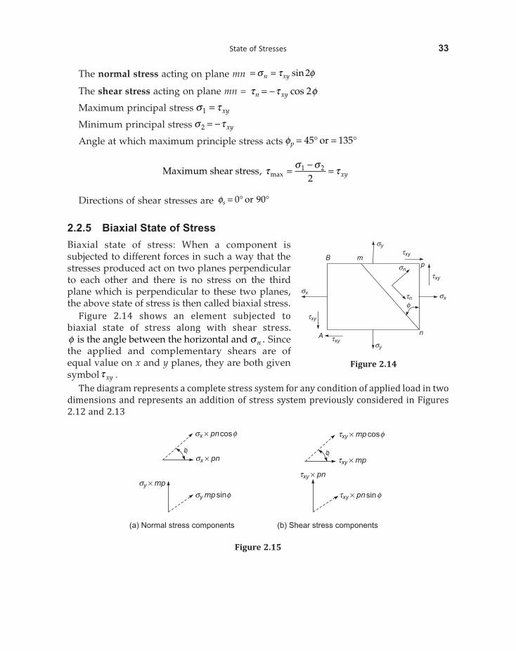
2.2.5 Biaxial State of Stress Biaxial state of stress: When a component is subjected to different forces in such a way that the stresses produced act on two planes perpendicular to each other and there is no stress on the third plane which is perpendicular to these two planes, the above state of stress is then called biaxial stress.
Figure 2.14 shows an element subjected to biaxial state of stress along with shear stress. f sis the angle between the horizontal and n . Since the applied and complementary shears are of equal value on x and y planes, they are both given symbolt xy .
The diagram represents a complete stress system for any condition of applied load in two dimensions and represents an addition of stress system previously considered in Figures 2.12 and 2.13
(a) Normal stress components (b) Shear stress components
sx pncos¥ f
sx pn¥f
sy mp¥sy mpsinf
txy mpcos¥ f
ftxy mp¥
txy pn¥
txy pnsin¥ f
Figure 2.15
mB
sy
txy
p
txy
sx
sx
txy
A txy
sy
n
f
sn
tn
Figure 2.14
State of Stresses 35
Resolving the force components along the tangential direction, we get
2.2.6 Principal Stresses and Planes If we consider the state of stress at any point in a strained material, there are three mutually orthogonal planes on which there is no shear stress—only resultant normal stresses. Such planes are called principal planes. Therefore, principal planes are defined as those planes at a given state of stress in a strained body, on which there is no shear stress. Essentially, principal planes are planes of zero shear stress on which the resultant is along the normal. The normal stress acting on the principal planes is known as principal stress. It can be proved that principal planes are mutually perpendicular (orthogonal).
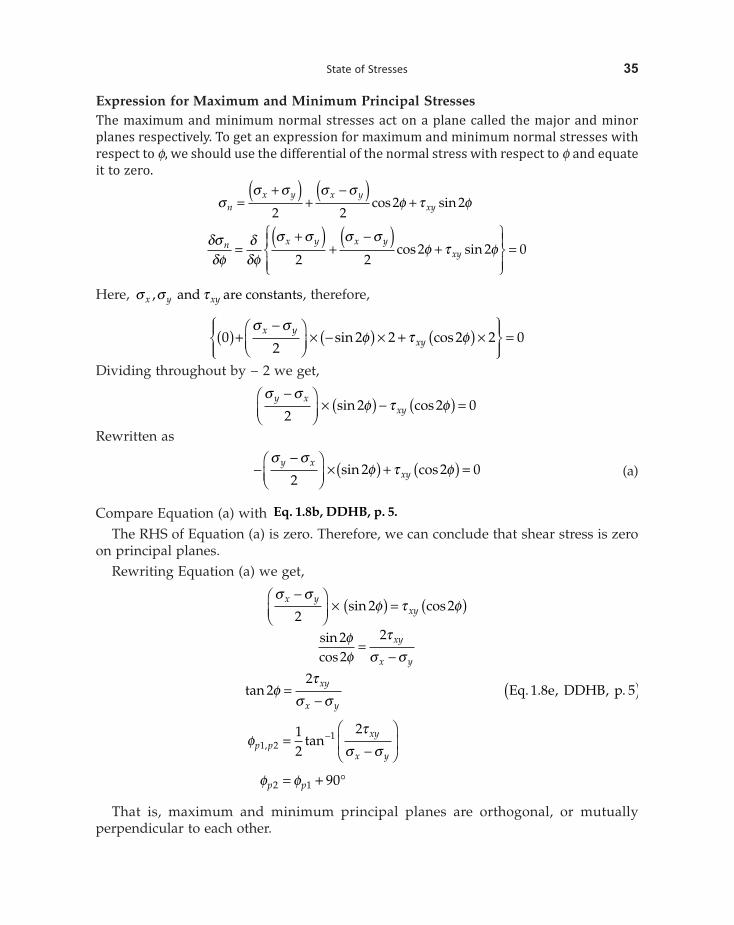
Expression for Maximum and Minimum Principal Stresses The maximum and minimum normal stresses act on a plane called the major and minor planes respectively. To get an expression for maximum and minimum normal stresses with respect to f, we should use the differential of the normal stress with respect to f and equate it to zero.
ss s s s
f t fnx y x y
xy=+( )
+-( )
+2 2
2 2cos sin
dsdf
ddf
s s s sf t fn x y x y
xy=+( )
+-( )
+ÏÌÔ
ÓÔ
¸˝Ô
Ô=
2 22 2 0cos sin
Here, s s tx y xy, and are constants, therefore,
02
2 2 2 2 0( )+-Ê
ËÁˆ¯
¥ -( ) ¥ + ( ) ¥ÏÌÔ
ÓÔ
¸˝ÔÔ
=sin coss s
f t fx yxy
Dividing throughout by − 2 we get,
s s
f t fy xxy
-ÊËÁ
ˆ¯
¥ ( ) - ( ) =2
2 2 0sin cos
Rewritten as
--Ê
ËÁˆ¯
¥( ) + ( ) =s s
f t fy xxy2
2 2 0sin cos (a)
Compare Equation (a) with Eq. 1.8b, DDHB, p. 5. The RHS of Equation (a) is zero. Therefore, we can conclude that shear stress is zero
on principal planes.Rewriting Equation (a) we get,
s s
f t fx yxy
-ÊËÁ
ˆ¯
¥ ( ) = ( )2
2 2sin cos
sincos
22
2ff
ts s
=-
xy
x y
tan 22
ft
s s=
-xy
x yEq e DDHB p. . , , .1 8 5( )
ft
s sp pxy
x y1 2
112
2, tan=
-
Ê
ËÁ
ˆ
¯˜
-
f fp p2 1 90= + ∞
That is, maximum and minimum principal planes are orthogonal, or mutually perpendicular to each other.
State of Stresses 37
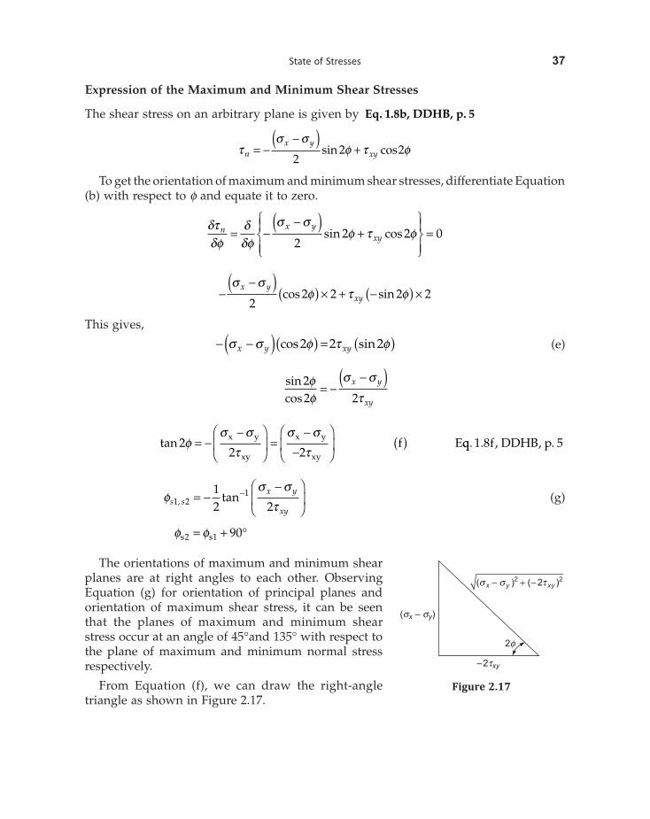
Expression of the Maximum and Minimum Shear Stresses
The shear stress on an arbitrary plane is given by Eq. 1.8b, DDHB, p. 5
ts s
f t fnx y
xy= --( )
+2
2 2sin cos
To get the orientation of maximum and minimum shear stresses, differentiate Equation (b) with respect to f and equate it to zero.
dtdf
ddf
s sf t fn x y
xy= --( )
+ÏÌÔ
ÓÔ
¸˝Ô
Ô=
22 2 0sin cos
--( ) ( ) ¥ + -( ) ¥
s sf t f
x yxy2
2 2 2 2cos sin
This gives,
- -( )( ) = ( )s s f t fx y xycos sin2 2 2 (e)
sincos
22 2ff
s s
t= -
-( )x y
xy
tan 22 2
fs s
ts s
t= -
-Ê
ËÁ
ˆ
¯˜ =
--
Ê
ËÁ
ˆ
¯˜ ( )x y
xy
x y
xyEf qq f DDHB p. . , , .1 8 5
fs s
ts sx y
xy1 2
112 2, tan= -
-Ê
ËÁ
ˆ
¯˜
- (g)
f fs s2 1 90= + ∞
The orientations of maximum and minimum shear planes are at right angles to each other. Observing Equation (g) for orientation of principal planes and orientation of maximum shear stress, it can be seen that the planes of maximum and minimum shear stress occur at an angle of 45°and 135° with respect to the plane of maximum and minimum normal stress respectively.
From Equation (f), we can draw the right-angle triangle as shown in Figure 2.17.
–2txy
2f
s s t- + -2 2( ) ( 2 )x y xy
( – )s sx y
Figure 2.17
40 Design of Machine Elements
We can also use Eq f DDHB p. . , , .1 8 5 to determine the maximum shear stress.
Maximum shear stress, ts s
max MPa=-
= - =1 2
220 0
210
ts s
tmax = ±-Ê
ËÁˆ¯
+ = ± -ÊËÁ
ˆ¯ + = ±x y
xy220 0
20 10
22
2
MPa
Maximum shear stress occurs on a plane where f = ∞45
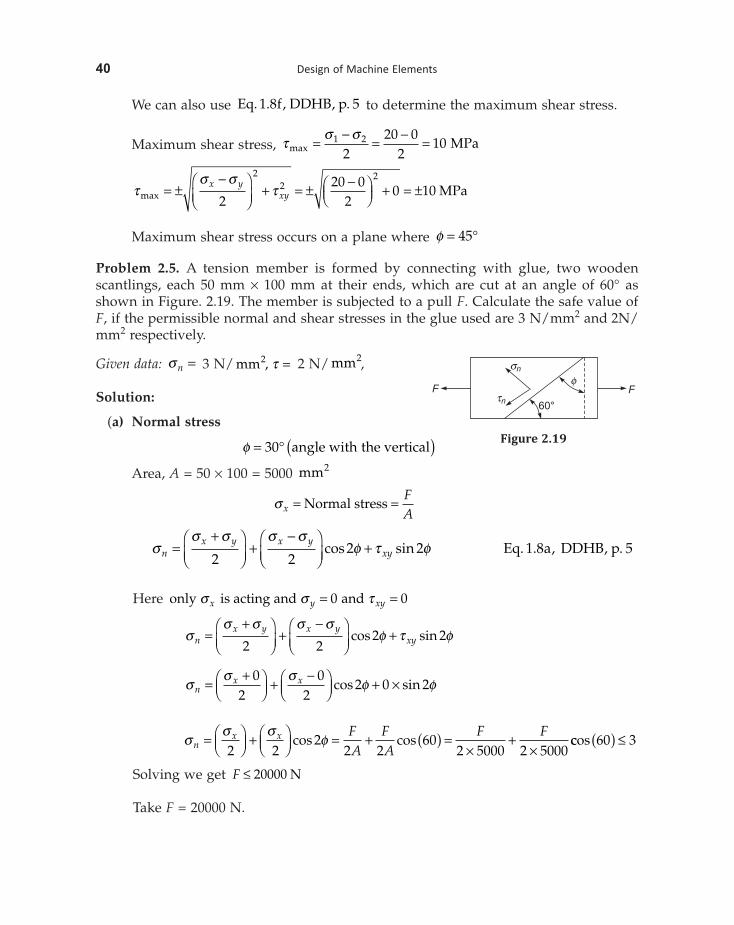
Problem 2.5. A tension member is formed by connecting with glue, two wooden scantlings, each 50 mm ¥ 100 mm at their ends, which are cut at an angle of 60° as shown in Figure. 2.19. The member is subjected to a pull F. Calculate the safe value of F, if the permissible normal and shear stresses in the glue used are 3 N/mm2 and 2N/mm2 respectively.
Given data: sn = 3 N/ mm2, t = 2 N/ mm2,
Solution:
(a) Normal stress
f = ∞ ( )30 angle with the vertical
Area, A = 50 ¥ 100 = 5000 mm2
s xFA
= =Normal stress
ss s s s
f t fnx y x y
xy=+Ê
ËÁˆ¯
+-Ê
ËÁˆ¯
+2 2
2 2cos sin Eq a DDHB p. . , , .1 8 5
Here only is acting and ands s tx y xy= =0 0
ss s s s
f t fnx y x y
xy=+Ê
ËÁˆ¯
+-Ê
ËÁˆ¯
+2 2
2 2cos sin
ss s
f fnx x=
+ÊËÁ
ˆ¯ +
-ÊËÁ
ˆ¯ + ¥
02
02
2 0 2cos sin
ss s
fnx x F
AFA
F F= ÊËÁ
ˆ¯ + Ê
ËÁˆ¯ = + ( ) =
¥+
¥2 22
2 260
2 5000 2 5000cos cos ccos 60 3( ) £
Solving we get F £ 20000 N
Take F = 20000 N.
60°
F F
sn
tn
f
Figure 2.19
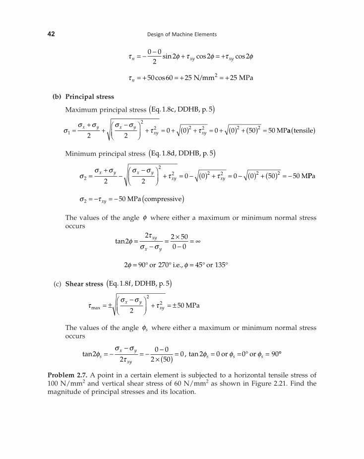
42 Design of Machine Elements
t f t f t fn xy xy= - - + = +0 02
2 2 2sin cos cos
t n = + = + = +50 60 25 252cos /N mm MPa
(b) Principal stress
Maximum principal stress Eq c DDHB p. . , , .1 8 5( )
ss s s s
t t1
22 2 2 2 2
2 20 0 0 0 50 50=
++
-ÊËÁ
ˆ¯
+ = + ( ) + = + ( ) + ( ) =x y x yxy xy MPaa tensile( )
Minimum principal stress Eq d DDHB p. . , , .1 8 5( )
ss s s s
t t2
22 2 2 2 2
2 20 0 0 0 50 50=
+-
-ÊËÁ
ˆ¯
+ = - ( ) + = - ( ) + ( ) = -x y x yxy xy MPPa
s t2 50= - = - ( )xy MPa compressive
The values of the angle f where either a maximum or minimum normal stress occurs
tan22 2 50
0 0f
ts s
•=-
= ¥-
=xy
x y
2 90 270 45 135f f= ∞ ∞ = ∞ ∞or i e or. .,
(c) Shear stress Eq f DDHB p. . , , .1 8 5( )
ts s
tmax = ±-Ê
ËÁˆ¯
+ = ±x yxy2
502
2 MPa
The values of the angle fs where either a maximum or minimum normal stress occurs
tan , tan22
0 02 50
0 2 0 0 90fs s
tf f fs
x y
xys s s= -
-= - -
¥ ( ) = = = ∞ =or or ∞∞
Problem 2.7. A point in a certain element is subjected to a horizontal tensile stress of 100 N/mm2 and vertical shear stress of 60 N/mm2 as shown in Figure 2.21. Find the magnitude of principal stresses and its location.
State of Stresses 45
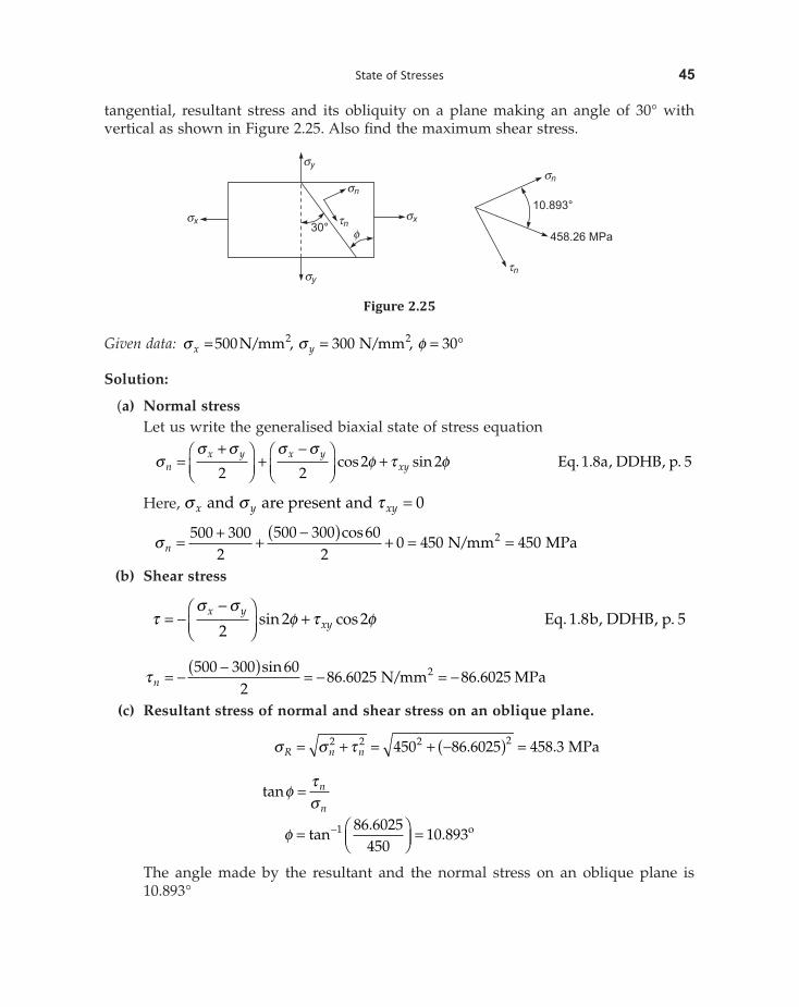
tangential, resultant stress and its obliquity on a plane making an angle of 30° with vertical as shown in Figure 2.25. Also find the maximum shear stress.
sy
sn
tn
fsx
30°sx
sy
sn
tn
10.893°
458.26 MPa
Figure 2.25
Given data: s s fx y= = = ∞/ , / ,500 300 302 2N mm N mm
Solution:
(a) Normal stress Let us write the generalised biaxial state of stress equation
ss s s s
f t fnx y x y
xy=+Ê
ËÁˆ¯
+-Ê
ËÁˆ¯
+2 2
2 2cos sin Eq a DDHB p. . , , .1 8 5
Here, s s tx y xyand are present and = 0
sn = + +-( ) + = =500 300
2500 300 60
20 450 4502cos
/N mm MPa
(b) Shear stress
ts s
f t f= --Ê
ËÁˆ¯
+x yxy2
2 2sin cos Eq b DDHB p. . , , .1 8 5
t n = --( ) = - = -
500 300 602
86 6025 86 60252sin. / .N mm MPa
(c) Resultant stress of normal and shear stress on an oblique plane.
s s tR n n= + = + -( ) =2 2 2 2450 86 6025 458 3. . MPa
tanfts
= n
n
f = ÊËÁ
ˆ¯
=-tan.
.1 86 6025450
10 893o
The angle made by the resultant and the normal stress on an oblique plane is 10.893°
46 Design of Machine Elements
(d) Maximum shear stress Eq f DDHB p. . , , .1 8 5( )
ts s
tmax = ±-Ê
ËÁˆ¯
+x yxy2
22
ts s
max = --Ê
ËÁˆ¯
= - -ÊËÁ
ˆ¯ = -x y
2500 300
2100 MPa
t max = -100 MPa.
It is negative shear stress and produces clockwise rotationn w r t the face. . x .
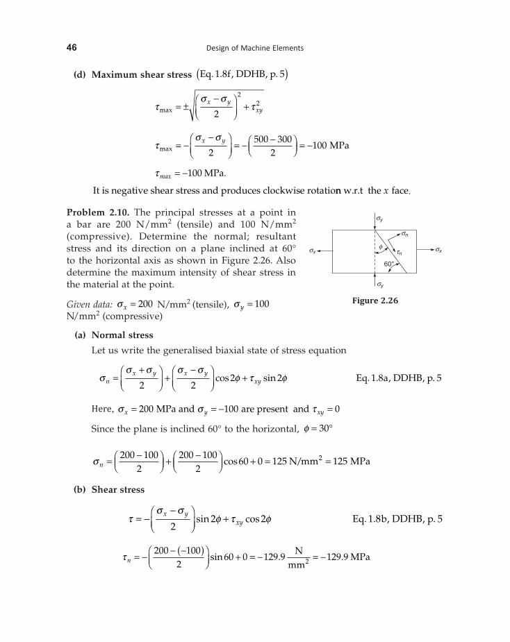
Problem 2.10. The principal stresses at a point in a bar are 200 N/mm2 (tensile) and 100 N/mm2
(compressive). Determine the normal; resultant stress and its direction on a plane inclined at 60° to the horizontal axis as shown in Figure 2.26. Also determine the maximum intensity of shear stress in the material at the point.
Given data: s x = 200 N/mm2 (tensile), s y = 100N/mm2 (compressive)
(a) Normal stress
Let us write the generalised biaxial state of stress equation
ss s s s
f t fnx y x y
xy=+Ê
ËÁˆ¯
+-Ê
ËÁˆ¯
+2 2
2 2cos sin Eq a DDHB p. . , , .1 8 5
Here, = = - =MPa and are present ands s tx y xy200 100 0
Since the plane is inclined 60° to the horizontal, f = ∞30
sn = -ÊËÁ
ˆ¯ + -Ê
ËÁˆ¯ + = =200 100
2200 100
260 0 125 1252cos /N mm MPa
(b) Shear stress
ts s
f t f= --Ê
ËÁˆ¯
+x yxy2
2 2sin cos Eq b DDHB p. . , , .1 8 5
t n = -- -( )Ê
ËÁˆ¯
+ = - = -200 100
260 0 129 9 129 92sin . .
Nmm
MPa
sy
sn
tnsxsx
sy
60°
f
Figure 2.26
State of Stresses 51
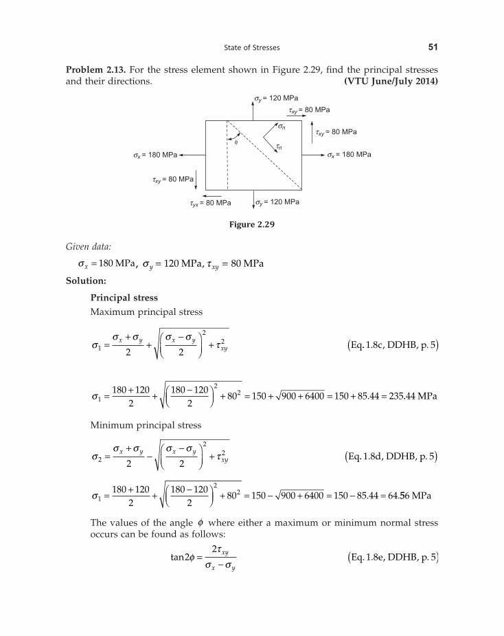
Problem 2.13. For the stress element shown in Figure 2.29, find the principal stresses and their directions. (VTU June/July 2014)
f
sy = 120 MPa
sn
tn
txy = 80 MPa
txy = 80 MPa
sx = 180 MPa
sy = 120 MPatyx = 80 MPa
txy = 80 MPa
sx = 180 MPa
Figure 2.29
Given data:
s x = 180 MPa , s ty xy= =MPa MPa120 80,
Solution:
Principal stress Maximum principal stress
s
s s s st1
22
2 2=
++
-ÊËÁ
ˆ¯
+x y x yxy Eq.. . , , .1 8 5c DDHB p( )
s1
22180 120
2180 120
280 150 900 6400 150 85 44 235= + + -Ê
ËÁˆ¯ + = + + = + =. ..44 MPa
Minimum principal stress
s
s s s st2
22
2 2=
+-
-ÊËÁ
ˆ¯
+x y x yxy Eq.. . , , .1 8 5d DDHB p( )
s1
22180 120
2180 120
280 150 900 6400 150 85 44 64= + + -Ê
ËÁˆ¯ + = - + = - =. .556 MPa
The values of the angle f where either a maximum or minimum normal stress occurs can be found as follows:
tan22
ft
s s=
-xy
x yEq e DDHB p. . , , .1 8 5( )
54 Design of Machine Elements
t max = +ÊËÁ
ˆ¯ + = ±30 20
215 29 155
22 . MPa
or ts s
max =-Ê
ËÁˆ¯
1 2
21 8Eq f DDHB. . , ,, .p 5( )
t max =- -( )Ê
ËÁˆ¯
= ±34 1547 24 155
229 155
. .. MPa
The values of the angle fs where either a maximum or minimum normal stress occurs can be found as follows:
tan 22
fs s
tsx y
xy= -
-Eq g DDHB p. . , , .1 8 5( )
tan 230 20
2 155030
fs = -- -( )( ) = -
2 59 03fs = - ∞.
or andf fs s1 229 518 29 518 90 60 481= - ∞ = - ∞ + ∞ = ∞. . .
Also
f f fs p s1 1 245 15 481 45 60 481 15 481 135 150 482= + = ∞ + ∞ = ∞ = ∞ + ∞ =. . . .and ∞∞
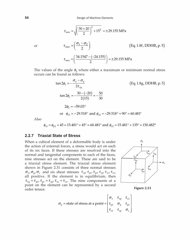
2.2.7 Triaxial State of StressWhen a cubical element of a deformable body is under the action of external forces, a stress would act on each of its six faces. If these stresses are resolved into the normal and tangential components to each of the faces, nine stresses act on the element. These are said to be a triaxial stress element. The triaxial stress element shown in Figure 2.31 consists of three normal stresses s s sx y z, , and six shear stresses t t t t t txy yx yz zy xz zx, , , ,, ,all positive. If the element is in equilibrium, then t t t t t txy yx yz zy xz zx= = =, , . The nine components at a point on the element can be represented by a second order tensor.
s
s t t
t s t
t t sij
x xy xz
yx y yz
zx zy z
= =
È
Î
Ístate of stress at a point ÍÍ
ÍÍ
˘
˚
˙˙˙˙
txz
sx
sy
tyz
tyx txy
tzy
tzx
sz
Figure 2.31
State of Stresses 55
In a triaxial state of stress, there are six faces on which normal and shear forces act and there will be three principal stresses and three principal planes. The principal stresses are obtained by solving the cubic equation.
s s s31
22 3 0- - + =I I I
where I x y z1 = + +s s s
I x y y z x z2 122
232
312= + + - - -s s s s s s t t t
Ix xy xz
yx y yz
zx zy z
3 =
È
Î
ÍÍÍ
˘
˚
˙˙˙
= ÈÎ ˘det det ij
s t tt s tt t s
s
where I I I1 2 3, , are called stress invariants.
In the case of triaxial state of stress, resultant unit deformation or strains in X, Y and Z directions are given by Equations 1.12(a), 1.12(b) and 1.12(c), DDHB, p. 7.
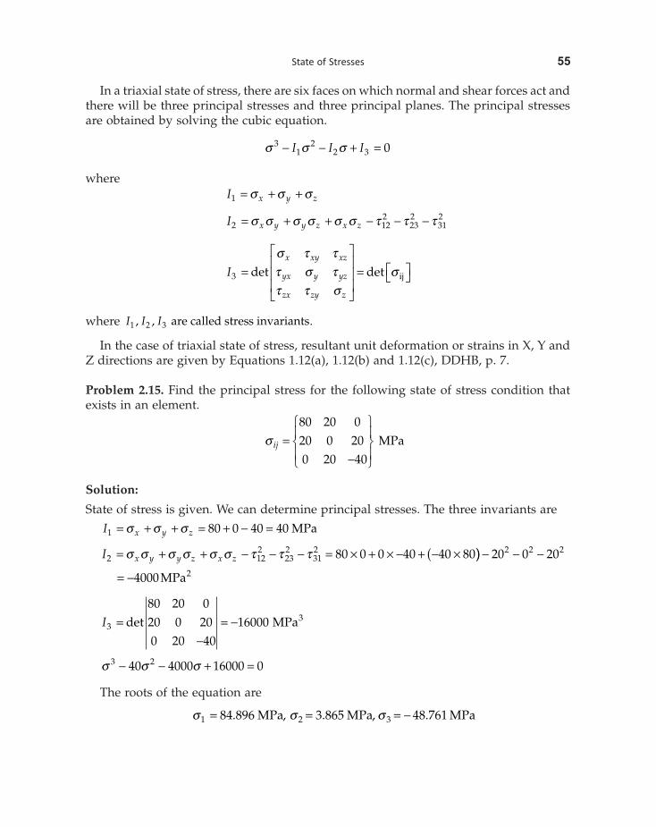
Problem 2.15. Find the principal stress for the following state of stress condition that exists in an element.
s ij =-
Ï
ÌÔ
ÓÔ
¸
˝Ô
˛Ô
80 20 020 0 200 20 40
MPa
Solution:
State of stress is given. We can determine principal stresses. The three invariants are
I x y z1 80 0 40 40= + + = + - =s s s MPa
I x y y z x z2 122
232
312 80 0 0 40 40 80= + + - - - = ¥ + ¥ - + - ¥(s s s s s s t t t )) - - -
= -
20 0 20
4000
2 2 2
2MPa
I33
80 20 020 0 200 20 40
16000=-
= -det MPa
s s s3 240 4000 16000 0- - + =
The roots of the equation are
s s s1 2 384 896 3 865 48 761. , . , .= = = -MPa MPa MPa
60 Design of Machine Elements
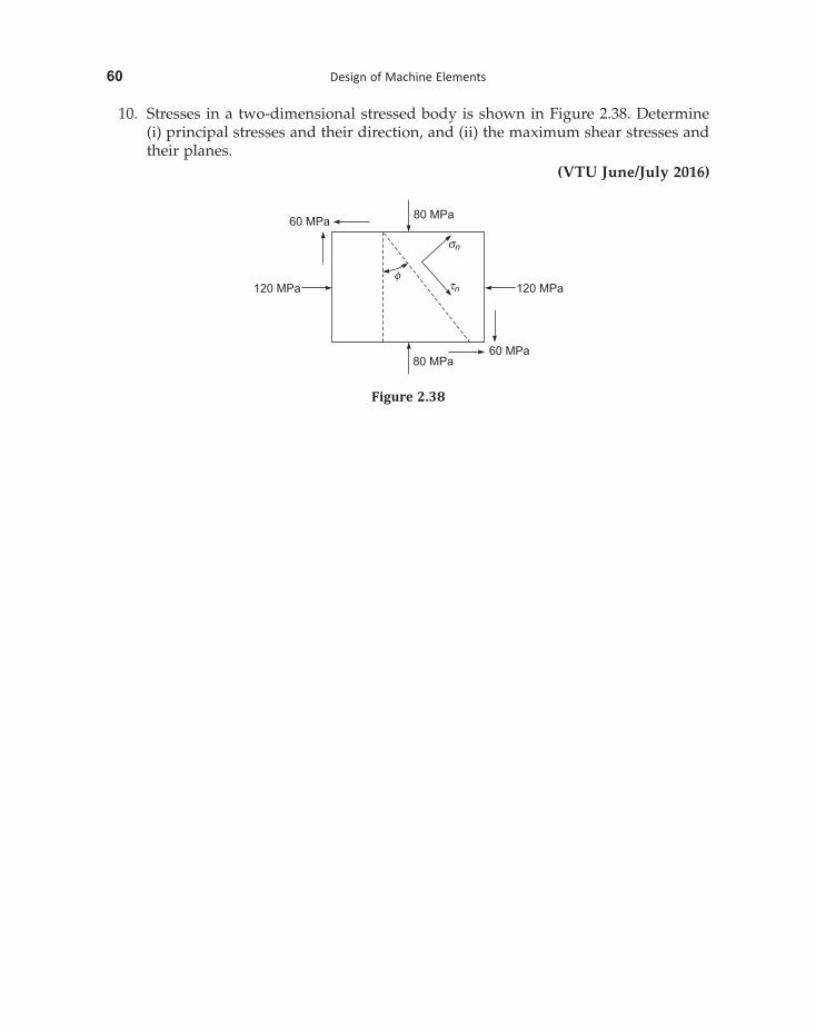
10. Stresses in a two-dimensional stressed body is shown in Figure 2.38. Determine (i) principal stresses and their direction, and (ii) the maximum shear stresses and their planes.
(VTU June/July 2016)
80 MPa60 MPa
120 MPaf
sn
tn 120 MPa
80 MPa60 MPa
Figure 2.38