calculation of stresses and natural frequencies for a rotating
TRANSCRIPT
U. S. DEPARTMENT OP COMMERCE NATIONAL BUREAU OF STANDARDS
RESEARCH PAPER RP1148
Part of Journal of Research of the }{ational Bureau of Standards, Volume 21, }{ovember 1938
CALCULATION OF STRESSES AND NATURAL FREQUEN. CIES FOR A ROTATING PROPELLER BLADE VIBRATING FLEXURALLY
By Walter Ramberg and Sam Levy
ABSTRACT
The present paper extends the method of computing the natural modes of flexural vibration of a nonrotating propeller blade which was described in RP764 to blades that rotate as in actual flight. The resulting integral equations were solved for two aluminum-alloy propeller blades of typical design vibrating with the fundamental mode and with the second harmonic mode and rotating at speeds covering the range of service speeds. The effect of rotation on the stress distributions and on the natural frequencies was obtained for the two extreme end conditions of rigid clamping at the hub and no clamping at the hub. Rotation was found to have a small effect (up to 13 percent) on the maximum stress per unit tip deflection and was found to shift the maximum toward the hub. For the determination of critical speeds, the natural freq uencies were shown to follow conveniently from Lord Rayleigh's energy method by making use of the solutions for no rotation outlined in RP764. The effect of initial twist on the flexural frequen cies of the blade was found to be small compared with the effect of changes in clamping at the hub. Changes in clamping may change the frequency up to 13 percent. A correction to RP764 is noted in this connection. Both the stress distribution and the natmal frequencies of a given propeller blade may be calculated from those obtained for a model blade by means of two model rules developed by Theodorsen.
CONTENTS l'age
I. Purpose of investigation ____ ___ ____ ___________ ________ ___ . _______ __ 640 II. Calculation of stresses _ _ _ _ _ _ _ _ _ _ _ _ _ _ _ _ _ _ _ _ _ _ _ _ _ _ _ _ _ _ _ _ _ _ _ _ _ _ _ _ _ _ _ 641
1. Equation of motion of idealized straight propeller blade__ _ _ _ _ _ _ 641 2. Mode of motion and stress distribution for fundamental mode __ 646 3. Mode of motion and stress distribution for second harmonic mode _________ ____ _____ ____ ___________ ____ ___ __ _____ ___ 652
(a) Outline of proccdure _____________ __ _____ ___ ____ ____ 652 (b) Results ______________ _____ __ ____ ____ ___ _____ _____ 656
III. Calculation of natural frequencies _______ ______ ___ ___ ____ ___ _____ __ 657 1. Approximate calculation by Rayleigh's method __ _____________ 657 2. Results for fundamental frequency and second harmonic fre-quency ___ _______ _______ _____ ______ ____________________ 660 3. Effect of restraint at hub; correction to R1'764_ _ _ _ _ _ _ _ _ _ _ _ _ _ _ 661 4. Effect of initial twist and of initial curvature __ __ ______ _ . _ _ _ _ _ _ 662 5. Critical speeds _____ ___ ____ ___________ __________________ __ _ 662
IV. Comparison of natural modes for affine propeller blades ___ _________ __ 665 V. Sumrnary _______________ ____ _____ ____ __ ___ ______ ____ _____ ___ ___ 667 VI. References _______ ______ ____ ___ ___ ______ ____ ____ ______ ___ ____ ____ 669
639
640 Journal of Research of the National Bureau of Standards [Vol. 11
1. PuRPOSE OF INVESTIGATION
The determination of stresses in a nonrotating propeller blade vibrating with a flexural mode has been discussed in Bureau Research Paper RP764 [1].1 In that paper it was shown that the bending stresses set up in the blade could be conveniently determined from strain measurements on the surface of the blade, after the blade had been set into resonance with the desired flexural mode. The stresses so determined were found to agree closely with those calculated from the theory of flexural vibrations for beams of variable section. Fatigue failures in the center portion of eight aluminum-alloy blades were produced by vibrating the blades at the fundamental mode with a sufficiently high amplitude to produce a crack after 33,800 to 2,390,000 cycles of vibration. The crack occUl'red in every case at a maximum stress amplitude greater than 14,000 pounds per square inch, and at a point where the stress differed only a few percent from the measured maximum stress. Attempts to produce fatigue failures near the tip in blades vibrating with the second harmonic mode were not successful, mainly because a sufficiently high stress amplitude could not be maintained in the blade. Within the last few months one such fatigue failure was obtained in an aluminum-alloy blade while it was being used to calibrate certain dynamic-strain gages. The fatigue crack extended through about 85 percent of the cross-sectional area of the blade and developed at a distance of 13 inches from the tip at a point within an inch of the location at which the maximum stress amplitude had been measured.
The results of tests on nonrotating blades can be applied to propellers in flight only if the effect of centrifugal force on the natural modes of vibration is clearly understood. A number of investigations have already been made to determined the effect of an angular speed, w, on the natural frequency, p, of the blade, and a formula of the type
(1)
was proposed as early as 1918 by Berry [2]. Values of the constant 0: ranging from 1.04 to 1.9 have been obtained by various investigators [3, 4, 5, 6, 7, 8, 9]. The large variation in the values of 0: may be ascribed, principally, to differences in the design of the propeller blade. The constant 0: was determined theoretically as 1.19 for the uniform beam vibrating with its fundamental mode, by Berry [2], and as 1.4 for a wedge, by Webb and Swain [3]. Hansen and Mesmer [7] concluded, on the basis of tests, that 0: is about 1.45 for blades of usual design. Theodorsen obtained a considerably higher value (0:=1.9), also on the basis of tests (revision of values given in [9].)
The effect of centrifugal force on the stress distribution in a rotating blade vibrating with a flexural mode has not been studied as extensively as the effect on the natural frequencies. An experimental determination of the stress distribution has not been possible until very recently, since no dynamic strain gages were available which could be attached to a rotating blade and which could be expected to give a fairly accurate value of the strain amplitude during lateral vibrations. In addition, the problem of exciting a single
I Figures in brackets indicate the literature references at the end of this paper.
r--------------------~--
RamberD] Levv Vibration oj Rotating Propeller Blade 641
flexural mode in a rotating blade is not a simple one; up to the present time it has been solved only for a thin model blade rotating at a relatively low speed [9].
Until the experimental difficulties just mentioned have been overcome, an answer to the problem can only be expected from a theoretical attack. The close agreement between measured and calculated stress distributions and natural frequencies for nonrotating blades suggested that an extension of the solution. to rotating blades would give equally reliable results on the effect of rotation on both stress distribution and natural frequencies.
The present paper deals with the extension of the theoretical method originally developed by Hansen and Mesmer [7, 1] to rotating blades and gives the resulting stress distributions and natural frequencies for two aluminum-alloy propeller blades of different design.
II. CALCULATION OF STRESSES
1. EQUATION OF MOTION OF IDEALIZED STRAIGHT PROPELLER BLADE
It will be assumed, as in the case of the nonrotating blade [1], that the flexural vibrations of the propeller blade may be adequately represented by the motion of a straight beam whose cross-sectional areas and principal moments of inertia are equal to those of the propeller blade, and whose principal axes of inertia remain parallel throughout the length of the beam. The ordinary beam theory may then be applied in setting up the equation of motion of the blade for the case of resonant vibration in the fundamental mode and the second harmonic mode.
The adequacy of this approximation as applied to nonrotating propeller blades was confirmed by the close agreement that was found [1] between the stress distribution and the frequency of the actual blade with its initial twist and initial curvature and the corresponding stress distributions and frequencies for the idealized straight blade. Its ade<l,uacy for determininr,; the fundamental frequency and second harmOille frequency of rotatmg blades is confirmed by the close agreement between the experimental frequencies determined by Theodorsen (revision of values r,;iven in [9]) and the frequencies calculated assuming an idealized straIght propeller blade (see fig. 17, page 660).
No data are available to verify the assumption that the stress distribution for the fundamental mode and the second harmonic mode of the rotating blade is not affected by the initial twist. Strain measurements to check this assumption are desirable.
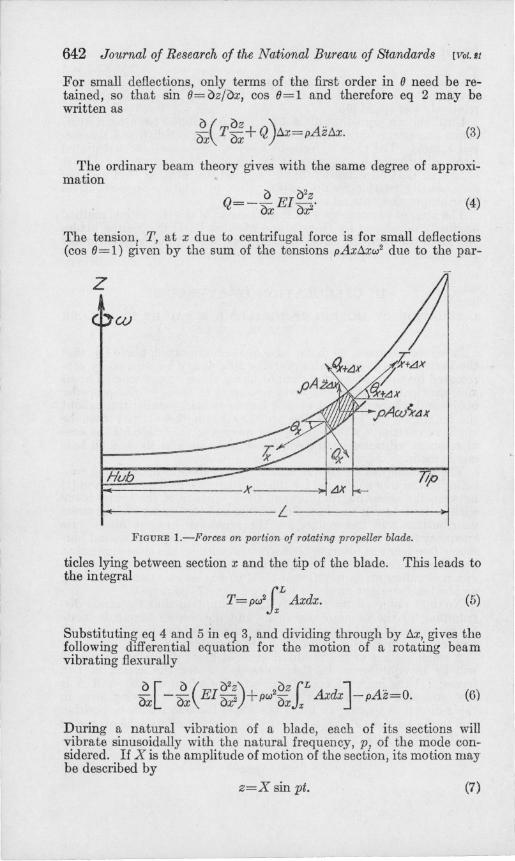
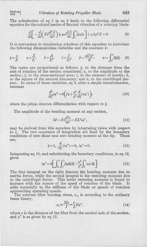
A small section of the idealized straight blade of length llx (fig. 1) will be in equilibrium in the z-direction under the action of two forces; (1) the inertia force p Azllx, where p is the density and A is the cross-sectional area of the blade; and (2) the restoring force in the z-direction tending to bring the blade back to its mean position due to the tension, T, and shear, Q. This condition may be expressed mathematically by
! (T sin 8+Q cos 8)llx=pAzllx. (2)
642 Journal oj Research oj the National Bureau oj Standards [VoUJ
For small deflections, only terms of the first order in (J need be retained, so that sin (J=oz/ox, cos (J=1 and therefore eq 2 may be written as
(3)
The ordinary beam theory gives with the same degree of approximation
o 02Z Q=--EI-· oX ox2 (4)
The tension, T, at x due to centrifugal force is for small deflections (cos (J=1) given by the sum of the tensions pAxLJ.xw2 due to the par-
z
Hub
~-----------L ---------------~
FIGURE I.-Forces on portion of rotating propeller blade.
ticles lying between section x and the tip of the blade. This leads to the integral
T=PW2iL Axdx. (5)
Substituting eq 4 and 5 in eq 3, and dividing through by LJ.X, gives the following differential equation for the motion of a rotating beam vibrating flexurally
gx[ - !( EI~;)+pw2~;lL Axdx]-pAz=O. (6)
During a natural vibration of a blade, each of its sections will vibrate sinusoidally with the natural frequency, p, of the mode considered. If X is the amplitude of motion of the section, its motion may be described by
z=X sin pt. (7)
l
Ramberu] Levu Vibration of Rotating Propeller Blade 643
The substitution of eq 7 in eq 6 leads to the following differential equation for the natural modes of flexural vibration of a rota tin., blade:
(8)
It is convenient in considering solutions of this equation to introduce the following dimensionless .variables and the constant k:
A f=V'
. I '/,=L4'
The ratios are proportional as follows: ~, to the distance from the axis of rotation of the section considered; rJ, to the amplitude at the section; f, to the cross-sectional area; i, to the moment of inertia; k, to the square of the natural frequency; and u, to the centrifugal tension. In terms of these variables, eq 8, after a simple transformation, becomes
d2." k(f +W2 d( I») de'/,rJ = rJ p2 d~ UrJ ,
where the prime denotes differentiation with respect to ~.
The amplitude of the bending moment at any section,
M=E1:~=EDirJ'"
(10)
(11)
may be derived from this equation by integrating twice with respect to~. The two constants of integration are fixed by the boundary conditions of zero shear and zero bending moment at the tip. These are,
t 1 d (.,,) 0 ." 0 ,,= , d~ '/,rJ = , '/,rJ = . (12)
I?tegrating eq 10, and substituting the boundary conditions, in eq 12, gIves
(13)
The first integral on the right denotes the bending moment due to inertia forces, while the second integral is the restoring moment due to the centrifugal forces. This latter restoring moment is found to increase with the square of the speed of rotation of the blade. It adds materially to the stiffness of the blade at speeds of rotation approaching operating speeds.
The extreme fiber bending stress, (Jx, is according to the ordinary beam theory,
Mc c E " u"=Y=r rJ , (14)
where c is the distance of the fiber from the neutral axis of the section, and rJ" is as given by eq 13.
644 Journal oj Research oj the National Bureau oj Standards [Vol.!t
An integral equation for the amplitude curve 7]m can be obtained by integrating eq 13 twice again and using the proper boundary conditions at the hub. These boundary conditions will depend upon the type of exciting forces and restraints. Because of the twist in propeller blades, the natural modes are neither purely symmetric nor purely antisymmetric. However, the motion for the lower-frequency modes is mainly parallel to the shaft, and the types of motion may be classified according to the symmetry or antisymmetry of this component.
Modes excited by forces at the center of the hub in the plane of rotation and modes excited by moments about axes in this plane will have components normal to this plane which are antisymmetric, while modes excited by forces at the hub parallel to the shaft and modes excited by moments about the shaft will have components normal to the plane of rotation, which are symmetric. Since the principal source of vibration in propellers is believed to be torque variation in the shaft, only the second type of motion is considered important. On this account, only symmetric modes in the idealized straight propeller are considered in this paper.
Integrating eq 13 twice for a symmetrical mode of vibration, that is, a mode of vibration satisfying the end condition,
~=O, 7]'=0, (15)
(16)
The constant of integration 7]0, which corresponds to the deflection at the hub, will depend on the restraint at the hub. The hub restraint at the root of each blade may be approximated by setting it equal to that due to a concentrated mass, M, rigidly attached to the hub combined with an elastic restraint against axial motion with a spring constant, S. The harmonic motion with an amplitude Xo= lfiJo of the mass, M, will apply a deflecting force with an amplitude MXOp2 to the hub, while the elastic restraint applies a restoring force with an amplitude SXo• Balancing the resultant of these forces by the shear in the hub section of the blade gives
(17)
It is convenient to express M and S in terms of the ratios,
M S m= pL3' s= pL3p2' (18)
so that eq 17 becomes with eq 9,
7]o(m-s) =[1. di7]"] k d~ <=0'
(19)
It will be noticed from eq 13 that for a symmetrical mode, 7]' (0) =0,
1 [di7]"] (1 k df <=0=- J/7]d~, (20)
Ramberg] LeDII Vibration oj Rotating Propeller Blade 645
so that eq 19 becomes
(21)
This equation evidently expresses the equilibrium between the concentrated transverse force applied at the hub and the distributed transverse inertia forces due to the vibration of the blade integra,ted from the hub to the tip. Substitution from eq 16 for the right-hand side of eq 21 leads to an equation which may be solved for 7]0' Substituting the resulting value of 7]0 in eq 16 leads to the following integral equation for symmetrical flexural modes of vibration:
7] =kf.CIa~f[lllj7]d~d~-;:J:IU7]'d~Jd~d~ (22)
1 l' r'f( r~ r~~[ r l f1hd~d~- w: rlU7]'d~Jd~d~)d~}' m-s+ jd~Jo Jo Jo 'L J~ J~ p J~
o
Numerical solutions of this integral equation were obtained for two special cases only; (1), the case of rigid clamping (fixed-free blade), which corresponds to infinite values of m-s, so that eq 22 becomes
7]=k{fo~fo~f[J:IJ:j7]d~d~-;:J:lu7]'d~Jd~d~}; (23)
and (2), the case of no clamping (free-free blade), which corresponds to m-s= O,.so that eq 22 becomes
7] = k{fo~fo~f[J:l.J:j7]d~d~-;:.J:IU7]'d~Jd~d~ (24)
-J;y)'f(f.'l'HI J,'t,dW!-;: J.'u,' d! }i!d! )1<)
It is interesting to note that the boundary condition m-s=O for a free-free blade may be satisfied theoretically in the presence of elastic restraint at the hub, provided the concentrated mass at the hub is such as to balance the spring force at the natural frequency in question.
The solutions, eq 23 and 24, will bound all those natural modes for which m-s~O, that is, they apply to the symmetrical flexural 'modes in a two-blade propeller whose hub acts like a concentrated mass, Mo=pD (m-s), In the remaining cases in which the propeller hub acts like a spring with an equivalent spring constant, So=pDp2(s-m), the frequency will, in general, lie outside of the values determined by eq 23 and 24, If, for example, in eq 22 m-s is given a large but finite negative value, the solution will have a frequency below that determined by eq 23; while if m-s is given a small negative value, the frequency will be above that determined by eq 24.
Experiments indicate that the natural flexural modes of nonrotating propellers [1] are bounded by the particular solutions in eq 23 and 24 with w=O. Propeller hubs of practical design seem to act
100926-38-8
646 Journal oj Research oj the National Bureau oj Standards [Vol. 11
like a concentrated mass rather than like a concentrated spring. It was decided, accordingly, to confine the theoretical work on the rotating blade to solutions of eq 23 and 24 for certain propeller blades of practical design. The resulting modes were found to be sufficiently similar for the two boundary conditions of rigid clamping and no clamping at the hub, as expressed by eq 23 and 24, to make it probable that they are adequate expressions for the flexural modes of the blades in a multiple-blade propeller as well as in a two-blade propeller.
2. MODE OF MOTION AND STRESS DISTRIBUTION FOR FUNDAMENTAL MODE
Equations 23 and 24 may be solved for the fundamental mode, and the stress distribution for this mode, by using a procedure that is a direct extension of the correspondin~ procedure for nonrotating propeller blades, as described in detail in Bureau Research Paper RP764 [1). The deflection curve 1/ for the fundamental mode for a given value of the ratio w/p is obtained by assuming a deflection curve 1/ which approximates roughly the shape of the expected deflection curve, substituting the assumed value of 1/ on the rightside of eq 23 or 24 and carrying out the integration by the numerical procedure described in detail in [1). This will, in general, lead to a value of rJ/k which approximates the shape of 1/ for the fundamental mode more closely than the initially assumed shape of 1/. The integration is repeated after inserting on the right-hand side of the equation a deflection curve proportional to the deflection curve 1//k just calculated, until the integral 1//k has the same shape as the 1/ in the integrand on the right. The constant of proportionality, k, will then give the angular frequency, p, of the blade, and· knowing p, one may calculate the speed of rotation, w, from the initially assumed value of w/p. The calculation was found to converge to the correct solution after two or three cycles of integration when the initial 1/ was taken as the deflection curve of the propeller blade without rotation. With the calculation of the dpflection curve for the fundamental mode of vibration the stress distribution may be determined by substituting the integral, eq 13, which is evaluated automatically as one of the steps in the integration of eq 23 or 24, in the stress formula, eq 14.
It should be noted from eq 23 and 24 that w/p must be below a certain value in order to lead to a positive value of k and hence a real natural frequency, p. This limiting value of w/p corresponds to the asymptote to the curve of p j(w) for infinitely high speeds of rotation, w. In propeller blades of usual design the asymptotic portion of the curve lies far beyond the range of operating speeds; the limiting value of w/p is, therefore, not of practical importance in this connection.
The above procedure was used to determine fundamental modes of vibration and stress distributions corresponding to these modes for aluminum-alloy blades of two typical designs. One design, which is referred to as type 32, had already been used to stud~ flexural vibrations of a nonrotating blade [1). The other design will be referred to as type 4371. A model blade of this design was used by Theodorsen [9] to determine the natural frequencies of flexural vibration with rotation. The radius, L (distance from center of hub to tip), for a propeller blade of type 32 was equal to 47.6 inches, while it was equal to
Ramberg] Levv Vibration oj Rotating Propeller Blade 647
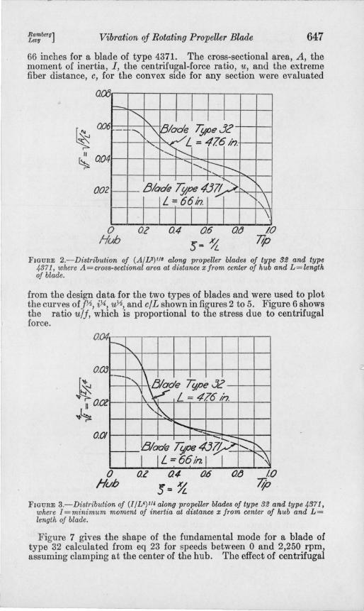
66 inches for a blade of type 4371. The cross-sectional area, A, the moment of inertia, I, the centrifugal-force ratio, u, and the extreme fiber distance, e, for the convex side for any section were evaluated
aoo f--
~ I'.
I I I
~ 006 -- ""', '\ Blade Type 32
II ~ a04
002
o Hub
" '<: L = 4161i? ........ t'---
........ , t--- r----.. 1' .... "'-
/3lade Type 4379 \ L=66in. -'- -,,\
oz 0.4 06
5= ~
\ at) 10
7lp
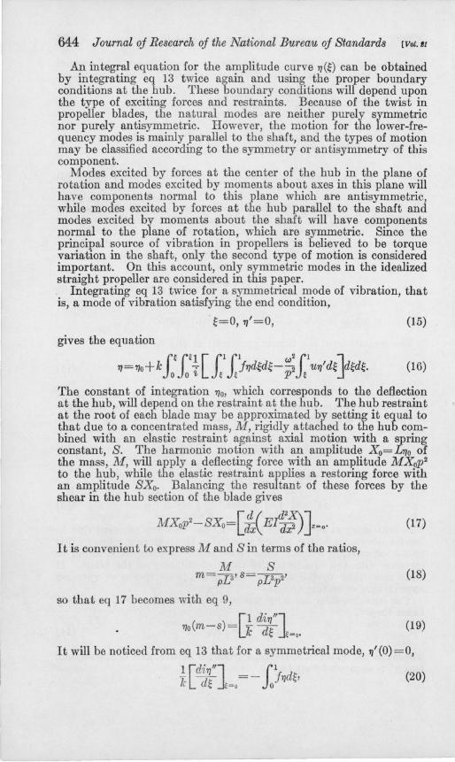
FIGURE 2.-Distribution of (A/V)III along propeller blades of type 32 and type 4371, where A = cross-sectional area at distance x from center of hub and L = length of blade.
from the design data for the two types of blades and were used to plot the curves off'A, iY.!. , u'A, and elL shown in figures 2 to 5. Figure 6 shows the ratio u/f, which is proportional to the stress due to centrifugal force.
0. ,., ~
r---.
/l~
"" 0. -Ol
a 01
o Hub
"'-'\
~ade ~!6""~ "
L - 4?6 In. '\. ~
............ ~ I::--. -- --'Blade T~e4J7I>- '-.. "-
I I L = 66 in. I I "\ az 0.4 0.6 at) 10
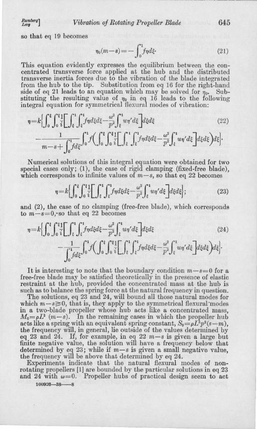
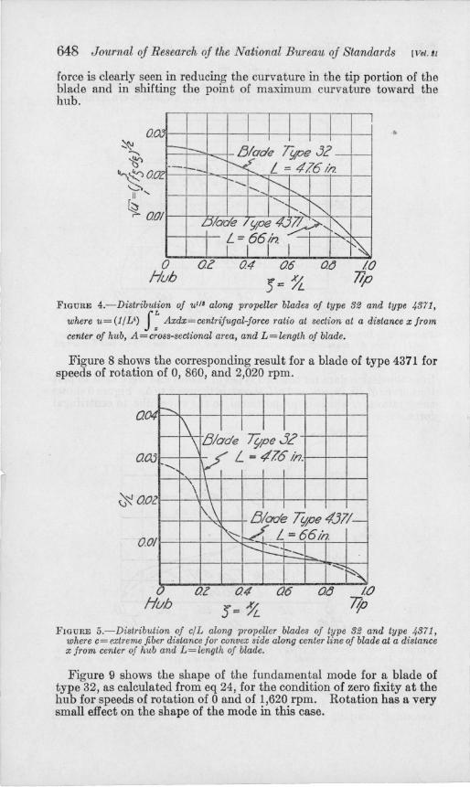
5=~ 7p FIGURE 3.-Distribution of (l/V) 114 along propeller blades of type 32 and type 4371,
where l=minimum moment of inertia at distance x from center of hub and L= length of blade.
Figure 7 gives the shape of the fundamental mode for a blade of type 32 calculated from eq 23 for speeds between 0 and 2,250 rpm, assuming clamping at the center of the hub. The effect of centrifugal
648 Journal oj Research oj the National Bureau oj Standards [Vol. II
force is clearly seen in reducing the curvature in the tip portion of the blade and in shifting the point of maximum curvature toward the hub.
o /H ~v -
-.oc
. 01
o Hub
I I I I I - Blade Type J2 -i'-/ L == 476 t/7. r---t-_ -.......... -.... r--..
""-~ 1' ......
Diode Y'pe 4J~, ~ I f=166(h, "
az 0.4 06 0.r5
'5.: 9t.
I
~ 10
7/p
..
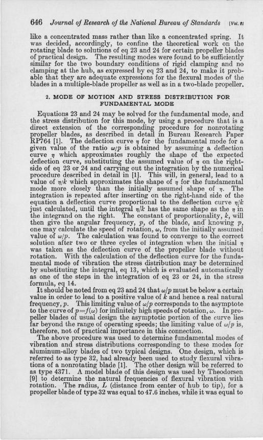
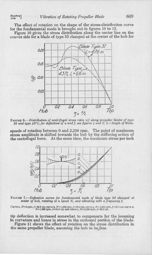
FIGURE 4.-Distribution of ulll along pTopeller blades of type 32 and type 1;371,
where U= (1/£4) f: Axdx=centrifugal-force ratio at section at a distance x from
center of hub, A=cross-sectional area, and L=length of blade.
Figure 8 shows the corresponding result for a blade of type 4371 for speeds of rotation of 0, 860, and 2,020 rpm.
a ,.,. -........ v
a aJ -Oc
.01
o Hub
\ \ !3lode Tl/pe.12 ~ L = 476 in.
\ 0\ \ 1',\ ~de ~pe.437/-~ . L - 66tn.
r-- --r-----~ -...;:
~ at 0.4 (}6 o.(J 1.0
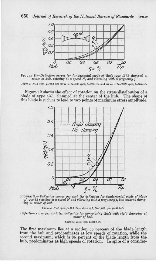
J= ~ 77p FIGURE 5.-Distribution of clL along propeller blades of type 32 and type 1;371,
where c= extreme fiber distance for conve.1: side along center line of blade at a distance x from center of hub and L = length of blade.
Figure 9 shows the shape of the fundamental mode for a blade of type 32, as calculated from eq 24, for the condition of zero fixity at the hub for speeds of rotation of 0 and of 1,620 rpm. Rotation has a very small effect on the shape of the mode in this case.
Rambero] Levu Vibration of Rotating Propeller Blade 649
The effect of rotation on the shape of the stress-distribution curve for the fundamental mode is brought out in figures 10 to 12.
Figure 10 gives the stress distribution along the center line on the convex side for a blade of type 32 clamped at the center of the hub for
DcO / r----. 81ade Tt;p~3C'
/ "~=f76h-
l)/ -- ", \ ho. 0/5 P ~/ -, 1\ r--f--- Blade Tt;peA [,,\
~ 010
O()5
o Hub
4J11, L = 66 In.
o.z
" ~\ ~
1\ \
o.e 10 7lp
FIGURE 6.-Distribution of centrifugal stress ratio u/f along propeller blades of type 32 and type 4371; for definition of u and f, see figures 4 and 2; L=length of blade.
speeds of rotation between 0 and 2,250 rpm. The point of maximum stress amplitude is shifted towards the hub by the stiffening action of the centrifugal force. At the same time, the maximum stress per inch
IO.-~~--~~~--~~~--~~
OrJl---+--+--
~06 ~041---+-~~--~~ ~ ~Ol~~-+--~~-4~~~~--+-~
o Hun
0;: 10 77;0
FIGURE 7.-Deftection curves for fundamental mode of blade type 32 clamped at center of hub, rotating at a speed N, and vibrating with a fj'equency f.
Curve a, N~O rpm,f=30.6 cis; curve b, N=l,050 rpm,I=39.2 cis; curve c, N=l,550 rpm,f=47.1 cis; curve d, N=l,960 rpm,/=54.6 cis; and curve e, N=2,250 rpm, 1=60.2 cis.
tip deflection is increased somewhat to compensate for the lessening in curvature and hence in stress in the outboard portion of the blade.
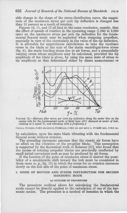
Figure 11 shows the effect of rotation on the stress distribution in the same propeller blade, assuming the hub to be..free.
650 Journal oj Research oj the National Bureau oj Standards [Vol. It
jO~~~~~--~~~~~~
O(J I--l---I--I---l---l---!--I---!---,W---l
:::::- 0.6 \.::. F::- 041--+--+----1--+--1-
~Oct-4--+~~+-~~~~+-~~
o Hub
OZ 04 06
)= ~ Ot} 10
.77p
FIGURE S.-Deflection curves for fundamental mode of blade type 4371 clamped at center of hub, rotating at a speed N, and vibrating with a frequency f.
Curve a, N=O rpm, /=26.0 cIs; curve b, N=860 rpm, /=32.6 cIs; and curve c, N=2,020 rpm, /=50.5 cIs.
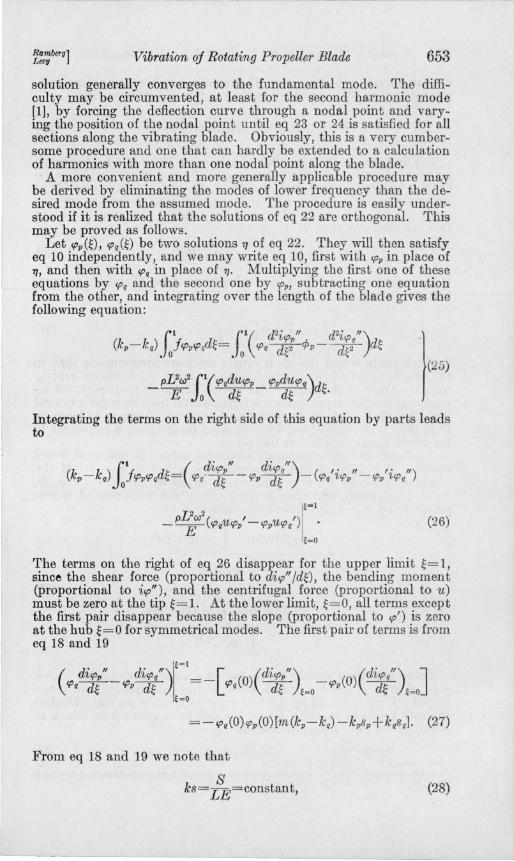
Figure 12 shows the effect of rotation on the stress distribution of a blade of type 4371 clamped at the center of the hub . The shape of this blade is such as to lead to two points of maximum stress amplitude.
IO'--~~~~~~~~~/
o.(J~~-+-+~~~+-~I/~ --- Ri91d C/ampin; Ii
1---- No clampl/7g' -l-----jl-/!-II+----I 06~+-+-+-~~~~-/~~~
~ II ~O'4~+-+-~~~~~~~--l ~ I-+--J.....--+--+--q" _ / rt
h,,, I) Qll--l--I----I---+-cS~ ~
_~/I/ O~~~~~~~~~~~~
I fAOf 3P Of Cf If Hub )=~ lip
FIGURE 9.-Deflection curves per inch tip deflection for fundamental mode of blade of type 32 rotating at a speed N and vibrating with a frequency f, but without clamping at center of hub.
Curve a, N=O rpm, /=34.1 cIs; and curve b, N=l,620 rpm,j=55.2 cIs.
Deflection curve per inch tip deflection for nonrotating blade with rigid clamping at center of hub .
. Curve c, N=O rpm, /=30.7 cIs.
The first maximum lies at a section 55 percent of the blade length from the hub and predominates at low speeds of rotation, while the second maximum, which is 35 percent of the blade length from the hub, predominates at high speeds of rotation. In spite of a consider-
r-.- .. --____ ~ _ _______ . __ ,~, ........ ~ __ •• ..".~_
Ramberu] Lev" Vibration oj Rotating Propeller Blade
/OXloJ~r-._=r_.--~_._.--._~
o Huh
OZ 04 06
)=~ OCJ
651
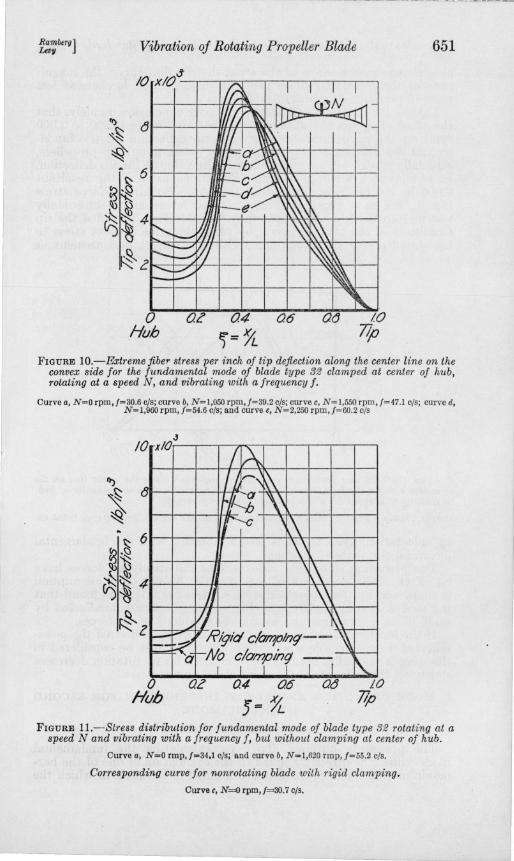
FIGURE lO.-Extreme jibe!" stress per inch of tip deflection along the center line on the convex side for the fundamental mode of blade type 32 clamped at center of hub, rotating at a speed N, and vibrating with a frequency f.
Curve a, N=O rpm,/=30.6 cis; curve b, N=I,050 rpm,/=39.2 cis; curve c, N=I,550 rpm, /=47.1 cis; Curve d, N=l,9ao rpm, /=54.6 cis; and curve e, N=2, 250 rpm,/=60.2 cis
/0 '0" xl< I ~ J~ .-\ ~ f£Z \\ r \\
\\ l\
J. ~ ./ IJ ~ -- Riqid c/amplnq-- ,
:::;;;;:; ~ -No ciampinI} --I II i I r ~
o Hub
az Q4 06
5= ~ O(} 10
77p
FIGURE ll.-Stress distribution for fundamental mode of blade type 32 rotating at a speed N and vibrating with a frequency f, but without clamping at center of hub.
Curve a, N=O rmp,/=34.1 cis; and curve b, N=I,620 rmp, /=55.2 cis.
Corresponding curve for nonrotating blade with rigid clamping.
Curve c, N=iJ rpm, /=30.7 cis.
652 Journal oj Research oj the National Bureau oj Standards [Vol. II
able change in the shape of the stress-distribution curve, the magnitude of the maximum stress per unit tip deflection is changed less than 13 percent as a result of rotation.
Figures 10, 11, and 12 all lead to the same conclusion, namely, that the effect of spe¢ds of rotation in the operating range (1,000 to 2,000 rpm) on the maximum stress per unit tip deflection for the fundamental flexural mode may be neglected when designing propellers, especially in view of the uncertainty in the value of the tip deflection. It is allowable for approximate calculations to take the resultant stress in the blade as the sum of the static centrifugal-force stress (fig. 6), the static bending stress due to air forces, and a sinusoidally varying stress whose amplitude may be calculated, provided the tip amplitude of the blade is given, by using the same ratio of stress to tip amplitude as that determined either by direct measurement or
FIGURE 12.-Extreme fiber stress per inch tip deflection along the center line on the convex side for the fundamental mode of blade type 4371 clamped at center of hub, rotating at a speed N, and vibrating with a freq·uency f.
Curve a, N=O rpm, [=26.0 cis; curve b, N=860 rpm, [=32.6 cis; and curve c, N=2,020 rpm, [=50.5 cis.
by calculation, upon the same blade vibrating with the fundamental flexural mode without rotation.
The preceding statement assumes that the steady air forces have no effect on the vibration of the propeller blade. This assumption is supported by the theoretical work of Reissner [17], who found that the modes of rotating propeller blades are practically unaffected by smn,ll initial curvatures such as may be produced by air forces.
If the location of the point of maximum stress is desired the possibility of a considerable shift toward the hub must be considered in those cases (e. g., fig. 12) in which the stress for no rotation decreases slowly on the hub side of the point of maximum stress.
3. MODE OF MOTION AND STRESS DISTRIBUTION FOR SECOND HARMONIC MODE
(a) OUTLINE OF PROCEDURE
The procedure outlined above for calculating the fundamental mode cannot be directly applied to the calculation of one of the harmonic modes. The procedure is a method of iteration in which the
Rambero] LevU Vibration oj Rotating Propeller Blade 653
solution generally converges to the fundamental mode. The difficulty may be circumvented, at least for the second harmonic mode [1], by forcing the deflection curve through a nodal point and varying the position of the nodal point until eq 23 or 24 is satisfied for all sections along the vibrating blade. Obviously, this is a very cumbersome procedure and one that can hardly be extended to a calculation of harmonics with more than one nodal point along the blade.
A more convenient and more generally applicable procedure may be derived by eliminating the modes of lower frequency than the desired mode from the assumed mode. The procedure is easily understood if it is realized that the solutions of eq 22 are orthogonal. This may be proved as follows.
Let cppm, cpqm be two solutions 7] of eq 22. They will then satisfy eq 10 independently, and we may write eq 10, first with CPP in place of 7], and then with Cpq in place of 7]. Multiplying the first one of these equations by CPq and the second one by CPp, subtracting one equation from the other, and integrating over the length of the blade gives the following equation:
(25) _ pL2w2 fl( cpqduCPP _ cppduCPq)d~
E Jo d~ d~ .
Integrating the terms on the right side of this equation by parts leads to
(26)
The terms on the right of eq 26 disappear for the upper limit ~=1, since the shear force (proportional to dicp" /d~), the bending moment (proportional to icp"), and the centrifugal force (proportional to u) must be zero at the tip ~=l. At the lower limit, ~=O, all terms except the first pair disappear because the slope (proportional to cp') is zero at the hub ~= 0 for symmetrical modes. The first pair of terms is from eq 18 and 19
( dicp/' _ diCP/)lt~l = _ [ (O)(dicpv") _ (O) ( dicp/ ) ] Cpq d~ CPP d~ Cpq d~ t=O CPP d~ t =O
t=O
From eq 18 and 19 we note that
S ks= LE=constant, (28)
654 Journal oj Research oj the National Bureau oj Standards [ltDl. II
so that the last two terms in eq 27 drop out. Substituting the resulting value of eq 27 in eq 26 gives the relation of orthogonality
m(c,opc,oq)~=o+ lfc,opc,oqd~=O, p~q. (29)
The first step in the procedure of solving eq 23 and 24 for harmonic modes consists in obtaining an assumed deflection curve T} which satisfies the four boundary conditions, eq 12, 15, and 21. It is possible to express this curve T} in terms of the normalized deflection curves 2
c,ol(~)' .•• c,on(~) ... for the natural modes of the propeller blade that are solutions of eq 22:
(30)
If the right-hand side of eq 30 is substituted in eq 22 and the integration performed, a new curve,
(31)
is obtained, in which the lower orders are more predominant than in the original curve T}, since the frequency ratio, k, increases rapidly with the order of the mode. The second harmonic frequency, for instance, is roughly three times the fundamental frequency for a typical propeller blade; this leads to a value k2 about 10 times as large kl •
It is thus understood how, by reiterated integration, T} converges to the mode having the lowest frequency.
A general method eliminating all modes below the one to be found consists in evaluating the tip amplitudes ai, .. " an, ... of the component modes by first multiplying eq 30 by jc,olW, ... jc,onW, .. " integrating, and then making use of the condition of orthogonality, eq 29. This leads to the values
mT} (0) c,ol (0) + ,Fofc,ol (~)T}(~)d~
lfc,oI2(~)d~ (32)
a = mT}(O)c,on(O)+.fofc,on(~)T}Wd~. n lfc,o/(~)d~
These equations enable us to free the assumed deflection curve. T}(~), of any component modes whose shape has already been determined. If we know all modes below the n-th mode we may calculate the n-th mode by starting out with a deflection curve from which all lower modes have been eliminated,
T}I=T}-alc,ol .•. -an-lc,on-I = anc,on + an+lc,on+l ... , (33)
'A deflection curve, ~I m, . . . <p.m, will be considered as normalized In this discussion Illts value at the propeller tip is taken as unity, that is, <PI (1)=1, .. . <P.(1)=1.
Ramberg] Leov Vibration oj Rotating Propeller Blade 655
and sUbstituting this deflection curve in the integrand on the righthand side of eq 22, 23, or 24. Carrying out the integration leads to a deflection curve,
I 'Pn + 'Pn+1 + I=ank- an+)k-n n+l
(34)
in which the n-th mode is more predominant than in 1/11 since the frequency ratio, k, increases rapidly with the order of the mode.
To get a better apprmomation of the n-th mode, one may normalize II by multiplying it by a factor which will make the tip deflection unity, and may then repeat the integration with the resulting deflection curve, 1/11,
(35)
until the resulting integral is proportional to the 1/m in the integrand within the accuracy of the numerical procedure used.
A second method of calculating ~he harmonic modes is considerably less general than the first method, but possibly more convenient, if only the fundamental need be eliminated.
In the second method we free the assumed deflection curve 1/ m of any component modes whose shape has already been determined after the integration of eq 31. The amplitudes a3, a4, ... will be small compared to a2, provided that 71 has approximately the shape of the second harmonic mode. If we let a3=a4= ... =0, we may solve eq 31 for k2 as follows:
1/1-a)'P) 11- a\'P)
k) (36)
The frequency ratio, k2' must have the same value for all sections along the blade. All quantities in eq 36 are already lmown except a) and k2• The amplitude a) may, therefore, be evaluated by deriving eq 36 for any two sections of the blade. A number of trials showed that the sections ~=0.45, ~=0.85 were particularly suitable. That is, al was evaluated. from
1/1(0.45) -a)'P) (0.45) _ 711(0.85) -a)'P) (0.85)
11 (0.45) _ a)'P) k~.45) - 11 (0.85) _ a)'P) k~·85)
Solving eq 3'7 for a) gave
(37)
(045) (085)[1(0.85) _ 1(0.45)J 1/. 1/. 71(0.85) 1/(0.45)
al = 'PI (0.45{ 1(0.85) - 1/(Ok~5)J- 'PI (0.85) [1(0.45) - 1/(Ok~5)J Know~g all a further approximation to 1/ was obtained from eq 30 by evaluatrng
(38)
(39)
and normalizing this expression. Repeating with the normalized curve 1/II proportional to eq 39 gave a still closer approximation fJ11I'
656 Journal oj Research oj the National Bureau oj Standards [VoUI
It was found that the fundamental component a! was negligible compared with a2 after the third run; three runs generally sufficed to obtain an accurate solution of eq 23 or 24 for the second harmonic mode.
A check determination of the second harmonic mode of a blade type 4371 rotating at 860 rpm was made to verify that both the procedures outlined above led to the same numerical result.
(b) RESULTS
The second harmonic mode was calculated by the second procedure outlined above for a number of rates of rotation for a blade of type 32
10 I I
~ I I-
06.
06
~
f=;7L I
01 ,
-..... ~4 Or A I.(
~ Ib~YI , ~
o
-oz
Hub ~ 7lp FIGURE 13.-Deflection curves for second harmonic mode oj blade type 3.13 clamped
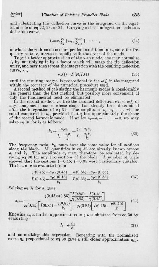
at center of hub, rotating at a speed N, and vibrating with a frequency f. Curve a, N=O rpm,f=1l9 c/s; curve b, N=8B rpm, f=124 c/s; curve c, N=1,2!O rpm,f=13! c/s; and curve
d, N=2,240 rpm,/=153 c/s.
clamped at the center of the hub. The results are shown in figures 13 and 14.
Figure 13 gives the shape of the mode for rates of rotation from 0 to 2,240 rpm. The deflection is seen to change only slightly because of rotation.
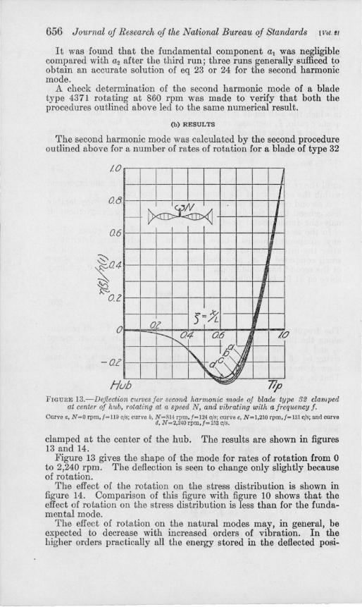
The effect of the rotation on the stress distribution is shown in figure 14. Comparison of this figure with figure 10 shows that the effect of rotation on the stress distribution is less than for the fundamental mode.
The effect of rotation on the natural modes may, in general, be expected to decrease with increased orders of vibration. In the higher orders practically all the energy stored in the deflected posi-
Ramberu] LevV Vibration of Rotating Propeller Blade 657
tion is energy of bending and the proportion of restoring force due to rotation becomes small compared with that due to bending. It may be concluded that except for the fundamental mode the stress distribution for a given tip deflection of a rotating blade vibrating with a flexural mode may be approximated closely by superimposing the vibratory stress in that mode, as determined for no rotation on the static stresses due to centrifugal force and to air loads.
-tO~~~~--~~~--~~~~
Hub 77p FIGURE 14.- Extreme fiber stress per inch tip deflection along the center line on the
convex side for the second harmonic mode of blade type 32 clamped at center of hub, rotating at a speed N , and vibrati ng with a freqllency f .
Curve a, N =O rpm;f= 1l9 cis; curvo b, N =814 rpm, /= 121 cis; curve c, N=I,210 rpm,J=131 cis; ann cu rve d, N =2,240 rpm, /=153 cis.
III. CALCULATION OF NATURAL FRE QUENCIES
An accurate knowledge of the natural frequencies of vibration of a propeller blade is required whenever there is a possibility of resonance between the propeller vibration and a periodic exciting force of sufficient amplitude from the engine. Accurate values of the frequency for the extreme end conditions of rigid clamping and of no clamping at the hub can be obtained by solving the integral eq 23 and 24, as was shown above. This involves too much calculation for practical design and fortunately is not necessary for speeds of rotation of a practical order.
1. APPROXIMATE CALCULATION BY RAYLEIGH'S METHOD
For speeds of rotation of a practical order, the shape of the deflection curve is not changed appreciably by the centrifugal force, and an accurate value of the natural frequency may be obtained, as noted below, by the Rayleigh energy method [10].
Rayleigh's method determines the natural frequency for a given mode X(x) of an elastic system from the equality of the potential energy, V, stored in the system at the extreme positIOn and the kinetic
658 Journal oj Research oj the National Bureau oj Standards [Vol. t l
energy, T, acquired by the system when it swings through its mean position. The potentIal energy of a rotating straight bar of variable section vibrating transversely consists of two terms [12]: (1), the potential energy due to bending,
(40)
and (2) , the potential energy V" due to the inward motion of the particles in the blade against centrifugal force.
VI/= foTw2pAx.r~(~:ydx}x. (41 )
The kinetic energy for sinusoidal vibrations, as given by eq 7, will be
(42)
The integrals on the right-hand side of eq 40 to 42 may be written more conveniently in terms of the ratios in eq 9. Doing this, and substituting the resulting expressions in the condition of conservation of energy,
V'+ VI/ =T, (43)
gives the following values for the square of the natural frequency, p, in radians per second:
f2 r\1)1/2d~+w2 rrJ~ r'1)'2d~Jd~ p2_P .10 Jo l Jo
- foj1)2d~ .
Equation 44 may be written in the form of the well-known eq 1,
p2=p~+ aw2(rad/sec)2, where
(44)
(45)
(46), (47)
provided 7] is taken as proportional to the deflection curve for no rotation.
The quantity P02 will be the square of the frequency without rotation and the ratio a will be constant as long as the shape 1)"(~) /7](1) of the curvature curve, the shape 'Y/' W/7] (1) of the slope curve, and the shape 7)(~)/7](1) of the deflection curve remain unaffected by the rotation w. The detailed analysis of the previous section showed that this is approx-
Ramberg] Levu Vibration of Rotating Propeller Blade 659
imately the case for propellers of usual design rotating at service speeds. .
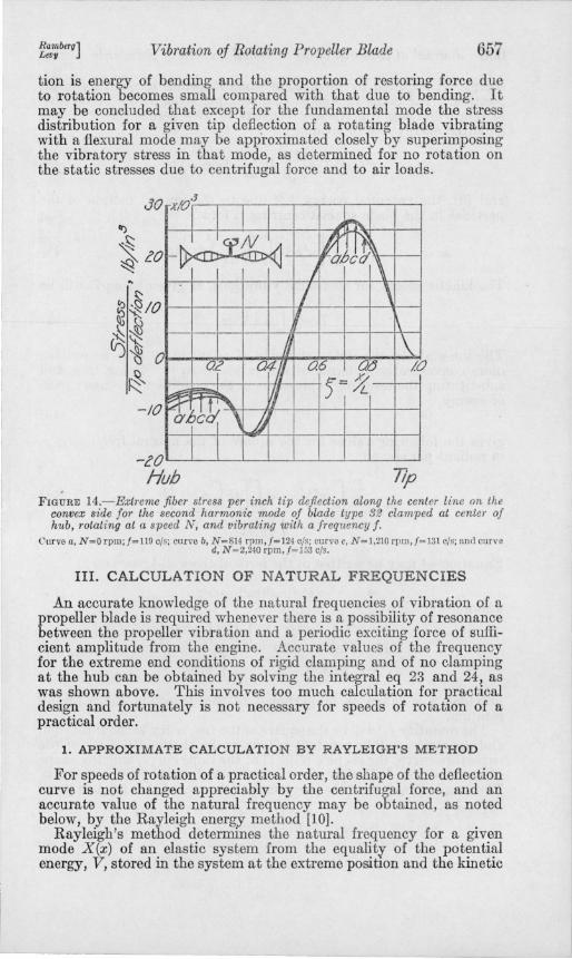
The closeness with which Rayleigh's method will give the correct solution of eq 23 and 24 for the fundamental frequency of a propeller blade, provided the mode for no rotation is substituted for 71, is brought out by a comparison of curves (a) and (b) in figure 15 (A) and 15 (B) with the open circles which were calculated for a blade of type 32 by direct solution of eq 23 and 24.
The insensitiveness of Rayleigh's method to variations in the shape of the deflection curve is so great that the deflection curve, 71, for a vibrating beam is frequently approximated by the deflection curve of the beam under its own weight. The deflection curve of the propeller blade as a cantilever beam deflected by its own weight follows from eq 23 by letting w=O and by replacing the vibrational acceleration, p2X=Lp 271, by the acceleration of gravity, g. Curve c in figures
60 /~Ca
/~ V /: 1f
0 ~
o A 2'0 40
~ rev05ec
6CW
4000
~
0
vb
~: "c 1,-0'
V~ jJ
Iff V
~ B
<XV /600 17~ (revpec)C
FIGURE 15.-Variation of natural frequency, f, of fundamental mode with speed of rotation, n, for blade type 32.
The points were calculated by solving integral equations 23 and 24, respectively. Curve a, Rayleigh's method using the mode for no rotation o( a flxed·free blade, f'=30.9'+1.95n' (c/s)';
curve b, Rayleigh's method using tbe mode for no rotat ion 0( .. (ree·(ree hlade.['=34.1'+2.46n' (c/s)'; and curve c, Rayleigh's method using tbe deflection curve of tbe blade under its own weight, f'=32.7'+2.04n' (c/s)'.
15 (A) and 15 (B) results for a blade of type 32. It is seen that the error in frequency as given by this procedure may be as much as 5 percent in this particular case.
The exactness with which the linear relation eq 45, between p2= (27rj)2 and w2= (27rn)2 holds is brought out in the plot of p against n2 in figure 15 (B).
It may be concluded that eq 45 will give an excellent approximation to the natural frequencies of a rotating blade,for ordinary values of w, provided Po is either directly observed or is calculated by the relatively exact method [1, 7J for no rotation. The ratio ex may then be calculated by substituting the deflection curve, 71W, for no rotation in eq 4,7. It may be expected to vary with a change in the design of the blade which would change the shape of the deflection curve, 71W, or the weight distribution, f.
--------
660 Journal oj Research oj the National Bureau oj Standards [VoUl
2. RESULTS FOR FUNDAMENTAL FREQUENCY AND SECOND HAR· MONIC FREQUENCY
Rayleigh's method, using the shape of the natural mode for no rot,ation, was applied to calculate the fundamental frequency and the
/60
!. '.50' ;.
~!. trl. ~ ~;;
'4(}
JO'
'to '/0
vO' '''A
90'
/'h9 0'
/ / " ...
", / / ;/
r-
A cO 40
~. n I rev./sec. -
//6 Cl
. v'" ~ . :/Y ./
,/ V . ~
B 0'
t:JaJ 1600
FIG VRE 16.- Variation of natural frequency , f , of second harmonic mode with speed of rotation, n, for blade type 32.
The points were calculated by solving Integral equations 23 and 24, respectIvely. Curve a, Rayleigh's method using tbe mode for no rotation of a fixed-Iree blade,['= 117.52+6.8nl (c/s)'; and curve b, RayleIgb's metbod using tbe mode (or no rotation o( a free-Cree blade,f'=130'+8.0n' (c/s)l.
FIGURE 17.-Variation of f1mdamental and second harmonic frequencies, f , with speed of rotation, n, for blade type 4371.
The open points were calculated by solving in· tegral equations 23 and 24, respectively. Curve a, Rayleigb's metbod using tbe mode (or no rotation of a fixed-free blade, lundamental mode. f'=2G.2'+L85n' (c/s)' and second barmonic mode, f' =72.4'+6A5n' (c/s)'· curve b, Rayleigh's method using the mode for no rotation of a free-free blade, fundamen tal mode,.f' = 29 .5' + 2.50n' (c/s)', and second barmonic mode,f'= 83.2'+7.73n' (c/s)' . The closed points were values derived by Theodorsen (rom experiments with an affine model (one-tenth thickDOSS) o( blade type 4371.
second harmonic frequency of propeller blades of type 32 and type 4371 for the two extreme end conditions of rigid clamping (zero deflection, zero slope) at the hub and complete freedom (zero slope, zero shear) at the hub. The results are listed in table 1 and are shown as curves in figure 16 (A) and 16 (B) for a blade of type 32 and in figure 17 for a blade of type 4371. The open circles in the figures indicate the results of solving eq 23 and 24 for the natural mode. The solid points in figure 17 are the results of experimental observations made by Theodorsen on a model blade of type 4371 [9], which results were communicated to the authors of the present paper by letter.
The open circles for the "exact" solution are seen to check the curves calculated from Rayleigh's method within the computational error. The solid points obtained by Theodorsen lie inside the narrow band bounded by the curves for the fixed-free and the .free-free end conditions.
Rambero] Levu
-----~~~--.......
Vibration oj Rotating Propeller Blade 661
TABLE 1.- Variation of natural frequency, f, with speed of rotation, n, for blades of two types
T ype of b Jado Method of d~termining frequency End condHion Mode
32 _____ ____________ ___ Rayleigh , ___ ____ __ __ Fi xed-free ___ __ FundamentaL _____ _ 32 ___ ________ _____ _________ do.' _ _ _ _ _ _ _ _ _ _ _ _ _ Free-free _________ __ do __________ ___ _ _ 32 ____ ________________ ____ _ do .. _______ ___ ___ Fixed-free ___ __ Second harmonic , __ _ 32 ___________________ • _____ do" _ _ _ __ _ __ _ _ _ _ _ Free-free ________ ___ do .' __ ___ _______ _ 4371. ___ __ ____ ________ ___ __ do .. _ _ __ ___ __ ____ Fixed-free __ ___ Fundamental. ___ __ _ 4371. _______ ____ ______ _____ do .. _ _ ___ ___ _ _ _ _ _ Free-free ______ _____ do ____ _____ ___ __ _ 4371. ___ __ __ __________ _____ do .. _ __ ___ _____ __ Fixed-free_ ___ _ Second harmonic , __ _ 4371. ________ • ________ ____ _ do .. _ _ _ _ _ _ _ _ _ _ _ _ _ Free-free _______ ___ _ do.' __ __ __ __ ____ _
4371. _______ _____ _____ From model blade 3_ Unknown _____ FundamentaL ___ __ _ 4371. ________________ __ ___ _ do.' ________ ____ _ ____ _ do ____ __ ___ Second harmonic , __ _
, Using shape of natural mode for no rotation. , Mode having one node near tip of blade.
Frequency, f
C/3
(30_9'+1.95n')~ (34.1'+2,461l ,)t (117.5'+o .8n,)t
(130'+S.On')' (26.2'+1.85n')'
(29.5'+2.5011')' (72.4'+6.45n') , (83.2'+7_7311,)"i
(30'+2.05n,)t (84 .1' +6_07n,)t
3 Test results by Theodorsen on model blade h.ving one-tenth the thickness of prototype 4371.
3. EFFECT OF RESTRAINT AT HUB; CORRECTION TO RP764 [1)
Examination of table 1 and of figures 15 to 17 shows that a change in the condition of restraint of the blade at the hub may change the natural frequency of the flexural vibrations by as much as 13 percent. The natural frequency for the free-free end condition is 10 to 13 percent higher than that for the fixed-free end condition for blades of both type 32 and 437L
An effect of restraint on frequency not considered in figures 15 to 17 is that due to the finite length of the hub clamp_ This will be equivalent to a shortening of the blade or to a displacement of the point of clamping toward the tip_ Calculations for a nonrotating blade of type 32, whose point of clamping was moved as much as 15 percent of the blade length toward the tip, gave an increase of 2 percent for the fundamental frequency as compared with the frequency for clamping at the center of the hub and an increase of 7 percent in the second harmonic frequency. The effect was too small to make it worth-while to extend the calculation to rotating blades. It appears, furthermore, that the direction of the effect is such as to increase the frequency for the clamped-free end condition so that the frequencies of blades with finite hub-clamps may be expected to lie inside the theoretical bands given in figures 15 to 17. An experimental confirmation of this result is desirable, especially in view of the limitation of the theoretical work (see p_ 644) to symmetrical modes with a restraint at the ~ub which may be replaced by a concentrated mass without anyspnng.
The statement made above that the natural frequency of a propeller blade increases as the point of clamping is moved toward the tip, calls for a correction of results to the opposite effect cited on p. 205,208, and 209 of [1). An error was found in the calculation for the frequenci,es cited on these pages for a blade of type 32 clamped at a point removed from the center of the hub. Correcting this error showed that a displacement of the point of clamping equal to 15 per-
100926-38-9
662 Journal oj Research oj the National Bureau oj Standards [Vol.'1
cent of the blade length raised the frequency for the fundamental from 30.;7 to 31.3 cIs and that of the second harmonic mode from 116.8 to 125.0 cIs. A displacement of 5 percent in the point of clamping raised the frequency of the second harmonic mode from 116.8 to 121.8 cis. After making these correctitms it may be concluded that the resultant variation in frequency will lie inside the 13 percent range limited by the frequencies for the fixed-free and free-free end condition. This ran~e is comparable to the variation of about 10 percent that was found III the maximum stress per unit tip deflection for different conditions of restraint.
4. EFFECT OF INITIAL TWIST AND OF INITIAL CURVATURE
The expression, eq 44, was derived for a straight propeller bJade without initial twist or initial curvature. ActuaJ propeller blades always show a large initial twist and a small amount of mitial curvature. Reissner [17] concluded from his theory of twisted and curved propeller blades that the initial curvature had a small effect, while the initIal twist may have a considerable effect on the natural frequencies of a rotating blade vibrating flexurally. He derived expressions corresponding to eq 40, 41, and 42 for the potential energy and the kinetic energy of a twisted and curved blade vibrating flexurally while in rotation. These expressions show that a change in the angle of attack of the blade as a whole has no effect on Po; a twist varying along the blade has a certain effect. The smallness of the effect of initial twist on the fundamental mode and second harmonic mode of a nonrotating blade is indicated by the good agreement between the frequencies and stresses calculated for the straight blade and those measured for an actual twisted blade [1]. The smallness of the effect on the coefficient ex occurring in eq 45 is shown by the close agreement between the calculated frequencies of the first two modes and those determined experimentally by Theodorsen on a model of a blade of type 4371. The principal axes of this blade twisted through approximately 35° in passin&" from a section 8 inches from the center of the hub to a section 56 mches from the center of the hub. It may be concluded that the effect of twist on the fundamental and second harmonic frequency of a propeller blade of this design is small compared to the effect of end restraint at the hub.
5. CRITICAL SPEEDS
Curves of natural frequency- versus speed of rotation, such as figures 16 and 17, may be used to estImate the critical speeds of rotation of the propeller, that is, those speeds at which there may be resonance between periodic impulses acting on the propeller with one of the natural frequencies of the propeller system. A condition of resonance is required to set up sufficiently high stresses in the propeller blades to cause their failure by fatigue.
The frequency of the exciting forces acting on a propeller in flight will in general be proportional to the speed of rotation of the propeller. They will be represented by straight lines through the origin, such as are shown in figures 18 and 19. The intersection of these straight lines with the bands denoting the natural frequencies gives the regions within which Qne way e~pect a critical speed.
Ramberg] LevU Vibration of Rotating Propeller Blade 663
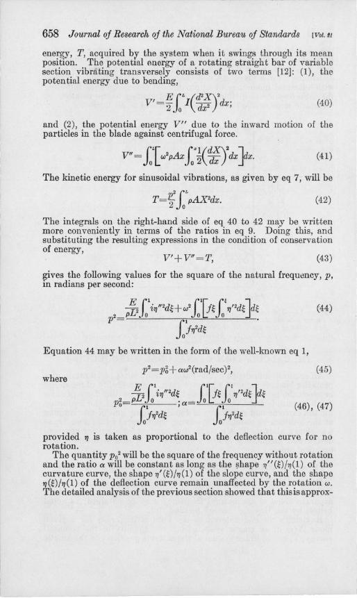
The straight lines in figures 18 and 19 were drawn to illustrate the determination of critical speeds leading to flexural vibrations in the fundamental mode and the second harmonic mode for blades of types 32 and 437 l.
Line a corresponds to exciting forces of the rotational frequency of the propeller, such as may be set up by a primary unbalance in the rotating system, or an asymmetry in the setting of one of the propeller blades which would cause a disturbance of propeller-rotation frequency in the airflow. This line does not intersect any of the bladefrequency curves since the blade frequency, j, is always higher than the frequency of rotation, n, due to the finite flexural rigidity of the blade.
Line b corresponds to exciting forces h~ving twice the rotational frequency of the propeller. Such excitation may exist in a two-blade
0/ ~ ~ ~ :rl7;P.~
,...-l.-,.-- /
// '/ L(L~ !j~(I7OnIC 1/ :/'d Seconcp
./
/' V -6
/ /. ,/ ,/ ./
I ~ / ,/'" ~ / /.'" ,/ -~~~
/ // 'Z..-;fi dc !(1Jerda/ Cl Fun " -.:::--
v ~ -:? v -l-
I -/At. ~ ...... - i
o 4«J 6'a? ROO 16m cO?o c4t70 Prqoeller ¥.%'d, revolt/po/ls jJer ml/7C1!e
FIGURE 18.- Critical speeds for flexural vibrations with fundamental mode and second harmonic mode, blade type 32.
Curve a,/=n; curve b,/=2n; curve c./=3n; curve d./=3.5n; and curve e,/=7n.
propeller in which each tip passes clo~e to a part of the airplane structure once per revolution. An exciting couple of twice the frequency of rotation will act on a two-blade propeller of an airplane flying in a curved path due to the gyroscopic couple [13] required to change the direction of the angular momentum of the propeller-engine combination during the turn.
Line c may enter in a three-blade propeller in which each tip passes once during a revolution close to a structural part of the airplane.
Line d corresponds to the princjpal variation in the gas-pressure torque (3 Yz times per revolution) for a single-row seven-cylinder engine with direct drive.
Line e corresponds to the principal variation in the gas-pressure torque (7 times per revolution) for a double-row 14-cylinder engine with direct drive.
664 Journal oj Research oj the National Bureau oj Standards [Vol. tl
In geared engines one would have to multiply the frequency of the unbalanced torque components in the engine by the gear ratio to obtain the frequency of the torque pulsations acting on the propeller hub.
The regions within which a critical speed may lie which leads to flexural vibrations in the fundamental mode or the second harmonic mode, are indicated by vertical shading. In the case of a blade of type 32, figure 18 indicates two dangerous regions for propellers rotating between 1,000 and 2,000 rpm. Unbalanced torques from the individual cylinders in a double-row 14-cylinder engine may lead to a resonant tip vibration at a speed somewhere between 1,080 and 1,200 rpm. Torque variations of the second order may excite resonant
IOcr' /VV
lei V
<%t!J j ~
V ",1()~ I~ ~ V ~
&:t(J 5e~~ !y; Z /. ~
,/ ,/
/ // /'.L. ~ V c 9 I---4700 l-
I /v v l:::: g .IJ4 ~ I ::v:.-~r£ifa!., j0.
?a?O I~z f-1-'. 1--_ hoy
~ f:::- - !II o 400 clO j, /600 c ~?o
P/"OjJe/kr ~eed, revo/vhol7s per mmvle FIGURE 19.-Critical speeds for flexural vibrat?:ons with fundamental mode and
second harmonic mode, blade type 4371. Curve a.f=n; curve b,f=2n; curve c,f=3n; curve d.f=3.5n; and curve e.f=7n.
vibrations. in the fundamental mode somewhere between 1,340 and 1,640 rpm.
In the case of a blade of type 4371, figure 19 indicates two dangerous regions for propellers rotating between 1,000 and 2,000 rpm. i;! Resonant vibrations in the fundamental mode may be excited by second order torque variations at a speed somewhere between 1,080 and 1,500 rpm. Resonant tip vibrations may be excited by 3 ;~-order torque variations due to the firing in the individual cylinders of a single-row seven-cylinder engine at a speed somewhere between21,800: and 2,300 rpm.
It should be emphasized that the above discussion is only intended as an illustrative example, and that it does not give a complete picture of all possible critical speeds that may be expected in a propeller of the type 32 and type 4371. Figures 18 and 19 do not contain the higher harmonics of flexural vibration which may be the cause of some tip failures in service [14]. Another omission is that mode in which the
Ramberg] Levv Vibration oj Rotating Propeller Blade 665
propeller vibrates as a torsion pendulum with the crankshaft as elastic member. Its frequency in this mode may be calculated by wellestablished methods [15]; it is nearly independent of the speed of rotation and will, therefore, be represented as a horizontal straight line in figures 18 and 19. Another mode that may be important in some cases is the torsional mode of the blade about its longitudinal axis. The frequency of this mode will be very high for all except very thin blades, such as solid-steel propeller blades.
A further limitation which must be kept in mind in applying diagrams of the type of figures 18 and 19 is that they neglect the coupling between different modes of vibration. The effect of coupling between the flexural vibrations of a propeller blade and the torsional vibration of the propeller about the crankshaft has been investigated for certain idealized cases by Carter [16].
In spite of all the limitations to which the diagrams in figures 18 and 19 are subject, their introduction may serve a useful purpose in pointing out the possibility of a large uncertainty in the critical speed corresponding to a small uncertainty in the natural frequencies of a propeller. If all natural modes of vibrations were included in the figures, it is probable that only a small portion of the service range of speeds would lie outside the possibility of resonance.
One will always have to contend with the presence of one or more critical speeds somewhere in the service range. It would be of some help if the location of these critical speeds could be determined much more accurately by experiment or otherwise than is possible with a chart such as figures 18 or 19, but it would be far better if the intensity of the periodic exciting forces acting on the propeller were reduced so that the stresses set up at a critical speed would lie below the endurance limit of the material. Adequate vibration insulation of the engine from the propeller would, for instance, reduce the excitation corresponding to curves e and d in figures 18 and 19 to a low figure and may prevent fatigue failures due to tip vibration in the second harmonic mode.
IV. COMPARISON OF NATURAL MODES FOR AFFINE PROPELLER BLADES
The work involved in obtaining a solution for a natural flexural mode of a given propeller blade is too great for routine calculation. Complete solutions will probably be carried out for only a few characteristic types of propeller blades. This makes it important to find a model rule which would permit application of these particular solutions to propeller blades of other materials and of shapes that are affine 3 to the shape of one of the propeller blades that has been studied in detail.
A model rule for predicting the natural frequencies of a given propeller blade from the frequency- of a propeller blade of affine shape has already been stated and applled by Theodorsen [9] . Theodorsen
, Two propeller blades. 1 and 2. are considered to be afllne in sbape if the surface!l(xl. 1/1. ZI) =0 of the first blade may be transformed to tbe surface j, (T,. 1/,. z,) =0 of the second by a linear transformation of tbe coordinates such that for corresponding points X,=aXI. Y,=f3l1 .. 2,='Y ZI. where a.f3. 'Y ure constants. This may be expressed more conCisely in mathematical terms by stating that tbe two surfaces may be written in the form! (x. v. 2)=0 and f (a x.f3 v. 'Y 2)=0. where a.f3. 'Yare constants.
- -- ------
666 Journal oj Research oj the National Bureau oj Standards [Vol. 11
states that the frequency of a given mode of flexural vibration of similar propeller blades will vary as the ratio
DV. L2 ' (48)
where L is the length of the blade, D is a quantity representative of the thickness, say the diameter of the blade at the hub, and V. = (Ejp) 1/2
is the velocity of longitudinal sound vibrations in the blade material. For rotating propellers, Theodorsen derived the following model
rule by proceeding from the frequency equation, eq 1. "The relative increase in frequency due to centrifugal force in similar 4 propellers is the same for the same value of the quantity
DV. LV/
(49)
where VT is the tip velocity of the propeller." The use of the approximate relation eq 1 as a proof for eq 49 is permissible in view of the excellent agreement between eq 1 and the more exact solution (see fig. 16 and 17) .
The model rules in eq 48 and 49 were derived for the flexural frequencies of propeller blades only. It is not safe, without further investigation, to conclude that they will give the conditions under which the flexural modes and hence the stress-distributions of two affine propellers are the same. An answer to this question for the idealized straight propeller blades, at least (see p. 641), may be obtained by determining under what conditions the deflection curves X1(Xl) and X 2(X2) of two affine propellers satisfy the same differential equation, 8 or 10. If Xl and X 2 satisfy the same equation at all points along the two propeller blades and if the conditions of restraint are the same, Xl and X 2 must be proportional to each other according to eq 8 and the deflection curves and stress-distribution curves must be the same for the two blades.
Let a, f3, 'Y be the ratios of affinity for length, breadth, and thickness dimensions of the two affine propeller blades, that is,
(50)
where L is the length of the blade and band c are respectively the breadth and thickness of the blade at a section a given percentage of the blade length from the tip. The subscripts 1 and 2 refer to the blades 1 and 2 that are being compared. The condition that the deflection curves 'YJI = Xt/L1, and 'YJ2=X2jL2 of the two blades satisfy the same differential equation, eq 10, is expressed by
• Theodorsen uses the word "similar" in [9J in place of the term "affine" used iu this paper.
RamberD] . LevI! Vibration oj Rotating Propeller Blade 667
The substitution of eq 52 in eq 51 shows that eq 51 is satisfied if
_ . ~(W2 VSl)2 -1 . ~4a.2 VBI)2_1 '11-7]2, 2 V. -, 2 v: -.
'Y WI 62 'Y I B2
These model rules may be written in the more convenient form:
(53)
The last equation is another statement of the model rule eq 48 that had already been given by Theodorsen for nonrotating propellers. Combining the second and third equations in eq 53, and noting that the tip speed, VT=Lw, leads to Theodorsen's model rule, eq 49, for the relative rise in frequency due to rotation.
It may be concluded that Theodorsen's model rules, eq 48 and 49, can be applied to calculate not only the frequency but also the shape of a natural flexural mode and hence the stress distribution of any idealized straight propeller blade from the corresponding natural mode of a "standard" propeller blade whose length, breadth, and thickness dimensions are affine to those of the propeller blade in question.
Although Theodorsen's model rules were derived for idealized straight blades only, they are probably also applicable to actual twisted blades vibrating with low-frequency flexural modes, in view of the agreement found between the observed stress distribution in a nonrotating blade and that calculated for the corresponding idealized straight blade [1], and in view of the agreement found between the frequencies observed by Theodorsen on a model of blade type 4371 and those calculated for the corresponding idealized straight blade (fig. 17).
An experimental investigation of the natural frequencies and the stress distributions in a rotating propeller blade vibrating in resonance with one of the flexural modes is highly desirable as a check on these conclusions as well as on the other theoretical results presented in this paper.
v. SUMMARY
The procedure for calculating the natural modes of flexural vibration of nonrotating propeller blades, which is described in RP764 has been extended to include the effect of rotation. The integral equations for the symmetrical modes of vibration of an idealized straight blade are given, in particular, for the cases of rigid clamping at the hub and zero clamping at the hub. These equations were solved numerically for aluminum-alloy propeller blades of two typical designs designated as type 32 and type 4371 rotating at speeds which cover the range of service speeds and vibrating with the fundamental flexural mode and with the second harmonic flexural mode (with a node near the tip).
The effect of rotation in the operating range (1,000 to 2,000 rpm) on the maximum stress amplitude per unit tip deflection for the fundamental mode was not more than 13 percent. It is sufficient for approximate calculations to take the resultant stress in a rotating blade vibrating with a given tip amplitude as the sum of the static stress due to centrifugal force and steady air forces and a sinusoidally varying stress whose amplitude is equal to that for the fundamental of the same blade vibrating without rotation with the given tip amplitude.
--------------------~------~-.- -- -. --
668 Journal of Research of the National Bureau of Standards [Vol.!1
Application of the same procedure to the second harmonic mode leads to a still better approximation because of the decrease in the relative importance of centrifugal force at the higher flexural modes. There may be a shift towards the hub of as much as 20 percent of the blade length in the location of the point of maximum stress amplitude in those cases in which the stress for no rotation decreases slowly on the hub side of the point of maximum stress amplitude.
The natural frequencies of a rotating propeller blade vibrating flexurally can be calculated by solving the integral equations. This is usually too cumbersome for practice and it is unnecessary since an excellent and convenient approximation to the frequencies obtained in this manner follows from Rayleigh's method by substituting the deflection curve of the propeller blade for no rotation in the expressions for potential and kinetic energy. Rayleigh's method was used to calculate the natural frequencies of the fundamental mode and the second harmonic mode for both types of propeller blades and for the two end conditions of rigid clamping and no clamping at the center of the hub. The frequency of the two flexural modes was found to change 9 to 13 percent in passing from no clamping to rigid clamping. Observed values of natural frequency for the fundamental mode and the second harmonic mode of a model blade of type 4371 which were obtained by Theodorsen at the Langley Memorial Laboratory were found to lie inside the narrow band bounded by the curves for rigid clamping and no clamping.
A displacement of the point of clamping from the center of the hub toward the tip such as may be expected due to the finite length of hub clamp will slightly increase the natural frequency of flexural vibrations. This calls for a correction to RP764 [1], where the opposite conclusion had been reached due to computational error.
The natural frequencies determined by Rayleigh's method may be used to calculate the critical speeds for flexural vibration. Unfortunately, it appears that a given error in the natural frequency of the blade may introduce several times that error in the critical speed, so that the calculated regions containing a critical speed may cover a considerable range of speeds.
Both the natural frequencies for flexural vibration and the stress distribution of a given idealized straight propeller blade may be obtained from the observed frequencies and stress distributions of a model blade that is affine to the blade in question by making use of the two model relations which were first applied by Theodorsen to calculate the frequencies of a propeller blade of type 4371 from a model blade having the same length and width dimensions but having one-tenth the thickness of the prototype. .
The above results are based upon theoretical reasoning and hence upon certain idealizing assumptions that can only be realized approximately in an actual propeller blade in flight. An experimental investigation of the natural frequencies and the stress distributions in a rotating propeller blade vibrating in resonance with one of the flexural modes is highly desirable as a check on these predictions of the theory and to establish the modes of vibration which are actually important in setting up severe alternating stresses in a propeller. More experiments are needed to determine the effects of twist on the natural flexural modes; existing tests have shown this effect to be small only for two nonrotating blades and for the fundamental and second
Ramberu] LevU Vibration of Rotating Propeller Blade 669
harmonic frequencies of one rotating model blade. Experiment only can give the actual amplitudes of the resonant vibrations; the theory may be of assistance in deducing the amplitude of stresses throughout the blade from the vibration amplitude measured at a convenient point. The carbon resistance strain pick-ups recently developed by A. V. deForest at the Massachusetts Institute of Technology may make an adequate experimental study of propeller vibration possible in the near future.
The authors of this paper acknowledge the assistance and advice received from other members of the engineering mechanics section of this Bureau. In particular, they express their appreciation to W. M. Bleakney for his penetrating criticisms, which have resulted in a more general and a more rigorous presentation of the mathematical theory involved.
VI. REFERENCES
[1] Walter Ramberg, Paul S. BailiE, and Mack J. West, A method jor determining stresses in a nonrotating propeller blade vibrating with a natural frequency, J. Research NBS H, 189 (1935) RP 764.
[2] A. Berry, On the vibrations of a uniform rod rotating uniformly about one end, which is encastTtl, T ech. Rep. Brit. Aero. Research Comm. 2, 748-752 (1918-19) Rep. & Memo. 488.
[3] H. A. Webb and L. Swain, Vibration speeds of airscrew blades, Tech. Rep. Brit. Aero. Research Comm. 2, 753 (1918-19) Rep. & Memo. 626.
[4] R. V. Southwell and B. S. Gough, On the free transverse vibrations of airscrew blades, Tech. Rep. Brit. Aero. Research Comm. 1, 358-369 (1921-22) Rep. & Memo. 766.
[5] A. Fage, An experimental study oj the vibrations in the blades and shaft of an airscrew, Tech. Rep. Brit. Aero. Research Comm. 585-600 (1925- 26) Rep. & Memo. 967.
[6] K. Hohenemser, Beitrag zur Dynamik des elastischen Stabes mit Anwendung auf den Propeller, Z. Flugtech. Motorluftschiffahrt 23. 37 (1932).
[7] M. Hansen and G. Mesmer, Luftschraubenschwingungen, Z. Flugtech. Motorluftschiffahrt. 24, 298 (1933).
[8] F. Liebers, Zur Berechnung der 3 tiefsten Biegefrequenzen der umlaufenden Schraube, Luftfahrtforsch. 12, 155-160 (1935).
[9] T. Theodorsen, Propelier vib'rations and the effect of the centrifugal force, Nat. Adv. Comm. Aero. Tech. Note 516 (1935).
[10] Lord Rayleigh, Theory of Sound, 1, par. 89. (Macmillan & Co. Ltd. London, 1896). .
[11] S. Timoshenko, Strength of Materials, p. 306 (D. Van Nostrand Co. Inc., New York, N . Y., 1930).
[12] S. Timoshenko, Vibration Problems in Engineering, par. 50 (D. Van Nostrand Co. Inc., New York, N. Y., 1928).
[13] M. Santillan, Forces d'inertie d'un sysMme et mouvement d'entrainement Compt. rend. 196, 1159 (1933).
[14] Frank W. Caldwell, Propellers for aircraft engines of high power output, J. Aero. Sci. 5, 37 (1937).
[15] S. Timoshenko, Vibration Problems in Engineering, par. 31 (D. Van Nostrand Co. Inc., New York, N. Y., 1928).
[16] B. C. Carter, Airscrew blade vibration, J. Roy. Aero. Soc. 41, 749 (1937). [17] H. Reissner, Formaenderung, Spannung und kleine Schwingungen von Staeben
mit anfaenglicher Kruemmung und Verwindung, die um eine Querachse rotieren, Ing. Arch. 4, 557 (1933).
WASHINGTON, July 6, 1938.