principle stresses
TRANSCRIPT
842
© 2014 Pearson Education, Inc., Upper Saddle River, NJ. All rights reserved. This material is protected under all copyright laws as they currentlyexist. No portion of this material may be reproduced, in any form or by any means, without permission in writing from the publisher.
Stress Transformation Equations:
we obtain,
Ans.
Ans.
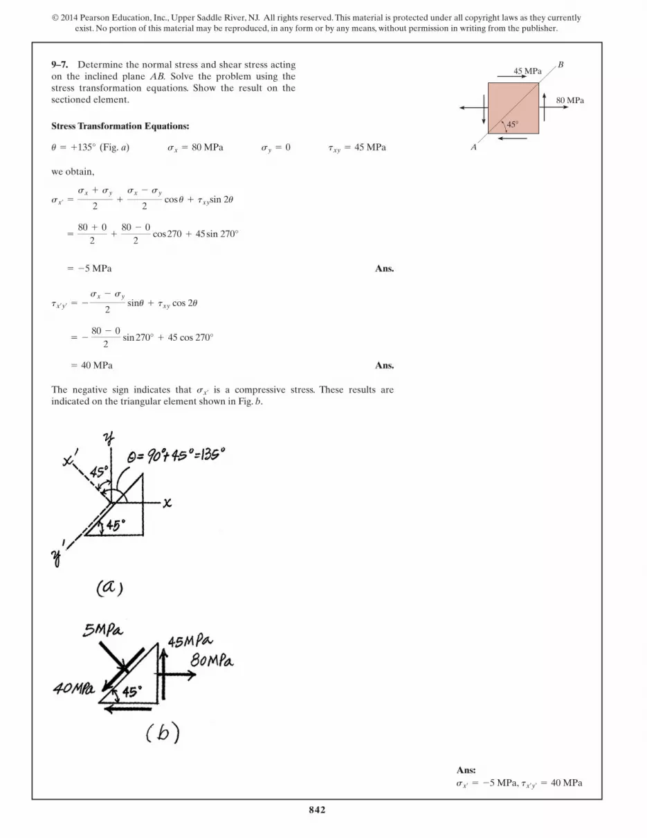
The negative sign indicates that is a compressive stress. These results areindicated on the triangular element shown in Fig. b.
sx¿
= 40 MPa
= - 80 - 0
2 sin 270° + 45 cos 270°
tx¿y¿= -
sx - sy
2 sinu + txy cos 2u
= -5 MPa
=
80 + 02
+
80 - 02
cos 270 + 45 sin 270°
sx¿=
sx + sy
2+
sx - sy
2 cos u + txysin 2u
u = +135° (Fig. a) sx = 80 MPa sy = 0 txy = 45 MPa
9–7. Determine the normal stress and shear stress actingon the inclined plane AB. Solve the problem using thestress transformation equations. Show the result on thesectioned element. 80 MPa
45 MPa
A
B
45�
Ans:sx¿
= -5 MPa, tx¿y¿= 40 MPa
Hibbeler_Chapter 9_836-894.qxd 2/19/13 2:57 PM Page 842

850
© 2014 Pearson Education, Inc., Upper Saddle River, NJ. All rights reserved. This material is protected under all copyright laws as they currentlyexist. No portion of this material may be reproduced, in any form or by any means, without permission in writing from the publisher.
a)
Ans.
Ans.
Orientation of principal stress:
Use Eq. 9–1 to determine the principal plane of and :
, where
Therefore Ans. and Ans.
b) Ans.
Ans.
Orientation of maximum in-plane shear stress:
Ans. and Ans.
By observation, in order to preserve equilibrium along AB, has to act in thedirection shown.
tmax
uy = 59.9°uy = -30.1°
tan 2uy =
-(sx - sy)>2txy
=
-(45 - (-60))>230
= -1.75
savg =
sx + sy
2=
45 + (-60)
2= -7.50 MPa
tmaxin - plane= Aasx - sy
2b2
+ txy2
= A a45 - (-60)2
b2+ 302
= 60.5 MPa
up2 = -75.1°up1 = 14.9°
=
45 + (-60)
2+
45 - (-60)
2 cos 29.74° + 30 sin 29.74° = 53.0 MPa
u = 14.87°sx¿=
sx + sy
2+
sx - sy
2 cos 2u + txy sin 2u
s2s1
-75.13°up = 14.87°,
tan 2up =
txy
(sx - sy)>2 =
30(45 - (-60))>2 = 0.5714
s2 = -68.0 MPa
s1 = 53.0 MPa
=
45 - 602
; Aa45 - (-60)2
b2+ (30)2
s1, 2 =
sx + sy
2; Aasx - sy
2b2
+ txy2
txy = 30 MPasy = -60 MPasx = 45 MPa
9–15. The state of stress at a point is shown on the element.Determine (a) the principal stress and (b) the maximum in-plane shear stress and average normal stress at the point.Specify the orientation of the element in each case.
60 MPa
30 MPa
45 MPa
Ans:
us = -30.1° and 59.9°
tmax in-plane
= 60.5 MPa,savg = -7.50 MPa,up1 = 14.9° and up2 = -75.1°,s1 = 53.0 MPa, s2 = -68.0 MPa,
Hibbeler_Chapter 9_836-894.qxd 2/19/13 5:33 PM Page 850
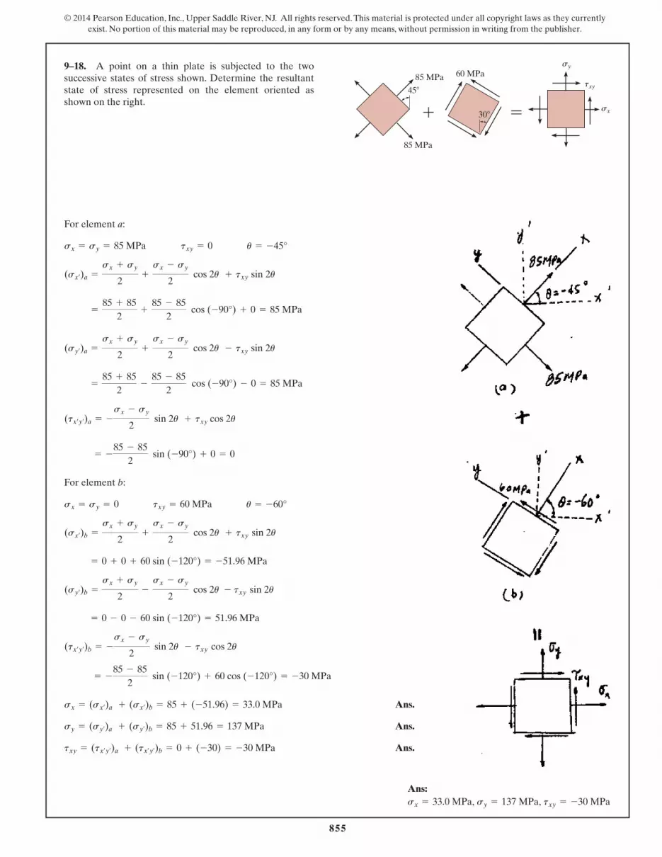
9–18. A point on a thin plate is subjected to the twosuccessive states of stress shown. Determine the resultantstate of stress represented on the element oriented asshown on the right.
For element a:
For element b:
Ans.
Ans.
Ans.txy = (tx¿y¿)a + (tx¿y¿
)b = 0 + (-30) = -30 MPa
sy = (sy¿)a + (sy¿
)b = 85 + 51.96 = 137 MPa
sx = (sx¿)a + (sx¿
)b = 85 + (-51.96) = 33.0 MPa
= -
85 - 852
sin (-120°) + 60 cos (-120°) = -30 MPa
(tx¿y¿)b = -
sx - sy
2 sin 2u - txy cos 2u
= 0 - 0 - 60 sin (-120°) = 51.96 MPa
(sy¿)b =
sx + sy
2-
sx - sy
2 cos 2u - txy sin 2u
= 0 + 0 + 60 sin (-120°) = -51.96 MPa
(sx¿)b =
sx + sy
2+
sx - sy
2 cos 2u + txy sin 2u
u = -60°txy = 60 MPasx = sy = 0
= -
85 - 852
sin (-90°) + 0 = 0
(tx¿y¿)a = -
sx - sy
2 sin 2u + txy cos 2u
=
85 + 852
-
85 - 852
cos (-90°) - 0 = 85 MPa
(sy¿)a =
sx + sy
2+
sx - sy
2 cos 2u - txy sin 2u
=
85 + 852
+
85 - 852
cos (-90°) + 0 = 85 MPa
(sx¿)a =
sx + sy
2+
sx - sy
2 cos 2u + txy sin 2u
u = -45°txy = 0sx = sy = 85 MPa
855
© 2014 Pearson Education, Inc., Upper Saddle River, NJ. All rights reserved. This material is protected under all copyright laws as they currentlyexist. No portion of this material may be reproduced, in any form or by any means, without permission in writing from the publisher.
85 MPa
60 MPa
30�
45�
85 MPa
��
sy
sx
txy
Ans:sx = 33.0 MPa, sy = 137 MPa, txy = -30 MPa
Hibbeler_Chapter 9_836-894.qxd 2/19/13 5:34 PM Page 855

863
© 2014 Pearson Education, Inc., Upper Saddle River, NJ. All rights reserved. This material is protected under all copyright laws as they currentlyexist. No portion of this material may be reproduced, in any form or by any means, without permission in writing from the publisher.
Ans.sy = -824 psi
550 = - a 400 - sy
2b sin 296° + 0
tx¿y¿= - asx - sy
2b sin 2u + txy cos 2u
9–25. The wooden block will fail if the shear stress actingalong the grain is 550 psi. If the normal stress ,determine the necessary compressive stress that willcause failure.
sy
sx = 400 psi
58�sx � 400 psi
sy
Ans:sy = -824 psi
Hibbeler_Chapter 9_836-894.qxd 2/19/13 5:36 PM Page 863

866
© 2014 Pearson Education, Inc., Upper Saddle River, NJ. All rights reserved. This material is protected under all copyright laws as they currentlyexist. No portion of this material may be reproduced, in any form or by any means, without permission in writing from the publisher.
Internal Loadings: Consider the equilibrium of the free-body diagram of thebracket’s left cut segment, Fig. a.
Normal and Shear Stresses: The normal stress is the combination of axial andbending stress. Thus,
The cross - sectional area and the moment of inertia about the z axis of the bracket’scross section is
For point B, . Then
Since no shear force is acting on the section,
The state of stress at point A can be represented on the element shown in Fig. b.
In - Plane Principal Stress: , , and . Since no shearstress acts on the element,
Ans.
The state of principal stresses can also be represented by the elements shown in Fig. b.
Maximum In - Plane Shear Stress:
Ans.
Orientation of the Plane of Maximum In - Plane Shear Stress:
Ans.us = 45° and 135°
tan 2us = -
Asx - sy B >2txy
= -
(-22.9 - 0)>20
= - q
tmax
in-plane= C¢sx - sy
2≤2
+ txy 2
= Ba -22.90 - 02
b2
+ 02= 11.5 ksi
s1 = sy = 0 s2 = sx = -22.90 ksi
txy = 0sy = 0sx = -22.90 ksi
tB = 0
sB =
30.875
-
(-12)(-1)
0.45573= -22.90 ksi
y = -1 in
I =
112
(1) A23 B -
112
(0.75) A1.53 B = 0.45573 in4
A = 1(2) - 0.75(1.5) = 0.875 in2
s =
N
A-
My
I
©MO = 0; 3(4) - M = 0 M = 12 kip # in
:+ ©Fx = 0; N - 3 = 0 N = 3 kip
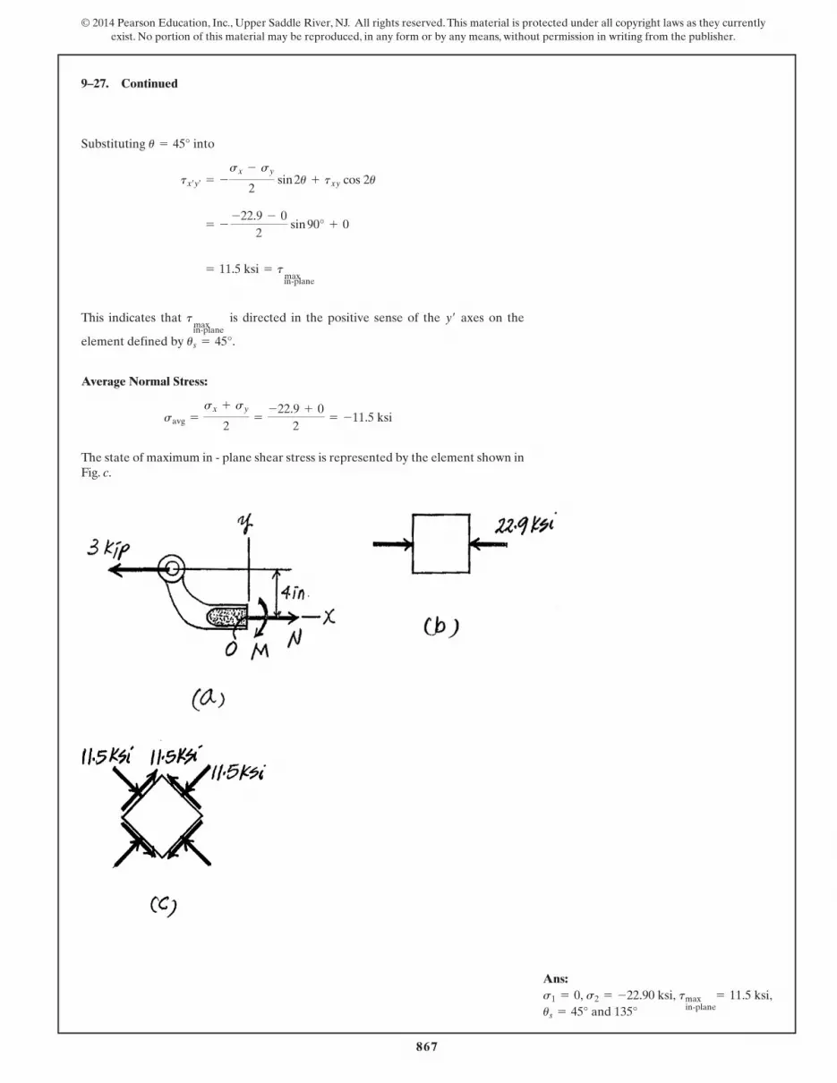
9–27. The bracket is subjected to the force of 3 kip.Determine the principal stress and maximum in-planeshear stress at point B on the cross section at section a–a.Specify the orientation of this state of stress and show theresults on elements.
a
a 3 in.3 kip3 kip
A
B
2 in.
1 in. 0.25 in.
0.25 in.
0.25 in.
Section a – a
Hibbeler_Chapter 9_836-894.qxd 2/19/13 5:37 PM Page 866
867
© 2014 Pearson Education, Inc., Upper Saddle River, NJ. All rights reserved. This material is protected under all copyright laws as they currentlyexist. No portion of this material may be reproduced, in any form or by any means, without permission in writing from the publisher.
9–27. Continued
Substituting into
This indicates that is directed in the positive sense of the axes on the
element defined by .
Average Normal Stress:
The state of maximum in - plane shear stress is represented by the element shown inFig. c.
savg =
sx + sy
2=
-22.9 + 02
= -11.5 ksi
us = 45°
y¿tmax
in-plane
= 11.5 ksi = tmax
in-plane
= - -22.9 - 0
2 sin 90° + 0
tx¿y¿= -
sx - sy
2 sin 2u + txy cos 2u
u = 45°
Ans:
us = 45° and 135°tmax
in-plane= 11.5 ksi,s1 = 0, s2 = -22.90 ksi,
Hibbeler_Chapter 9_836-894.qxd 2/19/13 2:58 PM Page 867

875
© 2014 Pearson Education, Inc., Upper Saddle River, NJ. All rights reserved. This material is protected under all copyright laws as they currentlyexist. No portion of this material may be reproduced, in any form or by any means, without permission in writing from the publisher.
Support Reactions: As shown on FBD(a).
Internal Forces and Moment: As shown on FBD(b).
Section Properties:
Normal Stress: Applying the flexure formula .
Shear Stress: Applying the shear formula
In-Plane Principal Stresses: , , and for point A. Sinceno shear stress acts on the element.
Ans.
Ans.
and for point B. Applying Eq. 9-5
Ans.s1 = 24.0 MPa s2 = -24.0 MPa
= 0 ; 24.0
= 0 ; 20 + (-24.0)2
s1,2 =
sx + sy
2; Casx - sy
2b2
+ t2xy
txy = -24.0 MPasx = sy = 0
s2 = sy = -192 MPa
s1 = sx = 0
txy = 0sy = -192 MPasx = 0
tB =
24.0(103) C9.375(10- 6) D0.3125(10- 6)(0.03)
= 24.0 MPa
tA =
24.0(103)(0)
0.3125(10- 6)(0.03)= 0
t =
VQ
It
sB = -
2.40(103)(0)
0.3125(10- 6)= 0
sA = -
2.40(103)(0.025)
0.3125(10- 6)= -192 MPa
s = -
My
I
QB = y¿A¿ = 0.0125(0.025)(0.03) = 9.375 A10- 6 B m3
QA = 0
I =
112
(0.03) A0.053 B = 0.3125 A10- 6 B m4
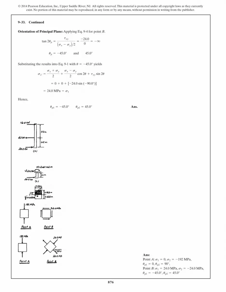
9–33. The clamp bears down on the smooth surface at E by tightening the bolt. If the tensile force in the bolt is 40 kN, determine the principal stress at points A and B andshow the results on elements located at each of thesepoints. The cross-sectional area at A and B is shown in theadjacent figure.
100 mm50 mm
A
E
BB
A
50 mm
30 mm
25 mm
100 mm
300 mm
Hibbeler_Chapter 9_836-894.qxd 2/19/13 2:58 PM Page 875
876
© 2014 Pearson Education, Inc., Upper Saddle River, NJ. All rights reserved. This material is protected under all copyright laws as they currentlyexist. No portion of this material may be reproduced, in any form or by any means, without permission in writing from the publisher.
9–33. Continued
Orientation of Principal Plane: Applying Eq. 9-4 for point B.
Substituting the results into Eq. 9-1 with yields
Hence,
Ans.up1 = -45.0° up2 = 45.0°
= 24.0 MPa = s1
= 0 + 0 + [-24.0 sin (-90.0°)]
sx¿=
sx + sy
2+
sx - sy
2 cos 2u + txy sin 2u
u = -45.0°
up = -45.0° and 45.0°
tan 2up =
txy
Asx - sy B >2 =
-24.00
= - q
Ans:Point A:
Point B:up1 = -45.0°, up2 = 45.0°
s1 = 24.0 MPa, s2 = -24.0 MPa,up1 = 0, up2 = 90°,
s1 = 0, s2 = -192 MPa,
Hibbeler_Chapter 9_836-894.qxd 2/19/13 2:58 PM Page 876
886
© 2014 Pearson Education, Inc., Upper Saddle River, NJ. All rights reserved. This material is protected under all copyright laws as they currentlyexist. No portion of this material may be reproduced, in any form or by any means, without permission in writing from the publisher.
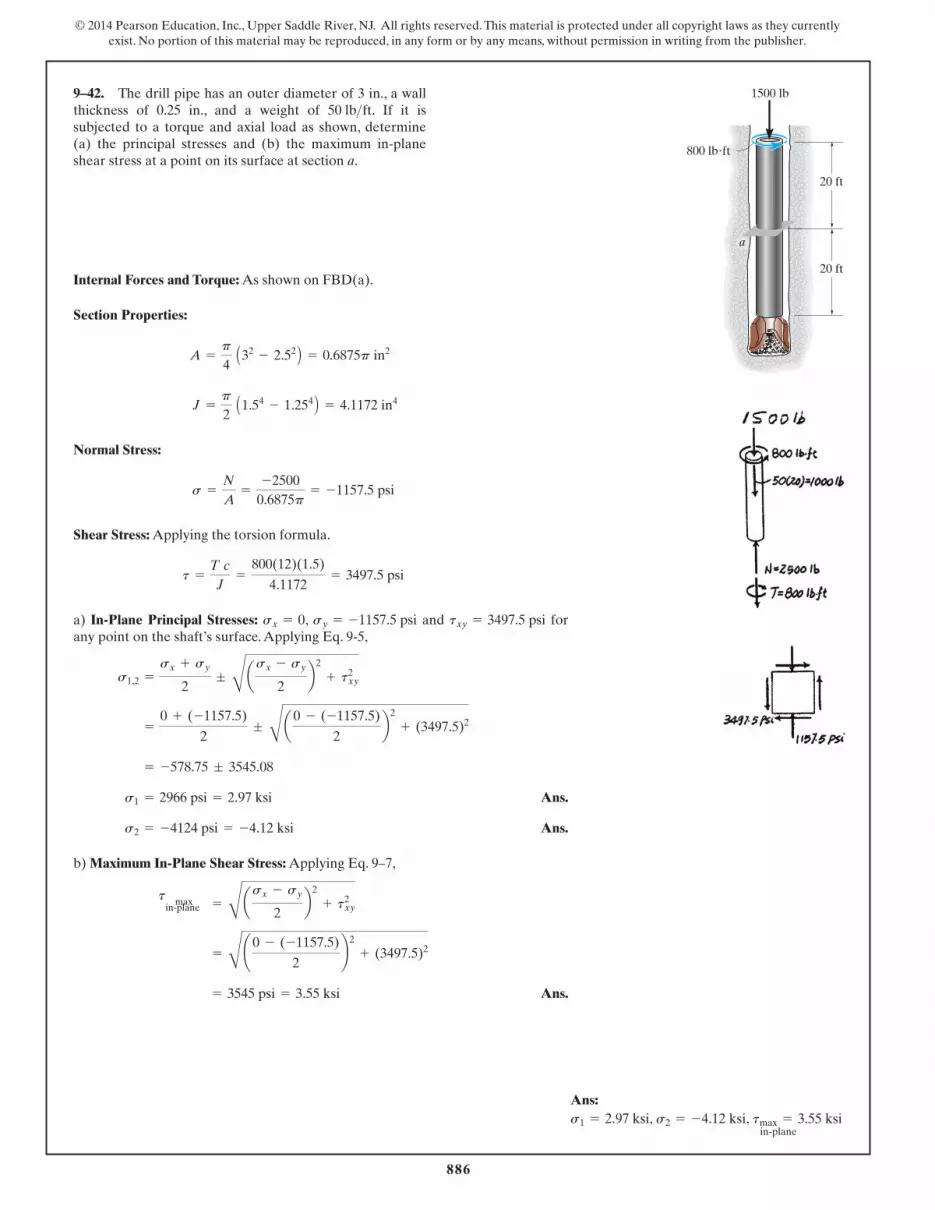
Internal Forces and Torque: As shown on FBD(a).
Section Properties:
Normal Stress:
Shear Stress: Applying the torsion formula.
a) In-Plane Principal Stresses: , and forany point on the shaft’s surface. Applying Eq. 9-5,
Ans.
Ans.
b) Maximum In-Plane Shear Stress: Applying Eq. 9–7,
Ans. = 3545 psi = 3.55 ksi
= C¢0 - (-1157.5)
2≤2
+ (3497.5)2
t max
in-plane = Casx - sy
2b2
+ txy2
s2 = -4124 psi = -4.12 ksi
s1 = 2966 psi = 2.97 ksi
= -578.75 ; 3545.08
=
0 + (-1157.5)
2; Ca0 - (-1157.5)
2b2
+ (3497.5)2
s1,2 =
sx + sy
2; Casx - sy
2b2
+ txy2
txy = 3497.5 psisy = -1157.5 psisx = 0
t =
T cJ
=
800(12)(1.5)
4.1172= 3497.5 psi
s =
N
A=
-25000.6875p
= -1157.5 psi
J =
p
2 A1.54
- 1.254 B = 4.1172 in4
A =
p
4 A32
- 2.52 B = 0.6875p in2
9–42. The drill pipe has an outer diameter of 3 in., a wallthickness of 0.25 in., and a weight of . If it issubjected to a torque and axial load as shown, determine (a) the principal stresses and (b) the maximum in-planeshear stress at a point on its surface at section a.
50 lb>ft800 lb�ft
20 ft
20 ft
1500 lb
a
Ans:s1 = 2.97 ksi, s2 = -4.12 ksi, tmax = 3.55 ksi
in-plane
Hibbeler_Chapter 9_836-894.qxd 2/19/13 2:58 PM Page 886
902
© 2014 Pearson Education, Inc., Upper Saddle River, NJ. All rights reserved. This material is protected under all copyright laws as they currentlyexist. No portion of this material may be reproduced, in any form or by any means, without permission in writing from the publisher.
Ans:
sy¿= 421 MPa
tx¿y¿= -354 MPa,sx¿
= -421 MPa,
Ans.
Ans.
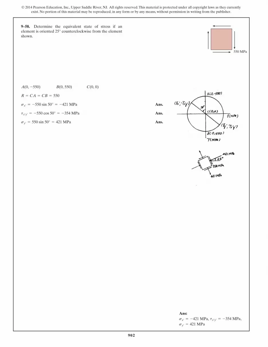
Ans.sy¿= 550 sin 50° = 421 MPa
tx¿y¿= -550 cos 50° = -354 MPa
sx¿= -550 sin 50° = -421 MPa
R = CA = CB = 550
C(0, 0)B(0, 550)A(0, -550)
9–58. Determine the equivalent state of stress if anelement is oriented 25° counterclockwise from the elementshown.
550 MPa
Hibbeler_Chapter 9_895-912.qxd 2/19/13 2:59 PM Page 902

905
© 2014 Pearson Education, Inc., Upper Saddle River, NJ. All rights reserved. This material is protected under all copyright laws as they currentlyexist. No portion of this material may be reproduced, in any form or by any means, without permission in writing from the publisher.
5 MPa
5 MPa
(a)
9–61. Draw Mohr’s circle that describes each of the followingstates of stress.
20 ksi
20 ksi
(b)
18 MPa
(c)
Hibbeler_Chapter 9_895-912.qxd 2/19/13 2:59 PM Page 905

910
© 2014 Pearson Education, Inc., Upper Saddle River, NJ. All rights reserved. This material is protected under all copyright laws as they currentlyexist. No portion of this material may be reproduced, in any form or by any means, without permission in writing from the publisher.
Section Properties:
Normal Stress: Since , thin wall analysis is valid.
Shear Stress: Applying the torsion formula,
Construction of the Circle: In accordance with the sign convention ,, and . Hence,
The coordinates for reference points A and C are
The radius of the circle is
In-Plane Principal Stress: The coordinates of point B and D represent and ,respectively.
Ans.
Ans.s2 = 6.175 - 23.2065 = -17.0 ksi
s1 = 6.175 + 23.2065 = 29.4 ksi
s2s1
R = 2(7.350 - 6.175)2+ 23.182
= 23.2065 ksi
A(7.350, -23.18) C(6.175, 0)
savg =
sx + sy
2=
7.350 + 5.002
= 6.175 ksi
txy = -23.18 ksisy = 5.00 ksisx = 7.350 ksi
t =
Tc
J=
20(12)(0.275)
2.84768(10- 3)= 23.18 ksi
shoop =
pr
t=
500(0.25)
0.025= 5.00 ksi
slong =
N
A+
pr
2t=
2000.013125p
+
500(0.25)
2(0.025)= 7.350 ksi
r
t=
0.250.025
= 10
J =
p
2 A0.2754
- 0.254 B = 2.84768 A10- 3 B in4
A = p A0.2752- 0.252 B = 0.013125p in2
9–65. The thin-walled pipe has an inner diameter of 0.5 in.and a thickness of 0.025 in. If it is subjected to an internalpressure of 500 psi and the axial tension and torsionalloadings shown, determine the principal stress at a point onthe surface of the pipe.
20 lb�ft 20 lb�ft
200 lb200 lb
Ans:, s2 = -17.0 ksis1 = 29.4 ksi
Hibbeler_Chapter 9_895-912.qxd 2/19/13 2:59 PM Page 910

926
© 2014 Pearson Education, Inc., Upper Saddle River, NJ. All rights reserved. This material is protected under all copyright laws as they currentlyexist. No portion of this material may be reproduced, in any form or by any means, without permission in writing from the publisher.
Internal Loadings: Considering the equilibrium of the free-body diagram of thewrench’s cut segment, Fig. a,
Section Properties: The moment of inertia about the z axis and the polar moment ofinertia of the wrench’s cross section are
Referring to Fig. b,
Normal and Shear Stress: The normal stress is caused by the bending stress due to
The shear stress at point B along the y axis is since . However, theshear stress along the z axis is caused by torsion.
The state of stress at point B is represented by the two-dimensional element shownin Fig. c.
(txz)B =
Tc
J=
600(0.5)
0.03125p= 3.056 ksi
(Qy)B(txy)B = 0
(sx)B = -
MzyB
Iz= -
100(0.5)
0.015625p= -1.019 ksi
Mz.
(Qy)B = 0
J =
p
2 (0.54) = 0.03125p in4
Iz =
p
4 (0.54) = 0.015625p in4
Mz = 100 lb # inMz - 50(2) = 0©Mz = 0;
T = -600 lb # inT + 50(12) = 0©Mx = 0;
Vy = -50 lbVy + 50 = 0©Fy = 0;
9–75. If the box wrench is subjected to the 50 lb force,determine the principal stress and maximum in-plane shearstress at point B on the cross section of the wrench atsection a–a. Specify the orientation of these states of stressand indicate the results on elements at the point.
aa
2 in.
12 in.
0.5 in.
50 lb
Section a – a
A B
Hibbeler_Chapter 9_913-933.qxd 2/19/13 3:00 PM Page 926

927
© 2014 Pearson Education, Inc., Upper Saddle River, NJ. All rights reserved. This material is protected under all copyright laws as they currentlyexist. No portion of this material may be reproduced, in any form or by any means, without permission in writing from the publisher.
Ans:, ,
, , us = 4.73°maxin-plane
= 3.10 ksitup2 = 49.7up1 = -40.3°,s2 = -3.61 ksis1 = 2.59 ksi
Construction of the Circle: and . Thus,
The coordinates of reference point A and the center C of the circle are
Thus, the radius of the circle is
Using these results, the circle is shown in Fig. d.
In-Plane Principal Stress: The coordinates of reference points B and D represent and , respectively.
Ans.
Ans.
Maximum In-Plane Shear Stress: The coordinates of point E represent themaximum in-plane stress, Fig. a.
Ans.tmaxin-plane
= R = 3.10 ksi
s2 = -0.5093 - 3.0979 = -3.61 ksi
s1 = -0.5093 + 3.0979 = 2.59 ksi
s2s1
R = CA = 2 [-1.019 - (-0.5093)]2+ (-3.056)2
= 3.0979 ksi
C(-0.5093, 0)A(-1.019, -3.056)
savg =
sx + sy
2=
-1.019 + 02
= -0.5093 ksi
txz = -3.056 ksisz = 0,sx = -1.019 ksi,
9–75. Continued
Hibbeler_Chapter 9_913-933.qxd 2/19/13 3:00 PM Page 927

942
© 2014 Pearson Education, Inc., Upper Saddle River, NJ. All rights reserved. This material is protected under all copyright laws as they currentlyexist. No portion of this material may be reproduced, in any form or by any means, without permission in writing from the publisher.
Ans:
maxin-plane
= 23.2 MPat
Power Transmission: Using the formula developed in Chapter 5,
Internal Torque and Force: As shown on FBD.
Section Properties:
Normal Stress:
Shear Stress: Applying the torsion formula.
Maximum In-Plane Principal Shear Stress: , , andfor any point on the shaft’s surface. Applying Eq. 9-7,
Ans. = 23.2 MPa
= Ca -25.06 - 02
b2
+ (19.56)2
t max
in-plane = Casx - sy
2b2
+ txy2
txy = 19.56 MPasy = 0sx = -25.06 MPa
t =
Tc
J=
60.0(103) (0.125)
0.3835 (10- 3)= 19.56 MPa
s =
N
A=
-1.23(106)
0.015625p= -25.06 MPa
J =
p
2 A0.1254 B = 0.3835 A10- 3 B m4
A =
p
4 A0.252 B = 0.015625p m2
T0 =
P
v=
0.900(106)
15= 60.0 A103 B N # m
P = 900 kW = 0.900 A106 B N # m>s
9–90. The solid propeller shaft on a ship extends outwardfrom the hull. During operation it turns at when the engine develops 900 kW of power. This causes athrust of on the shaft. If the shaft has adiameter of 250 mm, determine the maximum in-plane shearstress at any point located on the surface of the shaft.
F = 1.23 MN
v = 15 rad>s
T
0.75 mA
F
Hibbeler_Chapter 9_934-953.qxd 2/19/13 5:45 PM Page 942
945
© 2014 Pearson Education, Inc., Upper Saddle River, NJ. All rights reserved. This material is protected under all copyright laws as they currentlyexist. No portion of this material may be reproduced, in any form or by any means, without permission in writing from the publisher.
Ans:, , sy¿
= -3.39 ksitx¿y¿= 7.88 ksisx¿
= -0.611 ksi
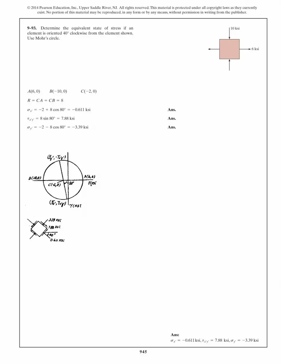
9–93. Determine the equivalent state of stress if anelement is oriented 40° clockwise from the element shown.Use Mohr’s circle.
Ans.
Ans.
Ans.sy¿= -2 - 8 cos 80° = -3.39 ksi
tx¿y¿= 8 sin 80° = 7.88 ksi
sx¿= -2 + 8 cos 80° = -0.611 ksi
R = CA = CB = 8
C(-2, 0)B(-10, 0)A(6, 0)
10 ksi
6 ksi
Hibbeler_Chapter 9_934-953.qxd 2/19/13 3:01 PM Page 945

946
© 2014 Pearson Education, Inc., Upper Saddle River, NJ. All rights reserved. This material is protected under all copyright laws as they currentlyexist. No portion of this material may be reproduced, in any form or by any means, without permission in writing from the publisher.
Ans:Point A: ,Point B: , s2 = -43.1 psis1 = 9.88 psi
s1 = 0, s2 = -1.20 ksi
9–94. The crane is used to support the 350-lb load.Determine the principal stresses acting in the boom atpoints A and B. The cross section is rectangular and has awidth of 6 in. and a thickness of 3 in. Use Mohr’s circle.
For point A:
Ans.
Ans.
For point B:
Ans.
Ans.s2 = -16.60 - 26.47 = -43.1 psi
s1 = -16.60 + 26.47 = 9.88 psi
R = 216.602+ 20.622
= 26.47
C(-16.60, 0)B(0, 20.62)A(-33.19, -20.62)
tB =
VQB
It=
247.49(13.5)
54(3)= 20.62 psi
sB = -
P
A= -
597.4918
= -33.19 psi
s2 = -1200 psi = -1.20 ksi
s1 = 0
tA = 0
sA = -
P
A-
My
I=
597.4918
-
1750(12)(3)
54= -1200 psi
QA = 0
QB = (1.5)(3)(3) = 13.5 in3
I =
112
(3)(63) = 54 in4A = 6(3) = 18 in2
5 ft
5 ft
45°
3 in.
AB
45°
Hibbeler_Chapter 9_934-953.qxd 2/19/13 5:46 PM Page 946