lte basic principle
TRANSCRIPT

www.DigiTrainee.com Company Confidential
LTE Basic Principle

www.DigiTrainee.com Company Confidential
Target
Participant know about LTE background Technology
Participant know about LTE Networks Architecture
Participant know about LTE Basic of Physical and Layer 2
Participant know about LTE Air Interface
Page 2

www.DigiTrainee.com Company Confidential
Content
Chapter 1 : LTE Protocol and Network Architecture Introduction
Chapter 2 : OFDM Introduction
Chapter 3 : LTE Pyhsical Layer and Structure Introduction
Chapter 4 : LTE Layer 2 Structure
Chapter 5 : LTE Key Technology Introduction
Page 3
www.DigiTrainee.com Company Confidential
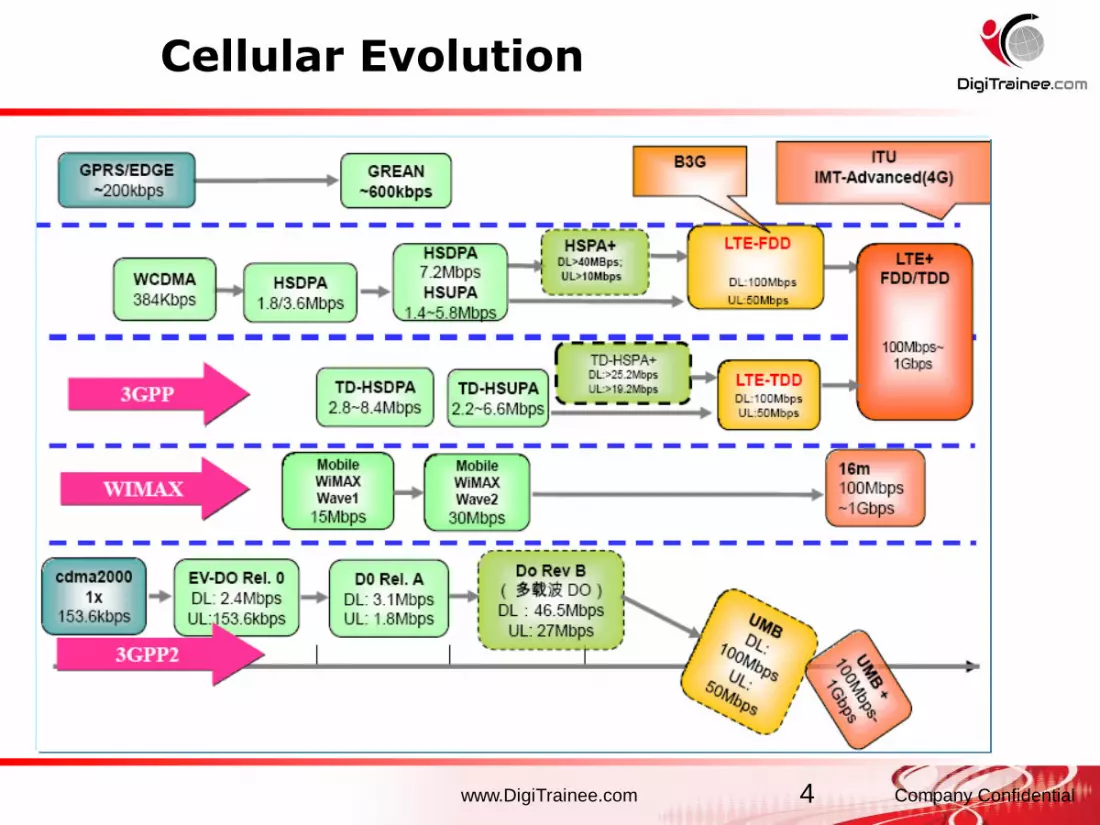
Cellular Evolution
4

www.DigiTrainee.com Company Confidential
What is new in LTE?
- New radio transmission schemes:
- OFDMA in downlink
Orthogonal Frequency Division Multiple
Access
- SC-FDMA in uplink
Single Carrier Frequency Division
Multiple Access
- MIMO Multiple Antenna Technology
- New radio protocol architecture:
- Complexity reduction
- Focus on shared channel operation, no
dedicated channels anymore
• New network architecture: flat
architecture– More functionality in the base
station (eNodeB)
– Focus on packet switched domain
• Important for Radio Planning– Frequency Reuse 1 No need for Frequency Planning
Importance of interference control
– No need to define neighbour lists
in LTE
– LTE requires Physical Layer Cell
Identity planning (504 physical
layer cell IDs organised into 168
groups of 3)

www.DigiTrainee.com Company Confidential
3GPP UMTS Evolution
• LTE is the next step in mobile radio communications after HSPA
• Evolution driven by data rate and latency requirements
WCDMA
384 kbps DL
384 kbps UL
RTT ~150 ms
CS/PS
HSDPA/HSUPA
14.4 Mbps peak DL
5.7 Mbps peak UL
RTT <100/50 ms
PS
HSPA +
28 Mbps peak DL
11 Mbps peak UL
RTT < 30 ms (2ms TTI)
PS
EUTRA
100 Mbps peak DL
50 Mbps peak UL
RTT ~10 ms
PS
UTRA evolution: WCDMA 5MHz UTRA Long Term Evolution:
up to 20 MHz BW
E-UTRA: Evolved UMTS Terrestrial Radio Access
www.DigiTrainee.com Company Confidential
Main LTE Requirements [3GPP TS25.913]
• Peak data rates of uplink/downlink 50/100 Mbps
• Reduced Latency:
- Enables round trip time <10 ms
• Ensure good level of mobility and security
- Optimized for low mobile speed but also support high mobile speed
• Frequency flexibility and bandwidth scalability:
- with 1.25, 2.5, 5, 10, 15 and 20 MHz allocations
• Improved Spectrum Efficiency:
- Capacity 2-4 times higher than with Release 6 HSPA
• Efficient support of the various types of services, especially from the PS domain
- Packet switched optimized
- Operation in FDD and TDD modes
• Improved terminal power efficiency
• Support for inter-working with existing 3G system and non-3GPP specified systems

www.DigiTrainee.com Company Confidential
LTE-Advanced (LTE-A) in 3GPP Release 10
• LTE- Advanced will be the main feature or 3GPP Release 10
• Formally submitted on the 7th October 2009 to the ITU for admission as a
candidate for IMT-Advanced (IMT-A)
• DL Spectral efficiency 2.4 bps/Hz/cell (1.7 bps/Hz/cell in LTE)
• Downlink data rates up to 1 Gbps (low mobility) and 100 Mbps (high
mobility)
• Uplink data rates up to 500Mbps
• Reduced Latency
• Uplink MIMO (2Tx antennas in UE) and further DL MIMO (up to 8x8) is
under study
• Backwards compatibility and interworking with LTE and other 3GPP
legacy systems
• First LTE-A networks expected +2014• Support for wider bandwidth (up to
100MHz) by carrier aggregation
• More info 3GPP TS36.814

www.DigiTrainee.com Company Confidential
4G LTE Network
9

www.DigiTrainee.com Company Confidential
Network Architecture Evolution
S- GW + P-GWGGSN
SGSN
RNC
Node B
(NB)
Direct tunnel
GGSN
SGSN
I-HSPA
MME
HSPA R7 HSPA R7 LTE R8
Node B +
RNC
Functionality
Evolved
Node B
(eNB)
GGSN
SGSN
RNC
Node B
(NB)
HSPA
HSPA R6
LTE
User plane
Control Plane
- Flat architecture: single network element in user
plane in radio network and core network

www.DigiTrainee.com Company ConfidentialPage 11
LTE Network Architecture
Main Network Element of LTE
- The E-UTRAN consists of e-NodeBs, providing the user
plane and control plane.
- The EPC consists of MME, S-GW and P-GW.
eNB
MME / S-GW MME / S-GW
eNB
eNB
S1
S1
S1
S1
X2
X2X
2
E-UTRAN
internet
eNB
RB Control
Connection Mobility Cont.
eNB Measurement
Configuration & Provision
Dynamic Resource
Allocation (Scheduler)
PDCP
PHY
MME
S-GW
S1
MAC
Inter Cell RRM
Radio Admission Control
RLC
E-UTRAN EPC
RRC
Mobility
Anchoring
EPS Bearer Control
Idle State Mobility
Handling
NAS Security
P-GW
UE IP address
allocation
Packet Filtering
RRC: Radio Resource Control
PDCP: Packet Data Convergence Protocol
RLC: Radio Link Control
MAC: Medium Access Control
PHY: Physical layer
EPC: Evolved Packet Core
MME: Mobility Management Entity
S-GW: Serving Gateway
P-GW: PDN Gateway
Compare with traditional 3G network, LTE
architecture becomes much more simple
and flat, which can lead to lower
networking cost, higher networking
flexibility and shorter time delay of user
data and control signaling. Network Interface of LTE
The e-NodeBs are interconnected with each other by means of the X2 interface, which enabling
direct transmission of data and signaling.
S1 is the interface between e-NodeBs and the EPC, more specifically to the MME via the S1-MME
and to the S-GW via the S1-U
www.DigiTrainee.com Company ConfidentialPage 12
internet
eNB
RB Control
Connection Mobility Cont.
eNB Measurement
Configuration & Provision
Dynamic Resource
Allocation (Scheduler)
PDCP
PHY
MME
S-GW
S1
MAC
Inter Cell RRM
Radio Admission Control
RLC
E-UTRAN EPC
RRC
Mobility
Anchoring
EPS Bearer Control
Idle State Mobility
Handling
NAS Security
P-GW
UE IP address
allocation
Packet Filtering
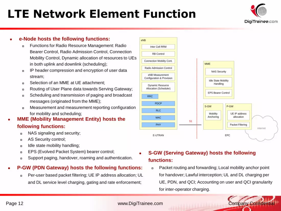
e-Node hosts the following functions:
Functions for Radio Resource Management: Radio
Bearer Control, Radio Admission Control, Connection
Mobility Control, Dynamic allocation of resources to UEs
in both uplink and downlink (scheduling);
IP header compression and encryption of user data
stream;
Selection of an MME at UE attachment;
Routing of User Plane data towards Serving Gateway;
Scheduling and transmission of paging and broadcast
messages (originated from the MME);
Measurement and measurement reporting configuration
for mobility and scheduling;
MME (Mobility Management Entity) hosts the
following functions:
NAS signaling and security;
AS Security control;
Idle state mobility handling;
EPS (Evolved Packet System) bearer control;
Support paging, handover, roaming and authentication. S-GW (Serving Gateway) hosts the following
functions:
Packet routing and forwarding; Local mobility anchor point
for handover; Lawful interception; UL and DL charging per
UE, PDN, and QCI; Accounting on user and QCI granularity
for inter-operator charging.
P-GW (PDN Gateway) hosts the following functions:
Per-user based packet filtering; UE IP address allocation; UL
and DL service level charging, gating and rate enforcement;
LTE Network Element Function

www.DigiTrainee.com Company ConfidentialPage 13
Introduction of LTE Radio Protocol Stack
Two Planes in LTE Radio Protocol:
- User-plane: For user data transfer
- Control-plane: For system signaling
transfer
Main Functions of User-plane:
- Header Compression
- Ciphering
- Scheduling
- ARQ/HARQ
eNB
PHY
UE
PHY
MAC
RLC
MAC
PDCPPDCP
RLC
eNB
PHY
UE
PHY
MAC
RLC
MAC
MME
RLC
NAS NAS
RRC RRC
PDCP PDCP
Main Functions of Control-plane:
RLC and MAC layers perform the same functions
as for the user plane
PDCP layer performs ciphering and integrity
protection
RRC layer performs broadcast, paging, connection
management, RB control, mobility functions, UE
measurement reporting and control
NAS layer performs EPS bearer management,
authentication, security control
User-plane protocol stack
Control-plane protocol stack
www.DigiTrainee.com Company ConfidentialPage 14
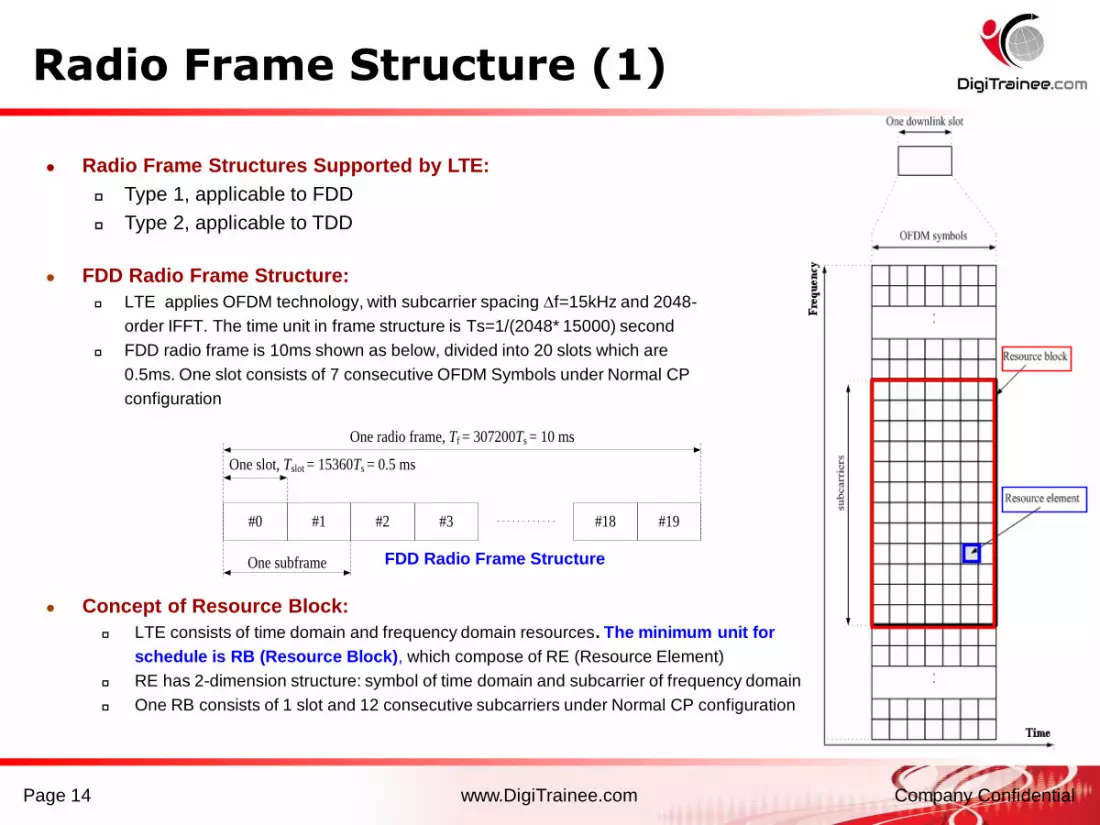
Radio Frame Structures Supported by LTE:
Type 1, applicable to FDD
Type 2, applicable to TDD
FDD Radio Frame Structure:
LTE applies OFDM technology, with subcarrier spacing f=15kHz and 2048-
order IFFT. The time unit in frame structure is Ts=1/(2048* 15000) second
FDD radio frame is 10ms shown as below, divided into 20 slots which are
0.5ms. One slot consists of 7 consecutive OFDM Symbols under Normal CP
configuration
#0 #1 #2 #3 #19#18
One radio frame, Tf = 307200Ts = 10 ms
One slot, Tslot = 15360Ts = 0.5 ms
One subframe FDD Radio Frame Structure
Concept of Resource Block:
LTE consists of time domain and frequency domain resources. The minimum unit for
schedule is RB (Resource Block), which compose of RE (Resource Element)
RE has 2-dimension structure: symbol of time domain and subcarrier of frequency domain
One RB consists of 1 slot and 12 consecutive subcarriers under Normal CP configuration
Radio Frame Structure (1)

www.DigiTrainee.com Company ConfidentialPage 15
TDD Radio Frame Structure:
- Applies OFDM, same subcarriers spacing and time
unit with FDD.
- Similar frame structure with FDD. radio frame is 10ms
shown as below, divided into 20 slots which are 0.5ms.
- The uplink-downlink configuration of 10ms frame are
shown in the right table.
One slot,
Tslot=15360Ts
GP UpPTSDwPTS
One radio frame, Tf = 307200Ts = 10 ms
One half-frame, 153600Ts = 5 ms
30720Ts
One subframe,
30720Ts
GP UpPTSDwPTS
Subframe #2 Subframe #3 Subframe #4Subframe #0 Subframe #5 Subframe #7 Subframe #8 Subframe #9
Uplink-downlink Configurations
Uplink-
downlink
configuration
Downlink-to-Uplink
Switch-point
periodicity
Subframe number
0 1 2 3 4 5 6 7 8 9
0 5 ms D S U U U D S U U U
1 5 ms D S U U D D S U U D
2 5 ms D S U D D D S U D D
3 10 ms D S U U U D D D D D
4 10 ms D S U U D D D D D D
5 10 ms D S U D D D D D D D
6 5 ms D S U U U D S U U D
DwPTS: Downlink Pilot Time Slot
GP: Guard Period
UpPTS: Uplink Pilot Time Slot
TDD Radio Frame Structure
D: Downlink subframe
U: Uplink subframe
S: Special subframe
Radio Frame Structure (2)

www.DigiTrainee.com Company ConfidentialPage 16
Radio Frame Structure (3)
CP Length Configuration:
- Cyclic Prefix is applied to eliminate ISI of OFDM.
- CP length is related with coverage radius.
Normal CP can fulfill the requirement of
common scenarios. Extended CP is for wide
coverage scenario.
- Longer CP, higher overheading.
ConfigurationDL OFDM CP
Length
UL SC-FDMA CP
Length
Sub-carrier
of each RB
Symbol of
each slot
Normal
CPf=15kHz
160 for slot #0
144 for slot #1~#6
160 for slot #0
144 for slot #1~#6 127
Extended
CP
f=15kHz 512 for slot #0~#5 512 for slot #0~#5 6
f=7.5kHz 1024 for slot #0~#2 NULL 24 (DL only) 3 (DL only)
CP Configuration
Slot structure under
Normal CP configuration
(△f=15kHz)
Slot structure under
Extended CP configuration
(△f=15kHz)
Slot structure under
Extended CP configuration
(△f=7.5kHz)

www.DigiTrainee.com Company ConfidentialPage 17
Brief Introduction of Physical Channels
Downlink Channels:
Physical Broadcast Channel (PBCH): Carries system information for
cell search, such as cell ID.
Physical Downlink Control Channel (PDCCH) : Carries the resource
allocation of PCH and DL-SCH, and Hybrid ARQ information.
Physical Downlink Shared Channel (PDSCH) : Carries the downlink
user data.
Physical Control Format Indicator Channel (PCFICH) : Carriers
information of the OFDM symbols number used for the PDCCH.
Physical Hybrid ARQ Indicator Channel (PHICH) : Carries Hybrid
ARQ ACK/NACK in response to uplink transmissions.
Physical Multicast Channel (PMCH) : Carries the multicast
information.
Uplink Channels:
Physical Random Access Channel (PRACH) : Carries the random
access preamble.
Physical Uplink Shared Channel (PUSCH) : Carries the uplink user
data.
Physical Uplink Control Channel (PUCCH) : Carries the HARQ
ACK/NACK, Scheduling Request (SR) and Channel Quality
Indicator (CQI), etc.
BCH PCH DL-SCHMCH
Downlink
Physical channels
Downlink
Transport channels
PBCH PDSCHPMCH PDCCH
Uplink
Physical channels
Uplink
Transport channels
UL-SCH
PUSCH
RACH
PUCCHPRACH
Mapping between downlink transport
channels and downlink physical channels
Mapping between uplink transport
channels and downlink physical
channels
Physical Layer
MAC Layer
Physical Layer
MAC Layer

www.DigiTrainee.com Company ConfidentialPage 18
Downlink Physical Channel
ScramblingModulation
mapper
Layer
mapperPrecoding
Resource element
mapper
OFDM signal
generation
Resource element
mapper
OFDM signal
generationScrambling
Modulation
mapper
layers antenna portscode words
Downlink Physical Channel Processing
scrambling of coded bits in each of the code words to be transmitted on a physical channel
modulation of scrambled bits to generate complex-valued modulation symbols
mapping of the complex-valued modulation symbols onto one or several transmission layers
precoding of the complex-valued modulation symbols on each layer for transmission on the antenna
ports
mapping of complex-valued modulation symbols for each antenna port to resource elements
generation of complex-valued time-domain OFDM signal for each antenna port
Modulation Scheme of
Downlink Channel
Shown at the right table
Phy ChModulation
SchemePhy Ch
Modulation
Scheme
PBCH QPSK PCFICH QPSK
PDCCH QPSK PHICH BPSK
PDSCH QPSK, 16QAM, 64QAM PMCH QPSK, 16QAM, 64QAM
www.DigiTrainee.com Company ConfidentialPage 19
Uplink Physical Channel
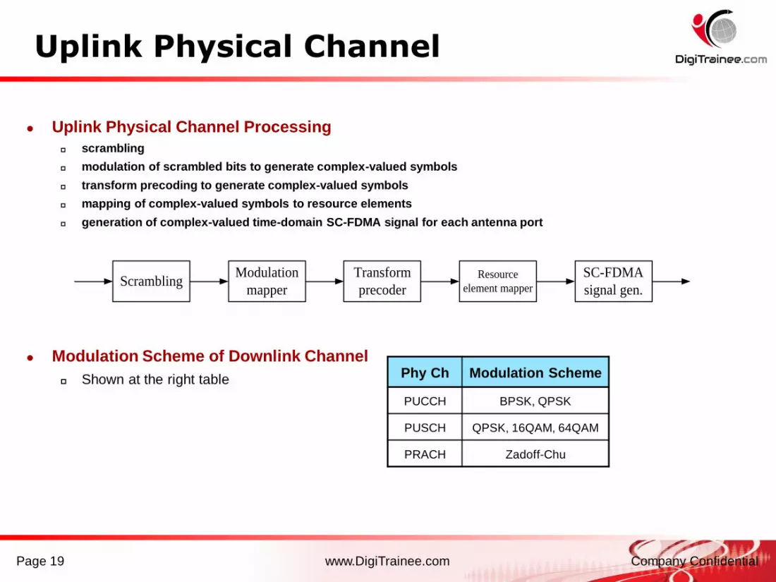
Uplink Physical Channel Processing
scrambling
modulation of scrambled bits to generate complex-valued symbols
transform precoding to generate complex-valued symbols
mapping of complex-valued symbols to resource elements
generation of complex-valued time-domain SC-FDMA signal for each antenna port
Modulation Scheme of Downlink Channel
Shown at the right table Phy Ch Modulation Scheme
PUCCH BPSK, QPSK
PUSCH QPSK, 16QAM, 64QAM
PRACH Zadoff-Chu
ScramblingModulation
mapper
Transform
precoder
Resource
element mapper
SC-FDMA
signal gen.

www.DigiTrainee.com Company ConfidentialPage 20
0l
0R
0R
0R
0R
6l 0l
0R
0R
0R
0R
6l
On
e a
nte
nn
a p
ort
Tw
o a
nte
nn
a p
ort
s
Resource element (k,l)
Not used for transmission on this antenna port
Reference symbols on this antenna port
0l
0R
0R
0R
0R
6l 0l
0R
0R
0R
0R
6l 0l
1R
1R
1R
1R
6l 0l
1R
1R
1R
1R
6l
0l
0R
0R
0R
0R
6l 0l
0R
0R
0R
0R
6l 0l
1R
1R
1R
1R
6l 0l
1R
1R
1R
1R
6l
Fo
ur
an
ten
na p
ort
s
0l 6l 0l
2R
6l 0l 6l 0l 6l
2R
2R
2R
3R
3R
3R
3R
even-numbered slots odd-numbered slots
Antenna port 0
even-numbered slots odd-numbered slots
Antenna port 1
even-numbered slots odd-numbered slots
Antenna port 2
even-numbered slots odd-numbered slots
Antenna port 3
Downlink Physical Signals (1)
Downlink RS (Reference Signal):
Similar with Pilot signal of CDMA. Used for downlink physical channel
demodulation and channel quality measurement (CQI)
Three types of RS in protocol. Cell-Specific Reference Signal is essential
and the other two types RS (MBSFN Specific RS & UE-Specific RS) are
optional.
Cell-Specific RS
Mapping in Time-
Frequency
Domain
On
e A
nte
nn
a P
ort
Tw
o A
nte
nn
a P
ort
sF
ou
r A
nte
nn
a P
ort
s
Antenna Port 0 Antenna Port 1 Antenna Port 2 Antenna Port 3
Characteristics:
Cell-Specific Reference Signals are generated from cell-
specific RS sequence and frequency shift mapping. RS is
the pseudo-random sequence transmits in the time-
frequency domain.
The frequency interval of RS is 6 subcarriers.
RS distributes discretely in the time-frequency domain,
sampling the channel situation which is the reference of DL
demodulation.
Serried RS distribution leads to accurate channel estimation,
also high overhead that impacting the system capacity.
MBSFN: Multicast/Broadcast over
a Single Frequency Network
RE
Not used for RS transmission on this antenna port
RS symbols on this antenna port
R1: RS transmitted in 1st ant port
R2: RS transmitted in 2nd ant port
R3: RS transmitted in 3rd ant port
R4: RS transmitted in 4th ant port

www.DigiTrainee.com Company ConfidentialPage 21
Synchronization Signal:
synchronization signals are used for time-frequency synchronization between UE and E-UTRAN during cell
search.
synchronization signal comprise two parts:
Primary Synchronization Signal, used for symbol timing, frequency synchronization and part of the
cell ID detection.
Secondary Synchronization Signal, used for detection of radio frame timing, CP length and cell group
ID.
Synchronization Signals Structure
Characteristics:
The bandwidth of the synchronization
signal is 62 subcarrier, locating in the
central part of system bandwidth,
regardless of system bandwidth size.
Synchronization signals are transmitted
only in the 1st and 11rd slots of every
10ms frame.
The primary synchronization signal is
located in the last symbol of the
transmit slot. The secondary
synchronization signal is located in the
2nd last symbol of the transmit slot.
Downlink Physical Signals (2)

www.DigiTrainee.com Company ConfidentialPage 22
Uplink RS (Reference Signal):
The uplink pilot signal, used for synchronization
between E-UTRAN and UE, as well as uplink
channel estimation.
Two types of UL reference signals:
DM RS (Demodulation Reference Signal),
associated with PUSCH and PUCCH transmission.
SRS (Sounding Reference Signal), without
associated with PUSCH and PUCCH transmission.
Characteristics: Each UE occupies parts of the system bandwidth since
SC-FDMA is applied in uplink. DM RS only transmits in
the bandwidth allocated to PUSCH and PUCCH.
The slot location of DM RS differs with associated
PUSCH and PUCCH format.
Sounding RS’s bandwidth is larger than that allocated to
UE, in order to provide the reference to e-NodeB for
channel estimation in the whole bandwidth.
Sounding RS is mapped to the last symbol of sub-frame.
The transmitted bandwidth and period can be
configured. SRS transmission scheduling of multi UE
can achieve time/frequency/code diversity.
DM RS associated with PUSCH is
mapped to the 4th symbol each slot
Time
Freq
Time
Freq
Time
Freq
DM RS associated with PUCCH
(transmits UL ACK signaling) is mapped
to the central 3 symbols each slot
DM RS associated with PUCCH
(transmits UL CQI signaling) is mapped
to the 2 symbols each slot
PUCCH is mapped to up &
down ends of the system
bandwidth, hopping between
two slots.
Allocated UL bandwidth of one UE
System bandwidth
Uplink Physical Signals
www.DigiTrainee.com Company ConfidentialPage 23
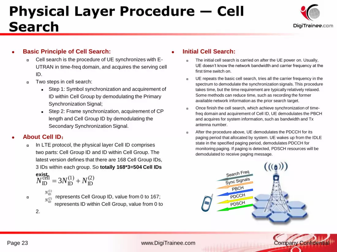
Basic Principle of Cell Search:
Cell search is the procedure of UE synchronizes with E-
UTRAN in time-freq domain, and acquires the serving cell
ID.
Two steps in cell search:
Step 1: Symbol synchronization and acquirement of
ID within Cell Group by demodulating the Primary
Synchronization Signal;
Step 2: Frame synchronization, acquirement of CP
length and Cell Group ID by demodulating the
Secondary Synchronization Signal.
About Cell ID:
In LTE protocol, the physical layer Cell ID comprises
two parts: Cell Group ID and ID within Cell Group. The
latest version defines that there are 168 Cell Group IDs,
3 IDs within each group. So totally 168*3=504 Cell IDs
exist.
represents Cell Group ID, value from 0 to 167;
represents ID within Cell Group, value from 0 to
2.
(2)ID
(1)ID
cellID 3 NNN
(1)IDN
(2)IDN
Initial Cell Search:
The initial cell search is carried on after the UE power on. Usually,
UE doesn’t know the network bandwidth and carrier frequency at the
first time switch on.
UE repeats the basic cell search, tries all the carrier frequency in the
spectrum to demodulate the synchronization signals. This procedure
takes time, but the time requirement are typically relatively relaxed.
Some methods can reduce time, such as recording the former
available network information as the prior search target.
Once finish the cell search, which achieve synchronization of time-
freq domain and acquirement of Cell ID, UE demodulates the PBCH
and acquires for system information, such as bandwidth and Tx
antenna number.
After the procedure above, UE demodulates the PDCCH for its
paging period that allocated by system. UE wakes up from the IDLE
state in the specified paging period, demodulates PDCCH for
monitoring paging. If paging is detected, PDSCH resources will be
demodulated to receive paging message.
Physical Layer Procedure — Cell Search

www.DigiTrainee.com Company ConfidentialPage 24
Basic Principle of Random Access :
Random access is the procedure of uplink
synchronization between UE and E-UTRAN.
Prior to random access, physical layer shall receive
the following information from the higher layers:
Random access channel parameters: PRACH
configuration, frequency position and preamble format,
etc.
Parameters for determining the preamble root sequences
and their cyclic shifts in the sequence set for the cell, in
order to demodulate the random access preamble.
Two steps in physical layer random access:
UE transmission of random access preamble
Random access response from E-UTRAN
Detail Procedure of Random Access:
Physical Layer procedure is triggered upon request of a
preamble transmission by higher layers.
The higher layers request indicates a preamble index, a
target preamble received power, a corresponding RA-RNTI
and a PRACH resource .
UE determines the preamble transmission power is
preamble target received power + Path Loss. The
transmission shall not higher than the maximum
transmission power of UE. Path Loss is the downlink path
loss estimate calculated in the UE.
A preamble sequence is selected from the preamble
sequence set using the preamble index.
A single preamble is transmitted using the selected preamble
sequence with calculated transmission power on the
indicated PRACH resource.
UE Detection of a PDCCH with the indicated RA-RNTI is
attempted during a window controlled by higher layers. If
detected, the corresponding PDSCH transport block is
passed to higher layers. The higher layers parse the
transport block and indicate the 20-bit grant.
RA-RNTI: Random Access Radio Network Temporary Identifier
Physical Layer Procedure — RandomAccess
www.DigiTrainee.com Company ConfidentialPage 25
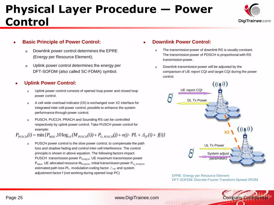
Basic Principle of Power Control:
Downlink power control determines the EPRE
(Energy per Resource Element);
Uplink power control determines the energy per
DFT-SOFDM (also called SC-FDMA) symbol.
Uplink Power Control:
Uplink power control consists of opened loop power and closed loop
power control.
A cell wide overload indicator (OI) is exchanged over X2 interface for
integrated inter-cell power control, possible to enhance the system
performance through power control.
PUSCH, PUCCH, PRACH and Sounding RS can be controlled
respectively by uplink power control. Take PUSCH power control for
example:
PUSCH power control is the slow power control, to compensate the path
loss and shadow fading and control inter-cell interference. The control
principle is shown in above equation. The following factors impact
PUSCH transmission power PPUSCH: UE maximum transmission power
PMAX, UE allocated resource MPUSCH, initial transmission power PO_PUSCH,
estimated path loss PL, modulation coding factor △TF and system
adjustment factor f (not working during opened loop PC)
UE report CQI
DL Tx Power
EPRE: Energy per Resource Element
DFT-SOFDM: Discrete Fourier Transform Spread OFDM
f(i)}(i)ΔPLα(j)(j)P(i))(M,{P(i)P TFO_PUSCHPUSCHMAXPUSCH 10log10min
Downlink Power Control:
The transmission power of downlink RS is usually constant.
The transmission power of PDSCH is proportional with RS
transmission power.
Downlink transmission power will be adjusted by the
comparison of UE report CQI and target CQI during the power
control.
X2
UL Tx Power
System adjust
parameters
Physical Layer Procedure — Power Control

www.DigiTrainee.com Company ConfidentialPage 26
Layer 2 is split into the following layers:
MAC (Medium Access Control) Layer
RLC (Radio Link Control ) Layer
PDCP (Packet Data Convergence Protocol )
Layer
Main Functions of Layer 2:
Header compression, Ciphering
Segmentation and concatenation, ARQ
Scheduling, priority handling, multiplexing
and demultiplexing, HARQ
Segm.
ARQ etc
Multiplexing UE1
Segm.
ARQ etc...
HARQ
Multiplexing UEn
HARQ
BCCH PCCH
Scheduling / Priority Handling
Logical Channels
Transport Channels
MAC
RLCSegm.
ARQ etc
Segm.
ARQ etc
PDCP
ROHC ROHC ROHC ROHC
Radio Bearers
Security Security Security Security
...
Multiplexing
...
HARQ
Scheduling / Priority Handling
Transport Channels
MAC
RLC
PDCP
Segm.
ARQ etc
Segm.
ARQ etc
Logical Channels
ROHC ROHC
Radio Bearers
Security Security
Layer 2 Structure for DL Layer 2 Structure for UL
Overview of LTE Layer 2
www.DigiTrainee.com Company ConfidentialPage 27
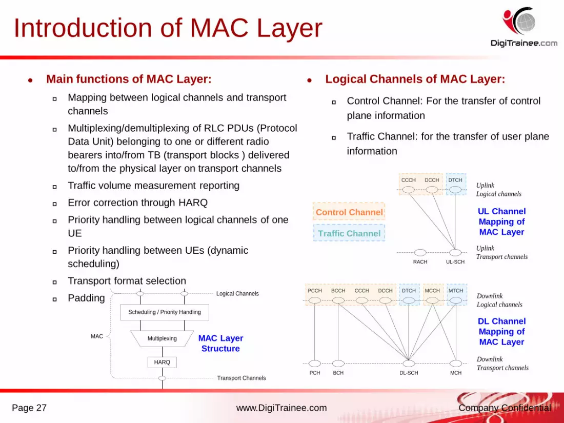
Main functions of MAC Layer:
Mapping between logical channels and transport
channels
Multiplexing/demultiplexing of RLC PDUs (Protocol
Data Unit) belonging to one or different radio
bearers into/from TB (transport blocks ) delivered
to/from the physical layer on transport channels
Traffic volume measurement reporting
Error correction through HARQ
Priority handling between logical channels of one
UE
Priority handling between UEs (dynamic
scheduling)
Transport format selection
Padding
Logical Channels of MAC Layer:
Control Channel: For the transfer of control
plane information
Traffic Channel: for the transfer of user plane
information
Multiplexing
...
HARQ
Scheduling / Priority Handling
Transport Channels
MAC
RLC
PDCP
Segm.
ARQ etc
Segm.
ARQ etc
Logical Channels
ROHC ROHC
Radio Bearers
Security Security
MAC Layer
Structure
BCCHPCCH CCCH DCCH DTCH MCCH MTCH
BCHPCH DL-SCH MCH
Downlink
Logical channels
Downlink
Transport channels
CCCH DCCH DTCH
UL-SCHRACH
Uplink
Logical channels
Uplink
Transport channels
UL Channel
Mapping of
MAC Layer
Control Channel
Traffic Channel
DL Channel
Mapping of
MAC Layer
Introduction of MAC Layer
www.DigiTrainee.com Company ConfidentialPage 28
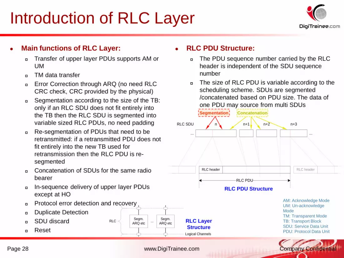
Main functions of RLC Layer:
Transfer of upper layer PDUs supports AM or
UM
TM data transfer
Error Correction through ARQ (no need RLC
CRC check, CRC provided by the physical)
Segmentation according to the size of the TB:
only if an RLC SDU does not fit entirely into
the TB then the RLC SDU is segmented into
variable sized RLC PDUs, no need padding
Re-segmentation of PDUs that need to be
retransmitted: if a retransmitted PDU does not
fit entirely into the new TB used for
retransmission then the RLC PDU is re-
segmented
Concatenation of SDUs for the same radio
bearer
In-sequence delivery of upper layer PDUs
except at HO
Protocol error detection and recovery
Duplicate Detection
SDU discard
Reset
RLC PDU Structure:
The PDU sequence number carried by the RLC
header is independent of the SDU sequence
number
The size of RLC PDU is variable according to the
scheduling scheme. SDUs are segmented
/concatenated based on PDU size. The data of
one PDU may source from multi SDUs
Multiplexing
...
HARQ
Scheduling / Priority Handling
Transport Channels
MAC
RLC
PDCP
Segm.
ARQ etc
Segm.
ARQ etc
Logical Channels
ROHC ROHC
Radio Bearers
Security Security
RLC Layer
Structure
AM: Acknowledge Mode
UM: Un-acknowledge
Mode
TM: Transparent Mode
TB: Transport Block
SDU: Service Data Unit
PDU: Protocol Data Unit
RLC PDU Structure
RLC header
RLC PDU
......
n n+1 n+2 n+3RLC SDU
RLC header
Segmentation Concatenation
Introduction of RLC Layer

www.DigiTrainee.com Company ConfidentialPage 29
Main functions of PDCP Layer:
Functions for User Plane:
Header compression and decompression:
ROHC
Transfer of user data: PDCP receives PDCP
SDU from the NAS and forwards it to the RLC
layer and vice versa
In-sequence delivery of upper layer PDUs at
handover for RLC AM
Duplicate detection of lower layer SDUs at
handover for RLC AM
Retransmission of PDCP SDUs at handover for
RLC AM
Ciphering
Timer-based SDU discard in uplink
Functions for Control Plane:
Ciphering and Integrity Protection
Transfer of control plane data: PDCP receives
PDCP SDUs from RRC and forwards it to the
RLC layer and vice versa
PDCP PDU Structure:
PDCP PDU and PDCP header are octet-
aligned
PDCP header can be either 1 or 2 bytes long
Multiplexing
...
HARQ
Scheduling / Priority Handling
Transport Channels
MAC
RLC
PDCP
Segm.
ARQ etc
Segm.
ARQ etc
Logical Channels
ROHC ROHC
Radio Bearers
Security SecurityPDCP Layer
Structure
ROHC: Robust Header Compression
PDCP SDUPDCP header
PDCP PDU
PDCP PDU Structure
Introduction of PDCP Layer

www.DigiTrainee.com Company ConfidentialPage 30
Data Transfer in Layer 1 and Layer 2
Data from the upper layer are headed and packaged, sent to the lower layer, vice
versa.
Scheduler effect in the RLC, MAC and Physical Layers. User data packages are
multiplexed in the MAC Layer.
CRC in Physical Layer.
Summary of Data Flow in Layer 1 & 2

www.DigiTrainee.com Company ConfidentialPage 31
Downlink MIMO
MIMO is supported in LTE downlink to achieve spatial
multiplexing, including single user mode SU-MIMO
and multi user mode MU-MIMO.
In order to improve MIMO performance, pre-coding is
used in both SU-MIMO and MU-MIMO to
control/reduce the interference among spatial
multiplexing data flows.
The spatial multiplexing data flows are scheduled to
one single user In SU-MIMO, to enhance the
transmission rate and spectrum efficiency. In MU-
MIMO, the data flows are scheduled to multi users and
the resources are shared within users. Multi user gain
can be achieved by user scheduling in the spatial
domain.
Uplink MIMO
Due to UE cost and power consumption, it is difficult to
implement the UL multi transmission and relative power
supply. Virtual-MIMO, in which multi single antenna UEs
are associated to transmit in the MIMO mode. Virtual-
MIMO is still under study.
Scheduler assigns the same resource to multi users.
Each user transmits data by single antenna. System
separates the data by the specific MIMO demodulation
scheme.
MIMO gain and power gain (higher Tx power in the
same time-freq resource) can be achieved by Virtual-
MIMO. Interference of the multi user data can be
controlled by the scheduler, which also bring multi user
gain.
Pre-coding vectors
User k data
User 2 data
User 1 data
Channel Information
User1
User2
User k
Scheduler Pre-coder
S1
S2
Pre-coding vectors
User k data
User 2 data
User 1 data
Channel Information
User1
User2
User k
Scheduler Pre-coder
S1
S2
User 1 data
Channel Information
User1
User2
User kScheduler
MIMO
DecoderUser k data
User 1 data
User 1 data
Channel Information
User1
User2
User kScheduler
MIMO
DecoderUser k data
User 1 data
MU-MIMO Virtual-MIMO
MIMO

www.DigiTrainee.com Company ConfidentialPage 32
User Multiplexing and Scheduling
Large system bandwidth (10/15/20MHz) of LTE will
facing the problem of frequency selected fading. The
fading characteristic on subcarriers of one user can be
regarded as same, but different in further subcarriers.
Select better subcarriers for specific user according to
the fading characteristic. User diversity can be
achieved to increase spectrum efficiency.
The LTE schedule period is one or more TTI.
The channel propagation information is feed back to e-
NodeB through the uplink. Channel quality identity is
the overheading of system. The less, the better.
Schedule and Link Auto-adaptation
Link Auto-adaptation
LTE support link auto-adaptation in time-domain
and frequency-domain. Modulation scheme is
selected based on the channel quality in
time/frequency-domain.
In CDMA system, power control is one important link
auto-adaptation technology, which can avoid
interference by far-near effect. In LTE system, user
multiplexed by OFDM technology. Power control is
used to reduce the uplink interference from adjacent
cell, to compensate path loss. It is one type of slow
link auto-adaptation scheme.
Channel Propagation Fading User Multiplexing and Scheduling
www.DigiTrainee.com Company Confidential
2. OFDM – SC FDMA Introduction
Page 33

www.DigiTrainee.com Company ConfidentialPage 34
OFDM & OFDMA
OFDM (Orthogonal Frequency Division Multiplexing)
is a modulation multiplexing technology, divides the
system bandwidth into orthogonal subcarriers. CP is
inserted between the OFDM symbols to avoid the ISI.
OFDMA is the multi-access technology related with
OFDM, is used in the LTE downlink. OFDMA is the
combination of TDMA and FDMA essentially.
Advantage: High spectrum utilization efficiency due to
orthogonal subcarriers need no protect bandwidth.
Support frequency link auto adaptation and
scheduling. Easy to combine with MIMO.
Disadvantage: Strict requirement of time-frequency
domain synchronization. High PAPR.
DFT-S-OFDM & SC-FDMA
DFT-S-OFDM (Discrete Fourier Transform
Spread OFDM) is the modulation multiplexing
technology used in the LTE uplink, which is
similar with OFDM but can release the UE PA
limitation caused by high PAPR. Each user is
assigned part of the system bandwidth.
SC-FDMA(Single Carrier Frequency Division
Multiple Accessing)is the multi-access
technology related with DFT-S-OFDM.
Advantage: High spectrum utilization efficiency
due to orthogonal user bandwidth need no
protect bandwidth. Low PAPR.
The subcarrier assignment scheme includes
Localized mode and Distributed mode.
LTE Key Technology — OFDMA &
SC-FDMA
User 1
User 2
User 3
Sub-carriers
TTI: 1ms
Frequency
System Bandwidth
Sub-band:12Sub-carriers
Time
User 1
User 2
User 3
User 1
User 2
User 3
Sub-carriers
TTI: 1ms
Frequency
System Bandwidth
Sub-band:12Sub-carriers
Time
Sub-carriers
TTI: 1ms
Frequency
Time
System Bandwidth
Sub-band:12Sub-carriers
User 1
User 2
User 3
Sub-carriers
TTI: 1ms
Frequency
Time
System Bandwidth
Sub-band:12Sub-carriers
User 1
User 2
User 3
User 1
User 2
User 3

www.DigiTrainee.com Company Confidential
OFDM Basics
- Transmits hundreds or even thousands of separately modulated radio signals using orthogonal subcarriers spread across a wideband channel
Orthogonality:
The peak (centre
frequency) of one
subcarrier …
…intercepts the
‘nulls’ of the
neighbouring
subcarriers
15 kHz in LTE:
fixed
Total transmission bandwidth
35

www.DigiTrainee.com Company Confidential
Contd..
- Data is sent in parallel across the set of subcarriers, each subcarrier only
transports a part of the whole transmission
- The throughput is the sum of the data rates of each individual (or used)
subcarriers while the power is distributed to all subcarriers
- FFT (Fast Fourier Transform) is used to create the orthogonal subcarriers. The
number of subcarriers is determined by the FFT size (by the bandwidth)
- In LTE, these subcarriers are separated 15kHZ
Power
frequency
bandwidth

www.DigiTrainee.com Company Confidential
Cyclic Prefix (CP) and Guard Time
Note: CP represents an
overhead resulting in symbol
rate reduction.
Having a CP reduces the
bandwidth efficiency but the
benefits in terms of minimising
the ISI compensate for it
t
total symbol time T(s)
Guard Time
T(g)
CP
T(g)Useful symbol
time T(b)
• Consists in copying the last part of a symbol shape for a duration of guard-time
and attaching it in front of the symbol
• CP needs to be longer than the channel multipath delay spread.
• A receiver typically uses the high correlation between the Cyclic Prefix (CP) and
the last part of the following symbol to locate the start of the symbol and begin
then with decoding
• 2 CP options in LTE:– Normal CP: for small cells or with short multipath delay spread
– Extended CP: designed for use with large cells or those with long delay profiles

www.DigiTrainee.com Company Confidential
OFDMA Symbol
- OFDMA is an extension of OFDM technique to allow multiple user transmissions
and it is used in other systems like Wi-Fi, DVB and WiMAX
- OFDMA Symbol is the Time period occupied by the modulation symbols on all
subcarriers. Represents all the data being transferred in parallel at a point in
time
• OFDM symbol duration including CP
is aprox. 71.4 µs (*)
– Long duration when compared with
3.69µs for GSM and 0.26µs for
WCDMA allowing a good CP duration Robust for mobile radio channel with
the use of guard internal/cyclic prefix
– Symbol length without considering
CP: 66.67µs (1/15kHz)
(*) normal CP
www.DigiTrainee.com Company Confidential
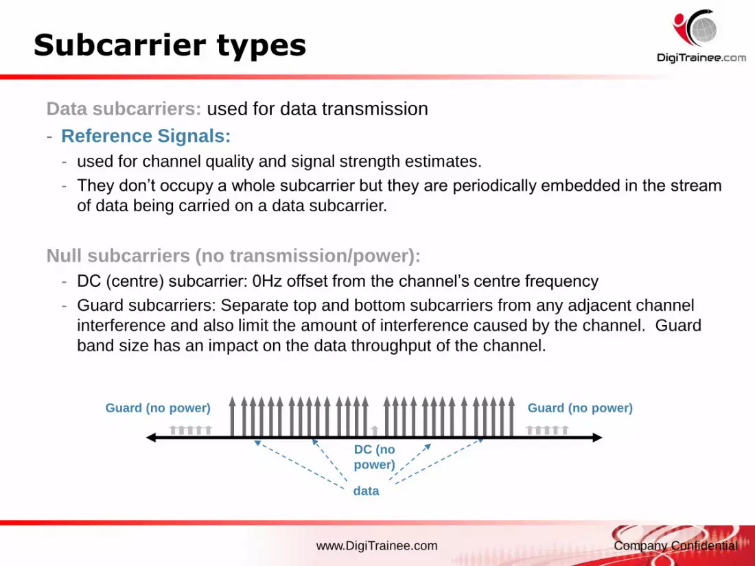
Subcarrier types
Data subcarriers: used for data transmission
- Reference Signals:
- used for channel quality and signal strength estimates.
- They don’t occupy a whole subcarrier but they are periodically embedded in the stream
of data being carried on a data subcarrier.
Null subcarriers (no transmission/power):
- DC (centre) subcarrier: 0Hz offset from the channel’s centre frequency
- Guard subcarriers: Separate top and bottom subcarriers from any adjacent channel
interference and also limit the amount of interference caused by the channel. Guard
band size has an impact on the data throughput of the channel.
Guard (no power)
DC (no
power)
data
Guard (no power)
www.DigiTrainee.com Company ConfidentialPresentation
/ Author /
Date
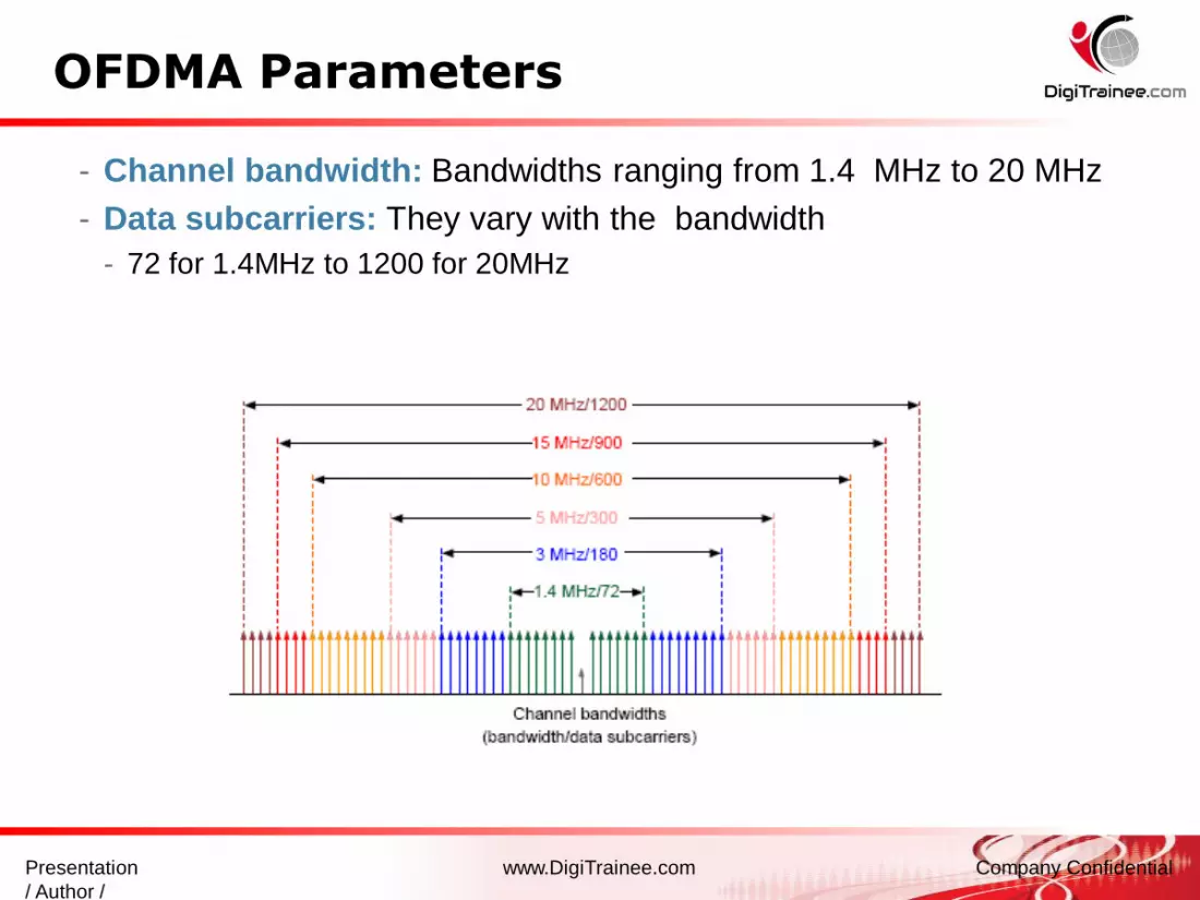
OFDMA Parameters
- Channel bandwidth: Bandwidths ranging from 1.4 MHz to 20 MHz
- Data subcarriers: They vary with the bandwidth
- 72 for 1.4MHz to 1200 for 20MHz
www.DigiTrainee.com Company Confidential
OFDMA Parameters
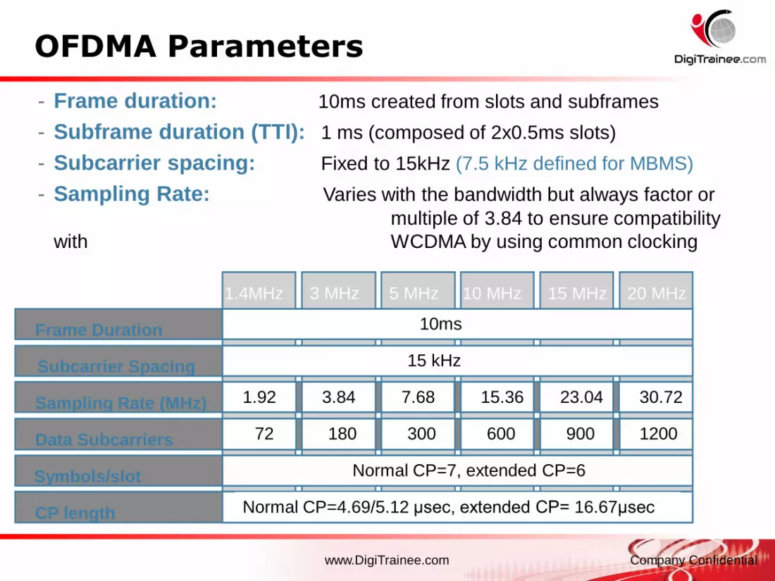
- Frame duration: 10ms created from slots and subframes
- Subframe duration (TTI): 1 ms (composed of 2x0.5ms slots)
- Subcarrier spacing: Fixed to 15kHz (7.5 kHz defined for MBMS)
- Sampling Rate: Varies with the bandwidth but always factor or
multiple of 3.84 to ensure compatibility
with WCDMA by using common clocking
Frame Duration
Subcarrier Spacing
Sampling Rate (MHz)
Data Subcarriers
Symbols/slot
CP length
1.4MHz 3 MHz 5 MHz 10 MHz 15 MHz 20 MHz
10 ms
15 kHz
Normal CP=7, extended CP=6
Normal CP=4.69/5.12 μsec, extended CP= 16.67μsec
1.92 3.84 7.68 15.36 23.04 30.72
72 180 300 600 900 1200
10ms

www.DigiTrainee.com Company Confidential
Peak-to-Average Power Ratio in OFDMA
The transmitted power is the sum of the
powers of all the subcarriers
- Due to large number of subcarriers, the
peak to average power ratio (PAPR)
tends to have a large range
- The higher the peaks, the greater the
range of power levels over which the
power amplifier is required to work
- Having a UE with such a PA that works
over a big range of powers would be
expensive
- Not best suited for use with mobile
(battery-powered) devices
www.DigiTrainee.com Company Confidential
Uplink Air Interface
Page 43

www.DigiTrainee.com Company Confidential
SC-FDMA in UL
- Single Carrier Frequency Division Multiple Access:
Transmission technique used for Uplink
• Variant of OFDM that reduces the PAPR:
- Combines the PAR of single-carrier system with the
multipath resistance and flexible subcarrier
frequency allocation offered by OFDM
- It can reduce the PAPR between 6…9dB compared
to OFDMA
- TS36.201 and TS36.211 provide the mathematical
description of the time domain representation of an
SC-FDMA symbol.
- Reduced PAPR means lower RF hardware
requirements (power amplifier)
SC
-FD
MA
OF
DM
A

www.DigiTrainee.com Company Confidential
SC-FDMA and OFDMA Comparison (1/2)
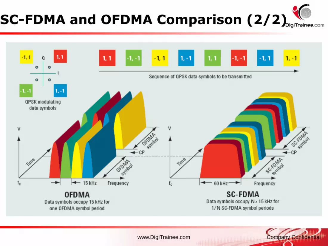
- OFDMA transmits data in parallel across multiple subcarriers
- SC-FDMA transmits data in series employing multiple subcarriers
- In the example:
- OFDMA: 6 modulation symbols (01,10,11,01,10 and 10) are transmitted per OFDMA
symbol, one on each subcarrier
- SC-FDMA: 6 modulation symbols are transmitted per SC-FDMA symbol using all
subcarriers per modulation symbol. The duration of each modulation symbol is 1/6th of
the modulation symbol in OFDMA
OFDMA SC-FDMA
www.DigiTrainee.com Company Confidential
SC-FDMA and OFDMA Comparison (2/2)

www.DigiTrainee.com Company Confidential
DL Physical Channels
PBCH:
- To broadcast the MIB (Master Information
Block), RACH parameters
PDSCH:
- Carries user data, paging data, SIBs (cell
status, cell IDs, allowed services…)
PMCH:
- For multicast traffic as MBMS services
PHICH:
- Carries H-ARQ Ack/Nack messages from eNB
to UE in response to UL transmission
There are no dedicated channels in LTE, neither in UL nor DL
PCFICH:
• Carries details of PDCCH’s format (e.g.# of symbols)
PDCCH: • Carries the DCI (DL control information): resource assignment messages for downlink
capacity allocations on PDSCH and scheduling grants for uplink allocations on PUSCH and
TCP commands for UL

www.DigiTrainee.com Company Confidential
Reference Signals: OFDMA Channel Estimation
- Channel estimation in LTE is based on reference signals (like CPICH
functionality in WCDMA)
- Reference signals position in time domain is fixed (0 and 4 for Type 1 Frame)
whereas in frequency domain it depends on the Cell ID
- In case more than one antenna is used (e.g. MIMO) the Resource elements
allocated to reference signals on one antenna are DTX on the other antennas
- Reference signals are modulated to identify the cell to which they belong.
Antenna 1 Antenna 2
subcarr
iers
symbols 60 symbols 60
subcarrie
rs
www.DigiTrainee.com Company Confidential
Synchronization Signals allocation (DL)
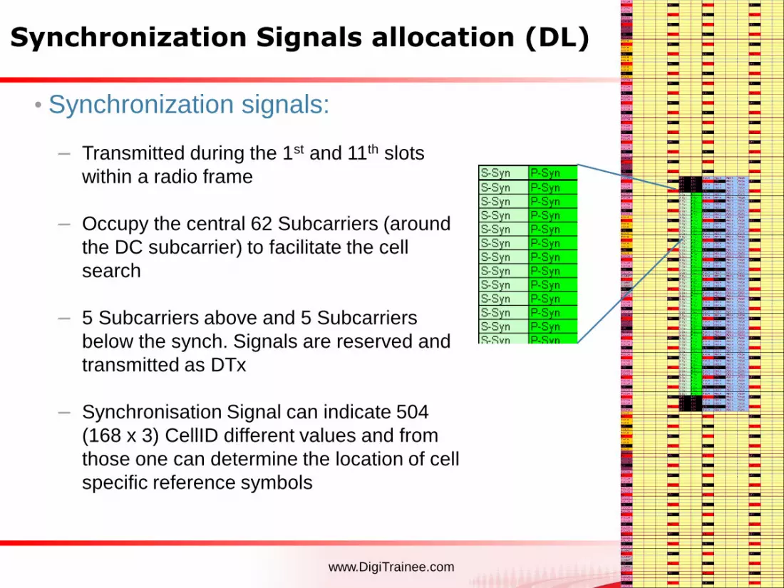
• Synchronization signals:
– Transmitted during the 1st and 11th slots
within a radio frame
– Occupy the central 62 Subcarriers (around
the DC subcarrier) to facilitate the cell
search
– 5 Subcarriers above and 5 Subcarriers
below the synch. Signals are reserved and
transmitted as DTx
– Synchronisation Signal can indicate 504
(168 x 3) CellID different values and from
those one can determine the location of cell
specific reference symbols
www.DigiTrainee.com Company Confidential
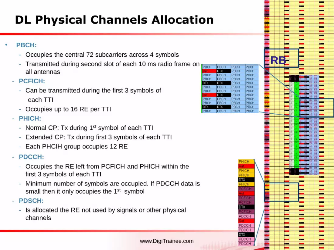
DL Physical Channels Allocation
• PBCH:
- Occupies the central 72 subcarriers across 4 symbols
- Transmitted during second slot of each 10 ms radio frame on
all antennas
- PCFICH:
- Can be transmitted during the first 3 symbols of
each TTI
- Occupies up to 16 RE per TTI
- PHICH:
- Normal CP: Tx during 1st symbol of each TTI
- Extended CP: Tx during first 3 symbols of each TTI
- Each PHCIH group occupies 12 RE
- PDCCH:
- Occupies the RE left from PCFICH and PHICH within the
first 3 symbols of each TTI
- Minimum number of symbols are occupied. If PDCCH data is
small then it only occupies the 1st symbol
- PDSCH:
- Is allocated the RE not used by signals or other physical
channels
RB

www.DigiTrainee.com Company Confidential
Uplink Physical Signals and Channels
- Uplink Physical Signals
- Demodulation Signals:
- Used for channel estimation in the eNodeB receiver to demodulate control and data
channels
- Located in the 4th symbol (normal CP) of each slot and spans the same bandwidth
as the allocated uplink data
- Sounding Reference Signals:
- Provides uplink channel quality estimation as basis for the UL scheduling decisions -
> similar in use as the CQI in DL
- Sent in different parts of the bandwidth where no uplink data transmission is
available.
- Not part of first NSNs implementations (UL channel aware scheduler in RL30)
- Uplink Physical Channels
- Physical Uplink Shared Channel (PUSCH)
- Physical Uplink Control Channel (PUCCH)
- Physical Random Access Channel (PRACH)
www.DigiTrainee.com Company Confidential
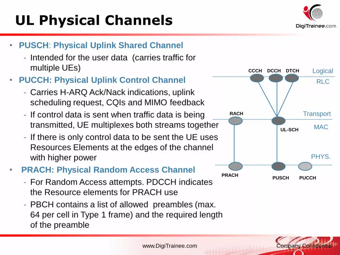
UL Physical Channels
• PUSCH: Physical Uplink Shared Channel
- Intended for the user data (carries traffic for
multiple UEs)
• PUCCH: Physical Uplink Control Channel
- Carries H-ARQ Ack/Nack indications, uplink
scheduling request, CQIs and MIMO feedback
- If control data is sent when traffic data is being
transmitted, UE multiplexes both streams together
- If there is only control data to be sent the UE uses
Resources Elements at the edges of the channel
with higher power
• PRACH: Physical Random Access Channel
- For Random Access attempts. PDCCH indicates
the Resource elements for PRACH use
- PBCH contains a list of allowed preambles (max.
64 per cell in Type 1 frame) and the required length
of the preamble
RACH
CCCH DCCH DTCH
UL-SCH
PRACHPUSCH PUCCH
Logical
Transport
PHYS.
RLC
MAC

www.DigiTrainee.com Company Confidential
Uplink Subframe Structure (PUSCH)- Frame Structure Similar to DL: 10 ms frame consisting in 20 slots of 0.5ms
- 1 slot carries 7 SC-FDMA symbols in case of Normal CP and 6 SC-FDMA
symbols if Extended CP.
- Symbol 3 in each slot carries the uplink Reference Signal (normal CP) for
channel Demodulation, remaining 6 symbols are available for traffic and
control data
- Momentary data rate (controlled by the eNodeB scheduler) depends on the
allocated transmission bandwidth (and CP length)
- E.g. Double data rate implies the transmission bandwidth duplicates
Demodulation Reference Signal
Normal CP slot0 1 2 3 4 5 610 ms frame
0.5 ms slot
s0 s1 s2 s3 s4 s5 s6 s7s18 s19…..
SF0 SF1 SF2 SF9…..SF3
UL TTI =1ms (as in downlink)
www.DigiTrainee.com Company Confidential
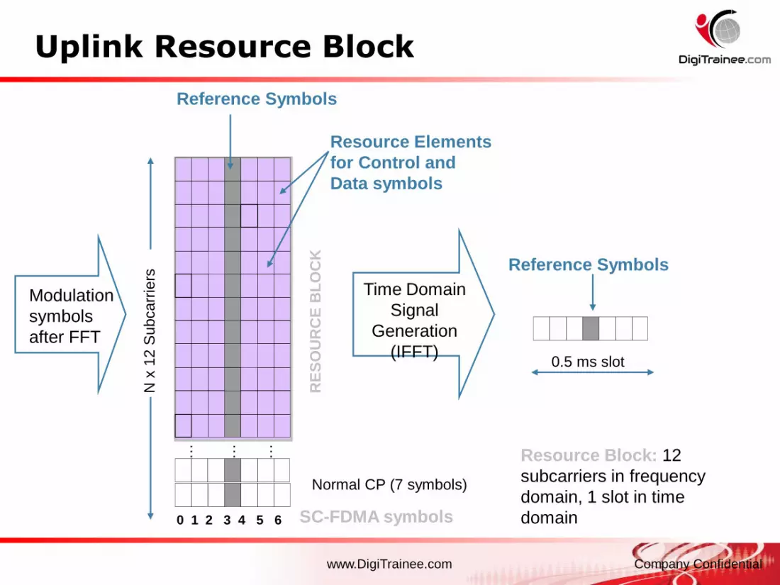
Uplink Resource Block
Time Domain
Signal
Generation
(IFFT)
Reference Symbols
0.5 ms slot
Resource Block: 12
subcarriers in frequency
domain, 1 slot in time
domain0 1 2 3 4 5 6
Modulation
symbols
after FFT
N x
12 S
ubcarr
iers
RE
SO
UR
CE
BL
OC
K
… … …
Reference Symbols
Resource Elements
for Control and
Data symbols
Normal CP (7 symbols)
SC-FDMA symbols

www.DigiTrainee.com Company Confidential
Uplink Resource Mapping
- Demodulation Reference
Signal:
Always on symbol 3 of each slot
(normal CP)
- PUSCH mapping:
Data is allocated in multiples
of 1 RB (12 subcarriers in
frequency domain). Only factors
of 2, 3 and 5 resource blocks are
allowed
- PUCCH mapping:
If PUCCH not multiplexed with
PUSCH then it is transmitted on
a reserved frequency region.
PUCCH occupies RBs at both
edges of the uplink bandwidth (in
green in the picture on the right)

www.DigiTrainee.com Company Confidential
Random Access Channel (PRACH)
- RACH operation uses around 1.08 MHz bandwidth
- This is equal to 6 resource blocks of 180 kHz
- The location of those resource blocks is dynamically defined by 2 RRC
Layer Parameters (PRACH Configuration Index and PRACH Frequency
offset)
- 4 possible PRACH durations (PRACH configuration index parameter selects one of the
4)
- PRACH only carries the preambles and it is used during the RACH process
307200Ts
TPRE TGT TCP
Preamble CP
0.1 ms 0.1 ms0.8 ms

www.DigiTrainee.com Company Confidential
b0 b1
QPSK
Im
Re10
11
00
01
b0 b1b2b3
16QAM
Im
Re
0000
1111
Im
Re
64QAM
b0 b1b2b3 b4 b5
• 3GPP standard defines the following options: QPSK,
16QAM, 64QAM in both directions (UL and DL)– UL 64QAM not supported in RL10
• Not every physical channel is allowed to use any
modulation scheme:
• Scheduler decides which form to use depending on carrier
quality feedback information from the UE
Modulation Schemes
QPSK:
2 bits/symbol
16QAM:
4 bits/symbol
64QAM:
6 bits/symbol
Physical
channel
Modulation
PDSCH QPSK,
16QAM,
64QAM
PMCH QPSK,
16QAM,
64QAM
PBCH QPSK
PDCCH
(PCFICH,
PHICH)
QPSK
PUSCH QPSK,
16QAM,
64QAM
PUCCH BPSK
and/or
QPSK

www.DigiTrainee.com Company ConfidentialPresentation / Author / Date
LTE Layer 2/3
www.DigiTrainee.com Company Confidential
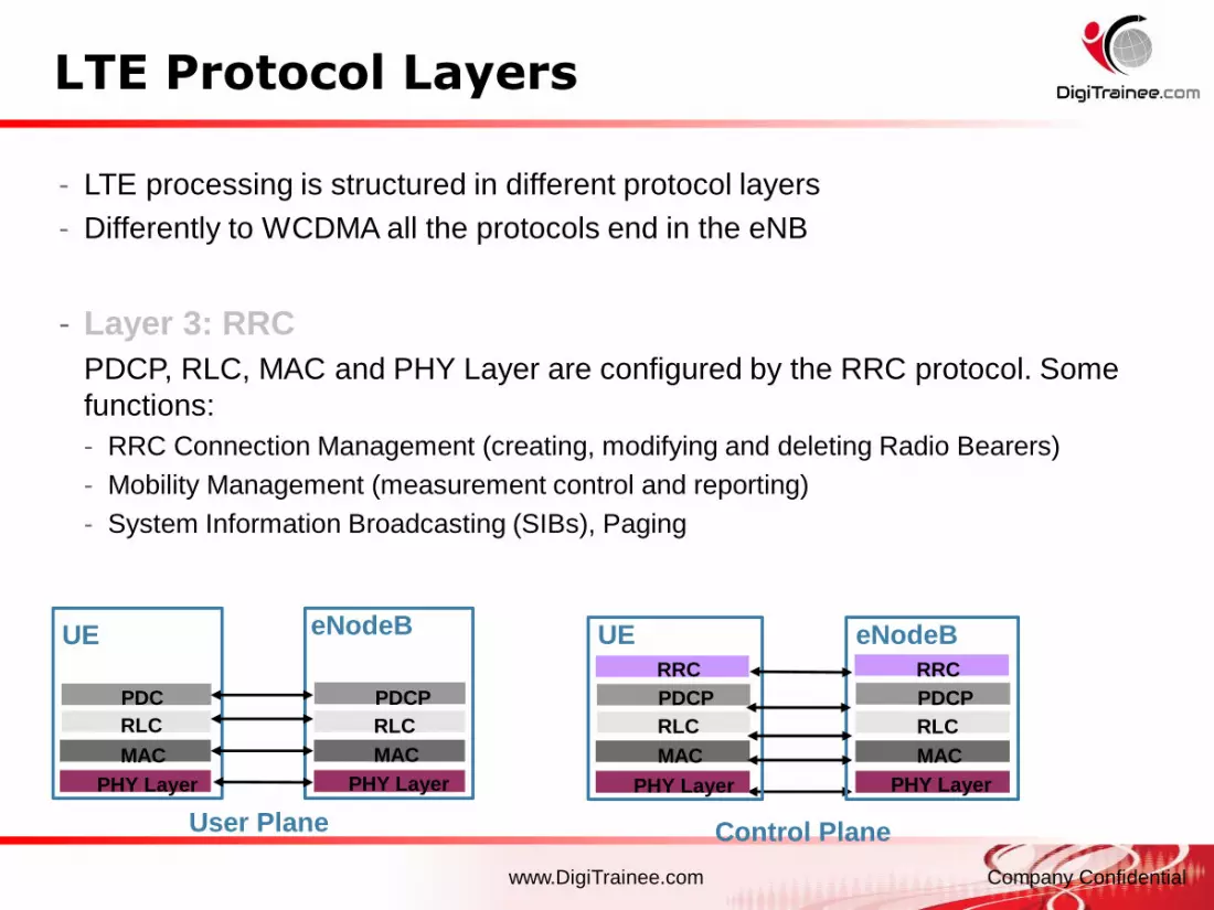
LTE Protocol Layers
- LTE processing is structured in different protocol layers
- Differently to WCDMA all the protocols end in the eNB
- Layer 3: RRC
PDCP, RLC, MAC and PHY Layer are configured by the RRC protocol. Some
functions:
- RRC Connection Management (creating, modifying and deleting Radio Bearers)
- Mobility Management (measurement control and reporting)
- System Information Broadcasting (SIBs), Paging
User Plane
PDCP
eNodeB
RLC
MAC
PHY Layer
PDC
P
UE
RLC
MAC
PHY Layer
PDCP
eNodeB
RLC
MAC
PHY Layer
PDCP
UE
RLC
MAC
PHY Layer
RRCRRC
Control Plane

www.DigiTrainee.com Company Confidential
LTE Layer 2 Structure (DL)Header
Compressions
for data (not
signalling)
Ciphering for
data and
signalling
Segm.
ARQ etc
Multiplexing UE1
Segm.
ARQ etc...
HARQ
Multiplexing UEn
HARQ
BCCH PCCH
Scheduling / Priority Handling
Logical Channels
Transport Channels
MAC
RLCSegm.
ARQ etc
Segm.
ARQ etc
PDCP
ROHC ROHC ROHC ROHC
Radio Bearers
Security Security Security Security
...
Note: In WCDMA PDCP was
only for user plane, now it is also
for control plane due ciphering
www.DigiTrainee.com Company Confidential
RLC Layer: Transmission Modes
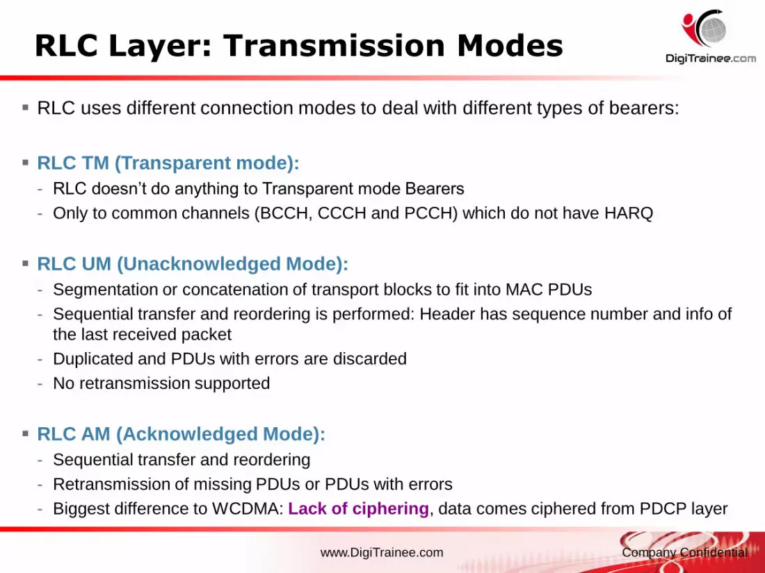
RLC uses different connection modes to deal with different types of bearers:
RLC TM (Transparent mode):
- RLC doesn’t do anything to Transparent mode Bearers
- Only to common channels (BCCH, CCCH and PCCH) which do not have HARQ
RLC UM (Unacknowledged Mode):
- Segmentation or concatenation of transport blocks to fit into MAC PDUs
- Sequential transfer and reordering is performed: Header has sequence number and info of
the last received packet
- Duplicated and PDUs with errors are discarded
- No retransmission supported
RLC AM (Acknowledged Mode):
- Sequential transfer and reordering
- Retransmission of missing PDUs or PDUs with errors
- Biggest difference to WCDMA: Lack of ciphering, data comes ciphered from PDCP layer

www.DigiTrainee.com Company Confidential
L2: Logical and Transport Channels DL
- Logical channels characterize the data to be transmitted: control or traffic
- Transport channels describe how and with what characteristics the data is
transmitted
- Multiplexed flows in a transport channel can contain data from a single user or
from multiple users
- The transport channels from the MAC layer are mapped to the physical channels
Note: No multicast in NSN implementation

www.DigiTrainee.com Company Confidential
L2: Logical and Transport Channels UL
- MAC layer provides the logical channels to RLC layer
- Transport channels in LTE have been reduced (also for DL direction) by using
in shared channel operation (no dedicated channels like in WCDMA)

www.DigiTrainee.com Company ConfidentialPage 64
End of Section