stresses and displacements in functionally graded materials
TRANSCRIPT
Materials 2012, 5, 210-226; doi:10.3390/ma5020210
materials ISSN 1996-1944
www.mdpi.com/journal/materials
Article
Stresses and Displacements in Functionally Graded Materials of Semi-Infinite Extent Induced by Rectangular Loadings
Hong-Tian Xiao 1 and Zhong-Qi Yue 2,*
1 Shandong Key Laboratory of Civil Engineering Disaster Prevention & Mitigation,
Shandong University of Science and Technology, Shandong, Qingdao 266590, China;
E-Mail: [email protected] 2 Department of Civil Engineering, The University of Hong Kong, Hong Kong, China
* Author to whom correspondence should be addressed; E-Mail: [email protected];
Tel.: +85-2-28591967; Fax: +85-2-25595337.
Received: 24 November 2011; in revised form: 16 January 2012 / Accepted: 17 January 2012 /
Published: 30 January 2012
Abstract: This paper presents the stress and displacement fields in a functionally graded
material (FGM) caused by a load. The FGM is a graded material of Si3N4-based ceramics
and is assumed to be of semi-infinite extent. The load is a distributed loading over a
rectangular area that is parallel to the external surface of the FGM and either on its external
surface or within its interior space. The point-load analytical solutions or so-called Yue’s
solutions are used for the numerical integration over the distributed loaded area. The loaded
area is discretized into 200 small equal-sized rectangular elements. The numerical
integration is carried out with the regular Gaussian quadrature. Weak and strong singular
integrations encountered when the field points are located on the loaded plane, are resolved
with the classical methods in boundary element analysis. The numerical integration results
have high accuracy.
Keywords: functionally graded materials; FGM; elasticity; multilayered solids; Yue’s
solution; Kelvin solution; stress analysis; numerical integration
1. Introduction
Functionally graded materials (FGMs), also known as graded materials, are generally multi-phase
composites with continuously varying mechanical properties. They are primarily used as coatings and
OPEN ACCESS
Materials 2012, 5
211
interfacial zones to reduce stresses resulting from the material property mismatch, to improve the surface
properties and to provide protection against severe loading, thermal and chemical environments. At
present, FGMs are usually associated with particulate composites where the volume fraction of particles
varies in one or several directions. With the wide use of FGMs in engineering, much attention has been
paid to the mechanical behavior of FGMs due to different loadings.
Significant efforts have been made in the study of the mechanical responses of FGMs. These studies
include the investigation of elastic fields, crack and contact problems in FGMs. For example,
Gibson [1], Booker et al. [2], Oner [3] and Butter et al. [4] analyzed the elastic behavior of
non-homogeneous half-spaces. Kassir [5], Giannakopoulos et al. [6] and Suresh [7] discussed the
contact problems between punches and graded materials. Chen et al. [8] presented a semianalytical
approach to solve the time-dependent response of a multilayered pavement. Delale et al. [9] analyzed the
fracture mechanics of crack problems in FGMs. Chan et al. [10] and Martin et al. [11] presented Green’s
functions for 2D and 3D exponentially-graded elastic solids, respectively. Birman et al. [12] presented a
review of the principal developments in FGMs and the critical areas where further research is needed for
a successful implementation of FGM in design. In particular, Carrera and his co-workers [13–15]
developed the unified formulation for analysis of classical layered structures and extended it for FGM
structures by using a set of functions which are indicated as thickness functions.
More recently, Xiao et al. [16] developed a numerical method in analyzing the contact between the
rectangular rigid plate and the graded material of semi-infinite extent. Xiao et al. [17] further developed
the numerical method for analysis of the elastic fields in heterogeneous rocks due to reservoir water
impoundment. The numerical method has high accuracy and efficiency by using the generalized Kelvin
solution of a multilayered medium of infinite extent, which is adoptable to a layered medium of
infinite extent.
In this paper, the numerical method is used for the analysis of elastic behaviors of FGM half-space.
Referring to the results in Pender et al. [18], the graded material of Si3N4-based ceramics of semi-infinite
extent is used as the FGM for the stress and displacement analysis. The rectangular loading area is
parallel to the boundary of the semi-infinite FGM space and the uniform normal loads are chosen. The
displacements and stresses induced in the graded materials are presented. The comparison of elastic
fields is made for two different positions of the rectangular loads.
2. Numerical Method for Analysis of Mechanical States in FGMs
2.1. The Point-Load Solution Suitable for the FGM
Yue [19] presented the point-load analytical solutions for multilayer elastic solids. This point-load
solution is an extension of the classical Kelvin solution for a point-load in a homogeneous elastic space
and is for the stress and displacement fields in a layered elastic solid of infinite extent caused by the
action of point loads. Each layer is a homogeneous elastic solid of finite thickness and infinite lateral
extension. The total number of the dissimilar elastic layers is an arbitrary integer. The internal layers
adhere to the first homogeneous elastic solid of upper semi-infinite extent and the last homogeneous
elastic solid of lower semi-infinite extent. The interface between any two connected dissimilar layers is
planar and fully bonded. All the layer interfaces are parallel to each other.
Materials 2012, 5
212
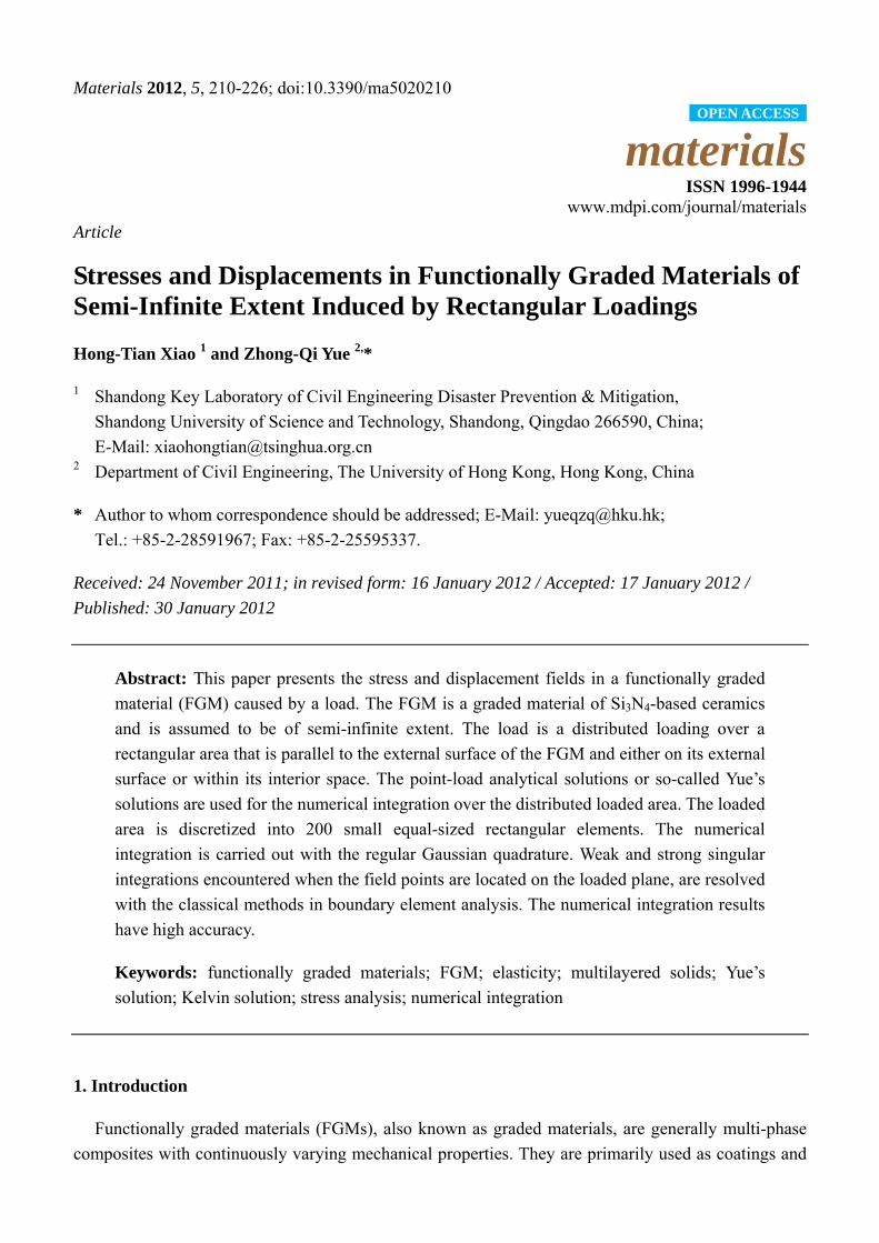
The FGM shown in Figure 1 has its isotropic elastic properties variable in depth and the layered
technique is used along the depth. For this FGM problem of semi-infinite extent, the shear modulus of
the first solid of upper semi-infinite extent is assigned a zero value (or an infinitesimal value, e.g., 10–15
MPa). Consequently, the first elastic solid becomes a void space of upper semi-infinite extent. The Yue’s
solution for a point load in a multilayered elastic solid of infinite extent is automatically degenerated into
the generalized Mindlin solution for a point load in a layered half-space.
Figure 1. Functionally Graded Material (FGM) half-space subjected to loads on a rectangular area (a = 2 mm, b = 1 mm).
2.2. The Numerical Method for Analysis of the FGM due to Distributed Loadings
By using Yue’s solution, Xiao et al. [16,20] presented the numerical analysis of contact problems
between rigid punch and the graded materials and elastic fields in heterogeneous rocks induced by
reservoir water impoundment, respectively. The accuracy and effectiveness of the numerical integration
method have been verified by comparing the numerical results with the existing analytical ones. The
numerical integration method is again used in the analysis of the stress and displacement fields in the
FGM as shown in Figure 1. It is also noted that Yue et al. [21] used the similar numerical integration
method and analyzed the effects of tire-pavement contact pressure distributions on the response of
asphalts concrete pavements.
Therefore, the mathematical formulation and computational procedures of the numerical integration
method are not presented here in detail. Basically, the numerical integration method needs to discretize
an FGM layer as a system of n number of fully bonded dissimilar sublayers. Thus, it uses Yue’s solution
[19] for the elastostatic field in a layered solid of infinite extent due to the action of concentrated point
loads. Figure 2 shows the discretization approach for FGMs. The Yue’s solution is used as the point-load
solution to replace the classical Mindlin point-load solution in conventional numerical integration
method for a homogeneous medium of semi-infinite extent. As a result, any FGMs with arbitrary
property gradient in depth can be examined using this numerical method.
As shown in Figure 1, the surface S of the layered medium of semi-infinite extent is subjected to loads
in the x, y and/or z directions. The total number of the dissimilar layers is an arbitrary integer. The
stresses and displacements at any points of the layered medium are described as
Materials 2012, 5
213
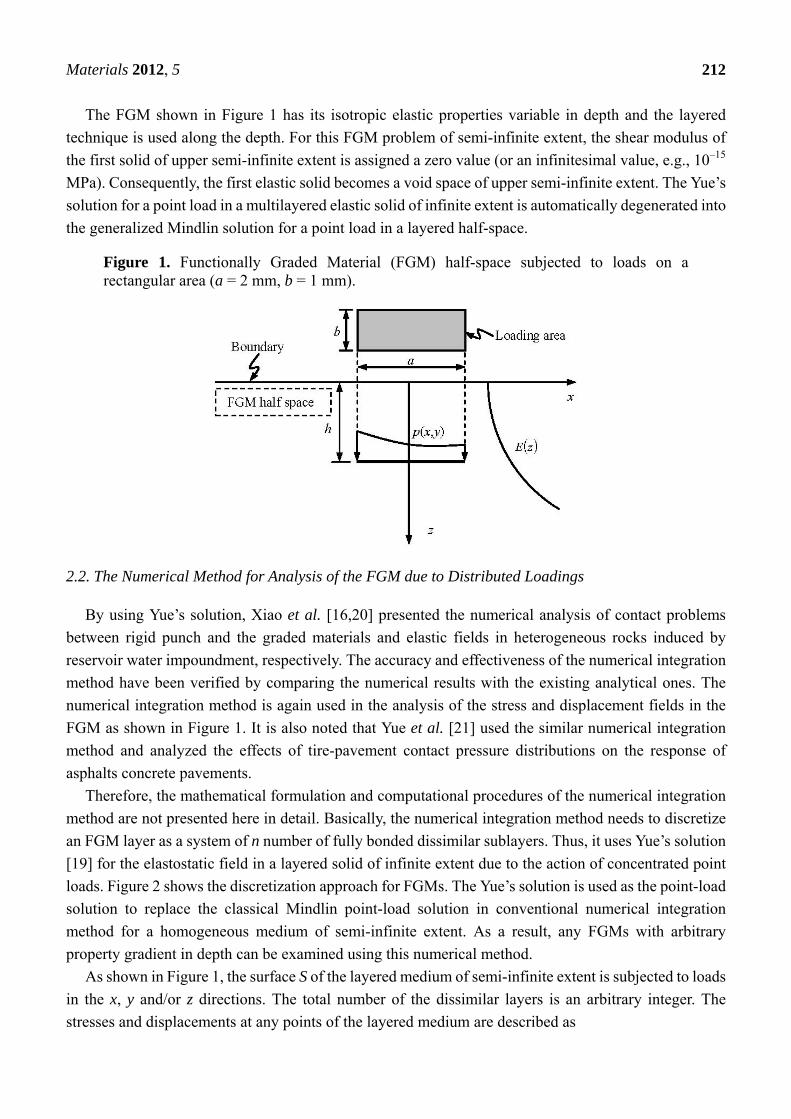
( ) ( ) ( ) ( )=S kijkij PdSPtPQQ ,*σσ , ,,,,, zyxkji = (1)
( ) ( ) ( ) )(,* PdSPtPQuQuS kiki = , zyxki ,,, = (2)
where σijk*(Q, P) and uik*(Q, P) are the point-load solutions of the layered medium; σijk*(Q, P) are
stresses for the field point Q due to the unit force along the k direction at the source point P; uik*(Q, P)
displacements for the field point Q along the i direction due to the unit force along the k direction at the
source point P; tk(P) is the traction at the source point P.
Figure 2. Variation of elastic modulus in layers for actual measured modulus.
200 225 250 275 300 325 3500.4
0.3
0.2
0.1
0.0
layered technique estimated using the relative amount
Dep
th fr
om s
urfa
ce, z
(mm
)
Elastic Modulus, E (GPa)
the boundary of a semi-infinite body
Due to the irregular shapes of a loading area and the non-uniform distribution of the traction tk(P), the
integrals shown in Expressions (1) and (2) cannot be integrated into analytical forms. The 2D integrals in
(1) and (2) have to be calculated numerically. A discretization technique, similar to that used in boundary
element methods [16], is adopted. The loading area S is discretized into quadrilateral elements. In each
element, the interpolation functions between the global and local coordinates are introduced. Thus, the
integral on each element is executed in local coordinates and is calculated by using the regular Gaussian
quadrature.
If the source point Q is located at the integral element, the integrand of Expression (1) is strongly
singular and the integrand of Expression (2) is weakly singular. The strongly singular integral of
Expression (1) is calculated by using the indirect method and the weakly singular integral of
Expression (2) is calculated by dividing an element into several triangular sub-elements and using the
coordinate transformation.
Materials 2012, 5
214
3. Displacements and Stresses in FGMs under Rectangular Loadings
3.1. General
In most of existing solutions to problems relating to FGMs, it is assumed that the material is isotropic,
the Poisson’s ratio is constant, and Young’s (or shear) modulus is either an exponential or a power
function of a space variable. In the studies described in Delale et al. [9], the shear modulus is assumed to
be μ = μ0exp(αy) where y = 0 is either the boundary of the half plane or the plane of the crack. In Kassir
[5], it is assumed that μ = μ0׀y׀m, (0 < m < 1).Generally, it is easy to obtain the analytical solutions of
FGMs for the above-mentioned assumption of the material properties. Actually, the properties of FGMs
are distributed in complex forms. Thus, the proposed numerical method is used much effectively to
analyze the mechanical response of the actual FGMs because it can also take into account the depth
variations in both Young’s modulus and Poisson’s ratio.
Herein, the Si3N4-based materials given in Pender et al. [18] are further used for the stress analysis.
The Si3N4-based graded materials were fabricated with controlled, unidirectional gradients in elastic
modulus from the surface to the interior. The elastic parameters shown in Figure 2 were estimated by
using several photomicrographs and image analysis software. The FGM had a constant Poisson’s ratio
0.22 and its elastic modulus is described by a piecewise linear interpolation as follows
mm40.0z ,0.310)(
mm40.030.0 ,)30.0(1.29459.280)(
mm30.025.0 ),25.0(4.5326.283)(
mm25.020.0 ),20.0(2.12220.277)(
mm20.015.0 ),15.0(0.14590.269)(
mm15.010.0 ),1.0(8.45036.247)(
mm10.005.0 , )05.0(4.7654.243)(
mm05.00 ,6.37001.225)(
≥=≤≤−+=≤≤−−=≤≤−+=≤≤−+=≤≤−+=≤≤−+=≤≤+=
zE
zzzE
zzzE
zzzE
zzzE
zzzE
zzzE
zzzE
(3)
where the unit of elastic modulus is GPa and z is the depth coordinate, as shown in Figure 2.
The FGM from the depth z = 0 mm to 0.4 mm is discretized into 30 thin layers, as shown in
Figure 2. Each layer has a constant modulus from Equation (3). The FGM from the depth
z = 0.4 mm to ∞ is modeled as a homogeneous elastic solid of lower half-space extent. The
above-mentioned FGMs will be referred to as Case 1. For reference and comparison, a homogeneous
medium of semi-infinite extent is chosen and will be referred to as Case 2. The Young’s modulus and the
Poisson’s ratio of the homogeneous elastic solid are assumed to be 225.1 GPa and 0.22, respectively,
(i.e., E0 = 225.1 GPa and ν = 0.22). This modulus value is equal to the average value of the
FGM modulus.
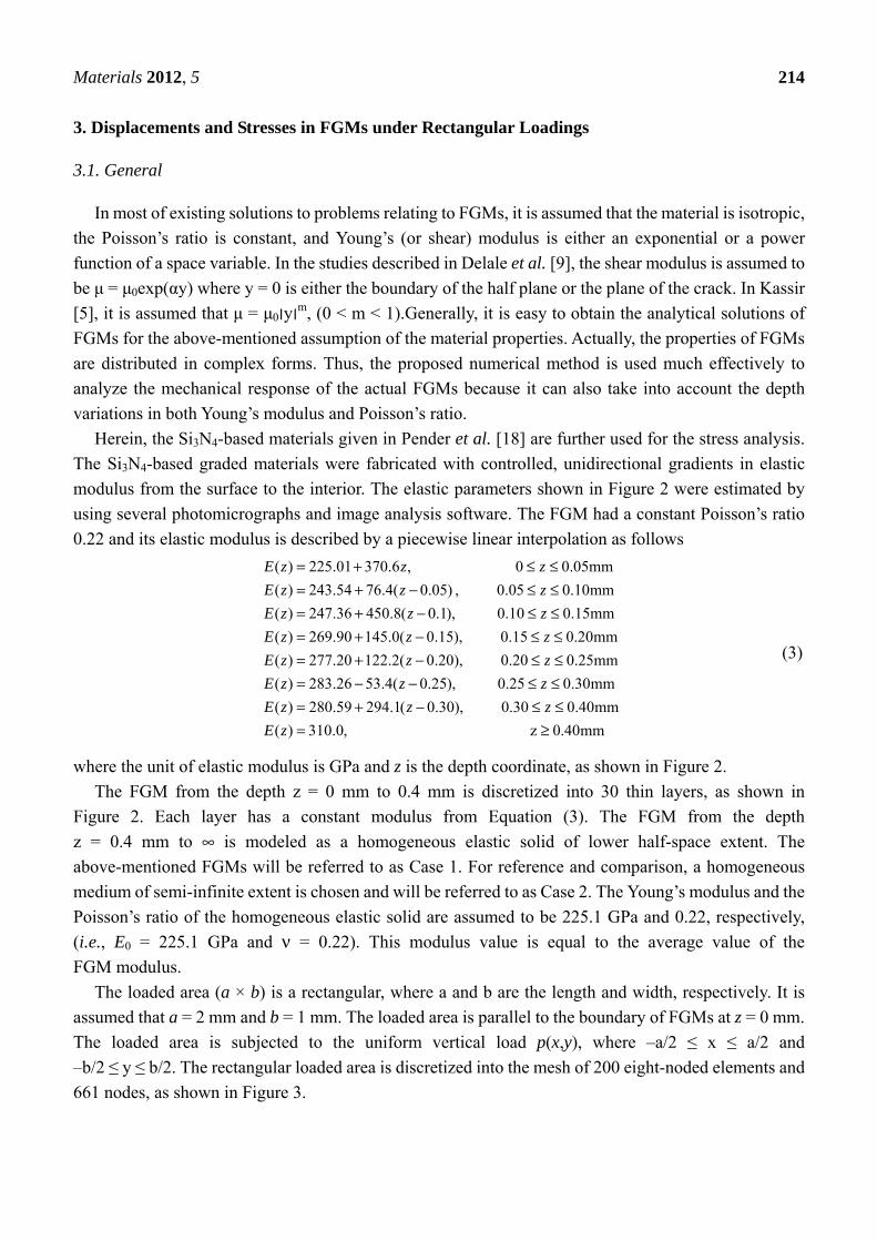
The loaded area (a × b) is a rectangular, where a and b are the length and width, respectively. It is
assumed that a = 2 mm and b = 1 mm. The loaded area is parallel to the boundary of FGMs at z = 0 mm.
The loaded area is subjected to the uniform vertical load p(x,y), where –a/2 ≤ x ≤ a/2 and
–b/2 ≤ y ≤ b/2. The rectangular loaded area is discretized into the mesh of 200 eight-noded elements and
661 nodes, as shown in Figure 3.
Materials 2012, 5
215
Figure 3. The mesh of loading area with 200 eight-noded elements and 661 nodes.
Lankford [22] measured hardness and compressive strength of several strong ceramics from room
temperature to 1,000 °C and gave the tensile and compressive strengths of the ceramic Si3N4. It can be
found that the tensile strength of Si3N4 is 810 MPa and the compressive strength of Si3N4 is more than
1.5 GPa. Herein, it is assumed that p(x,y) = 100 MPa. For this case, the FGMs may be in the elastic state
and the proposed method can be used for analysis of the displacement and stress fields.
For the FGM half-space subjected to the rectangular loading, the distribution characteristics of the
elastic fields at the loaded plane are in general similar to those of the elastic fields in two bonded rocks of
infinite extent induced by the rectangular loadings [17]. In Xiao et al. [17], the closed-form solutions
were presented for the elastic fields in two bonded rocks of infinite extent induced by the uniform
rectangular loadings. The continuities of the stresses and displacements across the loading plane and the
material interface were discussed in detail. In the ensuing, distributions of the elastic fields for Cases 1
and 2 at different depths are presented and discussed in detail.
3.2. The Loading Area at h = 0 mm
The rectangular loading on the plane h = 0 mm is examined in this section. In this case, the loading is
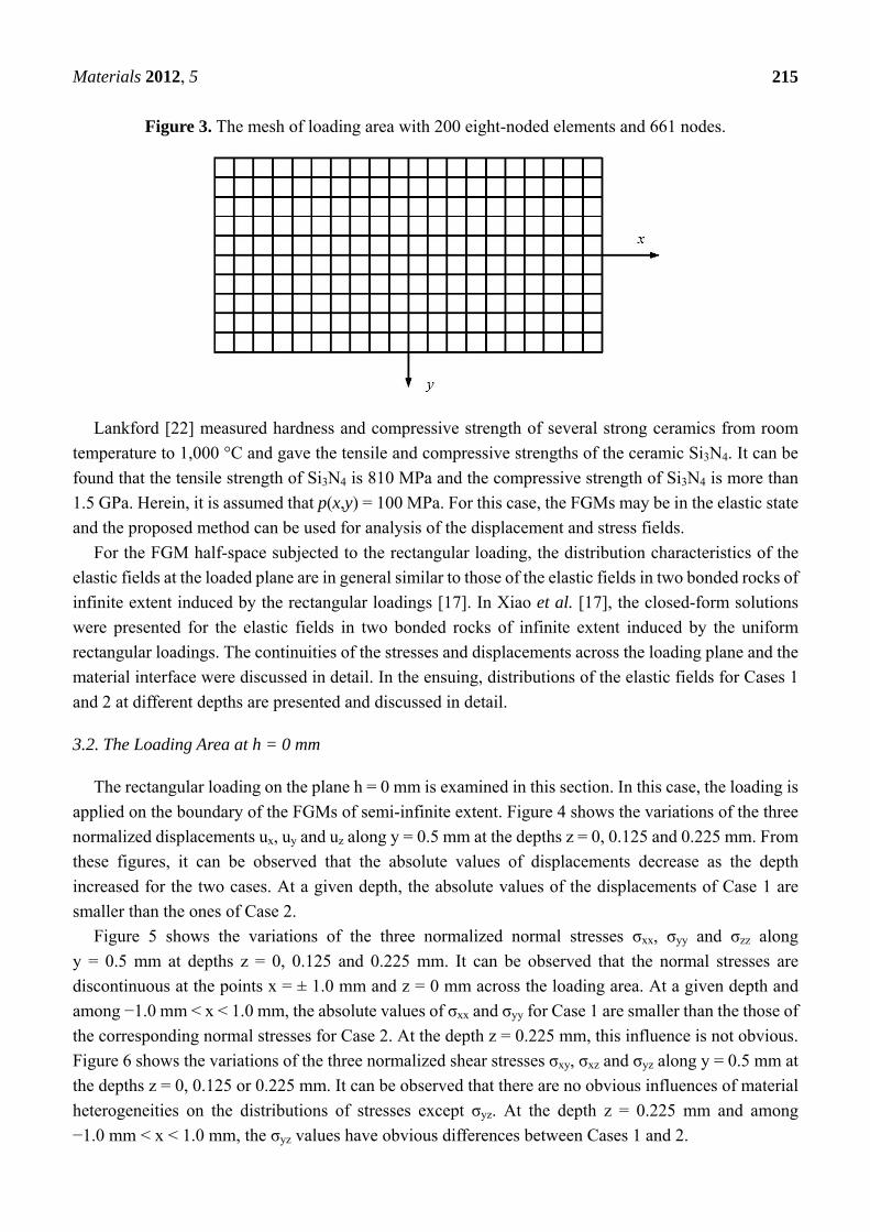
applied on the boundary of the FGMs of semi-infinite extent. Figure 4 shows the variations of the three
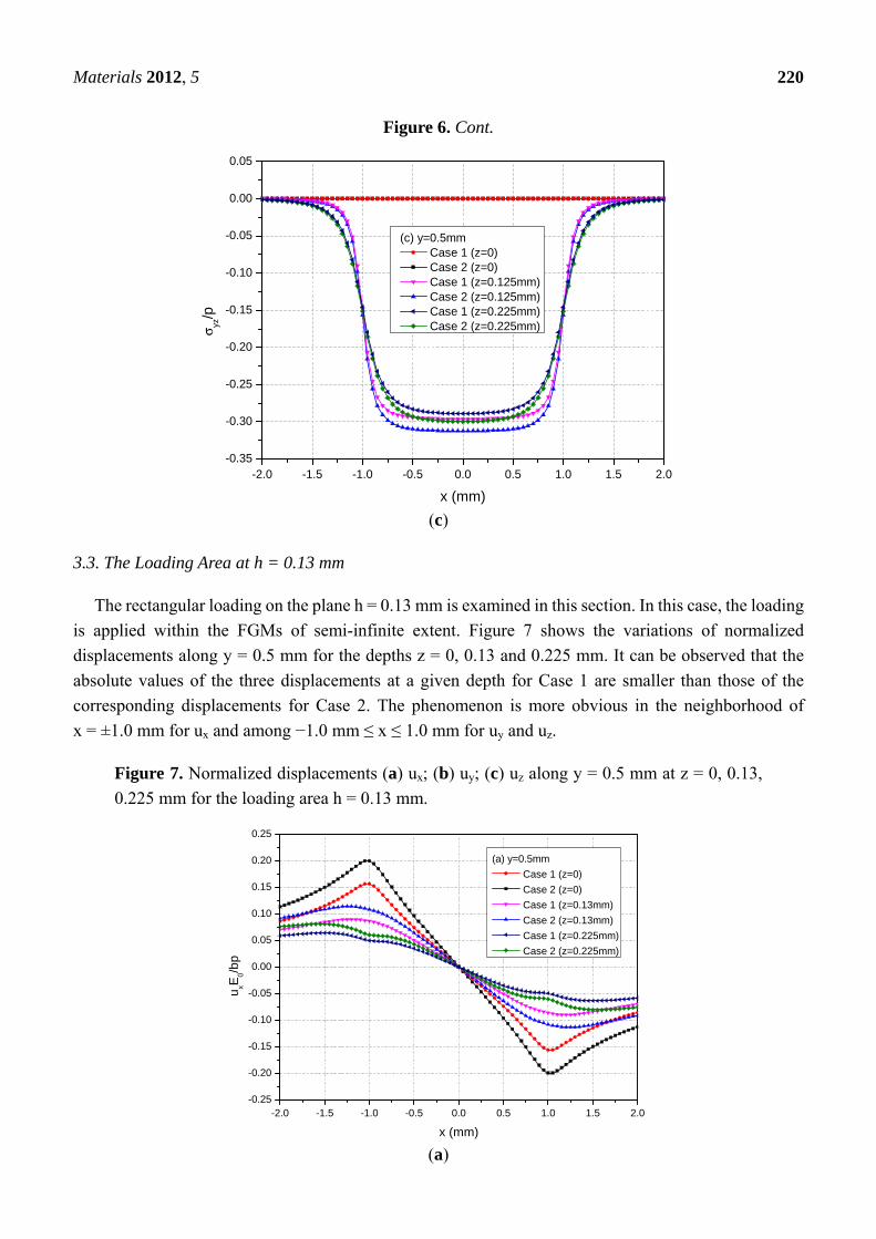
normalized displacements ux, uy and uz along y = 0.5 mm at the depths z = 0, 0.125 and 0.225 mm. From
these figures, it can be observed that the absolute values of displacements decrease as the depth
increased for the two cases. At a given depth, the absolute values of the displacements of Case 1 are
smaller than the ones of Case 2.
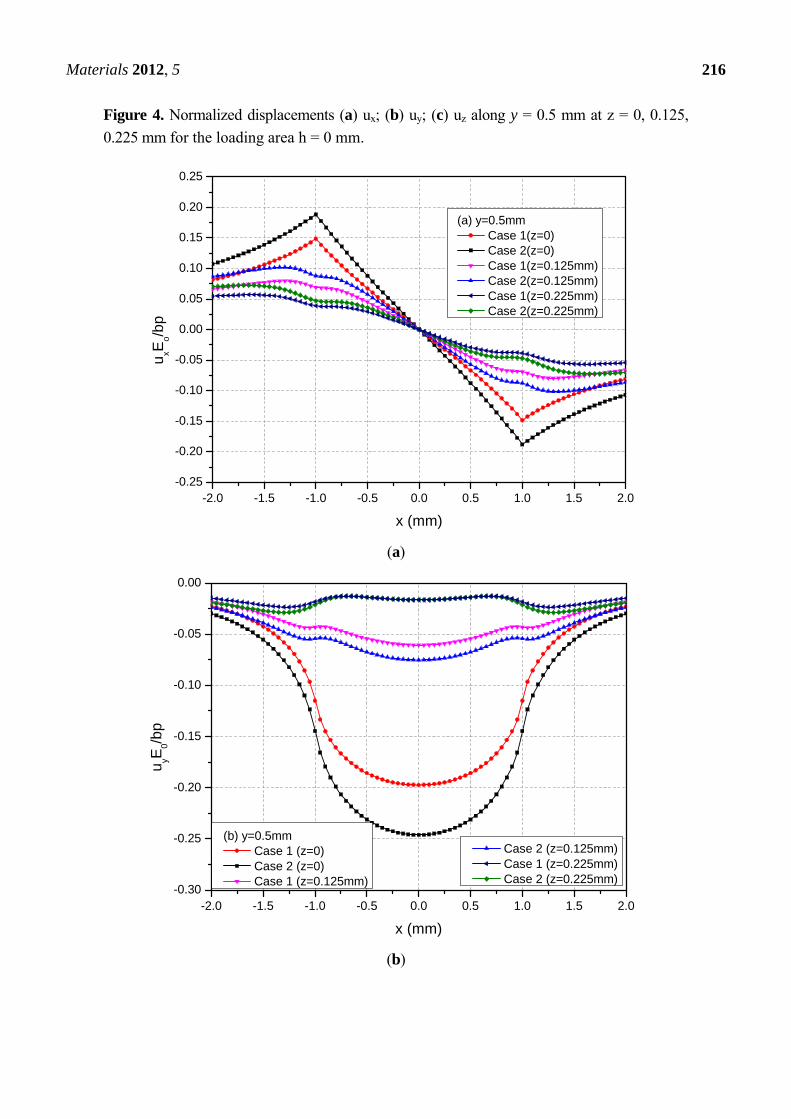
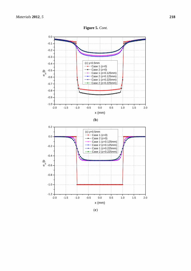
Figure 5 shows the variations of the three normalized normal stresses σxx, σyy and σzz along
y = 0.5 mm at depths z = 0, 0.125 and 0.225 mm. It can be observed that the normal stresses are
discontinuous at the points x = ± 1.0 mm and z = 0 mm across the loading area. At a given depth and
among −1.0 mm < x < 1.0 mm, the absolute values of σxx and σyy for Case 1 are smaller than the those of
the corresponding normal stresses for Case 2. At the depth z = 0.225 mm, this influence is not obvious.
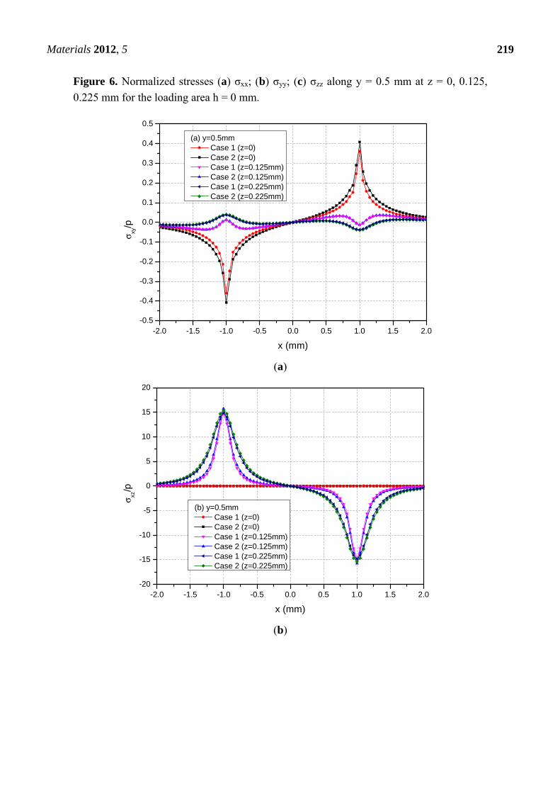
Figure 6 shows the variations of the three normalized shear stresses σxy, σxz and σyz along y = 0.5 mm at
the depths z = 0, 0.125 or 0.225 mm. It can be observed that there are no obvious influences of material
heterogeneities on the distributions of stresses except σyz. At the depth z = 0.225 mm and among
−1.0 mm < x < 1.0 mm, the σyz values have obvious differences between Cases 1 and 2.
Materials 2012, 5
216
Figure 4. Normalized displacements (a) ux; (b) uy; (c) uz along y = 0.5 mm at z = 0, 0.125,
0.225 mm for the loading area h = 0 mm.
-2.0 -1.5 -1.0 -0.5 0.0 0.5 1.0 1.5 2.0-0.25
-0.20
-0.15
-0.10
-0.05
0.00
0.05
0.10
0.15
0.20
0.25u xE
o/bp
x (mm)
(a) y=0.5mm Case 1(z=0) Case 2(z=0) Case 1(z=0.125mm) Case 2(z=0.125mm) Case 1(z=0.225mm) Case 2(z=0.225mm)
(a)
-2.0 -1.5 -1.0 -0.5 0.0 0.5 1.0 1.5 2.0-0.30
-0.25
-0.20
-0.15
-0.10
-0.05
0.00
Case 2 (z=0.125mm) Case 1 (z=0.225mm) Case 2 (z=0.225mm)
u yE0/b
p
x (mm)
(b) y=0.5mm Case 1 (z=0) Case 2 (z=0) Case 1 (z=0.125mm)
(b)
Materials 2012, 5
217
Figure 4. Cont.
-2.0 -1.5 -1.0 -0.5 0.0 0.5 1.0 1.5 2.00.2
0.3
0.4
0.5
0.6
0.7
0.8
0.9
1.0
1.1
1.2
u zE0/b
p
x (mm)
(c) y=0.5mm Case 1 (z=0) Case 2 (z=0) Case 1 (z=0.125mm) Case 2 (z=0.125mm) Case 1 (z=0.225mm) Case 2 (z=0.225mm)
(c)
Figure 5. Normalized stresses (a) σxx; (b) σyy; (c) σzz along y = 0.5 mm at z = 0, 0.125,
0.225 mm for the loading area h = 0 mm.
-2.0 -1.5 -1.0 -0.5 0.0 0.5 1.0 1.5 2.0-0.7
-0.6
-0.5
-0.4
-0.3
-0.2
-0.1
0.0
0.1
0.2
σ xx/p
x (mm)
(a) y=0.5mm Case 1 (z=0) Case 2 (z=0) Case 1 (z=0.125mm) Case 2 (z=0.125mm) Case 1 (z=0.225mm) Case 2 (z=0.225mm)
(a)
Materials 2012, 5
218
Figure 5. Cont.
-2.0 -1.5 -1.0 -0.5 0.0 0.5 1.0 1.5 2.0-1.0
-0.9
-0.8
-0.7
-0.6
-0.5
-0.4
-0.3
-0.2
-0.1
0.0
σ yy/p
x (mm)
(c) y=0.5mm Case 1 (z=0) Case 2 (z=0) Case 1 (z=0.125mm) Case 2 (z=0.125mm) Case 1 (z=0.225mm) Case 2 (z=0.225mm)
(b)
-2.0 -1.5 -1.0 -0.5 0.0 0.5 1.0 1.5 2.0-1.2
-1.0
-0.8
-0.6
-0.4
-0.2
0.0
0.2
σ zz/p
x (mm)
(c) y=0.5mm Case 1 (z=0) Case 2 (z=0) Case 1 (z=0.125mm) Case 2 (z=0.125mm) Case 1 (z=0.225mm) Case 2 (z=0.225mm)
(c)
Materials 2012, 5
219
Figure 6. Normalized stresses (a) σxx; (b) σyy; (c) σzz along y = 0.5 mm at z = 0, 0.125,
0.225 mm for the loading area h = 0 mm.
-2.0 -1.5 -1.0 -0.5 0.0 0.5 1.0 1.5 2.0-0.5
-0.4
-0.3
-0.2
-0.1
0.0
0.1
0.2
0.3
0.4
0.5σ xy
/p
x (mm)
(a) y=0.5mm Case 1 (z=0) Case 2 (z=0) Case 1 (z=0.125mm) Case 2 (z=0.125mm) Case 1 (z=0.225mm) Case 2 (z=0.225mm)
(a)
-2.0 -1.5 -1.0 -0.5 0.0 0.5 1.0 1.5 2.0-20
-15
-10
-5
0
5
10
15
20
σ xz/p
x (mm)
(b) y=0.5mm Case 1 (z=0) Case 2 (z=0) Case 1 (z=0.125mm) Case 2 (z=0.125mm) Case 1 (z=0.225mm) Case 2 (z=0.225mm)
(b)
Materials 2012, 5
220
Figure 6. Cont.
-2.0 -1.5 -1.0 -0.5 0.0 0.5 1.0 1.5 2.0-0.35
-0.30
-0.25
-0.20
-0.15
-0.10
-0.05
0.00
0.05
σ yz/p
x (mm)
(c) y=0.5mm Case 1 (z=0) Case 2 (z=0) Case 1 (z=0.125mm) Case 2 (z=0.125mm) Case 1 (z=0.225mm) Case 2 (z=0.225mm)
(c)
3.3. The Loading Area at h = 0.13 mm
The rectangular loading on the plane h = 0.13 mm is examined in this section. In this case, the loading
is applied within the FGMs of semi-infinite extent. Figure 7 shows the variations of normalized
displacements along y = 0.5 mm for the depths z = 0, 0.13 and 0.225 mm. It can be observed that the
absolute values of the three displacements at a given depth for Case 1 are smaller than those of the
corresponding displacements for Case 2. The phenomenon is more obvious in the neighborhood of
x = ±1.0 mm for ux and among −1.0 mm ≤ x ≤ 1.0 mm for uy and uz.
Figure 7. Normalized displacements (a) ux; (b) uy; (c) uz along y = 0.5 mm at z = 0, 0.13,
0.225 mm for the loading area h = 0.13 mm.
-2.0 -1.5 -1.0 -0.5 0.0 0.5 1.0 1.5 2.0-0.25
-0.20
-0.15
-0.10
-0.05
0.00
0.05
0.10
0.15
0.20
0.25
u xE 0/bp
x (mm)
(a) y=0.5mm Case 1 (z=0) Case 2 (z=0) Case 1 (z=0.13mm) Case 2 (z=0.13mm) Case 1 (z=0.225mm) Case 2 (z=0.225mm)
(a)
Materials 2012, 5
221
Figure 7. Cont.
-2.0 -1.5 -1.0 -0.5 0.0 0.5 1.0 1.5 2.0-0.30
-0.25
-0.20
-0.15
-0.10
-0.05
0.00
(b) y=0.5mm Case 1 (z=0) Case 2 (z=0)
u yE0/b
p
x (mm)
Case 1 (z=0.13mm) Case 2 (z=0.13mm) Case 1 (z=0.225mm) Case 2 (z=0.225mm)
(b)
-2.0 -1.5 -1.0 -0.5 0.0 0.5 1.0 1.5 2.00.2
0.3
0.4
0.5
0.6
0.7
0.8
0.9
1.0
1.1
1.2
u zE0/b
p
x (mm)
(c) y=0.5mm Case 1 (z=0) Case 2 (z=0) Case 1 (z=0.13mm) Case 2 (z=0.13mm) Case 1 (z=0.225mm) Case 2 (z=0.225mm)
(c)
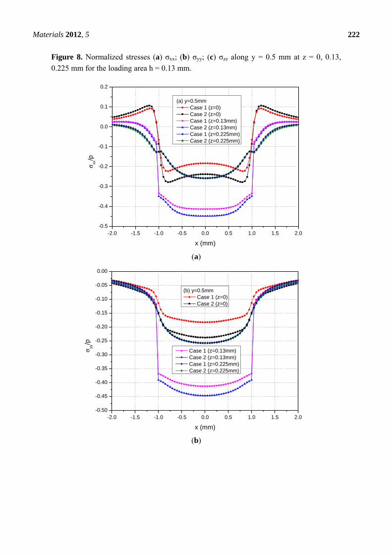
Figure 8 shows the variations of the three normalized normal stresses along y = 0.5 mm at the depths
z = 0, 0.13 and 0.225 mm. It can be found that the normal stresses σxx and σyy for Cases 1 and 2 have
obvious differences for −1.0 mm ≤ x ≤ 1.0 mm at the depths z = 0 mm and 0.13 mm while the stresses
has negligible differences at z = 0.225 mm. However, the values of σzz at any depths for Cases 1 and 2
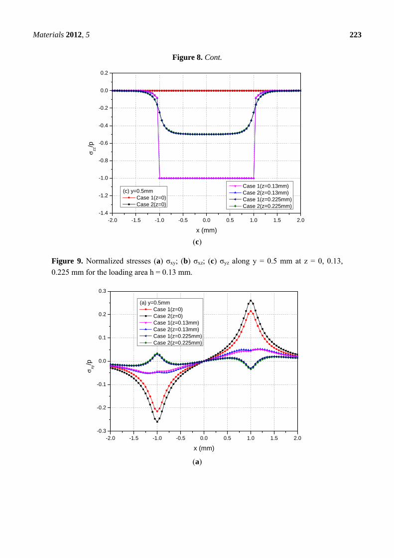
have no obvious differences. Figure 9 shows the variations of the three normalized shear stresses along
y = 0.5 mm for different depths z = 0, 0.13 and 0.225 mm. It can be found that there are small differences
between Cases 1 and 2 except the shear stress σxy. The σxy values have large differences between Cases 1
and 2.
Materials 2012, 5
222
Figure 8. Normalized stresses (a) σxx; (b) σyy; (c) σzz along y = 0.5 mm at z = 0, 0.13,
0.225 mm for the loading area h = 0.13 mm.
-2.0 -1.5 -1.0 -0.5 0.0 0.5 1.0 1.5 2.0-0.5
-0.4
-0.3
-0.2
-0.1
0.0
0.1
0.2σ xx
/p
x (mm)
(a) y=0.5mm Case 1 (z=0) Case 2 (z=0) Case 1 (z=0.13mm) Case 2 (z=0.13mm) Case 1 (z=0.225mm) Case 2 (z=0.225mm)
(a)
-2.0 -1.5 -1.0 -0.5 0.0 0.5 1.0 1.5 2.0-0.50
-0.45
-0.40
-0.35
-0.30
-0.25
-0.20
-0.15
-0.10
-0.05
0.00
(b) y=0.5mm Case 1 (z=0) Case 2 (z=0)
σ yy/p
x (mm)
Case 1 (z=0.13mm) Case 2 (z=0.13mm) Case 1 (z=0.225mm) Case 2 (z=0.225mm)
(b)
Materials 2012, 5
223
Figure 8. Cont.
-2.0 -1.5 -1.0 -0.5 0.0 0.5 1.0 1.5 2.0-1.4
-1.2
-1.0
-0.8
-0.6
-0.4
-0.2
0.0
0.2
Case 1(z=0.13mm) Case 2(z=0.13mm) Case 1(z=0.225mm) Case 2(z=0.225mm)
σ zz/p
x (mm)
(c) y=0.5mm Case 1(z=0) Case 2(z=0)
(c)
Figure 9. Normalized stresses (a) σxy; (b) σxz; (c) σyz along y = 0.5 mm at z = 0, 0.13,
0.225 mm for the loading area h = 0.13 mm.
-2.0 -1.5 -1.0 -0.5 0.0 0.5 1.0 1.5 2.0-0.3
-0.2
-0.1
0.0
0.1
0.2
0.3
σ xy/p
x (mm)
(a) y=0.5mm Case 1(z=0) Case 2(z=0) Case 1(z=0.13mm) Case 2(z=0.13mm) Case 1(z=0.225mm) Case 2(z=0.225mm)
(a)
Materials 2012, 5
224
Figure 9. Cont.
-2.0 -1.5 -1.0 -0.5 0.0 0.5 1.0 1.5 2.0-0.20
-0.15
-0.10
-0.05
0.00
0.05
0.10
0.15
0.20
σ xz/p
x (mm)
(b) y=0.5mm Case 1 (z=0) Case 2 (z=0) Case 1 (z=0.13mm) Case 2 (z=0.13mm) Case 1 (z=0.225mm) Case 2 (z=0.225mm)
(b)
-2.0 -1.5 -1.0 -0.5 0.0 0.5 1.0 1.5 2.0-0.35
-0.30
-0.25
-0.20
-0.15
-0.10
-0.05
0.00
0.05
σ yz/p
x (mm)
(c) y=0.5mm Case 1 (z=0) Case 2 (z=0) Case 1 (z=0.13mm) Case 2 (z=0.13mm) Case 1 (z=0.225mm) Case 2 (z=0.225mm)
(c)
3.4. Comparison of Elastic Fields for the Two Loading Positions
Among the displacement components, the uz values for h = 0.13 mm are smaller than the ones for
h = 0 mm. This is because the materials above the loading plane h = 0.13 mm constrain the deformation
of the FGMs. However, ux and uy have small differences for two loading positions.
For two loading positions, σxx, σyy and σzz are the maximums at loading plane positions h = 0 mm and
h = 0.13 mm, respectively. Away from the loading plane positions, the values of these stress components
become small. For the two loading positions, the absolute values of σxy are the maximums at z = 0 mm,
Materials 2012, 5
225
i.e., the boundary of semi-infinite extent. At x = ±1.0 mm, σxz = 0 and σyz = 0 for the loading position
h = 0 mm while σxz and σyz has a jump for the loading position h = 0.13 mm.
4. Conclusions
This paper has analyzed the stress and displacement fields in a functionally graded material of
semi-infinite extent induced by rectangular loading. The FGM can have their elastic properties
exhibiting the variation in depth while keeping constant in lateral directions. This paper has examined
the theoretical stress and displacement fields in the Si3N4-based ceramics due to the rectangular loading.
The displacements and stresses are presented and compared to those of a homogeneous elastic solid of
semi-infinite extent. It was found that the heterogeneity of FGM has an evident influence on the elastic
fields of the semi-infinite elastic solids. This capability to exactly calculate the complete elastic field
induced in FGM is important to the understanding of the FGM mechanical behavior and in the design of
FGM properties with depth.
Acknowledgements
The authors would like to thank the financial supports from the Committee on Research and
Conference Grants of The University of Hong Kong and the National Natural Science Foundation of
China (Grant Nos. 51079081 and 41172242).
References
1. Gibson, R.E. Some results concerning displacements and stresses in a non-homogeneous elastic half
space. Geotechnique 1967, 17, 58–67.
2. Booker, J.R.; Balaam, N.P.; Davis, E.H. The behavior of an elastic non-homogeneous half-space.
Part I—Line and point load. Int. J. Numer. Anal. Meth. Geomech. 1985, 9, 353–367.
3. Oner, M. Vertical and horizontal deformation of an inhomogeneous elastic half-space. Int. J. Numer.
Anal. Meth. Geomech. 1990, 14, 613–629.
4. Butter, W.G.; Paulino, G.H.; Song, S.H. Application of gradient finite elements for asphalt
pavements. J. Eng. Mech. 2006, 132, 240–249.
5. Kassir, M.K. Boussineq problems for a non-homogeneous solid. J. Eng. Mech. 1972, 98, 457–470.
6. Giannakopoulos, A.E.; Suresh, S. Indentation of solids with gradients in elastic properties: Part I.
point force. Int. J. Solids Struct. 1997, 34, 2357–2392.
7. Suresh, S. Graded materials for resistance to contact deformation and damage. Science 2001, 292,
2447–2451.
8. Chen, Y.G.; Pan, E.; Green, R. Surface loading of a multilayered viscoelastic pavement:
Semianalytical solution. J. Eng. Mech. 2009, 135, 517–528.
9. Delale, F.; Erdogan, F. The crack problem for a nonhomogeneous plane. J. Appl. Mech. 1983, 50,
609–614.
10. Chan, Y.S.; Gray, L.J.; Kaplan, T.; Paulino, G.H. Green’s function for a two-dimensional
exponentially graded elastic medium. Proc. R. Soc. 2004, 460, 1689–1706.
Materials 2012, 5
226
11. Martin, P.A.; Richardson, J.D.; Gray, L.J.; Berger, J.R. On Green’s function for a three-dimensional
exponentially-graded elastic solid. Proc. R. Soc. 2002, A458, 1931–1947.
12. Birman, V.; Byrd, L.W. Modeling and analysis of functionally graded materials and structures. Appl.
Mech. Rev. 2007, 60, 195–216.
13. Carrera, E. Evaluation of layer-wise mixed theories for laminated plates analysis. AIAA J. 1998, 26,
830–839.
14. Carrera, E.; Brischetto, S.; Robaldo, A. Variable kinematic model for the analysis of functionally
graded material plates. AIAA J. 2008, 46, 194–203.
15. Cinefra, M.; Belouettar, S.; Soave, M.; Carrera, E. Variable kinematic models applied to free
vibration analysis of functionally graded materials shells. Eur. J. Mech. A 2010, 29, 1078–1087.
16. Xiao, H.T.; Yue, Z.Q. A generalized Kelvin solution based BEM for contact problems of elastic
indenter on functionally graded materials. CMES Comput. Model. Eng. Sci. 2009, 52, 159–179.
17. Xiao, H.T.; Yue, Z.Q. Elastic fields in two joined transversely isotropic media if infinite extent as a
result of rectangular loading. Int. J. Numer. Analy. Meth. Geomech. 2011, doi:10.1002/nag.1098.
18. Pender, D.C.; Padture, N.P.; Giannakopoulos, A.E. Gradients in elastic modulus for improved
contact-damage resistance: Part I. Acta Mater. 2001, 49, 3255–3262.
19. Yue, Z.Q. On generalized Kelvin solutions in a multilayered elastic medium. J. Elast. 1995, 40,
1–43.
20. Xiao, H.T.; Yue, Z.Q.; Zhao, X.M. A generalized Kelvin solution based method for analyzing elastic
fields in heterogeneous rocks due to reservoir water impoundment. Comput. Geosci. 2011, in press.
21. Yue, Z.Q.; Svec, O.J. Effects of tire-pavement contact pressure distributions on the response of
asphalts concrete pavements. Can. J. Civ. Eng. 1995, 22, 849–860.
22. Lankford, J. Comparative study of the temperature dependence of hardness and compressive
strength in ceramics. J. Mater. Sci. 1983, 18, 1666–1674.
© 2012 by the authors; licensee MDPI, Basel, Switzerland. This article is an open access article
distributed under the terms and conditions of the Creative Commons Attribution license
(http://creativecommons.org/licenses/by/3.0/).