investigation of residual stresses on transversally loaded thermoplastic composite plates
TRANSCRIPT
Turkish Journal of Science & Technology Volume 4, No 1, 31- 44, 2009
Investigation of Residual Stresses on Transversally Loaded Thermoplastic Composite Plates
Kadir TURAN, Mete Onur KAMAN and Mustafa GÜR
Firat University, Department of Mechanical Engineering, 23119, Elazig, TURKEY [email protected]
(Received: 27.11.2008; Accepted: 19.03.2009)
Abstract
In this study, elastic-plastic stress analysis is performed in thermoplastic plate, which has symmetric and anti-symmetric bonded laminated, with circular or square hole in the centre of plate. Elastic-plastic stress analysis is carried out on the laminated composite plate by using finite element method. The finite element package program ANSYS is used to perform the numerical analysis using eight node layered shell elements. In the analysis, the loads are applied transversally and plate edges are simply supported. Loading is gradually increased from zero to yield point of the plate as 0.0001 MPa at each load steps. The residual stresses are calculated for yield load +100 load steps and their expansion is investigated with +50, +100 and +150 load steps. The maximum residual stress at upper and lower surfaces of plate with different fiber orientations is found. The results of the residual stress are compared with other plates having square and circular holes. It is seen that the difference between yield loads and residual stress values of composite plates with square and circular hole is minor and plastic zones and residual stress values of the composite plate are increased by increasing transverse loads.
Keywords: Elastic-Plastic Stress Analysis, Thermoplastic Composites, Finite Element Method.
Düzlemine Dik Yüklenmiş Termoplastik Kompozit Levhalarda Artık
Gerilmelerin Araştırılması
Özet Bu çalışmada ortasında dairesel ve kare delik bulunan, simetrik ve anti-simetrik tabaka dizilimine sahip termoplastik levhada elasto-plastik gerilme analizi sonlu elemanlar metodu kullanılarak yapılmıştır. Elasto - plastik gerilme analizi tabakalı kompozit malzemeler için sonlu elemanlar metodunu kullanarak yapılmıştır. Sayısal çözüm, sekiz düğümlü tabakalı kabuk eleman kullanılarak ANSYS sonlu eleman paket programı ile yapılmıştır. Analizde yüklemeler tabaka düzlemine dik doğrultuda uygulanmış ve plaka kenarlarından basit mesnet tipi ile mesnetlenmiştir. Yükleme sıfırdan başlamak üzere plakanın akma noktasına kadar her bir adım için 0.0001 MPa’ lık artımlarla kademeli olarak yapılmıştır. Artık gerilmeler, plakanın akma noktasındaki yük değerinden sonraki +100 yük adımı için hesaplanmıştır ve plastik bölgenin yayılımı ise +50, +100 ve +150 yük adımı için araştırılmıştır. Maksimum artık gerilmeler farklı fiber dizilimleri için plakanın alt ve üst yüzeylerinde bulunmuştur. Artık gerilme değerleri kare ve dairesel deliğe sahip levhalar için karşılaştırılmıştır. Kare ve dairesel deliğe sahip kompozit levhaların akma gerilmeleri ve artık gerilme değerleri arasındaki farkın çok küçük olduğu ve yük artışına bağlı olarak artık gerilmelerin ve plastik bölgelerin arttığı görülmüştür. Anahtar Kelimeler: Elasto-Plastik Gerilme Analizi, Termoplastik Kompozitler, Sonlu Elemanlar Metodu. 1 . Introduction
The fiber reinforced composites have been used in many structures and commercial applications in industry for a long time because of their improved inter laminar fracture toughness, increased impact resistance, higher
strength to weight ratio, resistance to corrosion, improved fatigue properties, electrical resistance and design freedom etc. The use of advanced fiber reinforced thermoplastic composite materials has increased significantly in recent years. High specific strength and stiffness make composites candidate materials for many
Kadir Turan, Mete Onur Kaman, Mustafa Gur
32
machine component applications [1]. In contrast to thermoset matrix composites, the thermoplastic composite materials have a yielding behavior. The yielding behavior is very important in materials selection. When machine components are exposed to limits beyond their yielding stresses limit, plastic deformations occur. Such plastic deformations increase strain hardening and redistribution of localized stress concentrations in machine components. However; thermoplastic composite materials possess many different properties; for instance, they are easily repaired, recycled and have high fracture toughness. The thermoplastic composites can be remelted and local cracks and delaminations are easily repaired by this way. Therefore, the characterization of the elastic-plastic response is indispensable in the limit analysis stage, which must be performed along the reliable design processes for composite structures involving plasticity effects in the nonlinear behavior [2]. There is a growing need to combine metals with polymeric composites in order to optimize the strength, weight and durability of components in aircrafts, railway vehicles and spacecraft applications. In addition to these requirements, in recent years, applications of reinforced thermoplastic have increased constantly in various fields such as automobiles, marine equipments etc. [3, 4]. The geometrical non linearity such as a circular or rectangular hole, which increases stresses and leads to plastic deformations on plate, is the main problem of the plasticity . El-Din et al. [5] developed a three-dimensional finite element code for the elastic-plastic analysis of fiber-reinforced composite materials and structures. They obtained the solution of the nonlinear equilibrium equations with a Newton–Raphson type iteration technique. Owen and Figueiras [6] presented the anisotropic elastic-plastic finite element analysis of thick and thin plates and shells. Jeronimidis and Parkyn [7] investigated the residual stresses in APC-2 cross-ply laminates. Predictions based on classical laminate theory were compared to measure levels of residual stress obtained from a number of experimental techniques. The analysis of the results showed that accurate predictions could be made provided that the changes in thermo elastic properties of the materials with temperature were
taken into account. Vaziri et al. [8] presented a new finite element program for in plane loading of FRC laminates. The program was based on a new comprehensive constitutive model incorporating yielding and failure in a unified manner. Sayman and Zor [9] studied on a low-density polyethylene (LDFE, F.2.12) thermoplastic composite beam reinforced with woven steel fibers loaded by a uniformly distributed force on the upper surface. A closed form solution was performed by satisfying both equations of equilibrium and boundary conditions. Ataş and Sayman [10] examined elastic-plastic stresses and expansion of failure zone in clamped and simply supported aluminum metal–matrix laminated plates. They used finite element code and first order shear deformation theory on a plate which was loaded transversally and supporting types were clamped and simply supported conditions. Özcan [11] studied elastic-plastic stress analysis in thermoplastic composite laminated plates under in plane loading conditions. Finite element code was used in numerical solution on a plate which had a circular hole at the center of the lamina. Arslan et al. [1] examined elastic-plastic behavior in a thermoplastic composite laminated plate with a rectangular hole at the center of the plate. The plate was loaded transversally and numerical solution was obtained from finite element code and first order shear deformation theory. Karakuzu et al. [2] analyzed residual stresses in a woven steel fiber reinforced thermoplastic laminated composite material which was loaded transversally and supported simply. They studied the effect of ply number, orientation angle and bonding type by using ANSYS finite element program. Sayman and Aksoy [12] achieved elastic-plastic stress analysis of simply supported and clamped aluminum metal-matrix composite laminated plates with a hole. It was presented that the expansion of plastic region and residual stress components were obtained on the upper and lower surface of the plates by using finite element method. The main aim of the present study is to determine the residual stresses on steel fiber reinforced thermoplastic laminated composite plates with different stacking sequence under transversally uniform loading conditions with
Investigation of Residual Stresses on Transversally Loaded Thermoplastic Composite Plates
33
simply supported boundary condition. Two plates with the same dimensions are used in the study. The first one of them has a circular hole and the second one has the square hole in the center of the plate. The radius of circular hole is equal to diagonal of the square. Three loading steps are carried out at each analysis consecutively. The effects of orientation angle are analyzed for each plate. 2. Finite Element Modeling
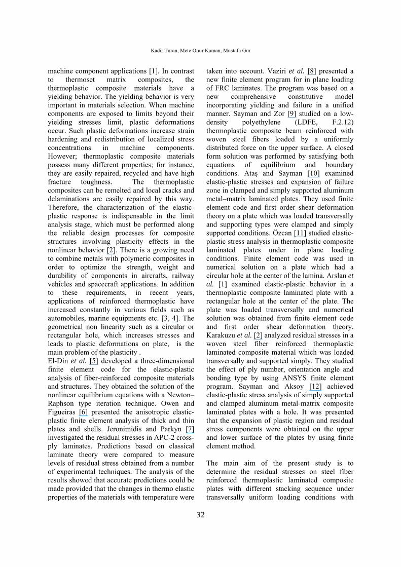
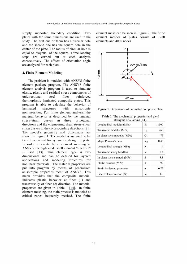
The problem is modeled with ANSYS finite element package program. The ANSYS finite element analysis program is used to simulate elastic, plastic and residual stress components of unidirectional steel fiber reinforced thermoplastic laminated composite plates. This program is able to calculate the behavior of laminated structures with anisotropic nonlinearities. For finite element analysis, the material behavior is described by the uniaxial stress–strain curves in three orthogonal directions and the engineering shear stress–shear strain curves in the corresponding directions [2]. The model’s geometry and dimensions are shown in Figure 1. The model is assumed to be two dimensional for symmetric design of plate. In order to create finite element meshing in ANSYS, the eight-node shell element “Shell 91” is used [13]. This element type is two dimensional and can be defined for layered applications and modeling structures for nonlinear materials. The material properties are put into program by means of generalized anisotropic properties menu of ANSYS. This menu provides that the composite material indicates plastic behavior at fiber (1) and transversally of fiber (2) direction. The material properties are given in Table 1 [14]. In finite element meshing, the main process is modeled at critical zones frequently meshed. The finite
element mesh can be seen in Figure 2. The finite element meshes of plates consist of 1280 elements and 4000 nodes
Figure 1. Dimensions of laminated composite plate.
Table 1. The mechanical properties and yield
strengths of a lamina [14]. Longitudinal modulus (MPa) E1 11300
Transverse modulus (MPa) E2 260
In-plane shear modulus (MPa) G12 75
Major Poisson’s ratio υ12 0.43
Longitudinal strength (MPa) X 14
Transverse strength (MPa) Y 5.4
In-plane shear strength (MPa) S 3.8
Plastic constant (MPa) K 92
Strain hardening parameter n 0.75
Fiber volume fraction (%) Vf 6
Kadir Turan, Mete Onur Kaman, Mustafa Gur
34
Figure 2. Finite element meshes of laminated composite plates.
2.1. Loading and boundary conditions
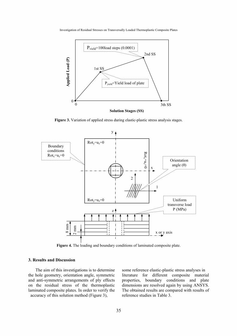
To obtain residual stress, the loads are applied as three loads steps in each analysis. First load step finds the yielding point for each plate. The loads are incrementally increased from zero to yield points. The yielding behavior is described when the first plastic stress is obtained in plate. For sensitive solution, the loads are applied in very small amounts such as 0.0001 MPa increments in each load steps. At the second step in analysis, the loads are applied for obtaining plastic stresses. The loads are applied yield load+50, +100 and +150 load steps. Each load step is 0.0001 MPa magnitudes. The last load step is applied for obtaining residual stress. In this step the loads are applied
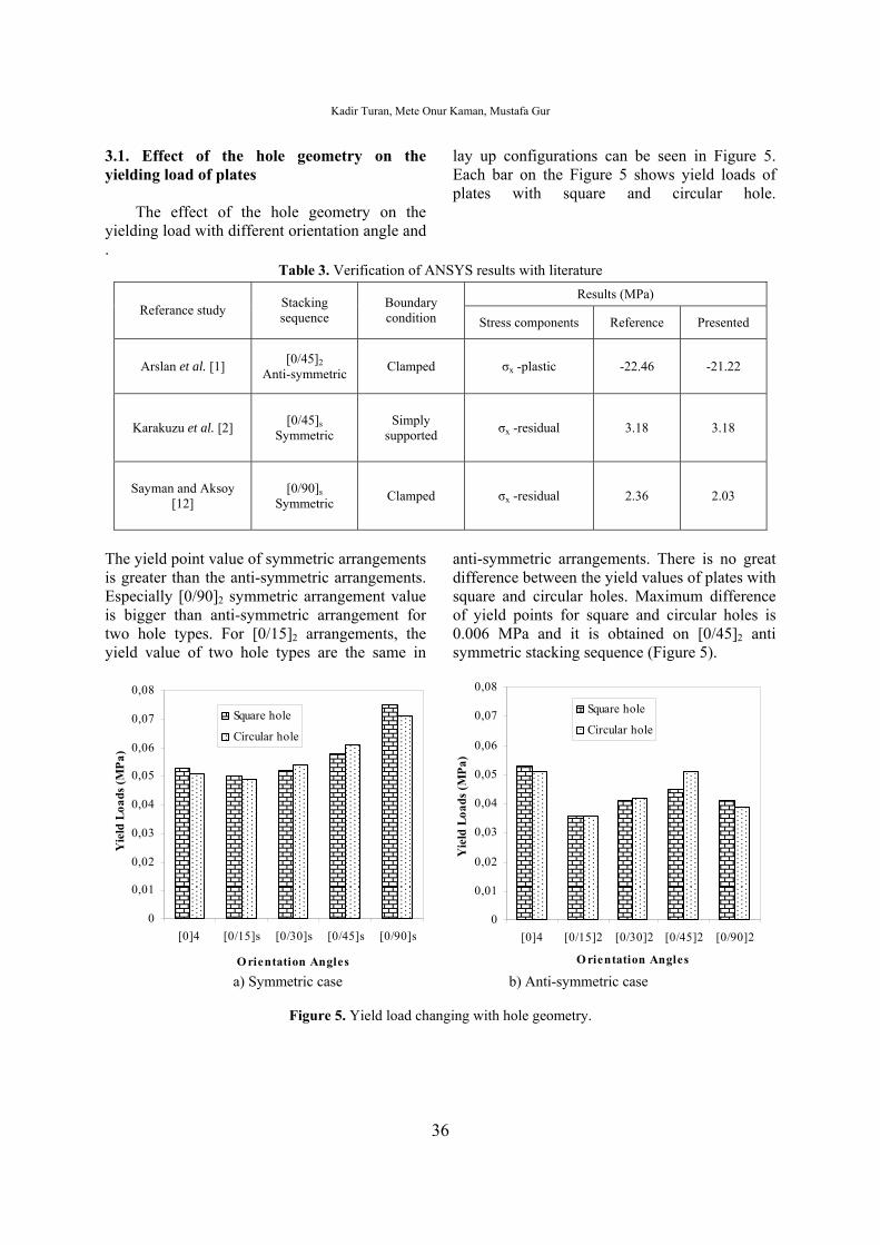
as zero which means; loads which are applied plates are released. The Figure 3 shows the changing time history of these loads. The loads are applied at uniform transversally direction of plates. Edges of the plates are simply supported. It is assumed that the uniform pressure acts on the upper surface of the laminated composite plate. The Figure 4 demonstrates the support types and loading conditions. The materials are chosen as the laminated plates. Each ply orientation, material properties and thickness are input program with Real Constant menu. The thickness of plate is 8 mm and each ply thickness is 2 mm. Orientation angle is [0/θ]2 symmetric and anti- symmetric four layered configuration. θ values are 0o, 15o, 30o, 45oand 90o.
Investigation of Residual Stresses on Transversally Loaded Thermoplastic Composite Plates
35
Figure 3. Variation of applied stress during elastic-plastic stress analysis stages.
Figure 4. The loading and boundary conditions of laminated composite plate.
3. Results and Discussion
The aim of this investigations is to determine the hole geometry, orientation angle, symmetric and anti-symmetric arrangements of ply effects on the residual stress of the thermoplastic laminated composite plates. In order to verify the accuracy of this solution method (Figure 3),
some reference elastic-plastic stress analyses in literature for different composite material properties, boundary conditions and plate dimensions are resolved again by using ANSYS. The obtained results are compared with results of reference studies in Table 3.
2
mm
8
mm
x or y axis
z
Uniform transverse load
P (MPa)
x
y
Roty=uz=0
Roty=uz=0
Rotx =u
z =0
2
1
Boundary conditions Rotx=uz=0
Orientation angle (θ)
Solution Stages (SS)
1st SS
2nd SS
3th SS
A
pplie
d L
oad
(P)
0 0
Pyield=Yield load of plate
Pyield+100load steps (0.0001)
Kadir Turan, Mete Onur Kaman, Mustafa Gur
36
3.1. Effect of the hole geometry on the yielding load of plates
The effect of the hole geometry on the yielding load with different orientation angle and
lay up configurations can be seen in Figure 5. Each bar on the Figure 5 shows yield loads of plates with square and circular hole.
. Table 3. Verification of ANSYS results with literature
Results (MPa) Referance study Stacking
sequence Boundary condition Stress components Reference Presented
Arslan et al. [1] [0/45]2
Anti-symmetric Clamped σx -plastic -22.46 -21.22
Karakuzu et al. [2] [0/45]s
Symmetric Simply
supported σx -residual 3.18 3.18
Sayman and Aksoy [12]
[0/90]s Symmetric Clamped σx -residual 2.36 2.03
The yield point value of symmetric arrangements is greater than the anti-symmetric arrangements. Especially [0/90]2 symmetric arrangement value is bigger than anti-symmetric arrangement for two hole types. For [0/15]2 arrangements, the yield value of two hole types are the same in
anti-symmetric arrangements. There is no great difference between the yield values of plates with square and circular holes. Maximum difference of yield points for square and circular holes is 0.006 MPa and it is obtained on [0/45]2 anti symmetric stacking sequence (Figure 5).
0
0,01
0,02
0,03
0,04
0,05
0,06
0,07
0,08
[0]4 [0/15]s [0/30]s [0/45]s [0/90]s
O rientation Angles
Yie
ld L
oads
(MPa
)
Square hole
Circular hole
0
0,01
0,02
0,03
0,04
0,05
0,06
0,07
0,08
[0]4 [0/15]2 [0/30]2 [0/45]2 [0/90]2
O rientation Angles
Yie
ld L
oads
(MPa
)
Square hole
Circular hole
a) Symmetric case b) Anti-symmetric case
Figure 5. Yield load changing with hole geometry.
Investigation of Residual Stresses on Transversally Loaded Thermoplastic Composite Plates
37
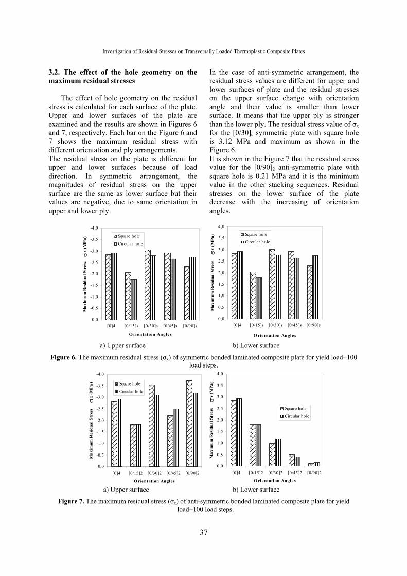
3.2. The effect of the hole geometry on the maximum residual stresses
The effect of hole geometry on the residual stress is calculated for each surface of the plate. Upper and lower surfaces of the plate are examined and the results are shown in Figures 6 and 7, respectively. Each bar on the Figure 6 and 7 shows the maximum residual stress with different orientation and ply arrangements. The residual stress on the plate is different for upper and lower surfaces because of load direction. In symmetric arrangement, the magnitudes of residual stress on the upper surface are the same as lower surface but their values are negative, due to same orientation in upper and lower ply.
In the case of anti-symmetric arrangement, the residual stress values are different for upper and lower surfaces of plate and the residual stresses on the upper surface change with orientation angle and their value is smaller than lower surface. It means that the upper ply is stronger than the lower ply. The residual stress value of σx for the [0/30]s symmetric plate with square hole is 3.12 MPa and maximum as shown in the Figure 6. It is shown in the Figure 7 that the residual stress value for the [0/90]2 anti-symmetric plate with square hole is 0.21 MPa and it is the minimum value in the other stacking sequences. Residual stresses on the lower surface of the plate decrease with the increasing of orientation angles.
-4,0
-3,5
-3,0
-2,5
-2,0
-1,5
-1,0
-0,5
0,0[0]4 [0/15]s [0/30]s [0/45]s [0/90]s
O rientation Angles
Max
imum
Res
idua
l Str
essσ
x (M
Pa) Square hole
Circular hole
0,0
0,5
1,0
1,5
2,0
2,5
3,0
3,5
4,0
[0]4 [0/15]s [0/30]s [0/45]s [0/90]s
O rientation Angles
Max
imum
Res
idua
l Str
ess
σx
(MPa
) Square hole
Circular hole
a) Upper surface b) Lower surface
Figure 6. The maximum residual stress (σx) of symmetric bonded laminated composite plate for yield load+100 load steps.
-4,0
-3,5
-3,0
-2,5
-2,0
-1,5
-1,0
-0,5
0,0[0]4 [0/15]2 [0/30]2 [0/45]2 [0/90]2
O rientation Angles
Max
imum
Res
idua
l Str
ess
σx
(MPa
) Square hole
Circular hole
0,0
0,5
1,0
1,5
2,0
2,5
3,0
3,5
4,0
[0]4 [0/15]2 [0/30]2 [0/45]2 [0/90]2
O rientation Angles
Max
imum
Res
idua
l Str
ess
σx
(MPa
)
Square hole
Circular hole
a) Upper surface b) Lower surface
Figure 7. The maximum residual stress (σx) of anti-symmetric bonded laminated composite plate for yield load+100 load steps.
Kadir Turan, Mete Onur Kaman, Mustafa Gur
38
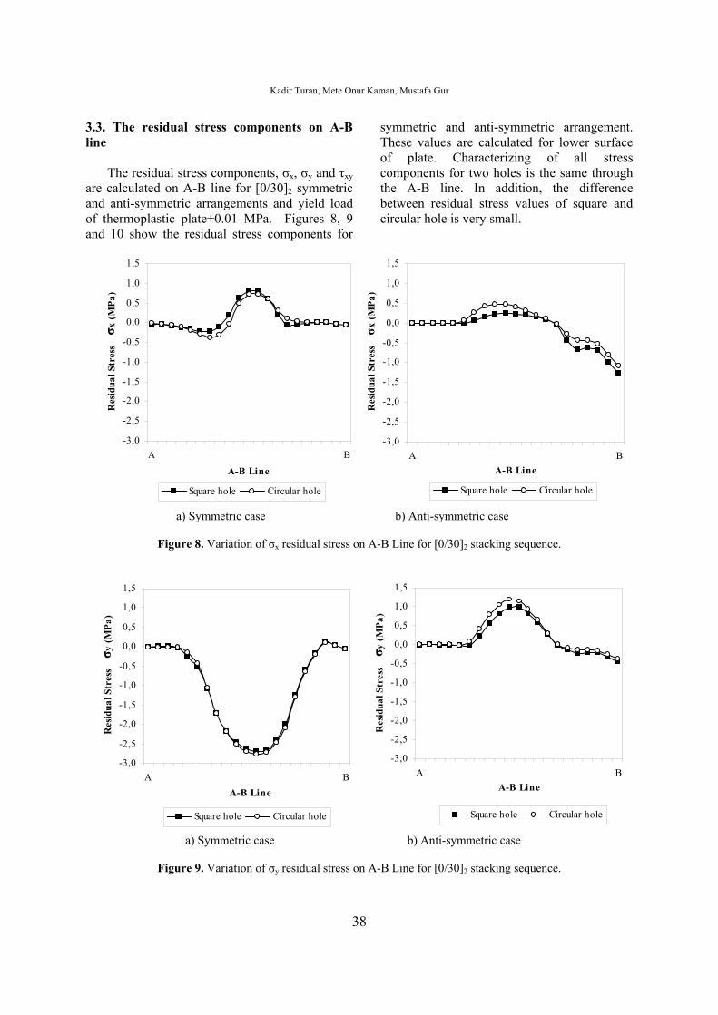
3.3. The residual stress components on A-B line
The residual stress components, σx, σy and τxy are calculated on A-B line for [0/30]2 symmetric and anti-symmetric arrangements and yield load of thermoplastic plate+0.01 MPa. Figures 8, 9 and 10 show the residual stress components for
symmetric and anti-symmetric arrangement. These values are calculated for lower surface of plate. Characterizing of all stress components for two holes is the same through the A-B line. In addition, the difference between residual stress values of square and circular hole is very small.
-3,0
-2,5
-2,0
-1,5
-1,0
-0,5
0,0
0,5
1,0
1,5
A B
A-B Line
Res
idua
l Str
ess σ x
(MPa
)
Square hole Circular hole
-3,0
-2,5
-2,0
-1,5
-1,0
-0,5
0,0
0,5
1,0
1,5
A BA-B Line
Res
idua
l Str
ess
σ x (M
Pa)
Square hole Circular hole
a) Symmetric case b) Anti-symmetric case
Figure 8. Variation of σx residual stress on A-B Line for [0/30]2 stacking sequence.
-3,0
-2,5
-2,0
-1,5
-1,0
-0,5
0,0
0,5
1,0
1,5
A BA-B Line
Res
idua
l Str
ess σ y
(MPa
)
Square hole Circular hole
-3,0
-2,5
-2,0
-1,5
-1,0
-0,5
0,0
0,5
1,0
1,5
A BA-B Line
Res
idua
l Str
ess σ y
(MPa
)
Square hole Circular hole
a) Symmetric case b) Anti-symmetric case
Figure 9. Variation of σy residual stress on A-B Line for [0/30]2 stacking sequence.
Investigation of Residual Stresses on Transversally Loaded Thermoplastic Composite Plates
39
-3,0
-2,5
-2,0
-1,5
-1,0
-0,5
0,0
0,5
1,0
1,5
A B
A-B Line
Res
idua
l Str
ess τ x
y (
MPa
)
Square hole Circular hole
-3,0
-2,5
-2,0
-1,5
-1,0
-0,5
0,0
0,5
1,0
1,5
A B
A-B Line
Res
idua
l Str
ess τ x
y (M
Pa)
Square hole Circular hole
a) Symmetric case b) Anti-symmetric case
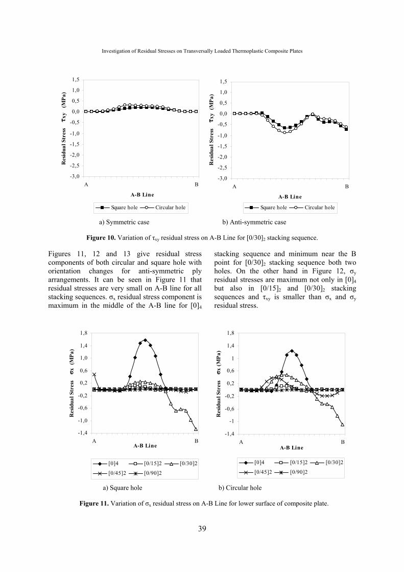
Figure 10. Variation of τxy residual stress on A-B Line for [0/30]2 stacking sequence.
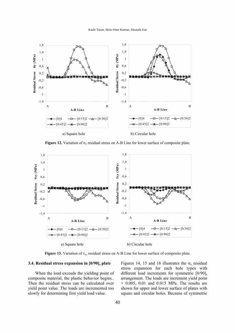
Figures 11, 12 and 13 give residual stress components of both circular and square hole with orientation changes for anti-symmetric ply arrangements. It can be seen in Figure 11 that residual stresses are very small on A-B line for all stacking sequences. σx residual stress component is maximum in the middle of the A-B line for [0]4
stacking sequence and minimum near the B point for [0/30]2 stacking sequence both two holes. On the other hand in Figure 12, σy residual stresses are maximum not only in [0]4 but also in [0/15]2 and [0/30]2 stacking sequences and τxy is smaller than σx and σy residual stress.
-1,4
-1,0
-0,6
-0,2
0,2
0,6
1,0
1,4
1,8
A BA-B Line
Res
idua
l Str
ess
σ x (
MPa
)
[0]4 [0/15]2 [0/30]2
[0/45]2 [0/90]2
-1,4
-1
-0,6
-0,2
0,2
0,6
1
1,4
1,8
A BA-B Line
Res
idua
l Str
ess
σ x (M
Pa)
[0]4 [0/15]2 [0/30]2
[0/45]2 [0/90]2
a) Square hole b) Circular hole
Figure 11. Variation of σx residual stress on A-B Line for lower surface of composite plate.
Kadir Turan, Mete Onur Kaman, Mustafa Gur
40
-1,4
-1
-0,6
-0,2
0,2
0,6
1
1,4
1,8
A BA-B Line
Res
idua
l Str
ess
σ y (M
Pa)
[0]4 [0/15]2 [0/30]2
[0/45]2 [0/90]2
-1,4
-1
-0,6
-0,2
0,2
0,6
1
1,4
1,8
A BA-B Line
Res
idua
l Str
ess
σ y (M
Pa)
[0]4 [0/15]2 [0/30]2
[0/45]2 [0/90]2
a) Square hole b) Circular hole
Figure 12. Variation of σy residual stress on A-B Line for lower surface of composite plate.
-1,4
-1
-0,6
-0,2
0,2
0,6
1
1,4
1,8
A BA-B Line
Res
idua
l Str
ess
τ xy
(MPa
)
[0]4 [0/15]2 [0/30]2
[0/45]2 [0/90]2
-1,4
-1
-0,6
-0,2
0,2
0,6
1
1,4
1,8
A BA-B Line
Res
idua
l Str
ess
τ xy
(MPa
)
[0]4 [0/15]2 [0/30]2
[0/45]2 [0/90]2
a) Square hole b) Circular hole
Figure 13. Variation of τxy residual stress on A-B Line for lower surface of composite plate.
3.4. Residual stress expansion in [0/90]s plate
When the load exceeds the yielding point of composite material, the plastic behavior begins.. Then the residual stress can be calculated over yield point value. The loads are incremented too slowly for determining first yield load value.
Figures 14, 15 and 16 illustrates the σx residual stress expansion for each hole types with different load increments for symmetric [0/90]s arrangement. The loads are increment yield point + 0.005, 0.01 and 0.015 MPa. The results are shown for upper and lower surface of plates with square and circular holes. Because of symmetric
Investigation of Residual Stresses on Transversally Loaded Thermoplastic Composite Plates
41
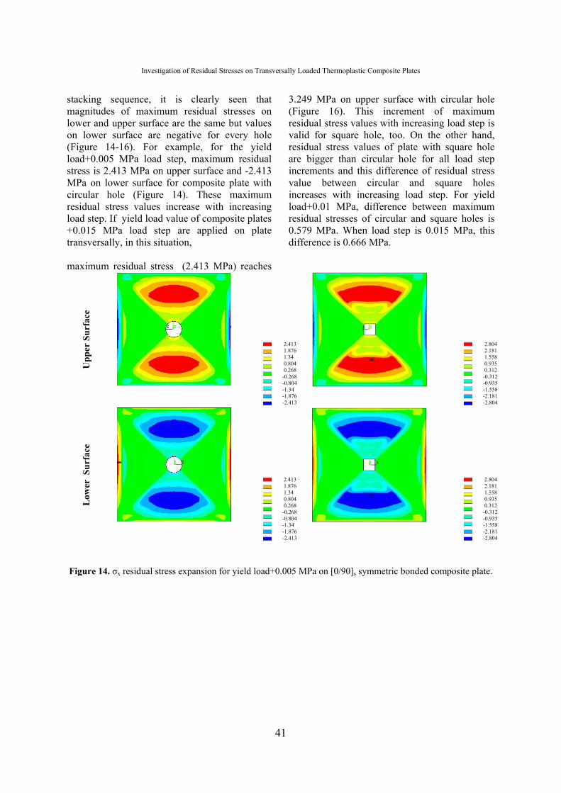
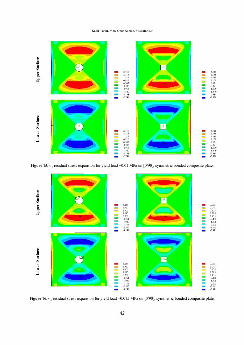
stacking sequence, it is clearly seen that magnitudes of maximum residual stresses on lower and upper surface are the same but values on lower surface are negative for every hole (Figure 14-16). For example, for the yield load+0.005 MPa load step, maximum residual stress is 2.413 MPa on upper surface and -2.413 MPa on lower surface for composite plate with circular hole (Figure 14). These maximum residual stress values increase with increasing load step. If yield load value of composite plates +0.015 MPa load step are applied on plate transversally, in this situation, maximum residual stress (2.413 MPa) reaches
3.249 MPa on upper surface with circular hole (Figure 16). This increment of maximum residual stress values with increasing load step is valid for square hole, too. On the other hand, residual stress values of plate with square hole are bigger than circular hole for all load step increments and this difference of residual stress value between circular and square holes increases with increasing load step. For yield load+0.01 MPa, difference between maximum residual stresses of circular and square holes is 0.579 MPa. When load step is 0.015 MPa, this difference is 0.666 MPa.
Figure 14. σx residual stress expansion for yield load+0.005 MPa on [0/90]s symmetric bonded composite plate.
Upp
er S
urfa
ce
2.413 1.876 1.34 0.804 0.268 -0.268 -0.804 -1.34 -1.876 -2.413
2.804 2.181 1.558 0.935 0.312 -0.312 -0.935 -1.558 -2.181 -2.804
Low
er S
urfa
ce
2.413 1.876 1.34 0.804 0.268 -0.268 -0.804 -1.34 -1.876 -2.413
2.804 2.181 1.558 0.935 0.312 -0.312 -0.935 -1.558 -2.181 -2.804
Kadir Turan, Mete Onur Kaman, Mustafa Gur
42
Figure 15. σx residual stress expansion for yield load +0.01 MPa on [0/90]s symmetric bonded composite plate.
Figure 16. σx residual stress expansion for yield load +0.015 MPa on [0/90]s symmetric bonded composite plate.
Upp
er S
urfa
ce
2.749 2.138 1.527 0.916 0.305 -0.305 -0.916 -1.527 -2.138 -2.749
3.328 2.588 1.849 1.109 0.37 -0.37 -1.109 -1.849 -2.588 -3.328
Low
er S
urfa
ce
2.749 2.138 1.527 0.916 0.305 -0.305 -0.916 -1.527 -2.138 -2.749
3.328 2.588 1.849 1.109 0.37 -0.37 -1.109 -1.849 -2.588 -3.328
Upp
er S
urfa
ce
3.249 2.527 1.805 1.083 0.361 -0.361 -1.083 -1.805 -2.527 -3.249
3.915 3.045 2.175 1.305 0.435 -0.435 -1.305 -2.175 -3.045 -3.915
Low
er S
urfa
ce
3.249 2.527 1.805 1.083 0.361 -0.361 -1.083 -1.805 -2.527 -3.249
3.915 3.045 2.175 1.305 0.435 -0.435 -1.305 -2.175 -3.045 -3.915
Investigation of Residual Stresses on Transversally Loaded Thermoplastic Composite Plates
43
4. Conclusions
The present study shows the residual stress components and residual stress expansion with a plate with square or circular hole. The yield load and variation of residual stresses are examined for laminated thermoplastic composite plates reinforced with unidirectional steel fibers. The plates are loaded in uniform static transversal direction and fixing is simply supported. The results can be concluded as below:
• The yield point value of symmetric bonded thermoplastic plates is greater than anti-symmetric bonded laminated.
• The biggest yield load is calculated for [0/90]s symmetric case on square hole and the smallest yield load is found for [0/15]2 anti-symmetric bonded laminated composite plates both square and circular holes.
• Difference between yield loads and residual stress values of composite plates with square and circular hole is very close. Besides characterizing, residual stress variation is the same for square and circular geometry.
• For anti-symmetric case, the maximum residual stress values of thermoplastic laminated plate on upper surface are bigger than lower surface. In the symmetric case, residual stress values are the same on upper and lower surface of plates for all stacking sequences.
• On the lower surface of plate, residual
stresses decrease with increasing orientation angle for anti-symmetric bonded laminated composite plates.
• Residual stress zones on the composite plate increase with increasing transverse loads.
• Found local residual stresses from elastic-plastic stress analysis can be used to increase strength of laminated thermoplastic composite for transverse loading conditions.
• In literature [1,3,9-12], elastic-plastic stress analysis problems were generally solved with program codes prepared and developed by the authors. However, in this study, for solution of these type of problems, the ANSYS finite element package program is used. In order to show a compatible solution method, some elastic-plastic stress problems for laminated composite plates are resolved again and the results are verified. Since ANSYS is a package finite element program and is very easy to apply for all two and three dimensional problems, it can also be used for complex geometries of different elastic-plastic problem .
5. References 1. Arslan, N., Arslan, N., and Okumuş, F. (2004).
Elastic-plastic Stress Analysis and Expansion of Plastic Zone in Clamped and Simply Supported Thermoplastic–Matrix Laminated Plates with Square Hole. Composites Science and Technology, 64 (9), 1147-1166.
2. Karakuzu, R., Aslan, Z., and Okutan B. (2004). The Effect of Ply Number, Orientation Angle and Bonding Type on Residual Stresses of Woven Steel Fiber Reinforced Thermoplastic Laminated Composite Plates Subjected to Transverse Uniform Load. Composites Science and Technology, 64 (7-8), 1049-1056.
3. Arslan, N., Çelik, M., and Arslan, N. (2002). Prediction of The Elastic-Plastic Behavior of Thermoplastic Composite Laminated Plates ([0o/θo]2) with Square Hole. Composite Structures,
55 (1), 37-49.
4. Karakuzu, R., Ataş, C., and Akbulut, H.
(2001). Elastic-Plastic Behavior of Woven Steel Fiber Reinforced Thermoplastic Laminated Plates Under in-Plane Loading. Composites Science and Technology, 61 (10), 1475-1483.
5. Bahei-El-Din, Y.A., Dvorak, G.J., and Utku, S. (1981). Finite Element Analysis of Elastic–Plastic Fibrous Composite Structures. Computers and Structures, 13 (1-3), 321–330.
6. Owen, D.R.J., and Figueiras, J.A. (1983). Anisotropic Elastic-Plastic Finite Element Analysis of Thick and Thin Plates and Shells. International Journal for Numerical Methods in Engineering, 19 (4), 541–566.
7. Jeronimidis, G., and Parkyn, A.T. (1988). Residual Stresses in Carbon Fiber– Thermoplastic Matrix Laminates. Journal of Composite Materials, 22 (5), 401–415.
Kadir Turan, Mete Onur Kaman, Mustafa Gur
44
8. Vaziri, R., Olson, M.D., and Anderson, D.L.
(1992). Finite Element Analysis of Fibrous Composite Structures: A Plasticity Approach. Computers and Structures, 44 (1-2), 103–116.
9. Sayman, O., and Zor, M. (2000). Elastic-Plastic Stress Analysis and Residual Stresses in A Woven Steel Fiber Reinforced Thermoplastic Composite Cantilever Beam Loaded Uniformly. Journal of Reinforced Plastics and Composites, 19 (13), 1078–1092.
10. Ataş, C., and Sayman, O. (2000). Elastic–Plastic Stress Analysis and Expansion of Plastic Zone in Clamped and Simply Supported Aluminum Metal-Matrix Laminated Plates. Composite Structures, 49 (1), 9-19.
11. Özcan, R. (2000). Elastic–Plastic Stress Analysis in Thermoplastic Composite Laminated Plates Under in-Plane Loading. Composite Structures, 49 (2), 201-208.
12. Sayman, O., and Aksoy, S. (2001). Elastic–
Plastic Stress Analysis of Simply Supported and Clamped Aluminum Metal Matrix Laminated Plates with a Hole. Composite Structures, 53 (3), 355-364.
13. ANSYS 11.0 Academic Teaching Introductory Help Menu, 2007.
14. Sayman, O., Duranay, M., Gür, M., and Koçak, S. (2006). Elastic-Plastic Stress Analysis of a Thermoplastic Composite Disc Under a Steady State Temperature Distribution. Science and Engineering of Composite Materials, 13 (2), 139-150.