thermoplastic hoses for hydraulics & industry
TRANSCRIPT

Thermoplastic H
oses for Hydraulics &
Industry
Parker Hannifi n Manufacturing Germany GmbH & Co. KGpolyflex DivisionAn der Tuchbleiche 468623 Lampertheim (Hüttenfeld)Tel.: +49 (0)6256 81-0Fax: +49 (0)6256 81-123www.parker.com/polyfl expolyfl [email protected]
Catalogue 4460-UK 05/2019© 2019 Parker Hannifin Corporation. All rights reserved. Subject to technical modifi cation and error.
Thermoplastic Hosesfor Hydraulics & IndustryCatalogue 4460-UK
Europe, Middle East, AfricaAE – United Arab Emirates, DubaiTel: +971 4 [email protected]
AT – Austria, St. FlorianTel: +43 (0)7224 66201 [email protected]
AZ – Azerbaijan, BakuTel: +994 50 2233 [email protected]
BE/NL/LU – Benelux, Hendrik Ido AmbachtTel: +31 (0)541 585 [email protected]
BG – Bulgaria, So� aTel: +359 2 980 [email protected]
BY – Belarus, MinskTel: +48 (0)22 573 24 [email protected]
CH – Switzerland, EtoyTel: +41 (0)21 821 87 00 [email protected]
CZ – Czech Republic, KlecanyTel: +420 284 083 [email protected]
DE – Germany, KaarstTel: +49 (0)2131 4016 [email protected]
DK – Denmark, BallerupTel: +45 43 56 04 [email protected]
ES – Spain, MadridTel: +34 902 330 [email protected]
FI – Finland, VantaaTel: +358 (0)20 753 2500parker.� [email protected]
FR – France, Contamine s/ArveTel: +33 (0)4 50 25 80 [email protected]
GR – Greece, PiraeusTel: +30 210 933 [email protected]
HU – Hungary, BudaörsTel: +36 23 885 [email protected]
IE – Ireland, DublinTel: +353 (0)1 466 [email protected]
IL – IsraelTel: +39 02 45 19 [email protected]
IT – Italy, Corsico (MI)Tel: +39 02 45 19 [email protected]
KZ – Kazakhstan, AlmatyTel: +7 7273 561 [email protected]
NO – Norway, AskerTel: +47 66 75 34 [email protected]
PL – Poland, WarsawTel: +48 (0)22 573 24 [email protected]
PT – PortugalTel: +351 22 999 [email protected]
RO – Romania, BucharestTel: +40 21 252 [email protected]
RU – Russia, MoscowTel: +7 495 [email protected]
SE – Sweden, SpångaTel: +46 (0)8 59 79 50 [email protected]
SK – Slovakia, Banská BystricaTel: +421 484 162 [email protected]
SL – Slovenia, Novo MestoTel: +386 7 337 [email protected]
TR – Turkey, IstanbulTel: +90 216 [email protected]
UA – Ukraine, KievTel: +48 (0)22 573 24 [email protected]
UK – United Kingdom, WarwickTel: +44 (0)1926 317 [email protected]
ZA – South Africa, Kempton ParkTel: +27 (0)11 961 [email protected]
Parker Worldwide
North AmericaCA – Canada, Milton, OntarioTel: +1 905 693 3000
US – USA, Cleveland Tel: +1 216 896 3000
Asia Pacifi cAU – Australia, Castle HillTel: +61 (0)2-9634 7777
CN – China, ShanghaiTel: +86 21 2899 5000
HK – Hong KongTel: +852 2428 8008
IN – India, MumbaiTel: +91 22 6513 7081-85
JP – Japan, TokyoTel: +81 (0)3 6408 3901
KR – South Korea, SeoulTel: +82 2 559 0400
MY – Malaysia, Shah AlamTel: +60 3 7849 0800
NZ – New Zealand, Mt WellingtonTel: +64 9 574 1744
SG – SingaporeTel: +65 6887 6300
TH – Thailand, BangkokTel: +662 186 7000
TW – Taiwan, TaipeiTel: +886 2 2298 8987
South AmericaAR – Argentina, Buenos AiresTel: +54 3327 44 4129
BR – Brazil, Sao Jose dos CamposTel: +55 800 727 5374
CL – Chile, SantiagoTel: +56 2 623 1216
MX – Mexico, TolucaTel: +52 72 2275 4200

Catalogue 4460-UK
Thermoplastic hose, fittings and accessories for hydraulic and industrial applicationsTable of contents
! Introduction and General Statements How to use the catalog . . . . . . . . . . . . . . . . . . . . . . . . . . . . . . . . . . . . . . . . II
Part number system & Explanation of symbols . . . . . . . . . . . . . . . . . . . . IV
Parker Hannifin – Polyflex Division . . . . . . . . . . . . . . . . . . . . . . . . . . . . . . VI
Why choose Parker thermoplastic hose? . . . . . . . . . . . . . . . . . . . . . . . . . VII
Preformed hoses . . . . . . . . . . . . . . . . . . . . . . . . . . . . . . . . . . . . . . . . . . . . . XIII
Non conductive hoses . . . . . . . . . . . . . . . . . . . . . . . . . . . . . . . . . . . . . . . . . XV
Twinline and multiline hoses . . . . . . . . . . . . . . . . . . . . . . . . . . . . . . . . . . . XVI
Hose bundles . . . . . . . . . . . . . . . . . . . . . . . . . . . . . . . . . . . . . . . . . . . . . . . . XVII
Parkrimp system . . . . . . . . . . . . . . . . . . . . . . . . . . . . . . . . . . . . . . . . . . . . . XVIII
Value added services . . . . . . . . . . . . . . . . . . . . . . . . . . . . . . . . . . . . . . . . . XIX
A Hose and Fitting Selection Hose selection . . . . . . . . . . . . . . . . . . . . . . . . . . . . . . . . . . . . . . . . . . . . . . . A – 2
Fitting selection . . . . . . . . . . . . . . . . . . . . . . . . . . . . . . . . . . . . . . . . . . . . . . A – 18
B Push-Lok® Hose and Fittings Push-Lok® hose . . . . . . . . . . . . . . . . . . . . . . . . . . . . . . . . . . . . . . . . . . . . . . B – 4
Fittings for Push-Lok® hose . . . . . . . . . . . . . . . . . . . . . . . . . . . . . . . . . . . . B – 6
C PTFE / Fluoropolymer Hose and Fittings PTFE hose . . . . . . . . . . . . . . . . . . . . . . . . . . . . . . . . . . . . . . . . . . . . . . . . . . C – 4
Fittings for PTFE hose . . . . . . . . . . . . . . . . . . . . . . . . . . . . . . . . . . . . . . . . C – 13
D Hose and Fittings for Alternative Fuels SCR hose . . . . . . . . . . . . . . . . . . . . . . . . . . . . . . . . . . . . . . . . . . . . . . . . . . . D – 4
CNG hose . . . . . . . . . . . . . . . . . . . . . . . . . . . . . . . . . . . . . . . . . . . . . . . . . . . D – 5
LPG hose . . . . . . . . . . . . . . . . . . . . . . . . . . . . . . . . . . . . . . . . . . . . . . . . . . . D – 6
Fittings . . . . . . . . . . . . . . . . . . . . . . . . . . . . . . . . . . . . . . . . . . . . . . . . . . . . . D – 7
AerospaceKey MarketsAftermarket services Commercial transportsEnginesGeneral & business aviationHelicoptersLaunch vehiclesMilitary aircraftMissilesPower generation Regional transportsUnmanned aerial vehicles
Key ProductsControl systems & actuation productsEngine systems & componentsFluid conveyance systems& componentsFluid metering, delivery & atomization devicesFuel systems & componentsFuel tank inerting systemsHydraulic systems & componentsThermal managementWheels & brakes
ElectromechanicalKey MarketsAerospaceFactory automationLife science & medicalMachine toolsPackaging machineryPaper machineryPlastics machinery & convertingPrimary metalsSemiconductor & electronicsTextileWire & cable
Key ProductsAC/DC drives & systemsElectric actuators, gantry robots & slidesElectrohydrostatic actuation systemsElectromechanical actuation systemsHuman machine interfaceLinear motorsStepper motors, servo motors, drives & controlsStructural extrusions
PneumaticsKey MarketsAerospaceConveyor & material handlingFactory automationLife science & medicalMachine toolsPackaging machineryTransportation & automotive
Key ProductsAir preparationBrass fittings & valvesManifoldsPneumatic accessoriesPneumatic actuators & grippersPneumatic valves & controlsQuick disconnectsRotary actuatorsRubber & thermoplastic hose & couplingsStructural extrusionsThermoplastic tubing & fittingsVacuum generators, cups & sensors
Fluid & Gas HandlingKey Markets Aerial liftAgricultureBulk chemical handlingConstruction machineryFood & beverageFuel & gas deliveryIndustrial machineryLife sciences MarineMiningMobileOil & gasRenewable energySolenoid valvesTransportation
Key Products Check valves Connectors for low pressure fluid conveyanceDeep sea umbilicalsDiagnostic equipment Hose couplingsIndustrial hoseMooring systems & power cablesPTFE hose & tubing Quick couplingsRubber & thermoplastic hose Tube fittings & adaptersTubing & plastic fittings
HydraulicsKey Markets Aerial liftAgricultureAlternative energyConstruction machineryForestryIndustrial machineryMachine toolsMarineMaterial handlingMiningOil & gasPower generationRefuse vehiclesRenewable energyTruck hydraulicsTurf equipment
Key Products AccumulatorsCartridge valvesElectrohydraulic actuatorsHuman machine interfacesHybrid drivesHydraulic cylinders Hydraulic motors & pumpsHydraulic systemsHydraulic valves & controlsHydrostatic steeringIntegrated hydraulic circuitsPower take-offs Power unitsRotary actuatorsSensors
Process ControlKey Markets Alternative fuelsBiopharmaceuticalsChemical & refiningFood & beverageMarine & shipbuildingMedical & dentalMicroelectronicsNuclear PowerOffshore oil explorationOil & gasPharmaceuticalsPower generationPulp & paperSteelWater/wastewater
Key ProductsAnalytical Instruments Analytical sample conditioningproducts & systemsChemical injection fittings& valvesFluoropolymer chemicaldelivery fittings, valves & pumpsHigh purity gas delivery fittings, valves, regulators& digital flow controllersIndustrial mass flow meters/controllersPermanent no-weld tube fittingsPrecision industrial regulators& flow controllersProcess control double block & bleedsProcess control fittings, valves, regulators & manifold valves
Sealing & ShieldingKey Markets AerospaceChemical processingConsumerFluid powerGeneral industrialInformation technologyLife sciencesMicroelectronicsMilitaryOil & gasPower generationRenewable energyTelecommunicationsTransportation
Key Products Dynamic sealsElastomeric o-ringsElectro-medical instrumentdesign & assemblyEMI shieldingExtruded & precision-cut,fabricated elastomeric sealsHigh temperature metal sealsHomogeneous & insertedelastomeric shapesMedical device fabrication & assemblyMetal & plastic retainedcomposite sealsShielded optical windowsSilicone tubing & extrusionsThermal managementVibration dampening
Parker’s Motion & Control Technologies
At Parker, we’re guided by a relentless drive to help our customers become more productive and achieve higher levels of profitabil-ity by engineering the best systems for their require-ments. It means looking at customer applications from many angles to find new ways to create value. What-ever the motion and control technology need, Parker has the experience, breadth of product and global reach to consistently deliver. No company knows more about motion and control technol-ogy than Parker. For further info call 00800 27 27 5374
Climate ControlKey Markets AgricultureAir conditioningConstruction MachineryFood & beverageIndustrial machineryLife sciencesOil & gasPrecision coolingProcessRefrigerationTransportation
Key Products AccumulatorsAdvanced actuatorsCO
2 controls
Electronic controllersFilter driersHand shut-off valvesHeat exchangers Hose & fittingsPressure regulating valvesRefrigerant distributorsSafety relief valvesSmart pumpsThermostatic expansion valves
FiltrationKey MarketsAerospaceFood & beverageIndustrial plant & equipmentLife sciencesMarineMobile equipmentOil & gasPower generation & renewable energyProcessTransportation Water Purification
Key Products Analytical gas generatorsCompressed air filters & dryersEngine air, coolant, fuel & oil filtration systemsFluid condition monitoring systemsHydraulic & lubrication filtersHydrogen, nitrogen & zero air generatorsInstrumentation filtersMembrane & fiber filtersMicrofiltrationSterile air filtrationWater desalination & purification filters & systems

Intr
o
I
A! B C D E F G H I
E Hose and Fittings for Hydraulic and Industrial Applications Small bore hose/mini-hydraulic hose . . . . . . . . . . . . . . . . . . . . . . . . . . . . E – 4
Medium pressure hose . . . . . . . . . . . . . . . . . . . . . . . . . . . . . . . . . . . . . . . . E – 7
High pressure hose . . . . . . . . . . . . . . . . . . . . . . . . . . . . . . . . . . . . . . . . . . . E – 14
Paint spray hose . . . . . . . . . . . . . . . . . . . . . . . . . . . . . . . . . . . . . . . . . . . . . E – 27
Gas hose . . . . . . . . . . . . . . . . . . . . . . . . . . . . . . . . . . . . . . . . . . . . . . . . . . . . E – 33
Hose fittings . . . . . . . . . . . . . . . . . . . . . . . . . . . . . . . . . . . . . . . . . . . . . . . . . E – 41
F Accessories Protective equipment (guards & sleeves) . . . . . . . . . . . . . . . . . . . . . . . . . F – 4
Banjo bolts & copper rings . . . . . . . . . . . . . . . . . . . . . . . . . . . . . . . . . . . . . F – 7
G Workshop Equipment Crimpers & Crimper accessories . . . . . . . . . . . . . . . . . . . . . . . . . . . . . . . . G – 4
Hose assembly equipment . . . . . . . . . . . . . . . . . . . . . . . . . . . . . . . . . . . . . G – 11
H Technical Information Crimpsource Online . . . . . . . . . . . . . . . . . . . . . . . . . . . . . . . . . . . . . . . . . . H – 4
Crimping and assembly instructions & procedures . . . . . . . . . . . . . . . . . H – 7
Selection criteria & installation tips . . . . . . . . . . . . . . . . . . . . . . . . . . . . . . H – 22
Unit conversion table . . . . . . . . . . . . . . . . . . . . . . . . . . . . . . . . . . . . . . . . . H – 27
Parker safety guide . . . . . . . . . . . . . . . . . . . . . . . . . . . . . . . . . . . . . . . . . . . H – 28
I Index of Part Numbers Index . . . . . . . . . . . . . . . . . . . . . . . . . . . . . . . . . . . . . . . . . . . . . . . . . . . . . . . I – 1
Safety note . . . . . . . . . . . . . . . . . . . . . . . . . . . . . . . . . . . . . . . . . . . . . . . . . . I – 14
The content contained in this catalogue has been compiled with the greatest care and corresponds to the information currently available to us.
However, we would like to point out that we reserve the right to make tech-nical changes and we kindly request you to contact us should you have any special questions.
Thermoplastic Hose, Fittings and Accessories for Hydraulic and Industrial Applications
Catalogue 4460-UK
Table of contents

Intr
o
Thermoplastic Hose, Fittings and Accessories for Hydraulic and Industrial Applications
II
How to use the catalogue
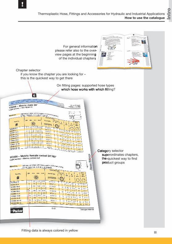
Overall structure of the catalogue:
General Info
Products
Detailed Technical InfoIndex
Hose data is always colored in blue
How to use the catalogue
Intr
o
Thermoplastic Hose, Fittings and Accessories for Hydraulic and Industrial Applications
!
III
Chapter selector if you know the chapter you are looking for –
this is the quickest way to get there
Category selector superordinates chapters,
the quickest way to fi nd product groups
On fi tting pages: supported hose types which hose works with which fi tting?
Category selector superordinates chapters,
the quickest way to fi nd product groups
which hose works with which fi tting?
Fitting data is always colored in yellow
For general information please refer also to the over-view pages at the beginning
of the individual chapters
For general information please refer also to the over-view pages at the beginning
of the individual chapters
For general information please refer also to the over-view pages at the beginning
How to use the catalogue
Intr
o
Thermoplastic Hose, Fittings and Accessories for Hydraulic and Industrial Applications
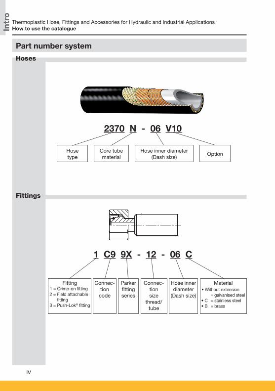
2370 N - 06 V10
Hosetype
Core tubematerial
Hose inner diameter(Dash size)
Option
1 C9 9X - 12 - 06 C
Fitting 1 = Crimp-on fitting 2 = Field attachable
fitting 3 = Push-Lok® fitting
Connec-tion
code
Parkerfittingseries
Connec-tionsize
thread/tube
Hose inner diameter
(Dash size)
Material • Without extension = galvanised steel • C = stainless steel • B = brass
Hoses
Fittings
Part number system
IV
How to use the catalogue
Intr
o
Thermoplastic Hose, Fittings and Accessories for Hydraulic and Industrial Applications
!
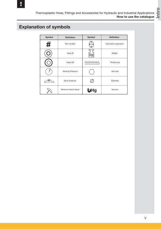
Explanation of symbols
Part number Volumetric expansion
Hose ID Weight
Hose OD
Working Pressure
Burst pressure
Minimum bend radius
Symbol Definition DefinitionSymbol
Thread size
Hex size
Diameter
Vacuum
V
Hg
How to use the catalogue

Intr
o
Thermoplastic Hose, Fittings and Accessories for Hydraulic and Industrial Applications
VI
Other catalogues with thermoplastic hoses
Parker Hannifin – Polyflex Division
Parker Hannifin offers an extensive programme of systems and components for fluid technology. Parker is structured by sales offices and manufacturing divisions to guar-antee optimum focus on our customers' demands and market interests at any time. The Polyflex division, with headquarters located in Hüttenfeld, Germany, provides thermoplastic hoses and tubes. These are applied in a variety of different markets such as standard hydraulics, ultra high pressure applications, and oil & gas industry. As a market leader in many areas and with a unique product range we are pleased to assist you with all your queries. This catalogue includes hoses and fittings for a pressure range up to 70 MPa. The indicated fittings are always adapted to the correspondent hose and offer optimum performance.
Catalogue 4462-UK
Catalogue 4465-UK
Parker Hannifin – Polyflex Division
Intr
o
Thermoplastic Hose, Fittings and Accessories for Hydraulic and Industrial Applications
!
VII
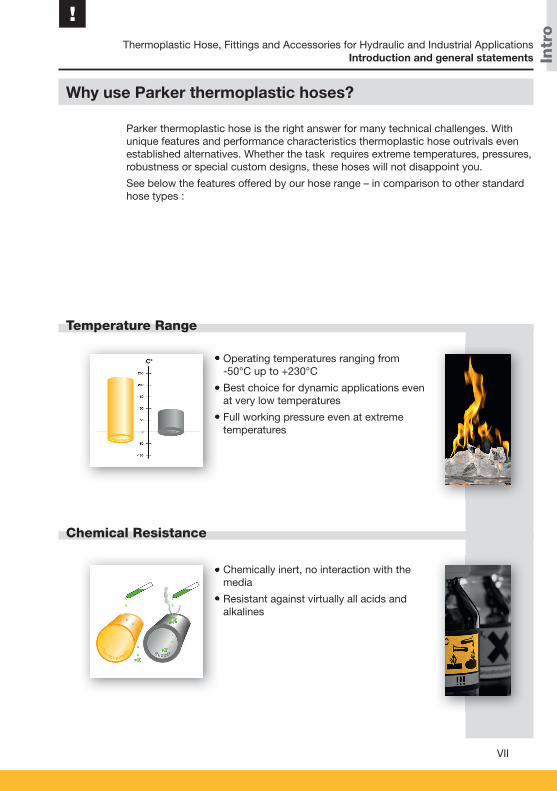
Temperature Range
Chemical Resistance
• Operating temperatures ranging from -50°C up to +230°C
• Best choice for dynamic applications even at very low temperatures
• Full working pressure even at extreme temperatures
Why use Parker thermoplastic hoses?
Parker thermoplastic hose is the right answer for many technical challenges. With unique features and performance characteristics thermoplastic hose outrivals even established alternatives. Whether the task requires extreme temperatures, pressures, robustness or special custom designs, these hoses will not disappoint you.
See below the features offered by our hose range – in comparison to other standard hose types :
• Chemically inert, no interaction with the media
• Resistant against virtually all acids and alkalines
• Operating temperatures ranging from
• Best choice for dynamic applications even
• Full working pressure even at extreme
• Chemically inert, no interaction with the
• Resistant against virtually all acids and
Introduction and general statements
Intr
o
Thermoplastic Hose, Fittings and Accessories for Hydraulic and Industrial Applications
VIII
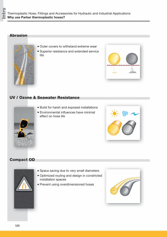
Abrasion
UV / Ozone & Seawater Resistance
Compact OD
• Outer covers to withstand extreme wear
• Superior resistance and extended service life
• Build for harsh and exposed installations
• Environmental infl uences have minimal effect on hose life
• Space saving due to very small diameters
• Optimized routing and design in constricted installation spaces
• Prevent using overdimensioned hoses
• Outer covers to withstand extreme wear
• Superior resistance and extended service
• Build for harsh and exposed installations
• Environmental infl uences have minimal
• Space saving due to very small diameters
• Optimized routing and design in constricted
• Prevent using overdimensioned hoses
Why use Parker thermoplastic hoses?
Intr
o
Thermoplastic Hose, Fittings and Accessories for Hydraulic and Industrial Applications
!
IX
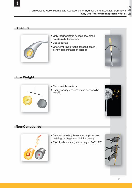
Small ID
Low Weight
Non-Conductive
• Only thermoplastic hoses allow smallIDs down to below 2mm
• Space saving
• Offers improved technical solutions in constricted installation spaces
• Major weight savings
• Energy savings as less mass needs to be moved
• Mandatory safety feature for applications with high voltage and high frequency
• Electrically isolating according to SAE J517
• Only thermoplastic hoses allow small
• Space saving
• Offers improved technical solutions in
• Major weight savings
• Energy savings as less mass needs to be
• Mandatory safety feature for applications
• Electrically isolating according to SAE J517
Why use Parker thermoplastic hoses?

Intr
o
Thermoplastic Hose, Fittings and Accessories for Hydraulic and Industrial Applications
X
Customization
Preforming
Cleanliness
• Multiple colors
• Twin and multiple lines
• Hose bundles
• Customer specifi c designs
• Combining the advantages of bent metal pipe with the fl exibility of hose
• Reducing weight, noise and vibration compared to bent metal pipe solutions
• Preformed hoses are maintaining their full technical specifi cations
• Less abrasion and contamination inside the hose
• Reduced residue build up
• Extended lifetime for fi lters, valves and hydraulic systems
• Multiple colors
• Twin and multiple lines
• Hose bundles
• Customer specifi c designs
• Combining the advantages of bent metal
• Reducing weight, noise and vibration
• Preformed hoses are maintaining their full
• Less abrasion and contamination inside
• Reduced residue build up
• Extended lifetime for fi lters, valves and
Why use Parker thermoplastic hoses?
Intr
o
Thermoplastic Hose, Fittings and Accessories for Hydraulic and Industrial Applications
!
XI
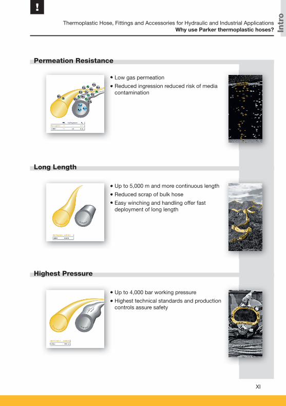
Permeation Resistance
Long Length
Highest Pressure
• Low gas permeation
• Reduced ingression reduced risk of media contamination
• Up to 5,000 m and more continuous length
• Reduced scrap of bulk hose
• Easy winching and handling offer fast deployment of long length
• Up to 4,000 bar working pressure
• Highest technical standards and production controls assure safety
• Low gas permeation
• Reduced ingression reduced risk of media
• Up to 5,000 m and more continuous length
• Reduced scrap of bulk hose
• Easy winching and handling offer fast
• Up to 4,000 bar working pressure
• Highest technical standards and production
Why use Parker thermoplastic hoses?

Intr
o
Thermoplastic Hose, Fittings and Accessories for Hydraulic and Industrial Applications
XII
Wide range of applications
• Standard hydraulics
• Industrial hydraulics e.g.
– alternative energies
– machine tools
– injection molding
• Mobile hydraulics e.g.
– material handling
– construction
– agriculture
• Automotive and truck industry
• Mini hydraulics
• Chemical industry
• Process industry
• Industrial gases
• Alternative fuels
• Boats and yachts
• Pneumatics
• Life Science
• Media transfer
• Standard hydraulics
• Industrial hydraulics e.g.
– alternative energies
– machine tools
– injection molding
• Mobile hydraulics e.g.
– material handling
– construction
– agriculture
Why use Parker thermoplastic hoses?

Intr
o
Thermoplastic Hose, Fittings and Accessories for Hydraulic and Industrial Applications
!
XIII
Technical benefits of Polyflex thermoplastic preformed assemblies
• Little space required: The assemblies have a very compact design and can be installed or just clipped on wherever they disturb least and where the designer wants them to be.
• Installation feasible even in difficult to reach places: The assemblies can be preformed into almost any shape.
• Reduction of potential leaks: In many cases, the flexible assemblies can replace hose / ri-gid tube combinations. This means fewer fittings and fewer screwed connections.
• Compensation of manufacturing inaccuracies: Thanks to their flexibility, the assemblies can easily compensate manufacturing tolerances between different components during installation.
• Noise reduction: The good vibrational behaviour reduces wear and tear caused by vibration and lowers the noise level.
• Weight reduction: As compared to steel tubes but also to conventional hose assemblies, Polyflex preformed assemblies are extremely light-weight.
Preformed hose
Preformed hose
Intr
o
Thermoplastic Hose, Fittings and Accessories for Hydraulic and Industrial Applications
XIV
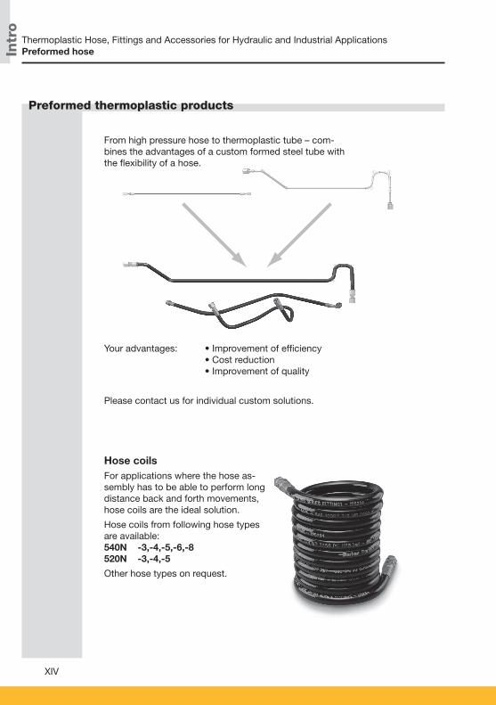
Preformed thermoplastic products
From high pressure hose to thermoplastic tube – com-bines the advantages of a custom formed steel tube with the fl exibility of a hose.
Your advantages: • Improvement of effi ciency • Cost reduction• Improvement of quality
Please contact us for individual custom solutions.
Hose coilsFor applications where the hose as-sembly has to be able to perform long distance back and forth movements, hose coils are the ideal solution.
Hose coils from following hose types are available:540N -3,-4,-5,-6,-8520N -3,-4,-5
Other hose types on request.
Preformed hose
Intr
o
Thermoplastic Hose, Fittings and Accessories for Hydraulic and Industrial Applications
!
XV
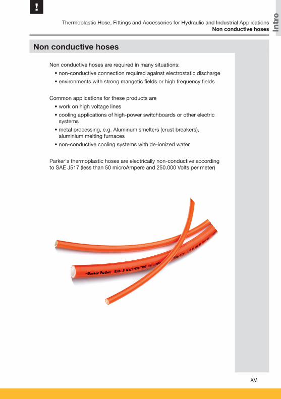
Non conductive hoses
Non conductive hoses are required in many situations:
• non-conductive connection required against electrostatic discharge
• environments with strong mangetic fields or high frequency fields
Common applications for these products are
• work on high voltage lines
• cooling applications of high-power switchboards or other electric systems
• metal processing, e.g. Aluminum smelters (crust breakers), aluminium melting furnaces
• non-conductive cooling systems with de-ionized water
Parker's thermoplastic hoses are electrically non-conductive according to SAE J517 (less than 50 microAmpere and 250.000 Volts per meter)
Non conductive hoses

Intr
o
Thermoplastic Hose, Fittings and Accessories for Hydraulic and Industrial Applications
XVI
Applications
Tools
Examples
Twinline or multiline hoses ensure easier installation, and especially in applications such as fork-lift trucks, aerial lifts and hydraulic cranes they form a compact unit. On request twinline and multiline hose can be joined using various com-binations of hose sizes and types.
For separating multiline hose and the appropriate tools see page H-20.
General comment:
All hoses with Polyurethane cover can be supplied as twinline or multiline hose.
The following hose types are available in twinline or multiline configuration: 540N 2040H
550H 520N
53DM 580N
55LT 2370N
590TJ 560TJ
5CNG
Other hose types on request.
Twinline and multiline hose
Part No. Part No. for twin hose
2040H-04V10 2040H-04-04V10V102040H-05V10 2040H-05-05V10V102040H-06V10 2040H-06-06V10V102040H-08V10 2040H-08-08V10V10
Part No. Part No. for twin hose
550H-4 550H-4-4550H-5 550H-5-5550H-6 550H-6-6550H-8 550H-8-8
Twinline and multiline hose
Intr
o
Thermoplastic Hose, Fittings and Accessories for Hydraulic and Industrial Applications
!
XVII
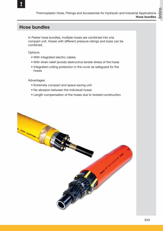
Hose bundles
In Parker hose bundles, multiple hoses are combined into one compact unit. Hoses with different pressure ratings and sizes can be combined.
Options:
• With integrated electric cables
• With strain relief (avoids destructive tensile stress of the hose)
• Integrated cutting protection in the cover as safeguard for the hoses
Advantages:
• Extremely compact and space saving unit
• No abrasion between the individual hoses
• Length compensation of the hoses due to twisted construction
Hose bundles
Intr
o
Thermoplastic Hose, Fittings and Accessories for Hydraulic and Industrial Applications
XVIII
Parkrimp – the system for fast and leak-free assemblies
The perfect match
Parker’s colour-coded die sets
Parkrimp is synonymous with the best solution for assembling hydraulic and related hose and fittings from both the technical and the manufacturing points of view!
Throughout the progressive thermoplastic material and metal compression during the crimping process, the reinforcement always remains intact. The meticulous design, testing and ma-nufacturing processes of Parkrimp hose and one piece fittings, combined with the approved crimping diameters provide an excellent mechanical connection between the hose and the fit-ting. This absolutely leak-free connection gives long service life even with the highest pressures associated most thermoplastic hoses below 700bar and one-piece fittings.
The smartly designed and timetested Parkrimp assembling equipment combined with Parker‘s assembling know how allow the safest, most efficient and mistake-proof assem-bly process. The Parkrimp equipment allows cost and time savings to the assembler and guarantees a defect-free, reliable and durable final product to the end-user.
• For crimping Parkrimp One-Piece fittings (not for two piece and re-usable fittings)
• Quick and easy: no gauges to set on the machine
• Portable machines for field repair
• Meets EN safety regulations
• Both thermoplastic and rubber hoses can be crim-ped on the same machine (only different die rings are needed)
• The complete system from one source
• Thermoplastic hoses, matching one piece fittings and crimping machine
• World-wide guarantee and availability
• No loose parts to mismatch or misplace
• Die set segments linked together
• Die sets provide 360° evenly applied crimping forces for an ideal crimp result
Parkrimp system
Parkrimp system

Intr
o
Thermoplastic Hose, Fittings and Accessories for Hydraulic and Industrial Applications
!
XIX
Parker Polyfl ex and the Parker Sales Companies offer value added services that compliment our production capabilities and product portfolio. These services are in place to meet the increasing customization and system criteria that our customers expect from a world-class supplier.The value added services detailed below are typical of the products and secondary services that we provide to our customers. If you have additional service needs that we have not detailed below please contact us. We are happy to discuss all potenti-al solutions for your requirements.
Value added services
ParkerStore™
At Parker Hannifi n, we’re continually looking for waysto deliver more products, more effi ciently.
The Global ParkerStore™ network enables Parker to provide:
• Prompt, effi cient, professional in-store services while you wait
• Expert local services and support
• A safe, friendly and convenient shopping environment
• A greater range of parts options so you get exactly what you’re looking for.
Customers trust ParkerStores to provide OEM and MRO custo-mers with direct access to:
• Custom-made hydraulic hose assemblies and complementary products to support their applications and decrease their downtime
• Expert technical support
• Professional, personalized services, including 24/7/365 support
• The convenience, comfort and amenities of a local service provider.
Value added services

Intr
o
Thermoplastic Hose, Fittings and Accessories for Hydraulic and Industrial Applications
XX
Parker HOSE DOCTORS
Parker Store Container Service
The Parker® Tracking System Enterprise (PTS)
are a network of independently-owned, mobile service technicians built around the commitment to identify and replace hose assemblies wherever their customers need them, with the fastest response times possible. HOSE DOCTORS® are an extension of the worldwide Parker distribution network, coupling their service commitment with Parker products – the highest quality hoses and fi ttings available in the market today.
The ParkerStore container is a transportable workshop, providing on-site maintenance and product support for large construction projects such as roadworks, tunnels, railways, underground systems, etc. Provides an on-site product and hose replacement service. With this service on your site, you can reduce your downtime keeping your project on time and on budget!
is designed to help customers reduce vehicle or asset down-time through increases in the speed, timing and accuracy of necessary repairs. PTS provides a unique 8 digit identifi cation code and bar code printed on a durable label for each hose assembly. PTS labels are specifi cally engineered to withstand harsh chemicals, temperatures, UV exposure and other challenging conditions.
• PTS captures, records and recalls unique hose assembly information – on demand
• Provides fast and accurate product identifi cation to speed up replacement regardless of where the original assembly was made.
• Assembly can be replaced with only the 8 digit PTS ID number/bar code eliminating the need to remove hoses prior to replacement. This can provide critical machine uptime and enable more conveniently scheduled repair.
• PTS includes additional reporting tools to assist in continuous improvement programmes and preventative maintenance initiatives.
Value added services

Intr
o
Thermoplastic Hose, Fittings and Accessories for Hydraulic and Industrial Applications
!
XXI
Kitting
Multiple components are supplied under a single part number
• Reduced number of suppliers
• Reduced stocks and no obsolete items
• Optimized management (stock and supplies)
• Simplifi ed and optimised order handling
• Reduced assembly costs
• Greater productivity
Breadman
Lean logistics and delivery of Parker products and kits directly to the customer’s assembly line, work stations or warehouse
• 100 % parts availability minimises downtime, increa-ses production and reduces costs
• Elimination of stock checking reduces manpower and maintains production levels
• Daily delivery reduces inventory and overheads
• Electronic order processing eliminates paperwork and reduces administration costs
Tech Services
Optimises the performance of your hydraulic and pneumatic circuits
• With Parker Tech Services involved, your time to mar-ket is shorter, which saves on development costs
• The 3 year no-leak guarantee enhances your reputati-on and lowers your warranty costs
• More reliable operation lowers your customer’s opera-ting costs
• More effi cient performance and no-leak guarantee is benefi cial to the environment
• Parker worldwide coverage ensures you can use the service and save costs wherever you are
Value added services

Intr
o
XXII
Thermoplastic Hose, Fittings and Accessories for Hydraulic and Industrial Applications
Catalogue 4460-UK
Notes
Sele
cti
on
A-1
A
Chapter A
Hose and Fitting Selection
Hose selection ......................................................................A-2 Hose selection by application ..................................................... A-4 Hose selection by working pressure and ID ............................... A-6 Hose selection by fluid compatibility/chemical resistance ......... A-8 Hose selection by standards and approvals ............................. A-15 Determination of hose size ....................................................... A-16 Pressure drop ............................................................................ A-17
Fitting selection ..................................................................A-18 Fittings overview ....................................................................... A-19
Hose and Fitting Selection
Catalogue 4460-UK
Table of contents

Sele
cti
on
A-2
Hose and Fitting Selection
Hose selection by application
Hose selection by working pressure and ID
This overview designates some application ranges together with hoses, which have proved to be especially suited for the associated application. Please note that only the most important applications can be listed. Moreover, the suitability of the desired hose for the individual environmental condi-tions must be verifi ed.
When working pressure and ID are given, use this table to select the possible hoses for the desired pressure range.
Many applications require highly chemical resistant materials due to aggressive media. The table lists chemical fl uids and rating codes for different hose materials.
This overview lists hose types by international standards, approvals and certifi cates.
Hose selection
Several criteria must be considered, when selecting the optimal hose for your application. According to the particular application there is – as a rule – at least one of these characteristics crucial for the selection. In this section you will fi nd the most important criteria and relevant selection guidelines.
Hose selection by fl uid compatibility/chemical resistance
Hose selection by standards and approvals
This overview designates some application ranges together
When working pressure and ID are given, use this table to
Many applications require highly chemical resistant
This overview lists hose types by international standards,
A - 4
A - 6
A - 8
A - 15
Introduction
Sele
cti
on
A-3
Hose and Fitting Selection
A
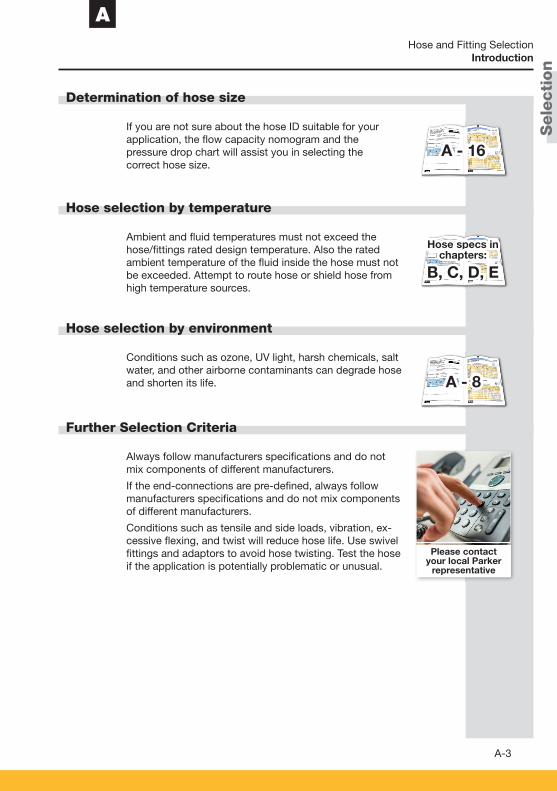
Determination of hose size
Hose selection by temperature
Hose selection by environment
Further Selection Criteria
If you are not sure about the hose ID suitable for your application, the fl ow capacity nomogram and the pressure drop chart will assist you in selecting the correct hose size.
Ambient and fl uid temperatures must not exceed the hose/fi ttings rated design temperature. Also the rated ambient temperature of the fl uid inside the hose must not be exceeded. Attempt to route hose or shield hose from high temperature sources.
Conditions such as ozone, UV light, harsh chemicals, salt water, and other airborne contaminants can degrade hose and shorten its life.
Always follow manufacturers specifi cations and do not mix components of different manufacturers.
If the end-connections are pre-defi ned, always follow manufacturers specifi cations and do not mix components of different manufacturers.
Conditions such as tensile and side loads, vibration, ex-cessive fl exing, and twist will reduce hose life. Use swivel fi ttings and adaptors to avoid hose twisting. Test the hose if the application is potentially problematic or unusual.
A - 16
Hose specs inchapters:
B, C, D, E
A - 8
Please contactyour local Parker
representative
Introduction
Sele
cti
on
A-4
Hose selection by application
Application 2010
H
2020
N
2030
T
2030
T
2033
T
2040
H
2040
N
2245
N
2246
F
2370
N
2380
F
518C
520N
527B
A
528N
53D
M
540N
550H
55LT
560T
J
575X
580N
588N
590T
J
594T
J
830M
838M
919
919U
929/
929B
939/
939B
5CN
G
8LP
G
SC
R
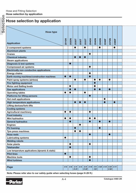
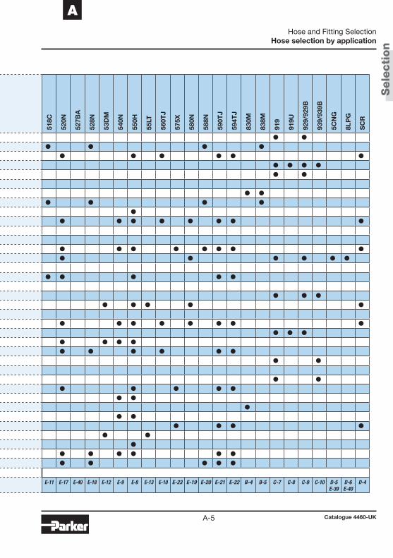
2-component systems I I I I I IAluminium plants I I I ICranes I I I I I I IChemical industry I I I I I I ISteam applications I IDiagnosis & test systems ICompressed-air systems I I IElectrically non-conductive applications I I I IEnergy chains I IEarth-moving machines/construction machines I I I I I I I I I I IPaint spray systems (airless) I I I I IFire fighting equipment IMotor and Sailing boats I I I I I I I I I IGas applications I I I I I I I I I I IOperating tables I I IPlatforms for lifting persons I I I I I IHot melt applications IHigh temperature applications I I I I I I I ILifting devices/fork-lifts I I I I ICooling systemsAgricultural machinery I I I I I I I I I I IFood industry I I IMini hydraulics I I I I I I I IGeneral hydraulics I I I I I I I I I IEngines I I IPU foaming I ITyre press machines I I I IHose reels I I I I I I ILubricating systems I I IWelding robots ISolar plants I I I ITelehandler I I I I ILow temperature applications (dynamic & static) I IPilot lines I IMachine tools I I I I I I I IWind turbines I I I I I I
Page E-5 E-6 C-4E-31
C-5 C-6E-32
E-16 E-15E-29
E-25 C-12 E-24E-30
C-11 E-11 E-17 E-40 E-18 E-12 E-9 E-8 E-13 E-10 E-23 E-19 E-20 E-21 E-22 B-4 B-5 C-7 C-8 C-9 C-10 D-5E-39
D-6E-40
D-4
Note: Please refer also to our safety guide when selecting hoses (page H-29 ff.)
Hose type
Hose and Fitting Selection
Catalogue 4460-UK
Hose selection by application
Sele
cti
on
A-5
A
Application 2010
H
2020
N
2030
T
2030
T
2033
T
2040
H
2040
N
2245
N
2246
F
2370
N
2380
F
518C
520N
527B
A
528N
53D
M
540N
550H
55LT
560T
J
575X
580N
588N
590T
J
594T
J
830M
838M
919
919U
929/
929B
939/
939B
5CN
G
8LP
G
SC
R
2-component systems I I I I I IAluminium plants I I I ICranes I I I I I I IChemical industry I I I I I I ISteam applications I IDiagnosis & test systems ICompressed-air systems I I IElectrically non-conductive applications I I I IEnergy chains I IEarth-moving machines/construction machines I I I I I I I I I I IPaint spray systems (airless) I I I I IFire fighting equipment IMotor and Sailing boats I I I I I I I I I IGas applications I I I I I I I I I I IOperating tables I I IPlatforms for lifting persons I I I I I IHot melt applications IHigh temperature applications I I I I I I I ILifting devices/fork-lifts I I I I ICooling systemsAgricultural machinery I I I I I I I I I I IFood industry I I IMini hydraulics I I I I I I I IGeneral hydraulics I I I I I I I I I IEngines I I IPU foaming I ITyre press machines I I I IHose reels I I I I I I ILubricating systems I I IWelding robots ISolar plants I I I ITelehandler I I I I ILow temperature applications (dynamic & static) I IPilot lines I IMachine tools I I I I I I I IWind turbines I I I I I I
Page E-5 E-6 C-4E-31
C-5 C-6E-32
E-16 E-15E-29
E-25 C-12 E-24E-30
C-11 E-11 E-17 E-40 E-18 E-12 E-9 E-8 E-13 E-10 E-23 E-19 E-20 E-21 E-22 B-4 B-5 C-7 C-8 C-9 C-10 D-5E-39
D-6E-40
D-4
Note: Please refer also to our safety guide when selecting hoses (page H-29 ff.)
Hose and Fitting Selection
Catalogue 4460-UK
Hose selection by application

Sele
cti
on
A-6
Hose selection by working pressure and ID
Pressure and ID / Hose selection by working pressure
Working pressure (MPa) Fitting P.
nom
. siz
e DN 2 2.5 3 4 5 6 8 10 12 16 20 25 32 40 50 seriessize -012 -016 -02 -025 -03 -04 -05 -06 -08 -10 -12 -16 -20 -24 -32mm* 2.0 2.4 3.2 4.0 4.8 6.4 7.9 9.5 12.7 15.9 19.0 25.4 31.8 38.1 50.8inch 5/64 3/32 1/8 5/32 3/16 1/4 5/16 3/8 1/2 5/8 3/4 1 1 1/4 1 1/2 2
Push-Lok® hose830M 1.6 1.6 1.6 1.6 1.6 82 B-4
838M 1.6 1.6 1.6 1.6 1.6 82 B-5
PTFE-/FEP hose2030T 27.5 24.0 20.0 17.5 15.0 12.5 10.0 8.0 YX C-4
2030T-##CON 17.2 15.5 13.8 10.3 8.3 6.9 4.6 3.4 PC C-5
2033T 27.5 25.0 22.5 20.0 17.5 15.0 11.0 PX/YX C-6
919 21.0 21.0 17.5 14.0 10.3 8.3 6.9 91N C-7
919U 21.0 17.5 14.0 8.3 6.9 91N C-8
929/929B 21.0 17.5 14.0 8.4 8.8 91N C-9
939/939B 10.3 9.5 6.9 7.5 6.9 6.9 5.0 1.7 93N C-10
2380F 42.5 37.5 35.0 32.5 30.0 27.5 22.5 NX C-11
2246F 41.5 37.5 34.0 32.5 30.0 26.5 21.0 NX C-12
Hose for alternative fuels5CNG 34.5 34.5 34.5 34.5 34.5 34.5 CG D-5
8LPG 3.0 3.0 3.0 3.0 PX-LPG D-6
Small bore hose/Mini hydraulic hose2010H 21.0 EX E-5
2020N (V30) 47.5 40.0 40.0 44.0 EX E-6
2020N (V50) 63.0 EX E-6
Medium pressure hose550H 22.5 21.0 17.5 15.5 14.0 10.0 8.5 7.0 56 E-8
540N 21.0 21.0 19.0 17.5 15.5 14.0 8.5 56 E-09
560TJ 25.0 22.4 20.6 19.0 17.2 13.7 12.0 56 E-10
518C 17.5 22.5 20.7 17.5 15.5 15.5 10.5 8.5 7.0 56 E-11
53DM 20.7 20.7 20.7 56 E-12
55LT 21.0 22.5 21.0 17.5 15.5 14.0 56 E-13
*: Exact value may vary, please check hose spec
Hose and Fitting Selection
Catalogue 4460-UK
Hose selection by working pressure and ID

Sele
cti
on
A-7
A
Working pressure (MPa) Fitting P.
nom
. siz
e DN 2 2.5 3 4 5 6 8 10 12 16 20 25 32 40 50 seriessize -012 -016 -02 -025 -03 -04 -05 -06 -08 -10 -12 -16 -20 -24 -32mm* 2.0 2.4 3.2 4.0 4.8 6.4 7.9 9.5 12.7 15.9 19.0 25.4 31.8 38.1 50.8inch 5/64 3/32 1/8 5/32 3/16 1/4 5/16 3/8 1/2 5/8 3/4 1 1 1/4 1 1/2 2
High pressure hose2040N (V00) 35.0 34.0 31.0 25.0 24.0 18.5 14.0 12.5 10.0 56/PX E-15
2040H 34.0 31.0 25.0 24.0 18.5 14.0 12.5 10.0 56/PX E-16
520N 34.5 34.5 31.0 27.5 24.0 56 E-17
528N 34.5 34.5 31.0 27.5 24.0 56 E-18
580N 24.5 19.0 15.5 14.0 56 E-19
588N 24.5 19.0 15.5 14.0 56 E-20
590TJ 34.5 27.6 24.1 17.2 13.8 43/48/56 E-21
594TJ 28.0 28.0 43/46/48 E-22
575X 34.5 34.5 34.5 34.5 34.5 34.5 CG E-23
2370N 46.5 44.0 42.0 35.0 9X/NX E-24
2245N 45.0 40.0 37.5 35.0 33.0 30.0 27.5 9X/NX E-25
Paint spray hose2040N 35.0 34.0 31.0 25.0 24.0 18.5 14.0 12.5 10.0 56/PX E-29
2370N 46.5 44.0 42.0 35.0 9X/NX E-30
2030T 27.5 24.0 20.0 17.5 15.0 12.5 10.0 8.0 YX E-31
2033T 27.5 25.0 22.5 20.0 17.5 15.0 11.0 PX/YX E-32
Gas hose527BA 41.4 41.4 41.4 CG E-38
5CNG 34.5 34.5 34.5 34.5 34.5 CG E-39
8LPG 3.0 3.0 3.0 3.0 PX-LPG E-40
Hose and Fitting Selection
Catalogue 4460-UK
Hose selection by working pressure and ID
Sele
cti
on
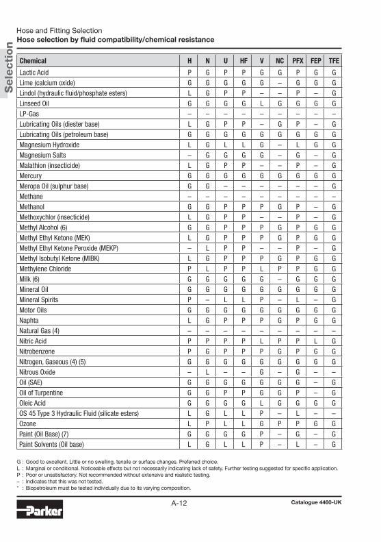
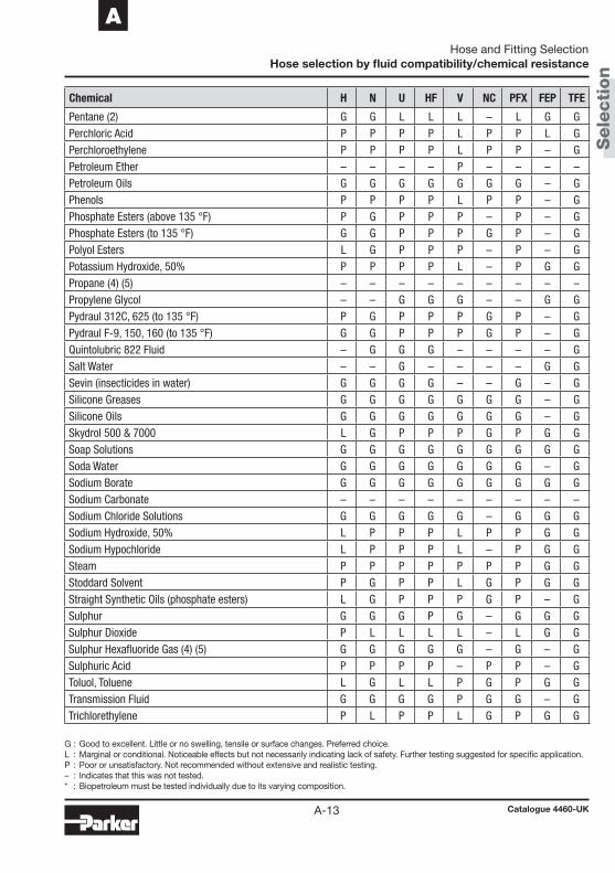
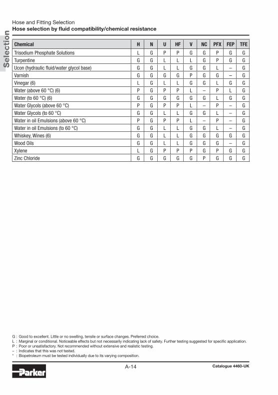
A-8
Hose selection by fluid compatibility/ chemical resistance
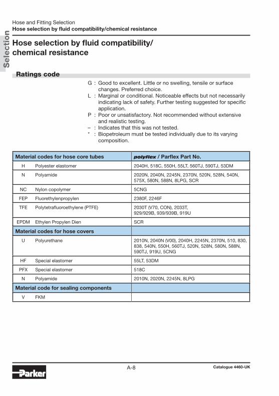
Ratings code G : Good to excellent. Little or no swelling, tensile or surface
changes. Preferred choice. L : Marginal or conditional. Noticeable effects but not necessarily
indicating lack of safety. Further testing suggested for specific application.
P : Poor or unsatisfactory. Not recommended without extensive and realistic testing.
– : Indicates that this was not tested. * : Biopetroleum must be tested individually due to its varying
composition.
Material codes for hose core tubes polyflex / Parflex Part No.
H Polyester elastomer 2040H, 518C, 550H, 55LT, 560TJ, 590TJ, 53DM
N Polyamide 2020N, 2040N, 2245N, 2370N, 520N, 528N, 540N, 575X, 580N, 588N, 8LPG, SCR
NC Nylon copolymer 5CNG
FEP Fluorethylenpropylen 2380F, 2246F
TFE Polytetrafluoroethylene (PTFE) 2030T (V70, CON), 2033T, 929/929B, 939/939B, 919U
EPDM Ethylen Propylen Dien SCR
Material codes for hose covers
U Polyurethane 2010N, 2040N (V00), 2040H, 2245N, 2370N, 510, 830, 838, 540N, 550H, 560TJ, 520N, 528N, 580N, 588N, 590TJ, 919U, 5CNG
HF Special elastomer 55LT, 53DM
PFX Special elastomer 518C
N Polyamide 2010N, 2020N, 2245N, 8LPG
Material code for sealing components
V FKM
Hose and Fitting Selection
Catalogue 4460-UK
Hose selection by fluid compatibility/chemical resistance

Sele
cti
on
A-9
A
Notes on the chemical resistance table (1) The fluid resistance tables are simplified rating tabulations
based on immersion tests at 24 °C. Higher temperatures tend to reduce ratings. Since final selection depends on pressure, fluid and ambient temperature and other factors not known to Parker Hannifin, no performance guarantee is expressed or implied. The indications do not imply any compliance with standards and regulations and do not refer to possible changes of colour, taste or smell. For food and drinking water specially approved materials have to be used. For fluids not listed or for advice on particular applications, please consult Parker Hannifin Manufac-turing Germany GmbH & Co. KG, polyflex Division in Hütten-feld, Germany.
(2) Hose applications for these fluids must take into account legal and insurance regulations. The chemical resistance indicated does not express or imply approval by certain institutions.
(3) Satisfactory at some concentrations and temperatures, unsatis-factory at others.
(4) For gas applications, the cover should be pin-pricked and the pressure must not be released quickly. Special safety guard ac-cessories are to be used to prevent damage or personal injury in the event of failure.
(5) Chemical resistance does not imply low permeation rates. Please consult Parker Hannifin GmbH for a recommendation for your specific requirements.
(6) The indication of chemical resistance does not imply any special food compatibility; it refers only to the chemical resistance of the material.
(7) Chemical resistance does not imply acceptability for use in airless paint spray applications. These applications require a special, electrically conductive hose.
Hose and Fitting Selection
Catalogue 4460-UK
Hose selection by fluid compatibility/chemical resistance

Sele
cti
on
A-10
G : Good to excellent. Little or no swelling, tensile or surface changes. Preferred choice.L : Marginal or conditional. Noticeable effects but not necessarily indicating lack of safety. Further testing suggested for specific application. P : Poor or unsatisfactory. Not recommended without extensive and realistic testing.– : Indicates that this was not tested.* : Biopetroleum must be tested individually due to its varying composition.
Chemical H N U HF V NC PFX FEP TFE
Acetaldehyde G L L L P – L G GAcetic Acid Glacial L L L L G P L L GAcetone L G P P P G P G GAcetylene – – – – – – – – –Air (4) G G G G G G G G GAmmonium Chloride G P G G G P G L GAmmonium Hydroxyde L G P P L – P G GAnhydrous Ammonia P P P P P P P – PAniline P P P P P P P G GAnimal Oils (6) G G G G G G G – GAromatic Hydrocarbons L G L L P G L – GAsphalt G G G G G G G L GBaygon (insecticide) L G P P – – P – GBeer G G G G G – G G GBenzene L G L L P L L G GBiopetroleum * * * * * * * * *Brake Fluid (DOT #3) – G P P P – P – GButane (2) (4) G G L L L P L – –Butter (6) G G G G G – G – GCalcium Chloride G – G G L – G G GCarbon Dioxide (4) G G G G G G G – –Carbon Monoxide (4) G – G G G – G – –Carbon Tetrachloride L G P P L G P G GCastor Oil G L L L G L L – GChlordane (insecticide) L G P P – – P – –Chlorinated Hydrocarbon Base Fluids L G L L P – L – GChlorinated Petroleum Oil G G L L – L L – –Chlorinated Solvents P – P P L – P – GChlorine, Gaseous, Dry P P P P G P P – –Chloroform P P P P P P P G GChromic Acid P – P P G P P L GCitric Acid Solutions G G L L G G L G GCrude Petroleum Oil G G G G G G G – GCyclohexane (2) G G G G – – G G GCygon (insecticide) L G P P – – P – –Diazion (insecticide) L G P P – – P – –Diesel Fuel (2) G G G G L G G – G
Hose and Fitting Selection
Catalogue 4460-UK
Hose selection by fluid compatibility/chemical resistance

Sele
cti
on
A-11
A
G : Good to excellent. Little or no swelling, tensile or surface changes. Preferred choice.L : Marginal or conditional. Noticeable effects but not necessarily indicating lack of safety. Further testing suggested for specific application. P : Poor or unsatisfactory. Not recommended without extensive and realistic testing.– : Indicates that this was not tested.* : Biopetroleum must be tested individually due to its varying composition.
Chemical H N U HF V NC PFX FEP TFE
Diester Oils L G P P P – P – GEnamels G G G G L – G – GEthanol (6) G G L L L L L – GEthers L G P P L G P G GEthylene Glycol G G L L G G L G GEthylene Oxide G G L L P – L – –Fatty Acids G G – – G G – G GFormaldehyde L L P P L L P G GFormic Acid J P P P P G P P G GFreon 12 (5) P G L L G G L – –Freon 22 (5) P G L L G G L – –Fruit Juices G G G G G – G – GFuel Oil (2) G G L L L G L G GGas (Oil) (2) G G G G G G G – GGasoline G G – – P G – G GGlue – – – – – – – – –Glycerine G G L L G G L G GGlycols (to 135 °F) G G L L G G L G GGrease (petroleum base) G G G L G G G – GHeptachlor (insecticide) L G P L L – P – GHexane (2) G G G L L G G G GHoughto Safe-1000 Series (phosphate esters) L G P P G G P – GHoughto Safe-600 Series (hydraulic fluid) G G L L G G L – GHydraulic Fluid (petroleum base) G G G G G G G L GHydraulic Fluid (phosphate ester base) L G L L L G P – GHydraulic Fluid (water glycol base) G G G G L G G – GHydraulic Oil (petroleum base) G G G G G G G L GHydrochloric Acid P L P P L P P G GHydrofluoric Acid P P P P L P P G GHydrolube (hydraulic fluid/water glycol base) G G L L G G L – GIRUS 902 (hydraulic fluid/water-oil emulsion) G G G G G G G – GIsocyanates (2) L L L L P – L – GIsooctane (2) G G G G L G L G GIsopropyl Alcohol G G L L L G L G GKerosene (2) G G L L L G P G GKetones L G P P P G P G GLacquer Solvents L G P P P – P L G
Hose and Fitting Selection
Catalogue 4460-UK
Hose selection by fluid compatibility/chemical resistance
Sele
cti
on
A-12
G : Good to excellent. Little or no swelling, tensile or surface changes. Preferred choice.L : Marginal or conditional. Noticeable effects but not necessarily indicating lack of safety. Further testing suggested for specific application. P : Poor or unsatisfactory. Not recommended without extensive and realistic testing.– : Indicates that this was not tested.* : Biopetroleum must be tested individually due to its varying composition.
Chemical H N U HF V NC PFX FEP TFE
Lactic Acid P G P P G G P G GLime (calcium oxide) G G G G G – G G GLindol (hydraulic fluid/phosphate esters) L G P P – – P – GLinseed Oil G G G G L G G G GLP-Gas – – – – – – – – –Lubricating Oils (diester base) L G P P – G P – GLubricating Oils (petroleum base) G G G G G G G G GMagnesium Hydroxide L G L L G – L G GMagnesium Salts – G G G G – G – GMalathion (insecticide) L G P P – – P – GMercury G G G G G G G G GMeropa Oil (sulphur base) G G – – – – – – GMethane – – – – – – – – –Methanol G G P P P G P – GMethoxychlor (insecticide) L G P P – – P – GMethyl Alcohol (6) G G P P P G P G GMethyl Ethyl Ketone (MEK) L G P P P G P G GMethyl Ethyl Ketone Peroxide (MEKP) – L P P – – P – GMethyl Isobutyl Ketone (MIBK) L G P P P G P G GMethylene Chloride P L P P L P P G GMilk (6) G G G G G – G G GMineral Oil G G G G G G G G GMineral Spirits P – L L P – L – GMotor Oils G G G G G G G G GNaphta L G P P P G P G GNatural Gas (4) – – – – – – – – –Nitric Acid P P P P L P P L GNitrobenzene P G P P P G P G GNitrogen, Gaseous (4) (5) G G G G G G G G GNitrous Oxide – L – – G – G – –Oil (SAE) G G G G G G G – GOil of Turpentine G G P P G G P – GOleic Acid G G G G L G G G GOS 45 Type 3 Hydraulic Fluid (silicate esters) L G L L P – L – –Ozone L P L L G P P G GPaint (Oil Base) (7) G G G G P – G – GPaint Solvents (Oil base) L G L L P – L – G
Hose and Fitting Selection
Catalogue 4460-UK
Hose selection by fluid compatibility/chemical resistance
Sele
cti
on
A-13
A
G : Good to excellent. Little or no swelling, tensile or surface changes. Preferred choice.L : Marginal or conditional. Noticeable effects but not necessarily indicating lack of safety. Further testing suggested for specific application. P : Poor or unsatisfactory. Not recommended without extensive and realistic testing.– : Indicates that this was not tested.* : Biopetroleum must be tested individually due to its varying composition.
Chemical H N U HF V NC PFX FEP TFE
Pentane (2) G G L L L – L G GPerchloric Acid P P P P L P P L GPerchloroethylene P P P P L P P – GPetroleum Ether – – – – P – – – –Petroleum Oils G G G G G G G – GPhenols P P P P L P P – GPhosphate Esters (above 135 °F) P G P P P – P – GPhosphate Esters (to 135 °F) G G P P P G P – GPolyol Esters L G P P P – P – GPotassium Hydroxide, 50% P P P P L – P G GPropane (4) (5) – – – – – – – – –Propylene Glycol – – G G G – – G GPydraul 312C, 625 (to 135 °F) P G P P P G P – GPydraul F-9, 150, 160 (to 135 °F) G G P P P G P – GQuintolubric 822 Fluid – G G G – – – – GSalt Water – – G – – – – G GSevin (insecticides in water) G G G G – – G – GSilicone Greases G G G G G G G – GSilicone Oils G G G G G G G – GSkydrol 500 & 7000 L G P P P G P G GSoap Solutions G G G G G G G G GSoda Water G G G G G G G – GSodium Borate G G G G G G G G GSodium Carbonate – – – – – – – – –Sodium Chloride Solutions G G G G G – G G GSodium Hydroxide, 50% L P P P L P P G GSodium Hypochloride L P P P L – P G GSteam P P P P P P P G GStoddard Solvent P G P P L G P G GStraight Synthetic Oils (phosphate esters) L G P P P G P – GSulphur G G G P G – G G GSulphur Dioxide P L L L L – L G GSulphur Hexafluoride Gas (4) (5) G G G G G – G – GSulphuric Acid P P P P – P P – GToluol, Toluene L G L L P G P G GTransmission Fluid G G G G P G G – GTrichlorethylene P L P P L G P G G
Hose and Fitting Selection
Catalogue 4460-UK
Hose selection by fluid compatibility/chemical resistance
Sele
cti
on
A-14
G : Good to excellent. Little or no swelling, tensile or surface changes. Preferred choice.L : Marginal or conditional. Noticeable effects but not necessarily indicating lack of safety. Further testing suggested for specific application. P : Poor or unsatisfactory. Not recommended without extensive and realistic testing.– : Indicates that this was not tested.* : Biopetroleum must be tested individually due to its varying composition.
Chemical H N U HF V NC PFX FEP TFE
Trisodium Phosphate Solutions L G P P G G P G GTurpentine G G L L L G P G GUcon (hydraulic fluid/water glycol base) G G L L G G L – GVarnish G G G G P G G – GVinegar (6) L G L L G G L G GWater (above 60 °C) (6) P G P P L – P L GWater (to 60 °C) (6) G G G G G G L G GWater Glycols (above 60 °C) P G P P L – P – GWater Glycols (to 60 °C) G G L L G G L – GWater in oil Emulsions (above 60 °C) P G P P L – P – GWater in oil Emulsions (to 60 °C) G G L L G G L – GWhiskey, Wines (6) G G L L G G G G GWood Oils G G L L G G G – GXylene L G P P P G P G GZinc Chloride G G G G G P G G G
Hose and Fitting Selection
Catalogue 4460-UK
Hose selection by fluid compatibility/chemical resistance
Sele
cti
on
A-15
A
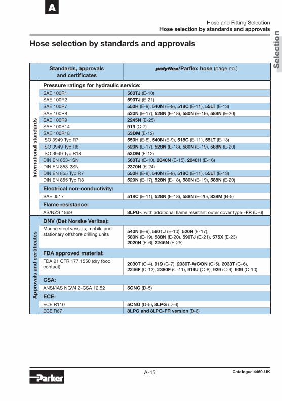
Hose selection by standards and approvals
Standards, approvals and certificates
polyflex/Parflex hose (page no.)
Inte
rnat
iona
l sta
ndar
ds
Pressure ratings for hydraulic service:SAE 100R1 560TJ (E-10)SAE 100R2 590TJ (E-21)SAE 100R7 550H (E-8), 540N (E-9), 518C (E-11), 55LT (E-13)SAE 100R8 520N (E-17), 528N (E-18), 580N (E-19), 588N (E-20)SAE 100R9 2245N (E-25)SAE 100R14 919 (C-7)SAE 100R18 53DM (E-12)ISO 3949 Typ R7 550H (E-8), 540N (E-9), 518C (E-11), 55LT (E-13)ISO 3949 Typ R8 520N (E-17), 528N (E-18), 580N (E-19), 588N (E-20)ISO 3949 Typ R18 53DM (E-12)DIN EN 853-1SN 560TJ (E-10), 2040N (E-15), 2040H (E-16)DIN EN 853-2SN 2370N (E-24)DIN EN 855 Typ R7 550H (E-8), 540N (E-9), 518C (E-11), 55LT (E-13)DIN EN 855 Typ R8 520N (E-17), 528N (E-18), 580N (E-19), 588N (E-20)
Electrical non-conductivity:SAE J517 518C (E-11), 528N (E-18), 588N (E-20), 838M (B-5)
Flame resistance:AS/NZS 1869 8LPG-. with additional flame resistant outer cover type -FR (D-6)
Ap
pro
vals
and
cer
tifi
cate
s
DNV (Det Norske Veritas):Marine steel vessels, mobile and stationary offshore drilling units
540N (E-9), 560TJ (E-10), 520N (E-17), 580N (E-19), 588N (E-20), 590TJ (E-21), 575X (E-23)2020N (E-6), 2245N (E-25)
FDA approved material:FDA 21 CFR 177.1550 (dry food contact)
2030T (C-4), 919 (C-7), 2030T-##CON (C-5), 2033T (C-6), 2246F (C-12), 2380F (C-11), 919U (C-8), 929 (C-9), 939 (C-10)
CSA:ANSI/IAS NGV4.2-CSA 12.52 5CNG (D-5)
ECE:ECE R110 5CNG (D-5), 8LPG (D-6)ECE R67 8LPG and 8LPG-FR version (D-6)
Hose and Fitting Selection
Catalogue 4460-UK
Hose selection by standards and approvals
Sele
cti
on
A-16
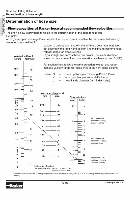
Determination of hose size
Flow capacities of Parker hose at recommended flow velocitiesThe chart below is provided as an aid in the determination of the correct hose size.Example: At 10 gallons per minute (gal/min), what is the proper hose size within the recommended velocity range for pressure lines? Locate 10 gallons per minute in the left-hand column and 25 feet
per second in the right-hand column (the maximum recommended velocity range for pressure lines). Lay a straight line across these two points. The inside diameter shown in the centre column is above -6 so we have to use -8 (1/2“). For suction lines, follow the same procedure except use recom-mended velocity range for intake lines in the right-hand column.
where: Q = flow in gallons per minute (gal/min & l/min) V = velocity in feet per second (f/s & m/s)
d = hose inside diameter (mm & dash size)
Volumetric flow Q (l/min) Gal/min*
Hose inner diameter d mm size Flow velocity v
(m/s) feet/s
Recommended maximum velocity for suction lines
Recommended maximum velocity for return lines
Recommended maximum velocity for pressure lines
* gallons are UK gallonsConversion factors: gal/min x 4.546 = l/min feet/s x 0.3948 = m/s
* Recommended velocities are according to hydraulic fluids of maximum viscosity 315 S.S.U. at 38 °C working at room temperature within 18 ° and 68 °C.
Hose and Fitting Selection
Catalogue 4460-UK
Determination of hose length
Sele
cti
on
A-17
A
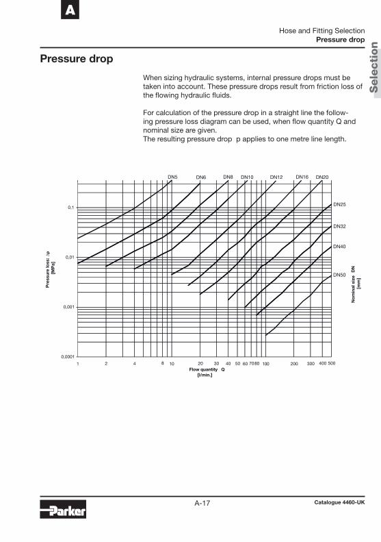
Pressure drop
When sizing hydraulic systems, internal pressure drops must be taken into account. These pressure drops result from friction loss of the flowing hydraulic fluids. For calculation of the pressure drop in a straight line the follow-ing pressure loss diagram can be used, when flow quantity Q and nominal size are given. The resulting pressure drop Δp applies to one metre line length.
0,01
0,1
∆p
DN5 DN6 DN8 DN10 DN12 DN16 DN20
DN25
DN32
DN40
0,0001
0,001
001011
Pre
ssur
e lo
ss:
[MP
a]
Flow quantity Q[l/min.]
DN50
No
min
al s
ize
DN
[mm
]2 4 8 20 30 5040 60 7080 200 300 400 500
Hose and Fitting Selection
Catalogue 4460-UK
Pressure drop

Sele
cti
on
A-18
Which is the approved fitting series for the selected hose? For each hose type at least one fitting series is approved.
Please refer to the related hose table contained in each hose de-scription to find out which fitting series is available for the desired hose type.
Which is the correct fitting with the required end connection for the relevant hose assembly?
Each end connection in this catalogue has its own alphanumeric code. For example, the alphanumeric code for a DKOL connec-tion with 90° elbow is "CF". Pages A-19 to A-24 show a complete overview of all end connections and the related codes. You have problems to locate the desired fitting? Please contact your local dealer.
Fitting selection
For new designs according to current industry standards, standpipes are no longer recommended.
Hose and Fitting Selection
Catalogue 4460-UK
Fitting selection

Sele
cti
on
A-19
A
Fittings overview
Metric DIN fittings
C4 Metric female swivel 24°/60°
45° elbow –Light series –Metric swivel nut
C5 Metric female swivel 24°/60°
Correspondence between Fitting Part No. and fitting representation in this overview
Example:
3 C5 82 - 10 - 06
90° elbow –Light series –Metric swivel nut
CA Metric female swivel 24°with O-ring
Light series – Metric swivel nut –ISO 12151-2
CE Metric female swivel 24°with O-ring
45° elbow – Light series –Metric swivel nut –ISO 12151-2
CF Metric female swivel 24°with O-ring
90° elbow – Light series –Metric swivel nut –ISO 12151-2
C3 Metric female swivel 24°/60°
Light series –Metric swivel nut
C6 Metric female swivel 24°/60°
Heavy series –Metric swivel nut
C9 Metric female swivel 24°with O-ring
Heavy series –Metric swivel nut –ISO 12151-2
0C Metric female swivel 24°with O-ring
45° elbow – Heavy series –Metric swivel nut –ISO 12151-2
1C Metric female swivel 24°with O-ring
90° elbow – Heavy series –Metric swivel nut –ISO 12151-2
See fittings tableon page B-11.
5C Metric female swivel 60° cone 6C Metric female swivel 60° cone
45° elbow
7C Metric female swivel 60° cone
90° elbow
9C Metric female swivel
90° elbow – Light series
9B Metric female swivel
45° elbow – Light series
56 . . . . . . . . . . E-4491N . . . . . . . . C-139X . . . . . . . . . . E-56NX . . . . . . . . . . E-70PC . . . . . . . . . C-30PX . . . . . . . . . . E-76PX-LPG . . . . . . D-7YX . . . . . . . . . C-4182 . . . . . . . . . . . B-9
56 . . . . . . . . . . E-4582 . . . . . . . . . . B-10
56 . . . . . . . . . . E-4582 . . . . . . . . . . B-11
56 . . . . . . . . . . E-42EX . . . . . . . . . . E-63PC . . . . . . . . . C-30PX . . . . . . . . . . E-77YX . . . . . . . . . C-4282 . . . . . . . . . . . B-6
56 . . . . . . . . . . E-43PC . . . . . . . . . C-31PX . . . . . . . . . . E-7982 . . . . . . . . . . . B-7
56 . . . . . . . . . . E-43PC . . . . . . . . . C-32PX . . . . . . . . . . E-8082 . . . . . . . . . . . B-7
56 . . . . . . . . . . E-48NX . . . . . . . . . . E-70
56 . . . . . . . . . . E-469X . . . . . . . . . . E-56EX . . . . . . . . . . E-63NX . . . . . . . . . . E-71PC . . . . . . . . . C-31PX . . . . . . . . . . E-78YX . . . . . . . . . C-42
56 . . . . . . . . . . E-469X . . . . . . . . . . E-57NX . . . . . . . . . . E-71PC . . . . . . . . . C-32PX . . . . . . . . . . E-79
56 . . . . . . . . . . E-479X . . . . . . . . . . E-57NX . . . . . . . . . . E-72PC . . . . . . . . . C-33PX . . . . . . . . . . E-80
82 . . . . . . . . . . B-24 82 . . . . . . . . . . B-25 82 . . . . . . . . . . B-25
82 . . . . . . . . . . B-13 82 . . . . . . . . . . B-13
Hose and Fitting Selection
Catalogue 4460-UK
Fitting overview
Sele
cti
on
A-20
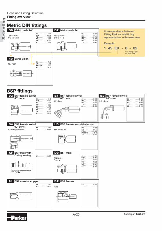
BSP fittings
Metric DIN fittings
91 BSP male taper pipe
92 BSP female swivel60° cone
B1 BSP female swivel60° cone
45° elbow
B2 BSP female swivel60° cone
90° elbow
B4 BSP female swivel60° cone
90° compact elbow
BP BSP female
Rigid
U0 BSP female swivel (ballnose)
BSP swivel nut
D9 BSP male
DIN 3852Form A
AF BSP male withO-ring sealing
D0 Metric male 24°
Light series –ISO 12151-2
D2 Metric male 24°
Heavy series –ISO 12151-2
49 Banjo union
DIN 7642
56 . . . . . . . . . . E-4991N . . . . . . . . C-179X . . . . . . . . . . E-58EX . . . . . . . . . . E-65NX . . . . . . . . . . E-73PC . . . . . . . . . C-35PX . . . . . . . . . . E-83YX . . . . . . . . . C-4482 . . . . . . . . . . B-14
56 . . . . . . . . . . E-49PC . . . . . . . . . C-35PX . . . . . . . . . . E-83YX . . . . . . . . . C-4582 . . . . . . . . . . B-14
56 . . . . . . . . . . E-50PC . . . . . . . . . C-36PX . . . . . . . . . . E-84YX . . . . . . . . . C-4582 . . . . . . . . . . B-15
PX . . . . . . . . . . E-84YX . . . . . . . . . C-47
NX . . . . . . . . . . E-73PC . . . . . . . . . C-36PX . . . . . . . . . . E-85PX-LPG . . . . . . D-8YX . . . . . . . . . C-47
56 . . . . . . . . . . E-5191N . . . . . . . . C-17EX . . . . . . . . . . E-65PC . . . . . . . . . C-37PX . . . . . . . . . . E-86YX . . . . . . . . . C-4882 . . . . . . . . . . B-15
82 . . . . . . . . . . B-23
PX . . . . . . . . . . E-8782 . . . . . . . . . . B-16
EX . . . . . . . . . . E-66
56 . . . . . . . . . . E-4491N . . . . . . . . C-14PC . . . . . . . . . C-33PX . . . . . . . . . . E-81YX . . . . . . . . . C-4382 . . . . . . . . . . . B-8
56 . . . . . . . . . . E-48EX . . . . . . . . . . E-68PX-LPG . . . . . . D-782 . . . . . . . . . . B-12
56 . . . . . . . . . . E-479X . . . . . . . . . . E-58NX . . . . . . . . . . E-72PC . . . . . . . . . C-34PX . . . . . . . . . . E-81YX . . . . . . . . . C-43
Correspondence between Fitting Part No. and fitting representation in this overview
Example:
1 49 EX - 8 - 02See fittings tableon page E-68.
Hose and Fitting Selection
Catalogue 4460-UK
Fitting overview
Sele
cti
on
A-21
A
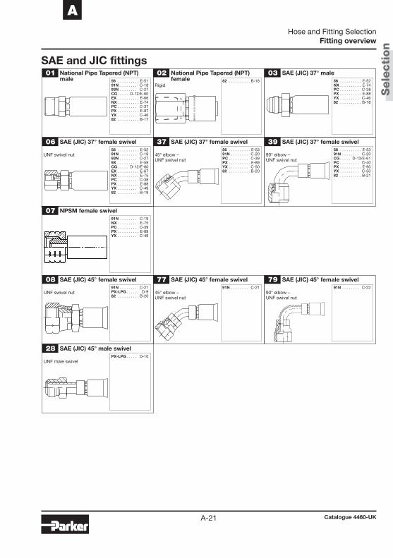
06 SAE (JIC) 37° female swivel
UNF swivel nut
37 SAE (JIC) 37° female swivel
45° elbow – UNF swivel nut
Rigid
39 SAE (JIC) 37° female swivel
90° elbow – UNF swivel nut
08 SAE (JIC) 45° female swivel
UNF swivel nut
77 SAE (JIC) 45° female swivel
45° elbow –UNF swivel nut
79 SAE (JIC) 45° female swivel
90° elbow –UNF swivel nut
28 SAE (JIC) 45° male swivel
UNF male swivel
SAE and JIC fittings01 National Pipe Tapered (NPT)
male02 National Pipe Tapered (NPT)
female03 SAE (JIC) 37° male
07 NPSM female swivel
56 . . . . . . . . . . E-5191N . . . . . . . . C-1893N . . . . . . . . C-27CG . . . . . D-12/E-60EX . . . . . . . . . . E-66NX . . . . . . . . . . E-74PC . . . . . . . . . C-37PX . . . . . . . . . . E-87YX . . . . . . . . . C-4682 . . . . . . . . . . B-17
82 . . . . . . . . . . B-18 56 . . . . . . . . . . E-52NX . . . . . . . . . . E-74PC . . . . . . . . . C-38PX . . . . . . . . . . E-88YX . . . . . . . . . C-4682 . . . . . . . . . . B-18
56 . . . . . . . . . . E-5291N . . . . . . . . C-1993N . . . . . . . . C-279X . . . . . . . . . . E-59CG . . . . . D-12/E-60EX . . . . . . . . . . E-67NX . . . . . . . . . . E-75PC . . . . . . . . . C-38PX . . . . . . . . . . E-88YX . . . . . . . . . C-4982 . . . . . . . . . . B-19
56 . . . . . . . . . . E-5391N . . . . . . . . C-20PC . . . . . . . . . C-39PX . . . . . . . . . . E-89YX . . . . . . . . . C-5082 . . . . . . . . . . B-20
56 . . . . . . . . . . E-5391N . . . . . . . . C-20CG . . . . . D-13/E-61PC . . . . . . . . . C-40PX . . . . . . . . . . E-90YX . . . . . . . . . C-5082 . . . . . . . . . . B-21
91N . . . . . . . . C-19NX . . . . . . . . . . E-75PC . . . . . . . . . C-39PX . . . . . . . . . . E-89YX . . . . . . . . . C-49
91N . . . . . . . . C-21PX-LPG . . . . . . D-982 . . . . . . . . . . B-20
91N . . . . . . . . C-21 91N . . . . . . . . C-22
PX-LPG . . . . . D-10
Hose and Fitting Selection
Catalogue 4460-UK
Fitting overview
Sele
cti
on
A-22
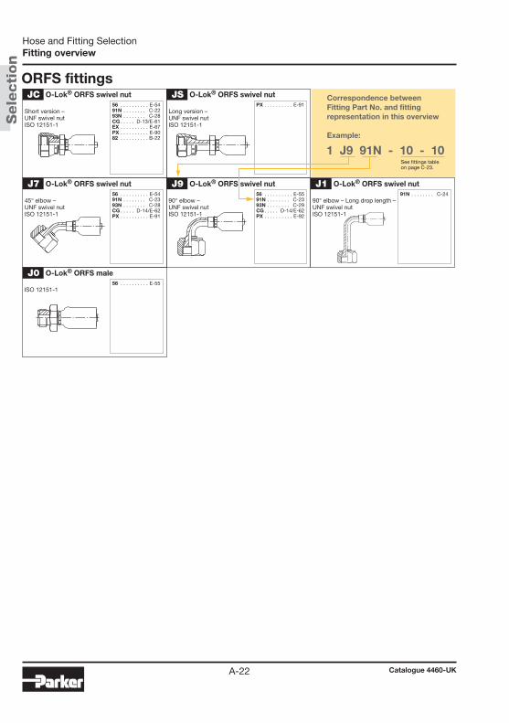
ORFS fittings
J1 O-Lok® ORFS swivel nut
90° elbow – Long drop length –UNF swivel nutISO 12151-1
J7 O-Lok® ORFS swivel nut
45° elbow –UNF swivel nutISO 12151-1
J9 O-Lok® ORFS swivel nut
90° elbow –UNF swivel nutISO 12151-1
JC O-Lok® ORFS swivel nut
Short version – UNF swivel nutISO 12151-1
JS O-Lok® ORFS swivel nut
Long version – UNF swivel nutISO 12151-1
J0 O-Lok® ORFS male
ISO 12151-1
56 . . . . . . . . . . E-5491N . . . . . . . . C-2293N . . . . . . . . C-28CG . . . . . D-13/E-61EX . . . . . . . . . . E-67PX . . . . . . . . . . E-9082 . . . . . . . . . . B-22
PX . . . . . . . . . . E-91
56 . . . . . . . . . . E-55
56 . . . . . . . . . . E-5491N . . . . . . . . C-2393N . . . . . . . . C-28CG . . . . . D-14/E-62PX . . . . . . . . . . E-91
56 . . . . . . . . . . E-5591N . . . . . . . . C-2393N . . . . . . . . C-29CG . . . . . D-14/E-62PX . . . . . . . . . . E-92
91N . . . . . . . . C-24
Correspondence between Fitting Part No. and fitting representation in this overview
Example:
1 J9 91N - 10 - 10See fittings tableon page C-23.
Hose and Fitting Selection
Catalogue 4460-UK
Fitting overview
Sele
cti
on
A-23
A
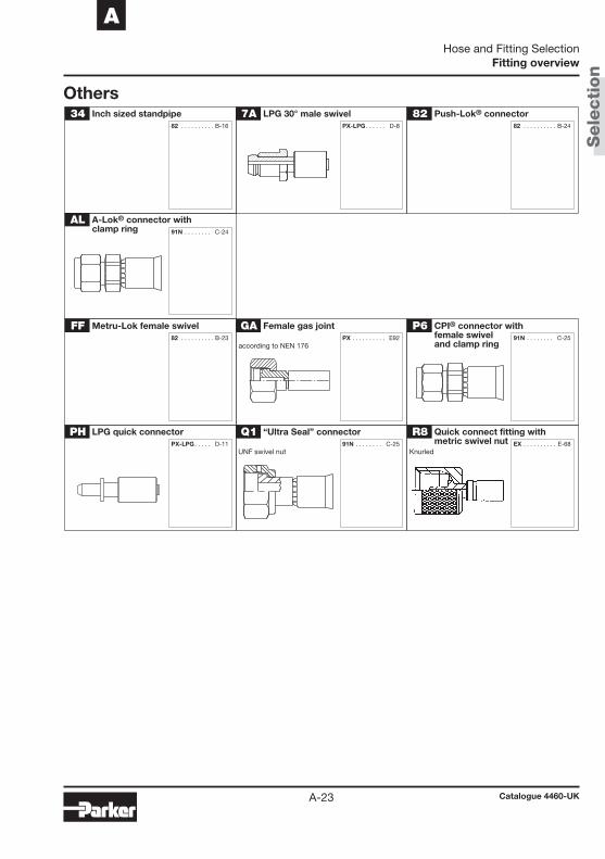
Others
Q1 “Ultra Seal” connector
UNF swivel nut
AL A-Lok® connector withclamp ring
GA Female gas joint
34 Inch sized standpipe 7A LPG 30° male swivel 82 Push-Lok® connector
according to NEN 176
FF Metru-Lok female swivel P6 CPI® connector withfemale swivel and clamp ring
PH LPG quick connector R8 Quick connect fitting withmetric swivel nut
Knurled
PX . . . . . . . . . . E92
91N . . . . . . . . C-25
91N . . . . . . . . C-24
82 . . . . . . . . . . B-16 PX-LPG . . . . . . D-8 82 . . . . . . . . . . B-24
82 . . . . . . . . . . B-23 91N . . . . . . . . C-25
PX-LPG . . . . . D-11 EX . . . . . . . . . . E-68
Hose and Fitting Selection
Catalogue 4460-UK
Fitting overview

Sele
cti
on
A-24
OthersTU A-Lok® tube stub end YW A-Lok® metric standpipe
YP Quick connect fittingwith clip
YR
91N . . . . . . . . C-26 91N . . . . . . . . C-26
EX . . . . . . . . . . E-69 EX . . . . . . . . . . E-69
Correspondence between Fitting Part No. and fitting representation in this overview
Example:
1 YR EX - 10 - 012See fittings tableon page E-69.
Quick connect fitting withmetric swivel nut
Hose and Fitting Selection
Catalogue 4460-UK
Fitting overview
Push
-Lok
®
Catalogue 4460-UKB-1
BPush-Lok® Hose and Fittings
Chapter B
Push-Lok® Hose and Fittings
Push-Lok® hoseIntroduction ......................................................................................... B-2830M – Push-Lok® self-grip hose .................................................... B-4838M – Push-Lok® self-grip hose, electrically non-conductive ....... B-5
Fittings for Push-Lok® hose82 series ............................................................................................... B-6
Push-Lok® Hose and Fittings
Catalogue 4460-UK
Table of contents

Push
-Lok
®
Introduction
B-2
Application
The Push Lok® hose range can be used for a wide range of applications and media such as
• Air systems
• Hydraulic applications
• In plant automotive applications for air, water, lubricating oils and antifreeze fl uids.
• Non-conductive cooling systems with de-Ionized water
• Energy chains
For details of fl uid compability please refer to chapter A “Hose selection by fl uid compatibility/chemical resistance”
Introduction
Parker Push-Lok® – The Most Complete Line of Premium-Quality, Low-Pres-sure Hose and Fittings.
Push-lok® is a registered trademark of Parker and is used for low pressure applications up to working pressures of 1.6 Mpa with all sizes of Parker Ther-moplastic Hose. The Push Lok® hose and fi ttings are a qualifi ed system with a design factor of 4:1 (burst pressure > 64 bar) . With it‘s “tool-free” assembly due to Parker Push-Lok® fi ttings it is very well recommend for many applica-tions.
The Push Lok
• Air systems
• Hydraulic applications
• In plant automotive applications for air, water,
• Non-conductive cooling systems with de-Ionized water
Push-Lok® Hose and FittingsIntroduction

Push
-Lok
®
B
Introduction
B-3
Features
Benefi ts
• High abrasion resistance
• Electrically non-conductive
• Free of paint effecting substances (labs free, compliant with automotive requirements)
• Tight bend radius
• Excellent UV and OZONE resistance
• Temperature range from -40°C up to +80°C
• Fast & easy assembly
• No hose clamps required
• Colour variety
• Long product lifetime
• Less downtime in the application
• Less maintenance necessary compared to other solutions
• Suitable for in plant automotive equipment
• Easy identifi cation of hose function due to colouring
• Safe and fast hose assembly
Push-Lok® Hose and FittingsIntroduction
Push
-Lok
®
Catalogue 4460-UKB-4
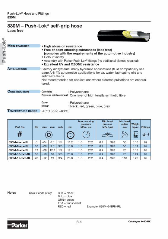
Push-Lok® Hose and Fittings830M
830M – Push-Lok® self-grip hoseLabs free
Colour code (xxx): BLK = black BLU = blue GRN = green TRA = transparent RED = red Example: 830M-6-GRN-RL
• High abrasion resistance • Free of paint effecting substances (labs free)
(complies with the requirements of the automotive industry) • Colour variety • Assembly with Parker Push-Lok® fittings (no additional clamps required) • Excellent UV and OZONE resistanceFactory air systems, many hydraulic applications (fluid compatibility see page A-8 ff.); automotive applications for air, water, lubricating oils andantifreeze fluids.Not recommended for applications where extreme pulsations are encoun-tered.
Polyurethane One layer of high tensile synthetic fibre Polyurethane black, red, green, blue, grey
-40°C up to +80°C.
Part No. DN size mm inch mm
Max. workingpressureMPa / psi
Min. burstpressureMPa / psi
Min. bend radius
mmWeightkg/m
Fittings
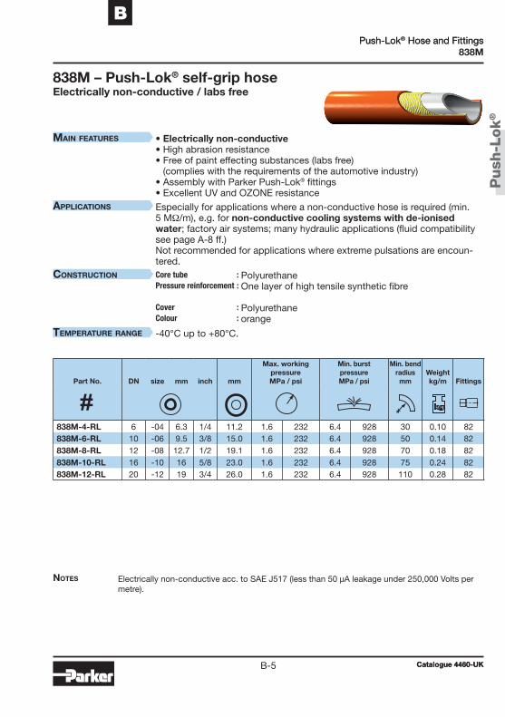
830M-4-xxx-RL 6 -04 6.3 1/4 11.2 1.6 232 6.4 928 30 0.10 82830M-6-xxx-RL 10 -06 9.5 3/8 15.0 1.6 232 6.4 928 50 0.14 82830M-8-xxx-RL 12 -08 12.7 1/2 19.1 1.6 232 6.4 928 70 0.18 82830M-10-xxx-RL 16 -10 16 5/8 23.0 1.6 232 6.4 928 75 0.24 82830M-12-xxx-RL 20 -12 19 3/4 26.0 1.6 232 6.4 928 110 0.28 82
Push-Lok® Hose and Fittings
Catalogue 4460-UK
Notes
MaiN features
applicatioNs
coNstructioN Core tube :Pressure reinforcement : Cover : Colour :
teMperature raNge
Push
-Lok
®
Catalogue 4460-UKB-5
BPush-Lok® Hose and Fittings
838M
838M – Push-Lok® self-grip hoseElectrically non-conductive / labs free
Electrically non-conductive acc. to SAE J517 (less than 50 μA leakage under 250,000 Volts per metre).
• Electrically non-conductive • High abrasion resistance • Free of paint effecting substances (labs free)
(complies with the requirements of the automotive industry)• Assembly with Parker Push-Lok® fittings• Excellent UV and OZONE resistance
Especially for applications where a non-conductive hose is required (min. 5 MΩ/m), e.g. for non-conductive cooling systems with de-ionised water; factory air systems; many hydraulic applications (fluid compatibility see page A-8 ff.)Not recommended for applications where extreme pulsations are encoun-tered.
Polyurethane One layer of high tensile synthetic fibre Polyurethane orange
-40°C up to +80°C.
Part No. DN size mm inch mm
Max. workingpressureMPa / psi
Min. burstpressureMPa / psi
Min. bend radius
mmWeightkg/m
Fittings
838M-4-RL 6 -04 6.3 1/4 11.2 1.6 232 6.4 928 30 0.10 82838M-6-RL 10 -06 9.5 3/8 15.0 1.6 232 6.4 928 50 0.14 82838M-8-RL 12 -08 12.7 1/2 19.1 1.6 232 6.4 928 70 0.18 82838M-10-RL 16 -10 16 5/8 23.0 1.6 232 6.4 928 75 0.24 82838M-12-RL 20 -12 19 3/4 26.0 1.6 232 6.4 928 110 0.28 82
Push-Lok® Hose and Fittings
Catalogue 4460-UK
Notes
MaiN features
applicatioNs
coNstructioN Core tube :Pressure reinforcement : Cover : Colour :
teMperature raNge

Push
-Lok
®
Catalogue 4460-UKB-6
Push-Lok® Hose and FittingsCA
CA – Female Metric 24° Light Series with O–Ring Swivel – Straight
ISO 12151-2-SWS-L – DKOLMaterial Galvanised steel with transparent Cr(VI)-free plating.
B: Brass; Fittings with standard O-ring seals can be used for working temperatures from -30 °C up to +105 °C.
Connection type Max.
Part No. DN size mm inch Thread size Tube OD
mmA
mmB
mmW
mmWPMPa
3CA82-6-4B 6 -4 6.4 1/4 M12x1.5 6 40 21 14 1.63CA82-6-4 6 -4 6.4 1/4 M12x1.5 6 40 21 14 1.63CA82-8-4 6 -4 6.4 1/4 M14x1.5 8 36 17 17 1.63CA82-8-4B 6 -4 6.4 1/4 M14x1.5 8 36 17 17 1.63CA82-10-4 6 -4 6.4 1/4 M16x1.5 10 36 17 19 1.63CA82-10-6 10 -6 9.5 3/8 M16x1.5 10 40 17 19 1.63CA82-10-6B 10 -6 9.5 3/8 M16x1.5 10 39 17 19 1.63CA82-12-6 10 -6 9.5 3/8 M18x1.5 12 40 17 22 1.63CA82-12-6B 10 -6 9.5 3/8 M18x1.5 12 39 17 22 1.63CA82-15-8 12 -8 12.7 1/2 M22x1.5 15 44 18 27 1.63CA82-15-8B 12 -8 12.7 1/2 M22x1.5 15 44 17 27 1.63CA82-15-10B 16 -10 15.9 5/8 M22x1.5 15 60 23 27 1.63CA82-18-10 16 -10 15.9 5/8 M26x1.5 18 56 19 32 1.63CA82-22-12B 19 -12 19.1 3/4 M30x2 22 58 21 36 1.63CA82-22-12 19 -12 19.1 3/4 M30x2 22 58 21 36 1.6
Push-Lok® Hose and Fittings
Catalogue 4460-UK
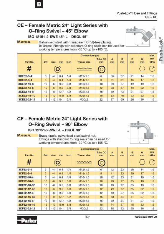
Push
-Lok
®
Catalogue 4460-UKB-7
BPush-Lok® Hose and Fittings
CE – CF
CE – Female Metric 24° Light Series with O–Ring Swivel – 45° Elbow
ISO 12151-2-SWE 45°-L – DKOL 45°
CF – Female Metric 24° Light Series with O–Ring Swivel – 90° Elbow
ISO 12151-2-SWE-L – DKOL 90°
Material Galvanised steel with transparent Cr(VI)-free plating. B: Brass; Fittings with standard O-ring seals can be used for working temperatures from -30 °C up to +105 °C.
Material Brass nipple, galvanised steel swivel nut. Fittings with standard O-ring seals can be used for working temperatures from -30 °C up to +105 °C.
Connection type Max.
Part No. DN size mm inch Thread size Tube OD
mmA
mmB
mmE
mmW
mmWPMPa
Connection type Max.
Part No. DN size mm inch Thread size Tube OD
mmA
mmB
mmE
mmW
mmWPMPa
3CE82-6-4 6 -4 6.4 1/4 M12x1.5 6 56 37 21 14 1.63CE82-8-4 6 -4 6.4 1/4 M14x1.5 8 51 31 16 17 1.63CE82-10-6 10 -6 9.5 3/8 M16x1.5 10 59 37 19 19 1.63CE82-12-6 10 -6 9.5 3/8 M18x1.5 12 60 37 19 22 1.63CE82-15-8 12 -8 12.7 1/2 M22x1.5 15 69 43 21 27 1.63CE82-18-10 16 -10 15.9 5/8 M26x1.5 18 83 46 23 32 1.63CE82-22-12 19 -12 19.1 3/4 M30x2 22 97 60 26 36 1.6
3CF82-6-4 6 -4 6.4 1/4 M12x1.5 6 42 23 36 14 1.63CF82-8-4 6 -4 6.4 1/4 M14x1.5 8 41 23 29 17 1.63CF82-10-4 6 -4 6.4 1/4 M16x1.5 10 42 23 31 19 1.63CF82-10-6 10 -6 9.5 3/8 M16x1.5 10 49 27 35 19 1.63CF82-10-6B 10 -6 9.5 3/8 M16x1.5 10 49 27 35 19 1.63CF82-12-6B 10 -6 9.5 3/8 M18x1.5 12 49 27 35 22 1.63CF82-12-6 10 -6 9.5 3/8 M18x1.5 12 49 27 35 22 1.63CF82-15-8B 12 -8 12.7 1/2 M22x1.5 15 60 34 41 27 1.63CF82-15-8 12 -8 12.7 1/2 M22x1.5 15 60 34 41 27 1.63CF82-18-10 16 -10 15.9 5/8 M26x1.5 18 74 37 45 32 1.63CF82-22-12 19 -12 19.1 3/4 M30x2 22 88 52 55 36 1.6
Push-Lok® Hose and Fittings
Catalogue 4460-UK
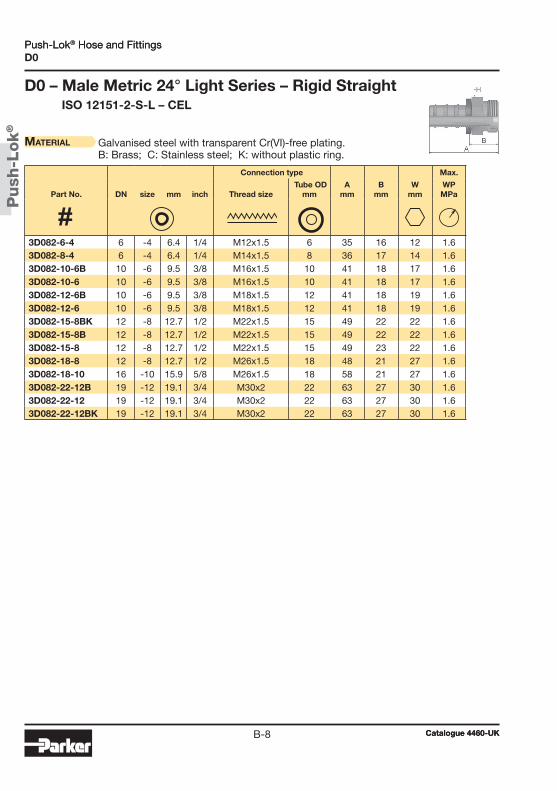
Push
-Lok
®
Catalogue 4460-UKB-8
Push-Lok® Hose and FittingsD0
D0 – Male Metric 24° Light Series – Rigid Straight ISO 12151-2-S-L – CEL
Material Galvanised steel with transparent Cr(VI)-free plating. B: Brass; C: Stainless steel; K: without plastic ring.
Connection type Max.
Part No. DN size mm inch Thread size Tube OD
mmA
mmB
mmW
mmWPMPa
3D082-6-4 6 -4 6.4 1/4 M12x1.5 6 35 16 12 1.63D082-8-4 6 -4 6.4 1/4 M14x1.5 8 36 17 14 1.63D082-10-6B 10 -6 9.5 3/8 M16x1.5 10 41 18 17 1.63D082-10-6 10 -6 9.5 3/8 M16x1.5 10 41 18 17 1.63D082-12-6B 10 -6 9.5 3/8 M18x1.5 12 41 18 19 1.63D082-12-6 10 -6 9.5 3/8 M18x1.5 12 41 18 19 1.63D082-15-8BK 12 -8 12.7 1/2 M22x1.5 15 49 22 22 1.63D082-15-8B 12 -8 12.7 1/2 M22x1.5 15 49 22 22 1.63D082-15-8 12 -8 12.7 1/2 M22x1.5 15 49 23 22 1.63D082-18-8 12 -8 12.7 1/2 M26x1.5 18 48 21 27 1.63D082-18-10 16 -10 15.9 5/8 M26x1.5 18 58 21 27 1.63D082-22-12B 19 -12 19.1 3/4 M30x2 22 63 27 30 1.63D082-22-12 19 -12 19.1 3/4 M30x2 22 63 27 30 1.63D082-22-12BK 19 -12 19.1 3/4 M30x2 22 63 27 30 1.6
Push-Lok® Hose and Fittings
Catalogue 4460-UK

Push
-Lok
®
Catalogue 4460-UKB-9
BPush-Lok® Hose and Fittings
C3
C3 – Female Metric Light Series – Swivel Straight (Ball Nose for 24° or 60° Cone)
DKLMaterial Galvanised steel with transparent Cr(VI)-free plating.
B: Brass; C: Stainless steel; K: without plastic ring.
Connection type Max.
Part No. DN size mm inch Thread size Tube OD
mmA
mmB
mmW
mmWPMPa
3C382-6-4 6 -4 6.4 1/4 M12x1.5 6 33 14 14 1.63C382-6-4BK 6 -4 6.4 1/4 M12x1.5 6 33 14 14 1.63C382-6-4B 6 -4 6.4 1/4 M12x1.5 6 33 14 14 1.63C382-8-4 6 -4 6.4 1/4 M14x1.5 8 33 14 17 1.63C382-8-4BK 6 -4 6.4 1/4 M14x1.5 8 36 17 19 1.63C382-8-4B 6 -4 6.4 1/4 M14x1.5 8 36 17 19 1.63C382-10-4 6 -4 6.4 1/4 M16x1.5 10 34 15 19 1.63C382-10-4BK 6 -4 6.4 1/4 M16x1.5 10 34 15 19 1.63C382-10-6 10 -6 9.5 3/8 M16x1.5 10 37 15 19 1.63C382-10-6BK 10 -6 9.5 3/8 M16x1.5 10 40 17 19 1.63C382-10-6B 10 -6 9.5 3/8 M16x1.5 10 40 17 19 1.63C382-12-6BK 10 -6 9.5 3/8 M18x1.5 12 40 17 22 1.63C382-12-6 10 -6 9.5 3/8 M18x1.5 12 38 16 22 1.63C382-15-8 12 -8 12.7 1/2 M22x1.5 15 42 15 27 1.63C382-15-8B 12 -8 12.7 1/2 M22x1.5 15 46 19 27 1.63C382-15-8BK 12 -8 12.7 1/2 M22x1.5 15 46 19 27 1.63C382-15-10 16 -10 15.9 5/8 M22x1.5 15 56 19 27 1.63C382-18-10B 16 -10 15.9 5/8 M26x1.5 18 58 22 32 1.63C382-18-10 16 -10 15.9 5/8 M26x1.5 18 53 17 32 1.63C382-18-10BK 16 -10 15.9 5/8 M26x1.5 18 58 22 32 1.63C382-22-12B 19 -12 19.1 3/4 M30x2 22 58 22 36 1.63C382-22-12 19 -12 19.1 3/4 M30x2 22 53 17 36 1.63C382-22-12BK 19 -12 19.1 3/4 M30x2 22 58 22 36 1.63C382-28-16 25 -16 25.4 1 M36x2 28 58 22 41 1.63C382-28-16-K 25 -16 25.4 1 M36x2 28 58 22 41 1.63C382-28-16BK 25 -16 25.4 1 M36x2 28 58 22 41 1.6
Push-Lok® Hose and Fittings
Catalogue 4460-UK
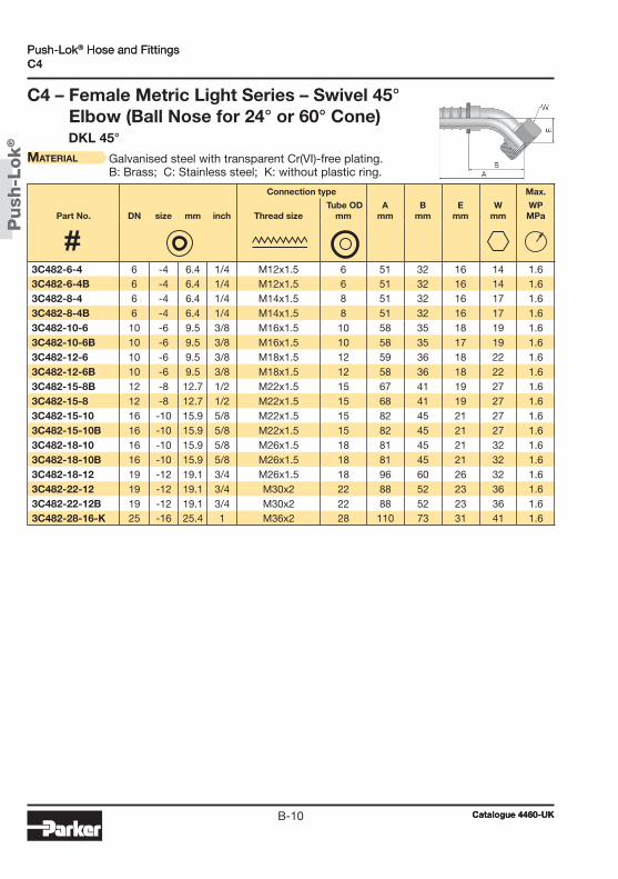
Push
-Lok
®
Catalogue 4460-UKB-10
Push-Lok® Hose and FittingsC4
C4 – Female Metric Light Series – Swivel 45° Elbow (Ball Nose for 24° or 60° Cone)
DKL 45°Material Galvanised steel with transparent Cr(VI)-free plating.
B: Brass; C: Stainless steel; K: without plastic ring.
Connection type Max.
Part No. DN size mm inch Thread size Tube OD
mmA
mmB
mmE
mmW
mmWPMPa
3C482-6-4 6 -4 6.4 1/4 M12x1.5 6 51 32 16 14 1.63C482-6-4B 6 -4 6.4 1/4 M12x1.5 6 51 32 16 14 1.63C482-8-4 6 -4 6.4 1/4 M14x1.5 8 51 32 16 17 1.63C482-8-4B 6 -4 6.4 1/4 M14x1.5 8 51 32 16 17 1.63C482-10-6 10 -6 9.5 3/8 M16x1.5 10 58 35 18 19 1.63C482-10-6B 10 -6 9.5 3/8 M16x1.5 10 58 35 17 19 1.63C482-12-6 10 -6 9.5 3/8 M18x1.5 12 59 36 18 22 1.63C482-12-6B 10 -6 9.5 3/8 M18x1.5 12 58 36 18 22 1.63C482-15-8B 12 -8 12.7 1/2 M22x1.5 15 67 41 19 27 1.63C482-15-8 12 -8 12.7 1/2 M22x1.5 15 68 41 19 27 1.63C482-15-10 16 -10 15.9 5/8 M22x1.5 15 82 45 21 27 1.63C482-15-10B 16 -10 15.9 5/8 M22x1.5 15 82 45 21 27 1.63C482-18-10 16 -10 15.9 5/8 M26x1.5 18 81 45 21 32 1.63C482-18-10B 16 -10 15.9 5/8 M26x1.5 18 81 45 21 32 1.63C482-18-12 19 -12 19.1 3/4 M26x1.5 18 96 60 26 32 1.63C482-22-12 19 -12 19.1 3/4 M30x2 22 88 52 23 36 1.63C482-22-12B 19 -12 19.1 3/4 M30x2 22 88 52 23 36 1.63C482-28-16-K 25 -16 25.4 1 M36x2 28 110 73 31 41 1.6
Push-Lok® Hose and Fittings
Catalogue 4460-UK

Push
-Lok
®
Catalogue 4460-UKB-11
BPush-Lok® Hose and Fittings
C5
C5 – Female Metric Light Series – Swivel 90° Elbow (Ball Nose for 24° or 60° Cone)
DKL 90°
Material Galvanised steel with transparent Cr(VI)-free plating. B: Brass; C: Stainless steel; K: without plastic ring.
Connection type Max.
Part No. DN size mm inch Thread size Tube OD
mmA
mmB
mmE
mmW
mmWPMPa
3C582-6-4 6 -4 6.4 1/4 M12x1.5 6 42 23 29 14 1.63C582-8-4 6 -4 6.4 1/4 M14x1.5 8 42 23 29 17 1.63C582-8-4B 6 -4 6.4 1/4 M14x1.5 8 41 23 29 17 1.63C582-10-4 6 -4 6.4 1/4 M16x1.5 10 42 23 29 19 1.63C582-10-6 10 -6 9.5 3/8 M16x1.5 10 49 27 33 19 1.63C582-12-6B 10 -6 9.5 3/8 M18x1.5 12 49 27 34 22 1.63C582-12-6 10 -6 9.5 3/8 M18x1.5 12 49 27 34 22 1.63C582-15-8 12 -8 12.7 1/2 M22x1.5 15 65 38 39 27 1.63C582-15-8B 12 -8 12.7 1/2 M22x1.5 15 65 38 39 27 1.63C582-18-10B 16 -10 15.9 5/8 M26x1.5 18 74 37 43 32 1.63C582-18-10 16 -10 15.9 5/8 M26x1.5 18 74 37 43 32 1.63C582-22-12B 19 -12 19.1 3/4 M30x2 22 88 52 50 36 1.63C582-22-12 19 -12 19.1 3/4 M30x2 22 88 51 50 36 1.63C582-28-16B 25 -16 25.4 1 M36x2 28 101 64 66 41 1.63C582-28-16-K 25 -16 25.4 1 M36x2 28 99 61 70 41 1.6
Push-Lok® Hose and Fittings
Catalogue 4460-UK
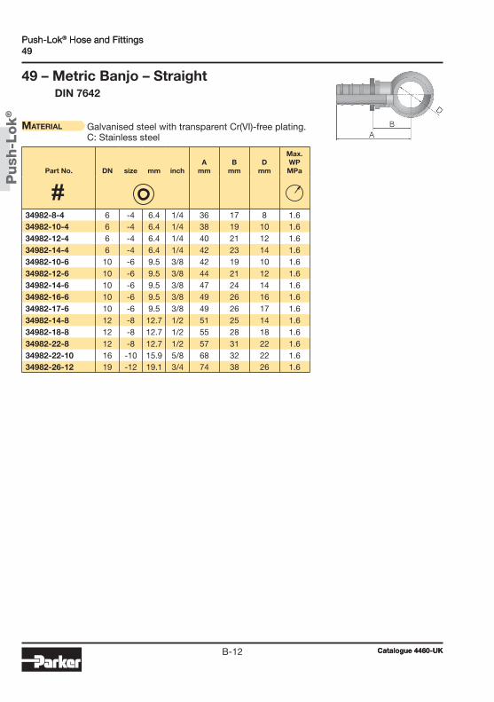
Push
-Lok
®
Catalogue 4460-UKB-12
Push-Lok® Hose and Fittings49
49 – Metric Banjo – Straight DIN 7642
Material Galvanised steel with transparent Cr(VI)-free plating. C: Stainless steel
Part No. DN size mm inchA
mmB
mmD
mm
Max.WPMPa
34982-8-4 6 -4 6.4 1/4 36 17 8 1.634982-10-4 6 -4 6.4 1/4 38 19 10 1.634982-12-4 6 -4 6.4 1/4 40 21 12 1.634982-14-4 6 -4 6.4 1/4 42 23 14 1.634982-10-6 10 -6 9.5 3/8 42 19 10 1.634982-12-6 10 -6 9.5 3/8 44 21 12 1.634982-14-6 10 -6 9.5 3/8 47 24 14 1.634982-16-6 10 -6 9.5 3/8 49 26 16 1.634982-17-6 10 -6 9.5 3/8 49 26 17 1.634982-14-8 12 -8 12.7 1/2 51 25 14 1.634982-18-8 12 -8 12.7 1/2 55 28 18 1.634982-22-8 12 -8 12.7 1/2 57 31 22 1.634982-22-10 16 -10 15.9 5/8 68 32 22 1.634982-26-12 19 -12 19.1 3/4 74 38 26 1.6
Push-Lok® Hose and Fittings
Catalogue 4460-UK
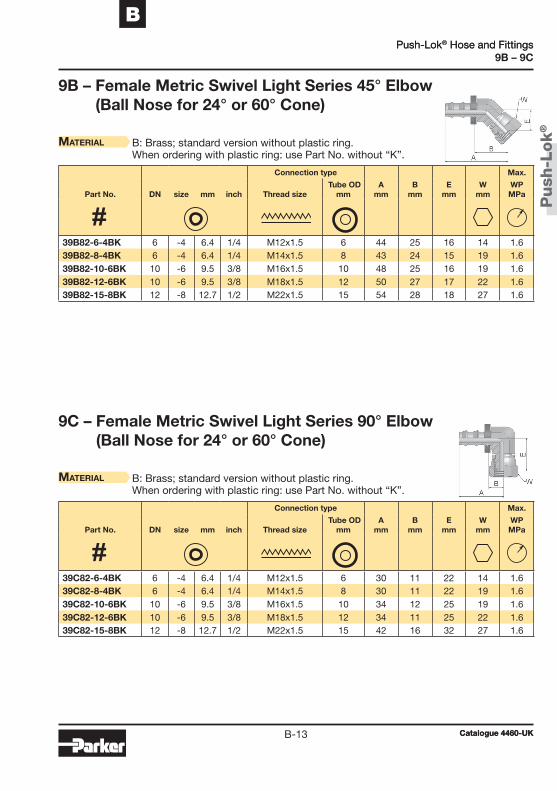
Push
-Lok
®
Catalogue 4460-UKB-13
BPush-Lok® Hose and Fittings
9B – 9C
9B – Female Metric Swivel Light Series 45° Elbow (Ball Nose for 24° or 60° Cone)
9C – Female Metric Swivel Light Series 90° Elbow (Ball Nose for 24° or 60° Cone)
Material B: Brass; standard version without plastic ring. When ordering with plastic ring: use Part No. without “K”.
Material B: Brass; standard version without plastic ring. When ordering with plastic ring: use Part No. without “K”.
Connection type Max.
Part No. DN size mm inch Thread size Tube OD
mmA
mmB
mmE
mmW
mmWPMPa
Connection type Max.
Part No. DN size mm inch Thread size Tube OD
mmA
mmB
mmE
mmW
mmWPMPa
39B82-6-4BK 6 -4 6.4 1/4 M12x1.5 6 44 25 16 14 1.639B82-8-4BK 6 -4 6.4 1/4 M14x1.5 8 43 24 15 19 1.639B82-10-6BK 10 -6 9.5 3/8 M16x1.5 10 48 25 16 19 1.639B82-12-6BK 10 -6 9.5 3/8 M18x1.5 12 50 27 17 22 1.639B82-15-8BK 12 -8 12.7 1/2 M22x1.5 15 54 28 18 27 1.6
39C82-6-4BK 6 -4 6.4 1/4 M12x1.5 6 30 11 22 14 1.639C82-8-4BK 6 -4 6.4 1/4 M14x1.5 8 30 11 22 19 1.639C82-10-6BK 10 -6 9.5 3/8 M16x1.5 10 34 12 25 19 1.639C82-12-6BK 10 -6 9.5 3/8 M18x1.5 12 34 11 25 22 1.639C82-15-8BK 12 -8 12.7 1/2 M22x1.5 15 42 16 32 27 1.6
Push-Lok® Hose and Fittings
Catalogue 4460-UK
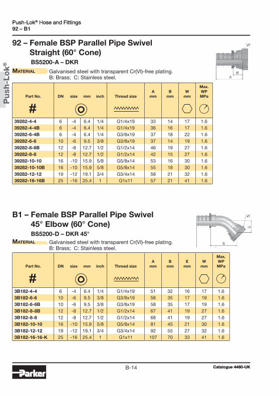
Push
-Lok
®
Catalogue 4460-UKB-14
Push-Lok® Hose and Fittings92 – B1
B1 – Female BSP Parallel Pipe Swivel 45° Elbow (60° Cone)
BS5200-D – DKR 45° Material Galvanised steel with transparent Cr(VI)-free plating.
B: Brass; C: Stainless steel.
92 – Female BSP Parallel Pipe Swivel Straight (60° Cone)
BS5200-A – DKR Material Galvanised steel with transparent Cr(VI)-free plating.
B: Brass; C: Stainless steel.
Part No. DN size mm inch Thread sizeA
mmB
mmE
mmW
mm
Max.WPMPa
Part No. DN size mm inch Thread sizeA
mmB
mmW
mm
Max.WPMPa
3B182-4-4 6 -4 6.4 1/4 G1/4x19 51 32 16 17 1.63B182-6-6 10 -6 9.5 3/8 G3/8x19 58 35 17 19 1.63B182-6-6B 10 -6 9.5 3/8 G3/8x19 58 35 17 19 1.63B182-8-8B 12 -8 12.7 1/2 G1/2x14 67 41 19 27 1.63B182-8-8 12 -8 12.7 1/2 G1/2x14 68 41 19 27 1.63B182-10-10 16 -10 15.9 5/8 G5/8x14 81 45 21 30 1.63B182-12-12 19 -12 19.1 3/4 G3/4x14 92 55 27 32 1.63B182-16-16-K 25 -16 25.4 1 G1x11 107 70 33 41 1.6
39282-4-4 6 -4 6.4 1/4 G1/4x19 33 14 17 1.639282-4-4B 6 -4 6.4 1/4 G1/4x19 36 16 17 1.639282-6-4B 6 -4 6.4 1/4 G3/8x19 37 18 22 1.639282-6-6 10 -6 9.5 3/8 G3/8x19 37 14 19 1.639282-8-8B 12 -8 12.7 1/2 G1/2x14 46 19 27 1.639282-8-8 12 -8 12.7 1/2 G1/2x14 42 15 27 1.639282-10-10 16 -10 15.9 5/8 G5/8x14 53 16 30 1.639282-10-10B 16 -10 15.9 5/8 G5/8x14 55 18 30 1.639282-12-12 19 -12 19.1 3/4 G3/4x14 58 21 32 1.639282-16-16B 25 -16 25.4 1 G1x11 57 21 41 1.6
Push-Lok® Hose and Fittings
Catalogue 4460-UK

Push
-Lok
®
Catalogue 4460-UKB-15
BPush-Lok® Hose and Fittings
B2 – D9
B2 – Female BSP Parallel Pipe Swivel 90° Elbow (60° Cone)
BS5200-B – DKR 90°Material Galvanised steel with transparent Cr(VI)-free plating.
B: Brass; C: Stainless steel.
D9 – Male BSP Parallel Pipe Rigid – Straight (60° Cone)
BS5200 – AGRMaterial Galvanised steel with transparent Cr(VI)-free plating.
B: Brass
Part No. DN size mm inch Thread sizeA
mmB
mmE
mmW
mm
Max.WPMPa
Part No. DN size mm inch Thread sizeA
mmB
mmH
mm
Max.WPMPa
3B282-4-4 6 -4 6.4 1/4 G1/4x19 42 23 29 17 1.63B282-6-6 10 -6 9.5 3/8 G3/8x19 49 26 33 19 1.63B282-8-8B 12 -8 12.7 1/2 G1/2x14 60 34 39 27 1.63B282-8-8 12 -8 12.7 1/2 G1/2x14 60 34 39 27 1.63B282-10-8 12 -8 12.7 1/2 G5/8x14 58 32 40 30 1.63B282-10-10 16 -10 15.9 5/8 G5/8x14 74 37 43 30 1.63B282-10-10B 16 -10 15.9 5/8 G5/8x14 74 37 44 30 1.63B282-12-12 19 -12 19.1 3/4 G3/4x14 83 46 53 32 1.63B282-12-12B 19 -12 19.1 3/4 G3/4x14 83 46 53 32 1.63B282-16-16-K 25 -16 25.4 1 G1x11 99 61 68 41 1.6
3D982-2-4 6 -4 6.4 1/4 G1/8x28 36 17 14 1.63D982-4-4B 6 -4 6.4 1/4 G1/4x19 41 23 19 1.63D982-4-4 6 -4 6.4 1/4 G1/4x19 41 23 19 1.63D982-4-6B 10 -6 9.5 3/8 G1/4x19 44 21 19 1.63D982-4-6 10 -6 9.5 3/8 G1/4x19 44 21 19 1.63D982-6-6 10 -6 9.5 3/8 G3/8x19 45 23 22 1.63D982-8-8B 12 -8 12.7 1/2 G1/2x14 53 27 27 1.63D982-8-8 12 -8 12.7 1/2 G1/2x14 53 27 27 1.63D982-8-10 16 -10 15.9 5/8 G1/2x14 62 25 27 1.63D982-12-12 19 -12 19.1 3/4 G3/4x14 65 28 32 1.6
Push-Lok® Hose and Fittings
Catalogue 4460-UK
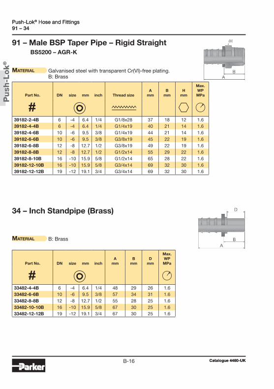
Push
-Lok
®
Catalogue 4460-UKB-16
Push-Lok® Hose and Fittings91 – 34
91 – Male BSP Taper Pipe – Rigid Straight BS5200 – AGR-K
Material Galvanised steel with transparent Cr(VI)-free plating. B: Brass
34 – Inch Standpipe (Brass)
Material B: Brass
Part No. DN size mm inchA
mmB
mmD
mm
Max.WPMPa
Part No. DN size mm inch Thread sizeA
mmB
mmH
mm
Max.WPMPa
39182-2-4B 6 -4 6.4 1/4 G1/8x28 37 18 12 1.639182-4-4B 6 -4 6.4 1/4 G1/4x19 40 21 14 1.639182-4-6B 10 -6 9.5 3/8 G1/4x19 44 21 14 1.639182-6-6B 10 -6 9.5 3/8 G3/8x19 45 22 19 1.639182-6-8B 12 -8 12.7 1/2 G3/8x19 49 22 19 1.639182-8-8B 12 -8 12.7 1/2 G1/2x14 55 29 22 1.639182-8-10B 16 -10 15.9 5/8 G1/2x14 65 28 22 1.639182-12-10B 16 -10 15.9 5/8 G3/4x14 69 32 30 1.639182-12-12B 19 -12 19.1 3/4 G3/4x14 69 32 30 1.6
33482-4-4B 6 -4 6.4 1/4 48 29 26 1.633482-6-6B 10 -6 9.5 3/8 57 34 31 1.633482-8-8B 12 -8 12.7 1/2 55 28 25 1.633482-10-10B 16 -10 15.9 5/8 67 30 25 1.633482-12-12B 19 -12 19.1 3/4 67 30 25 1.6
Push-Lok® Hose and Fittings
Catalogue 4460-UK
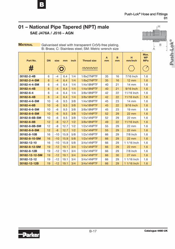
Push
-Lok
®
Catalogue 4460-UKB-17
BPush-Lok® Hose and Fittings
01
01 – National Pipe Tapered (NPT) male SAE J476A / J516 – AGN
Material Galvanised steel with transparent Cr(VI)-free plating. B: Brass; C: Stainless steel; SM: Metric wrench size
Part No. DN size mm inch Thread sizeA
mmB
mmH
mm/inch
Max.WPMPa
30182-2-4B 6 -4 6.4 1/4 1/8x27NPTF 35 16 7/16 Inch 1.630182-2-4-SM 6 -4 6.4 1/4 1/8x27NPTF 35 16 12 mm 1.630182-4-4-SM 6 -4 6.4 1/4 1/4x18NPTF 40 21 14 mm 1.630182-4-4B 6 -4 6.4 1/4 1/4x18NPTF 40 21 9/16 Inch 1.630182-6-4 6 -4 6.4 1/4 3/8x18NPTF 42 22 11/16 Inch 1.630182-6-4B 6 -4 6.4 1/4 3/8x18NPTF 42 22 11/16 Inch 1.630182-4-6-SM 10 -6 9.5 3/8 1/4x18NPTF 45 23 14 mm 1.630182-4-6B 10 -6 9.5 3/8 1/4x18NPTF 45 22 9/16 Inch 1.630182-6-6-SM 10 -6 9.5 3/8 3/8x18NPTF 45 23 19 mm 1.630182-8-6-SM 10 -6 9.5 3/8 1/2x14NPTF 52 29 22 mm 1.630182-8-6B-SM 10 -6 9.5 3/8 1/2x14NPTF 52 29 22 mm 1.630182-6-8B 12 -8 12.7 1/2 3/8x18NPTF 49 22 11/16 Inch 1.630182-8-8B-SM 12 -8 12.7 1/2 1/2x14NPTF 55 29 22 mm 1.630182-8-8-SM 12 -8 12.7 1/2 1/2x14NPTF 55 29 22 mm 1.630182-8-10B 16 -10 15.9 5/8 1/2x14NPTF 66 29 7/8 Inch 1.630182-8-10-SM 16 -10 15.9 5/8 1/2x14NPTF 66 29 22 mm 1.630182-12-10 16 -10 15.9 5/8 3/4x14NPTF 66 29 1 1/16 Inch 1.630182-8-12-SM 19 -12 19.1 3/4 1/2x14NPTF 66 29 22 mm 1.630182-8-12B 19 -12 19.1 3/4 1/2x14NPTF 66 29 7/8 Inch 1.630182-12-12-SM 19 -12 19.1 3/4 3/4x14NPTF 66 30 27 mm 1.630182-12-12 19 -12 19.1 3/4 3/4x14NPTF 66 29 1 1/16 Inch 1.630182-12-12B 19 -12 19.1 3/4 3/4x14NPTF 66 29 1 1/16 Inch 1.6
Push-Lok® Hose and Fittings
Catalogue 4460-UK
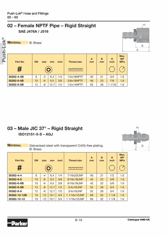
Push
-Lok
®
Catalogue 4460-UKB-18
Push-Lok® Hose and Fittings02 – 03
02 – Female NPTF Pipe – Rigid Straight SAE J476A / J516
Material B: Brass
03 – Male JIC 37° – Rigid Straight ISO12151-5-S – AGJ
Material Galvanised steel with transparent Cr(VI)-free plating. B: Brass
Part No. DN size mm inch Thread sizeA
mmB
mmH
inch
Max.WPMPa
Part No. DN size mm inch Thread sizeA
mmB
mmH
inch
Max.WPMPa
30282-4-4B 6 -4 6.4 1/4 1/4x18NPTF 40 21 3/4 1.630282-6-6B 10 -6 9.5 3/8 3/8x18NPTF 46 23 7/8 1.630282-8-8B 12 -8 12.7 1/2 1/2x14NPTF 55 28 1 1/16 1.6
30382-4-4 6 -4 6.4 1/4 7/16x20UNF 40 21 1/2 1.630382-6-6 10 -6 9.5 3/8 9/16x18UNF 45 22 5/8 1.630382-6-6B 10 -6 9.5 3/8 9/16x18UNF 45 22 5/8 1.630382-8-8B 12 -8 12.7 1/2 3/4x16UNF 52 26 3/4 1.630382-8-8 12 -8 12.7 1/2 3/4x16UNF 52 26 3/4 1.630382-12-12B 19 -12 19.1 3/4 1 1/16x12UNF 69 32 1 1/8 1.630382-12-12 19 -12 19.1 3/4 1 1/16x12UNF 69 32 1 1/8 1.6
Push-Lok® Hose and Fittings
Catalogue 4460-UK

Push
-Lok
®
Catalogue 4460-UKB-19
BPush-Lok® Hose and Fittings
06/68
06/68 – Female – JIC 37° SAE 45° Dual Flare Swivel – Straight
ISO12151-5-SWS – DKJMaterial Galvanised steel with transparent Cr(VI)-free plating.
C: Stainless steel; SM: Metric wrench size
Part No. DN size mm inch Thread sizeA
mmB
mmW
mm/inch
Max.WPMPa
30682-4-4-SM 6 -4 6.4 1/4 7/16x20UNF 40 21 14 mm 1.630682-4-4B 6 -4 6.4 1/4 7/16x20UNF 39 19 9/16 Inch 1.630682-5-4B 6 -4 6.4 1/4 1/2x20UNF 40 21 5/8 Inch 1.630682-6-4B 6 -4 6.4 1/4 9/16x18UNF 42 22 11/16 Inch 1.630682-5-6B 10 -6 9.5 3/8 1/2x20UNF 44 21 5/8 Inch 1.630682-6-6-SM 10 -6 9.5 3/8 9/16x18UNF 45 22 19 mm 1.630682-6-6 10 -6 9.5 3/8 9/16x18UNF 46 22 11/16 Inch 1.630682-6-6B-SM 10 -6 9.5 3/8 9/16x18UNF 45 22 19 mm 1.636882-8-6-SM 10 -6 9.5 3/8 3/4x16UNF 48 25 22 mm 1.630682-8-6B 10 -6 9.5 3/8 3/4x16UNF 47 24 7/8 Inch 1.636882-8-8B-SM 12 -8 12.7 1/2 3/4x16UNF 51 25 22 mm 1.636882-8-8-SM 12 -8 12.7 1/2 3/4x16UNF 51 25 22 mm 1.630682-10-8B 12 -8 12.7 1/2 7/8x14UNF 52 25 1 Inch 1.630682-10-10-SM 16 -10 15.9 5/8 7/8x14UNF 65 28 27 mm 1.630682-10-10B 16 -10 15.9 5/8 7/8x14UNF 62 25 1 Inch 1.630682-12-12-SM 19 -12 19.1 3/4 1 1/16x12UNF 67 30 32 mm 1.630682-12-12B-SM 19 -12 19.1 3/4 1 1/16x12UNF 67 31 32 mm 1.6
Push-Lok® Hose and Fittings
Catalogue 4460-UK
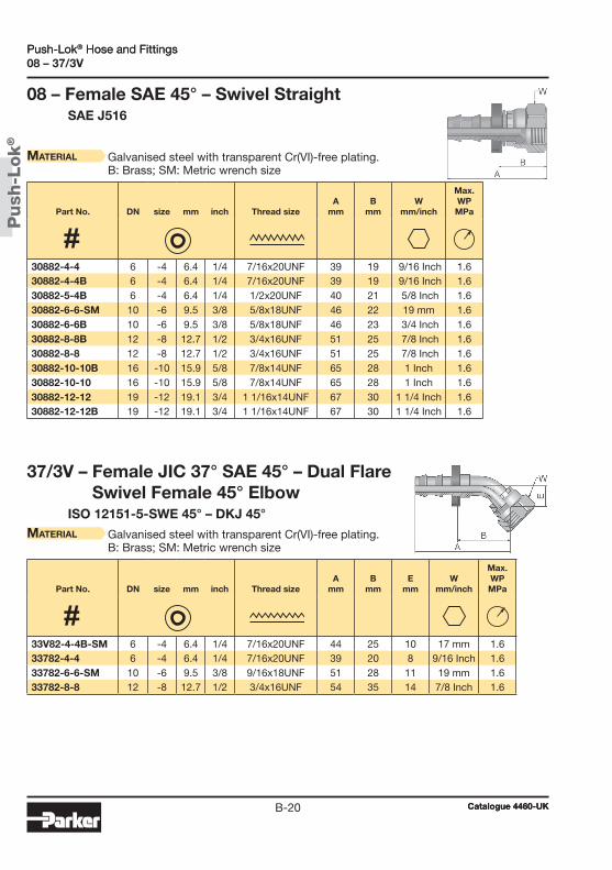
Push
-Lok
®
Catalogue 4460-UKB-20
Push-Lok® Hose and Fittings08 – 37/3V
Material Galvanised steel with transparent Cr(VI)-free plating. B: Brass; SM: Metric wrench size
08 – Female SAE 45° – Swivel Straight SAE J516
37/3V – Female JIC 37° SAE 45° – Dual Flare Swivel Female 45° Elbow
ISO 12151-5-SWE 45° – DKJ 45°Material Galvanised steel with transparent Cr(VI)-free plating.
B: Brass; SM: Metric wrench size
Part No. DN size mm inch Thread sizeA
mmB
mmW
mm/inch
Max.WPMPa
Part No. DN size mm inch Thread sizeA
mmB
mmE
mmW
mm/inch
Max.WPMPa
30882-4-4 6 -4 6.4 1/4 7/16x20UNF 39 19 9/16 Inch 1.630882-4-4B 6 -4 6.4 1/4 7/16x20UNF 39 19 9/16 Inch 1.630882-5-4B 6 -4 6.4 1/4 1/2x20UNF 40 21 5/8 Inch 1.630882-6-6-SM 10 -6 9.5 3/8 5/8x18UNF 46 22 19 mm 1.630882-6-6B 10 -6 9.5 3/8 5/8x18UNF 46 23 3/4 Inch 1.630882-8-8B 12 -8 12.7 1/2 3/4x16UNF 51 25 7/8 Inch 1.630882-8-8 12 -8 12.7 1/2 3/4x16UNF 51 25 7/8 Inch 1.630882-10-10B 16 -10 15.9 5/8 7/8x14UNF 65 28 1 Inch 1.630882-10-10 16 -10 15.9 5/8 7/8x14UNF 65 28 1 Inch 1.630882-12-12 19 -12 19.1 3/4 1 1/16x14UNF 67 30 1 1/4 Inch 1.630882-12-12B 19 -12 19.1 3/4 1 1/16x14UNF 67 30 1 1/4 Inch 1.6
33V82-4-4B-SM 6 -4 6.4 1/4 7/16x20UNF 44 25 10 17 mm 1.633782-4-4 6 -4 6.4 1/4 7/16x20UNF 39 20 8 9/16 Inch 1.633782-6-6-SM 10 -6 9.5 3/8 9/16x18UNF 51 28 11 19 mm 1.633782-8-8 12 -8 12.7 1/2 3/4x16UNF 54 35 14 7/8 Inch 1.6
Push-Lok® Hose and Fittings
Catalogue 4460-UK
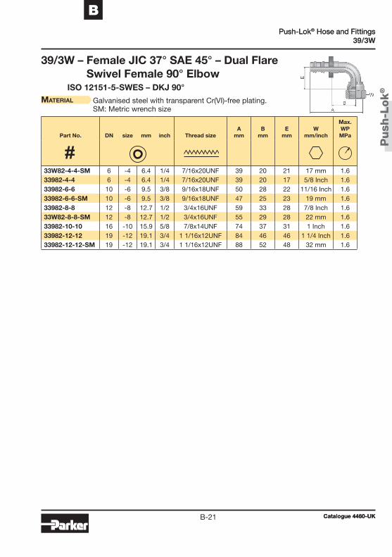
Push
-Lok
®
Catalogue 4460-UKB-21
BPush-Lok® Hose and Fittings
39/3W
39/3W – Female JIC 37° SAE 45° – Dual Flare Swivel Female 90° Elbow
ISO 12151-5-SWES – DKJ 90°Material Galvanised steel with transparent Cr(VI)-free plating.
SM: Metric wrench size
Part No. DN size mm inch Thread sizeA
mmB
mmE
mmW
mm/inch
Max.WPMPa
33W82-4-4-SM 6 -4 6.4 1/4 7/16x20UNF 39 20 21 17 mm 1.633982-4-4 6 -4 6.4 1/4 7/16x20UNF 39 20 17 5/8 Inch 1.633982-6-6 10 -6 9.5 3/8 9/16x18UNF 50 28 22 11/16 Inch 1.633982-6-6-SM 10 -6 9.5 3/8 9/16x18UNF 47 25 23 19 mm 1.633982-8-8 12 -8 12.7 1/2 3/4x16UNF 59 33 28 7/8 Inch 1.633W82-8-8-SM 12 -8 12.7 1/2 3/4x16UNF 55 29 28 22 mm 1.633982-10-10 16 -10 15.9 5/8 7/8x14UNF 74 37 31 1 Inch 1.633982-12-12 19 -12 19.1 3/4 1 1/16x12UNF 84 46 46 1 1/4 Inch 1.633982-12-12-SM 19 -12 19.1 3/4 1 1/16x12UNF 88 52 48 32 mm 1.6
Push-Lok® Hose and Fittings
Catalogue 4460-UK

Push
-Lok
®
Catalogue 4460-UKB-22
Push-Lok® Hose and FittingsJC
JC – Female ORFS Swivel – Straight Short ISO 12151-1 – SWSA
SAE J516 – ORFS
Material Galvanised steel with transparent Cr(VI)-free plating. SM: Metric wrench size
Part No. DN size mm inch Thread sizeA
mmB
mmH
mm/inchW
mm/inch
Max.WPMPa
3JC82-4-4 6 -4 6.4 1/4 9/16x18UNF 36 17 9/16 Inch 11/16 Inch 1.63JC82-6-6 10 -6 9.5 3/8 11/16x16UNF 40 18 11/16 Inch 13/16 Inch 1.63JC82-6-6-SM 10 -6 9.5 3/8 11/16x16UNF 40 18 19 mm 22 mm 1.63JC82-8-6-SM 10 -6 9.5 3/8 13/16x16UNF 43 21 22 mm 24 mm 1.63JC82-8-8-SM 12 -8 12.7 1/2 13/16x16UNF 47 21 22 mm 24 mm 1.63JC82-8-10 16 -10 15.9 5/8 13/16x16UNF 57 21 3/4 Inch 15/16 Inch 1.63JC82-10-10 16 -10 15.9 5/8 1x14UNF 61 24 15/16 Inch 1 1/8 Inch 1.63JC82-10-12 19 -12 19.1 3/4 1x14UNF 61 24 1 Inch 1 1/8 Inch 1.63JC82-12-12 19 -12 19.1 3/4 1 3/16x12UNF 67 30 1 1/8 Inch 1 3/8 Inch 1.6
Push-Lok® Hose and Fittings
Catalogue 4460-UK
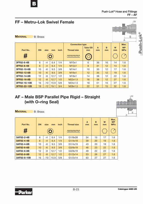
Push
-Lok
®
Catalogue 4460-UKB-23
BPush-Lok® Hose and Fittings
FF – AF
FF – Metru–Lok Swivel Female
Material B: Brass
AF – Male BSP Parallel Pipe Rigid – Straight (with O–ring Seal)
Material B: Brass
Part No. DN size mm inch Thread sizeA
mmB
mmW
mm
Max.WPMPa
Connection type Max.
Part No. DN size mm inch Thread size Tube OD
mmA
mmB
mmW
mmWPMPa
3AF82-2-4B 6 -4 6.4 1/4 G1/8x28 34 15 17 1.63AF82-4-4B 6 -4 6.4 1/4 G1/4x19 39 20 19 1.63AF82-4-6B 10 -6 9.5 3/8 G1/4x19 43 20 19 1.63AF82-6-6B 10 -6 9.5 3/8 G3/8x19 46 23 22 1.63AF82-6-8B 12 -8 12.7 1/2 G3/8x19 49 22 22 1.63AF82-8-8B 12 -8 12.7 1/2 G1/2x14 53 26 27 1.63AF82-8-10B 16 -10 15.9 5/8 G1/2x14 63 27 27 1.6
3FF82-6-4B 6 -4 6.4 1/4 M10x1 6 36 16 14 1.63FF82-8-4B 6 -4 6.4 1/4 M12x1 8 31 12 14 1.63FF82-10-6B 10 -6 9.5 3/8 M14x1 10 35 12 17 1.63FF82-12-6B 10 -6 9.5 3/8 M16x1 12 35 12 19 1.63FF82-14-8B 12 -8 12.7 1/2 M18x1 14 38 12 22 1.63FF82-16-8B 12 -8 12.7 1/2 M22x1.5 16 38 12 27 1.63FF82-18-10B 16 -10 15.9 5/8 M24x1.5 18 51 15 27 1.63FF82-22-12B 19 -12 19.1 3/4 M28x1.5 22 51 15 32 1.6
Push-Lok® Hose and Fittings
Catalogue 4460-UK

Push
-Lok
®
Catalogue 4460-UKB-24
Push-Lok® Hose and Fittings82 – 5C
82 – Push–Lok® Union
Material Galvanised steel with transparent Cr(VI)-free plating. B: Brass
5C – 60° Cone Swivel Female
Material B: Brass; K: without plastic ring.
Part No. DN size mm inchA
mm
Max.WPMPa
Part No. DN size mm inch Thread sizeA
mmB
mmW
mm
Max.WPMPa
38282-4-4 6 -4 6.4 1/4 45 1.638282-4-4B 6 -4 6.4 1/4 46 1.638282-6-6B 10 -6 9.5 3/8 54 1.638282-8-8B 12 -8 12.7 1/2 64 1.638282-8-8 12 -8 12.7 1/2 64 1.638282-10-10 16 -10 15.9 5/8 84 1.638282-10-10B 16 -10 15.9 5/8 84 1.638282-12-12 19 -12 19.1 3/4 84 1.638282-12-12B 19 -12 19.1 3/4 84 1.6
35C82-6-4BK 6 -4 6.4 1/4 M12x1.5 33 14 14 1.635C82-10-6BK 10 -6 9.5 3/8 M16x1.5 38 15 19 1.635C82-10-6B 10 -6 9.5 3/8 M16x1.5 38 15 19 1.635C82-15-8BK 12 -8 12.7 1/2 M22x1.5 44 18 27 1.635C82-18-10BK 16 -10 15.9 5/8 M26x1.5 57 21 32 1.6
Push-Lok® Hose and Fittings
Catalogue 4460-UK
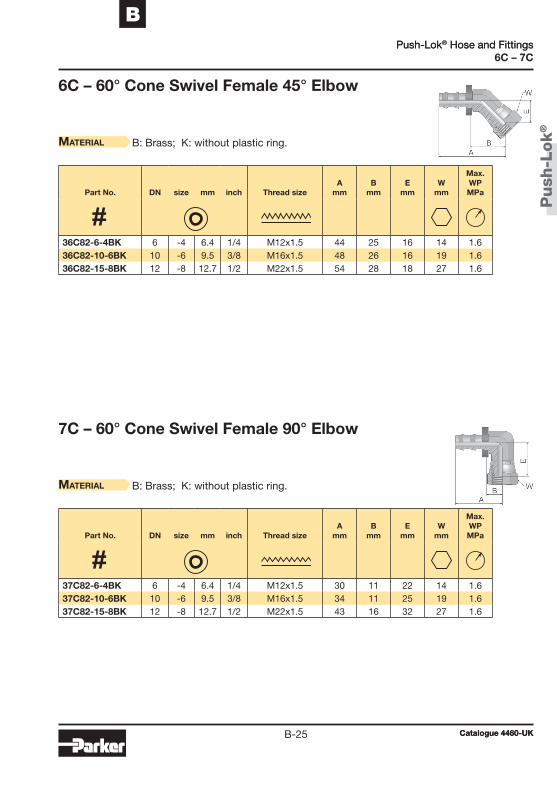
Push
-Lok
®
Catalogue 4460-UKB-25
BPush-Lok® Hose and Fittings
6C – 7C
6C – 60° Cone Swivel Female 45° Elbow
Material B: Brass; K: without plastic ring.
7C – 60° Cone Swivel Female 90° Elbow
Material B: Brass; K: without plastic ring.
Part No. DN size mm inch Thread sizeA
mmB
mmE
mmW
mm
Max.WPMPa
Part No. DN size mm inch Thread sizeA
mmB
mmE
mmW
mm
Max.WPMPa
36C82-6-4BK 6 -4 6.4 1/4 M12x1.5 44 25 16 14 1.636C82-10-6BK 10 -6 9.5 3/8 M16x1.5 48 26 16 19 1.636C82-15-8BK 12 -8 12.7 1/2 M22x1.5 54 28 18 27 1.6
37C82-6-4BK 6 -4 6.4 1/4 M12x1.5 30 11 22 14 1.637C82-10-6BK 10 -6 9.5 3/8 M16x1.5 34 11 25 19 1.637C82-15-8BK 12 -8 12.7 1/2 M22x1.5 43 16 32 27 1.6
Push-Lok® Hose and Fittings
Catalogue 4460-UK

Push
-Lok
®
Catalogue 4460-UKB-26
Push-Lok® Hose and Fittings Push-Lok® Hose and Fittings
Catalogue 4460-UK
Notes
PT
FE
/ F
EP
PT
FE
/ F
EP
C-1
C
Chapter C
PTFE / Fluoropolymer Hose and Fittings
PTFE hoseIntroduction ................................................................................C-22030T – PTFE hose ............................................................C-42030T-##CON – PTFE hose – convoluted ......................................C-52033T – PTFE hose ............................................................C-6919 – PTFE hose ............................................................C-7 919U – PTFE hose with PU cover ....................................C-8929/929B – Heavy-wall PTFE hose .........................................C-9939/939B – PTFE hose – convoluted ....................................C-102380F – FEP high pressure hose .....................................C-112246F – FEP high pressure hose .....................................C-12
Fittings for PTFE hose91N series ....................................................................................C-1393N series ....................................................................................C-27PC series ....................................................................................C-30YX series ....................................................................................C-41
Catalogue 4460-UK
PTFE / Fluoropolymer Hose and FittingsTable of contents

C-2
Application
PT
FE
/ F
EP
PTFE hoses are used in many different industries and applications
• Transportation and Mobile Hydraulics such as compressor discharge lines and coolant lines
• Fluid Transfer and Handling such as chemicals transfer lines and steam lines, e.g. in the process industry
• Industrial Hydraulics and Pneumatics such as thermo oil line and supply line for hot air
Introduction
PTFE (polytetrafl uoroethylene) is a high performance fl uoroplastic with high crystallinity and high molecular weight, discovered in 1938 by DuPont chemist, Dr. Roy J. Plunkett.
Parker PTFE hose provides full conveyance solutions for a wide array of markets and applications because of the unique properties of PTFE. A fl exible fl uoropolymer tubing with unmatched chemical resistance and a non-stick surface that facilitates fl ow and eliminates media build up. The Parker PTFE hose portfolio ranges from smooth bore and convoluted hose types to high pressure types with FEP inner core for up to 42.5 MPa.
PTFE hoses are used in many different industries and applications
• Transportation and Mobile Hydraulics such as compressor
• Fluid Transfer and Handling such as chemicals transfer
• Industrial Hydraulics and Pneumatics such as thermo oil
PTFE / Fluoropolymer Hose and FittingsIntroduction
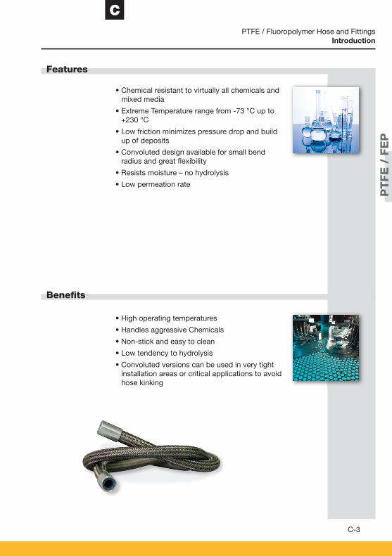
C
C-3
Features
Benefi ts
PT
FE
/ F
EP
• Chemical resistant to virtually all chemicals and mixed media
• Extreme Temperature range from -73 °C up to +230 °C
• Low friction minimizes pressure drop and build up of deposits
• Convoluted design available for small bend radius and great fl exibility
• Resists moisture – no hydrolysis
• Low permeation rate
• High operating temperatures
• Handles aggressive Chemicals
• Non-stick and easy to clean
• Low tendency to hydrolysis
• Convoluted versions can be used in very tight installation areas or critical applications to avoid hose kinking
PTFE / Fluoropolymer Hose and FittingsIntroduction

PT
FE
/ F
EP
PT
FE
/ F
EP
C-4
2030T
2030T – PTFE hose
• Suitable for high temperatures• Inert to virtually all hydraulic and chemical fluids
Medium pressure service for use with hydraulic fluids at high temperatures and aggressive chemicals in the chemical industry, surface engineering, 2-component systems.The core tube material conforms to FDA 21 CFR177.1550.
Polytetrafluoroethylene One braided layer of stainless steel wire – –
-50°C up to +150°C permanent temperature +230°C at working pressures up to 2 MPa
• Not recommended for dynamic applications.
Part No. DN size mm inch mm
Max. workingpressureMPa / psi
Min. burstpressureMPa / psi
Min. bend radius
mmWeightkg/m
Fittings
2030T-03V70 5 -03 4.7 3/16 7.8 27.5 3,985 110.0 15,950 50 0.09 YX2030T-04V70 6 -04 6.3 1/4 9.5 24.0 3,480 96.0 13,920 75 0.13 YX2030T-05V70 8 -05 8.2 5/16 11.5 20.0 2,900 80.0 11,600 100 0.17 YX2030T-06V70 10 -06 9.7 3/8 13.0 17.5 2,535 70.0 10,150 120 0.19 YX2030T-08V70 12 -08 12.8 1/2 16.7 15.0 2,175 60.0 8,700 135 0.29 YX2030T-10V70 16 -10 16.0 5/8 20.0 12.5 1,810 50.0 7,250 160 0.34 YX2030T-12V70 20 -12 19.4 3/4 23.5 10.0 1,450 40.0 5,800 200 0.41 YX2030T-16V70 25 -16 25.0 1 29.0 8.0 1,160 32.0 4,640 250 0.51 YX
Notes
MaiN features
applicatioNs
coNstructioN Core tube :Pressure reinforcement : Cover : Colour :
teMperature raNge
Catalogue 4460-UK
PTFE Hoses
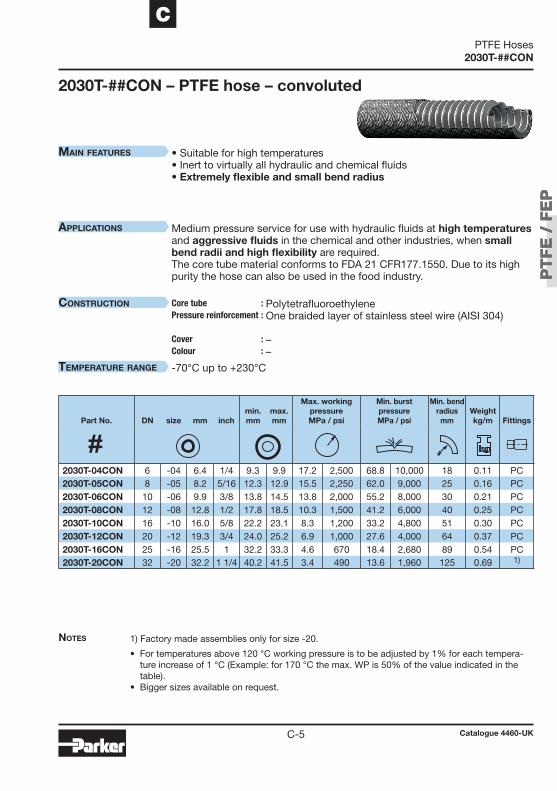
PT
FE
/ F
EP
PT
FE
/ F
EP
C-5
C
2030T-##CON
• Suitable for high temperatures• Inert to virtually all hydraulic and chemical fluids • Extremely flexible and small bend radius
Medium pressure service for use with hydraulic fluids at high temperatures and aggressive fluids in the chemical and other industries, when small bend radii and high flexibility are required. The core tube material conforms to FDA 21 CFR177.1550. Due to its high purity the hose can also be used in the food industry.
Polytetrafluoroethylene One braided layer of stainless steel wire (AISI 304) – –
-70°C up to +230°C
1) Factory made assemblies only for size -20.
• For temperatures above 120 °C working pressure is to be adjusted by 1% for each tempera-ture increase of 1 °C (Example: for 170 °C the max. WP is 50% of the value indicated in the table).
• Bigger sizes available on request.
2030T-##CON – PTFE hose – convoluted
Part No. DN size mm inchmin.mm
max.mm
Max. workingpressureMPa / psi
Min. burstpressureMPa / psi
Min. bend radius
mmWeightkg/m
Fittings
2030T-04CON 6 -04 6.4 1/4 9.3 9.9 17.2 2,500 68.8 10,000 18 0.11 PC2030T-05CON 8 -05 8.2 5/16 12.3 12.9 15.5 2,250 62.0 9,000 25 0.16 PC2030T-06CON 10 -06 9.9 3/8 13.8 14.5 13.8 2,000 55.2 8,000 30 0.21 PC2030T-08CON 12 -08 12.8 1/2 17.8 18.5 10.3 1,500 41.2 6,000 40 0.25 PC2030T-10CON 16 -10 16.0 5/8 22.2 23.1 8.3 1,200 33.2 4,800 51 0.30 PC2030T-12CON 20 -12 19.3 3/4 24.0 25.2 6.9 1,000 27.6 4,000 64 0.37 PC2030T-16CON 25 -16 25.5 1 32.2 33.3 4.6 670 18.4 2,680 89 0.54 PC2030T-20CON 32 -20 32.2 1 1/4 40.2 41.5 3.4 490 13.6 1,960 125 0.69 1)
Notes
MaiN features
applicatioNs
coNstructioN Core tube :Pressure reinforcement : Cover : Colour :
teMperature raNge
Catalogue 4460-UK
PTFE Hoses
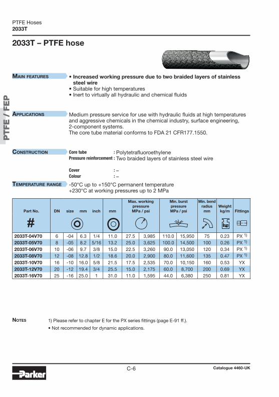
PT
FE
/ F
EP
PT
FE
/ F
EP
C-6
2033T
• Increased working pressure due to two braided layers of stainless steel wire
• Suitable for high temperatures• Inert to virtually all hydraulic and chemical fluids
Medium pressure service for use with hydraulic fluids at high temperatures and aggressive chemicals in the chemical industry, surface engineering, 2-component systems.The core tube material conforms to FDA 21 CFR177.1550.
Polytetrafluoroethylene Two braided layers of stainless steel wire – –
-50°C up to +150°C permanent temperature +230°C at working pressures up to 2 MPa
1) Please refer to chapter E for the PX series fittings (page E-91 ff.).
• Not recommended for dynamic applications.
2033T – PTFE hose
Part No. DN size mm inch mm
Max. workingpressureMPa / psi
Min. burstpressureMPa / psi
Min. bend radius
mmWeightkg/m
Fittings
2033T-04V70 6 -04 6.3 1/4 11.0 27.5 3,985 110.0 15,950 75 0.23 PX 1)
2033T-05V70 8 -05 8.2 5/16 13.2 25.0 3,625 100.0 14,500 100 0.26 PX 1)
2033T-06V70 10 -06 9.7 3/8 15.0 22.5 3,260 90.0 13,050 120 0.34 PX 1)
2033T-08V70 12 -08 12.8 1/2 18.6 20.0 2,900 80.0 11,600 135 0.47 PX 1)
2033T-10V70 16 -10 16.0 5/8 21.5 17.5 2,535 70.0 10,150 160 0.53 YX2033T-12V70 20 -12 19.4 3/4 25.5 15.0 2,175 60.0 8,700 200 0.69 YX2033T-16V70 25 -16 25.0 1 31.0 11.0 1,595 44.0 6,380 250 0.81 YX
Notes
MaiN features
applicatioNs
coNstructioN Core tube :Pressure reinforcement : Cover : Colour :
teMperature raNge
Catalogue 4460-UK
PTFE Hoses

PT
FE
/ F
EP
PT
FE
/ F
EP
C-7
C
919
919 – PTFE hosePerformance acc. to SAE 100 R14A
• Conforms to requirements of SAE 100R14 • 100% working pressure at continuous temperatures of 232 °C max. • Inert to virtually all hydraulic and chemical fluids • One-piece fittings suitable for the Parker assembly system
Medium pressure service for use with hydraulic fluids at high temperatures, steam and aggressive chemicals in the chemical industry. Especially suit-able for the food industry. The core tube material conforms to FDA 21 CFR177.1550.
Polytetrafluoroethylene One braided layer of stainless steel wire (AISI304) – –
-73°C up to +232°C
• Vacuum rating: 95 kPa (13.8 psi) size -4 up to -10 40 kPa ( 5.8 psi) size -12 47 kPa ( 6.8 psi) size -16
Part No. DN size mm inch mm
Max. workingpressureMPa / psi
Min. burstpressureMPa / psi
Min. bend radius
mmWeightkg/m
Fittings
919-4 5 -4 4.7 3/16 7.8 21.0 3,000 84.0 12,000 51 0.09 91N919-5 6 -5 6.5 1/4 9.5 21.0 3,000 84.0 12,000 76 0.13 91N919-6 8 -6 7.9 5/16 11.0 17.5 2,500 70.0 10,000 102 0.15 91N919-8 10 -8 10.5 13/32 13.5 14.0 2,000 56.0 8,000 127 0.19 91N919-10 12 -10 12.7 1/2 15.9 10.5 1,500 42.0 6,000 165 0.22 91N919-12 16 -12 15.9 5/8 19.1 8.4 1,200 33.5 4,800 191 0.28 91N919-16 22 -16 22.2 7/8 26.2 7.0 1,000 28.0 4,000 229 0.40 91N
Notes
MaiN features
applicatioNs
coNstructioN Core tube :Pressure reinforcement : Cover : Colour :
teMperature raNge
Catalogue 4460-UK
PTFE Hoses
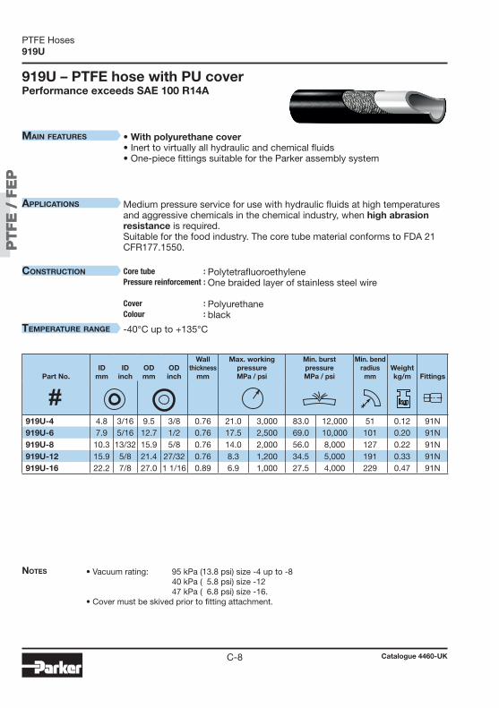
PT
FE
/ F
EP
PT
FE
/ F
EP
C-8
919U
• With polyurethane cover• Inert to virtually all hydraulic and chemical fluids • One-piece fittings suitable for the Parker assembly system
Medium pressure service for use with hydraulic fluids at high temperatures and aggressive chemicals in the chemical industry, when high abrasion resistance is required. Suitable for the food industry. The core tube material conforms to FDA 21 CFR177.1550.
Polytetrafluoroethylene One braided layer of stainless steel wire Polyurethane black
-40°C up to +135°C
• Vacuum rating: 95 kPa (13.8 psi) size -4 up to -8 40 kPa ( 5.8 psi) size -12 47 kPa ( 6.8 psi) size -16. • Cover must be skived prior to fitting attachment.
919U – PTFE hose with PU coverPerformance exceeds SAE 100 R14A
Part No.ID
mmID
inchODmm
ODinch
Wallthickness
mm
Max. workingpressureMPa / psi
Min. burstpressureMPa / psi
Min. bend radius
mmWeightkg/m
Fittings
919U-4 4.8 3/16 9.5 3/8 0.76 21.0 3,000 83.0 12,000 51 0.12 91N919U-6 7.9 5/16 12.7 1/2 0.76 17.5 2,500 69.0 10,000 101 0.20 91N919U-8 10.3 13/32 15.9 5/8 0.76 14.0 2,000 56.0 8,000 127 0.22 91N919U-12 15.9 5/8 21.4 27/32 0.76 8.3 1,200 34.5 5,000 191 0.33 91N919U-16 22.2 7/8 27.0 1 1/16 0.89 6.9 1,000 27.5 4,000 229 0.47 91N
Notes
MaiN features
applicatioNs
coNstructioN Core tube :Pressure reinforcement : Cover : Colour :
teMperature raNge
Catalogue 4460-UK
PTFE Hoses
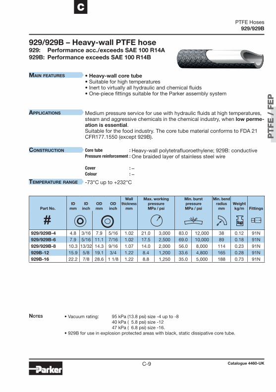
PT
FE
/ F
EP
PT
FE
/ F
EP
C-9
C
929/929B
• Vacuum rating: 95 kPa (13.8 psi) size -4 up to -8 40 kPa ( 5.8 psi) size -12 47 kPa ( 6.8 psi) size -16. • 929B for use in explosion protected areas with black, static dissipative core tube.
• Heavy-wall core tube • Suitable for high temperatures • Inert to virtually all hydraulic and chemical fluids • One-piece fittings suitable for the Parker assembly system
Medium pressure service for use with hydraulic fluids at high temperatures, steam and aggressive chemicals in the chemical industry, when low perme-ation is essential. Suitable for the food industry. The core tube material conforms to FDA 21 CFR177.1550 (except 929B).
Heavy-wall polytetrafluoroethylene; 929B: conductive One braided layer of stainless steel wire – –
-73°C up to +232°C
929/929B – Heavy-wall PTFE hose929: Performance acc./exceeds SAE 100 R14A 929B: Performance exceeds SAE 100 R14B
Part No.ID
mmID
inchODmm
ODinch
Wallthickness
mm
Max. workingpressureMPa / psi
Min. burstpressureMPa / psi
Min. bend radius
mmWeightkg/m
Fittings
929/929B-4 4.8 3/16 7.9 5/16 1.02 21.0 3,000 83.0 12,000 38 0.12 91N929/929B-6 7.9 5/16 11.1 7/16 1.02 17.5 2,500 69.0 10,000 89 0.18 91N929/929B-8 10.3 13/32 14.3 9/16 1.07 14.0 2,000 56.0 8,000 114 0.23 91N929B-12 15.9 5/8 19.1 3/4 1.22 8.4 1,200 33.6 4,800 165 0.28 91N929B-16 22.2 7/8 28.6 1 1/8 1.22 8.8 1,250 35.0 5,000 188 0.73 91N
Notes
MaiN features
applicatioNs
coNstructioN Core tube :Pressure reinforcement : Cover : Colour :
teMperature raNge
Catalogue 4460-UK
PTFE Hoses
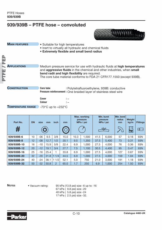
PT
FE
/ F
EP
PT
FE
/ F
EP
C-10
939/939B
• Suitable for high temperatures• Inert to virtually all hydraulic and chemical fluids • Extremely flexible and small bend radius
Medium pressure service for use with hydraulic fluids at high temperatures and aggressive fluids in the chemical and other industries, when small bend radii and high flexibility are required. The core tube material conforms to FDA 21 CFR177.1550 (except 939B).
Polytetrafluoroethylene, 939B: conductive One braided layer of stainless steel wire – –
-73°C up to +232°C
• Vacuum rating: 95 kPa (13.8 psi) size -6 up to -16 67 kPa ( 9.8 psi) size -20 40 kPa ( 5.8 psi) size -24 17 kPa ( 2.5 psi) size -32.
939/939B – PTFE hose – convoluted
Part No. DN size mm inch mm
Max. workingpressureMPa / psi
Min. burstpressureMPa / psi
Min. bend radius
mmWeightkg/m
Fittings
939/939B-6 10 -06 9.5 3/8 15.0 10.3 1,500 41.5 6,000 57 0.18 93N939/939B-8 12 -08 12.7 1/2 20.1 9.5 1,350 37.5 5,400 73 0.31 93N939/939B-10 16 -10 15.9 5/8 22.4 6.9 1,000 27.5 4,000 76 0.36 93N939/939B-12 20 -12 19.1 3/4 27.7 7.5 1,100 30.5 4,400 95 0.47 93N939/939B-16 25 -16 25.4 1 33.8 6.9 1,000 27.5 4,000 127 0.67 93N939/939B-20 32 -20 31.8 1 1/4 44.5 6.9 1,000 27.5 4,000 159 1.04 93N939/939B-24 40 -24 38.1 1 1/2 52.1 5.0 750 21.0 3,000 191 1.18 93N939/939B-32 50 -32 50.8 2 65.0 1.7 250 6.9 1,000 254 1.50 93N
Notes
MaiN features
applicatioNs
coNstructioN Core tube :Pressure reinforcement : Cover : Colour :
teMperature raNge
Catalogue 4460-UK
PTFE Hoses

PT
FE
/ F
EP
PT
FE
/ F
EP
C-11
C
2380F
• Working pressures up to 42 MPa • With polyurethane cover• Inert to virtually all hydraulic and chemical fluids
Glue applications in the automotive industry and material lines for tempera-tures below +80°C.
Fluoroethylenepropylene Two spiral layers and two open spiral layers of high tensile steel wire Polyurethane grey
-40°C up to +80°C
1) Please refer to chapter E for the NX series fittings (page E-81 ff.).
• For pinpricked hose please add “-P”, e.g. 2380F-04V07-P. • Not recommended for applications where extreme pulsations are encountered.
2380F – FEP high pressure hose
Part No. DN size mm inch mm
Max. workingpressureMPa / psi
Min. burstpressureMPa / psi
Min. bend radius
mmWeightkg/m
Fittings
2380F-04V07 6 -04 6.3 1/4 12.5 42.5 6,160 170.0 24,650 60 0.26 NX 1)
2380F-05V07 8 -05 8.0 5/16 14.3 37.5 5,435 150.0 21,750 85 0.35 NX 1)
2380F-06V07 10 -06 9.7 3/8 17.0 35.0 5,075 140.0 20,300 110 0.41 NX 1)
2380F-08V07 12 -08 12.8 1/2 20.5 32.5 4,710 130.0 18,850 140 0.58 NX 1)
2380F-10V07 16 -10 16.0 5/8 24.5 30.0 4,350 120.0 17,400 175 0.75 NX 1)
2380F-12V07 20 -12 19.4 3/4 28.5 27.5 3,985 110.0 15,950 205 0.96 NX 1)
2380F-16V07 25 -16 25.0 1 34.0 22.5 3,260 90.0 13,050 240 1.28 NX 1)
Notes
MaiN features
applicatioNs
coNstructioN Core tube :Pressure reinforcement : Cover : Colour :
teMperature raNge
Catalogue 4460-UK
PTFE Hoses

PT
FE
/ F
EP
PT
FE
/ F
EP
C-12
2246F
• Working pressures up to 41.5 MPa • Without hose cover• Suitable for temperatures up to 150 °C • Inert to virtually all hydraulic and chemical fluids
• Suitable for applications with additional heating elements• Hotmelt applications in the automotive industry
Fluoroethylenepropylene Two spiral layers and one braided layer of high tensile steel wire – –
-50°C up to +150°C
1) Please refer to chapter E for the NX series fittings (page E-81 ff.).
• Not recommended for applications where extreme pulsations are encountered.
2246F – FEP high pressure hose
Part No. DN size mm inch mm
Max. workingpressureMPa / psi
Min. burstpressureMPa / psi
Min. bend radius
mmWeightkg/m
Fittings
2246F-04V70 6 -04 6.3 1/4 11.4 41.5 6,015 165.0 23,925 60 0.26 NX 1)
2246F-05V70 8 -05 8.2 5/16 13.8 37.5 5,435 150.0 21,750 85 0.33 NX 1)
2246F-06V70 10 -06 9.7 3/8 16.0 34.0 4,930 136.0 19,720 110 0.35 NX 1)
2246F-08V70 12 -08 12.8 1/2 18.5 32.5 4,710 130.0 18,850 140 0.53 NX 1)
2246F-10V70 16 -10 16.0 5/8 23.4 30.0 4,350 120.0 17,400 175 0.70 NX 1)
2246F-12V70 20 -12 19.4 3/4 27.0 26.5 3,840 106.0 15,370 205 0.92 NX 1)
2246F-16V70 25 -16 25.0 1 32.5 21.0 3,045 84.0 12,180 240 1.18 NX 1)
Notes
MaiN features
applicatioNs
coNstructioN Core tube :Pressure reinforcement : Cover : Colour :
teMperature raNge
Catalogue 4460-UK
PTFE Hoses

PT
FE
/ F
EP
PT
FE
/ F
EP
C-13
C
1C391N
1C3 91N – Metric female swivel 24°/60°Light series – Metric swivel nut
919 • 919U • 929 • 929B
Materiale Galvanised steel with transparent Cr(VI)-free plating.For stainless steel (AISI 316) please add C to the Part No. Example: 1C391N-6-4C.Other materials available on request.
J
AB
Connection type Max.
Part No. DN size mm inch Thread size Tube OD
mmA
mmB
mmJ
mmWPMPa
1C391N-6-4-RD 5 -04 4.8 3/16 M12x1.5 6 29 14 14 25.0 1C391N-6-5-RD 6 -05 6.4 1/4 M12x1.5 6 30 14 14 25.0 1C391N-8-5-RD 6 -05 6.4 1/4 M14x1.5 8 31 14 17 25.0 1C391N-8-6-RD 8 -06 7.9 5/16 M14x1.5 8 32 14 17 25.0 1C391N-10-6-RD 8 -06 7.9 5/16 M16x1.5 10 34 16 19 25.0 1C391N-10-8-RD 10 -08 10.3 13/32 M16x1.5 10 36 17 19 25.0 1C391N-12-8-RD 10 -08 10.3 13/32 M18x1.5 12 35 15 22 25.0 1C391N-12-10-RD 12 -10 12.7 1/2 M18x1.5 12 38 18 22 25.0 1C391N-15-10-RD 12 -10 12.7 1/2 M22x1.5 15 37 17 27 25.0 1C391N-18-10-RD 12 -10 12.7 1/2 M26x1.5 18 37 17 32 16.0 1C391N-18-12-RD 16 -12 15.9 5/8 M26x1.5 18 40 17 32 16.0 1C391N-22-16-RD 22 -16 22.2 7/8 M30x2 22 49 22 36 16.0
Catalogue 4460-UK
Fittings

PT
FE
/ F
EP
PT
FE
/ F
EP
C-14
1D091N
1D091N – Metric male 24°Light seriesISO 12151-2
919 • 919U • 929 • 929B
Materiale Galvanised steel with transparent Cr(VI)-free plating.For stainless steel (AISI 316) please add C to the Part No. Example: 1D091N-8-6C.Other materials available on request.
H
AB
Connection type Max.
Part No. DN size mm inch Thread size Tube OD
mmA
mmB
mmH
mmWPMPa
1D091N-6-4 5 -04 4.8 3/16 M12x1.5 6 31 16 12 25.0 1D091N-8-5 6 -05 6.4 1/4 M14x1.5 8 33 16 14 42.5 1D091N-8-6 8 -06 7.9 5/16 M14x1.5 8 34 16 14 42.5 1D091N-10-6 8 -06 7.9 5/16 M16x1.5 10 35 17 17 40.0 1D091N-10-8 10 -08 10.3 13/32 M16x1.5 10 39 19 17 40.0 1D091N-12-8 10 -08 10.3 13/32 M18x1.5 12 39 19 19 35.0 1D091N-12-10 12 -10 12.7 1/2 M18x1.5 12 41 20 19 35.0 1D091N-15-10 12 -10 12.7 1/2 M22x1.5 15 42 21 22 31.0 1D091N-18-12 16 -12 15.9 5/8 M26x1.5 18 46 23 27 28.0 1D091N-22-16 22 -16 22.2 7/8 M30x2 22 54 27 30 28.0
Catalogue 4460-UK
Fittings
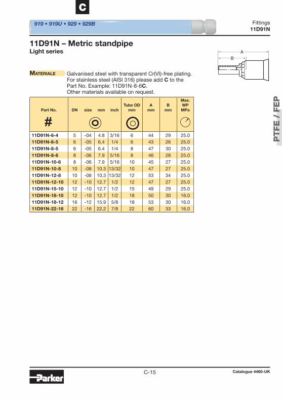
PT
FE
/ F
EP
PT
FE
/ F
EP
C-15
C
11D91N
11D91N – Metric standpipeLight series
919 • 919U • 929 • 929B
Materiale Galvanised steel with transparent Cr(VI)-free plating.For stainless steel (AISI 316) please add C to the Part No. Example: 11D91N-8-6C.Other materials available on request.
Part No. DN size mm inch
Tube OD
mmA
mmB
mm
Max. WPMPa
AB
11D91N-6-4 5 -04 4.8 3/16 6 44 29 25.0 11D91N-6-5 6 -05 6.4 1/4 6 43 26 25.0 11D91N-8-5 6 -05 6.4 1/4 8 47 30 25.0 11D91N-8-6 8 -06 7.9 5/16 8 46 28 25.0 11D91N-10-6 8 -06 7.9 5/16 10 45 27 25.0 11D91N-10-8 10 -08 10.3 13/32 10 47 27 25.0 11D91N-12-8 10 -08 10.3 13/32 12 53 34 25.0 11D91N-12-10 12 -10 12.7 1/2 12 47 27 25.0 11D91N-15-10 12 -10 12.7 1/2 15 49 29 25.0 11D91N-18-10 12 -10 12.7 1/2 18 50 30 16.0 11D91N-18-12 16 -12 15.9 5/8 18 53 30 16.0 11D91N-22-16 22 -16 22.2 7/8 22 60 33 16.0
Catalogue 4460-UK
Fittings

PT
FE
/ F
EP
PT
FE
/ F
EP
C-16
13D91N
13D91N – Metric standpipeHeavy series
919 • 919U • 929 • 929B
Materiale Galvanised steel with transparent Cr(VI)-free plating.For stainless steel (AISI 316) please add C to the Part No. Example: 13D91N-6-3C.Other materials available on request.
Part No. DN size mm inch Tube OD
mmA
mmB
mm
Max. WPMPa
AB
13D91N-6-3 3 -03 3.2 1/8 6 41 30 63.0 13D91N-8-4 5 -04 4.8 3/16 8 43 27 63.0 13D91N-10-5 6 -05 6.4 1/4 10 46 29 63.0 13D91N-12-6 8 -06 7.9 5/16 12 48 30 63.0 13D91N-14-8 10 -08 10.3 13/32 14 53 33 63.0 13D91N-16-10 12 -06 12.7 1/2 16 55 35 40.0 13D91N-20-12 16 -10 15.9 5/8 20 63 40 40.0 13D91N-25-16 22 -12 22.2 7/8 25 71 44 40.0 13D91N-30-16 22 -16 22.2 7/8 30 75 48 25.0
Catalogue 4460-UK
Fittings

PT
FE
/ F
EP
PT
FE
/ F
EP
C-17
C
19291N – 1D991N
19291N – BSP female swivel 60° cone
1D991N – BSP maleDIN 3852 Form A
919 • 919U • 929 • 929B
Materiale Galvanised steel with transparent Cr(VI)-free plating.For stainless steel (AISI 316) please add C to the Part No. Example: 19291N-4-4C-RD.Other materials available on request.
Materiale Galvanised steel with transparent Cr(VI)-free plating.For stainless steel (AISI 316) please add C to the Part No. Example: 1D991N-6-6C.Other materials available on request.
J
AB
H
AB
Connection type Max.
Part No. DN size mm inch Thread size Tube OD
inchA
mmB
mmJ
mmWPMPa
Connection type Max.
Part No. DN size mm inch Thread size Tube OD
inchA
mmB
mmH
mmWPMPa
19291N-4-4-RD 5 -04 4.8 3/16 G 1/4 1/4 27 11 19 63.0 19291N-4-5-RD 6 -05 6.4 1/4 G 1/4 1/4 28 11 19 63.0 19291N-6-6-RD 8 -06 7.9 5/16 G 3/8 3/8 33 15 22 55.0 19291N-6-8-RD 10 -08 10.3 13/32 G 3/8 3/8 34 15 22 55.0 19291N-8-10-RD 12 -10 12.7 1/2 G 1/2 1/2 37 17 27 43.0 19291N-12-12-RD 16 -12 15.9 5/8 G 3/4 3/4 40 17 32 35.0 19291N-12-16-RD 22 -16 22.2 7/8 G 3/4 3/4 46 19 32 35.0
1D991N-4-4 5 -04 4.8 3/16 G 1/4 1/4 38 23 19 63.0 1D991N-4-5 6 -05 6.4 1/4 G 1/4 1/4 38 22 19 63.0 1D991N-6-6 8 -06 7.9 5/16 G 3/8 3/8 40 22 22 55.0 1D991N-6-8 10 -08 10.3 13/32 G 3/8 3/8 41 21 22 55.0 1D991N-8-10 12 -10 12.7 1/2 G 1/2 1/2 47 27 27 43.0 1D991N-12-12 16 -12 15.9 5/8 G 3/4 3/4 51 28 32 35.0 1D991N-12-16 22 -16 22.2 7/8 G 3/4 3/4 57 30 32 35.0
Catalogue 4460-UK
Fittings
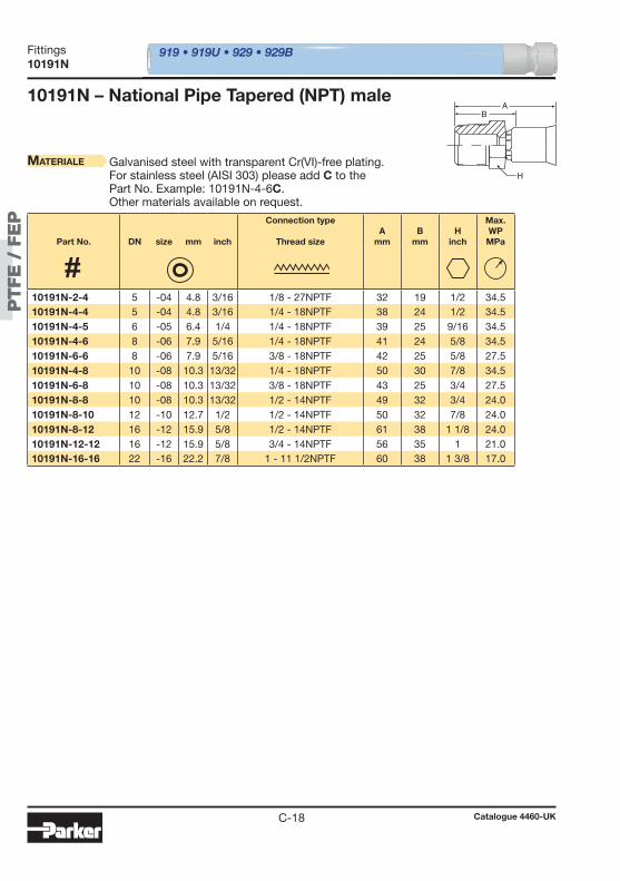
PT
FE
/ F
EP
PT
FE
/ F
EP
C-18
10191N 919 • 919U • 929 • 929B
Materiale Galvanised steel with transparent Cr(VI)-free plating.For stainless steel (AISI 303) please add C to the Part No. Example: 10191N-4-6C.Other materials available on request.
10191N – National Pipe Tapered (NPT) maleA
H
B
Part No. DN size mm inch
Connection type
Thread sizeA
mmB
mmH
inch
Max. WPMPa
10191N-2-4 5 -04 4.8 3/16 1/8 - 27NPTF 32 19 1/2 34.5 10191N-4-4 5 -04 4.8 3/16 1/4 - 18NPTF 38 24 1/2 34.5 10191N-4-5 6 -05 6.4 1/4 1/4 - 18NPTF 39 25 9/16 34.5 10191N-4-6 8 -06 7.9 5/16 1/4 - 18NPTF 41 24 5/8 34.5 10191N-6-6 8 -06 7.9 5/16 3/8 - 18NPTF 42 25 5/8 27.5 10191N-4-8 10 -08 10.3 13/32 1/4 - 18NPTF 50 30 7/8 34.5 10191N-6-8 10 -08 10.3 13/32 3/8 - 18NPTF 43 25 3/4 27.5 10191N-8-8 10 -08 10.3 13/32 1/2 - 14NPTF 49 32 3/4 24.0 10191N-8-10 12 -10 12.7 1/2 1/2 - 14NPTF 50 32 7/8 24.0 10191N-8-12 16 -12 15.9 5/8 1/2 - 14NPTF 61 38 1 1/8 24.0 10191N-12-12 16 -12 15.9 5/8 3/4 - 14NPTF 56 35 1 21.0 10191N-16-16 22 -16 22.2 7/8 1 - 11 1/2NPTF 60 38 1 3/8 17.0
Catalogue 4460-UK
Fittings

PT
FE
/ F
EP
PT
FE
/ F
EP
C-19
C
10691N – 10791N 919 • 919U • 929 • 929B
Materiale Galvanised steel with transparent Cr(VI)-free plating.For stainless steel (AISI 316) please add C to the Part No. Example: 10691N-6-6C.Other materials available on request.
10691N – SAE (JIC) 37° female swivelUNF swivel nut
Materiale Galvanised steel with transparent Cr(VI)-free plating.For stainless steel (AISI 303) please add C to the Part No. Example: 10791N-4-4C.Other materials available on request.
10791N – NPSM female swivel
A45°
37°
J H
B
A
HJ
30°
B
Connection type Max.
Part No. DN size mm inch Thread size Tube OD
inchA
mmB
mmH
inchJ
inchWPMPa
Connection type Max.
Part No. DN size mm inch Thread size Tube OD
inchA
mmB
mmH
inchJ
inchWPMPa
10691N-4-4 5 -04 4.8 3/16 7/16 - 20UNF 1/4 36 22 3/8 9/16 41.0 10691N-5-5 6 -05 6.4 1/4 1/2 - 20UNF 5/16 40 24 7/16 5/8 41.0 10691N-6-6 8 -06 7.9 5/16 9/16 - 18UNF 3/8 41 25 1/2 11/16 34.5 10691N-8-8 10 -08 10.3 13/32 3/4 - 16UNF 1/2 48 30 11/16 7/8 34.5 10691N-10-10 12 -10 12.7 1/2 7/8 - 14UNF 5/8 52 33 13/16 1 34.5 10691N-12-12 16 -12 15.9 5/8 1 1/16 - 12UNF 3/4 54 33 1 1 1/4 34.5 10691N-16-16 22 -16 22.2 7/8 1 5/16 - 12UNF 1 62 40 1 1/4 1 1/2 27.5
10791N-4-4 5 -04 4.8 3/16 1/4 - 18NPSM 1/4 38 24 9/16 3/4 34.5 10791N-6-6 8 -06 7.9 5/16 3/8 - 18NPSM 3/8 42 25 5/8 7/8 27.5 10791N-8-8 10 -08 10.3 13/32 1/2 - 14NPSM 1/2 46 29 3/4 1 24.0 10791N-12-12 16 -12 15.9 5/8 3/4 - 14NPSM 3/4 53 33 1 1 1/4 21.0 10791N-16-16 22 -16 22.2 7/8 1 - 11 1/2NPSM 1 57 33 1 3/16 1 3/8 17.0
Catalogue 4460-UK
Fittings
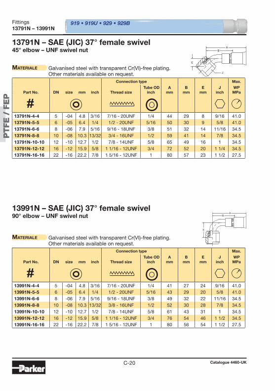
PT
FE
/ F
EP
PT
FE
/ F
EP
C-20
13791N – 13991N 919 • 919U • 929 • 929B
13791N – SAE (JIC) 37° female swivel45° elbow – UNF swivel nut
Materiale Galvanised steel with transparent Cr(VI)-free plating.Other materials available on request.
13991N – SAE (JIC) 37° female swivel90° elbow – UNF swivel nut
Materiale Galvanised steel with transparent Cr(VI)-free plating.Other materials available on request.
A
E
J
B
A
E
B
Connection type Max.
Part No. DN size mm inch Thread size Tube OD
inchA
mmB
mmE
mmJ
inchWPMPa
Connection type Max.
Part No. DN size mm inch Thread size Tube OD
inchA
mmB
mmE
mmJ
inchWPMPa
13791N-4-4 5 -04 4.8 3/16 7/16 - 20UNF 1/4 44 29 8 9/16 41.0 13791N-5-5 6 -05 6.4 1/4 1/2 - 20UNF 5/16 50 30 9 5/8 41.0 13791N-6-6 8 -06 7.9 5/16 9/16 - 18UNF 3/8 51 32 14 11/16 34.5 13791N-8-8 10 -08 10.3 13/32 3/4 - 16UNF 1/2 59 41 14 7/8 34.5 13791N-10-10 12 -10 12.7 1/2 7/8 - 14UNF 5/8 65 49 16 1 34.5 13791N-12-12 16 -12 15.9 5/8 1 1/16 - 12UNF 3/4 72 52 20 1 1/4 34.5 13791N-16-16 22 -16 22.2 7/8 1 5/16 - 12UNF 1 80 57 23 1 1/2 27.5
13991N-4-4 5 -04 4.8 3/16 7/16 - 20UNF 1/4 41 27 24 9/16 41.0 13991N-5-5 6 -05 6.4 1/4 1/2 - 20UNF 5/16 43 29 20 5/8 41.0 13991N-6-6 8 -06 7.9 5/16 9/16 - 18UNF 3/8 49 32 22 11/16 34.5 13991N-8-8 10 -08 10.3 13/32 3/8 - 16UNF 1/2 52 30 28 7/8 34.5 13991N-10-10 12 -10 12.7 1/2 7/8 - 14UNF 5/8 61 43 31 1 34.5 13991N-12-12 16 -12 15.9 5/8 1 1/16 - 12UNF 3/4 76 54 46 1 1/2 34.5 13991N-16-16 22 -16 22.2 7/8 1 5/16 - 12UNF 1 80 56 54 1 1/2 27.5
Catalogue 4460-UK
Fittings
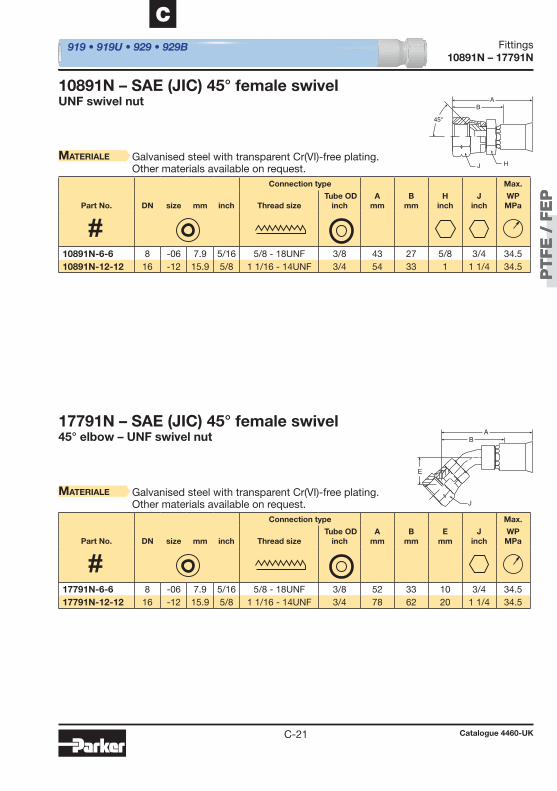
PT
FE
/ F
EP
PT
FE
/ F
EP
C-21
C
10891N – 17791N 919 • 919U • 929 • 929B
10891N – SAE (JIC) 45° female swivelUNF swivel nut
Materiale Galvanised steel with transparent Cr(VI)-free plating.Other materials available on request.
Materiale Galvanised steel with transparent Cr(VI)-free plating.Other materials available on request.
17791N – SAE (JIC) 45° female swivel45° elbow – UNF swivel nut
A
HJ
45°
B
A
E
J
B
Connection type Max.
Part No. DN size mm inch Thread size Tube OD
inchA
mmB
mmH
inchJ
inchWPMPa
Connection type Max.
Part No. DN size mm inch Thread size Tube OD
inchA
mmB
mmE
mmJ
inchWPMPa
10891N-6-6 8 -06 7.9 5/16 5/8 - 18UNF 3/8 43 27 5/8 3/4 34.5 10891N-12-12 16 -12 15.9 5/8 1 1/16 - 14UNF 3/4 54 33 1 1 1/4 34.5
17791N-6-6 8 -06 7.9 5/16 5/8 - 18UNF 3/8 52 33 10 3/4 34.5 17791N-12-12 16 -12 15.9 5/8 1 1/16 - 14UNF 3/4 78 62 20 1 1/4 34.5
Catalogue 4460-UK
Fittings
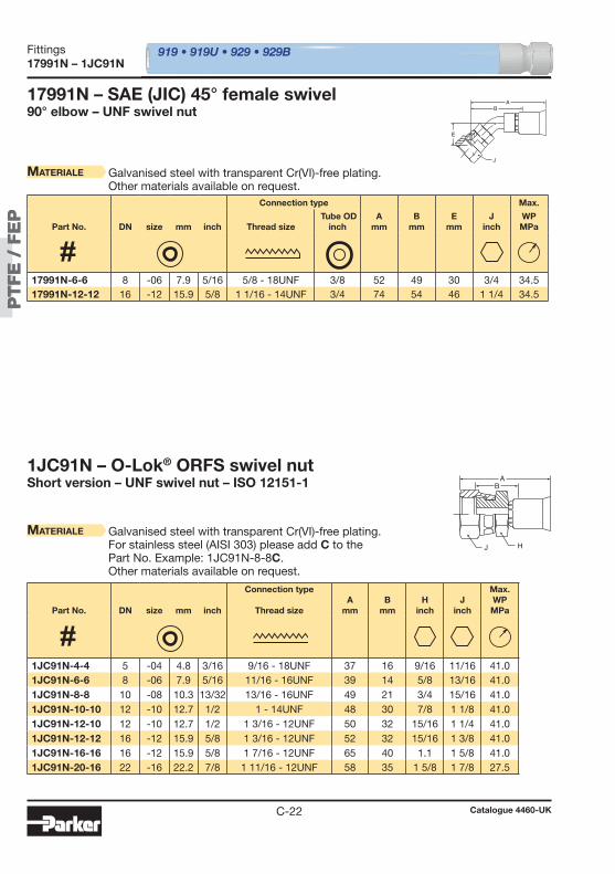
PT
FE
/ F
EP
PT
FE
/ F
EP
C-22
17991N – 1JC91N 919 • 919U • 929 • 929B
Materiale Galvanised steel with transparent Cr(VI)-free plating.Other materials available on request.
17991N – SAE (JIC) 45° female swivel90° elbow – UNF swivel nut
1JC91N – O-Lok® ORFS swivel nutShort version – UNF swivel nut – ISO 12151-1
Materiale Galvanised steel with transparent Cr(VI)-free plating.For stainless steel (AISI 303) please add C to the Part No. Example: 1JC91N-8-8C.Other materials available on request.
A
E
J
B
A
HJ
B
Connection type Max.
Part No. DN size mm inch Thread size Tube OD
inchA
mmB
mmE
mmJ
inchWPMPa
Part No. DN size mm inch
Connection type
Thread sizeA
mmB
mmH
inchJ
inch
Max. WPMPa
17991N-6-6 8 -06 7.9 5/16 5/8 - 18UNF 3/8 52 49 30 3/4 34.5 17991N-12-12 16 -12 15.9 5/8 1 1/16 - 14UNF 3/4 74 54 46 1 1/4 34.5
1JC91N-4-4 5 -04 4.8 3/16 9/16 - 18UNF 37 16 9/16 11/16 41.0 1JC91N-6-6 8 -06 7.9 5/16 11/16 - 16UNF 39 14 5/8 13/16 41.0 1JC91N-8-8 10 -08 10.3 13/32 13/16 - 16UNF 49 21 3/4 15/16 41.0 1JC91N-10-10 12 -10 12.7 1/2 1 - 14UNF 48 30 7/8 1 1/8 41.0 1JC91N-12-10 12 -10 12.7 1/2 1 3/16 - 12UNF 50 32 15/16 1 1/4 41.0 1JC91N-12-12 16 -12 15.9 5/8 1 3/16 - 12UNF 52 32 15/16 1 3/8 41.0 1JC91N-16-16 16 -12 15.9 5/8 1 7/16 - 12UNF 65 40 1.1 1 5/8 41.0 1JC91N-20-16 22 -16 22.2 7/8 1 11/16 - 12UNF 58 35 1 5/8 1 7/8 27.5
Catalogue 4460-UK
Fittings
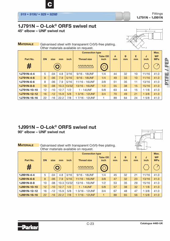
PT
FE
/ F
EP
PT
FE
/ F
EP
C-23
C
1J791N – 1J991N 919 • 919U • 929 • 929B
1J791N – O-Lok® ORFS swivel nut45° elbow – UNF swivel nut
Materiale Galvanised steel with transparent Cr(VI)-free plating.Other materials available on request.
1J991N – O-Lok® ORFS swivel nut90° elbow – UNF swivel nut
Materiale Galvanised steel with transparent Cr(VI)-free plating.Other materials available on request.
A
J
E
B
A
E
J
B
Connection type Max.
Part No. DN size mm inch Thread size Tube OD
inchA
mmB
mmE
mmJ
inchWPMPa
Connection type Max.
Part No. DN size mm inch Thread size Tube OD
inchA
mmB
mmE
mmJ
inchWPMPa
1J791N-4-4 5 -04 4.8 3/16 9/16 - 18UNF 1/4 44 32 10 11/16 41.0 1J791N-4-6 8 -06 7.9 5/16 9/16 - 18UNF 1/4 49 33 10 11/16 41.0 1J791N-6-6 8 -06 7.9 5/16 11/16 - 16UNF 3/8 51 35 11 13/16 41.0 1J791N-8-8 10 -08 10.3 13/32 13/16 - 16UNF 1/2 55 38 15 15/16 41.0 1J791N-10-10 12 -10 12.7 1/2 1 - 14UNF 5/8 63 44 15 1 1/8 41.0 1J791N-12-12 16 -12 15.9 5/8 1 3/16 - 12UNF 3/4 70 49 21 1 3/8 41.0 1J791N-16-16 22 -16 22.2 7/8 1 7/16 - 12UNF 1 89 64 24 1 5/8 41.0
1J991N-4-4 5 -04 4.8 3/16 9/16 - 18UNF 1/4 45 32 21 11/16 41.0 1J991N-6-6 8 -06 7.9 5/16 11/16 - 16UNF 3/8 47 32 23 13/16 41.0 1J991N-8-8 10 -08 10.3 13/32 13/16 - 16UNF 1/2 53 35 29 15/16 41.0 1J991N-10-10 12 -10 12.7 1/2 1 - 14UNF 5/8 57 38 32 1 1/8 41.0 1J991N-12-12 16 -12 15.9 5/8 1 3/16 - 12UNF 3/4 67 48 47 1 3/8 41.0 1J991N-16-16 22 -16 22.2 7/8 1 7/16 - 12UNF 1 88 65 56 1 5/8 41.0
Catalogue 4460-UK
Fittings
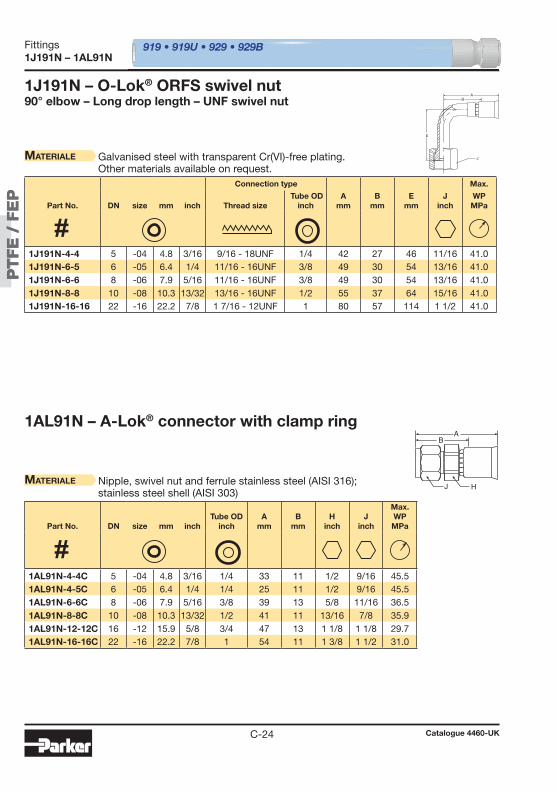
PT
FE
/ F
EP
PT
FE
/ F
EP
C-24
1J191N – 1AL91N 919 • 919U • 929 • 929B
1J191N – O-Lok® ORFS swivel nut90° elbow – Long drop length – UNF swivel nut
Materiale Galvanised steel with transparent Cr(VI)-free plating.Other materials available on request.
1AL91N – A-Lok® connector with clamp ring
Materiale Nipple, swivel nut and ferrule stainless steel (AISI 316);stainless steel shell (AISI 303)
A
J
E
B
A
HJ
B
Connection type Max.
Part No. DN size mm inch Thread size Tube OD
inchA
mmB
mmE
mmJ
inchWPMPa
Part No. DN size mm inchTube OD
inchA
mmB
mmH
inchJ
inch
Max. WPMPa
1J191N-4-4 5 -04 4.8 3/16 9/16 - 18UNF 1/4 42 27 46 11/16 41.0 1J191N-6-5 6 -05 6.4 1/4 11/16 - 16UNF 3/8 49 30 54 13/16 41.0 1J191N-6-6 8 -06 7.9 5/16 11/16 - 16UNF 3/8 49 30 54 13/16 41.0 1J191N-8-8 10 -08 10.3 13/32 13/16 - 16UNF 1/2 55 37 64 15/16 41.0 1J191N-16-16 22 -16 22.2 7/8 1 7/16 - 12UNF 1 80 57 114 1 1/2 41.0
1AL91N-4-4C 5 -04 4.8 3/16 1/4 33 11 1/2 9/16 45.5 1AL91N-4-5C 6 -05 6.4 1/4 1/4 25 11 1/2 9/16 45.5 1AL91N-6-6C 8 -06 7.9 5/16 3/8 39 13 5/8 11/16 36.5 1AL91N-8-8C 10 -08 10.3 13/32 1/2 41 11 13/16 7/8 35.9 1AL91N-12-12C 16 -12 15.9 5/8 3/4 47 13 1 1/8 1 1/8 29.7 1AL91N-16-16C 22 -16 22.2 7/8 1 54 11 1 3/8 1 1/2 31.0
Catalogue 4460-UK
Fittings
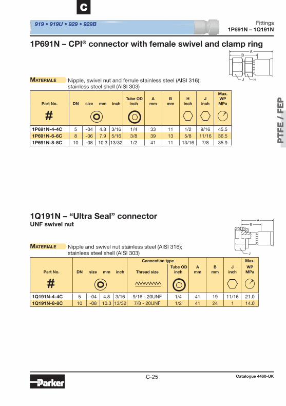
PT
FE
/ F
EP
PT
FE
/ F
EP
C-25
C
1P691N – 1Q191N 919 • 919U • 929 • 929B
1P691N – CPI® connector with female swivel and clamp ring
Materiale Nipple, swivel nut and ferrule stainless steel (AISI 316);stainless steel shell (AISI 303)
1Q191N – “Ultra Seal” connectorUNF swivel nut
Materiale Nipple and swivel nut stainless steel (AISI 316);stainless steel shell (AISI 303)
A
J H
B
A
J
B
Part No. DN size mm inch Tube OD
inchA
mmB
mmH
inchJ
inch
Max. WPMPa
Connection type Max.
Part No. DN size mm inch Thread size Tube OD
inchA
mmB
mmJ
inchWPMPa
1P691N-4-4C 5 -04 4.8 3/16 1/4 33 11 1/2 9/16 45.5 1P691N-6-6C 8 -06 7.9 5/16 3/8 39 13 5/8 11/16 36.5 1P691N-8-8C 10 -08 10.3 13/32 1/2 41 11 13/16 7/8 35.9
1Q191N-4-4C 5 -04 4.8 3/16 9/16 - 20UNF 1/4 41 19 11/16 21.0 1Q191N-8-8C 10 -08 10.3 13/32 7/8 - 20UNF 1/2 41 24 1 14.0
Catalogue 4460-UK
Fittings
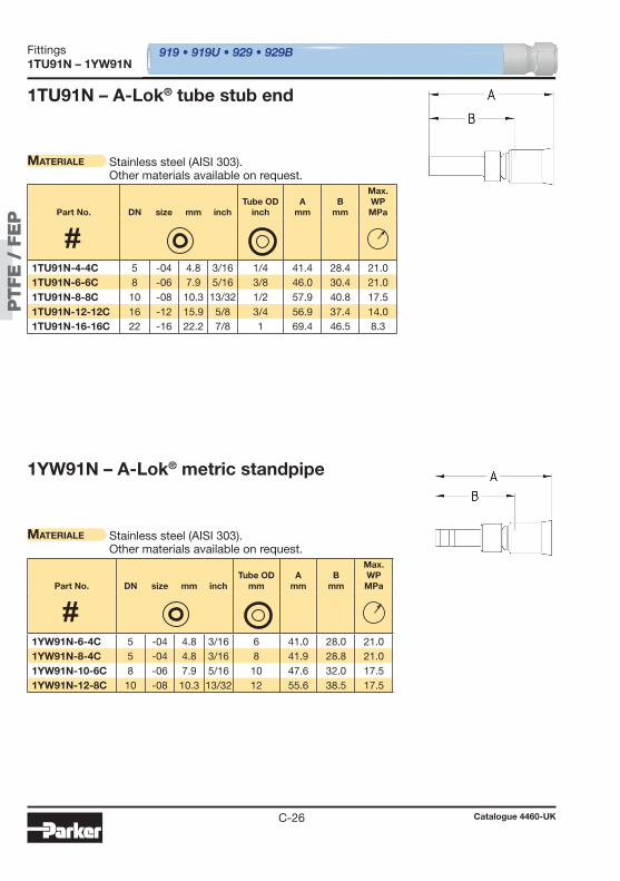
PT
FE
/ F
EP
PT
FE
/ F
EP
C-26
1TU91N – 1YW91N 919 • 919U • 929 • 929B
1TU91N – A-Lok® tube stub end
Materiale Stainless steel (AISI 303).Other materials available on request.
1YW91N – A-Lok® metric standpipe
Materiale Stainless steel (AISI 303).Other materials available on request.
Part No. DN size mm inch
Tube OD
inchA
mmB
mm
Max. WPMPa
Part No. DN size mm inch
Tube OD
mmA
mmB
mm
Max. WPMPa
1TU91N-4-4C 5 -04 4.8 3/16 1/4 41.4 28.4 21.0 1TU91N-6-6C 8 -06 7.9 5/16 3/8 46.0 30.4 21.0 1TU91N-8-8C 10 -08 10.3 13/32 1/2 57.9 40.8 17.5 1TU91N-12-12C 16 -12 15.9 5/8 3/4 56.9 37.4 14.0 1TU91N-16-16C 22 -16 22.2 7/8 1 69.4 46.5 8.3
1YW91N-6-4C 5 -04 4.8 3/16 6 41.0 28.0 21.0 1YW91N-8-4C 5 -04 4.8 3/16 8 41.9 28.8 21.0 1YW91N-10-6C 8 -06 7.9 5/16 10 47.6 32.0 17.5 1YW91N-12-8C 10 -08 10.3 13/32 12 55.6 38.5 17.5
Catalogue 4460-UK
Fittings
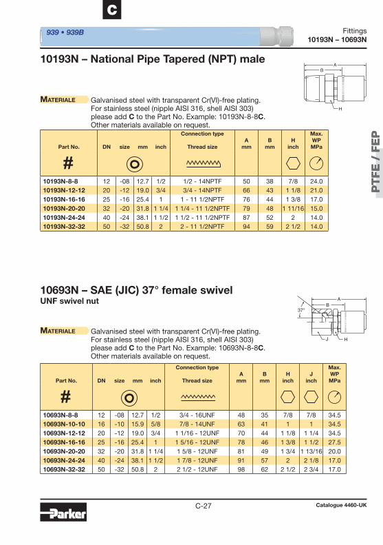
PT
FE
/ F
EP
PT
FE
/ F
EP
C-27
C
10193N – 10693N
101 93N – National Pipe Tapered (NPT) male
939 • 939B
Materiale Galvanised steel with transparent Cr(VI)-free plating.For stainless steel (nipple AISI 316, shell AISI 303) please add C to the Part No. Example: 10193N-8-8C.Other materials available on request.
Materiale Galvanised steel with transparent Cr(VI)-free plating.For stainless steel (nipple AISI 316, shell AISI 303) please add C to the Part No. Example: 10693N-8-8C.Other materials available on request.
10693N – SAE (JIC) 37° female swivelUNF swivel nut
A
H
B
A
37°
J H
B
Part No. DN size mm inch
Connection type
Thread sizeA
mmB
mmH
inch
Max. WPMPa
Part No. DN size mm inch
Connection type
Thread sizeA
mmB
mmH
inchJ
inch
Max. WPMPa
10193N-8-8 12 -08 12.7 1/2 1/2 - 14NPTF 50 38 7/8 24.0 10193N-12-12 20 -12 19.0 3/4 3/4 - 14NPTF 66 43 1 1/8 21.0 10193N-16-16 25 -16 25.4 1 1 - 11 1/2NPTF 76 44 1 3/8 17.0 10193N-20-20 32 -20 31.8 1 1/4 1 1/4 - 11 1/2NPTF 79 48 1 11/16 15.0 10193N-24-24 40 -24 38.1 1 1/2 1 1/2 - 11 1/2NPTF 87 52 2 14.0 10193N-32-32 50 -32 50.8 2 2 - 11 1/2NPTF 94 59 2 1/2 14.0
10693N-8-8 12 -08 12.7 1/2 3/4 - 16UNF 48 35 7/8 7/8 34.5 10693N-10-10 16 -10 15.9 5/8 7/8 - 14UNF 63 41 1 1 34.5 10693N-12-12 20 -12 19.0 3/4 1 1/16 - 12UNF 70 44 1 1/8 1 1/4 34.5 10693N-16-16 25 -16 25.4 1 1 5/16 - 12UNF 78 46 1 3/8 1 1/2 27.5 10693N-20-20 32 -20 31.8 1 1/4 1 5/8 - 12UNF 81 49 1 3/4 1 13/16 20.0 10693N-24-24 40 -24 38.1 1 1/2 1 7/8 - 12UNF 91 57 2 2 1/8 17.0 10693N-32-32 50 -32 50.8 2 2 1/2 - 12UNF 98 62 2 1/2 2 3/4 17.0
Catalogue 4460-UK
Fittings
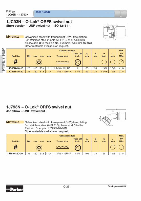
PT
FE
/ F
EP
PT
FE
/ F
EP
C-28
1JC93N – 1J793N 939 • 939B
Materiale Galvanised steel with transparent Cr(VI)-free plating.For stainless steel (nipple AISI 316, shell AISI 303) please add C to the Part No. Example: 1JC93N-16-16C.Other materials available on request.
1JC93N – O-Lok® ORFS swivel nutShort version – UNF swivel nut – ISO 12151-1
1J793N – O-Lok® ORFS swivel nut45° elbow – UNF swivel nut
Materiale Galvanised steel with transparent Cr(VI)-free plating.For stainless steel (AISI 316) please add C to the Part No. Example: 1J793N-16-16C.Other materials available on request.
A
J H
B
A
J
E
B
Connection type Max.
Part No. DN size mm inch Thread size Tube OD
inchA
mmB
mmH
inchJ
inchWPMPa
Connection type Max.
Part No. DN size mm inch Thread size Tube OD
inchA
mmB
mmE
mmJ
inchWPMPa
1JC93N-16-16 25 -16 25.4 1 1 7/16 - 12UNF 1 66 35 1 3/8 1 5/8 41.0 1JC93N-20-20 32 -20 31.8 1 1/4 1 11/16 - 12UNF 1 1/4 65 33 1 5/16 1 7/8 27.5
1J793N-20-20 32 -20 31.8 1 1/4 1 11/16 - 12UNF 1 1/4 106 75 25 1 7/8 27.5
Catalogue 4460-UK
Fittings
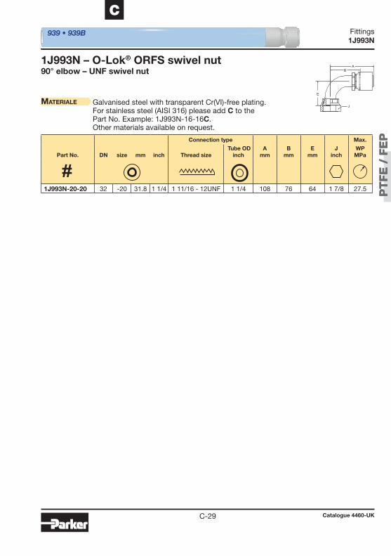
PT
FE
/ F
EP
PT
FE
/ F
EP
C-29
C
1J993N 939 • 939B
1J993N – O-Lok® ORFS swivel nut90° elbow – UNF swivel nut
Materiale Galvanised steel with transparent Cr(VI)-free plating.For stainless steel (AISI 316) please add C to the Part No. Example: 1J993N-16-16C.Other materials available on request.
A
J
E
B
Connection type Max.
Part No. DN size mm inch Thread size Tube OD
inchA
mmB
mmE
mmJ
inchWPMPa
1J993N-20-20 32 -20 31.8 1 1/4 1 11/16 - 12UNF 1 1/4 108 76 64 1 7/8 27.5
Catalogue 4460-UK
Fittings
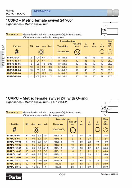
PT
FE
/ F
EP
PT
FE
/ F
EP
C-30
1C3PC – 1CAPC 2030T-##CON
1C3 PC – Metric female swivel 24°/60°Light series – Metric swivel nut
Materiale Galvanised steel with transparent Cr(VI)-free plating.Other materials available on request.
1CAPC – Metric female swivel 24° with O-ringLight series – Metric swivel nut – ISO 12151-2
Materiale Galvanised steel with transparent Cr(VI)-free plating.Other materials available on request.
Connection type Max.
Part No. DN size mm inch Thread size Tube OD
mmA
mmB
mmJ
mmWPMPa
Connection type Max.
Part No. DN size mm inch Thread size Tube OD
mmA
mmB
mmJ
mmWPMPa
1C3PC-8-04 6 -04 6.4 1/4 M14x1.5 8 46 18 17 25.0 1C3PC-10-04 6 -04 6.4 1/4 M16x1.5 10 46 18 19 25.0 1C3PC-10-05 8 -05 7.9 5/16 M16x1.5 10 46 18 19 25.0 1C3PC-10-06 10 -06 9.5 3/8 M16x1.5 10 49 20 22 25.0 1C3PC-12-06 10 -06 9.5 3/8 M18x1.5 12 48 19 22 25.0 1C3PC-12-08 12 -08 12.7 1/2 M18x1.5 12 52 20 24 25.0 1C3PC-15-08 12 -08 12.7 1/2 M22x1.5 15 51 20 27 25.0
1CAPC-6-04 6 -04 6.4 1/4 M12x1.5 6 48 20 17 31.5 1CAPC-8-04 6 -04 6.4 1/4 M14x1.5 8 51 23 17 42.5 1CAPC-10-04 6 -04 6.4 1/4 M16x1.5 10 50 22 19 40.0 1CAPC-10-05 8 -05 7.9 5/16 M16x1.5 10 50 22 19 40.0 1CAPC-12-05 8 -05 7.9 5/16 M18x1.5 12 50 22 22 35.0 1CAPC-10-06 10 -06 9.5 3/8 M16x1.5 10 51 22 22 40.0 1CAPC-12-06 10 -06 9.5 3/8 M18x1.5 12 52 23 22 35.0 1CAPC-15-08 12 -08 12.7 1/2 M22x1.5 15 59 28 27 31.5 1CAPC-18-10 16 -10 15.9 5/8 M26x1.5 18 56 25 32 31.5 1CAPC-22-12 20 -12 19.0 3/4 M30x2 22 62 27 36 28.0 1CAPC-28-16 25 -16 25.4 1 M36x2 28 64 29 41 21.0
Catalogue 4460-UK
Fittings

PT
FE
/ F
EP
PT
FE
/ F
EP
C-31
C
1C9PC – 1CEPC
1C9PC – Metric female swivel 24° with O-ringHeavy series – Metric swivel nut – ISO 12151-2
Materiale Galvanised steel with transparent Cr(VI)-free plating.Other materials available on request.
2030T-##CON
1CEPC – Metric female swivel 24° with O-ring45° elbow – Light series – Metric swivel nut – ISO 12151-2
Materiale Galvanised steel with transparent Cr(VI)-free plating.Other materials available on request.
Connection type Max.
Part No. DN size mm inch Thread size Tube OD
mmA
mmB
mmJ
mmWPMPa
Connection type Max.
Part No. DN size mm inch Thread size Tube OD
mmA
mmB
mmE
mmJ
mmWPMPa
1C9PC-10-04 6 -04 6.4 1/4 M18x1.5 10 55 27 22 63.0 1C9PC-12-05 8 -05 7.9 5/16 M20x1.5 12 56 28 24 63.0 1C9PC-12-06 10 -06 9.5 3/8 M20x1.5 12 54 25 24 63.0 1C9PC-14-06 10 -06 9.5 3/8 M22x1.5 14 59 30 27 63.0 1C9PC-16-08 12 -08 12.7 1/2 M24x1.5 16 65 34 30 42.0 1C9PC-20-10 16 -10 15.9 5/8 M30x2 20 68 37 36 42.0
1CEPC-6-04 6 -04 6.4 1/4 M12x1.5 6 72 43 23 17 31.5 1CEPC-8-04 6 -04 6.4 1/4 M14x1.5 8 72 43 23 17 42.5 1CEPC-10-05 8 -05 7.9 5/16 M16x1.5 10 72 43 20 19 40.0 1CEPC-10-06 10 -06 9.5 3/8 M16x1.5 10 70 40 18 19 40.0 1CEPC-12-06 10 -06 9.5 3/8 M18x1.5 12 70 40 18 22 35.0 1CEPC-15-08 12 -08 12.7 1/2 M22x1.5 15 83 51 21 27 31.5 1CEPC-18-10 16 -10 15.9 5/8 M26x1.5 18 96 65 27 32 31.5 1CEPC-22-12 20 -12 19.0 3/4 M30x2 22 114 79 32 36 28.0 1CEPC-28-16 25 -16 25.4 1 M36x2 28 112 77 35 41 21.0
Catalogue 4460-UK
Fittings
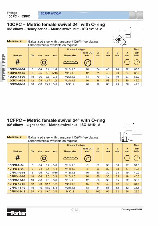
PT
FE
/ F
EP
PT
FE
/ F
EP
C-32
10CPC – 1CFPC
10CPC – Metric female swivel 24° with O-ring45° elbow – Heavy series – Metric swivel nut – ISO 12151-2
Materiale Galvanised steel with transparent Cr(VI)-free plating.Other materials available on request.
2030T-##CON
1CFPC – Metric female swivel 24° with O-ring90° elbow – Light series – Metric swivel nut – ISO 12151-2
Materiale Galvanised steel with transparent Cr(VI)-free plating.Other materials available on request.
Connection type Max.
Part No. DN size mm inch Thread size Tube OD
mmA
mmB
mmE
mmJ
mmWPMPa
Connection type Max.
Part No. DN size mm inch Thread size Tube OD
mmA
mmB
mmE
mmJ
mmWPMPa
10CPC-10-04 6 -04 6.4 1/4 M18x1.5 10 74 45 24 22 63.0 10CPC-12-05 8 -05 7.9 5/16 M20x1.5 12 71 42 20 24 63.0 10CPC-14-06 10 -06 9.5 3/8 M22x1.5 14 70 40 19 27 63.0 10CPC-16-08 12 -08 12.7 1/2 M24x1.5 16 85 53 23 30 42.0 10CPC-20-10 16 -10 15.9 5/8 M30x2 20 99 68 29 36 42.0
1CFPC-6-04 6 -04 6.4 3/8 M12x1.5 6 59 30 33 17 31.5 1CFPC-8-04 6 -04 6.4 1/4 M14x1.5 8 59 30 33 17 42.5 1CFPC-10-05 8 -05 7.9 5/16 M16x1.5 10 59 30 33 19 40.0 1CFPC-10-06 10 -06 9.5 3/8 M16x1.5 10 60 30 35 19 40.0 1CFPC-12-06 10 -06 9.5 3/8 M18x1.5 12 60 30 35 22 35.0 1CFPC-15-08 12 -08 12.7 1/2 M22x1.5 15 74 42 42 27 31.5 1CFPC-18-10 16 -10 15.9 5/8 M26x1.5 18 84 53 52 32 31.5 1CFPC-22-12 20 -12 19.0 3/4 M30x2 22 100 65 62 36 28.0
Catalogue 4460-UK
Fittings
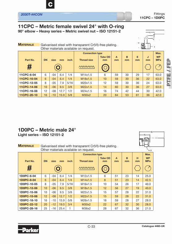
PT
FE
/ F
EP
PT
FE
/ F
EP
C-33
C
11CPC – 1D0PC
11CPC – Metric female swivel 24° with O-ring90° elbow – Heavy series – Metric swivel nut – ISO 12151-2
Materiale Galvanised steel with transparent Cr(VI)-free plating.Other materials available on request.
2030T-##CON
1D0PC – Metric male 24°Light series – ISO 12151-2
Materiale Galvanised steel with transparent Cr(VI)-free plating.Other materials available on request.
Connection type Max.
Part No. DN size mm inch Thread size Tube OD
mmA
mmB
mmE
mmJ
mmWPMPa
Connection type Max.
Part No. DN size mm inch Thread size Tube OD
mmA
mmB
mmH
mmWPMPa
11CPC-6-04 6 -04 6.4 1/4 M14x1.5 6 59 30 29 17 63.0 11CPC-10-04 6 -04 6.4 1/4 M18x1.5 10 59 30 36 22 63.0 11CPC-12-05 8 -05 7.9 5/16 M20x1.5 12 59 30 36 24 63.0 11CPC-14-06 10 -06 9.5 3/8 M22x1.5 14 60 30 36 27 63.0 11CPC-16-08 12 -08 12.7 1/2 M24x1.5 16 74 42 44 30 42.0 11CPC-20-10 16 -10 15.9 5/8 M30x2 20 84 53 61 36 42.0
1D0PC-6-04 6 -04 6.4 1/4 M12x1.5 6 51 23 14 25.0 1D0PC-8-04 6 -04 6.4 1/4 M14x1.5 8 51 23 14 42.5 1D0PC-10-05 8 -05 7.9 5/16 M16x1.5 10 54 26 17 40.0 1D0PC-12-06 10 -06 9.5 3/8 M18x1.5 12 56 27 19 40.0 1D0PC-15-06 10 -06 9.5 3/8 M22x1.5 15 57 28 22 31.0 1D0PC-15-08 12 -08 12.7 1/2 M22x1.5 15 59 28 22 31.0 1D0PC-18-10 16 -10 15.9 5/8 M26x1.5 18 59 28 27 28.0 1D0PC-22-12 20 -12 19.0 3/4 M30x2 22 67 32 30 28.0 1D0PC-28-16 25 -16 25.4 1 M36x2 28 67 32 36 21.0
Catalogue 4460-UK
Fittings
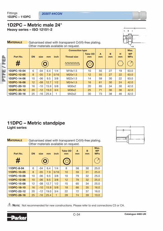
PT
FE
/ F
EP
PT
FE
/ F
EP
C-34
1D2PC – 11DPC
1D2PC – Metric male 24°Heavy series – ISO 12151-2
Materiale Galvanised steel with transparent Cr(VI)-free plating.Other materials available on request.
2030T-##CON
11DPC – Metric standpipeLight series
Materiale Galvanised steel with transparent Cr(VI)-free plating.Other materials available on request.
Note: Not recommended for new constructions. Please refer to end connections C3 or CA.
Connection type Max.
Part No. DN size mm inch Thread size Tube OD
mmA
mmB
mmH
mmWPMPa
Part No. DN size mm inch Tube OD
mmA
mmB
mm
Max. WPMPa
1D2PC-10-04 6 -04 6.4 1/4 M18x1.5 10 55 27 19 63.0 1D2PC-12-05 8 -05 7.9 5/16 M20x1.5 12 55 27 22 63.0 1D2PC-14-06 10 -06 9.5 3/8 M22x1.5 14 59 30 22 63.0 1D2PC-16-08 12 -08 12.7 1/2 M24x1.5 16 61 30 24 42.0 1D2PC-20-10 16 -10 15.9 5/8 M30x2 20 65 34 30 42.0 1D2PC-25-12 20 -12 19.0 3/4 M36x2 25 71 36 36 42.0 1D2PC-30-16 25 -16 25.4 1 M42x2 30 73 38 46 42.0
11DPC-8-04 6 -04 6.4 1/4 8 58 30 25.0 11DPC-10-05 8 -05 7.9 5/16 10 59 31 25.0 11DPC-10-06 10 -06 9.5 3/8 10 79 32 25.0 11DPC-12-06 10 -06 9.5 3/8 12 79 32 25.0 11DPC-15-08 12 -08 12.7 1/2 15 65 34 25.0 11DPC-18-10 16 -10 15.9 5/8 18 66 35 16.0 11DPC-22-12 20 -12 19.0 3/4 22 72 37 16.0 11DPC-28-16 25 -16 25.4 1 28 74 39 10.0
Catalogue 4460-UK
Fittings
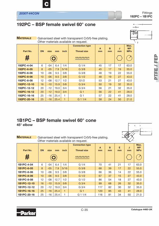
PT
FE
/ F
EP
PT
FE
/ F
EP
C-35
C
192PC – 1B1PC
192PC – BSP female swivel 60° cone
Materiale Galvanised steel with transparent Cr(VI)-free plating.Other materials available on request.
2030T-##CON
1B1PC – BSP female swivel 60° cone45° elbow
Materiale Galvanised steel with transparent Cr(VI)-free plating.Other materials available on request.
Part No. DN size mm inch
Connection type
Thread sizeA
mmB
mmJ
mm
Max. WPMPa
Part No. DN size mm inch
Connection type
Thread sizeA
mmB
mmE
mmJ
mm
Max. WPMPa
192PC-4-04 6 -04 6.4 1/4 G 1/4 45 17 17 63.0 192PC-6-05 8 -05 7.9 5/16 G 3/8 45 17 19 55.0 192PC-6-06 10 -06 9.5 3/8 G 3/8 48 19 22 55.0 192PC-8-06 10 -06 9.5 3/8 G 1/2 48 19 27 43.0 192PC-8-08 12 -08 12.7 1/2 G1/2 53 21 27 43.0 192PC-12-10 16 -10 15.9 5/8 G 3/4 50 19 32 35.0 192PC-12-12 20 -12 19.0 3/4 G 3/4 56 21 32 35.0 192PC-16-12 20 -12 19.0 3/4 G 1 56 22 41 28.0 192PC-16-16 25 -16 25.4 1 G 1 57 22 41 28.0 192PC-20-16 25 -16 25.4 1 G 1 1/4 58 24 50 21.0
1B1PC-4-04 6 -04 6.4 1/4 G 1/4 70 41 21 17 63.0 1B1PC-6-05 8 -05 7.9 5/16 G 3/8 68 39 17 22 55.0 1B1PC-6-06 10 -06 9.5 3/8 G 3/8 66 36 14 22 55.0 1B1PC-8-06 10 -06 9.5 3/8 G 1/2 67 37 15 27 43.0 1B1PC-8-08 12 -08 12.7 1/2 G 1/2 86 54 18 27 43.0 1B1PC-12-10 16 -10 15.9 5/8 G 3/4 99 68 26 32 35.0 1B1PC-12-12 20 -12 19.0 3/4 G 3/4 117 82 30 32 35.0 1B1PC-16-16 25 -16 25.4 1 G 1 120 85 43 41 28.0 1B1PC-20-16 25 -16 25.4 1 G 1 1/4 116 81 34 50 21.0
Catalogue 4460-UK
Fittings

PT
FE
/ F
EP
PT
FE
/ F
EP
C-36
1B2PC – 1U0PC
1B2PC – BSP female swivel 60° cone90° elbow
Materiale Galvanised steel with transparent Cr(VI)-free plating.Other materials available on request.
2030T-##CON
1U0PC – BSP female swivel (ballnose)BSP swivel nut
Materiale Galvanised steel with transparent Cr(VI)-free plating.Other materials available on request.
Part No. DN size mm inch
Connection type
Thread sizeA
mmB
mmE
mmJ
mm
Max. WPMPa
Part No. DN size mm inch
Connection type
Thread sizeA
mmB
mmJ
mm
Max. WPMPa
1B2PC-4-04 6 -04 6.4 1/4 G 1/4 59 30 30 17 63.0 1B2PC-6-05 8 -05 7.9 5/16 G 3/8 59 30 28 22 55.0 1B2PC-6-06 10 -06 9.5 3/8 G 3/8 60 30 30 22 55.0 1B2PC-8-06 10 -06 9.5 3/8 G 1/2 60 30 31 27 43.0 1B2PC-8-08 12 -08 12.7 1/2 G 1/2 74 42 38 27 43.0 1B2PC-12-10 16 -10 15.9 5/8 G 3/4 84 53 50 32 35.0 1B2PC-12-12 20 -12 19.0 3/4 G 3/4 100 65 60 32 35.0 1B2PC-20-16 25 -16 25.4 1 G 1 1/4 100 65 70 50 21.0
1U0PC-4-04 6 -04 6.4 1/4 G 1/4 45 17 17 63.0 1U0PC-6-05 8 -05 7.9 5/16 G 3/8 45 17 19 55.0 1U0PC-6-06 10 -06 9.5 3/8 G 3/8 48 19 22 55.0 1U0PC-8-06 10 -06 9.5 3/8 G 1/2 48 19 27 43.0 1U0PC-8-08 12 -08 12.7 1/2 G 1/2 53 21 27 43.0 1U0PC-12-10 16 -10 15.9 5/8 G 3/4 50 19 32 35.0 1U0PC-12-12 20 -12 19.0 3/4 G 3/4 56 21 32 35.0 1U0PC-16-12 20 -12 19.0 3/4 G 1 56 22 41 25.0 1U0PC-16-16 25 -16 25.4 1 G 1 57 22 41 25.0 1U0PC-20-16 25 -16 25.4 1 G 1 1/4 58 24 50 21.0
Catalogue 4460-UK
Fittings
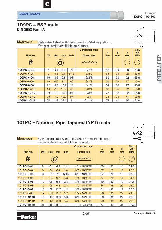
PT
FE
/ F
EP
PT
FE
/ F
EP
C-37
C
1D9PC – 101PC
1D9PC – BSP maleDIN 3852 Form A
Materiale Galvanised steel with transparent Cr(VI)-free plating.Other materials available on request.
2030T-##CON
101PC – National Pipe Tapered (NPT) male
Materiale Galvanised steel with transparent Cr(VI)-free plating.Other materials available on request.
Part No. DN size mm inch
Connection type
Thread sizeA
mmB
mmH
mm
Max. WPMPa
Part No. DN size mm inch
Connection type
Thread sizeA
mmB
mmH
mm
Max. WPMPa
1D9PC-4-04 6 -04 6.4 1/4 G 1/4 57 29 19 63.0 1D9PC-6-05 8 -05 7.9 5/16 G 3/8 58 29 22 55.0 1D9PC-6-06 10 -06 9.5 3/8 G 3/8 60 30 22 55.0 1D9PC-8-06 10 -06 9.5 3/8 G 1/2 62 33 27 43.0 1D9PC-8-08 12 -08 12.7 1/2 G 1/2 64 33 27 43.0 1D9PC-12-10 16 -10 15.9 5/8 G 3/4 66 35 32 35.0 1D9PC-12-12 20 -12 19.0 3/4 G 3/4 72 37 32 35.0 1D9PC-16-12 20 -12 19.0 3/4 G 1 74 39 41 28.0 1D9PC-20-16 25 -16 25.4 1 G 1 1/4 76 41 50 21.0
101PC-4-04 6 -04 6.4 1/4 1/4 - 18NPTF 55 27 14 34.5 101PC-6-04 6 -04 6.4 1/4 3/8 - 18NPTF 57 29 19 27.5 101PC-6-05 8 -05 7.9 5/16 3/8 - 18NPTF 57 29 19 27.5 101PC-4-06 10 -06 9.5 3/8 1/4 - 18NPTF 57 28 14 34.5 101PC-6-06 10 -06 9.5 3/8 3/8 - 18NPTF 59 30 19 27.5 101PC-8-06 10 -06 9.5 3/8 1/2 - 14NPTF 64 35 22 24.0 101PC-6-08 12 -08 12.7 1/2 3/8 - 18NPTF 61 30 19 27.5 101PC-8-08 12 -08 12.7 1/2 1/2 - 14NPTF 66 35 22 24.0 101PC-12-10 16 -10 15.9 5/8 3/4 - 14NPTF 66 35 27 21.0 101PC-12-12 20 -12 19.0 3/4 3/4 - 14NPTF 70 35 27 21.0 101PC-16-16 25 -16 25.4 1 1 - 11 1/2NPTF 77 42 36 17.0
Catalogue 4460-UK
Fittings
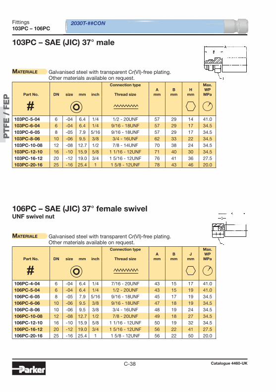
PT
FE
/ F
EP
PT
FE
/ F
EP
C-38
103PC – 106PC
103PC – SAE (JIC) 37° male
Materiale Galvanised steel with transparent Cr(VI)-free plating.Other materials available on request.
2030T-##CON
106PC – SAE (JIC) 37° female swivelUNF swivel nut
Materiale Galvanised steel with transparent Cr(VI)-free plating.Other materials available on request.
Part No. DN size mm inch
Connection type
Thread sizeA
mmB
mmH
mm
Max. WPMPa
Part No. DN size mm inch
Connection type
Thread sizeA
mmB
mmJ
mm
Max. WPMPa
103PC-5-04 6 -04 6.4 1/4 1/2 - 20UNF 57 29 14 41.0 103PC-6-04 6 -04 6.4 1/4 9/16 - 18UNF 57 29 17 34.5 103PC-6-05 8 -05 7.9 5/16 9/16 - 18UNF 57 29 17 34.5 103PC-8-06 10 -06 9.5 3/8 3/4 - 16UNF 62 33 22 34.5 103PC-10-08 12 -08 12.7 1/2 7/8 - 14UNF 70 38 24 34.5 103PC-12-10 16 -10 15.9 5/8 1 1/16 - 12UNF 71 40 30 34.5 103PC-16-12 20 -12 19.0 3/4 1 5/16 - 12UNF 76 41 36 27.5 103PC-20-16 25 -16 25.4 1 1 5/8 - 12UNF 78 43 46 20.0
106PC-4-04 6 -04 6.4 1/4 7/16 - 20UNF 43 15 17 41.0 106PC-5-04 6 -04 6.4 1/4 1/2 - 20UNF 43 15 19 41.0 106PC-6-05 8 -05 7.9 5/16 9/16 - 18UNF 45 17 19 34.5 106PC-6-06 10 -06 9.5 3/8 9/16 - 18UNF 47 18 19 34.5 106PC-8-06 10 -06 9.5 3/8 3/4 - 16UNF 48 19 24 34.5 106PC-10-08 12 -08 12.7 1/2 7/8 - 20UNF 49 18 27 34.5 106PC-12-10 16 -10 15.9 5/8 1 1/16 - 12UNF 50 19 32 34.5 106PC-16-12 20 -12 19.0 3/4 1 5/16 - 12UNF 56 22 41 27.5 106PC-20-16 25 -16 25.4 1 1 5/8 - 12UNF 56 22 50 20.0
Catalogue 4460-UK
Fittings
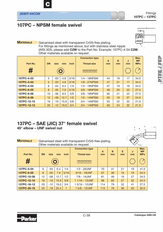
PT
FE
/ F
EP
PT
FE
/ F
EP
C-39
C
107PC – 137PC
107PC – NPSM female swivel
Materiale Galvanised steel with transparent Cr(VI)-free plating.For fi ttings as mentioned above, but with stainless steel nipple(AISI 303), please add C2W to the Part No. Example: 107PC-4-04 C2W.Other materials available on request.
2030T-##CON
137PC – SAE (JIC) 37° female swivel45° elbow – UNF swivel nut
Materiale Galvanised steel with transparent Cr(VI)-free plating.Other materials available on request.
Part No. DN size mm inch
Connection type
Thread sizeA
mmB
mmJ
mm
Max. WPMPa
Part No. DN size mm inch
Connection type
Thread sizeA
mmB
mmE
mmJ
mm
Max. WPMPa
107PC-4-03 5 -03 4.8 3/16 1/4 - 18NPSM 44 19 17 34.5 107PC-2-03 5 -03 4.8 3/16 1/8 - 27NPSM 47 21 17 34.5 107PC-4-04 6 -04 6.4 1/4 1/4 - 18NPSM 47 19 19 34.5 107PC-6-05 8 -05 7.9 5/16 3/8 - 18NPSM 48 20 22 27.5 107PC-6-06 10 -06 9.5 3/8 3/8 - 18NPSM 50 21 22 27.5 107PC-8-08 12 -08 12.7 1/2 1/2 - 14NPSM 50 19 27 24.0 107PC-12-10 16 -10 15.9 5/8 3/4 - 14NPSM 53 22 32 21.0 107PC-12-12 20 -12 19.0 3/4 3/4 - 14NPSM 59 24 32 21.0
137PC-5-04 6 -04 6.4 1/4 1/2 - 20UNF 70 41 21 19 41.0 137PC-6-05 8 -05 7.9 5/16 9/16 - 18UNF 67 38 16 19 34.5 137PC-10-08 12 -08 12.7 1/2 7/8 - 14UNF 81 49 19 27 34.5 137PC-12-10 16 -10 15.9 5/8 1 1/16 - 12UNF 96 65 27 32 34.5 137PC-16-12 20 -12 19.0 3/4 1 5/16 - 12UNF 114 79 32 41 27.5 137PC-20-16 25 -16 25.4 1 1 5/8 - 12UNF 113 78 36 50 20.0
Catalogue 4460-UK
Fittings
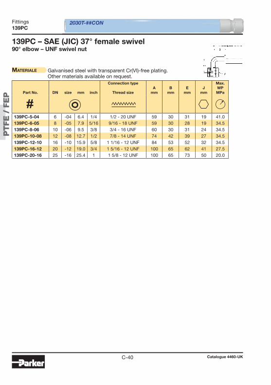
PT
FE
/ F
EP
PT
FE
/ F
EP
C-40
139PC
139PC – SAE (JIC) 37° female swivel90° elbow – UNF swivel nut
Materiale Galvanised steel with transparent Cr(VI)-free plating.Other materials available on request.
2030T-##CON
Part No. DN size mm inch
Connection type
Thread sizeA
mmB
mmE
mmJ
mm
Max. WPMPa
139PC-5-04 6 -04 6.4 1/4 1/2 - 20 UNF 59 30 31 19 41.0 139PC-6-05 8 -05 7.9 5/16 9/16 - 18 UNF 59 30 28 19 34.5 139PC-8-06 10 -06 9.5 3/8 3/4 - 16 UNF 60 30 31 24 34.5 139PC-10-08 12 -08 12.7 1/2 7/8 - 14 UNF 74 42 39 27 34.5 139PC-12-10 16 -10 15.9 5/8 1 1/16 - 12 UNF 84 53 52 32 34.5 139PC-16-12 20 -12 19.0 3/4 1 5/16 - 12 UNF 100 65 62 41 27.5 139PC-20-16 25 -16 25.4 1 1 5/8 - 12 UNF 100 65 73 50 20.0
Catalogue 4460-UK
Fittings
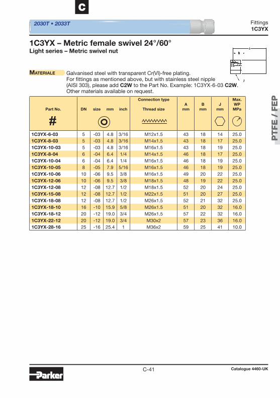
PT
FE
/ F
EP
PT
FE
/ F
EP
C-41
C
1C3YX
1C3 YX – Metric female swivel 24°/60°Light series – Metric swivel nut
2030T • 2033T
Materiale Galvanised steel with transparent Cr(VI)-free plating.For fi ttings as mentioned above, but with stainless steel nipple(AISI 303), please add C2W to the Part No. Example: 1C3YX-6-03 C2W.Other materials available on request.
Part No. DN size mm inch
Connection type
Thread sizeA
mmB
mmJ
mm
Max. WPMPa
1C3YX-6-03 5 -03 4.8 3/16 M12x1.5 43 18 14 25.0 1C3YX-8-03 5 -03 4.8 3/16 M14x1.5 43 18 17 25.0 1C3YX-10-03 5 -03 4.8 3/16 M16x1.5 43 18 19 25.0 1C3YX-8-04 6 -04 6.4 1/4 M14x1.5 46 18 17 25.0 1C3YX-10-04 6 -04 6.4 1/4 M16x1.5 46 18 19 25.0 1C3YX-10-05 8 -05 7.9 5/16 M16x1.5 46 18 19 25.0 1C3YX-10-06 10 -06 9.5 3/8 M16x1.5 49 20 22 25.0 1C3YX-12-06 10 -06 9.5 3/8 M18x1.5 48 19 22 25.0 1C3YX-12-08 12 -08 12.7 1/2 M18x1.5 52 20 24 25.0 1C3YX-15-08 12 -08 12.7 1/2 M22x1.5 51 20 27 25.0 1C3YX-18-08 12 -08 12.7 1/2 M26x1.5 52 21 32 25.0 1C3YX-18-10 16 -10 15.9 5/8 M26x1.5 51 20 32 16.0 1C3YX-18-12 20 -12 19.0 3/4 M26x1.5 57 22 32 16.0 1C3YX-22-12 20 -12 19.0 3/4 M30x2 57 23 36 16.0 1C3YX-28-16 25 -16 25.4 1 M36x2 59 25 41 10.0
Catalogue 4460-UK
Fittings
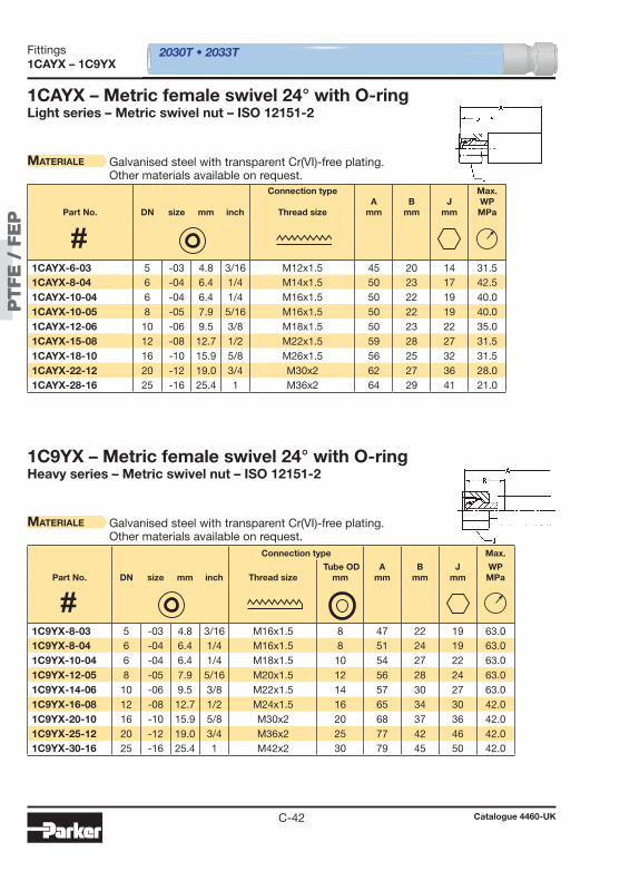
PT
FE
/ F
EP
PT
FE
/ F
EP
C-42
1CAYX – 1C9YX
1CAYX – Metric female swivel 24° with O-ringLight series – Metric swivel nut – ISO 12151-2
Materiale Galvanised steel with transparent Cr(VI)-free plating.Other materials available on request.
1C9YX – Metric female swivel 24° with O-ringHeavy series – Metric swivel nut – ISO 12151-2
Materiale Galvanised steel with transparent Cr(VI)-free plating.Other materials available on request.
2030T • 2033T
Part No. DN size mm inch
Connection type
Thread sizeA
mmB
mmJ
mm
Max. WPMPa
Connection type Max.
Part No. DN size mm inch Thread size Tube OD
mmA
mmB
mmJ
mmWPMPa
1CAYX-6-03 5 -03 4.8 3/16 M12x1.5 45 20 14 31.5 1CAYX-8-04 6 -04 6.4 1/4 M14x1.5 50 23 17 42.5 1CAYX-10-04 6 -04 6.4 1/4 M16x1.5 50 22 19 40.0 1CAYX-10-05 8 -05 7.9 5/16 M16x1.5 50 22 19 40.0 1CAYX-12-06 10 -06 9.5 3/8 M18x1.5 50 23 22 35.0 1CAYX-15-08 12 -08 12.7 1/2 M22x1.5 59 28 27 31.5 1CAYX-18-10 16 -10 15.9 5/8 M26x1.5 56 25 32 31.5 1CAYX-22-12 20 -12 19.0 3/4 M30x2 62 27 36 28.0 1CAYX-28-16 25 -16 25.4 1 M36x2 64 29 41 21.0
1C9YX-8-03 5 -03 4.8 3/16 M16x1.5 8 47 22 19 63.0 1C9YX-8-04 6 -04 6.4 1/4 M16x1.5 8 51 24 19 63.0 1C9YX-10-04 6 -04 6.4 1/4 M18x1.5 10 54 27 22 63.0 1C9YX-12-05 8 -05 7.9 5/16 M20x1.5 12 56 28 24 63.0 1C9YX-14-06 10 -06 9.5 3/8 M22x1.5 14 57 30 27 63.0 1C9YX-16-08 12 -08 12.7 1/2 M24x1.5 16 65 34 30 42.0 1C9YX-20-10 16 -10 15.9 5/8 M30x2 20 68 37 36 42.0 1C9YX-25-12 20 -12 19.0 3/4 M36x2 25 77 42 46 42.0 1C9YX-30-16 25 -16 25.4 1 M42x2 30 79 45 50 42.0
Catalogue 4460-UK
Fittings

PT
FE
/ F
EP
PT
FE
/ F
EP
C-43
C
1D0YX – 1D2YX
1D0YX – Metric male 24°Light series – ISO 12151-2
Materiale Galvanised steel with transparent Cr(VI)-free plating.Other materials available on request.
2030T • 2033T
1D2YX – Metric male 24°Heavy series – ISO 12151-2
Materiale Galvanised steel with transparent Cr(VI)-free plating.Other materials available on request.
Part No. DN size mm inch
Connection type
Thread sizeA
mmB
mmH
mm
Max. WPMPa
Connection type Max.
Part No. DN size mm inch Thread size Tube OD
mmA
mmB
mmH
mmWPMPa
1D0YX-6-03 5 -03 4.8 3/16 M12x1.5 48 23 12 25.0 1D0YX-8-04 6 -04 6.4 1/4 M14x1.5 50 23 14 42.5 1D0YX-10-05 8 -05 7.9 5/16 M16x1.5 54 26 17 40.0 1D0YX-12-06 10 -06 9.5 3/8 M18x1.5 54 27 19 35.0 1D0YX-15-08 12 -08 12.7 1/2 M22x1.5 59 28 22 31.0 1D0YX-18-10 16 -10 15.9 5/8 M26x1.5 59 28 27 28.0 1D0YX-22-12 20 -12 19.0 3/4 M30x2 67 32 30 28.0 1D0YX-28-16 25 -16 25.4 1 M36x2 67 32 36 21.0
1D2YX-8-03 5 -03 4.8 3/16 M16x1.5 8 50 25 17 63.0 1D2YX-10-04 6 -04 6.4 1/4 M18x1.5 10 54 27 19 63.0 1D2YX-12-05 8 -05 7.9 5/16 M20x1.5 12 55 27 22 63.0 1D2YX-14-06 10 -06 9.5 3/8 M22x1.5 14 57 30 22 63.0 1D2YX-16-08 12 -08 12.7 1/2 M24x1.5 16 61 30 24 42.0 1D2YX-20-10 16 -10 15.9 5/8 M30x2 20 65 34 30 42.0 1D2YX-25-12 20 -12 19.0 3/4 M36x2 25 71 36 36 42.0 1D2YX-30-16 25 -16 25.4 1 M42x2 30 73 38 46 42.0
Catalogue 4460-UK
Fittings
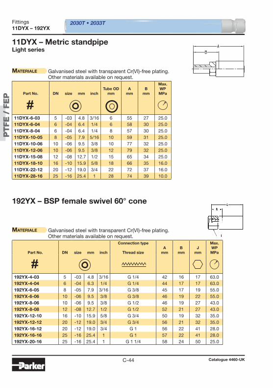
PT
FE
/ F
EP
PT
FE
/ F
EP
C-44
11DYX – 192YX
192YX – BSP female swivel 60° cone
Materiale Galvanised steel with transparent Cr(VI)-free plating.Other materials available on request.
2030T • 2033T
11DYX – Metric standpipeLight series
Materiale Galvanised steel with transparent Cr(VI)-free plating.Other materials available on request.
Part No. DN size mm inch
Connection type
Thread sizeA
mmB
mmJ
mm
Max. WPMPa
Part No. DN size mm inchTube OD
mmA
mmB
mm
Max. WPMPa
192YX-4-03 5 -03 4.8 3/16 G 1/4 42 16 17 63.0 192YX-4-04 6 -04 6.3 1/4 G 1/4 44 17 17 63.0 192YX-6-05 8 -05 7.9 3/16 G 3/8 45 17 19 55.0 192YX-6-06 10 -06 9.5 3/8 G 3/8 46 19 22 55.0 192YX-8-06 10 -06 9.5 3/8 G 1/2 46 19 27 43.0 192YX-8-08 12 -08 12.7 1/2 G 1/2 52 21 27 43.0 192YX-12-10 16 -10 15.9 5/8 G 3/4 50 19 32 35.0 192YX-12-12 20 -12 19.0 3/4 G 3/4 56 21 32 35.0 192YX-16-12 20 -12 19.0 3/4 G 1 56 22 41 28.0 192YX-16-16 25 -16 25.4 1 G 1 57 22 41 28.0 192YX-20-16 25 -16 25.4 1 G 1 1/4 58 24 50 25.0
11DYX-6-03 5 -03 4.8 3/16 6 55 27 25.0 11DYX-6-04 6 -04 6.4 1/4 6 58 30 25.0 11DYX-8-04 6 -04 6.4 1/4 8 57 30 25.0 11DYX-10-05 8 -05 7.9 5/16 10 59 31 25.0 11DYX-10-06 10 -06 9.5 3/8 10 77 32 25.0 11DYX-12-06 10 -06 9.5 3/8 12 79 32 25.0 11DYX-15-08 12 -08 12.7 1/2 15 65 34 25.0 11DYX-18-10 16 -10 15.9 5/8 18 66 35 16.0 11DYX-22-12 20 -12 19.0 3/4 22 72 37 16.0 11DYX-28-16 25 -16 25.4 1 28 74 39 10.0
Catalogue 4460-UK
Fittings
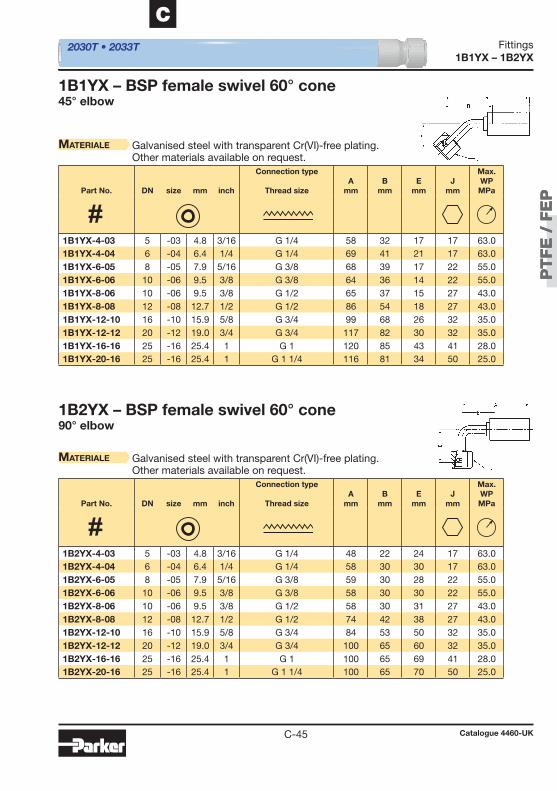
PT
FE
/ F
EP
PT
FE
/ F
EP
C-45
C
1B1YX – 1B2YX
1B1YX – BSP female swivel 60° cone45° elbow
Materiale Galvanised steel with transparent Cr(VI)-free plating.Other materials available on request.
1B2YX – BSP female swivel 60° cone90° elbow
Materiale Galvanised steel with transparent Cr(VI)-free plating.Other materials available on request.
2030T • 2033T
Part No. DN size mm inch
Connection type
Thread sizeA
mmB
mmE
mmJ
mm
Max. WPMPa
Part No. DN size mm inch
Connection type
Thread sizeA
mmB
mmE
mmJ
mm
Max. WPMPa
1B1YX-4-03 5 -03 4.8 3/16 G 1/4 58 32 17 17 63.0 1B1YX-4-04 6 -04 6.4 1/4 G 1/4 69 41 21 17 63.0 1B1YX-6-05 8 -05 7.9 5/16 G 3/8 68 39 17 22 55.0 1B1YX-6-06 10 -06 9.5 3/8 G 3/8 64 36 14 22 55.0 1B1YX-8-06 10 -06 9.5 3/8 G 1/2 65 37 15 27 43.0 1B1YX-8-08 12 -08 12.7 1/2 G 1/2 86 54 18 27 43.0 1B1YX-12-10 16 -10 15.9 5/8 G 3/4 99 68 26 32 35.0 1B1YX-12-12 20 -12 19.0 3/4 G 3/4 117 82 30 32 35.0 1B1YX-16-16 25 -16 25.4 1 G 1 120 85 43 41 28.0 1B1YX-20-16 25 -16 25.4 1 G 1 1/4 116 81 34 50 25.0
1B2YX-4-03 5 -03 4.8 3/16 G 1/4 48 22 24 17 63.0 1B2YX-4-04 6 -04 6.4 1/4 G 1/4 58 30 30 17 63.0 1B2YX-6-05 8 -05 7.9 5/16 G 3/8 59 30 28 22 55.0 1B2YX-6-06 10 -06 9.5 3/8 G 3/8 58 30 30 22 55.0 1B2YX-8-06 10 -06 9.5 3/8 G 1/2 58 30 31 27 43.0 1B2YX-8-08 12 -08 12.7 1/2 G 1/2 74 42 38 27 43.0 1B2YX-12-10 16 -10 15.9 5/8 G 3/4 84 53 50 32 35.0 1B2YX-12-12 20 -12 19.0 3/4 G 3/4 100 65 60 32 35.0 1B2YX-16-16 25 -16 25.4 1 G 1 100 65 69 41 28.0 1B2YX-20-16 25 -16 25.4 1 G 1 1/4 100 65 70 50 25.0
Catalogue 4460-UK
Fittings
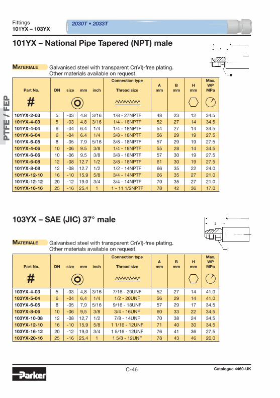
PT
FE
/ F
EP
PT
FE
/ F
EP
C-46
101YX – 103YX
101YX – National Pipe Tapered (NPT) male
103YX – SAE (JIC) 37° male
Materiale Galvanised steel with transparent Cr(VI)-free plating.Other materials available on request.
Materiale Galvanised steel with transparent Cr(VI)-free plating.Other materials available on request.
2030T • 2033T
Part No. DN size mm inch
Connection type
Thread sizeA
mmB
mmH
mm
Max. WPMPa
Part No. DN size mm inch
Connection type
Thread sizeA
mmB
mmH
mm
Max. WPMPa
101YX-2-03 5 -03 4.8 3/16 1/8 - 27NPTF 48 23 12 34.5 101YX-4-03 5 -03 4.8 3/16 1/4 - 18NPTF 52 27 14 34.5 101YX-4-04 6 -04 6.4 1/4 1/4 - 18NPTF 54 27 14 34.5 101YX-6-04 6 -04 6.4 1/4 3/8 - 18NPTF 56 29 19 27.5 101YX-6-05 8 -05 7.9 5/16 3/8 - 18NPTF 57 29 19 27.5 101YX-4-06 10 -06 9.5 3/8 1/4 - 18NPTF 55 28 14 34.5 101YX-6-06 10 -06 9.5 3/8 3/8 - 18NPTF 57 30 19 27.5 101YX-6-08 12 -08 12.7 1/2 3/8 - 18NPTF 61 30 19 27.5 101YX-8-08 12 -08 12.7 1/2 1/2 - 14NPTF 66 35 22 24.0 101YX-12-10 16 -10 15.9 5/8 3/4 - 14NPTF 66 35 27 21.0 101YX-12-12 20 -12 19.0 3/4 3/4 - 14NPTF 70 35 27 21.0 101YX-16-16 25 -16 25.4 1 1 - 11 1/2NPTF 78 42 36 17.0
103YX-4-03 5 -03 4,8 3/16 7/16 - 20UNF 52 27 14 41,0 103YX-5-04 6 -04 6,4 1/4 1/2 - 20UNF 56 29 14 41,0 103YX-6-05 8 -05 7,9 5/16 9/16 - 18UNF 57 29 17 34,5 103YX-8-06 10 -06 9,5 3/8 3/4 - 16UNF 60 33 22 34,5 103YX-10-08 12 -08 12,7 1/2 7/8 - 14UNF 70 38 24 34,5 103YX-12-10 16 -10 15,9 5/8 1 1/16 - 12UNF 71 40 30 34,5 103YX-16-12 20 -12 19,0 3/4 1 5/16 - 12UNF 76 41 36 27,5 103YX-20-16 25 -16 25,4 1 1 5/8 - 12UNF 78 43 46 20,0
Catalogue 4460-UK
Fittings

PT
FE
/ F
EP
PT
FE
/ F
EP
C-47
C
1B4YX – 1U0YX
1B4YX – BSP female swivel 60° cone90° compact elbow
Materiale Galvanised steel with transparent Cr(VI)-free plating.Other materials available on request.
1U0YX – BSP female swivel (ballnose)BSP swivel nut
2030T • 2033T
Materiale Galvanised steel with transparent Cr(VI)-free plating.For fi ttings as mentioned above, but with stainless steel nipple(AISI 303), please add C2W to the Part No. Example: 1U0YX-4-03 C2W.Other materials available on request.
Part No. DN size mm inch
Connection type
Thread sizeA
mmB
mmJ
mm
Max. WPMPa
Part No. DN size mm inch
Connection type
Thread sizeA
mmB
mmJ
mm
Max. WPMPa
1B4YX-4-04 6 -04 6.3 1/4 G 1/4 46 19 19 63.0 1B4YX-6-05 8 -05 7.9 3/16 G 3/8 51 23 22 55.0 1B4YX-6-06 10 -06 9.5 3/8 G 3/8 51 24 22 55.0 1B4YX-8-08 12 -08 12.7 1/2 G 1/2 57 26 27 43.0
1U0YX-2-03 5 -03 4.8 3/16 G 1/8 43 18 17 41.0 1U0YX-4-03 5 -03 4.8 3/16 G 1/4 42 16 17 63.0 1U0YX-4-04 6 -04 6.4 1/4 G 1/4 45 17 17 63.0 1U0YX-6-03 5 -03 4.8 3/16 G 3/8 45 17 17 55.0 1U0YX-6-04 6 -04 6.4 1/4 G 3/8 45 17 17 55.0 1U0YX-6-05 8 -05 7.9 5/16 G 3/8 45 17 19 55.0 1U0YX-6-06 10 -06 9.5 3/8 G 3/8 48 19 22 55.0 1U0YX-8-06 10 -06 9.5 3/8 G 1/2 48 19 27 43.0 1U0YX-8-08 12 -08 12.7 1/2 G 1/2 53 21 27 43.0 1U0YX-10-08 12 -08 12.7 1/2 G 5/8 51 20 27 35.0 1U0YX-12-10 16 -10 15.9 5/8 G 3/4 50 19 32 35.0 1U0YX-12-12 20 -12 19.0 3/4 G 3/4 56 21 32 35.0 1U0YX-16-12 20 -12 19.0 3/4 G 1 56 22 41 28.0 1U0YX-16-16 25 -16 25.4 1 G 1 57 22 41 28.0 1U0YX-20-16 25 -16 25.4 1 G 1 1/4 58 24 50 21.0
Catalogue 4460-UK
Fittings

PT
FE
/ F
EP
PT
FE
/ F
EP
C-48
1D9YX 2030T • 2033T
1D9YX – BSP maleDIN 3852 Form A
Materiale Galvanised steel with transparent Cr(VI)-free plating.Other materials available on request.
Part No. DN size mm inch
Connection type
Thread sizeA
mmB
mmH
mm
Max. WPMPa
1D9YX-2-03 5 -03 4.8 3/16 G 1/8 48 22 14 55.0 1D9YX-4-03 5 -03 4.8 3/16 G 1/4 54 29 19 63.0 1D9YX-4-04 6 -04 6.4 1/4 G 1/4 58 29 19 63.0 1D9YX-6-05 8 -05 7.9 5/16 G 3/8 58 29 22 55.0 1D9YX-4-06 10 -06 9.5 3/8 G 1/4 57 30 19 63.0 1D9YX-6-06 10 -06 9.5 3/8 G 3/8 58 30 22 55.0 1D9YX-8-06 10 -06 9.5 3/8 G 1/2 60 33 27 43.0 1D9YX-8-08 12 -08 12.7 1/2 G 1/2 64 33 27 43.0 1D9YX-12-10 16 -10 15.9 5/8 G 3/4 66 35 32 35.0 1D9YX-12-12 20 -12 19.0 3/4 G 3/4 72 37 32 35.0 1D9YX-16-12 20 -12 19.0 3/4 G 1 74 39 41 28.0 1D9YX-20-16 25 -16 25.4 1 G 1 1/4 76 41 50 21.0
Catalogue 4460-UK
Fittings
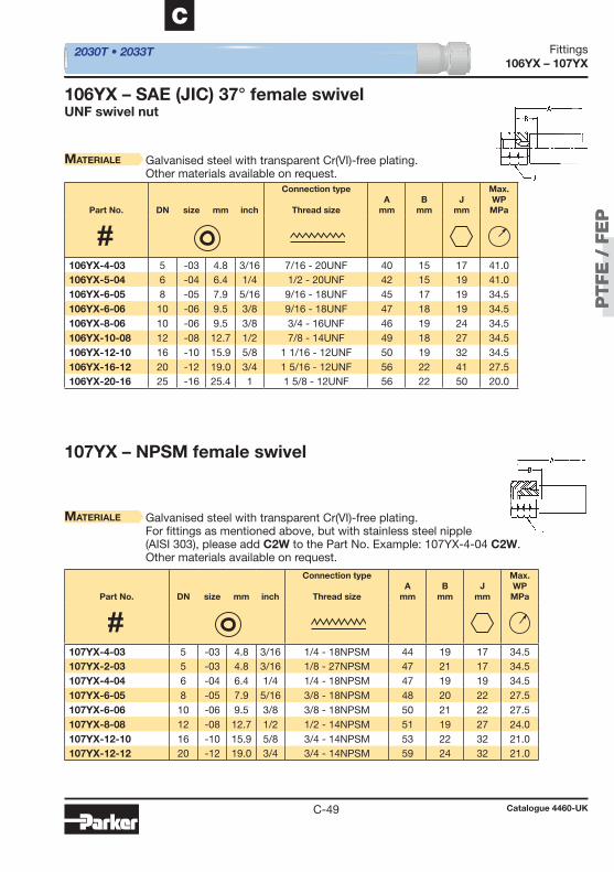
PT
FE
/ F
EP
PT
FE
/ F
EP
C-49
C
106YX – 107YX 2030T • 2033T
106YX – SAE (JIC) 37° female swivelUNF swivel nut
Materiale Galvanised steel with transparent Cr(VI)-free plating.Other materials available on request.
107YX – NPSM female swivel
Materiale Galvanised steel with transparent Cr(VI)-free plating.For fi ttings as mentioned above, but with stainless steel nipple(AISI 303), please add C2W to the Part No. Example: 107YX-4-04 C2W.Other materials available on request.
Part No. DN size mm inch
Connection type
Thread sizeA
mmB
mmJ
mm
Max. WPMPa
Part No. DN size mm inch
Connection type
Thread sizeA
mmB
mmJ
mm
Max. WPMPa
106YX-4-03 5 -03 4.8 3/16 7/16 - 20UNF 40 15 17 41.0 106YX-5-04 6 -04 6.4 1/4 1/2 - 20UNF 42 15 19 41.0 106YX-6-05 8 -05 7.9 5/16 9/16 - 18UNF 45 17 19 34.5 106YX-6-06 10 -06 9.5 3/8 9/16 - 18UNF 47 18 19 34.5 106YX-8-06 10 -06 9.5 3/8 3/4 - 16UNF 46 19 24 34.5 106YX-10-08 12 -08 12.7 1/2 7/8 - 14UNF 49 18 27 34.5 106YX-12-10 16 -10 15.9 5/8 1 1/16 - 12UNF 50 19 32 34.5 106YX-16-12 20 -12 19.0 3/4 1 5/16 - 12UNF 56 22 41 27.5 106YX-20-16 25 -16 25.4 1 1 5/8 - 12UNF 56 22 50 20.0
107YX-4-03 5 -03 4.8 3/16 1/4 - 18NPSM 44 19 17 34.5 107YX-2-03 5 -03 4.8 3/16 1/8 - 27NPSM 47 21 17 34.5 107YX-4-04 6 -04 6.4 1/4 1/4 - 18NPSM 47 19 19 34.5 107YX-6-05 8 -05 7.9 5/16 3/8 - 18NPSM 48 20 22 27.5 107YX-6-06 10 -06 9.5 3/8 3/8 - 18NPSM 50 21 22 27.5 107YX-8-08 12 -08 12.7 1/2 1/2 - 14NPSM 51 19 27 24.0 107YX-12-10 16 -10 15.9 5/8 3/4 - 14NPSM 53 22 32 21.0 107YX-12-12 20 -12 19.0 3/4 3/4 - 14NPSM 59 24 32 21.0
Catalogue 4460-UK
Fittings
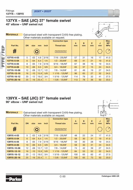
PT
FE
/ F
EP
PT
FE
/ F
EP
C-50
137YX – 139YX 2030T • 2033T
137YX – SAE (JIC) 37° female swivel45° elbow – UNF swivel nut
139YX – SAE (JIC) 37° female swivel90° elbow – UNF swivel nut
Materiale Galvanised steel with transparent Cr(VI)-free plating.Other materials available on request.
Materiale Galvanised steel with transparent Cr(VI)-free plating.Other materials available on request.
Part No. DN size mm inch
Connection type
Thread sizeA
mmB
mmE
mmJ
mm
Max. WPMPa
Part No. DN size mm inch
Connection type
Thread sizeA
mmB
mmE
mmJ
mm
Max. WPMPa
137YX-4-03 5 -03 4.8 3/16 7/16 - 20UNF 57 31 16 17 41.0 137YX-5-04 6 -04 6.4 1/4 1/2 - 20UNF 69 41 21 19 41.0 137YX-6-05 8 -05 7.9 5/16 9/16 - 18UNF 67 38 16 19 34.5 137YX-8-06 10 -06 9.5 3/8 3/4 - 16UNF 65 37 15 24 34.5 137YX-10-08 12 -08 12.7 1/2 7/8 - 14UNF 81 49 19 27 34.5 137YX-12-10 16 -10 15.9 5/8 1 1/16 - 12UNF 96 65 27 32 34.5 137YX-16-12 20 -12 19.0 3/4 1 5/16 - 12UNF 114 79 32 41 27.5 137YX-20-16 25 -16 25.4 1 1 5/8 - 12UNF 113 78 36 50 20.0
139YX-4-03 5 -03 4.8 3/16 7/16 - 20UNF 48 22 24 17 41.0 139YX-5-04 6 -04 6.4 1/4 1/2 - 20UNF 58 30 31 19 41.0 139YX-6-05 8 -05 7.9 5/16 9/16 - 18UNF 59 30 28 19 34.5 139YX-8-06 10 -06 9.5 3/8 3/4 - 16UNF 58 30 31 24 34.5 139YX-10-08 12 -08 12.7 1/2 7/8 - 14UNF 74 42 39 27 34.5 139YX-12-10 16 -10 15.9 5/8 1 1/16 - 12UNF 84 53 52 32 34.5 139YX-16-12 20 -12 19.0 3/4 1 5/16 - 12UNF 100 65 62 41 27.5 139YX-20-16 25 -16 25.4 1 1 5/8 - 12UNF 100 65 73 50 20.0
Catalogue 4460-UK
Fittings
Alt
ern
ati
ve f
uels
Alt
ern
ati
ve f
uels
D-1
D
Chapter D
Hose and Fittings for Alternative Fuels
Introduction ......................................................................D-2
SCR hoseSCR – Parflex SCR Hose Assemblies ............................................ D-4
CNG hose5CNG – Compressed natural gas dispense hose ............................ D-5
LPG hose8LPG – Liquified propane gas and natural gas hose ...................... D-6
FittingsPX-LPG series ...................................................................................... D-7CG series .................................................................................... D-12
Catalogue 4460-UKCatalogue 4460-UK
Hose and Fittings for Alternative FuelsTable of contents

D-2
Application
Alt
ern
ati
ve f
uels
• Fuel and media transfer on board of trucks, mobile vehi-cles, busses and cars
• Fuel transfer lines on stationary equipment, like compres-sors or gensets
• Dispensing lines for refueling equipment used on workshop equipment and public gas stations
Introduction
Parker thermoplastic hoses help to achieve tigther emission standards. To support future emission levels we have designed a wide range of hoses for alternative fuels, like compressed natural gas (CNG) or liquifi ed propane gas (LPG).
The alternative fuel hoses can be used as fuel transfer lines onboard, as well as refueling lines on dispensing equipment.
Selective catalytic reduction systems help to reduce NOx emission level of diesel engines. Parker designed a range of heated and non-heated SCR hoses for DEF/Adblue® transfer.
• Fuel and media transfer on board of trucks, mobile vehi-
• Fuel transfer lines on stationary equipment, like compres-
• Dispensing lines for refueling equipment used on workshop
Hose and Fittings for Alternative FuelsIntroduction
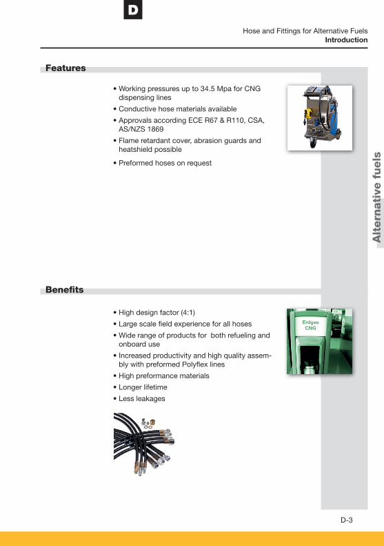
D
D-3
Features
Benefi ts
Alt
ern
ati
ve f
uels
• Working pressures up to 34.5 Mpa for CNG dispensing lines
• Conductive hose materials available
• Approvals according ECE R67 & R110, CSA, AS/NZS 1869
• Flame retardant cover, abrasion guards and heatshield possible
• Preformed hoses on request
• High design factor (4:1)
• Large scale fi eld experience for all hoses
• Wide range of products for both refueling and onboard use
• Increased productivity and high quality assem-bly with preformed Polyfl ex lines
• High preformance materials
• Longer lifetime
• Less leakages
Hose and Fittings for Alternative FuelsIntroduction
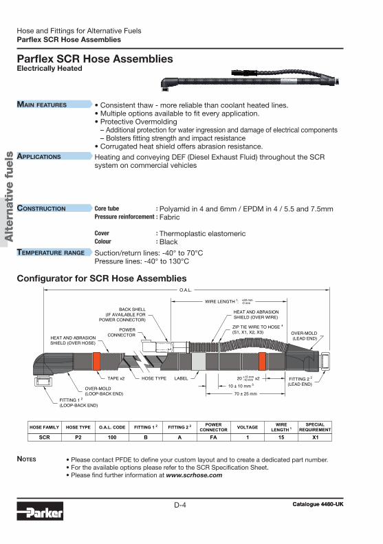
Alt
ern
ati
ve f
uels
Alt
ern
ati
ve f
uels
D-4
Parflex SCR Hose Assemblies
Parflex SCR Hose AssembliesElectrically Heated
Notes • Please contact PFDE to define your custom layout and to create a dedicated part number.• For the available options please refer to the SCR Specification Sheet.• Please find further information at www.scrhose.com
• Consistent thaw - more reliable than coolant heated lines.• Multiple options available to fit every application.• Protective Overmolding
– Additional protection for water ingression and damage of electrical components – Bolsters fitting strength and impact resistance
• Corrugated heat shield offers abrasion resistance.
Heating and conveying DEF (Diesel Exhaust Fluid) throughout the SCR system on commercial vehicles
Polyamid in 4 and 6mm / EPDM in 4 / 5.5 and 7.5mm Fabric Thermoplastic elastomeric Black
Suction/return lines: -40° to 70°CPressure lines: -40° to 130°C
Configurator for SCR Hose AssembliesO.A.L.
FITTING 1 2(LOOP-BACK END)
FITTING 2 2(LEAD END)
WIRE LENGTH 1: +20 mm-0 mm
HOSE TYPE
OVER-MOLD(LOOP-BACK END)
HOSE TYPE O.A.L. CODE FITTING 1 2 FITTING 2 2 POWERCONNECTOR VOLTAGE WIRE
LENGTH 1SPECIAL
REQUIREMENT
SCR P2 100 B A FA 1 15 X1
HOSE FAMILY
LABEL
OVER-MOLD(LEAD END)
70 ± 25 mm
10 ± 10 mm 520 +15 mm
-10 mm x2TAPE x2
POWERCONNECTOR
ZIP TIE WIRE TO HOSE 4(S1, X1, X2, X3)
BACK SHELL(IF AVAILABLE FOR
POWER CONNECTOR)
HEAT AND ABRASIONSHIELD (OVER WIRE)
HEAT AND ABRASIONSHIELD (OVER HOSE)
Catalogue 4460-UKCatalogue 4460-UK
Hose and Fittings for Alternative Fuels
Main features
applications
construction Core tube :Pressure reinforcement : Cover : Colour :
teMperature range
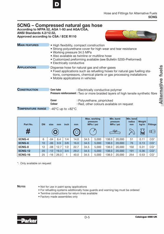
Alt
ern
ati
ve f
uels
Alt
ern
ati
ve f
uels
D-5
D
5CNG
5CNG – Compressed natural gas hoseAccording to NFPA 52, AGA 1-93 and AGA/CGA, ANSI Standards 4.2/12.52, Approved according to CSA / ECE R110
Notes • Not for use in paint spray applications• For refuelling systems additionally hose guards and warning tag must be ordered • Twinline constructions for return lines available• Factory made assemblies only
• High flexibility, compact construction• Strong polyurethane cover for high wear and tear resistance• Working pressure 34.5 MPa• Also available as twinline or multiline hose• Customized preforming available (see Bulletin 5200-Preformed)• Electrically conductive
Dispense hose for natural gas and other gases• Fixed applications such as refuelling hoses for natural gas fuelling sta-
tions, compressors, chemical plants or gas processing installations• Mobile applications in vehicles
Electrically conductive polymer Two or more braided layers of high tensile synthetic fibre Polyurethane, pinpricked Red, other colours available on request
-40°C up to +82°C
*: Only available on request
Part No. DN size mm inch mm
Max. workingpressureMPa / psi
Min. burstpressureMPa / psi
Min. bend radius
mmWeightkg/m
Fittings
5CNG-4 6 -04 6.4 1/4 14.0 34.5 5,000 138.0 20,000 51 0.11 CG*5CNG-6 10 -06 9.9 3/8 16.0 34.5 5,000 138.0 20,000 76 0.13 CG*5CNG-8 12 -08 12.7 1/2 22.7 34.5 5,000 138.0 20,000 102 0.31 CG*5CNG-12 20 -12 19.3 3/4 29.2 34.5 5,000 138.0 20,000 191 0.36 CG*5CNG-16 25 -16 26.0 1 40.0 34.5 5,000 138.0 20,000 254 0.53 CG*
Catalogue 4460-UKCatalogue 4460-UK
Hose and Fittings for Alternative Fuels
Main features
applications
construction Core tube :Pressure reinforcement : Cover : Colour :
teMperature range
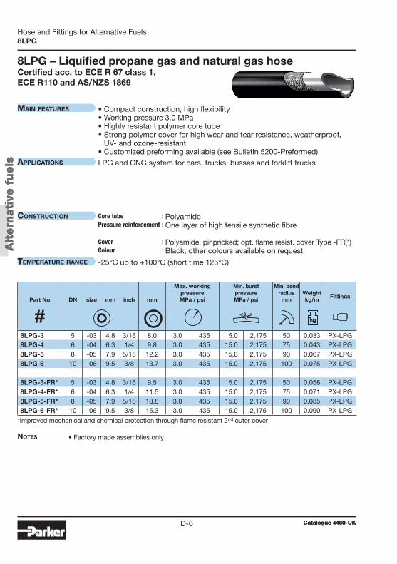
Alt
ern
ati
ve f
uels
Alt
ern
ati
ve f
uels
D-6
8LPG
8LPG – Liquified propane gas and natural gas hoseCertified acc. to ECE R 67 class 1, ECE R110 and AS/NZS 1869
Notes • Factory made assemblies only
• Compact construction, high flexibility• Working pressure 3.0 MPa• Highly resistant polymer core tube • Strong polymer cover for high wear and tear resistance, weatherproof,
UV- and ozone-resistant• Customized preforming available (see Bulletin 5200-Preformed)
LPG and CNG system for cars, trucks, busses and forklift trucks
Polyamide One layer of high tensile synthetic fibre Polyamide, pinpricked; opt. flame resist. cover Type -FR(*) Black, other colours available on request
-25°C up to +100°C (short time 125°C)
*Improved mechanical and chemical protection through flame resistant 2nd outer cover
Part No. DN size mm inch mm
Max. workingpressureMPa / psi
Min. burstpressureMPa / psi
Min. bend radius
mmWeightkg/m
Fittings
8LPG-3 5 -03 4.8 3/16 8.0 3.0 435 15.0 2,175 50 0.033 PX-LPG8LPG-4 6 -04 6.3 1/4 9.8 3.0 435 15.0 2,175 75 0.043 PX-LPG8LPG-5 8 -05 7.9 5/16 12.2 3.0 435 15.0 2,175 90 0.067 PX-LPG8LPG-6 10 -06 9.5 3/8 13.7 3.0 435 15.0 2,175 100 0.075 PX-LPG
8LPG-3-FR* 5 -03 4.8 3/16 9.5 3.0 435 15.0 2,175 50 0.058 PX-LPG8LPG-4-FR* 6 -04 6.3 1/4 11.5 3.0 435 15.0 2,175 75 0.071 PX-LPG8LPG-5-FR* 8 -05 7.9 5/16 13.8 3.0 435 15.0 2,175 90 0.085 PX-LPG8LPG-6-FR* 10 -06 9.5 3/8 15.3 3.0 435 15.0 2,175 100 0.090 PX-LPG
Catalogue 4460-UKCatalogue 4460-UK
Hose and Fittings for Alternative Fuels
Main features
applications
construction Core tube :Pressure reinforcement : Cover : Colour :
teMperature range
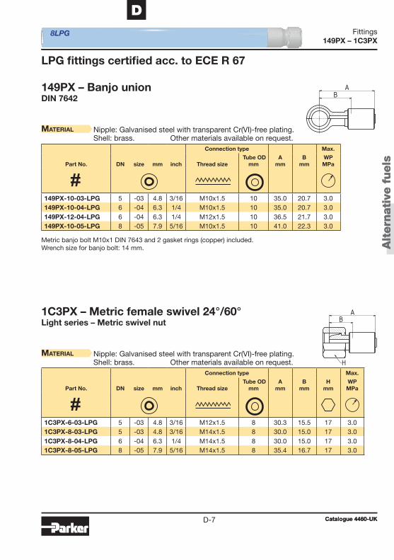
Alt
ern
ati
ve f
uels
Alt
ern
ati
ve f
uels
149PX – 1C3PX
D-7
D
149PX – Banjo unionDIN 7642
LPG fi ttings certifi ed acc. to ECE R 67
1C3PX – Metric female swivel 24°/60°Light series – Metric swivel nut
Material Nipple: Galvanised steel with transparent Cr(VI)-free plating.Shell: brass. Other materials available on request.
Material Nipple: Galvanised steel with transparent Cr(VI)-free plating.Shell: brass. Other materials available on request.
Metric banjo bolt M10x1 DIN 7643 and 2 gasket rings (copper) included.Wrench size for banjo bolt: 14 mm.
8LPG
Connection type Max.
Part No. DN size mm inch Thread size Tube OD
mmA
mmB
mmWPMPa
Connection type Max.
Part No. DN size mm inch Thread size Tube OD
mmA
mmB
mmH
mmWPMPa
149PX-10-03-LPG 5 -03 4.8 3/16 M10x1.5 10 35.0 20.7 3.0 149PX-10-04-LPG 6 -04 6.3 1/4 M10x1.5 10 35.0 20.7 3.0 149PX-12-04-LPG 6 -04 6.3 1/4 M12x1.5 10 36.5 21.7 3.0 149PX-10-05-LPG 8 -05 7.9 5/16 M10x1.5 10 41.0 22.3 3.0
1C3PX-6-03-LPG 5 -03 4.8 3/16 M12x1.5 8 30.3 15.5 17 3.0 1C3PX-8-03-LPG 5 -03 4.8 3/16 M14x1.5 8 30.0 15.0 17 3.0 1C3PX-8-04-LPG 6 -04 6.3 1/4 M14x1.5 8 30.0 15.0 17 3.0 1C3PX-8-05-LPG 8 -05 7.9 5/16 M14x1.5 8 35.4 16.7 17 3.0
Catalogue 4460-UKCatalogue 4460-UK
Fittings

Alt
ern
ati
ve f
uels
Alt
ern
ati
ve f
uels
1U0PX – 17APX
D-8
1U0PX – BSP female swivel (ballnose)BSP swivel nut
Material Nipple: Galvanised steel with transparent Cr(VI)-free plating.Shell: brass. Other materials available on request.
17APX – LPG 30° male swivel
Material Nipple: Galvanised steel with transparent Cr(VI)-free plating.Shell: brass. Other materials available on request.
8LPG
Connection type Max.
Part No. DN size mm inch Thread size Tube OD
inchA
mmB
mmH
mmWPMPa
Connection type Max.
Part No. DN size mm inch Thread size Tube ODmm/inch
Amm
Bmm
Hmm
WPMPa
1U0PX-4-03-LPG 5 -03 4.8 3/16 G1/4 1/4 30.0 15.0 17 3.0 1U0PX-4-04-LPG 6 -04 6.3 1/4 G1/4 1/4 30.0 15.0 17 3.0 1U0PX-4-05-LPG 8 -05 7.9 5/16 G1/4 1/4 35.4 16.7 17 3.0
17APX-6-03-LPG 5 -03 4.8 3/16 M10x1 8 42.3 28 17 3.0 17APX-8-04-LPG 6 -04 6.3 1/4 M12x1 8 45.3 31 17 3.0 17APX-4-03S-LPG 5 -03 4.8 3/16 7/16-20 UNF 1/4" 42.3 28 17 3.0 17APX-8-04S-LPG 6 -04 6.3 1/4 7/16-20 UNF 1/4“ 45.3 31 17 3.0
Catalogue 4460-UKCatalogue 4460-UK
Fittings
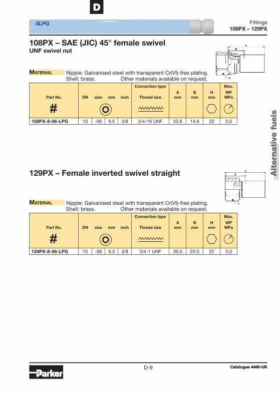
Alt
ern
ati
ve f
uels
Alt
ern
ati
ve f
uels
108PX – 129PX
D-9
D
108PX – SAE (JIC) 45° female swivelUNF swivel nut
129PX – Female inverted swivel straight
Material Nipple: Galvanised steel with transparent Cr(VI)-free plating.Shell: brass. Other materials available on request.
Material Nipple: Galvanised steel with transparent Cr(VI)-free plating.Shell: brass. Other materials available on request.
8LPG
Connection type Max.
Part No. DN size mm inch Thread sizeA
mmB
mmH
mmWPMPa
Connection type Max.
Part No. DN size mm inch Thread sizeA
mmB
mmH
mmWPMPa
108PX-8-06-LPG 10 -06 9.5 3/8 3/4-16 UNF 33.6 14.6 22 3.0
129PX-8-06-LPG 10 -06 9.5 3/8 3/4-1 UNF 39.0 20.0 22 3.0
Catalogue 4460-UKCatalogue 4460-UK
Fittings
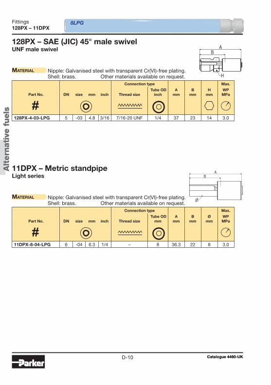
Alt
ern
ati
ve f
uels
Alt
ern
ati
ve f
uels
128PX – 11DPX
D-10
128PX – SAE (JIC) 45° male swivelUNF male swivel
11DPX – Metric standpipeLight series
Material Nipple: Galvanised steel with transparent Cr(VI)-free plating.Shell: brass. Other materials available on request.
Material Nipple: Galvanised steel with transparent Cr(VI)-free plating.Shell: brass. Other materials available on request.
8LPG
Connection type Max.
Part No. DN size mm inch Thread size Tube OD
inchA
mmB
mmH
mmWPMPa
Connection type Max.
Part No. DN size mm inch Thread size Tube OD
mmA
mmB
mmØ
mmWPMPa
128PX-4-03-LPG 5 -03 4.8 3/16 7/16-20 UNF 1/4 37 23 14 3.0
11DPX-8-04-LPG 6 -04 6.3 1/4 – 8 36.3 22 8 3.0
Catalogue 4460-UKCatalogue 4460-UK
Fittings

Alt
ern
ati
ve f
uels
Alt
ern
ati
ve f
uels
1PHPX
D-11
D
1PHPX – LPG quick connector
Material Nipple: Galvanised steel with transparent Cr(VI)-free plating.Shell: brass. Other materials available on request.
Other fi ttings available on request.
8LPG
Connection type Max.
Part No. DN size mm inch Thread size Tube OD
mmA
mmB
mmØ
mmWPMPa
1PHPX-5.5-03S-LPG 5 -03 4.8 3/16 – 5.5 34.5 21 5.5 3.0
Catalogue 4460-UKCatalogue 4460-UK
Fittings

Alt
ern
ati
ve f
uels
Alt
ern
ati
ve f
uels
101CG – 106CG
D-12
101CG – National Pipe Tapered (NPT) male
Material Galvanised steel with transparent Cr(VI)-free plating.Other materials available on request.
106CG – SAE (JIC) 37° female swivelUNF swivel nut
Material Galvanised steel with transparent Cr(VI)-free plating.Other materials available on request.
AB
H
AB
J H
5CNG
Connection type Max.
Part No. DN size mm inch Thread size Tube OD
inchA
mmB
mmH
inchWPMPa
Connection type Max.
Part No. DN size mm inch Thread size Tube OD
inchA
mmB
mmH
inchJ
inchWPMPa
101CG-2-3 5 -03 4.8 3/16 1/8 - 27 NPTF 1/8 49.4 25.0 9/16 82.7 101CG-4-3 5 -03 4.8 3/16 1/4 - 18 NPTF 1/4 53.9 30.0 11/16 82.7 101CG-4-4 6 -04 6.4 1/4 1/4 - 18 NPTF 1/4 58.8 30.0 11/16 82.7 101CG-6-6 10 -06 9.5 3/8 3/8 - 18 NPTF 3/8 67.6 33.0 3/4 69.0 101CG-8-8 12 -08 12.7 1/2 1/2 - 14 NPTF 1/2 78.6 39.0 15/16 69.0 101CG-12-12 20 -12 19.0 3/4 3/4 - 14 NPTF 3/4 99.4 43.0 1 1/4 51.7 101CG-16-16 25 -16 25.4 1 1 - 11 1/2 NPTF 1 120.9 51.0 1 3/4 44.8
106CG-4-3 5 -03 4.8 3/16 7/16 - 20 UNF 1/4 56.7 33.0 9/16 9/16 41.4 106CG-4-4 6 -04 6.4 1/4 7/16 - 20 UNF 1/4 60.0 31.0 5/8 9/16 41.4 106CG-6-6 10 -06 9.5 3/8 9/16 - 18 UNF 3/8 68.6 34.0 11/16 11/16 34.5 106CG-8-8 12 -08 12.7 1/2 3/4 - 16 UNF 1/2 78.1 38.0 7/8 7/8 34.5 106CG-12-12 20 -12 19.0 3/4 1 1/16-12 UNF 3/4 105.9 46.0 1 1/4 1 5/16 34.5 106CG-16-16 25 -16 25.4 1 1 5/16 - 12 UNF 1 125.3 56.0 1 3/4 1 5/8 27.6
106CG-4-3 5 -03 4.8 3/16 7/16 - 20 UNF 1/4 56.7 33.0 9/16 9/16 41.4 106CG-4-4 6 -04 6.4 1/4 7/16 - 20 UNF 1/4 60.0 31.0 5/8 9/16 41.4 106CG-6-6 10 -06 9.5 3/8 9/16 - 18 UNF 3/8 68.6 34.0 11/16 11/16 34.5 106CG-8-8 12 -08 12.7 1/2 3/4 - 16 UNF 1/2 78.1 38.0 7/8 7/8 34.5 106CG-12-12 20 -12 19.0 3/4 1 1/16-12 UNF 3/4 105.9 46.0 1 1/4 1 5/16 34.5 106CG-16-16 25 -16 25.4 1 1 5/16 - 12 UNF 1 125.3 56.0 1 3/4 1 5/8 27.6
Catalogue 4460-UKCatalogue 4460-UK
Fittings

Alt
ern
ati
ve f
uels
Alt
ern
ati
ve f
uels
139CG – 1JCCG
D-13
D
139CG – SAE (JIC) 37° female swivel90° elbow – UNF swivel nut
Material Galvanised steel with transparent Cr(VI)-free plating.Other materials available on request.
1JCCG – O-Lok® ORFS swivel nutShort version – UNF swivel nut – ISO 12151-1
Material Galvanised steel with transparent Cr(VI)-free plating.Other materials available on request.
J
BA
H
5CNG
Connection type Max.
Part No. DN size mm inch Thread size Tube OD
inchA
mmB
mmE
mmH
inchJ
inchWPMPa
Connection type Max.
Part No. DN size mm inch Thread size Tube OD
inchA
mmB
mmH
inchJ
inchWPMPa
1JCCG-4-4 6 -04 6.4 1/4 9/16 - 18 UNF 1/4 53.2 25.0 5/8 11/16 63.0 1JCCG-6-6 10 -06 9.5 3/8 11/16 - 16 UNF 3/8 62.7 28.0 11/16 13/16 63.0 1JCCG-8-8 12 -08 12.7 1/2 13/16 - 16 UNF 1/2 69.9 30.0 7/8 15/16 63.0 1JCCG-12-12 20 -12 19.0 3/4 1 - 14 UNF 3/4 97.9 38.0 1 1/4 1 3/8 41.4 1JCCG-16-16 25 -16 25.4 1 1 7/16 - 12 UNF 1 118.3 48.0 1 3/4 1 5/8 41.4
139CG-4-4 6 -04 6.4 1/4 7/16 - 20 UNF 1/4 63.7 35.0 17.3 5/8 9/16 41.4 139CG-6-6 10 -06 9.5 3/8 9/16 - 18 UNF 3/8 73.2 38.0 21.6 3/4 11/16 34.5
Catalogue 4460-UKCatalogue 4460-UK
Fittings
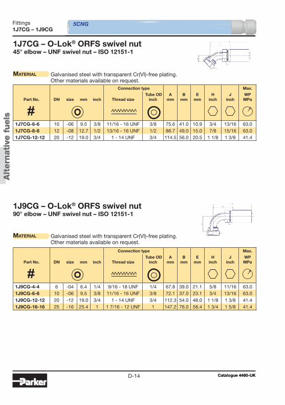
Alt
ern
ati
ve f
uels
Alt
ern
ati
ve f
uels
1J7CG – 1J9CG
D-14
1J7CG – O-Lok® ORFS swivel nut45° elbow – UNF swivel nut – ISO 12151-1
Material Galvanised steel with transparent Cr(VI)-free plating.Other materials available on request.
1J9CG – O-Lok® ORFS swivel nut90° elbow – UNF swivel nut – ISO 12151-1
Material Galvanised steel with transparent Cr(VI)-free plating.Other materials available on request.
5CNG
Connection type Max.
Part No. DN size mm inch Thread size Tube OD
inchA
mmB
mmE
mmH
inchJ
inchWPMPa
Connection type Max.
Part No. DN size mm inch Thread size Tube OD
inchA
mmB
mmE
mmH
inchJ
inchWPMPa
1J7CG-6-6 10 -06 9.5 3/8 11/16 - 16 UNF 3/8 75.6 41.0 10.9 3/4 13/16 63.0 1J7CG-8-8 12 -08 12.7 1/2 13/16 - 16 UNF 1/2 88.7 49.0 15.0 7/8 15/16 63.0 1J7CG-12-12 20 -12 19.0 3/4 1 - 14 UNF 3/4 114.5 56.0 20.5 1 1/8 1 3/8 41.4
1J9CG-4-4 6 -04 6.4 1/4 9/16 - 18 UNF 1/4 67.8 39.0 21.1 5/8 11/16 63.0 1J9CG-6-6 10 -06 9.5 3/8 11/16 - 16 UNF 3/8 72.1 37.0 23.1 3/4 13/16 63.0 1J9CG-12-12 20 -12 19.0 3/4 1 - 14 UNF 3/4 112.3 54.0 48.0 1 1/8 1 3/8 41.4 1J9CG-16-16 25 -16 25.4 1 1 7/16 - 12 UNF 1 147.2 76.0 58.4 1 3/4 1 5/8 41.4
Catalogue 4460-UKCatalogue 4460-UK
Fittings
Hyd
raulic
/ Indust
rial
Catalogue 4460-UKE-1
EHose and Fittings for Hydraulic and Industrial Applications
Chapter E
Hose and Fittings for Hydraulic and Industrial Applications
Introduction ......................................................................E-2
Part 1 – Small bore hose/mini-hydraulic hose ..................E-4
Part 2 – Medium pressure hose ..........................................E-7
Part 3 – High pressure hose ..............................................E-14
Part 4 – Paint spray hose ..................................................E-27
Part 5 – Gas hose ...............................................................E-33
Part 6 – Hose fittings .........................................................E-41
Table of contents
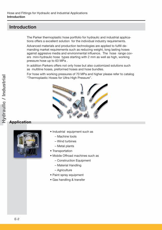
Hyd
raulic
/ Indust
rial
E-2
Application
Hose and Fittings for Hydraulic and Industrial Applications
• Industrial equipment such as
– Machine tools
– Wind turbines
– Metal plants
• Transportation
• Mobile Offroad machines such as
– Construction Equipment
– Material Handling
– Agriculture
• Paint spray equipment
• Gas handling & transfer
Introduction
The Parker thermoplastic hose portfolio for hydraulic and industrial applica-tions offers a excellent solution for the individual industry requirements.
Advanced materials and production technologies are applied to fulfi ll de-manding market requirements such as reducing weight, long lasting hoses against aggresive media and environmental infl uence. The hose range cov-ers mini-hydraulic hose types starting with 2 mm as well as high, working pressure hose up to 63 MPa .
In addition Parkers offers not only hose but also customized solutions such as multiline hoses, preformed hoses and hose bundles.
For hose with working pressures of 70 MPa and higher please refer to catalog “Thermoplastic Hoses for Ultra High Pressure”.
Introduction
• Industrial equipment such as
– Machine tools
– Wind turbines
– Metal plants
• Transportation
• Mobile Offroad machines such as
– Construction Equipment
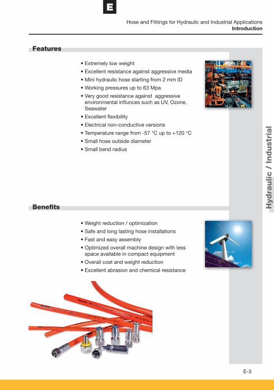
Hyd
raulic
/ Indust
rial
E
E-3
Features
Benefi ts
Hose and Fittings for Hydraulic and Industrial Applications
• Extremely low weight
• Excellent resistance against aggressive media
• Mini hydraulic hose starting from 2 mm ID
• Working pressures up to 63 Mpa
• Very good resistance against aggressive environmental infl unces such as UV, Ozone, Seawater
• Excellent fl exibility
• Electrical non-conductive versions
• Temperature range from -57 °C up to +120 °C
• Small hose outside diameter
• Small bend radius
• Weight reduction / optimization
• Safe and long lasting hose installations
• Fast and easy assembly
• Optimized overall machine design with less space available in compact equipment
• Overall cost and weight reduction
• Excellent abrasion and chemical resistance
Introduction

Hyd
raulic
/ Indust
rial
Catalogue 4460-UKE-4
Hose and Fittings for Hydraulic and Industrial ApplicationsSmall bore hose/mini-hydraulic hose
Part 1 – Small bore hose/mini-hydraulic hose2010H – Small bore hose/mini-hydraulic hose up to 21 MPa ..................E-52020N – Small bore hose/mini-hydraulic hose up to 63 MPa ..................E-6
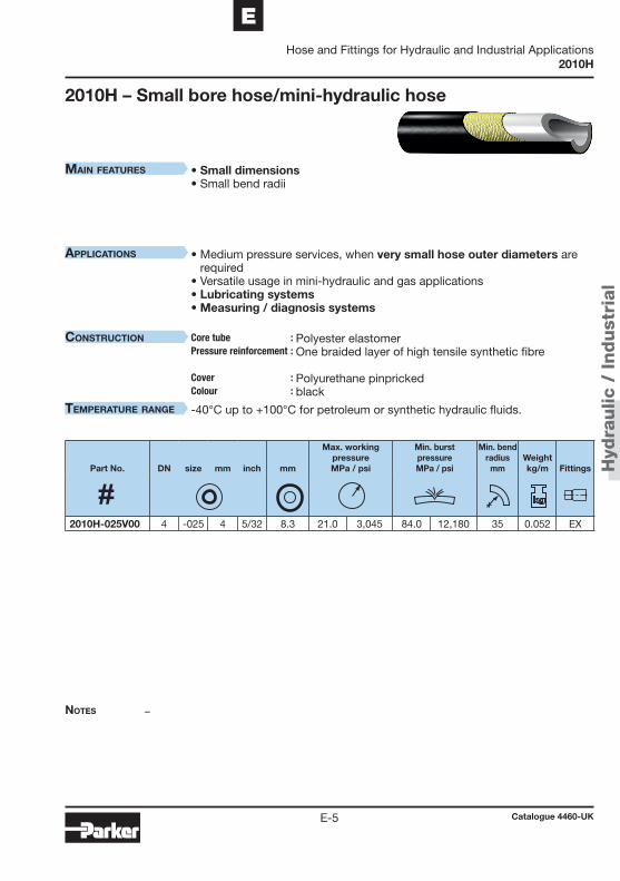
Hyd
raulic
/ Indust
rial
Catalogue 4460-UKE-5
EHose and Fittings for Hydraulic and Industrial Applications
2010H
Notes
MaiN features
applicatioNs
coNstructioN Core tube :Pressure reinforcement : Cover : Colour :
teMperature raNge
2010H – Small bore hose/mini-hydraulic hose
–
• Small dimensions• Small bend radii
• Medium pressure services, when very small hose outer diameters are required
• Versatile usage in mini-hydraulic and gas applications • Lubricating systems• Measuring / diagnosis systems
Polyester elastomer One braided layer of high tensile synthetic fibre Polyurethane pinpricked black
-40°C up to +100°C for petroleum or synthetic hydraulic fluids.
Part No. DN size mm inch mm
Max. workingpressureMPa / psi
Min. burstpressureMPa / psi
Min. bend radius
mmWeightkg/m
Fittings
2010H-025V00 4 -025 4 5/32 8.3 21.0 3,045 84.0 12,180 35 0.052 EX
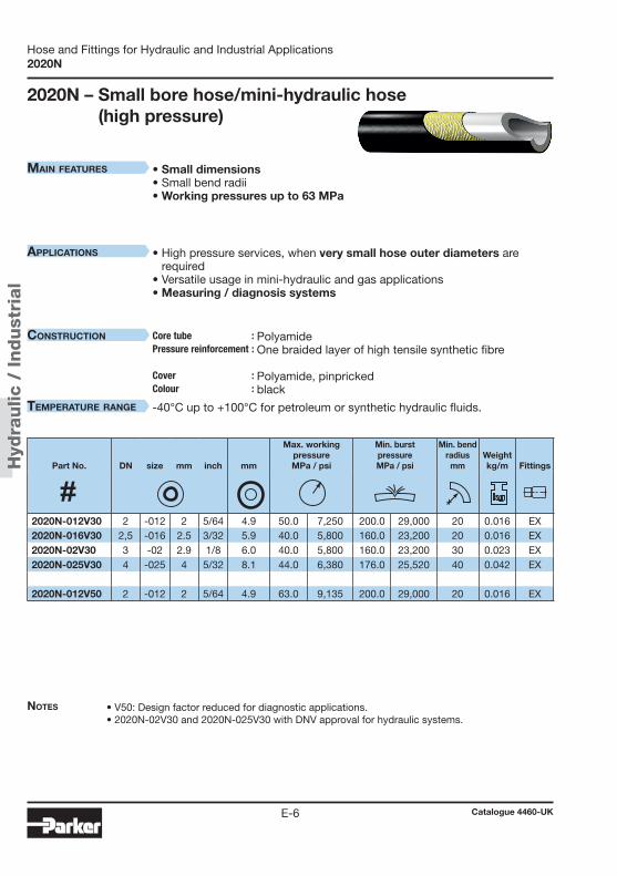
Hyd
raulic
/ Indust
rial
Catalogue 4460-UKE-6
Hose and Fittings for Hydraulic and Industrial Applications2020N
Notes
MaiN features
applicatioNs
coNstructioN Core tube :Pressure reinforcement : Cover : Colour :
teMperature raNge
2020N – Small bore hose/mini-hydraulic hose (high pressure)
• V50: Design factor reduced for diagnostic applications.• 2020N-02V30 and 2020N-025V30 with DNV approval for hydraulic systems.
• Small dimensions• Small bend radii• Working pressures up to 63 MPa
• High pressure services, when very small hose outer diameters are required
• Versatile usage in mini-hydraulic and gas applications • Measuring / diagnosis systems
Polyamide One braided layer of high tensile synthetic fibre Polyamide, pinpricked black
-40°C up to +100°C for petroleum or synthetic hydraulic fluids.
Part No. DN size mm inch mm
Max. workingpressureMPa / psi
Min. burstpressureMPa / psi
Min. bend radius
mmWeightkg/m
Fittings
2020N-012V30 2 -012 2 5/64 4.9 50.0 7,250 200.0 29,000 20 0.016 EX2020N-016V30 2,5 -016 2.5 3/32 5.9 40.0 5,800 160.0 23,200 20 0.016 EX2020N-02V30 3 -02 2.9 1/8 6.0 40.0 5,800 160.0 23,200 30 0.023 EX2020N-025V30 4 -025 4 5/32 8.1 44.0 6,380 176.0 25,520 40 0.042 EX
2020N-012V50 2 -012 2 5/64 4.9 63.0 9,135 200.0 29,000 20 0.016 EX

Hyd
raulic
/ Indust
rial
Catalogue 4460-UKE-7
EHose and Fittings for Hydraulic and Industrial Applications
Medium pressure hose
Part 2 – Medium pressure hose550H – Standard hydraulic hose ..................................................... E-8540N – Medium pressure hose for aggressive fluids ...................... E-9560TJ – ToughJACKET™ Hose ...................................................... E-10518C – Medium pressure hose, electrically non-conductive ........ E-1153DM – Low temperature hose – constant working pressure ........ E-1255LT – Low temperature hose ...................................................... E-13
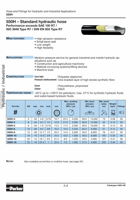
Hyd
raulic
/ Indust
rial
Catalogue 4460-UKE-8
Hose and Fittings for Hydraulic and Industrial Applications550H
Notes
MaiN features
applicatioNs
coNstructioN Core tube :Pressure reinforcement : Cover : Colour :
teMperature raNge
550H – Standard hydraulic hosePerformance exceeds SAE 100 R7 / ISO 3949 Type R7 / DIN EN 855 Type R7
Also available as twinline or multiline hose, see page XVI.
• High abrasion resistance• Small bend radii• Low weight • High flexibility
Medium pressure service for general industrial and mobile hydraulic ap-plications such as • Construction and agricultural machinery• Material conveying systems/lifting devices • Machine tools
Polyester elastomer One braided layer of high tensile synthetic fibre Polyurethane, pinpricked black
-40°C up to +100°C for petroleum, max. 57°C for synthetic hydraulic fluids and water-based hydraulic fluids.
Part No. DN size mm inch mm
Max. workingpressureMPa / psi
Min. burstpressureMPa / psi
Min. bend radius
mmWeightkg/m
Fittings
550H-3 5 -03 4.8 3/16 10.7 22.5 3,250 90.0 13,000 19 0.08 56550H-4 6 -04 6.3 1/4 12.6 21.0 3,000 83.0 12,000 32 0.10 56550H-5 8 -05 7.9 5/16 14.3 17.5 2,500 69.0 10,000 44 0.13 56550H-6 10 -06 9.5 3/8 16.3 15.5 2,250 62.0 9,000 51 0.14 56550H-8 12 -08 12.7 1/2 20.3 14.0 2,000 56.0 8,000 76 0.21 56550H-10 16 -10 15.9 5/8 24.5 10.0 1,500 40.0 6,000 102 0.30 56550H-12 20 -12 19.1 3/4 27.4 8.5 1,250 34.5 5,000 127 0.31 56550H-16 25 -16 25.4 1 33.3 7.0 1,000 27.5 4,000 203 0.40 56
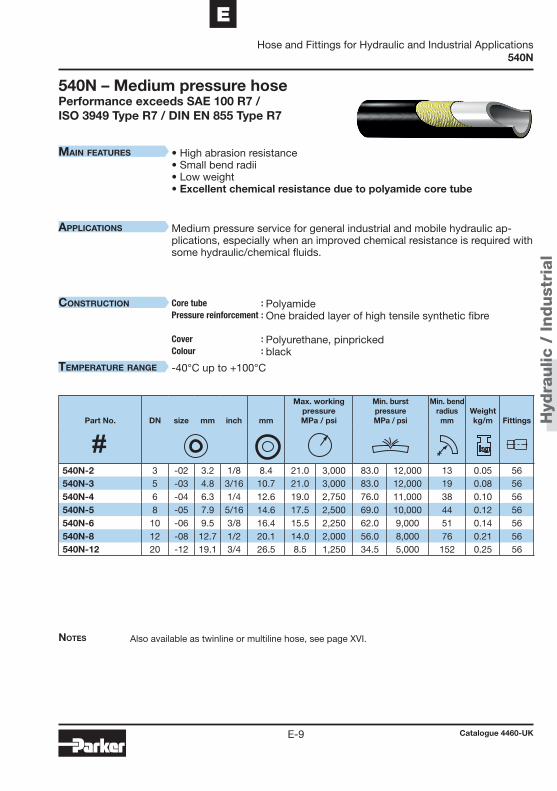
Hyd
raulic
/ Indust
rial
Catalogue 4460-UKE-9
EHose and Fittings for Hydraulic and Industrial Applications
540N
Notes
MaiN features
applicatioNs
coNstructioN Core tube :Pressure reinforcement : Cover : Colour :
teMperature raNge
540N – Medium pressure hosePerformance exceeds SAE 100 R7 / ISO 3949 Type R7 / DIN EN 855 Type R7
Also available as twinline or multiline hose, see page XVI.
• High abrasion resistance• Small bend radii• Low weight • Excellent chemical resistance due to polyamide core tube
Medium pressure service for general industrial and mobile hydraulic ap-plications, especially when an improved chemical resistance is required with some hydraulic/chemical fluids.
Polyamide One braided layer of high tensile synthetic fibre Polyurethane, pinpricked black
-40°C up to +100°C
Part No. DN size mm inch mm
Max. workingpressureMPa / psi
Min. burstpressureMPa / psi
Min. bend radius
mmWeightkg/m
Fittings
540N-2 3 -02 3.2 1/8 8.4 21.0 3,000 83.0 12,000 13 0.05 56540N-3 5 -03 4.8 3/16 10.7 21.0 3,000 83.0 12,000 19 0.08 56540N-4 6 -04 6.3 1/4 12.6 19.0 2,750 76.0 11,000 38 0.10 56540N-5 8 -05 7.9 5/16 14.6 17.5 2,500 69.0 10,000 44 0.12 56540N-6 10 -06 9.5 3/8 16.4 15.5 2,250 62.0 9,000 51 0.14 56540N-8 12 -08 12.7 1/2 20.1 14.0 2,000 56.0 8,000 76 0.21 56540N-12 20 -12 19.1 3/4 26.5 8.5 1,250 34.5 5,000 152 0.25 56

Hyd
raulic
/ Indust
rial
Catalogue 4460-UKE-10
Hose and Fittings for Hydraulic and Industrial Applications560TJ – ToughJACKET™ Hose
Notes
MaiN features
applicatioNs
coNstructioN Core tube :Pressure reinforcement : Cover : Colour :
teMperature raNge
560TJ – ToughJACKET™ HosePerformance exceeds SAE 100 R1AT / DIN EN 853-1SN
Also available as twinline or multiline hose, see page XVI.
• High abrasion resistance• Small bend radii• Steel wire pressure reinforcement
Medium pressure service for general industrial and mobile hydraulic ap-plications.
Polyester elastomer One braided layer of high tensile steel wire Polyurethane black
-40°C up to +121°C for petroleum, max. 57°C for synthetic hydraulic fluids and water-based hydraulic fluids.
Part No. DN size mm inch mm
Max. workingpressureMPa / psi
Min. burstpressureMPa / psi
Min. bend radius
mmWeightkg/m
Fittings
560TJ-3 5 -03 5 3/16 9.9 25.0 3,625 100.0 14,503 19 0.11 56560TJ-4 6 -04 6 1/4 11.9 22.4 3,250 90.0 13,053 38 0.14 56560TJ-5 8 -05 8 5/16 13.4 20.6 3,000 86.0 12,473 44 0.16 56560TJ-6 10 -06 10 3/8 15.5 19.0 2,750 75.8 11,000 51 0.21 56560TJ-8 12 -08 13 1/2 19.0 17.2 2,500 69.0 10,000 76 0.29 56560TJ-10 16 -10 16 5/8 23.6 13.7 2,000 55.2 8,000 102 0.47 56560TJ-12 20 -12 19 3/4 26.4 12.0 1,750 48.3 7,000 108 0.42 56

Hyd
raulic
/ Indust
rial
Catalogue 4460-UKE-11
EHose and Fittings for Hydraulic and Industrial Applications
518C
Notes
MaiN features
applicatioNs
coNstructioN Core tube :Pressure reinforcement : Cover : Colour :
teMperature raNge
518C – Medium pressure hoseElectrically non-conductive – Performance exceeds SAE 100 R7 / ISO 3949 Type R7 / DIN EN 855 Type R7
• Field attachable fittings available on request.• Electrically non-conductive acc. to SAE J517 (less than 50 μA leakage under 250,000 Volts per
meter).
• Electrically non-conductive • High abrasion resistance• Small bend radii• Low weight
Medium pressure service for general industrial and mobile hydraulic appli-cations, when electrically non-conductive lines are required, e.g.:• Working platforms for high-voltage line repair• Aluminium melting furnaces
Polyester elastomer, except -2: polyamide One braided layer of high tensile synthetic fibre Polyurethane orange
-40°C up to +100°C for petroleum, max. 57°C for synthetic hydraulic fluids and water-based hydraulic fluids.
Part No. DN size mm inch mm
Max. workingpressureMPa / psi
Min. burstpressureMPa / psi
Min. bend radius
mmWeightkg/m
Fittings
518C-2 3 -02 3.2 1/8 8.4 17.5 2,500 69.0 10,000 13 0.05 56518C-3 5 -03 4.8 3/16 10.7 22.5 3,250 90.0 13,000 19 0.07 56518C-4 6 -04 6.3 1/4 11.7 20.7 3,000 83.0 12,000 38 0.08 56518C-5 8 -05 7.9 5/16 14.3 17.5 2,500 69.0 10,000 44 0.11 56518C-6 10 -06 9.5 3/8 16.0 15.5 2,250 62.0 9,000 51 0.14 56518C-8 12 -08 12.7 1/2 20.4 15.5 2,250 62.0 9,000 76 0.22 56518C-10 16 -10 15.9 5/8 24.9 10.5 1,500 42.0 6,000 102 0.30 56518C-12 20 -12 19.1 3/4 27.4 8.5 1,250 34.5 5,000 152 0.31 56518C-16 25 -16 25.4 1 33.5 7.0 1,000 27.5 4,000 203 0.40 56

Hyd
raulic
/ Indust
rial
Catalogue 4460-UKE-12
Hose and Fittings for Hydraulic and Industrial Applications53DM
Notes
MaiN features
applicatioNs
coNstructioN Core tube :Pressure reinforcement : Cover : Colour :
teMperature raNge
53DM – Low temperature hoseSame working pressure for all sizesPerformance exceeds SAE 100 R18 / ISO 3949 Type R18
Also available as twinline or multiline hose, see page XVI.
• Working pressure 21 MPa for all sizes• Perfect solution for low temperature applications with dynamic
movements • High abrasion resistance• Small bend radii• Very low weight
Medium pressure service for general industrial and mobile hydraulic appli-cations, especially for systems working at very low temperatures, e.g.: • Fork lifts in cold storage houses,• Construction and agricultural machinery operating in climatic regions with
lower temperatures.
Polyester elastomer One or two braided layers of high tensile synthetic fibre Special polyester, pinpricked black
-57°C up to +100°C for petroleum, max. 57°C for synthetic hydraulic fluids and water-based hydraulic fluids.
Part No. DN size mm inch mm
Max. workingpressureMPa / psi
Min. burstpressureMPa / psi
Min. bend radius
mmWeightkg/m
Fittings
53DM-6 10 -06 10.0 3/8 17.0 21.0 3,000 84.0 12,000 51 0.16 5653DM-8 12 -08 12.5 1/2 21.0 21.0 3,000 84.0 12,000 89 0.26 5653DM-10 16 -10 16.0 5/8 26.0 21.0 3,000 84.0 12,000 102 0.33 56

Hyd
raulic
/ Indust
rial
Catalogue 4460-UKE-13
EHose and Fittings for Hydraulic and Industrial Applications
55LT
Notes
MaiN features
applicatioNs
coNstructioN Core tube :Pressure reinforcement : Cover : Colour :
teMperature raNge
55LT – Low temperature hosePerformance exceeds SAE 100 R7 / ISO 3949 Type R7 / DIN EN 855 Type R7
Also available as twinline or multiline hose, see page XVI.
• Ideal for low temperature applications • High abrasion resistance• Small bend radii• Low weight
Medium pressure service for general industrial and mobile hydraulic appli-cations, especially for systems working at very low temperatures, e.g.: • Fork lifts in cold storage houses,• Construction and agricultural machinery operating in climatic regions with
lower temperatures.
Polyester elastomer, except -02: polyamide Two braided layers of high tensile sythetic fibre Special polyester, pinpricked black
-57°C up to +100°C for petroleum, max. 57°C for synthetic hydraulic fluids and water-based hydraulic fluids.
Part No. DN size mm inch mm
Max. workingpressureMPa / psi
Min. burstpressureMPa / psi
Min. bend radius
mmWeightkg/m
Fittings
55LT-2 3 -02 3.2 1/8 8.6 21.0 3,000 79.0 11,500 13 0.05 5655LT-3 5 -03 4.8 3/16 10.9 22.5 3,250 90.0 13,000 19 0.08 5655LT-4 6 -04 6.3 1/4 13.0 21.0 3,000 83.0 12,000 32 0.10 5655LT-5 8 -05 7.9 5/16 14.3 17.5 2,500 69.0 10,000 44 0.13 5655LT-6 10 -06 9.5 3/8 16.3 15.5 2,250 62.0 9,000 51 0.14 5655LT-8 12 -08 12.7 1/2 20.3 14.0 2,000 56.0 8,000 76 0.21 56

Hyd
raulic
/ Indust
rial
Catalogue 4460-UKE-14
Hose and Fittings for Hydraulic and Industrial ApplicationsHigh pressure hose
Part 3 – High pressure hose2040N – Multi purpose hose ................................................. E-152040H – Standard hydraulic hose ......................................... E-16520N – Standard hydraulic hose ......................................... E-17528N – Electrically non-conductive hose ............................ E-18580N – Standard hydraulic hose ......................................... E-19588N – Electrically non-conductive hose ............................ E-20590TJ – ToughJACKET™ Hose ............................................ E-21594TJ – ToughJACKET™ Hose ............................................ E-22575X – High pressure hose, low volumetric expansion ...... E-232370N – Multi purpose hose ................................................. E-242245N – High pressure hose ................................................. E-25
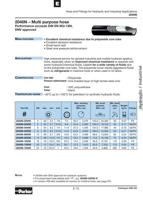
Hyd
raulic
/ Indust
rial
Catalogue 4460-UKE-15
EHose and Fittings for Hydraulic and Industrial Applications
2040N
Main features
applications
construction Core tube :Pressure reinforcement : Cover : Colour :
teMperature range
2040N – Multi purpose hosePerformance exceeds DIN EN 853-1SN, DNV approved
Notes • 2040N with DNV approval for hydraulic systems.• For pinpricked hose please add “-P”, e.g. 2040N-02V00-P.• In version V00 also available as twinline or multiline hose, see page XVI.
• Excellent chemical resistance due to polyamide core tube • Excellent abrasion resistance• Small bend radii• Steel wire pressure reinforcement
High pressure service for general industrial and mobile hydraulic applica-tions, especially when an improved chemical resistance is required with some hydraulic/chemical fluids. Usable for a wide variety of fluids due to the polyamide core tube. The polyamide cover resists aggressive fluids such as refrigerants in machine tools or when used in oil tanks.
Polyamide One braided layer of high tensile steel wire V00: polyurethane black
-40°C up to +100°C for petroleum or synthetic hydraulic fluids.
Part No. DN size mm inch mm
Max. workingpressureMPa / psi
Min. burstpressureMPa / psi
Min. bend radius
mmWeightkg/m
Fittings
2040N-02V00 3 -02 3.2 1/8 7.0 35.0 5,075 140.0 20,300 30 0.07 PX2040N-03V00 5 -03 4.7 3/16 9.8 34.0 4,930 136.0 19,720 30 0.11 56/PX2040N-04V00 6 -04 6.3 1/4 11.9 31.0 4,495 124.0 17,980 40 0.16 56/PX2040N-05V00 8 -05 8.2 5/16 14.0 25.0 3,625 100.0 14,500 50 0.21 56/PX2040N-06V00 10 -06 9.7 3/8 15.9 24.0 3,480 96.0 13,920 60 0.24 56/PX2040N-08V00 12 -08 12.8 1/2 19.3 18.5 2,680 74.0 10,730 75 0.29 56/PX2040N-10V00 16 -10 16.0 5/8 23.5 14.0 2,030 56.0 8,120 110 0.39 PX2040N-12V00 20 -12 19.4 3/4 26.7 12.5 1,810 50.0 7,250 170 0.50 PX2040N-16V00 25 -16 25.0 1 33.5 10.0 1,450 40.0 5,800 230 0.60 PX
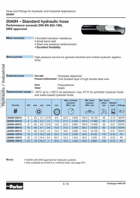
Hyd
raulic
/ Indust
rial
Catalogue 4460-UKE-16
Hose and Fittings for Hydraulic and Industrial Applications2040H
Notes
MaiN features
applicatioNs
coNstructioN Core tube :Pressure reinforcement : Cover : Colour :
teMperature raNge
2040H – Standard hydraulic hosePerformance exceeds DIN EN 853-1SN, DNV approved
• 2040H with DNV approval for hydraulic systems.• Also available as twinline or multiline hose, see page XVI.
• Excellent abrasion resistance• Small bend radii• Steel wire pressure reinforcement• Excellent flexibility
High pressure service for general industrial and mobile hydraulic applica-tions.
Polyester elastomer One braided layer of high tensile steel wire Polyurethane black
-40°C up to +100°C for petroleum, max. 57°C for synthetic hydraulic fluids and water-based hydraulic fluids.
Part No. DN size mm inch mm
Max. workingpressureMPa / psi
Min. burstpressureMPa / psi
Min. bend radius
mmWeightkg/m
Fittings
2040H-03V10 5 -03 4.7 3/16 9.8 34.0 4,930 136.0 19,720 30 0.12 56/PX2040H-04V10 6 -04 6.3 1/4 11.9 31.0 4,495 124.0 17,980 40 0.17 56/PX2040H-05V10 8 -05 8.2 5/16 14.0 25.0 3,625 100.0 14,500 50 0.21 56/PX2040H-06V10 10 -06 9.7 3/8 15.9 24.0 3,480 96.0 13,920 60 0.26 56/PX2040H-08V10 12 -08 12.8 1/2 19.3 18.5 2,680 74.0 10,730 75 0.31 56/PX2040H-10V10 16 -10 16.0 5/8 23.5 14.0 2,030 56.0 8,120 110 0.43 PX2040H-12V10 20 -12 19.4 3/4 26.7 12.5 1,810 50.0 7,250 170 0.53 PX2040H-16V10 25 -16 25.0 1 33.5 10.0 1,450 40.0 5,800 230 0.72 PX
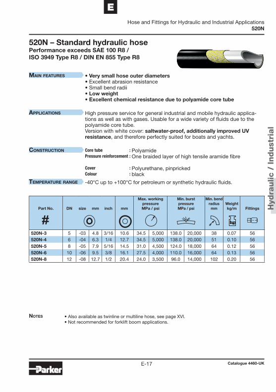
Hyd
raulic
/ Indust
rial
Catalogue 4460-UKE-17
EHose and Fittings for Hydraulic and Industrial Applications
520N
Notes
MaiN features
applicatioNs
coNstructioN Core tube :Pressure reinforcement : Cover : Colour :
teMperature raNge
520N – Standard hydraulic hosePerformance exceeds SAE 100 R8 / ISO 3949 Type R8 / DIN EN 855 Type R8
• Also available as twinline or multiline hose, see page XVI.• Not recommended for forklift boom applications.
• Very small hose outer diameters • Excellent abrasion resistance• Small bend radii• Low weight • Excellent chemical resistance due to polyamide core tube
High pressure service for general industrial and mobile hydraulic applica-tions as well as with gases. Usable for a wide variety of fluids due to the polyamide core tube. Version with white cover: saltwater-proof, additionally improved UV resistance, and therefore perfectly suited for boats and yachts.
Polyamide One braided layer of high tensile aramide fibre Polyurethane, pinpricked black
-40°C up to +100°C for petroleum or synthetic hydraulic fluids.
Part No. DN size mm inch mm
Max. workingpressureMPa / psi
Min. burstpressureMPa / psi
Min. bend radius
mmWeightkg/m
Fittings
520N-3 5 -03 4.8 3/16 10.6 34.5 5,000 138.0 20,000 38 0.07 56520N-4 6 -04 6.3 1/4 12.7 34.5 5,000 138.0 20,000 51 0.10 56520N-5 8 -05 7.9 5/16 14.5 31.0 4,500 124.0 18,000 64 0.12 56520N-6 10 -06 9.5 3/8 16.1 27.5 4,000 110.0 16,000 64 0.13 56520N-8 12 -08 12.7 1/2 20.4 24.0 3,500 96.0 14,000 102 0.20 56

Hyd
raulic
/ Indust
rial
Catalogue 4460-UKE-18
Hose and Fittings for Hydraulic and Industrial Applications528N
Notes
MaiN features
applicatioNs
coNstructioN Core tube :Pressure reinforcement : Cover : Colour :
teMperature raNge
528N – Electrically non-conductive hosePerformance exceeds SAE 100 R8 / ISO 3949 Type R8 / DIN EN 855 Type R8
• Electrically non-conductive acc. to SAE J517 (less than 50 μA leakage under 250,000 Volts per meter).• Not recommended for forklift boom applications.
• Electrically non-conductive • Very small hose outer diameters• Excellent abrasion resistance• Small bend radii• Low weight • Excellent chemical resistance due to polyamide core tube
High pressure service for general industrial and mobile hydraulic applica-tions, where a non-conductive hose is required.
Polyamide One braided layer of high tensile aramide fibre Polyurethane, not pinpricked orange
-40°C up to +100°C for petroleum or synthetic hydraulic fluids.
Part No. DN size mm inch mm
Max. workingpressureMPa / psi
Min. burstpressureMPa / psi
Min. bend radius
mmWeightkg/m
Fittings
528N-3 5 -03 4.8 3/16 10.6 34.5 5,000 138.0 20,000 38 0.07 56528N-4 6 -04 6.3 1/4 12.7 34.5 5,000 138.0 20,000 51 0.10 56528N-5 8 -05 7.9 5/16 14.5 31.0 4,500 124.0 18,000 64 0.12 56528N-6 10 -06 9.5 3/8 16.1 27.5 4,000 110.0 16,000 64 0.13 56528N-8 12 -08 12.7 1/2 20.4 24.0 3,500 96.0 14,000 102 0.20 56
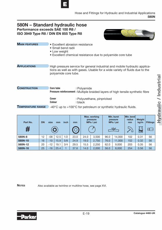
Hyd
raulic
/ Indust
rial
Catalogue 4460-UKE-19
EHose and Fittings for Hydraulic and Industrial Applications
580N
Notes
MaiN features
applicatioNs
coNstructioN Core tube :Pressure reinforcement : Cover : Colour :
teMperature raNge
580N – Standard hydraulic hosePerformance exceeds SAE 100 R8 / ISO 3949 Type R8 / DIN EN 855 Type R8
Also available as twinline or multiline hose, see page XVI.
• Excellent abrasion resistance• Small bend radii• Low weight • Excellent chemical resistance due to polyamide core tube
High pressure service for general industrial and mobile hydraulic applica-tions as well as with gases. Usable for a wide variety of fluids due to the polyamide core tube.
Polyamide Multiple braided layers of high tensile synthetic fibre Polyurethane, pinpricked black
-40°C up to +100°C for petroleum or synthetic hydraulic fluids.
Part No. DN size mm inch mm
Max. workingpressureMPa / psi
Min. burstpressureMPa / psi
Min. bend radius
mmWeightkg/m
Fittings
580N-8 12 -08 12.5 1/2 23.0 24.0 3,500 96.0 14,000 102 0.31 56580N-10 16 -10 15.9 5/8 24.9 19.0 2,750 76.0 11,000 152 0.32 56580N-12 20 -12 19.1 3/4 29.5 15.5 2,250 62.0 9,000 203 0.35 56580N-16 25 -16 25.4 1 37.6 14.0 2,000 56.0 8,000 254 0.56 56
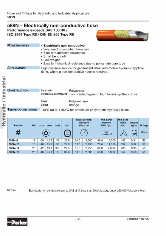
Hyd
raulic
/ Indust
rial
Catalogue 4460-UKE-20
Hose and Fittings for Hydraulic and Industrial Applications588N
Notes
MaiN features
applicatioNs
coNstructioN Core tube :Pressure reinforcement : Cover : Colour :
teMperature raNge
588N – Electrically non-conductive hosePerformance exceeds SAE 100 R8 / ISO 3949 Type R8 / DIN EN 855 Type R8
Electrically non-conductive acc. to SAE J517 (less than 50 μA leakage under 250,000 Volts per meter).
• Electrically non-conductive • Very small hose outer diameters• Excellent abrasion resistance• Small bend radii• Low weight • Excellent chemical resistance due to polyamide core tube
High pressure service for general industrial and mobile hydraulic applica-tions, where a non-conductive hose is required.
Polyamide Two braided layers of high tensile synthetic fibre Polyurethane orange
-40°C up to +100°C for petroleum or synthetic hydraulic fluids.
Part No. DN size mm inch mm
Max. workingpressureMPa / psi
Min. burstpressureMPa / psi
Min. bend radius
mmWeightkg/m
Fittings
588N-8 12 -08 12.7 1/2 23.0 24.0 3,500 96.0 14,000 102 0.31 56588N-10 16 -10 15.9 5/8 24.9 19.0 2,750 76.0 11,000 152 0.32 56588N-12 20 -12 19.1 3/4 29.5 15.5 2,250 62.0 9,000 203 0.35 56588N-16 25 -16 25.4 1 37.6 14.0 2,000 56.0 8,000 254 0.56 56
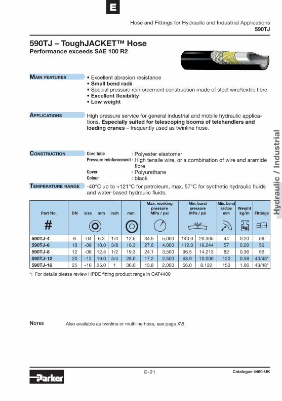
Hyd
raulic
/ Indust
rial
Catalogue 4460-UKE-21
EHose and Fittings for Hydraulic and Industrial Applications
590TJ
Notes
MaiN features
applicatioNs
coNstructioN Core tube :Pressure reinforcement : Cover : Colour :
teMperature raNge
590TJ – ToughJACKET™ HosePerformance exceeds SAE 100 R2
Also available as twinline or multiline hose, see page XVI.
• Excellent abrasion resistance• Small bend radii • Special pressure reinforcement construction made of steel wire/textile fibre• Excellent flexibility • Low weight
High pressure service for general industrial and mobile hydraulic applica-tions. Especially suited for telescoping booms of telehandlers and loading cranes – frequently used as twinline hose.
Polyester elastomer High tensile wire, or a combination of wire and aramide fibre Polyurethane black
-40°C up to +121°C for petroleum, max. 57°C for synthetic hydraulic fluids and water-based hydraulic fluids.
*: For details please review HPDE fitting product range in CAT4400
Part No. DN size mm inch mm
Max. workingpressureMPa / psi
Min. burstpressureMPa / psi
Min. bend radius
mmWeightkg/m
Fittings
590TJ-4 6 -04 6.3 1/4 12.5 34.5 5,000 140.0 20.305 44 0.20 56590TJ-6 10 -06 10.0 3/8 16.3 27.6 4,000 112.0 16.244 57 0.29 56590TJ-8 12 -08 12.5 1/2 19.3 24.1 3,500 96.5 14.213 82 0.36 56590TJ-12 20 -12 19.0 3/4 28.0 17.2 2,500 68.9 10.000 120 0.58 43/48*590TJ-16 25 -16 25.0 1 36.0 13.8 2,000 56.0 8.122 150 1.06 43/48*
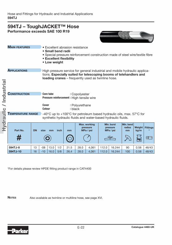
Hyd
raulic
/ Indust
rial
Catalogue 4460-UKE-22
Hose and Fittings for Hydraulic and Industrial Applications594TJ
Notes
MaiN features
applicatioNs
coNstructioN Core tube :Pressure reinforcement : Cover : Colour :
teMperature raNge
594TJ – ToughJACKET™ HosePerformance exceeds SAE 100 R19
• Excellent abrasion resistance• Small bend radii • Special pressure reinforcement construction made of steel wire/textile fibre• Excellent flexibility • Low weight
High pressure service for general industrial and mobile hydraulic applica-tions. Especially suited for telescoping booms of telehandlers and loading cranes – frequently used as twinline hose.
Copolyester High tensile wire
Polyurethane black
-40°C up to +100°C for petroleum based hydraulic oils, max. 57°C for synthetic hydraulic fluids and water-based hydraulic fluids.
*For details please review HPDE fitting product range in CAT4400
Also available as twinline or multiline hose, see page XVI.
Part No. DN size mm inch mm
Max. workingpressureMPa / psi
Min. burstpressureMPa / psi
Min. bend radius
mmWeightkg/m
Fittings *
594TJ-8 13 -08 13.0 1/2 21.5 28.0 4,061 112.0 16.244 90 0.58 46/43594TJ-10 16 -10 16.0 5/8 26.4 28.0 4,061 112.0 16.244 100 0.58 48/43
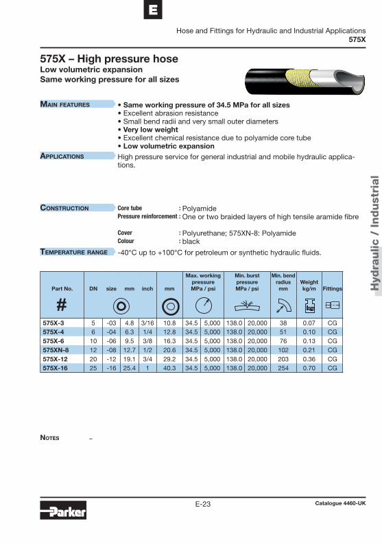
Hyd
raulic
/ Indust
rial
Catalogue 4460-UKE-23
EHose and Fittings for Hydraulic and Industrial Applications
575X
Notes
MaiN features
applicatioNs
coNstructioN Core tube :Pressure reinforcement : Cover : Colour :
teMperature raNge
575X – High pressure hoseLow volumetric expansionSame working pressure for all sizes
–
• Same working pressure of 34.5 MPa for all sizes• Excellent abrasion resistance• Small bend radii and very small outer diameters• Very low weight • Excellent chemical resistance due to polyamide core tube • Low volumetric expansionHigh pressure service for general industrial and mobile hydraulic applica-tions.
Polyamide One or two braided layers of high tensile aramide fibre Polyurethane; 575XN-8: Polyamide black
-40°C up to +100°C for petroleum or synthetic hydraulic fluids.
Part No. DN size mm inch mm
Max. workingpressureMPa / psi
Min. burstpressureMPa / psi
Min. bend radius
mmWeightkg/m
Fittings
575X-3 5 -03 4.8 3/16 10.8 34.5 5,000 138.0 20,000 38 0.07 CG575X-4 6 -04 6.3 1/4 12.8 34.5 5,000 138.0 20,000 51 0.10 CG575X-6 10 -06 9.5 3/8 16.3 34.5 5,000 138.0 20,000 76 0.13 CG575XN-8 12 -08 12.7 1/2 20.6 34.5 5,000 138.0 20,000 102 0.21 CG575X-12 20 -12 19.1 3/4 29.2 34.5 5,000 138.0 20,000 203 0.36 CG575X-16 25 -16 25.4 1 40.3 34.5 5,000 138.0 20,000 254 0.70 CG

Hyd
raulic
/ Indust
rial
Catalogue 4460-UKE-24
Hose and Fittings for Hydraulic and Industrial Applications2370N
Notes
MaiN features
applicatioNs
coNstructioN Core tube :Pressure reinforcement : Cover : Colour :
teMperature raNge
2370N – Multi purpose hosePerformance exceeds DIN EN 853-2SN
• Also available as twinline or multiline hose, see page XVI. • For pinpricked hose please add “-P”, e.g. 2370N-04V10-P.
• Working pressures up to 46.5 MPa • Excellent chemical resistance due to polyamide core tube
High pressure service for general industrial and mobile hydraulic applica-tions as well as with gases. Usable for a wide variety of fluids due to the polyamide core tube.
Polyamide Two spiral layers of high tensile steel wire, two open spiral layers of high tensile synthetic fibre Polyurethane black; other colours on request
-40°C up to +100°C (short term +120°C) for petroleum or synthetic hydraulic fluids.
Part No. DN size mm inch mm
Max. workingpressureMPa / psi
Min. burstpressureMPa / psi
Min. bend radius
mmWeightkg/m
Fittings
2370N-04V10 6 -04 6.3 1/4 12.4 46.5 6,740 186.0 26,970 70 0.19 NX2370N-05V10 8 -05 8.2 5/16 14.3 44.0 6,380 176.0 25,520 100 0.25 NX2370N-06V10 10 -06 9.8 3/8 16.4 42.0 6,090 168.0 24,360 120 0.33 9X2370N-08V10 12 -08 12.8 1/2 20.0 35.0 5,075 140.0 20,300 150 0.42 9X

Hyd
raulic
/ Indust
rial
Catalogue 4460-UKE-25
EHose and Fittings for Hydraulic and Industrial Applications
2245N
Notes
MaiN features
applicatioNs
coNstructioN Core tube :Pressure reinforcement : Cover : Colour :
teMperature raNge
2245N – High pressure hosePerformance exceeds SAE100R9
• 2245N with DNV approval for hydraulic systems.• For pinpricked hose please add “-P”, e.g. 2245N-04V00-P.
• High working pressures for large sizes• Excellent chemical resistance due to polyamide core tube
High pressure service for general industrial and mobile hydraulic applica-tions as well as with gases. Usable for a wide variety of fluids due to the polyamide core tube.
Polyamide Two spiral layers of high tensile steel wire, one braided layer of steel wire Polyurethane; -10 and above: polyamide black
-40°C up to +100°C (short term +120°C) for petroleum or synthetic hydraulic fluids.
Part No. DN size mm inch mm
Max. workingpressureMPa / psi
Min. burstpressureMPa / psi
Min. bend radius
mmWeightkg/m
Fittings
2245N-04V00 6 -04 6.3 1/4 12.5 45.0 6,525 180.0 26,100 70 0.25 NX2245N-05V00 8 -05 8.2 5/16 14.3 40.0 5,800 160.0 23,200 100 0.32 NX2245N-06V00 10 -06 9.7 3/8 17.0 37.5 5,435 150.0 21,750 120 0.42 NX2245N-08V00 12 -08 12.8 1/2 20.7 35.0 5,075 140.0 20,300 165 0.52 9X2245N-10V30 16 -10 16.0 5/8 24.5 33.0 4,785 132.0 19,140 200 0.72 NX2245N-12V30 20 -12 19.6 3/4 28.5 30.0 4,350 120.0 17,400 240 0.92 NX2245N-16V30 25 -16 25.0 1 34.0 27.5 3,985 110.0 15,950 280 1.15 NX

Hyd
raulic
/ Indust
rial
Catalogue 4460-UKE-26
Hose and Fittings for Hydraulic and Industrial ApplicationsNotes

Hyd
raulic
/ Indust
rial
Catalogue 4460-UKE-27
EHose and Fittings for Hydraulic and Industrial Applications
Paint spray hose
Part 4 – Paint spray hoseAirless paint spray applications – General statements .................... E-282040N – Medium pressure hose ........................................... E-292370N – High pressure hose ................................................. E-302030T – PTFE hose ............................................................... E-312033T – PTFE hose ............................................................... E-32

Hyd
raulic
/ Indust
rial
Catalogue 4460-UKE-28
Hose and Fittings for Hydraulic and Industrial ApplicationsPaint spray hose
Airless paint spray applications – General statements
Hose assembly Hoses for airless paint spray applications require a specific assem-
bly procedure. It is imperative to have assembly training by Parker on the individual product. The hose assembly must be silicone-free as silicone interferes with the paint spray quality. This requirement includes all the compo-nents and the testing media. For each hose type specific Parker hose assembly and testing instructions have to be applied.
Conductivity The hose assemblies must be conductive in order to dissipate the
electrostatic charge. The conductivity of the hose assembly must be ensured and proven (100% testing) according to the Parker specifi-cation.
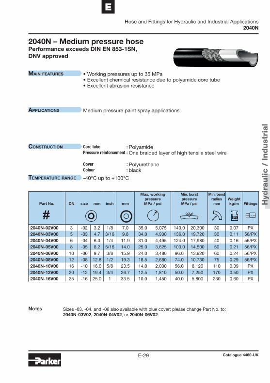
Hyd
raulic
/ Indust
rial
Catalogue 4460-UKE-29
EHose and Fittings for Hydraulic and Industrial Applications
2040N
Notes
MaiN features
applicatioNs
coNstructioN Core tube :Pressure reinforcement : Cover : Colour :
teMperature raNge
2040N – Medium pressure hosePerformance exceeds DIN EN 853-1SN,DNV approved
Sizes -03, -04, and -06 also available with blue cover; please change Part No. to: 2040N-03V02, 2040N-04V02, or 2040N-06V02
• Working pressures up to 35 MPa • Excellent chemical resistance due to polyamide core tube • Excellent abrasion resistance
Medium pressure paint spray applications.
Polyamide One braided layer of high tensile steel wire Polyurethane black
-40°C up to +100°C
Part No. DN size mm inch mm
Max. workingpressureMPa / psi
Min. burstpressureMPa / psi
Min. bend radius
mmWeightkg/m
Fittings
2040N-02V00 3 -02 3.2 1/8 7.0 35.0 5,075 140.0 20,300 30 0.07 PX2040N-03V00 5 -03 4.7 3/16 9.8 34.0 4,930 136.0 19,720 30 0.11 56/PX2040N-04V00 6 -04 6.3 1/4 11.9 31.0 4,495 124.0 17,980 40 0.16 56/PX2040N-05V00 8 -05 8.2 5/16 14.0 25.0 3,625 100.0 14,500 50 0.21 56/PX2040N-06V00 10 -06 9.7 3/8 15.9 24.0 3,480 96.0 13,920 60 0.24 56/PX2040N-08V00 12 -08 12.8 1/2 19.3 18.5 2,680 74.0 10,730 75 0.29 56/PX2040N-10V00 16 -10 16.0 5/8 23.5 14.0 2,030 56.0 8,120 110 0.39 PX2040N-12V00 20 -12 19.4 3/4 26.7 12.5 1,810 50.0 7,250 170 0.50 PX2040N-16V00 25 -16 25.0 1 33.5 10.0 1,450 40.0 5,800 230 0.60 PX

Hyd
raulic
/ Indust
rial
Catalogue 4460-UKE-30
Hose and Fittings for Hydraulic and Industrial Applications2370N
Notes
MaiN features
applicatioNs
coNstructioN Core tube :Pressure reinforcement : Cover : Colour :
teMperature raNge
2370N – High pressure hosePerformance exceeds DIN EN 853-2SN
Sizes -04 and -06 also available with blue cover; please change Part No. to: 2370N-04V02 or 2370N-06V02
• Working pressures up to 46.5 MPa • Excellent chemical resistance due to polyamide core tube • Excellent abrasion resistance
High pressure paint spray applications.
Polyamide Two spiral layers of high tensile steel wire, two open spiral layers of synthetic fibre Polyurethane black
-40°C up to +100°C
Part No. DN size mm inch mm
Max. workingpressureMPa / psi
Min. burstpressureMPa / psi
Min. bend radius
mmWeightkg/m
Fittings
2370N-04V10 6 -04 6.3 1/4 12.4 46.5 6,740 186.0 26,970 70 0.19 NX2370N-05V10 8 -05 8.2 5/16 14.3 44.0 6,380 176.0 25,520 100 0.25 NX2370N-06V10 10 -06 9.8 3/8 16.4 42.0 6,090 168.0 24,360 120 0.33 9X2370N-08V10 12 -08 12.8 1/2 20.0 35.0 5,075 140.0 20,300 150 0.42 9X
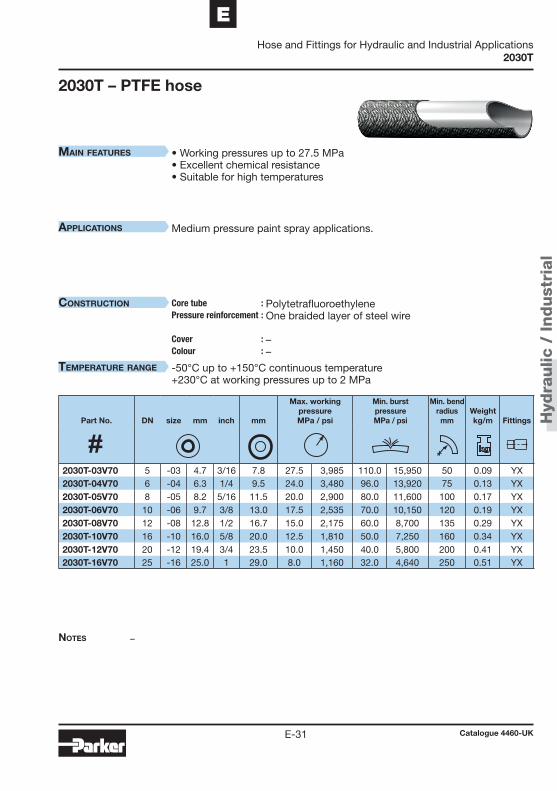
Hyd
raulic
/ Indust
rial
Catalogue 4460-UKE-31
EHose and Fittings for Hydraulic and Industrial Applications
2030T
Notes
MaiN features
applicatioNs
coNstructioN Core tube :Pressure reinforcement : Cover : Colour :
teMperature raNge
2030T – PTFE hose
–
• Working pressures up to 27.5 MPa • Excellent chemical resistance• Suitable for high temperatures
Medium pressure paint spray applications.
Polytetrafluoroethylene One braided layer of steel wire
––
-50°C up to +150°C continuous temperature +230°C at working pressures up to 2 MPa
Part No. DN size mm inch mm
Max. workingpressureMPa / psi
Min. burstpressureMPa / psi
Min. bend radius
mmWeightkg/m
Fittings
2030T-03V70 5 -03 4.7 3/16 7.8 27.5 3,985 110.0 15,950 50 0.09 YX2030T-04V70 6 -04 6.3 1/4 9.5 24.0 3,480 96.0 13,920 75 0.13 YX2030T-05V70 8 -05 8.2 5/16 11.5 20.0 2,900 80.0 11,600 100 0.17 YX2030T-06V70 10 -06 9.7 3/8 13.0 17.5 2,535 70.0 10,150 120 0.19 YX2030T-08V70 12 -08 12.8 1/2 16.7 15.0 2,175 60.0 8,700 135 0.29 YX2030T-10V70 16 -10 16.0 5/8 20.0 12.5 1,810 50.0 7,250 160 0.34 YX2030T-12V70 20 -12 19.4 3/4 23.5 10.0 1,450 40.0 5,800 200 0.41 YX2030T-16V70 25 -16 25.0 1 29.0 8.0 1,160 32.0 4,640 250 0.51 YX

Hyd
raulic
/ Indust
rial
Catalogue 4460-UKE-32
Hose and Fittings for Hydraulic and Industrial Applications2033T
Notes
MaiN features
applicatioNs
coNstructioN Core tube :Pressure reinforcement : Cover : Colour :
teMperature raNge
2033T – PTFE hose
–
• Improved working pressures due to two braided layers of steel wire• Suitable for high temperatures• Excellent chemical resistance
Medium pressure paint spray applications.
Polytetrafluoroethylene Two braided layers of steel wire
––
-50°C up to +150°C continuous temperature +230°C at working pressures up to 2 MPa
Part No. DN size mm inch mm
Max. workingpressureMPa / psi
Min. burstpressureMPa / psi
Min. bend radius
mmWeightkg/m
Fittings
2033T-04V70 6 -04 6.3 1/4 11.0 27.5 3,985 110.0 15,950 75 0.23 PX2033T-05V70 8 -05 8.2 5/16 13.2 25.0 3,625 100.0 14,500 100 0.26 PX2033T-06V70 10 -06 9.7 3/8 15.0 22.5 3,260 90.0 13,050 120 0.34 PX2033T-08V70 12 -08 12.8 1/2 18.6 20.0 2,900 80.0 11,600 135 0.47 PX2033T-10V70 16 -10 16.0 5/8 21.5 17.5 2,535 70.0 10,150 160 0.53 YX2033T-12V70 20 -12 19.4 3/4 25.5 15.0 2,175 60.0 8,700 200 0.69 YX2033T-16V70 25 -16 25.0 1 31.0 11.0 1,595 44.0 6,380 250 0.81 YX

Hyd
raulic
/ Indust
rial
Catalogue 4460-UKE-33
EHose and Fittings for Hydraulic and Industrial Applications
Gas hose
Part 5 – Gas hoseIntroduction ................................................................................... E-34Thermoplastic hose for applications with industrial gases .......... E-35Thermoplastic hose types with specific approvals ........................ E-37- 527BA – Breathing air refill hose ..................................................... E-38- 5CNG – Compressed natural gas dispense hose .......................... E-39- 8LPG – Hose for mobile applications in vehicles .......................... E-40

Hyd
raulic
/ Indust
rial
Catalogue 4460-UKE-34
Hose and Fittings for Hydraulic and Industrial ApplicationsGas hose
Gas hose applications – General statements
Hose selection for industrial gases Parker thermoplastic hoses are perfectly suited for applications with
industrial gases and are being used in the field for many years. When selecting hoses for industrial gases, attention should be paid to the following three criteria:
1. Chemical resistance
Due to the high-grade core tube materials Parker thermoplastic hoses are chemically resistant to most of the industrial gases, such as acetylene, propane, butane, methane, natural gas, CNG, carbon dioxide, nitrogen and inert gases (see chemical resistance table, page A-10).
2. Permeation Parker thermoplastic hoses have relatively low permeation rates, thus minimising the loss of gases. This leads to an optimisation of operational costs, and gas enrichments in the surroundings caused by permeation are minimised.
3. Perforation It is mandatory for gas applications to use perforated (pinpricked) hoses in order to avoid bubble formation in the hose cover.
For further information please refer to our Engineering Standard
PFDE-ES01, which is available on request at Parker Polyflex.

Hyd
raulic
/ Indust
rial
Catalogue 4460-UKE-35
EHose and Fittings for Hydraulic and Industrial Applications
Gas hose
Thermoplastic hose for applications with industrial gases
Based on the technical requirements noted in the introduction some hose types are particularly suited for gas applications. These hose types can be classified as fol-lows:
1) Hoses with textile fibre reinforcement – these have pinpricked covers by de-fault: 540N 5CNG 520N 8LPG 2010N 2020N
2) Hoses with steel wire reinforcement – these have to be pinpricked especially for gas applications: 2040N 2370N 2245N
3) Hoses with core tubes made from fluoropolymer – these are especially suited for aggressive fluids and/or higher temperatures: 2030T 2033T 939 2246F
Please use the following table to select the desired hose type by size and working pressure.

Hyd
raulic
/ Indust
rial
Catalogue 4460-UKE-36
Hose and Fittings for Hydraulic and Industrial ApplicationsGas hose
For gas applications temperature limitations must be considered. For most of the gases the above Parker hose types are suitable for temperatures up to 50°C. For higher temperatures please contact Parker Polyflex.
For hose applications with gases legal and actuarial regulations must be observed. The specification of the chemical resistance does not replace approval of certain bodies or for specific applications.
The user has to assume full responsibility for hose selection, testing of the applica-tion and the environmental conditions, and release for the individual application.
Please refer also to the standards, approvals and certificates when selecting hoses (see page A-15).
Working pressure (MPa) Fitting pg
No
m. s
ize DN 2 2.5 3 4 5 6 8 10 12 16 20 25 32 40 50 series
size -012 -016 -02 -025 -03 -04 -05 -06 -08 -10 -12 -16 -20 -24 -32mm* 2.0 2.4 3.2 4.0 4.8 6.4 7.9 9.5 12.7 15.9 19.0 25.4 31.8 38.1 50.8inch 5/64 3/32 1/8 5/32 3/16 1/4 5/16 3/8 1/2 5/8 3/4 1 1 1/4 1 1/2 2
Hoses with textile fibre reinforcement540N 21.0 21.0 19.0 17.5 15.5 14.0 8.5 56 E-9
520N 34.5 34.5 31.0 27.5 24.0 56 E-17
2020N (V30) 47.5 40.0 40.0 44.0 EX E-6
5CNG 34.5 34.5 34.5 34.5 34.5 34.5 CG E-39
8LPG 3.0 3.0 3.0 3.0 PX-LPG E-40
Hoses with steel wire reinforcement2040N (V00) 35.0 34.0 31.0 25.0 24.0 18.5 14.0 12.5 10.0 56/PX E-29
2370N 46.5 44.0 42.0 35.0 9X/NX E-30
2245N 45.0 40.0 37.5 35.0 33.0 30.0 27.5 NX E-25
Hoses with core tubes made from fluoropolymer2030T 27.5 24.0 20.0 17.5 15.0 12.5 10.0 8.0 YX C-4
2033T 27.5 25.0 22.5 20.0 17.5 15.0 11.0 PX/YX C-6
939/939B 10.3 9.5 6.9 7.5 6.9 6.9 5.0 1.7 93N C-10
2246F 41.5 37.5 34.0 32.5 30.0 26.5 21.0 NX C-12
*: Exact value may vary, please check hose spec
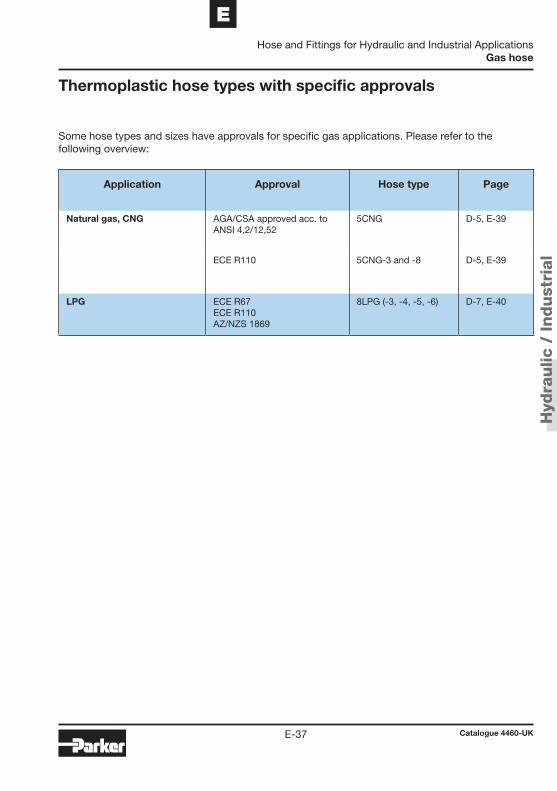
Hyd
raulic
/ Indust
rial
Catalogue 4460-UKE-37
EHose and Fittings for Hydraulic and Industrial Applications
Gas hose
Thermoplastic hose types with specific approvals
Some hose types and sizes have approvals for specific gas applications. Please refer to the following overview:
Application Approval Hose type Page
Natural gas, CNG AGA/CSA approved acc. to ANSI 4,2/12,52
5CNG D-5, E-39
ECE R110 5CNG-3 and -8 D-5, E-39
LPG ECE R67 ECE R110 AZ/NZS 1869
8LPG (-3, -4, -5, -6) D-7, E-40
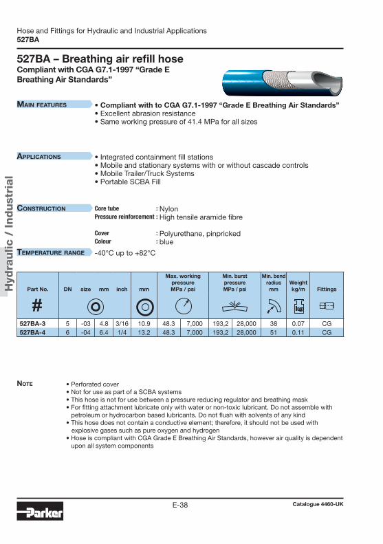
Hyd
raulic
/ Indust
rial
Catalogue 4460-UKE-38
Hose and Fittings for Hydraulic and Industrial Applications527BA
Main features
applications
construction Core tube :Pressure reinforcement : Cover : Colour :
teMperature range
527BA – Breathing air refill hoseCompliant with CGA G7.1-1997 “Grade E Breathing Air Standards”
Note • Perforated cover• Not for use as part of a SCBA systems• This hose is not for use between a pressure reducing regulator and breathing mask• For fitting attachment lubricate only with water or non-toxic lubricant. Do not assemble with
petroleum or hydrocarbon based lubricants. Do not flush with solvents of any kind• This hose does not contain a conductive element; therefore, it should not be used with explosive gases such as pure oxygen and hydrogen• Hose is compliant with CGA Grade E Breathing Air Standards, however air quality is dependent
upon all system components
• Compliant with to CGA G7.1-1997 “Grade E Breathing Air Standards”• Excellent abrasion resistance• Same working pressure of 41.4 MPa for all sizes
• Integrated containment fill stations• Mobile and stationary systems with or without cascade controls• Mobile Trailer/Truck Systems• Portable SCBA Fill
Nylon High tensile aramide fibre Polyurethane, pinpricked blue
-40°C up to +82°C
Part No. DN size mm inch mm
Max. workingpressureMPa / psi
Min. burstpressureMPa / psi
Min. bend radius
mmWeightkg/m
Fittings
527BA-3 5 -03 4.8 3/16 10.9 48.3 7,000 193,2 28,000 38 0.07 CG527BA-4 6 -04 6.4 1/4 13.2 48.3 7,000 193,2 28,000 51 0.11 CG
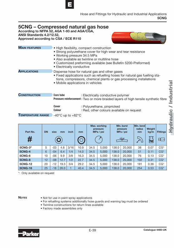
Hyd
raulic
/ Indust
rial
Catalogue 4460-UKE-39
EHose and Fittings for Hydraulic and Industrial Applications
5CNG
Main features
applications
construction Core tube :Pressure reinforcement : Cover : Colour :
teMperature range
• High flexibility, compact construction• Strong polyurethane cover for high wear and tear resistance• Working pressure 34.5 MPa• Also available as twinline or multiline hose• Customized preforming available (see Bulletin 5200-Preformed)• Electrically conductive
Dispense hose for natural gas and other gases• Fixed applications such as refuelling hoses for natural gas fuelling sta-
tions, compressors, chemical plants or gas processing installations• Mobile applications in vehicles
Electrically conductive polymer Two or more braided layers of high tensile synthetic fibre Polyurethane, pinpricked Red, other colours available on request
-40°C up to +82°C
Notes • Not for use in paint spray applications• For refuelling systems additionally hose guards and warning tag must be ordered • Twinline constructions for return lines available• Factory made assemblies only
*: Only available on request
5CNG – Compressed natural gas hoseAccording to NFPA 52, AGA 1-93 and AGA/CGA, ANSI Standards 4.2/12.52, Approved according to CSA / ECE R110
Part No. DN size mm inch mm
Max. workingpressureMPa / psi
Min. burstpressureMPa / psi
Min. bend radius
mmWeightkg/m
Fittings
5CNG-3* 5 -03 4.8 3/16 10.9 34.5 5,000 138.0 20,000 38 0.07 CG*5CNG-4 6 -04 6.4 1/4 14.0 34.5 5,000 138.0 20,000 51 0.11 CG*5CNG-6 10 -06 9.9 3/8 16.3 34.5 5,000 138.0 20,000 76 0.13 CG*5CNG-8 12 -08 12.7 1/2 22.7 34.5 5,000 138.0 20,000 102 0.31 CG*5CNG-12 20 -12 19.3 3/4 29.2 34.5 5,000 138.0 20,000 191 0.36 CG*5CNG-16 25 -16 26.0 1 40.4 34.5 5,000 138.0 20,000 254 0.53 CG*
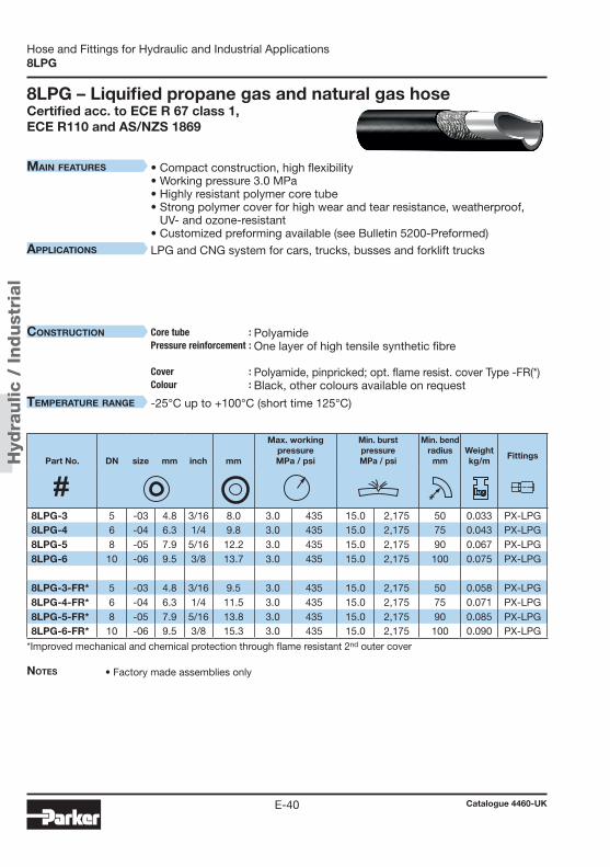
Hyd
raulic
/ Indust
rial
Catalogue 4460-UKE-40
Hose and Fittings for Hydraulic and Industrial Applications8LPG
Main features
applications
construction Core tube :Pressure reinforcement : Cover : Colour :
teMperature range
8LPG – Liquified propane gas and natural gas hoseCertified acc. to ECE R 67 class 1, ECE R110 and AS/NZS 1869
Notes • Factory made assemblies only
• Compact construction, high flexibility• Working pressure 3.0 MPa• Highly resistant polymer core tube • Strong polymer cover for high wear and tear resistance, weatherproof,
UV- and ozone-resistant• Customized preforming available (see Bulletin 5200-Preformed)
LPG and CNG system for cars, trucks, busses and forklift trucks
Polyamide One layer of high tensile synthetic fibre Polyamide, pinpricked; opt. flame resist. cover Type -FR(*) Black, other colours available on request
-25°C up to +100°C (short time 125°C)
*Improved mechanical and chemical protection through flame resistant 2nd outer cover
Part No. DN size mm inch mm
Max. workingpressureMPa / psi
Min. burstpressureMPa / psi
Min. bend radius
mmWeightkg/m
Fittings
8LPG-3 5 -03 4.8 3/16 8.0 3.0 435 15.0 2,175 50 0.033 PX-LPG8LPG-4 6 -04 6.3 1/4 9.8 3.0 435 15.0 2,175 75 0.043 PX-LPG8LPG-5 8 -05 7.9 5/16 12.2 3.0 435 15.0 2,175 90 0.067 PX-LPG8LPG-6 10 -06 9.5 3/8 13.7 3.0 435 15.0 2,175 100 0.075 PX-LPG
8LPG-3-FR* 5 -03 4.8 3/16 9.5 3.0 435 15.0 2,175 50 0.058 PX-LPG8LPG-4-FR* 6 -04 6.3 1/4 11.5 3.0 435 15.0 2,175 75 0.071 PX-LPG8LPG-5-FR* 8 -05 7.9 5/16 13.8 3.0 435 15.0 2,175 90 0.085 PX-LPG8LPG-6-FR* 10 -06 9.5 3/8 15.3 3.0 435 15.0 2,175 100 0.090 PX-LPG

Hose
fitt
ings
Hose Fittings
Catalogue 4460-UKE-41
E
Part 6 – Hose Fittings56 series .................................................................................... E-429X series .................................................................................... E-56CG series .................................................................................... E-60EX series .................................................................................... E-63NX series .................................................................................... E-70PX series .................................................................................... E-76
Table of contents
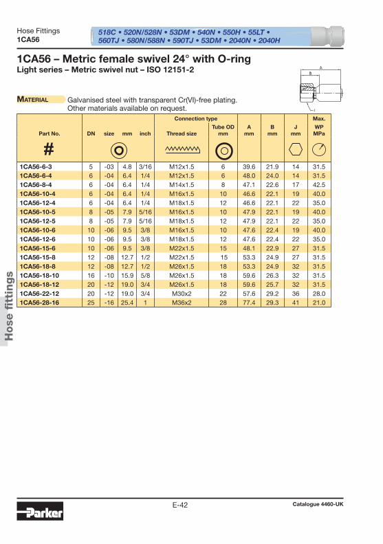
518C • 520N/528N • 53DM • 540N • 550H • 55LT • 560TJ • 580N/588N • 590TJ • 53DM • 2040N • 2040H
Hose
fi t
tings
Hose Fittings
Catalogue 4460-UKE-42
1CA56
1CA56 – Metric female swivel 24° with O-ring Light series – Metric swivel nut – ISO 12151-2
Material Galvanised steel with transparent Cr(VI)-free plating.Other materials available on request.
Connection type Max.
Part No. DN size mm inch Thread sizeTube OD
mmA
mmB
mmJ
mmWPMPa
1CA56-6-3 5 -03 4.8 3/16 M12x1.5 6 39.6 21.9 14 31.5 1CA56-6-4 6 -04 6.4 1/4 M12x1.5 6 48.0 24.0 14 31.5 1CA56-8-4 6 -04 6.4 1/4 M14x1.5 8 47.1 22.6 17 42.5 1CA56-10-4 6 -04 6.4 1/4 M16x1.5 10 46.6 22.1 19 40.0 1CA56-12-4 6 -04 6.4 1/4 M18x1.5 12 46.6 22.1 22 35.0 1CA56-10-5 8 -05 7.9 5/16 M16x1.5 10 47.9 22.1 19 40.0 1CA56-12-5 8 -05 7.9 5/16 M18x1.5 12 47.9 22.1 22 35.0 1CA56-10-6 10 -06 9.5 3/8 M16x1.5 10 47.6 22.4 19 40.0 1CA56-12-6 10 -06 9.5 3/8 M18x1.5 12 47.6 22.4 22 35.0 1CA56-15-6 10 -06 9.5 3/8 M22x1.5 15 48.1 22.9 27 31.5 1CA56-15-8 12 -08 12.7 1/2 M22x1.5 15 53.3 24.9 27 31.5 1CA56-18-8 12 -08 12.7 1/2 M26x1.5 18 53.3 24.9 32 31.5 1CA56-18-10 16 -10 15.9 5/8 M26x1.5 18 59.6 26.3 32 31.5 1CA56-18-12 20 -12 19.0 3/4 M26x1.5 18 59.6 25.7 32 31.5 1CA56-22-12 20 -12 19.0 3/4 M30x2 22 57.6 29.2 36 28.0 1CA56-28-16 25 -16 25.4 1 M36x2 28 77.4 29.3 41 21.0
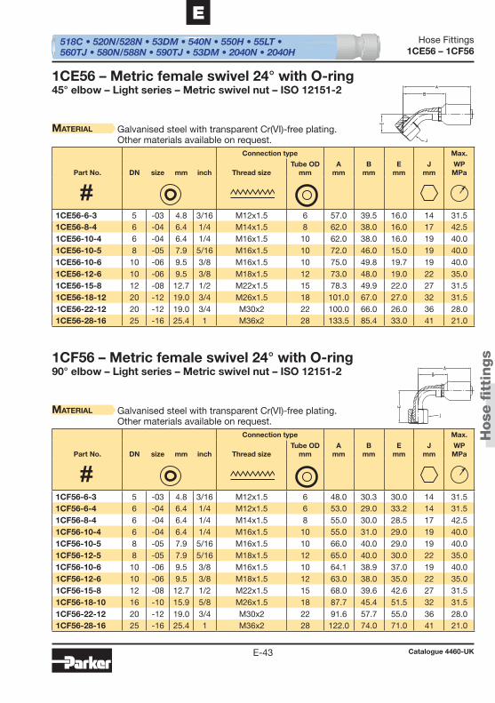
518C • 520N/528N • 53DM • 540N • 550H • 55LT • 560TJ • 580N/588N • 590TJ • 53DM • 2040N • 2040H
Hose
fi t
tings
Hose Fittings
Catalogue 4460-UKE-43
E
1CE56 – 1CF56
1CE56 – Metric female swivel 24° with O-ring45° elbow – Light series – Metric swivel nut – ISO 12151-2
Material Galvanised steel with transparent Cr(VI)-free plating.Other materials available on request.
1CF56 – Metric female swivel 24° with O-ring90° elbow – Light series – Metric swivel nut – ISO 12151-2
Material Galvanised steel with transparent Cr(VI)-free plating.Other materials available on request.
Connection type Max.
Part No. DN size mm inch Thread sizeTube OD
mmA
mmB
mmE
mmJ
mmWPMPa
Connection type Max.
Part No. DN size mm inch Thread sizeTube OD
mmA
mmB
mmE
mmJ
mmWPMPa
1CE56-6-3 5 -03 4.8 3/16 M12x1.5 6 57.0 39.5 16.0 14 31.5 1CE56-8-4 6 -04 6.4 1/4 M14x1.5 8 62.0 38.0 16.0 17 42.5 1CE56-10-4 6 -04 6.4 1/4 M16x1.5 10 62.0 38.0 16.0 19 40.0 1CE56-10-5 8 -05 7.9 5/16 M16x1.5 10 72.0 46.0 15.0 19 40.0 1CE56-10-6 10 -06 9.5 3/8 M16x1.5 10 75.0 49.8 19.7 19 40.0 1CE56-12-6 10 -06 9.5 3/8 M18x1.5 12 73.0 48.0 19.0 22 35.0 1CE56-15-8 12 -08 12.7 1/2 M22x1.5 15 78.3 49.9 22.0 27 31.5 1CE56-18-12 20 -12 19.0 3/4 M26x1.5 18 101.0 67.0 27.0 32 31.5 1CE56-22-12 20 -12 19.0 3/4 M30x2 22 100.0 66.0 26.0 36 28.0 1CE56-28-16 25 -16 25.4 1 M36x2 28 133.5 85.4 33.0 41 21.0
1CF56-6-3 5 -03 4.8 3/16 M12x1.5 6 48.0 30.3 30.0 14 31.5 1CF56-6-4 6 -04 6.4 1/4 M12x1.5 6 53.0 29.0 33.2 14 31.5 1CF56-8-4 6 -04 6.4 1/4 M14x1.5 8 55.0 30.0 28.5 17 42.5 1CF56-10-4 6 -04 6.4 1/4 M16x1.5 10 55.0 31.0 29.0 19 40.0 1CF56-10-5 8 -05 7.9 5/16 M16x1.5 10 66.0 40.0 29.0 19 40.0 1CF56-12-5 8 -05 7.9 5/16 M18x1.5 12 65.0 40.0 30.0 22 35.0 1CF56-10-6 10 -06 9.5 3/8 M16x1.5 10 64.1 38.9 37.0 19 40.0 1CF56-12-6 10 -06 9.5 3/8 M18x1.5 12 63.0 38.0 35.0 22 35.0 1CF56-15-8 12 -08 12.7 1/2 M22x1.5 15 68.0 39.6 42.6 27 31.5 1CF56-18-10 16 -10 15.9 5/8 M26x1.5 18 87.7 45.4 51.5 32 31.5 1CF56-22-12 20 -12 19.0 3/4 M30x2 22 91.6 57.7 55.0 36 28.0 1CF56-28-16 25 -16 25.4 1 M36x2 28 122.0 74.0 71.0 41 21.0
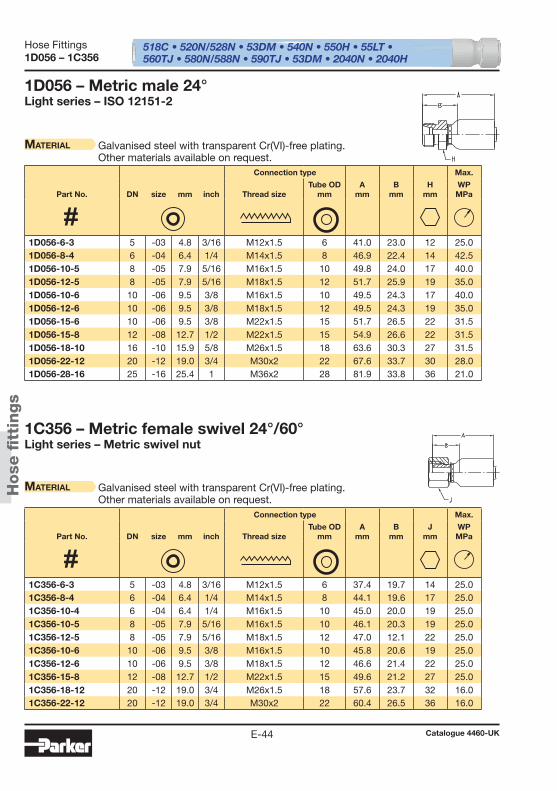
518C • 520N/528N • 53DM • 540N • 550H • 55LT • 560TJ • 580N/588N • 590TJ • 53DM • 2040N • 2040H
Hose
fi t
tings
Hose Fittings
Catalogue 4460-UKE-44
1D056 – 1C356
1D056 – Metric male 24°Light series – ISO 12151-2
Material Galvanised steel with transparent Cr(VI)-free plating.Other materials available on request.
1C356 – Metric female swivel 24°/60°Light series – Metric swivel nut
Material Galvanised steel with transparent Cr(VI)-free plating.Other materials available on request.
Connection type Max.
Part No. DN size mm inch Thread sizeTube OD
mmA
mmB
mmH
mmWPMPa
Connection type Max.
Part No. DN size mm inch Thread sizeTube OD
mmA
mmB
mmJ
mmWPMPa
1D056-6-3 5 -03 4.8 3/16 M12x1.5 6 41.0 23.0 12 25.0 1D056-8-4 6 -04 6.4 1/4 M14x1.5 8 46.9 22.4 14 42.5 1D056-10-5 8 -05 7.9 5/16 M16x1.5 10 49.8 24.0 17 40.0 1D056-12-5 8 -05 7.9 5/16 M18x1.5 12 51.7 25.9 19 35.0 1D056-10-6 10 -06 9.5 3/8 M16x1.5 10 49.5 24.3 17 40.0 1D056-12-6 10 -06 9.5 3/8 M18x1.5 12 49.5 24.3 19 35.0 1D056-15-6 10 -06 9.5 3/8 M22x1.5 15 51.7 26.5 22 31.5 1D056-15-8 12 -08 12.7 1/2 M22x1.5 15 54.9 26.6 22 31.5 1D056-18-10 16 -10 15.9 5/8 M26x1.5 18 63.6 30.3 27 31.5 1D056-22-12 20 -12 19.0 3/4 M30x2 22 67.6 33.7 30 28.0 1D056-28-16 25 -16 25.4 1 M36x2 28 81.9 33.8 36 21.0
1C356-6-3 5 -03 4.8 3/16 M12x1.5 6 37.4 19.7 14 25.0 1C356-8-4 6 -04 6.4 1/4 M14x1.5 8 44.1 19.6 17 25.0 1C356-10-4 6 -04 6.4 1/4 M16x1.5 10 45.0 20.0 19 25.0 1C356-10-5 8 -05 7.9 5/16 M16x1.5 10 46.1 20.3 19 25.0 1C356-12-5 8 -05 7.9 5/16 M18x1.5 12 47.0 12.1 22 25.0 1C356-10-6 10 -06 9.5 3/8 M16x1.5 10 45.8 20.6 19 25.0 1C356-12-6 10 -06 9.5 3/8 M18x1.5 12 46.6 21.4 22 25.0 1C356-15-8 12 -08 12.7 1/2 M22x1.5 15 49.6 21.2 27 25.0 1C356-18-12 20 -12 19.0 3/4 M26x1.5 18 57.6 23.7 32 16.0 1C356-22-12 20 -12 19.0 3/4 M30x2 22 60.4 26.5 36 16.0

518C • 520N/528N • 53DM • 540N • 550H • 55LT • 560TJ • 580N/588N • 590TJ • 53DM • 2040N • 2040H
Hose
fi t
tings
Hose Fittings
Catalogue 4460-UKE-45
E
1C456 – 1C556
1C556 – Metric female swivel 24°/60°90° elbow – Light series – Metric swivel nut
Material Galvanised steel with transparent Cr(VI)-free plating.Other materials available on request.
1C456 – Metric female swivel 24°/60°45° elbow – Light series – Metric swivel nut
Material Galvanised steel with transparent Cr(VI)-free plating.Other materials available on request.
Connection type Max.
Part No. DN size mm inch Thread sizeTube OD
mmA
mmB
mmE
mmJ
mmWPMPa
Connection type Max.
Part No. DN size mm inch Thread sizeTube OD
mmA
mmB
mmE
mmJ
mmWPMPa
1C556-6-3 5 -03 4.8 3/16 M12x1.5 6 48.0 30.3 30.0 14 25.0 1C556-8-4 6 -04 6.4 1/4 M14x1.5 8 53.0 28.0 26.0 17 25.0 1C556-10-4 6 -04 6.4 1/4 M16x1.5 10 53.0 28.0 27.0 19 25.0 1C556-10-5 8 -05 7.9 5/16 M18x1.5 10 66.0 40.0 33.0 19 25.0 1C556-10-6 10 -06 9.5 3/8 M16x1.5 10 63.0 38.0 33.3 19 25.0 1C556-12-6 10 -06 9.5 3/8 M18x1.5 12 63.0 38.0 34.0 22 25.0 1C556-15-8 12 -08 12.7 1/2 M22x1.5 15 96.8 68.4 39.0 27 25.0
1C456-6-3 5 -03 4.8 3/16 M12x1.5 6 57.0 40.0 16 14 25.0 1C456-8-4 6 -04 6.4 1/4 M14x1.5 8 60.0 35.8 14 17 25.0 1C456-10-5 8 -05 7.9 5/16 M16x1.5 10 62.0 37.0 15 19 25.0 1C456-12-6 10 -06 9.5 3/8 M18x1.5 12 72.5 47.0 18 22 25.0 1C456-15-8 12 -08 12.7 1/2 M22x1.5 15 76.1 47.7 19 27 25.0
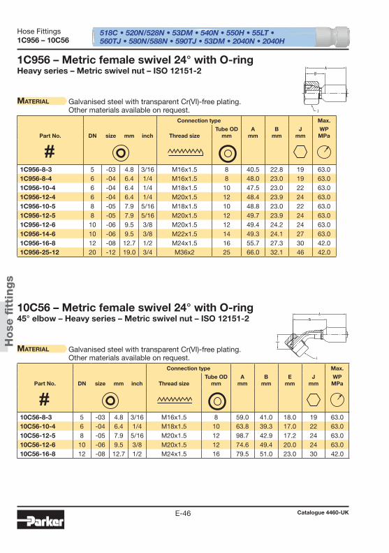
518C • 520N/528N • 53DM • 540N • 550H • 55LT • 560TJ • 580N/588N • 590TJ • 53DM • 2040N • 2040H
Hose
fi t
tings
Hose Fittings
Catalogue 4460-UKE-46
1C956 – 10C56
1C956 – Metric female swivel 24° with O-ringHeavy series – Metric swivel nut – ISO 12151-2
Material Galvanised steel with transparent Cr(VI)-free plating.Other materials available on request.
10C56 – Metric female swivel 24° with O-ring45° elbow – Heavy series – Metric swivel nut – ISO 12151-2
Material Galvanised steel with transparent Cr(VI)-free plating.Other materials available on request.
Connection type Max.
Part No. DN size mm inch Thread sizeTube OD
mmA
mmB
mmJ
mmWPMPa
Connection type Max.
Part No. DN size mm inch Thread sizeTube OD
mmA
mmB
mmE
mmJ
mmWPMPa
1C956-8-3 5 -03 4.8 3/16 M16x1.5 8 40.5 22.8 19 63.0 1C956-8-4 6 -04 6.4 1/4 M16x1.5 8 48.0 23.0 19 63.0 1C956-10-4 6 -04 6.4 1/4 M18x1.5 10 47.5 23.0 22 63.0 1C956-12-4 6 -04 6.4 1/4 M20x1.5 12 48.4 23.9 24 63.0 1C956-10-5 8 -05 7.9 5/16 M18x1.5 10 48.8 23.0 22 63.0 1C956-12-5 8 -05 7.9 5/16 M20x1.5 12 49.7 23.9 24 63.0 1C956-12-6 10 -06 9.5 3/8 M20x1.5 12 49.4 24.2 24 63.0 1C956-14-6 10 -06 9.5 3/8 M22x1.5 14 49.3 24.1 27 63.0 1C956-16-8 12 -08 12.7 1/2 M24x1.5 16 55.7 27.3 30 42.0 1C956-25-12 20 -12 19.0 3/4 M36x2 25 66.0 32.1 46 42.0
10C56-8-3 5 -03 4.8 3/16 M16x1.5 8 59.0 41.0 18.0 19 63.0 10C56-10-4 6 -04 6.4 1/4 M18x1.5 10 63.8 39.3 17.0 22 63.0 10C56-12-5 8 -05 7.9 5/16 M20x1.5 12 98.7 42.9 17.2 24 63.0 10C56-12-6 10 -06 9.5 3/8 M20x1.5 12 74.6 49.4 20.0 24 63.0 10C56-16-8 12 -08 12.7 1/2 M24x1.5 16 79.5 51.0 23.0 30 42.0
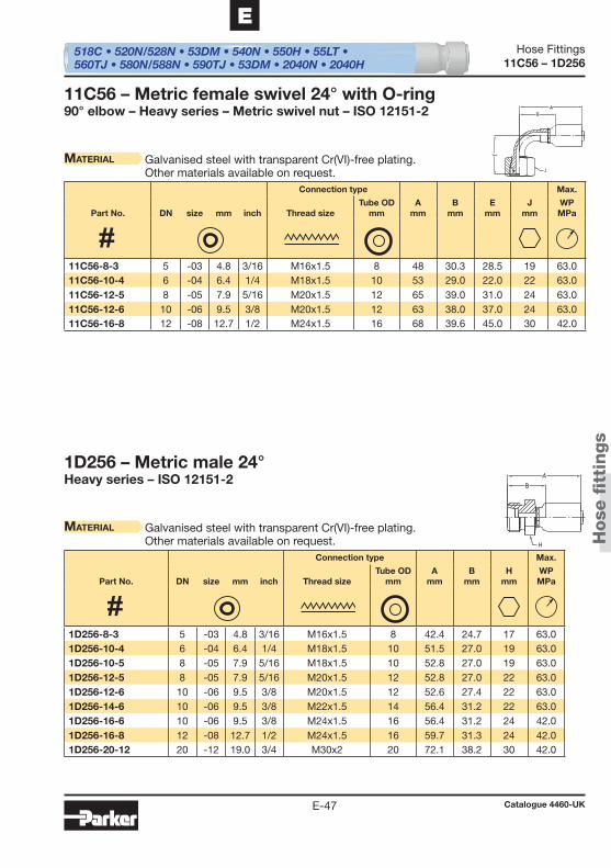
518C • 520N/528N • 53DM • 540N • 550H • 55LT • 560TJ • 580N/588N • 590TJ • 53DM • 2040N • 2040H
Hose
fi t
tings
Hose Fittings
Catalogue 4460-UKE-47
E
11C56 – 1D256
11C56 – Metric female swivel 24° with O-ring90° elbow – Heavy series – Metric swivel nut – ISO 12151-2
Material Galvanised steel with transparent Cr(VI)-free plating.Other materials available on request.
1D256 – Metric male 24°Heavy series – ISO 12151-2
Material Galvanised steel with transparent Cr(VI)-free plating.Other materials available on request.
Connection type Max.
Part No. DN size mm inch Thread sizeTube OD
mmA
mmB
mmE
mmJ
mmWPMPa
Connection type Max.
Part No. DN size mm inch Thread sizeTube OD
mmA
mmB
mmH
mmWPMPa
11C56-8-3 5 -03 4.8 3/16 M16x1.5 8 48 30.3 28.5 19 63.0 11C56-10-4 6 -04 6.4 1/4 M18x1.5 10 53 29.0 22.0 22 63.0 11C56-12-5 8 -05 7.9 5/16 M20x1.5 12 65 39.0 31.0 24 63.0 11C56-12-6 10 -06 9.5 3/8 M20x1.5 12 63 38.0 37.0 24 63.0 11C56-16-8 12 -08 12.7 1/2 M24x1.5 16 68 39.6 45.0 30 42.0
1D256-8-3 5 -03 4.8 3/16 M16x1.5 8 42.4 24.7 17 63.0 1D256-10-4 6 -04 6.4 1/4 M18x1.5 10 51.5 27.0 19 63.0 1D256-10-5 8 -05 7.9 5/16 M18x1.5 10 52.8 27.0 19 63.0 1D256-12-5 8 -05 7.9 5/16 M20x1.5 12 52.8 27.0 22 63.0 1D256-12-6 10 -06 9.5 3/8 M20x1.5 12 52.6 27.4 22 63.0 1D256-14-6 10 -06 9.5 3/8 M22x1.5 14 56.4 31.2 22 63.0 1D256-16-6 10 -06 9.5 3/8 M24x1.5 16 56.4 31.2 24 42.0 1D256-16-8 12 -08 12.7 1/2 M24x1.5 16 59.7 31.3 24 42.0 1D256-20-12 20 -12 19.0 3/4 M30x2 20 72.1 38.2 30 42.0
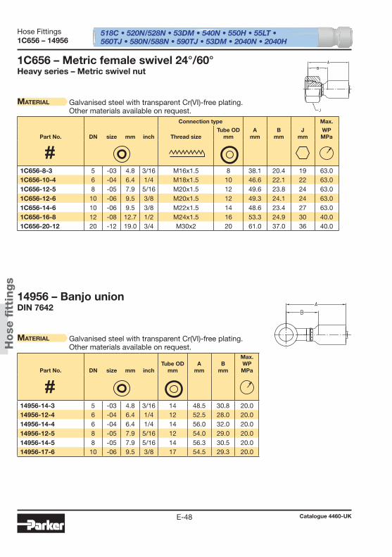
518C • 520N/528N • 53DM • 540N • 550H • 55LT • 560TJ • 580N/588N • 590TJ • 53DM • 2040N • 2040H
Hose
fi t
tings
Hose Fittings
Catalogue 4460-UKE-48
1C656 – 14956
14956 – Banjo unionDIN 7642
Material Galvanised steel with transparent Cr(VI)-free plating.Other materials available on request.
1C656 – Metric female swivel 24°/60°Heavy series – Metric swivel nut
Material Galvanised steel with transparent Cr(VI)-free plating.Other materials available on request.
Part No. DN size mm inchTube OD
mmA
mmB
mm
Max. WPMPa
Connection type Max.
Part No. DN size mm inch Thread sizeTube OD
mmA
mmB
mmJ
mmWPMPa
14956-14-3 5 -03 4.8 3/16 14 48.5 30.8 20.0 14956-12-4 6 -04 6.4 1/4 12 52.5 28.0 20.0 14956-14-4 6 -04 6.4 1/4 14 56.0 32.0 20.0 14956-12-5 8 -05 7.9 5/16 12 54.0 29.0 20.0 14956-14-5 8 -05 7.9 5/16 14 56.3 30.5 20.0 14956-17-6 10 -06 9.5 3/8 17 54.5 29.3 20.0
1C656-8-3 5 -03 4.8 3/16 M16x1.5 8 38.1 20.4 19 63.0 1C656-10-4 6 -04 6.4 1/4 M18x1.5 10 46.6 22.1 22 63.0 1C656-12-5 8 -05 7.9 5/16 M20x1.5 12 49.6 23.8 24 63.0 1C656-12-6 10 -06 9.5 3/8 M20x1.5 12 49.3 24.1 24 63.0 1C656-14-6 10 -06 9.5 3/8 M22x1.5 14 48.6 23.4 27 63.0 1C656-16-8 12 -08 12.7 1/2 M24x1.5 16 53.3 24.9 30 40.0 1C656-20-12 20 -12 19.0 3/4 M30x2 20 61.0 37.0 36 40.0
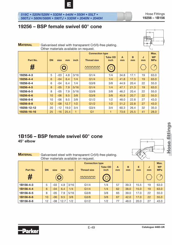
518C • 520N/528N • 53DM • 540N • 550H • 55LT • 560TJ • 580N/588N • 590TJ • 53DM • 2040N • 2040H
Hose
fi t
tings
Hose Fittings
Catalogue 4460-UKE-49
E
19256 – 1B156
19256 – BSP female swivel 60° cone
Material Galvanised steel with transparent Cr(VI)-free plating.Other materials available on request.
1B156 – BSP female swivel 60° cone45° elbow
Material Galvanised steel with transparent Cr(VI)-free plating.Other materials available on request.
Connection type Max.
Part No. DN size mm inch Thread sizeTube OD
inchA
mmB
mmJ
mmWPMPa
Connection type Max.
Part No. DN size mm inch Thread sizeTube OD
inchA
mmB
mmE
mmJ
mmWPMPa
19256-4-3 5 -03 4.8 3/16 G1/4 1/4 34.8 17.1 19 63.0 19256-4-4 6 -04 6.4 1/4 G1/4 1/4 41.8 17.3 19 63.0 19256-6-4 6 -04 6.4 1/4 G3/8 3/8 44.9 20.4 22 55.0 19256-4-5 8 -05 7.9 5/16 G1/4 1/4 47.1 21.3 19 63.0 19256-6-5 8 -05 7.9 5/16 G3/8 3/8 46.2 20.4 22 55.0 19256-6-6 10 -06 9.5 3/8 G3/8 3/8 45.9 20.7 22 55.0 19256-8-6 10 -06 9.5 3/8 G1/2 1/2 48.0 22.8 27 43.0 19256-8-8 12 -08 12.7 1/2 G1/2 1/2 51.2 22.8 27 43.0 19256-12-12 20 -12 19.0 3/4 G3/4 3/4 60.3 26.4 32 35.0 19256-16-16 25 -16 25.4 1 G1 1 73.6 25.5 41 28.0
1B156-4-3 5 -03 4.8 3/16 G1/4 1/4 57 39.3 15.5 19 63.0 1B156-4-4 6 -04 6.4 1/4 G1/4 1/4 62 38.0 15.0 19 63.0 1B156-6-5 8 -05 7.9 5/16 G3/8 3/8 65 39.0 17.0 22 55.0 1B156-6-6 10 -06 9.5 3/8 G3/8 3/8 67 42.0 17.0 22 55.0 1B156-8-8 12 -08 12.7 1/2 G1/2 1/2 77 48.0 20.0 27 43.0
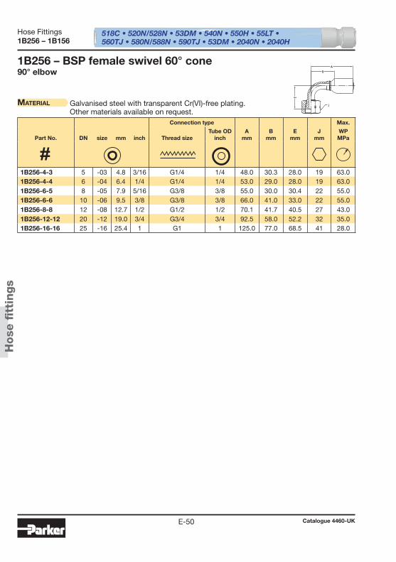
518C • 520N/528N • 53DM • 540N • 550H • 55LT • 560TJ • 580N/588N • 590TJ • 53DM • 2040N • 2040H
Hose
fi t
tings
Hose Fittings
Catalogue 4460-UKE-50
1B256 – 1B156
1B256 – BSP female swivel 60° cone90° elbow
Material Galvanised steel with transparent Cr(VI)-free plating.Other materials available on request.
Connection type Max.
Part No. DN size mm inch Thread sizeTube OD
inchA
mmB
mmE
mmJ
mmWPMPa
1B256-4-3 5 -03 4.8 3/16 G1/4 1/4 48.0 30.3 28.0 19 63.0 1B256-4-4 6 -04 6.4 1/4 G1/4 1/4 53.0 29.0 28.0 19 63.0 1B256-6-5 8 -05 7.9 5/16 G3/8 3/8 55.0 30.0 30.4 22 55.0 1B256-6-6 10 -06 9.5 3/8 G3/8 3/8 66.0 41.0 33.0 22 55.0 1B256-8-8 12 -08 12.7 1/2 G1/2 1/2 70.1 41.7 40.5 27 43.0 1B256-12-12 20 -12 19.0 3/4 G3/4 3/4 92.5 58.0 52.2 32 35.0 1B256-16-16 25 -16 25.4 1 G1 1 125.0 77.0 68.5 41 28.0
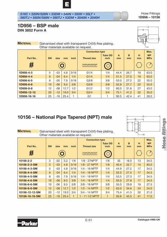
AB
H
518C • 520N/528N • 53DM • 540N • 550H • 55LT • 560TJ • 580N/588N • 590TJ • 53DM • 2040N • 2040H
Hose
fi t
tings
Hose Fittings
Catalogue 4460-UKE-51
E
1D956 – 10156
1D956 – BSP maleDIN 3852 Form A
Material Galvanised steel with transparent Cr(VI)-free plating.Other materials available on request.
10156 – National Pipe Tapered (NPT) male
Material Galvanised steel with transparent Cr(VI)-free plating.Other materials available on request.
Connection type Max.
Part No. DN size mm inch Thread sizeTube OD
inchA
mmB
mmH
mmWPMPa
Connection type Max.
Part No. DN size mm inch Thread sizeTube OD
inchA
mmB
mmH
mmWPMPa
1D956-4-3 5 -03 4.8 3/16 G1/4 1/4 44.4 26.7 19 63.0 1D956-4-4 6 -04 6.4 1/4 G1/4 1/4 51.5 27.0 19 63.0 1D956-6-5 8 -05 7.9 5/16 G3/8 3/8 53.0 27.2 22 55.0 1D956-6-6 10 -06 9.5 3/8 G3/8 3/8 52.9 27.7 22 55.0 1D956-8-8 12 -08 12.7 1/2 G1/2 1/2 60.0 31.6 27 43.0 1D956-12-12 20 -12 19.0 3/4 G3/4 3/4 75.1 41.2 32 35.0 1D956-16-16 25 -16 25.4 1 G1 1 90.5 42.4 41 28.0
10156-2-2 3 -02 3.2 1/8 1/8 - 27NPTF 1/8 35 18.0 13 34.5 10156-2-3-SM 5 -03 4.8 3/16 1/8 - 27 NPTF 1/8 40.4 22.7 14 83.0 10156-4-3-SM 5 -03 4.8 3/16 1/4 - 18 NPTF 1/4 44.9 27.2 17 34.5 10156-4-4-SM 6 -04 6.4 1/4 1/4 - 18 NPTF 1/4 52.0 27.5 17 34.5 10156-4-5-SM 8 -05 7.9 5/16 1/4 - 18 NPTF 1/4 53.5 27.3 17 34.5 10156-4-6-SM 10 -06 9.5 3/8 1/4 - 18 NPTF 1/4 55.0 27.8 17 34.5 10156-6-6-SM 10 -06 9.5 3/8 3/8 - 18 NPTF 3/8 55.0 29.8 19 27.5 10156-8-8-SM 12 -08 12.7 1/2 1/2 - 14 NPTF 1/2 63.0 34.6 24 24.0 10156-12-12-SM 20 -12 19.0 3/4 3/4 - 14 NPTF 3/4 75.4 41.5 32 21.0 10156-16-16-SM 25 -16 25.4 1 1 - 11 1/2 NPTF 1 93.6 45.5 41 17.0
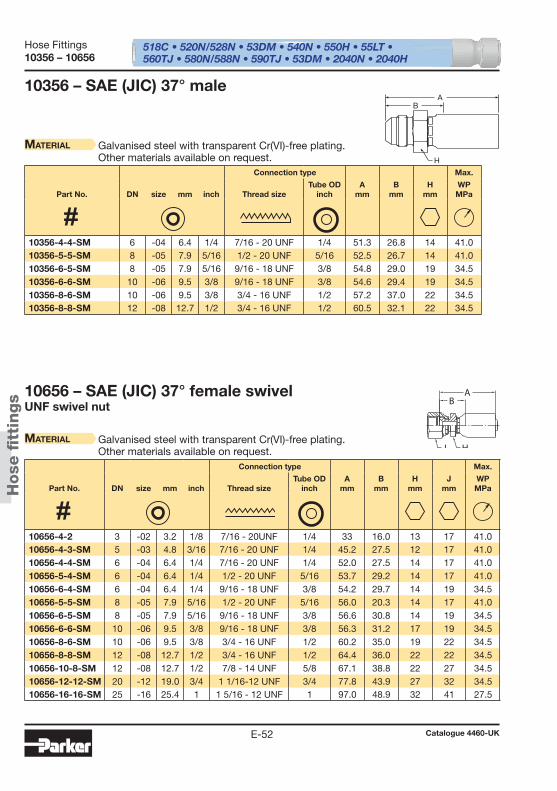
A
H
B
AB
J H
518C • 520N/528N • 53DM • 540N • 550H • 55LT • 560TJ • 580N/588N • 590TJ • 53DM • 2040N • 2040H
Hose
fi t
tings
Hose Fittings
Catalogue 4460-UKE-52
10356 – 10656
10356 – SAE (JIC) 37° male
Material Galvanised steel with transparent Cr(VI)-free plating.Other materials available on request.
10656 – SAE (JIC) 37° female swivelUNF swivel nut
Material Galvanised steel with transparent Cr(VI)-free plating.Other materials available on request.
Connection type Max.
Part No. DN size mm inch Thread sizeTube OD
inchA
mmB
mmH
mmWPMPa
Connection type Max.
Part No. DN size mm inch Thread sizeTube OD
inchA
mmB
mmH
mmJ
mmWPMPa
10356-4-4-SM 6 -04 6.4 1/4 7/16 - 20 UNF 1/4 51.3 26.8 14 41.0 10356-5-5-SM 8 -05 7.9 5/16 1/2 - 20 UNF 5/16 52.5 26.7 14 41.0 10356-6-5-SM 8 -05 7.9 5/16 9/16 - 18 UNF 3/8 54.8 29.0 19 34.5 10356-6-6-SM 10 -06 9.5 3/8 9/16 - 18 UNF 3/8 54.6 29.4 19 34.5 10356-8-6-SM 10 -06 9.5 3/8 3/4 - 16 UNF 1/2 57.2 37.0 22 34.5 10356-8-8-SM 12 -08 12.7 1/2 3/4 - 16 UNF 1/2 60.5 32.1 22 34.5
10656-4-2 3 -02 3.2 1/8 7/16 - 20UNF 1/4 33 16.0 13 17 41.0 10656-4-3-SM 5 -03 4.8 3/16 7/16 - 20 UNF 1/4 45.2 27.5 12 17 41.0 10656-4-4-SM 6 -04 6.4 1/4 7/16 - 20 UNF 1/4 52.0 27.5 14 17 41.0 10656-5-4-SM 6 -04 6.4 1/4 1/2 - 20 UNF 5/16 53.7 29.2 14 17 41.0 10656-6-4-SM 6 -04 6.4 1/4 9/16 - 18 UNF 3/8 54.2 29.7 14 19 34.5 10656-5-5-SM 8 -05 7.9 5/16 1/2 - 20 UNF 5/16 56.0 20.3 14 17 41.0 10656-6-5-SM 8 -05 7.9 5/16 9/16 - 18 UNF 3/8 56.6 30.8 14 19 34.5 10656-6-6-SM 10 -06 9.5 3/8 9/16 - 18 UNF 3/8 56.3 31.2 17 19 34.5 10656-8-6-SM 10 -06 9.5 3/8 3/4 - 16 UNF 1/2 60.2 35.0 19 22 34.5 10656-8-8-SM 12 -08 12.7 1/2 3/4 - 16 UNF 1/2 64.4 36.0 22 22 34.5 10656-10-8-SM 12 -08 12.7 1/2 7/8 - 14 UNF 5/8 67.1 38.8 22 27 34.5 10656-12-12-SM 20 -12 19.0 3/4 1 1/16-12 UNF 3/4 77.8 43.9 27 32 34.5 10656-16-16-SM 25 -16 25.4 1 1 5/16 - 12 UNF 1 97.0 48.9 32 41 27.5
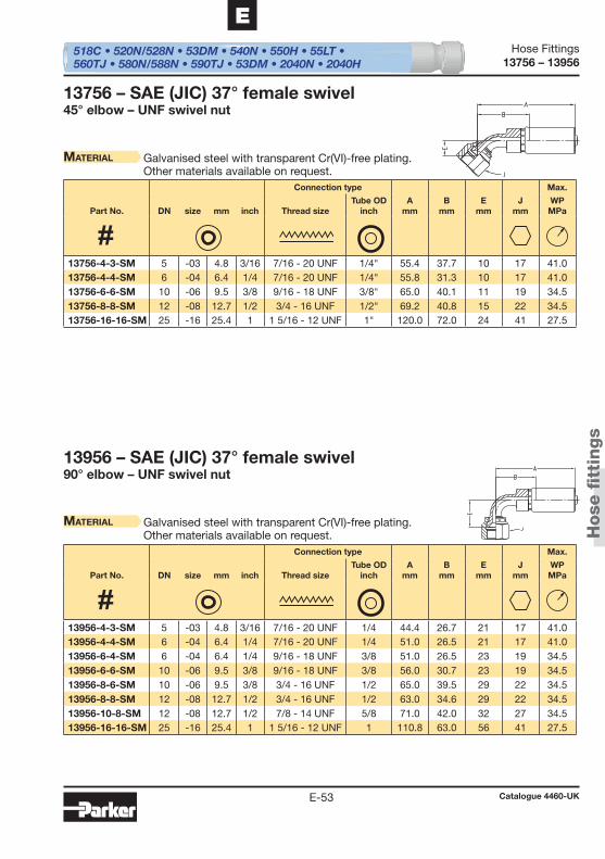
518C • 520N/528N • 53DM • 540N • 550H • 55LT • 560TJ • 580N/588N • 590TJ • 53DM • 2040N • 2040H
Hose
fi t
tings
Hose Fittings
Catalogue 4460-UKE-53
E
13756 – 13956
13756 – SAE (JIC) 37° female swivel45° elbow – UNF swivel nut
Material Galvanised steel with transparent Cr(VI)-free plating.Other materials available on request.
13956 – SAE (JIC) 37° female swivel90° elbow – UNF swivel nut
Material Galvanised steel with transparent Cr(VI)-free plating.Other materials available on request.
Connection type Max.
Part No. DN size mm inch Thread sizeTube OD
inchA
mmB
mmE
mmJ
mmWPMPa
Connection type Max.
Part No. DN size mm inch Thread sizeTube OD
inchA
mmB
mmE
mmJ
mmWPMPa
13756-4-3-SM 5 -03 4.8 3/16 7/16 - 20 UNF 1/4" 55.4 37.7 10 17 41.0 13756-4-4-SM 6 -04 6.4 1/4 7/16 - 20 UNF 1/4" 55.8 31.3 10 17 41.0 13756-6-6-SM 10 -06 9.5 3/8 9/16 - 18 UNF 3/8" 65.0 40.1 11 19 34.5 13756-8-8-SM 12 -08 12.7 1/2 3/4 - 16 UNF 1/2" 69.2 40.8 15 22 34.5 13756-16-16-SM 25 -16 25.4 1 1 5/16 - 12 UNF 1" 120.0 72.0 24 41 27.5
13956-4-3-SM 5 -03 4.8 3/16 7/16 - 20 UNF 1/4 44.4 26.7 21 17 41.0 13956-4-4-SM 6 -04 6.4 1/4 7/16 - 20 UNF 1/4 51.0 26.5 21 17 41.0 13956-6-4-SM 6 -04 6.4 1/4 9/16 - 18 UNF 3/8 51.0 26.5 23 19 34.5 13956-6-6-SM 10 -06 9.5 3/8 9/16 - 18 UNF 3/8 56.0 30.7 23 19 34.5 13956-8-6-SM 10 -06 9.5 3/8 3/4 - 16 UNF 1/2 65.0 39.5 29 22 34.5 13956-8-8-SM 12 -08 12.7 1/2 3/4 - 16 UNF 1/2 63.0 34.6 29 22 34.5 13956-10-8-SM 12 -08 12.7 1/2 7/8 - 14 UNF 5/8 71.0 42.0 32 27 34.5 13956-16-16-SM 25 -16 25.4 1 1 5/16 - 12 UNF 1 110.8 63.0 56 41 27.5
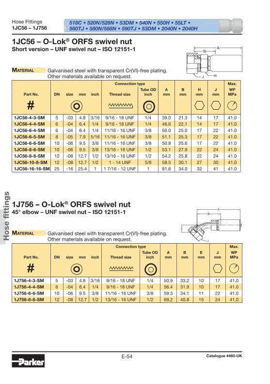
J
BA
H
518C • 520N/528N • 53DM • 540N • 550H • 55LT • 560TJ • 580N/588N • 590TJ • 53DM • 2040N • 2040H
Hose
fi t
tings
Hose Fittings
Catalogue 4460-UKE-54
1JC56 – 1J756
1JC56 – O-Lok® ORFS swivel nutShort version – UNF swivel nut – ISO 12151-1
Material Galvanised steel with transparent Cr(VI)-free plating.Other materials available on request.
1J756 – O-Lok® ORFS swivel nut45° elbow – UNF swivel nut – ISO 12151-1
Material Galvanised steel with transparent Cr(VI)-free plating.Other materials available on request.
Connection type Max.
Part No. DN size mm inch Thread sizeTube OD
inchA
mmB
mmH
mmJ
mmWPMPa
Connection type Max.
Part No. DN size mm inch Thread sizeTube OD
inchA
mmB
mmE
mmJ
mmWPMPa
1JC56-4-3-SM 5 -03 4.8 3/16 9/16 - 18 UNF 1/4 39.0 21.3 14 17 41.0 1JC56-4-4-SM 6 -04 6.4 1/4 9/16 - 18 UNF 1/4 46.6 22.1 14 17 41.0 1JC56-6-4-SM 6 -04 6.4 1/4 11/16 - 16 UNF 3/8 50.0 25.0 17 22 41.0 1JC56-6-5-SM 8 -05 7.9 5/16 11/16 - 16 UNF 3/8 51.1 25.3 17 22 41.0 1JC56-6-6-SM 10 -06 9.5 3/8 11/16 - 16 UNF 3/8 50.8 25.6 17 22 41.0 1JC56-8-6-SM 10 -06 9.5 3/8 13/16 - 16 UNF 1/2 53.1 27.9 22 24 41.0 1JC56-8-8-SM 12 -08 12.7 1/2 13/16 - 16 UNF 1/2 54.2 25.8 22 24 41.0 1JC56-10-8-SM 12 -08 12.7 1/2 1 - 14 UNF 5/8 58.5 30.1 27 30 41.0 1JC56-16-16-SM 25 -16 25.4 1 1 7/16 - 12 UNF 1 81.6 34.0 32 41 41.0
1J756-4-3-SM 5 -03 4.8 3/16 9/16 - 18 UNF 1/4 50.9 33.2 10 17 41.0 1J756-4-4-SM 6 -04 6.4 1/4 9/16 - 18 UNF 1/4 56.4 31.9 10 17 41.0 1J756-6-6-SM 10 -06 9.5 3/8 11/16 - 16 UNF 3/8 59.3 34.1 11 22 41.0 1J756-8-8-SM 12 -08 12.7 1/2 13/16 - 16 UNF 1/2 69.2 40.8 15 24 41.0

H
BA
518C • 520N/528N • 53DM • 540N • 550H • 55LT • 560TJ • 580N/588N • 590TJ • 53DM • 2040N • 2040H
Hose
fi t
tings
Hose Fittings
Catalogue 4460-UKE-55
E
1J956 – 1J056
1J956 – O-Lok® ORFS swivel nut90° elbow – UNF swivel nut – ISO 12151-1
Material Galvanised steel with transparent Cr(VI)-free plating.Other materials available on request.
1J056 – O-Lok® ORFS maleISO 12151-1
Material Galvanised steel with transparent Cr(VI)-free plating.Other materials available on request.
Connection type Max.
Part No. DN size mm inch Thread sizeTube OD
inchA
mmB
mmE
mmJ
mmWPMPa
Connection type Max.
Part No. DN size mm inch Thread sizeTube OD
inchA
mmB
mmH
mmWPMPa
1J956-4-3-SM 5 -03 4.8 3/16 9/16 - 18 UNF 1/4 46.0 28.3 21 17 41.0 1J956-4-4-SM 6 -04 6.4 1/4 9/16 - 18 UNF 1/4 54.0 26.5 21 17 41.0 1J956-6-4-SM 6 -04 6.4 1/4 11/16 - 16 UNF 3/8 54.5 30.0 23 22 41.0 1J956-6-5-SM 8 -05 7.9 5/16 11/16 - 16 UNF 3/8 57.8 32.0 23 22 41.0 1J956-6-6-SM 10 -06 9.5 3/8 11/16 - 16 UNF 3/8 56.3 31.1 23 22 41.0 1J956-8-8-SM 12 -08 12.7 1/2 13/16 - 16 UNF 1/2 63.0 34.6 29 24 41.0 1J956-10-8-SM 12 -08 12.7 1/2 1 - 14 UNF 5/8 71.0 42.0 32 30 41.0 1J956-12-12-SM 20 -12 19.0 3/4 1 3/16 - 12 UNF 3/4 99.0 65.0 48 36 41.0 1J956-16-16-SM 25 -16 25.4 1 1 7/16 - 12 UNF 1 110.8 63.0 56 41 41.0
1J056-4-4-SM 6 -04 6.4 1/4 9/16 - 18 UNF 1/4 42.9 24.7 17 41.0 1J056-6-6-SM 10 -06 9.5 3/8 11/16 - 16 UNF 3/8 52.3 28.1 19 41.0 1J056-8-6-SM 10 -06 9.5 3/8 13/16 - 16 UNF 1/2 54.6 29.4 22 41.0 1J056-8-8-SM 12 -08 12.7 1/2 13/16 - 16 UNF 1/2 55.4 27.0 22 41.0
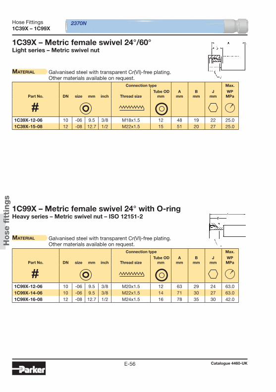
2370N
Hose
fi t
tings
Hose Fittings
Catalogue 4460-UKE-56
1C39X – 1C99X
1C39X – Metric female swivel 24°/60°Light series – Metric swivel nut
Material Galvanised steel with transparent Cr(VI)-free plating.Other materials available on request.
1C99X – Metric female swivel 24° with O-ringHeavy series – Metric swivel nut – ISO 12151-2
Material Galvanised steel with transparent Cr(VI)-free plating.Other materials available on request.
Connection type Max.
Part No. DN size mm inch Thread size Tube OD
mmA
mmB
mmJ
mmWPMPa
Connection type Max.
Part No. DN size mm inch Thread size Tube OD
mmA
mmB
mmJ
mmWPMPa
1C39X-12-06 10 -06 9.5 3/8 M18x1.5 12 48 19 22 25.0 1C39X-15-08 12 -08 12.7 1/2 M22x1.5 15 51 20 27 25.0
1C99X-12-06 10 -06 9.5 3/8 M20x1.5 12 63 29 24 63.0 1C99X-14-06 10 -06 9.5 3/8 M22x1.5 14 71 30 27 63.0 1C99X-16-08 12 -08 12.7 1/2 M24x1.5 16 78 35 30 42.0
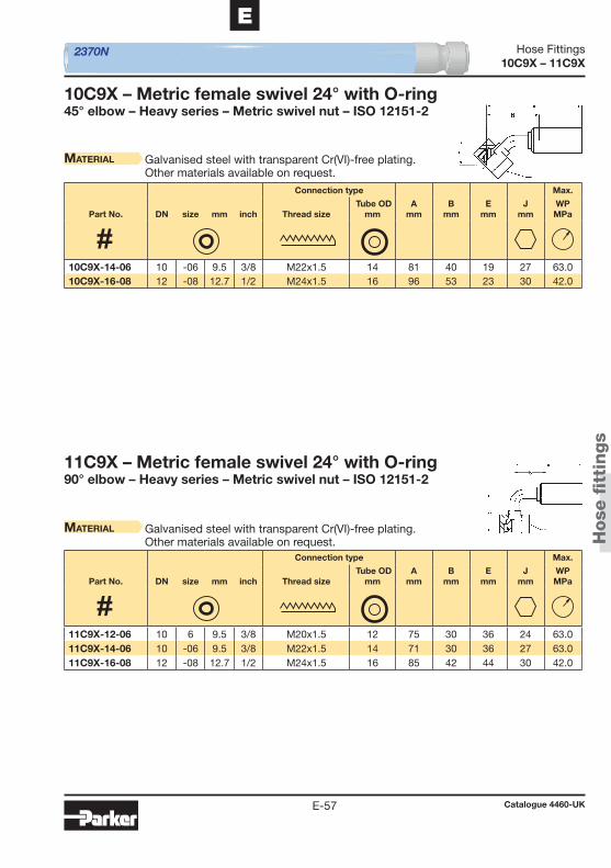
2370N
Hose
fi t
tings
Hose Fittings
Catalogue 4460-UKE-57
E
10C9X – 11C9X
10C9X – Metric female swivel 24° with O-ring45° elbow – Heavy series – Metric swivel nut – ISO 12151-2
Material Galvanised steel with transparent Cr(VI)-free plating.Other materials available on request.
11C9X – Metric female swivel 24° with O-ring90° elbow – Heavy series – Metric swivel nut – ISO 12151-2
Material Galvanised steel with transparent Cr(VI)-free plating.Other materials available on request.
Connection type Max.
Part No. DN size mm inch Thread size Tube OD
mmA
mmB
mmE
mmJ
mmWPMPa
Connection type Max.
Part No. DN size mm inch Thread size Tube OD
mmA
mmB
mmE
mmJ
mmWPMPa
10C9X-14-06 10 -06 9.5 3/8 M22x1.5 14 81 40 19 27 63.0 10C9X-16-08 12 -08 12.7 1/2 M24x1.5 16 96 53 23 30 42.0
11C9X-12-06 10 6 9.5 3/8 M20x1.5 12 75 30 36 24 63.0 11C9X-14-06 10 -06 9.5 3/8 M22x1.5 14 71 30 36 27 63.0 11C9X-16-08 12 -08 12.7 1/2 M24x1.5 16 85 42 44 30 42.0

2370N
Hose
fi t
tings
Hose Fittings
Catalogue 4460-UKE-58
1D29X – 1929X
1D29X – Metric male 24°Heavy series – ISO 12151-2
Material Galvanised steel with transparent Cr(VI)-free plating.Other materials available on request.
1929X – BSP female swivel 60° cone
Material Galvanised steel with transparent Cr(VI)-free plating.Other materials available on request.
Connection type Max.
Part No. DN size mm inch Thread size Tube OD
mmA
mmB
mmH
mmWPMPa
Part No. DN size mm inch
Connection type
Thread sizeA
mmB
mmJ
mm
Max. WPMPa
1D29X-14-06 10 -06 9.5 3/8 M22x1.5 14 71 31 22 63.0 1D29X-16-08 12 -08 12.7 1/2 M24x1.5 16 74 31 24 42.0
1929X-6-06 10 -06 9.5 3/8 G 3/8 59 19 22 55.0 1929X-8-08 12 -08 12.7 1/2 G 1/2 63 20 27 43.0
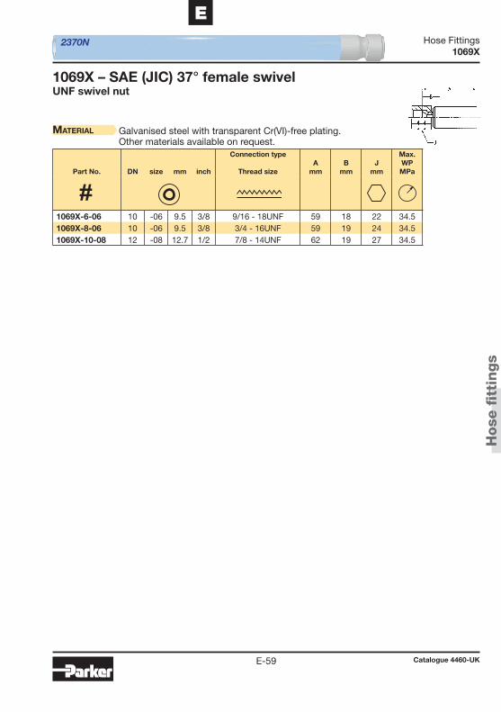
2370N
Hose
fi t
tings
Hose Fittings
Catalogue 4460-UKE-59
E
1069X
1069X – SAE (JIC) 37° female swivelUNF swivel nut
Material Galvanised steel with transparent Cr(VI)-free plating.Other materials available on request.
Part No. DN size mm inch
Connection type
Thread sizeA
mmB
mmJ
mm
Max. WPMPa
1069X-6-06 10 -06 9.5 3/8 9/16 - 18UNF 59 18 22 34.5 1069X-8-06 10 -06 9.5 3/8 3/4 - 16UNF 59 19 24 34.5 1069X-10-08 12 -08 12.7 1/2 7/8 - 14UNF 62 19 27 34.5
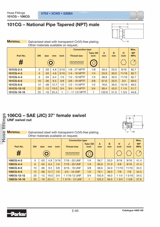
575X • 5CNG • 526BA
AB
H
AB
J H
Hose
fi t
tings
Hose Fittings
Catalogue 4460-UKE-60
101CG – 106CG
101CG – National Pipe Tapered (NPT) male
Material Galvanised steel with transparent Cr(VI)-free plating.Other materials available on request.
106CG – SAE (JIC) 37° female swivelUNF swivel nut
Material Galvanised steel with transparent Cr(VI)-free plating.Other materials available on request.
Connection type Max.
Part No. DN size mm inch Thread size Tube OD
inchA
mmB
mmH
inchWPMPa
Connection type Max.
Part No. DN size mm inch Thread size Tube OD
inchA
mmB
mmH
inchJ
inchWPMPa
101CG-2-3 5 -03 4.8 3/16 1/8 - 27 NPTF 1/8 49.4 25.0 9/16 82.7 101CG-4-3 5 -03 4.8 3/16 1/4 - 18 NPTF 1/4 53.9 30.0 11/16 82.7 101CG-4-4 6 -04 6.4 1/4 1/4 - 18 NPTF 1/4 58.8 30.0 11/16 82.7 101CG-6-6 10 -06 9.5 3/8 3/8 - 18 NPTF 3/8 67.6 33.0 3/4 69.0 101CG-8-8 12 -08 12.7 1/2 1/2 - 14 NPTF 1/2 78.6 39.0 15/16 69.0 101CG-12-12 20 -12 19.0 3/4 3/4 - 14 NPTF 3/4 99.4 43.0 1 1/4 51.7 101CG-16-16 25 -16 25.4 1 1 - 11 1/2 NPTF 1 120.9 51.0 1 3/4 44.8
106CG-4-3 5 -03 4.8 3/16 7/16 - 20 UNF 1/4 56.7 33.0 9/16 9/16 41.4 106CG-4-4 6 -04 6.4 1/4 7/16 - 20 UNF 1/4 60.0 31.0 5/8 9/16 41.4 106CG-6-6 10 -06 9.5 3/8 9/16 - 18 UNF 3/8 68.6 34.0 11/16 11/16 34.5 106CG-8-8 12 -08 12.7 1/2 3/4 - 16 UNF 1/2 78.1 38.0 7/8 7/8 34.5 106CG-12-12 20 -12 19.0 3/4 1 1/16-12 UNF 3/4 105.9 46.0 1 1/4 1 5/16 34.5 106CG-16-16 25 -16 25.4 1 1 5/16 - 12 UNF 1 125.3 56.0 1 3/4 1 5/8 27.6
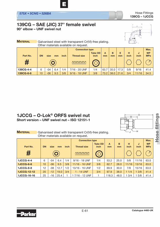
J
BA
H
575X • 5CNG • 526BA
Hose
fi t
tings
Hose Fittings
Catalogue 4460-UKE-61
E
139CG – 1JCCG
139CG – SAE (JIC) 37° female swivel90° elbow – UNF swivel nut
Material Galvanised steel with transparent Cr(VI)-free plating.Other materials available on request.
1JCCG – O-Lok® ORFS swivel nutShort version – UNF swivel nut – ISO 12151-1
Material Galvanised steel with transparent Cr(VI)-free plating.Other materials available on request.
Connection type Max.
Part No. DN size mm inch Thread size Tube OD
inchA
mmB
mmE
mmH
inchJ
inchWPMPa
Connection type Max.
Part No. DN size mm inch Thread size Tube OD
inchA
mmB
mmH
inchJ
inchWPMPa
139CG-4-4 6 -04 6.4 1/4 7/16 - 20 UNF 1/4 63.7 35.0 17.3 5/8 9/16 41.4 139CG-6-6 10 -06 9.5 3/8 9/16 - 18 UNF 3/8 73.2 38.0 21.6 3/4 11/16 34.5
1JCCG-4-4 6 -04 6.4 1/4 9/16 - 18 UNF 1/4 53.2 25.0 5/8 11/16 63.0 1JCCG-6-6 10 -06 9.5 3/8 11/16 - 16 UNF 3/8 62.7 28.0 11/16 13/16 63.0 1JCCG-8-8 12 -08 12.7 1/2 13/16 - 16 UNF 1/2 69.9 30.0 7/8 15/16 63.0 1JCCG-12-12 20 -12 19.0 3/4 1 - 14 UNF 3/4 97.9 38.0 1 1/4 1 3/8 41.4 1JCCG-16-16 25 -16 25.4 1 1 7/16 - 12 UNF 1 118.3 48.0 1 3/4 1 5/8 41.4
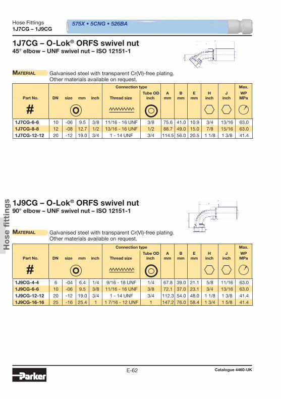
575X • 5CNG • 526BA
Hose
fi t
tings
Hose Fittings
Catalogue 4460-UKE-62
1J7CG – 1J9CG
1J7CG – O-Lok® ORFS swivel nut45° elbow – UNF swivel nut – ISO 12151-1
Material Galvanised steel with transparent Cr(VI)-free plating.Other materials available on request.
1J9CG – O-Lok® ORFS swivel nut90° elbow – UNF swivel nut – ISO 12151-1
Material Galvanised steel with transparent Cr(VI)-free plating.Other materials available on request.
Connection type Max.
Part No. DN size mm inch Thread size Tube OD
inchA
mmB
mmE
mmH
inchJ
inchWPMPa
Connection type Max.
Part No. DN size mm inch Thread size Tube OD
inchA
mmB
mmE
mmH
inchJ
inchWPMPa
1J7CG-6-6 10 -06 9.5 3/8 11/16 - 16 UNF 3/8 75.6 41.0 10.9 3/4 13/16 63.0 1J7CG-8-8 12 -08 12.7 1/2 13/16 - 16 UNF 1/2 88.7 49.0 15.0 7/8 15/16 63.0 1J7CG-12-12 20 -12 19.0 3/4 1 - 14 UNF 3/4 114.5 56.0 20.5 1 1/8 1 3/8 41.4
1J9CG-4-4 6 -04 6.4 1/4 9/16 - 18 UNF 1/4 67.8 39.0 21.1 5/8 11/16 63.0 1J9CG-6-6 10 -06 9.5 3/8 11/16 - 16 UNF 3/8 72.1 37.0 23.1 3/4 13/16 63.0 1J9CG-12-12 20 -12 19.0 3/4 1 - 14 UNF 3/4 112.3 54.0 48.0 1 1/8 1 3/8 41.4 1J9CG-16-16 25 -16 25.4 1 1 7/16 - 12 UNF 1 147.2 76.0 58.4 1 3/4 1 5/8 41.4
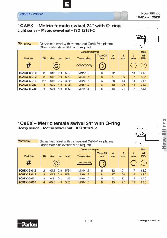
2010H • 2020N
Hose
fi t
tings
Hose Fittings
Catalogue 4460-UKE-63
E
1CAEX – 1C9EX
1CAEX – Metric female swivel 24° with O-ringLight series – Metric swivel nut – ISO 12151-2
Material Galvanised steel with transparent Cr(VI)-free plating.Other materials available on request.
1C9EX – Metric female swivel 24° with O-ringHeavy series – Metric swivel nut – ISO 12151-2
Material Galvanised steel with transparent Cr(VI)-free plating.Other materials available on request.
Connection type Max.
Part No. DN size mm inch Thread size Tube OD
mmA
mmB
mmJ
mmWPMPa
Connection type Max.
Part No. DN size mm inch Thread size Tube OD
mmA
mmB
mmJ
mmWPMPa
1CAEX-6-012 2 -012 2.0 5/64 M12x1.5 6 32 21 14 31.5 1CAEX-8-012 2 -012 2.0 5/64 M14x1.5 8 37 26 17 42.5 1CAEX-6-016 2.5 -016 2.5 3/32 M12x1.5 6 28 18 14 31.5 1CAEX-6-025 4 -025 4.0 5/32 M12x1.5 6 42 20 14 31.5 1CAEX-8-025 4 -025 4.0 5/32 M14x1.5 8 48 24 17 42.5
1C9EX-6-012 2 -012 2.0 5/64 M14x1.5 6 32 21 17 63.0 1C9EX-8-012 2 -012 2.0 5/64 M16x1.5 8 37 26 19 63.0 1C9EX-8-02 3 -02 3.2 1/8 M16x1.5 8 32 22 19 63.0 1C9EX-8-025 4 -025 4.0 5/32 M16x1.5 8 45 22 19 63.0
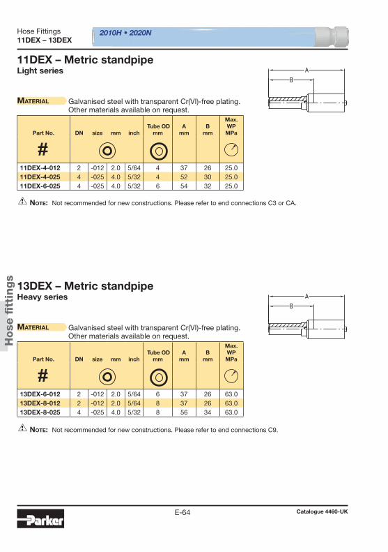
2010H • 2020N
Hose
fi t
tings
Hose Fittings
Catalogue 4460-UKE-64
11DEX – 13DEX
11DEX – Metric standpipeLight series
Material Galvanised steel with transparent Cr(VI)-free plating.Other materials available on request.
Note: Not recommended for new constructions. Please refer to end connections C3 or CA.
13DEX – Metric standpipeHeavy series
Material Galvanised steel with transparent Cr(VI)-free plating.Other materials available on request.
Note: Not recommended for new constructions. Please refer to end connections C9.
Part No. DN size mm inch Tube OD
mmA
mmB
mm
Max. WPMPa
Part No. DN size mm inch Tube OD
mmA
mmB
mm
Max. WPMPa
11DEX-4-012 2 -012 2.0 5/64 4 37 26 25.0 11DEX-4-025 4 -025 4.0 5/32 4 52 30 25.0 11DEX-6-025 4 -025 4.0 5/32 6 54 32 25.0
13DEX-6-012 2 -012 2.0 5/64 6 37 26 63.0 13DEX-8-012 2 -012 2.0 5/64 8 37 26 63.0 13DEX-8-025 4 -025 4.0 5/32 8 56 34 63.0
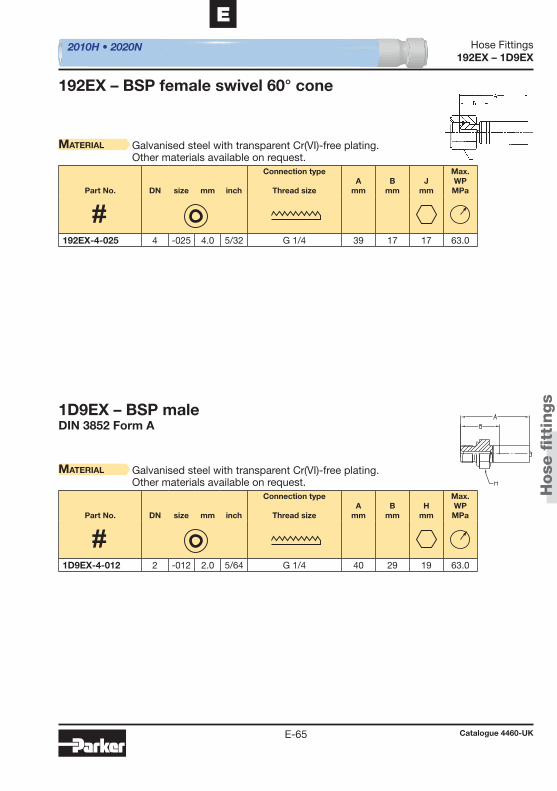
2010H • 2020N
Hose
fi t
tings
Hose Fittings
Catalogue 4460-UKE-65
E
192EX – 1D9EX
1D9EX – BSP maleDIN 3852 Form A
192EX – BSP female swivel 60° cone
Material Galvanised steel with transparent Cr(VI)-free plating.Other materials available on request.
Material Galvanised steel with transparent Cr(VI)-free plating.Other materials available on request.
Part No. DN size mm inch
Connection type
Thread sizeA
mmB
mmJ
mm
Max. WPMPa
Part No. DN size mm inch
Connection type
Thread sizeA
mmB
mmH
mm
Max. WPMPa
192EX-4-025 4 -025 4.0 5/32 G 1/4 39 17 17 63.0
1D9EX-4-012 2 -012 2.0 5/64 G 1/4 40 29 19 63.0
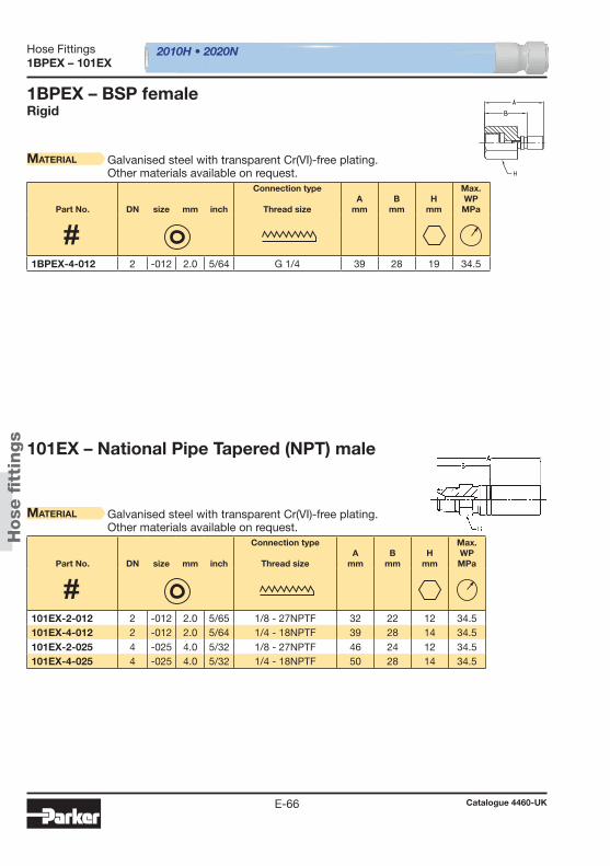
2010H • 2020N
Hose
fi t
tings
Hose Fittings
Catalogue 4460-UKE-66
1BPEX – 101EX
1BPEX – BSP femaleRigid
Material Galvanised steel with transparent Cr(VI)-free plating.Other materials available on request.
101EX – National Pipe Tapered (NPT) male
Material Galvanised steel with transparent Cr(VI)-free plating.Other materials available on request.
Part No. DN size mm inch
Connection type
Thread sizeA
mmB
mmH
mm
Max. WPMPa
Part No. DN size mm inch
Connection type
Thread sizeA
mmB
mmH
mm
Max. WPMPa
1BPEX-4-012 2 -012 2.0 5/64 G 1/4 39 28 19 34.5
101EX-2-012 2 -012 2.0 5/65 1/8 - 27NPTF 32 22 12 34.5 101EX-4-012 2 -012 2.0 5/64 1/4 - 18NPTF 39 28 14 34.5 101EX-2-025 4 -025 4.0 5/32 1/8 - 27NPTF 46 24 12 34.5 101EX-4-025 4 -025 4.0 5/32 1/4 - 18NPTF 50 28 14 34.5

2010H • 2020N
Hose
fi t
tings
Hose Fittings
Catalogue 4460-UKE-67
E
106EX – 1JCEX
106EX – SAE (JIC) 37° female swivelUNF swivel nut
Material Galvanised steel with transparent Cr(VI)-free plating.Other materials available on request.
1JCEX – O-Lok® ORFS swivel nutShort version – UNF swivel nut – ISO 12151-1
Material Galvanised steel with transparent Cr(VI)-free plating.Other materials available on request.
Part No. DN size mm inch
Connection type
Thread sizeA
mmB
mmJ
mm
Max. WPMPa
Connection type Max.
Part No. DN size mm inch Thread size Tube OD
inchA
mmB
mmJ
mmWPMPa
106EX-3-012 2 -012 2.0 5/64 3/8 - 24UNF 23 12 14 41.0 106EX-4-012 2 -012 2.0 5/64 7/16 - 20UNF 25 14 17 41.0 106EX-4-025 4 -025 4.0 5/32 7/16 - 20UNF 40 18 17 41.0
1JCEX-4-012 2 -012 2.0 5/64 9/16 - 18 UNF 1/4 28 17 14 41.0 1JCEX-6-012 2 -012 2.0 5/64 11/16 - 16 UNF 3/8 26 15 22 41.0

2010H • 2020N
Hose
fi t
tings
Hose Fittings
Catalogue 4460-UKE-68
149EX – 1R8EX
149EX – Banjo unionDIN 7642
Material Galvanised steel with transparent Cr(VI)-free plating.Other materials available on request.
1R8EX – Quick connect fi tting with metric swivel nutKnurled
Material Galvanised steel with transparent Cr(VI)-free plating.Other materials available on request.
Part No. DN size mm inch Tube OD
mmA
mmB
mm
Max. WPMPa
Part No. DN size mm inch
Connection type
Thread sizeA
mmB
mm
Max. WPMPa
149EX-8-02 3 -02 3.2 1/8 8 23 13 20.0 149EX-10-025 4 -025 4.0 5/32 10 44 22 20.0
1R8EX-11-012 2 -012 2.0 5/64 M16x2 30 19 63.0 1R8EX-11-02 3 -02 3.2 1/8 M16x2 30 20 63.0

2010H • 2020N
Hose
fi t
tings
Hose Fittings
Catalogue 4460-UKE-69
E
1YPEX – 1YREX
1YPEX – Quick connect fi tting with clip
Material Galvanised steel with transparent Cr(VI)-free plating.Other materials available on request.
1YREX – Quick connect fi tting with metric swivel nut
Material Galvanised steel with transparent Cr(VI)-free plating.Other materials available on request.
Part No.
Fitting
Part No.
Clip DN size mm inch
Connection type
Thread sizeA
mmB
mm
Max. WPMPa
Part No. DN size mm inch
Connection type
Thread sizeA
mmB
mmJ
mm
Max. WPMPa
1YPEX-3-012 HG-DN2 02 -12 2.0 5/64 - 28 17 63.0
1YREX-10-012 2 -012 2.0 5/64 M16x1.5 30 19 19 63.0 1YREX-11-012 2 -012 2.0 5/64 M16x2 30 19 19 63.0
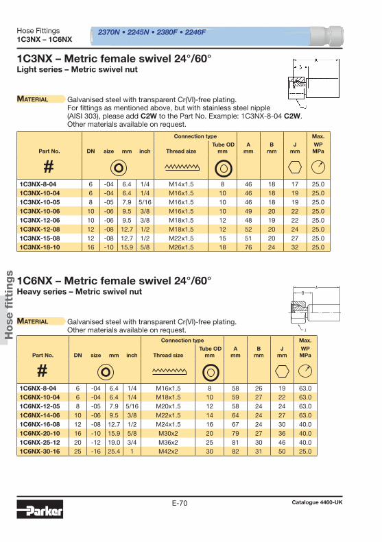
2370N • 2245N • 2380F • 2246F
Hose
fi t
tings
Hose Fittings
Catalogue 4460-UKE-70
1C3NX – 1C6NX
1C3NX – Metric female swivel 24°/60°Light series – Metric swivel nut
Material Galvanised steel with transparent Cr(VI)-free plating.For fi ttings as mentioned above, but with stainless steel nipple(AISI 303), please add C2W to the Part No. Example: 1C3NX-8-04 C2W.Other materials available on request.
Material Galvanised steel with transparent Cr(VI)-free plating.Other materials available on request.
1C6NX – Metric female swivel 24°/60°Heavy series – Metric swivel nut
Connection type Max.
Part No. DN size mm inch Thread size Tube OD
mmA
mmB
mmJ
mmWPMPa
Connection type Max.
Part No. DN size mm inch Thread size Tube OD
mmA
mmB
mmJ
mmWPMPa
1C3NX-8-04 6 -04 6.4 1/4 M14x1.5 8 46 18 17 25.0 1C3NX-10-04 6 -04 6.4 1/4 M16x1.5 10 46 18 19 25.0 1C3NX-10-05 8 -05 7.9 5/16 M16x1.5 10 46 18 19 25.0 1C3NX-10-06 10 -06 9.5 3/8 M16x1.5 10 49 20 22 25.0 1C3NX-12-06 10 -06 9.5 3/8 M18x1.5 12 48 19 22 25.0 1C3NX-12-08 12 -08 12.7 1/2 M18x1.5 12 52 20 24 25.0 1C3NX-15-08 12 -08 12.7 1/2 M22x1.5 15 51 20 27 25.0 1C3NX-18-10 16 -10 15.9 5/8 M26x1.5 18 76 24 32 25.0
1C6NX-8-04 6 -04 6.4 1/4 M16x1.5 8 58 26 19 63.0 1C6NX-10-04 6 -04 6.4 1/4 M18x1.5 10 59 27 22 63.0 1C6NX-12-05 8 -05 7.9 5/16 M20x1.5 12 58 24 24 63.0 1C6NX-14-06 10 -06 9.5 3/8 M22x1.5 14 64 24 27 63.0 1C6NX-16-08 12 -08 12.7 1/2 M24x1.5 16 67 24 30 40.0 1C6NX-20-10 16 -10 15.9 5/8 M30x2 20 79 27 36 40.0 1C6NX-25-12 20 -12 19.0 3/4 M36x2 25 81 30 46 40.0 1C6NX-30-16 25 -16 25.4 1 M42x2 30 82 31 50 25.0
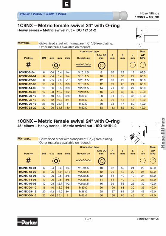
2370N • 2245N • 2380F • 2246F
Hose
fi t
tings
Hose Fittings
Catalogue 4460-UKE-71
E
1C9NX – 10CNX
Material Galvanised steel with transparent Cr(VI)-free plating.Other materials available on request.
1C9NX – Metric female swivel 24° with O-ringHeavy series – Metric swivel nut – ISO 12151-2
10CNX – Metric female swivel 24° with O-ring45° elbow – Heavy series – Metric swivel nut – ISO 12151-2
Material Galvanised steel with transparent Cr(VI)-free plating.Other materials available on request.
Connection type Max.
Part No. DN size mm inch Thread size Tube OD
mmA
mmB
mmJ
mmWPMPa
Connection type Max.
Part No. DN size mm inch Thread size Tube OD
mmA
mmB
mmE
mmJ
mmWPMPa
1C9NX-8-04 6 -04 6.4 1/4 M16x1.5 8 60 28 19 63.0 1C9NX-10-04 6 -04 6.4 1/4 M18x1.5 10 65 33 22 63.0 1C9NX-12-05 8 -05 7.9 5/16 M20x1.5 12 63 29 24 63.0 1C9NX-12-06 10 -06 9.5 3/8 M18x1.5 12 69 28 24 63.0 1C9NX-14-06 10 -06 9.5 3/8 M22x1.5 14 71 30 27 63.0 1C9NX-16-08 12 -08 12.7 1/2 M24x1.5 16 78 35 30 42.0 1C9NX-20-10 16 -10 15.9 5/8 M30x2 20 91 40 36 42.0 1C9NX-25-12 20 -12 19.0 3/4 M36x2 25 96 45 46 42.0 1C9NX-30-16 25 -16 25.4 1 M42x2 30 98 47 50 42.0 1C9NX-38-20 32 -20 31.8 1 1/4 M52x2 38 113 52 60 42.0
10CNX-10-04 6 -04 6.4 1/4 M18x1.5 10 82 50 24 22 63.0 10CNX-12-05 8 -05 7.9 5/16 M20x1.5 12 76 42 20 24 63.0 10CNX-12-06 10 -06 9.5 3/8 M20x1.5 12 81 40 19 24 63.0 10CNX-14-06 10 -06 9.5 3/8 M22x1.5 14 81 40 19 27 63.0 10CNX-16-08 12 -08 12.7 1/2 M24x1.5 16 96 53 23 30 42.0 10CNX-20-10 16 -10 15.9 5/8 M30x2 20 120 68 30 36 42.0 10CNX-25-12 20 -12 19.0 3/4 M36x2 25 137 85 37 46 42.0 10CNX-30-16 25 -16 25.4 1 M42x2 30 136 85 43 50 42.0
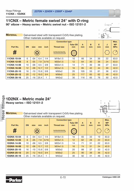
2370N • 2245N • 2380F • 2246F
Hose
fi t
tings
Hose Fittings
Catalogue 4460-UKE-72
11CNX – 1D2NX
11CNX – Metric female swivel 24° with O-ring90° elbow – Heavy series – Metric swivel nut – ISO 12151-2
Material Galvanised steel with transparent Cr(VI)-free plating.Other materials available on request.
1D2NX – Metric male 24°Heavy series – ISO 12151-2
Material Galvanised steel with transparent Cr(VI)-free plating.Other materials available on request.
Connection type Max.
Part No. DN size mm inch Thread size Tube OD
mmA
mmB
mmE
mmJ
mmWPMPa
Connection type Max.
Part No. DN size mm inch Thread size Tube OD
mmA
mmB
mmH
mmWPMPa
11CNX-10-04 6 -04 6.4 1/4 M18x1.5 10 66 34 36 22 63.0 11CNX-12-05 8 -05 7.9 5/16 M20x1.5 12 64 30 36 24 63.0 11CNX-14-06 10 -06 9.5 3/8 M22x1.5 14 71 30 36 27 63.0 11CNX-16-08 12 -08 12.7 1/2 M24x1.5 16 85 42 44 30 42.0 11CNX-20-10 16 -10 15.9 5/8 M30x2 20 105 53 61 36 42.0 11CNX-25-12 20 -12 19.0 3/4 M36x2 25 117 65 62 46 42.0 11CNX-30-16 25 -16 25.4 1 M42x2 30 116 65 76 50 42.0
1D2NX-10-04 6 -04 6.4 1/4 M18x1.5 10 65 33 19 63.0 1D2NX-12-05 8 -05 7.9 5/16 M20x1.5 12 62 28 22 63.0 1D2NX-14-06 10 -06 9.5 3/8 M22x1.5 14 71 31 22 63.0 1D2NX-16-08 12 -08 12.7 1/2 M24x1.5 16 74 31 24 42.0 1D2NX-20-10 16 -10 15.9 5/8 M30x2 20 88 37 30 42.0 1D2NX-25-12 20 -12 19.0 3/4 M36x2 25 90 39 36 42.0 1D2NX-30-16 25 -16 25.4 1 M42x2 30 92 41 46 42.0
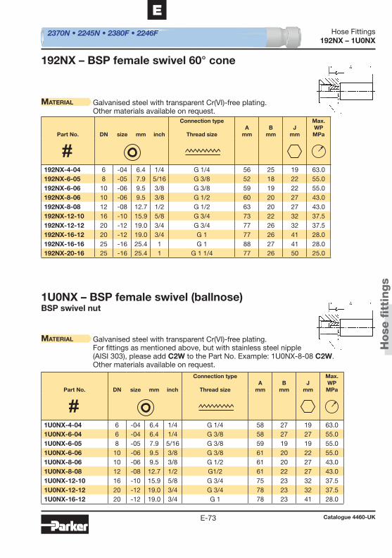
2370N • 2245N • 2380F • 2246F
Hose
fi t
tings
Hose Fittings
Catalogue 4460-UKE-73
E
192NX – 1U0NX
192NX – BSP female swivel 60° cone
Material Galvanised steel with transparent Cr(VI)-free plating.Other materials available on request.
1U0NX – BSP female swivel (ballnose)BSP swivel nut
Material Galvanised steel with transparent Cr(VI)-free plating.For fi ttings as mentioned above, but with stainless steel nipple(AISI 303), please add C2W to the Part No. Example: 1U0NX-8-08 C2W.Other materials available on request.
Part No. DN size mm inch
Connection type
Thread sizeA
mmB
mmJ
mm
Max. WPMPa
Part No. DN size mm inch
Connection type
Thread sizeA
mmB
mmJ
mm
Max. WPMPa
192NX-4-04 6 -04 6.4 1/4 G 1/4 56 25 19 63.0 192NX-6-05 8 -05 7.9 5/16 G 3/8 52 18 22 55.0 192NX-6-06 10 -06 9.5 3/8 G 3/8 59 19 22 55.0 192NX-8-06 10 -06 9.5 3/8 G 1/2 60 20 27 43.0 192NX-8-08 12 -08 12.7 1/2 G 1/2 63 20 27 43.0 192NX-12-10 16 -10 15.9 5/8 G 3/4 73 22 32 37.5 192NX-12-12 20 -12 19.0 3/4 G 3/4 77 26 32 37.5 192NX-16-12 20 -12 19.0 3/4 G 1 77 26 41 28.0 192NX-16-16 25 -16 25.4 1 G 1 88 27 41 28.0 192NX-20-16 25 -16 25.4 1 G 1 1/4 77 26 50 25.0
1U0NX-4-04 6 -04 6.4 1/4 G 1/4 58 27 19 63.0 1U0NX-6-04 6 -04 6.4 1/4 G 3/8 58 27 27 55.0 1U0NX-6-05 8 -05 7.9 5/16 G 3/8 59 19 19 55.0 1U0NX-6-06 10 -06 9.5 3/8 G 3/8 61 20 22 55.0 1U0NX-8-06 10 -06 9.5 3/8 G 1/2 61 20 27 43.0 1U0NX-8-08 12 -08 12.7 1/2 G1/2 61 22 27 43.0 1U0NX-12-10 16 -10 15.9 5/8 G 3/4 75 23 32 37.5 1U0NX-12-12 20 -12 19.0 3/4 G 3/4 78 23 32 37.5 1U0NX-16-12 20 -12 19.0 3/4 G 1 78 23 41 28.0
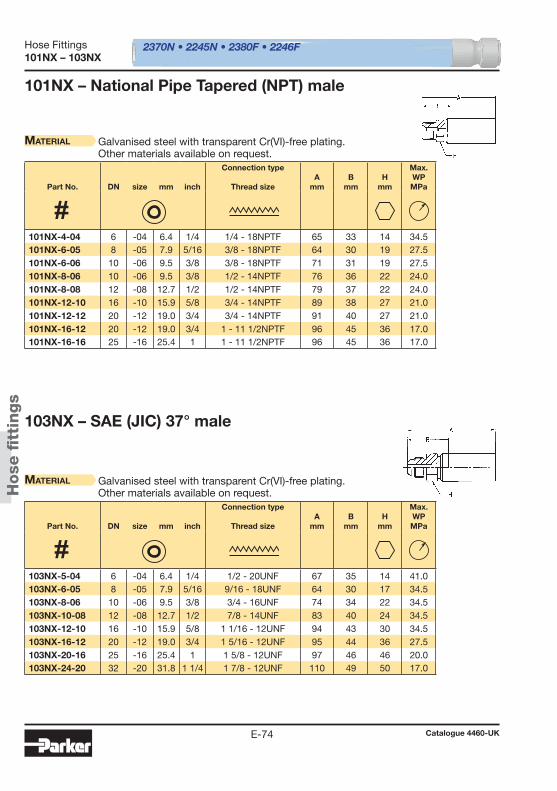
2370N • 2245N • 2380F • 2246F
Hose
fi t
tings
Hose Fittings
Catalogue 4460-UKE-74
101NX – 103NX
101NX – National Pipe Tapered (NPT) male
Material Galvanised steel with transparent Cr(VI)-free plating.Other materials available on request.
103NX – SAE (JIC) 37° male
Material Galvanised steel with transparent Cr(VI)-free plating.Other materials available on request.
Part No. DN size mm inch
Connection type
Thread sizeA
mmB
mmH
mm
Max. WPMPa
Part No. DN size mm inch
Connection type
Thread sizeA
mmB
mmH
mm
Max. WPMPa
101NX-4-04 6 -04 6.4 1/4 1/4 - 18NPTF 65 33 14 34.5 101NX-6-05 8 -05 7.9 5/16 3/8 - 18NPTF 64 30 19 27.5 101NX-6-06 10 -06 9.5 3/8 3/8 - 18NPTF 71 31 19 27.5 101NX-8-06 10 -06 9.5 3/8 1/2 - 14NPTF 76 36 22 24.0 101NX-8-08 12 -08 12.7 1/2 1/2 - 14NPTF 79 37 22 24.0 101NX-12-10 16 -10 15.9 5/8 3/4 - 14NPTF 89 38 27 21.0 101NX-12-12 20 -12 19.0 3/4 3/4 - 14NPTF 91 40 27 21.0 101NX-16-12 20 -12 19.0 3/4 1 - 11 1/2NPTF 96 45 36 17.0 101NX-16-16 25 -16 25.4 1 1 - 11 1/2NPTF 96 45 36 17.0
103NX-5-04 6 -04 6.4 1/4 1/2 - 20UNF 67 35 14 41.0 103NX-6-05 8 -05 7.9 5/16 9/16 - 18UNF 64 30 17 34.5 103NX-8-06 10 -06 9.5 3/8 3/4 - 16UNF 74 34 22 34.5 103NX-10-08 12 -08 12.7 1/2 7/8 - 14UNF 83 40 24 34.5 103NX-12-10 16 -10 15.9 5/8 1 1/16 - 12UNF 94 43 30 34.5 103NX-16-12 20 -12 19.0 3/4 1 5/16 - 12UNF 95 44 36 27.5 103NX-20-16 25 -16 25.4 1 1 5/8 - 12UNF 97 46 46 20.0 103NX-24-20 32 -20 31.8 1 1/4 1 7/8 - 12UNF 110 49 50 17.0

2370N • 2245N • 2380F • 2246F
Hose
fi t
tings
Hose Fittings
Catalogue 4460-UKE-75
E
106NX – 107NX
107NX – NPSM female swivel
Material Galvanised steel with transparent Cr(VI)-free plating.For fi ttings as mentioned above, but with stainless steel nipple(AISI 303), please add C2W to the Part No. Example: 107NX-4-04 C2W.Other materials available on request.
106NX – SAE (JIC) 37° female swivelUNF swivel nut
Material Galvanised steel with transparent Cr(VI)-free plating.Other materials available on request.
Part No. DN size mm inch
Connection type
Thread sizeA
mmB
mmJ
mm
Max. WPMPa
Part No. DN size mm inch
Connection type
Thread sizeA
mmB
mmJ
mm
Max. WPMPa
107NX-4-04 6 -04 6.4 1/4 1/4 - 18NPSM 47 19 19 34.5 107NX-6-05 8 -05 7.9 5/16 3/8 - 18NPSM 48 20 22 27.5 107NX-6-06 10 -06 9.5 3/8 3/8 - 18NPSM 50 21 22 27.5 107NX-8-08 12 -08 12.7 1/2 1/2 - 14NPSM 50 19 27 24.0 107NX-12-10 16 -10 15.9 5/8 3/4 - 14NPSM 53 22 32 21.0 107NX-12-12 20 -12 19.0 3/4 3/4 - 14NPSM 59 24 32 21.0
106NX-4-04 6 -04 6.4 1/4 7/16 - 20UNF 58 25 19 41.0 106NX-5-04 6 -04 6.4 1/4 1/2 - 20UNF 55 23 19 41.0 106NX-6-05 8 -05 7.9 5/16 9/16 - 18UNF 50 16 19 34.5 106NX-6-06 10 -06 9.5 3/8 9/16 - 18UNF 59 18 22 34.5 106NX-8-06 10 -06 9.5 3/8 3/4 - 16UNF 59 19 24 34.5 106NX-8-08 12 -08 12.7 1/2 3/4 - 16UNF 64 21 27 34.5 106NX-10-08 12 -08 12.7 1/2 7/8 - 14UNF 62 19 27 34.5 106NX-10-10 16 -10 15.9 5/8 7/8 - 14UNF 73 22 27 34.5 106NX-12-10 16 -10 15.9 5/8 1 1/16 - 12UNF 73 22 32 34.5 106NX-12-12 20 -12 19.0 3/4 1 1/16 - 12UNF 79 28 36 34.5 106NX-16-12 20 -12 19.0 3/4 1 5/16 - 12UNF 75 24 41 27.5 106NX-16-16 25 -16 25.4 1 1 5/16 - 12UNF 77 26 41 27.5 106NX-20-16 25 -16 25.4 1 1 5/8 - 12UNF 75 24 50 20.0
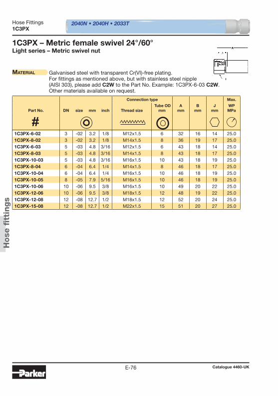
2040N • 2040H • 2033T
Hose
fi t
tings
Hose Fittings
Catalogue 4460-UKE-76
1C3PX
1C3PX – Metric female swivel 24°/60°Light series – Metric swivel nut
Material Galvanised steel with transparent Cr(VI)-free plating.For fi ttings as mentioned above, but with stainless steel nipple(AISI 303), please add C2W to the Part No. Example: 1C3PX-6-03 C2W.Other materials available on request.
Connection type Max.
Part No. DN size mm inch Thread size Tube OD
mmA
mmB
mmJ
mmWPMPa
1C3PX-6-02 3 -02 3.2 1/8 M12x1.5 6 32 16 14 25.0 1C3PX-8-02 3 -02 3.2 1/8 M14x1.5 8 36 19 17 25.0 1C3PX-6-03 5 -03 4.8 3/16 M12x1.5 6 43 18 14 25.0 1C3PX-8-03 5 -03 4.8 3/16 M14x1.5 8 43 18 17 25.0 1C3PX-10-03 5 -03 4.8 3/16 M16x1.5 10 43 18 19 25.0 1C3PX-8-04 6 -04 6.4 1/4 M14x1.5 8 46 18 17 25.0 1C3PX-10-04 6 -04 6.4 1/4 M16x1.5 10 46 18 19 25.0 1C3PX-10-05 8 -05 7.9 5/16 M16x1.5 10 46 18 19 25.0 1C3PX-10-06 10 -06 9.5 3/8 M16x1.5 10 49 20 22 25.0 1C3PX-12-06 10 -06 9.5 3/8 M18x1.5 12 48 19 22 25.0 1C3PX-12-08 12 -08 12.7 1/2 M18x1.5 12 52 20 24 25.0 1C3PX-15-08 12 -08 12.7 1/2 M22x1.5 15 51 20 27 25.0
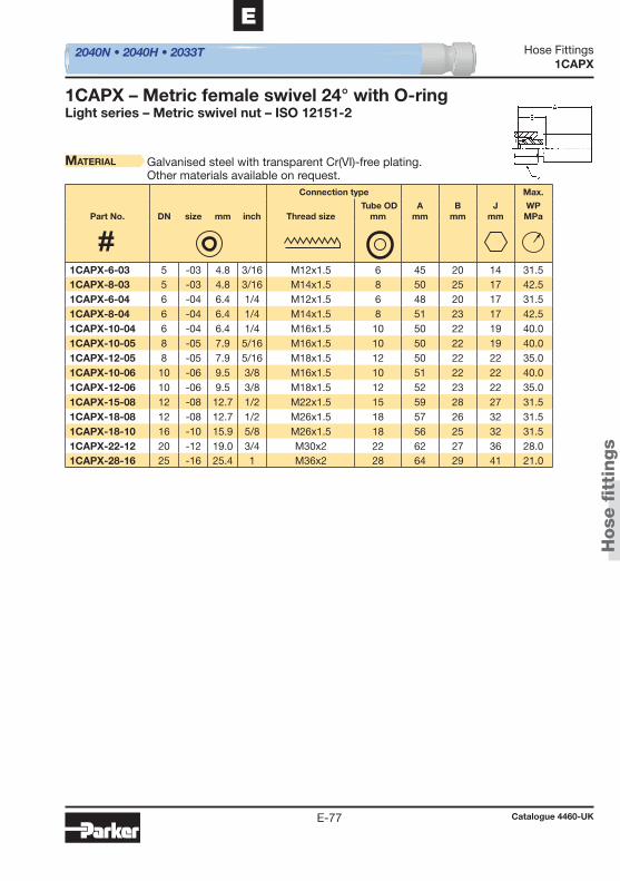
2040N • 2040H • 2033T
Hose
fi t
tings
Hose Fittings
Catalogue 4460-UKE-77
E
1CAPX
1CAPX – Metric female swivel 24° with O-ringLight series – Metric swivel nut – ISO 12151-2
Material Galvanised steel with transparent Cr(VI)-free plating.Other materials available on request.
Connection type Max.
Part No. DN size mm inch Thread size Tube OD
mmA
mmB
mmJ
mmWPMPa
1CAPX-6-03 5 -03 4.8 3/16 M12x1.5 6 45 20 14 31.5 1CAPX-8-03 5 -03 4.8 3/16 M14x1.5 8 50 25 17 42.5 1CAPX-6-04 6 -04 6.4 1/4 M12x1.5 6 48 20 17 31.5 1CAPX-8-04 6 -04 6.4 1/4 M14x1.5 8 51 23 17 42.5 1CAPX-10-04 6 -04 6.4 1/4 M16x1.5 10 50 22 19 40.0 1CAPX-10-05 8 -05 7.9 5/16 M16x1.5 10 50 22 19 40.0 1CAPX-12-05 8 -05 7.9 5/16 M18x1.5 12 50 22 22 35.0 1CAPX-10-06 10 -06 9.5 3/8 M16x1.5 10 51 22 22 40.0 1CAPX-12-06 10 -06 9.5 3/8 M18x1.5 12 52 23 22 35.0 1CAPX-15-08 12 -08 12.7 1/2 M22x1.5 15 59 28 27 31.5 1CAPX-18-08 12 -08 12.7 1/2 M26x1.5 18 57 26 32 31.5 1CAPX-18-10 16 -10 15.9 5/8 M26x1.5 18 56 25 32 31.5 1CAPX-22-12 20 -12 19.0 3/4 M30x2 22 62 27 36 28.0 1CAPX-28-16 25 -16 25.4 1 M36x2 28 64 29 41 21.0
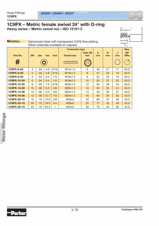
2040N • 2040H • 2033T
Hose
fi t
tings
Hose Fittings
Catalogue 4460-UKE-78
1C9PX
1C9PX – Metric female swivel 24° with O-ringHeavy series – Metric swivel nut – ISO 12151-2
Material Galvanised steel with transparent Cr(VI)-free plating.Other materials available on request.
Connection type Max.
Part No. DN size mm inch Thread size Tube OD
mmA
mmB
mmJ
mmWPMPa
1C9PX-6-03 5 -03 4.8 3/16 M14x1.5 6 46 21 17 63.0 1C9PX-8-03 5 -03 4.8 3/16 M16x1.5 8 47 22 19 63.0 1C9PX-8-04 6 -04 6.4 1/4 M16x1.5 8 52 24 19 63.0 1C9PX-10-04 6 -04 6.4 1/4 M18x1.5 10 55 27 22 63.0 1C9PX-12-05 8 -05 7.9 5/16 M20x1.5 12 56 28 24 63.0 1C9PX-12-06 10 -06 9.5 3/8 M20x1.5 12 54 25 24 63.0 1C9PX-14-06 10 -06 9.5 3/8 M22x1.5 14 59 30 27 63.0 1C9PX-16-08 12 -08 12.7 1/2 M24x1.5 16 65 34 30 42.0 1C9PX-20-10 16 -10 15.9 5/8 M30x2 20 68 37 36 42.0 1C9PX-25-12 20 -12 19.0 3/4 M36x2 25 77 42 46 42.0 1C9PX-30-16 25 -16 25.4 1 M42x2 30 79 45 50 42.0
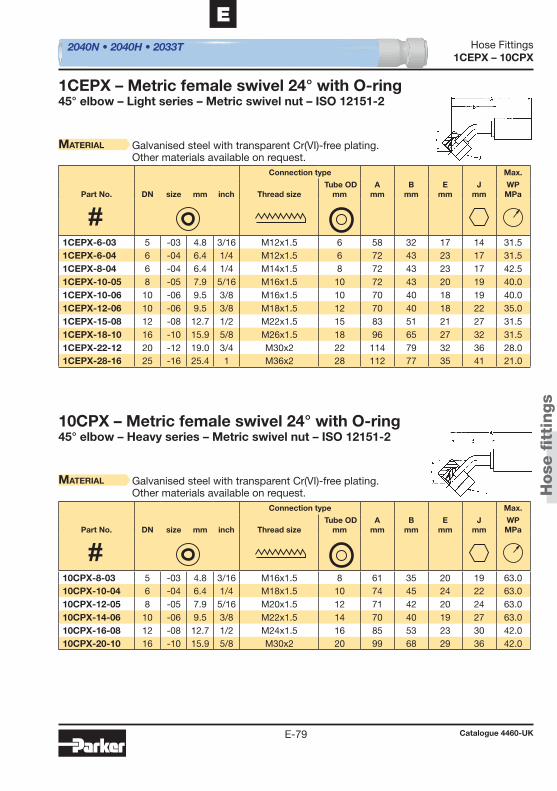
2040N • 2040H • 2033T
Hose
fi t
tings
Hose Fittings
Catalogue 4460-UKE-79
E
1CEPX – 10CPX
1CEPX – Metric female swivel 24° with O-ring45° elbow – Light series – Metric swivel nut – ISO 12151-2
Material Galvanised steel with transparent Cr(VI)-free plating.Other materials available on request.
10CPX – Metric female swivel 24° with O-ring45° elbow – Heavy series – Metric swivel nut – ISO 12151-2
Material Galvanised steel with transparent Cr(VI)-free plating.Other materials available on request.
Connection type Max.
Part No. DN size mm inch Thread size Tube OD
mmA
mmB
mmE
mmJ
mmWPMPa
Connection type Max.
Part No. DN size mm inch Thread size Tube OD
mmA
mmB
mmE
mmJ
mmWPMPa
1CEPX-6-03 5 -03 4.8 3/16 M12x1.5 6 58 32 17 14 31.5 1CEPX-6-04 6 -04 6.4 1/4 M12x1.5 6 72 43 23 17 31.5 1CEPX-8-04 6 -04 6.4 1/4 M14x1.5 8 72 43 23 17 42.5 1CEPX-10-05 8 -05 7.9 5/16 M16x1.5 10 72 43 20 19 40.0 1CEPX-10-06 10 -06 9.5 3/8 M16x1.5 10 70 40 18 19 40.0 1CEPX-12-06 10 -06 9.5 3/8 M18x1.5 12 70 40 18 22 35.0 1CEPX-15-08 12 -08 12.7 1/2 M22x1.5 15 83 51 21 27 31.5 1CEPX-18-10 16 -10 15.9 5/8 M26x1.5 18 96 65 27 32 31.5 1CEPX-22-12 20 -12 19.0 3/4 M30x2 22 114 79 32 36 28.0 1CEPX-28-16 25 -16 25.4 1 M36x2 28 112 77 35 41 21.0
10CPX-8-03 5 -03 4.8 3/16 M16x1.5 8 61 35 20 19 63.0 10CPX-10-04 6 -04 6.4 1/4 M18x1.5 10 74 45 24 22 63.0 10CPX-12-05 8 -05 7.9 5/16 M20x1.5 12 71 42 20 24 63.0 10CPX-14-06 10 -06 9.5 3/8 M22x1.5 14 70 40 19 27 63.0 10CPX-16-08 12 -08 12.7 1/2 M24x1.5 16 85 53 23 30 42.0 10CPX-20-10 16 -10 15.9 5/8 M30x2 20 99 68 29 36 42.0
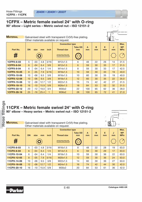
2040N • 2040H • 2033T
Hose
fi t
tings
Hose Fittings
Catalogue 4460-UKE-80
1CFPX – 11CPX
1CFPX – Metric female swivel 24° with O-ring90° elbow – Light series – Metric swivel nut – ISO 12151-2
Material Galvanised steel with transparent Cr(VI)-free plating.Other materials available on request.
11CPX – Metric female swivel 24° with O-ring90° elbow – Heavy series – Metric swivel nut – ISO 12151-2
Material Galvanised steel with transparent Cr(VI)-free plating.Other materials available on request.
Connection type Max.
Part No. DN size mm inch Thread size Tube OD
mmA
mmB
mmE
mmJ
mmWPMPa
Connection type Max.
Part No. DN size mm inch Thread size Tube OD
mmA
mmB
mmE
mmJ
mmWPMPa
1CFPX-6-03 5 -03 4.8 3/16 M12x1.5 6 48 22 26 14 31.5 1CFPX-6-04 6 -04 6.4 3/8 M12x1.5 6 59 30 33 17 31.5 1CFPX-8-04 6 -04 6.4 1/4 M14x1.5 8 59 30 33 17 42.5 1CFPX-10-05 8 -05 7.9 5/16 M16x1.5 10 59 30 33 19 40.0 1CFPX-10-06 10 -06 9.5 3/8 M16x1.5 10 60 30 35 19 40.0 1CFPX-12-06 10 -06 9.5 3/8 M18x1.5 12 60 30 35 22 35.0 1CFPX-15-08 12 -08 12.7 1/2 M22x1.5 15 74 42 42 27 31.5 1CFPX-18-10 16 -10 15.9 5/8 M26x1.5 18 84 53 52 32 31.5 1CFPX-22-12 20 -12 19.0 3/4 M30x2 22 100 65 62 36 28.0 1CFPX-28-16 25 -16 25.4 1 M36x2 28 100 65 72 41 21.0
11CPX-8-03 5 -03 4.8 3/16 M16x1.5 8 48 22 28 19 63.0 11CPX-6-04 6 -04 6.4 1/4 M14x1.5 6 59 30 29 17 63.0 11CPX-10-04 6 -04 6.4 1/4 M18x1.5 10 59 30 36 22 63.0 11CPX-12-05 8 -05 7.9 5/16 M20x1.5 12 59 30 36 24 63.0 11CPX-14-06 10 -06 9.5 3/8 M22x1.5 14 60 30 36 27 63.0 11CPX-16-08 12 -08 12.7 1/2 M24x1.5 16 74 42 44 30 42.0 11CPX-20-10 16 -10 15.9 5/8 M30x2 20 84 53 61 36 42.0
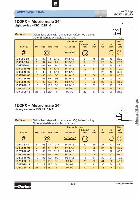
2040N • 2040H • 2033T
Hose
fi t
tings
Hose Fittings
Catalogue 4460-UKE-81
E
1D0PX – 1D2PX
1D0PX – Metric male 24°Light series – ISO 12151-2
Material Galvanised steel with transparent Cr(VI)-free plating.Other materials available on request.
1D2PX – Metric male 24°Heavy series – ISO 12151-2
Material Galvanised steel with transparent Cr(VI)-free plating.Other materials available on request.
Connection type Max.
Part No. DN size mm inch Thread size Tube OD
mmA
mmB
mmH
mmWPMPa
Connection type Max.
Part No. DN size mm inch Thread size Tube OD
mmA
mmB
mmH
mmWPMPa
1D0PX-6-03 5 -03 4.8 3/16 M12x1.5 6 48 23 12 25.0 1D0PX-6-04 6 -04 6.4 1/4 M12x1.5 6 51 23 14 25.0 1D0PX-8-04 6 -04 6.4 1/4 M14x1.5 8 51 23 14 42.5 1D0PX-10-05 8 -05 7.9 5/16 M16x1.5 10 54 26 17 40.0 1D0PX-12-05 8 -05 7.9 5/16 M18x1.5 12 54 26 19 35.0 1D0PX-12-06 10 -06 9.5 3/8 M18x1.5 12 56 27 19 40.0 1D0PX-15-06 10 -06 9.5 3/8 M22x1.5 15 57 28 22 31.0 1D0PX-15-08 12 -08 12.7 1/2 M22x1.5 15 59 28 22 31.0 1D0PX-18-10 16 -10 15.9 5/8 M26x1.5 18 59 28 27 28.0 1D0PX-22-12 20 -12 19.0 3/4 M30x2 22 67 32 30 28.0 1D0PX-28-16 25 -16 25.4 1 M36x2 28 67 32 36 21.0
1D2PX-8-03 5 -03 4.8 3/16 M16x1.5 8 50 25 17 63.0 1D2PX-10-04 6 -04 6.4 1/4 M18x1.5 10 55 27 19 63.0 1D2PX-12-05 8 -05 7.9 5/16 M20x1.5 12 55 27 22 63.0 1D2PX-14-06 10 -06 9.5 3/8 M22x1.5 14 59 30 22 63.0 1D2PX-16-08 12 -08 12.7 1/2 M24x1.5 16 61 30 24 42.0 1D2PX-20-10 16 -10 15.9 5/8 M30x2 20 65 34 30 42.0 1D2PX-25-12 20 -12 19.0 3/4 M36x2 25 71 36 36 42.0 1D2PX-30-16 25 -16 25.4 1 M42x2 30 73 38 46 42.0
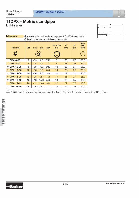
2040N • 2040H • 2033T
Hose
fi t
tings
Hose Fittings
Catalogue 4460-UKE-82
11DPX
11DPX – Metric standpipeLight series
Material Galvanised steel with transparent Cr(VI)-free plating.Other materials available on request.
Note: Not recommended for new constructions. Please refer to end connections C3 or CA.
Part No. DN size mm inch Tube OD
mmA
mmB
mm
Max. WPMPa
11DPX-6-03 5 -03 4.8 3/16 6 55 27 25.0 11DPX-8-04 6 -04 6.4 1/4 8 58 30 25.0 11DPX-10-05 8 -05 7.9 5/16 10 59 31 25.0 11DPX-10-06 10 -06 9.5 3/8 10 79 32 25.0 11DPX-12-06 10 -06 9.5 3/8 12 79 32 25.0 11DPX-15-08 12 -08 12.7 1/2 15 65 34 25.0 11DPX-18-10 16 -10 15.9 5/8 18 66 35 16.0 11DPX-22-12 20 -12 19.0 3/4 22 72 37 16.0 11DPX-28-16 25 -16 25.4 1 28 74 39 10.0
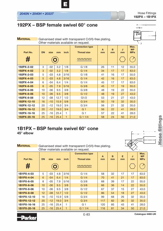
2040N • 2040H • 2033T
Hose
fi t
tings
Hose Fittings
Catalogue 4460-UKE-83
E
192PX – 1B1PX
1B1PX – BSP female swivel 60° cone45° elbow
Material Galvanised steel with transparent Cr(VI)-free plating.Other materials available on request.
192PX – BSP female swivel 60° cone
Material Galvanised steel with transparent Cr(VI)-free plating.Other materials available on request.
Part No. DN size mm inch
Connection type
Thread sizeA
mmB
mmE
mmJ
mm
Max. WPMPa
Part No. DN size mm inch
Connection type
Thread sizeA
mmB
mmJ
mm
Max. WPMPa
1B1PX-4-03 5 -03 4.8 3/16 G 1/4 58 32 17 17 63.0 1B1PX-4-04 6 -04 6.4 1/4 G 1/4 70 41 21 17 63.0 1B1PX-6-05 8 -05 7.9 5/16 G 3/8 68 39 17 22 55.0 1B1PX-6-06 10 -06 9.5 3/8 G 3/8 66 36 14 22 55.0 1B1PX-8-06 10 -06 9.5 3/8 G 1/2 67 37 15 27 43.0 1B1PX-8-08 12 -08 12.7 1/2 G 1/2 86 54 18 27 43.0 1B1PX-12-10 16 -10 15.9 5/8 G 3/4 99 68 26 32 35.0 1B1PX-12-12 20 -12 19.0 3/4 G 3/4 117 82 30 32 35.0 1B1PX-16-16 25 -16 25.4 1 G 1 120 85 43 41 28.0 1B1PX-20-16 25 -16 25.4 1 G 1 1/4 116 81 34 50 21.0
192PX-2-02 3 -02 3.2 1/8 G 1/8 26 11 12 55.0 192PX-4-02 3 -02 3.2 1/8 G 1/4 34 17 17 63.0 192PX-2-03 5 -03 4.8 3/16 G 1/8 41 16 17 55.0 192PX-4-03 5 -03 4.8 3/16 G 1/4 42 16 17 63.0 192PX-4-04 6 -04 6.4 1/4 G 1/4 45 17 17 63.0 192PX-6-05 8 -05 7.9 5/16 G 3/8 45 17 19 55.0 192PX-6-06 10 -06 9.5 3/8 G 3/8 48 19 22 55.0 192PX-8-06 10 -06 9.5 3/8 G 1/2 48 19 27 43.0 192PX-8-08 12 -08 12.7 1/2 G1/2 53 21 27 43.0 192PX-12-10 16 -10 15.9 5/8 G 3/4 50 19 32 35.0 192PX-12-12 20 -12 19.0 3/4 G 3/4 56 21 32 35.0 192PX-16-12 20 -12 19.0 3/4 G 1 56 22 41 28.0 192PX-16-16 25 -16 25.4 1 G 1 57 22 41 28.0 192PX-20-16 25 -16 25.4 1 G 1 1/4 58 24 50 21.0
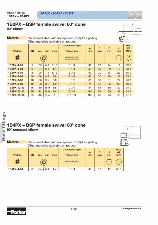
2040N • 2040H • 2033T
Hose
fi t
tings
Hose Fittings
Catalogue 4460-UKE-84
1B2PX – 1B4PX
1B2PX – BSP female swivel 60° cone90° elbow
Material Galvanised steel with transparent Cr(VI)-free plating.Other materials available on request.
1B4PX – BSP female swivel 60° cone90° compact elbow
Material Galvanised steel with transparent Cr(VI)-free plating.Other materials available on request.
Part No. DN size mm inch
Connection type
Thread sizeA
mmB
mmE
mmJ
mm
Max. WPMPa
Part No. DN size mm inch
Connection type
Thread sizeA
mmB
mmJ
mm
Max. WPMPa
1B2PX-4-03 5 -03 4.8 3/16 G 1/4 48 22 24 17 63.0 1B2PX-4-04 6 -04 6.4 1/4 G 1/4 59 30 30 17 63.0 1B2PX-6-05 8 -05 7.9 5/16 G 3/8 59 30 28 22 55.0 1B2PX-6-06 10 -06 9.5 3/8 G 3/8 60 30 30 22 55.0 1B2PX-8-06 10 -06 9.5 3/8 G 1/2 60 30 31 27 43.0 1B2PX-8-08 12 -08 12.7 1/2 G 1/2 74 42 38 27 43.0 1B2PX-12-10 16 -10 15.9 5/8 G 3/4 84 53 50 32 35.0 1B2PX-12-12 20 -12 19.0 3/4 G 3/4 100 65 60 32 35.0 1B2PX-20-16 25 -16 25.4 1 G 1 1/4 100 65 70 50 21.0
1B4PX-4-04 6 -04 6.4 1/4 G 1/4 45 17 17 63.0

2040N • 2040H • 2033T
Hose
fi t
tings
Hose Fittings
Catalogue 4460-UKE-85
E
1U0PX
1U0PX – BSP female swivel (ballnose)BSP swivel nut
Material Galvanised steel with transparent Cr(VI)-free plating.For fi ttings as mentioned above, but with stainless steel nipple(AISI 303), please add C2W to the Part No. Example: 1U0PX-4-04 C2W.Other materials available on request.
Part No. DN size mm inch
Connection type
Thread sizeA
mmB
mmJ
mm
Max. WPMPa
1U0PX-4-02 3 -02 3.2 1/8 G 1/4 35 19 17 63.0 1U0PX-4-03 5 -03 4.8 3/16 G 1/4 42 16 17 63.0 1U0PX-4-04 6 -04 6.4 1/4 G 1/4 45 17 17 63.0 1U0PX-6-03 5 -03 4.8 3/16 G 3/8 43 18 19 55.0 1U0PX-6-04 6 -04 6.4 1/4 G 3/8 47 18 19 55.0 1U0PX-6-05 8 -05 7.9 5/16 G 3/8 45 17 19 55.0 1U0PX-6-06 10 -06 9.5 3/8 G 3/8 48 19 22 55.0 1U0PX-8-06 10 -06 9.5 3/8 G 1/2 48 19 27 43.0 1U0PX-8-08 12 -08 12.7 1/2 G 1/2 53 21 27 43.0 1U0PX-12-10 16 -10 15.9 5/8 G 3/4 50 19 32 35.0 1U0PX-12-12 20 -12 19.0 3/4 G 3/4 56 21 32 35.0 1U0PX-16-12 20 -12 19.0 3/4 G 1 56 22 41 25.0 1U0PX-16-16 25 -16 25.4 1 G 1 57 22 41 25.0 1U0PX-20-16 25 -16 25.4 1 G 1 1/4 58 24 50 21.0

2040N • 2040H • 2033T
Hose
fi t
tings
Hose Fittings
Catalogue 4460-UKE-86
1D9PX
1D9PX – BSP maleDIN 3852 Form A
Material Galvanised steel with transparent Cr(VI)-free plating.Other materials available on request.
Part No. DN size mm inch
Connection type
Thread sizeA
mmB
mmJ
mm
Max. WPMPa
1D9PX-2-02 3 -02 3.2 1/8 G 1/8 38 21 14 55.0 1D9PX-2-03 5 -03 4.8 3/16 G 1/8 48 22 14 55.0 1D9PX-4-03 5 -03 4.8 3/16 G 1/4 54 29 19 63.0 1D9PX-4-04 6 -04 6.4 1/4 G 1/4 57 29 19 63.0 1D9PX-6-05 8 -05 7.9 5/16 G 3/8 58 29 22 55.0 1D9PX-6-06 10 -06 9.5 3/8 G 3/8 60 30 22 55.0 1D9PX-8-06 10 -06 9.5 3/8 G 1/2 62 33 27 43.0 1D9PX-8-08 12 -08 12.7 1/2 G 1/2 64 33 27 43.0 1D9PX-12-10 16 -10 15.9 5/8 G 3/4 66 35 32 35.0 1D9PX-12-12 20 -12 19.0 3/4 G 3/4 72 37 32 35.0 1D9PX-16-12 20 -12 19.0 3/4 G 1 74 39 41 28.0 1D9PX-20-16 25 -16 25.4 1 G 1 1/4 76 41 50 21.0
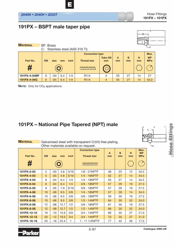
2040N • 2040H • 2033T
H
Hose
fi t
tings
Hose Fittings
Catalogue 4460-UKE-87
E
191PX – 101PX
101PX – National Pipe Tapered (NPT) male
Material Galvanised steel with transparent Cr(VI)-free plating.Other materials available on request.
191PX – BSPT male taper pipe
Material BF: BrassC: Stainless steel (AISI 316 Ti)
Note: Only for CO2 applications.
Part No. DN size mm inch
Connection type
Thread sizeA
mmB
mmH
mm
Max. WPMPa
Connection type Max.
Part No. DN size mm inch Thread size Tube OD
mmA
mmB
mmH
mmWPMPa
101PX-2-03 5 -03 4.8 3/16 1/8 - 27NPTF 48 23 12 34.5 101PX-4-03 5 -03 4.8 3/16 1/4 - 18NPTF 52 27 14 34.5 101PX-4-04 6 -04 6.4 1/4 1/4 - 18NPTF 55 27 14 34.5 101PX-6-04 6 -04 6.4 1/4 3/8 - 18NPTF 57 29 19 27.5 101PX-6-05 8 -05 7.9 5/16 3/8 - 18NPTF 57 29 19 27.5 101PX-4-06 10 -06 9.5 3/8 1/4 - 18NPTF 57 28 14 34.5 101PX-6-06 10 -06 9.5 3/8 3/8 - 18NPTF 59 30 19 27.5 101PX-8-06 10 -06 9.5 3/8 1/2 - 14NPTF 64 35 22 24.0 101PX-6-08 12 -08 12.7 1/2 3/8 - 18NPTF 61 30 19 27.5 101PX-8-08 12 -08 12.7 1/2 1/2 - 14NPTF 66 35 22 24.0 101PX-12-10 16 -10 15.9 5/8 3/4 - 14NPTF 66 35 27 21.0 101PX-12-12 20 -12 19.0 3/4 3/4 - 14NPTF 70 35 27 21.0 101PX-16-16 25 -16 25.4 1 1 - 11 1/2NPTF 77 42 36 17.0
191PX-4-04BF 6 -04 6.4 1/4 R1/4 4 55 27 14 27 191PX-4-04C 6 -04 6.4 1/4 R1/4 4 55 27 14 43.0

2040N • 2040H • 2033T
Hose
fi t
tings
Hose Fittings
Catalogue 4460-UKE-88
103PX – 106PX
103PX – SAE (JIC) 37° male
Material Galvanised steel with transparent Cr(VI)-free plating.Other materials available on request.
106PX – SAE (JIC) 37° female swivelUNF swivel nut
Material Galvanised steel with transparent Cr(VI)-free plating.Other materials available on request.
Part No. DN size mm inch
Connection type
Thread sizeA
mmB
mmH
mm
Max. WPMPa
Part No. DN size mm inch
Connection type
Thread sizeA
mmB
mmJ
mm
Max. WPMPa
103PX-4-03 5 -03 4.8 3/16 7/16 - 20UNF 52 27 14 41.0 103PX-5-04 6 -04 6.4 1/4 1/2 - 20UNF 57 29 14 41.0 103PX-6-04 6 -04 6.4 1/4 9/16 - 18UNF 57 29 17 34.5 103PX-6-05 8 -05 7.9 5/16 9/16 - 18UNF 57 29 17 34.5 103PX-8-06 10 -06 9.5 3/8 3/4 - 16UNF 62 33 22 34.5 103PX-10-08 12 -08 12.7 1/2 7/8 - 14UNF 70 38 24 34.5 103PX-12-10 16 -10 15.9 5/8 1 1/16 - 12UNF 71 40 30 34.5 103PX-16-12 20 -12 19.0 3/4 1 5/16 - 12UNF 76 41 36 27.5 103PX-20-16 25 -16 25.4 1 1 5/8 - 12UNF 78 43 46 20.0
106PX-4-02 3 -02 3.2 1/8 7/16 - 20UNF 29 13 17 41.0 106PX-4-03 5 -03 4.8 3/16 7/16 - 20UNF 40 15 17 41.0 106PX-4-04 6 -04 6.4 1/4 7/16 - 20UNF 43 15 17 41.0 106PX-5-04 6 -04 6.4 1/4 1/2 - 20UNF 43 15 19 41.0 106PX-6-04 6 -04 6.4 1/4 9/16 - 18UNF 45 17 19 34.5 106PX-6-05 8 -05 7.9 5/16 9/16 - 18UNF 45 17 19 34.5 106PX-6-06 10 -06 9.5 3/8 9/16 - 18UNF 47 18 19 34.5 106PX-8-06 10 -06 9.5 3/8 3/4 - 16UNF 48 19 24 34.5 106PX-10-08 12 -08 12.7 1/2 7/8 - 14UNF 49 18 27 34.5 106PX-12-10 16 -10 15.9 5/8 1 1/16 - 12UNF 50 19 32 34.5 106PX-16-12 20 -12 19.0 3/4 1 5/16 - 12UNF 56 22 41 27.5 106PX-20-16 25 -16 25.4 1 1 5/8 - 12UNF 56 22 50 20.0
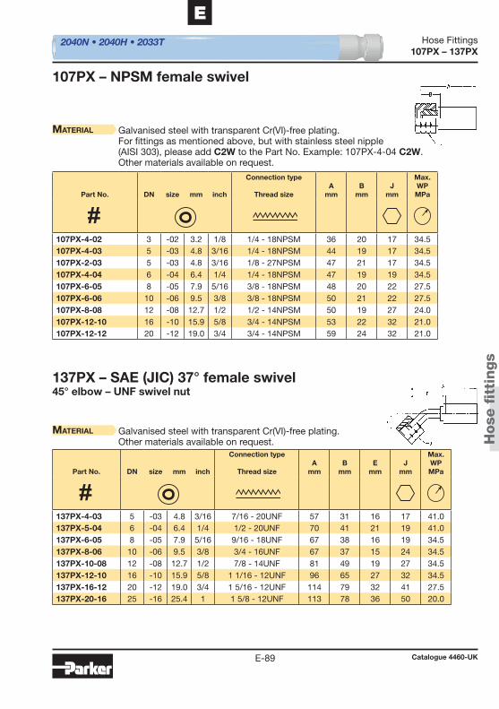
2040N • 2040H • 2033T
Hose
fi t
tings
Hose Fittings
Catalogue 4460-UKE-89
E
107PX – 137PX
137PX – SAE (JIC) 37° female swivel45° elbow – UNF swivel nut
Material Galvanised steel with transparent Cr(VI)-free plating.Other materials available on request.
107PX – NPSM female swivel
Material Galvanised steel with transparent Cr(VI)-free plating.For fi ttings as mentioned above, but with stainless steel nipple(AISI 303), please add C2W to the Part No. Example: 107PX-4-04 C2W.Other materials available on request.
Part No. DN size mm inch
Connection type
Thread sizeA
mmB
mmE
mmJ
mm
Max. WPMPa
Part No. DN size mm inch
Connection type
Thread sizeA
mmB
mmJ
mm
Max. WPMPa
137PX-4-03 5 -03 4.8 3/16 7/16 - 20UNF 57 31 16 17 41.0 137PX-5-04 6 -04 6.4 1/4 1/2 - 20UNF 70 41 21 19 41.0 137PX-6-05 8 -05 7.9 5/16 9/16 - 18UNF 67 38 16 19 34.5 137PX-8-06 10 -06 9.5 3/8 3/4 - 16UNF 67 37 15 24 34.5 137PX-10-08 12 -08 12.7 1/2 7/8 - 14UNF 81 49 19 27 34.5 137PX-12-10 16 -10 15.9 5/8 1 1/16 - 12UNF 96 65 27 32 34.5 137PX-16-12 20 -12 19.0 3/4 1 5/16 - 12UNF 114 79 32 41 27.5 137PX-20-16 25 -16 25.4 1 1 5/8 - 12UNF 113 78 36 50 20.0
107PX-4-02 3 -02 3.2 1/8 1/4 - 18NPSM 36 20 17 34.5 107PX-4-03 5 -03 4.8 3/16 1/4 - 18NPSM 44 19 17 34.5 107PX-2-03 5 -03 4.8 3/16 1/8 - 27NPSM 47 21 17 34.5 107PX-4-04 6 -04 6.4 1/4 1/4 - 18NPSM 47 19 19 34.5 107PX-6-05 8 -05 7.9 5/16 3/8 - 18NPSM 48 20 22 27.5 107PX-6-06 10 -06 9.5 3/8 3/8 - 18NPSM 50 21 22 27.5 107PX-8-08 12 -08 12.7 1/2 1/2 - 14NPSM 50 19 27 24.0 107PX-12-10 16 -10 15.9 5/8 3/4 - 14NPSM 53 22 32 21.0 107PX-12-12 20 -12 19.0 3/4 3/4 - 14NPSM 59 24 32 21.0
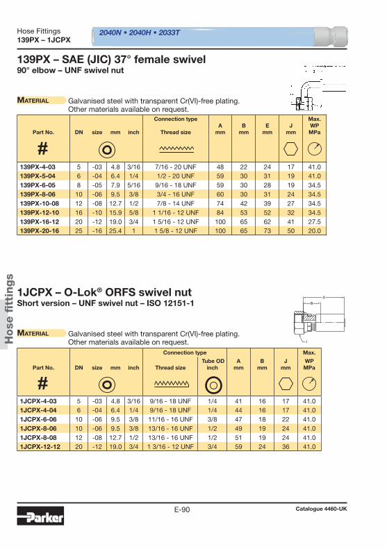
2040N • 2040H • 2033T
Hose
fi t
tings
Hose Fittings
Catalogue 4460-UKE-90
139PX – 1JCPX
139PX – SAE (JIC) 37° female swivel90° elbow – UNF swivel nut
Material Galvanised steel with transparent Cr(VI)-free plating.Other materials available on request.
1JCPX – O-Lok® ORFS swivel nutShort version – UNF swivel nut – ISO 12151-1
Material Galvanised steel with transparent Cr(VI)-free plating.Other materials available on request.
Part No. DN size mm inch
Connection type
Thread sizeA
mmB
mmE
mmJ
mm
Max. WPMPa
Connection type Max.
Part No. DN size mm inch Thread size Tube OD
inchA
mmB
mmJ
mmWPMPa
139PX-4-03 5 -03 4.8 3/16 7/16 - 20 UNF 48 22 24 17 41.0 139PX-5-04 6 -04 6.4 1/4 1/2 - 20 UNF 59 30 31 19 41.0 139PX-6-05 8 -05 7.9 5/16 9/16 - 18 UNF 59 30 28 19 34.5 139PX-8-06 10 -06 9.5 3/8 3/4 - 16 UNF 60 30 31 24 34.5 139PX-10-08 12 -08 12.7 1/2 7/8 - 14 UNF 74 42 39 27 34.5 139PX-12-10 16 -10 15.9 5/8 1 1/16 - 12 UNF 84 53 52 32 34.5 139PX-16-12 20 -12 19.0 3/4 1 5/16 - 12 UNF 100 65 62 41 27.5 139PX-20-16 25 -16 25.4 1 1 5/8 - 12 UNF 100 65 73 50 20.0
1JCPX-4-03 5 -03 4.8 3/16 9/16 - 18 UNF 1/4 41 16 17 41.0 1JCPX-4-04 6 -04 6.4 1/4 9/16 - 18 UNF 1/4 44 16 17 41.0 1JCPX-6-06 10 -06 9.5 3/8 11/16 - 16 UNF 3/8 47 18 22 41.0 1JCPX-8-06 10 -06 9.5 3/8 13/16 - 16 UNF 1/2 49 19 24 41.0 1JCPX-8-08 12 -08 12.7 1/2 13/16 - 16 UNF 1/2 51 19 24 41.0 1JCPX-12-12 20 -12 19.0 3/4 1 3/16 - 12 UNF 3/4 59 24 36 41.0
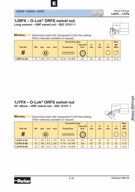
2040N • 2040H • 2033T
Hose
fi t
tings
Hose Fittings
Catalogue 4460-UKE-91
E
1JSPX – 1J7PX
1J7PX – O-Lok® ORFS swivel nut45° elbow – UNF swivel nut – ISO 12151-1
Material Galvanised steel with transparent Cr(VI)-free plating.Other materials available on request.
1JSPX – O-Lok® ORFS swivel nutLong version – UNF swivel nut – ISO 12151-1
Material Galvanised steel with transparent Cr(VI)-free plating.Other materials available on request.
Connection type Max.
Part No. DN size mm inch Thread size Tube OD
inchA
mmB
mmE
mmJ
mmWPMPa
Connection type Max.
Part No. DN size mm inch Thread size Tube OD
inchA
mmB
mmJ
mmWPMPa
1J7PX-4-04 6 -04 6.4 1/4 9/16 - 18 UNF 1/4 64 35 15 17 41.0 1J7PX-6-06 10 -06 9.5 3/8 11/16 - 16 UNF 3/8 67 37 17 22 41.0 1J7PX-8-08 12 -08 12.7 1/2 13/16 - 16 UNF 1/2 74 42 17 24 41.0
1JSPX-8-06 10 -06 9.5 3/8 13/16 - 16 UNF 1/2 52 22 24 41.0
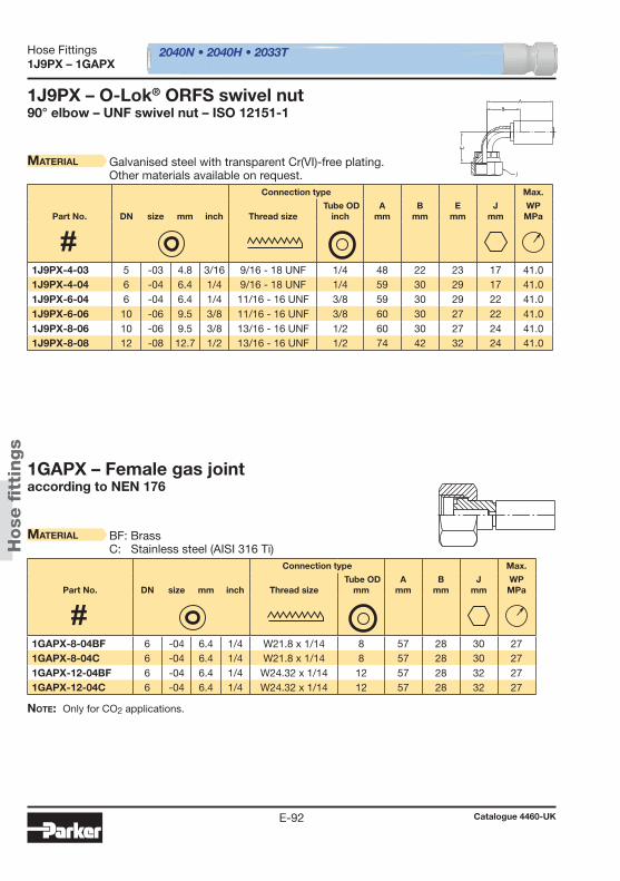
2040N • 2040H • 2033T
Hose
fi t
tings
Hose Fittings
Catalogue 4460-UKE-92
1J9PX – 1GAPX
1J9PX – O-Lok® ORFS swivel nut90° elbow – UNF swivel nut – ISO 12151-1
Material Galvanised steel with transparent Cr(VI)-free plating.Other materials available on request.
1GAPX – Female gas jointaccording to NEN 176
Material BF: BrassC: Stainless steel (AISI 316 Ti)
Note: Only for CO2 applications.
Connection type Max.
Part No. DN size mm inch Thread size Tube OD
inchA
mmB
mmE
mmJ
mmWPMPa
Connection type Max.
Part No. DN size mm inch Thread size Tube OD
mmA
mmB
mmJ
mmWPMPa
1J9PX-4-03 5 -03 4.8 3/16 9/16 - 18 UNF 1/4 48 22 23 17 41.0 1J9PX-4-04 6 -04 6.4 1/4 9/16 - 18 UNF 1/4 59 30 29 17 41.0 1J9PX-6-04 6 -04 6.4 1/4 11/16 - 16 UNF 3/8 59 30 29 22 41.0 1J9PX-6-06 10 -06 9.5 3/8 11/16 - 16 UNF 3/8 60 30 27 22 41.0 1J9PX-8-06 10 -06 9.5 3/8 13/16 - 16 UNF 1/2 60 30 27 24 41.0 1J9PX-8-08 12 -08 12.7 1/2 13/16 - 16 UNF 1/2 74 42 32 24 41.0
1GAPX-8-04BF 6 -04 6.4 1/4 W21.8 x 1/14 8 57 28 30 27 1GAPX-8-04C 6 -04 6.4 1/4 W21.8 x 1/14 8 57 28 30 27 1GAPX-12-04BF 6 -04 6.4 1/4 W24.32 x 1/14 12 57 28 32 27 1GAPX-12-04C 6 -04 6.4 1/4 W24.32 x 1/14 12 57 28 32 27
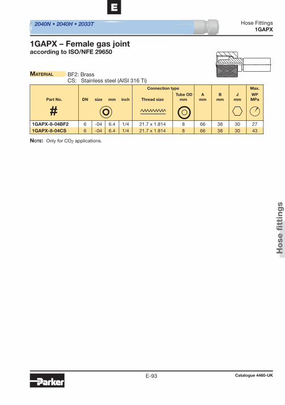
2040N • 2040H • 2033T
Hose
fi t
tings
Hose Fittings
Catalogue 4460-UKE-93
E
1GAPX
1GAPX – Female gas jointaccording to ISO/NFE 29650
Material BF2: BrassCS: Stainless steel (AISI 316 Ti)
Note: Only for CO2 applications.
Connection type Max.
Part No. DN size mm inch Thread size Tube OD
mmA
mmB
mmJ
mmWPMPa
1GAPX-8-04BF2 6 -04 6.4 1/4 21.7 x 1.814 8 66 38 30 27 1GAPX-8-04CS 6 -04 6.4 1/4 21.7 x 1.814 8 66 38 30 43

Hose
fitt
ings
Catalogue 4460-UKE-94
Hose FittingsNotes

Access
ori
es
Catalogue 4460-UKF-1
FAccessories
Chapter F
Accessories
Introduction ............................................................................................F-2Spiral Guard™ ........................................................................................F-4Fire protection sleeves ...........................................................................F-5Special cut-to-length spring guards ......................................................F-6Banjo bolt ...............................................................................................F-7Copper ring ............................................................................................F-8
Table of contents
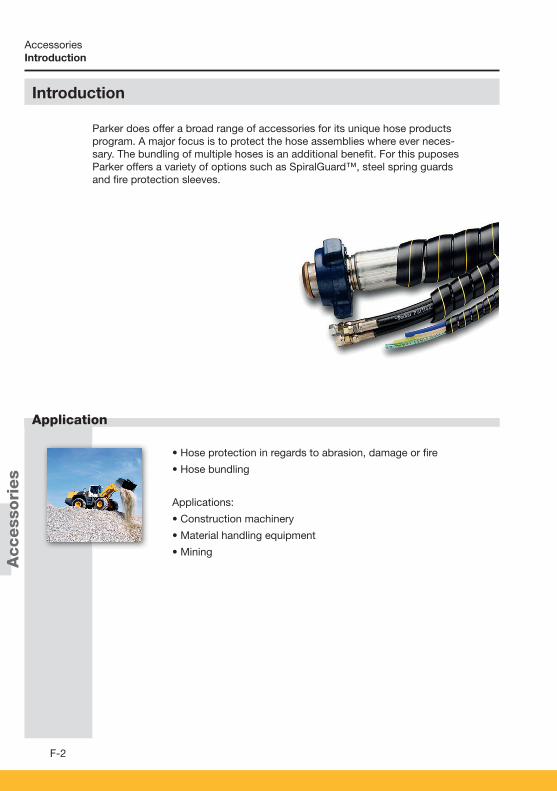
Access
ori
es
F-2
Application
Accessories
• Hose protection in regards to abrasion, damage or fi re
• Hose bundling
Applications:
• Construction machinery
• Material handling equipment
• Mining
Parker does offer a broad range of accessories for its unique hose products program. A major focus is to protect the hose assemblies where ever neces-sary. The bundling of multiple hoses is an additional benefi t. For this puposes Parker offers a variety of options such as SpiralGuard™, steel spring guards and fi re protection sleeves.
Introduction
Introduction
• Hose protection in regards to abrasion, damage or fi re
• Hose bundling
Applications:
• Construction machinery
• Material handling equipment
• Mining
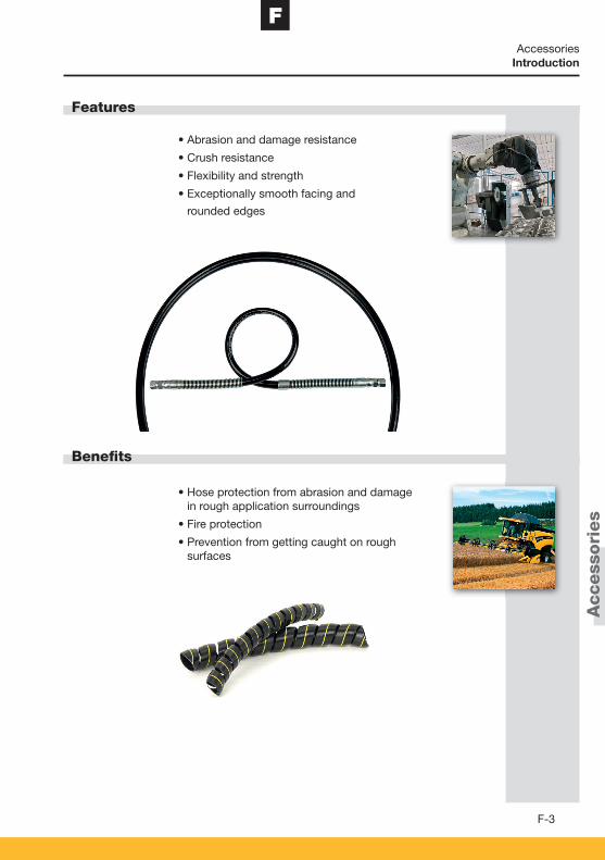
Access
ori
es
F
F-3
Features
Benefi ts
Accessories
• Abrasion and damage resistance
• Crush resistance
• Flexibility and strength
• Exceptionally smooth facing and
rounded edges
• Hose protection from abrasion and damage in rough application surroundings
• Fire protection
• Prevention from getting caught on rough surfaces
Introduction

Access
ori
es
Catalogue 4460-UKF-4
AccessoriesSpiral Guard™
Spiral Guard™ Features:
• High-strength, resilient Spiral Guard protects hose and cable with superior anti-crush performance.• Exceptionally smooth facing and rounded edges prevent Spiral Guard from getting caught on rough
surfaces, as sleeves often can• No cutting of hose cover or injuries of staff• Made of High Density Polyethylene• O.D. sizes from 12 to over 150 mm• Can be used to wrap multiple hose bundles• Temperature range -100 °C up to +100 °C
Variations:
• PSG: Standard, e.g. PSG-20• PSG-FRAS: MSHA approved, Flame Retardant Anti Static, e.g. PSG-FRAS-20• “Glow in the dark” version: on request
Part No.Hose OD
range(mm)
Cartonquantity
(m)
1-wire braidsize
2-wire braidsize
Multispiralsize
PSG-12 10 - 13 20 — — — PSG-16 or PSG-FRAS-16 12 - 17 20 1/4“ 1/4“ — PSG-20 or PSG-FRAS-20 16 - 22 20 3/8“ 1/4“, 3/8“ 3/8“ PSG-25 or PSG-FRAS-25 22 - 28 20 1/2“, 5/8“ 1/2“, 5/8“ 1/2“, 5/8“ PSG-32 or PSG-FRAS-32 27 - 33 20 3/4“ 5/8“ 3/4“ 3/4“ PSG-40 or PSG-FRAS-40 33 - 42 20 1“ 1“ 1“ PSG-50 or PSG-FRAS-50 42 - 55 20 1-1/4“, 1-1/2“ 1-1/4“ 1-1/4“ PSG-63 or PSG-FRAS-63 52 - 65 20 2“ 1-1/2“ 1-1/2“ PSG-75 or PSG-FRAS-75 65 - 80 10 — 2“ 2“ PSG-90 or PSG-FRAS-90 80 - 150 10 — — — PSG-110 or PSG-FRAS-110 150 - above 10 — — —
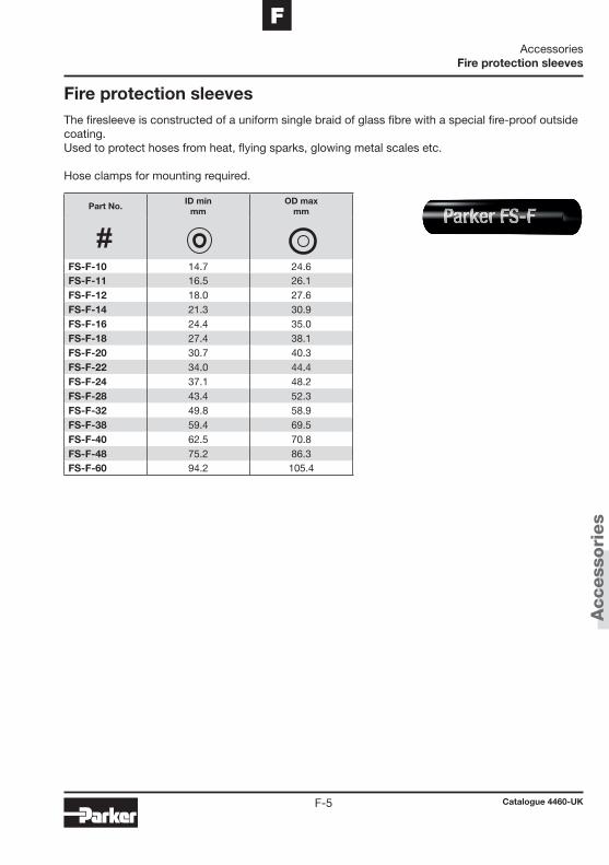
Access
ori
es
Catalogue 4460-UKF-5
FAccessories
Fire protection sleeves
Fire protection sleevesThe firesleeve is constructed of a uniform single braid of glass fibre with a special fire-proof outside coating.Used to protect hoses from heat, flying sparks, glowing metal scales etc.
Hose clamps for mounting required.
Part No.ID min
mmOD max
mm
FS-F-10 14.7 24.6FS-F-11 16.5 26.1FS-F-12 18.0 27.6FS-F-14 21.3 30.9FS-F-16 24.4 35.0FS-F-18 27.4 38.1FS-F-20 30.7 40.3FS-F-22 34.0 44.4FS-F-24 37.1 48.2FS-F-28 43.4 52.3FS-F-32 49.8 58.9FS-F-38 59.4 69.5FS-F-40 62.5 70.8FS-F-48 75.2 86.3FS-F-60 94.2 105.4

Access
ori
es
Catalogue 4460-UKF-6
AccessoriesSpecial cut-to-length spring guards
For hose types 2040N/2040H/2245N/2370N/526BA
Special cut-to-length spring guards(plated, hard drawn-steel wire)
For CNG hoses
Part No.Guard ID
mmStandard length mm
55SG-4 14.0 127.055SG-5 15.5 127.055SG-6 17.3 127.055SG-8 21.1 127.055SG-12 27.7 177.8
5PSG-4 16.0 158.85PSG-6 19.8 165.15PSG-8 22.9 165.1
Part No. Hose type Standard length mm
17135 2040H/N-04 526BA-4 14017155 2245N-04 1601717 2040H/N-05 526BA-6 2370N-04 1701718.5 2040H/N-06 2370N-05 200
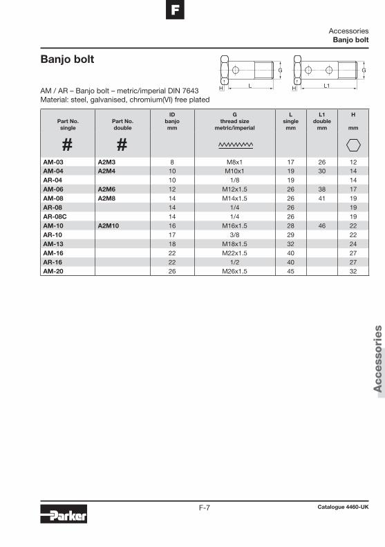
Access
ori
es
Catalogue 4460-UKF-7
FAccessoriesBanjo bolt
Banjo bolt
AM / AR – Banjo bolt – metric/imperial DIN 7643 Material: steel, galvanised, chromium(VI) free plated
G
L1H
G
LH
Part No.single
Part No.double
IDbanjomm
Gthread size
metric/imperial
Lsinglemm
L1double
mm
H
mm
AM-03 A2M3 8 M8x1 17 26 12AM-04 A2M4 10 M10x1 19 30 14AR-04 10 1/8 19 14AM-06 A2M6 12 M12x1.5 26 38 17AM-08 A2M8 14 M14x1.5 26 41 19AR-08 14 1/4 26 19AR-08C 14 1/4 26 19AM-10 A2M10 16 M16x1.5 28 46 22AR-10 17 3/8 29 22AM-13 18 M18x1.5 32 24AM-16 22 M22x1.5 40 27AR-16 22 1/2 40 27AM-20 26 M26x1.5 45 32
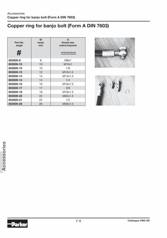
Access
ori
es
Catalogue 4460-UKF-8
AccessoriesCopper ring for banjo bolt (Form A DIN 7603)
Copper ring for banjo bolt (Form A DIN 7603)
Part No.single
IDbanjomm
Gthread size
metric/imperial
853009-8 8 M8x1853009-10 10 M10x1853009-10 10 1/8853009-12 12 M12x1.5853009-14 14 M14x1.5853009-14 14 1/4853009-16 16 M16x1.5853009-17 17 3/8853009-18 18 M18x1.5853009-22 22 M22x1.5853009-21 22 1/2853009-26 26 M26x1.5

Work
shop e
quip
ment
Catalogue 4460-UKG-1
GWorkshop Equipment
Chapter G
Workshop Equipment
Introduction ..........................................................................................G-2Heavy-duty hose crimper TH8-380.E ...................................................G-4KarryKrimp® 2 crimping press 85CE-06 ................................................G-5Hand pump 85CE-0HP .........................................................................G-5Turbo air pump 85C-0AP ......................................................................G-5Power pump 82CE-0EP ........................................................................G-5PHastkrimp® crimping press 89CE-061 ................................................G-6Parkrimp® 2 crimping press 83CE .........................................................G-6MiniKrimp® 94C-001-PFD .....................................................................G-7Parflex Parkrimp® dies ..........................................................................G-8Hose cutting tool ST250 .......................................................................G-9Tape .......................................................................................................G-9Sleeve marking tool TH4-4 ..................................................................G-10Hose assembling machine SMM100 ..................................................G-10Hose test rig TH5-3 .............................................................................G-10Hose assembling accessories 8.2.......................................................G-11Pin gauges PD-1-5MM .......................................................................G-11Push-Lok® assembly tool ....................................................................G-11
Table of contents

Work
shop e
quip
ment
G-2
Application
Workshop Equipment
• Crimping hoses
• Hose assemblies
• Cutting hoses
• Marking hoses
• Pressure testing of hoses
Introduction
For customers manufacturing hose assemblies themselves we offer a wide range of workshop equipment which is perfectly matched to the Parker hose product range. This includes stationary and mobile hose crimping presses, pumps, cutting and marking tools, assembly machines, test rigs and acces-sories.
Introduction
• Crimping hoses
• Hose assemblies
• Cutting hoses
• Marking hoses
• Pressure testing of hoses

Work
shop e
quip
ment
G
G-3
Features
Benefi ts
Workshop Equipment
• Rugged built tools
• Compact and portable built presses for onsite jobs
• High crimping rates
• We offer both Parkrimp™ and freeadjustable crimpers
• Longlife and reliable
• Perfectly matching the Parker hose and fi ttings product program
• Optimally suited for stationary heavy duty or portable onsite applications
Introduction
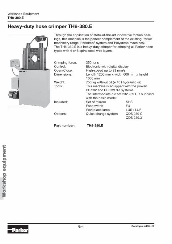
Work
shop e
quip
ment
Catalogue 4460-UKG-4
Workshop EquipmentTH8-380.E
Heavy-duty hose crimper TH8-380.E
Through the application of state-of-the-art innovative friction bear-ings, this machine is the perfect complement of the existing Parker machinery range (Parkrimp® system and Polykrimp machines). The TH8-380.E is a heavy-duty crimper for crimping all Parker hose types with 4 or 6 spiral steel wire layers.
Crimping force: 350 tons Control: Electronic with digital display Open/Close: High-speed up to 23 mm/s Dimensions: Length 1200 mm x width 600 mm x height
1600 mm Weight: 750 kg without oil (+ 40 l hydraulic oil) Tools: This machine is equipped with the proven
PB 232 and PB 239 die systems. The intermediate die set 232.239 L is supplied with the basic model.
Included: Set of mirrors SHS Foot switch FU Workplace lamp LUS / LUF
Options: Quick change system QDS 239 C QDS 239.3
Part number: TH8-380.E

Work
shop e
quip
ment
Catalogue 4460-UKG-5
GWorkshop Equipment
85CE-061
The following pumps can be used with the KarryKrimp® 2 crimping press:
reMarks All pumps also suitable for KarryKrimp® 82C-061.
KarryKrimp® 2 crimping press 85CE-061
KarryKrimp® 2 is portable, compact and ruggedly built. You have everything you need to crimp hoses from DN 6 to DN32. Model 85C-061 includes crimping machine, take-apart stand, die rings and connection hose with quick coupling. For Parker hose with textile and steel wire reinforcements up to 4SP DN 32 and 4SH/100 R13 up to DN 25. Complete with hose assembly and quick coupling, 2 die rings and take-apart stand.
Dimensions (with stand): H 762.0 mm x W 355.6 mm x J 381.0 mm Weight: ca. 46 kg
Part No.: 85CE-061
Hand pump 85CE-0HP Working pressure: max. 70 MPa Dimensions: L 539 mm x W 417 mm x H 151 mm Weight: 11.6 kg Tank capacity: 2294 cm3 Lever Force: 55 kg Part No.: 85CE-0HP
Turbo air pump 85C-0AP Working pressure: 70 MPa Dimensions: L 320 mm x W 320 mm x H 480 mm Weight: 8.4 kg Tank capacity: 662 cm3 Compressed-air supply: 1/4-18NPTF thread Part No.: 85C-0AP
Power pump 82CE-0EP Working pressure: 70 MPa with 3/2 hand valve Dimensions: L 320 mm x W 320 mm x H 480 mm Weight: 12 kg Tank capacity: 2000 cm3
Connection: single phase / 230 V Part No.: 82CE-0EP
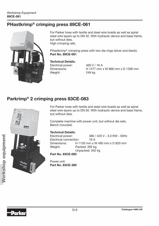
Work
shop e
quip
ment
Catalogue 4460-UKG-6
Workshop Equipment89CE-061
For Parker hose with textile and steel wire braids as well as spiral steel wire layers up to DN 50. With hydraulic device and base frame, but without dies.
Complete machine with power unit, but without die sets. Bench mounted.
Technical Details: Electrical power: 380 / 420 V - 3.0 KW - 50Hz Electrical connection: 16 A Dimensions: H 1130 mm x W 490 mm x D 820 mm Weight: Packed: 392 kg Unpacked: 342 kg Part No. 83CE-083 Power unit: Part No. 83CE-380
PHastkrimp® crimping press 89CE-061
For Parker hose with textile and steel wire braids as well as spiral steel wire layers up to DN 32. With hydraulic device and base frame, but without dies. High crimping rate. PHastkrimp® crimping press with two die rings (silver and black):
Part No. 89CE-061
Technical Details: Electrical power: 400 V / 16 A Dimensions: H 1477 mm x W 866 mm x D 1298 mm Weight: 249 kg
Parkrimp® 2 crimping press 83CE-083

Work
shop e
quip
ment
Catalogue 4460-UKG-7
GWorkshop Equipment
MiniKrimp
MiniKrimp® 94C-001-PFD
MiniKrimp® is a portable, one piece crimper. Due to its light and very compact design the MiniKrimp® is easy to transport and provides a cost effective way to make hose assem-blies in the field.
The MiniKrimp® is able to crimp the following fitting series: 55/56/57/58/91N and EH of the polyflex Division product range, 43/46/48 and 26 of the HPDE product range. Specifications:
Rating: 30 tons Set-up time: 20 s
Dimensions: Depth: 127 mm Width: 178 mm Height: 394 mm Weight: 16 kg
Name: MiniKrimp®
Part No.: 94C-001-PFD
Patent-No. 6715335 and D495938
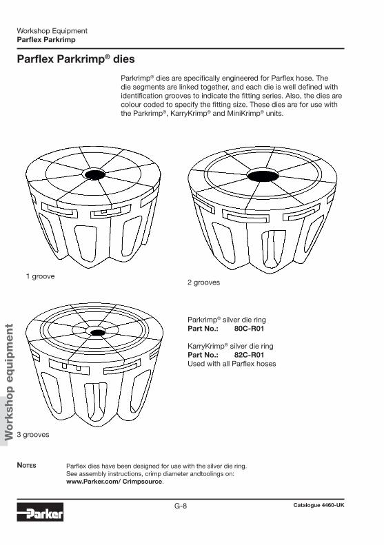
Work
shop e
quip
ment
Catalogue 4460-UKG-8
Workshop EquipmentParflex Parkrimp
Parflex Parkrimp® dies
Parkrimp® dies are specifically engineered for Parflex hose. The die segments are linked together, and each die is well defined with identification grooves to indicate the fitting series. Also, the dies are colour coded to specify the fitting size. These dies are for use with the Parkrimp®, KarryKrimp® and MiniKrimp® units.
Notes Parflex dies have been designed for use with the silver die ring.See assembly instructions, crimp diameter and toolings on:www.Parker.com/ Crimpsource.
1 groove2 grooves
3 grooves
Parkrimp® silver die ring Part No.: 80C-R01
KarryKrimp® silver die ring Part No.: 82C-R01Used with all Parflex hoses
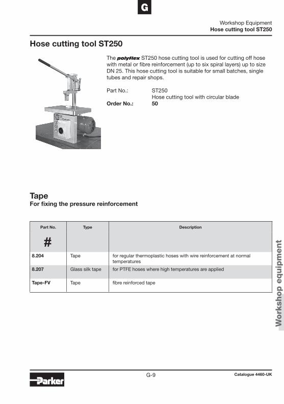
Work
shop e
quip
ment
Catalogue 4460-UKG-9
GWorkshop Equipment
Hose cutting tool ST250
Hose cutting tool ST250
The polyflex ST250 hose cutting tool is used for cutting off hose with metal or fibre reinforcement (up to six spiral layers) up to size DN 25. This hose cutting tool is suitable for small batches, single tubes and repair shops.
Part No.: ST250 Hose cutting tool with circular blade Order No.: 50
TapeFor fixing the pressure reinforcement
Part No. Type Description
8.204 Tape for regular thermoplastic hoses with wire reinforcement at normal temperatures
8.207 Glass silk tape for PTFE hoses where high temperatures are applied
Tape-FV Tape fibre reinforced tape

Work
shop e
quip
ment
Catalogue 4460-UKG-10
Workshop EquipmentHose assembling machine SMM100
Hose assembling machine SMM100
The polyflex SMM100 hose as sembling machine facilitates the at-tachment of fittings. The standard model includes electrical cabinet, foot switch, and safety three-segment chuck. The SMM 100 is suit-able for fittings up to size DN 32.
Part No.: SMM100 Hose assembling machine with three-segment chuck
Order No.: 60
Hose test rig TH 5-3
This workshop test rig is used for static pressure testing of hose assemblies ready for installation. Its test pressure ranges from 12 to 145 MPa. Almost all standard fittings can be tested.
Part No.: TH 5-3 Hose Test Rig
Order No.: TH 5-3
Test rigs for higher pressures on request
Sleeve marking tool TH4-4
The polyflex TH4-4 is for the permanent marking of hose assem-blies or the crimp ferrule of the hose fitting. The standard model includes the table top device with base plate, height adjustable handwheel, fixable type holder, and a letter case with hardened steel type.
Part no.: TH4-4 Embossing tool with type holder (for one row of type) and letter case
Order No.: TH 4-4
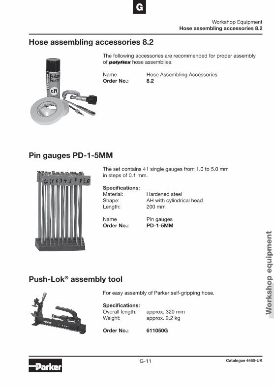
Work
shop e
quip
ment
Catalogue 4460-UKG-11
GWorkshop Equipment
Hose assembling accessories 8.2
Hose assembling accessories 8.2
The following accessories are recommended for proper assembly of polyflex hose assemblies.
Name Hose Assembling Accessories Order No.: 8.2
Pin gauges PD-1-5MM
Push-Lok® assembly tool
The set contains 41 single gauges from 1.0 to 5.0 mm in steps of 0.1 mm.
Specifications: Material: Hardened steel Shape: AH with cylindrical head Length: 200 mm
Name Pin gauges Order No.: PD-1-5MM
For easy assembly of Parker self-gripping hose. Specifications: Overall length: approx. 320 mm Weight: approx. 2.2 kg
Order No.: 611050G

Work
shop e
quip
ment
Catalogue 4460-UKG-12
Workshop EquipmentNotes
Technic
al in
form
ati
on
Catalogue 4460-UKH-1
HTechnical Information
Chapter H
Technical Information
Introduction ...........................................................................................H-2Crimpsource Online ..............................................................................H-4Assembly procedures – MiniKrimp® ......................................................H-7Assembly procedures – Parkrimp® 2 .................................................H-12Assembly procedures – Push-Lok® self-grip hose .............................H-19Twinline and multiline hose separation instructions ............................H-20Determining the hose length for over-the-sheaf applications .............H-21Selection, installation, and maintenance.............................................H-22Installation standards ..........................................................................H-24Installation tips ....................................................................................H-26Unit Conversion Table .........................................................................H-27 Parker safety guide .............................................................................H-28
Table of contents
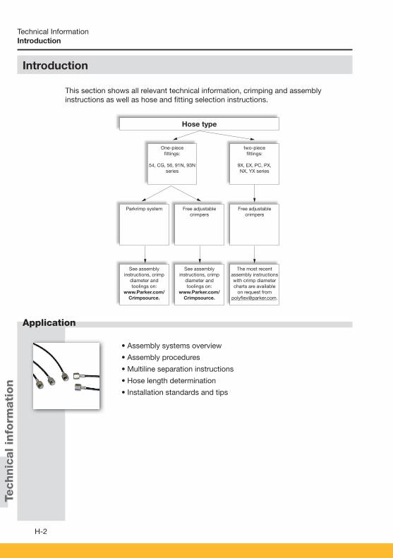
Technic
al in
form
ati
on
H-2
Application
Technical Information
• Assembly systems overview
• Assembly procedures
• Multiline separation instructions
• Hose length determination
• Installation standards and tips
This section shows all relevant technical information, crimping and assembly instructions as well as hose and fi tting selection instructions.
Introduction
Hose type
One-piece fittings:
54, CG, 56, 91N, 93N series
two-piece fittings:
9X, EX, PC, PX,NX, YX series
Parkrimp system Free adjustable crimpers
Free adjustable crimpers
See assemblyinstructions, crimp
diameter andtoolings on:
www.Parker.com/ Crimpsource.
See assemblyinstructions, crimp
diameter andtoolings on:
www.Parker.com/ Crimpsource.
The most recent assembly instructions with crimp diameter charts are available
on request from [email protected].
Introduction
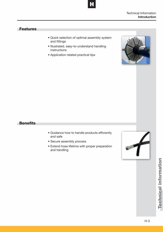
Technic
al in
form
ati
on
H
H-3
Features
Benefi ts
Technical Information
• Quick selection of optimal assembly system and fi ttings
• Illustrated, easy-to-understand handling instructions
• Application related practical tips
• Guidance how to handle products effi ciently and safe
• Secure assembly process
• Extend hose lifetime with proper preparation and handling
Introduction
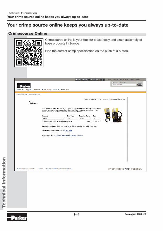
Technic
al in
form
ati
on
Catalogue 4460-UKH-4
Technical InformationYour crimp source online keeps you always up-to-date
Your crimp source online keeps you always up-to-date
Crimpsource online is your tool for a fast, easy and exact assembly of hose products in Europe.
Find the correct crimp specification on the push of a button.
Crimpsource Online
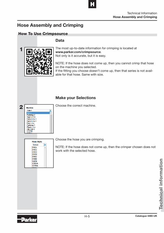
1
2
Technic
al in
form
ati
on
Catalogue 4460-UKH-5
HTechnical Information
Hose Assembly and Crimping
Hose Assembly and Crimping
Data
The most up-to-date information for crimping is located at www.parker.com/crimpsource. Not only is it accurate, but it is easy.
NOTE: If the hose does not come up, then you cannot crimp that hose on the machine you selected.If the fitting you choose doesn’t come up, then that series is not avail-able for that hose. Same with size.
Make your Selections
Choose the correct machine.
Choose the hose you are crimping.
NOTE: If the hose does not come up, then the crimper chosen does not work with the selected hose.
How To Use Crimpsource
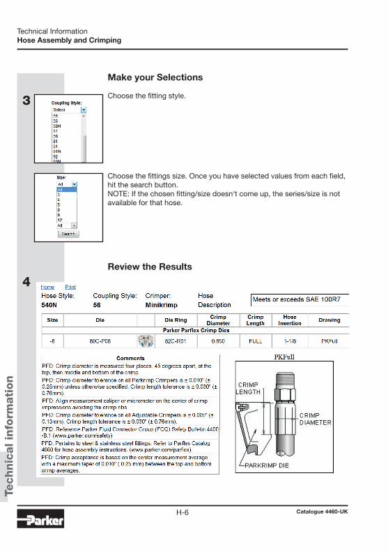
4
3
Technic
al in
form
ati
on
Catalogue 4460-UKH-6
Technical InformationHose Assembly and Crimping
Make your Selections
Choose the fitting style.
Choose the fittings size. Once you have selected values from each field, hit the search button.NOTE: If the chosen fitting/size doesn‘t come up, the series/size is not available for that hose.
Review the Results

1
2
3Te
chnic
al in
form
ati
on
Catalogue 4460-UKH-7
HTechnical Information
Assembly procedures – MiniKrimp®
Verify if type and size of the hose printed on the layline do match the work order.
NOTE When calculating hose length, take into consideration the change in hose length (expansion/contraction) that may occur during pressurisation. Using a flexible or rigid measuring tape, measure the length of hose required as follows: a. Verify required length of hose assembly with fittings. b. Subtract “Cutoff Allowance” of each fitting from hose assembly length. (Refer to
Hose Fittings Tables for proper cutoff allowances) = dimension “B”
Example: Hose assembly length with fittings = 500 mm Fitting Cutoff Allowance (1B256-6-6) 41 mm Fitting Cutoff Allowance (10356-8-6-SM) 37 mm Total Cutoff Allowance 78 mm 500 mm – 78 mm = 422 mm Length of hose required = 422 mm
Secure hose in some type of fixture to ensure straightness.
CAUTION Do not use abrasive wheels to cut hose. Abrasive wheels will damage core tube.
Measure and cut hose to length
Measure and mark hose.
Assembly procedures – MiniKrimp®
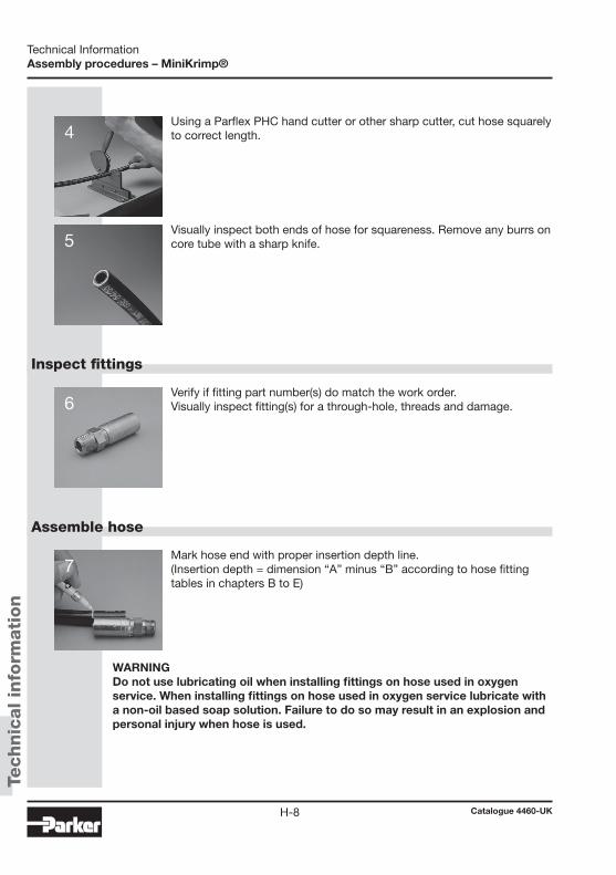
4
5
6
7
Technic
al in
form
ati
on
Catalogue 4460-UKH-8
Technical InformationAssembly procedures – MiniKrimp®
Using a Parflex PHC hand cutter or other sharp cutter, cut hose squarely to correct length.
Inspect fittings
Assemble hose
Visually inspect both ends of hose for squareness. Remove any burrs on core tube with a sharp knife.
Verify if fitting part number(s) do match the work order. Visually inspect fitting(s) for a through-hole, threads and damage.
Mark hose end with proper insertion depth line. (Insertion depth = dimension “A” minus “B” according to hose fitting tables in chapters B to E)
WARNING Do not use lubricating oil when installing fittings on hose used in oxygen service. When installing fittings on hose used in oxygen service lubricate with a non-oil based soap solution. Failure to do so may result in an explosion and personal injury when hose is used.

8
9
10
11
Technic
al in
form
ati
on
Catalogue 4460-UKH-9
HTechnical Information
Assembly procedures – MiniKrimp®
Using an SAE 20 lubricating oil, lightly lubricate inside of hose end. (Use non-oil based soap solution for oxygen service.)
Push hose into fitting all the way to depth insertion mark. (If fitting does not readily slide onto hose, perform the next step.)
Tap fitting onto hose as follows: Using Parker VBS or VBL vice blocks, place hose with fitting into proper hole of vice block and place in bench vice.
Using a rubber mallet, tap fitting onto hose until bottom of fitting shell is aligned with depth insertion mark. Repeat Steps 7-10 for other end of hose if required.
CAUTION Ensure hose extends from vice blocks only enough to clear depth inser-tion mark. Failure to do this may result in harmful kinking to the hose.
NOTE The following steps are performed using the Parker MiniKrimp®. The MiniKrimp® crimping machine must only be set-up and operated by quali-fied and/or authorised staff. Parker will not accept warranty for the improper operation of MiniKrimp®.
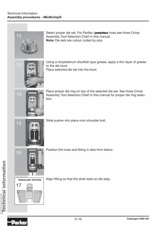
rR
12
13
14
15
16
17
Technic
al in
form
ati
on
Catalogue 4460-UKH-10
Technical InformationAssembly procedures – MiniKrimp®
Select proper die set. For Parflex-/polyflex hose see Hose Crimp Assembly Tool Selection Chart in this manual. Note: Die sets are colour coded by size.
Using a molybdenum disulfide type grease, apply a thin layer of grease to the die bowl. Place selected die set into the bowl.
Place proper die ring on top of the selected die set. See Hose Crimp Assembly Tool Selection Chart in this manual for proper die ring selec-tion.
Slide pusher into place onto shoulder bolt.
Position the hose and fitting in dies from below.
Align fitting so that the shell rests on die step.PARKALIGN® FEATURE
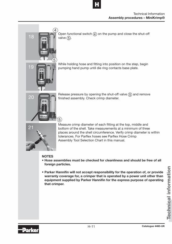
5
4
5
18
19
20
21
Technic
al in
form
ati
on
Catalogue 4460-UKH-11
HTechnical Information
Assembly procedures – MiniKrimp®
Open functional switch d on the pump and close the shut-off valve e.
Measure crimp diameter of each fitting at the top, middle and bottom of the shell. Take measurements at a minimum of three places around the shell circumference. Verify crimp diameter is within tolerances. For Parflex hoses see Parflex Hose Crimp Assembly Tool Selection Chart in this manual.
NOTES• Hose assemblies must be checked for cleanliness and should be free of all
foreign particles.
• Parker Hannifin will not accept responsibility for the operation of, or provide warranty coverage for, a crimper that is operated by a power unit other than equipment supplied by Parker Hannifin for the express purpose of operating that crimper.
While holding hose and fitting into position on the step, begin pumping hand pump until die ring contacts base plate.
Release pressure by opening the shut-off valve e and remove finished assembly. Check crimp diameter.

1
2
3
Technic
al in
form
ati
on
Catalogue 4460-UKH-12
Technical InformationAssembly procedures – Parkrimp® 2
Verify if type and size of the hose printed on the layline do match the work order.
Measure and cut hose to length
NOTE When calculating hose length, take into consideration the change in hose length (expansion/contraction) that may occur during pressurisation.
Using a flexible or rigid measuring tape, measure the length of hose required as follows: a. Verify required length of hose assembly with fittings. b. Subtract “Cutoff Allowance” of each fitting from hose assembly length. (Refer to Hose Fittings Tables for proper cutoff allowances)= dimension “B” Example: Hose assembly length with fittings = 500 mm Fitting Cutoff Allowance (1B256-6-6) 41 mm Fitting Cutoff Allowance (10356-8-6-SM) 37 mm Total Cutoff Allowance 78 mm 500 mm – 78 mm = 422 mm Length of hose required = 422 mm
CAUTION Do not use abrasive wheels to cut hose. Abrasive wheels will damage core tube.
Secure hose in some type of fixture to ensure straightness.
Measure and mark hose.
Assembly procedures – Parkrimp® 2
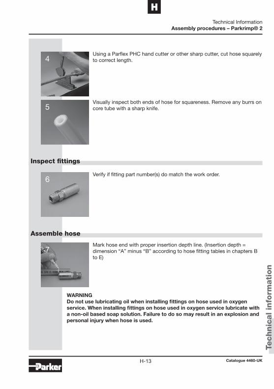
4
5
6
7
Technic
al in
form
ati
on
Catalogue 4460-UKH-13
HTechnical Information
Assembly procedures – Parkrimp® 2
Using a Parflex PHC hand cutter or other sharp cutter, cut hose squarely to correct length.
Inspect fittings
Assemble hose
WARNING Do not use lubricating oil when installing fittings on hose used in oxygen service. When installing fittings on hose used in oxygen service lubricate with a non-oil based soap solution. Failure to do so may result in an explosion and personal injury when hose is used.
Mark hose end with proper insertion depth line. (Insertion depth = dimension “A” minus “B” according to hose fitting tables in chapters B to E)
Visually inspect both ends of hose for squareness. Remove any burrs on core tube with a sharp knife.
Verify if fitting part number(s) do match the work order.

8
9
10
11
Technic
al in
form
ati
on
Catalogue 4460-UKH-14
Technical InformationAssembly procedures – Parkrimp® 2
Using an SAE 20 lubricating oil, lightly lubricate inside of hose end. (Use soap solution for oxygen service.)
Push hose into fitting all the way to depth insertion mark. (If fitting does not readily slide onto hose, perfrom the next step.)
Tap fitting onto hose as follows: Using Parker VBS or VBL vice blocks, place hose with fitting into proper hole of vice block and place in bench vice.
Using a rubber mallet, tap fitting onto hose until bottom of fitting shell is aligned with depth insertion mark. Repeat Steps 7-10 for other end of hose if required.
CAUTION Ensure hose extends from vice blocks only enough to clear depth insertion mark. Failure to do this may result in harmful kinking of hose.
NOTE • The following steps are performed using the Parker ParKrimp® 2.• Pusher slide pin is located inside rear of pusher.
CAUTION Do not use the black spacer ring on Parflex fittings. Use of the black spacer ring will result in improperly crimped fittings and hose assem-blies.

12
13
14
15
16Te
chnic
al in
form
ati
on
Catalogue 4460-UKH-15
HTechnical Information
Assembly procedures – Parkrimp® 2
With pusher in full up position, position rear half of split die ring in rear of pusher. Lock ring in position by pushing in slide pin.
Install adaptor bowl in base plate of crimper for hose sizes 4 through 20.
Using a molybydendum disulfide type grease, apply a thin layer of grease on inside of adaptor bowl.
Select proper Par krimp® die set. (See Swage and Crimp Die Selection Chart in this catalog section for proper part number selection.)
Place die set into bowl.
NOTE When installing adaptor bowl, tilt bowl toward back of crimper during insertion.
CAUTION When crimping stainless steel fittings, lubricate dies with Parker 702 Oil. Fail-ure to do so may result in damage to fittings.
SLIDE PIN
SPLIT DIE RING
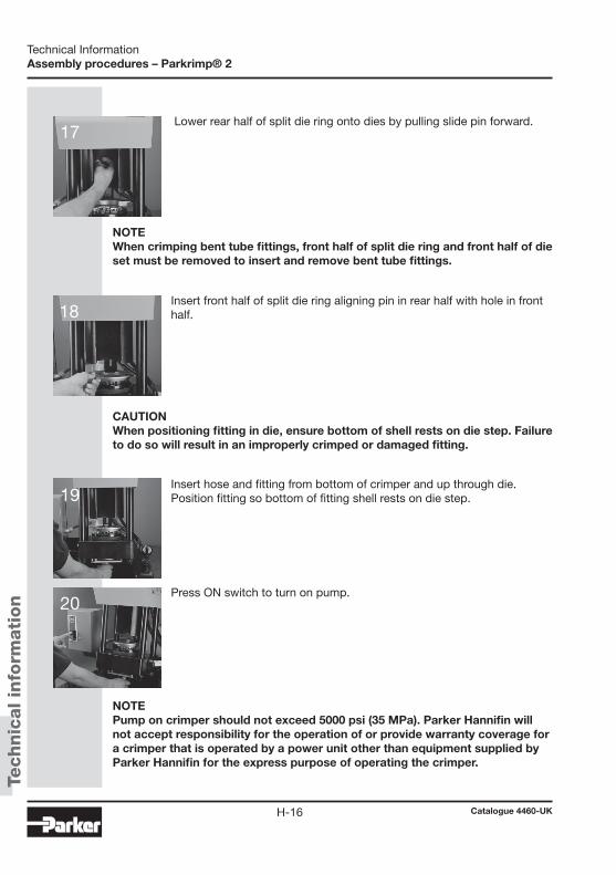
17
18
19
20
Technic
al in
form
ati
on
Catalogue 4460-UKH-16
Technical InformationAssembly procedures – Parkrimp® 2
Lower rear half of split die ring onto dies by pulling slide pin forward.
Insert front half of split die ring aligning pin in rear half with hole in front half.
Insert hose and fitting from bottom of crimper and up through die. Position fitting so bottom of fitting shell rests on die step.
Press ON switch to turn on pump.
NOTE When crimping bent tube fittings, front half of split die ring and front half of die set must be removed to insert and remove bent tube fittings.
CAUTION When positioning fitting in die, ensure bottom of shell rests on die step. Failure to do so will result in an improperly crimped or damaged fitting.
NOTE Pump on crimper should not exceed 5000 psi (35 MPa). Parker Hannifin will not accept responsibility for the operation of or provide warranty coverage for a crimper that is operated by a power unit other than equipment supplied by Parker Hannifin for the express purpose of operating the crimper.
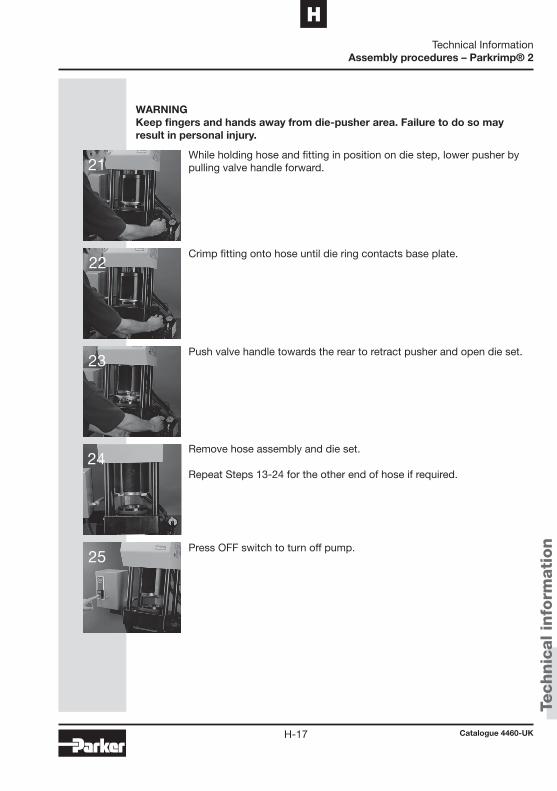
21
22
23
24
25Te
chnic
al in
form
ati
on
Catalogue 4460-UKH-17
HTechnical Information
Assembly procedures – Parkrimp® 2
WARNING Keep fingers and hands away from die-pusher area. Failure to do so may result in personal injury.
While holding hose and fitting in position on die step, lower pusher by pulling valve handle forward.
Crimp fitting onto hose until die ring contacts base plate.
Push valve handle towards the rear to retract pusher and open die set.
Remove hose assembly and die set.
Repeat Steps 13-24 for the other end of hose if required.
Press OFF switch to turn off pump.
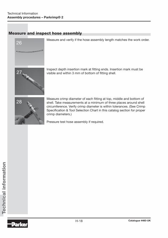
26
27
28
Technic
al in
form
ati
on
Catalogue 4460-UKH-18
Technical InformationAssembly procedures – Parkrimp® 2
Measure and verify if the hose assembly length matches the work order.
Measure and inspect hose assembly
Inspect depth insertion mark at fitting ends. Insertion mark must be visible and within 3 mm of bottom of fitting shell.
Measure crimp diameter of each fitting at top, middle and bottom of shell. Take measurements at a minimum of three places around shell circumference. Verify crimp diameter is within tolerances. (See Crimp Specification & Tool Selection Chart in this catalog section for proper crimp diameters.) Pressure test hose assembly if required.

Technic
al in
form
ati
on
Catalogue 4460-UKH-19
HTechnical Information
Assembly procedure – Push-Lok® self-grip hose
Assembly procedure – Push-Lok® self-grip hose
Cut hose perpendicularly with a sharp knife. If necessary, lubricate fitting end with water or soap and water solution (5% liquid soap + 95% water) for ease of assembly.
Assembly
Disassembly
Push-Lok® assembly tool
Insert fitting into hose and push with steady force until fitting is com-pletely in hose. Grip hose approximately 2.5 cm from end. As an alterna-tive, use the Parker 611050G assembly tool.
Cut the hose longitudinally along a line at approximately a 20° angle from the centre line of the hose. Make sure not to nick the barbs of the fitting.
Pull fitting out of hose.
For easy assembly of Parker self-gripping hose. Overall length: approx. 320 mm Weight: approx. 2.2 kg Part No. 611050G
CAUTIONBefore reusing the fitting, check fitting for damages. Damaged fittings result in leakage.
CAUTIONPush-Lok® fittings will provide an effective grip only when the Push-Lok® hose is pushed fully onto the insert, where the cropped end of the hose should be fully concealed by the plastic collar. Lubricate fitting end with water, soap, or a Push-Lok® assembly oil.
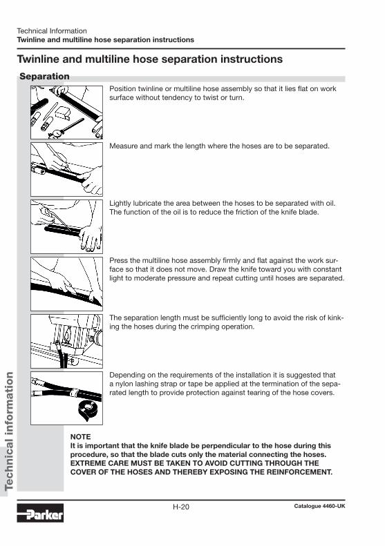
Technic
al in
form
ati
on
Catalogue 4460-UKH-20
Technical InformationTwinline and multiline hose separation instructions
Twinline and multiline hose separation instructions
Position twinline or multiline hose assembly so that it lies flat on work surface without tendency to twist or turn.
Separation
Measure and mark the length where the hoses are to be separated.
Lightly lubricate the area between the hoses to be separated with oil. The function of the oil is to reduce the friction of the knife blade.
Press the multiline hose assembly firmly and flat against the work sur-face so that it does not move. Draw the knife toward you with constant light to moderate pressure and repeat cutting until hoses are separated.
The separation length must be sufficiently long to avoid the risk of kink-ing the hoses during the crimping operation.
Depending on the requirements of the installation it is suggested that a nylon lashing strap or tape be applied at the termination of the sepa-rated length to provide protection against tearing of the hose covers.
NOTEIt is important that the knife blade be perpendicular to the hose during this procedure, so that the blade cuts only the material connecting the hoses. EXTREME CARE MUST BE TAKEN TO AVOID CUTTING THROUGH THE COVER OF THE HOSES AND THEREBY EXPOSING THE REINFORCEMENT.

Technic
al in
form
ati
on
Catalogue 4460-UKH-21
HTechnical InformationThermoplastic hose
Thermoplastic hose
Determining the hose length for over-the-sheaf applications The exact cut-off length for an optimum over-the-sheaf assembly
depends on the particular mechanical arrangement of the machine. A method for finding an approximate starting point is as follows:
1. Assemble hose with one coupling, as shown in diagram.
2. Measure hose length from point 1 to point 2 with taut hose (Lo = length)
3. Calculate the hose length: Calculate hose cut-off or free length Lf: Lf = 0.985 Lo + 2x Where Lf includes coupling insert allowance on both ends. The coupling insertion allowance (x) may be taken from the fitting ta-bles as well as from the related drawing (difference measurement A-B) or from direct measuring on the coupling. A 1.5% stretch allowance is provided in this formula.
4. Couple the remaining hose end and assemble on the machine.
Definition of nominal length
Nominal length (L)
Nominal length (L)
Nominal length (L)

Technic
al in
form
ati
on
Catalogue 4460-UKH-22
Technical InformationSelection, installation, and maintenance
Selection, installation, and maintenance of polyflex/Parflex hose and hose assemblies Hose and hose assemblies have a finite life span and many factors
can reduce this time. This recommended practice should be read by designers and users of hose to assist them in the proper selection of hose. These guidelines, while not exhaustive, will assist the user in maintaining hydraulic and pneumatic systems. READ THE PARKER SAFETY GUIDE CONTAINED IN THIS CATALOGUE IN ITS ENTIRETY!
Part 1 - How to select hose • Pressure - Maximum operating pressure of the hose must be
greater than or equal to the system pressure. Pressure surges or system “spikes” in excess of the maximum operating pressure will shorten hose life and must be avoided.
• Temperature - Ambient and fluid temperatures must not exceed the hose/fittings rated design temperature. Also the rated ambient temperature of the fluid inside the hose must not be exceeded. At-tempt to route hose or shield hose from high temperature sources.
• Size - Adequately size hose and fittings to avoid damaging hose with excessive turbulence, or heat build-up, while maintaining proper flow and pressure. (Refer to fluid velocity nomogram.)
• Fluid Resistance - Refer to Chemical Resistance Guide in this catalogue for use of fluids with various materials. If unsure of an application, contact Parker polyflex.
• Environment - Conditions such as ozone, UV light, harsh chemi-cals, salt water, and other airborne contaminants can degrade hose and shorten its life.
• Length - Hose length changes with pressure. This, along with equipment movement, must be considered in the system design.
• Proper couplings - Always follow manufacturers specifications and do not mix components of different manufacturers.
• Mechanical loads - Conditions such as tensile and side loads, vibration, excessive flexing, and twist will reduce hose life. Use swivel fittings and adaptors to avoid hose twisting. Test the hose if the application is potentially problematic or unusual.

Technic
al in
form
ati
on
Catalogue 4460-UKH-23
HTechnical Information
Selection, installation, and maintenance
Part 2 – Installation and maintenance • Inspect components - Check hose for cover cracks, blisters,
cleanliness, kinks, cracks or core tube obstructions or other de-fects. Examine fittings for poor threads, obstructions, cracks, rust. Do not use hose or fittings if these problems exist.
• Assemble per instructions contained in this catalogue. • Do not exceed specified minimum bend radius - Use stress
relievers to prevent sharp bends at the hose and fitting juncture. These can be spring guards or other stress relieving members.
• After installation, eliminate air entrapped In system, pressu-rise to maximum operating pressure, and check for leaks and proper system function.
• After installation, periodically (frequency depends on severity of application and potential risk) inspect the system for the following:
1. Blistered, degraded, or loose hose covers. 2. Stiff, cracked, or charred hose. 3. Cuts or abrasion of hose. Look for exposed reinforcement. 4. Leaks in hose or fittings. 5. Damaged or corroded fittings. 6. Excessive build up of dirt, grease, oils, etc. 7. Defective or broken accessories (clamping devices, kink
guards) 8. Kinks in hoses. Upon discovery of any of these items, replace it. DO NOT IGNORE IT!
• Retest the system after all maintenance procedures. • Establish replacement schedules based on previous service
life, or when failures could result in damage, personal injury, excessive or unacceptable downtime.
Technic
al in
form
ati
on
Catalogue 4460-UKH-24
Technical InformationInstallation standards
Hose installation tips Establish hose size (ID) and style based upon flow rate (l/min),
pressure drop, and chemical resistance with liquid or gaseous fluid. Other significant factors to be considered in hose selection and installation are the following:
Burst pressure and working pressure The specified burst pressure for each hose style and dash size
are for unaged hoses tested at normal laboratory temperature in accordance with SAE J343 specification for normal service and technically ideal installations. The maximum recommended working pressure is 1/4 of the minimum rated burst pressure, except as otherwise specifically stated in those product specifications. For more severe service, a higher rated working pressure hose may have to be selected.
Operating temperature The temperature range for satisfactory service (maximum hose life)
depends to a great extent upon the fluid being conveyed. Use of a hose above maximum specified temperature ratings will shorten hose life due, but not limited, to oxidation, chemical degradation and loss of compression within the coupling.
Pressure effects Pressure surges and system shocks (spikes) are common in hy-
draulic systems. The normal 1:4 design factor should reflect these transient pressures. Where these surges and shocks are considered severe or hazardous, the design factor should be increased. When hose is under pressure, it may change in length by as much as +2/ -4%. Installation should compensate for shortening by providing an appropriate amount of slack and for lengthening by allowing space for this growth to be absorbed.
Bend radius The minimum bend radii listed in this catalogue are valid at rated
working pressures and indicated service temperatures. Service life of a hose may be shortened if the minimum radius is exceeded or if the hose is flexed continuously in use.
Installation standards
Technic
al in
form
ati
on
Catalogue 4460-UKH-25
HTechnical Information
Installation standards
Ambient temperature Exceedingly high or low ambient temperatures will affect the materi-
als from which the hose is constructed and will negatively influence hose life. When at all possible, the hose should be routed in such a manner as to protect it from heat sources. In extreme cold applica-tions, the equipment should be designed with remote relief valves to allow circulation and warming of the oil before hose articulation is attempted.
Abrasion Abrasion occurs in numerous forms. Among the more common
are the typical rubbing or chafing, with the second being very high frequency, low amplitude friction. This type of abrasion results from pump pressure pulses depending on the pump characteristics. It can also be caused by equipment vibration or resonance. Abrasion may occur when two hose lines cross or when a hose line rubs or bears against a fixed point. Abrasion resistance is also a function of temperature and attack of the cover material by aggressive chemi-cals. Protective sleeving can ward off premature hose failure resulting from abrasion.
Routing and clamping Maximum efforts should be made to route hose so it flexes in a sin-
gle plane. Routing hoses in flexure through compound bends results in torsion. When this is unavoidable, the torsion should be distrib-uted over the maximum hose length possible. Wire reinforced hoses suffer the most rapid and severe loss of service life when applied in torsion. Extremely tight and improperly located clamps focus this torsion over short distances. Analysis of the hose function is required before the proper clamp-ing techniques can be selected. In some applications, hoses must be contained to stay out of harm’s way and at the same time be free to come and go with equipment articulation. Other applications may require restrictive clamping, in which case a protective material should be used around the hose to provide the grasp without defor-mation of the hose by the clamp.

Technic
al in
form
ati
on
Catalogue 4460-UKH-26
Technical InformationInstallation tips
Installation tips
Hose is weakened when installed in twisted position. Also, pressure pulses in twisted hose tend to fatigue wire and loosen fitting con-nections. Design so that machine motion produces bending rather than torsion.
Hose should exit coupling in a straight position rather than side loaded. The minimum bend radius must not be exceeded to avoid kinking of hose and flow restriction.
When hose assembly is installed in a flexing application, remember that metal hose fittings are not part of the flexible portion.
Use elbows or adaptors as necessary to eliminate excess hose length and to ensure neater installation and easier maintenance.
Free hose length allowance: Pressure can change hose in length by as much as ±2%. This must be considered when cutting hose to appropriate length.
Avoid installing hose assemblies close to heat sources. However, if this should be required, insulate hose.
right
wrong
wrong
right
right
wrong
right
wrong
right
wrong
wrong
right
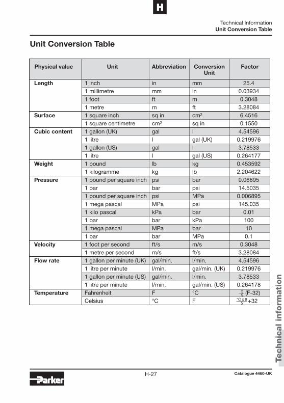
Technic
al in
form
ati
on
Catalogue 4460-UKH-27
HTechnical Information
Unit Conversion Table
Unit Conversion Table
1 inch in mm 25.41 millimetre mm in 0.039341 foot ft m 0.30481 metre m ft 3.280841 square inch sq in cm2 6.45161 square centimetre cm2 sq in 0.15501 gallon (UK) gal l 4.545961 litre l gal (UK) 0.2199761 gallon (US) gal l 3.785331 litre l gal (US) 0.2641771 pound lb kg 0.4535921 kilogramme kg lb 2.2046221 pound per square inch psi bar 0.068951 bar bar psi 14.50351 pound per square inch psi MPa 0.0068951 mega pascal MPa psi 145.0351 kilo pascal kPa bar 0.011 bar bar kPa 1001 mega pascal MPa bar 101 bar bar MPa 0.11 foot per second ft/s m/s 0.30481 metre per second m/s ft/s 3.280841 gallon per minute (UK) gal/min. l/min. 4.545961 litre per minute l/min. gal/min. (UK) 0.2199761 gallon per minute (US) gal/min. l/min. 3.785331 litre per minute l/min. gal/min. (US) 0.264178Fahrenheit F °C (F-32)Celsius °C F +32
59
°C x 95
Length
Surface
Cubic content
Weight
Pressure
Velocity
Flow rate
Temperature
Physical value Unit Abbreviation Conversion Factor Unit
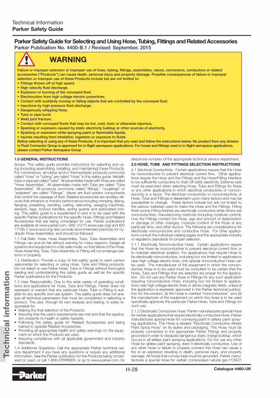
Technic
al in
form
ati
on
Catalogue 4460-UKH-28
Technical InformationParker Safety Guide
1.0 GENERAL INSTRUCTIONSScope: This safety guide provides instructions for selecting and us-ing (including assembling, installing, and maintaining) these Products. For convenience, all rubber and/or thermoplastic products commonly called “hose” or “tubing” are called “Hose” in this safety guide. Metallic tube or pipe are called “tube”. All assemblies made with Hose are called “Hose Assemblies”. All assemblies made with Tube are called “Tube Assemblies”. All products commonly called “fittings”, “couplings” or “adapters” are called “Fittings”. Valves are fluid system components that control the passage of fluid. Related accessories are ancillary de-vices that enhance or monitor performance including crimping, flaring, flanging, presetting, bending, cutting, deburring, swaging machines, sensors, tags, lockout handles, spring guards and associated tool-ing. This safety guide is a supplement to and is to be used with the specific Parker publications for the specific Hose, Fittings and Related Accessories that are being considered for use. Parker publications are available at www.parker.com. SAE J1273 (www.sae.org) and ISO 17165-2 (www.ansi.org) also provide recommended practices for hy-draulic Hose Assemblies, and should be followed.1.1 Fail-Safe: Hose, Hose Assemblies, Tube, Tube Assemblies and Fittings can and do fail without warning for many reasons. Design all systems and equipment in a fail-safe mode, so that failure of the Hose, Hose Assembly, Tube, Tube Assembly or Fitting will not endanger per-sons or property.1.2 Distribution: Provide a copy of this safety guide to each person responsible for selecting or using Hose, Tube and Fitting products. Do not select or use Parker Hose, Tube or Fittings without thoroughly reading and understanding this safety guide as well as the specific Parker publications for the Products.1.3 User Responsibility: Due to the wide variety of operating condi-tions and applications for Hose, Tube and Fittings. Parker does not represent or warrant that any particular Hose, Tube or Fitting is suit-able for any specific end use system. This safety guide does not ana-lyze all technical parameters that must be considered in selecting a product. The user, through its own analysis and testing, is solely re-sponsible for:• Making the final selection of the Products.• Assuring that the user’s requirements are met and that the applica-
tion presents no health or safety hazards.• Following the safety guide for Related Accessories and being
trained to operate Related Accessories.• Providing all appropriate health and safety warnings on the equip-
ment on which the Products are used.• Assuring compliance with all applicable government and industry
standards.1.4 Additional Questions: Call the appropriate Parker technical ser-vice department if you have any questions or require any additional information. See the Parker publication for the Products being consid-ered or used, or call 1-800-CPARKER, or go to www.parker.com, for
telephone numbers of the appropriate technical service department.2.0 HOSE, TUBE AND FITTINGS SELECTION INSTRUCTIONS 2.1 Electrical Conductivity: Certain applications require that the Hose be nonconductive to prevent electrical current flow. Other applica-tions require the Hose and the Fittings and the Hose/Fitting interface to be sufficiently conductive to drain off static electricity. Extreme care must be exercised when selecting Hose, Tube and Fittings for these or any other applications in which electrical conductivity or noncon-ductivity is a factor. The electrical conductivity or nonconductivity of Hose, Tube and Fittings is dependent upon many factors and may be susceptible to change. These factors include but are not limited to the various materials used to make the Hose and the Fittings, Fitting finish (some Fitting finishes are electrically conductive while others are nonconductive), manufacturing methods (including moisture control), how the Fittings contact the Hose, age and amount of deterioration or damage or other changes, moisture content of the Hose at any particular time, and other factors. The following are considerations for electrically nonconductive and conductive Hose. For other applica-tions consult the individual catalog pages and the appropriate industry or regulatory standards for proper selection. 2.1.1 Electrically Nonconductive Hose: Certain applications require that the Hose be nonconductive to prevent electrical current flow or to maintain electrical isolation. For applications that require Hose to be electrically nonconductive, including but not limited to applications near high voltage electric lines, only special nonconductive Hose can be used. The manufacturer of the equipment in which the noncon-ductive Hose is to be used must be consulted to be certain that the Hose, Tube and Fittings that are selected are proper for the applica-tion. Do not use any Parker Hose or Fittings for any such application requiring nonconductive Hose, including but not limited to applica-tions near high voltage electric lines or dense magnetic fields, unless (i) the application is expressly approved in the Parker technical publica-tion for the product, (ii) the Hose is marked “nonconductive”, and (iii) the manufacturer of the equipment on which the Hose is to be used specifically approves the particular Parker Hose, Tube and Fittings for such use. 2.1.2 Electrically Conductive Hose: Parker manufactures special Hose for certain applications that require electrically conductive Hose. Parker manufactures special Hose for conveying paint in airless paint spray-ing applications. This Hose is labeled “Electrically Conductive Airless Paint Spray Hose” on its layline and packaging. This Hose must be properly connected to the appropriate Parker Fittings and properly grounded in order to dissipate dangerous static charge buildup, which occurs in all airless paint spraying applications. Do not use any other Hose for airless paint spraying, even if electrically conductive. Use of any other Hose or failure to properly connect the Hose can cause a fire or an explosion resulting in death, personal injury, and property damage. All hoses that convey fuels must be grounded. Parker manu-factures a special Hose for certain compressed natural gas (“CNG”)
WARNINGFailure or improper selection or improper use of hose, tubing, fittings, assemblies, valves, connectors, conductors or related accessories (“Products”) can cause death, personal injury and property damage. Possible consequences of failure or improper selection or improper use of these Products include but are not limited to:• Fittings thrown off at high speed.• High velocity fluid discharge.• Explosion or burning of the conveyed fluid.• Electrocution from high voltage electric powerlines.• Contact with suddenly moving or falling objects that are controlled by the conveyed fluid.• Injections by high-pressure fluid discharge.• Dangerously whipping Hose.• Tube or pipe burst.• Weld joint fracture.• Contact with conveyed fluids that may be hot, cold, toxic or otherwise injurious.• Sparking or explosion caused by static electricity buildup or other sources of electricity.• Sparking or explosion while spraying paint or flammable liquids.• Injuries resulting from inhalation, ingestion or exposure to fluids.Before selecting or using any of these Products, it is important that you read and follow the instructions below. No product from any division in Fluid Connector Group is approved for in-flight aerospace applications. For hoses and fittings used in in-flight aerospace applications, please contact Parker Aerospace Group
Parker Safety Guide for Selecting and Using Hose, Tubing, Fittings and Related AccessoriesParker Publication No. 4400-B.1 / Revised: September, 2015
Technic
al in
form
ati
on
Catalogue 4460-UKH-29
HTechnical InformationParker Safety Guide
applications where static electricity buildup may occur. Parker CNG Hose assemblies comply with the requirements of ANSI/IAS NGV 4.2; CSA 12.52, “Hoses for Natural Gas Vehicles and Dispensing Systems” (www.ansi.org). This Hose is labeled “Electrically Conductive for CNG Use” on its layline and packaging. This Hose must be properly con-nected to the appropriate Parker Fittings and properly grounded in order to dissipate dangerous static charge buildup, which occurs in, for example, high velocity CNG dispensing or transfer. Do not use any other Hose for CNG applications where static charge buildup may oc-cur, even if electrically conductive. Use of other Hoses in CNG appli-cations or failure to properly connect or ground this Hose can cause a fire or an explosion resulting in death, personal injury, and property damage. Care must also be taken to protect against CNG permeation through the Hose wall. See section 2.6, Permeation, for more infor-mation. Parker CNG Hose is intended for dispenser and vehicle use within the specified temperature range. Parker CNG Hose should not be used in confined spaces or unventilated areas or areas exceeding the specified temperature range. Final assemblies must be tested for leaks. CNG Hose Assemblies should be tested on a monthly basis for conductivity per ANSI/IAS NGV 4.2; CSA 12.52. Parker manufac-tures special Hose for aerospace in-flight applications. Aerospace in-flight applications employing Hose to transmit fuel, lubricating fluids and hydraulic fluids require a special Hose with a conductive inner tube. This Hose for in-flight applications is available only from Parker's Stratoflex Products Division. Do not use any other Parker Hose for in-flight applications, even if electrically conductive. Use of other Hoses for in-flight applications or failure to properly connect or ground this Hose can cause a fire or an explosion resulting in death, personal injury and property damage. These Hose assemblies for in-flight applica-tions must meet all applicable aerospace industry, aircraft engine and aircraft requirements. 2.2 Pressure: Hose, Tube and Fitting selection must be made so that the published maximum working pressure of the Hose, Tube and Fit-tings are equal to or greater than the maximum system pressure. The maximum working pressure of a Hose, or Tube Assembly is the lower of the respective published maximum working pressures of the Hose, Tube and the Fittings used. Surge pressures or peak transient pres-sures in the system must be below the published maximum working pressure for the Hose, Tube and Fitting. Surge pressures and peak pressures can usually only be determined by sensitive electrical instru-mentation that measures and indicates pressures at millisecond inter-vals. Mechanical pressure gauges indicate only average pressures and cannot be used to determine surge pressures or peak transient pres-sures. Published burst pressure ratings for Hose is for manufacturing test purposes only and is no indication that the Product can be used in applications at the burst pressure or otherwise above the published maximum recommended working pressure. 2.3 Suction: Hoses used for suction applications must be selected to insure that the Hose will withstand the vacuum and pressure of the system. Improperly selected Hose may collapse in suction application. 2.4 Temperature: Be certain that fluid and ambient temperatures, both steady and transient, do not exceed the limitations of the Hose, Tube, Fitting and Seals. Temperatures below and above the recommended limit can degrade Hose, Tube, Fittings and Seals to a point where a failure may occur and release fluid. Tube and Fittings performances are normally degraded at elevated temperature. Material compatibility can also change at temperatures outside of the rated range. Properly insulate and protect the Hose Assembly when routing near hot objects (e.g. manifolds). Do not use any Hose in any application where failure of the Hose could result in the conveyed fluids (or vapors or mist from the conveyed fluids) contacting any open flame, molten metal, or other potential fire ignition source that could cause burning or explosion of the conveyed fluids or vapors. 2.5 Fluid Compatibility: Hose, and Tube Assembly selection must as-sure compatibility of the Hose tube, cover, reinforcement, Tube, Plating and Seals with the fluid media used. See the fluid compatibility chart in the Parker publication for the product being considered or used. This information is offered only as a guide. Actual service life can only be determined by the end user by testing under all extreme condi-tions and other analysis. Hose, and Tube that is chemically compatible with a particular fluid must be assembled using Fittings and adapters containing likewise compatible seals. Flange or flare processes can change Tube material properties that may not be compatible with cer-tain requirements such as NACE 2.6 Permeation: Permeation (that is, seepage through the Hose or Seal) will occur from inside the Hose or Fitting to outside when Hose or Fitting is used with gases, liquid and gas fuels, and refrigerants (includ-ing but not limited to such materials as helium, diesel fuel, gasoline,
natural gas, or LPG). This permeation may result in high concentra-tions of vapors which are potentially flammable, explosive, or toxic, and in loss of fluid. Dangerous explosions, fires, and other hazards can result when using the wrong Hose for such applications. The sys-tem designer must take into account the fact that this permeation will take place and must not use Hose or Fitting if this permeation could be hazardous. The system designer must take into account all legal, government, insurance, or any other special regulations which govern the use of fuels and refrigerants. Never use a Hose or Fitting even though the fluid compatibility is acceptable without considering the potential hazardous effects that can result from permeation through the Hose or Tube Assembly. Permeation of moisture from outside the Hose or Fitting to inside the Hose or Fitting will also occur in Hose or Tube assemblies, regardless of internal pressure. If this moisture per-meation would have detrimental effects (particularly, but not limited to refrigeration and air conditioning systems), incorporation of sufficient drying capacity in the system or other appropriate system safeguards should be selected and used. The sudden pressure release of highly pressurized gas could also result in Explosive Decompression failure of permeated Seals and Hoses.2.7 Size: Transmission of power by means of pressurized fluid varies with pressure and rate of flow. The size of the components must be adequate to keep pressure losses to a minimum and avoid damage due to heat generation or excessive fluid velocity. .2.8 Routing: Attention must be given to optimum routing to minimize inherent problems (kinking or flow restriction due to Hose collapse, twisting of the Hose, proximity to hot objects or heat sources). For ad-ditional routing recommendations see SAE J1273 and ISO 17165-2. Hose Assemblies have a finite life and should be installed in a man-ner that allows for ease of inspection and future replacement. Hose because of its relative short life, should not be used in residential and commercial buildings inside of inaccessible walls or floors, unless spe-cifically allowed in the product literature. Always review all product lit-erature for proper installation and routing instructions. 2.9 Environment: Care must be taken to insure that the Hose, Tube and Fittings are either compatible with or protected from the environ-ment (that is, surrounding conditions) to which they are exposed. En-vironmental conditions including but not limited to ultraviolet radiation, sunlight, heat, ozone, moisture, water, salt water, chemicals and air pollutants can cause degradation and premature failure. 2.10 Mechanical Loads: External forces can significantly reduce Hose, Tube and Fitting life or cause failure. Mechanical loads which must be considered include excessive flexing, twist, kinking, tensile or side loads, bend radius, and vibration. Use of swivel type Fittings or adapt-ers may be required to insure no twist is put into the Hose. Use of proper Hose or Tube clamps may also be required to reduce external mechanical loads. Unusual applications may require special testing prior to Hose selection. 2.11 Physical Damage: Care must be taken to protect Hose from wear, snagging, kinking, bending smaller that minimum bend radius and cutting, any of which can cause premature Hose failure. Any Hose that has been kinked or bent to a radius smaller than the minimum bend radius, and any Hose that has been cut or is cracked or is other-wise damaged should be removed and discarded. Fittings with dam-ages such as scratches on sealing surfaces and deformation should be replaced. 2.12 Proper End Fitting: See instructions 3.2 through 3.5. These rec-ommendations may be substantiated by testing to industry standards such as SAE J517 for hydraulic applications, or MIL-A-5070, AS1339, or AS3517 for Hoses from Parker's Stratoflex Products Division for aerospace applications. 2.13 Length: When determining the proper Hose or Tube length of an assembly, be aware of Hose length change due to pressure, Tube length change due to thermal expansion or contraction, and Hose or Tube and machine tolerances and movement must be considered. When routing short hose assemblies, it is recommended that the mini-mum free hose length is always used. Consult the hose manufacturer for their minimum free hose length recommendations. Hose assem-blies should be installed in such a way that any motion or flexing oc-curs within the same plane. 2.14 Specifications and Standards: When selecting Hose, Tube and Fittings, government, industry, and Parker specifications and recom-mendations must be reviewed and followed as applicable. 2.15 Hose Cleanliness: Hose and Tube components may vary in cleanliness levels. Care must be taken to insure that the Hose and Tube Assembly selected has an adequate level of cleanliness for the application.

Technic
al in
form
ati
on
Catalogue 4460-UKH-30
Technical InformationParker Safety Guide
2.16 Fire Resistant Fluids: Some fire resistant fluids that are to be con-veyed by Hose or Tube require use of the same type of Hose or Tube as used with petroleum base fluids. Some such fluids require a special Hose, Tube, Fitting and Seal, while a few fluids will not work with any Hose at all. See instructions 2.5 and 1.5. The wrong Hose, Tube, Fit-ting or Seal may fail after a very short service. In addition, all liquids but pure water may burn fiercely under certain conditions, and even pure water leakage may be hazardous.2.17 Radiant Heat: Hose and Seals can be heated to destruction with-out contact by such nearby items as hot manifolds or molten metal. The same heat source may then initiate a fire. This can occur despite the presence of cool air around the Hose or Seal. Performance of Tube and Fitting subjected to the heat could be degraded. 2.18 Welding or Brazing: When using a torch or arc welder in close proximity to hydraulic lines, the hydraulic lines should be removed or shielded with appropriate fire resistant materials. Flame or weld spat-ter could burn through the Hose or Seal and possibly ignite escaping fluid resulting in a catastrophic failure. Heating of plated parts, includ-ing Hose Fittings and adapters, above 450°F (232°C) such as during welding, brazing or soldering may emit deadly gases. Any elastomer seal on fittings shall be removed prior to welding or brazing, any metal-lic surfaces shall be protected after brazing or welding when neces-sary. Welding and brazing filler material shall be compatible with the Tube and Fitting that are joined. 2.19 Atomic Radiation: Atomic radiation affects all materials used in Hose and Tube assemblies. Since the long-term effects may be un-known, do not expose Hose or Tube assemblies to atomic radiation. Nuclear applications may require special Tube and Fittings. 2.20 Aerospace Applications: The only Hose, Tube and Fittings that may be used for in-flight aerospace applications are those available from Parker’s Stratoflex Products Division. Do not use any other Hose or Fittings for in-flight applications. Do not use any Hose or Fittings from Parker’s Stratoflex Products Division with any other Hose or Fit-tings, unless expressly approved in writing by the engineering manag-er or chief engineer of Stratoflex Products Division and verified by the user’s own testing and inspection to aerospace industry standards. 2.21 Unlocking Couplings: Ball locking couplings or other Fittings with quick disconnect ability can unintentionally disconnect if they are dragged over obstructions, or if the sleeve or other disconnect mem-ber, is bumped or moved enough to cause disconnect. Threaded Fit-tings should be considered where there is a potential for accidental uncoupling. 3.0 HOSE AND FITTINGS ASSEMBLY AND INSTALLATION IN-STRUCTIONS 3.1 Component Inspection: Prior to assembly, a careful examination of the Hose and Fittings must be performed. All components must be checked for correct style, size, catalog number, and length. The Hose must be examined for cleanliness, obstructions, blisters, cover looseness, kinks, cracks, cuts or any other visible defects. Inspect the Fitting and sealing surfaces for burrs, nicks, corrosion or other imperfections. Do NOT use any component that displays any signs of nonconformance. 3.2 Hose and Fitting Assembly: Do not assemble a Parker Fitting on a Parker Hose that is not specifically listed by Parker for that Fitting, un-less authorized in writing by the engineering manager or chief engineer of the appropriate Parker division. Do not assemble a Parker Fitting on another manufacturer's Hose or a Parker Hose on another manu-facturer's Fitting unless (i) the engineering manager or chief engineer of the appropriate Parker division approves the Assembly in writing or that combination is expressly approved in the appropriate Parker literature for the specific Parker product, and (ii) the user verifies the Assembly and the application through analysis and testing. For Parker Hose that does not specify a Parker Fitting, the user is solely responsible for the selection of the proper Fitting and Hose Assembly procedures. See instruction 1.4. To prevent the possibility of problems such as leakage at the Fitting or system con-tamination, it is important to completely remove all debris from the cut-ting operation before installation of the Fittings. The Parker published instructions must be followed for assembling the Fittings on the Hose. These instructions are provided in the Parker Fitting catalog for the specific Parker Fitting being used, or by calling 1-800-CPARKER, or at www.parker.com. 3.3 Related Accessories: Do not crimp or swage any Parker Hose or Fitting with anything but the listed swage or crimp machine and dies in accordance with Parker published instructions. Do not crimp
or swage another manufacturer's Fitting with a Parker crimp or swage die unless authorized in writing by the engineering manager or chief engineer of the appropriate Parker division. 3.4 Parts: Do not use any Parker Fitting part (including but not limited to socket, shell, nipple, or insert) except with the correct Parker mat-ing parts, in accordance with Parker published instructions, unless authorized in writing by the engineering manager or chief engineer of the appropriate Parker division. 3.5 Field Attachable/Permanent: Do not reuse any field attachable Hose Fitting that has blown or pulled off a Hose. Do not reuse a Park-er permanent Hose Fitting (crimped or swaged) or any part thereof. Complete Hose Assemblies may only be reused after proper inspec-tion under section 4.0. Do not assemble Fittings to any previously used hydraulic Hose that was in service, for use in a fluid power application. 3.6 Pre-Installation Inspection: Prior to installation, a careful examina-tion of the Hose Assembly must be performed. Inspect the Hose As-sembly for any damage or defects. DO NOT use any Hose Assembly that displays any signs of nonconformance. 3.7 Minimum Bend Radius: Installation of a Hose at less than the minimum listed bend radius may significantly reduce the Hose life. Particular attention must be given to preclude sharp bending at the Hose to Fitting juncture. Any bending during installation at less than the minimum bend radius must be avoided. If any Hose is kinked dur-ing installation, the Hose must be discarded. 3.8 Twist Angle and Orientation: Hose Assembly installation must be such that relative motion of machine components does not produce twisting. 3.9 Securement: In many applications, it may be necessary to restrain, protect, or guide the Hose to protect it from damage by unnecessary flexing, pressure surges, and contact with other mechanical compo-nents. Care must be taken to insure such restraints do not introduce additional stress or wear points. 3.10 Proper Connection of Ports: Proper physical installation of the Hose Assembly requires a correctly installed port connection insuring that no twist or torque is transferred to the Hose when the Fittings are being tightened or otherwise during use. 3.11 External Damage: Proper installation is not complete without in-suring that tensile loads, side loads, kinking, flattening, potential abra-sion, thread damage or damage to sealing surfaces are corrected or eliminated. See instruction 2.10. 3.12 System Checkout: All air entrapment must be eliminated and the system pressurized to the maximum system pressure (at or below the Hose maximum working pressure) and checked for proper function and freedom from leaks. Personnel must stay out of potential hazard-ous areas while testing and using. 3.13 Routing: The Hose Assembly should be routed in such a manner so if a failure does occur, the escaping media will not cause personal injury or property damage. In addition, if fluid media comes in contact with hot surfaces, open flame or sparks, a fire or explosion may occur. See section 2.4. 3.14 Ground Fault Equipment Protection Devices (GFEPDs): WARN-ING! Fire and Shock Hazard. To minimize the danger of fire if the heat-ing cable of a Multitube bundle is damaged or improperly installed, use a Ground Fault Equipment Protection Device. Electrical fault currents may be insufficient to trip a conventional circuit breaker. For ground fault protection, the IEEE 515: (www.ansi.org) standard for heating ca-bles recommends the use of GFEPDs with a nominal 30 milliampere trip level for “piping systems in classified areas, those areas requiring a high degree of maintenance, or which may be exposed to physical abuse or corrosive atmospheres”. 4.0 TUBE AND FITTINGS ASSEMBLY AND INSTALLATION IN-STRUCTIONS 4.1 Component Inspection: Prior to assembly, a careful examination of the Tube and Fittings must be performed. All components must be checked for correct style, size, material, seal, and length. Inspect the Fitting and sealing surfaces for burrs, nicks, corrosion, missing seal or other imperfections. Do NOT use any component that displays any signs of nonconformance. 4.2 Tube and Fitting Assembly: Do not assemble a Parker Fitting with a Tube that is not specifically listed by Parker for that Fitting, unless authorized in writing by the engineering manager or chief engineer of the appropriate Parker division. The Tube must meet the require-ments specified to the Fitting. The Parker published instructions must be followed for assembling the Fittings to a Tube. These instructions
Technic
al in
form
ati
on
Catalogue 4460-UKH-31
HTechnical InformationParker Safety Guide
are provided in the Parker Fitting catalog for the specific Parker Fitting being used, or by calling 1-800-CPARKER, or at www.parker.com. 4.3 Related Accessories: Do not preset or flange Parker Fitting com-ponents using another manufacturer’s equipment or procedures un-less authorized in writing by the engineering manager or chief engineer of the appropriate Parker division. Tube, Fitting component and tool-ing must be check for correct style, size and material. Operation and maintenance of Related Accessories must be in accordance with the operation manual for the designated Accessory. 4.4 Securement: In many applications, it may be necessary to restrain, protect, or guide the Tube to protect it from damage by unnecessary flexing, pressure surges, vibration, and contact with other mechanical components. Care must be taken to insure such restraints do not introduce additional stress or wear points. 4.5 Proper Connection of Ports: Proper physical installation of the Tube Assembly requires a correctly installed port connection insuring that no torque is transferred to the Tube when the Fittings are being tightened or otherwise during use. 4.6 External Damage: Proper installation is not complete without insuring that tensile loads, side loads, flattening, potential abrasion, thread damage or damage to sealing surfaces are corrected or elimi-nated. See instruction 2.10. 4.7 System Checkout: All air entrapment must be eliminated and the system pressurized to the maximum system pressure (at or below the Tube Assembly maximum working pressure) and checked for proper function and freedom from leaks. Personnel must stay out of potential hazardous areas while testing and using. Routing: The Tube Assembly should be routed in such a manner so if a failure does occur, the escaping media will not cause personal injury or property damage. In addition, if fluid media comes in contact with hot surfaces, open flame or sparks, a fire or explosion may occur. See section 2.4. 5.0 HOSE AND FITTING MAINTENANCE AND REPLACEMENT INSTRUCTIONS5.1 Even with proper selection and installation, Hose life may be sig-nificantly reduced without a continuing maintenance program. The severity of the application, risk potential from a possible Hose failure, and experience with any Hose failures in the application or in similar applications should determine the frequency of the inspection and the replacement for the Products so that Products are replaced before any failure occurs. Certain products require maintenance and inspec-tion per industry requirements. Failure to adhere to these requirements may lead to premature failure. A maintenance program must be es-tablished and followed by the user and, at minimum, must include instructions 5.2 through 5.7 5.2 Visual Inspection Hose/Fitting: Any of the following conditions re-quire immediate shut down and replacement of the Hose Assembly: • Fitting slippage on Hose; • Damaged, cracked, cut or abraded cover (any reinforcement ex-
posed); • Hard, stiff, heat cracked, or charred Hose; • Cracked, damaged, or badly corroded Fittings; • Leaks at Fitting or in Hose; • Kinked, crushed, flattened or twisted Hose; and • Blistered, soft, degraded, or loose cover. 5.3 Visual Inspection All Other: The following items must be tightened,
repaired, corrected or replaced as required:• Leaking port conditions; • Excess dirt buildup; • Worn clamps, guards or shields; and • System fluid level, fluid type, and any air entrapment.5.4 Functional Test: Operate the system at maximum operating pres-sure and check for possible malfunctions and leaks. Personnel must avoid potential hazardous areas while testing and using the system. See section 2.2. 5.5 Replacement Intervals: Hose assemblies and elastomeric seals used on Hose Fittings and adapters will eventually age, harden, wear and deteriorate under thermal cycling and compression set. Hose Assemblies and elastomeric seals should be inspected and replaced at specific replacement intervals, based on previous service life, gov-ernment or industry recommendations, or when failures could result in unacceptable downtime, damage, or injury risk. See section 1.2. Hose and Fittings may be subjected to internal mechanical and/or chemical wear from the conveying fluid and may fail without warning. The user must determine the product life under such circumstances by testing. Also see section 2.5.
5.6 Hose Inspection and Failure: Hydraulic power is accomplished by utilizing high pressure fluids to transfer energy and do work. Hoses, Fittings and Hose Assemblies all contribute to this by transmitting flu-ids at high pressures. Fluids under pressure can be dangerous and potentially lethal and, therefore, extreme caution must be exercised when working with fluids under pressure and handling the Hoses transporting the fluids. From time to time, Hose Assemblies will fail if they are not replaced at proper time intervals. Usually these failures are the result of some form of misapplication, abuse, wear or failure to perform proper maintenance. When Hoses fail, generally the high pressure fluids inside escape in a stream which may or may not be visible to the user. Under no circumstances should the user attempt to locate the leak by “feeling” with their hands or any other part of their body. High pressure fluids can and will penetrate the skin and cause severe tissue damage and possibly loss of limb. Even seemingly minor hydraulic fluid injection injuries must be treated immediately by a phy-sician with knowledge of the tissue damaging properties of hydraulic fluid. If a Hose failure occurs, immediately shut down the equipment and leave the area until pressure has been completely released from the Hose Assembly. Simply shutting down the hydraulic pump may or may not eliminate the pressure in the Hose Assembly. Many times check valves, etc., are employed in a system and can cause pressure to remain in a Hose Assembly even when pumps or equipment are not operating. Tiny holes in the Hose, commonly known as pinholes, can eject small, dangerously powerful but hard to see streams of hy-draulic fluid. It may take several minutes or even hours for the pressure to be relieved so that the Hose Assembly may be examined safely. Once the pressure has been reduced to zero, the Hose Assembly may be taken off the equipment and examined. It must always be replaced if a failure has occurred. Never attempt to patch or repair a Hose Assembly that has failed. Consult the nearest Parker distribu-tor or the appropriate Parker division for Hose Assembly replacement information. Never touch or examine a failed Hose Assembly unless it is obvious that the Hose no longer contains fluid under pressure. The high pressure fluid is extremely dangerous and can cause serious and potentially fatal injury. 5.7 Elastomeric seals: Elastomeric seals will eventually age, harden, wear and deteriorate under thermal cycling and compression set. Elastomeric seals should be inspected and replaced. 5.8 Refrigerant gases: Special care should be taken when working with refrigeration systems. Sudden escape of refrigerant gases can cause blindness if the escaping gases contact the eye and can cause freezing or other severe injuries if it contacts any other portion of the body. 5.9 Compressed natural gas (CNG): Parker CNG Hose Assemblies should be tested after installation and before use, and at least on a monthly basis per instructions provided on the Hose Assembly tag. The recommended procedure is to pressurize the Hose and check for leaks and to visually inspect the Hose for damage and to perform an electrical resistance test. Caution: Matches, candles, open flame or other sources of ignition shall not be used for Hose inspection. Leak check solutions should be rinsed off after use. 6.0 HOSE STORAGE6.1 Age Control: Hose and Hose Assemblies must be stored in a manner that facilitates age control and first-in and first-out usage based on manufacturing date of the Hose and Hose Assemblies. Un-less otherwise specified by the manufacturer or defined by local laws and regulations: 6.1.1 The shelf life of rubber hose in bulk form or hose made from two or more materials is 28 quarters (7 years) from the date of manufac-ture, with an extension of 12 quarters (3 years), if stored in accordance with ISO 2230; 6.1.2 The shelf life of thermoplastic and polytetrafluoroethylene hose is considered to be unlimited; 6.1.3 Hose assemblies that pass visual inspection and proof test shall not be stored for longer than 2 years. 6.1.4 Storage: Stored Hose and Hose Assemblies must not be sub-jected to damage that could reduce their expected service life and must be placed in a cool, dark and dry area with the ends capped. Stored Hose and Hose Assemblies must not be exposed to tempera-ture extremes, ozone, oils, corrosive liquids or fumes, solvents, high humidity, rodents, insects, ultraviolet light, electromagnetic fields or radioactive materials.

Technic
al in
form
ati
on
Catalogue 4460-UKH-32
Technical InformationNotes

Catalogue 4460-UKI-1
IIndex of Part Numbers
Index
Chapter I
Index of Part NumbersPart No. Page Part No. Page Part No. Page
101NX-6-06 ........................ E-74101NX-8-06 ........................ E-74101NX-8-08 ........................ E-74101PC-12-10 ...................... C-37101PC-12-12 ...................... C-37101PC-16-16 ...................... C-37101PC-4-04 ........................ C-37101PC-4-06 ........................ C-37101PC-6-04 ........................ C-37101PC-6-05 ........................ C-37101PC-6-06 ........................ C-37101PC-6-08 ........................ C-37101PC-8-06 ........................ C-37101PC-8-08 ........................ C-37101PX-12-10 ...................... E-87101PX-12-12 ...................... E-87101PX-16-16 ...................... E-87101PX-2-03 ........................ E-87101PX-4-03 ........................ E-87101PX-4-04 ........................ E-87101PX-4-06 ........................ E-87101PX-6-04 ........................ E-87101PX-6-05 ........................ E-87101PX-6-06 ........................ E-87101PX-6-08 ........................ E-87101PX-8-06 ........................ E-87101PX-8-08 ........................ E-87101YX-12-10 ...................... C-46101YX-12-12 ...................... C-46101YX-16-16 ...................... C-46101YX-2-03 ........................ C-46101YX-4-03 ........................ C-46101YX-4-04 ........................ C-46101YX-4-06 ........................ C-46101YX-6-04 ........................ C-46101YX-6-05 ........................ C-46101YX-6-06 ........................ C-46101YX-6-08 ........................ C-46101YX-8-08 ........................ C-4610356-4-4-SM .................... E-5210356-5-5-SM .................... E-5210356-6-5-SM .................... E-5210356-6-6-SM .................... E-5210356-8-6-SM .................... E-5210356-8-8-SM .................... E-52
103NX-10-08 ...................... E-74103NX-12-10 ...................... E-74103NX-16-12 ...................... E-74103NX-20-16 ...................... E-74103NX-24-20 ...................... E-74103NX-5-04 ........................ E-74103NX-6-05 ........................ E-74103NX-8-06 ........................ E-74103PC-10-08 ...................... C-38103PC-12-10 ...................... C-38103PC-16-12 ...................... C-38103PC-20-16 ...................... C-38103PC-5-04 ........................ C-38103PC-6-04 ........................ C-38103PC-6-05 ........................ C-38103PC-8-06 ........................ C-38103PX-10-08 ...................... E-88103PX-12-10 ...................... E-88103PX-16-12 ...................... E-88103PX-20-16 ...................... E-88103PX-4-03 ........................ E-88103PX-5-04 ........................ E-88103PX-6-04 ........................ E-88103PX-6-05 ........................ E-88103PX-8-06 ........................ E-88103YX-10-08 ...................... C-46103YX-12-10 ...................... C-46103YX-16-12 ...................... C-46103YX-20-16 ...................... C-46103YX-4-03 ........................ C-46103YX-5-04 ........................ C-46103YX-6-05 ........................ C-46103YX-8-06 ........................ C-4610656-10-8-SM .................. E-5210656-12-12-SM ................ E-5210656-16-16-SM ................ E-5210656-4-2 ........................... E-5210656-4-3-SM .................... E-5210656-4-4-SM .................... E-5210656-5-4-SM .................... E-5210656-5-5-SM .................... E-5210656-6-4-SM .................... E-5210656-6-5-SM .................... E-5210656-6-6-SM .................... E-5210656-8-6-SM .................... E-52
10156-12-12-SM ................ E-5110156-16-16-SM ................ E-5110156-2-2 ........................... E-5110156-2-3-SM .................... E-5110156-4-3-SM .................... E-5110156-4-4-SM .................... E-5110156-4-5-SM .................... E-5110156-4-6-SM .................... E-5110156-6-6-SM .................... E-5110156-8-8-SM .................... E-5110191N-12-12 .................... C-1810191N-16-16 .................... C-1810191N-2-4 ........................ C-1810191N-4-4 ........................ C-1810191N-4-5 ........................ C-1810191N-4-6 ........................ C-1810191N-4-8 ........................ C-1810191N-6-6 ........................ C-1810191N-6-8 ........................ C-1810191N-8-10 ...................... C-1810191N-8-12 ...................... C-1810191N-8-8 ........................ C-1810193N-12-12 .................... C-2710193N-16-16 .................... C-2710193N-20-20 .................... C-2710193N-24-24 .................... C-2710193N-32-32 .................... C-2710193N-8-8 ........................ C-27101CG-12-12 ........... D-12, E-60101CG-16-16 ........... D-12, E-60101CG-2-3 ............... D-12, E-60101CG-4-3 ............... D-12, E-60101CG-4-4 ............... D-12, E-60101CG-6-6 ............... D-12, E-60101CG-8-8 ............... D-12, E-60101EX-2-012 ...................... E-66101EX-2-025 ...................... E-66101EX-4-012 ...................... E-66101EX-4-025 ...................... E-66101NX-12-10 ...................... E-74101NX-12-12 ...................... E-74101NX-16-12 ...................... E-74101NX-16-16 ...................... E-74101NX-4-04 ........................ E-74101NX-6-05 ........................ E-74
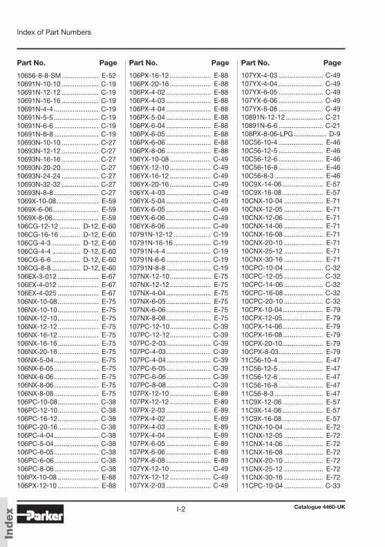
Catalogue 4460-UKI-2
Index of Part Numbers
Index
Part No. Page Part No. Page Part No. Page
10656-8-8-SM .................... E-5210691N-10-10 .................... C-1910691N-12-12 .................... C-1910691N-16-16 .................... C-1910691N-4-4 ........................ C-1910691N-5-5 ........................ C-1910691N-6-6 ........................ C-1910691N-8-8 ........................ C-1910693N-10-10 .................... C-2710693N-12-12 .................... C-2710693N-16-16 .................... C-2710693N-20-20 .................... C-2710693N-24-24 .................... C-2710693N-32-32 .................... C-2710693N-8-8 ........................ C-271069X-10-08 ....................... E-591069X-6-06 ......................... E-591069X-8-06 ......................... E-59106CG-12-12 ........... D-12, E-60106CG-16-16 ........... D-12, E-60106CG-4-3 ............... D-12, E-60106CG-4-4 ............... D-12, E-60106CG-6-6 ............... D-12, E-60106CG-8-8 ............... D-12, E-60106EX-3-012 ...................... E-67106EX-4-012 ...................... E-67106EX-4-025 ...................... E-67106NX-10-08 ...................... E-75106NX-10-10 ...................... E-75106NX-12-10 ...................... E-75106NX-12-12 ...................... E-75106NX-16-12 ...................... E-75106NX-16-16 ...................... E-75106NX-20-16 ...................... E-75106NX-5-04 ........................ E-75106NX-6-05 ........................ E-75106NX-6-06 ........................ E-75106NX-8-06 ........................ E-75106NX-8-08 ........................ E-75106PC-10-08 ...................... C-38106PC-12-10 ...................... C-38106PC-16-12 ...................... C-38106PC-20-16 ...................... C-38106PC-4-04 ........................ C-38106PC-5-04 ........................ C-38106PC-6-05 ........................ C-38106PC-6-06 ........................ C-38106PC-8-06 ........................ C-38106PX-10-08 ...................... E-88106PX-12-10 ...................... E-88
106PX-16-12 ...................... E-88106PX-20-16 ...................... E-88106PX-4-02 ........................ E-88106PX-4-03 ........................ E-88106PX-4-04 ........................ E-88106PX-5-04 ........................ E-88106PX-6-04 ........................ E-88106PX-6-05 ........................ E-88106PX-6-06 ........................ E-88106PX-8-06 ........................ E-88106YX-10-08 ...................... C-49106YX-12-10 ...................... C-49106YX-16-12 ...................... C-49106YX-20-16 ...................... C-49106YX-4-03 ........................ C-49106YX-5-04 ........................ C-49106YX-6-05 ........................ C-49106YX-6-06 ........................ C-49106YX-8-06 ........................ C-4910791N-12-12 .................... C-1910791N-16-16 .................... C-1910791N-4-4 ........................ C-1910791N-6-6 ........................ C-1910791N-8-8 ........................ C-19107NX-12-10 ...................... E-75107NX-12-12 ...................... E-75107NX-4-04 ........................ E-75107NX-6-05 ........................ E-75107NX-6-06 ........................ E-75107NX-8-08 ........................ E-75107PC-12-10 ...................... C-39107PC-12-12 ...................... C-39107PC-2-03 ........................ C-39107PC-4-03 ........................ C-39107PC-4-04 ........................ C-39107PC-6-05 ........................ C-39107PC-6-06 ........................ C-39107PC-8-08 ........................ C-39107PX-12-10 ...................... E-89107PX-12-12 ...................... E-89107PX-2-03 ........................ E-89107PX-4-02 ........................ E-89107PX-4-03 ........................ E-89107PX-4-04 ........................ E-89107PX-6-05 ........................ E-89107PX-6-06 ........................ E-89107PX-8-08 ........................ E-89107YX-12-10 ...................... C-49107YX-12-12 ...................... C-49107YX-2-03 ........................ C-49
107YX-4-03 ........................ C-49107YX-4-04 ........................ C-49107YX-6-05 ........................ C-49107YX-6-06 ........................ C-49107YX-8-08 ........................ C-4910891N-12-12 .................... C-2110891N-6-6 ........................ C-21108PX-8-06-LPG .................. D-910C56-10-4 ........................ E-4610C56-12-5 ........................ E-4610C56-12-6 ........................ E-4610C56-16-8 ........................ E-4610C56-8-3 .......................... E-4610C9X-14-06 ...................... E-5710C9X-16-08 ...................... E-5710CNX-10-04 ..................... E-7110CNX-12-05 ..................... E-7110CNX-12-06 ..................... E-7110CNX-14-06 ..................... E-7110CNX-16-08 ..................... E-7110CNX-20-10 ..................... E-7110CNX-25-12 ..................... E-7110CNX-30-16 ..................... E-7110CPC-10-04 ..................... C-3210CPC-12-05 ..................... C-3210CPC-14-06 ..................... C-3210CPC-16-08 ..................... C-3210CPC-20-10 ..................... C-3210CPX-10-04 ...................... E-7910CPX-12-05 ...................... E-7910CPX-14-06 ...................... E-7910CPX-16-08 ...................... E-7910CPX-20-10 ...................... E-7910CPX-8-03 ........................ E-7911C56-10-4 ........................ E-4711C56-12-5 ........................ E-4711C56-12-6 ........................ E-4711C56-16-8 ........................ E-4711C56-8-3 .......................... E-4711C9X-12-06 ...................... E-5711C9X-14-06 ...................... E-5711C9X-16-08 ...................... E-5711CNX-10-04 ..................... E-7211CNX-12-05 ..................... E-7211CNX-14-06 ..................... E-7211CNX-16-08 ..................... E-7211CNX-20-10 ..................... E-7211CNX-25-12 ..................... E-7211CNX-30-16 ..................... E-7211CPC-10-04 ..................... C-33
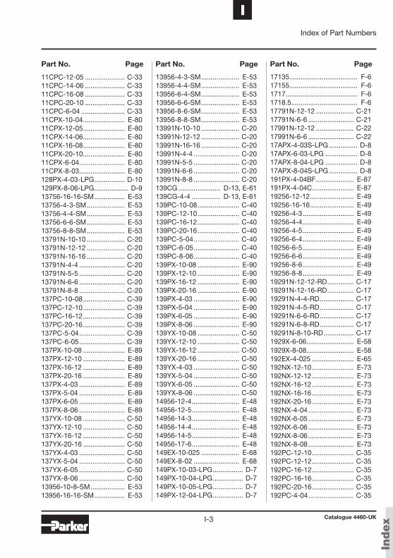
Catalogue 4460-UKI-3
IIndex of Part Numbers
Index
Part No. Page Part No. Page Part No. Page
11CPC-12-05 ..................... C-3311CPC-14-06 ..................... C-3311CPC-16-08 ..................... C-3311CPC-20-10 ..................... C-3311CPC-6-04 ....................... C-3311CPX-10-04 ...................... E-8011CPX-12-05 ...................... E-8011CPX-14-06 ...................... E-8011CPX-16-08 ...................... E-8011CPX-20-10 ...................... E-8011CPX-6-04 ........................ E-8011CPX-8-03 ........................ E-80128PX-4-03-LPG ................ D-10129PX-8-06-LPG .................. D-913756-16-16-SM ................ E-5313756-4-3-SM .................... E-5313756-4-4-SM .................... E-5313756-6-6-SM .................... E-5313756-8-8-SM .................... E-5313791N-10-10 .................... C-2013791N-12-12 .................... C-2013791N-16-16 .................... C-2013791N-4-4 ........................ C-2013791N-5-5 ........................ C-2013791N-6-6 ........................ C-2013791N-8-8 ........................ C-20137PC-10-08 ...................... C-39137PC-12-10 ...................... C-39137PC-16-12 ...................... C-39137PC-20-16 ...................... C-39137PC-5-04 ........................ C-39137PC-6-05 ........................ C-39137PX-10-08 ...................... E-89137PX-12-10 ...................... E-89137PX-16-12 ...................... E-89137PX-20-16 ...................... E-89137PX-4-03 ........................ E-89137PX-5-04 ........................ E-89137PX-6-05 ........................ E-89137PX-8-06 ........................ E-89137YX-10-08 ...................... C-50137YX-12-10 ...................... C-50137YX-16-12 ...................... C-50137YX-20-16 ...................... C-50137YX-4-03 ........................ C-50137YX-5-04 ........................ C-50137YX-6-05 ........................ C-50137YX-8-06 ........................ C-5013956-10-8-SM .................. E-5313956-16-16-SM ................ E-53
13956-4-3-SM .................... E-5313956-4-4-SM .................... E-5313956-6-4-SM .................... E-5313956-6-6-SM .................... E-5313956-8-6-SM .................... E-5313956-8-8-SM .................... E-5313991N-10-10 .................... C-2013991N-12-12 .................... C-2013991N-16-16 .................... C-2013991N-4-4 ........................ C-2013991N-5-5 ........................ C-2013991N-6-6 ........................ C-2013991N-8-8 ........................ C-20139CG ...................... D-13, E-61139CG-4-4 ............... D-13, E-61139PC-10-08 ...................... C-40139PC-12-10 ...................... C-40139PC-16-12 ...................... C-40139PC-20-16 ...................... C-40139PC-5-04 ........................ C-40139PC-6-05 ........................ C-40139PC-8-06 ........................ C-40139PX-10-08 ...................... E-90139PX-12-10 ...................... E-90139PX-16-12 ...................... E-90139PX-20-16 ...................... E-90139PX-4-03 ........................ E-90139PX-5-04 ........................ E-90139PX-6-05 ........................ E-90139PX-8-06 ........................ E-90139YX-10-08 ...................... C-50139YX-12-10 ...................... C-50139YX-16-12 ...................... C-50139YX-20-16 ...................... C-50139YX-4-03 ........................ C-50139YX-5-04 ........................ C-50139YX-6-05 ........................ C-50139YX-8-06 ........................ C-5014956-12-4 ......................... E-4814956-12-5 ......................... E-4814956-14-3 ......................... E-4814956-14-4 ......................... E-4814956-14-5 ......................... E-4814956-17-6 ......................... E-48149EX-10-025 .................... E-68149EX-8-02 ........................ E-68149PX-10-03-LPG ................ D-7149PX-10-04-LPG ................ D-7149PX-10-05-LPG ................ D-7149PX-12-04-LPG ................ D-7
17135.................................... F-617155.................................... F-61717...................................... F-61718.5................................... F-617791N-12-12 .................... C-2117791N-6-6 ........................ C-2117991N-12-12 .................... C-2217991N-6-6 ........................ C-2217APX-4-03S-LPG ............... D-817APX-6-03-LPG ................. D-817APX-8-04-LPG ................. D-817APX-8-04S-LPG ............... D-8191PX-4-04BF .................... E-87191PX-4-04C ...................... E-8719256-12-12 ....................... E-4919256-16-16 ....................... E-4919256-4-3 ........................... E-4919256-4-4 ........................... E-4919256-4-5 ........................... E-4919256-6-4 ........................... E-4919256-6-5 ........................... E-4919256-6-6 ........................... E-4919256-8-6 ........................... E-4919256-8-8 ........................... E-4919291N-12-12-RD .............. C-1719291N-12-16-RD .............. C-1719291N-4-4-RD .................. C-1719291N-4-5-RD .................. C-1719291N-6-6-RD .................. C-1719291N-6-8-RD .................. C-1719291N-8-10-RD ................ C-171929X-6-06 ......................... E-581929X-8-08 ......................... E-58192EX-4-025 ...................... E-65192NX-12-10 ...................... E-73192NX-12-12 ...................... E-73192NX-16-12 ...................... E-73192NX-16-16 ...................... E-73192NX-20-16 ...................... E-73192NX-4-04 ........................ E-73192NX-6-05 ........................ E-73192NX-6-06 ........................ E-73192NX-8-06 ........................ E-73192NX-8-08 ........................ E-73192PC-12-10 ...................... C-35192PC-12-12 ...................... C-35192PC-16-12 ...................... C-35192PC-16-16 ...................... C-35192PC-20-16 ...................... C-35192PC-4-04 ........................ C-35

Catalogue 4460-UKI-4
Index of Part Numbers
Index
Part No. Page Part No. Page Part No. Page
192PC-6-05 ........................ C-35192PC-6-06 ........................ C-35192PC-8-06 ........................ C-35192PC-8-08 ........................ C-35192PX-12-10 ...................... E-83192PX-12-12 ...................... E-83192PX-16-12 ...................... E-83192PX-16-16 ...................... E-83192PX-2-02 ........................ E-83192PX-2-03 ........................ E-83192PX-20-16 ...................... E-83192PX-4-02 ........................ E-83192PX-4-03 ........................ E-83192PX-4-04 ........................ E-83192PX-6-05 ........................ E-83192PX-6-06 ........................ E-83192PX-8-06 ........................ E-83192PX-8-08 ........................ E-83192YX-12-10 ...................... C-44192YX-12-12 ...................... C-44192YX-16-12 ...................... C-44192YX-16-16 ...................... C-44192YX-20-16 ...................... C-44192YX-4-03 ........................ C-44192YX-4-04 ........................ C-44192YX-6-05 ........................ C-44192YX-6-06 ........................ C-44192YX-8-06 ........................ C-44192YX-8-08 ........................ C-441AL91N-12-12C ................. C-241AL91N-16-16C ................. C-241AL91N-4-4C ..................... C-241AL91N-4-5C ..................... C-241AL91N-6-6C ..................... C-241AL91N-8-8C ..................... C-241B156-4-3 .......................... E-491B156-4-4 .......................... E-491B156-6-5 .......................... E-491B156-6-6 .......................... E-491B156-8-8 .......................... E-491B1PC-12-10 ..................... C-351B1PC-12-12 ..................... C-351B1PC-16-16 ..................... C-351B1PC-20-16 ..................... C-351B1PC-4-04 ....................... C-351B1PC-6-05 ....................... C-351B1PC-6-06 ....................... C-351B1PC-8-06 ....................... C-351B1PC-8-08 ....................... C-351B1PX-12-10 ...................... E-83
1B1PX-12-12 ...................... E-831B1PX-16-16 ...................... E-831B1PX-20-16 ...................... E-831B1PX-4-03 ........................ E-831B1PX-4-04 ........................ E-831B1PX-6-05 ........................ E-831B1PX-6-06 ........................ E-831B1PX-8-06 ........................ E-831B1PX-8-08 ........................ E-831B1YX-12-10 ...................... C-451B1YX-12-12 ...................... C-451B1YX-16-16 ...................... C-451B1YX-20-16 ...................... C-451B1YX-4-03 ........................ C-451B1YX-4-04 ........................ C-451B1YX-6-05 ........................ C-451B1YX-6-06 ........................ C-451B1YX-8-06 ........................ C-451B1YX-8-08 ........................ C-451B256-12-12 ...................... E-501B256-16-16 ...................... E-501B256-4-3 .......................... E-501B256-4-4 .......................... E-501B256-6-5 .......................... E-501B256-6-6 .......................... E-501B256-8-8 .......................... E-501B2PC-12-10 ..................... C-361B2PC-12-12 ..................... C-361B2PC-20-16 ..................... C-361B2PC-4-04 ....................... C-361B2PC-6-05 ....................... C-361B2PC-6-06 ....................... C-361B2PC-8-06 ....................... C-361B2PC-8-08 ....................... C-361B2PX-12-10 ...................... E-841B2PX-12-12 ...................... E-841B2PX-20-16 ...................... E-841B2PX-4-03 ........................ E-841B2PX-4-04 ........................ E-841B2PX-6-05 ........................ E-841B2PX-6-06 ........................ E-841B2PX-8-06 ........................ E-841B2PX-8-08 ........................ E-841B2YX-12-10 ...................... C-451B2YX-12-12 ...................... C-451B2YX-16-16 ...................... C-451B2YX-20-16 ...................... C-451B2YX-4-03 ........................ C-451B2YX-4-04 ........................ C-451B2YX-6-05 ........................ C-45
1B2YX-6-06 ........................ C-451B2YX-8-06 ........................ C-451B2YX-8-08 ........................ C-451B4PX-4-04 ........................ E-841B4YX-4-04 ........................ C-471B4YX-6-05 ........................ C-471B4YX-6-06 ........................ C-471B4YX-8-08 ........................ C-471BPEX-4-012 ...................... E-661C356-10-4 ........................ E-441C356-10-5 ........................ E-441C356-10-6 ........................ E-441C356-12-5 ........................ E-441C356-12-6 ........................ E-441C356-15-8 ........................ E-441C356-18-12 ...................... E-441C356-22-12 ...................... E-441C356-6-3 .......................... E-441C356-8-4 .......................... E-441C391N-10-6-RD ............... C-131C391N-10-8-RD ............... C-131C391N-12-10-RD ............. C-131C391N-12-8-RD ............... C-131C391N-15-10-RD ............. C-131C391N-18-10-RD ............. C-131C391N-18-12-RD ............. C-131C391N-22-16-RD ............. C-131C391N-6-4-RD ................. C-131C391N-6-5-RD ................. C-131C391N-8-5-RD ................. C-131C391N-8-6-RD ................. C-131C39X-12-06 ...................... E-561C39X-15-08 ...................... E-561C3NX-10-04 ..................... E-701C3NX-10-05 ..................... E-701C3NX-10-06 ..................... E-701C3NX-12-06 ..................... E-701C3NX-12-08 ..................... E-701C3NX-15-08 ..................... E-701C3NX-18-10 ..................... E-701C3NX-8-04 ....................... E-701C3PC-10-04 ..................... C-301C3PC-10-05 ..................... C-301C3PC-10-06 ..................... C-301C3PC-12-06 ..................... C-301C3PC-12-08 ..................... C-301C3PC-15-08 ..................... C-301C3PC-8-04 ....................... C-301C3PX-10-03 ...................... E-761C3PX-10-04 ...................... E-76
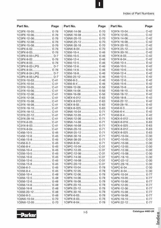
Catalogue 4460-UKI-5
IIndex of Part Numbers
Index
Part No. Page Part No. Page Part No. Page
1C3PX-10-05 ...................... E-761C3PX-10-06 ...................... E-761C3PX-12-06 ...................... E-761C3PX-12-08 ...................... E-761C3PX-15-08 ...................... E-761C3PX-6-02 ........................ E-761C3PX-6-03 ........................ E-761C3PX-6-03-LPG ................. D-71C3PX-8-02 ........................ E-761C3PX-8-03 ........................ E-761C3PX-8-03-LPG ................. D-71C3PX-8-04 ........................ E-761C3PX-8-04-LPG ................. D-71C3PX-8-05-LPG ................. D-71C3YX-10-03 ...................... C-411C3YX-10-04 ...................... C-411C3YX-10-05 ...................... C-411C3YX-10-06 ...................... C-411C3YX-12-06 ...................... C-411C3YX-12-08 ...................... C-411C3YX-15-08 ...................... C-411C3YX-18-08 ...................... C-411C3YX-18-10 ...................... C-411C3YX-18-12 ...................... C-411C3YX-22-12 ...................... C-411C3YX-28-16 ...................... C-411C3YX-6-03 ........................ C-411C3YX-8-03 ........................ C-411C3YX-8-04 ........................ C-411C456-10-5 ........................ E-451C456-12-6 ........................ E-451C456-15-8 ........................ E-451C456-6-3 .......................... E-451C456-8-4 .......................... E-451C556-10-4 ........................ E-451C556-10-5 ........................ E-451C556-10-6 ........................ E-451C556-12-6 ........................ E-451C556-15-8 ........................ E-451C556-6-3 .......................... E-451C556-8-4 .......................... E-451C656-10-4 ........................ E-481C656-12-5 ........................ E-481C656-12-6 ........................ E-481C656-14-6 ........................ E-481C656-16-8 ........................ E-481C656-20-12 ...................... E-481C656-8-3 .......................... E-481C6NX-10-04 ..................... E-701C6NX-12-05 ..................... E-70
1C6NX-14-06 ..................... E-701C6NX-16-08 ..................... E-701C6NX-20-10 ..................... E-701C6NX-25-12 ..................... E-701C6NX-30-16 ..................... E-701C6NX-8-04 ....................... E-701C956-10-4 ........................ E-461C956-10-5 ........................ E-461C956-12-4 ........................ E-461C956-12-5 ........................ E-461C956-12-6 ........................ E-461C956-14-6 ........................ E-461C956-16-8 ........................ E-461C956-25-12 ...................... E-461C956-8-3 .......................... E-461C956-8-4 .......................... E-461C99X-12-06 ...................... E-561C99X-14-06 ...................... E-561C99X-16-08 ...................... E-561C9EX-6-012 ...................... E-631C9EX-8-012 ...................... E-631C9EX-8-02 ........................ E-631C9EX-8-025 ...................... E-631C9NX-10-04 ..................... E-711C9NX-12-05 ..................... E-711C9NX-12-06 ..................... E-711C9NX-14-06 ..................... E-711C9NX-16-08 ..................... E-711C9NX-20-10 ..................... E-711C9NX-25-12 ..................... E-711C9NX-30-16 ..................... E-711C9NX-38-20 ..................... E-711C9NX-8-04 ....................... E-711C9PC-10-04 ..................... C-311C9PC-12-05 ..................... C-311C9PC-12-06 ..................... C-311C9PC-14-06 ..................... C-311C9PC-16-08 ..................... C-311C9PC-20-10 ..................... C-311C9PX-10-04 ...................... E-781C9PX-12-05 ...................... E-781C9PX-12-06 ...................... E-781C9PX-14-06 ...................... E-781C9PX-16-08 ...................... E-781C9PX-20-10 ...................... E-781C9PX-25-12 ...................... E-781C9PX-30-16 ...................... E-781C9PX-6-03 ........................ E-781C9PX-8-03 ........................ E-781C9PX-8-04 ........................ E-78
1C9YX-10-04 ...................... C-421C9YX-12-05 ...................... C-421C9YX-14-06 ...................... C-421C9YX-16-08 ...................... C-421C9YX-20-10 ...................... C-421C9YX-25-12 ...................... C-421C9YX-30-16 ...................... C-421C9YX-8-03 ........................ C-421C9YX-8-04 ........................ C-421CA56-10-4 ........................ E-421CA56-10-5 ........................ E-421CA56-10-6 ........................ E-421CA56-12-4 ........................ E-421CA56-12-5 ........................ E-421CA56-12-6 ........................ E-421CA56-15-6 ........................ E-421CA56-15-8 ........................ E-421CA56-18-10 ...................... E-421CA56-18-12 ...................... E-421CA56-18-8 ........................ E-421CA56-22-12 ...................... E-421CA56-28-16 ...................... E-421CA56-6-3 .......................... E-421CA56-6-4 .......................... E-421CA56-8-4 .......................... E-421CAEX-6-012 ..................... E-631CAEX-6-016 ..................... E-631CAEX-6-025 ..................... E-631CAEX-8-012 ..................... E-631CAEX-8-025 ..................... E-631CAPC-10-04 ..................... C-301CAPC-10-05 ..................... C-301CAPC-10-06 ..................... C-301CAPC-12-05 ..................... C-301CAPC-12-06 ..................... C-301CAPC-15-08 ..................... C-301CAPC-18-10 ..................... C-301CAPC-22-12 ..................... C-301CAPC-28-16 ..................... C-301CAPC-6-04 ....................... C-301CAPC-8-04 ....................... C-301CAPX-10-04 ..................... E-771CAPX-10-05 ..................... E-771CAPX-10-06 ..................... E-771CAPX-12-05 ..................... E-771CAPX-12-06 ..................... E-771CAPX-15-08 ..................... E-771CAPX-18-08 ..................... E-771CAPX-18-10 ..................... E-771CAPX-22-12 ..................... E-77
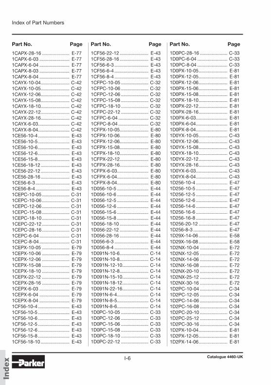
Catalogue 4460-UKI-6
Index of Part Numbers
Index
Part No. Page Part No. Page Part No. Page
1CAPX-28-16 ..................... E-771CAPX-6-03 ....................... E-771CAPX-6-04 ....................... E-771CAPX-8-03 ....................... E-771CAPX-8-04 ....................... E-771CAYX-10-04 ...................... C-421CAYX-10-05 ...................... C-421CAYX-12-06 ...................... C-421CAYX-15-08 ...................... C-421CAYX-18-10 ...................... C-421CAYX-22-12 ...................... C-421CAYX-28-16 ...................... C-421CAYX-6-03 ........................ C-421CAYX-8-04 ........................ C-421CE56-10-4 ........................ E-431CE56-10-5 ........................ E-431CE56-10-6 ........................ E-431CE56-12-6 ........................ E-431CE56-15-8 ........................ E-431CE56-18-12 ...................... E-431CE56-22-12 ...................... E-431CE56-28-16 ...................... E-431CE56-6-3 .......................... E-431CE56-8-4 .......................... E-431CEPC-10-05 ..................... C-311CEPC-10-06 ..................... C-311CEPC-12-06 ..................... C-311CEPC-15-08 ..................... C-311CEPC-18-10 ..................... C-311CEPC-22-12 ..................... C-311CEPC-28-16 ..................... C-311CEPC-6-04 ....................... C-311CEPC-8-04 ....................... C-311CEPX-10-05 ..................... E-791CEPX-10-06 ..................... E-791CEPX-12-06 ..................... E-791CEPX-15-08 ..................... E-791CEPX-18-10 ..................... E-791CEPX-22-12 ..................... E-791CEPX-28-16 ..................... E-791CEPX-6-03 ....................... E-791CEPX-6-04 ....................... E-791CEPX-8-04 ....................... E-791CF56-10-4 ........................ E-431CF56-10-5 ........................ E-431CF56-10-6 ........................ E-431CF56-12-5 ........................ E-431CF56-12-6 ........................ E-431CF56-15-8 ........................ E-431CF56-18-10 ...................... E-43
1CF56-22-12 ...................... E-431CF56-28-16 ...................... E-431CF56-6-3 .......................... E-431CF56-6-4 .......................... E-431CF56-8-4 .......................... E-431CFPC-10-05 ..................... C-321CFPC-10-06 ..................... C-321CFPC-12-06 ..................... C-321CFPC-15-08 ..................... C-321CFPC-18-10 ..................... C-321CFPC-22-12 ..................... C-321CFPC-6-04 ....................... C-321CFPC-8-04 ....................... C-321CFPX-10-05 ...................... E-801CFPX-10-06 ...................... E-801CFPX-12-06 ...................... E-801CFPX-15-08 ...................... E-801CFPX-18-10 ...................... E-801CFPX-22-12 ...................... E-801CFPX-28-16 ...................... E-801CFPX-6-03 ........................ E-801CFPX-6-04 ........................ E-801CFPX-8-04 ........................ E-801D056-10-5 ........................ E-441D056-10-6 ........................ E-441D056-12-5 ........................ E-441D056-12-6 ........................ E-441D056-15-6 ........................ E-441D056-15-8 ........................ E-441D056-18-10 ...................... E-441D056-22-12 ...................... E-441D056-28-16 ...................... E-441D056-6-3 .......................... E-441D056-8-4 .......................... E-441D091N-10-6 ...................... C-141D091N-10-8 ...................... C-141D091N-12-10 .................... C-141D091N-12-8 ...................... C-141D091N-15-10 .................... C-141D091N-18-12 .................... C-141D091N-22-16 .................... C-141D091N-6-4 ........................ C-141D091N-8-5 ........................ C-141D091N-8-6 ........................ C-141D0PC-10-05 ..................... C-331D0PC-12-06 ..................... C-331D0PC-15-06 ..................... C-331D0PC-15-08 ..................... C-331D0PC-18-10 ..................... C-331D0PC-22-12 ..................... C-33
1D0PC-28-16 ..................... C-331D0PC-6-04 ....................... C-331D0PC-8-04 ....................... C-331D0PX-10-05 ...................... E-811D0PX-12-05 ...................... E-811D0PX-12-06 ...................... E-811D0PX-15-06 ...................... E-811D0PX-15-08 ...................... E-811D0PX-18-10 ...................... E-811D0PX-22-12 ...................... E-811D0PX-28-16 ...................... E-811D0PX-6-03 ........................ E-811D0PX-6-04 ........................ E-811D0PX-8-04 ........................ E-811D0YX-10-05 ...................... C-431D0YX-12-06 ...................... C-431D0YX-15-08 ...................... C-431D0YX-18-10 ...................... C-431D0YX-22-12 ...................... C-431D0YX-28-16 ...................... C-431D0YX-6-03 ........................ C-431D0YX-8-04 ........................ C-431D256-10-4 ........................ E-471D256-10-5 ........................ E-471D256-12-5 ........................ E-471D256-12-6 ........................ E-471D256-14-6 ........................ E-471D256-16-6 ........................ E-471D256-16-8 ........................ E-471D256-20-12 ...................... E-471D256-8-3 .......................... E-471D29X-14-06 ...................... E-581D29X-16-08 ...................... E-581D2NX-10-04 ..................... E-721D2NX-12-05 ..................... E-721D2NX-14-06 ..................... E-721D2NX-16-08 ..................... E-721D2NX-20-10 ..................... E-721D2NX-25-12 ..................... E-721D2NX-30-16 ..................... E-721D2PC-10-04 ..................... C-341D2PC-12-05 ..................... C-341D2PC-14-06 ..................... C-341D2PC-16-08 ..................... C-341D2PC-20-10 ..................... C-341D2PC-25-12 ..................... C-341D2PC-30-16 ..................... C-341D2PX-10-04 ...................... E-811D2PX-12-05 ...................... E-811D2PX-14-06 ...................... E-81
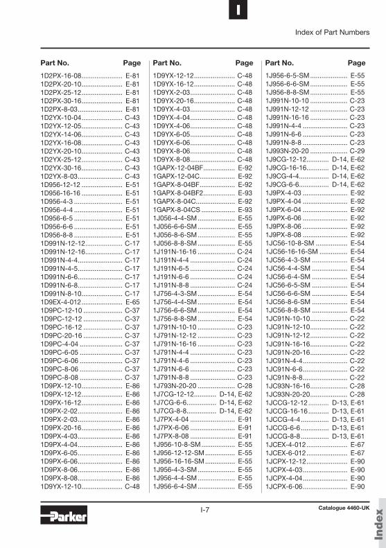
Catalogue 4460-UKI-7
IIndex of Part Numbers
Index
Part No. Page Part No. Page Part No. Page
1D2PX-16-08 ...................... E-811D2PX-20-10 ...................... E-811D2PX-25-12 ...................... E-811D2PX-30-16 ...................... E-811D2PX-8-03 ........................ E-811D2YX-10-04 ...................... C-431D2YX-12-05 ...................... C-431D2YX-14-06 ...................... C-431D2YX-16-08 ...................... C-431D2YX-20-10 ...................... C-431D2YX-25-12 ...................... C-431D2YX-30-16 ...................... C-431D2YX-8-03 ........................ C-431D956-12-12 ...................... E-511D956-16-16 ...................... E-511D956-4-3 .......................... E-511D956-4-4 .......................... E-511D956-6-5 .......................... E-511D956-6-6 .......................... E-511D956-8-8 .......................... E-511D991N-12-12 .................... C-171D991N-12-16 .................... C-171D991N-4-4 ........................ C-171D991N-4-5 ........................ C-171D991N-6-6 ........................ C-171D991N-6-8 ........................ C-171D991N-8-10 ...................... C-171D9EX-4-012 ...................... E-651D9PC-12-10 ..................... C-371D9PC-12-12 ..................... C-371D9PC-16-12 ..................... C-371D9PC-20-16 ..................... C-371D9PC-4-04 ....................... C-371D9PC-6-05 ....................... C-371D9PC-6-06 ....................... C-371D9PC-8-06 ....................... C-371D9PC-8-08 ....................... C-371D9PX-12-10 ...................... E-861D9PX-12-12 ...................... E-861D9PX-16-12 ...................... E-861D9PX-2-02 ........................ E-861D9PX-2-03 ........................ E-861D9PX-20-16 ...................... E-861D9PX-4-03 ........................ E-861D9PX-4-04 ........................ E-861D9PX-6-05 ........................ E-861D9PX-6-06 ........................ E-861D9PX-8-06 ........................ E-861D9PX-8-08 ........................ E-861D9YX-12-10 ...................... C-48
1D9YX-12-12 ...................... C-481D9YX-16-12 ...................... C-481D9YX-2-03 ........................ C-481D9YX-20-16 ...................... C-481D9YX-4-03 ........................ C-481D9YX-4-04 ........................ C-481D9YX-4-06 ........................ C-481D9YX-6-05 ........................ C-481D9YX-6-06 ........................ C-481D9YX-8-06 ........................ C-481D9YX-8-08 ........................ C-481GAPX-12-04BF ................. E-921GAPX-12-04C ................... E-921GAPX-8-04BF ................... E-921GAPX-8-04BF2 ................. E-931GAPX-8-04C ..................... E-921GAPX-8-04CS .................. E-931J056-4-4-SM .................... E-551J056-6-6-SM .................... E-551J056-8-6-SM .................... E-551J056-8-8-SM .................... E-551J191N-16-16 .................... C-241J191N-4-4 ........................ C-241J191N-6-5 ........................ C-241J191N-6-6 ........................ C-241J191N-8-8 ........................ C-241J756-4-3-SM .................... E-541J756-4-4-SM .................... E-541J756-6-6-SM .................... E-541J756-8-8-SM .................... E-541J791N-10-10 .................... C-231J791N-12-12 .................... C-231J791N-16-16 .................... C-231J791N-4-4 ........................ C-231J791N-4-6 ........................ C-231J791N-6-6 ........................ C-231J791N-8-8 ........................ C-231J793N-20-20 .................... C-281J7CG-12-12 ............ D-14, E-621J7CG-6-6 ................ D-14, E-621J7CG-8-8 ................ D-14, E-621J7PX-4-04 ........................ E-911J7PX-6-06 ........................ E-911J7PX-8-08 ........................ E-911J956-10-8-SM .................. E-551J956-12-12-SM ................ E-551J956-16-16-SM ................ E-551J956-4-3-SM .................... E-551J956-4-4-SM .................... E-551J956-6-4-SM .................... E-55
1J956-6-5-SM .................... E-551J956-6-6-SM .................... E-551J956-8-8-SM .................... E-551J991N-10-10 .................... C-231J991N-12-12 .................... C-231J991N-16-16 .................... C-231J991N-4-4 ........................ C-231J991N-6-6 ........................ C-231J991N-8-8 ........................ C-231J993N-20-20 .................... C-291J9CG-12-12 ............ D-14, E-621J9CG-16-16 ............ D-14, E-621J9CG-4-4 ................ D-14, E-621J9CG-6-6 ................ D-14, E-621J9PX-4-03 ........................ E-921J9PX-4-04 ........................ E-921J9PX-6-04 ........................ E-921J9PX-6-06 ........................ E-921J9PX-8-06 ........................ E-921J9PX-8-08 ........................ E-921JC56-10-8-SM ................. E-541JC56-16-16-SM ............... E-541JC56-4-3-SM ................... E-541JC56-4-4-SM ................... E-541JC56-6-4-SM ................... E-541JC56-6-5-SM ................... E-541JC56-6-6-SM ................... E-541JC56-8-6-SM ................... E-541JC56-8-8-SM ................... E-541JC91N-10-10 .................... C-221JC91N-12-10 .................... C-221JC91N-12-12 .................... C-221JC91N-16-16 .................... C-221JC91N-20-16 .................... C-221JC91N-4-4 ........................ C-221JC91N-6-6 ........................ C-221JC91N-8-8 ........................ C-221JC93N-16-16 .................... C-281JC93N-20-20 .................... C-281JCCG-12-12 ........... D-13, E-611JCCG-16-16 ........... D-13, E-611JCCG-4-4 ............... D-13, E-611JCCG-6-6 ............... D-13, E-611JCCG-8-8 ............... D-13, E-611JCEX-4-012 ...................... E-671JCEX-6-012 ...................... E-671JCPX-12-12 ...................... E-901JCPX-4-03 ........................ E-901JCPX-4-04 ........................ E-901JCPX-6-06 ........................ E-90
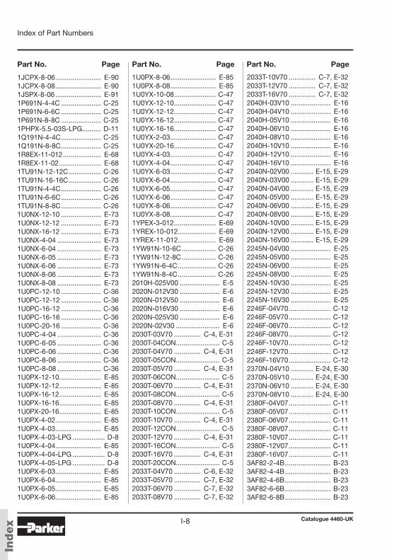
Catalogue 4460-UKI-8
Index of Part Numbers
Index
Part No. Page Part No. Page Part No. Page
1JCPX-8-06 ........................ E-901JCPX-8-08 ........................ E-901JSPX-8-06 ........................ E-911P691N-4-4C ..................... C-251P691N-6-6C ..................... C-251P691N-8-8C ..................... C-251PHPX-5.5-03S-LPG.......... D-111Q191N-4-4C ..................... C-251Q191N-8-8C ..................... C-251R8EX-11-012 .................... E-681R8EX-11-02 ...................... E-681TU91N-12-12C ................. C-261TU91N-16-16C ................. C-261TU91N-4-4C ..................... C-261TU91N-6-6C ..................... C-261TU91N-8-8C ..................... C-261U0NX-12-10 ..................... E-731U0NX-12-12 ..................... E-731U0NX-16-12 ..................... E-731U0NX-4-04 ....................... E-731U0NX-6-04 ....................... E-731U0NX-6-05 ....................... E-731U0NX-6-06 ....................... E-731U0NX-8-06 ....................... E-731U0NX-8-08 ....................... E-731U0PC-12-10 ..................... C-361U0PC-12-12 ..................... C-361U0PC-16-12 ..................... C-361U0PC-16-16 ..................... C-361U0PC-20-16 ..................... C-361U0PC-4-04 ....................... C-361U0PC-6-05 ....................... C-361U0PC-6-06 ....................... C-361U0PC-8-06 ....................... C-361U0PC-8-08 ....................... C-361U0PX-12-10 ...................... E-851U0PX-12-12 ...................... E-851U0PX-16-12 ...................... E-851U0PX-16-16 ...................... E-851U0PX-20-16 ...................... E-851U0PX-4-02 ........................ E-851U0PX-4-03 ........................ E-851U0PX-4-03-LPG ................. D-81U0PX-4-04 ........................ E-851U0PX-4-04-LPG ................. D-81U0PX-4-05-LPG ................. D-81U0PX-6-03 ........................ E-851U0PX-6-04 ........................ E-851U0PX-6-05 ........................ E-851U0PX-6-06 ........................ E-85
1U0PX-8-06 ........................ E-851U0PX-8-08 ........................ E-851U0YX-10-08 ...................... C-471U0YX-12-10 ...................... C-471U0YX-12-12 ...................... C-471U0YX-16-12 ...................... C-471U0YX-16-16 ...................... C-471U0YX-2-03 ........................ C-471U0YX-20-16 ...................... C-471U0YX-4-03 ........................ C-471U0YX-4-04 ........................ C-471U0YX-6-03 ........................ C-471U0YX-6-04 ........................ C-471U0YX-6-05 ........................ C-471U0YX-6-06 ........................ C-471U0YX-8-06 ........................ C-471U0YX-8-08 ........................ C-471YPEX-3-012 ...................... E-691YREX-10-012 .................... E-691YREX-11-012 .................... E-691YW91N-10-6C .................. C-261YW91N-12-8C .................. C-261YW91N-6-4C .................... C-261YW91N-8-4C .................... C-262010H-025V00 ..................... E-52020N-012V30 ..................... E-62020N-012V50 ..................... E-62020N-016V30 ..................... E-62020N-025V30 ..................... E-62020N-02V30 ....................... E-62030T-03V70 .............. C-4, E-312030T-04CON ....................... C-52030T-04V70 .............. C-4, E-312030T-05CON ....................... C-52030T-05V70 .............. C-4, E-312030T-06CON ....................... C-52030T-06V70 .............. C-4, E-312030T-08CON ....................... C-52030T-08V70 .............. C-4, E-312030T-10CON ....................... C-52030T-10V70 .............. C-4, E-312030T-12CON ....................... C-52030T-12V70 .............. C-4, E-312030T-16CON ....................... C-52030T-16V70 .............. C-4, E-312030T-20CON ....................... C-52033T-04V70 .............. C-6, E-322033T-05V70 .............. C-7, E-322033T-06V70 .............. C-7, E-322033T-08V70 .............. C-7, E-32
2033T-10V70 .............. C-7, E-322033T-12V70 .............. C-7, E-322033T-16V70 .............. C-7, E-322040H-03V10 ..................... E-162040H-04V10 ..................... E-162040H-05V10 ..................... E-162040H-06V10 ..................... E-162040H-08V10 ..................... E-162040H-10V10 ..................... E-162040H-12V10 ..................... E-162040H-16V10 ..................... E-162040N-02V00 ............ E-15, E-292040N-03V00 ............ E-15, E-292040N-04V00 ............ E-15, E-292040N-05V00 ............ E-15, E-292040N-06V00 ............ E-15, E-292040N-08V00 ............ E-15, E-292040N-10V00 ............ E-15, E-292040N-12V00 ............ E-15, E-292040N-16V00 ............ E-15, E-292245N-04V00 ..................... E-252245N-05V00 ..................... E-252245N-06V00 ..................... E-252245N-08V00 ..................... E-252245N-10V30 ..................... E-252245N-12V30 ..................... E-252245N-16V30 ..................... E-252246F-04V70 ...................... C-122246F-05V70 ...................... C-122246F-06V70 ...................... C-122246F-08V70 ...................... C-122246F-10V70 ...................... C-122246F-12V70 ...................... C-122246F-16V70 ...................... C-122370N-04V10 ............ E-24, E-302370N-05V10 ............ E-24, E-302370N-06V10 ............ E-24, E-302370N-08V10 ............ E-24, E-302380F-04V07 ...................... C-112380F-05V07 ...................... C-112380F-06V07 ...................... C-112380F-08V07 ...................... C-112380F-10V07 ...................... C-112380F-12V07 ...................... C-112380F-16V07 ...................... C-113AF82-2-4B ........................ B-233AF82-4-4B ........................ B-233AF82-4-6B ........................ B-233AF82-6-6B ........................ B-233AF82-6-8B ........................ B-23
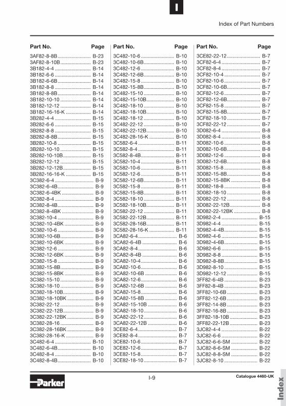
Catalogue 4460-UKI-9
IIndex of Part Numbers
Index
Part No. Page Part No. Page Part No. Page
3AF82-8-8B ........................ B-233AF82-8-10B ...................... B-233B182-4-4 .......................... B-143B182-6-6 .......................... B-143B182-6-6B ........................ B-143B182-8-8 .......................... B-143B182-8-8B ........................ B-143B182-10-10 ...................... B-143B182-12-12 ...................... B-143B182-16-16-K .................. B-143B282-4-4 .......................... B-153B282-6-6 .......................... B-153B282-8-8 .......................... B-153B282-8-8B ........................ B-153B282-10-8 ........................ B-153B282-10-10 ...................... B-153B282-10-10B .................... B-153B282-12-12 ...................... B-153B282-12-12B .................... B-153B282-16-16-K .................. B-153C382-6-4 ............................ B-93C382-6-4B .......................... B-93C382-6-4BK ....................... B-93C382-8-4 ............................ B-93C382-8-4B .......................... B-93C382-8-4BK ....................... B-93C382-10-4 .......................... B-93C382-10-4BK ..................... B-93C382-10-6 .......................... B-93C382-10-6B ........................ B-93C382-10-6BK ..................... B-93C382-12-6 .......................... B-93C382-12-6BK ..................... B-93C382-15-8 .......................... B-93C382-15-8B ........................ B-93C382-15-8BK ..................... B-93C382-15-10 ........................ B-93C382-18-10 ........................ B-93C382-18-10B ...................... B-93C382-18-10BK ................... B-93C382-22-12 ........................ B-93C382-22-12B ...................... B-93C382-22-12BK ................... B-93C382-28-16 ........................ B-93C382-28-16BK ................... B-93C382-28-16-K .................... B-93C482-6-4 .......................... B-103C482-6-4B ........................ B-103C482-8-4 .......................... B-103C482-8-4B ........................ B-10
3C482-10-6 ........................ B-103C482-10-6B ...................... B-103C482-12-6 ........................ B-103C482-12-6B ...................... B-103C482-15-8 ........................ B-103C482-15-8B ...................... B-103C482-15-10 ...................... B-103C482-15-10B .................... B-103C482-18-10 ...................... B-103C482-18-10B .................... B-103C482-18-12 ...................... B-103C482-22-12 ...................... B-103C482-22-12B .................... B-103C482-28-16-K .................. B-103C582-6-4 .......................... B-113C582-8-4 .......................... B-113C582-8-4B ........................ B-113C582-10-4 ........................ B-113C582-10-6 ........................ B-113C582-12-6 ........................ B-113C582-12-6B ...................... B-113C582-15-8 ........................ B-113C582-15-8B ...................... B-113C582-18-10 ...................... B-113C582-18-10B .................... B-113C582-22-12 ...................... B-113C582-22-12B .................... B-113C582-28-16B .................... B-113C582-28-16-K .................. B-113CA82-6-4 ............................ B-63CA82-6-4B ......................... B-63CA82-8-4 ............................ B-63CA82-8-4B ......................... B-63CA82-10-4 .......................... B-63CA82-10-6 .......................... B-63CA82-10-6B ....................... B-63CA82-12-6 .......................... B-63CA82-12-6B ....................... B-63CA82-15-8 .......................... B-63CA82-15-8B ....................... B-63CA82-15-10B ..................... B-63CA82-18-10 ........................ B-63CA82-22-12 ........................ B-63CA82-22-12B ..................... B-63CE82-6-4 ............................ B-73CE82-8-4 ............................ B-73CE82-10-6 .......................... B-73CE82-12-6 .......................... B-73CE82-15-8 .......................... B-73CE82-18-10 ........................ B-7
3CE82-22-12 ........................ B-73CF82-6-4 ............................ B-73CF82-8-4 ............................ B-73CF82-10-4 .......................... B-73CF82-10-6 .......................... B-73CF82-10-6B ........................ B-73CF82-12-6 .......................... B-73CF82-12-6B ........................ B-73CF82-15-8 .......................... B-73CF82-15-8B ........................ B-73CF82-18-10 ........................ B-73CF82-22-12 ........................ B-73D082-6-4 ............................ B-83D082-8-4 ............................ B-83D082-10-6 .......................... B-83D082-10-6B ........................ B-83D082-12-6 .......................... B-83D082-12-6B ........................ B-83D082-15-8 .......................... B-83D082-15-8B ........................ B-83D082-15-8BK ..................... B-83D082-18-8 .......................... B-83D082-18-10 ........................ B-83D082-22-12 ........................ B-83D082-22-12B ...................... B-83D082-22-12BK ................... B-83D982-2-4 .......................... B-153D982-4-4 .......................... B-153D982-4-4B ........................ B-153D982-4-6 .......................... B-153D982-4-6B ........................ B-153D982-6-6 .......................... B-153D982-8-8 .......................... B-153D982-8-8B ........................ B-153D982-8-10 ........................ B-153D982-12-12 ...................... B-153FF82-6-4B ........................ B-233FF82-8-4B ........................ B-233FF82-10-6B ...................... B-233FF82-12-6B ...................... B-233FF82-14-8B ...................... B-233FF82-16-8B ...................... B-233FF82-18-10B .................... B-233FF82-22-12B .................... B-233JC82-4-4 .......................... B-223JC82-6-6 .......................... B-223JC82-6-6-SM ................... B-223JC82-8-6-SM ................... B-223JC82-8-8-SM ................... B-223JC82-8-10 ........................ B-22
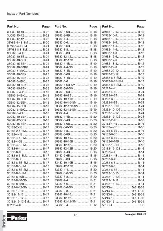
Catalogue 4460-UKI-10
Index of Part Numbers
Index
Part No. Page Part No. Page Part No. Page
3JC82-10-10 ...................... B-223JC82-10-12 ...................... B-223JC82-12-12 ...................... B-2233V82-4-4B-SM ................. B-2033W82-4-4-SM ................... B-2133W82-8-8-SM ................... B-2135C82-6-4BK ..................... B-2435C82-10-6B ...................... B-2435C82-10-6BK ................... B-2435C82-15-8BK ................... B-2435C82-18-10BK ................. B-2436C82-6-4BK ..................... B-2536C82-10-6BK ................... B-2536C82-15-8BK ................... B-2537C82-6-4BK ..................... B-2537C82-10-6BK ................... B-2537C82-15-8BK ................... B-2539B82-6-4BK ..................... B-1339B82-8-4BK ..................... B-1339B82-10-6BK ................... B-1339B82-12-6BK ................... B-1339B82-15-8BK ................... B-1339C82-6-4BK ..................... B-1339C82-8-4BK ..................... B-1339C82-10-6BK ................... B-1339C82-12-6BK ................... B-1339C82-15-8BK ................... B-1330182-2-4B ........................ B-1730182-2-4-SM .................... B-1730182-4-4B ........................ B-1730182-4-4-SM .................... B-1730182-4-6B ........................ B-1730182-4-6-SM .................... B-1730182-6-4 ........................... B-1730182-6-4B ........................ B-1730182-6-6-SM .................... B-1730182-6-8B ........................ B-1730182-8-6B-SM ................. B-1730182-8-6-SM .................... B-1730182-8-8B-SM ................. B-1730182-8-8-SM .................... B-1730182-8-10B ...................... B-1730182-8-10-SM .................. B-1730182-8-12B ...................... B-1730182-8-12-SM .................. B-1730182-12-10 ....................... B-1730182-12-12 ....................... B-1730182-12-12B .................... B-1730182-12-12-SM ................ B-1730282-4-4B ........................ B-18
30282-6-6B ........................ B-1830282-8-8B ........................ B-1830382-4-4 ........................... B-1830382-6-6 ........................... B-1830382-6-6B ........................ B-1830382-8-8 ........................... B-1830382-8-8B ........................ B-1830382-12-12 ....................... B-1830382-12-12B .................... B-1830682-4-4B ........................ B-1930682-4-4-SM .................... B-1930682-5-4B ........................ B-1930682-5-6B ........................ B-1930682-6-4B ........................ B-1930682-6-6 ........................... B-1930682-6-6B-SM ................. B-1930682-6-6-SM .................... B-1930682-8-6B ........................ B-1930682-10-8B ...................... B-1930682-10-10B .................... B-1930682-10-10-SM ................ B-1930682-12-12B-SM ............. B-1930682-12-12-SM ................ B-1930882-4-4 ........................... B-2030882-4-4B ........................ B-2030882-5-4B ........................ B-2030882-6-6B ........................ B-2030882-6-6-SM .................... B-2030882-8-8 ........................... B-2030882-8-8B ........................ B-2030882-10-10 ....................... B-2030882-10-10B .................... B-2030882-12-12 ....................... B-2030882-12-12B .................... B-2033482-4-4B ........................ B-1633482-6-6B ........................ B-1633482-8-8B ........................ B-1633482-10-10B .................... B-1633482-12-12B .................... B-1633782-4-4 ........................... B-2033782-6-6-SM .................... B-2033782-8-8 ........................... B-2033982-4-4 ........................... B-2133982-6-6 ........................... B-2133982-6-6-SM .................... B-2133982-8-8 ........................... B-2133982-10-10 ....................... B-2133982-12-12 ....................... B-2133982-12-12-SM ................ B-2134982-8-4 ........................... B-12
34982-10-4 ......................... B-1234982-10-6 ......................... B-1234982-12-4 ......................... B-1234982-12-6 ......................... B-1234982-14-4 ......................... B-1234982-14-6 ......................... B-1234982-14-8 ......................... B-1234982-16-6 ......................... B-1234982-17-6 ......................... B-1234982-18-8 ......................... B-1234982-22-8 ......................... B-1234982-22-10 ....................... B-1234982-26-12 ....................... B-1236882-8-6-SM .................... B-1936882-8-8B-SM ................. B-1936882-8-8-SM .................... B-1938282-4-4 ........................... B-2438282-4-4B ........................ B-2438282-6-6B ........................ B-2438282-8-8 ........................... B-2438282-8-8B ........................ B-2438282-10-10 ....................... B-2438282-10-10B .................... B-2438282-12-12 ....................... B-2438282-12-12B .................... B-2439182-2-4B ........................ B-1639182-4-4B ........................ B-1639182-4-6B ........................ B-1639182-6-6B ........................ B-1639182-6-8B ........................ B-1639182-8-8B ........................ B-1639182-8-10B ...................... B-1639182-12-10B .................... B-1639182-12-12B .................... B-1639282-4-4 ........................... B-1439282-4-4B ........................ B-1439282-6-4B ........................ B-1439282-6-6 ........................... B-1439282-8-8 ........................... B-1439282-8-8B ........................ B-1439282-10-10 ....................... B-1439282-10-10B .................... B-1439282-12-12 ....................... B-1439282-16-16B .................... B-14 5CNG-4 ...................... D-5, E-395CNG-6 ...................... D-5, E-395CNG-8 ...................... D-5, E-395CNG-12 .................... D-5, E-395CNG-16 .................... D-5, E-395PSG-4 ................................. F-6
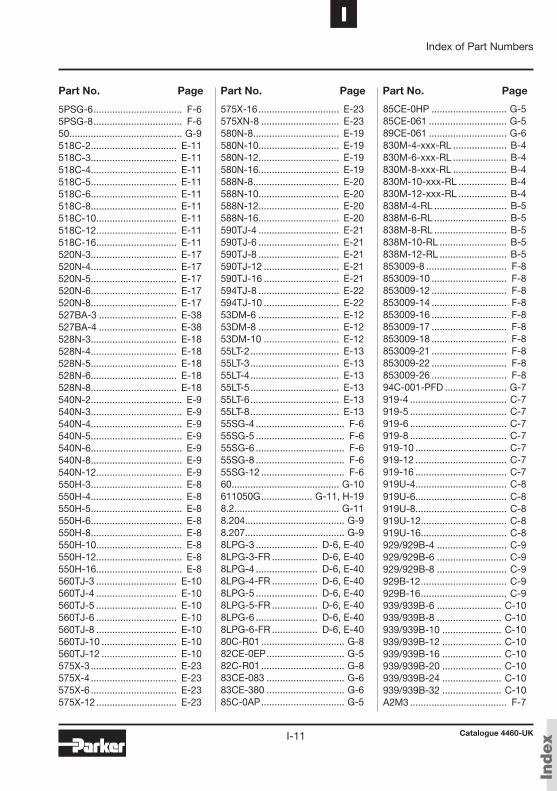
Catalogue 4460-UKI-11
IIndex of Part Numbers
Index
Part No. Page Part No. Page Part No. Page
5PSG-6 ................................. F-65PSG-8 ................................. F-650.......................................... G-9518C-2 ................................ E-11518C-3 ................................ E-11518C-4 ................................ E-11518C-5 ................................ E-11518C-6 ................................ E-11518C-8 ................................ E-11518C-10 .............................. E-11518C-12 .............................. E-11518C-16 .............................. E-11520N-3 ................................ E-17520N-4 ................................ E-17520N-5 ................................ E-17520N-6 ................................ E-17520N-8 ................................ E-17527BA-3 ............................. E-38527BA-4 ............................. E-38528N-3 ................................ E-18528N-4 ................................ E-18528N-5 ................................ E-18528N-6 ................................ E-18528N-8 ................................ E-18540N-2 .................................. E-9540N-3 .................................. E-9540N-4 .................................. E-9540N-5 .................................. E-9540N-6 .................................. E-9540N-8 .................................. E-9540N-12 ................................ E-9550H-3 .................................. E-8550H-4 .................................. E-8550H-5 .................................. E-8550H-6 .................................. E-8550H-8 .................................. E-8550H-10 ................................ E-8550H-12 ................................ E-8550H-16 ................................ E-8560TJ-3 .............................. E-10560TJ-4 .............................. E-10560TJ-5 .............................. E-10560TJ-6 .............................. E-10560TJ-8 .............................. E-10560TJ-10 ............................ E-10560TJ-12 ............................ E-10575X-3 ................................ E-23575X-4 ................................ E-23575X-6 ................................ E-23575X-12 .............................. E-23
575X-16 .............................. E-23575XN-8 ............................. E-23580N-8 ................................ E-19580N-10 .............................. E-19580N-12 .............................. E-19580N-16 .............................. E-19588N-8 ................................ E-20588N-10 .............................. E-20588N-12 .............................. E-20588N-16 .............................. E-20590TJ-4 .............................. E-21590TJ-6 .............................. E-21590TJ-8 .............................. E-21590TJ-12 ............................ E-21590TJ-16 ............................ E-21594TJ-8 .............................. E-22594TJ-10 ............................ E-2253DM-6 .............................. E-1253DM-8 .............................. E-1253DM-10 ............................ E-1255LT-2 ................................. E-1355LT-3 ................................. E-1355LT-4 ................................. E-1355LT-5 ................................. E-1355LT-6 ................................. E-1355LT-8 ................................. E-1355SG-4 ................................. F-655SG-5 ................................. F-655SG-6 ................................. F-655SG-8 ................................. F-655SG-12 ............................... F-660........................................ G-10611050G ................... G-11, H-198.2....................................... G-118.204..................................... G-98.207..................................... G-98LPG-3 ....................... D-6, E-408LPG-3-FR ................. D-6, E-408LPG-4 ....................... D-6, E-408LPG-4-FR ................. D-6, E-408LPG-5 ....................... D-6, E-408LPG-5-FR ................. D-6, E-408LPG-6 ....................... D-6, E-408LPG-6-FR ................. D-6, E-4080C-R01 ............................... G-882CE-0EP ............................. G-582C-R01 ............................... G-883CE-083 ............................. G-683CE-380 ............................. G-685C-0AP ............................... G-5
85CE-0HP ............................ G-585CE-061 ............................. G-589CE-061 ............................. G-6830M-4-xxx-RL .................... B-4830M-6-xxx-RL .................... B-4830M-8-xxx-RL .................... B-4830M-10-xxx-RL .................. B-4830M-12-xxx-RL .................. B-4838M-4-RL ........................... B-5838M-6-RL ........................... B-5838M-8-RL ........................... B-5838M-10-RL ......................... B-5838M-12-RL ......................... B-5853009-8 .............................. F-8853009-10 ............................ F-8853009-12 ............................ F-8853009-14 ............................ F-8853009-16 ............................ F-8853009-17 ............................ F-8853009-18 ............................ F-8853009-21 ............................ F-8853009-22 ............................ F-8853009-26 ............................ F-894C-001-PFD ....................... G-7919-4 .................................... C-7919-5 .................................... C-7919-6 .................................... C-7919-8 .................................... C-7919-10 .................................. C-7919-12 .................................. C-7919-16 .................................. C-7919U-4 .................................. C-8919U-6 .................................. C-8919U-8 .................................. C-8919U-12 ................................ C-8919U-16 ................................ C-8929/929B-4 .......................... C-9929/929B-6 .......................... C-9929/929B-8 .......................... C-9929B-12 ................................ C-9929B-16 ................................ C-9939/939B-6 ........................ C-10939/939B-8 ........................ C-10939/939B-10 ...................... C-10939/939B-12 ...................... C-10939/939B-16 ...................... C-10939/939B-20 ...................... C-10939/939B-24 ...................... C-10939/939B-32 ...................... C-10A2M3 .................................... F-7
Catalogue 4460-UKI-12
Index of Part Numbers
Index
Part No. Page Part No. Page Part No. Page
For Your Safety!Hose assemblies are used to transmit various kinds of fluids at considerable pressures. The critical zone of a hose assembly is the connection between flexible hose and rigid fitting (crimping area). Only the use of original polyflex components (hose, fittings and tooling) and full compliance with the polyflex assembly instructions can guarantee safety and conformity with standards.
When making and testing hose assemblies in connection with the respective field of application the guidelines and technical regulations as well as protection and hazard prevention rulings must be adhered to.
You as the manufacturer of polyflex hose assemblies are obliged to mark the hose assemblies according to the regulations.
Non-compliance with these rules can lead to the failure of a hose assembly and the loss of warranty.
A2M4 .................................... F-7A2M6 .................................... F-7A2M8 .................................... F-7A2M10 .................................. F-7AM-03 ................................... F-7AM-04 ................................... F-7AM-06 ................................... F-7AM-08 ................................... F-7AM-10 ................................... F-7AM-13 ................................... F-7AM-16 ................................... F-7AM-20 ................................... F-7AR-04 ................................... F-7AR-08 ................................... F-7AR-08C ................................. F-7AR-10 ................................... F-7AR-16 ................................... F-7FS-F-10 ................................ F-5FS-F-11 ................................ F-5FS-F-12 ................................ F-5
FS-F-14 ................................ F-5FS-F-16 ................................ F-5FS-F-18 ................................ F-5FS-F-20 ................................ F-5FS-F-22 ................................ F-5FS-F-24 ................................ F-5FS-F-28 ................................ F-5FS-F-32 ................................ F-5FS-F-38 ................................ F-5FS-F-40 ................................ F-5FS-F-48 ................................ F-5FS-F-60 ................................ F-5PD-1-5MM .......................... G-11PSG-12 ................................. F-4PSG-16 ................................. F-4PSG-20 ................................. F-4PSG-25 ................................. F-4PSG-32 ................................. F-4PSG-40 ................................. F-4PSG-50 ................................. F-4
PSG-63 ................................. F-4PSG-75 ................................. F-4PSG-90 ................................. F-4PSG-110 ............................... F-4PSG-FRAS-16 ...................... F-4PSG-FRAS-20 ...................... F-4PSG-FRAS-25 ...................... F-4PSG-FRAS-32 ...................... F-4PSG-FRAS-40 ...................... F-4PSG-FRAS-50 ...................... F-4PSG-FRAS-63 ...................... F-4PSG-FRAS-75 ...................... F-4PSG-FRAS-90 ...................... F-4PSG-FRAS-110 .................... F-4SMM100 ............................. G-10ST250 ................................... G-9Tape-FV ................................ G-9TH 4-4 ................................ G-10TH 5-3 ................................ G-10TH8-380.E ............................ G-4

Catalogue 4460-UKI-13
IIndex of Part Numbers
Index
Notes

Catalogue 4460-UKI-14
Index of Part Numbers
Index
Notes

Catalogue 4460-UK
Thermoplastic hose, fittings and accessories for hydraulic and industrial applicationsTable of contents
! Introduction and General Statements How to use the catalog . . . . . . . . . . . . . . . . . . . . . . . . . . . . . . . . . . . . . . . . II
Part number system & Explanation of symbols . . . . . . . . . . . . . . . . . . . . IV
Parker Hannifin – Polyflex Division . . . . . . . . . . . . . . . . . . . . . . . . . . . . . . VI
Why choose Parker thermoplastic hose? . . . . . . . . . . . . . . . . . . . . . . . . . VII
Preformed hoses . . . . . . . . . . . . . . . . . . . . . . . . . . . . . . . . . . . . . . . . . . . . . XIII
Non conductive hoses . . . . . . . . . . . . . . . . . . . . . . . . . . . . . . . . . . . . . . . . . XV
Twinline and multiline hoses . . . . . . . . . . . . . . . . . . . . . . . . . . . . . . . . . . . XVI
Hose bundles . . . . . . . . . . . . . . . . . . . . . . . . . . . . . . . . . . . . . . . . . . . . . . . . XVII
Parkrimp system . . . . . . . . . . . . . . . . . . . . . . . . . . . . . . . . . . . . . . . . . . . . . XVIII
Value added services . . . . . . . . . . . . . . . . . . . . . . . . . . . . . . . . . . . . . . . . . XIX
A Hose and Fitting Selection Hose selection . . . . . . . . . . . . . . . . . . . . . . . . . . . . . . . . . . . . . . . . . . . . . . . A – 2
Fitting selection . . . . . . . . . . . . . . . . . . . . . . . . . . . . . . . . . . . . . . . . . . . . . . A – 18
B Push-Lok® Hose and Fittings Push-Lok® hose . . . . . . . . . . . . . . . . . . . . . . . . . . . . . . . . . . . . . . . . . . . . . . B – 4
Fittings for Push-Lok® hose . . . . . . . . . . . . . . . . . . . . . . . . . . . . . . . . . . . . B – 6
C PTFE / Fluoropolymer Hose and Fittings PTFE hose . . . . . . . . . . . . . . . . . . . . . . . . . . . . . . . . . . . . . . . . . . . . . . . . . . C – 4
Fittings for PTFE hose . . . . . . . . . . . . . . . . . . . . . . . . . . . . . . . . . . . . . . . . C – 13
D Hose and Fittings for Alternative Fuels SCR hose . . . . . . . . . . . . . . . . . . . . . . . . . . . . . . . . . . . . . . . . . . . . . . . . . . . D – 4
CNG hose . . . . . . . . . . . . . . . . . . . . . . . . . . . . . . . . . . . . . . . . . . . . . . . . . . . D – 5
LPG hose . . . . . . . . . . . . . . . . . . . . . . . . . . . . . . . . . . . . . . . . . . . . . . . . . . . D – 6
Fittings . . . . . . . . . . . . . . . . . . . . . . . . . . . . . . . . . . . . . . . . . . . . . . . . . . . . . D – 7
AerospaceKey MarketsAftermarket services Commercial transportsEnginesGeneral & business aviationHelicoptersLaunch vehiclesMilitary aircraftMissilesPower generation Regional transportsUnmanned aerial vehicles
Key ProductsControl systems & actuation productsEngine systems & componentsFluid conveyance systems& componentsFluid metering, delivery & atomization devicesFuel systems & componentsFuel tank inerting systemsHydraulic systems & componentsThermal managementWheels & brakes
ElectromechanicalKey MarketsAerospaceFactory automationLife science & medicalMachine toolsPackaging machineryPaper machineryPlastics machinery & convertingPrimary metalsSemiconductor & electronicsTextileWire & cable
Key ProductsAC/DC drives & systemsElectric actuators, gantry robots & slidesElectrohydrostatic actuation systemsElectromechanical actuation systemsHuman machine interfaceLinear motorsStepper motors, servo motors, drives & controlsStructural extrusions
PneumaticsKey MarketsAerospaceConveyor & material handlingFactory automationLife science & medicalMachine toolsPackaging machineryTransportation & automotive
Key ProductsAir preparationBrass fittings & valvesManifoldsPneumatic accessoriesPneumatic actuators & grippersPneumatic valves & controlsQuick disconnectsRotary actuatorsRubber & thermoplastic hose & couplingsStructural extrusionsThermoplastic tubing & fittingsVacuum generators, cups & sensors
Fluid & Gas HandlingKey Markets Aerial liftAgricultureBulk chemical handlingConstruction machineryFood & beverageFuel & gas deliveryIndustrial machineryLife sciences MarineMiningMobileOil & gasRenewable energySolenoid valvesTransportation
Key Products Check valves Connectors for low pressure fluid conveyanceDeep sea umbilicalsDiagnostic equipment Hose couplingsIndustrial hoseMooring systems & power cablesPTFE hose & tubing Quick couplingsRubber & thermoplastic hose Tube fittings & adaptersTubing & plastic fittings
HydraulicsKey Markets Aerial liftAgricultureAlternative energyConstruction machineryForestryIndustrial machineryMachine toolsMarineMaterial handlingMiningOil & gasPower generationRefuse vehiclesRenewable energyTruck hydraulicsTurf equipment
Key Products AccumulatorsCartridge valvesElectrohydraulic actuatorsHuman machine interfacesHybrid drivesHydraulic cylinders Hydraulic motors & pumpsHydraulic systemsHydraulic valves & controlsHydrostatic steeringIntegrated hydraulic circuitsPower take-offs Power unitsRotary actuatorsSensors
Process ControlKey Markets Alternative fuelsBiopharmaceuticalsChemical & refiningFood & beverageMarine & shipbuildingMedical & dentalMicroelectronicsNuclear PowerOffshore oil explorationOil & gasPharmaceuticalsPower generationPulp & paperSteelWater/wastewater
Key ProductsAnalytical Instruments Analytical sample conditioningproducts & systemsChemical injection fittings& valvesFluoropolymer chemicaldelivery fittings, valves & pumpsHigh purity gas delivery fittings, valves, regulators& digital flow controllersIndustrial mass flow meters/controllersPermanent no-weld tube fittingsPrecision industrial regulators& flow controllersProcess control double block & bleedsProcess control fittings, valves, regulators & manifold valves
Sealing & ShieldingKey Markets AerospaceChemical processingConsumerFluid powerGeneral industrialInformation technologyLife sciencesMicroelectronicsMilitaryOil & gasPower generationRenewable energyTelecommunicationsTransportation
Key Products Dynamic sealsElastomeric o-ringsElectro-medical instrumentdesign & assemblyEMI shieldingExtruded & precision-cut,fabricated elastomeric sealsHigh temperature metal sealsHomogeneous & insertedelastomeric shapesMedical device fabrication & assemblyMetal & plastic retainedcomposite sealsShielded optical windowsSilicone tubing & extrusionsThermal managementVibration dampening
Parker’s Motion & Control Technologies
At Parker, we’re guided by a relentless drive to help our customers become more productive and achieve higher levels of profitabil-ity by engineering the best systems for their require-ments. It means looking at customer applications from many angles to find new ways to create value. What-ever the motion and control technology need, Parker has the experience, breadth of product and global reach to consistently deliver. No company knows more about motion and control technol-ogy than Parker. For further info call 00800 27 27 5374
Climate ControlKey Markets AgricultureAir conditioningConstruction MachineryFood & beverageIndustrial machineryLife sciencesOil & gasPrecision coolingProcessRefrigerationTransportation
Key Products AccumulatorsAdvanced actuatorsCO
2 controls
Electronic controllersFilter driersHand shut-off valvesHeat exchangers Hose & fittingsPressure regulating valvesRefrigerant distributorsSafety relief valvesSmart pumpsThermostatic expansion valves
FiltrationKey MarketsAerospaceFood & beverageIndustrial plant & equipmentLife sciencesMarineMobile equipmentOil & gasPower generation & renewable energyProcessTransportation Water Purification
Key Products Analytical gas generatorsCompressed air filters & dryersEngine air, coolant, fuel & oil filtration systemsFluid condition monitoring systemsHydraulic & lubrication filtersHydrogen, nitrogen & zero air generatorsInstrumentation filtersMembrane & fiber filtersMicrofiltrationSterile air filtrationWater desalination & purification filters & systems

Thermoplastic H
oses for Hydraulics &
Industry
Parker Hannifi n Manufacturing Germany GmbH & Co. KGpolyflex DivisionAn der Tuchbleiche 468623 Lampertheim (Hüttenfeld)Tel.: +49 (0)6256 81-0Fax: +49 (0)6256 81-123www.parker.com/polyfl expolyfl [email protected]
Catalogue 4460-UK 05/2019© 2019 Parker Hannifin Corporation. All rights reserved. Subject to technical modifi cation and error.
Thermoplastic Hosesfor Hydraulics & IndustryCatalogue 4460-UK
Europe, Middle East, AfricaAE – United Arab Emirates, DubaiTel: +971 4 [email protected]
AT – Austria, St. FlorianTel: +43 (0)7224 66201 [email protected]
AZ – Azerbaijan, BakuTel: +994 50 2233 [email protected]
BE/NL/LU – Benelux, Hendrik Ido AmbachtTel: +31 (0)541 585 [email protected]
BG – Bulgaria, So� aTel: +359 2 980 [email protected]
BY – Belarus, MinskTel: +48 (0)22 573 24 [email protected]
CH – Switzerland, EtoyTel: +41 (0)21 821 87 00 [email protected]
CZ – Czech Republic, KlecanyTel: +420 284 083 [email protected]
DE – Germany, KaarstTel: +49 (0)2131 4016 [email protected]
DK – Denmark, BallerupTel: +45 43 56 04 [email protected]
ES – Spain, MadridTel: +34 902 330 [email protected]
FI – Finland, VantaaTel: +358 (0)20 753 2500parker.� [email protected]
FR – France, Contamine s/ArveTel: +33 (0)4 50 25 80 [email protected]
GR – Greece, PiraeusTel: +30 210 933 [email protected]
HU – Hungary, BudaörsTel: +36 23 885 [email protected]
IE – Ireland, DublinTel: +353 (0)1 466 [email protected]
IL – IsraelTel: +39 02 45 19 [email protected]
IT – Italy, Corsico (MI)Tel: +39 02 45 19 [email protected]
KZ – Kazakhstan, AlmatyTel: +7 7273 561 [email protected]
NO – Norway, AskerTel: +47 66 75 34 [email protected]
PL – Poland, WarsawTel: +48 (0)22 573 24 [email protected]
PT – PortugalTel: +351 22 999 [email protected]
RO – Romania, BucharestTel: +40 21 252 [email protected]
RU – Russia, MoscowTel: +7 495 [email protected]
SE – Sweden, SpångaTel: +46 (0)8 59 79 50 [email protected]
SK – Slovakia, Banská BystricaTel: +421 484 162 [email protected]
SL – Slovenia, Novo MestoTel: +386 7 337 [email protected]
TR – Turkey, IstanbulTel: +90 216 [email protected]
UA – Ukraine, KievTel: +48 (0)22 573 24 [email protected]
UK – United Kingdom, WarwickTel: +44 (0)1926 317 [email protected]
ZA – South Africa, Kempton ParkTel: +27 (0)11 961 [email protected]
Parker Worldwide
North AmericaCA – Canada, Milton, OntarioTel: +1 905 693 3000
US – USA, Cleveland Tel: +1 216 896 3000
Asia Pacifi cAU – Australia, Castle HillTel: +61 (0)2-9634 7777
CN – China, ShanghaiTel: +86 21 2899 5000
HK – Hong KongTel: +852 2428 8008
IN – India, MumbaiTel: +91 22 6513 7081-85
JP – Japan, TokyoTel: +81 (0)3 6408 3901
KR – South Korea, SeoulTel: +82 2 559 0400
MY – Malaysia, Shah AlamTel: +60 3 7849 0800
NZ – New Zealand, Mt WellingtonTel: +64 9 574 1744
SG – SingaporeTel: +65 6887 6300
TH – Thailand, BangkokTel: +662 186 7000
TW – Taiwan, TaipeiTel: +886 2 2298 8987
South AmericaAR – Argentina, Buenos AiresTel: +54 3327 44 4129
BR – Brazil, Sao Jose dos CamposTel: +55 800 727 5374
CL – Chile, SantiagoTel: +56 2 623 1216
MX – Mexico, TolucaTel: +52 72 2275 4200