nuclear thermal hydraulics research & development
TRANSCRIPT

Project FORTE - Nuclear Thermal Hydraulics Research & Development
Critical Review of State-of-the-Art Thermal
Hydraulic Prediction Capability
June 2019
FNC 53798/46733R Issue 1
;’a;’;’ Department for Business, Energy and Industrial Strategy (BEIS)
w
SYSTEMS AND ENGINEERING TECHNOLOGY

An introduction to Project FORTE
The Department for Business, Energy and Industrial Strategy (BEIS) has tasked Frazer-Nash Consultancy and its partner organisations to deliver the first phase of a programme of nuclear thermal hydraulics research and development.
Phase 1 of the programme comprises two parts:
The specification and development of innovative thermal hydraulic modelling methods and tools; and
The specification of a new United Kingdom thermal hydraulics test facility.
The work is intended to consider all future reactor technologies including Gen III+, small modular reactors and advanced reactor technologies.
Our project partners The team is led by Frazer-Nash Consultancy and includes:
For more information, visit www.innovationfornuclear.co.uk/nuclearthermalhydraulics.html

FNC 53798/46733R Issue No. 1
© FNC 2019 Page 3 of 178
Executive Summary
Nuclear Thermal-hydraulics (NTH) is a key element of Nuclear Power Plant (NPP) design and
safety. It is the study of engineering systems where energy from nuclear fuel is transferred by a
coolant to a power generation turbine or to the environment, by heat transfer, phase change and
flow processes.
Computational modelling of NTH is already a vital part of both the design and safety
substantiation of modern NPP. State-of-the-art NTH modelling tools have the potential to enable
a level of design and operational optimisation for future NPP beyond anything seen in the past,
delivering both improved safety and economic benefits.
NTH shares modelling challenges and tools with many industries where fluid dynamics is
important, but perhaps uniquely, has to deal with all of them simultaneously on a huge range of
geometrical scales. Moreover, practical NTH computer codes cannot be completely based on first
principles, so incomplete knowledge results in uncertainties that must be rigorously quantified
and mitigated.
This review highlights a selection of underlying phenomena most important to NPP, including:
turbulence; heat transfer; bubble and droplet thermodynamics and transport; flow induced
vibration; surface effects and ageing of structures, together with the multiscale aspects linking of
all the above. Current practice and procedures by designers, regulators and utilities are outlined,
including consideration of uncertainty management and the challenges of scaling from
experiments. Classical ‘whole system’ tools are briefly summarised followed by more detailed
discussion on finer grained modelling by 3D Computational Fluid Dynamics (CFD). This review
also includes sections summarising emergent technology and international benchmarks and
projects.
This review found that, thanks to the exponential growth of computing power, previously
unexploitable methods are shown to now be applicable to the research of real NPP components.
For example, Direct Numerical Simulation (solving first principles equations avoiding any
modelling approximations) is set to complement (and in some cases replace) experiments. This
change in frame-of-mind and basic philosophy is supported by many experts and particularly by
the US Department of Energy. “Conservative” safety margins can now be re-evaluated and
placed in more likely accident scenarios with “best estimate plus uncertainty methods”. Raw
computer power combined with mathematical advances have accelerated changes in risk
management and decision making methods. This places additional complexity on top of existing
complex processes, but “machine learning”, an established branch of Artificial Intelligence, can
alleviate this, and is already being used to assist in turbulence modelling.
After 50 years of research and technology progress, NPP design and safety challenges still
remain great enough that it is tempting to conclude that it is impossible or unreasonable to
foresee major modernisation to the empirical and conservative methodology used in the industry.
There is, however, a surprising extent of worldwide openness and collaboration (in open-source
codes, forums and documentation), as well as improving ease of use of all kinds of mature
software. Progress is accelerating at an ever increasing rate, perhaps reaching a “singularity” in
technology progress speed, and now is the perfect time for the UK to invest to gain the full
advantage of these advances. The UK was historically, and still is, well placed to harness a
combination of engineers, mathematicians and computer power to tackle the hardest thermal
hydraulic problems.

FNC 53798/46733R Issue No. 1
© FNC 2019 Page 4 of 178
Preface
This review was assembled by academics at the Universities of Manchester and Sheffield, some
of whom have up to 50 years’ experience of continuous research in Nuclear Power Plant (NPP)
flows. This is mostly related to refined modelling of turbulence, in collaboration with the likes of
CEGB, EDF R&D, and more recently British Energy, EDF Energy, National Nuclear Laboratories,
BNFL and Rolls-Royce. Nevertheless, the breadth of the prediction methodologies employed in
nuclear thermal hydraulics proved a challenge even to our collective expertise. Even while
limiting the search to the recent decade, an assessment of the online literature led to thousands
of papers, as well as to mention thousands of documents from regulators and organisations more
directly involved in tools for NPP design; US NRC, DOE and Nuclear related National Labs,
OECD Nuclear Energy Agency and others.
While completing this review we discovered fresh books, reviews and action plans compiled by
hundreds of international experts. The four below are essential vis-à-vis this project’s objectives:
1. Thermal Hydraulics in Water-Cooled Nuclear Reactors, D’Auria, F.
2. Grand Challenges of Advanced Computing for Energy Innovation Report, Larzelere, A.
et al. (2013). Technical Report, Pacific Northwest National Lab, Richland, WA.
3. Handbook of Uncertainty Quantification, Ghanem, R. et al. (Eds.), 2017.
4. Scaling in System Thermal-Hydraulic Applications to Nuclear Reactor Safety and
Design: A State-of-the-Art Report, Bestion, D., D’Auria, F., Lien, P., Nakamura, H., 2016.
Report (No. NEA/CSNI/R(2016)14). OECD-NEA.
The 2017 book on thermal hydraulics (D’Auria, 2017) in NPP by 14 world-leading senior experts
with life-long careers in Thermal Hydraulics (TH) in conventional NPP, covers almost all aspects
of our intended review. The extent of the task is best expressed in D’Auria’s preface:
“This implies the consideration of a universe of topics which may need an encyclopaedia rather
than a book. So, …[only] a window is opened”
“Thermal-hydraulic phenomena identification and characterisation, code development and
validation, as well as scaling demonstration and prediction of errors of code calculations, i.e.,
uncertainty evaluation, may appear a matter for guru: rigorous procedures are not always applied
or simply do not exist. This is also a consequence of some inadequate modelling of aspects in
nature, behaviours like turbulence, and bubble motion and coalescence”
“The grown expertise, sometimes of guru-type, is going to be lost because of retirement of top
scientists acting during the golden period,…the enormous research investment 1970-2000.”
“The Book may resemble a description of a dynamic target rather than an archival product.”
The ‘silver lining’ we discovered through this review exercise is that the “moving target” is in fact
accelerating at an increasing pace! The computer power available at the beginning of our career
has increased a million times and Artificial Intelligence (AI) is transforming all areas of
engineering, from driverless cars to machine learning design of NPP. The US Department of
Energy (Larzelere et al., 2013) “has no doubt” that safer, more efficient, NPP will be conceived
through Nuclear Energy Advanced Modelling and Simulation (NEAMS), from “first principles
simulations” to Uncertainty Quantification (UQ).
UQ (Ghanem et al., 2017a) in support of risk management and decision making has also
progressed incredibly fast and is producing reliable and probability framed predictions to replace
the “conservative” approach (a worst case single result plus a guessed safety margin) used for
licensing, which has possibly ill-directed technical focus and introduced excessively costly safety

FNC 53798/46733R Issue No. 1
© FNC 2019 Page 5 of 178
measures. UQ is now applicable to very complex systems thanks to the combined efforts of
mathematicians and physicists embracing full statistical approaches, but it is again thanks to the
brute force of today’s computers enabling 100’s of simulations with Monte-Carlo inputs for each
case, compared to the past where we used to produce just one solution.
The following review is inevitably incomplete and uneven. We give more details on issues that we
are more familiar with and are relevant to plant operators, such as life extension, conjugate heat
transfer and 3D CFD turbulent simulations of flow around fuel pins and heat exchangers. The
areas less well covered here, such as historic developments, severe accidents and licensing, 1D
systems’ codes and experiments are well presented in the TH in water cooled nuclear reactors
book (D’Auria, 2017). Its subject index is essential for any reader wishing more details, for
example, on the 100’s of concepts and phenomena we could only introduce herein. We also only
briefly comment on the monumental cataloguing, evaluation and exploitation work by the OECD
Nuclear Energy Agency on 100’s of separate and integral test facilities which they revisited in the
recent report on Scaling (Bestion et al., 2016a).
Another encouraging revelation from this review is the open dissemination and world-wide
collaboration around TH for NPP, perhaps as a response to public wariness and subsequent
pressure on decision makers. This openness should help acceptance of modern tools and UQ for
NPP design and will likely also help the UK to be accepted into areas where we have not been
active for some time.
Lead Author:
Professor D. Laurence The University of Manchester
Authors:
Professor H. Iacovides The University of Manchester
Dr T. Craft The University of Manchester
Dr D. Wilson The University of Manchester
Dr A. Cioncolini The University of Manchester
Dr C. Moulinec Science and Technology Facilities Council
Professor S. He The University of Sheffield
Dr B. Liu The University of Sheffield
Editors:
R. Underhill Frazer-Nash Consultancy Ltd
Dr G. Macpherson Frazer-Nash Consultancy Ltd
C. Howlett Frazer-Nash Consultancy Ltd

FNC 53798/46733R Issue No. 1
© FNC 2019 Page 6 of 178
Contents
1 INTRODUCTION 8
1.1 Objective 9
1.2 Report Structure 9
2 THERMAL-HYDRAULIC CHALLENGES 10
2.1 Natural Convection 11
2.2 Conjugate Heat Transfer 13
2.3 Turbulence 14
2.4 Turbulent Heat Transfer 15
2.5 Two-Phase flow and Phase Change 17
2.6 Rough Wall Friction and Heat Transfer 19
2.7 Particulates, Corrosion and Ageing 21
2.8 Fluid-Structure Interaction 22
2.9 Transient and Unsteady Flows 23
2.10 Liquid Metals 23
2.11 Multiscale 25
2.12 Examples of the Impact of Thermal-Hydraulic Phenomena 27
3 CURRENT PRACTICE AND PROCEDURES 32
3.1 Scaling 32
3.2 Uncertainty Management 34
3.3 US NRC (Nuclear Regulatory Commission) 37
3.4 OECD/NEA 37
4 SYSTEM AND SUBCHANNEL CODES 39
4.1 System Codes 39
4.2 Subchannel Codes 42
4.3 Summary 43
5 COMPUTATIONAL FLUID DYNAMICS (CFD) 45
5.1 Finite Volume Codes 46
5.2 Mesh Generation and Optimisation 51
5.3 Turbulence Modelling 53
5.4 Two-Phase Flow and Phase Change Modelling 61
5.5 Component Modelling 76
5.6 Whole System Modelling 84
5.7 Porous Media 86
5.8 Fluid-Structure Interaction 89

FNC 53798/46733R Issue No. 1
© FNC 2019 Page 7 of 178
5.9 Conjugate Heat Transfer 93
5.10 Liquid Metals 97
6 ADVANCED SIMULATION AND MODELLING PACKAGES 102
6.1 Computing and simulation as the Third leg of scientific methods 102
6.2 High Performance Computing and Thermal Hydraulics 103
6.3 Direct Numerical Simulation 103
6.4 Data reduction: POD, Dynamic mode decomposition 104
6.5 Artificial Intelligence and Machine Learning 105
7 DATABASES AND BENCHMARKING 107
7.1 OECD/NEA 107
7.2 ERCOFTAC 111
7.3 Research Group Databases 112
7.4 NASA 114
7.5 Commercial CFD code Validation Cases 115
7.6 FLOWNET 116
8 MAJOR PROJECTS WORLDWIDE 117
8.1 Europe 117
8.2 US 118
8.3 IAEA CRPs 119
9 CLOSING REMARKS 122
9.1 Strengths and Weaknesses 122
9.2 Opportunities and Threats 123
10 ABBREVIATIONS 124
11 ORGANISATIONS 128
12 REFERENCES 130

FNC 53798/46733R Issue No. 1
© FNC 2019 Page 8 of 178
1 Introduction Thermal Hydraulics (TH) modelling for Nuclear
Power Plants (NPP) is daunting as it
encompasses almost all fields of Fluid
Mechanics, but benefits from research progress
that is driven and funded through many
application areas such as aerospace,
turbomachinery, chemical engineering, and
environmental flows. To name a few baseline
examples:
Lift-drag-vibrations: the fixed flowrate through
fuel cooling passages or across boiler tubes
must be kept high enough to extract the heat released yet below a threshold where lift
forces might retard the fall of control rods or increase vibrations of the very long and thin
fuel rods or exchanger tubes.
Turbulent Mixing: in hot-cold T-Junctions, downcomer, boron dilution, hydrogen/air
concentration, atmospheric dispersion. These are all applications in which turbulent mixing
controls the turbulent diffusion of mass, chemical concentration, momentum and thermal
energy, all of which can be critical to the performance of reactor components.
Rotating flows: strongly affecting turbulence in turbines, pumps, cyclone separators, but
also in pipe bends or T-Junctions followed by persistent swirling motion as in “wing tip
vortices”.
Buoyancy: as in cold source dilution (river, hot water discharges and cooling tower plumes)
borrowing and coupling methods from coastal / atmospheric modelling, but also cold fluid
traps in e.g. lower U-Shaped pipes during transients. Horizontal stratified flows severely
damp turbulent mixing. Horizontal penetrations provide another example of a reactor space
where buoyancy can generate unstable flow and thermal fluctuations. Less obviously,
buoyancy aided vertical flows, as in passive safety also impair heat transfer.
Perhaps no other sector tackles such a wide range of even baseline turbulent flows and this is
without even mentioning the challenges of two-phase flows in many flavours: droplets, bubbles,
nucleate boiling, film boiling, annular boiling in internal passages etc.
In addition, multidisciplinary issues are now attracting a lot of interest. These include fluid-solid
interactions, conjugate heat transfer, deposition, corrosion, embrittlement, weld and materials
ageing that need to be accounted for in the design of a near century-long investment; from
planning, build, 60 years amortisement to decommissioning.
Severe accident management outside of the reactor is not even considered herein. Some
consider that it “is so complex that it is always unpredictable to some extent. Instead, one
should design systems that are not at all likely to lead to severe accidents and put the effort
toward eliminating severe accidents rather than understanding, computing, analysing,
managing, and/or mitigating them” (Yadigaroglu and Lakehal, 2016).

FNC 53798/46733R Issue No. 1
© FNC 2019 Page 9 of 178
1.1 Objective
The main objective of this review is to produce an assessment of the capabilities of current
prediction methods of thermal hydraulics phenomena relevant to nuclear power plants. This
includes identifying the contributions these methods currently make to nuclear reactor design
and innovation, their current levels of reliability across the range of thermal hydraulics
phenomena present in nuclear power plants and the topics in which further development is most
essential.
In order to achieve these objectives, we start by presenting the thermal hydraulics phenomena
relevant to existing and proposed designs, we then review current practices in nuclear thermal
hydraulics, the most widely used modelling packages, and the available resources. The detailed
review of current prediction methodologies across a range of thermal hydraulics phenomena
relevant to nuclear power plants is then followed by a look at emerging methodologies and
explore their potential.
The above enable us to finally reach conclusions and recommendations for future research and
development.
1.2 Report Structure
This review covers the following areas:
Thermal hydraulic phenomena relevant to existing and advanced designs (Section 2);
Practices (Section 3) and current (Section 4) and developing (Section 5) simulation and
modelling employed by the industry and regulators;
Emerging disruptive technologies and innovative advanced models being tested and used
in a research environment (Section 6);
Verification and Validation (V&V) resources, databases and outputs from national and
international projects (Section 7);
Outputs from international consortia and projects (Section 8).

FNC 53798/46733R Issue No. 1
© FNC 2019 Page 10 of 178
2 Thermal-Hydraulic Challenges The design and safe operation of nuclear power plants presents a number of signficant thermal
hydraulic modelling challenges, often involving a combination of complex and interacting
phenomena.
The level of understanding of these challenges and the phenomena involved varies with the
level of maturity of the plant technology and the length of time for which development has
occurred. For example, for the continuously developed, mature Light Water Reactor (LWR)
technologies, the NEA’s Committee on Safety of Nuclear Installations (CSNI) has produced test
matrices for Separate Effect Tests (SET) and Integral Effect Tests (IET) and listed the thermal-
hydraulic phenomena that they have categorised. The CSNI document also provides a wide and
high level general description of the types of phenomena and physics that need to be modelled
to capture the effects accurately.
‘Separate Effects Test Matrix for Thermal-Hydraulic Code Validation: Volume 1 Phenomena
Characterisation and selection of facilities and tests (OECD/NEA, 1994)’
This 680-page report on SET matrices classifies 67 thermal hydraulic phenomena providing a
cross-reference to 2,094 experimental tests from 187 test facilities (1973-1993) in the LWR
safety thermal hydraulics field. Some of the TH phenomena identified are basic fluid mechanics
phenomena within a large range of useful parameters, for example: fluid to wall friction, heat
transfer and critical flow, stratification in horizontal flow and phase separation in vertical flow.
Other listed phenomena are more specific to LWR components or regimes such as: pressure
drop at geometrical singularities, phase separation at branches, entrainment/de-entrainment,
liquid-vapour mixing with condensation, condensation in stratified conditions, spray effects,
counter-current flow, heat transfer and global multi-dimensional fluid temperature void and flow
distribution.
CSNI also produced expert panel’s evaluation of reports on:
Separate effect tests1 (SET) (Aksan et al., 1996);
Integral Test Facility Validation2 (Glaeser et al., 1996);
Scaling3 (Bestion et al., 2016a).
CSNI’s SET database has been valuable in collecting best sets of open data for code validation
on isolated components or physical phenomena. It recognised the value of exact computation of
partial differential conservation equations and also provided a sound view of the nature of two
types of correlation coefficients: the more naturally empirical coefficients such as friction and the
ones due to the necessity (with limited computing power at the time) to introduce space and
time averaging. This led to the need to empirically set “coefficients that appear as the ratio of
the averages of products divided by products of averages” e.g. for turbulence or two-phase flow
mixtures since microscales could not be resolved. Paul Durbin wittily summarised mitigation for
similar loss of information through averaging non-linear equations as: “a model coefficient is the
ratio of what you wanted to what you get” (about earlier near wall turbulence damping
functions).
For NPP other than those employing light water as a coolant, the data available for validation
and the understanding of the phenomena is less widespread. In other technologies most of the
modelling challenges associated with Generation I and II gas cooled reactors remain, e.g.
1 https://www.oecd-nea.org/nsd/docs/1996/csni-r1996-16.pdf 2 https://www.oecd-nea.org/nsd/docs/1996/csni-r1996-17.pdf 3 https://www.oecd-nea.org/nsd/docs/2016/csni-r2016-14.pdf
FNC 53798/46733R Issue No. 1
© FNC 2019 Page 11 of 178
turbulence, or even exacerbated as when natural convection (buoyancy) is replacing fixed
flowrate pumps, others such as two-phase flows may be alleviated.
Far from being encyclopaedic, but with tools for design of future plants in mind, a selection of
the most important thermal-hydraulic challenges seen in nuclear reactors are introduced below
and revisited throughout the report in the context of specific modelling methods and tools.
2.1 Natural Convection
Natural convection is a mechanism of heat transfer where the motion of the fluid is driven by
density differences (resulting in buoyancy forces) occurring due to temperature gradients.
Natural convection, stratification (where the buoyant forces act to maintain temperature
gradients) and mixed convection (where buoyancy influences fluid already in motion) are
ubiquitous in Generation II and III reactor thermal hydraulics: cold trap transients in U-bends,
severe accident conditions, hydrogen build-up in the reactor building, in vessel retention. All of
these are also key to passive safety in Generation III+ and Generation IV reactor design and yet
remain very challenging to model.
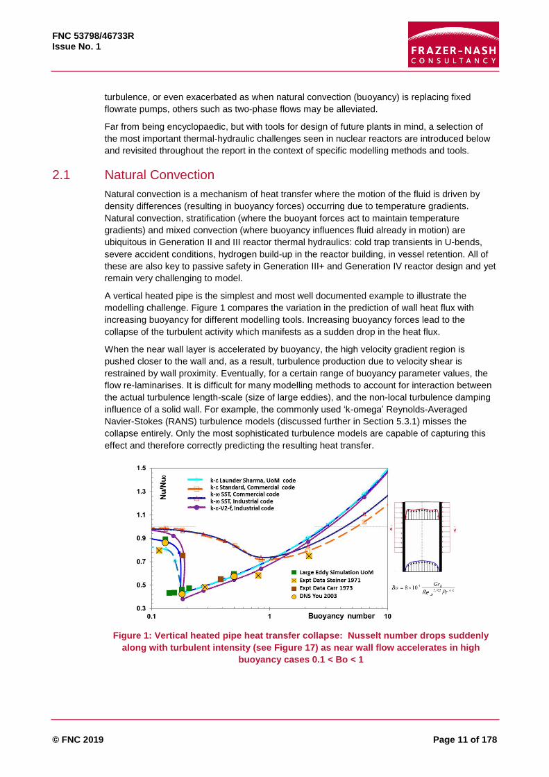
A vertical heated pipe is the simplest and most well documented example to illustrate the
modelling challenge. Figure 1 compares the variation in the prediction of wall heat flux with
increasing buoyancy for different modelling tools. Increasing buoyancy forces lead to the
collapse of the turbulent activity which manifests as a sudden drop in the heat flux.
When the near wall layer is accelerated by buoyancy, the high velocity gradient region is
pushed closer to the wall and, as a result, turbulence production due to velocity shear is
restrained by wall proximity. Eventually, for a certain range of buoyancy parameter values, the
flow re-laminarises. It is difficult for many modelling methods to account for interaction between
the actual turbulence length-scale (size of large eddies), and the non-local turbulence damping
influence of a solid wall. For example, the commonly used ‘k-omega’ Reynolds-Averaged
Navier-Stokes (RANS) turbulence models (discussed further in Section 5.3.1) misses the
collapse entirely. Only the most sophisticated turbulence models are capable of capturing this
effect and therefore correctly predicting the resulting heat transfer.
Figure 1: Vertical heated pipe heat transfer collapse: Nusselt number drops suddenly
along with turbulent intensity (see Figure 17) as near wall flow accelerates in high
buoyancy cases 0.1 < Bo < 1

FNC 53798/46733R Issue No. 1
© FNC 2019 Page 12 of 178
Figure 2: AGR feeder line stratification (Addad et al., 2015)
Buoyancy driven flows even in simple cavities bounded by co-axial horizontal cylinders present
a more complex example. In Advanced Gas Reactors (AGR) for instance, there can be
‘thermosyphons’ in the penetrations running horizontally through the thickness of the Reactor
Pressure Vessel (RPV), or in the spent fuel transfer cask neutron shields. There are complex
flow patterns inside the annuli, the coexistence of turbulent and stagnation regions and a wide
range of time scales, from boundary layer heat transfer to global cavity thermal equilibrium.
Significant modelling challenges arise due to the geometry curvature and the impingement of
the hot fluid on the walls as visible in Figure 2.
Research groups at the University of Manchester and EDF Energy in the UK (previously CEGB
or British Energy) and in France have collaborated over 3-4 decades on the modelling of these
buoyant cavity flows, i.e. entire careers of some authors of this report. Work was initially with
simple rectangular cavity experiments, which are still challenging to model, producing well
recognised databases (such as the ERCOFTAC database discussed later) for rectangular
cavities (Boudjemadi et al., 1997) and some more complex flows such as a negatively buoyant
jet (Addad et al., 2004). They extended the low Rayleigh number experimental data for the
coaxial cavity using advanced modelling techniques such as fine Large Eddy Simulation (LES)
(Addad et al., 2006) and recently Direct Numerical Simulation (DNS) (Addad et al., 2015) which
remove most of or all (respectively) turbulence modelling hypotheses.
Readers unfamiliar with the turbulence models employed in CFD and their associated
abbreviations may first browse Section 5.3.
Natural convection at NPP scales is among the most difficult single phase flows to model, it is
therefore worth detailing further. Lab-scale dimensions and temperature differences of physical
and then later DNS studies were limited to the lower Rayleigh number range (104 < 𝑅𝑎 < 109).
As 𝑅𝑎 is roughly the square of the Reynolds number, 𝑅𝑒 varied between a few hundreds to a
few thousands, i.e. onset of the laminar to turbulent transition. There is a wealth of
environmental data available, but that is at the other (high) Ra-range extreme and does not
provide the fluid to smooth-solid-wall heat transfer information needed. The RANS route was
initially favoured in view of the slow and long transients that make the LES approach a
four-dimensional multiscale problem, however, fine experimental data is very scarce for RANS
validation. Measuring turbulent heat flux, i.e. the correlation between fluctuating velocity and
temperature at the same location, was found to be all but impossible without large filtering and
flow perturbation errors. It is now worth revisiting with modern non-intrusive data acquisition
techniques.

FNC 53798/46733R Issue No. 1
© FNC 2019 Page 13 of 178
Part of the validation problem also arises from the time taken to reach steady conditions. A
laboratory experiment, of only 50 cm, with a cavity heated and cooled on opposite sides needs
to be left running for hours before the turbulent contribution is established and mean
temperatures stabilise. Starting from isothermal state there is no motion and only molecular
diffusion slowly develops thin temperature gradients very near the thermally active walls. To
reach fully developed state the following physical processes must take place:
1. Velocity gradients away from the wall need to be developed.
2. The resulting shear generates turbulence.
3. Turbulent mixing then enhances heat fluxes.
4. Increased wall heat transfer leads to faster development of temperature gradients.
5. The resulting stronger buoyancy forces away from the wall enhance velocity gradients
which leads back to 1.
Only then does the coupling process speed up, through turbulence and wall layer renewal, as
characterised by the Nusselt number typically of order 100. This is only at mean velocity and
temperature level. There are further anisotropic convoluted coupling effects between Reynolds
stresses, heat fluxes and turbulent kinetic energy and temperature fluctuation variance. As
vertical temperature differences develop in the cavity, core stratification damps turbulence,
slowing down the stabilisation of the temperature profile in the cavity but also allowing
secondary natural convection cells and gravity waves to appear both with timescales ten
thousand times larger than that of the boundary layer turbulence.
The DNS analysis of the AGR cavity in Figure 2 needed a millisecond fixed time-step to capture
the small physical time scales and the simulation could only run for a physical duration of a
minute, probably too short for gravity waves which are certainly most important for the ageing of
the external steel casing and concrete, not to mention the transient regimes, which are totally
out of reach of DNS.
The complexity of the phenomena involved in predicting heat transfer due to natural convection
results in the use of empirical correlations by most industrial engineers. However, many
currently used empirical methods are based entirely on experiments relating to specific
geometries and quickly become inaccurate when applied more widely. This, in combination with
the importance of this area to both current and future NPP designs, emphasises the potential
benefits of improved prediction methods. The accurate prediction of the turbulent mixing is key
for success and the modelling of turbulence using CFD is discussed further in Section 5.3.
Advanced CFD methods have demonstrated that considerable improvement is possible, but the
modelling of natural convection is still an area requiring development to realise the benefits of
advanced methods. This is certainly an archetype of nuclear thermal hydraulics problems
needing a joint physical and first principles simulation approach.
2.2 Conjugate Heat Transfer
The term ‘conjugate heat transfer’ is used to describe the combination of heat transfer within
both fluids and solids where there is thermal interaction between them. The ability to predict the
variation in the temperatures of solid components as a result of heating or cooling by a fluid is
important in all NPP technologies. For example, materials scientists could use this information
to assess whether a component will fail through high-cycle fatigue crack growth. Enhanced
understanding of these issues will help design long life NPP which was essential for
amortisation of classic plants and of course now mandatory for SMR’s to be loaded once and
buried underground.

FNC 53798/46733R Issue No. 1
© FNC 2019 Page 14 of 178
As mentioned in the TEE Junction problem considered later in Section 2.12.2, extending a CFD
simulation to include temperatures inside solid walls is easy but there is no detailed validation
data. It suffices to solve the same equation as in the fluid while setting the convective velocity
and turbulence generation to zero. Alternatively the CFD code can be coupled to a structures
code. Applied studies have so far only considered mean temperatures, with few extensions to
predict fluctuating temperatures inside the solid.
Study of conjugate heat transfer including solid temperature (and subsequently stress)
fluctuations using first principles DNS is very recent but promising. Figure 3 shows attenuation
of small scale instantaneous temperature fluctuations at a TEE junction (Wu et al., 2017) while
larger scale ones are traversing the wall.
Figure 3: Instantaneous temperature fluctuations above and below a TEE junction
Top left in the fluid near wall layer (𝒚 = +𝟎. 𝟎𝟓)
Top middle: on the fluid-solid interface (𝒚 = 𝟎)
Top right: inside the solid wall (𝒚 = −𝟎. 𝟓)
Bottom: time series and spectrum of temperature fluctuations
2.3 Turbulence
The term ‘turbulence’ is used to describe the chaotic variations in pressure and velocity that
occur in fluids where the kinetic energy of the flow overcomes the fluid’s viscous damping. In
general terms it is the presence of unsteady vortices of a variety of scales which interact with
each other changing important overall flow characteristics such as the drag and heat transfer.
The importance of the modelling of turbulence is therefore certainly not limited to nuclear
thermal hydraulics. Much, although by no means all, turbulence model development over the
past two decades has been primarily sponsored by the aerospace sector, with lift and drag
forces, near-wall modelling and flow separation playing major roles. While much of this work is
also relevant to thermal hydraulics, there are often further challenges to consider, including heat
transfer and buoyancy effects, and the fact that, in closed circuit applications, the details of flow
downstream of bluff bodies must be correctly captured (whereas for single aerodynamic body
structures the far downstream behaviour is often not so crucial).

FNC 53798/46733R Issue No. 1
© FNC 2019 Page 15 of 178
Thermal hydraulics problems frequently involve natural or mixed convection; adequately
representing this requires not only accurate modelling of the near-wall flow and heat transfer
processes, but also the subtle interactions between the buoyancy forces and turbulence
structures and statistics in both the near-wall and outer flow regions. Many such flows can also
be statistically unsteady, posing a further challenge for turbulence models.
Buoyancy influences on turbulence are typically very anisotropic in nature, and at the modelling
level this means that schemes are required to adequately capture the interactions between the
various Reynolds stress and turbulent heat flux components. Many of the simpler models that
rely mainly on predicting the correct shear stress response to mean flow behaviour can fail in
such flow situations, as can the simpler gradient diffusion representations for turbulent heat
fluxes. Whilst more complex models, including full stress transport models, have been shown to
perform more reliably in many buoyancy-dominated flows, their take-up in general purpose CFD
codes has been rather limited often due to the perceived higher costs and longer timescales
associated with both building and running the models.
A further challenge in many turbulent thermal hydraulics problems is the modelling of the near-
wall flow layers, which are often crucial to accurate predictions because of their importance in
heat transfer processes. Resolving these thin layers with very fine grids, and turbulence models
designed to account for near-wall effects where turbulent eddies become very small and
momentum or temperature mixing occurs on molecular scales increases computational costs
drastically (both in RANS and LES modelling approaches, see Section 5.3). Alternatives such
as “wall-functions” which bridge the viscous sub-layer thanks to correlations are widely-used,
but most of the standard forms of these are based around log-law representations which are
rarely appropriate for strongly buoyancy-influenced flows. More advanced forms of wall-
functions have been developed, and applied with some success, although there is clear scope
for further development and application to allow both advanced RANS and LES modelling
approaches to be used in very large and complex industrial applications at a reasonable
computational cost. A detailed discussion of the modelling of turbulence use in CFD methods is
given in Section 5.3.
2.4 Turbulent Heat Transfer
The prediction of turbulent heat transfer within fluids and between fluids and solid surfaces is
amongst the most important of all modelling challenges to both NPP design and safe operation.
For most industrial applications relating to NPP this means turbulent heat transfer.
In lower fidelity modelling codes (such as the system codes described in Section 4) the overall
heat transfer between fluid and solid walls is prescribed via solution specific empirical
correlations. In most higher fidelity methods (i.e. classic CFD), this heat transfer is predicted by
solving the energy equation together with the momentum equations with a user specified
‘turbulent Prandtl number’, the constant introduced to model the ratio between turbulent
viscosity and turbulent thermal conductivity in effective-viscosity models.
The fact that a 30% variation of this turbulent Prandtl number (𝑃𝑟𝑡) between 0.7 and 1.0, is
widely accepted is perhaps by analogy to large changes of the molecular Prandtl number (the
viscosity to diffusivity ratio) with temperature and type of fluid. There is no relation, however,
between fluid properties and turbulent flow characteristics at high Reynolds numbers and
leaving the choice of 𝑃𝑟𝑡 up to the user’s whims or default code value is one of the weakest links
in CFD thermal hydraulics predictions.
Unlike in pure aerodynamics, which is dominated by the exact pressure-inertia balance, while
turbulent effects are weaker, temperatures depend only on convection and turbulent heat flux

FNC 53798/46733R Issue No. 1
© FNC 2019 Page 16 of 178
balance and thus predictions are much more sensitive firstly to the kinematic turbulence model
chosen and secondly to how it is extended to heat fluxes. Much larger differences are observed
in temperatures between simulations as a result of user choices which explain the wariness of
decision makers in NPP thermal hydraulics compared to aerospace. This is in part due to the
historic turbulent Prandtl number “fallacy”:
‘The Reynolds analogy leads to assuming that the ratio of turbulent momentum transfer over
turbulent heat transfer is constant, in space and across applications and that this turbulent
Prandtl number can be prescribed a priori by the savvy CFD user, or worse, by the code
default value.’
Already in 1975, Reynolds (1975) asserted that this approach “is almost certainly inadequate…
the roles of intensity and of position within the flow must be separately accounted for”, and this
even for passive simple shear flows where the single mean temperature gradient and mean flow
velocity gradient are aligned (e.g. boundary layers and jets). He tagged the 30 analytical models
already on offer “a tribute to man’s ingenuity and individuality” and accurately predicted that
rapid progress was unlikely.
Figure 4: Turbulent Prandtl number fallacy
Slide on right shows in red effect of adding buoyancy to the tensorial Re stress and heat
flux coupling for a simple 1D shear flow. These production terms are exact at second
moment closure level.
It is disappointing that years later most applied thermal hydraulics studies are still based on a
user prescribed turbulent Prandtl number despite the availability of entire books devoted to
more general second moment closures (Hanjalić and Launder, 2011). As major CFD codes now
start to seriously incorporate these there is at last hope they might be used, protracted certainly
by the complexity of the theory of second moment closures where all six turbulent stresses and
three heat fluxes are kept as independently computed variables (Figure 4 and Section 5.3.1.3).
It is easy to see that it is already a dramatic over-simplification to reduce these nine
fundamental stresses and fluxes to just two scalars (an eddy viscosity forcing alignment of the
stress tensor on the velocity gradient and an eddy diffusivity aligning the heat or concentration
fluxes on the mean gradient). In Figure 4 right, the blue boxed terms are exact gradient
production terms with arrows pointing to the tensorial level coupling. Red boxes indicate the
additional production terms introduced by buoyancy effects. The introduction of the turbulent
Prandtl number to define the eddy diffusivity as a rescaled eddy viscosity (left of Figure 4) is

FNC 53798/46733R Issue No. 1
© FNC 2019 Page 17 of 178
another drastic simplification. Its value or choice of correlation (“a tribute to man’s ingenuity and
individuality”) is left to the whims of the CFD user.
The more advanced turbulence modelling methods that do not require the user-specification of
a turbulent Prandtl number have been developed over decades, but are very seldom used in
NPP TH studies due to the complexity of the theory and lack of fine enough validation data in
this context. Recent breakthroughs in machine learning (Section 6.4) might resolve these issues
regarding second moment closures. In the LES context, the so called “dynamic sub-grid-scale
modelling” approach whereby the modelling of small scale turbulence is improved by observing
interactions at slightly larger scales, while the simulation progresses in time, might already be
considered as machine learning.
2.5 Two-Phase flow and Phase Change
The term two-phase flow refers to a mixture of a liquid and a gas or a vapour that flows
simultaneously through a channel, and is a particular example of a multi-phase flow. These
flows, or indeed those which are expected to undergo a change of phase, pose a serious
challenge for numerical modelling owing to their increased complexity over their single-phase
counterparts. The primary complication arises from the existence of discernible interfacial, or
boundary, regions which separate the phases. As well as the challenge of how to actually
represent the interface region in a numerical sense, the interfaces undergo continual topological
change whilst simultaneously facilitating the exchange of mass, momentum and energy
between the phases. This two-way coupling between the fields of the phases is one of the most
difficult aspects of multi-phase flows to model.
Two-phase flows feature extensively within the context of nuclear thermal hydraulics and are
expected to be present both during normal operations and off-design conditions. The most
obvious occurrence of on-design two-phase flow is the process of boiling within the core of a
Boiling Water Reactor (BWR), but subcooled nucleate boiling also usually occurs inside the top-
third of a Pressurised Water Reactor (PWR) core (D’Auria, 2017). It is also relevant to LWRs
under various fault conditions when, aside from the potential for significant vapour generation in
the fuel channels, vapour bubbles in water, droplets in steam or other flow regimes in between
may occur anywhere within the reactor.
Even in geometries limited to simple channels, two-phase flows exhibit a variety of flow regimes,
or flow patterns, dependent on the relative concentration of the two phases, the total mass flow
rate, the operating pressure and flow geometry of the channel. These range from separated
flows, where the two-phases are almost entirely separated by a large interface, to dispersed
flows, where one phase consists of discrete elements (such as bubbles or droplets) and those
flows which are in a transition between the two. General types of two-phase flow (Figure 5) are
described in Ishii and Hibiki (2011), but those of particular relevance to nuclear applications are:
Bubbly flow: characterised by a continuous liquid phase with dispersed vapour bubbles,
where the bubbles are notably smaller that the channel diameter;
Slug flow: the vapour is concentrated in elongated bubbles whose diameter approaches
that of the channel, interspersed by liquid slugs;
Annular flow: a continuous liquid film flows along the channel wall surrounding a central
vapour core that may carry entrained liquid droplets in suspension;
Mist flow: characterised by a continuous vapour phase with dispersed liquid droplets in
suspension;
Inverted annular flow: a continuous liquid jet flowing in the centre of the channel with a
vapour film located at the channel wall.

FNC 53798/46733R Issue No. 1
© FNC 2019 Page 18 of 178
Separated flows
Mixed or transitional flows
Dispersed flows
Figure 5: General types of two-phase flow patterns
Transition between these regimes indicates phase change within the flow. Within NPP, this can
both be desirable and undesirable, as we can have transition to a number of phenomena,
including subcooled and saturated flow boiling, Departure from Nucleate Boiling (DNB), dry-out,
flashing, and condensation with and without non-condensables. Two of these which hold critical
relevance to NPP safety in LWRs are DNB and dry-out, because they can cause a steep
increase in wall temperature, and both of which are directly related to the occurrence of the
Critical Heat Flux (CHF). This is the heat flux at which an undesired change in the boiling
regime occurs; typically where the rate of vapour being generated from the heated fuel rod
surface increases such that it prevents adequate liquid contact with the surface.
The term DNB is usually reserved for the occurrence of CHF in PWRs, where the fluid typically
undergoes subcooled nucleate boiling during normal operations. At the CHF, vapour bubbles
coalesce on the surface and form a stable vapour layer resulting in a type of annular inverted
flow. Dry-out refers to the occurrence of CHF caused by the evaporation of the wall liquid film in
the annular flow regime. The reliable prediction of the transition to such phenomena without the
need to use empirical models, is probably the greatest challenge here.

FNC 53798/46733R Issue No. 1
© FNC 2019 Page 19 of 178
Thermal and fluid phenomena in two-phase flows are strongly linked to the flow pattern, so that
mechanistic prediction methods should clearly be flow-pattern based to incorporate the
fundamental physics and unique characteristics of each single flow pattern (Thome and
Cioncolini, 2015). The “geometric structures” of two-phase flows thus become the mechanistic
“building blocks” of mechanistic and theoretically based models, which can then be used to build
flow regime specific models for flow boiling heat transfer coefficients, two-phase pressure drops,
void fractions, entrainment, dry-out, critical heat flux and so forth.
In fact, the best and most reliable mechanistically based prediction methods currently available
attempt to capture the two-phase flow structure of the particular flow pattern to account for its
dominant flow phenomena: bubbles, liquid slugs, shear-driven liquid films, entrained droplets,
etc. To simulate flow boiling along channels in which the flow pattern goes from one flow regime
to another from inlet to outlet, accurate flow pattern maps are thus imperative to reliably identify
what type of flow pattern exists at the local flow conditions along the channel whilst mechanistic
models try to capture the influence of the two-phase flow structure on the heat transfer and
momentum processes.
This vision is quite different to the wholly empirical approach often used in this field, in which ad-
hoc non-dimensionless groups or sometimes dimension correlations are used to predict local
heat transfer coefficients. Notwithstanding this, the empirical approach will continue to play a
major role in two-phase convective heat transfer analysis, just like it does in turbulent single-
phase flows. One, however, should aim for mechanistic and theoretically based models that are
“finished off” by the fitting of a few empirical constants rather than proposing ever more new
correlations with 10-30 empirical constants and exponents in which the physical picture of the
process is completely lost, as unfortunately is frequently done.
2.6 Rough Wall Friction and Heat Transfer
Many modelling approaches (and experimental investigations) consider solid walls as
predominantly ‘smooth’. However, in real NPP, walls are neither smooth nor is their roughness
necesasrily a constant through life due to manufacturing processes, ageing, deposition and
corrosion. An extreme case being carbon deposition on AGR fuel pins (Figure 6).
(Courtesy of EDF Energy)
Figure 6: Carbon crud on AGR fuel pin (Mowforth et al., 2015)
However, progress in modelling and validation data for wall roughness is very scarce and
intermittent. The modelling proposal of Suga et al. (2006) is a notable exception, although
detailed validation data is again very sparse, and practically non-existent concerning heat
transfer. Rough-wall-effects provide an ideal case for local DNS with bespoke meshing or the
immersed boundary technique. However, actual surface topology will need to be experimentally
characterised for many types of materials and manufacturing processes with modern

FNC 53798/46733R Issue No. 1
© FNC 2019 Page 20 of 178
tomography methods. In any case, engineering calculations, e.g. rod bundles, require ‘wall
function’ type of rough-surface modelling, which need careful validation.
Even on a clean, new AGR fuel pin heat transfer is poorly predicted by classic RANS models so
crud effects are best left to experimentalists. Figure 7 shows the huge effect (+/- 100%) of
erroneous separation bubble size prediction on wall heat transfer increase (Nusselt number)
over smooth pipe value.
Figure 7: AGR ribbed fuel pin. Separation bubble size effect on wall heat transfer
It is only when detailed mean flow features are reliably predicted that we may see improvements
of turbulent heat flux modelling on rough surfaces. There are many more examples where
accurate small scale or secondary flow prediction could have large design benefits, such as
flow-induced corrosion (see Section 2.7).
Turbulence models for refined CFD, detailed later in Section 5.3, were developed in many
different application sectors which perhaps have different “safety margin” focus. For instance “k-
omega” rather than “k-epsilon” type models are preferred in the Aerospace sector. They tend to
predict weaker turbulent mixing and hence earlier and longer boundary layer separation (with
dramatic loss of lift forces). However, but of no concern to Aerospace, they can under-estimate
heat transfer or miss re-laminarisation effects (damping of turbulence) in the presence of
buoyancy. These features are better reproduced by “k-epsilon” models which are thus more
frequently used in the NPP TH sector. Advanced turbulence models providing improved
predictions for detailed flow features, such as shown in Figure 7, are now available in major
commercial and industrial software for a the wide range of applications.
However, they are only frequently used by R&D CFD specialists while applied CFD NPP
engineers are more comfortable with the standard models in their sector, which have been
validated on more global values of many established test cases. As finer benchmarking data
became available obvious flaws of standard models were proven to be corrected by the more
recent ones, but through compensating (opposite) errors global values predicted by older and
advanced models are often similar.

FNC 53798/46733R Issue No. 1
© FNC 2019 Page 21 of 178
The benefits of an advanced model are in the details and reliability over a wider range of
applications. It will allow a finer breakdown of safety margins (uncertainty quantification) and
exploration of novel designs. For run of the mill CFD studies, over a well-known and validated
application range, the extra cost and effort in applying these advanced models was perhaps not
perceived worthwhile. This could change with advances in computing: easier to use human-
machine interfaces, intelligent “default values of model constants” and cheaper, enhanced
computing power.
2.7 Particulates, Corrosion and Ageing
In addition to the more obvious thermal and mechanical cyclic loading over years of operation,
there are steady flow phenomena with the potential to limit the lifespan of NPP components by:
Pure hydrodynamics; erosion, cavitation, droplet impingement;
Physio-chemical effects; flow accelerated corrosion, particle deposition, altering coolant
chemistry.
Because wall thinning often occurs on the inside of tubes it is not detected without very specific
and localised inspection devices. Ageing of steel pipes, vessels and heat exchangers are
crucial factors to sustain safety but also economic viability of long term NPP operation that have
plagued utilities. These could be better addressed at the design stage with artificially
accelerated ageing, thanks to better numerical models and experimental methods.
For Flow Accelerated Corrosion (FAC), the chemical process in the surface boundary layer
depends on mass transfer and precise flow patterns, which can be modelled by 3D CFD codes.
The mass transfer by turbulent diffusion of ions generated at the piping wall to the bulk flow
determines the rate of FAC which increases in regions of high turbulence, such as the flow
downstream of orifices, valves and in bend geometries. Corrosive conditions can be further
evaluated from concentrations and electrochemical corrosion potential and finally wall thinning
rates (Uchida et al., 2012, 2010).
Predictions are harder when the ageing agent is particulate rather than dilute; the complex
water droplet/vapour bubble phenomena are discussed in the two-phase flow section (Section
2.5). Solid particle transport and deposition phenomena are perhaps equally daunting.
Lagrangian transport research has barely started for non-spherical particles such as carbon
flakes growing and blown off AGR fuel pins.
Steam Generators age faster than the reactor core components and replacement is extremely
costly. Complex models aim to predict the localisation and the growth rate of deposits in order to
simulate tube fouling, as well as tube-support-plate flow blockage leading to Flow-Induced
Vibrations (FIV) and tube cracks in some cases, see Prusek et al. (2013).
A PWR steam generator contains thousands of thin tubes separating primary and secondary
flow, which can leak after years of use. Several tube support-plates are placed along the tube
bundle. Holes allow secondary flow to go through these tube plates, around which deposits are
created, by both particle deposition and soluble species precipitation into the pores of the
deposits. Corrosion and degradation products such as metallic oxide particles and soluble
species produce deposits in low-velocity recirculation zones (Corredera et al., 2008). As the
deposit grows, the flow contraction and associated boundary-layer separation will become more
severe and the vena contracta mechanism tends to become progressively worse.
Highly detailed flow features and multiphysics numerical simulations can now drastically
accelerate time. For instance, evolution of the Seine estuary sediment evolution over the past
century has been successfully reconstructed in a few hours. Millennium-long TH simulations are
FNC 53798/46733R Issue No. 1
© FNC 2019 Page 22 of 178
ongoing for deep geological waste storage. Moreover, clever dimensional analysis substitution
experiments can also mimic ageing or provide validation data. For bends, Mazhar et al. (2013)
measured mass transfer using a dissolvable wall in test sections cast from gypsum, to obtain
wall wear patterns in a reasonable test time. A probabilistic yet more complete example in terms
of multiphysics phenomena can be found in Yuan et al. (2008). Therefore, ageing of reactors
should be an integral part of new NPP design and detailed data collection during deconstruction
of decommissioned plants would provide a wealth of validation data for TH and materials
degradation modelling, alongside imaginative experiments.
2.8 Fluid-Structure Interaction
Fluid-Structure Interaction (FSI), whereby displacement of an elastic structure by hydrodynamic
lift or drag modifies the flow pattern which in turn amplifies the displacement, is well known. This
feedback effect leading to fretting, and possibly catastrophic rupture, is considered in the design
of many engineering systems, e.g. aircraft wings, turbine blades, bridges, piping systems. The
very long and slender tubes in heat exchangers and fuel pins are quite susceptible to FSI.
Oscillating lift or vortex shedding coupled to structural elasticity for cylinders in crossflow is a
text-book example, but flow parallel to tubes is also prone to FSI (Baratto et al., 2006).
Among hundreds of NPP Flow-Induced Vibration (FIV) papers, particularly on tube failures due
to fretting-wear and vibration-related damage of reactor internals, a still relevant review by
Pettigrew et al. (1998) concludes that “most flow-induced vibration problems can now be
avoided by proper analysis at the design stage” but “while much progress has been
accomplished to understand flow-induced vibration mechanisms, the effect of two-phase flow
requires further attention”.
Today many codes, including commercial solvers permit a monolithic approach (flow and the
displacement of the structure solved simultaneously, with a single solver) and should allow more
systematic evaluation of FSI risks thanks to High performance Computing (HPC) resources, but
when re-meshing is needed for large displacements, or a large number of tubes must be
accounted for, this can be costly. Longatte et al. (2013) suggest a hybrid strategy using both
numerical local solutions and empirical global solutions.
Pins and tube bundles are reviewed in Section 2.12.3. As a dissimilar, but historical example, a
less obvious effect (a priori) was the large fluid-elastic vibration of the thermal shield in the
French fast breeder reactor SuperPhenix. The top of the cylindrical thermal shield holding cooler
liquid sodium against the vessel wall behaved as a flexible weir as fluid was cascading over it
into the plenum which had a lower free surface. As the new plant was first tested a loud
drumbeat was heard due to shield vibrations and sloshing fluid. After ad-hoc coupling fluid and
solid simulations and a reduced scale model using water and a bronze weir (chosen from
dimensional analysis, Cauchy number for elasticity and Froude number for gravity) fully
explained the phenomenon, this very worrying phenomenon was resolved by simply adjusting
free surface levels. The design of a Fast Breeder Reactor, still under construction in India, has
led to more recent experiments (Thirumalai et al., 2010).
In areas of complex flow, where accurate prediction of the flow field alone is challenging, FSI
adds an extra layer of modelling complexity. Even designers with considerable modelling
expertise currently rely heavily on testing to determine if FSI will cause a problem, sometimes
resulting in costly rework.

FNC 53798/46733R Issue No. 1
© FNC 2019 Page 23 of 178
2.9 Transient and Unsteady Flows
Transients occur where a significant change of conditions occurs over time and are a concern in
NPP design and operation. Examples are reactor startup or power changes or Loss-of-Coolant
Accident (LOCA) depressurisation and coolant injection. Unsteady flows occur where the
macroscopic component or reactor conditions are constant, but the flow contains inherent
instabilities, that result in either periodic or chaotically changing flow patterns.
Most empirical heat transfer correlations are derived for fully developed steady state conditions
while rapid transient and non-established flows exist in most accident conditions. Transient
flows make up most of the CSNI 63 SET collection and the effect of downscaled ITF on time
similarity is much discussed in the recent Scaling report (Bestion et al., 2016a). Even when
vertical scale and velocities are conserved, the inevitable volume and power reductions raise
the issue of time-dependency transposition.
Turbulence modelling via RANS is based on steady state mean flow conditions. When the
transient timescale is much larger than the turbulent timescale, RANS is generally assumed
acceptable but the limit is not clearly defined. For example, in vortex shedding behind a bluff
body the issue is still unresolved and there is a wide range of intermediate approaches between
RANS and LES where the ranges of applicability are still less clear (Detached Eddy Simulation,
Partially Integrated RANS, Stress-Strain Lag model). Transients are very costly to tackle via
LES or DNS because of the scale difference between the long timescale transient event and the
small, rapid flow instabilities. This is made further challenging if using ensemble averaging
(running the same transient many times) instead of time-averaged statistics.
For similar reasons, conjugate heat transfer studies are costly due to the long transient
timescales resulting from the thermal mass of structures. This leads to much longer solution
timescales than those encountered in steady state heat transfer. Long transients are also found
in normal plant operations such as evacuating cold water plugs in lower U-bend piping systems
and horizontal stratifications.
Natural convection is another case where transient or unstable events lead to long solution
timescales. Even small 50cm cavity experimental rigs are often left running for hours to allow
the flow to be fully established, whereas the data acquisition phase might only occur over a
matter of minutes. In natural convection simulations, bifurcating or periodic solutions have been
observed.
2.10 Liquid Metals
Two of the Generation IV reactors use liquid metal as the primary-circuit coolant, i.e. the
Sodium-cooled Fast Reactor (SFR) and the Lead-cooled Fast Reactor (LFR). The convective
heat transfer in liquid metals is inherently different from that in water or air due to its very low
value of Prandtl number (𝑃𝑟), normally between 0.01 and 0.001 depending on the temperature
under reactor conditions. These values are significantly lower than those of air (~0.7) and water
(~7 at room temperature). As a consequence, in contrast to that in air or water, the thermal
boundary layer is often much thicker than that of momentum boundary layer, and hence the
thermal conduction plays an important role.
For liquid metal, the turbulent thermal diffusivity is only greater than the molecular thermal
diffusivity at high Reynolds number: when 𝑅𝑒 > 60,000 for 𝑃𝑟 = 0.025, or 𝑅𝑒 > 214,000 for 𝑃𝑟 =
0.007, where 𝑅𝑒 = 𝑈𝑏𝐷ℎ 𝜈⁄ , where 𝑈𝑏 is the bulk velocity, 𝐷ℎ the hydraulic diameter and 𝜈 the
kinematic viscosity (Grötzbach, 2013). The implication of this is that the Reynolds analogy
between the thermal and momentum transfer based on 𝑃𝑟~𝑂(1) implied in conventional

FNC 53798/46733R Issue No. 1
© FNC 2019 Page 24 of 178
turbulence modelling as a basic assumption is no longer valid. The solutions of the energy and
momentum equations are normally related through the use of the so-called turbulent Prandtl
number, which is commonly taken to be a constant ~0.85. An equivalent 𝑃𝑟𝑡 for sodium would
be much smaller than the above value and would be varying in the flow field. Advanced
turbulent heat flux models have been developed and used for ‘normal’ fluids, but they will need
to be validated/recalibrated for liquid metal flow.
The second challenge associated with Liquid Metal Fast Reactors (LMFR) is related to their
particular design which nearly always adopts a pool-type style (except the Japanese SFR
design which adopts a loop type). The main components of the reactor including the core, the
circulators and intermediate heat exchangers are submerged in a large pool of liquid metal. This
inevitably results in the existence of ‘dead’ areas where stratification may occur. Such
stratifications are always associated with a high temperature gradient and tend to be
unstable/unsteady, which may lead to thermal fatigue of adjacent structures.
Buoyancy force and natural circulation play a more important role in LMFRs than in many other
reactor designs in both normal operation and decay heat removal. For the latter, passive cooling
decay heat removal with/without the assistance of circulators is an advantage of such reactors.
Even though extensive efforts have been directed at the modelling of natural circulation (and
mixed convection) in CFD in general and nuclear thermal hydraulics in particular, it still remains
as one of the greatest challenges. The main reason is that the thermal and momentum fields
are strongly and nonlinearly connected – the buoyancy force resulting from the solution of the
energy equation (which depends on the flow field) serves as the source term that drives the
flow. In forced convection however, the momentum equation can be solved without considering
the thermal field, which can be solved later as a passive scaler. Additionally, natural circulation
tends to involve various flow regimes (laminar, transitional and turbulent) and there is a lack of a
main flow direction, which all increase the difficulty in modelling.
Another feature of SFRs is the use of an argon cover gas layer above the sodium pool to
prevent any leakage air into the vessel from coming into contact with sodium, which creates a
free surface above the sodium pool. The heat transfer from the surface to the roof of the core is
of significant interest in understanding the behaviour of the reactor. Here the heat transfer is
largely by radiation through the argon cover gas with mists of sodium aerosols which may
deposit onto the roof. Conversely, the free surface is a major source of argon gas entrainment
to sodium. This effect increases as the cover gas space is reduced under the pressure of the
reduction in the overall size of the reactor, which leads to greater free surface
velocity/disturbances and more/stronger vortices generated around structures protruding the
free surfaces, all of which lead to stronger gas entrainment. The principal concern of gas
entrainment is the possible positive reactivity, followed by adverse impacts on the circulator
pumps.
Other challenges include thermal striping and gapping instability. The former is due to the
potential differences in temperature between the outgoing fluid streams from the core - these
‘jets’ are rather unstable and take time to mix, which are potential sources of thermal fatigue of
the above core structures. The latter is a phenomenon that occurs in closely-packed tube
bundles when Kelvin Helmholtz instability may induce vibration. These are also complicated by
the use of spiral spacer wires used in-between the fuel rods which create additional
disturbances to the flow and challenges for prediction of flow and temperature.
Molten Salt Reactors (MSRs) can be included here in passing as they are more similar to liquid
metal than water cooled reactors. Advantages (in addition to the strong negative temperature
coefficient of reactivity) are that core pressure can be low and the temperature much higher
(lower leak risk yet higher efficiency). Risks of corrosion and alloy embrittlement under high

FNC 53798/46733R Issue No. 1
© FNC 2019 Page 25 of 178
neutron flux are perhaps more severe, but not new. The additional TH modelling challenges are
mostly related to varying and composition dependent fluid properties, but otherwise the same
turbulent flow and heat transfer models used for water are expected to be applicable to MSRs
2.11 Multiscale
A Light Water Reactor holds a fluid volume of 100’s of m3 at 16.0 MPa pressure and 315 °C. A
PWR steam generator is approximately 20 m high, with the core diameter approximately 3m. On
the other hand, the gaps between the fuel pins are typically several millimetres, while the
dimensions of the vortex generator and the fluid gaps behind the springs of PWR mixer grids
are sub-millimetres. These must be represented to study mechanical loading, vibrations and
thermal hydraulic homogenisation across fuel bundles (Chabard and Laurence, 2009).
Consequently, inside the reactor bounding volume, flow paths have hydraulic diameters
spanning 3-4 decades from mm/cm to 10 m. This poses a huge challenge to modelling as well
as physical testing. On the modelling side, multi-level fidelity prediction tools are necessary,
including, for example, system codes or sub-channel approaches based on 0 or 1 dimensional
modelling for the system/multi-channel modelling and conventional CFD for local flow
phenomena.
Integral experiments must also drastically reduce scales, especially volumes to reduce cost and
power to a manageable level while trying to still represent buoyancy, and hence with a smaller
reduction in height. This huge variation in scale represents a significant challenge in both
thermal hydraulic modelling and testing best illustrated by the examples below.
Figure 8: ROSA/LSTF rig example (Takeda et al, 2012)
The Japan Atomic Energy Agency’s Rig of Safety / Large Scale Test facility (ROSA/LSTF) is a
very large integral test facility (Figure 8) designed to investigate multi-dimensional thermal-
hydraulic responses during PWR transients and accidents.
The total height is 29 m such that major components are exceptionally kept at full-scale to
correctly capture gravity effects. The volume is scaled down to 1/48 and the power represents

FNC 53798/46733R Issue No. 1
© FNC 2019 Page 26 of 178
14% of the Westinghouse 3,400 MW reactor thermal power because of an obvious limitation in
the capacity of power supply for 1,008 electrically heated rods. Such large experiments, whilst
carefully designed to avoid distorting buoyancy and turbulence effects, are obviously very
expensive.
Figure 9: Multiscale challenge of representing 1.2 mm thick springs and swirl generators
of spacer grids in long PWR fuel bundles (Code_Saturne CFD and Song et al. 2012)
At the other extreme mm scale details of vortex generators and fluid gaps behind springs of
PWR mixer grids (Figure 9) must be represented to study mechanical loading, vibrations and
thermal hydraulic homogenisation across fuel bundles.
Needless to say the tiny fluid passages in this tight arrangement are inaccessible to
measurements. The quasi-random orientation of the vortex generators prevents use of
periodicity to reduce the number of tubes in the model. Moreover, when conjugate heat transfer
is required, experiments are simply impossible. Kraus et al. 2020 are running a 4.3 billion points
DNS on this reduced 5x5 only rod bundle and Re number of 19,000 to provide RANS or LES
validation data.
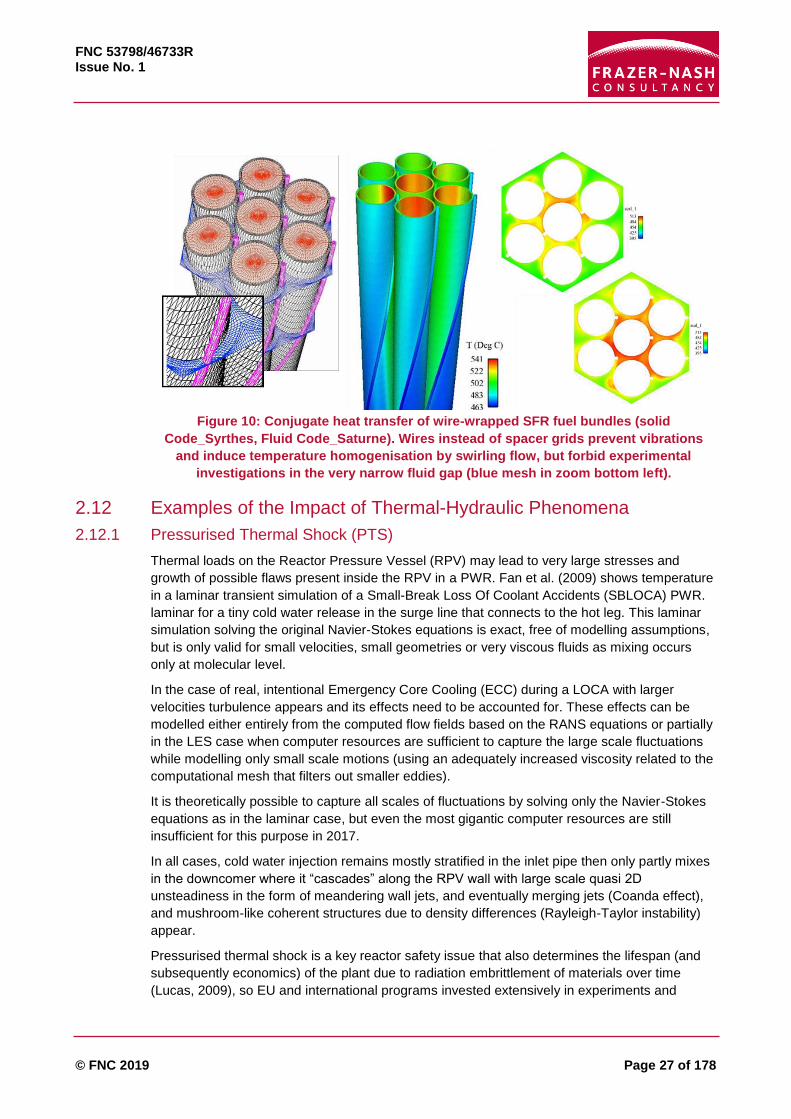
The geometry of SFR wire wrapped fuel pins is even more inaccessible and pose severe
meshing challenges because the contact point rotates, as shown in Figure 10. Bundle casing
side effects have been noted (Rolfo et al., 2012) and the actual design contains not 7 but 217
pins. Argonne National Laboratory (ANL) is computing the latter with the first principles code
NEK 5000 and offering it as benchmark to the international community (Merzari et al. 2016).
Modelling of the small details and small scale flow features are needed to enable the prediction
of important reactor parameters. However, studies of this level of detail over entire bundles, let
alone entire reactors are not generally practicable.
FNC 53798/46733R Issue No. 1
© FNC 2019 Page 27 of 178
Figure 10: Conjugate heat transfer of wire-wrapped SFR fuel bundles (solid
Code_Syrthes, Fluid Code_Saturne). Wires instead of spacer grids prevent vibrations
and induce temperature homogenisation by swirling flow, but forbid experimental
investigations in the very narrow fluid gap (blue mesh in zoom bottom left).
2.12 Examples of the Impact of Thermal-Hydraulic Phenomena
2.12.1 Pressurised Thermal Shock (PTS)
Thermal loads on the Reactor Pressure Vessel (RPV) may lead to very large stresses and
growth of possible flaws present inside the RPV in a PWR. Fan et al. (2009) shows temperature
in a laminar transient simulation of a Small-Break Loss Of Coolant Accidents (SBLOCA) PWR.
laminar for a tiny cold water release in the surge line that connects to the hot leg. This laminar
simulation solving the original Navier-Stokes equations is exact, free of modelling assumptions,
but is only valid for small velocities, small geometries or very viscous fluids as mixing occurs
only at molecular level.
In the case of real, intentional Emergency Core Cooling (ECC) during a LOCA with larger
velocities turbulence appears and its effects need to be accounted for. These effects can be
modelled either entirely from the computed flow fields based on the RANS equations or partially
in the LES case when computer resources are sufficient to capture the large scale fluctuations
while modelling only small scale motions (using an adequately increased viscosity related to the
computational mesh that filters out smaller eddies).
It is theoretically possible to capture all scales of fluctuations by solving only the Navier-Stokes
equations as in the laminar case, but even the most gigantic computer resources are still
insufficient for this purpose in 2017.
In all cases, cold water injection remains mostly stratified in the inlet pipe then only partly mixes
in the downcomer where it “cascades” along the RPV wall with large scale quasi 2D
unsteadiness in the form of meandering wall jets, and eventually merging jets (Coanda effect),
and mushroom-like coherent structures due to density differences (Rayleigh-Taylor instability)
appear.
Pressurised thermal shock is a key reactor safety issue that also determines the lifespan (and
subsequently economics) of the plant due to radiation embrittlement of materials over time
(Lucas, 2009), so EU and international programs invested extensively in experiments and

FNC 53798/46733R Issue No. 1
© FNC 2019 Page 28 of 178
extreme simulations addressing this issue. Therefore, it is worth explaining, as a generic
example, why neither “downscaled” experiments nor simulations are sufficiently reliable to
determine the key parameter for the design of safety margins and lifespan of the vessel: what
are the real thermal stresses experienced by the embrittled sections of the vessel? The
coherent quasi 2D structures in the annular downcomer shown above “look like” the flow
visualisations from the Plexiglas adiabatic experimental rigs, but this does not mean that the
simulations, extrapolating from scaled experiment validations to actual reactor scale give an
accurate prediction of the heat flux into the RPV wall, for many reasons:
The Reynolds number in the RPV PTS is Re ~106, but experiments are at Re ~ 20,000.
Experiments also use sugar or salted water to reproduce density variations, but the Prandtl
number is then distorted (acceptable for large scale mixing but not down to the wall effects).
Besides, the full scale RPV may be in a different wall-roughness regime to the plexiglass.
Non-adiabatic steel rigs provide some solid temperature data, but no velocity, they are for
simplified geometries and measurements inside the steel are not available or strongly
attenuated.
Can the Nusselt number (dimensionless wall heat transfer), really be assumed to scale as
Nu Re0.8 because this correlation is for steady state mean pipe flow?
The wall heat transfer is highly sensitive to the 3D Turbulent Boundary Layer (TBL) which
scales down to much smaller scales at Re 106. The TBL is distorted in downscaled
experiments, absent in the laminar simulation and modelled by wall-functions (mean
velocity/wall-friction and temperature/wall-heat-flux steady state correlations) in the RANS
and LES simulations.
RANS or LES wall-functions are based on correlations derived from steady-state mean-
flow, very far from the meandering cascade and coherent structures seen here (a Log-law
velocity profile in a pipe flow is only established hundreds of diameters downstream of the
inlet). Simulations conducted for different Re, do not prove that Re number is high enough
to be unimportant, as standard wall functions are precisely based on equilibrium / Re
number invariance assumptions.
The approximations and uncertainties listed for the above pressurised thermal shock case may
or may not err on the conservative side. Heat transfer coefficients designed for mean thermal
fields (RANS) then applied to fluctuating temperatures lead to overvaluing. Even the more
advanced methods used in industry (Moriya et al., 2003) for evaluating the fluctuating heat
transfer from the ratio of power spectrum of a probe in the fluid and another in the solid is
erroneous. This is because it ignores the real 4D nature of the fluctuating thermal field in the
solid and assumes a planar wave: 𝑇(𝑦 = 0, 𝑡), i.e. homogeneous in the wall parallel 𝑥, 𝑧
directions. The real higher frequency fluctuations, on the other hand, will be damped
increasingly with depth (𝑦 < 0) by the wall thermal mass (a typical RPV is made of 70 mm alloy
plus 200mm steel). If the temperature map on the solid surface is non-uniform, 𝑇(𝑥, 𝑦 = 0, 𝑧, 𝑡)
peaks and troughs will penetrate as cones or wedges and diffuse in the 𝑥, 𝑧 directions,
attenuated by inertia and diffusive cancellation. It is therefore not known if the design safety
margins and plant life assessment are conservative.
2.12.2 T-Junction Thermal Mixing
Besides radiation decreasing the vessel resistance to emergency thermal shocks, thermal cycle
ageing of the piping materials over years is a key turbulence issue overlooked in earlier designs.
Welds are less resistant and located in areas where differential dilatation of pipes is constrained
by the geometry. Thermal stratifications also lead to stress accumulation but these are more
predictable than purely turbulence induced thermal stresses.

FNC 53798/46733R Issue No. 1
© FNC 2019 Page 29 of 178
In May 1998, a through-wall crack was discovered on the Residual Heat Removal system
(RHR) of the French Civaux 1 PWR only five months after finishing construction, resulting in
early pipe rupture and release of radioactive steam into the reactor building. It resulted in a hot
shutdown. Other non-through cracks were then detected in other piping systems. This accident
was classified as Level 2 on the INES scale. Later research found the cracks were due to
thermal striping (Stephan et al., 2002).
The crack happened downstream of a T-junction where two streams of fluid at different
temperatures encounter each other. The turbulent mixing of hot and cold fluid introduced
temperature fluctuations. Such temperature fluctuations penetrated into the wall of the pipe and
caused high-cycle thermal stresses which induced the subsequent fatigue cracking of the wall
material. The Japanese Tsuruga-2 and Tomari-2 PWR plants in 1999 and 2003 (Le Duff et al.,
2007) are two other accident examples among this type of safety incidents.
T-junction test cases were in collaborative projects set up to assess the predictive capabilities of
CFD techniques, for example the test rig by Vattenfall in Sweden. Data from this test have been
used specifically for an OECD CFD benchmark exercise (Smith et al., 2013a). The
computational results of 29 participants show that RANS models fail to predict a realistic mixing
between the fluids. The results were significantly better with scale-resolving methods such as
LES, showing fairly good predictions of the velocity field and mean temperatures. The
calculation predicts also similar fluctuations and frequencies observed in the model test.
Unfortunately such rigs focus on long straight inlet pipes to facilitate boundary conditions
whereas Tunstall et al. (2016a, 2016b) showed that most large scale fluctuations are generated
by the instability of a pair of Dean vortices generated in an upstream bend. This pair tends to be
asymmetric, one vortex larger than the other generating persistent swirl in the downstream pipe
and over the T-junction, which then switch over time, a phenomenon called “switch-swirling.
Figure 11: Swirl effects of upstream bend on TEE Junction flow Tunstall et al. (2016a,
2016b)
Test rigs are also limited by the fact that they have isothermal or adiabatic walls so
temperatures inside the walls cannot be validated. Extending a CFD simulation to include
temperatures inside solid walls is easy; it suffices to solve the same equation as in the fluid
while setting the convective velocity and turbulence generation to zero. Alternatively, the CFD
code can be coupled to a finite element structures code. Applied studies have so far only
considered mean temperatures, with some extensions to fluctuating temperatures inside the
solid by LES, and only recently by first principles DNS (Flageul et al., 2015; Wu et al., 2017).

FNC 53798/46733R Issue No. 1
© FNC 2019 Page 30 of 178
Material scientists can use this information to assess whether a component will fail through
high-cycle fatigue crack growth.
2.12.3 Tube Bundles
Flow around fuel pins are mostly guided and parallel so can be related to pipe flow correlations.
Tube banks in crossflow are more complex and mostly a concern for utilities regarding the life-
span of heat exchangers. In PWR steam generators the primary fluid flows inside thousands of
thin U-shaped tubes. Vibrations coupled with crossflow on the secondary side may induce wear
against support grids, and a few primary circuit tubes may be blocked without much effect on
efficiency but temperature heterogeneity needs to be studied. Secondary flow comes at all
angles of attack, crossflow in the lower inlet and outlet regions and the top 180° bends.
Despite a dozen PhD projects over the last 30 years at EDF R&D, downsizing of the whole
domain simply cannot be trusted to be predictive, even for the simplest square arrangement
exactly aligned with pressure gradient. The mean flow often exhibits non-symmetric solutions as
in Figure 12.
Figure 12: Flow across tube bundles are rarely symmetrical and steady (West, 2013)
Figure 13: Time averaged streamlines in tube array, Gap/Diameter = 0.2, 0.5, 0.6 and 0.75
All cases “inline” (horizontal) mean pressure gradient (Afgan, 2007)
For a Gap/Diameter (G/D) of 0.2, the flow is globally deflected to one side, and obviously to
conserve mass, pressure will build up on lateral end walls which will force the flow to be
deflected to the other side in another cross-section. It seems that a gap of 0.75 G/D is the
minimum for 2 symmetric vortices to be installed (although some vortex shedding is still
apparent on instantaneous snapshots). The actual design value is about 0.5 G/D, which is the

FNC 53798/46733R Issue No. 1
© FNC 2019 Page 31 of 178
most unstable case with room for only one vortex, but this one flips clockwise or anti-clockwise
in both tube-row and time.
To make LES feasible, a smaller computational domain is usually generated by assuming
periodic patterns (values at top open boundary equal to ones at bottom), but then the results are
sensitive to the number and parity of tubes 2x2, 3x3, 4x4, 5x5, etc. included between periodic
boundary conditions, which are presumed able to represent an infinite number of tubes. The
depth of the domain, where again periodicity is assumed, is also influential. A deeper domain
will allow more deflections. The patterns in Figure 13 should not be considered general.
LES has been useful in understanding the complexity and versatility of this type of flow,
because there was, for decades, an expectation to study a range of attack and inclination
angles, flow induced vibration, heat transfer, two-phase flows. A tube bank simulation, however,
needs to represent a very large section to be relevant to actual steam generator geometry,
perhaps up to 100’s of long tubes. Current HPC resources are insufficient for this, so unsteady
RANS models (URANS) seemed an alternative, but (with the qualification that this should not be
re-quoted out of context): “it is impossible to conclude other than that the quality level of the
URANS predictions is poor” (Iacovides et al., 2014). Concerningly, a large variation in flow
pattern and local heat transfer coefficient was exhibited by changing only the turbulence model.

FNC 53798/46733R Issue No. 1
© FNC 2019 Page 32 of 178
3 Current Practice and Procedures The body of work available covers several decades of world-wide government, academic and
industry collaborations, covering thousands of documents and hundreds of concepts. Because
of this scale, the coverage in this section is intended to highlight current trends and their
application to future tools for NPP design. In particular, the challenges of scaling and uncertainty
evaluation are discussed and a number of important references to NRC publications covering
additional areas are included.
3.1 Scaling
Scaling is key to the whole area of NPP design and safety assessment since a full-size reactor
experiment is not achievable and must be replaced by a clever combination of integral and
separate effects test facilities, ITF and SETF respectively, and simulation, tied together by
scaling principles. Dimensional analysis and the reduced number of significant parameters
enabled by the Buckingham π theorem is, therefore one of the most important tools in thermal
hydraulics.
System codes or 3D CFD can be used at full-size reactor scale because there is no limit to the
value of the dimensionless parameters (Reynolds, Froude, Euler, Weber, etc.) whereas they are
always distorted in the Integral Tests and more or less in SETF; e.g. in a simple friction and
buoyancy balance test a factor of 4 length scale reduction requires a 4-fold increase in
reference velocity to conserve the Reynolds number, but a factor of 2 reduction of the same
velocity to conserve the Froude number4.
Credibility of the simulations is established through a code-validation process by comparing the
results of the code’s prediction for separate-effect and integral-effect tests data. The codes are
then used to extrapolate from ITF values up to dimensionless parameter values of the actual
NPP.
ITFs are necessarily downscaled in some dimensions, size, volume, flow rate and power
otherwise they would cost as much as a full scale prototype and need a second real plant to
provide the heat or electricity replacing the nuclear energy in the instrumented vessel. ITFs are
intended to encompass multiple phenomena in transients and accident scenario, but cannot
conserve all dimensionless parameters. Moreover, fluid properties vary with pressure and
temperature during TH transients.
The SET data is essential in ensuring that codes are able to extrapolate from the downscaled
ITF to the actual scale of the phenomenon expected in the plant. This is possible since when
the SETs are focussed on a single phenomenon, the reduced number of dimensionless
parameters alleviates most of the down-scaling conflicts.
Scaling compromises in NPP TH are much more elaborate than the above simplistic
introduction and have been discussed by hundreds of experts over decades. The state of the art
CSNI report on scaling (Bestion et al., 2016b) is very timely and comprehensive, indeed “The
need for this document testifies the importance of scaling in nuclear technology, but also the
controversial evaluations of scaling-related findings by the scientific community”.
The CSNI “scaling” report covers in much detail the scaling distortion: technological limitations
in constructing and operating test facilities, and computer code scalability, uncertainty methods
across all aspects, and relationship of scaling and uncertainty, in measurements and in
4 at EDF R&D cooling tower plumes were studied in a water channel to gain a factor 10 on Re thanks to water/air viscosity ratio

FNC 53798/46733R Issue No. 1
© FNC 2019 Page 33 of 178
simulations. CSNI also usefully revisits the SET and IET matrices of 1996, adding more recent
data and acknowledges the much larger contribution of codes today and noted that even “failed
agreement” between different scaled experiments can be useful for code validation: if the code
can explain the discrepancy it adds credibility.
It is impossible to summarise further this 400-page review work and selection of 300 references,
but the 8 classes of scaling methods identified in Chapter 2 give an idea of its breadth (quoting):
1. Linear scaling: “The same aspect ratio and the same velocity in the model as in the
prototype. This approach can excessively distort gravity effects.”
2. Power-to-volume scaling: “This method conserves time and heat flux in the prototype and
can reproduce phenomena in which the gravity effect is significant. It is suitable to simulate
an accident in which flashing occurs during depressurisation. It was successfully used to
design most of the integral-effect test facilities.... However, when it is applied to a smaller
facility with the full height, due to the smaller area ratio, some important phenomena can be
distorted, for example, the excessive stored heat in structures...”
3. Three-level scaling: “The first step is an integral - or a global-scaling analysis to conserve
a single and/or a two-phase natural circulation flow, using a 1-D non-dimensional governing
equation of natural circulation. The second step is a boundary flow and inventory scaling. ...
In the last step, a local phenomenon scaling is performed to conserve the important
thermal-hydraulic phenomena occurring in each system… The three-level scaling method is
characterised by relaxing restriction on the length scale…”
4. Hierarchical 2-Tiered Scaling (H2TS): “The procedure consists of four stages, i.e. system
decomposition, scale identification, top-down analysis, and bottom-up analysis. At the first
stage, the system conceptually is decomposed into subsystems, modules, constituents,
phases, geometric configurations, fields, and processes. The scale identification … provides
the hierarchy for the characteristic volume fraction, spatial scale, and temporal scale. …by
dividing by the system’s response time based on a volumetric flow-rate. The top-down
scaling as in the 3rd stage offers a scaling hierarchy, using the conservation equations of
the mass, momentum, and energy in a control volume. ... All the processes can be
compared, and ranked for importance on the system to establish priority in the scaled
models. The bottom-up scaling, as the 4th stage of the method, offers a detailed scaling
analysis for key local phenomena, such as the CCFL and choking…”
5. Power to Mass Scaling: “This method determines scaled core-power according to the
initial coolant’s mass inventory in the reactor’s coolant system... The mass flow rate of the
core is scaled down according to the power and heat capacity relationship…”
6. Modified Linear Scaling: “The multi-dimensional behaviours of the Emergency Core
Cooling (ECC) water in the downcomer (e.g. the ECC bypass) are observed during the
LBLOCA refill phase. … Twelve dimensionless parameters were obtained from the two-fluid
momentum equations in the downcomer.”
7. Fractional Scaling Analysis (FSA): “FSA is a hierarchic approach similar to H2TS. In the
first step, the regions of interest and the durations of the transients are specified. The rate of
change of the state variables over the region are connected to the transfer functions defined
at the boundary, and inside the volume. The relative effect of components is based on their
relative impact on state variables in the transfer function connected to that component. ...
FSA offers a systematic method of ranking components and their phenomena in terms of
their effect on the Figure Of Merit (FOM), or the safety parameter. It can also estimate scale
distortions, and synthesise data from different facilities for the same class of transients. …”
8. Dynamical System Scaling (DSS): “To address the time dependency of scaling distortion,
[it converts] the transport equations into a process space through a coordinate

FNC 53798/46733R Issue No. 1
© FNC 2019 Page 34 of 178
transformation, and exploits the principle of covariance to derive similarity relationships
between the prototype and model. After the transformation, the target process can be
expressed in the process-time space as a three-dimensional phase curve, called geodesics.
.. Any deviation of the process curves represents the deviation of scaling as a function of
time… this generalised approach offers the benefit of identifying the distortion objectively
and quantitatively at any moment of the transient.”
3.2 Uncertainty Management
Thanks to wider usage of advanced mathematical/probabilistic theory and computer power this
science is rapidly progressing, breaking down and quantifying sources of uncertainty, improving
reliability of model predictions, planning of experiments, ultimately speeding up, reducing costs
and broadening the scope of engineering designs. Progress in Uncertainty Management will
radically change engineering and decision making in the future, particularly for NPP design and
licensing.
Rather than another catalogue of past practices, a brief overview is given of current trends in
Uncertainty Quantification (UQ) while concepts and maturity of this combined mathematics,
statistics and engineering science for predictive assessments of risk for design actions is
assessed in a recently published 2,000 page book by top international experts (Ghanem et al.,
2017b) with contributions from the NPP sector (Sandia National Labs, EDF R&D, CEA etc.)
(Baudin et al., 2017; Beck and Zuev, 2017; Mousseau and Williams, 2017; Rider et al., 2015).
3.2.1 Uncertainty Quantification and Conservative Safety Limits
In a nutshell, a safety analysis element or result that is within limits specified by regulators is
“conservative” when at each stage the most pessimistic choices have been made for baseline
models, codes, initial plant conditions, readiness of equipment and accident sequences.
“Best estimate” models and codes provide the most realistic estimate (based on current
knowledge) of individual phenomena and overall response of the plant during an accident,
assuming the plant is as built and operations as designed. Obviously error bands around the
best estimate need to be carefully calculated for the predicted result to be of any usefulness.
Safety regulations of the 70s were based on large global safety margins to compensate “lack of
knowledge or confidence”, and so model predictions in each worst case scenario were expected
to demonstrate that the design and operation procedures were “conservative”. This mostly
involved checking that a single value predicted by the licensing applicant was below a severe
threshold set by regulators. Therefore, all the protection against “lack of knowledge or
confidence” (used here instead of “uncertainty” which has a clearer probabilistic sense) in the
acceptable threshold determination and design value prediction methods was lumped into the
conservative limit. “Sensitivity” to input parameters and different models was recommended, but
this was down to rather ad-hoc user choices.
Uncertainty Quantification is in a way the reverse approach to raising the final thresholds. It
ensures that predicted values are framed by realistic error bands, confidence intervals or
probability distributions. In complex systems the uncertainty can be propagated from input
parameter probabilities throughout all components of the modelling process. It is then easier to
assign an uncertainty measure to each stage and mathematical tools enable this is to be
transferred to a total uncertainty around the final result. Forward uncertainty propagation can be
by brute force Monte Carlo simulation or mathematical manipulation of equations such as
polynomial chaos expansions.

FNC 53798/46733R Issue No. 1
© FNC 2019 Page 35 of 178
In Monte Carlo, sensitivity analysis input values are simply randomly sampled. The number of
required simulations rapidly increases with degrees of freedom. Latin Hypecube Sampling more
efficiently maps the field of input values with each one representing an equi-probable section of
the fields. This brute force empirical method still requires large statistical samples and thus is
potentially very costly. Alternatively, models can be enhanced with multiple regression on input
variables (least squares fit plus confidence interval).
In thermal hydraulics, UQ developed rapidly and naturally around System codes and CFD in the
2000’s (RANS model, after all, based on predicting mean behaviour plus variance). Inserting
probability density functions into the NS equations is common in e.g. reacting flows or two-
phase flow bubble size distribution (population balance) models. A Best Estimate Plus
Uncertainty (BEPU) approach is more realistic than “Conservative” assumptions. The latter
might drive safety margins on the basis of impossible events, but neglect other combinations,
for example, the co-incidence of two “less serious” and more frequent events with a more
severe combined outcome.
3.2.2 Best Estimate Plus Uncertainty (BEPU) Development and Acceptance
Quantification of Margins and Uncertainty (QMU) originated in the 1990’s mainly from HPC
equipped Lawrence Livermore, Sandia and Los Alamos National Labs. Along with HPC it is now
developing in all complex engineering where experimentation and modelling have limitations.
Around 2000, HPC became more widespread and system codes had been sufficiently validated
to allow a statistical approach. Complexity and multiple unknowns in LBLOCA accident studies
was an obvious application area for the researchers and NPP designers, but authorities needed
to be convinced before these could be included in Safety Analysis Reports (SAR) submitted to
licensing. Transients such as LOCA mitigating measures must lead to “conservative” parameter
values defined by regulators, e.g. Peak Cladding Temperature (PCT) or a maximum overall
oxidation value to limit hydrogen release. The safety margins were added to values determined
by simple empirical models to account for limited confidence in peak value predictions and
unknown effects. Other “conservative” measures were more qualitative than numerical but erred
on the pessimistic side e.g. degraded cooling effects (high steam/water ratio), geometrical
deformation (ballooning blocking of coolant passages), required duration of cooling, etc. These
are described in the vast safety regulations documents of the U.S. (NRC) or IAEA, which are
publically available e.g. for emergency cooling:
Code of Federal Regulations, Title 10, “Energy,” Part 50, “Domestic Licensing of Production
and Utilization Facilities,” Appendix K, “ECCS Evaluation Models,” U.S. Nuclear Regulatory
Commission (1996).
“Accident Analysis for Nuclear Power Plants,” IAEA Safety Reports Series, No. 23,
International Atomic Energy Agency (2002).
In the US, Code Scaling Applicability and Uncertainty (CSAU), and Phenomena Identification
and Ranking Table (PIRT) marked the kick-off of a variety of code simulation and statistical
uncertainty quantification methods developed around the world, with an associated flurry of
acronyms now designated under the common name BEPU. Wilson (2013) gives a historical
perspective of the original CSAU and PIRT processes and subsequent improvements through to
2010 in BEPU methodologies.
Initially the methods acceptable in safety analysis reports were combined: BEPU was
acceptable only in the computer code part while availability of systems as well as initial and
boundary conditions remained conservative. Gradually, the latter 2 physical inputs are being
replaced by BEPU, i.e. realistic thermomechanical values, whereas for readiness of equipment,
harder to mathematically quantify, is still based on conservative assumptions.

FNC 53798/46733R Issue No. 1
© FNC 2019 Page 36 of 178
The previously described extensive work on cataloguing, quality and completeness assessment
of SET and ITF data by OECD/CSNI enabled a better evaluation of the degree of confidence in
system codes predictions. CSNI then promoted a number of international conferences around
uncertainty methodologies leading to a flurry of publications from academics and industrial
stakeholders.
A summary and independent view of these international efforts to use BEPU for licensing can
be found by Prošek and Mavko (2003). An overview of the theories and application examples to
LOCA is given by Prošek and Mavko (2007). Bucalossi et al. (2010) show the benefits of BEPU
over the conservative approach in terms of increased margins to acceptance criteria. D’Auria et
al. (2006) detail the process, qualification issues and sources of uncertainty for operating
system codes under BEPU and licensing issues are discussed in e.g. D’Auria et al. (2012),
Glaeser (2006), and Hrehor et al. (2007).
Beyond system codes applied to LOCA, Unal et al. (2011) make a case to stakeholders and US
NRC for extending BEPU to multiphysics modelling and simulation and extending applications
even beyond the code’s validation and calibration range thanks to data assimilation.
To conclude, there is now a wealth of theory and demonstration papers clearly addressed to
Licensing Authorities who monitor and interact on this research progress and will probably
decide when BEPU is mature enough to advantageously replace conservative margins. A
selection of BEPU papers with quite explicit titles is simply listed below.
Theory
“The State-of-the-Art Theory and Applications of Best-Estimate Plus Uncertainty Methods”
(Prošek and Mavko, 2007).
“Review of best estimate plus uncertainty methods of thermal-hydraulic safety analysis”
(Prošek and Mavko, 2003).
“Historical insights in the development of Best Estimate Plus Uncertainty safety analysis“
(Wilson, 2013).
“Comparison between Best-Estimate Plus Uncertainty Methods and Conservative Tools for
Nuclear Power Plant Licensing” (Bucalossi et al., 2010).
“Perspectives on the application of order-statistics in best-estimate plus uncertainty nuclear
safety analysis “ (Martin and Nutt, 2011).
“State of the art in using best estimate calculation tools in nuclear technology” (D’Auria et
al., 2006).
Licensing
“The Best Estimate Plus Uncertainty (BEPU) approach in licensing of current nuclear
reactors” (D’Auria et al., 2012).
“Task Group on Safety Margins Action Plan (SMAP) Safety Margins Action Plan - Final
Report “ (Hrehor et al., 2007).
“Evaluation of Licensing Margins of Operating Reactors Using ‘Best Estimate’ Methods
Including Uncertainty Analysis “ (Glaeser, 2006).
“Improved best estimate plus uncertainty methodology, including advanced validation
concepts, to license evolving nuclear reactors “ (Unal et al., 2011).
BEPU Application examples
“Analysis of LBLOCA using best estimate plus uncertainties for three-loop nuclear power
plant power uprate “ (Kang, 2016).

FNC 53798/46733R Issue No. 1
© FNC 2019 Page 37 of 178
“Best estimate plus uncertainty analysis of departure from nucleate boiling limiting case with
CASL core simulator VERA-CS in response to PWR main steam line break event” (Brown et
al., 2016).
“RELAP5 Code Analysis of LSTF Small Break LOCA Tests With Steam Generator
Intentional Depressurization as an Accident Management Procedure: Investigation on Base
Case Result Appropriate for the Best Estimate Plus Uncertainty (BEPU) Application”
(Kinoshita et al., 2014).
“Application of the best-estimate plus uncertainty approach on a BWR ATWS transient
using the NURESIM European code platform” (Perin and Escalante, 2017).
“Application of the best estimate plus uncertainty method to the small break LOCA with high
pressure injection failure: Effect evaluation of the model uncertainty on the safety evaluation
parameter” (Torige et al., 2015).
“Application of the Best Estimate Plus Uncertainty method to the small break LOCA with
high pressure injection failure: Uncertainty quantification of the RELAP5 model related to
fuel clad oxidation, decay heat, fuel clad deformation and SG U-tube condensation” (Torige
et al., 2014).
3.3 US NRC (Nuclear Regulatory Commission)
The NRC oversees reactor safety and security, administering reactor licensing and renewal,
licensing radioactive materials, radionuclide safety, and managing the storage, security,
recycling, and disposal of spent fuel.
The NRC documents complete collections online5, including ADAMS, the Agency wide
Documents Access and Management System6, which contains ¾ million full text online
publically available documents and 2 million pre-1980 document bibliographic citations.
Progress in risk management and modelling techniques is carefully monitored by NRC and
eventually accredited, backed by massive record keeping for public inspection, but also for
guidance and training to stakeholders. Using keywords from the present literature review, the
database can be consulted to check currently acceptable practices.
3.4 OECD/NEA
The NEA offers technical knowledge bases to assess the safety of nuclear reactors and fuel
cycle facilities and promotes research or the sharing of data on a cost-sharing basis:
Ongoing experimental projects7
Ongoing event records database projects7
Completed projects
CSNI Code Validation Matrix Integral Test Data8
CSNI Code Validation Matrix Separate Effects Test Data9
Quite relevant herein are the CFD for Nuclear Reactor Safety Applications (CFD4NRS)
workshops and reports providing guidance on CFD application to NRS. The Committee is made
up of senior scientists and engineers, with broad responsibilities for safety technology and
research programmes, and representatives from regulatory authorities:
5 https://www.nrc.gov/reading-rm/doc-collections/ 6 https://www.nrc.gov/reading-rm/adams.html 7 http://www.oecd-nea.org/jointproj/ 8 https://www.oecd-nea.org/dbprog/ccvm/ 9 https://www.oecd-nea.org/dbprog/ccvm/indexset.html

FNC 53798/46733R Issue No. 1
© FNC 2019 Page 38 of 178
“Best Practice Guidelines for the use of CFD in Nuclear Reactor Safety Applications”,
NEA/CSNI/2(2014)1110 (Mahaffy et al., 2014).
“Assessment of CFD Codes for Nuclear Reactor Safety Problems - Revision 2”,
NEA/CSNI/R(2014)1211 (Smith et al., 2015).
“Extension of CFD Codes Application to Two-Phase Flow Safety Problems - Phase 3”,
NEA/CSNI/R(2014)1312 (Bestion et al., 2014).
“Review of Uncertainty Methods for Computational Fluid Dynamics Application to Nuclear
Reactor Thermal Hydraulics”, NEA/CSNI/R(2016)413 (Bestion et al., 2016c).
“Uncertainty and sensitivity analysis of QUENCH experiments using ASTEC and
RELAP/SCDAPSIM codes”, (Vileiniškis et al., 2014).
10 https://www.oecd-nea.org/nsd/docs/2014/csni-r2014-11.pdf 11 https://www.oecd-nea.org/nsd/docs/2014/csni-r2014-12.pdf 12 https://www.oecd-nea.org/nsd/docs/2014/csni-r2014-13.pdf 13 https://www.oecd-nea.org/nsd/docs/2016/csni-r2016-4.pdf
FNC 53798/46733R Issue No. 1
© FNC 2019 Page 39 of 178
4 System and Subchannel Codes A large number of computer codes have been developed to design, analyse and operate
nuclear reactor systems. Modern nuclear reactor systems operate at a level of sophistication
whereby human reasoning and theoretical models alone are not capable of bringing to light full
understanding of a system's response to some proposed perturbation. There is, however an
inherent need to acquire such understanding, notably for safety analyses. Over the last few
decades there has been a concerted effort on the part of the power utilities, regulatory bodies,
research organisations and academia to develop advanced computational tools for simulating
reactor system thermal hydraulic behaviour during real and hypothetical transient scenarios.
The presence of two-phase flows poses additional complications not encountered with single-
phase flows:
The thermo-physical properties (notably the density, viscosity, and thermal conductivity) of
two-phase flows are not readily available as is the case with single-phase flows, and cannot
be simply calculated by averaging the liquid and vapour values as the two phases normally
flow at different velocities and the apparent density, viscosity and thermal conductivity of the
mixture changes dynamically with the flow pattern.
The two phases can arrange themselves in a variety of flow patterns, and the flow pattern
largely controls the physics of the two-phase flow.
Mass, linear momentum and energy are exchanged through the interface that separates the
two phases, which changes dynamically in time.
Two-phase flows are intrinsically intermittent with local time constants that may differ by
orders of magnitude, implying that two-phase flow simulations should be time varying and
capable of handling phenomena that vary very fast as well as slowly varying ones.
The presence of evaporation, condensation and mass transfer between the phases, and
their dependence on complicated phenomena such as surface morphology for flow boiling
and the presence of non-condensable gases for condensation.
Thermodynamic non-equilibrium phenomena that appear in sub-cooled flow boiling and in
evaporation beyond the boiling crisis.
There are broadly two categories of non-CFD thermal hydraulic analysis tools applied in nuclear
power plant design; system codes (Section 4.1) and subchannel codes (Section 4.2).
4.1 System Codes
System codes are conceived to deal with the entire nuclear power system and predict its overall
behaviour during numerous scenarios that span both normal and off-normal operating
conditions, including the extreme transients encountered during severe accidents. System
codes must thus be able to simulate every sub-system and component present in the system,
together with their respective couplings and all relevant physical phenomena and processes
that characterise their behaviour.
System codes contain many more empirical correlations than 3D CFD codes (Section 5), but
System Codes have been extensively validated on a much wider range of NPP-specific test
cases than CFD and will remain a major modelling tool in this sector. However, as they are
custom-made for PWRs mostly and a few gas or liquid metal cooled reactors, novel design
exploration might rely increasingly on CFD codes, where the modelling is less geometry specific
and empirical and they are validated on a much wider range of flows and fluids across many
industrial sectors. An example of the level of detail represented by a typical system code model
is shown in Figure 14.

FNC 53798/46733R Issue No. 1
© FNC 2019 Page 40 of 178
The principal system codes currently in use in the nuclear industry worldwide are RELAP,
TRACE, CATHARE and ATHLET: these codes are briefly described in the following
subsections.
Figure 14: Representative example of RELAP5 nodalisation (Takeda et al., 2012)
4.1.1 ATHLET
The thermal hydraulic computer code ATHLET (Analysis of Thermal-Hydraulics of LEaks and
Transients)14 is being developed by the Gesellschaft fur Anlagen und Reaktorsicherheit (GRS)
for the analysis of operational conditions, abnormal transients and all kinds of leaks and breaks
in nuclear power plants (Di Marcello et al., 2016, 2015; Glaeser, 1995; Hainoun and Schaffrath,
2001; Kirmse et al., 1995; Zhou et al., 2012). The code covers the whole spectrum of design
basis and beyond design basis accidents (without core degradation) for PWRs, BWRs, SMRs
and future Gen IV reactors with one single code.
ATHLET-CD (Core Degradation) has been developed for accidents with core damage to extend
the simulation to include mechanical fuel behaviour, core melting and relocation, debris bed
formation as well as fission product release and transport. The range of working fluids covers
light and heavy water enabling the transition between subcritical and supercritical fluid states,
and uses the same input deck as ATHLET.
In addition, ATHLET can simulate advanced reactor coolants (helium, liquid metal and molten
salt), although these extensions are subject to further development and validation. Numerous
institutions in Germany and abroad are applying ATHLET, and the German Federal Ministry for
Economic Affairs and Energy (BMWi) sponsors its development and validation.
4.1.2 CATHARE
The CATHARE code (Code for Analysis of THermalhydraulics during an Accident of Reactor
and safety Evaluation) is a two-phase thermal hydraulic simulator. Code development began in
1979 at CEA-Grenoble as part of an agreement between the CEA, EDF, AREVA and the IRSN
(Bandini et al., 2011; Barre and Bernard, 1990; Bestion, 1990; Emonot et al., 2011; Geffraye et
al., 2012, 2011; Valette et al., 2011). The software is currently in its third major revision and is
14 https://www.grs.de/en/computer-code-athlet

FNC 53798/46733R Issue No. 1
© FNC 2019 Page 41 of 178
used, in particular, for PWR safety analyses, verification of post-accidental operating
procedures, and research and development.
CATHARE has a modular structure capable of operating in 0D, 1D or 3D. It is capable of
modelling any type of water-cooled reactor (PWR, RBMK, VVER, etc.), several types of system
loop and also contains a module capable of simulating the behaviour of a nuclear reactor
containment vessel in the event of a break in either the primary or secondary circuit. It is
capable of simulating the physical phenomena that occur during small and large-break loss-of-
coolant accidents, steam generator tube ruptures, feed water line breaks, residual heat removal
failures and steam line breaks.
For the investigation of transients leading to severe reactor core degradation (severe accident),
CATHARE has been linked to the ICARE software. CATHARE has also been integrated into the
IRSN SOFIA (Simulateur d’Observation du Fonctionnement Incidentel et Accidentel) accidental
simulator for the EDF reactors. This simulator is used to train specialists, prepare crisis
management exercises and to carry out studies in support of reactor assessments.
4.1.3 RELAP
The RELAP5-3D (Reactor Excursion and Leak Analysis Program - Three-Dimensional) code is
part of a series of computer programs developed at Idaho National Laboratory (INL) for
modelling nuclear power plants (Berar et al., 2013; Guillen et al., 2006; Hoffer et al., 2011; Hou
et al., 2017; Mangal et al., 2012; Mesina, 2016, 2010; Mesina et al., 2014). The first RELAP
code release was funded by the US Atomic Energy Commission, which is now the US NRC, to
model small-break loss-of-coolant accidents specifically for PWRs.
In the early 1980s, the United States Department of Energy (US DOE) began sponsoring
additional RELAP5 development, which continued until 1995 up to the release of
RELAP5/MOD3.2. At this point, the code was split into a US NRC version (TRACE) and a US
DOE version (RELAP5-3D).
The RELAP5-3D code maintains the proven performance and validation history of
RELAP5/MOD3.2 with additional enhancements, including a fully integrated, multi-dimensional
thermal hydraulic and kinetic modelling capability, a new matrix solver for 3D problems, new
water properties and improved time advancement.
RELAP5-3D’s modelling capability has expanded to include large-break loss-of-coolant
accidents and operational transients for PWRs, BWRs, MSRs, LMFRs, HTGRs, supercritical
fluid and advanced reactor designs. Most recently, RELAP5-3D is being applied to model
advanced reactor designs such as small modular reactors and a traveling wave reactor.
The RELAP code is also installed in nuclear plant operator training simulators at many sites
around the world and in universities and research centres to train operators on basic reactor
dynamics. Notably, the RELAP code is used in industry, research centres and academia for pre-
test and post-test simulations to support the design of nuclear thermal hydraulics test facilities,
and interpret the experimental data that these provide.
4.1.4 TRACE
The code TRACE (TRAC-RELAP Advanced Computational Engine) is the thermal hydraulics
analysis tool used by the US NRC for nuclear reactor design licensing in the USA (Berar et al.,
2013; Freixa and Manera, 2011; Jaeger et al., 2013; Lin et al., 2014; Mascari et al., 2011; Wulff,
2011). The code consolidates and extends the capabilities of NRC's 3 legacy safety codes:
TRAC-P (system code originally designed to model large-break loss-of-coolant accidents and
system transients for PWR reactors), TRAC-B (system code originally designed to model small

FNC 53798/46733R Issue No. 1
© FNC 2019 Page 42 of 178
and large-break loss-of-coolant accidents and system transients for BWR reactors) and RELAP
(see above).
TRACE is able to analyse small and large-break loss-of-coolant accidents and system
transients in both PWRs and BWRs. The capability exists to model thermal hydraulic
phenomena in both one-dimensional and three-dimensional space.
4.2 Subchannel Codes
The whole plant behaviour, as predicted by system codes, is only part of the process of
determining the thermal hydraulic operating limits and safety margins of a reactor because the
representation of a reactor core is coarse grained to the point where the behaviour in individual
channels is not captured (Figure 14). The thermal hydraulic safety margins of most reactors are
currently assessed using subchannel analysis codes, where the governing equations of mass,
momentum and energy are solved in control volumes that are resolved at a level of the gaps
between individual fuel rods.
The flow distributions in the rod bundle geometries are predicted by empirical correlations for
heat and momentum transfer at surfaces and interfaces, as well as inter-channel mixing models
to account for the transport between adjacent sub-channels. These subchannel codes require
empirical correlations to be implemented and are a representation of intermediate level of detail:
they are coarser than a CFD model, but resolved sufficiently to provide estimations of the local
conditions of the sub-channels in the limiting fuel assembly of the core. Subchannel codes
involve more complex representations of the physics of thermal hydraulic phenomena than
system codes, and are required to predict local fuel temperature, void fraction, and the margin
to CHF.
Increased computing power has allowed subchannel codes to represent entire reactor cores,
rather than just a single channel, and have progressively added 3D solution features, resulting
in a gradual overlap with lower-resolution forms of CFD. Another technique that has approached
this functionality, but from the opposite direction is Coarse-Grid-CFD where flow between fuel
pins and large and medium scale flow features are simulated, but at a lower fidelity than ‘true’
CFD.
Examples of subchannel codes in current use and under further development are CTF, FLICA,
SUBCHANFLOW and VIPRE.
4.2.1 CTF
The COBRA (COolant Boiling in Rod Arrays) software was developed to solve the flow and
enthalpy distribution in nuclear fuel rod bundles and cores by Pacific Northwest National
Laboratory (PNNL) in the 1960s. This was expanded by PNNL in 1980 under sponsorship of the
US NRC to form the original COBRA-TF (Two-Fluid) code. Since then, various organisations
have adapted and further developed the code, resulting in many other COBRA variants, such as
F-COBRA-TF, COBRA-FLX, COBRA-IE, MATRA and ASSERT-PV (Galimov et al., 2015).
CTF is the name given to the version of COBRA-TF developed and maintained by Oak Ridge
National Laboratory (ORNL) and the Reactor Dynamics and Fuel Modelling Group (RDFMG),
initially at Pennsylvania State University, and currently at North Carolina State University
(NCSU). CTF is based on a separated flow representation of two-phase flow into three fields:
liquid film, liquid droplets and vapour. It is capable of modelling solid structure and fluid regions
within the core under normal operation and accident scenarios. Improvements in CTF include
turbulent mixing, void drift and grid-spacer heat transfer enhancement.

FNC 53798/46733R Issue No. 1
© FNC 2019 Page 43 of 178
CTF has recently been included in two large projects: US DOE CASL and European
Commission (EC) NUclear REactor SAFEty simulation platform (NURESAFE). This has led to a
number of developments within the code and resulted in a significant amount of verification and
validation testing. CTF has also been integrated into the Virtual Environment for Reactor
Applications (VERA) Core Simulator environment, and work is underway to modify and validate
CTF for MSR and SFR reactor technologies.
4.2.2 FLICA
FLICA-4 is a 3D two-phase flow code for reactor core analysis that began development in the
1970s at CEA (Fillion et al., 2011). It uses a four-equation mixture model (mass, momentum and
energy of mixture and mass of vapour) with a drift-flux model to simulate the relative velocity
between phases.
CEA began developing FLICA-OVAP in 2005, which builds on FLICA-4 and includes both a two-
fluid two-phase flow model and a multi-field model that accounts for both liquid and vapour
phases. The FLICA-OVAP platform incorporates both subchannel and CFD scale applications
and can be coupled to multi-physics and multi-scale applications.
FLICA was used as part of the EC NURESAFE project, and can be applied to two-phase flow in
PWRs and BWRs.
4.2.3 SUBCHANFLOW
SUBCHANFLOW is based on COBRA and was developed by the Institute for Neutron Physics
and Reactor Technology (INR) at the Karlsruhe Institute of Technology (KIT).
SUBCHANFLOW is a single- and two-phase (three-equation mixture model) subchannel code
that is used to simulate core geometries built from rectangular and hexagonal fuel bundles.
Empirical correlations are then used for pressure drop, heat transfer coefficient and void
generation with mixture equations for wall friction, wall heat flux and slip velocity. The solution
progresses axially up the core, which limits the code to cases with positive flow up the core.
SUBCHANFLOW was used as part of the EC NURESAFE project, and can be coupled to a
number of multi-physics codes. It includes properties for liquid metal, water, helium, and air, and
so can be applied to PWRs, SFRs, LFRs and HTGRs.
4.2.4 VIPRE
VIPRE-01 (Versatile Internals and component Program for REactors) was originally developed
from COBRA by Battelle Pacific Northwest Laboratories under sponsorship of the Electric
Power Research Institute (EPRI). The VIPRE User Group is run by Zachry Nuclear Engineering
Inc., who manage the maintenance and development of the code for member organisations and
EPRI.
VIPRE-01 predicts the three-dimensional flow field and fuel rod temperatures for single- and
two-phase flow in PWR and BWR cores for an interconnected array of channels. It solves the
finite-difference equations assuming homogeneous equilibrium (empirical models are included
for vapour/liquid slip and subcooled boiling) incompressible flow with no time-step or channel
size restrictions for stability.
4.3 Summary
System and subchannel codes have been developed since the start of the application of
computer analysis to nuclear thermal hydraulics. They have gradually been developed and can
deal with many of the complexities of nuclear power systems. System codes are the only tool

FNC 53798/46733R Issue No. 1
© FNC 2019 Page 44 of 178
presently available that are capable of predicting the overall performance of a nuclear power
system and its evolution during transients and accidents.
The system and subchannel codes are all based on best-estimate methodologies: this approach
aims at providing a detailed realistic description of postulated accident scenarios based on best-
available modelling methodologies and numerical solution strategies sufficiently verified against
experimental data from differently scaled separate effect test and integral effect test facilities.
Nearly all current two-phase flow models used in present best-estimate thermal hydraulic
system codes are based on the so called two-fluid model (Bestion, 2008; Levy, 1999; Todreas
and Kazimi, 1990). Phases are treated as interpenetrating continua and macroscopic separate
balance equations for each phase are obtained by a space and/or time or ensemble averaging
of the local instantaneous basic flow equations, with source terms representing the interfacial
transfers for mass, momentum and energy. The presence of different flow patterns in two-phase
flow is recognised by implementing different closure laws for mass, momentum and energy
exchange that are tailored to each specific flow pattern.
Physical models are required in system and subchannel codes to close the system of equations.
Closure relationships concern mass, momentum, and energy exchanges between phases and
between each phase and the wall. Specific separate effect tests are performed and analysed to
investigate two-phase flows in conditions representative of the reactor transients to be
simulated. Based on these data new correlations are developed when existing models were not
satisfactory. The degree of empiricism depends on the comprehension of the physical
mechanisms involved. Modern system and subchannel codes implement so many empirical
correlations that it would be impractical to provide a complete review here.

FNC 53798/46733R Issue No. 1
© FNC 2019 Page 45 of 178
5 Computational Fluid Dynamics (CFD) CFD simulations provide predictions of 3D and time dependent velocity, pressure, temperature
fields, by numerical solution of fundamental partial differential equations, on meshes which
divide the domain of interest into cells. When turbulent eddies, droplets or bubbles are small
compared to the cell size, their effects still need to be modelled. CFD often includes
multipurpose empirical models for small scale features which cannot be captured on meshes
comprising millions of cells (as are often employed by industry).
Currently the use of CFD in the design of NPP is often limited by both the timescales/cost
associated with performing the modelling and uncertainty in the final predictions. As computing
power grows and the costs of finer meshes are reduced, there is the potential for CFD to
employ fewer modelling assumptions and inevitably CFD will be used for a wider range of
applications. As System codes integrate more 3D modules and commercial CFD codes provide
easy-to-implement 1D links between components the frontier between the two becomes blurred.
With this flexibility one can envisage a gradual and automatic evolution of the simulation from a
coarse quick prototyping idea to a fully refined geometry as the idea matures.
CFD is another chapter that would need to be blown up to encyclopaedic proportions to give an
impartial and comprehensive picture of its inception, 50 years evolution, current practises and
progress due to exponential growth of affordable computer power. This section is shaped by the
excellent and timely contribution (by the Chief Editor of the journal of Nuclear Engineering and
Design) to the TH of nuclear reactors handbook:
Hassan, Y., (2017). “An overview of computational fluid dynamics and nuclear applications”,
in: D’Auria, F. (Ed.), Thermal-Hydraulics of Water Cooled Nuclear Reactors. Woodhead
Publishing, pp. 729–829.
Hassan’s presentation (which at 100 pages is still brief) is highly relevant because it
concentrates on the heart of NPP TH modelling by avoiding the easy route of bland technical
overview, it explains why “Some think that the CFD is promising and can play a key role in
nuclear thermal fluid problems now and in the near future, while others think that CFD is not
reliable compared to the experiment and it will take a very long time”. In short, CFD is now a
very mature self-standing technology, developed and applied in all areas of Engineering, but
due to the complexity of its practice, the reliability of CFD results is reliant on user expertise and
validation for a given range of applications.
Best Practice Guidelines and thorough validation has been the aim of numerous international
efforts, particularly in the NPP sector which Hassan was also able to reasonably summarise,
notably the large efforts by OECD/ NEA/CSNI, and CFD4NRS series of Workshops, with both
praise and criticisms (which we share).
To summarise Hassan’s synopsis of a “work-in-progress building site” the list below reproduces
some of the NPP TH CFD modelling insights he provided:
Motivation for CFD in NPP: is the right representation of CFD available to decision makers
and end users?
Emphasising differences between CFD and System TH codes: what System TH codes
cannot do.
The ideal and real in nuclear thermal fluid CFD:
Ideal: 3D computed data is accurate, reliable and trustworthy.
Real: the need to calibrate, verify and validate models against the results of experiments.
Emphasising the issues with System TH codes that CFD codes cannot address.

FNC 53798/46733R Issue No. 1
© FNC 2019 Page 46 of 178
Detailing the variety of NPP TH problems which can be addressed by CFD analysis.
Addressing the difficulties in applying CFD analysis to nuclear thermal hydraulic problems.
As a complement we will explain why the same approach of extending mathematically sound
finite element approach to continuum mechanics to fluid flow simulation has failed. Instead the
exotic and disparate range of ‘recipes’ developed separately by hundreds of fluid-dynamists
finally converged toward unstructured-grid finite volumes in 3 world-leading commercial codes,
Fluent, CFX, STAR-CCM+, and in the open source OpenFOAM and Code_Saturne.
5.1 Finite Volume Codes
What can be notable to numerical engineers outside of the discipline is the large variety of
different CFD methods that have been developed. Conversely, the structures and solid
mechanics communities settled on Finite Elements with a clear breakdown of the problem
solving steps into:
Meshing; easily automated when using tetrahedrons;
Discretisation; mathematical transformation of partial differential equations (p.d.e.) into a
system of algebraic linear equations, e.g. integrating by parts the beam p.d.e. pre-multiplied
by known shape functions several times;
Linear systems solvers; vector-matrix product inversion, which can be efficiently executed
by computers; and
Post-processing.
Each of these steps was highly optimised by specialists from different disciplines, especially
applied mathematics, while physicists could focus on the phenomena with little FE expertise.
In fluid dynamics, the variety of phenomena originating from the non-linearity of the p.d.e. is so
broad that for each one, a different CFD method has emerged: panel methods for potential flow,
vorticity-stream function for vortex shedding, marker and cell for free-surface flows, spectral
methods for DNS, Approximate Riemann solvers for shock waves and finite volume methods for
RANS models. Each method is highly efficient for its particular application area because the
physicists have intervened at each stage to choose an appropriate trade-off, for example:
Choice of original form of flow p.d.e., either Lagrangian or Eulerian; quasi-linear or
conservative forms, e.g. 𝑢 𝑑𝑢 𝑑𝑥⁄ + 𝜌−1𝑑𝑃 𝑑𝑥⁄ or 𝑑(1 2𝑢2⁄ + 𝜌−1𝑃)/𝑑𝑥 respectively; choice
of velocity, vorticity or momentum as primitive variables etc;
Structured grid meshing for thin boundary layers (initially hand-made rather than Voronoi-
tetra);
Conservation of mass and momentum rather than local accuracy in sharp gradient regions
for time-dependent flows; and
Iterative rather than exact linear systems solver (since the matrices containing convection,
density, turbulent or temperature dependent viscosity… change at every time-step or global
iteration it is extremely wasteful to use a direct matrix inversion).
5.1.1 Origins and Originality of CFD
CFD for time-dependent flows such as a drop hitting a fluid surface, a dam break, a vortex
street really took off at Los Alamos National Labs (Harlow and Welch, 1965) where instead of
direct finite differences applied to the Navier-Stokes equations Harlow’s fluid dynamics group
combined a range of physicist’s ideas: tracking particles moved by forces, writing balance
equations on 3 overlapping staggered grids for velocities and pressure etc.

FNC 53798/46733R Issue No. 1
© FNC 2019 Page 47 of 178
As Harlow (2004) recalls: “Early 1960s there was a lot of suspicion about numerical techniques.
Computers and the solutions you could calculate were said to be the playthings of rich
laboratories. You couldn’t learn very much unless you did studies analytically. The truth, of
course, has turned out to lie in the complementary interaction between calculations and analysis
and in the validation of both, through comparisons with experiments. .. improvement came with
the capability to record our flow calculations on 35-mm film …we found that many universities,
industries, and governmental agencies began to solve problems of interest using numerical
techniques…”
CFD in the US was also developing along similar principles in weather prediction. The co-
inventor of the Smagorinsky-Lilly model for LES noted (Lilly, 1965) “finite differences may be
appropriate for problems involving a single energetic event …[but] are severely inadequate for
highly non-linear atmospheric and oceanographic equations which require that momentum,
energy, circulation, heat and other be created, transformed, dissipated through several cycles
[be computed] with minimum consistency i.e. non-random computational error… A numerical
calculation in which 10% of the mass of the atmosphere is lost through computation error may
be highly suspicious”.
5.1.2 UK’s “Practical CFD” Developments
Simultaneously in the UK, Brian Spalding and his Imperial College group in the mid-60s and
mid-70s developed general purpose CFD software tools for “engineering” flows of interest to the
industry, i.e. able to deal with turbulence, chemical reactions and combustion, incorporating the
𝑘-휀 model with Brian Launder, upwind differencing for convection etc.
PHOENICS was the first commercially available code (through CHAM Ltd15) in 1978, gradually
incorporating multiphase flows, combustion, and radiation. Like the Los Alamos group Spalding
also promoted a physical rather than a mathematical approach where the focus of interest
should not be variables but their “fluxes” and “control volumes” viewing each node of a grid as
an independent tank which exchanges fluxes with other tanks/nodes, a precursor of the “Finite
Volume” method (Runchal, 2009).
The FV method stems from the basic physics principal that rate of change of a quantity inside a
control volume or mesh cell is equal to the sum of the fluxes across the bounding (flat) surfaces.
Heat, mass or momentum flowing out of one cell is exactly equal to what goes into the
neighbouring cell, such that these quantities are globally conserved even on coarse meshes.
The convection and pressure terms lend themselves to this integration by Gauss theorem
directly while some approximations are needed to compute the second order viscous or
diffusion terms, interpreted as divergence of a gradient times a diffusivity, but in turbulent flows
the latter is only an approximate rheology model anyhow while divergence-to-fluxes integration
by Gauss formula ensures conservation. The p.d.e. of a scalar variable submitted to convection,
diffusion + source term is first written in conservative form:
𝜕𝜌𝜑
𝜕𝑡+ ∇ ⋅ (𝐔𝜌𝜑) = ∇ ⋅ (𝜌𝛾∇(𝜑)) + 𝑞𝜑
Integrating on a (here fixed) control volume Ω of surface S with normal 𝑛 pointing outside and
using Gauss’ formula gives the finite volume (FV) conservation equation:
𝜕
𝜕𝑡∫ 𝜌𝜑 dΩ
Ω
+ ∫ 𝜌𝜑𝐔 ⋅ 𝐧 d𝑆𝑆
= ∫ 𝜌𝛾(∇(𝜑) ⋅ 𝐧) d𝑆𝑆
+ ∫ 𝑞𝜑 dΩΩ
15 http://www.cham.co.uk

FNC 53798/46733R Issue No. 1
© FNC 2019 Page 48 of 178
Also at Imperial College, David Gosman and his group later developed the STAR-CD code
which was particularly successful in the automotive, heat transfer and combustion sectors, but
was also used for NPP TH e.g. by AREVA. Joining a US partner to form CD-Adapco, the
software was completely re-written in object-oriented C++ language in 2004 with new code
name STAR-CCM+, the "CCM" standing for "Computational Continuum Mechanics". C++
facilitates modular developments, friendly interfaces and integration with CAD. STAR-CCM+
included the world's first commercially available polyhedral meshing algorithm, i.e. control
volumes with any number of faces based on agglomeration of tetrahedra and hexahedra thus
enabling easy automatic meshing or mesh refinement with e.g. both wall-normal boundary layer
refinement of structured CFD codes and flexibility of finite elements in complex geometries. In
2016, Siemens acquired CD-Adapco.
5.1.3 Finite Volumes Versus Finite Elements
Fully unstructured finite volumes had been a target for STAR-CD early on (Muzaferija and
Gosman, 1997) but also at Fluent Inc. in the US (Mathur and Murthy, 1997). Both papers
describe how the Taylor series expansion of the finite difference method may be combined with
FV to interpolate or extrapolate the value from the cell centre to the surfaces or even to
neighbouring cells.
A pragmatic presentation of the FV method common to current major commercial and in house
engineering CFD codes can be found in the book by Ferziger and Perić (2002). As with Harlow
and Spalding the book takes the fluid dynamist’s point of view rather than mathematicians as
there a number of approximations, e.g. the FV balance gives the average value in the cell which
is later interpreted as the local value at the cell centre in interpolations; as the Gauss theorem
can only be used once, second order derivatives (diffusion, pressure equations) are
problematic; the extrapolation from 2 neighbour cell centres sharing a common surface may
lead to over-determination resolved by a least square method; the interpolations assume that
the line connecting 2 cell centres cut the surface orthogonally at its centre, then corrected using
older values (“deferred correction”).
As a result of approximations in distorted cells the method may converge even more slowly than
first order. However, the flexibility of polyhedral cells allows high quality grids to be automatically
generated, even for LES (Moulinec et al., 2005) or DNS (Addad et al., 2015) where fine tuning
the grid to the local turbulent length-scale is the key factor.
Figure 15: Polyhedral cell mesh for pipe bend LES with boundary layer insertion, initial
tetra grid and dual mesh to polyhedral transformation
Also UK based and similar to STAR-CCM+ (FV and unstructured grids in C++) is OpenFOAM
which origin is traced back to Henry Weller and others from Gosman’s Imperial College group. It
is general-purpose open-source, i.e. with free access to the source-code. It has spread rapidly
around the international CFD research community, but also into large companies particularly in

FNC 53798/46733R Issue No. 1
© FNC 2019 Page 49 of 178
the automotive and naval sectors. This large research community interacts via forums and wikis,
while support, training and code development can be commissioned from OpenCFD Ltd and
CFD Direct.
ESI based in Paris developed FE software with large deformations PAM-CRASH from 1985 and
in 1997 acquired the Framatome (now AREVA) software branch Framasoft. In 2012, it bought
OpenCFD Ltd and the OpenFOAM trademark, but the OpenFOAM code itself continues to be
freely accessible under an open source license.
FLOW3D was the UK's Atomic Energy Authority (AEA) CFD code. Its privatised business, AEA
Technology bought the Canadian unstructured solver TASCflow in 1997 which later became
CFX. It was used in by NPP stakeholders in the UK and Europe.
ANSYS, a leading commercial supplier of Computer Aided Design Engineering, purchased
ICEM CFD, specialised in meshing for CFD and FE analysis. As a sign that FE was not suitable
for TH, ANSYS also bought the CFX division of AEA Technology in 2003, then in 2006 ANSYS
acquired Fluent Inc. developers of the most widely used CFD code.
EDF R&D’s open source Code_Saturne is similar to the major CFD codes star (CCM+, Fluent,
OpenFOAM). It is based on a co-located Finite Volume approach that can handle meshes built
with any type of cell (tetrahedral, hexahedral, prismatic, pyramidal and polyhedral) combined
with any type of grid structure (unstructured, block structured or mismatching grid-blocks). It is
able to simulate either incompressible or variable density flows, with a large variety of models to
account for turbulence. Code_Saturne is particularly optimised for massive TH simulations and
hence often benchmarked on the world’s largest computers such as Julich, DOE Argonne,
Barcelona SPC and UKRI-STFC Hartree Centre, in addition to EDF’s own. For instance
Moulinec et al. (2016) report a 1 billion cell simulation of flow inside the AGR fuel assembly,
including the tiny spiral ribs, and mixing with cold gas leakage through the graphite sleeve
(Figure 16).
Figure 16: One Billion cells Code_Saturne simulation of flow in AGR fuel assembly
(Moulinec et al., 2016)
In 1982-2000, EDF R&D had the largest HPC computers in France (CRAY-1, YMP, and later
BlueGene) and “practical” fluid dynamists were following UK and US original developments.
While theoreticians in the “Informatics and Applied Mathematics” department were given
decades and large budgets to extend finite element approaches to fluid-dynamics (and

FNC 53798/46733R Issue No. 1
© FNC 2019 Page 50 of 178
struggling to compute the simplest laminar flows), engineers were developing ad-hoc FV type
codes to provide quick responses to industrial fluid mechanics problems. Collaborations with
Stanford, Imperial College, UMIST Manchester and the CEGB greatly helped this “pragmatic”
technology transfer.
Whereas it is quite easy for physicists to directly update their constantly evolving models in the
FV framework (“tanks and pipes”), FE requires a number of mathematical manipulations
(integration by parts to weak formulation, assembly sub-matrices), it is limited to few cell shapes
(tetrahedron, hexahedron, square pyramids and triangular prisms), struggles with concepts such
as upwinding and does not lend itself to massive parallelisation as easily as FV. Iterative solvers
such as GMRES (Generalised Minimal RESidual) don’t even need a vector-matrix structure; a
direct measure of the physical imbalance i.e. “residual = rate of change in volume minus sum of
fluxes” is sufficient to improve the next iteration. As fully unstructured finite volumes became
possible, the last advantage of FE disappeared. Physicists and applied mathematicians joined
efforts to create a “common solver” with all of the physical models and HPC performance gains.
This later became Code_Saturne.
In 2007, in order to establish a large community of users and to extend, by this means, the
confidence it can have in its software, EDF made Code_Saturne open-source. It is provided
under the GNU General Public Licence. Associated libraries for “Base Functions and Types”
and “Finite Volume Mesh” are provided under the GNU Lesser General Public Licence (LGPL).
5.1.4 Merging of CFD codes
20 years ago fluids groups were either developing their own codes or adapting one from early
inventors such as ICL’s group, recruiting their students or experimenting yet more exotic
techniques. There was no documentation other than PhD dissertations or proximity of the code
author. A number of industry and academic groups further developed their specific “in-house”
codes or rather versions so these diverged except where centralised funding encouraged
collaborations (such as in EU Aerospace programmes). The EU Science Foundation
interviewed many of the authors of this review to ask “why the CFD community is so
fragmented” (and requesting funding for several dozens of codes).
The diversity of flow regimes and optimisation to specific HPC hardware led to this
fragmentation. However, as the number of users grew, the imperative for documentation and
validation (which programmers found tedious) became obvious, but only affordable in large
projects.
After a series of acquisitions and mergers a large number of “in-house” CFD codes (notably
originating from the UK), the world-wide commercial CFD market is dominated by 2 companies
and 3 unstructured FV codes with very similar models and numerical solvers. Enormous efforts
could then be devoted to ease of use but also documentation (theory manual, user manuals,
examples, Best Practice Guidelines (BPG) specific to numerous fluid-flow types and complex
thermodynamics). This html documentation spanning tens of thousands of pages is outstanding
even from an academic view, explaining not only the physical phenomena models but also the
way they are discretised and solved. Training of Engineers in fluid mechanics is now based on
experimenting with these virtual wind tunnels and power plants, even in academic birthplaces of
CFD, then pitfalls and BPG are taught later. How CFD works in detail is mostly delayed to
Master level. This new generation will be more open to accepting, perhaps too accepting, NPP
design by CFD than the retiring System Code and ITF facilities experts.
Alongside commercial software models, CFD techniques are still progressing through “open-
source” codes and consolidating through natural selection (if it’s free, choose the best and most

FNC 53798/46733R Issue No. 1
© FNC 2019 Page 51 of 178
widely accepted). Less user-friendly interfaces, documentation and validation are compensated
by large and serious Wiki and open forum communities.
Far from competing, collaboration between commercial and open-source developers and
academia benefit each other, ending the era of a fragmented CFD community. Experts train and
move between the 2 poles and, with the now common FV framework, prototypes of improved
models in the later are more rapidly integrated in the former benefiting the whole industry.
Similar open-source communities are preparing the longer term evolution beyond FV with more
exotic discretisation methods, some starting upstream of the Navier-Stokes equations, e.g. with
simpler particle collision type algorithms, the crudeness of which is compensated by more
efficient use of the simple, but raw power step change of swarms of graphic processing units
In his CFD chapter contribution to the book on NPP TH, Hassan, Y., (2017) lists Lattice
Boltzmann methods (LBM)16 and Immersed boundary methods (IBM)17 as most relevant. Entry
points for similar emerging simple and brute force methods may be found on Wikipedia. For
example, Smoothed-Particle Hydrodynamics (SPH)18, mesh-free methods19, moving particle
semi-implicit method20, multi-particle collision dynamics21 and stochastic Eulerian Lagrangian
method22.
5.2 Mesh Generation and Optimisation
Independent of the physics being tackled (single-phase flow, multi-phase flow, multi-physics
including Fluid-Structure Interaction (FSI), Conjugate Heat Transfer (CHT), or multi-scale
involving CFD and neutronics, for instance) thermal hydraulic simulations are of two kinds,
either high-fidelity simulations targeting petascale and now exascale machines, potentially
requiring meshes of up to 10s or 100s billions of cells or elements, or much smaller scale
simulations involving more modelling, but on optimised meshes designed to capture a given
physics. Since the latter are most commonly used in industry, the design and build of a suitable
mesh is both vital for success and a significant proportion of the cost of building a model for use
in a CFD code.
This section presents both aspects separately, even if optimised meshes should eventually be
used for some high-fidelity simulations. ‘High-fidelity’ CFD simulations refer to Direct Numerical
Simulation (DNS) or Large-Eddy Simulation (LES).
5.2.1 Mesh Generation
Generation of structured meshes, Cartesian or body-fitted for finite difference-based codes for
DNS is usually handled by the codes themselves using on-the-fly meshing. This also has the
huge advantage of not having to deal with Inputs/Outputs because no mesh is read. However,
for other types of software, such as the ones based on the Finite Volume Method (FVM), Finite
Element Method (FEM) or HP-spectral method, for instance, the size of the mesh used in high-
fidelity simulations (multibillion cells) makes serial mesh generation unrealistic, because of both
memory and time required for the operation. There is therefore an obvious need for parallel
mesh generators. An example of a parallel, open source mesh generator is snappyHexMesh,
16 https://en.wikipedia.org/wiki/Lattice_Boltzmann_methods 17 https://en.wikipedia.org/wiki/Immersed_boundary_method 18 https://en.wikipedia.org/wiki/Smoothed-particle_hydrodynamics 19 https://en.wikipedia.org/wiki/Meshfree_methods 20 https://en.wikipedia.org/wiki/Moving_particle_semi-implicit_method 21 https://en.wikipedia.org/wiki/Multi-particle_collision_dynamics 22 https://en.wikipedia.org/wiki/Stochastic_Eulerian_Lagrangian_method

FNC 53798/46733R Issue No. 1
© FNC 2019 Page 52 of 178
which is part of OpenFOAM. Good overviews of mesh generation are given by Chrisochoides
(2005) and Hassan et al. (2007).
Alternative ways to full mesh generation do exist, though, such as mesh joining of already very
detailed parts of the final configuration as well as mesh multiplication. There principles are
briefly presented here.
5.2.1.1 Mesh Joining
Current serial mesh generators are limited to a few hundred million cells/elements because of
the memory they require. Moreover, generating meshes is a task that requires great expertise,
especially for complex geometries, where cells/elements of a high quality should be generated
at walls and around obstacles. Memory requirements of 1 to 3 GB per million cells can be used
as a rule of thumb to estimate the largest size of mesh that can be generated on a single
computer.
Mesh joining is then a very attractive option to circumvent the problem of generating huge
meshes, as the original geometry is split into several parts that can be meshed independently.
Faces at the interfaces between the different parts might be non-conforming. These are
detected by an octree algorithm, before conforming sub-faces, and then new cells are built. A
detailed explanation of how this technique works is available in Fournier et al. (2011).
5.2.1.2 Parallel Mesh and Surface Multiplication
Mesh multiplication or global refinement or homogeneous mesh refinement consists of
homogeneously splitting all the cells of an original mesh to end up with a much finer mesh. This
method is increasingly popular to work on meshes using hexa-, tetrahedral and prismatic cells
(Houzeaux et al., 2013; Moureau et al., 2011; Yilmaz et al., 2012) but the generalisation to
arbitrary polyhedral cells is difficult. The principle of the method is to start with parent
hexahedral, tetrahedral and prismatic cells all split into sub-cells, which are of the same type as
the original cell. This allows the conservation of the aspect ratio of the initial mesh.
This process is run in parallel, but using the partitioning of the original mesh. The quality of this
partitioning for the finest mesh might not be sufficient enough for the solver to exhibit good
performance with the finest mesh, as any load-unbalance is magnified by the multiplication
process. A new partition of the refined mesh should be computed to ensure a better load
balance.
Curved solid surface features are lost from one level of refinement to the next one because
linear interpolation is carried out. To improve wall description, Yilmaz et al. (2012) suggest
starting from a very fine original surface mesh, which would be suitable for the finest mesh, and
after each subdivision to linearly map the subdivided surface mesh onto the fine original surface
mesh. A similar technique is available in Gargallo-Peiró et al. (2017).
5.2.2 Mesh Optimisation
This section is split in two, focusing first on static mesh optimisation, where prior simulations are
performed in order to optimise mesh density as for a given turbulence model, for instance, and
dynamic mesh optimisation, relying on Adaptive Mesh Refinement (AMR).
5.2.2.1 Static Approach
This approach requires prior simulations on lesser quality meshes. It is used to optimise wall
treatment, as for instance by computing an estimation of the turbulence and thermal boundary
layer thicknesses. This helps determine the height of the prismatic layers generated at the wall
and the number of layers, adapting both to the turbulence model used (low or high Reynolds
modelling). A new mesh is then generated, either by the mesh generator itself, or by the CFD
solver, if this feature exists, as in Code_Saturne.

FNC 53798/46733R Issue No. 1
© FNC 2019 Page 53 of 178
Prior simulations using RANS modelling might also be used to prepare meshes for LES, by
computing the Taylor turbulent micro-scale. This estimation is then used to refine some parts of
the original mesh Addad et al. (2008).
5.2.2.2 Dynamic Approach
Adaptive mesh refinement (see Berger and Colella (1989) and Plewa et al. (2003) for instance)
consists of dynamically refining or de-refining some parts of the mesh, in the course of a
simulation. Triggering refinement/de-refinement is usually automated. It might be performed by
computing the gradient or the second derivative of a quantity of concern and then analysing its
steepness. If the gradient/second derivative is beyond a given threshold, refinement/de-
refinement is activated.
Another possibility is to compute an error representative of the quality of the solution. If this
estimation is too large, mesh refinement is carried out. The key issue when performing AMR
and HPC (several 1,000s of processors) is to preserve the good load-balance of the original
mesh. This is possible either by re-partitioning and re-distributing the new mesh over all the
processors, or by identifying the processors which are over-loaded and re-distributing some of
the new cells/elements to the other processors.
5.2.3 Concluding Remarks
The way forward to generate meshes to run for high fidelity simulations targeting peta- and exa-
scale would combine both techniques, mesh joining of detailed parts of a complex configuration
and mesh multiplication. Smoothing the final mesh might be required for the cells located at the
interfaces between the various parts of the original mesh to be less skewed. Highly optimised
meshes could be generated by static of dynamic approaches.
5.3 Turbulence Modelling
The subject of turbulence modelling for CFD, even purely restricted to thermal hydraulics
applications, is a vast one, and a comprehensive coverage is beyond the scope of the present
document. However, the sections below serve to outline the main approaches currently
employed in industrial and research applications.
Section 2 has introduced a number of modelling challenges in nuclear thermal hydraulics, most
of which, for example conjugate heat transfer, fluid-structure interaction, surface roughness,
transience, and low values of the molecular Prandtl number, have significant turbulence
modelling challenges to be addressed. In addition, Section 2 specifically identified phenomena
such as those of natural and mixed convection which increase the anisotropy of turbulence, the
modelling of near-wall turbulence and representation of the turbulent heat fluxes as major
turbulence modelling challenges in nuclear thermal hydraulics.
This section provides an overview of the most widely used models of turbulence employed
within the framework of Reynolds-Averaged Navier-Stokes (RANS) equations, which provide
the most cost-effective approach to the representation of turbulent motion, and presents
predictive comparisons for cases relevant to nuclear TH. Higher fidelity, and more costly,
turbulence modelling methodologies (LES and DNS) are also introduced and their role in TH
hydraulics simulations is briefly discussed. Subsequent sections also touch upon turbulence
modelling issues related to specific challenges.
The starting point for all approaches is the Navier-Stokes (NS) equations which remain valid in
turbulent flows, but to reduce the cost of tracking all turbulent eddies as in Direct Numerical
Simulation (DNS) some averaging is generally introduced. This leads to “average of velocity
products”, which differ from “products of averaged velocities”. The difference between the two

FNC 53798/46733R Issue No. 1
© FNC 2019 Page 54 of 178
are the Reynolds Stresses or more generally “second moments”, while “first moments” are
mean velocity, temperature or concentration obtained by numerically solving the Averaged
Navier-Stokes equations.
Exact equations for second moments can be derived but will contain 3rd moments etc. A model
or “closure” must be introduced. This closure is semi-empirical, based on experimental
correlations for some dimensionless coefficients valid for a range of baseline flow regimes and
the general shape of equations (inevitably there will be many in this section) derived from the
original NS and subsequent higher moments equations. The original RANS approach is based
on a very wide spatial, or very long-time, averaging for homogenous or steady state cases
respectively. In Large Eddy Simulation (LES) the averaging (called “filtering”) is more limited
such that turbulent structures large enough to be captured on the mesh are computed while
only the smaller “sub-grid scale” ones need to be modelled.
Hassan’s (2017) chapter in the TH book covers the whole range of models from RANS to LES
and in-between hybrids with virtually no equations but a focus on benchmarking, NPP
applications and authoritative opinions, as chief editor of Nuclear Engineering and Design and a
CFD expert. Complementarily, and as model developers, we present below some of the more
popular types of models while applications to NPP are presented throughout this report.
5.3.1 Reynolds-Averaged Navier-Stokes (RANS) Approaches
In these approaches none of the turbulent structures within the flow are resolved by the
simulation. Instead, the “averaged” flow field is solved for, and the governing equations for
momentum and temperature then contain additional terms (the Reynolds stresses and turbulent
heat fluxes respectively) that have to be modelled.
5.3.1.1 Linear Eddy-Viscosity Models
Linear Eddy-Viscosity Models (EVMs) use a simple linear algebraic relationship to model the
Reynolds stresses in terms of the mean strains and a turbulent viscosity:
𝑢𝑖𝑢𝑗 = −𝜈𝑡 (𝜕𝑈𝑖
𝜕𝑥𝑗
+𝜕𝑈𝑗
𝜕𝑥𝑖
) + 2 3⁄ 𝑘𝛿𝑖𝑗
Models within this class are typically categorised into zero-equation (or mixing length), one-
equation, or two-equation models, depending on how many additional transport equations are
introduced to model the turbulent viscosity. Of these, the two-equation models are generally
seen as the most realistic prospect for general flow modelling, as the others usually require
significant case-to-case and ad-hoc input (for example, in prescribing the variation of turbulence
length scale across the flow).
The 𝑘-휀 model (Launder and Spalding, 1974) is one of the most well-known and widely-used
two-equation linear EVMs. In its original form this did not account for viscous effects found in the
very near-wall flow layers, but a number of so-called low-Reynolds-number variants have also
been proposed which do include terms to allow the model to be applied in such regions (e.g.
Launder and Sharma (1974), Chien (1982), Yang & Shih (1993), among many). These
examples of low-Reynolds-number models, and a multitude of others, introduce near-wall
“damping” and other terms into the modelled turbulence equations, typically based on the local
turbulence Reynolds number, or non-dimensional wall-distance. For general applications the
former is usually seen as preferable, because of the difficulty in uniquely defining wall-distance
in complex or intricate geometries.

FNC 53798/46733R Issue No. 1
© FNC 2019 Page 55 of 178
Other approaches to developing near-wall models have also been proposed, including a
number based on the 𝑣2-𝑓 model of Durbin (1991), in which further transport equations are
solved to approximate the wall-normal Reynolds stress, and this then used to provide the near-
wall turbulence damping effects. Variants of this have been put forward by Billard & Laurence
(2012), amongst others.
In addition to 휀-based schemes such as those above, other two-equation modelling frameworks
have been proposed, including a number of 𝑘-𝜔 schemes such as that of Wilcox (1988). A
variant on this proposed by Menter (1994) , which has enjoyed a certain amount of popularity, is
the so-called 𝑘-𝜔 Shear Stress Transport (SST) model designed to behave like the 𝑘-𝜔 model
near the wall, but switch to what is essentially the 𝑘-휀 model away from it. Although this has
proved reasonably successful in a number of external aerodynamic flows, both it and other
𝜔-based schemes have often not proved to be so reliable in buoyancy influenced applications.
As an example, Figure 17 shows a number of predictions of heat transfer in buoyancy-aided
pipe flow. One of the best models in capturing the decrease and subsequent increase in heat
transfer as the buoyancy force is increased is the Launder-Sharma 𝑘-휀 scheme, which
interestingly has also often proved to give reasonable results in many similar related flows. In
this case its success is largely due to the modelled 휀 equation responding correctly to the
accelerated near-wall mean flow (as a result of the buoyancy forces), leading to reduced
turbulence levels. This is, in fact, linked to the model’s known success in predicting the
reduction in turbulence levels (and eventual laminarisation) in an accelerated boundary layer.
Whilst models such as the Launder-Sharma 𝑘-휀 (Figure 17) can achieve a certain level of
accuracy in some buoyancy-influenced flows, it often does so largely by responding correctly to
changes brought about in the mean velocity field by the buoyancy. The direct effects of the
buoyancy on the turbulence itself are typically not so well captured. One of the reasons for this
is that the buoyancy effects on the turbulent kinetic energy depend on the turbulent heat fluxes,
and at this level of modelling these are usually approximated via a simple gradient diffusion
model, which takes no direct account of the buoyancy influences on the heat fluxes.
Figure 17: Vertical heated pipe heat transfer collapse: Velocity, turbulent shear stress
and temperature profiles for 4 increasing buoyancy numbers 0 < Bo < 1. Symbols = DNS,
lines = Low Re k- (Launder Sharma). Corresponding Nusselt numbers in Figure 1
As an example of such a failure, salinity profiles across a stably-stratified mixing layer were
studied experimentally by Uittenbogaard (1998) and computed by Kidger (1999). In this case
the stable stratification should strongly decrease the turbulence levels, leading to very little
mixing between the two streams. However, the 𝑘-휀 scheme does not capture the buoyant
damping of the turbulence levels and therefore predicts an almost completely mixed stream by
the downstream profile station.
FNC 53798/46733R Issue No. 1
© FNC 2019 Page 56 of 178
Some proposals have been made for improved turbulent heat flux models within the EVM
framework, including the four-equation model of Hanjalić et al. (1996). In this, additional
transport equations were solved for the temperature variance and its dissipation rate, with the
former being used to approximate the effects of buoyancy within an extended algebraic
expression for the turbulent heat fluxes.
Linear EVMs have often been described as largely being the workhorse for industrial CFD, and
from the above it can be seen that some such schemes can be used with a certain amount of
success in a number of thermal hydraulics applications. However, since they all employ the
algebraic linear stress-strain relationship, they cannot represent the highly anisotropic nature of
buoyancy forces on the Reynolds stresses and may, therefore, often fail in situations where the
direct influences of buoyancy on the stress levels are a dominant feature. Such models do also,
of course, suffer the same well-known problems that any linear EVMs exhibit in complex flows
(e.g. impinging flow, streamline curvature, rotation, strong unsteadiness), where the linear
stress-strain is simply unable to represent the interactions between the mean strain field and the
Reynolds stress anisotropy in an accurate manner.
5.3.1.2 Non-linear EVMs
As a result of the weaknesses of linear eddy-viscosity models in complex flow fields, noted
above, non-linear EVM’s were largely developed as an attempt to provide a more reliable
linkage between mean strain and Reynolds stresses, whilst still retaining a relatively cheap
computational modelling framework. Most such schemes therefore fall within the two-equation
class of models, but extend the linear stress-strain relation to include suitable non-linear product
combinations of mean strain terms.
Some of the original ideas for these non-linear schemes goes back to the work of Pope (1975),
although most practical schemes were developed somewhat later. A number of models
including quadratic products of mean strain have appeared in the literature, including those by
Speziale (1987), Myong and Kasagi (1990) and Shih et al. (1993), whilst the proposals of Craft
et al (1996) and Apsley and Leschziner (1998) have gone further, by including cubic products in
their stress-strain relationships. One of the advantages of going to the added complexity of
cubic terms is that features such as the effects from flow curvature and rotation on the Reynolds
stresses can then be accounted for, at least qualitatively.
Whilst non-linear EVM’s have gained some popularity as a relatively cheap method to improve
the Reynolds stress representation in complex strain fields, they have not been so widely
employed in studying thermal hydraulics related buoyancy influenced flows. Part of the reason
for this would appear to be that although one might expect the non-linear formulation to be able
to capture the response of the Reynolds stresses to changes in the mean velocity field
somewhat better than with a linear scheme, none of the forms proposed have included any
direct buoyancy-related influence on the Reynolds stresses themselves (and it is not obvious
how one might develop such interactions within the algebraic stress-strain formulation). As a
consequence, they have often not performed particularly better than linear schemes when
applied to thermal hydraulics problems with strong buoyancy influences.
5.3.1.3 Stress Transport Models
At the stress transport modelling level, instead of employing an algebraic stress-strain
relationship, a separate transport equation is solved for each of the Reynolds stress
components, of the general form
𝐷𝑢𝑖𝑢𝑗
𝐷𝑡= 𝑃𝑖𝑗 + 𝐺𝑖𝑗 + 𝜙𝑖𝑗 − 휀𝑖𝑗 + 𝑑𝑖𝑗

FNC 53798/46733R Issue No. 1
© FNC 2019 Page 57 of 178
Although some terms (𝜙𝑖𝑗, 휀𝑖𝑗, 𝑑) in these equations do have to be modelled, one of the
strengths of stress transport models is that the generation terms 𝑃𝑖𝑗 (dependent on mean
strains) and 𝐺𝑖𝑗 (due to buoyancy, and dependent on the turbulent heat fluxes) can be
represented exactly, and thus do not require any direct modelling input. This means that such
schemes can, in principle, fairly naturally account for the highly anisotropic effects of buoyancy
(or other force fields) on the Reynolds stress tensor. This was illustrated by Figure 4.
Of the terms that require modelling, the pressure strain, 𝜙𝑖𝑗, is usually the most influential, and a
number of different closure schemes have been proposed. Two well-known linear formulations
that are often available in software are those of Launder et al. (1975) and Gibson and Launder
(1978). Both of these are high-Reynolds-number models, so cannot be applied directly across
the near-wall viscous layer, although there have been proposals that extend them to low-
Reynolds-number regions, including those of Shima (1998), Hanjalić and Jakirlić (1998),
Manceau and Hanjalić (2002).
Speziale et al. (1991) introduced some non-linear elements into their proposed pressure-strain
model, whilst Craft et al. (1996) reported a non-linear form that was designed to also satisfy the
two-component turbulence limit (meaning the Reynolds stress field will remain realisable, even
when one component vanishes). Although such a limiting case might seem a little academic, it
is worth noting that the very near-wall flow does approach such a limit, as can a strongly stable
buoyancy-affected flow.
Stress transport models have not been as widely employed as linear EVM’s in most industrial
CFD. This is probably for a variety of reasons, including the fact that the larger set of coupled
equations may make solution algorithms slight less stable, and increase computational cost. A
number of early studies also reported relatively small predictive improvements in complex flows
when using stress transport models, although in at least some cases this conclusion was partly
clouded by the lack of numerical grid resolution, meaning that purely modelling errors could not
be entirely distinguished from numerical discretisation ones.
With greater computing resources now available, a number of more recent studies have
demonstrated that such schemes can often return more accurate and reliable predictions than
many of the simpler EVM’s in complex flows, particularly those involving highly anisotropic
forcing, such as strong buoyancy.
One such example in a simple geometry is from the work of Omranian (2011), who modelled
natural convection in a tall rectangular cavity at different angles of inclination (the flow being
driven by differential heating/cooling from opposite side walls of the cavity). When the cavity
was inclined in an unstable configuration (with the lower wall being heated), many models could
return reasonable results, since the flow is dominated by large-scale unsteady roll cells.
However, when inclined in a stable configuration, stress transport models, together with
advanced near-wall modelling treatments, were able to capture the subtle secondary flows
present in the measured flow field (Figure 18).
A much more complex application example is the simulation of heterogeneities at the exit of a
PWR upper plenum by Défossez et al (2012). The secondary motions seen in Figure 19 arise
from the conditions in the upper vessel, and are well-captured by a stress transport scheme
once a fine enough grid is employed to adequately represent the intricate geometry details that
generate these motions. At such a grid resolution the improvement from a simpler k- scheme
was much clearer than on an earlier, and much coarser, 1M cell mesh.

FNC 53798/46733R Issue No. 1
© FNC 2019 Page 58 of 178
Figure 18: RSM and 𝒌-𝜺 model predictions of the time-averaged velocity field across
midplanes in highly inclined tall cavity natural convection flows
Upper: Unstable heating arrangement; Lower: stable arrangement. From Omranian (2011)
Figure 19: RSM simulation of heterogeneities at the exit of a PWR upper plenum
Scalar tracers through plenum to 4 hot leg exits (left); geometrical details as seen from
actual mesh surface (right); secondary motion in hot leg cross-section (centre). From
Martinez and Alvarez (2009)

FNC 53798/46733R Issue No. 1
© FNC 2019 Page 59 of 178
5.3.2 Near-Wall Modelling Treatments
One of the challenges in modelling large and complex industrial applications is how to handle
the very thin near-wall viscosity-affected regions of the flow in both an accurate and
computationally efficient manner. Because of the steep flow field and thermal gradients that
occur across these regions, properly resolving them requires a very fine grid (together with a
turbulence model designed to account for viscous and other near-wall effects). In thermal
hydraulics applications this region is often of crucial importance, since wall heat transfer is
strongly affected by the near-wall flow and turbulence behaviour. In large high-Reynolds-
number cases, even with relatively simple wall geometries, this can result in a substantial
proportion of the computing time being associated with a very fine grid covering only a few
percent of the overall flow domain volume.
The traditional alternative to fully resolving the near-wall viscous layers has been to use wall-
functions, which provide estimates for the wall shear stress, wall heat flux and other quantities
that may be needed from approximations regarding the shape of velocity and temperature
profiles across the near-wall computational cell. Most of the forms readily available in
commercial CFD software are based on assumed logarithmic near-wall profiles for mean
velocity and temperature, broadly following the practices of, for example Launder and Spalding
(1974) and Chieng and Launder (1980).
Whilst logarithmic-based wall functions can perform reasonably well in certain flows, the
assumptions behind them are essentially local equilibrium boundary layer conditions. In
practice, such conditions are rarely found in complex flows, and particularly not in thermal
hydraulics problems where there can be strong near-wall buoyancy, pressure gradient and other
forces. There have been a number of modified forms proposed, although most are based on
what are essentially still log-law type of near-wall profiles (e.g. Ciofalo & Collins, (1989)).
A more radical departure was developed by Craft et al. (2002), in the Analytical Wall Function
(AWF). This was obtained from a simplified analytical integration of the near-wall mean velocity
and temperature transport equations, which includes terms to represent the near-wall
convection, pressure gradient and buoyancy forces.
5.3.3 Large Eddy Simulation
LES has been used as a valuable tool to study fundamental thermal hydraulic flows, and
produce detailed data for RANS model validation. This is a significant computational cost, which
increases rapidly with Re if the near-wall regions are to be adequately resolved.
In a Large Eddy Simulation, instead of solving for the Reynolds-averaged flow field, one solves
transport equations for the spatially filtered flow field, essentially meaning that “large” turbulent
eddies should be resolved, but the smaller ones will not be. A sub-grid-scale model therefore
has to be introduced into the equations to account for the effect of the unresolved structures.
However, these models tend to be quite simple, often following the proposals of Smagorinsky
(1963), on the basis that the smallest eddies tend to be significantly more isotropic than the
more complex large turbulent structures.
Despite not resolving all of the turbulent structures, a good quality LES for complex flows still
requires very significant computational resources, since it should resolve a large fraction of the
turbulence spectrum, meaning that the approach is still not generally a feasible option for
everyday design applications. It can, however, be used to study particular problems in detail,
and well-resolved LES has been employed to provide valuable data for some fundamental

FNC 53798/46733R Issue No. 1
© FNC 2019 Page 60 of 178
thermal hydraulics problems. As an example, Ammour (2013) performed well-resolved
simulations of natural convection flows in inclined rectangular cavities, as well as horizontal
cylindrical penetration cavities, with the data being used in that and the study of Omranian
(2011) to assess the performance of a range of turbulence models and near-wall treatments in
such flow situations.
One significant challenge with LES for thermal hydraulics flows is that the near-wall regions can
often be quite important, because of the influence of the near-wall turbulence on heat transfer
rates. In a near-wall region the range of turbulent eddy sizes is diminished (since larger ones
are broken down), and so if the LES is to resolve a significant percentage of the turbulence
energy it does have to resolve down to smaller scales (in some cases approaching a Direct
Numerical Simulation) in these areas. This can lead to large increases in cost as the Rayleigh
number increases. Although there have been some attempts at developing wall-function
approximations for LES, they are typically even more restrictive than the RANS counterparts
(since they are making assumptions about fluctuating velocity profiles, which are even less likely
to fit any particular shape).
5.3.4 Hybrid Models
Because of the cost associated with applying LES over the whole flow domain, there has been
some considerable interest in developing hybrid RANS/LES methods. The idea behind such
approaches is that parts of the flow field should be resolved by LES, whilst in other regions,
where the details of the turbulent structures are deemed to be less important, a cheaper RANS
model could be applied. A number of such approaches have been proposed in the literature,
ranging from some in which the location where one switches between modelling schemes is
user-prescribed, to ones in which the two treatments are blended to give a smooth transition
(such as the Detached Eddy Simulation (DES) and variants of Spalart et al. (2006, 1997) and
Shur et al. (2008), through to some approaches in which both models are solved in overlapping
regions of the flow domain (such as that of Uribe et al. (2010)).
Whilst some success has been reported, most such hybrid approaches still generally appear to
require quite significant case-by-case modifications or adjustments, and a good pre-knowledge
of the flow in question, to avoid problems arising from the interface and matching conditions
between the two conceptually different modelling strategies.
5.3.5 Summary
This section has presented different approaches to the modelling of turbulence, with special
emphasis on RANS modelling. It has introduced different approaches to the modelling of the
turbulent stresses and also different strategies to the modelling of the effects of near wall
turbulence.
Comparisons with data from experiments relevant to nuclear TH applications demonstrate the
importance of adopting models which reproduce the anisotropy of turbulence, such as stress
transport models and also the critical significance of strategies for the modelling of near-wall
turbulence.
FNC 53798/46733R Issue No. 1
© FNC 2019 Page 61 of 178
5.4 Two-Phase Flow and Phase Change Modelling
As detailed in Section 2.5, two-phase flows can be present in a variety of flow configurations
ranging from bubbly, where gas bubbles are distributed throughout a liquid, to disperse, where
liquid droplets are interspersed within a flow of gas. The complexity and variety of flow patterns
which arise in gas-liquid flows are predominantly caused by the deformable nature of the gas-
liquid interface, which can adopt an arbitrary shape, and the interphase transfers of mass,
momentum and energy. Naturally, this increased physical diversity within the flow means that
there is now a much broader range of modelling methodologies which can be used to construct
viable numerical models.
When compared with their single-phase counter-parts two-phase flows present a number of
characteristics which complicate their modelling:
For a dispersed phase within a continuous phase, there are various types of interphase and
intraphase interactions which can be taken into account. For example, in a two-phase
bubbly flow the vapour bubbles can be observed to coalesce, collapse and elastically
collide. Thus, the dispersed phase can affect the flow of the continuous phase, changes in
the continuous phase can affect the dispersed phase and the dispersed phase can interact
with other instances of itself. Each of these represents a different level of coupling between
the two phases and will require a suitable mathematical treatment.
A defining feature of two-phase flows is the deformable interface region which separates the
two phases. Once this is coupled with the naturally occurring turbulence in either phase, the
picture becomes quite complex. Approaches for single-phase flows generally assume that
the fluid forms one continuous region which spans the domain of interest. With two-phase
flow, a means of tracking or determining the position, shape and size of the interface is
required.
These complexities mean that a truly ‘one size fits all’ approach to modelling two-phase flow
does not, and might likely never, exist. Whilst models are developed to be as widely applicable
as possible, different modelling approaches are generally suited only to particular flow regimes
or patterns. Thus the successful application of two-phase CFD models generally requires prior
assessment by other means to determine the dominating flow regime or the regime of interest.
Models are then chosen based on their applicability to that regime of interest. This makes ‘blind
flow’ calculations currently difficult, if not impossible, and restricts the range of effects which
might be captured with any particular model.
5.4.1 Overview of Two-phase Modelling Approaches
In a two-phase flow, the phases interact at the interfacial areas which separate them. Thus, a
locally complete and correct description of the flow would require separate governing equations
to be composed for each and every contiguous volume that each phase occupies. The interface
areas then form the boundary conditions for each of the equation sets, of which there could be
many. Such an approach remains practically impossible due to both the excessive
computational cost required, especially for highly dispersed flows, and the sheer difficulty in
actually numerically implementing such a multi-boundary approach (Crowe, 2006).
Current two-phase CFD modelling approaches can be broadly split according to way in which
the flow field of each phase can be described. For dispersed flows, the dispersed phase
(particles, bubbles or droplets, for instance) is usually thought of as being immersed within a
continuous carrier phase. The latter typically invites an Eulerian description of the flow. For the
dispersed phase itself, both Eulerian and Lagrangian approaches have been employed. In the
Lagrangian description a number of individual fluid/solid ‘particles’ are identified and their
positions, velocities and other properties are tracked and computed throughout time. The

FNC 53798/46733R Issue No. 1
© FNC 2019 Page 62 of 178
particles can exchange momentum, mass and energy with the continuous phase by the
presence of suitable terms in the governing equations. Since trajectories have to be computed
for each particle included, the approach can quickly become computationally expensive for
highly dispersed phases, which thus require a large number of particles.
If an Eulerian description is applied to the dispersed phase, then the approach is usually termed
Eulerian-Eulerian and a number of different modelling strategies arise depending on how the
governing equations are formulated. These include the two-fluid approach, where the phases
are treated as interpenetrating with separate sets of governing equations for each phase, the
one-fluid interface tracking or capturing approach, where one set of governing equations is
solved and a discontinuous change in material properties across the interface distinguishes the
phases, and the one-fluid homogenous or mixture approach, where an assumption that the two-
phases are strongly coupled negates the need to solve separate transport equations.
The wide variety of approaches, sub-models and formulations within those sub-models serves
to illustrate the difficulties in modelling multi-phase flows; disagreement is even present over
which equations should be solved.
5.4.2 Eulerian-Eulerian framework
From a numerical perspective, applying an Eulerian description to both phases is particularly
attractive since the governing equations can then be discretised and solved using existing, and
naturally efficient, numerical solution methods. It also provides a common framework in which to
utilise the more mature modelling strategies and techniques developed for single-phase CFD.
5.4.2.1 Two-fluid
In the two-fluid approach, both phases are treated as continuous and interpenetrating. That is,
the fields that represent the phases mathematically exist at all points within the solution domain.
Since, however, only one phase can occupy any given volume at a time, separate sets of
governing equations can be derived for each phase by introducing the concept of a volume
fraction, or void fraction, to the Navier-Stokes equations and applying an averaging procedure.
The volume fraction determines the fraction of volume that each phase occupies within each
control volume in the domain. Interfacial interactions between the phases can then be
incorporated through prescribing source terms in the momentum and energy equations, which
couple the phases together. The phases are often also assumed to share a single pressure field
(Ishii and Hibiki, 2011).
The two-fluid approach (sometimes termed the six-equation model) is considered to be the most
general of the two-phase models since, in principle, it can be used to model any number of
phases which may interact. Its success, however, hinges on accurate formulation of the
constitutive equations for the interfacial exchange terms (Ishii and Kocamustafaogullari, 1983).
This is complicated by the fact that interfacial transport mechanisms differ according to the flow
regime present and most terms still rely on empirical correlations. Unless these interaction
terms are accurately modelled, the advantage of the two-fluid model over simpler models
disappears (Ishii and Mishima, 1984).
Early approaches to modelling the interfacial forces in one-dimensional system codes typically
expressed them in terms of a generalised drag force; a linear combination of terms which model
the effects of momentum transport due to mass transfer, interfacial shear stress, interfacial
pressure and the various forces (drag, lift, etc.) which may affect the secondary phase. These
are also used in three-dimensional CFD calculations and Table 1 provides a sample of those
currently found within the literature. Their applicability varies depending on the validation
process used and most are formulated using experimental data or with phenomenological
arguments which may only be valid for the regimes in which they have been calibrated. They

FNC 53798/46733R Issue No. 1
© FNC 2019 Page 63 of 178
can also seldom reflect the true dynamic nature of changes in the interfacial structure, nor any
gradual regime transition. For example, nearly all drag force models only provide a drag
coefficient based on the Reynolds number and the particle/bubble diameter, with the latter
generally being user specified prior to computation.
Interfacial force Model reference
Drag force Schiller and Naumann (1935)
Morsi and Alexander (1972)
Clift et al. (1978)
Ishii and Zuber (1979)
Tomiyama (1998)
Universal Drag Laws (Kolev, 2007)
Lift force Moraga et al. (1999)
Saffman (1968, 1965)
Legendre and Magnaudet (1998)
Tomiyama (1998), later modified by Frank et al. (2004)
Hibiki and Ishii (2007)
Wall lubrication Antal et al. (1991)
Tomiyama et al. (1995)
Nguyen et al. (2013a)
Lubchenko et al. (2018)
Bubble-wall collision Chuang and Hibiki (2017)
Turbulent dispersion Lahey et al. (1993)
Burns et al. (2004)
Lopez de Bertodano et al. (2006)
Balachandar and Eaton (2010)
Laviéville et al. (2017)
Bubble collision Alajbegovic et al. (1999)
Sharma et al. (2017)
Chuang and Hibiki (2017)
Interfacial pressure force Vaidheeswaran and de Bertodano (2016)
Interfacial shear force Antal et al. (1991)
Ishii and Hibiki (2011)
Virtual mass force Ishii and Mishima (1980)
Basset force Ishii and Hibiki (2011)
Table 1: Models for Interfacial forces available in the literature, partly drawn from Chuang
and Hibiki (2017)
Most current research focuses on the calibration of the coefficients which appear in those
models (Chuang and Hibiki, 2017). Frank et al. (2004) applied the two-fluid model with the
commercial ANSYS CFX-5 package in order to predict the development of upward directed gas-
liquid flows in a vertical pipe. Models were used for drag (Clift et al., 1978), lift (Tomiyama,
1998), wall lubrication (Antal et al., 1991) and turbulent dispersion (Burns et al., 2004) with
correlations providing the interfacial area concentration. Turbulence in the liquid phase was

FNC 53798/46733R Issue No. 1
© FNC 2019 Page 64 of 178
modelled with a 𝑘-𝜔 SST model (Menter, 1994) and in the bubble phase with a zero-equation
model. Results demonstrated good agreement with benchmark experimental data from the
MT-Loop test facility (Zschau et al., 2003).
5.4.2.2 Interfacial Area Transport
Improvements to the above approach can be sought by recognising that the forcing models can
generally be represented as the product of a driving force and the interfacial area concentration
(the interfacial area per unit volume). Whilst the constitutive relations above provide a measure
of the forcing mechanism, they rely on empirical correlations or user-input to specify a
representative interfacial area (which is, of course, regime dependent). To tackle this,
Kocamustafaogullari and Ishii (1995) developed an Interfacial Area Transport Equation (IATE)
for the interfacial area concentration. This provides a mechanistic way to predict the evolution of
the flow structure and particle/bubble interaction phenomena, such as coalescence and
breakup. It can be incorporated through modelled source and sink terms. To take account of
differences in bubble shape, two-group (Takashi Hibiki and Ishii, 2000; Sun et al., 2003)
implementations of the IATE have been proposed in addition to one-group (T. Hibiki and Ishii,
2000; Wu et al., 1998) formulations.
The IATE has been used to produce improved results in 1D two-fluid modelling of subcooled
boiling flow (Lee et al., 2009), various two-phase flows in microgravity (Takamasa et al., 2003;
Vasavada et al., 2007) and with rod bundle geometry (Paranjape et al., 2010). Wang and Sun
(2010) modelled air-water bubbly flow using ANSYS Fluent, extending and calibrating the IATE
1D model coefficients against experimental data to make them suitable for 3D use. Nguyen et
al. (2013b) looked at bubble coalescence and breakup, taking into account turbulent
suppression phenomena found in the bubbly flow regime (Serizawa and Kataoka, 1990).
Comparisons against the experiments of Hibiki et al. (2001) showed improvement over the
earlier model of Yao and Morel (2004). Lee et al. (2013) used the two-group formulation of (Sun
et al., 2004) in ANSYS CFX to compute non-bubbly adiabatic air-water upward flows and
showed promising results against the benchmark experimental data of (Sun, 2001). They
noticed some discrepancies, however, which were attributed to underestimated source terms in
the IATE and momentum equations.
5.4.2.3 Population Balance Models
The IATE approach can be viewed as a simplification of the more general Population Balance
Model (PBM) approach. These are concerned with maintaining a record for the number of
entities (bubbles, droplets etc.), whose creation, destruction and presence may dictate the
behaviour of the system (Ramkrishna and Mahoney, 2002). PBM’s have significant history
(Hulburt and Katz, 1964; Ramkrishna and Borwanker, 1973; Randolph, 1964) but their potential
for solving multiphase engineering problems was not fully realised until early 2000 (Ramkrishna,
2000).
The general aim is to provide a means to predict the number density of particles within the
primary phase and several approaches within the PBM framework have been developed to
achieve this, including Class Methods, which directly solve for a set of discrete size classes, and
Moment Methods, which solve equations representing the moments of the number density. The
latter is particularly attractive from a computational point of view as it only tracks a small number
of moments rather than a potentially large number of discrete size classes (Yeoh et al., 2014).
Despite this, for the MUltiple-SIze-Group (MUSIG) model (Lo, 1996), a type of Class Method, a
significant number of studies adopting it have been reported in the scientific literature. The
MUSIG model approximates the continuous particle size distribution by a specific number of
size fractions and balances mass conservation within each size fraction with the inter-fraction
mass transfer which results from particle-particle phenomena. Two formulations of the MUSIG
FNC 53798/46733R Issue No. 1
© FNC 2019 Page 65 of 178
exist; the homogeneous, which assumes the size fractions all move with the same velocity, and
the inhomogeneous, which allows groups of size fractions to have different velocities.
Frank et al. (2008) applied the inhomogeneous MUSIG approach in ANSYS CFX to
experimental mono and poly-disperse air-water flows at the MT-Loop (Lucas et al., 2005) and
TOPFLOW (Prasser et al., 2006) test facilities. Good agreement was presented but
improvements to the bubble break-up and coalescence models were suggested; conclusions
which were echoed in a similar study by Krepper et al. (2008).
Bannari et al. (2008) implemented a Class Method into OpenFOAM to model dispersed bubble
columns, where turbulence was modelled using a modified 𝑘-휀 equation with additional source
terms to incorporate the effects of the dispersed phase on the turbulence. Good agreement is
obtained against experimental data (Buwa et al., 2006; Pfleger et al., 1999) whilst results
obtained using a fixed bubble size were inferior.
Peña-Monferrer et al. (2016) applied the Quadrature Method of Moments model in OpenFOAM
to upward bubbly flow, showing satisfactory agreement with experimental data. Cheung et al.
(2013) compared the capability of the Direct Quadrature Method of Moments (DQMOM), the
homogenous MUSIG model and an Average Bubble Number Density (ABND) model in
capturing bubble coalescence and break-up in bubble columns. Comparisons with experimental
results from the TOPFLOW and MT-Loop facilities were satisfactory, with the ABND providing
substantial computational economy but losing information on bubble size distribution. The
DQMOM and MUSIG models demonstrated similar performance, with the DQMOM offering
greater potential for computational savings.
5.4.2.4 One-fluid: Mixture/Homogenous
Many of the early approaches to modelling multiphase flow in one-dimensional nuclear thermal
hydraulic system codes were developed by noting that, generally, only information on the
dynamics and response of the phases as a whole (i.e. the mixture) was required, rather than on
the responses and interactions between the individual phases in the system. Thus the basic
concept was to consider the mixture as a whole rather than as separate intertwined phases.
This first gave rise to the Homogenous model, which considered the phases to be moving
uniformly with one another, and then separated-flow models, where the two phases were
allowed to have different averaged velocities. A notable separated-flow model is the frequently
used drift-flux model (Zuber and Findlay, 1965), which uses constitutive relations to take
account of the relative motion and interfacial transport between the phases (Hibiki and Ishii,
2003).
The application of the above concepts within the context of CFD results in the homogeneous
and mixture one-fluid models. The governing equations are written for the balance of mixture
mass, momentum and energy in terms of the mixture properties by summing together the
equations for individual phases. The resulting set of equations bear resemblance to those of
single-phase flow except for the presence of two additional source terms in the momentum
equations; one representing the effects of interfacial surface tension and the other the
momentum diffusion due to the relative motion between the two phases. The latter term requires
a kinematic constitutive relationship to link the relative, or slip, velocity between the phases to
the mixture velocity. This is usually called an algebraic slip or drift-flux model and most are
based on a simple force balance over a dispersed fluid particle. Further constitutive
relationships are required for the viscous stresses and turbulent stresses, since those usually
employed for single-phase flows may no longer be applicable to the mixture (Hibiki and Ishii,
2003). A continuity equation is also solved for one of the phases, in terms of the mixture
velocity, in order to provide a volume fraction, which is used to evaluate the properties of the
mixture (Ishii and Hibiki, 2011; Manninen et al., 1996).

FNC 53798/46733R Issue No. 1
© FNC 2019 Page 66 of 178
If the relative motion between phases can be considered negligible (i.e. the phases are very
tightly coupled), then the slip velocity is zero and the mixture model reduces to the homogenous
model. This allows the constitutive relations be reduced to much simpler forms, but does reduce
the overall applicability of the model. Conversely, there are cases, such as when the two phases
flow in opposite directions, driven by different forces, when it is not possible to determine the
slip velocity from the local mixture flow conditions. The phases can no longer be considered
coupled together and the approach then breaks down.
Whilst one-dimensional drift-flux, and to a lesser extent homogenous, models feature frequently
in the scientific literature, and are still undergoing development in the context of system codes
(Chen et al., 2012; Gao et al., 2008; Hashemi-Tilehnoee and Rahgoshay, 2013; Hurisse, 2017;
Talebi et al., 2012; Talebi and Kazeminejad, 2013), the majority of the work on the use of
mixture models in the context of CFD is in the field of nanofluids. Examples include Akbari et al.
(2012), Chen et al. (2014) and Ghaffari et al. (2010). Hadad et al. (2013) investigated the
thermal hydraulic behaviour of a water/Al2O3 nanofluid in a single fuel assembly of the VVER-
1000 nuclear reactor and found the mixture model offered improved results over a single-phase
approach. Other recent applications of the mixture model include sediment flows (Liang et al.,
2017) and liquid atomisation (Jayanthi and Peddieson, 2014).
5.4.2.5 One-fluid: Interface Capturing
Interface capturing methods focus on providing a means to infer the interface area between the
two-phases. Generally, the specific numerical approach must provide a spatial resolution fine
enough to be able to capture some form of discernible interface, and thus they cannot be readily
applied to heavily dispersed phases. They are, however, particularly suited to stratified flows,
free-surface flows and slug flows, where a large interface is the most dominant characterising
feature.
One set of governing equations is solved throughout the domain and the fluid velocity, pressure
and energy fields are shared amongst the phases. The material properties appearing in the
transport equations are determined by the properties of the phase present locally within a
particular control volume which, in turn, is dependent on the value of a phase-indicating scalar.
Thus, the two-phase system is treated as one continuous fluid whose properties vary sharply
across the interface region. A number of different formulations exists; those most frequently
employed are the Volume Of Fluid (VOF) method and the Level-Set (LS) method.
The VOF method (Hirt and Nichols, 1981; Rider and Kothe, 1998) is perhaps the most widely
used interface capturing model and relies on providing a definition for the volume fraction
occupied by one of the phases as the phase-indicating scalar. This is obtained through solution
of a transport equation:
𝜕
𝜕𝑡(𝜒𝑘𝜌𝑘) +
𝜕
𝜕𝑥𝑗
(𝜒𝑘𝜌𝑘𝑈𝑖𝑘) = 0
where 𝜒𝑘 is the phase-indicating scalar, 𝜌𝑘 is the density and 𝑈𝑖𝑘 the velocity for phase 𝑘. The
phase-indicating function is constructed to take a value of 1 if the phase is present and zero
otherwise.
Following solution of the above equation, regions purely occupied by one particular phase can
be identified by the value of 𝜒𝑘, with cells containing the interfacial regions being identified such
that 0 < 𝜒𝑘 < 1. Central to the VOF method is the use of the resulting 𝜒𝑘 field to provide the
interface geometry. Once this has been established, the interface curvature and surface normal
are computed and used to determine the surface tension force, which is added as a source term
in the momentum equations. Typically the Continuous Surface Force model of Brackbill et al.

FNC 53798/46733R Issue No. 1
© FNC 2019 Page 67 of 178
(1992) is used, but other, more elaborate, models exist (Francois et al., 2006; Renardy and
Renardy, 2002; Scardovelli and Zaleski, 1999).
Although the form of the equation for the phase indicating scalar lends itself readily to solution
by conventional finite-difference and finite-volume schemes, the computation of the numerical
fluxes of 𝜒𝑘at the cells containing the interface is not straightforward. The numerical diffusion
generated by some discretisation schemes can lead to numerical smearing of the interface and
issues with preserving the boundedness of the volume fraction (Gopala and van Wachem,
2008). A significant number of schemes have been proposed in the literature to correctly
account for this that fall into two main approaches; geometric reconstruction of the interface or
the use of non-linear higher-order discretisation schemes to directly advect the sharp interface.
Early geometric reconstruction schemes such as the Simple Line Interface Construction (SLIC)
of Noh and Woodward (1976) used only lines parallel to the cell faces to define the interfaces. A
frequently used refinement is to fit oblique lines or piecewise linear segments through the
interface in each cell by estimating the interface normal; a technique called Piecewise Linear
Interface Construction (PLIC) introduced by Youngs (1982). Further improvements were made
by Ashgriz and Poo (1991) with their Flux Line-segment model for Advection and Interface
Reconstruction (FLAIR) algorithm, which required the piecewise segments to be joined at the
interface.
More recent advancements include second order algorithms by Pilliod and Puckett (2004),
which can reproduce linear interfaces exactly, algorithms which fit quadratic (Diwakar et al.,
2009) and cubic (López et al., 2004) splines to the interface given by the PLIC method, which
allow a direct estimate of the interface curvature, and methods which attempt to resolve subgrid
sized particles (Sun, 2011), which can provide a direct measure of the interface normal by
directly integrating equations for it. Unfortunately, many of the PLIC based methods focus on
two-dimensional structured implementations, since most of the algorithms become cumbersome
and difficult to implement in 3D. Some extensions to arbitrary unstructured and three-
dimensional meshes have been presented however (Ito et al., 2013).
Due to the above mentioned difficultly of implementing geometric reconstruction methods in 3D,
another approach is to instead solve the phase-indicating scalar equation in a way which keeps
the interface sharp. Early 1D schemes, such as the Donor-Acceptor algorithm of Hirt and
Nichols (1981), were based on a variation of the Flux-Corrected Transport (FCT) algorithm
(Boris and Book, 1973) which combined first-order upwind and downwind fluxes in such a way
as to maximise stability whilst minimizing diffusion. A 2D implementation by Rudman (1997)
showed superior results over earlier multi-dimensional work by Zalesak (1979). H
High resolution schemes based on the TVD (Total Variation Diminishing) and NVD (Normalised
Variable Diagram) can maintain a sharp interface, but have been shown to distort or wrinkle the
interface when the free surface is not aligned with the control volume faces (Lafaurie et al.,
1994). Thus various blending schemes have been proposed in the literature, which switch
between high-resolution schemes and compressive schemes. These include CICSAM (Ubbink
and Issa, 1999), HiRAC (Heyns et al., 2013), SURFER (Lafaurie et al., 1994), STACS (Darwish
and Moukalled, 2006), HRIC (Muzaferija et al., 1998), FBCIS (Tsui et al., 2009) and THOR
(Hogg et al., 2006). An altogether different approach is the so-called Tangent of Hyperbola
INterface Capturing (THINC) method (Xiao et al., 2011, 2005) which approximates the interface
jump with a hyperbolic tangent function and avoids the need for any interface reconstruction.
VOF methods are inherently conservative, which is a major advantage, and have seen
continuous development in the past two decades, as evidenced by the plethora of different
formulations available within the overall approach. The VOF formulation also can account for

FNC 53798/46733R Issue No. 1
© FNC 2019 Page 68 of 178
interface interactions (merging/collapse) in a natural fashion, but requires sufficient grid
resolution to capture interfaces. Meier et al. (2000) used a 2D PLIC based VOF method to
numerically model the downward injection of air bubbles into water and verified the results
against small-scale experimental data (Meier, 1999). Liovic et al. (2004) and Liovic and Lakehal
(2007) used a 3D LES PLIC based VOF approach to model the same experimental data (Meier,
1999). Results from Liovic and Lakehal (2007) demonstrated the potential of LES VOF to
capture the chaotic fully 3D effects seen in bubble growth. Yamashita et al. (2017) first validated
the VOF-THINC scheme against the single rising bubble problem of Hnat and Buckmaster
(1976) and then applied it to the severe-accident corium spreading benchmark experiment
VULCANO (Journeau et al., 2006). Results showed reasonable agreement but problems in
reproducing detailed phenomena were highlighted.
Simulations of unstable stratified two-phase flows that are potentially present during a
Pressurised Thermal Shock (PTS) scenario were presented by Bartosiewicz et al. (2008) as
part of the European NURESIM program. They compared a geometric reconstruction VOF
method implemented in Fluent and a two-fluid approach modified for surface tension in
NEPTUNE_CFD against experimental data from the Thorpe experiment (1969). Results
demonstrated both approaches produced results in agreement with the experimental data and
showed the potential of the two-fluid approach in modelling complex stratified flows; something
that it is not inherently suited to. Comparisons between the two-fluid, in ANSYS-CFX and
NETPTUNE_CFD with an added interface detection algorithm, and VOF, in Fluent, were also
presented by Apanasevich et al. (2014) for a PTS scenario as part of the European NURISP
program. Whilst all codes produced reasonable results there were considerable differences
between them and further modelling work on key PTS relevant phenomena, like interfacial
momentum transfer and turbulence, was suggested.
As an alternative to the VOF formulation, originally introduced by Osher and Sethian (1988),
Level-Set (LS) methods are a family of surface tracking methods that define the interface as the
zero-contour, or zero level-set, of a higher dimensional function termed the level-set function 𝜙.
Typically this function is initialised as a signed function from the interface, where negative
values correspond to one of the phases, positive to the other and the zero value corresponds
exactly to the interface. The interface evolves with the local fluid velocity through the solution of
a transport equation for 𝜙, which resembles a simple scalar advection equation.
First applied to model two-phase flow by Sussman (1994), LS methods make use of a unit-step
(Heaviside) function to compute the respective fluid properties for each phase, which is typically
smoothed to aid numerical stability. Whilst the transport equation for 𝜙 appears straightforward,
an important distinction is that here it does not arise from a conservation law and thus its
solution can lead to difficulties in conserving mass and preserving interface sharpness. To
alleviate this, 𝜙 can be regularly reinitialised so that it again satisfies the properties of the signed
function (Russo and Smereka, 2000; Sussman et al., 1994) but mass conservations errors can
be compounded over relatively long time durations. This has led to some authors finding more
conservative LS approaches using alternative LS functions (Olsson et al., 2007; Olsson and
Kreiss, 2005) or applying explicit mass corrections schemes (Chang et al., 1996; Zhang et al.,
2010) with some success.
Major strengths of LS methods include the fact that 𝜙 varies smoothly across the interface,
which allows the interface curvature and surface normal to be represented using convenient
formulae, and the simplicity of the method, which eases multidimensional implementation. They
have seen considerable use and development within the literature over the past few decades
(Gibou et al., 2018; Osher and Fedkiw, 2001; Sethian and Smereka, 2003). Recently, Bilger et
al. (2017) implemented an advanced compressive VOF approach and a conservative LS

FNC 53798/46733R Issue No. 1
© FNC 2019 Page 69 of 178
approach (Olsson and Kreiss, 2005) in the open source OpenFOAM code and applied it to a
series of test cases, including Rayleigh-Taylor instability and static droplets. They showed that
both methods compared favourably with the standard VOF solver (interFOAM) within
OpenFOAM but required some tuning specific to each case.
The difficulties with mass conservation in LS methods together with inaccurate interface
capturing methods of the VOF method has led some authors to propose coupling the two
methods together. In one approach, the LS distance function is advected and the interface
reconstructed using the LS method, which corrects interface inaccuracies in the VOF method.
Then the VOF method is used to re-initialise the distance function, which tackles the issues with
mass conservation. Results have shown improvements over pure LS or VOF methods for rising
air bubbles (Sussman and Puckett, 2000; Yokoi, 2013), wave breaking problems (Wang et al.,
2009), impacting droplets (Dianat et al., 2017). Another approach reverses the order of
coupling, solving only for the volume fraction in the VOF method but using an iterative LS based
method to then compute the distance function and the interface position. This also offered
improvement over LS or VOF methods for dam-breaks and rising gas bubbles (Sun and Tao,
2010).
5.4.2.6 Two-Phase Turbulence Modelling
Accurately accounting for turbulence still poses a significant challenge in single-phase flows,
where it is tackled with a variety of different closure approaches (eddy-viscosity, stress-
transport, etc.) within a number of distinct numerical frameworks (Reynolds-averaged Navier-
Stokes, Large Eddy Simulation etc.). Multiphase flows are, like their single-phase counterparts,
invariably turbulent and this adds further complexity to an already significantly challenging
modelling task. Within the Eulerian framework, this is largely tackled by generalising the well-
known single-phase turbulence modelling approaches and introducing further closure models
for any additional terms. For two-fluid multiphase models, however, concepts like Reynolds
averaging are not trivial since phasic-averaging (be that volume or ensemble) has already been
applied to the instantaneous equations in order to numerically represent multiple phases.
Performing a Reynolds-decomposition directly on the phase-averaged quantities does not yield
the fluctuating component as one might expect. This is something which, unfortunately, does
frequent the literature (Crowe, 2000).
Early approaches to modelling turbulence in the two-fluid approach consisted of ad-hoc
phenomenological modifications to the turbulence in the carrier phase (Drew and Lahey, 1981;
Sato et al., 1981) but their application was limited by their dependence on experimental data.
Following this, later efforts focused on direct derivation of the equations for the various
turbulence modelling approaches guided by their single-phase counterparts. RANS multiphase
equivalents of algebraic closure approaches (Michiyoshi and Serizawa, 1986; Sato and
Sekoguchi, 1975), two-equation eddy-viscosity models, including 𝑘-휀 (Besnard and Harlow,
1988; Elghobashi and Abou-Arab, 1983; Kataoka and Serizawa, 1989; Lopez de Bertodano et
al., 1994) and 𝑘-𝜔 (Bellakhal et al., 2004) variants, and Reynolds stress models (Chahed et al.,
2003; Kumar, 1995; Lance et al., 1991; Lopez de Bertodano et al., 1990) have been presented
in the literature. A recent review by Vaidheeswaran and Hibiki (2017) provides a
comprehensive overview. The resulting two-phase models most closely resemble their single-
phase counterparts, with a key common difference being the appearance of additional modelled
terms representing inter-phase turbulent interactions.
One of the most widely studied contributions to inter-phase turbulent interactions is that seen in
bubbly flows. The presence of bubbles is known to modify the structure of the liquid turbulence
and turbulent production through shear, which can then affect bubble distribution, break-up and
coalescence (Lance et al., 1991). The bubbles act as a source of bubble-induced turbulence,

FNC 53798/46733R Issue No. 1
© FNC 2019 Page 70 of 178
which generally leads to an increase in turbulent intensity (Shawkat et al., 2008) and can cause
turbulence generation in flows that would otherwise be laminar (Hosokawa and Tomiyama,
2013). Thus accurate modelling of this is essential. Rzehak and Krepper (2013) performed a
comparison numerical benchmark against a comprehensive set of experimental data for vertical
bubbly flow using a two-fluid approach with modified 𝑘-휀 and 𝑘-𝜔 SST two-equation models.
Turbulent kinetic energy plots along the pipe radius showed that it was largely underestimated
by nearly all models with significant differences seen between them.
Multiphase turbulence model implementations in the major commercial CFD codes (CFX,
Fluent) provide options to apply the models to each phase, to the continuous phase with
additional terms representing the dispersed phase interactions, and to the overall mixture. The
latter utilises mixture properties and mixture velocities much like in the one-fluid mixture
approach considered in Section 5.4.2.4. Zhang et al. (2015a) compared these approaches by
modelling subcooled nucleate boiling in a vertical heated pipe. Results showed that the
per-phase and continuous only treatments provided no major advantage over the mixture
treatment, despite being computationally more expensive.
A further complication is the approach taken in the near wall region for coarse meshes. A
number of studies simply use the well-known single-phase logarithmic law of the wall but this
has been shown to over-predict velocity distributions in the near-wall boiling region in subcooled
boiling (Lee et al., 2002). Končar and Borut (2010) extended the standard logarithmic law of the
wall using the idea that nucleating bubbles disturb the boundary layer in a similar fashion to
surface roughness. This was implemented in the NEPTUNE_CFD code and validated against
three sets of upward boiling flow experiments. Results showed that the new formulation
generally offered improved near-wall predictions.
5.4.3 Eulerian-Lagrangian framework
For two-phase flows in which one of the phases is sufficiently dispersed, i.e. it can be described
as a collection of discrete particles, bubbles or droplets, a Lagrangian description can be used
to compute and track the trajectories of these particles throughout the computational domain.
This can provide detailed information on particle position, velocity, temperature and other
scalars and has the potential to handle certain physical phenomena, such as particle-particle
collision, heat transfer, mass transfer and turbulent interactions, in a more natural fashion (Yeoh
and Tu, 2010).
To determine the particle trajectories, the forces which act on each individual particle need to be
computed. There are two main approaches to this. In the point-force (or point-particle)
approach, the surface forces acting on the particles (pressure, viscous) are approximated as
surface-averaged forces based on analytical or empirical expressions (drag, lift, virtual mass
etc.). In the resolved surface approach, the surface forces are fully resolved over the entire
surface of the particle and then integrated to obtain the overall hydrodynamic forces (Crowe,
2006). This approach requires a high spatial resolution of the continuous phase in order to
properly resolve the surface forces. Once the forces have been computed, the trajectories can
be determined by applying a simple force balance over the particle and integrating in time. If
particle rotation is of interest, a torque balance can also be applied. Since this has to be done
for each particle in the flow, the Lagrangian technique becomes computationally demanding
when large numbers of particles are introduced. Particles can be grouped together into
representative discrete elements to alleviate this somewhat.
The level of coupling between the discrete and continuous phases depends on the particle size.
If the particle size associated with the dispersed phase is small, then its influence on the
continuous phase can often be neglected and the coupling between the phases is only one-

FNC 53798/46733R Issue No. 1
© FNC 2019 Page 71 of 178
way. This can greatly simplify the computation, since the trajectories of the dispersed particles
can be computed completely independently of the continuous phase. Two-way coupling can be
employed, where the behaviour of particles does influence the motion of the continuous phase.
Particle-particle collisions can also be included (so-called “four-way coupling”) with additional
modelling. The number density of the particles can then be used to compute a volume fraction,
which is used in the solution of the continuous phase. The inter-phase exchange of mass,
momentum and energy is incorporated through source terms in the continuous phase equations
(Crowe, 2006).
Deterministic computation of the particle trajectories within a turbulent flow poses some difficulty
in a Lagrangian framework, since it is the instantaneous flow velocity which is required to
compute the forces on the particle; something which may not be readily available. Thus, in order
to include the effects of turbulence on the particles, i.e. turbulent dispersion, a stochastic model
can be used with the aim of generating the random velocity fluctuations which will affect the
particle during its lifetime. A widely used stochastic model is the Discrete Random Walk Model
(Gosman and loannides, 1983) which assumes that as a particle is captured by a turbulent
eddy, the instantaneous velocity will be equal to the mean fluid velocity plus a random
contribution drawn by multiplying the RMS value by a Gaussian distribution. When the lifetime of
the eddy is over, or the particle travels a distance greater than the size of the eddy, another
interaction occurs with a different eddy and another random value is sampled. The time and
length scales associated with the eddy are typically provided by a turbulence model. Other ways
of computing this effect include the Continuous Random Walk Model (Iliopoulos et al., 2003)
and methods utilising probability density functions (Subramaniam, 2013).
Whilst Eulerian-Lagrangian methods are commonly used to simulate a variety of multiphase
flows, including bubble columns (Delnoij et al., 1999, 1997a, 1997b, Laın et al., 2002, 1999;
Lapin and Lübbert, 1994), biomass gasification (Ku et al., 2014), coal gasification (Snider et al.,
2011; Xie et al., 2013, 2012), particulate flows (Patankar and Joseph, 2001) and sedimentation
(Snider et al., 1998), their use in the context of nuclear thermal hydraulics is much more limited.
Exploratory work by Badillo and Andreani (2017) as part of the European NURESAFE project
looked at modelling the cooling effect of small droplets entrained in the flow of superheated
steam during a LOCA in a LWR. They used a Lagrangian model implemented in Code_Saturne
and looked at the effect of various simulation parameters, including the lift force model, the
number of particles injected and the particle diameter. Results showed that the cross-sectional
distribution of the droplets only had a mild effect on the temperature of the stream, in agreement
with Andreani, (1992), but the authors use of “soft” two-way coupling, in which only thermal
exchanges between the phases are considered (i.e. the presence of the droplets cannot modify
the flow structure), is limiting. The results do, however, demonstrate the method has potential
should the community carry out further development and modelling.
5.4.4 Modelling Phase Change
Owing to the ability of fluids to store or release large amounts of latent heat upon phase
change, vaporisation and condensation phenomena form a significant aspect of many
engineering processes. They feature extensively in the context of nuclear thermal hydraulics.
On design phenomena such as subcooled boiling are integral to plant operation whilst off-
design phenomena, such as pressurised thermal shock, departure from nucleate boiling, core
re-flooding, condensation (steam discharge into a pool, for example) and flash boiling following
a PV rupture, can present challenges. Accurate predictions of such phase change phenomena
are thus essential for the safe design and operation of Nuclear Power Plants.
Away from walls, phase change can be handled by including suitable formulations of the
interfacial mass and heat flux terms which appear in the balance equations for mass,

FNC 53798/46733R Issue No. 1
© FNC 2019 Page 72 of 178
momentum and energy. Due to their empirical nature, there is, however, no universally
accepted approach to formulating these terms. A number of mass transfer models appears
within the literature. These include the Schrage model (Schrage, 1953), which utilises the kinetic
theory of gases but requires an identifiable interface, and the Lee model (Lee, 2013), which
identifies phase change as driven primarily by a deviation of interface temperature from the
saturation temperature. Both of these approaches require empirical coefficients and others
(Jeon et al., 2011; Krepper et al., 2007; Zhuan and Wang, 2010) are based largely on heat
transfer correlations or experimental data. An alternative is the so-called “two-resistance” model,
which is implemented in commercial codes Fluent and CFX. Originally inherited from thermal
hydraulics system codes, where it was typically called the “heat conduction limited” model, this
computes the mass transfer rate as that required to satisfy a heat balance applied over the
interface.
At the walls, additional modelling is required to take account of the heat transfer mechanisms
present in nucleate boiling. Vapour generation at nucleation sites leads to the growth of
bubbles, which in the presence of convective forces may detach and interact with the bulk liquid.
Aside from the strong interfacial transfers, under certain conditions this can cause significant
changes in interface topology; even to the point where a change in flow regime is seen.
5.4.4.1 Boiling
Owing to its importance in many engineering processes, a significant amount of literature can
be found on efforts to accurately numerically predict boiling (Kharangate and Mudawar, 2017;
Liao and Lucas, 2017a). Of the three modes; film, transition and nucleate - subcooled nucleate
boiling has received the most attention owing to its significance in LWR sub-channel heat
transfer.
Nucleate boiling is characterised by liquid-vapour phase change at nucleation sites along a
heated wall. When the wall temperature rises above the saturation temperature of the
contacting fluid, vapour bubbles begin to grow at the nucleation sites and eventually detach,
transferring heat away from the wall in the process. If the bulk liquid temperature remains below
the saturation temperature, then the boiling is said to be subcooled. After the bubbles detach,
the temperature difference between the vapour and subcooled liquid drives condensation which
will eventually lead to bubble collapse.
The inclusion of nucleate boiling within a CFD package requires accurate modelling of the wall
heat flux. Early efforts were primarily aimed at developing empirical correlations (Warrier and
Dhir, 2006), but these are generally only valid for the flow configuration in which they were
formulated and are limited to the prediction of the total wall heat flux. Physically, the heat
transfer at the wall is consumed by different mechanisms over the course of the boiling cycle:
Vapour generation during bubble nucleation and growth;
Wall-liquid transient conduction as cooler liquid replaces the departing bubble; and
Single-phase conduction at locations without bubble growth (Crowe, 2006).
Reflecting this, the predominant methodology within the literature is mechanistic (Yeoh et al.,
2008), with a number of different heat flux partitioning schemes being reported (Del Valle and
Kenning, 1985; Graham and Hendricks, 1967). The most popular is the so-called Rensselaer
Polytechnic Institute (RPI) wall boiling model of Kurul and Podowski (1991), which considers the
total wall heat flux as the sum of three parts: evaporation, quenching and single-phase
(turbulent) convection.
With the exception of single-phase convection, the sub-models required for each of these
components are heavily dependent on the vapour bubble dynamics; coefficients representing

FNC 53798/46733R Issue No. 1
© FNC 2019 Page 73 of 178
bubble detachment diameter, nucleation site density, bubble departure frequency and bubble
growth rate all typically factor in some fashion and a large number of formulations for these
have been proposed (Mali et al., 2017; Mohanty and Das, 2017). Later extensions to the RPI
model for vertical flows also included the effects of bubble-slide (Basu et al., 2005; Gilman and
Baglietto, 2013; Thorncroft and Klausner, 2001), which was noted by Thorncroft et al. (1998) as
playing an important role in enhancing energy transfer. Some of these sub-models have been
shown to produce satisfactory results (Prabhudharwadkar et al., 2014), but a recent numerical
assessment by Thakrar et al. (2014) highlighted various deficiencies in others.
Krepper et al. (2007) used a two-fluid Eulerian approach with a modified RPI wall boiling model
to model subcooled boiling in vertical heated pipes and PWR coolant channels. Validation
against experimental data for the former showed good agreement, but no experimental data
was available for the latter. Zhang et al. (2015b) reported similar results. Gu et al. (2017)
extended the RPI approach to ultra-high pressure conditions in a vertical heated tube
demonstrating good agreement against the experimental data of (Bartolomei, 1982). An
extensive comparison by Mali et al. (2017) of a number of recent computational efforts for
subcooled boiling in vertical heated tubes or annuli (Braz Filho et al., 2016; Chen et al., 2009;
Colombo and Fairweather, 2016; Gao et al., 2016; Končar et al., 2004; Končar and Krepper,
2008; Krepper et al., 2007; Krepper and Rzehak, 2011; Li et al., 2011; Mimouni et al., 2016;
Murallidharan et al., 2016; Prabhudharwadkar et al., 2014; Zhang et al., 2015a) noted that there
is a lack of consistency in the selection of RPI sub-models due to no readily identifiable (or
agreeable) criterion and that models for bubble induced turbulence showed large
disagreements.
Interface capturing methods have also seen significant application to nucleate boiling but the
inherent requirement to resolve (or infer) the interface currently renders large scale nucleate
boiling simulations unfeasible, with most recent efforts focusing on investigating single bubble
dynamics at single nucleation sites (Jia et al., 2015; Kunkelmann and Stephan, 2010, 2009;
Mukherjee and Dhir, 2005; Son et al., 2001, 1999; Welch and Wilson, 2000). This, however, is
quite useful, since accurate descriptions of single bubble dynamics are essential in order to
make improvements to the mechanistic wall boiling sub-models which prevail in two-fluid
approaches. Most of the modelling efforts within these are directed towards accurate
representation of the microlayer, a thin layer, generally too thin to be resolved, of superheated
liquid known to exist beneath a large majority of the developing vapour bubble (Moore and
Mesler, 1961). The exact contribution of this layer to bubble growth, however, is still debated
(Hänsch et al., 2017).
The film boiling regime is characterised by the presence of a stable vapour layer that
separates the liquid phase from the heated surface. Vaporisation now occurs at the liquid-
vapour interface, rather than at the nucleation sites along the now dry heated surface. With a
continued increase in wall temperature, this regime emerges from nucleate boiling after a
transition period that has the following features:
Vapour bubbles begin to laterally coalesce and the heat transfer rate relative to the surface
temperature then begins to drop as the significant generation of vapour starts to prevent the
surface from being continuously wetted.
A peak in wall heat flux, with increasing wall temperature, is observed, the critical wall heat
flux, before it begins to decrease.
As the wall temperature rises further the vapour bubbles begin to dominate the surface,
drastically reducing the heat transfer into the fluid.
Eventually, beyond a certain wall temperature, the surface becomes completely covered by
a thin film of vapour and the vapour bubbles generate at the liquid-vapour interface.

FNC 53798/46733R Issue No. 1
© FNC 2019 Page 74 of 178
Film boiling has historically received significant attention in the literature (Bui and Dhir, 1985;
Ellion, 1953; Kalinin et al., 1975; Nishio and Ohtake, 1993), since it can pose issues for many
engineering processes. The poor heat transport properties of the vapour (compared with the
liquid) mean that, at constant heat flux, transition to this regime can lead to a sudden jump in
heated surface temperatures. Within nuclear thermal hydraulics, film boiling can be present
during a boiling crisis (Theofanous, 1980), which can challenge the structural integrity of the fuel
rods, or during ECC (Emergency Core Cooling) quenching (Hsu et al., 2015; Kopun et al., 2014;
Srinivasan et al., 2010; Yagov et al., 2016). It is also important in cryogenics (Ahammad et al.,
2016, 2016).
The modelling of film boiling phenomena requires accurate relationships for the interfacial heat
and momentum transfer between the superheated vapour blanket and the subcooled or
saturated liquid core. The net interfacial heat transfer determines the rate of vapour generation
and, therefore, the film thickness. As with two-phase modelling in general, the main challenge
resides in the proper choice of the interfacial heat and momentum exchange correlations.
Initially for thin vapour films, the heat transfer from the wall to the liquid is primarily by
conduction across a laminar vapour layer. Once the thickness increases, however, turbulent
flow occurs in the film and the liquid-vapour interface is agitated and becomes wavy. Wave
structure on the interface is determined from experiments to be important (Greitzer and
Abernathy, 1972; Vijaykumar and Dhir, 1992) and thus provides a challenge when it comes to
numerical models.
Classical laminar film boiling correlations by (Bromley, 1950; Ellion, 1953; Hsu and Westwater,
1960) are still used, but are generally limited to the flow conditions and thermal ranges of the
experiments they were constructed from. Most current efforts revolve around interface capturing
and tracking methodologies to resolve the thin interface. Two-dimensional horizontal film boiling
has been tackled using VOF (Agarwal et al., 2004; Samkhaniani and Ansari, 2017; Sun et al.,
2014, 2012; Welch and Wilson, 2000), level-set (Gibou et al., 2007; Son and Dhir, 2007) and FT
(Esmaeeli and Tryggvason, 2004; Juric and Tryggvason, 1998) with generally good results.
Since these approaches require mesh resolutions fine enough to resolve/reconstruct the
interface, computational requirements generally prohibit their application to larger scale
problems, but they provide useful insight into localised behaviour. There are very few reported
studies using full Eulerian two-fluid approaches. Srinivasan et al. (2010) used the AVL-FIRE
commercial code to simulate the quench cooling of a hot solid rod inside subcooled liquid. The
Bromley correlation (Bromley, 1950) was used to compute interfacial heat transfer coefficients
and numerical simulations showed good agreement with concurrent experiments.
Flash boiling occurs when a sudden reduction in ambient pressure to below that of the fluid
saturation pressure causes boiling and uncontrolled vapour growth. It differs from most other
kinds of boiling in that the phase change is caused by depressurisation, rather than an external
heat source. It is a common phenomenon in many industrial applications, including fuel
atomisation (Kawano et al., 2006), paper drying (Woods et al., 2000) and desalination
(Kalogirou, 2005), but can have an unwanted, and decisive, presence in nuclear thermal
hydraulics applications, including LOCA in PWRs (Imre et al., 2010), pressure release through
blow-off valves and two-phase critical flow through constrictions (Liao and Lucas, 2017b).
Flashing is initiated through two primary mechanisms: homogenous nucleation and
heterogeneous nucleation. The former occurs homogenously in the bulk of the fluid due to
thermal fluctuations and is often neglected, since it typically requires much larger degrees of
superheat (Marsh and O’Mahony, 2009). The latter occurs at cavities on the walls or on small
impurities in the fluid; these unwettable sites provide the initial interfacial area required for heat
transfer and vapour generation (Janet et al., 2015). Accurate modelling of the heterogeneous

FNC 53798/46733R Issue No. 1
© FNC 2019 Page 75 of 178
mechanisms is thus the focus of most modelling efforts, but a major difficulty is how to
determine the distribution and density of activated nucleation sites, as well as the nucleation
rate and bubble size. A recent survey by Liao and Lucas (2017a) noted that the few models
that have been presented are generally inadequate or based entirely on empiricism. Most
studies assume that vapour generation occurs solely due to interphase heat transfer, and thus
use variations on the wall-nucleation models considered earlier.
Liao et al. (2013) used a two-fluid approach to model the flashing evaporation of water inside a
vertical pipe; a test case based on the TOPFLOW pressure release experiment (Schaffrath et
al., 2001). Citing a lack of nucleation models, a small non-zero (10−9) steam volume fraction
was assigned with a constant bubble size. Comparisons with experimental results showed that
the use of a constant bubble size was a severe limitation, whilst preliminary simulations using
the inhomogeneous MUSIG approach showed improvement. Janet et al. (2015) tested a variety
of nucleation models (Blinkov et al., 1993; Riznic and Ishii, 1989; Rohatgi and Reshotko, 1975),
including an RPI wall boiling model, in the flash boiling observed during depressurisation
through a constriction or rupture (converging-diverging nozzle). ANSYS CFX was utilised with a
two-fluid approach and results obtained with the RPI and Blinkov models demonstrated good
agreement with experimental data following some minor parameter tuning.
5.4.4.2 Condensation
As the reverse of vaporisation, condensation plays an equally important role in a wide variety of
engineering processes, most notably in systems requiring heat exchangers. It also forms an
essential part of subcooled nucleate boiling in PWR’s, in the suppression pool systems of
BWR’s, which can provide a large pressure and heat sink by condensing unwanted steam
during a LOCA, and during a PTS scenario. Condensation appears in several configurations,
including film condensation, which involves the formation of a liquid film on a wall whose
temperature is below saturation, dropwise condensation, which is characterised by the presence
of droplets on the walls, and internal flow condensation, which contributes to the formation of
the various two-phase flow regimes (annular, slug, bubbly etc.). It can also be further
categorised according to the source of the heat sink; direct contact condensation is that which
occurs when the vapour directly contacts a subcooled liquid, rather than a subcooled surface.
As with boiling, the successful modelling of condensation phenomena requires accurate
constitutive relations for the interphase heat and mass transfer. The mass transfer models
include the Scharge and Lee models which, as discussed previously, require interfacial heat
transfer coefficients for closure. These are overwhelmingly provided by empirical correlations
(Akiyama, 1973; Chen and Mayinger, 1992; Hughmark, 1967; Isenberg and Sideman, 1970;
Shah, 1979; Warrier et al., 2002; Zeitoun et al., 1994) which, whilst having varying levels of
sophistication, ultimately rely on experimental tuning and integral parameters. Some recent
studies (Apanasevich et al., 2015, 2015; Patel et al., 2017), however, have used correlations
based on the surface renewal model of Hughes and Duffey (1991), which utilises local turbulent
quantities.
Owing to their suitability for handling large interfacial areas, a number of studies have used
interface capturing/tracking techniques to simulate the condensing of a single bubble rising
though a vertical pipe/channel (Jeon et al., 2011; Liu et al., 2015; Owoeye and Schubring, 2015;
Pan et al., 2012; Samkhaniani and Ansari, 2016; Sun et al., 2014). Most demonstrate
satisfactory agreement with experimental results, where compared, but their use of empirical
correlations tuned for such flows renders this largely unsurprising.
Lucas et al. (2011) extended the inhomogeneous MUSIG two-fluid approach to include the
growing or shrinking of bubbles due to mass transfer (it previously only included bubble
coalescence and breakup) and applied it to poly-dispersed steam condensation in a vertical flow

FNC 53798/46733R Issue No. 1
© FNC 2019 Page 76 of 178
of subcooled water. Results demonstrated good agreement with experiments in the TOPFLOW
facility (Prasser et al., 2006). Patel et al. (2017) used NEPTUNE_CFD and OpenFOAM to
model the drywell-wetwell steam suppression pool system experiment PPOOLEX at the
Lappreenranta University of Technology (Puustinen et al., 2013). As well as a Hughes and
Duffey based correlation, they applied a later one by Coste (2004) which demonstrated
improvement. Results of this, and a similar later study by Tanskanen et al. (2014), were
promising but noted that large modelling improvements are still required.
5.4.5 Summary
The ubiquity of two-phase flows within NPP systems means that their accurate numerical
prediction becomes of critical importance to the development, uptake and ultimate acceptance
of CFD within the NPP community. The scale and difficulty of the challenge stems primarily from
the diverse variety of flow regimes present and the current lack of a ‘one-size fits all’ modelling
approach. Currently modelling approaches generally require prior knowledge of the prevailing
flow regime; something which might not be readily available or even known. This makes
exploratory or ‘blind’ computations difficult and increases the expertise requirements of the user.
The more advanced models can, in principle, handle very complex flow configurations but
those, at some level, still rely heavily on regime dependent experimental and empirical
correlations. These are typically used outside of their originally intended area of applicability
which, as a result, can decrease the quality of results and the strength of the conclusions.
Significant investment and advancement in computational power has enabled more advanced
numerical tools, such as Direct Numerical Simulation, to provide a glimpse of what might be
possible in the decades ahead. That level of computational power, however, is expensive and it
is reasonable to assume that routine thermal hydraulic computations and exploratory design
calculations will still rely on the modelling methodologies introduced within this section for at
least the foreseeable future.
In order for these models to better serve the nuclear industry, there needs to be an aim to
advance the development of more mechanistic and theoretically based models which can be
closed with the fitting of a few empirical constants, rather than relying wholly (or even partly) on
experimental correlations. The majority of the, usually extensive, experimental work done
historically in the process of supporting numerical nuclear thermal hydraulics has been directed
towards the validation of system codes. The fidelity of the data is unfortunately, but
understandably, too coarse to be useful for the kind of model development work needed to
achieve this aim. Thus, this will only be possible if work is done to produce, or make available,
high quality CFD grade nuclear thermal hydraulics experimental data.
5.5 Component Modelling
CFD is recognised as a high-computational-demand method in solving practical engineering
problems, such as nuclear reactor systems, since the governing equations of momentum, mass
and energy are approximated with a set of discrete equations which are solved over a domain
with millions or even billions of elements. As a result of the rapid development of computer
technology and computing science since the second half of the last century, great progress has
been made in the development of CFD methodologies.
However, major challenges still exist, especially those associate with turbulence modelling
which is believed to be the last “mountain” to climb for single phase flows, (Smith et al., 2013b).
Recently, high-fidelity methods, such as LES (Large Eddy Simulation) and DNS (Direct
Numerical Simulation), have become a research hotspot in turbulence studies to produce
simulation of flow phenomena using minimum or no empirical models which are the

FNC 53798/46733R Issue No. 1
© FNC 2019 Page 77 of 178
fundamental limitations of the traditional RANS or URANS (Unsteady RANS) turbulence
approaches (Menter et al., 2003).
As such, both in academia and industry, LES and DNS methods tend to be more and more
frequently used to predict turbulence-related physical phenomena in real-world processes and
equipment, and nuclear thermal hydraulics is no exception. Unfortunately, these advanced
methods place great demands on computing power, and consequently are still limited to simple
geometries and low Reynolds numbers. In fact, even simulating the entire reactor core with
less-expensive RANS models still faces tremendous challenges in computing capability due to
the complex internal geometries (Yu et al., 2015).
5.5.1 Application of Turbulence Models to Reactor Internals
The internal structure of a nuclear reactor core is extremely complex and varies from design to
design. Nevertheless, the primary coolant flow inside a nuclear reactor can be mostly
considered as fully developed wall-bounded turbulent flow from a perspective of basic flow
regime, such as the flow in a rod bundle of a PWR. Nevertheless, the ability to predict some
classic “simple” flows, such as flows through a channel or a pipe, a forward or backward facing
step, or around a certain-shape obstacle (e.g. a sphere or a cylinder, etc.) is fundamental to the
prediction of the reactor cooling (Benim et al., 2008; Boileau et al., 2013; Chien, 1982;
Constantinescu et al., 2003; Fornberg, 1988; E.M.J. Komen et al., 2017; E. M.J. Komen et al.,
2017; Liu et al., 2017; Meri et al., 2001; Piomelli et al., 1988; Tiselj and Cizelj, 2012; Travin et
al., 1999; Vreman and Kuerten, 2014; Werner and Wengle, 1993).
High fidelity simulations, such as LES and DNS, (Boileau et al., 2013; DeVilliers, 2006; Liu et
al., 2017; Meri et al., 2001; Piomelli et al., 1988; Tiselj and Cizelj, 2012; Vreman and Kuerten,
2014; Werner and Wengle, 1993) have also been used, but they are still limited by the high
computational overhead for complicated geometric components. Hybrid RANS-LES and DES,
which are comparatively less computationally-expensive than LES will develop further (Slotnick
et al., 2014). However, the more traditional RANS and URANS methods are likely to continue to
play a dominant role in large-scale simulations in the area of nuclear thermal hydraulics,
although they provide less information than the above high-fidelity methods (Benim et al., 2008;
Kawai and Larsson, 2012).
5.5.2 Fuel assembly
5.5.2.1 PWR
Spacer grids with mixing vanes are generally used to reinforce the array of the fuel rods and
enhance the fuel-to-coolant heat transfer by inducing turbulent secondary flows downstream,
which brings additional challenges to CFD simulations (Conner et al., 2010). Figure 20 shows
two types of spacer grids used in laboratories representing some key features of spacers used
in reactors. In order to test the ability of state-of-the-art CFD methods to capture the important
turbulent structures in fuel bundles, benchmark experiments were designed and carried out with
experimental facilities constructed in accordance with real-world fuel bundle designs. They
provide accurate testing data to the CFD community, to facilitate performance improvement and
assessment criteria of CFD simulations in this area.
Considering the affordability of computing costs, 4x4 and 5x5 rod bundle designs are most
commonly adopted in place of a real-world 14x14 or 17x17 PWR rod bundle without losing
major flow characteristics, (Denefle et al., 2017; Navarro and Santos, 2011), e.g. OECD/NEA
KAERI MATiS-H, (Lee et al., 2014) and EPRI NESTOR CFD Round Robin, (Wells et al., 2015).
In these benchmark experiments, velocity profiles and turbulence statistics were obtained with
advanced Laser Doppler Velocimetry (LDV) (Chang et al., 2014; Fen Shen et al., 1991; Karouta
et al., 1995; Rowe et al., 1974; Xiong et al., 2014a, 2014b; Yang and Chung, 1998) or Particle

FNC 53798/46733R Issue No. 1
© FNC 2019 Page 78 of 178
Image Velocimetry (PIV) based technologies (Conner et al., 2013; Dominguez-Ontiveros and
Hassan, 2009; Elvis et al., 2012; Hosokawa et al., 2012; Lee et al., 2013). Figure 21 presents a
typical result of the measurements in a benchmarking experiment.
(a)
(b)
Figure 20: Two types of spacer grids used in OECD/NEA KAERI MATiS-H benchmark
(a) Split-type spacer grid, (b) Swirl-type spacer grid (Smith et al., 2013b)
Figure 21: Distribution of measured lateral velocity vectors U, V coloured according to
turbulence intensity, Urms/Wbulk at Z=1.0 Dh
(a) Split-type spacer (b) Swirl-type spacer (Smith et al., 2013b)
Since the early 1990s, researchers have begun performing CFD simulations to study the flow
around PWR rod bundles with spacer grids. Due to the limitation of computing capability, these
early studies mostly adopted a single sub-channel domain with symmetry assumptions at
boundaries to minimise the computational mesh (Cui and Kim, 2003; Házi, 2005; Imaizumi et
al., 1995; Karouta et al., 1995). However, these assumptions and simplifications cannot always
lead to reliable results. Lee and Choi (2007) pointed out that the number of sub-channels in a
CFD model is important for accurate predictions due to the complex interactions between sub-
channels.
With the rapid development in computing power, 2-subchannel and 4-subchannel models
become more popular, (G. Chen et al., 2017; Han et al., 2017; Liu et al., 2012; Liu and Ferng,
2010; Tseng et al., 2014; H. Zhao et al., 2017) and provide relatively better results than single
sub-channel approaches. In the recent decade, CFD simulations of coolant flow in sub-channels
were intensively performed based on 4x4 and 5x5 rod bundle arrays, (Agbodemegbe et al.,
2016; Ala et al., 2017; Bieder, 2017; Bieder et al., 2014; Chen et al., 2016; X. Chen et al., 2017;
Cheng et al., 2017; Conner et al., 2010; Denefle et al., 2017; Ikeda, 2014; In et al., 2017, 2001;
Kang and Hassan, 2016; Lee et al., 2014; Navarro and Santos, 2011; Peña-Monferrer et al.,
2012; Podila et al., 2014; Podila and Rao, 2016a, 2017; Wei et al., 2017; Zhou et al., 2017),
making use of a number of benchmark experiments that have been carried out with similar rod
(a) (b)

FNC 53798/46733R Issue No. 1
© FNC 2019 Page 79 of 178
bundle configurations. Turbulence models were carefully investigated in these studies to confirm
their validity in predicting complex flows in the vicinity of the spacer grids.
In addition to the traditional two-equation eddy-viscosity models, a number of advanced
RANS/URANS models (such as 𝑘-𝜔 SST, RSM), hybrid RANS-LES models and full LES were
applied to simulate the turbulent swirling flow downstream of the mixing vane. However, it is
generally agreed within the CFD community that high-order turbulence models do not always
guarantee a better numerical solution in rod bundle simulations, which is quite different from the
conclusions from OECD/NEA Vattenfall T-junction benchmark exercise, (Mahaffy et al., 2014;
Smith et al., 2011).
In general, LES performs somewhat better than RANS in predicting turbulence statistics
downstream of the spacer grids, (Bieder, 2017; Bieder et al., 2014; Lee et al., 2014), but it is far
from overwhelmingly superior than some RANS and URANS models, such as the 𝑘-𝜔 SST
model, which has been found to have an excellent performance in such kind of simulations
(Cheng et al., 2017; Liu et al., 2012; Sohag et al., 2017; Tseng et al., 2014). Even some low
computing-cost models, such as the 𝑘-휀 model with standard wall function, can produce
acceptable results in terms of mean velocity and pressure drop, (X. Chen et al., 2017; Podila et
al., 2014). This is clearly a case that needs to be better understood.
A good proportion of the investigations reviewed above also studied the heat transfer between
the coolant and the rod bundle. It has been generally concluded from these studies that heat
transfer along the fuel rod is significantly enhanced by secondary flows induced by the spacer
grid, (Chen et al., 2016; Cheng et al., 2017; Sohag et al., 2017; Zhou et al., 2017). RANS
turbulence models can predict the axial wall temperature with reasonable agreement with
experimental measurements when conjugate heat transfer is considered, (In et al., 2017; Kang
and Hassan, 2016). However, these models cannot capture well the heat transfer in the corners
of sub-channels, and in turn the circumferential temperature may be poorly predicted, (Podila
and Rao, 2017; Tseng et al., 2014). In addition, the computational grid is another major concern
in rod bundle simulations, as such the results have been found to be highly sensitive to grid
quality which is of similar importance to that of gird resolution itself (Lee et al., 2014). More
robust and adaptive numerical methodologies are required to deal with this issue.
5.5.2.2 HTGR/VHTR
High Temperature Gas-cooled Reactor (HTGR)/Very High Temperature Reactor (VHTR) are
one of the candidate Generation IV nuclear reactor designs advanced for their inherently safe
performance by using a large amount of graphite, low power density design, high conversion
efficiency and integrated energy utilisation, e.g. hydrogen production, coal gasification, etc. (Wu
et al., 2010).
A pebble bed of spherical fuel pellets is one of the core designs adopted in the HTGR. Due to
narrow flow channels formed around the fuel pellets, the coolant flow is very complex in terms of
strong anisotropic curvature near the surface of the fuel pebbles. Direct measurements of the
flow field of the pebble bed is extremely difficult, hence numerical simulation is a useful tool.
Shams et al. (2013a) pointed out that to simulate a full-scale pebble bed with detailed CFD
methods is not feasible in the foreseeable decades, and simulations based on a limited-sized
domain are a compromise between accuracy and computing cost.
Over the last decade, the RANS approach has intensively been used to model the complex flow
around curved pebble surfaces (In et al., 2008; Lee et al., 2007; Taylor et al., 2002; Wu et al.,
2010). However, no particular success has been achieved which may be due to limitations
imposed by the various closures as explained by Wu et al. (2010). More recently, Hassan
(Hassan, 2008) and Shams et al. (2015a; 2014b, 2013a, 2013b) used more advanced

FNC 53798/46733R Issue No. 1
© FNC 2019 Page 80 of 178
turbulence models, such as LES, hybrid LES/RANS and DES, to investigated the flow
distribution in the pebble bed. Shams et al. (2013c, 2013d, 2012) also did q-DNS simulations
and found that q-DNS data can be considered as benchmarks to validate other low-order
turbulence models. By comparing the results with q-DNS data, Shams et al. (2013a) found that
LES is much better than RANS and URANS in terms of predictions of RMS fields, and so may
be used to validate RANS approaches in a realistic pebble bed configuration. However, URANS
models such as the cubic 𝑘-휀 model still seem to be acceptable to produce scoping simulations
for such complex flow configurations, considering that they are much faster than LES.
Another version of the VHTR is the prismatic reactor in which the core consists of several rings
of hexagonal graphite blocks drilled to accept fuel pins and provide flow channels for helium
coolant. Gaps occur between adjacent hexagonal blocks to allow for tolerances in
manufacturing the blocks and geometrical changes over the lifetime of the reactor, which allow
bypass flow of the coolant therein. MacDonald (2003) pointed out that the bypass flow can be
as high as 20% of the total coolant flow in the core, which can have a significant effect on the
overall performance of the reactor.
Due to difficulties in experimental measurements, the studies of the bypass flow are largely
numerical using CFD methods. In order to minimise the computing cost, most of these studies
were based on a geometry of a 1/12 sector of a prismatic block for the whole core length,
(Johnson and Sato, 2012; Lee et al., 2016; Sato et al., 2010, 2009; Tak et al., 2008; Tung et al.,
2012). Others use geometries at core-scale of corresponding experimental facilities,
(Kanjanakijkasem et al., 2016; Wang et al., 2014). These works systematically studied the
effects of the gap width, wall roughness and irradiation-caused shrinkage of the graphite block
on cooling effect, temperature distribution and flow regimes.
For steady state operation, the 1/12-sector model gained significant success. It seemed,
however, to be too small for a natural convection-dominated situation which would appear after
a loss of forced convection through the core for various reasons. Simoneau et al. (2007)
employed a porous medium model to account for a 30 degree section of the reactor core and
simulated the natural circulation under a laminar flow assumption. Tung et al. (2016, 2014,
2013), on the other hand, performed a staged study using a detailed CFD method, which
included a 1/12-sector model, a sub-region model including several sectors and finally a 1/12-
core model. In these studies, a variety of RANS turbulence models were investigated and
compared against the laminar assumption of the flow in the fuel channel. The realisable 𝑘-휀
model combined with a two-layer shear driven approach was finally selected for turbulence
modelling in the 1/12 core model which provides the most detailed and accurate results to
characterise the phenomena of natural convection with 520 million computational cells.
Takamatsu (2017) and Tsuji et al. (2014) also employed detailed core-scale models to simulate
forced convection and mixed convection in a High Temperature engineering Test Reactor
(HTTR). Their results agreed well with the experimental measurements.
5.5.2.3 SCWR
The SuperCritical Water Reactor (SCWR) is the only water-cooled reactor in the proposed
Generation IV reactors, which has a high thermal efficiency, a compact system structure and
low capital cost, (Heusener et al., 2000; NERAC and GIF, 2002; Oka and Koshizuka, 2001,
2000). Different from sub-critical conditions, heat transfer behaviour of supercritical fluid shows
some surprising characteristics due to drastic changes in thermal-physical properties in the
vicinity of pseudo-critical temperature, such as density, specific heat, viscosity as well as
thermal conductivity (Jackson and Hall, 1979a, 1979b). Hence, a comprehensive understanding
of supercritical pressure flow and heat transfer, especially in the flow geometry related to the
fuel assembly, is essential for the development of SCWR.

FNC 53798/46733R Issue No. 1
© FNC 2019 Page 81 of 178
One of the most significant features of the supercritical flow is the heat transfer deterioration
which may be caused by buoyancy effects resulting from sharp variation of density near the
pseudo-critical line (Rahman et al., 2016). Due to great technical difficulties and high economic
expense, experimental studies on heat transfer of supercritical pressure fluids are still limited.
Thanks to the fast development of computational methods and increase of computing capacity,
CFD methods have been used by many researchers to study supercritical flows in different
geometries, e.g. circular pipes, (Bae et al., 2005; He et al., 2008a, 2008b, 2005, 2004a, 2004b;
Jaromin and Anglart, 2013; Liu et al., 2013a; A Shams et al., 2015; M. B. Sharabi et al., 2008;
Wen and Gu, 2011; Zhang et al., 2012), plane channels, (M.-T. Kao et al., 2010; M. Sharabi et
al., 2008) and annular channels, (Liu et al., 2013b; Ma et al., 2017), which largely enhanced the
understanding of this phenomenon.
However, these studies could not provide a general consensus on the choice of a suitable
turbulence model for supercritical flow simulations, as it has been found that the performance of
the turbulence models used in these works varied significantly from case to case, and they are
flow and geometry dependent (Podila and Rao, 2016b). Among various turbulence models
tested, the low-Reynolds-number 𝑘-𝜔 SST model was believed by some researchers to have
better performance than other RANS models in supercritical pressure flow simulations given the
wall region is well resolved (𝑦+= ~1.0), (Liu et al., 2013b; Palko and Anglart, 2008;
Schulenberg and Visser, 2013; Zhu, 2010).
With the accumulation of knowledge derived from these studies, exhaustive studies have been
focused on modelling of a single sub-channel of a SCWR due to its low computing cost,
(Ampomah-Amoako et al., 2013; Gu et al., 2010, 2008; Podila and Rao, 2015; Rahman et al.,
2016; Sharabi et al., 2009; H. Wang et al., 2016; S. Zhang et al., 2014). However, the single
channel analysis could be conservative under a real SCWR condition due to the complex
exchanges among channels. More recently, some researchers began to simulate the SCWR
with rod bundle models, such as 2x2 square bundle and 7-rod hexagon bundle (Podila and Rao,
2016b; Shang, 2009; Shang and Lo, 2011, 2010). The results obtained indicated that both the
geometry and orientation of the rod bundle can have a significant effect on the flow and thermal
behaviour in a SCWR. DNS has been used to complement experiments to produce detailed
information to improve our understanding of heat transfer deterioration and to improve
turbulence models (Bae et al., 2006, 2005; Nemati et al., 2016, 2015; Wang and He, 2015). In
the future, more work needs to be done along this direction to provide more information to guide
the design of the SCWR.
5.5.3 Plenum
Typically prior to the reactor core fuel assembly, the coolant first flows through the bottom
plenum, which aims to produce a uniform flow distribution in the fuel channels. After the coolant
is heated up by the nuclear fuel and comes out from the fuel assembly, it flows into the outlet
plenum before leaving the core. Therefore, understanding the coolant flow and mixing in the
plena plays an important role in nuclear reactor design and fabrication, control at operation or
accident conditions, as well as maintaining the integrity of the fuel assembly and other
components (Wu et al., 2012). The internal structure is usually very complex in the plenum
which aggravates the lateral flow caused by flow direction change. This brings additional
challenges to CFD simulations.
For CFD simulation of the outlet plenum, one of the challenges is the non-uniformity of the inlet
flow and temperature distribution. To obtain suitable inlet boundary conditions for the CFD
model, some researchers carried out separate analysis using a system code e.g. Chiang’s work
in modelling the upper plenum of a PWR (Chiang et al., 2011), Anderson’s work in modelling the
outlet plenum of a VHTR (Anderson et al., 2008) and Mochizuki’s work in modelling the upper

FNC 53798/46733R Issue No. 1
© FNC 2019 Page 82 of 178
plenum of a sodium-cooled reactor (Mochizuki and Yao, 2014). Xu et al. (2012) on the other
hand, performed an isothermal simulation of the outlet plenum of a PWR with a uniform velocity
inlet boundary condition based on previous finds of Conner et al. (2003). Kao et al. (2010; 2011)
performed a CFD analysis for two different sub-domains of the upper plenum of a PWR, which
were a ¼ section of one control rod guide tube and a representative unit containing two ¼
sections of adjacent control rod guide tubes and one ¼ section of a neighbouring support
column, respectively. Fine meshes were used in this work, which allow capturing smaller
geometries and flow details. Böttcher (2008) set up a CFD model for a complete reactor
pressure vessel with some simplifications for complex structures in the core, but the outlet
plenum was fully resolved.
The inlet plenum is also of great importance due to its significant influence on the flow behaviour
of the coolant in the reactor core, (Jeong and Han, 2008; Watanabe et al., 2015). It has been
found that the coolant flow coming from the cold leg encountered high resistance in the inlet
plenum and is redistributed due to internal structures, such as Control Rod Guide Tubes
(CRGT), (Frepoli, 1996; Matsumoto et al., 2007; Takahashi et al., 2003). This changes the
pressure loss and flow distribution significantly depending on the specific design of the plenum.
To achieve a better understanding of the stratification and mixing behaviour of the coolant flow
in various conditions, boundary conditions representative of the reactor conditions are essential
in CFD simulations. Early studies (Bieder et al., 2007) used a uniform velocity field at the inlet of
the cold legs, which was found to be inappropriate for the prediction of buoyant asymmetric flow
in the cooling loop (Boumaza et al., 2014; Farkas et al., 2016). In addition, the strong swirl
induced by the main circulation pump may also have strong effects and needs to be considered
as well, (Petrov and Manera, 2011).
Due to the complexity of the geometry, detailed modelling of the inlet plenum based on a real-
scale reactor is rare in the current literature. Alternatively, simplifications have been made,
which have still provided some details on the unsteady flow field of the reactors (Boyd and
Skarda, 2014; Brewster et al., 2017). Recently, in order to achieve more uniform flow into the
core region, EDF Energy launched a research project for a new reactor design by optimising the
flow diffuser in the inlet plenum. A number of research projects were carried out to investigate
the effects of different designs of the diffuser based on simplified models where the core was
modelled using a porous medium approach (Ge et al., 2017; Xu et al., 2017, 2016).
5.5.4 Containment
In most NPP designs, the third and the fourth levels of defence are achieved through a strong
structure enveloping the nuclear reactor, which is referred to as the containment. The
containment protects the nuclear reactor system against external (e.g. hurricane, earthquake,
aircraft crash etc.) and internal (e.g. LOCA, Main Steam Line Break (MSLB) accident, etc.)
events and accidents, and provides biological shielding of neutron or gamma radiation (IAEA,
2004). To design the containment to fulfil these requirements, it is very important to understand
the thermal hydraulic characteristics of the flow within the containment under operational state
and accident conditions.
Thermal hydraulic analyses of the containment have mostly been done with lumped parameter
codes in the past, (Tills et al., 2009; Vijaykumar and Khatib-Rahbar, 1999), despite some
inaccuracy due to larger control volumes used, (Xiao et al., 2017). Water film evaporation plays
a significant role in decay heat removal from an over-heated containment vessel, (Woodcock et
al., 2004). Ambrosini et al. (2002) carried out a CFD simulation on the evaporation cooling
process of an experimental water film. More recently, CFD analysis has been performed to
simulate natural circulation with thermal and density stratification which is believed to be not well

FNC 53798/46733R Issue No. 1
© FNC 2019 Page 83 of 178
resolved in typical system codes, especially for postulated design-base accidents (LOCA or
MSLB) in a Passive Containment Cooling System (PCCS).
Jang et al. (2013) and Su et al. (2014) performed CFD analysis of the cooling system on a
simplified geometry with an evaporation channel and a condensation channel. Wang et al.
(2016) investigated the AP1000 PCCS outside cooling with a CFD approach incorporating the
Eulerian wall film model to account for the water film evaporation. Xiao et al. (2017) performed a
comprehensive simulation of the conjugate heat and mass transfer between the gas inside the
containment, water film on the inner steel wall of the containment and the gas in the annular
channel between the two walls of the containment. Heat conduction in the solid structure of the
containment was also considered in this study.
5.5.5 Summary
Typical reactor cores contain thousands of fuel pins which result in thousands of fuel channels
where the coolant circulates to remove heat generated from the nuclear fuels. Despite the
complexity of the reactor core, the internal structures are spatially repetitive in the three
directions. This repetition allows a CFD model for a small part of the reactor to be constructed
rather than based on the entire reactor core. Such CFD models are feasible to gain local flow
information contributing to an understanding of the whole picture inside. In the above section,
the research progress in CFD modelling of the fuel assembly, plenum and containment has
been reviewed.
The fuel assembly is undoubtedly the most important one which attracts a huge attention from
the CFD community in nuclear thermal hydraulics. Regarding PWR rod bundles, validation of
advanced turbulence models used in simulating the turbulent swirl flow downstream of spacer
grids is currently a research hotspot. Experience shows that the use of more complicated
turbulence models does not always necessarily lead to better simulation results. For instance,
the MATiS-H benchmark exercise shows that the advanced LES method is not always superior
to a RANS/URANS model in simulating PWR rod bundles with mixing spacers. Therefore, more
work needs to be done to setup guidelines for reasonable utilisation of the turbulence models
according to specific needs. This will also be helpful to improve the simulations of flow and heat
transfer around the spacer grids and further optimise the design of these structures.
For the cases of other types of nuclear reactor, CFD approaches seem much less sufficient than
that of the PWR. To date, some high fidelity methods (LES and DNS) have been found to be
used for simulation of the pebble-bed reactor. However, RANS simulations are still the main
stream for the prismatic reactor. Future studies should consider the use of more advanced
turbulence models to provide more accurate predictions on flow transitions and temperature
profiles in these reactor types. In SCWR, heat transfer deterioration is a major concern that has
been intensively studied in simple geometries, and the 𝑘-𝜔 SST turbulence model is found to
have better performance than other RANS models in predicting flows at a supercritical pressure.
In conclusion, although significant progress has been made in the application of CFD to fuel
assembly modelling, improvements are still needed to model some of the important flow physics
that may occur in both normal and accident operations, including heat transfer deterioration,
buoyancy effects in mixed convection, swirling flow, etc. Such improvements may result from
further development of advanced wall treatments and improved meshing methodologies.
Considering the limitations of the current computer capability, these advanced methods are very
likely to be used for the modelling of small segments of a real-world fuel assembly.
Alternatively, the development of ‘coarse-mesh’ CFD methods, or semi-empirical approaches,
can significantly reduce the mesh and computational requirements. With this kind of method, the

FNC 53798/46733R Issue No. 1
© FNC 2019 Page 84 of 178
fuel assembly or even the whole core could be simulated with much more modest computational
resource and might help to bridge the gap between detailed CFD and system codes.
5.6 Whole System Modelling
To faithfully capture the detailed flow and heat transfer phenomena in a reactor core and
understand the overall thermal hydraulic performance of the nuclear reactor, sufficient mesh
resolution and accurate models are essential in well-resolved CFD simulations. As a result,
such simulations are restricted to modelling partial sections of the key components of the
nuclear reactor due to constraints in computer capacity (Viellieber and Class, 2012).
Up to now, very few studies can be found to simulate the entire reactor core using well-resolved
CFD. Instead, the overall reactor has been traditionally simulated using the best-estimate
system analysis codes (Section 4) developed based on 0D/1-D methods, such as COBRA2-CP
(Thurgood et al., 1983), TRAC (Liles and Mahaffy, 1986), TRACE (U.S. Nuclear Regulatory
Commission, 2010), CATHARE (Bestion, 1990), RELAP5 (RELAP5 Development Team, 1995),
ATHLET (Lerchl et al., 2012) and MARS (Chung et al., 2010). Despite being able to provide a
complete description of a NPP at various conditions, system codes are not always satisfactory
in simulating 3D transients that take place in complex geometries (Corzo et al., 2015).
5.6.1 CFD Methods
With suitable simplifications, CFD methods can also be used to model the whole reactor core at
an acceptable computing cost. Tsuji et al. (2014) and Takamatsu et al. (2017) simulated a
natural convection-dominant circulation in a HTTR under LOCA conditions using a 1/12-core
model, which was confirmed to be superior to the corresponding component modelling by Tung
et al. (2016), who carried out a staged study on a similar prismatic VHTR. In these studies, the
sectional core models used in place of the entire reactor core largely reduced the total
computational domain taking advantage of the circumferential symmetry of this type of reactor.
Simoneau et al. (2007) made further simplifications to the 1/12-core model of a modular
prismatic high temperature reactor. In their study, a porous media approach was used to model
the prismatic fuel stacks. The total number of control volumes was therefore reduced by 1 and 3
orders of magnitude as compared with those of Tsuji and Tung, respectively. In the past
decade, the porous media approach has been widely used in coupling with the well-resolved
CFD method to simplify the core modelling. In most of these cases, the porous media
simplification was used to describe the fuel assembly, (Chen et al., 2015; Fiorina et al., 2015;
Skibin et al., 2017; Viellieber and Class, 2012; Yu et al., 2017, 2015), others also include the
plena, (Brewster et al., 2017; R. Chen et al., 2017).
In addition, some researchers proposed other ways for modelling the core. Böttcher (2008)
simulated the full RPV of a VVER-1000 PWR with geometric simplification of the core region
and an additional pressure loss coefficient for the lower plenum. Corzo et al. (2015)
incorporated a 1-D finite volume code to account for the complex fuel channels in a full core
simulation of a pressurised heavy water reactor. Zhang et al. (2013) employed a distributed
resistance model to represent the core module of a real geometry model of a PWR, whilst a
detailed model was used for the downcomer and the lower plenum.
5.6.2 Coupled Methods of CFD and System Codes
In addition to the simulations applied to the reactor core and its key components, CFD can also
be used for design and safety assessment of the entire NPP system. Such applications are not
based on CFD modelling of the whole NPP system, which is neither necessary nor practical, but
is achieved by coupling it with thermal hydraulic system codes. Best-estimate system codes

FNC 53798/46733R Issue No. 1
© FNC 2019 Page 85 of 178
have been developed to analyse system response during a wide variety of accident scenarios
and transients, but they cannot capture the transients where 3-D flows play an important role in
a given accident scenario. Therefore, a coupling between system codes and CFD combining
both advantages is a hopeful endeavour for safety assessments in these situations (Bertolotto
et al., 2009). To date, tremendous efforts have been devoted to find different ways of coupling
different pairs of codes.
From a spatial point of view, two coupling methods are described in the literature, namely the
domain decomposition and domain overlapping approaches. From a temporal point of view,
they can be classified as implicit/semi-implicit and explicit approaches, respectively (Grunloh
and Manera, 2016). Early attempts to coupling a system code with CFD include Aumiller et al.
(2001) and Gibeling and Mahaffy (2002). In recent years, a number of demonstrations of
coupling system codes and CFD codes have been made for applications in a variety of simple
testing geometries, such as a straight pipe, bent pipe, T-junction, etc. (Bertolotto et al., 2009;
Grunloh and Manera, 2016; Li et al., 2014; Papukchiev et al., 2009; Park et al., 2013). Some
researchers have applied coupled simulations to nuclear systems:
Anderson et al. (2008) analysed a VHTR-type reactor with a coupled RELAP/CFD model
where the 3-D flow in the outlet plenum was accounted for by the CFD model.
Papukchiev et al. (2011) coupled ATHLET and ANSYS CFX and validated it against a
pressure thermal shock related experiment for a PWR.
Vyskocil and Macek (2014) coupled the system code ATHLET, the neutron kinetic code
DYN3D and the CFD code ANSYS Fluent. A scenario with strong 3-D phenomena referred
to as ‘one steam dump to the atmosphere’ of a VVER-1000 reactor was simulated.
Bury (2013) studied a containment system under a LOCA using an in-house system code
HEPCAL-AD coupled with ANSYS Fluent, which simulated the natural circulation within an
annular channel between an inner steel vessel and the containment wall.
Bavière et al. (2014) simulated a sodium cooled nuclear system with coupled simulation of
CATHARE2 and Trio_U, which allows energy and momentum feedback from CFD to the
system code. The difficulties that the system code encountered in predicting evolution from
forced convection to natural convection in a large pool for a sodium reactor with a complex
3D geometry can be addressed with the coupled simulation (Pialla et al., 2015).
5.6.3 Summary
In this section, the possible ways are discussed for CFD to be used in whole core modelling or
even the whole NPP system modelling, which have been done with the best-estimate system
codes for decades. Two methodologies have been used to apply CFD to extend the capability
of the traditional system codes.
Firstly, the moderately computationally-expensive coarse-grid CFD/under-resolved CFD is an
option to produce more detailed simulations of the whole reactor core compared with the system
codes. Such CFD adopts geometry simplification, porous media approach or distributed
resistance method. In comparison with system codes, coarse-grid CFD provide more flexibility,
relies less on experimental or empirical inputs and has the potential to reproduce the results of
detailed CFD simulations. However, such methods are still at their infancy and significant
developments are needed to realise their potential.
Secondly, the capability of the traditional system code can be enhanced by coupling it with a
CFD code, which is used to simulate components where the representation of the 3-D
characteristics is required. Despite some promising results, the validation of the coupling
methodology is still an imperative and challenging task for the future. Most work reported to date
is for coupling of specific pairs of codes, and the methods used are still relatively primitive.

FNC 53798/46733R Issue No. 1
© FNC 2019 Page 86 of 178
Development of advanced and generic methodologies to improve stability and efficiency of
coupling will certainly see broader applications of this promising whole system modelling.
5.7 Porous Media
Flow and heat transfer characteristics in porous media are of interest in many practical
applications, such as gas turbine blade cooling, metal foam heat-exchangers, cooling of
electronic components, catalytic converters and fuel cells. Depending on whether the solid
material of the porous matrix has high or low thermal conductivity, porous components can be
used to either greatly enhance or attenuate heat transfer. Porous components are introduced to
thermal hydraulic systems of current reactors and are expected to be more widely used in new
generation designs. The most obvious example is the pebble bed nuclear reactor, an example
of which is shown in Figure 22.
It is therefore necessary to be able to represent the flow within a porous material and also to
quantify the thermal interaction between the fluid and the solid matrix. Further interest in the use
of numerical models of flow through porous media in thermal hydraulics analysis arises from the
current practice within the nuclear industry, mentioned in Section 5.6.1, to model flows through
complex and multi-layer components as flows through porous materials. An example of this is
the modelling of heat transfer and fluid flow within insulation packs used to protect the hot-box
dome of advanced gas cooled reactors, which is described in Cooper et al. (2016).
Figure 22: Pebble bed reactor (Revol, 2015)
5.7.1 Modelling Review
To describe the flow and heat transfer characteristics precisely within the pores of porous media
requires huge computer resources, and in any event it is only possible in packed bed types, in
which the geometry of the solid matrix is well defined and repeatable. In the case of porous
foam matrices with a random structure, microscopic analysis requires techniques like x-ray
tomography. Therefore, the volume-averaging theorem is usually applied to flow and heat
transfer transport equations to analyse the flow through porous media. This process results in a
set of the Navier-Stokes equations for the macroscopic flow, meaning the space-averaged flow,
in terms of the Darcy velocity (total volume averaged velocity) and the porosity of the porous
media, 𝜑, which is essentially the void volume fraction occupied by the fluid.

FNC 53798/46733R Issue No. 1
© FNC 2019 Page 87 of 178
The drag force that the porous structure exerts on the fluid is modelled through two terms, the
Darcy term, which accounts for the extra viscous force, and the Forchheimer term, which
accounts for form drag due to the porous structure. Both terms include the porosity and the
latter also involves the permeability, 𝐾 (m2), which represents a measure of the interconnected
pores inside the porous media, which allows fluid to penetrate within these pores.
For the thermal variation within the porous medium, two macroscopic temperature models are
available; a Local Thermal Equilibrium (LTE) model, or One-Equation Energy model, and a
model for separate fluid and solid temperatures called the Local Thermal Non-Equilibrium
(LTNE) model, or Two-Equation Energy model. In the former approach, the average solid and
fluid temperatures are locally assumed equal. The transient and conduction terms are based on
a weighted average of the fluid and solid thermo-physical properties. In the second approach
the average solid temperature locally differs from the average fluid temperature. There are two
macroscopic transport equations, one for the energy of the fluid and one for the energy of the
solid. An interfacial energy transfer term is included in both equations to account for the local
transfer of thermal energy between the solid and the fluid phases, which of course can now
have different local temperatures. The latter approach is more appropriate for transient cases
and also cases with internal heat generation.
Turbulent flow can be detected even in the porous media when the pore length scale is larger
than the turbulent length scale. When the pore Reynolds number is sufficiently high, Nakayama
and Kuwahara (1999), turbulence modelling is required. Numerical modelling of turbulent flow in
porous media is mainly based on the macroscopic approach in which the double-averaging
(volume and Reynolds averaging) is used. Macroscopic Navier-Stokes equations can be
derived by two different methodologies: either using time-averaging of volume-averaged Navier-
Stokes equations, or volume-averaging.
Pedras and de Lemos (2001) and Nakayama and Kuwahara (1999) and subsequently
Nakayama and Kuwahara (2008) developed macroscopic two-equation 𝑘-휀 turbulence models
for turbulent flow through porous media. Additional terms were introduced in the macroscopic
turbulent transport equations to account for the effects of the porous forces on the generation
rate of turbulence and on the production rate of its dissipation rate, with their coefficients
determined by conducting microscopic analysis through spatially periodic arrays of square and
elliptic bars by the former Pedras and de Lemos (2001) and latter Nakayama and Kuwahara
(2008) study, respectively. These source terms were modelled based on a balance of either
turbulent kinetic energy or mean kinetic energy within the pore in the former and latter,
respectively. More recently, Kuwata and Suga (2015) developed a volume-averaged version of
the Craft and Launder (1996) Two-Component-Limit (TCL) Reynolds Stress closure, and
Mößner and Radespiel (2015) developed a volume-averaged version of the Jakirlić and Hanjalić
(2002) Reynolds stress version.
The flow over a porous wall behaves differently to that over a solid wall. The slip velocity at the
permeable wall is one of the characteristic features. Since the permeable wall only provides
weak blocking, momentum exchanges across the fluid/porous interface region are expected and
cause energy dissipation, which leads to a significant increase in the friction factor compared
with that at an impermeable wall. Therefore, the porous surface enhances the onset of
turbulence, and the flow is expected to be turbulent at a lower Reynolds number compared with
that over a solid surface.
This is modelled by following the approach of Kuwata and Suga (2013), where a variable
resistance, for a second-moment closure, across the interface region was implemented by
applying variable porosity and damping functions for the extra drag forces in the governing
momentum transport equations and also for the extra terms in the turbulent stresses and 휀
FNC 53798/46733R Issue No. 1
© FNC 2019 Page 88 of 178
transport equations. These damping functions have been tuned and optimised to produce
reasonable results in comparison with available DNS and experimental data. This approach to
the modelling of interface effects has recently been extended to 𝑘-휀 models by Al-Aabidy et al.
(2017), but further developments are necessary.
5.7.2 Summary
In summary, as far as nuclear thermal hydraulics is concerned, the next challenge in the
modelling of flows through porous media is in the modelling of heat and fluid flow through
porous regions, sometimes deliberately chosen to have a low thermal conductivity and
sometimes the opposite. There is therefore a need for more reliable and cost-effective
turbulence models of steady and transient turbulent heat and fluid flows through porous regions.
The scientific literature shows that the above described RANS models of turbulent flow in
porous media have been applied to internal flows of considerable complexity, and validations of
flow predictions have been successful, especially at high Reynolds numbers. There is, however,
less validation of the turbulence modelling of the interface regions, of the thermal predictions,
especially with natural convection, and what there is, it is mainly confined to air as the fluid,
which has a Prandtl number of 0.7.
Moreover, existing validation is confined to steady state cases. To address the needs of the
nuclear industry, the existing RANS models need to be further developed by extending the
validation to unsteady flow phenomena and also to forced and natural convection cases for a
range of Prandtl numbers. This is essential for the RANS models to become sufficiently general
for reliable use in future reactor designs.

FNC 53798/46733R Issue No. 1
© FNC 2019 Page 89 of 178
5.8 Fluid-Structure Interaction
Fluid-Structure Interaction (FSI) phenomena play a significant role in most engineering
applications; the collapse of the Tacoma Narrows Bridge in 1940 being a well-known example.
FSI analysis is equally important in nuclear engineering. An obvious example is Flow-Induced
Vibration (FIV) of PWR fuel pins. As shown in Figure 23, the fuel elements consist of long
slender vertical rods. The coolant fluid, in this case water, is pumped upwards in a direction
parallel to the rods and the turbulence of the coolant generates flow-induced vibrations. Kim
(2010) reported a systematic fuel failure occurring in a 16x16 Korean Optimised Fuel Assembly
(KOFA).
Figure 23: Schematic view of a PWR (Copyright World Nuclear Association)
Fretting phenomena due to flow-induced structural vibrations have also been identified in many
other types of nuclear reactors, including lead/lead alloy cooled fast reactors, accelerator driven
systems (Del Giacco et al., 2014, 2012a, 2012b) and boiling water reactors (Edsinger et al.,
2011). According to Kim (2013), grid-to-rod fretting induced failure accounted for around 70% of
the worldwide nuclear fuel rod failures in 2011. Other FSI-induced problems are also present
such as the vibration of boiler tubes in many types of nuclear reactor. There is consequently a
strong case for the development of versatile FSI solvers which can deal with a wide range of
problems including the challenging topic of FIV.
5.8.1 FSI Methodologies
Traditionally the choice has been to focus on either the fluid or the solid aspect of the problem
at hand and to simplify the other. Even though this approach might be useful in some situations,
it is not acceptable for cases where the coupling is so intricate that the simplification of either
one yields incorrect results. Several approaches are suitable for FSI modelling, depending on
the degree of accuracy required, and on the characteristics of the problem under consideration.
The two main existing branches according to the behaviour of the solid body are: a) deformable
solid body modelling, and b) rigid-body motion modelling.
Regardless of the assumptions made about solid behaviour, a further modelling choice relates
to yet another equally crucial question, namely the coupling strategy e.g. direct or segregated
coupling. Coupling can be achieved in a direct manner if both solid and fluid are solved
concurrently. This approach requires a powerful nonlinear numerical solver, designed with this
purpose in mind. Because the engineering field has historically been segregated regarding the
simulation of solid and fluid problems, domain specific solvers are currently the norm rather than

FNC 53798/46733R Issue No. 1
© FNC 2019 Page 90 of 178
the exception. It is therefore more practical to integrate existing bespoke fluid or solid solvers
together to tackle FSI problems, than to create one from the ground up. This is why the
segregated coupling approach is far more popular. Strong coupling can still be achieved with
segregated solvers by means of outer iterations. If the interaction amongst the two media is not
so intrinsic, acceptable solutions might be obtained with weak coupling techniques, and thus
avoid the computational overhead inherent to segregated strong coupling algorithms.
Fluid-solid interaction phenomena are complicated by nature since they involve coupled
behaviour. There are two general coupling techniques to solve FSI problems:
Monolithic approach
Partitioned approach
In a monolithic implementation the entire set of non-linear algebraic equations arising from the
discretised governing equations of fluid flow and solid mechanics is solved as a whole (Tyković
and Jasak, 2007). That way, there is no need to treat the interface section separately in order to
couple the problem. This method usually exhibits a better convergence rate than its partitioned
counterpart (Heil et al., 2008; Ryzhakov et al., 2010). Due to the deep-rooted interaction
between the fluid and the solid while formulating and solving FSI problems with this technique, it
is well suited to handle strongly coupled behaviours (Greenshields and Weller, 2005).
In contrast, the partitioned technique relies on solving the fluid and solid domains in a
segregated manner. This allows for either the same or different equation discretisation method
to be used for the two domains. The interaction of both domains is handled at the interface
(Tyković and Jasak, 2007). From the numerical solutions of the fluid and solid domains, the
resulting pressure or displacement fields are applied as boundary conditions for the respective
media. In the partitioned approach context, this is the most widely applied methodology at the
interface to couple the problem. However, a key factor that directly impacts the accuracy of the
solution is how to handle the transfer of information from one domain to the other. If the
locations where the dependent variables are stored in each region are different, which means
that interpolation is required, then the accuracy of the overall model can depend heavily on the
interpolation scheme.
Traditionally, the governing equations of fluid flow are derived in an Eulerian reference frame by
means of the material derivative. The governing equations of solid mechanics, on the other
hand, are usually presented in a Lagrangian reference frame. When solving FSI problems it is of
vital importance to account for the changes in the fluid physical domain due to the deformation
or rigid movement of the solid body. For the solid region, the computational domain adopts the
same reference frame as the governing equations, in this case being a Lagrangian reference
frame. This way, tracking free surfaces or interfaces between different materials becomes much
easier. The drawback of this computational domain methodology comes when large
deformations of the material arise, causing the computational domain to experience such large
deformations as well which might break the underlying solver.
The Arbitrary Lagrangian-Eulerian (ALE) method implements a combination of both the
Lagrangian and Eulerian descriptions to take advantage of their strengths. The result is a
powerful method to solve problems in which both large deformations and tracking of surfaces or
interfaces matter.
5.8.2 Deformable Solid FSI Modelling
If the problem requires the solid to be modelled as a deformable body, then the first obstacle for
attacking numerically the coupled phenomena is the fact that both the solid and the fluid
domains are usually discretised employing different approaches in most commercially available

FNC 53798/46733R Issue No. 1
© FNC 2019 Page 91 of 178
segregated solvers. While solid mechanics problems typically are dealt with using the Finite
Element Method (FEM), fluid mechanics problems are discretised via the Finite Volume Method
(FVM). Furthermore, the solution techniques employed by both methods to solve the discretised
set of equations are radically different. Numerical fluid mechanics solutions are obtained with
iterative methods, which are better suited to attack non-linearities. On the other hand, solid
mechanics problems typically rely on direct methods for such tasks (Jasak and Weller, 2000).
With plenty of FEM and FVM commercial codes available nowadays, the traditional FSI
approach is to set up the solid mechanics problem with imported stress boundary conditions.
The imported boundary conditions result from a flow field solution obtained by using a different
software package corresponding to the fluid with which the solid interacts.
As discussed in Yates (2011), this procedure involves several factors that have to be
considered before committing to solve the problem in this fashion. The aforementioned
boundary condition information has to be interpolated to the locations on the boundary where
the discrete values of the dependent variables are stored in the FEM. This will unavoidably lead
to errors that could be significant. Computational overhead is also likely to occur since the data
storage structure of both approaches is quite different; this is exacerbated when dealing with
transient problems where the transfer of information has to be repeated for each time step.
An alternative to employing the two separate discretisation methods is to solve both the fluid
and solid domains using a single discretisation technique. This, along with the same variable
storage arrangement for both domains, eliminates the major issues mentioned above. The
obvious question then becomes whether to extend the FEM method to the solution of fluid
dynamics or the FVM to the solution of the solid mechanics equations.
The FEM has overcome one of its major limitations when being considered for the solution of
fluid dynamics problems, namely the usage of computationally expensive direct methods for
solving the resulting system of discretised equations (Reddy and Gartling, 2010). The FVM has
also earned a respectable reputation amongst researchers to attack solid dynamics problems,
because of its conservative properties, and the inherent nature of iterative solvers to deal with
non-linearities.
The work of Farhat et al. (1995) is regarded as revolutionary in the field of FSI. It implements a
partitioned FEM-FVM solver using the ALE method for the transient movement of the fluid
computational domain with application to aero-elastic problems. Another early example of a
partitioned FVM-FEM study is the work of Glück et al. (2001), to solve for lightweight membrane
structures interacting with fluid flow. The coupling depended on the transfer of information
between the two non-matching grids, and was handled by a conservative algorithm scheme
pioneered by Farhat et al. (1998). To account for the mesh motion the ALE technique
introduced by Demirdžić and Perić (1990), and reviewed above, was used. A novel concept to
FSI modelling was presented by Slone et al. (2002). The authors implemented a single
governing equation discretisation method; the FVM for both media. Furthermore, by using a
vertex based FVM for the solid continuum, the transfer of information between both media was
done efficiently and without the need to employ non-conservative interpolation methods. A
similar approach was also successfully implemented by Yates (2011) in the simulation of bio-
engineering flows.
A more general approach to elastic fluid-structure interaction using the Overset Grid method can
be found in Kimura et al. (2010), Paik (2010), Nakata and Liu (2012) and Miller et al. (2014). In
particular, the study of Miller et al. (2014) employs a FEM-FVM partitioned solver along with the
overset grid method. Results show a significant improvement over the traditional ALE method
with regard to mesh quality and the avoidance of having to re-mesh the whole fluid
computational domain for transient moving bodies. A strong advantage of the overset grid

FNC 53798/46733R Issue No. 1
© FNC 2019 Page 92 of 178
method is the high quality of the near-wall mesh, which is critical in turbulent FSI analysis and
also in FSI applications influenced by thermal variations.
5.8.3 Rigid Body FSI Modelling
If the problem is suitable to model the solid as a rigid body then the solid governing equations
are, in general, less challenging to solve. However, the coupling is still critical to obtain accurate
solutions. In these cases, the most challenging aspect to deal with is efficient fluid domain grid
generation at each time step without degrading mesh quality due to solid body motion.
Fortunately there exist methodologies that allow efficient redefinition of the fluid computational
domain at each time step, while preserving the original mesh quality. The Immersed Boundary
Method (IBM) is a popular choice for this purpose. The overset grid method also falls under this
category, with the added benefit of being particularly well-suited for problems requiring fine
near-wall grids without compromising grid quality. Both approaches rely on somehow disabling
or neglecting computational cells in regions occupied by the solid mass.
In terms of grid generation ease, the immersed boundary method is perhaps the simplest
choice, as in most of its variants a static non-conformal Cartesian grid is used to discretise the
fluid physical domain, whilst the body generated mesh comprises a set of Lagrangian nodes.
The concept behind the method is to account for solid interaction on the fluid side by means of
the addition of source terms that represent wall forces in the fluid momentum equations, while
the solid mesh is responsible for tracking solid body motion (Peskin, 2002).
Although the original method was developed for elastic FSI problems, several modified
implementations have proven its viability to resolve rigid-body FSI problems. The Immersed
Boundary Projection Method (Taira and Colonius, 2007) was successfully applied to model rigid
body FSI problems in which the motion of the immersed rigid structure was prescribed. More
recently it was successfully applied to model strongly coupled two-way FSI of a set of articulated
plates (Wang and Eldredge, 2015).
One of the earliest published studies employing overset grids for FSI phenomena is that of
Freitas and Runnels (1999). They analysed the flow-induced rigid body dynamics of a square
cylinder. By integrating the stress field generated by the flow over the surface of the cylinder,
the resultant force and moment were fed to the rigid body dynamics equations to compute the
resulting kinematics. Similarly, Prewitt et al. (2000) further extended the Chimera method to
account for the six-degrees of freedom rigid body motion for purposes of aerodynamic analysis.
The overset grid technique is increasingly becoming popular within the CFD community to solve
rigid-body FSI problems. Recently there has been a surge in the usage of the method to model
naval applications, Carrica et al. (2007). More recently their research group has implemented a
solver in the open source OpenFOAM platform that makes use of overlapping grids to model
ship hydrodynamics under different operating conditions (Shen et al., 2015) . Their simulations
include a free surface solver, six degree of freedom solver (6DOF), unstructured overset grids,
turbulence modelling and rotating ship propellers.
The solid body motion solver is commonly based on high order numerical methods such as
Runge-Kutta or Adams-Bashford, and the solution of the Euler-Newton equations of rigid body
motion introduces negligibly little cost to the overall solution algorithm. Currently most
commercial CFD packages offer rigid body motion solver modules which can be coupled to the
fluid flow solution.

FNC 53798/46733R Issue No. 1
© FNC 2019 Page 93 of 178
5.8.4 Summary
As demonstrated by the multiple and ever growing number of research projects involving the
use of the FVM to solve solid mechanics problems, elastic FSI modelling seems to be pointing
towards a partitioned single FVM formulation. The conservative properties of the FVM along
with the existence of iterative solvers allow it to tackle fluid dynamics problems more efficiently
than its FEM counterpart while being perfectly capable of simulating elastic solid mechanics.
The use of a single integrated environment for simulating solid-deformation FSI problems avoids
many of the difficulties associated with different data structures and interpolation schemes.
Furthermore, readily available open source FVM CFD tools such as OpenFOAM have instilled
methodical software development practices suitable for complex undertakings such as FSI
simulations.
The use of the overset grid method provides considerable advantages when it comes to
modelling fluid flow around moving bodies. In combination with the ALE method and
unstructured grids, it allows the preservation of mesh quality even around deforming solid
bodies, and enables the flexibility of introducing local mesh adaption techniques. Ultimately, a
partitioned single unstructured FVM formulation, coupled with the overset grid method, proves
to be a powerful modelling environment, for deformable solid FSI problems.
Although not as popular as the immersed boundary method, the use of overlapping grids to
model fluid flow around moving rigid-bodies is definitely more established than its use to model
flow over elastic bodies.
In a NPP context, it has been seen that FSI phenomena, such as flow-induced vibration, can
cause serious damage to reactor components. The development of reliable and validated
simulation methodologies for unsteady FSI phenomena is consequently urgently needed.
Progress has so far been slow because of the multidisciplinary nature of the phenomenon,
which makes the development of simulation methodologies more challenging, but also suitable
validation data very hard to come by.
As far as simulation methodologies for unsteady FSI reactor phenomena are concerned, the
use of a single integrated environment, combined with the use of overset meshes, offer a
promising strategy. The provision of suitable and detailed validation data is essential for the
development of suitable FSI algorithms in nuclear thermal hydraulics and needs to be given a
very high priority.
5.9 Conjugate Heat Transfer
Conjugate Heat Transfer (CHT) is the coupling of heat conduction analysis in solids with
convective heat transfer analysis in fluid regions. CHT is attracting increasing attention, and
gaining importance in a diverse range of engineering applications, from geothermal energy
generation to casting and solidification, including nuclear engineering. One such example is the
EDF Energy thermo-mechanical study of the bolts holding the PWR core shielding, shown in
Figure 24. The objective was the evaluation of the mechanical integrity of 1,000 bolts used to
hold the peripheral thermal shielding part of the nuclear core, through structural mechanics
analysis of the thermal stresses. A coupled CFD/heat conduction simulation, using two separate
codes, one for CFD (Code_Saturne) and one for heat conduction (SYRTHES) was carried out.
The simulated temperature field of the bolts holding the peripheral shielding was transferred to a
structural analysis code.
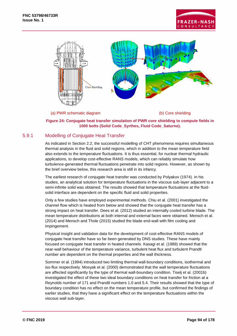
FNC 53798/46733R Issue No. 1
© FNC 2019 Page 94 of 178
(a) PWR schematic diagram (b) Core shielding
Figure 24: Conjugate heat transfer simulation of PWR core shielding to compute fields in
1000 bolts (Solid Code_Syrthes, Fluid Code_Saturne).
5.9.1 Modelling of Conjugate Heat Transfer
As indicated in Section 2.2, the successful modelling of CHT phenomena requires simultaneous
thermal analysis in the fluid and solid regions, which in addition to the mean temperature field
also extends to the temperature fluctuations. It is thus essential, for nuclear thermal hydraulic
applications, to develop cost-effective RANS models, which can reliably simulate how
turbulence-generated thermal fluctuations penetrate into solid regions. However, as shown by
the brief overview below, this research area is still in its infancy.
The earliest research of conjugate heat transfer was conducted by Polyakov (1974). In his
studies, an analytical solution for temperature fluctuations in the viscous sub-layer adjacent to a
semi-infinite solid was obtained. The results showed that temperature fluctuations at the fluid-
solid interface are dependent on the specific fluid and solid properties.
Only a few studies have employed experimental methods. Chiu et al. (2001) investigated the
channel flow which is heated from below and showed that the conjugate heat transfer has a
strong impact on heat transfer. Dees et al. (2012) studied an internally cooled turbine blade. The
mean temperature distributions at both internal and external faces were obtained. Mensch et al.
(2014) and Mensch and Thole (2015) studied the blade end-wall with film cooling and
impingement.
Physical insight and validation data for the development of cost-effective RANS models of
conjugate heat transfer have so far been generated by DNS studies. These have mainly
focused on conjugate heat transfer in heated channels. Kasagi et al. (1989) showed that the
near-wall behaviour of the temperature variance, turbulent heat flux and turbulent Prandtl
number are dependent on the thermal properties and the wall thickness.
Sommer et al. (1994) introduced two limiting thermal wall-boundary conditions, isothermal and
iso-flux respectively. Mosyak et al. (2000) demonstrated that the wall temperature fluctuations
are affected significantly by the type of thermal wall-boundary condition. Tiselj et al. (2001b)
investigated the effect of these two ideal boundary conditions on heat transfer for friction at a
Reynolds number of 171 and Prandtl numbers 1.0 and 5.4. Their results showed that the type of
boundary condition has no effect on the mean temperature profile, but confirmed the findings of
earlier studies, that they have a significant effect on the temperature fluctuations within the
viscous wall sub-layer.

FNC 53798/46733R Issue No. 1
© FNC 2019 Page 95 of 178
There then followed a series of further DNS studies by Tiselj and co-workers, which include
Tiselj et al. (2013, 2004, 2001a), Tiselj and Cizelj (2012) and Tiselj (2014). They further
explored conjugate heat transfer in a heated channel of walls of different thicknesses and over a
range of Reynolds numbers, Prandtl numbers and wall thermo-physical properties. They
demonstrated that two dimensionless parameters play an important role in determining the
strength of temperature fluctuations in the fluid near-wall region and also within the wall; the
thermal activity ratio, 𝐾 and the diffusivity ratio 𝐺. These are defined as:
𝐾 =(𝜌𝑓𝑐𝑃𝑓𝜆𝑓)
12
(𝜌𝑠𝑐𝑃𝑠𝜆𝑠)12
, 𝐺 =𝛼𝑓
𝑎𝑠
where 𝜌, 𝑐𝑃, 𝜆 and 𝛼 are the density, specific heat capacity, thermal conductivity and thermal
diffusivity (∝= 𝜆 𝜌𝐶𝑃⁄ ) respectively and subscripts 𝑓 and 𝑠 denote fluid and solid respectively.
More recently Flageul et al. (2017, 2015) in their DNS study of conjugate heat transfer in a
heated channel provided information on the variation of the dissipation rate of the temperature
variance. They demonstrated that due to the changes in thermo-physical properties, the
dissipation rate is discontinuous across the surface of the solid wall.
In a departure from the practice of focussing on conjugate heat transfer in basic channel flow
cases, Wu et al. (2017) have applied DNS analysis to the more complex conjugate heat transfer
case, of a jet in a cross-flow, shown in Figure 25. They demonstrated for such complex cases
the effective diffusivity approximation of the turbulent heat fluxes becomes inadequate.
Figure 25: Flow structures of jet in crossflow. From (Wu et al., 2017)
Compared to the above-mentioned DNS studies, RANS simulations of conjugate heat transfer
must not only be able to reproduce the mean temperature variation within the fluid and solid
domains, but also the temperature fluctuations within the solid. This in turn requires the
inclusion of transport equations for the temperature variance and its dissipation rate. Such
model equations have been proposed by Hanjalić et al. (1996), but not within the CHT context.
The work of Craft et al. (2010) has made some progress in the development of RANS models
which can reproduce the correct variation of the temperature variance and its dissipation rate
within the fluid and also across the solid. More extensive validation is however needed before
this approach can be more widely applied.
5.9.2 Summary
Conjugate heat transfer (CHT) analysis is assuming increasing importance in reactor design
and safety analysis. There is consequently a need for the development of simulation methods

FNC 53798/46733R Issue No. 1
© FNC 2019 Page 96 of 178
which can not only reproduce the mean temperature variation in the fluid and solid regions
simultaneously, but which can also predict how turbulence-induced thermal fluctuations
penetrate into the solid.
So far, experimental investigations have made only a modest contribution to the advancement
of our understanding of CHT, and these are mostly for turbine blade cooling applications.
Combined fluid/solid DNS has proved a valuable tool in improving our knowledge and
understanding of this phenomenon, but inevitably such a computationally expensive approach,
with one or two notable exceptions, has so far been limited to simple test cases. For CHT
analysis of more complex cases, the development of suitable and cost-effective RANS is
necessary.
The development of RANS thermal models suitable for CHT analysis is still in its early stages,
with very few researchers involved in such efforts. A more concerted research effort is needed.
FNC 53798/46733R Issue No. 1
© FNC 2019 Page 97 of 178
5.10 Liquid Metals
It is worth first noting some recent review papers providing a useful overview on international
activities on the thermal hydraulics of liquid metals.
Cheng et al. (2015) and Papukchiev and Buchholz (2017) provided an overview of a
recently completed European project, THINS, on modelling of next generation nuclear
power systems.
Roelofs et al. (2015; 2017) described two ongoing European consortia on LMFR thermal
hydraulics, that is, the Horizon 2020 SESAME and MYRTE projects.
Merzari et al. (2017) discussed issues and perspectives of applications of LES in nuclear
reactors from the point of view of a US consortium, the Centre for Exascale Simulation for
Advanced Reactor (CESAR).
Kamide et al. (2017) provided an overview of activities in SFR in Japan and Chellapandi
and Velusamy (2015) in India.
Tenchine (2010), Grötzbach (2013) and Roelofs et al. (2013) discussed some fundamental
challenges in simulating heat transfer to liquid metals.
5.10.1 Fundamental Studies on Heat Transfer to Fluids of Low Prandtl Number
Heat transfer to liquid metal is special because the Prandtl number of liquid metal (sodium, lead)
is significantly lower than one (around 0.01 to 0.001) as opposed to of order unity for air and
water where most heat transfer research has been carried out. As a consequence, the process
of heat transfer in liquid-metal turbulent flow exhibits significantly different characteristics from
those of ‘common’ fluids, having a very thick thermal boundary layer, for example.
Specific correlations have been found to be necessary for such fluids, normally based on Peclet
number (𝑅𝑒𝑃𝑟). A recent review of experimental data and correlations for turbulent forced
convection of liquid metals in pipes can be found in Pacio et al. (2015). For CFD and turbulence
modelling, the key challenge is the invalidity of the Reynolds analogy, as the turbulent Prandtl
number, which is often taken as a constant, varies significantly in the boundary layer. Improving
turbulent heat flux (𝑢𝑖𝑇′ , appearing in the Reynolds-averaged energy equation) is a key topic in
the CFD modelling of liquid metal. Grötzbach (2013) provided a comprehensive overview of
challenges in low-Prandtl number heat transfer simulation and modelling.
As part of a European consortium project, THINS, a number of approaches have been
developed and/or tested for the modelling of turbulent heat flux (Cheng et al., 2015; Papukchiev
and Buchholz, 2017; Ferry Roelofs et al., 2015). As a basic approach deviating from the
constant turbulent Prandtl number (𝑃𝑟𝑡), Duponcheel et al. (2014) assessed the performance of
turbulent heat flux models using variable 𝑃𝑟𝑡 based on LES channel-flow data at a reasonably
high Reynolds number (𝑅𝑒𝜏 = 2000). The models examined include (i) Reynolds (1975), which
is dependent on global flow parameters; (ii) Weigand et al. (1997), which is partly dependent on
global flow parameters and (iii) Kays (1994), which is dependent on local flow parameters. They
also proposed a new expression, the so-called mixed-law-of-the-wall.
Kenjereš and Hanjalić (2000) proposed an algebraic heat transfer model (not specifically for low
𝑃𝑟 fluids), which has been widely used and implemented in STAR-CCM+ (Kenjereš et al.,
2005). Shams et al. (2014a) assessed and recalibrated such models for heat transfer to liquid
metals. A shortcoming of the original model (Kenjereš et al., 2005) is that different sets of
constant coefficients were used for different flow regimes. Shams et al. (2014a) replaced one of
the constant coefficients with a correlation based on the Peclet number, which has achieved
much improved performance. Additionally, a four equation turbulence model has been
developed and used for forced convection heat transfer to liquid metals in Manservisi and

FNC 53798/46733R Issue No. 1
© FNC 2019 Page 98 of 178
Menghini (2014). Marocco et al. (2017) performed a careful assessment of the correlation model
of Kays (1994) and the four equation model of Manservisi and Menghini (2014) in the simulation
of mixed convection in a vertical concentric annulus. They have rather interestingly found that
the former simpler model performs much better than the latter more sophisticated four-equation
model in capturing the heat transfer deterioration due to buoyancy.
5.10.2 Fuel Assembly
In addition to the ‘peculiar’ heat transfer characteristic due to low Prandtl number, other
challenges involved in the SFR sub-assemblies include transverse flows, the effect of the spiral
spacer wires, blockage and the so-called gap instability (e.g. Meyer & Rehme (1994) and Duan
& He (2017)) associated with the small pitch-to-diameter ratio used in SFRs, which potentially
lead to strong flow instabilities and fuel pin vibrations.
ANL has developed a fluid and thermal simulation computer package Nek5000, which is aimed
at tackling transitional and turbulent flows in complex domains based on the spectral element
method (not specifically for liquid metal). The package is particularly suitable for LES and DNS.
As part of the US NEAMS and CESAR programs, Nek5000 was used to perform various LES
simulations for SFR cores providing valuable detailed data required for improvement/validation
of simulation tools (Pointer et al., 2009).
Merzari et al. (2017) described their methodology and LES in simulations for both fuel channels
and reactor core natural circulations, including a 37-pin bare rod bundle and a 19-pin SFR
bundle with a pin-to-diameter ratio of 1.08 and Re=15,000. In the current European SESAME
and MYRTE projects, DNS and LES are also identified and used as a key approach to generate
detailed validation data on LMFR thermal hydraulics alongside physical experiments (Roelofs et
al., 2017). Earlier work using DNS and LES for Lead-Bismuth Eutectic (LBE) was reported in
Bricteux et al. (2012). The reliance on such high fidelity CFD is due to the rapid development in
computer technology as well as the fact that physical experiments are technically challenging
and liquid metal is opaque, making advanced flow measurement techniques inaccessible.
Merzari et al. (2016) summarised a benchmarking exercise based on a collaboration between
Argonne and some European organisations (NRG, SCK-CEN and UGent) examining the
performance of RANS simulations in reproducing a LES simulation of an isothermal flow in a
7-pin SFR assembly with wire-wrapped spacer. It was found that all models tested (including the
𝑘-𝜔 SST, a cubic 𝑘-휀 model and a 𝑘-휀 realisable model) were able to capture somewhat the
cross flow, with the 𝑘-𝜔 SST performing marginally better than other models. Jeong et al. (2017)
reported a separate study of a 7-pin wire wrapped rod bundle with heat transfer and again to
some extent endorsed the reasonably good performance of the 𝑘-𝜔 SST model in producing a
good level of cross flow. Doolaard et al. (2015) reported some preliminary results of a
benchmark of RANS models against a LES with conjugate heat transfer for a 19-pin wire-
wrapped rod bundle with characteristics representative of MYRRHA. Pacio et al. (2015; 2017,
2016) described comparison between experiments and simulations of an LBE cooled fuel
assembly in a hexagonal rod bundle with spacers and the MYRRHA reactor respectively.
Zhao et al. (2017) carried out CFD simulations of an isothermal flow in a wire-wrapped
hexagonal 7-pin enclosed bundle and found that the transverse flow does not vary significantly
with the Reynolds number, but rather strongly with the pitch-diameter ratio.
Manservisi and Menghini (2015) simulated liquid metal flowing in a square lattice bare rod
bundle geometry using a constant turbulent Prandtl number as well as a two-equation turbulent
heat flux model. The constant turbulent Prandtl number clearly did not capture the expected
behaviour whereas the conclusion regarding the two-equation model was inconclusive due to
the lack of data for comparison, but these authors believe such a model was tested favourably

FNC 53798/46733R Issue No. 1
© FNC 2019 Page 99 of 178
in simpler flow configurations. Ge et al. (2017) performed simulations of flow of heavy liquid
metal in triangular and square lattices using the low Reynolds number Launder-Sharma
turbulence model coupled with various turbulent-Prandtl-number models to assess their
performance. The assessment was based on heat transfer correlations for such sub-channels.
Among the models tested, Kays (1994) and Aoki (1963) were found to produce predictions that
are close to the empirical correlations.
Finally, it is worth noting the work by Hu and Fanning (2013), who developed a momentum
source model for a wire-wrapped rod bundle to simplify mesh generation to resolve the
geometry of the wire spacers which remains a major challenge. They have demonstrated the
advantage and reliability of this method in simulating 7-pin and 37-pin bundle configurations.
5.10.3 Pool Thermal Hydraulics
A principal safety concern in the top plenum is the mixing of the sub-assembly jets with various
fluid temperatures in the core outlet region, which may potentially cause high-cycle thermal
fatigue resulting in thermal striping or cracks. The temperature variation may be several tens of
degrees and the frequency is between 1 Hz to 50 Hz (Velusamy et al., 2010). Recent studies
include:
A detailed experiment has been carried out using a sodium experimental facility with parallel
triple-jets at JAEA (Kimura et al., 2007). LES was performed to simulate the jet mixing and
compared with experiments by Kiruma et al. (2002), Chacko et al. (2011) and some others.
Tenchine et al. (2013b) described experimental studies at CEA based on two identical test
sections, one with air and one with sodium based on two co-axial jets at different
temperatures emerging from a large tank. Numerical simulations using both RANS and LES
(using the CFD package TRIO_VF developed at CEA) were compared with their
experimental data as well as those of Kimura et al. (2007) mentioned above. It was
concluded that the LES expectantly performed better than the RANS, but the former still
needs improving.
More recently Varol et al. (2017) reported a combined experimental and numerical study
using LES of parallel jets mixing about perforated obstacles. Good agreement between
them was found which illustrated the mixing characteristics.
LES was also performed to study the thermal striping in the upper plenum of the Korean
PGSFR at KAERI (Choi et al., 2015). Nouali and Mataoui (2014) studied horizontal jets of
different patterns using URANS.
Ward et al. (2018) discussed the scaling of thermal stratification and mixing in the outlet of
the plenum of SFRs to address the issue encountered when scaled-down experiments are
designed to study such phenomena in real reactors.
The sodium-argon free surface in the primary sodium circuit is an important source of gas
entrainment which may present a safety problem. Tenchine et al. (2014) described several
water tests in relatively simple flow conditions to study vortex formation and gas entrainments.
This was accompanied by numerical simulations using a front-tracking method coupled with a
LES using TRIO_U (a CFD package developed at CEA) to study surface instabilities and vortex
occurrence.
Anderson and Jackson (2017) summarised studies of experimental investigations at the
University of Manchester into radiative heat transfer between the pool free surface and the roof,
and the characteristics of the sodium aerosols formed in the argon cover gas above the pool.
Numerical simulations of these experiments are currently being carried as part of project
FORTE.

FNC 53798/46733R Issue No. 1
© FNC 2019 Page 100 of 178
5.10.4 Whole Core and System Thermal Hydraulics
Tenchine et al. (2013a) described an international benchmark organised by an IAEA
Coordinated Research Project (CRP) on the natural convection in the primary circuit of PHENIX
which was performed before its shutdown in 2009 (see also Tenchine et al. (2012c) describing
the test in detail). Some eight organisations participated in the benchmark using 1D or 3D
system/sub-channel codes. The rapid onset of natural circulation was demonstrated when the
primary pumps were tripped, together with other phenomena including significant heat removal
through thermal mass and heat losses, efficient heat removal through steam generator natural
convection air cooling. Overall the different codes seemed to show coherent qualitative results,
but significant discrepancies were demonstrated. It was shown that the use of 3D or 1D/3D
coupling were necessary to resolve natural circulation. Additionally, the THINS project also used
this data for validation of system and system/CFD coupling approaches (Pialla et al., 2015),
which also concluded that system/CFD coupling is necessary to resolve the three-dimensional
circulations.
The CATHARE system code, which was initially developed for PWRs, was adapted for SFR
starting from 2006 and has become the French reference code for SFR applications (Tenchine
et al., 2012b). The coupling between CATHARE and a CFD code TRIO_U (now TRIO_CFD)
was also noted in this paper and in Tenchine et al. (2012a), but is further described in detail in
Bavière et al. (2014) in which the approach was applied to simulating the PHENIX natural
circulation test. TRIO_U is capable of simulating the whole core as well as the sub-assembly
and the fuel channels (Tenchine et al., 2012a).
Hu and Yu (2016) reported the development of a 3D full core conjugate heat transfer capability
of a sub-channel modelling type for SFRs at ANL. The hexagon lattice core is modelled as 1D
parallel channels, with 2D models for the duct walls and inter-assembly gaps with the six sides
modelled separately accounting for asymmetric temperature distribution such as in edge
channels. The Jacobian Free Newton Krylov solution was applied to simultaneously solve the
fluid/solid fields in a fully coupled manner. The model was compared with a full CFD solution
favourably.
Finally, a 3D CFD model has been used to simulate the natural circulation in the main vessel of
a pool type reactor in India as part of their SFR development activities (Vivek et al., 2013).
5.10.5 Decay Heat Removal
An important feature of SFRs is that it can naturally include passive decay removal in its design
and some rather preliminary CFD attempts have been made to demonstrate such capabilities.
Hung et al. (2011) performed a rather straightforward simulation of decay heat removal using a
𝑘-휀 turbulence model (Launder and Spalding, 1974) with a wall function implemented in Fluent
with no special treatment for turbulent Prandtl number. The model seemed to be able to
demonstrate the decay heat removal principle and compare the performances of different
configurations.
Parthasarathy et al. (2012) carried out a much more detailed CFD model for the Indian
Prototype Fast Breeder Reactor (PFBR) to resolve the various parts of the core coupled with a
1D code to simulate other sub-systems of the decay removal circuit. They validated their model
against the plant data from PHENIX. However their turbulence and heat flux models are the
same as those of Hung et al. (2011). Again, the basic principle has been well demonstrated but
it would not be surprising that the detailed natural circulation is not well resolved by such simple
treatments such as the use of a standard wall function as well as a constant 𝑃𝑟𝑡. More recently,
David et al. (2017, 2015) extended the above work, studying the decay heat removal under

FNC 53798/46733R Issue No. 1
© FNC 2019 Page 101 of 178
natural circulation in a typical SFR pool under a core meltdown scenario with part of the core
debris settling core catcher, again using the Launder-Sharma model.
5.10.6 Summary
The most special feature of liquid metals is the low Prandtl number, which necessitates the
development and testing of advanced turbulent heat flux models (beyond the conventional
constant turbulent Prandtl number). Models of various complexities have been developed,
including for example, the relatively simpler turbulent-Prandtl-number correlations and the more
sophisticated models using transport equations for mean-square temperature variance and its
rate of destruction. These models have up to now mostly been tested in simple conditions.
Validation using more complex geometry/conditions including for example, jet mixing, flow
separation and flows around wire-spacers are ongoing. Simulations of the fuel assemblies have
been undertaken using various turbulence models and the effects of blockage, wire-spacer, flow
instability and inter-wrapper flows are being investigated using various turbulence models. The
𝑘-𝜔 SST turbulence model seemed to be singled out as performing better than others, but few
investigations used advanced turbulent heat flux models in simulations of assemblies. Various
preliminary attempts have been made to simulate the plena flow with strong buoyancy using
CFD. In addition, coupling CFD with system codes is an area of development to improve the
predictions for the whole systems.
Finally, it is noted that experiments using liquid metal are extremely difficult and therefore very
limited data are in existence for model testing and validation. Various international campaigns
are in progress in developing liquid metal experimental facilities, but many experimental
validations for liquid metal fast reactors (including assemblies and the pool) use simulating fluids
such as water to reduce experimental difficulties as well as to produce detailed information that
is difficult to generate with the opaque liquid metals.
In addition, high fidelity CFD (DNS and LES) is now used in the liquid metal thermal hydraulics
community (including in the US and Europe) as an important and ‘routine’ complimentary way to
physical experiments to generate data with which modelling tools can be validated against.
Currently, such high fidelity CFD provides data for both fundamental phenomena, such as
channel flow, separations and jets, and fuel assemblies with and without wire spacers.

FNC 53798/46733R Issue No. 1
© FNC 2019 Page 102 of 178
6 Advanced Simulation and Modelling Packages
6.1 Computing and simulation as the Third leg of scientific methods
It is now 20 years since the US Department Of Energy’s (DOE) Accelerated Strategic
Computing Initiative (ASCI) program was introduced to “eliminate reliance upon nuclear testing
in the US nuclear weapons program and achieve high confidence in the use of simulations for
stockpile assessment and certification”. As illustrated by the DOE director in Figure 26: “(ASCI)
established computational simulation into a third fundamental piece of the scientific method, on
a par with theory and experiment. [in 10 years] astounding advances were made in simulation
applications, computing platforms, and user environments” (Larzelere, 2007).
(Courtesy of Oak Ridge National Laboratory, U.S. Dept. of Energy)
Figure 26: Enabling the Shift to a Science Based Approach (Larzelere, 2010)
A 10,000-fold increase in system performance in 15 years was seen in the US from the first
tera-scale system, ASCI Red in 1997 to peta-scale systems 2012: Sequoia, Cielo, and
Roadrunner. Hoang (2013) explains how the Office of Advanced Simulation and Computing
(ASC), Nuclear National Security Administration plans for the next stage with a focus on
collaboration and end user productivity in view of the increasing complexity. V&V also figures
prominently alongside HPC technology.
While the traditional scientific method (experimental and theoretical) did not yet acknowledge
the role for computing and simulation, Ang et al. (1998) established the model verification and
simulation validation from first Principles simulations in the ASCI program. This practice of using
first Principles simulations to validate CFD models is now ubiquitous in academic circles. In
thermal hydraulics turbulence modelling, DNS databases are used extensively to improve and
validate RANS models.
As stated in Merzari et al. (2016), as part of a U.S. DOE International Nuclear Energy Research
Initiative (I-NERI), ANL is collaborating with the Dutch and Belgian Nuclear Research (NRG,
SCK·CEN) to perform and compare a series of fuel-pin-bundle calculations representative of a
wire-wrapped fuel bundle for which little data is available for verification and validation of new
simulation tools.
Ghent University and NRG performed their simulations with commercially available CFD codes.
The high-fidelity ANL LES code Nek5000 from the Simulation-based High-efficiency Advanced
Reactor Prototyping (SHARP) suite was also used. It was intended to serve both as a surrogate
for physical experiments and provide insight into experimental results.
Addition of Science Based Modelling and Simulation
Science (1st principles) based modelling and simulation used to extrapolate and predict beyond tested states.
Can quickly confirm or disprove Theory hypotheses.
Improve experiments by predicting ‘areas of interest’ and expected results.

FNC 53798/46733R Issue No. 1
© FNC 2019 Page 103 of 178
As part of the NEAMS program, ANL has performed several wire-wrapped analyses with
Nek5000. The geometry is related to the assembly design of MYRRHA. A 19-pin wire-wrapped
conjugate heat transfer benchmark is also open to international participants.
6.2 High Performance Computing and Thermal Hydraulics
Using commercially available hardware, ASCI boosted the development of teraflop HPC
components which has now increased by 105 to hundreds of petaflops. Later Japan, then China
competed for leadership23, but also EU with Switzerland (currently 3rd), UK (11th), Spain (13th),
Italy (14th) and industry such as Total (19th). EDF Energy, in the top 50 for a decade has fallen
behind. The UK has 10 machines in the Teraflop range (5 in the Met Office and ECMWF,
EPSRC and STFC, Edinburgh, Cambridge and AWE). In 2016, DOE’s HPC (TITAN, MIRA)
peaked at 10-27 petaflops, upgrading to 150-180 petaflops by 2019 (National Academies of
Sciences, Engineering and Medicine, 2016).
Bell (2015) shows a 1,000 Million times increase in computing speed over last 30 years, and so
Moore’s law of power doubling every 18 to 24 months (x 1,000 per decade) is in-fact exceeded.
The development of desktop computing power that could be bought for $1,000 is equally
astonishing. Radical changes of algorithms from Navier-Stokes equations solvers to Monte
Carlo simulations where processes are identical and better suited for cheaply available GPUs
bring another dramatic price drop and could make first principles thermal hydraulics simulations
available to all.
6.3 Direct Numerical Simulation
Discrepancies with fine experiments could entirely be removed by spatially averaging the DNS
to match the viscous-scaled length of the hot-wire sensor, thereby explaining observed
differences solely by insufficient spatial resolution of the sensor. For simple RMS fluctuation
measurements, DNS is now more accurate than experiments (Örlü and Schlatter, 2013).
The number of cells needed for DNS scales with 𝑅𝑒 to the power of 9/4. Laminar to turbulent
flow transition occurs at mean flow Reynolds numbers of roughly 𝑅𝑒𝑀 = 3000. DNS 𝑅𝑒 numbers
are reported using turbulent scales (𝑅𝑒𝑡), but if we re-scale them in terms of mean flow
parameters we see that around 2001, DNS with several million cells only focused on laminar-
turbulent transition and viscous-log layer interaction for small lab-scale experiments. With million
cell simulations possible since around 2010, DNS is relevant to industrial scale flows. A
Reynolds number around a million becomes possible with 1012 grid points.
The Gordon Bell 2013 HPC prize was awarded for a thermal hydraulics simulation cloud
cavitation collapse of 15,000 bubbles on a mesh of 13.2 Trillion cells, at a throughput speed of
721 billion points per second on Lawrence Livermore National Laboratory’s (LLNL) “Sequoia”
IBM BlueGene/Q (1.6 Million core in 96 racks).
DNS now includes heat transfer and curved geometries. With ANL’s Nek5000 DNS code,
oblique flow over a wire mounted flat wall served as a benchmark case to study fundamental
flow physics as in wrapped fuel pins in SFR designs (Ranjan et al., 2011).
The actual geometry of a 19-Pin SFR rod bundle was simulated only 5 years later with 250
billion colocation points (Merzari et al., 2017).
In the cornerstone test-case of a hot jet impinging on a cold plate, the maximum mean heat
transfer (Nusselt number) occurs under the nozzle slightly off axis, but with a smaller secondary
23 https://www.top500.org

FNC 53798/46733R Issue No. 1
© FNC 2019 Page 104 of 178
peak four pipe radius away, which has been difficult to capture with RANS models. The DNS of
Dairay et al., (2015) shows that the highest-heat-transfer regions are located in this region as a
result of formation of larger secondary vortices whose induced velocity generates a convective
flux of cold fluid towards the impingement plate.
This shows that engineering models derived from simple pipe flow aligning and extrapolating
RMS values from mean values of Nu are certainly erroneous for fatigue studies and could lead
to placing conservative margins in the wrong places.
In conjugate heat transfer, mentioned in Section 2.2, unsteady heat transfer coefficients are
generally evaluated based on a 1D method normal to the solid. This doesn’t account for wall
parallel attenuation, as could be seen in Figure 3 where small scale hot and cold spots
annihilate each other by conduction in the wall parallel directions. The TEE flow introduces
added complexity of separation and reattachment and there are a vast number of configurations
in terms of pipe diameters and relative flow-rates to explore. RANS models extended to
fluctuations inside the solid such as proposed by Craft et al. (2010) are a more practical
engineering approach permitting parametric studies, even with some uncertainty margins, as
long as they are well identified.
Figure 27 illustrates a simple heated channel flow DNS yielding the 4D thermal field (𝑥, 𝑦, 𝑧, 𝑡)
that allows better understanding jumps in statistics due to conductivity and volumetric heat
capacity discontinuities between the fluid and solid (Flageul et al., 2015).
However, for this simplest conjugate heat transfer benchmark, thousands of DNS simulations
will be needed to fully calibrate the models for the four characteristic parameters; conductivity,
diffusivity, Re number and plate/channel thickness values. Machine learning could provide this
on much shorter timescales than the previous decades of sporadic human benchmarking of
temperature variance models on very scarce and integral data.
(Courtesy of Cedric Flageul, HAL-01162346)
Figure 27: Conjugate heat transfer channel flow DNS: T fluctuation snapshot, variance
and its dissipation. Open symbols correspond to the limiting adiabatic and isothermal
cases for minor differences in conductivity and capacity. Data reduction: POD, Dynamic
mode decomposition

FNC 53798/46733R Issue No. 1
© FNC 2019 Page 105 of 178
Reporting thermal hydraulic studies (experimental and computational) has long been limited to
mean and RMS values and at best spectrum of time series at few (𝑥, 𝑦, 𝑧) locations and arbitrary
snapshots. This is clearly insufficient for analysis and validation.
It is certainly wasteful when the 4D fields e.g. 𝑇(𝑥, 𝑦, 𝑧, 𝑡), are available from DNS, but only for a
millisecond in between timesteps. Storage space is the bottleneck of HPC. The Johns Hopkins
Turbulence Database (see Section 7.3.5) with terabytes of DNS data available to all online is an
exception. It is sponsored by US NSF who’s wider objective is supporting Big Data research
efforts.
Modern experimental techniques can also provide such thermal hydraulic fields 4D (𝑥, 𝑦, 𝑧, 𝑡) in
more limited windows, but CFD-experimental comparisons in publications too often include a
couple of arbitrary snapshots side by side for illustration only. Fortunately, data-driven
algorithms can now be used to determine characteristics of the vortices buried in turbulent
flows.
Proper Orthogonal Decomposition (POD) takes an expansion basis of the eigenvectors of the
auto-covariance matrix (computed on the fly from the snapshots) and ranks the modes
according to their energy content.
Contrary to POD, Koopman modes are not based on the energy content of the flow, but rather
on its spectral content. They are infinite-dimensional but can be reduced and approximated, for
example, using the Dynamic Mode Decomposition (DMD) algorithm proposed by Schmid (2010)
and Schmid et al. (2012). Individual POD modal coefficients can carry several dominant
frequencies while the DMD coefficients only carry one frequency by nature and are preferable in
some cases where POD would eliminate dynamically relevant modes because of their relatively
low energy content while DMD accurately capture the dominant frequencies and spatial
structures (Mezić, 2013; Rowley et al., 2009; Q. Zhang et al., 2014).
Many aspects of NPP flows (tube bundles, bends, TEE junctions, jet in crossflow, natural
convection and others) exhibit multi-dominant structures with spatial-temporal features of each
coherent structure that are challenging to identify, but play a significant role in the study of
various physical processes e.g. heat and mass transfer vibrations. Proper orthogonal
decomposition and dynamic mode decomposition, for example, should now be part of any
CFD-experimental comparison project.
6.4 Artificial Intelligence and Machine Learning
On 19 Oct 2017, Google’s DeepMind new neural network program beat the original AlphaGo
program by 100 games to zero after only 72 hours of learning by playing games against itself
and being given only the very simple set of game rules24. The original program had already
defeated the world's number one Go player but after months of learning from, and improving
upon, human strategies. The new AlphaGo needed only three days and a fraction (8%) of the
previous computing power. "It shows that it is the novel algorithms that count, neither the
computing power, nor the data. We've actually removed the constraints of human knowledge
and it's able, therefore, to create knowledge itself from first principles, from a blank slate" said
David Silver from London based Deep Mind25.
“This approach, without the benefit of any training data, resulted in a significantly smarter Go
player than Artificial Intelligence (AI) programs that were able to analyse reams of human
matches. As the DeepMind article points out, if similar techniques could be used to attack other
24 http://www.bbc.com/news/technology-41668701 25 http://www.deepmind.com/

FNC 53798/46733R Issue No. 1
© FNC 2019 Page 106 of 178
structured problems, like protein folding or materials design, it could result in breakthroughs
across many domains. And removing the impediment of relying on large datasets, means that
this technology has the potential to be much more broadly applied” (Feldman, 2017).
Undoubtedly this applies to thermal hydraulics model development and validation from first
principles DNS and AI, then will be integrated into design optimisation by virtual power plant
simulators (DOE NEAMS, Section 8.2). This will be Machine Learning by itself from first
Principles without human intervention nor even using Big Data, e.g. running and using DNS
data “on the fly” rather than recourse to huge DNS databases, which are near impossible to
store and rapidly obsolescent as HPC power increases relentlessly enabling bigger, finer DNS.
Current physical experiments will serve as milestones with PIRT checkpoints for complex
designs. Future experimental programs need careful planning to provide added value between
DNS and NPP scale models.
6.4.1 Machine learning for turbulence modelling
At Sandia National Laboratory Ling and Templeton (2015) demonstrated the ability of data-
driven algorithms to provide substantial improvements over the current state-of-the-art in RANS
error detection. The 3 algorithms, learning algorithms to identify regions of high RANS
uncertainty were trained on a database of DNS or LES results, and then used to classify RANS
results uncertainty and the breakdown of specific RANS modelling assumptions in 7 test cases.
Following that, Ling et al. (2016) included fundamental invariance principles (tensor basis neural
network) towards automatic improved RANS predictive accuracy. This approach seems to make
obsolete decades of turbulence modeller’s efforts, but it could lead to more general acceptance
of “improved” RANS models in industrial applications and commercial CFD codes.
This area is rapidly attracting interest in the academic turbulence model community e.g. at
Stanford’s Centre for Turbulence Research:
A return to eddy viscosity model for epistemic uncertainty quantification in RANS closure
(Edeling et al., 2017).
Data-driven dimensional analysis: algorithms for unique and relevant dimensionless groups
(Constantine et al., 2017).
Physics-informed machine learning approach for reconstructing Reynolds stress modelling
discrepancies based on DNS data (Wang et al., 2017).
A Comprehensive Physics-Informed Machine Learning Framework for Predictive
Turbulence Modelling (Wang et al., 2017).
The method is also invaluable for uncertainty quantification, now an imperative in NPP Design
and certification by CFD.

FNC 53798/46733R Issue No. 1
© FNC 2019 Page 107 of 178
7 Databases and Benchmarking CFD as a technology has seen significant growth and uptake within a wide range of industrial
contexts over the past few decades. Commercial CFD vendors now provide general, state-of-
the-art, robust packages which are user-friendly and well supported. This reduction in the barrier
to entry rightly raises questions about quality and trust in the outputs that users produce.
CFD packages are as internally complex as the problems they are applied to; the adage
“garbage-in garbage-out” remains ever relevant. In response, a number of groups and
organisations have produced “best practice” guidelines, which combine decades of practice and
experience. A central theme within these is the Verification and Validation (V&V) processes,
steps which aim to build trust and increase quality by assessing the predictions of the virtual
world (i.e. CFD computations) against real-world (i.e. experimental) results. Quantifying and
understanding the differences between the two is the primary outcome of the validation process.
Thermal-hydraulic systems within a NPP, as with most engineering systems, involve many
different interacting physical phenomena within complex geometries. Attempting to validate CFD
models against such a system as a whole is impractical and counter-productive, since
deficiencies cannot be easily attributed to any one particular model and, at worst, may even
cancel out. A tiered strategy is generally applied, in which a system is broken down into
progressively simpler subsystems which can be validated (Oberkampf et al., 2004; Oberkampf
and Trucano, 2002):
Complete system;
Subsystem cases;
Benchmark cases; and
Unit problems.
This tiered, hierarchical approach builds confidence and allows modelling problems to be more
easily isolated and addressed.
The following sections identify major sources of CFD-grade (and, to a lesser extent, near-CFD
grade) experimental and numerical data which might be suitable for validation purposes. The
majority of existing databases are focused towards aerospace and aerodynamics applications,
with a number of sources offering cases which could be considered as more academic. Whilst
these cases do not directly address specific nuclear thermal hydraulics problems, they
nevertheless represent cases a CFD code should be able to solve and are useful for core model
development.
The majority of these databases have already been highlighted as outcomes of other projects.
In January 2015, the OECD/NEA published a report assessing the use of CFD codes for
Nuclear Reactor Safety problems (Smith et al., 2015) which identified four major CFD
benchmark cases in addition to more general sources.
7.1 OECD/NEA
The role of the OECD/NEA is to assist member countries in maintaining and further developing
the scientific, technological and legal bases required for a safe, environmentally friendly and
economical use of nuclear energy. Within this, the NEA Committee on the Safety of Nuclear
Installations (CSNI) holds broad responsibility for safety technology and research programmes
and was set up to develop and co-ordinate NEA activities concerning technical aspects of the
design, construction and operation of nuclear installations.

FNC 53798/46733R Issue No. 1
© FNC 2019 Page 108 of 178
Since its inception in 1958 (and the CSNI in 1973), the NEA has conducted and coordinated a
large number of nuclear safety related projects. The data and reports produced through these
projects form a substantial body of knowledge and experience. The various databases and
project lists are discussed below.
7.1.1 OECD/NEA Sponsored CFD Benchmark Exercises
In 2008, the OECD/NEA used the Special CFD Group of the Working Group on the Analysis
and Management of Accidents (WGAMA) to undertake a series of international benchmark
exercises. Both single-phase and two-phase flow options were considered. It was generally
agreed that this would be a blind benchmarking activity, in which participants would not have
access to measured data, apart from what was necessary to define initial and boundary
conditions for the numerical simulation, until they had submitted their numerical predictions for
evaluation.
This entails finding a completed, or nearly completed, experiment for which the data had not yet
been released, or encouraging a new experiment (most likely in an existing facility) to be
undertaken especially for this exercise. The group took on the responsibility of finding a suitable
experiment, for providing the organisational basis for launching the benchmark exercise, and for
the subsequent synthesis of the results.
The following CFD benchmark exercises have been completed or are underway:
1. OECD/NEA Vattenfall T-Junction benchmark exercise (high-cycle thermal fatigue)26. This
was based on previously unreleased test data from a very careful experiment carried out at
the Älvkarleby Laboratory of Vattenfall Research and Development in Sweden in November
2008.
2. OECD/NEA KAERI Rod Bundle CFD benchmark exercise (turbulent mixing downstream of
a spacer grid)27. Special tests were carried out in the MATiS-H cold-flow facility at the Korea
Atomic Energy Research Institute (KAERI) in early Spring 2012. Two spacer grids (of
generic design), of the split type and swirl-type, were featured in the study. Computer Aided
Design (CAD) files of the spacer grids were made available by KAERI to aid CFD mesh
generation.
3. OECD/NEA PSI CFD benchmark exercise (jet erosion of a stratified atmosphere)28. A new
test was carried out during February-March 2013 within one, comprehensively-instrumented
vessel of the PANDA integral containment facility, located at PSI in Switzerland. This
benchmark was specifically aimed at examining the erosion of a hydrogen-rich, stratified
layer, occupying the upper reaches of a containment volume. This was accomplished by the
impingement of a buoyant, vertical jet, placed off-centre with respect to the axis of the
vessel, in order to induce significant three-dimensional motions in the flow.
4. OECD/NEA CFD benchmark with Uncertainty Quantification (turbulent mixing). This
exercise started in 2015, and has not yet been formally reported. The experiments in the
GEMIX (GEneral MIXing experiment) facility located at PSI in Switzerland focus on the
mixing in the wake of two water streams (having identical or different densities and identical
velocities) generated downstream of a splitter plate. This facility includes detailed flow
measurements using Particle Image Velocimetry (PIV), Laser Induced Fluorescence (LIF)
and Wire Mesh Sensors (WMS).
26 http://www.oecd-nea.org/nsd/docs/2011/csni-r2011-5.pdf 27 http://www.oecd-nea.org/nsd/docs/2013/csni-r2013-5.pdf 28 http://www.oecd-nea.org/nsd/docs/2016/csni-r2016-2.pdf
FNC 53798/46733R Issue No. 1
© FNC 2019 Page 109 of 178
5. OECD/NEA CFD benchmark with Uncertainty Quantification (cold leg mixing). The 5th
benchmark of CFD applications to Nuclear reactor safety has been approved by CSNI and
is currently underway. Its main objective is to go a step further in the application of single-
phase CFD to nuclear safety issues with mixing problems possibly in presence of buoyancy
effects. The Pressurized Thermal Shock (PTS) facility located at Texas A&M University in
the US can simulate some mixing phenomena of cold water and hot water in geometry
representative of a horizontal cold leg of a PWR, as encountered in some accidental
situations with ECCS injection. The facility is equipped with state-of-the-art instrumentation
and measurement techniques to provide high resolution measurements of velocity,
concentrations, and pressure drops at different locations within the leg, nozzle, and
downcomer.
7.1.2 CSNI Code Validation Matrix
System codes have been the primary tool for analysing LWRs over the past 30 years. In order
to validate the codes and the sub-models used within them, data is collected both from
commercial plant operators and through conducting specifically designed experimental tests. A
significant amount of test data has been accumulated over the years and the CSNI Code
Validation Matrix is an attempt to collate and organise the data to be more conducive to
validating system codes.
The result is a collection of internationally agreed matrices which guide code validation and
present a basis for comparisons of predictions amongst the various system codes. The matrices
identify the main physical phenomena that occur during LOCA and reactor transients and cross-
reference these against the test facilities identified as suitable for reproducing those
phenomena. The tests are categorised as being either integral tests, which capture the
behaviour of the reactor system as a whole, or separate tests, which focus on the behaviour of a
single component or thermal-hydraulic phenomenon. The phenomena, identification criteria and
matrices are documented in a number of OECD/NEA reports (Glaeser et al., 1996; OECD/NEA,
1994).
The OECD/NEA has recently developed The International Experimental Thermal Hydraulics
Systems Database (TIETHYS)29. TIETHYS is an online searchable database that collates all of
the separate effects (Section 7.1.2.1) and integral effects (Section 7.1.2.2) test matrices.
7.1.2.1 Separate Effects Test Matrix
https://www.oecd-nea.org/dbprog/ccvm/indexset.html
The Separate Effects Test (SET) validation matrix is representative of the major part of the
experimental work which has been carried out in LWR-safety thermal hydraulics fields, covering
a large number of phenomena over a large range of useful parameters. A total of 2,094 tests
are included in the SET matrix and phenomena tested include critical flow, phase
separation/vertical flow, horizontal stratification, entrainment, liquid-vapour mixing with
condensation, spray effects and heat transfer.
The website separates the tests according to the facility they were conducted in and provides an
abstract for each experiment or test. The level of detail in each abstract varies, but most include
at least a description of the test facility, a description of the test, the phenomena tested, the
current status of the test and some references. Data available also varies; some experiments
only offer a report whilst others provide some amount of test data. The data needs to be
formally requested and this is subject to a non-disclosure agreement and to certain restrictions.
29 https://www.oecd-nea.org/tiethysweb

FNC 53798/46733R Issue No. 1
© FNC 2019 Page 110 of 178
7.1.2.2 Integral Effects Test Matrix
https://www.oecd-nea.org/dbprog/ccvm/index.html
The Integral Effects Test (IET) matrix data is suitable for the validation of best estimate thermal-
hydraulic computer codes. It consists of phenomenologically well founded experiments, for
which comparison of the measured and calculated parameters form a basis for establishing the
accuracy of the test predictions. Test types include core re-flooding, steam generator tube
rupture, loss of feed water and transients at shutdown. The available data is organised as
described above for the Separate Test Effects Matrix.
The volume of tests and accompanying data makes a complete assessment of the quality of the
data impractical but the intended purpose of the test matrices (the validation of 1D system
codes) implies that the fidelity of the data is not likely to be high enough to serve as validation
data for 3D CFD codes. Nonetheless, they represent tests which a CFD code should be able to
accurately reproduce.
7.1.3 NEA Computer Program Services
http://www.oecd-nea.org/tools/abstract/list/category
The NEA Computer Program Services provides a centralised repository of software libraries and
programs relating to nuclear energy applications. The service collects, compiles and verifies the
programs are suitable, complete and adequately documented.
The program categories include neutronics, hydrodynamics, shield design, experimental data
processing, but most relevant is those on heat transfer and fluid flow. Many of the tools are very
old.
7.1.4 Safety Joint Research Project Database
https://www.oecd-nea.org/dbprog/safety-joint-research-databases.html
The NEAs Safety Joint Research Project database maintains a list of projects which have been
undertaken by participants within the OECD/NEA group in collaboration with other external
agencies, companies and countries.
An overview, list of participants, the dates and budget are provided for each project. Data
abstracts are also provided in a similar form to those listed for the CSNI Code Validation Matrix.
Some of these abstracts provide varying levels of project data to download, though a formal
request for access is required.
7.1.5 Storage of Thermal REactor Safety Analysis (STRESA)
https://stresa.jrc.ec.europa.eu
STRESA was initially an information system developed in 2000 by the EU Commission’s Joint
Research Centre (JRC) to disseminate documents and experimental data from large in-house
JRC scientific projects on severe accidents. It now forms the main secure experimental data
repository for the JRC. STRESA was considerably upgraded and improved by the Nuclear
Reactor Safety Assessment Unit (NRSA) of the JRC in 2009 in order to take advantage of more
modern software solutions.
This tool provides secure storage for severe accident experimental data and calculations
conducted through the European Union. The public facing section of the website provides
details on all of the experimental facilities, including the organisation, the type of facility and the
number of experiments conducted at the facility which have been entered into the database. Of

FNC 53798/46733R Issue No. 1
© FNC 2019 Page 111 of 178
the 58 experimental facilities listed in the database, 12 are categorised as being relevant to
nuclear thermal-hydraulics.
The restricted section of the website contains further features and tools for accessing and
manipulating the experimental data available. Whilst it appears a straightforward registration
form is all that is required to access the restricted section, the experimental groups and funding
agencies are able to restrict access to organisations and users of their choosing. The
experimental data appears to be geared towards validation and verification of system-codes.
Nevertheless, it provides a valuable, easily accessible, central repository in which to request
further details or experimental data.
7.2 ERCOFTAC
In the 1990’s, the UK’s CEGB, EDF R&D, EU aerospace industry and turbulence modelling
academic groups launched the European Research Community on Flow, Turbulence And
Combustion (ERCOFTAC30), reporting progress in the predominantly applied, industrially-
oriented areas of turbulence research. ERCOFTAC was the first to publish Best Practice
Guidelines31 for CFD and turbulence and later a more specialised one on two-phase flows.
It also has a Bulletin32 (100th Edition), ERCOFTAC Book Series33 and Journal of Flow,
Turbulence and Combustion. Activity is organised via 30 Special Interest Groups34 (SIG) which,
alongside the historic Turbulence Modelling SIG now includes Large Eddy Simulation, Variable
Density Turbulent Flows, Design Optimisation, Uncertainty Quantification in Industrial Analysis
and Design. A major overarching objective is the coordination and maintenance of databases
suitable for code verification and validation and a number of resources are currently active.
7.2.1 Classic Collection
http://cfd.mace.manchester.ac.uk/ercoftac
The ERCOFTAC “Classic Collection” was established in 1995 and is now administered by the
Turbulence Modelling research group at The University of Manchester. It currently contains 93
test-cases is recognised as an excellent source of experimental, LES and DNS data for
verification and validation of turbulent flow. Each case contains at least a brief description,
downloadable data and references to published work with some containing significantly more.
The database is open to the public, but (free) registration is required to download the data. A
number of cases are relevant to nuclear thermal-hydraulics, including mixing layers, turbulent
flow over curved surfaces, flow past tube bundles and turbulent Rayleigh-Bénard convection.
7.2.2 SIG-15 Test Case Database
https://www.ercoftac.org/special_interest_groups/15_turbulence_modelling
The Special Interest Group on Refined Turbulence Modelling organised its 15th benchmarking
workshop in Chatou, France in October 2011 and presented a series of benchmark calculations
for heat transfer in a suddenly expanding pipe and thermal mixing in a T-junction.
30 http://www.ercoftac.org 31 http://www.ercoftac.org/publications/ercoftac_best_practice_guidelines/ 32 http://www.ercoftac.org/publications/ercoftac_bulletin/ 33 http://www.ercoftac.org/publications/ercoftac_book_series/ 34 http://www.ercoftac.org/special_interest_groups/

FNC 53798/46733R Issue No. 1
© FNC 2019 Page 112 of 178
7.2.3 Knowledge Base Wiki
http://www.ercoftac.org/products_and_services/wiki
The Knowledge Base Wiki, formerly known as the QNET-CFD Knowledge Base, originated from
a four year EU Network on Quality and Trust in the industrial application of CFD. This was a four
year project which brought together the expertise of 43 participating organisations across
Europe and aimed to improve the level of trust that could be placed in industrial level CFD
computations.
Members were principally from industry, but universities, national research organisations and
major European CFD code vendors were also strongly represented. Following the end of the EU
Network in 2004, responsibility for the Knowledge Base was passed to ERCOFTAC.
The network is organised into six applications areas. Spanning those areas were application
challenges, which consisted of realistic test cases suitable for CFD assessment, and Underlying
Flow Regimes, which contained well studied academic test cases suitable for assessing the key
physical elements which make up the application challenges. The six current application areas
include:
External Aerodynamics;
Combustion;
Chemical, Process, Thermal and Nuclear Safety;
Civil Construction and HVAC;
Environmental Flow; and
Turbomachinery Internal Flow.
Within the Chemical, Process, Thermal and Nuclear Safety application area there are 7 test
cases:
Buoyancy-opposed wall jet (contributed by Magnox Electric);
Induced flow in a T-junction (EDF R&D), cyclone separator (Fluent Europe);
Spray evolution in turbulent flow (Martin-Luther-Universitat Halle-Wittenberg);
Combining/dividing flow in Y junction (Rolls-Royce);
Downward flow in a heated annulus (British Energy); and
Particle-laden swirling flow (Martin-Luther-Universitat Halle-Wittenberg).
Each case contains a detailed description, sets of test data, details of CFD simulations, an
evaluation of the results and some best practice advice. Some, but not all, data is available to
download.
7.3 Research Group Databases
A number of fluid dynamics research groups host some of the data they produce during their
research either through their institutions or on personal sites. Thus, they are not necessarily
formal products or offerings from the institution; rather, they are managed by the research group
members themselves.
7.3.1 DATHET - Thermal Engineering Division, JSME
https://www.jsme.or.jp/ted/HTDB/dathet.html
DATHET (Database on Turbulent Heat Transfer) is a heat transfer focused database hosted by
the Thermal Engineering Division of the Japanese Society of Mechanical Engineers. Details on

FNC 53798/46733R Issue No. 1
© FNC 2019 Page 113 of 178
the governance and history of the database are not presented but the site contains a mix of
experimental and DNS cases on forced convection, natural convection and combined
convection (typically mixing layers, backwards facing step and swirling flows).
Each case has a downloadable CSV file which contains details on the experimental/numerical
method, the flow parameters, uncertainty and the flow data itself.
7.3.2 DNS Database of Wall Turbulence and Heat Transfer - Kawamura Lab
http://murasun.me.noda.tus.ac.jp/turbulence35
Hosted by the Kawamura Lab in collaboration with the Japan Aerospace Exploration Agency
(JAXA), the DNS Database of Wall Turbulence and Heat Transfer contains turbulent channel
flows, boundary layer flows and channel flows with two-dimensional slits. Both isothermal and
thermal flows are considered.
Each DNS simulation consists of a downloadable text file with details on flow parameters, mesh
refinement, references and the flow data itself. Access is freely open to the public.
7.3.3 Fluid Dynamics Group – Technical University of Madrid
https://torroja.dmt.upm.es/turbdata
The Fluid Dynamics Group at the Technical University of Madrid has published a number of
detailed DNS studies on a range of fundamental fluid flow (Cardesa et al., 2017; Hoyas and
Jiménez, 2008, 2006). Processed data produced for those, and many other, studies is made
available at the group’s website. The database contains cases on isotropic turbulence, high
Reynolds number channel flows (up to 𝑅𝑒𝜏 = 4200), boundary layer flows and homogeneous
shear layers. The database is freely accessible to the public, and each case contains a detailed
description, a selection of processed data, explanations of the data files and references to
publications. Additionally, the raw data produced from a selection of those cases is also
available to download (a collection totalling nearly 100TB).
Hosted on the same website is a database containing the results of Working Group 21 of the
Fluid Dynamics Panel of AGARD (Advisory Group for Aerospace Research and Development).
AGARD was an agency of NATO that existing from 1952 to 1996 with the intention of bringing
together expertise in aerospace science and technology from across NATO nations. The
primary outcome of the Working Group was a report and database intended specifically for the
validation of LES computations.
The database contains a mixture of DNS and experimental data and is organised into six
sections: homogenous turbulence, shock wave interaction with grid turbulence, pipes and
channels, free shear flows, turbulent boundary layers and a section for more complex flows. A
detailed report accompanies the data, which provides a short article like description of each
section and some sample plots. A total of 66 cases are presented. Flows of interest include
mixing layers, flows in square ducts and flows with surface curvature.
7.3.4 Institute for Computational Engineering and Sciences - The University of Texas
http://turbulence.ices.utexas.edu
Data produced by the research groups at the University of Texas’ Institute for Computational
Engineering and Sciences will be well known to a large majority of turbulence modelling
practitioners; the channel flow data published by Kim et al. (1987) has accrued well over 4,000
35 At the time of writing this website was unavailable at this address, but a mirror can be found at http://www.rs.tus.ac.jp/~t2lab/db/index.html

FNC 53798/46733R Issue No. 1
© FNC 2019 Page 114 of 178
citations. The group continues to publish hi-fidelity DNS simulations for a range of wall-bounded
and boundary layer flows and the data produced is made available online.
Processed data (profiles, statistics, balances etc.) exists for channel flows over a large range of
Reynolds numbers (180 < 𝑅𝑒𝜏 < 5200) and is freely downloadable through links on the site.
Arrangements for full datasets can also be made providing the recipient can supply a hard drive
suitable for transfer and make delivery arrangements. The site also hosts a mirror of some of
the data produced by Fluid Dynamics Group at the Technical University of Madrid (Section
7.3.3). Whilst the data is of a more fundamental nature, it provides an essential starting point for
the development of turbulence models.
7.3.5 John Hopkins Turbulence Database
http://turbulence.pha.jhu.edu
The John Hopkins Turbulence DataBase (JHTDB) is a publically accessible DNS data archiving
database system, hosted by the John Hopkins University, USA, under the sponsorship of the
US’ National Science Foundation. In contrast to the majority of the databases considered here,
access to the data is facilitated by a Web services interface that permits numerical experiments
and database queries to be run across the internet. Clients utilise a freely available web
services library to allow their own programs (written in C, Fortran or Matlab) to directly query the
dataset without having to download it. The technical details of the open access implementation
can be found in a number of published papers (Graham et al., 2016; Li et al., 2008).
The datasets available include forced isotropic turbulence, forced magnetohydrodynamic
turbulence, channel flow, homogenous buoyancy driven turbulence and forced isotropic
turbulence. The database is accompanied by detailed documentation and sample code to help
researchers incorporate the dataset into their own analysis programs.
7.4 NASA
The American National Aeronautics and Space Administration remains a major developer, user
and contributor of CFD technology. Its efforts are spread amongst a number of technical groups
and divisions, but there are some available CFD resources of value.
7.4.1 NPARC Alliance
https://www.grc.nasa.gov/www/wind/valid/archive.html
The National Project for Applications-Oriented Research in CFD (NPARC) was formed in 1993
by the US Air Force Arnold Engineering Development Center (AEDC) and the NASA Glenn
Research Center (GRC) in response to requests from industry and academic for the formal
support and development of a common CFD code.
As part of the verification and validation of that code, called WIND, the NPARC collated a data
archive of a number of primarily aerospace related test cases. Each case contains a detailed
description, data files available to download, references and general “best practice” guidelines.
7.4.2 Advanced Supercomputing Division
https://www.nas.nasa.gov/publications/datasets.html
The Advanced Supercomputing Division is primarily concerned with the development and
advancement of high-end supercomputing technologies and modelling and simulation methods.
There is, however, a small database of freely available CFD datasets which include viscous flow
around a tapered cylinder, a blunt fin and a space shuttle launch vehicle.

FNC 53798/46733R Issue No. 1
© FNC 2019 Page 115 of 178
7.4.3 Langley Research Center
https://turbmodels.larc.nasa.gov/index.html
As part of an effort by The Turbulence Model Benchmarking Working Group (a working group of
the Fluid Dynamics Technical committee of the AIAA), a number of verification cases are hosted
as a Turbulence Modelling Resource at NASA’s Langley Research Center.
The cases are again predominantly aerospace related, but with a focus on the development of
Reynolds-averaged Navier-Stokes turbulence models. Some cases which may hold relevance
to nuclear thermal-hydraulics include mixing layers, jets and internal flows.
7.5 Commercial CFD code Validation Cases
General purpose commercial CFD code vendors, such as ANSYS (Fluent, CFX), Siemens PLM
(STAR-CCM+), EDF R&D (Code_Saturne) and Cham (PHOENICS) amongst others, are keen
to demonstrate the accuracy and effectiveness of their products and thus a number of
benchmark results have been conducted during the development and testing of their codes. All
of these code vendors have customers within the nuclear industry.
The sensitive and commercial nature of their operations means, however, that publically
available information can be limited. The primary resource for specifics on validation cases is
the websites of the respective vendors and details are usually restricted to licensed users of the
software.
7.5.1 ANSYS-Fluent and ANSYS-CFX
http://www.ansys.com
The Fluent & CFX codes developed and marketed by ANSYS have seen considerable use in
both academia and industry. No validation details are publically available but licensed users
have access to a “Fluid Dynamics Verification Manual” which contains brief simulation results
for 70 different test cases.
The results are not intended to demonstrate validation and, whilst comparisons with
experimental results are presented, only a single run on a single mesh with a single modelling
approach is typically presented. Example cases of relevance include turbulent natural
convection in a tall-cavity, anisotropic conduction heat transfer, boiling in a pipe-critical heat flux
and two-phase stratified wall-bounded flow.
7.5.2 STAR-CCM+
https://mdx.plm.automation.siemens.com/star-ccm-plus
Internally, Siemens PLM conducts verification cases using the STAR-TEST suite which contains
more than 30,000 individual test cases. These include both unit tests and application verification
tests based on standardised validation cases. A subset of the STAR-TEST suite is provided to
licensed customers of the software.
Whilst this is primarily intended to confirm the local installation of the software is correct, the set
includes a number of cases relevant to nuclear thermal hydraulic. These include bulk boiling,
bubbly flow, turbulent natural convection in tall cavities and axisymmetric impinging heated jets.
7.5.3 Code_Saturne
https://www.code-saturne.org

FNC 53798/46733R Issue No. 1
© FNC 2019 Page 116 of 178
Code_Saturne, developed by EDF R&D, is open source software and thus anyone is free to
audit and verify that the code implementation is correct. A V&V program is conducted internally
on each version of the code. A validation manual is produced, but this is only available for the
core development team and internal users.
The manual covers both separate and integral effects, with the separate effects manual
including a range of approximately 40 test cases. The data used for each case is either sourced
from published literature or from experiments/DNS conducted by EDF or their partners.
7.5.4 PHOENICS
http://www.cham.co.uk/phoenics.php
PHOENICS provide a publically available online Encyclopaedia36 which provides a set of
validation examples. The cases are relatively academic in nature, but do include some cases of
relevance, such as two-phase flows in bubble-columns, buoyancy driven cavity flow and heat
transfer in damaged AGR fuel stringers.
7.5.5 Nek5000
https://nek5000.mcs.anl.gov
Nek5000 is open source and freely available from the source code hosting website GitHub. The
GitHub site contains a repository with a number of simple example cases, including Rayleigh-
Bénard convection and free-surface channel flow.
A significantly more relevant V&V exercise, presented at NURETH15, concerns high-fidelity
LES reference simulations conducted with Nek5000 on the OECD/NEA T-Junction and
MATiS-H benchmark experiments and for the Novosibirsk “SIBERIA” and ANL MAX con-current
validation experiments (Obabko et al., 2015).
7.6 FLOWNET
FLOWNET (Flow Library On the Web NETwork) was an EU initiative aimed at providing the
scientific and industrial communities with a code validation tool for use with flow modelling and
computational/experimental methods. This was to be achieved by the establishment of a
database network, which would enable scientists, academics and industrial experts to share
technical complements (test cases, experimental models and codes).
The project was active between 1998 and 2001 and primarily aimed at aerospace applications.
Unfortunately, aside from the EU funding record, very little evidence of the project remains.
36 http://www.cham.co.uk/phoenics/d_polis/d_applic/appval.htm#250

FNC 53798/46733R Issue No. 1
© FNC 2019 Page 117 of 178
8 Major Projects Worldwide
In this section we briefly review some major thermal-hydraulics-related projects in Europe, US
as well as some relevant Coordinated Research Projects (CRPs) of the IAEA, to provide an
appreciation of the main activities in thermal hydraulics worldwide.
8.1 Europe
The EU 7th Framework Programme funded a major project - Thermal-Hydraulics of Innovative
Nuclear Systems (THINS), which was active between 2010 and 2015 Cheng et al. (2015). The
project focused on a number topics, including:
Advanced reactor core thermal-hydraulics;
Single phase mixed convection;
Single phase turbulence;
Multiphase flow; and
Numerical code coupling and qualification.
The project aimed at establishing an experimental database and the development of new and
more accurate physical models and numerical simulation tools. Some twelve experimental
facilities were included in the project. New correlations or models were developed such as for
heat transfer coefficient, friction factor, turbulent Prandtl number and an algebraic heat flux
model. They were (partially) validated, based on the established test data and also implemented
in numerical codes.
Currently in Europe, there are a number of consortia in Generation IV reactors supported
through the Horizon 2020 program, including SESAME, MYRTE, SAMOFAR, all running
between 2015 and 2019. The former two are concerned with liquid metal cooled reactors
(including both SFR and LFR), whereas the latter is concerned with Molten Salt Reactors.
The SESAME (Simulations and Experiments for the Safety Assessment of MEtal cooled
reactors) is solely concerned with thermal hydraulics, focusing on pre-normative, fundamental,
safety-related, generic challenges. This is complemented by the MYRTE (MYRRHA Research
and Transmutation Endeavour) project, which focuses on the further development of the
MYRRHA reactor in Belgium, with a large part devoted to thermal hydraulics (F. Roelofs et al.,
2015; Roelofs et al., 2017). The two projects work closely together and identified the following
key areas of development: Liquid metal heat transfer, fuel assemblies, plenum and system
thermal-hydraulics. The projects aim to validate analytical and simulation methods with
reference data. If possible and affordable, such reference data will be based on experimental
results. However, the projects recognise that there are significant limitations/difficulties in
physical experiments with liquid metals due to the accessibility to the flow area and level of
details that experiments can provide. High fidelity simulation data (typically DNS or LES) are
used to generate data to complement or replace experimental data for model validation.
The SAMOFAR (Safety Assessment of the Molten Salt Fast Reactor37) project aims to achieve
a number of objectives, including to:
Deliver the experimental proof of concept of the safety features of the MSFR;
Provide a complete safety assessment of the MSFR and associated chemical plant; and
Update the conceptual design of the MSFR with all input gathered during the project.
37 http://samofar.eu/

FNC 53798/46733R Issue No. 1
© FNC 2019 Page 118 of 178
In the area of thermal hydraulics, the project aims to develop experimental facilities to produce
data on heat transfer and flow/loop instability, as well as develop leading-edge multi-physics
codes including uncertainty propagation for transient calculations.
8.2 US
Currently, there are three major national R&D projects in nuclear modelling and simulation in the
US; CASL and NEAMS funded by the US DoE Office of Nuclear Energy and CESAR funded by
the US DoE Office of Science. Figure 28 illustrates the relationship between the three programs
and how they contribute to the US nuclear energy program.
The Consortium for Advanced Simulation of Light Water Reactors (CASL)38 - A DoE Energy
Innovation Hub aims at delivering solutions to industry-defined challenges in the current LWR
technology. It is a consortium between industry, national labs and universities with a vision to
provide leading edge modelling and simulation capabilities to deploy within US nuclear energy
industry to improve LWR operation performance. One of its key outputs is to develop and
validate the so-called ‘virtual reactor’ package (VERA) to proactively address critical
performance goals for nuclear power. The thermal hydraulic analysis is based on a coupled
approach between the system/sub-channel codes and CFD. Developments in the VERA tools
are increasingly based on Idaho National Laboratory’s MOOSE39 which is a modern, open-
source, actively developed, parallel finite element framework for coupling a wide range of
physical phenomena.
The Nuclear Energy Advanced Modelling and Simulation Program40 (NEAMS) develops and
validates predictive analytic computer methods for the analysis and design of advanced reactor
and fuel cycle systems including Generation IV reactors (SFR and HTGRs) and SMRs. The
vision of the NEAMS Pellet-to-Plant Toolkit (a high performance computing solution for nuclear
performance and safety) is to provide insights that cannot be achieved through experimentation
alone. Consequently high fidelity simulation is the focus of the methodology that is being
developed.
The Centre for Exascale Simulation of Advanced Reactors41 (CESAR) focuses on the two key
physics components of reactor core modelling - CFD and neutron transport - with particular
focus on parameter regimes required for robust, coupled reactor core modelling. The program
has an ambitious long term mission to enable exascale reactor simulations, which will
fundamentally change the paradigm of how nuclear reactors are built, tested and operated. This
is expressed as a two-fold goal:
To drive the design of future hardware architecture, system software, and applications
based on the algorithmic requirements of nuclear engineering applications.
To develop a new generation of underlying algorithms which successfully exploit exascale
computing to solve significant reactor simulation problems.
Both NEAMS and CESAR develop and use a common simulation Nek5000 package for thermal
hydraulics. Nek5000 is based on a high order, high efficiency spectral element incompressible
solver aimed at producing high fidelity simulations (i.e. DNS and LES) for complex geometries.
The code however also provides options for ‘intermediate’ fidelity URANS and reduced fidelity
CFD such as a porous medium approach.
38 https://www.casl.gov 39 http://mooseframework.org 40 https://energy.gov/ne/nuclear-reactor-technologies/advanced-modeling-simulation 41 https://cesar.mcs.anl.gov/content/about-cesar

FNC 53798/46733R Issue No. 1
© FNC 2019 Page 119 of 178
(Courtesy of Oak Ridge National Laboratory, U.S. Dept. of Energy)
Figure 28: US nuclear Modelling and Simulation (M&S) programs (Larzelere, 2011)
8.3 IAEA CRPs
IAEA’s Coordinated Research Activities (CRAs) aim at simulating and coordinating research
activities of its member countries in selected nuclear fields. These are carried out through
Coordinated Research Projects (CRPs), which bring together an average of 15 scientific
institutes from different member countries to work on problems of common interest42. A number
of such active CRPs deal with thermal hydraulics for Generation IV reactors: HTGRs (Section
8.3.1 and 8.3.2), SCWRs (Section 8.3.3) and SFRs (Section 8.3.4), SMRs (Section 8.3.5) and
application of CFD to NPP design (Section 8.3.6).
8.3.1 HTGR Reactor Physics, Thermal-Hydraulics and Depletion Uncertainty Analysis (1000154) 2012-04-19 to 2019-04-18
The continued development of High Temperature Gas Cooled Reactors (HTGRs) requires
verification of HTGR design and safety features with reliable high fidelity physics models and
robust, efficient, and accurate codes. The predictive capability of coupled neutronics/thermal-
hydraulics simulations for reactor design and safety analysis can be assessed with sensitivity
analysis (SA) and uncertainty analysis (UA) methods. Uncertainty originates from errors in
physical data, manufacturing uncertainties, and modelling and computational algorithms. SA is
helpful to partition the prediction uncertainty to various contributing sources of uncertainty and
error.
SA and UA is required to address cost, safety, and licensing needs and should be applied to all
aspects of reactor multi-physics simulation. SA and UA can guide experimental, modelling, and
algorithm research and development. Current SA and UA rely either on derivative based
methods such as stochastic sampling methods or on generalised perturbation theory to obtain
sensitivity coefficients. Neither approach addresses all needs.
42 http://cra.iaea.org/cra/index.html

FNC 53798/46733R Issue No. 1
© FNC 2019 Page 120 of 178
In order to benefit from recent advances in modelling and simulation and the availability of new
covariance data (nuclear data uncertainties) extensive sensitivity and uncertainty studies are
needed for quantification of the impact of different sources of uncertainties on the design and
safety parameters of HTGRs. Only a parallel effort in advanced simulation and in nuclear data
improvement will be able to provide designers with more general and well validated calculation
tools to meet design target accuracies.
8.3.2 Modular High Temperature Gas Cooled Reactor Safety Design (I31026) 2014-12-12 to 2018-12-11
The CRP will investigate and make proposals on modular high temperature gas cooled reactor
(HTGR) safety design criteria. It is expected that these criteria would refer to light water reactor
safety standards (e.g. Safety of Nuclear Power Plants: Design (IAEA Safety Standards Series
No. SSR-2/1, Vienna, 2012)), and the deterministic and risk-informed safety design standards
under development for existing and planned HTGRs worldwide that apply to the wide spectrum
of design basis and beyond design basis events.
The CRP would also take into account the effect of the Fukushima Daiichi accident, clarifying
the safety requirements and safety evaluation criteria for design extension conditions, especially
those events that can affect multiple reactor modules or are dependent on the application (such
as process heat or hydrogen production) on the plant site. The logical flow of criteria is from the
fundamental inherent safety characteristics of modular HTGRs and associated expected
performance characteristics, to the safety functions required to ensure those characteristics,
and finally to specific criteria related to those functions.
The initial focus will be on the criteria for a specific HTGR concept (e.g. steam cycle) but other
concepts (e.g. gas turbine and process heat) will also be looked at. Both prismatic and pebble
bed modular HTGR designs will be considered. Several publications and presentations were
identified as important input to the CRP and will be used as the point of departure. The results
of the CRP will be documented in an IAEA Technical Document (TECDOC) to be made
available to the entire HTGR community. The CRP could also provide technical information for
future separate activities on the development of IAEA safety standards for HTGRs with the
cooperation of the IAEA Department of Nuclear Safety and Security.
8.3.3 Understanding and Prediction of Thermal Hydraulics Phenomena Relevant to Supercritical Water Cooled Reactors (I31025) 2014-06-19 to 2019-06-19
The supercritical water cooled reactor (SCWR) is one of the innovative water cooled reactor
(WCR) concepts mainly for large scale production of electricity. By utilising its high coolant
temperature, the SCWR is expected to achieve much higher thermal efficiencies than those of
current WCRs, and thereby promise improved economics.
The objective of the CRP is to improve the understanding and prediction accuracy of thermal
hydraulics phenomena relevant to SCWRs and to benchmark numerical toolsets for their
analysis. Several key phenomena, such as heat transfer, pressure drop and flow stability, have
been identified as crucial to the successful development of SCWRs. This CRP will enhance
understanding of thermal hydraulics phenomena, sharing of experimental and analytical results,
prediction methods for key thermal hydraulics parameters, and cross-training of personnel
between participating institutes.

FNC 53798/46733R Issue No. 1
© FNC 2019 Page 121 of 178
8.3.4 Sodium Properties and Safe Operation of Experimental Facilities in Support of the Development and Deployment of Sodium-cooled Fast Reactors (NAPRO) (I31024) 2013-09-05 to 2018-09-05
The CRP addresses the need of standardisation of sodium (Na) physical, physio-chemical and
thermo-dynamic properties, main rules for design, construction and operation of Na
experimental facilities, as well as good practices and safety guidelines for Na experiments.
8.3.5 Design and Performance Assessment of Passive Engineered Safety Features in Advanced Small Modular Reactors (I32010) 2017-07-19 to 2020-07-18
The majority of Small Modular Reactor (SMR) designs for near-term deployment adopt
advanced passive safety system technology to cope with both design basis- and design
extension conditions.
The goal of the CRP is to develop a common novel approach for designing passive engineered
safety features for SMRs and offer methods or good practices for assessing their performance
and reliability. Design safety considerations on appropriate and practical countermeasures to
incorporate and address lessons learned from the major accidents to enhance the design of
engineered safety systems of SMRs (particularly of the integral-PWR type currently under
development) will be developed.
8.3.6 Application of Computational Fluid Dynamics (CFD) Codes for Nuclear Power Plant Design (I31022) 2013-02-22 to 2018-02-21
The CRP addresses the application of CFD computer codes to the process of optimising the
design of water cooled NPP. Following a number of initiatives within IAEA where CFD codes are
applied to a wide range of situations of interest in nuclear reactor technology, the CRP intends
to constitute a systematic framework for the consistent application of those codes.
Namely, the CRP will contribute to establish a common vision in relation to the capabilities of
CFD codes and their qualification level. The CRP is also expected to provide a roadmap
strengthening the application domain of the related technology. Blind analyses (i.e. code
calculations performed without having access to experimental data) performed by participants
will allow the achievement of the proposed objectives.

FNC 53798/46733R Issue No. 1
© FNC 2019 Page 122 of 178
9 Closing Remarks This report presented an overview of recent research and current practices and provided a
background to recommendations for investment in the UK’s thermal hydraulics modelling
capability. The topic is so broad and the activity so international, that rather than presenting just
a lists of projects and references, a few of the challenges have been highlighted using selected
examples.
Focusing on most recent and, where possible, UK related references, the process of evaluating
the state of the art led the senior academic investigators to recognise that the impact of
continued exponential growth of high performance computing power, combined with novel
algorithms such as AI and machine learning is much broader than was perceived in their field of
specialisation. It was realised that, in certain thermal hydraulics topics, including one of our own
fields of expertise, CFD models of turbulence, the “technological singularity” point may be close,
driven by abundant computational power.
The opportunities offered by modern methods that exploit large-scale computing enables a
change in philosophy when analysing nuclear power plants. Operating and accident conditions
can now be re-evaluated and placed in more realistic scenarios with “best estimate plus
uncertainty methods”, compared to previous methods that used pessimistic conditions to cover
the uncertainties left by low-fidelity models.
In 2012, US DoE director Steven Chu stated that ”Supercomputing Will Change Our Energy
Future”43. The reality of this can be seen in recent outputs of the US NEAMS projects where
“first principles” simulations can replace experiments and surpass them with finer details.
It is perhaps uncomfortable to acknowledge that the development and tuning of thermal
hydraulics models, in the way that has taken place over the last few decades, will be more
effectively and rapidly accomplished by Machine Learning algorithms. As these revolutionary
developments occur, however, there will need to be a corresponding response in the rate of
acceptance of these novel models and methods. This will still require subject matter experts in
academia and industry, with expertise in thermal hydraulics to train the new generation of
researchers and engineers to harness these tools, as well in the management of complexity and
uncertainty.
A summary of the thoughts of the authors in the form of the UK strengths, weaknesses,
opportunities and threats has been used to present the concluding comments.
9.1 Strengths and Weaknesses
The UK is strong in modelling and at the origin of engineering CFD, major commercial
codes and RANS. While modelling activities are not as extensive as in earlier decades,
there is still a research base which can be strengthened and expanded.
Nuclear naval propulsion and high temperature gas cooled reactors (AGR experience,
which is relevant to VHTRs) are areas in which the UK has maintained research activities,
and as a result retains strong expertise.
The UK is strong in high performance computing for science and engineering as well as in
areas such as AI. This provides a strong base for the development of modelling capabilities
in compute-intensive aspects of nuclear thermal hydraulics simulation.
43 https://www.forbes.com/sites/joshwolfe/2012/05/08/why-the-doe-thinks-supercomputing-will-change-our-energy-future

FNC 53798/46733R Issue No. 1
© FNC 2019 Page 123 of 178
The UK has limited experience in the system and subchannel analysis codes that are used
for thermal-hydraulics analysis in the majority of international reactor design and safety
engineering organisations.
There is a rapidly diminishing pool of expertise and experience of historical UK NPP design
capability; in this area the UK has fallen behind the leading international players.
9.2 Opportunities and Threats
More benefit can be obtained by choosing to collaborate rather than reinvent or compete in
thermal hydraulics research by identifying gaps in international research capabilities and
addressing questions currently not considered. However, international activities are
extensive and the UK’s research funding is limited by comparison.
New advanced designs being considered (such as liquid metal or molten salt cooled
reactors) provide the opportunity for the UK to develop expertise in alternative reactor
designs.
Nuclear thermal hydraulics is potentially on the brink of radical change (“Supercomputing
Will Change Our Energy Future”). This is an opportunity that plays to the strengths of the
UK research community. One way to gain the benefits of these developments would be for
the UK to engage with the US’s NEAMS program (Nuclear Energy Advanced Modelling and
Simulation). Such involvement could enable the UK thermal hydraulics community to
become a contributor in the development of this cutting-edge research, but extensive
involvement is likely beyond the scope (and budget) of this project.
Thermal Hydraulics also serves Nuclear Fusion, where the UK is active. This is a topic in
which the UK has the opportunity to develop a strong position.

FNC 53798/46733R Issue No. 1
© FNC 2019 Page 124 of 178
10 Abbreviations
Acronym Definition
AI Artificial Intelligence
ASCI Accelerated Strategic Computing Initiative
ABND Average Bubble Number Density Model
ALE Arbitrary Lagrangian-Eulerian
AMR Adaptive Mesh Refinement
ATWS Anticipated transient without SCRAM
ATHLET Analysis of Thermal-hydraulics of LEaks and Transients
AWF Analytical Wall Function
BEPU Best Estimate Plus Uncertainty
BPG Best Practice Guidelines
BWR Boiling Water Reactor
CANDU Canada Deuterium Uranium
CATHARE Code for Analysis of THermalhydraulics during an Accident of Reactor and safety Evaluation
CCFL Counter Current Flow Limitation
CFD Computational Fluid Dynamic
CHF Critical Heat Flux
CHT Conjugate Heat Transfer
CRGT Control Rod Guide Tubes
CRP IAEA Coordinated Research Projects
CRA IAEA Coordinated Research Activities
CSAU Code Scaling Applicability and Uncertainty
CSV Comma Separated Variable
DES Detached Eddy Simulation
DMD Dynamic Mode Decomposition
DNB Departure from Nucleate Boiling
DNS Direct Numerical Simulation
DQMOM Direct Quadrature Method of Moments
DSS Dynamic System Scaling
ECC(S) Emergency Core Cooling (Systems)
EPR European Pressurised Reactor
EVM Eddy-viscosity Model
FAC Flow accelerated corrosion
FCT Flux-Corrected Transport
FE(M) Finite Element (Method)
FIV Flow Induced Vibration
FLAIR Flux Line-Segment Model for Advection and Interface Reconstruction
FOM Figure of Merit
FSA Fractional Scaling Analysis
FSI Fluid-Structure Interaction
FV(M) Finite Volume (Method)

FNC 53798/46733R Issue No. 1
© FNC 2019 Page 125 of 178
Acronym Definition
GEN-IV Generation IV
GMRES Generalised Minimal Residual Method
HGCR Heterogeneous Gas Core Reactor
HPC High performance Computing
HTGR High-Temperature Gas-cooled Reactor
HTTR High-Temperature Test Reactor
HVAC Heating, Ventilation and Air-Conditioning
IATE Interfacial Area Transport Equation
IBM Immersed Boundary Method
IET Integral Effect Test
ITF Integrated Test Facility
INES International Nuclear and Radiological Event Scale
JHTDB John Hopkins Turbulence Database
KOFA Korean Optimised Fuel Assembly
LBE Lead Bismuth Eutectic
LBLOCA Large Break Loss of Coolant Accident
LBM Lattice Boltzmann Methods
LDV Laser Doppler Velocimetry
LES Large Eddy Simulation
LIF Laser Induced Fluorescence
LFR Lead-cooled Fast Reactor
LM Liquid Metal
LMFR Liquid Metal Fast Reactor
LSTF See ROSA/LSTF
LOCA Loss-of-Coolant Accident
LS Level-Set
LWR Light Water Reactor
LTE Local Thermal Equilibrium
LTNE Local Thermal Non-Equilibrium
MASLWR Multi-Application Small Light Water Reactor
MSLB Main Steam Line Break
MSR Molten Salt Reactor
MSFR Molten Salt Fast Reactor
MYRTE MYRRHA Research and Transmutation Endeavour
MYRRHA Multi-purpose hYbrid Research Reactor for High-tech Applications
MUSIG MUltiple SIze Group Model
NAPRO Sodium Properties and Safe Operation of Experimental Facilities in Support of the Development and Deployment of Sodium-cooled Fast Reactors
NEAMS Nuclear Energy Advanced Modeling and Simulation
NESTOR New Experimental Studies of Thermal-Hydraulics of Rod Bundles
NURISP Nuclear Reactor Integrated Simulation Project
NURESAFE NUclear Reactor SAFEty Simulation Platform
NPP Nuclear Power Plant

FNC 53798/46733R Issue No. 1
© FNC 2019 Page 126 of 178
Acronym Definition
NTH Nuclear Thermal-hydraulics
NS Navier-Stokes
NVD Normalised Variable Diagram
PBM Population Balance Model
PCCS Passive Containment Cooling System
PCT Peak Cladding Temperature
PFBR Prototype Fast Breeder Reactor
PGSFR Prototype Gen IV Sodium cooled Fast Reactor
PHWR Pressurised Heavy Water Reactor
PIRT Phenomena Identification and Ranking Table
PIV Particle Image Velocimetry
PLIC Piecewise Linear Interface Construction
POD Proper Orthogonal Decomposition
PTS Pressurised Thermal Shock
PV Pressure Vessel
PIV Particle Image Velocimetry
PWR Pressurised Water Reactor
QMU Quantifications of Margins and Uncertainty
R&D Research and Development
RANS Reynolds-averaged Navier-Stokes
RELAP Reactor Excursion and Leak Analysis Program
ROSA/LSTF Japan Atomic Energy Agency Rig of Safety/Large Scale Test Facility
RBMK Reaktor Bolshoy Moshchnosti Kanalnyy (High Power Channel-type Reactor)
RMS Root Mean Square
RPV Reactor Pressure Vessel
RSM Reynolds Stress Model
SAMOFAR Safety Assessment of the MOlten salt FAst Reactor
SAR Safety Analysis Reports
SESAME Simulations and Experiments for the Safety Assessment of MEtal cooled reactors
SMAP Safety Margins Action Plan
SBLOCA Small-Break Loss of Coolant Accident
SCWR SuperCritical Water-cooled Reactor
SET(F) Separate Effect Test (Facility)
SHARP Simulation-based High-efficiency Advanced Reactor Prototyping suite
SFR Sodium-cooled Fast Reactor
SIG Special Interest Group
SLIC Simple Line Interface Construction
SOFIA Simulateur d’Observation du Fonctionnement Incidentel et Accidentel
SMR Small Modular Reactor
SST Shear Stress Transport
SG Steam Generator
SPH Smoothed-Particle Hydrodynamics
STRESA Storage of Thermal REactor Safety Analysis

FNC 53798/46733R Issue No. 1
© FNC 2019 Page 127 of 178
Acronym Definition
TBL Turbulent Boundary Layer
TCL Two-Component Limit
TH Thermal Hydraulics
THINS Thermal Hydraulics of Innovative Nuclear Systems
TVD Total Variation Diminishing
UQ Uncertainty quantification
URANS Unsteady Reynolds-averaged Navier-Stokes
VHTR Very High-Temperature Reactor
VOF Volume of Fluid
VVER Water-Water Energetic Reactor
VERA-CS Virtual Environment for Reactor Applications, Core Simulator
WCR Water Cooled Reactor
WMS Wire Mesh Sensor

FNC 53798/46733R Issue No. 1
© FNC 2019 Page 128 of 178
11 Organisations
Acronym Definition
AEA See UKAEA
AIAA American Institute of Aeronautics and Astronautics (USA)
AEDC US Air Force Arnold Engineering Development Center (USA)
ANL Argonne National Laboratory (USA)
ANSYS Commercial engineering code provider (USA)
AREVA Nuclear company (France)
AWE Atomic Weapons Establishment (UK)
AGARD Advisory Group for Aerospace Research and Development – NATO Agency
BEIS Department for Business, Energy and Industrial Strategy (UK)
BNFL British Nuclear Fuels Ltd (UK)
CASL Consortium for Advanced Simulation of Light Water Reactors (USA)
CEA Commissariat à l’Energie Atomique et aux Energies Alternatives (France)
CEBG Central Electricity Generating Board (UK)
CESAR Centre for Exascale Simulation for Advanced Reactor (USA)
CHAM Concentration, Heat and Momentum Limited (UK)
CNL Canadian Nuclear Laboratories (Canada)
Columbia Columbia University (USA)
CSNI NEA Committee on the Safety of Nuclear Installations
DoE Department of Energy (USA)
ECMWF European Centre for Medium-Range Weather Forecasts (EU)
EDF Électricité de France (France)
EPRI Electric Power Research Institute (USA)
EPSRC Engineering and Physical Sciences Research Council (UK)
ERCOFTAC European Research Community on Flow, Turbulence and Combustion (EU)
ETH Zurich Swiss Federal Institute of Technology in Zurich
EU European Union
EURATOM European Atomic Energy Community (EU)
GIF Generation IV International Forum
GRC NASA Glenn Research Center (USA)
GNU Free-software and mass-collaboration project (USA)
IAEA International Atomic Energy Agency
I-NERI International Nuclear Energy Research Initiative (USA)
INL Idaho National Laboratory (USA)
IRSN Institute for Radiological Protection and Nuclear Safety (France)
JAEA Japan Atomic Energy Agency (Japan)
JAXA Japan Aerospace Exploration Agency (Japan)
JRC Ispra Joint Research Centre of the European Commission (Italy)
KAERI Korean Atomic Energy Institute (Korea)
MIT Massachusetts Institute of Technology (USA)

FNC 53798/46733R Issue No. 1
© FNC 2019 Page 129 of 178
Acronym Definition
NASA National Aeronautics and Space Administration (USA)
NATO North Atlantic Treaty Organisation
NEA Nuclear Energy Agency of the OECD
NERAC Nuclear Energy Research Advisory Committee (USA)
NIRAB Nuclear Innovation and Research Advisory Board (UK)
NRC See USNRC
NRG Nuclear Research and Consultancy Group (Netherlands)
NPARC National Project for Applications-Oriented Research in CFD (USA)
NRSA Nuclear Reactor Safety Assessment Unit of the JRC
NSF National Science Foundation (USA)
NUPEC NUclear Power Engineering Corporation (now JNES, Japan)
OECD Organisation for Economic Co-operation and Development
SCK-CEN Belgian Nuclear Research Centre (Belgium)
Stanford CTR Stanford Center for Turbulence Research (USA)
STFC Science and Technology Facilities Council (UK)
UGent Ghent University (Belgium)
UKAEA UK Atomic Energy Authority (UK)
USNRC United States Nuclear Regulatory Commission (USA)

FNC 53798/46733R Issue No. 1
© FNC 2019 Page 130 of 178
12 References Addad, Y., Benhamadouche, S., Laurence, D., 2004. The negatively buoyant wall-jet: LES results. Int. J.
Heat Fluid Flow 25, 795–808. https://doi.org/10.1016/j.ijheatfluidflow.2004.05.008
Addad, Y., Gaitonde, U., Laurence, D., Rolfo, S., 2008. Optimal Unstructured Meshing for Large Eddy
Simulations, in: Quality and Reliability of Large-Eddy Simulations, Ercoftac Series. Springer, Dordrecht,
pp. 93–103. https://doi.org/10.1007/978-1-4020-8578-9_8
Addad, Y., Rabbitt, M., Laurence, D.R., 2006. Turbulent Natural Convection in Horizontal Coaxial
Cylindrical Enclosures: LES and RANS Models. Begellhouse, pp. 507–510.
https://doi.org/10.1615/ICHMT.2006.TurbulHeatMassTransf.1050
Addad, Y., Zaidi, I., Laurence, D., 2015. Quasi-DNS of natural convection flow in a cylindrical annuli with
an optimal polyhedral mesh refinement. Comput. Fluids 118, 44–52.
https://doi.org/10.1016/j.compfluid.2015.06.014
Afgan, I., 2007. Large Eddy Simulation of Flow over Cylindrical Bodies using Unstructured Finite Volume
Meshes. University of Manchester, Manchester.
Agarwal, D.K., Welch, S.W.J., Biswas, G., Durst, F., 2004. Planar Simulation of Bubble Growth in Film
Boiling in Near-Critical Water Using a Variant of the VOF Method. J. Heat Transf. 126, 329–338.
https://doi.org/10.1115/1.1737779
Agbodemegbe, V.Y., Cheng, X., Akaho, E.H.K., Allotey, F.K.A., 2016. An investigation of the effect of
split-type mixing vane on extent of crossflow between subchannels through the fuel rod gaps. Ann. Nucl.
Energy 88, 174–185. https://doi.org/10.1016/j.anucene.2015.10.036
Ahammad, M., Olewski, T., Véchot, L.N., Mannan, S., 2016. A CFD based model to predict film boiling
heat transfer of cryogenic liquids. J. Loss Prev. Process Ind. 44, 247–254.
https://doi.org/10.1016/j.jlp.2016.09.017
Akbari, M., Galanis, N., Behzadmehr, A., 2012. Comparative assessment of single and two-phase
models for numerical studies of nanofluid turbulent forced convection. Int. J. Heat Fluid Flow 37, 136–
146. https://doi.org/10.1016/j.ijheatfluidflow.2012.05.005
Akiyama, M., 1973. Bubble Collapse in Subcooled Boiling. Bull. JSME 16, 570–575.
https://doi.org/10.1299/jsme1958.16.570
Aksan, N., D’Auria, F., Glaeser, H., Lillington, J., Pochard, R., Sjoberg, A., 1996. OECD/NEA-CSNI
Separate Effects Test Matrix for Thermal-Hydraulic Code Validation (No. NEA/CSNI/R(96)16). OECD-
NEA.
Ala, A.A., Tan, S., Eltayeb, A., Zhengpeng, M., Xing, L., 2017. Simulation Study of Turbulent Flow
Through 5x5 Rod Bundle, in: Proceedings of 17th International Topical Meeting on Nuclear Reactor
Thermalhydraulics (NURETH-17). Xi’an.
Al-Aabidy, Q., Craft, T., Iacovides, H., 2017. Numerical Calculation of Internal Blade Cooling Using
Porous Ribs, in: 23rd ISABE Conference: International Society of Air Breathing Engines. Presented at
the International Symposium on Air-Breathing Engines, Manchester.
Alajbegovic, A., Drew, D.A., Lahey Jr, R.T., 1999. An Analysis of Phase Distribution and Turbulence in
Dispersed Particle/Liquid Flows. Chem. Eng. Commun. 174, 85–133.
https://doi.org/10.1080/00986449908912791
FNC 53798/46733R Issue No. 1
© FNC 2019 Page 131 of 178
Ambrosini, W., Forgione, N., Mazzini, D., Oriolo, F., 2002. Computational study of evaporative film
cooling in a vertical rectangular channel. Heat Transf. Eng. 23, 25–35.
https://doi.org/10.1080/01457630290098619
Ammour, D., Craft, T., Iacovides, H., 2013. Highly Resolved LES and URANS of Turbulent Buoyancy-
Driven Flow Within Inclined Differentially-Heated Enclosures. Flow Turbul. Combust. 91, 669–696.
https://doi.org/10.1007/s10494-013-9497-1
Ampomah-Amoako, E., Akaho, E.H.K., Nyarko, B.J.B., Ambrosini, W., 2013. Analysis of flow stability in
nuclear reactor subchannels with water at supercritical pressures. Ann. Nucl. Energy 60, 396–405.
https://doi.org/10.1016/j.anucene.2013.05.031
Anderson, A., Jackson, J.D., Jackson, J.D., 2017. Study of heat transfer from a pool of liquid sodium
through a cloud of aerosol-laden argon gas, Technical Report for BEIS/FNC project.
Anderson, N., Hassan, Y., Schultz, R., 2008. Analysis of the hot gas flow in the outlet plenum of the very
high temperature reactor using coupled RELAP5-3D system code and a CFD code. Nucl. Eng. Des. 238,
274–279. https://doi.org/10.1016/j.nucengdes.2007.06.008
Andreani, M., 1992. Studies of Dispersed Flow Film Boiling with 3-D Lagrangian Hydrodynamics and a
2-D Eulerian Vapour Field. Swiss Federal Institute of Technology, Zurich.
Ang, J.A., Trucano, T.G., Luginbuhl, D.R., 1998. Confidence in Asci Scientific Simulations (No. SAND--
98-1525C; CONF-980113--). Sandia National Labs., Albuquerque, NM (United States).
Antal, S.P., Lahey, R.T., Flaherty, J.E., 1991. Analysis of phase distribution in fully developed laminar
bubbly two-phase flow. Int. J. Multiph. Flow 17, 635–652. https://doi.org/10.1016/0301-9322(91)90029-3
Aoki, S., 1963. A consideration on the Heat Transfer in Liquid Metal. Bull Tokyo Inst Tech Ser B, B 54.
Apanasevich, P., Coste, P., Ničeno, B., Heib, C., Lucas, D., 2014. Comparison of CFD simulations on
two-phase Pressurized Thermal Shock scenarios. Nucl. Eng. Des. 266, 112–128.
https://doi.org/10.1016/j.nucengdes.2013.10.023
Apanasevich, P., Lucas, D., Beyer, M., Szalinski, L., 2015. CFD based approach for modeling direct
contact condensation heat transfer in two-phase turbulent stratified flows. Int. J. Therm. Sci. 95, 123–
135. https://doi.org/10.1016/j.ijthermalsci.2014.11.015
Apsley, D., Leschziner, M., 1998. A new low-Reynolds-number nonlinear two-equation turbulence model
for complex flows. Int. J. Heat Fluid Flow 19, 209–222. https://doi.org/10.1016/S0142-727X(97)10007-8
Ashgriz, N., Poo, J.Y., 1991. FLAIR: Flux line-segment model for advection and interface reconstruction.
J. Comput. Phys. 93, 449–468. https://doi.org/10.1016/0021-9991(91)90194-P
Aumiller, D.L., Tomlinson, E.T., Bauer, R.C., 2001. A Coupled RELAP5-3D/CFD methodology with a
proof-of-principle calculation. Nucl. Eng. Des. 205, 83–90. https://doi.org/10.1016/S0029-
5493(00)00370-8
Badillo, A., Andreani, M., 2017. An exploratory work on the use of a Lagrangian-Eulerian model for
simulating heat transfer of subchannels under reflooding conditions. Nucl. Eng. Des., Multi-scale multi-
physics analysis of reactor transients in the NURESAFE project 321, 156–172.
https://doi.org/10.1016/j.nucengdes.2016.11.031
Bae, J.H., Yoo, J.Y., Choi, H., 2005. Direct numerical simulation of turbulent supercritical flows with heat
transfer. Phys. Fluids 17. https://doi.org/10.1063/1.2047588
Bae, J.H., Yoo, J.Y., Choi, H., McEligot, D.M., 2006. Effects of large density variation on strongly heated
internal air flows. Phys. Fluids 18. https://doi.org/10.1063/1.2216988

FNC 53798/46733R Issue No. 1
© FNC 2019 Page 132 of 178
Balachandar, S., Eaton, J.K., 2010. Turbulent Dispersed Multiphase Flow. Annu. Rev. Fluid Mech. 42,
111–133. https://doi.org/10.1146/annurev.fluid.010908.165243
Bandini, G., Meloni, P., Polidori, M., Lombardo, C., 2011. Validation of CATHARE V2.5 thermal-hydraulic
code against full-scale PERSEO tests for decay heat removal in LWRs. Nucl. Eng. Des., The18th
International Conference on Nuclear Engineering (ICONE-18) 241, 4662–4671.
https://doi.org/10.1016/j.nucengdes.2011.02.034
Bannari, R., Kerdouss, F., Selma, B., Bannari, A., Proulx, P., 2008. Three-dimensional mathematical
modeling of dispersed two-phase flow using class method of population balance in bubble columns.
Comput. Chem. Eng. 32, 3224–3237. https://doi.org/10.1016/j.compchemeng.2008.05.016
Baratto, F., Bailey, S.C.C., Tavoularis, S., 2006. Measurements of frequencies and spatial correlations of
coherent structures in rod bundle flows. Nucl. Eng. Des. 236, 1830–1837.
https://doi.org/10.1016/j.nucengdes.2005.12.009
Barre, F., Bernard, M., 1990. The CATHARE code strategy and assessment. Nucl. Eng. Des. 124, 257–
284. https://doi.org/10.1016/0029-5493(90)90296-A
Bartolomei, G.G., 1982. An experimental investigation of true volumetric vapour content with subcooled
boiling in tubes. Therm. Eng. 29, 132–135.
Bartosiewicz, Y., Laviéville, J., Seynhaeve, J.-M., 2008. A first assessment of the NEPTUNE_CFD code:
Instabilities in a stratified flow comparison between the VOF method and a two-field approach. Int. J.
Heat Fluid Flow 29, 460–478. https://doi.org/10.1016/j.ijheatfluidflow.2007.09.005
Basu, N., Warrier, G.R., Dhir, V.K., 2005. Wall Heat Flux Partitioning During Subcooled Flow Boiling:
Part 1—Model Development. J. Heat Transf. 127, 131–140. https://doi.org/10.1115/1.1842784
Baudin, M., Dutfoy, A., Iooss, B., Popelin, A.-L., 2017. OpenTURNS: An Industrial Software for
Uncertainty Quantification in Simulation, in: Ghanem, R., Higdon, D., Owhadi, H. (Eds.), Handbook of
Uncertainty Quantification. Springer International Publishing, Cham, pp. 2001–2038.
https://doi.org/10.1007/978-3-319-12385-1_64
Bavière, R., Tauveron, N., Perdu, F., Garré, E., Li, S., 2014. A first system/CFD coupled simulation of a
complete nuclear reactor transient using CATHARE2 and TRIO_U. Preliminary validation on the Phénix
Reactor Natural Circulation Test. Nucl. Eng. Des. 277, 124–137.
https://doi.org/10.1016/j.nucengdes.2014.05.031
Beck, J.L., Zuev, K.M., 2017. Rare-Event Simulation, in: Ghanem, R., Higdon, D., Owhadi, H. (Eds.),
Handbook of Uncertainty Quantification. Springer International Publishing, Cham, pp. 1075–1100.
https://doi.org/10.1007/978-3-319-12385-1_24
Bell, G., 2015. Super Computers: The Amazing Race (Technical Report No. MSR-TR-2015-2). Microsoft
Research, San Francisco, California.
Bellakhal, G., Chahed, J., Masbernat, L., 2004. K-Omega turbulence model for bubbly flows, in:
Proceedings of the 5th International Conference on Multiphase Flow. Presented at the ICMF’04,
Yokohama, Japan.
Benim, A.C., Pasqualotto, E., Suh, S.H., 2008. Modelling turbulent flow past a circular cylinder by RANS,
URANS, LES and DES. Prog. Comput. Fluid Dyn. Int. J. 8, 299.
https://doi.org/10.1504/PCFD.2008.019483
Berar, O.-A., Prošek, A., Mavko, B., 2013. RELAP5 and TRACE assessment of the Achilles natural
reflood experiment. Nucl. Eng. Des. 261, 306–316. https://doi.org/10.1016/j.nucengdes.2013.05.007

FNC 53798/46733R Issue No. 1
© FNC 2019 Page 133 of 178
Berger, M.J., Colella, P., 1989. Local adaptive mesh refinement for shock hydrodynamics. J. Comput.
Phys. 82, 64–84. https://doi.org/10.1016/0021-9991(89)90035-1
Bertolotto, D., Manera, A., Frey, S., Prasser, H.M., Chawla, R., 2009. Single-phase mixing studies by
means of a directly coupled CFD/system-code tool. Ann. Nucl. Energy 36, 310–316.
https://doi.org/10.1016/j.anucene.2008.11.027
Besnard, D.C., Harlow, F.H., 1988. Turbulence in multiphase flow. Int. J. Multiph. Flow 14, 679–699.
https://doi.org/10.1016/0301-9322(88)90068-7
Bestion, D., 2008. System Code Models and Capabilities. Presented at the THICKET 2008: Seminar on
the Transfer of Knowledge Gained through CSNI Activities in the Field of Thermal-hydraulics, Pisa, Italy,
p. 486.
Bestion, D., 1990. The physical closure laws in the CATHARE code. Nucl. Eng. Des. 124, 229–245.
https://doi.org/10.1016/0029-5493(90)90294-8
Bestion, D., Anglart, H., Mahaffy, J., Lucas, D., Song, C.H., Scheuerer, M., Zigh, G., Andreani, M.,
Kasahara, F., Heitsch, M., Komen, E., Moretti, F., Morii, T., Muehlbauer, P., Smith, B.L., Watanabe, T.,
2014. Extension of CFD Codes Application to Two-Phase Flow Safety Problems - Phase 3 (No.
NEA/CSNI/R(2014)13). OECD-NEA.
Bestion, D., D’Auria, F., Lien, P., Nakamura, H., 2016a. Scaling in System Thermal-Hydraulic
Applications to Nuclear Reactor Safety and Design: A State-of-the-Art Report (No.
NEA/CSNI/R(2016)14). OECD-NEA.
Bestion, D., D’Auria, F., Lien, P., Nakamura, H., et al., 2016b. A state-of-the-art report on scaling in
system thermalhydraulics applications to nuclear reactor safety and design (No. NEA/CSNI/R(2016)14).
OECD NEA.
Bestion, D., de Crécy, A., Camy, R., Barhet, A., Bellet, S., Badillo, A., Niceno, B., Hedberg, P., Muñoz
Cobo, J.L., Moretti, F., Scheuerer, M., Nickolaeva, A., 2016c. Review of Uncertainty Methods for
Computational Fluid Dynamics Application to Nuclear Reactor Thermal Hydraulics (No.
NEA/CSNI/R(2016)4). OECD-NEA.
Bieder, U., 2017. Analysis of the IAEA-benchmark on flow mixing in a 4x4 rod bundle, in: Proceedings of
17th International Topical Meeting on Nuclear Reactor Thermalhydraulics (NURETH-17). Xi’an.
Bieder, U., Falk, F., Fauchet, G., 2014. LES analysis of the flow in a simplified PWR assembly with
mixing grid. Prog. Nucl. Energy 75, 15–24. https://doi.org/10.1016/j.pnucene.2014.03.014
Bieder, U., Fauchet, G., Bétin, S., Kolev, N., Popov, D., 2007. Simulation of mixing effects in a VVER-
1000 reactor. Nucl. Eng. Des. 237, 1718–1728. https://doi.org/10.1016/j.nucengdes.2007.02.015
Bilger, C., Aboukhedr, M., Vogiatzaki, K., Cant, R.S., 2017. Evaluation of two-phase flow solvers using
Level Set and Volume of Fluid methods. J. Comput. Phys. 345, 665–686.
https://doi.org/10.1016/j.jcp.2017.05.044
Billard, F., Laurence, D., 2012. A robust k−ε−v2¯/k elliptic blending turbulence model applied to near-
wall, separated and buoyant flows. Int. J. Heat Fluid Flow 33, 45–58.
https://doi.org/10.1016/j.ijheatfluidflow.2011.11.003
Blinkov, V.N., Jones, O.C., Nigmatulin, B.I., 1993. Nucleation and flashing in nozzles—2. Comparison
with experiments using a five-equation model for vapor void development. Int. J. Multiph. Flow 19, 965–
986. https://doi.org/10.1016/0301-9322(93)90072-3
Boris, J.P., Book, D.L., 1973. Flux-corrected transport. I. SHASTA, a fluid transport algorithm that works.
J. Comput. Phys. 11, 38–69. https://doi.org/10.1016/0021-9991(73)90147-2

FNC 53798/46733R Issue No. 1
© FNC 2019 Page 134 of 178
Böttcher, M., 2008. Detailed CFX-5 study of the coolant mixing within the reactor pressure vessel of a
VVER-1000 reactor during a non-symmetrical heat-up test. Nucl. Eng. Des. 238, 445–452.
https://doi.org/10.1016/j.nucengdes.2007.02.054
Boudjemadi, R., Maupu, V., Laurence, D., Le. Quéré, P., 1997. Budgets of turbulent stresses and fluxes
in a vertical slot natural convection flow at Rayleigh Ra = 10^5 and 5.4*10^5. Int. J. Heat Fluid Flow 18,
70–79. https://doi.org/10.1016/S0142-727X(96)00144-0
Boumaza, M., Moretti, F., Dizene, R., 2014. Numerical simulation of flow and mixing in ROCOM facility
using uniform and non-uniform inlet flow velocity profiles. Nucl. Eng. Des. 280, 362–371.
https://doi.org/10.1016/j.nucengdes.2014.10.018
Boyd, C., Skarda, R., 2014. CFD predictions of standby liquid control system mixing in lower plenum of a
BWR. Nucl. Eng. Des. 279, 109–115. https://doi.org/10.1016/j.nucengdes.2014.02.007
Brackbill, J.U., Kothe, D.B., Zemach, C., 1992. A continuum method for modeling surface tension. J.
Comput. Phys. 100, 335–354. https://doi.org/10.1016/0021-9991(92)90240-Y
Braz Filho, F.A., Ribeiro, G.B., Caldeira, A.D., 2016. Prediction of subcooled flow boiling characteristics
using two-fluid Eulerian CFD model. Nucl. Eng. Des. 308, 30–37.
https://doi.org/10.1016/j.nucengdes.2016.08.016
Brewster, R.A., Bissett, T.A., Xu, Y., 2017. Computational Fluid Dynamics Assessment of Baffle Plate
Leakage Flow Effects in a Downflow 4-Loop Reactor, in: Proceedings of 17th International Topical
Meeting on Nuclear Reactor Thermalhydraulics (NURETH-17). Xi’an.
Bricteux, L., Duponcheel, M., Winckelmans, G., Tiselj, I., Bartosiewicz, Y., 2012. Direct and large eddy
simulation of turbulent heat transfer at very low Prandtl number: Application to lead–bismuth flows. Nucl.
Eng. Des., Selected and expanded papers from International Conference Nuclear Energy for New
Europe 2010, Portorož, Slovenia, September 6-9, 2010 246, 91–97.
https://doi.org/10.1016/j.nucengdes.2011.07.010
Bromley, L.A., 1950. Heat transfer in stable film boiling. Chem. Eng. Prog. 46, 221–227.
Brown, C.S., Zhang, H., Kucukboyaci, V., Sung, Y., 2016. Best estimate plus uncertainty analysis of
departure from nucleate boiling limiting case with CASL core simulator VERA-CS in response to PWR
main steam line break event. Nucl. Eng. Des. 309, 8–22.
https://doi.org/10.1016/j.nucengdes.2016.09.006
Bucalossi, A., Petruzzi, A., Kristof, M., D’Auria, F., 2010. Comparison between Best-Estimate–Plus–
Uncertainty Methods and Conservative Tools for Nuclear Power Plant Licensing. Nucl. Technol. 172,
29–47. https://doi.org/10.13182/NT172-29
Bui, T.D., Dhir, V.K., 1985. Film Boiling Heat Transfer on an Isothermal Vertical Surface. J. Heat Transf.
107, 764–771. https://doi.org/10.1115/1.3247502
Burns, A.D., Frank, T., Hamill, I., Shi, J., 2004. The Favre Averaged Drag Model for Turbulent Dispersion
in Eulerian Multi-Phase Flows. Presented at the 5th International Conference on Multiphase Flow,
Yokohama, Japan.
Bury, T., 2013. Coupling of CFD and lumped parameter codes for thermal-hydraulic simulations of
reactor containment. Comput. Assist. Methods Eng. Sci. 20, 195–206.
Buwa, V.V., Deo, D.S., Ranade, V.V., 2006. Eulerian–Lagrangian simulations of unsteady gas–liquid
flows in bubble columns. Int. J. Multiph. Flow 32, 864–885.
https://doi.org/10.1016/j.ijmultiphaseflow.2006.02.017

FNC 53798/46733R Issue No. 1
© FNC 2019 Page 135 of 178
Cardesa, J.I., Vela-Martín, A., Jiménez, J., 2017. The turbulent cascade in five dimensions. Science 357,
782–784. https://doi.org/10.1126/science.aan7933
Carrica, P.M., Wilson, R.V., Noack, R.W., Stern, F., 2007. Ship motions using single-phase level set with
dynamic overset grids. Comput. Fluids 36, 1415–1433. https://doi.org/10.1016/j.compfluid.2007.01.007
Chabard, J.P., Laurence, D., 2009. Heat and fluid flow simulations for deciding tomorrow’s energies.
Chacko, S., Chung, Y.M., Choi, S.K., Nam, H.Y., Jeong, H.Y., 2011. Large-eddy simulation of thermal
striping in unsteady non-isothermal triple jet. Int. J. Heat Mass Transf. 54, 4400–4409.
https://doi.org/10.1016/j.ijheatmasstransfer.2011.05.002
Chahed, J., Roig, V., Masbernat, L., 2003. Eulerian–Eulerian two-fluid model for turbulent gas–liquid
bubbly flows. Int. J. Multiph. Flow 29, 23–49. https://doi.org/10.1016/S0301-9322(02)00123-4
Chang, S.-K., Kim, S., Song, C.-H., 2014. Turbulent mixing in a rod bundle with vaned spacer grids:
OECD/NEA-KAERI CFD benchmark exercise test. Nucl. Eng. Des. 279, 19–36.
https://doi.org/10.1016/j.nucengdes.2014.03.008
Chang, Y.C., Hou, T.Y., Merriman, B., Osher, S., 1996. A Level Set Formulation of Eulerian Interface
Capturing Methods for Incompressible Fluid Flows. J. Comput. Phys. 124, 449–464.
https://doi.org/10.1006/jcph.1996.0072
Chellapandi, P., Velusamy, K., 2015. Thermal hydraulic issues and challenges for current and new
generation FBRs. Nucl. Eng. Des. 294, 202–225.
Chen, D., Xiao, Y., Xie, S., Yuan, D., Lang, X., Yang, Z., Zhong, Y., Lu, Q., 2016. Thermal-hydraulic
performance of a 5 × 5 rod bundle with spacer grid in a nuclear reactor. Appl. Therm. Eng. 103, 1416–
1426. https://doi.org/10.1016/j.applthermaleng.2016.05.028
Chen, E., Li, Y., Cheng, X., 2009. CFD simulation of upward subcooled boiling flow of refrigerant-113
using the two-fluid model. Appl. Therm. Eng. 29, 2508–2517.
https://doi.org/10.1016/j.applthermaleng.2008.12.022
Chen, G., Zhang, Z., Tian, Z., Li, L., Dong, X., Ju, H., 2017. Design of a CFD scheme using multiple
RANS models for PWR. Ann. Nucl. Energy 102, 349–358. https://doi.org/10.1016/j.anucene.2016.12.030
Chen, R., Tian, M., Chen, S., Tian, W., Su, G.H., Qiu, S., 2017. Three dimensional thermal hydraulic
characteristic analysis of reactor core based on porous media method. Ann. Nucl. Energy 104, 178–190.
https://doi.org/10.1016/j.anucene.2017.02.020
Chen, S.-W., Liu, Y., Hibiki, T., Ishii, M., Yoshida, Y., Kinoshita, I., Murase, M., Mishima, K., 2012. One-
dimensional drift-flux model for two-phase flow in pool rod bundle systems. Int. J. Multiph. Flow 40, 166–
177. https://doi.org/10.1016/j.ijmultiphaseflow.2011.11.004
Chen, X., Du, S., Zhang, Y., Yu, H., Li, S., Peng, H., Wang, W., Zeng, W., 2017. Validation of CFD
analysis for rod bundle flow test with vaned spacer grids. Ann. Nucl. Energy 109, 370–379.
https://doi.org/10.1016/j.anucene.2017.05.055
Chen, Y., Li, Y., Liu, Z., 2014. Numerical simulations of forced convection heat transfer and flow
characteristics of nanofluids in small tubes using two-phase models. Int. J. Heat Mass Transf. 78, 993–
1003. https://doi.org/10.1016/j.ijheatmasstransfer.2014.07.052
Chen, Y.M., Mayinger, F., 1992. Measurement of heat transfer at the phase interface of condensing
bubbles. Int. J. Multiph. Flow 18, 877–890. https://doi.org/10.1016/0301-9322(92)90065-O
Chen, Z., Chen, X.N., Rineiski, A., Zhao, P., Chen, H., 2015. Coupling a CFD code with neutron kinetics
and pin thermal models for nuclear reactor safety analyses. Ann. Nucl. Energy 83, 41–49.
https://doi.org/10.1016/j.anucene.2015.03.023

FNC 53798/46733R Issue No. 1
© FNC 2019 Page 136 of 178
Cheng, S., Chen, H., Zhang, X., 2017. CFD analysis of flow field in a 5 x 5 rod bundle with multi-grid.
Ann. Nucl. Energy 99, 464–470. https://doi.org/10.1016/j.nucengdes.2008.08.020
Cheng, X., Batta, A., Bandini, G., Roelofs, F., Van Tichelen, K., Gerschenfeld, A., Prasser, M.,
Papukchiev, A., Hampel, U., Ma, W.M., 2015. European activities on crosscutting thermal-hydraulic
phenomena for innovative nuclear systems. Nucl. Eng. Des. 290, 2–12.
Cheung, S.C.P., Deju, L., Yeoh, G.H., Tu, J.Y., 2013. Modeling of bubble size distribution in isothermal
gas–liquid flows: Numerical assessment of population balance approaches. Nucl. Eng. Des. 265, 120–
136. https://doi.org/10.1016/j.nucengdes.2013.08.049
Chiang, J.S.C., Pei, B.-S., Tsai, F.P., 2011. Pressurized water reactor (PWR) hot-leg streaming Part 1:
Computational fluid dynamics (CFD) simulations. Nucl. Eng. Des. 241, 1768–1775.
https://doi.org/10.1016/j.nucengdes.2009.12.028
Chien, K., 1982. Predictions of Channel and Boundary-Layer Flows with a Low-Reynolds-Number
Turbulence Model. AIAA J. 20, 33–38. https://doi.org/10.2514/3.51043
Chieng, C.C., Launder, B.E., 1980. On the Calculation of Turbulent Heat Transport Downstream from an
Abrupt Pipe Expansion. Numer. Heat Transf. 3, 189–207. https://doi.org/10.1080/01495728008961754
Chiu, W.K.S., Richards, C.J., Jaluria, Y., 2001. Experimental and Numerical Study of Conjugate Heat
Transfer in a Horizontal Channel Heated From Below. J. Heat Transf. 123, 688–697.
https://doi.org/10.1115/1.1372316
Choi, S.-K., Kim, D.-E., Ko, S.-H., Lee, T.-H., 2015. Large eddy simulation of thermal striping in the
upper plenum of the PGSFR. J. Nucl. Sci. Technol. 52, 878–886.
https://doi.org/10.1080/00223131.2014.990532
Chrisochoides, N., 2005. A survey of parallel mesh generation methods (Technical Report). Brown
University.
Chuang, T.-J., Hibiki, T., 2017. Interfacial forces used in two-phase flow numerical simulation. Int. J.
Heat Mass Transf. 113, 741–754. https://doi.org/10.1016/j.ijheatmasstransfer.2017.05.062
Chung, B.D., Kim, K.D., Bae, S.W., Jeong, J.J., Lee, S.W., Hwang, M.K., Yoon, C., 2010. MARS code
manual volume I: code structure, system models, and solution methods (Code Manual No. KAERI/TR--
2812/2004). Korea Atomic Energy Research Institute, Daejeon, Republic of Korea.
Ciofalo, M., Collins, M.W., 1989. k-ε Predictions of Heat Transfer in Turbulent Recirculating Flows Using
an Improved Wall Treatment. Numer. Heat Transf. Part B Fundam. 15, 21–47.
https://doi.org/10.1080/10407798909342397
Clift, R., Grace, J.R., Weber, M.E., 1978. Bubbles, Drops, and Particles. Academic Press.
Colombo, M., Fairweather, M., 2016. CFD Simulation of Boiling Flows for Nuclear Reactor Thermal
Hydraulic Applications. Comput. Aided Chem. Eng., 26 European Symposium on Computer Aided
Process Engineering 38, 445–450. https://doi.org/10.1016/B978-0-444-63428-3.50079-5
Conner, M.E., Baglietto, E., Elmahdi, A.M., 2010. CFD methodology and validation for single-phase flow
in PWR fuel assemblies. Nucl. Eng. Des. 240, 2088–2095.
https://doi.org/10.1016/j.nucengdes.2009.11.031
Conner, M.E., Hassan, Y.A., Dominguez-Ontiveros, E.E., 2013. Hydraulic benchmark data for PWR
mixing vane grid. Nucl. Eng. Des. 264, 97–102. https://doi.org/10.1016/j.nucengdes.2012.12.001
Conner, M.E., Smith III, L.D., Paramonov, D.V., Liu, B., Dzodzo, M., 2003. Understanding and predicting
the flow field in a reactor core, in: Top Fuel 2003. Wurzburg.

FNC 53798/46733R Issue No. 1
© FNC 2019 Page 137 of 178
Constantine, P.G., del Rosario, Z., Iaccarino, G., 2017. Data-driven dimensional analysis: algorithms for
unique and relevant dimensionless groups. ArXiv170804303 Math Stat.
Cooper, D., Cotton, M.A., Iacovides, H., Zhang, S., 2016. The effects of natural and mixed convection on
heat transfer across adjacent micro-channels, in extreme pressure and temperature conditions. Appl.
Therm. Eng. 106, 640–650. https://doi.org/10.1016/j.applthermaleng.2016.06.052
Corredera, G., Alves-Vieira, M., de Bouvier, O., 2008. Fouling and TSP Blockage of Steam Generators
on EDF Fleet : Identified Correlations with Secondary Water Chemistry and planned Remedies.
Presented at the International Conference on Water Chemistry of Nuclear Reactor Systems, VGB,
Berlin, Germany.
Corzo, S., Ramajo, D., Nigro, N., 2015. 1/3D modeling of the core coolant circuit of a PHWR nuclear
power plant. Ann. Nucl. Energy 83, 386–397. https://doi.org/10.1016/j.anucene.2014.12.035
Coste, P., 2004. Computational simulation of multi-d liquid–vapor thermal shock with condensation, in:
Proceedings of ICMF’04. Presented at the ICMF, Yokohama, Japan.
Craft, T., Launder, B., Suga, K., 1996. Development and application of a cubic eddy-viscosity model of
turbulence. Int. J. Heat Fluid Flow 17, 108–115. https://doi.org/10.1016/0142-727X(95)00079-6
Craft, T.J., Gerasimov, A.V., Iacovides, H., Launder, B.E., 2002. Progress in the generalization of wall-
function treatments. Int. J. Heat Fluid Flow 23, 148–160. https://doi.org/10.1016/S0142-727X(01)00143-6
Craft, T.J., Iacovides, H., Uapipatanakul, S., 2010. Towards the development of RANS models for
conjugate heat transfer. J. Turbul.
Craft, T.J., Ince, N.Z., Launder, B.E., 1996. Recent developments in second-moment closure for
buoyancy-affected flows. Dyn. Atmospheres Oceans 23, 99–114. https://doi.org/10.1016/0377-
0265(95)00424-6
Craft, T.J., Launder, B.E., 1996. A Reynolds stress closure designed for complex geometries. Int. J. Heat
Fluid Flow 17, 245–254. https://doi.org/10.1016/0142-727X(96)00038-0
Crowe, C.T. (Ed.), 2006. Multiphase flow handbook, Mechanical engineering series. CRC : Taylor &
Francis, Boca Raton, FL.
Crowe, C.T., 2000. On models for turbulence modulation in fluid–particle flows. Int. J. Multiph. Flow 26,
719–727. https://doi.org/10.1016/S0301-9322(99)00050-6
Cui, X.Z., Kim, K.Y., 2003. Three-dimensional analysis of turbulent heat transfer and flow through mixing
vane in a subchannel of nuclear reactor. J. Nucl. Sci. Technol. 40, 719–724. https://doi.org/Doi
10.3327/Jnst.40.719
Dairay, T., Fortuné, V., Lamballais, E., Brizzi, L.E., 2015. Direct numerical simulation of a turbulent jet
impinging on a heated wall. J Fluid Mech 764, 362–394.
Darwish, M., Moukalled, F., 2006. Convective Schemes for Capturing Interfaces of Free-Surface Flows
on Unstructured Grids. Numer. Heat Transf. Part B Fundam. 49, 19–42.
https://doi.org/10.1080/10407790500272137
D’Auria, F., 2017. Thermal Hydraulics in Water-Cooled Nuclear Reactors. Woodhead Publishing,
Duxford.
D’Auria, F., Bousbia-Salah, A., Petruzzi, A., Nevo, A.D., 2006. State of the art in using best estimate
calculation tools in nuclear technology. Nucl. Eng. Technol. 38, 11–32.

FNC 53798/46733R Issue No. 1
© FNC 2019 Page 138 of 178
D’Auria, F., Camargo, C., Mazzantini, O., 2012. The Best Estimate Plus Uncertainty (BEPU) approach in
licensing of current nuclear reactors. Nucl. Eng. Des. 248, 317–328.
https://doi.org/10.1016/j.nucengdes.2012.04.002
David, D.K., Nashine, B.K., Selvaraj, P., Chellapandi, P., 2015. Numerical simulation of passive heat
removal under severe core meltdown scenario in a sodium cooled fast reactor. Nucl. Eng. Des. 291,
188–203.
David, D.K., Rao, P.M., Nashine, B.K., Selvaraj, P., 2017. Numerical simulation of Post Accident Heat
Removal in a typical pool-type SFR under severe core relocation scenario. Prog. Nucl. Energy 101, 224–
234.
Dees, J.E., Bogard, D.G., Ledezma, G.A., Laskowski, G.M., Tolpadi, A.K., 2012. Experimental
Measurements and Computational Predictions for an Internally Cooled Simulated Turbine Vane. J.
Turbomach. 134, 061003-061003–9. https://doi.org/10.1115/1.4006280
Défossez, A., Bellet, S., Benhamadouche, S., 2012. CFD of the Upper Plenum and Its Hot Legs for a PWR: Sensitivity to the Turbulence Model. In ICONE20-POWER2012, 537–44. Volume 4. https://doi.org/10.1115/ICONE20-POWER2012-54754.
Del Giacco, M., Weisenburger, A., Mueller, G., 2014. Fretting corrosion of steels for lead alloys cooled
ADS. J. Nucl. Mater., Special Theme Issue on Spallation Materials Technology. Selected papers from
the Eleventh International Workshop on Spallation Materials Technology (IWSMT-11) 450, 225–236.
https://doi.org/10.1016/j.jnucmat.2013.07.005
Del Giacco, M., Weisenburger, A., Mueller, G., 2012a. Fretting corrosion in liquid lead of structural steels
for lead-cooled nuclear systems: Preliminary study of the influence of temperature and time. J. Nucl.
Mater. 423, 79–86. https://doi.org/10.1016/j.jnucmat.2012.01.007
Del Giacco, M., Weisenburger, A., Spieler, P., Zimmermann, F., Lang, F., Jianu, A., Mueller, G., 2012b.
Experimental equipment for fretting corrosion simulation in heavy liquid metals for nuclear applications.
Wear 280–281, 46–53. https://doi.org/10.1016/j.wear.2012.01.018
Del Valle, V.H., Kenning, D.B.R., 1985. Subcooled flow boiling at high heat flux. Int. J. Heat Mass Transf.
28, 1907–1920. https://doi.org/10.1016/0017-9310(85)90213-3
Delnoij, E., Kuipers, J.A.M., van Swaaij, W.P.M., 1999. A three-dimensional CFD model for gas–liquid
bubble columns. Chem. Eng. Sci. 54, 2217–2226. https://doi.org/10.1016/S0009-2509(98)00362-5
Delnoij, E., Kuipers, J.A.M., van Swaaij, W.P.M., 1997a. Dynamic simulation of gas-liquid two-phase
flow: effect of column aspect ratio on the flow structure. Chem. Eng. Sci. 52, 3759–3772.
https://doi.org/10.1016/S0009-2509(97)00222-4
Delnoij, E., Lammers, F.A., Kuipers, J.A.M., van Swaaij, W.P.M., 1997b. Dynamic simulation of
dispersed gas-liquid two-phase flow using a discrete bubble model. Chem. Eng. Sci. 52, 1429–1458.
https://doi.org/10.1016/S0009-2509(96)00515-5
Demirdžić, I., Perić, M., 1990. Finite volume method for prediction of fluid flow in arbitrarily shaped
domains with moving boundaries. Int. J. Numer. Methods Fluids 10, 771–790.
https://doi.org/10.1002/fld.1650100705
Denefle, R., Gauffre, M.C., Benhamadouche, S., 2017. CFD Study of Flow Redistributions in PWR Fuel
Assemblies, in: Proceedings of 17th International Topical Meeting on Nuclear Reactor Thermalhydraulics
(NURETH-17). Xi’an.
Di Marcello, V., Escalante, J.J., Espinoza, V.S., 2015. Validation of the thermal-hydraulic system code
ATHLET based on selected pressure drop and void fraction BFBT tests. Nucl. Eng. Des. 288, 183–194.
https://doi.org/10.1016/j.nucengdes.2015.04.003
FNC 53798/46733R Issue No. 1
© FNC 2019 Page 139 of 178
Di Marcello, V., Imke, U., Sanchez, V., 2016. Validation and application of the system code ATHLET-CD
for BWR severe accident analyses. Nucl. Eng. Des. 307, 284–298.
https://doi.org/10.1016/j.nucengdes.2016.07.013
Dianat, M., Skarysz, M., Garmory, A., 2017. A Coupled Level Set and Volume of Fluid method for
automotive exterior water management applications. Int. J. Multiph. Flow 91, 19–38.
https://doi.org/10.1016/j.ijmultiphaseflow.2017.01.008
Diwakar, S.V., Das, S.K., Sundararajan, T., 2009. A Quadratic Spline based Interface (QUASI)
reconstruction algorithm for accurate tracking of two-phase flows. J. Comput. Phys. 228, 9107–9130.
https://doi.org/10.1016/j.jcp.2009.09.014
Dominguez-Ontiveros, E.E., Hassan, Y.A., 2009. Non-intrusive experimental investigation of flow
behavior inside a 5x5 rod bundle with spacer grids using PIV and MIR. Nucl. Eng. Des. 239, 888–898.
https://doi.org/10.1016/j.nucengdes.2009.01.009
Doolaard, H., Shams, A., Roelofs, F., Van Tichelen, K., Keijers, S., De Ridder, J., Degroote, J.,
Vierendeels, J., Di Piazza, I., Merzari, E., 2015. CFD benchmark for a heavy liquid metal fuel assembly.
Presented at the NURETH-16.
Drew, D.A., Lahey, J., R.T., 1981. Phase Distribution Mechanisms in Turbulent Two-Phase Flow in
Channels of Arbitrary Cross Section. J. Fluids Eng. 103, 583–589. https://doi.org/10.1115/1.3241773
Duan, Y., He, S., 2017. Heat transfer of a buoyancy-aided turbulent flow in a trapezoidal annulus. Int. J.
Heat Mass Transf. 114, 211–224. https://doi.org/10.1016/j.ijheatmasstransfer.2017.06.070
Duponcheel, M., Bricteux, L., Manconi, M., Winckelmans, G., Bartosiewicz, Y., 2014. Assessment of
RANS and improved near-wall modeling for forced convection at low Prandtl numbers based on LES up
to Reτ=2000. Int. J. Heat Mass Transf. 75, 470–482.
https://doi.org/10.1016/j.ijheatmasstransfer.2014.03.080
Durbin, P.A., 1991. Near-wall turbulence closure modeling without “damping functions.” Theor. Comput.
Fluid Dyn. 3, 1–13. https://doi.org/10.1007/BF00271513
Edeling, W.N., Iaccarino, G., Cinnella, P., 2017. A return to eddy viscosity model for epistemic UQ in
RANS closures. ArXiv170505354 Phys.
Edsinger, K., Stanek, C.R., Wirth, B.D., 2011. Light water reactor fuel performance: Current status,
challenges, and future high fidelity modeling. JOM 63, 49. https://doi.org/10.1007/s11837-011-0138-7
Elghobashi, S.E., Abou-Arab, T.W., 1983. A two-equation turbulence model for two-phase flows. Phys.
Fluids 26, 931–938. https://doi.org/10.1063/1.864243
Ellion, M.E., 1953. A study of the mechanism of boiling heat transfer (phd). California Institute of
Technology.
Elvis, E.D.O., Hassan, Y.A., Conner, M.E., Karoutas, Z., 2012. Experimental benchmark data for PWR
rod bundle with spacer-grids. Nucl. Eng. Des. 253, 396–405.
https://doi.org/10.1016/j.nucengdes.2012.09.003
Emonot, P., Souyri, A., Gandrille, J.L., Barré, F., 2011. CATHARE-3: A new system code for thermal-
hydraulics in the context of the NEPTUNE project. Nucl. Eng. Des., 13th International Topical Meeting on
Nuclear Reactor Thermal Hydraulics (NURETH-13) 241, 4476–4481.
https://doi.org/10.1016/j.nucengdes.2011.04.049
Esmaeeli, A., Tryggvason, G., 2004. Computations of film boiling. Part II: multi-mode film boiling. Int. J.
Heat Mass Transf. 47, 5463–5476. https://doi.org/10.1016/j.ijheatmasstransfer.2004.07.028

FNC 53798/46733R Issue No. 1
© FNC 2019 Page 140 of 178
Fan, Z., Kuo, Y.C., Zhao, Y., Qiu, F., Kaufman, A., Arcieri, W., 2009. Visual simulation of thermal fluid
dynamics in a pressurized water reactor. Vis. Comput. 25, 985–996.
Farhat, C., Lesoinne, M., Le Tallec, P., 1998. Load and motion transfer algorithms for fluid/structure
interaction problems with non-matching discrete interfaces: Momentum and energy conservation, optimal
discretization and application to aeroelasticity. Comput. Methods Appl. Mech. Eng. 157, 95–114.
https://doi.org/10.1016/S0045-7825(97)00216-8
Farhat, C., Lesoinne, M., Maman, N., 1995. Mixed explicit/implicit time integration of coupled aeroelastic
problems: Three-field formulation, geometric conservation and distributed solution. Int. J. Numer.
Methods Fluids 21, 807–835. https://doi.org/10.1002/fld.1650211004
Farkas, I., Hutli, E., Farkas, T., Takács, A., Guba, A., Tóth, I., 2016. Validation of Computational Fluid
Dynamics Calculation Using Rossendorf Coolant Mixing Model Flow Measurements in Primary Loop of
Coolant in a Pressurized Water Reactor Model. Nucl. Eng. Technol. 48, 941–951.
https://doi.org/10.1016/j.net.2016.02.017
Feldman, M., 2017. Google Latest AlphaGo AI Program Crushes Its Predecessor | TOP500
Supercomputer Sites [WWW Document]. Top500 List. URL https://www.top500.org/news/google-latest-
alphago-ai-program-crushes-its-predecessor/ (accessed 4.4.18).
Fen Shen, Y., Dong Cao, Z., Gang Lu, Q., 1991. An investigation of crossflow mixing effect caused by
grid spacer with mixing blades in a rod bundle. Nucl. Eng. Des. 125, 111–119.
https://doi.org/10.1016/0029-5493(91)90071-O
Ferziger, J.H., Perić, M., 2002. Computational methods for fluid dynamics. Springer.
Fillion, P., Chanoine, A., Dellacherie, S., Kumbaro, A., 2011. FLICA-OVAP: A new platform for core
thermal–hydraulic studies. Nucl. Eng. Des. 241, 4348–4358.
https://doi.org/10.1016/j.nucengdes.2011.04.048
Fiorina, C., Clifford, I., Aufiero, M., Mikityuk, K., 2015. GeN-Foam: A novel OpenFOAM® based multi-
physics solver for 2D/3D transient analysis of nuclear reactors. Nucl. Eng. Des. 294, 24–37.
https://doi.org/10.1016/j.nucengdes.2015.05.035
Flageul, C., Benhamadouche, S., Lamballais, É., Laurence, D., 2017. On the discontinuity of the
dissipation rate associated with the temperature variance at the fluid-solid interface for cases with
conjugate heat transfer. Int. J. Heat Mass Transf. 111, 321–328.
https://doi.org/10.1016/j.ijheatmasstransfer.2017.04.005
Flageul, C., Benhamadouche, S., Lamballais, É., Laurence, D., 2015. DNS of turbulent channel flow with
conjugate heat transfer: Effect of thermal boundary conditions on the second moments and budgets. Int.
J. Heat Fluid Flow, Special Issue devoted to the 10th Int. Symposium on Engineering Turbulence
Modelling and Measurements (ETMM10) held in Marbella, Spain on September 17-19, 2014 55, 34–44.
https://doi.org/10.1016/j.ijheatfluidflow.2015.07.009
Fournier, J., Bonelle, P., Vezolle, C., Moulinec, C., Sunderland, A.G., 2011. An Automatic Joining Mesh
Approach for CFD to Reach 1B Cell Simulation. Pareng.
Francois, M.M., Cummins, S.J., Dendy, E.D., Kothe, D.B., Sicilian, J.M., Williams, M.W., 2006. A
balanced-force algorithm for continuous and sharp interfacial surface tension models within a volume
tracking framework. J. Comput. Phys. 213, 141–173. https://doi.org/10.1016/j.jcp.2005.08.004
Frank, T., Shi, J., Burns, A.D., 2004. Validation of Eulerian multiphase flow models for nuclear safety
application, in: Proceeding of the Third International Symposium on Two-Phase Modelling and
Experimentation, Pisa, Italy.

FNC 53798/46733R Issue No. 1
© FNC 2019 Page 141 of 178
Frank, T., Zwart, P.J., Krepper, E., Prasser, H.-M., Lucas, D., 2008. Validation of CFD models for mono-
and polydisperse air–water two-phase flows in pipes. Nucl. Eng. Des., Benchmarking of CFD Codes for
Application to Nuclear Reactor Safety 238, 647–659. https://doi.org/10.1016/j.nucengdes.2007.02.056
Freitas, C.J., Runnels, S.R., 1999. SIMULATION OF FLUID–STRUCTURE INTERACTION USING
PATCHED-OVERSET GRIDS. J. Fluids Struct. 13, 191–207. https://doi.org/10.1006/jfls.1998.0200
Freixa, J., Manera, A., 2011. Verification of a TRACE EPRTM model on the basis of a scaling calculation
of an SBLOCA ROSA test. Nucl. Eng. Des. 241, 888–896.
https://doi.org/10.1016/j.nucengdes.2010.12.016
Frepoli, C., 1996. Numerical simulation of the inlet plenum flow field for a LWR reactor pressure vessel.
Appl.Math.Modelling 20.
Galimov, A., Bradbury, M., Gose, G., Salko, R., Delfino, C., 2015. Comparison of COBRA-TF and
VIPRE-01 Against Low Flow Code Assessment Problems. Presented at the NURETH-16, Chicago, IL.
Gao, S., Leslie, D.C., Hewitt, G.F., 2008. Improvements to the modelling of two-phase flow and heat
transfer in a transient nuclear reactor analysis code. Appl. Therm. Eng. 28, 915–922.
https://doi.org/10.1016/j.applthermaleng.2007.07.004
Gao, Y., Shao, S., Xu, H., Zou, H., Tang, M., Tian, C., 2016. Numerical investigation on onset of
significant void during water subcooled flow boiling. Appl. Therm. Eng. 105, 8–17.
https://doi.org/10.1016/j.applthermaleng.2016.05.127
Gargallo-Peiró, A., Houzeaux, G., Roca, X., 2017. Subdividing triangular and quadrilateral meshes in
parallel to approximate curved geometries. Procedia Eng. 203, 310–322.
https://doi.org/10.1016/j.proeng.2017.09.814
Ge, J., Tian, W., Xu, T., Min, J., Bellet, S., Howard, R., Alvarez, D., 2017. Numerical Simulation of Vver
Type Reactor Internal Flow and optimization of the flow diffuser with Code_Saturne, in: Proceedings of
17th International Topical Meeting on Nuclear Reactor Thermalhydraulics (NURETH-17). Xi’an.
Geffraye, G., Antoni, O., Farvacque, M., Kadri, D., Lavialle, G., Rameau, B., Ruby, A., 2011. CATHARE
2 V2.5_2: A single version for various applications. Nucl. Eng. Des., 13th International Topical Meeting
on Nuclear Reactor Thermal Hydraulics (NURETH-13) 241, 4456–4463.
https://doi.org/10.1016/j.nucengdes.2010.09.019
Geffraye, G., Kalitvianski, V., Maas, L., Meloni, P., Polidori, M., Tauveron, N., Cochemé, F., 2012.
CATHARE 2 code validation on HE-FUS3 loop. Nucl. Eng. Des., The 8th International Topical Meeting
on Nuclear Thermal-Hydraulics, Operation and Safety (NUTHOS-8 249, 237–247.
https://doi.org/10.1016/j.nucengdes.2011.08.056
Ghaffari, O., Behzadmehr, A., Ajam, H., 2010. Turbulent mixed convection of a nanofluid in a horizontal
curved tube using a two-phase approach. Int. Commun. Heat Mass Transf. 37, 1551–1558.
https://doi.org/10.1016/j.icheatmasstransfer.2010.09.003
Ghanem, R., Higdon, D., Owhadi, H. (Eds.), 2017a. Handbook of Uncertainty Quantification. Springer
International Publishing, Cham. https://doi.org/10.1007/978-3-319-12385-1
Ghanem, R., Higdon, D., Owhadi, H., 2017b. Introduction to Uncertainty Quantification, in: Handbook of
Uncertainty Quantification. Springer, Cham, pp. 3–6. https://doi.org/10.1007/978-3-319-12385-1_1
Gibeling, H., Mahaffy, J.H., 2002. Benchmarking Simulations with CFD to 1-D Coupling. Jt. IAEANEA
Tech. Meet. Use Comput. Fluid Dyn. CFD Codes Saf. Anal. React. Syst. Pisa Italy.

FNC 53798/46733R Issue No. 1
© FNC 2019 Page 142 of 178
Gibou, F., Chen, L., Nguyen, D., Banerjee, S., 2007. A level set based sharp interface method for the
multiphase incompressible Navier–Stokes equations with phase change. J. Comput. Phys. 222, 536–
555. https://doi.org/10.1016/j.jcp.2006.07.035
Gibou, F., Fedkiw, R., Osher, S., 2018. A review of level-set methods and some recent applications. J.
Comput. Phys. 353, 82–109. https://doi.org/10.1016/j.jcp.2017.10.006
Gibson, M., Launder, B.E., 1978. Ground Effects on Pressure Fluctuations in the Atmospheric Boundary
Layer. J. Fluid Mech. 86, 491–511. https://doi.org/10.1017/S0022112078001251
Gilman, L., Baglietto, E., 2013. Advancements on wall boiling modeling in CFD: leveraging new
understanding from MIT flow boiling facility (No. CASL-8-2013-0185-000). Consortium for Advanced
Simulation of LWRs.
Glaeser, H., 2006. Evaluation of Licensing Margins of Operating Reactors Using ‘Best Estimate’
Methods Including Un- certainty Analysis.
Glaeser, H., 1995. Validation and uncertainty analysis of the Athlet thermal-hydraulic computer code.
Presented at the Proceedings of the Second Regional Meeting on Nuclear Energy in Central Europe,
Nuclear Society of Slovenia, Slovenia, p. 615.
Glaeser, H., Annunziato, A., Lillington, J., Marsili, P., Renault, C., Sjoberg, A., 1996. CSNI Integral Test
Facility Validation Matrix for the Assessment of Thermal-Hydraulic Codes for LWR LOCA and Transients
(No. OCDE/GD(97)12). OECD-NEA, Paris.
Glück, M., Breuer, M., Durst, F., Halfmann, A., Rank, E., 2001. Computation of fluid–structure interaction
on lightweight structures. J. Wind Eng. Ind. Aerodyn., Bluff Body Aerodynamics and Applications 89,
1351–1368. https://doi.org/10.1016/S0167-6105(01)00150-7
Gopala, V.R., van Wachem, B.G.M., 2008. Volume of fluid methods for immiscible-fluid and free-surface
flows. Chem. Eng. J. 141, 204–221. https://doi.org/10.1016/j.cej.2007.12.035
Gosman, A.D., loannides, E., 1983. Aspects of Computer Simulation of Liquid-Fueled Combustors. J.
Energy 7, 482–490. https://doi.org/10.2514/3.62687
Graham, J., Kanov, K., Yang, X.I.A., Lee, M., Malaya, N., Lalescu, C.C., Burns, R., Eyink, G., Szalay, A.,
Moser, R.D., Meneveau, C., 2016. A Web services accessible database of turbulent channel flow and its
use for testing a new integral wall model for LES. J. Turbul. 17, 181–215.
https://doi.org/10.1080/14685248.2015.1088656
Graham, R.W., Hendricks, R.C., 1967. Assessment of convection, conduction, and evaporation in
nucleate boiling (NASA Technical Note No. NASA-TN-D-3943). Lewis Research Center, Cleveland,
Ohio.
Greenshields, C.J., Weller, H.G., 2005. A unified formulation for continuum mechanics applied to fluid–
structure interaction in flexible tubes. Int. J. Numer. Methods Eng. 64, 1575–1593.
https://doi.org/10.1002/nme.1409
Greitzer, E.M., Abernathy, F.H., 1972. Film boiling on vertical surfaces. Int. J. Heat Mass Transf. 15,
475–491. https://doi.org/10.1016/0017-9310(72)90211-6
Grötzbach, G., 2013. Challenges in low-Prandtl number heat transfer simulation and modelling. Nucl.
Eng. Des., SI:NURETH-14 264, 41–55. https://doi.org/10.1016/j.nucengdes.2012.09.039
Grunloh, T.P., Manera, A., 2016. A novel domain overlapping strategy for the multiscale coupling of CFD
with 1D system codes with applications to transient flows. Ann. Nucl. Energy 90, 422–432.
https://doi.org/10.1016/j.anucene.2015.12.027

FNC 53798/46733R Issue No. 1
© FNC 2019 Page 143 of 178
Gu, H.Y., Cheng, X., Yang, Y.H., 2010. CFD analysis of thermal-hydraulic behavior of supercritical water
in sub-channels. Nucl. Eng. Des. 240, 364–374. https://doi.org/10.1016/j.nucengdes.2008.08.022
Gu, H.Y., Cheng, X., Yang, Y.H., 2008. CFD analysis of thermal-hydraulic behavior in SCWR typical flow
channels. Nucl. Eng. Des. 238, 3348–3359. https://doi.org/10.1016/j.nucengdes.2008.06.010
Gu, J., Wang, Q., Wu, Y., Lyu, J., Li, S., Yao, W., 2017. Modeling of subcooled boiling by extending the
RPI wall boiling model to ultra-high pressure conditions. Appl. Therm. Eng. 124, 571–584.
https://doi.org/10.1016/j.applthermaleng.2017.06.017
Guillen, D.P., Mesina, G.L., Hykes, J.M., Guillen, D.P., Mesina, G.L., Hykes, J.M., 2006. Restructuring
RELAP5-3D for Next Generation Nuclear Plant Analysis. Trans. Am. Nucl. Soc. 94.
Hadad, K., Rahimian, A., Nematollahi, M.R., 2013. Numerical study of single and two-phase models of
water/Al2O3 nanofluid turbulent forced convection flow in VVER-1000 nuclear reactor. Ann. Nucl. Energy
60, 287–294. https://doi.org/10.1016/j.anucene.2013.05.017
Hainoun, A., Schaffrath, A., 2001. Simulation of subcooled flow instability for high flux research reactors
using the extended code ATHLET. Nucl. Eng. Des. 207, 163–180. https://doi.org/10.1016/S0029-
5493(00)00410-6
Han, B., Wang, B., Zhou, Z., Zha, Y., 2017. Numerical study on the effect of grid mixing span in 2×1
spacer grid, in: Proceedings of 17th International Topical Meeting on Nuclear Reactor Thermalhydraulics
(NURETH-17). Xi’an.
Hanjalić, K., Jakirlić, S., 1998. Contribution towards the second-moment closure modelling of separating
turbulent flows. Comput. Fluids 27, 137–156. https://doi.org/10.1016/S0045-7930(97)00036-4
Hanjalić, K., Kenjereš, S., Durst, F., 1996. Natural convection in partitioned two-dimensional enclosures
at higher Rayleigh numbers. Int. J. Heat Mass Transf. 39, 1407–1427. https://doi.org/10.1016/0017-
9310(95)00219-7
Hanjalić, K., Launder, B., 2011. Modelling turbulence in engineering and the environment: second-
moment routes to closure. Cambridge university press.
Hänsch, S., Walker, S., Narayanan, C., 2017. Mechanistic studies of single bubble growth using
interface-tracking methods. Nucl. Eng. Des., Multi-scale multi-physics analysis of reactor transients in
the NURESAFE project 321, 230–243. https://doi.org/10.1016/j.nucengdes.2016.08.003
Harlow, F.H., 2004. Fluid dynamics in Group T-3 Los Alamos National Laboratory. J. Comput. Phys. 195,
414–433. https://doi.org/10.1016/j.jcp.2003.09.031
Harlow, F.H., Welch, J.E., 1965. Numerical Calculation of Time-Dependent Viscous Incompressible Flow
of Fluid with Free Surface. Phys. Fluids 8, 2182–2189. https://doi.org/10.1063/1.1761178
Hashemi-Tilehnoee, M., Rahgoshay, M., 2013. Benchmarking a sub-channel program based on a drift-
flux model with 8×8 NUPEC BWR rod bundle. Ann. Nucl. Energy 58, 202–212.
https://doi.org/10.1016/j.anucene.2013.03.005
Hassan, O., Morgan, K., Weatherill, N., 2007. Unstructured mesh methods for the solution of the
unsteady compressible flow equations with moving boundary components. Philos. Trans. R. Soc. Lond.
Math. Phys. Eng. Sci. 365, 2531–2552. https://doi.org/10.1098/rsta.2007.2020
Hassan, Y., 2017. An overview of computational fluid dynamics and nuclear applications, in: D’Auria, F.
(Ed.), Thermal-Hydraulics of Water Cooled Nuclear Reactors. Woodhead Publishing, pp. 729–829.
https://doi.org/10.1016/B978-0-08-100662-7.00012-9
Hassan, Y.A., 2008. Large eddy simulation in pebble bed gas cooled core reactors. Nucl. Eng. Des. 238,
530–537. https://doi.org/10.1016/j.nucengdes.2007.02.041

FNC 53798/46733R Issue No. 1
© FNC 2019 Page 144 of 178
Házi, G., 2005. On turbulence models for rod bundle flow computations. Ann. Nucl. Energy 32, 755–761.
https://doi.org/10.1016/j.anucene.2004.12.012
He, S., Jiang, P.X., Shi, R., Kim, W.S., Jackson, J.D., 2004a. Computational study of convective heat
transfer to CO2 at supercritical pressure in a vertical mini tube, in: Proceedings of the 2nd International
Conference on Microchannels and Minichannels. New York.
He, S., Jiang, P.-X., Xu, Y.-J., Shi, R.-F., Kim, W.S., Jackson, J.D., 2005. A computational study of
convection heat transfer to CO2 at supercritical pressures in a vertical mini tube. Int. J. Therm. Sci. 44,
521–530. https://doi.org/10.1016/j.ijthermalsci.2004.11.003
He, S., Kim, W.S., Bae, J.H., 2008a. Assessment of performance of turbulence models in predicting
supercritical pressure heat transfer in a vertical tube. Int. J. Heat Mass Transf. 51, 4659–4675.
https://doi.org/10.1016/j.ijheatmasstransfer.2007.12.028
He, S., Kim, W.S., Jackson, J.D., 2008b. A computational study of convective heat transfer to carbon
dioxide at a pressure just above the critical value. Appl. Therm. Eng. 28, 1662–1675.
https://doi.org/10.1016/j.applthermaleng.2007.11.001
He, S., Kim, W.S., Jiang, P.X., Jackson, J.D., 2004b. Simulation of mixed convection heat transfer to
carbon dioxide at supercritical pressure, in: Proceedings of the Institution of Mechanical Engineers Part
C-Journal of Mechanical Engineering Science. pp. 1281–1296.
https://doi.org/10.1177/095440620421801101
Heil, M., Hazel, A.L., Boyle, J., 2008. Solvers for large-displacement fluid–structure interaction problems:
segregated versus monolithic approaches. Comput. Mech. 43, 91–101. https://doi.org/10.1007/s00466-
008-0270-6
Heusener, G., Muller, U., Schulenberg, T., Squarer, D., 2000. A European Development Program for a
High Performance Light Water Reactor ( HPLWR ), in: Proceedings of the 1st International Symposium
on Supercritical Water Cooled Reactor Design and Technology. Tokyo.
Heyns, J.A., Malan, A.G., Harms, T.M., Oxtoby, O.F., 2013. Development of a compressive surface
capturing formulation for modelling free-surface flow by using the volume-of-fluid approach. Int. J.
Numer. Methods Fluids 71, 788–804. https://doi.org/10.1002/fld.3694
Hibiki, T., Ishii, M., 2007. Lift force in bubbly flow systems. Chem. Eng. Sci. 62, 6457–6474.
https://doi.org/10.1016/j.ces.2007.07.034
Hibiki, T., Ishii, M., 2003. One-dimensional drift-flux model and constitutive equations for relative motion
between phases in various two-phase flow regimes. Int. J. Heat Mass Transf. 46, 4935–4948.
https://doi.org/10.1016/S0017-9310(03)00322-3
Hibiki, Takashi, Ishii, M., 2000. Two-group interfacial area transport equations at bubbly-to-slug flow
transition. Nucl. Eng. Des. 202, 39–76. https://doi.org/10.1016/S0029-5493(00)00286-7
Hibiki, T., Ishii, M., 2000. One-group interfacial area transport of bubbly flows in vertical round tubes. Int.
J. Heat Mass Transf. 43, 2711–2726. https://doi.org/10.1016/S0017-9310(99)00325-7
Hibiki, T., Ishii, M., Xiao, Z., 2001. Axial interfacial area transport of vertical bubbly flows. Int. J. Heat
Mass Transf. 44, 1869–1888. https://doi.org/10.1016/S0017-9310(00)00232-5
Hirt, C.W., Nichols, B.D., 1981. Volume of fluid (VOF) method for the dynamics of free boundaries. J.
Comput. Phys. 39, 201–225. https://doi.org/10.1016/0021-9991(81)90145-5
Hnat, J.G., Buckmaster, J.D., 1976. Spherical cap bubbles and skirt formation. Phys. Fluids 19, 182–
194. https://doi.org/10.1063/1.861445
FNC 53798/46733R Issue No. 1
© FNC 2019 Page 145 of 178
Hoang, T., 2013. Advanced Simulation and Computing, Computing Program, NA-114. Office of
Advanced Simulation & Computing, Nuclear National Security Administration, Defense Programs.
Hoffer, N., Sabharwall, P., Anderson, N., 2011. Modeling a Helical-coil Steam Generator in RELAP5- 3D
for the Next Generation Nuclear Plant. Idaho National Laboratory, Idaho.
Hogg, P.W., Gu, X.J., Emerson, D.R., 2006. An implicit algorithm for capturing sharp fluid interfaces in
the volume of fluid advection method, in: ECCOMAS CFD 2006: Proceedings of the European
Conference on Computational Fluid Dynamic. Presented at the European Conference on Computational
Fluid Dynamics, Delft University of Technology, Egmond aan Zee, Netherlands.
Hosokawa, S., Tomiyama, A., 2013. Bubble-induced pseudo turbulence in laminar pipe flows. Int. J.
Heat Fluid Flow 40, 97–105. https://doi.org/10.1016/j.ijheatfluidflow.2013.01.004
Hosokawa, S., Yamamoto, T., Okajima, J., Tomiyama, A., 2012. Measurements of turbulent flows in a 2
× 2 rod bundle. Nucl. Eng. Des. 249, 2–13. https://doi.org/10.1016/j.nucengdes.2011.11.035
Hou, X., Sun, Z., Lei, W., 2017. Capability of RELAP5 code to simulate the thermal-hydraulic
characteristics of open natural circulation. Ann. Nucl. Energy 109, 612–625.
https://doi.org/10.1016/j.anucene.2017.06.010
Houzeaux, G., de la Cruz, R., Owen, H., Vázquez, M., 2013. Parallel uniform mesh multiplication applied
to a Navier–Stokes solver. Comput. Fluids 80, 142–151. https://doi.org/10.1016/j.compfluid.2012.04.017
Hoyas, S., Jiménez, J., 2008. Reynolds number effects on the Reynolds-stress budgets in turbulent
channels. Phys. Fluids 20, 101511-101511–8. https://doi.org/doi:10.1063/1.3005862
Hoyas, S., Jiménez, J., 2006. Scaling of the velocity fluctuations in turbulent channels up to Reτ = 2003.
Phys. Fluids 18, 011702-011702–4. https://doi.org/doi:10.1063/1.2162185
Hrehor, M., Gavrilas, M., Belac, J., Sairanen, R., Bruna, G., Reocreux, M., Touboul, F., Krzykacz-
Hausmann, B., Park, J.S., Prosek, A., Hortal, J., Sandervaag, O., Zimmerman, M., 2007. Task Group on
Safety Margins Action Plan (SMAP) Safety Margins Action Plan - Final Report (No.
NEA/CSNI/R(2007)9). OECD-NEA.
Hsu, S.-H., Ho, Y.-H., Ho, M.-X., Wang, J.-C., Pan, C., 2015. On the formation of vapor film during
quenching in de-ionized water and elimination of film boiling during quenching in natural sea water. Int. J.
Heat Mass Transf. 86, 65–71. https://doi.org/10.1016/j.ijheatmasstransfer.2015.02.049
Hsu, Y.Y., Westwater, J.W., 1960. Approximate Theory for Film Boiling on Vertical Surfaces. Chem. Eng.
Prog. Vol: 56: Symposium Ser. No. 30.
Hu, R., Fanning, T.H., 2013. A momentum source model for wire-wrapped rod bundles—Concept,
validation, and application. Nucl. Eng. Des. 262, 371–389.
https://doi.org/10.1016/j.nucengdes.2013.04.026
Hu, R., Yu, Y., 2016. A computationally efficient method for full-core conjugate heat transfer modeling of
sodium fast reactors. Nucl. Eng. Des. 308, 182–193.
Hughes, E.D., Duffey, R.B., 1991. Direct contact condensation and momentum transfer in turbulent
separated flows. Int. J. Multiph. Flow 17, 599–619. https://doi.org/10.1016/0301-9322(91)90027-Z
Hughmark, G.A., 1967. Mass and heat transfer from rigid spheres. AIChE J. 13, 1219–1221.
https://doi.org/10.1002/aic.690130638
Hulburt, H.M., Katz, S., 1964. Some problems in particle technology: A statistical mechanical
formulation. Chem. Eng. Sci. 19, 555–574. https://doi.org/10.1016/0009-2509(64)85047-8

FNC 53798/46733R Issue No. 1
© FNC 2019 Page 146 of 178
Hung, T.C., Dhir, V.K., Chang, J.C., Wang, S.K., 2011. CFD modeling and thermal-hydraulic analysis for
the passive decay heat removal of a sodium-cooled fast reactor. Nucl. Eng. Des. 241, 425–432.
Hurisse, O., 2017. Numerical simulations of steady and unsteady two-phase flows using a homogeneous
model. Comput. Fluids 152, 88–103. https://doi.org/10.1016/j.compfluid.2017.04.007
Iacovides, H., Launder, B., West, A., 2014. A comparison and assessment of approaches for modelling
flow over in-line tube banks. Int. J. Heat Fluid Flow, 8th Symposium on Turbulence & Shear Flow
Phenomena (TSFP8) 49, 69–79. https://doi.org/10.1016/j.ijheatfluidflow.2014.05.011
IAEA, 2004. Design of Reactor Containment Systems for Nuclear Power Plants, IAEA Safety Standards
Series.
IAEA, 2002. Accident Analysis for Nuclear Power Plants (No. STI/PUB/1131), Safety Reports Series.
Ikeda, K., 2014. CFD application to advanced design for high efficiency spacer grid. Nucl. Eng. Des. 279,
73–82. https://doi.org/10.1016/j.nucengdes.2014.02.013
Iliopoulos, I., Mito, Y., Hanratty, T.J., 2003. A stochastic model for solid particle dispersion in a
nonhomogeneous turbulent field. Int. J. Multiph. Flow 29, 375–394. https://doi.org/10.1016/S0301-
9322(02)00165-9
Imaizumi, M., Ichioka, T., Hoshi, M., Teshima, H., Kobayashi, H., Yokoyama, T., 1995. Development of
CFD method to evaluate 3-D flow characteristics for PWR fuel assembly, in: Transactions of the 13th
International Conference on Structural Mechanics in Reactor Technology. Porto Alegre, pp. 1–12.
Imre, A.R., Barna, I.F., Ézsöl, G., Házi, G., Kraska, T., 2010. Theoretical study of flashing and water
hammer in a supercritical water cycle during pressure drop. Nucl. Eng. Des. 240, 1569–1574.
https://doi.org/10.1016/j.nucengdes.2010.03.008
In, W., Lee, K., Lee, C., Shin, C., 2017. CFD Analysis of Heat Transfer in Regular and Tight-Lattice Rod
Bundles With the Twist-Vane Grid, in: Proceedings of 17th International Topical Meeting on Nuclear
Reactor Thermalhydraulics (NURETH-17). Xi’an.
In, W.K., Lee, W., Hassan, Y.A., 2008. CFD Simulation of a Coolant Flow and a Heat Transfer in a
Pebble. React. Technol. 1–5.
In, W.K., Oh, D.S., Chun, T.H., 2001. Flow analysis for optimum design of mixing vane in a PWR fuel
assembly. J. Korean Nucl. Soc.
Isenberg, J., Sideman, S., 1970. Direct contact heat transfer with change of phase: Bubble condensation
in immiscible liquids. Int. J. Heat Mass Transf. 13, 997–1011. https://doi.org/10.1016/0017-
9310(70)90166-3
Ishii, M., Hibiki, T., 2011. Thermo-fluid dynamics of two-phase flow, 2nd ed. ed. Springer, New York.
Ishii, M., Kocamustafaogullari, G., 1983. Two-phase flow models and their limitations. Argonne National
Lab.
Ishii, M., Mishima, K., 1984. Two-fluid model and hydrodynamic constitutive relations. Nucl. Eng. Des.
82, 107–126. https://doi.org/10.1016/0029-5493(84)90207-3
Ishii, M., Mishima, K., 1980. Study of two-fluid model and interfacial area. Argonne National Lab.
Ishii, M., Zuber, N., 1979. Drag coefficient and relative velocity in bubbly, droplet or particulate flows.
AIChE J. 25, 843–855. https://doi.org/10.1002/aic.690250513
Ito, K., Kunugi, T., Ohshima, H., Kawamura, T., 2013. A volume-conservative PLIC algorithm on three-
dimensional fully unstructured meshes. Comput. Fluids 88, 250–261.
https://doi.org/10.1016/j.compfluid.2013.09.016

FNC 53798/46733R Issue No. 1
© FNC 2019 Page 147 of 178
Jackson, J.D., Hall, W.B., 1979a. Influences of buoyancy on heat transfer to fluids flowing in vertical
tubes under turbulent conditions, in: Turbulent Forced Convection in Channels and Rod Bundles. New
York, pp. 613–640.
Jackson, J.D., Hall, W.B., 1979b. Forced convection heat transfer to fluids at supercritical pressure, in:
Turbulent Forced Convection in Channels and Rod Bundles. New York, pp. 563–611.
Jaeger, W., Manes, J.P., Imke, U., Escalante, J.J., Espinoza, V.S., 2013. Validation and comparison of
two-phase flow modeling capabilities of CFD, sub channel and system codes by means of post-test
calculations of BFBT transient tests. Nucl. Eng. Des. 263, 313–326.
https://doi.org/10.1016/j.nucengdes.2013.06.002
Jakirlić, S., Hanjalić, K., 2002. A new approach to modelling near-wall turbulence energy and stress
dissipation. J. Fluid Mech. 459, 139–166. https://doi.org/10.1017/S0022112002007905
Janet, J.P., Liao, Y., Lucas, D., 2015. Heterogeneous nucleation in CFD simulation of flashing flows in
converging–diverging nozzles. Int. J. Multiph. Flow 74, 106–117.
https://doi.org/10.1016/j.ijmultiphaseflow.2015.04.005
Jaromin, M., Anglart, H., 2013. A numerical study of heat transfer to supercritical water flowing upward in
vertical tubes under normal and deteriorated conditions. Nucl. Eng. Des. 264, 61–70.
https://doi.org/10.1016/j.nucengdes.2012.10.028
Jasak, H., Weller, H.G., 2000. Application of the finite volume method and unstructured meshes to linear
elasticity. Int. J. Numer. Methods Eng. 48, 267–287. https://doi.org/10.1002/(SICI)1097-
0207(20000520)48:2<267::AID-NME884>3.0.CO;2-Q
Jayanthi, A., Peddieson, J., 2014. Formulation of multiphase mixture models for fragmenting flows. Eur.
J. Mech. - BFluids 46, 118–125. https://doi.org/10.1016/j.euromechflu.2014.02.014
Jeon, S.-S., Kim, S.-J., Park, G.-C., 2011. Numerical study of condensing bubble in subcooled boiling
flow using volume of fluid model. Chem. Eng. Sci. 66, 5899–5909.
https://doi.org/10.1016/j.ces.2011.08.011
Jeong, J.H., Han, B.S., 2008. Coolant flow field in a real geometry of PWR downcomer and lower
plenum. Ann. Nucl. Energy 35, 610–619. https://doi.org/10.1016/j.anucene.2007.08.010
Jeong, J.-H., Song, M.-S., Lee, K.-L., 2017. Thermal-hydraulic effect of wire spacer in a wire-wrapped
fuel bundles for SFR. Nucl. Eng. Des. 320, 28–43.
Jia, H.W., Zhang, P., Fu, X., Jiang, S.C., 2015. A numerical investigation of nucleate boiling at a
constant surface temperature. Appl. Therm. Eng., Special Issue for International Heat Transfer
Symposium 2014 88, 248–257. https://doi.org/10.1016/j.applthermaleng.2014.09.022
Jiang, X.W., Studer, E., Kudriakov, S., 2013. A simplified model of Passive Containment Cooling System
in a CFD code. Nucl. Eng. Des. 262, 579–588. https://doi.org/10.1016/j.nucengdes.2013.06.010
Johnson, R.W., Sato, H., 2012. Bypass flow computations using a one-twelfth symmetric sector for
normal operation in a 350 MWth prismatic VHTR. Nucl. Eng. Des. 251, 84–91.
https://doi.org/10.1016/j.nucengdes.2011.10.070
Journeau, C., Haquet, J.-F., Spindler, B., Spengler, C., Foit, J., 2006. The VULCANO VE-U7 Corium
spreading benchmark. Prog. Nucl. Energy 48, 215–234. https://doi.org/10.1016/j.pnucene.2005.09.009
Juric, D., Tryggvason, G., 1998. Computations of boiling flows. Int. J. Multiph. Flow 24, 387–410.
https://doi.org/10.1016/S0301-9322(97)00050-5

FNC 53798/46733R Issue No. 1
© FNC 2019 Page 148 of 178
Kalinin, E.K., Berlin, I.I., Kostyuk, V.V., 1975. Film-Boiling Heat Transfer, in: Irvine, T.F., Hartnett, J.P.
(Eds.), Advances in Heat Transfer. Elsevier, pp. 51–197. https://doi.org/10.1016/S0065-2717(08)70074-
1
Kalogirou, S.A., 2005. Seawater desalination using renewable energy sources. Prog. Energy Combust.
Sci. 31, 242–281. https://doi.org/10.1016/j.pecs.2005.03.001
Kamide, H., Ohshima, H., Sakai, T., Tanaka, M., 2017. Progress of thermal hydraulic evaluation
methods and experimental studies on a sodium-cooled fast reactor and its safety in Japan. Nucl. Eng.
Des. 312, 30–41.
Kang, D.G., 2016. Analysis of LBLOCA using best estimate plus uncertainties for three-loop nuclear
power plant power uprate. Ann. Nucl. Energy 90, 318–330.
https://doi.org/10.1016/j.anucene.2015.12.017
Kang, S.K., Hassan, Y.A., 2016. Computational fluid dynamics (CFD) round robin benchmark for a
pressurized water reactor (PWR) rod bundle. Nucl. Eng. Des. 301, 204–231.
https://doi.org/10.1016/j.nucengdes.2016.03.007
Kanjanakijkasem, W., Wang, H., Dominguez-Ontiveros, E., Hassan, Y.A., 2016. Experimental and CFD
studies of the bypass flow in a prismatic core of VHTR using a small-scale model. Prog. Nucl. Energy 91,
223–235. https://doi.org/10.1016/j.pnucene.2016.05.002
Kao, M., Wu, C., Chieng, C., Xu, Y., Yuan, K., Dzodzo, M.B., Conner, M.E., Beltz, S., Ray, S., Bissett,
T., 2010. CFD Analysis of PWR Reactor Vessel Upper Plenum Sections- Flow Simulation in Control
Rods Guide Tubes, in: Proceedings of the 18th International Conference on Nuclear Engineering
(ICONE18). Xi’an, pp. 1–8. https://doi.org/10.1115/ICONE18-29466
Kao, M.-T., Lee, M., Ferng, Y.-M., Chieng, C.-C., 2010. Heat transfer deterioration in a supercritical
water channel. Nucl. Eng. Des. 240, 3321–3328. https://doi.org/10.1016/j.nucengdes.2010.06.028
Kao, M.T., Wu, C.Y., Chieng, C.C., Xu, Y., Yuan, K., Dzodzo, M., Conner, M., Beltz, S., Ray, S., Bissett,
T., 2011. CFD analysis of PWR core top and reactor vessel upper plenum internal subdomain models.
Nucl. Eng. Des. 241, 4181–4193. https://doi.org/10.1016/j.nucengdes.2011.08.007
Karouta, Z., GU, C.-Y., Schoelin, B., 1995. 3-D flow analyses for design of nuclear fuel spacer, in:
Proceedings of 7th International Meeting on Nuclear Reactor Thermal-Hydraulics. New York.
Kasagi, N., Kuroda, A., Hirata, M., 1989. Numerical Investigation of Near-Wall Turbulent Heat Transfer
Taking Into Account the Unsteady Heat Conduction in the Solid Wall. J. Heat Transf. 111, 385–392.
https://doi.org/10.1115/1.3250689
Kataoka, I., Serizawa, A., 1989. Basic equations of turbulence in gas-liquid two-phase flow. Int. J.
Multiph. Flow 15, 843–855. https://doi.org/10.1016/0301-9322(89)90045-1
Kawai, S., Larsson, J., 2012. Wall-modeling in large eddy simulation: Length scales, grid resolution, and
accuracy. Phys. Fluids 24, 015105: 1–10. https://doi.org/10.1063/1.3678331
Kawano, D., Ishii, H., Suzuki, H., Goto, Y., Odaka, M., Senda, J., 2006. Numerical study on flash-boiling
spray of multicomponent fuel. Heat Transfer—Asian Res. 35, 369–385. https://doi.org/10.1002/htj.20117
Kays, W.M., 1994. Turbulent Prandtl Number—Where Are We? J. Heat Transf. 116, 284.
https://doi.org/10.1115/1.2911398
Kenjereš, S., Gunarjo, S.B., Hanjalić, K., 2005. Contribution to elliptic relaxation modelling of turbulent
natural and mixed convection. Int. J. Heat Fluid Flow 26, 569–586.
https://doi.org/10.1016/j.ijheatfluidflow.2005.03.007

FNC 53798/46733R Issue No. 1
© FNC 2019 Page 149 of 178
Kenjereš, S., Hanjalić, K., 2000. Convective rolls and heat transfer in finite-length Rayleigh-Bénard
convection: A two-dimensional numerical study. Phys. Rev. E 62, 7987–7998.
https://doi.org/10.1103/PhysRevE.62.7987
Keshmiri, A., Addad, Y., Cotton, M.A., Laurence, D.R., Billard, F., 2008. Refined Eddy Viscosity schemes
and Large Eddy Simulations for ascending mixed convection flows, in: Proceedings of CHT-08.
Presented at the ICHMT International Symposium on Advances in Computational Heat Transfer,
Begellhouse, Marrakech, Morocco, pp. 1–22. https://doi.org/10.1615/ICHMT.2008.CHT.2410
Kharangate, C.R., Mudawar, I., 2017. Review of computational studies on boiling and condensation. Int.
J. Heat Mass Transf. 108, 1164–1196. https://doi.org/10.1016/j.ijheatmasstransfer.2016.12.065
Kidger, J.W., 1999. Turbulence modelling for stably stratified flows and free surface jets (Ph.D.).
University of Manchester, Manchester.
Kim, J., Moin, P., Moser, R., 1987. Turbulence statistics in fully developed channel flow at low Reynolds
number. J. Fluid Mech. 177, 133–166. https://doi.org/10.1017/S0022112087000892
Kim, K.-T., 2013. Evolutionary developments of advanced PWR nuclear fuels and cladding materials.
Nucl. Eng. Des. 263, 59–69. https://doi.org/10.1016/j.nucengdes.2013.04.013
Kim, K.-T., 2010. A study on the grid-to-rod fretting wear-induced fuel failure observed in the
16×16KOFA fuel. Nucl. Eng. Des. 240, 756–762. https://doi.org/10.1016/j.nucengdes.2009.12.014
Kimura, N., Miyakoshi, H., Kamide, H., 2007. Experimental investigation on transfer characteristics of
temperature fluctuation from liquid sodium to wall in parallel triple-jet. Int. J. Heat Mass Transf. 50, 2024–
2036. https://doi.org/10.1016/j.ijheatmasstransfer.2006.09.030
Kimura, N., Nishimura, M., Kamide, H., 2002. Study on Convective Mixing for Thermal Striping
Phenomena. Experimental Analyses on Mixing Process in Parallel Triple-Jet and Comparisons between
Numerical Methods. JSME Int. J. Ser. B 45, 592–599. https://doi.org/10.1299/jsmeb.45.592
Kimura, Y., Yanagi, H., Morinishi, K., Mori, N., Yasuda, T., Mase, H., 2010. Wave Response Analysis of
Flapgate Breakwater Using Fluid-Structure Interaction Model by Overset Grid Method. J. Jpn. Soc. Civ.
Eng. Ser B2 Coast. Eng. 66, 811–815. https://doi.org/10.2208/kaigan.66.811
MuzaferijaKirmse, R., Pointner, W., Sonnenburg, H.G., Steinhoff, F., 1995. Small-break loss-of-coolant
accident analysis for pressurized water reactors with an advanced drift-flux model in ATHLET. Nucl. Eng.
Des. 154, 23–25. https://doi.org/10.1016/0029-5493(94)00894-5
Kocamustafaogullari, G., Ishii, M., 1995. Foundation of the interfacial area transport equation and its
closure relations. Int. J. Heat Mass Transf. 38, 481–493. https://doi.org/10.1016/0017-9310(94)00183-V
Kolev, N.I., 2007. Multiphase Flow Dynamics 2 - Thermal and Mechanical. Springer, Berlin; New York.
Končar, B., Borut, M., 2010. Wall function approach for boiling two-phase flows. Nucl. Eng. Des. 240,
3910–3918. https://doi.org/10.1016/j.nucengdes.2010.08.004
Končar, B., Kljenak, I., Mavko, B., 2004. Modelling of local two-phase flow parameters in upward
subcooled flow boiling at low pressure. Int. J. Heat Mass Transf. 47, 1499–1513.
https://doi.org/10.1016/j.ijheatmasstransfer.2003.09.021
Končar, B., Krepper, E., 2008. CFD simulation of convective flow boiling of refrigerant in a vertical
annulus. Nucl. Eng. Des., Benchmarking of CFD Codes for Application to Nuclear Reactor Safety 238,
693–706. https://doi.org/10.1016/j.nucengdes.2007.02.035
Kopun, R., Škerget, L., Hriberšek, M., Zhang, D., Stauder, B., Greif, D., 2014. Numerical simulation of
immersion quenching process for cast aluminium part at different pool temperatures. Appl. Therm. Eng.
65, 74–84. https://doi.org/10.1016/j.applthermaleng.2013.12.058

FNC 53798/46733R Issue No. 1
© FNC 2019 Page 150 of 178
Kraus A., Merzari E., Norddine T., Marin O., Benhamadouche S., 2020, ‘Direct Numerical Simulation of Fluid Flow in a 5x5 Square Rod Bundle Using Nek5000’. ArXiv:2007.00630 [Physics]. http://arxiv.org/abs/2007.00630
Krepper, E., Končar, B., Egorov, Y., 2007. CFD modelling of subcooled boiling—Concept, validation and
application to fuel assembly design. Nucl. Eng. Des. 237, 716–731.
https://doi.org/10.1016/j.nucengdes.2006.10.023
Krepper, E., Lucas, D., Frank, T., Prasser, H.-M., Zwart, P.J., 2008. The inhomogeneous MUSIG model
for the simulation of polydispersed flows. Nucl. Eng. Des. 238, 1690–1702.
https://doi.org/10.1016/j.nucengdes.2008.01.004
Krepper, E., Rzehak, R., 2011. CFD for subcooled flow boiling: Simulation of DEBORA experiments.
Nucl. Eng. Des., Seventh European Commission conference on Euratom research and training in reactor
systems (Fission Safety 2009) 241, 3851–3866. https://doi.org/10.1016/j.nucengdes.2011.07.003
Ku, X., Li, T., Løvås, T., 2014. Eulerian–Lagrangian Simulation of Biomass Gasification Behavior in a
High-Temperature Entrained-Flow Reactor. Energy Fuels 28, 5184–5196.
https://doi.org/10.1021/ef5010557
Kumar, R., 1995. An algebraic stress/flux model for two-phase turbulent flow (No. KAPL-P--000013).
Knolls Atomic Power Lab.
Kunkelmann, C., Stephan, P., 2010. Numerical simulation of the transient heat transfer during nucleate
boiling of refrigerant HFE-7100. Int. J. Refrig. 33, 1221–1228.
https://doi.org/10.1016/j.ijrefrig.2010.07.013
Kunkelmann, C., Stephan, P., 2009. CFD Simulation of Boiling Flows Using the Volume-of-Fluid Method
within OpenFOAM. Numer. Heat Transf. Part Appl. 56, 631–646.
https://doi.org/10.1080/10407780903423908
Kurul, N., Podowski, M., 1991. On the modeling of multidimensional effects in boiling channels ANS, in:
Proceedings of the 27th National Heat Transfer Conference. Minneapolis, USA.
Kuwata, Y., Suga, K., 2015. Progress in the extension of a second-moment closure for turbulent
environmental flows. Int. J. Heat Fluid Flow, Theme special issue celebrating the 75th birthdays of Brian
Launder and Kemo Hanjalic 51, 268–284. https://doi.org/10.1016/j.ijheatfluidflow.2014.10.011
Kuwata, Y., Suga, K., 2013. Modelling turbulence around and inside porous media based on the second
moment closure. Int. J. Heat Fluid Flow, 7th International Symposium on Turbulence Heat & Mass
Transfer (THMT-7), Palermo 43, 35–51. https://doi.org/10.1016/j.ijheatfluidflow.2013.03.001
Lafaurie, B., Nardone, C., Scardovelli, R., Zaleski, S., Zanetti, G., 1994. Modelling Merging and
Fragmentation in Multiphase Flows with SURFER. J. Comput. Phys. 113, 134–147.
https://doi.org/10.1006/jcph.1994.1123
Lahey, R.T., Lopez de Bertodano, M., Jones, O.C., 1993. Phase distribution in complex geometry
conduits. Nucl. Eng. Des. 141, 177–201. https://doi.org/10.1016/0029-5493(93)90101-E
Laın, S., Bröder, D., Sommerfeld, M., 1999. Experimental and numerical studies of the hydrodynamics in
a bubble column. Chem. Eng. Sci. 54, 4913–4920. https://doi.org/10.1016/S0009-2509(99)00212-2
Laın, S., Bröder, D., Sommerfeld, M., Göz, M.F., 2002. Modelling hydrodynamics and turbulence in a
bubble column using the Euler–Lagrange procedure. Int. J. Multiph. Flow 28, 1381–1407.
https://doi.org/10.1016/S0301-9322(02)00028-9
Lance, M., Marié, J.L., Bataille, J., 1991. Homogeneous Turbulence in Bubbly Flows. J. Fluids Eng. 113,
295–300. https://doi.org/10.1115/1.2909495

FNC 53798/46733R Issue No. 1
© FNC 2019 Page 151 of 178
Lapin, A., Lübbert, A., 1994. Numerical simulation of the dynamics of two-phase gas—liquid flows in
bubble columns. Chem. Eng. Sci. 49, 3661–3674. https://doi.org/10.1016/0009-2509(94)E0121-6
Larzelere, A.R., 2011. Nuclear Energy Modeling and Simulation Energy Innovation Hub Year One
Results.
Larzelere, A.R., 2010. Nuclear Energy Advanced Modelling and Simulation (NEAMS). https://www.energy.gov/sites/prod/files/NEAC042910-NEAM.pdf
Larzelere, A.R., Ashby, S.F., Christensen, D.C., Crawford, D.L., Khaleel, M.A., John, G., Stults, B.R.,
Lee, S.L., Hammond, S.W., Grover, B.T., Neely, R., Dudney, L.A., Goldstein, N.C., Wells, J., Peltz, J.,
2013. Grand Challenges of Advanced Computing for Energy Innovation Report from the Workshop Held
July 31-August 2, 2012 (Technical Report No. PNNL-22265, NT00108060). Pacific Northwest National
Lab, Richland, WA. https://doi.org/10.2172/1086918
Larzelere, I.I., 2007. Delivering Insight The History of the Accelerated Strategic Computing Initiative.
Lawrence Livermore National Laboratory (LLNL), Livermore, CA.
Launder, B., Reece, G.J., Rodi, W., 1975. Progress in the development of a Reynolds-stress turbulence
closure. J. Fluid Mech. 68, 537–566. https://doi.org/10.1017/S0022112075001814
Launder, B., Sharma, B., 1974. Application of the energy-dissipation model of turbulence to the
calculation of flow near a spinning disc. Lett. Heat Mass Transf. 1, 131–137.
https://doi.org/10.1016/0094-4548(74)90150-7
Launder, B., Spalding, D., 1974. The numerical computation of turbulent flows. Comput. Methods Appl.
Mech. Eng. 3, 269–289. https://doi.org/10.1016/0045-7825(74)90029-2
Laviéville, J., Mérigoux, N., Guingo, M., Baudry, C., Mimouni, S., 2017. A Generalized turbulent
dispersion model for bubbly flow numerical simulation in NEPTUNE_CFD. Nucl. Eng. Des., 16th
International Topical Meeting on Nuclear Reactor Thermal Hydraulics 312, 284–293.
https://doi.org/10.1016/j.nucengdes.2016.11.003
Le Duff, J.-A., Lefrançois, A., Meyzaud, Y., Vernot, J.-P., Martin, D., Mendez, J., Lehericy, Y., 2007. High
cycle thermal fatigue Issues in PWR nuclear power plants, life time improvement of some austenitic
stainless steel components. Rev. Métallurgie 104, 156–162. https://doi.org/10.1051/metal:2007142
Lee, C.M., Choi, Y.D., 2007. Comparison of thermo-hydraulic performances of large scale vortex flow
(LSVF) and small scale vortex flow (SSVF) mixing vanes in 17x17 nuclear rod bundle. Nucl. Eng. Des.
237, 2322–2331. https://doi.org/10.1016/j.nucengdes.2007.04.011
Lee, C.Y., Shin, C.H., In, W.K., 2013. Effect of gap width on turbulent mixing of parallel flow in a square
channel with a cylindrical rod. Exp. Therm. Fluid Sci. 47, 98–107.
https://doi.org/10.1016/j.expthermflusci.2013.01.005
Lee, J.-J., Park, G.-C., Kim, K.-Y., Lee, W.-J., 2007. Numerical treatment of pebble contact in the flow
and heat transfer analysis of a pebble bed reactor core. Nucl. Eng. Des. 237, 2183–2196.
https://doi.org/10.1016/j.nucengdes.2007.03.046
Lee, J.R., Kim, J., Song, C.H., 2014. Synthesis of the turbulent mixing in a rod bundle with vaned spacer
grids based on the OECD-KAERI CFD benchmark exercise. Nucl. Eng. Des. 279, 3–18.
https://doi.org/10.1016/j.nucengdes.2014.03.008
Lee, S.N., Tak, N., Kim, M.H., 2016. Fuel temperature prediction using a variable bypass gap size in the
prismatic VHTR. Nucl. Eng. Des. 300, 578–590. https://doi.org/10.1016/j.nucengdes.2016.02.029

FNC 53798/46733R Issue No. 1
© FNC 2019 Page 152 of 178
Lee, T.H., Park, G.C., Lee, D.J., 2002. Local flow characteristics of subcooled boiling flow of water in a
vertical concentric annulus. Int. J. Multiph. Flow 28, 1351–1368. https://doi.org/10.1016/S0301-
9322(02)00026-5
Lee, T.-H., Situ, R., Hibiki, T., Park, H.-S., Ishii, M., Mori, M., 2009. Axial developments of interfacial area
and void concentration profiles in subcooled boiling flow of water. Int. J. Heat Mass Transf. 52, 473–487.
https://doi.org/10.1016/j.ijheatmasstransfer.2008.05.038
Lee, W.H., 2013. A Pressure Iteration Scheme for Two-Phase Flow Modeling, in: Computational
Methods for Two-Phase Flow and Particle Transport. World Scientific, pp. 61–82.
https://doi.org/10.1142/9789814460286_0004
Legendre, D., Magnaudet, J., 1998. The lift force on a spherical bubble in a viscous linear shear flow. J.
Fluid Mech. 368, 81–126. https://doi.org/10.1017/S0022112098001621
Lerchl, G., Austregesilo, H., Glaeser, H., Hrubisko, M., Luther, W., 2012. ATHLET MOD3.0 Cycle A.
Levy, S., 1999. Two-phase flow in complex systems. John Wiley, New York.
Li, H., Vasquez, S.A., Punekar, H., Muralikrishnan, R., 2011. Prediction of Boiling and Critical Heat Flux
Using an Eulerian Multiphase Boiling Model 463–476. https://doi.org/10.1115/IMECE2011-65539
Li, W., Wu, X., Zhang, D., Su, G., Tian, W., Qiu, S., 2014. Preliminary study of coupling CFD code
FLUENT and system code RELAP5. Ann. Nucl. Energy 73, 96–107.
https://doi.org/10.1016/j.anucene.2014.06.042
Li, Y., Perlman, E., Wan, M., Yang, Y., Meneveau, C., Burns, R., Chen, S., Szalay, A., Eyink, G., 2008. A
public turbulence database cluster and applications to study Lagrangian evolution of velocity increments
in turbulence. J. Turbul. 9, N31. https://doi.org/10.1080/14685240802376389
Liang, L., Yu, X., Bombardelli, F., 2017. A general mixture model for sediment laden flows. Adv. Water
Resour. 107, 108–125. https://doi.org/10.1016/j.advwatres.2017.06.012
Liao, Y., Lucas, D., 2017a. Computational modelling of flash boiling flows: A literature survey. Int. J. Heat
Mass Transf. 111, 246–265. https://doi.org/10.1016/j.ijheatmasstransfer.2017.03.121
Liao, Y., Lucas, D., 2017b. Possibilities and Limitations of CFD Simulation for Flashing Flow Scenarios in
Nuclear Applications. Energies 10, 139. https://doi.org/10.3390/en10010139
Liao, Y., Lucas, D., Krepper, E., Rzehak, R., 2013. Flashing evaporation under different pressure levels.
Nucl. Eng. Des. 265, 801–813. https://doi.org/10.1016/j.nucengdes.2013.09.027
Liles, D.R., Mahaffy, J.H., 1986. TRAC-PF1/MOD1: An Advanced Best-estimate Computer Program for
Pressurized Water Reactor Thermal-hydraulic Analysis. NUREGCR-3858.
Lilly, D.K., 1965. On the computational stability of numerical solutions of time-dependent nonlinear
geophysical fluid dynamics problems. Mon. Weather Rev. 93, 11–25. https://doi.org/10.1175/1520-
0493(1965)093<0011:OTCSON>2.3.CO;2
Lin, H.-T., Wang, J.-R., Chen, H.-C., Shih, C., 2014. The development and assessment of
TRACE/PARCS model for Lungmen ABWR. Nucl. Eng. Des. 273, 241–250.
https://doi.org/10.1016/j.nucengdes.2014.03.027
Ling, J., Kurzawski, A., Templeton, J., 2016. Reynolds averaged turbulence modelling using deep neural
networks with embedded invariance. J. Fluid Mech. 807, 155–166. https://doi.org/10.1017/jfm.2016.615
Ling, J., Templeton, J., 2015. Evaluation of machine learning algorithms for prediction of regions of high
Reynolds averaged Navier Stokes uncertainty. Phys. Fluids 27, 085103.
https://doi.org/10.1063/1.4927765

FNC 53798/46733R Issue No. 1
© FNC 2019 Page 153 of 178
Liovic, P., Lakehal, D., 2007. Interface–turbulence interactions in large-scale bubbling processes. Int. J.
Heat Fluid Flow, The International Conference on Heat Transfer and Fluid Flow in Microscale (HTFFM-
05) 28, 127–144. https://doi.org/10.1016/j.ijheatfluidflow.2006.03.003
Liovic, P., Lakehal, D., Liow, J.-L., 2004. LES of Turbulent Bubble Formation and Break-Up Based on
Interface Tracking, in: Direct and Large-Eddy Simulation V, ERCOFTAC Series. Springer, Dordrecht, pp.
261–270. https://doi.org/10.1007/978-1-4020-2313-2_28
Liu, C.C., Ferng, Y.M., 2010. Numerically simulating the thermal-hydraulic characteristics within the fuel
rod bundle using CFD methodology. Nucl. Eng. Des. 240, 3078–3086.
https://doi.org/10.1016/j.nucengdes.2010.05.021
Liu, C.C., Ferng, Y.M., Shih, C.K., 2012. CFD evaluation of turbulence models for flow simulation of the
fuel rod bundle with a spacer assembly. Appl. Therm. Eng. 40, 389–396.
https://doi.org/10.1016/j.applthermaleng.2012.02.027
Liu, L., Xiao, Z., Yan, X., Zeng, X., Huang, Y., 2013a. Heat transfer deterioration to supercritical water in
circular tube and annular channel. Nucl. Eng. Des. 255, 97–104.
https://doi.org/10.1016/j.nucengdes.2012.09.025
Liu, L., Xiao, Z., Yan, X., Zeng, X., Huang, Y., 2013b. Numerical simulation of heat transfer deterioration
phenomenon to supercritical water in annular channel. Ann. Nucl. Energy 53, 170–181.
https://doi.org/10.1016/j.anucene.2012.08.022
Liu, Z., Sunden, B., Wu, H., 2015. Numerical Modeling of Multiple Bubbles Condensation in Subcooled
Flow Boiling. J. Therm. Sci. Eng. Appl. 7, 031003-031003–9. https://doi.org/10.1115/1.4029953
Lo, S., 1996. Application of population balance to CFD modeling of bubbly flow via the MUSIG model
(No. AEAT-1096). AEA Technology.
Longatte, E., Baj, F., Hoarau, Y., Braza, M., Ruiz, D., Canteneur, C., 2013. Advanced numerical
methods for uncertainty reduction when predicting heat exchanger dynamic stability limits: Review and
perspectives. Nucl. Eng. Des. 258, 164–175. https://doi.org/10.1016/j.nucengdes.2012.12.003
Lopez de Bertodano, M., Lahey, J., R.T., Jones, O.C., 1994. Development of a k-ε Model for Bubbly
Two-Phase Flow. J. Fluids Eng. 116, 128–134. https://doi.org/10.1115/1.2910220
Lopez de Bertodano, M., Lee, S.-J., Lahey, J., R.T., Drew, D.A., 1990. The Prediction of Two-Phase
Turbulence and Phase Distribution Phenomena Using a Reynolds Stress Model. J. Fluids Eng. 112,
107–113. https://doi.org/10.1115/1.2909357
Lopez de Bertodano, M., Sun, X., Ishii, M., Ulke, A., 2006. Phase Distribution in the Cap Bubble Regime
in a Duct. J. Fluids Eng. 128, 811–818. https://doi.org/10.1115/1.2201626
López, J., Hernández, J., Gómez, P., Faura, F., 2004. A volume of fluid method based on
multidimensional advection and spline interface reconstruction. J. Comput. Phys. 195, 718–742.
https://doi.org/10.1016/j.jcp.2003.10.030
Lubchenko, N., Magolan, B., Sugrue, R., Baglietto, E., 2018. A more fundamental wall lubrication force
from turbulent dispersion regularization for multiphase CFD applications. Int. J. Multiph. Flow 98, 36–44.
https://doi.org/10.1016/j.ijmultiphaseflow.2017.09.003
Lucas, D., 2009. An Overview of the Pressurized Thermal Shock Issue in the Context of the NURESIM
Project. Sci. Technol. Nucl. Install. Print 2009.
Lucas, D., Frank, T., Lifante, C., Zwart, P., Burns, A., 2011. Extension of the inhomogeneous MUSIG
model for bubble condensation. Nucl. Eng. Des., 13th International Topical Meeting on Nuclear Reactor
Thermal Hydraulics (NURETH-13) 241, 4359–4367. https://doi.org/10.1016/j.nucengdes.2010.10.039

FNC 53798/46733R Issue No. 1
© FNC 2019 Page 154 of 178
Lucas, D., Krepper, E., Prasser, H.-M., 2005. Development of co-current air–water flow in a vertical pipe.
Int. J. Multiph. Flow 31, 1304–1328. https://doi.org/10.1016/j.ijmultiphaseflow.2005.07.004
Ma, D., Zhou, T., Li, B., 2017. Diametrical effects of supercritical water heat transfer in annular channels,
in: Proceedings of 17th International Topical Meeting on Nuclear Reactor Thermalhydraulics (NURETH-
17). Xi’an.
MacDonald, P.E., 2003. Results of the Initial NGNP Preliminary Point Design – Results of the Initial
Neutronics and Thermal-Hydraulic Assessments During FY-03. Ineel/Ext. https://doi.org/10.2172/910732
Mahaffy, J., Chung, B., Dubois, F., Ducros, F., Graffard, E., Heitsch, M., Henriksson, M., Komen, E.,
Moretti, F., Morii, T., Mühlbauer, P., Rohde, U., Scheuerer, M., Smith, B.L., Song, C., Watanabe, T.,
Zigh, G., 2014. Best Practice Guidelines for the Use of CFD in Nuclear Reactor Safety Applications (No.
NEA/CSNI/R(2014)11). OECD-NEA.
Mali, C.R., Vinod, V., Patwardhan, A.W., 2017. Comparison of phase interaction models for high
pressure subcooled boiling flow in long vertical tubes. Nucl. Eng. Des. 324, 337–359.
https://doi.org/10.1016/j.nucengdes.2017.09.010
Manceau, R., Hanjalić, K., 2002. Elliptic blending model: A new near-wall Reynolds-stress turbulence
closure. Phys. Fluids 14, 744–754. https://doi.org/10.1063/1.1432693
Mangal, A., Jain, V., Nayak, A.K., 2012. Capability of the RELAP5 code to simulate natural circulation
behavior in test facilities. Prog. Nucl. Energy 61, 1–16. https://doi.org/10.1016/j.pnucene.2012.06.005
Manninen, M., Taivassalo, V., Kallio, S., 1996. On the mixture model for multiphase flow (Technical
Report). Technical Research Centre of Finland Finland.
Manservisi, S., Menghini, F., 2015. CFD simulations in heavy liquid metal flows for square lattice bare
rod bundle geometries with a four parameter heat transfer turbulence model. Nucl. Eng. Des. 295, 251–
260.
Manservisi, S., Menghini, F., 2014. A CFD four parameter heat transfer turbulence model for engineering
applications in heavy liquid metals. Int. J. Heat Mass Transf. 69, 312–326.
https://doi.org/10.1016/j.ijheatmasstransfer.2013.10.017
Marocco, L., di Valmontana, A.A., Wetzel, T., 2017. Numerical investigation of turbulent aided mixed
convection of liquid metal flow through a concentric annulus. Int. J. Heat Mass Transf. 105, 479–494.
Marsh, C.A., O’Mahony, A.P., 2009. Three-dimensional modelling of industrial flashing flows. Prog.
Comput. Fluid Dyn. Int. J. 9, 393. https://doi.org/10.1504/PCFD.2009.027370
Martin, R.P., Nutt, W.T., 2011. Perspectives on the application of order-statistics in best-estimate plus
uncertainty nuclear safety analysis. Nucl. Eng. Des. 241, 274–284.
https://doi.org/10.1016/j.nucengdes.2010.10.034
Martinez, P., Alvarez, D., 2009. CFD pour la conception et la sûreté des réacteurs. Presented at the
Société Française d’Energie Nucléaire ST6, Chatou, France.
Mascari, F., Vella, G., Woods, B.G., Welter, K., Pottorf, J., Young, E., Adorni, M., D’auria, F., 2011.
Sensitivity analysis of the MASLWR helical coil steam generator using TRACE. Nucl. Eng. Des. 241,
1137–1144. https://doi.org/10.1016/j.nucengdes.2010.05.002
Mathur, S.R., Murthy, J.Y., 1997. A Pressure-Based Methods for Unstructured Meshes. Numer. Heat
Transf. Part B Fundam. 31, 195–215. https://doi.org/10.1080/10407799708915105
Matsumoto, K., Uchida, K., Koshi, Y., Fujita, S., 2007. Integrated analysis system for BWR plant and its
application to thermal hydraulic evaluation in reactor pressure vessel, in: Proceedings of the 15th
International Conference on Nuclear Engineering, (ICONE15-10584). London.

FNC 53798/46733R Issue No. 1
© FNC 2019 Page 155 of 178
Mazhar, H., Ewing, D., Cotton, J.S., Ching, C.Y., 2013. Experimental investigation of mass transfer in
90° pipe bends using a dissolvable wall technique. Int. J. Heat Mass Transf. 65, 280–288.
https://doi.org/10.1016/j.ijheatmasstransfer.2013.06.001
Meier, M., 1999. Numerical and Experimental Study of large Steam-Air Bubbles Injected in a Water Pool.
Swiss Federal Institute for Technology, Zurich.
Meier, M., Yadigaroglu, G., Andreani, M., 2000. Numerical and Experimental Study of Large Steam-Air
Bubbles Injected in a Water Pool. Nucl. Sci. Eng. 136, 363–375. https://doi.org/10.13182/NSE00-A2165
Mensch, A., Thole, K.A., 2015. Conjugate heat transfer analysis of the effects of impingement channel
height for a turbine blade endwall. Int. J. Heat Mass Transf. 82, 66–77.
https://doi.org/10.1016/j.ijheatmasstransfer.2014.10.076
Mensch, A., Thole, K.A., Craven, B.A., 2014. Conjugate Heat Transfer Measurements and Predictions of
a Blade Endwall With a Thermal Barrier Coating. J. Turbomach. 136, 121003-121003–11.
https://doi.org/10.1115/1.4028233
Menter, F.R., 1994. Two-equation eddy-viscosity turbulence models for engineering applications. AIAA J.
32, 1598–1605. https://doi.org/10.2514/3.12149
Menter, F.R., Kuntz, M., Langtry, R., 2003. Ten Years of Industrial Experience with the SST Turbulence
Model. Turbul. Heat Mass Transf. 4 4, 625–632. https://doi.org/10.4028/www.scientific.net/AMR.576.60
Merzari, E., Fischer, P., Yuan, H., Van Tichelen, K., Keijers, S., De Ridder, J., Degroote, J., Vierendeels,
J., Doolaard, H., Gopala, V.R., 2016. Benchmark exercise for fluid flow simulations in a liquid metal fast
reactor fuel assembly. Nucl. Eng. Des. 298, 218–228. https://doi.org/10.1016/j.nucengdes.2015.11.002
Merzari, E., Obabko, A., Fischer, P., Halford, N., Walker, J., Siegel, A., Yu, Y., 2017. Large-scale large
eddy simulation of nuclear reactor flows: Issues and perspectives. Nucl. Eng. Des. 312, 86–98.
Mesina, G.L., 2016. A History of RELAP Computer Codes. Nucl. Sci. Eng. 182, v–ix.
https://doi.org/10.13182/NSE16-A38253
Mesina, G.L., 2010. Reformulation RELAP5-3D in FORTRAN 95 and Results. Presented at the ASME
2010 3rd Joint US-European Fluids Engineering Summer Meeting collocated with 8th International
Conference on Nanochannels, Microchannels, and Mini Channels, ASME, Montreal, Canada, pp. 1959–
1968. https://doi.org/10.1115/FEDSM-ICNMM2010-30401
Mesina, G.L., Aumiller, D.L., Buschman, F.X., 2014. Automated, Highly Accurate Verification of
RELAP5-3D. Presented at the 22nd International Conference on Nuclear Engineering, Prague, Czech
Republic, p. V02BT09A054. https://doi.org/10.1115/ICONE22-31153
Meyer, L., Rehme, K., 1994. Large-scale turbulence phenomena in compound rectangular channels.
Exp. Therm. Fluid Sci. 8, 286–304. https://doi.org/10.1016/0894-1777(94)90059-0
Mezić, I., 2013. Analysis of Fluid Flows via Spectral Properties of the Koopman Operator. Annu. Rev.
Fluid Mech. 45, 357–378. https://doi.org/10.1146/annurev-fluid-011212-140652
Michiyoshi, I., Serizawa, A., 1986. Turbulence in two-phase bubbly flow. Nucl. Eng. Des. 95, 253–267.
https://doi.org/10.1016/0029-5493(86)90052-X
Miller, S.T., Campbell, R.L., Elsworth, C.W., Pitt, J.S., Boger, D.A., 2014. An Overset Grid Method for
Fluid-Structure Interaction. World J. Mech. 2014. https://doi.org/10.4236/wjm.2014.47023
Mimouni, S., Benguigui, W., Laviéville, J., Merigoux, N., Guingo, M., Baudry, C., Marfaing, O., 2016.
New nucleation boiling model devoted to high pressure flows. Presented at the 9th International
Conference on Multiphase Flow, Firenze, Italy.

FNC 53798/46733R Issue No. 1
© FNC 2019 Page 156 of 178
Mochizuki, H., Yao, H., 2014. Analysis of thermal stratification in the upper plenum of the “monju”
reactor. Nucl. Eng. Des. 270, 48–59. https://doi.org/10.1016/j.nucengdes.2013.12.049
Mohanty, R.L., Das, M.K., 2017. A critical review on bubble dynamics parameters influencing boiling
heat transfer. Renew. Sustain. Energy Rev. 78, 466–494. https://doi.org/10.1016/j.rser.2017.04.092
Moore, F.D., Mesler, R.B., 1961. The measurement of rapid surface temperature fluctuations during
nucleate boiling of water. AIChE J. 7, 620–624. https://doi.org/10.1002/aic.690070418
Moraga, F.J., Bonetto, F.J., Lahey, R.T., 1999. Lateral forces on spheres in turbulent uniform shear flow.
Int. J. Multiph. Flow 25, 1321–1372. https://doi.org/10.1016/S0301-9322(99)00045-2
Moriya, S., Ogura, K., Shiina, K., Tanimoto, K., Fukuda, T., Minami, Y., 2003. Prediction Method of
Surface Temperature Fluctuation for Thermal Striping Evaluation, in: The Proceedings of the
International Conference on Nuclear Engineering (ICONE). Presented at the ICONE11, p. 262.
https://doi.org/10.1299/jsmeicone.2003.262
Morsi, S.A., Alexander, A.J., 1972. An investigation of particle trajectories in two-phase flow systems. J.
Fluid Mech. 55, 193–208. https://doi.org/10.1017/S0022112072001806
Mößner, M., Radespiel, R., 2015. Modelling of turbulent flow over porous media using a volume
averaging approach and a Reynolds stress model. Comput. Fluids 108, 25–42.
https://doi.org/10.1016/j.compfluid.2014.11.024
Mosyak, A., Pogrebnyak, E., Hetsroni, G., 2000. Effect of Constant Heat Flux Boundary Condition on
Wall Temperature Fluctuations. J. Heat Transf. 123, 213–218. https://doi.org/10.1115/1.1345886
Moulinec, C., Benhamadouehe, S., Laurence, D., Perić, M., 2005. Les in a U-Bend Pipe Meshed by
Polyhedral Cells, in: Rodi, W., Mulas, M. (Eds.), Engineering Turbulence Modelling and Experiments 6.
Elsevier Science B.V., Amsterdam, pp. 237–246. https://doi.org/10.1016/B978-008044544-1/50022-4
Moulinec, C., Uribe, J.C., Gotts, J., Xu, B., Emerson, D.R., 2016. Sleeve leakage gas impact on fuel
assembly temperature distribution. Int. J. Comput. Fluid Dyn. 30, 419–424.
https://doi.org/10.1080/10618562.2016.1218481
Moureau, V., Domingo, P., Vervisch, L., 2011. From Large-Eddy Simulation to Direct Numerical
Simulation of a lean premixed swirl flame: Filtered laminar flame-PDF modeling. Combust. Flame 158,
1340–1357. https://doi.org/10.1016/j.combustflame.2010.12.004
Mousseau, V.A., Williams, B.J., 2017. Uncertainty Quantification in a Regulatory Environment, in:
Ghanem, R., Higdon, D., Owhadi, H. (Eds.), Handbook of Uncertainty Quantification. Springer
International Publishing, Cham, pp. 1613–1648. https://doi.org/10.1007/978-3-319-12385-1_49
Mowforth, C., Hinds, K., Smith. N., 2015. Control of Carbon Deposition within the AGR Primary Circuit,
Chemistry in Energy conference, Edinburgh.
Mukherjee, A., Dhir, V.K., 2005. Study of Lateral Merger of Vapor Bubbles During Nucleate Pool Boiling.
J. Heat Transf. 126, 1023–1039. https://doi.org/10.1115/1.1834614
Murallidharan, J.S., Prasad, B.V.S.S.S., Patnaik, B.S.V., Hewitt, G.F., Badalassi, V., 2016. CFD
investigation and assessment of wall heat flux partitioning model for the prediction of high pressure
subcooled flow boiling. Int. J. Heat Mass Transf. 103, 211–230.
https://doi.org/10.1016/j.ijheatmasstransfer.2016.06.050
Muzaferija, S., Gosman, D., 1997. Finite-Volume CFD Procedure and Adaptive Error Control Strategy for
Grids of Arbitrary Topology. J. Comput. Phys. 138, 766–787. https://doi.org/doi: DOI:
10.1006/jcph.1997.5853

FNC 53798/46733R Issue No. 1
© FNC 2019 Page 157 of 178
Muzaferija, S., Peric, M., Sames, P., Schellin, T., 1998. A two-fluid Navier-Stokes solver to simulate
water entry, in: Proc. of the 22nd Symp. on Naval Hydro. Presented at the Twenty-Second Symposium
on Naval Hydrodynamics.
Myong, H.K., Kasagi, N., 1990. Prediction of Anisotropy of the Near-Wall Turbulence With an Anisotropic
Low-Reynolds-Number k–ε Turbulence Model. J. Fluids Eng. 112, 521–524.
https://doi.org/10.1115/1.2909437
Nakata, T., Liu, H., 2012. A fluid–structure interaction model of insect flight with flexible wings. J.
Comput. Phys. 231, 1822–1847. https://doi.org/10.1016/j.jcp.2011.11.005
Nakayama, A., Kuwahara, F., 2008. A General Macroscopic Turbulence Model for Flows in Packed
Beds, Channels, Pipes, and Rod Bundles. J. Fluids Eng. 130, 101205-101205–7.
https://doi.org/10.1115/1.2969461
Nakayama, A., Kuwahara, F., 1999. A Macroscopic Turbulence Model for Flow in a Porous Medium. J.
Fluids Eng. 121, 427–433. https://doi.org/10.1115/1.2822227
National Academies of Sciences, Engineering and Medicine, 2016. Future Directions for NSF Advanced
Computing Infrastructure to Support U.S. Science and Engineering in 2017-2020. The National
Academies Press, Washington, DC. https://doi.org/10.17226/21886
Navarro, M.A., Santos, A.A.C., 2011. Evaluation of a numeric procedure for flow simulation of a 5 × 5
PWR rod bundle with a mixing vane spacer. Prog. Nucl. Energy 53, 1190–1196.
https://doi.org/10.1016/j.pnucene.2011.08.002
Nemati, H., Patel, A., Boersma, B.J., Pecnik, R., 2016. The effect of thermal boundary conditions on
forced convection heat transfer to fluids at supercritical pressure. J. Fluid Mech. 800, 531–556.
https://doi.org/10.1017/jfm.2016.411
Nemati, H., Patel, A., Boersma, B.J., Pecnik, R., 2015. Mean statistics of a heated turbulent pipe flow at
supercritical pressure. Int. J. Heat Mass Transf. 83, 741–752.
https://doi.org/10.1016/j.ijheatmasstransfer.2014.12.039
NERAC, GIF, 2002. A Technology Roadmap for Generation IV Nuclear Energy Systems (No. GIF-002-
00).
Nguyen, V.T., Song, C.-H., Bae, B.-U., Euh, D.-J., 2013a. The dependence of wall lubrication force on
liquid velocity in turbulent bubbly two-phase flows. J. Nucl. Sci. Technol. 50, 781–798.
https://doi.org/10.1080/00223131.2013.807999
Nguyen, V.T., Song, C.-H., Bae, B.-U., Euh, D.-J., 2013b. Modeling of bubble coalescence and break-up
considering turbulent suppression phenomena in bubbly two-phase flow. Int. J. Multiph. Flow 54, 31–42.
https://doi.org/10.1016/j.ijmultiphaseflow.2013.03.001
Nishio, S., Ohtake, H., 1993. Vapor-film-unit model and heat transfer correlation for natural-convection
film boiling with wave motion under subcooled conditions. Int. J. Heat Mass Transf. 36, 2541–2552.
https://doi.org/10.1016/S0017-9310(05)80192-9
Noh, W.F., Woodward, P., 1976. SLIC (Simple Line Interface Calculation), in: Proceedings of the Fifth
International Conference on Numerical Methods in Fluid Dynamics June 28 – July 2, 1976 Twente
University, Enschede, Lecture Notes in Physics. Springer, Berlin, Heidelberg, pp. 330–340.
https://doi.org/10.1007/3-540-08004-X_336
Nouali, N., Mataoui, A., 2014. Analysis of steady turbulent triple jet flow with temperature difference.
Nucl. Eng. Des. 280, 8–20. https://doi.org/10.1016/j.nucengdes.2014.10.002

FNC 53798/46733R Issue No. 1
© FNC 2019 Page 158 of 178
Obabko, A., Fischer, P., Marin, O., Merzari, E., Pointer, D., 2015. Verification and validation of nek 5000
for T-junction, matis, SIBERIA, and max experiments, in: Proceedings of 16th International Topical
Meeting on Nuclear Reactor Thermal Hydraulics. Presented at the International Topical Meeting on
Nuclear Reactor Thermal Hydraulics 2015, NURETH 2015, pp. 1462–1473.
Oberkampf, W.L., Trucano, T.G., 2002. Verification and validation in computational fluid dynamics. Prog.
Aerosp. Sci. 38, 209–272. https://doi.org/10.1016/S0376-0421(02)00005-2
Oberkampf, W.L., Trucano, T.G., Hirsch, C., 2004. Verification, validation, and predictive capability in
computational engineering and physics. Appl. Mech. Rev. 57, 345–384.
https://doi.org/10.1115/1.1767847
OECD/NEA, 1994. Phenomena Characterisation and Selection of Facilities and Tests (Technical Report
No. OCDE/GD(94)82), Seperate Effects Test Matrix for Thermal-Hydraulic Code Validation. Nuclear
Energy Agency, OECD, Paris.
Oka, Y., Koshizuka, S., 2001. Supercritical-pressure, once-through cycle light water cooled reactor
concept. J. Nucl. Sci. Technol. 38, 1081–1089. https://doi.org/10.1080/18811248.2001.9715139
Oka, Y., Koshizuka, S., 2000. Design Concept of Once-Through Cycle Supercritical-Pressure Light
Water Cooled Reactors, in: Proceedings of the 1st International Symposium on Supercritical Water
Cooled Reactor Design and Technology. Tokyo.
Olsson, E., Kreiss, G., 2005. A conservative level set method for two phase flow. J. Comput. Phys. 210,
225–246. https://doi.org/10.1016/j.jcp.2005.04.007
Olsson, E., Kreiss, G., Zahedi, S., 2007. A conservative level set method for two phase flow II. J.
Comput. Phys. 225, 785–807. https://doi.org/10.1016/j.jcp.2006.12.027
Omranian, S., 2011. The computation of turbulent natural convection flows (Ph.D. Thesis). University of
Manchester, Manchester.
Örlü, R., Schlatter, P., 2013. Comparison of experiments and simulations for zero pressure gradient
turbulent boundary layers at moderate Reynolds numbers. Exp. Fluids 54, 1–21.
Osher, S., Fedkiw, R.P., 2001. Level Set Methods: An Overview and Some Recent Results. J. Comput.
Phys. 169, 463–502. https://doi.org/10.1006/jcph.2000.6636
Osher, S., Sethian, J.A., 1988. Fronts propagating with curvature-dependent speed: Algorithms based
on Hamilton-Jacobi formulations. J. Comput. Phys. 79, 12–49. https://doi.org/10.1016/0021-
9991(88)90002-2
Owoeye, E.J., Schubring, D., 2015. Numerical simulation of vapor bubble condensation in turbulent
subcooled flow boiling. Nucl. Eng. Des. 289, 126–143. https://doi.org/10.1016/j.nucengdes.2015.04.036
Pacio, J., Daubner, M., Fellmoser, F., Litfin, K., Wetzel, T., 2016. Experimental study of heavy-liquid
metal (LBE) flow and heat transfer along a hexagonal 19-rod bundle with wire spacers. Nucl. Eng. Des.
301, 111–127.
Pacio, J., Litfin, K., Batta, A., Viellieber, M., Class, A., Doolaard, H., Roelofs, F., Manservisi, S.,
Menghini, F., Böttcher, M., 2015. Heat transfer to liquid metals in a hexagonal rod bundle with grid
spacers: Experimental and simulation results. Nucl. Eng. Des., Thermal-Hydraulics of Innovative Nuclear
Systems 290, 27–39. https://doi.org/10.1016/j.nucengdes.2014.11.001
Pacio, Julio, Marocco, L., Wetzel, T., 2015. Review of data and correlations for turbulent forced
convective heat transfer of liquid metals in pipes. Heat Mass Transf. 51, 153–164.

FNC 53798/46733R Issue No. 1
© FNC 2019 Page 159 of 178
Pacio, J., Wetzel, T., Doolaard, H., Roelofs, F., Van Tichelen, K., 2017. Thermal-hydraulic study of the
LBE-cooled fuel assembly in the MYRRHA reactor: Experiments and simulations. Nucl. Eng. Des. 312,
327–337.
Paik, K., 2010. Simulation of fluid-structure interaction for surface ships with linear/nonlinear
deformations. Theses Diss.
Palko, D., Anglart, H., 2008. Theoretical and numerical study of heat transfer deterioration in high
performance light water reactor. Sci. Technol. Nucl. Install. 2008. https://doi.org/10.1155/2008/405072
Pan, L., Tan, Z., Chen, D., Xue, L., 2012. Numerical investigation of vapor bubble condensation
characteristics of subcooled flow boiling in vertical rectangular channel. Nucl. Eng. Des. 248, 126–136.
https://doi.org/10.1016/j.nucengdes.2012.04.001
Papukchiev, A., Buchholz, S., 2017. Validation of ANSYS CFX for gas and liquid metal flows with
conjugate heat transfer within the European project THINS. Nucl. Eng. Des. 312, 338–350.
https://doi.org/10.1016/j.nucengdes.2016.07.028
Papukchiev, A., Lerchl, G., Waata, C., Frank, T., 2009. Extension of the simulation capabilities of the 1D
system code ATHLET by coupling with the 3D CFD software package ANSYS CFX, in: Proceedings of
The 13th International Topical Meeting on Nuclear Reactor Thermal Hydraulics (NURETH-13).
Kanazawa City, pp. 1–13.
Papukchiev, A., Lerchl, G., Weis, J., Scheuerer, M., Austregesilo, H., 2011. Development of a coupled
1D-3D Thermal-Hydraulic Code for Nuclear Power Plant Simulation and its Application to a Pressurized
Thermal Shock Scenario in PWR, in: Proceedings of 14th International Topical Meeting on Nuclear
Reactor Thermalhydraulics Conference (NURETH-14). Toronto.
Paranjape, S., Ishii, M., Hibiki, T., 2010. Modeling and measurement of interfacial area concentration in
two-phase flow. Nucl. Eng. Des., Experiments and CFD Code Applications to Nuclear Reactor Safety
(XCFD4NRS) 240, 2329–2337. https://doi.org/10.1016/j.nucengdes.2009.11.009
Park, I.K., Lee, J.R., Lee, S.Y., Yoon, H.Y., Jeong, J.J., 2013. An implicit code coupling of 1-D system
code and 3-D in-house CFD code for multi-scaled simulations of nuclear reactor transients. Ann. Nucl.
Energy 59, 80–91. https://doi.org/10.1016/j.anucene.2013.03.048
Parthasarathy, U., Sundararajan, T., Balaji, C., Velusamy, K., Chellapandi, P., Chetal, S.C., 2012. Decay
heat removal in pool type fast reactor using passive systems. Nucl. Eng. Des. 250, 480–499.
Patankar, N.A., Joseph, D.D., 2001. Modeling and numerical simulation of particulate flows by the
Eulerian–Lagrangian approach. Int. J. Multiph. Flow 27, 1659–1684. https://doi.org/10.1016/S0301-
9322(01)00021-0
Patel, G., Tanskanen, V., Hujala, E., Hyvärinen, J., 2017. Direct contact condensation modeling in
pressure suppression pool system. Nucl. Eng. Des., Multi-scale multi-physics analysis of reactor
transients in the NURESAFE project 321, 328–342. https://doi.org/10.1016/j.nucengdes.2016.08.026
Pedras, M.H.J., de Lemos, M.J.S., 2001. Simulation of Turbulent Flow in Porous Media Using a Spatially
Periodic Array and a Low Re Two-Equation Closure. Numer. Heat Transf. Part Appl. 39, 35–59.
https://doi.org/10.1080/10407780121486
Peña-Monferrer, C., Chiva, S., Muñoz-Cobo, J.L., Vela, E., Pelayo, F., 2012. Participation in the
NEA/OECD MATiS-H Benchmark exercise. Study of spacer grids in a rod bundle. 38 Reunión Anu. Soc.
Nucl. Esp.
Peña-Monferrer, C., Passalacqua, A., Chiva, S., Muñoz-Cobo, J.L., 2016. CFD modelling and validation
of upward bubbly flow in an adiabatic vertical pipe using the quadrature method of moments. Nucl. Eng.
Des. 301, 320–332. https://doi.org/10.1016/j.nucengdes.2016.03.006

FNC 53798/46733R Issue No. 1
© FNC 2019 Page 160 of 178
Perin, Y., Escalante, J.J., 2017. Application of the best-estimate plus uncertainty approach on a BWR
ATWS transient using the NURESIM European code platform. Nucl. Eng. Des., Multi-scale multi-physics
analysis of reactor transients in the NURESAFE project 321, 48–56.
https://doi.org/10.1016/j.nucengdes.2017.05.018
Peskin, C.S., 2002. The immersed boundary method. Acta Numer. 11, 479–517.
https://doi.org/10.1017/S0962492902000077
Petrov, V., Manera, A., 2011. Effect of pump-induced cold-leg swirls on the flow field in the RPV of the
EPRTM: CFD investigations and comparison with experimental results. Nucl. Eng. Des. 241, 1478–1485.
https://doi.org/10.1016/j.nucengdes.2011.02.027
Pettigrew, M.J., Taylor, C.E., Fisher, N.J., Yetisir, M., Smith, B.A.W., 1998. Flow-induced vibration:
recent findings and open questions. Nucl. Eng. Des. 185, 249–276. https://doi.org/10.1016/S0029-
5493(98)00238-6
Pfleger, D., Gomes, S., Gilbert, N., Wagner, H.-G., 1999. Hydrodynamic simulations of laboratory scale
bubble columns fundamental studies of the Eulerian–Eulerian modelling approach. Chem. Eng. Sci. 54,
5091–5099. https://doi.org/10.1016/S0009-2509(99)00261-4
Pialla, D., Tenchine, D., Li, S., Gauthe, P., Vasile, A., Baviere, R., Tauveron, N., Perdu, F., Maas, L.,
Cocheme, F., Huber, K., Cheng, X., 2015. Overview of the system alone and system/CFD coupled
calculations of the PHENIX Natural Circulation Test within the THINS project. Nucl. Eng. Des. 290, 78–
86. https://doi.org/10.1016/j.nucengdes.2014.12.006
Pilliod, J.E., Puckett, E.G., 2004. Second-order accurate volume-of-fluid algorithms for tracking material
interfaces. J. Comput. Phys. 199, 465–502. https://doi.org/10.1016/j.jcp.2003.12.023
Plewa, T., Linde, T., Weirs, V.G., 2003. Adaptive Mesh Refinement, in: Proceedings of the Chicago
Workshop on Adaptive Mesh Refinement Methods.
Podila, K., Rao, Y., 2016a. CFD modelling of turbulent flows through 5×5 fuel rod bundles with spacer-
grids. Ann. Nucl. Energy 97, 86–95. https://doi.org/10.1016/j.anucene.2016.07.003
Podila, K., Rao, Y., 2016b. CFD modelling of supercritical water flow and heat transfer in a 2×2 fuel rod
bundle. Nucl. Eng. Des. 301, 279–289. https://doi.org/10.1016/j.nucengdes.2016.03.019
Podila, K., Rao, Y.F., 2017. CNL Results for the IAEA CFD Benchmark on Simulation of Heated Rod
Bundles, in: Proceedings of 17th International Topical Meeting on Nuclear Reactor Thermalhydraulics
(NURETH-17). Xi’an.
Podila, K., Rao, Y.F., 2015. CFD analysis of flow and heat transfer in Canadian supercritical water
reactor bundle. Ann. Nucl. Energy 75, 1–10. https://doi.org/10.1016/j.anucene.2014.07.039
Podila, K., Rao, Y.F., Krause, M., Bailey, J., 2014. A CFD simulation of 5 × 5 rod bundles with split-type
spacers. Prog. Nucl. Energy 70, 167–175. https://doi.org/10.1016/j.pnucene.2013.08.012
Pointer, W.D., Thomas, J., Fanning, T., Fischer, P., Siegel, A., Smith, J., Tokuhiro, A., 2009. RANS-
based CFD simulations of sodium fast reactor wire-wrapped pin bundles. Presented at the American
Nuclear Society International Conference on Mathematics, Computational Methods and Reactor
Physics, pp. 2212–2224.
Polyakov, A.F., 1974. Wall Effect of Temperature Fluctuations in the Viscous Sublayer. Teplofiz. Vysok.
Temp. 12, 328–337.
Pope, S.B., 1975. A more general effective-viscosity hypothesis. J. Fluid Mech. 72, 331–340.
https://doi.org/10.1017/S0022112075003382
FNC 53798/46733R Issue No. 1
© FNC 2019 Page 161 of 178
Prabhudharwadkar, D., Lopez-de-Bertodano, M.A., Hibiki, T., Buchanan, J.R., 2014. Assessment of
subcooled boiling wall boundary correlations for two-fluid model CFD. Int. J. Heat Mass Transf. 79, 602–
617. https://doi.org/10.1016/j.ijheatmasstransfer.2014.08.040
Prasser, H.-M., Beyer, M., Carl, H., Manera, A., Pietruske, H., Schütz, P., Weiß, F.-P., 2006. The
multipurpose thermalhydraulic test facility TOPFLOW: an overview on experimental capabilities,
instrumentation and results. Kerntechnik 71, 163–173. https://doi.org/10.3139/124.100289
Prewitt, N.C., Belk, D.M., Shyy, W., 2000. Parallel computing of overset grids for aerodynamic problems
with moving objects. Prog. Aerosp. Sci. 36, 117–172. https://doi.org/10.1016/S0376-0421(99)00013-5
Prošek, A., Mavko, B., 2007. The State-of-the-Art Theory and Applications of Best-Estimate Plus
Uncertainty Methods. Nucl. Technol. 158, 69–79. https://doi.org/10.13182/NT07-1
Prošek, A., Mavko, B., 2003. Review of best estimate plus uncertainty methods of thermal-hydraulic
safety analysis, in: Proceedings of the International Conference Nuclear Energy for New Europe 2003.
Presented at the Nuclear Energy for Central Europe, Nuclear Society of Slovenia, Portorož, Slovenia, p.
827.
Prusek, T., Moleiro, E., Oukacine, F., Adobes, A., Jaeger, M., Grandotto, M., 2013. Deposit models for
tube support plate flow blockage in Steam Generators. Nucl. Eng. Des. 262, 418–428.
https://doi.org/10.1016/j.nucengdes.2013.05.017
Puustinen, M., Riikonen, V., Laine, J., Purhonen, H., Hujala, E., Tanskanen, V., Kyrki-Rajamäki, R.,
2013. BWR Suppression Pool Studies with POOLEX and PPOOLEX Test Facilities at LUT - CONVERIS
Research Information System by Thomson Reuters: - Converis Standard Config, in: The 15th
International Topical Meeting on Nuclear Thermal Hydraulics (NURETH-15). Presented at the NURETH-
15, Pisa, Italy.
Rahman, M.M., Dongxu, J., Beni, M.S., Hei, H.C., He, W., Zhao, J., 2016. Supercritical water heat
transfer for nuclear reactor applications: A review. Ann. Nucl. Energy 97, 53–65.
https://doi.org/10.1016/j.anucene.2016.06.022
Ramkrishna, D., 2000. Population balances: theory and applications to particulate systems in
engineering. Academic Press, San Diego, CA.
Ramkrishna, D., Borwanker, J.D., 1973. A puristic analysis of population balance - I. Chem. Eng. Sci. 28,
1423–1435. https://doi.org/10.1016/0009-2509(73)85147-4
Ramkrishna, D., Mahoney, A.W., 2002. Population balance modeling. Promise for the future. Chem.
Eng. Sci. 57, 595–606. https://doi.org/10.1016/S0009-2509(01)00386-4
Randolph, A.D., 1964. A population balance for countable entities. Can. J. Chem. Eng. 42, 280–281.
https://doi.org/10.1002/cjce.5450420612
Ranjan, R., Pantano, C., Fischer, P., 2011. Direct simulation of turbulent heat transfer in swept flow over
a wire in a channel. Int. J. Heat Mass Transf. 54, 4636–4654.
https://doi.org/10.1016/j.ijheatmasstransfer.2011.06.013
Reddy, J.N., Gartling, D.K., 2010. The Finite Element Method in Heat Transfer and Fluid Dynamics,
Third Edition, 3 edition. ed. CRC Press, Boca Raton, FL.
RELAP5 Development Team, 1995. RELAP5/MOD3 Code Manual Code Structure, System Models, and
Solution Methods.
Renardy, Y., Renardy, M., 2002. PROST: A Parabolic Reconstruction of Surface Tension for the
Volume-of-Fluid Method. J. Comput. Phys. 183, 400–421. https://doi.org/10.1006/jcph.2002.7190
FNC 53798/46733R Issue No. 1
© FNC 2019 Page 162 of 178
Revol, P., 2015. Thorium: An energy source for the world of tomorrow. EPJ Web of Conferences Volume 98, 05002. https://doi.org/10.1051/epjconf/20159805002
Reynolds, A.J., 1975. The prediction of turbulent Prandtl and Schmidt numbers. Int. J. Heat Mass Transf.
18, 1055–1069. https://doi.org/10.1016/0017-9310(75)90223-9
Rider, W.J., Kothe, D.B., 1998. Reconstructing Volume Tracking. J. Comput. Phys. 141, 112–152.
https://doi.org/10.1006/jcph.1998.5906
Rider, W.J., Witkowski, W.R., Mousseau, V., 2015. Uncertainty Quantification’s Role in Modeling and
Simulation Planning, and Credibility Assessment Through the Predictive Capability Maturity Model, in:
Ghanem, R., Higdon, D., Owhadi, H. (Eds.), Handbook of Uncertainty Quantification. Springer
International Publishing, pp. 1–23. https://doi.org/10.1007/978-3-319-11259-6_51-1
Riznic, J.R., Ishii, M., 1989. Bubble number density and vapor generation in flashing flow. Int. J. Heat
Mass Transf. 32, 1821–1833. https://doi.org/10.1016/0017-9310(89)90154-3
Roelofs, F., Gopala, V.R., Jayaraju, S., Shams, A., Komen, E., 2013. Review of fuel assembly and pool
thermal hydraulics for fast reactors. Nucl. Eng. Des. 265, 1205–1222.
Roelofs, Ferry, Shams, A., Otic, I., Böttcher, M., Duponcheel, M., Bartosiewicz, Y., Lakehal, D.,
Baglietto, E., Lardeau, S., Cheng, X., 2015. Status and perspective of turbulence heat transfer modelling
for the industrial application of liquid metal flows. Nucl. Eng. Des., Thermal-Hydraulics of Innovative
Nuclear Systems 290, 99–106. https://doi.org/10.1016/j.nucengdes.2014.11.006
Roelofs, F., Shams, A., Pacio, J., Moreau, V., Planquart, P., van Tichelen, K., Di Piazza, I., Tarantino,
M., 2015. European outlook for LMR thermal hydraulics, in: NURETH-16, Chicago, IL. Chicago, IL.
Roelofs, F., Tichelen, K., Tarantino, M., 2017. European Thermal-Hydraulic Progress for Sodium and
Lead Fast Reactors, in: The 17th International Topical Meeting on Nuclear Reactor Thermal Hydraulics
(NURETH-17). Presented at the NURETH, Xi’an, China.
Rohatgi, U.S., Reshotko, E., 1975. Non-equilibrium one-dimensional two-phase flow in variable area
channels. Presented at the Non-equilibrium two-phase flows; Proceedings of the Winter Annual Meeting,
Houston, Tex., November 30-December 5, 1975. Meeting sponsored by the American Society of
Mechanical Engineers. New York, American Society of Mechanical Engineers, 1975, p. 47-54., pp. 47–
54.
Rolfo, S., Péniguel, C., Guillaud, M., Laurence, D., 2012. Thermal-hydraulic study of a wire spacer fuel
assembly. Nucl. Eng. Des. 243, 251–262. https://doi.org/10.1016/j.nucengdes.2011.11.021
Rossinelli, D., Hejazialhosseini, B., Hadjidoukas, P., Bekas, C., Curioni, A., Bertsch, A., Futral, S.,
Schmidt, S.J., Adams, N.A., Koumoutsakos, P., 2013. 11 PFLOP/s Simulations of Cloud Cavitation
Collapse, in: Proceedings of the International Conference on High Performance Computing, Networking,
Storage and Analysis, SC ’13. ACM, New York, NY, USA, pp. 3:1–3:13.
https://doi.org/10.1145/2503210.2504565
Rowe, D.S., Johnson, B.M., Knudsen, J.G., 1974. Implications concerning rod bundle crossflow mixing
based on measurements of turbulent flow structure. Int. J. Heat Mass Transf. 17, 407–419.
https://doi.org/10.1016/0017-9310(74)90012-X
Rowley, C.W., Mezić, I., Bagheri, S., Schlatter, P., Henningson, D.S., 2009. Spectral analysis of
nonlinear flows. J. Fluid Mech. 641, 115–127. https://doi.org/10.1017/S0022112009992059
Rudman, M., 1997. Volume-Tracking Methods for Interfacial Flow Calculations. Int. J. Numer. Methods
Fluids 24, 671–691. https://doi.org/10.1002/(SICI)1097-0363(19970415)24:7<671::AID-
FLD508>3.0.CO;2-9
FNC 53798/46733R Issue No. 1
© FNC 2019 Page 163 of 178
Runchal, A.K., 2009. Brian Spalding: CFD and reality – A personal recollection. Int. J. Heat Mass
Transf., Special Issue Honoring Professor D. Brian Spalding 52, 4063–4073.
https://doi.org/10.1016/j.ijheatmasstransfer.2009.03.058
Russo, G., Smereka, P., 2000. A Remark on Computing Distance Functions. J. Comput. Phys. 163, 51–
67. https://doi.org/10.1006/jcph.2000.6553
Ryzhakov, P.B., Rossi, R., Idelsohn, S.R., Oñate, E., 2010. A monolithic Lagrangian approach for fluid–
structure interaction problems. Comput. Mech. 46, 883–899. https://doi.org/10.1007/s00466-010-0522-0
Rzehak, R., Krepper, E., 2013. Closure models for turbulent bubbly flows: A CFD study. Nucl. Eng. Des.
265, 701–711. https://doi.org/10.1016/j.nucengdes.2013.09.003
Saffman, P.G., 1968. The lift on a small sphere in a slow shear flow - Corrigendum. J. Fluid Mech. 31,
624–624. https://doi.org/10.1017/S0022112068999990
Saffman, P.G., 1965. The lift on a small sphere in a slow shear flow. J. Fluid Mech. 22, 385–400.
https://doi.org/10.1017/S0022112065000824
Samkhaniani, N., Ansari, M.R., 2017. The evaluation of the diffuse interface method for phase change
simulations using OpenFOAM. Heat Transfer—Asian Res. 46, 1173–1203.
https://doi.org/10.1002/htj.21268
Samkhaniani, N., Ansari, M.R., 2016. Numerical simulation of bubble condensation using CF-VOF. Prog.
Nucl. Energy 89, 120–131. https://doi.org/10.1016/j.pnucene.2016.02.004
Sato, H., Johnson, R., Schultz, R., 2010. Computational fluid dynamic analysis of core bypass flow
phenomena in a prismatic VHTR. Ann. Nucl. Energy 37, 1172–1185.
https://doi.org/10.1016/j.anucene.2010.04.021
Sato, H., Johnson, R., Schultz, R., 2009. Preliminary Studies of Coolant By-Pass Flows in a Prismatic
Very High Temperature Reactor Using Computational Fluid Dynamics, in: Proceedings of 13th
International Topical Meeting on Nuclear Reactor Thermalhydraulics (NURETH-13). Kanazawa City.
Sato, Y., Sadatomi, M., Sekoguchi, K., 1981. Momentum and heat transfer in two-phase bubble flow—I.
Theory. Int. J. Multiph. Flow 7, 167–177. https://doi.org/10.1016/0301-9322(81)90003-3
Sato, Y., Sekoguchi, K., 1975. Liquid velocity distribution in two-phase bubble flow. Int. J. Multiph. Flow
2, 79–95. https://doi.org/10.1016/0301-9322(75)90030-0
Scardovelli, R., Zaleski, S., 1999. Direct Numerical Simulation of Free-Surface and Interfacial Flow.
Annu. Rev. Fluid Mech. 31, 567–603. https://doi.org/10.1146/annurev.fluid.31.1.567
Schaffrath, A., Kruessenberg, A.K., Weiss, F.P., Beyer, M., Carl, H., Prasser, H.M., Schuster, J.,
Schuetz, P., Tamme, M., Zimmermann, W., Hicken, E.F., 2001. TOPFLOW - a new multipurpose
thermalhydraulic test facility for the investigation of steady state and transient two phase flow
phenomena. Kerntech. 1987 66, 209–213.
Schiller, L., Naumann, Z.V., 1935. Deutsch. Ing.–1935.–Р 77–318.
Schlatter, P., Li, Q., Brethouwer, G., Johansson, A.V., Henningson, D.S., 2010. Simulations of spatially
evolving turbulent boundary layers up to Reθ=4300. Int. J. Heat Fluid Flow, Sixth International
Symposium on Turbulence and Shear Flow Phenomena 31, 251–261.
https://doi.org/10.1016/j.ijheatfluidflow.2009.12.011
Schmid, P.J., 2010. Dynamic mode decomposition of numerical and experimental data. J. Fluid Mech.
656, 5–28. https://doi.org/10.1017/S0022112010001217

FNC 53798/46733R Issue No. 1
© FNC 2019 Page 164 of 178
Schmid, P.J., Li, L., Juniper, M.P., Pust, O., 2011. Applications of the dynamic mode decomposition.
Theor. Comput. Fluid Dyn. 25, 249–259. https://doi.org/10.1007/s00162-010-0203-9
Schmid, P.J., Violato, D., Scarano, F., 2012. Decomposition of time-resolved tomographic PIV. Exp.
Fluids 52, 1567–1579. https://doi.org/10.1007/s00348-012-1266-8
Schrage, R.W., 1953. A theoretical study of interphase mass transfer. Columbia University Press, New
York.
Schulenberg, T., Visser, D.C., 2013. Thermal-hydraulics and safety concepts of supercritical water
cooled reactors. Nucl. Eng. Des. 264, 231–237. https://doi.org/10.1016/j.nucengdes.2012.08.040
Serizawa, A., Kataoka, I., 1990. Turbulence suppression in bubbly two-phase flow. Nucl. Eng. Des. 122,
1–16. https://doi.org/10.1016/0029-5493(90)90193-2
Sethian, J.A., Smereka, P., 2003. Level Set Methods for Fluid Interfaces. Annu. Rev. Fluid Mech. 35,
341–372. https://doi.org/10.1146/annurev.fluid.35.101101.161105
Shah, M.M., 1979. A general correlation for heat transfer during film condensation inside pipes. Int. J.
Heat Mass Transf. 22, 547–556. https://doi.org/10.1016/0017-9310(79)90058-9
Shams, A., Roelofs, F., Baglietto, E., Lardeau, S., Kenjeres, S., 2014a. Assessment and calibration of
analgebraic turbulent heat flux model for low-Prandtl fluids. Int. J. Heat Mass Transf. 79, 589–601.
Shams, A, Roelofs, F., Komen, E.M.J., 2015. High-Fidelity Numerical Simulation of the Flow Through an
Infinite Wire-Wrapped Fuel Assembly, in: Proceedings of 16th International Topical Meeting on Nuclear
Reactor Thermalhydraulics (NURETH-16). Chicago, pp. 2817–2829.
Shams, A., Roelofs, F., Komen, E.M.J., Baglietto, E., 2015a. Improved delayed detached eddy
simulation of a randomly stacked nuclear pebble bed. Comput. Fluids 122, 12–25.
https://doi.org/10.1016/j.compfluid.2015.08.015
Shams, A., Roelofs, F., Komen, E.M.J., Baglietto, E., 2015b. Numerical simulation of nuclear pebble bed
configurations. Nucl. Eng. Des. 290, 51–64. https://doi.org/10.1016/j.nucengdes.2014.11.002
Shams, A., Roelofs, F., Komen, E.M.J., Baglietto, E., 2014b. Large eddy simulation of a randomly
stacked nuclear pebble bed. Comput. Fluids 96, 302–321.
https://doi.org/10.1016/j.compfluid.2014.03.025
Shams, A., Roelofs, F., Komen, E.M.J., Baglietto, E., 2013a. Numerical simulations of a pebble bed
configuration using hybrid (RANS–LES) methods. Nucl. Eng. Des. 261, 201–211.
https://doi.org/10.1016/j.nucengdes.2013.04.001
Shams, A., Roelofs, F., Komen, E.M.J., Baglietto, E., 2013b. Large eddy simulation of a nuclear pebble
bed configuration. Nucl. Eng. Des. 261, 10–19. https://doi.org/10.1016/j.nucengdes.2013.03.040
Shams, A., Roelofs, F., Komen, E.M.J., Baglietto, E., 2013c. Quasi-direct numerical simulation of a
pebble bed configuration, Part-II: Temperature field analysis. Nucl. Eng. Des. 263, 490–499.
https://doi.org/10.1016/j.nucengdes.2013.02.015
Shams, A., Roelofs, F., Komen, E.M.J., Baglietto, E., 2013d. Quasi-direct numerical simulation of a
pebble bed configuration. Part I: Flow (velocity) field analysis. Nucl. Eng. Des. 263, 473–489.
https://doi.org/10.1016/j.nucengdes.2012.06.016
Shams, A., Roelofs, F., Komen, E.M.J., Baglietto, E., 2012. Optimization of a pebble bed configuration
for quasi-direct numerical simulation. Nucl. Eng. Des. 242, 331–340.
https://doi.org/10.1016/j.nucengdes.2011.10.054

FNC 53798/46733R Issue No. 1
© FNC 2019 Page 165 of 178
Shang, Z., 2009. CFD investigation of vertical rod bundles of supercritical water-cooled nuclear reactor.
Nucl. Eng. Des. 239, 2562–2572. https://doi.org/10.1016/j.nucengdes.2009.07.021
Shang, Z., Lo, S., 2011. CFD in supercritical water-cooled nuclear reactor (SCWR) with horizontal tube
bundles. Nucl. Eng. Des. 241, 4427–4433. https://doi.org/10.1016/j.nucengdes.2010.09.024
Shang, Z., Lo, S., 2010. Numerical investigation of supercritical water-cooled nuclear reactor in
horizontal rod bundles. Nucl. Eng. Des. 240, 776–782. https://doi.org/10.1016/j.nucengdes.2009.10.029
Sharabi, M., Ambrosini, W., He, S., Jackson, J.D., 2008. Prediction of turbulent convective heat transfer
to a fluid at supercritical pressure in square and triangular channels. Ann. Nucl. Energy 35, 993–1005.
https://doi.org/10.1016/j.anucene.2007.11.006
Sharabi, M., Ambrosini, W., He, S., Jiang, P.-X., Zhao, C.-R., 2009. Transient Three-Dimensional
Stability Analysis of Supercritical Water Reactor Rod Bundle Subchannels by a Computatonal Fluid
Dynamics Code. J. Eng. Gas Turbines Power 131, 022903: 1–6. https://doi.org/10.1115/1.3032437
Sharabi, M.B., Ambrosini, W., He, S., 2008. Prediction of unstable behaviour in a heated channel with
water at supercritical pressure by CFD models. Ann. Nucl. Energy 35, 767–782.
https://doi.org/10.1016/j.anucene.2007.09.019
Sharma, S.L., Hibiki, T., Ishii, M., Brooks, C.S., Schlegel, J.P., Liu, Y., Buchanan, J.R., 2017.
Turbulence-induced bubble collision force modeling and validation in adiabatic two-phase flow using
CFD. Nucl. Eng. Des., 16th International Topical Meeting on Nuclear Reactor Thermal Hydraulics 312,
399–409. https://doi.org/10.1016/j.nucengdes.2016.05.006
Shawkat, M.E., Ching, C.Y., Shoukri, M., 2008. Bubble and liquid turbulence characteristics of bubbly
flow in a large diameter vertical pipe. Int. J. Multiph. Flow 34, 767–785.
https://doi.org/10.1016/j.ijmultiphaseflow.2008.01.007
Shen, Z., Wan, D., Carrica, P.M., 2015. Dynamic overset grids in OpenFOAM with application to KCS
self-propulsion and maneuvering. Ocean Eng. 108, 287–306.
https://doi.org/10.1016/j.oceaneng.2015.07.035
Shih, T., Zhu, J., Lumley, J., 1993. A realizable Reynolds stress algebraic equation model. NASA Tech.
Memo. 105993.
Shima, N., 1998. Low-Reynolds-number second-moment closure without wall-reflection redistribution
terms. Int. J. Heat Fluid Flow 19, 549–555. https://doi.org/10.1016/S0142-727X(98)10012-7
Shur, M.L., Spalart, P.R., Strelets, M.K., Travin, A.K., 2008. A hybrid RANS-LES approach with delayed-
DES and wall-modelled LES capabilities. Int. J. Heat Fluid Flow 29, 1638–1649.
https://doi.org/10.1016/j.ijheatfluidflow.2008.07.001
Simoneau, J.P., Champigny, J., Mays, B., Lommers, L., 2007. Three-dimensional simulation of the
coupled convective, conductive, and radiative heat transfer during decay heat removal in an HTR. Nucl.
Eng. Des. 237, 1923–1937. https://doi.org/10.1016/j.nucengdes.2007.03.010
Skibin, A.P., Volkov, V.Y., Golibrodo, L.A., Krutikov, A.A., Kudryavtsev, O. V, Nadinskiy, Y.N.,
Gidropress, O.K.B., 2017. Development of CFD-Model of AES-2006 Reactor, in: Proceedings of 17th
International Topical Meeting on Nuclear Reactor Thermalhydraulics (NURETH-17). Xi’an.
Slone, A.K., Pericleous, K., Bailey, C., Cross, M., 2002. Dynamic fluid–structure interaction using finite
volume unstructured mesh procedures. Comput. Struct. 80, 371–390. https://doi.org/10.1016/S0045-
7949(01)00177-8
Smagorinsky, J., 1963. General circulation experiments with the primitive equations. Mon. Weather Rev.
91, 99–164. https://doi.org/10.1175/1520-0493(1963)091<0099:GCEWTP>2.3.CO;2

FNC 53798/46733R Issue No. 1
© FNC 2019 Page 166 of 178
Smith, B.L., Andreani, M., Bieder, U., Ducros, F., Bestion, D., Graffard, E., Heitsch, M., Scheuerer, M.,
Henriksson, M., Hoehne, T., Houkema, M., Komen, E., Mahaffy, J., Menter, F., Moretti, F., Morii, T.,
Muehlbauer, P., Rohde, U., Krepper, E., Song, C.H., Watanabe, T., Zigh, G., Boyd, C.F., Archambeau,
F., Bellet, S., Munoz-Cobo, J.M., Simoneau, J.P., 2015. Assessment of CFD Codes for Nuclear Reactor
Safety Problems - Revision 2 (No. NEA/CSNI/R(2014)12). OECD-NEA.
Smith, B.L., Mahaffy, J.H., Angele, K., 2013a. A CFD benchmarking exercise based on flow mixing in a
T-junction. Nucl. Eng. Des., SI:NURETH-14 264, 80–88.
https://doi.org/10.1016/j.nucengdes.2013.02.030
Smith, B.L., Mahaffy, J.H., Angele, K., Westin, J., 2011. Report of the OECD/NEA-Vattenfall T-Junction
Benchmark exercise. Nea/Csni/R(2011)5.
Smith, B.L., Song, C.-H., Chang, S.-K., Lee, R.J., Kim, J.W., 2013b. Report of the OECD/NEA KAERI
Rod Bundle CFD Benchmark Exercise, Nea/Csni/R(2013)5.
Snider, D.M., Clark, S.M., O’Rourke, P.J., 2011. Eulerian–Lagrangian method for three-dimensional
thermal reacting flow with application to coal gasifiers. Chem. Eng. Sci. 66, 1285–1295.
https://doi.org/10.1016/j.ces.2010.12.042
Snider, D.M., O’Rourke, P.J., Andrews, M.J., 1998. Sediment flow in inclined vessels calculated using a
multiphase particle-in-cell model for dense particle flows. Int. J. Multiph. Flow 24, 1359–1382.
https://doi.org/10.1016/S0301-9322(98)00030-5
Sohag, F.A., Mohanta, L., Cheung, F.B., 2017. CFD analyses of mixed and forced convection in a
heated vertical rod bundle. Appl. Therm. Eng. 117, 85–93.
https://doi.org/10.1016/j.applthermaleng.2017.02.020
Sommer, T.P., So, R.M.C., Zhang, H.S., 1994. Heat Transfer Modeling and the Assumption of Zero Wall
Temperature Fluctuations. J. Heat Transf. 116, 855–863. https://doi.org/10.1115/1.2911459
Son, G., Dhir, V.K., 2007. A Level Set Method for Analysis of Film Boiling on an Immersed Solid Surface.
Numer. Heat Transf. Part B Fundam. 52, 153–177. https://doi.org/10.1080/10407790701347720
Son, G., Dhir, V.K., Ramanujapu, N., 1999. Dynamics and Heat Transfer Associated With a Single
Bubble During Nucleate Boiling on a Horizontal Surface. J. Heat Transf. 121, 623–631.
https://doi.org/10.1115/1.2826025
Son, G., Ramanujapu, N., Dhir, V.K., 2001. Numerical Simulation of Bubble Merger Process on a Single
Nucleation Site During Pool Nucleate Boiling. J. Heat Transf. 124, 51–62.
https://doi.org/10.1115/1.1420713
Song, K.-n. and Lee, S.-h., 2012. Effect of Weld Properties on the Crush Strength of the PWR Spacer Grid. Science and Technology of Nuclear Installations, Volume 2012, https://doi.org/10.1155/2012/540285
Spalart, P.R., Deck, S., Shur, M.L., Squires, K.D., Strelets, M.K., Travin, A., 2006. A New Version of
Detached-eddy Simulation, Resistant to Ambiguous Grid Densities. Theor. Comput. Fluid Dyn. 20, 181.
https://doi.org/10.1007/s00162-006-0015-0
Spalart, P.R., Jou, W.-H., Strelets, M., Allmaras, S.R., 1997. Comments on the feasibility of LES for
wings, and on a hybrid RANS/LES approach., in: Proceedings of the First AFOSR International
Conference on DNS/LES. Presented at the Advances in DNS/LES, Greyden Press, Louisiana Tech
University.
Speziale, C., 1987. On Nonlinear K-L and K-Ε Models of Turbulence. J. Fluid Mech. 178, 459–475.
https://doi.org/10.1017/S0022112087001319
FNC 53798/46733R Issue No. 1
© FNC 2019 Page 167 of 178
Speziale, C., Sarkar, S., Gatski, T., 1991. Modelling the Pressure–strain Correlation of Turbulence: An
Invariant Dynamical Systems Approach. J. Fluid Mech. 227, 245–272.
https://doi.org/10.1017/S0022112091000101
Srinivasan, V., Moon, K.-M., Greif, D., Wang, D.M., Kim, M., 2010. Numerical simulation of immersion
quench cooling process using an Eulerian multi-fluid approach. Appl. Therm. Eng. 30, 499–509.
https://doi.org/10.1016/j.applthermaleng.2009.10.012
Stephan, J.M., Curtit, F., Vindeirinho, C., Taheri, S., Akamatsu, M., Peniguel, C., 2002. Evaluation of the
Risk of Damages in Mixing Zones: EDF R&D Programme, in: Fatigue, Fracture and Damage Analysis,
Volume 1. ASME, pp. 33–38. https://doi.org/10.1115/PVP2002-1328
Su, J., Sun, Z., Zhang, D., 2014. Numerical analysis of steam condensation over a vertical surface in
presence of air. Ann. Nucl. Energy 72, 268–276. https://doi.org/10.1016/j.anucene.2014.05.019
Subramaniam, S., 2013. Lagrangian–Eulerian methods for multiphase flows. Prog. Energy Combust.
Sci. 39, 215–245. https://doi.org/10.1016/j.pecs.2012.10.003
Suga, K., Craft, T.J., Iacovides, H., 2006. An analytical wall-function for turbulent flows and heat transfer
over rough walls. Int. J. Heat Fluid Flow, Special issue of the 6th International Symposium on
Engineering Turbulence Modelling and Measurements – ETMM6 27, 852–866.
https://doi.org/10.1016/j.ijheatfluidflow.2006.03.011
Sun, D., Xu, J., Chen, Q., 2014. Modeling of the Evaporation and Condensation Phase-Change
Problems with FLUENT. Numer. Heat Transf. Part B Fundam. 66, 326–342.
https://doi.org/10.1080/10407790.2014.915681
Sun, D.L., Tao, W.Q., 2010. A coupled volume-of-fluid and level set (VOSET) method for computing
incompressible two-phase flows. Int. J. Heat Mass Transf. 53, 645–655.
https://doi.org/10.1016/j.ijheatmasstransfer.2009.10.030
Sun, D.-L., Xu, J.-L., Wang, L., 2012. Development of a vapor–liquid phase change model for volume-of-
fluid method in FLUENT. Int. Commun. Heat Mass Transf. 39, 1101–1106.
https://doi.org/10.1016/j.icheatmasstransfer.2012.07.020
Sun, M., 2011. Volume-tracking of subgrid particles. Int. J. Numer. Methods Fluids 66, 1530–1554.
https://doi.org/10.1002/fld.2331
Sun, X., 2001. Two-group interfacial area transport equation for a confined test section. Purdue
University.
Sun, X., Ishii, M., Kelly, J.M., 2003. Modified two-fluid model for the two-group interfacial area transport
equation. Ann. Nucl. Energy 30, 1601–1622. https://doi.org/10.1016/S0306-4549(03)00150-6
Sun, X., Kim, S., Ishii, M., Beus, S.G., 2004. Modeling of bubble coalescence and disintegration in
confined upward two-phase flow. Nucl. Eng. Des., 11th International Conference on Nuclear Energy 230,
3–26. https://doi.org/10.1016/j.nucengdes.2003.10.008
Sussman, M., Puckett, E.G., 2000. A Coupled Level Set and Volume-of-Fluid Method for Computing 3D
and Axisymmetric Incompressible Two-Phase Flows. J. Comput. Phys. 162, 301–337.
https://doi.org/10.1006/jcph.2000.6537
Sussman, M., Smereka, P., Osher, S., 1994. A Level Set Approach for Computing Solutions to
Incompressible Two-Phase Flow. J. Comput. Phys. 114, 146–159.
https://doi.org/10.1006/jcph.1994.1155
Taira, K., Colonius, T., 2007. The immersed boundary method: A projection approach. J. Comput. Phys.
225, 2118–2137. https://doi.org/10.1016/j.jcp.2007.03.005

FNC 53798/46733R Issue No. 1
© FNC 2019 Page 168 of 178
Tak, N., Kim, M.-H., Lee, W.J., 2008. Numerical investigation of a heat transfer within the prismatic fuel
assembly of a very high temperature reactor. Ann. Nucl. Energy 35, 1892–1899.
http://dx.doi.org/10.1016/j.anucene.2008.04.005
Takahashi, S., Shiina, K., Soneda, H., Yasuda, K., Matsumura, S., Sakashita, A., Yamashita, N.,
Ishiguro, N., Matsuda, T., 2003. Evaluation of flow characteristics in the lower plenum of the ABWR by
using CFD analysis, in: Proceedings of the 11th International Conference on Nuclear Engineering
(ICONE11-36393). Tokyo.
Takamasa, T., Iguchi, T., Hazuku, T., Hibiki, T., Ishii, M., 2003. Interfacial area transport of bubbly flow
under microgravity environment. Int. J. Multiph. Flow 29, 291–304. https://doi.org/10.1016/S0301-
9322(02)00129-5
Takamatsu, K., 2017. Thermal-hydraulic analyses of the High-Temperature engineering Test Reactor for
loss of forced cooling at 30% reactor power. Ann. Nucl. Energy 106, 71–83.
https://doi.org/10.1016/j.anucene.2017.03.032
Takeda, T., Asaka, H., Nakamura, H., 2012. RELAP5 Analysis of OECD/NEA ROSA Project Experiment
Simulating a PWR Loss-of-Feedwater Transient with High-Power Natural Circulation. Science and
Technology of Nuclear Installations, Volume 2012, https://doi.org/10.1155/2012/957285.
Talebi, S., Kazeminejad, H., 2013. A new approach to two-phase flow analysis in a rod bundle. Nucl.
Eng. Des. 255, 263–272. https://doi.org/10.1016/j.nucengdes.2012.10.027
Talebi, S., Kazeminejad, H., Davilu, H., 2012. A numerical technique for analysis of transient two-phase
flow in a vertical tube using the Drift Flux Model. Nucl. Eng. Des. 242, 316–322.
https://doi.org/10.1016/j.nucengdes.2011.10.038
Tanskanen, V., Jordan, A., Puustinen, M., Kyrki-Rajamäki, R., 2014. CFD simulation and pattern
recognition analysis of the chugging condensation regime. Ann. Nucl. Energy 66, 133–143.
https://doi.org/10.1016/j.anucene.2013.12.007
Taylor, J.B., Yavuzkurt, S., Baratta, A.J., 2002. Modeling of the Fluid Flow and Heat Transfer in a Pebble
Bed Modular Reactor Core With a Computational Fluid Dynamics Code, in: Proceedings of ICONE10
10th International Conference on Nuclear Engineerin. Arlington, pp. 1–10.
Tenchine, D., 2010. Some thermal hydraulic challenges in sodium cooled fast reactors. Nucl. Eng. Des.
240, 1195–1217.
Tenchine, D., Barthel, V., Bieder, U., Ducros, F., Fauchet, G., Fournier, C., Mathieu, B., Perdu, F.,
Quemere, P., Vandroux, S., 2012a. Status of TRIO_U code for sodium cooled fast reactors. Nucl. Eng.
Des. 242, 307–315.
Tenchine, D., Baviere, R., Bazin, P., Ducros, F., Geffraye, G., Kadri, D., Perdu, F., Pialla, D., Rameau,
B., Tauveron, N., 2012b. Status of CATHARE code for sodium cooled fast reactors. Nucl. Eng. Des. 245,
140–152.
Tenchine, D., Fournier, C., Dolias, Y., 2014. Gas entrainment issues in sodium cooled fast reactors.
Nucl. Eng. Des. 270, 302–311.
Tenchine, D., Pialla, D., Fanning, T.H., Thomas, J.W., Chellapandi, P., Shvetsov, Y., Maas, L., Jeong,
H.-Y., Mikityuk, K., Chenu, A., 2013a. International benchmark on the natural convection test in Phenix
reactor. Nucl. Eng. Des. 258, 189–198.
Tenchine, D., Pialla, D., Gauthé, P., Vasile, A., 2012c. Natural convection test in Phenix reactor and
associated CATHARE calculation. Nucl. Eng. Des., SI : CFD4NRS-3 253, 23–31.
https://doi.org/10.1016/j.nucengdes.2012.08.001

FNC 53798/46733R Issue No. 1
© FNC 2019 Page 169 of 178
Tenchine, D., Vandroux, S., Barthel, V., Cioni, O., 2013b. Experimental and numerical studies on mixing
jets for sodium cooled fast reactors. Nucl. Eng. Des. 263, 263–272.
Thakrar, R., Murallidharan, J.S., Walker, S.P., 2014. An Evaluation of the RPI Model for the Prediction of
the Wall Heat Flux Partitioning in Subcooled Boiling Flows, in: Proceedings of the 2014 22nd
International Conference on Nuclear Engineering. Presented at the ICONE22-30125, Prague, Czech
Republic, p. V005T17A014. https://doi.org/10.1115/ICONE22-30125
Theofanous, T.G., 1980. The boiling crisis in nuclear reactor safety and performance. Int. J. Multiph.
Flow 6, 69–95. https://doi.org/10.1016/0301-9322(80)90040-3
Thirumalai, M., Anandaraj, M., Kumar, P.A., Prakash, V., Anandbabu, C., Kalyanasundaram, P.,
Vaidyanathan, G., 2010. Experimental investigation of weir instability in main vessel cooling system of
1/4 FBR model. Nucl. Eng. Des. 240, 84–91. https://doi.org/10.1016/j.nucengdes.2009.10.012
Thome, J.R., Cioncolini, A., 2015. Flow Boiling in Macro and Microchannels, in: Thome, J.R. (Ed.),
Encyclopedia of Two-Phase Heat Transfer and Flow I: Fundamentals and Methods. World Scientific,
Singapore.
Thorncroft, G.E., Klausner, J.F., 2001. Bubble forces and detachment models. Multiph. Sci. Technol. 13.
https://doi.org/10.1615/MultScienTechn.v13.i3-4.20
Thorncroft, G.E., Klausner, J.F., Mei, R., 1998. An experimental investigation of bubble growth and
detachment in vertical upflow and downflow boiling. Int. J. Heat Mass Transf. 41, 3857–3871.
https://doi.org/10.1016/S0017-9310(98)00092-1
Thorpe, S.A., 1969. Experiments on the instability of stratified shear flows: immiscible fluids. J. Fluid
Mech. 39, 25–48. https://doi.org/10.1017/S0022112069002023
Thurgood, M.J., Kelly, J.M., Guidotti, T.E., Kohrt, R.J., Crowell, K.R., 1983. COBRA/TRAC-A Thermal-
Hydraulics Code for Transient Analysis of Nuclear Reactor Vessels and Primary Coolant Systems 3046–
4385.
Tills, J., Notafrancesco, A., Phillips, J., 2009. Application of the MELCOR Code to Design Basis PWR
Large Dry Containment Analysis, Sandia Report, Sandia Report. https://doi.org/SAND2009-2858
Tiselj, I., 2014. Tracking of large-scale structures in turbulent channel with direct numerical simulation of
low Prandtl number passive scalar. Phys. Fluids 26, 125111. https://doi.org/10.1063/1.4905018
Tiselj, I., Bergant, R., Mavko, B., Bajsić, I., Hetsroni, G., 2001a. DNS of Turbulent Heat Transfer in
Channel Flow With Heat Conduction in the Solid Wall. J. Heat Transf. 123, 849–857.
https://doi.org/10.1115/1.1389060
Tiselj, I., Cizelj, L., 2012. DNS of turbulent channel flow with conjugate heat transfer at Prandtl number
0.01. Nucl. Eng. Des. 253, 153–160. https://doi.org/10.1016/j.nucengdes.2012.08.008
Tiselj, I., Horvat, A., Mavko, B., Pogrebnyak, E., Mosyak, A., Hetsroni, G., 2004. Wall Properties and
Heat Transfer in Near-Wall Turbulent Flow. Numer. Heat Transf. Part Appl. 46, 717–729.
https://doi.org/10.1080/104077890504005
Tiselj, I., Oder, J., Cizelj, L., 2013. Double-sided cooling of heated slab: Conjugate heat transfer DNS.
Int. J. Heat Mass Transf. 66, 781–790. https://doi.org/10.1016/j.ijheatmasstransfer.2013.07.076
Tiselj, I., Pogrebnyak, E., Li, C., Mosyak, A., Hetsroni, G., 2001b. Effect of wall boundary condition on
scalar transfer in a fully developed turbulent flume. Phys. Fluids 13, 1028–1039.
https://doi.org/10.1063/1.1350899
Todreas, N.E., Kazimi, M.S., 1990. Nuclear Systems 1: Thermal Hydraulic Fundamentals. Hemisphere
Pub. Corp, New York.

FNC 53798/46733R Issue No. 1
© FNC 2019 Page 170 of 178
Tomiyama, A., 1998. Struggle with Computational Bubble Dynamics. Multiph. Sci. Technol. 10.
https://doi.org/10.1615/MultScienTechn.v10.i4.40
Tomiyama, A., Sou, A., Zun, I., Kanami, N., Sakaguchi, T., 1995. Effects of Eötvös Number and
Dimensionless Liquid Volumetric Flux on Lateral Motion of a Bubble in a Laminar Duct Flow, in:
Serizawa, A., Fukano, T., Bataille, J. (Eds.), Multiphase Flow 1995. Elsevier, Amsterdam, pp. 3–15.
https://doi.org/10.1016/B978-0-444-81811-9.50005-6
Torige, T., Kinoshita, I., Yamada, M., 2015. Application of the best estimate plus uncertainty method to
the small break LOCA with high pressure injection failure Effect evaluation of the model uncertainty on
the safety evaluation parameter. INSS J. 177–185.
Torige, T., Kinoshita, I., Yamada, M., 2014. Application of the Best Estimate Plus Uncertainty method to
the small break LOCA with high pressure injection failure Uncertainty quantification of the RELAP5
model related to fuel clad oxidation, decay heat, fuel clad deformation and SG U-tube condensation.
INSS J. 213–222.
Tseng, Y.S., Ferng, Y.M., Lin, C.H., 2014. Investigating flow and heat transfer characteristics in a fuel
bundle with split-vane pair grids by CFD methodology. Ann. Nucl. Energy 64, 93–99.
https://doi.org/10.1016/j.anucene.2013.09.037
Tsui, Y.-Y., Lin, S.-W., Cheng, T.-T., Wu, T.-C., 2009. Flux-blending schemes for interface capture in
two-fluid flows. Int. J. Heat Mass Transf. 52, 5547–5556.
https://doi.org/10.1016/j.ijheatmasstransfer.2009.06.026
Tsuji, N., Nakano, M., Takada, E., Tokuhara, K., Ohashi, K., Okamoto, F., Tazawa, Y., Inaba, Y.,
Tachibana, Y., 2014. Study of the applicability of CFD calculation for HTTR reactor. Nucl. Eng. Des. 271,
564–568. https://doi.org/10.1016/j.nucengdes.2013.12.033
Tung, Y.H., Ferng, Y.M., Johnson, R.W., Chieng, C.C., 2016. Transient LOFA computations for a VHTR
using one-twelfth core flow models. Nucl. Eng. Des. 301, 89–100.
https://doi.org/10.1016/j.nucengdes.2016.03.002
Tung, Y.H., Ferng, Y.M., Johnson, R.W., Chieng, C.C., 2013. Study of natural circulation in a VHTR after
a LOFA using different turbulence models. Nucl. Eng. Des. 263, 206–217.
https://doi.org/10.1016/j.nucengdes.2013.04.009
Tung, Y.H., Johnson, R.W., Ferng, Y.M., Chieng, C.C., 2014. Modeling strategies to compute natural
circulation using CFD in a VHTR after a LOFA. Nucl. Eng. Des. 275, 80–90.
https://doi.org/10.1016/j.nucengdes.2014.04.012
Tung, Y.H., Johnson, R.W., Sato, H., 2012. Effects of graphite surface roughness on bypass flow
computations for an HTGR. Nucl. Eng. Des. 252, 78–87.
https://doi.org/10.1016/j.nucengdes.2012.07.010
Tunstall, R., Laurence, D., Prosser, R., Skillen, A., 2016a. Benchmarking LES with wall-functions and
RANS for fatigue problems in thermal–hydraulics systems. Nucl. Eng. Des. 308, 170–181.
https://doi.org/10.1016/j.nucengdes.2016.08.022
Tunstall, R., Laurence, D., Prosser, R., Skillen, A., 2016b. Large eddy simulation of a T-Junction with
upstream elbow: The role of Dean vortices in thermal fatigue. Appl. Therm. Eng. 107, 672–680.
https://doi.org/10.1016/j.applthermaleng.2016.07.011
Tyković, Z., Jasak, H., 2007. FVM for fluid-structure interaction with large structural displacements.
Ubbink, O., Issa, R.I., 1999. A Method for Capturing Sharp Fluid Interfaces on Arbitrary Meshes. J.
Comput. Phys. 153, 26–50. https://doi.org/10.1006/jcph.1999.6276

FNC 53798/46733R Issue No. 1
© FNC 2019 Page 171 of 178
Uchida, S., Naitoh, M., Okada, H., Ohira, T., Koshizuka, S., Lister, D.H., 2012. Verification and Validation
of Evaluation Procedures for Local Wall Thinning Due to Flow-Accelerated Corrosion and Liquid Droplet
Impingement. Nucl. Technol. 178, 280–297. https://doi.org/10.13182/NT12-A13594
Uchida, S., Naitoh, M., Uehata, Y., Okada, H., Ohira, T., Takiguchi, H., Sugino, W., Koshizuka, S., 2010.
Evaluation Methods for Corrosion Damage of Components in Cooling Systems of Nuclear Power Plants
by Coupling Analysis of Corrosion and Flow Dynamics (IV) Comparison of Wall Thinning Rates
Calculated with the Coupled Model of Static Electrochemical Analysis and Dynamic Double Oxide Layer
Analysis and Their Values Measured at a PWR Plant. J. Nucl. Sci. Technol. 47, 184–196.
https://doi.org/10.1080/18811248.2010.9711944
Uittenbogaard, R.E., 1998. Measurement of turbulence fluxes in a steady, stratified, mixing layer, in:
Proceedings of 3rd International Symposium on Refined Flow Modelling and Turbulence Measurements.
Tokyo, Japan.
Unal, C., Williams, B., Hemez, F., Atamturktur, S.H., McClure, P., 2011. Improved best estimate plus
uncertainty methodology, including advanced validation concepts, to license evolving nuclear reactors.
Nucl. Eng. Des., ICONE-17: Heavy Liquid Metal Technologies and Material Challenges for Gen IV Fast
Reactors 241, 1813–1833. https://doi.org/10.1016/j.nucengdes.2011.01.048
United States Nuclear Regulatory Commission, 1996. NRC: 10 CFR Part 50—Domestic Licensing of
Production and Utilization Facilities (Regulations). NRC.
Uribe, J.C., Jarrin, N., Prosser, R., Laurence, D., 2010. Development of a Two-velocities Hybrid RANS-
LES Model and its Application to a Trailing Edge Flow. Flow Turbul. Combust. 85, 181–197.
https://doi.org/10.1007/s10494-010-9263-6
U.S. Nuclear Regulatory Commission, 2010. TRACE v5.0 user’s manual.
Vaidheeswaran, A., de Bertodano, M.L., 2016. Interfacial Pressure Coefficient for Ellipsoids and Its
Effect on the Two-Fluid Model Eigenvalues. J. Fluids Eng. 138, 081302-081302–7.
https://doi.org/10.1115/1.4032755
Vaidheeswaran, A., Hibiki, T., 2017. Bubble-induced turbulence modeling for vertical bubbly flows. Int. J.
Heat Mass Transf. 115, 741–752. https://doi.org/10.1016/j.ijheatmasstransfer.2017.08.075
Valette, M., Pouvreau, J., Bestion, D., Emonot, P., 2011. Revisiting large break LOCA with the
CATHARE-3 three-field model. Nucl. Eng. Des., 13th International Topical Meeting on Nuclear Reactor
Thermal Hydraulics (NURETH-13) 241, 4487–4496. https://doi.org/10.1016/j.nucengdes.2011.04.019
Varol, Y., Kok, B., Ayhan, H., Oztop, H.F., 2017. Experimental study and Large Eddy Simulation of
thermal mixing phenomena of a parallel jet with perforated obstacles. Int. J. Therm. Sci. 111, 1–17.
Vasavada, S., Sun, X., Ishii, M., Duval, W., 2007. Study of two-phase flows in reduced gravity using
ground based experiments. Exp. Fluids 43, 53–75. https://doi.org/10.1007/s00348-007-0321-3
Velusamy, K., Chellapandi, P., Chetal, S.C., Raj, B., 2010. Overview of pool hydraulic design of Indian
prototype fast breeder reactor. Sadhana 35, 97–128. https://doi.org/10.1007/s12046-010-0022-0
Viellieber, M., Class, A.G., 2012. Anisotropic porosity formulation of the coarse-grid-CFD (CGCFD), in:
Proceedings of the 2012 20th International Conference on Nuclear Engineering Collocated with the
ASME 2012 Power Conference ICONE20-POWER2012. California, pp. 1–11.
Vijaykumar, R., Dhir, V.K., 1992. An Experimental Study of Subcooled Film Boiling on a Vertical
Surface—Hydrodynamic Aspects. J. Heat Transf. 114, 161–168. https://doi.org/10.1115/1.2911242

FNC 53798/46733R Issue No. 1
© FNC 2019 Page 172 of 178
Vijaykumar, R., Khatib-Rahbar, M., 1999. Applicability of the CONTAIN code heat and mass-transfer
models to asymmetrically heated vertical channels. Nucl. Technol. 128, 313–326.
https://doi.org/10.13182/NT99-A3034
Vileiniškis, V., Kaliatka, T., Kaliatka, A., Ušpuras, E., Šutas, A., 2014. Uncertainty and sensitivity analysis
of QUENCH experiments using ASTEC and RELAP/SCDAPSIM codes, in: Proceedings of the 10th
International Topical Meeting on Nuclear Thermal Hydraulics, Operation and Safety. Presented at the
(NUTHOS-10), Okinawa Prefecture, Japan, p. 2846.
Vivek, V., Sharma, A.K., Balaji, C., 2013. A CFD based approach for thermal hydraulic design of main
vessel cooling system of pool type fast reactors. Ann. Nucl. Energy 57, 269–279.
Vyskocil, L., Macek, J., 2014. Coupling CFD code with system code and neutron kinetic code. Nucl. Eng.
Des. 279, 210–218. https://doi.org/10.1016/j.nucengdes.2014.02.011
Wang, C., Eldredge, J.D., 2015. Strongly coupled dynamics of fluids and rigid-body systems with the
immersed boundary projection method. J. Comput. Phys. 295, 87–113.
https://doi.org/10.1016/j.jcp.2015.04.005
Wang, H., Bi, Q., Wang, L., 2016. Heat transfer characteristics of supercritical water in a 2×2 rod bundle
- numerical simulation and experimental validation. Appl. Therm. Eng. 100, 730–743.
https://doi.org/10.1016/j.applthermaleng.2016.02.083
Wang, H., Dominguez-Ontiveros, E., Hassan, Y.A., 2014. Computational fluid dynamics analysis of core
bypass flow and crossflow in a prismatic very high temperature gas-cooled nuclear reactor based on a
two-layer block model. Nucl. Eng. Des. 268, 64–76. https://doi.org/10.1016/j.nucengdes.2013.12.044
Wang, J.-X., Wu, J., Ling, J., Iaccarino, G., Xiao, H., 2017. A Comprehensive Physics-Informed Machine
Learning Framework for Predictive Turbulence Modeling. ArXiv170107102 Phys.
Wang, W., He, S., 2015. Direct Numerical Simulation of Fluid Flow At Supercritical Pressure in a Vertical
Channel, in: Proceeding of 16th International Topical Meeting on Nuclear Reactor Thermal Hydraulics
(NURETH-16). Chicago, pp. 2334–2347.
Wang, X., Chang, H., Corradini, M., Cong, T., Wang, J., 2016. Prediction of falling film evaporation on
the AP1000 passive containment cooling system using ANSYS FLUENT code. Ann. Nucl. Energy 95,
168–175. https://doi.org/10.1016/j.anucene.2016.05.014
Wang, X., Sun, X., 2010. Three-dimensional simulations of air–water bubbly flows. Int. J. Multiph. Flow
36, 882–890. https://doi.org/10.1016/j.ijmultiphaseflow.2010.08.004
Wang, Z., Yang, J., Koo, B., Stern, F., 2009. A coupled level set and volume-of-fluid method for sharp
interface simulation of plunging breaking waves. Int. J. Multiph. Flow 35, 227–246.
https://doi.org/10.1016/j.ijmultiphaseflow.2008.11.004
Ward, B., Wiley, A., Wilson, G., Bindra, H., 2018. Scaling of thermal stratification or mixing in outlet plena
of SFRs. Ann. Nucl. Energy 112, 431–438.
Warrier, G.R., Basu, N., Dhir, V.K., 2002. Interfacial heat transfer during subcooled flow boiling. Int. J.
Heat Mass Transf. 45, 3947–3959. https://doi.org/10.1016/S0017-9310(02)00102-3
Warrier, G.R., Dhir, V.K., 2006. Heat Transfer and Wall Heat Flux Partitioning During Subcooled Flow
Nucleate Boiling—A Review. J. Heat Transf. 128, 1243–1256. https://doi.org/10.1115/1.2349510
Watanabe, S., Abe, Y., Kaneko, A., Watanabe, F., Tezuka, K., Hirao, K., 2015. Effect of complicated
coolant flow behavior in the ABWR lower plenum on flow distribution to the core. Nucl. Eng. Des. 295, 1–
14. https://doi.org/10.1016/j.nucengdes.2015.09.009

FNC 53798/46733R Issue No. 1
© FNC 2019 Page 173 of 178
Wei, C., Yang, B., Han, B., Zhou, Z., 2017. The Impact of Mixing Vane Arrangement on Mixing
Coefficient β for Subchannel Analysis, in: Proceedings of 17th International Topical Meeting on Nuclear
Reactor Thermalhydraulics (NURETH-17). Xi’an.
Weigand, B., Ferguson, J.R., Crawford, M.E., 1997. An extended Kays and Crawford turbulent Prandtl
number model. Int. J. Heat Mass Transf. 40, 4191–4196. https://doi.org/10.1016/S0017-9310(97)00084-
7
Welch, S.W.J., Wilson, J., 2000. A Volume of Fluid Based Method for Fluid Flows with Phase Change. J.
Comput. Phys. 160, 662–682. https://doi.org/10.1006/jcph.2000.6481
Wells, D.M., Peturaud, P., Yagnik, S.K., 2015. Overview of CFD round robin benchmark of the high
fidelity fuel rod bundle NESTOR experimental data, in: Proceedings of 16th International Topical Meeting
on Nuclear Reactor Thermal Hydraulics. Chicago, pp. 627–639.
Wen, Q.L., Gu, H.Y., 2011. Numerical investigation of acceleration effect on heat transfer deterioration
phenomenon in supercritical water. Prog. Nucl. Energy 53, 480–486.
https://doi.org/10.1016/j.pnucene.2011.02.012
West, A.P., 2013. Assessment of Computational Strategies for Modelling In-Line Tube Banks (Ph.D.
Thesis). University of Manchester, Manchester. www.escholar.manchester.ac.uk/uk-ac-man-
scw:190105.
Wilcox, D., 1988. Reassessment of the scale-determining equation for advanced turbulence models.
AIAA J. 26, 1299–1310. https://doi.org/10.2514/3.10041
Wilson, G.E., 2013. Historical insights in the development of Best Estimate Plus Uncertainty safety
analysis. Ann. Nucl. Energy, Nuclear Reactor Safety Simulation and Uncertainty Analysis 52, 2–9.
https://doi.org/10.1016/j.anucene.2012.03.002
Woodcock, J., Andreychek, T.S., Conway, L., Elicson, T., Forgic, A., Gresham, J.A., Haessler, R.,
Donnell, T.O., Ofstun, R., Spencer, D.R., Sredzienski, M., Analysis, N.S., Reserved, A.R., 2004.
WGOTHIC Application to AP1000 and AP600.
Woods, A., Bloom, F., Orloff, D., 2000. Modeling of flash evaporation I: Formulation of the mathematical
model. Math. Comput. Model. 32, 1153–1169. https://doi.org/10.1016/S0895-7177(00)00197-7
Wu, C.Y., Ferng, Y.M., Chieng, C.C., Kang, Z.C., 2012. CFD analysis for full vessel upper plenum in
Maanshan Nuclear Power Plant. Nucl. Eng. Des. 253, 285–293.
https://doi.org/10.1016/j.nucengdes.2012.08.014
Wu, C.Y., Ferng, Y.M., Chieng, C.C., Liu, C.C., 2010. Investigating the advantages and disadvantages of
realistic approach and porous approach for closely packed pebbles in CFD simulation. Nucl. Eng. Des.
240, 1151–1159. https://doi.org/10.1016/j.nucengdes.2010.01.015
Wu, Q., Kim, S., Ishii, M., Beus, S.G., 1998. One-group interfacial area transport in vertical bubbly flow.
Int. J. Heat Mass Transf. 41, 1103–1112. https://doi.org/10.1016/S0017-9310(97)00167-1
Wu, Z., Laurence, D., Iacovides, H., Afgan, I., 2017. Direct simulation of conjugate heat transfer of jet in
channel crossflow. Int. J. Heat Mass Transf. 110, 193–208.
https://doi.org/10.1016/j.ijheatmasstransfer.2017.03.027
Wulff, W., 2011. Critical review of conservation equations for two-phase flow in the U.S. NRC TRACE
code. Nucl. Eng. Des. 241, 4237–4260. https://doi.org/10.1016/j.nucengdes.2011.01.030
Xiao, F., Honma, Y., Kono, T., 2005. A simple algebraic interface capturing scheme using hyperbolic
tangent function. Int. J. Numer. Methods Fluids 48, 1023–1040. https://doi.org/10.1002/fld.975

FNC 53798/46733R Issue No. 1
© FNC 2019 Page 174 of 178
Xiao, F., Ii, S., Chen, C., 2011. Revisit to the THINC scheme: A simple algebraic VOF algorithm. J.
Comput. Phys. 230, 7086–7092. https://doi.org/10.1016/j.jcp.2011.06.012
Xiao, J., Travis, J., Bottoni, M., 2017. Status of dynamic water film model development in 3-D CFD code
GASFLOW-MPI for analysis of passive containment cooling system. Ann. Nucl. Energy 108, 99–112.
https://doi.org/10.1016/j.anucene.2017.04.007
Xie, J., Zhong, W., Jin, B., Shao, Y., Huang, Y., 2013. Eulerian–Lagrangian method for three-
dimensional simulation of fluidized bed coal gasification. Adv. Powder Technol. 24, 382–392.
https://doi.org/10.1016/j.apt.2012.09.001
Xie, J., Zhong, W., Jin, B., Shao, Y., Liu, H., 2012. Simulation on gasification of forestry residues in
fluidized beds by Eulerian–Lagrangian approach. Bioresour. Technol. 121, 36–46.
https://doi.org/10.1016/j.biortech.2012.06.080
Xiong, J., Yu, N., Yu, Y., Fu, X., Cheng, X., Yang, Y., 2014a. Experimental investigation on anisotropic
turbulent flow in a 6 × 6 rod bundle with LDV. Nucl. Eng. Des. 278, 333–343.
https://doi.org/10.1016/j.nucengdes.2014.08.004
Xiong, J., Yu, Y., Yu, N., Fu, X., Wang, H., Cheng, X., Yang, Y., 2014b. Laser Doppler measurement and
CFD validation in 3x3 bundle flow. Nucl. Eng. Des. 270, 396–403.
https://doi.org/10.1016/j.nucengdes.2014.02.009
Xu, T., Min, J., Bellet, S., Ge, J., Tian, W., Howard, R., Alvarez, D., 2017. Numerical Comparison of the
Effect of Different Lower Plenum Flow Diffusers on the Core Inlet Flow Distribution of a PWR With
Code_Saturne, in: Proceedings of 17th International Topical Meeting on Nuclear Reactor
Thermalhydraulics (NURETH-17). Xi’an.
Xu, T., Min, J., Chen, G., Delepine, S., Bellet, S., Ge, J., Tian, W., 2016. Numerical investigation of flow
diffuser optimization for a PWR reactor with Code_Saturne-Analysis on EPR type reactor, in:
Proceedings of the 2016 24th International Conference on Nuclear Engineering. Charlotte.
Xu, Y., Conner, M., Yuan, K., Dzodzo, M.B., Karoutas, Z., Beltz, S.A., Ray, S., Bissett, T.A., Chieng,
C.C., Kao, M.T., Wu, C.Y., 2012. Study of impact of the AP1000 reactor vessel upper internals design on
fuel performance. Nucl. Eng. Des. 252, 128–134. https://doi.org/10.1016/j.nucengdes.2012.06.036
Yadigaroglu, G., Lakehal, D., 2016. Nuclear Safety and Thermal Hydraulics: Personal Thoughts and
Some Recent Progress. Nucl. Technol. 196, 409–420. https://doi.org/10.13182/NT16-49
Yagov, V.V., Lexin, M.A., Zabirov, A.R., Kaban’kov, O.N., 2016. Film boiling of subcooled liquids. Part I:
Leidenfrost phenomenon and experimental results for subcooled water. Int. J. Heat Mass Transf. 100,
908–917. https://doi.org/10.1016/j.ijheatmasstransfer.2016.02.049
Yamashita, S., Ina, T., Idomura, Y., Yoshida, H., 2017. A numerical simulation method for molten
material behavior in nuclear reactors. Nucl. Eng. Des. 322, 301–312.
https://doi.org/10.1016/j.nucengdes.2017.06.032
Yang, S.K., Chung, M.K., 1998. Turbulence flow through spacer grids in rod bundles. Trans. ASME J
Fluids Eng 120, 786–791.
Yang, Z., Shih, T.H., 1993. A Galilean and tensorial invariant k-epsilon model for near wall turbulence.
Presented at the 24th Fluid Dynamics Conference, AIAA, Orlando, Florida.
Yao, W., Morel, C., 2004. Volumetric interfacial area prediction in upward bubbly two-phase flow. Int. J.
Heat Mass Transf. 47, 307–328. https://doi.org/10.1016/j.ijheatmasstransfer.2003.06.004
Yates, M.N., 2011. Application of the finite-volume method to fluid-structure interaction analysis (Ph.D.).
University of Manchester.

FNC 53798/46733R Issue No. 1
© FNC 2019 Page 175 of 178
Yeoh, G.H., Cheung, C.P., Tu, J., 2014. Multiphase flow analysis using population balance modeling:
bubbles, drops, and particles, IChemE. Elsevier, Butterworth-Heinemann, Amsterdam.
Yeoh, G.H., Cheung, S.C.P., Tu, J.Y., Ho, M.K.M., 2008. Fundamental consideration of wall heat
partition of vertical subcooled boiling flows. Int. J. Heat Mass Transf. 51, 3840–3853.
https://doi.org/10.1016/j.ijheatmasstransfer.2007.11.047
Yeoh, G.H., Tu, J., 2010. Computational techniques for multi-phase flows: basics and applications, 1. ed.
ed, Butterworth-Heinemann IChemE series. Elsevier, Butterworth-Heinemann, Amsterdam.
Yilmaz, E., Aliabadi, S., Sahu, J., 2012. Mesh Multiplication Integrated With Overset Mesh Technique
For Very Large-Scale CFD Problems. ParallelCFD.
Yokoi, K., 2013. A practical numerical framework for free surface flows based on CLSVOF method,
multi-moment methods and density-scaled CSF model: Numerical simulations of droplet splashing. J.
Comput. Phys. 232, 252–271. https://doi.org/10.1016/j.jcp.2012.08.034
Youngs, D., 1982. Time-Dependent Multi-material Flow with Large Fluid Distortion.
Yu, F., Class, A., Xiao, J., Jordan, T., 2017. Coarse grid CFD methodology: flux corrections for individual
mesh cells and application to rod bundles, in: Proceedings of 17th International Topical Meeting on
Nuclear Reactor Thermalhydraulics (NURETH-17). Xi’an.
Yu, Y., Merzari, E., Obabko, A., Thomas, J., 2015. A porous medium model for predicting the duct wall
temperature of sodium fast reactor fuel assembly. Nucl. Eng. Des. 295, 48–58.
https://doi.org/10.1016/j.nucengdes.2015.09.020
Yuan, X.-X., Pandey, M.D., Bickel, G.A., 2008. A probabilistic model of wall thinning in CANDU feeders
due to flow-accelerated corrosion. Nucl. Eng. Des. 238, 16–24.
https://doi.org/10.1016/j.nucengdes.2007.06.004
Zalesak, S.T., 1979. Fully multidimensional flux-corrected transport algorithms for fluids. J. Comput.
Phys. 31, 335–362. https://doi.org/10.1016/0021-9991(79)90051-2
Zeitoun, O., Shoukri, M., Chatoorgoon, V., 1994. Measurement of interfacial area concentration in
subcooled liquid-vapour flow. Nucl. Eng. Des. 152, 243–255. https://doi.org/10.1016/0029-
5493(94)90089-2
Zhang, G., Yang, Y.H., Gu, H.Y., Yu, Y.Q., 2013. Coolant distribution and mixing at the core inlet of
PWR in a real geometry. Ann. Nucl. Energy 60, 187–194. https://doi.org/10.1016/j.anucene.2013.05.008
Zhang, G., Zhang, H., Gu, H., Yang, Y., Cheng, X., 2012. Experimental and numerical investigation of
turbulent convective heat transfer deterioration of supercritical water in vertical tube. Nucl. Eng. Des.
248, 226–237. https://doi.org/10.1016/j.nucengdes.2012.03.026
Zhang, Q., Liu, Y., Wang, S., 2014. The identification of coherent structures using proper orthogonal
decomposition and dynamic mode decomposition. J. Fluids Struct. 49, 53–72.
https://doi.org/10.1016/j.jfluidstructs.2014.04.002
Zhang, R., Cong, T., Tian, W., Qiu, S., Su, G., 2015a. Effects of turbulence models on forced convection
subcooled boiling in vertical pipe. Ann. Nucl. Energy 80, 293–302.
https://doi.org/10.1016/j.anucene.2015.01.039
Zhang, R., Cong, T., Tian, W., Qiu, S., Su, G., 2015b. CFD analysis on subcooled boiling phenomena in
PWR coolant channel. Prog. Nucl. Energy 81, 254–263. https://doi.org/10.1016/j.pnucene.2015.02.005
Zhang, S., Gu, H., Xiong, Z., Gong, S., 2014. Numerical investigation on heat transfer of supercritical
fluid in a vertical 7-rod bundle. J. Supercrit. Fluids 92, 8–15. https://doi.org/10.1016/j.supflu.2014.04.013

FNC 53798/46733R Issue No. 1
© FNC 2019 Page 176 of 178
Zhang, Y., Zou, Q., Greaves, D., 2010. Numerical simulation of free-surface flow using the level-set
method with global mass correction. Int. J. Numer. Methods Fluids 63, 651–680.
https://doi.org/10.1002/fld.2090
Zhao, H., Yang, B., Zha, Y., 2017. Analysis of the Three Dimension Flow Field of Single and Multi-Span
Fuel Assemblies, in: Proceedings of 17th International Topical Meeting on Nuclear Reactor
Thermalhydraulics (NURETH-17). Xi’an.
Zhao, P., Liu, J., Ge, Z., Wang, X., Cheng, X., 2017. CFD analysis of transverse flow in a wire-wrapped
hexagonal seven-pin bundle. Nucl. Eng. Des. 317, 146–157.
Zhou, C., Yang, Y., Cheng, X., 2012. Feasibility analysis of the modified ATHLET code for supercritical
water cooled systems. Nucl. Eng. Des. 250, 600–612. https://doi.org/10.1016/j.nucengdes.2012.06.021
Zhou, Z., Yang, B., Han, B., Wei, C., Zha, Y., 2017. The Study on Integrative Effect of Dimple and Mixing
Vane on Spacer Grid Design, in: International Topical Meeting on Nuclear Reactor Thermalhydraulics
(NURETH-17). Xi’an.
Zhu, Y., 2010. Numerical Investigation of the Flow and Heat Transfer within the Core Cooling Channel of
a Supercritical Water Reactor, PhD Thesis. PhD Thesis.
Zhuan, R., Wang, W., 2010. Simulation on nucleate boiling in micro-channel. Int. J. Heat Mass Transf.
53, 502–512. https://doi.org/10.1016/j.ijheatmasstransfer.2009.08.019
Zschau, J., Zippe, W., Zippe, C., Prasser, H.-M., Lucas, D., Rohde, U., Böttger, A., Schütz, P., Krepper,
E., Weiß, F.-P., Baldauf, D., 2003. Strömungskarten und Modelle für transiente Zweiphasenströmungen
(No. FZR-379). Forschungs- zentrum Rossendorf.
Zuber, N., Findlay, J.A., 1965. Average Volumetric Concentration in Two-Phase Flow Systems. J. Heat
Transf. 87, 453–468. https://doi.org/10.1115/1.3689137
FNC 53798/46733R Issue No. 1
© FNC 2019 Page 177 of 178
DOCUMENT INFORMATION
Project : Project FORTE - Nuclear Thermal Hydraulics Research & Development
Report Title : Critical Review of State-of-the-Art Thermal Hydraulic Prediction Capability
Client : Department for Business, Energy and Industrial Strategy (BEIS)
Report No. : FNC 53798/46733R Lead Author : Professor D. Laurence (The University of Manchester)
Issue No. : 1
Date : June 2019 Approved By : R. Underhill
Legal Statement
This document has been prepared for the UK Government Department for Business, Energy and Industrial Strategy (BEIS) by Frazer-Nash Consultancy Ltd, and any statements contained herein referring to ‘we’ or ‘our’ shall apply to Frazer-Nash Consultancy and BEIS both individually and jointly. The Copyright in this work is vested in Frazer-Nash Consultancy Limited. Reproduction in whole or in part or use for tendering or manufacturing purposes is prohibited except under an agreement with or with the written consent of Frazer-Nash Consultancy Limited and then only on the condition that this notice is included in any such reproduction. This document is provided for general information only. It is not intended to amount to advice or suggestions on which any party should, or can, rely. You must obtain professional or specialist advice before taking or refraining from taking any action on the basis of the content of this document.
We make no representations and give no warranties or guarantees, whether express or implied, that the content of this document is accurate, complete, up to date, free from any third party encumbrances or fit for any particular purpose. We disclaim to the maximum extent permissible and accept no responsibility for the consequences of this document being relied upon by you, any other party or parties, or being used for any purpose, or containing any error or omission.
Except for death or personal injury caused by our negligence or any other liability which may not be excluded by an applicable law, we will not be liable to any party placing any form of reliance on the document for any loss or damage, whether in contract, tort (including negligence) breach of statutory duty, or otherwise, even if foreseeable, arising under or in connection with use of or reliance on any content of this document in whole or in part.
This document represents the views of the Authors / Frazer-Nash Consultancy Limited and does not represent the views of BEIS or the UK Government more widely.
Originating Office: FRAZER-NASH CONSULTANCY LIMITED The Cube, 1 Lower Lamb Street, Bristol, BS1 5UD
T: +44 (0)117 9226242 F: +44 (0)117 9468924 W: www.fnc.co.uk

Frazer-Nash Consultancy Ltd The Cube 1 Lower Lamb Street Bristol BS1 5UD T +44 (0)117 9226242 F +44 (0)117 9468924 www.fnc.co.uk Offices at: Bristol, Burton-on-Trent, Dorchester, Dorking, Glasgow, Plymouth, Warrington and Adelaide