model bsi-2a biphasic stimulus isolator
TRANSCRIPT
MicroProbesf o r L i f e S c i e n c e
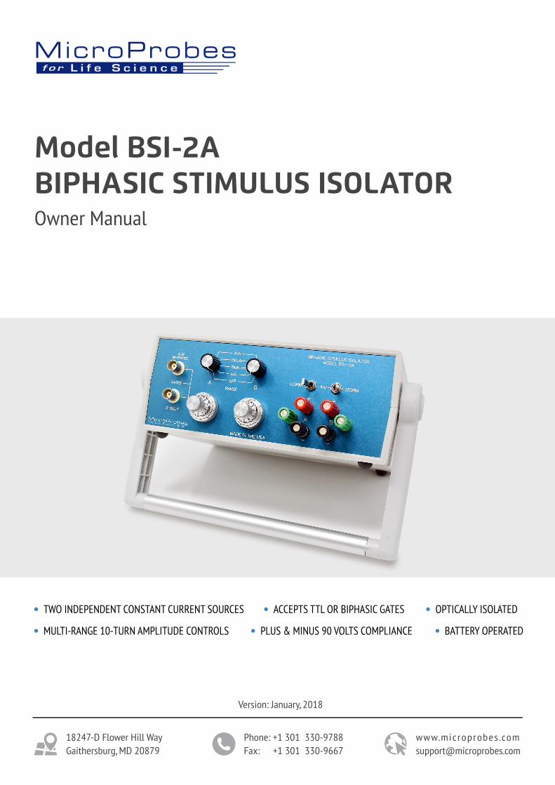
Model BSI-2ABIPHASIC STIMULUS ISOLATOROwner Manual
Version: January, 2018
18247-D Flower Hill WayGaithersburg, MD 20879
Phone: +1 301 330-9788Fax: +1 301 330-9667
www.microprobes [email protected]
TWO INDEPENDENT CONSTANT CURRENT SOURCES ACCEPTS TTL OR BIPHASIC GATES
PLUS & MINUS 90 VOLTS COMPLIANCE BATTERY OPERATEDMULTI-RANGE 10-TURN AMPLITUDE CONTROLS
OPTICALLY ISOLATED
2
Table Of Contents
Digital Version - Master Copy with QMS Representative
General Information 6
Specifications 4
Control Layout 5
Receiving and Installation 6Applications 7
Circuit Description 16General 16
Maintenance and Calibration 16
Digital Version - Master Copy with QMS Representative
Introduction 3
Operation Instructions 7Introduction 7Battery Power and High Voltage generation 8Changing Batteries 8Input Gates 8Current Range Controls 9Output Polarity Controls 10Output Configurations 11Output Monitoring 14
Service 17
Certification 17
Warranty 17
Contact information 17
3Digital Version - Master Copy with QMS Representative
Introduction
The Model BSI-2A Biphasic Stimulus Isolator has been optimized for applications requiring precise control of rectangular waveform stimuli. It is designed for use with external timing circuits, such as biphasic single channel (e. g. Microprobes for Life Science BPG-1P) or dual channel TTL (Bak Electronics DC-1 Digital Controller or other monophasic pulse signal sources such as computers). The external timing input(s) gates each of the two optically isolated, independently battery powered, constant current sources. Because they have completely independent isolators, range controls, and output circuits, the “A” and “B” outputs can be used as independent monophasic stimuli which are completely isolated from each other as well as from the control input. Each output has an inversion switch and an extra binding post to facilitate installation of coupling capacitors or current monitoring resistors. The two sets of output binding posts are strategically placed so that the addition of two jumpers (provided) converts the unit instantly to biphasic or pulse pair operation.
The Model BSI-2A features high compliance, high isolation, and the same conveniently portable plastic case as the BSI-1A. The main difference is that its output circuitry has been optimized for gated on-off operation rather than proportional input following. This mode of operation is inherently very low noise and eliminates the danger of applying DC currents as a result of low level offsets in the control signal between output pulses. It also permits manual fine tuning of the output level from the unit itself which can be placed near the preparation. If you need non-rectangular waveforms (e. g. sinusoids, ramps or computer D/A driving), we recommend the BSI-1A, a linear biphasic stimulus isolator with a complete range of both constant current and constant voltage output levels.
4Digital Version - Master Copy with QMS Representative
Specifications
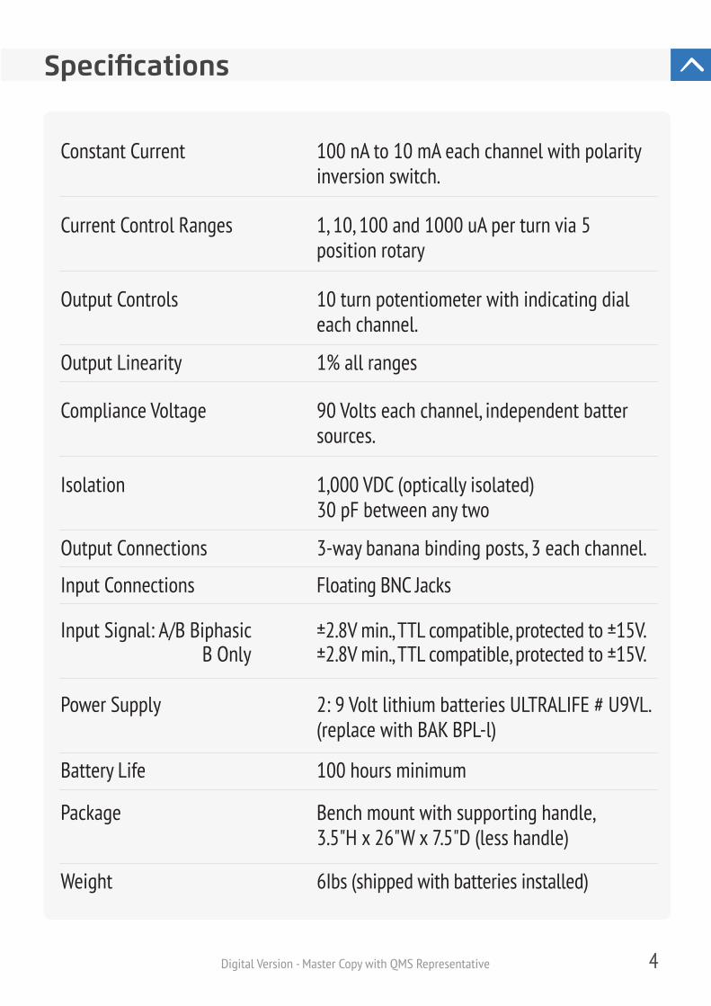
1, 10, 100 and 1000 uA per turn via 5position rotary
100 nA to 10 mA each channel with polarityinversion switch.
10 turn potentiometer with indicating dialeach channel.
1% all ranges
90 Volts each channel, independent battersources.
1,000 VDC (optically isolated)30 pF between any two
3-way banana binding posts, 3 each channel.
Floating BNC Jacks
±2.8V min., TTL compatible, protected to ±15V.±2.8V min., TTL compatible, protected to ±15V.B Only
2: 9 Volt lithium batteries ULTRALIFE # U9VL.(replace with BAK BPL-l)
100 hours minimum
Bench mount with supporting handle,3.5"H x 26"W x 7.5"D (less handle)
6Ibs (shipped with batteries installed)
Constant Current
Current Control Ranges
Output Controls
Output Linearity
Compliance Voltage
Isolation
Output Connections
Input Connections
Input Signal: A/B Biphasic
Power Supply
Battery Life
Package
Weight
5Digital Version - Master Copy with QMS Representative
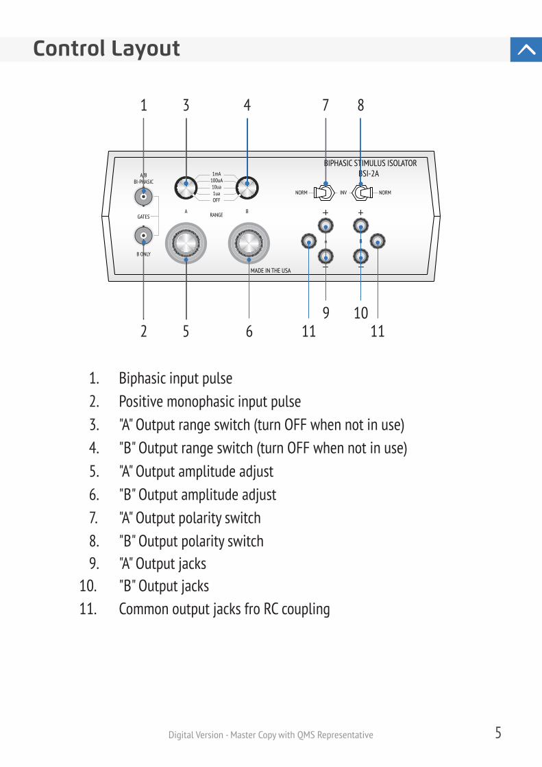
Control Layout
BIPHASIC STIMULUS ISOLATORBSI-2A
MADE IN THE USA
RANGE
OFF1ua
10ua100uA1mA
B ONLY
GATES
A/BBI-PHASIC
A
A
NORM NORMINV
B
B
1. Biphasic input pulse2. Positive monophasic input pulse3. "A" Output range switch (turn OFF when not in use)4. "B" Output range switch (turn OFF when not in use)5. "A" Output amplitude adjust6. "B" Output amplitude adjust7. "A" Output polarity switch8. "B" Output polarity switch9. "A" Output jacks
10. "B" Output jacks11. Common output jacks fro RC coupling
2 510
1 3 4 7 8
69
11 11
6
This instrument was thoroughly inspected both mechanically and electrically before leaving the factory. Please check for physical damage, which may have occurred during shipment and file a report with the carrier if any damage is found.
The power requirements for the BSI-2A are met by two 9V batteries. Before using, insure that all voltages appear at the appropriate test jacks at the rear of the instrument. Battery life is rated at 100 hours of continuous use, which is defined as any time that a RANGE switch is in the ON position. Actual battery life will usually be greater if the duty cycle is low, but the instrument should always be turned off to conserve the batteries when not in use. Battery shelf life is generally greater than one year, but this will depend on conditions of temperature and humidity. Condensation may lead to serious damage from corrosion and should be avoided. See Section Changing Batteries for detailed information on testing and replacing batteries.
Care needs to be taken in connecting an isolated, constant current device safely and effectively into configurations with other equipment. See Section Output Monitoring regarding test configurations to verify the performance of this device. Remember that a constant current device will attempt to use all available compliance voltage to force any requested output current through its output load. When connected to no load or directly to high impedance inputs such as oscilloscopes and amplifiers, as much as 180 volts total compliance voltage may be present on the outputs, which can damage sensitive equipment and poses a safety hazard.
Digital Version - Master Copy with QMS Representative
General Information
Receiving and Installation
Always verify the loading conditions to insure a safe current path before turning the instrument on.
Applications
The BSI-2A is designed for the delivery of rectangular pulse stimuli whose current amplitude is set by the panel controls and whose timing is controlled by external timing gates applied to the panel input connectors. It can be used to deliver one biphasic stimulus output, one output consisting of monophasic pulse pairs under independent timing and amplitude control, or two independent monophasic output sources, depending on the interconnection of the two sets of output jacks labeled A and B. The various configurations are described in detail in section OPERATING INSTRUCTIONS. The selection of the proper mode of operation will depend on the experimental design and the types of electrodes being used. Generally, electrical stimulation pulses delivered via metal electrodes to skin or internal tissues should contain no net DC current over time. This minimizes damage to tissue from electrolysis of body fluids and damage to electrodes from corrosion. Section Output Configurations includes specific information on the use of coupling capacitors and bleed resistors to achieve charge balance when using monophasic stimulus pulses. Even when configured in the bipolar mode, it is usually wise to include a coupling capacitor in the output to minimize the effects of small imbalances in the selected output currents for each phase.
7Digital Version - Master Copy with QMS Representative
Although the operation of the BSI-2A is straightforward, it is important that some time be spent understanding the relationships between the two input/output channels A and B and the configuration of external equipment with which they may be used.
Operation Instructions
Introduction
8Digital Version - Master Copy with QMS Representative
Battery Power and High Voltage Monitoring
The batteries should last a minimum of 100 hours during normal operation. After long periods of disuse or in case of any question regarding the proper response of the unit, the battery voltages should be checked using any DC voltmeter on the test jacks at the rear. The instrument will operate normally when the batteries are within 75% of maximum rated value, although the output voltage compliance range may be slightly reduced. Always be sure to check both batteries since they will discharge at different rates depending on the type of usage. The RANGE switch for each of the two channels is also POWER switches for each channel. When the system is not in use, they should be in the OFF position in order to reduce current consumption.
High Voltages (90 Volts per channel) are generated from the 9-Volt batteries by means of an SMPS (switch mode power supply). These voltages can be monitored on the rear of the unit and are present only when a RANGE/POWER switch is on. When switched off, voltage will linger there for several minutes but will eventually decrease to zero.
Changing Batteries
On the rear of the unit are two battery holders that are accessed by placing your thumbnail into the slot on the bottom of the door and lifting slightly. Then pull the drawer outward. The battery can then be replaced.
Input Gates
There are two input BNC connectors for control signals, labeled A/B BIPHASIC and B ONLY. Both accept logical (TTL) rather than linear control signals, and they turn on a selected output current only for the duration over which they exceed a nominal 2.8 V level.
9Digital Version - Master Copy with QMS Representative
Input A/B Biphasic can be used when a single biphasic control signal is available to control both the A and B output channels. When the input signal exceeds +2.8V, and channel ‘A’ is activated at the selected current; when the input signal is more negative than -2.8V, and B channel is activated at the selected current. Note that both channels cannot be activated simultaneously via this input alone.
Input B ONLY is used when positive going control signals are available to activate the B channel. When this input signal exceeds +2.8V, the B channel is activated at the selected current. Note that two separate positive TTL signals can be used to control the A and B channels by applying them to the A/B and B inputs respectively. In this mode, both channels may be activated simultaneously. If a negative signal is applied to the A/B input and a positive to the B ONLY input, the output of the B channel is the logical inclusive OR of the two input gates.
Both inputs are protected to ±15V only, and should never be subjected to voltages outside this range.
Current Range Controls
The output current for each channel is defined by the setting of a range selector switch and a 10-turn potentiometer. For biphasic output stimuli, the two channels should be hooked in parallel and are generally operated at the same range for similar if not identical output currents. However, for separate use of the two output channels, both controls for each channel are completely independent.
The RANGE/TURN switch selects the amount of output current per turn of the 10-turn potentiometer. Thus, the maximum output on each channel is 10 turns x 1 mA/turn or 10 mA. The minimum output current for any range except OFF is defined by the range times the minimum setting of the stop of the 10 turn potentiometer. You will note that the potentiometer dial reaches a stop before it reads exactly zero (at about 0.1 turn).
10Digital Version - Master Copy with QMS Representative
Output Polarity Controls
Each output channel has a three-position lever switch to select the polarity of the output current at the output binding posts. In the center OFF position, the output posts are disconnected from the output circuitry. In the NORMAL position, the red post, marked (+) is the anode and will have a positive driving voltage with respect to the green post, marked ‘IN’ the (INVERT) position, the output posts are reversed, and their driving voltages are given by the (-) and (+) symbols. When the two outputs are connected in parallel for biphasic pulsing, both switches should be positioned in the same direction: both to the left if the ‘A’ control gate should result in an anodal signal and the B control gate in a cathodal pulse, or both to the right for reversed biphasic polarity. When the two outputs are connected in parallel but for monophasic pulse pair delivery, the control levers will be pointing either away from each other (anodal pulse pairs) or towards each (cathodal pulse pairs). When the two outputs are used separately and isolated from each other, either output may be inverted independently of the other.
Note that the definition of current polarity applies only to the output jacks of the stimulator and not to the preparation itself. For example, if a monopolar stimulating electrode is used with respect to a large, remote indifferent, then the polarity of the effective stimulating current may be reversed by rearranging the connections to the output jacks as well as using the polarity controls.
This is not an error. This position has been factory calibrated to correspond to the minimum current output for each range. To resolve smaller currents, use the next lower range. The minimum controlled output current is thus 0.1 turn x 1 uA/turn or 100 nA. To prevent the channel from delivering any current at all in response to an input gate, set the RANGE to OFF. It is advisable to always hook up the preparation with the RANGE in the OFF position and work gradually upwards.
11Digital Version - Master Copy with QMS Representative
Output Configurations
Constant current generators may be connected in parallel but should never be connected in series. For equivalent circuit purposes, they are modeled as very high source impedances, so one cannot drive current through the other but only through a load. Note that this is the reverse of a voltage stimulator or battery, which is a very low impedance source. Batteries may be hooked in series to achieve the desired voltage, but will discharge each other if hooked in parallel with different or opposing voltages. See OUTPUT POLARITY CONTROLS, for details of biphasic polarity control, when using the two generators A and B in parallel.
When generating monophasic pulses or significantly asymmetrical biphasic pulses for use with metal electrodes in biological tissue, it is generally advisable to incorporate a coupling capacitor to prevent long term accumulated net DC current flow.
To avoid confusion, the user should adopt some convention and stick to it. When used with biphasic pulse generators such as the MLS BPG-1 pulse polarity at the preparation is the result of a least three separate selection options: the connections to the output jacks, the position of the output polarity controls, and the polarity control on the pulse generator. It is best to keep two of these fixed and switch only the most convenient one. Note that when the two output currents are not selected to be equal to each other on the , the effects of flipping polarity at the pulse generator are not the same as flipping polarity at the output polarity control, since the former will swap the two selected amplitudes as well as their signs.
The principle is that the capacitor stores all the charge of each pulse, then slowly leaks backwards an equivalent amount of charge between pulses. If an asymmetrical biphasic pulse was delivered, the net charge difference between the two phases will be leaked back. However, simply putting a capacitor in series will not work because the constant current generator is in series with the discharge path, and it has a
12
When using the IMP-2A to provide two independent, capacitively coupled currentsources, the extra binding posts provided (white, no internal connection on either)next to each output section are useful for mounting the separate coupling capacitorand bleed resistor needed for each section. Remember that the two output channels
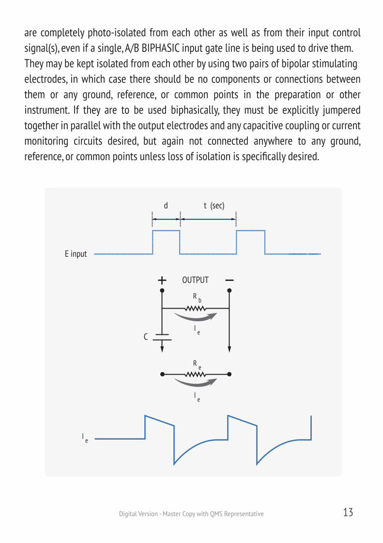
a virtually infinite source impedance even in the off state. In this case, the capacitor will simply charge cumulatively with each output pulse until it is storing a voltage equal to the output compliance voltage (assuming it does not break down at that voltage), at which time the constant current generator can no longer deliver any output. As the figure below indicates, a bleed resistor, Rb, must be placed across the outputs of the current generator to limit its output impedance. Unfortunately, this constitutes a parallel load during the delivery of current pulses, which will soak up some of the current intended for the electrodes.
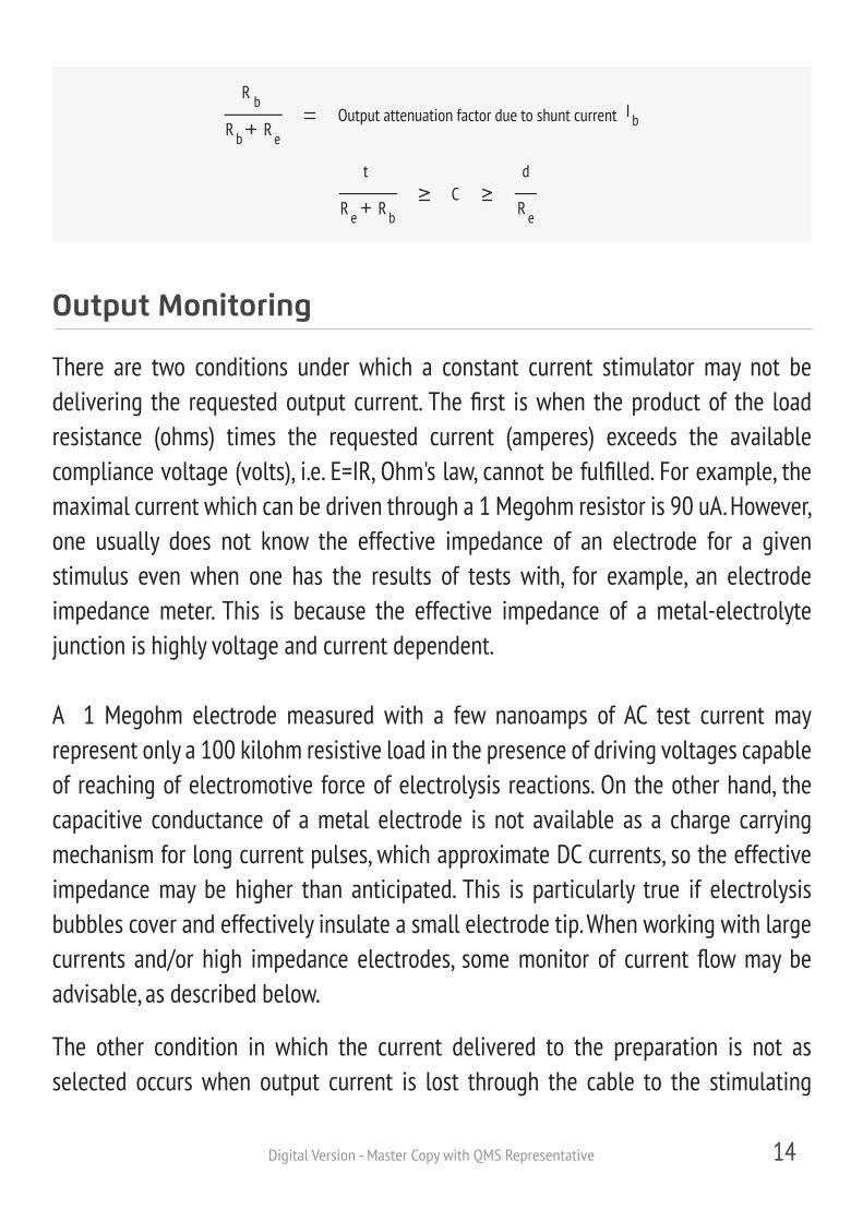
Generally, a compromise must be reached in which Rb is as large as possible (relative to the electrode impedance Re) but still small enough to pass adequate current to discharge the series capacitor between output pulses. This in turn depends on the value of that capacitor, which should be as small as possible to discharge as rapidly as possible, but must not be so small that it charges up to compliance voltage during each stimulus output. Thus, the optimal value for the capacitor can be bracketed by the charging and discharge times of the circuit. From the equations in the figure below, it is apparent that for some conditions (long pulse durations and short inter-pulse intervals), no combination of values is possible which does not seriously degrade output linearity. For these situations, closely balanced biphasic pulses are the best choice. To calculate a coupling capacitor value for additional safety under these circumstances, scale down variable "d" by the maximal percentage imbalance anticipated. If no bleed resistor at all is used, the voltage across C can actually be used as a monitor of charge imbalance between phases, since it effectively integrates any net charge.
Digital Version - Master Copy with QMS Representative
13Digital Version - Master Copy with QMS Representative
OUTPUT
C
d t
E input
(sec)
R b
I e
R e
I e
I e
are completely photo-isolated from each other as well as from their input control signal(s), even if a single, A/B BIPHASIC input gate line is being used to drive them.They may be kept isolated from each other by using two pairs of bipolar stimulatingelectrodes, in which case there should be no components or connections between them or any ground, reference, or common points in the preparation or other instrument. If they are to be used biphasically, they must be explicitly jumpered together in parallel with the output electrodes and any capacitive coupling or currentmonitoring circuits desired, but again not connected anywhere to any ground, reference, or common points unless loss of isolation is specifically desired.
14Digital Version - Master Copy with QMS Representative
I bOutput attenuation factor due to shunt current
C
R b
R eR b
t
R bR e
d
R e
Output Monitoring
There are two conditions under which a constant current stimulator may not be delivering the requested output current. The first is when the product of the load resistance (ohms) times the requested current (amperes) exceeds the available compliance voltage (volts), i.e. E=IR, Ohm's law, cannot be fulfilled. For example, the maximal current which can be driven through a 1 Megohm resistor is 90 uA. However, one usually does not know the effective impedance of an electrode for a given stimulus even when one has the results of tests with, for example, an electrode impedance meter. This is because the effective impedance of a metal-electrolyte junction is highly voltage and current dependent.
A 1 Megohm electrode measured with a few nanoamps of AC test current may represent only a 100 kilohm resistive load in the presence of driving voltages capable of reaching of electromotive force of electrolysis reactions. On the other hand, the capacitive conductance of a metal electrode is not available as a charge carrying mechanism for long current pulses, which approximate DC currents, so the effective impedance may be higher than anticipated. This is particularly true if electrolysis bubbles cover and effectively insulate a small electrode tip. When working with large currents and/or high impedance electrodes, some monitor of current flow may be advisable, as described below.
The other condition in which the current delivered to the preparation is not asselected occurs when output current is lost through the cable to the stimulating
15Digital Version - Master Copy with QMS Representative
When monitoring output current, special measures must be taken to avoid breaking electrical isolation or damaging monitoring equipment with high compliance voltages. Generally, current is best monitored by examining the voltage dropped across a small value, precision resistor in series with the actual load. If kept significantly small than the actual electrode load resistance, this resistor will experience voltage drops which are always a small percentage of the compliance voltage even at maximal output levels, and will not significantly degrade the available compliance voltage at the electrode. It is very difficult to maintain complete electrical isolation when monitoring this voltage unless a battery powered, optically isolated differential preamplifier is available. For many purposes, it may be possible to merely confirm that the desired current is being passed during test stimulation with the circuit ground referenced, then detach the monitor circuit and assume that the stimulator is working. In this case, any point in the series circuit consisting of output jacks, stimulating electrodes, and series resistor may be selected as ground since they are all floating. Note, however, that the monitored current polarity will depend on where in the circuit the ground is placed. If current must be continuously monitored during the experiment, it may be possible to compromise isolation only marginally by using a high impedance, differential amplifier across the series resistor,
electrode tips. In this case, the stimulator is in fact, supplying the requested current, but it is being shunted by stray capacitance or resistive leakage in the output leads. When attempting to pass very brief current pulses through high impedance electrodes, the parallel loading capacitance contributed by, for example, a length of coaxial cable, can soak up a significant percentage of the output current. There is no way to monitor this problem without making it worse by adding more stray capacitance. For very high impedance situations such as fast iontophoretic injections through fine micropipettes, special capacitive peaking techniques are required, as employed in the Microprobes for Life Science microiontophoresis systems. Generally, careful positioning and minimized cabling of the output stage are sufficient measures.
The Model BSI-2A contains two separate externally gated constant current sources They can be triggered simultaneously by applying a biphasic pulse pair to the A/B in put or independently by applying monophasic pulses separately to the A/B and B ONLY inputs. Each circuit operates from its own battery and isolation of the two circuits is maintained by careful component layout. When biphasic output pulses are desired one simply ties the output binding post, connectors in parallel. The desired polarity is achieved by proper positioning of the two polarity switches, normal being positive going. The two additional white binding posts are not connected to anything and are meant to be used as a tie point for external resistor capacitor coupling components.
which amplifier is physically grounded to the preparation at its common or reference input. The degree of loss of isolation is approximately the ratio of the impedance of the pair of stimulating electrodes to the input impedance of the amplifier. Again, however, the effective input impedance to be considered must include all the wires and shields associated with the amplifier, which must be minimized to reduce both isolation loss and current shunting. The third binding post of each output channel (white) is not connected internally and provides a convenient place to attach a series current monitoring resistor and amplifier leads.
Circuit Description
General
Digital Version - Master Copy with QMS Representative
No field calibration is required.
Maintenance and Calibration
16

17Digital Version - Master Copy with QMS Representative
CertificationMicroprobes for Life Science certifies that all its instrument are tested and inspected thoroughly and found to meet all published specifications before shipment from the factory.
WarrantyAll Microprobes for Life Science' products are warranted against defects in materials and workmanship for one full year from the date of delivery. Products that prove to be defective during the warranty period will be repaired or replaced without charge provided they are returned to the factory. No other warranty is expressed or implied. We are not liable for consequential damages.
ServiceMicroprobes for Life Science will provide for servicing and calibration after the warranty period for a reasonable service charge. The instrument should be shipped to the factory postage prepaid. There is a minimum service charge of one hundred dollars ($100.00) and all instruments will be repaired, calibrated and returned promptly. Please enclose a cover letter with the instrument explaining deficiencies and identify by serial number in all correspondence pertaining to any instrument.
Contact Information
18247-D Flower Hill Way Gaithersburg, MD 20879 Phone: +1 (301) - 330-9788 Fax: +1 (301) - 330-9667
[email protected] www.microprobes.com
MicroProbesf o r L i f e S c i e n c e