bsi british standards
TRANSCRIPT
raising standards worldwide™
NO COPYING WITHOUT BSI PERMISSION EXCEPT AS PERMITTED BY COPYRIGHT LAW
BSI British Standards
Limits and fits for engineeringPart 2: Guide to the selection of fits in BS 1916-1
BS 1916-2:2009
BS 1916-2:2009 BRITISH STANDARD
Publishing and copyright informationThe BSI copyright notice displayed in this document indicates when the document was last issued.
© BSI 2009
ISBN 978 0 580 65215 8
ICS 17.040.10
The following BSI references relate to the work on this standard: Committee reference TDW/4 Draft for comment 09/30192611 DC
Publication historyFirst published December 1953Second (present) edition, September 2009
Amendments issued since publication
Date Text affected
标准分享网 www.bzfxw.com 免费下载
BRITISH STANDARD
© BSI 2009 • i
BS 1916-2:2009
ContentsForeword ii1 Scope 12 Normative references 13 Terms and definitions 14 Terminology 35 Hole tolerances 36 Classification of fits 37 Choice of fit 88 Choice of tolerance 99 Preferred sizes 910 Recommended tolerances for standard fits 14
Bibliography 40
List of figuresFigure 1 – Diagram showing disposition of limits and tolerances (unilateral hole basis) 2Figure 2 – The disposition of standard shaft fits with H7 and H8 holes for diameter range 1.19 in to 1.97 in 5Figure 3 – The degree of accuracy which can reasonably be expected from various manufacturing processes under average conditions 10Figure 4 – Typical data sheet 16Figure 5 – Belt drive unit 17Figure 6 – Belt driven gear pump 17Figure 7 – Link mechanism: shaft and lever 18Figure 8 – Dashpot for oil circuit breaker 19Figure 9 – Dashpot for switchgear time lag device 20Figure 10 – High pressure hydraulic hand pump 21
List of tablesTable 1 – Classification of types of fits 4Table 2 – Equivalent fits on the hole basis and shaft basis 8Table 3 – Preferred sizes: fractional inch series 11Table 4 – Preferred sizes: decimal inch series 12Table 5 – Complete series of preferred inch sizes 13Table 6 – Tolerances for clearance fits, shaft c 22Table 7 – Tolerances for clearance fits, shaft d 23Table 8 – Tolerances for clearance fits, shaft e 24Table 9 – Tolerances for clearance fits, shaft f 25Table 10 – Tolerances for clearance fits, shaft g 26Table 11 – Tolerances for clearance fits, shaft h 27Table 12 – Tolerances for transition fits, shaft j 28Table 13 – Tolerances for transition fits, shaft k 29Table 14 – Tolerances for transition fits, shaft m 30Table 15 – Tolerances for transition fits, shaft n 31Table 16 – Tolerances for interference fits, shaft p 32Table 17 – Tolerances for interference fits, shaft r 33Table 18 – Tolerances for interference fits, shaft s 34Table 19 – Tolerances for interference fits, shaft t 36Table 20 – Tolerances for interference fits, shaft u 38
Summary of pagesThis document comprises a front cover, an inside front cover, pages i to ii, pages 1 to 40, an inside back cover and a back cover.
BS 1916-2:2009
ii • © BSI 2009
BRITISH STANDARD
Foreword
Publishing information
This British Standard is published by BSI and came into effect on 30 September 2009. It was prepared by Technical Committee TDW/4, Technical product realization. A list of organizations represented on this committee can be obtained on request to its secretary.
Supersession
This British Standard supersedes BS 1916-2:1953, which is withdrawn.
Relationship with other publications
This British Standard is published in three parts:
Part 1 – Guide to limits and tolerances;
Part 2 – Guide to the selection of fits in BS 1916-1;
Part 3 – Guide to tolerances, limits and fits for large diameters;
The ISO 286 (BS EN 20286) series establishes the ISO code-system for tolerances of linear sizes and is published in the following parts:
ISO 286-1 (BS EN 20286-1), ISO system of limits and fits – Part 1: Bases of tolerances, deviations and fits;
ISO 286-2 (BS EN 20286-2), ISO system of limits and fits – Part 2: Tables of standard tolerance grades and limit deviations for holes and shafts.
The ISO 286 series covers the metric system of limits and fits; the BS 1916 series provides guidance and recommendations on the equivalent inch system (imperial).
Information about this document
In view of the time elapsed since its original publication in 1953, this British Standard was reviewed in detail in 2009. It was decided that the technical provisions of the previous edition were still generally applicable, but the figures have been redrawn for ease of use, the wording of some guidance updated for clarity, and the opportunity was taken to update references to other standards.
Use of this document
As a guide, this part of BS 1916 takes the form of guidance and recommendations. It should not be quoted as if it were a specification or a code of practice and claims of compliance cannot be made to it.
Contractual and legal considerations
This publication does not purport to include all the necessary provisions of a contract. Users are responsible for its correct application.
Compliance with a British Standard cannot confer immunity from legal obligations.
标准分享网 www.bzfxw.com 免费下载
www.bzfxw.com
BRITISH STANDARD
© BSI 2009 • 1
BS 1916-2:2009
1 ScopeThis British Standard gives guidance on the selection of fits given in BS 1916-1.
The recommendations apply, in particular, to fits between cylindrical parts, designated as “holes” and “shafts”, in which case the term “size” refers to the diameter of the mating parts. The recommendations are also applicable to parts other than cylindrical, in which case the term “size” refers to a length, width or other dimension.
Tables of preferred sizes are included to avoid the indiscriminate selection of dimensions, and their use is strongly recommended.
2 Normative referencesThe following referenced documents are indispensable for the application of this document. For dated references, only the edition cited applies. For undated references, the latest edition of the referenced document (including any amendments) applies.
BS 1916-1:2009, Limits and fits for engineering – Part 1: Guide to limits and tolerances
BS 8888, Technical product specification – Specification
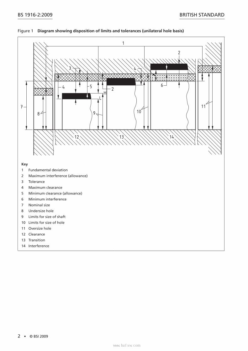
3 Terms and definitionsFor the purposes of this part of BS 1916, the following terms and definitions apply.
NOTE Figure 1 illustrates the basic definitions used in the text
www.bzfxw.com
BS 1916-2:2009
2 • © BSI 2009
BRITISH STANDARD
Figure 1 Diagram showing disposition of limits and tolerances (unilateral hole basis)
1
3 4
2
6
1110
2
9
54
8
7
12 13 14
LH
Key
1 Fundamental deviation
2 Maximum interference (allowance)
3 Tolerance
4 Maximum clearance
5 Minimum clearance (allowance)
6 Minimum interference
7 Nominal size
8 Undersize hole
9 Limits for size of shaft
10 Limits for size of hole
11 Oversize hole
12 Clearance
13 Transition
14 Interference
标准分享网 www.bzfxw.com 免费下载
www.bzfxw.com
BRITISH STANDARD
© BSI 2009 • 3
BS 1916-2:2009
4 TerminologyThe disposition of the tolerance zone for a hole relative to the nominal size is denoted by a capital letter and the magnitude, or grade, of the tolerance by a suffix number, e.g. H7.
The disposition of the tolerance zone for a shaft relative to the nominal size is denoted by a small letter and the magnitude, or grade, of the tolerance by a suffix number, e.g. p6.
A fit is described by a combination of symbols, e.g. H7–p6 or H7/p6.
NOTE See BS 1916-1:2009, Clauses 6 and 7.
On production drawings, the actual limits for both hole and shaft should be stated by one of the methods recommended in BS 8888, so that the actual size of the part can be ascertained without reference to this standard. There are, however, certain circumstances, for example in general specifications, or on preliminary design drawings, in which it is convenient to state the particular type of fit by symbols only.
5 Hole tolerancesThe following is a summary of the uses of the various grades of the unilateral hole H from H5 to H11.
• H5. This grade can normally only be produced by precision boring, fine internal grinding, or honing.
• H6. This grade can be produced by fine grinding or honing, and possibly hand reaming.
• H7. This grade is produced by grinding, broaching or careful reaming.
• H8. This grade is produced by boring or machine reaming.
• H9. This grade is used on high quality products for milled or slotted widths.
• H10. This grade is not normally used for diameter fits, although it can be used for drilled holes. It is used for milled widths on unimportant parts.
• H11. This grade is used for coarse drilled, punched or pressed holes on non-fitting parts.
6 Classification of fits
6.1 GeneralThe whole range of fits is divided into three main classes:
• clearance;
• transition;
• interference.
Each main class, using the unilateral (H) hole, is further sub-divided into several types of fit; for example, clearance fits are divided into six types, from very fine to very coarse clearance. Each type of fit is classified by the letter symbol of the shaft which produces that type, for example: clearance fit, shaft “e”; or clearance fit, shaft “f”.
www.bzfxw.com
BS 1916-2:2009
4 • © BSI 2009
BRITISH STANDARD
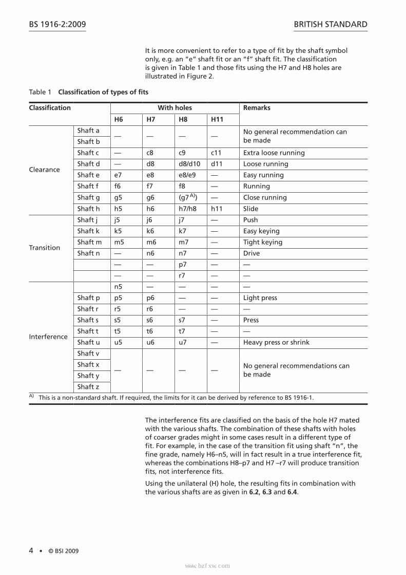
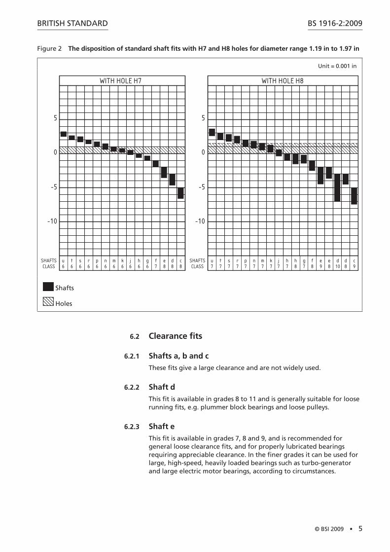
It is more convenient to refer to a type of fit by the shaft symbol only, e.g. an “e” shaft fit or an “f” shaft fit. The classification is given in Table 1 and those fits using the H7 and H8 holes are illustrated in Figure 2.
Table 1 Classification of types of fits
Classification With holes Remarks
H6 H7 H8 H11
Clearance
Shaft a— — — —
No general recommendation can be madeShaft b
Shaft c — c8 c9 c11 Extra loose running
Shaft d — d8 d8/d10 d11 Loose running
Shaft e e7 e8 e8/e9 — Easy running
Shaft f f6 f7 f8 — Running
Shaft g g5 g6 (g7 A)) — Close running
Shaft h h5 h6 h7/h8 h11 Slide
Transition
Shaft j j5 j6 j7 — Push
Shaft k k5 k6 k7 — Easy keying
Shaft m m5 m6 m7 — Tight keying
Shaft n — n6 n7 — Drive
— — p7 — —
— — r7 — —
Interference
n5 — — — —
Shaft p p5 p6 — — Light press
Shaft r r5 r6 — — —
Shaft s s5 s6 s7 — Press
Shaft t t5 t6 t7 — —
Shaft u u5 u6 u7 — Heavy press or shrink
Shaft v
— — — —No general recommendations can be made
Shaft x
Shaft y
Shaft zA) This is a non-standard shaft. If required, the limits for it can be derived by reference to BS 1916-1.
The interference fits are classified on the basis of the hole H7 mated with the various shafts. The combination of these shafts with holes of coarser grades might in some cases result in a different type of fit. For example, in the case of the transition fit using shaft “n”, the fine grade, namely H6–n5, will in fact result in a true interference fit, whereas the combinations H8–p7 and H7 –r7 will produce transition fits, not interference fits.
Using the unilateral (H) hole, the resulting fits in combination with the various shafts are as given in 6.2, 6.3 and 6.4.
标准分享网 www.bzfxw.com 免费下载
www.bzfxw.com
BRITISH STANDARD
© BSI 2009 • 5
BS 1916-2:2009
Figure 2 The disposition of standard shaft fits with H7 and H8 holes for diameter range 1.19 in to 1.97 in
Unit = 0.001 in
u 6
t 6
s 6
r 6
p 6
n 6
m 6
k 6
j 6
h 6
g 6
f 7
e 8
d 8
c 8
u 7
t 7
s 7
r 7
p 7
n 7
m 7
k 7
j 7
h 7
h 8
g 7
f 8
e 9
e 8
d 10
d 8
c 9
-10
-5
0
5
-10
-5
0
5
WITH HOLE H7 WITH HOLE H8
SHAFTSCLASS
SHAFTSCLASS
Shafts
Holes
6.2 Clearance fits
6.2.1 Shafts a, b and c
These fits give a large clearance and are not widely used.
6.2.2 Shaft d
This fit is available in grades 8 to 11 and is generally suitable for loose running fits, e.g. plummer block bearings and loose pulleys.
6.2.3 Shaft e
This fit is available in grades 7, 8 and 9, and is recommended for general loose clearance fits, and for properly lubricated bearings requiring appreciable clearance. In the finer grades it can be used for large, high-speed, heavily loaded bearings such as turbo-generator and large electric motor bearings, according to circumstances.
www.bzfxw.com
BS 1916-2:2009
6 • © BSI 2009
BRITISH STANDARD
6.2.4 Shaft f
This fit is available in grades 6, 7 and 8 and is recommended for use as a normal running fit. It is widely used as a normal grease-lubricated or oil-lubricated bearing where no substantial temperature differences are encountered. Typical applications are gearbox shaft bearings and the bearings of small electric motors, pumps, etc.
6.2.5 Shaft g
This fit is expensive to manufacture since the clearance is small, and it is not recommended as a running fit except in precision equipment where shaft loadings are very light. Typical applications are the bearings for accurate linkwork, and for piston and slide valves. In addition it is often used for spigot or location fits.
6.2.6 Shaft h
The upper shaft limit of this fit is zero, although in practice a slight clearance will usually be found. It exists in grades 5 to 11, and is widely used for non-running parts. It is useful for normal location and spigot fits and in the finer grades can be used as a precision sliding fit.
6.3 Transition fits
6.3.1 Shaft j
This is a transition fit averaging a slight clearance, and is available in grades 5 to 11. It is recommended for location fits, requiring slightly less clearance than is given with the “h” shaft, and where a slight interference is permissible. Typical applications are coupling spigots and recesses, gear rings clamped to steel hubs, etc.
6.3.2 Shaft k
This is a true transition fit averaging virtually no clearance. It is available in grades 5 to 11, and is recommended for location fits where a slight interference can be tolerated with the object, for example, of eliminating vibration.
6.3.3 Shaft m
This transition fit averages a slight interference, although appreciable assembly force will be required if the extremes are encountered. It is available in grades 5, 6 and 7.
6.3.4 Shaft n
This transition fit averages slightly more interference than the “m” shaft, and gives clearance only on extreme sizes. It is available in grades 5, 6 and 7, and is recommended for generally “tight” assembly fits. The finest grade (n5) is used as a true interference fit with the hole H6.
标准分享网 www.bzfxw.com 免费下载
www.bzfxw.com
BRITISH STANDARD
© BSI 2009 • 7
BS 1916-2:2009
6.4 Interference fitsNOTE The factors governing the choice of an interference fit are such that only generalized recommendations can be made. Some general guidance is given here and some particular examples are quoted in the fit tables (Table 16 to Table 20), but it is recommended that in every case, careful consideration be given to the factors affecting the fit, i.e. diameter and length of engagement, materials, surface finish, induced stresses, gripping forces, assembly forces and assembly method, before the final choice is made.
6.4.1 Shafts
6.4.1.1 Shaft p
This will give a true interference fit with holes of grades 6 or 7, but with holes of grade 8 a transition fit will be obtained. The amount of interference is not excessive but is sufficient to give non-ferrous parts a light press fit which can be dismantled when required. It is the standard press fit for steel, cast iron or brass-to-steel assemblies. The amount of interference is too small for satisfactory fits to be obtained in very elastic materials, such as light alloys.
6.4.1.2 Shaft r
This combination will give a medium drive fit on ferrous parts, and on non-ferrous parts a light drive fit which can be easily dismantled when required. With the hole H8 an interference fit is obtained with diameters over 3.94 in; with smaller diameters a transition fit results.
6.4.1.3 Shaft s
This is used for the permanent or semi-permanent assembly of steel and cast iron members, the amount of interference being sufficient to provide considerable gripping force. When using elastic materials, e.g. light alloys, it is equivalent to the “p” shaft fit in ferrous materials. Typical applications are collars pressed on to shafts, valve seatings, etc.
6.4.1.4 Shafts t, u, v, x, y and z
These fits involve an increasing degree of interference, and no general recommendations can be made.
6.4.2 Tolerances
When determining the tolerances for an interference fit, it is necessary to check the minimum as well as the maximum interference; the former with regard to the longitudinal forces and torques to be transmitted, the latter with regard to the permissible stresses in the material and the assembling and dismantling forces. Therefore, for interference fits, the lower deviations of the shafts were determined in such a way as to provide a definite amount of minimum interference with reference to the upper deviations of the hole H7.
www.bzfxw.com
BS 1916-2:2009
8 • © BSI 2009
BRITISH STANDARD
If D = geometric mean of the diameter size range in inches, the amounts of minimum interference in units of 0.001 in are as follows.
• Shaft s: Minimum interference = 0.4 × D = (0.000 4 in per in of diameter).
• Shaft t: Minimum interference = 0.63 × D = (0.000 63 in per in of diameter).
• Shaft u: Minimum interference = 1.0 × D = (0.001 in per in of diameter).
• Shaft v: Minimum interference = 1.25 × D = (0.001 25 in per in of diameter).
• Shaft x: Minimum interference = 1.6 × D = (0.001 6 in per in of diameter).
• Shaft y: Minimum interference = 2.0 × D = (0.002 in per in of diameter).
• Shaft z: Minimum interference = 2.5 × D = (0.002 5 in per in of diameter).
7 Choice of fitThe tables of recommended fits are compiled on the unilateral (H) hole basis system, but if unilateral (h) shaft basis fits are required, the same maximum and minimum amounts of clearance or interference are provided by the equivalent shaft basis fits. For transition and interference fits, this condition is only satisfied if the holes are mated with a shaft of the next finer quality, e.g.:
• hole basis clearance fit H7–g6 = shaft basis clearance fit G7–h6;
• hole basis transition fit H7–m6 = shaft basis transition fit M7–h6.
A complete list of interchangeable fits is given in Table 2.
Table 2 Equivalent fits on the hole basis and shaft basis
Clearance Transition Interference
Hole basis Shaft basis Hole basis Shaft basis Hole basis Shaft basis
H7–c8 H8–c9 H11–c11
C8–h7 C9–h8 C11–h11
H6–j5 H7–j6 H8–j7
J6–h5 J7–h6 J8–h7
H6–n5 N6–h5
H6–p5 H7–p6
P6–h5 P7–h6H7–d8
H8–d9 H11–d11
D8–h7 D9–h8 D11–h11
H6–k5 H7–k6 H8–k7
K6–h5 K7–h6 K8–h7
H6–r5 H7–r6
R6–h5 R7–h6
H6–e7 H7–e8 H8–e8
E7–h6 E8–h7 E8–h8
H6–m5 H7–m6 H8–m7
M6–h5 M7–h6 M8–h7
H6–s5 H7–s6 H8–s7
S6–h5 S7–h6 S8–h7
H6–f6 H7–f7 H8–f8
F6–h6 F7–h7 F8–h8
H7–n6 H8–n7
N7–h6 N8–h7
H6–t5 H7–t6 H8–t7
T6–h5 T7–h6 T8–h7
H8–p7 P8–h7H6–g5 H7–g6 H8–g7
G6–h5 G7–h6 G8–h7
H6–u5 H7–u6 H8–u7
U6–h5 U7–h6 U8–h7
H8–r7 R8–h7
标准分享网 www.bzfxw.com 免费下载
www.bzfxw.com
BRITISH STANDARD
© BSI 2009 • 9
BS 1916-2:2009
The use of the unilateral hole basis is strongly recommended, but there is still a need for oversize and undersize holes for special applications, e.g. in the case of two different fits on the same shaft diameter. The system makes provision for this by a series of oversize holes (A to G), and a series of undersize holes (K to Z), which will be useful for outside diameter fits for ball bearings.
NOTE Tolerances for these holes are in BS 1916-1:2009, Table 2.
The tolerance symbols given in the tables of recommended fits (Table 6 to Table 20) are equally suitable for inch or metric measure (see BS EN 20286 for metric units of measurement).
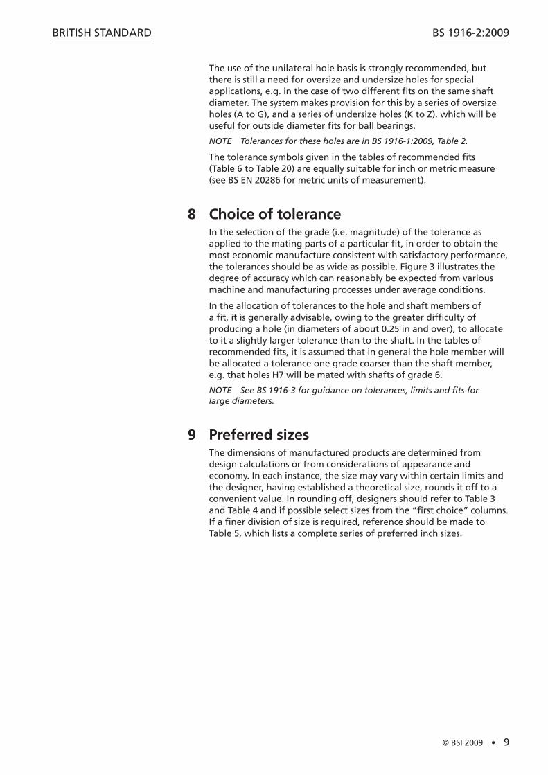
8 Choice of toleranceIn the selection of the grade (i.e. magnitude) of the tolerance as applied to the mating parts of a particular fit, in order to obtain the most economic manufacture consistent with satisfactory performance, the tolerances should be as wide as possible. Figure 3 illustrates the degree of accuracy which can reasonably be expected from various machine and manufacturing processes under average conditions.
In the allocation of tolerances to the hole and shaft members of a fit, it is generally advisable, owing to the greater difficulty of producing a hole (in diameters of about 0.25 in and over), to allocate to it a slightly larger tolerance than to the shaft. In the tables of recommended fits, it is assumed that in general the hole member will be allocated a tolerance one grade coarser than the shaft member, e.g. that holes H7 will be mated with shafts of grade 6.
NOTE See BS 1916-3 for guidance on tolerances, limits and fits for large diameters.
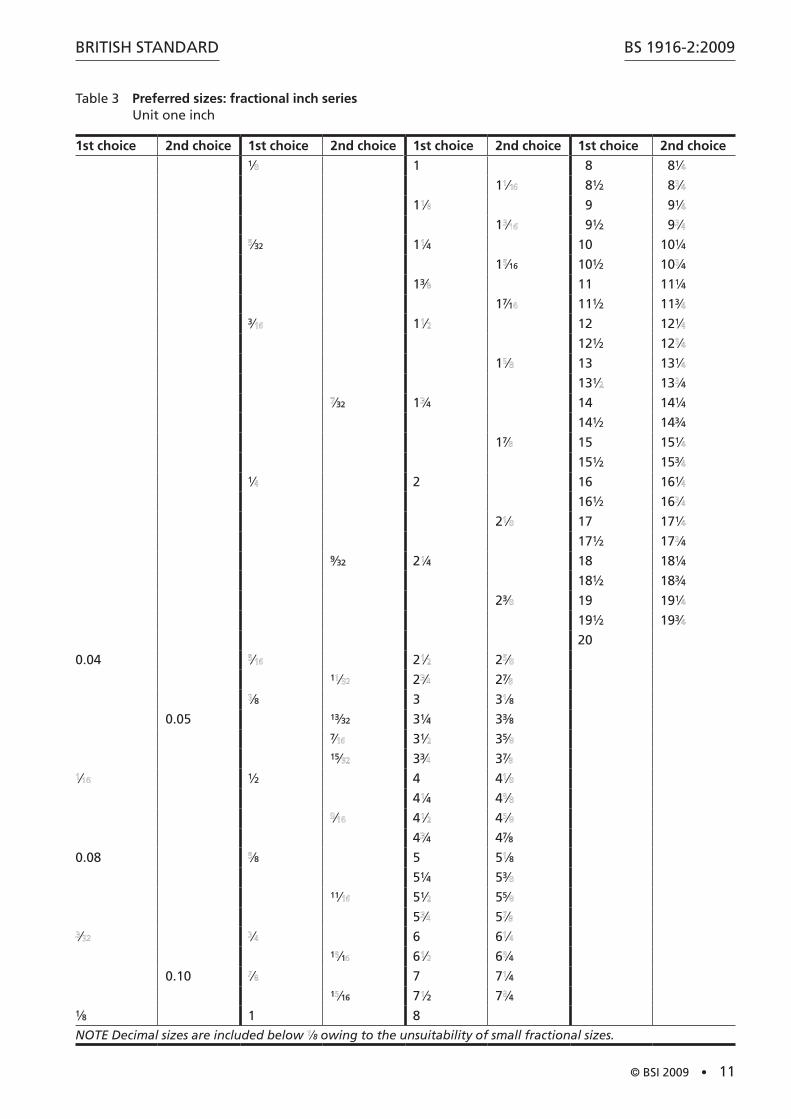
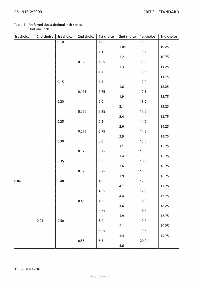
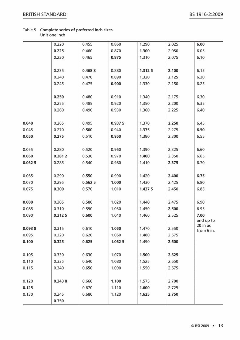
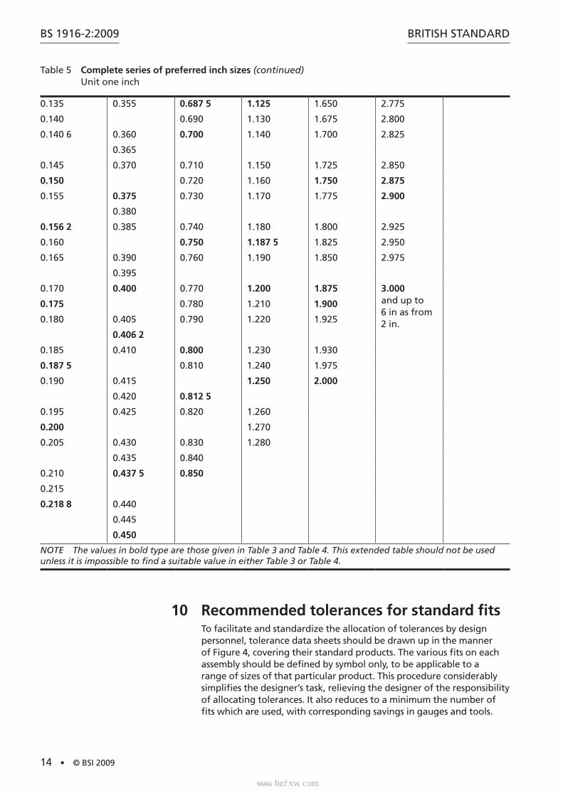
9 Preferred sizesThe dimensions of manufactured products are determined from design calculations or from considerations of appearance and economy. In each instance, the size may vary within certain limits and the designer, having established a theoretical size, rounds it off to a convenient value. In rounding off, designers should refer to Table 3 and Table 4 and if possible select sizes from the “first choice” columns. If a finer division of size is required, reference should be made to Table 5, which lists a complete series of preferred inch sizes.
www.bzfxw.com
BS 1916-2:2009
10 • © BSI 2009
BRITISH STANDARD
Figure 3 The degree of accuracy which can reasonably be expected from various manufacturing processes under average conditions
Dimensions in inches
16
15
14
13
12
11
10
9
8
7
6
5
4
3
2
1
0.5 1.0 1.5 2.0 2.5 3.0 3.5 4.00.05
0.0
0.2
0.5
1.0
2.0
5.0
10.0
20.0
50.0
100.0
Tolerance(0.001)
Tolerancequality
Diameter
Tolerance qualities key
1 Slip blocks, reference gauges
2 High quality gauges, plug gauges
3 Good quality gauges, gap gauges
4 Gauges, fits of extreme precision produced by lapping
5 Ball bearings, machine lapping, diamond or fine boring, fine grinding
6 Grinding, fine honing
7 High quality turning, broaching, honing
8 Centre lathe turning and boring, reaming, capstan or automatic in good condition
9 Worn capstan or automatic; horizontal or vertical boring machine
10 Milling, slotting, planing, metal rolling or extrusion
11 Drilling, rough turning and boring; precision tube drawing
12 Light press work; tube drawing
13 Press work; tube rolling
14 Die casting or moulding; rubber moulding
15 Stamping (approximately)
16 Sand casting (approximately); flame cutting
标准分享网 www.bzfxw.com 免费下载
www.bzfxw.com
BRITISH STANDARD
© BSI 2009 • 11
BS 1916-2:2009
Table 3 Preferred sizes: fractional inch seriesUnit one inch
1st choice 2nd choice 1st choice 2nd choice 1st choice 2nd choice 1st choice 2nd choice1⁄ 1 8 81⁄
1 ⁄ 81⁄2 8 ⁄
1 ⁄ 9 91⁄
1 ⁄ 91⁄2 9 ⁄
⁄32 1 ⁄4 10 101⁄4
1 ⁄16 101⁄2 10 ⁄4
13⁄ 11 111⁄4
17⁄1 111⁄2 113⁄3⁄ 1 ⁄ 12 121⁄
121⁄2 12 ⁄
1 ⁄ 13 131⁄
131⁄ 13 ⁄4
⁄32 1 ⁄4 14 141⁄4
141⁄2 143⁄4
17⁄ 15 151⁄
151⁄2 153⁄1⁄ 2 16 161⁄
161⁄2 16 ⁄
2 ⁄ 17 171⁄
171⁄2 17 ⁄49⁄32 2 ⁄4 18 181⁄4
181⁄2 183⁄4
23⁄ 19 191⁄
191⁄2 193⁄
20
0.04 ⁄ 2 ⁄ 2 ⁄1 ⁄ 2 ⁄ 27⁄
⁄8 3 3 ⁄8
0.05 13⁄32 31⁄4 33⁄87⁄ 31⁄ 35⁄15⁄ 33⁄ 37⁄
⁄ 1⁄2 4 4 ⁄
4 ⁄4 4 ⁄
⁄ 4 ⁄ 4 ⁄
4 ⁄4 47⁄8
0.08 ⁄8 5 5 ⁄8
51⁄4 53⁄11⁄ 51⁄ 55⁄
5 ⁄ 5 ⁄
⁄ ⁄ 6 6 ⁄1 ⁄1 6 ⁄ 6 ⁄4
0.10 ⁄ 7 7 ⁄41 ⁄16 7 ⁄2 7 ⁄4
1⁄8 1 8
NOTE Decimal sizes are included below ⁄8 owing to the unsuitability of small fractional sizes.
www.bzfxw.com
BS 1916-2:2009
12 • © BSI 2009
BRITISH STANDARD
Table 4 Preferred sizes: decimal inch seriesUnit one inch
1st choice 2nd choice 1st choice 2nd choice 1st choice 2nd choice 1st choice 2nd choice
0.10 1.0 10.0
1.05 10.25
1.1 10.5
1.2 10.75
0.125 1.25 11.0
1.3 11.25
1.4 11.5
11.75
0.15 1.5 12.0
1.6 12.25
0.175 1.75 12.5
1.9 12.75
0.20 2.0 13.0
2.1 13.25
0.225 2.25 13.5
2.4 13.75
0.25 2.5 14.0
2.6 14.25
0.275 2.75 14.5
2.9 14.75
0.30 3.0 15.0
3.1 15.25
0.325 3.25 15.5
3.4 15.75
0.35 3.5 16.0
3.6 16.25
0.375 3.75 16.5
3.9 16.75
0.04 0.40 4.0 17.0
4.1 17.25
4.25 17.5
4.4 17.75
0.45 4.5 18.0
4.6 18.25
4.75 18.5
4.9 18.75
0.05 0.50 5.0 19.0
5.1 19.25
5.25 19.5
5.4 19.75
0.55 5.5 20.0
5.6
标准分享网 www.bzfxw.com 免费下载
www.bzfxw.com
BRITISH STANDARD
© BSI 2009 • 13
BS 1916-2:2009
Table 5 Complete series of preferred inch sizesUnit one inch
0.220 0.455 0.860 1.290 2.025 6.00
0.225 0.460 0.870 1.300 2.050 6.05
0.230 0.465 0.875 1.310 2.075 6.10
0.235 0.468 8 0.880 1.312 5 2.100 6.15
0.240 0.470 0.890 1.320 2.125 6.20
0.245 0.475 0.900 1.330 2.150 6.25
0.250 0.480 0.910 1.340 2.175 6.30
0.255 0.485 0.920 1.350 2.200 6.35
0.260 0.490 0.930 1.360 2.225 6.40
0.040 0.265 0.495 0.937 5 1.370 2.250 6.45
0.045 0.270 0.500 0.940 1.375 2.275 6.50
0.050 0.275 0.510 0.950 1.380 2.300 6.55
0.055 0.280 0.520 0.960 1.390 2.325 6.60
0.060 0.281 2 0.530 0.970 1.400 2.350 6.65
0.062 5 0.285 0.540 0.980 1.410 2.375 6.70
0.065 0.290 0.550 0.990 1.420 2.400 6.75
0.070 0.295 0.562 5 1.000 1.430 2.425 6.80
0.075 0.300 0.570 1.010 1.437 5 2.450 6.85
0.080 0.305 0.580 1.020 1.440 2.475 6.90
0.085 0.310 0.590 1.030 1.450 2.500 6.95
0.090 0.312 5 0.600 1.040 1.460 2.525 7.00 and up to 20 in as from 6 in.0.093 8 0.315 0.610 1.050 1.470 2.550
0.095 0.320 0.620 1.060 1.480 2.575
0.100 0.325 0.625 1.062 5 1.490 2.600
0.105 0.330 0.630 1.070 1.500 2.625
0.110 0.335 0.640 1.080 1.525 2.650
0.115 0.340 0.650 1.090 1.550 2.675
0.120 0.343 8 0.660 1.100 1.575 2.700
0.125 0.670 1.110 1.600 2.725
0.130 0.345 0.680 1.120 1.625 2.750
0.350
www.bzfxw.com
BS 1916-2:2009
14 • © BSI 2009
BRITISH STANDARD
Table 5 Complete series of preferred inch sizes (continued)Unit one inch
0.135 0.355 0.687 5 1.125 1.650 2.775
0.140 0.690 1.130 1.675 2.800
0.140 6 0.360 0.700 1.140 1.700 2.825
0.365
0.145 0.370 0.710 1.150 1.725 2.850
0.150 0.720 1.160 1.750 2.875
0.155 0.375 0.730 1.170 1.775 2.900
0.380
0.156 2 0.385 0.740 1.180 1.800 2.925
0.160 0.750 1.187 5 1.825 2.950
0.165 0.390 0.760 1.190 1.850 2.975
0.395
0.170 0.400 0.770 1.200 1.875 3.000and up to 6 in as from 2 in.
0.175 0.780 1.210 1.900
0.180 0.405 0.790 1.220 1.925
0.406 2
0.185 0.410 0.800 1.230 1.930
0.187 5 0.810 1.240 1.975
0.190 0.415 1.250 2.000
0.420 0.812 5
0.195 0.425 0.820 1.260
0.200 1.270
0.205 0.430 0.830 1.280
0.435 0.840
0.210 0.437 5 0.850
0.215
0.218 8 0.440
0.445
0.450
NOTE The values in bold type are those given in Table 3 and Table 4. This extended table should not be used unless it is impossible to find a suitable value in either Table 3 or Table 4.
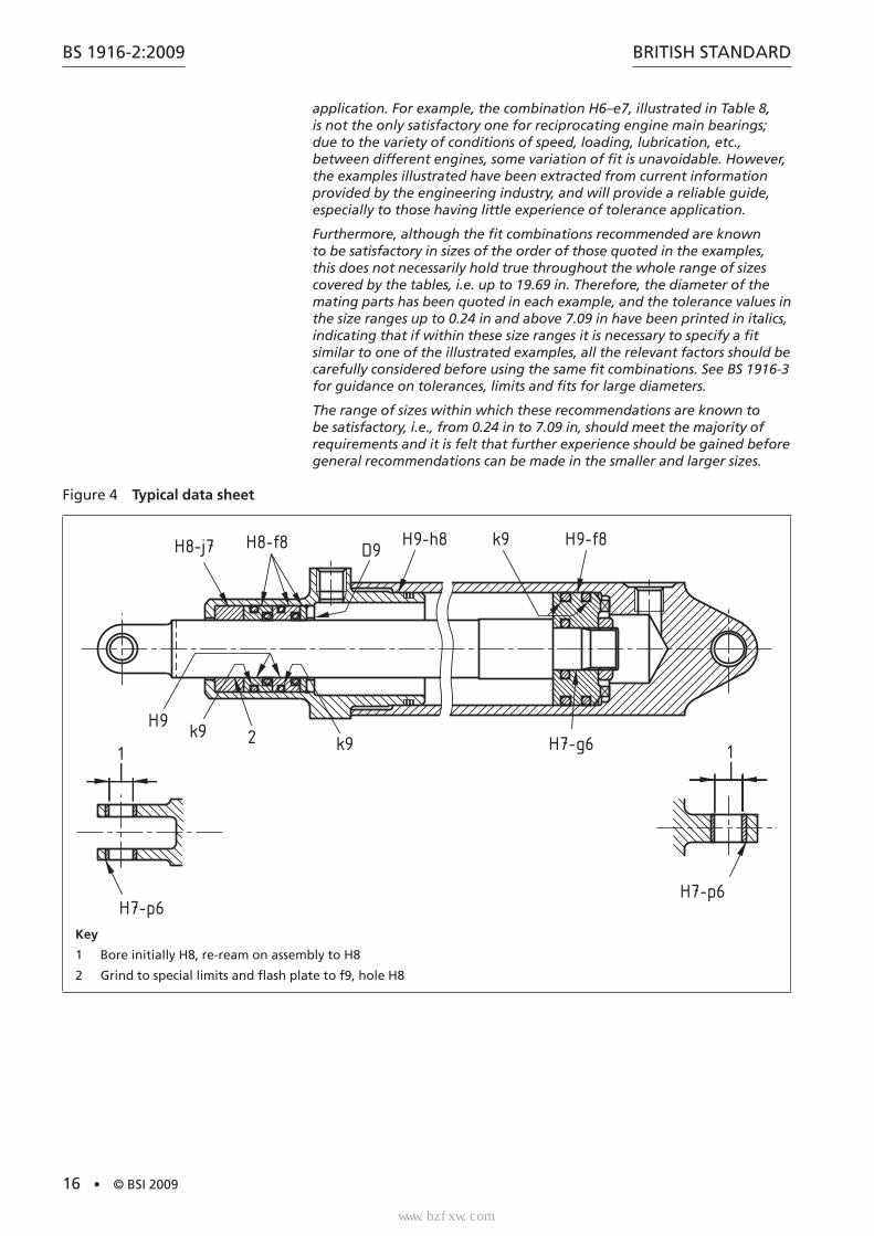
10 Recommended tolerances for standard fitsTo facilitate and standardize the allocation of tolerances by design personnel, tolerance data sheets should be drawn up in the manner of Figure 4, covering their standard products. The various fits on each assembly should be defined by symbol only, to be applicable to a range of sizes of that particular product. This procedure considerably simplifies the designer’s task, relieving the designer of the responsibility of allocating tolerances. It also reduces to a minimum the number of fits which are used, with corresponding savings in gauges and tools.
标准分享网 www.bzfxw.com 免费下载
www.bzfxw.com
BRITISH STANDARD
© BSI 2009 • 15
BS 1916-2:2009
Figure 5 to Figure 10 illustrate typical engineering assemblies and give recommended tolerances for the mating parts.
Table 6 to Table 20 illustrate and describe each of the types of fit listed in Clause 6. In each type, the selected grade of fit (i.e. the grade of tolerance used) for which the hole and shaft tolerances are listed in full has been chosen as representing medium to good quality workmanship (see also Table 1). In any particular organization the choice of grade depends upon the quality of work being produced and the type and quality of machine tools available, but it is recommended that a choice is made from the grades listed here. The complete range of available types of fit, comprising as it does 15 different types, is unnecessarily extensive for normal engineering requirements, and a short list should be compiled which caters for all normal applications and yet achieves the maximum economy of fixed tools and gauges. The following series is suitable for use by an organization engaged in good quality light or medium engineering production.
a) Clearance
• H8–d8
• H6–e7
• H8–e8
• H6–f6
• H7–f7
• H8–f8
• H6–g5
• H7–g6
• H7–h6
• H8–h7
b) Transition
• H8–j7
• H7–k6
• H8–k7
• H7–m6
• H8–m7
c) Interference
• H7–p6
• H7–s6
• H7–u6
The tolerance values for grades other than those whose values are listed in the tables can be obtained by reference to BS 1916-1.
Tables are not included for shafts a, b, v, x, y and z. These fits are not widely used and at present, there are insufficient data on which to base these recommendations.
NOTE The illustrated examples of applications of each type of fit (see Table 6 to Table 20) are included for general guidance only, and the fit combinations suggested are not the only solutions to any particular
www.bzfxw.com
BS 1916-2:2009
16 • © BSI 2009
BRITISH STANDARD
application. For example, the combination H6–e7, illustrated in Table 8, is not the only satisfactory one for reciprocating engine main bearings; due to the variety of conditions of speed, loading, lubrication, etc., between different engines, some variation of fit is unavoidable. However, the examples illustrated have been extracted from current information provided by the engineering industry, and will provide a reliable guide, especially to those having little experience of tolerance application.
Furthermore, although the fit combinations recommended are known to be satisfactory in sizes of the order of those quoted in the examples, this does not necessarily hold true throughout the whole range of sizes covered by the tables, i.e. up to 19.69 in. Therefore, the diameter of the mating parts has been quoted in each example, and the tolerance values in the size ranges up to 0.24 in and above 7.09 in have been printed in italics, indicating that if within these size ranges it is necessary to specify a fit similar to one of the illustrated examples, all the relevant factors should be carefully considered before using the same fit combinations. See BS 1916-3 for guidance on tolerances, limits and fits for large diameters.
The range of sizes within which these recommendations are known to be satisfactory, i.e., from 0.24 in to 7.09 in, should meet the majority of requirements and it is felt that further experience should be gained before general recommendations can be made in the smaller and larger sizes.
Figure 4 Typical data sheet
H8-j7 H8-f8
k9H9
k9
D9H9-h8
2
k9 H9-f8
H7-g61 1
H7-p6H7-p6
Key
1 Bore initially H8, re-ream on assembly to H8
2 Grind to special limits and flash plate to f9, hole H8
标准分享网 www.bzfxw.com 免费下载
www.bzfxw.com
BRITISH STANDARD
© BSI 2009 • 17
BS 1916-2:2009
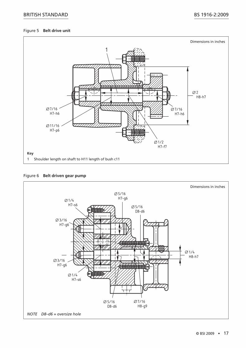
Figure 5 Belt drive unit
Dimensions in inches
1
7/16H7-h6
11/16H7-p6
2H8-h7
7/16H7-h6
1/2H7-f7
Key
1 Shoulder length on shaft to H11 length of bush c11
Figure 6 Belt driven gear pump
Dimensions in inches
1/4H7-s6
1/4H7-s6
3/16H7-g6
3/16H7-g6
5/16H7-g6
5/16D8-d6
7/16H8-g9
1/4H8-h7
5/16D8-d6
NOTE D8–d6 = oversize hole
www.bzfxw.com
BS 1916-2:2009
18 • © BSI 2009
BRITISH STANDARD
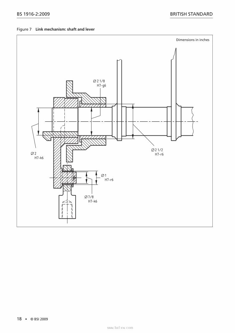
Figure 7 Link mechanism: shaft and lever
Dimensions in inches
2 1/2H7-r6
2 1/8H7-g6
2H7-k6
1H7-r6
7/8H7-k6
标准分享网 www.bzfxw.com 免费下载
www.bzfxw.com
BRITISH STANDARD
© BSI 2009 • 19
BS 1916-2:2009
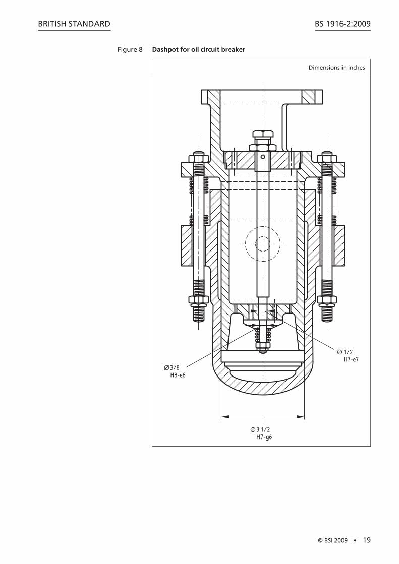
Figure 8 Dashpot for oil circuit breaker
Dimensions in inches
1/2H7-e7
3/8H8-e8
3 1/2H7-g6
www.bzfxw.com
BS 1916-2:2009
20 • © BSI 2009
BRITISH STANDARD
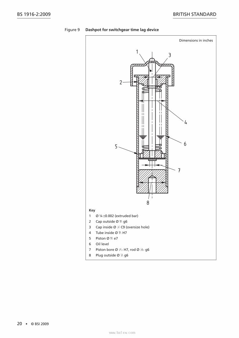
Figure 9 Dashpot for switchgear time lag device
Dimensions in inches
1
2
3
4
6
7
8
5
Key
1 Ø 1⁄4 ±0.002 (extruded bar)
2 Cap outside Ø 7⁄ g6
3 Cap inside Ø ⁄ C9 (oversize hole)
4 Tube inside Ø 7⁄ H7
5 Piston Ø 7⁄ e7
6 Oil level
7 Piston bore Ø ⁄ H7, rod Ø ⁄1 g6
8 Plug outside Ø ⁄ g6
标准分享网 www.bzfxw.com 免费下载
www.bzfxw.com
BRITISH STANDARD
© BSI 2009 • 21
BS 1916-2:2009
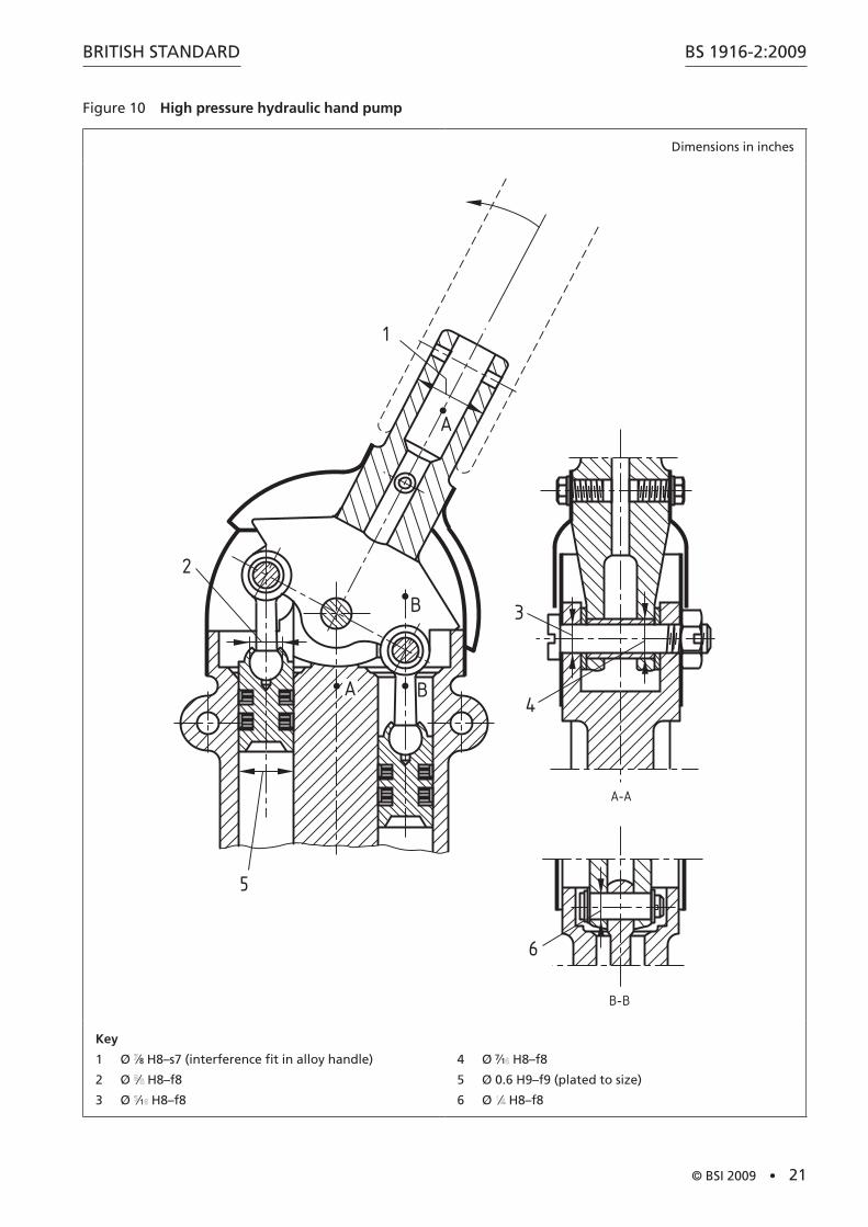
Figure 10 High pressure hydraulic hand pump
Dimensions in inches
A
B
BA
1
2
5
3
4
6
A-A
B-B
Key
1 Ø ⁄8 H8–s7 (interference fit in alloy handle)
2 Ø ⁄ H8–f8
3 Ø ⁄1 H8–f8
4 Ø 7⁄1 H8–f8
5 Ø 0.6 H9–f9 (plated to size)
6 Ø ⁄ H8–f8
www.bzfxw.com
BS 1916-2:2009
22 • © BSI 2009
BRITISH STANDARD
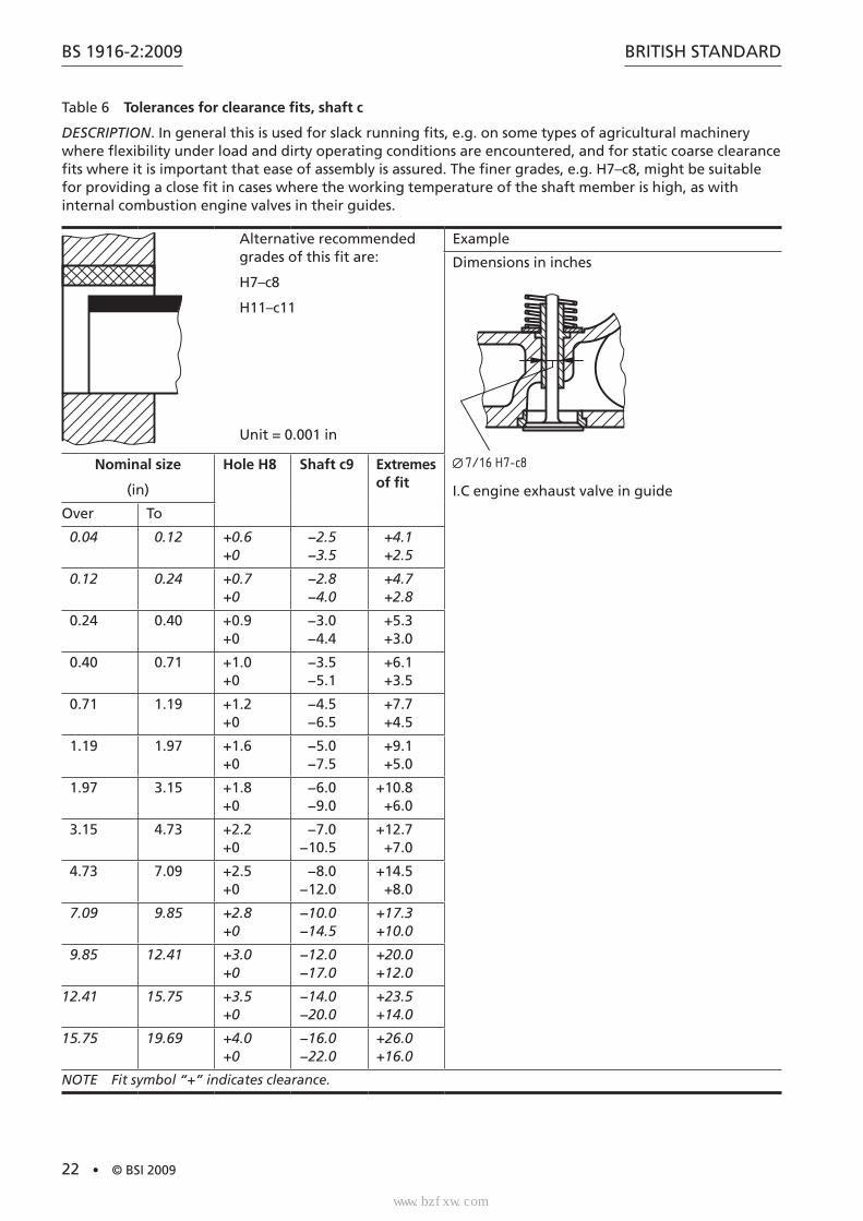
Table 6 Tolerances for clearance fits, shaft c
DESCRIPTION. In general this is used for slack running fits, e.g. on some types of agricultural machinery where flexibility under load and dirty operating conditions are encountered, and for static coarse clearance fits where it is important that ease of assembly is assured. The finer grades, e.g. H7–c8, might be suitable for providing a close fit in cases where the working temperature of the shaft member is high, as with internal combustion engine valves in their guides.
Alternative recommended grades of this fit are:
H7–c8
H11–c11
Unit = 0.001 in
Example
Dimensions in inches
7/16 H7-c8
I.C engine exhaust valve in guide
Nominal size
(in)
Hole H8 Shaft c9 Extremes of fit
Over To
0.04 0.12 +0.6+0
−2.5−3.5
+4.1+2.5
0.12 0.24 +0.7+0
−2.8−4.0
+4.7+2.8
0.24 0.40 +0.9+0
−3.0−4.4
+5.3+3.0
0.40 0.71 +1.0+0
−3.5−5.1
+6.1+3.5
0.71 1.19 +1.2+0
−4.5−6.5
+7.7+4.5
1.19 1.97 +1.6+0
−5.0−7.5
+9.1+5.0
1.97 3.15 +1.8+0
−6.0−9.0
+10.8+6.0
3.15 4.73 +2.2+0
−7.0−10.5
+12.7+7.0
4.73 7.09 +2.5+0
−8.0−12.0
+14.5+8.0
7.09 9.85 +2.8+0
−10.0−14.5
+17.3+10.0
9.85 12.41 +3.0+0
−12.0−17.0
+20.0+12.0
12.41 15.75 +3.5+0
−14.0−20.0
+23.5+14.0
15.75 19.69 +4.0+0
−16.0−22.0
+26.0+16.0
NOTE Fit symbol “+” indicates clearance.
标准分享网 www.bzfxw.com 免费下载
www.bzfxw.com
BRITISH STANDARD
© BSI 2009 • 23
BS 1916-2:2009
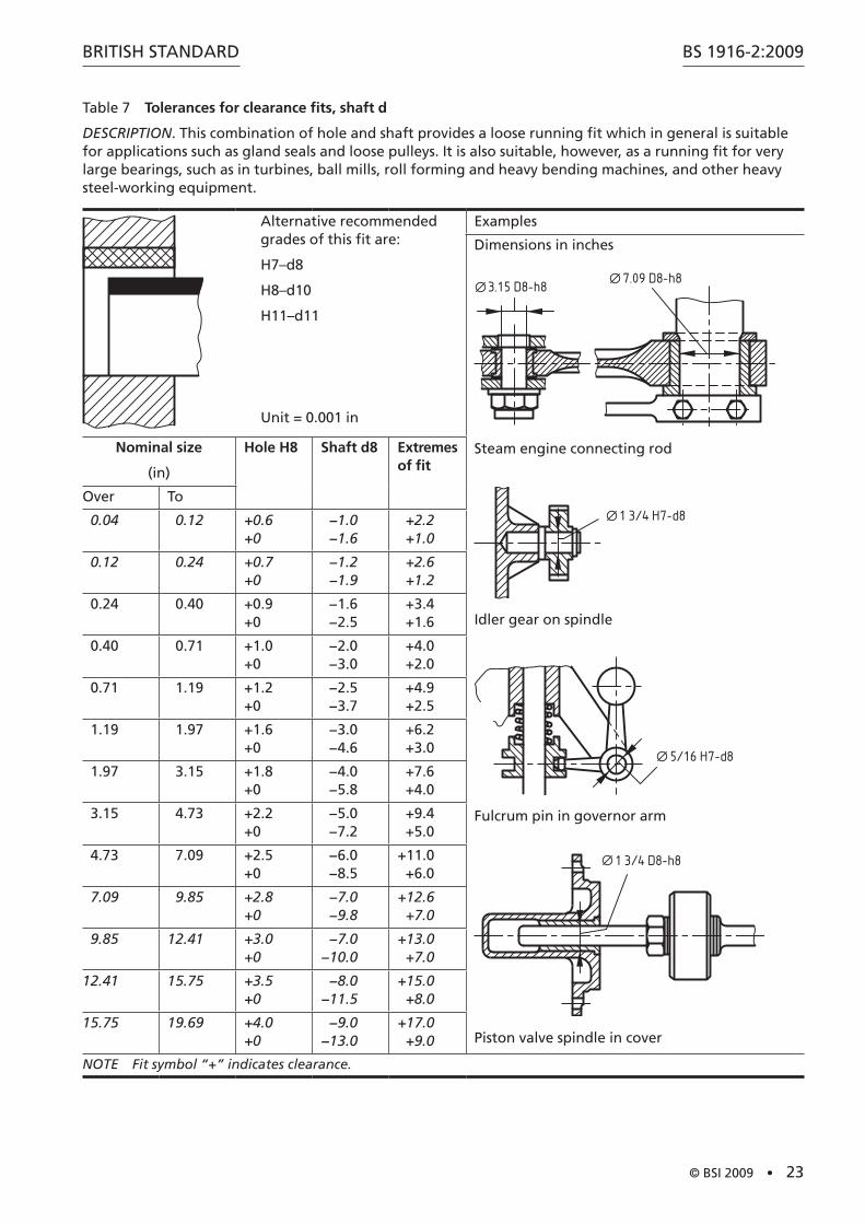
Table 7 Tolerances for clearance fits, shaft d
DESCRIPTION. This combination of hole and shaft provides a loose running fit which in general is suitable for applications such as gland seals and loose pulleys. It is also suitable, however, as a running fit for very large bearings, such as in turbines, ball mills, roll forming and heavy bending machines, and other heavy steel-working equipment.
Alternative recommended grades of this fit are:
H7–d8
H8–d10
H11–d11
Unit = 0.001 in
Examples
Dimensions in inches
3.15 D8-h87.09 D8-h8
Steam engine connecting rod
1 3/4 H7-d8
Idler gear on spindle
5/16 H7-d8
Fulcrum pin in governor arm
1 3/4 D8-h8
Piston valve spindle in cover
Nominal size
(in)
Hole H8 Shaft d8 Extremes of fit
Over To
0.04 0.12 +0.6 +0
−1.0−1.6
+2.2+1.0
0.12 0.24 +0.7 +0
−1.2−1.9
+2.6+1.2
0.24 0.40 +0.9 +0
−1.6−2.5
+3.4+1.6
0.40 0.71 +1.0 +0
−2.0−3.0
+4.0+2.0
0.71 1.19 +1.2 +0
−2.5−3.7
+4.9+2.5
1.19 1.97 +1.6 +0
−3.0−4.6
+6.2+3.0
1.97 3.15 +1.8 +0
−4.0−5.8
+7.6+4.0
3.15 4.73 +2.2 +0
−5.0−7.2
+9.4+5.0
4.73 7.09 +2.5 +0
−6.0−8.5
+11.0+6.0
7.09 9.85 +2.8 +0
−7.0−9.8
+12.6+7.0
9.85 12.41 +3.0 +0
−7.0−10.0
+13.0+7.0
12.41 15.75 +3.5 +0
−8.0−11.5
+15.0+8.0
15.75 19.69 +4.0 +0
−9.0−13.0
+17.0+9.0
NOTE Fit symbol “+” indicates clearance.
www.bzfxw.com
BS 1916-2:2009
24 • © BSI 2009
BRITISH STANDARD
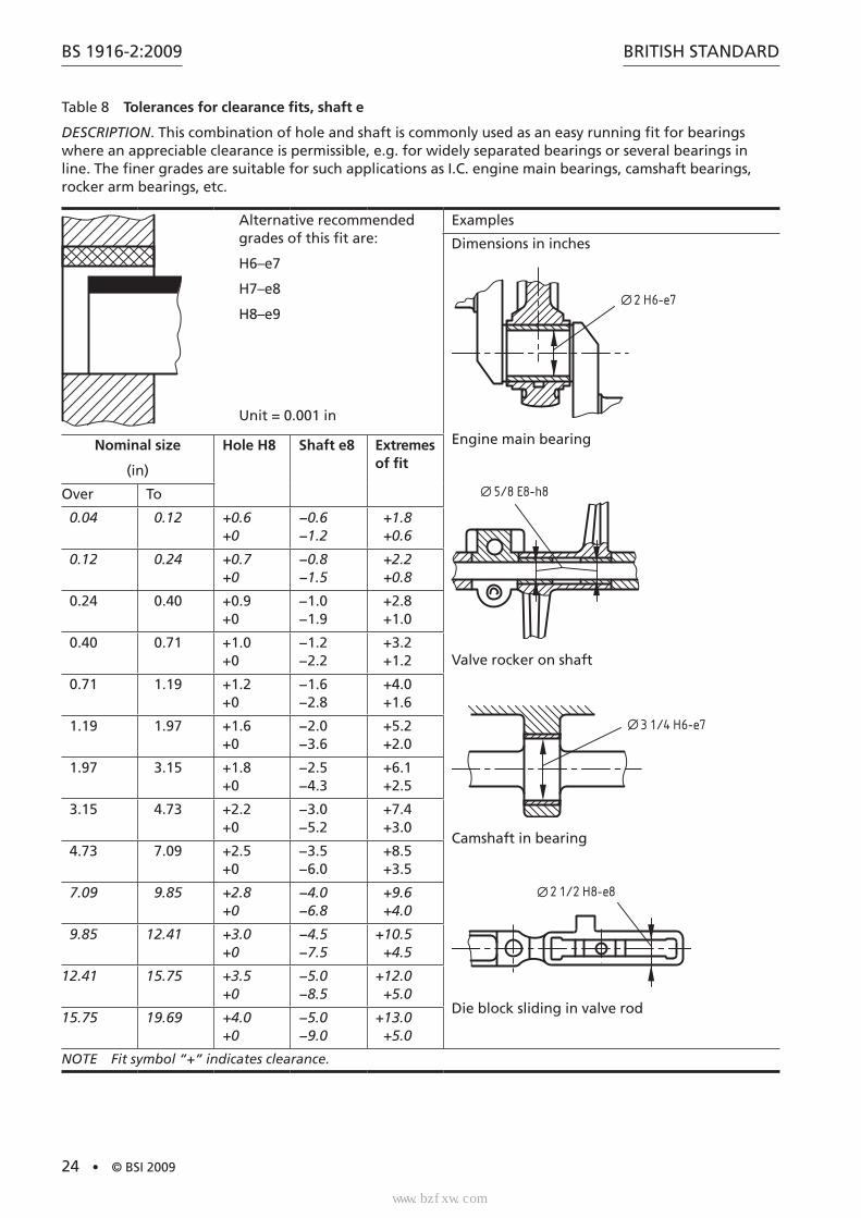
Table 8 Tolerances for clearance fits, shaft e
DESCRIPTION. This combination of hole and shaft is commonly used as an easy running fit for bearings where an appreciable clearance is permissible, e.g. for widely separated bearings or several bearings in line. The finer grades are suitable for such applications as I.C. engine main bearings, camshaft bearings, rocker arm bearings, etc.
Alternative recommended grades of this fit are:
H6–e7
H7–e8
H8–e9
Unit = 0.001 in
Examples
Dimensions in inches
2 H6-e7
Engine main bearing
5/8 E8-h8
Valve rocker on shaft
3 1/4 H6-e7
Camshaft in bearing
2 1/2 H8-e8
Die block sliding in valve rod
Nominal size
(in)
Hole H8 Shaft e8 Extremes of fit
Over To
0.04 0.12 +0.6+0
−0.6−1.2
+1.8+0.6
0.12 0.24 +0.7+0
−0.8−1.5
+2.2+0.8
0.24 0.40 +0.9+0
−1.0−1.9
+2.8+1.0
0.40 0.71 +1.0+0
−1.2−2.2
+3.2+1.2
0.71 1.19 +1.2+0
−1.6−2.8
+4.0+1.6
1.19 1.97 +1.6+0
−2.0−3.6
+5.2+2.0
1.97 3.15 +1.8+0
−2.5−4.3
+6.1+2.5
3.15 4.73 +2.2+0
−3.0−5.2
+7.4+3.0
4.73 7.09 +2.5+0
−3.5−6.0
+8.5+3.5
7.09 9.85 +2.8+0
−4.0−6.8
+9.6+4.0
9.85 12.41 +3.0+0
−4.5−7.5
+10.5+4.5
12.41 15.75 +3.5+0
−5.0−8.5
+12.0+5.0
15.75 19.69 +4.0+0
−5.0−9.0
+13.0+5.0
NOTE Fit symbol “+” indicates clearance.
标准分享网 www.bzfxw.com 免费下载
www.bzfxw.com
BRITISH STANDARD
© BSI 2009 • 25
BS 1916-2:2009
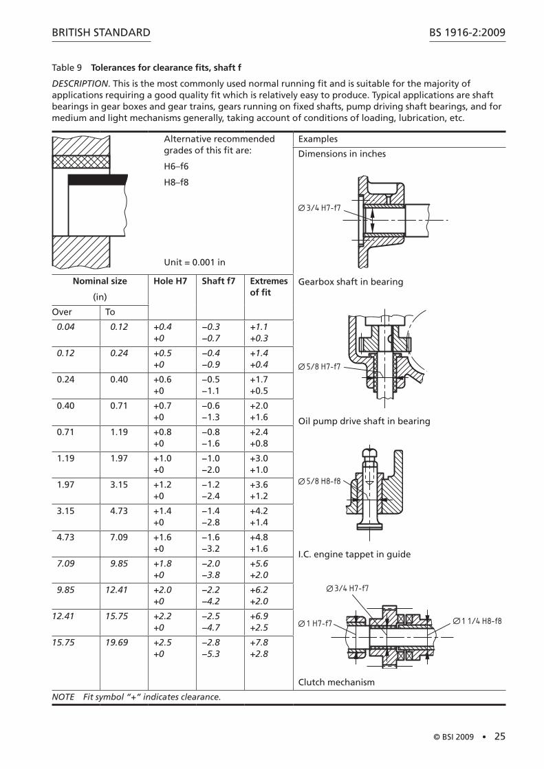
Table 9 Tolerances for clearance fits, shaft f
DESCRIPTION. This is the most commonly used normal running fit and is suitable for the majority of applications requiring a good quality fit which is relatively easy to produce. Typical applications are shaft bearings in gear boxes and gear trains, gears running on fixed shafts, pump driving shaft bearings, and for medium and light mechanisms generally, taking account of conditions of loading, lubrication, etc.
Alternative recommended grades of this fit are:
H6–f6
H8–f8
Unit = 0.001 in
Examples
Dimensions in inches
3/4 H7-f7
Gearbox shaft in bearing
5/8 H7-f7
Oil pump drive shaft in bearing
5/8 H8-f8
I.C. engine tappet in guide
1 H7-f7
3/4 H7-f7
1 1/4 H8-f8
Clutch mechanism
Nominal size
(in)
Hole H7 Shaft f7 Extremes of fit
Over To
0.04 0.12 +0.4+0
−0.3−0.7
+1.1+0.3
0.12 0.24 +0.5+0
−0.4−0.9
+1.4+0.4
0.24 0.40 +0.6+0
−0.5−1.1
+1.7+0.5
0.40 0.71 +0.7+0
−0.6−1.3
+2.0+1.6
0.71 1.19 +0.8+0
−0.8−1.6
+2.4+0.8
1.19 1.97 +1.0+0
−1.0−2.0
+3.0+1.0
1.97 3.15 +1.2+0
−1.2−2.4
+3.6+1.2
3.15 4.73 +1.4+0
−1.4−2.8
+4.2+1.4
4.73 7.09 +1.6+0
−1.6−3.2
+4.8+1.6
7.09 9.85 +1.8+0
−2.0−3.8
+5.6+2.0
9.85 12.41 +2.0+0
−2.2−4.2
+6.2+2.0
12.41 15.75 +2.2+0
−2.5−4.7
+6.9+2.5
15.75 19.69 +2.5+0
−2.8−5.3
+7.8+2.8
NOTE Fit symbol “+” indicates clearance.

www.bzfxw.com
BS 1916-2:2009
26 • © BSI 2009
BRITISH STANDARD
Table 10 Tolerances for clearance fits, shaft g
DESCRIPTION. The amount of clearance provided by this fit is small and it is not recommended for a continuously running bearing except in precision applications where shaft loadings are light and conditions suitable. It may be used as a precision sliding fit, and for non-running location and spigot fits, according to requirements.
Alternative recommended grades of this fit are:
H6–g5
H8–g7
NOTE 1 The limits for H8–g7 are derived from BS 1916-1:2009, Table 1 and Table 3.
Unit = 0.001 in
Examples
Dimensions in inches
1/4 H7-g6
Valve mechanism link pin
1/2 H8-g7
Connecting rod cap bolt
4 7/8 G6-h7
Bearing flanges
NOTE 2 Male member is given greater tolerance owing to difficulty of manufacture.
1 H7-g6
Oil pump driving eccentric
Nominal size
(in)
Hole H7 Shaft g6 Extremes of fit
Over To
0.04 0.12 +0.4 +0
−0.1−0.35
+0.75+0.1
0.12 0.24 +0.5 +0
−0.15−0.45
+0.95+0.15
0.24 0.40 +0.6 +0
−0.2−0.6
+1.2+0.2
0.40 0.71 +0.7 +0
−0.25−0.65
+1.35+0.25
0.71 1.19 +0.8 +0
−0.3−0.8
+1.6+0.3
1.19 1.97 +1.0 +0
−0.4−1.0
+2.0+0.4
1.97 3.15 +1.2 +0
−0.4−1.1
+2.3+0.4
3.15 4.73 +1.4 +0
−0.5−1.4
+2.8+0.5
4.73 7.09 +1.6 +0
−0.6−1.6
+3.2+0.6
7.09 9.85 +1.8 +0
−0.6−1.8
+3.6+0.6
9.85 12.41 +2.0 +0
−0.7−1.9
+3.9+0.7
12.41 15.75 +2.0 +0
−0.7−2.1
+4.3+0.7
15.75 19.69 +2.5 +0
−0.8−2.4
+4.9+0.8
NOTE Fit symbol “+” indicates clearance.
标准分享网 www.bzfxw.com 免费下载
BRITISH STANDARD
© BSI 2009 • 27
BS 1916-2:2009
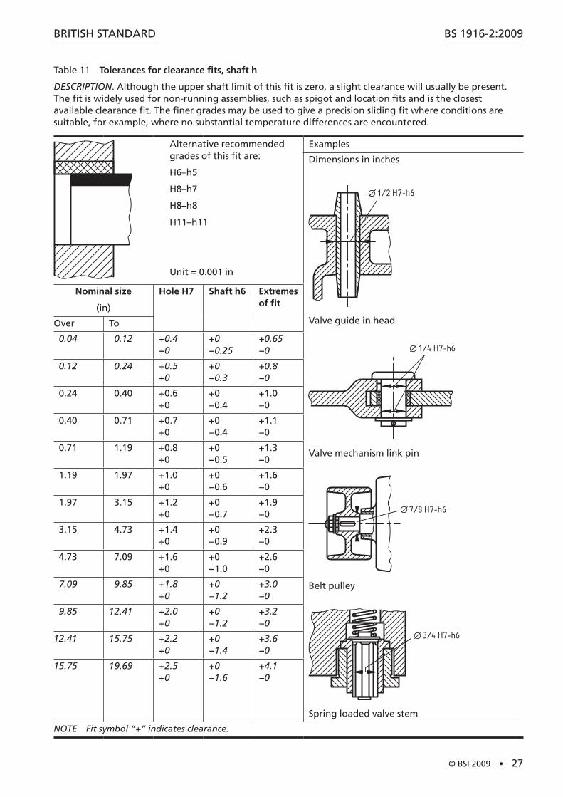
Table 11 Tolerances for clearance fits, shaft h
DESCRIPTION. Although the upper shaft limit of this fit is zero, a slight clearance will usually be present. The fit is widely used for non-running assemblies, such as spigot and location fits and is the closest available clearance fit. The finer grades may be used to give a precision sliding fit where conditions are suitable, for example, where no substantial temperature differences are encountered.
Alternative recommended grades of this fit are:
H6–h5
H8–h7
H8–h8
H11–h11
Unit = 0.001 in
Examples
Dimensions in inches
1/2 H7-h6
Valve guide in head
1/4 H7-h6
Valve mechanism link pin
7/8 H7-h6
Belt pulley
3/4 H7-h6
Spring loaded valve stem
Nominal size
(in)
Hole H7 Shaft h6 Extremes of fit
Over To
0.04 0.12 +0.4 +0
+0 −0.25
+0.65 −0
0.12 0.24 +0.5 +0
+0 −0.3
+0.8 −0
0.24 0.40 +0.6 +0
+0 −0.4
+1.0 −0
0.40 0.71 +0.7 +0
+0 −0.4
+1.1 −0
0.71 1.19 +0.8 +0
+0 −0.5
+1.3 −0
1.19 1.97 +1.0 +0
+0 −0.6
+1.6 −0
1.97 3.15 +1.2 +0
+0 −0.7
+1.9 −0
3.15 4.73 +1.4 +0
+0 −0.9
+2.3 −0
4.73 7.09 +1.6 +0
+0 −1.0
+2.6 −0
7.09 9.85 +1.8 +0
+0 −1.2
+3.0 −0
9.85 12.41 +2.0 +0
+0 −1.2
+3.2 −0
12.41 15.75 +2.2 +0
+0 −1.4
+3.6 −0
15.75 19.69 +2.5 +0
+0 −1.6
+4.1 −0
NOTE Fit symbol “+” indicates clearance.
BS 1916-2:2009
28 • © BSI 2009
BRITISH STANDARD
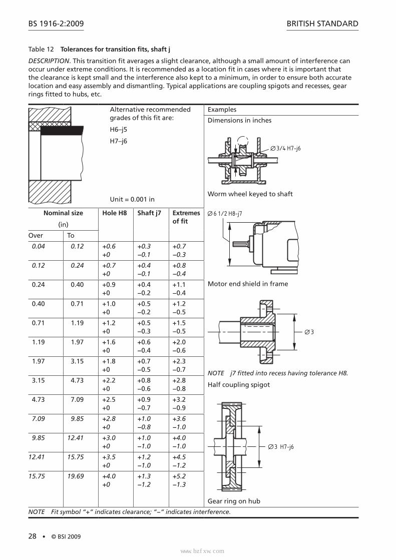
Table 12 Tolerances for transition fits, shaft j
DESCRIPTION. This transition fit averages a slight clearance, although a small amount of interference can occur under extreme conditions. It is recommended as a location fit in cases where it is important that the clearance is kept small and the interference also kept to a minimum, in order to ensure both accurate location and easy assembly and dismantling. Typical applications are coupling spigots and recesses, gear rings fitted to hubs, etc.
Alternative recommended grades of this fit are:
H6–j5
H7–j6
Unit = 0.001 in
Examples
Dimensions in inches
3/4 H7-j6
Worm wheel keyed to shaft
6 1/2 H8-j7
Motor end shield in frame
3
NOTE j7 fitted into recess having tolerance H8.
Half coupling spigot
3 H7-j6
Gear ring on hub
Nominal size
(in)
Hole H8 Shaft j7 Extremes of fit
Over To
0.04 0.12 +0.6 +0
+0.3 −0.1
+0.7 −0.3
0.12 0.24 +0.7 +0
+0.4 −0.1
+0.8 −0.4
0.24 0.40 +0.9 +0
+0.4 −0.2
+1.1 −0.4
0.40 0.71 +1.0 +0
+0.5 −0.2
+1.2 −0.5
0.71 1.19 +1.2 +0
+0.5 −0.3
+1.5 −0.5
1.19 1.97 +1.6 +0
+0.6 −0.4
+2.0 −0.6
1.97 3.15 +1.8 +0
+0.7 −0.5
+2.3 −0.7
3.15 4.73 +2.2 +0
+0.8 −0.6
+2.8 −0.8
4.73 7.09 +2.5 +0
+0.9 −0.7
+3.2 −0.9
7.09 9.85 +2.8 +0
+1.0 −0.8
+3.6 −1.0
9.85 12.41 +3.0 +0
+1.0 −1.0
+4.0 −1.0
12.41 15.75 +3.5 +0
+1.2 −1.0
+4.5 −1.2
15.75 19.69 +4.0 +0
+1.3 −1.2
+5.2 −1.3
NOTE Fit symbol “+” indicates clearance; “−” indicates interference.
标准分享网 www.bzfxw.com 免费下载
BRITISH STANDARD
© BSI 2009 • 29
BS 1916-2:2009
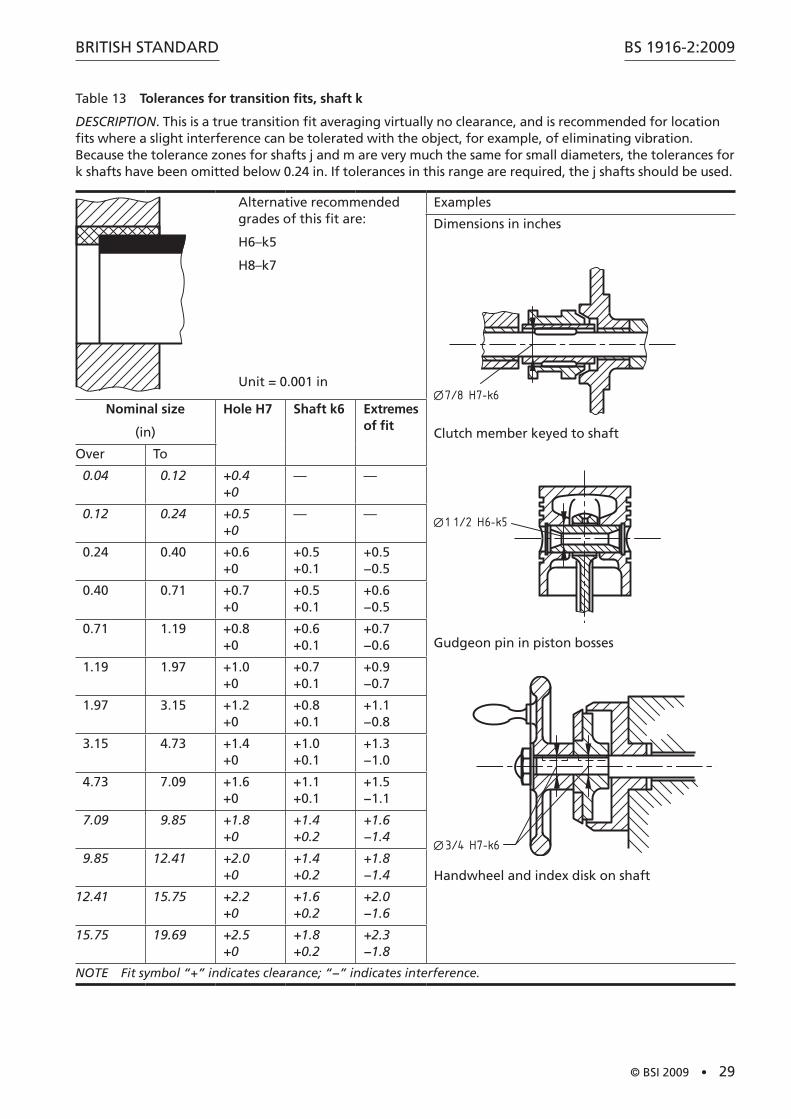
Table 13 Tolerances for transition fits, shaft k
DESCRIPTION. This is a true transition fit averaging virtually no clearance, and is recommended for location fits where a slight interference can be tolerated with the object, for example, of eliminating vibration. Because the tolerance zones for shafts j and m are very much the same for small diameters, the tolerances for k shafts have been omitted below 0.24 in. If tolerances in this range are required, the j shafts should be used.
Alternative recommended grades of this fit are:
H6–k5
H8–k7
Unit = 0.001 in
Examples
Dimensions in inches
7/8 H7-k6
Clutch member keyed to shaft
1 1/2 H6-k5
Gudgeon pin in piston bosses
3/4 H7-k6
Handwheel and index disk on shaft
Nominal size
(in)
Hole H7 Shaft k6 Extremes of fit
Over To
0.04 0.12 +0.4 +0
— —
0.12 0.24 +0.5 +0
— —
0.24 0.40 +0.6 +0
+0.5 +0.1
+0.5 −0.5
0.40 0.71 +0.7 +0
+0.5 +0.1
+0.6 −0.5
0.71 1.19 +0.8 +0
+0.6 +0.1
+0.7 −0.6
1.19 1.97 +1.0 +0
+0.7 +0.1
+0.9 −0.7
1.97 3.15 +1.2 +0
+0.8 +0.1
+1.1 −0.8
3.15 4.73 +1.4 +0
+1.0 +0.1
+1.3 −1.0
4.73 7.09 +1.6 +0
+1.1 +0.1
+1.5 −1.1
7.09 9.85 +1.8 +0
+1.4 +0.2
+1.6 −1.4
9.85 12.41 +2.0 +0
+1.4 +0.2
+1.8 −1.4
12.41 15.75 +2.2 +0
+1.6 +0.2
+2.0 −1.6
15.75 19.69 +2.5 +0
+1.8 +0.2
+2.3 −1.8
NOTE Fit symbol “+” indicates clearance; “−” indicates interference.
BS 1916-2:2009
30 • © BSI 2009
BRITISH STANDARD
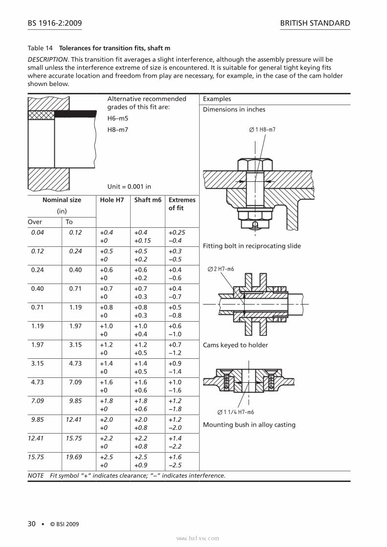
Table 14 Tolerances for transition fits, shaft m
DESCRIPTION. This transition fit averages a slight interference, although the assembly pressure will be small unless the interference extreme of size is encountered. It is suitable for general tight keying fits where accurate location and freedom from play are necessary, for example, in the case of the cam holder shown below.
Alternative recommended grades of this fit are:
H6–m5
H8–m7
Unit = 0.001 in
Examples
Dimensions in inches
1 H8-m7
Fitting bolt in reciprocating slide
2 H7-m6
Cams keyed to holder
1 1/4 H7-m6
Mounting bush in alloy casting
Nominal size
(in)
Hole H7 Shaft m6 Extremes of fit
Over To
0.04 0.12 +0.4 +0
+0.4 +0.15
+0.25 −0.4
0.12 0.24 +0.5 +0
+0.5 +0.2
+0.3 −0.5
0.24 0.40 +0.6 +0
+0.6 +0.2
+0.4 −0.6
0.40 0.71 +0.7 +0
+0.7 +0.3
+0.4 −0.7
0.71 1.19 +0.8 +0
+0.8 +0.3
+0.5 −0.8
1.19 1.97 +1.0 +0
+1.0 +0.4
+0.6 −1.0
1.97 3.15 +1.2 +0
+1.2 +0.5
+0.7 −1.2
3.15 4.73 +1.4 +0
+1.4 +0.5
+0.9 −1.4
4.73 7.09 +1.6 +0
+1.6 +0.6
+1.0 −1.6
7.09 9.85 +1.8 +0
+1.8 +0.6
+1.2 −1.8
9.85 12.41 +2.0 +0
+2.0 +0.8
+1.2 −2.0
12.41 15.75 +2.2 +0
+2.2 +0.8
+1.4 −2.2
15.75 19.69 +2.5 +0
+2.5 +0.9
+1.6 −2.5
NOTE Fit symbol “+” indicates clearance; “−” indicates interference.
标准分享网 www.bzfxw.com 免费下载
BRITISH STANDARD
© BSI 2009 • 31
BS 1916-2:2009
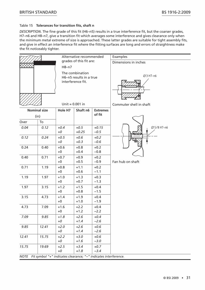
Table 15 Tolerances for transition fits, shaft n
DESCRIPTION. The fine grade of this fit (H6–n5) results in a true interference fit, but the coarser grades, H7–n6 and H8–n7, give a transition fit which averages some interference and gives clearance only when the minimum metal extreme of size is approached. These latter grades are suitable for tight assembly fits, and give in effect an interference fit where the fitting surfaces are long and errors of straightness make the fit noticeably tighter.
Alternative recommended grades of this fit are:
H8–n7
The combination H6–n5 results in a true interference fit.
Unit = 0.001 in
Examples
Dimensions in inches
3 H7-n6
Commuter shell in shaft
5/8 H7-n6
Fan hub on shaft
Nominal size
(in)
Hole H7 Shaft n6 Extremes of fit
Over To
0.04 0.12 +0.4 +0
+0.5 +0.25
+0.15 −0.5
0.12 0.24 +0.5 +0
+0.6 +0.3
+0.2 −0.6
0.24 0.40 +0.6 +0
+0.8 +0.4
+0.2 −0.8
0.40 0.71 +0.7 +0
+0.9 +0.5
+0.2 −0.9
0.71 1.19 +0.8 +0
+1.1 +0.6
+0.2 −1.1
1.19 1.97 +1.0 +0
+1.3 +0.7
+0.3 −1.3
1.97 3.15 +1.2 +0
+1.5 +0.8
+0.4 −1.5
3.15 4.73 +1.4 +0
+1.9 +1.0
+0.4 −1.9
4.73 7.09 +1.6 +0
+2.2 +1.2
+0.4 −2.2
7.09 9.85 +1.8 +0
+2.6 +1.4
+0.4 −2.6
9.85 12.41 +2.0 +0
+2.6 +1.4
+0.6 −2.6
12.41 15.75 +2.2 +0
+3.0 +1.6
+0.6 −3.0
15.75 19.69 +2.5 +0
+3.4 +1.8
+0.7 −3.4
NOTE Fit symbol “+” indicates clearance; “−” indicates interference.
BS 1916-2:2009
32 • © BSI 2009
BRITISH STANDARD
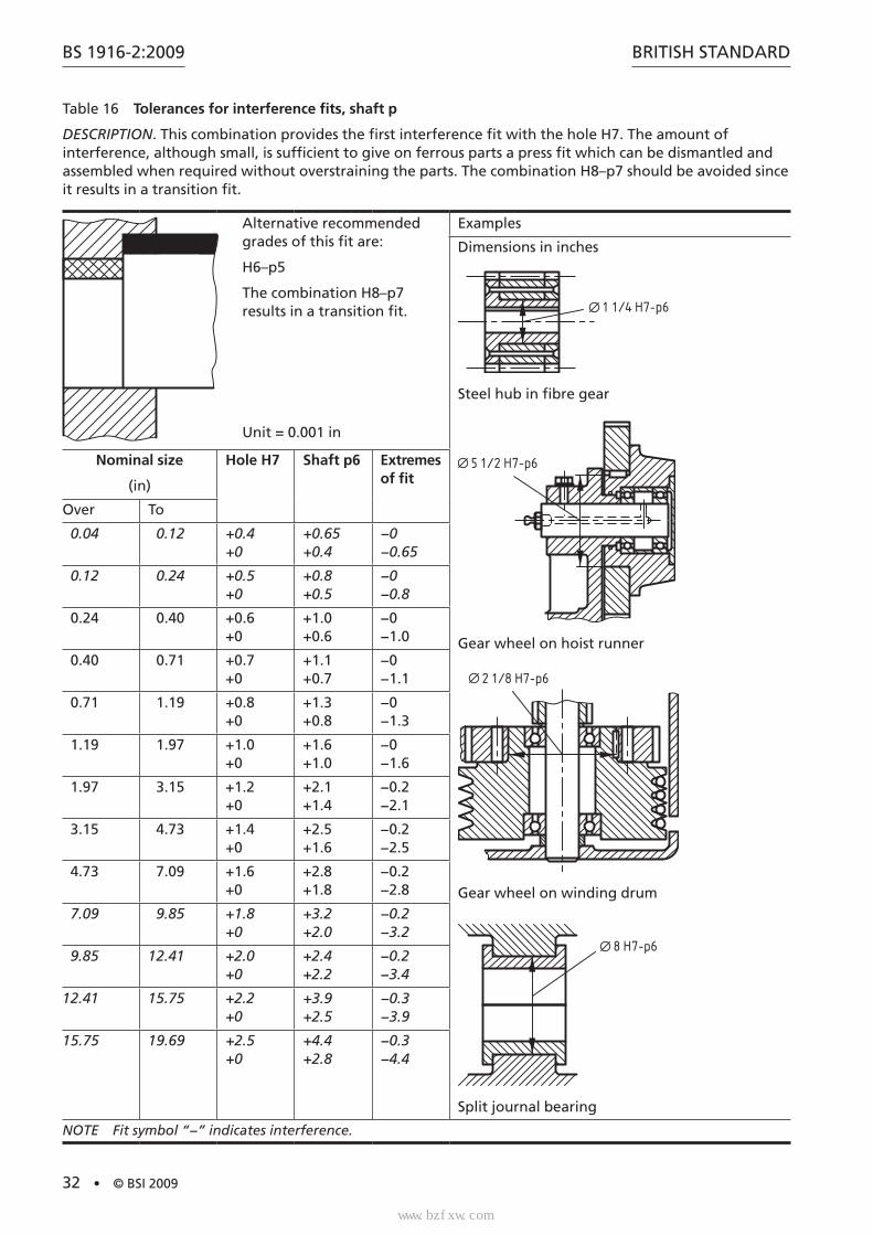
Table 16 Tolerances for interference fits, shaft p
DESCRIPTION. This combination provides the first interference fit with the hole H7. The amount of interference, although small, is sufficient to give on ferrous parts a press fit which can be dismantled and assembled when required without overstraining the parts. The combination H8–p7 should be avoided since it results in a transition fit.
Alternative recommended grades of this fit are:
H6–p5
The combination H8–p7 results in a transition fit.
Unit = 0.001 in
Examples
Dimensions in inches
1 1/4 H7-p6
Steel hub in fibre gear
5 1/2 H7-p6
Gear wheel on hoist runner
2 1/8 H7-p6
Gear wheel on winding drum
8 H7-p6
Split journal bearing
Nominal size
(in)
Hole H7 Shaft p6 Extremes of fit
Over To
0.04 0.12 +0.4 +0
+0.65 +0.4
−0 −0.65
0.12 0.24 +0.5 +0
+0.8 +0.5
−0 −0.8
0.24 0.40 +0.6 +0
+1.0 +0.6
−0 −1.0
0.40 0.71 +0.7 +0
+1.1 +0.7
−0 −1.1
0.71 1.19 +0.8 +0
+1.3 +0.8
−0 −1.3
1.19 1.97 +1.0 +0
+1.6 +1.0
−0 −1.6
1.97 3.15 +1.2 +0
+2.1 +1.4
−0.2 −2.1
3.15 4.73 +1.4 +0
+2.5 +1.6
−0.2 −2.5
4.73 7.09 +1.6 +0
+2.8 +1.8
−0.2 −2.8
7.09 9.85 +1.8 +0
+3.2 +2.0
−0.2 −3.2
9.85 12.41 +2.0 +0
+2.4 +2.2
−0.2 −3.4
12.41 15.75 +2.2 +0
+3.9 +2.5
−0.3 −3.9
15.75 19.69 +2.5 +0
+4.4 +2.8
−0.3 −4.4
NOTE Fit symbol “−” indicates interference.
标准分享网 www.bzfxw.com 免费下载
BRITISH STANDARD
© BSI 2009 • 33
BS 1916-2:2009
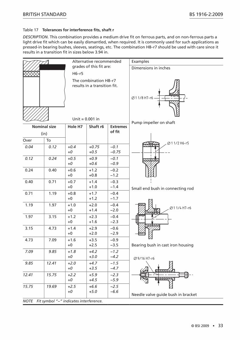
Table 17 Tolerances for interference fits, shaft r
DESCRIPTION. This combination provides a medium drive fit on ferrous parts, and on non-ferrous parts a light drive fit which can be easily dismantled, when required. It is commonly used for such applications as pressed-in bearing bushes, sleeves, seatings, etc. The combination H8–r7 should be used with care since it results in a transition fit in sizes below 3.94 in.
Alternative recommended grades of this fit are:
H6–r5
The combination H8–r7 results in a transition fit.
Unit = 0.001 in
Examples
Dimensions in inches
1 1/8 H7-r6
Pump impeller on shaft
1 1/2 H6-r5
Small end bush in connecting rod
1 1/4 H7-r6
Bearing bush in cast iron housing
9/16 H7-r6
Needle valve guide bush in bracket
Nominal size
(in)
Hole H7 Shaft r6 Extremes of fit
Over To
0.04 0.12 +0.4 +0
+0.75 +0.5
−0.1 −0.75
0.12 0.24 +0.5 +0
+0.9 +0.6
−0.1 −0.9
0.24 0.40 +0.6 +0
+1.2 +0.8
−0.2 −1.2
0.40 0.71 +0.7 +0
+1.4 +1.0
−0.3 −1.4
0.71 1.19 +0.8 +0
+1.7 +1.2
−0.4 −1.7
1.19 1.97 +1.0 +0
+2.0 +1.4
−0.4 −2.0
1.97 3.15 +1.2 +0
+2.3 +1.6
−0.4 −2.3
3.15 4.73 +1.4 +0
+2.9 +2.0
−0.6 −2.9
4.73 7.09 +1.6 +0
+3.5 +2.5
−0.9 −3.5
7.09 9.85 +1.8 +0
+4.2 +3.0
−1.2 −4.2
9.85 12.41 +2.0 +0
+4.7 +3.5
−1.5 −4.7
12.41 15.75 +2.2 +0
+5.9 +4.5
−2.3 −5.9
15.75 19.69 +2.5 +0
+6.6 +5.0
−2.5 −6.6
NOTE Fit symbol “−” indicates interference.
BS 1916-2:2009
34 • © BSI 2009
BRITISH STANDARD
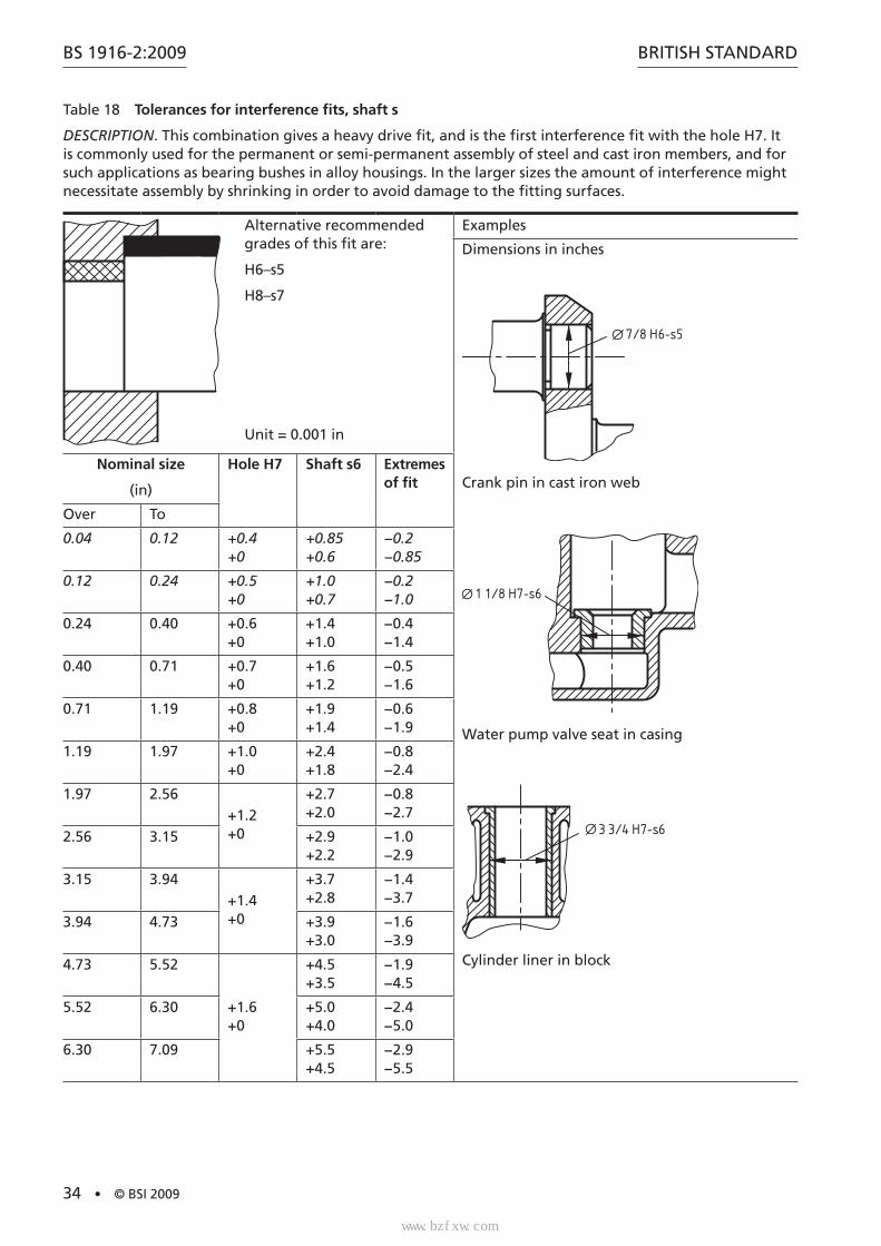
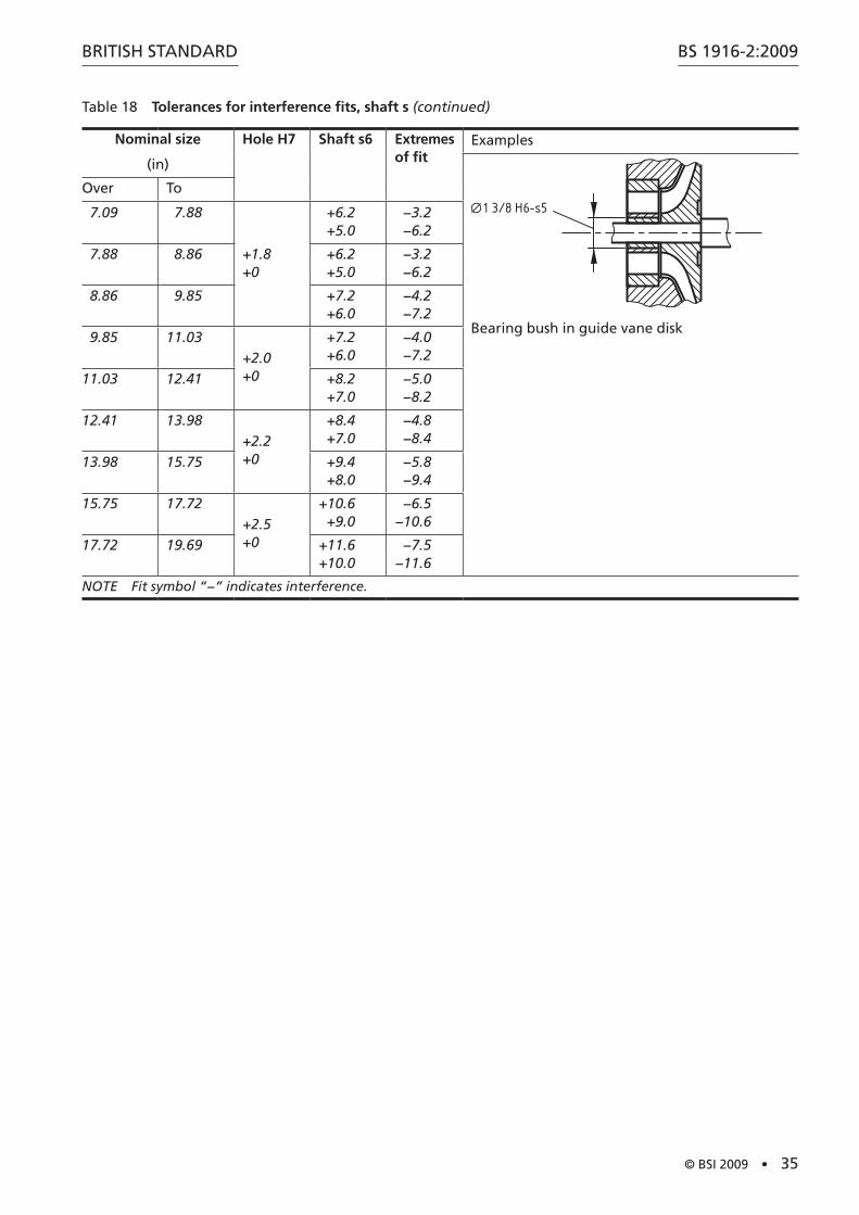
Table 18 Tolerances for interference fits, shaft s
DESCRIPTION. This combination gives a heavy drive fit, and is the first interference fit with the hole H7. It is commonly used for the permanent or semi-permanent assembly of steel and cast iron members, and for such applications as bearing bushes in alloy housings. In the larger sizes the amount of interference might necessitate assembly by shrinking in order to avoid damage to the fitting surfaces.
Alternative recommended grades of this fit are:
H6–s5
H8–s7
Unit = 0.001 in
Examples
Dimensions in inches
7/8 H6-s5
Crank pin in cast iron web
1 1/8 H7-s6
Water pump valve seat in casing
3 3/4 H7-s6
Cylinder liner in block
Nominal size
(in)
Hole H7 Shaft s6 Extremes of fit
Over To
0.04 0.12 +0.4 +0
+0.85 +0.6
−0.2 −0.85
0.12 0.24 +0.5 +0
+1.0 +0.7
−0.2 −1.0
0.24 0.40 +0.6 +0
+1.4 +1.0
−0.4 −1.4
0.40 0.71 +0.7 +0
+1.6 +1.2
−0.5 −1.6
0.71 1.19 +0.8 +0
+1.9 +1.4
−0.6 −1.9
1.19 1.97 +1.0 +0
+2.4 +1.8
−0.8 −2.4
1.97 2.56+1.2 +0
+2.7 +2.0
−0.8 −2.7
2.56 3.15 +2.9 +2.2
−1.0 −2.9
3.15 3.94+1.4 +0
+3.7 +2.8
−1.4 −3.7
3.94 4.73 +3.9 +3.0
−1.6 −3.9
4.73 5.52
+1.6 +0
+4.5 +3.5
−1.9 −4.5
5.52 6.30 +5.0 +4.0
−2.4 −5.0
6.30 7.09 +5.5 +4.5
−2.9 −5.5
标准分享网 www.bzfxw.com 免费下载
BRITISH STANDARD
© BSI 2009 • 35
BS 1916-2:2009
Table 18 Tolerances for interference fits, shaft s (continued)
Nominal size
(in)
Hole H7 Shaft s6 Extremes of fit
Examples
1 3/8 H6-s5
Bearing bush in guide vane disk
Over To
7.09 7.88
+1.8 +0
+6.2+5.0
−3.2−6.2
7.88 8.86 +6.2+5.0
−3.2−6.2
8.86 9.85 +7.2+6.0
−4.2−7.2
9.85 11.03+2.0 +0
+7.2+6.0
−4.0−7.2
11.03 12.41 +8.2+7.0
−5.0−8.2
12.41 13.98+2.2 +0
+8.4+7.0
−4.8−8.4
13.98 15.75 +9.4+8.0
−5.8−9.4
15.75 17.72+2.5 +0
+10.6+9.0
−6.5−10.6
17.72 19.69 +11.6+10.0
−7.5−11.6
NOTE Fit symbol “−” indicates interference.

BS 1916-2:2009
36 • © BSI 2009
BRITISH STANDARD
Table 19 Tolerances for interference fits, shaft t
DESCRIPTION. The minimum amount of interference provided by the combination H7–t6 is equal to 0.000 63 in per in of diameter, giving a force fit suitable for the permanent assembly of steel and cast iron parts.
In the small sizes, the deviations for s and u shafts are so close that those for t shafts have been omitted up to 0.95 in. If a fit is required in this size range, the s shaft or u shaft fits should be used.
Alternative recommended grades of this fit are:
H6–t5
H8–t7
Unit = 0.001 in
Examples
Dimensions in inches
3 1/2 H6-t5
Valve seat insert in cylinder head
7 H7-t6
Half-coupling shrunk on without key
Nominal size
(in)
Hole H7 Shaft t6 Extremes of fit
Over To
0.04 0.12 +0.4 +0
— —
0.12 0.24 +0.5 +0
— —
0.24 0.40 +0.6 +0
— —
0.40 0.71 +0.7 +0
— —
0.71 0.95+0.8 +0
— —
0.95 1.19 +2.1 +1.6
−1.0 −2.1
1.19 1.58+1.0 +0
+2.6 +2.0
−1.0 −2.6
1.58 1.97 +2.8 +2.2
−1.2 −2.8
1.97 2.56+1.2 +0
+3.2 +2.5
−1.3 −3.2
2.56 3.15 +3.7 +3.0
−1.8 −3.7
3.15 3.94+1.4 +0
+4.4 +3.5
−2.2 −4.4
3.94 4.73 +4.9 +4.0
−2.6 −4.9
标准分享网 www.bzfxw.com 免费下载
BRITISH STANDARD
© BSI 2009 • 37
BS 1916-2:2009
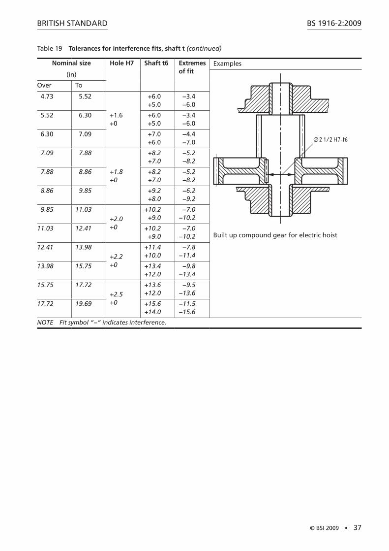
Table 19 Tolerances for interference fits, shaft t (continued)
Nominal size
(in)
Hole H7 Shaft t6 Extremes of fit
Examples
2 1/2 H7-t6
Built up compound gear for electric hoist
Over To
4.73 5.52
+1.6 +0
+6.0+5.0
−3.4−6.0
5.52 6.30 +6.0+5.0
−3.4−6.0
6.30 7.09 +7.0+6.0
−4.4−7.0
7.09 7.88
+1.8 +0
+8.2+7.0
−5.2−8.2
7.88 8.86 +8.2+7.0
−5.2−8.2
8.86 9.85 +9.2+8.0
−6.2−9.2
9.85 11.03+2.0 +0
+10.2+9.0
−7.0−10.2
11.03 12.41 +10.2+9.0
−7.0−10.2
12.41 13.98+2.2 +0
+11.4+10.0
−7.8−11.4
13.98 15.75 +13.4+12.0
−9.8−13.4
15.75 17.72+2.5 +0
+13.6+12.0
−9.5−13.6
17.72 19.69 +15.6+14.0
−11.5−15.6
NOTE Fit symbol “−” indicates interference.
BS 1916-2:2009
38 • © BSI 2009
BRITISH STANDARD
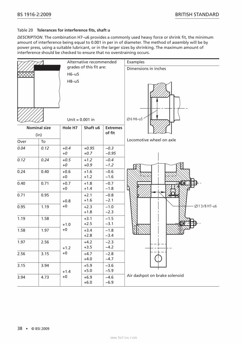
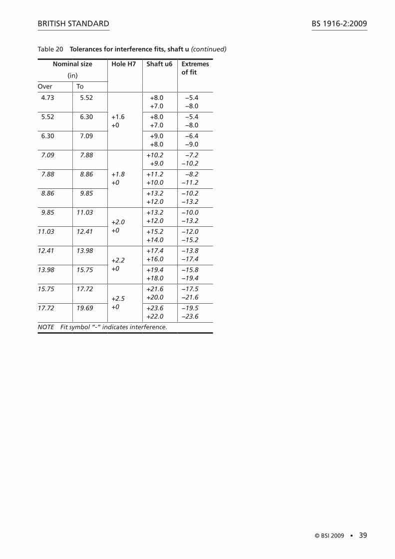
Table 20 Tolerances for interference fits, shaft u
DESCRIPTION. The combination H7–u6 provides a commonly used heavy force or shrink fit, the minimum amount of interference being equal to 0.001 in per in of diameter. The method of assembly will be by power press, using a suitable lubricant, or in the larger sizes by shrinking. The maximum amount of interference should be checked to ensure that no overstraining occurs.
Alternative recommended grades of this fit are:
H6–u5
H8–u5
Unit = 0.001 in
Examples
Dimensions in inches
6 H6-u5
Locomotive wheel on axle
1 3/8 H7-u6
Air dashpot on brake solenoid
Nominal size
(in)
Hole H7 Shaft u6 Extremes of fit
Over To
0.04 0.12 +0.4 +0
+0.95 +0.7
−0.3 −0.95
0.12 0.24 +0.5 +0
+1.2 +0.9
−0.4 −1.2
0.24 0.40 +0.6 +0
+1.6 +1.2
−0.6 −1.6
0.40 0.71 +0.7 +0
+1.8 +1.4
−0.7 −1.8
0.71 0.95+0.8 +0
+2.1 +1.6
−0.8 −2.1
0.95 1.19 +2.3 +1.8
−1.0 −2.3
1.19 1.58+1.0 +0
+3.1 +2.5
−1.5 −3.1
1.58 1.97 +3.4 +2.8
−1.8 −3.4
1.97 2.56+1.2 +0
+4.2 +3.5
−2.3 −4.2
2.56 3.15 +4.7 +4.0
−2.8 −4.7
3.15 3.94
+1.4 +0
+5.9 +5.0
−3.6 −5.9
3.94 4.73 +6.9 +6.0
−4.6 −6.9
标准分享网 www.bzfxw.com 免费下载
BRITISH STANDARD
© BSI 2009 • 39
BS 1916-2:2009
Table 20 Tolerances for interference fits, shaft u (continued)
Nominal size
(in)
Hole H7 Shaft u6 Extremes of fit
Over To
4.73 5.52
+1.6 +0
+8.0+7.0
−5.4−8.0
5.52 6.30 +8.0+7.0
−5.4−8.0
6.30 7.09 +9.0+8.0
−6.4−9.0
7.09 7.88
+1.8 +0
+10.2+9.0
−7.2−10.2
7.88 8.86 +11.2+10.0
−8.2−11.2
8.86 9.85 +13.2+12.0
−10.2−13.2
9.85 11.03+2.0 +0
+13.2+12.0
−10.0−13.2
11.03 12.41 +15.2+14.0
−12.0−15.2
12.41 13.98+2.2 +0
+17.4+16.0
−13.8−17.4
13.98 15.75 +19.4+18.0
−15.8−19.4
15.75 17.72+2.5 +0
+21.6+20.0
−17.5−21.6
17.72 19.69 +23.6+22.0
−19.5−23.6
NOTE Fit symbol “-” indicates interference.

BS 1916-2:2009
40 • © BSI 2009
BRITISH STANDARD
Bibliography
Standards publications
For dated references, only the edition cited applies. For undated references, the latest edition of the referenced document (including any amendments) applies.
BS 1916-3, Limits and fits for engineering – Part 3: Guide to tolerances, limits and fits for large diameters
BS EN 20286-1, ISO system of limits and fits – Part 1: Bases of tolerances, deviations and fits
BS EN 20286-2, ISO system of limits and fits – Part 2: Tables of standard tolerance grades and limit deviations for holes and shafts
标准分享网 www.bzfxw.com 免费下载

This page deliberately left blank

BSI is the independent national body responsible for preparing British Standards. It presents the UK view on standards in Europe and at the international level.
It is incorporated by Royal Charter.
British Standards Institution (BSI)
raising standards worldwide™
BSI Group Headquarters
389 Chiswick High Road London W4 4AL UK
Tel +44 (0)20 8996 9001Fax +44 (0)20 8996 7001www.bsigroup.com/standards
RevisionsBritish Standards are updated by amendment or revision. Users of BritishStandards should make sure that they possess the latest amendments oreditions.
It is the constant aim of BSI to improve the quality of our products andservices. We would be grateful if anyone finding an inaccuracy orambiguity while using this British Standard would inform the Secretary ofthe technical committee responsible, the identity of which can be foundon the inside front cover.
Tel: +44 (0)20 8996 9000 Fax: +44 (0)20 8996 7400BSI offers members an individual updating service called PLUS whichensures that subscribers automatically receive the latest editions ofstandards.
Buying standardsOrders for all BSI, international and foreign standards publicationsshould be addressed to BSI Customer Services.
Tel: +44 (0)20 8996 9001 Fax: +44 (0)20 8996 7001Email: [email protected] may also buy directly using a debit/credit card from the BSI Shopon the website www.bsigroup.com/shopIn response to orders for international standards, it is BSI policy tosupply the BSI implementation of those that have been publishedas British Standards, unless otherwise requested.
Information on standardsBSI provides a wide range of information on national, European andinternational standards through its Library.
Various BSI electronic information services are also available which givedetails on all its products and services. Contact the Information Centre.
Tel: +44 (0)20 8996 7111 Fax: +44 (0)20 8996 7048 Email: [email protected] members of BSI are kept up to date with standardsdevelopments and receive substantial discounts on the purchase priceof standards. For details of these and other benefits contact MembershipAdministration.
Tel: +44 (0)20 8996 7002 Fax: +44 (0)20 8996 7001 Email: [email protected] Information regarding online access to British Standards via BritishStandards Online can be found at www.bsigroup.com/BSOLFurther information about BSI is available on the BSI website atwww.bsigroup.com
CopyrightCopyright subsists in all BSI publications. BSI also holds the copyright, in the UK, of thepublications of the international standardization bodies. Except as permitted under theCopyright, Designs and Patents Act 1988 no extract may be reproduced, stored in a retrievalsystem or transmitted in any form or by any means – electronic, photocopying, recording orotherwise – without prior written permission from BSI. This does not preclude the free use, in the course of implementing the standard of necessarydetails such as symbols, and size, type or grade designations. If these details are to be used forany other purpose than implementation then the prior written permission of BSI must beobtained. Details and advice can be obtained from the Copyright & Licensing Manager.
Tel: +44 (0)20 8996 7070 Email: [email protected]
标准分享网 www.bzfxw.com 免费下载