differential expansion transducer system
TRANSCRIPT
Part Number 105826-01 Rev. F (09/07)
Bently Nevada™ Asset Condition Monitoring
Operation Manual
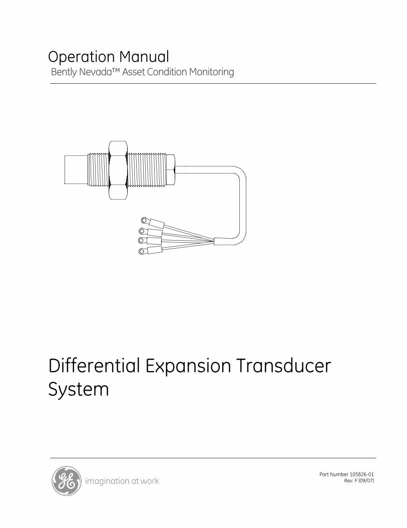
Differential Expansion Transducer System
Differential Expansion Transducer System Operation Manual
ii
Copyright 1993. Bently Nevada LLC.
All rights reserved.
The information contained in this document is subject to change without notice.
The following are trademarks of General Electric Company in the United States and other countries:
CableLoc, Keyphasor and Proximitor
The following are trademarks of the legal entities cited:
Teflon® and Viton® are registered trademarks of Dupont.
Sealtite® is a registered trademark of Anaconda Wire and Cable Company.
Loctite® is a registered trademark of Anaconda Wire and Cable Company.
Contact Information
The following ways of contacting Bently Nevada are provided for those times when you cannot contact your local representative:
Mailing Address 1631 Bently Parkway South
Minden, Nevada USA 89423
USA
Telephone 1.775.782.3611
1.800.227.5514
Fax 1.775.215.2873
Internet www.ge-energy.com/bently
iii
Additional Information
Product Disposal Statement
Customers and third parties, who are not member states of the European Union, who are in control of the product at the end of its life or at the end of its use, are solely responsible for the proper disposal of the product. No person, firm, corporation, association or agency that is in control of product shall dispose of it in a manner that is in violation of any applicable federal, state, local or international law. Bently Nevada LLC is not responsible for the disposal of the product at the end of its life or at the end of its use.
Differential Expansion Transducer System Operation Manual
iv
Contents 1. System Description ........................................................................................2
1.1 The Transducer System.................................................................................................................. 2
1.2 Unique Features of the Transducer ......................................................................................... 2
1.3 Theory of Operation ......................................................................................................................... 3
2. Installation.......................................................................................................5
2.1 Planning the Installation ................................................................................................................ 5
2.1.1 Picking the Mounting Location............................................................................................... 5
2.1.2 Checking the Environmental Conditions............................................................................ 8
2.1.3 Evaluating the Observed Surface ......................................................................................... 9
2.1.4 Verifying the Mounting Location .........................................................................................11
2.1.5 Transducer Separation ............................................................................................................12
2.2 Mounting the Transducer ............................................................................................................12
2.2.1 Installing the Mounting Bracket...........................................................................................13
2.2.2 Checking the Mounting Holes...............................................................................................13
2.2.3 Installing the Transducer in the Mounting Bracket.....................................................13
2.3 Checking the Transducer Installation ....................................................................................14
2.3.1 Gapping the Transducer .........................................................................................................16
2.4 Common Transducer Installation Errors...............................................................................19
3. Maintenance................................................................................................20
3.1 Recommended Maintenance Equipment ............................................................................20
3.2 Storing the System..........................................................................................................................20
3.3 Verification Test ...............................................................................................................................21
3.4 Troubleshooting...............................................................................................................................23
4. Glossary........................................................................................................28
5. Appendix A Ordering Information .............................................................31
5.1 Receiving and Inspecting Your Order.....................................................................................31
5.2 Ordering Information.....................................................................................................................32
6. Appendix B Optional Accessories ..............................................................36
6.1 Housings..............................................................................................................................................36
6.2 Transducer Accessories ...............................................................................................................37
7. Appendix C Mechanical Drawings.............................................................40

v
8. Appendix D Specifications.......................................................................... 45
9. Appendix E Sensitivity Curves ................................................................... 49
10. Index ........................................................................................................... 55
Differential Expansion Transducer System Operation Manual
2
1. System Description This section describes the 25mm Differential Expansion Transducer System and explains the theory of operation of the transducer.
1.1 The Transducer System
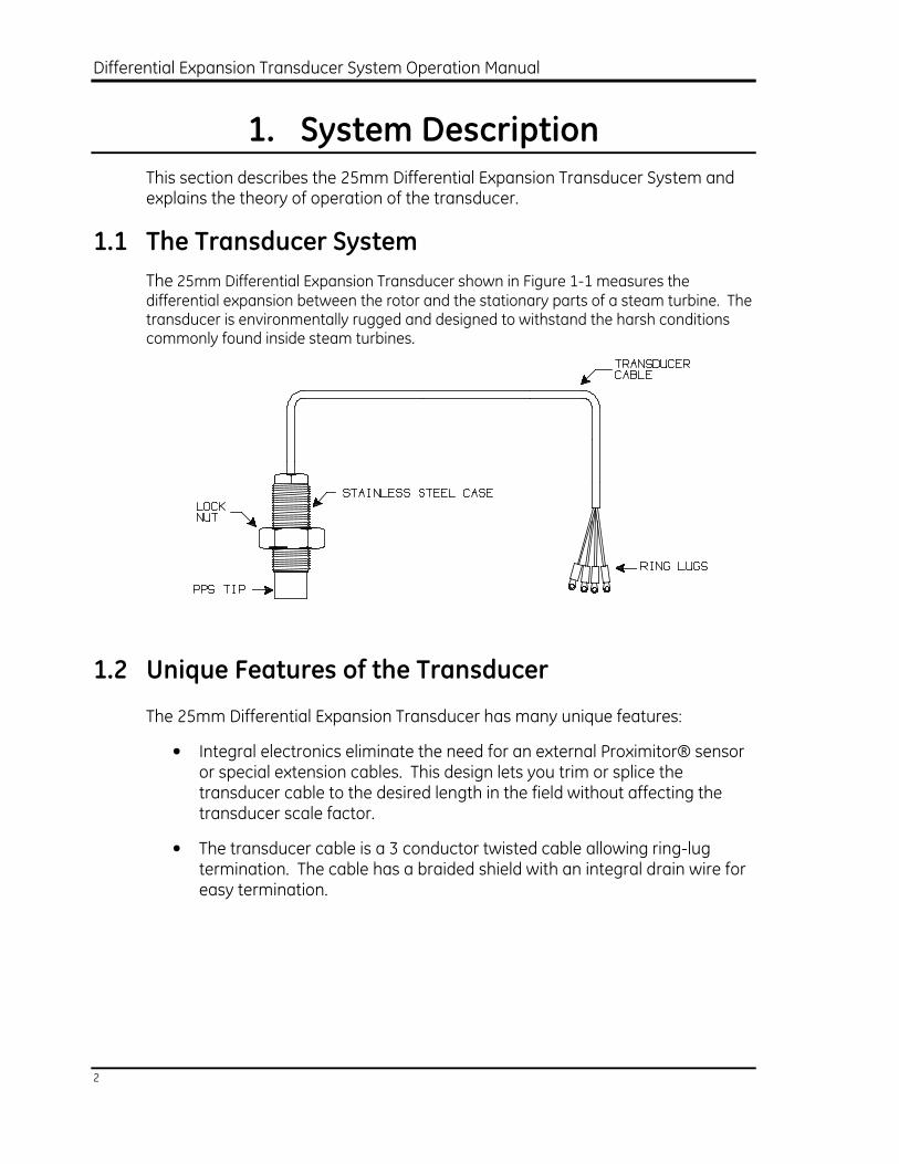
The 25mm Differential Expansion Transducer shown in Figure 1-1 measures the differential expansion between the rotor and the stationary parts of a steam turbine. The transducer is environmentally rugged and designed to withstand the harsh conditions commonly found inside steam turbines.
1.2 Unique Features of the Transducer
The 25mm Differential Expansion Transducer has many unique features:
• Integral electronics eliminate the need for an external Proximitor® sensor or special extension cables. This design lets you trim or splice the transducer cable to the desired length in the field without affecting the transducer scale factor.
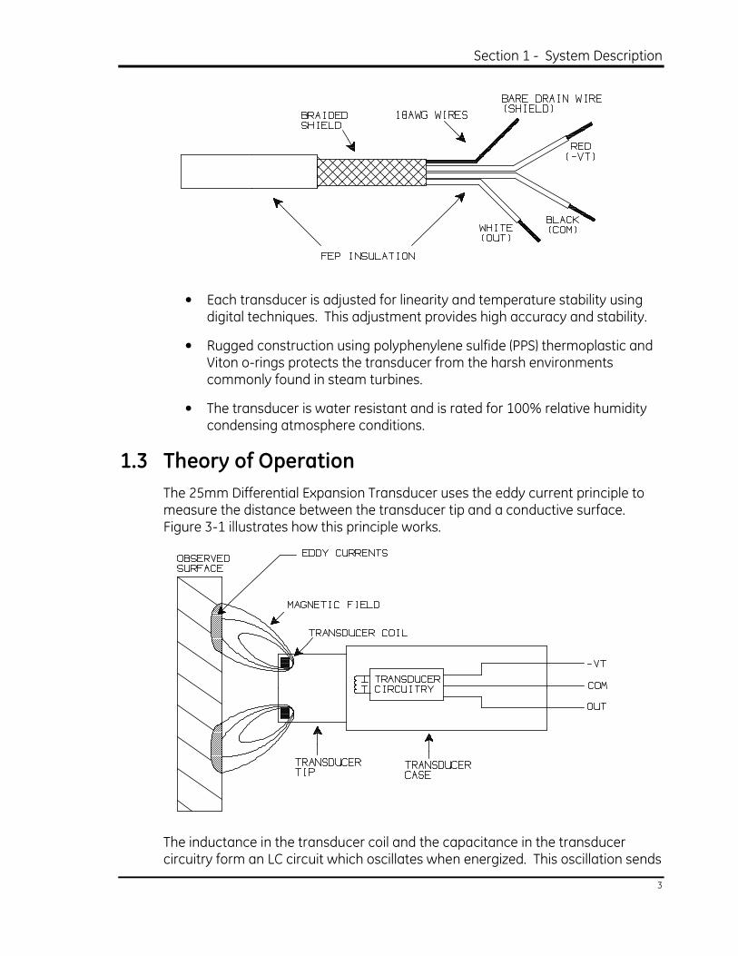
• The transducer cable is a 3 conductor twisted cable allowing ring-lug termination. The cable has a braided shield with an integral drain wire for easy termination.
Section 1 - System Description
3
• Each transducer is adjusted for linearity and temperature stability using digital techniques. This adjustment provides high accuracy and stability.
• Rugged construction using polyphenylene sulfide (PPS) thermoplastic and Viton o-rings protects the transducer from the harsh environments commonly found in steam turbines.
• The transducer is water resistant and is rated for 100% relative humidity condensing atmosphere conditions.
1.3 Theory of Operation
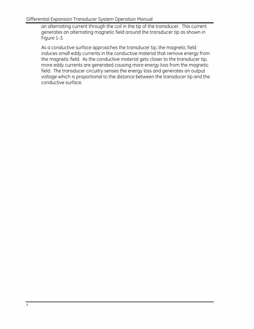
The 25mm Differential Expansion Transducer uses the eddy current principle to measure the distance between the transducer tip and a conductive surface. Figure 3-1 illustrates how this principle works.
The inductance in the transducer coil and the capacitance in the transducer circuitry form an LC circuit which oscillates when energized. This oscillation sends
Differential Expansion Transducer System Operation Manual
4
an alternating current through the coil in the tip of the transducer. This current generates an alternating magnetic field around the transducer tip as shown in Figure 1-3.
As a conductive surface approaches the transducer tip, the magnetic field induces small eddy currents in the conductive material that remove energy from the magnetic field. As the conductive material gets closer to the transducer tip, more eddy currents are generated causing more energy loss from the magnetic field. The transducer circuitry senses the energy loss and generates an output voltage which is proportional to the distance between the transducer tip and the conductive surface.
Section 2 - Installation
5
2. Installation
This section shows how to install the 25mm transducer to measure differential
expansion. Use this approach to install the transducer.
• Plan the Installation
• Mount the Transducer
• Check the Installation
• Gap the Transducer
• Connect the Transducer Wiring
For information about applications other than differential expansion, contact your local Bently Nevada Corporation office.
2.1 Planning the Installation
To ensure that the installed system will work properly, we recommend that you consider the following items before you install the system.
• Pick an appropriate mounting location for the transducer.
• Check that the environmental conditions at the transducer mounting site are within the specifications of the system.
• Verify that the observed surface is a suitable target for the transducer.
• Verify that the mounting location gives adequate side clearance and transducer separation.
2.1.1 Picking the Mounting Location
CAUTION
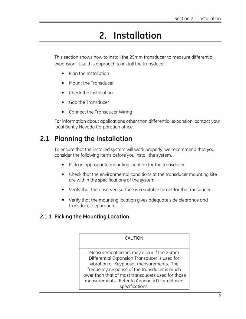
Measurement errors may occur if the 25mm Differential Expansion Transducer is used for vibration or Keyphasor measurements. The frequency response of the transducer is much
lower than that of most transducers used for those measurements. Refer to Appendix D for detailed
specifications.
Differential Expansion Transducer System Operation Manual
6
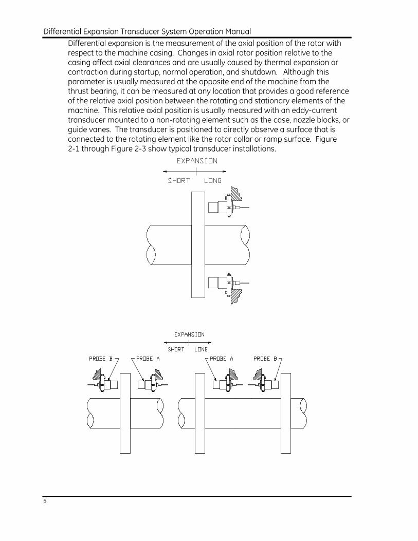
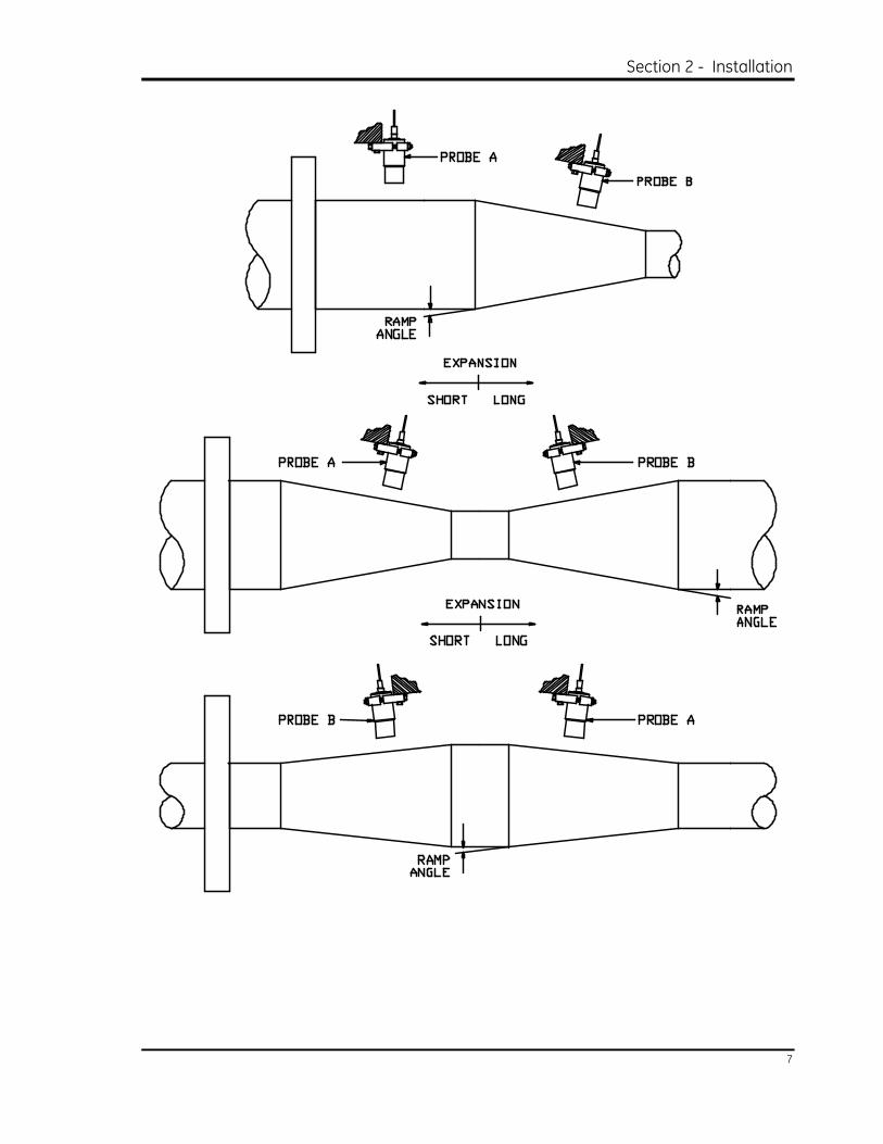
Differential expansion is the measurement of the axial position of the rotor with respect to the machine casing. Changes in axial rotor position relative to the casing affect axial clearances and are usually caused by thermal expansion or contraction during startup, normal operation, and shutdown. Although this parameter is usually measured at the opposite end of the machine from the thrust bearing, it can be measured at any location that provides a good reference of the relative axial position between the rotating and stationary elements of the machine. This relative axial position is usually measured with an eddy-current transducer mounted to a non-rotating element such as the case, nozzle blocks, or guide vanes. The transducer is positioned to directly observe a surface that is connected to the rotating element like the rotor collar or ramp surface. Figure 2-1 through Figure 2-3 show typical transducer installations.
Section 2 - Installation
7
Differential Expansion Transducer System Operation Manual
8
2.1.2 Checking the Environmental Conditions
Although the transducer is designed to withstand the harsh environment for most differential expansion applications, check that the temperature, pressure, and exposure to chemicals and moisture are within the specifications of the system.
2.1.2.1 Operating Temperature
The 25mm Differential Expansion Transducer is usually located in an oil environment which rarely exceeds the maximum rated temperature of the transducer. However, if the transducer is located in the condenser of a steam turbine and the vacuum in the condenser is lost during a machine coast down, the transducer may be exposed to wet steam under pressure. This steam can increase the internal temperature of the turbine above 125°C (257°F) and damage the transducer. This situation can be avoided by maintaining a vacuum in the turbine section where the transducer is located while the machine is operating. The vacuum will usually keep temperatures low enough to avoid damage to the transducer.
2.1.2.2 Pressure Sealing
25 mm DE Transducers are designed to seal differential pressure between the probe tip and case. The probe sealing material consists of a Viton® O-ring. Probes are not pressure tested prior to shipment. Contact our custom design department if you require a test of the pressure seal for your application.
It is the responsibility of the customer or user to ensure that all liquids and gases are contained and safely controlled should leakage occur from a proximity transducer. In addition, solutions with high or low pH values may erode the tip assembly of the probe causing media leakage into surrounding areas. Bently Nevada Corporation will not be held responsible for any damages resulting from leaking 25 mm DE transducers. In addition, 25 mm DE transducers will not be replaced under the service plan due to probe leakage.
2.1.2.3 Chemical Compatibility
Although the 25mm Differential Expansion Transducers are compatible with many types of harsh chemical environments, certain chemicals can damage the transducer. Potentially damaging chemicals include strong acids (pH < 4), strong bases (pH > 10), and some organic solvents (like dimethyl formamide). See
CAUTION
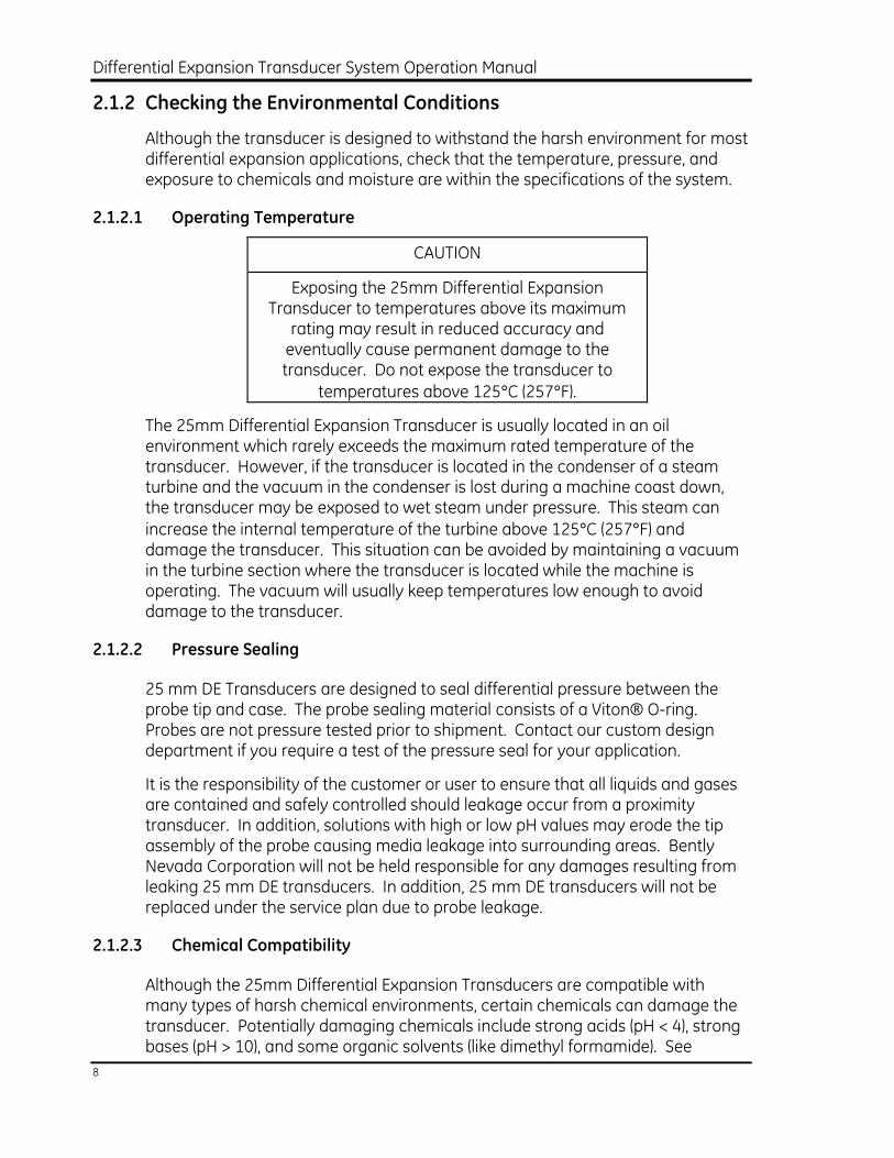
Exposing the 25mm Differential Expansion Transducer to temperatures above its maximum rating may result in reduced accuracy and eventually cause permanent damage to the transducer. Do not expose the transducer to
temperatures above 125°C (257°F).
Section 2 - Installation
9
Appendix D for more information on chemical compatibility. Contact the nearest Bently Nevada Corporation office if you need assistance in determining chemical compatibility.
2.1.2.4 Moisture Sealing
Protect splices and connections in the cable by using terminal blocks in the appropriate housing. Appendix B shows these blocks and housings.
CAUTION
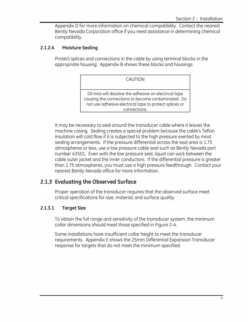
Oil mist will dissolve the adhesive on electrical tape causing the connections to become contaminated. Do not use adhesive electrical tape to protect splices or
connections.
It may be necessary to seal around the transducer cable where it leaves the machine casing. Sealing creates a special problem because the cable's Teflon insulation will cold flow if it is subjected to the high pressure exerted by most sealing arrangements. If the pressure differential across the seal area is 1.75 atmospheres or less, use a low pressure cable seal such as Bently Nevada part number 43501. Even with the low pressure seal, liquid can wick between the cable outer jacket and the inner conductors. If the differential pressure is greater than 1.75 atmospheres, you must use a high pressure feedthrough. Contact your nearest Bently Nevada office for more information.
2.1.3 Evaluating the Observed Surface
Proper operation of the transducer requires that the observed surface meet critical specifications for size, material, and surface quality.
2.1.3.1 Target Size
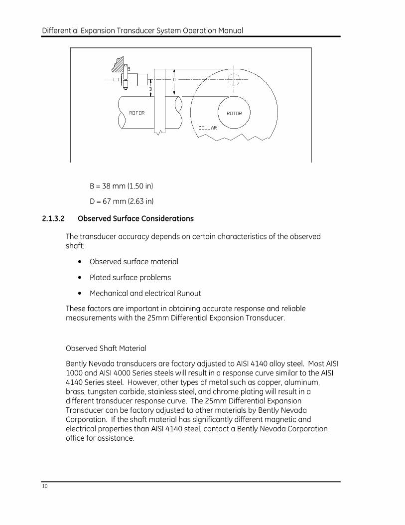
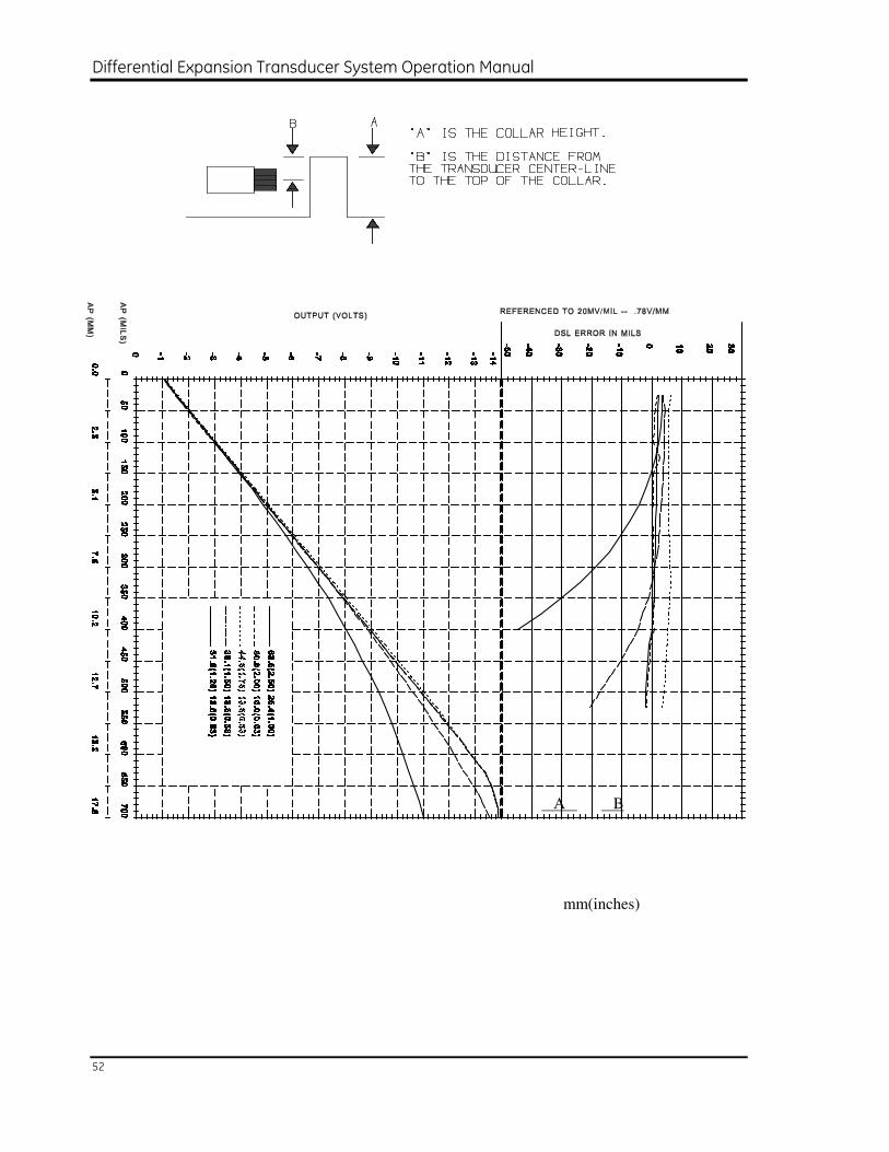
To obtain the full range and sensitivity of the transducer system, the minimum collar dimensions should meet those specified in Figure 2-4.
Some installations have insufficient collar height to meet the transducer requirements. Appendix E shows the 25mm Differential Expansion Transducer response for targets that do not meet the minimum specified.
Differential Expansion Transducer System Operation Manual
10
B = 38 mm (1.50 in)
D = 67 mm (2.63 in)
2.1.3.2 Observed Surface Considerations
The transducer accuracy depends on certain characteristics of the observed shaft:
• Observed surface material
• Plated surface problems
• Mechanical and electrical Runout
These factors are important in obtaining accurate response and reliable measurements with the 25mm Differential Expansion Transducer.
Observed Shaft Material
Bently Nevada transducers are factory adjusted to AISI 4140 alloy steel. Most AISI 1000 and AISI 4000 Series steels will result in a response curve similar to the AISI 4140 Series steel. However, other types of metal such as copper, aluminum, brass, tungsten carbide, stainless steel, and chrome plating will result in a different transducer response curve. The 25mm Differential Expansion Transducer can be factory adjusted to other materials by Bently Nevada Corporation. If the shaft material has significantly different magnetic and electrical properties than AISI 4140 steel, contact a Bently Nevada Corporation office for assistance.
Section 2 - Installation
11
Plated Surfaces
If the shaft target area is plated, either remove the plating material, or contact the nearest Bently Nevada Corporation office for assistance. When plating is applied to the observed surface of a shaft, the sensitivity of the transducer will change. Since the transducer senses below the surface of the shaft material, its sensitivity can be affected by the type and thickness of the plating. For example, if the target material is chrome plated, the plating must be uniform and at least 0.76 mm (20 mils) deep.
Mechanical and Electrical Runout
Proper transducer installation requires that the shaft target area be free of surface irregularities and residual magnetism. These conditions can cause measurement errors which are called electrical or mechanical runout.
Avoid surface irregularities such as hammer marks, scratches, shoulders, projections, holes, or keyways. Bently Nevada recommends 0.41 to 0.76 micrometres (16 to 30 microinches) shaft surface finish because cast or rough surfaces produce small amounts of mechanical runout. American Petroleum Institute (API) 670 recommends a maximum residual magnetism of 0.5 millitesla (5.0 gauss). In addition, any type of plating (including chrome) which has a nonuniform thickness may result in electrical or mechanical runout. The following application notes describe various techniques for reducing or eliminating electrical and mechanical runout:
• "Glitch": Definition of and Methods for Correction, including Shaft Burnishing to Remove Electrical Runout. (Application note AN002)
• API 670, second edition, Section 4.1.2: Machine Shaft Requirements for Electrical and Mechanical runout.
2.1.4 Verifying the Mounting Location
Since the transducer operates by using a magnetic field at the tip, design the transducer mounts with adequate side clearance and separation so that nothing interferes with the magnetic field.
2.1.4.1 Side Clearance
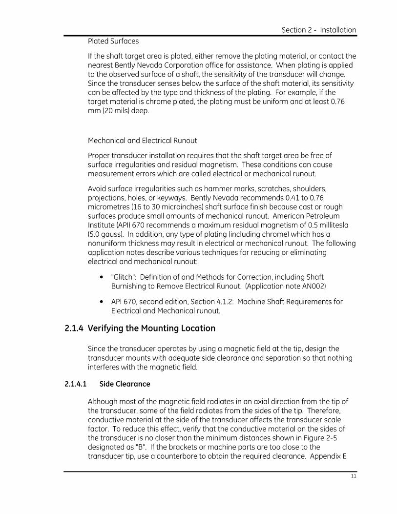
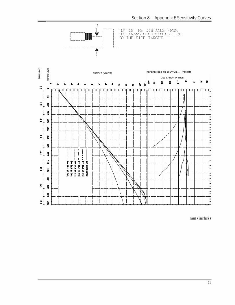
Although most of the magnetic field radiates in an axial direction from the tip of the transducer, some of the field radiates from the sides of the tip. Therefore, conductive material at the side of the transducer affects the transducer scale factor. To reduce this effect, verify that the conductive material on the sides of the transducer is no closer than the minimum distances shown in Figure 2-5 designated as "B". If the brackets or machine parts are too close to the transducer tip, use a counterbore to obtain the required clearance. Appendix E
Differential Expansion Transducer System Operation Manual
12
shows the typical effect of insufficient flat surface side clearance on the 25mm Differential Expansion Transducer. This effect varies in actual applications due to surface material and mounting configurations.
B = 38mm (1.5 in) minimum
C = 22.2mm (0.875 in) minimum
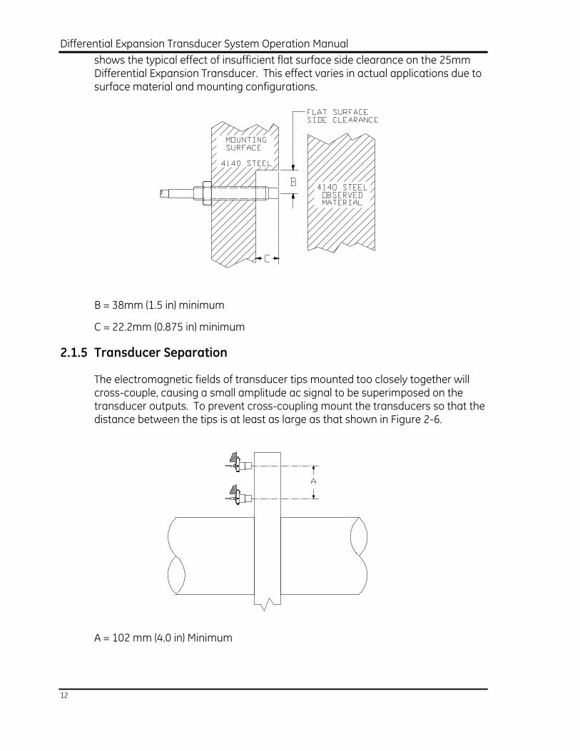
2.1.5 Transducer Separation
The electromagnetic fields of transducer tips mounted too closely together will cross-couple, causing a small amplitude ac signal to be superimposed on the transducer outputs. To prevent cross-coupling mount the transducers so that the distance between the tips is at least as large as that shown in Figure 2-6.
A = 102 mm (4.0 in) Minimum
Section 2 - Installation
13
2.2 Mounting the Transducer
Mount the transducer in the machine by installing the mounting bracket, checking the mounting holes, and installing the transducer in the mounting bracket.
2.2.1 Installing the Mounting Bracket
WARNING
Contact with rotating machinery causes severe injury. Exercise extreme care when working
around rotating machinery.
The brackets and other structural members used to mount the transducer must be rigid. The resonant frequency of the mounts should be at least 10 times the machine running speed to reduce false vibration signals.
A smooth body transducer mounting clamp is shipped with each smooth body transducer. The user must supply the mount for threaded body transducer applications. Attach the mount to the machine case either directly or by means of a user supplied bracket.
The transducer mount should be installed so the transducer will be perpendicular to the observed surface or the transducer range, scale factor, and linearity may be affected. Errors caused by an incorrect mounting angle are usually small if the transducer is mounted within ±5° of perpendicular.
2.2.2 Checking the Mounting Holes
CAUTION
Metal filings can damage the internal components of the machine. Remove all of the metal filings
from inside of the machine.
Be sure the mounting holes for the transducer are free of foreign material. If you cannot screw the transducer into the mounting hole easily, use an appropriate tap to clean the threads.
2.2.3 Installing the Transducer in the Mounting Bracket
CAUTION
Threading the transducer without turning the cable may damage the transducer. When installing a transducer with a long integral cable, be sure the
cable turns with the transducer.
Differential Expansion Transducer System Operation Manual
14
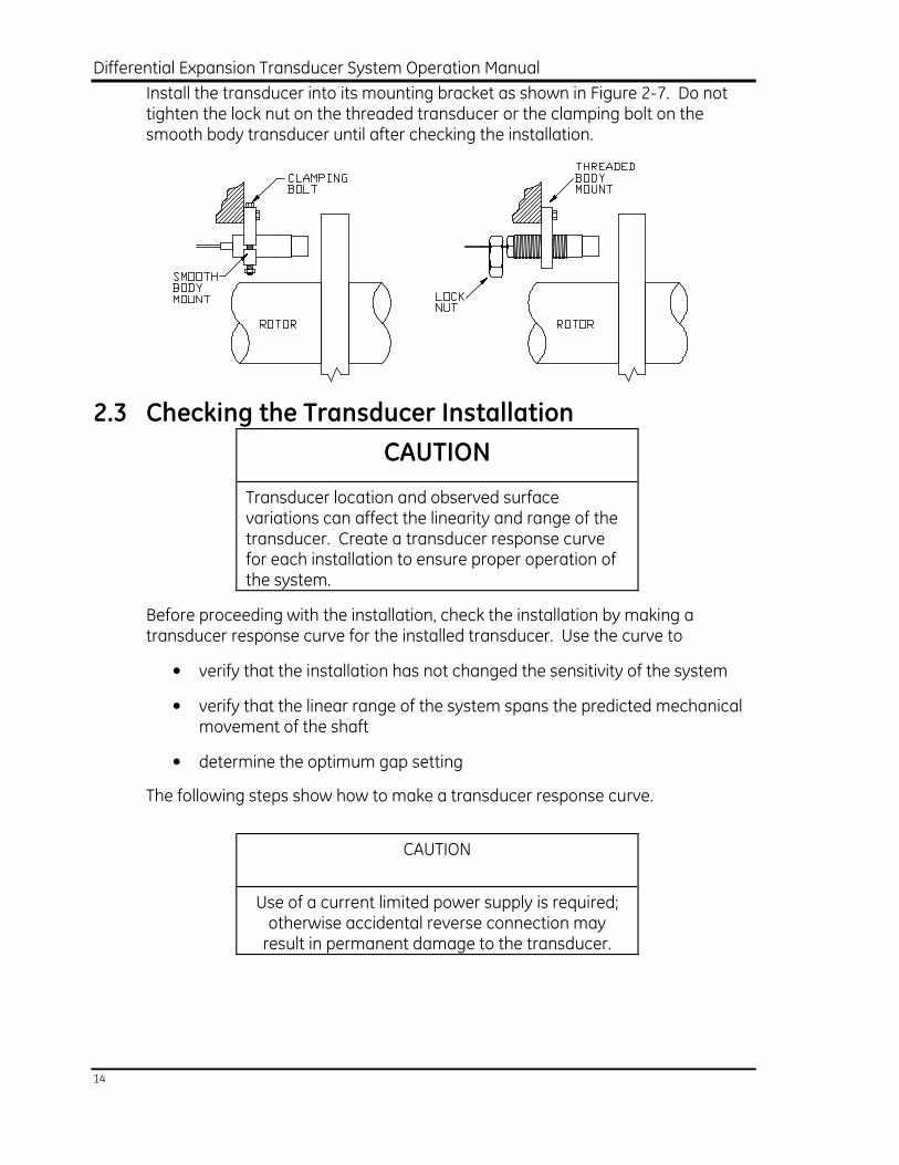
Install the transducer into its mounting bracket as shown in Figure 2-7. Do not tighten the lock nut on the threaded transducer or the clamping bolt on the smooth body transducer until after checking the installation.
2.3 Checking the Transducer Installation
CAUTION
Transducer location and observed surface variations can affect the linearity and range of the transducer. Create a transducer response curve for each installation to ensure proper operation of the system.
Before proceeding with the installation, check the installation by making a transducer response curve for the installed transducer. Use the curve to
• verify that the installation has not changed the sensitivity of the system
• verify that the linear range of the system spans the predicted mechanical movement of the shaft
• determine the optimum gap setting
The following steps show how to make a transducer response curve.
CAUTION
Use of a current limited power supply is required; otherwise accidental reverse connection may result in permanent damage to the transducer.
Section 2 - Installation
15
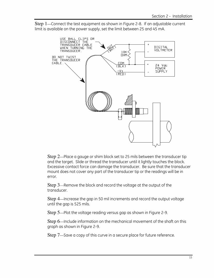
Step 1—Connect the test equipment as shown in Figure 2-8. If an adjustable current limit is available on the power supply, set the limit between 25 and 45 mA.
Step 2—Place a gauge or shim block set to 25 mils between the transducer tip and the target. Slide or thread the transducer until it lightly touches the block. Excessive contact force can damage the transducer. Be sure that the transducer mount does not cover any part of the transducer tip or the readings will be in error.
Step 3—Remove the block and record the voltage at the output of the transducer.
Step 4—Increase the gap in 50 mil increments and record the output voltage until the gap is 525 mils.
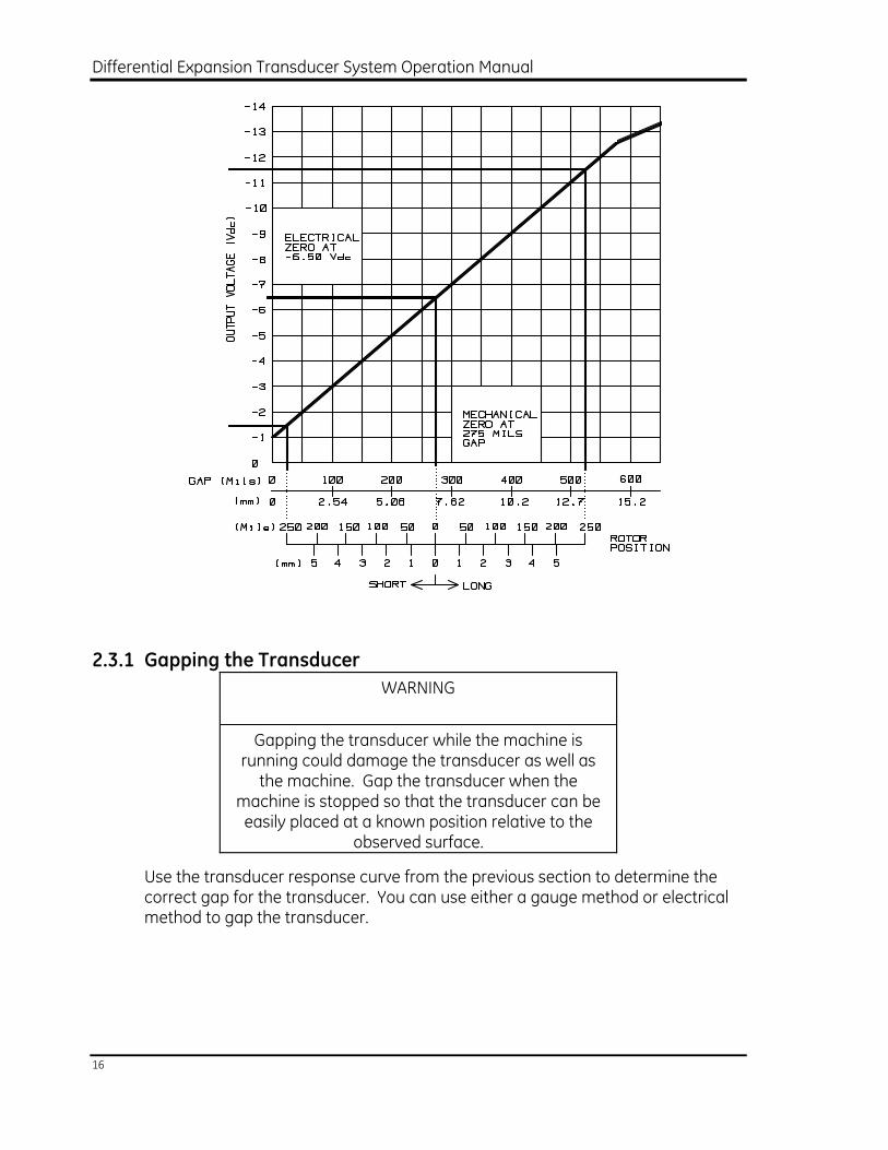
Step 5—Plot the voltage reading versus gap as shown in Figure 2-9.
Step 6—Include information on the mechanical movement of the shaft on this graph as shown in Figure 2-9.
Step 7—Save a copy of this curve in a secure place for future reference.
Differential Expansion Transducer System Operation Manual
16
2.3.1 Gapping the Transducer
WARNING
Gapping the transducer while the machine is running could damage the transducer as well as the machine. Gap the transducer when the
machine is stopped so that the transducer can be easily placed at a known position relative to the
observed surface.
Use the transducer response curve from the previous section to determine the correct gap for the transducer. You can use either a gauge method or electrical method to gap the transducer.
Section 2 - Installation
17
Gauge Method
Place a gauge or shim block that is as wide as the desired mechanical gap between the transducer tip and the target. Slide or thread the transducer until it lightly touches the block.
Electrical method
Connect the transducer as shown in Figure 2-8. Slide or thread the transducer into the mount until the proper output voltage is observed.
WARNING
Loose parts in the machine can cause damage or injury. Secure all parts that can loosen over time with steel safety wire and a thread locking
compound.
Tighten the lock nut, clamp, or other retainer. Use a thread locking compound (Loctite or equivalent) and safety wire to prevent parts from loosening.
2.3.1.1 Connecting the Transducer Wiring
After the transducer is mounted in the machine, route the wiring back to the monitor by:
• securing the cable inside the machine
• terminating the transducer cable and connecting it to the field wiring
• routing the field wiring back to the monitor
Secure the Cable Inside the Machine
Since the transducer cable mounted inside the machine may be worn or damaged by windage (circulating air inside the turbine), secure the cable by using conduit. If conduit is unavailable, use armored cable and securely fasten the armor to a rigid surface. The use of unprotected cable (no conduit or armor) is not recommended. If unprotected cable must be used, securely fasten the cable to a rigid surface using non-metallic tie downs such as teflon cable ties. Other cable holding devices can be used, but be sure that the teflon jacket on the cable does not cold flow and short to any conductive material. A short could introduce ground loops into the system.
Differential Expansion Transducer System Operation Manual
18
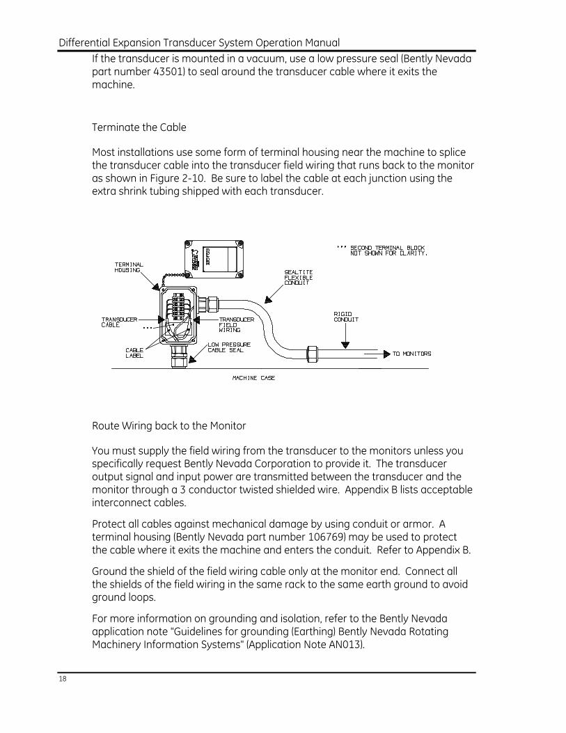
If the transducer is mounted in a vacuum, use a low pressure seal (Bently Nevada part number 43501) to seal around the transducer cable where it exits the machine.
Terminate the Cable
Most installations use some form of terminal housing near the machine to splice the transducer cable into the transducer field wiring that runs back to the monitor as shown in Figure 2-10. Be sure to label the cable at each junction using the extra shrink tubing shipped with each transducer.
Route Wiring back to the Monitor
You must supply the field wiring from the transducer to the monitors unless you specifically request Bently Nevada Corporation to provide it. The transducer output signal and input power are transmitted between the transducer and the monitor through a 3 conductor twisted shielded wire. Appendix B lists acceptable interconnect cables.
Protect all cables against mechanical damage by using conduit or armor. A terminal housing (Bently Nevada part number 106769) may be used to protect the cable where it exits the machine and enters the conduit. Refer to Appendix B.
Ground the shield of the field wiring cable only at the monitor end. Connect all the shields of the field wiring in the same rack to the same earth ground to avoid ground loops.
For more information on grounding and isolation, refer to the Bently Nevada application note "Guidelines for grounding (Earthing) Bently Nevada Rotating Machinery Information Systems" (Application Note AN013).
Section 2 - Installation
19
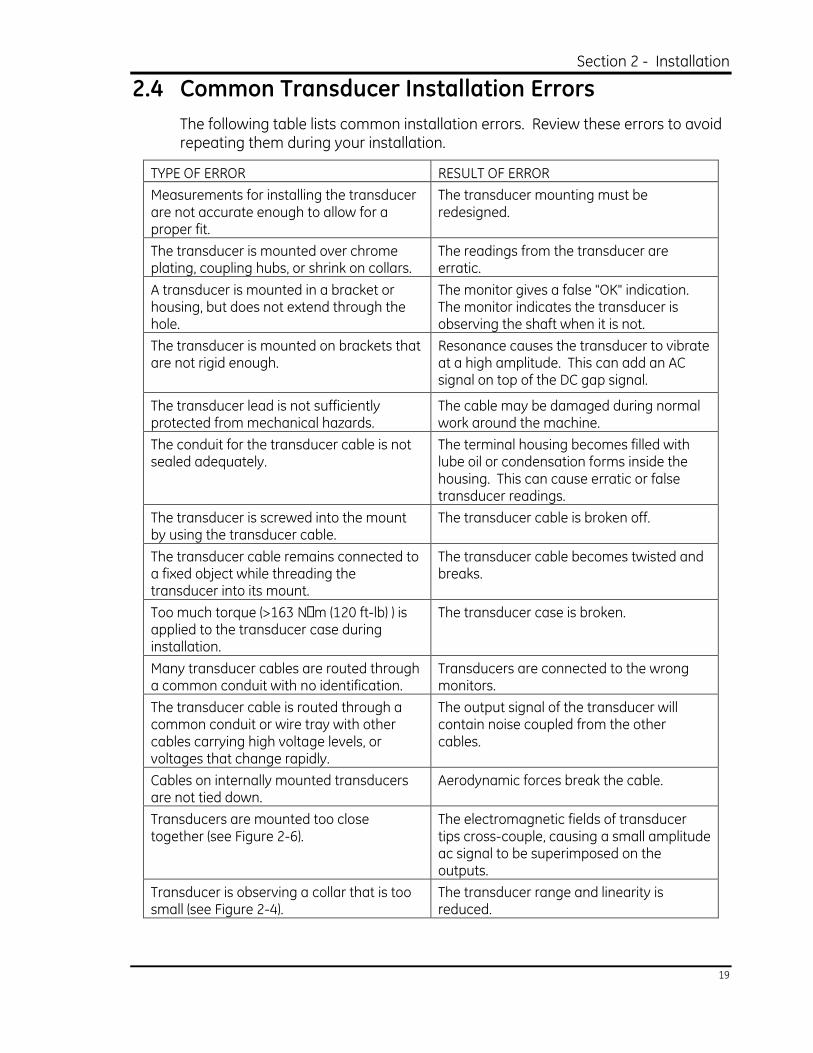
2.4 Common Transducer Installation Errors
The following table lists common installation errors. Review these errors to avoid repeating them during your installation.
TYPE OF ERROR RESULT OF ERROR
Measurements for installing the transducer are not accurate enough to allow for a proper fit.
The transducer mounting must be redesigned.
The transducer is mounted over chrome plating, coupling hubs, or shrink on collars.
The readings from the transducer are erratic.
A transducer is mounted in a bracket or housing, but does not extend through the hole.
The monitor gives a false "OK" indication. The monitor indicates the transducer is observing the shaft when it is not.
The transducer is mounted on brackets that are not rigid enough.
Resonance causes the transducer to vibrate at a high amplitude. This can add an AC signal on top of the DC gap signal.
The transducer lead is not sufficiently protected from mechanical hazards.
The cable may be damaged during normal work around the machine.
The conduit for the transducer cable is not sealed adequately.
The terminal housing becomes filled with lube oil or condensation forms inside the housing. This can cause erratic or false transducer readings.
The transducer is screwed into the mount by using the transducer cable.
The transducer cable is broken off.
The transducer cable remains connected to a fixed object while threading the transducer into its mount.
The transducer cable becomes twisted and breaks.
Too much torque (>163 NMm (120 ft-lb) ) is applied to the transducer case during installation.
The transducer case is broken.
Many transducer cables are routed through a common conduit with no identification.
Transducers are connected to the wrong monitors.
The transducer cable is routed through a common conduit or wire tray with other cables carrying high voltage levels, or voltages that change rapidly.
The output signal of the transducer will contain noise coupled from the other cables.
Cables on internally mounted transducers are not tied down.
Aerodynamic forces break the cable.
Transducers are mounted too close together (see Figure 2-6).
The electromagnetic fields of transducer tips cross-couple, causing a small amplitude ac signal to be superimposed on the outputs.
Transducer is observing a collar that is too small (see Figure 2-4).
The transducer range and linearity is reduced.
Differential Expansion Transducer System Operation Manual
20
3. Maintenance This section contains a list of recommended maintenance equipment and instructions for storing, testing, and troubleshooting the transducer system. Performing any maintenance other than that which is specified in this section may void the warranty for the transducer system.
3.1 Recommended Maintenance Equipment
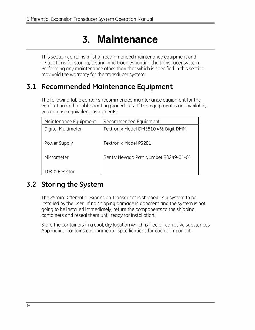
The following table contains recommended maintenance equipment for the verification and troubleshooting procedures. If this equipment is not available, you can use equivalent instruments.
Maintenance Equipment Recommended Equipment
Digital Multimeter
Power Supply
Micrometer
10K Ω Resistor
Tektronix Model DM2510 4½ Digit DMM
Tektronix Model PS281
Bently Nevada Part Number 88249-01-01
3.2 Storing the System
The 25mm Differential Expansion Transducer is shipped as a system to be installed by the user. If no shipping damage is apparent and the system is not going to be installed immediately, return the components to the shipping containers and reseal them until ready for installation.
Store the containers in a cool, dry location which is free of corrosive substances. Appendix D contains environmental specifications for each component.
Section 3 - Maintenance
21
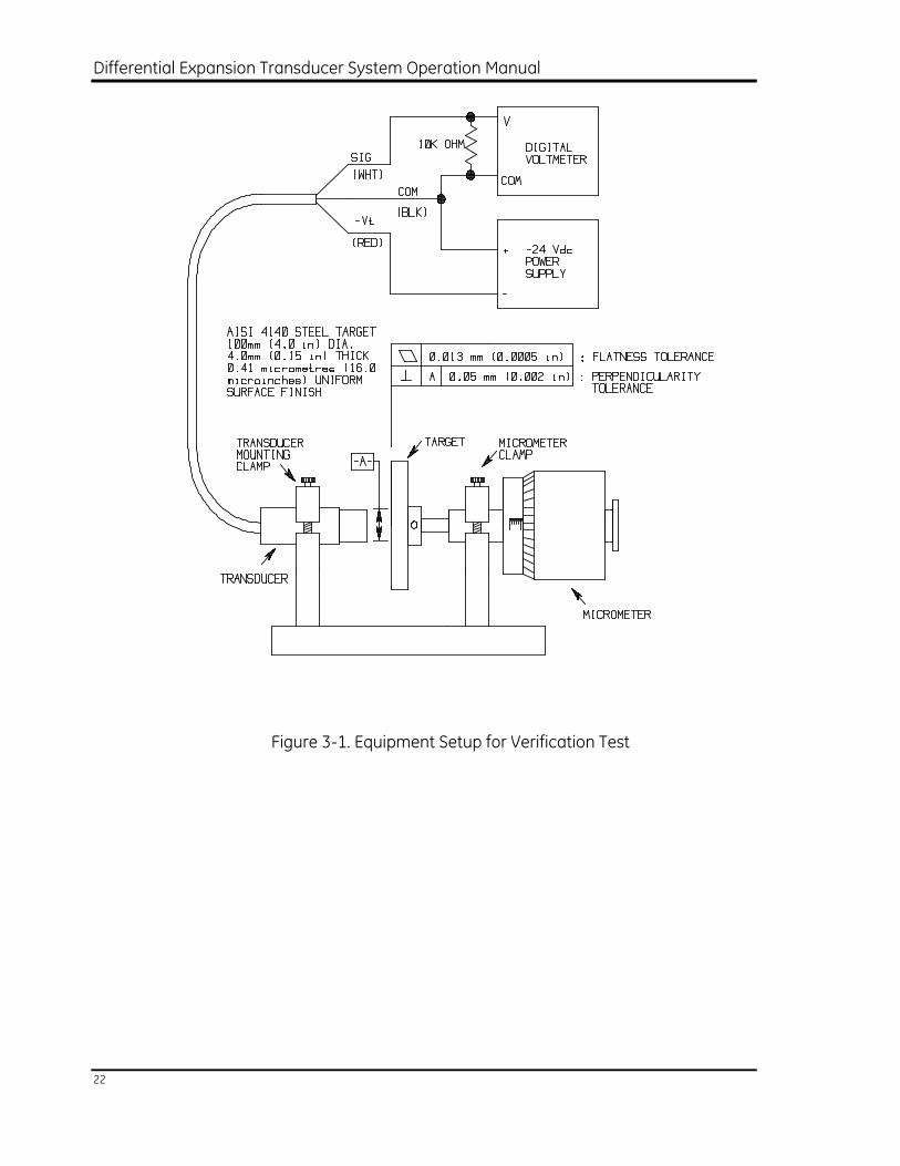
3.3 Verification Test
Use this test procedure to verify the operation of your 25mm Differential Expansion Transducer System. Perform the verification test if you change transducers or use target material other than 4140 steel.
Step 1—Connect the test equipment as shown in 1. Be sure that your transducer
system is properly connected. If an adjustable current limit is available on your power supply, set it between 25 and 45 mA.
Step 2—Set the spindle on the micrometer to zero.
Step 3—Insert the transducer into the transducer holder so that the transducer tip
lightly contacts the target. Clamp the transducer in this position.
Step 4—Adjust the gap to 25 mils and record the output voltage.
Step 5—Increase the gap in 50 mil increments and record the output voltage at
each gap.
Step 6—Calculate the system average scale factor (ASF). Subtract the voltage at
the 525 mils gap from the voltage at the 25 mils gap and divide by 500.
The calculated ASF for the system should be within 19.0 to 21.0 mV/mil for 4140.
Note:Special target materials or unusual target geometries can cause increased error. The best test for the system is to run a transducer response curve in place on the machine and verify that it meets the needs of the application. See Checking the Transducer Installation on page 14.
Differential Expansion Transducer System Operation Manual
22
Figure 3-1. Equipment Setup for Verification Test
Section 3 - Maintenance
23
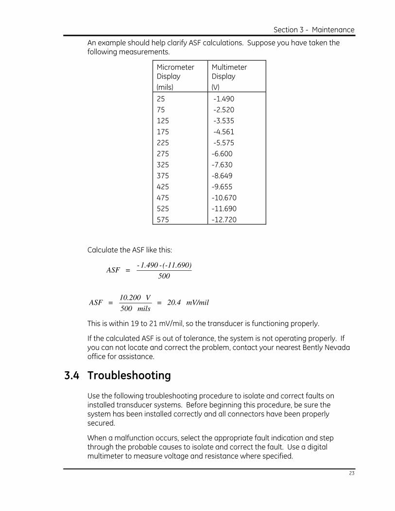
An example should help clarify ASF calculations. Suppose you have taken the following measurements.
Micrometer Display
(mils)
Multimeter Display
(V)
25
75
125
175
225
275
325
375
425
475
525
575
-1.490
-2.520
-3.535
-4.561
-5.575
-6.600
-7.630
-8.649
-9.655
-10.670
-11.690
-12.720
Calculate the ASF like this:
mV/mil 20.4 = mils 500
V 10.200 = ASF
500
(-11.690)-1.490- = ASF
This is within 19 to 21 mV/mil, so the transducer is functioning properly.
If the calculated ASF is out of tolerance, the system is not operating properly. If you can not locate and correct the problem, contact your nearest Bently Nevada office for assistance.
3.4 Troubleshooting
Use the following troubleshooting procedure to isolate and correct faults on installed transducer systems. Before beginning this procedure, be sure the system has been installed correctly and all connectors have been properly secured.
When a malfunction occurs, select the appropriate fault indication and step through the probable causes to isolate and correct the fault. Use a digital multimeter to measure voltage and resistance where specified.
Differential Expansion Transducer System Operation Manual
24
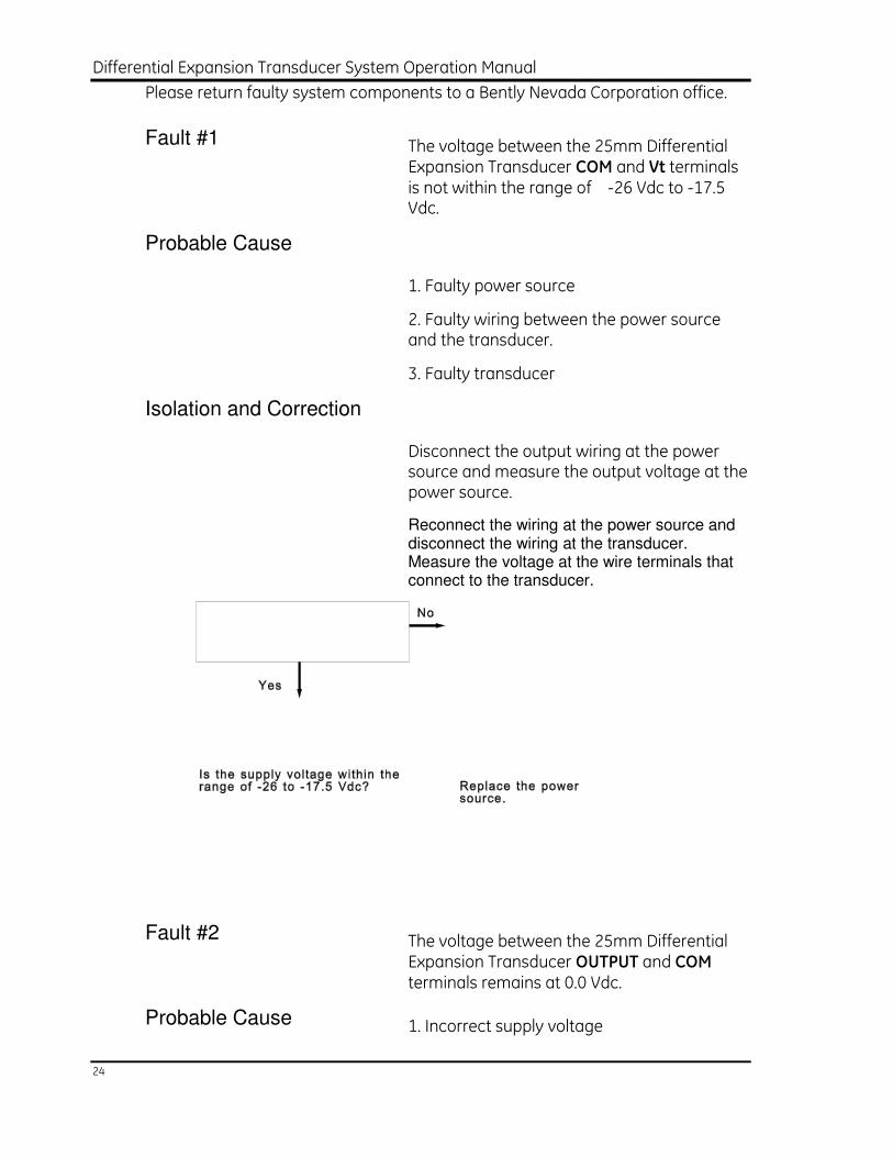
Please return faulty system components to a Bently Nevada Corporation office.
Fault #1 The voltage between the 25mm Differential Expansion Transducer COM and Vt terminals is not within the range of -26 Vdc to -17.5 Vdc.
Probable Cause
1. Faulty power source
2. Faulty wiring between the power source and the transducer.
3. Faulty transducer
Isolation and Correction
Disconnect the output wiring at the power source and measure the output voltage at the power source.
Reconnect the wiring at the power source and disconnect the wiring at the transducer. Measure the voltage at the wire terminals that connect to the transducer.
Fault #2 The voltage between the 25mm Differential Expansion Transducer OUTPUT and COM terminals remains at 0.0 Vdc.
Probable Cause 1. Incorrect supply voltage
Section 3 - Maintenance
25
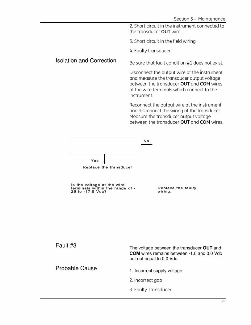
2. Short circuit in the instrument connected to the transducer OUT wire
3. Short circuit in the field wiring
4. Faulty transducer
Isolation and Correction Be sure that fault condition #1 does not exist.
Disconnect the output wire at the instrument and measure the transducer output voltage between the transducer OUT and COM wires at the wire terminals which connect to the instrument.
Reconnect the output wire at the instrument and disconnect the wiring at the transducer. Measure the transducer output voltage between the transducer OUT and COM wires.
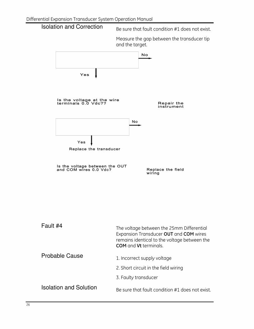
Fault #3 The voltage between the transducer OUT and
COM wires remains between -1.0 and 0.0 Vdc but not equal to 0.0 Vdc.
Probable Cause 1. Incorrect supply voltage
2. Incorrect gap
3. Faulty Transducer
Differential Expansion Transducer System Operation Manual
26
Isolation and Correction Be sure that fault condition #1 does not exist.
Measure the gap between the transducer tip and the target.
Fault #4 The voltage between the 25mm Differential Expansion Transducer OUT and COM wires remains identical to the voltage between the COM and Vt terminals.
Probable Cause 1. Incorrect supply voltage
2. Short circuit in the field wiring
3. Faulty transducer
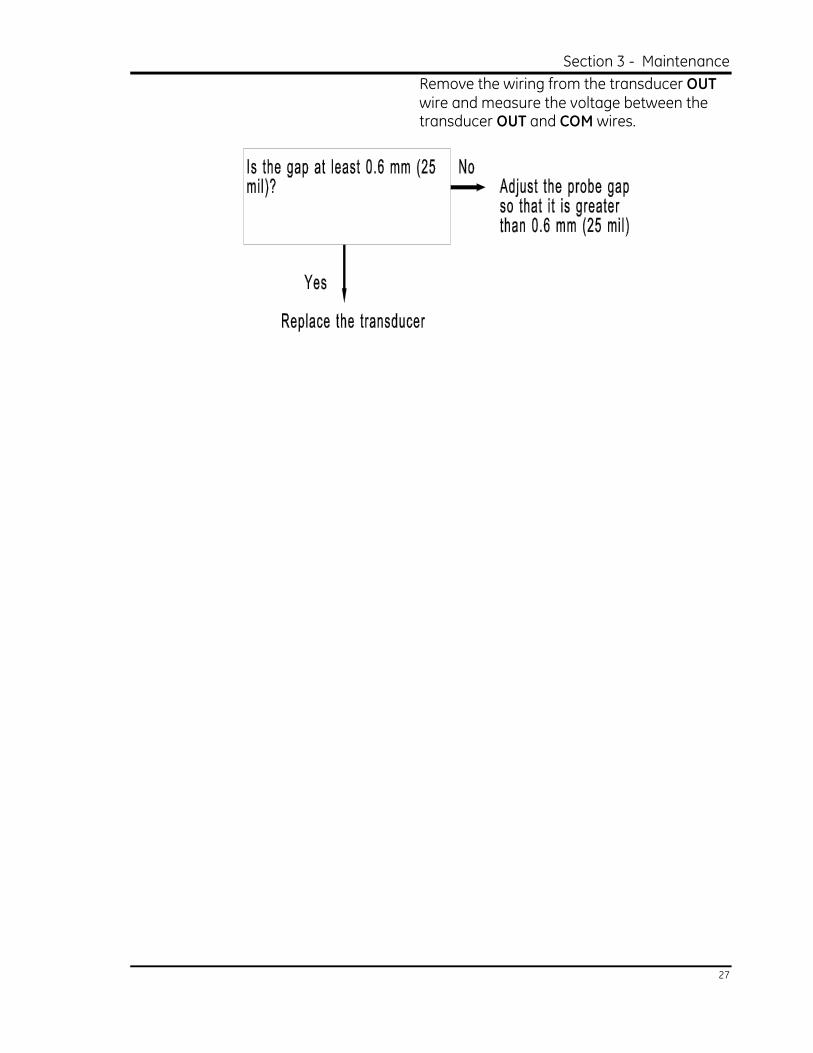
Isolation and Solution Be sure that fault condition #1 does not exist.
Section 3 - Maintenance
27
Remove the wiring from the transducer OUT wire and measure the voltage between the transducer OUT and COM wires.
Differential Expansion Transducer System Operation Manual
28
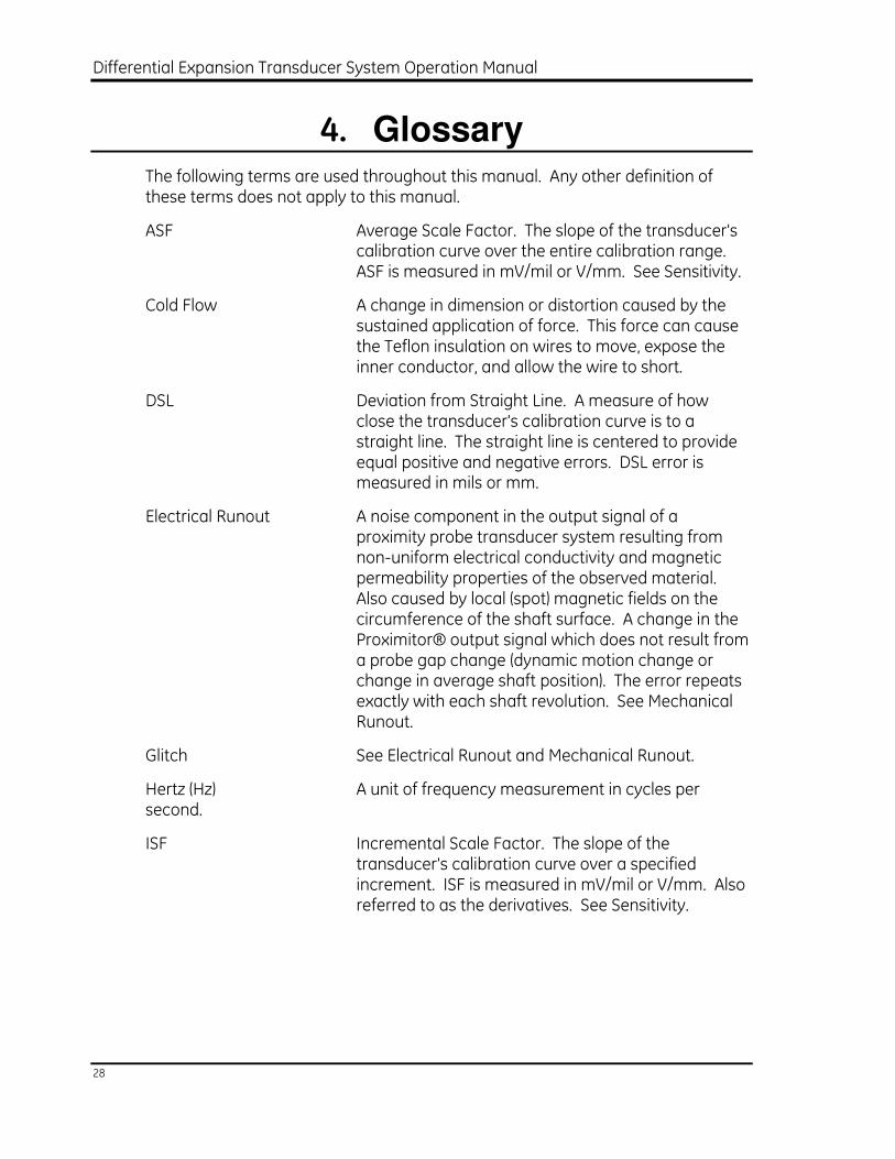
4. Glossary The following terms are used throughout this manual. Any other definition of these terms does not apply to this manual.
ASF Average Scale Factor. The slope of the transducer's calibration curve over the entire calibration range. ASF is measured in mV/mil or V/mm. See Sensitivity.
Cold Flow A change in dimension or distortion caused by the sustained application of force. This force can cause the Teflon insulation on wires to move, expose the inner conductor, and allow the wire to short.
DSL Deviation from Straight Line. A measure of how close the transducer's calibration curve is to a straight line. The straight line is centered to provide equal positive and negative errors. DSL error is measured in mils or mm.
Electrical Runout A noise component in the output signal of a proximity probe transducer system resulting from non-uniform electrical conductivity and magnetic permeability properties of the observed material. Also caused by local (spot) magnetic fields on the circumference of the shaft surface. A change in the Proximitor® output signal which does not result from a probe gap change (dynamic motion change or change in average shaft position). The error repeats exactly with each shaft revolution. See Mechanical Runout.
Glitch See Electrical Runout and Mechanical Runout.
Hertz (Hz) A unit of frequency measurement in cycles per second.
ISF Incremental Scale Factor. The slope of the transducer's calibration curve over a specified increment. ISF is measured in mV/mil or V/mm. Also referred to as the derivatives. See Sensitivity.
Section 4 - Glossary
29
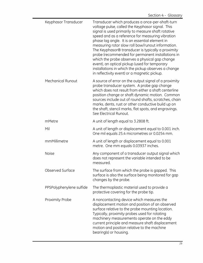
Keyphasor Transducer Transducer which produces a once-per-shaft-turn voltage pulse, called the Keyphasor signal. This signal is used primarily to measure shaft rotative speed and as a reference for measuring vibration phase lag angle. It is an essential element in measuring rotor slow roll bow/runout information. The Keyphasor® transducer is typically a proximity probe (recommended for permanent installations in which the probe observes a physical gap change event), an optical pickup (used for temporary installations in which the pickup observes a change in reflectivity event) or a magnetic pickup.
Mechanical Runout A source of error on the output signal of a proximity probe transducer system. A probe gap change which does not result from either a shaft centerline position change or shaft dynamic motion. Common sources include out of round shafts, scratches, chain marks, dents, rust or other conductive build up on the shaft, stencil marks, flat spots, and engravings. See Electrical Runout.
mMetre A unit of length equal to 3.2808 ft.
Mil A unit of length or displacement equal to 0.001 inch. One mil equals 25.4 micrometres or 0.0254 mm.
mmMillimetre A unit of length or displacement equal to 0.001 metre. One mm equals 0.03937 inches.
Noise Any component of a transducer output signal which does not represent the variable intended to be measured.
Observed Surface The surface from which the probe is gapped. This surface is also the surface being monitored for gap changes by the probe.
PPSPolyphenylene sulfide The thermoplastic material used to provide a protective covering for the probe tip.
Proximity Probe A noncontacting device which measures the displacement motion and position of an observed surface relative to the probe mounting location. Typically, proximity probes used for rotating machinery measurements operate on the eddy current principle and measure shaft displacement motion and position relative to the machine bearing(s) or housing.

Differential Expansion Transducer System Operation Manual
30
Sensitivity The ratio of the response or change induced in the output to a stimulus or change in the input. The sensitivity for a 25mm Differential Expansion transducer is 788 V/mm (20 mV/mil). See ASF and ISF.
NOTE: For more definitions of terms used in rotating machinery, refer to the Bently Nevada Glossary (BNC Publication L-1014).
Section 5 - Appendix A – Ordering Information
31
5. Appendix A Ordering Information Appendix A contains ordering information for the 25mm Differential Expansion Transducer System including instructions for receiving and inspecting your order and part numbers for each system component.
5.1 Receiving and Inspecting Your Order
When you receive your order, carefully remove all equipment from the shipping containers and inspect each item for shipping damage. If shipping damage is apparent, file a claim with the carrier and submit a copy to Bently Nevada Corporation. Include the part numbers and serial numbers of the damaged items on all correspondence.
Differential Expansion Transducer System Operation Manual
32
5.2 Ordering Information
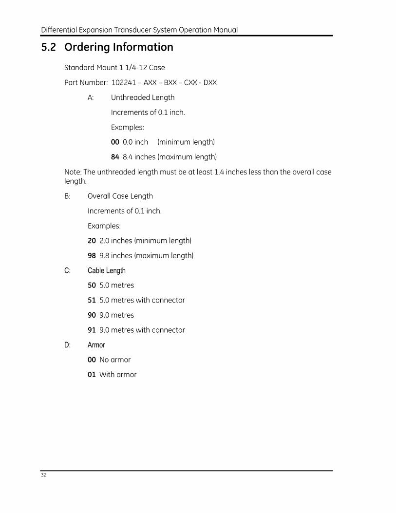
Standard Mount 1 1/4-12 Case
Part Number: 102241 – AXX – BXX – CXX - DXX
A: Unthreaded Length
Increments of 0.1 inch.
Examples:
00 0.0 inch (minimum length)
84 8.4 inches (maximum length)
Note: The unthreaded length must be at least 1.4 inches less than the overall case length.
B: Overall Case Length
Increments of 0.1 inch.
Examples:
20 2.0 inches (minimum length)
98 9.8 inches (maximum length)
C: Cable Length
50 5.0 metres
51 5.0 metres with connector
90 9.0 metres
91 9.0 metres with connector
D: Armor
00 No armor
01 With armor
Section 5 - Appendix A – Ordering Information
33
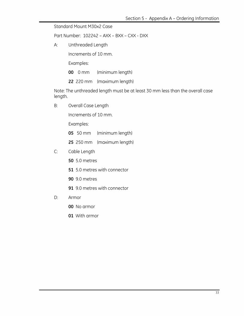
Standard Mount M30x2 Case
Part Number: 102242 – AXX – BXX – CXX - DXX
A: Unthreaded Length
Increments of 10 mm.
Examples:
00 0 mm (minimum length)
22 220 mm (maximum length)
Note: The unthreaded length must be at least 30 mm less than the overall case length.
B: Overall Case Length
Increments of 10 mm.
Examples:
05 50 mm (minimum length)
25 250 mm (maximum length)
C: Cable Length
50 5.0 metres
51 5.0 metres with connector
90 9.0 metres
91 9.0 metres with connector
D: Armor
00 No armor
01 With armor
Differential Expansion Transducer System Operation Manual
34
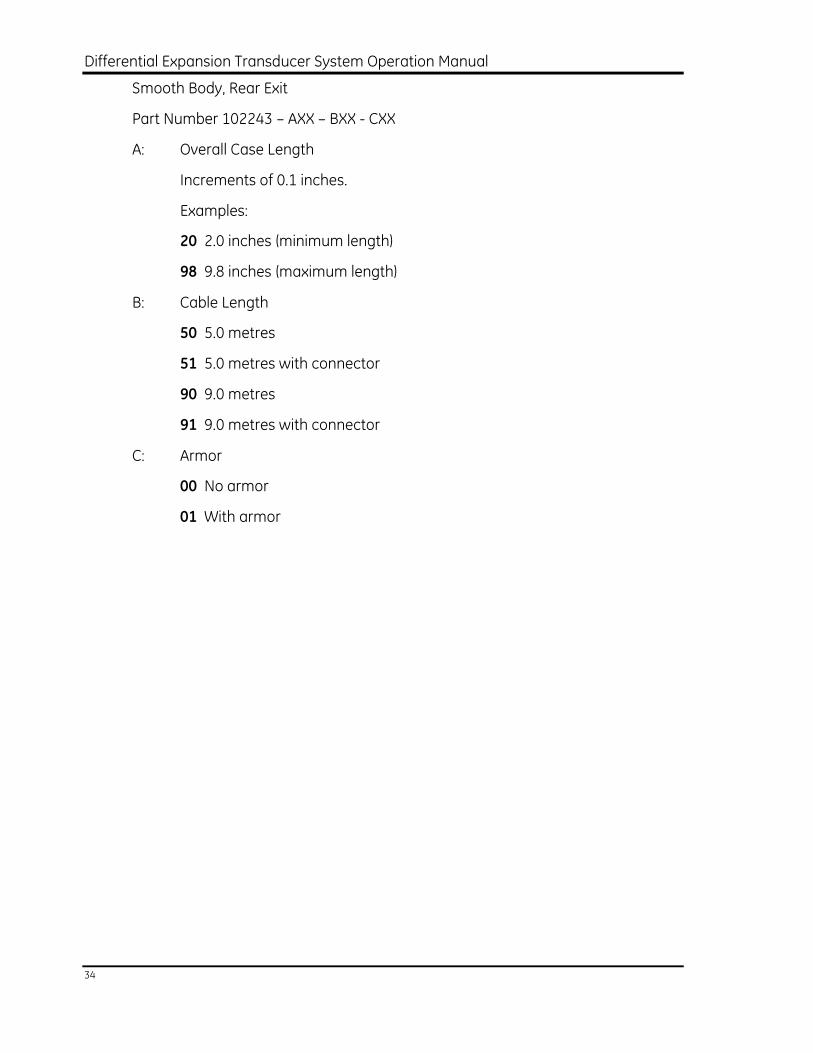
Smooth Body, Rear Exit
Part Number 102243 – AXX – BXX - CXX
A: Overall Case Length
Increments of 0.1 inches.
Examples:
20 2.0 inches (minimum length)
98 9.8 inches (maximum length)
B: Cable Length
50 5.0 metres
51 5.0 metres with connector
90 9.0 metres
91 9.0 metres with connector
C: Armor
00 No armor
01 With armor
Section 5 - Appendix A – Ordering Information
35
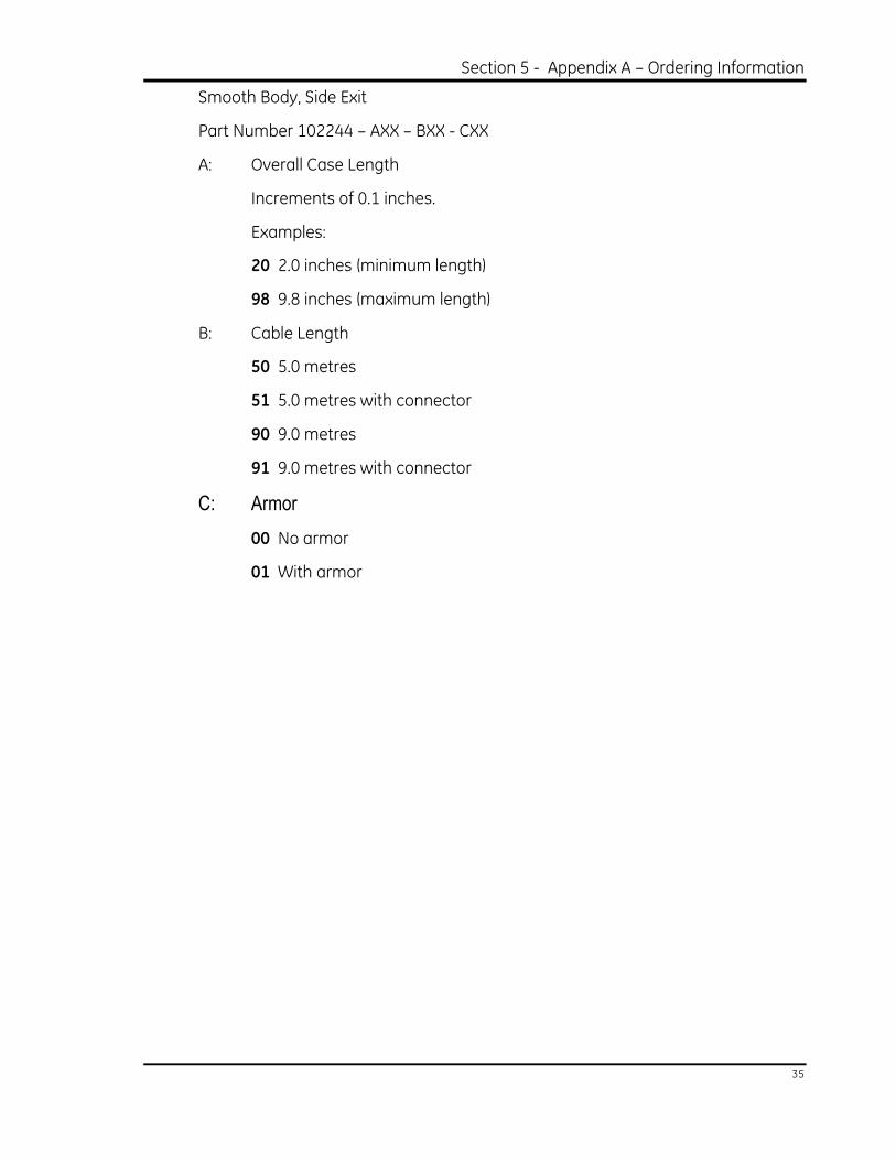
Smooth Body, Side Exit
Part Number 102244 – AXX – BXX - CXX
A: Overall Case Length
Increments of 0.1 inches.
Examples:
20 2.0 inches (minimum length)
98 9.8 inches (maximum length)
B: Cable Length
50 5.0 metres
51 5.0 metres with connector
90 9.0 metres
91 9.0 metres with connector
C: Armor
00 No armor
01 With armor
Differential Expansion Transducer System Operation Manual
36
6. Appendix B Optional Accessories
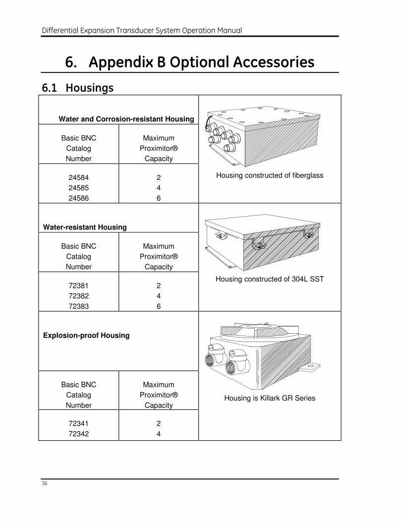
6.1 Housings
Water and Corrosion-resistant Housing
Basic BNC
Catalog
Number
Maximum
Proximitor®
Capacity
24584
24585
24586
2
4
6
Housing constructed of fiberglass
Water-resistant Housing
Basic BNC
Catalog
Number
Maximum
Proximitor®
Capacity
72381
72382
72383
2
4
6
Housing constructed of 304L SST
Explosion-proof Housing
Basic BNC
Catalog
Number
Maximum
Proximitor®
Capacity
72341
72342
2
4
Housing is Killark GR Series
Section 6 - Appendix B – Optional Accessories
37
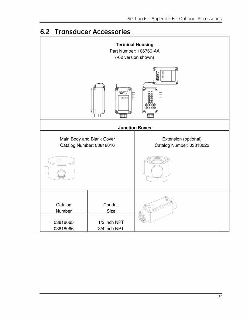
6.2 Transducer Accessories
Terminal Housing
Part Number: 106769-AA
(-02 version shown)
Junction Boxes
Main Body and Blank Cover
Catalog Number: 03818016
Extension (optional)
Catalog Number: 03818022
Catalog
Number
Conduit
Size
03818065
03818066
1/2 inch NPT
3/4 inch NPT
Differential Expansion Transducer System Operation Manual
38
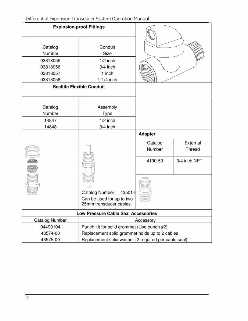
Explosion-proof Fittings
Catalog
Number
Conduit
Size
03818055
03818056
03818057
03818058
1/2 inch
3/4 inch
1 inch
1-1/4 inch
Sealtite Flexible Conduit
Catalog
Number
Assembly
Type
14847
14848
1/2 inch
3/4 inch
Adapter
Catalog
Number
External
Thread
4190-59 3/4 inch NPT
Catalog Number: 43501-HP
Can be used for up to two 25mm transducer cables.
Use punch kit below
Low Pressure Cable Seal Accessories
Catalog Number Accessory
04490104
43574-00
43575-00
Punch kit for solid grommet (Use punch #2)
Replacement solid grommet holds up to 2 cables
Replacement solid washer (2 required per cable seal)
Section 7 - Index
39
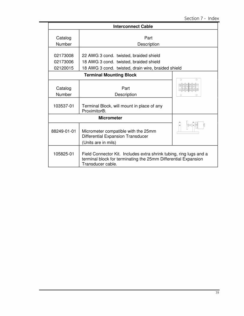
Interconnect Cable
Catalog
Number
Part
Description
02173008
02173006
02120015
22 AWG 3 cond. twisted, braided shield
18 AWG 3 cond. twisted, braided shield
18 AWG 3 cond. twisted, drain wire, braided shield
Terminal Mounting Block
Catalog
Number
Part
Description
103537-01
Terminal Block, will mount in place of any Proximitor®.
Micrometer
88249-01-01
Micrometer compatible with the 25mm Differential Expansion Transducer
(Units are in mils)
105825-01
Field Connector Kit. Includes extra shrink tubing, ring lugs and a terminal block for terminating the 25mm Differential Expansion Transducer cable.
Differential Expansion Transducer System Operation Manual
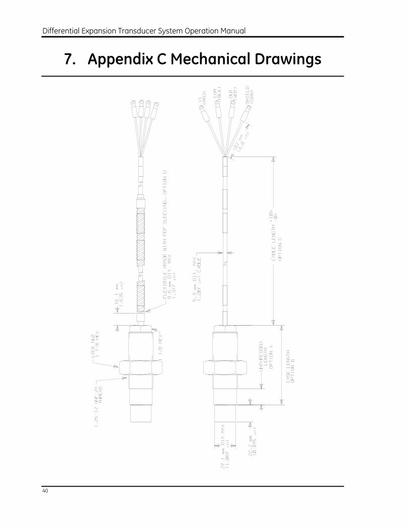
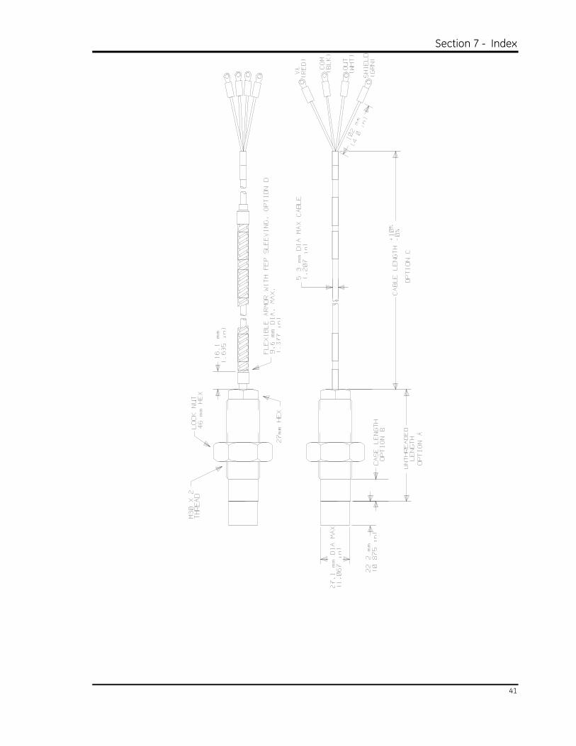
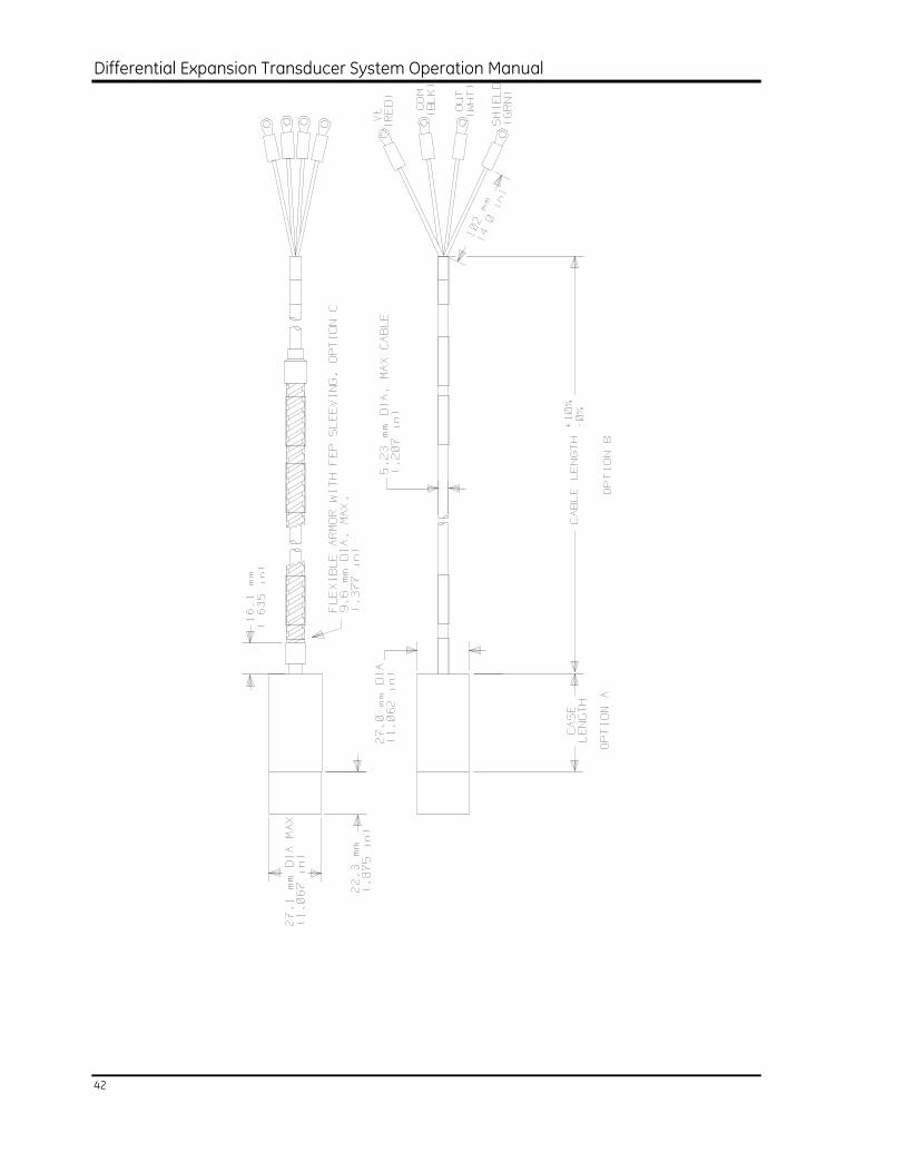
40
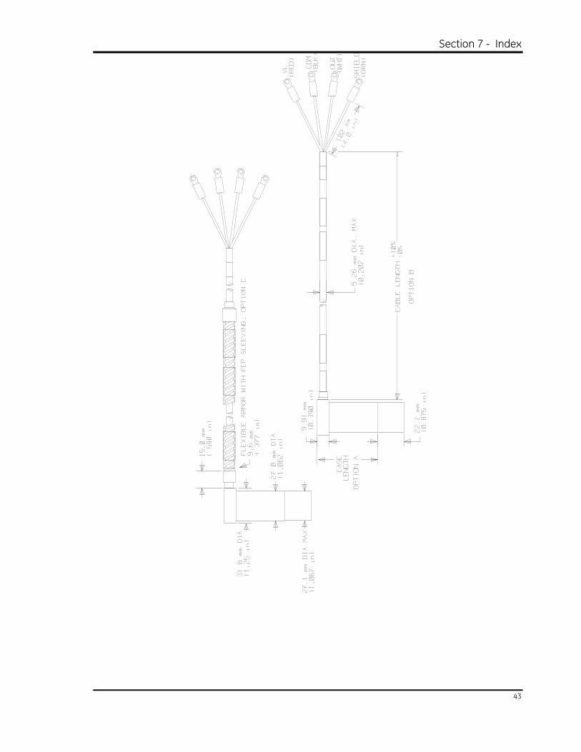
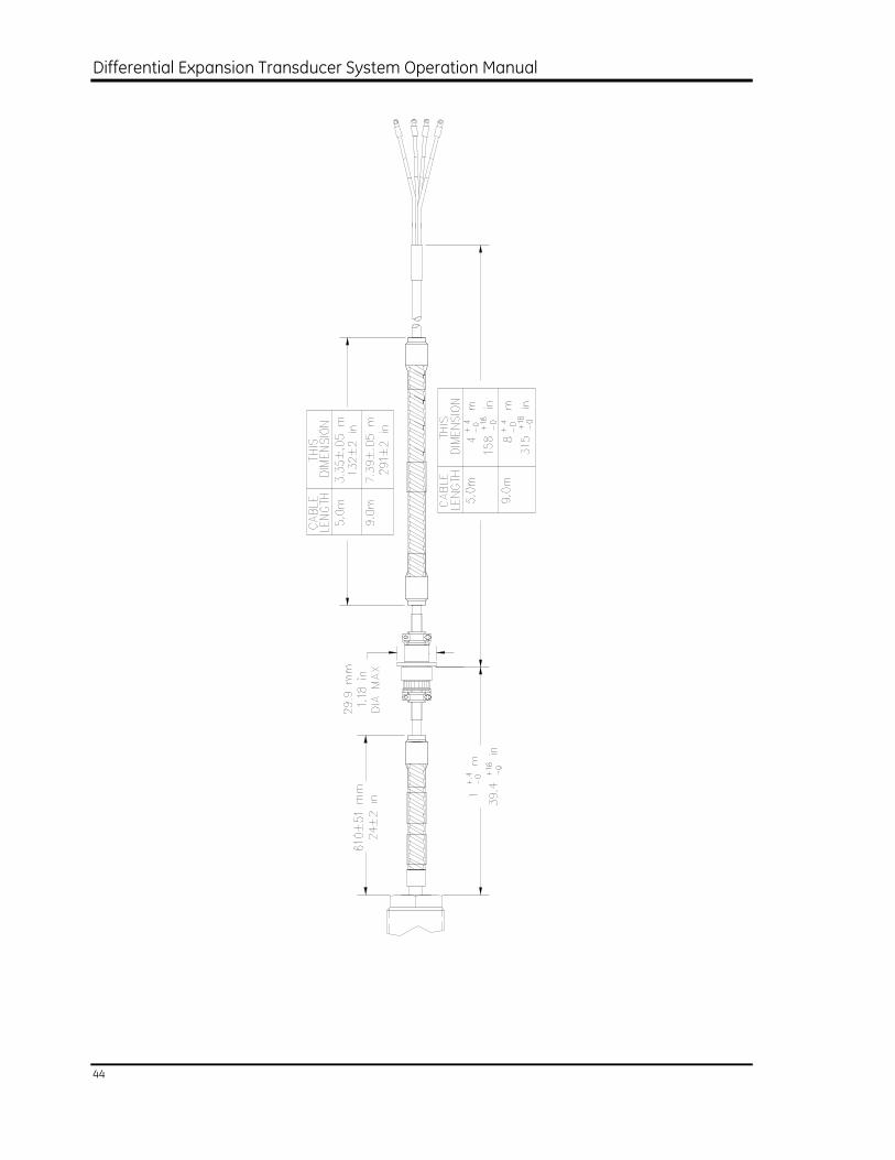
7. Appendix C Mechanical Drawings
Section 7 - Index
41
Differential Expansion Transducer System Operation Manual
42
Section 7 - Index
43
Differential Expansion Transducer System Operation Manual
44
Section 7 - Index
45
8. Appendix D Specifications
Unless otherwise noted, the following specifications apply at 22 °C ± 4.4 °C (72 °F ± 8 °F) using a target of AISI 4140 steel and test equipment with accuracy as specified by Bently Nevada Specification 150980.
NOTE: Operation outside the specified limits will result in false readings or loss of machine monitoring.
The linear range is defined as the 12.7 mm (500 mil) range from 2.54 mm (100 mils) below -3.5 Vdc to 10.16 mm (400 mils) above -3.5 Vdc. This range is approximately equivalent to a linear range from 0.635 mm (25 mils) to 13.34 mm (525 mils).
Electrical
Average scale factor (ASF)
788 ± 15.8 mV/mm ( 20 ± 0.4 mV/mil )
Deviation from a straight line (DSL)
Within ± 0.178 mm ( + 7 mils )
Deviation or error from a straight line is the difference between the actual and theoretical output for a transducer. To calculate DSL, generate an output voltage versus gap curve over the linear range of the transducer under test. Next, determine the theoretical straight line that best fits the actual curve and has a slope equal to the ideal scale factor. To determine the DSL for each gap reading, convert the voltage difference to units of distance by multiplying by the ideal scale factor.
Mechanical Gap Output will be -3.5 Vdc at a gap of 3.175 + 0.203 mm
(125 + 8 mils )
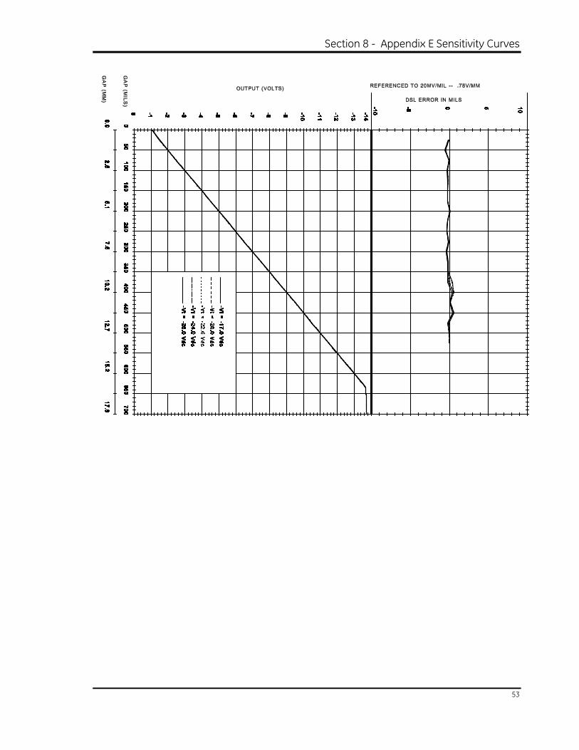
Supply sensitivity Less than 2 mV change in output per volt change at input
Supply voltage range -17.5 to -26 Vdc
Current draw 12 mA maximum with 10 kΩ load to common
Output resistance 50 Ω
Differential Expansion Transducer System Operation Manual
46
Output load All specifications with a 10 kΩ, 0.01 µF parallel load
Calibrated using 10 kΩ load only
Incorrect field wiring When used below 71°C (160°F) with a 3300 Series monitor, the 25mm Differential Expansion Transducer can be wired wrong in any manner, for an indefinite period of time, without damage.
Short circuit duration Output may be shorted to common continuously for ambient temperatures below 71°C (160°F)
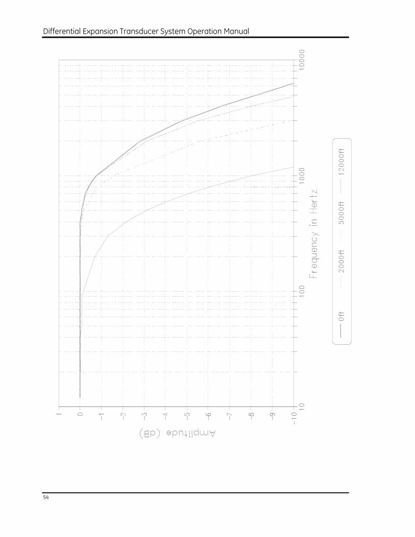
Typical Frequency response
+0%, -5% from 0 to 800 Hz (0 to 48,000 cpm)
+0, -3dB from 0 to 2000 Hz (0 to 120,000 cpm)
Frequency response due to a capacitive load
See Figure E-5.
Output noise Less than 50 mV pp, plus any high frequency noise present on the supply when connected to a monitor with a 0.01uF capacitor on the transducer output.
Recalibration to materials other than 4140
The unique digital calibration method used in the 25mm Differential Expansion Transducer allows recalibration to most metals with little reduction in room temperature performance. This flexibility requires that recalibration be done by Bently Nevada Corporation. Contact your nearest Bently Nevada Corporation representative for assistance in obtaining calibration for custom materials.
Case to cable isolation resistance
Capable of withstanding a minimum of 500 Vac at 60 Hz between transducer case and electrical circuits with less than 1 mA current flow
Environmental
Temperature
Storage -35 to +125°C (-31 to +257°F)
Operating -35 to +125°C (-31 to +257°F)
Relative humidity 100% condensing RH
Section 7 - Index
47
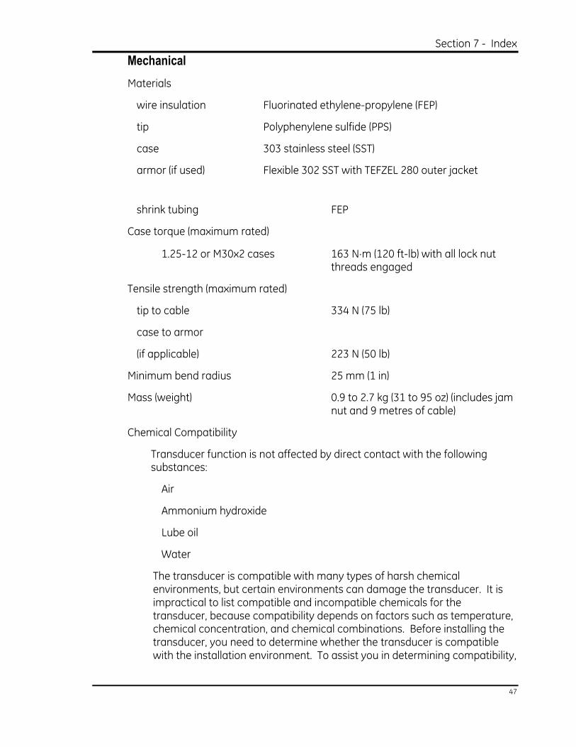
Mechanical
Materials
wire insulation Fluorinated ethylene-propylene (FEP)
tip Polyphenylene sulfide (PPS)
case 303 stainless steel (SST)
armor (if used) Flexible 302 SST with TEFZEL 280 outer jacket
shrink tubing FEP
Case torque (maximum rated)
1.25-12 or M30x2 cases 163 N⋅m (120 ft-lb) with all lock nut threads engaged
Tensile strength (maximum rated)
tip to cable 334 N (75 lb)
case to armor
(if applicable) 223 N (50 lb)
Minimum bend radius 25 mm (1 in)
Mass (weight) 0.9 to 2.7 kg (31 to 95 oz) (includes jam nut and 9 metres of cable)
Chemical Compatibility
Transducer function is not affected by direct contact with the following substances:
Air
Ammonium hydroxide
Lube oil
Water
The transducer is compatible with many types of harsh chemical environments, but certain environments can damage the transducer. It is impractical to list compatible and incompatible chemicals for the transducer, because compatibility depends on factors such as temperature, chemical concentration, and chemical combinations. Before installing the transducer, you need to determine whether the transducer is compatible with the installation environment. To assist you in determining compatibility,
Differential Expansion Transducer System Operation Manual
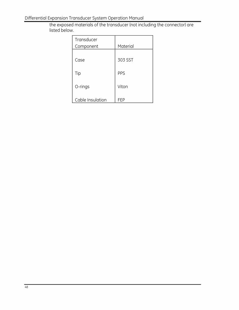
48
the exposed materials of the transducer (not including the connector) are listed below.
Transducer
Component
Material
Case
Tip
O-rings
Cable Insulation
303 SST
PPS
Viton
FEP
Section 8 - Appendix E Sensitivity Curves
49
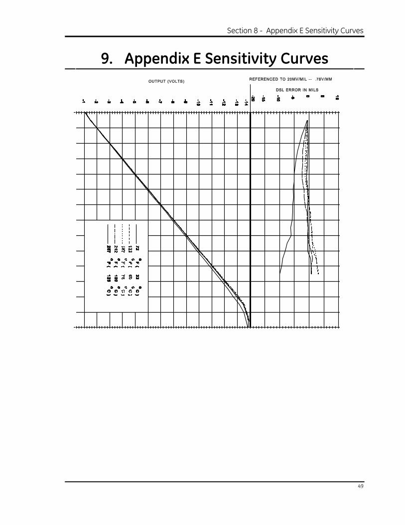
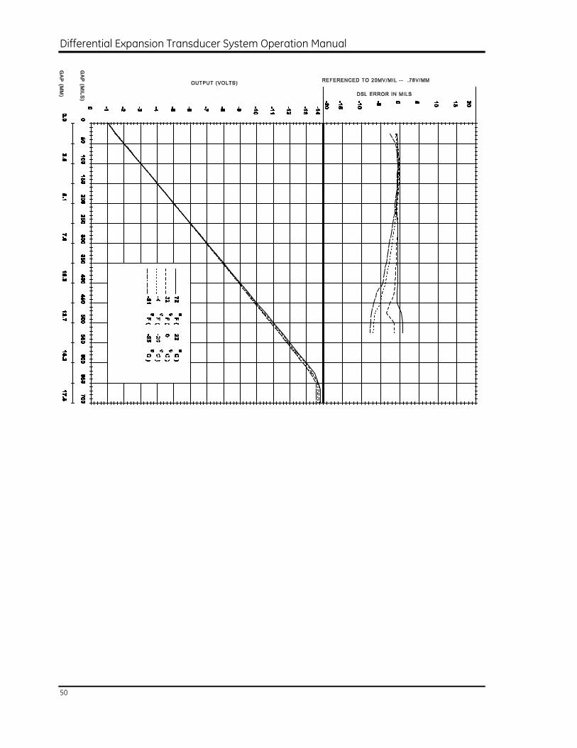
9. Appendix E Sensitivity Curves
Differential Expansion Transducer System Operation Manual
50
Section 8 - Appendix E Sensitivity Curves
51
mm (inches)
Differential Expansion Transducer System Operation Manual
52
A B
mm(inches)
Section 8 - Appendix E Sensitivity Curves
53
Differential Expansion Transducer System Operation Manual
54
Section 9 - Index
55
10. Index
A
Accessories ..................................................................B-1
AISI series steels ........................................................ 2-8
Angle, required mounting angle ......................2-12
Application notes .......................................... 2-8, 2-19
Applications
High pressure applications ............................ 2-5
How to measure differential expansion..................................................... 2-2
Inappropriate applications............................. 2-2
Approvals ......................................................................A-4
Armor Option...............................................................D-3
ASF (see average scale factor)
Average scale factor (ASF)
Definition..................................................Glossary-1
How to calculate ................................................. 3-2
Sample calculation ............................................ 3-4
Worst case specification.................................D-1
B
Bently Nevada application notes .......... 2-8, 2-19
Block diagram............................................................. 1-3
Bracket, installing the mounting bracket.........................................................2-12
C
Cable
Cable construction............................................. 1-2
Connecting transducer wiring....................2-18
Mechanical drawings........................................C-1
Minimum bend radius.......................................D-3
Ordering information ........................................A-2
Part numbers ........................................................B-4
Result of incorrect field wiring......................D-1
Terminating the cable at the machine case...........................................2-19
Cable Seal .....................................................................B-3
Capacitance
Response to a capacitive load.....................D-2
Role in operation..................................................1-3
Case
Block diagram.......................................................1-3
Ordering information........................................ A-2
Specifications .......................................................D-3
System components ..........................................1-1
Chemical compatibility .................................2-6, D-3
Chrome plating ...........................................................2-8
Circuitry
Basic operation.....................................................1-3
Block diagram.......................................................1-3
Clearance ...................................................................2-10
Cold flow .............................................. 2-6, Glossary-1
Collar height variations
Required target size ...........................................2-7
Sensitivity curve ...................................................E-4
Common installation errors...............................2-20
Complimentary input differential expansion .....................................................2-3
Conductive surface
Evaluating the observed surface.................2-7
Recalibration for other surfaces .................D-2
Theory of operation............................................1-3
Conduit........................................................................... B-3
Installation considerations ..........................2-18
Ordering information........................................ B-3
Configurations, mounting......................................2-3
Connector
Option....................................................................... A-4
Counterboring, when required.........................2-10
Cross coupling
Required probe separation..........................2-11
Current draw...............................................................D-1
Curve
Making a response curve .............................2-14
Sensitivity curves.................................................E-1
Differential Expansion Transducer System Operation Manual
56
D
Deviation from Straight Line (DSL)............................
Glossary-1, D-1
Diagnostics
Common installation errors.........................2-20
Cross coupling ...................................................2-11
Plated surfaces.....................................................2-8
Troubleshooting procedure............................3-4
Using a response curve.................................2-14
Verification test ....................................................3-2
Diagrams
Block diagram.......................................................1-3
Mounting configurations .................................2-3
Typical response curve..................................2-16
Differential expansion
How to measure ..................................................2-2
Mounting configurations .................................2-3
E
Eddy currents, theory of operation ...................1-3
Electrical method, probe gapping ..................2-17
Electrical runout, installation consideration .................... 2-8, Glossary-1
Environmental conditions
Checking environmental conditions ..........2-5
Environmental specifications .......................D-2
Equipment setup
for transducer response curve ..................2-14
for verification test..............................................3-3
Errors
Common installation errors.........................2-20
Deviation from straight line (DSL) ...............D-1
F
Fiberglass housing ................................................... B-1
Field Wiring ..................................................................D-2
Frequency response
Specification .........................................................D-2
Typical frequency response at mid-gap .........................................................E-6
G
Gap
Gapping the transducer................................ 2-17
Mechanical gap specification ...................... D-1
Gauge method, probe gapping....................... 2-17
Glitch 2-8, Glossary-1
Grounding .................................................................. 2-19
H
Hazardous Area Approvals...................................A-4
High pressure applications...................................2-5
Housing
Transducer accessories ...................................B-1
Using terminal housing near the machine...................................................... 2-19
I
Incremental Scale Factor (ISF)............. Glossary-1
Input Power................................................................. D-1
Inspecting and receiving .......................................A-1
Installation
Checking environmental conditions ..........2-5
Checking the installation .................................. 2-14
Checking the mounting holes ........................ 2-13
Common installation errors ............................ 2-20
Connecting the transducer wiring ............... 2-18
Evaluating the observed surface.....................2-7
Gapping the transducer.................................... 2-17
General approach...................................................2-1
Installing the mounting bracket.................... 2-12
Installing transducer in bracket .................... 2-13
Mounting configurations .....................................2-3
Planning the installation ......................................2-1
Securing the cable............................................... 2-18
Verifying the mounting location ................... 2-10
ISF (see incremental scale factor)
J
Junction Box ....................................................................B-2
Section 9 - Index
57
K
Keyphasor measurements, inappropriate application ....................................................... 2-2
Keyphasor transducer .................................Glossary-1
L
Leakage of gasses and liquids................................ 2-5
Load, ouput load .......................................................D-1
M
Magnetic field
Minimum probe separation .........................2-10
Theory of operation ........................................... 1-3
Maintenance ............................................................... 3-1
Maintenance Equipment ....................................... 3-1
Malfunctions
Common installation errors.........................2-20
Cross coupling....................................................2-11
Plated surfaces .................................................... 2-8
Troubleshooting procedure ........................... 3-4
Using a response curve .................................2-14
Mass, specification ...................................................D-3
Material
Material used in system components.......D-3
Observed shaft material.................................. 2-8
Mechanical drawings..............................................C-1
Mechanical method, probe gapping .............2-17
Mechanical runout, installation consideration.....................2-8, Glossary-2
Mechanical specifications ....................................D-3
Micrometer................................................................... 3-1
for verification test ............................................. 3-3
Part number ..........................................................B-4
Moisture sealing ........................................................ 2-6
Monitor, routing wiring to the monitor .........2-19
Mounting
Configurations...................................................... 2-3
Installing the mounting bracket ................2-12
Resonant frequency of mounting bracket.........................................................2-12
Verifying the mounting location................2-10
Mounting angle........................................................2-12
Mounting configurations
for measuring differential expansion ........2-3
Mechanical drawings ....................................... C-3
Ordering options................................................. A-4
N
Noise
Definition .................................................Glossary-2
Specification .........................................................D-2
O
Observed material
Affect on response curve.................................2-8
Observed surface, definition ................Glossary-2
Operating temperature ..........................................2-5
Operation.......................................................................1-3
Ordering Information.............................................. A-1
Output
Load ..........................................................................D-1
Noise specification.............................................D-2
Resistance..............................................................D-1
P
Part numbers.............................................................. A-2
Planning the installation.........................................2-1
Plated surfaces ...........................................................2-8
Power supply voltage
Range .......................................................................D-1
Sensitivity to supply voltage...........................E-5
Troubleshooting incorrect voltage..............3-5
Pressure sealing
Cable seal accessories..................................... B-3
Installation considerations .............................2-5
Probe tip...................................................................2-5
Probe gap
Gapping the transducer................................2-17
Mechanical gap specification.......................D-1
Probe tip
Definition .................................................Glossary-2
Gapping the transducer................................2-17
Pressure sealing...................................................2-5
Differential Expansion Transducer System Operation Manual
58
Required separation........................................2-11
Required side clearance................................2-10
Theory of operation............................................1-3
Probe, Installation considerations
Chemical compatibility .....................................2-6
Pressure sealing...................................................2-5
Surface considerations.....................................2-7
Problems
Common installation errors.........................2-20
Cross coupling ...................................................2-11
Plated surfaces.....................................................2-8
Troubleshooting procedure............................3-4
Using a response curve.................................2-14
Protective Armor .......................................................D-3
Proximity probe, definition ....................Glossary-2
R
Ramp differential expansion................................2-4
Rear exit mounting configuration..................... A-4
Receiving and inspecting...................................... A-1
Residual magnetism, Effect on runout............2-8
Resistance
Case to cable isolation resistance..............D-2
Output resistance...............................................D-1
Resonant frequency
of mounting bracket .......................................2-12
Response curve
Affect of observed material............................2-8
How to plot ..........................................................2-14
Typical response curve..................................2-16
Typical temperature response curve................
E-1, E-2
Runout, installation consideration ....................2-8
S
Sealing
Moisture sealing...................................................2-6
Pressure sealing...................................... 2-5, 2-18
Sealing accessories ........................................... B-3
Sensitivity Curves.......................................................E-1
Sensitivity, definition.................................Glossary-2
Separation, required transducer separation ................................................. 2-11
Setup
for transducer response curve 2-14
for verification test 3-3
Shaft
Material 2-8
Shaft surface finish 2-8
Short circuit duration D-2
Shrink Tubing D-3
Side clearance
Effect of side clearance E-3
Installation consideration 2-10
Side exit mounting configuration A-4
Single input differential expansion 2-3
Smooth body transducer
Installation 2-12
Mechanical drawings C-3
Ordering information A-4
Specifications D-1
Standard body mount
Mechanical drawings C-1
Mounting the transducer 2-13
Ordering information A-2
Securing the transducer 2-17
Steels 2-8
Storing the System 3-1
Supply voltage
Range D-1
Sensitivity to supply voltage E-5
Troubleshooting incorrect power supply voltage 3-5
Surface
Considerations 2-7
Definition Glossary-2
Effect of plated surfaces on runout 2-8
Evaluating the observed surface 2-7
Finish 2-8
Recalibration to other surfaces D-2
Theory of operation 1-3
System
Components of 1-1
Section 9 - Index
59
Features 1-2
Inappropriate applications 2-2
Material used in system components D-3
Recalibration to other surfaces D-2
Receiving and inspecting A-1
Storing the system 3-1
Theory of operation 1-3
Troubleshooting the system 3-4
Verification test 3-2
Verifying the performance 2-14
T
Target material
Affect on response curve 2-8, 3-2
Recalibration to other surfaces D-2
Target size
Effect of collar height variations E-4
Minimum requirement 2-7
Teflon insulation on the cable 2-6
Temperature
Operating temperature 2-5
Storage and operating specifications D-2
Typical response curve E-1, E-2
Tensile strength D-3
Terminal housing
Ordering information B-2
Terminating the cable at the machine case 2-19
Test and Calibration Kit 3-1
Tests
Transducer response curve 2-14
Verification test 3-2
Theory of operation 1-3
Threaded body mount
Mounting the transducer 2-13
Ordering information ........................................A-2
Securing the transducer................................2-17
Tip (see Probe tip)
Torque, maximum case torque..........................D-3
Transducer cable
Cable construction............................................. 1-2
Mechanical drawings........................................C-1
Minimum bend radius ......................................D-3
Part numbers........................................................ B-4
Terminating the cable at the machine case...........................................2-19
Transducer case
Block diagram.......................................................1-3
Ordering information........................................ A-2
Specifications .......................................................D-3
System components ..........................................1-1
Transducer installation
Checking environmental conditions ..........2-5
Checking the installation ..............................2-14
Checking the mounting holes ....................2-13
Common installation errors.........................2-20
Connecting the transducer wiring ...........2-18
Evaluating the observed surface.................2-7
Gapping the transducer................................2-17
General approach ...............................................2-1
Installing the mounting bracket................2-12
Installing transducer in bracket ................2-13
Mounting configurations .................................2-3
Planning the installation ..................................2-1
Securing the cable ...........................................2-18
Verifying the mounting location................2-10
Transducer separation.........................................2-11
Transducer system
Block diagram.......................................................1-3
Components of .....................................................1-1
Features ...................................................................1-2
Inappropriate applications .............................2-2
Material used in system components ......D-3
Recalibration to other surfaces...................D-2
Receiving and inspecting................................ A-1
Storing the system..............................................3-1
Theory of operation............................................1-3
Troubleshooting the system ..........................3-4
Verification test ....................................................3-2
Verifying the performance...........................2-14
Transducer wiring
Cable construction..............................................1-2
Connecting the transducer wiring ...........2-18
Result of incorrect field wiring .....................D-1
Differential Expansion Transducer System Operation Manual
60
Troubleshooting
Common installation errors.........................2-20
Cross coupling ...................................................2-11
Plated surfaces.....................................................2-8
Procedures 3-4
Using a response curve 2-14
Verification test 3-2
V
Verification Test..........................................................3-2
Vibration measurements, inappropriate application....................................................2-2
Voltage
Power supply voltage range .........................D-1
Sensitivity to supply voltage...........................E-5
Troubleshooting incorrect power supply voltage ............................................3-5
W
Warranty........................................................................3-1
Water-resistant housing ....................................... B-1
Weight, specification...............................................D-3
Wiring D-2
Cable construction..............................................1-2
Connecting transducer wiring ...................2-18
Mechanical drawings ....................................... C-1
Part numbers........................................................ B-4
Result of incorrect field wiring .....................D-1
Terminating the cable at the machine case......................................2-1