rcf the transducer innovators - tout le haut parleur
TRANSCRIPT
1
Established in 1949, RCF prides itself on carrying out the design and production of its own products.We have always preferred to completely design and construct all our own components. Many years dedicated to studying and building audio transducers have resulted in some notable milestones. There are many different ingredients that go into creating quality products and systems—these include computer aided simulation software to assist the understanding of transducer behaviour and the relationship of dynamics and transient response. RCF utilises many state of the art software, however it is the vast technical and practical experience that our Research and Engineering team posseses that ensures the quality of our products, thus placing RCF as the market leaders in transducer development.
RCF The Transducer Innovators The RCF loudspeaker line incorporates a vast range of transducers covering the entire audio spectrum. We design our transducers to optimise the relationship between the purity of sound, combining the absence of distortion and the ability to withstand high power levels over a long period of time.RCF develops advanced transducer technology including the application of high-tech materials such as Neodymium, Carbon Fibre, Pure Titanium, Kevlar, Kapton and Mylar hybrids.With over 60 years of design and manufacturing experience in the market, RCF has been instrumental in technological inventions such as: carbon fibre cone moulding, double silicon spiders, inside/outside voice coil windings to edge wound voicecoil manufacturing and pure titanium diaphragm forming. Our latest developments have resulted in designing state of the art neodymium magnetic circuits, radically new voice coil ventilation systems and ground breaking direct drive voice coil assemblies.
2
POWER HANDLINGAt the core of RCF’s new transducer designs, significant amounts of time and resources were spent in terms of material science, design topology research and power testing in order to develop products with high structural strength, optimal thermal characteristics and the best possible power handling. RCF Precision engineers have developed a composite polyimide-imide former material capable of withstanding peak temperatures in excess of 380°C, well beyond the thermal requirements of modern professional audio systems.By combining this material with special adhesives, our inside-outside voice coil technology, dual silicone spiders, dual forced hyperventilation and cones based on a special fibre doping and treatment, the new RCF family of products features the industry’s most robust and reliable transducers.
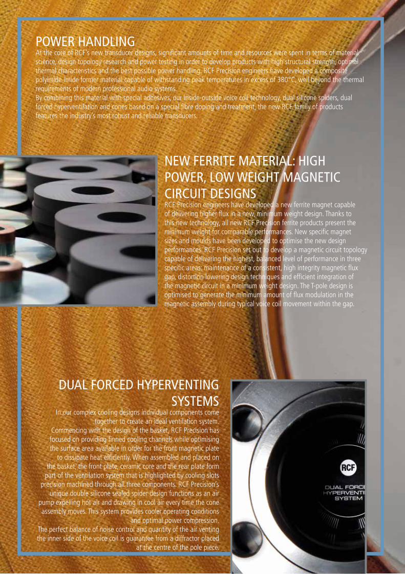
DUAL FORCED HYPERVENTING SYSTEMS
In our complex cooling designs individual components come together to create an ideal ventilation system.
Commencing with the design of the basket, RCF Precision has focused on providing finned cooling channels while optimising the surface area available in order for the front magnetic plate
to dissipate heat efficiently. When assembled and placed on the basket, the front plate, ceramic core and the rear plate form
part of the ventilation system that is highlighted by cooling slots precision machined through all three components. RCF Precision’s
unique double silicone sealed spider design functions as an air pump expelling hot air and drawing in cool air every time the cone assembly moves. This system provides cooler operating conditions
and optimal power compression.The perfect balance of noise control and quantity of the air venting the inner side of the voice coil is guarantee from a diffractor placed
at the centre of the pole piece.
NEW FERRITE MATERIAL: HIGH POWER, LOW WEIGHT MAGNETIC CIRCUIT DESIGNSRCF Precision engineers have developed a new ferrite magnet capable of delivering higher flux in a new, minimum weight design. Thanks to this new technology, all new RCF Precision ferrite products present the minimum weight for comparable performances. New specific magnet sizes and moulds have been developed to optimise the new design performances. RCF Precision set out to develop a magnetic circuit topology capable of delivering the highest, balanced level of performance in three specific areas: maintenance of a consistent, high integrity magnetic flux gap, distortion lowering design techniques and efficient integration of the magnetic circuit in a minimum weight design. The T-pole design is optimised to generate the minimum amount of flux modulation in the magnetic assembly during typical voice coil movement within the gap.
3
DIRECT DRIVE VOICE COIL ASSEMBLYThe top of the former is bent and bonded directly to the edge of the titanium diaphragm resulting in a Direct Drive configuration. Direct Drive guarantees optimal transfer of energy between the voice coil and the dome assembly, providing smoother, extended frequency response beyond 10 KHz, reducing break up modes and lowering distortion.This assembly delivers high power handling along with excellent mechanical and thermal properties that make RCF neodymium compression drivers robust and reliable.
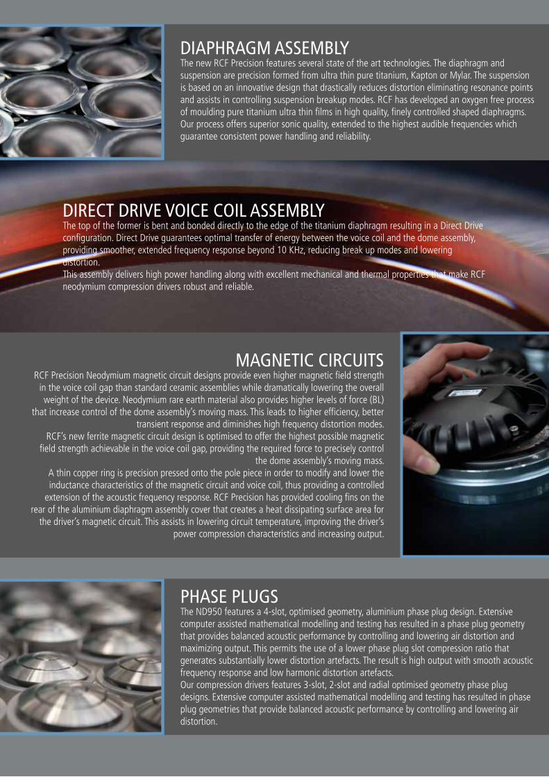
MAGNETIC CIRCUITSRCF Precision Neodymium magnetic circuit designs provide even higher magnetic field strength
in the voice coil gap than standard ceramic assemblies while dramatically lowering the overall weight of the device. Neodymium rare earth material also provides higher levels of force (BL)
that increase control of the dome assembly’s moving mass. This leads to higher efficiency, better transient response and diminishes high frequency distortion modes.
RCF’s new ferrite magnetic circuit design is optimised to offer the highest possible magnetic field strength achievable in the voice coil gap, providing the required force to precisely control
the dome assembly’s moving mass. A thin copper ring is precision pressed onto the pole piece in order to modify and lower the inductance characteristics of the magnetic circuit and voice coil, thus providing a controlled
extension of the acoustic frequency response. RCF Precision has provided cooling fins on the rear of the aluminium diaphragm assembly cover that creates a heat dissipating surface area for
the driver’s magnetic circuit. This assists in lowering circuit temperature, improving the driver’s power compression characteristics and increasing output.
PHASE PLUGSThe ND950 features a 4-slot, optimised geometry, aluminium phase plug design. Extensive computer assisted mathematical modelling and testing has resulted in a phase plug geometry that provides balanced acoustic performance by controlling and lowering air distortion and maximizing output. This permits the use of a lower phase plug slot compression ratio that generates substantially lower distortion artefacts. The result is high output with smooth acoustic frequency response and low harmonic distortion artefacts.Our compression drivers features 3-slot, 2-slot and radial optimised geometry phase plug designs. Extensive computer assisted mathematical modelling and testing has resulted in phase plug geometries that provide balanced acoustic performance by controlling and lowering air distortion.
DIAPHRAGM ASSEMBLYThe new RCF Precision features several state of the art technologies. The diaphragm and suspension are precision formed from ultra thin pure titanium, Kapton or Mylar. The suspension is based on an innovative design that drastically reduces distortion eliminating resonance points and assists in controlling suspension breakup modes. RCF has developed an oxygen free process of moulding pure titanium ultra thin films in high quality, finely controlled shaped diaphragms. Our process offers superior sonic quality, extended to the highest audible frequencies which guarantee consistent power handling and reliability.
4
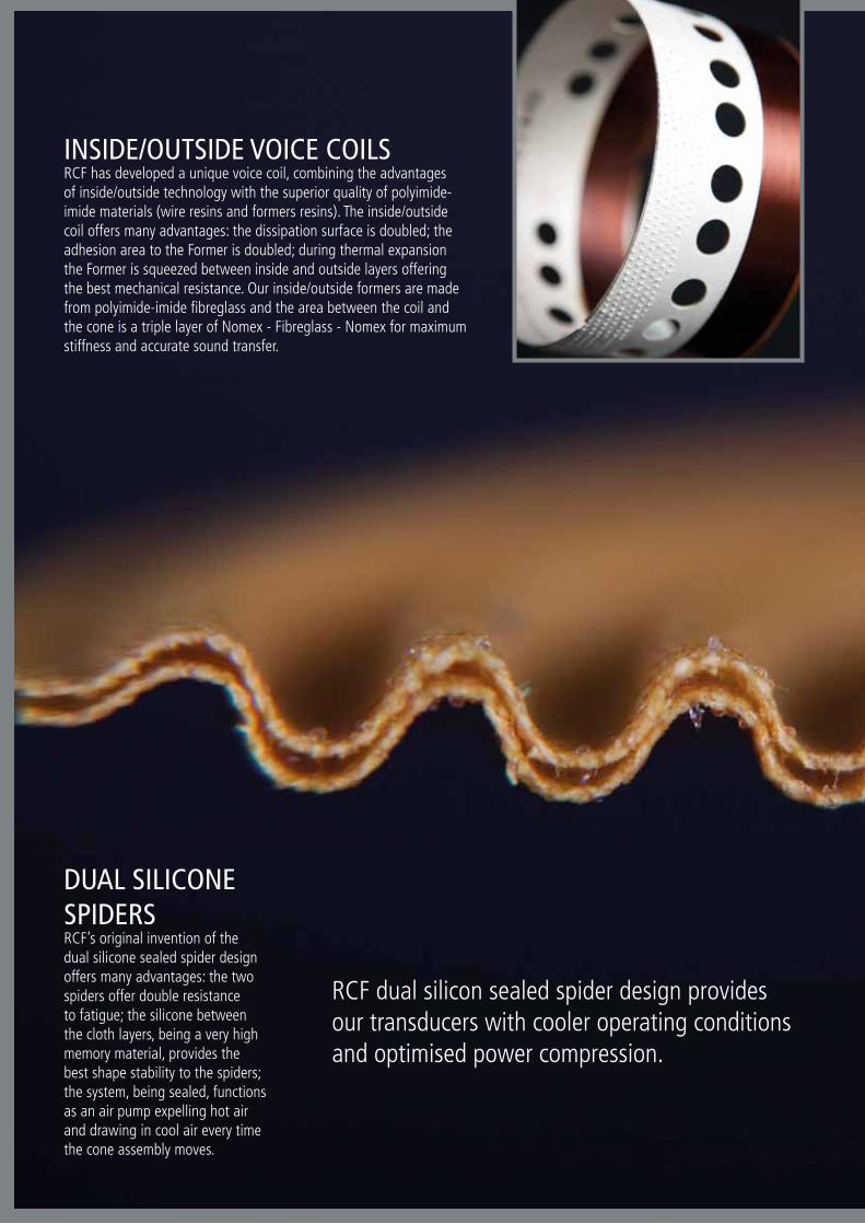
INSIDE/OUTSIDE VOICE COILSRCF has developed a unique voice coil, combining the advantagesof inside/outside technology with the superior quality of polyimide-imide materials (wire resins and formers resins). The inside/outsidecoil offers many advantages: the dissipation surface is doubled; the adhesion area to the Former is doubled; during thermal expansion the Former is squeezed between inside and outside layers offering the best mechanical resistance. Our inside/outside formers are made from polyimide-imide fibreglass and the area between the coil and the cone is a triple layer of Nomex - Fibreglass - Nomex for maximum stiffness and accurate sound transfer.
DUAL SILICONE SPIDERSRCF’s original invention of the dual silicone sealed spider design offers many advantages: the two spiders offer double resistance to fatigue; the silicone between the cloth layers, being a very high memory material, provides the best shape stability to the spiders; the system, being sealed, functions as an air pump expelling hot air and drawing in cool air every time the cone assembly moves.
RCF dual silicon sealed spider design provides our transducers with cooler operating conditions and optimised power compression.
5
EDGEWOUND COILSEdge-wound flat wire voice coils are a hallmark of advanced manufacturing.RCF produces in-house all the flat wire voice coils used in its compression drivers. To guarantee the ultimate level of performance and reliability, maximum care in material selection and process design is combined with extensive use of quality control and power testing procedures. Each driver is thoroughly tested for frequency response, impedance and distortion with DSP enabled digital testing equipment. The result is a robust device capable of withstanding the rigors of modern loudspeaker system applications.
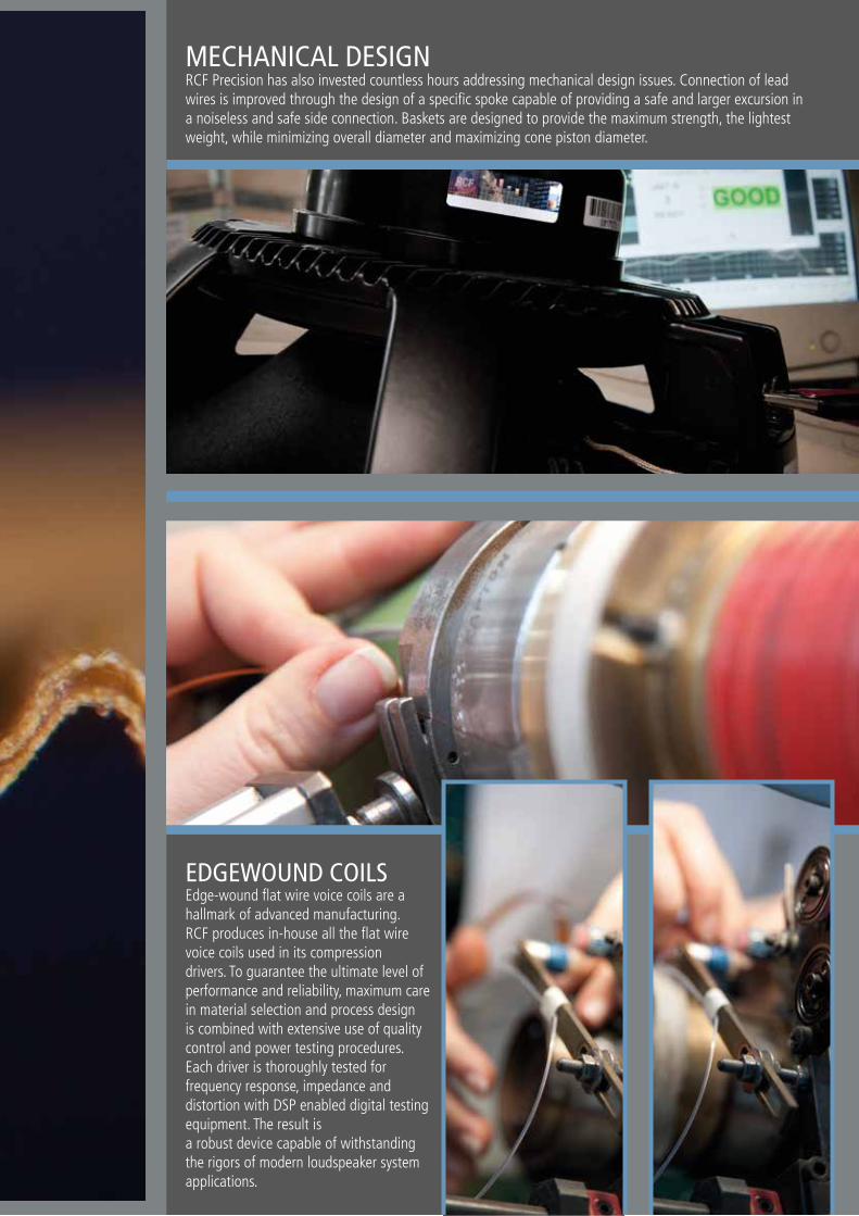
MECHANICAL DESIGNRCF Precision has also invested countless hours addressing mechanical design issues. Connection of lead wires is improved through the design of a specific spoke capable of providing a safe and larger excursion in a noiseless and safe side connection. Baskets are designed to provide the maximum strength, the lightest weight, while minimizing overall diameter and maximizing cone piston diameter.
6
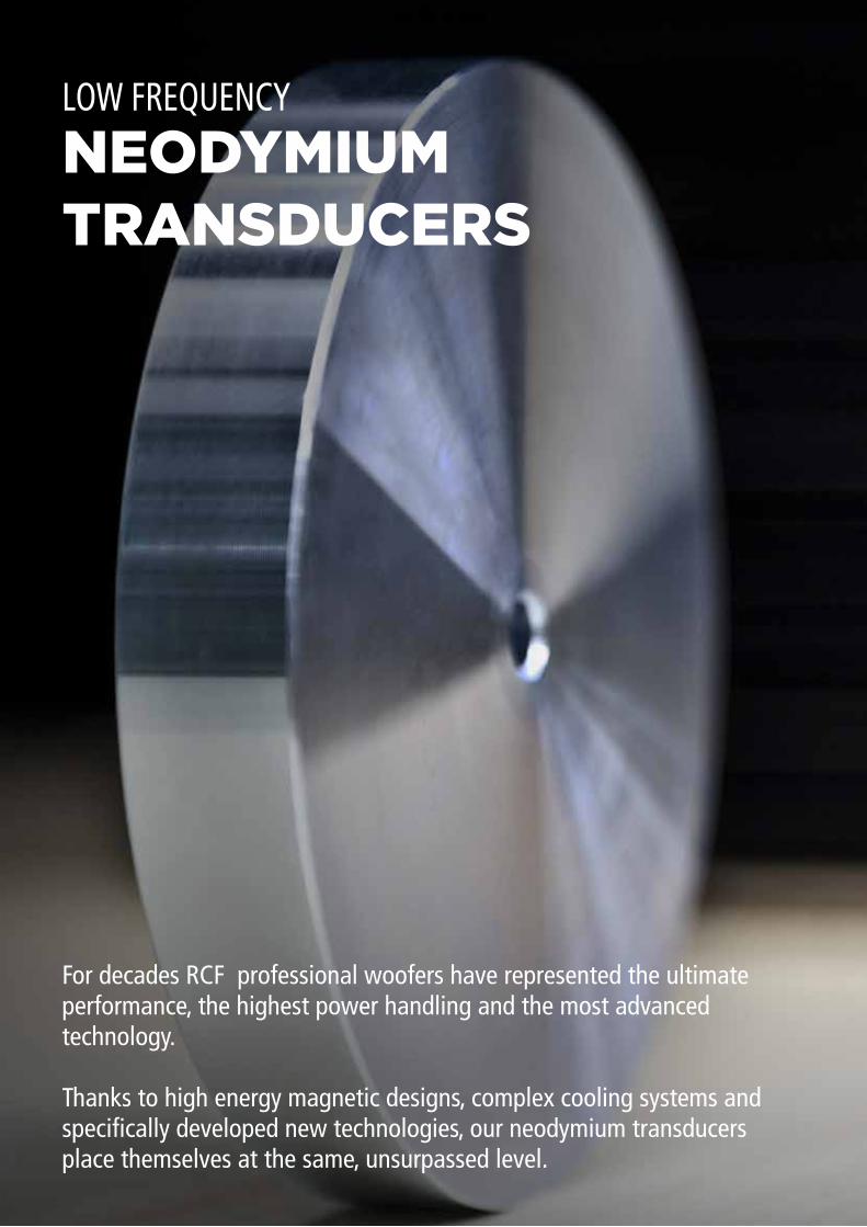
NEODYMIUMTRANSDUCERS
LOW FREQUENCY
For decades RCF professional woofers have represented the ultimate performance, the highest power handling and the most advanced technology.
Thanks to high energy magnetic designs, complex cooling systems and specifically developed new technologies, our neodymium transducers place themselves at the same, unsurpassed level.
7
SEALED MIDRANGE TRANSDUCERS
INSIDE/OUTSIDE VOICE COILS
COMPLEX COOLING SYSTEMS
RCF has developed two exceptional, sealed, midrange neodymium designs. This innovative solution offer many advantages compared to traditional midranges designs:- thanks to a massive neodymium magnetic circuit, sensitivity is up to 4 dB higher than traditional designs;- the optimally tuned rear chamber is sealed and doesn’t require the typical back wooden chamber;- the aluminum basket, in direct contact to the magnetic circuit, provides the best cooling ever found in a midrange transducer.
RCF has developed a unique voice coil, combining the advantages of inside/outside technology to the superior quality of polyimide-imide materials (wire resins and formers resins).
The inside/outside coil offers many advantages:- the dissipation surface is doubled;- the adhesion area to the Former is doubled;- during thermal expansion the Former is squeezed between inside and outside layers offering the best mechanical resistance.
Our inside/outside formers are made from polyimide-imide fibreglass and the area between the coil and the cone is a triple layer of Nomex - fibreglass - Nomex for maximum stiffness and accurate sound transfer.
In our complex cooling designs individual components come together to create an ideal ventilation system. Commencing with the design of the basket, RCF has focused on providing finned cooling channels while optimising the surface area available to the front magnetic plate to dissipate heat efficiently.The dust cap and the sealed spiders function as an air pump expelling hot air and drawing in cool air every time the cone assembly moves. Many openings are situated directly on the transducer’s side and on the rear plate.
8
80
90
100
110
SPL,
1w/
1m (d
B)
Frequency (Hz)
20 100 1.000 10.000 20.000
Frequency (Hz)
20 100 1.000 10.000 20.000
10
100
316Im
peda
nce
(ohm
s)
ø 547 mm
245 mm
ø 508 mm
ø 170 mm
15 mm
20 100 10.000 20.0001.000
30 1000
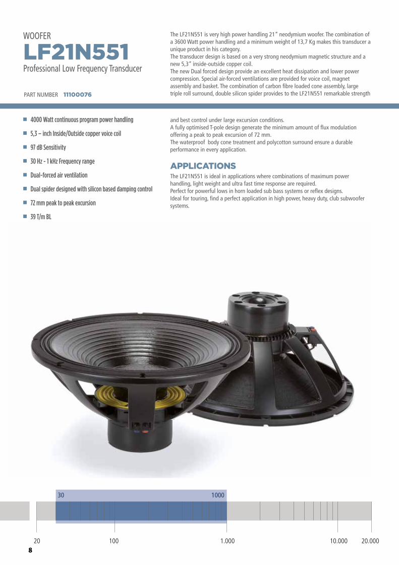
The LF21N551 is very high power handling 21” neodymium woofer. The combination of a 3600 Watt power handling and a minimum weight of 13,7 Kg makes this transducer a unique product in his category.The transducer design is based on a very strong neodymium magnetic structure and a new 5,3” inside-outside copper coil. The new Dual forced design provide an excellent heat dissipation and lower power compression. Special air-forced ventilations are provided for voice coil, magnet assembly and basket. The combination of carbon fibre loaded cone assembly, large triple roll surround, double silicon spider provides to the LF21N551 remarkable strength
The LF21N551 is ideal in applications where combinations of maximum power handling, light weight and ultra fast time response are required. Perfect for powerful lows in horn loaded sub bass systems or reflex designs. Ideal for touring, find a perfect application in high power, heavy duty, club subwoofer systems.
APPLICATIONS
and best control under large excursion conditions.A fully optimised T-pole design generate the minimum amount of flux modulation offering a peak to peak excursion of 72 mm. The waterproof body cone treatment and polycotton surround ensure a durable performance in every application.
PART NUMBER 11100076
4000 Watt continuous program power handling
5,3 – inch Inside/Outside copper voice coil
97 dB Sensitivity
30 Hz - 1 kHz Frequency range
Dual-forced air ventilation
Dual spider designed with silicon based damping control
72 mm peak to peak excursion
39 T/m BL
LF21N551Professional Low Frequency Transducer
WOOFER
9
80
90
100
110
SPL,
1w/
1m (d
B)
Frequency (Hz)
20 100 1.000 10.000 20.000
Frequency (Hz)
20 100 1.000 10.000 20.000
10
100
316
Impe
danc
e (o
hms)
ø 547 mm
245 mm
ø 508 mm
ø 170 mm
15 mm
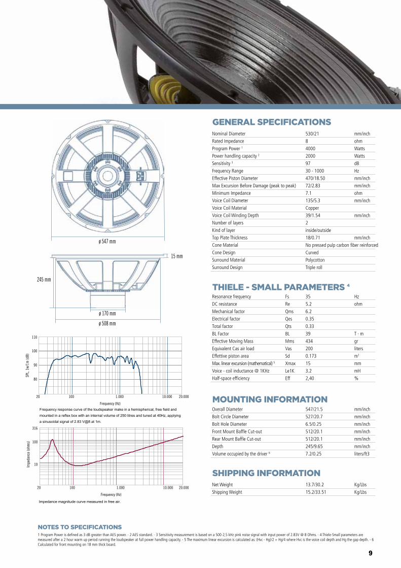
GENERAL SPECIFICATIONS
THIELE - SMALL PARAMETERS 4
MOUNTING INFORMATION
SHIPPING INFORMATION
1 Program Power is defined as 3 dB greater than AES power. - 2 AES standard. - 3 Sensitivity measurement is based on a 500-2,5 kHz pink noise signal with input power of 2.83V @ 8 Ohms. - 4 Thiele-Small parameters are measured after a 2 hour warm up period running the loudspeaker at full power handling capacity. - 5 The maximum linear excursion is calculated as: (Hvc - Hg)/2 + Hg/4 where Hvc is the voice coil depth and Hg the gap depth. - 6 Calculated for front mounting on 18 mm thick board.
Overall Diameter
Bolt Circle Diameter
Bolt Hole Diameter
Front Mount Baffle Cut-out
Rear Mount Baffle Cut-out
Depth
Volume occupied by the driver 6
547/21.5
527/20.7
6.5/0.25
512/20.1
512/20.1
245/9.65
7.2/0.25
mm/inch
mm/inch
mm/inch
mm/inch
mm/inch
mm/inch
liters/ft3
Net Weight
Shipping Weight
13.7/30.2
15.2/33.51
Kg/Lbs
Kg/Lbs
Resonance frequency
DC resistance
Mechanical factor
Electrical factor
Total factor
BL Factor
Effective Moving Mass
Equivalent Cas air load
Effettive piston area
Max. linear excursion (mathematical) 5
Voice - coil inductance @ 1KHz
Half-space efficiency
Hz
ohm
T · m
gr
liters
m2
mm
mH
%
35
5.2
6.2
0.35
0.33
39
434
200
0.173
15
3.2
2,40
Fs
Re
Qms
Qes
Qts
BL
Mms
Vas
Sd
Xmax
Le1K
Eff
Nominal Diameter
Rated Impedance
Program Power 1
Power handling capacity 2
Sensitivity 3
Frequency Range
Effective Piston Diameter
Max Excursion Before Damage (peak to peak)
Minimum Impedance
Voice Coil Diameter
Voice Coil Material
Voice Coil Winding Depth
Number of layers
Kind of layer
Top Plate Thickness
Cone Material
Cone Design
Surround Material
Surround Design
530/21
8
4000
2000
97
30 - 1000
470/18.50
72/2.83
7.1
135/5.3
Copper
39/1.54
2
inside/outside
18/0.71
No pressed pulp carbon fiber reinforced
Curved
Polycotton
Triple roll
mm/inch
ohm
Watts
Watts
dB
Hz
mm/inch
mm/inch
ohm
mm/inch
mm/inch
mm/inch
NOTES TO SPECIFICATIONS
10
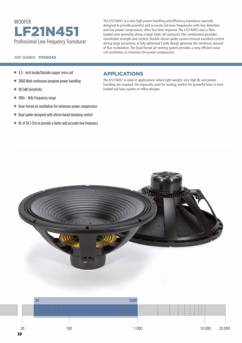
The LF21N451 is a very high power handling and efficiency transducer specially designed to provide powerful and accurate sub-bass frequencies with low distortion and low power compression. Ultra fast time response. The LF21N451 uses a fibre loaded cone assembly along a large triple roll surround, this combination provides remarkable strength and control. Double silicon spider system ensures excellent control during large excursions. A fully optimised T-pole design generate the minimum amount of flux modulation. The Dual-forced air venting system provides a very efficient voice coil ventilation to minimize the power compression.
The LF21N451 is ideal in applications where light weight, very high BL and power handling are required. Itís especially used for touring, perfect for powerful lows in horn loaded sub bass system or reflex designs.
APPLICATIONS
PART NUMBER 11100043
4,5 - inch Inside/Outside copper voice coil
3000 Watt continuous program power handling
98.5dB Sensitivity
30Hz - 1kHz Frequency range
Dual-forced air ventilation for minimum power compression
Dual spider designed with silicon based damping control
BL of 34.5 T/m to provide a faster and accurate low frequency
LF21N451Professional Low Frequency Transducer
WOOFER
30 1000
20 100 10.000 20.0001.000
11
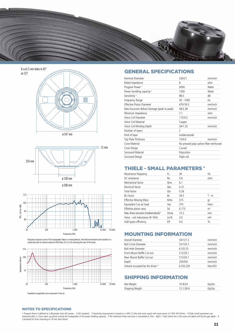
Frequency response curve of the loudspeaker taken in a hemispherical, free �eld environment and mounted in a closed box with an internal volume of 600 litres (21,2 cu.ft) enclosing the rear of the driver.
Impedance magnitude curve measured in free air.
ø 547 mm
8 x ø 6.5 mm holes to 45°on 527
ø 508 mm
ø 148 mm
234 mm
15 mm
Frequency (Hz)
20 100 1.000 10.000 20.000
10
100
316
Impe
danc
e (o
hms)
80
90
100
110
SPL,
1w/
1m (d
B)
Frequency (Hz)
20 100 1.000 10.000 20.000
GENERAL SPECIFICATIONS
THIELE - SMALL PARAMETERS 4
MOUNTING INFORMATION
SHIPPING INFORMATION
1 Program Power is defined as 3 dB greater than AES power. - 2 AES standard. - 3 Sensitivity measurement is based on a 500-2,5 kHz pink noise signal with input power of 2.83V @ 8 Ohms. - 4 Thiele-Small parameters are measured after a 2 hour warm up period running the loudspeaker at full power handling capacity. - 5 The maximum linear excursion is calculated as: (Hvc - Hg)/2 + Hg/4 where Hvc is the voice coil depth and Hg the gap depth. - 6 Calculated for front mounting on 18 mm thick board.
Overall Diameter
Bolt Circle Diameter
Bolt Hole Diameter
Front Mount Baffle Cut-out
Rear Mount Baffle Cut-out
Depth
Volume occupied by the driver 6
547/21.5
527/20.7
6.5/0.25
512/20.1
512/20.1
250/9.8
6.5/0.229
mm/inch
mm/inch
mm/inch
mm/inch
mm/inch
mm/inch
liters/ft3
Net Weight
Shipping Weight
10.9/24
12.1/26.6
Kg/Lbs
Kg/Lbs
Resonance frequency
DC resistance
Mechanical factor
Electrical factor
Total factor
BL Factor
Effective Moving Mass
Equivalent Cas air load
Effettive piston area
Max. linear excursion (mathematical) 5
Voice - coil inductance @ 1KHz
Half-space efficiency
Hz
ohm
T · m
gr
liters
m2
mm
mH
%
30
5.6
6.1
0.27
0.26
34.5
315
375
0.173
13.2
3.0
4.0
Fs
Re
Qms
Qes
Qts
BL
Mms
Vas
Sd
Xmax
Le1K
Eff
Nominal Diameter
Rated Impedance
Program Power 1
Power handling capacity 2
Sensitivity 3
Frequency Range
Effective Piston Diameter
Max Excursion Before Damage (peak to peak)
Minimum Impedance
Voice Coil Diameter
Voice Coil Material
Voice Coil Winding Depth
Number of layers
Kind of layer
Top Plate Thickness
Cone Material
Cone Design
Surround Material
Surround Design
530/21
8
3000
1500
98,5
30 - 1000
470/18.5
58/2.28
7.1
115/4.5
Copper
34/1.33
2
inside/outside
15/0.6
No pressed pulp carbon fiber reinforced
Curved
Polycotton
Triple roll
mm/inch
ohm
Watts
Watts
dB
Hz
mm/inch
mm/inch
ohm
mm/inch
mm/inch
mm/inch
NOTES TO SPECIFICATIONS
12
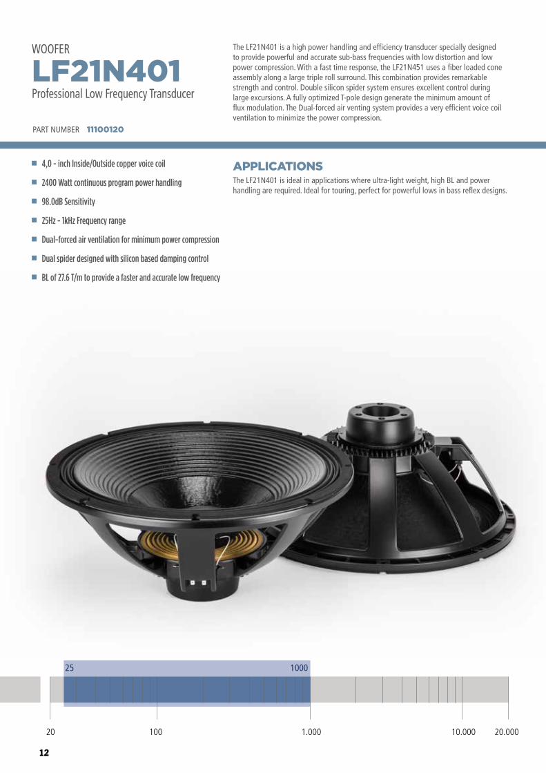
The LF21N401 is a high power handling and efficiency transducer specially designed to provide powerful and accurate sub-bass frequencies with low distortion and low power compression. With a fast time response, the LF21N451 uses a fiber loaded cone assembly along a large triple roll surround. This combination provides remarkable strength and control. Double silicon spider system ensures excellent control during large excursions. A fully optimized T-pole design generate the minimum amount of flux modulation. The Dual-forced air venting system provides a very efficient voice coil ventilation to minimize the power compression.
The LF21N401 is ideal in applications where ultra-light weight, high BL and power handling are required. Ideal for touring, perfect for powerful lows in bass reflex designs.
APPLICATIONS
PART NUMBER 11100120
4,0 - inch Inside/Outside copper voice coil
2400 Watt continuous program power handling
98.0dB Sensitivity
25Hz - 1kHz Frequency range
Dual-forced air ventilation for minimum power compression
Dual spider designed with silicon based damping control
BL of 27.6 T/m to provide a faster and accurate low frequency
LF21N401Professional Low Frequency Transducer
WOOFER
25 1000
20 100 10.000 20.0001.000
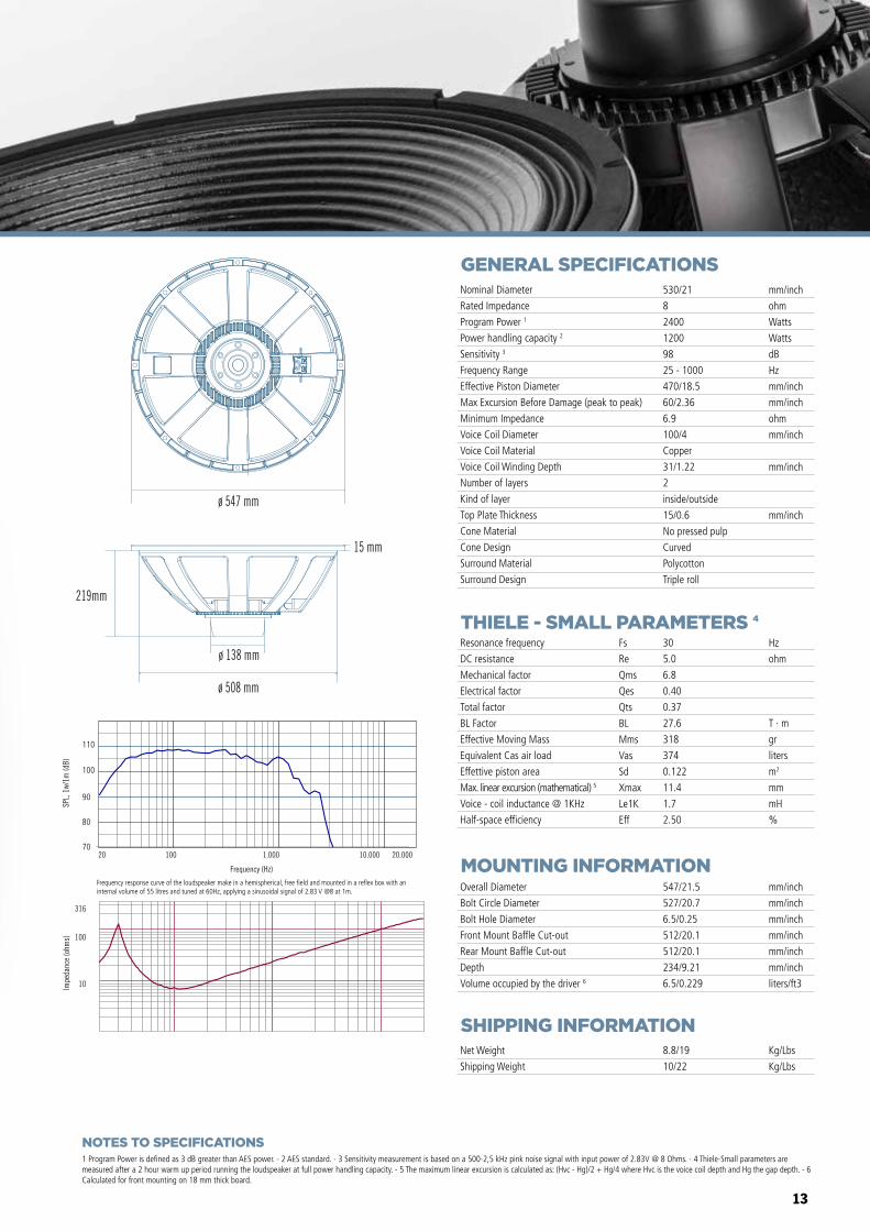
13
ø 547 mm
ø 508 mm
15 mm
219mm
ø 138 mm
GENERAL SPECIFICATIONS
THIELE - SMALL PARAMETERS 4
MOUNTING INFORMATION
SHIPPING INFORMATION
1 Program Power is defined as 3 dB greater than AES power. - 2 AES standard. - 3 Sensitivity measurement is based on a 500-2,5 kHz pink noise signal with input power of 2.83V @ 8 Ohms. - 4 Thiele-Small parameters are measured after a 2 hour warm up period running the loudspeaker at full power handling capacity. - 5 The maximum linear excursion is calculated as: (Hvc - Hg)/2 + Hg/4 where Hvc is the voice coil depth and Hg the gap depth. - 6 Calculated for front mounting on 18 mm thick board.
Overall Diameter
Bolt Circle Diameter
Bolt Hole Diameter
Front Mount Baffle Cut-out
Rear Mount Baffle Cut-out
Depth
Volume occupied by the driver 6
547/21.5
527/20.7
6.5/0.25
512/20.1
512/20.1
234/9.21
6.5/0.229
mm/inch
mm/inch
mm/inch
mm/inch
mm/inch
mm/inch
liters/ft3
Net Weight
Shipping Weight
8.8/19
10/22
Kg/Lbs
Kg/Lbs
Resonance frequency
DC resistance
Mechanical factor
Electrical factor
Total factor
BL Factor
Effective Moving Mass
Equivalent Cas air load
Effettive piston area
Max. linear excursion (mathematical) 5
Voice - coil inductance @ 1KHz
Half-space efficiency
Hz
ohm
T · m
gr
liters
m2
mm
mH
%
30
5.0
6.8
0.40
0.37
27.6
318
374
0.122
11.4
1.7
2.50
Fs
Re
Qms
Qes
Qts
BL
Mms
Vas
Sd
Xmax
Le1K
Eff
Nominal Diameter
Rated Impedance
Program Power 1
Power handling capacity 2
Sensitivity 3
Frequency Range
Effective Piston Diameter
Max Excursion Before Damage (peak to peak)
Minimum Impedance
Voice Coil Diameter
Voice Coil Material
Voice Coil Winding Depth
Number of layers
Kind of layer
Top Plate Thickness
Cone Material
Cone Design
Surround Material
Surround Design
530/21
8
2400
1200
98
25 - 1000
470/18.5
60/2.36
6.9
100/4
Copper
31/1.22
2
inside/outside
15/0.6
No pressed pulp
Curved
Polycotton
Triple roll
mm/inch
ohm
Watts
Watts
dB
Hz
mm/inch
mm/inch
ohm
mm/inch
mm/inch
mm/inch
NOTES TO SPECIFICATIONS
Impedance magnitude curve measured in free air.
Frequency (Hz)
20 100 1.000 10.000 20.000
10
100
316
Impe
danc
e (o
hms)
Frequency (Hz)
20 100 1.000 10.000 20.000
Frequency response curve of the loudspeaker taken in a hemispherical, free �eld environment and mounted in a closed box with an internal volume of 600 litres (21,2 cu.ft) enclosing the rear of the driver.
80
90
100
110
SPL,
1w/
1m (d
B)
Frequency (Hz)
20 100 1.000 10.000 20.000
Frequency response curve of the loudspeaker taken in a hemispherical, free �eld environment and mounted in a closed box with an internal volume of 600 litres (21,2 cu.ft) enclosing the rear of the driver.
80
90
100
110
SPL,
1w/
1m (d
B)
70
80
90
100
110
Frequency response curve of the loudspeaker make in a hemispherical, free field and mounted in a reflex box with an internal volume of 55 litres and tuned at 60Hz, applying a sinusoidal signal of 2.83 V @8 at 1m.
14
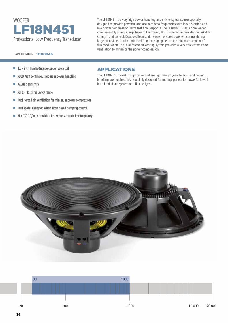
The LF18N451 is a very high power handling and efficiency transducer specially designed to provide powerful and accurate bass frequencies with low distortion and low power compression. Ultra fast time response. The LF18N451 uses a fibre loaded cone assembly along a large triple roll surround, this combination provides remarkable strength and control. Double silicon spider system ensures excellent control during large excursions. A fully optimised T-pole design generate the minimum amount of flux modulation. The Dual-forced air venting system provides a very efficient voice coil ventilation to minimize the power compression.
The LF18N451 is ideal in applications where light weight ,very high BL and power handling are required. Itís especially designed for touring, perfect for powerful lows in horn loaded sub system or reflex designs.
APPLICATIONS
PART NUMBER 11100046
4,5 - inch Inside/Outside copper voice coil
3000 Watt continuous program power handling
97.5dB Sensitivity
30Hz - 1kHz Frequency range
Dual-forced air ventilation for minimum power compression
Dual spider designed with silicon based damping control
BL of 30.2 T/m to provide a faster and accurate low frequency
LF18N451Professional Low Frequency Transducer
WOOFER
30 1000
20 100 10.000 20.0001.000
15
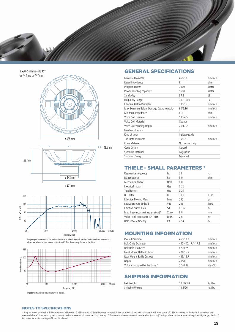
GENERAL SPECIFICATIONS
THIELE - SMALL PARAMETERS 4
MOUNTING INFORMATION
SHIPPING INFORMATION
1 Program Power is defined as 3 dB greater than AES power. - 2 AES standard. - 3 Sensitivity measurement is based on a 500-2,5 kHz pink noise signal with input power of 2.83V @ 8 Ohms. - 4 Thiele-Small parameters are measured after a 2 hour warm up period running the loudspeaker at full power handling capacity. - 5 The maximum linear excursion is calculated as: (Hvc - Hg)/2 + Hg/4 where Hvc is the voice coil depth and Hg the gap depth. - 6 Calculated for front mounting on 18 mm thick board.
Overall Diameter
Bolt Circle Diameter
Bolt Hole Diameter
Front Mount Baffle Cut-out
Rear Mount Baffle Cut-out
Depth
Volume occupied by the driver 6
465/18.3
442-447/17.4-17.6
6.5/0.25
424/16.7
425/16.7
205/8.1
5.5/0.19
mm/inch
mm/inch
mm/inch
mm/inch
mm/inch
mm/inch
liters/ft3
Net Weight
Shipping Weight
10.6/23.3
11.8/26
Kg/Lbs
Kg/Lbs
Resonance frequency
DC resistance
Mechanical factor
Electrical factor
Total factor
BL Factor
Effective Moving Mass
Equivalent Cas air load
Effettive piston area
Max. linear excursion (mathematical) 5
Voice - coil inductance @ 1KHz
Half-space efficiency
Hz
ohm
T · m
gr
liters
m2
mm
mH
%
31
5.0
6.0
0.25
0.24
30.2
235
245
0.122
8.8
2.6
2.54
Fs
Re
Qms
Qes
Qts
BL
Mms
Vas
Sd
Xmax
Le1K
Eff
Nominal Diameter
Rated Impedance
Program Power 1
Power handling capacity 2
Sensitivity 3
Frequency Range
Effective Piston Diameter
Max Excursion Before Damage (peak to peak)
Minimum Impedance
Voice Coil Diameter
Voice Coil Material
Voice Coil Winding Depth
Number of layers
Kind of layer
Top Plate Thickness
Cone Material
Cone Design
Surround Material
Surround Design
460/18
8
3000
1500
97.5
30 - 1000
395/15.6
60/2.36
6.3
115/4.5
Copper
26/1.02
2
inside/outside
15/0.6
No pressed pulp
Curved
Polycotton
Triple roll
mm/inch
ohm
Watts
Watts
dB
Hz
mm/inch
mm/inch
ohm
mm/inch
mm/inch
mm/inch
Frequency response curve of the loudspeaker taken in a hemispherical, free �eld environment and mounted in a closed box with an internal volume of 600 litres (21,2 cu.ft) enclosing the rear of the driver.
Impedance magnitude curve measured in free air.
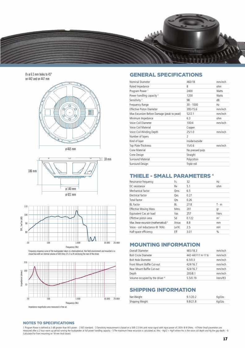
8 x ø 6.5 mm holes to 45°on 442 and on 447 mm
ø 421 mm
ø 148 mm
199 mm
23.5 mm
ø 465 mm
Frequency (Hz)
20 100 1.000 10.000 20.000
10
100
316
Impe
danc
e (o
hms)
80
90
100
110
SPL,
1w/
1m (d
B)
Frequency (Hz)
20 100 1.000 10.000 20.000
NOTES TO SPECIFICATIONS
16
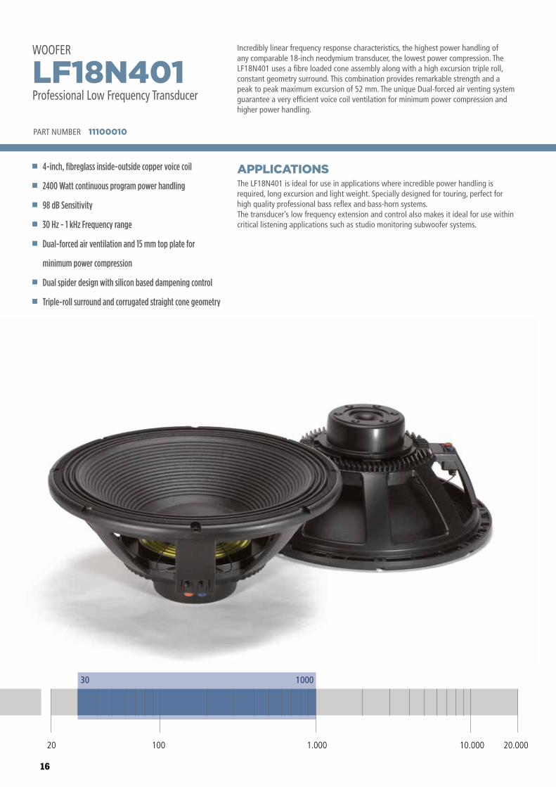
Incredibly linear frequency response characteristics, the highest power handling of any comparable 18-inch neodymium transducer, the lowest power compression. The LF18N401 uses a fibre loaded cone assembly along with a high excursion triple roll, constant geometry surround. This combination provides remarkable strength and a peak to peak maximum excursion of 52 mm. The unique Dual-forced air venting system guarantee a very efficient voice coil ventilation for minimum power compression and higher power handling.
The LF18N401 is ideal for use in applications where incredible power handling is required, long excursion and light weight. Specially designed for touring, perfect for high quality professional bass reflex and bass-horn systems.The transducer’s low frequency extension and control also makes it ideal for use within critical listening applications such as studio monitoring subwoofer systems.
APPLICATIONS
PART NUMBER 11100010
4-inch, fibreglass inside-outside copper voice coil
2400 Watt continuous program power handling
98 dB Sensitivity
30 Hz - 1 kHz Frequency range
Dual-forced air ventilation and 15 mm top plate for
minimum power compression
Dual spider design with silicon based dampening control
Triple-roll surround and corrugated straight cone geometry
LF18N401Professional Low Frequency Transducer
WOOFER
30 1000
20 100 10.000 20.0001.000
17
GENERAL SPECIFICATIONS
THIELE - SMALL PARAMETERS 4
MOUNTING INFORMATION
SHIPPING INFORMATION
1 Program Power is defined as 3 dB greater than AES power. - 2 AES standard. - 3 Sensitivity measurement is based on a 500-2,5 kHz pink noise signal with input power of 2.83V @ 8 Ohms. - 4 Thiele-Small parameters are measured after a 2 hour warm up period running the loudspeaker at full power handling capacity. - 5 The maximum linear excursion is calculated as: (Hvc - Hg)/2 + Hg/4 where Hvc is the voice coil depth and Hg the gap depth. - 6 Calculated for front mounting on 18 mm thick board.
Overall Diameter
Bolt Circle Diameter
Bolt Hole Diameter
Front Mount Baffle Cut-out
Rear Mount Baffle Cut-out
Depth
Volume occupied by the driver 6
465/18.3
442-447/17.4-17.6
6.5/0.3
424/16.7
424/16.7
205/8.1
5.5/0.19
mm/inch
mm/inch
mm/inch
mm/inch
mm/inch
mm/inch
liters/ft3
Net Weight
Shipping Weight
9.1/20.2
9.8/21.8
Kg/Lbs
Kg/Lbs
Resonance frequency
DC resistance
Mechanical factor
Electrical factor
Total factor
BL Factor
Effective Moving Mass
Equivalent Cas air load
Effettive piston area
Max. linear excursion (mathematical) 5
Voice - coil inductance @ 1KHz
Half-space efficiency
Hz
ohm
T · m
gr
liters
m2
mm
mH
%
32
5.1
6.5
0.27
0.26
27.8
201
257
0.122
8.8
2.5
3.01
Fs
Re
Qms
Qes
Qts
BL
Mms
Vas
Sd
Xmax
Le1K
Eff
Nominal Diameter
Rated Impedance
Program Power 1
Power handling capacity 2
Sensitivity 3
Frequency Range
Effective Piston Diameter
Max Excursion Before Damage (peak to peak)
Minimum Impedance
Voice Coil Diameter
Voice Coil Material
Voice Coil Winding Depth
Number of layers
Kind of layer
Top Plate Thickness
Cone Material
Cone Design
Surround Material
Surround Design
460/18
8
2400
1200
98
30 - 1000
395/15.6
52/2.1
6.3
100/4
Copper
25/1.0
2
inside/outside
15/0.6
No pressed pulp
Straight
Polycotton
Triple roll
mm/inch
ohm
Watts
Watts
dB
Hz
mm/inch
mm/inch
ohm
mm/inch
mm/inch
mm/inch
80
90
100
110
SPL,
1w/
1m (d
B)
Frequency (Hz)
20 100 1.000 10.000 20.000
Frequency response curve of the loudspeaker taken in a hemispherical, free �eld environment and mounted in a closed box with an internal volume of 600 litres (21,2 cu.ft) enclosing the rear of the driver.
Frequency (Hz)
20 100 1.000 10.000 20.000
10
100
316
Impe
danc
e (o
hms)
Impedance magnitude curve measured in free air.
ø 465 mm
8 x ø 6.5 mm holes to 45°on 442 and on 447 mm
ø 421 mm
ø 140 mm
186 mm
18 mm
NOTES TO SPECIFICATIONS
18
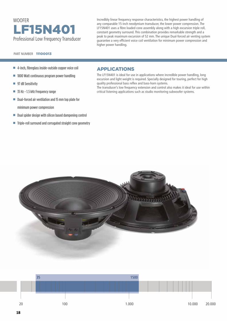
Incredibly linear frequency response characteristics, the highest power handling of any comparable 15-inch neodymium transducer, the lower power compression. The LF15N401 uses a fibre loaded cone assembly along with a high excursion triple roll, constant geometry surround. This combination provides remarkable strength and a peak to peak maximum excursion of 52 mm. The unique Dual-forced air venting system guarantee a very efficient voice coil ventilation for minimum power compression and higher power handling.
The LF15N401 is ideal for use in applications where incredible power handling, long excursion and light weight is required. Specially designed for touring, perfect for high quality professional bass reflex and bass-horn systems.The transducer’s low frequency extension and control also makes it ideal for use within critical listening applications such as studio monitoring subwoofer systems.
APPLICATIONS
PART NUMBER 11100013
4-inch, fibreglass inside-outside copper voice coil
1800 Watt continuous program power handling
97 dB Sensitivity
35 Hz - 1.5 kHz Frequency range
Dual-forced air ventilation and 15 mm top plate for
minimum power compression
Dual spider design with silicon based dampening control
Triple-roll surround and corrugated straight cone geometry
LF15N401Professional Low Frequency Transducer
WOOFER
35 1500
20 100 10.000 20.0001.000
19
GENERAL SPECIFICATIONS
THIELE - SMALL PARAMETERS 4
MOUNTING INFORMATION
SHIPPING INFORMATION
1 Program Power is defined as 3 dB greater than AES power. - 2 AES standard. - 3 Sensitivity measurement is based on a 500-2,5 kHz pink noise signal with input power of 2.83V @ 8 Ohms. - 4 Thiele-Small parameters are measured after a 2 hour warm up period running the loudspeaker at full power handling capacity. - 5 The maximum linear excursion is calculated as: (Hvc - Hg)/2 + Hg/4 where Hvc is the voice coil depth and Hg the gap depth. - 6 Calculated for front mounting on 18 mm thick board.
Overall Diameter
Bolt Circle Diameter
Bolt Hole Diameter
Front Mount Baffle Cut-out
Rear Mount Baffle Cut-out
Depth
Volume occupied by the driver 6
393/15.5
371-376/14.6-14.8
6.5/0.3
354/13.9
354/14.2
158/6.2
3.8/0.13
mm/inch
mm/inch
mm/inch
mm/inch
mm/inch
mm/inch
liters/ft3
Net Weight
Shipping Weight
8.6/19.1
9.3/20.7
Kg/Lbs
Kg/Lbs
Resonance frequency
DC resistance
Mechanical factor
Electrical factor
Total factor
BL Factor
Effective Moving Mass
Equivalent Cas air load
Effettive piston area
Max. linear excursion (mathematical) 5
Voice - coil inductance @ 1KHz
Half-space efficiency
Hz
ohm
T · m
gr
liters
m2
mm
mH
%
34
5.1
5.8
0.23
0.22
27.8
158
160
0.091
8.8
2.5
2.64
Fs
Re
Qms
Qes
Qts
BL
Mms
Vas
Sd
Xmax
Le1K
Eff
Nominal Diameter
Rated Impedance
Program Power 1
Power handling capacity 2
Sensitivity 3
Frequency Range
Effective Piston Diameter
Max Excursion Before Damage (peak to peak)
Minimum Impedance
Voice Coil Diameter
Voice Coil Material
Voice Coil Winding Depth
Number of layers
Kind of layer
Top Plate Thickness
Cone Material
Cone Design
Surround Material
Surround Design
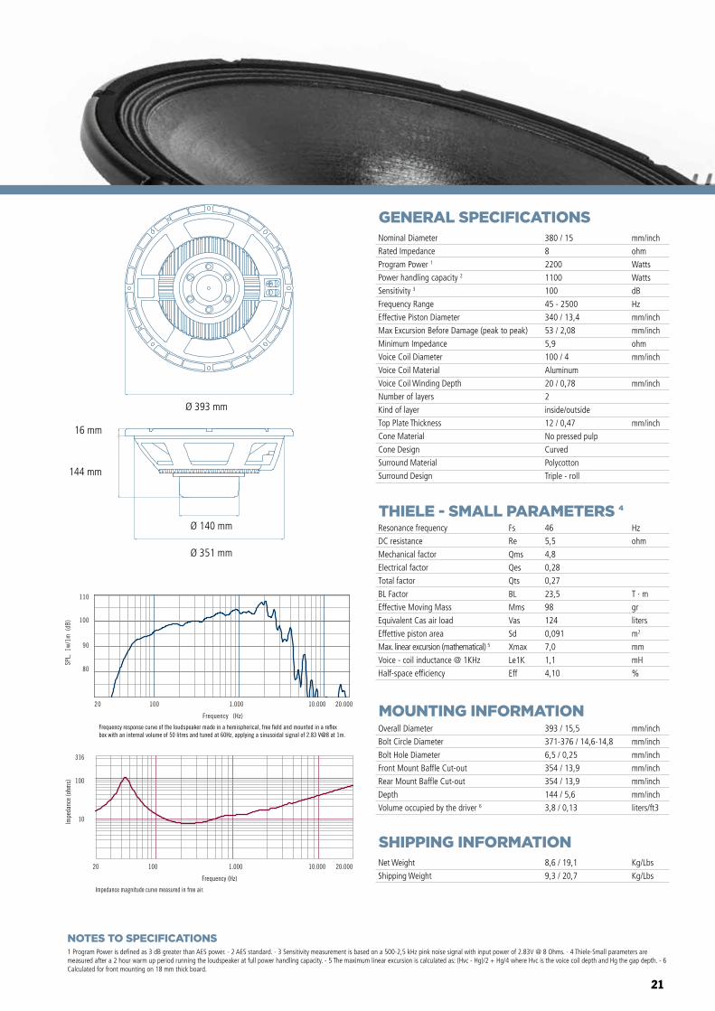
380/15
8
1800
900
97
35 - 1500
340/13.4
52/2.1
6,3
100/4
Copper
25/1.0
2
inside/outside
15/0.6
No pressed pulp
Straight
Polycotton
Triple roll
mm/inch
ohm
Watts
Watts
dB
Hz
mm/inch
mm/inch
ohm
mm/inch
mm/inch
mm/inch
80
90
100
110
SPL,
1w/
1m (d
B)
Frequency (Hz)
20 100 1.000 10.000 20.000
Frequency (Hz)
20 100 1.000 10.000 20.000
10
100
316
Impe
danc
e (o
hms)
Impedance magnitude curve measured in free air.
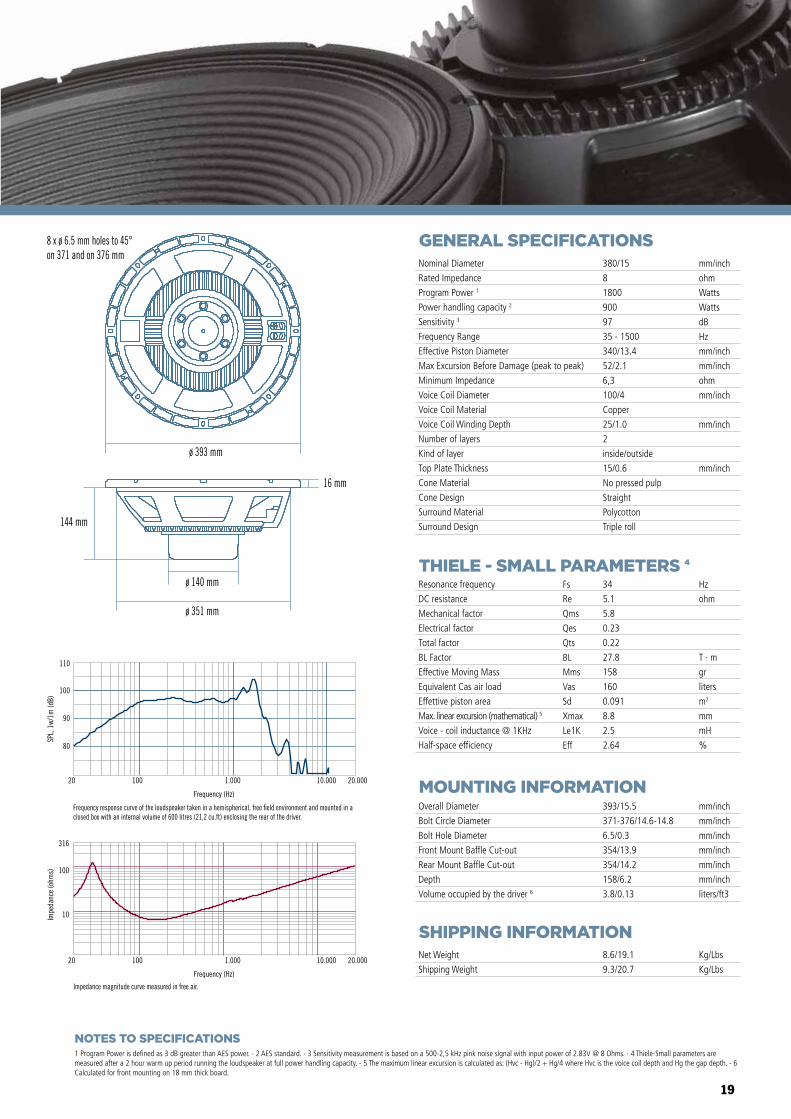
8 x ø 6.5 mm holes to 45°on 371 and on 376 mm
ø 393 mm
16 mm
144 mm
ø 140 mm
ø 351 mm
Frequency response curve of the loudspeaker taken in a hemispherical, free �eld environment and mounted in a closed box with an internal volume of 600 litres (21,2 cu.ft) enclosing the rear of the driver.
NOTES TO SPECIFICATIONS
20
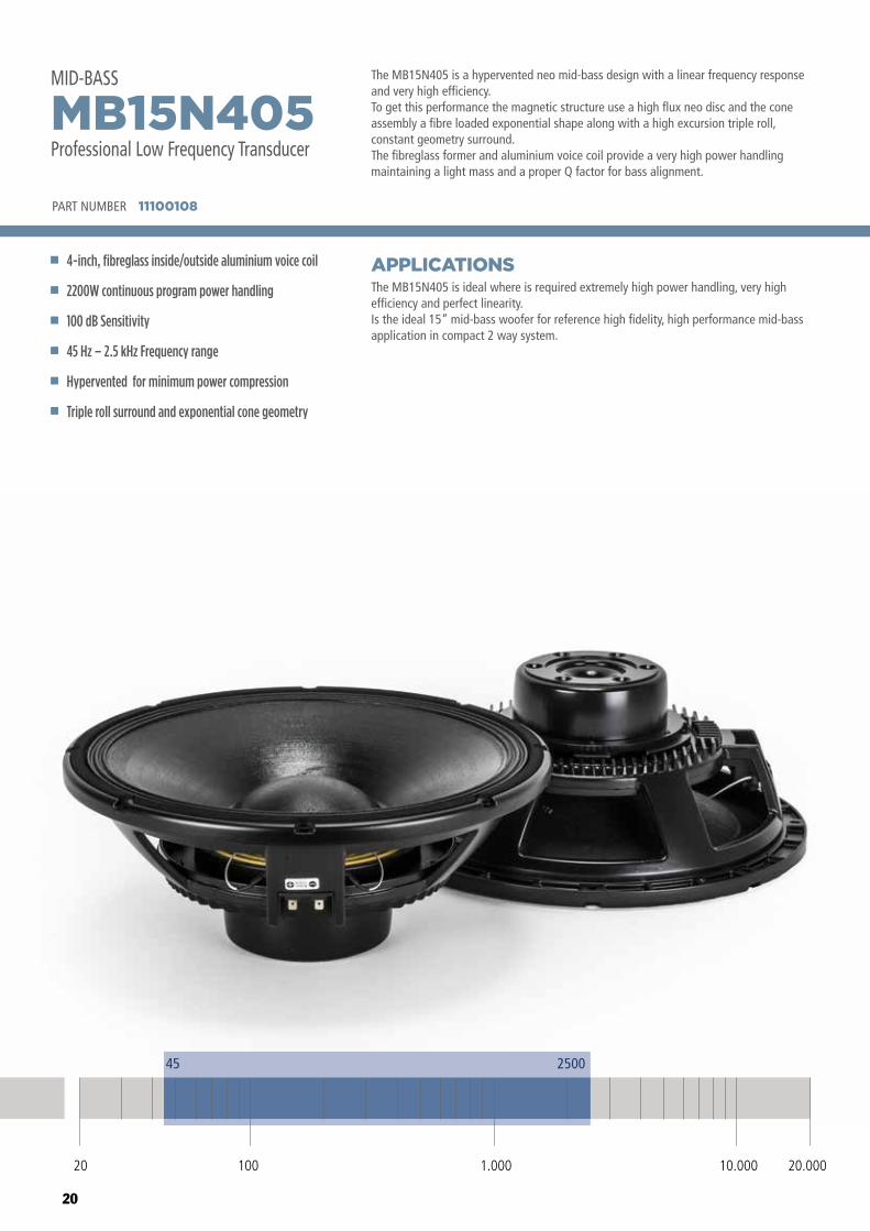
The MB15N405 is a hypervented neo mid-bass design with a linear frequency response and very high efficiency. To get this performance the magnetic structure use a high flux neo disc and the cone assembly a fibre loaded exponential shape along with a high excursion triple roll, constant geometry surround.The fibreglass former and aluminium voice coil provide a very high power handling maintaining a light mass and a proper Q factor for bass alignment.
The MB15N405 is ideal where is required extremely high power handling, very high efficiency and perfect linearity.Is the ideal 15” mid-bass woofer for reference high fidelity, high performance mid-bass application in compact 2 way system.
APPLICATIONS
PART NUMBER 11100108
4-inch, fibreglass inside/outside aluminium voice coil
2200W continuous program power handling
100 dB Sensitivity
45 Hz – 2.5 kHz Frequency range
Hypervented for minimum power compression
Triple roll surround and exponential cone geometry
MB15N405Professional Low Frequency Transducer
MID-BASS
45 2500
20 100 10.000 20.0001.000
21
GENERAL SPECIFICATIONS
THIELE - SMALL PARAMETERS 4
MOUNTING INFORMATION
SHIPPING INFORMATION
1 Program Power is defined as 3 dB greater than AES power. - 2 AES standard. - 3 Sensitivity measurement is based on a 500-2,5 kHz pink noise signal with input power of 2.83V @ 8 Ohms. - 4 Thiele-Small parameters are measured after a 2 hour warm up period running the loudspeaker at full power handling capacity. - 5 The maximum linear excursion is calculated as: (Hvc - Hg)/2 + Hg/4 where Hvc is the voice coil depth and Hg the gap depth. - 6 Calculated for front mounting on 18 mm thick board.
Overall Diameter
Bolt Circle Diameter
Bolt Hole Diameter
Front Mount Baffle Cut-out
Rear Mount Baffle Cut-out
Depth
Volume occupied by the driver 6
393 / 15,5
371-376 / 14,6-14,8
6,5 / 0,25
354 / 13,9
354 / 13,9
144 / 5,6
3,8 / 0,13
mm/inch
mm/inch
mm/inch
mm/inch
mm/inch
mm/inch
liters/ft3
Net Weight
Shipping Weight
8,6 / 19,1
9,3 / 20,7
Kg/Lbs
Kg/Lbs
Resonance frequency
DC resistance
Mechanical factor
Electrical factor
Total factor
BL Factor
Effective Moving Mass
Equivalent Cas air load
Effettive piston area
Max. linear excursion (mathematical) 5
Voice - coil inductance @ 1KHz
Half-space efficiency
Hz
ohm
T · m
gr
liters
m2
mm
mH
%
46
5,5
4,8
0,28
0,27
23,5
98
124
0,091
7,0
1,1
4,10
Fs
Re
Qms
Qes
Qts
BL
Mms
Vas
Sd
Xmax
Le1K
Eff
Nominal Diameter
Rated Impedance
Program Power 1
Power handling capacity 2
Sensitivity 3
Frequency Range
Effective Piston Diameter
Max Excursion Before Damage (peak to peak)
Minimum Impedance
Voice Coil Diameter
Voice Coil Material
Voice Coil Winding Depth
Number of layers
Kind of layer
Top Plate Thickness
Cone Material
Cone Design
Surround Material
Surround Design
380 / 15
8
2200
1100
100
45 - 2500
340 / 13,4
53 / 2,08
5,9
100 / 4
Aluminum
20 / 0,78
2
inside/outside
12 / 0,47
No pressed pulp
Curved
Polycotton
Triple - roll
mm/inch
ohm
Watts
Watts
dB
Hz
mm/inch
mm/inch
ohm
mm/inch
mm/inch
mm/inch
Impedance magnitude curve measured in free air.
Frequency (Hz)
20 100 1.000 10.000 20.000
10
100
316
Impe
danc
e (o
hms)
Frequency (Hz)
20 100
110
100
90
80
1.000 10.000 20.000
SPL,
1w/
1m (
dB)
Frequency response curve of the loudspeaker made in a hemispherical, free �eld and mounted in a re�ex box with an internal volume of 50 litres and tuned at 60Hz, applying a sinusoidal signal of 2.83 V@8 at 1m.
MB10G251
MB12X301 MB15X301
MB15N405MB12N405
MB10N305
Ø 393 mm
Ø 140 mm
Ø 351 mm
144 mm
16 mm
NOTES TO SPECIFICATIONS
22
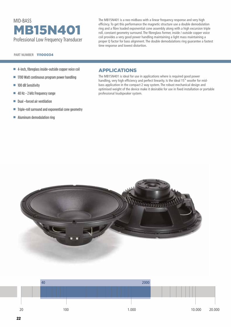
The MB15N401 is a neo midbass with a linear frequency response and very high efficincy. To get this performance the magnetic structure use a double demodulation ring and a fibre loaded exponential cone assembly along with a high excursion triple roll, constant geometry surround. The fibreglass former, inside / outside copper voice coil provides a very good power handling maintaining a light mass maintaining a proper Q factor for bass alignment. The double demodulations ring guarantee a fastest time response and lowest distortion.
The MB15N401 is ideal for use in applications where is required good power handling, very high efficiency and perfect linearity. Is the ideal 15” woofer for mid-bass application in the compact 2 way system. The robust mechanical design and optimised weight of the device make it desirable for use in fixed installation or portable professional loudspeaker system.
APPLICATIONS
PART NUMBER 11100034
4-inch, fibreglass inside-outside copper voice coil
1700 Watt continuous program power handling
100 dB Sensitivity
40 Hz - 2 kHz Frequency range
Dual –forced air ventilation
Triple-roll surround and exponential cone geometry
Aluminum demodulation ring
MB15N401Professional Low Frequency Transducer
MID-BASS
40 2000
20 100 10.000 20.0001.000
23
GENERAL SPECIFICATIONS
THIELE - SMALL PARAMETERS 4
MOUNTING INFORMATION
SHIPPING INFORMATION
1 Program Power is defined as 3 dB greater than AES power. - 2 AES standard. - 3 Sensitivity measurement is based on a 500-2,5 kHz pink noise signal with input power of 2.83V @ 8 Ohms. - 4 Thiele-Small parameters are measured after a 2 hour warm up period running the loudspeaker at full power handling capacity. - 5 The maximum linear excursion is calculated as: (Hvc - Hg)/2 + Hg/4 where Hvc is the voice coil depth and Hg the gap depth. - 6 Calculated for front mounting on 18 mm thick board.
Overall Diameter
Bolt Circle Diameter
Bolt Hole Diameter
Front Mount Baffle Cut-out
Rear Mount Baffle Cut-out
Depth
Volume occupied by the driver 6
393/15.5
371-376/14.6-14.8
6.5/0.25
354/13.9
354/14.2
158/6.2
3.8/0.13
mm/inch
mm/inch
mm/inch
mm/inch
mm/inch
mm/inch
liters/ft3
Net Weight
Shipping Weight
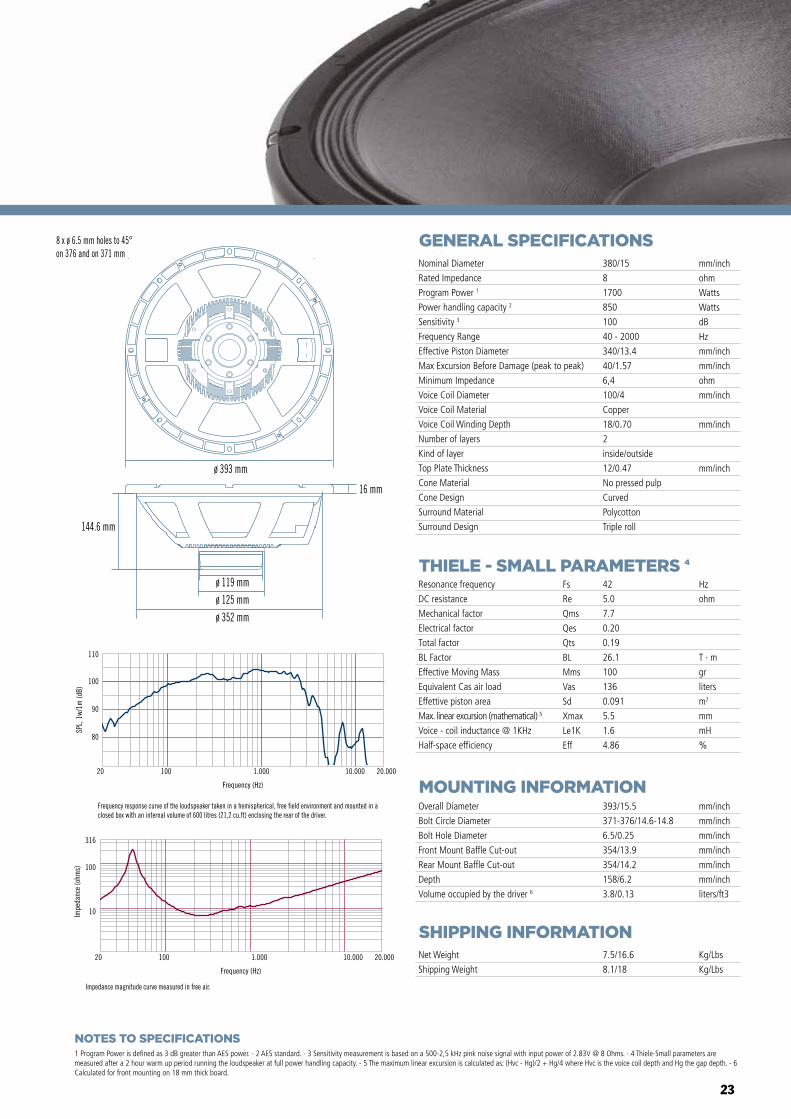
7.5/16.6
8.1/18
Kg/Lbs
Kg/Lbs
Resonance frequency
DC resistance
Mechanical factor
Electrical factor
Total factor
BL Factor
Effective Moving Mass
Equivalent Cas air load
Effettive piston area
Max. linear excursion (mathematical) 5
Voice - coil inductance @ 1KHz
Half-space efficiency
Hz
ohm
T · m
gr
liters
m2
mm
mH
%
42
5.0
7.7
0.20
0.19
26.1
100
136
0.091
5.5
1.6
4.86
Fs
Re
Qms
Qes
Qts
BL
Mms
Vas
Sd
Xmax
Le1K
Eff
Nominal Diameter
Rated Impedance
Program Power 1
Power handling capacity 2
Sensitivity 3
Frequency Range
Effective Piston Diameter
Max Excursion Before Damage (peak to peak)
Minimum Impedance
Voice Coil Diameter
Voice Coil Material
Voice Coil Winding Depth
Number of layers
Kind of layer
Top Plate Thickness
Cone Material
Cone Design
Surround Material
Surround Design
380/15
8
1700
850
100
40 - 2000
340/13.4
40/1.57
6,4
100/4
Copper
18/0.70
2
inside/outside
12/0.47
No pressed pulp
Curved
Polycotton
Triple roll
mm/inch
ohm
Watts
Watts
dB
Hz
mm/inch
mm/inch
ohm
mm/inch
mm/inch
mm/inch
Impedance magnitude curve measured in free air.
8 x ø 6.5 mm holes to 45°on 376 and on 371 mm
ø 352 mm
ø 393 mm
16 mm
144.6 mm
ø 125 mmø 119 mm
Frequency response curve of the loudspeaker taken in a hemispherical, free field environment and mounted in a closed box with an internal volume of 600 litres (21,2 cu.ft) enclosing the rear of the driver.
80
90
100
110
SPL,
1w/
1m (d
B)
Frequency (Hz)
20 100 1.000 10.000 20.000
Frequency (Hz)
20 100 1.000 10.000 20.000
10
100
316
Impe
danc
e (o
hms)
NOTES TO SPECIFICATIONS
24
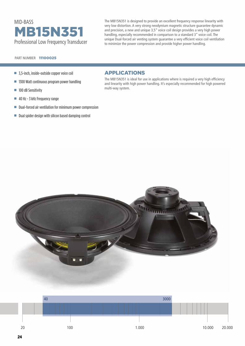
The MB15N351 is designed to provide an excellent frequency response linearity with very low distortion. A very strong neodymium magnetic structure guarantee dynamic and precision, a new and unique 3,5” voice coil design provides a very high power handling, especially recommended in comparison to a standard 3” voice coil. The unique Dual-forced air venting system guarantee a very efficient voice coil ventilation to minimize the power compression and provide higher power handling.
The MB15N351 is ideal for use in applications where is required a very high efficiency and linearity with high power handling. It’s especially recommended for high powered multi-way system.
APPLICATIONS
PART NUMBER 11100025
3,5-inch, inside-outside copper voice coil
1300 Watt continuous program power handling
100 dB Sensitivity
40 Hz - 3 kHz Frequency range
Dual-forced air ventilation for minimum power compression
Dual spider design with silicon based damping control
MB15N351Professional Low Frequency Transducer
MID-BASS
40 3000
20 100 10.000 20.0001.000
25
GENERAL SPECIFICATIONS
THIELE - SMALL PARAMETERS 4
MOUNTING INFORMATION
SHIPPING INFORMATION
1 Program Power is defined as 3 dB greater than AES power. - 2 AES standard. - 3 Sensitivity measurement is based on a 500-2,5 kHz pink noise signal with input power of 2.83V @ 8 Ohms. - 4 Thiele-Small parameters are measured after a 2 hour warm up period running the loudspeaker at full power handling capacity. - 5 The maximum linear excursion is calculated as: (Hvc - Hg)/2 + Hg/4 where Hvc is the voice coil depth and Hg the gap depth. - 6 Calculated for front mounting on 18 mm thick board.
Overall Diameter
Bolt Circle Diameter
Bolt Hole Diameter
Front Mount Baffle Cut-out
Rear Mount Baffle Cut-out
Depth
Volume occupied by the driver 6
393/15.5
371-376/14.6-14.8
6.5/0.3
354/13.9
354/14.2
164/6.4
3.8/0.13
mm/inch
mm/inch
mm/inch
mm/inch
mm/inch
mm/inch
liters/ft3
Net Weight
Shipping Weight
5.0/11.0
5.8/12.7
Kg/Lbs
Kg/Lbs
Resonance frequency
DC resistance
Mechanical factor
Electrical factor
Total factor
BL Factor
Effective Moving Mass
Equivalent Cas air load
Effettive piston area
Max. linear excursion (mathematical) 5
Voice - coil inductance @ 1KHz
Half-space efficiency
Hz
ohm
T · m
gr
liters
m2
mm
mH
%
42
5.6
4.0
0.24
0.22
22.5
80
191
0.0855
5.5
1.65
5.68
Fs
Re
Qms
Qes
Qts
BL
Mms
Vas
Sd
Xmax
Le1K
Eff
Nominal Diameter
Rated Impedance
Program Power 1
Power handling capacity 2
Sensitivity 3
Frequency Range
Effective Piston Diameter
Max Excursion Before Damage (peak to peak)
Minimum Impedance
Voice Coil Diameter
Voice Coil Material
Voice Coil Winding Depth
Number of layers
Kind of layer
Top Plate Thickness
Cone Material
Cone Design
Surround Material
Surround Design
380/15
8
1300
650
100
40 - 3000
330/13
39/1.5
6,8
87/3.4
Copper
16.5/0.65
2
inside/outside
11/0.43
No pressed pulp
Curved
Polycotton
M-roll
mm/inch
ohm
Watts
Watts
dB
Hz
mm/inch
mm/inch
ohm
mm/inch
mm/inch
mm/inch
Impedance magnitude curve measured in free air.
8 x ø 6.5 mm holes to 45°on 371 and on 376 mm
ø 393 mm
16 mm
164 mm
ø 118 mm
ø 351 mm
Frequency (Hz)
20 100 1.000 10.000 20.000
10
100
316
Impe
danc
e (o
hms)
Frequency response curve of the loudspeaker taken in a hemispherical, free field environment and mounted in a closed box with an internal volume of 600 litres (21,2 cu.ft) enclosing the rear of the driver.
80
90
100
110
SPL,
1w/
1m (d
B)
Frequency (Hz)
20 100 1.000 10.000 20.000
NOTES TO SPECIFICATIONS
26
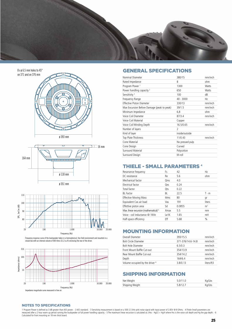
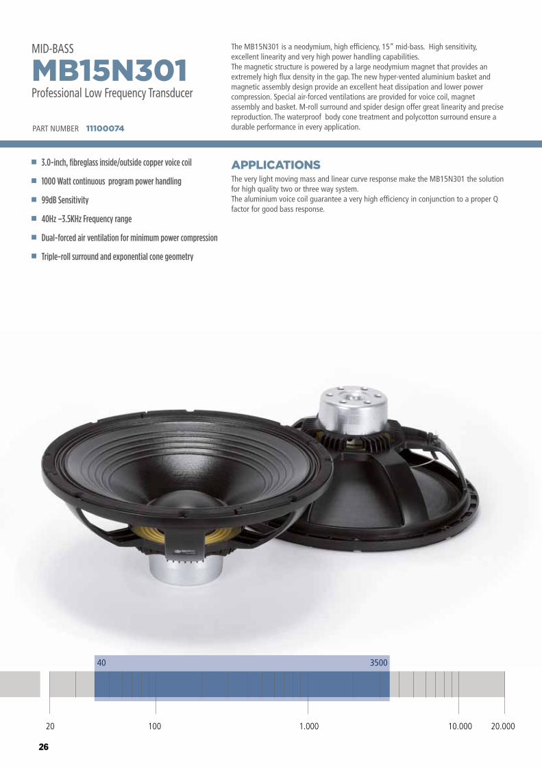
The MB15N301 is a neodymium, high efficiency, 15” mid-bass. High sensitivity, excellent linearity and very high power handling capabilities.The magnetic structure is powered by a large neodymium magnet that provides an extremely high flux density in the gap. The new hyper-vented aluminium basket and magnetic assembly design provide an excellent heat dissipation and lower power compression. Special air-forced ventilations are provided for voice coil, magnet assembly and basket. M-roll surround and spider design offer great linearity and precise reproduction. The waterproof body cone treatment and polycotton surround ensure a durable performance in every application.
The very light moving mass and linear curve response make the MB15N301 the solution for high quality two or three way system. The aluminium voice coil guarantee a very high efficiency in conjunction to a proper Q factor for good bass response.
APPLICATIONS
PART NUMBER 11100074
3.0-inch, fibreglass inside/outside copper voice coil
1000 Watt continuous program power handling
99dB Sensitivity
40Hz –3.5KHz Frequency range
Dual-forced air ventilation for minimum power compression
Triple-roll surround and exponential cone geometry
MB15N301Professional Low Frequency Transducer
MID-BASS
40 3500
20 100 10.000 20.0001.000
27
GENERAL SPECIFICATIONS
THIELE - SMALL PARAMETERS 4
MOUNTING INFORMATION
SHIPPING INFORMATION
1 Program Power is defined as 3 dB greater than AES power. - 2 AES standard. - 3 Sensitivity measurement is based on a 500-2,5 kHz pink noise signal with input power of 2.83V @ 8 Ohms. - 4 Thiele-Small parameters are measured after a 2 hour warm up period running the loudspeaker at full power handling capacity. - 5 The maximum linear excursion is calculated as: (Hvc - Hg)/2 + Hg/4 where Hvc is the voice coil depth and Hg the gap depth. - 6 Calculated for front mounting on 18 mm thick board.
Overall Diameter
Bolt Circle Diameter
Bolt Hole Diameter
Front Mount Baffle Cut-out
Rear Mount Baffle Cut-out
Depth
Volume occupied by the driver 6
388/15.3
369-373.5/14.5-14.7
5.5/0.22
355/13.98
358/14.09
152/5.98
3.0/0.11
mm/inch
mm/inch
mm/inch
mm/inch
mm/inch
mm/inch
liters/ft3
Net Weight
Shipping Weight
3.7/8.16
4.7/10.36
Kg/Lbs
Kg/Lbs
Resonance frequency
DC resistance
Mechanical factor
Electrical factor
Total factor
BL Factor
Effective Moving Mass
Equivalent Cas air load
Effettive piston area
Max. linear excursion (mathematical) 5
Voice - coil inductance @ 1KHz
Half-space efficiency
Hz
ohm
T · m
gr
liters
m2
mm
mH
%
48
5.8
4.6
0.39
0.37
19.2
90
134
0.086
6.0
0.9
3.70
Fs
Re
Qms
Qes
Qts
BL
Mms
Vas
Sd
Xmax
Le1K
Eff
Nominal Diameter
Rated Impedance
Program Power 1
Power handling capacity 2
Sensitivity 3
Frequency Range
Effective Piston Diameter
Max Excursion Before Damage (peak to peak)
Minimum Impedance
Voice Coil Diameter
Voice Coil Material
Voice Coil Winding Depth
Number of layers
Kind of layer
Top Plate Thickness
Cone Material
Cone Design
Surround Material
Surround Design
380/15
8
1000
500
99
40 - 3500
330/13.0
40/1.57
6.8
76/3.0
Aluminum
17/0.67
2
inside/outside
10/0.39
No pressed pulp
Curved
Polycotton
Triple-roll
mm/inch
ohm
Watts
Watts
dB
Hz
mm/inch
mm/inch
ohm
mm/inch
mm/inch
mm/inch
80
90
100
110
SPL,
1w/
1m (d
B)
Frequency (Hz)
20 100 1.000 10.000 20.000
Frequency (Hz)
20 100 1.000 10.000 20.000
10
100
316
Impe
danc
e (o
hms)
ø 388 mm
152 mm
12.5 mm
ø 103 mm
ø 353 mm
NOTES TO SPECIFICATIONS
28
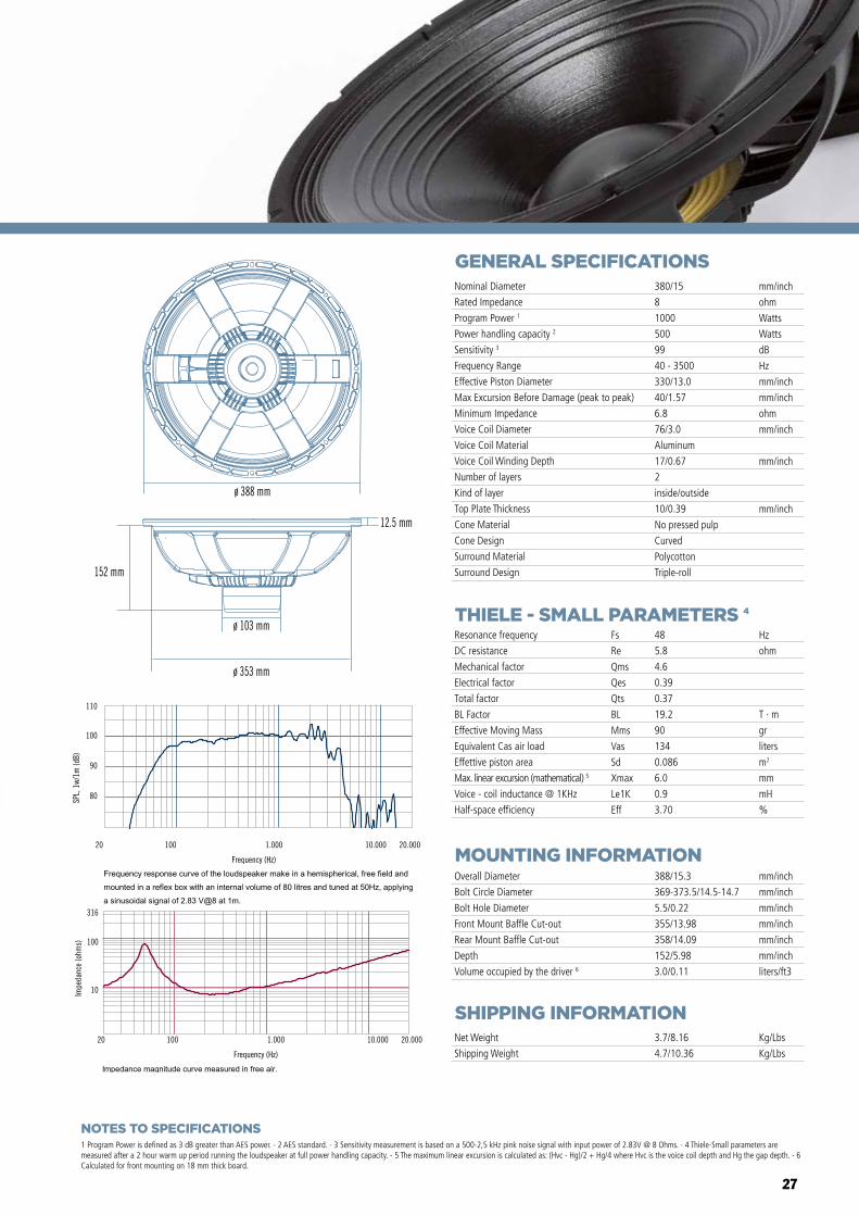
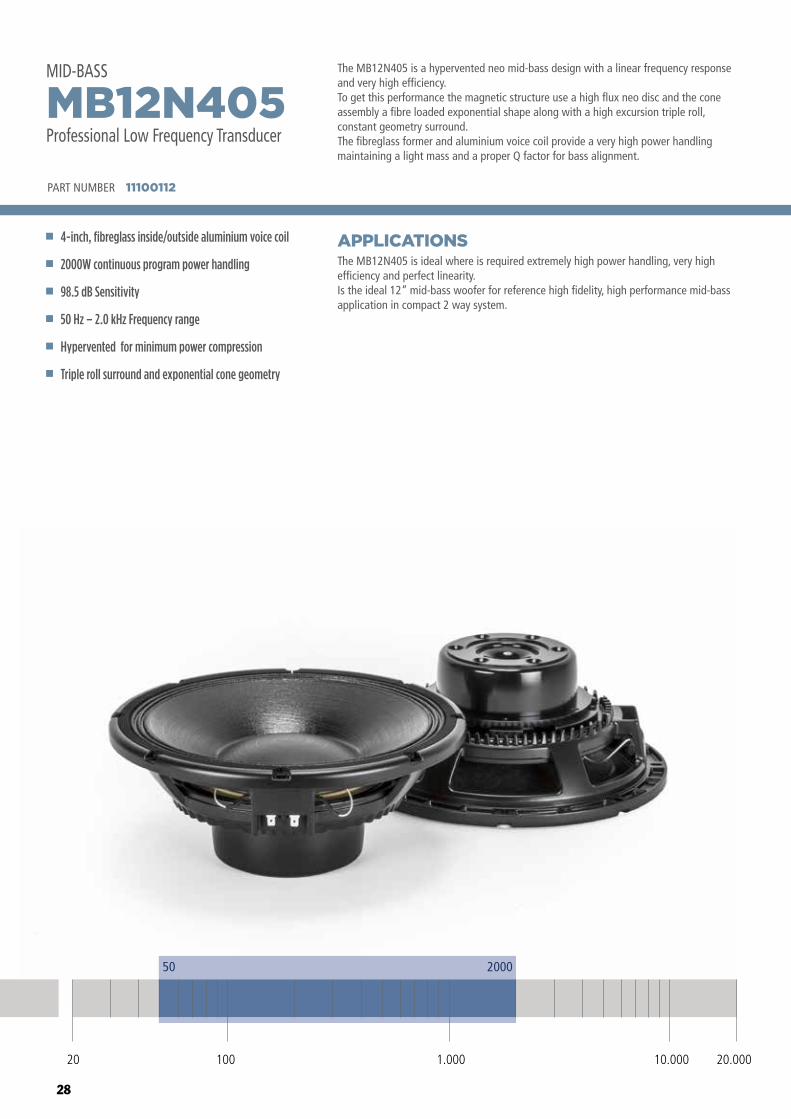
The MB12N405 is a hypervented neo mid-bass design with a linear frequency response and very high efficiency. To get this performance the magnetic structure use a high flux neo disc and the cone assembly a fibre loaded exponential shape along with a high excursion triple roll, constant geometry surround.The fibreglass former and aluminium voice coil provide a very high power handling maintaining a light mass and a proper Q factor for bass alignment.
The MB12N405 is ideal where is required extremely high power handling, very high efficiency and perfect linearity.Is the ideal 12” mid-bass woofer for reference high fidelity, high performance mid-bass application in compact 2 way system.
APPLICATIONS
PART NUMBER 11100112
4-inch, fibreglass inside/outside aluminium voice coil
2000W continuous program power handling
98.5 dB Sensitivity
50 Hz – 2.0 kHz Frequency range
Hypervented for minimum power compression
Triple roll surround and exponential cone geometry
MB12N405Professional Low Frequency Transducer
MID-BASS
50 2000
20 100 10.000 20.0001.000
29
GENERAL SPECIFICATIONS
THIELE - SMALL PARAMETERS 4
MOUNTING INFORMATION
SHIPPING INFORMATION
1 Program Power is defined as 3 dB greater than AES power. - 2 AES standard. - 3 Sensitivity measurement is based on a 500-2,5 kHz pink noise signal with input power of 2.83V @ 8 Ohms. - 4 Thiele-Small parameters are measured after a 2 hour warm up period running the loudspeaker at full power handling capacity. - 5 The maximum linear excursion is calculated as: (Hvc - Hg)/2 + Hg/4 where Hvc is the voice coil depth and Hg the gap depth. - 6 Calculated for front mounting on 18 mm thick board.
Overall Diameter
Bolt Circle Diameter
Bolt Hole Diameter
Front Mount Baffle Cut-out
Rear Mount Baffle Cut-out
Depth
Volume occupied by the driver 6
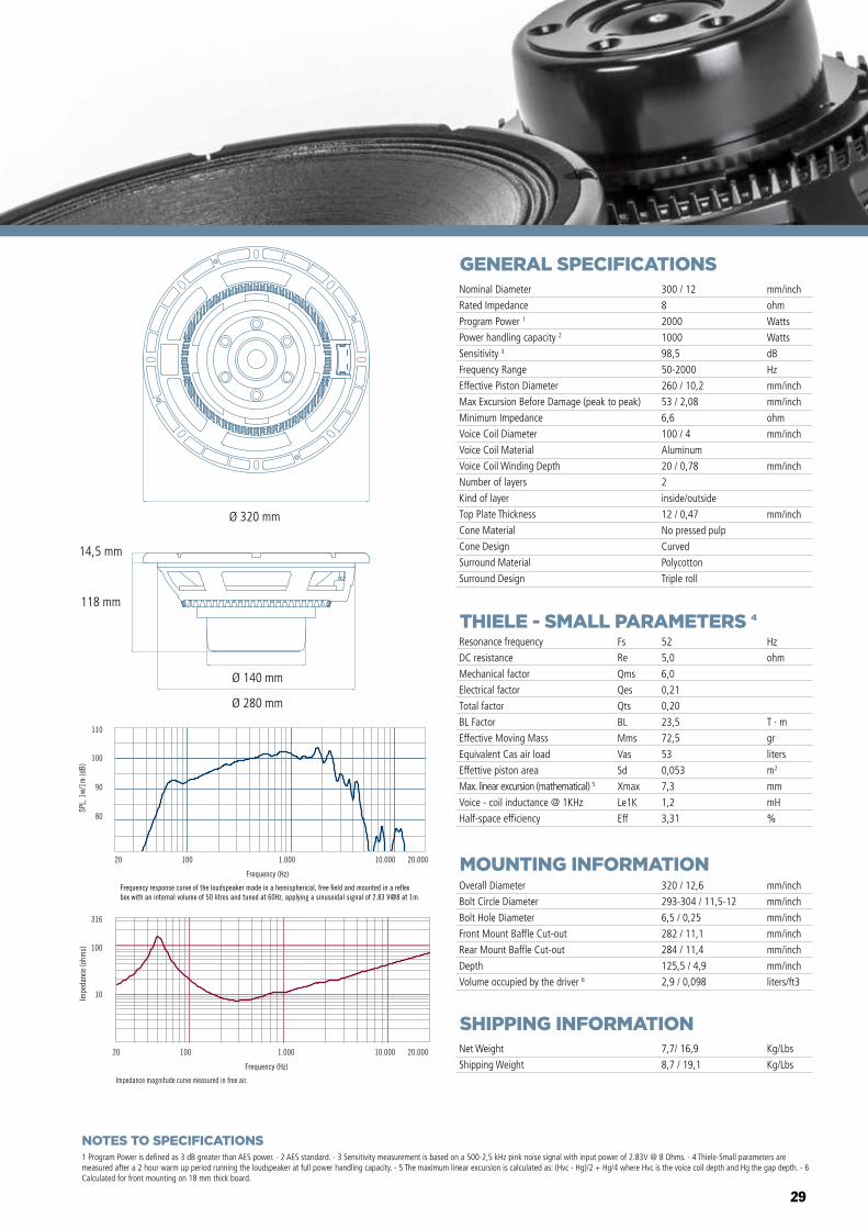
320 / 12,6
293-304 / 11,5-12
6,5 / 0,25
282 / 11,1
284 / 11,4
125,5 / 4,9
2,9 / 0,098
mm/inch
mm/inch
mm/inch
mm/inch
mm/inch
mm/inch
liters/ft3
Net Weight
Shipping Weight
7,7/ 16,9
8,7 / 19,1
Kg/Lbs
Kg/Lbs
Resonance frequency
DC resistance
Mechanical factor
Electrical factor
Total factor
BL Factor
Effective Moving Mass
Equivalent Cas air load
Effettive piston area
Max. linear excursion (mathematical) 5
Voice - coil inductance @ 1KHz
Half-space efficiency
Hz
ohm
T · m
gr
liters
m2
mm
mH
%
52
5,0
6,0
0,21
0,20
23,5
72,5
53
0,053
7,3
1,2
3,31
Fs
Re
Qms
Qes
Qts
BL
Mms
Vas
Sd
Xmax
Le1K
Eff
Nominal Diameter
Rated Impedance
Program Power 1
Power handling capacity 2
Sensitivity 3
Frequency Range
Effective Piston Diameter
Max Excursion Before Damage (peak to peak)
Minimum Impedance
Voice Coil Diameter
Voice Coil Material
Voice Coil Winding Depth
Number of layers
Kind of layer
Top Plate Thickness
Cone Material
Cone Design
Surround Material
Surround Design
300 / 12
8
2000
1000
98,5
50-2000
260 / 10,2
53 / 2,08
6,6
100 / 4
Aluminum
20 / 0,78
2
inside/outside
12 / 0,47
No pressed pulp
Curved
Polycotton
Triple roll
mm/inch
ohm
Watts
Watts
dB
Hz
mm/inch
mm/inch
ohm
mm/inch
mm/inch
mm/inch
Impedance magnitude curve measured in free air.
Frequency (Hz)
20 100 1.000 10.000 20.000
10
100
316
Impe
danc
e (o
hms)
Frequency (Hz)
20 100 1.000 10.000 20.000
80
90
100
110
SPL,
1w/
1m (d
B)
Frequency response curve of the loudspeaker made in a hemispherical, free �eld and mounted in a re�ex box with an internal volume of 50 litres and tuned at 60Hz, applying a sinusoidal signal of 2.83 V@8 at 1m.
MB10G251
MB12X301 MB15X301
MB15N405MB12N405
MB10N305
Ø 320 mm
Ø 140 mm
Ø 280 mm
118 mm
14,5 mm
NOTES TO SPECIFICATIONS
30
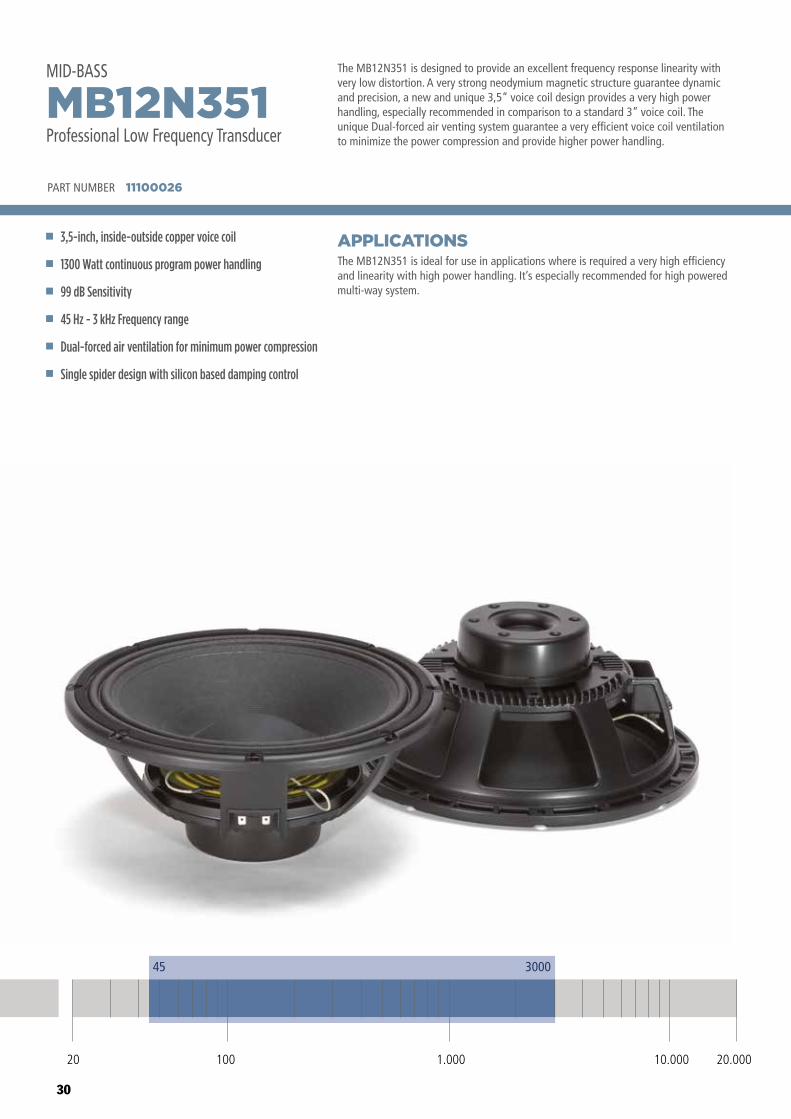
The MB12N351 is designed to provide an excellent frequency response linearity with very low distortion. A very strong neodymium magnetic structure guarantee dynamic and precision, a new and unique 3,5” voice coil design provides a very high power handling, especially recommended in comparison to a standard 3” voice coil. The unique Dual-forced air venting system guarantee a very efficient voice coil ventilation to minimize the power compression and provide higher power handling.
The MB12N351 is ideal for use in applications where is required a very high efficiency and linearity with high power handling. It’s especially recommended for high powered multi-way system.
APPLICATIONS
PART NUMBER 11100026
3,5-inch, inside-outside copper voice coil
1300 Watt continuous program power handling
99 dB Sensitivity
45 Hz - 3 kHz Frequency range
Dual-forced air ventilation for minimum power compression
Single spider design with silicon based damping control
MB12N351Professional Low Frequency Transducer
MID-BASS
45 3000
20 100 10.000 20.0001.000
31
GENERAL SPECIFICATIONS
THIELE - SMALL PARAMETERS 4
MOUNTING INFORMATION
SHIPPING INFORMATION
1 Program Power is defined as 3 dB greater than AES power. - 2 AES standard. - 3 Sensitivity measurement is based on a 500-2,5 kHz pink noise signal with input power of 2.83V @ 8 Ohms. - 4 Thiele-Small parameters are measured after a 2 hour warm up period running the loudspeaker at full power handling capacity. - 5 The maximum linear excursion is calculated as: (Hvc - Hg)/2 + Hg/4 where Hvc is the voice coil depth and Hg the gap depth. - 6 Calculated for front mounting on 18 mm thick board.
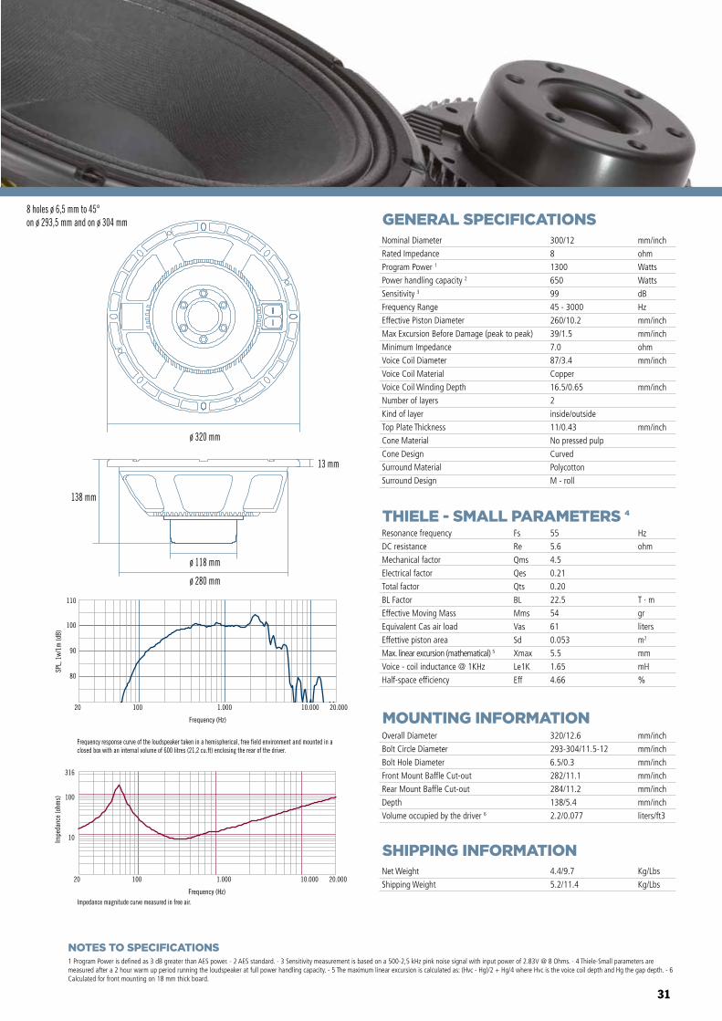
Overall Diameter
Bolt Circle Diameter
Bolt Hole Diameter
Front Mount Baffle Cut-out
Rear Mount Baffle Cut-out
Depth
Volume occupied by the driver 6
320/12.6
293-304/11.5-12
6.5/0.3
282/11.1
284/11.2
138/5.4
2.2/0.077
mm/inch
mm/inch
mm/inch
mm/inch
mm/inch
mm/inch
liters/ft3
Net Weight
Shipping Weight
4.4/9.7
5.2/11.4
Kg/Lbs
Kg/Lbs
Resonance frequency
DC resistance
Mechanical factor
Electrical factor
Total factor
BL Factor
Effective Moving Mass
Equivalent Cas air load
Effettive piston area
Max. linear excursion (mathematical) 5
Voice - coil inductance @ 1KHz
Half-space efficiency
Hz
ohm
T · m
gr
liters
m2
mm
mH
%
55
5.6
4.5
0.21
0.20
22.5
54
61
0.053
5.5
1.65
4.66
Fs
Re
Qms
Qes
Qts
BL
Mms
Vas
Sd
Xmax
Le1K
Eff
Nominal Diameter
Rated Impedance
Program Power 1
Power handling capacity 2
Sensitivity 3
Frequency Range
Effective Piston Diameter
Max Excursion Before Damage (peak to peak)
Minimum Impedance
Voice Coil Diameter
Voice Coil Material
Voice Coil Winding Depth
Number of layers
Kind of layer
Top Plate Thickness
Cone Material
Cone Design
Surround Material
Surround Design
300/12
8
1300
650
99
45 - 3000
260/10.2
39/1.5
7.0
87/3.4
Copper
16.5/0.65
2
inside/outside
11/0.43
No pressed pulp
Curved
Polycotton
M - roll
mm/inch
ohm
Watts
Watts
dB
Hz
mm/inch
mm/inch
ohm
mm/inch
mm/inch
mm/inchø 320 mm
138 mm
ø 118 mm
ø 280 mm
13 mm
Impedance magnitude curve measured in free air.
8 holes ø 6,5 mm to 45°on ø 293,5 mm and on ø 304 mm
Frequency (Hz)
20 100 1.000 10.000 20.000
10
100
316
Impe
danc
e (o
hms)
Frequency response curve of the loudspeaker taken in a hemispherical, free field environment and mounted in a closed box with an internal volume of 600 litres (21,2 cu.ft) enclosing the rear of the driver.
80
90
100
110
SPL,
1w/
1m (d
B)
Frequency (Hz)
20 100 1.000 10.000 20.000
NOTES TO SPECIFICATIONS
32
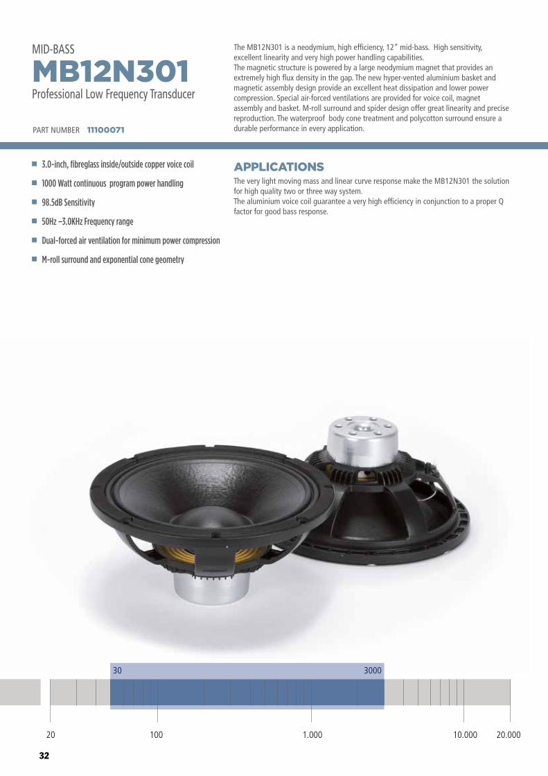
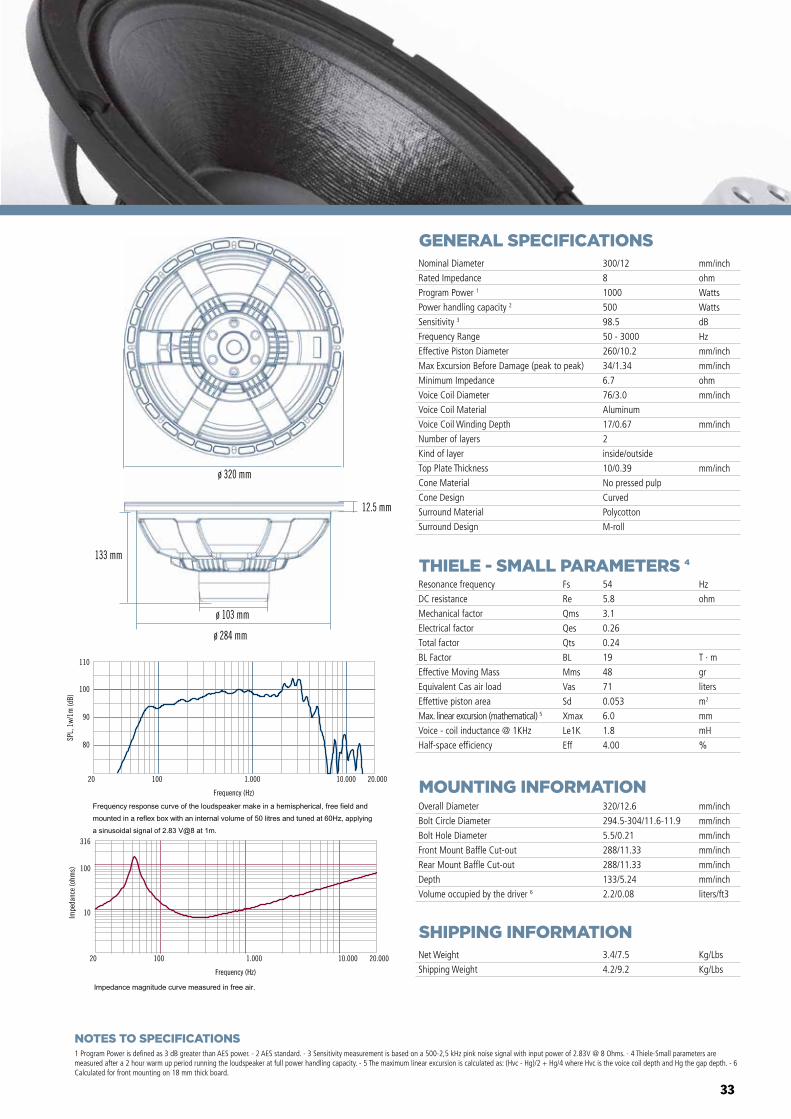
The MB12N301 is a neodymium, high efficiency, 12” mid-bass. High sensitivity, excellent linearity and very high power handling capabilities.The magnetic structure is powered by a large neodymium magnet that provides an extremely high flux density in the gap. The new hyper-vented aluminium basket and magnetic assembly design provide an excellent heat dissipation and lower power compression. Special air-forced ventilations are provided for voice coil, magnet assembly and basket. M-roll surround and spider design offer great linearity and precise reproduction. The waterproof body cone treatment and polycotton surround ensure a durable performance in every application.
The very light moving mass and linear curve response make the MB12N301 the solution for high quality two or three way system. The aluminium voice coil guarantee a very high efficiency in conjunction to a proper Q factor for good bass response.
APPLICATIONS
PART NUMBER 11100071
3.0-inch, fibreglass inside/outside copper voice coil
1000 Watt continuous program power handling
98.5dB Sensitivity
50Hz –3.0KHz Frequency range
Dual-forced air ventilation for minimum power compression
M-roll surround and exponential cone geometry
MB12N301Professional Low Frequency Transducer
MID-BASS
30 3000
20 100 10.000 20.0001.000
33
GENERAL SPECIFICATIONS
THIELE - SMALL PARAMETERS 4
MOUNTING INFORMATION
SHIPPING INFORMATION
1 Program Power is defined as 3 dB greater than AES power. - 2 AES standard. - 3 Sensitivity measurement is based on a 500-2,5 kHz pink noise signal with input power of 2.83V @ 8 Ohms. - 4 Thiele-Small parameters are measured after a 2 hour warm up period running the loudspeaker at full power handling capacity. - 5 The maximum linear excursion is calculated as: (Hvc - Hg)/2 + Hg/4 where Hvc is the voice coil depth and Hg the gap depth. - 6 Calculated for front mounting on 18 mm thick board.
Overall Diameter
Bolt Circle Diameter
Bolt Hole Diameter
Front Mount Baffle Cut-out
Rear Mount Baffle Cut-out
Depth
Volume occupied by the driver 6
320/12.6
294.5-304/11.6-11.9
5.5/0.21
288/11.33
288/11.33
133/5.24
2.2/0.08
mm/inch
mm/inch
mm/inch
mm/inch
mm/inch
mm/inch
liters/ft3
Net Weight
Shipping Weight
3.4/7.5
4.2/9.2
Kg/Lbs
Kg/Lbs
Resonance frequency
DC resistance
Mechanical factor
Electrical factor
Total factor
BL Factor
Effective Moving Mass
Equivalent Cas air load
Effettive piston area
Max. linear excursion (mathematical) 5
Voice - coil inductance @ 1KHz
Half-space efficiency
Hz
ohm
T · m
gr
liters
m2
mm
mH
%
54
5.8
3.1
0.26
0.24
19
48
71
0.053
6.0
1.8
4.00
Fs
Re
Qms
Qes
Qts
BL
Mms
Vas
Sd
Xmax
Le1K
Eff
Nominal Diameter
Rated Impedance
Program Power 1
Power handling capacity 2
Sensitivity 3
Frequency Range
Effective Piston Diameter
Max Excursion Before Damage (peak to peak)
Minimum Impedance
Voice Coil Diameter
Voice Coil Material
Voice Coil Winding Depth
Number of layers
Kind of layer
Top Plate Thickness
Cone Material
Cone Design
Surround Material
Surround Design
300/12
8
1000
500
98.5
50 - 3000
260/10.2
34/1.34
6.7
76/3.0
Aluminum
17/0.67
2
inside/outside
10/0.39
No pressed pulp
Curved
Polycotton
M-roll
mm/inch
ohm
Watts
Watts
dB
Hz
mm/inch
mm/inch
ohm
mm/inch
mm/inch
mm/inch
80
90
100
110
SPL,
1w/
1m (d
B)
Frequency (Hz)
20 100 1.000 10.000 20.000
Frequency (Hz)
20 100 1.000 10.000 20.000
10
100
316
Impe
danc
e (o
hms)
ø 320 mm
133 mm
ø 284 mm
ø 103 mm
12.5 mm
NOTES TO SPECIFICATIONS
34
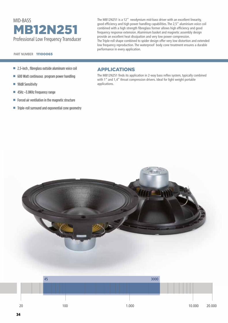
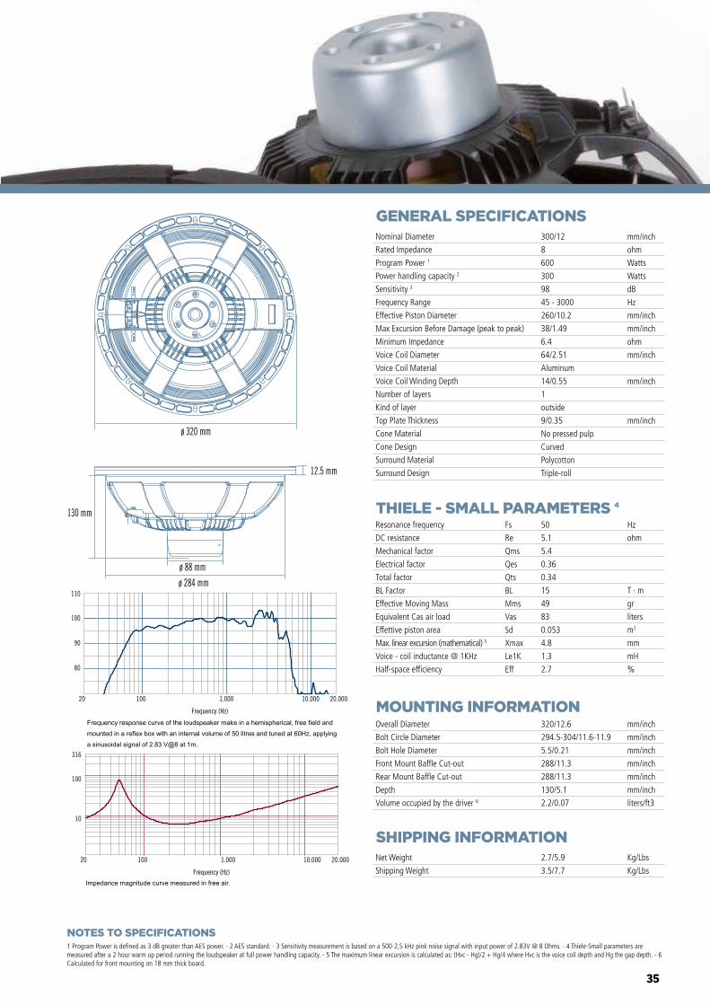
The MB12N251 is a 12” neodymium mid-bass driver with an excellent linearity, good efficiency and high power handling capabilities. The 2,5” aluminium voice coil combined with a high strength fibreglass former allows high efficiency and good frequency response extension. Aluminium basket and magnetic assembly design provide an excellent heat dissipation and very low power compression.The Triple-roll shape combined to spider design offer very low distortion and extended low frequency reproduction. The waterproof body cone treatment ensures a durable performance in every application.
The MB12N251 finds its application in 2-way bass reflex system, typically combined with 1” and 1,4” throat compression drivers. Ideal for light weight portable applications.
APPLICATIONS
PART NUMBER 11100065
2.5-inch , fibreglass outside aluminum voice coil
600 Watt continuous program power handling
98dB Sensitivity
45Hz –3.0KHz Frequency range
Forced air ventilation in the magnetic structure
Triple-roll surround and exponential cone geometry
MB12N251Professional Low Frequency Transducer
MID-BASS
45 3000
20 100 10.000 20.0001.000
35
GENERAL SPECIFICATIONS
THIELE - SMALL PARAMETERS 4
MOUNTING INFORMATION
SHIPPING INFORMATION
1 Program Power is defined as 3 dB greater than AES power. - 2 AES standard. - 3 Sensitivity measurement is based on a 500-2,5 kHz pink noise signal with input power of 2.83V @ 8 Ohms. - 4 Thiele-Small parameters are measured after a 2 hour warm up period running the loudspeaker at full power handling capacity. - 5 The maximum linear excursion is calculated as: (Hvc - Hg)/2 + Hg/4 where Hvc is the voice coil depth and Hg the gap depth. - 6 Calculated for front mounting on 18 mm thick board.
Overall Diameter
Bolt Circle Diameter
Bolt Hole Diameter
Front Mount Baffle Cut-out
Rear Mount Baffle Cut-out
Depth
Volume occupied by the driver 6
320/12.6
294.5-304/11.6-11.9
5.5/0.21
288/11.3
288/11.3
130/5.1
2.2/0.07
mm/inch
mm/inch
mm/inch
mm/inch
mm/inch
mm/inch
liters/ft3
Net Weight
Shipping Weight
2.7/5.9
3.5/7.7
Kg/Lbs
Kg/Lbs
Resonance frequency
DC resistance
Mechanical factor
Electrical factor
Total factor
BL Factor
Effective Moving Mass
Equivalent Cas air load
Effettive piston area
Max. linear excursion (mathematical) 5
Voice - coil inductance @ 1KHz
Half-space efficiency
Hz
ohm
T · m
gr
liters
m2
mm
mH
%
50
5.1
5.4
0.36
0.34
15
49
83
0.053
4.8
1.3
2.7
Fs
Re
Qms
Qes
Qts
BL
Mms
Vas
Sd
Xmax
Le1K
Eff
Nominal Diameter
Rated Impedance
Program Power 1
Power handling capacity 2
Sensitivity 3
Frequency Range
Effective Piston Diameter
Max Excursion Before Damage (peak to peak)
Minimum Impedance
Voice Coil Diameter
Voice Coil Material
Voice Coil Winding Depth
Number of layers
Kind of layer
Top Plate Thickness
Cone Material
Cone Design
Surround Material
Surround Design
300/12
8
600
300
98
45 - 3000
260/10.2
38/1.49
6.4
64/2.51
Aluminum
14/0.55
1
outside
9/0.35
No pressed pulp
Curved
Polycotton
Triple-roll
mm/inch
ohm
Watts
Watts
dB
Hz
mm/inch
mm/inch
ohm
mm/inch
mm/inch
mm/inch
80
90
100
110
SPL,
1w/
1m (d
B)
Frequency (Hz)
20 100 1.000 10.000 20.000
Frequency (Hz)
20 100 1.000 10.000 20.000
10
100
316
Impe
danc
e (o
hms)
ø 320 mm
130 mm
ø 88 mm
ø 284 mm
12.5 mm
NOTES TO SPECIFICATIONS
36
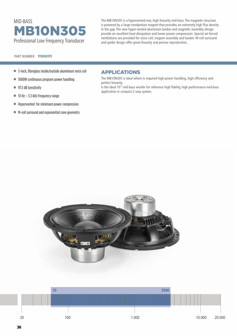
The MB10N305 is a hypervented neo, high linearity mid-bass. The magnetic structure is powered by a large neodymium magnet that provides an extremely high flux density in the gap. The new hyper-vented aluminium basket and magnetic assembly design provide an excellent heat dissipation and lower power compression. Special air-forced ventilations are provided for voice coil, magnet assembly and basket. M-roll surround and spider design offer great linearity and precise reproduction.
The MB10N305 is ideal where is required high power handling, high efficiency and perfect linearity.Is the ideal 10” mid-bass woofer for reference high fidelity, high performance mid-bass application in compact 2 way system.
APPLICATIONS
PART NUMBER 11100111
3-inch, fibreglass inside/outside aluminium voice coil
1000W continuous program power handling
97.5 dB Sensitivity
55 Hz – 3.5 kHz Frequency range
Hypervented for minimum power compression
M-roll surround and exponential cone geometry
MB10N305Professional Low Frequency Transducer
MID-BASS
20 100 10.000 20.0001.000
55 3500
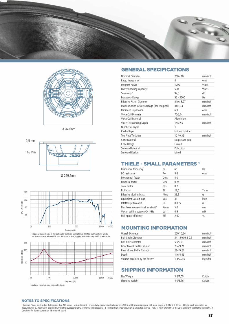
37
GENERAL SPECIFICATIONS
THIELE - SMALL PARAMETERS 4
MOUNTING INFORMATION
SHIPPING INFORMATION
1 Program Power is defined as 3 dB greater than AES power. - 2 AES standard. - 3 Sensitivity measurement is based on a 500-2,5 kHz pink noise signal with input power of 2.83V @ 8 Ohms. - 4 Thiele-Small parameters are measured after a 2 hour warm up period running the loudspeaker at full power handling capacity. - 5 The maximum linear excursion is calculated as: (Hvc - Hg)/2 + Hg/4 where Hvc is the voice coil depth and Hg the gap depth. - 6 Calculated for front mounting on 18 mm thick board.
Overall Diameter
Bolt Circle Diameter
Bolt Hole Diameter
Front Mount Baffle Cut-out
Rear Mount Baffle Cut-out
Depth
Volume occupied by the driver 6
260/10,24
241-246/9,5-9,6
5,5/0,21
234/9,21
234/9,21
116/4,56
1,4/0,046
mm/inch
mm/inch
mm/inch
mm/inch
mm/inch
mm/inch
liters/ft3
Net Weight
Shipping Weight
3,2/7,05
4,0/8,76
Kg/Lbs
Kg/Lbs
Resonance frequency
DC resistance
Mechanical factor
Electrical factor
Total factor
BL Factor
Effective Moving Mass
Equivalent Cas air load
Effettive piston area
Max. linear excursion (mathematical) 5
Voice - coil inductance @ 1KHz
Half-space efficiency
Hz
ohm
T · m
gr
liters
m2
mm
mH
%
60
5,6
4,0
0,24
0,23
18,5
36,5
31
0,035
5,0
0,9
2,90
Fs
Re
Qms
Qes
Qts
BL
Mms
Vas
Sd
Xmax
Le1K
Eff
Nominal Diameter
Rated Impedance
Program Power 1
Power handling capacity 2
Sensitivity 3
Frequency Range
Effective Piston Diameter
Max Excursion Before Damage (peak to peak)
Minimum Impedance
Voice Coil Diameter
Voice Coil Material
Voice Coil Winding Depth
Number of layers
Kind of layer
Top Plate Thickness
Cone Material
Cone Design
Surround Material
Surround Design
260 / 10
8
1000
500
97,5
55 - 3500
210 / 8,27
34/1,34
6,9
76/3,0
Aluminium
14/0,55
1
inside / outside
10 / 0,39
No pressed pulp
Curved
Polycotton
M-roll
mm/inch
ohm
Watts
Watts
dB
Hz
mm/inch
mm/inch
ohm
mm/inch
mm/inch
mm/inch
Impedance magnitude curve measured in free air.
Frequency (Hz)
20 100 1.000 10.000 20.000
10
100
316
Impe
danc
e (o
hms)
Frequency (Hz)
20 100 1.000 10.000 20.000
80
90
100
110
SPL,
1w/
1m (d
B)
Frequency response curve of the loudspeaker made in a hemispherical, free �eld and mounted in a re�ex box with an internal volume of 50 litres and tuned at 60Hz, applying a sinusoidal signal of 2.83 V@8 at 1m.
MB10G251
MB12X301 MB15X301
MB15N405MB12N405
MB10N305
Ø 260 mm
Ø 229,5mm
116 mm
9,5 mm
NOTES TO SPECIFICATIONS
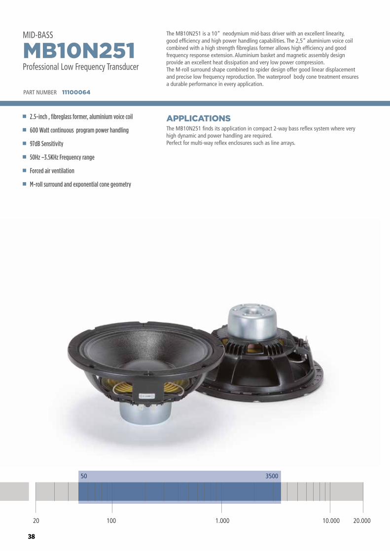
38
The MB10N251 is a 10” neodymium mid-bass driver with an excellent linearity, good efficiency and high power handling capabilities. The 2,5” aluminium voice coil combined with a high strength fibreglass former allows high efficiency and good frequency response extension. Aluminium basket and magnetic assembly design provide an excellent heat dissipation and very low power compression.The M-roll surround shape combined to spider design offer good linear displacement and precise low frequency reproduction. The waterproof body cone treatment ensures a durable performance in every application.
The MB10N251 finds its application in compact 2-way bass reflex system where very high dynamic and power handling are required. Perfect for multi-way reflex enclosures such as line arrays.
APPLICATIONS
PART NUMBER 11100064
2.5-inch , fibreglass former, aluminium voice coil
600 Watt continuous program power handling
97dB Sensitivity
50Hz –3.5KHz Frequency range
Forced air ventilation
M-roll surround and exponential cone geometry
MB10N251Professional Low Frequency Transducer
MID-BASS
20 100 10.000 20.0001.000
50 3500
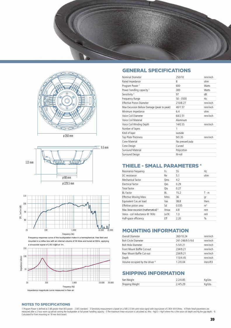
39
GENERAL SPECIFICATIONS
THIELE - SMALL PARAMETERS 4
MOUNTING INFORMATION
SHIPPING INFORMATION
1 Program Power is defined as 3 dB greater than AES power. - 2 AES standard. - 3 Sensitivity measurement is based on a 500-2,5 kHz pink noise signal with input power of 2.83V @ 8 Ohms. - 4 Thiele-Small parameters are measured after a 2 hour warm up period running the loudspeaker at full power handling capacity. - 5 The maximum linear excursion is calculated as: (Hvc - Hg)/2 + Hg/4 where Hvc is the voice coil depth and Hg the gap depth. - 6 Calculated for front mounting on 18 mm thick board.
Overall Diameter
Bolt Circle Diameter
Bolt Hole Diameter
Front Mount Baffle Cut-out
Rear Mount Baffle Cut-out
Depth
Volume occupied by the driver 6
260/10.24
241-246/9.5-9.6
5.5/0.21
234/9.21
234/9.21
113/4.45
1.2/0.04
mm/inch
mm/inch
mm/inch
mm/inch
mm/inch
mm/inch
liters/ft3
Net Weight
Shipping Weight
2.2/4.85
2.4/5.29
Kg/Lbs
Kg/Lbs
Resonance frequency
DC resistance
Mechanical factor
Electrical factor
Total factor
BL Factor
Effective Moving Mass
Equivalent Cas air load
Effettive piston area
Max. linear excursion (mathematical) 5
Voice - coil inductance @ 1KHz
Half-space efficiency
Hz
ohm
T · m
gr
liters
m2
mm
mH
%
55
5.1
4.2
0.29
0.27
15.2
36
38.8
0.035
4.8
1.3
2.20
Fs
Re
Qms
Qes
Qts
BL
Mms
Vas
Sd
Xmax
Le1K
Eff
Nominal Diameter
Rated Impedance
Program Power 1
Power handling capacity 2
Sensitivity 3
Frequency Range
Effective Piston Diameter
Max Excursion Before Damage (peak to peak)
Minimum Impedance
Voice Coil Diameter
Voice Coil Material
Voice Coil Winding Depth
Number of layers
Kind of layer
Top Plate Thickness
Cone Material
Cone Design
Surround Material
Surround Design
250/10
8
600
300
97
50 - 3500
210/8.27
40/1.57
6.4
64/2.51
Aluminum
14/0.55
1
outside
9/0.35
No pressed pulp
Curved
Polycotton
M-roll
mm/inch
ohm
Watts
Watts
dB
Hz
mm/inch
mm/inch
ohm
mm/inch
mm/inch
mm/inch
80
90
100
110
SPL,
1w/
1m (d
B)
Frequency (Hz)
20 100 1.000 10.000 20.000
Frequency (Hz)
20 100 1.000 10.000 20.000
10
100
316
Impe
danc
e (o
hms)
ø 260 mm
113 mm
9.5 mm
ø 229.5 mm
ø 88 mm
NOTES TO SPECIFICATIONS
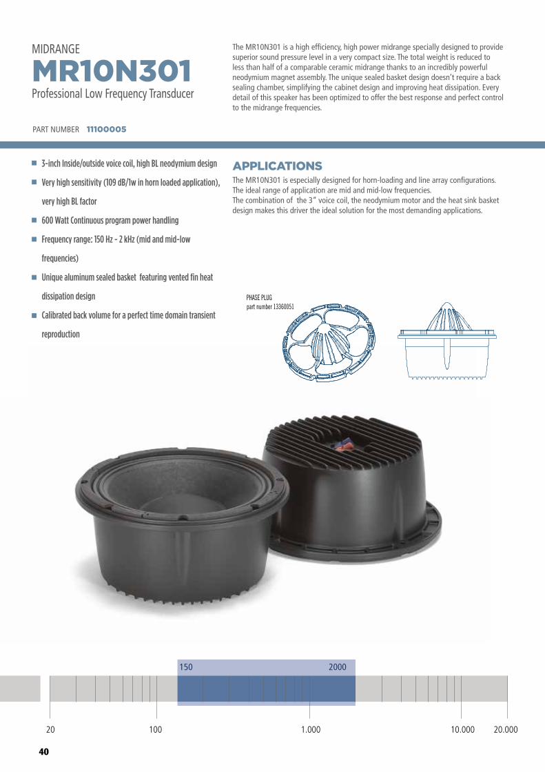
40
The MR10N301 is a high efficiency, high power midrange specially designed to provide superior sound pressure level in a very compact size. The total weight is reduced to less than half of a comparable ceramic midrange thanks to an incredibly powerful neodymium magnet assembly. The unique sealed basket design doesn’t require a back sealing chamber, simplifying the cabinet design and improving heat dissipation. Every detail of this speaker has been optimized to offer the best response and perfect control to the midrange frequencies.
The MR10N301 is especially designed for horn-loading and line array configurations.The ideal range of application are mid and mid-low frequencies.The combination of the 3” voice coil, the neodymium motor and the heat sink basket design makes this driver the ideal solution for the most demanding applications.
APPLICATIONS
PART NUMBER 11100005
3-inch Inside/outside voice coil, high BL neodymium design
Very high sensitivity (109 dB/1w in horn loaded application),
very high BL factor
600 Watt Continuous program power handling
Frequency range: 150 Hz - 2 kHz (mid and mid-low
frequencies)
Unique aluminum sealed basket featuring vented fin heat
dissipation design
Calibrated back volume for a perfect time domain transient
reproduction
MR10N301Professional Low Frequency Transducer
MIDRANGEMIDRANGEMR10N301Professional Low Frequency Transducer
2000150
20 100 1.000 10.000 20.000
PHASE PLUGpart number 13360051
PART NUMBER 11100005
20 100 10.000 20.0001.000
150 2000
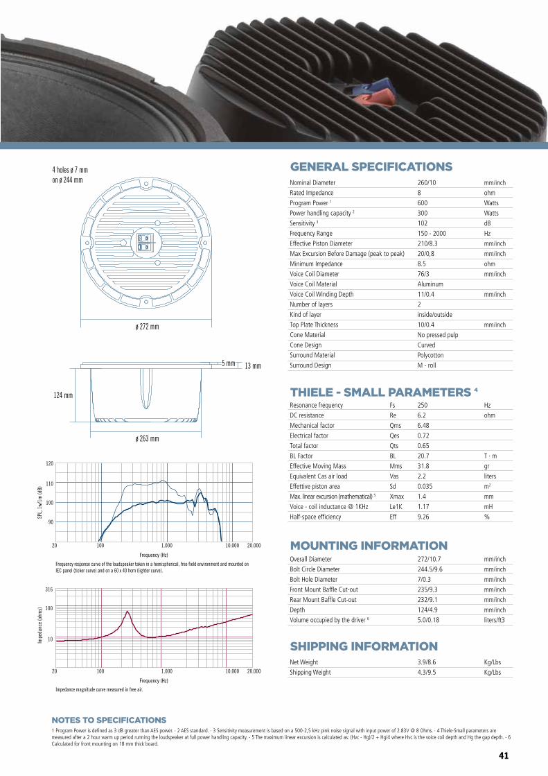
41
GENERAL SPECIFICATIONS
THIELE - SMALL PARAMETERS 4
MOUNTING INFORMATION
SHIPPING INFORMATION
1 Program Power is defined as 3 dB greater than AES power. - 2 AES standard. - 3 Sensitivity measurement is based on a 500-2,5 kHz pink noise signal with input power of 2.83V @ 8 Ohms. - 4 Thiele-Small parameters are measured after a 2 hour warm up period running the loudspeaker at full power handling capacity. - 5 The maximum linear excursion is calculated as: (Hvc - Hg)/2 + Hg/4 where Hvc is the voice coil depth and Hg the gap depth. - 6 Calculated for front mounting on 18 mm thick board.
Overall Diameter
Bolt Circle Diameter
Bolt Hole Diameter
Front Mount Baffle Cut-out
Rear Mount Baffle Cut-out
Depth
Volume occupied by the driver 6
272/10.7
244.5/9.6
7/0.3
235/9.3
232/9.1
124/4.9
5.0/0.18
mm/inch
mm/inch
mm/inch
mm/inch
mm/inch
mm/inch
liters/ft3
Net Weight
Shipping Weight
3.9/8.6
4.3/9.5
Kg/Lbs
Kg/Lbs
Resonance frequency
DC resistance
Mechanical factor
Electrical factor
Total factor
BL Factor
Effective Moving Mass
Equivalent Cas air load
Effettive piston area
Max. linear excursion (mathematical) 5
Voice - coil inductance @ 1KHz
Half-space efficiency
Hz
ohm
T · m
gr
liters
m2
mm
mH
%
250
6.2
6.48
0.72
0.65
20.7
31.8
2.2
0.035
1.4
1.17
9.26
Fs
Re
Qms
Qes
Qts
BL
Mms
Vas
Sd
Xmax
Le1K
Eff
Nominal Diameter
Rated Impedance
Program Power 1
Power handling capacity 2
Sensitivity 3
Frequency Range
Effective Piston Diameter
Max Excursion Before Damage (peak to peak)
Minimum Impedance
Voice Coil Diameter
Voice Coil Material
Voice Coil Winding Depth
Number of layers
Kind of layer
Top Plate Thickness
Cone Material
Cone Design
Surround Material
Surround Design
260/10
8
600
300
102
150 - 2000
210/8.3
20/0,8
8.5
76/3
Aluminum
11/0.4
2
inside/outside
10/0.4
No pressed pulp
Curved
Polycotton
M - roll
mm/inch
ohm
Watts
Watts
dB
Hz
mm/inch
mm/inch
ohm
mm/inch
mm/inch
mm/inch
90
100
110
SPL,
1w/
1m (d
B)
Frequency (Hz)
20 100 1.000 10.000 20.000
Frequency response curve of the loudspeaker taken in a hemispherical, free field environment and mounted on IEC panel (ticker curve) and on a 60 x 40 horn (lighter curve).
Impedance magnitude curve measured in free air.
ø 263 mm
ø 272 mm
124 mm
13 mm
Frequency (Hz)
20 100 1.000 10.000 20.000
10
100
316
Impe
danc
e (o
hms)
120
5 mm
4 holes ø 7 mmon ø 244 mm
NOTES TO SPECIFICATIONS
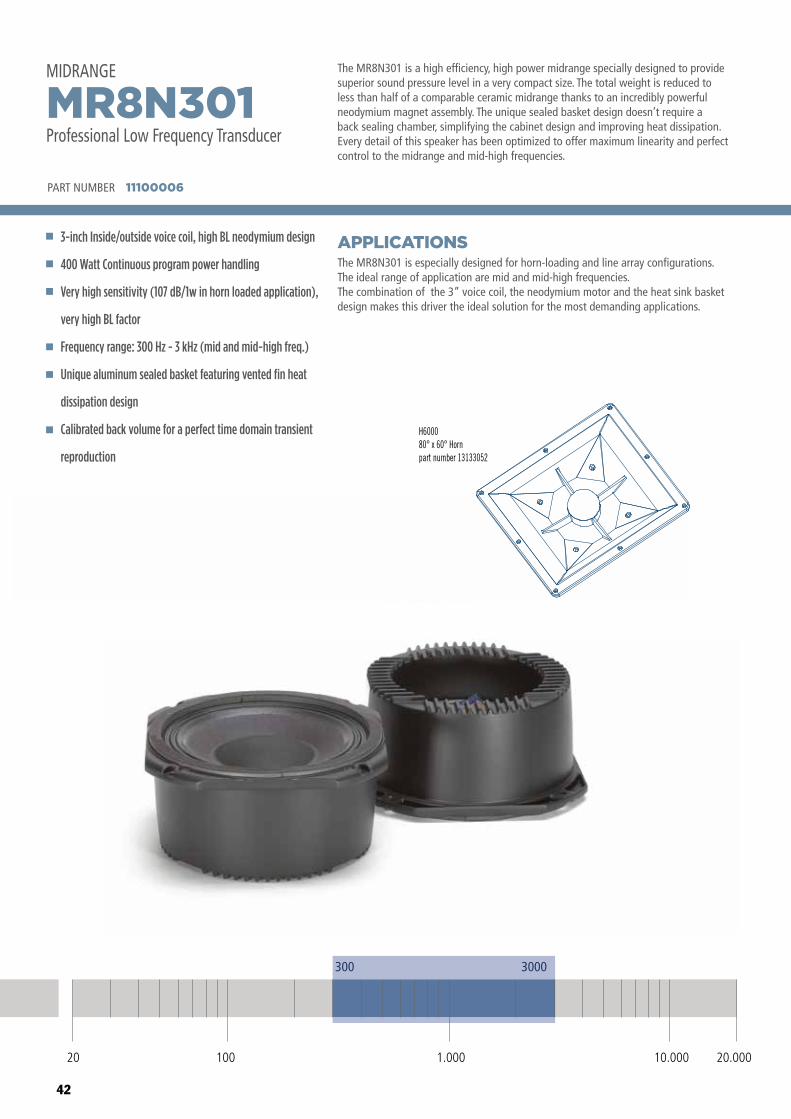
42
The MR8N301 is a high efficiency, high power midrange specially designed to provide superior sound pressure level in a very compact size. The total weight is reduced to less than half of a comparable ceramic midrange thanks to an incredibly powerful neodymium magnet assembly. The unique sealed basket design doesn’t require a back sealing chamber, simplifying the cabinet design and improving heat dissipation. Every detail of this speaker has been optimized to offer maximum linearity and perfect control to the midrange and mid-high frequencies.
The MR8N301 is especially designed for horn-loading and line array configurations.The ideal range of application are mid and mid-high frequencies.The combination of the 3” voice coil, the neodymium motor and the heat sink basket design makes this driver the ideal solution for the most demanding applications.
APPLICATIONS
PART NUMBER 11100006
3-inch Inside/outside voice coil, high BL neodymium design
400 Watt Continuous program power handling
Very high sensitivity (107 dB/1w in horn loaded application),
very high BL factor
Frequency range: 300 Hz - 3 kHz (mid and mid-high freq.)
Unique aluminum sealed basket featuring vented fin heat
dissipation design
Calibrated back volume for a perfect time domain transient
reproduction
MR8N301Professional Low Frequency Transducer
MIDRANGEMIDRANGEMR8N301Professional Low Frequency Transducer
300
20 100 1.000 10.000 20.000
3000
PART NUMBER 11100006
H600080° x 60° Hornpart number 13133052
20 100 10.000 20.0001.000
300 3000
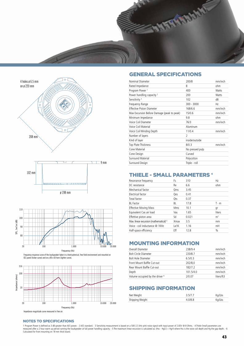
43
GENERAL SPECIFICATIONS
THIELE - SMALL PARAMETERS 4
MOUNTING INFORMATION
SHIPPING INFORMATION
1 Program Power is defined as 3 dB greater than AES power. - 2 AES standard. - 3 Sensitivity measurement is based on a 500-2,5 kHz pink noise signal with input power of 2.83V @ 8 Ohms. - 4 Thiele-Small parameters are measured after a 2 hour warm up period running the loudspeaker at full power handling capacity. - 5 The maximum linear excursion is calculated as: (Hvc - Hg)/2 + Hg/4 where Hvc is the voice coil depth and Hg the gap depth. - 6 Calculated for front mounting on 18 mm thick board.
Overall Diameter
Bolt Circle Diameter
Bolt Hole Diameter
Front Mount Baffle Cut-out
Rear Mount Baffle Cut-out
Depth
Volume occupied by the driver 6
238/9.4
220/8.7
6.5/0.3
202/8,0
182/7.2
101.5/4.0
2/0.07
mm/inch
mm/inch
mm/inch
mm/inch
mm/inch
mm/inch
liters/ft3
Net Weight
Shipping Weight
3.5/7.7
4.0/8.8
Kg/Lbs
Kg/Lbs
Resonance frequency
DC resistance
Mechanical factor
Electrical factor
Total factor
BL Factor
Effective Moving Mass
Equivalent Cas air load
Effettive piston area
Max. linear excursion (mathematical) 5
Voice - coil inductance @ 1KHz
Half-space efficiency
Hz
ohm
T · m
gr
liters
m2
mm
mH
%
310
6.6
3.45
0.41
0.37
17.8
10.1
1.65
0.021
3.5
1.16
12.8
Fs
Re
Qms
Qes
Qts
BL
Mms
Vas
Sd
Xmax
Le1K
Eff
Nominal Diameter
Rated Impedance
Program Power 1
Power handling capacity 2
Sensitivity 3
Frequency Range
Effective Piston Diameter
Max Excursion Before Damage (peak to peak)
Minimum Impedance
Voice Coil Diameter
Voice Coil Material
Voice Coil Winding Depth
Number of layers
Kind of layer
Top Plate Thickness
Cone Material
Cone Design
Surround Material
Surround Design
200/8
8
400
200
102
300 - 3000
168/6.6
15/0.6
9.8
76/3
Aluminum
11/0.4
2
inside/outside
8/0.3
No pressed pulp
Curved
Polycotton
Triple - roll
mm/inch
ohm
Watts
Watts
dB
Hz
mm/inch
mm/inch
ohm
mm/inch
mm/inch
mm/inch
80
90
100
110
SPL,
1w/
1m (d
B)
Frequency (Hz)
20 100 1.000 10.000 20.000
Frequency response curve of the loudspeaker taken in a hemispherical, free field environment and mounted on IEC panel (ticker curve) and on a 80 x 60 horn (lighter curve).
Frequency (Hz)
20 100 1.000 10.000 20.000
10
100
316
Impe
danc
e (o
hms)
Impedance magnitude curve measured in free air.
4 holes ø 6.5 mmon ø 220 mm
ø 198 mm
9 mm
102 mm
208 mm
NOTES TO SPECIFICATIONS
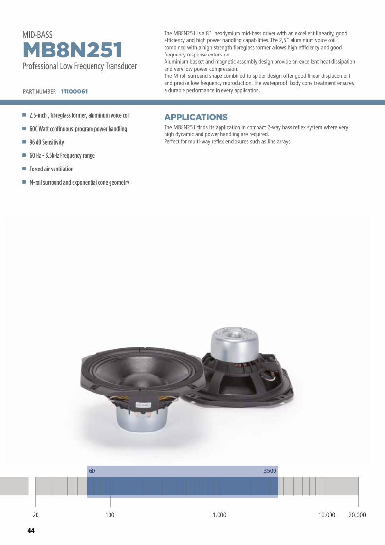
44
The MB8N251 is a 8” neodymium mid-bass driver with an excellent linearity, good efficiency and high power handling capabilities. The 2,5” aluminium voice coil combined with a high strength fibreglass former allows high efficiency and good frequency response extension. Aluminium basket and magnetic assembly design provide an excellent heat dissipation and very low power compression.The M-roll surround shape combined to spider design offer good linear displacement and precise low frequency reproduction. The waterproof body cone treatment ensures a durable performance in every application.
The MB8N251 finds its application in compact 2-way bass reflex system where very high dynamic and power handling are required. Perfect for multi-way reflex enclosures such as line arrays.
APPLICATIONS
PART NUMBER 11100061
2.5-inch , fibreglass former, aluminum voice coil
600 Watt continuous program power handling
96 dB Sensitivity
60 Hz - 3.5kHz Frequency range
Forced air ventilation
M-roll surround and exponential cone geometry
MB8N251Professional Low Frequency Transducer
MID-BASS
20 100 10.000 20.0001.000
60 3500
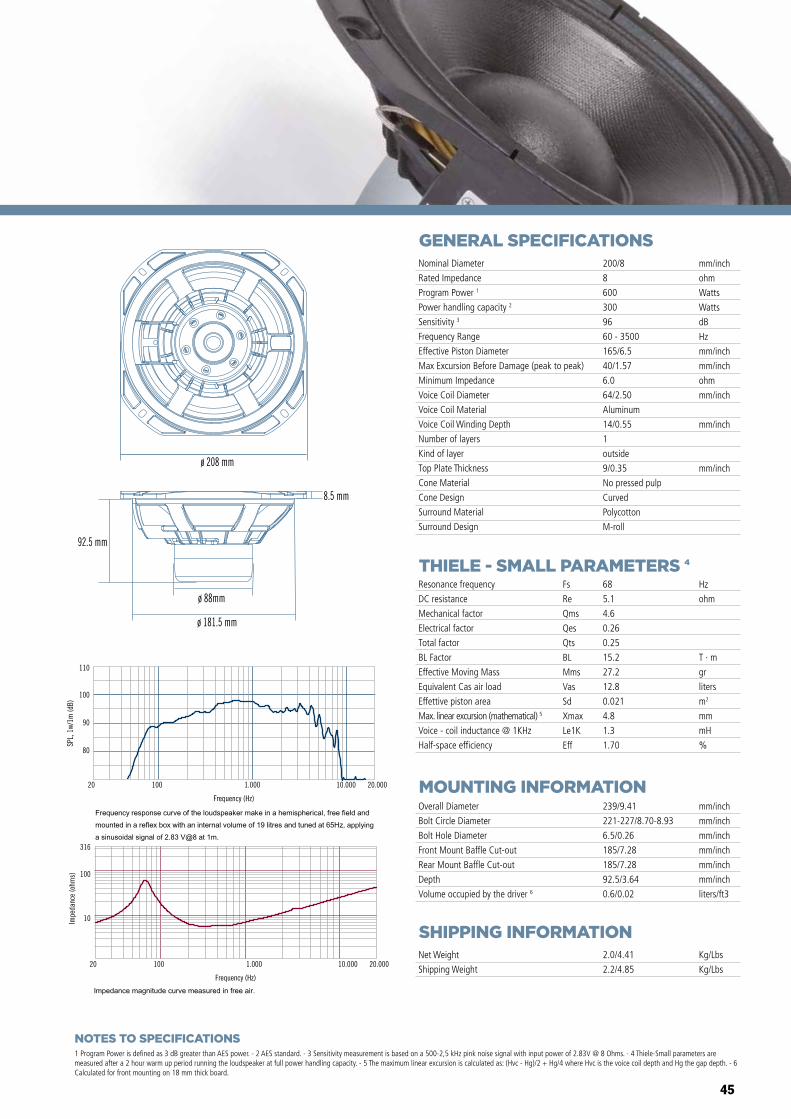
45
NOTES TO SPECIFICATIONS
GENERAL SPECIFICATIONS
THIELE - SMALL PARAMETERS 4
MOUNTING INFORMATION
SHIPPING INFORMATION
1 Program Power is defined as 3 dB greater than AES power. - 2 AES standard. - 3 Sensitivity measurement is based on a 500-2,5 kHz pink noise signal with input power of 2.83V @ 8 Ohms. - 4 Thiele-Small parameters are measured after a 2 hour warm up period running the loudspeaker at full power handling capacity. - 5 The maximum linear excursion is calculated as: (Hvc - Hg)/2 + Hg/4 where Hvc is the voice coil depth and Hg the gap depth. - 6 Calculated for front mounting on 18 mm thick board.
Overall Diameter
Bolt Circle Diameter
Bolt Hole Diameter
Front Mount Baffle Cut-out
Rear Mount Baffle Cut-out
Depth
Volume occupied by the driver 6
239/9.41
221-227/8.70-8.93
6.5/0.26
185/7.28
185/7.28
92.5/3.64
0.6/0.02
mm/inch
mm/inch
mm/inch
mm/inch
mm/inch
mm/inch
liters/ft3
Net Weight
Shipping Weight
2.0/4.41
2.2/4.85
Kg/Lbs
Kg/Lbs
Resonance frequency
DC resistance
Mechanical factor
Electrical factor
Total factor
BL Factor
Effective Moving Mass
Equivalent Cas air load
Effettive piston area
Max. linear excursion (mathematical) 5
Voice - coil inductance @ 1KHz
Half-space efficiency
Hz
ohm
T · m
gr
liters
m2
mm
mH
%
68
5.1
4.6
0.26
0.25
15.2
27.2
12.8
0.021
4.8
1.3
1.70
Fs
Re
Qms
Qes
Qts
BL
Mms
Vas
Sd
Xmax
Le1K
Eff
Nominal Diameter
Rated Impedance
Program Power 1
Power handling capacity 2
Sensitivity 3
Frequency Range
Effective Piston Diameter
Max Excursion Before Damage (peak to peak)
Minimum Impedance
Voice Coil Diameter
Voice Coil Material
Voice Coil Winding Depth
Number of layers
Kind of layer
Top Plate Thickness
Cone Material
Cone Design
Surround Material
Surround Design
200/8
8
600
300
96
60 - 3500
165/6.5
40/1.57
6.0
64/2.50
Aluminum
14/0.55
1
outside
9/0.35
No pressed pulp
Curved
Polycotton
M-roll
mm/inch
ohm
Watts
Watts
dB
Hz
mm/inch
mm/inch
ohm
mm/inch
mm/inch
mm/inch
80
90
100
110
SPL,
1w/
1m (d
B)
Frequency (Hz)
20 100 1.000 10.000 20.000
Frequency (Hz)
20 100 1.000 10.000 20.000
10
100
316
Impe
danc
e (o
hms)
ø 208 mm
8.5 mm
92.5 mm
ø 88mm
ø 181.5 mm
46
TRANSDUCERSLOW FREQUENCY
RCF was the first manufacturer introducing many of the innovations that are now recognised standard in professional transducers, pioneering new solutions, from inside-outside voice coils to dual spider silicon damped designs.
Our range, including several industry milestones, is able to provide innovative tools and solutions for the most demanding speaker manufacturers.
47
MAGNETIC CIRCUITS DESIGNS
DUAL SILICON SPIDERS
PROGRESSIVE SPACED DEMODULATION RINGS
RCF R&D set out to develop magnetic circuits capable of delivering the highest, balanced level of performance in three specific areas; maintenance of a consistent, high integrity magnetic flux, distortion lowering design techniques and efficient integration of the magnetic circuit design within the overall design of the loudspeaker cooling system. Our transducers features a fully optimized magnetic circuit highlighted by a flux maximizing design and a rear plate that provides the lightest possible weight and highest flux efficiency. The design is optimized to generate the minimum amount of flux modulation in the magnetic assembly during typical voice coil movement within the gap.
RCF original dual silicone sealed spider design offers many advantages:- the two spiders offers double resistance to fatigue;- the silicon between the cloth layers, being a very high memory material, provides the best shape stability to the spiders;- the system, being sealed, functions as an air pump expelling hot air and drawing in cool air every time the cone assembly moves.
RCF dual silicon sealed spider design provides to our transducers cooler operating conditions and optimised power compression.
Our top level low frequency transducers feature RCF unique spaced gap demodulation technology designed to dramatically lower distortion artifacts within the loudspeaker’s operating frequency band. This technology assists in progressively braking the voice coil as it reaches its maximum excursion point. This braking effect provides a much quieter, smoother transition for the moving mass as it reaches its maximum excursion limits.
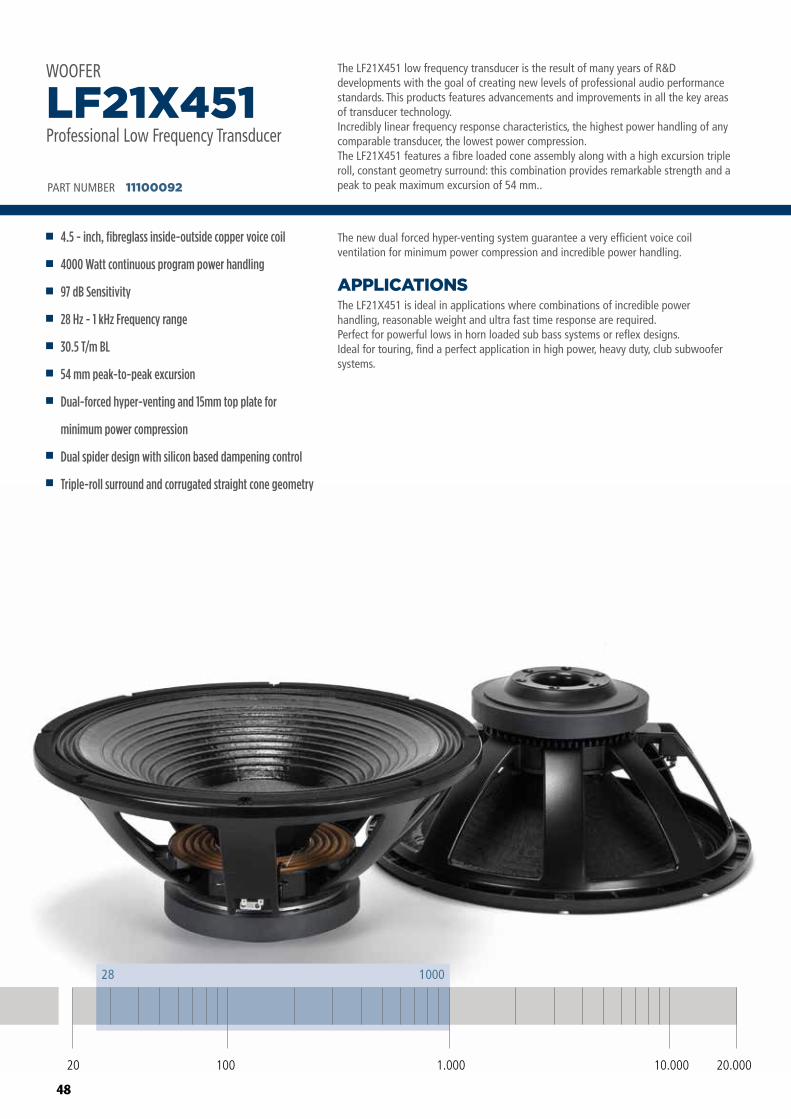
48
The LF21X451 low frequency transducer is the result of many years of R&D developments with the goal of creating new levels of professional audio performance standards. This products features advancements and improvements in all the key areas of transducer technology.Incredibly linear frequency response characteristics, the highest power handling of any comparable transducer, the lowest power compression.The LF21X451 features a fibre loaded cone assembly along with a high excursion triple roll, constant geometry surround: this combination provides remarkable strength and a peak to peak maximum excursion of 54 mm..
The LF21X451 is ideal in applications where combinations of incredible powerhandling, reasonable weight and ultra fast time response are required.Perfect for powerful lows in horn loaded sub bass systems or reflex designs.Ideal for touring, find a perfect application in high power, heavy duty, club subwoofer systems.
APPLICATIONS
The new dual forced hyper-venting system guarantee a very efficient voice coil ventilation for minimum power compression and incredible power handling.
PART NUMBER 11100092
4.5 - inch, fibreglass inside-outside copper voice coil
4000 Watt continuous program power handling
97 dB Sensitivity
28 Hz - 1 kHz Frequency range
30.5 T/m BL
54 mm peak-to-peak excursion
Dual-forced hyper-venting and 15mm top plate for
minimum power compression
Dual spider design with silicon based dampening control
Triple-roll surround and corrugated straight cone geometry
LF21X451Professional Low Frequency Transducer
WOOFER
20 100 10.000 20.0001.000
28 1000
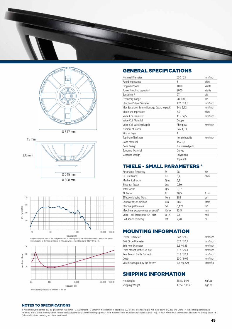
49
NOTES TO SPECIFICATIONS
GENERAL SPECIFICATIONS
THIELE - SMALL PARAMETERS 4
MOUNTING INFORMATION
SHIPPING INFORMATION
1 Program Power is defined as 3 dB greater than AES power. - 2 AES standard. - 3 Sensitivity measurement is based on a 500-2,5 kHz pink noise signal with input power of 2.83V @ 8 Ohms. - 4 Thiele-Small parameters are measured after a 2 hour warm up period running the loudspeaker at full power handling capacity. - 5 The maximum linear excursion is calculated as: (Hvc - Hg)/2 + Hg/4 where Hvc is the voice coil depth and Hg the gap depth. - 6 Calculated for front mounting on 18 mm thick board.
Overall Diameter
Bolt Circle Diameter
Bolt Hole Diameter
Front Mount Baffle Cut-out
Rear Mount Baffle Cut-out
Depth
Volume occupied by the driver 6
547 / 21,5
527 / 20,7
6,5 / 0,25
512 / 20,1
512 / 20,1
230 / 9,05
6,5 / 0,229
mm/inch
mm/inch
mm/inch
mm/inch
mm/inch
mm/inch
liters/ft3
Net Weight
Shipping Weight
15,5 / 34,0
17.59 / 38,77
Kg/Lbs
Kg/Lbs
Resonance frequency
DC resistance
Mechanical factor
Electrical factor
Total factor
BL Factor
Effective Moving Mass
Equivalent Cas air load
Effettive piston area
Max. linear excursion (mathematical) 5
Voice - coil inductance @ 1KHz
Half-space efficiency
Hz
ohm
T · m
gr
liters
m2
mm
mH
%
28
5,4
6,9
0,39
0,37
30,5
355
385
0,173
13,5
2,8
2,20
Fs
Re
Qms
Qes
Qts
BL
Mms
Vas
Sd
Xmax
Le1K
Eff
Nominal Diameter
Rated Impedance
Program Power 1
Power handling capacity 2
Sensitivity 3
Frequency Range
Effective Piston Diameter
Max Excursion Before Damage (peak to peak)
Minimum Impedance
Voice Coil Diameter
Voice Coil Material
Voice Coil Winding Depth
Number of layers
Kind of layer
Top Plate Thickness
Cone Material
Cone Design
Surround Material
Surround Design
530 / 21
8
4000
2000
97
28-1000
470 / 18,5
54 / 2,12
6,7
115 / 4,5
Copper
fiberglass
34 / 1,33
2
inside/outside
15 / 0,6
No pressed pulp
Curved
Polycotton
Triple roll
mm/inch
ohm
Watts
Watts
dB
Hz
mm/inch
mm/inch
ohm
mm/inch
mm/inch
mm/inch
Impedance magnitude curve measured in free air.
Frequency (Hz)
20 100 1.000 10.000 20.000
10
100
316
Impe
danc
e (o
hms)
Frequency (Hz)
20 100 1.000 10.000 20.000
Frequency response curve of the loudspeaker taken in a hemispherical, free �eld environment and mounted in a closed box with an internal volume of 600 litres (21,2 cu.ft) enclosing the rear of the driver.
80
90
100
110
SPL,
1w/
1m (d
B)
LF21X451 LF18X451
Ø 547 mm
Ø 245 mm
Ø 508 mm
230 mm
15 mm
Frequency response curve of the loudspeaker make in a hemispherical, free field and mounted in a reflex box with an internal volume of 250 litres and tuned at 40Hz, applying a sinusoidal signal of 2.83 V @8 at 1m.
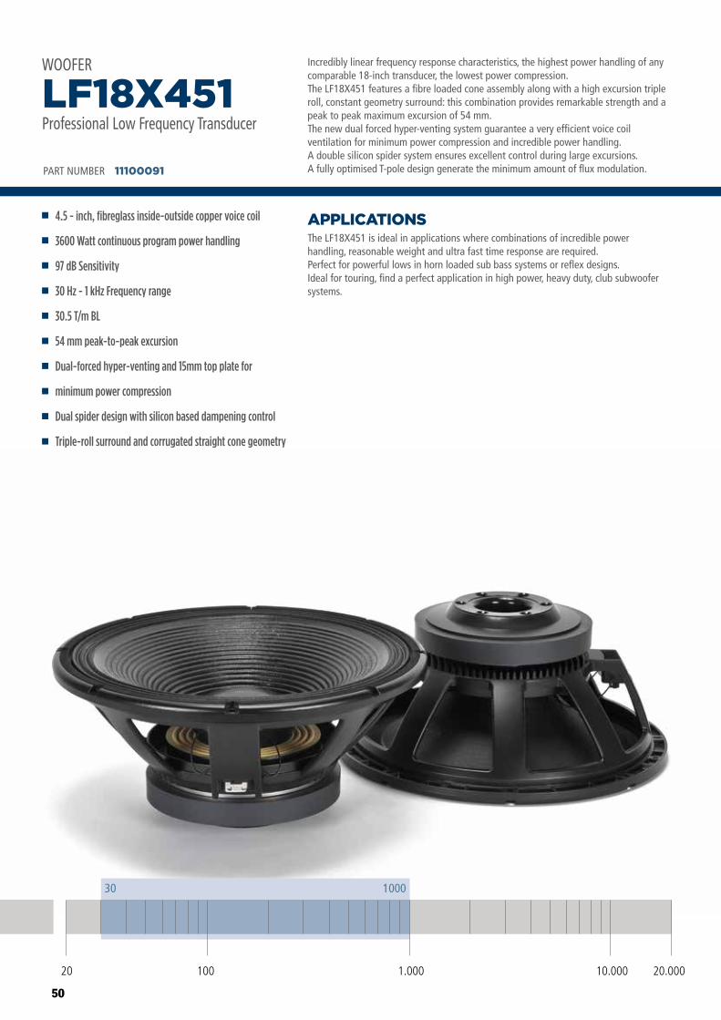
50
Incredibly linear frequency response characteristics, the highest power handling of any comparable 18-inch transducer, the lowest power compression. The LF18X451 features a fibre loaded cone assembly along with a high excursion triple roll, constant geometry surround: this combination provides remarkable strength and a peak to peak maximum excursion of 54 mm.The new dual forced hyper-venting system guarantee a very efficient voice coil ventilation for minimum power compression and incredible power handling.A double silicon spider system ensures excellent control during large excursions.A fully optimised T-pole design generate the minimum amount of flux modulation.
The LF18X451 is ideal in applications where combinations of incredible powerhandling, reasonable weight and ultra fast time response are required.Perfect for powerful lows in horn loaded sub bass systems or reflex designs.Ideal for touring, find a perfect application in high power, heavy duty, club subwoofer systems.
APPLICATIONS
PART NUMBER 11100091
4.5 - inch, fibreglass inside-outside copper voice coil
3600 Watt continuous program power handling
97 dB Sensitivity
30 Hz - 1 kHz Frequency range
30.5 T/m BL
54 mm peak-to-peak excursion
Dual-forced hyper-venting and 15mm top plate for
minimum power compression
Dual spider design with silicon based dampening control
Triple-roll surround and corrugated straight cone geometry
LF18X451Professional Low Frequency Transducer
WOOFER
20 100 10.000 20.0001.000
30 1000
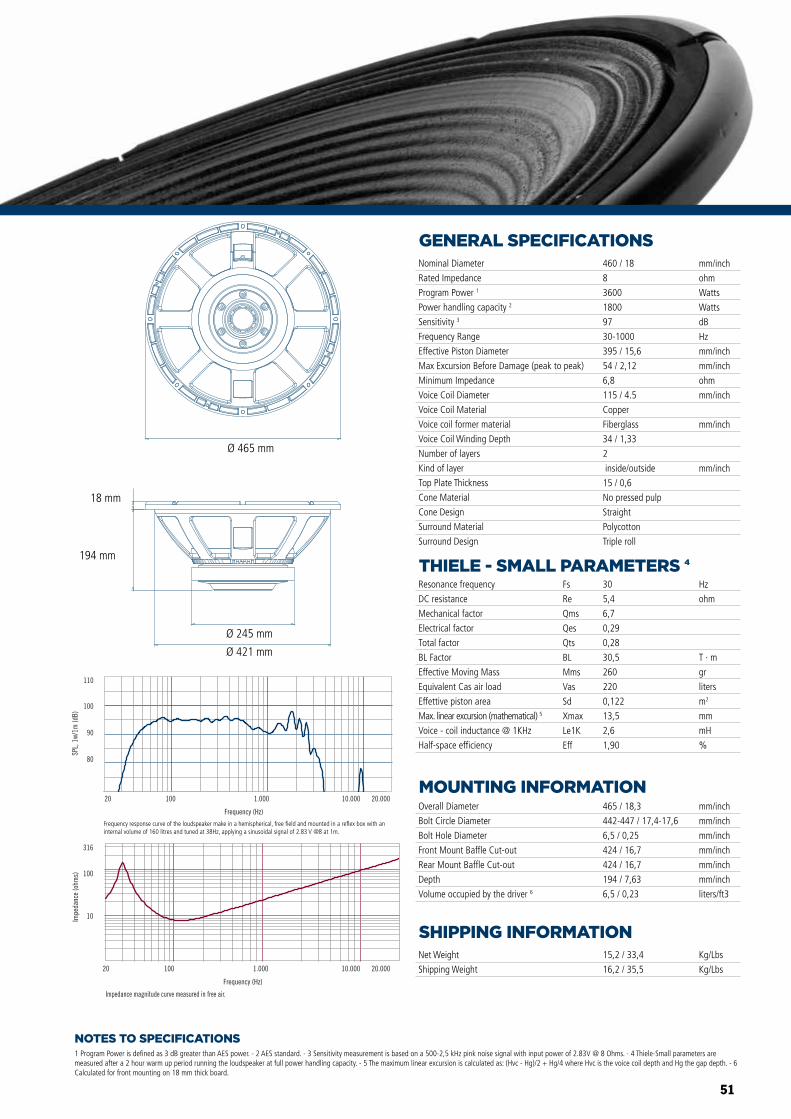
51
NOTES TO SPECIFICATIONS
GENERAL SPECIFICATIONS
THIELE - SMALL PARAMETERS 4
MOUNTING INFORMATION
SHIPPING INFORMATION
1 Program Power is defined as 3 dB greater than AES power. - 2 AES standard. - 3 Sensitivity measurement is based on a 500-2,5 kHz pink noise signal with input power of 2.83V @ 8 Ohms. - 4 Thiele-Small parameters are measured after a 2 hour warm up period running the loudspeaker at full power handling capacity. - 5 The maximum linear excursion is calculated as: (Hvc - Hg)/2 + Hg/4 where Hvc is the voice coil depth and Hg the gap depth. - 6 Calculated for front mounting on 18 mm thick board.
Overall Diameter
Bolt Circle Diameter
Bolt Hole Diameter
Front Mount Baffle Cut-out
Rear Mount Baffle Cut-out
Depth
Volume occupied by the driver 6
465 / 18,3
442-447 / 17,4-17,6
6,5 / 0,25
424 / 16,7
424 / 16,7
194 / 7,63
6,5 / 0,23
mm/inch
mm/inch
mm/inch
mm/inch
mm/inch
mm/inch
liters/ft3
Net Weight
Shipping Weight
15,2 / 33,4
16,2 / 35,5
Kg/Lbs
Kg/Lbs
Resonance frequency
DC resistance
Mechanical factor
Electrical factor
Total factor
BL Factor
Effective Moving Mass
Equivalent Cas air load
Effettive piston area
Max. linear excursion (mathematical) 5
Voice - coil inductance @ 1KHz
Half-space efficiency
Hz
ohm
T · m
gr
liters
m2
mm
mH
%
30
5,4
6,7
0,29
0,28
30,5
260
220
0,122
13,5
2,6
1,90
Fs
Re
Qms
Qes
Qts
BL
Mms
Vas
Sd
Xmax
Le1K
Eff
Nominal Diameter
Rated Impedance
Program Power 1
Power handling capacity 2
Sensitivity 3
Frequency Range
Effective Piston Diameter
Max Excursion Before Damage (peak to peak)
Minimum Impedance
Voice Coil Diameter
Voice Coil Material
Voice coil former material
Voice Coil Winding Depth
Number of layers
Kind of layer
Top Plate Thickness
Cone Material
Cone Design
Surround Material
Surround Design
460 / 18
8
3600
1800
97
30-1000
395 / 15,6
54 / 2,12
6,8
115 / 4.5
Copper
Fiberglass
34 / 1,33
2
inside/outside
15 / 0,6
No pressed pulp
Straight
Polycotton
Triple roll
mm/inch
ohm
Watts
Watts
dB
Hz
mm/inch
mm/inch
ohm
mm/inch
mm/inch
mm/inch
Impedance magnitude curve measured in free air.
Frequency (Hz)
20 100 1.000 10.000 20.000
10
100
316
Impe
danc
e (o
hms)
Frequency (Hz)
20 100 1.000 10.000 20.000
Frequency response curve of the loudspeaker taken in a hemispherical, free �eld environment and mounted in a closed box with an internal volume of 600 litres (21,2 cu.ft) enclosing the rear of the driver.
80
90
100
110
SPL,
1w/
1m (d
B)
LF21X451 LF18X451
Ø 465 mm
Ø 245 mm
Ø 421 mm
194 mm
18 mm
Frequency response curve of the loudspeaker make in a hemispherical, free field and mounted in a reflex box with an internal volume of 160 litres and tuned at 38Hz, applying a sinusoidal signal of 2.83 V @8 at 1m.
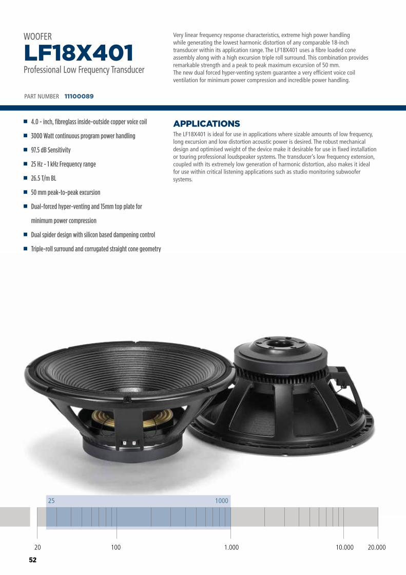
52
Very linear frequency response characteristics, extreme high power handlingwhile generating the lowest harmonic distortion of any comparable 18-inchtransducer within its application range. The LF18X401 uses a fibre loaded coneassembly along with a high excursion triple roll surround. This combination providesremarkable strength and a peak to peak maximum excursion of 50 mm. The new dual forced hyper-venting system guarantee a very efficient voice coil ventilation for minimum power compression and incredible power handling.
The LF18X401 is ideal for use in applications where sizable amounts of low frequency, long excursion and low distortion acoustic power is desired. The robust mechanical design and optimised weight of the device make it desirable for use in fixed installation or touring professional loudspeaker systems. The transducer’s low frequency extension, coupled with its extremely low generation of harmonic distortion, also makes it ideal for use within critical listening applications such as studio monitoring subwoofer systems.
APPLICATIONS
PART NUMBER 11100089
4.0 - inch, fibreglass inside-outside copper voice coil
3000 Watt continuous program power handling
97.5 dB Sensitivity
25 Hz - 1 kHz Frequency range
26.5 T/m BL
50 mm peak-to-peak excursion
Dual-forced hyper-venting and 15mm top plate for
minimum power compression
Dual spider design with silicon based dampening control
Triple-roll surround and corrugated straight cone geometry
LF18X401Professional Low Frequency Transducer
WOOFER
20 100 10.000 20.0001.000
25 1000
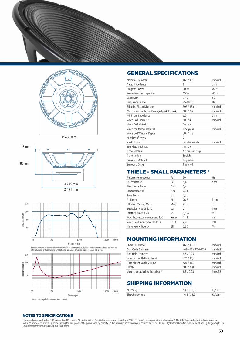
53
NOTES TO SPECIFICATIONS
GENERAL SPECIFICATIONS
THIELE - SMALL PARAMETERS 4
MOUNTING INFORMATION
SHIPPING INFORMATION
1 Program Power is defined as 3 dB greater than AES power. - 2 AES standard. - 3 Sensitivity measurement is based on a 500-2,5 kHz pink noise signal with input power of 2.83V @ 8 Ohms. - 4 Thiele-Small parameters are measured after a 2 hour warm up period running the loudspeaker at full power handling capacity. - 5 The maximum linear excursion is calculated as: (Hvc - Hg)/2 + Hg/4 where Hvc is the voice coil depth and Hg the gap depth. - 6 Calculated for front mounting on 18 mm thick board.
Overall Diameter
Bolt Circle Diameter
Bolt Hole Diameter
Front Mount Baffle Cut-out
Rear Mount Baffle Cut-out
Depth
Volume occupied by the driver 6
465 / 18,3
442-447 / 17,4-17,6
6,5 / 0,25
424 / 16,7
425 / 16,7
188 / 7.40
6,5 / 0,23
mm/inch
mm/inch
mm/inch
mm/inch
mm/inch
mm/inch
liters/ft3
Net Weight
Shipping Weight
13,3 / 29,3
14,3 / 31,5
Kg/Lbs
Kg/Lbs
Resonance frequency
DC resistance
Mechanical factor
Electrical factor
Total factor
BL Factor
Effective Moving Mass
Equivalent Cas air load
Effettive piston area
Max. linear excursion (mathematical) 5
Voice - coil inductance @ 1KHz
Half-space efficiency
Hz
ohm
T · m
gr
liters
m2
mm
mH
%
30
5,4
7,4
0,31
0,30
26,5
215
274
0,122
11,5
2,4
2,30
Fs
Re
Qms
Qes
Qts
BL
Mms
Vas
Sd
Xmax
Le1K
Eff
Nominal Diameter
Rated Impedance
Program Power 1
Power handling capacity 2
Sensitivity 3
Frequency Range
Effective Piston Diameter
Max Excursion Before Damage (peak to peak)
Minimum Impedance
Voice Coil Diameter
Voice Coil Material
Voice coil former material
Voice Coil Winding Depth
Number of layers
Kind of layer
Top Plate Thickness
Cone Material
Cone Design
Surround Material
Surround Design
460 / 18
8
3000
1500
97,5
25-1000
395 / 15,6
50 / 1,97
6,5
100 / 4
Copper
Fiberglass
30 / 1,18
2
inside/outside
15 / 0,6
No pressed pulp
Straight
Polycotton
Triple roll
mm/inch
ohm
Watts
Watts
dB
Hz
mm/inch
mm/inch
ohm
mm/inch
mm/inch
mm/inch
Impedance magnitude curve measured in free air.
Frequency (Hz)
20 100 1.000 10.000 20.000
10
100
316
Impe
danc
e (o
hms)
Frequency (Hz)
20 100 1.000 10.000 20.000
Frequency response curve of the loudspeaker taken in a hemispherical, free �eld environment and mounted in a closed box with an internal volume of 600 litres (21,2 cu.ft) enclosing the rear of the driver.
80
90
100
110
SPL,
1w/
1m (d
B)
Impedance magnitude curve measured in free air.
Frequency (Hz)
20 100 1.000 10.000 20.000
10
100
316
Impe
danc
e (o
hms)
Frequency (Hz)
20 100 1.000 10.000 20.000
Frequency response curve of the loudspeaker taken in a hemispherical, free �eld environment and mounted in a closed box with an internal volume of 600 litres (21,2 cu.ft) enclosing the rear of the driver.
80
90
100
110
SPL,
1w/
1m (d
B)
LF18X401 LF15X401 LF12X401
Ø 465 mm
Ø 245 mm
Ø 421 mm
188 mm
18 mm
Frequency response curve of the loudspeaker make in a hemispherical, free field and mounted in a reflex box with an internal volume of 160 litres and tuned at 38Hz, applying a sinusoidal signal of 2.83 V @8 at 1m.
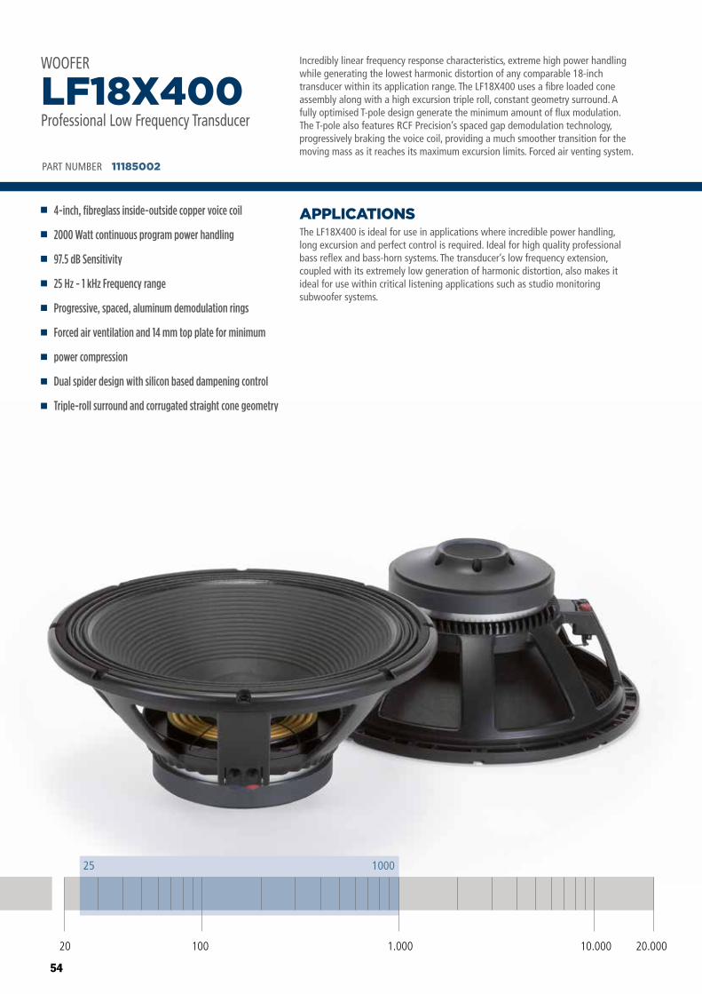
54
Incredibly linear frequency response characteristics, extreme high power handlingwhile generating the lowest harmonic distortion of any comparable 18-inchtransducer within its application range. The LF18X400 uses a fibre loaded coneassembly along with a high excursion triple roll, constant geometry surround. Afully optimised T-pole design generate the minimum amount of flux modulation.The T-pole also features RCF Precision’s spaced gap demodulation technology,progressively braking the voice coil, providing a much smoother transition for themoving mass as it reaches its maximum excursion limits. Forced air venting system.
The LF18X400 is ideal for use in applications where incredible power handling,long excursion and perfect control is required. Ideal for high quality professionalbass reflex and bass-horn systems. The transducer’s low frequency extension,coupled with its extremely low generation of harmonic distortion, also makes itideal for use within critical listening applications such as studio monitoringsubwoofer systems.
APPLICATIONS
PART NUMBER 11185002
4-inch, fibreglass inside-outside copper voice coil
2000 Watt continuous program power handling
97.5 dB Sensitivity
25 Hz - 1 kHz Frequency range
Progressive, spaced, aluminum demodulation rings
Forced air ventilation and 14 mm top plate for minimum
power compression
Dual spider design with silicon based dampening control
Triple-roll surround and corrugated straight cone geometry
LF18X400Professional Low Frequency Transducer
WOOFER
20 100 10.000 20.0001.000
25 1000
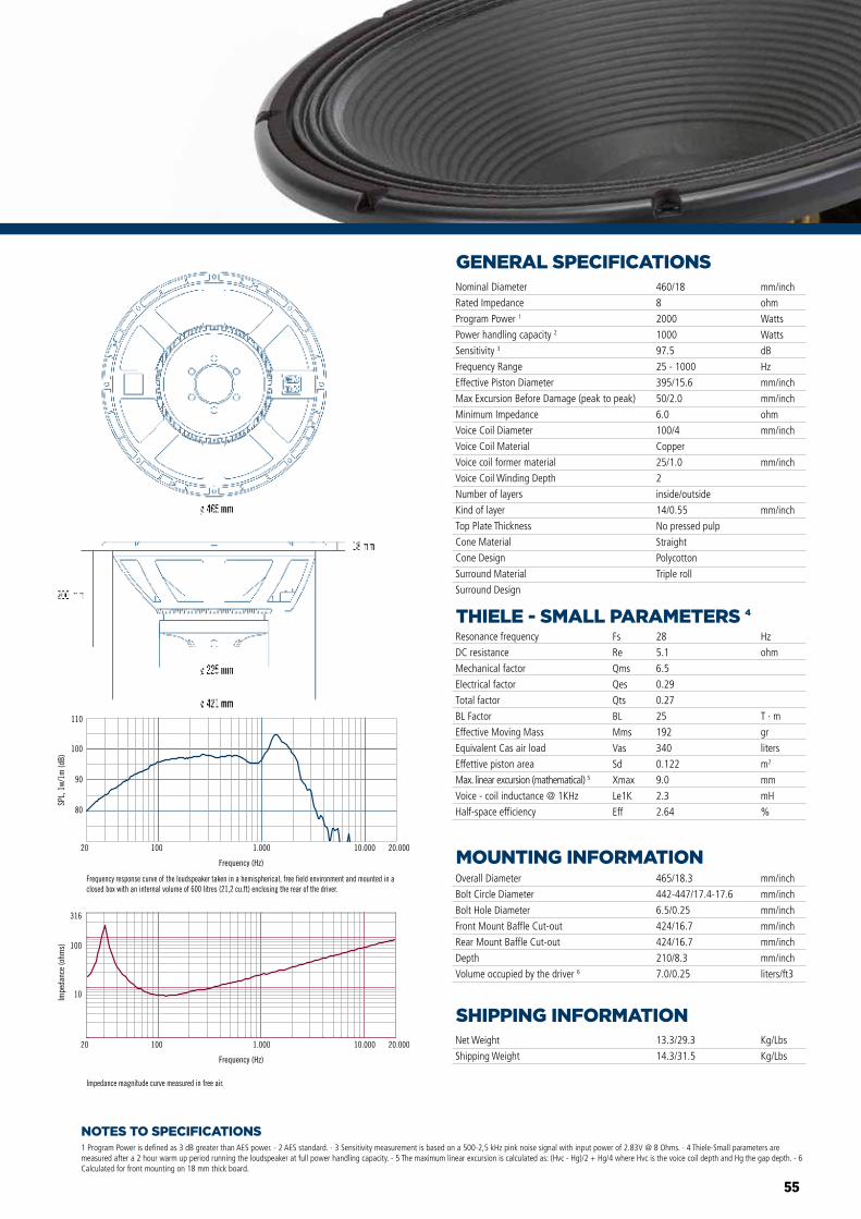
55
NOTES TO SPECIFICATIONS
GENERAL SPECIFICATIONS
THIELE - SMALL PARAMETERS 4
MOUNTING INFORMATION
SHIPPING INFORMATION
1 Program Power is defined as 3 dB greater than AES power. - 2 AES standard. - 3 Sensitivity measurement is based on a 500-2,5 kHz pink noise signal with input power of 2.83V @ 8 Ohms. - 4 Thiele-Small parameters are measured after a 2 hour warm up period running the loudspeaker at full power handling capacity. - 5 The maximum linear excursion is calculated as: (Hvc - Hg)/2 + Hg/4 where Hvc is the voice coil depth and Hg the gap depth. - 6 Calculated for front mounting on 18 mm thick board.
Overall Diameter
Bolt Circle Diameter
Bolt Hole Diameter
Front Mount Baffle Cut-out
Rear Mount Baffle Cut-out
Depth
Volume occupied by the driver 6
465/18.3
442-447/17.4-17.6
6.5/0.25
424/16.7
424/16.7
210/8.3
7.0/0.25
mm/inch
mm/inch
mm/inch
mm/inch
mm/inch
mm/inch
liters/ft3
Net Weight
Shipping Weight
13.3/29.3
14.3/31.5
Kg/Lbs
Kg/Lbs
Resonance frequency
DC resistance
Mechanical factor
Electrical factor
Total factor
BL Factor
Effective Moving Mass
Equivalent Cas air load
Effettive piston area
Max. linear excursion (mathematical) 5
Voice - coil inductance @ 1KHz
Half-space efficiency
Hz
ohm
T · m
gr
liters
m2
mm
mH
%
28
5.1
6.5
0.29
0.27
25
192
340
0.122
9.0
2.3
2.64
Fs
Re
Qms
Qes
Qts
BL
Mms
Vas
Sd
Xmax
Le1K
Eff
Nominal Diameter
Rated Impedance
Program Power 1
Power handling capacity 2
Sensitivity 3
Frequency Range
Effective Piston Diameter
Max Excursion Before Damage (peak to peak)
Minimum Impedance
Voice Coil Diameter
Voice Coil Material
Voice coil former material
Voice Coil Winding Depth
Number of layers
Kind of layer
Top Plate Thickness
Cone Material
Cone Design
Surround Material
Surround Design
460/18
8
2000
1000
97.5
25 - 1000
395/15.6
50/2.0
6.0
100/4
Copper
25/1.0
2
inside/outside
14/0.55
No pressed pulp
Straight
Polycotton
Triple roll
mm/inch
ohm
Watts
Watts
dB
Hz
mm/inch
mm/inch
ohm
mm/inch
mm/inch
mm/inch
Impedance magnitude curve measured in free air.
Frequency response curve of the loudspeaker taken in a hemispherical, free field environment and mounted in a closed box with an internal volume of 600 litres (21,2 cu.ft) enclosing the rear of the driver.
Frequency (Hz)
20 100 1.000 10.000 20.000
10
100
316
Impe
danc
e (o
hms)
80
90
100
110
SPL,
1w/
1m (d
B)
Frequency (Hz)
20 100 1.000 10.000 20.000
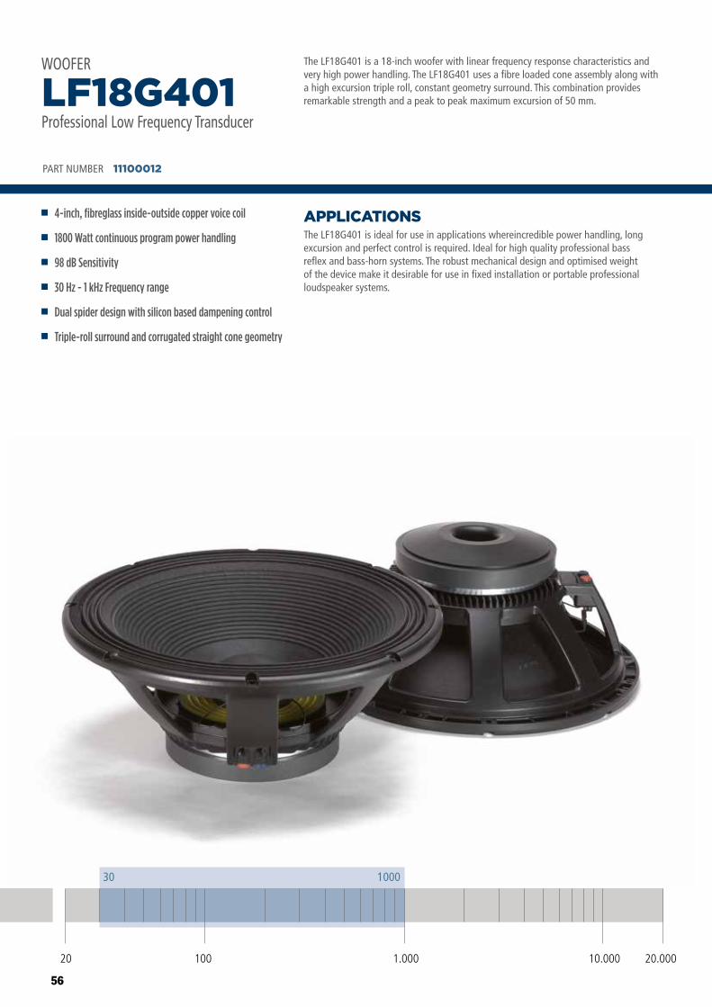
56
The LF18G401 is a 18-inch woofer with linear frequency response characteristics and very high power handling. The LF18G401 uses a fibre loaded cone assembly along with a high excursion triple roll, constant geometry surround. This combination provides remarkable strength and a peak to peak maximum excursion of 50 mm.
The LF18G401 is ideal for use in applications whereincredible power handling, long excursion and perfect control is required. Ideal for high quality professional bass reflex and bass-horn systems. The robust mechanical design and optimised weight of the device make it desirable for use in fixed installation or portable professional loudspeaker systems.
APPLICATIONS
PART NUMBER 11100012
4-inch, fibreglass inside-outside copper voice coil
1800 Watt continuous program power handling
98 dB Sensitivity
30 Hz - 1 kHz Frequency range
Dual spider design with silicon based dampening control
Triple-roll surround and corrugated straight cone geometry
LF18G401Professional Low Frequency Transducer
WOOFER
20 100 10.000 20.0001.000
30 1000
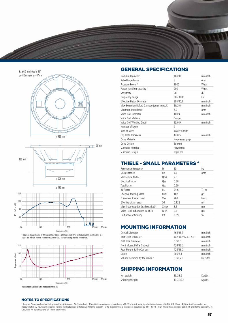
57
NOTES TO SPECIFICATIONS
GENERAL SPECIFICATIONS
THIELE - SMALL PARAMETERS 4
MOUNTING INFORMATION
SHIPPING INFORMATION
1 Program Power is defined as 3 dB greater than AES power. - 2 AES standard. - 3 Sensitivity measurement is based on a 500-2,5 kHz pink noise signal with input power of 2.83V @ 8 Ohms. - 4 Thiele-Small parameters are measured after a 2 hour warm up period running the loudspeaker at full power handling capacity. - 5 The maximum linear excursion is calculated as: (Hvc - Hg)/2 + Hg/4 where Hvc is the voice coil depth and Hg the gap depth. - 6 Calculated for front mounting on 18 mm thick board.
Overall Diameter
Bolt Circle Diameter
Bolt Hole Diameter
Front Mount Baffle Cut-out
Rear Mount Baffle Cut-out
Depth
Volume occupied by the driver 6
465/18.3
442-447/17.4-17.6
6.5/0.3
424/16.7
424/16.7
205/8.1
6.0/0.21
mm/inch
mm/inch
mm/inch
mm/inch
mm/inch
mm/inch
liters/ft3
Net Weight
Shipping Weight
13/28.9
13.7/30.4
Kg/Lbs
Kg/Lbs
Resonance frequency
DC resistance
Mechanical factor
Electrical factor
Total factor
BL Factor
Effective Moving Mass
Equivalent Cas air load
Effettive piston area
Max. linear excursion (mathematical) 5
Voice - coil inductance @ 1KHz
Half-space efficiency
Hz
ohm
T · m
gr
liters
m2
mm
mH
%
33
4.8
7.6
0.30
0.29
24.6
182
268
0.122
8.5
2.4
3.09
Fs
Re
Qms
Qes
Qts
BL
Mms
Vas
Sd
Xmax
Le1K
Eff
Nominal Diameter
Rated Impedance
Program Power 1
Power handling capacity 2
Sensitivity 3
Frequency Range
Effective Piston Diameter
Max Excursion Before Damage (peak to peak)
Minimum Impedance
Voice Coil Diameter
Voice Coil Material
Voice Coil Winding Depth
Number of layers
Kind of layer
Top Plate Thickness
Cone Material
Cone Design
Surround Material
Surround Design
460/18
8
1800
900
98
30 - 1000
395/15,6
50/2.0
5,9
100/4
Copper
23/0.9
2
inside/outside
12/0.5
No pressed pulp
Straight
Polycotton
Triple roll
mm/inch
ohm
Watts
Watts
dB
Hz
mm/inch
mm/inch
ohm
mm/inch
mm/inch
mm/inch
80
90
100
110
SPL,
1w/
1m (d
B)
Frequency (Hz)
20 100 1.000 10.000 20.000
Frequency response curve of the loudspeaker taken in a hemispherical, free field environment and mounted in a closed box with an internal volume of 600 litres (21,2 cu.ft) enclosing the rear of the driver.
Frequency (Hz)
20 100 1.000 10.000 20.000
10
100
316
Impe
danc
e (o
hms)
Impedance magnitude curve measured in free air.
ø 465 mm
ø 421 mm
18 mm
188 mm
ø 225 mm
8 x ø 6.5 mm holes to 45°on 442 mm and on 447mm
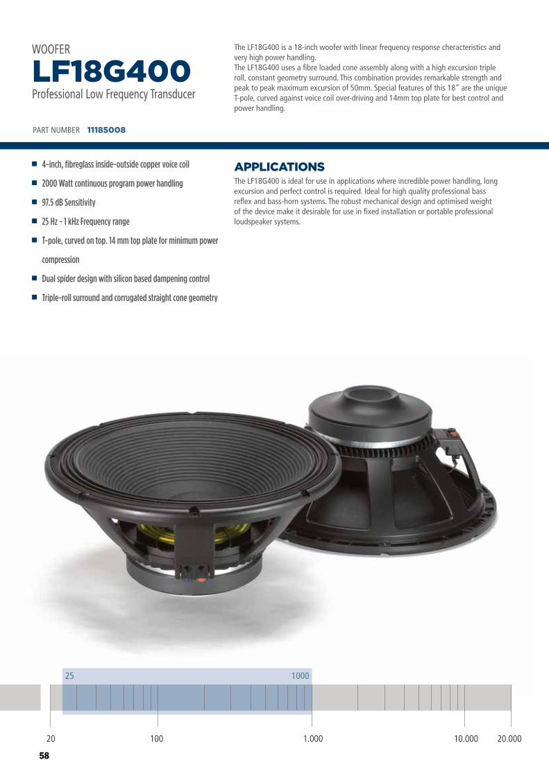
58
The LF18G400 is a 18-inch woofer with linear frequency response cheracteristics and very high power handling.The LF18G400 uses a fibre loaded cone assembly along with a high excursion triple roll, constant geometry surround. This combination provides remarkable strength and peak to peak maximum excursion of 50mm. Special features of this 18” are the unique T-pole, curved against voice coil over-driving and 14mm top plate for best control and power handling.
The LF18G400 is ideal for use in applications where incredible power handling, long excursion and perfect control is required. Ideal for high quality professional bass reflex and bass-horn systems. The robust mechanical design and optimised weight of the device make it desirable for use in fixed installation or portable professional loudspeaker systems.
APPLICATIONS
PART NUMBER 11185008
4-inch, fibreglass inside-outside copper voice coil
2000 Watt continuous program power handling
97.5 dB Sensitivity
25 Hz - 1 kHz Frequency range
T-pole, curved on top. 14 mm top plate for minimum power
compression
Dual spider design with silicon based dampening control
Triple-roll surround and corrugated straight cone geometry
LF18G400Professional Low Frequency Transducer
WOOFER
20 100 10.000 20.0001.000
25 1000
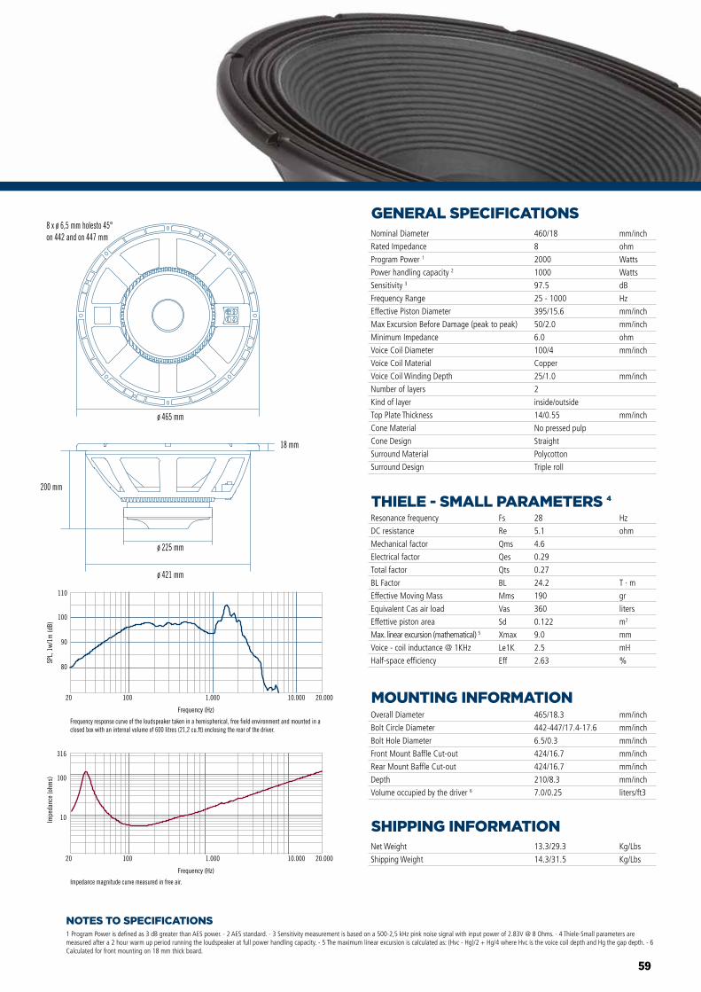
59
NOTES TO SPECIFICATIONS
GENERAL SPECIFICATIONS
THIELE - SMALL PARAMETERS 4
MOUNTING INFORMATION
SHIPPING INFORMATION
1 Program Power is defined as 3 dB greater than AES power. - 2 AES standard. - 3 Sensitivity measurement is based on a 500-2,5 kHz pink noise signal with input power of 2.83V @ 8 Ohms. - 4 Thiele-Small parameters are measured after a 2 hour warm up period running the loudspeaker at full power handling capacity. - 5 The maximum linear excursion is calculated as: (Hvc - Hg)/2 + Hg/4 where Hvc is the voice coil depth and Hg the gap depth. - 6 Calculated for front mounting on 18 mm thick board.
Overall Diameter
Bolt Circle Diameter
Bolt Hole Diameter
Front Mount Baffle Cut-out
Rear Mount Baffle Cut-out
Depth
Volume occupied by the driver 6
465/18.3
442-447/17.4-17.6
6.5/0.3
424/16.7
424/16.7
210/8.3
7.0/0.25
mm/inch
mm/inch
mm/inch
mm/inch
mm/inch
mm/inch
liters/ft3
Net Weight
Shipping Weight
13.3/29.3
14.3/31.5
Kg/Lbs
Kg/Lbs
Resonance frequency
DC resistance
Mechanical factor
Electrical factor
Total factor
BL Factor
Effective Moving Mass
Equivalent Cas air load
Effettive piston area
Max. linear excursion (mathematical) 5
Voice - coil inductance @ 1KHz
Half-space efficiency
Hz
ohm
T · m
gr
liters
m2
mm
mH
%
28
5.1
4.6
0.29
0.27
24.2
190
360
0.122
9.0
2.5
2.63
Fs
Re
Qms
Qes
Qts
BL
Mms
Vas
Sd
Xmax
Le1K
Eff
Nominal Diameter
Rated Impedance
Program Power 1
Power handling capacity 2
Sensitivity 3
Frequency Range
Effective Piston Diameter
Max Excursion Before Damage (peak to peak)
Minimum Impedance
Voice Coil Diameter
Voice Coil Material
Voice Coil Winding Depth
Number of layers
Kind of layer
Top Plate Thickness
Cone Material
Cone Design
Surround Material
Surround Design
460/18
8
2000
1000
97.5
25 - 1000
395/15.6
50/2.0
6.0
100/4
Copper
25/1.0
2
inside/outside
14/0.55
No pressed pulp
Straight
Polycotton
Triple roll
mm/inch
ohm
Watts
Watts
dB
Hz
mm/inch
mm/inch
ohm
mm/inch
mm/inch
mm/inch
80
90
100
110
SPL,
1w/
1m (d
B)
Frequency (Hz)
20 100 1.000 10.000 20.000
Frequency response curve of the loudspeaker taken in a hemispherical, free field environment and mounted in a closed box with an internal volume of 600 litres (21,2 cu.ft) enclosing the rear of the driver.
Frequency (Hz)
20 100 1.000 10.000 20.000
10
100
316
Impe
danc
e (o
hms)
Impedance magnitude curve measured in free air.
ø 465 mm
ø 421 mm
18 mm
200 mm
ø 225 mm
8 x ø 6,5 mm holesto 45°on 442 and on 447 mm
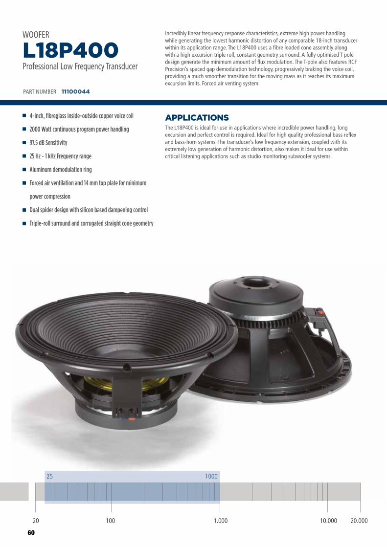
60
Incredibly linear frequency response characteristics, extreme high power handling while generating the lowest harmonic distortion of any comparable 18-inch transducer within its application range. The L18P400 uses a fibre loaded cone assembly along with a high excursion triple roll, constant geometry surround. A fully optimised T-pole design generate the minimum amount of flux modulation. The T-pole also features RCF Precision’s spaced gap demodulation technology, progressively braking the voice coil, providing a much smoother transition for the moving mass as it reaches its maximum excursion limits. Forced air venting system.
The L18P400 is ideal for use in applications where incredible power handling, long excursion and perfect control is required. Ideal for high quality professional bass reflex and bass-horn systems. The transducer’s low frequency extension, coupled with its extremely low generation of harmonic distortion, also makes it ideal for use within critical listening applications such as studio monitoring subwoofer systems.
APPLICATIONS
PART NUMBER 11100044
4-inch, fibreglass inside-outside copper voice coil
2000 Watt continuous program power handling
97.5 dB Sensitivity
25 Hz - 1 kHz Frequency range
Aluminum demodulation ring
Forced air ventilation and 14 mm top plate for minimum
power compression
Dual spider design with silicon based dampening control
Triple-roll surround and corrugated straight cone geometry
L18P400Professional Low Frequency Transducer
WOOFER
20 100 10.000 20.0001.000
25 1000
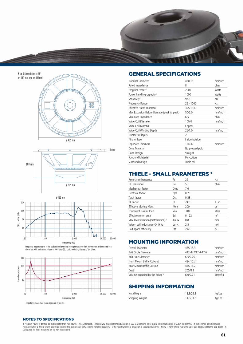
61
NOTES TO SPECIFICATIONS
GENERAL SPECIFICATIONS
THIELE - SMALL PARAMETERS 4
MOUNTING INFORMATION
SHIPPING INFORMATION
1 Program Power is defined as 3 dB greater than AES power. - 2 AES standard. - 3 Sensitivity measurement is based on a 500-2,5 kHz pink noise signal with input power of 2.83V @ 8 Ohms. - 4 Thiele-Small parameters are measured after a 2 hour warm up period running the loudspeaker at full power handling capacity. - 5 The maximum linear excursion is calculated as: (Hvc - Hg)/2 + Hg/4 where Hvc is the voice coil depth and Hg the gap depth. - 6 Calculated for front mounting on 18 mm thick board.
Overall Diameter
Bolt Circle Diameter
Bolt Hole Diameter
Front Mount Baffle Cut-out
Rear Mount Baffle Cut-out
Depth
Volume occupied by the driver 6
465/18.3
442-447/17.4-17.6
6.5/0.25
424/16.7
425/16.7
205/8.1
6.0/0.21
mm/inch
mm/inch
mm/inch
mm/inch
mm/inch
mm/inch
liters/ft3
Net Weight
Shipping Weight
13.3/29.3
14.3/31.5
Kg/Lbs
Kg/Lbs
Resonance frequency
DC resistance
Mechanical factor
Electrical factor
Total factor
BL Factor
Effective Moving Mass
Equivalent Cas air load
Effettive piston area
Max. linear excursion (mathematical) 5
Voice - coil inductance @ 1KHz
Half-space efficiency
Hz
ohm
T · m
gr
liters
m2
mm
mH
%
29
5.1
7.6
0.29
0.28
24.6
200
340
0.122
8.8
2.5
2.63
Fs
Re
Qms
Qes
Qts
BL
Mms
Vas
Sd
Xmax
Le1K
Eff
Nominal Diameter
Rated Impedance
Program Power 1
Power handling capacity 2
Sensitivity 3
Frequency Range
Effective Piston Diameter
Max Excursion Before Damage (peak to peak)
Minimum Impedance
Voice Coil Diameter
Voice Coil Material
Voice Coil Winding Depth
Number of layers
Kind of layer
Top Plate Thickness
Cone Material
Cone Design
Surround Material
Surround Design
460/18
8
2000
1000
97.5
25 - 1000
395/15.6
50/2.0
6.5
100/4
Copper
25/1.0
2
inside/outside
15/0.6
No pressed pulp
Straight
Polycotton
Triple roll
mm/inch
ohm
Watts
Watts
dB
Hz
mm/inch
mm/inch
ohm
mm/inch
mm/inch
mm/inch
Impedance magnitude curve measured in free air.
ø 421 mm
ø 465 mm
18 mm
188 mm
ø 225 mm
8 x ø 6.5 mm holes to 45°on 442 mm and on 447mm
80
90
100
110
SPL,
1w/
1m (d
B)
Frequency (Hz)
20 100 1.000 10.000 20.000
Frequency response curve of the loudspeaker taken in a hemispherical, free field environment and mounted in a closed box with an internal volume of 600 litres (21,2 cu.ft) enclosing the rear of the driver.
Frequency (Hz)
20 100 1.000 10.000 20.000
10
100
316
Impe
danc
e (o
hms)
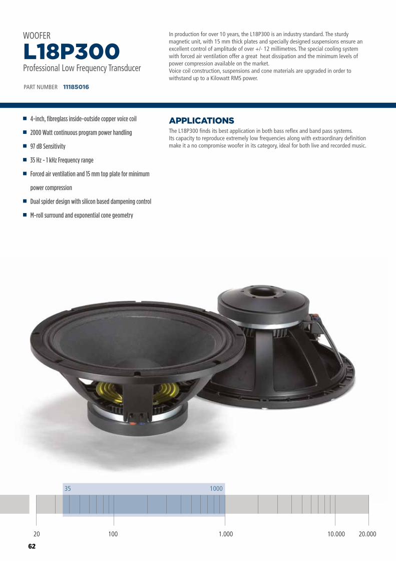
62
In production for over 10 years, the L18P300 is an industry standard. The sturdy magnetic unit, with 15 mm thick plates and specially designed suspensions ensure an excellent control of amplitude of over +/- 12 millimetres. The special cooling system with forced air ventilation offer a great heat dissipation and the minimum levels of power compression available on the market.Voice coil construction, suspensions and cone materials are upgraded in order to withstand up to a Kilowatt RMS power.
The L18P300 finds its best application in both bass reflex and band pass systems.Its capacity to reproduce extremely low frequencies along with extraordinary definition make it a no compromise woofer in its category, ideal for both live and recorded music.
APPLICATIONS
PART NUMBER 11185016
4-inch, fibreglass inside-outside copper voice coil
2000 Watt continuous program power handling
97 dB Sensitivity
35 Hz - 1 kHz Frequency range
Forced air ventilation and 15 mm top plate for minimum
power compression
Dual spider design with silicon based dampening control
M-roll surround and exponential cone geometry
L18P300Professional Low Frequency Transducer
WOOFER
20 100 10.000 20.0001.000
35 1000
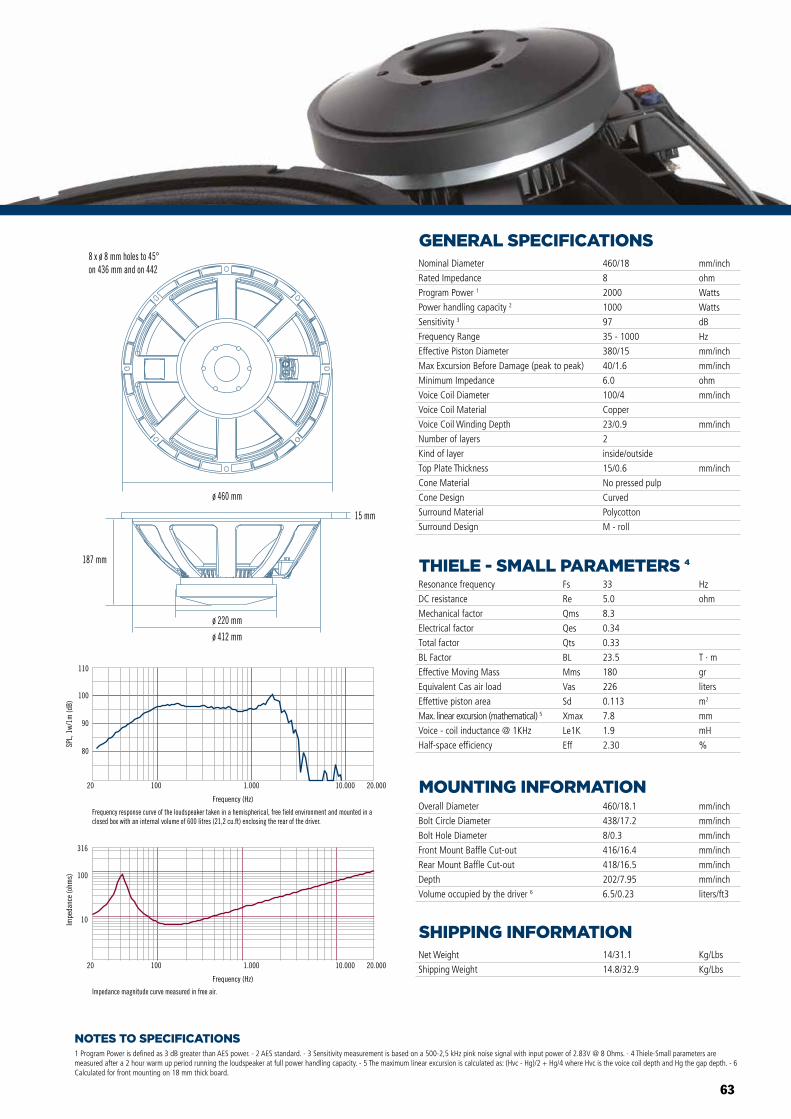
63
NOTES TO SPECIFICATIONS
GENERAL SPECIFICATIONS
THIELE - SMALL PARAMETERS 4
MOUNTING INFORMATION
SHIPPING INFORMATION
1 Program Power is defined as 3 dB greater than AES power. - 2 AES standard. - 3 Sensitivity measurement is based on a 500-2,5 kHz pink noise signal with input power of 2.83V @ 8 Ohms. - 4 Thiele-Small parameters are measured after a 2 hour warm up period running the loudspeaker at full power handling capacity. - 5 The maximum linear excursion is calculated as: (Hvc - Hg)/2 + Hg/4 where Hvc is the voice coil depth and Hg the gap depth. - 6 Calculated for front mounting on 18 mm thick board.
Overall Diameter
Bolt Circle Diameter
Bolt Hole Diameter
Front Mount Baffle Cut-out
Rear Mount Baffle Cut-out
Depth
Volume occupied by the driver 6
460/18.1
438/17.2
8/0.3
416/16.4
418/16.5
202/7.95
6.5/0.23
mm/inch
mm/inch
mm/inch
mm/inch
mm/inch
mm/inch
liters/ft3
Net Weight
Shipping Weight
14/31.1
14.8/32.9
Kg/Lbs
Kg/Lbs
Resonance frequency
DC resistance
Mechanical factor
Electrical factor
Total factor
BL Factor
Effective Moving Mass
Equivalent Cas air load
Effettive piston area
Max. linear excursion (mathematical) 5
Voice - coil inductance @ 1KHz
Half-space efficiency
Hz
ohm
T · m
gr
liters
m2
mm
mH
%
33
5.0
8.3
0.34
0.33
23.5
180
226
0.113
7.8
1.9
2.30
Fs
Re
Qms
Qes
Qts
BL
Mms
Vas
Sd
Xmax
Le1K
Eff
Nominal Diameter
Rated Impedance
Program Power 1
Power handling capacity 2
Sensitivity 3
Frequency Range
Effective Piston Diameter
Max Excursion Before Damage (peak to peak)
Minimum Impedance
Voice Coil Diameter
Voice Coil Material
Voice Coil Winding Depth
Number of layers
Kind of layer
Top Plate Thickness
Cone Material
Cone Design
Surround Material
Surround Design
460/18
8
2000
1000
97
35 - 1000
380/15
40/1.6
6.0
100/4
Copper
23/0.9
2
inside/outside
15/0.6
No pressed pulp
Curved
Polycotton
M - roll
mm/inch
ohm
Watts
Watts
dB
Hz
mm/inch
mm/inch
ohm
mm/inch
mm/inch
mm/inch
80
90
100
110
SPL,
1w/
1m (d
B)
Frequency (Hz)
20 100 1.000 10.000 20.000
Frequency response curve of the loudspeaker taken in a hemispherical, free field environment and mounted in a closed box with an internal volume of 600 litres (21,2 cu.ft) enclosing the rear of the driver.
Frequency (Hz)
20 100 1.000 10.000 20.000
10
100
316
Impe
danc
e (o
hms)
Impedance magnitude curve measured in free air.
ø 460 mm
15 mm
187 mm
ø 220 mm
ø 412 mm
8 x ø 8 mm holes to 45°on 436 mm and on 442
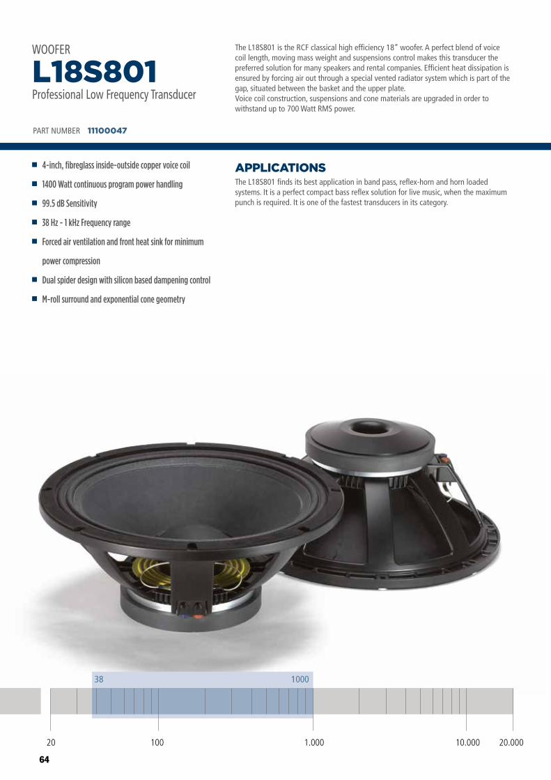
64
The L18S801 is the RCF classical high efficiency 18” woofer. A perfect blend of voice coil length, moving mass weight and suspensions control makes this transducer the preferred solution for many speakers and rental companies. Efficient heat dissipation is ensured by forcing air out through a special vented radiator system which is part of the gap, situated between the basket and the upper plate.Voice coil construction, suspensions and cone materials are upgraded in order to withstand up to 700 Watt RMS power.
The L18S801 finds its best application in band pass, reflex-horn and horn loaded systems. It is a perfect compact bass reflex solution for live music, when the maximum punch is required. It is one of the fastest transducers in its category.
APPLICATIONS
PART NUMBER 11100047
4-inch, fibreglass inside-outside copper voice coil
1400 Watt continuous program power handling
99.5 dB Sensitivity
38 Hz - 1 kHz Frequency range
Forced air ventilation and front heat sink for minimum
power compression
Dual spider design with silicon based dampening control
M-roll surround and exponential cone geometry
L18S801Professional Low Frequency Transducer
WOOFER
20 100 10.000 20.0001.000
38 1000
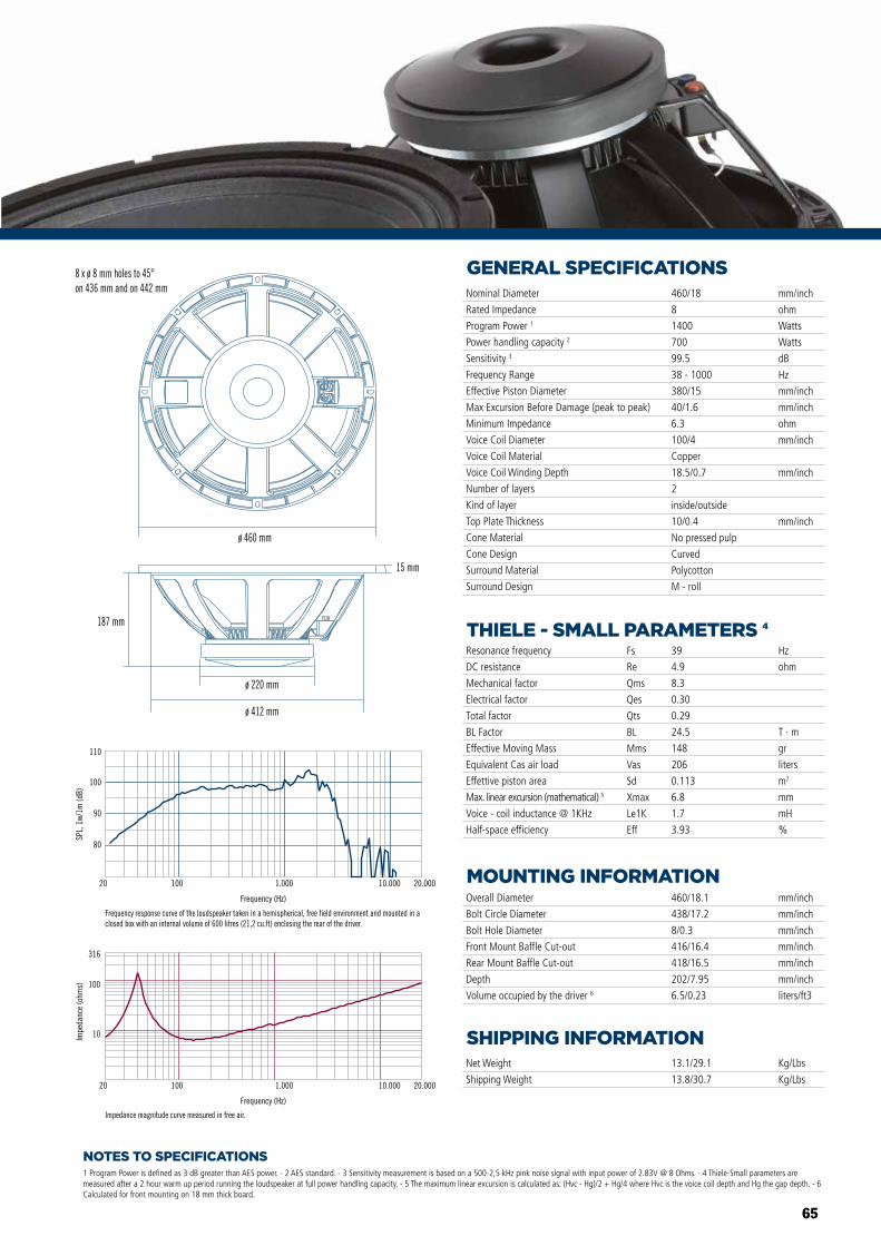
65
NOTES TO SPECIFICATIONS
GENERAL SPECIFICATIONS
THIELE - SMALL PARAMETERS 4
MOUNTING INFORMATION
SHIPPING INFORMATION
1 Program Power is defined as 3 dB greater than AES power. - 2 AES standard. - 3 Sensitivity measurement is based on a 500-2,5 kHz pink noise signal with input power of 2.83V @ 8 Ohms. - 4 Thiele-Small parameters are measured after a 2 hour warm up period running the loudspeaker at full power handling capacity. - 5 The maximum linear excursion is calculated as: (Hvc - Hg)/2 + Hg/4 where Hvc is the voice coil depth and Hg the gap depth. - 6 Calculated for front mounting on 18 mm thick board.
Overall Diameter
Bolt Circle Diameter
Bolt Hole Diameter
Front Mount Baffle Cut-out
Rear Mount Baffle Cut-out
Depth
Volume occupied by the driver 6
460/18.1
438/17.2
8/0.3
416/16.4
418/16.5
202/7.95
6.5/0.23
mm/inch
mm/inch
mm/inch
mm/inch
mm/inch
mm/inch
liters/ft3
Net Weight
Shipping Weight
13.1/29.1
13.8/30.7
Kg/Lbs
Kg/Lbs
Resonance frequency
DC resistance
Mechanical factor
Electrical factor
Total factor
BL Factor
Effective Moving Mass
Equivalent Cas air load
Effettive piston area
Max. linear excursion (mathematical) 5
Voice - coil inductance @ 1KHz
Half-space efficiency
Hz
ohm
T · m
gr
liters
m2
mm
mH
%
39
4.9
8.3
0.30
0.29
24.5
148
206
0.113
6.8
1.7
3.93
Fs
Re
Qms
Qes
Qts
BL
Mms
Vas
Sd
Xmax
Le1K
Eff
Nominal Diameter
Rated Impedance
Program Power 1
Power handling capacity 2
Sensitivity 3
Frequency Range
Effective Piston Diameter
Max Excursion Before Damage (peak to peak)
Minimum Impedance
Voice Coil Diameter
Voice Coil Material
Voice Coil Winding Depth
Number of layers
Kind of layer
Top Plate Thickness
Cone Material
Cone Design
Surround Material
Surround Design
460/18
8
1400
700
99.5
38 - 1000
380/15
40/1.6
6.3
100/4
Copper
18.5/0.7
2
inside/outside
10/0.4
No pressed pulp
Curved
Polycotton
M - roll
mm/inch
ohm
Watts
Watts
dB
Hz
mm/inch
mm/inch
ohm
mm/inch
mm/inch
mm/inch
80
90
100
110
SPL,
1w/
1m (d
B)
Frequency (Hz)
20 100 1.000 10.000 20.000
Frequency response curve of the loudspeaker taken in a hemispherical, free field environment and mounted in a closed box with an internal volume of 600 litres (21,2 cu.ft) enclosing the rear of the driver.
Frequency (Hz)
20 100 1.000 10.000 20.000
10
100
316
Impe
danc
e (o
hms)
Impedance magnitude curve measured in free air.
ø 460 mm
ø 220 mm
ø 412 mm
187 mm
15 mm
8 x ø 8 mm holes to 45°on 436 mm and on 442 mm
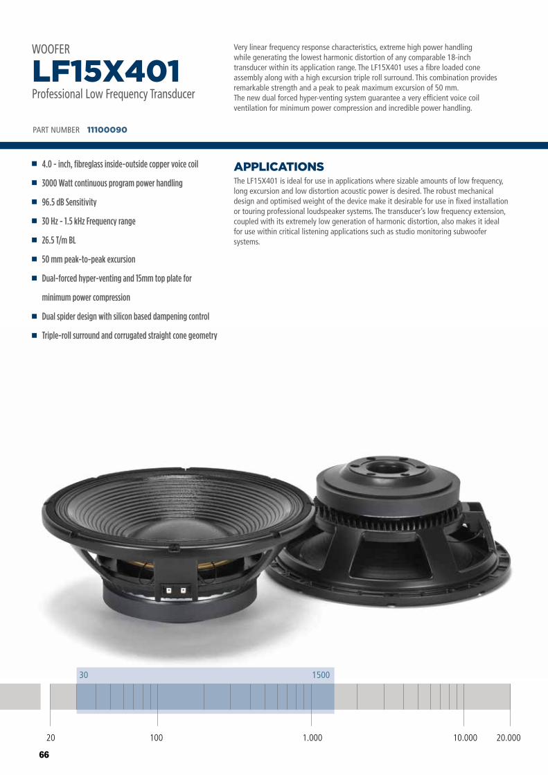
66
Very linear frequency response characteristics, extreme high power handlingwhile generating the lowest harmonic distortion of any comparable 18-inchtransducer within its application range. The LF15X401 uses a fibre loaded coneassembly along with a high excursion triple roll surround. This combination providesremarkable strength and a peak to peak maximum excursion of 50 mm. The new dual forced hyper-venting system guarantee a very efficient voice coil ventilation for minimum power compression and incredible power handling.
The LF15X401 is ideal for use in applications where sizable amounts of low frequency, long excursion and low distortion acoustic power is desired. The robust mechanical design and optimised weight of the device make it desirable for use in fixed installation or touring professional loudspeaker systems. The transducer’s low frequency extension, coupled with its extremely low generation of harmonic distortion, also makes it ideal for use within critical listening applications such as studio monitoring subwoofer systems.
APPLICATIONS
PART NUMBER 11100090
4.0 - inch, fibreglass inside-outside copper voice coil
3000 Watt continuous program power handling
96.5 dB Sensitivity
30 Hz - 1.5 kHz Frequency range
26.5 T/m BL
50 mm peak-to-peak excursion
Dual-forced hyper-venting and 15mm top plate for
minimum power compression
Dual spider design with silicon based dampening control
Triple-roll surround and corrugated straight cone geometry
LF15X401Professional Low Frequency Transducer
WOOFER
20 100 10.000 20.0001.000
30 1500
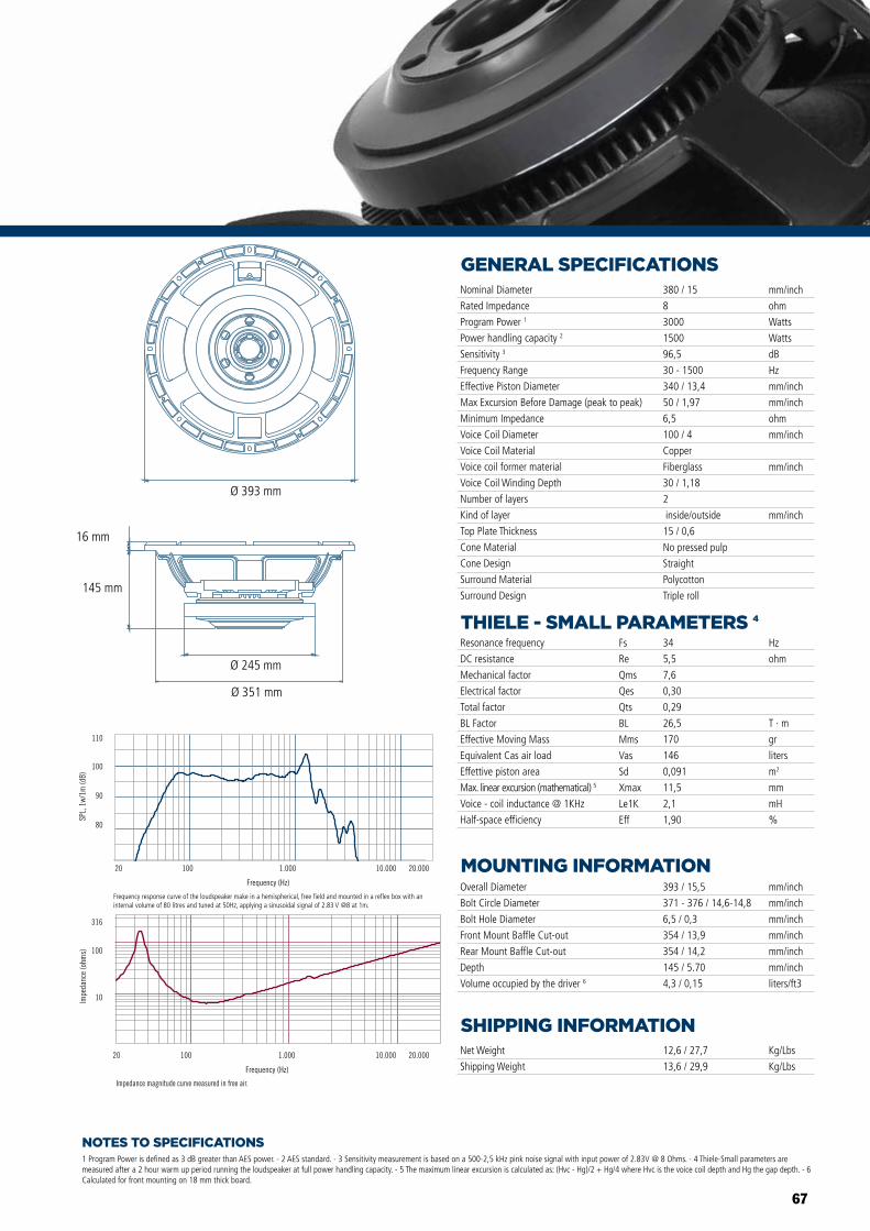
67
NOTES TO SPECIFICATIONS
GENERAL SPECIFICATIONS
THIELE - SMALL PARAMETERS 4
MOUNTING INFORMATION
SHIPPING INFORMATION
1 Program Power is defined as 3 dB greater than AES power. - 2 AES standard. - 3 Sensitivity measurement is based on a 500-2,5 kHz pink noise signal with input power of 2.83V @ 8 Ohms. - 4 Thiele-Small parameters are measured after a 2 hour warm up period running the loudspeaker at full power handling capacity. - 5 The maximum linear excursion is calculated as: (Hvc - Hg)/2 + Hg/4 where Hvc is the voice coil depth and Hg the gap depth. - 6 Calculated for front mounting on 18 mm thick board.
Overall Diameter
Bolt Circle Diameter
Bolt Hole Diameter
Front Mount Baffle Cut-out
Rear Mount Baffle Cut-out
Depth
Volume occupied by the driver 6
393 / 15,5
371 - 376 / 14,6-14,8
6,5 / 0,3
354 / 13,9
354 / 14,2
145 / 5.70
4,3 / 0,15
mm/inch
mm/inch
mm/inch
mm/inch
mm/inch
mm/inch
liters/ft3
Net Weight
Shipping Weight
12,6 / 27,7
13,6 / 29,9
Kg/Lbs
Kg/Lbs
Resonance frequency
DC resistance
Mechanical factor
Electrical factor
Total factor
BL Factor
Effective Moving Mass
Equivalent Cas air load
Effettive piston area
Max. linear excursion (mathematical) 5
Voice - coil inductance @ 1KHz
Half-space efficiency
Hz
ohm
T · m
gr
liters
m2
mm
mH
%
34
5,5
7,6
0,30
0,29
26,5
170
146
0,091
11,5
2,1
1,90
Fs
Re
Qms
Qes
Qts
BL
Mms
Vas
Sd
Xmax
Le1K
Eff
Nominal Diameter
Rated Impedance
Program Power 1
Power handling capacity 2
Sensitivity 3
Frequency Range
Effective Piston Diameter
Max Excursion Before Damage (peak to peak)
Minimum Impedance
Voice Coil Diameter
Voice Coil Material
Voice coil former material
Voice Coil Winding Depth
Number of layers
Kind of layer
Top Plate Thickness
Cone Material
Cone Design
Surround Material
Surround Design
380 / 15
8
3000
1500
96,5
30 - 1500
340 / 13,4
50 / 1,97
6,5
100 / 4
Copper
Fiberglass
30 / 1,18
2
inside/outside
15 / 0,6
No pressed pulp
Straight
Polycotton
Triple roll
mm/inch
ohm
Watts
Watts
dB
Hz
mm/inch
mm/inch
ohm
mm/inch
mm/inch
mm/inch
Impedance magnitude curve measured in free air.
Frequency (Hz)
20 100 1.000 10.000 20.000
10
100
316
Impe
danc
e (o
hms)
Frequency (Hz)
20 100 1.000 10.000 20.000
Frequency response curve of the loudspeaker taken in a hemispherical, free �eld environment and mounted in a closed box with an internal volume of 600 litres (21,2 cu.ft) enclosing the rear of the driver.
80
90
100
110
SPL,
1w/
1m (d
B)
Impedance magnitude curve measured in free air.
Frequency (Hz)
20 100 1.000 10.000 20.000
10
100
316
Impe
danc
e (o
hms)
Frequency (Hz)
20 100 1.000 10.000 20.000
Frequency response curve of the loudspeaker taken in a hemispherical, free �eld environment and mounted in a closed box with an internal volume of 600 litres (21,2 cu.ft) enclosing the rear of the driver.
80
90
100
110
SPL,
1w/
1m (d
B)LF18X401 LF15X401 LF12X401LF18X401 LF15X401 LF12X401
Ø 393 mm
Ø 245 mm
Ø 351 mm
145 mm
16 mm
Frequency response curve of the loudspeaker make in a hemispherical, free field and mounted in a reflex box with an internal volume of 80 litres and tuned at 50Hz, applying a sinusoidal signal of 2.83 V @8 at 1m.
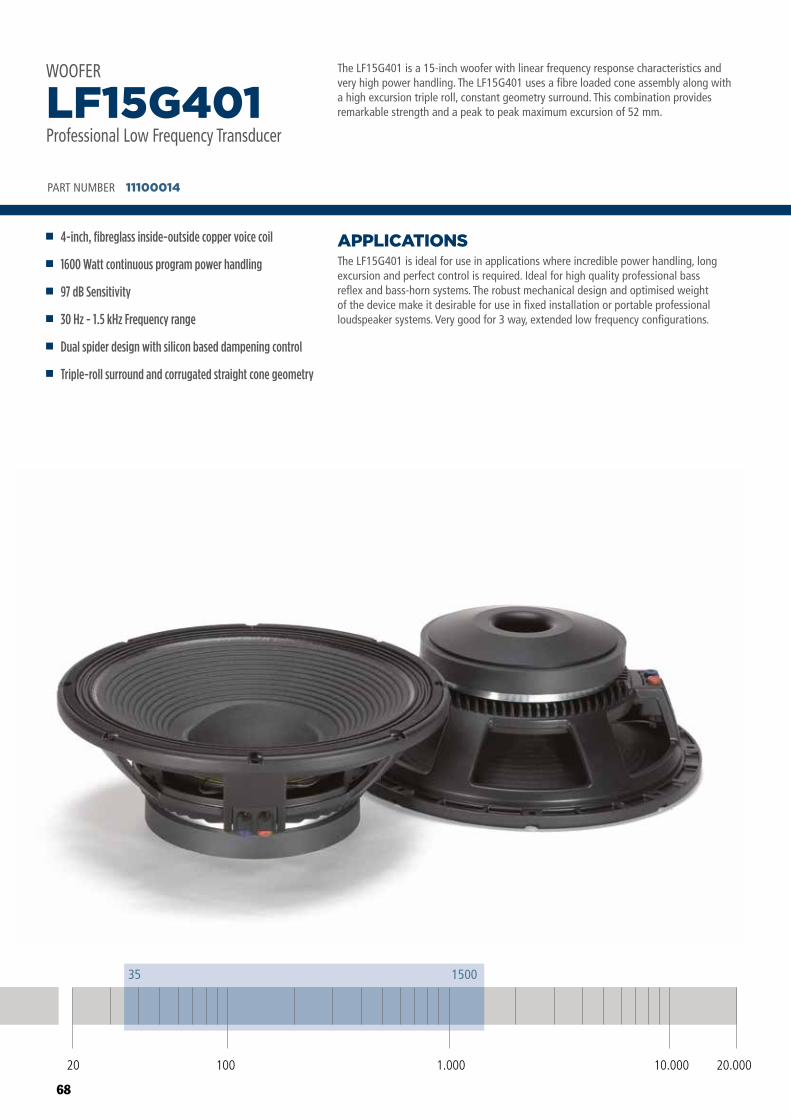
68
The LF15G401 is a 15-inch woofer with linear frequency response characteristics and very high power handling. The LF15G401 uses a fibre loaded cone assembly along with a high excursion triple roll, constant geometry surround. This combination provides remarkable strength and a peak to peak maximum excursion of 52 mm.
The LF15G401 is ideal for use in applications where incredible power handling, long excursion and perfect control is required. Ideal for high quality professional bass reflex and bass-horn systems. The robust mechanical design and optimised weight of the device make it desirable for use in fixed installation or portable professional loudspeaker systems. Very good for 3 way, extended low frequency configurations.
APPLICATIONS
PART NUMBER 11100014
4-inch, fibreglass inside-outside copper voice coil
1600 Watt continuous program power handling
97 dB Sensitivity
30 Hz - 1.5 kHz Frequency range
Dual spider design with silicon based dampening control
Triple-roll surround and corrugated straight cone geometry
LF15G401Professional Low Frequency Transducer
WOOFER
20 100 10.000 20.0001.000
35 1500
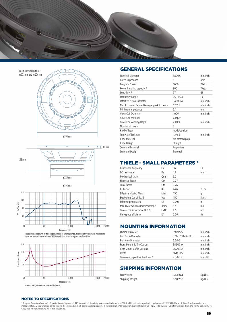
69
NOTES TO SPECIFICATIONS
GENERAL SPECIFICATIONS
THIELE - SMALL PARAMETERS 4
MOUNTING INFORMATION
SHIPPING INFORMATION
1 Program Power is defined as 3 dB greater than AES power. - 2 AES standard. - 3 Sensitivity measurement is based on a 500-2,5 kHz pink noise signal with input power of 2.83V @ 8 Ohms. - 4 Thiele-Small parameters are measured after a 2 hour warm up period running the loudspeaker at full power handling capacity. - 5 The maximum linear excursion is calculated as: (Hvc - Hg)/2 + Hg/4 where Hvc is the voice coil depth and Hg the gap depth. - 6 Calculated for front mounting on 18 mm thick board.
Overall Diameter
Bolt Circle Diameter
Bolt Hole Diameter
Front Mount Baffle Cut-out
Rear Mount Baffle Cut-out
Depth
Volume occupied by the driver 6
393/15.5
371-376/14.6-14.8
6.5/0.3
352/13.9
360/14.2
164/6.45
4.3/0.15
mm/inch
mm/inch
mm/inch
mm/inch
mm/inch
mm/inch
liters/ft3
Net Weight
Shipping Weight
12.2/26.8
12.8/28.4
Kg/Lbs
Kg/Lbs
Resonance frequency
DC resistance
Mechanical factor
Electrical factor
Total factor
BL Factor
Effective Moving Mass
Equivalent Cas air load
Effettive piston area
Max. linear excursion (mathematical) 5
Voice - coil inductance @ 1KHz
Half-space efficiency
Hz
ohm
T · m
gr
liters
m2
mm
mH
%
36
4.8
6.2
0.27
0.26
24.6
150
150
0.091
8.5
2.5
2.50
Fs
Re
Qms
Qes
Qts
BL
Mms
Vas
Sd
Xmax
Le1K
Eff
Nominal Diameter
Rated Impedance
Program Power 1
Power handling capacity 2
Sensitivity 3
Frequency Range
Effective Piston Diameter
Max Excursion Before Damage (peak to peak)
Minimum Impedance
Voice Coil Diameter
Voice Coil Material
Voice Coil Winding Depth
Number of layers
Kind of layer
Top Plate Thickness
Cone Material
Cone Design
Surround Material
Surround Design
380/15
8
1600
800
97
35 - 1500
340/13.4
52/2.1
6.1
100/4
Copper
23/0.9
2
inside/outside
12/0.5
No pressed pulp
Straight
Polycotton
Triple roll
mm/inch
ohm
Watts
Watts
dB
Hz
mm/inch
mm/inch
ohm
mm/inch
mm/inch
mm/inch
80
90
100
110
SPL,
1w/
1m (d
B)
Frequency (Hz)
20 100 1.000 10.000 20.000
Frequency response curve of the loudspeaker taken in a hemispherical, free field environment and mounted in a closed box with an internal volume of 600 litres (21,2 cu.ft) enclosing the rear of the driver.
Frequency (Hz)
20 100 1.000 10.000 20.000
10
100
316
Impe
danc
e (o
hms)
Impedance magnitude curve measured in free air.
ø 351 mm
ø 220 mm
16 mm
ø 393 mm
8 x ø 6.5 mm holes to 45°on 371 mm and on 376 mm
148 mm
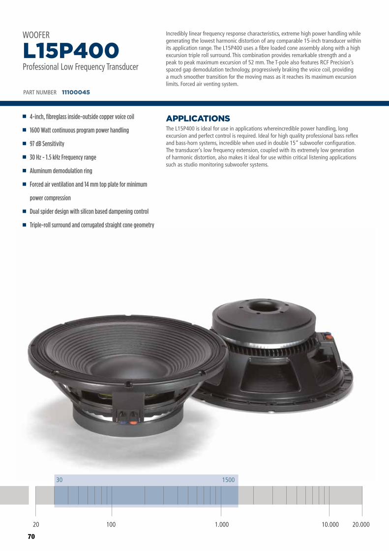
70
Incredibly linear frequency response characteristics, extreme high power handling while generating the lowest harmonic distortion of any comparable 15-inch transducer within its application range. The L15P400 uses a fibre loaded cone assembly along with a high excursion triple roll surround. This combination provides remarkable strength and a peak to peak maximum excursion of 52 mm. The T-pole also features RCF Precision’s spaced gap demodulation technology, progressively braking the voice coil, providing a much smoother transition for the moving mass as it reaches its maximum excursion limits. Forced air venting system.
The L15P400 is ideal for use in applications whereincredible power handling, long excursion and perfect control is required. Ideal for high quality professional bass reflex and bass-horn systems, incredible when used in double 15” subwoofer configuration.The transducer’s low frequency extension, coupled with its extremely low generation of harmonic distortion, also makes it ideal for use within critical listening applications such as studio monitoring subwoofer systems.
APPLICATIONS
PART NUMBER 11100045
4-inch, fibreglass inside-outside copper voice coil
1600 Watt continuous program power handling
97 dB Sensitivity
30 Hz - 1.5 kHz Frequency range
Aluminum demodulation ring
Forced air ventilation and 14 mm top plate for minimum
power compression
Dual spider design with silicon based dampening control
Triple-roll surround and corrugated straight cone geometry
L15P400Professional Low Frequency Transducer
WOOFER
20 100 10.000 20.0001.000
30 1500
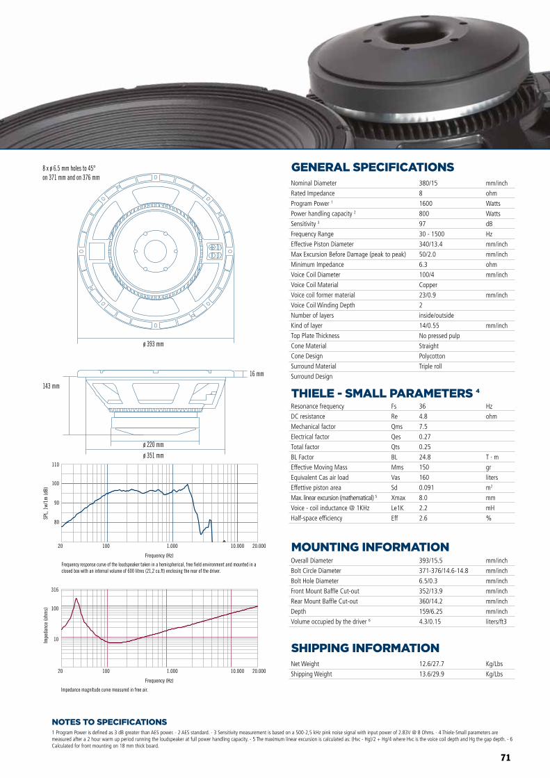
71
NOTES TO SPECIFICATIONS
GENERAL SPECIFICATIONS
THIELE - SMALL PARAMETERS 4
MOUNTING INFORMATION
SHIPPING INFORMATION
1 Program Power is defined as 3 dB greater than AES power. - 2 AES standard. - 3 Sensitivity measurement is based on a 500-2,5 kHz pink noise signal with input power of 2.83V @ 8 Ohms. - 4 Thiele-Small parameters are measured after a 2 hour warm up period running the loudspeaker at full power handling capacity. - 5 The maximum linear excursion is calculated as: (Hvc - Hg)/2 + Hg/4 where Hvc is the voice coil depth and Hg the gap depth. - 6 Calculated for front mounting on 18 mm thick board.
Overall Diameter
Bolt Circle Diameter
Bolt Hole Diameter
Front Mount Baffle Cut-out
Rear Mount Baffle Cut-out
Depth
Volume occupied by the driver 6
393/15.5
371-376/14.6-14.8
6.5/0.3
352/13.9
360/14.2
159/6.25
4.3/0.15
mm/inch
mm/inch
mm/inch
mm/inch
mm/inch
mm/inch
liters/ft3
Net Weight
Shipping Weight
12.6/27.7
13.6/29.9
Kg/Lbs
Kg/Lbs
Resonance frequency
DC resistance
Mechanical factor
Electrical factor
Total factor
BL Factor
Effective Moving Mass
Equivalent Cas air load
Effettive piston area
Max. linear excursion (mathematical) 5
Voice - coil inductance @ 1KHz
Half-space efficiency
Hz
ohm
T · m
gr
liters
m2
mm
mH
%
36
4.8
7.5
0.27
0.25
24.8
150
160
0.091
8.0
2.2
2.6
Fs
Re
Qms
Qes
Qts
BL
Mms
Vas
Sd
Xmax
Le1K
Eff
Nominal Diameter
Rated Impedance
Program Power 1
Power handling capacity 2
Sensitivity 3
Frequency Range
Effective Piston Diameter
Max Excursion Before Damage (peak to peak)
Minimum Impedance
Voice Coil Diameter
Voice Coil Material
Voice coil former material
Voice Coil Winding Depth
Number of layers
Kind of layer
Top Plate Thickness
Cone Material
Cone Design
Surround Material
Surround Design
380/15
8
1600
800
97
30 - 1500
340/13.4
50/2.0
6.3
100/4
Copper
23/0.9
2
inside/outside
14/0.55
No pressed pulp
Straight
Polycotton
Triple roll
mm/inch
ohm
Watts
Watts
dB
Hz
mm/inch
mm/inch
ohm
mm/inch
mm/inch
mm/inch
Impedance magnitude curve measured in free air.
ø 393 mm
ø 351 mm
ø 220 mm
16 mm
8 x ø 6.5 mm holes to 45°on 371 mm and on 376 mm
143 mm
80
90
100
110
SPL,
1w/
1m (d
B)
Frequency (Hz)
20 100 1.000 10.000 20.000
Frequency response curve of the loudspeaker taken in a hemispherical, free field environment and mounted in a closed box with an internal volume of 600 litres (21,2 cu.ft) enclosing the rear of the driver.
Frequency (Hz)
20 100 1.000 10.000 20.000
10
100
316
Impe
danc
e (o
hms)
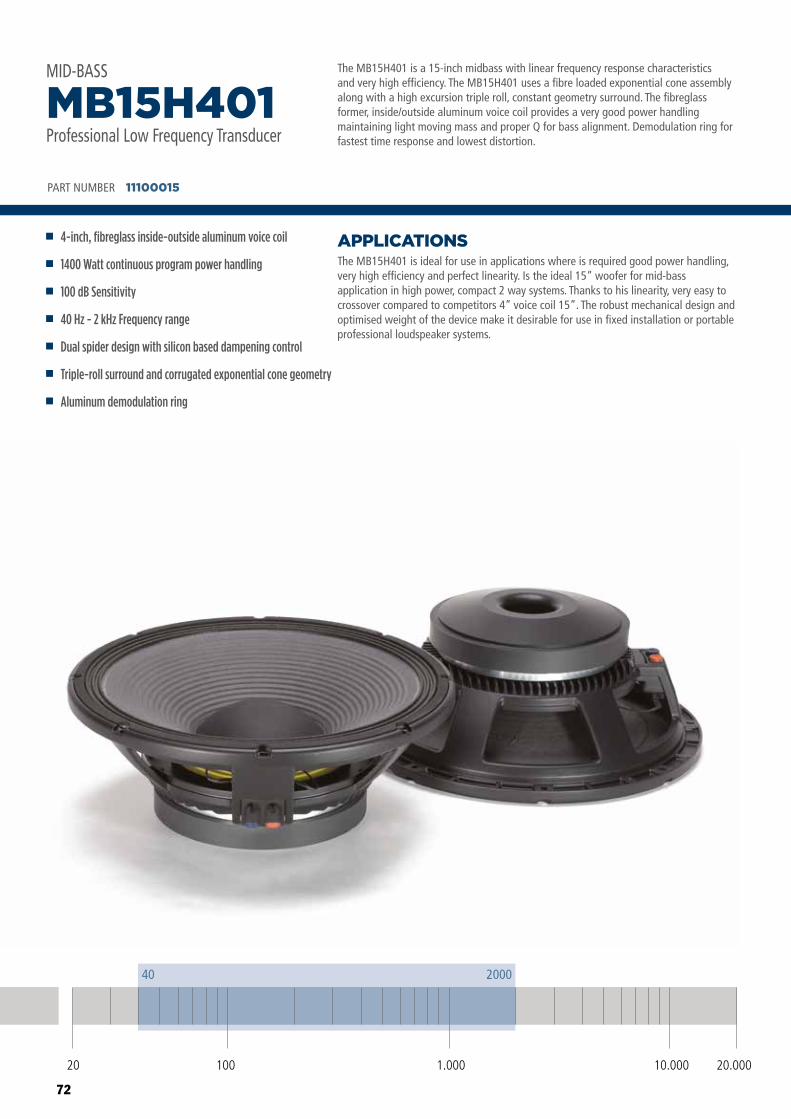
72
The MB15H401 is a 15-inch midbass with linear frequency response characteristics and very high efficiency. The MB15H401 uses a fibre loaded exponential cone assembly along with a high excursion triple roll, constant geometry surround. The fibreglass former, inside/outside aluminum voice coil provides a very good power handling maintaining light moving mass and proper Q for bass alignment. Demodulation ring for fastest time response and lowest distortion.
The MB15H401 is ideal for use in applications where is required good power handling, very high efficiency and perfect linearity. Is the ideal 15” woofer for mid-bass application in high power, compact 2 way systems. Thanks to his linearity, very easy to crossover compared to competitors 4” voice coil 15”. The robust mechanical design and optimised weight of the device make it desirable for use in fixed installation or portable professional loudspeaker systems.
APPLICATIONS
PART NUMBER 11100015
4-inch, fibreglass inside-outside aluminum voice coil
1400 Watt continuous program power handling
100 dB Sensitivity
40 Hz - 2 kHz Frequency range
Dual spider design with silicon based dampening control
Triple-roll surround and corrugated exponential cone geometry
Aluminum demodulation ring
MB15H401Professional Low Frequency Transducer
MID-BASS
20 100 10.000 20.0001.000
40 2000
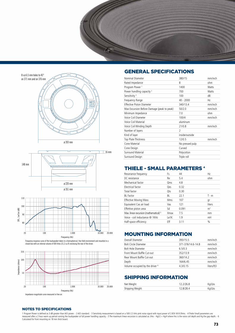
73
NOTES TO SPECIFICATIONS
GENERAL SPECIFICATIONS
THIELE - SMALL PARAMETERS 4
MOUNTING INFORMATION
SHIPPING INFORMATION
1 Program Power is defined as 3 dB greater than AES power. - 2 AES standard. - 3 Sensitivity measurement is based on a 500-2,5 kHz pink noise signal with input power of 2.83V @ 8 Ohms. - 4 Thiele-Small parameters are measured after a 2 hour warm up period running the loudspeaker at full power handling capacity. - 5 The maximum linear excursion is calculated as: (Hvc - Hg)/2 + Hg/4 where Hvc is the voice coil depth and Hg the gap depth. - 6 Calculated for front mounting on 18 mm thick board.
Overall Diameter
Bolt Circle Diameter
Bolt Hole Diameter
Front Mount Baffle Cut-out
Rear Mount Baffle Cut-out
Depth
Volume occupied by the driver 6
393/15.5
371-376/14.6-14.8
6.5/0.3
352/13.9
360/14.2
164/6.45
4.3/0.15
mm/inch
mm/inch
mm/inch
mm/inch
mm/inch
mm/inch
liters/ft3
Net Weight
Shipping Weight
12.2/26.8
12.8/28.4
Kg/Lbs
Kg/Lbs
Resonance frequency
DC resistance
Mechanical factor
Electrical factor
Total factor
BL Factor
Effective Moving Mass
Equivalent Cas air load
Effettive piston area
Max. linear excursion (mathematical) 5
Voice - coil inductance @ 1KHz
Half-space efficiency
Hz
ohm
T · m
gr
liters
m2
mm
mH
%
44
5.4
4.8
0.32
0.30
22.1
107
121
0.091
7.5
1.9
3.11
Fs
Re
Qms
Qes
Qts
BL
Mms
Vas
Sd
Xmax
Le1K
Eff
Nominal Diameter
Rated Impedance
Program Power 1
Power handling capacity 2
Sensitivity 3
Frequency Range
Effective Piston Diameter
Max Excursion Before Damage (peak to peak)
Minimum Impedance
Voice Coil Diameter
Voice Coil Material
Voice Coil Winding Depth
Number of layers
Kind of layer
Top Plate Thickness
Cone Material
Cone Design
Surround Material
Surround Design
380/15
8
1400
700
100
40 - 2000
340/13.4
50/2.0
7.0
100/4
aluminum
21/0.8
2
inside/outside
12/0.5
No pressed pulp
Curved
Polycotton
Triple roll
mm/inch
ohm
Watts
Watts
dB
Hz
mm/inch
mm/inch
ohm
mm/inch
mm/inch
mm/inch
80
90
100
110
SPL,
1w/
1m (d
B)
Frequency (Hz)
20 100 1.000 10.000 20.000
Frequency response curve of the loudspeaker taken in a hemispherical, free field environment and mounted in a closed box with an internal volume of 600 litres (21,2 cu.ft) enclosing the rear of the driver.
Frequency (Hz)
20 100 1.000 10.000 20.000
10
100
316
Impe
danc
e (o
hms)
Impedance magnitude curve measured in free air.
ø 351 mm
8 x ø 6.5 mm holes to 45°on 371 mm and on 376 mm
ø 220 mm
148 mm
16 mm
ø 393 mm
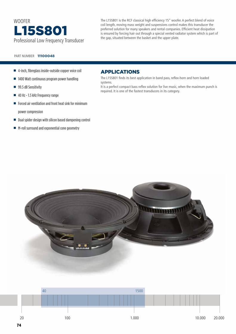
74
The L15S801 is the RCF classical high efficiency 15” woofer. A perfect blend of voice coil length, moving mass weight and suspensions control makes this transducer the preferred solution for many speakers and rental companies. Efficient heat dissipation is ensured by forcing hair out through a special vented radiator system which is part of the gap, situated between the basket and the upper plate.
The L15S801 finds its best application in band pass, reflex-horn and horn loaded systems.It is a perfect compact bass reflex solution for live music, when the maximum punch is required. It is one of the fastest transducers in its category.
APPLICATIONS
PART NUMBER 11100048
4-inch, fibreglass inside-outside copper voice coil
1400 Watt continuous program power handling
99.5 dB Sensitivity
40 Hz - 1.5 kHz Frequency range
Forced air ventilation and front heat sink for minimum
power compression
Dual spider design with silicon based dampening control
M-roll surround and exponential cone geometry
L15S801Professional Low Frequency Transducer
WOOFER
80
90
100
110
SPL,
1w/
1m (d
B)
Frequency (Hz)
20 100 1.000 10.000 20.000
Frequency response curve of the loudspeaker taken in a hemispherical, free field environment and mounted in a closed box with an internal volume of 600 litres (21,2 cu.ft) enclosing the rear of the driver.
Frequency (Hz)
20 100 1.000 10.000 20.000
10
100
316Im
peda
nce
(ohm
s)
Impedance magnitude curve measured in free air.
ø 393 mm
16 mm
146 mm
8 x ø 6.5 mm holes to 45°on 371 mm and on 376 mm
ø 220 mm
ø 351 mm
20 100 10.000 20.0001.000
40 1500
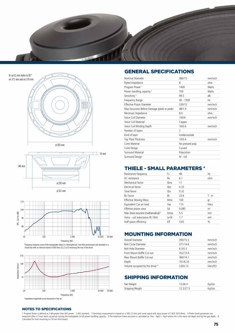
75
NOTES TO SPECIFICATIONS
GENERAL SPECIFICATIONS
THIELE - SMALL PARAMETERS 4
MOUNTING INFORMATION
SHIPPING INFORMATION
1 Program Power is defined as 3 dB greater than AES power. - 2 AES standard. - 3 Sensitivity measurement is based on a 500-2,5 kHz pink noise signal with input power of 2.83V @ 8 Ohms. - 4 Thiele-Small parameters are measured after a 2 hour warm up period running the loudspeaker at full power handling capacity. - 5 The maximum linear excursion is calculated as: (Hvc - Hg)/2 + Hg/4 where Hvc is the voice coil depth and Hg the gap depth. - 6 Calculated for front mounting on 18 mm thick board.
Overall Diameter
Bolt Circle Diameter
Bolt Hole Diameter
Front Mount Baffle Cut-out
Rear Mount Baffle Cut-out
Depth
Volume occupied by the driver 6
393/15.5
371/14.6
6.5/0.3
352/13.9
360/14.1
161/6.33
3.8/0.13
mm/inch
mm/inch
mm/inch
mm/inch
mm/inch
mm/inch
liters/ft3
Net Weight
Shipping Weight
12/26.4
12.5/27.5
Kg/Lbs
Kg/Lbs
Resonance frequency
DC resistance
Mechanical factor
Electrical factor
Total factor
BL Factor
Effective Moving Mass
Equivalent Cas air load
Effettive piston area
Max. linear excursion (mathematical) 5
Voice - coil inductance @ 1KHz
Half-space efficiency
Hz
ohm
T · m
gr
liters
m2
mm
mH
%
48
6.1
11
0.33
0.32
23.6
100
113
0.085
5.5
1.7
3.65
Fs
Re
Qms
Qes
Qts
BL
Mms
Vas
Sd
Xmax
Le1K
Eff
Nominal Diameter
Rated Impedance
Program Power 1
Power handling capacity 2
Sensitivity 3
Frequency Range
Effective Piston Diameter
Max Excursion Before Damage (peak to peak)
Minimum Impedance
Voice Coil Diameter
Voice Coil Material
Voice Coil Winding Depth
Number of layers
Kind of layer
Top Plate Thickness
Cone Material
Cone Design
Surround Material
Surround Design
380/15
8
1400
700
99.5
40 - 1500
330/13
48/1.9
8.0
100/4
Copper
16/0.6
2
inside/outside
10/0.4
No pressed pulp
Curved
Polycotton
M - roll
mm/inch
ohm
Watts
Watts
dB
Hz
mm/inch
mm/inch
ohm
mm/inch
mm/inch
mm/inch
80
90
100
110
SPL,
1w/
1m (d
B)
Frequency (Hz)
20 100 1.000 10.000 20.000
Frequency response curve of the loudspeaker taken in a hemispherical, free field environment and mounted in a closed box with an internal volume of 600 litres (21,2 cu.ft) enclosing the rear of the driver.
Frequency (Hz)
20 100 1.000 10.000 20.000
10
100
316
Impe
danc
e (o
hms)
Impedance magnitude curve measured in free air.
ø 393 mm
16 mm
146 mm
8 x ø 6.5 mm holes to 45°on 371 mm and on 376 mm
ø 220 mm
ø 351 mm
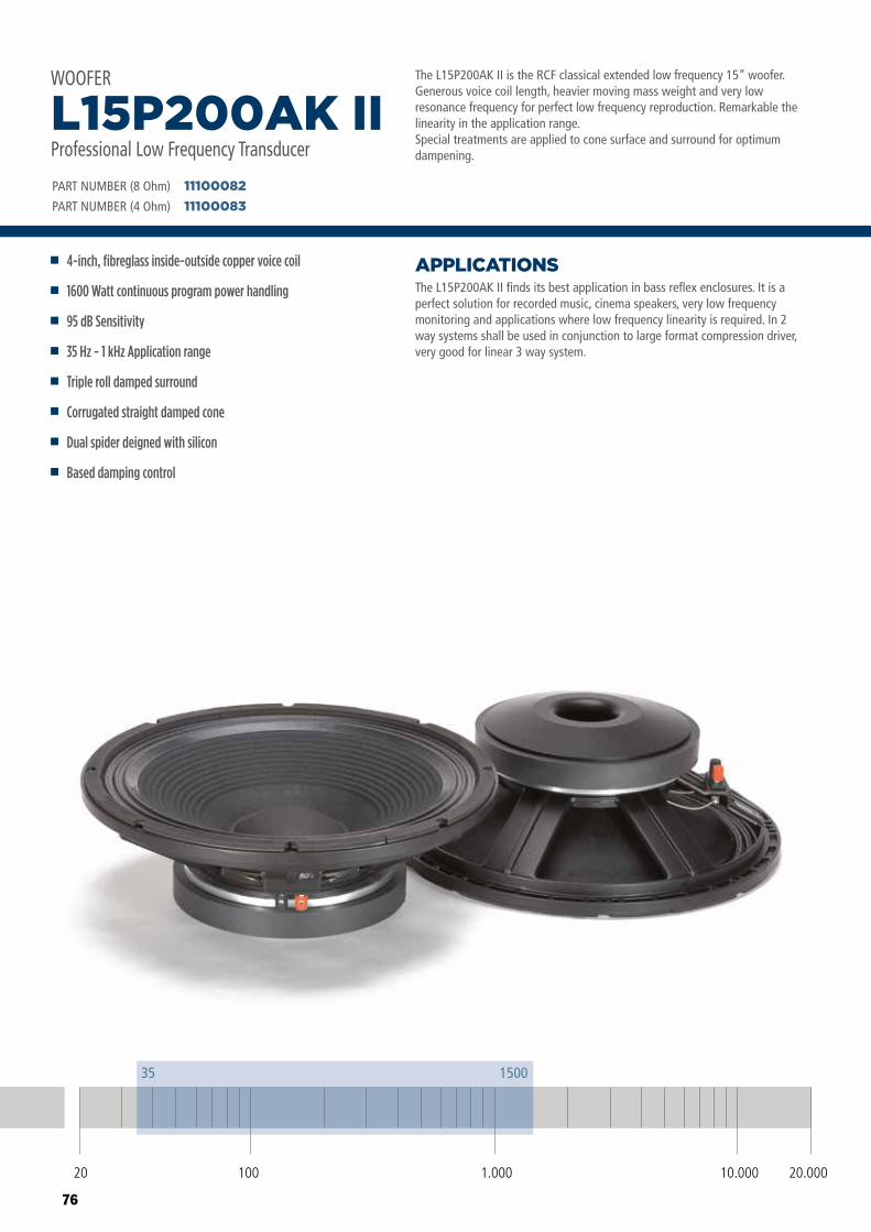
76
The L15P200AK II is the RCF classical extended low frequency 15” woofer. Generous voice coil length, heavier moving mass weight and very low resonance frequency for perfect low frequency reproduction. Remarkable the linearity in the application range.Special treatments are applied to cone surface and surround for optimum dampening.
The L15P200AK II finds its best application in bass reflex enclosures. It is a perfect solution for recorded music, cinema speakers, very low frequency monitoring and applications where low frequency linearity is required. In 2 way systems shall be used in conjunction to large format compression driver, very good for linear 3 way system.
APPLICATIONS
PART NUMBER (8 Ohm)
PART NUMBER (4 Ohm)
1110008211100083
4-inch, fibreglass inside-outside copper voice coil
1600 Watt continuous program power handling
95 dB Sensitivity
35 Hz - 1 kHz Application range
Triple roll damped surround
Corrugated straight damped cone
Dual spider deigned with silicon
Based damping control
L15P200AK IIProfessional Low Frequency Transducer
WOOFER
20 100 10.000 20.0001.000
35 1500
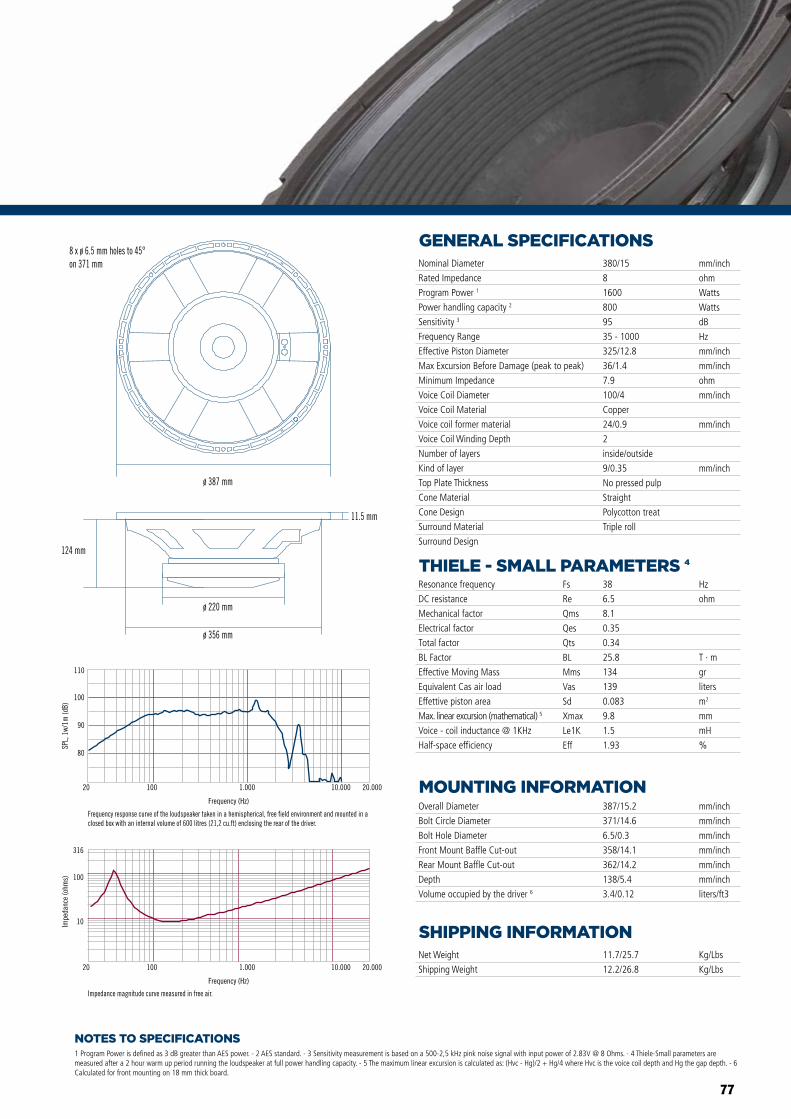
77
NOTES TO SPECIFICATIONS
GENERAL SPECIFICATIONS
THIELE - SMALL PARAMETERS 4
MOUNTING INFORMATION
SHIPPING INFORMATION
1 Program Power is defined as 3 dB greater than AES power. - 2 AES standard. - 3 Sensitivity measurement is based on a 500-2,5 kHz pink noise signal with input power of 2.83V @ 8 Ohms. - 4 Thiele-Small parameters are measured after a 2 hour warm up period running the loudspeaker at full power handling capacity. - 5 The maximum linear excursion is calculated as: (Hvc - Hg)/2 + Hg/4 where Hvc is the voice coil depth and Hg the gap depth. - 6 Calculated for front mounting on 18 mm thick board.
Overall Diameter
Bolt Circle Diameter
Bolt Hole Diameter
Front Mount Baffle Cut-out
Rear Mount Baffle Cut-out
Depth
Volume occupied by the driver 6
387/15.2
371/14.6
6.5/0.3
358/14.1
362/14.2
138/5.4
3.4/0.12
mm/inch
mm/inch
mm/inch
mm/inch
mm/inch
mm/inch
liters/ft3
Net Weight
Shipping Weight
11.7/25.7
12.2/26.8
Kg/Lbs
Kg/Lbs
Resonance frequency
DC resistance
Mechanical factor
Electrical factor
Total factor
BL Factor
Effective Moving Mass
Equivalent Cas air load
Effettive piston area
Max. linear excursion (mathematical) 5
Voice - coil inductance @ 1KHz
Half-space efficiency
Hz
ohm
T · m
gr
liters
m2
mm
mH
%
38
6.5
8.1
0.35
0.34
25.8
134
139
0.083
9.8
1.5
1.93
Fs
Re
Qms
Qes
Qts
BL
Mms
Vas
Sd
Xmax
Le1K
Eff
Nominal Diameter
Rated Impedance
Program Power 1
Power handling capacity 2
Sensitivity 3
Frequency Range
Effective Piston Diameter
Max Excursion Before Damage (peak to peak)
Minimum Impedance
Voice Coil Diameter
Voice Coil Material
Voice coil former material
Voice Coil Winding Depth
Number of layers
Kind of layer
Top Plate Thickness
Cone Material
Cone Design
Surround Material
Surround Design
380/15
8
1600
800
95
35 - 1000
325/12.8
36/1.4
7.9
100/4
Copper
24/0.9
2
inside/outside
9/0.35
No pressed pulp
Straight
Polycotton treat
Triple roll
mm/inch
ohm
Watts
Watts
dB
Hz
mm/inch
mm/inch
ohm
mm/inch
mm/inch
mm/inch
80
90
100
110
SPL,
1w/
1m (d
B)
Frequency (Hz)
20 100 1.000 10.000 20.000
Frequency response curve of the loudspeaker taken in a hemispherical, free field environment and mounted in a closed box with an internal volume of 600 litres (21,2 cu.ft) enclosing the rear of the driver.
Frequency (Hz)
20 100 1.000 10.000 20.000
10
100
316
Impe
danc
e (o
hms)
Impedance magnitude curve measured in free air.
124 mm
8 x ø 6.5 mm holes to 45°on 371 mm
11.5 mm
ø 387 mm
ø 220 mm
ø 356 mm
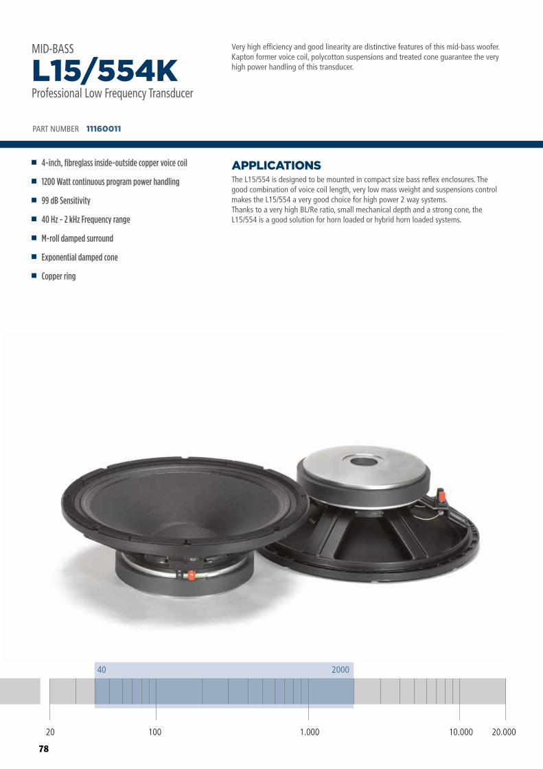
78
Very high efficiency and good linearity are distinctive features of this mid-bass woofer.Kapton former voice coil, polycotton suspensions and treated cone guarantee the very high power handling of this transducer.
The L15/554 is designed to be mounted in compact size bass reflex enclosures. The good combination of voice coil length, very low mass weight and suspensions control makes the L15/554 a very good choice for high power 2 way systems.Thanks to a very high BL/Re ratio, small mechanical depth and a strong cone, the L15/554 is a good solution for horn loaded or hybrid horn loaded systems.
APPLICATIONS
PART NUMBER 11160011
4-inch, fibreglass inside-outside copper voice coil
1200 Watt continuous program power handling
99 dB Sensitivity
40 Hz - 2 kHz Frequency range
M-roll damped surround
Exponential damped cone
Copper ring
L15/554KProfessional Low Frequency Transducer
MID-BASS
20 100 10.000 20.0001.000
40 2000
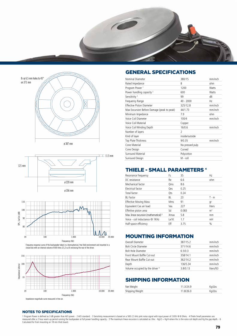
79
NOTES TO SPECIFICATIONS
GENERAL SPECIFICATIONS
THIELE - SMALL PARAMETERS 4
MOUNTING INFORMATION
SHIPPING INFORMATION
1 Program Power is defined as 3 dB greater than AES power. - 2 AES standard. - 3 Sensitivity measurement is based on a 500-2,5 kHz pink noise signal with input power of 2.83V @ 8 Ohms. - 4 Thiele-Small parameters are measured after a 2 hour warm up period running the loudspeaker at full power handling capacity. - 5 The maximum linear excursion is calculated as: (Hvc - Hg)/2 + Hg/4 where Hvc is the voice coil depth and Hg the gap depth. - 6 Calculated for front mounting on 18 mm thick board.
Overall Diameter
Bolt Circle Diameter
Bolt Hole Diameter
Front Mount Baffle Cut-out
Rear Mount Baffle Cut-out
Depth
Volume occupied by the driver 6
387/15.2
371/14.6
6.5/0.3
358/14.1
362/14.2
136/5.34
3.8/0.13
mm/inch
mm/inch
mm/inch
mm/inch
mm/inch
mm/inch
liters/ft3
Net Weight
Shipping Weight
11.3/24.9
11.8/26.0
Kg/Lbs
Kg/Lbs
Resonance frequency
DC resistance
Mechanical factor
Electrical factor
Total factor
BL Factor
Effective Moving Mass
Equivalent Cas air load
Effettive piston area
Max. linear excursion (mathematical) 5
Voice - coil inductance @ 1KHz
Half-space efficiency
Hz
ohm
T · m
gr
liters
m2
mm
mH
%
35
6.6
8.6
0.25
0.24
23
91
227
0.083
5.8
1.7
3.75
Fs
Re
Qms
Qes
Qts
BL
Mms
Vas
Sd
Xmax
Le1K
Eff
Nominal Diameter
Rated Impedance
Program Power 1
Power handling capacity 2
Sensitivity 3
Frequency Range
Effective Piston Diameter
Max Excursion Before Damage (peak to peak)
Minimum Impedance
Voice Coil Diameter
Voice Coil Material
Voice Coil Winding Depth
Number of layers
Kind of layer
Top Plate Thickness
Cone Material
Cone Design
Surround Material
Surround Design
380/15
8
1200
600
99
40 - 2000
325/12.8
44/1.73
7.9
100/4
Copper
16/0.6
2
inside/outside
9/0.35
No pressed pulp
Curved
Polycotton
M - roll
mm/inch
ohm
Watts
Watts
dB
Hz
mm/inch
mm/inch
ohm
mm/inch
mm/inch
mm/inch
80
90
100
110
SPL,
1w/
1m (d
B)
Frequency (Hz)
20 100 1.000 10.000 20.000
Frequency response curve of the loudspeaker taken in a hemispherical, free field environment and mounted in a closed box with an internal volume of 600 litres (21,2 cu.ft) enclosing the rear of the driver.
Frequency (Hz)
20 100 1.000 10.000 20.000
10
100
316
Impe
danc
e (o
hms)
Impedance magnitude curve measured in free air.
ø 387 mm
ø 356 mm
ø 220 mm
11.5 mm
121 mm
8 x ø 6.5 mm holes to 45°on 371 mm
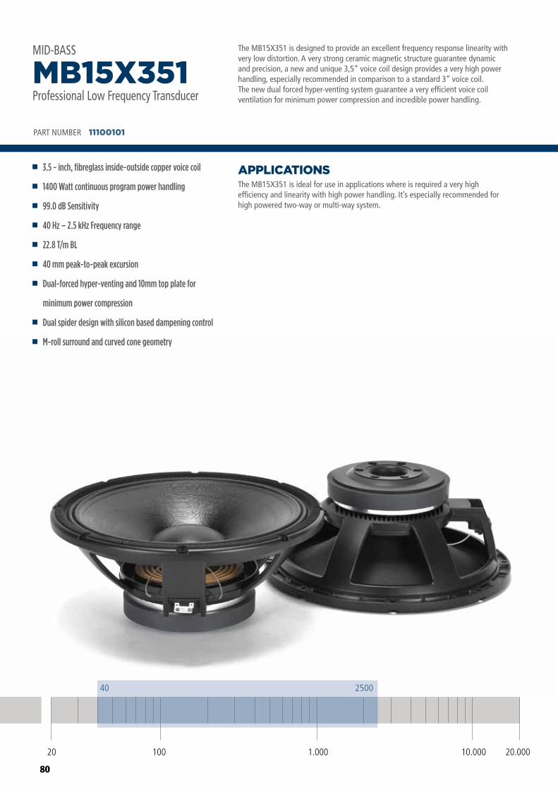
80
The MB15X351 is designed to provide an excellent frequency response linearity withvery low distortion. A very strong ceramic magnetic structure guarantee dynamicand precision, a new and unique 3,5” voice coil design provides a very high powerhandling, especially recommended in comparison to a standard 3” voice coil. The new dual forced hyper-venting system guarantee a very efficient voice coil ventilation for minimum power compression and incredible power handling.
The MB15X351 is ideal for use in applications where is required a very highefficiency and linearity with high power handling. It’s especially recommended forhigh powered two-way or multi-way system.
APPLICATIONS
PART NUMBER 11100101
3.5 - inch, fibreglass inside-outside copper voice coil
1400 Watt continuous program power handling
99.0 dB Sensitivity
40 Hz – 2.5 kHz Frequency range
22.8 T/m BL
40 mm peak-to-peak excursion
Dual-forced hyper-venting and 10mm top plate for
minimum power compression
Dual spider design with silicon based dampening control
M-roll surround and curved cone geometry
MB15X351Professional Low Frequency Transducer
MID-BASS
20 100 10.000 20.0001.000
40 2500
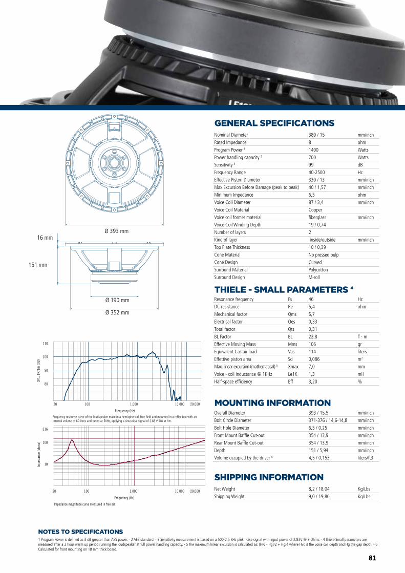
81
NOTES TO SPECIFICATIONS
GENERAL SPECIFICATIONS
THIELE - SMALL PARAMETERS 4
MOUNTING INFORMATION
SHIPPING INFORMATION
1 Program Power is defined as 3 dB greater than AES power. - 2 AES standard. - 3 Sensitivity measurement is based on a 500-2,5 kHz pink noise signal with input power of 2.83V @ 8 Ohms. - 4 Thiele-Small parameters are measured after a 2 hour warm up period running the loudspeaker at full power handling capacity. - 5 The maximum linear excursion is calculated as: (Hvc - Hg)/2 + Hg/4 where Hvc is the voice coil depth and Hg the gap depth. - 6 Calculated for front mounting on 18 mm thick board.
Overall Diameter
Bolt Circle Diameter
Bolt Hole Diameter
Front Mount Baffle Cut-out
Rear Mount Baffle Cut-out
Depth
Volume occupied by the driver 6
393 / 15,5
371-376 / 14,6-14,8
6,5 / 0,25
354 / 13,9
354 / 13,9
151 / 5,94
4,5 / 0,153
mm/inch
mm/inch
mm/inch
mm/inch
mm/inch
mm/inch
liters/ft3
Net Weight
Shipping Weight
8,2 / 18,04
9,0 / 19,80
Kg/Lbs
Kg/Lbs
Resonance frequency
DC resistance
Mechanical factor
Electrical factor
Total factor
BL Factor
Effective Moving Mass
Equivalent Cas air load
Effettive piston area
Max. linear excursion (mathematical) 5
Voice - coil inductance @ 1KHz
Half-space efficiency
Hz
ohm
T · m
gr
liters
m2
mm
mH
%
46
5,4
6,7
0,33
0,31
22,8
106
114
0,086
7,0
1,3
3,20
Fs
Re
Qms
Qes
Qts
BL
Mms
Vas
Sd
Xmax
Le1K
Eff
Nominal Diameter
Rated Impedance
Program Power 1
Power handling capacity 2
Sensitivity 3
Frequency Range
Effective Piston Diameter
Max Excursion Before Damage (peak to peak)
Minimum Impedance
Voice Coil Diameter
Voice Coil Material
Voice coil former material
Voice Coil Winding Depth
Number of layers
Kind of layer
Top Plate Thickness
Cone Material
Cone Design
Surround Material
Surround Design
380 / 15
8
1400
700
99
40-2500
330 / 13
40 / 1,57
6,5
87 / 3,4
Copper
fiberglass
19 / 0,74
2
inside/outside
10 / 0,39
No pressed pulp
Curved
Polycotton
M-roll
mm/inch
ohm
Watts
Watts
dB
Hz
mm/inch
mm/inch
ohm
mm/inch
mm/inch
mm/inch
Impedance magnitude curve measured in free air.
Frequency (Hz)
20 100 1.000 10.000 20.000
10
100
316
Impe
danc
e (o
hms)
Frequency (Hz)
20 100 1.000 10.000 20.000
Frequency response curve of the loudspeaker taken in a hemispherical, free �eld environment and mounted in a closed box with an internal volume of 600 litres (21,2 cu.ft) enclosing the rear of the driver.
80
90
100
110
SPL,
1w/
1m (d
B)
MB15X351 MB12X351
Ø 393 mm
Ø 190 mm
Ø 352 mm
151 mm
16 mm
Frequency response curve of the loudspeaker make in a hemispherical, free field and mounted in a reflex box with an internal volume of 80 litres and tuned at 50Hz, applying a sinusoidal signal of 2.83 V @8 at 1m.
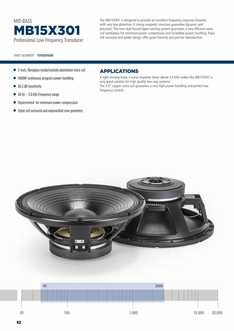
82
The MB15X301 is designed to provide an excellent frequency response linearity with very low distortion. A strong magnetic structure guarantee dynamic and precision. The new dual forced hyper-venting system guarantee a very efficient voice coil ventilation for minimum power compression and incredible power handling. Triple roll surround and spider design offer great linearity and precise reproduction.
A light moving mass, a curve response linear above 3.0 kHz makes the MB15X301 a very good solution for high quality two way systems.The 3.0” copper voice coil guarantee a very high power handling and perfect low frequency control.
APPLICATIONS
PART NUMBER 11100106
3-inch, fibreglass inside/outside aluminium voice coil
1000W continuous program power handling
98.5 dB Sensitivity
40 Hz – 3.0 kHz Frequency range
Hypervented for minimum power compression
Triple roll surround and exponential cone geometry
MB15X301Professional Low Frequency Transducer
MID-BASS
20 100 10.000 20.0001.000
40 3000
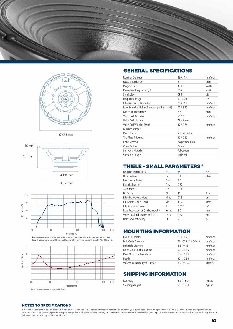
83
NOTES TO SPECIFICATIONS
GENERAL SPECIFICATIONS
THIELE - SMALL PARAMETERS 4
MOUNTING INFORMATION
SHIPPING INFORMATION
1 Program Power is defined as 3 dB greater than AES power. - 2 AES standard. - 3 Sensitivity measurement is based on a 500-2,5 kHz pink noise signal with input power of 2.83V @ 8 Ohms. - 4 Thiele-Small parameters are measured after a 2 hour warm up period running the loudspeaker at full power handling capacity. - 5 The maximum linear excursion is calculated as: (Hvc - Hg)/2 + Hg/4 where Hvc is the voice coil depth and Hg the gap depth. - 6 Calculated for front mounting on 18 mm thick board.
Overall Diameter
Bolt Circle Diameter
Bolt Hole Diameter
Front Mount Baffle Cut-out
Rear Mount Baffle Cut-out
Depth
Volume occupied by the driver 6
393 / 15,5
371-376 / 14,6-14,8
6,5 / 0,25
354 / 13,9
354 / 13,9
151 / 5,94
4,5 / 0,153
mm/inch
mm/inch
mm/inch
mm/inch
mm/inch
mm/inch
liters/ft3
Net Weight
Shipping Weight
8,2 / 18,04
9,0 / 19,80
Kg/Lbs
Kg/Lbs
Resonance frequency
DC resistance
Mechanical factor
Electrical factor
Total factor
BL Factor
Effective Moving Mass
Equivalent Cas air load
Effettive piston area
Max. linear excursion (mathematical) 5
Voice - coil inductance @ 1KHz
Half-space efficiency
Hz
ohm
T · m
gr
liters
m2
mm
mH
%
38
5,4
5,0
0,37
0,34
18
91,5
195
0,086
6,0
0,52
2,80
Fs
Re
Qms
Qes
Qts
BL
Mms
Vas
Sd
Xmax
Le1K
Eff
Nominal Diameter
Rated Impedance
Program Power 1
Power handling capacity 2
Sensitivity 3
Frequency Range
Effective Piston Diameter
Max Excursion Before Damage (peak to peak)
Minimum Impedance
Voice Coil Diameter
Voice Coil Material
Voice Coil Winding Depth
Number of layers
Kind of layer
Top Plate Thickness
Cone Material
Cone Design
Surround Material
Surround Design
380 / 15
8
1000
500
98,5
40-3000
330 / 13
40 / 1,57
6,5
76 / 3,0
Aluminum
17 / 0,66
2
inside/outside
10 / 0,39
No pressed pulp
Curved
Polycotton
Triple-roll
mm/inch
ohm
Watts
Watts
dB
Hz
mm/inch
mm/inch
ohm
mm/inch
mm/inch
mm/inch
Impedance magnitude curve measured in free air.
Frequency (Hz)
20 100 1.000 10.000 20.000
10
100
316
Impe
danc
e (o
hms)
Frequency (Hz)
20 100 1.000 10.000 20.000
80
90
100
110
SPL,
1w/
1m (d
B)
Frequency response curve of the loudspeaker made in a hemispherical, free �eld and mounted in a re�ex box with an internal volume of 50 litres and tuned at 60Hz, applying a sinusoidal signal of 2.83 V@8 at 1m.
MB10G251
MB12X301 MB15X301
MB15N405MB12N405
MB10N305
Ø 393 mm
Ø 190 mm
Ø 352 mm
151 mm
16 mm

84
High power 15” woofer. Very good power handling, excellent linearity and very low distortion. Very efficient heat dissipation is ensured by a radiator that is part of the basket design. The air is forced in the radiator thanks to a dual sealed spider design.
The excellent linear response, well controlled down to 40 Hertz, makes the L15P540 especially suitable for horn-loaded applications, band-pass enclosures and small size bass reflex systems.It is a very good solution for two or three way system when a very high BL and maximum punch is required.
APPLICATIONS
PART NUMBER 11165015
3-inch, fibreglass inside-outside copper voice coil
1O00 Watt continuous program power handling
98 dB Sensitivity
40 Hz - 2 kHz Frequency range
Dual spider design with silicon based dampening control
M-roll surround and exponential cone geometry
L15P540Professional Low Frequency Transducer
WOOFER
20 100 10.000 20.0001.000
40 2000
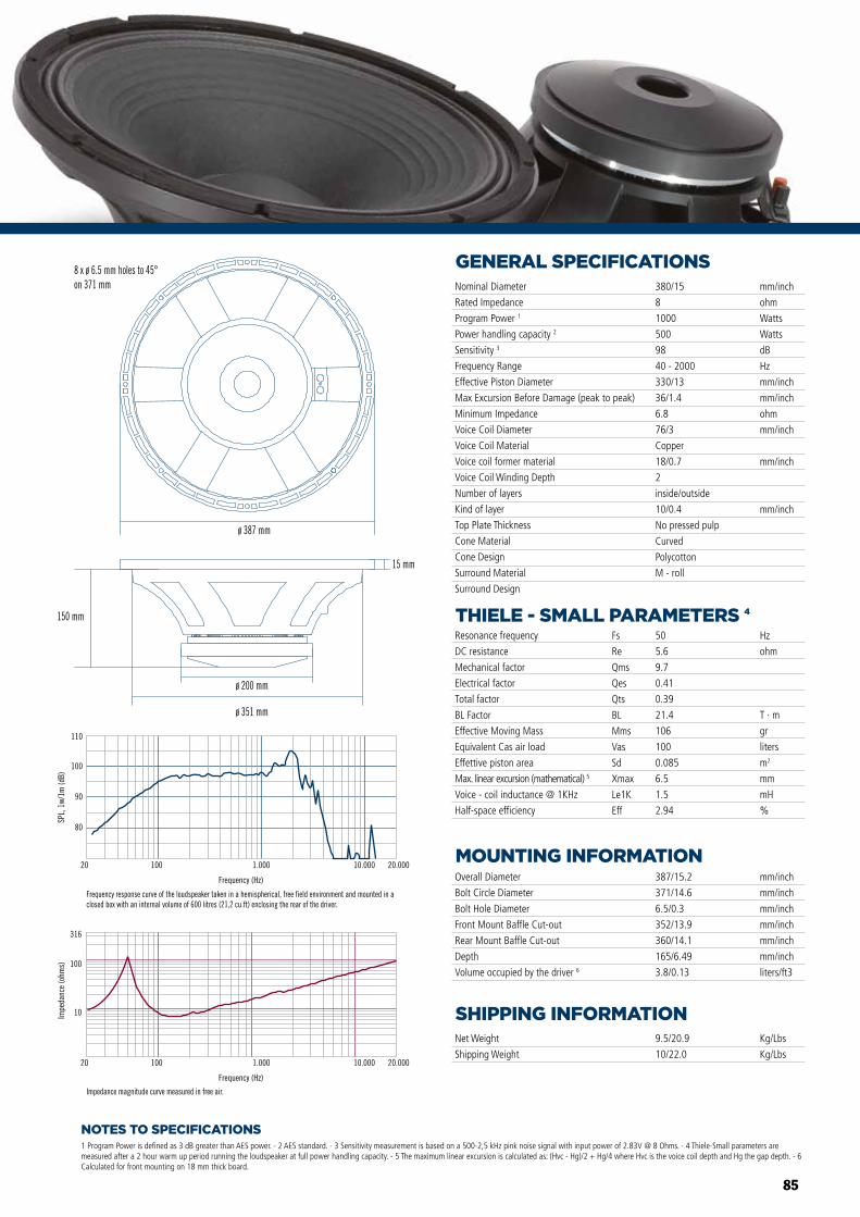
85
NOTES TO SPECIFICATIONS
GENERAL SPECIFICATIONS
THIELE - SMALL PARAMETERS 4
MOUNTING INFORMATION
SHIPPING INFORMATION
1 Program Power is defined as 3 dB greater than AES power. - 2 AES standard. - 3 Sensitivity measurement is based on a 500-2,5 kHz pink noise signal with input power of 2.83V @ 8 Ohms. - 4 Thiele-Small parameters are measured after a 2 hour warm up period running the loudspeaker at full power handling capacity. - 5 The maximum linear excursion is calculated as: (Hvc - Hg)/2 + Hg/4 where Hvc is the voice coil depth and Hg the gap depth. - 6 Calculated for front mounting on 18 mm thick board.
Overall Diameter
Bolt Circle Diameter
Bolt Hole Diameter
Front Mount Baffle Cut-out
Rear Mount Baffle Cut-out
Depth
Volume occupied by the driver 6
387/15.2
371/14.6
6.5/0.3
352/13.9
360/14.1
165/6.49
3.8/0.13
mm/inch
mm/inch
mm/inch
mm/inch
mm/inch
mm/inch
liters/ft3
Net Weight
Shipping Weight
9.5/20.9
10/22.0
Kg/Lbs
Kg/Lbs
Resonance frequency
DC resistance
Mechanical factor
Electrical factor
Total factor
BL Factor
Effective Moving Mass
Equivalent Cas air load
Effettive piston area
Max. linear excursion (mathematical) 5
Voice - coil inductance @ 1KHz
Half-space efficiency
Hz
ohm
T · m
gr
liters
m2
mm
mH
%
50
5.6
9.7
0.41
0.39
21.4
106
100
0.085
6.5
1.5
2.94
Fs
Re
Qms
Qes
Qts
BL
Mms
Vas
Sd
Xmax
Le1K
Eff
Nominal Diameter
Rated Impedance
Program Power 1
Power handling capacity 2
Sensitivity 3
Frequency Range
Effective Piston Diameter
Max Excursion Before Damage (peak to peak)
Minimum Impedance
Voice Coil Diameter
Voice Coil Material
Voice coil former material
Voice Coil Winding Depth
Number of layers
Kind of layer
Top Plate Thickness
Cone Material
Cone Design
Surround Material
Surround Design
380/15
8
1000
500
98
40 - 2000
330/13
36/1.4
6.8
76/3
Copper
18/0.7
2
inside/outside
10/0.4
No pressed pulp
Curved
Polycotton
M - roll
mm/inch
ohm
Watts
Watts
dB
Hz
mm/inch
mm/inch
ohm
mm/inch
mm/inch
mm/inch
80
90
100
110
SPL,
1w/
1m (d
B)
Frequency (Hz)
20 100 1.000 10.000 20.000
Frequency response curve of the loudspeaker taken in a hemispherical, free field environment and mounted in a closed box with an internal volume of 600 litres (21,2 cu.ft) enclosing the rear of the driver.
Frequency (Hz)
20 100 1.000 10.000 20.000
10
100
316
Impe
danc
e (o
hms)
Impedance magnitude curve measured in free air.
ø 387 mm
8 x ø 6.5 mm holes to 45°on 371 mm
ø 200 mm
ø 351 mm
150 mm
15 mm
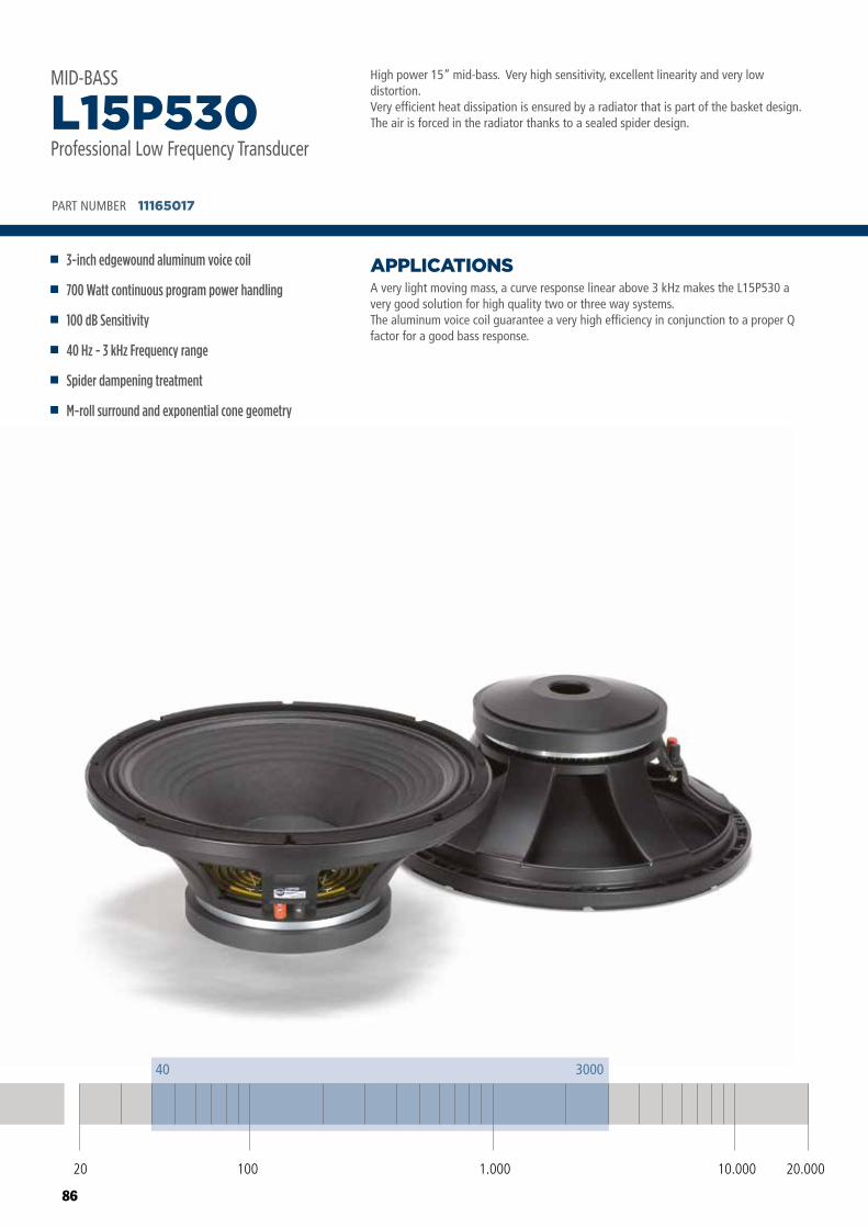
86
High power 15” mid-bass. Very high sensitivity, excellent linearity and very low distortion. Very efficient heat dissipation is ensured by a radiator that is part of the basket design. The air is forced in the radiator thanks to a sealed spider design.
A very light moving mass, a curve response linear above 3 kHz makes the L15P530 a very good solution for high quality two or three way systems.The aluminum voice coil guarantee a very high efficiency in conjunction to a proper Q factor for a good bass response.
APPLICATIONS
PART NUMBER 11165017
3-inch edgewound aluminum voice coil
700 Watt continuous program power handling
100 dB Sensitivity
40 Hz - 3 kHz Frequency range
Spider dampening treatment
M-roll surround and exponential cone geometry
L15P530Professional Low Frequency Transducer
MID-BASS
20 100 10.000 20.0001.000
40 3000
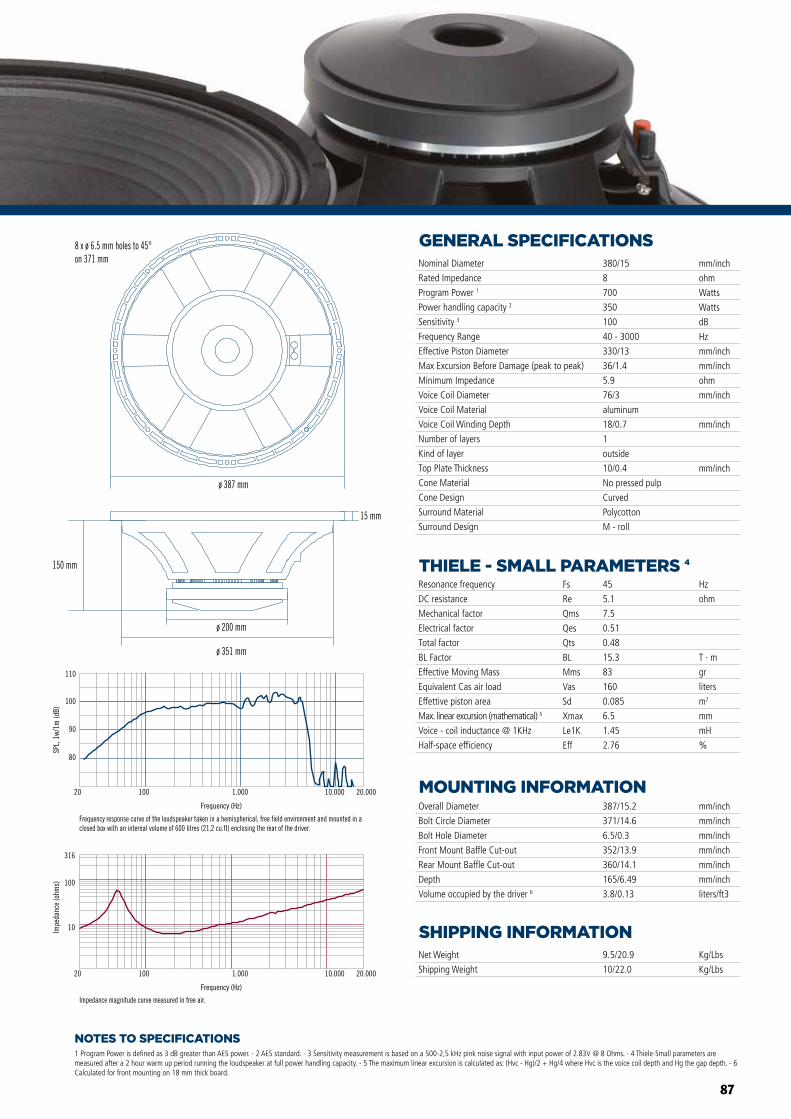
87
NOTES TO SPECIFICATIONS
GENERAL SPECIFICATIONS
THIELE - SMALL PARAMETERS 4
MOUNTING INFORMATION
SHIPPING INFORMATION
1 Program Power is defined as 3 dB greater than AES power. - 2 AES standard. - 3 Sensitivity measurement is based on a 500-2,5 kHz pink noise signal with input power of 2.83V @ 8 Ohms. - 4 Thiele-Small parameters are measured after a 2 hour warm up period running the loudspeaker at full power handling capacity. - 5 The maximum linear excursion is calculated as: (Hvc - Hg)/2 + Hg/4 where Hvc is the voice coil depth and Hg the gap depth. - 6 Calculated for front mounting on 18 mm thick board.
Overall Diameter
Bolt Circle Diameter
Bolt Hole Diameter
Front Mount Baffle Cut-out
Rear Mount Baffle Cut-out
Depth
Volume occupied by the driver 6
387/15.2
371/14.6
6.5/0.3
352/13.9
360/14.1
165/6.49
3.8/0.13
mm/inch
mm/inch
mm/inch
mm/inch
mm/inch
mm/inch
liters/ft3
Net Weight
Shipping Weight
9.5/20.9
10/22.0
Kg/Lbs
Kg/Lbs
Resonance frequency
DC resistance
Mechanical factor
Electrical factor
Total factor
BL Factor
Effective Moving Mass
Equivalent Cas air load
Effettive piston area
Max. linear excursion (mathematical) 5
Voice - coil inductance @ 1KHz
Half-space efficiency
Hz
ohm
T · m
gr
liters
m2
mm
mH
%
45
5.1
7.5
0.51
0.48
15.3
83
160
0.085
6.5
1.45
2.76
Fs
Re
Qms
Qes
Qts
BL
Mms
Vas
Sd
Xmax
Le1K
Eff
Nominal Diameter
Rated Impedance
Program Power 1
Power handling capacity 2
Sensitivity 3
Frequency Range
Effective Piston Diameter
Max Excursion Before Damage (peak to peak)
Minimum Impedance
Voice Coil Diameter
Voice Coil Material
Voice Coil Winding Depth
Number of layers
Kind of layer
Top Plate Thickness
Cone Material
Cone Design
Surround Material
Surround Design
380/15
8
700
350
100
40 - 3000
330/13
36/1.4
5.9
76/3
aluminum
18/0.7
1
outside
10/0.4
No pressed pulp
Curved
Polycotton
M - roll
mm/inch
ohm
Watts
Watts
dB
Hz
mm/inch
mm/inch
ohm
mm/inch
mm/inch
mm/inch
80
90
100
110
SPL,
1w/
1m (d
B)
Frequency (Hz)
20 100 1.000 10.000 20.000
Frequency response curve of the loudspeaker taken in a hemispherical, free field environment and mounted in a closed box with an internal volume of 600 litres (21,2 cu.ft) enclosing the rear of the driver.
Frequency (Hz)
20 100 1.000 10.000 20.000
10
100
316
Impe
danc
e (o
hms)
Impedance magnitude curve measured in free air.
ø 387 mm
8 x ø 6.5 mm holes to 45°on 371 mm
ø 200 mm
ø 351 mm
150 mm
15 mm
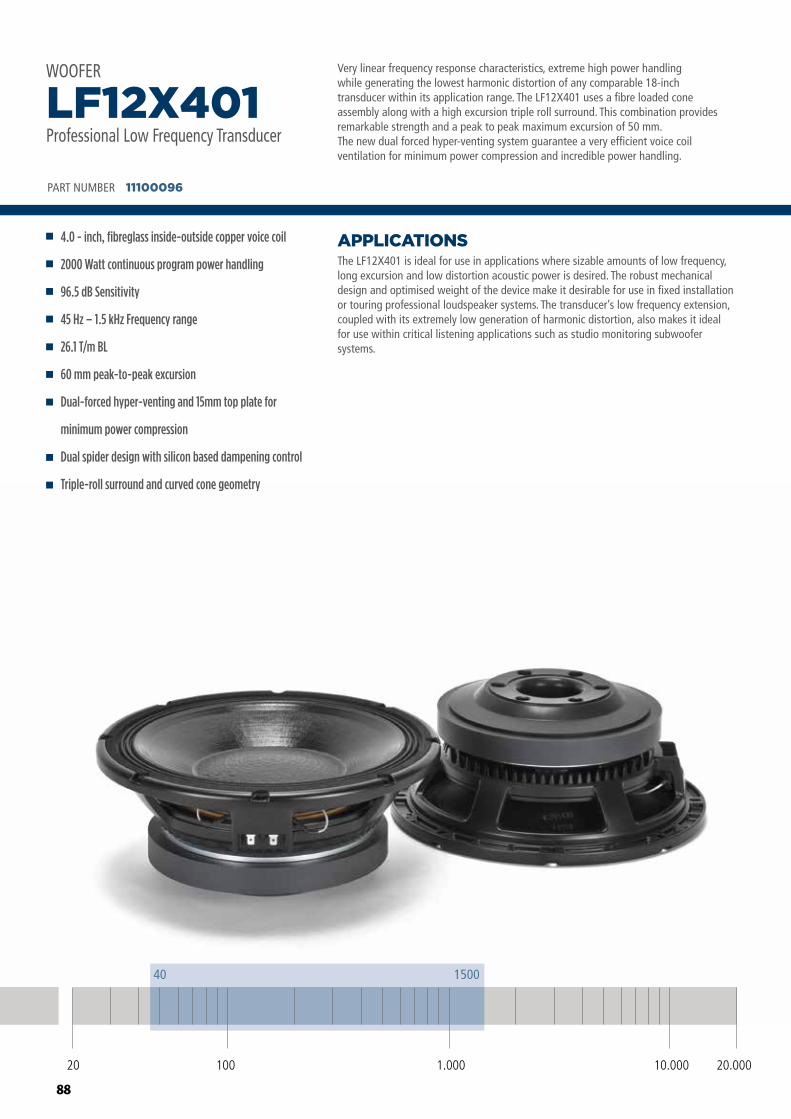
88
Very linear frequency response characteristics, extreme high power handlingwhile generating the lowest harmonic distortion of any comparable 18-inchtransducer within its application range. The LF12X401 uses a fibre loaded coneassembly along with a high excursion triple roll surround. This combination providesremarkable strength and a peak to peak maximum excursion of 50 mm. The new dual forced hyper-venting system guarantee a very efficient voice coil ventilation for minimum power compression and incredible power handling.
The LF12X401 is ideal for use in applications where sizable amounts of low frequency, long excursion and low distortion acoustic power is desired. The robust mechanical design and optimised weight of the device make it desirable for use in fixed installation or touring professional loudspeaker systems. The transducer’s low frequency extension, coupled with its extremely low generation of harmonic distortion, also makes it ideal for use within critical listening applications such as studio monitoring subwoofer systems.
APPLICATIONS
PART NUMBER 11100096
4.0 - inch, fibreglass inside-outside copper voice coil
2000 Watt continuous program power handling
96.5 dB Sensitivity
45 Hz – 1.5 kHz Frequency range
26.1 T/m BL
60 mm peak-to-peak excursion
Dual-forced hyper-venting and 15mm top plate for
minimum power compression
Dual spider design with silicon based dampening control
Triple-roll surround and curved cone geometry
LF12X401Professional Low Frequency Transducer
WOOFER
20 100 10.000 20.0001.000
40 1500
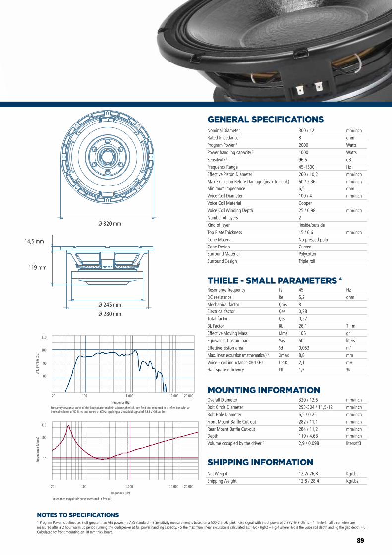
89
NOTES TO SPECIFICATIONS
GENERAL SPECIFICATIONS
THIELE - SMALL PARAMETERS 4
MOUNTING INFORMATION
SHIPPING INFORMATION
1 Program Power is defined as 3 dB greater than AES power. - 2 AES standard. - 3 Sensitivity measurement is based on a 500-2,5 kHz pink noise signal with input power of 2.83V @ 8 Ohms. - 4 Thiele-Small parameters are measured after a 2 hour warm up period running the loudspeaker at full power handling capacity. - 5 The maximum linear excursion is calculated as: (Hvc - Hg)/2 + Hg/4 where Hvc is the voice coil depth and Hg the gap depth. - 6 Calculated for front mounting on 18 mm thick board.
Overall Diameter
Bolt Circle Diameter
Bolt Hole Diameter
Front Mount Baffle Cut-out
Rear Mount Baffle Cut-out
Depth
Volume occupied by the driver 6
320 / 12,6
293-304 / 11,5-12
6,5 / 0,25
282 / 11,1
284 / 11,2
119 / 4.68
2,9 / 0,098
mm/inch
mm/inch
mm/inch
mm/inch
mm/inch
mm/inch
liters/ft3
Net Weight
Shipping Weight
12,2/ 26,8
12,8 / 28,4
Kg/Lbs
Kg/Lbs
Resonance frequency
DC resistance
Mechanical factor
Electrical factor
Total factor
BL Factor
Effective Moving Mass
Equivalent Cas air load
Effettive piston area
Max. linear excursion (mathematical) 5
Voice - coil inductance @ 1KHz
Half-space efficiency
Hz
ohm
T · m
gr
liters
m2
mm
mH
%
45
5,2
8
0,28
0,27
26,1
105
50
0,053
8,8
2,1
1,5
Fs
Re
Qms
Qes
Qts
BL
Mms
Vas
Sd
Xmax
Le1K
Eff
Nominal Diameter
Rated Impedance
Program Power 1
Power handling capacity 2
Sensitivity 3
Frequency Range
Effective Piston Diameter
Max Excursion Before Damage (peak to peak)
Minimum Impedance
Voice Coil Diameter
Voice Coil Material
Voice Coil Winding Depth
Number of layers
Kind of layer
Top Plate Thickness
Cone Material
Cone Design
Surround Material
Surround Design
300 / 12
8
2000
1000
96,5
45-1500
260 / 10,2
60 / 2,36
6,5
100 / 4
Copper
25 / 0,98
2
inside/outside
15 / 0,6
No pressed pulp
Curved
Polycotton
Triple roll
mm/inch
ohm
Watts
Watts
dB
Hz
mm/inch
mm/inch
ohm
mm/inch
mm/inch
mm/inch
Impedance magnitude curve measured in free air.
Frequency (Hz)
20 100 1.000 10.000 20.000
10
100
316
Impe
danc
e (o
hms)
Frequency (Hz)
20 100 1.000 10.000 20.000
Frequency response curve of the loudspeaker taken in a hemispherical, free �eld environment and mounted in a closed box with an internal volume of 600 litres (21,2 cu.ft) enclosing the rear of the driver.
80
90
100
110
SPL,
1w/
1m (d
B)
LF18X401 LF15X401 LF12X401
LF18X401 LF15X401 LF12X401
Ø 320 mm
Ø 245 mm
Ø 280 mm
119 mm
14,5 mm
Frequency response curve of the loudspeaker make in a hemispherical, free field and mounted in a reflex box with an internal volume of 50 litres and tuned at 60Hz, applying a sinusoidal signal of 2.83 V @8 at 1m.
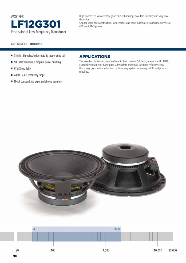
90
High power 12” woofer. Very good power handling, excellent linearity and very low distortion. Copper voice coil construction, suspensions and cone materials designed to survive at 450 Watt RMS power.
The excellent linear response, well controlled down to 50 Hertz, makes the LF12G301 especially suitable for band-pass subwoofers and small size bass reflex systems.It is a very good solution for two or three way system when a good BL and punch is required.
APPLICATIONS
PART NUMBER 11100016
3-inch, , fibreglass inside-outside copper voice coil
900 Watt continuous program power handling
97 dB Sensitivity
40 Hz - 2 kHz Frequency range
M-roll surround and exponential cone geometry
LF12G301Professional Low Frequency Transducer
WOOFER
20 100 10.000 20.0001.000
40 2000
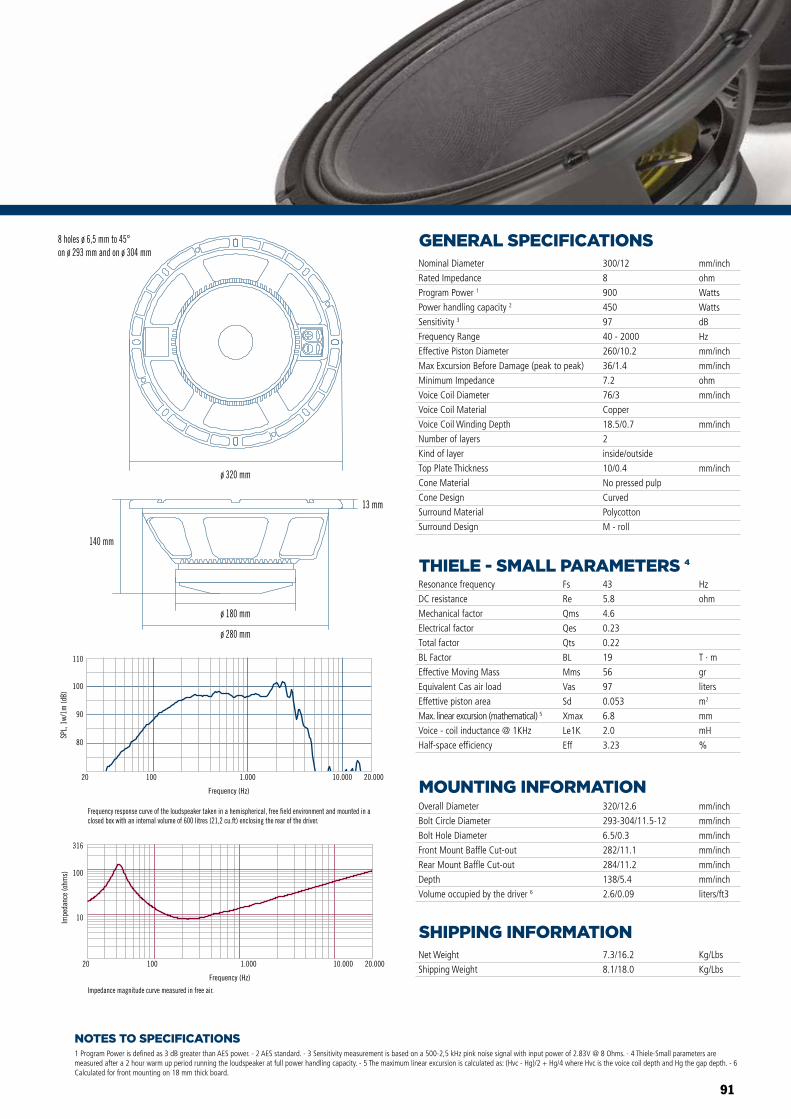
91
NOTES TO SPECIFICATIONS
GENERAL SPECIFICATIONS
THIELE - SMALL PARAMETERS 4
MOUNTING INFORMATION
SHIPPING INFORMATION
1 Program Power is defined as 3 dB greater than AES power. - 2 AES standard. - 3 Sensitivity measurement is based on a 500-2,5 kHz pink noise signal with input power of 2.83V @ 8 Ohms. - 4 Thiele-Small parameters are measured after a 2 hour warm up period running the loudspeaker at full power handling capacity. - 5 The maximum linear excursion is calculated as: (Hvc - Hg)/2 + Hg/4 where Hvc is the voice coil depth and Hg the gap depth. - 6 Calculated for front mounting on 18 mm thick board.
Overall Diameter
Bolt Circle Diameter
Bolt Hole Diameter
Front Mount Baffle Cut-out
Rear Mount Baffle Cut-out
Depth
Volume occupied by the driver 6
320/12.6
293-304/11.5-12
6.5/0.3
282/11.1
284/11.2
138/5.4
2.6/0.09
mm/inch
mm/inch
mm/inch
mm/inch
mm/inch
mm/inch
liters/ft3
Net Weight
Shipping Weight
7.3/16.2
8.1/18.0
Kg/Lbs
Kg/Lbs
Resonance frequency
DC resistance
Mechanical factor
Electrical factor
Total factor
BL Factor
Effective Moving Mass
Equivalent Cas air load
Effettive piston area
Max. linear excursion (mathematical) 5
Voice - coil inductance @ 1KHz
Half-space efficiency
Hz
ohm
T · m
gr
liters
m2
mm
mH
%
43
5.8
4.6
0.23
0.22
19
56
97
0.053
6.8
2.0
3.23
Fs
Re
Qms
Qes
Qts
BL
Mms
Vas
Sd
Xmax
Le1K
Eff
Nominal Diameter
Rated Impedance
Program Power 1
Power handling capacity 2
Sensitivity 3
Frequency Range
Effective Piston Diameter
Max Excursion Before Damage (peak to peak)
Minimum Impedance
Voice Coil Diameter
Voice Coil Material
Voice Coil Winding Depth
Number of layers
Kind of layer
Top Plate Thickness
Cone Material
Cone Design
Surround Material
Surround Design
300/12
8
900
450
97
40 - 2000
260/10.2
36/1.4
7.2
76/3
Copper
18.5/0.7
2
inside/outside
10/0.4
No pressed pulp
Curved
Polycotton
M - roll
mm/inch
ohm
Watts
Watts
dB
Hz
mm/inch
mm/inch
ohm
mm/inch
mm/inch
mm/inchø 320 mm
140 mm
ø 180 mm
ø 280 mm
13 mm
Frequency (Hz)
20 100 1.000 10.000 20.000
10
100
316
Impe
danc
e (o
hms)
Impedance magnitude curve measured in free air.
8 holes ø 6,5 mm to 45°on ø 293 mm and on ø 304 mm
Frequency response curve of the loudspeaker taken in a hemispherical, free field environment and mounted in a closed box with an internal volume of 600 litres (21,2 cu.ft) enclosing the rear of the driver.
80
90
100
110
SPL,
1w/
1m (d
B)
Frequency (Hz)
20 100 1.000 10.000 20.000
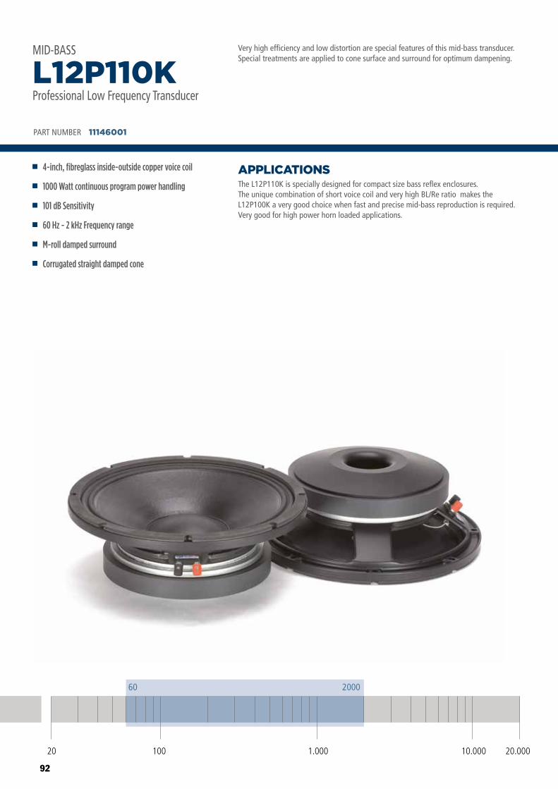
92
Very high efficiency and low distortion are special features of this mid-bass transducer. Special treatments are applied to cone surface and surround for optimum dampening.
The L12P110K is specially designed for compact size bass reflex enclosures. The unique combination of short voice coil and very high BL/Re ratio makes the L12P100K a very good choice when fast and precise mid-bass reproduction is required.Very good for high power horn loaded applications.
APPLICATIONS
PART NUMBER 11146001
4-inch, fibreglass inside-outside copper voice coil
1000 Watt continuous program power handling
101 dB Sensitivity
60 Hz - 2 kHz Frequency range
M-roll damped surround
Corrugated straight damped cone
L12P110KProfessional Low Frequency Transducer
MID-BASS
20 100 10.000 20.0001.000
60 2000
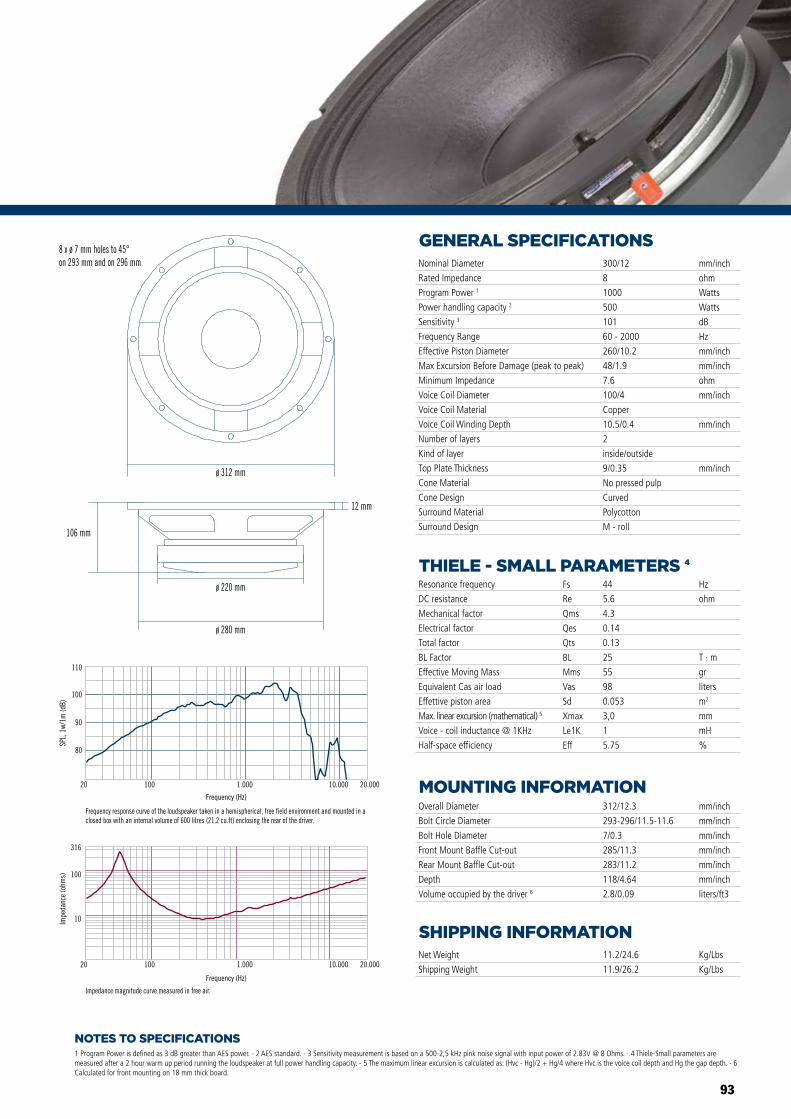
93
NOTES TO SPECIFICATIONS
GENERAL SPECIFICATIONS
THIELE - SMALL PARAMETERS 4
MOUNTING INFORMATION
SHIPPING INFORMATION
1 Program Power is defined as 3 dB greater than AES power. - 2 AES standard. - 3 Sensitivity measurement is based on a 500-2,5 kHz pink noise signal with input power of 2.83V @ 8 Ohms. - 4 Thiele-Small parameters are measured after a 2 hour warm up period running the loudspeaker at full power handling capacity. - 5 The maximum linear excursion is calculated as: (Hvc - Hg)/2 + Hg/4 where Hvc is the voice coil depth and Hg the gap depth. - 6 Calculated for front mounting on 18 mm thick board.
Overall Diameter
Bolt Circle Diameter
Bolt Hole Diameter
Front Mount Baffle Cut-out
Rear Mount Baffle Cut-out
Depth
Volume occupied by the driver 6
312/12.3
293-296/11.5-11.6
7/0.3
285/11.3
283/11.2
118/4.64
2.8/0.09
mm/inch
mm/inch
mm/inch
mm/inch
mm/inch
mm/inch
liters/ft3
Net Weight
Shipping Weight
11.2/24.6
11.9/26.2
Kg/Lbs
Kg/Lbs
Resonance frequency
DC resistance
Mechanical factor
Electrical factor
Total factor
BL Factor
Effective Moving Mass
Equivalent Cas air load
Effettive piston area
Max. linear excursion (mathematical) 5
Voice - coil inductance @ 1KHz
Half-space efficiency
Hz
ohm
T · m
gr
liters
m2
mm
mH
%
44
5.6
4.3
0.14
0.13
25
55
98
0.053
3,0
1
5.75
Fs
Re
Qms
Qes
Qts
BL
Mms
Vas
Sd
Xmax
Le1K
Eff
Nominal Diameter
Rated Impedance
Program Power 1
Power handling capacity 2
Sensitivity 3
Frequency Range
Effective Piston Diameter
Max Excursion Before Damage (peak to peak)
Minimum Impedance
Voice Coil Diameter
Voice Coil Material
Voice Coil Winding Depth
Number of layers
Kind of layer
Top Plate Thickness
Cone Material
Cone Design
Surround Material
Surround Design
300/12
8
1000
500
101
60 - 2000
260/10.2
48/1.9
7.6
100/4
Copper
10.5/0.4
2
inside/outside
9/0.35
No pressed pulp
Curved
Polycotton
M - roll
mm/inch
ohm
Watts
Watts
dB
Hz
mm/inch
mm/inch
ohm
mm/inch
mm/inch
mm/inch
80
90
100
110
SPL,
1w/
1m (d
B)
20 100 1.000 10.000 20.000
Frequency response curve of the loudspeaker taken in a hemispherical, free field environment and mounted in a closed box with an internal volume of 600 litres (21,2 cu.ft) enclosing the rear of the driver.
Frequency (Hz)
20 100 1.000 10.000 20.000
10
100
316
Impe
danc
e (o
hms)
Impedance magnitude curve measured in free air.
ø 312 mm
8 x ø 7 mm holes to 45°on 293 mm and on 296 mm
12 mm
ø 280 mm
ø 220 mm
106 mm
Frequency (Hz)
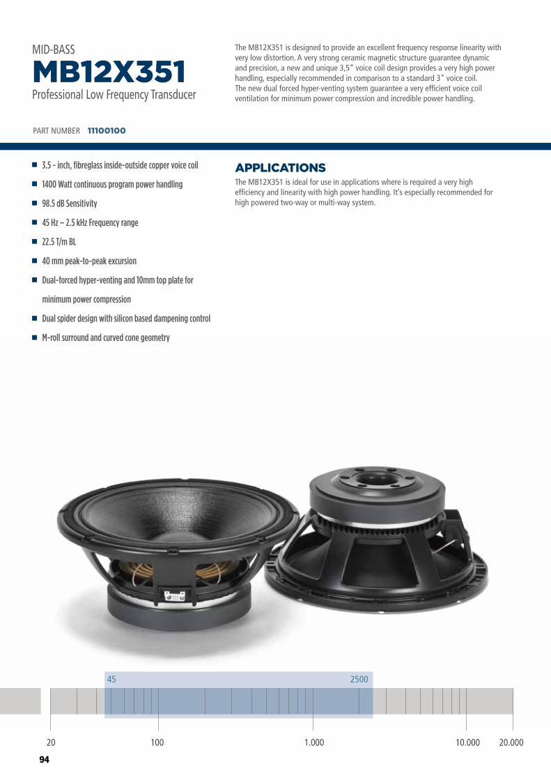
94
The MB12X351 is designed to provide an excellent frequency response linearity withvery low distortion. A very strong ceramic magnetic structure guarantee dynamicand precision, a new and unique 3,5” voice coil design provides a very high powerhandling, especially recommended in comparison to a standard 3” voice coil. The new dual forced hyper-venting system guarantee a very efficient voice coil ventilation for minimum power compression and incredible power handling.
The MB12X351 is ideal for use in applications where is required a very highefficiency and linearity with high power handling. It’s especially recommended forhigh powered two-way or multi-way system.
APPLICATIONS
PART NUMBER 11100100
3.5 - inch, fibreglass inside-outside copper voice coil
1400 Watt continuous program power handling
98.5 dB Sensitivity
45 Hz – 2.5 kHz Frequency range
22.5 T/m BL
40 mm peak-to-peak excursion
Dual-forced hyper-venting and 10mm top plate for
minimum power compression
Dual spider design with silicon based dampening control
M-roll surround and curved cone geometry
MB12X351Professional Low Frequency Transducer
MID-BASS
20 100 10.000 20.0001.000
45 2500
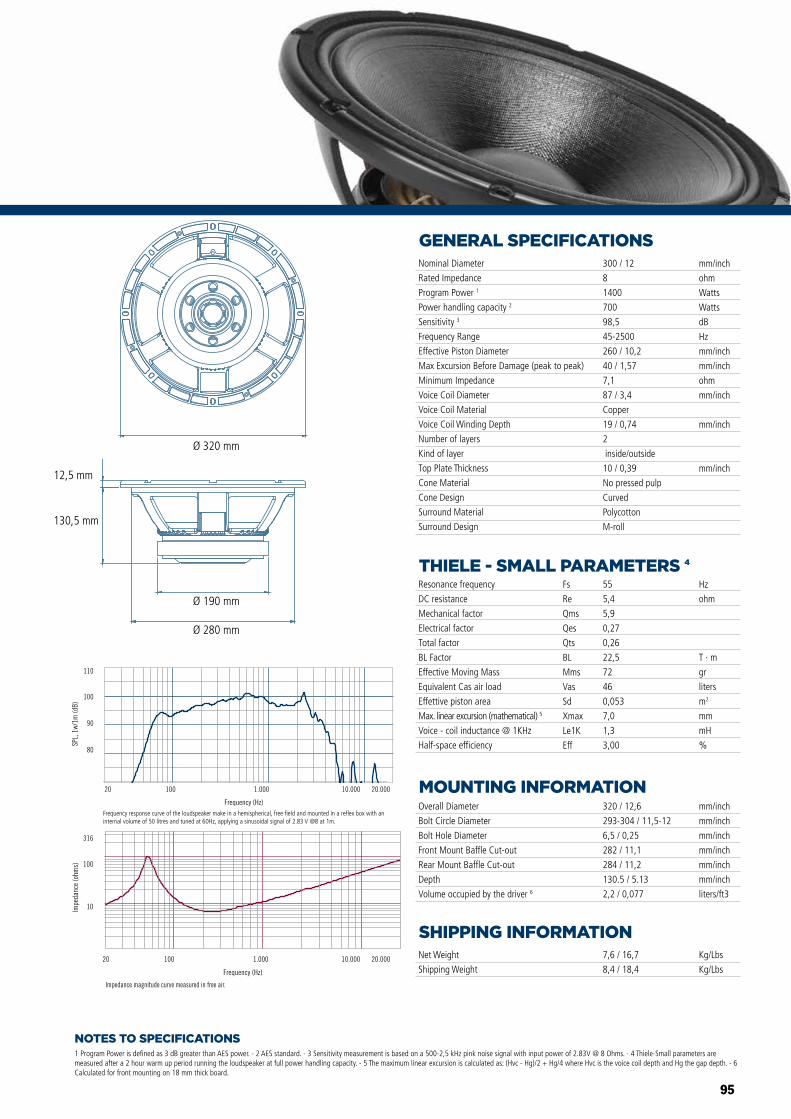
95
NOTES TO SPECIFICATIONS
GENERAL SPECIFICATIONS
THIELE - SMALL PARAMETERS 4
MOUNTING INFORMATION
SHIPPING INFORMATION
1 Program Power is defined as 3 dB greater than AES power. - 2 AES standard. - 3 Sensitivity measurement is based on a 500-2,5 kHz pink noise signal with input power of 2.83V @ 8 Ohms. - 4 Thiele-Small parameters are measured after a 2 hour warm up period running the loudspeaker at full power handling capacity. - 5 The maximum linear excursion is calculated as: (Hvc - Hg)/2 + Hg/4 where Hvc is the voice coil depth and Hg the gap depth. - 6 Calculated for front mounting on 18 mm thick board.
Overall Diameter
Bolt Circle Diameter
Bolt Hole Diameter
Front Mount Baffle Cut-out
Rear Mount Baffle Cut-out
Depth
Volume occupied by the driver 6
320 / 12,6
293-304 / 11,5-12
6,5 / 0,25
282 / 11,1
284 / 11,2
130.5 / 5.13
2,2 / 0,077
mm/inch
mm/inch
mm/inch
mm/inch
mm/inch
mm/inch
liters/ft3
Net Weight
Shipping Weight
7,6 / 16,7
8,4 / 18,4
Kg/Lbs
Kg/Lbs
Resonance frequency
DC resistance
Mechanical factor
Electrical factor
Total factor
BL Factor
Effective Moving Mass
Equivalent Cas air load
Effettive piston area
Max. linear excursion (mathematical) 5
Voice - coil inductance @ 1KHz
Half-space efficiency
Hz
ohm
T · m
gr
liters
m2
mm
mH
%
55
5,4
5,9
0,27
0,26
22,5
72
46
0,053
7,0
1,3
3,00
Fs
Re
Qms
Qes
Qts
BL
Mms
Vas
Sd
Xmax
Le1K
Eff
Nominal Diameter
Rated Impedance
Program Power 1
Power handling capacity 2
Sensitivity 3
Frequency Range
Effective Piston Diameter
Max Excursion Before Damage (peak to peak)
Minimum Impedance
Voice Coil Diameter
Voice Coil Material
Voice Coil Winding Depth
Number of layers
Kind of layer
Top Plate Thickness
Cone Material
Cone Design
Surround Material
Surround Design
300 / 12
8
1400
700
98,5
45-2500
260 / 10,2
40 / 1,57
7,1
87 / 3,4
Copper
19 / 0,74
2
inside/outside
10 / 0,39
No pressed pulp
Curved
Polycotton
M-roll
mm/inch
ohm
Watts
Watts
dB
Hz
mm/inch
mm/inch
ohm
mm/inch
mm/inch
mm/inch
Impedance magnitude curve measured in free air.
Frequency (Hz)
20 100 1.000 10.000 20.000
10
100
316
Impe
danc
e (o
hms)
Frequency (Hz)
20 100 1.000 10.000 20.000
Frequency response curve of the loudspeaker taken in a hemispherical, free �eld environment and mounted in a closed box with an internal volume of 600 litres (21,2 cu.ft) enclosing the rear of the driver.
80
90
100
110
SPL,
1w/
1m (d
B)
Impedance magnitude curve measured in free air.
Frequency (Hz)
20 100 1.000 10.000 20.000
10
100
316
Impe
danc
e (o
hms)
Frequency (Hz)
20 100 1.000 10.000 20.000
Frequency response curve of the loudspeaker taken in a hemispherical, free �eld environment and mounted in a closed box with an internal volume of 600 litres (21,2 cu.ft) enclosing the rear of the driver.
80
90
100
110
SPL,
1w/
1m (d
B)MB15X351 MB12X351MB15X351 MB12X351
Ø 320 mm
Ø 190 mm
Ø 280 mm
130,5 mm
12,5 mm
Frequency response curve of the loudspeaker make in a hemispherical, free field and mounted in a reflex box with an internal volume of 50 litres and tuned at 60Hz, applying a sinusoidal signal of 2.83 V @8 at 1m.
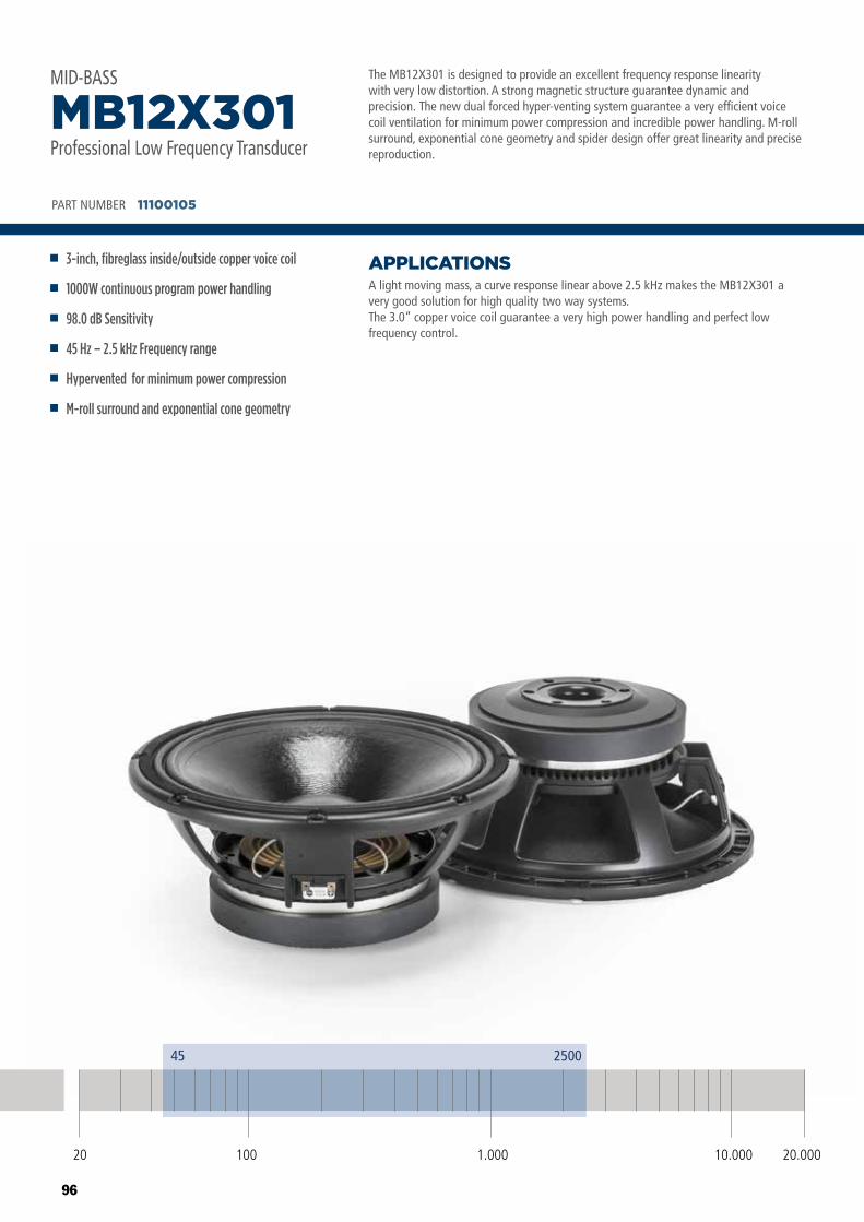
96
The MB12X301 is designed to provide an excellent frequency response linearity with very low distortion. A strong magnetic structure guarantee dynamic and precision. The new dual forced hyper-venting system guarantee a very efficient voice coil ventilation for minimum power compression and incredible power handling. M-roll surround, exponential cone geometry and spider design offer great linearity and precise reproduction.
A light moving mass, a curve response linear above 2.5 kHz makes the MB12X301 a very good solution for high quality two way systems.The 3.0” copper voice coil guarantee a very high power handling and perfect low frequency control.
APPLICATIONS
PART NUMBER 11100105
3-inch, fibreglass inside/outside copper voice coil
1000W continuous program power handling
98.0 dB Sensitivity
45 Hz – 2.5 kHz Frequency range
Hypervented for minimum power compression
M-roll surround and exponential cone geometry
MB12X301Professional Low Frequency Transducer
MID-BASS
20 100 10.000 20.0001.000
45 2500
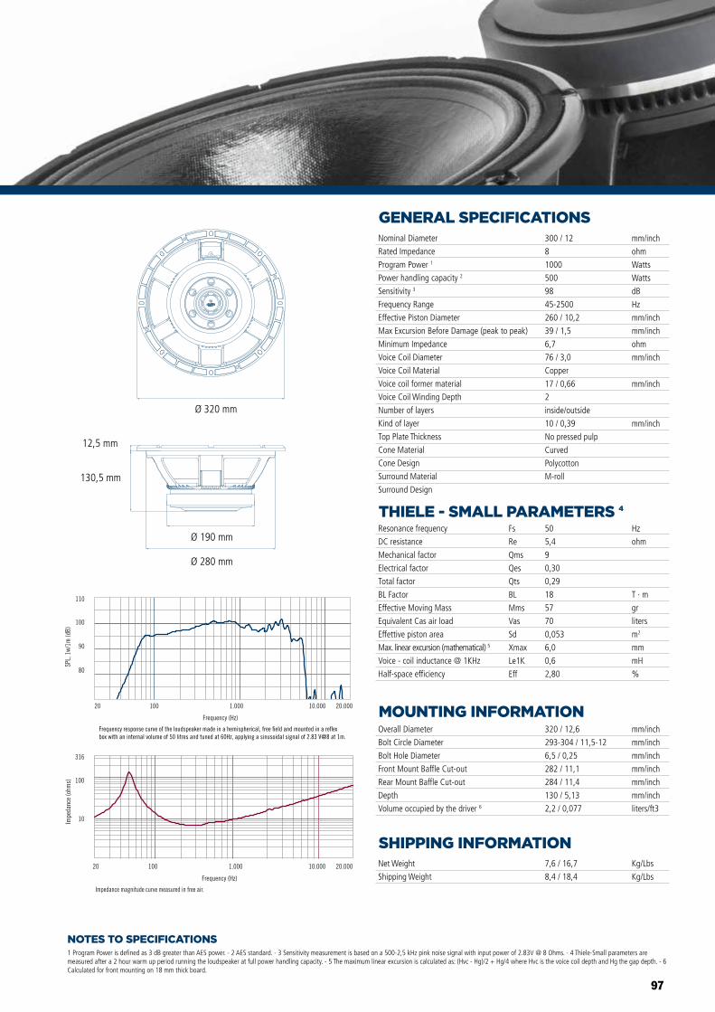
97
NOTES TO SPECIFICATIONS
GENERAL SPECIFICATIONS
THIELE - SMALL PARAMETERS 4
MOUNTING INFORMATION
SHIPPING INFORMATION
1 Program Power is defined as 3 dB greater than AES power. - 2 AES standard. - 3 Sensitivity measurement is based on a 500-2,5 kHz pink noise signal with input power of 2.83V @ 8 Ohms. - 4 Thiele-Small parameters are measured after a 2 hour warm up period running the loudspeaker at full power handling capacity. - 5 The maximum linear excursion is calculated as: (Hvc - Hg)/2 + Hg/4 where Hvc is the voice coil depth and Hg the gap depth. - 6 Calculated for front mounting on 18 mm thick board.
Overall Diameter
Bolt Circle Diameter
Bolt Hole Diameter
Front Mount Baffle Cut-out
Rear Mount Baffle Cut-out
Depth
Volume occupied by the driver 6
320 / 12,6
293-304 / 11,5-12
6,5 / 0,25
282 / 11,1
284 / 11,4
130 / 5,13
2,2 / 0,077
mm/inch
mm/inch
mm/inch
mm/inch
mm/inch
mm/inch
liters/ft3
Net Weight
Shipping Weight
7,6 / 16,7
8,4 / 18,4
Kg/Lbs
Kg/Lbs
Resonance frequency
DC resistance
Mechanical factor
Electrical factor
Total factor
BL Factor
Effective Moving Mass
Equivalent Cas air load
Effettive piston area
Max. linear excursion (mathematical) 5
Voice - coil inductance @ 1KHz
Half-space efficiency
Hz
ohm
T · m
gr
liters
m2
mm
mH
%
50
5,4
9
0,30
0,29
18
57
70
0,053
6,0
0,6
2,80
Fs
Re
Qms
Qes
Qts
BL
Mms
Vas
Sd
Xmax
Le1K
Eff
Nominal Diameter
Rated Impedance
Program Power 1
Power handling capacity 2
Sensitivity 3
Frequency Range
Effective Piston Diameter
Max Excursion Before Damage (peak to peak)
Minimum Impedance
Voice Coil Diameter
Voice Coil Material
Voice coil former material
Voice Coil Winding Depth
Number of layers
Kind of layer
Top Plate Thickness
Cone Material
Cone Design
Surround Material
Surround Design
300 / 12
8
1000
500
98
45-2500
260 / 10,2
39 / 1,5
6,7
76 / 3,0
Copper
17 / 0,66
2
inside/outside
10 / 0,39
No pressed pulp
Curved
Polycotton
M-roll
mm/inch
ohm
Watts
Watts
dB
Hz
mm/inch
mm/inch
ohm
mm/inch
mm/inch
mm/inch
Impedance magnitude curve measured in free air.
Frequency (Hz)
20 100 1.000 10.000 20.000
10
100
316
Impe
danc
e (o
hms)
Frequency (Hz)
20 100 1.000 10.000 20.000
80
90
100
110
SPL,
1w/
1m (d
B)
Frequency response curve of the loudspeaker made in a hemispherical, free �eld and mounted in a re�ex box with an internal volume of 50 litres and tuned at 60Hz, applying a sinusoidal signal of 2.83 V@8 at 1m.
MB10G251
MB12X301 MB15X301
MB15N405MB12N405
MB10N305
Ø 320 mm
Ø 190 mm
Ø 280 mm
130,5 mm
12,5 mm
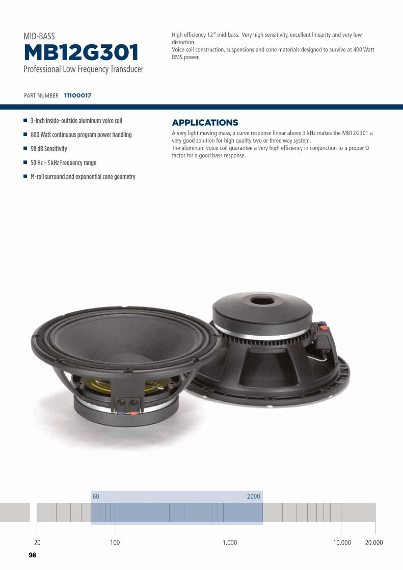
98
High efficiency 12” mid-bass. Very high sensitivity, excellent linearity and very low distortion. Voice coil construction, suspensions and cone materials designed to survive at 400 Watt RMS power.
A very light moving mass, a curve response linear above 3 kHz makes the MB12G301 a very good solution for high quality two or three way system.The aluminum voice coil guarantee a very high efficiency in conjunction to a proper Q factor for a good bass response.
APPLICATIONS
PART NUMBER 11100017
3-inch inside-outside aluminum voice coil
800 Watt continuous program power handling
98 dB Sensitivity
50 Hz - 3 kHz Frequency range
M-roll surround and exponential cone geometry
MB12G301Professional Low Frequency Transducer
MID-BASS
20 100 10.000 20.0001.000
60 2000
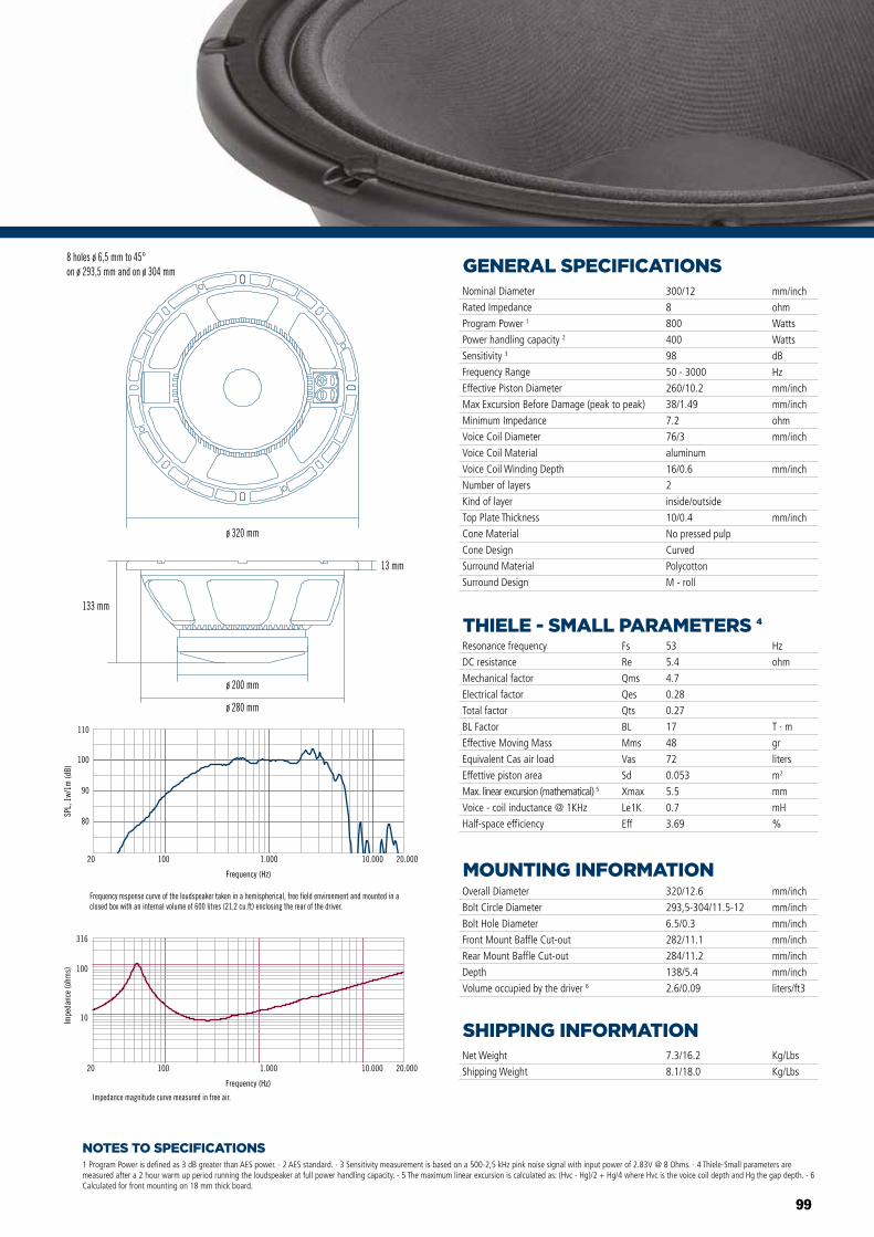
99
NOTES TO SPECIFICATIONS
GENERAL SPECIFICATIONS
THIELE - SMALL PARAMETERS 4
MOUNTING INFORMATION
SHIPPING INFORMATION
1 Program Power is defined as 3 dB greater than AES power. - 2 AES standard. - 3 Sensitivity measurement is based on a 500-2,5 kHz pink noise signal with input power of 2.83V @ 8 Ohms. - 4 Thiele-Small parameters are measured after a 2 hour warm up period running the loudspeaker at full power handling capacity. - 5 The maximum linear excursion is calculated as: (Hvc - Hg)/2 + Hg/4 where Hvc is the voice coil depth and Hg the gap depth. - 6 Calculated for front mounting on 18 mm thick board.
Overall Diameter
Bolt Circle Diameter
Bolt Hole Diameter
Front Mount Baffle Cut-out
Rear Mount Baffle Cut-out
Depth
Volume occupied by the driver 6
320/12.6
293,5-304/11.5-12
6.5/0.3
282/11.1
284/11.2
138/5.4
2.6/0.09
mm/inch
mm/inch
mm/inch
mm/inch
mm/inch
mm/inch
liters/ft3
Net Weight
Shipping Weight
7.3/16.2
8.1/18.0
Kg/Lbs
Kg/Lbs
Resonance frequency
DC resistance
Mechanical factor
Electrical factor
Total factor
BL Factor
Effective Moving Mass
Equivalent Cas air load
Effettive piston area
Max. linear excursion (mathematical) 5
Voice - coil inductance @ 1KHz
Half-space efficiency
Hz
ohm
T · m
gr
liters
m2
mm
mH
%
53
5.4
4.7
0.28
0.27
17
48
72
0.053
5.5
0.7
3.69
Fs
Re
Qms
Qes
Qts
BL
Mms
Vas
Sd
Xmax
Le1K
Eff
Nominal Diameter
Rated Impedance
Program Power 1
Power handling capacity 2
Sensitivity 3
Frequency Range
Effective Piston Diameter
Max Excursion Before Damage (peak to peak)
Minimum Impedance
Voice Coil Diameter
Voice Coil Material
Voice Coil Winding Depth
Number of layers
Kind of layer
Top Plate Thickness
Cone Material
Cone Design
Surround Material
Surround Design
300/12
8
800
400
98
50 - 3000
260/10.2
38/1.49
7.2
76/3
aluminum
16/0.6
2
inside/outside
10/0.4
No pressed pulp
Curved
Polycotton
M - roll
mm/inch
ohm
Watts
Watts
dB
Hz
mm/inch
mm/inch
ohm
mm/inch
mm/inch
mm/inchø 320 mm
133 mm
ø 200 mm
ø 280 mm
13 mm
Frequency (Hz)
20 100 1.000 10.000 20.000
10
100
316
Impe
danc
e (o
hms)
Impedance magnitude curve measured in free air.
8 holes ø 6,5 mm to 45°on ø 293,5 mm and on ø 304 mm
Frequency response curve of the loudspeaker taken in a hemispherical, free field environment and mounted in a closed box with an internal volume of 600 litres (21,2 cu.ft) enclosing the rear of the driver.
80
90
100
110
SPL,
1w/
1m (d
B)
Frequency (Hz)
20 100 1.000 10.000 20.000
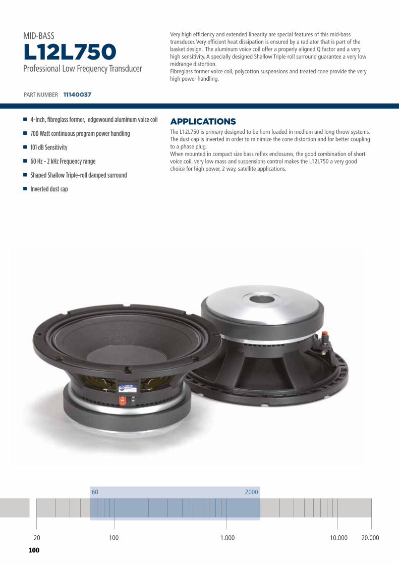
100
Very high efficiency and extended linearity are special features of this mid-bass transducer. Very efficient heat dissipation is ensured by a radiator that is part of the basket design. The aluminum voice coil offer a properly aligned Q factor and a very high sensitivity. A specially designed Shallow Triple-roll surround guarantee a very low midrange distortion.Fibreglass former voice coil, polycotton suspensions and treated cone provide the very high power handling.
The L12L750 is primary designed to be horn loaded in medium and long throw systems. The dust cap is inverted in order to minimize the cone distortion and for better coupling to a phase plug. When mounted in compact size bass reflex enclosures, the good combination of short voice coil, very low mass and suspensions control makes the L12L750 a very good choice for high power, 2 way, satellite applications.
APPLICATIONS
PART NUMBER 11140037
4-inch, fibreglass former, edgewound aluminum voice coil
700 Watt continuous program power handling
101 dB Sensitivity
60 Hz - 2 kHz Frequency range
Shaped Shallow Triple-roll damped surround
Inverted dust cap
L12L750Professional Low Frequency Transducer
MID-BASS
20 100 10.000 20.0001.000
60 2000
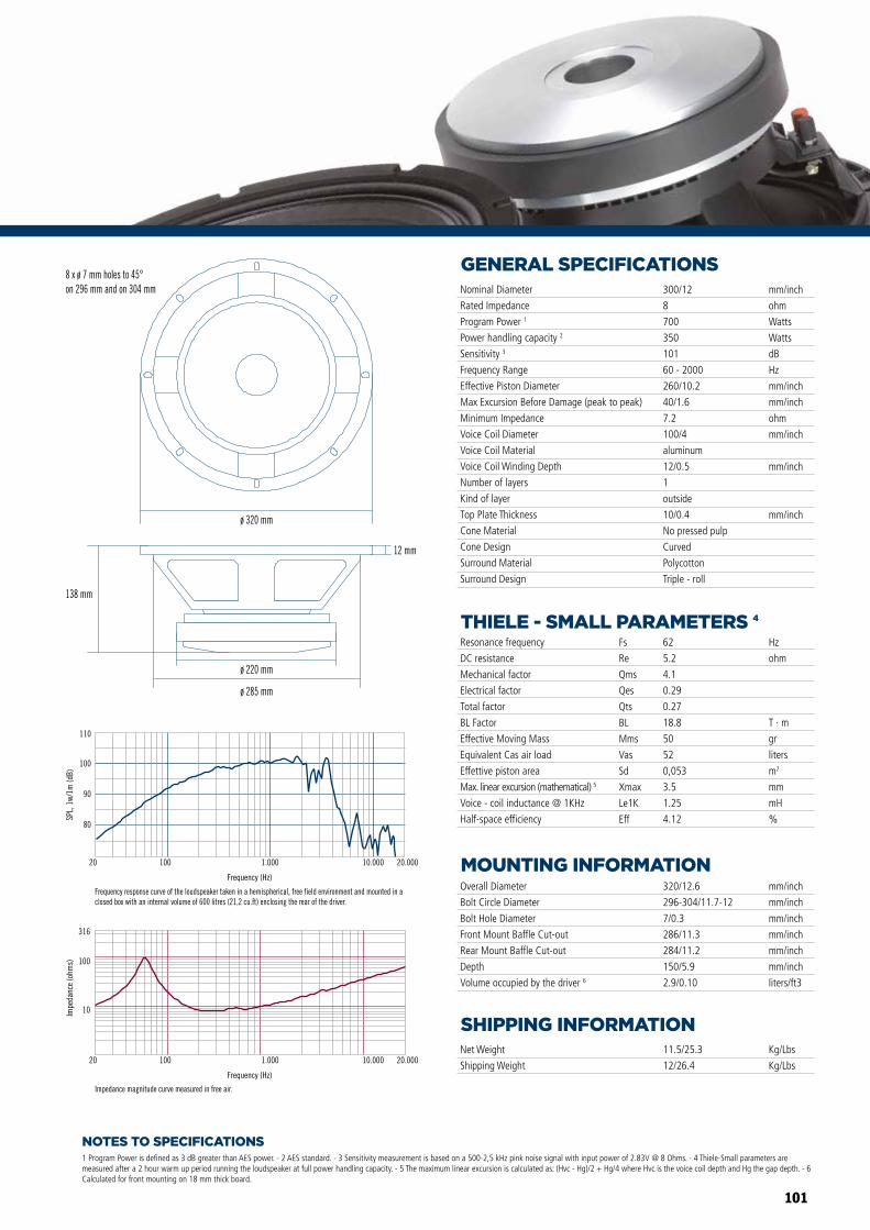
101
NOTES TO SPECIFICATIONS
GENERAL SPECIFICATIONS
THIELE - SMALL PARAMETERS 4
MOUNTING INFORMATION
SHIPPING INFORMATION
1 Program Power is defined as 3 dB greater than AES power. - 2 AES standard. - 3 Sensitivity measurement is based on a 500-2,5 kHz pink noise signal with input power of 2.83V @ 8 Ohms. - 4 Thiele-Small parameters are measured after a 2 hour warm up period running the loudspeaker at full power handling capacity. - 5 The maximum linear excursion is calculated as: (Hvc - Hg)/2 + Hg/4 where Hvc is the voice coil depth and Hg the gap depth. - 6 Calculated for front mounting on 18 mm thick board.
Overall Diameter
Bolt Circle Diameter
Bolt Hole Diameter
Front Mount Baffle Cut-out
Rear Mount Baffle Cut-out
Depth
Volume occupied by the driver 6
320/12.6
296-304/11.7-12
7/0.3
286/11.3
284/11.2
150/5.9
2.9/0.10
mm/inch
mm/inch
mm/inch
mm/inch
mm/inch
mm/inch
liters/ft3
Net Weight
Shipping Weight
11.5/25.3
12/26.4
Kg/Lbs
Kg/Lbs
Resonance frequency
DC resistance
Mechanical factor
Electrical factor
Total factor
BL Factor
Effective Moving Mass
Equivalent Cas air load
Effettive piston area
Max. linear excursion (mathematical) 5
Voice - coil inductance @ 1KHz
Half-space efficiency
Hz
ohm
T · m
gr
liters
m2
mm
mH
%
62
5.2
4.1
0.29
0.27
18.8
50
52
0,053
3.5
1.25
4.12
Fs
Re
Qms
Qes
Qts
BL
Mms
Vas
Sd
Xmax
Le1K
Eff
Nominal Diameter
Rated Impedance
Program Power 1
Power handling capacity 2
Sensitivity 3
Frequency Range
Effective Piston Diameter
Max Excursion Before Damage (peak to peak)
Minimum Impedance
Voice Coil Diameter
Voice Coil Material
Voice Coil Winding Depth
Number of layers
Kind of layer
Top Plate Thickness
Cone Material
Cone Design
Surround Material
Surround Design
300/12
8
700
350
101
60 - 2000
260/10.2
40/1.6
7.2
100/4
aluminum
12/0.5
1
outside
10/0.4
No pressed pulp
Curved
Polycotton
Triple - roll
mm/inch
ohm
Watts
Watts
dB
Hz
mm/inch
mm/inch
ohm
mm/inch
mm/inch
mm/inch
80
90
100
110
SPL,
1w/
1m (d
B)
Frequency (Hz)
20 100 1.000 10.000 20.000
Frequency response curve of the loudspeaker taken in a hemispherical, free field environment and mounted in a closed box with an internal volume of 600 litres (21,2 cu.ft) enclosing the rear of the driver.
Frequency (Hz)
20 100 1.000 10.000 20.000
10
100
316
Impe
danc
e (o
hms)
Impedance magnitude curve measured in free air.
8 x ø 7 mm holes to 45°on 296 mm and on 304 mm
ø 320 mm
ø 285 mm
ø 220 mm
138 mm
12 mm
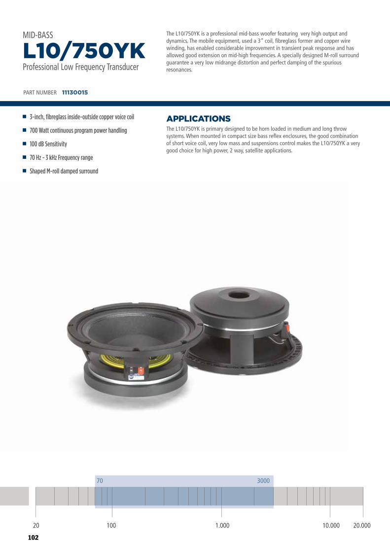
102
20 100 10.000 20.0001.000
70 3000
The L10/750YK is a professional mid-bass woofer featuring very high output and dynamics. The mobile equipment, used a 3” coil, fibreglass former and copper wire winding, has enabled considerable improvement in transient peak response and has allowed good extension on mid-high frequencies. A specially designed M-roll surround guarantee a very low midrange distortion and perfect damping of the spurious resonances.
The L10/750YK is primary designed to be horn loaded in medium and long throw systems. When mounted in compact size bass reflex enclosures, the good combination of short voice coil, very low mass and suspensions control makes the L10/750YK a very good choice for high power, 2 way, satellite applications.
APPLICATIONS
PART NUMBER 11130015
3-inch, fibreglass inside-outside copper voice coil
700 Watt continuous program power handling
100 dB Sensitivity
70 Hz - 3 kHz Frequency range
Shaped M-roll damped surround
L10/750YKProfessional Low Frequency Transducer
MID-BASS
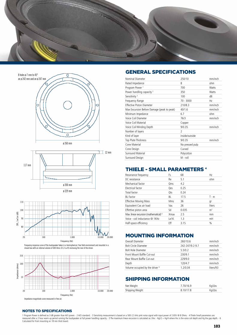
103
ø 260 mm
117 mm
ø 200 mm
ø 229 mm
12 mm
Frequency (Hz)
20 100 1.000 10.000 20.000
10
100
316
Impe
danc
e (o
hms)
Impedance magnitude curve measured in free air.
80
90
100
110
SPL,
1w/
1m (d
B)
20 100 1.000 10.000 20.000
Frequency response curve of the loudspeaker taken in a hemispherical, free field environment and mounted in a closed box with an internal volume of 600 litres (21,2 cu.ft) enclosing the rear of the driver.
8 holes ø 7 mm to 45°on ø 242 mm and on ø 247 mm
Frequency (Hz)
NOTES TO SPECIFICATIONS
GENERAL SPECIFICATIONS
THIELE - SMALL PARAMETERS 4
MOUNTING INFORMATION
SHIPPING INFORMATION
1 Program Power is defined as 3 dB greater than AES power. - 2 AES standard. - 3 Sensitivity measurement is based on a 500-2,5 kHz pink noise signal with input power of 2.83V @ 8 Ohms. - 4 Thiele-Small parameters are measured after a 2 hour warm up period running the loudspeaker at full power handling capacity. - 5 The maximum linear excursion is calculated as: (Hvc - Hg)/2 + Hg/4 where Hvc is the voice coil depth and Hg the gap depth. - 6 Calculated for front mounting on 18 mm thick board.
Overall Diameter
Bolt Circle Diameter
Bolt Hole Diameter
Front Mount Baffle Cut-out
Rear Mount Baffle Cut-out
Depth
Volume occupied by the driver 6
260/10.6
242-247/9.2-9.7
5.5/0.2
230/9.1
229/9.0
120/4.7
1.2/0.04
mm/inch
mm/inch
mm/inch
mm/inch
mm/inch
mm/inch
liters/ft3
Net Weight
Shipping Weight
7.70/16.9
8.10/17.8
Kg/Lbs
Kg/Lbs
Resonance frequency
DC resistance
Mechanical factor
Electrical factor
Total factor
BL Factor
Effective Moving Mass
Equivalent Cas air load
Effettive piston area
Max. linear excursion (mathematical) 5
Voice - coil inductance @ 1KHz
Half-space efficiency
Hz
ohm
T · m
gr
liters
m2
mm
mH
%
68
5.1
4.2
0.25
0.24
17.5
36
26
0.035
2.5
1.3
3.15
Fs
Re
Qms
Qes
Qts
BL
Mms
Vas
Sd
Xmax
Le1K
Eff
Nominal Diameter
Rated Impedance
Program Power 1
Power handling capacity 2
Sensitivity 3
Frequency Range
Effective Piston Diameter
Max Excursion Before Damage (peak to peak)
Minimum Impedance
Voice Coil Diameter
Voice Coil Material
Voice Coil Winding Depth
Number of layers
Kind of layer
Top Plate Thickness
Cone Material
Cone Design
Surround Material
Surround Design
250/10
8
700
350
100
70 - 3000
210/8.3
40/1.6
6.7
76/3
Copper
9/0.35
2
inside/outside
9/0.35
No pressed pulp
Curved
Polycotton
M - roll
mm/inch
ohm
Watts
Watts
dB
Hz
mm/inch
mm/inch
ohm
mm/inch
mm/inch
mm/inch
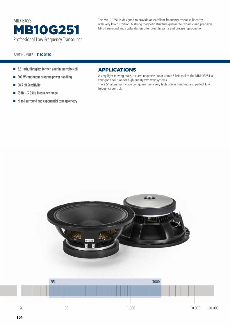
104
The MB10G251 is designed to provide an excellent frequency response linearity with very low distortion. A strong magnetic structure guarantee dynamic and precision. M-roll surround and spider design offer great linearity and precise reproduction.
A very light moving mass, a curve response linear above 3 kHz makes the MB10G251 a very good solution for high quality two way systems. The 2.5” aluminium voice coil guarantee a very high power handling and perfect low frequency control.
APPLICATIONS
PART NUMBER 11100110
2.5-inch, fibreglass former, aluminium voice coil
600 W continuous program power handling
98.5 dB Sensitivity
55 Hz – 3.0 kHz Frequency range
M-roll surround and exponential cone geometry
MB10G251Professional Low Frequency Transducer
MID-BASS
20 100 10.000 20.0001.000
55 3000
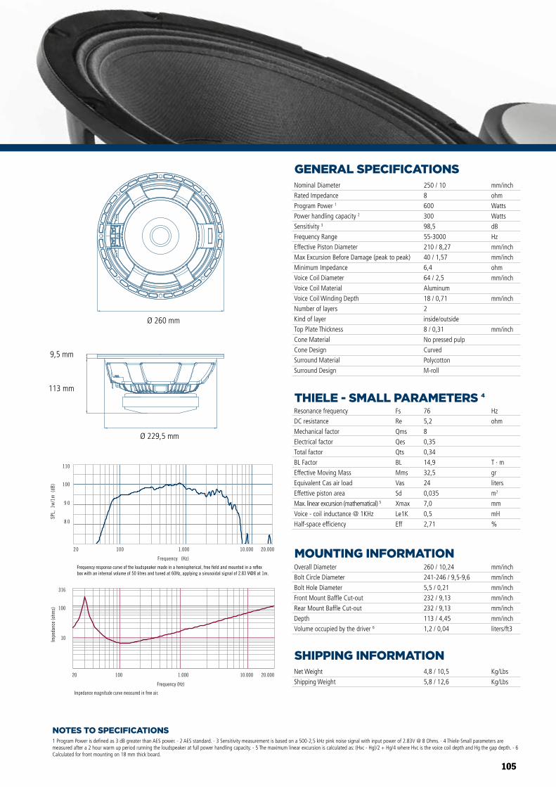
105
NOTES TO SPECIFICATIONS
GENERAL SPECIFICATIONS
THIELE - SMALL PARAMETERS 4
MOUNTING INFORMATION
SHIPPING INFORMATION
1 Program Power is defined as 3 dB greater than AES power. - 2 AES standard. - 3 Sensitivity measurement is based on a 500-2,5 kHz pink noise signal with input power of 2.83V @ 8 Ohms. - 4 Thiele-Small parameters are measured after a 2 hour warm up period running the loudspeaker at full power handling capacity. - 5 The maximum linear excursion is calculated as: (Hvc - Hg)/2 + Hg/4 where Hvc is the voice coil depth and Hg the gap depth. - 6 Calculated for front mounting on 18 mm thick board.
Overall Diameter
Bolt Circle Diameter
Bolt Hole Diameter
Front Mount Baffle Cut-out
Rear Mount Baffle Cut-out
Depth
Volume occupied by the driver 6
260 / 10,24
241-246 / 9,5-9,6
5,5 / 0,21
232 / 9,13
232 / 9,13
113 / 4,45
1,2 / 0,04
mm/inch
mm/inch
mm/inch
mm/inch
mm/inch
mm/inch
liters/ft3
Net Weight
Shipping Weight
4,8 / 10,5
5,8 / 12,6
Kg/Lbs
Kg/Lbs
Resonance frequency
DC resistance
Mechanical factor
Electrical factor
Total factor
BL Factor
Effective Moving Mass
Equivalent Cas air load
Effettive piston area
Max. linear excursion (mathematical) 5
Voice - coil inductance @ 1KHz
Half-space efficiency
Hz
ohm
T · m
gr
liters
m2
mm
mH
%
76
5,2
8
0,35
0,34
14,9
32,5
24
0,035
7,0
0,5
2,71
Fs
Re
Qms
Qes
Qts
BL
Mms
Vas
Sd
Xmax
Le1K
Eff
Nominal Diameter
Rated Impedance
Program Power 1
Power handling capacity 2
Sensitivity 3
Frequency Range
Effective Piston Diameter
Max Excursion Before Damage (peak to peak)
Minimum Impedance
Voice Coil Diameter
Voice Coil Material
Voice Coil Winding Depth
Number of layers
Kind of layer
Top Plate Thickness
Cone Material
Cone Design
Surround Material
Surround Design
250 / 10
8
600
300
98,5
55-3000
210 / 8,27
40 / 1,57
6,4
64 / 2,5
Aluminum
18 / 0,71
2
inside/outside
8 / 0,31
No pressed pulp
Curved
Polycotton
M-roll
mm/inch
ohm
Watts
Watts
dB
Hz
mm/inch
mm/inch
ohm
mm/inch
mm/inch
mm/inch
Impedance magnitude curve measured in free air.
Frequency (Hz)
20 100 1.000 10.000 20.000
10
100
316
Impe
danc
e (o
hms)
Frequency response curve of the loudspeaker made in a hemispherical, free �eld and mounted in a re�ex box with an internal volume of 50 litres and tuned at 60Hz, applying a sinusoidal signal of 2.83 V@8 at 1m.
Frequency (Hz)
20 100 1.000 10.000 20.000
8 0
9 0
100
110
SPL,
1w
/1m
(dB
)
MB10G251
MB12X301 MB15X301
MB15N405MB12N405
MB10N305
Ø 260 mm
Ø 229,5 mm
113 mm
9,5 mm
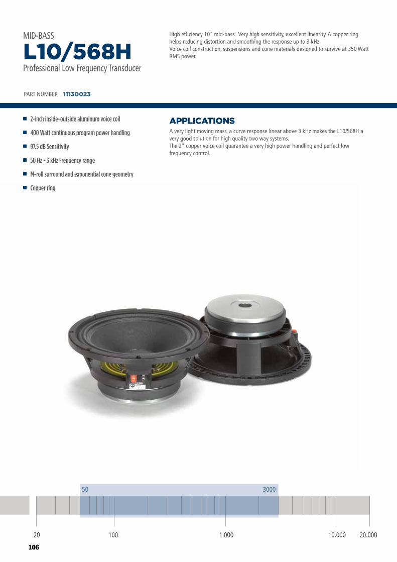
106
High efficiency 10” mid-bass. Very high sensitivity, excellent linearity. A copper ring helps reducing distortion and smoothing the response up to 3 kHz.Voice coil construction, suspensions and cone materials designed to survive at 350 Watt RMS power.
A very light moving mass, a curve response linear above 3 kHz makes the L10/568H a very good solution for high quality two way systems.The 2” copper voice coil guarantee a very high power handling and perfect low frequency control.
APPLICATIONS
PART NUMBER 11130023
2-inch inside-outside aluminum voice coil
400 Watt continuous program power handling
97.5 dB Sensitivity
50 Hz - 3 kHz Frequency range
M-roll surround and exponential cone geometry
Copper ring
L10/568HProfessional Low Frequency Transducer
MID-BASS
20 100 10.000 20.0001.000
50 3000
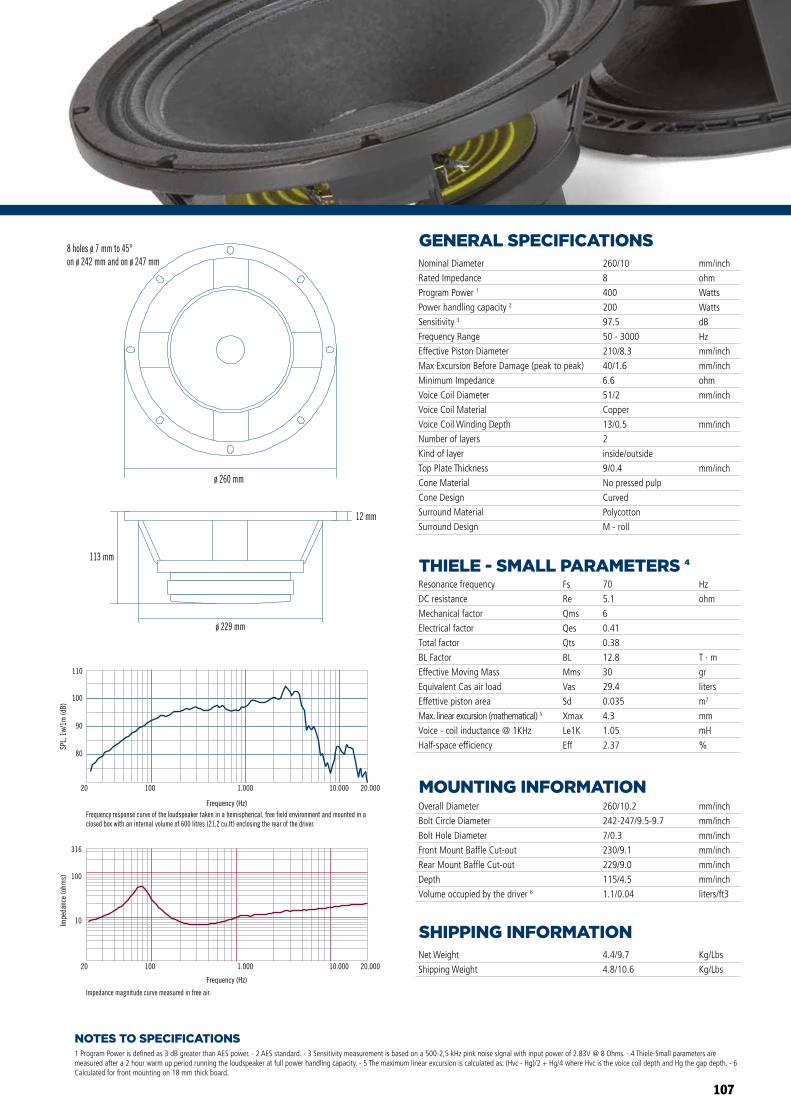
107
NOTES TO SPECIFICATIONS
GENERAL SPECIFICATIONS
THIELE - SMALL PARAMETERS 4
MOUNTING INFORMATION
SHIPPING INFORMATION
1 Program Power is defined as 3 dB greater than AES power. - 2 AES standard. - 3 Sensitivity measurement is based on a 500-2,5 kHz pink noise signal with input power of 2.83V @ 8 Ohms. - 4 Thiele-Small parameters are measured after a 2 hour warm up period running the loudspeaker at full power handling capacity. - 5 The maximum linear excursion is calculated as: (Hvc - Hg)/2 + Hg/4 where Hvc is the voice coil depth and Hg the gap depth. - 6 Calculated for front mounting on 18 mm thick board.
Overall Diameter
Bolt Circle Diameter
Bolt Hole Diameter
Front Mount Baffle Cut-out
Rear Mount Baffle Cut-out
Depth
Volume occupied by the driver 6
260/10.2
242-247/9.5-9.7
7/0.3
230/9.1
229/9.0
115/4.5
1.1/0.04
mm/inch
mm/inch
mm/inch
mm/inch
mm/inch
mm/inch
liters/ft3
Net Weight
Shipping Weight
4.4/9.7
4.8/10.6
Kg/Lbs
Kg/Lbs
Resonance frequency
DC resistance
Mechanical factor
Electrical factor
Total factor
BL Factor
Effective Moving Mass
Equivalent Cas air load
Effettive piston area
Max. linear excursion (mathematical) 5
Voice - coil inductance @ 1KHz
Half-space efficiency
Hz
ohm
T · m
gr
liters
m2
mm
mH
%
70
5.1
6
0.41
0.38
12.8
30
29.4
0.035
4.3
1.05
2.37
Fs
Re
Qms
Qes
Qts
BL
Mms
Vas
Sd
Xmax
Le1K
Eff
Nominal Diameter
Rated Impedance
Program Power 1
Power handling capacity 2
Sensitivity 3
Frequency Range
Effective Piston Diameter
Max Excursion Before Damage (peak to peak)
Minimum Impedance
Voice Coil Diameter
Voice Coil Material
Voice Coil Winding Depth
Number of layers
Kind of layer
Top Plate Thickness
Cone Material
Cone Design
Surround Material
Surround Design
260/10
8
400
200
97.5
50 - 3000
210/8.3
40/1.6
6.6
51/2
Copper
13/0.5
2
inside/outside
9/0.4
No pressed pulp
Curved
Polycotton
M - roll
mm/inch
ohm
Watts
Watts
dB
Hz
mm/inch
mm/inch
ohm
mm/inch
mm/inch
mm/inchø 260 mm
113 mm
ø 229 mm
12 mm
Frequency (Hz)
20 100 1.000 10.000 20.000
10
100
316
Impe
danc
e (o
hms)
Impedance magnitude curve measured in free air.
80
90
100
110
SPL,
1w/
1m (d
B)
20 100 1.000 10.000 20.000
Frequency response curve of the loudspeaker taken in a hemispherical, free field environment and mounted in a closed box with an internal volume of 600 litres (21,2 cu.ft) enclosing the rear of the driver.
8 holes ø 7 mm to 45°on ø 242 mm and on ø 247 mm
Frequency (Hz)
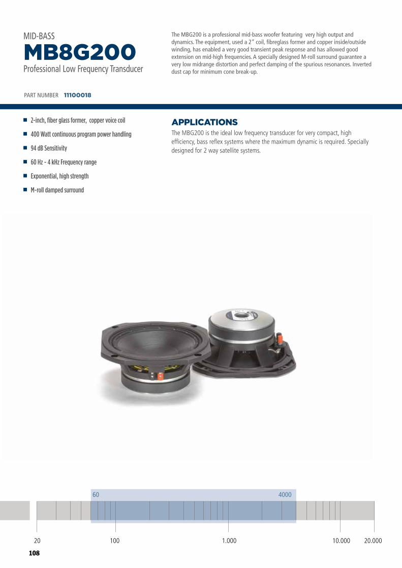
108
The MBG200 is a professional mid-bass woofer featuring very high output and dynamics. The equipment, used a 2” coil, fibreglass former and copper inside/outside winding, has enabled a very good transient peak response and has allowed good extension on mid-high frequencies. A specially designed M-roll surround guarantee a very low midrange distortion and perfect damping of the spurious resonances. Inverted dust cap for minimum cone break-up.
The MBG200 is the ideal low frequency transducer for very compact, high efficiency, bass reflex systems where the maximum dynamic is required. Specially designed for 2 way satellite systems.
APPLICATIONS
PART NUMBER 11100018
2-inch, fiber glass former, copper voice coil
400 Watt continuous program power handling
94 dB Sensitivity
60 Hz - 4 kHz Frequency range
Exponential, high strength
M-roll damped surround
MB8G200Professional Low Frequency Transducer
MID-BASS
20 100 10.000 20.0001.000
60 4000
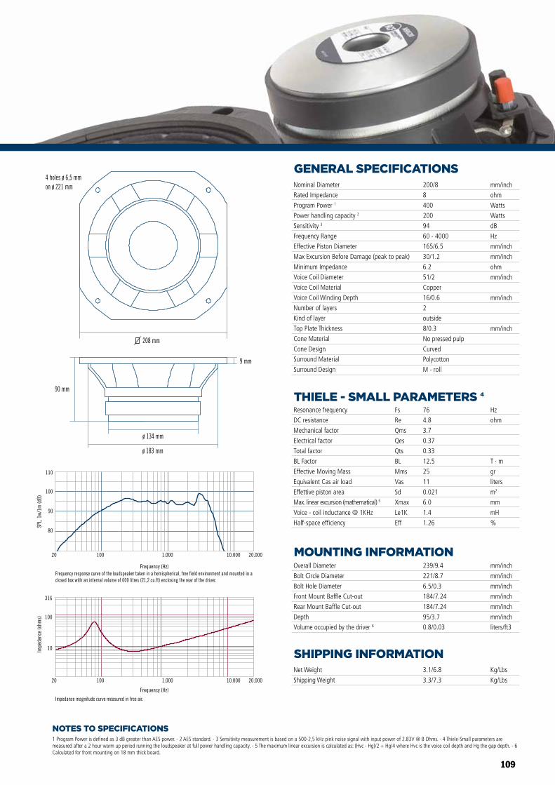
109
NOTES TO SPECIFICATIONS
GENERAL SPECIFICATIONS
THIELE - SMALL PARAMETERS 4
MOUNTING INFORMATION
SHIPPING INFORMATION
1 Program Power is defined as 3 dB greater than AES power. - 2 AES standard. - 3 Sensitivity measurement is based on a 500-2,5 kHz pink noise signal with input power of 2.83V @ 8 Ohms. - 4 Thiele-Small parameters are measured after a 2 hour warm up period running the loudspeaker at full power handling capacity. - 5 The maximum linear excursion is calculated as: (Hvc - Hg)/2 + Hg/4 where Hvc is the voice coil depth and Hg the gap depth. - 6 Calculated for front mounting on 18 mm thick board.
Overall Diameter
Bolt Circle Diameter
Bolt Hole Diameter
Front Mount Baffle Cut-out
Rear Mount Baffle Cut-out
Depth
Volume occupied by the driver 6
239/9.4
221/8.7
6.5/0.3
184/7.24
184/7.24
95/3.7
0.8/0.03
mm/inch
mm/inch
mm/inch
mm/inch
mm/inch
mm/inch
liters/ft3
Net Weight
Shipping Weight
3.1/6.8
3.3/7.3
Kg/Lbs
Kg/Lbs
Resonance frequency
DC resistance
Mechanical factor
Electrical factor
Total factor
BL Factor
Effective Moving Mass
Equivalent Cas air load
Effettive piston area
Max. linear excursion (mathematical) 5
Voice - coil inductance @ 1KHz
Half-space efficiency
Hz
ohm
T · m
gr
liters
m2
mm
mH
%
76
4.8
3.7
0.37
0.33
12.5
25
11
0.021
6.0
1.4
1.26
Fs
Re
Qms
Qes
Qts
BL
Mms
Vas
Sd
Xmax
Le1K
Eff
Nominal Diameter
Rated Impedance
Program Power 1
Power handling capacity 2
Sensitivity 3
Frequency Range
Effective Piston Diameter
Max Excursion Before Damage (peak to peak)
Minimum Impedance
Voice Coil Diameter
Voice Coil Material
Voice Coil Winding Depth
Number of layers
Kind of layer
Top Plate Thickness
Cone Material
Cone Design
Surround Material
Surround Design
200/8
8
400
200
94
60 - 4000
165/6.5
30/1.2
6.2
51/2
Copper
16/0.6
2
outside
8/0.3
No pressed pulp
Curved
Polycotton
M - roll
mm/inch
ohm
Watts
Watts
dB
Hz
mm/inch
mm/inch
ohm
mm/inch
mm/inch
mm/inch
208 mm
9 mm
90 mm
ø 183 mm
ø 134 mm
Frequency (Hz)
20 100 1.000 10.000 20.000
10
100
316
Impe
danc
e (o
hms)
Impedance magnitude curve measured in free air.
80
90
100
110
SPL,
1w/
1m (d
B)
20 100 1.000 10.000 20.000
Frequency response curve of the loudspeaker taken in a hemispherical, free field environment and mounted in a closed box with an internal volume of 600 litres (21,2 cu.ft) enclosing the rear of the driver.
4 holes ø 6,5 mmon ø 221 mm
Frequency (Hz)
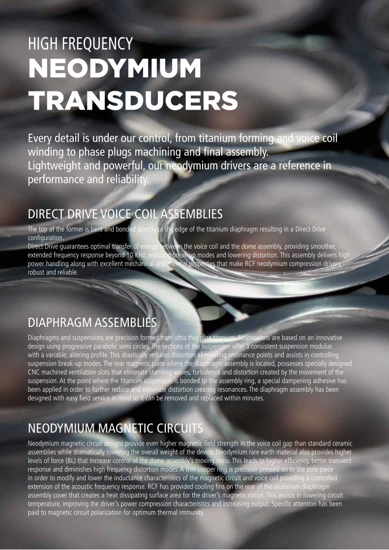
110
NEODYMIUMTRANSDUCERS
HIGH FREQUENCY
Every detail is under our control, from titanium forming and voice coil winding to phase plugs machining and final assembly. Lightweight and powerful, our neodymium drivers are a reference in performance and reliability.
DIRECT DRIVE VOICE COIL ASSEMBLIES
DIAPHRAGM ASSEMBLIES
NEODYMIUM MAGNETIC CIRCUITS
The top of the former is bent and bonded directly to the edge of the titanium diaphragm resulting in a Direct Drive configuration. Direct Drive guarantees optimal transfer of energy between the voice coil and the dome assembly, providing smoother, extended frequency response beyond 10 KHz, reducing break up modes and lowering distortion. This assembly delivers high power handling along with excellent mechanical and thermal properties that make RCF neodymium compression drivers robust and reliable.
Diaphragms and suspensions are precision formed from ultra thin pure titanium. Suspensions are based on an innovative design using progressive parabolic semi circles. The sections of the suspension offer a consistent suspension modulus with a variable, altering profile. This drastically reduces distortion eliminating resonance points and assists in controlling suspension break-up modes. The rear magnetic plate where the diaphragm assembly is located, possesses specially designed CNC machined ventilation slots that eliminate standing waves, turbulence and distortion created by the movement of the suspension. At the point where the titanium suspension is bonded to the assembly ring, a special dampening adhesive has been applied in order to further reduce and eliminate distortion creating resonances. The diaphragm assembly has been designed with easy field service in mind as it can be removed and replaced within minutes.
Neodymium magnetic circuit designs provide even higher magnetic field strength in the voice coil gap than standard ceramic assemblies while dramatically lowering the overall weight of the device. Neodymium rare earth material also provides higher levels of force (BL) that increase control of the dome assembly’s moving mass. This leads to higher efficiency, better transient response and diminishes high frequency distortion modes. A thin copper ring is precision pressed on to the pole piece in order to modify and lower the inductance characteristics of the magnetic circuit and voice coil providing a controlled extension of the acoustic frequency response. RCF has provided cooling fins on the rear of the aluminum diaphragm assembly cover that creates a heat dissipating surface area for the driver’s magnetic circuit. This assists in lowering circuit temperature, improving the driver’s power compression characteristics and increasing output. Specific attention has been paid to magnetic circuit polarization for optimum thermal immunity.
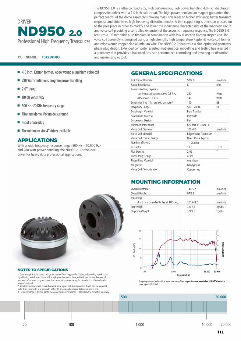
111
DRIVER ND950 2.0
Frequency response and electrical impedance curve of the compression driver mounted on 90°Hx40°V horn with input signal of 2.83 Volt.
20.000500
20 100 10.000 20.0001.000
Professional High Frequency Transducer
PART NUMBER 15129040
80
90
100
110
120
100 1.000 10.000 20.000Frequency (Hz)
SPL,
1w/
1m (d
B)
Impe
danc
e (o
hms)
100
500
NOTES TO SPECIFICATIONS
The ND950 2.0 is a ultra compact size, high performance, high power handling 4.0-inch diaphragm compression driver with a 2.0 inch exit throat. The high power neodymium magnet guarantee the perfect control of the dome assembly’s moving mass. This leads to higher efficiency, better transient response and diminishes high frequency distortion modes. A thin copper ring is precision pressed on to the pole piece in order to modify and lower the inductance characteristics of the magnetic circuit and voice coil providing a controlled extension of the acoustic frequency response. The ND950 2.0 features a .05 mm thick pure titanium in combination with low distortion Kapton suspension. The voice coil assembly is designed using a high strength, high temperature Kapton® voice coil former and edge wound copper clad aluminium wire. The ND950 2.0 features a 4-slot, optimised geometry, phase plug design. Extended computer assisted mathematical modelling and testing has resulted in a geometry that provides a balanced acoustic performance controlling and lowering air distortion and maximizing output.
With a wide frequency response range (500 Hz – 20.000 Hz) and 280 Watt power handling, the ND950 2.0 is the ideal driver for heavy duty professional applications.
APPLICATIONS
GENERAL SPECIFICATIONS
MOUNTING INFORMATION
1. Continuos pink noise power ratings are derived from suggested AES standards sending a pink noise signal having a 6 dB crest factor with a high pass filter set at the specified lower limiting frequency for two hours. Continuos program power is a conservative power rating for reproduction of typical audio program material.2. Sensitivity measurement is based on pink noise signal with input power of 1 watt and measured at 1 meter from the mouth of a horn with a Q of 15 on axis and averaged between 2 and 5 kHz.3. Frequency range is defined as the measured frequency response -10dB relative to the rated sensitivity.
Exit Throat Diameter
Rated Impedance
Power handling capacity 1
continuous program above 0.8 kHz
AES above 0.8 kHz
Sensitivity 1 W, 1 M, on axis, on horn 2
Frequency Range 3
Diaphragm Material
Suspension Material
Suspension Design
Minimum Impedance
Voice Coil Diameter
Voice Coil Material
Voice Coil Former Design
Number of layers
BL Factor
Flux Density
Phase Plug Design
Phase Plug Material
Magnetics
Voice Coil Demodulation
Overall Diameter
Overall Height
Mounting
4 x 6 mm threaded holes at 180 deg.
Net Weight
Shipping Weight
50/2.0
8
280
140
110
500 - 20000
Pure Titanium
Polymide
Flat
8.5 ohm at 3500 Hz
100/4.0
Edgewound Aluminum
Direct Drive Kapton
1 - Outside
17.6
2.05
4 slot
Aluminum
Neodymium
Copper ring
146/5.7
97/3.8
101.6/4.0
3.6/7.8
3.9/8.5
mm/inch
ohm
Watt
Watt
dB
Hz
mm/inch
T · m
T
mm/inch
mm/inch
mm/inch
kg/Lbs
kg/Lbs
PART NUMBER 15129040
4.0 inch, Kapton former, edge wound aluminium voice coil
280 Watt continuous program power handling
2.0” throat
110 dB Sensitivity
500 Hz –20 KHz Frequency range
Titanium dome, Polymide surround
4 slot phase plug
The minimum size 4” driver available
ND950 2.0Professional High Frequency Transducer
DRIVER
20 100 10.000 20.0001.000
500 20.000
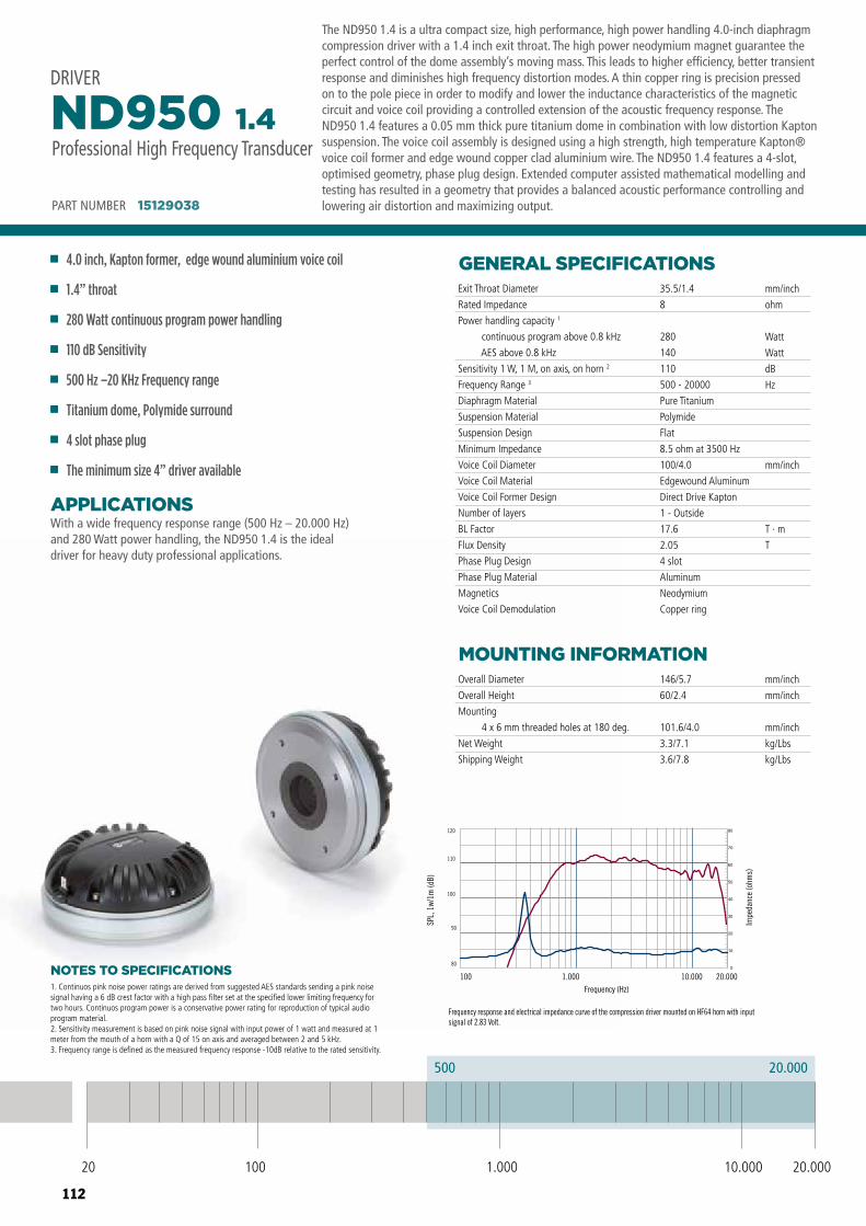
112
DRIVER ND950 1.4
Frequency response and electrical impedance curve of the compression driver mounted on HF64 horn with input signal of 2.83 Volt.
20.000500
20 100 10.000 20.0001.000
Professional High Frequency Transducer
PART NUMBER 15129038
80
90
100
110
120
100 1.000 10.000 20.000Frequency (Hz)
SPL,
1w/
1m (d
B)
Impe
danc
e (o
hms)
NOTES TO SPECIFICATIONS
The ND950 1.4 is a ultra compact size, high performance, high power handling 4.0-inch diaphragm compression driver with a 1.4 inch exit throat. The high power neodymium magnet guarantee the perfect control of the dome assembly’s moving mass. This leads to higher efficiency, better transient response and diminishes high frequency distortion modes. A thin copper ring is precision pressed on to the pole piece in order to modify and lower the inductance characteristics of the magnetic circuit and voice coil providing a controlled extension of the acoustic frequency response. The ND950 1.4 features a 0.05 mm thick pure titanium dome in combination with low distortion Kapton suspension. The voice coil assembly is designed using a high strength, high temperature Kapton® voice coil former and edge wound copper clad aluminium wire. The ND950 1.4 features a 4-slot, optimised geometry, phase plug design. Extended computer assisted mathematical modelling and testing has resulted in a geometry that provides a balanced acoustic performance controlling and lowering air distortion and maximizing output.
With a wide frequency response range (500 Hz – 20.000 Hz) and 280 Watt power handling, the ND950 1.4 is the ideal driver for heavy duty professional applications.
APPLICATIONS
GENERAL SPECIFICATIONS
MOUNTING INFORMATION
1. Continuos pink noise power ratings are derived from suggested AES standards sending a pink noise signal having a 6 dB crest factor with a high pass filter set at the specified lower limiting frequency for two hours. Continuos program power is a conservative power rating for reproduction of typical audio program material.2. Sensitivity measurement is based on pink noise signal with input power of 1 watt and measured at 1 meter from the mouth of a horn with a Q of 15 on axis and averaged between 2 and 5 kHz.3. Frequency range is defined as the measured frequency response -10dB relative to the rated sensitivity.
Exit Throat Diameter
Rated Impedance
Power handling capacity 1
continuous program above 0.8 kHz
AES above 0.8 kHz
Sensitivity 1 W, 1 M, on axis, on horn 2
Frequency Range 3
Diaphragm Material
Suspension Material
Suspension Design
Minimum Impedance
Voice Coil Diameter
Voice Coil Material
Voice Coil Former Design
Number of layers
BL Factor
Flux Density
Phase Plug Design
Phase Plug Material
Magnetics
Voice Coil Demodulation
Overall Diameter
Overall Height
Mounting
4 x 6 mm threaded holes at 180 deg.
Net Weight
Shipping Weight
35.5/1.4
8
280
140
110
500 - 20000
Pure Titanium
Polymide
Flat
8.5 ohm at 3500 Hz
100/4.0
Edgewound Aluminum
Direct Drive Kapton
1 - Outside
17.6
2.05
4 slot
Aluminum
Neodymium
Copper ring
146/5.7
60/2.4
101.6/4.0
3.3/7.1
3.6/7.8
mm/inch
ohm
Watt
Watt
dB
Hz
mm/inch
T · m
T
mm/inch
mm/inch
mm/inch
kg/Lbs
kg/Lbs
PART NUMBER 15129038
4.0 inch, Kapton former, edge wound aluminium voice coil
1.4” throat
280 Watt continuous program power handling
110 dB Sensitivity
500 Hz –20 KHz Frequency range
Titanium dome, Polymide surround
4 slot phase plug
The minimum size 4” driver available
ND950 1.4Professional High Frequency Transducer
DRIVER
20 100 10.000 20.0001.000
500 20.000
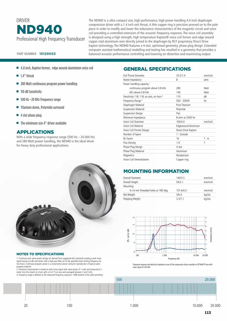
113
Frequency response and electrical impedance curve of the compression driver mounted on 90°Hx40°V horn with input signal of 2.83 Volt.
80
90
100
110
120
100 1.000 10.000 20.000Frequency (Hz)
SPL,
1w/
1m (d
B)
Impe
danc
e (o
hms)
ND940ND640
Frequency response and electrical impedance curve of the compression driver mounted on HF64 horn with input signal of 2.83 Volt.
80
90
100
110
120
100 1.000 10.000 20.000Frequency (Hz)
SPL,
1w/
1m (d
B)
Impe
danc
e (o
hms)
ND840
Frequency response and electrical impedance curve of the compression driver mounted on 90°Hx40°V horn with input signal of 2.83 Volt.
80
90
100
110
120
100 1.000 10.000 20.000Frequency (Hz)
SPL,
1w/
1m (d
B)
Impe
danc
e (o
hms)
NOTES TO SPECIFICATIONS
With a wide frequency response range (500 Hz – 20.000 Hz) and 280 Watt power handling, the ND940 is the ideal driver for heavy duty professional applications.
APPLICATIONS
GENERAL SPECIFICATIONS
MOUNTING INFORMATION
Exit Throat Diameter
Rated Impedance
Power handling capacity 1
continuous program above 0.8 kHz
AES above 0.8 kHz
Sensitivity 1 W, 1 M, on axis, on horn 2
Frequency Range 3
Diaphragm Material
Suspension Material
Suspension Design
Minimum Impedance
Voice Coil Diameter
Voice Coil Material
Voice Coil Former Design
Number of layers
BL Factor
Flux Density
Phase Plug Design
Phase Plug Material
Magnetics
Voice Coil Demodulation
Overall Diameter
Overall Height
Mounting
4 x 6 mm threaded holes at 180 deg.
Net Weight
Shipping Weight
35.5/1.4
8
280
140
110
500 - 20000
Pure Titanium
Polymide
Flat
8 ohm at 3500 Hz
100/4.0
Edgewound Aluminum
Direct Drive Kapton
1 - Outside
16
1.9
4 slot
Aluminum
Neodymium
Copper ring
140/5.5
54/2.1
101.6/4.0
3/6.4
3.3/7.1
mm/inch
ohm
Watt
Watt
dB
Hz
mm/inch
T · m
T
mm/inch
mm/inch
mm/inch
kg/Lbs
kg/Lbs
PART NUMBER 15129053
4.0 inch, Kapton former, edge wound aluminium voice coil
1.4” throat
280 Watt continuous program power handling
110 dB Sensitivity
500 Hz –20 KHz Frequency range
Titanium dome, Polymide surround
4 slot phase plug
The minimum size 4” driver available
ND940Professional High Frequency Transducer
DRIVER
1. Continuos pink noise power ratings are derived from suggested AES standards sending a pink noise signal having a 6 dB crest factor with a high pass filter set at the specified lower limiting frequency for two hours. Continuos program power is a conservative power rating for reproduction of typical audio program material.2. Sensitivity measurement is based on pink noise signal with input power of 1 watt and measured at 1 meter from the mouth of a horn with a Q of 15 on axis and averaged between 2 and 5 kHz.3. Frequency range is defined as the measured frequency response -10dB relative to the rated sensitivity.
The ND940 is a ultra compact size, high performance, high power handling 4.0-inch diaphragm compression driver with a 1.4 inch exit throat. A thin copper ring is precision pressed on to the pole piece in order to modify and lower the inductance characteristics of the magnetic circuit and voice coil providing a controlled extension of the acoustic frequency response. The voice coil assembly is designed using a high strength, high temperature Kapton® voice coil former and edge wound copper clad aluminium wire directly joined to the diaphragm by RCF proprietary Direct Drive kapton technology. The ND940 features a 4-slot, optimised geometry, phase plug design. Extended computer assisted mathematical modelling and testing has resulted in a geometry that provides a balanced acoustic performance controlling and lowering air distortion and maximizing output.
20 100 10.000 20.0001.000
500 20.000
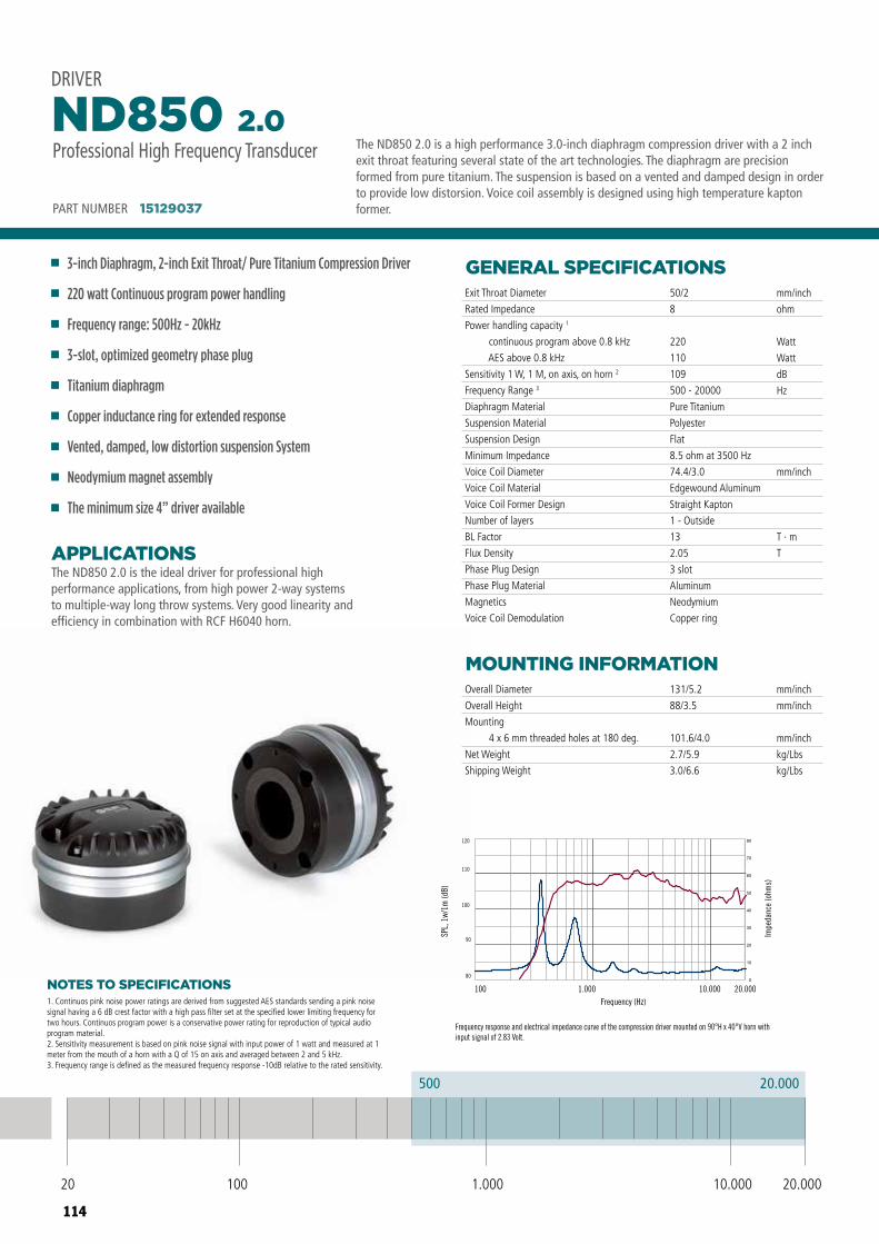
114
DRIVER ND850 2.0
Frequency response and electrical impedance curve of the compression driver mounted on 90°H x 40°V horn with input signal of 2.83 Volt.
20.000500
20 100 10.000 20.0001.000
Professional High Frequency Transducer
PART NUMBER 15129037
80
90
100
110
120
100 1.000 10.000 20.000Frequency (Hz)
SPL,
1w/
1m (d
B)
Impe
danc
e (o
hms)
20 100 10.000 20.0001.000
500 20.000
NOTES TO SPECIFICATIONS
The ND850 2.0 is the ideal driver for professional high performance applications, from high power 2-way systems to multiple-way long throw systems. Very good linearity and efficiency in combination with RCF H6040 horn.
APPLICATIONS
GENERAL SPECIFICATIONS
MOUNTING INFORMATION
Exit Throat Diameter
Rated Impedance
Power handling capacity 1
continuous program above 0.8 kHz
AES above 0.8 kHz
Sensitivity 1 W, 1 M, on axis, on horn 2
Frequency Range 3
Diaphragm Material
Suspension Material
Suspension Design
Minimum Impedance
Voice Coil Diameter
Voice Coil Material
Voice Coil Former Design
Number of layers
BL Factor
Flux Density
Phase Plug Design
Phase Plug Material
Magnetics
Voice Coil Demodulation
Overall Diameter
Overall Height
Mounting
4 x 6 mm threaded holes at 180 deg.
Net Weight
Shipping Weight
50/2
8
220
110
109
500 - 20000
Pure Titanium
Polyester
Flat
8.5 ohm at 3500 Hz
74.4/3.0
Edgewound Aluminum
Straight Kapton
1 - Outside
13
2.05
3 slot
Aluminum
Neodymium
Copper ring
131/5.2
88/3.5
101.6/4.0
2.7/5.9
3.0/6.6
mm/inch
ohm
Watt
Watt
dB
Hz
mm/inch
T · m
T
mm/inch
mm/inch
mm/inch
kg/Lbs
kg/Lbs
PART NUMBER 15129037
3-inch Diaphragm, 2-inch Exit Throat/ Pure Titanium Compression Driver
220 watt Continuous program power handling
Frequency range: 500Hz - 20kHz
3-slot, optimized geometry phase plug
Titanium diaphragm
Copper inductance ring for extended response
Vented, damped, low distortion suspension System
Neodymium magnet assembly
The minimum size 4” driver available
ND850 2.0Professional High Frequency Transducer
DRIVER
1. Continuos pink noise power ratings are derived from suggested AES standards sending a pink noise signal having a 6 dB crest factor with a high pass filter set at the specified lower limiting frequency for two hours. Continuos program power is a conservative power rating for reproduction of typical audio program material.2. Sensitivity measurement is based on pink noise signal with input power of 1 watt and measured at 1 meter from the mouth of a horn with a Q of 15 on axis and averaged between 2 and 5 kHz.3. Frequency range is defined as the measured frequency response -10dB relative to the rated sensitivity.
The ND850 2.0 is a high performance 3.0-inch diaphragm compression driver with a 2 inch exit throat featuring several state of the art technologies. The diaphragm are precision formed from pure titanium. The suspension is based on a vented and damped design in order to provide low distorsion. Voice coil assembly is designed using high temperature kapton former.
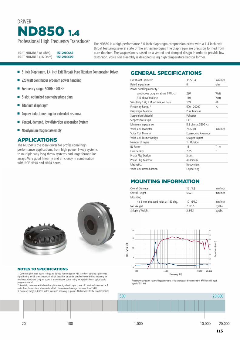
115
DRIVER ND850 1.4
Frequency response and electrical impedance curve of the compression driver mounted on HF64 horn with input signal of 2.83 Volt.
20.000500
20 100 10.000 20.0001.000
Professional High Frequency Transducer
PART NUMBER 15129022
80
90
100
110
120
100 1.000 10.000 20.000Frequency (Hz)
SPL,
1w/
1m (d
B)
Impe
danc
e (o
hms)
20 100 10.000 20.0001.000
500 20.000
NOTES TO SPECIFICATIONS
The ND850 is the ideal driver for professional high performance applications, from high power 2-way systems to multiple-way long throw systems and large format line arrays. Very good linearity and efficiency in combination with RCF HF94 and HF64 horns.
APPLICATIONS
GENERAL SPECIFICATIONS
MOUNTING INFORMATION
Exit Throat Diameter
Rated Impedance
Power handling capacity 1
continuous program above 0.8 kHz
AES above 0.8 kHz
Sensitivity 1 W, 1 M, on axis, on horn 2
Frequency Range 3
Diaphragm Material
Suspension Material
Suspension Design
Minimum Impedance
Voice Coil Diameter
Voice Coil Material
Voice Coil Former Design
Number of layers
BL Factor
Flux Density
Phase Plug Design
Phase Plug Material
Magnetics
Voice Coil Demodulation
Overall Diameter
Overall Height
Mounting
4 x 6 mm threaded holes at 180 deg.
Net Weight
Shipping Weight
35.5/1.4
8
220
110
109
500 - 20000
Pure Titanium
Polyester
Flat
8.5 ohm at 3500 Hz
74.4/3.0
Edgewound Aluminum
Straight Kapton
1 - Outside
13
2.05
3 slot
Aluminum
Neodymium
Copper ring
131/5.2
54/2.1
101.6/4.0
2.5/5.5
2.8/6.1
mm/inch
ohm
Watt
Watt
dB
Hz
mm/inch
T · m
T
mm/inch
mm/inch
mm/inch
kg/Lbs
kg/Lbs
3-inch Diaphragm, 1.4-inch Exit Throat/ Pure Titanium Compression Driver
220 watt Continuous program power handling
Frequency range: 500Hz - 20kHz
3-slot, optimized geometry phase plug
Titanium diaphragm
Copper inductance ring for extended response
Vented, damped, low distortion suspension System
Neodymium magnet assembly
ND850 1.4Professional High Frequency Transducer
DRIVER
1. Continuos pink noise power ratings are derived from suggested AES standards sending a pink noise signal having a 6 dB crest factor with a high pass filter set at the specified lower limiting frequency for two hours. Continuos program power is a conservative power rating for reproduction of typical audio program material.2. Sensitivity measurement is based on pink noise signal with input power of 1 watt and measured at 1 meter from the mouth of a horn with a Q of 15 on axis and averaged between 2 and 5 kHz.3. Frequency range is defined as the measured frequency response -10dB relative to the rated sensitivity.
The ND850 is a high performance 3.0-inch diaphragm compression driver with a 1.4 inch exit throat featuring several state of the art technologies. The diaphragm are precision formed from pure titanium. The suspension is based on a vented and damped design in order to provide low distorsion. Voice coil assembly is designed using high temperature kapton former.PART NUMBER (16 Ohm)
PART NUMBER (8 Ohm)1512903915129022
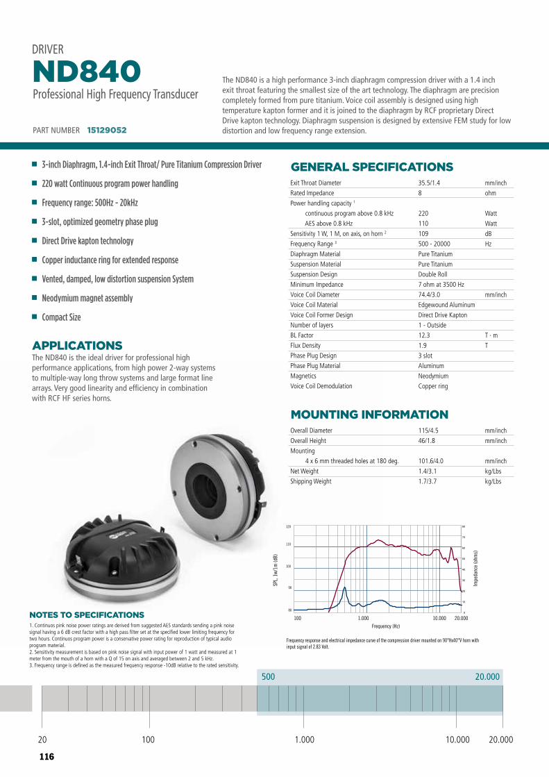
116
NOTES TO SPECIFICATIONS
The ND840 is the ideal driver for professional high performance applications, from high power 2-way systems to multiple-way long throw systems and large format line arrays. Very good linearity and efficiency in combination with RCF HF series horns.
APPLICATIONS
GENERAL SPECIFICATIONS
MOUNTING INFORMATION
Exit Throat Diameter
Rated Impedance
Power handling capacity 1
continuous program above 0.8 kHz
AES above 0.8 kHz
Sensitivity 1 W, 1 M, on axis, on horn 2
Frequency Range 3
Diaphragm Material
Suspension Material
Suspension Design
Minimum Impedance
Voice Coil Diameter
Voice Coil Material
Voice Coil Former Design
Number of layers
BL Factor
Flux Density
Phase Plug Design
Phase Plug Material
Magnetics
Voice Coil Demodulation
Overall Diameter
Overall Height
Mounting
4 x 6 mm threaded holes at 180 deg.
Net Weight
Shipping Weight
35.5/1.4
8
220
110
109
500 - 20000
Pure Titanium
Pure Titanium
Double Roll
7 ohm at 3500 Hz
74.4/3.0
Edgewound Aluminum
Direct Drive Kapton
1 - Outside
12.3
1.9
3 slot
Aluminum
Neodymium
Copper ring
115/4.5
46/1.8
101.6/4.0
1.4/3.1
1.7/3.7
mm/inch
ohm
Watt
Watt
dB
Hz
mm/inch
T · m
T
mm/inch
mm/inch
mm/inch
kg/Lbs
kg/Lbs
PART NUMBER 15129052
3-inch Diaphragm, 1.4-inch Exit Throat/ Pure Titanium Compression Driver
220 watt Continuous program power handling
Frequency range: 500Hz - 20kHz
3-slot, optimized geometry phase plug
Direct Drive kapton technology
Copper inductance ring for extended response
Vented, damped, low distortion suspension System
Neodymium magnet assembly
Compact Size
ND840Professional High Frequency Transducer
DRIVER
1. Continuos pink noise power ratings are derived from suggested AES standards sending a pink noise signal having a 6 dB crest factor with a high pass filter set at the specified lower limiting frequency for two hours. Continuos program power is a conservative power rating for reproduction of typical audio program material.2. Sensitivity measurement is based on pink noise signal with input power of 1 watt and measured at 1 meter from the mouth of a horn with a Q of 15 on axis and averaged between 2 and 5 kHz.3. Frequency range is defined as the measured frequency response -10dB relative to the rated sensitivity.
The ND840 is a high performance 3-inch diaphragm compression driver with a 1.4 inch exit throat featuring the smallest size of the art technology. The diaphragm are precision completely formed from pure titanium. Voice coil assembly is designed using high temperature kapton former and it is joined to the diaphragm by RCF proprietary Direct Drive kapton technology. Diaphragm suspension is designed by extensive FEM study for low distortion and low frequency range extension.
20 100 10.000 20.0001.000
500 20.000
Frequency response and electrical impedance curve of the compression driver mounted on 90°Hx40°V horn with input signal of 2.83 Volt.
80
90
100
110
120
100 1.000 10.000 20.000Frequency (Hz)
SPL,
1w/
1m (d
B)
Impe
danc
e (o
hms)
ND940ND640
Frequency response and electrical impedance curve of the compression driver mounted on HF64 horn with input signal of 2.83 Volt.
80
90
100
110
120
100 1.000 10.000 20.000Frequency (Hz)
SPL,
1w/
1m (d
B)
Impe
danc
e (o
hms)
ND840
Frequency response and electrical impedance curve of the compression driver mounted on 90°Hx40°V horn with input signal of 2.83 Volt.
80
90
100
110
120
100 1.000 10.000 20.000Frequency (Hz)
SPL,
1w/
1m (d
B)
Impe
danc
e (o
hms)
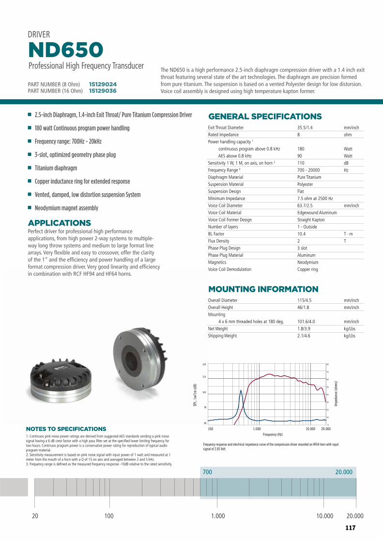
117
DRIVER ND650
Frequency response and electrical impedance curve of the compression driver mounted on HF64 horn with input signal of 2.83 Volt.
20.000700
20 100 10.000 20.0001.000
Professional High Frequency Transducer
PART NUMBER 15129024
80
90
100
110
120
100 1.000 10.000 20.000Frequency (Hz)
SPL,
1w/
1m (d
B)
Impe
danc
e (o
hms)
NOTES TO SPECIFICATIONS
Perfect driver for professional high performance applications, from high power 2-way systems to multiple-way long throw systems and medium to large format line arrays. Very flexible and easy to crossover, offer the clarity of the 1” and the efficiency and power handling of a large format compression driver. Very good linearity and efficiency in combination with RCF HF94 and HF64 horns.
APPLICATIONS
GENERAL SPECIFICATIONS
MOUNTING INFORMATION
Exit Throat Diameter
Rated Impedance
Power handling capacity 1
continuous program above 0.8 kHz
AES above 0.8 kHz
Sensitivity 1 W, 1 M, on axis, on horn 2
Frequency Range 3
Diaphragm Material
Suspension Material
Suspension Design
Minimum Impedance
Voice Coil Diameter
Voice Coil Material
Voice Coil Former Design
Number of layers
BL Factor
Flux Density
Phase Plug Design
Phase Plug Material
Magnetics
Voice Coil Demodulation
Overall Diameter
Overall Height
Mounting
4 x 6 mm threaded holes at 180 deg.
Net Weight
Shipping Weight
35.5/1.4
8
180
90
110
700 - 20000
Pure Titanium
Polyester
Flat
7.5 ohm at 2500 Hz
63.7/2.5
Edgewound Aluminum
Straight Kapton
1 - Outside
10.4
2
3 slot
Aluminum
Neodymium
Copper ring
115/4.5
46/1.8
101.6/4.0
1.8/3.9
2.1/4.6
mm/inch
ohm
Watt
Watt
dB
Hz
mm/inch
T · m
T
mm/inch
mm/inch
mm/inch
kg/Lbs
kg/Lbs
2.5-inch Diaphragm, 1.4-inch Exit Throat/ Pure Titanium Compression Driver
180 watt Continuous program power handling
Frequency range: 700Hz - 20kHz
3-slot, optimized geometry phase plug
Titanium diaphragm
Copper inductance ring for extended response
Vented, damped, low distortion suspension System
Neodymium magnet assembly
ND650Professional High Frequency Transducer
DRIVER
1. Continuos pink noise power ratings are derived from suggested AES standards sending a pink noise signal having a 6 dB crest factor with a high pass filter set at the specified lower limiting frequency for two hours. Continuos program power is a conservative power rating for reproduction of typical audio program material.2. Sensitivity measurement is based on pink noise signal with input power of 1 watt and measured at 1 meter from the mouth of a horn with a Q of 15 on axis and averaged between 2 and 5 kHz.3. Frequency range is defined as the measured frequency response -10dB relative to the rated sensitivity.
The ND650 is a high performance 2.5-inch diaphragm compression driver with a 1.4 inch exit throat featuring several state of the art technologies. The diaphragm are precision formed from pure titanium. The suspension is based on a vented Polyester design for low distorsion. Voice coil assembly is designed using high temperature kapton former.PART NUMBER (16 Ohm)
PART NUMBER (8 Ohm)1512903615129024
20 100 10.000 20.0001.000
700 20.000
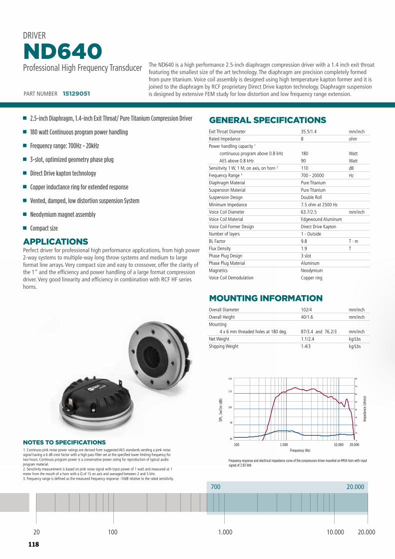
118
Frequency response and electrical impedance curve of the compression driver mounted on 90°Hx40°V horn with input signal of 2.83 Volt.
80
90
100
110
120
100 1.000 10.000 20.000Frequency (Hz)
SPL,
1w/
1m (d
B)
Impe
danc
e (o
hms)
ND940ND640
Frequency response and electrical impedance curve of the compression driver mounted on HF64 horn with input signal of 2.83 Volt.
80
90
100
110
120
100 1.000 10.000 20.000Frequency (Hz)
SPL,
1w/
1m (d
B)
Impe
danc
e (o
hms)
ND840
Frequency response and electrical impedance curve of the compression driver mounted on 90°Hx40°V horn with input signal of 2.83 Volt.
80
90
100
110
120
100 1.000 10.000 20.000Frequency (Hz)
SPL,
1w/
1m (d
B)
Impe
danc
e (o
hms)
20 100 10.000 20.0001.000
700 20.000
NOTES TO SPECIFICATIONS
Perfect driver for professional high performance applications, from high power 2-way systems to multiple-way long throw systems and medium to large format line arrays. Very compact size and easy to crossover, offer the clarity of the 1” and the efficiency and power handling of a large format compression driver. Very good linearity and efficiency in combination with RCF HF series horns.
APPLICATIONS
GENERAL SPECIFICATIONS
MOUNTING INFORMATION
Exit Throat Diameter
Rated Impedance
Power handling capacity 1
continuous program above 0.8 kHz
AES above 0.8 kHz
Sensitivity 1 W, 1 M, on axis, on horn 2
Frequency Range 3
Diaphragm Material
Suspension Material
Suspension Design
Minimum Impedance
Voice Coil Diameter
Voice Coil Material
Voice Coil Former Design
Number of layers
BL Factor
Flux Density
Phase Plug Design
Phase Plug Material
Magnetics
Voice Coil Demodulation
Overall Diameter
Overall Height
Mounting
4 x 6 mm threaded holes at 180 deg.
Net Weight
Shipping Weight
35.5/1.4
8
180
90
110
700 - 20000
Pure Titanium
Pure Titanium
Double Roll
7.5 ohm at 2500 Hz
63.7/2.5
Edgewound Aluminum
Direct Drive Kapton
1 - Outside
9.8
1.9
3 slot
Aluminum
Neodymium
Copper ring
102/4
40/1.6
87/3.4 and 76.2/3
1.1/2.4
1.4/3
mm/inch
ohm
Watt
Watt
dB
Hz
mm/inch
T · m
T
mm/inch
mm/inch
mm/inch
kg/Lbs
kg/Lbs
PART NUMBER 15129051
2.5-inch Diaphragm, 1.4-inch Exit Throat/ Pure Titanium Compression Driver
180 watt Continuous program power handling
Frequency range: 700Hz - 20kHz
3-slot, optimized geometry phase plug
Direct Drive kapton technology
Copper inductance ring for extended response
Vented, damped, low distortion suspension System
Neodymium magnet assembly
Compact size
ND640Professional High Frequency Transducer
DRIVER
1. Continuos pink noise power ratings are derived from suggested AES standards sending a pink noise signal having a 6 dB crest factor with a high pass filter set at the specified lower limiting frequency for two hours. Continuos program power is a conservative power rating for reproduction of typical audio program material.2. Sensitivity measurement is based on pink noise signal with input power of 1 watt and measured at 1 meter from the mouth of a horn with a Q of 15 on axis and averaged between 2 and 5 kHz.3. Frequency range is defined as the measured frequency response -10dB relative to the rated sensitivity.
The ND640 is a high performance 2.5-inch diaphragm compression driver with a 1.4 inch exit throat featuring the smallest size of the art technology. The diaphragm are precision completely formed from pure titanium. Voice coil assembly is designed using high temperature kapton former and it is joined to the diaphragm by RCF proprietary Direct Drive kapton technology. Diaphragm suspension is designed by extensive FEM study for low distortion and low frequency range extension.
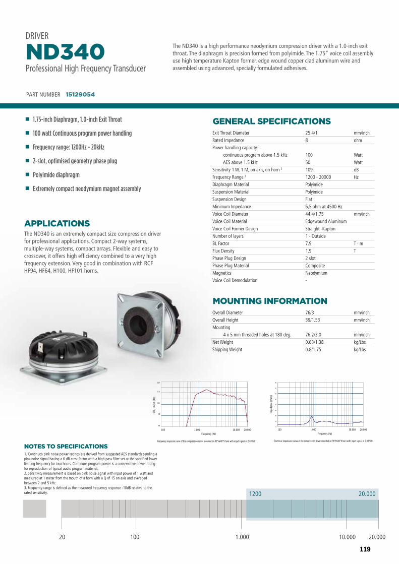
119
The ND340 is a high performance neodymium compression driver with a 1.0-inch exit throat. The diaphragm is precision formed from polyimide. The 1.75” voice coil assembly use high temperature Kapton former, edge wound copper clad aluminum wire and assembled using advanced, specially formulated adhesives.
PART NUMBER 15129054
1.75-inch Diaphragm, 1.0-inch Exit Throat
100 watt Continuous program power handling
Frequency range: 1200Hz - 20kHz
2-slot, optimised geometry phase plug
Polyimide diaphragm
Extremely compact neodymium magnet assembly
ND340Professional High Frequency Transducer
DRIVER
20 100 10.000 20.0001.000
1200 20.000
1. Continuos pink noise power ratings are derived from suggested AES standards sending a pink noise signal having a 6 dB crest factor with a high pass filter set at the specified lower limiting frequency for two hours. Continuos program power is a conservative power rating for reproduction of typical audio program material.2. Sensitivity measurement is based on pink noise signal with input power of 1 watt and measured at 1 meter from the mouth of a horn with a Q of 15 on axis and averaged between 2 and 5 kHz.3. Frequency range is defined as the measured frequency response -10dB relative to the rated sensitivity.
NOTES TO SPECIFICATIONS
GENERAL SPECIFICATIONS
MOUNTING INFORMATION
Exit Throat Diameter
Rated Impedance
Power handling capacity 1
continuous program above 1.5 kHz
AES above 1.5 kHz
Sensitivity 1 W, 1 M, on axis, on horn 2
Frequency Range 3
Diaphragm Material
Suspension Material
Suspension Design
Minimum Impedance
Voice Coil Diameter
Voice Coil Material
Voice Coil Former Design
Number of layers
BL Factor
Flux Density
Phase Plug Design
Phase Plug Material
Magnetics
Voice Coil Demodulation
Overall Diameter
Overall Height
Mounting
4 x 5 mm threaded holes at 180 deg.
Net Weight
Shipping Weight
25.4/1
8
100
50
109
1200 - 20000
Polyimide
Polyimide
Flat
6,5 ohm at 4500 Hz
44.4/1.75
Edgewound Aluminum
Straight -Kapton
1 - Outside
7.9
1.9
2 slot
Composite
Neodymium
-
76/3
39/1.53
76.2/3.0
0.63/1.38
0.8/1.75
mm/inch
ohm
Watt
Watt
dB
Hz
mm/inch
T · m
T
mm/inch
mm/inch
mm/inch
kg/Lbs
kg/Lbs
ND340
Frequency response curve of the compression driver mounted on 90°Hx40°V horn with input signal of 2.83 Volt.
80
90
100
110
120
100 1.000 10.000 20.000Frequency (Hz)
SPL,
1w/
1m (d
B)
ND340
Electrical impedance curve of the compression driver mounted on 90°Hx40°V horn with input signal of 2.83 Volt.
100 1.000 10.000 20.000Frequency (Hz)
Impe
danc
e (o
hms)
The ND340 is an extremely compact size compression driver for professional applications. Compact 2-way systems, multiple-way systems, compact arrays. Flexible and easy to crossover, it offers high efficiency combined to a very high frequency extension. Very good in combination with RCF HF94, HF64, H100, HF101 horns.
APPLICATIONS
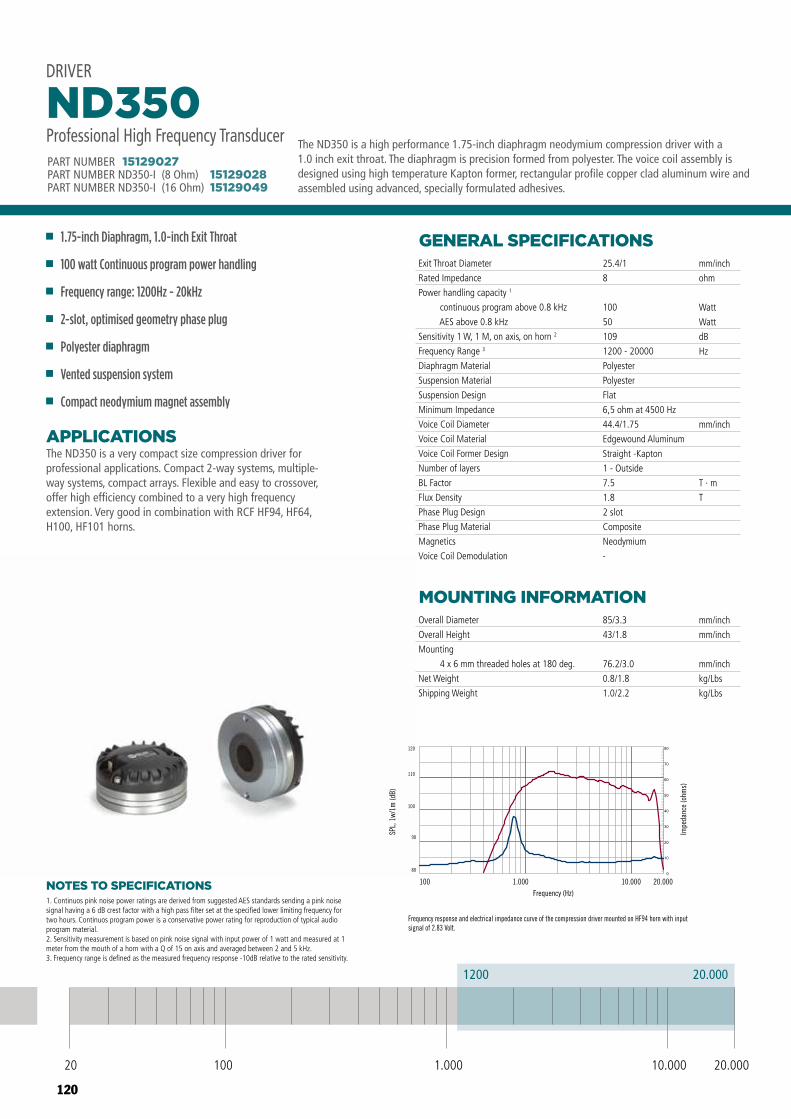
120
DRIVER ND350
Frequency response and electrical impedance curve of the compression driver mounted on HF94 horn with input signal of 2.83 Volt.
20.0001200
20 100 10.000 20.0001.000
Professional High Frequency Transducer
PART NUMBER 15129027
80
90
100
110
120
100 1.000 10.000 20.000Frequency (Hz)
SPL,
1w/
1m (d
B)
Impe
danc
e (o
hms)
20 100 10.000 20.0001.000
1200 20.000
NOTES TO SPECIFICATIONS
The ND350 is a very compact size compression driver for professional applications. Compact 2-way systems, multiple-way systems, compact arrays. Flexible and easy to crossover, offer high efficiency combined to a very high frequency extension. Very good in combination with RCF HF94, HF64, H100, HF101 horns.
APPLICATIONS
GENERAL SPECIFICATIONS
MOUNTING INFORMATION
Exit Throat Diameter
Rated Impedance
Power handling capacity 1
continuous program above 0.8 kHz
AES above 0.8 kHz
Sensitivity 1 W, 1 M, on axis, on horn 2
Frequency Range 3
Diaphragm Material
Suspension Material
Suspension Design
Minimum Impedance
Voice Coil Diameter
Voice Coil Material
Voice Coil Former Design
Number of layers
BL Factor
Flux Density
Phase Plug Design
Phase Plug Material
Magnetics
Voice Coil Demodulation
Overall Diameter
Overall Height
Mounting
4 x 6 mm threaded holes at 180 deg.
Net Weight
Shipping Weight
25.4/1
8
100
50
109
1200 - 20000
Polyester
Polyester
Flat
6,5 ohm at 4500 Hz
44.4/1.75
Edgewound Aluminum
Straight -Kapton
1 - Outside
7.5
1.8
2 slot
Composite
Neodymium
-
85/3.3
43/1.8
76.2/3.0
0.8/1.8
1.0/2.2
mm/inch
ohm
Watt
Watt
dB
Hz
mm/inch
T · m
T
mm/inch
mm/inch
mm/inch
kg/Lbs
kg/Lbs
1.75-inch Diaphragm, 1.0-inch Exit Throat
100 watt Continuous program power handling
Frequency range: 1200Hz - 20kHz
2-slot, optimised geometry phase plug
Polyester diaphragm
Vented suspension system
Compact neodymium magnet assembly
ND350Professional High Frequency Transducer
DRIVER
1. Continuos pink noise power ratings are derived from suggested AES standards sending a pink noise signal having a 6 dB crest factor with a high pass filter set at the specified lower limiting frequency for two hours. Continuos program power is a conservative power rating for reproduction of typical audio program material.2. Sensitivity measurement is based on pink noise signal with input power of 1 watt and measured at 1 meter from the mouth of a horn with a Q of 15 on axis and averaged between 2 and 5 kHz.3. Frequency range is defined as the measured frequency response -10dB relative to the rated sensitivity.
The ND350 is a high performance 1.75-inch diaphragm neodymium compression driver with a 1.0 inch exit throat. The diaphragm is precision formed from polyester. The voice coil assembly is designed using high temperature Kapton former, rectangular profile copper clad aluminum wire and assembled using advanced, specially formulated adhesives.PART NUMBER ND350-I (16 Ohm) 15129049
PART NUMBER ND350-I (8 Ohm) 15129028PART NUMBER 15129027
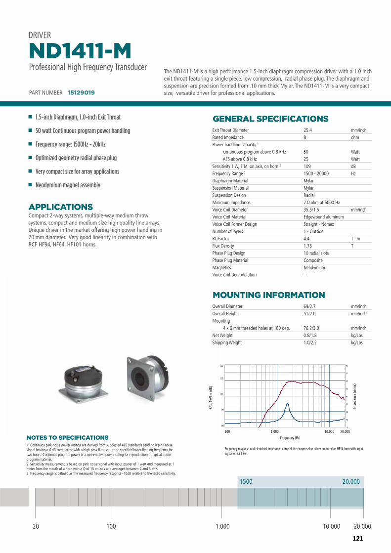
121
DRIVERND1411-MProfessional High Frequency Transducer
80
90
100
110
120
100 1.000 10.000 20.000
Frequency response and electrical impedance curve of the compression driver mounted on HF94 horn with input signal of 2.83 Volt.
20.0001500
20 100 10.000 20.0001.000
PART NUMBER 15129019
Frequency (Hz)
SPL,
1w/
1m (d
B)
Impe
danc
e (o
hms)
NOTES TO SPECIFICATIONS
Compact 2-way systems, multiple-way medium throw systems, compact and medium size high quality line arrays. Unique driver in the market offering high power handling in 70 mm diameter. Very good linearity in combination with RCF HF94, HF64, HF101 horns.
APPLICATIONS
GENERAL SPECIFICATIONS
MOUNTING INFORMATION
Exit Throat Diameter
Rated Impedance
Power handling capacity 1
continuous program above 0.8 kHz
AES above 0.8 kHz
Sensitivity 1 W, 1 M, on axis, on horn 2
Frequency Range 3
Diaphragm Material
Suspension Material
Suspension Design
Minimum Impedance
Voice Coil Diameter
Voice Coil Material
Voice Coil Former Design
Number of layers
BL Factor
Flux Density
Phase Plug Design
Phase Plug Material
Magnetics
Voice Coil Demodulation
Overall Diameter
Overall Height
Mounting
4 x 6 mm threaded holes at 180 deg.
Net Weight
Shipping Weight
25.4
8
50
25
109
1500 - 20000
Mylar
Mylar
Radial
7.0 ohm at 6000 Hz
35.5/1.5
Edgewound aluminum
Straight - Nomex
1 - Outside
4.4
1.75
10 radial slots
Composite
Neodymium
-
69/2.7
51/2.0
76.2/3.0
0.8/1.8
1.0/2.2
mm/inch
ohm
Watt
Watt
dB
Hz
mm/inch
T · m
T
mm/inch
mm/inch
mm/inch
kg/Lbs
kg/Lbs
PART NUMBER 15129019
1.5-inch Diaphragm, 1.0-inch Exit Throat
50 watt Continuous program power handling
Frequency range: 1500Hz - 20kHz
Optimized geometry radial phase plug
Very compact size for array applications
Neodymium magnet assembly
ND1411-MProfessional High Frequency Transducer
DRIVER
1. Continuos pink noise power ratings are derived from suggested AES standards sending a pink noise signal having a 6 dB crest factor with a high pass filter set at the specified lower limiting frequency for two hours. Continuos program power is a conservative power rating for reproduction of typical audio program material.2. Sensitivity measurement is based on pink noise signal with input power of 1 watt and measured at 1 meter from the mouth of a horn with a Q of 15 on axis and averaged between 2 and 5 kHz.3. Frequency range is defined as the measured frequency response -10dB relative to the rated sensitivity.
The ND1411-M is a high performance 1.5-inch diaphragm compression driver with a 1.0 inch exit throat featuring a single piece, low compression, radial phase plug. The diaphragm and suspension are precision formed from .10 mm thick Mylar. The ND1411-M is a very compact size, versatile driver for professional applications.
20 100 10.000 20.0001.000
1500 20.000
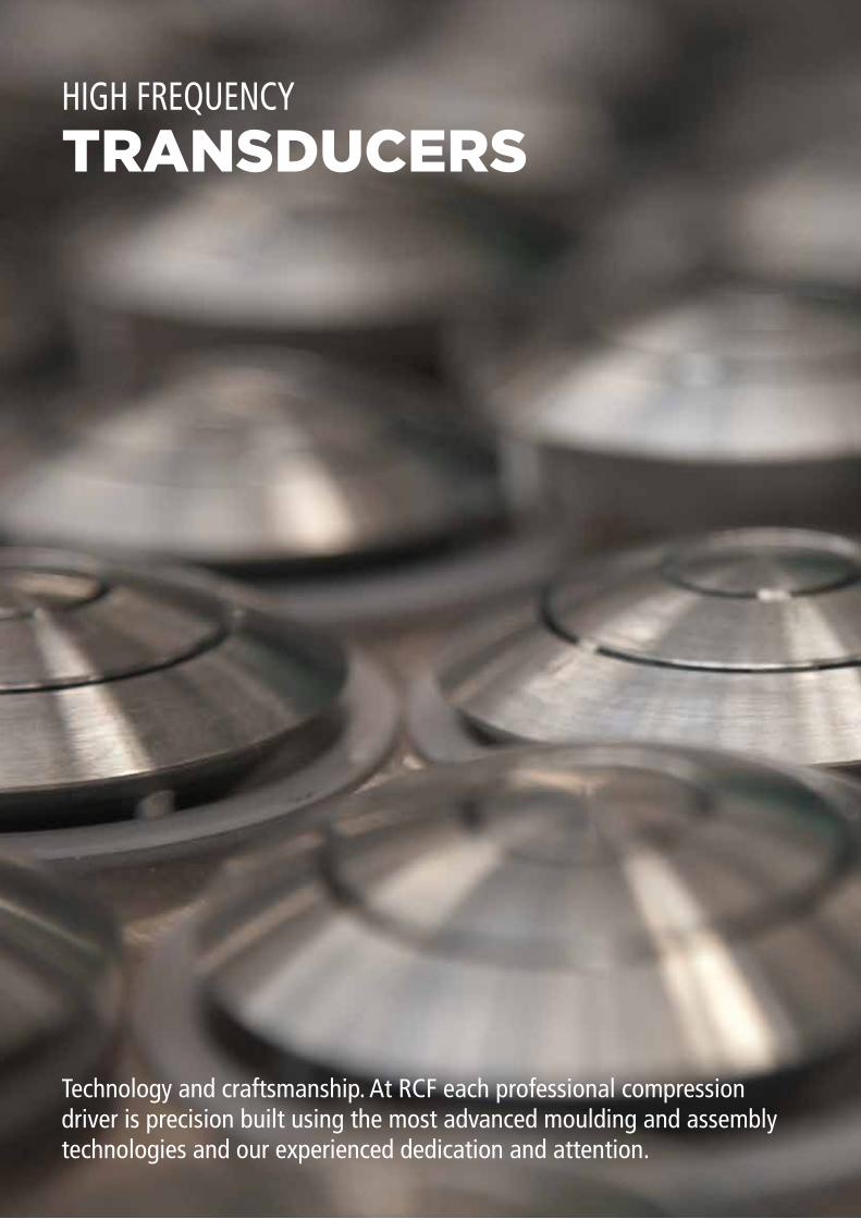
122
TRANSDUCERSHIGH FREQUENCY
Technology and craftsmanship. At RCF each professional compression driver is precision built using the most advanced moulding and assembly technologies and our experienced dedication and attention.
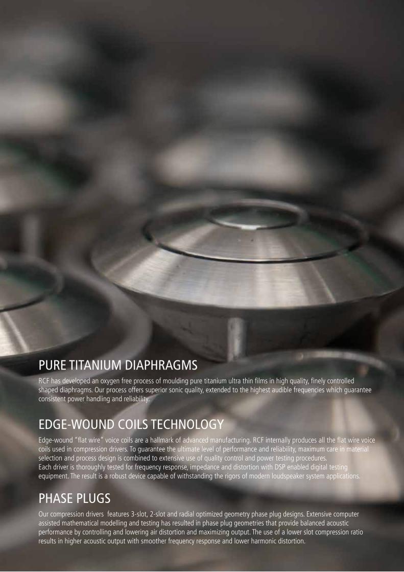
123
PURE TITANIUM DIAPHRAGMS
EDGE-WOUND COILS TECHNOLOGY
PHASE PLUGS
RCF has developed an oxygen free process of moulding pure titanium ultra thin films in high quality, finely controlled shaped diaphragms. Our process offers superior sonic quality, extended to the highest audible frequencies which guarantee consistent power handling and reliability.
Edge-wound “flat wire” voice coils are a hallmark of advanced manufacturing. RCF internally produces all the flat wire voice coils used in compression drivers. To guarantee the ultimate level of performance and reliability, maximum care in material selection and process design is combined to extensive use of quality control and power testing procedures. Each driver is thoroughly tested for frequency response, impedance and distortion with DSP enabled digital testing equipment. The result is a robust device capable of withstanding the rigors of modern loudspeaker system applications.
Our compression drivers features 3-slot, 2-slot and radial optimized geometry phase plug designs. Extensive computer assisted mathematical modelling and testing has resulted in phase plug geometries that provide balanced acoustic performance by controlling and lowering air distortion and maximizing output. The use of a lower slot compression ratio results in higher acoustic output with smoother frequency response and lower harmonic distortion.
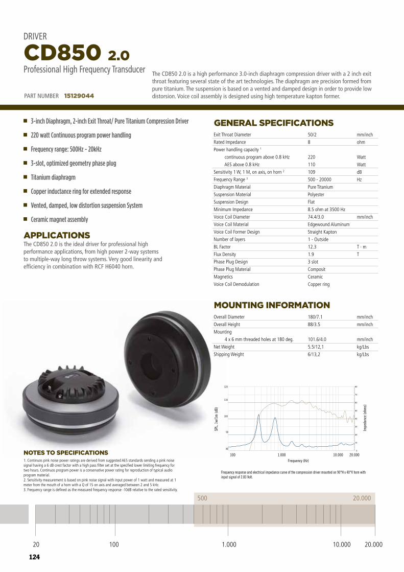
124
DRIVER CD850 2.0
Frequency response and electrical impedance curve of the compression driver mounted on 90°H x 40°V horn with input signal of 2.83 Volt.
20.000500
20 100 10.000 20.0001.000
Professional High Frequency Transducer
PART NUMBER 15129044
80
90
100
110
120
100 1.000 10.000 20.000Frequency (Hz)
SPL,
1w/
1m (d
B)
Impe
danc
e (o
hms)
NOTES TO SPECIFICATIONS
The CD850 2.0 is the ideal driver for professional high performance applications, from high power 2-way systems to multiple-way long throw systems. Very good linearity and efficiency in combination with RCF H6040 horn.
APPLICATIONS
GENERAL SPECIFICATIONS
MOUNTING INFORMATION
Exit Throat Diameter
Rated Impedance
Power handling capacity 1
continuous program above 0.8 kHz
AES above 0.8 kHz
Sensitivity 1 W, 1 M, on axis, on horn 2
Frequency Range 3
Diaphragm Material
Suspension Material
Suspension Design
Minimum Impedance
Voice Coil Diameter
Voice Coil Material
Voice Coil Former Design
Number of layers
BL Factor
Flux Density
Phase Plug Design
Phase Plug Material
Magnetics
Voice Coil Demodulation
Overall Diameter
Overall Height
Mounting
4 x 6 mm threaded holes at 180 deg.
Net Weight
Shipping Weight
50/2
8
220
110
109
500 - 20000
Pure Titanium
Polyester
Flat
8.5 ohm at 3500 Hz
74.4/3.0
Edgewound Aluminum
Straight Kapton
1 - Outside
12.3
1.9
3 slot
Composit
Ceramic
Copper ring
180/7.1
88/3.5
101.6/4.0
5.5/12,1
6/13,2
mm/inch
ohm
Watt
Watt
dB
Hz
mm/inch
T · m
T
mm/inch
mm/inch
mm/inch
kg/Lbs
kg/Lbs
PART NUMBER 15129044
3-inch Diaphragm, 2-inch Exit Throat/ Pure Titanium Compression Driver
220 watt Continuous program power handling
Frequency range: 500Hz - 20kHz
3-slot, optimized geometry phase plug
Titanium diaphragm
Copper inductance ring for extended response
Vented, damped, low distortion suspension System
Ceramic magnet assembly
CD850 2.0Professional High Frequency Transducer
DRIVER
1. Continuos pink noise power ratings are derived from suggested AES standards sending a pink noise signal having a 6 dB crest factor with a high pass filter set at the specified lower limiting frequency for two hours. Continuos program power is a conservative power rating for reproduction of typical audio program material.2. Sensitivity measurement is based on pink noise signal with input power of 1 watt and measured at 1 meter from the mouth of a horn with a Q of 15 on axis and averaged between 2 and 5 kHz.3. Frequency range is defined as the measured frequency response -10dB relative to the rated sensitivity.
The CD850 2.0 is a high performance 3.0-inch diaphragm compression driver with a 2 inch exit throat featuring several state of the art technologies. The diaphragm are precision formed from pure titanium. The suspension is based on a vented and damped design in order to provide low distorsion. Voice coil assembly is designed using high temperature kapton former.
20 100 10.000 20.0001.000
500 20.000
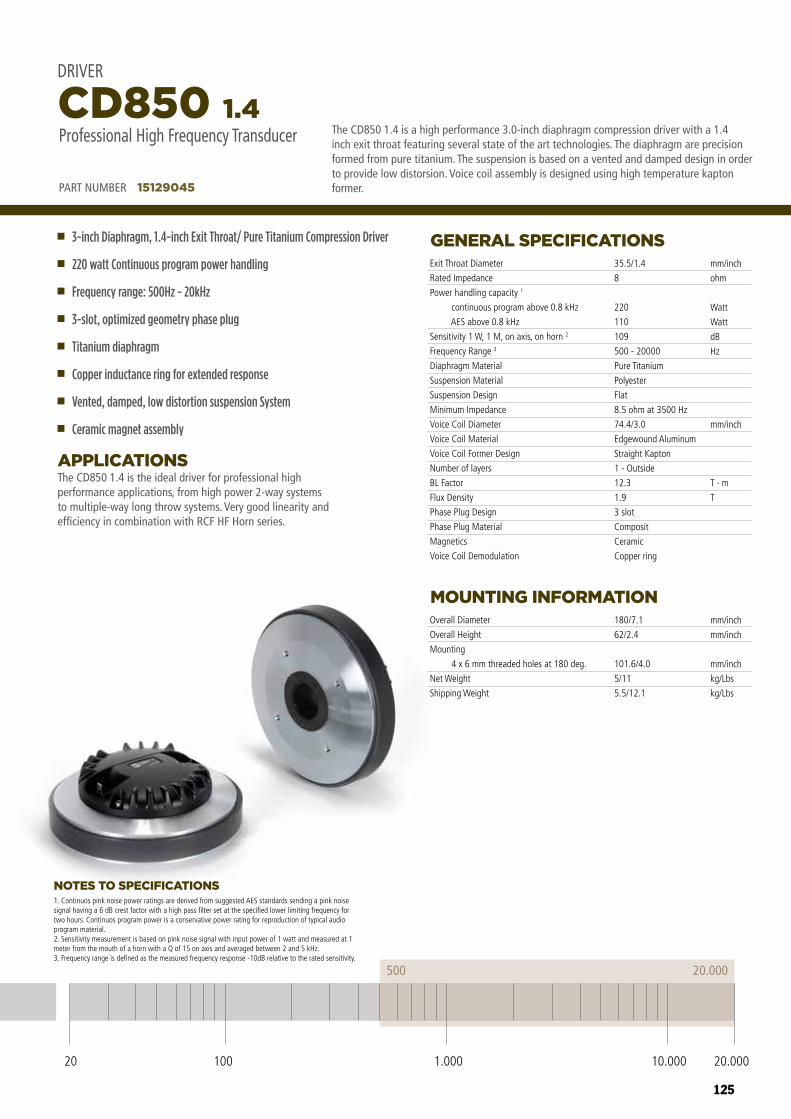
125
20 100 10.000 20.0001.000
500 20.000
NOTES TO SPECIFICATIONS
The CD850 1.4 is the ideal driver for professional high performance applications, from high power 2-way systems to multiple-way long throw systems. Very good linearity and efficiency in combination with RCF HF Horn series.
APPLICATIONS
GENERAL SPECIFICATIONS
MOUNTING INFORMATION
Exit Throat Diameter
Rated Impedance
Power handling capacity 1
continuous program above 0.8 kHz
AES above 0.8 kHz
Sensitivity 1 W, 1 M, on axis, on horn 2
Frequency Range 3
Diaphragm Material
Suspension Material
Suspension Design
Minimum Impedance
Voice Coil Diameter
Voice Coil Material
Voice Coil Former Design
Number of layers
BL Factor
Flux Density
Phase Plug Design
Phase Plug Material
Magnetics
Voice Coil Demodulation
Overall Diameter
Overall Height
Mounting
4 x 6 mm threaded holes at 180 deg.
Net Weight
Shipping Weight
35.5/1.4
8
220
110
109
500 - 20000
Pure Titanium
Polyester
Flat
8.5 ohm at 3500 Hz
74.4/3.0
Edgewound Aluminum
Straight Kapton
1 - Outside
12.3
1.9
3 slot
Composit
Ceramic
Copper ring
180/7.1
62/2.4
101.6/4.0
5/11
5.5/12.1
mm/inch
ohm
Watt
Watt
dB
Hz
mm/inch
T · m
T
mm/inch
mm/inch
mm/inch
kg/Lbs
kg/Lbs
PART NUMBER 15129045
3-inch Diaphragm, 1.4-inch Exit Throat/ Pure Titanium Compression Driver
220 watt Continuous program power handling
Frequency range: 500Hz - 20kHz
3-slot, optimized geometry phase plug
Titanium diaphragm
Copper inductance ring for extended response
Vented, damped, low distortion suspension System
Ceramic magnet assembly
CD850 1.4Professional High Frequency Transducer
DRIVER
1. Continuos pink noise power ratings are derived from suggested AES standards sending a pink noise signal having a 6 dB crest factor with a high pass filter set at the specified lower limiting frequency for two hours. Continuos program power is a conservative power rating for reproduction of typical audio program material.2. Sensitivity measurement is based on pink noise signal with input power of 1 watt and measured at 1 meter from the mouth of a horn with a Q of 15 on axis and averaged between 2 and 5 kHz.3. Frequency range is defined as the measured frequency response -10dB relative to the rated sensitivity.
The CD850 1.4 is a high performance 3.0-inch diaphragm compression driver with a 1.4 inch exit throat featuring several state of the art technologies. The diaphragm are precision formed from pure titanium. The suspension is based on a vented and damped design in order to provide low distorsion. Voice coil assembly is designed using high temperature kapton former.
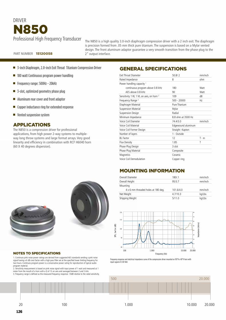
126
DRIVERN850Professional High Frequency Transducer
Frequency response and electrical impedance curve of the compression driver mounted on 90°H x 40°V horn with input signal of 2.83 Volt.
20.000500
20 100 10.000 20.0001.000
PART NUMBER 15120058
80
90
100
110
120
100 1.000 10.000 20.000Frequency (Hz)
SPL,
1w/
1m (d
B)
Impe
danc
e (o
hms)
20 100 10.000 20.0001.000
500 20.000
NOTES TO SPECIFICATIONS
The N850 is a compression driver for professional applications, from high power 2-way systems to multiple-way long throw systems and large format arrays. Very good linearity and efficiency in combination with RCF H6040 horn (60 X 40 degrees dispersion).
APPLICATIONS
GENERAL SPECIFICATIONS
MOUNTING INFORMATION
Exit Throat Diameter
Rated Impedance
Power handling capacity 1
continuous program above 0.8 kHz
AES above 0.8 kHz
Sensitivity 1 W, 1 M, on axis, on horn 2
Frequency Range 3
Diaphragm Material
Suspension Material
Suspension Design
Minimum Impedance
Voice Coil Diameter
Voice Coil Material
Voice Coil Former Design
Number of layers
BL Factor
Flux Density
Phase Plug Design
Phase Plug Material
Magnetics
Voice Coil Demodulation
Overall Diameter
Overall Height
Mounting
4 x 6 mm threaded holes at 180 deg.
Net Weight
Shipping Weight
50.8/ 2
8
180
90
109
500 - 20000
Pure Titanium
Mylar
Radial
8.8 ohm at 3500 Hz
74.4/3.0
Edgewound aluminum
Straight -Kapton
1 - Outside
12
1.85
3 slot
Composite
Ceramic
Copper ring
180/.1
95/3.7
101.6/4.0
4.7/10.3
5/11.0
mm/inch
ohm
Watt
Watt
dB
Hz
mm/inch
T · m
T
mm/inch
mm/inch
mm/inch
kg/Lbs
kg/Lbs
PART NUMBER 15120058
3-inch Diaphragm, 2.0-inch Exit Throat Titanium Compression Driver
180 watt Continuous program power handling
Frequency range: 500Hz - 20kHz
3-slot, optimized geometry phase plug
Aluminum rear cover and front adaptor
Copper inductance ring for extended response
Vented suspension system
N850Professional High Frequency Transducer
DRIVER
1. Continuos pink noise power ratings are derived from suggested AES standards sending a pink noise signal having a 6 dB crest factor with a high pass filter set at the specified lower limiting frequency for two hours. Continuos program power is a conservative power rating for reproduction of typical audio program material.2. Sensitivity measurement is based on pink noise signal with input power of 1 watt and measured at 1 meter from the mouth of a horn with a Q of 15 on axis and averaged between 2 and 5 kHz.3. Frequency range is defined as the measured frequency response -10dB relative to the rated sensitivity.
The N850 is a high quality 3.0-inch diaphragm compression driver with a 2 inch exit. The diaphragm is precision formed from .05 mm thick pure titanium. The suspension is based on a Mylar vented design. The front aluminum adaptor guarantee a very smooth transition from the phase plug to the 2” output interface.
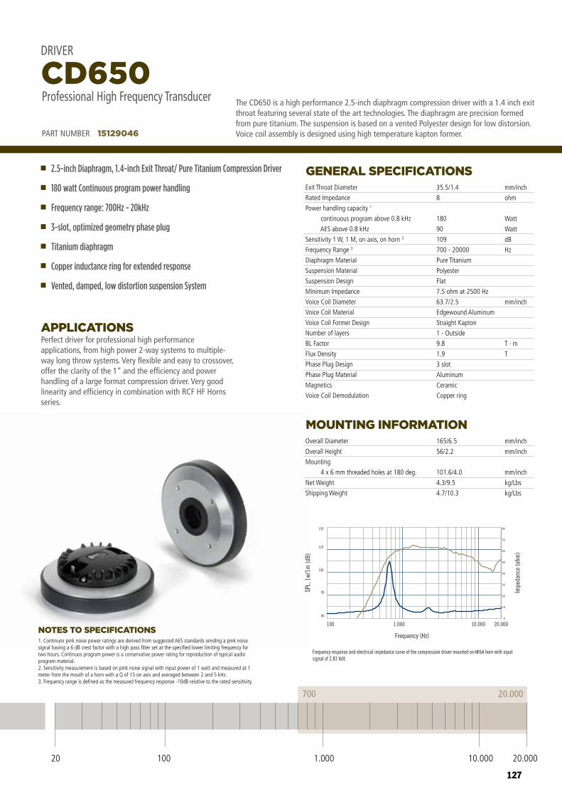
127
20 100 10.000 20.0001.000
700 20.000
SPL,
1w/
1m (d
B)
80
90
100
110
120
Impe
danc
e (o
hm)
000.02000.01000.1001
Frequency (Hz)
HF64
NOTES TO SPECIFICATIONS
Perfect driver for professional high performance applications, from high power 2-way systems to multiple-way long throw systems. Very flexible and easy to crossover, offer the clarity of the 1” and the efficiency and power handling of a large format compression driver. Very good linearity and efficiency in combination with RCF HF Horns series.
APPLICATIONS
GENERAL SPECIFICATIONS
MOUNTING INFORMATION
Exit Throat Diameter
Rated Impedance
Power handling capacity 1
continuous program above 0.8 kHz
AES above 0.8 kHz
Sensitivity 1 W, 1 M, on axis, on horn 2
Frequency Range 3
Diaphragm Material
Suspension Material
Suspension Design
Minimum Impedance
Voice Coil Diameter
Voice Coil Material
Voice Coil Former Design
Number of layers
BL Factor
Flux Density
Phase Plug Design
Phase Plug Material
Magnetics
Voice Coil Demodulation
Overall Diameter
Overall Height
Mounting
4 x 6 mm threaded holes at 180 deg.
Net Weight
Shipping Weight
35.5/1.4
8
180
90
109
700 - 20000
Pure Titanium
Polyester
Flat
7.5 ohm at 2500 Hz
63.7/2.5
Edgewound Aluminum
Straight Kapton
1 - Outside
9.8
1.9
3 slot
Aluminum
Ceramic
Copper ring
165/6.5
56/2.2
101.6/4.0
4.3/9.5
4.7/10.3
mm/inch
ohm
Watt
Watt
dB
Hz
mm/inch
T · m
T
mm/inch
mm/inch
mm/inch
kg/Lbs
kg/Lbs
PART NUMBER 15129046
2.5-inch Diaphragm, 1.4-inch Exit Throat/ Pure Titanium Compression Driver
180 watt Continuous program power handling
Frequency range: 700Hz - 20kHz
3-slot, optimized geometry phase plug
Titanium diaphragm
Copper inductance ring for extended response
Vented, damped, low distortion suspension System
CD650Professional High Frequency Transducer
DRIVER
1. Continuos pink noise power ratings are derived from suggested AES standards sending a pink noise signal having a 6 dB crest factor with a high pass filter set at the specified lower limiting frequency for two hours. Continuos program power is a conservative power rating for reproduction of typical audio program material.2. Sensitivity measurement is based on pink noise signal with input power of 1 watt and measured at 1 meter from the mouth of a horn with a Q of 15 on axis and averaged between 2 and 5 kHz.3. Frequency range is defined as the measured frequency response -10dB relative to the rated sensitivity.
The CD650 is a high performance 2.5-inch diaphragm compression driver with a 1.4 inch exit throat featuring several state of the art technologies. The diaphragm are precision formed from pure titanium. The suspension is based on a vented Polyester design for low distorsion. Voice coil assembly is designed using high temperature kapton former.
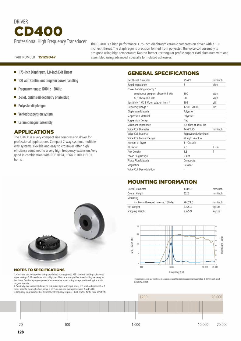
128
20 100 10.000 20.0001.000
1200 20.000
SPL,
1w/
1m (d
B)
80
90
100
110
120
Impe
danc
e (o
hm)
000.02000.01000.1001
Frequency (Hz)NOTES TO SPECIFICATIONS
The CD400 is a very compact size compression driver for professional applications. Compact 2-way systems, multiple-way systems. Flexible and easy to crossover, offer high efficiency combined to a very high frequency extension. Very good in combination with RCF HF94, HF64, H100, HF101 horns.
APPLICATIONS
GENERAL SPECIFICATIONS
MOUNTING INFORMATION
Exit Throat Diameter
Rated Impedance
Power handling capacity 1
continuous program above 0.8 kHz
AES above 0.8 kHz
Sensitivity 1 W, 1 M, on axis, on horn 2
Frequency Range 3
Diaphragm Material
Suspension Material
Suspension Design
Minimum Impedance
Voice Coil Diameter
Voice Coil Material
Voice Coil Former Design
Number of layers
BL Factor
Flux Density
Phase Plug Design
Phase Plug Material
Magnetics
Voice Coil Demodulation
Overall Diameter
Overall Height
Mounting
4 x 6 mm threaded holes at 180 deg.
Net Weight
Shipping Weight
25.4/1
8
100
50
109
1200 - 20000
Polyester
Polyester
Flat
6,5 ohm at 4500 Hz
44.4/1.75
Edgewound Aluminum
Straight -Kapton
1 - Outside
7.5
1.8
2 slot
Composite
Ceramic
-
134/5.3
52/2
76.2/3.0
2.4/5.3
2.7/5.9
mm/inch
ohm
Watt
Watt
dB
Hz
mm/inch
T · m
T
mm/inch
mm/inch
mm/inch
kg/Lbs
kg/Lbs
PART NUMBER 15129047
1.75-inch Diaphragm, 1.0-inch Exit Throat
100 watt Continuous program power handling
Frequency range: 1200Hz - 20kHz
2-slot, optimised geometry phase plug
Polyester diaphragm
Vented suspension system
Ceramic magnet assembly
CD400Professional High Frequency Transducer
DRIVER
1. Continuos pink noise power ratings are derived from suggested AES standards sending a pink noise signal having a 6 dB crest factor with a high pass filter set at the specified lower limiting frequency for two hours. Continuos program power is a conservative power rating for reproduction of typical audio program material.2. Sensitivity measurement is based on pink noise signal with input power of 1 watt and measured at 1 meter from the mouth of a horn with a Q of 15 on axis and averaged between 2 and 5 kHz.3. Frequency range is defined as the measured frequency response -10dB relative to the rated sensitivity.
The CD400 is a high performance 1.75-inch diaphragm ceramic compression driver with a 1.0 inch exit throat. The diaphragm is precision formed from polyester. The voice coil assembly is designed using high temperature Kapton former, rectangular profile copper clad aluminum wire and assembled using advanced, specially formulated adhesives.
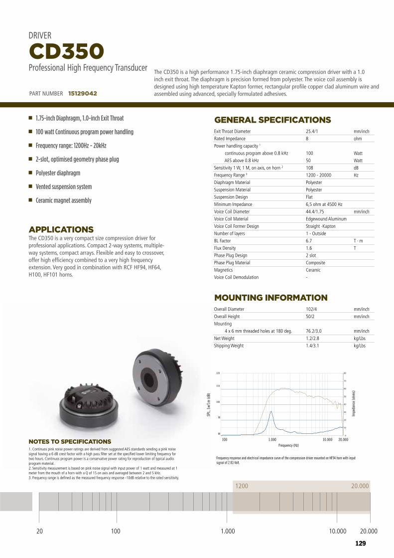
129
DRIVER CD350
Frequency response and electrical impedance curve of the compression driver mounted on HF94 horn with input signal of 2.83 Volt.
20.0001200
20 100 10.000 20.0001.000
Professional High Frequency Transducer
PART NUMBER 15129042
80
90
100
110
120
100 1.000 10.000 20.000Frequency (Hz)
SPL,
1w/
1m (d
B)
Impe
danc
e (o
hms)
20 100 10.000 20.0001.000
1200 20.000
NOTES TO SPECIFICATIONS
The CD350 is a very compact size compression driver for professional applications. Compact 2-way systems, multiple-way systems, compact arrays. Flexible and easy to crossover, offer high efficiency combined to a very high frequency extension. Very good in combination with RCF HF94, HF64, H100, HF101 horns.
APPLICATIONS
GENERAL SPECIFICATIONS
MOUNTING INFORMATION
Exit Throat Diameter
Rated Impedance
Power handling capacity 1
continuous program above 0.8 kHz
AES above 0.8 kHz
Sensitivity 1 W, 1 M, on axis, on horn 2
Frequency Range 3
Diaphragm Material
Suspension Material
Suspension Design
Minimum Impedance
Voice Coil Diameter
Voice Coil Material
Voice Coil Former Design
Number of layers
BL Factor
Flux Density
Phase Plug Design
Phase Plug Material
Magnetics
Voice Coil Demodulation
Overall Diameter
Overall Height
Mounting
4 x 6 mm threaded holes at 180 deg.
Net Weight
Shipping Weight
25.4/1
8
100
50
108
1200 - 20000
Polyester
Polyester
Flat
6,5 ohm at 4500 Hz
44.4/1.75
Edgewound Aluminum
Straight -Kapton
1 - Outside
6.7
1.6
2 slot
Composite
Ceramic
-
102/4
50/2
76.2/3.0
1.2/2.8
1.4/3.1
mm/inch
ohm
Watt
Watt
dB
Hz
mm/inch
T · m
T
mm/inch
mm/inch
mm/inch
kg/Lbs
kg/Lbs
PART NUMBER 15129042
1.75-inch Diaphragm, 1.0-inch Exit Throat
100 watt Continuous program power handling
Frequency range: 1200Hz - 20kHz
2-slot, optimised geometry phase plug
Polyester diaphragm
Vented suspension system
Ceramic magnet assembly
CD350Professional High Frequency Transducer
DRIVER
1. Continuos pink noise power ratings are derived from suggested AES standards sending a pink noise signal having a 6 dB crest factor with a high pass filter set at the specified lower limiting frequency for two hours. Continuos program power is a conservative power rating for reproduction of typical audio program material.2. Sensitivity measurement is based on pink noise signal with input power of 1 watt and measured at 1 meter from the mouth of a horn with a Q of 15 on axis and averaged between 2 and 5 kHz.3. Frequency range is defined as the measured frequency response -10dB relative to the rated sensitivity.
The CD350 is a high performance 1.75-inch diaphragm ceramic compression driver with a 1.0 inch exit throat. The diaphragm is precision formed from polyester. The voice coil assembly is designed using high temperature Kapton former, rectangular profile copper clad aluminum wire and assembled using advanced, specially formulated adhesives.
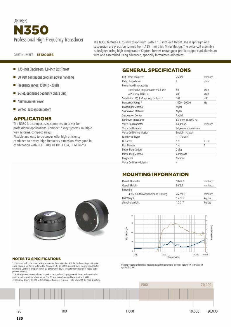
130
DRIVERN350Professional High Frequency Transducer
80
90
100
110
120
100 1.000 10.000 20.000
Frequency response and electrical impedance curve of the compression driver mounted on H100 horn with input signal of 2.83 Volt.
20.0001500
20 100 10.000 20.0001.000
PART NUMBER 15120056
Frequency (Hz)
SPL,
1w/
1m (d
B)
Impe
danc
e (o
hms)
20 100 10.000 20.0001.000
1500 20.000
NOTES TO SPECIFICATIONS
The N350 is a compact size compression driver for professional applications. Compact 2-way systems, multiple-way systems, compact arrays.Flexible and easy to crossover, offer high efficiency combined to a very high frequency extension. Very good in combination with RCF H100, HF101, HF94, HF64 horns.
APPLICATIONS
GENERAL SPECIFICATIONS
MOUNTING INFORMATION
Exit Throat Diameter
Rated Impedance
Power handling capacity 1
continuous program above 0.8 kHz
AES above 0.8 kHz
Sensitivity 1 W, 1 M, on axis, on horn 2
Frequency Range 3
Diaphragm Material
Suspension Material
Suspension Design
Minimum Impedance
Voice Coil Diameter
Voice Coil Material
Voice Coil Former Design
Number of layers
BL Factor
Flux Density
Phase Plug Design
Phase Plug Material
Magnetics
Voice Coil Demodulation
Overall Diameter
Overall Height
Mounting
4 x 6 mm threaded holes at 180 deg.
Net Weight
Shipping Weight
25.4/1
8
80
40
107
1500 - 20000
Mylar
Mylar
Radial
8.3 ohm at 3500 Hz
44.4/1.75
Edgewound aluminum
Straight -Kapton
1 - Outside
5.9
1.4
2 slot
Composite
Ceramic
-
102/4.0
60/2.4
76.2/3.0
1.4/3.1
1.7/3.7
mm/inch
ohm
Watt
Watt
dB
Hz
mm/inch
T · m
T
mm/inch
mm/inch
mm/inch
kg/Lbs
kg/Lbs
PART NUMBER 15120056
1.75-inch Diaphragm, 1.0-inch Exit Throat
80 watt Continuous program power handling
Frequency range: 1500Hz - 20kHz
2-slot, optimized geometry phase plug
Aluminum rear cover
Vented suspension system
N350Professional High Frequency Transducer
DRIVER
1. Continuos pink noise power ratings are derived from suggested AES standards sending a pink noise signal having a 6 dB crest factor with a high pass filter set at the specified lower limiting frequency for two hours. Continuos program power is a conservative power rating for reproduction of typical audio program material.2. Sensitivity measurement is based on pink noise signal with input power of 1 watt and measured at 1 meter from the mouth of a horn with a Q of 15 on axis and averaged between 2 and 5 kHz.3. Frequency range is defined as the measured frequency response -10dB relative to the rated sensitivity.
The N350 features 1.75-inch diaphragm with a 1.0 inch exit throat. The diaphragm and suspension are precision formed from .125 mm thick Mylar design. The voice coil assembly is designed using high temperature Kapton former, rectangular profile copper clad aluminum wire and assembled using advanced, specially formulated adhesives.
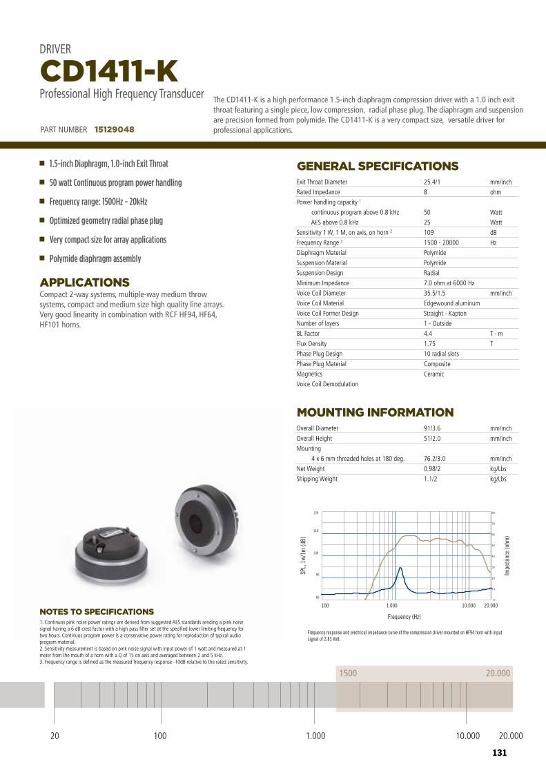
131
20 100 10.000 20.0001.000
1500 20.000
SPL,
1w/
1m (d
B)
80
90
100
110
120
Impe
danc
e (o
hm)
000.02000.01000.1001
Frequency (Hz)NOTES TO SPECIFICATIONS
Compact 2-way systems, multiple-way medium throw systems, compact and medium size high quality line arrays. Very good linearity in combination with RCF HF94, HF64, HF101 horns.
APPLICATIONS
GENERAL SPECIFICATIONS
MOUNTING INFORMATION
Exit Throat Diameter
Rated Impedance
Power handling capacity 1
continuous program above 0.8 kHz
AES above 0.8 kHz
Sensitivity 1 W, 1 M, on axis, on horn 2
Frequency Range 3
Diaphragm Material
Suspension Material
Suspension Design
Minimum Impedance
Voice Coil Diameter
Voice Coil Material
Voice Coil Former Design
Number of layers
BL Factor
Flux Density
Phase Plug Design
Phase Plug Material
Magnetics
Voice Coil Demodulation
Overall Diameter
Overall Height
Mounting
4 x 6 mm threaded holes at 180 deg.
Net Weight
Shipping Weight
25.4/1
8
50
25
109
1500 - 20000
Polymide
Polymide
Radial
7.0 ohm at 6000 Hz
35.5/1.5
Edgewound aluminum
Straight - Kapton
1 - Outside
4.4
1.75
10 radial slots
Composite
Ceramic
91/3.6
51/2.0
76.2/3.0
0.98/2
1.1/2
mm/inch
ohm
Watt
Watt
dB
Hz
mm/inch
T · m
T
mm/inch
mm/inch
mm/inch
kg/Lbs
kg/Lbs
PART NUMBER 15129048
1.5-inch Diaphragm, 1.0-inch Exit Throat
50 watt Continuous program power handling
Frequency range: 1500Hz - 20kHz
Optimized geometry radial phase plug
Very compact size for array applications
Polymide diaphragm assembly
CD1411-KProfessional High Frequency Transducer
DRIVER
1. Continuos pink noise power ratings are derived from suggested AES standards sending a pink noise signal having a 6 dB crest factor with a high pass filter set at the specified lower limiting frequency for two hours. Continuos program power is a conservative power rating for reproduction of typical audio program material.2. Sensitivity measurement is based on pink noise signal with input power of 1 watt and measured at 1 meter from the mouth of a horn with a Q of 15 on axis and averaged between 2 and 5 kHz.3. Frequency range is defined as the measured frequency response -10dB relative to the rated sensitivity.
The CD1411-K is a high performance 1.5-inch diaphragm compression driver with a 1.0 inch exit throat featuring a single piece, low compression, radial phase plug. The diaphragm and suspension are precision formed from polymide. The CD1411-K is a very compact size, versatile driver for professional applications.
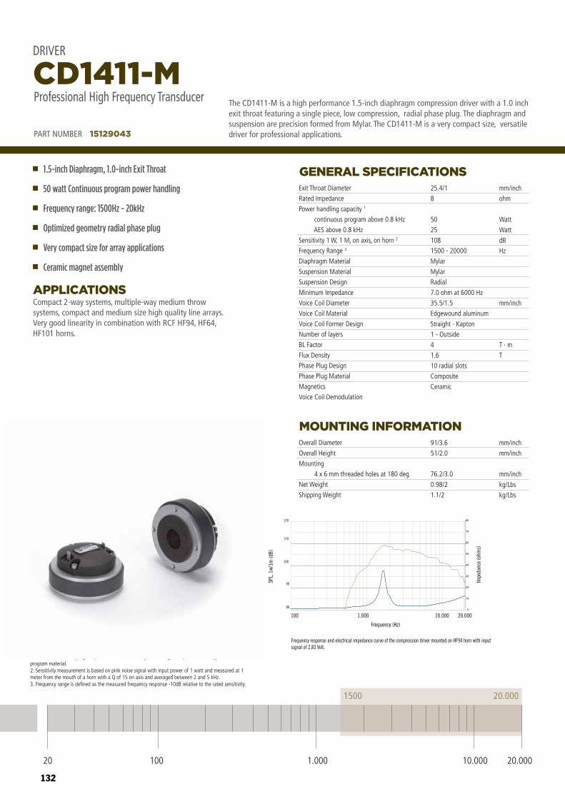
132
NOTES TO SPECIFICATIONS
Compact 2-way systems, multiple-way medium throw systems, compact and medium size high quality line arrays. Very good linearity in combination with RCF HF94, HF64, HF101 horns.
APPLICATIONS
GENERAL SPECIFICATIONS
MOUNTING INFORMATION
Exit Throat Diameter
Rated Impedance
Power handling capacity 1
continuous program above 0.8 kHz
AES above 0.8 kHz
Sensitivity 1 W, 1 M, on axis, on horn 2
Frequency Range 3
Diaphragm Material
Suspension Material
Suspension Design
Minimum Impedance
Voice Coil Diameter
Voice Coil Material
Voice Coil Former Design
Number of layers
BL Factor
Flux Density
Phase Plug Design
Phase Plug Material
Magnetics
Voice Coil Demodulation
Overall Diameter
Overall Height
Mounting
4 x 6 mm threaded holes at 180 deg.
Net Weight
Shipping Weight
25.4/1
8
50
25
108
1500 - 20000
Mylar
Mylar
Radial
7.0 ohm at 6000 Hz
35.5/1.5
Edgewound aluminum
Straight - Kapton
1 - Outside
4
1.6
10 radial slots
Composite
Ceramic
91/3.6
51/2.0
76.2/3.0
0.98/2
1.1/2
mm/inch
ohm
Watt
Watt
dB
Hz
mm/inch
T · m
T
mm/inch
mm/inch
mm/inch
kg/Lbs
kg/Lbs
PART NUMBER 15129043
1.5-inch Diaphragm, 1.0-inch Exit Throat
50 watt Continuous program power handling
Frequency range: 1500Hz - 20kHz
Optimized geometry radial phase plug
Very compact size for array applications
Ceramic magnet assembly
CD1411-MProfessional High Frequency Transducer
DRIVER
1. Continuos pink noise power ratings are derived from suggested AES standards sending a pink noise signal having a 6 dB crest factor with a high pass filter set at the specified lower limiting frequency for two hours. Continuos program power is a conservative power rating for reproduction of typical audio program material.2. Sensitivity measurement is based on pink noise signal with input power of 1 watt and measured at 1 meter from the mouth of a horn with a Q of 15 on axis and averaged between 2 and 5 kHz.3. Frequency range is defined as the measured frequency response -10dB relative to the rated sensitivity.
The CD1411-M is a high performance 1.5-inch diaphragm compression driver with a 1.0 inch exit throat featuring a single piece, low compression, radial phase plug. The diaphragm and suspension are precision formed from Mylar. The CD1411-M is a very compact size, versatile driver for professional applications.
DRIVERCD1411-MProfessional High Frequency Transducer
80
90
100
110
120
100 1.000 10.000 20.000
Frequency response and electrical impedance curve of the compression driver mounted on HF94 horn with input signal of 2.83 Volt.
20.0001500
20 100 10.000 20.0001.000
PART NUMBER 15129043
Frequency (Hz)
SPL,
1w/
1m (d
B)
Impe
danc
e (o
hms)
20 100 10.000 20.0001.000
1500 20.000
133
134
TRANSDUCERSCOAXIAL
The power of Neodymium, the integration of two magnetic circuits in one, the precision of assembly.
In all RCF coaxial transducers we take care of every single detail; magnetic circuits, horns, cones and basket designs are all conceived to guarantee the perfect match. RCF coaxial “point source” transducers deliver the full frequency range in correct phase alignment, resulting in a smoother frequency response, precise polar pattern and perfect clarity.

135
HIGH NEODYMIUM FLUX, BEST CONTROL
HIPER VENTED DESIGNS
PHASE ALIGNED CONICAL HORNS
Often a big drawback in coaxial designs is the lack of magnetic force due to the fact that woofer and compression driver are sharing the same magnet. All RCF Coaxial designs takes advantage of large sized magnetic rings that guarantee for both the transducers the same flux in the gap that they have in stadard, single magnetic circuit, applications.
In a coaxial design the thermal dissipation required is higher than in conventional designs: woofer and compression driver are both dissipating heat in the same structure. New basket designs and new ventilation system for magnet plates, together with inside-outside voice coils and high temperature material guarantee the perfect behaviour of the transducer in the most stressful conditions.
The tweeter/cone interaction is improved on RCF coaxial speaker by the mean of large-sized, phase aligned, conical horns. RCF horns are specifically designed to improve the transducers phase alignment, to offer a smooth crossover transition, to guarantee a perfect constant and conical directivity to the compression driver. The presence of the horn avoid any intermodulation distortion caused from the low frequency excursion of the woofer cone.
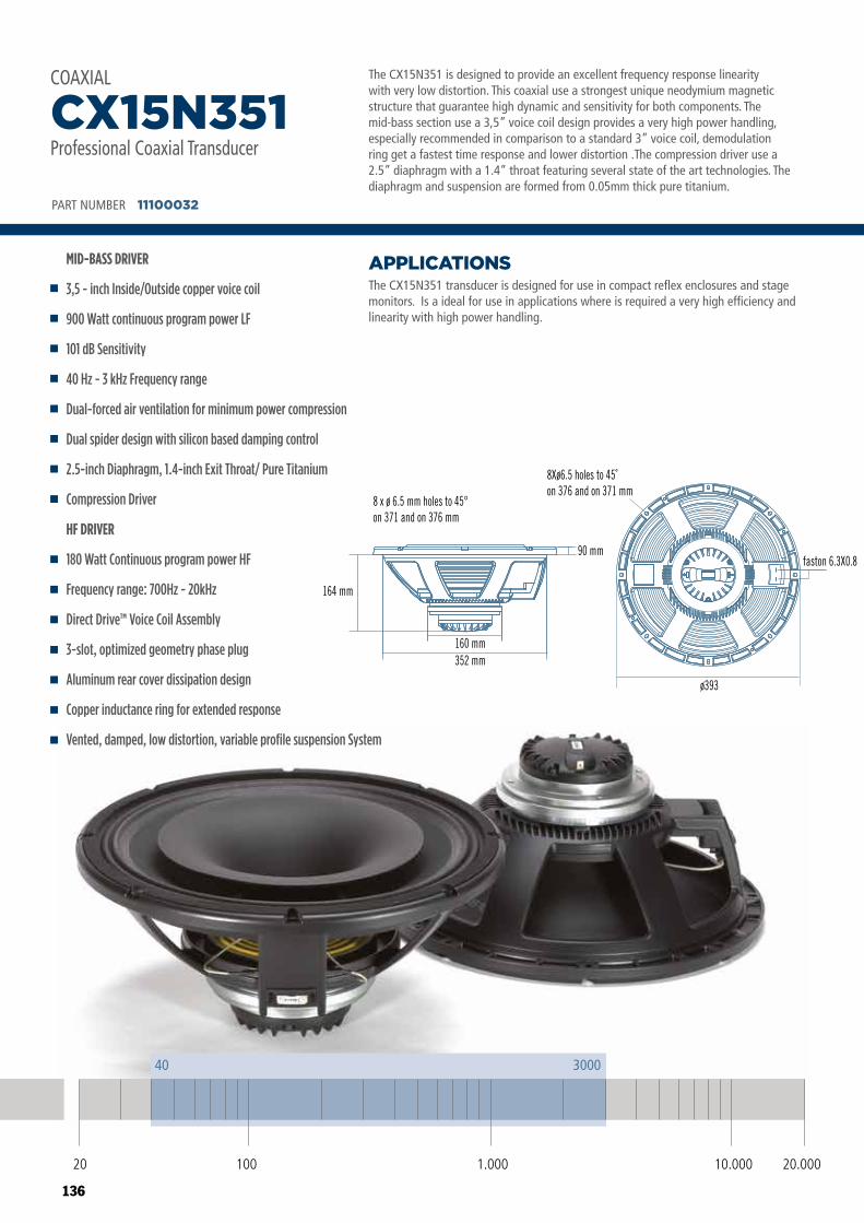
136
COAXIALCX15N351Professional Low Frequency Transducer
PART NUMBER 11100032
8 x ø 6.5 mm holes to 45°on 371 and on 376 mm
ø393
faston 6.3X0.8
8Xø6.5 holes to 45˚on 376 and on 371 mm
90 mm
164 mm
160 mm352 mm
20 100 10.000 20.0001.000
40 3000
The CX15N351 is designed to provide an excellent frequency response linearity with very low distortion. This coaxial use a strongest unique neodymium magnetic structure that guarantee high dynamic and sensitivity for both components. The mid-bass section use a 3,5” voice coil design provides a very high power handling, especially recommended in comparison to a standard 3” voice coil, demodulation ring get a fastest time response and lower distortion .The compression driver use a 2.5” diaphragm with a 1.4” throat featuring several state of the art technologies. The diaphragm and suspension are formed from 0.05mm thick pure titanium.
The CX15N351 transducer is designed for use in compact reflex enclosures and stage monitors. Is a ideal for use in applications where is required a very high efficiency and linearity with high power handling.
APPLICATIONS
PART NUMBER 11100032
MID-BASS DRIVER
3,5 - inch Inside/Outside copper voice coil
900 Watt continuous program power LF
101 dB Sensitivity
40 Hz - 3 kHz Frequency range
Dual-forced air ventilation for minimum power compression
Dual spider design with silicon based damping control
2.5-inch Diaphragm, 1.4-inch Exit Throat/ Pure Titanium
Compression Driver
HF DRIVER
180 Watt Continuous program power HF
Frequency range: 700Hz - 20kHz
Direct Drive™ Voice Coil Assembly
3-slot, optimized geometry phase plug
Aluminum rear cover dissipation design
Copper inductance ring for extended response
Vented, damped, low distortion, variable profile suspension System
CX15N351Professional Coaxial Transducer
COAXIAL
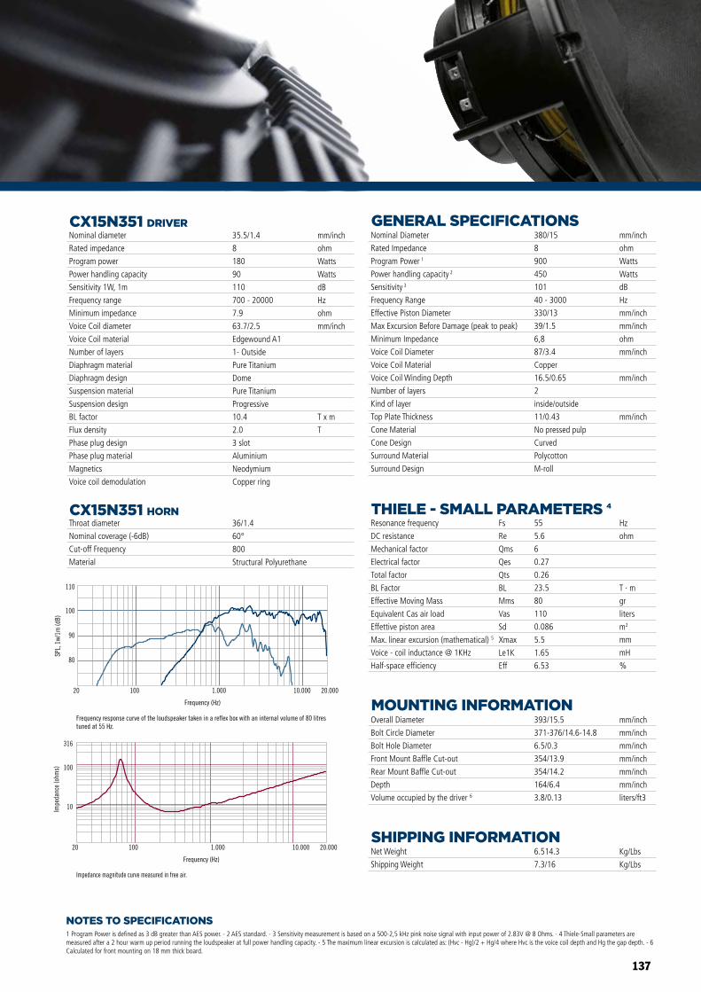
137
Impedance magnitude curve measured in free air.
Frequency response curve of the loudspeaker taken in a reflex box with an internal volume of 80 litres tuned at 55 Hz.
80
90
100
110
SPL,
1w/
1m (d
B)
Frequency (Hz)
20 100 1.000 10.000 20.000
Frequency (Hz)
20 100 1.000 10.000 20.000
10
100
316
Impe
danc
e (o
hms)
Impedance magnitude curve measured in free air.
Frequency response curve of the loudspeaker taken in a reflex box with an internal volume of 80 litres tuned at 55 Hz.
80
90
100
110
SPL,
1w/
1m (d
B)
Frequency (Hz)
20 100 1.000 10.000 20.000
Frequency (Hz)
20 100 1.000 10.000 20.000
10
100
316
Impe
danc
e (o
hms)
NOTES TO SPECIFICATIONS
CX15N351 DRIVER
1 Program Power is defined as 3 dB greater than AES power. - 2 AES standard. - 3 Sensitivity measurement is based on a 500-2,5 kHz pink noise signal with input power of 2.83V @ 8 Ohms. - 4 Thiele-Small parameters are measured after a 2 hour warm up period running the loudspeaker at full power handling capacity. - 5 The maximum linear excursion is calculated as: (Hvc - Hg)/2 + Hg/4 where Hvc is the voice coil depth and Hg the gap depth. - 6 Calculated for front mounting on 18 mm thick board.
CX15N351 HORN
Overall Diameter
Bolt Circle Diameter
Bolt Hole Diameter
Front Mount Baffle Cut-out
Rear Mount Baffle Cut-out
Depth
Volume occupied by the driver 6
Net Weight
Shipping Weight
Nominal Diameter
Rated Impedance
Program Power 1
Power handling capacity 2
Sensitivity 3
Frequency Range
Effective Piston Diameter
Max Excursion Before Damage (peak to peak)
Minimum Impedance
Voice Coil Diameter
Voice Coil Material
Voice Coil Winding Depth
Number of layers
Kind of layer
Top Plate Thickness
Cone Material
Cone Design
Surround Material
Surround Design
Resonance frequency
DC resistance
Mechanical factor
Electrical factor
Total factor
BL Factor
Effective Moving Mass
Equivalent Cas air load
Effettive piston area
Max. linear excursion (mathematical) 5
Voice - coil inductance @ 1KHz
Half-space efficiency
393/15.5
371-376/14.6-14.8
6.5/0.3
354/13.9
354/14.2
164/6.4
3.8/0.13
6.514.3
7.3/16
380/15
8
900
450
101
40 - 3000
330/13
39/1.5
6,8
87/3.4
Copper
16.5/0.65
2
inside/outside
11/0.43
No pressed pulp
Curved
Polycotton
M-roll
mm/inch
mm/inch
mm/inch
mm/inch
mm/inch
mm/inch
liters/ft3
Kg/Lbs
Kg/Lbs
Hz
ohm
T · m
gr
liters
m2
mm
mH
%
55
5.6
6
0.27
0.26
23.5
80
110
0.086
5.5
1.65
6.53
Fs
Re
Qms
Qes
Qts
BL
Mms
Vas
Sd
Xmax
Le1K
Eff
mm/inch
ohm
Watts
Watts
dB
Hz
mm/inch
mm/inch
ohm
mm/inch
mm/inch
mm/inch
Throat diameter
Nominal coverage (-6dB)
Cut-off Frequency
Material
Nominal diameter
Rated impedance
Program power
Power handling capacity
Sensitivity 1W, 1m
Frequency range
Minimum impedance
Voice Coil diameter
Voice Coil material
Number of layers
Diaphragm material
Diaphragm design
Suspension material
Suspension design
BL factor
Flux density
Phase plug design
Phase plug material
Magnetics
Voice coil demodulation
35.5/1.4
8
180
90
110
700 - 20000
7.9
63.7/2.5
Edgewound A1
1- Outside
Pure Titanium
Dome
Pure Titanium
Progressive
10.4
2.0
3 slot
Aluminium
Neodymium
Copper ring
36/1.4
60°
800
Structural Polyurethane
mm/inch
ohm
Watts
Watts
dB
Hz
ohm
mm/inch
T x m
T
GENERAL SPECIFICATIONS
MOUNTING INFORMATION
SHIPPING INFORMATION
THIELE - SMALL PARAMETERS 4
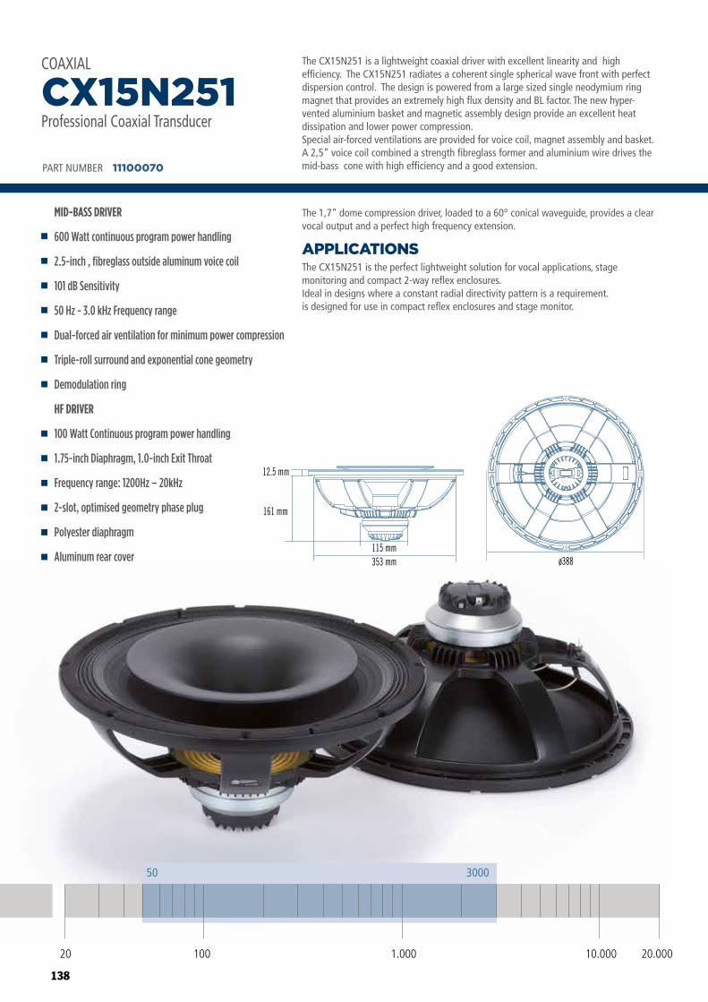
138
The CX15N251 is a lightweight coaxial driver with excellent linearity and high efficiency. The CX15N251 radiates a coherent single spherical wave front with perfect dispersion control. The design is powered from a large sized single neodymium ring magnet that provides an extremely high flux density and BL factor. The new hyper-vented aluminium basket and magnetic assembly design provide an excellent heat dissipation and lower power compression.Special air-forced ventilations are provided for voice coil, magnet assembly and basket. A 2,5” voice coil combined a strength fibreglass former and aluminium wire drives the mid-bass cone with high efficiency and a good extension.
The CX15N251 is the perfect lightweight solution for vocal applications, stage monitoring and compact 2-way reflex enclosures.Ideal in designs where a constant radial directivity pattern is a requirement.is designed for use in compact reflex enclosures and stage monitor.
APPLICATIONS
The 1,7” dome compression driver, loaded to a 60° conical waveguide, provides a clear vocal output and a perfect high frequency extension.
PART NUMBER 11100070
MID-BASS DRIVER
600 Watt continuous program power handling
2.5-inch , fibreglass outside aluminum voice coil
101 dB Sensitivity
50 Hz - 3.0 kHz Frequency range
Dual-forced air ventilation for minimum power compression
Triple-roll surround and exponential cone geometry
Demodulation ring
HF DRIVER
100 Watt Continuous program power handling
1.75-inch Diaphragm, 1.0-inch Exit Throat
Frequency range: 1200Hz – 20kHz
2-slot, optimised geometry phase plug
Polyester diaphragm
Aluminum rear cover
CX15N251Professional Coaxial Transducer
COAXIALCOAXIALCX15N251Professional Low Frequency Transducer
PART NUMBER 11100070
ø388
12.5 mm
161 mm
115 mm353 mm
20 100 10.000 20.0001.000
50 3000
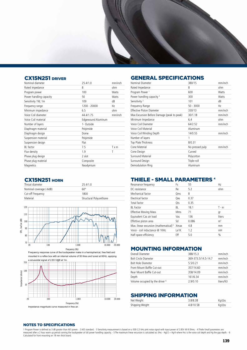
139
Frequency (Hz)
20 100 1.000 10.000 20.000
10
100
316
Impe
danc
e (o
hms)
80
100
110
120
SPL,
1w/
1m (d
B)
Frequency (Hz)
20 100 1.000 10.000 20.00070
90
NOTES TO SPECIFICATIONS
CX15N251 DRIVER
1 Program Power is defined as 3 dB greater than AES power. - 2 AES standard. - 3 Sensitivity measurement is based on a 500-2,5 kHz pink noise signal with input power of 2.83V @ 8 Ohms. - 4 Thiele-Small parameters are measured after a 2 hour warm up period running the loudspeaker at full power handling capacity. - 5 The maximum linear excursion is calculated as: (Hvc - Hg)/2 + Hg/4 where Hvc is the voice coil depth and Hg the gap depth. - 6 Calculated for front mounting on 18 mm thick board.
CX15N251 HORN
COAXIALCX15N251Professional Low Frequency Transducer
PART NUMBER 11100070
ø388
12.5 mm
161 mm
115 mm353 mm
Frequency (Hz)
20 100 1.000 10.000 20.000
10
100
316
Impe
danc
e (o
hms)
80
100
110
120
SPL,
1w/
1m (d
B)
Frequency (Hz)
20 100 1.000 10.000 20.00070
90
Overall Diameter
Bolt Circle Diameter
Bolt Hole Diameter
Front Mount Baffle Cut-out
Rear Mount Baffle Cut-out
Depth
Volume occupied by the driver 6
Net Weight
Shipping Weight
Nominal Diameter
Rated Impedance
Program Power 1
Power handling capacity 3
Sensitivity 3
Frequency Range
Effective Piston Diameter
Max Excursion Before Damage (peak to peak)
Minimum Impedance
Voice Coil Diameter
Voice Coil Material
Voice Coil Winding Depth
Number of layers
Top Plate Thickness
Cone Material
Cone Design
Surround Material
Surround Design
Demodulation Ring
Resonance frequency
DC resistance
Mechanical factor
Electrical factor
Total factor
BL Factor
Effective Moving Mass
Equivalent Cas air load
Effettive piston area
Max. linear excursion (mathematical) 5
Voice - coil inductance @ 1KHz
Half-space efficiency
388/15.3
369-373.5/14.5-14.7
5.5/0.21
357/14.60
358/14.09
161/6.34
2.9/0.10
3.8/8.38
4.8/10.58
380/15
8
600
300
101
50 - 3000
330/13
30/1.18
6,4
64/2.52
Aluminum
14/0.55
1
8/0.31
No pressed pulp
Curved
Polycotton
Triple-roll
Aluminum
mm/inch
mm/inch
mm/inch
mm/inch
mm/inch
mm/inch
liters/ft3
Kg/Lbs
Kg/Lbs
Hz
ohm
T · m
gr
liters
m2
mm
mH
%
55
5.2
8
0.37
0.35
18.1
71
136
0.086
4.8
1.2
5.0
Fs
Re
Qms
Qes
Qts
BL
Mms
Vas
Sd
Xmax
Le1K
Eff
mm/inch
ohm
Watts
Watts
dB
Hz
mm/inch
mm/inch
ohm
mm/inch
mm/inch
mm/inch
Throat diameter
Nominal coverage (-6dB)
Cut-off Frequency
Material
Nominal diameter
Rated impedance
Program power
Power handling capacity
Sensitivity 1W, 1m
Frequency range
Minimum impedance
Voice Coil diameter
Voice Coil material
Number of layers
Diaphragm material
Diaphragm design
Suspension material
Suspension design
BL factor
Flux density
Phase plug design
Phase plug material
Magnetics
25.4/1.0
8
100
50
109
1200 - 20000
6.5
44.4/1.75
Edgewound Aluminum
1- Outside
Polyimide
Dome
Polyimide
Flat
7.5
1.9
2 slot
Composite
Neodymium
25.4/1.0
60°
1800
Structural Polyurethane
mm/inch
ohm
Watts
Watts
dB
Hz
ohm
mm/inch
T x m
T
GENERAL SPECIFICATIONS
MOUNTING INFORMATION
SHIPPING INFORMATION
THIELE - SMALL PARAMETERS 4
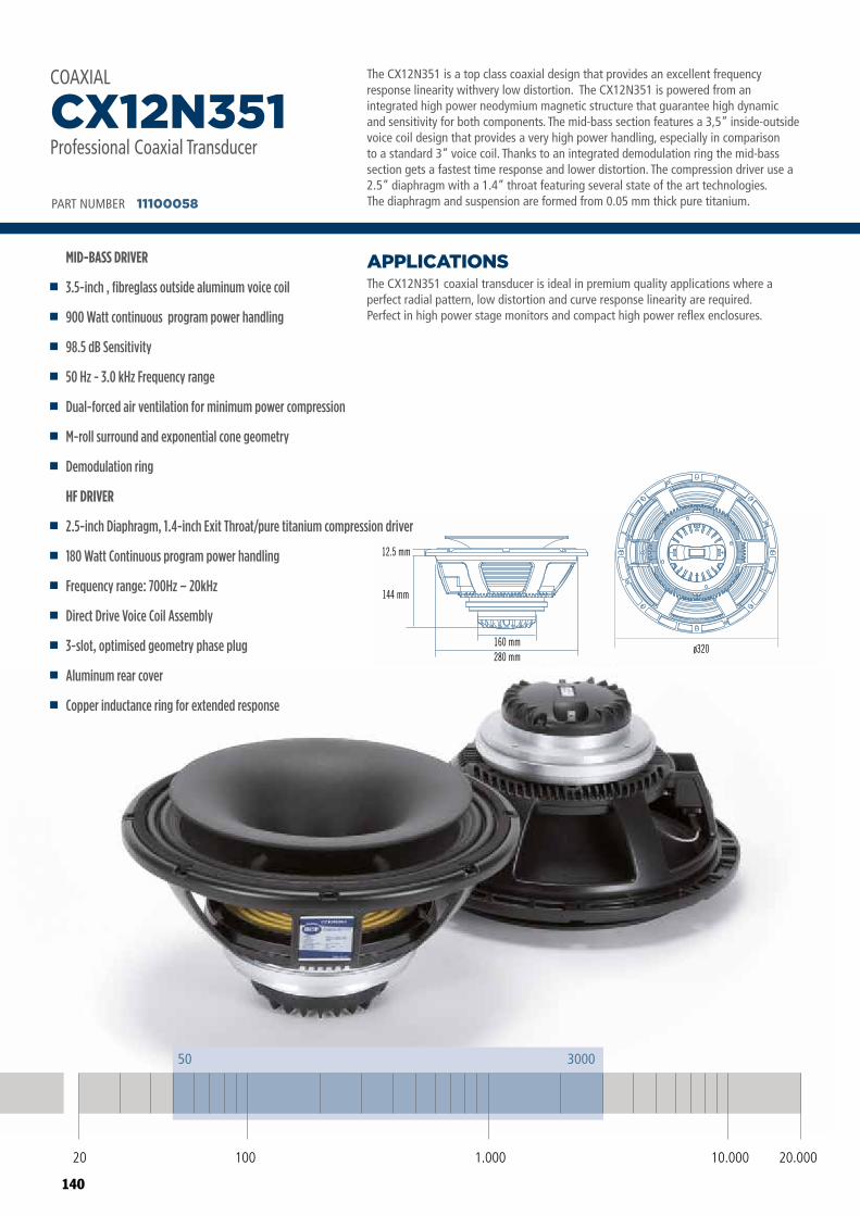
140
COAXIALCX12N351Professional Low Frequency Transducer
PART NUMBER 11100058
ø320
12.5 mm
144 mm
160 mm280 mm
COAXIALCX12N351Professional Low Frequency Transducer
PART NUMBER 11100058
ø320
12.5 mm
144 mm
160 mm280 mm
20 100 10.000 20.0001.000
50 3000
The CX12N351 is a top class coaxial design that provides an excellent frequency response linearity withvery low distortion. The CX12N351 is powered from an integrated high power neodymium magnetic structure that guarantee high dynamic and sensitivity for both components. The mid-bass section features a 3,5” inside-outside voice coil design that provides a very high power handling, especially in comparison to a standard 3” voice coil. Thanks to an integrated demodulation ring the mid-bass section gets a fastest time response and lower distortion. The compression driver use a 2.5” diaphragm with a 1.4” throat featuring several state of the art technologies. The diaphragm and suspension are formed from 0.05 mm thick pure titanium.
The CX12N351 coaxial transducer is ideal in premium quality applications where a perfect radial pattern, low distortion and curve response linearity are required.Perfect in high power stage monitors and compact high power reflex enclosures.
APPLICATIONS
PART NUMBER 11100058
MID-BASS DRIVER
3.5-inch , fibreglass outside aluminum voice coil
900 Watt continuous program power handling
98.5 dB Sensitivity
50 Hz - 3.0 kHz Frequency range
Dual-forced air ventilation for minimum power compression
M-roll surround and exponential cone geometry
Demodulation ring
HF DRIVER
2.5-inch Diaphragm, 1.4-inch Exit Throat/pure titanium compression driver
180 Watt Continuous program power handling
Frequency range: 700Hz – 20kHz
Direct Drive Voice Coil Assembly
3-slot, optimised geometry phase plug
Aluminum rear cover
Copper inductance ring for extended response
CX12N351Professional Coaxial Transducer
COAXIAL
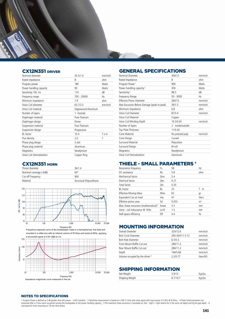
141
Frequency (Hz)
20 100 1.000 10.000 20.000
10
100
316
Impe
danc
e (o
hms)
80
100
110
120
SPL,
1w/
1m (d
B)
Frequency (Hz)
20 100 1.000 10.000 20.00070
90
Frequency (Hz)
20 100 1.000 10.000 20.000
10
100
316
Impe
danc
e (o
hms)
80
100
110
120
SPL,
1w/
1m (d
B)
Frequency (Hz)
20 100 1.000 10.000 20.00070
90
NOTES TO SPECIFICATIONS
CX12N351 DRIVER
1 Program Power is defined as 3 dB greater than AES power. - 2 AES standard. - 3 Sensitivity measurement is based on a 500-2,5 kHz pink noise signal with input power of 2.83V @ 8 Ohms. - 4 Thiele-Small parameters are measured after a 2 hour warm up period running the loudspeaker at full power handling capacity. - 5 The maximum linear excursion is calculated as: (Hvc - Hg)/2 + Hg/4 where Hvc is the voice coil depth and Hg the gap depth. - 6 Calculated for front mounting on 18 mm thick board.
CX12N351 HORN
Overall Diameter
Bolt Circle Diameter
Bolt Hole Diameter
Front Mount Baffle Cut-out
Rear Mount Baffle Cut-out
Depth
Volume occupied by the driver 6
Net Weight
Shipping Weight
Nominal Diameter
Rated Impedance
Program Power 1
Power handling capacity 2
Sensitivity 3
Frequency Range
Effective Piston Diameter
Max Excursion Before Damage (peak to peak)
Minimum Impedance
Voice Coil Diameter
Voice Coil Material
Voice Coil Winding Depth
Number of layers
Top Plate Thickness
Cone Material
Cone Design
Surround Material
Surround Design
Magnetics
Voice Coil Demodulation
Resonance frequency
DC resistance
Mechanical factor
Electrical factor
Total factor
BL Factor
Effective Moving Mass
Equivalent Cas air load
Effettive piston area
Max. linear excursion (mathematical) 5
Voice - coil inductance @ 1KHz
Half-space efficiency
320/12.6
293-304/11.5-12
6.5/0.3
284/11.2
284/11.2
144/5.66
2.2/0.77
5.9/13
6.7/14.7
300/12
8
900
450
98.5
50 - 3000
260/13
39/1.5
6,8
87/3.4
Copper
16.5/0.65
2 - inside/outside
11/0.43
No pressed pulp
Curved
Polycotton
M-roll
Neodymium
Aluminum
mm/inch
mm/inch
mm/inch
mm/inch
mm/inch
mm/inch
liters/ft3
Kg/Lbs
Kg/Lbs
Hz
ohm
T · m
gr
liters
m2
mm
mH
%
58
5.8
5.4
0.21
0.20
25
62
47
0.053
5.5
1.5
4.4
Fs
Re
Qms
Qes
Qts
BL
Mms
Vas
Sd
Xmax
Le1K
Eff
mm/inch
ohm
Watts
Watts
dB
Hz
mm/inch
mm/inch
ohm
mm/inch
mm/inch
mm/inch
Throat diameter
Nominal coverage (-6dB)
Cut-off Frequency
Material
Nominal diameter
Rated impedance
Program power
Power handling capacity
Sensitivity 1W, 1m
Frequency range
Minimum impedance
Voice Coil diameter
Voice Coil material
Number of layers
Diaphragm material
Diaphragm design
Suspension material
Suspension design
BL factor
Flux density
Phase plug design
Phase plug material
Magnetics
Voice Coil Demodulation
35.5/1.4
8
180
90
110
700 - 20000
7.9
63.7/2.5
Edgewound Aluminum
1- Outside
Pure Titanium
Dome
Pure Titanium
Progressive
10.4
2.0
3 slot
Aluminum
Neodymium
Copper Ring
36/1.4
60°
900
Structural Polyurethane
mm/inch
ohm
Watts
Watts
dB
Hz
ohm
mm/inch
T x m
T
GENERAL SPECIFICATIONS
MOUNTING INFORMATION
SHIPPING INFORMATION
THIELE - SMALL PARAMETERS 4
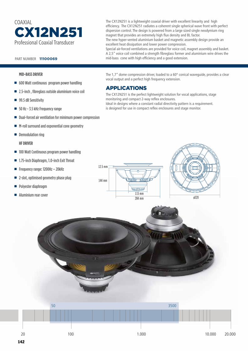
142
COAXIALCX12N251Professional Low Frequency Transducer
PART NUMBER 11100069
ø320
12.5 mm
144 mm
115 mm284 mm
20 100 10.000 20.0001.000
50 3500
The CX12N251 is a lightweight coaxial driver with excellent linearity and high efficiency. The CX12N251 radiates a coherent single spherical wave front with perfect dispersion control. The design is powered from a large sized single neodymium ring magnet that provides an extremely high flux density and BL factor. The new hyper-vented aluminium basket and magnetic assembly design provide an excellent heat dissipation and lower power compression.Special air-forced ventilations are provided for voice coil, magnet assembly and basket. A 2,5” voice coil combined a strength fibreglass former and aluminium wire drives the mid-bass cone with high efficiency and a good extension.
The CX12N251 is the perfect lightweight solution for vocal applications, stage monitoring and compact 2-way reflex enclosures.Ideal in designs where a constant radial directivity pattern is a requirement.is designed for use in compact reflex enclosures and stage monitor.
APPLICATIONS
The 1,7” dome compression driver, loaded to a 60° conical waveguide, provides a clear vocal output and a perfect high frequency extension.
PART NUMBER 11100069
MID-BASS DRIVER
600 Watt continuous program power handling
2.5-inch , fibreglass outside aluminium voice coil
99.5 dB Sensitivity
50 Hz - 3.5 kHz Frequency range
Dual-forced air ventilation for minimum power compression
M-roll surround and exponential cone geometry
Demodulation ring
HF DRIVER
100 Watt Continuous program power handling
1.75-inch Diaphragm, 1.0-inch Exit Throat
Frequency range: 1200Hz – 20kHz
2-slot, optimised geometry phase plug
Polyester diaphragm
Aluminium rear cover
CX12N251Professional Coaxial Transducer
COAXIAL
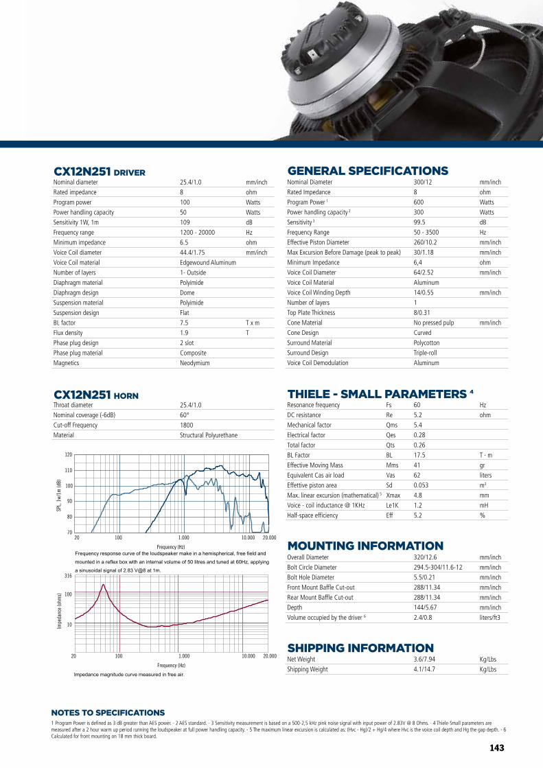
143
Frequency (Hz)
20 100 1.000 10.000 20.000
10
100
316
Impe
danc
e (o
hms)
80
100
110
120
SPL,
1w/
1m (d
B)
Frequency (Hz)
20 100 1.000 10.000 20.00070
90
Frequency (Hz)
20 100 1.000 10.000 20.000
10
100
316
Impe
danc
e (o
hms)
80
100
110
120
SPL,
1w/
1m (d
B)
Frequency (Hz)
20 100 1.000 10.000 20.00070
90
COAXIALCX12N251Professional Low Frequency Transducer
PART NUMBER 11100069
ø320
12.5 mm
144 mm
115 mm284 mm
NOTES TO SPECIFICATIONS
CX12N251 DRIVER
1 Program Power is defined as 3 dB greater than AES power. - 2 AES standard. - 3 Sensitivity measurement is based on a 500-2,5 kHz pink noise signal with input power of 2.83V @ 8 Ohms. - 4 Thiele-Small parameters are measured after a 2 hour warm up period running the loudspeaker at full power handling capacity. - 5 The maximum linear excursion is calculated as: (Hvc - Hg)/2 + Hg/4 where Hvc is the voice coil depth and Hg the gap depth. - 6 Calculated for front mounting on 18 mm thick board.
CX12N251 HORN
Overall Diameter
Bolt Circle Diameter
Bolt Hole Diameter
Front Mount Baffle Cut-out
Rear Mount Baffle Cut-out
Depth
Volume occupied by the driver 6
Net Weight
Shipping Weight
Nominal Diameter
Rated Impedance
Program Power 1
Power handling capacity 2
Sensitivity 3
Frequency Range
Effective Piston Diameter
Max Excursion Before Damage (peak to peak)
Minimum Impedance
Voice Coil Diameter
Voice Coil Material
Voice Coil Winding Depth
Number of layers
Top Plate Thickness
Cone Material
Cone Design
Surround Material
Surround Design
Voice Coil Demodulation
Resonance frequency
DC resistance
Mechanical factor
Electrical factor
Total factor
BL Factor
Effective Moving Mass
Equivalent Cas air load
Effettive piston area
Max. linear excursion (mathematical) 5
Voice - coil inductance @ 1KHz
Half-space efficiency
320/12.6
294.5-304/11.6-12
5.5/0.21
288/11.34
288/11.34
144/5.67
2.4/0.8
3.6/7.94
4.1/14.7
300/12
8
600
300
99.5
50 - 3500
260/10.2
30/1.18
6,4
64/2.52
Aluminum
14/0.55
1
8/0.31
No pressed pulp
Curved
Polycotton
Triple-roll
Aluminum
mm/inch
mm/inch
mm/inch
mm/inch
mm/inch
mm/inch
liters/ft3
Kg/Lbs
Kg/Lbs
Hz
ohm
T · m
gr
liters
m2
mm
mH
%
60
5.2
5.4
0.28
0.26
17.5
41
62
0.053
4.8
1.2
5.2
Fs
Re
Qms
Qes
Qts
BL
Mms
Vas
Sd
Xmax
Le1K
Eff
mm/inch
ohm
Watts
Watts
dB
Hz
mm/inch
mm/inch
ohm
mm/inch
mm/inch
mm/inch
Throat diameter
Nominal coverage (-6dB)
Cut-off Frequency
Material
Nominal diameter
Rated impedance
Program power
Power handling capacity
Sensitivity 1W, 1m
Frequency range
Minimum impedance
Voice Coil diameter
Voice Coil material
Number of layers
Diaphragm material
Diaphragm design
Suspension material
Suspension design
BL factor
Flux density
Phase plug design
Phase plug material
Magnetics
25.4/1.0
8
100
50
109
1200 - 20000
6.5
44.4/1.75
Edgewound Aluminum
1- Outside
Polyimide
Dome
Polyimide
Flat
7.5
1.9
2 slot
Composite
Neodymium
25.4/1.0
60°
1800
Structural Polyurethane
mm/inch
ohm
Watts
Watts
dB
Hz
ohm
mm/inch
T x m
T
GENERAL SPECIFICATIONS
MOUNTING INFORMATION
SHIPPING INFORMATION
THIELE - SMALL PARAMETERS 4
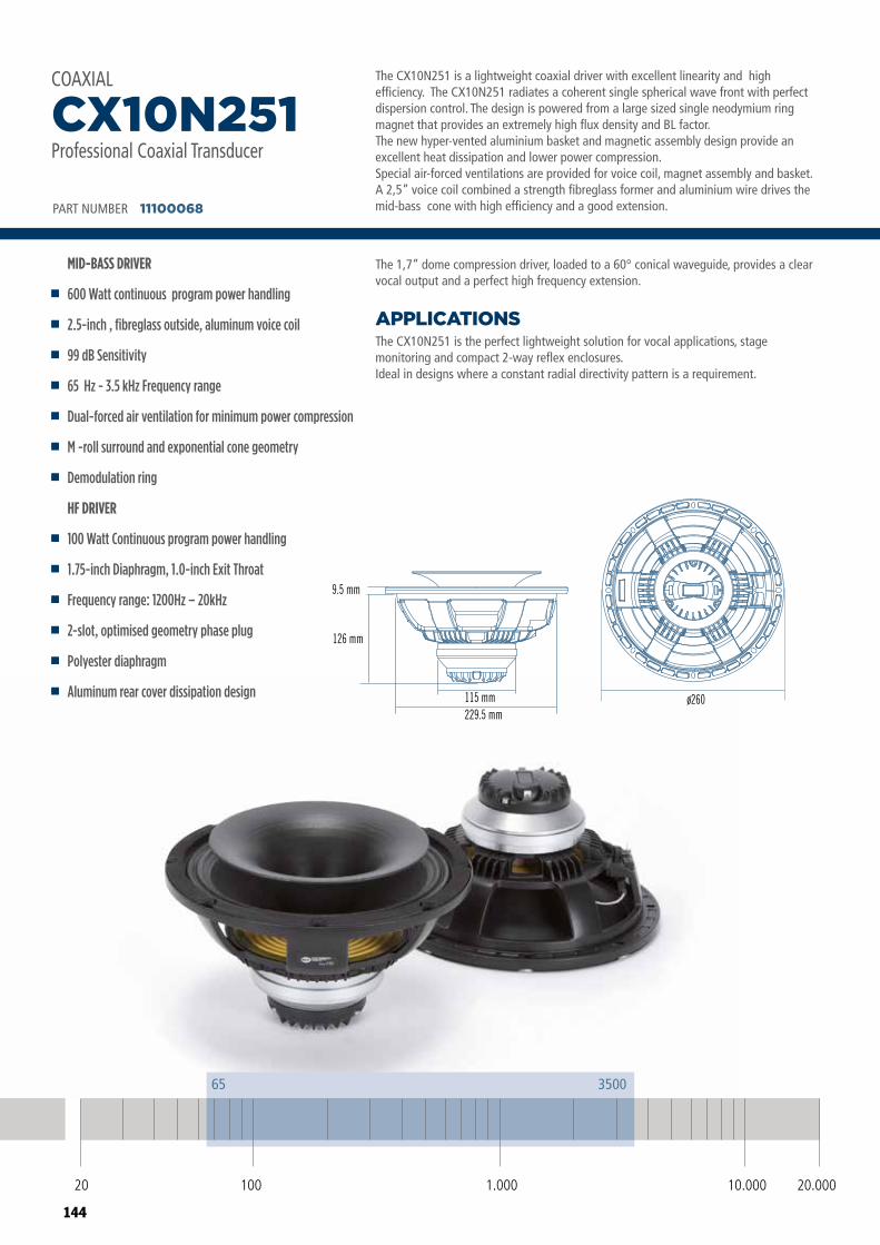
144
COAXIALCX10N251Professional Low Frequency Transducer
PART NUMBER 11100068
ø260
9.5 mm
126 mm
115 mm229.5 mm
20 100 10.000 20.0001.000
65 3500
The CX10N251 is a lightweight coaxial driver with excellent linearity and high efficiency. The CX10N251 radiates a coherent single spherical wave front with perfect dispersion control. The design is powered from a large sized single neodymium ring magnet that provides an extremely high flux density and BL factor. The new hyper-vented aluminium basket and magnetic assembly design provide an excellent heat dissipation and lower power compression.Special air-forced ventilations are provided for voice coil, magnet assembly and basket. A 2,5” voice coil combined a strength fibreglass former and aluminium wire drives the mid-bass cone with high efficiency and a good extension.
The CX10N251 is the perfect lightweight solution for vocal applications, stage monitoring and compact 2-way reflex enclosures.Ideal in designs where a constant radial directivity pattern is a requirement.
APPLICATIONS
The 1,7” dome compression driver, loaded to a 60° conical waveguide, provides a clear vocal output and a perfect high frequency extension.
PART NUMBER 11100068
MID-BASS DRIVER
600 Watt continuous program power handling
2.5-inch , fibreglass outside, aluminum voice coil
99 dB Sensitivity
65 Hz - 3.5 kHz Frequency range
Dual-forced air ventilation for minimum power compression
M -roll surround and exponential cone geometry
Demodulation ring
HF DRIVER
100 Watt Continuous program power handling
1.75-inch Diaphragm, 1.0-inch Exit Throat
Frequency range: 1200Hz – 20kHz
2-slot, optimised geometry phase plug
Polyester diaphragm
Aluminum rear cover dissipation design
CX10N251Professional Coaxial Transducer
COAXIAL
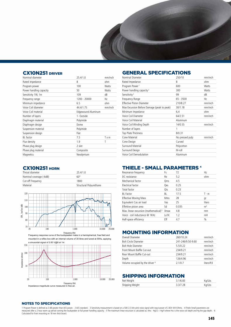
145
Frequency (Hz)
20 100 1.000 10.000 20.000
10
100
316
Impe
danc
e (o
hms)
80
100
110
120
SPL,
1w/
1m (d
B)
Frequency (Hz)
20 100 1.000 10.000 20.00070
90
Frequency (Hz)
20 100 1.000 10.000 20.000
10
100
316
Impe
danc
e (o
hms)
80
100
110
120
SPL,
1w/
1m (d
B)
Frequency (Hz)
20 100 1.000 10.000 20.00070
90
NOTES TO SPECIFICATIONS
CX10N251 DRIVER
1 Program Power is defined as 3 dB greater than AES power. - 2 AES standard. - 3 Sensitivity measurement is based on a 500-2,5 kHz pink noise signal with input power of 2.83V @ 8 Ohms. - 4 Thiele-Small parameters are measured after a 2 hour warm up period running the loudspeaker at full power handling capacity. - 5 The maximum linear excursion is calculated as: (Hvc - Hg)/2 + Hg/4 where Hvc is the voice coil depth and Hg the gap depth. - 6 Calculated for front mounting on 18 mm thick board.
CX10N251 HORN
Overall Diameter
Bolt Circle Diameter
Bolt Hole Diameter
Front Mount Baffle Cut-out
Rear Mount Baffle Cut-out
Depth
Volume occupied by the driver 6
Net Weight
Shipping Weight
Nominal Diameter
Rated Impedance
Program Power 1
Power handling capacity 2
Sensitivity 3
Frequency Range
Effective Piston Diameter
Max Excursion Before Damage (peak to peak)
Minimum Impedance
Voice Coil Diameter
Voice Coil Material
Voice Coil Winding Depth
Number of layers
Top Plate Thickness
Cone Material
Cone Design
Surround Material
Surround Design
Voice Coil Demodulation
Resonance frequency
DC resistance
Mechanical factor
Electrical factor
Total factor
BL Factor
Effective Moving Mass
Equivalent Cas air load
Effettive piston area
Max. linear excursion (mathematical) 5
Voice - coil inductance @ 1KHz
Half-space efficiency
260/10.24
241-246/9.50-9.60
5.5/0.22
234/9.21
234/9.21
126/4.96
2.1/0.7
3.1/6.83
3.3/7.28
250/10
8
600
300
99
65 - 3500
210/8.27
30/1.18
6,4
64/2.51
Aluminum
14/0.55
1
8/0.31
No pressed pulp
Curved
Polycotton
M-roll
Aluminum
mm/inch
mm/inch
mm/inch
mm/inch
mm/inch
mm/inch
liters/ft3
Kg/Lbs
Kg/Lbs
Hz
ohm
T · m
gr
liters
m2
mm
mH
%
72
5.2
4.5
0.25
0.23
17.5
28
25
0.035
4.8
1.2
4.7
Fs
Re
Qms
Qes
Qts
BL
Mms
Vas
Sd
Xmax
Le1K
Eff
mm/inch
ohm
Watts
Watts
dB
Hz
mm/inch
mm/inch
ohm
mm/inch
mm/inch
mm/inch
Throat diameter
Nominal coverage (-6dB)
Cut-off Frequency
Material
Nominal diameter
Rated impedance
Program power
Power handling capacity
Sensitivity 1W, 1m
Frequency range
Minimum impedance
Voice Coil diameter
Voice Coil material
Number of layers
Diaphragm material
Diaphragm design
Suspension material
Suspension design
BL factor
Flux density
Phase plug design
Phase plug material
Magnetics
25.4/1.0
8
100
50
109
1200 - 20000
6.5
44.4/1.75
Edgewound Aluminum
1- Outside
Polyimide
Dome
Polyimide
Flat
7.5
1.9
2 slot
Composite
Neodymium
25.4/1.0
60°
1800
Structural Polyurethane
mm/inch
ohm
Watts
Watts
dB
Hz
ohm
mm/inch
T x m
T
GENERAL SPECIFICATIONS
MOUNTING INFORMATION
SHIPPING INFORMATION
THIELE - SMALL PARAMETERS 4
146
HORNSHIGH FREQUENCY
High performance solutions in a lightweight compact package.A perfect mach of constant directivity horns for professional applications.Ideal for compact 2-way systems or bigger sized multiple-way products.
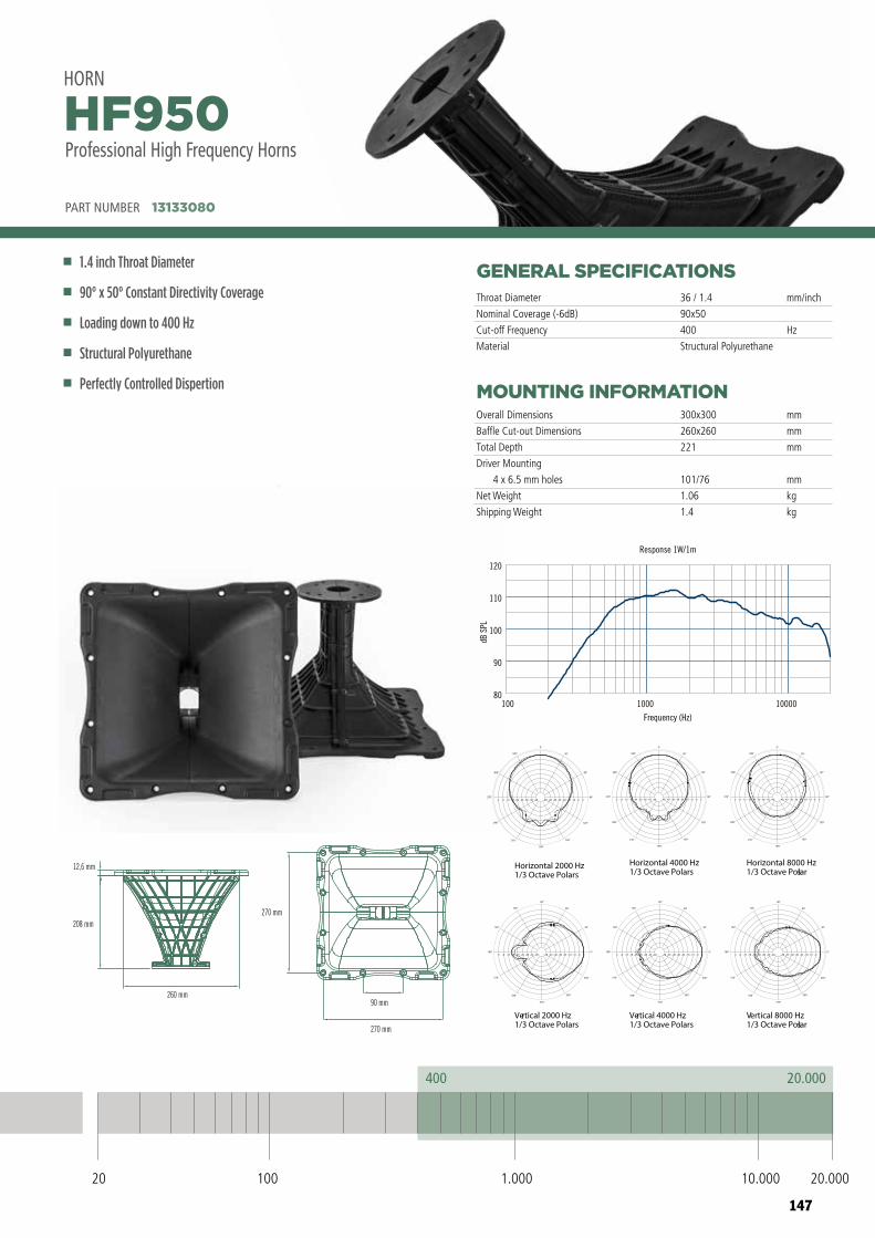
147
100 1000 10000
Frequency (Hz)
80
90
100
110
120
dB S
PL
Response 1W/1m
Horizontal 2000 Hz1/3 Octave Polars
Vertical 2000 Hz1/3 Octave Polars
Vertical 4000 Hz1/3 Octave Polars
Horizontal 4000 Hz1/3 Octave Polars
Horizontal 8000 Hz1/3 Octave Polars
Vertical 8000 Hz1/3 Octave Polars
-48-48 -42-42 -36-36 -30-30 -24-24 -18-18 -12-12 -6-6 00
300°
330°
270°
240°
210°
180°
150°
120°
90°
60°
30°
0°
-48-48 -42-42 -36-36 -30-30 -24-24 -18-18 -12-12 -6-6 00
300°
330°
270°
240°
210°
180°
150°
120°
90°
60°
30°
0°
-48-48 -42-42 -36-36 -30-30 -24-24 -18-18 -12-12 -6-6 00
300°
330°
270°
240°
210°
180°
150°
120°
90°
60°
30°
0°
-48-48 -42-42 -36-36 -30-30 -24-24 -18-18 -12-12 -6-6 00
150°
120°
180°
210°
240°
270°
300°
330°
0°
30°
60°
90°
-48-48 -42-42 -36-36 -30-30 -24-24 -18-18 -12-12 -6-6 00
150°
120°
180°
210°
240°
270°
300°
330°
0°
30°
60°
90°
-48-48 -42-42 -36-36 -30-30 -24-24 -18-18 -12-12 -6-6 00
150°
120°
180°
210°
240°
270°
300°
330°
0°
30°
60°
90°
HF950
12,6 mm
208 mm
260 mm
270 mm
90 mm
270 mm
HF950
12,6 mm
208 mm
260 mm
270 mm
90 mm
270 mm
20 100 10.000 20.0001.000
400 20.000
GENERAL SPECIFICATIONS
MOUNTING INFORMATION
PART NUMBER 13133080
1.4 inch Throat Diameter
90° x 50° Constant Directivity Coverage
Loading down to 400 Hz
Structural Polyurethane
Perfectly Controlled Dispertion
HF950Professional High Frequency Horns
HORN
Throat Diameter
Nominal Coverage (-6dB)
Cut-off Frequency
Material
Overall Dimensions
Baffle Cut-out Dimensions
Total Depth
Driver Mounting
4 x 6.5 mm holes
Net Weight
Shipping Weight
36 / 1.4
90x50
400
Structural Polyurethane
mm
mm
mm
mm
kg
kg
300x300
260x260
221
101/76
1.06
1.4
mm/inch
Hz
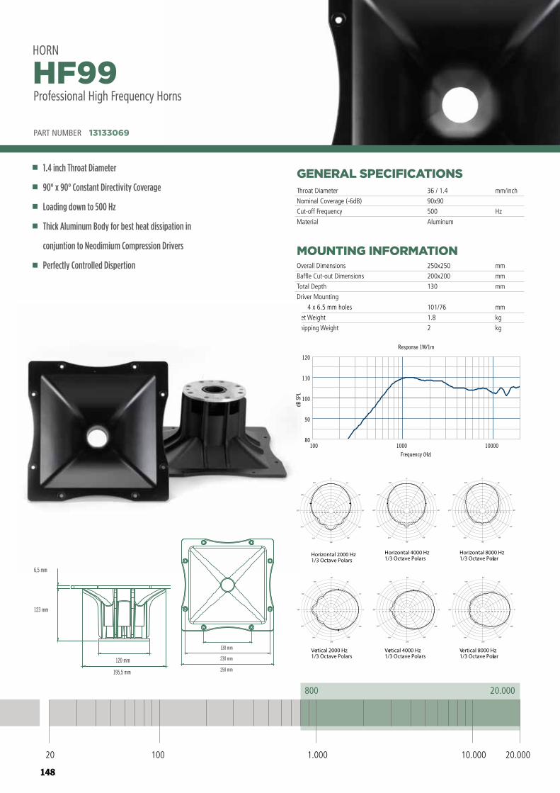
148
GENERAL SPECIFICATIONS
MOUNTING INFORMATION
PART NUMBER 13133069
1.4 inch Throat Diameter
90° x 90° Constant Directivity Coverage
Loading down to 500 Hz
Thick Aluminum Body for best heat dissipation in
conjuntion to Neodimium Compression Drivers
Perfectly Controlled Dispertion
HF99Professional High Frequency Horns
HORN
Throat Diameter
Nominal Coverage (-6dB)
Cut-off Frequency
Material
Overall Dimensions
Baffle Cut-out Dimensions
Total Depth
Driver Mounting
4 x 6.5 mm holes
Net Weight
Shipping Weight
36 / 1.4
90x90
500
Aluminum
mm
mm
mm
mm
kg
kg
250x250
200x200
130
101/76
1.8
2
mm/inch
Hz
HF66 HF96HF99
250 mm
230 mm
130 mm
250 mm
230 mm
130 mm
250 mm
230 mm
130 mm
195,5 mm
120 mm
123 mm
6,5 mm
196,5 mm
120 mm
123 mm
6,5 mm
206,6 mm
120,4 mm
28,5 mm
6,5 mm
HF66 HF96HF99
250 mm
230 mm
130 mm
250 mm
230 mm
130 mm
250 mm
230 mm
130 mm
195,5 mm
120 mm
123 mm
6,5 mm
196,5 mm
120 mm
123 mm
6,5 mm
206,6 mm
120,4 mm
28,5 mm
6,5 mm
20 100 10.000 20.0001.000
800 20.000
000010001001Frequency (Hz)
80
90
100
110
120
dB S
PL
Response 1W/1m
HF99
100 1000 10000
Frequency (Hz)
80
90
100
110
120
dB S
PL
Response 1W/1m
Horizontal 2000 Hz1/3 Octave Polars
Vertical 2000 Hz1/3 Octave Polars
Vertical 4000 Hz1/3 Octave Polars
Horizontal 4000 Hz1/3 Octave Polars
Horizontal 8000 Hz1/3 Octave Polars
Vertical 8000 Hz1/3 Octave Polars
-48-48 -42-42 -36-36 -30-30 -24-24 -18-18 -12-12 -6-6 00
300°
330°
270°
240°
210°
180°
150°
120°
90°
60°
30°
0°
-48-48 -42-42 -36-36 -30-30 -24-24 -18-18 -12-12 -6-6 00
300°
330°
270°
240°
210°
180°
150°
120°
90°
60°
30°
0°
-48-48 -42-42 -36-36 -30-30 -24-24 -18-18 -12-12 -6-6 00
300°
330°
270°
240°
210°
180°
150°
120°
90°
60°
30°
0°
-48-48 -42-42 -36-36 -30-30 -24-24 -18-18 -12-12 -6-6 00
150°
120°
180°
210°
240°
270°
300°
330°
0°
30°
60°
90°
-48-48 -42-42 -36-36 -30-30 -24-24 -18-18 -12-12 -6-6 00
150°
120°
180°
210°
240°
270°
300°
330°
0°
30°
60°
90°
-48-48 -42-42 -36-36 -30-30 -24-24 -18-18 -12-12 -6-6 00
150°
120°
180°
210°
240°
270°
300°
330°
0°
30°
60°
90°
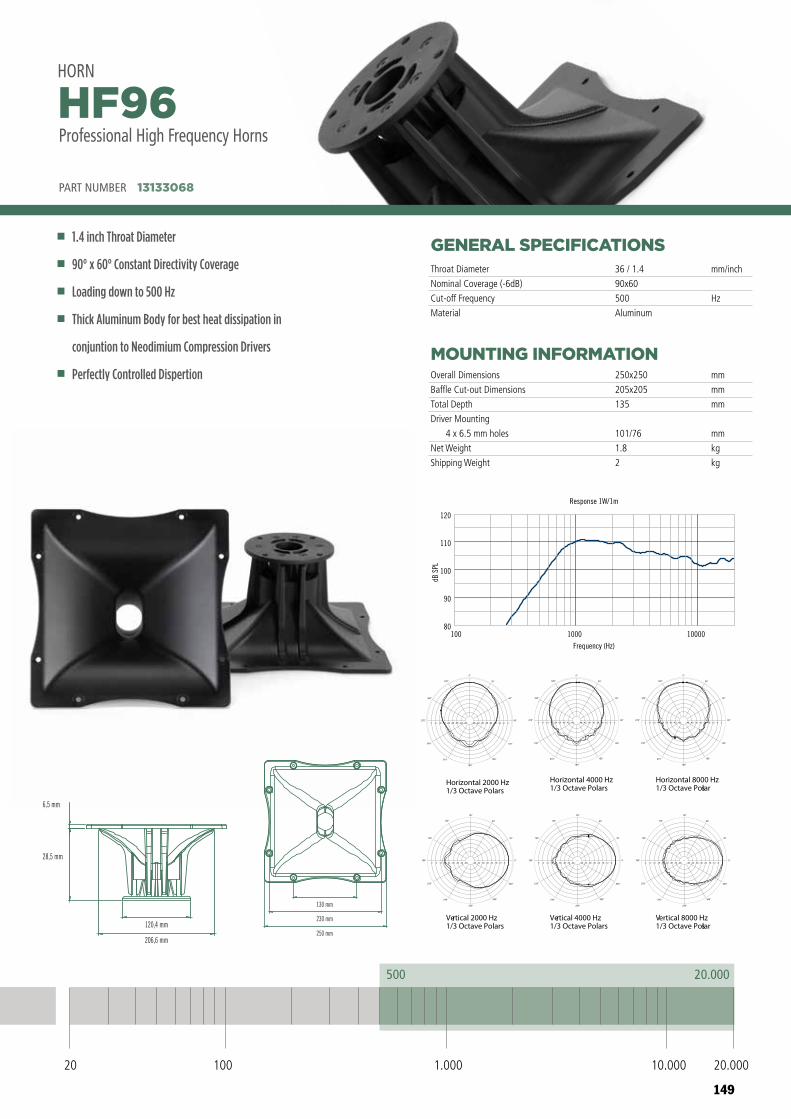
149
GENERAL SPECIFICATIONS
MOUNTING INFORMATION
PART NUMBER 13133068
1.4 inch Throat Diameter
90° x 60° Constant Directivity Coverage
Loading down to 500 Hz
Thick Aluminum Body for best heat dissipation in
conjuntion to Neodimium Compression Drivers
Perfectly Controlled Dispertion
HF96HORN
Throat Diameter
Nominal Coverage (-6dB)
Cut-off Frequency
Material
Overall Dimensions
Baffle Cut-out Dimensions
Total Depth
Driver Mounting
4 x 6.5 mm holes
Net Weight
Shipping Weight
36 / 1.4
90x60
500
Aluminum
mm
mm
mm
mm
kg
kg
250x250
205x205
135
101/76
1.8
2
mm/inch
Hz
20 100 10.000 20.0001.000
500 20.000
000010001001Frequency (Hz)
80
90
100
110
120
dB S
PL
Response 1W/1m
HF96
100 1000 10000
Frequency (Hz)
80
90
100
110
120
dB S
PL
Response 1W/1m
Horizontal 2000 Hz1/3 Octave Polars
Vertical 2000 Hz1/3 Octave Polars
Vertical 4000 Hz1/3 Octave Polars
Horizontal 4000 Hz1/3 Octave Polars
Horizontal 8000 Hz1/3 Octave Polars
Vertical 8000 Hz1/3 Octave Polars
-48-48 -42-42 -36-36 -30-30 -24-24 -18-18 -12-12 -6-6 00
300°
330°
270°
240°
210°
180°
150°
120°
90°
60°
30°
0°
-48-48 -42-42 -36-36 -30-30 -24-24 -18-18 -12-12 -6-6 00
300°
330°
270°
240°
210°
180°
150°
120°
90°
60°
30°
0°
-48-48 -42-42 -36-36 -30-30 -24-24 -18-18 -12-12 -6-6 00
300°
330°
270°
240°
210°
180°
150°
120°
90°
60°
30°
0°
-48-48 -42-42 -36-36 -30-30 -24-24 -18-18 -12-12 -6-6 00
150°
120°
180°
210°
240°
270°
300°
330°
0°
30°
60°
90°
-48-48 -42-42 -36-36 -30-30 -24-24 -18-18 -12-12 -6-6 00
150°
120°
180°
210°
240°
270°
300°
330°
0°
30°
60°
90°
-48-48 -42-42 -36-36 -30-30 -24-24 -18-18 -12-12 -6-6 00
150°
120°
180°
210°
240°
270°
300°
330°
0°
30°
60°
90°
HF66 HF96HF99
250 mm
230 mm
130 mm
250 mm
230 mm
130 mm
250 mm
230 mm
130 mm
195,5 mm
120 mm
123 mm
6,5 mm
196,5 mm
120 mm
123 mm
6,5 mm
206,6 mm
120,4 mm
28,5 mm
6,5 mm
HF66 HF96HF99
250 mm
230 mm
130 mm
250 mm
230 mm
130 mm
250 mm
230 mm
130 mm
195,5 mm
120 mm
123 mm
6,5 mm
196,5 mm
120 mm
123 mm
6,5 mm
206,6 mm
120,4 mm
28,5 mm
6,5 mm
Professional High Frequency Horns
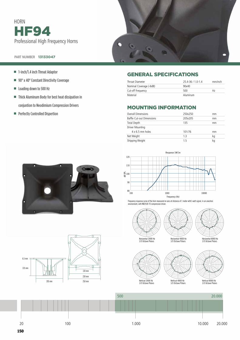
150
HORNHF94Professional High Frequency Horn
20000500
20 100 1.000 10.000 20.000
100 1000 10000
Frequency (Hz)
80
90
100
110
120
dB S
PL
Response 1W/1m
Frequency response curve of the horn measured on axis at distance of 1 meter with1 watt signal, in an anechoic environment, with ND2530-T3 compression driver.
130 mm
230 mm
250 mm
6.5 mm
135 mm
205 mm
PART NUMBER 13133047
Horizontal 4000 Hz1/3 Octave Polars
Vertical 4000 Hz1/3 Octave Polars
Horizontal 2000 Hz1/3 Octave Polars
Vertical 2000 Hz1/3 Octave Polars
Horizontal 8000 Hz1/3 Octave Polars
Vertical 8000 Hz1/3 Octave Polars
GENERAL SPECIFICATIONS
MOUNTING INFORMATION
PART NUMBER 13133047
1-inch/1.4 inch Throat Adaptor
90° x 40° Constant Directivity Coverage
Loading down to 500 Hz
Thick Aluminum Body for best heat dissipation in
conjuntion to Neodimium Compression Drivers
Perfectly Controlled Dispertion
HF94HORN
Throat Diameter
Nominal Coverage (-6dB)
Cut-off Frequency
Material
Overall Dimensions
Baffle Cut-out Dimensions
Total Depth
Driver Mounting
4 x 6.5 mm holes
Net Weight
Shipping Weight
25.4-36 / 1.0-1.4
90x40
500
Aluminum
mm
mm
mm
mm
kg
kg
250x250
205x205
135
101/76
1.3
1.5
mm/inch
Hz
HORNHF94Professional High Frequency Horn
20000500
20 100 1.000 10.000 20.000
100 1000 10000
Frequency (Hz)
80
90
100
110
120
dB S
PL
Response 1W/1m
Frequency response curve of the horn measured on axis at distance of 1 meter with1 watt signal, in an anechoic environment, with ND2530-T3 compression driver.
130 mm
230 mm
250 mm
6.5 mm
135 mm
205 mm
PART NUMBER 13133047
Horizontal 4000 Hz1/3 Octave Polars
Vertical 4000 Hz1/3 Octave Polars
Horizontal 2000 Hz1/3 Octave Polars
Vertical 2000 Hz1/3 Octave Polars
Horizontal 8000 Hz1/3 Octave Polars
Vertical 8000 Hz1/3 Octave Polars
20 100 10.000 20.0001.000
500 20.000
Professional High Frequency Horns
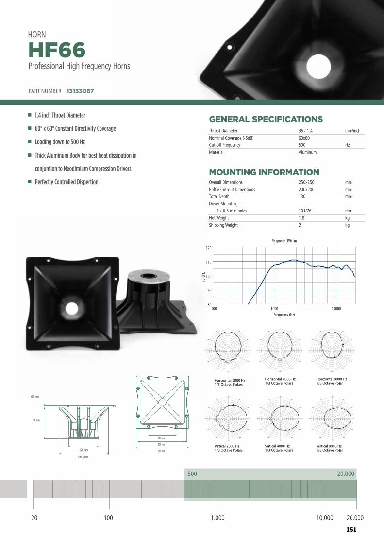
151
HORNHF94Professional High Frequency Horn
20000500
20 100 1.000 10.000 20.000
100 1000 10000
Frequency (Hz)
80
90
100
110
120
dB S
PL
Response 1W/1m
Frequency response curve of the horn measured on axis at distance of 1 meter with1 watt signal, in an anechoic environment, with ND2530-T3 compression driver.
130 mm
230 mm
250 mm
6.5 mm
135 mm
205 mm
PART NUMBER 13133047
Horizontal 4000 Hz1/3 Octave Polars
Vertical 4000 Hz1/3 Octave Polars
Horizontal 2000 Hz1/3 Octave Polars
Vertical 2000 Hz1/3 Octave Polars
Horizontal 8000 Hz1/3 Octave Polars
Vertical 8000 Hz1/3 Octave Polars
GENERAL SPECIFICATIONS
MOUNTING INFORMATION
PART NUMBER 13133067
1.4 inch Throat Diameter
60° x 60° Constant Directivity Coverage
Loading down to 500 Hz
Thick Aluminum Body for best heat dissipation in
conjuntion to Neodimium Compression Drivers
Perfectly Controlled Dispertion
HF66HORN
Throat Diameter
Nominal Coverage (-6dB)
Cut-off Frequency
Material
Overall Dimensions
Baffle Cut-out Dimensions
Total Depth
Driver Mounting
4 x 6.5 mm holes
Net Weight
Shipping Weight
36 / 1.4
60x60
500
Aluminum
mm
mm
mm
mm
kg
kg
250x250
200x200
130
101/76
1.8
2
mm/inch
Hz
HORNHF94Professional High Frequency Horn
20000500
20 100 1.000 10.000 20.000
100 1000 10000
Frequency (Hz)
80
90
100
110
120
dB S
PL
Response 1W/1m
Frequency response curve of the horn measured on axis at distance of 1 meter with1 watt signal, in an anechoic environment, with ND2530-T3 compression driver.
130 mm
230 mm
250 mm
6.5 mm
135 mm
205 mm
PART NUMBER 13133047
Horizontal 4000 Hz1/3 Octave Polars
Vertical 4000 Hz1/3 Octave Polars
Horizontal 2000 Hz1/3 Octave Polars
Vertical 2000 Hz1/3 Octave Polars
Horizontal 8000 Hz1/3 Octave Polars
Vertical 8000 Hz1/3 Octave Polars
20 100 10.000 20.0001.000
500 20.000
Horizontal 2000 Hz1/3 Octave Polars
Vertical 2000 Hz1/3 Octave Polars
Vertical 4000 Hz1/3 Octave Polars
Horizontal 4000 Hz1/3 Octave Polars
Horizontal 8000 Hz1/3 Octave Polars
Vertical 8000 Hz1/3 Octave Polars
-48-48 -42-42 -36-36 -30-30 -24-24 -18-18 -12-12 -6-6 00
300°
330°
270°
240°
210°
180°
150°
120°
90°
60°
30°
0°
-48-48 -42-42 -36-36 -30-30 -24-24 -18-18 -12-12 -6-6 00
300°
330°
270°
240°
210°
180°
150°
120°
90°
60°
30°
0°
-48-48 -42-42 -36-36 -30-30 -24-24 -18-18 -12-12 -6-6 00
300°
330°
270°
240°
210°
180°
150°
120°
90°
60°
30°
0°
-48-48 -42-42 -36-36 -30-30 -24-24 -18-18 -12-12 -6-6 00
150°
120°
180°
210°
240°
270°
300°
330°
0°
30°
60°
90°
-48-48 -42-42 -36-36 -30-30 -24-24 -18-18 -12-12 -6-6 00
150°
120°
180°
210°
240°
270°
300°
330°
0°
30°
60°
90°
-48-48 -42-42 -36-36 -30-30 -24-24 -18-18 -12-12 -6-6 00
150°
120°
180°
210°
240°
270°
300°
330°
0°
30°
60°
90°
HF66 HF96HF99
250 mm
230 mm
130 mm
250 mm
230 mm
130 mm
250 mm
230 mm
130 mm
195,5 mm
120 mm
123 mm
6,5 mm
196,5 mm
120 mm
123 mm
6,5 mm
206,6 mm
120,4 mm
28,5 mm
6,5 mm
HF66 HF96HF99
250 mm
230 mm
130 mm
250 mm
230 mm
130 mm
250 mm
230 mm
130 mm
195,5 mm
120 mm
123 mm
6,5 mm
196,5 mm
120 mm
123 mm
6,5 mm
206,6 mm
120,4 mm
28,5 mm
6,5 mm
100 1000 10000
Frequency (Hz)
80
90
100
110
120
dB S
PL
Response 1W/1m
Professional High Frequency Horns
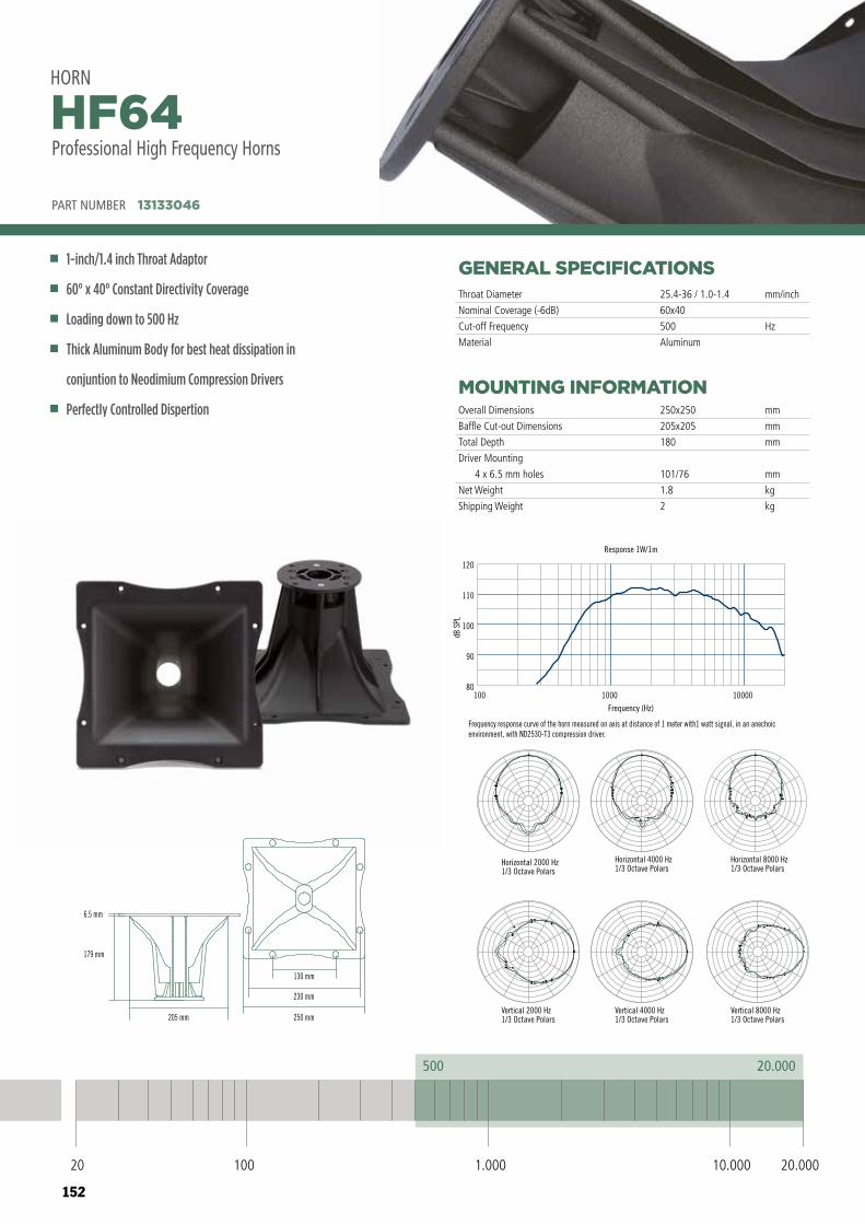
152
HORNHF64Professional High Frequency Horn
20000500
20 100 1.000 10.000 20.000
100 1000 10000
Frequency (Hz)
80
90
100
110
120
dB S
PL
Response 1W/1m
Frequency response curve of the horn measured on axis at distance of 1 meter with1 watt signal, in an anechoic environment, with ND2530-T3 compression driver.
130 mm
230 mm
250 mm205 mm
6.5 mm
179 mm
PART NUMBER 13133046
Horizontal 2000 Hz1/3 Octave Polars
Vertical 2000 Hz1/3 Octave Polars
Vertical 4000 Hz1/3 Octave Polars
Horizontal 4000 Hz1/3 Octave Polars
Horizontal 8000 Hz1/3 Octave Polars
Vertical 8000 Hz1/3 Octave Polars
GENERAL SPECIFICATIONS
MOUNTING INFORMATION
PART NUMBER 13133046
1-inch/1.4 inch Throat Adaptor
60° x 40° Constant Directivity Coverage
Loading down to 500 Hz
Thick Aluminum Body for best heat dissipation in
conjuntion to Neodimium Compression Drivers
Perfectly Controlled Dispertion
HF64HORN
Throat Diameter
Nominal Coverage (-6dB)
Cut-off Frequency
Material
Overall Dimensions
Baffle Cut-out Dimensions
Total Depth
Driver Mounting
4 x 6.5 mm holes
Net Weight
Shipping Weight
25.4-36 / 1.0-1.4
60x40
500
Aluminum
mm
mm
mm
mm
kg
kg
250x250
205x205
180
101/76
1.8
2
mm/inch
Hz
HORNHF64Professional High Frequency Horn
20000500
20 100 1.000 10.000 20.000
100 1000 10000
Frequency (Hz)
80
90
100
110
120
dB S
PL
Response 1W/1m
Frequency response curve of the horn measured on axis at distance of 1 meter with1 watt signal, in an anechoic environment, with ND2530-T3 compression driver.
130 mm
230 mm
250 mm205 mm
6.5 mm
179 mm
PART NUMBER 13133046
Horizontal 2000 Hz1/3 Octave Polars
Vertical 2000 Hz1/3 Octave Polars
Vertical 4000 Hz1/3 Octave Polars
Horizontal 4000 Hz1/3 Octave Polars
Horizontal 8000 Hz1/3 Octave Polars
Vertical 8000 Hz1/3 Octave Polars
20 100 10.000 20.0001.000
500 20.000
Professional High Frequency Horns
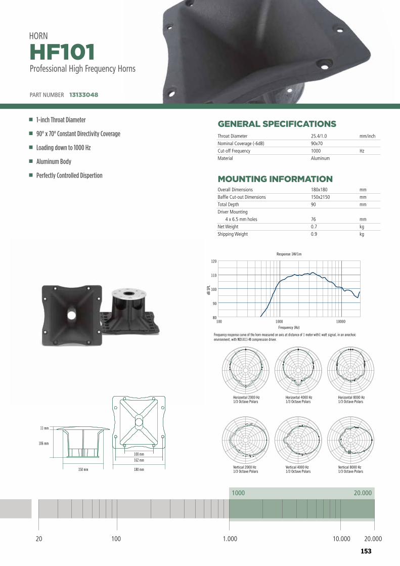
153
HORNHF101Professional High Frequency Horn
200001000
20 100 1.000 10.000 20.000
100 1000 10000
Frequency (Hz)
80
90
100
110
120
dB S
PL
Response 1W/1m
Frequency response curve of the horn measured on axis at distance of 1 meter with1 watt signal, in an anechoic environment, with ND1411-M compression driver.
100 mm162 mm
180 mm150 mm
106 mm
11 mm
PART NUMBER 13133048
Vertical 8000 Hz1/3 Octave Polars
Horizontal 8000 Hz1/3 Octave Polars
Horizontal 4000 Hz1/3 Octave Polars
Vertical 4000 Hz1/3 Octave Polars
Horizontal 2000 Hz1/3 Octave Polars
Vertical 2000 Hz1/3 Octave Polars
GENERAL SPECIFICATIONS
MOUNTING INFORMATION
PART NUMBER 13133048
1-inch Throat Diameter
90° x 70° Constant Directivity Coverage
Loading down to 1000 Hz
Aluminum Body
Perfectly Controlled Dispertion
HF101HORN
Throat Diameter
Nominal Coverage (-6dB)
Cut-off Frequency
Material
Overall Dimensions
Baffle Cut-out Dimensions
Total Depth
Driver Mounting
4 x 6.5 mm holes
Net Weight
Shipping Weight
25.4/1.0
90x70
1000
Aluminum
mm
mm
mm
mm
kg
kg
180x180
150x2150
90
76
0.7
0.9
mm/inch
Hz
HORNHF64Professional High Frequency Horn
20000500
20 100 1.000 10.000 20.000
100 1000 10000
Frequency (Hz)
80
90
100
110
120
dB S
PL
Response 1W/1m
Frequency response curve of the horn measured on axis at distance of 1 meter with1 watt signal, in an anechoic environment, with ND2530-T3 compression driver.
130 mm
230 mm
250 mm205 mm
6.5 mm
179 mm
PART NUMBER 13133046
Horizontal 2000 Hz1/3 Octave Polars
Vertical 2000 Hz1/3 Octave Polars
Vertical 4000 Hz1/3 Octave Polars
Horizontal 4000 Hz1/3 Octave Polars
Horizontal 8000 Hz1/3 Octave Polars
Vertical 8000 Hz1/3 Octave Polars
HORNHF101Professional High Frequency Horn
200001000
20 100 1.000 10.000 20.000
100 1000 10000
Frequency (Hz)
80
90
100
110
120
dB S
PL
Response 1W/1m
Frequency response curve of the horn measured on axis at distance of 1 meter with1 watt signal, in an anechoic environment, with ND1411-M compression driver.
100 mm162 mm
180 mm150 mm
106 mm
11 mm
PART NUMBER 13133048
Vertical 8000 Hz1/3 Octave Polars
Horizontal 8000 Hz1/3 Octave Polars
Horizontal 4000 Hz1/3 Octave Polars
Vertical 4000 Hz1/3 Octave Polars
Horizontal 2000 Hz1/3 Octave Polars
Vertical 2000 Hz1/3 Octave Polars
20 100 10.000 20.0001.000
1000 20.000
Professional High Frequency Horns
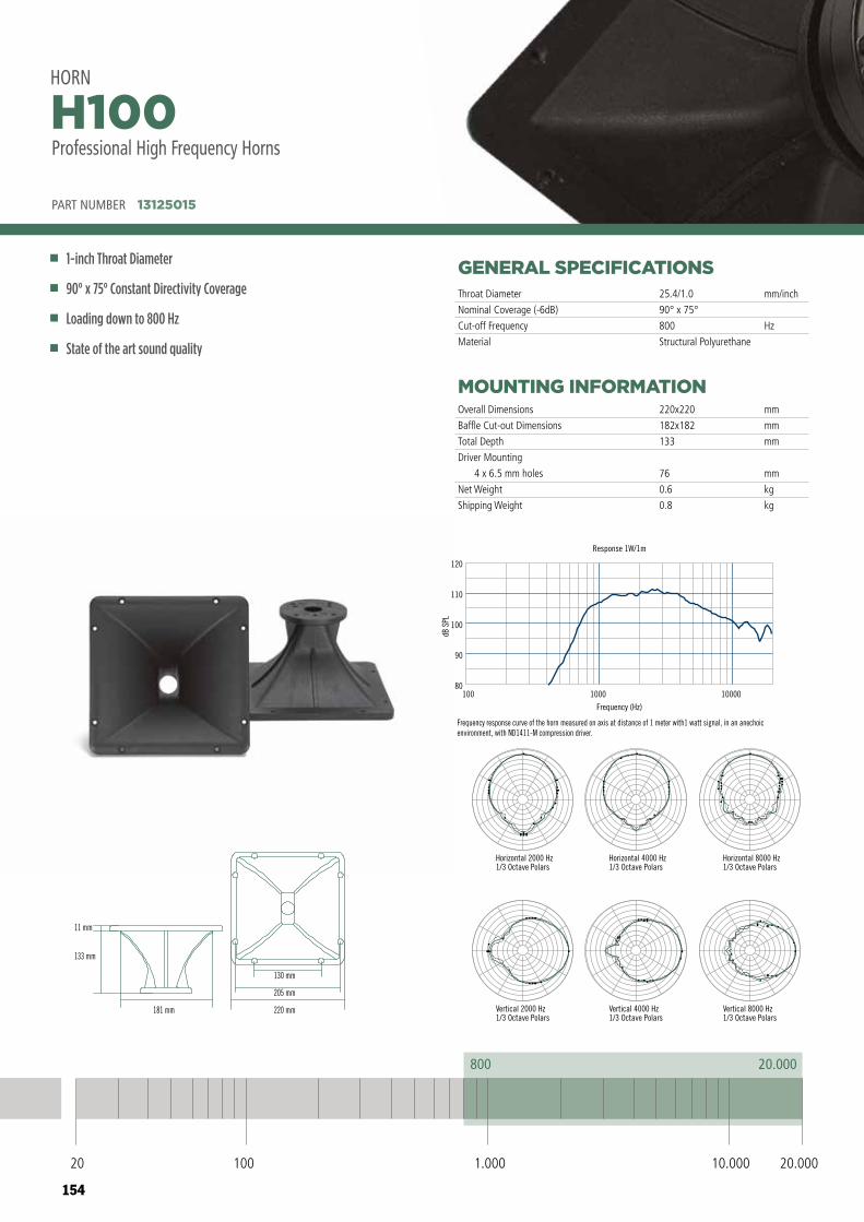
154
HORNH100Professional High Frequency Horn
20000800
20 100 1.000 10.000 20.000
100 1000 10000
Frequency (Hz)
80
90
100
110
120
dB S
PL
Response 1W/1m
Frequency response curve of the horn measured on axis at distance of 1 meter with1 watt signal, in an anechoic environment, with ND1411-M compression driver.
181 mm
11 mm
133 mm
220 mm
205 mm
130 mm
PART NUMBER 13125015
Vertical 8000 Hz1/3 Octave Polars
Horizontal 8000 Hz1/3 Octave Polars
Horizontal 2000 Hz1/3 Octave Polars
Vertical 2000 Hz1/3 Octave Polars
Horizontal 4000 Hz1/3 Octave Polars
Vertical 4000 Hz1/3 Octave Polars
GENERAL SPECIFICATIONS
MOUNTING INFORMATION
PART NUMBER 13125015
1-inch Throat Diameter
90° x 75° Constant Directivity Coverage
Loading down to 800 Hz
State of the art sound quality
H100HORN
Throat Diameter
Nominal Coverage (-6dB)
Cut-off Frequency
Material
Overall Dimensions
Baffle Cut-out Dimensions
Total Depth
Driver Mounting
4 x 6.5 mm holes
Net Weight
Shipping Weight
25.4/1.0
90° x 75°
800
Structural Polyurethane
mm
mm
mm
mm
kg
kg
220x220
182x182
133
76
0.6
0.8
mm/inch
Hz
HORNH100Professional High Frequency Horn
20000800
20 100 1.000 10.000 20.000
100 1000 10000
Frequency (Hz)
80
90
100
110
120
dB S
PL
Response 1W/1m
Frequency response curve of the horn measured on axis at distance of 1 meter with1 watt signal, in an anechoic environment, with ND1411-M compression driver.
181 mm
11 mm
133 mm
220 mm
205 mm
130 mm
PART NUMBER 13125015
Vertical 8000 Hz1/3 Octave Polars
Horizontal 8000 Hz1/3 Octave Polars
Horizontal 2000 Hz1/3 Octave Polars
Vertical 2000 Hz1/3 Octave Polars
Horizontal 4000 Hz1/3 Octave Polars
Vertical 4000 Hz1/3 Octave Polars
20 100 10.000 20.0001.000
800 20.000
Professional High Frequency Horns
155
NOTES
156
NOTES