hst-3 expansion anchor
TRANSCRIPT

HST-3EXPANSION ANCHOR
Technical DatasheetUpdate: May-19

1 May-19
HST3 Expansion anchor Ultimate-performance expansion anchor for cracked concrete and seismic
Anchor version Benefits
HST3 HST3-R (M8-M20)
- Highest resistance for reduced member
thickness, short spacing and edge
distances
- Increased undercut percentage in
combination with optimized coating
- Suitable for non-cracked and cracked
concrete
- Normal and lightweight concrete with
concrete compressive strength range
from 2,500 psi (17.2 MPa) to 8,500 psi
(58.6 MPa)
- Highly reliable and safe anchor for
structural seismic design
- Product and length identification mark
facilitates quality control and inspection
HST3-BW
HST3-R-BW
(M8-M24)
Base material Load conditions
Concrete (non-cracked)
Concrete (cracked)
Static/ quasi-static
Seismic Fire resistance
Installation conditions Other information
Hammer drilled holes
Diamond drilled holes
Hollow drill-bit drilling
CE conformity
FM approved Uniform Evaluation Service
Data source Technical data in this section is based on evaluation report ER-578 by IAPMO UES according to ACI 355.2 and
ICC-ES AC193, except for the following - Diamond drilled holes, Hollow-drill bit, shallow embedment data for M10
to M16, Seismic filling set, and the -BW version.
Additional data for Diamond drilled holes, Hollow-drill bit, shallow embedment data for M10 to M16, Seismic filling
set, and the -BW version, is based on technical assessment of testing done for ETA-98/0001 and evaluated by Hilti
for designs in accordance with ACI 318-14 chapter 17. Published technical data is not contained in an external
evaluation report (i.e. ICC-ES or IAPMO-UES) or other approval at this time, and can be used as Hilti Technical
Data only.
Approvals / certificates
Description Authority / Laboratory No. / date of issue
Shock approval FOCP, Zurich BZS D 08-602 / 2016-08-17
ACI 318 assessment IAPMO UES, USA ER-578 / 2019-28-02

May-19 2
Anchor performance
Design information for tension a) for HST3
Design parameter Nominal anchor diameter (mm)
M8 M10 M12 M16 M20
Anchor O.D. da mm 8 10 12 16 20
Effective min. embedment hef mm 47 40 60 50 70 65 85 101
Tension, steel failure modes
Strength reduction factor for steel
in tension b) sa,N 0.75
Min. specified yield strength,
threads fya,threads N/mm2 640 640 640 576 560
Min. specified ult. strength,
threads futa,threads N/mm2 800 800 800 720 700
Effective-cross sectional steel area
in tension, threads Ase,N,thrd mm2 36.6 58.0 84.3 157.0 245.0
Min. specified yield strength, neck fya,neck N/mm2 688 740 731 688 634
Min. specified ult. strength, neck futa,neck N/mm2 800 860 850 800 740
Effective-cross sectional steel area
in tension, neck Ase,N,neck mm2 24.6 37.8 53.1 95.0 167.9
Nominal steel strength in tension Nsa kN 19.7 32.5 45.1 76.0 124.2
Tension, concrete failure modes
Anchor category 1
Strength reduction factor for
concrete failure in tension,
Condition A c)
c,N 0.75
Strength reduction factor for
concrete failure in tension,
Condition B c)
c,N 0.65
Strength reduction factor for
pullout failure in tension, Condition
A and B c)
p,N 0.65
Effectiveness factor for uncracked
concrete kuncr 10.0 11.3 10.0 11.3 10.0 11.3 10.0
Effectiveness factor for cracked
concrete kcr 7.1 8.8 7.1 8.8 7.1 8.8
Modification factor for anchor
resistance, tension, uncracked
conc. d)
c,N 1.0
Critical edge distance cac mm 71 95 115 90 110 115 128 192
Pullout strength in uncracked
concrete e) Np,uncr kN 11.0 NA NA NA NA NA NA NA
Pullout strength in cracked
concrete e) Np,cr kN 8.5 NA NA NA NA NA NA NA
Pullout strength in cracked
concrete, seismic e) Np,eq kN 8.5 - NA - NA - 19.9 36.6
a) Design information in accordance with ACI 355.2-07 and AC193
b) The HST3 carbon steel anchor is considered a ductile steel element as defined by ICC-ES AC193 section 6.3.6. c) For use with the load combinations of ACI 318-14 section 5.3. Condition B applies where supplementary reinforcement in conformance
with ACI 318-14 section 17.3.3 c) is not provided, or where pullout or pryout strength governs. For cases where the presence of
supplementary reinforcement can be verified, the resistance modification factors associated with Condition A may be used.
d) For all design cases, c,N = 1.0. The appropriate effectiveness factor for cracked concrete (kcr) or uncracked (kuncr) concrete must be used.

3 May-19
e) For all design cases, c,P = 1.0. Tabular value for pullout strength is for a concrete compressive strength of 17.2 MPa. Pullout strength for
concrete compressive strength greater than 17.2 MPa may be increased by multiplying the tabular pullout strength by (f'c / 17.2)0.5. NA (not
applicable) denotes that pullout strength does not need to be considered for design.
f) Design information in accordance with ACI 355.2-07 and AC193
g) The HST3 carbon steel anchor is considered a ductile steel element as defined by ICC-ES AC193 section 6.3.6. h) For use with the load combinations of ACI 318-14 section 5.3. Condition B applies where supplementary reinforcement in conformance
with ACI 318-14 section 17.3.3 c) is not provided, or where pullout or pryout strength governs. For cases where the presence of
supplementary reinforcement can be verified, the resistance modification factors associated with Condition A may be used.
f) Shear and seismic shear tests are all performed in cracked concrete member according to ICC-ES AC193 section 9.4 and 9.6 respectively.
Value of Vsa(,eq) < 0.6 Ase,V futa for all cases.
Design information for shear a) for HST3
Design parameter Nominal anchor diameter (mm)
M8 M10 M12 M16 M20
Anchor O.D. da mm 8 10 12 16 20
Effective min. embedment hef mm 47 40 60 50 70 65 85 101
Shear, steel failure modes
Strength reduction factor for steel
in shear b) sa,V 0.65
Nominal steel strength in shear f) Vsa kN 12.9 19.1 19.1 26.2 27.6 45.3 47.6 64.3
Nominal steel strength in shear,
seismic f) Vsa,eq kN 11.5 - 19.1 - 24.9 - 43.1 64.3
Nominal steel strength in shear, w/
Seismic/Filling Set f) Vsa kN 16.6 - 25.8 - 39.0 - 60.9 100.4
Nominal steel strength in shear,
seismic, w/ Seismic/Filling Set f) Vsa,eq kN 16.6 - 25.8 - 39.0 - 60.9 100.4
Shear, concrete failure modes
Strength reduction factor for
concrete breakout failure in shear,
Condition A c)
c,V 0.75
Strength reduction factor for
concrete breakout failure in shear,
Condition B c)
c,V 0.70
Strength reduction factor for pryout
failure in shear, Condition A and B c) p,V 0.70
Load bearing length of anchor in
shear le mm 47 40 60 50 70 65 85 101
Effectiveness factor for pryout kcp - 1.0 1.0 1.0 1.0 2.0 2.0 2.0 2.0

May-19 4
Design information for tension a) for HST3-R
Design parameter Nominal anchor diameter (mm)
M8 M10 M12 M16 M20
Anchor O.D. da mm 8 10 12 16 20
Effective min. embedment hef mm 47 40 60 50 70 65 85 101
Tension, steel failure modes
Strength reduction factor for steel
in tension b) sa,N 0.75
Min. specified yield strength,
threads fya,threads N/mm2 576 568 568 520 520
Min. specified ult. strength,
threads futa,threads N/mm2 720 710 710 650 650
Effective-cross sectional steel
area in tension, threads Ase,N,thrd mm2 36.6 58.0 84.3 157.0 245.0
Min. specified yield strength, neck fya,neck N/mm2 619 654 688 628 593
Min. specified ult. strength, neck futa,neck N/mm2 720 760 800 730 690
Effective-cross sectional steel
area in tension, neck Ase,N,neck mm2 24.6 37.8 53.1 95.0 167.9
Nominal steel strength in tension Nsa kN 17.7 28.7 42.5 69.4 115.8
Tension, concrete failure modes
Anchor category 1
Strength reduction factor for
concrete failure in tension,
Condition A c)
c,N 0.75
Strength reduction factor for
concrete failure in tension,
Condition B c)
c,N 0.65
Strength reduction factor for
pullout failure in tension, Condition
A and B c)
p,N 0.65
Effectiveness factor for uncracked
concrete kuncr 10.0 11.3 10.0 11.3 10.0 11.3 10.0
Effectiveness factor for cracked
concrete kcr 7.1 8.8 7.1 8.8 7.1 8.8
Modification factor for anchor
resistance, tension, uncracked
conc. d)
c,N 1.0
Critical edge distance cac mm 71 95 115 90 110 115 128 192
Pullout strength in uncracked
concrete e) Np,uncr kN 11.0 NA NA NA NA NA NA NA
Pullout strength in cracked
concrete e) Np,cr kN 8.5 NA NA NA NA NA NA NA
Pullout strength in cracked
concrete, seismic e) Np,eq kN 8.5 - NA - NA - 19.9 36.6
a) Design information in accordance with ACI 355.2-07 and AC193
b) The HST3 carbon steel anchor is considered a ductile steel element as defined by ICC-ES AC193 section 6.3.6. c) For use with the load combinations of ACI 318-14 section 5.3. Condition B applies where supplementary reinforcement in conformance
with ACI 318-14 section 17.3.3 c) is not provided, or where pullout or pryout strength governs. For cases where the presence of
supplementary reinforcement can be verified, the resistance modification factors associated with Condition A may be used.
d) For all design cases, c,N = 1.0. The appropriate effectiveness factor for cracked concrete (kcr) or uncracked (kuncr) concrete must be used.
e) For all design cases, c,P = 1.0. Tabular value for pullout strength is for a concrete compressive strength of 17.2 MPa. Pullout strength for
concrete compressive strength greater than 17.2 MPa may be increased by multiplying the tabular pullout strength by (f'c / 17.2)0.5. NA (not
applicable) denotes that pullout strength does not need to be considered for design.

5 May-19
Design information for shear a) for HST3-R
Design parameter Nominal anchor diameter (mm)
M8 M10 M12 M16 M20
Anchor O.D. da mm 8 10 12 16 20
Effective min. embedment hef mm 47 40 60 50 70 65 85 101
Shear, steel failure modes
Strength reduction factor for steel
in shear b) sa,V 0.65
Nominal steel strength in shear f) Vsa kN 10.1 23.1 24.4 27.9 28.9 44.1 61.2 79.2
Nominal steel strength in shear,
seismic f) Vsa,eq kN 9.8 - 22.1 - 28.9 - 60.7 51.5
Nominal steel strength in shear, w/
Seismic/Filling Set f) Vsa kN 19.5 - 28.4 - 44.3 - 70.2 102.7
Nominal steel strength in shear,
seismic, w/ Seismic/Filling Set f) Vsa,eq kN 19.5 - 28.4 - 44.3 - 70.2 102.7
Shear, concrete failure modes
Strength reduction factor for
concrete breakout failure in shear,
Condition A c)
c,V 0.75
Strength reduction factor for
concrete breakout failure in shear,
Condition B c)
c,V 0.70
Strength reduction factor for pryout
failure in shear, Condition A and B c) p,V 0.70
Load bearing length of anchor in
shear le mm 47 40 60 50 70 65 85 101
Effectiveness factor for pryout kcp - 1.0 1.0 1.0 1.0 2.0 2.0 2.0 2.0
f) Design information in accordance with ACI 355.2-07 and AC193
g) The HST3 carbon steel anchor is considered a ductile steel element as defined by ICC-ES AC193 section 6.3.6. h) For use with the load combinations of ACI 318-14 section 5.3. Condition B applies where supplementary reinforcement in conformance
with ACI 318-14 section 17.3.3 c) is not provided, or where pullout or pryout strength governs. For cases where the presence of
supplementary reinforcement can be verified, the resistance modification factors associated with Condition A may be used.
f) Shear and seismic shear tests are all performed in cracked concrete member according to ICC-ES AC193 section 9.4 and 9.6 respectively.
Value of Vsa(,eq) < 0.6 Ase,V futa for all cases.
May-19 6
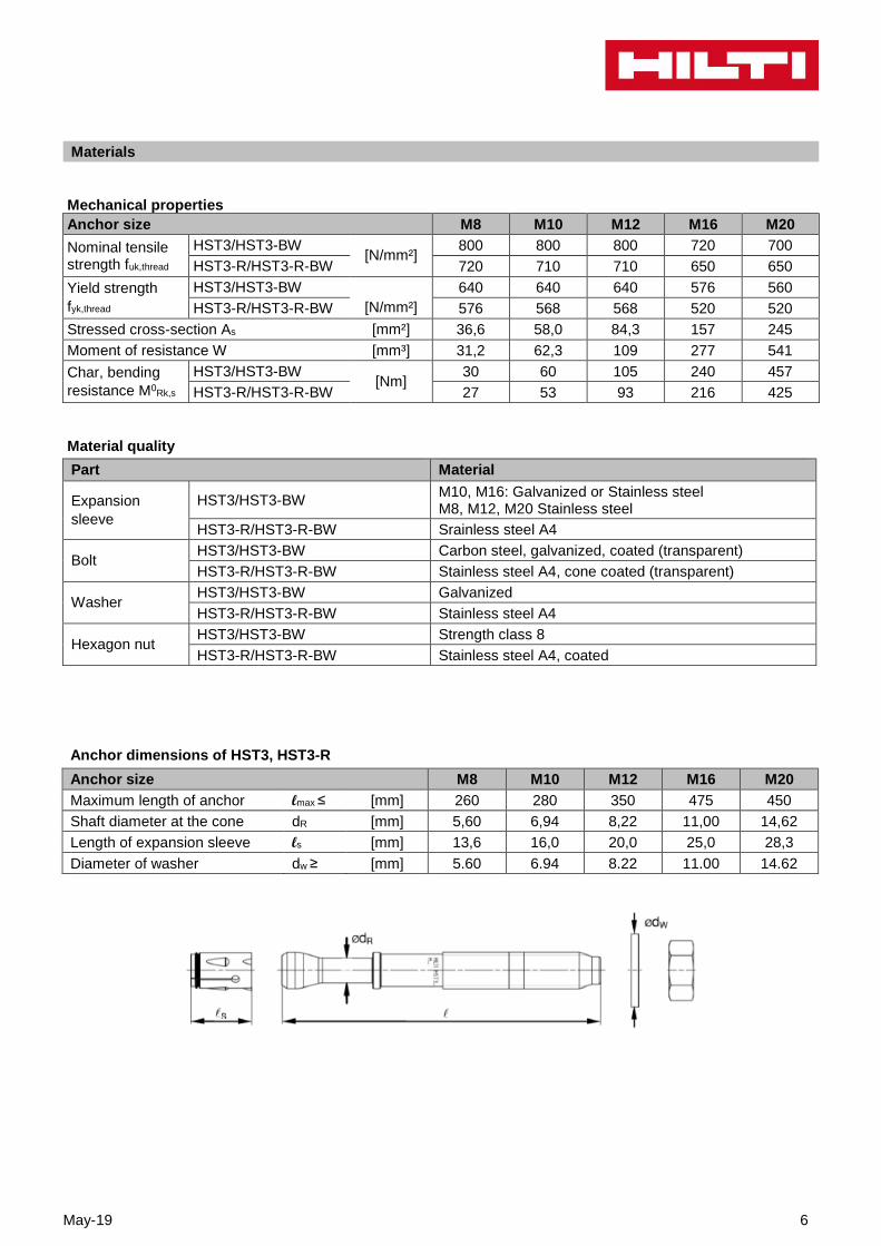
Materials Mechanical properties Anchor size M8 M10 M12 M16 M20
Nominal tensile strength fuk,thread
HST3/HST3-BW [N/mm²]
800 800 800 720 700
HST3-R/HST3-R-BW 720 710 710 650 650
Yield strength
fyk,thread
HST3/HST3-BW
[N/mm²]
640 640 640 576 560
HST3-R/HST3-R-BW 576 568 568 520 520
Stressed cross-section As [mm²] 36,6 58,0 84,3 157 245
Moment of resistance W [mm³] 31,2 62,3 109 277 541
Char, bending
resistance M0Rk,s
HST3/HST3-BW [Nm]
30 60 105 240 457
HST3-R/HST3-R-BW 27 53 93 216 425
Material quality
Part Material
Expansion
sleeve
HST3/HST3-BW M10, M16: Galvanized or Stainless steel M8, M12, M20 Stainless steel
HST3-R/HST3-R-BW Srainless steel A4
Bolt HST3/HST3-BW Carbon steel, galvanized, coated (transparent)
HST3-R/HST3-R-BW Stainless steel A4, cone coated (transparent)
Washer HST3/HST3-BW Galvanized
HST3-R/HST3-R-BW Stainless steel A4
Hexagon nut HST3/HST3-BW Strength class 8
HST3-R/HST3-R-BW Stainless steel A4, coated
Anchor dimensions of HST3, HST3-R
Anchor size M8 M10 M12 M16 M20
Maximum length of anchor lmax ≤ [mm] 260 280 350 475 450
Shaft diameter at the cone dR [mm] 5,60 6,94 8,22 11,00 14,62
Length of expansion sleeve ls [mm] 13,6 16,0 20,0 25,0 28,3
Diameter of washer dw ≥ [mm] 5.60 6.94 8.22 11.00 14.62

7 May-19
Setting information
Setting details
Setting information Nominal anchor diameter (mm)
M8 M10 M12 M16 M20
Nominal drill bit diameter do mm 8 10 12 16 20
Effective minimum embedment hef mm 47 40 60 50 70 65 85 101
Nominal minimum embedment hnom mm 54 48 68 60 80 78 98 116
Minimum hole depth in concrete a) h1 mm 59 53 73 68 88 86 10
6 124
Fixture hole diameter df mm 9 12 14 18 22
Maximum thickness of fixture tfix,max mm 195 220 270 370 310
Installation torque Tinst Nm 20 45 60 110 180
Length of expansion sleeve ls mm 13.6 16.0 20.0 25.0 28.3
Diameter of washer dW > mm 5.60 6.94 8.22 11.00 14.62
Width across flats of nut SW mm 13 17 19 24 30
a) When diamond core drilling is used, add 5mm to h1 for M8 and M10, and add 2mm to h1 for M12 to M20.
Installation equipment
Anchor size M8 M10 M12 M16 M20
Rotary hammer TE2(-A) – TE30(-A) TE40 –
TE80
Diamond coring tool DD EC-1 coring tool with DD-C … TS/TL or T2/T4 core bits
DD 30-W coring tool with C+ … SPX-T core bits
Setting tool Hilti S7W 6AT 22A – SI-AT-A22 -
Hollow drill bit - TE-CD, TE-YD
Other tools hammer, torque wrench, blow out pump
May-19 8
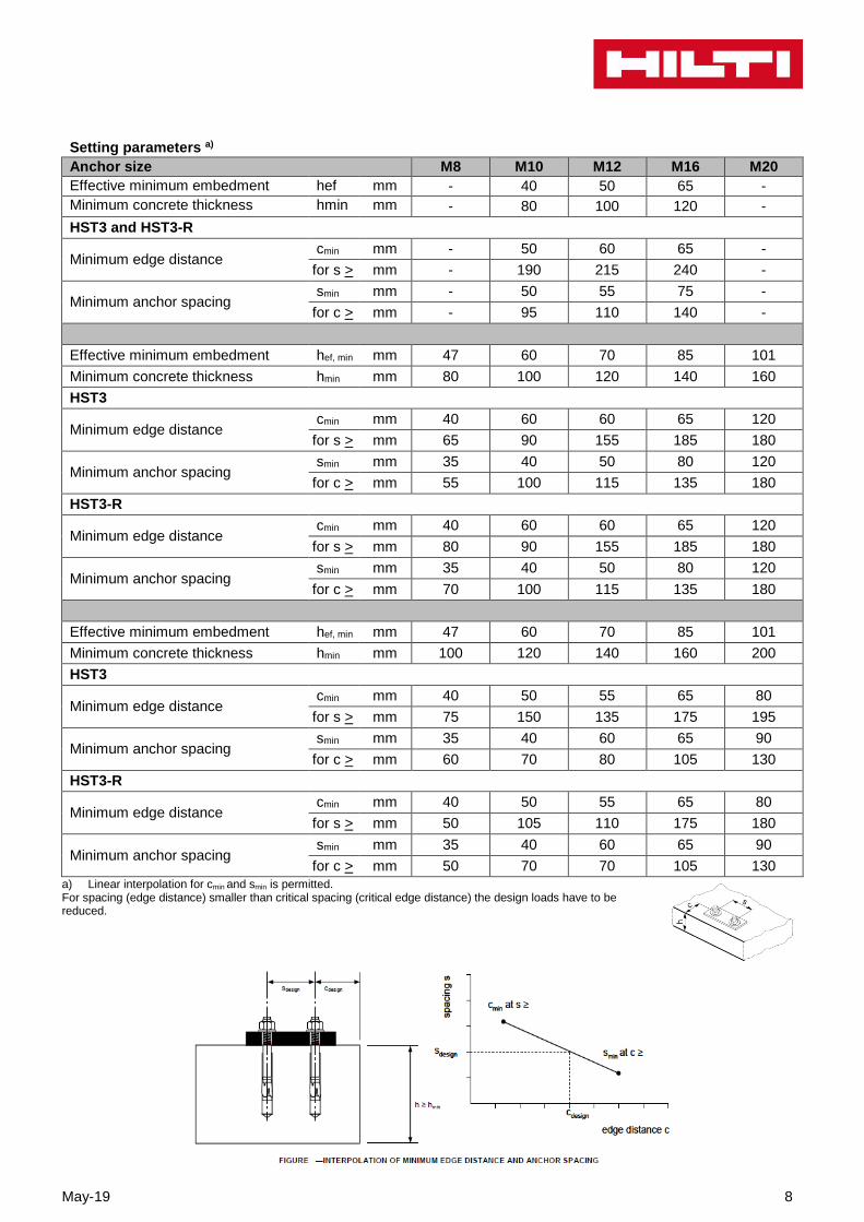
Setting parameters a)
Anchor size M8 M10 M12 M16 M20
Effective minimum embedment hef mm - 40 50 65 -
Minimum concrete thickness hmin mm - 80 100 120 -
HST3 and HST3-R
Minimum edge distance cmin mm - 50 60 65 -
for s > mm - 190 215 240 -
Minimum anchor spacing smin mm - 50 55 75 -
for c > mm - 95 110 140 -
Effective minimum embedment hef, min mm 47 60 70 85 101
Minimum concrete thickness hmin mm 80 100 120 140 160
HST3
Minimum edge distance cmin mm 40 60 60 65 120
for s > mm 65 90 155 185 180
Minimum anchor spacing smin mm 35 40 50 80 120
for c > mm 55 100 115 135 180
HST3-R
Minimum edge distance cmin mm 40 60 60 65 120
for s > mm 80 90 155 185 180
Minimum anchor spacing smin mm 35 40 50 80 120
for c > mm 70 100 115 135 180
Effective minimum embedment hef, min mm 47 60 70 85 101
Minimum concrete thickness hmin mm 100 120 140 160 200
HST3
Minimum edge distance cmin mm 40 50 55 65 80
for s > mm 75 150 135 175 195
Minimum anchor spacing smin mm 35 40 60 65 90
for c > mm 60 70 80 105 130
HST3-R
Minimum edge distance cmin mm 40 50 55 65 80
for s > mm 50 105 110 175 180
Minimum anchor spacing smin mm 35 40 60 65 90
for c > mm 50 70 70 105 130
a) Linear interpolation for cmin and smin is permitted. For spacing (edge distance) smaller than critical spacing (critical edge distance) the design loads have to be reduced.

9 May-19
Setting instructions
*For detailed information on installation see instruction for use given with the package of the product
Setting instruction for HST3, HST3-R
Hammer drilling (M8, M10, M12, M16, M20)
1. Drill the hole
2. Clean the hole
3. Insert the anchor
4. Use a setting tool HS-SC
5. Checking
6.a Attach the belonging washer
6.b Attach the belonging washer with screw driver (M8, M10, M12)
Hollow Drill Bit (M16, M20), no cleaning required
1. Drill the hole with the Hollow drill bit
2. Insert the anchor
3. Use a setting tool HS-SC
4. Checking
5.a Attach the belonging washer
5.b Attach the belonging washer with screw driver (M8, M10, M12)
May-19 10
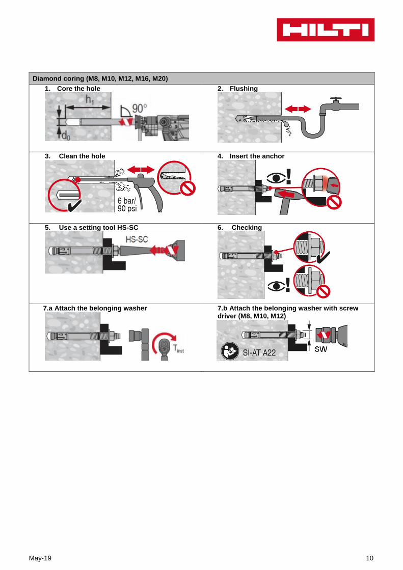
Diamond coring (M8, M10, M12, M16, M20)
1. Core the hole
2. Flushing
3. Clean the hole
4. Insert the anchor
5. Use a setting tool HS-SC
6. Checking
7.a Attach the belonging washer
7.b Attach the belonging washer with screw driver (M8, M10, M12)