hilti anchor channel systems (hac and hac-t)
TRANSCRIPT
HILTI ANCHORCHANNEL SYSTEMS (HAC AND HAC-T)Canadian Design Guide 19th Edition

2June 2019
CANADIAN DESIGN GUIDE1.0 Introduction
This section is a supplement to the Hilti North American Product Technical Guide for Hilti anchor channel systems HAC and HAC-T. Hilti anchor channels HAC with Hilti channel bolts HBC-B, HBC-C and HBC-C-N and Hilti anchor channels HAC-T with Hilti channel bolts HBC-T are qualified in accordance with ICC-ES Acceptance Criteria (AC232) for use in cracked and uncracked concrete in ICC-ES Evaluation Service Report ESR-3520. Based on these recognitions, Hilti anchor channel systems are alternatives to cast-in-place anchors and may be used where an engineered design is permitted in accordance with AC232, ACI 318, and ESR-3520.
Since no similar design provision exists in Canada, the following document provides an alternative design method based on Ultimate Limit State Design, described in the provisions of CSA A23.3-14 Annex D. Factored tension and shear loads on the anchor channel systems are defined using the method provided in AC232 and described in section 2.0 of this document. The design resistances of the anchor channel systems are developed based on design criteria of AC232 and CSA A23.3-14. Geometric and design parameters given in tables 1 through 13 are derived from information in ESR-3520.
Note that all figures are adopted (reprinted) from ICC-ES Evaluation Service Report ESR-3520 with permission, and are applicable to Limit State Design criteria. For a detailed explanation of the design method, technical assistance is available by contacting Hilti at 1-800-363-4458 or at www.hilti.ca.
2.0 Factored loads on anchor channel systems
Hilti anchor channels and channel bolts are used to resist static, seismic, and wind loads in tension and shear. Figure 1 demonstrates the load directions including tension load (Nfa), shear load perpendicular to the longitudinal channel axis (Vfa,y), and shear load acting in the direction of the longitudinal channel axis (Vfa,x) acting on the anchor channels. Refer to the notations in section 4.0 and figures 19 through 22 of this document for definitions and details of the variables noted below.
2.1 Factored tension load (Nfa)
The tension loads, Nafa,i , on an anchor due to a tension load, Nfa , acting on the channel
shall be computed in accordance with Eq. (1). An example for the calculation of the tension loads acting on the anchors is given in Figure 2.
Nafa,i = k · A' i · Nfa (1)
where:
A' i = ordinate at the position of the anchor i assuming a triangle with the unit height at the position of load Nfa and the base length 2ℓin.
k = 1 / ∑A’i (2)
ℓin = 13 (Iy)0.05 s ≥ s, mm (3)
s = anchor spacing, mm
Nfa = factored tension load on channel bolt, N
Iy = the moment of inertia of the channel (provided in Table 1 of this document)
If several tension loads are simultaneously acting on the channel, a linear superimposition of the anchor forces for all loads shall be assumed. If the exact position of the load on the
1.0 Introduction
2.0 Factored loads on anchor channel
3.0 Resistance of anchor channels
4.0 Notations

3
Canadian Design Guide
June 2019
channel is not known, the most unfavorable loading position shall be assumed for each failure mode (e.g. load acting over an anchor for the case of failure of an anchor by steel rupture or pull-out and load acting between anchors in the case of bending failure of the channel).
The bending moment, Mf,flex, on the channel due to tension loads acting on the channel shall be computed assuming a simply supported single span beam with a span length equal to the anchor spacing, s.
Tension load Nfa: z-direction (in direction of anchor)
Shear load Vfa,y: y-direction (perpendicular to longitudinal axis of channel)
Longitudinal load Vfa,x: x-direction (in direction of longitudinal axis of channel)
Figure 1: Load directions covered by this document
2.2 Factored shear load perpendicular to channel longitudinal axis (Vfa,y)
The shear load,V afa,y,i , on an anchor due to a shear load Vfa,y acting on the channel perpendicular to its longitudinal axis shall be computed in accordance with Section 2.1 replacing Nfa in Eq. (1) by Vfa,y.
2.3 Factored shear load in the direction of channel longitudinal axis (Vfa,x)
The shear load, V afa,x,i , on an anchor due to a shear load, Vfa,x, acting on the channel in direction of the longitudinal channel axis shall be computed as follows:
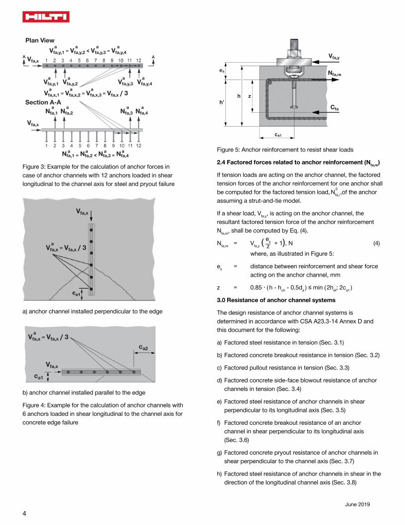
For the verification of the resistance of the anchor channel for failure of the anchor or failure of the connection between anchor and channel, pryout failure, and concrete edge failure in case of anchor channels arranged parallel to the edge without corner effects, the shear load, Vfa,x, shall be equally distributed to all anchors for anchor channels with not more than three anchors or to three anchors for anchor channels with more than three anchors (see Figure 3). The shear load, Vfa,x, shall be distributed to those three anchors that result in the most unfavorable design condition (in the example given in Figure 3 the shear load, Vfa,x, shall be distributed to the anchors 10 to 12).
For the verification of the resistance of the anchor channel for concrete edge failure in case of anchor channels arranged perpendicular to the edge and in case of anchor channels arranged parallel to the edge with corner effects, the shear load, Vfa,x, shall be equally distributed to all anchors for anchor channels with not more than three anchors or to the three anchors closest to the edge or corner for anchor channels with more than three anchors (see Figure 4).
Nfa
ℓ ℓ
A' 2 = 0.25s = 1 N fa,1 = N fa,5 = 0 ℓin 6
aA' 3 = 1.25s = 5 N fa,2 = 1 · 2 · N fa = 1 N fa ℓin 6 6 3 9
aA' 4 = 0.75s = 1 N fa,3 = 5 · 2 · N fa = 5 N fa ℓin 2 6 3 9
ak = 1 = 2 N fa,4 = 1 · 2 · N fa = 1 N fa A' 2 + A' 3 + A' 4 3 2 3 3
Figure 2: Example for the calculation of anchor forces in accordance with the triangular load distribution method for an anchor channel with five anchors. The influence length is assumed as ℓin = 1.5s
4June 2019
a a a aVfa,y,1 = Vfa,y,2 < Vfa,y,3 = Vfa,y,4
a a a aNfa,1 = Nfa,2 < Nfa,3 = Nfa,4
a aVfa,y,1 Vfa,y,2
a aVfa,y,3 Vfa,y,4
a aNfa,1 Nfa,2
a aNfa,3 Nfa,4
Vfa,x
a a a Vfa,x,1 = Vfa,x,2 = Vfa,x,3 = Vfa,x / 3
Plan View
Section A-A
Vfa,x
Figure 3: Example for the calculation of anchor forces in case of anchor channels with 12 anchors loaded in shear longitudinal to the channel axis for steel and pryout failure
aVfa,x = Vfa,x / 3
Vfa,x
a) anchor channel installed perpendicular to the edge
aVfa,x = Vfa,x / 3
Vfa,x
ca1
ca2
b) anchor channel installed parallel to the edge
Figure 4: Example for the calculation of anchor channels with 6 anchors loaded in shear longitudinal to the channel axis for concrete edge failure
Vfa,y
Nfa,re
Cfah'
Figure 5: Anchor reinforcement to resist shear loads
2.4 Factored forces related to anchor reinforcement (Nfa,re)
If tension loads are acting on the anchor channel, the factored tension forces of the anchor reinforcement for one anchor shall be computed for the factored tension load,
0
Nfa,i ,of the anchor assuming a strut-and-tie model.
If a shear load, Vfa,y, is acting on the anchor channel, the resultant factored tension force of the anchor reinforcement Nfa,re, shall be computed by Eq. (4).
Nfa,re = Vfa,y ( es esz + 1), N (4)
where, as illustrated in Figure 5:
es = distance between reinforcement and shear force acting on the anchor channel, mm
z = 0.85 ∙ ( h - hch - 0.5da ) ≤ min ( 2hef; 2ca1 )
3.0 Resistance of anchor channel systems
The design resistance of anchor channel systems is determined in accordance with CSA A23.3-14 Annex D and this document for the following:
a) Factored steel resistance in tension (Sec. 3.1)
b) Factored concrete breakout resistance in tension (Sec. 3.2)
c) Factored pullout resistance in tension (Sec. 3.3)
d) Factored concrete side-face blowout resistance of anchor channels in tension (Sec. 3.4)
e) Factored steel resistance of anchor channels in shear perpendicular to its longitudinal axis (Sec. 3.5)
f) Factored concrete breakout resistance of an anchor channel in shear perpendicular to its longitudinal axis (Sec. 3.6)
g) Factored concrete pryout resistance of anchor channels in shear perpendicular to the channel axis (Sec. 3.7)
h) Factored steel resistance of anchor channels in shear in the direction of the longitudinal channel axis (Sec. 3.8)

5
Canadian Design Guide
June 2019
i) Factored concrete breakout resistance of anchor channels in shear in the direction of the longitudinal channel axis (Sec. 3.9)
j) Factored concrete pryout resistance for anchor channels in shear in the direction of the longitudinal channel axis (Sec. 3.10)
Design parameters are provided in Table 1 through Table 12 of this document. Material resistance factors, фc and фs, and resistance modification factor, R, as given in CSA A23.3-14 sections 8.4.2, 8.4.3, and D.5.3 and in the tables of this document, as applicable, must be used for load combinations calculated in accordance with Annex C of CSA A23.3-14.
Overall the controlling resistance of the anchor channel Nr and Vr are the lowest design factored resistances determined from all applicable failure modes. Nr is the lowest design factored resistance in tension of an anchor channel system determined from consideration of Nsar, Nscr, Nslr, Nssr, Ms,flexr, Ncbr, (anchor channels without anchor reinforcement to take up tension loads) or Ncar (anchor channels with anchor reinforcement to take up tension loads), Npnr, and Nsbr. Vr,y is the lowest design factored resistance in shear perpendicular to the axis of an anchor channel as determined from Vsar,y, Vscr,y, Vssr, Vssr,M, Vslr,y, Vcbr,y (anchor channel without anchor reinforcement to take up shear loads perpendicular to the channel axis), or Vcar,y (anchor channel with anchor reinforcement to take up shear loads perpendicular to the channel axis) and Vcpr,y. Vr,x is the lowest design factored resistance in shear acting longitudinal to the channel axis of an anchor channel as determined from Vsar,x, Vscr,x, Vssr, Vssr,M, Vslr,x, Vcbr,x (anchor channel with or without anchor reinforcement to take up shear loads in the direction of the longitudinal channel axis) and Vcpr,x. The design factored resistances for all anchors of an anchor channel shall be determined.
For anchor channels in seismic area the design resistances shall be taken as the corresponding seismic design resistances Nr,seis, Vr,x,seis and Vr,y,seis.
Anchor channels shall satisfy the requirements for edge distance, spacing, and member thickness provided in Table 1 of this document. The critical edge distance, cac, shall be taken from Table 4 of this document.
For the use of anchor channel systems in lightweight concrete, the modification factor λ shall be taken as 0.75 for all-lightweight concrete and 0.85 for sand-lightweight concrete in accordance with CSA A23.3-14. Linear interpolation shall be permitted if partial sand replacement is used.
3.1 Factored steel resistance in tension
Nsar (factored tensile steel resistance of a single anchor), Nscr (factored tensile steel resistance of the connection between channel and anchor), and Ms,flexr (factored flexural resistance of the anchor channel) are provided in Table 3 of this document.
Nslr (factored tensile steel resistance of the local bending of the channel lips) must be taken from Table 3 of this document. This value is valid only if the center to center distance between two channel bolts, schb, is at least 2bch (see Figure 21 and Figure 22). If this requirement is not met then the value Nslr given in Table 3 must be reduced by the factor
(5) 1
[(1-schb,i )
2 ·
2bch
bN ua,i ]N b ua,1
1+ ∑ n+1
i=2
where the center-to-center spacing between channel bolts shall not be less than 3-times the bolt diameter ds. Nssr (factored tensile resistance of a channel bolt) must be taken from Table 11 of this document.
3.2 Factored concrete breakout resistance in tension
Ncbr (factored concrete breakout resistance of a single anchor of anchor channel in tension) shall be determined in accordance with Eq. (6).
Ncbr = Nbr . ψs,N . ψed,N .ψco,N . ψc,N . ψcp,N, N (6)
The basic concrete breakout resistance of a single anchor in tension in cracked concrete, Nbr, shall be determined in accordance with Eq. (7).
Nbr = 10 · фc · αch.N · λ · ƒ' c · h1.5 ef · R, N (7)
where:
αch.N = ( es hef180 )0.15
≤ 1 (8)
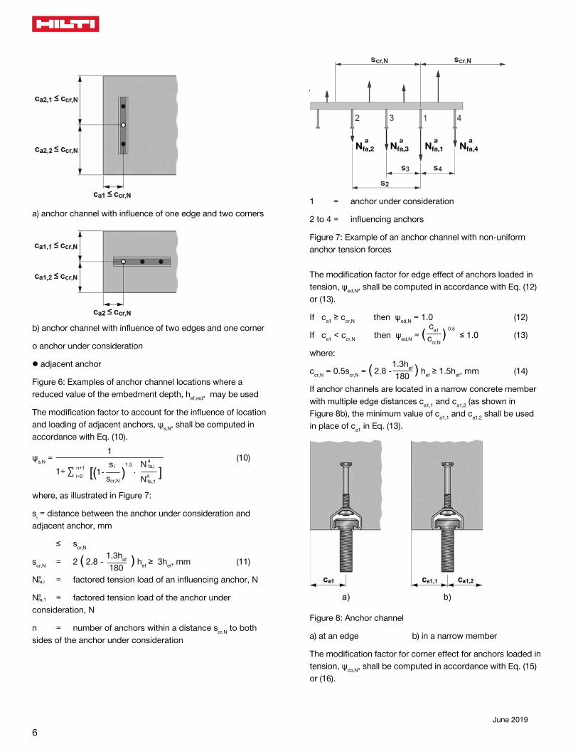
Where anchor channels with hef > 180 mm are located in an application with three or more edges (see Figure 6) with edge distances less than ccr,N (ccr,N in accordance with Eq. (14)) from the anchor under consideration, the values of hef used in Eq. (7), (8), and (11) may be reduced to hef,red in accordance with Eq. (9).
hef,red = max ( es ca,maxccr,N
· hef ; es s
scr,N· hef ), mm (9)
where: ca,max = maximum value of edge or corner distance, mm
The values ccr,N and scr,N in Eq. (9) shall be computed with hef.
6June 2019
a) anchor channel with influence of one edge and two corners
b) anchor channel with influence of two edges and one corner
о anchor under consideration
▯ adjacent anchor
Figure 6: Examples of anchor channel locations where a reduced value of the embedment depth, hef,red, may be used
The modification factor to account for the influence of location and loading of adjacent anchors, ψs,N, shall be computed in accordance with Eq. (10).
ψs,N = 1
(10)
[(1-
s i )
1.5 ·
scr,N
aN fa,i ]Na fa,1
1+ ∑ n+1
i=2
where, as illustrated in Figure 7:
si = distance between the anchor under consideration and adjacent anchor, mm
≤ scr,N
scr,N = 2 ( 2.8 - es 1.3hef
180 ) hef ≥ 3hef, mm (11)
Nafa,i = factored tension load of an influencing anchor, N
Nafa,1 = factored tension load of the anchor under
consideration, N
n = number of anchors within a distance scr,N to both sides of the anchor under consideration
\
aNfa,2
aNfa,3
aNfa,1
aNfa,4
1 = anchor under consideration
2 to 4 = influencing anchors
Figure 7: Example of an anchor channel with non-uniform anchor tension forces
The modification factor for edge effect of anchors loaded in tension, ψed,N, shall be computed in accordance with Eq. (12) or (13).
If ca1 ≥ ccr,N then ψed,N = 1.0 (12)
If ca1 < ccr,N then ψed,N = ( es ca1
ccr,N) 0.5
≤ 1.0 (13)
where:
ccr,N = 0.5scr,N = ( 2.8 -es 1.3hef
180 ) hef ≥ 1.5hef, mm (14)
If anchor channels are located in a narrow concrete member with multiple edge distances ca1,1 and ca1,2 (as shown in Figure 8b), the minimum value of ca1,1 and ca1,2 shall be used in place of ca1 in Eq. (13).
Figure 8: Anchor channel
a) at an edge b) in a narrow member
The modification factor for corner effect for anchors loaded in tension, ψco,N, shall be computed in accordance with Eq. (15) or (16).

7
Canadian Design Guide
June 2019
If ca2 ≥ ccr,N then ψco,N = 1.0 (15)
If ca2 < ccr,N then ψco,N = ( es ca2
ccr,N)0.5
≤ 1.0 (16)
where:
ca2 = distance of the anchor under consideration to the corner (see Figure 9a, b)
If an anchor is influenced by two corners (see Figure 9c), the factor ψco,N shall be computed for each of the values ca2,1 and ca2,2 and the product of the factors, ψco,N, shall be inserted in Eq. (6).
Figure 9: Anchor channel at a corner of a concrete member
For anchor channels located in a region of a concrete member where analysis indicates no cracking at service load levels, the following modification factor shall be permitted
ψc,N = 1.25
Where analysis indicates cracking at service load levels ψc,N shall be taken as 1.0. The cracking in the concrete shall be controlled by flexural reinforcement distributed in accordance with CSA A23.3-14 Section 10.6 or equivalent crack control shall be provided by confining reinforcement.
Nfa
a) at an edge
Nfa
b) in a narrow member
Figure 10: Arrangement of anchor reinforcement for anchor channels loaded by tension load
8June 2019
The modification factor for anchor channels designed for uncracked concrete without supplementary reinforcement to control splitting, ψcp,N, shall be computed in accordance with Eq. (17) or (18). The critical edge distance, cac, shall be taken from Table 4 of this document.
If ca,min ≥ cac then ψcp,N = 1.0 (17)
If ca,min < cac then ψcp,N = ( es ca,min
cac
) (18)
Whereby ψcp,N as determined in accordance with Eq. (18) shall not be taken less than ccr,N / cac, with ccr,N taken from Eq. (14).
For all other cases, ψcp,N shall be taken as 1.0.
Where anchor reinforcement is developed in accordance with CSA A23.3-14 Chapter 7 on both sides of the breakout surface for an anchor of an anchor channel, the design resistance of the anchor reinforcement, Ncar, shall be permitted to be used instead of the concrete breakout resistance, Ncbr, in determining Nr. The anchor reinforcement for one anchor shall be designed for the tension force,
a
Nfa, on this anchor using a strut-and-tie model. The provisions in Figure 10 shall be taken into account when sizing and detailing the anchor reinforcement. Anchor reinforcement shall consist of stirrups made from deformed reinforcing bars with a maximum diameter of 16 mm (No. 5 bar). A resistance modification factor, R, of 1.15 shall be used in the design of the anchor reinforcement.
For anchor channels located parallel to the edge of a concrete member or in a narrow concrete member, the plane of the anchor reinforcement shall be arranged perpendicular to the longitudinal axis of the channel, as shown in Figure 10.
3.3 Factored pullout resistance in tension
For anchors of anchor channels, the factored pullout resistance Npnr shall be computed in accordance with D.6.3.1, D.6.3.4, and D.6.3.6 of CSA A23.3-14.
3.4 Factored concrete side-face blowout resistance of anchor channels in tension
For anchor channels with deep embedment close to an edge (hef > 2ca1) the factored side-face blowout resistance, Nsbr, of a single anchor shall be computed in accordance with Eq. (19).
Nsbr =
0
Nsbr · ψs,Nb · ψg,Nb · ψco,Nb · ψh,Nb · ψc,Nb, N (19)
The basic factored resistance of a single anchor without influence of neighboring anchors, corner or member thickness effects in cracked concrete, N0
sbr, shall be computed in accordance with Eq. (20).
N0sbr = 10.5 · Фc · ca1 · λ · Abrg · ƒ' c · R, N (20)
The modification factor accounting for the distance to and loading of neighboring anchors, ψs,Nb, shall be computed in accordance with Eq. (10), however scr,N shall be replaced by scr,Nb, which shall be computed in accordance with Eq. (21).
scr,Nb = 4ca1, mm (21)
The modification factor to account for influence of the bearing area of neighboring anchors, Ψg,Nb, shall be computed in accordance with Eq. (22) or Eq. (23).
If s ≥ 4ca1 then ψg,Nb = 1.0 (22)
If s < 4ca1 then ψg,Nb = n + (1 - n ) · es s
4ca1 ≥ 1.0 (23)
where:
n = number of tensioned anchors in a row parallel to the edge
The modification factor to account for influence of corner effects, ψco,Nb, shall be computed in accordance with Eq. (24).
ψco,Nb = ( es ca2
ccr,Nb)0.5
≤ 1.0 (24)
where:
ca2 = corner distance of the anchor, for which the resistance is computed, mm
ccr,Nb = 2ca1, mm (25)
If an anchor is influenced by two corners (ca2 < 2ca1), then the factor, ψco,Nb, shall be computed for ca2,1 and ca2,2 and the product of the factors shall be inserted in Eq. (19).
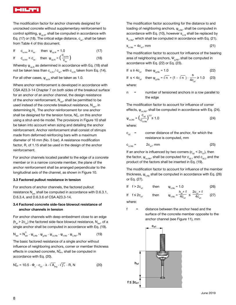
The modification factor to account for influence of the member thickness, ψh,Nb shall be computed in accordance with Eq. (26) or Eq. (27).
If f > 2ca1 then ψh,Nb = 1.0 (26)
If f ≤ 2ca1 then ψh,Nb = es hef+ f 4ca1
≤ 22es 22ca1+ f 4ca1
(27)
where:
f = distance between the anchor head and the surface of the concrete member opposite to the anchor channel (see Figure 11), mm
9
Canadian Design Guide
June 2019
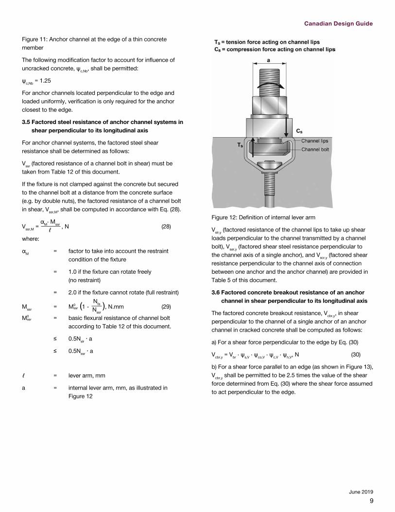
Figure 11: Anchor channel at the edge of a thin concrete member
The following modification factor to account for influence of uncracked concrete, ψc,Nb, shall be permitted:
ψc,Nb = 1.25
For anchor channels located perpendicular to the edge and loaded uniformly, verification is only required for the anchor closest to the edge.
3.5 Factored steel resistance of anchor channel systems in shear perpendicular to its longitudinal axis
For anchor channel systems, the factored steel shear resistance shall be determined as follows:
Vssr (factored resistance of a channel bolt in shear) must be taken from Table 12 of this document.
If the fixture is not clamped against the concrete but secured to the channel bolt at a distance from the concrete surface (e.g. by double nuts), the factored resistance of a channel bolt in shear, Vssr,M, shall be computed in accordance with Eq. (28).
Vssr,M = αM· Mssr
ℓ , N (28)
where:
αM = factor to take into account the restraint condition of the fixture
= 1.0 if the fixture can rotate freely (no restraint)
= 2.0 if the fixture cannot rotate (full restraint)
Mssr = M0ssr (1 -
es Nfa
Nssr), N.mm (29)
M0ssr = basic flexural resistance of channel bolt
according to Table 12 of this document.
≤ 0.5Nslr ∙ a
≤ 0.5Nssr ∙ a
ℓ = lever arm, mm
a = internal lever arm, mm, as illustrated in Figure 12
Figure 12: Definition of internal lever arm
Vslr,y (factored resistance of the channel lips to take up shear loads perpendicular to the channel transmitted by a channel bolt), Vsar,y (factored shear steel resistance perpendicular to the channel axis of a single anchor), and Vscr,y (factored shear resistance perpendicular to the channel axis of connection between one anchor and the anchor channel) are provided in Table 5 of this document.
3.6 Factored concrete breakout resistance of an anchor channel in shear perpendicular to its longitudinal axis
The factored concrete breakout resistance, Vcbr,y, in shear perpendicular to the channel of a single anchor of an anchor channel in cracked concrete shall be computed as follows:
a) For a shear force perpendicular to the edge by Eq. (30)
Vcbr,y = Vbr · ψs,V · ψco,V · ψc,V · ψh,V, N (30)
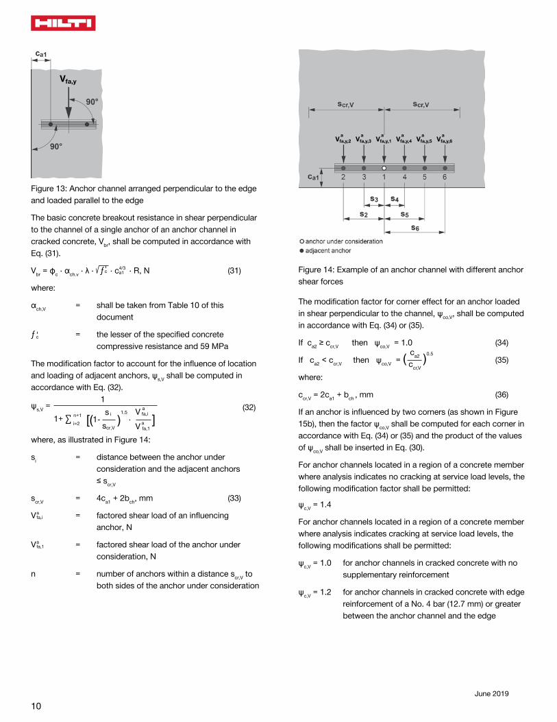
b) For a shear force parallel to an edge (as shown in Figure 13), Vcbr,y shall be permitted to be 2.5 times the value of the shear force determined from Eq. (30) where the shear force assumed to act perpendicular to the edge.
10June 2019
Figure 13: Anchor channel arranged perpendicular to the edge and loaded parallel to the edge
The basic concrete breakout resistance in shear perpendicular to the channel of a single anchor of an anchor channel in cracked concrete, Vbr, shall be computed in accordance with Eq. (31).
Vbr = фc · αch.v · λ · ƒ'c · c4/3a1 · R, N (31)
where:
αch,V = shall be taken from Table 10 of this document
ƒ 'c = the lesser of the specified concrete compressive resistance and 59 MPa
The modification factor to account for the influence of location and loading of adjacent anchors, ψs,V shall be computed in accordance with Eq. (32).
ψs,V = 1
[(1-
s i )
1.5 ·
scr,V
aV fa,i ]V a fa,1
1+ ∑ n+1
i=2
(32)
where, as illustrated in Figure 14:
si = distance between the anchor under consideration and the adjacent anchors ≤ scr,V
scr,V = 4ca1 + 2bch, mm (33)
V afa,i = factored shear load of an influencing anchor, N
V afa,1 = factored shear load of the anchor under consideration, N
n = number of anchors within a distance scr,V to both sides of the anchor under consideration
Figure 14: Example of an anchor channel with different anchor shear forces
The modification factor for corner effect for an anchor loaded in shear perpendicular to the channel, ψco,V, shall be computed in accordance with Eq. (34) or (35).
If ca2 ≥ ccr,V then ψco,V = 1.0 (34)
If ca2 < ccr,V then ψco,V = ( es ca2
ccr,V)0.5
(35)
where:
ccr,V = 2ca1 + bch , mm (36)
If an anchor is influenced by two corners (as shown in Figure 15b), then the factor ψco,V shall be computed for each corner in accordance with Eq. (34) or (35) and the product of the values of ψco,V shall be inserted in Eq. (30).
For anchor channels located in a region of a concrete member where analysis indicates no cracking at service load levels, the following modification factor shall be permitted:
ψc,V = 1.4
For anchor channels located in a region of a concrete member where analysis indicates cracking at service load levels, the following modifications shall be permitted:
ψc,V = 1.0 for anchor channels in cracked concrete with no supplementary reinforcement
ψc,V = 1.2 for anchor channels in cracked concrete with edge reinforcement of a No. 4 bar (12.7 mm) or greater between the anchor channel and the edge
11
Canadian Design Guide
June 2019
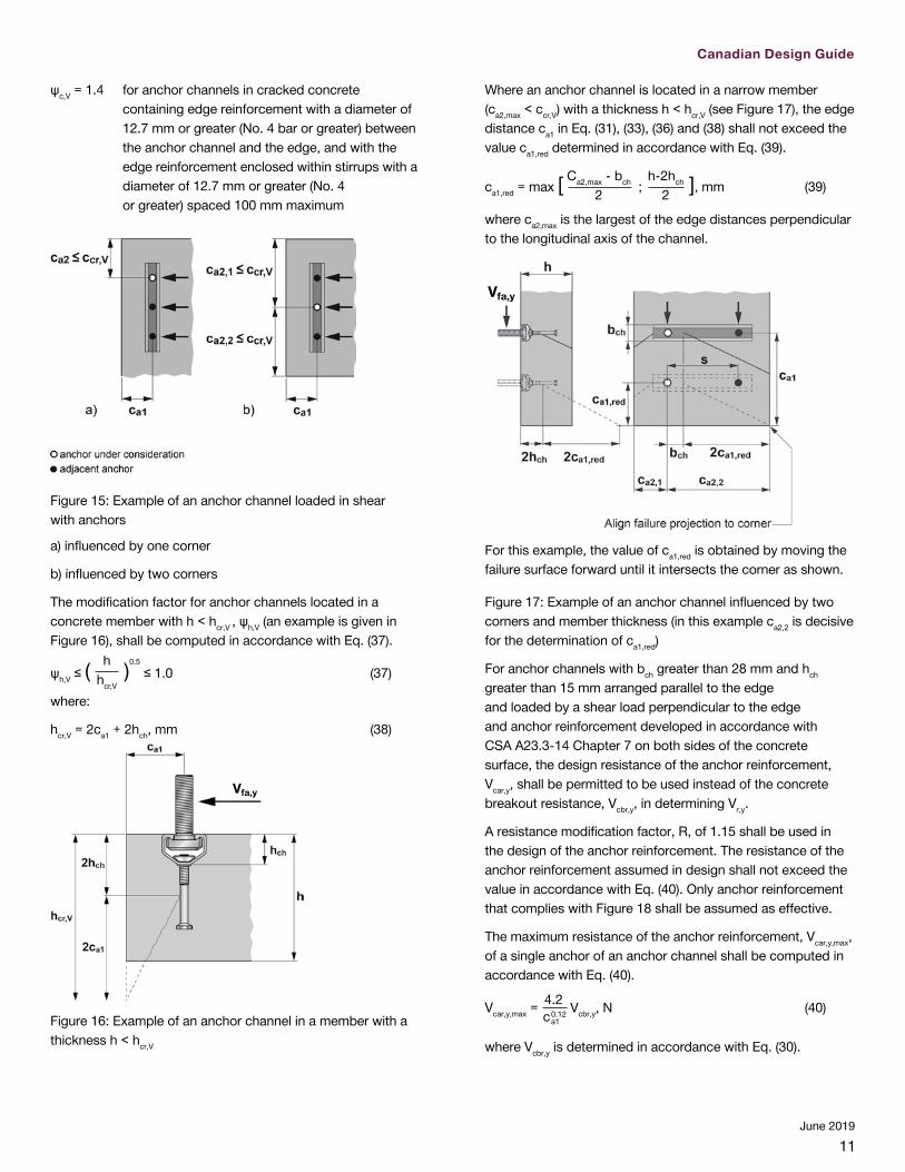
ψc,V = 1.4 for anchor channels in cracked concrete containing edge reinforcement with a diameter of 12.7 mm or greater (No. 4 bar or greater) between the anchor channel and the edge, and with the edge reinforcement enclosed within stirrups with a diameter of 12.7 mm or greater (No. 4 or greater) spaced 100 mm maximum
Figure 15: Example of an anchor channel loaded in shear with anchors
a) influenced by one corner
b) influenced by two corners
The modification factor for anchor channels located in a concrete member with h < hcr,V , ψh,V (an example is given in Figure 16), shall be computed in accordance with Eq. (37).
ψh,V ≤ ( es hhcr,V
)0.5 ≤ 1.0 (37)
where:
hcr,V = 2ca1 + 2hch, mm (38)
Figure 16: Example of an anchor channel in a member with a thickness h < hcr,V
Where an anchor channel is located in a narrow member (ca2,max < ccr,V) with a thickness h < hcr,V (see Figure 17), the edge distance ca1 in Eq. (31), (33), (36) and (38) shall not exceed the value ca1,red determined in accordance with Eq. (39).
ca1,red = max [ es Ca2,max - bch
2 ; es h-2hch
2 ], mm (39)
where ca2,max is the largest of the edge distances perpendicular to the longitudinal axis of the channel.
For this example, the value of ca1,red is obtained by moving the failure surface forward until it intersects the corner as shown.
Figure 17: Example of an anchor channel influenced by two corners and member thickness (in this example ca2,2 is decisive for the determination of ca1,red)
For anchor channels with bch greater than 28 mm and hch greater than 15 mm arranged parallel to the edge and loaded by a shear load perpendicular to the edge and anchor reinforcement developed in accordance with CSA A23.3-14 Chapter 7 on both sides of the concrete surface, the design resistance of the anchor reinforcement, Vcar,y, shall be permitted to be used instead of the concrete breakout resistance, Vcbr,y, in determining Vr,y.
A resistance modification factor, R, of 1.15 shall be used in the design of the anchor reinforcement. The resistance of the anchor reinforcement assumed in design shall not exceed the value in accordance with Eq. (40). Only anchor reinforcement that complies with Figure 18 shall be assumed as effective.
The maximum resistance of the anchor reinforcement, Vcar,y,max, of a single anchor of an anchor channel shall be computed in accordance with Eq. (40).
Vcar,y,max = es4.2 0.12
c a1
Vcbr,y, N (40)
where Vcbr,y is determined in accordance with Eq. (30).

12June 2019
Anchor reinforcement shall consist of stirrups made from deformed reinforcing steel bars with a maximum diameter of 15.9 mm (No. 5 bar) and straight edge reinforcement with a diameter not smaller than the diameter of the stirrups (as shown in Figure 18). Only one bar at both sides of each anchor shall be assumed as effective. The distance of this bar from the anchor shall not exceed 0.5 ca1 and the anchorage length in the breakout body shall be not less than 4 times the bar diameter. The distance between stirrups shall not exceed the smaller of anchor spacing or 152 mm.
The anchor reinforcement of an anchor channel shall be designed for the highest anchor load,
a
Vfa,y , of all anchors but
at least for the highest individual shear load,
b
Vfa,y, acting on the channel. This anchor reinforcement shall be arranged at all anchors of an anchor channel.
Figure 18: Requirements for detailing of anchor reinforcement of anchor channels
3.7 Factored concrete pryout resistance of anchor channels in shear perpendicular to the channel axis
The factored pryout resistance, Vcpr,y, in shear of a single anchor of an anchor channel without anchor reinforcement shall be computed in accordance with Eq. (41).
Vcpr = Vcpr,x = Vcpr,y = kcp · Ncbr, N (41)
where:
kcp = shall be taken from Table 10
Ncbr = factored concrete breakout resistance of the anchor under consideration, N, determined in accordance with Section 3.2; however in the determination of the modification factor ψs,N, the values N afa,1 and N afa,i in Eq. (10) shall be replaced by V afa,1 and V afa,i , respectively.
The factored pryout resistance, Vcpr,y, in shear of a single anchor of an anchor channel with anchor reinforcement shall not exceed:
Vcpr = Vcpr,x = Vcpr,y = 0.75 · kcp · Ncbr, N (42)
with kcp and Ncbr as defined above.
3.8 Factored steel resistance of anchor channel systems in shear in the direction of the longitudinal channel axis
Vssr (factored resistance of channel bolt in shear) must be taken from Table 12 of this document.
If the fixture is not clamped against the concrete but secured to the channel bolt at a distance from the concrete surface (e.g. by double nuts), the factored resistance of a channel bolt in shear, Vssr,M, shall be computed in accordance with Eq. (28).
Vslr,x (factored shear steel resistance in longitudinal channel axis of connection between channel bolt and channel lips) must be taken from Table 6, 7, 8, or Table 9, as applicable.
Vsar,x (factored shear steel resistance in longitudinal channel axis of a single anchor) is provided in Table 5.
Vscr,x (factored shear resistance in longitudinal channel axis of connection between one anchor and the anchor channel) is provided in Table 5.
3.9 Factored concrete breakout resistance of anchor channels in shear in the direction of the longitudinal channel axis
The factored concrete breakout resistance, Vcbr,x, in shear acting in longitudinal direction of an anchor channel in cracked concrete shall be computed as follows:
a) For a shear force perpendicular to the edge, by Eq. (D-32) in CSA A23.3-14 Section D.7.2.1. The basic concrete breakout resistance in shear in longitudinal channel axis of a single round anchor in an anchor channel in cracked concrete, Vbr, shall be computed in accordance with Section D.7.2.2 (CSA A23.3-14).
b) For a shear force parallel to an edge, Vcbr,x shall be permitted to be twice the value of the shear force determined from Eq. (D-32), D.7.2.1 (CSA A23.3-14) where the shear force assumed to act perpendicular to the edge.
3.10 Factored concrete pryout resistance for anchor channels in shear in the direction of the longitudinal channel axis
The factored pryout resistance, Vcpr,x, in shear of a single anchor of an anchor channel without anchor reinforcement shall be computed in accordance with Eq. (41).
The factored pryout resistance, Vcpr,x, in shear of a single anchor of an anchor channel with anchor reinforcement shall not exceed Eq. (42).

13
Canadian Design Guide
June 2019
3.11 Interaction of tensile and shear forces
If forces act in more than one direction the combination of loads has to be verified.
Anchor channel systems subjected to combined tensile and shear loads shall be designed to satisfy the following requirements by distinguishing between steel failure of the channel bolt, steel failure modes of the channel and concrete failure modes.
3.11.1 Steel failure of channel bolts under combined loads
For channel bolts, Eq. (43) shall be satisfied.
( N bfaNssr
)2
+ ( V bfaVssr
)2
≤ 1.0 (43)
where:
V bfa = [ (V bfa,y )2
+ (V bfa,x )2 ]
0.5
This verification is not required in case of shear load with lever arm as Eq. (28) accounts for the interaction.
3.11.2 Steel failure modes of anchor channel systems under combined loads
For steel failure modes of anchor channels Eq. (44), Eq. (45) and Eq. (46) shall be satisfied.
max( N afaNsar
; N afaNscr
)α
+max( V afa,y
Vsar,y ; V afa,y
Vscr,y )
α*+max( V afa,x
Vsar,x; V afa,x
Vscr,x)2
≤1.0 (44)
where:
α = 2 for anchor channels with max (Vsar,y; Vscr,y) ≤ min (Nsar; Nscr )
α = 1 for anchor channels with max (Vsar,y; Vscr,y) > min (Nsar; Nscr )
It shall be permitted to assume reduced values for Vsar,y and Vscr,y corresponding to the use of an exponent α = 2. In this case the reduced values for Vsar,y and Vscr,y shall also be used in Section 3.5).
b) At the point of load application:
( N bfaNslr
)α
+ ( V bfa,y
Vslr,y )
α
+ ( V bfa,x
Vslr,x )
2
≤1.0
(45)
( Mf,flexMs,flexr
)α
+ ( V bfa,y
Vslr,y
)α
+ ( V bfa,x
Vslr,x
)2
≤1.0
(46)
where:
α = 2 for anchor channels with Vslr,y ≤ Nslr,i
α = 1 for anchor channels with Vslr,y > Nslr,i
It shall be permitted to assume reduced values for Vslr,y corresponding to the use of an exponent α = 2. (In this case the reduced value for Vslr,y shall also be used in Section 3.5).
3.11.3 Concrete failure modes of anchor channels under combined loads
For concrete failure modes, anchor channels shall be designed to satisfy the requirements given in a) through d).
a) If ( V afa,y
Vrc,y ) + ( V afa,x
Vrc,x ) ≤ 0.2
then the full strength in tension shall be permitted:
N rc ≥ N afa
b) If N afa ≤ 0.2 N rc
then the full strength in shear shall be permitted:
( V afa,y
Vrc,y ) + ( V afa,x
Vrc,x ) ≤ 1.0
c) If ( V afa,y
Vrc,y ) + ( V afa,x
Vrc,x ) > 0.2 and N afa > 0.2 N rc
Then Eq. (47) applies
( N afaN rc ) + ( V afa,y
Vrc,y ) + ( V afa,x
Vrc,x ) ≤ 1.2 (47)
d) Alternatively, instead of satisfying the requirements in a) through c), the interaction Eq. (48) shall be satisfied:
( N afaN rc )5/3
+ ( V afa,y
Vrc,y )5/3
+ ( V afa,x
Vrc,x )5/3
≤ 1.0 (48)
4.0 Notations
Equations are provided in SI (metric) units.
bch width of channel (see Figure 19), mm
ca edge distance of anchor channel, measured from edge of concrete member to axis of the nearest anchor (see Figure 5), mm
ca1 edge distance of anchor channel in direction 1 (see Figure 5), mm
c'a1 net distance between edge of the concrete member and the anchor channel: c’a1 = ca1 – bch / 2, mm
ca1,red reduced edge distance of the anchor channel, as referenced in Eq. (39)
ca2 edge distance of anchor channel in direction 2 (see Figure 9), mm
ca,max maximum edge distance of anchor channel, mm
ca,min minimum edge distance of anchor channel, mm
cac edge distance required to develop full concrete capacity in absence of reinforcement to control splitting, mm
ccr edge distance required to develop full concrete capacity in absence of anchor reinforcement, mm
14June 2019
ccr,N critical edge distance for anchor channel for tension loading for concrete breakout, mm
ccr,Nb critical edge distance for anchor channel for tension loading, concrete blowout, mm
ccr,V critical edge distance for anchor channel for shear loading, concrete edge breakout, mm
d1 diameter of head of round anchor (see Figure 19), mm
d2 shaft diameter of round anchor (see Figure 19), mm
df diameter of hole in the fixture, mm
da diameter of anchor reinforcement, mm
ds diameter of channel bolt, mm
e1 distance between shear load and concrete surface, mm
es distance between the axis of the shear load and the axis of the anchor reinforcement resisting the shear load, mm
f distance between anchor head and surface of the concrete, mm
f'c specified compressive strength of concrete, MPa
Фc Material resistance factor for concrete
Фs Material resistance factor for steel component
futa specified ultimate tensile strength of anchor, MPa
futc specified ultimate tensile strength channel, MPa
futb specified ultimate tensile strength of channel bolt, MPa
fy specified yield tensile strength of steel, MPa
fya specified yield strength of anchor, MPa
fyc specified yield strength of channel, MPa
fys specified yield strength of channel bolt, MPa
h thickness of concrete member or test member (see Figure 19), mm
hch height of channel (see Figure 19), mm
hcr,V critical member thickness, mm
hef effective embedment depth (see Figure 19), mm
hef,min minimum effective embedment depth, mm
hef,red reduced effective embedment depth, as referenced in Eq. (9), mm
hnom nominal embedment depth (see Figure 19), mm
k load distribution factor, as referenced in Eq. (1)
kcp pryout factor
ℓA nominal embedment depth, minus channel height (see Figure 19), mm
ℓ lever arm of the shear force acting on the channel bolt, mm
ℓdh development length in tension of deformed bar or deformed wire with a standard hook, measured from critical section to outside end of hook, mm
ℓin influence length of an external load Nfa along an anchor channel, mm
s spacing of anchors in direction of longitudinal axis of channel, mm
schb center-to-center distance between channel bolts in direction of longitudinal axis of channel, mm
scr anchor spacing required to develop full concrete capacity in absence of anchor reinforcement, mm
scr,N critical anchor spacing for tension loading, concrete breakout, mm
smax maximum spacing between anchor elements in anchor channels, mm
smin minimum spacing between anchor elements in anchor channels, mm
scr,Nb critical anchor spacing for tension loading, concrete blowout, mm
scr,V critical anchor spacing for shear loading, concrete edge breakout, mm
th thickness of head portion of headed anchor (see Figure 19), mm
x distance between end of channel and nearest anchor, mm
z internal lever arm of the concrete member, mm
Abrg bearing area of anchor head, mm2
Ai ordinate at the position of the anchor i, as illustrated in Figure 2, mm
Ase,N effective cross-sectional area of anchor or channel bolt in tension, mm²
Ase,V effective cross-sectional area of channel bolt in shear, mm²
Iy moment of inertia of the channel about principal y-axis, mm4
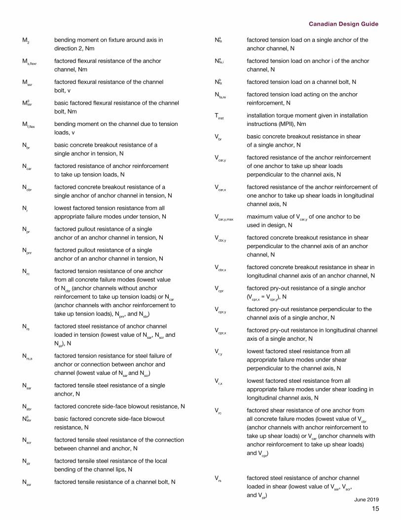
M1 bending moment on fixture around axis in direction 1, Nm
15
Canadian Design Guide
June 2019
M2 bending moment on fixture around axis in direction 2, Nm
Ms,flexr factored flexural resistance of the anchor channel, Nm
Mssr factored flexural resistance of the channel bolt, v
M0ssr basic factored flexural resistance of the channel
bolt, Nm
Mf,flex bending moment on the channel due to tension loads, v
Nbr basic concrete breakout resistance of a single anchor in tension, N
Ncar factored resistance of anchor reinforcement to take up tension loads, N
Ncbr factored concrete breakout resistance of a single anchor of anchor channel in tension, N
Nr lowest factored tension resistance from all appropriate failure modes under tension, N
Npr factored pullout resistance of a single anchor of an anchor channel in tension, N
Npnr factored pullout resistance of a single anchor of an anchor channel in tension, N
Nrc factored tension resistance of one anchor from all concrete failure modes (lowest value of Ncbr (anchor channels without anchor reinforcement to take up tension loads) or Ncar (anchor channels with anchor reinforcement to take up tension loads), Npnr, and Nsbr)
Nrs factored steel resistance of anchor channel loaded in tension (lowest value of Nsar, Nscr and Nslr), N
Nrs,a factored tension resistance for steel failure of anchor or connection between anchor and channel (lowest value of Nsar and Nscr)
Nsar factored tensile steel resistance of a single anchor, N
Nsbr factored concrete side-face blowout resistance, N
N0sbr basic factored concrete side-face blowout
resistance, N
Nscr factored tensile steel resistance of the connection between channel and anchor, N
Nslr factored tensile steel resistance of the local bending of the channel lips, N
Nssr factored tensile resistance of a channel bolt, N
Nafa factored tension load on a single anchor of the
anchor channel, N
Nafa,i factored tension load on anchor i of the anchor
channel, N
Nbfa factored tension load on a channel bolt, N
Nfa,re factored tension load acting on the anchor reinforcement, N
Tinst installation torque moment given in installation instructions (MPII), Nm
Vbr basic concrete breakout resistance in shear of a single anchor, N
Vcar,y factored resistance of the anchor reinforcement of one anchor to take up shear loads perpendicular to the channel axis, N
Vcar,x factored resistance of the anchor reinforcement of one anchor to take up shear loads in longitudinal channel axis, N
Vcar,y,max maximum value of Vcar,y of one anchor to be used in design, N
Vcbr,y factored concrete breakout resistance in shear perpendicular to the channel axis of an anchor channel, N
Vcbr,x factored concrete breakout resistance in shear in longitudinal channel axis of an anchor channel, N
Vcpr factored pry-out resistance of a single anchor (Vcpr,x = Vcpr,y), N
Vcpr,y factored pry-out resistance perpendicular to the channel axis of a single anchor, N
Vcpr,x factored pry-out resistance in longitudinal channel axis of a single anchor, N
Vr,y lowest factored steel resistance from all appropriate failure modes under shear perpendicular to the channel axis, N
Vr,x lowest factored steel resistance from all appropriate failure modes under shear loading in longitudinal channel axis, N
Vrc factored shear resistance of one anchor from all concrete failure modes (lowest value of Vcbr (anchor channels with anchor reinforcement to take up shear loads) or Vcar (anchor channels with anchor reinforcement to take up shear loads) and Vcpr)
Vrs factored steel resistance of anchor channel loaded in shear (lowest value of Vsar, Vscr, and Vslr)

16June 2019
Vrs,a factored shear resistance for steel failure of anchor or connection between anchor and channel (lowest value of Vsar and Vscr)
Vsar,y factored shear steel resistance perpendicular to the channel axis of a single anchor, N
Vsar,x factored shear steel resistance in longitudinal channel axis of a single anchor, N
Vsar,y,seis factored seismic shear steel resistance perpendicular to the channel axis of a single anchor, N
Vsar,x,seis factored seismic shear steel resistance in longitudinal channel axis of a single anchor, N
Vscr,y factored shear resistance perpendicular to the channel axis of connection between one anchor and the anchor channel, N
Vscr,x factored shear resistance in longitudinal channel axis of connection between one anchor and the anchor channel, N
Vscr,y,seis factored seismic shear resistance perpendicular to the channel axis of connection between one anchor bolt and the anchor channel, N
Vscr,x,seis factored seismic shear resistance in longitudinal channel axis of connection between one anchor bolt and the anchor channel, N
Vslr,y factored shear steel resistance perpendicular to the channel axis of the local bending of the channel lips, N
Vslr,x factored shear steel resistance in longitudinal channel axis of connection between channel bolt and channel lips, N
Vslr,y,seis factored seismic shear steel resistance perpendicular to the channel axis of the local bending of the channel lips, N
Vslr,x,seis factored seismic shear steel resistance in longitudinal channel axis of connection between channel bolt and channel lips, N
Vssr factored resistance of channel bolt in shear, N
Vssr,M factored resistance of channel bolt in case of shear with lever arm, N
Vfa factored shear load on anchor channel, N
Vfa,x factored shear load on anchor channel in longitudinal channel axis, N
Vfa,y factored shear load on anchor channel perpendicular to the channel axis, N
V afa factored shear load on a single anchor of the
anchor channel, N
V afa,x factored shear load on a single anchor of the anchor channel in longitudinal channel axis, N
V afa,y factored shear load on a single anchor of the anchor channel perpendicular to the channel axis, N
V afa,i factored shear load on anchor i of the anchor channel, N
V afa,x,i factored shear load on anchor i of the anchor channel in longitudinal channel axis, N
V afa,y,i factored shear load on anchor i of the anchor channel perpendicular to the channel axis, N
V bfa factored shear load on a channel bolt, N
V bfa,x factored shear load on a channel bolt in longitudinal channel axis, N
V bfa,y factored shear load on a channel bolt perpendicular to the channel axis, N
α exponent of interaction equation (see Section 3.11)
αch,N factor to account for the influence of channel size on concrete breakout resistance in tension
αM factor to account for the influence of restraint of fixture on the flexural resistance of the channel bolt
αch,V factor to account for the influence of channel size and anchor diameter on concrete edge breakout resistance in shear N1/2/mm1/3
λ modification factor for lightweight concrete (λ = 1 for normal weight concrete)
ψc,N modification factor to account for influence of cracked or uncracked concrete on concrete breakout resistance
ψc,Nb modification factor to account for influence of cracked or uncracked concrete on concrete blowout resistance
ψc,V modification factor to account for influence of cracked or uncracked concrete for concrete edge breakout resistance
ψco,N modification factor for corner effects on concrete breakout resistance for anchors loaded in tension
ψco,Nb modification factor for corner effects on concrete blowout resistance for anchors loaded in tension
ψco,V modification factor for corner effects on concrete edge breakout resistance for anchor channels
17
Canadian Design Guide
June 2019
loaded in shear
ψcp,N modification factor for anchor channels to control splitting
ψed,N modification factor for edge effect on concrete breakout resistance for anchors loaded in tension
ψg,Nb modification factor to account for influence of bearing area of neighboring anchors on concrete blowout resistance for anchors loaded in tension
ψh,Nb modification factor to account for influence of member thickness on concrete blowout resistance for anchors loaded in tension
ψh,V modification factor to account for influence of member thickness on concrete edge breakout resistance for anchors channels loaded in shear
ψs,N modification factor to account for influence of location and loading of neighboring anchors on concrete breakout resistance for anchor channels loaded in tension
ψs,Nb modification factor to account for influence of location and loading of neighboring anchors on concrete blowout resistance for anchor channels loaded in tension
ψs,V modification factor to account for influence of location and loading of neighboring anchors on concrete edge breakout resistance for anchor channels loaded in shear
18June 2019
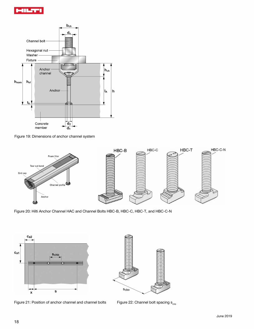
Figure 19: Dimensions of anchor channel system
Figure 20: Hilti Anchor Channel HAC and Channel Bolts HBC-B, HBC-C, HBC-T, and HBC-C-N
Figure 21: Position of anchor channel and channel bolts Figure 22: Channel bolt spacing schb
19
Canadian Design Guide
June 2019
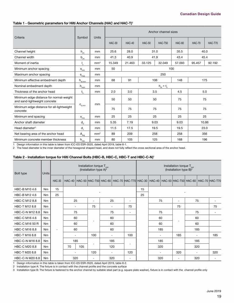
Table 1 - Geometric parameters for Hilti Anchor Channels (HAC and HAC-T)1
Criteria Symbol Units
Anchor channel sizes
HAC-30 HAC-40 HAC-50 HAC-T50 HAC-60 HAC-70 HAC-T70
Channel height hch mm 25.6 28.0 31.0 35.5 40.0
Channel width bch mm 41.3 40.9 41.9 43.4 45.4
Moment of inertia Iy mm4 15.349 21.463 33.125 32.049 57.093 95.457 92.192
Minimum anchor spacing smin mm 50 100
Maximum anchor spacing smax mm 250
Minimum effective embedment depth hef,min mm 68 91 106 148 175
Nominal embedment depth hnom mm hef + th
Thickness of the anchor head th mm 2.0 3.0 3.5 4.5 5.0
Minimum edge distance for normal-weight and sand-lightweight concrete
ca,min mm50 50 50 75 75
Minimum edge distance for all-lightweight concrete 75 75 75 75 75
Minimum end spacing xmin mm 25 25 25 25 25
Anchor shaft diameter d2 mm 5.35 7.19 9.03 9.03 10.86
Head diameter2 d1 mm 11.5 17.5 19.5 19.5 23.0
Net bearing area of the anchor head Abrg mm2 89 209 258 258 356
Minimum concrete member thickness hmin mm 80 105 125 168 1961 Design information in this table is taken from ICC-ES ESR-3520, dated April 2019, table 8-1.2 The head diameter is the inner diameter of the hexagonal shaped head, and does not fully reflect the cross sectional area of the anchor head.
Table 2 - Installation torque for Hilti Channel Bolts (HBC-B, HBC-C, HBC-T and HBC-C-N)1
Bolt type Units
Installation torque Tinst (Installation type A)2
Installation torque Tinst (Installation type B)3
HAC-30 HAC-40 HAC-50 HAC-T50 HAC-60 HAC-70 HAC-T70 HAC-30 HAC-40 HAC-50 HAC-T50 HAC-60 HAC-70 HAC-T70
HBC-B M10 4.6 Nm 15-
15-
HBC-B M12 4.6 Nm 25 25
HBC-C M12 8.8 Nm
-
25 - 25 - 75 - 75 -
HBC-T M12 8.8 Nm - 75 - 75 75 75
HBC-C-N M12 8.8 Nm 75
-
75 - 75
-
75 -
HBC-C M16 4.6 Nm 60 60 60 60
HBC-C M16 50 R Nm 60 60 60 60
HBC-C M16 8.8 Nm 60 60 185 185
HBC-T M16 8.8 Nm - 100 - 100 - 185 - 185
HBC-C-N M16 8.8 Nm 185-
185-
185 185
HBC-C M20 8.8 Nm 70 105 120 320 320
HBC-T M20 8.8 Nm - 120 - 120 - 320 - 320
HBC-C-N M20 8.8 Nm 320 - 320 - 320 - 320 -1 Design information in this table is taken from ICC-ES ESR-3520, dated April 2019, table 8-2.2 Installation type A: The fixture is in contact with the channel profile and the concrete surface3 Installation type B: The fixture is fastened to the anchor channel by suitable steel part (e.g. square plate washer), fixture is in contact with the channel profile only

20June 2019
Table 3 - Tension steel strength design information for Hilti Anchor Channels (HAC and HAC-T) with Hilti Channel Bolts (HBC-B, HBC-C, HBC-T and HBC-C-N)1
Criteria Symbol Units
Anchor channel sizes
HAC-30 HAC-40 HAC-50 HAC-T50 HAC-60 HAC-70 HAC-T70
Factored tensile steel resistance for local failure of channel lips Nslr kN 11.9 17.0 23.8 34.0 48.3
Factored tensile steel resistance for local failure of channel lips for seismic design Nslr,seis kN 11.9 17.0 23.8 23.8 48.3
Material resistance factor for local failure of channel lips Фs - 0.85
Resistance modification factor for tension. local failure of channel lips R - 0.8
Factored tensile steel resistance of a single anchor Nsar kN 11.8 18.7 34.0 34.0 49.4
Factored tensile steel resistance of a single anchor for seismic design Nsar,seis kN 11.8 18.7 34.0 34.0 49.4
Material resistance factor for anchor failure Фs - 0.85
Resistance modification factor for tension. anchor failure R - 0.8 0.70 0.80
Factored tensile steel resistance of connection between anchor and channel Nscr kN 11.9 17.0 23.8 34.0 48.3
Factored tensile steel resistance of connection between anchor and channel
for seismic designNscr,seis kN 11.9 17.0 23.8 23.8 48.3
Material resistance factor for failure of connection between anchor and channel Фs - 0.85
Resistance modification factor for tension. failure of connection between
anchor and channelR - 0.8
Factored bending resistance of the anchor channel with HBC-B
Ms,flexr Nm
515 - - - - - -
Factored bending resistance of the anchor channel with HBC-C - 869 1,221 - 1,673 2,420 -
Factored bending resistance of the anchor channel with HBC-T - - - 1,221 - - 2,276
Factored bending resistance of the anchor channel with HBC-C-N - 750 1,029 - 1,649 2,299 -
Factored bending resistance of the anchor channel for seismic design with
HBC-B
Ms,flexr,seis Nm
515 - - - - - -
Factored bending resistance of the anchor channel for seismic design with
HBC-C- 869 1,221 - 1,221 2,420 -
Factored bending resistance of the anchor channel for seismic design with
HBC-T- - - 1,221 - - 2,276
Factored bending resistance of the anchor channel for seismic design with
HBC-C-N- 750 1,029 - 1,029 2,299 -
Material resistance factor for bending failure Фs - 0.85
Resistance modification factor for tension. bending failure R - 0.90
1 Design information in this table is taken from ICC-ES ESR-3520, dated April 2019, table 8-3, and converted for use with CSA A23.3-14.

21
Canadian Design Guide
June 2019
Table 4 - Tension concrete strength design information for Hilti Anchor Channels (HAC and HAC-T)1
Criteria Symbol Units
Anchor channel sizes
HAC-30 HAC-40 HAC-50 HAC-T50 HAC-60 HAC-70
HAC-T70
Edge distance required to develop full concrete capacity in absence of anchor
reinforcementcac mm 204 273 318 444 525
Material resistance factor for tension, concrete failure modes Фc - 0.65
Resistance modification factor for tension. concrete failure modes.
Condition B2R - 1.00
1 Design information in this table is taken from ICC-ES ESR-3520, dated April 2019, table 8-4.2 For use with the load combinations of CSA A23.3-14 Annex C or CSA A23.3-04 Annex C, as applicable. Condition B applies where supplementary
reinforcement in conformance with CSA A23.3-14 D.5.3(c) or CSA A23.3-04 D.5.4(c), as applicable, is not provided. For installations where complying supplementary reinforcement can be verified, the strength reduction factors associated with Condition A may be used.
22June 2019
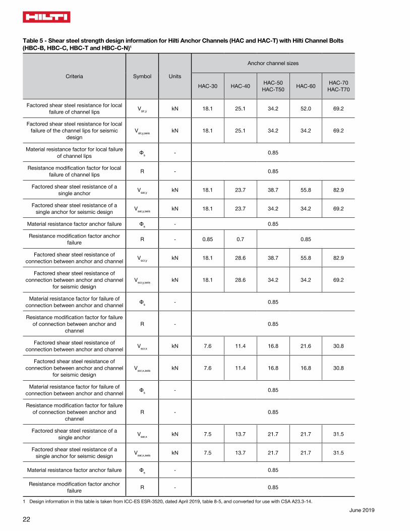
Table 5 - Shear steel strength design information for Hilti Anchor Channels (HAC and HAC-T) with Hilti Channel Bolts (HBC-B, HBC-C, HBC-T and HBC-C-N)1
Criteria Symbol Units
Anchor channel sizes
HAC-30 HAC-40 HAC-50HAC-T50 HAC-60 HAC-70
HAC-T70
Factored shear steel resistance for local failure of channel lips Vslr,y kN 18.1 25.1 34.2 52.0 69.2
Factored shear steel resistance for local failure of the channel lips for seismic
designVslr,y,seis kN 18.1 25.1 34.2 34.2 69.2
Material resistance factor for local failure of channel lips Фs - 0.85
Resistance modification factor for local failure of channel lips R - 0.85
Factored shear steel resistance of a single anchor Vsar,y kN 18.1 23.7 38.7 55.8 82.9
Factored shear steel resistance of a single anchor for seismic design Vsar,y,seis kN 18.1 23.7 34.2 34.2 69.2
Material resistance factor anchor failure Фs - 0.85
Resistance modification factor anchor failure R - 0.85 0.7 0.85
Factored shear steel resistance of connection between anchor and channel Vscr,y kN 18.1 28.6 38.7 55.8 82.9
Factored shear steel resistance of connection between anchor and channel
for seismic designVscr,y,seis kN 18.1 28.6 34.2 34.2 69.2
Material resistance factor for failure of connection between anchor and channel Фs - 0.85
Resistance modification factor for failure of connection between anchor and
channelR - 0.85
Factored shear steel resistance of connection between anchor and channel Vscr,x kN 7.6 11.4 16.8 21.6 30.8
Factored shear steel resistance of connection between anchor and channel
for seismic designVscr,x,seis kN 7.6 11.4 16.8 16.8 30.8
Material resistance factor for failure of connection between anchor and channel Фs - 0.85
Resistance modification factor for failure of connection between anchor and
channelR - 0.85
Factored shear steel resistance of a single anchor Vsar,x kN 7.5 13.7 21.7 21.7 31.5
Factored shear steel resistance of a single anchor for seismic design Vsar,x,seis kN 7.5 13.7 21.7 21.7 31.5
Material resistance factor anchor failure Фs - 0.85
Resistance modification factor anchor failure R - 0.85
1 Design information in this table is taken from ICC-ES ESR-3520, dated April 2019, table 8-5, and converted for use with CSA A23.3-14.
23
Canadian Design Guide
June 2019
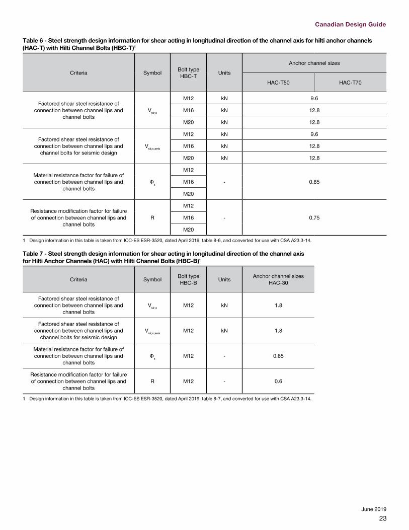
Table 6 - Steel strength design information for shear acting in longitudinal direction of the channel axis for hilti anchor channels (HAC-T) with Hilti Channel Bolts (HBC-T)1
Criteria Symbol Bolt type HBC-T Units
Anchor channel sizes
HAC-T50 HAC-T70
Factored shear steel resistance of connection between channel lips and
channel boltsVslr,x
M12 kN 9.6
M16 kN 12.8
M20 kN 12.8
Factored shear steel resistance of connection between channel lips and
channel bolts for seismic designVslr,x,seis
M12 kN 9.6
M16 kN 12.8
M20 kN 12.8
Material resistance factor for failure of connection between channel lips and
channel boltsФs
M12
- 0.85M16
M20
Resistance modification factor for failure of connection between channel lips and
channel boltsR
M12
- 0.75M16
M20
1 Design information in this table is taken from ICC-ES ESR-3520, dated April 2019, table 8-6, and converted for use with CSA A23.3-14.
Table 7 - Steel strength design information for shear acting in longitudinal direction of the channel axis for Hilti Anchor Channels (HAC) with Hilti Channel Bolts (HBC-B)1
Criteria Symbol Bolt type HBC-B Units Anchor channel sizes
HAC-30
Factored shear steel resistance of connection between channel lips and
channel boltsVslr,x M12 kN 1.8
Factored shear steel resistance of connection between channel lips and
channel bolts for seismic designVslr,x,seis M12 kN 1.8
Material resistance factor for failure of connection between channel lips and
channel bolts Фs M12 - 0.85
Resistance modification factor for failure of connection between channel lips and
channel boltsR M12 - 0.6
1 Design information in this table is taken from ICC-ES ESR-3520, dated April 2019, table 8-7, and converted for use with CSA A23.3-14.
24June 2019
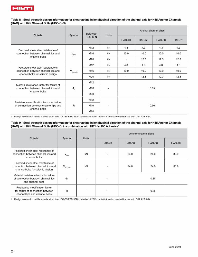
Table 9 - Steel strength design information for shear acting in longitudinal direction of the channel axis for Hilti Anchor Channels (HAC) with Hilti Channel Bolts (HBC-C) in combination with HIT HY-100 Adhesive1
Criteria Symbol Units
Anchor channel sizes
HAC-40 HAC-50 HAC-60 HAC-70
Factored shear steel resistance of connection between channel lips and
channel boltsVslr,x kN - 24.0 24.0 30.9
Factored shear steel resistance of connection between channel lips and
channel bolts for seismic designVslr,x,seis kN - 24.0 24.0 30.9
Material resistance factor for failure of connection between channel lips
and channel boltsФs - - 0.85
Resistance modification factor for failure of connection between
channel lips and channel boltsR - - 0.85
1 Design information in this table is taken from ICC-ES ESR-3520, dated April 2019, table 8-9, and converted for use with CSA A23.3-14.
Table 8 - Steel strength design information for shear acting in longitudinal direction of the channel axis for Hilti Anchor Channels (HAC) with Hilti Channel Bolts (HBC-C-N)1
Criteria Symbol Bolt type HBC-C-N Units
Anchor channel sizes
HAC-40 HAC-50 HAC-60 HAC-70
Factored shear steel resistance of connection between channel lips and
channel boltsVslr,x
M12 kN 4.3 4.3 4.3 4.3
M16 kN 10.0 10.0 10.0 10.0
M20 kN - 12.3 12.3 12.3
Factored shear steel resistance of connection between channel lips and
channel bolts for seismic designVslr,x,seis
M12 kN 4.3 4.3 4.3 4.3
M16 kN 10.0 10.0 10.0 10.0
M20 kN - 12.3 12.3 12.3
Material resistance factor for failure of connection between channel lips and
channel boltsФs
M12
- 0.85M16
M20
Resistance modification factor for failure of connection between channel lips and
channel boltsR
M12
- 0.60M16
M20
1 Design information in this table is taken from ICC-ES ESR-3520, dated April 2019, table 8-8, and converted for use with CSA A23.3-14.

25
Canadian Design Guide
June 2019
Table 10 - Shear concrete strength design information for Hilti Anchor Channels (HAC and HAC-T) with Hilti Channel Bolts (HBC-B, HBC-C, HBC-T and HBC-C-N)1
Criteria Symbol Units
Anchor channel sizes
HAC-30 HAC-40 HAC-50HAC-T50 HAC-60 HAC-70
HAC-T70
Factor to account for the influence of channel size and anchor diameter on concrete edge breakout resistance
in shear
αch.V (N1/2/mm1/3) 7.5
Coefficient for pryout resistance kcp - 2.0
Material resistance factor for shear concrete failure modes Фs - 0.65
Resistance modification factor for shear, concrete failure modes
Condition B2R - 1.00
1 Design information in this table is taken from ICC-ES ESR-3520, dated April 2019, table 8-10, and converted for use with CSA A23.3-14.2 For use with the load combinations of CSA A23.3-14 Annex C or CSA A23.3-04 Annex C, as applicable. Condition B applies where supplementary reinforcement in
conformance with CSA A23.3-14 D.5.3(c) or CSA A23.3-04 D.5.4(c), as applicable, is not provided. For installations where complying supplementary reinforcement can be verified, the strength reduction factors associated with Condition A may be used.
26June 2019
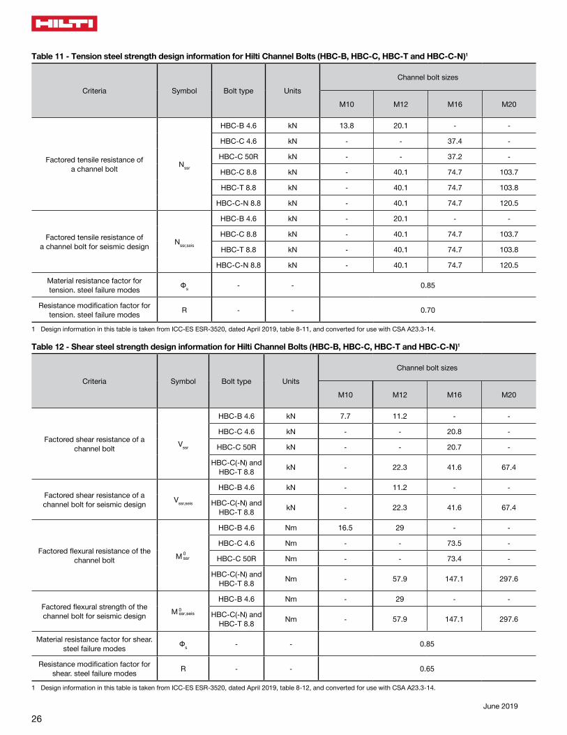
Table 11 - Tension steel strength design information for Hilti Channel Bolts (HBC-B, HBC-C, HBC-T and HBC-C-N)1
Criteria Symbol Bolt type Units
Channel bolt sizes
M10 M12 M16 M20
Factored tensile resistance of a channel bolt Nssr
HBC-B 4.6 kN 13.8 20.1 - -
HBC-C 4.6 kN - - 37.4 -
HBC-C 50R kN - - 37.2 -
HBC-C 8.8 kN - 40.1 74.7 103.7
HBC-T 8.8 kN - 40.1 74.7 103.8
HBC-C-N 8.8 kN - 40.1 74.7 120.5
Factored tensile resistance ofa channel bolt for seismic design Nssr,seis
HBC-B 4.6 kN - 20.1 - -
HBC-C 8.8 kN - 40.1 74.7 103.7
HBC-T 8.8 kN - 40.1 74.7 103.8
HBC-C-N 8.8 kN - 40.1 74.7 120.5
Material resistance factor for tension. steel failure modes Фs - - 0.85
Resistance modification factor for tension. steel failure modes R - - 0.70
1 Design information in this table is taken from ICC-ES ESR-3520, dated April 2019, table 8-11, and converted for use with CSA A23.3-14.
Table 12 - Shear steel strength design information for Hilti Channel Bolts (HBC-B, HBC-C, HBC-T and HBC-C-N)1
Criteria Symbol Bolt type Units
Channel bolt sizes
M10 M12 M16 M20
Factored shear resistance of a channel bolt Vssr
HBC-B 4.6 kN 7.7 11.2 - -
HBC-C 4.6 kN - - 20.8 -
HBC-C 50R kN - - 20.7 -
HBC-C(-N) andHBC-T 8.8 kN - 22.3 41.6 67.4
Factored shear resistance of a channel bolt for seismic design Vssr,seis
HBC-B 4.6 kN - 11.2 - -
HBC-C(-N) and HBC-T 8.8 kN - 22.3 41.6 67.4
Factored flexural resistance of the channel bolt M 0ssr
HBC-B 4.6 Nm 16.5 29 - -
HBC-C 4.6 Nm - - 73.5 -
HBC-C 50R Nm - - 73.4 -
HBC-C(-N) andHBC-T 8.8 Nm - 57.9 147.1 297.6
Factored flexural strength of the channel bolt for seismic design M 0ssr,seis
HBC-B 4.6 Nm - 29 - -
HBC-C(-N) andHBC-T 8.8 Nm - 57.9 147.1 297.6
Material resistance factor for shear. steel failure modes Фs - - 0.85
Resistance modification factor for shear. steel failure modes R - - 0.65
1 Design information in this table is taken from ICC-ES ESR-3520, dated April 2019, table 8-12, and converted for use with CSA A23.3-14.

27
Canadian Design Guide
June 2019
Table 13 - Material specifications and properties for Hilti Anchor Channels (HAC and HAC-T) and Hilti Channel Bolts (HBC-B, HBC-C, HBC-T and HBC-C-N)1
Component Carbon steel Surface Stainless steel
Channel Profile
Carbon steel
Hot dip galvanized (F) ≥ 55 µm2
Hot dip galvanized (F) ≥ 70 µm3 -
Rivet Hot dip galvanized (F) ≥ 45 µm -
Anchor Hot dip galvanized (F) ≥ 45 µm -
Channel boltGrade 4.6 and 8.8
according to DIN EN ISO 898-1:2009-8
Hot dip galvanized (F) ≥ 45 µm,or
electroplated (G) ≥ 8 µm
Grade 50 according toDIN EN ISO 3506-1:2010-4,
passivation according ASTM A380
Plain washer 4 ISO 7089 and ISO 7093-1 Hardness A, 200 HV
Hot dip galvanized (F),or
electroplated (G)
Hardness A, 200 HVaccording toISO 3506-1
Hexagonal nut ISO 4032 or DIN 9345
Property class 8according to ISO 898-2,
orproperty class 5
according to DIN 267-4
Hot dip galvanized (F) ≥ 45 µm,or
electroplated (G) ≥ 8 µm
Property class 70according to DIN 267-11
1 Design information in this table is taken from ICC-ES ESR-3520, dated April 2019, table 8-132 For HAC-30F, HAC-40F and HAC(-T)503 For HAC-60F and HAC(-T)704 Not in scope of delivery5 Hexagonal nuts DIN 934 for channel bolts made from carbon steel grade 4.6 and stainless steel bolts

BB
• 8/
18
Hilti, Inc. (U.S.) 1-800-879-8000en español 1-800-879-5000www.hilti.com
Hilti (Canada) Corporation 1-800-363-4458www.hilti.com