ttu-2 transducer test unit users guide
TRANSCRIPT

PA W-TA W-JO H N SE R V I C E S , INC .™
TECHNICAL REFERENCE AND OPERATIONS GUIDE
TTU-2 TRANSDUCER TEST UNIT
USERS GUIDE
TECHNICAL REFERENCE AND
OPERATIONS GUIDE
◊ ◊ ◊
TRANSDUCER TEST UNIT TTU-2 USERS GUIDE
◊ ◊ ◊
PA W-TA W-JO H N SE R V I C E S , INC .™ 18125 N. Ramsey Rd.
Rathdrum, ID 83858-8288 Phone: 208-687-1478 Fax: 208-687-4148
Web: www.pawtaw.com
E-mail: [email protected]
II
Notice The information contained in this document is subject to change without notice. Paw-Taw-John Services, Inc.™ makes no warranty of any kind with regard to this material, including, but not limited to, the implied warranties of merchantability and fitness for a particular purpose. Paw-Taw-John Services, Inc.™ shall not be liable for errors contained herein or for incidental or consequential damages in connection with the furnishing, performance, or use of this material. Paw-Taw-John Services, Inc.™ assumes no responsibility for the use or reliability of its software and hardware on equipment that is not furnished by Paw-Taw-John Services, Inc.™. This document contains proprietary information that is protected by copyright. All rights are reserved. No part of this document may be photocopied, reproduced, or translated to another language without prior written consent of Paw-Taw-John Services, Inc.™. Paw-Taw-John Services, Inc.™ 18125 N. Ramsey Rd. Rathdrum, ID 83858-8288 ©2005 Paw-Taw-John Services, Inc.™, all rights reserved.
Paw-Taw-John Services, Inc.™ and Servo Sensor™ are registered trademarks of Paw-Taw-John Services, Inc.™ in the United States of America and other countries.
MTS® and Temposonics® are registered trademarks of MTS Systems Corporation.
Other brand or product names are the trademarks of their respective holders.
III

Revision History Sep 03 – First release Mar 04 – Added SSI information Dec 04 – Added G-Series information Apr 05 – Added G-Series programming information
IV
Table of Contents Page
Notice--------------------------------------------------------------------------------------------------------- III Revision History ---------------------------------------------------------------------------------------------- IV Table of Contents---------------------------------------------------------------------------------------------- V Product Warranty -------------------------------------------------------------------------------------------VII Important Rules for Safe Operation ----------------------------------------------------------------------VIII
Symbols Used in This Manual ---------------------------------------------------------------------------------------------------------------VIII Safety Summary--------------------------------------------------------------------------------------------------------------------------------- IX Damage that Requires Service---------------------------------------------------------------------------------------------------------------- XI
Shipping------------------------------------------------------------------------------------------------------XII Unpacking the Product ------------------------------------------------------------------------------------------------------------------------XII Repackaging for Shipment--------------------------------------------------------------------------------------------------------------------XII
Specifications-----------------------------------------------------------------------------------------------XIII Physical Specifications------------------------------------------------------------------------------------------------------------------------XIII Electrical Specifications ----------------------------------------------------------------------------------------------------------------------XIII Environmental Specifications----------------------------------------------------------------------------------------------------------------XIII Shipping Specifications-----------------------------------------------------------------------------------------------------------------------XIII
INTRODUCTION ----------------------------------------------------------------------------------------------- 1 About This Manual ------------------------------------------------------------------------------------------------------------------------------- 1 Who We Are -------------------------------------------------------------------------------------------------------------------------------------- 1 MTS Temposonics Linear-Position Sensor Basics ------------------------------------------------------------------------------------------- 1 Examples of MTS Model Numbers------------------------------------------------------------------------------------------------------------- 7 MTS Basics Summary---------------------------------------------------------------------------------------------------------------------------10
TTU-2 OVERVIEW --------------------------------------------------------------------------------------------11 General Introduction ---------------------------------------------------------------------------------------------------------------------------11 Functional Diagram -----------------------------------------------------------------------------------------------------------------------------12 Functional Description--------------------------------------------------------------------------------------------------------------------------13
BASIC OPERATION -------------------------------------------------------------------------------------------15 Tools and Parts Required ----------------------------------------------------------------------------------------------------------------------15 Before Using the Tester------------------------------------------------------------------------------------------------------------------------15 Sensor Test Setup ------------------------------------------------------------------------------------------------------------------------------16 Basic Test Procedure for All Digital and Analog Sensors----------------------------------------------------------------------------------18
DETAILED OPERATION --------------------------------------------------------------------------------------21 Procedure for Testing MTS I (Temposonics I) Sensors -----------------------------------------------------------------------------------21 Procedure for Testing MTS II (Temposonics II) Sensors ---------------------------------------------------------------------------------25 Procedure for Testing L-Series Sensors -----------------------------------------------------------------------------------------------------33 Procedure for Testing E-Series Sensors -----------------------------------------------------------------------------------------------------40 Procedure for Testing S-Series Sensors -----------------------------------------------------------------------------------------------------46 Procedure for Testing R-Series Sensors -----------------------------------------------------------------------------------------------------54 Procedure for Testing G-Series Sensors-----------------------------------------------------------------------------------------------------64
APPENDICES --------------------------------------------------------------------------------------------------78 APPENDIX A --------------------------------------------------------------------------------------------------79
Removal of L, R, G and S Series Sensors ---------------------------------------------------------------------------------------------------79 Installation of L, R, G and S Series Sensors ------------------------------------------------------------------------------------------------80
APPENDIX B --------------------------------------------------------------------------------------------------81 Removal of Temposonics I & II Series Sensors --------------------------------------------------------------------------------------------81 Installation of Temposonics I & II Series Sensors -----------------------------------------------------------------------------------------82
APPENDIX C --------------------------------------------------------------------------------------------------83 Determining Position of Pulse Width Modulation (PWM) Sensors -----------------------------------------------------------------------83
APPENDIX D --------------------------------------------------------------------------------------------------85
V

This page intentionally left blank.
VI

Product Warranty Paw-Taw-John Services, Inc., (Seller) warrants product(s) of its manufacture to be free of defects in material and workmanship for a period of 90 days from date of shipment from Sellers facility. Sellers only obligation under this warranty is to furnish an equivalent product(s) by form fit and function, return shipping prepaid, for any product(s) returned, shipping prepaid, to Sellers facility and found to contain a liable defect within the warranty period. Paw-Taw-John Services, Inc., shall accept liability only if the product(s):
• Are erected, tested, and operated in a manner approved by, or in accordance with instructions provided by seller,
• Have not been subjected to electrical or mechanical misuse or abuse or accident, • Have been used for the purpose for which the goods were designed, • Have not been altered or repaired by persons other than seller in any respect which in the judgment of
seller affects the condition or operation of the product(s). This warranty constitutes Paw-Taw-John Services, Inc., entire and only warranty. There are no other warranties, expressed or implied in law or in fact including implied warranties of fitness and merchantability. Paw-Taw-John Services, Inc., will not be liable for compensatory or incidental damages caused by defects and will not be responsible for costs or repairs done by others. Returned goods must be carefully packed, preferably using the original shipping carton and packaging material. Product(s) should be returned prepaid to:
Paw-Taw-John Services, Inc. 18125 N. Ramsey Road Rathdrum, ID 83858 Phone: 208-687-1478 Fax: 208-687-4148
VII
Important Rules for Safe Operation The general safety information in this part of the manual is for both operating and servicing personnel. Specific warnings and cautions will be found throughout the manual where they apply and do not appear in this summary. Always follow basic safety procedures when using this equipment to reduce risk of injury from fire or shock
READ AND RETAIN THESE RULES
• Read all of the instructions before you operate this equipment. Give particular attention to all safety precautions. Retain these instructions for future reference.
• Comply with all warning and caution statements in the instructions. Observe all warning and caution
symbols that are affixed to this equipment.
• Comply with all instructions that accompany this equipment.
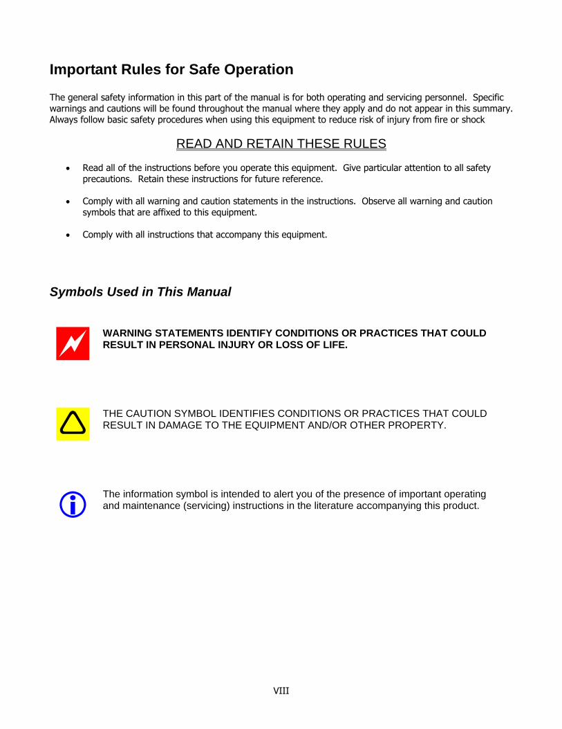
Symbols Used in This Manual
WARNING STATEMENTS IDENTIFY CONDITIONS OR PRACTICES THAT COULD RESULT IN PERSONAL INJURY OR LOSS OF LIFE.
THE CAUTION SYMBOL IDENTIFIES CONDITIONS OR PRACTICES THAT COULD RESULT IN DAMAGE TO THE EQUIPMENT AND/OR OTHER PROPERTY.
The information symbol is intended to alert you of the presence of important operating and maintenance (servicing) instructions in the literature accompanying this product.
VIII
Safety Summary
Power Source This product is intended to operate from a power source that will not apply more that 120 volts RMS (132 volts RMS maximum) between the power supply conductors or between either power supply conductors and ground. A protective ground connection by way of the grounding conductor in the power cord is essential for safe operation.
Grounding the Product This equipment has a three-prong plug. This equipment is grounded through the grounding conductor in the power cord. Properly ground (earth) this equipment by inserting the plug into a grounded electrical, three-socket outlet. To avoid electrical shock, plug the power cord into a properly wired receptacle before making any connections to the equipment input and output terminals. A protective ground connection by way of the grounding conductor in the power cord is essential for safe operation. If you are unable to insert this plug fully into the outlet, contact an electrician to replace your obsolete outlet.
Danger Resulting From Loss of Ground Upon loss of protective-ground, all accessible conductive parts (including those controls and connectors that may appear to be insulated) may render an electric shock.
Use the Proper Power Cord Use only the factory-supplied power cord for this equipment. Use only a power cord that is in good condition. Do not use damaged power cord. Replace frayed, worn or damaged power cord immediately. If extension cords are required for proper operation, use only a suitable, grounded extension cord.
Power Cord Protection Arrange the power cord so that people cannot walk on the cords, place objects on the cords or place objects against the cords, which can damage the cords. Pay particular attention to cords that are at plugs, at electrical outlets, and at the places where the cords exit the equipment.
Overloading Do not overload electric outlets or extension cords as this can result in risk of fire or electric shock.
Use the Proper Fuse To avoid fire hazard, use only a fuse of the correct type, voltage rating and current rating as specified in the parts list for your equipment.
Do Not Operate In Explosive Atmospheres To avoid explosion, do not operate this equipment in an explosive atmosphere.
IX
Lightning and Power Surges Plug your equipment into a surge protector in order to reduce the risk of damage from lightning strikes and power surges. If you are unsure of the type of surge protector to use, contact your local electrician or electrical service provider.
Servicing Do not open the cover of this equipment. If you open the cover, your warranty will be void. Refer all servicing to qualified personnel only. Contact Paw-Taw-John Services, Inc., for instructions. To avoid personal injury, do not remove the equipment covers or panels. Do not operate the equipment without the covers and panels properly installed. This equipment contains no user serviceable parts, components or adjustments inside. Refer all servicing to qualified service personnel.
Object and Liquid Entry Never push objects of any kind into this product through openings as they may touch dangerous voltage points or short out parts that could result in a fire or electric shock. Do not expose this equipment to liquid or moisture. Do not place this equipment on a wet surface. Do not spill liquids on or near this equipment.
Do Not Expose the Product to Moisture TO PREVENT FIRE OR ELECTRIC SHOCK DO NOT EXPOSE THIS UNIT TO RAIN OR MOISTURE. To avoid the risk of electrical shock to yourself, do not use this equipment when you or the products are wet.
Cleaning the Equipment Before cleaning this equipment, unplug it from the electrical outlet. Use a slightly damp cloth to clean this equipment. Do not use a liquid cleaner or an aerosol cleaner. Do not use magnetic or static cleaning devices (dust remover) to clean this equipment.
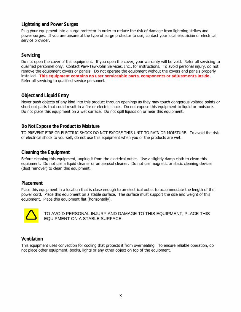
Placement Place this equipment in a location that is close enough to an electrical outlet to accommodate the length of the power cord. Place this equipment on a stable surface. The surface must support the size and weight of this equipment. Place this equipment flat (horizontally).
TO AVOID PERSONAL INJURY AND DAMAGE TO THIS EQUIPMENT, PLACE THIS EQUIPMENT ON A STABLE SURFACE.
Ventilation This equipment uses convection for cooling that protects it from overheating. To ensure reliable operation, do not place other equipment, books, lights or any other object on top of the equipment.
X
Damage that Requires Service For damage that requires service, unplug this equipment from the electrical outlet. Contact qualified service personnel when any of the following occurs:
• There is damage to the power cord or plug • Liquid enters the equipment • A heavy object falls on the equipment • There is exposure to rain or water • Operation is not normal (the instructions describe the normal operation) • If you drop this equipment, or damage the case of this equipment • If this equipment exhibits a distinct change in performance
Upon completion of any service or repairs to this equipment, the qualified service technician will perform safety checks to determine that the equipment is in proper operating condition.
XI

Shipping
Unpacking the Product 1. Inspect the shipping carton for shipping damage and exposure to moisture or unknown substances.
Notify your commercial freight carrier of any visible signs of damage. 2. Unpack the contents from the shipping carton. 3. Verify the contents against the packing list. Notify Paw-Taw-John Services, Inc., of any discrepancy
between the contents and the packing list. 4. Visually inspect the contents for shipping damage and exposure to moisture or unknown substances. 5. Open the product and verify the contents.
Repackaging for Shipment It is recommended that the original carton and packaging material be saved in case the product needs to be reshipped using a commercial freight carrier. If the original packing materials are not available, use the following recommended guidelines:
1. Use a corrugated cardboard shipping carton with rated test strength of 250 pounds and inside dimensions at least 6 inches greater than the instrument dimensions.
2. Enclose the following information: a. The owners name and address. b. A name and phone number of a contact person. c. The model type and serial number of the product. d. The reason for returning. e. A complete description of the repair or service to be performed.
3. Cushion the product on all sides using 3 inches of padding tightly packed between the carton and the product.
4. Seal the carton with an industrial stapler or strapping tape. 5. Mark the address of Paw-Taw-John Services, Inc., and the return address in two locations on the carton.
Paw-Taw-John Services, Inc. 18125 N. Ramsey Road Rathdrum, ID 83858 Phone: 208-687-1478 Fax: 208-687-4148
XII
Specifications
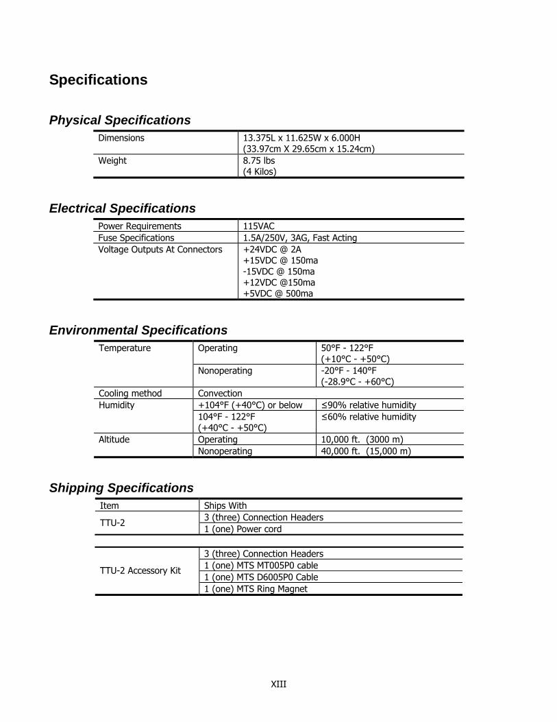
Physical Specifications Dimensions 13.375L x 11.625W x 6.000H
(33.97cm X 29.65cm x 15.24cm) Weight 8.75 lbs
(4 Kilos)
Electrical Specifications Power Requirements 115VAC Fuse Specifications 1.5A/250V, 3AG, Fast Acting Voltage Outputs At Connectors +24VDC @ 2A
+15VDC @ 150ma -15VDC @ 150ma +12VDC @150ma +5VDC @ 500ma
Environmental Specifications Operating 50°F - 122°F
(+10°C - +50°C) Temperature
Nonoperating -20°F - 140°F (-28.9°C - +60°C)
Cooling method Convection +104°F (+40°C) or below ≤90% relative humidity Humidity 104°F - 122°F (+40°C - +50°C)
≤60% relative humidity
Operating 10,000 ft. (3000 m) Altitude Nonoperating 40,000 ft. (15,000 m)
Shipping Specifications Item Ships With
3 (three) Connection Headers TTU-2 1 (one) Power cord
3 (three) Connection Headers 1 (one) MTS MT005P0 cable 1 (one) MTS D6005P0 Cable
TTU-2 Accessory Kit
1 (one) MTS Ring Magnet
XIII

CHAPTER
1INTRODUCTION
The purpose of this chapter is to describe the basic features and use of this manual, and an introduction to MTS Temposonics Sensors.
Congratulations on your purchase of the Transducer Test Unit (TTU-2), a powerful test instrument for MTS linear-position sensors. You can use the TTU-2 to test MTS sensors to verify operation prior to installing in systems, or troubleshoot sensors in existing systems.
About This Manual Paw-Taw-John Services, Inc., provides this operations manual and technical reference as an instructional aid for the operation of the Transducer Test Unit (TTU-2) in conjunction with Temposonics linear-position sensors. The information included in this technical reference and operations manual is generic to Paw-Taw-John Services, Inc., and MTS products. Information that is specific to a particular product, such as mechanical and electrical drawings and schematics and parts lists, are provided in addition to this manual.
Who We Are Paw-Taw-John Services, Inc., is a designer and manufacturer of semi-custom servo controller systems and associated components. The company brings together individuals with decades of experience in systems and software design, custom electrical and electronic systems manufacturing and technical sales with expertise in system manufacturing. Paw-Taw-John Services, Inc., specializes in systems that provide greater user flexibility, lower maintenance, increased productivity, quicker payback and higher yield. Our systems are in use worldwide by companies wanting more intelligence with their controllers.
MTS Temposonics Linear-Position Sensor Basics It is not the intention of this manual to re-create the sensor information readily available from MTS. The information presented here is of a broad how-to nature, as it relates to the Transducer Test Unit. The MTS information is accurate at the writing of this manual. The specific sensors discussed in this manual relate to the most common models and outputs. For specific information on Temposonics linear-position sensors, contact MTS at:
MTS Systems Corporation Sensors Division 3001 Sheldon Drive Cary, NC 27513 Tel: 919-677-0100 Fax: 919-677-0200
Web: http://www.mtssensors.com/
MTS has manufactured numerous models of Temposonics linear-position sensors to meet many different applications. New models employing improved technology have also added to the product mix. Many of these sensor configurations have very different operating parameters. It cannot be stressed enough that the
INTRODUCTION
information on MTS linear-position sensors presented in this manual is generic in nature and may not apply to the specific sensor to be tested. Information presented here is based on the most common models and configurations.
Sensor Types Although transducers are available in many body styles, they can generally be categorized by the output, and can be reduced to the following types:
• Neuter Sensors These sensors supply a raw signal output representative of the actual return pulse of the waveguide determined by the magnet position only. This signal is used by other external electronics to create a useable signal such as PWM, Start/Stop, and Analog outputs.
• Digital Sensors Sensors that provide pulse width modulation (PWM) and Start/Stop (RPM) outputs are considered digital sensors. These have special modules/electronics installed inside the sensor cap that use the raw signal from the waveguide and converts it to a signal that a host controller/electronics can use.
• Analog Sensors Sensors that supply a voltage or current output representative of the magnet position are considered analog sensors. They also have specialized modules/electronics inside the head of a sensor that convert the raw signal from the waveguide to a usable analog signal for host controllers/electronics.
• Protocol Sensors Sensors that provide CANbus, Device-Net, PROFIBUS and SSI outputs are considered protocol sensors. These have special modules/electronics installed inside the sensor cap that use the raw signal from the waveguide and convert it to an information signal that a host controller can use.
• Motion Controller Sensors The S-Series sensor, also referred to as the Servo Sensor, is a specialized sensor combining the measurement sensing capability with a motion controller and proportional valve drive electronics (on a second connector), all in the sensor head.
2
INTRODUCTION
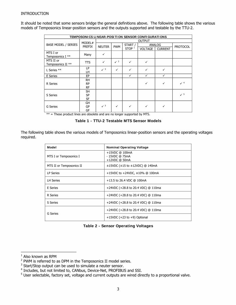
It should be noted that some sensors bridge the general definitions above. The following table shows the various models of Temposonics linear-position sensors and the outputs supported and testable by the TTU-2.
TEMPOSONICS LINEAR-POSITION SENSOR CONFIGURATIONS OUTPUT
ANALOG BASE MODEL / SERIES MODEL# PREFIX NEUTER PWM START /
STOP 1 VOLTAGE CURRENT PROTOCOL
MTS I or Temposonics I ** Many
MTS II or Temposonics II ** TTS 2
L Series ** LP LH 3
E Series EP
R Series RH RP RF
4
S Series SH SP SF
5
G Series GH GP GF
3
** = These product lines are obsolete and are no longer supported by MTS.
Table 1 - TTU-2 Testable MTS Sensor Models
The following table shows the various models of Temposonics linear-position sensors and the operating voltages required.
Model Nominal Operating Voltage
MTS I or Temposonics I +15VDC @ 100mA - 15VDC @ 75mA +12VDC @ 50mA
MTS II or Temposonics II ±15VDC (±15 to ±12VDC) @ 140mA
LP Series +15VDC to +24VDC, ±10% @ 100mA
LH Series +13.5 to 26.4 VDC @ 100mA
E Series +24VDC (+28.8 to 20.4 VDC) @ 110ma
R Series +24VDC (+28.8 to 20.4 VDC) @ 110ma
S Series +24VDC (+28.8 to 20.4 VDC) @ 110ma
+24VDC (+28.8 to 20.4 VDC) @ 110ma G Series
+15VDC (+23 to +9) Optional
Table 2 - Sensor Operating Voltages
1 Also known as RPM 2 PWM is referred to as DPM in the Temposonics II model series. 3 Start/Stop output can be used to simulate a neuter sensor. 4 Includes, but not limited to, CANbus, Device-Net, PROFIBUS and SSI. 5 User selectable, factory set, voltage and current outputs are wired directly to a proportional valve.
3
INTRODUCTION
Sensor Connection Types In order to connect the sensor to the TTU-2 the connection to the sensor falls into three broad classes:
• Integral Connector The connection to the sensor is provided by a built in integral connector or connectors (located at the end of the sensor cover) and is usually mated with a matching cable.
• Integral Cable to Pigtail The connection to the sensor is provided by a built in integral cable (located on the end of a cable coming from the end of the sensor cover) and is terminated in pigtail leads.
• Integral Cable with Hanging Connector The connection to the sensor is provided by a built in integral cable (located on the end of a short cable coming from the end of the sensor cover) and terminates in a hanging connector (a connector on the end of a cable coming from the end of the sensor cover). This hanging connector may, or may not, be MTS standard, and often is system dependent. Care must be used in testing these types of sensors. Consult your engineering specifications for the particular hanging connector attached to the sensor cable. MTS Sensors Division provides technical materials for the various sensor models. Material available includes:
• Datasheets • Specification sheets • Users guides • Application notes
Contact Paw-Taw-John Services, Inc., or MTS directly or visit the MTS website to obtain sensor information.
4
INTRODUCTION
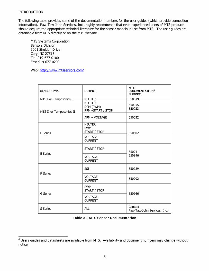
The following table provides some of the documentation numbers for the user guides (which provide connection information). Paw-Taw-John Services, Inc., highly recommends that even experienced users of MTS products should acquire the appropriate technical literature for the sensor models in use from MTS. The user guides are obtainable from MTS directly or on the MTS website.
MTS Systems Corporation Sensors Division 3001 Sheldon Drive Cary, NC 27513 Tel: 919-677-0100 Fax: 919-677-0200
Web: http://www.mtssensors.com/
SENSOR TYPE OUTPUT MTS DOCUMENTATION6
NUMBER
MTS I or Temposonics I NEUTER 550019 NEUTER DPM (PWM) RPM –START / STOP
550055 550033
MTS II or Temposonics II
APM – VOLTAGE 550032
NEUTER PWM START / STOP L Series VOLTAGE CURRENT
550602
START / STOP
E Series VOLTAGE CURRENT
550741 550996
SSI 550989
R Series VOLTAGE CURRENT 550992
PWM START / STOP
G Series VOLTAGE CURRENT
550966
S Series ALL Contact Paw-Taw-John Services, Inc.
Table 3 - MTS Sensor Documentation
6 Users guides and datasheets are available from MTS. Availability and document numbers may change without notice.
5
INTRODUCTION
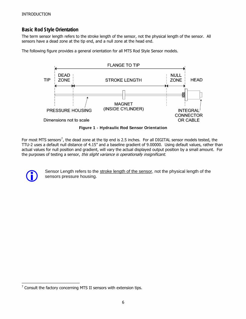
Basic Rod Style Orientation The term sensor length refers to the stroke length of the sensor, not the physical length of the sensor. All sensors have a dead zone at the tip end, and a null zone at the head end. The following figure provides a general orientation for all MTS Rod Style Sensor models.
Figure 1 - Hydraulic Rod Sensor Orientation
For most MTS sensors7, the dead zone at the tip end is 2.5 inches. For all DIGITAL sensor models tested, the TTU-2 uses a default null distance of 4.15” and a baseline gradient of 9.00000. Using default values, rather than actual values for null position and gradient, will vary the actual displayed output position by a small amount. For the purposes of testing a sensor, this slight variance is operationally insignificant.
Sensor Length refers to the stroke length of the sensor, not the physical length of the sensors pressure housing.
7 Consult the factory concerning MTS II sensors with extension tips.
6
INTRODUCTION
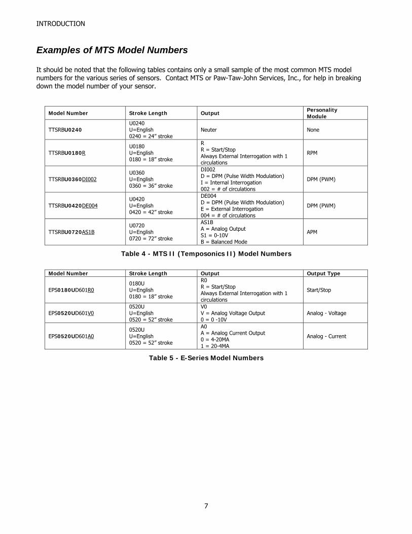
Examples of MTS Model Numbers It should be noted that the following tables contains only a small sample of the most common MTS model numbers for the various series of sensors. Contact MTS or Paw-Taw-John Services, Inc., for help in breaking down the model number of your sensor.
Model Number Stroke Length Output Personality Module
TTSRBU0240 U0240 U=English 0240 = 24” stroke
Neuter None
TTSRBU0180RU0180 U=English 0180 = 18” stroke
R R = Start/Stop Always External Interrogation with 1 circulations
RPM
TTSRBU0360DI002U0360 U=English 0360 = 36” stroke
DI002 D = DPM (Pulse Width Modulation) I = Internal Interrogation 002 = # of circulations
DPM (PWM)
TTSRBU0420DE004U0420 U=English 0420 = 42” stroke
DE004 D = DPM (Pulse Width Modulation) E = External Interrogation 004 = # of circulations
DPM (PWM)
TTSRBU0720AS1BU0720 U=English 0720 = 72” stroke
AS1B A = Analog Output S1 = 0-10V B = Balanced Mode
APM
Table 4 - MTS II (Temposonics II) Model Numbers
Model Number Stroke Length Output Output Type
EPS0180UD601R00180U U=English 0180 = 18” stroke
R0 R = Start/Stop Always External Interrogation with 1 circulations
Start/Stop
EPS0520UD601V00520U U=English 0520 = 52” stroke
V0 V = Analog Voltage Output 0 = 0 -10V
Analog - Voltage
EPS0520UD601A00520U U=English 0520 = 52” stroke
A0 A = Analog Current Output 0 = 4-20MA 1 = 20-4MA
Analog - Current
Table 5 - E-Series Model Numbers
7
INTRODUCTION
Model Number Stroke Length Output Output Type
LHTRB00U024014NOU0240 U=English 0240 = 24” stroke
4N0 4N0 = Neuter Neuter
LHTRB00U01801R0LPSCSU01801
U0180 U=English 0180 = 18” stroke
R0 OR SR0 or S = Start/Stop Always External Interrogation with 1 circulations
Start/Stop
LHTRB00U03601DI02LPSCPU0360100I02
U0360 U=English 0360 = 36” stroke
DI02 or P & I02D or P = Pulse Width Modulation I = Internal Interrogation 002 = # of circulations
PWM
LHTRB00U04201DE04LPSCPU0420100E04
U0420 U=English 0420 = 42” stroke
DE04 or P & E04D or P = Pulse Width Modulation E = External Interrogation 004 = # of circulations
PWM
LHTRB00U07201VOLPSCVU07201
U0720 U=English 0720 = 72” stroke
V0 or VV = Analog Voltage Output 0 = 0 -10V
Analog - Voltage
LHTRB00U07201A0LPSCAU07201
U0720 U=English 0720 = 72” stroke
A0 or AA = Analog Current Output 0 = 4-20MA
Analog - Current
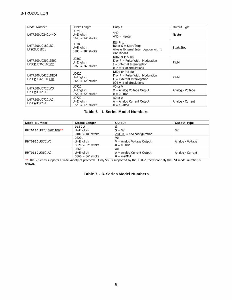
Table 6 - L-Series Model Numbers
Model Number Stroke Length Output Output Type
RHT0180UD701S2B1100** 0180U U=English 0180 = 18” stroke
S S = SSI 2B1100 = SSI configuration
SSI
RHT0520UD701V00520U U=English 0520 = 52” stroke
V0 V = Analog Voltage Output 0 = 0 -10V
Analog - Voltage
RHT0360UD601A00360U U=English 0360 = 36” stroke
A0 A = Analog Current Output 0 = 4-20MA
Analog - Current
** The R-Series supports a wide variety of protocols. Only SSI is supported by the TTU-2, therefore only the SSI model number is shown.
Table 7 - R-Series Model Numbers
8
INTRODUCTION
Model Number Stroke Length Output Output Type
GHT0240UD601N080240U U=English 0240 = 24” stroke
N0 N0 = Neuter8 Neuter
GHT0180UD601R00180U U=English 0180 = 18” stroke
R0 R0 = Start/Stop Always External Interrogation with 1 circulations
RPM
GHT0360UD601DI20360U U=English 0360 = 36” stroke
DI2 D = Pulse Width Modulation I = Internal Interrogation 2 = # of circulations
PWM
GHT0420UD601DE40420U U=English 0420 = 42” stroke
DE4 D = Pulse Width Modulation E = External Interrogation 4 = # of circulations
PWM
GHT0720UD601V00720U U=English 0720 = 72” stroke
V0 V = Analog Voltage Output 0 = 0 -10V
Analog - Voltage
GHT0720UD601A00720U U=English 0720 = 72” stroke
A0 A = Analog Current Output 0 = 4-20MA
Analog - Current
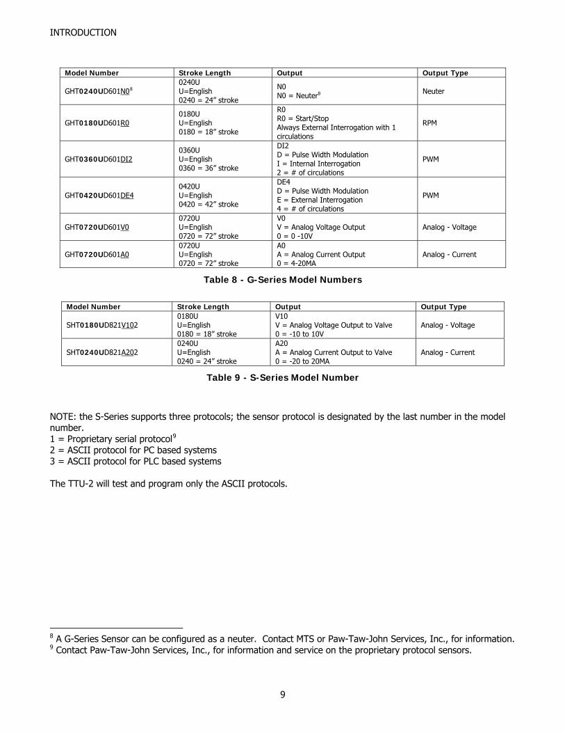
Table 8 - G-Series Model Numbers
Model Number Stroke Length Output Output Type
SHT0180UD821V102 0180U U=English 0180 = 18” stroke
V10 V = Analog Voltage Output to Valve 0 = -10 to 10V
Analog - Voltage
SHT0240UD821A202 0240U U=English 0240 = 24” stroke
A20 A = Analog Current Output to Valve 0 = -20 to 20MA
Analog - Current
Table 9 - S-Series Model Number
NOTE: the S-Series supports three protocols; the sensor protocol is designated by the last number in the model number. 1 = Proprietary serial protocol9
2 = ASCII protocol for PC based systems 3 = ASCII protocol for PLC based systems The TTU-2 will test and program only the ASCII protocols.
8 A G-Series Sensor can be configured as a neuter. Contact MTS or Paw-Taw-John Services, Inc., for information. 9 Contact Paw-Taw-John Services, Inc., for information and service on the proprietary protocol sensors.
9
INTRODUCTION
MTS Basics Summary The information provided in the tables and figures above are provided to the user for the purposes of determining the following:
• Sensor output (PWM, S/S, ect.): the test header, operating voltage connections and input and output connections to use.
• Type of connection: how to connect to the test header. If there is no way of determining the model number from the sensor itself, it may be necessary to consult records of service or purchase, engineering drawings and documents, or system operating manuals and users guides to determine the model number. If unable to determine the model number or the operating characteristics, contact Paw-Taw-John Services, Inc., or MTS for help with this crucial step.
10
CHAPTER
2TTU-2 OVERVIEW
This chapter provides an overview of the Transducer Test Unit.
General Introduction Paw-Taw-John Services, Inc., developed the Transducer Test Unit, (referred to as TTU-2), to provide a quick and accurate means of determining the operational status of MTS Temposonics linear-position transducers. The TTU-2 was designed to test the most common configurations of Temposonics linear-position sensors in a field or bench environment. The TTU-2 can aid service personnel in system troubleshooting by testing and eliminating the sensor as a possible fault. Using microcontroller and PLD technology, the TTU-2 produces and monitors the signals to and from a sensor for integrity in a system application. The unit front panel is designed for quick connections of sensors under test. Tests are performed using a menu driven LCD display and keypad. The TTU-2 tests for the correct parameters required by the specific model of sensor being tested. Sensor selection and parameter value(s) are selected and entered via the keypad and position information is displayed on the TTU-2s LCD display. The TTU-2 has a detachable three-wire power cord with a three contact plug for connection to both the power source and protective ground. The protective ground contact on the plug connects through the power cord protective grounding conductor to the accessible metal parts of the front panel. For electrical shock protection, insert the power cord plug into a power outlet that has a properly grounded protective-ground contact.
11
OVERVIEW
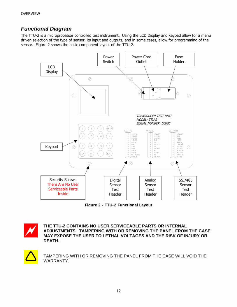
Functional Diagram The TTU-2 is a microprocessor controlled test instrument. Using the LCD Display and keypad allow for a menu driven selection of the type of sensor, its input and outputs, and in some cases, allow for programming of the sensor. Figure 2 shows the basic component layout of the TTU-2.
Figure 2 - TTU-2 Functional Layout
Power Switch
Power Cord Outlet
Fuse Holder
LCD Display
Keypad
Digital Sensor Test
Header
Analog Sensor Test
Header
Security Screws
TRANSDUCER TEST UNIT MODEL: TTU-2 SERIAL NUMBER: 5C005
SSI/485Sensor Test
Header
There Are No User Serviceable Parts
Inside
THE TTU-2 CONTAINS NO USER SERVICEABLE PARTS OR INTERNAL ADJUSTMENTS. TAMPERING WITH OR REMOVING THE PANEL FROM THE CASE MAY EXPOSE THE USER TO LETHAL VOLTAGES AND THE RISK OF INJURY OR DEATH.
TAMPERING WITH OR REMOVING THE PANEL FROM THE CASE WILL VOID THE WARRANTY.
12
OVERVIEW
Functional Description The principle sections are:
• POWER BLOCK o Provides a safe connection for power and ground and contains the On/Off switch and fuse.
• LCD o Displays menus and sensor information
• KEYPAD o Selects items from the various menus and enters data as needed
• DIGITAL HEADER o Connections for testing neuter, PWM, and Start/Stop sensors
• ANALOG HEADER o Connections for testing the various analog sensor models
• SSI/485 HEADER o Connections for R-Series SSI and S-Series model sensors, both operation and programming
modes. o Connections for G-Series model sensor, programming mode only.
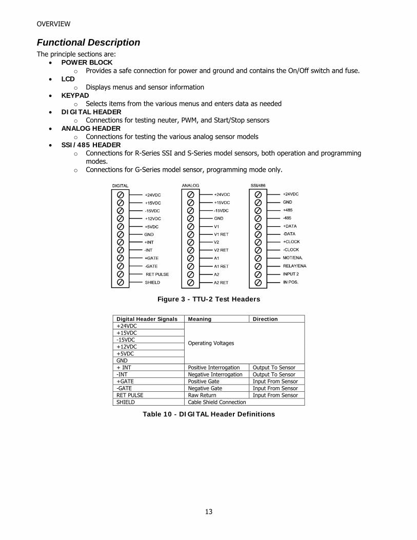
Figure 3 - TTU-2 Test Headers
Digital Header Signals Meaning Direction +24VDC +15VDC -15VDC +12VDC +5VDC GND
Operating Voltages
+ INT Positive Interrogation Output To Sensor -INT Negative Interrogation Output To Sensor +GATE Positive Gate Input From Sensor -GATE Negative Gate Input From Sensor RET PULSE Raw Return Input From Sensor SHIELD Cable Shield Connection
Table 10 - DIGITAL Header Definitions
13
OVERVIEW
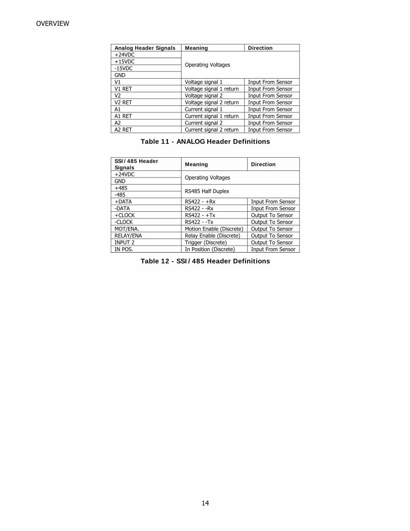
Analog Header Signals Meaning Direction +24VDC +15VDC -15VDC GND
Operating Voltages
V1 Voltage signal 1 Input From Sensor V1 RET Voltage signal 1 return Input From Sensor V2 Voltage signal 2 Input From Sensor V2 RET Voltage signal 2 return Input From Sensor A1 Current signal 1 Input From Sensor A1 RET Current signal 1 return Input From Sensor A2 Current signal 2 Input From Sensor A2 RET Current signal 2 return Input From Sensor
Table 11 - ANALOG Header Definitions
SSI/485 Header Signals Meaning Direction
+24VDC GND
Operating Voltages
+485 -485
RS485 Half Duplex
+DATA RS422 - +Rx Input From Sensor -DATA RS422 - -Rx Input From Sensor +CLOCK RS422 - +Tx Output To Sensor -CLOCK RS422 - -Tx Output To Sensor MOT/ENA. Motion Enable (Discrete) Output To Sensor RELAY/ENA Relay Enable (Discrete) Output To Sensor INPUT 2 Trigger (Discrete) Output To Sensor IN POS. In Position (Discrete) Input From Sensor
Table 12 - SSI/485 Header Definitions
14
CHAPTER
3
BASIC OPERATION
This chapter describes the basic operation of the Transducer Test Unit.
Tools and Parts Required
1. TTU-2, Transducer Test Unit 2. Interface cable
a. For sensors with an integral connector, an interface cable appropriate to the sensor under test. These cables may be purchased from Paw-Taw-John Services, Inc., or MTS.
b. Sensors with an integral cable to pigtail connect directly to the appropriate TTU-2 connector. c. Sensors with hanging connectors must have a connector-to-pigtail adapter cable made locally.
These adapters may be purchased from Paw-Taw-John Services, Inc. 3. An appropriate MTS sensor magnet for the sensor model. These magnets may be purchased from Paw-
Taw-John Services, Inc., or MTS. 4. Small slotted screwdriver, 1/8” blade width.
Before Using the Tester Before actual use of the tester, and perhaps the most important, is a visual inspection of the sensor. Look for the following:
• Oil on, or dripping, from the sensor body or cap. Clean when necessary. • If the sensor head cap (containing the sensor electronics) is loose, dangling from the pressure housing,
or is deformed or damaged the sensor should not be tested and returned for repair or replacement. • If the integral connector is loose or can be moved, the sensor should be sent in for repair. Testing can
be done to verify electronics but broken connections could prevent a good test. • When an integral cable is installed on the sensor, check for wear, cracks, shields showing, splices, severe
bends, and connector integrity. These observations indicate possible problems and repair/replacement may be required.
• The sensor tip is worn down enough that a black seal is partially showing. This indicates that oil may have entered the pressure housing and the unit should be replaced. Other mechanics should be checked if this occurs.
• Scoring of the body or pressure housing. This would indicate wear caused by external sources. These problems should be explored further to prevent compromising the ingress protection of the sensor.
• A small black weld spot, or spots, near the end of the sensor or anywhere along the sensor pressure housing. This usually indicates that welding was done near the sensor and the welder was improperly grounded. Typically, the electronics in the head of the sensor would be destroyed. A repair may be necessary.
• If there are bends greater than 2 degrees, the sensor’s linearity is suspect. Although the sensor may work, the measurement quality is degraded. The unit should be sent in for repair.
• Bends or excessive wear spots along the pressure housing. If the sensor is used in a cylinder that is too short or too long, the pressure housing may show a distinct corkscrew effect. The sensor cannot be repaired and is not worth testing.
15
BASIC OPERATION
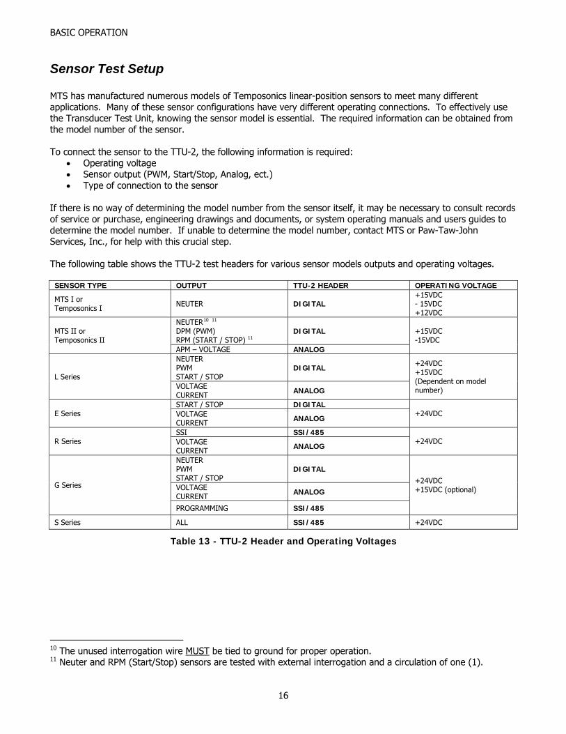
Sensor Test Setup MTS has manufactured numerous models of Temposonics linear-position sensors to meet many different applications. Many of these sensor configurations have very different operating connections. To effectively use the Transducer Test Unit, knowing the sensor model is essential. The required information can be obtained from the model number of the sensor. To connect the sensor to the TTU-2, the following information is required:
• Operating voltage • Sensor output (PWM, Start/Stop, Analog, ect.) • Type of connection to the sensor
If there is no way of determining the model number from the sensor itself, it may be necessary to consult records of service or purchase, engineering drawings and documents, or system operating manuals and users guides to determine the model number. If unable to determine the model number, contact MTS or Paw-Taw-John Services, Inc., for help with this crucial step. The following table shows the TTU-2 test headers for various sensor models outputs and operating voltages.
SENSOR TYPE OUTPUT TTU-2 HEADER OPERATING VOLTAGE
MTS I or Temposonics I NEUTER DIGITAL
+15VDC - 15VDC +12VDC
NEUTER10 11
DPM (PWM) RPM (START / STOP) 11
DIGITAL MTS II or Temposonics II
APM – VOLTAGE ANALOG
+15VDC -15VDC
NEUTER PWM START / STOP
DIGITAL L Series
VOLTAGE CURRENT ANALOG
+24VDC +15VDC (Dependent on model number)
START / STOP DIGITAL E Series VOLTAGE
CURRENT ANALOG +24VDC
SSI SSI/485 R Series VOLTAGE
CURRENT ANALOG +24VDC
NEUTER PWM START / STOP
DIGITAL
VOLTAGE CURRENT ANALOG
G Series
PROGRAMMING SSI/485
+24VDC +15VDC (optional)
S Series ALL SSI/485 +24VDC
Table 13 - TTU-2 Header and Operating Voltages
10 The unused interrogation wire MUST be tied to ground for proper operation. 11 Neuter and RPM (Start/Stop) sensors are tested with external interrogation and a circulation of one (1).
16
BASIC OPERATION
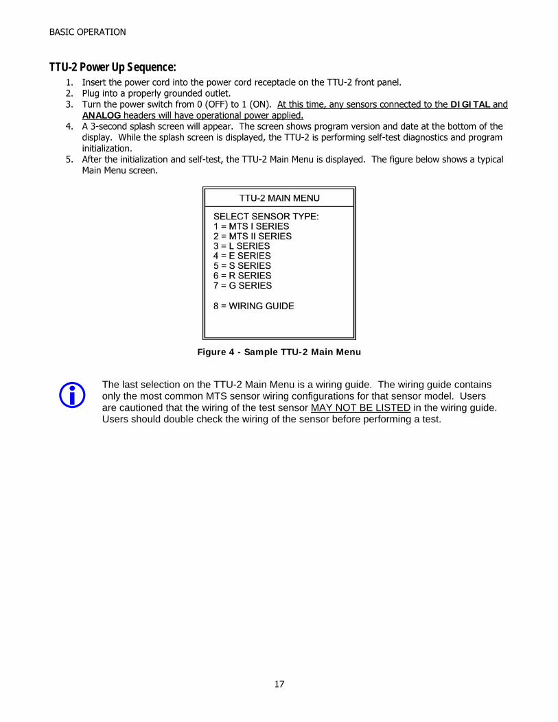
TTU-2 Power Up Sequence: 1. Insert the power cord into the power cord receptacle on the TTU-2 front panel. 2. Plug into a properly grounded outlet. 3. Turn the power switch from 0 (OFF) to 1 (ON). At this time, any sensors connected to the DIGITAL and
ANALOG headers will have operational power applied. 4. A 3-second splash screen will appear. The screen shows program version and date at the bottom of the
display. While the splash screen is displayed, the TTU-2 is performing self-test diagnostics and program initialization.
5. After the initialization and self-test, the TTU-2 Main Menu is displayed. The figure below shows a typical Main Menu screen.
Figure 4 - Sample TTU-2 Main Menu
The last selection on the TTU-2 Main Menu is a wiring guide. The wiring guide contains only the most common MTS sensor wiring configurations for that sensor model. Users are cautioned that the wiring of the test sensor MAY NOT BE LISTED in the wiring guide. Users should double check the wiring of the sensor before performing a test.
17
BASIC OPERATION
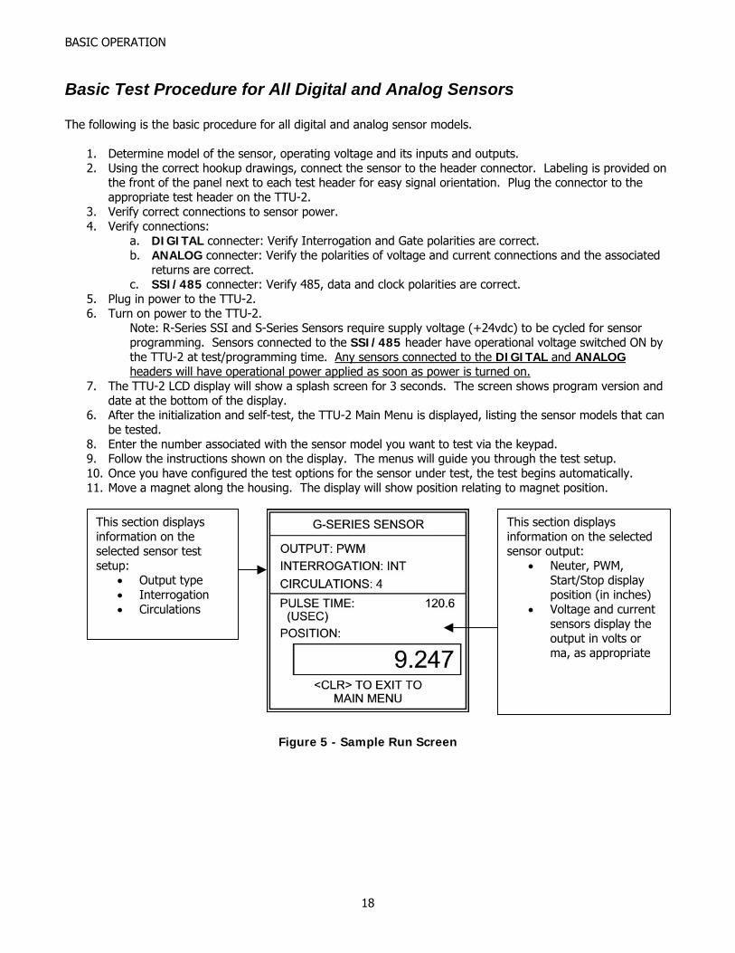
Basic Test Procedure for All Digital and Analog Sensors The following is the basic procedure for all digital and analog sensor models.
1. Determine model of the sensor, operating voltage and its inputs and outputs. 2. Using the correct hookup drawings, connect the sensor to the header connector. Labeling is provided on
the front of the panel next to each test header for easy signal orientation. Plug the connector to the appropriate test header on the TTU-2.
3. Verify correct connections to sensor power. 4. Verify connections:
a. DIGITAL connecter: Verify Interrogation and Gate polarities are correct. b. ANALOG connecter: Verify the polarities of voltage and current connections and the associated
returns are correct. c. SSI/485 connecter: Verify 485, data and clock polarities are correct.
5. Plug in power to the TTU-2. 6. Turn on power to the TTU-2.
Note: R-Series SSI and S-Series Sensors require supply voltage (+24vdc) to be cycled for sensor programming. Sensors connected to the SSI/485 header have operational voltage switched ON by the TTU-2 at test/programming time. Any sensors connected to the DIGITAL and ANALOG headers will have operational power applied as soon as power is turned on.
7. The TTU-2 LCD display will show a splash screen for 3 seconds. The screen shows program version and date at the bottom of the display.
6. After the initialization and self-test, the TTU-2 Main Menu is displayed, listing the sensor models that can be tested.
8. Enter the number associated with the sensor model you want to test via the keypad. 9. Follow the instructions shown on the display. The menus will guide you through the test setup. 10. Once you have configured the test options for the sensor under test, the test begins automatically. 11. Move a magnet along the housing. The display will show position relating to magnet position.
This section displays information on the selected sensor test setup:
• Output type • Interrogation • Circulations
This section displays information on the selected sensor output:
• Neuter, PWM, Start/Stop display position (in inches)
• Voltage and current sensors display the output in volts or ma, as appropriate
Figure 5 - Sample Run Screen
18
BASIC OPERATION
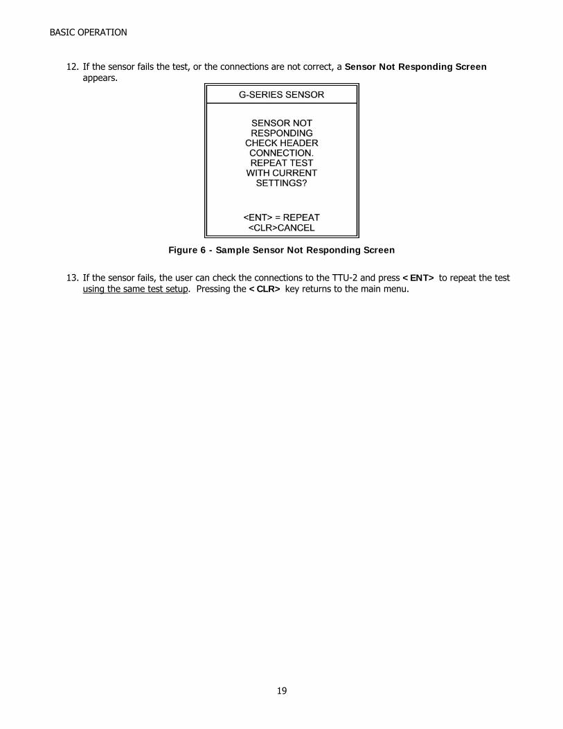
12. If the sensor fails the test, or the connections are not correct, a Sensor Not Responding Screen
appears.
Figure 6 - Sample Sensor Not Responding Screen
13. If the sensor fails, the user can check the connections to the TTU-2 and press <ENT> to repeat the test
using the same test setup. Pressing the <CLR> key returns to the main menu.
19
BASIC OPERATION
Display Interpretations for Troubleshooting • If the TTU-2 is displaying a position on a Run Screen:
o Slowly move the magnet through the full stroke length of the sensor. Observe the display as the magnet is moved.
If the displayed position stops changing but continues to show a steady position, repair or replacement is needed.
If the Sensor Not Responding Screen appears, the sensor has a dead spot, and repair or replacement is needed
o Sensors have a 2.5” dead band at the tip end of the pressure housing. Observe the display as the magnet is moved toward the tip end of the sensor, but before the 2.5” dead band is reached.
If the displayed position stops changing but continues to show a steady position, repair or replacement is needed.
If the Sensor Not Responding Screen appears, the sensor has a dead spot, and repair or replacement is needed. Pay particular attention to the magnet position while testing the sensor at the tip end. The Sensor Not Responding Screen will appear when you hit the dead band.
o Gently move the connector and/or cable connection to the head cap while observing the displayed position. If the position freezes or a Sensor Not Responding Screen is shown, the sensor needs repair. Please note: the object is to confirm a solid connection to the sensor, so exert little or no force while testing the connector and/or cabling.
o While holding the magnet steady, lightly tap the housing and observe the position on the display. (Use a small screwdriver, and tap no harder than you would tap on the back of your hand). If the position jumps significantly or a Sensor Not Responding Screen appears, the sensor has problems with the waveguide or sensor pickup and needs repair.
• If the Sensor Not Responding Screen appears (no Run Screen is displayed):
o Check the connections to the TTU-2 headers. If the connections are correct then sensor repair or replacement is needed.
o Gently move the connector and/or cable connection to the head cap while pressing <ENT> to repeat the test with current settings. If a Run Screen is displayed, the sensor connector/cabling needs repair. Please note: the object is to confirm a solid connection to the sensor, so exert little or no force while testing the connector and/or cabling.
20
CHAPTER
4DETAILED OPERATION
This chapter describes the testing of specific sensor models.
Procedure for Testing MTS I (Temposonics I) Sensors The Temposonics I sensor was the original magnetostrictive sensor offered first by the Temposonics company and then later by MTS® who bought Temposonics. For the purposes of this manual, Temposonics I sensors are referred to as MTS I sensors. They are considered neuter sensors and generally have small external electronic conversion boxes for converting the raw return signal to a useable signal for host controllers/electronics. The TTU-2 provides proper voltages for this unit. Only two basic types of MTS I sensors were built:
• Short sensors, less than 12 inches12, usually use negative interrogation. • Long sensors, 12 inches12 and longer, usually use positive interrogation. • In some cases the sensor serial number may end in ‘P’ or ‘N’, indicating ‘P’ositive or ‘N’egative
interrogation. Due to the older vintage of these sensors, the length may or may not be written on the sensor. If not, there is no way of determining the length from the model number. Therefore, it may be necessary to consult records of service or purchase to determine the length. Contact Paw-Taw-John Services, Inc., or MTS for help with this step.
CONNECTING THE SENSOR TO THE INCORRECT POLARITY OF THE INTERROGATION PULSE CAN DAMAGE OR DESTROY THE SENSOR ELECTRONICS.
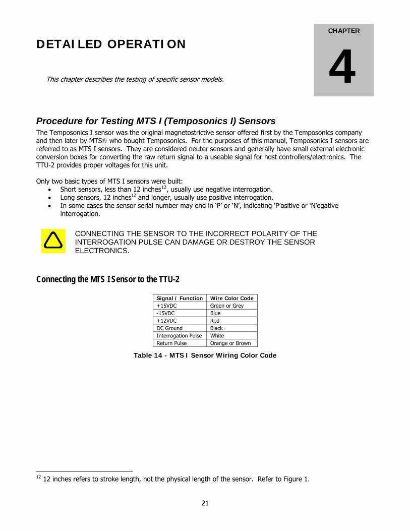
Connecting the MTS I Sensor to the TTU-2
Signal / Function Wire Color Code +15VDC Green or Grey -15VDC Blue +12VDC Red DC Ground Black Interrogation Pulse White Return Pulse Orange or Brown
Table 14 - MTS I Sensor Wiring Color Code
12 12 inches refers to stroke length, not the physical length of the sensor. Refer to Figure 1.
21
DETAILED OPERATION
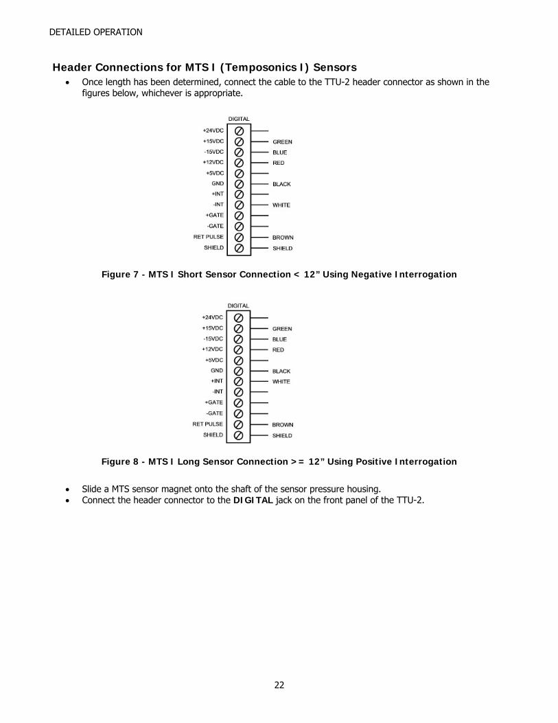
Header Connections for MTS I (Temposonics I) Sensors • Once length has been determined, connect the cable to the TTU-2 header connector as shown in the
figures below, whichever is appropriate.
Figure 7 - MTS I Short Sensor Connection < 12” Using Negative Interrogation
Figure 8 - MTS I Long Sensor Connection >= 12” Using Positive Interrogation
• Slide a MTS sensor magnet onto the shaft of the sensor pressure housing. • Connect the header connector to the DIGITAL jack on the front panel of the TTU-2.
22
DETAILED OPERATION
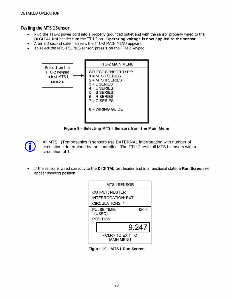
Testing the MTS I Sensor • Plug the TTU-2 power cord into a properly grounded outlet and with the sensor properly wired to the
DIGITAL test header turn the TTU-2 on. Operating voltage is now applied to the sensor. • After a 3 second splash screen, the TTU-2 MAIN MENU appears. • To select the MTS I SERIES sensor, press 1 on the TTU-2 keypad.
Press 1 on the TTU-2 keypad to test MTS I
sensors
Figure 9 - Selecting MTS I Sensors from the Main Menu
All MTS I (Temposonics I) sensors use EXTERNAL interrogation with number of circulations determined by the controller. The TTU-2 tests all MTS I sensors with a circulation of 1.
• If the sensor is wired correctly to the DIGITAL test header and in a functional state, a Run Screen will appear showing position.
Figure 10 - MTS I Run Screen
23

DETAILED OPERATION
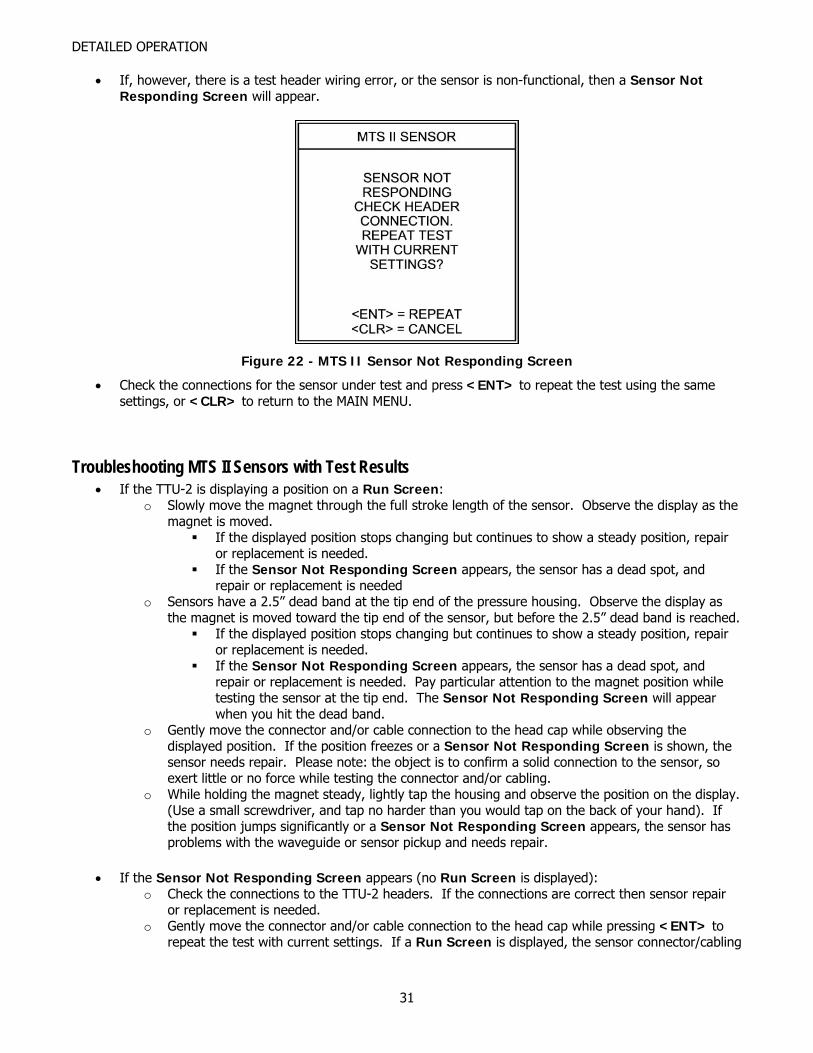
• If, however, there is a test header wiring error, or the sensor is non-functional, then a Sensor Not Responding Screen will appear.
Figure 11 - MTS I Sensor Not Responding Screen
Troubleshooting Using Test Results • If the TTU-2 is displaying a position on a Run Screen:
o Slowly move the magnet through the full stroke length of the sensor. Observe the display as the magnet is moved.
If the displayed position stops changing but continues to show a steady position, repair or replacement is needed.
If the Sensor Not Responding Screen appears, the sensor has a dead spot, and repair or replacement is needed
o Sensors have a 5-7” dead band at the tip end of the pressure housing. Observe the display as the magnet is moved toward the tip end of the sensor, but before the 5-7” dead band is reached.
If the displayed position stops changing but continues to show a steady position, repair or replacement is needed.
If the Sensor Not Responding Screen appears, the sensor has a dead spot, and repair or replacement is needed. Pay particular attention to the magnet position while testing the sensor at the tip end. The Sensor Not Responding Screen will appear when you hit the dead band.
o Gently move the connector and/or cable connection to the head cap while observing the displayed position. If the position freezes or a Sensor Not Responding Screen is shown, the sensor needs repair. Please note: the object is to confirm a solid connection to the sensor, so exert little or no force while testing the connector and/or cabling.
o While holding the magnet steady, lightly tap the housing and observe the position on the display. (Use a small screwdriver, and tap no harder than you would tap on the back of your hand). If the position jumps significantly or a Sensor Not Responding Screen appears, the sensor has problems with the waveguide or sensor pickup and needs repair.
• If the Sensor Not Responding Screen appears (no Run Screen is displayed):
o Check the connections to the TTU-2 headers. If the connections are correct then sensor repair or replacement is needed.
o Gently move the connector and/or cable connection to the head cap while pressing <ENT> to repeat the test with current settings. If a Run Screen is displayed, the sensor connector/cabling needs repair. Please note: the object is to confirm a solid connection to the sensor, so exert little or no force while testing the connector and/or cabling.
24
DETAILED OPERATION
Procedure for Testing MTS II (Temposonics II) Sensors The Temposonics II sensor was a magnetostrictive sensor offered first by the Temposonics Company and then later by MTS who bought Temposonics. For the purposes of this manual, Temposonics II sensors are referred to as MTS II sensors. The TTU-2 DIGITAL and ANALOG headers provide proper voltages for this unit. NOTE: In reference to the term sensor length, the term refers to the stroke length of the sensor, not the physical length of the sensor. All sensors have a dead zone at the tip end, and a null zone at the head end. Refer to Figure 1.
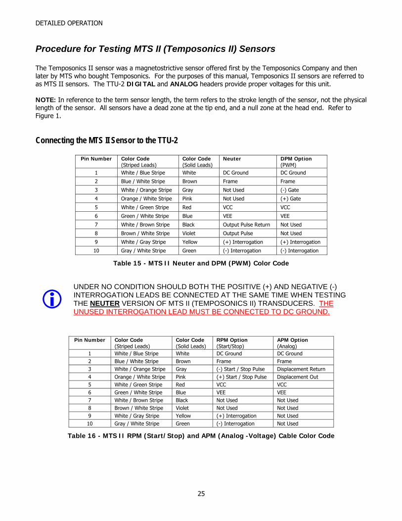
Connecting the MTS II Sensor to the TTU-2
Pin Number Color Code (Striped Leads)
Color Code (Solid Leads)
Neuter DPM Option (PWM)
1 White / Blue Stripe White DC Ground DC Ground
2 Blue / White Stripe Brown Frame Frame
3 White / Orange Stripe Gray Not Used (-) Gate
4 Orange / White Stripe Pink Not Used (+) Gate
5 White / Green Stripe Red VCC VCC
6 Green / White Stripe Blue VEE VEE
7 White / Brown Stripe Black Output Pulse Return Not Used
8 Brown / White Stripe Violet Output Pulse Not Used
9 White / Gray Stripe Yellow (+) Interrogation (+) Interrogation
10 Gray / White Stripe Green (-) Interrogation (-) Interrogation
Table 15 - MTS II Neuter and DPM (PWM) Color Code
UNDER NO CONDITION SHOULD BOTH THE POSITIVE (+) AND NEGATIVE (-) INTERROGATION LEADS BE CONNECTED AT THE SAME TIME WHEN TESTING THE NEUTER VERSION OF MTS II (TEMPOSONICS II) TRANSDUCERS. THE UNUSED INTERROGATION LEAD MUST BE CONNECTED TO DC GROUND.
Pin Number Color Code (Striped Leads)
Color Code (Solid Leads)
RPM Option (Start/Stop)
APM Option (Analog)
1 White / Blue Stripe White DC Ground DC Ground 2 Blue / White Stripe Brown Frame Frame 3 White / Orange Stripe Gray (-) Start / Stop Pulse Displacement Return 4 Orange / White Stripe Pink (+) Start / Stop Pulse Displacement Out 5 White / Green Stripe Red VCC VCC 6 Green / White Stripe Blue VEE VEE 7 White / Brown Stripe Black Not Used Not Used 8 Brown / White Stripe Violet Not Used Not Used 9 White / Gray Stripe Yellow (+) Interrogation Not Used 10 Gray / White Stripe Green (-) Interrogation Not Used
Table 16 - MTS II RPM (Start/Stop) and APM (Analog -Voltage) Cable Color Code
25
DETAILED OPERATION
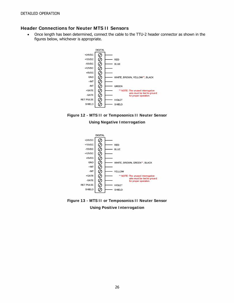
Header Connections for Neuter MTS II Sensors • Once length has been determined, connect the cable to the TTU-2 header connector as shown in the
figures below, whichever is appropriate.
Figure 12 - MTS II or Temposonics II Neuter Sensor
Using Negative Interrogation
Figure 13 - MTS II or Temposonics II Neuter Sensor
Using Positive Interrogation
26
DETAILED OPERATION
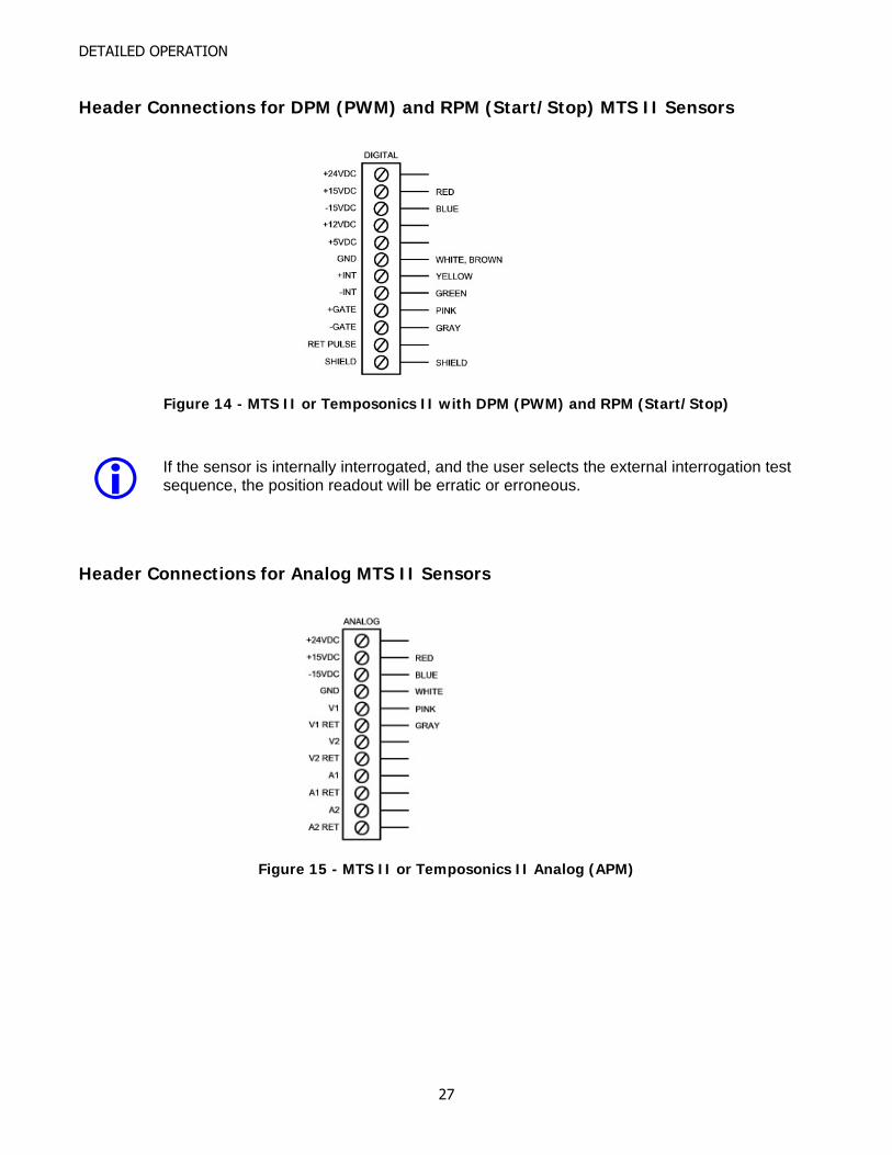
Header Connections for DPM (PWM) and RPM (Start/Stop) MTS II Sensors
Figure 14 - MTS II or Temposonics II with DPM (PWM) and RPM (Start/Stop)
If the sensor is internally interrogated, and the user selects the external interrogation test sequence, the position readout will be erratic or erroneous.
Header Connections for Analog MTS II Sensors
Figure 15 - MTS II or Temposonics II Analog (APM)
27
DETAILED OPERATION
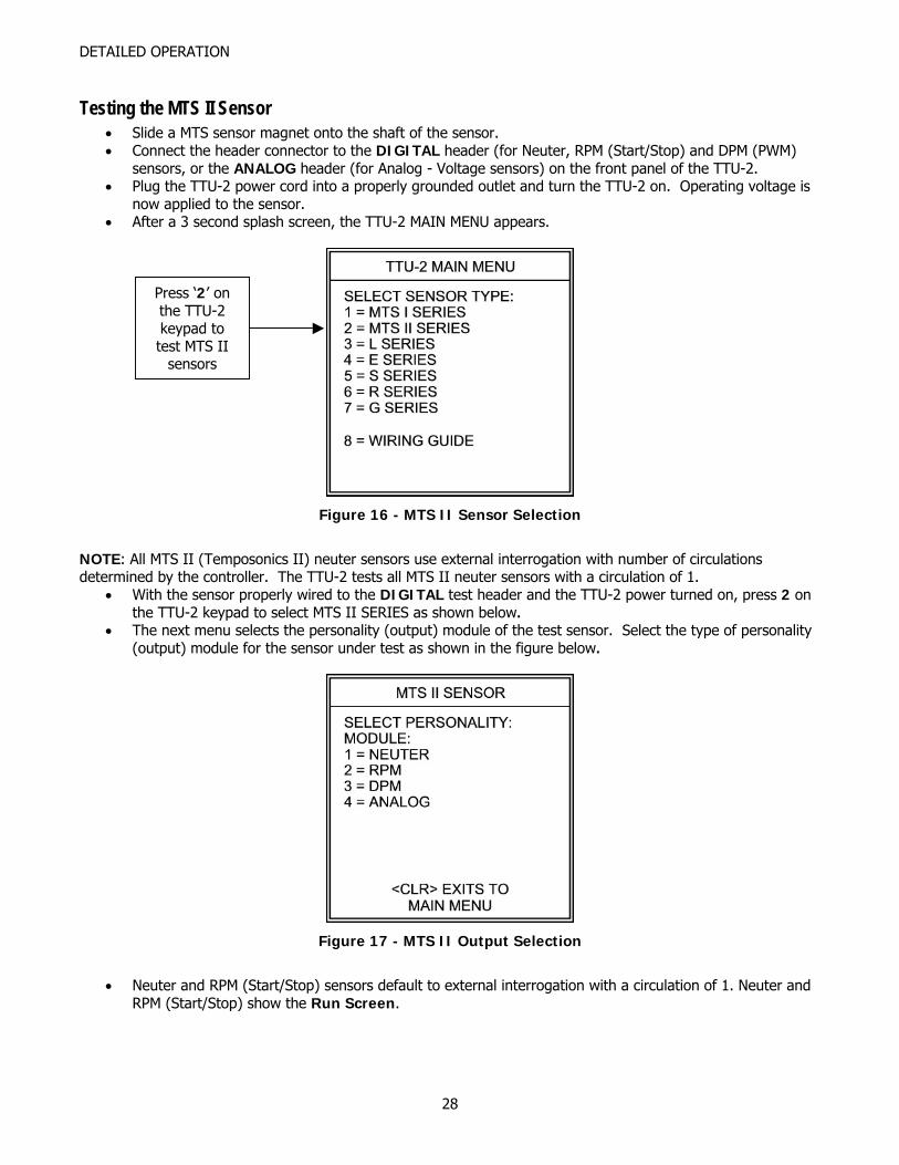
Testing the MTS II Sensor • Slide a MTS sensor magnet onto the shaft of the sensor. • Connect the header connector to the DIGITAL header (for Neuter, RPM (Start/Stop) and DPM (PWM)
sensors, or the ANALOG header (for Analog - Voltage sensors) on the front panel of the TTU-2. • Plug the TTU-2 power cord into a properly grounded outlet and turn the TTU-2 on. Operating voltage is
now applied to the sensor. • After a 3 second splash screen, the TTU-2 MAIN MENU appears.
Press ‘2’ on the TTU-2 keypad to test MTS II
sensors
Figure 16 - MTS II Sensor Selection
NOTE: All MTS II (Temposonics II) neuter sensors use external interrogation with number of circulations determined by the controller. The TTU-2 tests all MTS II neuter sensors with a circulation of 1.
• With the sensor properly wired to the DIGITAL test header and the TTU-2 power turned on, press 2 on the TTU-2 keypad to select MTS II SERIES as shown below.
• The next menu selects the personality (output) module of the test sensor. Select the type of personality (output) module for the sensor under test as shown in the figure below.
Figure 17 - MTS II Output Selection
• Neuter and RPM (Start/Stop) sensors default to external interrogation with a circulation of 1. Neuter and
RPM (Start/Stop) show the Run Screen.
28
DETAILED OPERATION
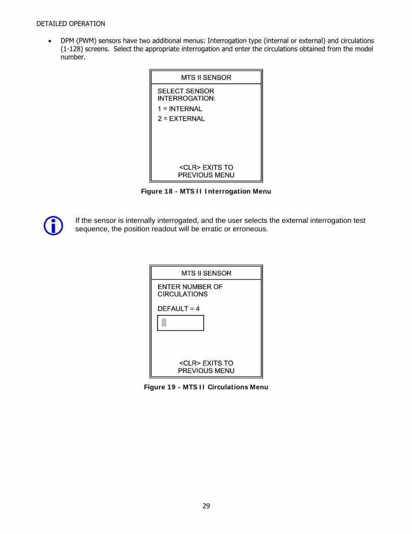
• DPM (PWM) sensors have two additional menus: Interrogation type (internal or external) and circulations (1-128) screens. Select the appropriate interrogation and enter the circulations obtained from the model number.
Figure 18 - MTS II Interrogation Menu
If the sensor is internally interrogated, and the user selects the external interrogation test sequence, the position readout will be erratic or erroneous.
Figure 19 - MTS II Circulations Menu
29
DETAILED OPERATION
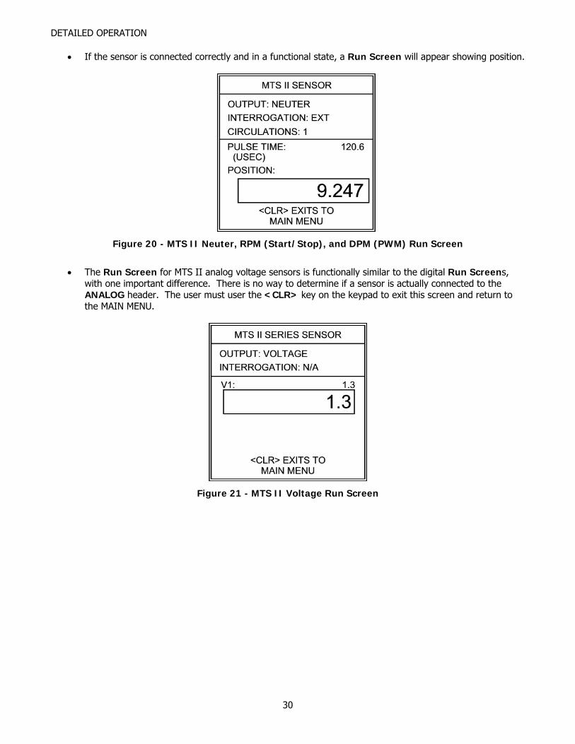
• If the sensor is connected correctly and in a functional state, a Run Screen will appear showing position.
Figure 20 - MTS II Neuter, RPM (Start/Stop), and DPM (PWM) Run Screen
• The Run Screen for MTS II analog voltage sensors is functionally similar to the digital Run Screens,
with one important difference. There is no way to determine if a sensor is actually connected to the ANALOG header. The user must user the <CLR> key on the keypad to exit this screen and return to the MAIN MENU.
Figure 21 - MTS II Voltage Run Screen
30
DETAILED OPERATION
• If, however, there is a test header wiring error, or the sensor is non-functional, then a Sensor Not Responding Screen will appear.
Figure 22 - MTS II Sensor Not Responding Screen
• Check the connections for the sensor under test and press <ENT> to repeat the test using the same settings, or <CLR> to return to the MAIN MENU.
Troubleshooting MTS II Sensors with Test Results • If the TTU-2 is displaying a position on a Run Screen:
o Slowly move the magnet through the full stroke length of the sensor. Observe the display as the magnet is moved.
If the displayed position stops changing but continues to show a steady position, repair or replacement is needed.
If the Sensor Not Responding Screen appears, the sensor has a dead spot, and repair or replacement is needed
o Sensors have a 2.5” dead band at the tip end of the pressure housing. Observe the display as the magnet is moved toward the tip end of the sensor, but before the 2.5” dead band is reached.
If the displayed position stops changing but continues to show a steady position, repair or replacement is needed.
If the Sensor Not Responding Screen appears, the sensor has a dead spot, and repair or replacement is needed. Pay particular attention to the magnet position while testing the sensor at the tip end. The Sensor Not Responding Screen will appear when you hit the dead band.
o Gently move the connector and/or cable connection to the head cap while observing the displayed position. If the position freezes or a Sensor Not Responding Screen is shown, the sensor needs repair. Please note: the object is to confirm a solid connection to the sensor, so exert little or no force while testing the connector and/or cabling.
o While holding the magnet steady, lightly tap the housing and observe the position on the display. (Use a small screwdriver, and tap no harder than you would tap on the back of your hand). If the position jumps significantly or a Sensor Not Responding Screen appears, the sensor has problems with the waveguide or sensor pickup and needs repair.
• If the Sensor Not Responding Screen appears (no Run Screen is displayed):
o Check the connections to the TTU-2 headers. If the connections are correct then sensor repair or replacement is needed.
o Gently move the connector and/or cable connection to the head cap while pressing <ENT> to repeat the test with current settings. If a Run Screen is displayed, the sensor connector/cabling
31

DETAILED OPERATION
needs repair. Please note: the object is to confirm a solid connection to the sensor, so exert little or no force while testing the connector and/or cabling.
32
DETAILED OPERATION
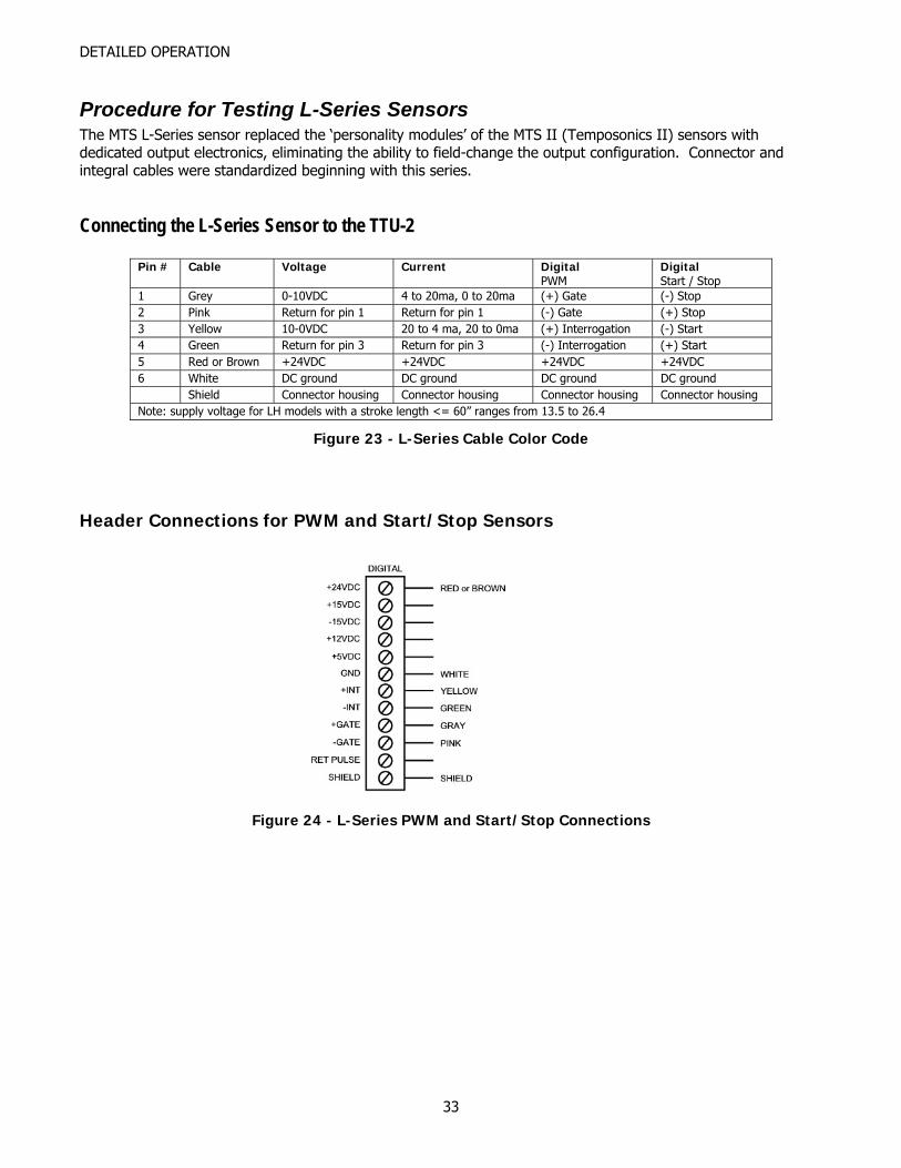
Procedure for Testing L-Series Sensors The MTS L-Series sensor replaced the ‘personality modules’ of the MTS II (Temposonics II) sensors with dedicated output electronics, eliminating the ability to field-change the output configuration. Connector and integral cables were standardized beginning with this series.
Connecting the L-Series Sensor to the TTU-2
Pin # Cable Voltage Current Digital PWM
Digital Start / Stop
1 Grey 0-10VDC 4 to 20ma, 0 to 20ma (+) Gate (-) Stop 2 Pink Return for pin 1 Return for pin 1 (-) Gate (+) Stop 3 Yellow 10-0VDC 20 to 4 ma, 20 to 0ma (+) Interrogation (-) Start 4 Green Return for pin 3 Return for pin 3 (-) Interrogation (+) Start 5 Red or Brown +24VDC +24VDC +24VDC +24VDC 6 White DC ground DC ground DC ground DC ground Shield Connector housing Connector housing Connector housing Connector housing Note: supply voltage for LH models with a stroke length <= 60” ranges from 13.5 to 26.4
Figure 23 - L-Series Cable Color Code
Header Connections for PWM and Start/Stop Sensors
Figure 24 - L-Series PWM and Start/Stop Connections
33
DETAILED OPERATION
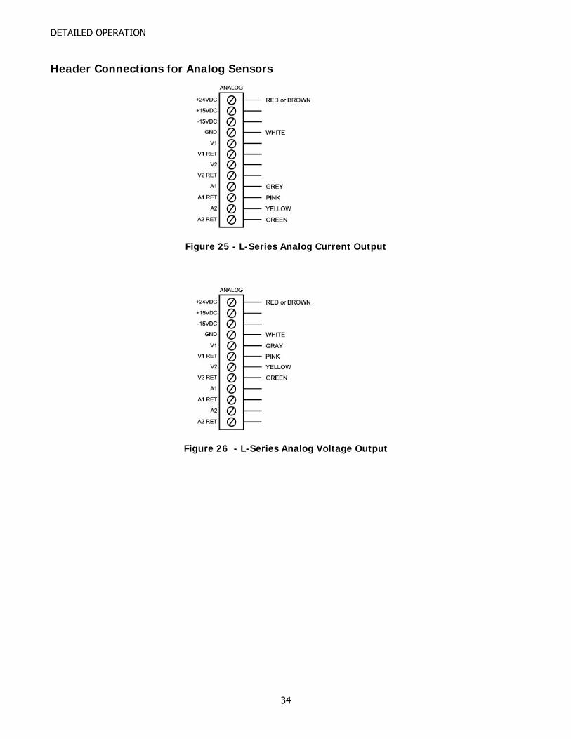
Header Connections for Analog Sensors
Figure 25 - L-Series Analog Current Output
Figure 26 - L-Series Analog Voltage Output
34
DETAILED OPERATION
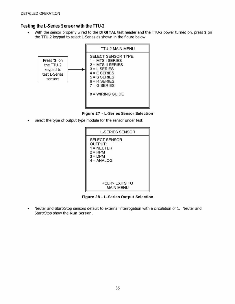
Testing the L-Series Sensor with the TTU-2 • With the sensor properly wired to the DIGITAL test header and the TTU-2 power turned on, press 3 on
the TTU-2 keypad to select L-Series as shown in the figure below.
Press ‘3’ on the TTU-2 keypad to
test L-Series sensors
Figure 27 - L-Series Sensor Selection
• Select the type of output type module for the sensor under test.
Figure 28 - L-Series Output Selection
• Neuter and Start/Stop sensors default to external interrogation with a circulation of 1. Neuter and
Start/Stop show the Run Screen.
35
DETAILED OPERATION
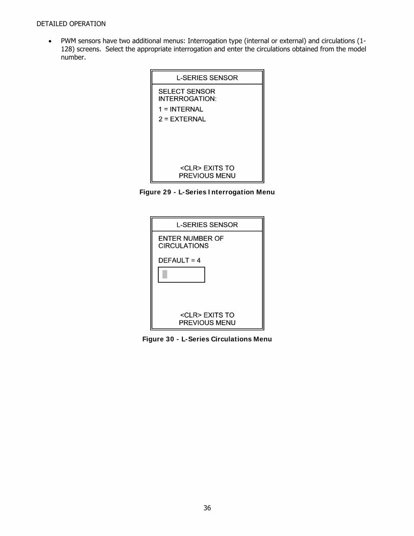
• PWM sensors have two additional menus: Interrogation type (internal or external) and circulations (1-128) screens. Select the appropriate interrogation and enter the circulations obtained from the model number.
Figure 29 - L-Series Interrogation Menu
Figure 30 - L-Series Circulations Menu
36
DETAILED OPERATION
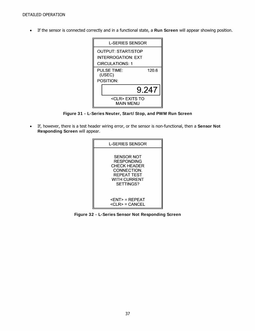
• If the sensor is connected correctly and in a functional state, a Run Screen will appear showing position.
Figure 31 - L-Series Neuter, Start/Stop, and PWM Run Screen
• If, however, there is a test header wiring error, or the sensor is non-functional, then a Sensor Not
Responding Screen will appear.
Figure 32 - L-Series Sensor Not Responding Screen
37
DETAILED OPERATION
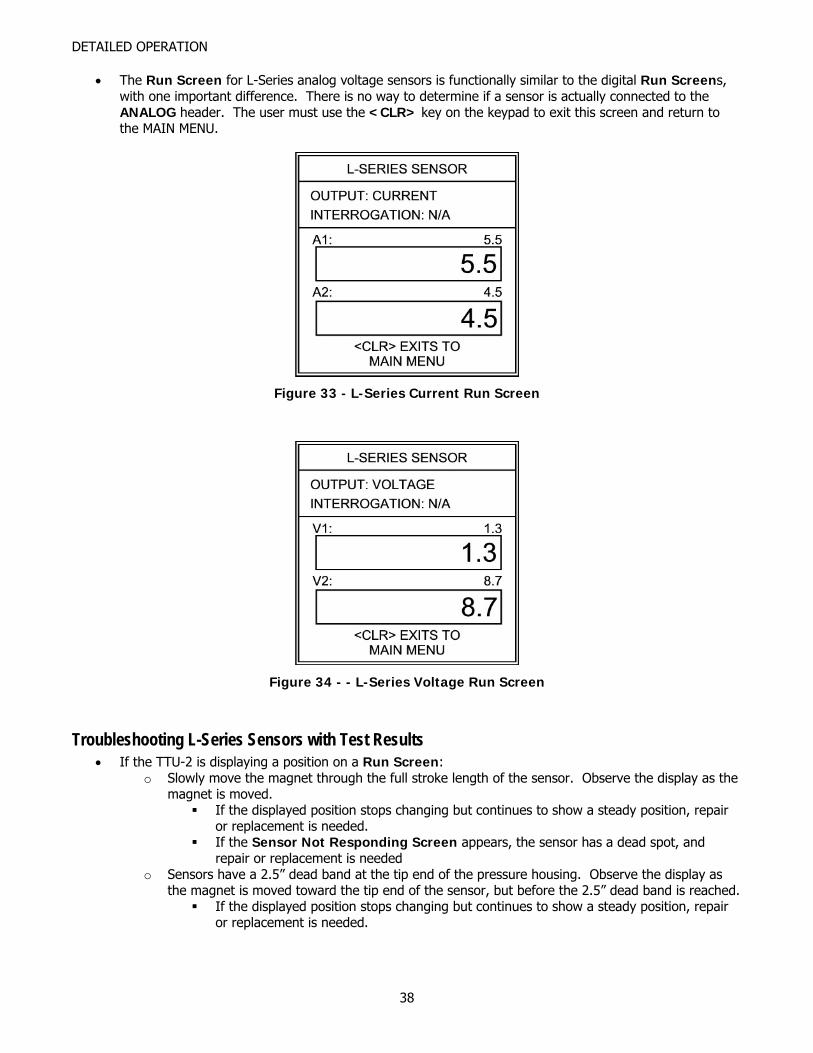
• The Run Screen for L-Series analog voltage sensors is functionally similar to the digital Run Screens, with one important difference. There is no way to determine if a sensor is actually connected to the ANALOG header. The user must use the <CLR> key on the keypad to exit this screen and return to the MAIN MENU.
Figure 33 - L-Series Current Run Screen
Figure 34 - - L-Series Voltage Run Screen
Troubleshooting L-Series Sensors with Test Results • If the TTU-2 is displaying a position on a Run Screen:
o Slowly move the magnet through the full stroke length of the sensor. Observe the display as the magnet is moved.
If the displayed position stops changing but continues to show a steady position, repair or replacement is needed.
If the Sensor Not Responding Screen appears, the sensor has a dead spot, and repair or replacement is needed
o Sensors have a 2.5” dead band at the tip end of the pressure housing. Observe the display as the magnet is moved toward the tip end of the sensor, but before the 2.5” dead band is reached.
If the displayed position stops changing but continues to show a steady position, repair or replacement is needed.
38
DETAILED OPERATION
If the Sensor Not Responding Screen appears, the sensor has a dead spot, and repair or replacement is needed. Pay particular attention to the magnet position while testing the sensor at the tip end. The Sensor Not Responding Screen will appear when you hit the dead band.
o Gently move the connector and/or cable connection to the head cap while observing the displayed position. If the position freezes or a Sensor Not Responding Screen is shown, the sensor needs repair. Please note: the object is to confirm a solid connection to the sensor, so exert little or no force while testing the connector and/or cabling.
o While holding the magnet steady, lightly tap the housing and observe the position on the display. (Use a small screwdriver, and tap no harder than you would tap on the back of your hand). If the position jumps significantly or a Sensor Not Responding Screen appears, the sensor has problems with the waveguide or sensor pickup and needs repair.
• If the Sensor Not Responding Screen appears (no Run Screen is displayed):
o Check the connections to the TTU-2 headers. If the connections are correct then sensor repair or replacement is needed.
o Gently move the connector and/or cable connection to the head cap while pressing <ENT> to repeat the test with current settings. If a Run Screen is displayed, the sensor connector/cabling needs repair. Please note: the object is to confirm a solid connection to the sensor, so exert little or no force while testing the connector and/or cabling.
39
DETAILED OPERATION
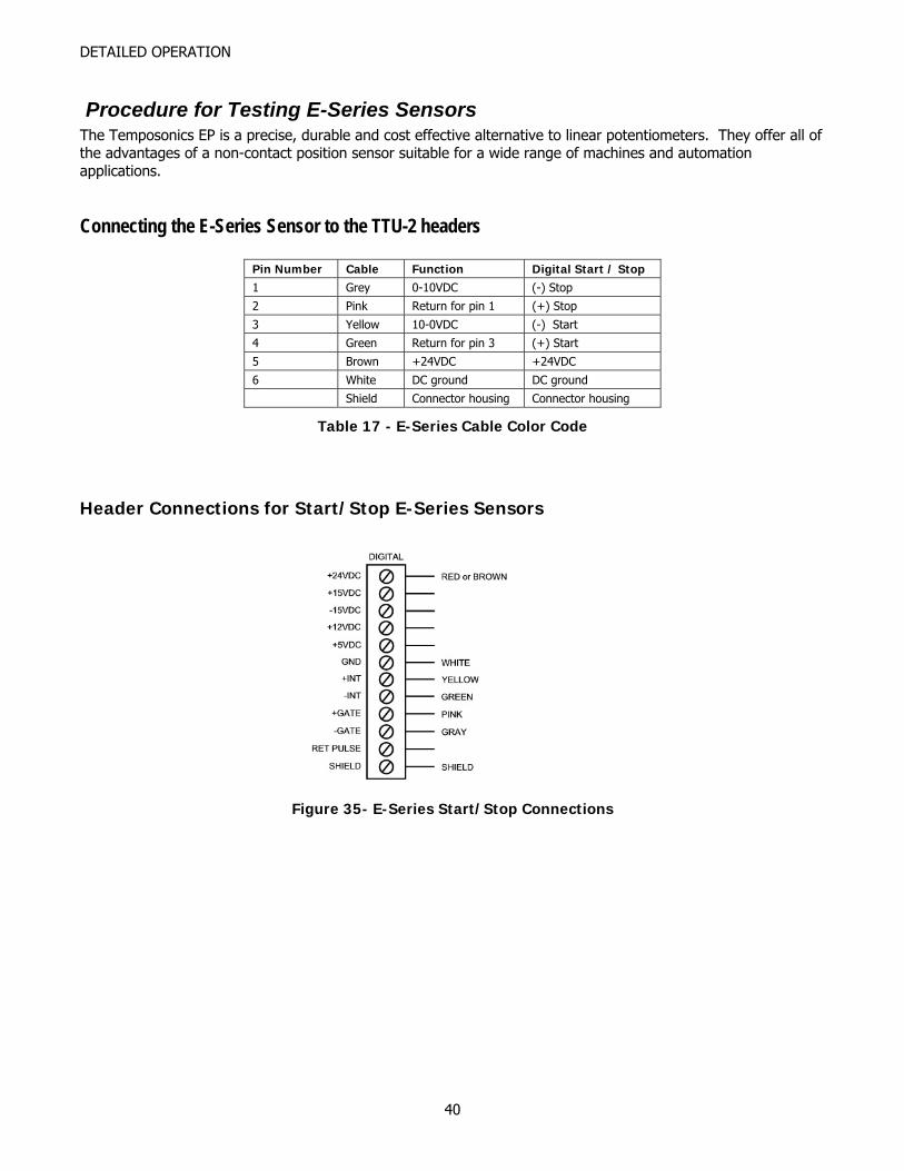
Procedure for Testing E-Series Sensors The Temposonics EP is a precise, durable and cost effective alternative to linear potentiometers. They offer all of the advantages of a non-contact position sensor suitable for a wide range of machines and automation applications.
Connecting the E-Series Sensor to the TTU-2 headers
Pin Number Cable Function Digital Start / Stop 1 Grey 0-10VDC (-) Stop
2 Pink Return for pin 1 (+) Stop
3 Yellow 10-0VDC (-) Start
4 Green Return for pin 3 (+) Start
5 Brown +24VDC +24VDC
6 White DC ground DC ground
Shield Connector housing Connector housing
Table 17 - E-Series Cable Color Code
Header Connections for Start/Stop E-Series Sensors
Figure 35- E-Series Start/Stop Connections
40
DETAILED OPERATION
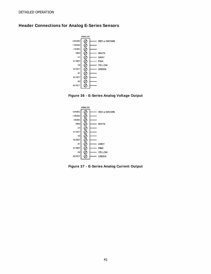
Header Connections for Analog E-Series Sensors
Figure 36 - E-Series Analog Voltage Output
Figure 37 - E-Series Analog Current Output
41
DETAILED OPERATION
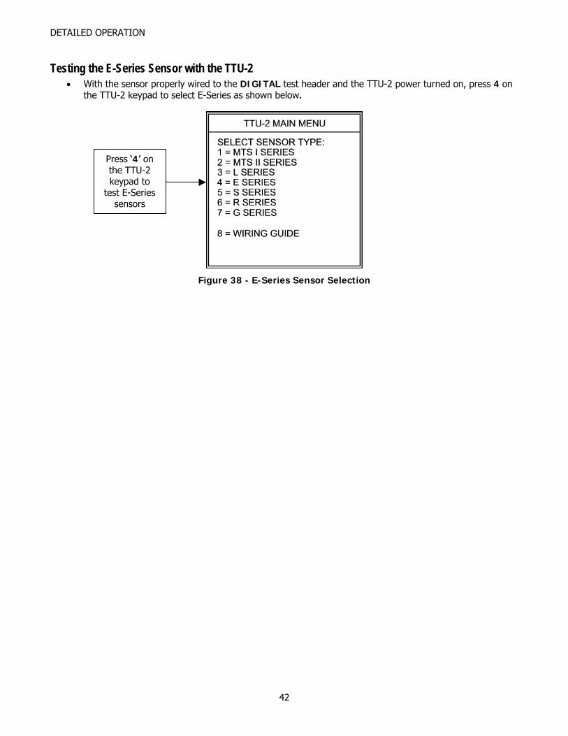
Testing the E-Series Sensor with the TTU-2 • With the sensor properly wired to the DIGITAL test header and the TTU-2 power turned on, press 4 on
the TTU-2 keypad to select E-Series as shown below.
Press ‘4’ on the TTU-2 keypad to
test E-Series sensors
Figure 38 - E-Series Sensor Selection
42
DETAILED OPERATION
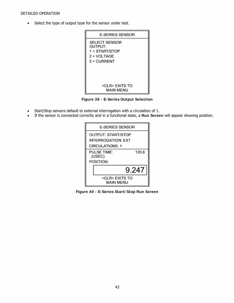
• Select the type of output type for the sensor under test.
Figure 39 - E-Series Output Selection
• Start/Stop sensors default to external interrogation with a circulation of 1. • If the sensor is connected correctly and in a functional state, a Run Screen will appear showing position.
Figure 40 - E-Series Start/Stop Run Screen
43
DETAILED OPERATION
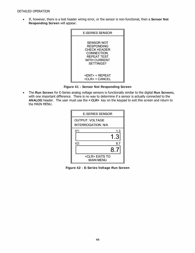
• If, however, there is a test header wiring error, or the sensor is non-functional, then a Sensor Not Responding Screen will appear.
Figure 41 - Sensor Not Responding Screen
• The Run Screen for E-Series analog voltage sensors is functionally similar to the digital Run Screens, with one important difference. There is no way to determine if a sensor is actually connected to the ANALOG header. The user must use the <CLR> key on the keypad to exit this screen and return to the MAIN MENU.
Figure 42 - E-Series Voltage Run Screen
44
DETAILED OPERATION
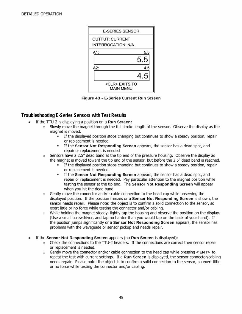
Figure 43 - E-Series Current Run Screen
Troubleshooting E-Series Sensors with Test Results • If the TTU-2 is displaying a position on a Run Screen:
o Slowly move the magnet through the full stroke length of the sensor. Observe the display as the magnet is moved.
If the displayed position stops changing but continues to show a steady position, repair or replacement is needed.
If the Sensor Not Responding Screen appears, the sensor has a dead spot, and repair or replacement is needed
o Sensors have a 2.5” dead band at the tip end of the pressure housing. Observe the display as the magnet is moved toward the tip end of the sensor, but before the 2.5” dead band is reached.
If the displayed position stops changing but continues to show a steady position, repair or replacement is needed.
If the Sensor Not Responding Screen appears, the sensor has a dead spot, and repair or replacement is needed. Pay particular attention to the magnet position while testing the sensor at the tip end. The Sensor Not Responding Screen will appear when you hit the dead band.
o Gently move the connector and/or cable connection to the head cap while observing the displayed position. If the position freezes or a Sensor Not Responding Screen is shown, the sensor needs repair. Please note: the object is to confirm a solid connection to the sensor, so exert little or no force while testing the connector and/or cabling.
o While holding the magnet steady, lightly tap the housing and observe the position on the display. (Use a small screwdriver, and tap no harder than you would tap on the back of your hand). If the position jumps significantly or a Sensor Not Responding Screen appears, the sensor has problems with the waveguide or sensor pickup and needs repair.
• If the Sensor Not Responding Screen appears (no Run Screen is displayed):
o Check the connections to the TTU-2 headers. If the connections are correct then sensor repair or replacement is needed.
o Gently move the connector and/or cable connection to the head cap while pressing <ENT> to repeat the test with current settings. If a Run Screen is displayed, the sensor connector/cabling needs repair. Please note: the object is to confirm a solid connection to the sensor, so exert little or no force while testing the connector and/or cabling.
45
DETAILED OPERATION
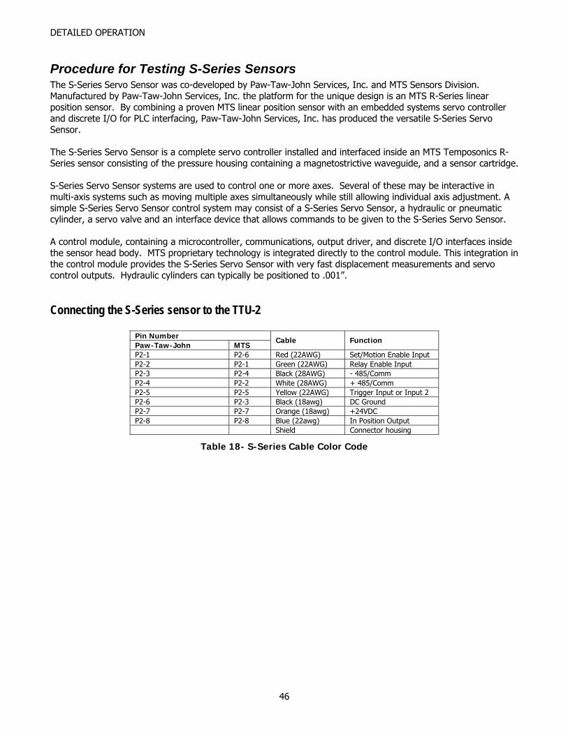
Procedure for Testing S-Series Sensors The S-Series Servo Sensor was co-developed by Paw-Taw-John Services, Inc. and MTS Sensors Division. Manufactured by Paw-Taw-John Services, Inc. the platform for the unique design is an MTS R-Series linear position sensor. By combining a proven MTS linear position sensor with an embedded systems servo controller and discrete I/O for PLC interfacing, Paw-Taw-John Services, Inc. has produced the versatile S-Series Servo Sensor. The S-Series Servo Sensor is a complete servo controller installed and interfaced inside an MTS Temposonics R-Series sensor consisting of the pressure housing containing a magnetostrictive waveguide, and a sensor cartridge. S-Series Servo Sensor systems are used to control one or more axes. Several of these may be interactive in multi-axis systems such as moving multiple axes simultaneously while still allowing individual axis adjustment. A simple S-Series Servo Sensor control system may consist of a S-Series Servo Sensor, a hydraulic or pneumatic cylinder, a servo valve and an interface device that allows commands to be given to the S-Series Servo Sensor. A control module, containing a microcontroller, communications, output driver, and discrete I/O interfaces inside the sensor head body. MTS proprietary technology is integrated directly to the control module. This integration in the control module provides the S-Series Servo Sensor with very fast displacement measurements and servo control outputs. Hydraulic cylinders can typically be positioned to .001”.
Connecting the S-Series sensor to the TTU-2
Pin Number Paw-Taw-John MTS
Cable Function
P2-1 P2-6 Red (22AWG) Set/Motion Enable Input P2-2 P2-1 Green (22AWG) Relay Enable Input P2-3 P2-4 Black (28AWG) - 485/Comm P2-4 P2-2 White (28AWG) + 485/Comm P2-5 P2-5 Yellow (22AWG) Trigger Input or Input 2 P2-6 P2-3 Black (18awg) DC Ground P2-7 P2-7 Orange (18awg) +24VDC P2-8 P2-8 Blue (22awg) In Position Output Shield Connector housing
Table 18- S-Series Cable Color Code
46
DETAILED OPERATION
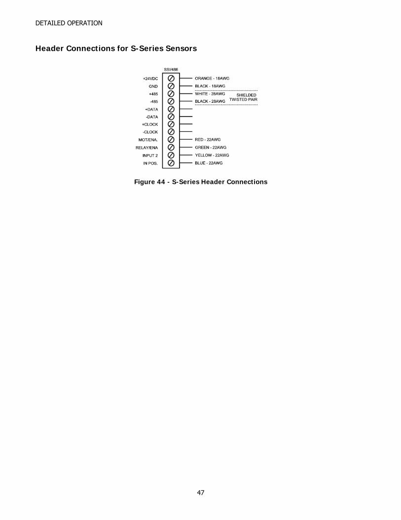
Header Connections for S-Series Sensors
Figure 44 - S-Series Header Connections
47
DETAILED OPERATION
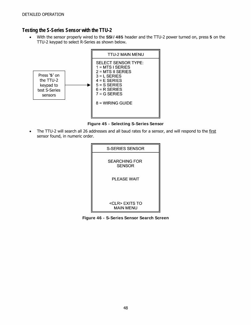
Testing the S-Series Sensor with the TTU-2 • With the sensor properly wired to the SSI/485 header and the TTU-2 power turned on, press 5 on the
TTU-2 keypad to select R-Series as shown below.
Press ‘5’ on the TTU-2 keypad to
test S-Series sensors
Figure 45 - Selecting S-Series Sensor
• The TTU-2 will search all 26 addresses and all baud rates for a sensor, and will respond to the first sensor found, in numeric order.
Figure 46 - S-Series Sensor Search Screen
48
DETAILED OPERATION
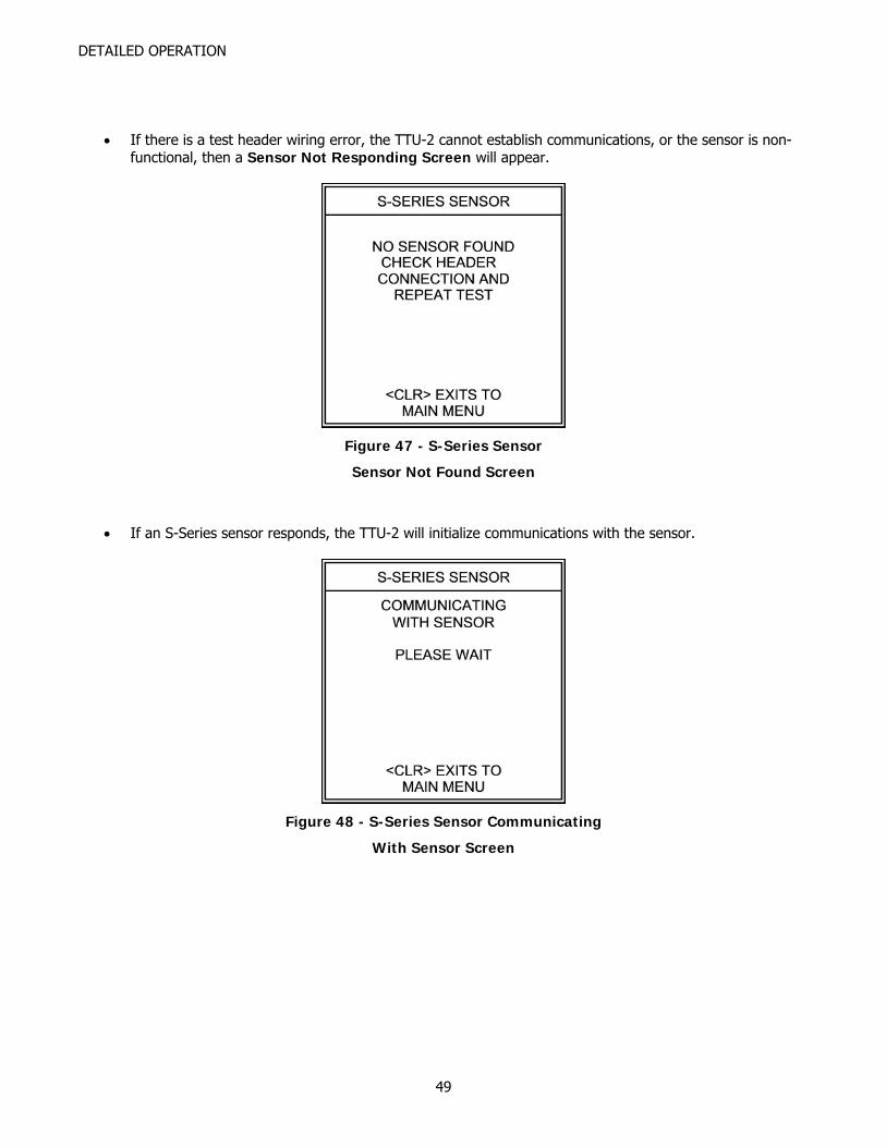
• If there is a test header wiring error, the TTU-2 cannot establish communications, or the sensor is non-
functional, then a Sensor Not Responding Screen will appear.
Figure 47 - S-Series Sensor
Sensor Not Found Screen
• If an S-Series sensor responds, the TTU-2 will initialize communications with the sensor.
Figure 48 - S-Series Sensor Communicating
With Sensor Screen
49
DETAILED OPERATION
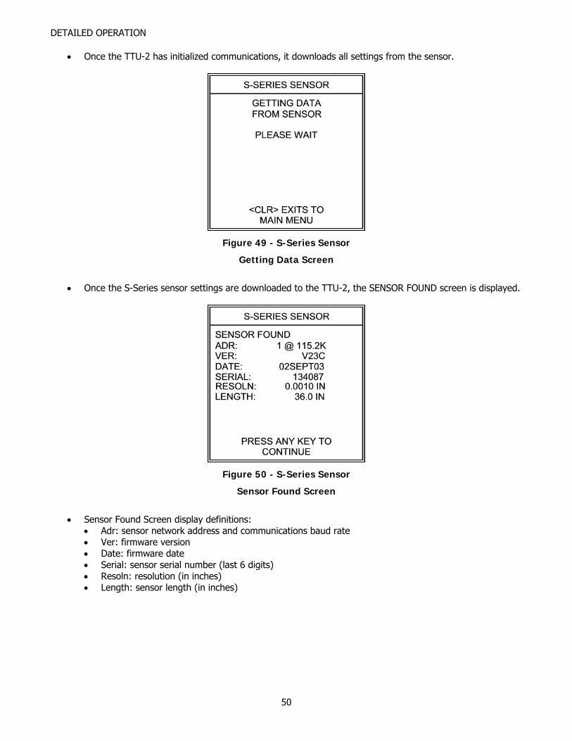
• Once the TTU-2 has initialized communications, it downloads all settings from the sensor.
Figure 49 - S-Series Sensor
Getting Data Screen
• Once the S-Series sensor settings are downloaded to the TTU-2, the SENSOR FOUND screen is displayed.
Figure 50 - S-Series Sensor
Sensor Found Screen
• Sensor Found Screen display definitions:
• Adr: sensor network address and communications baud rate • Ver: firmware version • Date: firmware date • Serial: sensor serial number (last 6 digits) • Resoln: resolution (in inches) • Length: sensor length (in inches)
50
DETAILED OPERATION
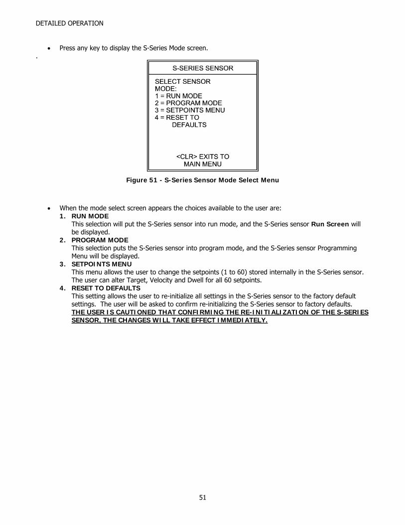
• Press any key to display the S-Series Mode screen.
.
Figure 51 - S-Series Sensor Mode Select Menu
• When the mode select screen appears the choices available to the user are: 1. RUN MODE
This selection will put the S-Series sensor into run mode, and the S-Series sensor Run Screen will be displayed.
2. PROGRAM MODE This selection puts the S-Series sensor into program mode, and the S-Series sensor Programming Menu will be displayed.
3. SETPOINTS MENU This menu allows the user to change the setpoints (1 to 60) stored internally in the S-Series sensor. The user can alter Target, Velocity and Dwell for all 60 setpoints.
4. RESET TO DEFAULTS This setting allows the user to re-initialize all settings in the S-Series sensor to the factory default settings. The user will be asked to confirm re-initializing the S-Series sensor to factory defaults. THE USER IS CAUTIONED THAT CONFIRMING THE RE-INITIALIZATION OF THE S-SERIES SENSOR, THE CHANGES WILL TAKE EFFECT IMMEDIATELY.
51
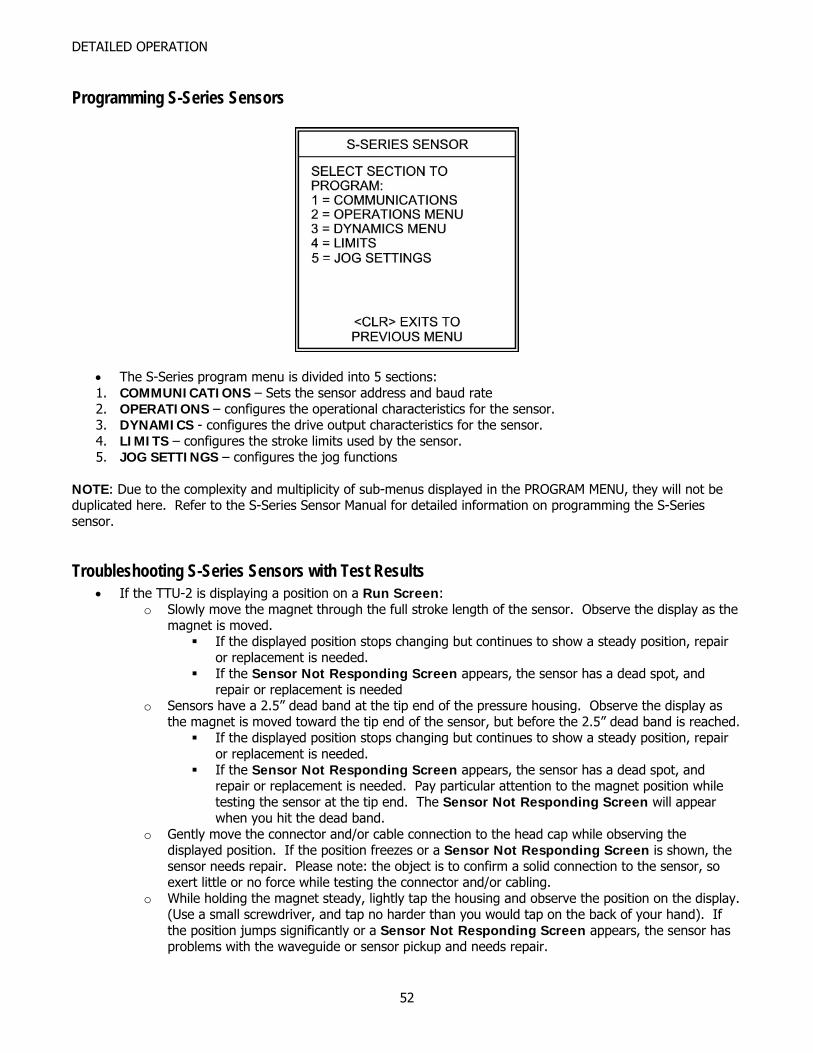
DETAILED OPERATION
Programming S-Series Sensors
• The S-Series program menu is divided into 5 sections: 1. COMMUNICATIONS – Sets the sensor address and baud rate 2. OPERATIONS – configures the operational characteristics for the sensor. 3. DYNAMICS - configures the drive output characteristics for the sensor. 4. LIMITS – configures the stroke limits used by the sensor. 5. JOG SETTINGS – configures the jog functions
NOTE: Due to the complexity and multiplicity of sub-menus displayed in the PROGRAM MENU, they will not be duplicated here. Refer to the S-Series Sensor Manual for detailed information on programming the S-Series sensor.
Troubleshooting S-Series Sensors with Test Results • If the TTU-2 is displaying a position on a Run Screen:
o Slowly move the magnet through the full stroke length of the sensor. Observe the display as the magnet is moved.
If the displayed position stops changing but continues to show a steady position, repair or replacement is needed.
If the Sensor Not Responding Screen appears, the sensor has a dead spot, and repair or replacement is needed
o Sensors have a 2.5” dead band at the tip end of the pressure housing. Observe the display as the magnet is moved toward the tip end of the sensor, but before the 2.5” dead band is reached.
If the displayed position stops changing but continues to show a steady position, repair or replacement is needed.
If the Sensor Not Responding Screen appears, the sensor has a dead spot, and repair or replacement is needed. Pay particular attention to the magnet position while testing the sensor at the tip end. The Sensor Not Responding Screen will appear when you hit the dead band.
o Gently move the connector and/or cable connection to the head cap while observing the displayed position. If the position freezes or a Sensor Not Responding Screen is shown, the sensor needs repair. Please note: the object is to confirm a solid connection to the sensor, so exert little or no force while testing the connector and/or cabling.
o While holding the magnet steady, lightly tap the housing and observe the position on the display. (Use a small screwdriver, and tap no harder than you would tap on the back of your hand). If the position jumps significantly or a Sensor Not Responding Screen appears, the sensor has problems with the waveguide or sensor pickup and needs repair.
52

DETAILED OPERATION
• If the Sensor Not Responding Screen appears (no Run Screen is displayed):
o Check the connections to the TTU-2 headers. If the connections are correct then sensor repair or replacement is needed.
o Gently move the connector and/or cable connection to the head cap while pressing <ENT> to repeat the test with current settings. If a Run Screen is displayed, the sensor connector/cabling needs repair. Please note: the object is to confirm a solid connection to the sensor, so exert little or no force while testing the connector and/or cabling.
53
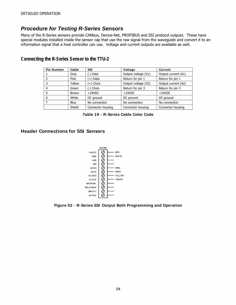
DETAILED OPERATION
Procedure for Testing R-Series Sensors Many of the R-Series sensors provide CANbus, Device-Net, PROFIBUS and SSI protocol outputs. These have special modules installed inside the sensor cap that use the raw signal from the waveguide and convert it to an information signal that a host controller can use. Voltage and current outputs are available as well.
Connecting the R-Series Sensor to the TTU-2
Pin Number Cable SSI Voltage Current 1 Grey (-) Data Output voltage (V1) Output current (A1) 2 Pink (+) Data Return for pin 1 Return for pin 1 3 Yellow (+) Clock Output voltage (V2) Output current (A2) 4 Green (-) Clock Return for pin 3 Return for pin 3 5 Brown +24VDC +24VDC +24VDC 6 White DC ground DC ground DC ground 7 Blue No connection No connection No connection Shield Connector housing Connector housing Connector housing
Table 19 - R-Series Cable Color Code
Header Connections for SSI Sensors
Figure 52 - R-Series SSI Output Both Programming and Operation
54

DETAILED OPERATION
Header Connections for R-Series Analog Sensors
Figure 53 - R-Series Analog Voltage Output
Figure 54 - R-Series Analog Current Output
55
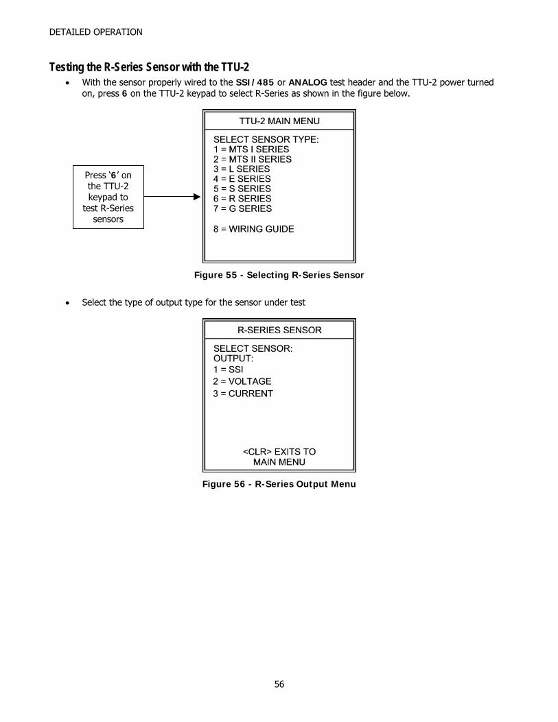
DETAILED OPERATION
Testing the R-Series Sensor with the TTU-2 • With the sensor properly wired to the SSI/485 or ANALOG test header and the TTU-2 power turned
on, press 6 on the TTU-2 keypad to select R-Series as shown in the figure below.
Press ‘6’ on the TTU-2 keypad to
test R-Series sensors
Figure 55 - Selecting R-Series Sensor
• Select the type of output type for the sensor under test
Figure 56 - R-Series Output Menu
56
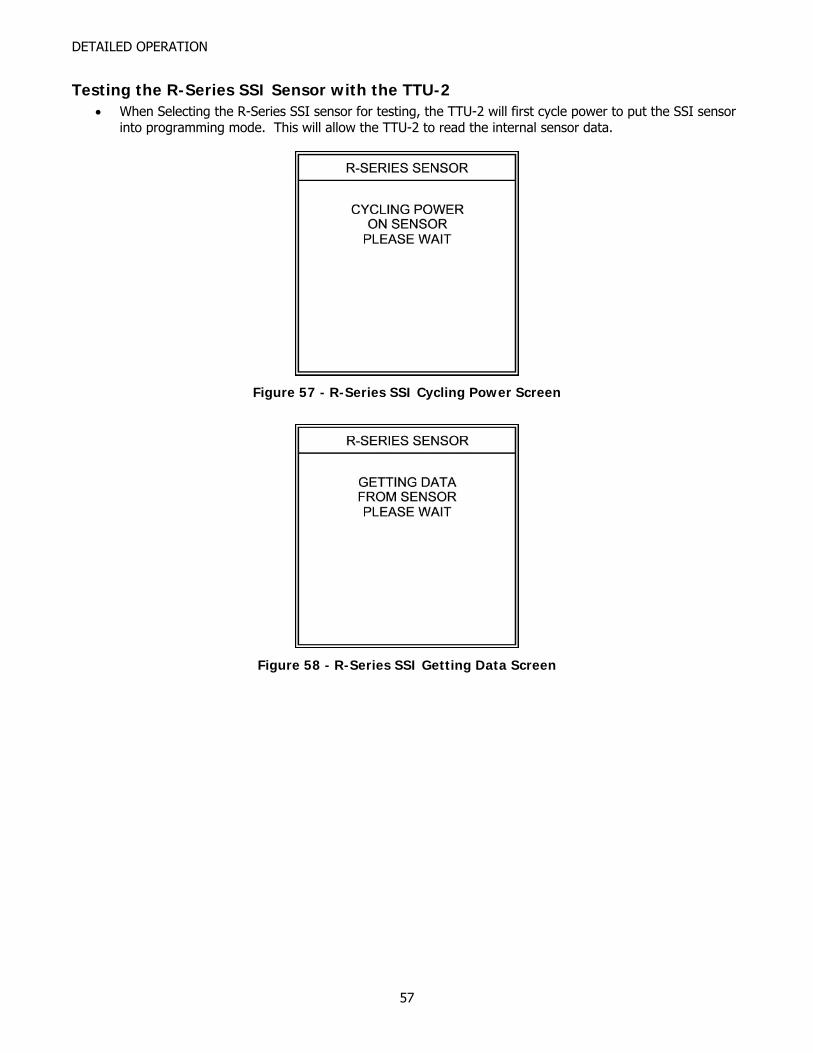
DETAILED OPERATION
Testing the R-Series SSI Sensor with the TTU-2 • When Selecting the R-Series SSI sensor for testing, the TTU-2 will first cycle power to put the SSI sensor
into programming mode. This will allow the TTU-2 to read the internal sensor data.
Figure 57 - R-Series SSI Cycling Power Screen
Figure 58 - R-Series SSI Getting Data Screen
57
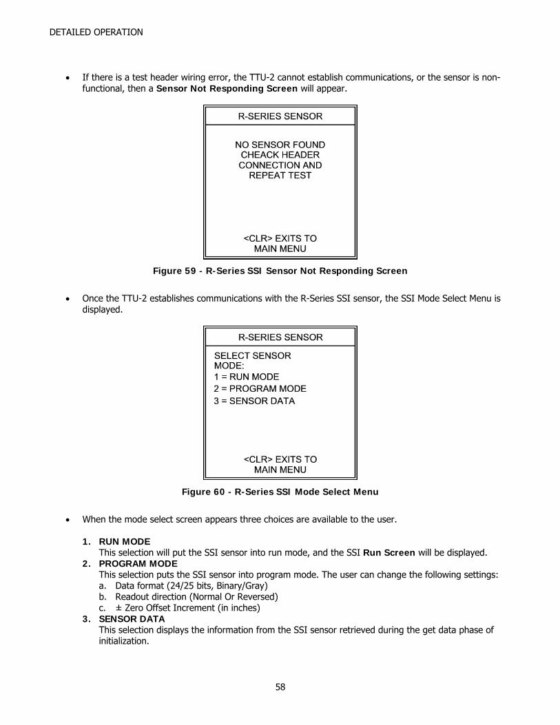
DETAILED OPERATION
• If there is a test header wiring error, the TTU-2 cannot establish communications, or the sensor is non-functional, then a Sensor Not Responding Screen will appear.
Figure 59 - R-Series SSI Sensor Not Responding Screen
• Once the TTU-2 establishes communications with the R-Series SSI sensor, the SSI Mode Select Menu is
displayed.
Figure 60 - R-Series SSI Mode Select Menu
• When the mode select screen appears three choices are available to the user.
1. RUN MODE
This selection will put the SSI sensor into run mode, and the SSI Run Screen will be displayed. 2. PROGRAM MODE
This selection puts the SSI sensor into program mode. The user can change the following settings: a. Data format (24/25 bits, Binary/Gray) b. Readout direction (Normal Or Reversed) c. ± Zero Offset Increment (in inches)
3. SENSOR DATA This selection displays the information from the SSI sensor retrieved during the get data phase of initialization.
58
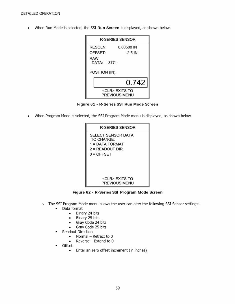
DETAILED OPERATION
• When Run Mode is selected, the SSI Run Screen is displayed, as shown below.
Figure 61 - R-Series SSI Run Mode Screen
• When Program Mode is selected, the SSI Program Mode menu is displayed, as shown below.
Figure 62 - R-Series SSI Program Mode Screen
o The SSI Program Mode menu allows the user can alter the following SSI Sensor settings:
Data format • Binary 24 bits • Binary 25 bits • Gray Code 24 bits • Gray Code 25 bits
Readout Direction • Normal – Retract to 0 • Reverse – Extend to 0
Offset • Enter an zero offset increment (in inches)
59
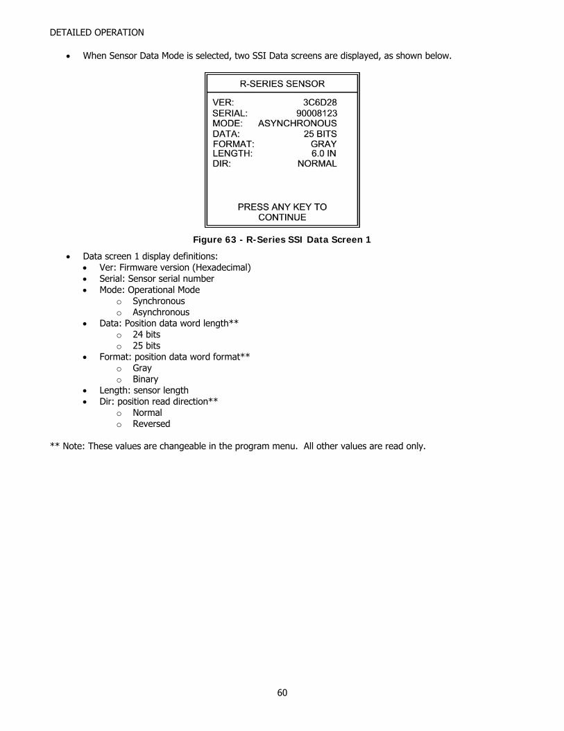
DETAILED OPERATION
• When Sensor Data Mode is selected, two SSI Data screens are displayed, as shown below.
Figure 63 - R-Series SSI Data Screen 1
• Data screen 1 display definitions: • Ver: Firmware version (Hexadecimal) • Serial: Sensor serial number • Mode: Operational Mode
o Synchronous o Asynchronous
• Data: Position data word length** o 24 bits o 25 bits
• Format: position data word format** o Gray o Binary
• Length: sensor length • Dir: position read direction**
o Normal o Reversed
** Note: These values are changeable in the program menu. All other values are read only.
60

DETAILED OPERATION
Figure 64 - R-Series SSI Data Screen 2
• Data screen 2 display definitions:
• Resoln: resolution (in inches) • Offset: zero offset (in inches)
Note: Offset is usually a negative number • Scale: resolution adjustment value • Speed: sensor gradient (µSec/inch) • Timing: asynchronous timing value • Measur: Jitter window, where 32H = 50µSec
61
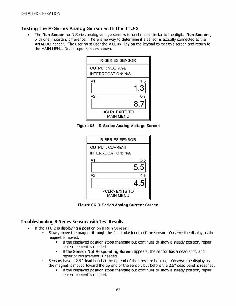
DETAILED OPERATION
Testing the R-Series Analog Sensor with the TTU-2 • The Run Screen for R-Series analog voltage sensors is functionally similar to the digital Run Screens,
with one important difference. There is no way to determine if a sensor is actually connected to the ANALOG header. The user must user the <CLR> key on the keypad to exit this screen and return to the MAIN MENU. Dual output sensors shown.
Figure 65 - R-Series Analog Voltage Screen
Figure 66 R-Series Analog Current Screen
Troubleshooting R-Series Sensors with Test Results • If the TTU-2 is displaying a position on a Run Screen:
o Slowly move the magnet through the full stroke length of the sensor. Observe the display as the magnet is moved.
If the displayed position stops changing but continues to show a steady position, repair or replacement is needed.
If the Sensor Not Responding Screen appears, the sensor has a dead spot, and repair or replacement is needed
o Sensors have a 2.5” dead band at the tip end of the pressure housing. Observe the display as the magnet is moved toward the tip end of the sensor, but before the 2.5” dead band is reached.
If the displayed position stops changing but continues to show a steady position, repair or replacement is needed.
62

DETAILED OPERATION
If the Sensor Not Responding Screen appears, the sensor has a dead spot, and repair or replacement is needed. Pay particular attention to the magnet position while testing the sensor at the tip end. The Sensor Not Responding Screen will appear when you hit the dead band.
o Gently move the connector and/or cable connection to the head cap while observing the displayed position. If the position freezes or a Sensor Not Responding Screen is shown, the sensor needs repair. Please note: the object is to confirm a solid connection to the sensor, so exert little or no force while testing the connector and/or cabling.
o While holding the magnet steady, lightly tap the housing and observe the position on the display. (Use a small screwdriver, and tap no harder than you would tap on the back of your hand). If the position jumps significantly or a Sensor Not Responding Screen appears, the sensor has problems with the waveguide or sensor pickup and needs repair.
• If the Sensor Not Responding Screen appears (no Run Screen is displayed):
o Check the connections to the TTU-2 headers. If the connections are correct then sensor repair or replacement is needed.
o Gently move the connector and/or cable connection to the head cap while pressing <ENT> to repeat the test with current settings. If a Run Screen is displayed, the sensor connector/cabling needs repair. Please note: the object is to confirm a solid connection to the sensor, so exert little or no force while testing the connector and/or cabling.
63
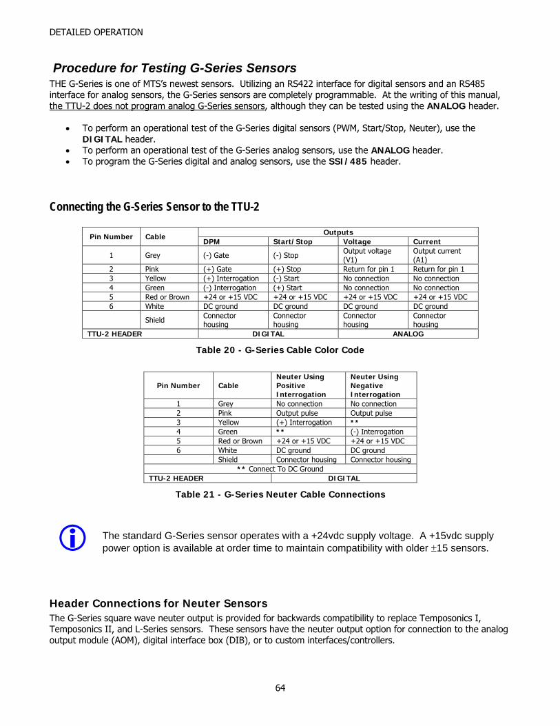
DETAILED OPERATION
Procedure for Testing G-Series Sensors THE G-Series is one of MTS’s newest sensors. Utilizing an RS422 interface for digital sensors and an RS485 interface for analog sensors, the G-Series sensors are completely programmable. At the writing of this manual, the TTU-2 does not program analog G-Series sensors, although they can be tested using the ANALOG header.
• To perform an operational test of the G-Series digital sensors (PWM, Start/Stop, Neuter), use the DIGITAL header.
• To perform an operational test of the G-Series analog sensors, use the ANALOG header. • To program the G-Series digital and analog sensors, use the SSI/485 header.
Connecting the G-Series Sensor to the TTU-2
Outputs Pin Number Cable DPM Start/Stop Voltage Current
1 Grey (-) Gate (-) Stop Output voltage (V1)
Output current (A1)
2 Pink (+) Gate (+) Stop Return for pin 1 Return for pin 1 3 Yellow (+) Interrogation (-) Start No connection No connection 4 Green (-) Interrogation (+) Start No connection No connection 5 Red or Brown +24 or +15 VDC +24 or +15 VDC +24 or +15 VDC +24 or +15 VDC 6 White DC ground DC ground DC ground DC ground
Shield Connector housing
Connector housing
Connector housing
Connector housing
TTU-2 HEADER DIGITAL ANALOG
Table 20 - G-Series Cable Color Code
Pin Number Cable Neuter Using Positive Interrogation
Neuter Using Negative Interrogation
1 Grey No connection No connection 2 Pink Output pulse Output pulse 3 Yellow (+) Interrogation ** 4 Green ** (-) Interrogation 5 Red or Brown +24 or +15 VDC +24 or +15 VDC 6 White DC ground DC ground Shield Connector housing Connector housing
** Connect To DC Ground TTU-2 HEADER DIGITAL
Table 21 - G-Series Neuter Cable Connections
The standard G-Series sensor operates with a +24vdc supply voltage. A +15vdc supply power option is available at order time to maintain compatibility with older ±15 sensors.
Header Connections for Neuter Sensors The G-Series square wave neuter output is provided for backwards compatibility to replace Temposonics I, Temposonics II, and L-Series sensors. These sensors have the neuter output option for connection to the analog output module (AOM), digital interface box (DIB), or to custom interfaces/controllers.
64
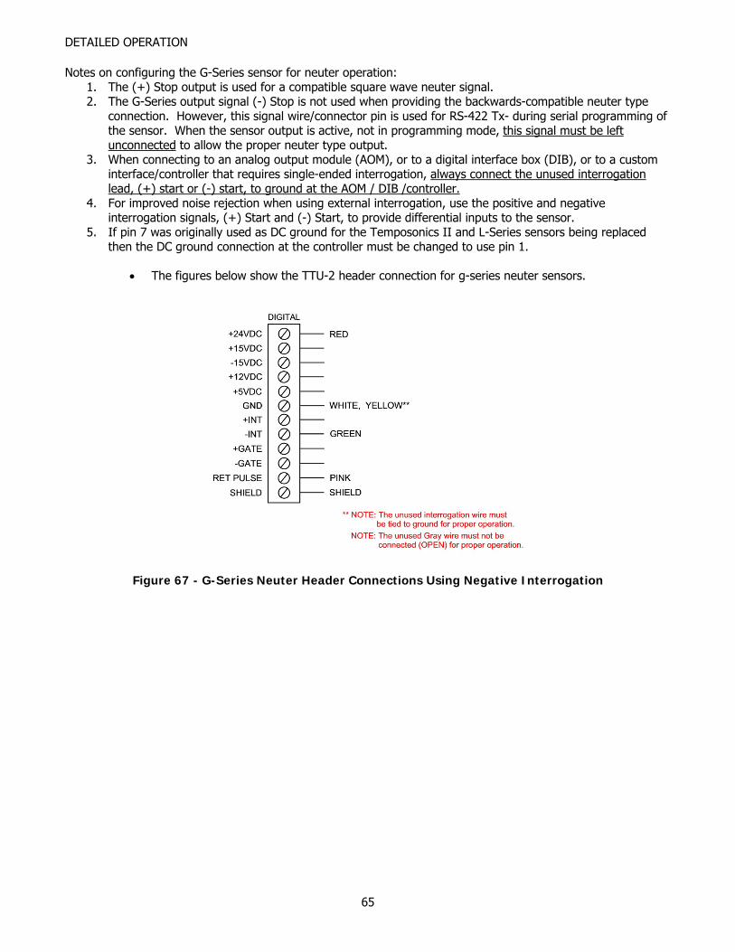
DETAILED OPERATION
Notes on configuring the G-Series sensor for neuter operation: 1. The (+) Stop output is used for a compatible square wave neuter signal. 2. The G-Series output signal (-) Stop is not used when providing the backwards-compatible neuter type
connection. However, this signal wire/connector pin is used for RS-422 Tx- during serial programming of the sensor. When the sensor output is active, not in programming mode, this signal must be left unconnected to allow the proper neuter type output.
3. When connecting to an analog output module (AOM), or to a digital interface box (DIB), or to a custom interface/controller that requires single-ended interrogation, always connect the unused interrogation lead, (+) start or (-) start, to ground at the AOM / DIB /controller.
4. For improved noise rejection when using external interrogation, use the positive and negative interrogation signals, (+) Start and (-) Start, to provide differential inputs to the sensor.
5. If pin 7 was originally used as DC ground for the Temposonics II and L-Series sensors being replaced then the DC ground connection at the controller must be changed to use pin 1.
• The figures below show the TTU-2 header connection for g-series neuter sensors.
Figure 67 - G-Series Neuter Header Connections Using Negative Interrogation
65
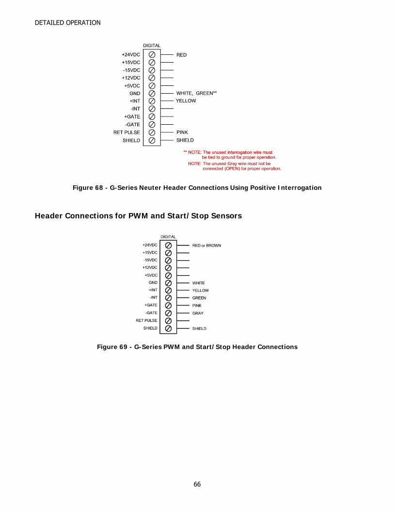
DETAILED OPERATION
Figure 68 - G-Series Neuter Header Connections Using Positive Interrogation
Header Connections for PWM and Start/Stop Sensors
Figure 69 - G-Series PWM and Start/Stop Header Connections
66
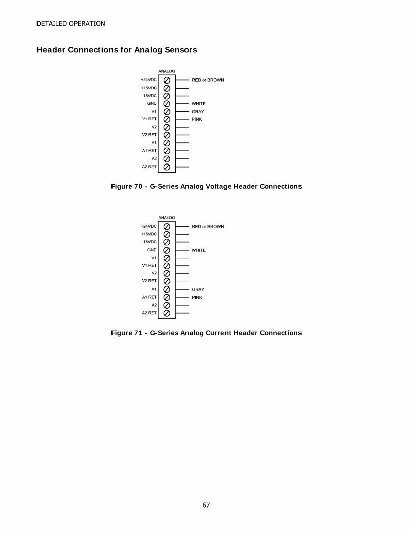
DETAILED OPERATION
Header Connections for Analog Sensors
Figure 70 - G-Series Analog Voltage Header Connections
Figure 71 - G-Series Analog Current Header Connections
67

DETAILED OPERATION
68
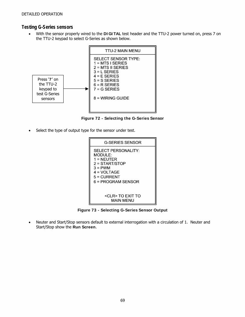
DETAILED OPERATION
Testing G-Series sensors • With the sensor properly wired to the DIGITAL test header and the TTU-2 power turned on, press 7 on
the TTU-2 keypad to select G-Series as shown below.
Press ‘7’ on the TTU-2 keypad to
test G-Series sensors
Figure 72 - Selecting the G-Series Sensor
• Select the type of output type for the sensor under test.
Figure 73 - Selecting G-Series Sensor Output
• Neuter and Start/Stop sensors default to external interrogation with a circulation of 1. Neuter and
Start/Stop show the Run Screen.
69
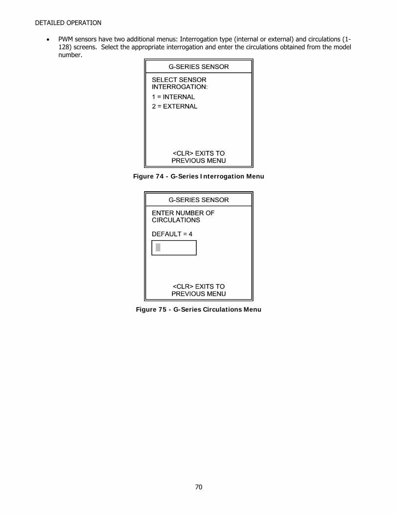
DETAILED OPERATION
• PWM sensors have two additional menus: Interrogation type (internal or external) and circulations (1-128) screens. Select the appropriate interrogation and enter the circulations obtained from the model number.
Figure 74 - G-Series Interrogation Menu
Figure 75 - G-Series Circulations Menu
70
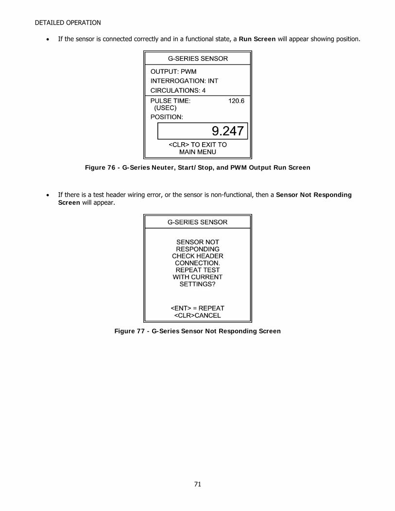
DETAILED OPERATION
• If the sensor is connected correctly and in a functional state, a Run Screen will appear showing position.
Figure 76 - G-Series Neuter, Start/Stop, and PWM Output Run Screen
• If there is a test header wiring error, or the sensor is non-functional, then a Sensor Not Responding Screen will appear.
Figure 77 - G-Series Sensor Not Responding Screen
71
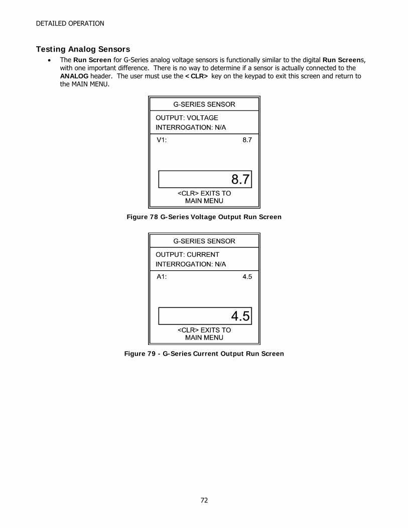
DETAILED OPERATION
Testing Analog Sensors • The Run Screen for G-Series analog voltage sensors is functionally similar to the digital Run Screens,
with one important difference. There is no way to determine if a sensor is actually connected to the ANALOG header. The user must use the <CLR> key on the keypad to exit this screen and return to the MAIN MENU.
Figure 78 G-Series Voltage Output Run Screen
Figure 79 - G-Series Current Output Run Screen
72
DETAILED OPERATION
Troubleshooting G-Series Sensors with Test Results • If the TTU-2 is displaying a position on a Run Screen:
o Slowly move the magnet through the full stroke length of the sensor. Observe the display as the magnet is moved.
If the displayed position stops changing but continues to show a steady position, repair or replacement is needed.
If the Sensor Not Responding Screen appears, the sensor has a dead spot, and repair or replacement is needed
o Sensors have a 2.5” dead band at the tip end of the pressure housing. Observe the display as the magnet is moved toward the tip end of the sensor, but before the 2.5” dead band is reached.
If the displayed position stops changing but continues to show a steady position, repair or replacement is needed.
If the Sensor Not Responding Screen appears, the sensor has a dead spot, and repair or replacement is needed. Pay particular attention to the magnet position while testing the sensor at the tip end. The Sensor Not Responding Screen will appear when you hit the dead band.
o Gently move the connector and/or cable connection to the head cap while observing the displayed position. If the position freezes or a Sensor Not Responding Screen is shown, the sensor needs repair. Please note: the object is to confirm a solid connection to the sensor, so exert little or no force while testing the connector and/or cabling.
o While holding the magnet steady, lightly tap the housing and observe the position on the display. (Use a small screwdriver, and tap no harder than you would tap on the back of your hand). If the position jumps significantly or a Sensor Not Responding Screen appears, the sensor has problems with the waveguide or sensor pickup and needs repair.
• If the Sensor Not Responding Screen appears (no Run Screen is displayed):
o Check the connections to the TTU-2 headers. If the connections are correct then sensor repair or replacement is needed.
o Gently move the connector and/or cable connection to the head cap while pressing <ENT> to repeat the test with current settings. If a Run Screen is displayed, the sensor connector/cabling needs repair. Please note: the object is to confirm a solid connection to the sensor, so exert little or no force while testing the connector and/or cabling.
73
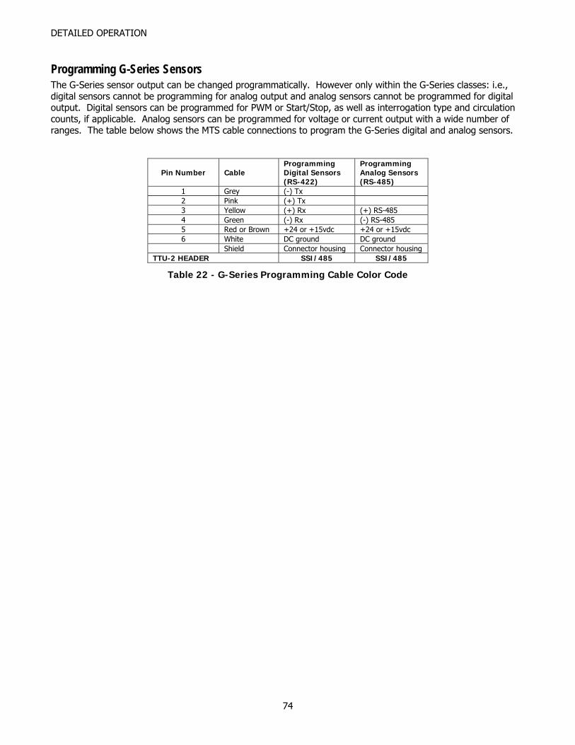
DETAILED OPERATION
Programming G-Series Sensors The G-Series sensor output can be changed programmatically. However only within the G-Series classes: i.e., digital sensors cannot be programming for analog output and analog sensors cannot be programmed for digital output. Digital sensors can be programmed for PWM or Start/Stop, as well as interrogation type and circulation counts, if applicable. Analog sensors can be programmed for voltage or current output with a wide number of ranges. The table below shows the MTS cable connections to program the G-Series digital and analog sensors.
Pin Number Cable Programming Digital Sensors (RS-422)
Programming Analog Sensors (RS-485)
1 Grey (-) Tx 2 Pink (+) Tx 3 Yellow (+) Rx (+) RS-485 4 Green (-) Rx (-) RS-485 5 Red or Brown +24 or +15vdc +24 or +15vdc 6 White DC ground DC ground Shield Connector housing Connector housing
TTU-2 HEADER SSI/485 SSI/485
Table 22 - G-Series Programming Cable Color Code
74
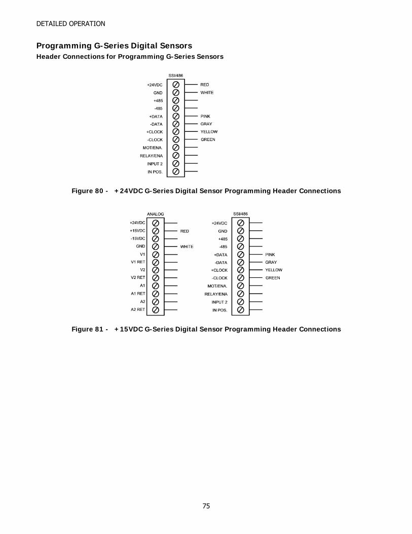
DETAILED OPERATION
Programming G-Series Digital Sensors Header Connections for Programming G-Series Sensors
Figure 80 - +24VDC G-Series Digital Sensor Programming Header Connections
Figure 81 - +15VDC G-Series Digital Sensor Programming Header Connections
75
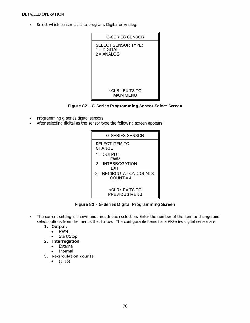
DETAILED OPERATION
• Select which sensor class to program, Digital or Analog.
Figure 82 - G-Series Programming Sensor Select Screen
• Programming g-series digital sensors • After selecting digital as the sensor type the following screen appears:
Figure 83 - G-Series Digital Programming Screen
• The current setting is shown underneath each selection. Enter the number of the item to change and
select options from the menus that follow. The configurable items for a G-Series digital sensor are: 1. Output:
• PWM • Start/Stop
2. Interrogation • External • Internal
3. Recirculation counts • (1-15)
76

DETAILED OPERATION
Programming G-Series Analog Sensors Programming for G-Series analog sensors is currently unavailable. Check Paw-Taw-John Services, Inc., website for updates to TTU-2 programming and updates to this manual.
77

APPENDICES
APPENDICES
78
APPENDICES APPENDIX
APPENDIX A
A L, R, G AND S SERIES SENSOR REPLACEMENT INSTRUCTIONS Recommended sensor removal and installation procedures are very important to minimize downtime and prevent further system damage. This appendix covers the steps for replacing L, R, G and S sensors used with hydraulic cylinders. Some cylinders have sensor guards attached to the end of the cylinder to prevent sensor damage. Other cylinders have the sensor cap and cable completely enclosed. Use the appropriate wrenches necessary to remove and reinstall the guards. The sensors have various connector/cable ensembles located at the head electronics, which gives the user quick- disconnect ability. The L, R, G and S series utilize high-pressure tube assemblies that remain in the cylinder. Removal and installation is much easier.
POWERED HYDRAULIC EQUIPMENT AND CONTROL SYSTEMS CAN INJURE PERSONNEL OR DAMAGE EQUIPMENT. LOCK OUT ALL APPROPRIATE HYDRAULIC POWER AND CONTROL SYSTEMS IN ACCORDANCE WITH LOCAL SAFETY REQUIREMENTS.
Paw-Taw-John Services, Inc. highly recommends that during the removal and installation of a sensor that all power to the system (hydraulics, control system and any other associated equipment) be turned off, tagged and locked out.
Removal of L, R, G and S Series Sensors
AVOID INJURY TO PERSONNEL AND DAMAGE TO EQUIPMENT. OBSERVE ALL LOCAL LOCKOUT AND SAFETY PROCEDURES!
1. Turn off motion control system power and control power to hydraulics. Lock Out! 2. Have replacement sensor ready and in clean and safe area. 3. Insure area around the sensor is clean and free of dirt, sawdust, and any other foreign material. 4. Survey the area behind the cylinder to make sure there is sufficient room to withdraw the sensor without
encountering obstructions. 5. Remove all protective covers from the back of the sensor and cable. 6. Disconnect cable/s from sensor and secure away from work area. 7. Loosen two hex head screws at head electronics. 8. Slide the sensing element/electronics assembly out of the high-pressure tube. 9. Wipe the cables clean of any exposure to hydraulic oil.
Note: Hydraulic oil can cause deterioration of the cable casing. 10. Proceed with sensor replacement immediately.
79
APPENDICES
Installation of L, R, G and S Series Sensors
AVOID INJURY TO PERSONNEL AND DAMAGE TO EQUIPMENT. OBSERVE ALL LOCAL LOCKOUT AND SAFETY PROCEDURES!
1. Verify the replacement sensor is compatible with the faulty sensor. 2. Maneuver the sensor element tip into the hole of the high-pressure tube. 3. Tighten the sensor securely with the two hex head screws used during removal. 4. Clean and reconnect the cables to the sensor. 5. Reinstall guard or protective sensor and cable cover.
Note: This step may be required prior to reconnecting cable. 6. Power may now be re-applied to the motion system. 7. Verify the sensor is working with the motion system electronics. 8. It is possible the sensor will need an address change when on a multiple axis system. Consult addressing
procedures. 9. Turn on hydraulics power. 10. Proceed with operation of the machine. 11. If problems are still present, consult Troubleshooting chapter of the manual for other possible solutions.
80
APPENDICES APPENDIX
APPENDIX B
B TEMPOSONICS I & II SERIES SENSOR REPLACEMENT INSTRUCTIONS Recommended sensor removal and installation procedures are very important to minimize downtime and prevent further system damage. This appendix covers the steps for replacing of a MTS I or MTS II sensors used with hydraulic cylinders. Some cylinders have sensor guards attached to the end of the cylinder to prevent sensor damage. Other cylinders have the sensor cap and cable completely enclosed. Use the appropriate wrenches necessary to remove and reinstall the guards. The sensors have various connector/cable ensembles located at the head electronics, which gives the user quick-disconnect ability.
POWERED HYDRAULIC EQUIPMENT AND CONTROL SYSTEMS CAN INJURE PERSONNEL OR DAMAGE EQUIPMENT. LOCK OUT ALL APPROPRIATE HYDRAULIC POWER AND CONTROL SYSTEMS IN ACCORDANCE WITH LOCAL SAFETY REQUIREMENTS.
Paw-Taw-John Services, Inc. highly recommends that during the removal and installation of a sensor that all power to the system (hydraulics, control system and any other associated equipment) be turned off, tagged and locked out.
Removal of Temposonics I & II Series Sensors
AVOID INJURY TO PERSONNEL AND DAMAGE TO EQUIPMENT. OBSERVE ALL LOCAL LOCKOUT AND SAFETY PROCEDURES!
1. Retract the cylinder as far back as possible. This makes it easier to install the sensor. 2. Turn off motion system power and control power to hydraulics. Lock Out! 3. Have replacement sensor ready and in clean and safe area. 4. Have a bucket for oil spillage and a clean rag available. 5. Insure area around the sensor is clean and free of dirt, sawdust, and any other foreign material. 6. Survey the area behind the cylinder to make sure there is sufficient room to withdraw the sensor without
encountering obstructions. 7. Remove all protective covers from the back of the sensor and cable. 8. Disconnect cable/s from sensor and secure away from work area. 9. Using a 1-¾ inch, wrench or socket, unscrew the sensor from the cylinder.
10. Slide the sensor out of the cylinder while holding the clean rag at the entry hole to the cylinder.
DO NOT ATTEMPT TO USE THE HEAD ELECTRONICS CAP TO UNSCREW THE SENSOR FROM THE CYLINDER. DAMAGE TO THE HEAD ELECTRONICS AND CAP CAN OCCUR.
11. Proceed with sensor replacement immediately.
81
APPENDICES
Installation of Temposonics I & II Series Sensors
AVOID INJURY TO PERSONNEL AND DAMAGE TO EQUIPMENT. OBSERVE ALL LOCAL LOCKOUT AND SAFETY PROCEDURES!
1. Verify the replacement sensor is compatible with the faulty sensor. 2. While keeping the clean rag at the entry hole to prevent oil from leaving the cylinder, maneuver the
sensor tip into the hole of the sensor. 3. Screw the sensor into the cylinder with wrench or socket while not using the cap/head electronics for
leverage. 4. Clean and reconnect the cables to the sensor. 5. Reinstall guard or protective sensor and cable cover. (Note: this step may be required prior to
reconnecting cable.) 6. Power may now be re-applied to the motion system. 7. Verify the sensor is working with the motion system electronics. 8. Turn on hydraulics power. 9. Proceed with operation of the machine. 10. If problems are still present, consult Troubleshooting chapter of the manual for other possible solutions.
82
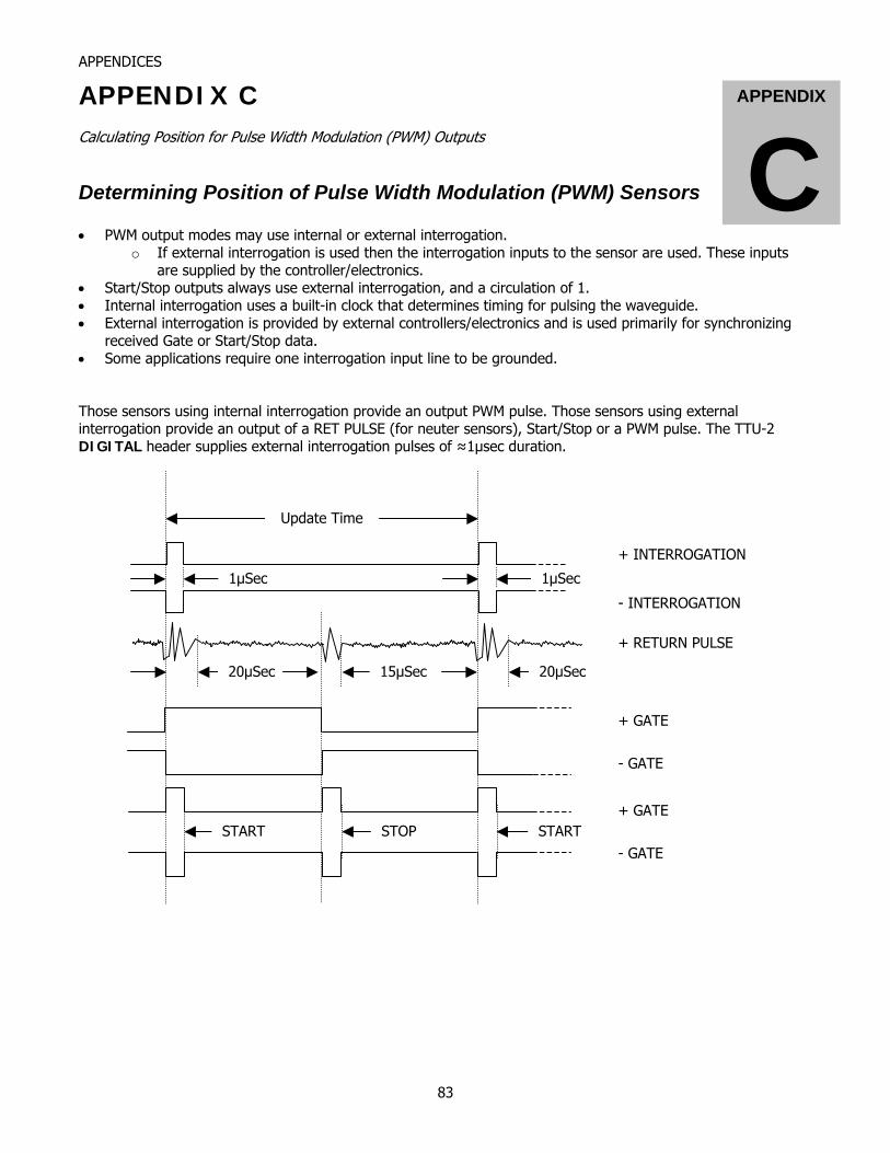
APPENDICES
APPENDIX C APPENDIX
C Calculating Position for Pulse Width Modulation (PWM) Outputs
Determining Position of Pulse Width Modulation (PWM) Sensors • PWM output modes may use internal or external interrogation.
o If external interrogation is used then the interrogation inputs to the sensor are used. These inputs are supplied by the controller/electronics.
• Start/Stop outputs always use external interrogation, and a circulation of 1. • Internal interrogation uses a built-in clock that determines timing for pulsing the waveguide. • External interrogation is provided by external controllers/electronics and is used primarily for synchronizing
received Gate or Start/Stop data. • Some applications require one interrogation input line to be grounded. Those sensors using internal interrogation provide an output PWM pulse. Those sensors using external interrogation provide an output of a RET PULSE (for neuter sensors), Start/Stop or a PWM pulse. The TTU-2 DIGITAL header supplies external interrogation pulses of ≈1µsec duration.
Update Time
1μSec 1μSec
- INTERROGATION
+ INTERROGATION
+ RETURN PULSE
+ GATE
- GATE
20μSec 15μSec 20μSec
START STOP START+ GATE
- GATE
83
APPENDICES
Upon receipt of the gate pulse, the pulse duration is determined, and the following formula is applied to determine position: POSITION in inches = ((PW (in µsec) ÷ circulations (1-128)) ÷ gradient) – null (inches) Where: Gradient13 = 9.0000 (the median gradient of MTS sensors) Null14 = 4.15 inches (the median null distance for most of MTS sensors) Circulations = User selectable at test time (1-128) Example: A Temposonics I using external interrogation with 1 circulation returning a 120.6µsec pulse. POSITION = ((PW (µsec) ÷ circulations) ÷ 9.0000) – 4.15 = ((120.6 ÷ 1) ÷ 9) – 4.15 = (120.6 ÷ 9) – 4.15 = 13.4 – 4.15 POSITION = 9.25 inches
13 The TTU-2 uses a fixed gradient of 9.00000 for all sensors. 14 The TTU-2 uses a fixed null distance of 4.15” for all sensors.
84

APPENDICES
APPENDIX
DAPPENDIX D
85