emfi-based ultrasonic transducer for robotics applications
TRANSCRIPT
Sensors and Actuators A 148 (2008) 342–349
Contents lists available at ScienceDirect
Sensors and Actuators A: Physical
journa l homepage: www.e lsev ier .com/ locate /sna
EMFi-based ultrasonic transducer for robotics applications
Ana Jiméneza,∗, Álvaro Hernándeza, Jesús Urenaa, Ma Carmen Péreza, Fernando J. Álvarezb,Carlos De Marziani c, Juan Jesús Garcíaa, J. Manuel Villadangosa
a Electronics Department, University of Alcala, E-28806 Alcalá de Henares, Spainb Department of Electrical Engineering, Electronics and Automatics, University of Extremadura, E-06071 Badajoz, Spainc Electronics Department, National University of Patagonia San Juan Bosco, 9005 Comodoro-Rivadavia, Argentina
a r t i c l e i n f o
Article history:Received 12 February 2008Received in revised form 14 July 2008Accepted 29 July 2008Available online 13 August 2008
Keywords:
a b s t r a c t
A prototype of an ultrasonic transducer based on electromechanical film (EMFi) is presented, as well as itselectronic driving and receiving blocks. The electromechanical film provides a wide bandwidth response,showing enough of a level of sensitivity to allow echo-pulse measurement in the most frequency rangesfor robotics applications. Emission patterns are obtained, verifying the correspondence between experi-mental data and the theoretical piston model. Experimental results show that the EMFi-based transducercan be used as a broadband ultrasonic transducer, allowing transmission from 20 to 200 kHz. The widebandwidth provided by the transducer is a remarkable advantage for sensor systems using encoded ultra-
Ultrasonic transducerEncoded ultrasonic emissionElectromechanical filmB
sonic signals with wideband modulation schemes, which require considerably more bandwidth than whatconventional transducers allow. In this way, main lobes can be discriminated more easily from sidelobes
can b
1
mctfiittrirttp
wnbfu
[sctsrcoi
srcwocot
0d
road bandwidth and crosstalk interference
. Introduction
Ultrasonic transducers have often been used in the develop-ent of sensory systems for robotics applications [1–3]. In most
ases, these sensory systems are based on the determination ofimes of flight (TOF) for signals from every transducer [4–6]. Therst proposals computed the TOFs for every transducer working
n an isolated way, and so a relatively small amount of informa-ion was obtained from the environment: only the distance fromhe transducer to the reflector inside the emission beam. In lateresearch, transducers were associated to form sensor arrays, hav-ng the same scanning area [6,7]. It is therefore possible to locate theeflector more accurately, by computing the lateral resolution (i.e.he deviation angle of the reflector position from the axial axis of theransducer) [2,6,8]. Since then, more complex analysis have becomeossible, such as reflector classification or mapping [9,10,7,11].
In the above mentioned previous research, the main drawbacksere reduced precision, as well as low scanning speeds, since it was
ot always possible to have simultaneous emission and receptiony all of the transducers in the array because of crosstalk inter-erence [12]. A common solution to this problem is to code theltrasonic emission with binary sequences, such as Barker codes∗ Corresponding author.E-mail address: [email protected] (A. Jiménez).
tuttmr
cm
924-4247/$ – see front matter © 2008 Elsevier B.V. All rights reserved.oi:10.1016/j.sna.2008.07.024
e reduced.© 2008 Elsevier B.V. All rights reserved.
6,13], pseudo-random sequences [12], or complementary sets ofequences [14]. On the one hand, pseudo-random sequences andomplementary sets of sequences present an auto-correlation func-ion with an easily detectable main lobe, and null or negligibleidelobes, increasing precision and immunity to noise in the envi-onment. Besides, the cross-correlation functions are negligibleompared to the main lobe in the auto-correlation, so simultane-us emission and reception can be carried out in the array withoutnterference.
In the use of ultrasonic transducers there are two main con-traints related to the ultrasonic signal encoding: directivity andeduced bandwidth [15,16]. The question of directivity should bearefully considered according to the application requirements:ide directivity is often desired to scan a larger area in front
f sensor arrays. On the other hand, the shape of the auto- andross-correlation functions strongly depend on the bandwidthf the transducer used, since narrow band transducers degradehe features of the correlation functions. Therefore, broadbandransducers provide less constraints to algorithms proposed forltrasonic signal processing, and allow other additional parameterso be extracted from the environment and reflections [17]. This ishe reason why broadband air ultrasonic transducers are becoming
ore important, because of the fact that they have large frequencyanges (i.e. 20–200 kHz) with high sensitivity.
These bandwidth requirements are often not achieved byommercially available airbone ultrasonic transducers. Severalaterials have been already used in the development of ultrasonic
A. Jiménez et al. / Sensors and Actu
Ft
tOp[bit
bpfiT[fits
taEromomc
2
2
w1ibtmpwbTep
ttmop
tqinTfmtMsmfmpPtmfidtt
cpdsatr5
2
ioitpafiet
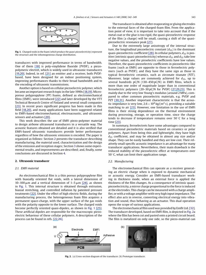
ig. 1. Charged voids in the foam (which produce the quasi-piezoelectricity) representhe structure and the inhomogeneous charge distribution.
ransducers with improved performance in terms of bandwidth.ne of them [18] is poly-vinylidene fluoride (PVDF), a piezo-olymeric electret, which is widely used in ultrasonic transducers19,20]. Indeed, in ref. [21] an emitter and a receiver, both PVDF-ased, have been designed for an indoor positioning system,
mproving performances thanks to their broad bandwidth and tohe encoding of ultrasonic transmissions.
Another option is based on cellular piezoelectric polymer, whichecame an important research topic in the late 1990s [18,19]. Micro-orous polypropylene (PP) foams, defined as electromechanicallms (EMFi), were introduced [22] and later developed by the VTTechnical Research Centre of Finland and several small companies23]. In recent years significant progress has been made in thiseld [18,20], and many applications have been suggested relatedo EMFi-based electromechanical, electroacoustic, and ultrasonicensors and actuators [20].
This work describes the use of EMFi piezo-polymer materialo design airbone ultrasound transducers in a versatile way. Thecoustic features obtained are detailed and it is also verified thatMFi-based ultrasonic transducers provide better performanceegardless of how the ultrasonic emission is encoded. The paper isrganized as follows: Section 2 presents the transducer describinganufacturing, the material used, characterization and the design
f the emission and reception stages; Section 3 shows some experi-ental results, and improvements are described; and, finally, some
onclusions are discussed in Section 4.
. Ultrasonic transducer
.1. EMFi material
An electromechanical film is a thin porous polypropylene filmith biaxially oriented flat voids, with a lateral dimension of
0–100 �m and a vertical dimension of 1–5 �m [24], as shownn Fig. 1. This internal structure is obtained through extrusion,iaxial stretching, and controlled inflation by patented pressurereatments [22]. Under the effect of high electric fields, during the
anufacturing process, the heterogeneous foam film acquires aermanent space-charge, with the upper surface of the gas voids
ith the polarity opposite to the lower surface. The charged voidsecome perfectly oriented quasi-dipoles, as shown in Fig. 1 [25].hese artificial dipoles are responsible for the macroscopic piezo-lectric behaviour of these cellular polymers. A description of therocess can be found in refs. [22,26].
o
TwT
Fig. 2. (a) Cross-section diagram of the tr
ators A 148 (2008) 342–349 343
The transducer is obtained after evaporating or gluing electrodeso the external faces of the charged-foam film. From the applica-ion point of view, it is important to take into account that if the
etal coat or the glue is too rigid, the quasi-piezoelectric responsef the film (a charge) will be small, causing a shift of the quasi-iezoelectric resonance peak [27].
Due to the extremely large anisotropy of the internal struc-ure, the longitudinal piezoelectric constant (d33) is the dominantuasi-piezoelectric coefficient [28]. In cellular polymers, d33 is pos-tive (intrinsic quasi-piezoelectricity) whereas d31 and d32 take lowegative values, and the piroelectric coefficients have low values.herefore, the quasi-piezoelectric coefficients in piezoelectric-likeoams (such as EMFi) are opposite to those in ferroelectric poly-
ers (such as PVDF); and they have the same sign as those inypical ferroelectric ceramics, such as zirconate titanate (PZT).
oreover, large values are commonly achieved for d33, up toeveral hundreds pC/N (130–450 pC/N) in EMFi films, which isore than one order of magnitude larger than in conventional
erroelectric polymers (20–30 pC/N for PVDF) [27,29,23]. This isainly due to the very low Young’s modulus (around 2 MPa), com-
ared to other common piezoelectric materials, e.g. PVDF andZT [30,31]. Another important characteristic is that the acous-ic impedance is very low, 2.6 × 10⁴ kg/(m2 s), providing a suitable
atching to air [23]. However, one limitation in the use of EMFilms is their strong dependence on the thermal environmenturing processing, storage, or operation time, since the chargeends to decrease if temperature remains over 50 ◦C for a longime [23].
In summary, ferroelectrets have some advantages compared toonventional piezoelectric materials based on ceramics or polarolymers. Apart from being thin and lightweight, they have high33 coefficient, and may be obtained in almost any size and/orhape. They can be easily handled and they are low cost. Their rel-tively small specific acoustic impedance is an advantage for manyransducer applications. Nevertheless, their main drawback is theeduced stability of the piezoelectric effect at temperatures over0 ◦C, what can limit their application range.
.2. Manufacturing
The electromechanical film can operate as a receiver generat-ng an electric charge when is exposed to dynamic mechanicalr acoustic energy. Consider an EMFi-based transducer work-ng in thickness mode, when an external force is applied thehickness of the film changes. As a consequence of intrinsic quasi-iezoelectricity, a mirror charge proportional to the force is inducedt the electrodes. This charge can be measured with a charge ampli-er, or with a voltage amplifier with very high input impedance. Theffect also acts in reverse, converting electrical energy into vibra-ion and sound, thus behaving as an actuator. This dual operation
pens the scope of various applications.The electromechanical film used was provided by Emfit Ltd. [32].he transducer developed, based on EMFi film, is depicted in Fig. 2ahere the film has been cut and pasted onto a printed circuit board.
he film is metalized on only one side, so the piezo-material can
ansducer. (b) Prototype transducer.
344 A. Jiménez et al. / Sensors and Actuators A 148 (2008) 342–349
er wit
oa
2
cpaftpw(sasrmeua
too
aTwhnn
atata
r(b
p
w
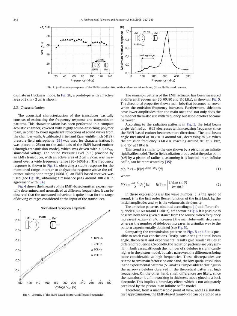
Fig. 3. (a) Frequency response of the EMFi-based emitt
scillate in thickness mode. In Fig. 2b, a prototype with an activerea of 2 cm × 2 cm is shown.
.3. Characterization
The acoustical characterization of the transducer basicallyonsists of estimating the frequency response and transmissionatterns. This characterization has been performed in a compactcoustic chamber, covered with highly sound-absorbing polymeroam, in order to avoid significant reflections of sound waves fromhe chamber walls. A calibrated Brüel and Kjaer eighth-inch (4138)ressure-field microphone [33] was used for characterization. Itas placed at 25 cm on the axial axis of the EMFi-based emitter
through-transmission mode), which was driven with a 300 Vpp
inusoidal voltage. The Sound Pressure Level (SPL) provided byn EMFi transducer, with an active area of 2 cm × 2 cm, was mea-ured over a wide frequency range (20–140 kHz). The frequencyesponse is shown in Fig. 3a, observing a stable response for theentioned range. In order to analyze the response above the ref-
rence microphone range (140 kHz), an EMFi-based receiver wassed (see Fig. 3b), obtaining a resonance peak around 300 kHz in
greement with [34].Fig. 4 shows the linearity of the EMFi-based emitter, experimen-ally determined and normalized at different frequencies. It can bebserved that the measured behaviour is quite linear for the rangef driving voltages considered at the input of the transducer.
Fig. 4. Linearity of the EMFi-based emitter at different frequencies.
P
si
qoiwp
sadihmritftep
fi
h a reference microphone; (b) an EMFi-based receiver.
The emission pattern of the EMFi actuator has been measuredt different frequencies (30, 60, 80 and 110 kHz), as shown in Fig. 5.he directional properties show a main lobe that becomes narrowerhen the emission frequency increases. Furthermore, sidelobesave lower amplitudes than the main one; and, not only does theumber of them also rise with frequency, but also sidelobes becomearrower.
According to the radiation patterns in Fig. 5, the total beamngle (defined at −6 dB) decreases with increasing frequency, sincehe EMFi-based emitter becomes more directional. The total beamngle measured at 30 kHz is around 50◦, decreasing to 30◦ whenhe emission frequency is 60 kHz, reaching around 20◦ at 80 kHz,nd 15◦ at 110 kHz.
This trend is similar to the one shown by a piston in an infiniteigid baffle model. The far field radiation produced at the polar pointr,�) by a piston of radius a, assuming it is located in an infiniteaffle, can be represented by [35]:
(r, �, t) = jP(r) ej(ωt−kr)H(�) (1)
here
(r) = �0 · c
2U0
a
rka H(�) =
∣∣∣∣
2J1(ka sin �)ka sin �
∣∣∣∣
(2)
In these expressions k is the wave number; c is the speed ofound; J1 is the first order Bessel function of the first kind; U0 thenitial amplitude; and �0 is the volumetric air density.
The emission patterns, obtained according to (1) at different fre-uencies (30, 60, 80 and 110 kHz), are shown in Fig. 6. It is possible tobserve how, for a given distance from the source, when frequencyncreases (i.e., ka = 2�a/� increases), the main lobe width decreases
hereas the number of sidelobes increases, in a similar way to theattern experimentally obtained (see Fig. 5).
Comparing the transmission patterns in Figs. 5 and 6 it is pos-ible to reach two conclusions. Firstly, considering the total beamngle, theoretical and experimental results give similar values atifferent frequencies. Secondly, the radiation patterns are very sim-
lar in both cases, although the number of sidelobes is significantlyigher in the piston model, but also narrower, the differences beingore considerable at high frequencies. These discrepancies are
elated to two main factors: on one hand, the low spatial resolutionn the experimental patterns (5◦) makes it impossible to distinguishhe narrow sidelobes observed in the theoretical pattern at highrequencies. On the other hand, small differences are likely, since
he transducer is a film working in thickness mode glued to a backlectrode. This implies a boundary effect, which is not adequatelyredicted by the piston in an infinite baffle model.Therefore, from a macroscopic point of view, and as a suitablerst approximation, the EMFi-based transducer can be studied as a

A. Jiménez et al. / Sensors and Actuators A 148 (2008) 342–349 345
itter a
ptdamtv
2
d[
baosm2
E
Fig. 5. Emission patterns of the EMFi-based em
iston source. More complex models could be considered, such ashose based on Finite Element Method (FEM), in order to include theependence of the transducer on film manufacturing parametersnd on the randomly inhomogeneous internal structure of EMFiaterial. However, they produce a higher computational load, and
hey are still approximated models, since the internal structure ofoids is far from being generic.
.4. Emission stage
Some specifications and requirements for the EMFi-based trans-ucer should be taken into account in the driving stage for emission23]. The response of an EMFi-based emitter is proportional to the
dsibT
Fig. 6. Simulated piston emission patterns at 30
t 30, 60, 80 and 110 kHz, with 300 Vpp at 25 cm.
ias voltage, so it is necessary to drive it with high voltages tochieve high sound pressure levels (SPL). This is why the devel-pment proposed here uses a maximum amplitude of 300 Vpp. Ithould be considered that the surface displacements of the poly-er remain approximately constant in the frequency range from
0 to 200 kHz.Since it is difficult to find a commercial setup to connect to the
MFi-based emitter without bandwidth constraints, an electronic
esign is proposed here. Fig. 7 shows the block diagram of the emis-ion stage, composed by two main components. A dc/dc converters proposed to provide a dc voltage to supply a power amplifier,ecause the EMFi-based transducer does not require a bias voltage.hus the dc/dc converter provides a symmetric voltage of ±150 V,, 60, 80 and 110 kHz, according to Eq. (1).

346 A. Jiménez et al. / Sensors and Actuators A 148 (2008) 342–349
aoa
p5±−sftdft3bst
2
ebmpat
Tfiws
tsaap
mn1F1iotiwc
Fig. 7. Electrical connection of APEX PA98 amplifier.
nd an output range of 300 Vpp, assuming an input power supplyf 12 V. The dc/dc converter is a F03CT from EMCO, which providesn isolated signal with low ripple [36].
The other component is an APEX PA98 amplifier, which is aower MOSFET device for high voltages, with a broad bandwidth of00 kHz, capable of providing up to 200 mA for a bipolar supply of215 V, or unipolar of 440 V [37]. The bandwidth of the amplifier at3 dB includes the range from 20 kHz to 200 kHz. Furthermore, the
lew-rate provided by the manufacturer is 1000 V/�s, high enoughor the proposal developed herein. On the other hand, it is desiredo generate the signal to be emitted by a digital device (i.e. a FPGAevice, Field-Programmable Gate Array), so the input amplitudesor the amplifier can be 5 V, 3.3 V, or below 1 V. For that purpose,hree switches allow the amplifier gain to be switched between 28,4 and 151. This solution provides a stable response for the desiredandwidth, without using a transformer, typical in other drivingtages for ultrasonic transducers. Fig. 8 shows the bandwidth ofhe proposed emission stage.
.5. Reception stage
The reception stage has been designed after careful consid-ration of the special features of EMFi (sensitivity and broad
andwidth) [23]. The signal received by a EMFi-based transducerust be amplified, since it is often in the range of �V. For thaturpose, it is possible to find some commercial prototypes formplifiers, although they do not provide a bandwidth broad enougho process the proposed ultrasonic emission (from 20 to 200 kHz).
twsTh
Fig. 9. Block diagram of the reception stage de
Fig. 8. Bandwidth of the proposed emission stage.
he reception stage proposed here can be divided into two parts:rstly, a pre-amplification module; and then, an amplification blockith variable gain. Fig. 9 shows the block diagram of this reception
tage.Possible noise sources should be carefully treated in the recep-
ion stage, since the input signal has very low amplitude. Thisuggests the use of low-noise amplifiers (< 10 nV/
√Hz), as well
s the placement of the transducer as near as possible to the pre-mplification block. The bandwidth should be similar to the onerovided in the emission stage: from 20 to 200 kHz.
The pre-amplification block consists of two main modules. Eachodule is based on two operational amplifiers in cascade with a
on-inverting configuration and an asymmetric power supply of2 V. These two operational amplifiers are provided by the AD8066ET (Field Effect Transistor) [38]. They present a bandwidth of45 MHz. The FET-type input is significant, due to the character-stics of low voltage signals provided by the transducer. Both setsf modules are connected in cascade, and, as a result, four opera-ional amplifiers are connected in cascade. A bias dc voltage of 6 Vs added to the input signal to be amplified, to take advantage of the
hole input range. The four operational amplifiers have a similaronnection, although the last one overlaps a dc voltage of 2.55 V
o provide a suitable output signal for other amplification blocksith power supplies of 5 V. Every amplifier provides a gain of 6.6,o the global gain of the pre-amplification stage is 6.64 = 1897.47.he AD8066 amplifier presents a slew-rate of 180 V/�s, which isigh enough assuming an amplitude of 100 �V [38].
veloped for an EMFi-based transducer.
A. Jiménez et al. / Sensors and Actuators A 148 (2008) 342–349 347
gned:
aTobd[3ifTuC
at2vrc
3
tb6rboeasa
iecctostTdmo
rbstcnKFtwmp
dcfitttCam/C0 [43], which is Cam/C0 = 0.79 for the case of the SensComptransducer.
The received signals for the PVDF-based and the EMFi-basedemitters are shown in Figs. 13 and 14, respectively. The behaviourobtained is similar to that observed with the SensComp trans-
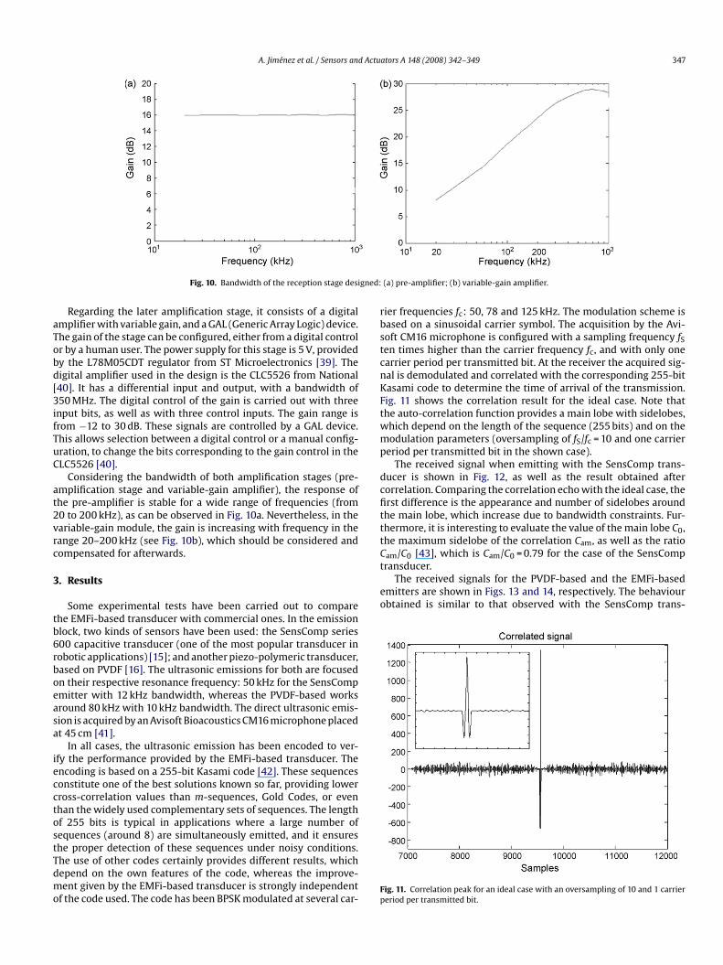
Fig. 10. Bandwidth of the reception stage desi
Regarding the later amplification stage, it consists of a digitalmplifier with variable gain, and a GAL (Generic Array Logic) device.he gain of the stage can be configured, either from a digital controlr by a human user. The power supply for this stage is 5 V, providedy the L78M05CDT regulator from ST Microelectronics [39]. Theigital amplifier used in the design is the CLC5526 from National40]. It has a differential input and output, with a bandwidth of50 MHz. The digital control of the gain is carried out with threenput bits, as well as with three control inputs. The gain range isrom −12 to 30 dB. These signals are controlled by a GAL device.his allows selection between a digital control or a manual config-ration, to change the bits corresponding to the gain control in theLC5526 [40].
Considering the bandwidth of both amplification stages (pre-mplification stage and variable-gain amplifier), the response ofhe pre-amplifier is stable for a wide range of frequencies (from0 to 200 kHz), as can be observed in Fig. 10a. Nevertheless, in theariable-gain module, the gain is increasing with frequency in theange 20–200 kHz (see Fig. 10b), which should be considered andompensated for afterwards.
. Results
Some experimental tests have been carried out to comparehe EMFi-based transducer with commercial ones. In the emissionlock, two kinds of sensors have been used: the SensComp series00 capacitive transducer (one of the most popular transducer inobotic applications) [15]; and another piezo-polymeric transducer,ased on PVDF [16]. The ultrasonic emissions for both are focusedn their respective resonance frequency: 50 kHz for the SensCompmitter with 12 kHz bandwidth, whereas the PVDF-based worksround 80 kHz with 10 kHz bandwidth. The direct ultrasonic emis-ion is acquired by an Avisoft Bioacoustics CM16 microphone placedt 45 cm [41].
In all cases, the ultrasonic emission has been encoded to ver-fy the performance provided by the EMFi-based transducer. Thencoding is based on a 255-bit Kasami code [42]. These sequencesonstitute one of the best solutions known so far, providing lowerross-correlation values than m-sequences, Gold Codes, or evenhan the widely used complementary sets of sequences. The lengthf 255 bits is typical in applications where a large number ofequences (around 8) are simultaneously emitted, and it ensures
he proper detection of these sequences under noisy conditions.he use of other codes certainly provides different results, whichepend on the own features of the code, whereas the improve-ent given by the EMFi-based transducer is strongly independentf the code used. The code has been BPSK modulated at several car-Fp
(a) pre-amplifier; (b) variable-gain amplifier.
ier frequencies fc: 50, 78 and 125 kHz. The modulation scheme isased on a sinusoidal carrier symbol. The acquisition by the Avi-oft CM16 microphone is configured with a sampling frequency fSen times higher than the carrier frequency fc, and with only onearrier period per transmitted bit. At the receiver the acquired sig-al is demodulated and correlated with the corresponding 255-bitasami code to determine the time of arrival of the transmission.ig. 11 shows the correlation result for the ideal case. Note thathe auto-correlation function provides a main lobe with sidelobes,hich depend on the length of the sequence (255 bits) and on theodulation parameters (oversampling of fS/fc = 10 and one carrier
eriod per transmitted bit in the shown case).The received signal when emitting with the SensComp trans-
ucer is shown in Fig. 12, as well as the result obtained afterorrelation. Comparing the correlation echo with the ideal case, therst difference is the appearance and number of sidelobes aroundhe main lobe, which increase due to bandwidth constraints. Fur-hermore, it is interesting to evaluate the value of the main lobe C0,he maximum sidelobe of the correlation Cam, as well as the ratio
ig. 11. Correlation peak for an ideal case with an oversampling of 10 and 1 carriereriod per transmitted bit.
348 A. Jiménez et al. / Sensors and Actuators A 148 (2008) 342–349
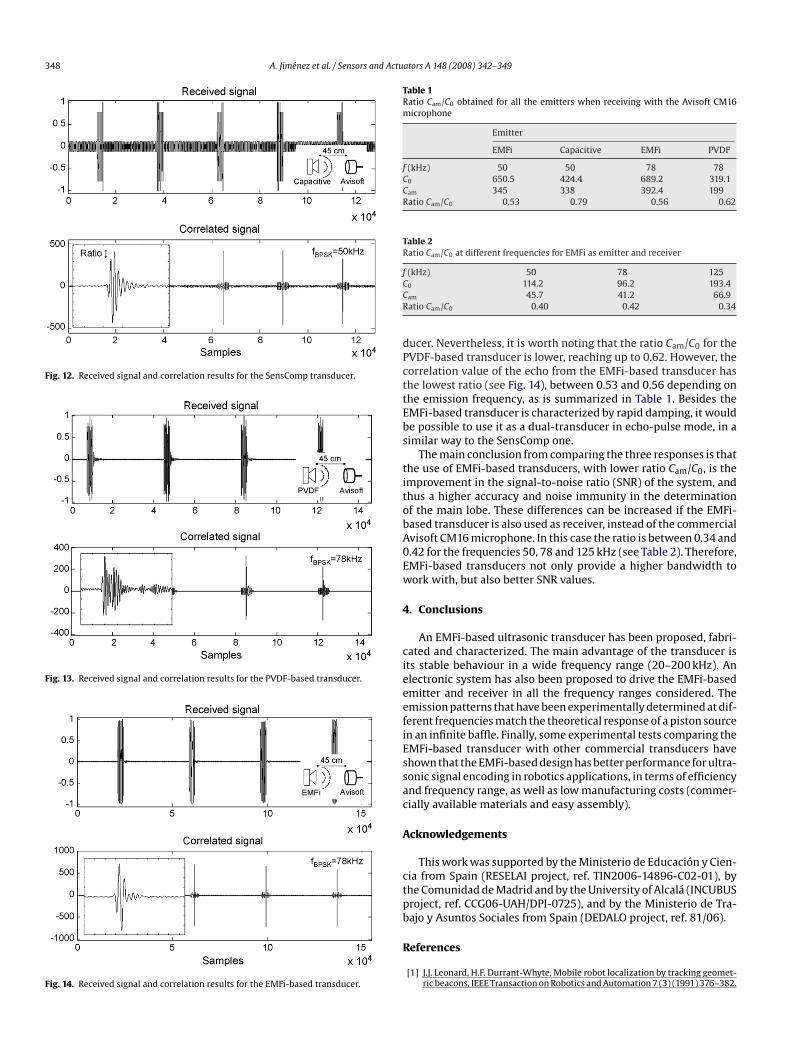
Fig. 12. Received signal and correlation results for the SensComp transducer.
Fig. 13. Received signal and correlation results for the PVDF-based transducer.
Fig. 14. Received signal and correlation results for the EMFi-based transducer.
Table 1Ratio Cam/C0 obtained for all the emitters when receiving with the Avisoft CM16microphone
Emitter
EMFi Capacitive EMFi PVDF
f (kHz) 50 50 78 78C0 650.5 424.4 689.2 319.1Cam 345 338 392.4 199Ratio Cam/C0 0.53 0.79 0.56 0.62
Table 2Ratio Cam/C0 at different frequencies for EMFi as emitter and receiver
f (kHz) 50 78 125CCR
dPcttEbs
titobA0Ew
4
cieeefiEssac
A
ctpb
R
0 114.2 96.2 193.4am 45.7 41.2 66.9atio Cam/C0 0.40 0.42 0.34
ucer. Nevertheless, it is worth noting that the ratio Cam/C0 for theVDF-based transducer is lower, reaching up to 0.62. However, theorrelation value of the echo from the EMFi-based transducer hashe lowest ratio (see Fig. 14), between 0.53 and 0.56 depending onhe emission frequency, as is summarized in Table 1. Besides theMFi-based transducer is characterized by rapid damping, it woulde possible to use it as a dual-transducer in echo-pulse mode, in aimilar way to the SensComp one.
The main conclusion from comparing the three responses is thathe use of EMFi-based transducers, with lower ratio Cam/C0, is themprovement in the signal-to-noise ratio (SNR) of the system, andhus a higher accuracy and noise immunity in the determinationf the main lobe. These differences can be increased if the EMFi-ased transducer is also used as receiver, instead of the commercialvisoft CM16 microphone. In this case the ratio is between 0.34 and.42 for the frequencies 50, 78 and 125 kHz (see Table 2). Therefore,MFi-based transducers not only provide a higher bandwidth toork with, but also better SNR values.
. Conclusions
An EMFi-based ultrasonic transducer has been proposed, fabri-ated and characterized. The main advantage of the transducer ists stable behaviour in a wide frequency range (20–200 kHz). Anlectronic system has also been proposed to drive the EMFi-basedmitter and receiver in all the frequency ranges considered. Themission patterns that have been experimentally determined at dif-erent frequencies match the theoretical response of a piston sourcen an infinite baffle. Finally, some experimental tests comparing theMFi-based transducer with other commercial transducers havehown that the EMFi-based design has better performance for ultra-onic signal encoding in robotics applications, in terms of efficiencynd frequency range, as well as low manufacturing costs (commer-ially available materials and easy assembly).
cknowledgements
This work was supported by the Ministerio de Educación y Cien-ia from Spain (RESELAI project, ref. TIN2006-14896-C02-01), byhe Comunidad de Madrid and by the University of Alcalá (INCUBUSroject, ref. CCG06-UAH/DPI-0725), and by the Ministerio de Tra-ajo y Asuntos Sociales from Spain (DEDALO project, ref. 81/06).
eferences
[1] J.J. Leonard, H.F. Durrant-Whyte, Mobile robot localization by tracking geomet-ric beacons, IEEE Transaction on Robotics and Automation 7 (3) (1991) 376–382.
Actu
[
[
[
[
[
[[
[
[
[
[
[
[
[
[
[
[
[
[
[
[
[
[[
[
[
[
[
[
[
[
[
[
[
B
ArdoACar
Áo(ord
JPmaccess
MdiDl
Fi2tto
Cstave
JPpAAiintegration for robot application and railway safety.
A. Jiménez et al. / Sensors and
[2] L. Kleeman, R. Kuc, Mobile robot sonar for target localization and classification,The International Journal of Robotics Research 14 (4) (1995) 295–318.
[3] W. Stubenvoll, T. Dimitrova, 3D high-accuracy sonar system for multiple mobilevehicles, in: Mobile Robots XIII and Intelligent Transportation Systems, January1999, Proceedings of SPIE 3525 (1999) 320–325.
[4] A. Elfes, Sonar based real-world mapping and navigation, IEEE Journal ofRobotics and Automation RA-3 (3) (1987) 249–264.
[5] J. Borestein, Y. Koren, Obstacle avoidance with ultrasonics sensors, IEEE Journalof Robotics and Automation 4 (2) (1988) 213–218.
[6] H. Peremans, K. Audenaert, J.M. Van Campenhout, A high resolution sensorbased on tri-aural perception, IEEE Transaction on Robotics and Automation 9(1) (1993) 36–48.
[7] L. Kleeman, Advanced sonar with velocity compensation, International Journalof Robotics Research 23 (2) (2004) 111–126.
[8] B. Barshan, R. Kuc, Differentiating sonar reflections from corners and planesby employing an intelligent sensor, IEEE Transaction on Pattern Analysis andMachine Intelligence 12 (6) (1990) 560–568.
[9] J.R. Gonzalez, C.J. Bleakley, Robust ultrasonic spread spectrum positioningsystem using a AoA/ToA method, in: Fifth IEEE International Symposium onIntelligent Signal Processing (WISP), Madrid, Spain, October 2007.
10] F. Moita, A.C. Lopes, U. Nunes, A fast firing binaural system for ultrasonic patternrecognition, Journal of Intelligent and Robotic Systems 50 (2) (2007) 141–162.
11] R. Kuc, Pseudo-amplitude scan sonar maps, IEEE Transaction on Robotics andAutomation 17 (5) (2001) 767–770.
12] K.-W. Jörg, M. Berg, Sophisticated mobile robot sonar sensing with pseudo-random codes, Robotics and Autonomous Systems 25 (3–4) (1998) 241–251.
13] J. Urena, M. Mazo, J.J. García, A. Hernández, E. Bueno, Classification of reflec-tors with an ultrasonic sensor for mobile robot applications, Robotics andAutonomous Systems 29 (1999) 269–279.
14] A. Hernández, J. Urena, J.J. García, M. Mazo, D. Herranz, J.P. Dérutin, J. Sérot,Ultrasonic ranging sensor using simultaneous emissions from different trans-ducers, IEEE Transaction on Ultrasonics, Ferroelectrics and Frequency Control51 (12) (2004) 1660–1670.
15] SensComp Inc., 600 Series Instrument Transducer, Product Specification, 2004.16] Leader Electronic Co., Ltd., 80 kHz cylindrical ultrasound transducer US80KS-01,
Product Specification, 2007.17] J. Reijneirs, H. Peremans, Biomimetic sonar system performing spectrum-based
localization, IEEE Transaction on Robotics 23 (6) (2007) 1151–1159.18] R. Gerhard-Multhaupt, Less can be more—holes in polymers lead to a new
paradigm of piezoelectric materials for electret transducers, IEEE Transactionon Dielectrics and Electrical Insulation 9 (2002) 850–859.
19] E. Fukada, History and recent progress in piezoelectric polymers, IEEE Trans-action on Ultrasonics, Ferroelectrics, and Frequency Control 47 (6) (2000)1277–1290.
20] S. Bauer, R. Gerhard-Multhaupt, G.M. Sessler, Ferroelectrets: Soft electroactivefoams for transducers, Physics Today 57 (2) (2004) 37–43.
21] M. Hazas, A. Hopper, Broadband ultrasonic location systems for improvedindoor positioning, IEEE Transaction on Mobile Computing 5 (5) (2006)536–547.
22] K. Kirjavainen, Electromechanical film and procedure for manufacturing same,U.S. Patent No. 4,654,546 (1987).
23] M. Paajanen, J. Lekkala, K. Kirjavainen, Electromechanical film EMFi. A newmultipurpose electret material, Sensors and Actuators A 84 (2000) 95–102.
24] M. Lindner, H. Hoislbauer, R. Schwödiauer, S. Bauer-Gogonea, S. Bauer,Charged cellular polymers with “ferroelectretic” behavior, IEEE Transactionson Dielectrics and Electrical Insulation 2 (2004) 255–263.
25] M. Lindner, S. Bauer-Gogonea, S. Bauer, M. Paajanen, J. Raukola, Dielectric bar-rier microdischarges: mechanism for the charging of cellular piezoelectricpolymers, Journal of Applied Physics 91 (2002) 5283–5287.
26] A. Savolainen, K. Kirjavainen, Electrothermomechanical film: Part 1. Design andcharacteristics, Journal of Macromolecular Science: Chemistry A26 (2–3) (1989)583–591.
27] G.S. Neugschwandtner, R. Schwodiauer, M. Vieytes, S. Bauer-Gogonea, S. Bauer,J. Hillenbrand, R. Kressmann, G.M. Sessler, M. Paajanen, J. Lekkala, Large andbroadband piezoelectricity in smart polymer-foam space-charge electrets,Applied Physics Letters 77 (2000) 3827–3829.
28] G.S. Neugschwandtner, R. Schwodiauer, S. Bauer-Gogonea, S. Bauer, M. Paa-janen, J. Lekkala, Piezo- and pyroelectricity of a polymer-foam space-chargeelectret, Journal of Applied Physics 89 (2001) 4503–4511.
29] G.M. Sessler, J. Hillenbrand, Electromechanical response of cellular electretfilms, Applied Physics Letters 75 (1999) 3405–3407.
30] X. Zhang, J. Hillenbrand, G.M. Sessler, Improvement of piezoelectric activityof cellular polymers using a double-expansion process, Journal of Physics D:Applied Physics 37 (2004) 2146–2150.
31] M. Wegener, W. Wirges, R. Gerhard-Multhaupt, M. Dansachmtiller, R. Schwd-diauer, S. Bauer-Gogonea, S. Bauer, M. Paajanen, H. Minkkinen, J. Raukola,Controlled inflation of voids in cellular polymer ferroelectrets: optimizingelectromechanical transducer properties, Applied Physics Letters 84 (2004)392–394.
32] Emfit Ltd., Emfit Film Product Specification, 2004.33] Brüel and Kjaer, Condenser microphone cartridges—Types 4133 to 4181, Prod-
uct Data, 2007.34] A. Streicher, R. Müller, H. Peremans, R. Lerch, Broadband Ultrasonic Transducer
for a Artificial Bat Head, 2003 IEEE Symposium on Ultrasonics, vol. 2, Honolulu,USA, October 2003, 2003, pp. 1364–1367.
JvDs
ators A 148 (2008) 342–349 349
35] L.E. Kinsler, A.R. Frey, A.B. Coppens, J.V. Sanders, Fundamentals of Acoustics,John Wiley & Sons, New York, USA, 1982.
36] EMCO High Voltage Corp., Dual polarity high voltage modules, Product Speci-fication, 2007.
37] APEX Microtechnology Corp., Power Operational Amplifiers PA98 PA98A, Prod-uct Specification, 2004.
38] Analog Devices, Inc., High performance 145 MHz FastFET Op Amps, ProductSpecification, 2006.
39] ST Microelectronics, L78Mxx Positive voltage regulators, Product Specification,2007.
40] National Semiconductor Corp., CLC5526 Digital variable gain amplifier (DVGA),Product Specification, 2002.
41] Avisoft Bioacoustics, UltraSoundGate microphone capsule CM16, Product Spec-ification, 2007.
42] J. Lahtonen, On the odd and the aperiodic correlation properties of theKasami Sequences, IEEE Transactions on Information Theory 41 (5) (1995)1506–1508.
43] P. Fan, M. Darnell, Sequence Design For Communications Applications, ResearchStudies Press Ltd., 1996.
iographies
na Jiménez studied Physics at the Complutense University of Madrid and Mate-ial Engineering at the Politecnica University of Madrid, where obtained the PhDegree in 2003. She has worked in MBE growth, fabrication, and characterizationf III-V Nitride heterostructures for electronic applications. She joined University oflcalá (Spain), Department of Electronics, in January 2004 as associate professor.urrently, her research interests are focused on ultrasonic transducers, design ofcquisition, analysis and processing systems for ultrasonic transducers for mobileobots.
lvaro Hernández obtained his Electronics Engineering degree from the Universityf Alcalá (Spain) in 1998. In 2003, he obtained his PhD from the University of AlcaláSpain), and from the Blaise Pascal University (France). He is currently a lecturerf Digital Systems at the Electronics Department in the University of Alcalá. Hisesearch areas are multi-sensor integration, electronic systems for mobile robots,igital systems and computing architecture.
esúus Urena received the Telecommunications Engineering (MS) from theolytechnical University of Madrid (Spain) in 1992; and his PhD degree in Telecom-unications from the University of Alcalá (Spain) in 1998. Since 1986 he has been an
ssociate professor of the Electronics Department at the University of Alcalá. He hasollaborated in several educational and research projects in the area of electronicontrol and sensory systems for mobile robots and wheelchairs and in the area oflectronic systems for railways. His current research areas are low-level ultrasonicignal processing, local positioning systems (LPS) and sensory systems for railwayafety.
a Carmen Pérez received the BS degree in Industrial Engineering and the MSegree in Electronics Engineering from the University of Alcalá, Madrid, Spain,
n 2002 and 2004 respectively. Currently, she is a PhD student at the Electronicsepartment of the same University. Her research interests include sequence design,
ow-level ultrasonic signal processing and computing architectures.
ernando J. Álvarez received his Physics degree from the University of Sevilla (Spain)n 1998 and his PhD degree in Electronics from the University of Alcalá (Spain) in006. He is currently an assistant professor of Control Engineering and Digital Elec-ronics in the Department of Electrical Engineering, Electronics and Automatics athe University of Extremadura, Badajoz, Spain. His research areas of interest areutdoor acoustics and ultrasonic sensory systems.
arlos M. De Marziani obtained his Electronics Engineering degree from the Univer-ity of Patagonia San Juan Bosco (Argentina) in 2001. In 2007, he obtained his PhD athe Electronics Department from the University of Alcalá (Spain). He is currently anssistant professor of Digital Systems at the Electronics Department from the Uni-ersity of Patagonia San Juan Bosco. His research areas are multi-sensor integration,lectronic systems for mobile robots, digital systems and computing architectures.
uan J. Garcia obtained his Electrical and Electronic Engineering degree from theolytechnical University of Valencia (Spain) in 1999. In 2006, he obtained his Euro-ean Ph.D. degree from the University of Alcala (Spain). He is currently Lecturer ofnalog and Digital Electronics at the Electronics Department of the University oflcalá. He has worked on several public and private research projects related to dig-
tal control and sensor systems, and his current areas of interest are multi-sensory
. Manuel Villadangos obtained his Electronics Engineering degree from the Uni-ersity of Valencia (Spain) in 1998. He is currently a lecturer at the Electronicsepartment from the University of Alcalá. His research areas are local positioning
ystems for indoor environments and digital systems.