programming guide - army ants robotics
TRANSCRIPT

Table of ContentsIntroduction 1
LabVIEW Basics 2-4
Project Overview 5-6
Begin & Finish 7
Teleop 8
Enum & Data Cluster 9
Sub VIs and Icons 10
Naming Standards 11
Data Types 12
Variables 13
Vision 14
Autonomous 15
Deploying Code 16
Drive Station 17
CAN & PID 18
Troubleshooting 19-20
1
Welcome to the 1st Edition of the Ultimate Programming Guide! The Army Ants 3792 is a
FIRST Robotics Competition team based in Columbia, Missouri, and have created this
programming guide to spread their knowledge of LabVIEW programming to other FRC participants.
The Ultimate Programming Guide will lead readers through the process of creating a complete
LabVIEW program for their robot.
A robot, no matter how well designed or built, is useless without programming. There are many programming languages that are used in FRC, including C++. While languages such as C++
involve typing out wordy lines of code, LabVIEW consists of blocks connected by wires, which build
a flowchart that also functions as the code itself. This concept is best understood through personal
experience. Let's get started!
Introduction
2
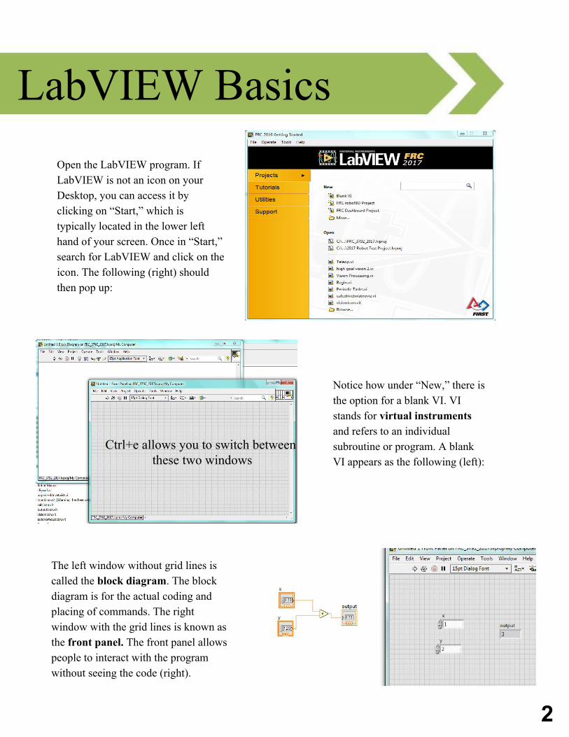
LabVIEW BasicsOpen the LabVIEW program. If LabVIEW is not an icon on your Desktop, you can access it by clicking on “Start,” which is typically located in the lower left hand of your screen. Once in “Start,” search for LabVIEW and click on the icon. The following (right) should then pop up:
Notice how under “New,” there is the option for a blank VI. VI stands for virtual instruments and refers to an individual subroutine or program. A blank VI appears as the following (left):
Ctrl+e allows you to switch between these two windows
The left window without grid lines is called the block diagram. The block diagram is for the actual coding and placing of commands. The right window with the grid lines is known as the front panel. The front panel allows people to interact with the program without seeing the code (right).
3
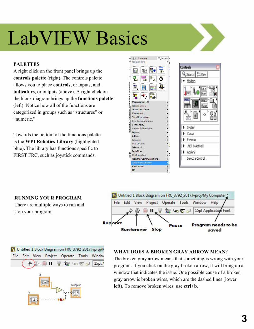
LabVIEW BasicsPALETTES A right click on the front panel brings up the controls palette (right). The controls palette allows you to place controls, or inputs, and indicators, or outputs (above). A right click on the block diagram brings up the functions palette (left). Notice how all of the functions are categorized in groups such as “structures” or “numeric.”
Towards the bottom of the functions palette is the WPI Robotics Library (highlighted blue). The library has functions specific to FIRST FRC, such as joystick commands.
RUNNING YOUR PROGRAM There are multiple ways to run and stop your program.
WHAT DOES A BROKEN GRAY ARROW MEAN? The broken gray arrow means that something is wrong with your program. If you click on the gray broken arrow, it will bring up a window that indicates the issue. One possible cause of a broken gray arrow is broken wires, which are the dashed lines (lower left). To remove broken wires, use ctrl+b.
4
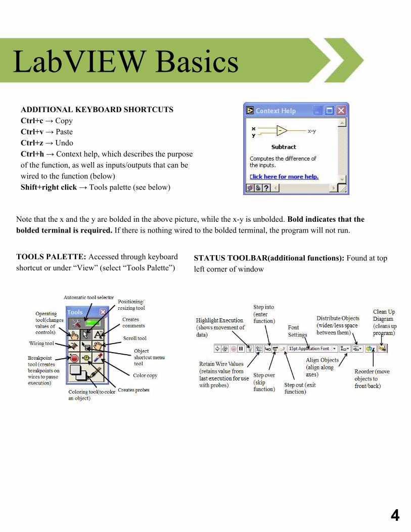
LabVIEW BasicsADDITIONAL KEYBOARD SHORTCUTSCtrl+c → CopyCtrl+v → PasteCtrl+z → UndoCtrl+h → Context help, which describes the purpose of the function, as well as inputs/outputs that can be wired to the function (below)Shift+right click → Tools palette (see below)
Note that the x and the y are bolded in the above picture, while the x-y is unbolded. Bold indicates that the bolded terminal is required. If there is nothing wired to the bolded terminal, the program will not run.
TOOLS PALETTE: Accessed through keyboard shortcut or under “View” (select “Tools Palette”)
STATUS TOOLBAR(additional functions): Found at top left corner of window
5
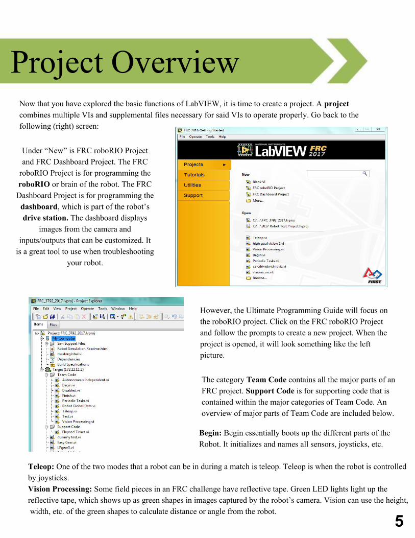
Project OverviewNow that you have explored the basic functions of LabVIEW, it is time to create a project. A project combines multiple VIs and supplemental files necessary for said VIs to operate properly. Go back to the following (right) screen:
However, the Ultimate Programming Guide will focus on the roboRIO project. Click on the FRC roboRIO Project and follow the prompts to create a new project. When the project is opened, it will look something like the left picture.
Under “New” is FRC roboRIO Project and FRC Dashboard Project. The FRC
roboRIO Project is for programming the roboRIO or brain of the robot. The FRC
Dashboard Project is for programming the dashboard, which is part of the robot’s drive station. The dashboard displays
images from the camera and inputs/outputs that can be customized. It
is a great tool to use when troubleshooting your robot.
The category Team Code contains all the major parts of an FRC project. Support Code is for supporting code that is contained within the major categories of Team Code. An overview of major parts of Team Code are included below.
Begin: Begin essentially boots up the different parts of the Robot. It initializes and names all sensors, joysticks, etc.
Teleop: One of the two modes that a robot can be in during a match is teleop. Teleop is when the robot is controlled by joysticks. Vision Processing: Some field pieces in an FRC challenge have reflective tape. Green LED lights light up the reflective tape, which shows up as green shapes in images captured by the robot’s camera. Vision can use the height, width, etc. of the green shapes to calculate distance or angle from the robot.
6
Autonomous Independent: The second mode that a robot can be in during a match is autonomous. In the first 15 seconds of each game, the robot runs a pre- downloaded program without human control. Periodic Tasks: Periodic tasks are tasks that must be done regularly at certain intervals in teleop. A common periodic task is to refill the compressor every few seconds. Finish: As implied by its name, Finish stops the functions of all sensors, joysticks, etc. referenced in Begin. Since all functions will be stopped automatically when the robot is shut down, Finish is not technically needed, but it serves as an additional shut-down mechanism and completes the begin-middle-end style of the project. Test: When a robot is in test mode, it will run Test. Disabled: When a robot is disabled, it will run Disabled. Robot Global Data: Robot Global Data passes data between VIs. It only has a front panel, because it can only store information and cannot perform calculations.
Project Overview
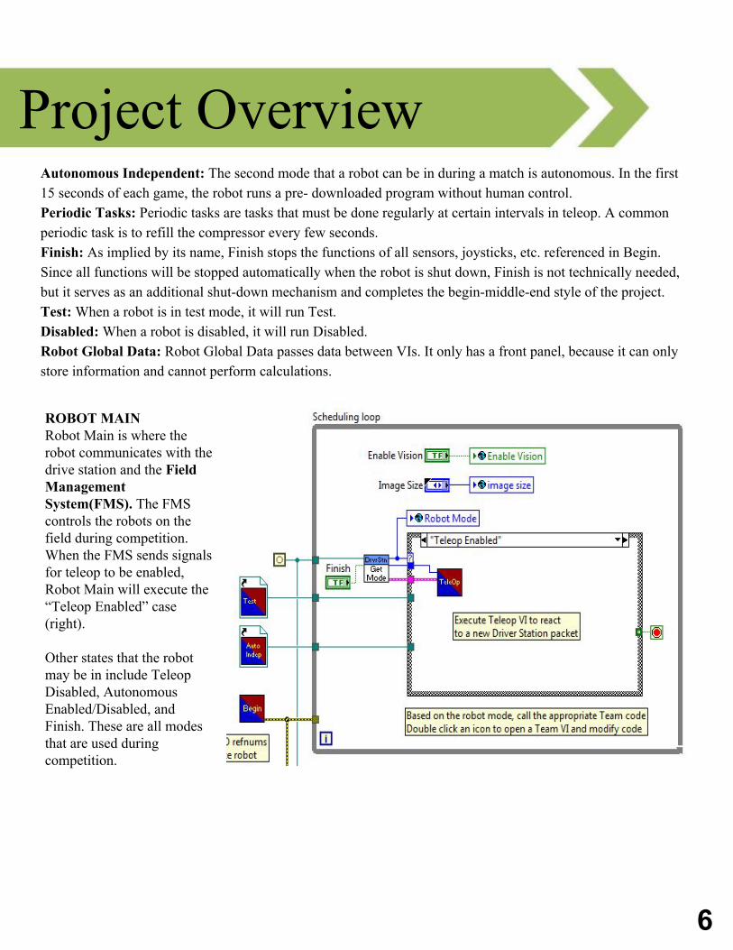
ROBOT MAINRobot Main is where the robot communicates with the drive station and the Field Management System(FMS). The FMS controls the robots on the field during competition. When the FMS sends signals for teleop to be enabled, Robot Main will execute the “Teleop Enabled” case (right).
Other states that the robot may be in include Teleop Disabled, Autonomous Enabled/Disabled, and Finish. These are all modes that are used during competition.
Begin & Finish
7
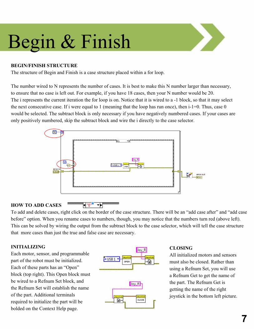
BEGIN/FINISH STRUCTURE The structure of Begin and Finish is a case structure placed within a for loop.
The number wired to N represents the number of cases. It is best to make this N number larger than necessary, to ensure that no case is left out. For example, if you have 18 cases, then your N number would be 20. The i represents the current iteration the for loop is on. Notice that it is wired to a -1 block, so that it may select the next consecutive case. If i were equal to 1 (meaning that the loop has run once), then i-1=0. Thus, case 0 would be selected. The subtract block is only necessary if you have negatively numbered cases. If your cases are only positively numbered, skip the subtract block and wire the i directly to the case selector.
HOW TO ADD CASESTo add and delete cases, right click on the border of the case structure. There will be an “add case after” and “add case before” option. When you rename cases to numbers, though, you may notice that the numbers turn red (above left). This can be solved by wiring the output from the subtract block to the case selector, which will tell the case structure that more cases than just the true and false case are necessary.
INITIALIZING Each motor, sensor, and programmable part of the robot must be initialized. Each of these parts has an “Open” block (top right). This Open block must be wired to a Refnum Set block, and the Refnum Set will establish the name of the part. Additional terminals required to initialize the part will be bolded on the Context Help page.
CLOSING All initialized motors and sensors must also be closed. Rather than using a Refnum Set, you will use a Refnum Get to get the name of the part. The Refnum Get is getting the name of the right joystick in the bottom left picture.
8
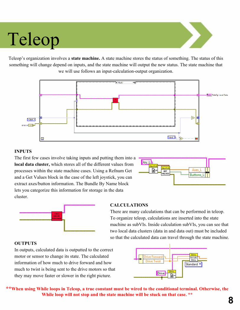
Teleop Teleop’s organization involves a state machine. A state machine stores the status of something. The status of this something will change depend on inputs, and the state machine will output the new status. The state machine that
we will use follows an input-calculation-output organization.
INPUTSThe first few cases involve taking inputs and putting them into a local data cluster, which stores all of the different values from processes within the state machine cases. Using a Refnum Get and a Get Values block in the case of the left joystick, you can extract axes/button information. The Bundle By Name block lets you categorize this information for storage in the data cluster.
CALCULATIONS There are many calculations that can be performed in teleop. To organize teleop, calculations are inserted into the state machine as subVIs. Inside calculation subVIs, you can see that two local data clusters (data in and data out) must be included so that the calculated data can travel through the state machine.
OUTPUTSIn outputs, calculated data is outputted to the correct motor or sensor to change its state. The calculated information of how much to drive forward and how much to twist is being sent to the drive motors so that they may move faster or slower in the right picture.
**When using While loops in Teleop, a true constant must be wired to the conditional terminal. Otherwise, the While loop will not stop and the state machine will be stuck on that case. **
9
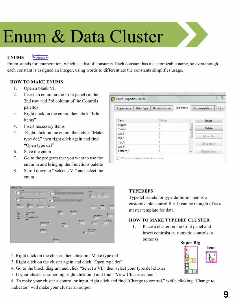
Enum & Data Cluster ENUMS Enum stands for enumeration, which is a list of constants. Each constant has a customizable name, so even though each constant is assigned an integer, using words to differentiate the constants simplifies usage.
HOW TO MAKE ENUMS 1. Open a blank VI,2. Insert an enum on the front panel (in the
2nd row and 3rd column of the Controls palette)
3. Right click on the enum, then click “Edit items”
4. Insert necessary items 5. Right click on the enum, then click “Make
type def,” then right click again and find “Open type def”
6. Save the enum 7. Go to the program that you want to use the
enum in and bring up the Functions palette 8. Scroll down to “Select a VI” and select the
enum
TYPEDEFSTypedef stands for type definition and is a customizable control file. It can be thought of as a master template for data.
HOW TO MAKE TYPEDEF CLUSTER 1. Place a cluster on the front panel and
insert controls(ex. numeric controls or buttons)
2. Right click on the cluster, then click on “Make type def”3. Right click on the cluster again and click “Open type def” 4. Go to the block diagram and click “Select a VI,” then select your type def cluster5. If your cluster is super big, right click on it and find “View Cluster as Icon” 6. To make your cluster a control or input, right click and find “Change to control,” while clicking “Change to indicator” will make your cluster an output
IconSuper Big
10
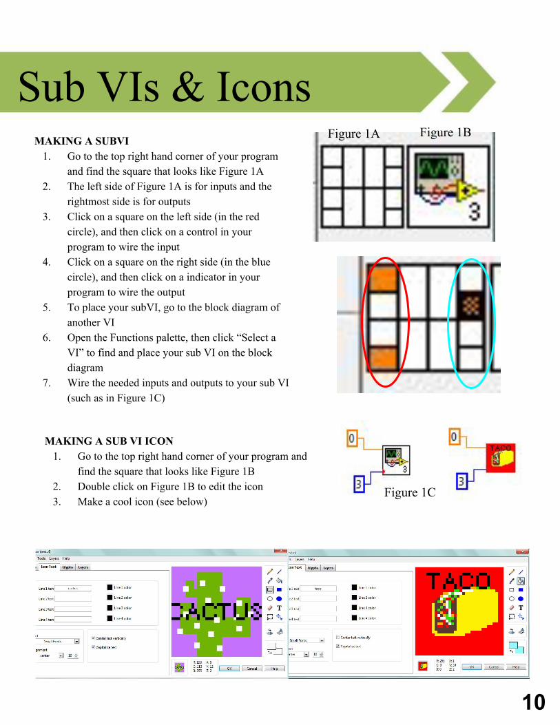
Sub VIs & Icons MAKING A SUBVI
1. Go to the top right hand corner of your program and find the square that looks like Figure 1A
2. The left side of Figure 1A is for inputs and the rightmost side is for outputs
3. Click on a square on the left side (in the red circle), and then click on a control in your program to wire the input
4. Click on a square on the right side (in the blue circle), and then click on a indicator in your program to wire the output
5. To place your subVI, go to the block diagram of another VI
6. Open the Functions palette, then click “Select a VI” to find and place your sub VI on the block diagram
7. Wire the needed inputs and outputs to your sub VI (such as in Figure 1C)
MAKING A SUB VI ICON
1. Go to the top right hand corner of your program and find the square that looks like Figure 1B
2. Double click on Figure 1B to edit the icon3. Make a cool icon (see below)
Figure 1A Figure 1B
Figure 1C
11
Naming Standards *If not on list, ASK BEFORE NAMING Last updated 7/16/17
NAMING RULES TO FOLLOW (in a state machine): 1. Always capitalize the first letter of each word2. If differentiating between left and right(ex. Left vs right
encoder) use: a. _L _R
3. No space between words4. Abbreviations(ex. RPM) are always all capitalized 5. All single letters(ex. X) should be capitalized 6. Naming rules for state machine cases:
a. For all inputs, start name with i (ex. i_Joy)b. For all calculations, start name with c (ex.
c_DriveTwist)c. For all outputs, start name with o (ex. o_MeterWheel)
NAMING RULES TO FOLLOW (for .vi): 1. The previous rules apply(except for rule 6),
however omit underscores 2. INSTEAD of rule 6, use the following: for all
calculations, start the .vi name with Calc3. If .vi is for autonomous, start .vi name with A(ex.
autonomous calculation for turning angle is ACalcTurn)
COMMON TERMS: Drive: DriveForwardDriveTwist DriveStraight GearBox→ Gear
Implements: Flywheel shooter → Fly Any form of ball intake → IntakeSpinning wheels that are not intake/shooting → Meter*Note that most implement names are self-explanatory (ex. Arm)
Sensors: Contact Switch → Contact Gyro Sensor → Gyro EncoderPotentiometer→ PotUltrasonic→ Ultra Accelerometer→ Accel
Vision: VisionAzimuth (Azimuth means horizontal angle to an object)VisionHeight *Depending on the challenge, there may be more variables to consider
Joystick Buttons: Joystick→ Joy X-axis → XY-axis → Y TriggerThumb Throttle Top 3,4,5,6 Bottom 7,8,9,10,11,12
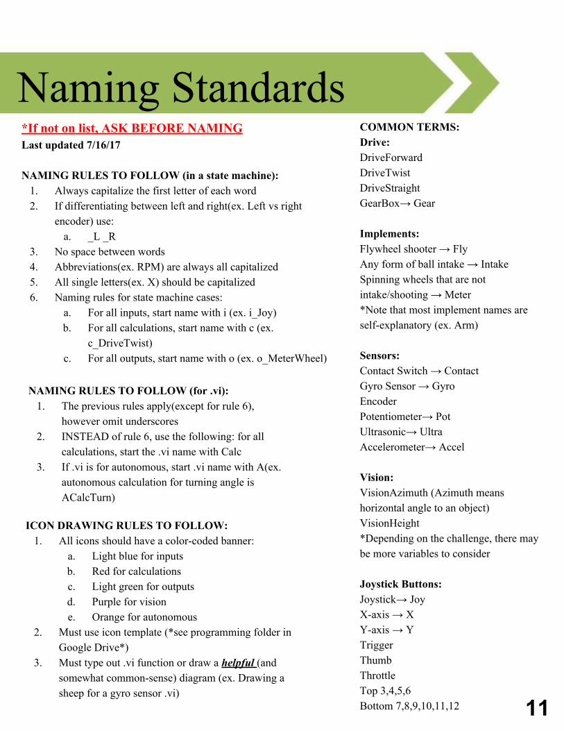
ICON DRAWING RULES TO FOLLOW: 1. All icons should have a color-coded banner:
a. Light blue for inputs b. Red for calculationsc. Light green for outputs d. Purple for vision e. Orange for autonomous
2. Must use icon template (*see programming folder in Google Drive*)
3. Must type out .vi function or draw a helpful (and somewhat common-sense) diagram (ex. Drawing a sheep for a gyro sensor .vi)
12
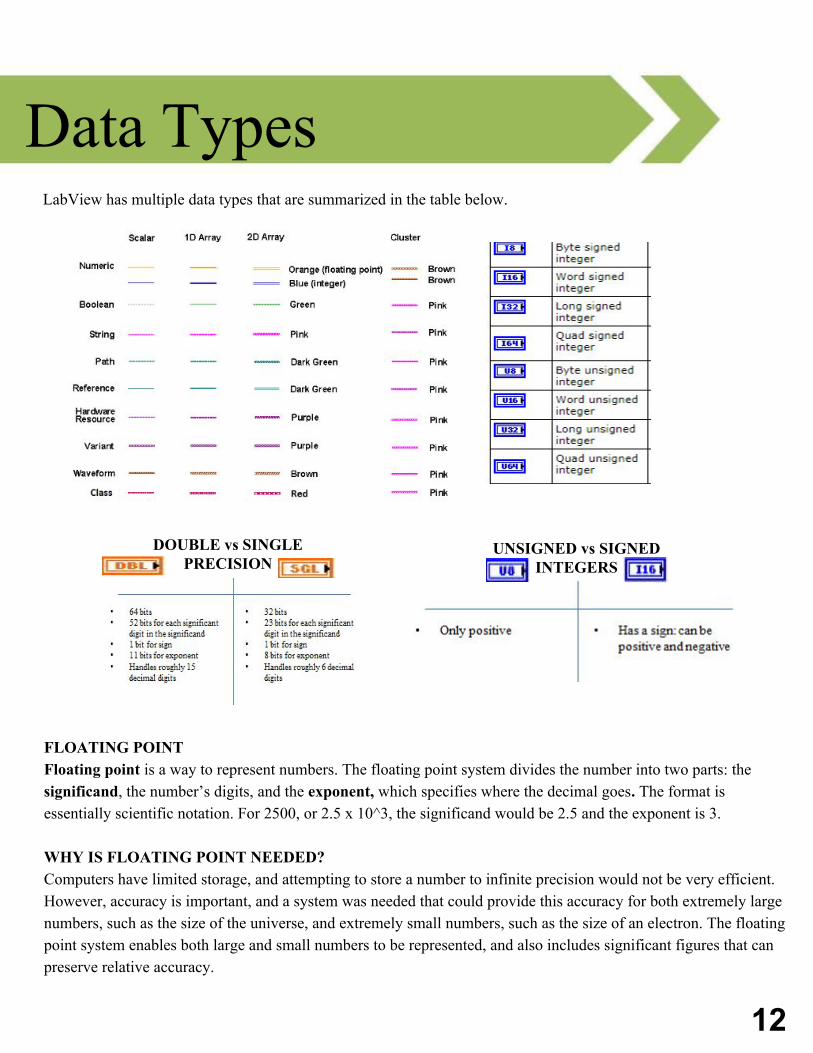
Data Types LabView has multiple data types that are summarized in the table below.
FLOATING POINT Floating point is a way to represent numbers. The floating point system divides the number into two parts: the significand, the number’s digits, and the exponent, which specifies where the decimal goes. The format is essentially scientific notation. For 2500, or 2.5 x 10^3, the significand would be 2.5 and the exponent is 3.
WHY IS FLOATING POINT NEEDED? Computers have limited storage, and attempting to store a number to infinite precision would not be very efficient. However, accuracy is important, and a system was needed that could provide this accuracy for both extremely large numbers, such as the size of the universe, and extremely small numbers, such as the size of an electron. The floating point system enables both large and small numbers to be represented, and also includes significant figures that can preserve relative accuracy.
DOUBLE vs SINGLE PRECISION
UNSIGNED vs SIGNED INTEGERS
13
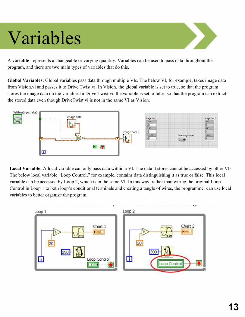
Variables A variable represents a changeable or varying quantity. Variables can be used to pass data throughout the program, and there are two main types of variables that do this.
Global Variables: Global variables pass data through multiple VIs. The below VI, for example, takes image data from Vision.vi and passes it to Drive Twist.vi. In Vision, the global variable is set to true, so that the program stores the image data on the variable. In Drive Twist.vi, the variable is set to false, so that the program can extract the stored data even though DriveTwist.vi is not in the same VI as Vision.
Local Variable: A local variable can only pass data within a VI. The data it stores cannot be accessed by other VIs. The below local variable “Loop Control,” for example, contains data distinguishing it as true or false. This local variable can be accessed by Loop 2, which is in the same VI. In this way, rather than wiring the original Loop Control in Loop 1 to both loop’s conditional terminals and creating a tangle of wires, the programmer can use local variables to better organize the program.
14
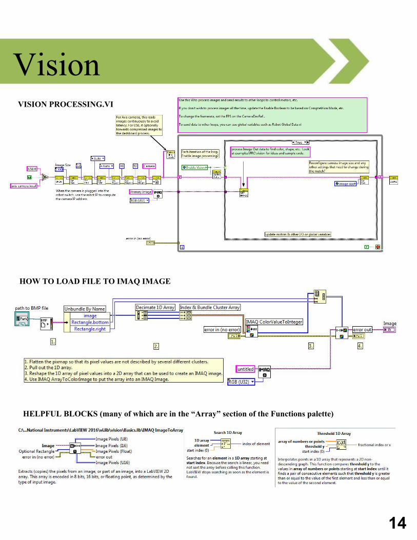
Vision
HOW TO LOAD FILE TO IMAQ IMAGE
VISION PROCESSING.VI
HELPFUL BLOCKS (many of which are in the “Array” section of the Functions palette)
15
Autonomous TIPS FOR PROGRAMMING AUTONOMOUS● Use encoders to measure the distance that the robot travels. This will improve the accuracy with which your
robot can complete the autonomous task. ● Use subVIs when placing code in Autonomous Independent.vi to organize your code ● There are two common methods used to make sure your robot turn x degrees:
■ Gyro sensor: Program x degrees into your gyro sensor.■ Encoder: Calculate the amount of encoder ticks that equals a 360 turn. From this value, you
can calculate how many encoder ticks equals x degrees.
SEPARATING ARCADE DRIVE If you use encoders, you will likely want to know the name of each individual drive motor so that you can reference each drive motor’s encoder.
Right motor name: Drive - Right Motor Left motor name: Drive - Left Motor
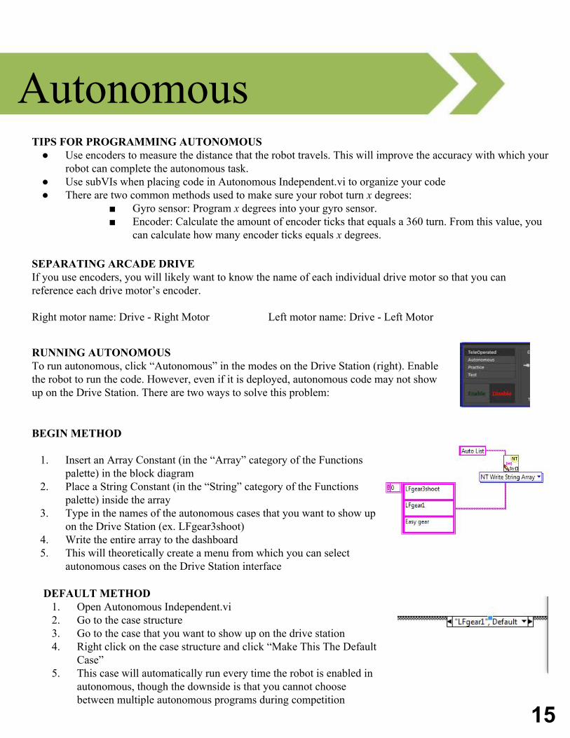
RUNNING AUTONOMOUS To run autonomous, click “Autonomous” in the modes on the Drive Station (right). Enable the robot to run the code. However, even if it is deployed, autonomous code may not show up on the Drive Station. There are two ways to solve this problem:
BEGIN METHOD
1. Insert an Array Constant (in the “Array” category of the Functions palette) in the block diagram
2. Place a String Constant (in the “String” category of the Functions palette) inside the array
3. Type in the names of the autonomous cases that you want to show up on the Drive Station (ex. LFgear3shoot)
4. Write the entire array to the dashboard 5. This will theoretically create a menu from which you can select
autonomous cases on the Drive Station interface
DEFAULT METHOD 1. Open Autonomous Independent.vi 2. Go to the case structure 3. Go to the case that you want to show up on the drive station4. Right click on the case structure and click “Make This The Default
Case” 5. This case will automatically run every time the robot is enabled in
autonomous, though the downside is that you cannot choose between multiple autonomous programs during competition
16
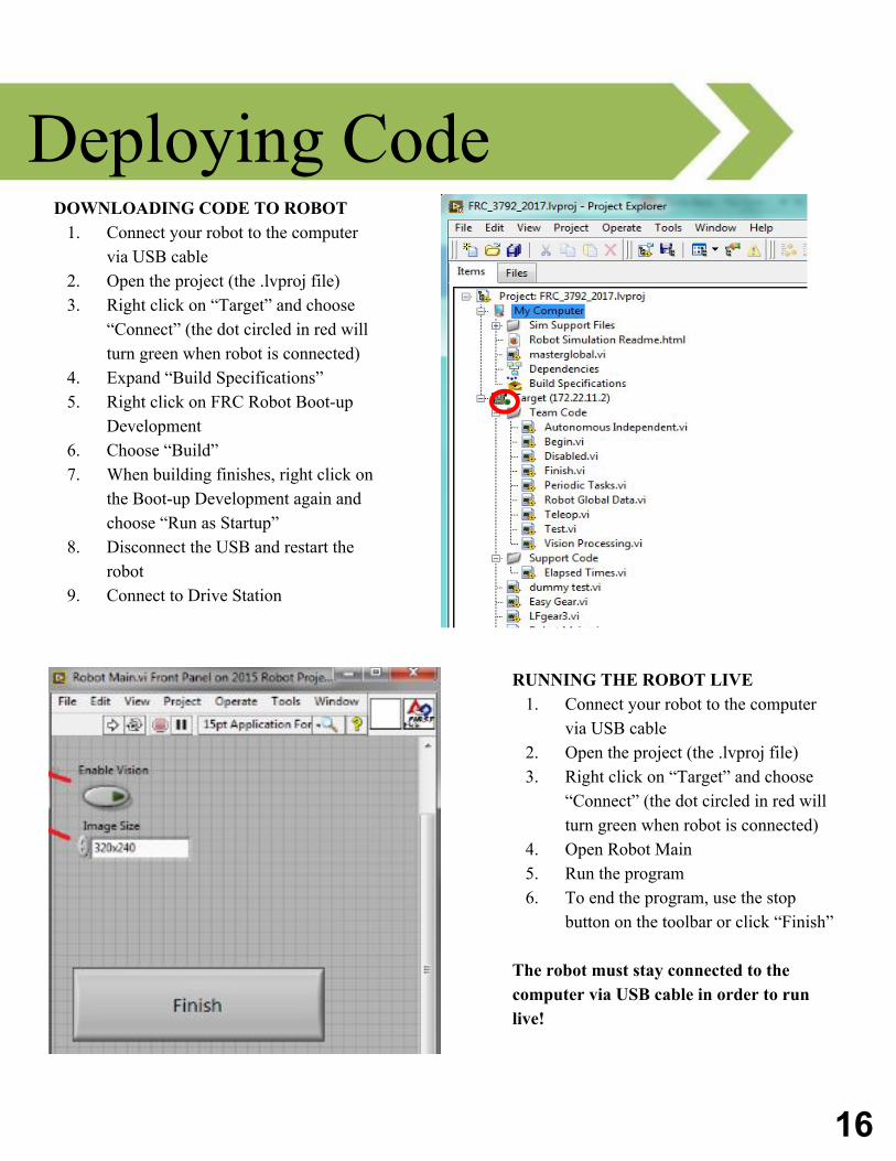
Deploying Code
RUNNING THE ROBOT LIVE 1. Connect your robot to the computer
via USB cable 2. Open the project (the .lvproj file)3. Right click on “Target” and choose
“Connect” (the dot circled in red will turn green when robot is connected)
4. Open Robot Main 5. Run the program 6. To end the program, use the stop
button on the toolbar or click “Finish”
The robot must stay connected to the computer via USB cable in order to run live!
DOWNLOADING CODE TO ROBOT1. Connect your robot to the computer
via USB cable2. Open the project (the .lvproj file) 3. Right click on “Target” and choose
“Connect” (the dot circled in red will turn green when robot is connected)
4. Expand “Build Specifications” 5. Right click on FRC Robot Boot-up
Development 6. Choose “Build” 7. When building finishes, right click on
the Boot-up Development again and choose “Run as Startup”
8. Disconnect the USB and restart the robot
9. Connect to Drive Station
17
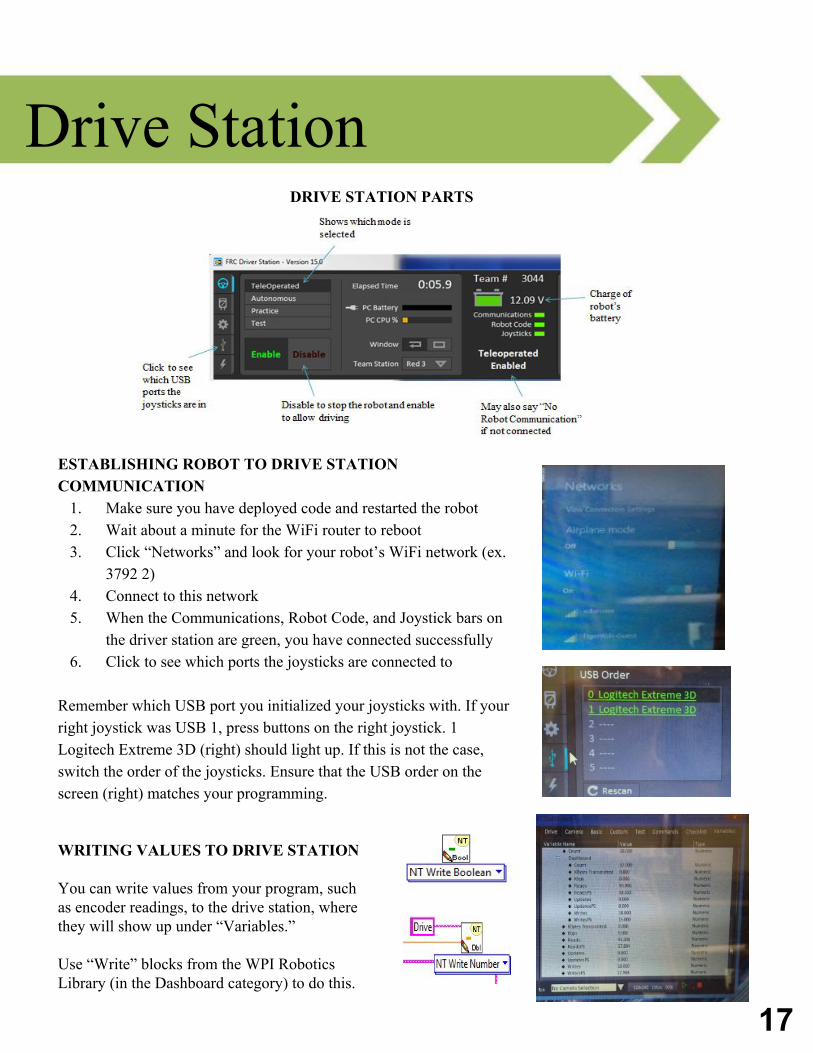
Drive Station
ESTABLISHING ROBOT TO DRIVE STATION COMMUNICATION
1. Make sure you have deployed code and restarted the robot 2. Wait about a minute for the WiFi router to reboot3. Click “Networks” and look for your robot’s WiFi network (ex.
3792 2)4. Connect to this network 5. When the Communications, Robot Code, and Joystick bars on
the driver station are green, you have connected successfully 6. Click to see which ports the joysticks are connected to
Remember which USB port you initialized your joysticks with. If your right joystick was USB 1, press buttons on the right joystick. 1 Logitech Extreme 3D (right) should light up. If this is not the case, switch the order of the joysticks. Ensure that the USB order on the screen (right) matches your programming.
DRIVE STATION PARTS
WRITING VALUES TO DRIVE STATION
You can write values from your program, such as encoder readings, to the drive station, where they will show up under “Variables.”
Use “Write” blocks from the WPI Robotics Library (in the Dashboard category) to do this.
18
CAN & PID WHAT IS CAN? Controller Area Network bus, otherwise known as CAN bus or CAN, is a way to control the multiple motors and sensors on the robot.
HOW DOES CAN WORK? Imagine that each device is lined up in a straight line and assigned a number. Say that you want to send a signal to the left motor, device 10. CAN bus will send that signal down the line until it reaches the 10th device. CAN bus allows all of the devices to communicate in this way.
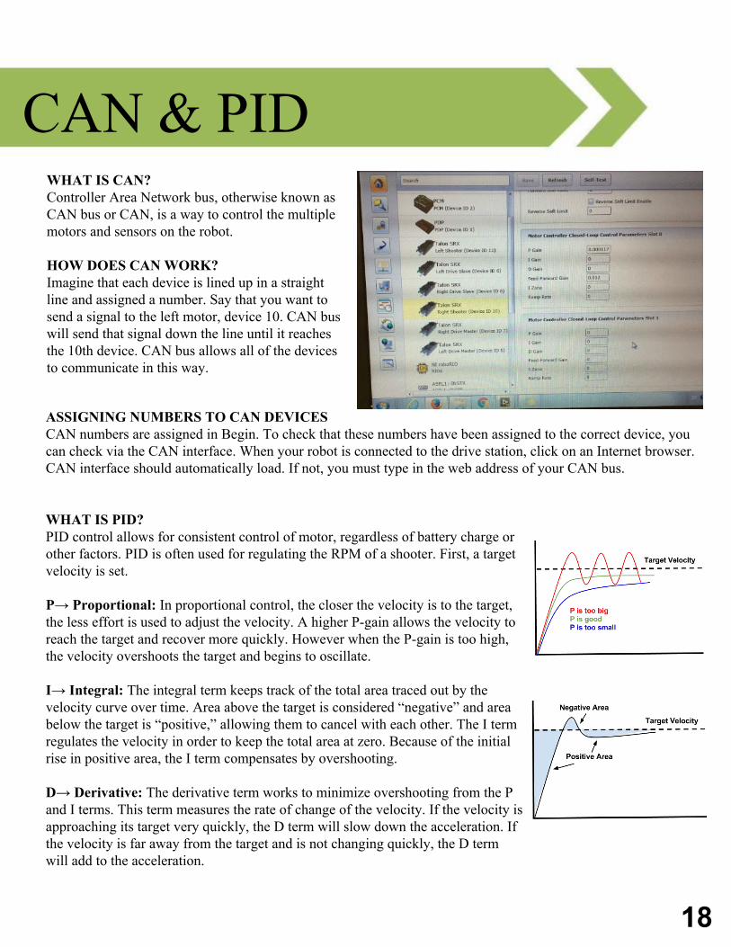
WHAT IS PID?PID control allows for consistent control of motor, regardless of battery charge or other factors. PID is often used for regulating the RPM of a shooter. First, a target velocity is set.
P→ Proportional: In proportional control, the closer the velocity is to the target, the less effort is used to adjust the velocity. A higher P-gain allows the velocity to reach the target and recover more quickly. However when the P-gain is too high, the velocity overshoots the target and begins to oscillate.
I→ Integral: The integral term keeps track of the total area traced out by the velocity curve over time. Area above the target is considered “negative” and area below the target is “positive,” allowing them to cancel with each other. The I term regulates the velocity in order to keep the total area at zero. Because of the initial rise in positive area, the I term compensates by overshooting.
D→ Derivative: The derivative term works to minimize overshooting from the P and I terms. This term measures the rate of change of the velocity. If the velocity is approaching its target very quickly, the D term will slow down the acceleration. If the velocity is far away from the target and is not changing quickly, the D term will add to the acceleration.
ASSIGNING NUMBERS TO CAN DEVICESCAN numbers are assigned in Begin. To check that these numbers have been assigned to the correct device, you can check via the CAN interface. When your robot is connected to the drive station, click on an Internet browser. CAN interface should automatically load. If not, you must type in the web address of your CAN bus.
19
Troubleshooting Troubleshooting is often a daily occurrence in robotics. There are many common issues that require
troubleshooting, and it can be helpful to know key troubleshooting tips.
ERROR BLOCKSError blocks are present so that any errors flowing through the code may become apparent. Thus, wiring the Error In cluster throughout the entire program into the Error Out cluster will help you find errors.
MERGE ERRORSTo merge multiple error wires, find the Error Merge block (right) in the 3rd row, 1st column of the Functions palette.
CLEAR ERRORS If you have a buildup of errors that is preventing your code from running, you may consider clearing these errors altogether. This will not fix the cause of your errors, but will stop these errors from hindering code downstream. The block to clear errors (right) is in the 3rd row, 1st column of the Functions palette.
DETERMINING THE ERROR’S CAUSE VIA ELIMINATION If you have zero idea as to the cause of your error, you may try disabling different sections of code to see which one is the cause. The Disable block is found in the “Structures” category of the Functions palette. It can also be used to disable unwanted code.
GRAPHINGGraphing data from the sensors or motors is a great way to see whether or not the device producing reasonable values. If the graph shows that the device’s values are negative, this may mean that it has been inverted. These negative values may also mess up calculations that assume all inputs are positive.
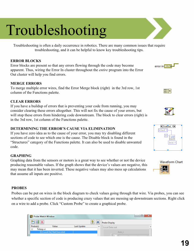
PROBESProbes can be put on wires in the block diagram to check values going through that wire. Via probes, you can see whether a specific section of code is producing crazy values that are messing up downstream sections. Right click on a wire to add a probe. Click “Custom Probe” to create a graphical probe.
20
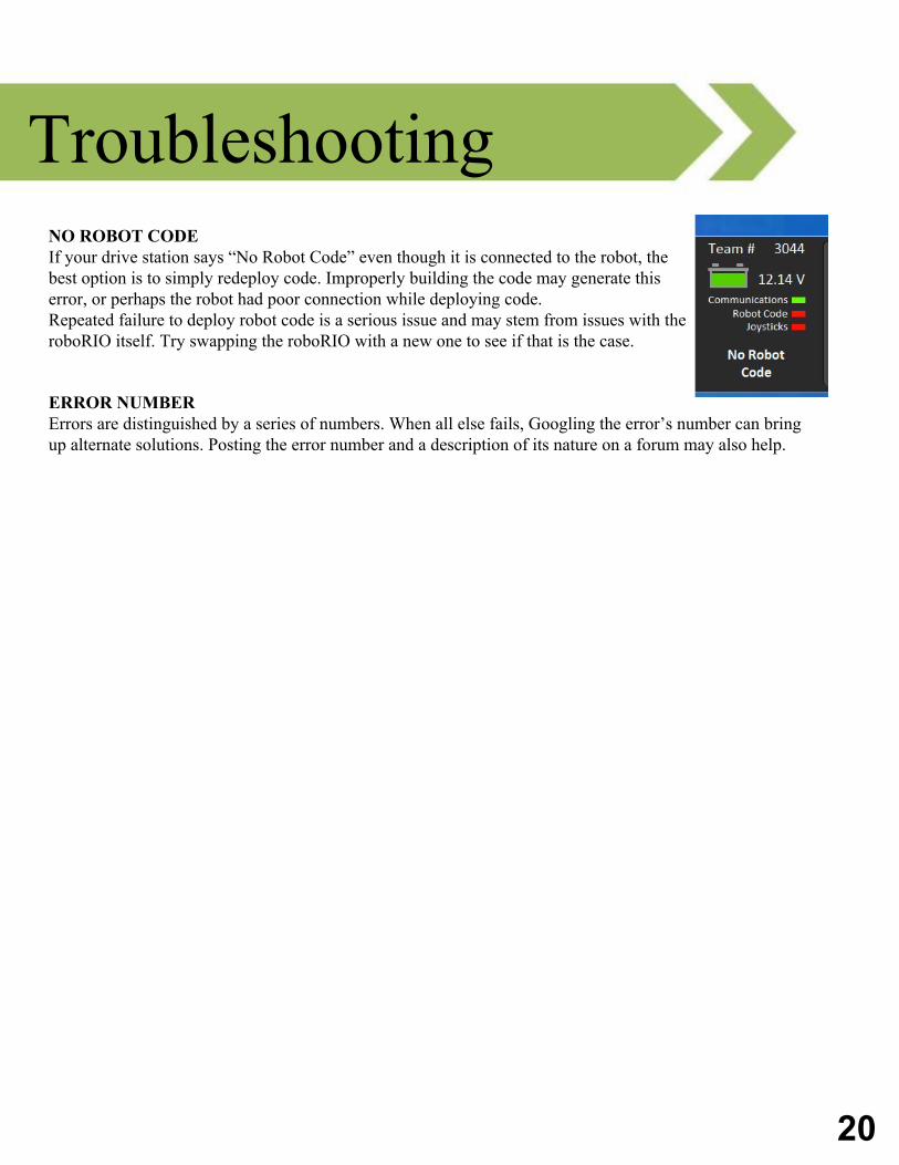
Troubleshooting NO ROBOT CODE If your drive station says “No Robot Code” even though it is connected to the robot, the best option is to simply redeploy code. Improperly building the code may generate this error, or perhaps the robot had poor connection while deploying code. Repeated failure to deploy robot code is a serious issue and may stem from issues with the roboRIO itself. Try swapping the roboRIO with a new one to see if that is the case.
ERROR NUMBERErrors are distinguished by a series of numbers. When all else fails, Googling the error’s number can bring up alternate solutions. Posting the error number and a description of its nature on a forum may also help.