transducer and lbl calibration - integrated functions in
TRANSCRIPT
Kongsberg Simrad
1
Transducer and LBL calibration -Integrated functions in HiPAP systems
Dynamic Positioning Conference, Houston, September 17-18 2002
arranged by
Kongsberg Simrad
2
Calibration of transducer alignment and of LBL array
� Transducer alignment calibration.The objective is to calculate the offset and the inclination of the transducer(s).
� LBL transponder array calibration.The objective is to calculate the positions of the LBL transponders in a North East local co-ordinate system.
All results presented are based on Kongsberg Simrad’s HiPAP system.
This presentation illustrates and stresses out the importance inacoustic positioning of:
Return to Session Directory

Kongsberg Simrad
3
Calibration of transducer alignment
The transponder position is measured in the transducer XYZ co-ordinate system.It is presented and sent to the DP in the vessel co-ordinate system with the origin in the centre of gravity (CG).
These two co-ordinate systems differ with an offset and an inclination, which both must be known.
X
Y
Z
Heading sensor
Roll/Pitch sensorAtwart ships
Alongships
Centre of gravity
GPS antenna
Transducer
SeabedTransponder
Return to Session Directory
Kongsberg Simrad
4
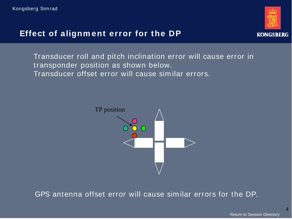
TP position
Transducer roll and pitch inclination error will cause error in transponder position as shown below.Transducer offset error will cause similar errors.
Effect of alignment error for the DP
GPS antenna offset error will cause similar errors for the DP.
Return to Session Directory

Kongsberg Simrad
5
For each measurement, the transponder position inlatitude, longitude and depth is calculated.
Measurements
Measurements for transducer alignment are done from several locations and with different headings. The measurements of interest are:
• The position of the vessel in latitude and longitude (dGPS)• The position of a transponder relative to the vessel (SSBL)
The transponder position in latitude, longitude and depth shall not move when the vessel moves and rotates. The function calculates the transducer offsets and inclinations that makes the spreading of the transponder position as small as possible.
Return to Session Directory
Kongsberg Simrad
6
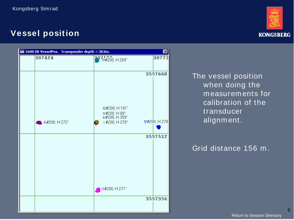
Vessel position
The vessel position when doing the measurements for calibration of the transducer alignment.
Grid distance 156 m.
Return to Session Directory
Kongsberg Simrad
7
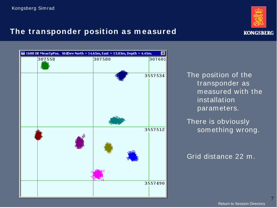
The transponder position as measured
The position of the transponder as measured with the installation parameters.
There is obviously something wrong.
Grid distance 22 m.
Return to Session Directory

Kongsberg Simrad
8
Result of the calculation
The HiPAP system calculates new values for the sound velocity and the transducer inclination.
The transducer and GPS antenna offset seems to be OK.
Insert the new transducer parameters by ticking the Update button.
Return to Session Directory

Kongsberg Simrad
9
The transponder position as compensated
The transponder position when compensated with the newly calculated parameters.
Grid distance 3 m.
It is NOT necessary to repeat the measurements.
Return to Session Directory
Kongsberg Simrad
10
History and summary
The function for calibration of the transducer alignment was added in the HiPAP system in the spring of 2000.
� All done on the already existing operator station, only dGPS required as external input.
� The process can be done by the either the vessel personnel or by a Kongsberg Simrad engineer.
� The function checks the GPS antenna offset, which has been a major error contributor.
� If you are not satisfied with the result, send the logged file to us on e-mail and we will evaluate it.
The experience with the new function is very good, both in shallow and deep waters.
Return to Session Directory
Kongsberg Simrad
11
Transducer alignment time and evaluation
When to do transducer alignment?
� After installation
� After any changes in gyro or VRU.
� A given periodic time depending on vessel type (each year for shuttle tanker as example)
When is the transducer alignment calibration done
successfully?
� The variation on the transponders lat/lon position is inside the expected accuracy on the actual depth.
Return to Session Directory

Kongsberg Simrad
12
New topic
End of transducer alignment
Start of LBL array calibration
Return to Session Directory
Kongsberg Simrad
13
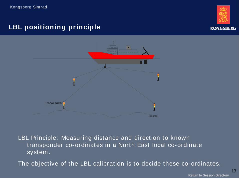
LBL positioning principle
LBL Principle: Measuring distance and direction to known transponder co-ordinates in a North East local co-ordinate system.
The objective of the LBL calibration is to decide these co-ordinates.
Return to Session Directory
Kongsberg Simrad
14
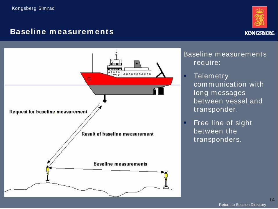
Baseline measurements
Baseline measurements require:
� Telemetry communication with long messages between vessel and transponder.
� Free line of sight between the transponders.
Return to Session Directory

Kongsberg Simrad
15
When to do the baseline measurements
The baseline measurements give the most accurate relative positions of the transponders in a local co-ordinate system. This accuracy may be necessary when the LBL positioning is used for:
� Survey operations
� ROV operations
� Multiuser transponder arrays
The new LBL Run Time calibration functionality makes the baseline measurements needless for DP LBL positioning.
Return to Session Directory
Kongsberg Simrad
16
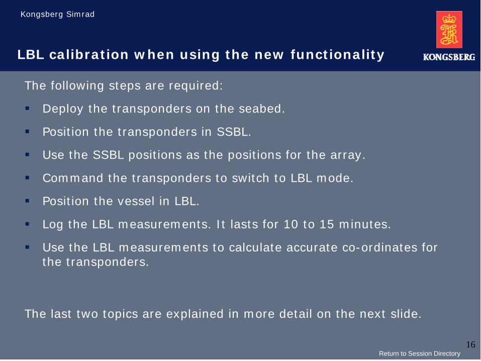
LBL calibration when using the new functionality
The following steps are required:
� Deploy the transponders on the seabed.
� Position the transponders in SSBL.
� Use the SSBL positions as the positions for the array.
� Command the transponders to switch to LBL mode.
� Position the vessel in LBL.
� Log the LBL measurements. It lasts for 10 to 15 minutes.
� Use the LBL measurements to calculate accurate co-ordinates for the transponders.
The last two topics are explained in more detail on the next slide.
Return to Session Directory

Kongsberg Simrad
17
Steps in LBL run time calibration
Steps when doing an LBLrun time calibration:
� Select the LBL RunTimecalibration command from the main menu
� Start to log measurements by ticking the “Start log” button.
� Stop logging by ticking the “Stop Log” button.
� Calculate by ticking the “Do Calculate” button.
Return to Session Directory
Kongsberg Simrad
18
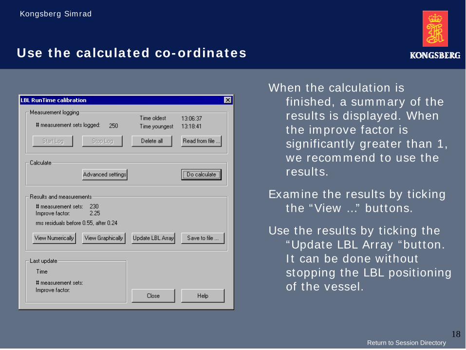
Use the calculated co-ordinates
When the calculation is finished, a summary of the results is displayed. When the improve factor is significantly greater than 1, we recommend to use the results.
Examine the results by ticking the “View …” buttons.
Use the results by ticking the “Update LBL Array “button. It can be done without stopping the LBL positioning of the vessel.
Return to Session Directory
Kongsberg Simrad
19
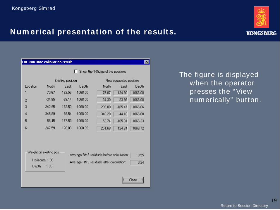
Numerical presentation of the results.
The figure is displayed when the operator presses the “View numerically” button.
Return to Session Directory

Kongsberg Simrad
20
Graphical presentation of the results
The figure is displayed when the operator ticks the “View graphically” button.The blue stars are the existing transponder positions. The green stars are the new calculated positions. The numbers are the depth.
The vessel was in the centre of the array when logging the measurements.
Return to Session Directory
Kongsberg Simrad
21
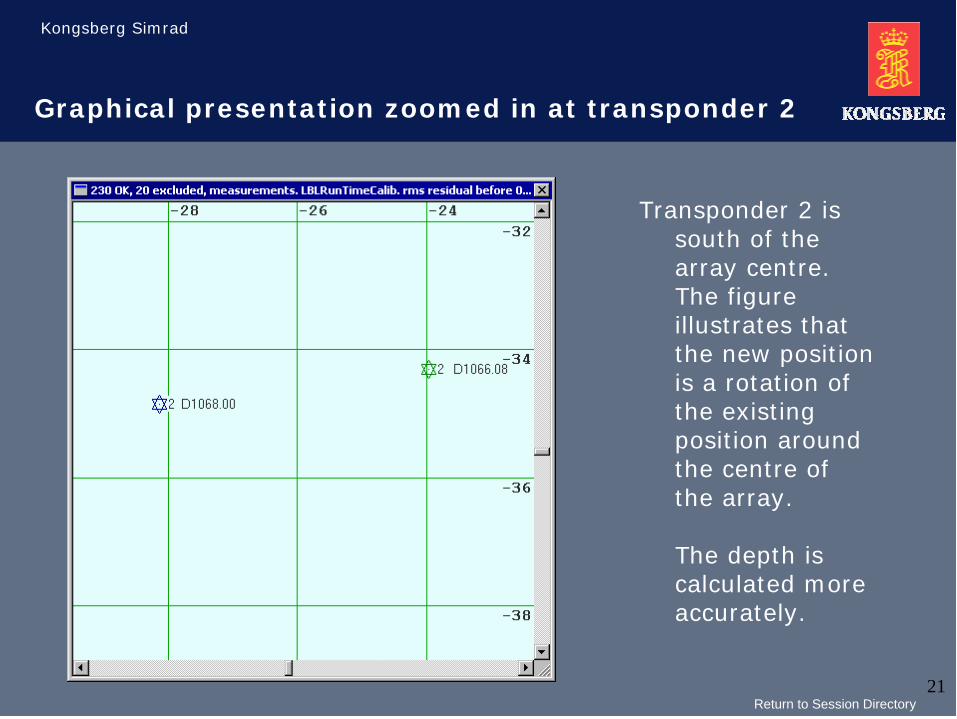
Graphical presentation zoomed in at transponder 2
Transponder 2 is south of the array centre. The figure illustrates that the new position is a rotation of the existing position around the centre of the array.
The depth is calculated more accurately.
Return to Session Directory
Kongsberg Simrad
22
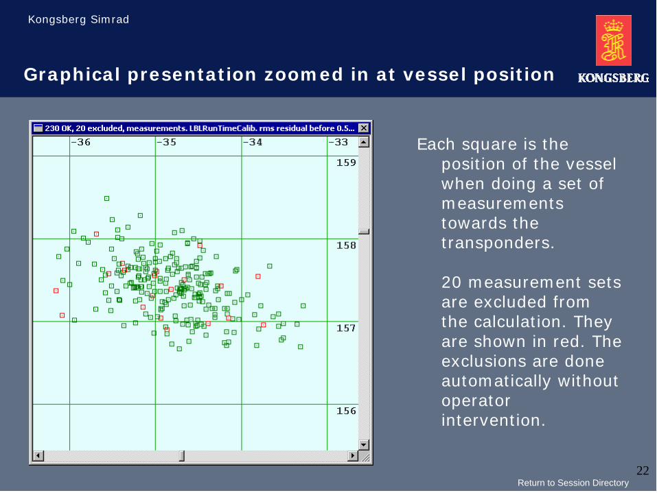
Graphical presentation zoomed in at vessel position
Each square is the position of the vessel when doing a set of measurements towards the transponders.
20 measurement sets are excluded from the calculation. They are shown in red. The exclusions are done automatically without operator intervention.
Return to Session Directory

Kongsberg Simrad
23
Experience with LBL run time calibration.
We obtain stable LBL positioning, mainly due to:
� The orientation of the LBL array with respect to geographical north is accurate, especially when an HiPAP system is used for the logging.
� The depths of the transponders are accurate.
The LBL run time calibration with HiPAP systems were testedoutside Horten (190 m depth), in the North Sea (330 m depth),in the Norwegian sea (1060 m depth) and in the gulf of Mexico (2000 m depth) before introduction 1 year ago.
Later it has been used by customers with good results, normally without the need for assistance from Kongsberg Simrad.
Return to Session Directory
Kongsberg Simrad
24
Advantages with LBL run time calibration.
� Short calibration time
� Easier to use
� Improved depth calibration
� Improved rotation of the array.
� Not necessary with “free sight” between transponders.
� Less depended on correct sound velocity.
Both transducer alignment and LBL runtime calibration are standard functions in HiPAP system with operator stations based on windows NT.
Return to Session Directory