underwater welded joint properties investigation
TRANSCRIPT
DOI: 10.2478/v10077-009-0016-y
D. Fydrych, T. Kozak Gdańsk University of Technology, Faculty of Mechanical Engineering, Department of Materials Technology and Welding, Gdańsk, Poland
UNDERWATER WELDED JOINT PROPERTIES INVESTIGATION
ABSTRACT
Macroscopic and microscopic examinations of implant joints made under water have been performed. The investigations results indicate that in HAZ of the tested joints a formation of brittle structures has occurred. The brittle structures are responsible for an increase of susceptibility to cold cracking of high strength low alloy steel. An analysis of hardness penetration patterns of implant joints also indicates an adverse effect of water environment on weldability of steel. Key words: underwater welding, local cavity, implant test
INTRODUCTION
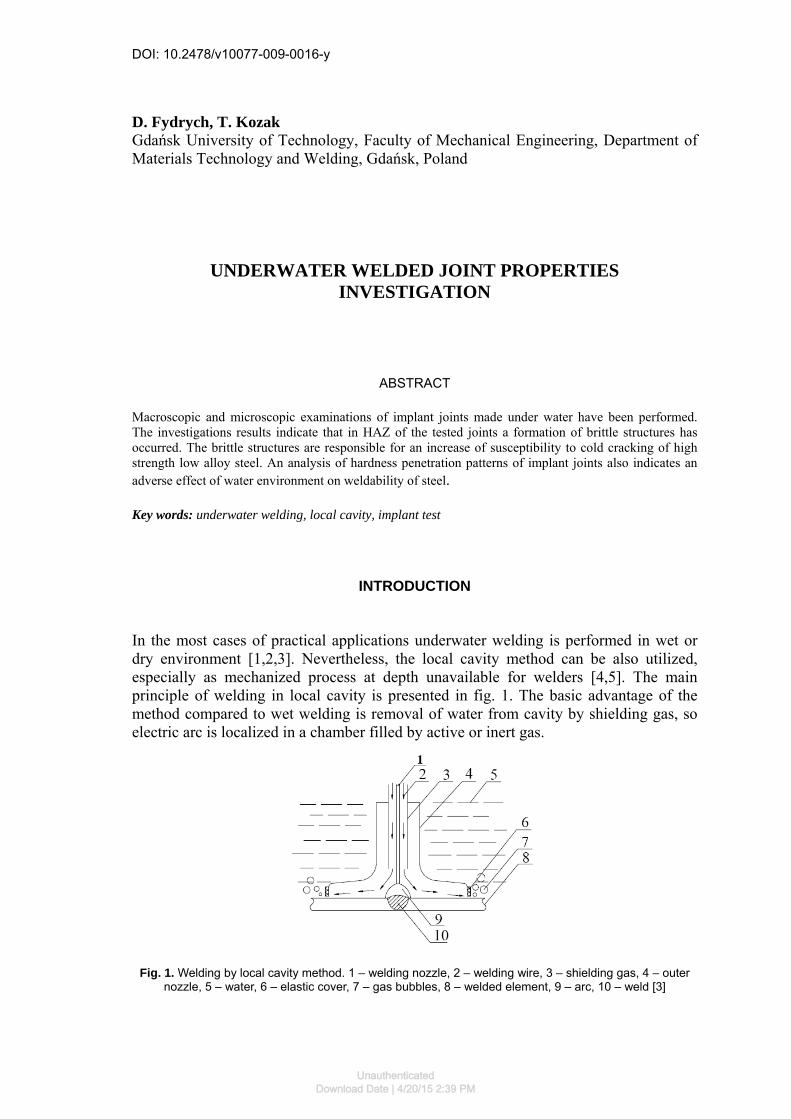
In the most cases of practical applications underwater welding is performed in wet or dry environment [1,2,3]. Nevertheless, the local cavity method can be also utilized, especially as mechanized process at depth unavailable for welders [4,5]. The main principle of welding in local cavity is presented in fig. 1. The basic advantage of the method compared to wet welding is removal of water from cavity by shielding gas, so electric arc is localized in a chamber filled by active or inert gas.
Fig. 1. Welding by local cavity method. 1 – welding nozzle, 2 – welding wire, 3 – shielding gas, 4 – outer nozzle, 5 – water, 6 – elastic cover, 7 – gas bubbles, 8 – welded element, 9 – arc, 10 – weld [3]
UnauthenticatedDownload Date | 4/20/15 2:39 PM

D. Frydrych, T. Kozak: Underwater welded joint properties investigation 5
Although underwater welding by local cavity process ensures conditions of cooling nearly the same as conditions existing during welding in the air [1,2,3], in the case of welding of high strength steel the formation of cold cracking can occur [1,3,5]. The aim of this research was to determine of the structure and morphology of crack surface in implant test pieces of joints made under water by local cavity method. For that purpose high strength low alloy steel grade S355J2G3 was selected together with suitable filler materials for GMAW process. Chemical composition of base material used for machined implant specimens is shown in table 1.
Table 1. Chemical composition of tested steel, wt. pct
Steel grade C Mn Si P S Cr Ni Cu Al S355J2G3 0.17 1.44 0.35 0.014 0.014 0.04 0.077 0.30 0.027
Investigation of susceptibility to cold cracking was carried out by implant method [5,6]. Implant test possesses a series of advantages, such as convenient testing procedure and saving of material and allows investigation of individual factors influencing cold cracking susceptibility. The mentioned factors are: presence of hardened microstructure in heat affected zone, stresses and diffusible hydrogen content. Cylindrical specimen with circular or helical notch of the tested material is inserted into a borehole of basic plate and then welded to it by one bead. After the welding the specimen is subjected to a static tensile loading. The time until the fracture occurs is measured. The tensile load is maintained for 16 hours if the specimen had not fracture before [6]. The dimensions of helical notched implant specimen and basic plate are shown in fig. 2.
Fig. 2. Implant specimen and basic plate for implant test [5,6]
Although investigations of susceptibility to cold cracking of steel during underwater welding in local cavity seem to be very important from practical point of view no data on this subject was found in the literature.
Unauthenticated
Download Date | 4/20/15 2:39 PM

6 ADVANCES IN MATERIALS SCIENCE, Vol. 9, No. 4 (22), December 2009
METALLOGRAPHIC INVESTIGATIONS Macroscopic investigations Specimens were taken from implant tests samples after the tests were conducted in water environment in the following conditions: heat input eL=10÷20 kJ/cm and flow rate of CO2 shielding gas Wg=20÷50 l/min [5]. The way of sampling of cross-sections is shown in the fig. 3. Metallographic sections were prepared using conventional metallographic technique [7].
Fig. 3. Schematic view of test welds deposited on basic plate. The horizontal intermitted line shows
investigated surface
The welded beads were deposited symmetrically so the conditions of implant tests were fulfilled (fig. 4a). The width of HAZ in tested joints was in the range from 3 to 6 mm. Accordingly to rules of implant test [6] all of the examined specimens fractured in HAZ as it is visible on the exemplary macroscopic photograph shown on fig. 4b.
a)
b) Fig. 4. Macroscopic photographs of implant joints: a) Wg=35 l/min, eL=15 kJ/cm, σi=420 MPa,
b) Wg=35 l/min, eL=15 kJ/cm, σi=450 MPa
Unauthenticated
Download Date | 4/20/15 2:39 PM

D. Frydrych, T. Kozak: Underwater welded joint properties investigation 7
Microscopic investigations Microscopic investigations of the structure of the tested joints were carried out using a metallographic microscope Neophot 32. An examination of the surface of metallographic sections revealed a number of cracks (fig. 5÷6). Fig. 5 shows micrograph taken from a metallographic section in the close proximity of cold crack path. In HAZ of investigated joints brittle structure - probably bainite is present. As can be seen from fig. 6 crack paths formed in specimen are irregular and branched. They run mainly perpendicularly to axis of implant specimen. In the range of investigation propagation of crack occurred both transgranularly and intergranularly.
Fig. 5. Exemplary microphotograph of the cold crack in the bainite structure (magnification 200×)
Fig. 6. Microphotograph of fusion line of implant joint: Wg=50 l/min, eL=20 kJ/cm, HVmax=404. Long branched crack is marked by arrow (magnification 100×)
Unauthenticated
Download Date | 4/20/15 2:39 PM

8 ADVANCES IN MATERIALS SCIENCE, Vol. 9, No. 4 (22), December 2009
Microfractographic investigations
For a detailed examination of cold cracking, the fracture surfaces of implant specimens were examined using SEM technique. Microscopic investigations of the surface morphology of cold cracks were carried out using scanning electron microscope PHILIPS XL 30 ESEM. In order to eliminate stress as a factor influencing on mode of the fracture, specimens tested only at 400 MPa were investigated. Some typical microstructure regions observed under the microscope are shown in fig. 7÷11.
Fig. 7. A part of crack path in the implant specimen: Wg=50 l/min, eL=10 kJ/cm, σi=400 MPa
As can be seen from fig. 8 and 9 propagation of cracks runs through several surfaces, so determination of initiation site of the crack is impossible [5]. It was found that in some cases small and rare fully plastic regions are present (fig. 10). As it has already been mentioned, propagation of crack occurred both transgranularly and intergranularly. It should be noted that in bainite or martensite structure cracks run only transgranularly. An example of such situation is shown in fig. 11.
Unauthenticated
Download Date | 4/20/15 2:39 PM

D. Frydrych, T. Kozak: Underwater welded joint properties investigation 9
Fig. 8. Overall SEM view of a fractured implant specimen surface: Wg=35 l/min, eL=20 kJ/cm, σi=400 MPa
Fig. 9. SEM image of cold crack fracture: Wg=35 l/min, eL=10 kJ/cm, σi=400 MPa. Transgranular (white arrow) and intergranular (black arrow) fracture regions
Unauthenticated
Download Date | 4/20/15 2:39 PM

10 ADVANCES IN MATERIALS SCIENCE, Vol. 9, No. 4 (22), December 2009
Fig. 10. SEM image of cold crack fracture: Wg=35 l/min, eL=20 kJ/cm, σi=400 MPa. Transgranular and intergranular fracture regions. Exemplary region of plastic fracture is marked by arrow
Fig. 11. SEM image of cold crack fracture: Wg=35 l/min, eL=10 kJ/cm, σi=400 MPa. Transgranular fracture in brittle structure
MEASUREMENT OF HARDNESS
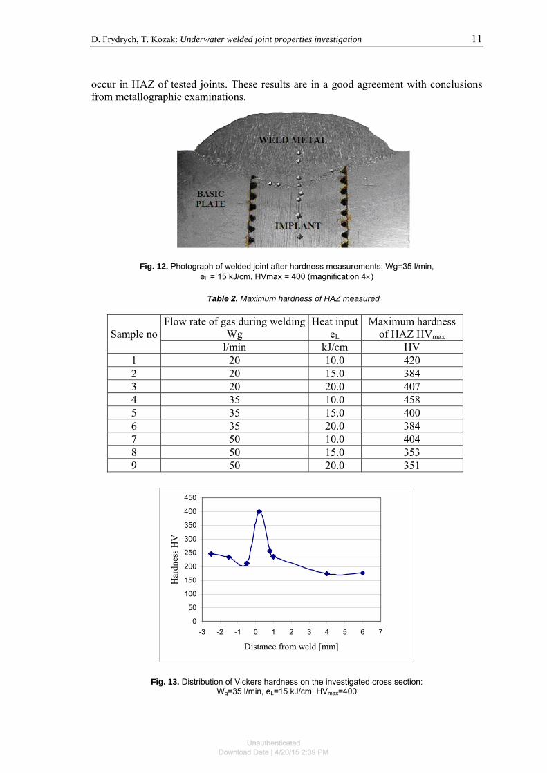
Hardness penetration profiles were determined as Vickers hardness HV according to standard [8] in the way shown in fig. 12. The results of these experiments are collected in table 2 and presented in fig. 13÷15. The measured values of HVmax are in the range from 351 to 458 and are higher than the 350 HV level stated as typical for bainitic structure. The obtained results suggest that bainite or martensite transformations can
Unauthenticated
Download Date | 4/20/15 2:39 PM
D. Frydrych, T. Kozak: Underwater welded joint properties investigation 11
occur in HAZ of tested joints. These results are in a good agreement with conclusions from metallographic examinations.
Fig. 12. Photograph of welded joint after hardness measurements: Wg=35 l/min,
eL = 15 kJ/cm, HVmax = 400 (magnification 4×)
Table 2. Maximum hardness of HAZ measured
Flow rate of gas during weldingWg
Heat inputeL
Maximum hardness of HAZ HVmaxSample no
l/min kJ/cm HV 1 20 10.0 420 2 20 15.0 384 3 20 20.0 407 4 35 10.0 458 5 35 15.0 400 6 35 20.0 384 7 50 10.0 404 8 50 15.0 353 9 50 20.0 351
0
50
100
150
200
250
300
350
400
450
-3 -2 -1 0 1 2 3 4 5 6 7
Distance from weld [mm]
Har
dnes
s HV
Fig. 13. Distribution of Vickers hardness on the investigated cross section: Wg=35 l/min, eL=15 kJ/cm, HVmax=400
Unauthenticated
Download Date | 4/20/15 2:39 PM

12 ADVANCES IN MATERIALS SCIENCE, Vol. 9, No. 4 (22), December 2009
0
50
100
150
200
250
300
350
400
450
500
-3 -2 -1 0 1 2 3 4 5 6 7
Distance from weld [mm]
Har
dnes
s HV
Fig. 14. Distribution of Vickers hardness on the investigated cross section: Wg=35 l/min, eL=10 kJ/cm, HVmax=458
0
50
100
150
200
250
300
350
400
450
-3 -2 -1 0 1 2 3 4 5 6 7
Distance from weld [mm]
Har
dnes
s HV
Fig. 15. Distribution of Vickers hardness on the investigated cross section: Wg=20 l/min, eL=20 kJ/cm, HVmax=407
The values of maximum hardness of implant joints depend on the differences in
welding conditions. With the aid of the Statistica software least squares regression was calculated for the results from table 2. Using maximum hardness HVmax of heat affected zone as dependent variable and heat input eL as independent variable the following regression equation was obtained:
LeHV ×−= 7,405,466max
with R2=0,64 (determination coefficient) and p=0,05 (level of significance). The relation is presented graphically in fig. 16.
Unauthenticated
Download Date | 4/20/15 2:39 PM

D. Frydrych, T. Kozak: Underwater welded joint properties investigation 13
200
250
300
350
400
450
500
5 10 15 20 2
Heat input of welding eL [kJ/cm]
Max
imum
har
dnes
s of H
AZ
HV
ma
5
x
Fig. 16. Relationship between heat input of welding and maximum hardness of HAZ
SUMMARY
The methods of standard optical and SEM metallography have been employed to investigate the structure and fracture modes of implant specimens obtained by underwater welding in local cavity. Additionally, hardness penetration patterns of tested joints have been prepared and analyzed. Basing on the realized research it can be stated that owing to the relatively high contents of Mn, Cr, Mo and Ni, rapid cooling cycles of underwater welding lead to hard bainitic or martensitic microstructures in the HAZ. It can be one of the reasons, besides higher diffusible hydrogen amount [9], of increased susceptibility to cold cracking of joints from S355J2G3 steel obtained by underwater local cavity welding.
REFERENCES
1. Kononenko V. Ya.: Technologies of underwater wet welding and cutting. E. O.
Paton Electric Welding Institute, Kiev, Ukraine 2000.
2. Christensen N.: The metallurgy of underwater welding. Proceedings of the International Conference „Underwater Welding”, Trondheim, Norway 1983.
3. Łabanowski J., Fydrych D., Rogalski G.: Underwater Welding – a review. Advances in Materials Science, Vol. 8, No.3(17) December 2008 11-22.
4. Zhang X., Ashida E., Shono S., Matsuda F.: Effect of shielding conditions of local dry cavity on weld quality in underwater Nd:YAG laser welding. Journal of Materials Processing Technology 174/2006.
Unauthenticated
Download Date | 4/20/15 2:39 PM

14 ADVANCES IN MATERIALS SCIENCE, Vol. 9, No. 4 (22), December 2009
5. Fydrych D.: Effect of welding conditions on susceptibility to cold cracking of welds obtained under water. Ph. D. thesis. Gdańsk University of Technology, Gdańsk 2005 (in Polish).
6. PN-EN ISO 17642-3:2005 Destructive tests on welds in metallic materials – Cold cracking tests for weldments – Arc welding processes – Part 3: Externally loaded tests.
7. PN-EN 1321:2000 Destructive tests on welds in metallic materials – Macroscopic and microscopic examination of welds.
8. PN-EN 1043-1:2000 Destructive tests on welds in metallic materials – Hardness testing – Hardness test on arc welded joints.
9. Fydrych D., Rogalski G.: Effect of underwater local cavity welding method conditions on diffusible hydrogen content in deposited metal. Przegląd Spawalnictwa 10/2009 (in Polish).
Unauthenticated
Download Date | 4/20/15 2:39 PM