experimental investigation on european welded connections
TRANSCRIPT

Experimental Investigation on European WeldedConnections
Elena Mele1; Luis Calado2; and Antonello De Luca, M.ASCE3
n welded. and Japancterized byparticular
he testses of the
ed loading
Dow
nloa
ded
from
asc
elib
rary
.org
by
Uni
vers
ita S
tudi
Nap
oli F
ed I
i on
07/0
7/15
. Cop
yrig
ht A
SCE
. For
per
sona
l use
onl
y; a
ll ri
ghts
res
erve
d.
Abstract: In this paper the results of a test program devoted to the assessment of the cyclic behavior of beam-to-columconnections are presented. The specimens are representative of the common European practice, which differs from both U.Spractice, due to the size of the connected members and to the welding technique and details. Three specimen groups, charadifferent values of the relative column-beam-panel zone strengths, are designed and tested under different loading histories. Insix tests~five cyclic and one monotonic! have been carried out on each group of specimens, encompassing a total of 18 tests. Thave evidenced the effect of column-to-beam strength ratio and of panel zone design on the cyclic behavior and failure modconnections. Furthermore the dependence of the absorbed energy and cumulative plastic rotation of the joint upon the applihistory is shown. Finally design implications are suggested on the basis of the test results.
DOI: 10.1061/~ASCE!0733-9445~2003!129:10~1301!
CE Database subject headings: Cyclic loads; Connections, welded; Failure modes; Europe; Experimentation.
cauein
re-ar
oc-e o
ec
uitaedbe
ca-r-of
rop
ni
-a-e
eenamec-
en-in
ded
Fser-
orones
heamametthe
ualcs,u-y
dsesmds
ent,
al.
ntiluaus
er1;
,
Introduction
The 1994 Northridge and 1995 Hyogoken-Nanbu earthquakesbe considered milestones since the research during the subseq1990s has been strongly inspired by the need of understandand explaining some ‘‘unexpected’’ aspects of the seismicsponse exhibited by steel buildings during these events. In pticular the extensive damage and brittle failure modes whichcurred at beam-to-column connections of frame structures wermajor concern.
Several experimental programs on beam-to-column conntions have been carried out in the United States~Mahin et al.1996; Malley 1998; Kunnath and Malley 2002! and in Japan~JCSS 1997; Tanaka et al. 1997; Nakashima et al. 1998; Set al. 1998! in order to understand the causes of the observdamage, to assess the major parameters affecting the cyclichavior of beam-to-column connections, and to suggest modifitions in the connection layout for improving the seismic perfomance. The renewed interest in the seismic behaviorconnections has also affected the recent research trends in Euwhere several experimental projects have been undertaken~Meleet al. 1997; Plumier et al. 1998; Taucer et al. 1998; Castiglioet al. 2000; Calado and Mele 2000!.
1Associate Professor, Structural Analysis and Design Departm~DAPS!, Univ. of Naples ‘‘Federico II,’’ P. le Tecchio 80, 80125 NaplesItaly. E-mail: [email protected]
2Associate Professor, Civil Engineering Dept.~DECivil!, Instituto Su-perior Tecnico, Av. Rovisco Pais, 1096 Lisboa Codex, Lisbon, Portug
3Professor, Structural Analysis and Design Department~DAPS!, Univ.of Naples ‘‘Federico II,’’ P. le Tecchio 80, 80125 Naples, Italy.
Note. Associate Editor: Christopher J. Earls. Discussion open uMarch 1, 2004. Separate discussions must be submitted for individpapers. To extend the closing date by one month, a written request mbe filed with the ASCE Managing Editor. The manuscript for this papwas submitted for review and possible publication on July 17, 200approved on December 16, 2002. This paper is part of theJournal ofStructural Engineering, Vol. 129, No. 10, October 1, 2003. ©ASCEISSN 0733-9445/2003/10-1301–1311/$18.00.
JOURNAL
J. Struct. Eng. 2003.1
nnt
g
-
f
-
-
e,
This paper describes a part~the one devoted to welded connections! of a wide experimental program carried out at the Mterial and Structures Test Laboratory of the Instituto Superior T´c-nico of Lisbon on different types~welded and bolted! of beam-to-column connections. The experimental tests have bperformed on specimens representative of moment resisting fr~MRF! beam-to-column joints typical of European design pratice. In order to provide a reference framework to the experimtal study, some major items of the European current practicedesigning the frame structural systems and in detailing the welbeam-to-column connections~Mele 2002! are reported in the fol-lowing.
• In Europe the design trend of adopting partial perimeter MRis not so widely established as in the United States; furthmore, building configurations with smaller bay spans~typi-cally 5–7 m! than in the United States are usually adopted. Fthe above reasons, beams are usually shallower than theadopted in the current U.S. design practice~Europe beamdepths, hb5300– 450 mm versus U.S. beam depths,hb
5600– 1,000 mm).• The beam section is typically welded to the column in t
shop: complete joint penetration welds are applied at the beflanges and fillet welds are applied at both sides of the beweb. Continuity plates are commonly utilized for stiffening thcolumn panel zone~PZ!, while doubler plates are generally nopresent, thus leading to a substantial contribution of PZ tooverall deformation of the connection.
• The typical welding technique used in Europe is the manmetal-arc welding~MMAW, also known as shielded metal arwelding, SMAW! although gas shielded welding processetypically metal inert gas and flux cored arc welding, are gradally superseding MMA welding for reasons of productivitand cost effectiveness~The Steel Construction Institute 1992!.A specific procedure for minimizing the porosities in the welis often implemented: After having welded the beam flangfrom the top, the root opening is cleaned of impurities frothe bottom, and the opening is filled by means of fillet wel
lt
OF STRUCTURAL ENGINEERING © ASCE / OCTOBER 2003 / 1301
29:1301-1311.

ste
wits toecci-isTh
ag thar
hare
tion
am.S.
eaner-is
ss
esss,ina
hanean
Dow
nloa
ded
from
asc
elib
rary
.org
by
Uni
vers
ita S
tudi
Nap
oli F
ed I
i on
07/0
7/15
. Cop
yrig
ht A
SCE
. For
per
sona
l use
onl
y; a
ll ri
ghts
res
erve
d.
~Taucer et al. 1998!. This procedure, minimizing the porositiethat may result at the bottom of the flange, reduces the potial of crack formation.The test program presented in this paper was carried out
the aim of defining the effects of the column size, which leaddifferent PZ properties, and of the loading history on the conntion behavior. In the following section, the design of the spemens is discussed, the experimental setup, and the loading hries which have been utilized in the tests are described.experimental results are presented through hysteresis loopsglobal performance parameters and the major factors affectincyclic behavior, the failure modes, and the rotation capacityassessed.
Experimental Program
Design of Specimens
Three different types of specimens, have been designed andbeen subjected to several rotation histories. The three diffe
Fig. 1. Layout of specimens
1302 / JOURNAL OF STRUCTURAL ENGINEERING © ASCE / OCTOBER
J. Struct. Eng. 2003
n-
h
-
to-ende
e
vent
specimens, labeled as BCC5, BCC6, and BCC8~Fig. 1!, havebeen selected on the basis of a typical European beam sec~IPE300, which could be considered equivalent to W12330 U.S.wide flange section!, usually adopted on European spacing~beamlengths typically comprised between 5 and 7 m!, and three differ-ent column sections:
• HE160B ~possibly equivalent to W8324) for the BCC5 se-ries,
• HE200B ~possibly equivalent to W8340) for the BCC6 se-ries, and
• HE240B ~possibly equivalent to W8358) for the BCC8 se-ries.Table 1 provides the main geometrical dimensions of the be
and columns sections, together with possibly comparable Uwide flange sections.
Some comments on a possible comparison between Europand U.S. shapes are in order. In this respect it should be undlined that the choice offered to a designer in the United Statedwider than in Europe. In the United States, for a given crosection number~related to height! up to 17 different choices areprovided, with weights, inertia, and plastic moment capaciticonsistently variable depending on web and flange thicknewhich leads to different local slenderness. The same is not trueEurope where, typically, three to five choices are offered forcross-section height. For the above reasons, in Table 1 more tone comparable U.S. section is provided for each of the Europsections used in this work.
Table 1. Beam and Column Sections of Specimens and Comparison to U.S. Equivalent Profiles
Element section h ~mm! bf ~mm! tw ~mm! t f ~mm! hw /tw bf /2t f Mass per length~kg/m! I xx ~cm4! Zx ~cm3!
BeamIPE 300 300 150 7.1 10.7 39.2 7.0 42.2 8356 628
U.S. section
W1236.5330 313 166 6.6 11.2 44.03 7.41 44.5 9934 708
W1236.5326 310 165 5.8 9.7 50.10 8.51 39.0 8527 612
W1038333 247 202 7.4 11.0 30.41 9.18 49.0 7097 636
Column BCC5HE 160 B 160 160 8 13 16.75 6.15 42.6 2492 354
U.S. section
W636325 162 154 8.1 11.6 17.14 6.64 37.1 2220 310
W836.5324 210 165 6.2 10.2 29.13 8.09 36 3438 379
Column BCC6HE 200 B 200 200 9 15 18.89 6.67 61.3 5696 643
U.S. section
W838331 203 203 7.2 11 25.14 9.23 46.1 4545 496
W838335 206 204 7.9 12.6 22.89 8.10 52.0 5268 569
W838340 210 205 9.1 14.2 19.96 7.22 59.0 6113 653
Column BCC8HE 240 B 240 240 10 17 20.6 7.06 83.2 11260 1053
U.S. section
W10310349 253 254 8.6 14.2 26.12 8.94 73.0 11290 986
W838348 216 206 10.2 17.4 17.76 5.92 71.0 7658 803
W838358 222 209 13.0 20.6 13.91 5.07 87.0 9467 980
2003
.129:1301-1311.

nksthe
lace-theces
ly ad arpy
er-onout.
om-nts,
f theth ofield
rd-
Dow
nloa
ded
from
asc
elib
rary
.org
by
Uni
vers
ita S
tudi
Nap
oli F
ed I
i on
07/0
7/15
. Cop
yrig
ht A
SCE
. For
per
sona
l use
onl
y; a
ll ri
ghts
res
erve
d.
It is confirmed, from the comparison given in Table 1, thatmore than one U.S. wide flange section can be considered equiva-lent to each European section, depending on the parameter whichis considered as the most influential for the comparison. In fact,from an economical point of view, the most important parametershould be the weight per unit length, while from a structural pointof view, in the elastic range the main parameter is the moment ofinertia, in the inelastic range the plastic moment capacity, togetherwith local slenderness of web and flanges (h/tw and bf /2t f , re-spectively!, are the parameters which govern the behavior. Thecomparison in terms of local slenderness indicates that a possiblyequivalent European section can be locally stockier than U.S.counterparts.
The choice of the three specimens provides cases which can beconsidered representative of typical beam-column assemblage oc-curring at different story levels in a low rise ‘‘European’’ steelframed structure.
Furthermore, having taken the beam section constant in thethree specimens, and having adopted three column sections whichare characterized by different plastic moment capacities, it hasbeen possible to investigate the influence of the beam-to-columnstrength ratios on the inelastic behavior. It can be underlined thatthe BCC5 specimens are characterized by the weakest columnsince the nominal plastic moment of the column is slightly largerthan half of the nominal plastic moment of the beam. In the BCC8specimen this situation is inverted since the nominal plastic mo-ment of column is almost twice the one of the beam. In the BCC6specimen the situation is intermediate. In the following para-graph, the values of bending strength capacities~plastic moments!of beam, column, and PZ computed both with nominal and actualmeasured values of yield stress are provided in detail.
Specimen Properties
The steel utilized for both beam and column elements of thespecimens is S 235 JR~EN 10025: 1993!, which is quite similarto the U.S. steel grade A36. In Table 2 the minimum specifiedvalues for the main mechanical properties of European and U.S.equivalent steel grades are provided. In this table both the steelgrades S 235 JR~U.S. equivalent: ASTM A36! and S 355 JR~U.S. equivalent: ASTM A572 Gr. 50! are considered, since thelatter seems to be used quite extensively at this time. However,
the tested specimens were made of steel S 235~A36!, since thismaterial provides better performance in the inelastic range thato the smaller nondimensional slenderness which results fromsame section. In any case the S 235~A36! is still used in Europe,especially in seismic regions, even though the attempt to repit with the grade S 355~A572 Gr.50! does exist. From the comparison of properties given in the Table 2, it is evident thatEuropean and U.S. materials are quite similar. Some differenworth being mentioned are that for European steel, not onminimum but also a maximum strength value is specified, anminimum toughness value is required according to the Chanotch test.
In order to obtain the actual values of the mechanical propties of beam and column elements, several tension testssamples taken from the specimen elements have been carriedThe average values of yield and ultimate stress have been cputed for both flanges and web of column and beam elemeand are reported in Table 3.
For the three specimens, the plastic moment capacities obeam, column, and PZ have been computed on the basis bothe nominal values and of the actual measured values of ystress. The PZ flexural strength~moment capacity! has beenevaluated according to the EC3 Annex J~CEN 1997! provisions,by means of the following formula:
M p,PZ5~VPZ1DVPZ!•z
b(1)
where VPZ5column web shear strength;DVPZ5additional shearstrength due to the contribution of transverse stiffeners~continuityplates!; z5 lever arm, which are, respectively, computed accoing to the following relationships:
VPZ50.9• f y,wc•Avc
)(2)
DVPZ54Mpl,fc,Rd
hs<
2M p,fc,Rd12Mpl,st,Rd
hs(3)
z5hb2t f b (4)
b512hc/2
Lb2
hb
Lc(5)
Table 2. Mimimum Specified Values of Mechanical Properties for European and Comparable U.S. Steel Grades
Steel grade
Mimimum specified values of mechanical properties
f y ~MPa! f u ~MPa! «u ~%! Notch impact test absorbed energy (at120°) ~J!
European steel grade: S 235 JR~EN 10025: 1993! 235 340–470 26 27Comparable U.S. steel grade: A36~ASTM! 250 400–550 20 —
European steel grade: S 355 JR~EN 10025: 1993! 355 490–630 22 27Comparable U.S. steel grade: A572 Gr.50~ASTM! 345 450 18 —
B
eb
99
Table 3. Average Values of Actual Measured Material Properties
BCC5 BCC6 BCC8
Beam IPE300 Column HE160B Beam IPE300 Column HE200B Beam IPE300 Column HE240
Variable Flange Web Flange Web Flange Web Flange Web Flange Web Flange W
f y ~MPa! 274.8 305.5 323.1 395.6 278.6 304.9 312.6 401.6 292 300 300 30f u ~MPa! 404.6 412.6 460.2 490.1 398.8 411.4 434.9 489.8 445 450 457 46YR 1.47 1.35 1.42 1.24 1.43 1.35 1.39 1.22 1.53 1.50 1.52 1.52
JOURNAL OF STRUCTURAL ENGINEERING © ASCE / OCTOBER 2003 / 1303
J. Struct. Eng. 2003.129:1301-1311.
Dow
nloa
ded
from
asc
elib
rary
.org
by
Uni
vers
ita S
tudi
Nap
oli F
ed I
i on
07/0
7/15
. Cop
yrig
ht A
SCE
. For
per
sona
l use
onl
y; a
ll ri
ghts
res
erve
d.
Table 4. Flexural Strengths~in kNm! of Beam, Column, and PanelZone ~Nominal and Actual Values!
Specimenseries Stress value
M pb
~kNm!M p,PZ
~kNm!M pc
~kNm!2 M pc
~kNm!
BCC5 Nominal values 147.6 91.1 83.2 166.4Actual values 172.6 149.9 114.4 228.8
BCC6 Nominal values 147.6 132.3 151.1 302.2Actual values 175 220.6 201.0 402.0
BCC8 Nominal values 147.6 182.8 247.5 495.0Actual values 183.4 239.6 315.9 631.8
an
nesheine.-foemaheme
hefoZta
chbe
nda
tic,m
s
vix-
-
ino
larc
talm-
sp tore,000eslete
web
e
where: f y,wc5yield stress of the column web;Avc5shear area ofthe column; M pl,fc,Rd5plastic moment of a column flange;M pl,st,Rd5plastic moment resistance of a stiffener;hs5distancebetween the centerlines of the stiffeners;hb , hc , t f b , Lb , andLc5beam depth, column depth, beam flange thickness, beam,column length, respectively.
The plastic moment capacities of the beam (M pb), panel zone(M p,PZ), and column (M pc), computed for the three specimens othe basis of both the nominal and actual measured yield strvalues, are reported in Table 4. In the sixth column of Table 4, tsummation of the plastic moment capacity of columns framingthe joint configuration considered in the experimental tests, i.SM pc52 M pc, is also provided. This value, in fact, can be directly compared to the beam and to the PZ moment capacitiesestablishing the weaker element in the beam-column subassblage, thus predicting the location where major inelastic deformtions will occur. It can be observed that for all three specimens tweakest component of the joint configuration is either the beaor the PZ, which have plastic capacity values always quite closIn particular, considering the nominal plastic capacity values, tweakest element is the PZ for the BCC5 specimen, the beamthe BCC8 specimen, while quite similar values of beam and Pcapacity can be derived for the BCC6 specimen. With referencethe actual values of plastic capacities, similar considerations cbe argued, with the exception of the BCC6 specimen, for whithe beam is slightly weaker than the PZ, due to the scatterstween minimum specified and actual yield stress.
On the basis of relative strength values of column, beam, aPZ, all specimens are expected to experience inelastic deformtions both in the beam and in the PZ, and in particular, inelasdeformation are likely to occur: mainly in the PZ for the BCC5both in the PZ and in the beam for the BCC6, mainly in the beafor the BCC8.
Similar predictions could be derived by computing the valueof the column-to-beam strength ratio~CBsr! and of the column-to-PZ strength ratio, as usually suggested in the seismic prosions for verifying the strong-column-weak-beam design. For eample, the UBC’94~UBC 1994! provides
CBsr5SZc~ f yc2 f a!/SZbf yb (6)
CPZsr5SZc~ f yc2 f a!/1.25SM pPZ (7)
whereZc andZb5plastic modulus of the column and beam sections, respectively;f yc and f yb5yield stress values of column andbeam section, respectively; andf a5stress value in the columndue to axial load.
By considering that, for the experimental tests presentedthis paperf a50, the above equations provide results similar twhat was previously anticipated.
In conclusion, the choice of the specimens, and in particuthe relative column-beam-PZ strength values of the three spe
1304 / JOURNAL OF STRUCTURAL ENGINEERING © ASCE / OCTOBER
J. Struct. Eng. 2003.
d
s
,
r-
-
.
r
on
-
-
-
i-
mens, can be considered particularly valuable for experimeninvestigations on the inelastic behavior and failure mode of beato-column connections.
Specimen Geometry and Details
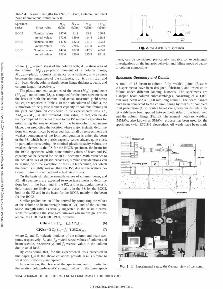
A total of 18 beam-to-column fully welded joints (3 serie36 specimens) have been designed, fabricated, and tested ufailure under different loading histories. The specimens aT-shaped beam-column subassemblages, consisting of a 1mm long beam and a 1,800 mm long column. The beam flanghave been connected to the column flange by means of compjoint penetration~CJP! double bevel vee groove welds, while fil-let welds have been applied between both sides of the beamand the column flange~Fig. 2!. The manual metal-arc welding~MMAW, also known as SMAW! process has been used for thspecimens~with E7018-1 electrodes!. All welds have been made
Fig. 3. ~a! Experimental setup;~b! General view of test setup
Fig. 2. Weld details of specimen
2003
129:1301-1311.

Dow
nloa
ded
from
asc
elib
rary
.org
by
Uni
vers
ita S
tudi
Nap
oli F
ed I
i on
07/0
7/15
. Cop
yrig
ht A
SCE
. For
per
sona
l use
onl
y; a
ll ri
ghts
res
erve
d.
Table 5. Loading Histories
Note: C. type5cyclic constant amplitude loading history; S.I. type5cyclic stepwise increasing amplitude loading history; M. type5monotonic loadinghistory.
l
-
e
r
-
in the horizontal position, no special access holes have been nec-essary to make the connection, and no weld runoff tabs have beenused to make the CJP welds. In the welding process, special carehas been paid in order to minimize porosity and defects, thusreducing the potentials of crack formation. The control of thewelds has been made through nondestructive tests using ultra-sonic equipment. The continuity of the connection through thecolumn has been ensured by horizontal 10 mm thick plate stiff-eners, fillet welded to the column web and flanges.
Experimental Setup and Loading Histories
The test setup, represented in Figs. 3~a and b!, mainly consists ina foundation, a supporting girder, a reaction RC wall, a powerjackscrew, and a lateral frame@Fig. 3~b!#. Due to the characteris-tics of the test setup the column was the horizontal element whilethe beam was the vertical one. The power jackscrew~capacity1,000 kN, stroke6400 mm! is attached to a specific frame, pre-stressed against the reaction wall, and designed to accommodatethe screw backward movement. The power jackscrew is con-nected to the end of the beam through a pinned connection inorder to avoid the introduction of moments. The specimen is con-nected to the supporting girder through two steel elements~A andB!. The connections between the ends of the column and the steelelements~A and B! are a pinned type. With this type of boundaryconditions it is possible to obtain approximately a null moment atboth ends of the column and represent half of the length of thecolumn in a real steel frame. The supporting girder is fastened to
the reaction wall and to the foundation by means of prestressedbars. The lateral frame was designed to prevent specimens’ lateradisplacement and is located at the end of the beam@Fig. 3~b!#. Anautomatic testing technique was developed to allow computerizedcontrol of the power jackscrew, of the displacement, and of all thetransducers used to monitor the specimens during the testing process@Fig. 3~b!#. Specimens have been instrumented with electri-cal displacement transducers~LVDTs!, which record the displace-ment histories at several points in order to obtain a carefuldocumentation of the various phenomena occurring during thetests. The same arrangement of LVDTs has been adopted for ththree specimen types.
Each set of specimens has been tested up to failure undeseveral rotation histories. The different rotation histories appliedto the specimens can be grouped in the following sets:~1! Mono-tonic; ~2! cyclic constant amplitude; and~3! cyclic stepwise in-creasing amplitude. This latter test type has been carried out according to the basic loading history recommended in ECCS~1986!. Table 5 provides the test loading histories, defined interms of cyclic amplitude of the applied beam tip displacement~d!; cyclic amplitude of the applied beam tip displacement nor-malized to theoretical value of the specimen yielding displace-ment dy (d/dy); cyclic amplitude of the applied interstory driftangle (d/H), i.e., d normalized to the distanceH between thebeam tip and the column centerline. One of the loading historieshas been applied twice on each specimen series~see Table 5: TestB and BB, for both BCC5 and BCC6; Test B and E for theBCC8!.
JOURNAL OF STRUCTURAL ENGINEERING © ASCE / OCTOBER 2003 / 1305
J. Struct. Eng. 2003.129:1301-1311.
m
Dow
nloa
ded
from
asc
elib
rary
.org
by
Uni
vers
ita S
tudi
Nap
oli F
ed I
i on
07/0
7/15
. Cop
yrig
ht A
SCE
. For
per
sona
l use
onl
y; a
ll ri
ghts
res
erve
d.
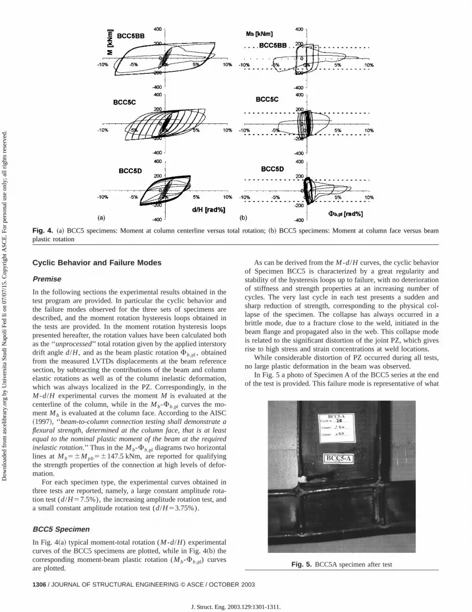
Fig. 4. ~a! BCC5 specimens: Moment at column centerline versus total rotation;~b! BCC5 specimens: Moment at column face versus beaplastic rotation
d
ofndl-a
ede
,
dt
Cyclic Behavior and Failure Modes
Premise
In the following sections the experimental results obtained in thetest program are provided. In particular the cyclic behavior andthe failure modes observed for the three sets of specimens aredescribed, and the moment rotation hysteresis loops obtained inthe tests are provided. In the moment rotation hysteresis loopspresented hereafter, the rotation values have been calculated bothas the ‘‘unprocessed’’ total rotation given by the applied interstorydrift angled/H, and as the beam plastic rotationFb,pl , obtainedfrom the measured LVTDs displacements at the beam referencesection, by subtracting the contributions of the beam and columnelastic rotations as well as of the column inelastic deformation,which was always localized in the PZ. Correspondingly, in theM -d/H experimental curves the momentM is evaluated at thecenterline of the column, while in theMb-Fb,pl curves the mo-mentMb is evaluated at the column face. According to the AISC~1997!, ‘‘ beam-to-column connection testing shall demonstrate aflexural strength, determined at the column face, that is at leastequal to the nominal plastic moment of the beam at the requiredinelastic rotation.’’ Thus in theMb-Fb,pl diagrams two horizontallines at Mb56M pb56147.5 kNm, are reported for qualifyingthe strength properties of the connection at high levels of defor-mation.
For each specimen type, the experimental curves obtained inthree tests are reported, namely, a large constant amplitude rota-tion test (d/H57.5%), the increasing amplitude rotation test, anda small constant amplitude rotation test (d/H53.75%).
BCC5 Specimen
In Fig. 4~a! typical moment-total rotation (M -d/H) experimentalcurves of the BCC5 specimens are plotted, while in Fig. 4~b! thecorresponding moment-beam plastic rotation (Mb-Fb,pl) curvesare plotted.
As can be derived from theM -d/H curves, the cyclic behaviorof Specimen BCC5 is characterized by a great regularity anstability of the hysteresis loops up to failure, with no deteriorationof stiffness and strength properties at an increasing numbercycles. The very last cycle in each test presents a sudden asharp reduction of strength, corresponding to the physical colapse of the specimen. The collapse has always occurred inbrittle mode, due to a fracture close to the weld, initiated in thbeam flange and propagated also in the web. This collapse mois related to the significant distortion of the joint PZ, which givesrise to high stress and strain concentrations at weld locations.
While considerable distortion of PZ occurred during all testsno large plastic deformation in the beam was observed.
In Fig. 5 a photo of Specimen A of the BCC5 series at the enof the test is provided. This failure mode is representative of wha
Fig. 5. BCC5A specimen after test
1306 / JOURNAL OF STRUCTURAL ENGINEERING © ASCE / OCTOBER 2003
J. Struct. Eng. 2003.129:1301-1311.

m
Dow
nloa
ded
from
asc
elib
rary
.org
by
Uni
vers
ita S
tudi
Nap
oli F
ed I
i on
07/0
7/15
. Cop
yrig
ht A
SCE
. For
per
sona
l use
onl
y; a
ll ri
ghts
res
erve
d.
Fig. 6. ~a! BCC8 specimens: Moment at column centerline versus total rotation;~b! BCC8 specimens: Moment at column face versus beaplastic rotation
e-
c-
e
was observed for all the BCC5 specimens, i.e., visible PZ distor-tion; brittle failure mode with cracks either at or close to thebeam-to-column weld locations, and no plastic hinge in the beam.It is worth pointing out that such behavior was the expected one,on the basis of the relative strength values provided in the section‘‘Specimen Properties.’’
BCC8 Specimen
In Fig. 6~a! the moment-total rotation (M -d/H) experimentalcurves of the BCC8 specimens are plotted, while in Fig. 6~b! thecorresponding moment-beam plastic rotation (Mb-Fb,pl) curves,are plotted.
The hysteresis loops obtained from the tests on the BCC8specimens~except the one obtained in the BCC8C test! show agradual reduction of the peak moment starting from the secondcycle, where the maximum value of the applied moment has beenusually registered. This progressive deterioration of the flexuralstrength of the connection is related to the appearance of localbuckling in the beam flanges, when cyclically subjected to com-pression, and to the consequent spreading of the buckling to widerzones of the flanges and to the web. A well defined plastic hingein the beam formed in all the tested specimens. In SpecimensBCC8 the contribution of the PZ deformation was not significant,and the plastic deformation mainly took place in the beam. In TestC, where the specimen has been subjected to a large constantamplitude rotation history, with peak cyclic rotation equal to 7.5%rad, an unstable behavior of the specimen was observed, withmultiple buckling occurring in the beam flanges starting from thefirst plastic cycle, and a sudden failure occurring at the third plas-tic cycle due to the fracture in the beam flange along the weld.
The final collapse of Specimens BCC8A and BCC8D was dueto fracture of the beam flange in the buckled zone, at approxi-mately 10–15 cm from the weld section. In Tests BCC8B,BCC8C, and BCC8E the collapse of the specimens occurred dueto fracture in the beam, starting along the weld or very close tothe weld line.
In Fig. 7 a photo of Specimen D of the BCC8 series at the endof the test is shown. This photo clearly shows the formation of aplastic hinge in the beam, which has been observed for all thBCC8 specimens, giving rise to a very ductile behavior. The prediction of a major contribution of the beam to the inelastic defor-mation mode of the connection, which has been made in the setion, ‘‘Specimen Properties,’’ through the comparison of beam,column, and PZ strength capacities, has been confirmed by thexperimental observations.
Fig. 7. BCC8D specimen after test
JOURNAL OF STRUCTURAL ENGINEERING © ASCE / OCTOBER 2003 / 1307
J. Struct. Eng. 2003.129:1301-1311.

am
Dow
nloa
ded
from
asc
elib
rary
.org
by
Uni
vers
ita S
tudi
Nap
oli F
ed I
i on
07/0
7/15
. Cop
yrig
ht A
SCE
. For
per
sona
l use
onl
y; a
ll ri
ghts
res
erve
d.
Fig. 8. ~a! BCC6 specimens: Moment at column centerline versus total rotation;~b! BCC6 specimens: Moment at column face versus beplastic rotation
alon-l-
nd
BCC6 Specimen
In Fig. 8~a! the moment-total rotation (M2d/H) experimentalcurves of the BCC6 specimens are plotted, while in Fig. 8~b! thecorresponding moment-beam plastic rotation (Mb-Fb,pl) curves,are plotted.
Throughout the test program, two different kinds of cyclicbehavior have been observed for the BCC6 specimens. In somecases~Tests C and D! the behavior of the specimens is close tothe behavior observed for the BCC5 type, with almost no dete-rioration of the mechanical properties up to the last cycle, duringwhich the collapse occurred. For the other tests~A, B, and BB! agradual reduction of the peak moment at an increasing number ofcycles is evident, thus indicating a progressive deterioration of theflexural strength of the connection. In these cases, starting fromthe very first plastic cycles, local buckling of the beam flangesoccurred, with a consequent decrease of the moment carried bythe beam. As the buckling zones extend and spread to the beamweb, a well defined plastic hinge formed in the beam. In Tests Cand D, buckling in the beam flanges was less significant and, evenif some plastification in the beam occurred, the plastic hinge wasnot as evident as in the A, B, and BB tests.
In all the BCC6 specimens the contribution of the PZ defor-mation was not as significant as in the BCC5 specimen type.However at the end of Tests A, B, and BB, permanent distortionsof the PZ, respectively, equal to 0.02, 0.035, and 0.01 rad, wereregistered.
The collapse of Specimens BCC6A and BCC6B was due tofracture of the beam flange in the buckled zone, at approximately10–15 cm from the weld section. Specimen BCC6BB failed dueto fracture in the beam flange along the weld line. Also for Speci-mens BCC6C and BCC6D a crack formed in the beam flangeclose to the weld, and propagated through the flange and the webof the beam, driving the specimens to collapse.
In Fig. 9 a photo of Specimen BB of the BCC6 series at the
end of the test is shown. The photo shows one of the two typicfailure modes observed for the BCC6 specimens, dependingthe applied loading history. It is worth underlining that, as predicted on the basis of the relative strength values of beam, coumn, and PZ, an intermediate behavior between the BCC5 aBCC8 specimens was observed for this specimen series.
Fig. 9. BCC6BB specimen after test
1308 / JOURNAL OF STRUCTURAL ENGINEERING © ASCE / OCTOBER 2003
J. Struct. Eng. 2003.129:1301-1311.

to-ticnnets
-
dts
Dow
nloa
ded
from
asc
elib
rary
.org
by
Uni
vers
ita S
tudi
Nap
oli F
ed I
i on
07/0
7/15
. Cop
yrig
ht A
SCE
. For
per
sona
l use
onl
y; a
ll ri
ghts
res
erve
d.
Fig. 10. Maximum rotation values from increasing amplitude tes
ec
ted
ems
thra
alunglbetarereer
nee
edionaln
inoger
laal
ege aureryiorngeaol
El-, it
es
hes
eply
fri-l-c-
ly
etoet
fthber
hest
ofen-
cc-s-
r-rsicis
tic
Evaluation of Connections Performance
Effect of Panel Zone on Specimen Rotations
Fig. 10 compares the rotations experienced by the three spmens in the increasing amplitude test~BCC5C, BCC6C, andBCC8D!. In particular for each specimen series the bars reporin the chart provide the total (elastic1plastic) rotation globallyexperienced by the beam-column subassemblaged/H tot ; the plas-tic rotation globally experienced by the beam-column subassblaged/Hpl ; the beam plastic rotation; and the PZ rotation. Acan be seen from this figure, the total rotation capacityd/H tot inthe increasing amplitude tests reach values of 0.064 rad forBCC5 specimen, 0.053 rad for the BCC6 specimen, and 0.046~at a loss of strength equal to 10% of the maximum strength! forthe BCC8 specimen. Comparing these values to the default vof interstory drift capacity required for special moment resistiframes~FEMA 2000!, equal to 0.04 rad~reported as a horizontaline in the chart!, the performance of the three specimens canjudged fully satisfactory. However these quite large values of torotation correspond to limited plastic rotations in the beams,spectively, equal to 0.0057, 0.0175, and 0.0242 rad for the thspecimens, thus confirming that large rotations can be expenced thanks to column web panel deformations.
The contribution of the PZ deformation to the global rotatioof the specimens, throughout the experimental program, has bremarkable~in average equal to the 80% of the total imposrotation!, in the specimens having the smallest column sect~BCC5!; less significant~in average equal to the 65% of the totimposed rotation! for the specimens with intermediate columsection~BCC6!; minor ~40–50% of the applied rotation! in thespecimens characterized by the largest column section~BCC8!.Consistently, the plastic rotations registered in the beam are mfor the BCC5, comparable to the PZ rotations in the BCC6, larfor the BCC8 specimens.
Effect of Panel Zone on Cyclic Behavior and FailureMode
The BCC5 specimens, even though able to experience high ptic deformation levels, have shown sudden failure modes incyclic tests, with hysteresis loops practically overlaid and no dradation of the flexural strength up to the very last cycle, whersharp decay of the load carrying capacity occurred due to fractgenerally developed in the proximity of the weld. On the contrathe BCC8 specimens have exhibited a typical ductile behavwith formation of a well defined plastic hinge in the beam startifrom the first plastic cycles, and a slow decrease of the pbending moment at increasing number of cycles up to the clapse.
These results confirm some major findings reported inTawil et al.~1999! where, on the basis of FEM analyses results
JOURNA
J. Struct. Eng. 2003.
i-
-
ed
e
l-ei-
n
r
s-l-
,
,
k-
is emphasized that although weak-panel design of the beam-column welded connections can substantially reduce beam plasrotation demands and effectively contribute to global connectioductility, the stress state arising at high levels of applied rotatioincreases the potentials for brittle fracture collapse mode of thconnection. Additional results, based both on experimental tesand FEM theoretical studies are provided by Lu et al.~2000!where it is found that weak column panel specimens~with PZcontribution equal to 70% of the total plastic rotation of the specimen! show brittle failure modes, with no previous deterioration ofthe strength capacity, due to fracture in the beam web weld anbeam bottom flange.
The BCC6 specimens have displayed a behavior sometimclose to the BCC5 specimens~Tests BCC6C and BCC6D!, some-times close to the BCC8 specimens~Tests BCC6A, BCC6B, andBCC6BB!, depending on the applied loading sequence. Also witregard to the final collapse of the specimens, in the former casit involved fracture in the beam starting at or close to the weldlocation, while in the latter cases it was due to cracking in thbuckled zones of the beam flanges. These aspects are more deeanalyzed in the next subsection.
Effect of Loading History on Failure Modes
No significant effect of the loading history on the failure mode othe BCC5 specimens has been observed throughout the expemental program: All BCC5 specimens have shown a sudden colapse, corresponding to a sharp decay of the load carrying capaity of the connection and associated to a brittle fracture, generaldeveloped in the proximity of the weld~brittle failure mode!.
For the BCC8 specimens a ductile deformation and failurmode has been observed, with final collapse occurring duefracture either in the buckled beam flange at the plastic hinglocation ~Test D at increasing amplitude, Test A at 5% constanamplitude! or in the beam flange close to the weld location~TestsB and E at 3.75% constant amplitude!. However in all cases awell defined plastic hinge formed in the beam and the failure othe connection occurred after a slow degradation of the strengcapacity of the specimens was observed at an increasing numof cycles~ductile failure mode!, thus a real load effect cannot beestablished for this specimen series.
On the contrary, for the BCC6 specimens two different kindsof inelastic behavior and collapse mode have been observed in tcyclic tests, depending on the applied loading history: for the teat increasing stepwise amplitude~C! and Test D, at the smallestconstant amplitude (d/H53.75%), a cyclic behavior similar tothe one exhibited by the BCC5 specimens, with sudden decaythe strength properties of the connection and brittle fracturmode, has been observed. For Tests A, B, and BB, at larger costant amplitude (d/H55 and 7.5%!, the behavior has been simi-lar to the one of the BCC8 specimens, with formation of a plastihinge, slow degradation of the strength capacity, and ductile frature mode. Thus for the BCC6 specimen series, the loading hitory has significantly affected the failure mode.
Effect of Loading History on Hysteretic Behavior
In order to assess the effect of the loading history on the hysteetic behavior of the specimens, different performance parametecan be computed and examined. In this paper both the cyclenergy and the cumulated plastic rotation have been used for thpurpose.
In Fig. 11 the normalized cyclic energy, i.e.,Ei /Eel,pl , definedas the ratio between the absorbed energy in the single plas
L OF STRUCTURAL ENGINEERING © ASCE / OCTOBER 2003 / 1309
129:1301-1311.

f the
r hasov-forhichthethe
Dow
nloa
ded
from
asc
elib
rary
.org
by
Uni
vers
ita S
tudi
Nap
oli F
ed I
i on
07/0
7/15
. Cop
yrig
ht A
SCE
. For
per
sona
l use
onl
y; a
ll ri
ghts
res
erve
d.
Fig. 11. Normalized cyclic energy
yc
thtestor thdeodth
ofe
thanthedean12renpe
8
le’’rgsrest
, thte
batheth
ccuthhig
op-
col-le’’thee,lds;
theave
theonsaysa-m
end-se;
nse-thes anclicfail-
in-
eon-
ticC5PZ,
kest
ofreticas
nsre-
aseci-her ofow-mnand
andea-on
cycleEi and the energy that might be absorbed in the same cif it had an elastic-perfectly plastic behaviorEel,pl is plottedagainst the number of cycle. The curves in Fig. 11 refer tothree specimens BCC5, BCC6, and BCC8, subjected to theat d/H53.75% andd/H55.0%. From the graph it is possiblederive a steady decrease of the normalized cyclic energy foBCC8 specimens, which finally experienced ductile failure moand, on the contrary, the sudden decay, due to brittle failure mof the normalized cyclic energy for the BCC5 specimens. ForBCC6 specimens, in the case ofd/H55.0% ~ductile failuremode!, the first kind of trend can be derived, while in the cased/H53.75% ~brittle failure mode!, the behavior is close to thone observed for the BCC5 specimens.
The above observations are also confirmed by examiningvalues of the cumulative plastic rotation, which is an importdeformation parameter for qualifying the performance ofwelded connection, since it globally accounts for the plasticformation occurring in specimens subjected to both constantincreasing amplitude cyclic histories. In the bar chart of Fig.the cumulated plastic rotation values are reported for the differotation histories applied to the specimens. The values aphighly variable for the BCC5 (d/Hpl,cum50.27– 0.65 rad) andBCC6 (d/Hpl,cum50.30– 0.73 rad) specimens, while the BCCspecimens, excluding the test C~7.5%!, show quite similar valuesfor all the tests (d/Hpl,cum50.48– 0.55 rad).
Therefore it can be concluded that, in the case of ‘‘brittfailure mode, the behavior of the different specimens show lascatters in the number of cycles to collapse and in the valuethe cycle energy at collapse, while in the case of ‘‘ductile’’ failumode the various specimens show a similar behavior in all tewith absorbed energy steadily decreasing up to failure. In factformation of a plastic hinge in the beam reduces the stress stathe welds, thus the failure of the specimen is achieved in thematerial at the plastic hinge location and is strictly related todeterioration of the mechanical properties of the beam. Oncontrary, when the specimen inelastic deformations do not omainly in the beam and the plastic hinge is not so evident,welds between the beam and the column are subjected to
Fig. 12. Cumulated plastic rotation values
1310 / JOURNAL OF STRUCTURAL ENGINEERING © ASCE / OCTOBER
J. Struct. Eng. 2003
le
ets
e,e,e
et
-d
tar
eof
s,ein
se
er
eh
stress levels and large plastic strains, thus the final collapse ospecimen occurs due to sudden failure at the weld locations.
Concluding Remarks and Design ImplicationsThe analysis of the experimental data presented in this papegiven us the opportunity of evidencing some aspects which gern the cyclic behavior of welded connections. In particular,three series of specimens, the effect of the column size, wdrives to different PZ properties, and of the loading history, oncyclic behavior, deformation capacity and failure mode ofconnections has been assessed.
Concerning the effect of the column size and of the PZ prerties, the following conclusions can be stated:• For the BCC5 specimens, characterized by the smallest
umn section and by the lowest PZ strength value, a ‘‘brittfailure mode has been observed in all the tests, due togoverning role of the PZ in the inelastic deformation modwhich places severe demands to the beam-to-column welarge scatters in the number of cycles to failure and invalues of performance parameters of the connections hbeen observed for this specimen series;
• On the contrary for the BCC8 specimens, characterized bystrongest PZ and by occurrence of inelastic deformatimainly in the beam, a typical ductile behavior has been alwobserved throughout the experimental program, with formtion of a well defined plastic hinge in the beam starting frothe first plastic cycles, and a slow decrease of the peak bing moment at increasing number of cycles up to the collapand
• For the intermediate size specimens~BCC6!, characterized byclose values of beam and PZ plastic capacity and, coquently, by occurrence of inelastic deformations both inbeam and in the PZ, the experimental evidence suggestintermediate behavior, with a strong dependence of the cybehavior, of the performance parameters values and of theure mode on the applied loading history.In order to assess the effect of the loading history, both
creasing cycle amplitude and constant cycle amplitude~large am-plitude and small amplitude! histories, have been applied to thspecimens. On the basis of the observations, the following cclusions can be stated:• Not a significant effect of the loading history on the inelas
behavior and failure mode has been observed for the BCand BCC8 specimen series, since, in the former case theand in the latter case the beam, were decisively the weaelement of the connection; and
• For the BCC6 specimens, which has quite close valuesbeam and PZ strength, a strong dependence of the hystebehavior and of the failure mode on the loading history hbeen observed.The quite high values of the maximum plastic rotatio
(d/Hpl) experienced by these European-type connections arelated to the significant contribution of PZ deformation, which hbeen observed throughout the tests for all three groups of spmens. This last point could suggest the possibility of utilizing tjoint panel for providing energy dissipation and stable behaviothe connections even at large number of cycles. Weak PZ, hever, give rise to inelastic deformation mode of the beam-colusubassemblage which produces high stress concentrationslarge plastic strains at the beam-to-column welded zones,finally drives the specimen to brittle collapse mode. For this rson the contribution of PZ distortion to the global plastic rotati
2003
.129:1301-1311.

n oth
thel
-
ve-
m
c-
-
an
,
r-
,
Dow
nloa
ded
from
asc
elib
rary
.org
by
Uni
vers
ita S
tudi
Nap
oli F
ed I
i on
07/0
7/15
. Cop
yrig
ht A
SCE
. For
per
sona
l use
onl
y; a
ll ri
ghts
res
erve
d.
of the connection should be properly calibrated in the desigthe connection, through the definition of adequate values ofrelative strength of beam and PZ.
Notation
The following symbols are used in this paper:Avc 5 shear area of column;
B 5 section width;d 5 applied beam tip displacement;
dy 5 theoretical yield displacement;d/dy 5 applied beam tip displacement normalized to
theoretical yield displacement;d/H 5 applied interstory drift angle;
d/Hpl 5 maximum plastic rotation globally experienced bybeam-column subassembly;
d/Hpl,cum5 cumulated plastic rotation globally experienced bybeam-column subassembly;
d/H tot 5 maximum total rotation globally experienced bybeam-column subassembly;
Ei 5 energy absorbed in single plastic cycle;Eel,pl 5 energy absorbed in elastic-perfectly plastic cycle;
f a 5 axial compressive stress;f y 5 yield stress;
f yb 5 beam yield stress;f yc 5 column yield stress;H 5 distance between beam tip and centerline of
column;hb 5 height of beam cross section;hc 5 height of column cross section;hs 5 distance between centerlines of stiffeners;hw 5 web height;
I 5 strong axis section moment of inertia;L 5 length;
Lb 5 beam length;Lc 5 column length;M 5 moment at column centerline;
Mb 5 moment at column face;M pb 5 beam moment capacity;M pc 5 column moment capacity;
M pl,fc,Rd5 plastic moment of column flange;M pl,st,Rd5 plastic moment resistance of stiffener;M p,PZ 5 panel zone moment capacity;
tw 5 web thickness;t f 5 flange thickness;
VPZ 5 column web shear strength;Z 5 plastic section modulus;
Zb 5 plastic section modulus of beam;Zc 5 plastic section modulus of column;
z 5 lever arm;DVPZ 5 shear strength contribution of transverse stiffeners;
andFb,pl 5 beam plastic rotation.
Subscriptsa 5 axial;b 5 beam;c 5 column;f 5 flange;
p, pl 5 plastic;s, st 5 stiffeners;
tot 5 total;w 5 web; andy 5 yield.
JOURNA
J. Struct. Eng. 2003
fe
References
American Institute of Steel Construction~AISC!. ~1997!. Seismic provi-sions for structural steel buildings, Chicago.
Calado, L., and Mele, E.~2000!. ‘‘Cyclic tests on bolted and weldedbeam-to-column connections.’’J. Earthquake Tech.,37~4!, 65–88.
Castiglioni, C. A., Bernuzzi, C., and Calado, L.~2000!. ‘‘Cyclic behaviorof steel beam-to-column joints with concrete slab.’’Proc., 3rd Int.Conf. on Steel Structures in Seismic Areas (STESSA), A. A. Balkema,Montreal, 147–154.
El-Tawil, S., Vidarsson, E., Mikesell, T., and Kunnath, S. K.~1999!.‘‘Inelastic behavior and design of steel panel zones.’’J. Struct. Eng.,125~2!, 183–193.
European Committee for Standardization~CEN!. ~1997!. TC250/SC3-PT9, ‘‘Joints in building frames.’’Part 1.1. Revised annex J, Editedapproved draft, January 1997, Eurocode 3, Brussels.
European Convention for Constructional Steelwork~ECCS!. ~1986!.‘‘Seismic design. Recommended testing procedure for assessingbehavior of structural steel elements under cyclic loads.’’ TechnicaCommunication 1—Structural Safety and Loadings, TWG1.3—Rep.No. 45.
Federal Emergency Management Agency~FEMA!. ~2000!. ‘‘Recom-mended seismic design criteria for new steel moment-frame building.’’ FEMA Rep. No. 350, Washington D.C.
Japanese Society of Steel Construction~JCSS!. ~1997!. ‘‘Kobe earth-quake damage to steel moment connections and suggested improment.’’ JSSC Technical Rep. No. 39, Tokyo.
Kunnath, S. K., and Malley, J. O., eds.~2002!. ‘‘Advances in seismicdesign and evaluation of steel moment frames: Recent findings froFEMA/SAC Phase II Project.’’J. Struct. Eng.,128~4!, 415–419.
Lu, L. W., Ricles, J. M., Mao, C., and Fisher, J. W.~2000!. ‘‘Criticalissues in achieving ductile behaviour of welded moment connetions.’’ J. Constr. Steel Res.,55, 325–341.
Malley, J. O. ~1998!. ‘‘SAC steel project: Summary of phase-1 testinginvestigation results.’’Eng. Struct.,20~4-6!, 300–309.
Mahin, S. A., Hamburger, R. O., and Malley, J. O.~1996!. ‘‘An integratedprogram to improve the performance of welded steel frame buildings.’’ Proc., 11th WCEE, World Conf. Earthquake Engineering,Elsevier Science Ltd., Acapulco, Mexico, Paper No. 1114.
Mele, E. ~2002!. ‘‘Moment resisting welded connections: an extensivereview of design practice and experimental research in USA, Japand Europe.’’J. Earthquake Eng.,6~1!, 1–35.
Mele, E., Calado, L., and Pucinotti, R.~1997!. ‘‘Indagine sperimentale sulcomportamento ciclico di alcuni collegamenti in acciaio.’’Proc., 8thNational Conf. Earthquake Engineering, Associazione Nazionale diIngegneria Sismica~ANIDIS!, Taormina, Italy, 1031–1040~in Ital-ian!.
Nakashima, M., Suita, K., Morisako, K., and Maruoka, Y.~1998!. ‘‘Testson welded beam-to-column subassemblages. I: Global behavior.’’J.Struct. Eng.,124~11!, 1236–1244.
Plumier, A., Agatino, M. R., Castellani, A., Castiglioni, C. A., and ChesiC. ~1998!. ‘‘Resistance of steel connections to low-cycle fatigue.’’Proc., 11th ECEE, European Conf. Earthquake Engineering,Balkema, Paris.
Suita, K., Nakashima, M., and Morisako, K.~1998!. ‘‘Tests of weldedbeam-to-column subassemblages. II: Detailed behavior.’’J. Struct.Eng.,124~11!, 1245–1252.
Tanaka, A., Kato, B., Kaneko, H., Sakamoto, S., Takahashi, Y., and Teaoka, M. ~1997!. ‘‘Seismic damage of steel beam-to-columnconnections—evaluation from statical aspects.’’Proc., 2nd Int. Conf.on Steel Structures in Seismic Areas (STESSA), Kyoto, Japan, 856–865.
Taucer, F., Negro, P., and Colombo, A.~1998!. ‘‘Cyclic testing of the steelframe.’’ JRC ELSA Special Publication No. I.98.160, Ispra, Italy.
The Steel Construction Institute.~1992!. Steel designers’ manual, G. W.Owens and P. R. Knowles, eds., Blackwell Scientific PublicationsLondon.
Uniform Building Code~UBC!. ~1994!. ‘‘International Conf. of buildingofficials.’’ Whittier, Calif.
L OF STRUCTURAL ENGINEERING © ASCE / OCTOBER 2003 / 1311
.129:1301-1311.