bolted and welded connections | mcgraw-hill education
TRANSCRIPT

112. Bolted and Welded Connections
112.1. General
Most failures in steel structures occur due to poorly designed and detailed connections. Member failures are relatively rare.Modern steel structures are connected using welds or bolts. Bolting with high-strength bolts has largely replaced riveting.Welded connections have several advantages over bolted connections. Welded connections require few, if any, holes.Aesthetically, welded connections appear simpler and "cleaner." However, welding requires skilled operators and inspection canbe difficult and costly.
Steel bolts are available in several grades:
A307 bolts are unfinished or ordinary or common bolts. They are available in sizes from 5/8 to 1 1/2 in diameter in 1/8 inincrements.
A325 bolts are high-strength bolts with material properties very similar to A36 steel. In the 14th edition of the SteelConstruction Manual, these bolts have been grouped with some other bolt designations as "Group A" bolts.
A490 bolts are high-strength bolts made from an alloy steel. High-strength bolts are available up to a maximum diameter of1 1/2 in. In the 14th edition of the Steel Construction Manual, these bolts have been grouped with some other boltdesignations as "Group B" bolts.
112.2. Snug-Tight versus Slip-Critical Connections
© McGraw-Hill Education. All rights reserved. Any use is subject to the Terms of Use, Privacy Notice and copyright information.

112.2. Snug-Tight versus Slip-Critical Connections
Bolted connections are either snug-tight or slip-critical. In a snug-tight connection, the bolt is not tensioned. The fitted parts fitsnugly but not with enough normal stress at the interface to activate added frictional resistance. In such a connection, thetension or compression in the connected parts leads to development of bearing stress on the shank of the bolt. This is whysuch connections are called bearing type connections. On the other hand, slip-critical connections use tensioned bolts. A307bolts are not used in slip-critical connections. The bolt tension causes the connected parts to develop a frictional resistance atthe interface. Table 112.1 shows minimum specified tensions for high-strength bolts in slip-critical connections. Thesetensions correspond to developing at least 70% of the tensile strength of the bolt.
Table 112.1 Minimum Fastener Tension (kips)
Diameter (in)
1/2 5/8 3/4 7/8 1 11/8 11/4 13/8 11/2
A325 12 19 28 39 51 56 71 85 103
A490 15 24 35 49 64 80 102 121 148
According to Specification for Structural Joints Using ASTM A325 or A490 Bolts, Research Council on Structural Connections,Chicago, 2004, the following four methods may be used for bolt tensioning:
1. Turn-of-the-nut method
2. Calibrated wrench tightening
3. Twist-off type bolts
4. Direct tension indicators
Table 112.2 shows nominal stresses in fasteners and threaded parts.
Table 112.2 Allowable Stress in Fasteners
Fastener grade Nominal tensile stress F(ksi)
Nominal shear stress in bearing type connectionsF (ksi)
A307 45 24
A325 or A325M (where threads are included in the shearplane)
90 48
A325 or A325M (where threads are excluded from theshear plane)
90 60
A490 or A490M (where threads are included in the shearplane)
113 60
A490 or A490M (where threads are excluded from theshear plane)
113 75
112.3. Bearing Type Connections
ntnv
© McGraw-Hill Education. All rights reserved. Any use is subject to the Terms of Use, Privacy Notice and copyright information.

Besides exceeding allowable shear stress in bolts, bolted connections can also fail due to inadequate distance between boltcenters or inadequate edge distance. The minimum center-to-center spacing between bolts in the direction of the load is 2.67 Dand minimum edge distance should be between 1.5D and 2D.
112.3.1. Bearing Strength of Bolts
For bearing type connections using at least 2 bolts per line (in the direction of the load), if the edge distance is greater than orequal to 1.5 times the bolt diameter and distance between bolt centers is greater than or equal to three times the bolt diameter,the nominal bearing strength of a single bolt is given by
(112.1)
where L = clear distance from the edge of the bolt hole to the edge of the adjacent bolt or the edge of the material (see Fig.112.1)
t = thickness of the connected part
d = diameter of the bolt
F = ultimate tensile stress of the connected part (not bolt)
Figure 112.1 Clear distance from edge of bolt hole.
For ASD, the allowable strength is
(112.2)
For LRFD, the design strength is
Rn = 1.2LctFu ≤ 2.4dtFu
c
u
Ra = =Rn
Ω
Rn
2.0
ϕRn = 0.75Rn
© McGraw-Hill Education. All rights reserved. Any use is subject to the Terms of Use, Privacy Notice and copyright information.

(112.3)
In the discussion above, the limit stress in bearing has been taken as F = 1.2F (for short-slotted or standard holes). If long-slotted holes are used, the limit stress is to be taken as F = 1.0F . If edge distance L is less than 1.5D or for a single bolt, thebearing strength is given by
(112.4)
112.3.2. Shear Strength of Bolts
The nominal shear strength of a bolt is given by
(112.5)
where F = nominal shear stress, given in Table 112.2
A = nominal bolt area (unthreaded part)
For ASD, the allowable strength is
(112.6)
For LRFD, the design strength is
(112.7)
Example
Example 112.1
A 3/8-in-thick × 3-in plate is a tension member and carries concentric axial loads. The plate is connected to a 3/8-in-thickgusset plate using two 3/4-in-diameter bolts, as shown. Check the adequacy of the connection if the following types of boltsare used: (a) A307 normal bolts, (b) A325 high-strength bolts with threads in the plane of shear, and (c) A325 high-strengthbolts with threads not in the plane of shear. Assume plate is A36 steel (F = 36 ksi, F = 58 ksi).
p u
p u e
Fp =LeFu
2D
Rn = FnvAb
nv
b
Ra = =FnvAb
Ω
FnvAb
2.0
ϕRn = 0.75Rn = 0.75FnvAb
y u
© McGraw-Hill Education. All rights reserved. Any use is subject to the Terms of Use, Privacy Notice and copyright information.
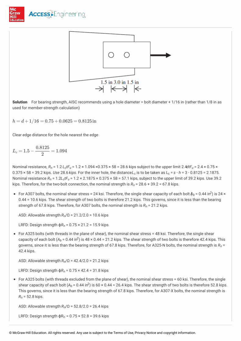
Solution For bearing strength, AISC recommends using a hole diameter = bolt diameter + 1/16 in (rather than 1/8 in asused for member-strength calculation)
Clear edge distance for the hole nearest the edge
Nominal resistance, R = 1.2 L tF = 1.2 × 1.094 ×0.375 × 58 = 28.6 kips subject to the upper limit 2.4dtF = 2.4 × 0.75 ×0.375 × 58 = 39.2 kips. Use 28.6 kips. For the inner hole, the distance L is to be taken as L = s - h = 3 - 0.8125 = 2.1875.Nominal resistance R = 1.2L tF = 1.2 × 2.1875 × 0.375 × 58 = 57.1 kips, subject to the upper limit of 39.2 kips. Use 39.2kips. Therefore, for the two-bolt connection, the nominal strength is R = 28.6 + 39.2 = 67.8 kips.
For A307 bolts, the nominal shear stress = 24 ksi. Therefore, the single shear capacity of each bolt (A = 0.44 in ) is 24 ×0.44 = 10.6 kips. The shear strength of two bolts is therefore 21.2 kips. This governs, since it is less than the bearingstrength of 67.8 kips. Therefore, for A307 bolts, the nominal strength is R = 21.2 kips.
ASD: Allowable strength R /Ω = 21.2/2.0 = 10.6 kips
LRFD: Design strength ϕR = 0.75 × 21.2 = 15.9 kips
For A325 bolts (with threads in the plane of shear), the nominal shear stress = 48 ksi. Therefore, the single shearcapacity of each bolt (A = 0.44 in ) is 48 × 0.44 = 21.2 kips. The shear strength of two bolts is therefore 42.4 kips. Thisgoverns, since it is less than the bearing strength of 67.8 kips. Therefore, for A325-N bolts, the nominal strength is R =42.4 kips.
ASD: Allowable strength R /Ω = 42.4/2.0 = 21.2 kips
LRFD: Design strength ϕR = 0.75 × 42.4 = 31.8 kips
For A325 bolts (with threads excluded from the plane of shear), the nominal shear stress = 60 ksi. Therefore, the singleshear capacity of each bolt (A = 0.44 in ) is 60 × 0.44 = 26.4 kips. The shear strength of two bolts is therefore 52.8 kips.This governs, since it is less than the bearing strength of 67.8 kips. Therefore, for A307-X bolts, the nominal strength isR = 52.8 kips.
ASD: Allowable strength R /Ω = 52.8/2.0 = 26.4 kips
LRFD: Design strength ϕR = 0.75 × 52.8 = 39.6 kips
h = d+1/16 = 0.75+0.0625 = 0.8125in
Lc = 1.5− = 1.0940.81252
n c u u
c c
n c u
n
b2
n
n
n
b2
n
n
n
b2
n
n
n
© McGraw-Hill Education. All rights reserved. Any use is subject to the Terms of Use, Privacy Notice and copyright information.

Example
Example 112.2
Cover plates are used to reinforce both flanges of a W18 × 50 section as shown. The plates are bolted to both flanges usingA325 bolts of 3/4 in diameter as shown. If the transverse shear force V = 76 kips, determine the required longitudinal pitchof the bolts.
Solution For W18 × 50, I = 800 in , d = 18 in, t = 0.570 in, b = 7.5 in. By symmetry, the neutral axis is at mid-depth, andoverall moment of inertia of the reinforced section is given by
The first moment of area at the interface between W section and the top plate is
The shear stress (per unit width) developed at the interface between the W section and the top plate is
If the allowable shear stress in bolts is 17 ksi, then the allowable shear force in each bolt is given by
and the maximum required spacing is given by
x4
f f
I = 800+2( +8×0.5×9.252) = 1484.67in48 ×0.53
12
Q = 8×0.5×9 = 36 in3
τ = = = 1.84kips/inVQ
I
76 ×361484.67
Vbolt = ×17 = 7.5kips/boltπ×0.752
4
© McGraw-Hill Education. All rights reserved. Any use is subject to the Terms of Use, Privacy Notice and copyright information.

112.4. Slip-Critical Connections
In slip-critical connections, no slippage between the connected parts is permitted. The resistance to slip is achieved by thefriction developed between the surfaces due to the normal force between the connected parts. The nominal slip resistance of abolt is given by
(112.8)
where μ = mean slip coefficient (= 0.35 for class A surfaces)
D = ratio of mean actual bolt pretension to the specified minimum pretension (default value 1.13)
h = hole factor = 1.0 for standard bolt holes
T = minimum fastener tension
N = number of slip planes
Class A surfaces are defined as surfaces having clean mill scale. In the AISC specifications, they have the smallest assignedcoefficient of friction and, therefore, it is conservative to assume class A surfaces if not otherwise specified.
112.5. Bolt Group Subject to Shear and Torsion
Figure 112.2 shows a bolt group is subjected to an eccentric load, which causes transverse shear stress in the bolts (which isequally shared among all bolts) as well as torsional shear stress due to the torsional moment (about the center of the boltgroup) created by the eccentric load.
s = = 8.15in7.5× 21.84
Rn = μDuhscTbNs
u
sc
b
s
© McGraw-Hill Education. All rights reserved. Any use is subject to the Terms of Use, Privacy Notice and copyright information.
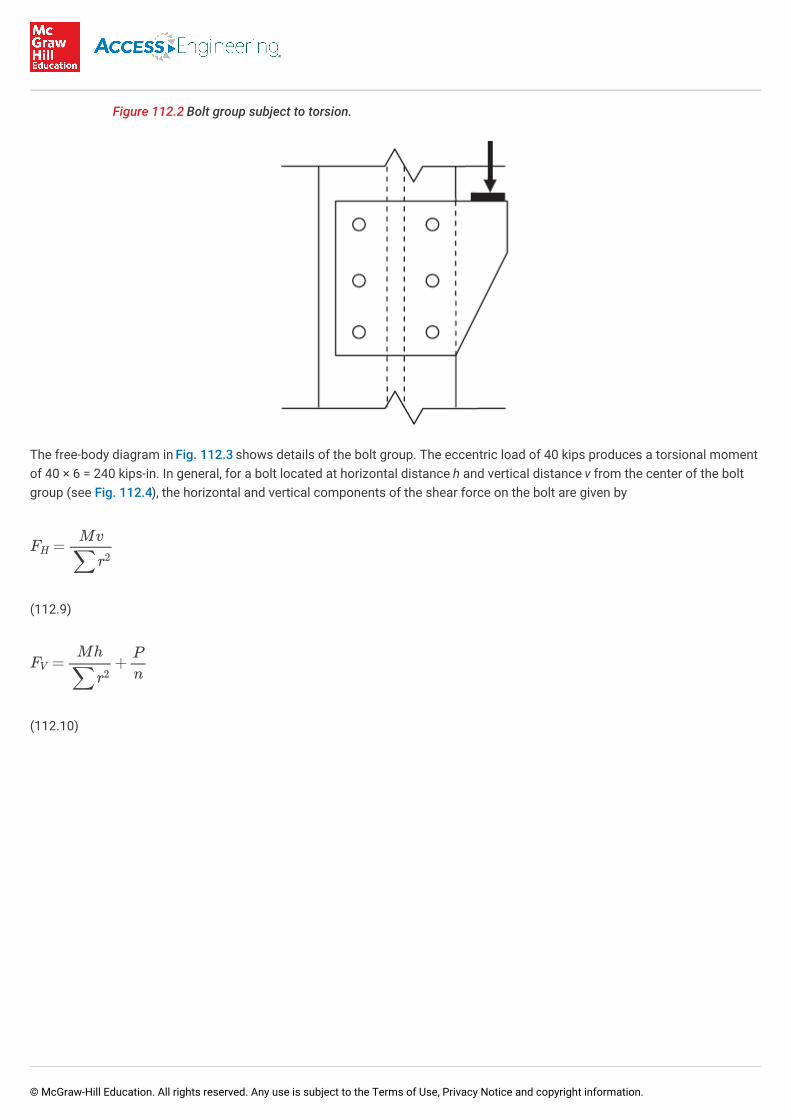
Figure 112.2 Bolt group subject to torsion.
The free-body diagram in Fig. 112.3 shows details of the bolt group. The eccentric load of 40 kips produces a torsional momentof 40 × 6 = 240 kips-in. In general, for a bolt located at horizontal distance h and vertical distance v from the center of the boltgroup (see Fig. 112.4), the horizontal and vertical components of the shear force on the bolt are given by
(112.9)
(112.10)
FH =Mv
∑r2
FV = +Mh
∑r2
P
n
© McGraw-Hill Education. All rights reserved. Any use is subject to the Terms of Use, Privacy Notice and copyright information.

Figure 112.3 Free-body diagram of bolt group subject to torsional moment.
Figure 112.4 Shear forces acting on bolt at edge of eccentrically loaded group.
The quantity ∑r is given by
The worst vector combination of these forces occurs on the outer bolts on the near line (since the downward component of thetorsional shear force combines with the vertical transverse shear force).
2
∑r2i = (2×22+4×3.612) = 60 in2
© McGraw-Hill Education. All rights reserved. Any use is subject to the Terms of Use, Privacy Notice and copyright information.

The resultant force on the bolt (combining vectorially)
112.6. Capacity of Bolted Connections—Design Tables inSCM, 14th Edition
112.6.1. Table 7-1: Available Shear Strength of Bolts (kips)
For group A, group B and A307 bolts in single and double shear, Table 7-1 lists available strength (kips) in shear (ϕr for LRFD, ϕ= 0.75; r /Ω for ASD, Ω = 2.0) for bolt diameters 5/8 in to 1.5 in (in 1/8 in increments). For the high-strength bolts (group A andgroup B), one must also choose whether threads are included (N) or excluded (X) from the shear plane.
112.6.2. Table 7-2: Available Tensile Strength of Bolts (kips)
For group A, group B and A307 bolts in tension, Table 7-2 lists available strength (kips) in tension (ϕr for LRFD, ϕ = 0.75; r /Ωfor ASD, Ω = 2.0) for bolt diameters 5/8 in to 1.5 in (in 1/8 in increments).
112.6.3. Table 7-3: Available Shear Strength of Slip-Critical Connections(kips)
Table 7-3 lists available shear strength for high-strength bolts (group A and group B) using various types of bolt-holes (standard,short slotted, long slotted, and oversized). Standard (STD) and short-slotted transverse to direction of load (SSLT) holes permitmaximum capacity, followed by oversized (OVS) and short-slotted parallel to direction of load (SSLP) holes. Long-slotted holes(LSL) result in lowest bolt capacity. Ordinary (A307) bolts are not used for slip-critical connections. This table is based on theassumption that the faying surface is class A (μ = 0.30).
112.6.4. Table 7-4: Available Bearing Strength (kips/in) Based on BoltSpacing
For two different values of ultimate stress (F = 58, 65 ksi), Table 7-4 yields the available bearing strength per unit thickness ofthe connected part. The results in this table are based on bolt spacing s = 2.67d and s = 3 in. The required bolt spacing todevelop full bearing strength (s ) is also given in this table.
112.6.5. Table 7-5: Available Bearing Strength (kips/in) Based on Bolt
FH = = = 12kips
FV = + = + = 14.67kips
Mv
∑r2
240 ×360
Mh
∑r2
V
n
240 ×260
406
R =√122+14.672= 18.95kips
n
n
n n
u
b
full
© McGraw-Hill Education. All rights reserved. Any use is subject to the Terms of Use, Privacy Notice and copyright information.

112.6.5. Table 7-5: Available Bearing Strength (kips/in) Based on BoltEdge Distance
For two different values of ultimate stress (F = 58, 65 ksi), Table 7-5 yields the available bearing strength per unit thickness ofthe connected part. The results in this table are based on edge distance L = 1.25 and 2 in. The required edge distance todevelop full bearing strength (L ) is also given in this table.
112.6.6. Tables 7-6 through 7-13: Nominal Shear Capacity Coefficient Cfor Eccentrically Loaded Bolt Groups
These tables yield a multiplicative coefficient C that can be used to calculate the capacity of the bolt group (R ) in terms of thecapacity of an individual bolt (r ).
Tables 7-6 through 7-13 can be used for the following scenarios:
Number of vertical rows = 1, 2, 3, or 4
Up to 12 bolts in each vertical row
Range of angles (with vertical) = 0°, 15°, 30°, 45°, 60°, 75°
Vertical spacing between horizontal rows = 3 in, 6 in
Horizontal spacing between vertical lines = 3 in, 5.5 in
Example
Example 112.3
In this example, the applicable table (from 7-6 to 7-13) is used to calculate the ultimate capacity P for an eccentricallyloaded bolt group as shown below. The group consists of 8 bolts arranged in two vertical lines spaced 5½ in, with 4 boltsper line. The vertical spacing between bolts is 3 in. The resultant load P acts at an eccentricity e = 4 in and is inclined tothe vertical by 30°.
Solution For angle θ = 30°, two vertical lines of bolts spaced 5½ in, we must use Table 7-8 on page 7-44.
Matching all parameters (n = 4, e = 4 in, s = 3 in), coefficient C = 5.30.
Therefore, R = Cr = 5.3r .
If 1-in-diameter group A bolts (with thread included in the shear plane) are used in single shear, Table 7-1 yields ϕr = 31.8kips (LRFD) and r /Ω = 21.2 kips (ASD).
Therefore, the capacity of the bolt group is obtained as 5.3 times the capacity of a single bolt.
u
e
e full
n
n
Rn = Crn
u
u x
x
n n n
n
n
Pu = ϕRn = Cϕrn = 5.30×31.8 = 168.5kips (LRFD)Pa = Rn/Ω = Crn/Ω = 5.30×21.2 = 112.4kips (ASD)
© McGraw-Hill Education. All rights reserved. Any use is subject to the Terms of Use, Privacy Notice and copyright information.

112.7. Bolts Subject to Shear and Tension
For bolts subject to shear, Table 112.3 outlines the allowable tension stress (ksi).
Table 112.3 Allowable Tension in Bolts Subject to Shear
Bolt Threads included in shear plane Threads included from shear plane
A 307 26 – 1.8f ≤ 20
A 325
A 490
112.8. Basic Weld Symbols
A typical weld symbol is shown in Fig. 112.5. The mandatory reference line is always horizontal. The arrow points to the locationof the weld. The tail of the weld symbol (if used) is used to indicate the welding or cutting processes, as well as the weldingspecs, procedures, or any other information to be used for making the weld. Notations below the reference line refer to the weldon the arrow side, while notations above the reference line refer to the weld on the opposite side. A circle at the junction of thearrow and the reference line indicates that welding must be performed all around. A flag at the junction of the arrow and thereference line indicates a field weld. The flag is always shown flying backward (away from weld arrow). A fillet weld is indicatedby a triangle on one or both sides of the reference line, as appropriate. The size of the fillet weld is indicated next to thetriangular symbol. For example, in Fig. 112.5, there is a ¼-in-size fillet weld of length 6 in on the arrow side.
Figure 112.5 Fillet weld.
The maximum size of fillet welds of connected parts shall be:
a. along edges of material less than ¼ in thick, not greater than the thickness of the material
b. along edges of material ¼ in or more in thickness, not greater than the thickness of the material minus 1/16 in, unless theweld is specifically designated on the drawings to be built out to obtain full-throat thickness
The minimum size of fillet welds shall be:
a. 1/8 in for thickness of thinner part to ¼ in (inclusive)
b. 3/16 in for thinner part thickness over ¼ in to ½ in
c. ¼ in for thinner part thickness over ½ in to ¾ in
v
√442−4.39f2v √442−2.15f2v
√542−3.75f2v √542−1.82f2v
© McGraw-Hill Education. All rights reserved. Any use is subject to the Terms of Use, Privacy Notice and copyright information.

d. 5/16 in thinner part thickness over ¾ in
Intermittent welds are indicated by specifying the weld length and the longitudinal pitch (center to center) of the weld lines. Anintermittent weld pattern can have welds that are not staggered [Fig. 112.6(a)] or staggered [Fig. 112.6(b)].
Figure 112.6 Intermittent fillet weld.
Figure 112.7 shows symbols used for different types of welds.
Figure 112.7 Weld symbols.
Table 112.4 shows various parts of the nomenclature used for groove welds.
© McGraw-Hill Education. All rights reserved. Any use is subject to the Terms of Use, Privacy Notice and copyright information.

Table 112.4 Basic Groove Weld Nomenclature
Symbols for weld type Symbols for joint type Symbols for weld process Symbols for base metal thickness andpenetration
1 Square Groove B = Butt Joint F = FCAW U = Unlimited thickness, Complete JointPenetration
2 Single V-Groove
3 Double V-Groove C = Corner Joint G = GMAW
4 Single Bevel Groove L = Limited thickness, Complete JointPenetration
5 Double Bevel Groove T = T Joint sc = Short Circuit
6 Single U-Groove
7 Double U-Groove BC = Butt or Corner S = SAW
8 Single J-Groove Joint
9 Double J-Groove None of the above = SMAW orGTAW
P = Partial Joint Penetration
10 Flare Groove TC = T or Corner
11 Flare Groove (openroot)
Joint
12 Flare Bevel Fillet BTC = Butt, T, or CornerJoint
Some examples of common groove welds are shown below. In these Figs. (112.8 and 112.9), E is the effective throat thickness.In Fig. 112.8, the symbol "f" is called the land. The land of the weld should be a minimum of 1/8 in.
Figure 112.8 Single bevel groove weld.
© McGraw-Hill Education. All rights reserved. Any use is subject to the Terms of Use, Privacy Notice and copyright information.

Figure 112.9 Flare groove weld.
112.9. Weld Specifications
Some of the best known welding methods are:
Shielded metal arc welding (SMAW)—also known as arc or stick welding. The electrode slowly melts to form the weldpuddle. Slag protects the weld puddle from atmospheric contamination. This very basic welding method is easy to masterand is well suited for thicknesses 4 mm and greater. Thinner sheet metals are more suited to the MIG process.
Gas metal arc welding (GMAW)—commonly termed MIG (metal, inert gas), uses a gun that feeds wire at an adjustable speedand flows an argon-based shielding gas or a mix of argon and carbon dioxide (CO ) over the weld puddle to protect it fromatmospheric contamination.
Gas tungsten arc welding (GTAW)—also known as TIG (tungsten, inert gas), uses a non-consumable tungsten electrode toproduce the weld. The weld area is protected from atmospheric contamination by an inert shielding gas such as argon orhelium. This is considered one of the most difficult and time consuming of welding processes.
Flux-cored arc welding (FCAW)—also known as "wire welding"—almost identical to MIG welding except it uses a specialtubular wire filled with flux; it can be used with or without shielding gas, depending on the filler.
Submerged arc welding (SAW)—uses an automatically fed consumable electrode and a blanket of granular fusible flux. Themolten weld and the arc zone are protected from atmospheric contamination by being "submerged" under the flux blanket.
Electroslag welding (ESW)—a highly productive, single pass welding process for thicker materials between 1 in and 12 in ina vertical or close to vertical position.
112.9.1. Electrodes
2
© McGraw-Hill Education. All rights reserved. Any use is subject to the Terms of Use, Privacy Notice and copyright information.

112.9.1. Electrodes
All electrodes must be of the low-hydrogen classification. Shielded metal arc welding (SMAW) is the only preapproved processfor welding on bridge members. The most common SMAW electrodes used are E7018 and E8018. E7018 electrodes are usedfor bridge members that are coated (painted, galvanized, or metalized). E8018 electrodes are used for bridge members that areuncoated.
A typical designation of a SMAW electrode is E7018. The first two digits stand for the minimum tensile strength (ksi) of thewelding electrode. Thus, the designation "70" correlates to the electrode having a tensile strength of 70 ksi.
The third digit on a SMAW electrode stands for the positions in which the electrode can be used.
The number 1 means the electrode can be used in all positions
The number 2 means the electrode can be used in the flat and horizontal position
The fourth digit on a SMAW electrode indicate the type of coating
The numbers 6 or 8 classify the electrode as low-hydrogen
112.9.2. Welder Position
Welders must be qualified for the position in which they are welding.
F - Flat position
H - Horizontal position
V - Vertical position
OH - Overhead position
112.9.3. Electrode Storage and Redrying
© McGraw-Hill Education. All rights reserved. Any use is subject to the Terms of Use, Privacy Notice and copyright information.
112.9.3. Electrode Storage and Redrying
Hydrogen is one of the major causes for weld defects, so care must be taken to ensure no moisture is picked up in the coatingon the electrodes.
Electrodes shall be purchased in hermetically sealed containers or shall be dried for at least 2 hours between 450 and 500°F forE70XX electrodes or between 700 and 800°F for E80XX electrodes.
Immediately after opening of the hermetically sealed container electrodes not being used must be stored in a storage oven(also known as a hot box) and held at a temperature of at least 250°F.
After the electrodes have been removed from the hermetically sealed containers or from the storage oven, the electrodes maybe exposed to the atmosphere for a period not to exceed the following:
E70XX 4 hours maximum
E80XX 2 hours maximum
If the electrode has been exposed to the atmosphere for a period less than that shown above, then the electrode may be placedback into the storage oven and dried for a period of no less than 4 hours. Electrodes that have been wet shall not be used.
The first step in making a sound weld is to make sure the joint is correctly cleaned and then preheated prior to welding.Cleaning the joint can be accomplished by using a stiff wire brush.
112.9.4. Weld Preheating
Preheat is an important step prior to welding. Preheating the joint helps remove any moisture from the joint and by heating thejoint initially before welding commences will allow the joint to cool at a slower rate which will allow for more time for hydrogento diffuse out of the molten weld metal.
Preheating is the required practice of providing localized heat to the weld zone. The preferred method of preheating is by theuse of a manual torch.
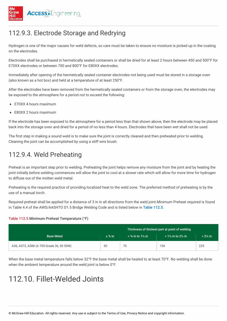
Required preheat shall be applied for a distance of 3 in in all directions from the weld joint.Minimum Preheat required is foundin Table 4.4 of the AWS/AASHTO D1.5 Bridge Welding Code and is listed below in Table 112.5.
Table 112.5 Minimum Preheat Temperature (°F)
Thickness of thickest part at point of welding
Base Metal ≤ ¾ in > ¾ in to 1½ in > 1½ in to 2½ in > 2½ in
A36, A572, A588 (A 709-Grade 36, 50 50W) 50 70 150 225
When the base metal temperature falls below 32°F the base metal shall be heated to at least 70°F. No welding shall be donewhen the ambient temperature around the weld joint is below 0°F.
112.10. Fillet-Welded Joints
© McGraw-Hill Education. All rights reserved. Any use is subject to the Terms of Use, Privacy Notice and copyright information.

Fillet-welded joints such as tee, lap, and corner joints are the most common connections in welded fabrication. Fillets are notonly the most frequently used weld joints but also one of the most difficult to weld with any real degree of consistency. Filletwelds require a higher heat input than a butt joint of the same thickness. This can lead to lack of penetration and/or fusiondefects that cannot be detected by visual examination and other nondestructive techniques. Inspection methods such as visualinspection, magnetic particle inspection, and penetrant inspection are surface examination techniques only.
Often the fillet welds that are produced are of a poor shape which can adversely influence their performance under load. Someof the deficiencies of fillet welds are shown in Figs. 112.10 to Figs. 112.13. Due to the melting of the corner of the upper plate,the vertical leg length is reduced meaning that the design throat is also reduced creating an undersized weld. To prevent this,the weld should be some 0.5 to 1 mm clear of the top corner. See Fig. 112.10.
Figure 112.10 Reduction of weld throat due to melting of top plate.
In addition to the reduction in throat thickness, there is the potential for additional problems such as overlap at the weld toedue to the larger weld pool size or an excessively convex weldface and consequential sharp notches at the weld toe. Thesesituations (illustrated in the Figs. 112.11 and 112.12) could adversely influence the fatigue life of the welded joint due to theincreased toe angle, which acts as a greater stress concentration. Improper alignment can also reduce the throat thickness asin Fig. 112.13.
Figure 112.11 Large weld pool size.
Figure 112.12 Excessively convex weldface.
© McGraw-Hill Education. All rights reserved. Any use is subject to the Terms of Use, Privacy Notice and copyright information.

Figure 112.13 Reduction of weld throat due to improper alignment.
112.11. Fillet Weld Features
The fillet weld is assumed to have a cross section of a 90-45-45 right triangle. The size of the weld is denoted by w (see Fig.112.14). Standard weld sizes are specified in increments of 1/16 in. A fillet weld is weakest in shear and failure is assumed tooccur on a plane through the throat of the weld. Throat is the perpendicular distance from the corner (root) of the weld to thehypotenuse and is equal to 0.707 times the weld size. A deep penetration weld is shown in Fig. 112.15.
Figure 112.14 Mitre fillet weld parameters.
Figure 112.15 Deep penetration weld parameters.
© McGraw-Hill Education. All rights reserved. Any use is subject to the Terms of Use, Privacy Notice and copyright information.

112.12. Strength of a Fillet Weld
For a weld of length L subjected to a force P, the critical shear stress (on the plane inclined along the throat) is given by
(112.11)
If the weld's ultimate shear stress is F , the nominal load capacity of the weld is given by
(112.12)
The ultimate shearing stress of the weld is 60% of the ultimate tensile strength F . The ultimate tensile strength of the weldmetal is defined using the standard notation such as E70XX or E80XX. For example, the E70XX electrode implies that the weldmetal has an ultimate tensile strength of 70 ksi. AISC specifications require the designer to use
E70XX electrodes for steel having a yield stress less than 60 ksi
E80XX electrodes for steel having a yield stress of 60 ksi or 65 ksi
When the direction of the load is at an angle to the weld line, as shown in Fig. 112.16, the nominal weld strength (shear) iscalculated as
(112.13)
Figure 112.16 Weld line subject to combined tension and shear.
The design shear strength of a fillet weld is given by
(112.14)
fv =P
0.707wL
w
Rn = 0.707FwwL
EXX
Fw = 0.6FEXX(1 +0.5 sin1.5θ)
ASD : Ra ≤ =Rn
Ω
Rn
2.0
LRFD : Pu ≤ ϕRn
© McGraw-Hill Education. All rights reserved. Any use is subject to the Terms of Use, Privacy Notice and copyright information.

(112.15)
112.13. Second Moments of Weld Runs
Table 112.6 shows second moments I , I , and I of several commonly used weld patterns. Example 112.3 illustrates theiruse.
Table 112.6 Second Moment of Weld Runs
xx yy xy
© McGraw-Hill Education. All rights reserved. Any use is subject to the Terms of Use, Privacy Notice and copyright information.

Example
Example 112.4
An eccentric load is applied to the flange of a W14 × 82 column as shown. The bracket plate transfers the dead load = 15kips and live load = 25 kips as shown. What is the minimum weld size needed if E70XX electrode is used?
Solution For the weld profile shown, the centroid is at a distance b /L = 8 /28 = 2.29 in from the back edge, causing theeccentricity of the load to be 16 – 2.29 = 13.71 in.
ASD
The design load P = 15 + 25 = 40 kips and moment M = 40 × 13.71 = 548.4 kips-in
Polar moment of inertia of the weld line = 720 + 195 = 915 in . The torsional shear stress has the following components:
2 2
Ixx = = = 720
Iyy = = = 195
d2(6b+ d)
12
122(6 × 8+12)
12b3(b+2d)3L
83(8 + 2×12)3 ×28
4
© McGraw-Hill Education. All rights reserved. Any use is subject to the Terms of Use, Privacy Notice and copyright information.

The direct shear stress is
The shear stress on the weld line is . The weld strength per inch is given by
(assume E70XX electrode):
The allowable load on the weld (per inch) is therefore
Equating this to the shear stress on the weld (6.08 kips/in), we get w = 0.41. Use 7/16 in weld size.
112.14. Inspection Criteria for Welds and Bolts
Quality assurance (QA) is process oriented and focuses on defect prevention, while quality control (QC) is product oriented andfocuses on defect identification. The goal of QA is to improve development and test processes so that defects do not arisewhen the product is being developed. The goal of QC is to identify defects after a product is developed and before it isreleased.
112.14.1. Minimum Requirements for Inspection of Structural Steel
τx = = = 3.42ksi
τy = = = 3.60ksi
My
J
548.4× 5.71915
Mx
J
548.4× 6915
τy= = = 1.43ksiP
L
4028
√3.422+(3.60+1.43)2= 6.08kips/in
Rn = 0.707wFw = 0.707×w×0.6×70 = 29.69w
= = 14.85wRn
Ω
29.69w2.0
© McGraw-Hill Education. All rights reserved. Any use is subject to the Terms of Use, Privacy Notice and copyright information.

112.14.1. Minimum Requirements for Inspection of Structural SteelBuildings
QC inspection tasks shall be performed by fabricator's or erector's QCI (quality control inspector). Applicable constructiondocuments are the shop drawings and the erection drawings and applicable specifications, codes, and standards. QAinspection of fabricated items shall occur at the fabricator's plant. QA inspection of the erected system shall occur at theproject site.
Prior to welding, QA and QC inspection must ensure that welding procedure specifications (WPSs) and manufacturer'scertifications for welding consumables (rods, etc.) are available for each welded joint or member. After welding, the followingmust be inspected:
1. Size, length, and location of welds
2. Welds meet the following visual acceptance criteria:
a. Weld has proper profile and has adequate size as given in job specifications.
b. Proper fusion of weld and base metal.
c. Crack prohibition. Crater cracks (occur when a crater is not filled before the arc is broken) can form in longitudinal,transverse, and/or radial directions. An undercut crack, also known as a heat-affected zone (HAZ) crack, is a crack thatforms a short distance away from the fusion line. Arc strike cracking occurs when the arc is struck but the spot is notwelded due to the spot being heated above the material's upper critical temperature and then essentially quenched.
d. Porosity of a weld occurs due to gas inclusion, which is the entrapment of gas within the solidified weld due to highsulfur content of the electrode, excessive moisture from the electrode, or due to wrong welding current or polarity.
e. Cracking in the "k" area, which is the region extending from approximately the midpoint of the radius of the fillet into theweb approximately 1 to 1.5 in beyond the point of tangency between the fillet and the web.
3. Backing removed and weld tabs removed.
112.14.2. Visual Inspection of Welds
© McGraw-Hill Education. All rights reserved. Any use is subject to the Terms of Use, Privacy Notice and copyright information.

112.14.2. Visual Inspection of Welds
A fillet weld gauge is the standard tool to check weld sizes. In addition to checking that the weld size meets specifications, allwelds should also be visually inspected for defects. Defects to look for include the following:
112.14.2.1. Cracks
No cracks in the surface of the welds shall be allowed. If a crack is found, the crack must be removed and magnetic-particleinspection performed to ensure the crack has been removed before rewelding.
112.14.2.2. Porosity
Porosity is a cavity in the weld that is formed by gas escaping from the molten weld metal during solidification. The AWS D1.5Code specification for porosity is
Maximum diameter shall not exceed 3/32 in
Frequency of any sized porosity shall not exceed one in 4 in or six in 4 ft of weld length
112.14.2.3. Craters
Craters are the ends of welds where the weld is not filled to its full cross section. The stresses that are caused by the unfilledcrater may cause cracks to form because of tension on the weld in the affected area. All welds must have full cross section theentire length of the weld.
112.14.2.4. Undercut
Undercut occurs at the edge of the weld along the leg. Undercut actually refers more to the base metal adjacent to the weld.Undercut is normally caused by excessive current in the welding operation. Undercut will cause stress risers and should beavoided. The AWS D1.5 Code requirement for undercut is:
Undercut shall be no more than 0.01 in deep when the weld is transverse to tensile stress.
Undercut shall be no more than 1/32 in deep for all other cases.
112.14.2.5. Arc Strikes
Arc strikes are areas where the welding electrode comes into contact with the base metal outside of the final weld. Arc strikesresult in heating and very rapid cooling. Arc strikes may result in hardening or fatigue cracking, and serve as potential sites forfracture initiation.
All arc strikes are to be removed by grinding. Grinding to a depth of 1/8 in below the original surface should remove all traces ofarc strikes and their hardened heat-affected zones. However, in tension areas of the bridge, the locations where arc strikes wereremoved shall have magnetic-particle inspection and hardness testing performed per The AWS D1.5 Bridge Welding Code.
112.14.3. Nondestructive Testing (NDT) of Welded Joints
© McGraw-Hill Education. All rights reserved. Any use is subject to the Terms of Use, Privacy Notice and copyright information.

112.14.3. Nondestructive Testing (NDT) of Welded Joints
Ultrasonic testing (UT), magnetic particle testing (MT), penetrant testing (PT), and radiographic testing (RT) shall be performedas part of QA, in accordance with AWS D1.1.
For structures in risk categories III or IV (ASCE7), UT shall be performed on all CJP groove welds subject to transversely appliedtension loads in butt, T- and corner joints, in material thickness 5/16 in or greater.
Exception Where the initial rate for UT is 100%, it shall be permitted to be reduced (for an individual welder) to 25% if the reject rate (weldscontaining unacceptable defects divided by number of welds completed) is less than 5%. This determination is based on a sampleof at least 40 completed welds. For continuous welds longer than 36 in where the effective throat is 1 in or less, each 12 in segmentor fraction thereof shall be considered as one weld. For welds with effective throat greater than 1 inch, each 6 in segment or fractionthereof shall be considered as one weld.
For structures in risk category II, UT shall be performed on 10% of CJP groove welds subject to transversely applied tensionloads in butt, T- and corner joints, in material thickness 5/16 in or greater.
Exception For structures in risk category II, where the initial rate of UT is 10%, it shall be increased to 100% should the reject rate (for anindividual welder) exceeds 5%, based on a minimum sample size of 20 welds. The rate of UT shall be returned to 10% when thereject rate (based on 40 completed welds) falls below 5%.
For structures in risk category I, NDT is not required. For structures in all risk categories, NDT of CJP groove in materials lessthan 5/16 in thick is not required.
112.14.4. Inspection of High-Strength Bolting
Tables N5.6-1 to N5.6-3 in AISC 360-10 Specifications for Structural Steel Buildings lay out QA and QC inspection requirementsprior to, during, and after bolting respectively. Some of these tasks are only random observations made without interruptingoperations. Other more critical tasks are mandatory and must be performed for each bolted connection.
1. For snug-tight joints, pre-installation verification testing as specified in Table N5.6-1 and monitoring of the installationprocedures as specified in Table N5.6-2 are not applicable. The QCI and QAI need not be present during the installation offasteners in snug-tight joints.
2. For pretensioned joints and slip-critical joints, when the installer is using the turn-of-nut method (with match marking), thedirect-tension-indicator method, or the twist-off-type tension-control-bolt method, monitoring of bolt pretensioningprocedures shall be as specified in Table N5.6-2. The QCI and QAI need not be present during the installation of fastenerswhen these methods are used by the installer.
3. For pretensioned joints and slip-critical joints, when the installer is using the calibrated-wrench method or the turn-of-nutmethod without match marking, monitoring of bolt pretensioning procedures shall be as specified in Table N5.6-2. The QCIand QAI shall be engaged in their assigned inspection duties during installation of fasteners when these methods are usedby the installer.
© McGraw-Hill Education. All rights reserved. Any use is subject to the Terms of Use, Privacy Notice and copyright information.