manufacturing of welded rings - diva portal
TRANSCRIPT
Manufacturing of Welded Rings
Evaluation of Post-Weld Operations
Tillverkning av svetsade ringämnen
Utvärdering av svetsfogsoperationer
Jim Andersson
Faculty of Health, Science and Technology
Degree Project for Master of science in Engineering, Mechanical Engineering
30 HP
Supervisor: Christer Burman
Examiner: Jens Bergström
2019-08-29
1

i

Abstract
Pipe and ring blanks can be produced in several different ways. Today’s focus on environ-mental effects motivates companies to develop processes that are as efficient as possible intheir production. Ringsvets AB is a company that produces pipe and ring blanks from a flatstock by rolling and welding the piece to make it stay in its desired form. The direct benefitof the method is the minimizing of material loss, and it has thereby both environmental andeconomical advantages. The downside of the method is that the processes involved changesthe mechanical behavior of the ring, locally around the weld zone. The focus of this masterthesis is the processes and how they affect the material, both microstructure and behavior.The processes involved are; rolling, welding, shaping, brushing, forging, heat treatment, andcalibration.
The purpose of this work was to elevate the knowledge and understanding of the processes atRingsvets. The goals were to give a theoretical description of them along with practical testresults and explanations of how and why they function in reality.
A literature study has been conducted which provided a theoretical basis on how the materialreacts on certain processes. Practical examination of samples from current production hasbeen done to get evidence of how well the processes are used, and how well they function,in today’s production. Lastly, the main focus of the thesis, an evaluation has been made; dotheory and practice correlate, and should anything be changed to correlate better?
The results showed that the first operations do not alter the material behavior to an unac-ceptable extent. Forging, on the other hand, gives the material a very high hardness in theweld zone, and that needs to be corrected. The following heat treatment should compensatefor that in a perfect world, but does not in reality. The finished ring shows good propertiesin general but with places where the heat treatment has failed to correct the uneven behaviorinduced by earlier operations.
The heat treatment requires some adjustments before it functions as intended. Some grainshas not been recrystallized which makes them very hard and non-ductile. Future tests usinga higher temperature or a longer heat treatment time would reveal the best way to adjustthe heat treatment to obtain the desired properties. Other changes in the processes couldalso be beneficial. Interesting things to try and change would, for example, be the degree ofdeformation in the forging, which affects the recrystallization temperature.
Notes should be taken that this examination is done on just one sample of just one size.Analyses of different samples of different sizes should be done to ensure of the accuracy of theexamination.
ii

iii
Sammanfattning
Ror- och ringamnen ar en produkt som kan produceras pa flera olika satt. Dagens fokus paatt gora ett sa litet avtryck pa naturen som mojligt motiverar foretag att utveckla processersom ar sa miljoeffektiva som mojligt i sin produktion. Ringsvets AB ar ett foretag som pro-ducerar ror och ringamnen fran ett platt grundamne genom att rulla och sedan svetsa ihopringen sa att den behaller den onskade formen. Den tydligaste fordelen med metoden ar attmaterialspillet minimeras, och det finns darfor bade miljomassiga och ekonomiska fordelar medden. Nackdelen med metoden ar att processerna som anvands forandrar ringens mekaniskaegenskaper i svetsomradet. Detta examensarbete ar fokuserat kring processerna och hur depaverkar materialet i ringarna, bade i mikrostruktur och beteende. Processerna som anvandsar; valsning, svetsning, hyvling, borstning, pragling, varmebehandling och kalibrering.
Syftet med projektet var att oka kunskapen och forstaelsen hos Ringsvets for processerna deanvander. Malet var att forse Ringsvets med teoretiska beskrivningar tillsammans med resultatfran praktiska undersokningar samt forklaringar till varfor processerna fungerar som de gor.
Genom att gora en litteraturstudie har en teoretisk grund erhallits for hur materialet reagerarpa vissa processer. Praktisk undersokning av prover fran nuvarande produktion har gjortsfor att fa bevis pa hur processerna anvands och hur bra de fungerar i dagens produktion.Slutligen huvuddelen av projektet dar teori och praktik jamfors; stammer teori overens medhur det fungerar i praktiken, och bor nagon eller nagra processer andras?
Resultaten visade att de forsta operationerna inte paverkar materialbeteendet speciellt mycket.Praglingen, a andra sidan, ger materialet en okar hardheten valdigt mycket i svetszonen, vilketbehover korrigeras. I en perfekt varld bor efterfoljande varmebehandling kompensera for det,men sa fungerar det inte idag. Den fardiga ringen visar goda egenskaper i allmanhet men medstallen dar varmebehandlingen inte lyckats korrigera de ojamna egenskaperna som tidigareoperationer introducerar.
Forandringar i varmebehandlingen behover goras for att fa ett perfekt resultat. Vissa korn harinte omkristalliserats, vilket gor dem valdigt harda och ger dem en lag duktilitet. Framtidatester med hogre temperatur och/eller langre tid i hog temperatur skulle visa vilken forandringsom ger onskat resultat, om nagon av de tva foreslagna. Andra forandringar i processerna kanocksa vara fordelaktiga. Intressanta saker att forandra skulle t.ex. kunna vara graden avdeformation i praglingen, vilket exempelvis paverkar rekristallisationstemperaturen.
Det bor noteras att denna undersokning bara gors pa ett prov med endast en storlek. Analyserav olika prov eller olika storlekar bor goras for att vara saker pa att resultatet av undersokningenar korrekt.
iv

v
Contents
1 Introduction 11.1 Background . . . . . . . . . . . . . . . . . . . . . . . . . . . . . . . . . . . . . 11.2 Problem statements . . . . . . . . . . . . . . . . . . . . . . . . . . . . . . . . . 21.3 Purpose and goal . . . . . . . . . . . . . . . . . . . . . . . . . . . . . . . . . . 21.4 Delimitations . . . . . . . . . . . . . . . . . . . . . . . . . . . . . . . . . . . . 3
2 Theoretical overview 42.1 Current processes . . . . . . . . . . . . . . . . . . . . . . . . . . . . . . . . . . 4
2.1.1 Material . . . . . . . . . . . . . . . . . . . . . . . . . . . . . . . . . . . 42.1.2 Welding . . . . . . . . . . . . . . . . . . . . . . . . . . . . . . . . . . . 42.1.3 Shaping . . . . . . . . . . . . . . . . . . . . . . . . . . . . . . . . . . . 52.1.4 Brushing . . . . . . . . . . . . . . . . . . . . . . . . . . . . . . . . . . . 62.1.5 Forging . . . . . . . . . . . . . . . . . . . . . . . . . . . . . . . . . . . 62.1.6 Heat treatment . . . . . . . . . . . . . . . . . . . . . . . . . . . . . . . 72.1.7 Calibration . . . . . . . . . . . . . . . . . . . . . . . . . . . . . . . . . 7
2.2 Literature study . . . . . . . . . . . . . . . . . . . . . . . . . . . . . . . . . . . 72.2.1 Crystal structure . . . . . . . . . . . . . . . . . . . . . . . . . . . . . . 72.2.2 Welding . . . . . . . . . . . . . . . . . . . . . . . . . . . . . . . . . . . 152.2.3 Induction heating . . . . . . . . . . . . . . . . . . . . . . . . . . . . . . 182.2.4 Shaping . . . . . . . . . . . . . . . . . . . . . . . . . . . . . . . . . . . 182.2.5 Friction and wear . . . . . . . . . . . . . . . . . . . . . . . . . . . . . . 20
3 Method 213.1 Influence of processes in theory . . . . . . . . . . . . . . . . . . . . . . . . . . 21
3.1.1 Reference . . . . . . . . . . . . . . . . . . . . . . . . . . . . . . . . . . 213.1.2 Rolled . . . . . . . . . . . . . . . . . . . . . . . . . . . . . . . . . . . . 213.1.3 Welding . . . . . . . . . . . . . . . . . . . . . . . . . . . . . . . . . . . 213.1.4 Brushing . . . . . . . . . . . . . . . . . . . . . . . . . . . . . . . . . . . 213.1.5 Forging . . . . . . . . . . . . . . . . . . . . . . . . . . . . . . . . . . . 223.1.6 Heat treatment . . . . . . . . . . . . . . . . . . . . . . . . . . . . . . . 223.1.7 Calibration . . . . . . . . . . . . . . . . . . . . . . . . . . . . . . . . . 22
3.2 Experimentals . . . . . . . . . . . . . . . . . . . . . . . . . . . . . . . . . . . . 233.2.1 Introduction . . . . . . . . . . . . . . . . . . . . . . . . . . . . . . . . . 233.2.2 Purpose and goal . . . . . . . . . . . . . . . . . . . . . . . . . . . . . . 233.2.3 Material and Measurements . . . . . . . . . . . . . . . . . . . . . . . . 243.2.4 Method . . . . . . . . . . . . . . . . . . . . . . . . . . . . . . . . . . . 24
4 Results 30
vi
4.1 Reference . . . . . . . . . . . . . . . . . . . . . . . . . . . . . . . . . . . . . . 304.2 Rolling . . . . . . . . . . . . . . . . . . . . . . . . . . . . . . . . . . . . . . . . 314.3 Welding . . . . . . . . . . . . . . . . . . . . . . . . . . . . . . . . . . . . . . . 324.4 Shaping and brushing . . . . . . . . . . . . . . . . . . . . . . . . . . . . . . . . 344.5 Forging . . . . . . . . . . . . . . . . . . . . . . . . . . . . . . . . . . . . . . . . 364.6 Heat treatment . . . . . . . . . . . . . . . . . . . . . . . . . . . . . . . . . . . 374.7 Calibration . . . . . . . . . . . . . . . . . . . . . . . . . . . . . . . . . . . . . 46
5 Discussion 525.1 Microstructure and preparation . . . . . . . . . . . . . . . . . . . . . . . . . . 525.2 Hardness tests . . . . . . . . . . . . . . . . . . . . . . . . . . . . . . . . . . . . 535.3 Evaluation of processes . . . . . . . . . . . . . . . . . . . . . . . . . . . . . . . 54
5.3.1 Reference and rolling . . . . . . . . . . . . . . . . . . . . . . . . . . . . 545.3.2 Welding . . . . . . . . . . . . . . . . . . . . . . . . . . . . . . . . . . . 545.3.3 Shaping and brushing . . . . . . . . . . . . . . . . . . . . . . . . . . . 555.3.4 Forging . . . . . . . . . . . . . . . . . . . . . . . . . . . . . . . . . . . 555.3.5 Heat treatment . . . . . . . . . . . . . . . . . . . . . . . . . . . . . . . 555.3.6 Calibration . . . . . . . . . . . . . . . . . . . . . . . . . . . . . . . . . 55
5.4 Summary . . . . . . . . . . . . . . . . . . . . . . . . . . . . . . . . . . . . . . 56
6 Future work 586.1 Complete analysis . . . . . . . . . . . . . . . . . . . . . . . . . . . . . . . . . . 586.2 Change of parameters . . . . . . . . . . . . . . . . . . . . . . . . . . . . . . . . 586.3 Change of geometry . . . . . . . . . . . . . . . . . . . . . . . . . . . . . . . . . 596.4 Change of material . . . . . . . . . . . . . . . . . . . . . . . . . . . . . . . . . 596.5 Change of operations . . . . . . . . . . . . . . . . . . . . . . . . . . . . . . . . 59
7 Conclusion 60
References 62
A Microscope Images A-1
vii

1 Introduction
This master thesis was performed in the facilities of Camatec Industriteknik in Karlstad withadditional supervising from Ringsvets and Karlstad University. The following chapter willintroduce the problem, the manufacturing company, and also state the questions, purpose, andaim included in this report.
1.1 Background
Components such as flanges for various applications, and for example a specific case; roller re-tainers in roll bearings, are made from circular stocks. The circular stock can be manufacturedin a couple of different ways. In the case of flanges, a common way of manufacturing the stockis laser cutting from a metal sheet. In the retainer case one way to go is by deep drawing, andthen remove the top and bottom to get a pipe. Both methods give a lot of material loss asthere are a lot of cut off material that remains unused [1].
Ringsvets AB is a company specialized in producing welded rings with minimal material losswith metal sheet or rods as the originating shape. All the stock material is used to make thefinished ring without any waste of material. The blanks produced by Ringsvets are in the nearnet shape of the flange or roller retainer that is the final form. The obvious benefits of thisare both economical but also environmental. Their lines producing welded rings are located inKopparberg, Sweden. Ringsvets has its roots in the 70’s as a part of SKF but has since 1987,when SKF decided to move the production, been operating on its own. Ringsvets is now theleading provider of welded rings in Sweden with SKF and Scania as customers [2].
In the making of a welded pipe or ring blank there are a couple of different processes involved.The flat stock is cut in suitable length, rolled into a circular shape, and then welded to geta complete circle. The resulting joint differs in desired form, but also in microstructure andmechanical properties compared to the rest of the ring. The procedures following welding aretherefore done to neutralize the effect of the welding where the goal is to make the joint asequal as possible to the rest of the ring material, geometry and structure wise. The weld jointis therefore shaped, brushed, forged, and heat treated before the ring gets its final shape bycalibration, see Figure 1.
1
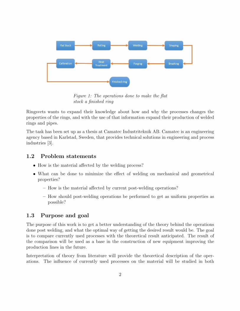
Figure 1: The operations done to make the flatstock a finished ring
Ringsvets wants to expand their knowledge about how and why the processes changes theproperties of the rings, and with the use of that information expand their production of weldedrings and pipes.
The task has been set up as a thesis at Camatec Industriteknik AB. Camatec is an engineeringagency based in Karlstad, Sweden, that provides technical solutions in engineering and processindustries [3].
1.2 Problem statements
• How is the material affected by the welding process?
• What can be done to minimize the effect of welding on mechanical and geometricalproperties?
– How is the material affected by current post-welding operations?
– How should post-welding operations be performed to get as uniform properties aspossible?
1.3 Purpose and goal
The purpose of this work is to get a better understanding of the theory behind the operationsdone post welding, and what the optimal way of getting the desired result would be. The goalis to compare currently used processes with the theoretical result anticipated. The result ofthe comparison will be used as a base in the construction of new equipment improving theproduction lines in the future.
Interpretation of theory from literature will provide the theoretical description of the oper-ations. The influence of currently used processes on the material will be studied in both
2

microscope and with hardness tests. Examination of the rings in some steps of the productionhas been done before [4]. The information in that test is however concluded to be incomplete,making a new test a requirement to make a good conclusion. A new and more thoroughexamination of the rings in each process will therefore be done.
1.4 Delimitations
The scope of the thesis is 20 weeks at 40h/week. The material compositions used at Ringsvetsare mostly low alloy steels, and the main objective of the analysis is therefore such steels. Theexact composition will not be revealed as it is classified on behalf of the ordering company.
3
2 Theoretical overview
This project is based on both the processes used in the production line today and also thetheory of the behavior of a steel. This chapter will describe current processes together with adeclaration of how a steel is structured and its theoretical reactions in the material by materialprocessing.
2.1 Current processes
The understanding and development of post-welding processes has its base in knowing the cur-rently used operations and their purpose in the production line. This chapter will describe theidea of the processes and how they are performed at Ringsvets in present time. This informa-tion was acquired by visiting Ringsvets, including a guided tour by the supervisor at Ringsvets(Oholm J, oral communication, december 14th, 2018 and januari 25th, 2019), and completinginformation retrieved from literature.
2.1.1 Material
The material that has the highest volume of production today is a low alloy steel with acomposition resembling AISI 1005, which means that the maximum amount of carbon allowedis < 0.06 wt% [5].
2.1.2 Welding
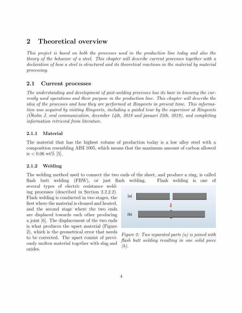
The welding method used to connect the two ends of the sheet, and produce a ring, is calledflash butt welding (FBW), or just flash welding. Flash welding is one of
Figure 2: Two separated parts (a) is joined withflash butt welding resulting in one solid piece(b).
several types of electric resistance weld-ing processes (described in Section 2.2.2.2).Flash welding is conducted in two stages, thefirst where the material is cleaned and heated,and the second stage where the two endsare displaced towards each other producinga joint [6]. The displacement of the two endsis what produces the upset material (Figure2), which is the geometrical error that needsto be corrected. The upset consist of previ-ously molten material together with slag andoxides.
4
2.1.3 Shaping
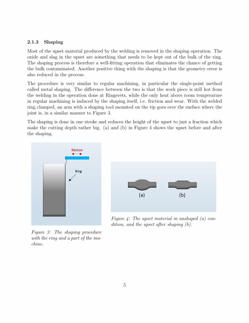
Most of the upset material produced by the welding is removed in the shaping operation. Theoxide and slag in the upset are something that needs to be kept out of the bulk of the ring.The shaping process is therefore a well-fitting operation that eliminates the chance of gettingthe bulk contaminated. Another positive thing with the shaping is that the geometry error isalso reduced in the process.
The procedure is very similar to regular machining, in particular the single-point methodcalled metal shaping. The difference between the two is that the work piece is still hot fromthe welding in the operation done at Ringsvets, while the only heat above room temperaturein regular machining is induced by the shaping itself, i.e. friction and wear. With the weldedring clamped, an arm with a shaping tool mounted on the tip goes over the surface where thejoint is, in a similar manner to Figure 3.
The shaping is done in one stroke and reduces the height of the upset to just a fraction whichmake the cutting depth rather big. (a) and (b) in Figure 4 shows the upset before and afterthe shaping.
Figure 3: The shaping procedurewith the ring and a part of the ma-chine.
Figure 4: The upset material in unshaped (a) con-dition, and the upset after shaping (b).
5
2.1.4 Brushing
Figure 5: (a) shows the joint in its shaped con-dition and (b) shows the smoother upset afterbrushing.
The shaping results in a thinner joint thick-ness, but the cutting also leaves sharp cor-ners of the upset, Figure 5(a). If the jointis struck in that condition the tool would bedamaged, and the result of the forging wouldalso be a less uniform geometry. To get abetter result, and also spare the forging tool,the brushing is done with steel wire brushes,giving the remaining upset a smoother tran-sition to the bulk material as seen in Figure5(b). Two brushes in the same axis rotate inopposite directions to make both sides of theupset smooth.
2.1.5 Forging
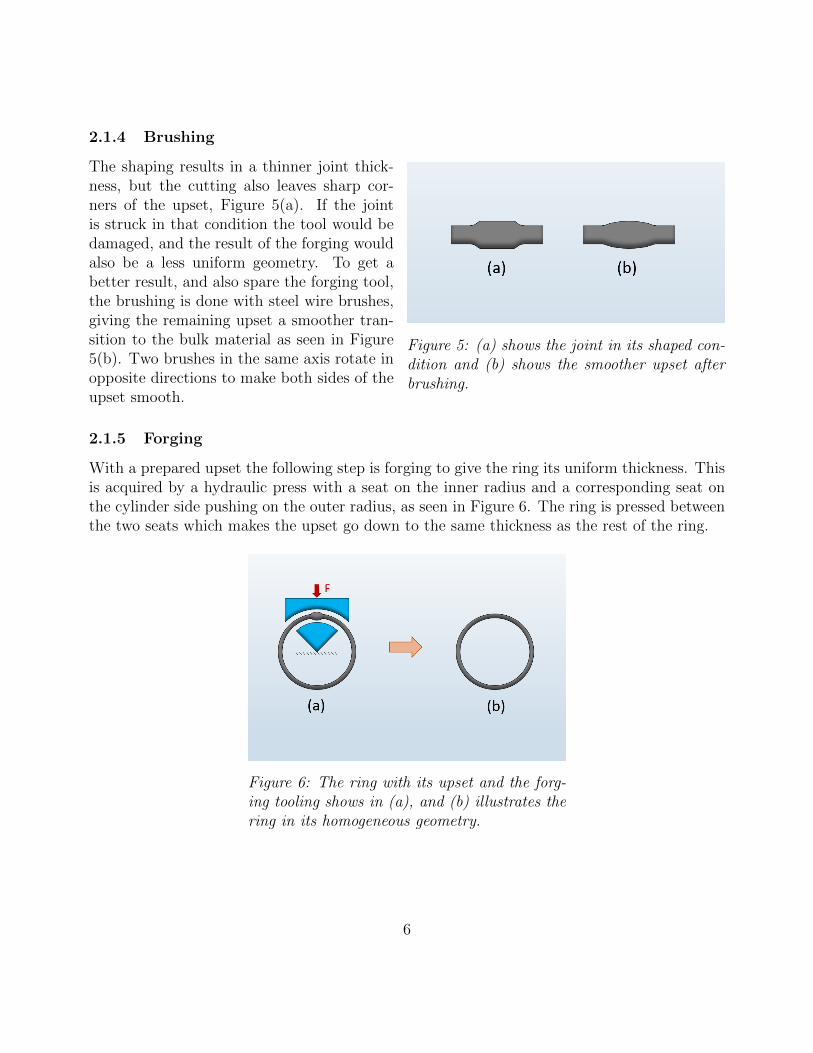
With a prepared upset the following step is forging to give the ring its uniform thickness. Thisis acquired by a hydraulic press with a seat on the inner radius and a corresponding seat onthe cylinder side pushing on the outer radius, as seen in Figure 6. The ring is pressed betweenthe two seats which makes the upset go down to the same thickness as the rest of the ring.
Figure 6: The ring with its upset and the forg-ing tooling shows in (a), and (b) illustrates thering in its homogeneous geometry.
6
2.1.6 Heat treatment
Previous operations gives the ring non-uniform mechanical properties. In most applicationsuniform properties are crucial, which is the motivation of the heat treatment. The heat treat-ment is done by induction heating of the joint area. Subsequent cooling with the ring travellingthrough a set of fans gives the ring its desired properties.
2.1.7 Calibration
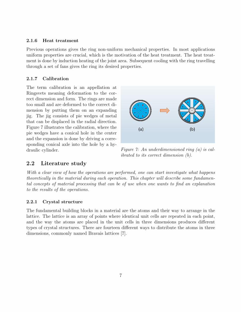
Figure 7: An underdimensioned ring (a) is cal-ibrated to its correct dimension (b).
The term calibration is an appellation atRingsvets meaning deformation to the cor-rect dimension and form. The rings are madetoo small and are deformed to the correct di-mension by putting them on an expandingjig. The jig consists of pie wedges of metalthat can be displaced in the radial direction.Figure 7 illustrates the calibration, where thepie wedges have a conical hole in the centerand the expansion is done by driving a corre-sponding conical axle into the hole by a hy-draulic cylinder.
2.2 Literature study
With a clear view of how the operations are performed, one can start investigate what happenstheoretically in the material during each operation. This chapter will describe some fundamen-tal concepts of material processing that can be of use when one wants to find an explanationto the results of the operations.
2.2.1 Crystal structure
The fundamental building blocks in a material are the atoms and their way to arrange in thelattice. The lattice is an array of points where identical unit cells are repeated in each point,and the way the atoms are placed in the unit cells in three dimensions produces differenttypes of crystal structures. There are fourteen different ways to distribute the atoms in threedimensions, commonly named Bravais lattices [7].
7
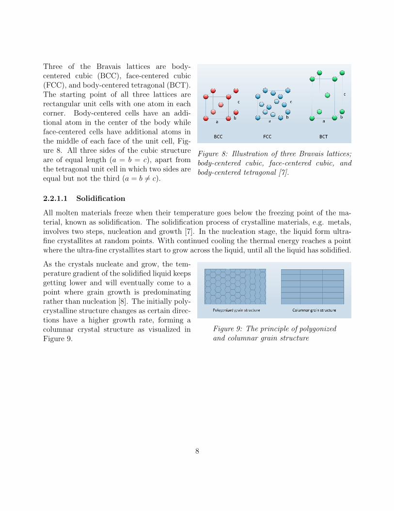
Figure 8: Illustration of three Bravais lattices;body-centered cubic, face-centered cubic, andbody-centered tetragonal [7].
Three of the Bravais lattices are body-centered cubic (BCC), face-centered cubic(FCC), and body-centered tetragonal (BCT).The starting point of all three lattices arerectangular unit cells with one atom in eachcorner. Body-centered cells have an addi-tional atom in the center of the body whileface-centered cells have additional atoms inthe middle of each face of the unit cell, Fig-ure 8. All three sides of the cubic structureare of equal length (a = b = c), apart fromthe tetragonal unit cell in which two sides areequal but not the third (a = b 6= c).
2.2.1.1 Solidification
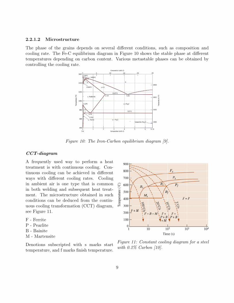
All molten materials freeze when their temperature goes below the freezing point of the ma-terial, known as solidification. The solidification process of crystalline materials, e.g. metals,involves two steps, nucleation and growth [7]. In the nucleation stage, the liquid form ultra-fine crystallites at random points. With continued cooling the thermal energy reaches a pointwhere the ultra-fine crystallites start to grow across the liquid, until all the liquid has solidified.
Figure 9: The principle of polygonizedand columnar grain structure
As the crystals nucleate and grow, the tem-perature gradient of the solidified liquid keepsgetting lower and will eventually come to apoint where grain growth is predominatingrather than nucleation [8]. The initially poly-crystalline structure changes as certain direc-tions have a higher growth rate, forming acolumnar crystal structure as visualized inFigure 9.
8
2.2.1.2 Microstructure
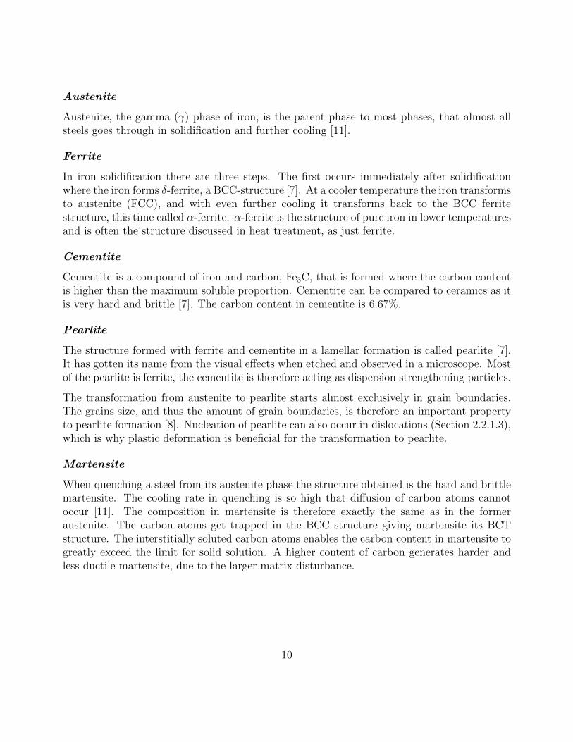
The phase of the grains depends on several different conditions, such as composition andcooling rate. The Fe-C equilibrium diagram in Figure 10 shows the stable phase at differenttemperatures depending on carbon content. Various metastable phases can be obtained bycontrolling the cooling rate.
Figure 10: The Iron-Carbon equilibrium diagram [9].
CCT-diagram
Figure 11: Constant cooling diagram for a steelwith 0.2% Carbon [10].
A frequently used way to perform a heattreatment is with continuous cooling. Con-tinuous cooling can be achieved in differentways with different cooling rates. Coolingin ambient air is one type that is commonin both welding and subsequent heat treat-ment. The microstructure obtained in suchconditions can be deduced from the contin-uous cooling transformation (CCT) diagram,see Figure 11.
F - FerriteP - PearliteB - BainiteM - Martensite
Denotions subscripted with s marks starttemperature, and f marks finish temperature.
9
Austenite
Austenite, the gamma (γ) phase of iron, is the parent phase to most phases, that almost allsteels goes through in solidification and further cooling [11].
Ferrite
In iron solidification there are three steps. The first occurs immediately after solidificationwhere the iron forms δ-ferrite, a BCC-structure [7]. At a cooler temperature the iron transformsto austenite (FCC), and with even further cooling it transforms back to the BCC ferritestructure, this time called α-ferrite. α-ferrite is the structure of pure iron in lower temperaturesand is often the structure discussed in heat treatment, as just ferrite.
Cementite
Cementite is a compound of iron and carbon, Fe3C, that is formed where the carbon contentis higher than the maximum soluble proportion. Cementite can be compared to ceramics as itis very hard and brittle [7]. The carbon content in cementite is 6.67%.
Pearlite
The structure formed with ferrite and cementite in a lamellar formation is called pearlite [7].It has gotten its name from the visual effects when etched and observed in a microscope. Mostof the pearlite is ferrite, the cementite is therefore acting as dispersion strengthening particles.
The transformation from austenite to pearlite starts almost exclusively in grain boundaries.The grains size, and thus the amount of grain boundaries, is therefore an important propertyto pearlite formation [8]. Nucleation of pearlite can also occur in dislocations (Section 2.2.1.3),which is why plastic deformation is beneficial for the transformation to pearlite.
Martensite
When quenching a steel from its austenite phase the structure obtained is the hard and brittlemartensite. The cooling rate in quenching is so high that diffusion of carbon atoms cannotoccur [11]. The composition in martensite is therefore exactly the same as in the formeraustenite. The carbon atoms get trapped in the BCC structure giving martensite its BCTstructure. The interstitially soluted carbon atoms enables the carbon content in martensite togreatly exceed the limit for solid solution. A higher content of carbon generates harder andless ductile martensite, due to the larger matrix disturbance.
10
Bainite
At temperatures between pearlite and martensite formation several different microstructuresform, called bainite. There is a distinct line of bainite transformation in low-alloy steels, whilethe change from pearlite to bainite, and bainite to martensite is more diffuse in medium- andhigh-carbon steels. A sufficiently high alloy content can completely arrest the formation ofbainite [11].
Six different morphologies of bainite are found. In high- and medium-carbon steels, bainite isa combination of ferrite and cementite, but has unlike pearlite a non-lamellar structure. Thereare two morphologies of ferrite-cementite bainite; upper and lower bainite. Low-carbon steelsform bainite without any cementite. This bainite is composed of ferrite and retained austenite.The bainite in low-carbon steels is considered as a form of ferrite, due to the lack of cementite.
2.2.1.3 Dislocations
Dislocations are line defects in the crystal lattice of a material, that can appear in the latticeafter solidification or from plastic deformation. Dislocations themselves, and grain boundariesare effective hinders to dislocation motion. Ductility, a measure of the ability to deform withoutbreak, is highly dependent on dislocation propagation, and therefore also on dislocation densityand the size of grain boundaries in the material. There are three types of dislocations; edgedislocation, screw dislocations, and mixed dislocations [7].
2.2.1.4 Deformation
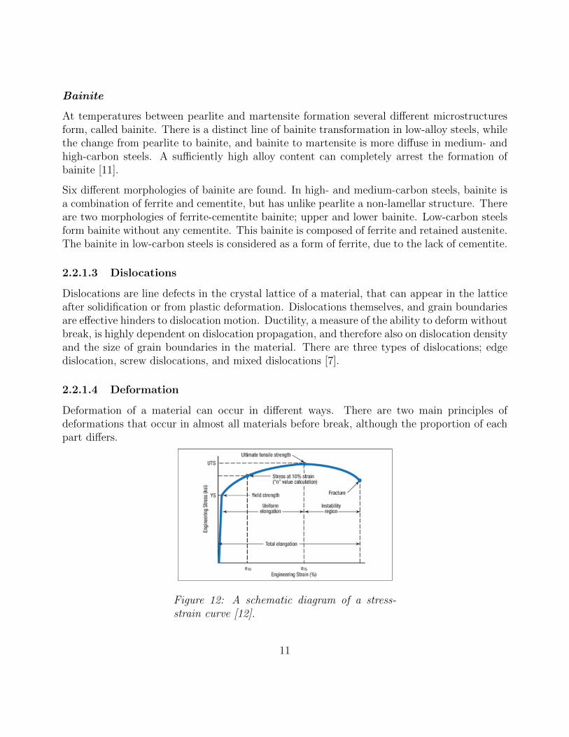
Deformation of a material can occur in different ways. There are two main principles ofdeformations that occur in almost all materials before break, although the proportion of eachpart differs.
Figure 12: A schematic diagram of a stress-strain curve [12].
11

Elastic Deformation The first part of a stress-strain curve (Figure 12) is the elastic part.The elastic deformation shows as the linear fraction of the curve. This type of deformation isnot permanent and will regress when unloading, also called elastic springback. The springbackis the elongation of the material in the elastic area [13].
Plastic deformation A higher load, resulting in a higher stress, makes the deformationtransform from elastic to plastic strain. That happens at the end of the the linear part ofthe curve when the stress reaches the yield stress of the material. The plastic deformationis permanent deformation that will remain even after unloading. There is elastic springbackwhen unloading even when plastic deformation has occured, making it an important propertyto consider in metal forming [13]. The plastic deformation occurs in the non-linear region ofthe stress strain curve between the yield stress and the tensile stress, Figure 12.
Cold working and strain hardening
Figure 13: Rolling of a metal sheet and thechange of grain geometry [7].
The principle of forming a metal by plasticdeformation below its recrystallization tem-perature is called cold work. The rollingprocess in the manufacturing of metal sheetsare one form of cold working. In rolling,the grains gain anisotropic behavior by elon-gation through the rolling process, demon-strated in Figure 13.
The principle of strain hardening is basedon that the number of dislocations is ele-vated during plastic deformation. When theamount of dislocations is at a certain level,they start to interact with each other, pre-venting further motion. Interacting disloca-tions increases the strength, but it also de-creases the ductility [7]. Not all materials can be strain hardened, but metals are one ofthose that can. The criteria of strain hardening is that the material needs to be of crystallinestructure and also non-brittle.
12
Hot forming
Another common way to form steel is by hot forming. Hot forming is when the steel is heated upbefore deformation. The plastic deformation initiates recrystallization which creates equiaxedgrains instead of elongated as in cold working. Hot rolling sheet metal is a substitute torolling in its cold state that produces a softer and more ductile metal sheet that is suitable forsubsequent cold working. One can obtain different grain sizes by controlling the temperatureof the hot rolling [11].
2.2.1.5 Dispersion strengthening
A dispersion-strengthened material consists of a matrix of a relatively soft and ductile phase,and small particles of a harder phase within the matrix. The strengthening effect comes fromthe stopping of dislocation motion that the dispersion soluted particles provide [7].
2.2.1.6 Annealing
Cold working can introduce both wanted and unwanted behavior to the material. Annealingis a heat treatment that is used to remove some or all of those behavior. Annealing can bedone in three different levels.
Recovery
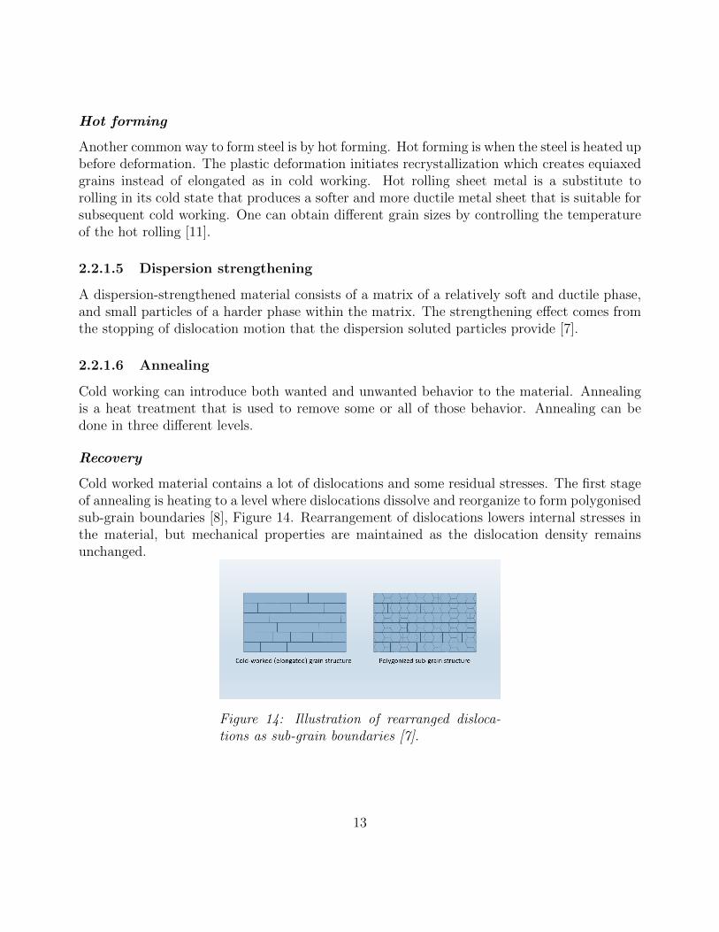
Cold worked material contains a lot of dislocations and some residual stresses. The first stageof annealing is heating to a level where dislocations dissolve and reorganize to form polygonisedsub-grain boundaries [8], Figure 14. Rearrangement of dislocations lowers internal stresses inthe material, but mechanical properties are maintained as the dislocation density remainsunchanged.
Figure 14: Illustration of rearranged disloca-tions as sub-grain boundaries [7].
13
Recrystallization
At a specific temperature, nucleation of new grains is initiated in the sub-grain boundariesformed by the dislocations in the recovery stage, creating a new polygonal grain structure. Thistemperature is called the recrystallization temperature and is dependent on several differentproperties. A high amount of the dislocations is removed giving the material a lower strengthand higher ductility than in the cold worked state [7].
The main things that the temperature of deformation depends on is [14]:
• Temperature and time of annealing
• Degree of cold work in the metal
• Amount of alloying elements in the metal
• Grain size before cold work
• Temperature during the deformation
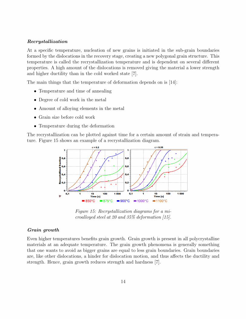
The recrystallization can be plotted against time for a certain amount of strain and tempera-ture. Figure 15 shows an example of a recrystallization diagram.
Figure 15: Recrystallization diagrams for a mi-croalloyed steel at 20 and 35% deformation [15].
Grain growth
Even higher temperatures benefits grain growth. Grain growth is present in all polycrystallinematerials at an adequate temperature. The grain growth phenomena is generally somethingthat one wants to avoid as bigger grains are equal to less grain boundaries. Grain boundariesare, like other dislocations, a hinder for dislocation motion, and thus affects the ductility andstrength. Hence, grain growth reduces strength and hardness [7].
14
2.2.1.7 Normalizing
The heat treatment used to give the steel a fine and uniform structure is called normalizing.In normalizing the steel is heated above the austenitizing temperature, to an even highertemperature than that of annealing. The steel is then cooled in air which consequence inhigher cooling rates than those used in annealing. The structure obtained due to the coolingrate is fine ferrite grains and a small spacing between the lamellas in the pearlite [11].
2.2.2 Welding
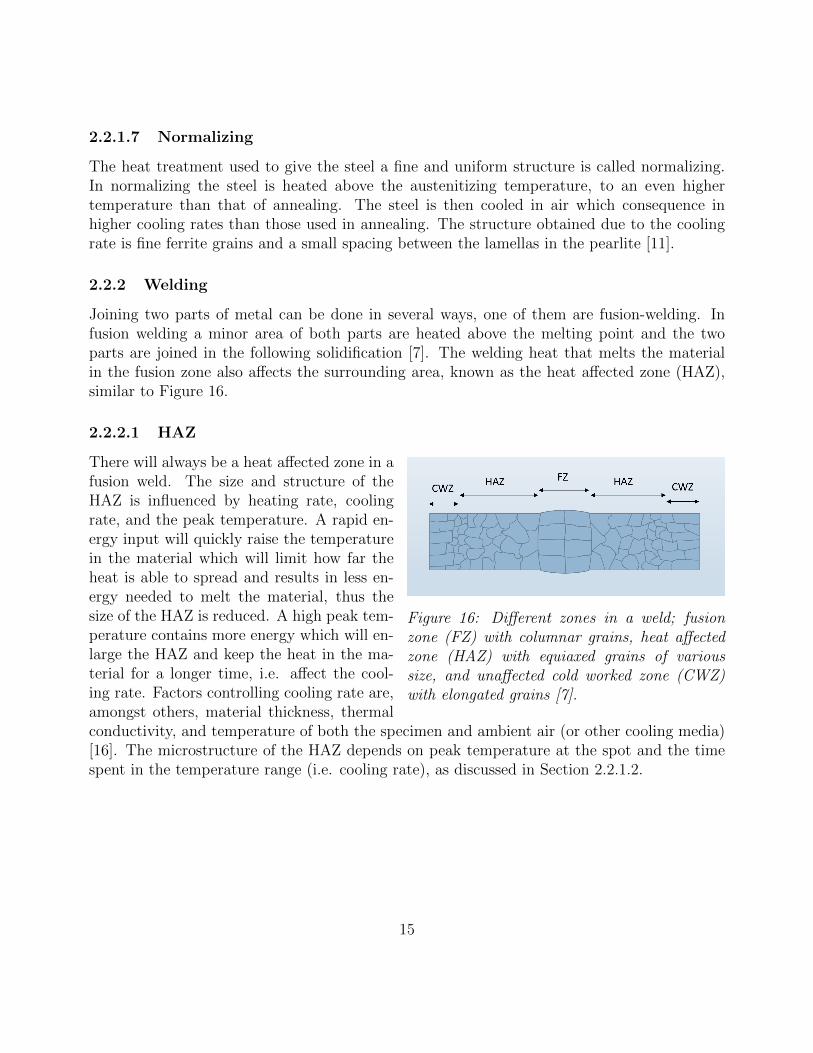
Joining two parts of metal can be done in several ways, one of them are fusion-welding. Infusion welding a minor area of both parts are heated above the melting point and the twoparts are joined in the following solidification [7]. The welding heat that melts the materialin the fusion zone also affects the surrounding area, known as the heat affected zone (HAZ),similar to Figure 16.
2.2.2.1 HAZ
Figure 16: Different zones in a weld; fusionzone (FZ) with columnar grains, heat affectedzone (HAZ) with equiaxed grains of varioussize, and unaffected cold worked zone (CWZ)with elongated grains [7].
There will always be a heat affected zone in afusion weld. The size and structure of theHAZ is influenced by heating rate, coolingrate, and the peak temperature. A rapid en-ergy input will quickly raise the temperaturein the material which will limit how far theheat is able to spread and results in less en-ergy needed to melt the material, thus thesize of the HAZ is reduced. A high peak tem-perature contains more energy which will en-large the HAZ and keep the heat in the ma-terial for a longer time, i.e. affect the cool-ing rate. Factors controlling cooling rate are,amongst others, material thickness, thermalconductivity, and temperature of both the specimen and ambient air (or other cooling media)[16]. The microstructure of the HAZ depends on peak temperature at the spot and the timespent in the temperature range (i.e. cooling rate), as discussed in Section 2.2.1.2.
15
2.2.2.2 Resistance welding
Heat generation in resistance welding comes from two sources of the same origin; current flow.The pieces that will be joined are clamped with electrodes and displaced until contact occursin the weld interface. The resulting current flow induces a joule heating of the two parts, inaddition to the higher temperature in the interface that comes from the electrical resistance inthe interface. Resistance welding is a very heat effective welding method compared to regulargas or arc welding as the welded metal itself is the heating source, and the heating rate istherefore very high [16].
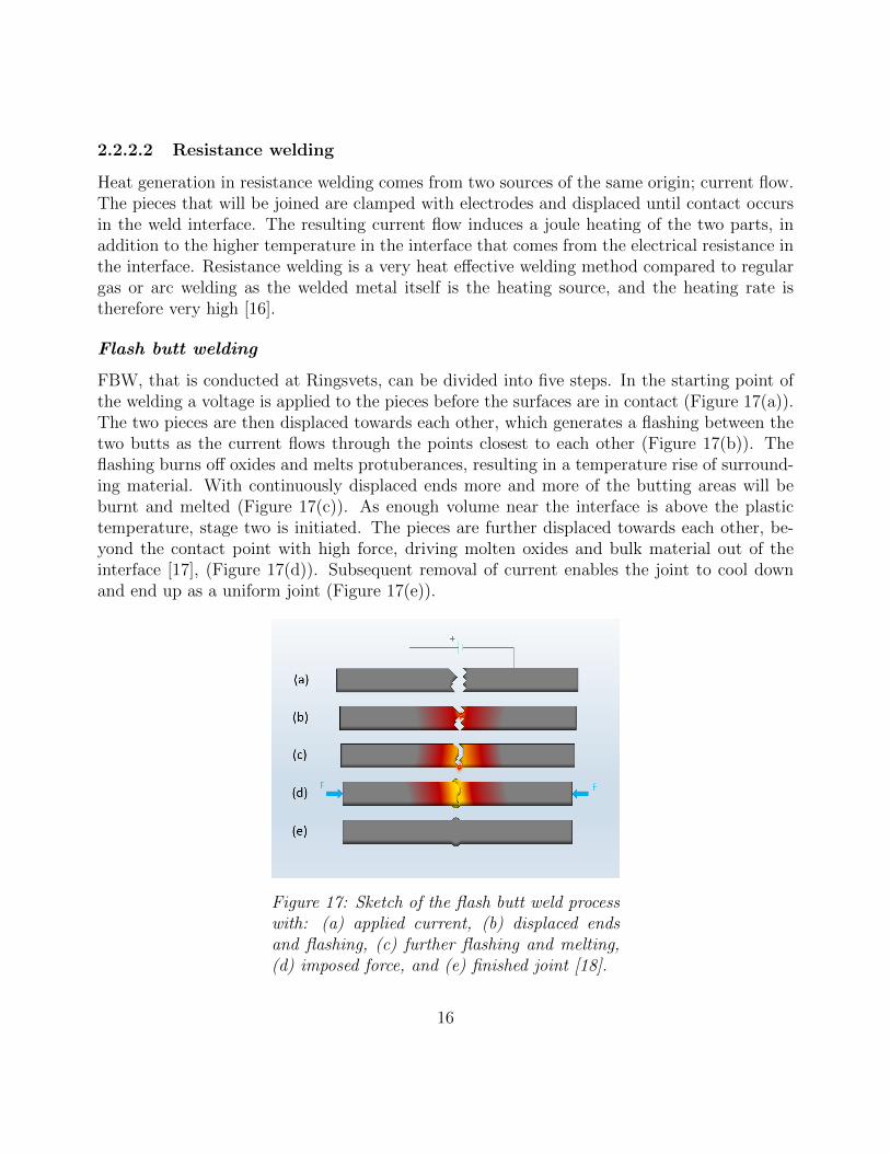
Flash butt welding
FBW, that is conducted at Ringsvets, can be divided into five steps. In the starting point ofthe welding a voltage is applied to the pieces before the surfaces are in contact (Figure 17(a)).The two pieces are then displaced towards each other, which generates a flashing between thetwo butts as the current flows through the points closest to each other (Figure 17(b)). Theflashing burns off oxides and melts protuberances, resulting in a temperature rise of surround-ing material. With continuously displaced ends more and more of the butting areas will beburnt and melted (Figure 17(c)). As enough volume near the interface is above the plastictemperature, stage two is initiated. The pieces are further displaced towards each other, be-yond the contact point with high force, driving molten oxides and bulk material out of theinterface [17], (Figure 17(d)). Subsequent removal of current enables the joint to cool downand end up as a uniform joint (Figure 17(e)).
Figure 17: Sketch of the flash butt weld processwith: (a) applied current, (b) displaced endsand flashing, (c) further flashing and melting,(d) imposed force, and (e) finished joint [18].
16
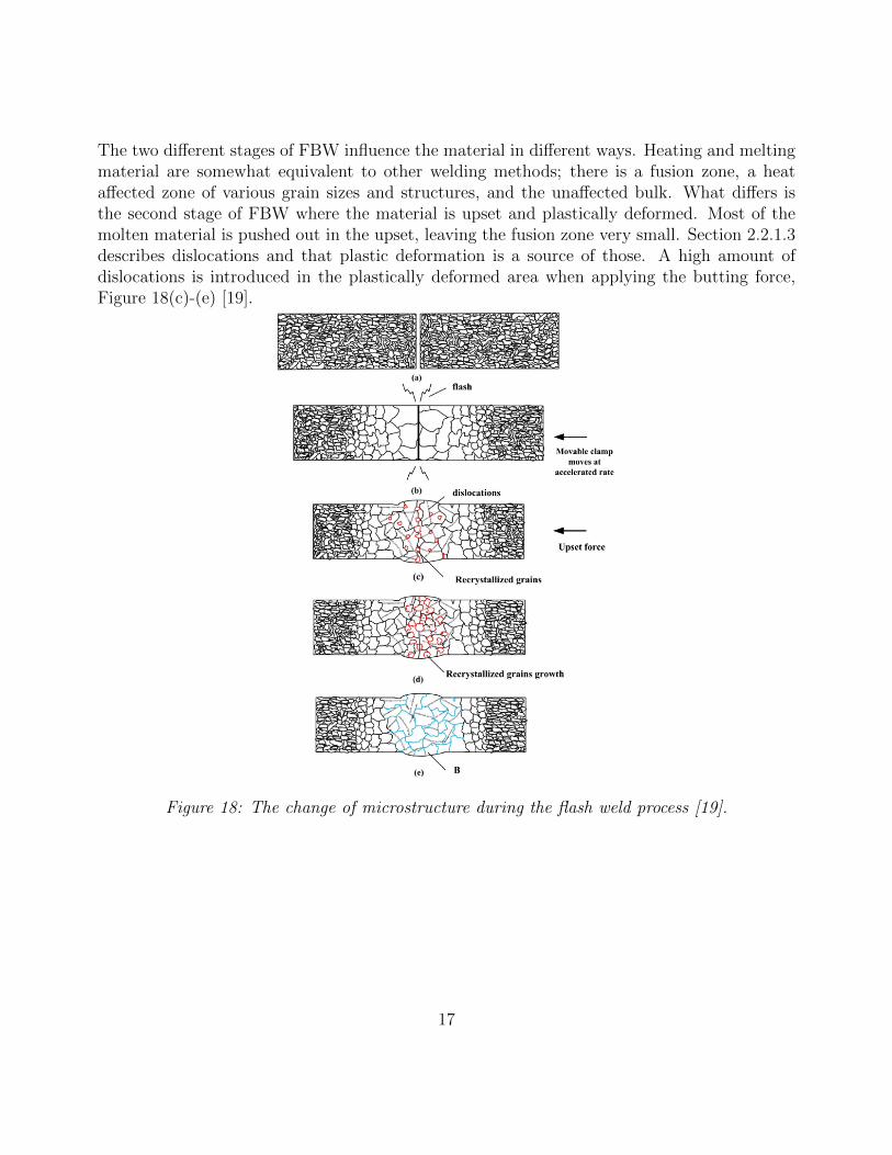
The two different stages of FBW influence the material in different ways. Heating and meltingmaterial are somewhat equivalent to other welding methods; there is a fusion zone, a heataffected zone of various grain sizes and structures, and the unaffected bulk. What differs isthe second stage of FBW where the material is upset and plastically deformed. Most of themolten material is pushed out in the upset, leaving the fusion zone very small. Section 2.2.1.3describes dislocations and that plastic deformation is a source of those. A high amount ofdislocations is introduced in the plastically deformed area when applying the butting force,Figure 18(c)-(e) [19].
Figure 18: The change of microstructure during the flash weld process [19].
17
2.2.3 Induction heating
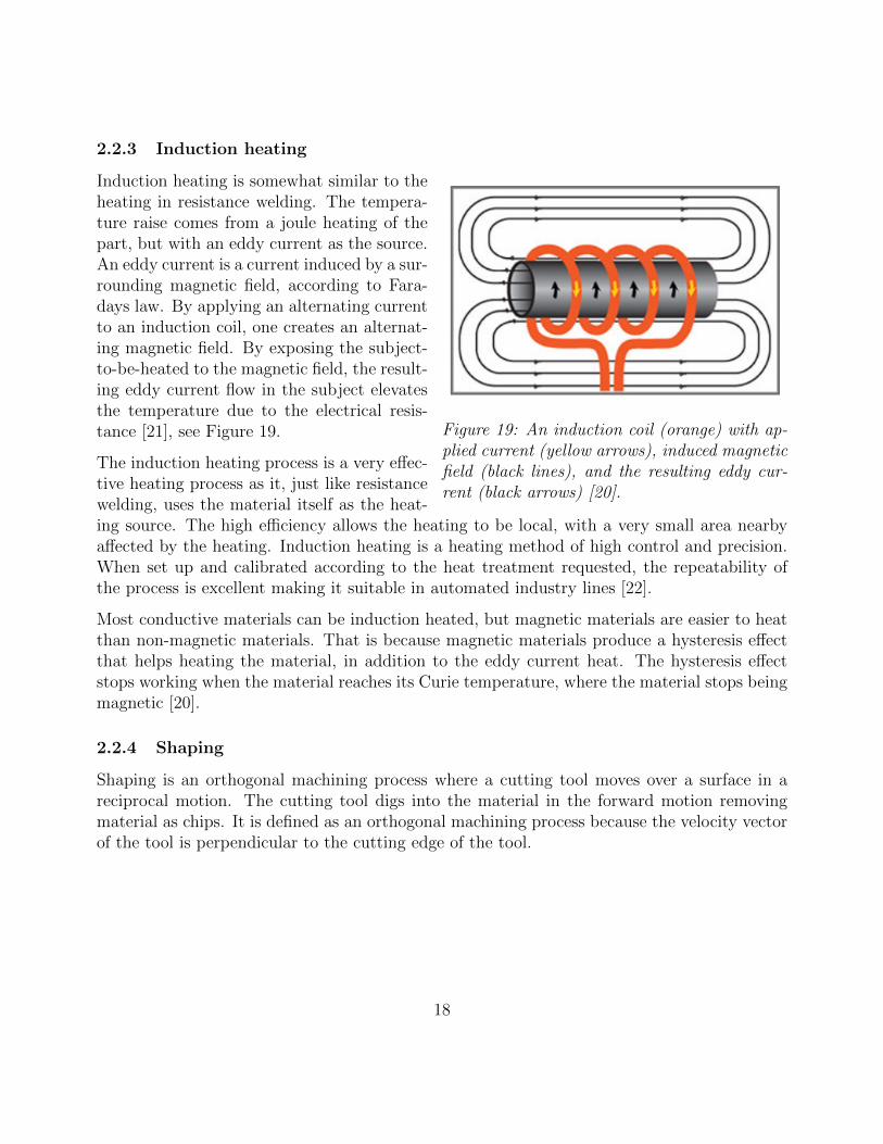
Figure 19: An induction coil (orange) with ap-plied current (yellow arrows), induced magneticfield (black lines), and the resulting eddy cur-rent (black arrows) [20].
Induction heating is somewhat similar to theheating in resistance welding. The tempera-ture raise comes from a joule heating of thepart, but with an eddy current as the source.An eddy current is a current induced by a sur-rounding magnetic field, according to Fara-days law. By applying an alternating currentto an induction coil, one creates an alternat-ing magnetic field. By exposing the subject-to-be-heated to the magnetic field, the result-ing eddy current flow in the subject elevatesthe temperature due to the electrical resis-tance [21], see Figure 19.
The induction heating process is a very effec-tive heating process as it, just like resistancewelding, uses the material itself as the heat-ing source. The high efficiency allows the heating to be local, with a very small area nearbyaffected by the heating. Induction heating is a heating method of high control and precision.When set up and calibrated according to the heat treatment requested, the repeatability ofthe process is excellent making it suitable in automated industry lines [22].
Most conductive materials can be induction heated, but magnetic materials are easier to heatthan non-magnetic materials. That is because magnetic materials produce a hysteresis effectthat helps heating the material, in addition to the eddy current heat. The hysteresis effectstops working when the material reaches its Curie temperature, where the material stops beingmagnetic [20].
2.2.4 Shaping
Shaping is an orthogonal machining process where a cutting tool moves over a surface in areciprocal motion. The cutting tool digs into the material in the forward motion removingmaterial as chips. It is defined as an orthogonal machining process because the velocity vectorof the tool is perpendicular to the cutting edge of the tool.
18
2.2.4.1 Chip formation
Figure 20: Close-up on the chip formation pro-cess [23].
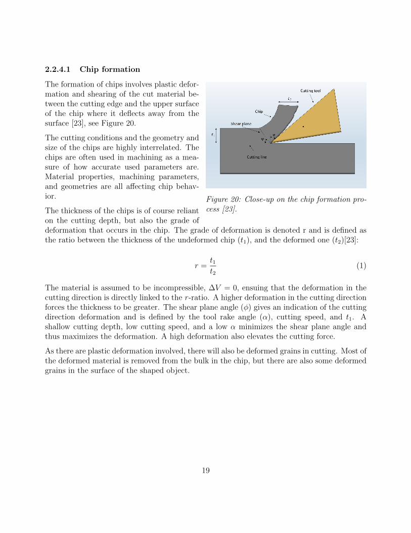
The formation of chips involves plastic defor-mation and shearing of the cut material be-tween the cutting edge and the upper surfaceof the chip where it deflects away from thesurface [23], see Figure 20.
The cutting conditions and the geometry andsize of the chips are highly interrelated. Thechips are often used in machining as a mea-sure of how accurate used parameters are.Material properties, machining parameters,and geometries are all affecting chip behav-ior.
The thickness of the chips is of course relianton the cutting depth, but also the grade ofdeformation that occurs in the chip. The grade of deformation is denoted r and is defined asthe ratio between the thickness of the undeformed chip (t1), and the deformed one (t2)[23]:
r =t1t2
(1)
The material is assumed to be incompressible, ∆V = 0, ensuing that the deformation in thecutting direction is directly linked to the r -ratio. A higher deformation in the cutting directionforces the thickness to be greater. The shear plane angle (φ) gives an indication of the cuttingdirection deformation and is defined by the tool rake angle (α), cutting speed, and t1. Ashallow cutting depth, low cutting speed, and a low α minimizes the shear plane angle andthus maximizes the deformation. A high deformation also elevates the cutting force.
As there are plastic deformation involved, there will also be deformed grains in cutting. Most ofthe deformed material is removed from the bulk in the chip, but there are also some deformedgrains in the surface of the shaped object.
19
2.2.5 Friction and wear
Two surfaces sliding against each other will, inevitably, be subjected to both friction and wear.The underlying mechanism for friction and wear is highly dependent on the basis of the sliding[24].
2.2.5.1 Abrasive wear
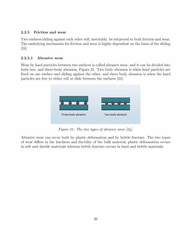
Wear by hard particles between two surfaces is called abrasive wear, and it can be divided intoboth two- and three-body abrasion, Figure 21. Two body abrasion is when hard particles arefixed on one surface and sliding against the other, and three body abrasion is when the hardparticles are free to either roll or slide between the surfaces [24].
Figure 21: The two types of abrasive wear [24].
Abrasive wear can occur both by plastic deformation and by brittle fracture. The two typesof wear differs in the hardness and ductility of the bulk material, plastic deformation occursin soft and ductile materials whereas brittle fracture occurs in hard and brittle materials.
20
3 Method
The method chapter is divided into three parts. One part with the processes in theory, one withthe processes in practice, and the third part were them both are compared.
3.1 Influence of processes in theory
As seen in Section 2.2, the microstructure and mechanical properties of a steel are greatlyaffected by physical circumstances. This section will describe how the rings theoretically willchange due to the operations, with a base in the literature study.
3.1.1 Reference
A hot rolled sheet metal would have polygonal grain structure. The grain size depends ondeformation and hot rolling temperature.
3.1.2 Rolled
The rolled metal sheet probably has a higher hardness than the flat sheet. The hardnessdifference depends on how deformed the sheet is. A thick thickness and a small radius forcesthe deformation on the outer and inner radius to be high, and it is probably at those areaswhere the rolled ring is the hardest. The hardness elevation comes from deformed grains anddislocation density, as stated in Section 2.2.1.4.
3.1.3 Welding
Resistance welding is a welding method of high heating rate resulting in a relatively small HAZ.The weld joint contains of small grains near the unaffected material and bigger grains nearthe interface. There is also a high dislocation density near the interface. The upset materialmakes the thickness non-uniform with a bead of oxide and previously molten material.
3.1.4 Brushing
The brushing operation is done in a temperature above room temperature, where the hardnessand yield strength of the material are lower than in lower temperatures. The metal wires on thebrushes are relatively stiff and hard making the material removal akin to abrasive wear. Theabrasive wear removes material and induces some plastic deformation into the material. Theresult is probably very equal to the previous stage with a small fraction of plastic deformation.The material removal is the most at the sharp edges making the remaining bead smooth again.
21
3.1.5 Forging
The forging operation is straight forward plastic deformation in a cold state, cold working.Elastic springback needs to be considered and compensated for to obtain the correct thickness.The material is deformed in the area of the upset resulting in elongated grains, similar to thosein Figure 13. Assuming that the material is incompressible implies that the volume of thematerial that is deformed and displaced from the thickness will be added to the circumference,and/or the width (axial direction) of the ring. The cold working will, as described in Section2.2.1.4, induce a lot of dislocations to the material in the deformed area.
The result of the forging is a ring with uniform thickness, and a little bit larger circumference.The grains will be similar to those after welding but a bit deformed. The ring will also containa lot of dislocations and some residual stresses.
3.1.6 Heat treatment
Previously performed operations provides a microstructure dissimilar to the base material.The heat treatment would optimally regain the size and geometry of the grains in the rolledcondition, and also present a microstructure of the same kind. Most of these properties canbe obtained with a heating procedure.
The heat treatment would give the ring nearly equal mechanical properties through the wholering. There will be some difference in grain size through the weld zone due to the temperaturegradient. A thoroughly controlled cooling allows the material to be of uniform microstructure.
3.1.6.1 Heating temperature
Heating the ring above the recrystallization temperature will dissolve dislocations and nucleatenew grains. The desired microstructure will be attained with sufficient grain growth, viz, asuitable temperature gradient in an appropriate time. As the material is a very low alloyedsteel there is not much restriction in cooling rate. Air cooling would be sufficient to obtain thedesired ferritic structure.
3.1.7 Calibration
With all operations finished to eliminate the properties induced by previous processes, theresulting ring would be in good enough shape to be called homogeneous in the desired mea-surements. The ring should show a consistent level of average grain size through the wholering with equiaxed grains all through. The microstructure should be equal throughout thesample with some dislocations and residual stresses induced by the last operation.
22
Again, the material is assumed to be incompressible. The change in the circuit of the ring willalso change the thickness of the ring. Attention must be paid so that the thickness ends up inthe interval of what the customer ordered. The strain must also be limited to not exceed theamount possible before break (shear stress below tensile strength).
3.2 Experimentals
Practical tests were executed in the metallurgical laboratory at Karlstad University. Sampleswere collected from various stages in the production at Ringsvets. This section will describethe samples and the analyses along with the results obtained.
3.2.1 Introduction
The theory states that several processes in the making of the rings have a large impact onthe mechanical and metallurgical properties. Material examination is therefore done to see inwhich way the processes affects the material. The hardness of a material is a great way tojudge mechanical properties as it is defined as the resistance to plastic deformation, which isa major property deciding the mechanical behavior of a material [25].
3.2.2 Purpose and goal
The purpose of the examination is to determine how the current processes affects the material,in microstructure and hardness.
The goal is to obtain pictures of the weld area in a large magnification to be able to distinguishthe phase of the microstructure and the grain shape. The grain size should be measured, andhardness measurements should be done to complete the information.
23

3.2.3 Material and Measurements
Figure 22: The measurements of theexamined ring.
The exact material of the rings are classified, as men-tioned in Section 2.1.1, but they are made of a verylow alloyed steel. Ringsvets produces rings in a varietyof dimension. The tested rings had the measurementsof diameter = 352 mm, thickness = 5 mm, and width= 75 mm, illustrated in Figure 22.
3.2.4 Method
Figure 23: The six samples collectedat Ringsvets. From the left; reference,welded, shaped and brushed, forged,heat treated, and calibrated.
Tests were done on samples in the stages of the produc-tion line that influences the microstructure the most,which where concluded to be; welding, forging, andheat treatment. Samples were therefore collected be-fore and after those processes to be able to makea conclusion of the influence of the operations. Asample of a finished ring (after calibration) were alsocollected along with reference samples of as-deliveredsheet metal and ring formed rolled sheet metal. Thesamples can be seen in Figure 23.
An attempt to measure the temperature in each stagewas made. A hand-held IR-thermometer was used inthe effort to get the temperature peak and cooling rateon paper. The thermometer was used simultaneouslywith the line in full production.
Ringsvets believe that some processes are not perfect and produces a differing result throughthe width of the rings (Oholm J, oral communication, januari 25th, 2019). The width wastherefore cut in three places, with a being furthest from the machine, b in the middle, and cclosest to the machine, Figure 24. The samples were hot mounted, looking in the axialdirec-tion of the ring. That is to make them easier to handle, and making them fit the preparationmachine [26], Figure 25. The hot mounted samples were then prepared in a standard metal-lurgical way [27].
24

Figure 24: The samples were sectioned inthree places; a, b, and c.
Figure 25: Eighteen of the hot mountedspecimens.
Table 1: The the samplesand their associated num-bers
No. Sample1. Reference3. Welded4. Shaped and Brushed5. Forged6. Heat Treated7. Calibrated
A unique name was given to each sample, to be able to separatethem from each other. The names have the format of XYZ. X isafter which process the sample is collected (Table 1), Y is whereon the width the cut is made (Figure 24), and Z is if the sampleis taken in the middle of the weld (Z=1), or outside the HAZ(Z=2). The pictures are given a name with an additional Uand V in it, XYZ-U-V. The U denotes the magnification of thepicture, and V is the position in each sample at which the pictureis taken, according to the figures associated to each sample.
Figure 26: The two spots where pictures weretaken in the samples from outside the weld re-gion.
The polished cylinders were etched and putin a microscope. Pictures were taken at sitesof interest, which differed depending on theprevious operation. The locations of the pic-tures are described later.
Samples were collected in and outside theweld zone. Pictures were taken on the outerareas in two spots as shown in Figure 26.
25
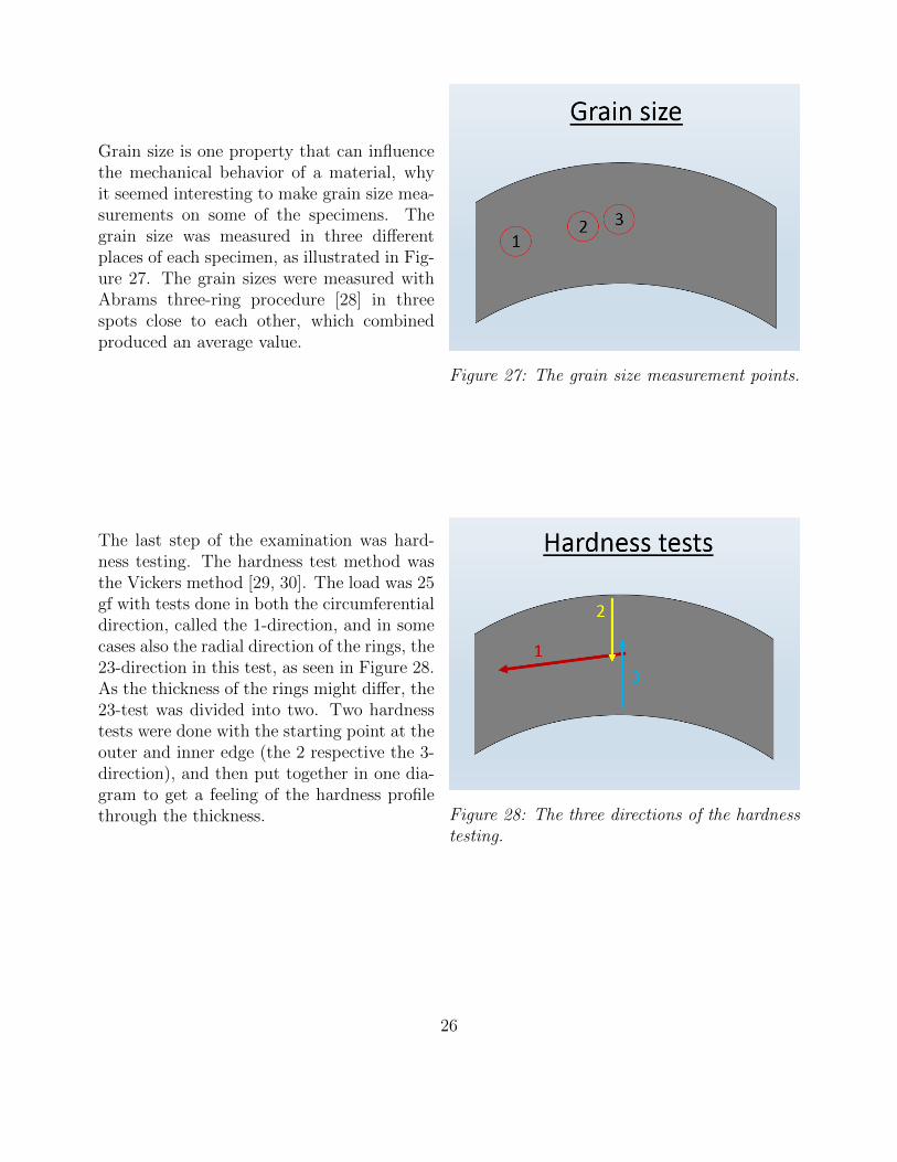
Figure 27: The grain size measurement points.
Grain size is one property that can influencethe mechanical behavior of a material, whyit seemed interesting to make grain size mea-surements on some of the specimens. Thegrain size was measured in three differentplaces of each specimen, as illustrated in Fig-ure 27. The grain sizes were measured withAbrams three-ring procedure [28] in threespots close to each other, which combinedproduced an average value.
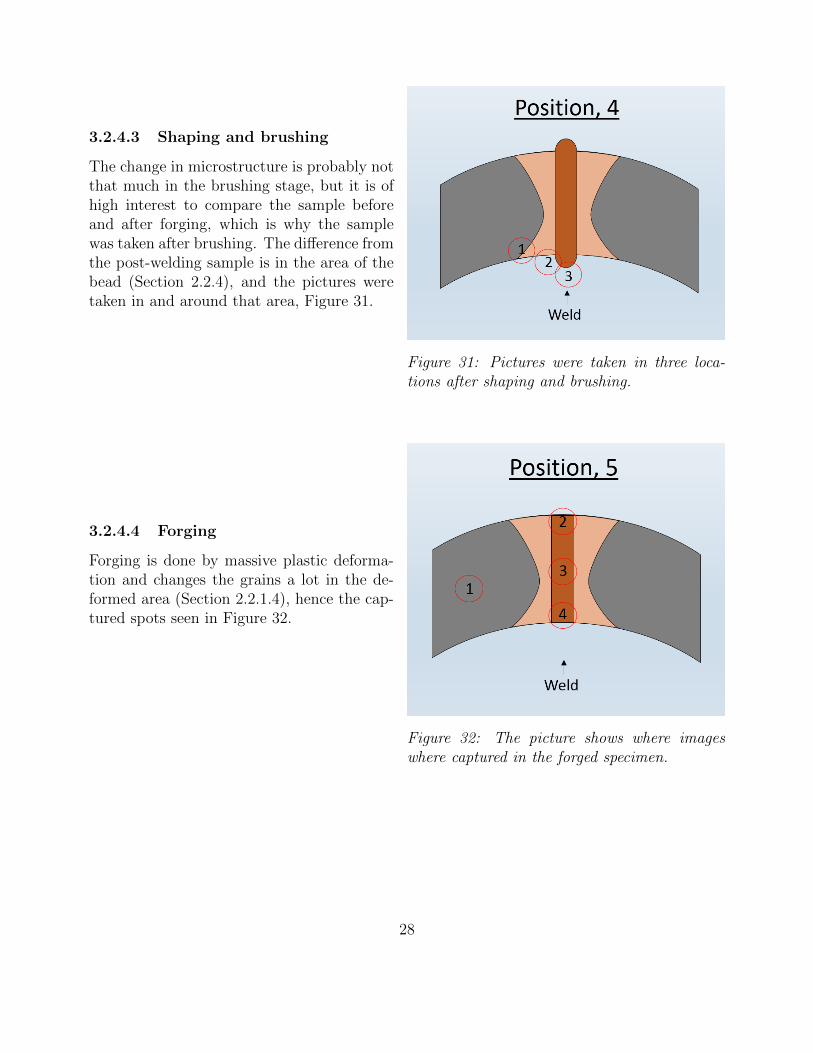
Figure 28: The three directions of the hardnesstesting.
The last step of the examination was hard-ness testing. The hardness test method wasthe Vickers method [29, 30]. The load was 25gf with tests done in both the circumferentialdirection, called the 1-direction, and in somecases also the radial direction of the rings, the23-direction in this test, as seen in Figure 28.As the thickness of the rings might differ, the23-test was divided into two. Two hardnesstests were done with the starting point at theouter and inner edge (the 2 respective the 3-direction), and then put together in one dia-gram to get a feeling of the hardness profilethrough the thickness.
26

3.2.4.1 Reference and rolling
Figure 29: The only spot where pictures weretaken in the reference and rolled sample.
Pictures were taken of the as-delivered sheetmetal and the rolled, but not welded, ring.Pictures of both samples were taken in justone spot as the microstructure is probablyequal through the whole sample as seen inFigure 29.
3.2.4.2 Welding
Figure 30: Points where pictures are taken afterthe welding operation.
In the welded stage the microstructure wouldhave changed due to both heating and de-formation (Section 2.2.2). The number ofspots where the microstructure was examinedis therefore more than in the reference case,as seen in Figure 30.
27
3.2.4.3 Shaping and brushing
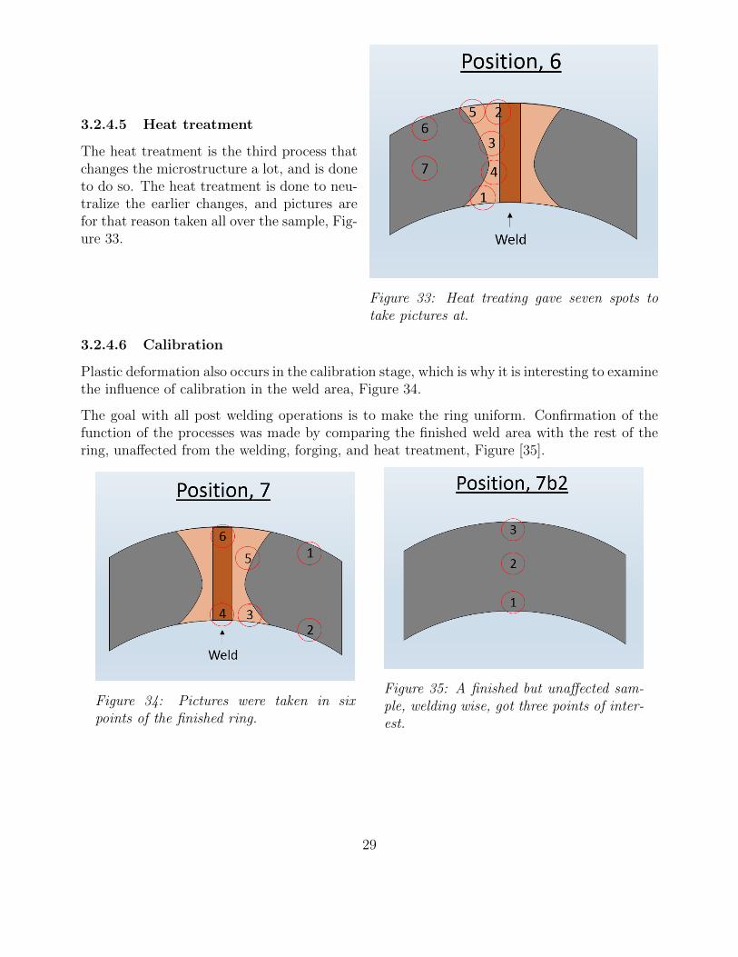
Figure 31: Pictures were taken in three loca-tions after shaping and brushing.
The change in microstructure is probably notthat much in the brushing stage, but it is ofhigh interest to compare the sample beforeand after forging, which is why the samplewas taken after brushing. The difference fromthe post-welding sample is in the area of thebead (Section 2.2.4), and the pictures weretaken in and around that area, Figure 31.
3.2.4.4 Forging
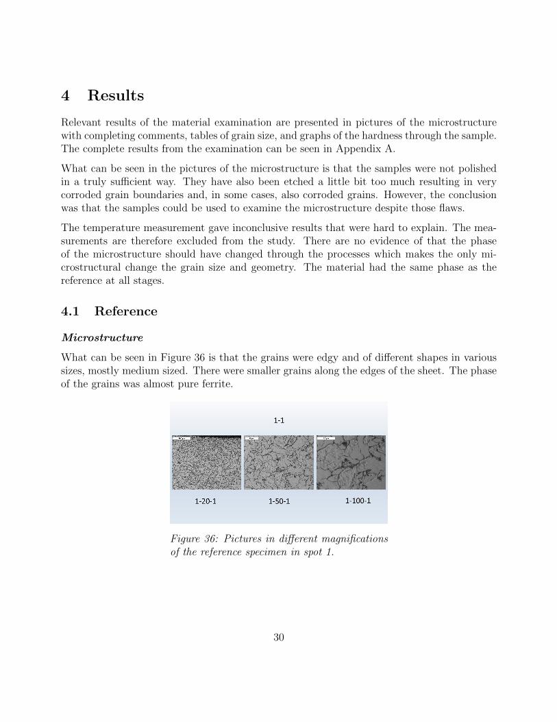
Figure 32: The picture shows where imageswhere captured in the forged specimen.
Forging is done by massive plastic deforma-tion and changes the grains a lot in the de-formed area (Section 2.2.1.4), hence the cap-tured spots seen in Figure 32.
28
3.2.4.5 Heat treatment
Figure 33: Heat treating gave seven spots totake pictures at.
The heat treatment is the third process thatchanges the microstructure a lot, and is doneto do so. The heat treatment is done to neu-tralize the earlier changes, and pictures arefor that reason taken all over the sample, Fig-ure 33.
3.2.4.6 Calibration
Plastic deformation also occurs in the calibration stage, which is why it is interesting to examinethe influence of calibration in the weld area, Figure 34.
The goal with all post welding operations is to make the ring uniform. Confirmation of thefunction of the processes was made by comparing the finished weld area with the rest of thering, unaffected from the welding, forging, and heat treatment, Figure [35].
Figure 34: Pictures were taken in sixpoints of the finished ring.
Figure 35: A finished but unaffected sam-ple, welding wise, got three points of inter-est.
29
4 Results
Relevant results of the material examination are presented in pictures of the microstructurewith completing comments, tables of grain size, and graphs of the hardness through the sample.The complete results from the examination can be seen in Appendix A.
What can be seen in the pictures of the microstructure is that the samples were not polishedin a truly sufficient way. They have also been etched a little bit too much resulting in verycorroded grain boundaries and, in some cases, also corroded grains. However, the conclusionwas that the samples could be used to examine the microstructure despite those flaws.
The temperature measurement gave inconclusive results that were hard to explain. The mea-surements are therefore excluded from the study. There are no evidence of that the phaseof the microstructure should have changed through the processes which makes the only mi-crostructural change the grain size and geometry. The material had the same phase as thereference at all stages.
4.1 Reference
Microstructure
What can be seen in Figure 36 is that the grains were edgy and of different shapes in varioussizes, mostly medium sized. There were smaller grains along the edges of the sheet. The phaseof the grains was almost pure ferrite.
Figure 36: Pictures in different magnificationsof the reference specimen in spot 1.
30
Hardness
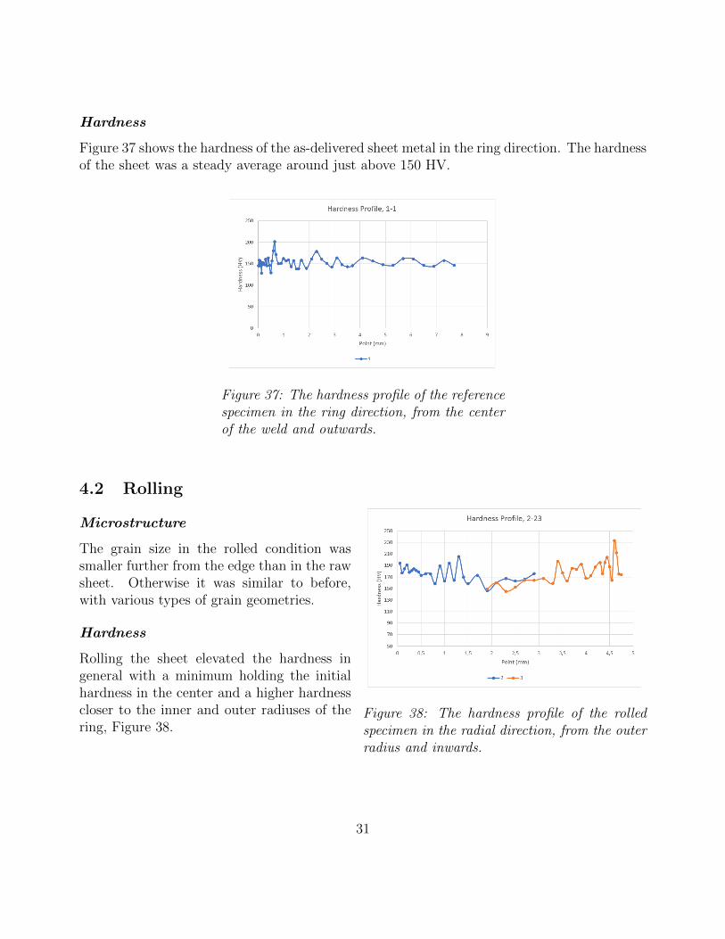
Figure 37 shows the hardness of the as-delivered sheet metal in the ring direction. The hardnessof the sheet was a steady average around just above 150 HV.
Figure 37: The hardness profile of the referencespecimen in the ring direction, from the centerof the weld and outwards.
4.2 Rolling
Figure 38: The hardness profile of the rolledspecimen in the radial direction, from the outerradius and inwards.
Microstructure
The grain size in the rolled condition wassmaller further from the edge than in the rawsheet. Otherwise it was similar to before,with various types of grain geometries.
Hardness
Rolling the sheet elevated the hardness ingeneral with a minimum holding the initialhardness in the center and a higher hardnesscloser to the inner and outer radiuses of thering, Figure 38.
31

4.3 Welding
Microstructure
There were similar grains to the reference in both position 1 and 2 after welding, althougha little bit smaller grains in position 2. Position 1 after forging and position 7 after heattreatment did also have the same microstructure, which is why the images are not included inthe report.
In Figure 39 one can see that the grains in position 3 were of very mixed geometry with smallerand bigger grains in both equiaxed and more random conditions.
Figure 39: Pictures in different magnificationsof the welded specimen in spot 3.
The grains in the bead were even more irregular and needle like. Both in the upper and in thelower bead, Figure 40 and 41.
Figure 40: Pictures in different magnifica-tions of the reference welded in spot 4.
Figure 41: Pictures in different magnifica-tions of the welded specimen in spot 5.
32
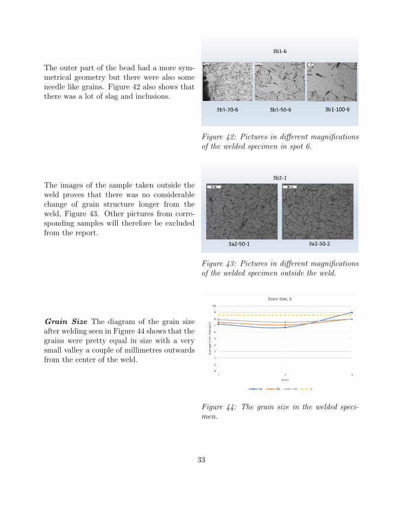
Figure 42: Pictures in different magnificationsof the welded specimen in spot 6.
The outer part of the bead had a more sym-metrical geometry but there were also someneedle like grains. Figure 42 also shows thatthere was a lot of slag and inclusions.
Figure 43: Pictures in different magnificationsof the welded specimen outside the weld.
The images of the sample taken outside theweld proves that there was no considerablechange of grain structure longer from theweld, Figure 43. Other pictures from corre-sponding samples will therefore be excludedfrom the report.
Figure 44: The grain size in the welded speci-men.
Grain Size The diagram of the grain sizeafter welding seen in Figure 44 shows that thegrains were pretty equal in size with a verysmall valley a couple of millimetres outwardsfrom the center of the weld.
33
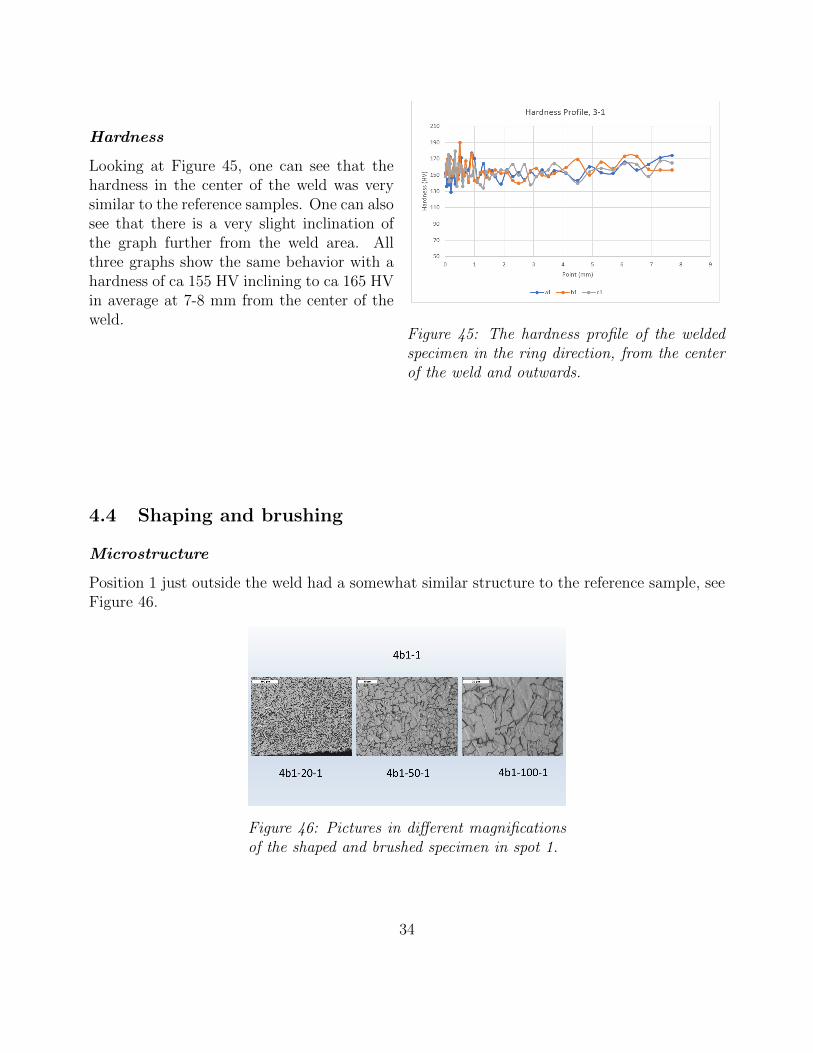
Figure 45: The hardness profile of the weldedspecimen in the ring direction, from the centerof the weld and outwards.
Hardness
Looking at Figure 45, one can see that thehardness in the center of the weld was verysimilar to the reference samples. One can alsosee that there is a very slight inclination ofthe graph further from the weld area. Allthree graphs show the same behavior with ahardness of ca 155 HV inclining to ca 165 HVin average at 7-8 mm from the center of theweld.
4.4 Shaping and brushing
Microstructure
Position 1 just outside the weld had a somewhat similar structure to the reference sample, seeFigure 46.
Figure 46: Pictures in different magnificationsof the shaped and brushed specimen in spot 1.
34

At the edge of the remaining bead there was the same geometry of the grains, but they were,as one can see in Figure 47, a little bit bigger.
At the peak of the bead there were grains that are quite deformed. Oblong and needle likegrains were present near the edge, Figure 48
Figure 47: Pictures in different magnifica-tions of the shaped and brushed specimenin spot 2.
Figure 48: Pictures in different magnifica-tions of the shaped and brushed specimenin spot 3.
Hardness
Shaping and brushing the weld appears to have risen the hardness near the center making theaverage hardness very static at just below 170 HV, aside a very small minimum at just over 2mm from the center. All three samples had the same behavior, which can be seen in Figure49.
Figure 49: The hardness profile of the shapedand brushed specimen in the ring direction,from the center of the weld and outwards.
35

4.5 Forging
Figure 50: Pictures in different magnifica-tions of the forged specimen in spot 2.
Microstructure
The forging produced deformed grainsthrough the whole thickness. The grains inthe center (Figure 51) were deformed moresevere than those on the outer (Figure 50)and inner radius (Figure 52).
Figure 51: Pictures in different magnifica-tions of the forged specimen in spot 3.
Figure 52: Pictures in different magnifica-tions of the forged specimen in spot 4.
Grain Size
The forging made a big impact in the appearance of the grains. As seen in Figure 53, the grainswere small in the center with slightly bigger grains some distance from the center. There areambiguous results further from the center. Two of the graphs shows a decrease in grain sizewhile the third one shows an increase in grain size.
The forging made a big impact in the appearance of the grains. As seen in Figure 53, the grainswere small in the center with slightly bigger grains some distance from the center. There areambiguous results further from the center. Two of the graphs shows a decrease in grain sizewhile the third one shows an increase in grain size.
36
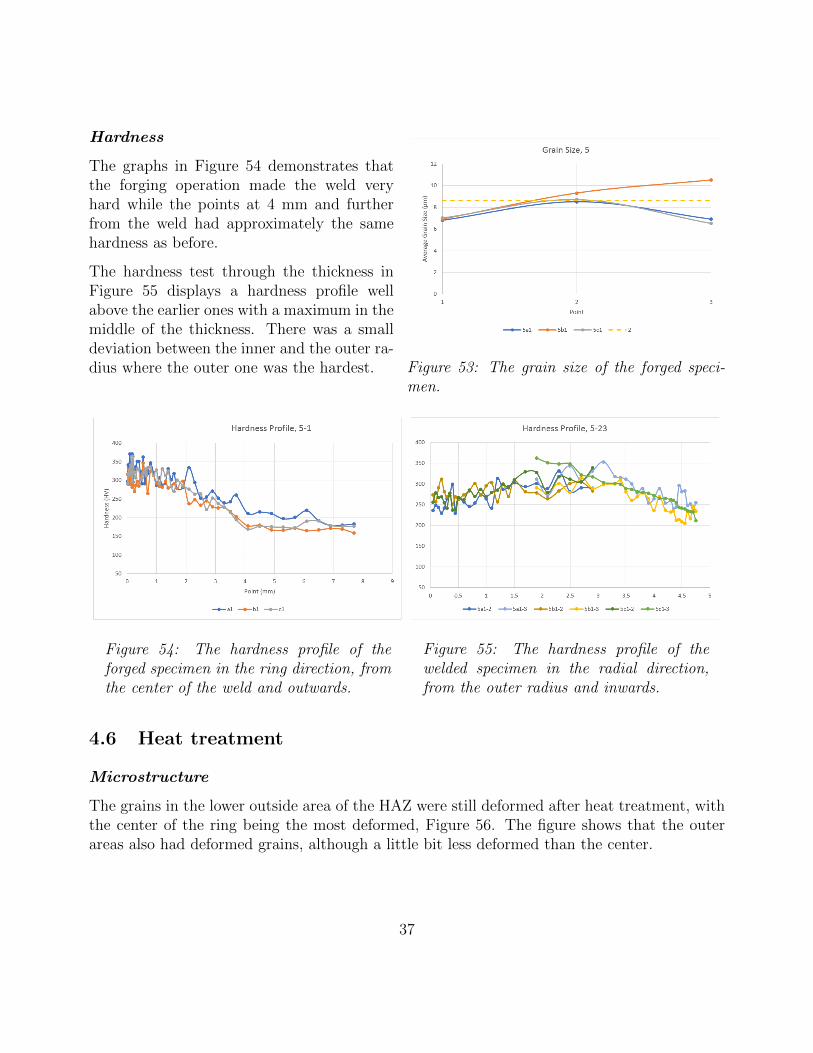
Figure 53: The grain size of the forged speci-men.
Hardness
The graphs in Figure 54 demonstrates thatthe forging operation made the weld veryhard while the points at 4 mm and furtherfrom the weld had approximately the samehardness as before.
The hardness test through the thickness inFigure 55 displays a hardness profile wellabove the earlier ones with a maximum in themiddle of the thickness. There was a smalldeviation between the inner and the outer ra-dius where the outer one was the hardest.
Figure 54: The hardness profile of theforged specimen in the ring direction, fromthe center of the weld and outwards.
Figure 55: The hardness profile of thewelded specimen in the radial direction,from the outer radius and inwards.
4.6 Heat treatment
Microstructure
The grains in the lower outside area of the HAZ were still deformed after heat treatment, withthe center of the ring being the most deformed, Figure 56. The figure shows that the outerareas also had deformed grains, although a little bit less deformed than the center.
37
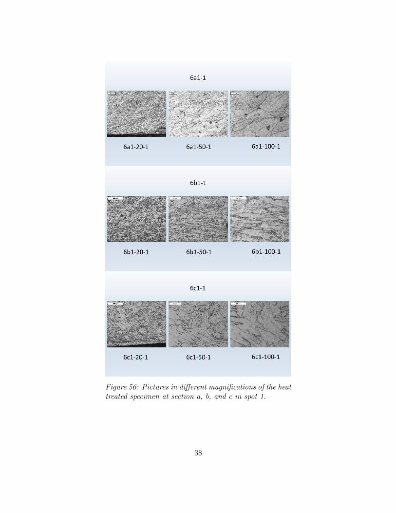
Figure 56: Pictures in different magnifications of the heattreated specimen at section a, b, and c in spot 1.
38
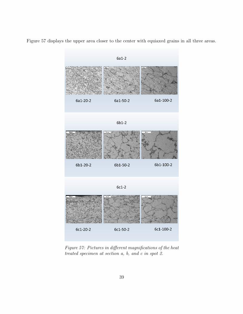
Figure 57 displays the upper area closer to the center with equiaxed grains in all three areas.
Figure 57: Pictures in different magnifications of the heattreated specimen at section a, b, and c in spot 2.
39
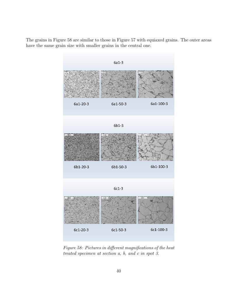
The grains in Figure 58 are similar to those in Figure 57 with equiaxed grains. The outer areashave the same grain size with smaller grains in the central one.
Figure 58: Pictures in different magnifications of the heattreated specimen at section a, b, and c in spot 3.
40
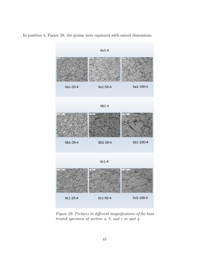
In position 4, Figure 59, the grains were equiaxed with mixed dimensions.
Figure 59: Pictures in different magnifications of the heattreated specimen at section a, b, and c in spot 4.
41
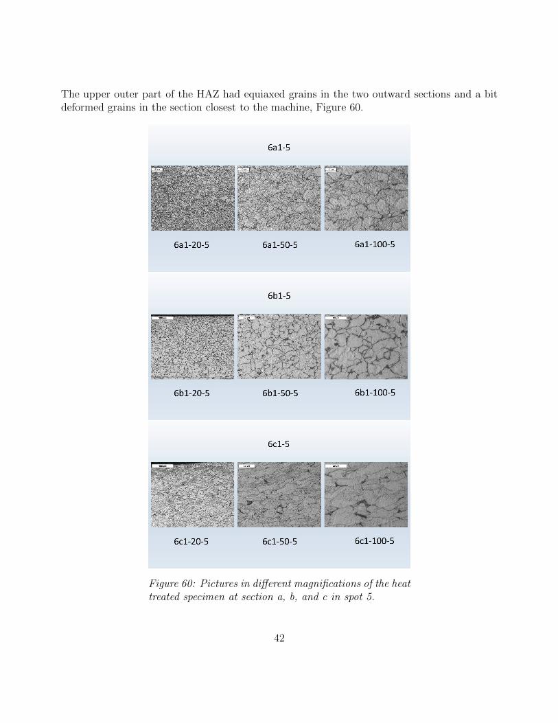
The upper outer part of the HAZ had equiaxed grains in the two outward sections and a bitdeformed grains in the section closest to the machine, Figure 60.
Figure 60: Pictures in different magnifications of the heattreated specimen at section a, b, and c in spot 5.
42
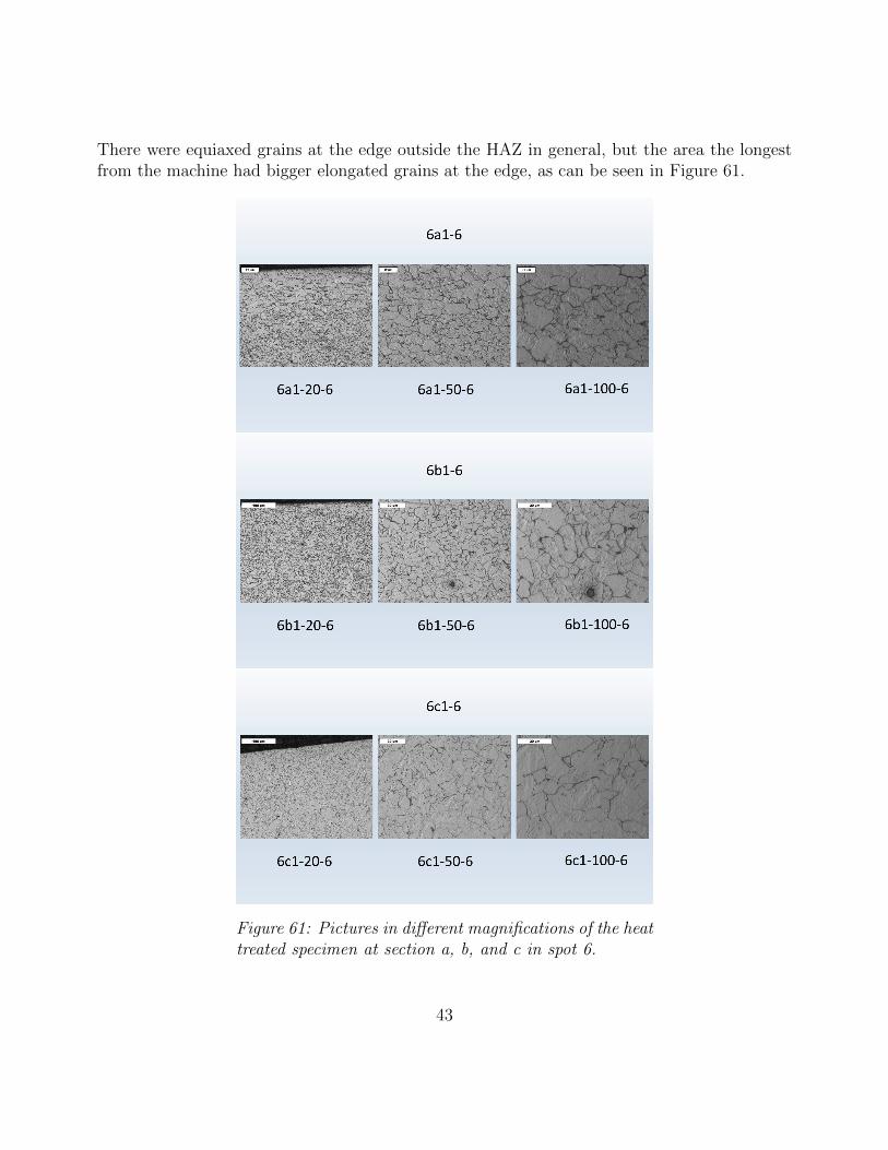
There were equiaxed grains at the edge outside the HAZ in general, but the area the longestfrom the machine had bigger elongated grains at the edge, as can be seen in Figure 61.
Figure 61: Pictures in different magnifications of the heattreated specimen at section a, b, and c in spot 6.
43

Hardness The heat treatment affected the grains in the way such that there were biggergrains found in the center of the weld with smaller grains further from the center, Figure 62.
Figure 62: The grain size in the heat treatedspecimen.
Hardness
The heat treatment lowered the hardness to the same level as the reference sample, from thecenter to about 2 mm outwards. Further from the center showed the same behavior as in theforging stage, as seen in Figure 63.
44

Figure 63: The hardness profile of the heattreated weld area in the ring direction, from thecenter of the weld and outwards.
There was not a completely equal hardness through the thickness after the heat treatment, atleast not in the center of the thickness. Figure 64 shows that the edges were harder than themiddle with the inner radius the hardest of the two.
Figure 64: The hardness profile of the heattreated specimen in the radial direction, fromthe outer radius and inwards.
45
4.7 Calibration
Figure 65: Pictures in different magnifications of the fin-ished ring at section a, b, and c in spot 1.
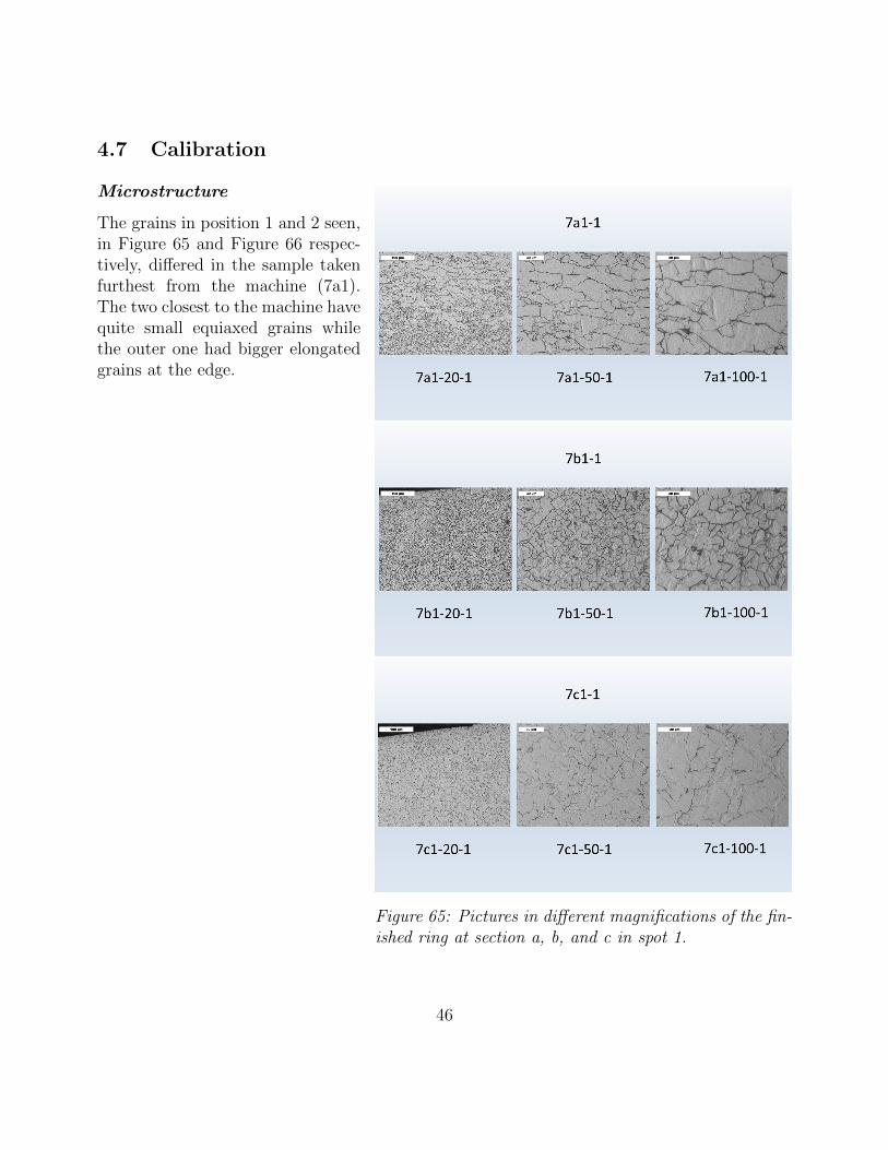
Microstructure
The grains in position 1 and 2 seen,in Figure 65 and Figure 66 respec-tively, differed in the sample takenfurthest from the machine (7a1).The two closest to the machine havequite small equiaxed grains whilethe outer one had bigger elongatedgrains at the edge.
46
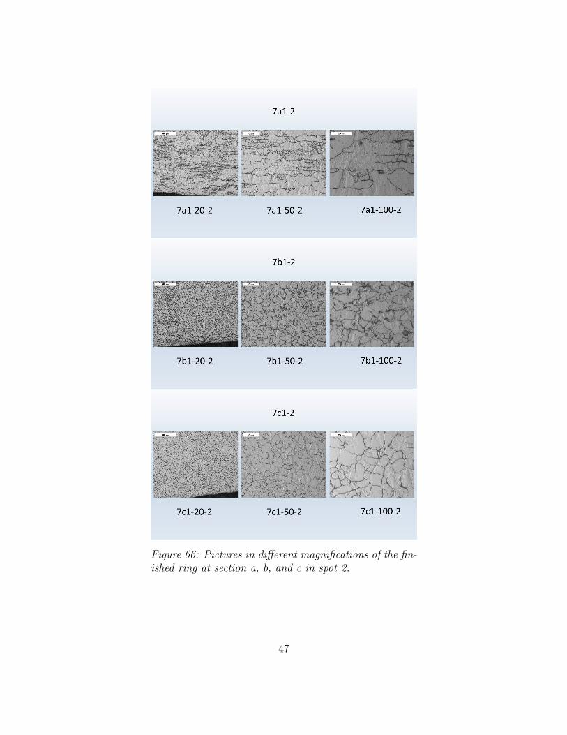
Figure 66: Pictures in different magnifications of the fin-ished ring at section a, b, and c in spot 2.
47
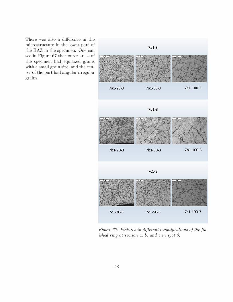
Figure 67: Pictures in different magnifications of the fin-ished ring at section a, b, and c in spot 3.
There was also a difference in themicrostructure in the lower part ofthe HAZ in the specimen. One cansee in Figure 67 that outer areas ofthe specimen had equiaxed grainswith a small grain size, and the cen-ter of the part had angular irregulargrains.
48
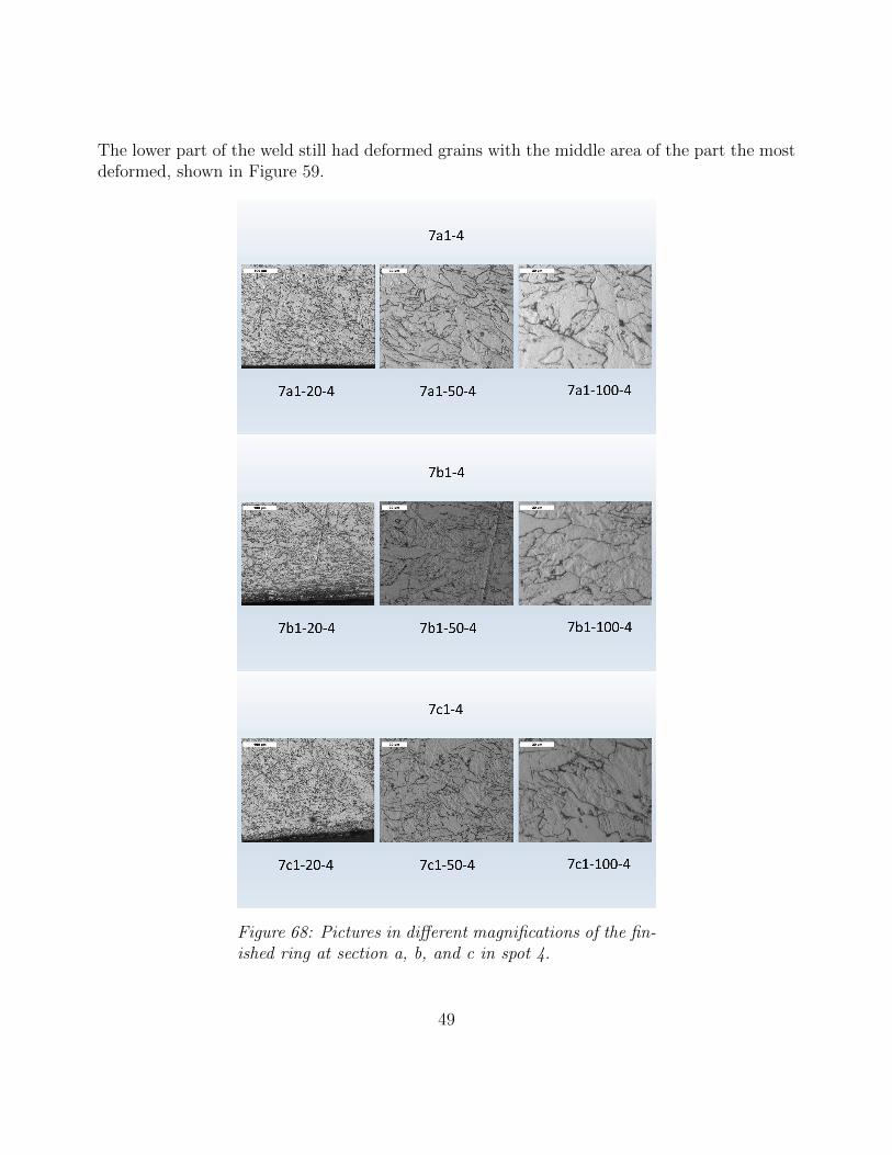
The lower part of the weld still had deformed grains with the middle area of the part the mostdeformed, shown in Figure 59.
Figure 68: Pictures in different magnifications of the fin-ished ring at section a, b, and c in spot 4.
49
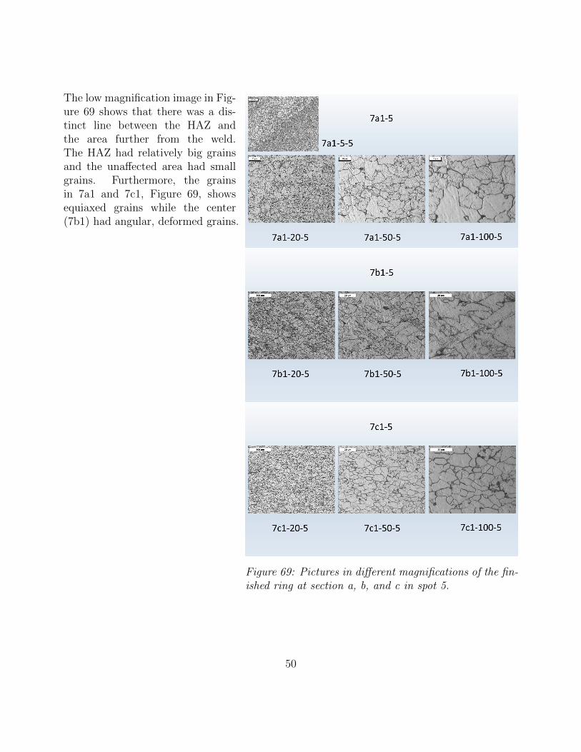
Figure 69: Pictures in different magnifications of the fin-ished ring at section a, b, and c in spot 5.
The low magnification image in Fig-ure 69 shows that there was a dis-tinct line between the HAZ andthe area further from the weld.The HAZ had relatively big grainsand the unaffected area had smallgrains. Furthermore, the grainsin 7a1 and 7c1, Figure 69, showsequiaxed grains while the center(7b1) had angular, deformed grains.
50
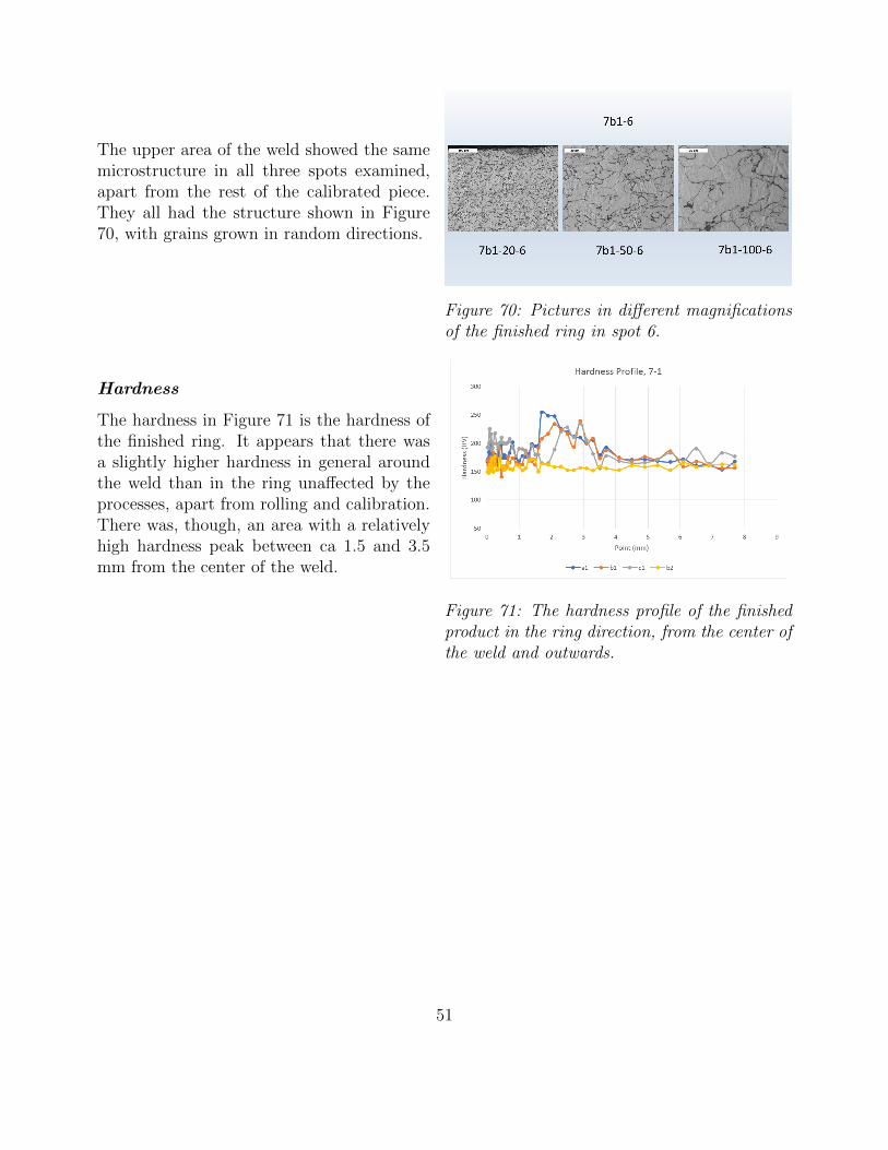
Figure 70: Pictures in different magnificationsof the finished ring in spot 6.
The upper area of the weld showed the samemicrostructure in all three spots examined,apart from the rest of the calibrated piece.They all had the structure shown in Figure70, with grains grown in random directions.
Hardness
Figure 71: The hardness profile of the finishedproduct in the ring direction, from the center ofthe weld and outwards.
The hardness in Figure 71 is the hardness ofthe finished ring. It appears that there wasa slightly higher hardness in general aroundthe weld than in the ring unaffected by theprocesses, apart from rolling and calibration.There was, though, an area with a relativelyhigh hardness peak between ca 1.5 and 3.5mm from the center of the weld.
51
5 Discussion
In all practical tests and measurements there is an uncertainty of how accurate the results are.The testing done in this work is no exception. The normal thing to do in practical testing isto do many equal tests, and from that take an average value that represents the population.This work is time limited and such many tests could not be made. This examination is doneon only one sample per process, one can therefore not be sure that the results are significantto all the manufactured rings. Though, the idea in an automated production line is that allproduced products should be in the same condition, making it a reasonable assumption thatthe results are somewhat representative in this case.
One thing that can confirm the results of this test is the test that was made earlier at Ringsvets.The results in that test were not completely equal, but very similar to the results obtained inthis work. The microstructure seems to be very alike, but the hardness differs. The reasonwhy there is some difference may be the geometry of the rings, which is not specified inthe examination done before. It might also be a difference in external conditions that altersthe result. One difference that most likely changes the outcome is how the examination isperformed, and that is confirmed to differ between the earlier and the present examination.
5.1 Microstructure and preparation
The margin of error in the captured images are mostly human errors. The pictures are meantto be taken at the same point in all corresponding samples. As the spots are chosen by theperson taking the pictures, they can be a bit off between the different specimens, and thus,making it impossible to compare if they are not taken in the same area.
There is not much wrong one can do in the cutting and hot mounting, except from enabling theheat getting too high and alter the microstructure. The polishing, however, is a critical partof the preparation where it is very important to use the correct method and equipment. If theabrasives are used with a too big grit difference, or not polished for a sufficiently long time, thescratches from the previous stage might not be eliminated. Similarly, if the equipment is notcleaned enough between each stage, abrasive particles can be left on the surface and scratchit in later stages. The scratches would then be too severe for the later stages to eliminate andthe result would thereby be of deficient quality.
Etching the sample is also a stage where a good result can be ruined. By inadequate etching ofthe sample the microscope might not be showing what is wanted. By etching the sample toomuch one can destroy the surface resulting in, like inadequate etching, inexplicit indications.
52
In Abrams method of grain size measuring one marks all spots where a ring cuts through agrain boundary. As that method involves the perception of what is a grain boundary, themeasurement error can be severe. One should therefore be a little bit restrictive with howmuch one thrusts the results. The measurements are taken in three spots creating an averageto reduce the error, but there is always a possibility that the value is incorrect.
5.2 Hardness tests
When doing a microhardness test the diamond tip can hit grains and inclusions with harder orsofter structure. The hardness can therefore, as seen in the results, vary a lot between spotsclose to each other. One can therefore not depend on one single spot to evaluate the hardness.The trend will, however, be pretty accurate to the actual hardness when doing a hardnessprofile, as done in this case.
The method of Vickers hardness testing involves a person in the work of measuring the hard-ness. That means that the person doing the tests plays a big role in the result of the measure-ment. Different people have different perceptions of where the edges of the indent are whichcan make the measurement differ on the same sample. The measurements in this work aredone by the same person, minimizing the fault of perception. The exact value might not be,or is most likely not, completely accurate, but the possible fault is the same in all tests (asequal as it can be, considered the human error).
A problem related to the human error is that the samples where etched when the hardnesstests were executed. The consequence of that can be that the outlines of the indentation mightbe hard to distinguish from grain boundaries and other irregularities.
Apart from the human error there is also a possible source of error in the machine. Thehardness value can deviate from reality if the machine is broken or calibrated incorrectly.
Even if the test was perfect, one cannot be sure to have the correct result as there is some roomfor error in the compilation of data. The tests are done with an old computer without USBports and internet connection. The results are in this case transferred from the test computerto another computer via a floppy disc. The data can then be transferred to, for example, aUSB memory before it is compiled on a third computer. Another consequence of using an oldcomputer is that the result file is not compatible with any program available in the computerused to compile the data. The results are therefore manually transferred from the result fileto a program in which graphs can be made. It would not be a too big surprise if a couple ofvalues has been mixed up somewhere on the way.
53
The hardness tests were only performed in one line, although zigzagged. One cannot be com-pletely sure that the profile obtained represents the whole sample. There is also a possibilitythat the starting point of the tests done in the 1-direction is not starting in the center of theweld. The starting point is set by ocular inspection of the weld area. It might consequentlybe either beyond the center or short of the center. Similarly, the thickness measurements aredone from two directions and the intersection of the two are just approximated. The resultsrepresent, despite the inaccuracy, the trend of the hardness in both cases.
5.3 Evaluation of processes
The outcomes from the literature study, Section 3.1, and the practical testing, Section 3.2, werecompared with each other so that a conclusion of how well current processes operates.
5.3.1 Reference and rolling
Both the raw sheet and the rolled one showed equiaxed grains as expected. The hardness wassimilar between the two, the rolled one with a harder surface than the bulk. That would comefrom the hot rolling process creating small grains at the surface. The phase of them both weremainly ferrite with some pearlite in grain boundaries.
5.3.2 Welding
There was not much difference in neither the grains nor the hardness after the welding stage.The hardness profile had a small inclination further from the center which implicated thatthere was a change in either structure or dislocation density.
The theory of welding predicted that there would be columnar grains in the FZ and equiaxedgrains of different sizes in a gradient with distance from the FZ. On the other hand, the theoryspecifically oriented to FBW means that there was a very small HAZ with all molten materialpushed to the bead. The small HAZ could then be cooled in an equal rate giving it almost thesame structure all through.
The phase of the structure was the same as before, ferrite with some pearlite. The compositionof the material used in this test were almost without alloying elements. The low alloying contentmakes it easier to obtain ferrite, the cooling rate needed to obtain martensite would be veryhigh.
54
5.3.3 Shaping and brushing
The hardness after shaping and brushing was a notch higher than before due to the imposedstress and dislocations. The shape of the hardness profile is back to the same as before thewelding. The only difference in grain structure was deformed grains at the surface of the bead,originating mostly from the shaping.
5.3.4 Forging
The forging was the first operation that really changed the behavior of the material. Thegrains were heavily deformed, and the dislocation density was high. The resulting hardnesswas a lot higher than before in the affected area, while the undeformed area kept its earlierhardness. This result is exactly what was expected from the forging operation.
5.3.5 Heat treatment
The goal with the heat treatment is to dissolve dislocations and recrystallize deformed grainsto create a polygonal grain structure. This is not what was done in the current operation, asthere were areas where the deformed grains have not recrystallized completely. The resultswas a recrystallized area in the middle, lowering the hardness to a value similar to unaffectedmaterial. There was, though, an area further from the center that still had deformed grainswhich gives a higher hardness than desired.
5.3.6 Calibration
The grain structure had not changed since the heat treatment but there was a small elevationof hardness. The change would probably come from induced dislocations in the process, whichwas plastic deformation by strain. There was a slightly higher hardness raise in the weldzone where the temperature still was a little bit higher from the heat treatment during thecalibration operation. The higher temperature lowered the yield strength and allowed moredeformation than the colder areas.
55
5.4 Summary
The product of the analysis can either match the expectation or be completely different. Thediscussion part of this report is where circumstances meet theory from where a conclusion ofthe outcome can be made.
Most of the processes alters the behavior of the rings in a way that one would expect. Thereare two operations that affect the material in a way that was not expected without a deeperknowledge of both the material and the processes prior the examination; welding and heattreatment.
Generally, a welding procedure would change the microstructure to be very different throughthe weld area. FBW, though, is not a welding method like others. In FBW, most of themolten material is pushed out of the bulk making the temperature and phase of the remainingmaterial very alike. In addition, the composition of the steel used in this test is very stableand produces the same structure in a very wide interval of cooling rates. Lastly, the geometryof the rings examined are relatively thin which promotes a faster and more regular coolingthrough the ring. The result is a material with a microstructure similar to the microstructurebefore welding, and a hardness that is comparable to the previous one.
Both shaping, brushing and forging affect the structure in a way that can be expected. Withthe welding process being less disturbing to the mechanical properties, the only operationmaking a huge impact on the mechanical behavior becomes the forging. The grains are verydeformed after the forging and the dislocation density are also a lot higher than before. Theresult is a hardness that is very high in the deformed area. The hardness diagram shows thatthere is a quite small area where the hardness is very high, which then descends to the sameas before, more or less.
The spike in hardness is unwanted and must therefore be eliminated. A heat treatment is suit-able for that, which is done at Ringsvets by induction heating. The heat treatment performedon the sample investigated in this work is not heat treated in a sufficient way. The resultingmicrostructure would in that case be polygonal with a fairly level grain size through the area.The microstructure in the examined rings are still deformed in some places implying that thegrains have not recrystallized in all areas.
The recrystallization depends on several different factors, as specified earlier. The recrystal-lization temperature depends on deformation, i.e. dislocation density and grain size. As themost deformed area is recrystallized and less deformed areas are not, one can draw the con-clusion that the recrystallization temperature is higher outside the most deformed area. Thetemperature used might therefore be too low to recrystallize in those areas. Another reasoncan be that the heating is too quick so that the material in the outer zones do not have thetime to reach the desired temperature.
56
As seen in the recrystallization diagram in Figure 15, recrystallization can happen in a lowertemperature if it is held for a longer time. By extending the time the higher temperature isheld in heat treatment, recrystallization might happen in the whole area.
One thing to consider while making changes to the heat treatment parameters is that it isa part of a production line that has a goal to produce as many rings, in the least time tothe lowest possible cost. Raising the temperature means more energy input, in the form ofelectricity. Electricity costs money. On the other hand, holding the temperature for a longertime also requires more energy and also a longer time window, which can be limited dependingon the cycle time of the other processes in the line. A third option is to elevate the grade ofdeformation, and thus lower recrystallization temperature. One thing to consider in that caseis that there would probably be a deformation gradient in that case too, and the problem withnon-uniform recrystallization temperatures would still be there.
It would be very convenient to know which temperature are used in the current productionto derive and evaluate the resulting microstructure. A trustworthy measurement could not beexecuted due to lack of time and appropriate equipment. A hand-held IR-thermometer is nota very exact method to use in the first place. To use it in an automated production line makesit no better which is why the results were so bad. The exact microstructure expected couldtherefore not be construed.
Ringsvets had a sense of that the hardness, and thereby the operations, would be different overthe width of the rings. The hardness tests show no evidence of that, apart from in the forgingstage where the hardness furthest from the machine seems to be a little bit higher than theother. The forging tool has an open geometry as the rings have a closed one, this to make itsimple to use it in an automated line. The consequence is that the wider the rings, the longerthe lever of moment on the tool and it might therefore be some deflection. It seems that theupper and lower seats of the forging tools are not parallel in the start of the forging, makingthe deformation non-uniform. There might also be other factors that affects the deformationlevel. One source of the obtained result can be the fact that the testing is done on just onesample, and that sample can be a one off deviating a perfect result.
57

6 Future work
A complete analysis of the production line takes a lot of time and resourcess, why many partshave been excluded in this study. As this is a base of information from where further inves-tigations can arise from, some areas have been discovered to be more interesting than others.This section brings up a couple of them with thoughts and explanations of why and how it isof interest for future work.
6.1 Complete analysis
As this work is a thesis with limited time, and a purpose of getting a broad view of where itis most efficient to put the focus on, a rather shallow analysis of each process has been done.
If one wants to see exactly what happens in each stage, a lot more samples from each operationwould have had to been examined to get a credible result. As one can see in this investigationthere are lots of different areas in each sample with reactions from the operation that differsfrom each other. Tests, measurements, and ocular examination would have had to been donein all areas of each sample to get a full picture of the material response from processing.
There is also the problem with the temperature. A better and more precise measurement hasto be done to be able to both derive the resulting microstructure, and also to explain obtainedresults in reality.
6.2 Change of parameters
Another interesting thing to do would be to change parameters in the operations to see whathappens with the result. Having a key to changes in the line can be used to optimize bothmaterial behavior, time, and in the end also money which ultimately is the driving force of abusiness.
An example of that is the shaping. How much of the bead should be left after the shaping?The result of altering bead thickness after shaping has an effect on both the forging and heattreatment. A thinner or thicker cut might affect the life span of the cutting tool. Proceedingto the forging, a change of bead thickness probably affects both the result of the forging, andalso the force needed to give the ring a uniform thickness. A higher force needed can also affectthe life span of the forging tools. The heat treatment is affected in such way that a biggerbead results in more deformation, a higher grade of deformation lowers the recrystallizationtemperature which can make the operation more time and energy efficient, apart from changingthe conditions to get a good end result.
58
The bead is still warm after welding when the shaping operation is performed. Coming backto cutting force and life span of the tool, what is the optimum bead temperature to do theshaping in with an economical orientation? Is that temperature different from the optimumtemperature with the result in mind? It is not obvious that it is possible to get the perfectbead for subsequent processing, if it is concluded that a bigger cut is more beneficial. A bigcut implies higher cutting forces which the cutting tool might not be able to withstand. Ashortcut to lower cutting forces is to elevate the temperature of the material, and thereby lowerthe yield strength.
The whole line can be affected by a small change of parameters, and analyses of all stagesneeds to be done to optimize the whole production line.
6.3 Change of geometry
How would the behavior change with a, for example, thicker base material? This is somewhatequal to the change of parameters where a change can alter the behavior completely. A thickersheet would cool slower and maybe affect both microstructure and subsequent operations. Theforging force might differ and, again, the cooling rate would change in heat treatment.
6.4 Change of material
One can see that, in the case of this work, there was no change of microstructure due to thelow alloying percentage. What would happen with a higher alloying content? There might bedifferent phases after welding, there might also be precipitates due to the heating.
The heat treatment used at Ringsvets is done by induction heating. The rings investigated inthis work are magnetic, and thereby very effective to heat with induction. Rings of stainlesssteel are not magnetic, and it would not be sufficient to use induction heating to do the heattreatment. Another heat treatment station would then be needed, as efficient and with asgood accuracy as the induction heating.
6.5 Change of operations
The above examples of interesting areas touch almost exclusively operations used in today’sproduction. What if one changes the operations used in the production? It is obvious that, inthe case of low alloy steel, the only operation affecting the structure to the grade that it needsto be corrected is the forging. Is it possible to eliminate the forging process and thus be ableto also skip the heat treatment? The problem then is to get the uniform geometry granted,but that is a task of future work.
59
7 Conclusion
The closing chapter of this report includes a short clarification of what has been concluded inthis work.
The production line at Ringsvets has the possibility to produce rings with a very good uni-formity geometry wise. There is not much of a change in mechanical properties from the firstoperations. It is when the last part of the bead is to be eliminated that the properties changea lot.
The phase of the microstructure is the same, but the grains are highly deformed with a lot ofdislocations. The result is a differing mechanical behavior in the weld area, which is harder andless ductile then the rest of the ring. The following heat treatment could, and should, eliminatethe change, but did not on the examined rings. Changes needs to be done on heat treatmentparameters to enable all deformed grains to recrystallize, either raise the temperature, timeor grade of deformation. The following step elevates the hardness some, but it still lies withinacceptable values. The temperature at when the last step, calibration, is done might needto be lowered to prevent uneven deformation due to higher temperature, and therefore loweryield strength in the heat-treated zone.
Further examination of these, and other, types of rings needs to be done to get a general keyto how and why the material is affected by the processes. The conclusion of such investigationwould give a lead on how to proceed with the development of the line, either with improvedoperations and machines or with completely new ones.
60

Acknowledgements
I would like to thank everyone that has helped me in this project. Thank you Johan Oholm atRingsvets for your interest in giving me the best conditions possible to do a god work. I alsowant to thank my supervisor at Karlstad University, Christer Burman, from which I receivedgood help in the examination of the microstructure. Lastly I would like to thank my classmatesfor valuable help and discussions regarding execution and writing of this thesis, and especiallythanks to my classmate Lotta Mansson.
61
References
[1] Products — Ringsvets AB. url: http://ringsvets.se/products/ (visited on 02/27/2019).[2] Ringsvets AB – market leader in welded and calibrated rings — Ringsvets AB. url:
http://ringsvets.se/home/ (visited on 02/27/2019).[3] Camatec Industriteknik AB — Heltackande ingenjorsbyra. url: http://www.camatec.
se/ingenjorsbyra/ (visited on 02/27/2019).[4] Brorson A. “Provningsrapport”. In: 1.556097 (2018), pp. 1–17.[5] AISI 1005 Steel. url: http://www.matweb.com/search/DataSheet.aspx?MatGUID=
1e1bb328dc144aa3b50d3eb9c39f8b8b%7B%5C&%7Dckck=1 (visited on 02/26/2019).[6] Moss L. E. Comparing flash and butt welding. 2002. url: https://www.thefabricator.
com/article/tubepipefabrication/comparing-flash-and-butt-welding (visitedon 02/26/2019).
[7] Askeland D. R., Fulay P. P., and Wright W. J. The Science and Engineering of Materials,SI Edition. 6th. CL-Engineering, 2011. isbn: 9780495668022.
[8] Smallman R. E. and Ngan A. H. W. Modern Physical Metallurgy. English. Vol. Eighthedi. Oxford, UK: Butterworth-Heinemann, 2014. isbn: 9780080982045.
[9] Reproduced Below Are The Fe-C Phase Diagram And Th... — Chegg.com. url: https:/ / www . chegg . com / homework - help / questions - and - answers / reproduced - fe -
c-phase-diagram-isothermal-transformation-diagram-hypoeutectoid-steel-
contai-q9550801 (visited on 05/09/2019).[10] The CCT Diagram for a Low-Alloy, 0.2% C Steel. url: https://www.researchgate.
net/figure/The-CCT-Diagram-for-a-Low-Alloy-02-C-Steel-6%7B%5C_%7Dfig8%
7B%5C_%7D235957389 (visited on 05/09/2019).[11] Krauss G. Steels : Processing, Structure, and Performance. English. Vol. 2nd ed. Mate-
rials Park: ASM International, 2015. isbn: 9781627080835.[12] The Science of Forming - True AHSS Stress-Strain Curves — MetalForming Magazine.
url: https://www.metalformingmagazine.com/magazine/article/?/2014/5/1/True%7B%5C_%7DAHSS%7B%5C_%7DStress- Strain%7B%5C_%7DCurves%7B%5C_%7D
(visited on 05/09/2019).[13] Tekkaya A. E. and Altan T. Sheet Metal Forming : Fundamentals. English. Materials
Park, Ohio: ASM International, 2012. isbn: 9781615038428.[14] Campbell F. C. ( C. Elements of metallurgy and engineering alloys. ASM International,
2008, p. 656. isbn: 1615030581.[15] Recrystallization in microalloyed steels. url: https://www.matcalc- engineering.
com / index . php / solutions / case - studies / welding / 2 - uncategorised / 136 -
recrystallization-in-microalloyed-steels (visited on 05/07/2019).[16] Singh R. P. Applied Welding Engineering : Processes, Codes, and Standards. English.
Vol. 1st ed. Waltham, MA: Butterworth-Heinemann, 2012. isbn: 9780123919168. url:
62
https://login.bibproxy.kau.se:8443/login?url=https://search.ebscohost.
com/login.aspx?direct=true%7B%5C&%7Ddb=nlebk%7B%5C&%7DAN=407849%7B%5C&
%7Dlang=sv%7B%5C&%7Dsite=eds-live.[17] Probst E. “Controlled Welding Process Joins Metal in a Flash : Modern Machine Shop”.
In: Modern Machine Shop (2015). url: https://www.mmsonline.com/articles/
controlled-welding-process-joins-metal-in-a-flash.[18] Flash-butt Welding —. url: http://www.railsystem.net/flash-butt-welding/
(visited on 02/27/2019).[19] Xi C., Sun D., Xuan Z., Wang J., and Song G. “Microstructures and mechanical prop-
erties of flash butt welded high strength steel joints”. In: Materials & Design 96 (Apr.2016), pp. 506–514. issn: 0264-1275. doi: 10.1016/J.MATDES.2016.01.129. url:https://www.sciencedirect.com/science/article/pii/S0264127516301290.
[20] Induction Heating: What It Is, How it Works. url: http://www.gh-ia.com/induction%7B%5C_%7Dheating.html (visited on 05/07/2019).
[21] What Is Induction Heating? url: https://www.comsol.com/multiphysics/induction-heating (visited on 02/27/2019).
[22] GH INDUCTION — About induction heating. url: http://www.ghinduction.com/about-induction-heating/?lang=sv (visited on 02/27/2019).
[23] Trent E. M. and Wright P. K. Metal Cutting. English. Vol. 4th ed. Boston: Butterworth-Heinemann, 2000. isbn: 9780750670692. url: https://login.bibproxy.kau.se:
8443/login?url=https://search.ebscohost.com/login.aspx?direct=true%7B%
5C&%7Ddb=nlebk%7B%5C&%7DAN=198914%7B%5C&%7Dlang=sv%7B%5C&%7Dsite=eds-
live.[24] Hutchings I. M. and Shipway P. Tribology : friction and wear of engineering materials.
English. 2017. isbn: 9780081009109 0081009100.[25] Tabor D. “The physical meaning of indentation and scratch hardness”. In: British Journal
of Applied Physics 7.5 (1956), pp. 159–166. doi: 10.1088/0508-3443/7/5/301.[26] Mounting Press — Qualitest. url: https://www.worldoftest.com/mounting-press
(visited on 04/29/2019).[27] Metallurgy.com. url: http://www.metallurgy.com/samples/preparation.cfm (vis-
ited on 04/29/2019).[28] “Standard Test Methods for Determining Average Grain Size 1”. In: (). doi: 10.1520/
E0112-10. url: www.astm.org,.[29] Microhardness Testing - Nanoscience Instruments. url: https://www.nanoscience.
com/techniques/mechanical-testing/microhardness-testing/ (visited on 04/29/2019).[30] Vickers Hardness Testing. url: https://www.hardnesstesters.com/test-types/
vickers-hardness-testing (visited on 04/29/2019).
63

Appendices
64
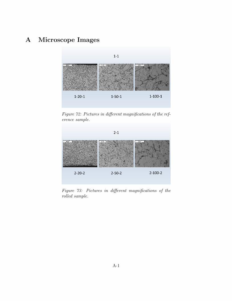
A Microscope Images
Figure 72: Pictures in different magnifications of the ref-erence sample.
Figure 73: Pictures in different magnifications of therolled sample.
A-1
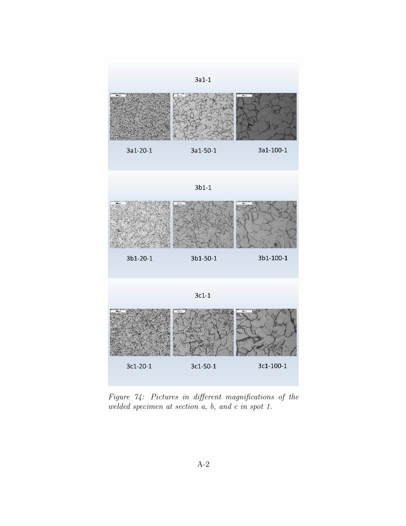
Figure 74: Pictures in different magnifications of thewelded specimen at section a, b, and c in spot 1.
A-2
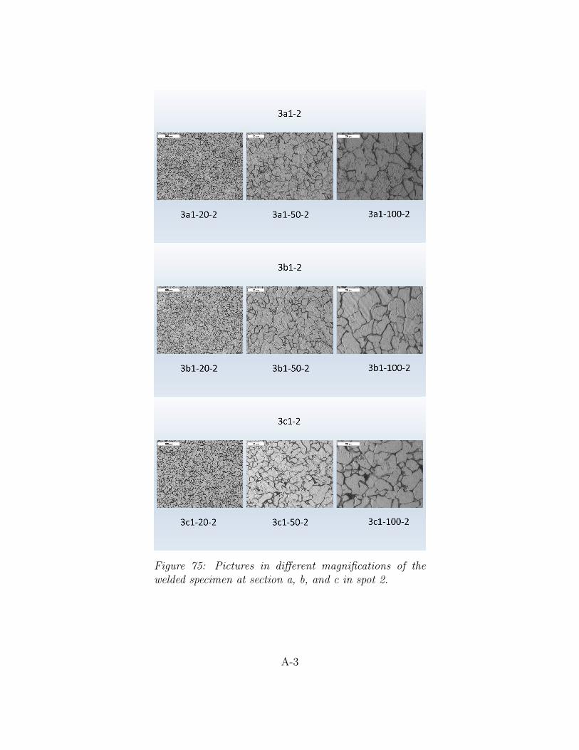
Figure 75: Pictures in different magnifications of thewelded specimen at section a, b, and c in spot 2.
A-3
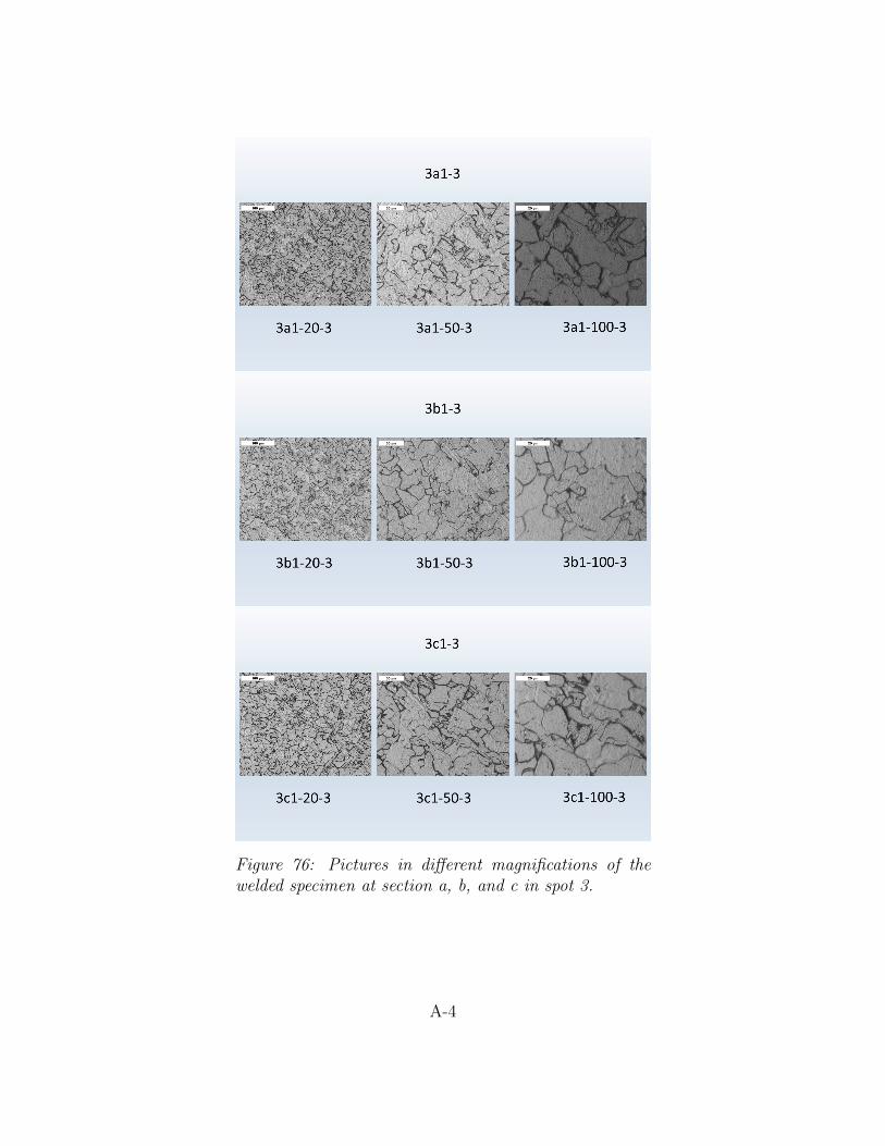
Figure 76: Pictures in different magnifications of thewelded specimen at section a, b, and c in spot 3.
A-4
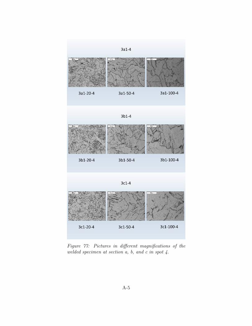
Figure 77: Pictures in different magnifications of thewelded specimen at section a, b, and c in spot 4.
A-5
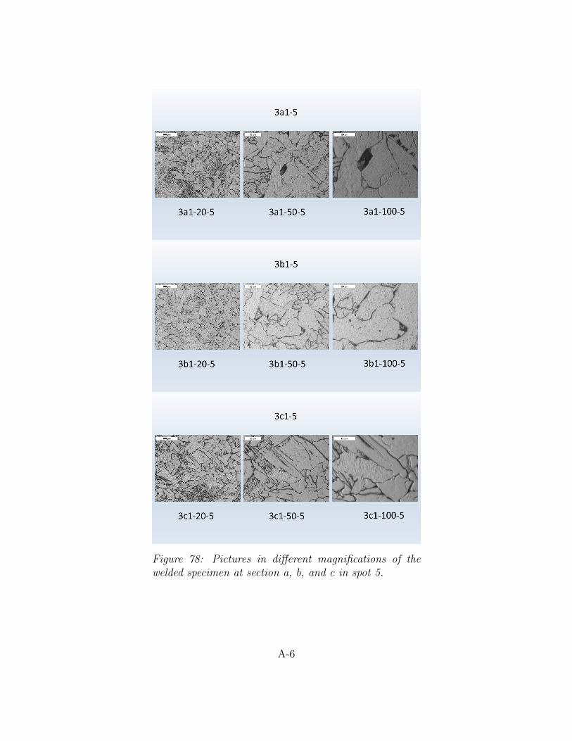
Figure 78: Pictures in different magnifications of thewelded specimen at section a, b, and c in spot 5.
A-6
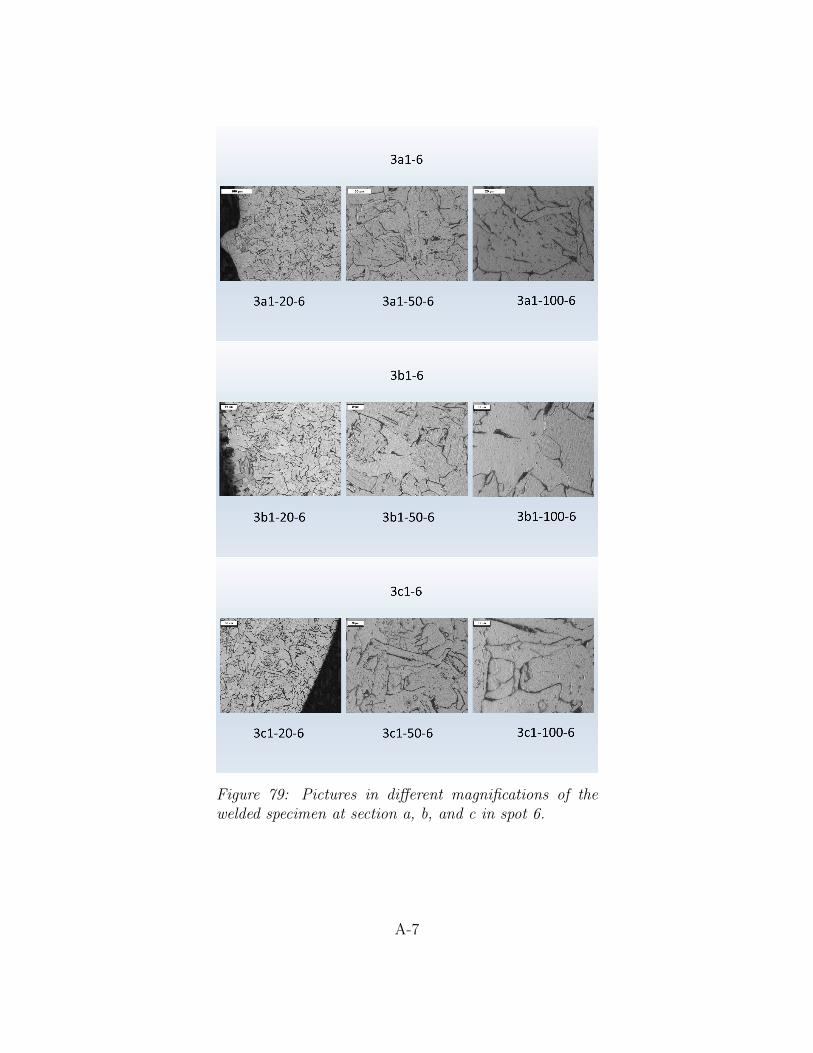
Figure 79: Pictures in different magnifications of thewelded specimen at section a, b, and c in spot 6.
A-7
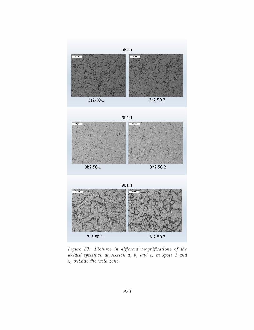
Figure 80: Pictures in different magnifications of thewelded specimen at section a, b, and c, in spots 1 and2, outside the weld zone.
A-8
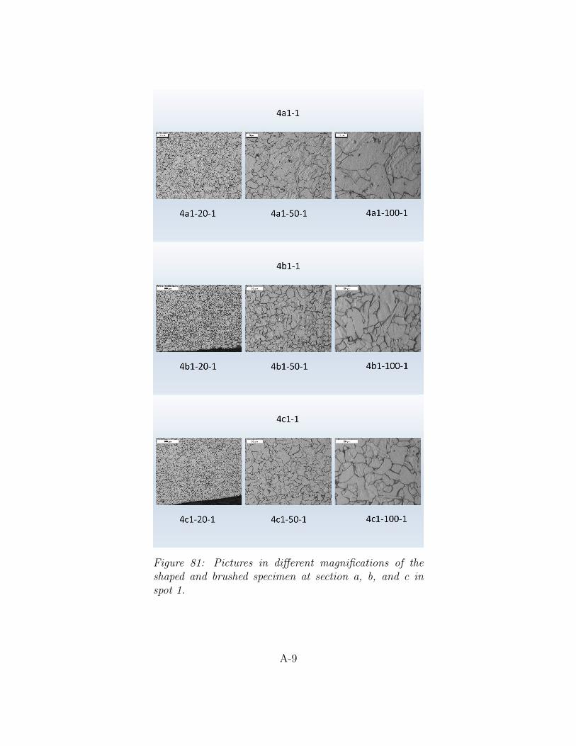
Figure 81: Pictures in different magnifications of theshaped and brushed specimen at section a, b, and c inspot 1.
A-9
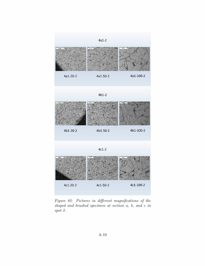
Figure 82: Pictures in different magnifications of theshaped and brushed specimen at section a, b, and c inspot 2.
A-10
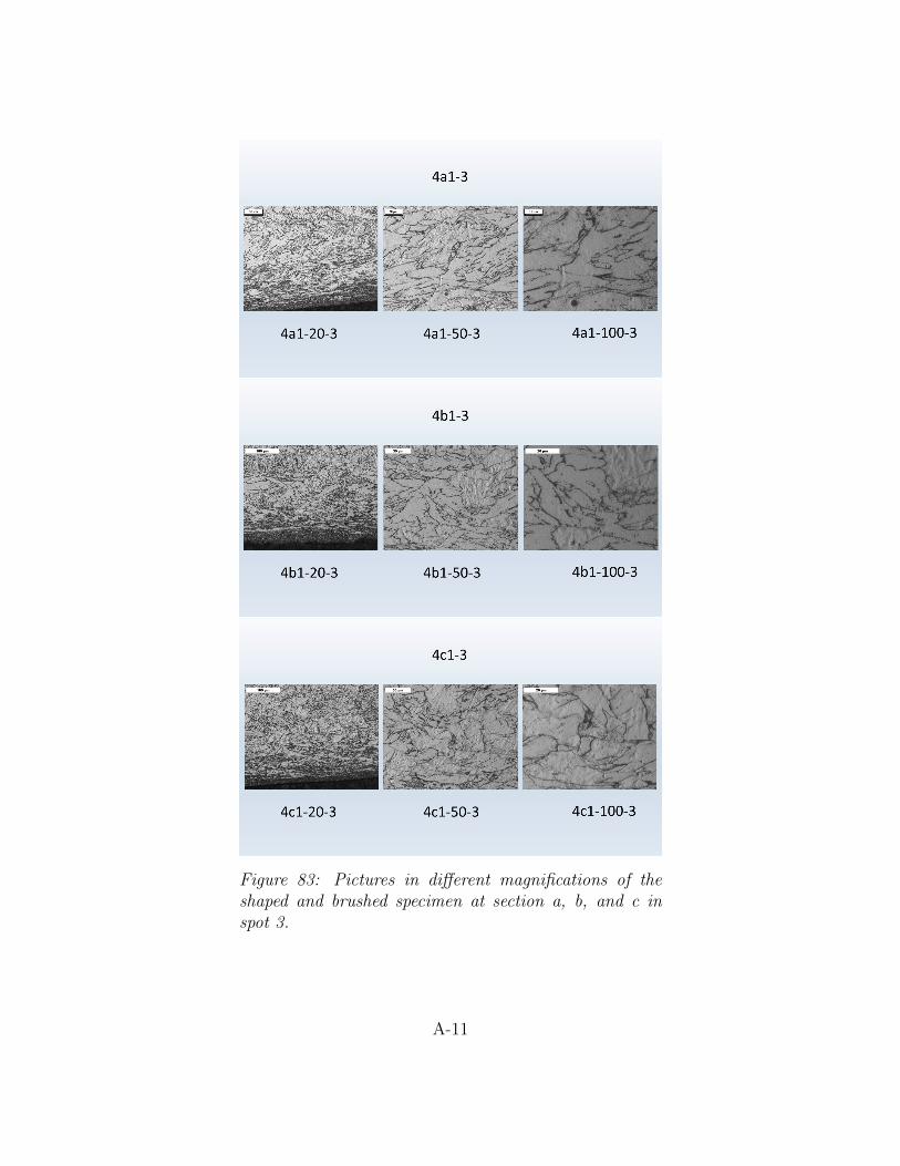
Figure 83: Pictures in different magnifications of theshaped and brushed specimen at section a, b, and c inspot 3.
A-11
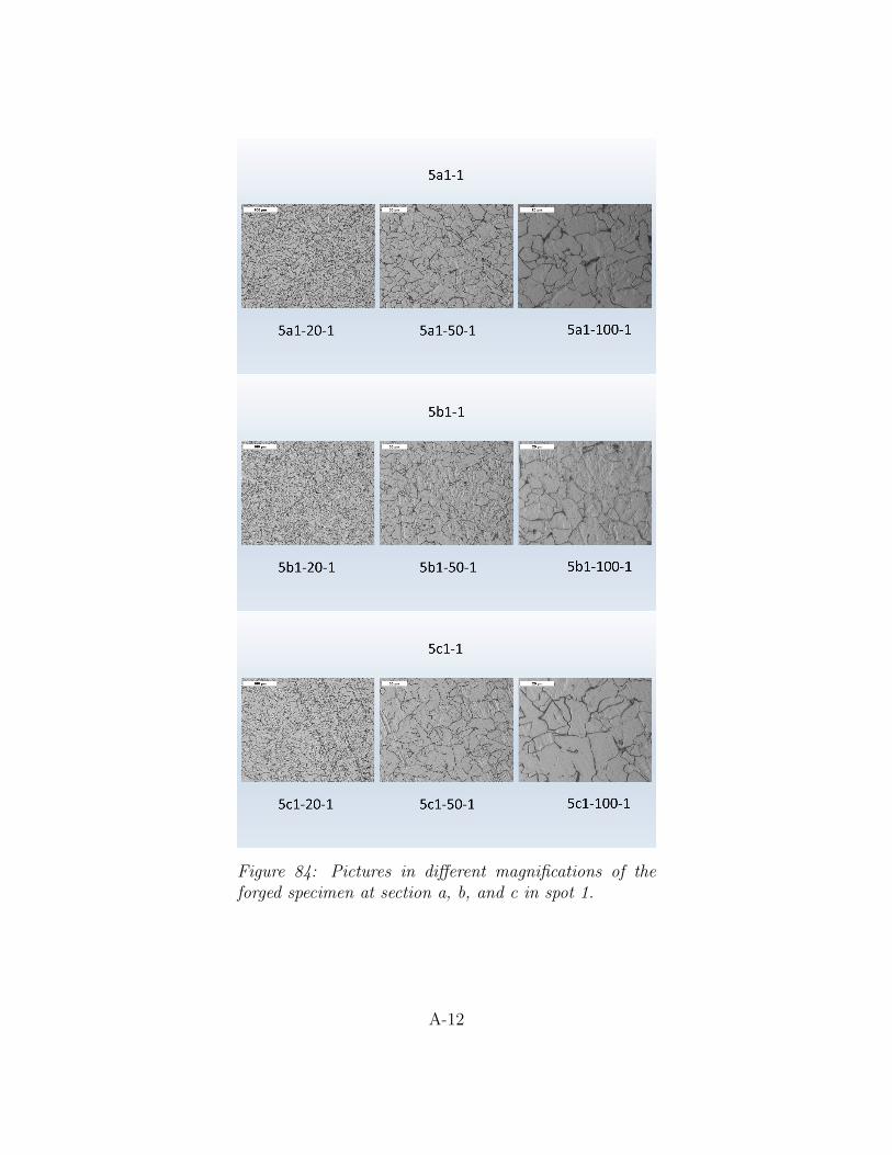
Figure 84: Pictures in different magnifications of theforged specimen at section a, b, and c in spot 1.
A-12
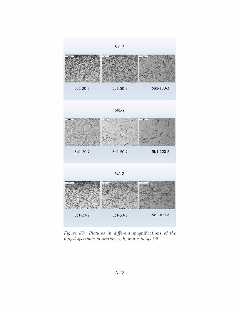
Figure 85: Pictures in different magnifications of theforged specimen at section a, b, and c in spot 2.
A-13
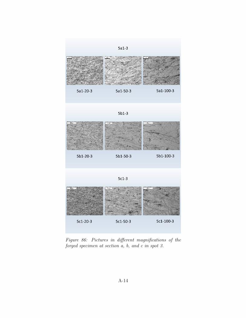
Figure 86: Pictures in different magnifications of theforged specimen at section a, b, and c in spot 3.
A-14
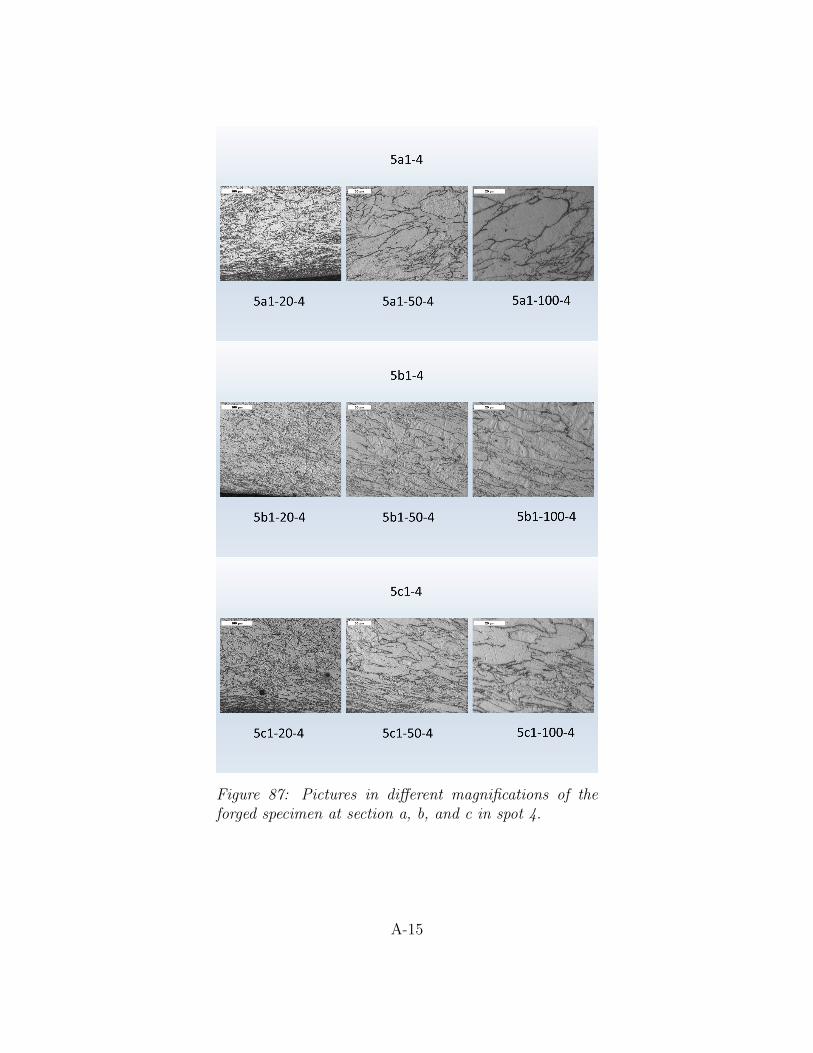
Figure 87: Pictures in different magnifications of theforged specimen at section a, b, and c in spot 4.
A-15

Figure 88: Pictures in different magnifications of the heattreated specimen at section a, b, and c in spot 1.
A-16
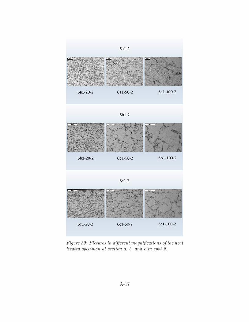
Figure 89: Pictures in different magnifications of the heattreated specimen at section a, b, and c in spot 2.
A-17
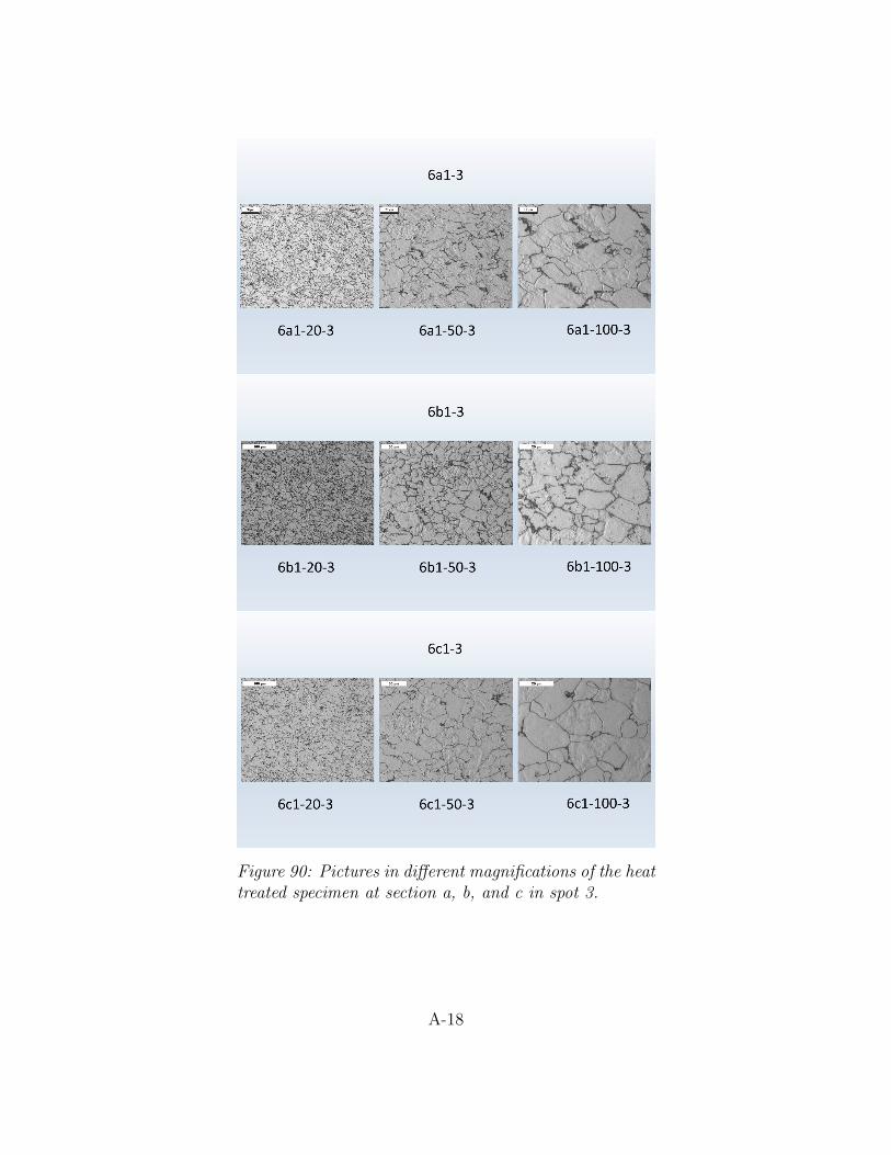
Figure 90: Pictures in different magnifications of the heattreated specimen at section a, b, and c in spot 3.
A-18
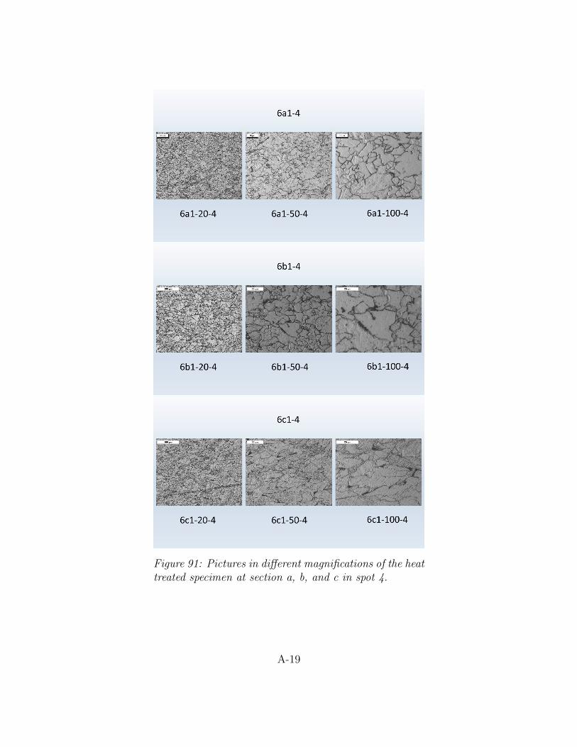
Figure 91: Pictures in different magnifications of the heattreated specimen at section a, b, and c in spot 4.
A-19
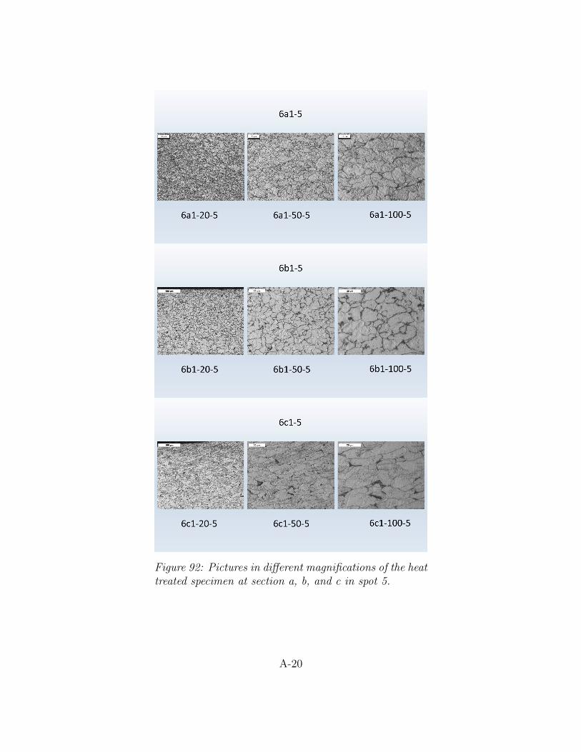
Figure 92: Pictures in different magnifications of the heattreated specimen at section a, b, and c in spot 5.
A-20
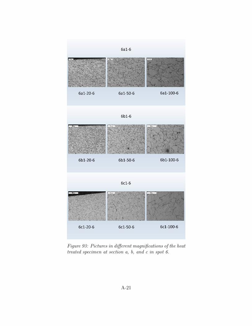
Figure 93: Pictures in different magnifications of the heattreated specimen at section a, b, and c in spot 6.
A-21
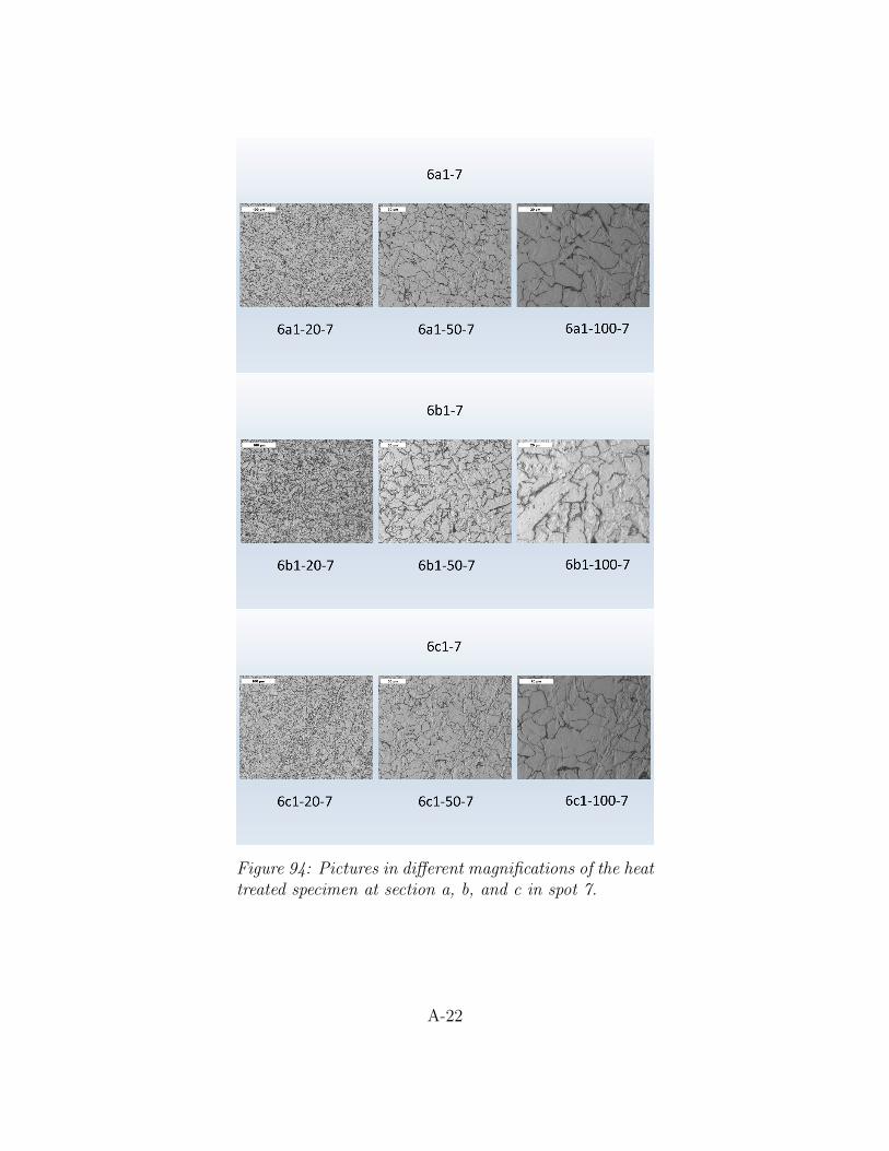
Figure 94: Pictures in different magnifications of the heattreated specimen at section a, b, and c in spot 7.
A-22
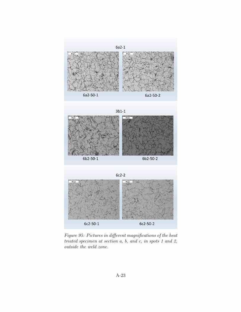
Figure 95: Pictures in different magnifications of the heattreated specimen at section a, b, and c, in spots 1 and 2,outside the weld zone.
A-23
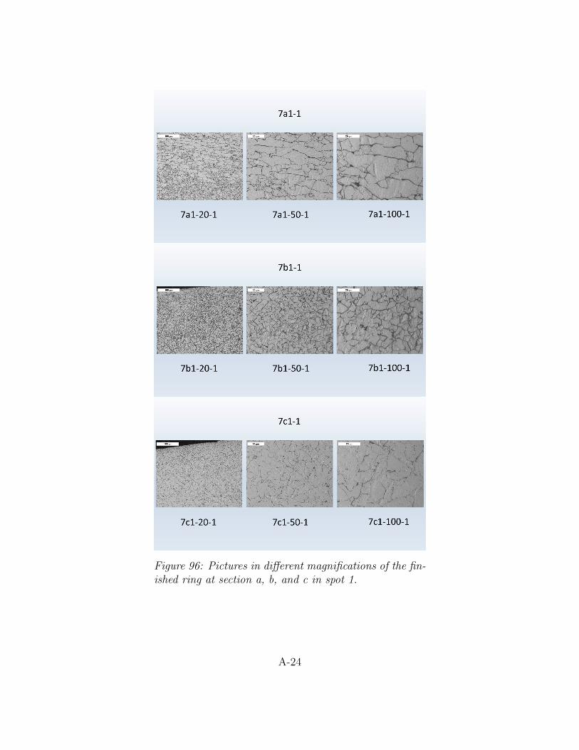
Figure 96: Pictures in different magnifications of the fin-ished ring at section a, b, and c in spot 1.
A-24

Figure 97: Pictures in different magnifications of the fin-ished ring at section a, b, and c in spot 2.
A-25
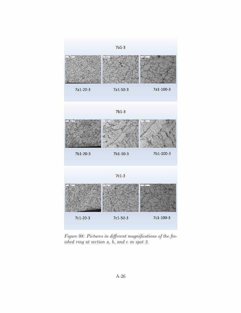
Figure 98: Pictures in different magnifications of the fin-ished ring at section a, b, and c in spot 3.
A-26
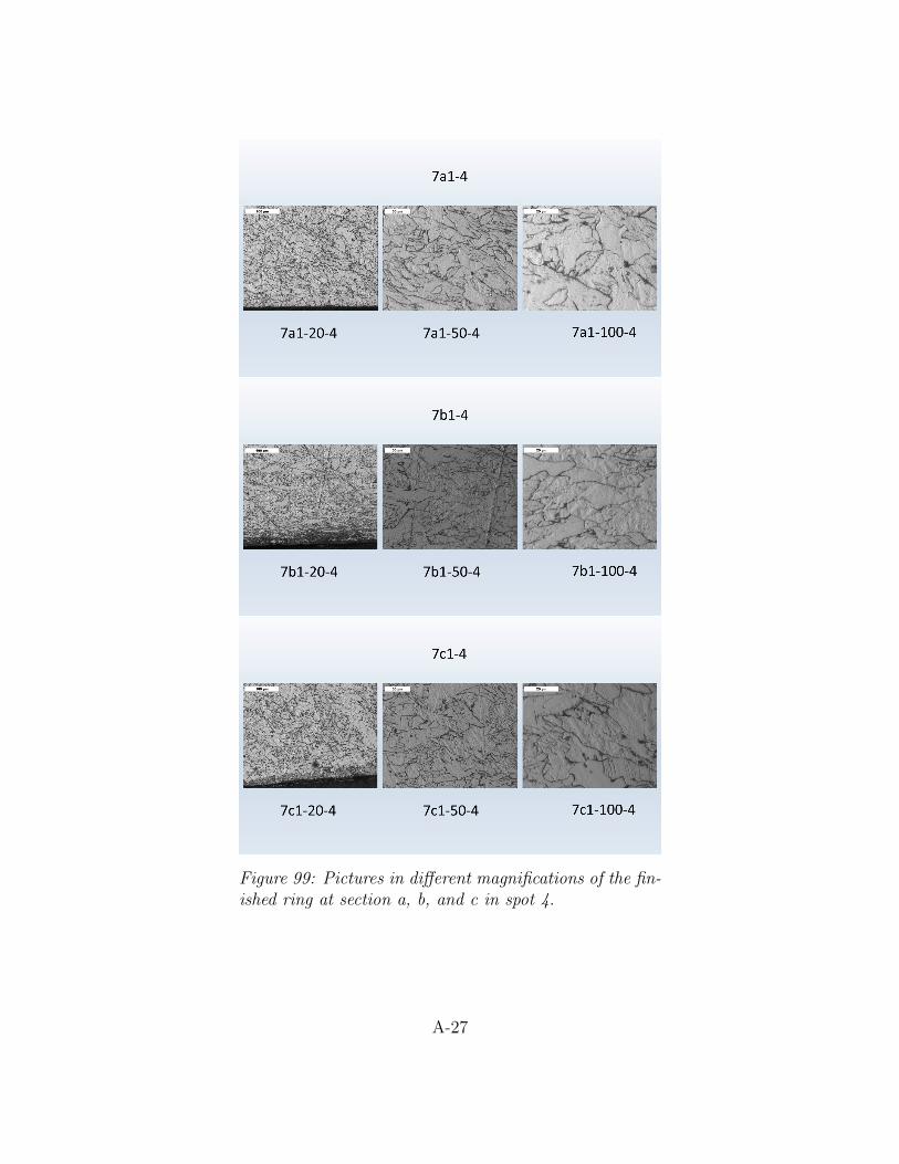
Figure 99: Pictures in different magnifications of the fin-ished ring at section a, b, and c in spot 4.
A-27
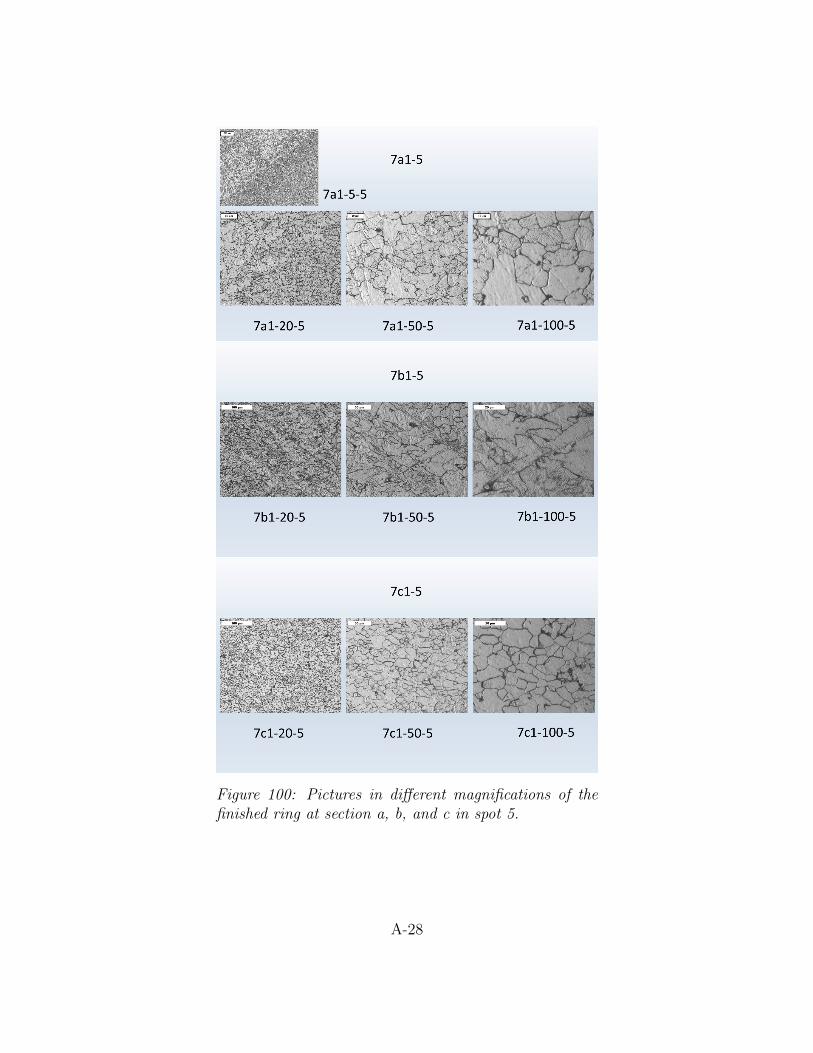
Figure 100: Pictures in different magnifications of thefinished ring at section a, b, and c in spot 5.
A-28
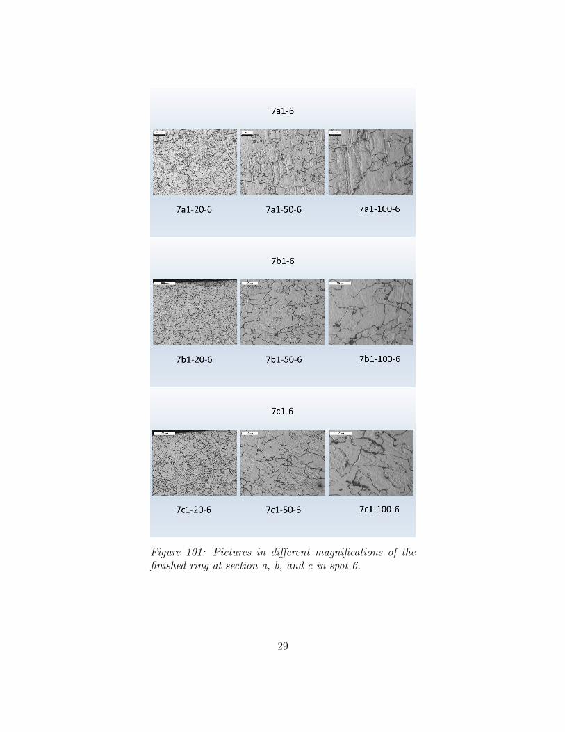
Figure 101: Pictures in different magnifications of thefinished ring at section a, b, and c in spot 6.
29