microstructural and electrochemical behavior of welded pipe
TRANSCRIPT
INTERCORR2018_147
Copyright 2018, ABRACO
Trabalho apresentado durante o INTERCORR 2018, em São Paulo, no mês de maio de 2018.
As informações e opiniões contidas neste trabalho são de exclusiva responsabilidade do(s) autor(es).
_________________________________________________________________________________________ 1Mestrando; Engenheiro Químico - Centro de Desenvolvimento de Tecnologia Nuclear 2Pesquisador; Engenheiro Mecânico - Centro de Desenvolvimento de Tecnologia Nuclear 3Pós Doutoranda; Química - Centro de Desenvolvimento de Tecnologia Nuclear 4Estudante; Engenheira Metalúrgica - Centro de Desenvolvimento de Tecnologia Nuclear 5Estudante; Engenheira Química - Centro de Desenvolvimento de Tecnologia Nuclear 6Pesquisador; Engenheiro Metalúrgico - Centro de Desenvolvimento de Tecnologia Nuclear
Microstructural and Electrochemical behavior of Welded Pipe A106 Gr. B and 316L with
nickel alloys 82 and 182 in 3.5 wt. % NaCl solution
Alisson H. Freire Vilela1, Wagner R. Costa Campos2, Luiza Esteves3,Camila R. Oliveira
Almeida4, Bárbara A. Cardoso5 ,Emerson G. Rabelo6
Abstract
The aim of this work was to investigate the microstructure and evaluate the corrosion
behavior of dissimilar metal welded between carbon steel pipe A106 Gr B and 316L
austenitic stainless steel with nickel alloy 82 and 182 as filler metals. These welded joints
were analyzed in three different conditions, as welded (AW), after post weld heat treatment
(PWHT) and after weld overlay (WOL), both used to minimize the residual stress effect.
Electrochemical tests were carried out considering three types of samples: weld joint, A106 B
and 316L steel base metal in 3.5% NaCl solution. Tafel extrapolation was used to calculate
the corrosion rate. For weld joint, welding heat cycle changed the microstructure of the heat
affect zone (HAZ) on root weld causing an intense grain refinement and polygonal ferrite and
perlite formation. Otherwise, on finish weld was observed allotriormophic ferrite, polygonal
ferrite, acicular ferrite, ferrite with martensite/austenite/carbides aligned and pearlite to AW
and PWHT conditions. Polygonal ferrite and perlite were observed in WOL condition. Similar
corrosion rates among the three conditions of each sample were observed. Base metal 316L
showed the lowest corrosion rate following by welded joint and finally base metal A106 B.
Keywords: A106 Gr B carbon steel; 316L stainless steel; corrosion; dissimilar metal weld;
Tafel extrapolation
Introduction
Dissimilar metal weld (DMW) involving austenitic stainless steel and ferritic carbon steels are
applied in petrochemical, thermoelectrical, nuclear, coil industries and distinct engineering
structures as heat exchangers, nozzles, boilers, pressure vessels and so on (1–3). The auxiliary
use of carbon steels in strategic locals pipe system gives reduction costs, since are cheaper
related to austenitic stainless steels and gives better mechanical properties weld due to joining
metals employed (4-6).
The weld process creates a residual stress due to different physical and mechanical properties
at structure steels (2). Therefore, nickel alloys are employed by having intermediate values,
INTERCORR2018_147
- 2 -
which decreases this difference between ferritic carbon and austenitic stainless steels, and
good resistance to corrosion and failure (7-10).
Stress corrosion cracking (SCC) may come from residual stress and leads to crack formation
at metallurgical susceptible metal due to simultaneous action of present residual stress and
corrosion environment. Continuous interaction with seawater, mainly chloride particles,
threats pipe system physical integrity through corrosion effects imposed to its structure. This
type corrosion is very present at oil extraction environment and nuclear power plants, for
instance (11-14).
In order to reduce SCC susceptibility, related to residual stress effects, a post weld heat
treatment (PWHT) may be applied to relief stress at welded joints (15-16). At crack presence,
a weld overlay (WOL) may be applied to impose a compressive tension (opposite to stress
tension caused by residual stress) and a mechanical and corrosive barrier to crack propagation
(7).
Due to importance application of this weld type, this work aims analyze the corrosion effects
in marine environment, with NaCl 3.5% wt. solution, at base metals and welded joints after
PWHT and WOL. Their corrosion rate was obtained through Tafel extrapolation e compared
to welded joint as welded (AW). In addition, the microstructure of these base metals and
joints were characterized by optical microscopy (OM).
Methodology
Materials and Methods
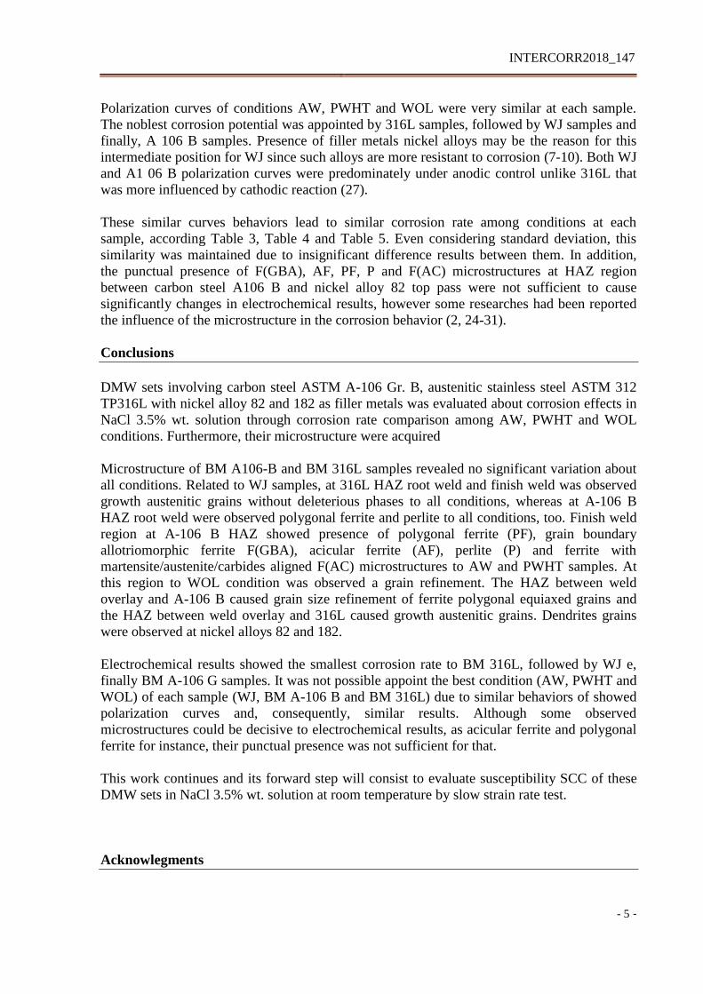
DMW pipe joints were composed of a seamless carbon steel pipe (ASTM A-106 Gr. B) and a
seamless austenitic stainless steel pipe (ASTM A-312 TP316L), schedule 160 with diameter
of 168.2 mm and wall thickness of 18.3 mm, with length of 150 mm, and two different filler
metals, the nickel alloy 82 (AWS A5.14 ER NiCr-3) with 2.0 mm diameter, buttering and root
layers weld, by gas tungsten arc welding (GTAW), and nickel alloy 182 (AWS A5.11 E
NiCrFe-3) with diameter of 3.25 mm to fill welding, shielded metal arc welding (SMAW).
The chemical compositions of the base metals and weld metals are summarized in Table 1.
asdasdasdasdasdasdasdasdasdasdasdasdasd
Welding, post weld heat treatment and weld overlay
The pipes were machined, bevelled at 30° V format and 200 °C preheated. Root weld about
2.00 mm was composed by two welding beads and buttering layer about 5.00 mm thickness
composed by three welding beads, both nickel alloy 82 by GTAW process. Seven layers of
nickel alloy 182 coated electrode was applicated as filler weld metal by SMAW process.
Root, buttering and fill interpasses were applied at range temperature of 140 ºC to 170 ºC. The
welding main parameters and the final DMW may be seen in Table 2 and Figure 1,
respectively.
A thermal blanket was positioned at center weld, with width about 100.00 mm to each side,
and heated the welded joint at 620 ºC during 2.5 h, with 220 ºC/h heating rate. Cooling was
done with thermal blanket turned off between 620 ºC and 300 ºC with cooling rate about 400
ºC/h and between 300 °C and 100 ºC with cooling rate about 75 ºC/h. PWHT steps to stress
INTERCORR2018_147
- 3 -
relief must include a moderated heating rate, residence time at range temperature between 600
ºC and 700 ºC to ferritic carbon steels and about 900 ºC to austenitic stainless steel and
cooling low rate to avoid new residual stress (15,17-19).
The weld overlay was applied at weld center with five layers of nickel alloy 82 by GTAW
process, with 115.00 mm length, about 45.0 mm to each side, and 7.00 mm thickness,
according to Figure 2:
Both PWHT and WOL applied in this study were efficient to reduce internal residual stress of
this welded sets through microhardness Vickers and Hole Drilling Strain Gage (22,23).
Metallographic analisys
The samples were extracted from longitunial section of welded sets and were identified
according to dissimilar weld original set: as welded (AW), with PWHT (PWHT) and with
weld overlay (WOL). The weld joints samples (WJ) encompas metal base parts, ASTM A-
106 Gr. B e ASTM 312 TP316L, their HAZ’s and weld metals 82 and 182. Whereas base
metals (BM) samples were extracted from side of WJ samples. After, a wire was solded at
each sample before cold mounting in resin epoxy. The working surface to WJ samples was
7.00 cm² and 3.00 cm² to BM samples. Then, the samples were cold mounted in resin epoxy,
grinded in 80#, 220#, 400#, 600#, 1200# e 2000# SiC paper, polished with diamond paste 6
μm, 3 μm and 1 μm, rinsed with distilled water and ethyl alcohol and dried with hot air before
metallographic analisys.
Macrostructure was revealed by exposing samples to Nital’s reagent 2% (2.0mL nitric acid
and 98.0 mL ethyl alcohol) during 10 s by imersion, followed by Marble’s reagent exposition
(4.0 g CuSO 4 , 20.0 mL HCl and 20.0 mL distilled water) during 120 s by imersion, and over
again, with cottom smearing, by Marble’s reagent during 15 s. Microstructure was revealed
by exposing samples to Nital’s reagent 2% during 10 s and electrolytic etching with oxalic
acid solution 10% wt. (10.0 g and 100.0 mL distilled water), 2.0 V during 120 s.
Metallographic examination was carried out using Leica DM4500P optical microscopy.
Electrochemical tests
After metallographic examination, the samples were grinded again in 80#, 220#, 400#, 600#,
1200# SiC paper, rinsed with distilled water and ethyl alcohol and dried with hot air before
electrochemical tests.
Potentiodynamic polaratization tests were carried out at least five times to acquire
reproducibility at room temperature. An electrochemical cell with silver/silver chloride
(Ag/AgCl, 3M KCl) as reference electrode platinum as counter electrode and samples as
working electrodes was used with NaCl 3.5% wt. (g/L) solution. The open circuit potencial
(OCP) was monitored and measured after 900 s (15 min) until its stabilization. Afterward, a
scan rate of 0.5 mV/s was applied, starting at – 250.0 mV (Ag/AgCl) to + 250.0 mV
(Ag/AgCl), related to OCP. A potentiostat Autolab PGSTAT 100 were employed and
polarization curves were produced by software NOVA 2.0. Corrosion rates (icorr) were
obtained through Tafel extrapolation with auxiliar equations 1 and 2 (21-22):
INTERCORR2018_147
- 4 -
ηa = ba . log (ia / icorr)
(1)
ηc = bc . log (ic / icorr) (2)
where, ηa e ηc, as anodic and cathodic polarization; ba e bc, as anodic and cathodic Tafel
slopes; and ia e ic, as anodic and cathodic current densities.
Results and discussion
Metallographic analisys
The surface of the longitudinal section was ground, polished and attacked with Marble and
Nital 2% reagents to reveal macrostructure. Figure 3 shows the etched macrostructure of the
DMW with carbon steel A-106 Gr. B and stainless steel TP316L pipes, with Alloy 82 (Ni 82)
buttering and root weld and Alloy 182 (Ni 182) fill weld metal.
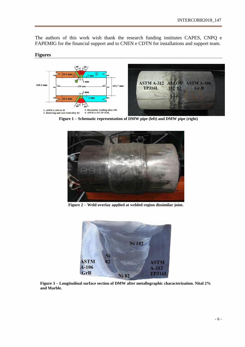
Figure 4 shows microphotographs DMW samples AW (a), PWHT (b) and WOL (c), etched
by Nital 10% at 10 seconds plus Marble at 120 seconds plus swab for 15 seconds.
The microstructure of the BM A 106 B samples to all conditions, showed by Figure 5, etching
Nital 3% during 10 seconds, consists of the ferrite (dark areas) and perlite (light areas) grains,
with 10 µm grain size. According to Figure 6, the microstructure of MB 316L samples
etching with oxalic acid 10% with 3V during 120 seconds, consists of equiaxial austenite
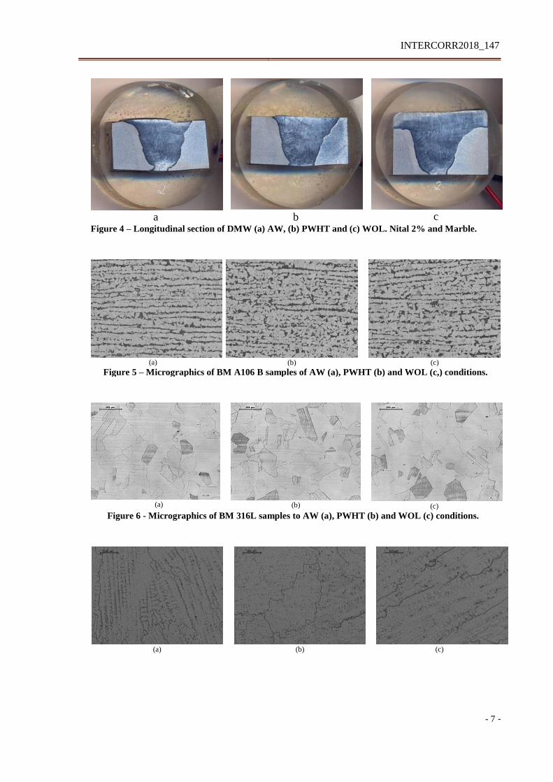
grains, with 60 µm grain size, to all conditions. Dendrites grains were observed with
inclusions and precipitates in WJ sample to all conditions AW (6a), PWHT (6b) and WOL
(6c), both nickel alloys 82 root pass and nickel alloys 82 top pass, according to Figure 6
About Figure 7, microstructure observed in ZTA root weld between carbon steel A106 B and
nickel alloy 82 to WJ sample showed polygonal ferrite and fine perlite to all conditions (7a,
7b and 7c). On finish weld region to AW and PWHT conditions (7d and 7e) were observed
polygonal ferrite (PF), grain boundary allotriomorphic ferrite F(GBA), acicular ferrite (AF),
perlite (P) and ferrite with martensite/austenite/carbides aligned F(AC) (28). The weld overlay
applied at WOL condition (7f) caused a grain refinement of polygonal structure. HAZ
microstructure of austenitic stainless steel 316L with nickel alloy 182 was composed by
growth austenitic grains to all conditions without deleterious phases.
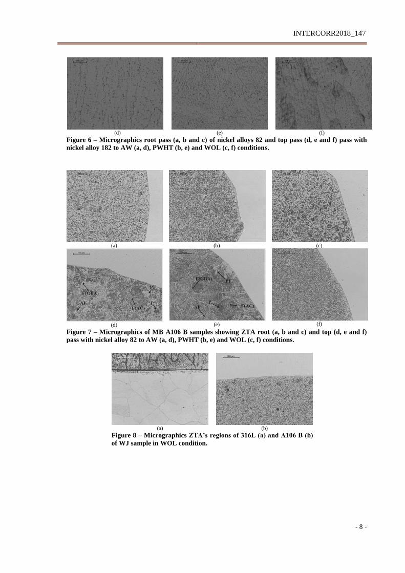
According Figure 8, to WJ sample of WOL condition was observed growth austenitic grains
in HAZ between weld overlay and austenitic stainless steel 316L (8a). The HAZ between
weld overlay and carbon steel A106 B showed grain size refinement with ferrite polygonal
equiaxed grains (8b).
Electrochemical tests
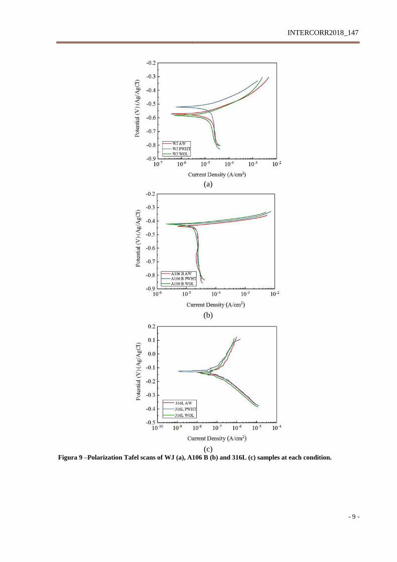
The potentiodynamic polarization Tafel scans of welded joint (WJ), base metals ASTM A106
Gr. B (A 106 B) and ASTM 312 TP316L (316L) samples show their electrochemical
behavior at 3.5% wt. NaCl solution through Figure 9a, Figure 9b and Figure 9c, respectively.
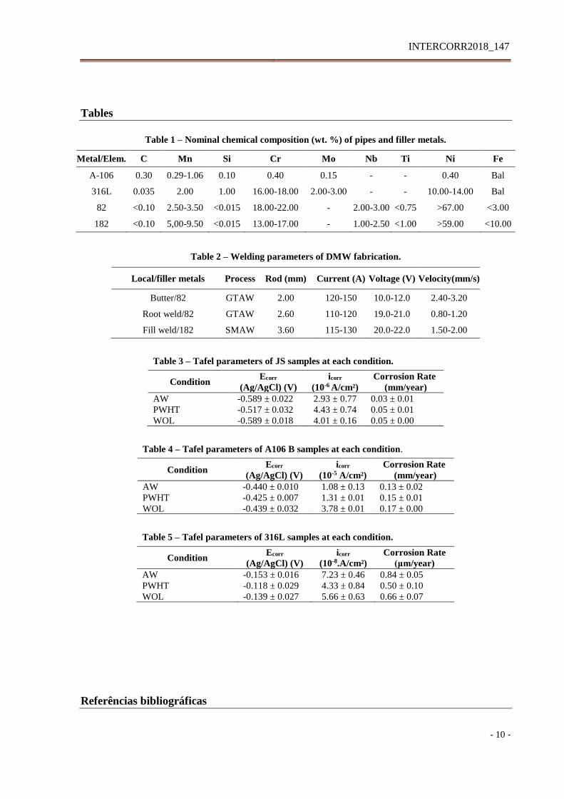
In addition, the parameters of each test are listed in Table 3 to WJ samples, Table 4 to A 106
B samples and Table 5 to 316L samples.
INTERCORR2018_147
- 5 -
Polarization curves of conditions AW, PWHT and WOL were very similar at each sample.
The noblest corrosion potential was appointed by 316L samples, followed by WJ samples and
finally, A 106 B samples. Presence of filler metals nickel alloys may be the reason for this
intermediate position for WJ since such alloys are more resistant to corrosion (7-10). Both WJ
and A1 06 B polarization curves were predominately under anodic control unlike 316L that
was more influenced by cathodic reaction (27).
These similar curves behaviors lead to similar corrosion rate among conditions at each
sample, according Table 3, Table 4 and Table 5. Even considering standard deviation, this
similarity was maintained due to insignificant difference results between them. In addition,
the punctual presence of F(GBA), AF, PF, P and F(AC) microstructures at HAZ region
between carbon steel A106 B and nickel alloy 82 top pass were not sufficient to cause
significantly changes in electrochemical results, however some researches had been reported
the influence of the microstructure in the corrosion behavior (2, 24-31).
Conclusions
DMW sets involving carbon steel ASTM A-106 Gr. B, austenitic stainless steel ASTM 312
TP316L with nickel alloy 82 and 182 as filler metals was evaluated about corrosion effects in
NaCl 3.5% wt. solution through corrosion rate comparison among AW, PWHT and WOL
conditions. Furthermore, their microstructure were acquired
Microstructure of BM A106-B and BM 316L samples revealed no significant variation about
all conditions. Related to WJ samples, at 316L HAZ root weld and finish weld was observed
growth austenitic grains without deleterious phases to all conditions, whereas at A-106 B
HAZ root weld were observed polygonal ferrite and perlite to all conditions, too. Finish weld
region at A-106 B HAZ showed presence of polygonal ferrite (PF), grain boundary
allotriomorphic ferrite F(GBA), acicular ferrite (AF), perlite (P) and ferrite with
martensite/austenite/carbides aligned F(AC) microstructures to AW and PWHT samples. At
this region to WOL condition was observed a grain refinement. The HAZ between weld
overlay and A-106 B caused grain size refinement of ferrite polygonal equiaxed grains and
the HAZ between weld overlay and 316L caused growth austenitic grains. Dendrites grains
were observed at nickel alloys 82 and 182.
Electrochemical results showed the smallest corrosion rate to BM 316L, followed by WJ e,
finally BM A-106 G samples. It was not possible appoint the best condition (AW, PWHT and
WOL) of each sample (WJ, BM A-106 B and BM 316L) due to similar behaviors of showed
polarization curves and, consequently, similar results. Although some observed
microstructures could be decisive to electrochemical results, as acicular ferrite and polygonal
ferrite for instance, their punctual presence was not sufficient for that.
This work continues and its forward step will consist to evaluate susceptibility SCC of these
DMW sets in NaCl 3.5% wt. solution at room temperature by slow strain rate test.
Acknowlegments
INTERCORR2018_147
- 6 -
The authors of this work wish thank the research funding institutes CAPES, CNPQ e
FAPEMIG for the financial support and to CNEN e CDTN for installations and support team.
Figures
Figure 1 – Schematic representation of DMW pipe (left) and DMW pipe (right)
Figure 3 – Longitudinal surface section of DMW after metallographic characterization. Nital 2%
and Marble.
Figure 2 – Weld overlay applied at welded region dissimilar joint.
INTERCORR2018_147
- 7 -
a
b
c
Figure 4 – Longitudinal section of DMW (a) AW, (b) PWHT and (c) WOL. Nital 2% and Marble.
(a) (b) (c)
Figure 5 – Micrographics of BM A106 B samples of AW (a), PWHT (b) and WOL (c,) conditions.
(a)
(b) (c)
Figure 6 - Micrographics of BM 316L samples to AW (a), PWHT (b) and WOL (c) conditions.
(a)
(b) (c)
INTERCORR2018_147
- 8 -
(d) (e) (f)
Figure 6 – Micrographics root pass (a, b and c) of nickel alloys 82 and top pass (d, e and f) pass with
nickel alloy 182 to AW (a, d), PWHT (b, e) and WOL (c, f) conditions.
(a) (b) (c)
(d) (e) (f)
Figure 7 – Micrographics of MB A106 B samples showing ZTA root (a, b and c) and top (d, e and f)
pass with nickel alloy 82 to AW (a, d), PWHT (b, e) and WOL (c, f) conditions.
(a)
(b)
Figure 8 – Micrographics ZTA’s regions of 316L (a) and A106 B (b)
of WJ sample in WOL condition.
INTERCORR2018_147
- 9 -
(a)
(b)
(c)
Figura 9 –Polarization Tafel scans of WJ (a), A106 B (b) and 316L (c) samples at each condition.
INTERCORR2018_147
- 10 -
Tables
Table 1 – Nominal chemical composition (wt. %) of pipes and filler metals.
Metal/Elem. C Mn Si Cr Mo Nb Ti Ni Fe
A-106 0.30 0.29-1.06 0.10 0.40 0.15 - - 0.40 Bal
316L 0.035 2.00 1.00 16.00-18.00 2.00-3.00 - - 10.00-14.00 Bal
82 <0.10 2.50-3.50 <0.015 18.00-22.00 - 2.00-3.00 <0.75 >67.00 <3.00
182 <0.10 5,00-9.50 <0.015 13.00-17.00 - 1.00-2.50 <1.00 >59.00 <10.00
Table 2 – Welding parameters of DMW fabrication.
Local/filler metals Process Rod (mm) Current (A) Voltage (V) Velocity(mm/s)
Butter/82 GTAW 2.00 120-150 10.0-12.0 2.40-3.20
Root weld/82 GTAW 2.60 110-120 19.0-21.0 0.80-1.20
Fill weld/182 SMAW 3.60 115-130 20.0-22.0 1.50-2.00
Table 3 – Tafel parameters of JS samples at each condition.
Condition Ecorr
(Ag/AgCl) (V)
icorr
(10-6 A/cm²)
Corrosion Rate
(mm/year)
AW -0.589 ± 0.022 2.93 ± 0.77 0.03 ± 0.01
PWHT -0.517 ± 0.032 4.43 ± 0.74 0.05 ± 0.01
WOL -0.589 ± 0.018 4.01 ± 0.16 0.05 ± 0.00
Table 4 – Tafel parameters of A106 B samples at each condition.
Condition Ecorr
(Ag/AgCl) (V)
icorr
(10-5 A/cm²)
Corrosion Rate
(mm/year)
AW -0.440 ± 0.010 1.08 ± 0.13 0.13 ± 0.02
PWHT -0.425 ± 0.007 1.31 ± 0.01 0.15 ± 0.01
WOL -0.439 ± 0.032 3.78 ± 0.01 0.17 ± 0.00
Table 5 – Tafel parameters of 316L samples at each condition.
Condition Ecorr
(Ag/AgCl) (V)
icorr
(10-8.A/cm²)
Corrosion Rate
(μm/year)
AW -0.153 ± 0.016 7.23 ± 0.46 0.84 ± 0.05
PWHT -0.118 ± 0.029 4.33 ± 0.84 0.50 ± 0.10
WOL -0.139 ± 0.027 5.66 ± 0.63 0.66 ± 0.07
Referências bibliográficas
INTERCORR2018_147
- 11 -
(1) ZHU, R. et al. Stress corrosion cracking of 316L HAZ for 316L stainless steel/Inconel
52M dissimilar metal weld joint in simulated primary water. Corrosion Science,
Beijing, v. 112, p. 373-384, Nov. 2016.
(2) HUANG, B. S. et al. Study on the microstructure, mechanical properties and corrosion
behaviour of S355JR/316L dissimilar welded joint prepared by gas tungsten arc
welding multi-pass welding process. Science Technology of Welding and Joining,
Chengdu, v. 21, n. 5, p. 381-388, Apr. 2016.
(3) FARREN, J.; DuPONT, J; NOECKER, F. Fabrication of a Carbon Steel-to-Stainless
Steel Transition Joint Using Direct Laser Deposition - A Feasibility Study. Welding
Journal, Bethlehem, v. 86, n. 3, p. 55-61, Mar. 2007.
(4) ROBERTS, D, I.; RYDER, R. H.; VISWANATHAN, R. Performance of Dissimilar
Welds in Service. Journal of Pressure Vessel Technology, Palo Alto, v. 107, n. 3, p.
247-254, Aug. 1985.
(5) VENKATA RAMANA, P. et al. Microstructure and residual stress distribution of
similar and dissimilar electron beam welds - Maraging steel to medium alloy medium
carbon steel. Materials and Design, Hyderabad, v. 31, n. 2, p. 749-760, Aug. 2010.
(6) LIPPOLD, J. C.; KOTECKI, D. J. Welding Metallurgy and Weldability of Stainless
Steels. Hoboken: John Wiley & Sons, 2005. 357 p..
(7) BAMFORD, W.; NEWTON, B.; SEEGER, D. Recent experience with weld overlay
repair of indications in alloy 182 butt welds in two operating PWRs. In: PRESSURE
VESSELS AND PIPING DIVISION CONFERENCE, 2006, Vancouver.
Proceedings... Vancouver: ASME, 2006. p. 427-434.
(8) EBERT, H. W. Nickel Alloy Filler Metal Review. Welding Journal, Madison, v. 83,
n. 7, p. 170-173, 2004.
(9) HICKLING, J. Materials Reability Programa Crack Growth Rates for Evaluating
Primary Water Stress Corrosion Cracking (PWSCC) of Alloy 82, 182, and 132
Welds (MRP-115). 6 ed. Palo Alto: EPRI, 2004. 186 p.
(10) KIM, J. W. et al. Local mechanical properties of Alloy 82/182 dissimilar weld joint
between SA508 Gr.1a and F316 SS at RT and 320 oC. Journal of Nuclear Materials,
Dong-gu, v. 384, n. 3, p. 212–221, Feb. 2009.
(11) ROBERGE, P. R. Handbook of Corrosion Engineering. New York: McGraw-Hill,
1999. 1128 p.
(12) KOCH, G. H. Tests for stress-corrosion cracking. Advanced Materials & Processes,
Dublin, v. 159, n. 8, p. 36-38, Aug. 2001.
(13) SEDRIKS, J. A. Stress Corrosion Cracking Test Methods. Arlington: NACE, 1990.
87 p.
(14) ASM - AMERICAN SOCIETY FOR METALS. Corrosion of weldments. ed 11.
Ohio: Materials Park, 2007. 225 p.
(15) KAPLAN, D; MURRY, G. Metallurgy and Mechanics of Welding: Processes and
Industrial Applications. Chippenham: Jonh Wiley & Sons, 2008. p. 125
(16) TSAI, W. T.; YU, C. L.; LEE, J. I. Effect of heat treatment on the sensitization of
Alloy 182 weld. Scripta Materialia, Tainan, v. 53, n. 5, p. 505-509, Sep. 2005.
(17) Gandy, D. Carbon Steel Handbook. Palo Alto: EPRI, 2007. 172 p.
(18) MODENESI, P. ; MARQUES, P; SANTOS, P. Introdução à metalurgia da
soldagem. Belo Horizonte: Universidade Federal de Minas Gerais, 2016. 213 p.
(19) OKUMURA, T.; TANIGUCHI, C. Engenharia de Soldagem e Aplicações. Rio de
Janeiro: LTC - Livros Técnicos e Científicos, 1982. 493 p.
INTERCORR2018_147
- 12 -
(20) MCCAFFERTY, E. Introduction to Corrosion Science. New York: Springer New
York, 2010. 575 p.
(21) WOLYNEC, S. Técnicas Eletroquímicas em Corrosão. São Paulo: Edusp - Editora
da Universidade de São Paulo, 2013. 163 p.
(22) CAMPOS, W. R. C. et al. Effects of Post Weld Heat Treatment and Weld Overlay on
the Residual Stress and Mechanical Properties in Dissimilar Metal Weld. In:
INTERNATIONAL NUCLEAR ATLANTIC CONFERENCE, 2017, Belo Horizonte.
Proceedings… Belo Horizonte: Associação Brasileira de Energia Nuclear, 2017, 13 p.
(23) RIBEIRO, V. S. Estudo de Técnicas de Redução de Tensão Residuais em Soldas
Dissimilares Envolvendo Aço Carbono Ferrítico e Aço Inoxidável Austenítico com
Adição das Ligas de Níquel 182/82. 2017. 110 f. Dissertação (Mestrado) - Centro de
Desenvolvimento de Tecnologia Nuclear, Belo Horizonte, 2017.
(24) LU Y,.et al. Effect of Welding Heat Input on the Corrosion Resistance of Carbon Steel
Weld Metal, Journal of Materials Engineering and Performance, Tianjin, vol. 25,
no. 2, p. 565–576, Feb. 2016.
(25) DEEN, K. M. et al. Microstructural study and electrochemical behavior of low alloy
steel weldment, Materials and Design, Lahore, vol. 31, no. 6, p. 3051–3055, Jun.
2010.
(26) KUMARESH BABU, S. P.; NATARAJAN, S. Influence of heat input on high
temperature weldment corrosion in submerged arc welded power plant carbon steel.
Materials and Design, Tiruchirappalli, vol. 29, no. 5, p. 1036–1042, Apr. 2007.
(27) MAKHDOOM, M. A. et al. Effect of multipasses on microstructure and
electrochemical behavior of weldments, Metallurgical and Materials Transactions A
, Lahore, vol. 44, no. 12, p. 5505–5512, Dec. 2013.
(28) ALÉ, R.M.; JORGE, J. C. F.; REBELLO, J. M. A. Constituintes Microestruturais de
Soldas de Aços C-Mn Baixa Liga. Parte II: Metal de Solda. Soldagem & Materiais.
São Paulo, v. 5, n. 3, p.18-25. Fev. 1993
(29) HER-HSIUNG HUANG ET AL. The influences of microstructure composition on the
electrochemical of a516 steel weldment. Corrosion Science, CIDADE, v. 36, n. 6, p.
1027–1038, MES. 1994.
(30) ALIZADEH, M.; BORDBAR, S. The influence of microstructure on the protective
properties of the corrosion product layer generated on the welded API X70 steel in
chloride solution. Corrosion Science, Kerman, v. 70, p. 170–179, May. 2013.
(31) DAAVARI, M. et al. Mechanical and electrochemical behaviors of butt-welded hig
temperature steel pipes. Engineering Failure Analysis, Hafez Ave, v. 62, p. 287-299,
Jan. 2016.