pipes and pipe joints n 261 pipes and pipe joints
TRANSCRIPT

������������������� � 261
�������������������
261
1. Introduction.2. Stresses in Pipes.3. Design of Pipes.4. Pipe Joints.5. Standard Pipe Flanges for
Steam.6. Hydraulic Pipe Joint for
High Pressures.7. Design of Circular Flanged
Pipe Joint.8. Design of Oval Flanged Pipe
Joint.9. Design of Square Flanged
Pipe Joint.
8
�
�
�
�
�
�
8.18.18.18.18.1 IntroductionIntroductionIntroductionIntroductionIntroductionThe pipes are used for transporting various fluids like
water, steam, different types of gases, oil and other chemicalswith or without pressure from one place to another. Cast iron,wrought iron, steel and brass are the materials generally usedfor pipes in engineering practice. The use of cast iron pipesis limited to pressures of about 0.7 N/mm2 because of itslow resistance to shocks which may be created due to theaction of water hammer. These pipes are best suited for waterand sewage systems. The wrought iron and steel pipes areused chiefly for conveying steam, air and oil. Brass pipes, insmall sizes, finds use in pressure lubrication systems on primemovers. These are made up and threaded to the samestandards as wrought iron and steel pipes. Brass pipe is notliable to corrosion. The pipes used in petroleum industry aregenerally seamless pipes made of heat-resistant chrome-molybdenum alloy steel. Such type of pipes can resistpressures more than 4 N/mm2 and temperatures greater than440°C.

262 � ����������������������������
8.28.28.28.28.2 Stresses in PipesStresses in PipesStresses in PipesStresses in PipesStresses in PipesThe stresses in pipes due to the internal fluid pressure are determined by Lame's equation as discussed
in the previous chapter (Art. 7.9). According to Lame's equation, tangential stress at any radius x,
σt =2 2
2 2 2
( ) ( )1
( ) ( )i o
o i
p r r
r r x
+
− ...(i)
and radial stress at any radius x,
σr =2 2
2 2 2
( ) ( )1
( ) ( )i o
o i
p r r
r r x
−
− ...(ii)
where p = Internal fluid pressure in the pipe,ri = Inner radius of the pipe, andro = Outer radius of the pipe.
The tangential stress is maximum at the inner surface (when x = ri) of the pipe and minimum atthe outer surface (when x = ro) of the pipe.
Substituting the values of x = ri and x = ro inequation (i), we find that the maximum tangentialstress at the inner surface of the pipe,
σt(max) =2 2
2 2
[( ) ( ) ]
( ) ( )o i
o i
p r r
r r
+−
and minimum tangential stress at the outer surfaceof the pipe,
σt(min) =2
2 2
2 ( )
( ) ( )i
o i
p r
r r−The radial stress is maximum at the inner
surface of the pipe and zero at the outer surface ofthe pipe. Substituting the values of x = ri and x = roin equation (ii), we find that maximum radial stressat the inner surface,
σr(max) =– p (compressive)
and minimum radial stress at the outer surface of the pipe,
σr(min) =0
The thick cylindrical formula may be applied when
(a) the variation of stress across the thickness of the pipe is taken into account,
(b) the internal diameter of the pipe (D) is less than twenty times its wall thickness ( t ) , i.e.D/t < 20, and
(c) the allowable stress (σt) is less than six times the pressure inside the pipe ( p ) i.e.σt / p < 6.
According to thick cylindrical formula (Lame's equation), wall thickness of pipe,
t = R 1t
t
p
p
σ +− σ −
where R = Internal radius of the pipe.
The following table shows the values of allowable tensile stress (σ t) to be used in the aboverelations:
Cast iron pipes.

������������������� � 263
Table 8.1. Values of allowable tensile stress for pipes of different materials.Table 8.1. Values of allowable tensile stress for pipes of different materials.Table 8.1. Values of allowable tensile stress for pipes of different materials.Table 8.1. Values of allowable tensile stress for pipes of different materials.Table 8.1. Values of allowable tensile stress for pipes of different materials.
S.No. Pipes Allowable tensile stress (σt ) in MPa or N/mm2
1. Cast iron steam or water pipes 14
2. Cast iron steam engine cylinders 12.5
3. Lap welded wrought iron tubes 60
4. Solid drawn steel tubes 140
5. Copper steam pipes 25
6. Lead pipes 1.6
Example 8.1. A cast iron pipe of internal diameter 200 mm and thickness 50 mm carries waterunder a pressure of 5 N/mm2. Calculate the tangential and radial stresses at radius (r) = 100 mm ;110 mm ; 120 mm ; 130 mm ; 140 mm and 150 mm. Sketch the stress distribution curves.
Solution. Given : di = 200 mm or ri = 100 mm ; t = 50 mm ; p = 5 N/mm2
We know that outer radius of the pipe,
ro = ri + t = 100 + 50 = 150 mm
Tangential stresses at radius 100 mm, 110 mm, 120 mm, 130 mm, 140 mm and 150 mmWe know that tangential stress at any radius x,
σt = 2 2 22
2 2 2 2 2 2
( ) ( ) ( )5 (100)1 1
( ) ( ) (150) (100)i o o
o i
p r r r
r r x x
+ = +
− −
=2
22
( )4 1 N/mm or MPaor
x
+
∴ Tangential stress at radius 100 mm (i.e. when x = 100 mm),
σt1 =2
2
(150)4 1 4 3.25 13 MPa
(100)
+ = × =
Ans.
Tangential stress at radius 110 mm (i.e. when x = 110 mm),
σt2 =2
2
(150)4 1 4 2.86 11.44 MPa
(110)
+ = × =
Ans.
Tangential stress at radius 120 mm (i.e. when x = 120 mm),
σt3 =2
2
(150)4 1 4 2.56 10.24 MPa
(120)
+ = × =
Ans.
Tangential stress at radius 130 mm (i.e. when x = 130 mm),
σt4 =2
2
(150)4 1 4 2.33 9.32 MPa
(130)
+ = × =
Ans.
Tangential stress at radius 140 mm (i.e. when x = 140 mm),
σt5 =2
2
(150)4 1 4 2.15 8.6 MPa
(140)
+ = × =
Ans.
and tangential stress at radius 150 mm (i.e. when x = 150 mm),
σt6 =2
2
(150)4 1 4 2 8 MPa
(150)
+ = × =
Ans.

264 � ����������������������������
Fig. 8.1
Radial stresses at radius 100 mm, 110 mm, 120 mm, 130 mm, 140 mm and 150 mmWe know that radial stress at any radius x,
σr =2 2 22
2 2 2 2 2 2
( ) ( ) ( )5 (100)1 1
( ) ( ) (150) (100)i o o
o i
p r r r
r r x x
− = −
− −
=2
22
( )4 1 N/mm or MPaor
x
−
∴ Radial stress at radius 100 mm (i.e. when x = 100 mm),
σr1 =2
2
(150)4 1 4 1.25 5 MPa
(100)
− = × − = −
Ans.
Radial stress at radius 110 mm (i.e., when x = 110 mm),
σr2 =2
2
(150)4 1 4 0.86 3.44 MPa
(110)
− = × − = −
Ans.
Radial stress at radius 120 mm (i.e. when x = 120 mm),
σr3 =2
2
(150)4 1 4 0.56 2.24 MPa
(120)
− = × − = −
Ans.
Radial stress at radius 130 mm (i.e. when x = 130 mm),
σr4 =2
2
(150)4 1 4 0.33 1.32 MPa
(130)
− = × − = −
Ans.
Radial stress at radius 140 mm (i.e. when x = 140 mm),
σr5 =2
2
(150)4 1 4 0.15 0.6 MPa
(140)
− = × − = −
Ans.
Radial stress at radius 150 mm (i.e. when x = 150 mm),
σr6 =2
2
(150)4 1 0
(150)
− =
Ans.
The stress distribution curves for tangential and radial stresses are shown in Fig. 8.1.
������������������� � 265
8.38.38.38.38.3 Design of PipesDesign of PipesDesign of PipesDesign of PipesDesign of PipesThe design of a pipe involves the determination of inside diameter of the pipe and its wall
thickness as discussed below:
1. Inside diameter of the pipe. The inside diameter of the pipe depends upon the quantity offluid to be delivered.
Let D = Inside diameter of the pipe,
v = Velocity of fluid flowing per minute, and
Q = Quantity of fluid carried per minute.
We know that the quantity of fluid flowing per minute,
Q = Area × Velocity = 2
4D v
π × ×
∴ D =4
1.13Q Q
v v× =
π2. Wall thickness of the pipe. After deciding upon
the inside diameter of the pipe, the thickness of the wall(t) in order to withstand the internal fluid pressure ( p)may be obtained by using thin cylindrical or thickcylindrical formula.
The thin cylindrical formula may be applied when
(a) the stress across the section of the pipe isuniform,
(b) the internal diameter of the pipe (D) is morethan twenty times its wall thickness (t), i.e.D/t > 20, and
(c) the allowable stress (σt) is more than sixtimes the pressure inside the pipe (p),i.e. σt /p > 6.
According to thin cylindrical formula, wall thickness of pipe,
t =. .
or2 2σ σ ηt t l
p D p D
where ηl = Efficiency of longitudinal joint.
A little consideration will show that the thickness of wall as obtained by the above relation istoo small. Therefore for the design of pipes, a certain constant is added to the above relation. Now therelation may be written as
t =.
2 t
p DC+
σThe value of constant ‘C’, according to Weisback, are given in the following table.
Table 8.2. Values of constant ‘Table 8.2. Values of constant ‘Table 8.2. Values of constant ‘Table 8.2. Values of constant ‘Table 8.2. Values of constant ‘C’C’C’C’C’.....
Material Cast iron Mild steel Zinc and LeadCopper
Constant (C) in mm 9 3 4 5
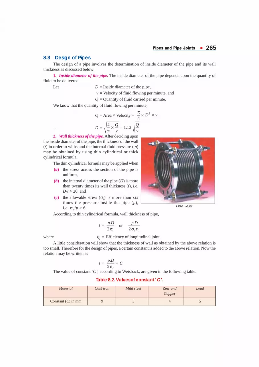
Pipe Joint

266 � ����������������������������
Example 8.2. A seamless pipe carries 2400 m3 of steam per hour at a pressure of 1.4 N/mm2.The velocity of flow is 30 m/s. Assuming the tensile stress as 40 MPa, find the inside diameter of thepipe and its wall thickness.
Solution. Given : Q = 2400 m3/h = 40 m3/min ; p = 1.4 N/mm2; v = 30 m/s = 1800 m/min ;σt = 40 MPa = 40 N/mm2
Inside diameter of the pipeWe know that inside diameter of the pipe,
D =40
1.13 1.13 0.17 m 170 mm1800
Q
v= = = Ans.
Wall thickness of the pipeFrom Table 8.2, we find that for a steel pipe, C = 3 mm. Therefore wall thickness of the pipe,
t =. 1.4 170
3 6 mm2 2 40
p DC
×+ = + =×
Ans.
8.48.48.48.48.4 Pipe JointsPipe JointsPipe JointsPipe JointsPipe JointsThe pipes are usually connected to vessels from which they transport the fluid. Since the length
of pipes available are limited, therefore various lengths of pipes have to be joined to suit any particularinstallation. There are various forms of pipe joints used in practice, but most common of them arediscussed below.
1. Socket or a coupler joint. The mostcommon method of joining pipes is by means of asocket or a coupler as shown in Fig. 8.2. A socket isa small piece of pipe threaded inside. It is screwedon half way on the threaded end of one pipe and theother pipe is then screwed in the remaining half ofsocket. In order to prevent leakage, jute or hemp iswound around the threads at the end of each pipe.This type of joint is mostly used for pipes carryingwater at low pressure and where the overall smallnessof size is most essential.
2. Nipple joint. In this type of joint, a nipple which is a small piece of pipe threaded outside isscrewed in the internally threaded end of each pipe, as shown in Fig. 8.3. The disadvantage of thisjoint is that it reduces the area of flow.
Fig. 8.3. Nipple joint. Fig. 8.4. Union joint.
3. Union joint. In order to disengage pipes joined by a socket, it is necessary to unscrew pipefrom one end. This is sometimes inconvenient when pipes are long.
The union joint, as shown in Fig. 8.4, provide the facility of disengaging the pipes by simplyunscrewing a coupler nut.
Fig. 8.2. Socket or coupler joint.

������������������� � 2674. Spigot and socket joint. A spigot and socket joint as shown in Fig. 8.5, is chiefly used for
pipes which are buried in the earth. Some pipe lines are laid straight as far as possible. One of theimportant features of this joint is its flexibility as it adopts itselfto small changes in level due to settlement of earth which takesplace due to climate and other conditions.
In this type of joint, the spigot end of one pipe fits into thesocket end of the other pipe. The remaining space between thetwo is filled with a jute rope and a ring of lead. When the leadsolidifies, it is caulked-in tightly.
5. Expansion joint. The pipes carrying steam at highpressures are usually joined by means of expansion joint. Thisjoint is used in steam pipes to take up expansion and contractionof pipe line due to change of temperature.
In order to allow for change in length, steam pipes are not rigidly clamped but supported onrollers. The rollers may be arranged on wall bracket, hangers or floor stands. The expansion bends, asshown in Fig. 8.6 (a) and (b), are useful in a long pipe line. These pipe bends will spring in eitherdirection and readily accommodate themselves to small movements of the actual pipe ends to whichthey are attached.
Fig. 8.6. Expansion bends.
Fig. 8.7. Expansion joints.
The copper corrugated expansion joint, as shown in Fig. 8.7 (a), is used on short lines and issatisfactory for limited service. An expansion joint as shown in Fig. 8.7 (b) (also known as gland andstuffing box arrangement), is the most satisfactory when the pipes are well supported and cannot sag.
Fig. 8.5. Spigot and socket joint.

268 � ����������������������������
6. Flanged joint. It is one of the most widely used pipe joint. A flanged joint may be made withflanges cast integral with the pipes or loose flanges welded or screwed. Fig. 8.8 shows two cast ironpipes with integral flanges at their ends. The flanges are connected by means of bolts. The flanges
have seen standardised for pressures upto2 N/mm2. The flange faces are machinedto ensure correct alignment of the pipes.The joint may be made leakproof byplacing a gasket of soft material, rubberor convass between the flanges. Theflanges are made thicker than the pipewalls, for strength. The pipes may bestrengthened for high pressure duty byincreasing the thickness of pipe for a shortlength from the flange, as shown in Fig. 8.9.
For even high pressure and for largediameters, the flanges are further strengthened by ribs or stiffners as shown in Fig. 8.10 (a). The ribsare placed between the bolt holes.
Fig. 8.10
For larger size pipes, separate loose flanges screwed on the pipes as shown in Fig. 8.10 (b) areused instead of integral flanges.
Fig. 8.8. Flanged joint.
Fig. 8.9. Flanged joint.

������������������� � 2697. Hydraulic pipe joint. This type of joint has oval flanges and are fastened by means of two bolts,
as shown in Fig. 8.11. The oval flanges are usually used for small pipes, upto 175 mm diameter. Theflanges are generally cast integral with the pipe ends. Such joints are used to carry fluid pressure varyingfrom 5 to 14 N/mm2. Such a high pressure is found in hydraulic applications like riveting, pressing, liftsetc. The hydraulic machines used in these installations are pumps, accumulators, intensifiers etc.
Fig. 8.11. Hydraulic pipe joint.
8.58.58.58.58.5 Standard Pipe Flanges for SteamStandard Pipe Flanges for SteamStandard Pipe Flanges for SteamStandard Pipe Flanges for SteamStandard Pipe Flanges for SteamThe Indian boiler regulations (I.B.R.) 1950 (revised 1961) have standardised all dimensions of
pipe and flanges based upon steam pressure. They have been divided into five classes as follows:
Class I : For steam pressures up to 0.35 N/mm2 and water pressures up to 1.4 N/mm2. This isnot suitable for feed pipes and shocks.
Class II : For steam pressures over 0.35 N/mm2 but not exceeding 0.7 N/mm2.
Class III : For steam pressures over 0.7 N/mm2 but not exceeding 1.05 N/mm2.
Class IV : For steam pressures over1.05 N/mm2 but not exceeding 1.75 N/mm2.
Class V : For steam pressures from1.75 N/mm2 to 2.45 N/mm2.
According to I.B.R., it is desirable thatfor classes II, III, IV and V, the diameter offlanges, diameter of bolt circles and numberof bolts should be identical and thatdifference should consist in variations of thethickness of flanges and diameter of boltsonly. The I.B.R. also recommends that allnuts should be chamfered on the side bearingon the flange and that the bearing surfacesof the flanges, heads and nuts should be true.The number of bolts in all cases should be amultiple of four. The I.B.R. recommends that for 12.5 mm and 15 mm bolts, the bolt holes should be1.5 mm larger and for higher sizes of bolts, the bolt holes should be 3 mm larger. All dimensions forpipe flanges having internal diameters 1.25 mm to 600 mm are standardised for the above mentionedclasses (I to V). The flanged tees, bends are also standardised.
The Trans-Alaska Pipeline was built to carry oil across thefrozen sub-Arctic landscape of North America.

270 � ����������������������������
Note: As soon as the size of pipe is determined, the rest of the dimensions for the flanges, bolts, bolt holes,thickness of pipe may be fixed from standard tables. In practice, dimensions are not calculated on a rationalbasis. The standards are evolved on the basis of long practical experience, suitability and interchangeability. Thecalculated dimensions as discussed in the previous articles do not agree with the standards. It is of academicinterest only that the students should know how to use fundamental principles in determining various dimen-sions e.g. wall thickness of pipe, size and number of bolts, flange thickness. The rest of the dimensions may beobtained from standard tables or by empirical relations.
8.68.68.68.68.6 Hydraulic Pipe Joint for High PressuresHydraulic Pipe Joint for High PressuresHydraulic Pipe Joint for High PressuresHydraulic Pipe Joint for High PressuresHydraulic Pipe Joint for High PressuresThe pipes and pipe joints for high fluid pressure are classified as follows:
1. For hydraulic pressures up to 8.4 N/mm2 and pipe bore from 50 mm to 175 mm, the flangesand pipes are cast integrally from remelted castiron. The flanges are made elliptical and securedby two bolts. The proportions of these pipe jointshave been standardised from 50 mm to 175 mm,the bore increasing by 25 mm. This category isfurther split up into two classes:
(a) Class A: For fluid pressures from5 to 6.3 N/mm2, and
(b) Class B: For fluid pressures from6.3 to 8.4 N/mm2.
The flanges in each of the above classesmay be of two types. Type I is suitable for pipesof 50 to 100 mm bore in class A, and for 50 to175 mm bore in class B. The flanges of type IIare stronger than those of Type I and are usuallyset well back on the pipe.
2. For pressures above 8.4 N/mm2 withbores of 50 mm or below, the piping is of wroughtsteel, solid drawn, seamless or rolled. The flangesmay be of cast iron, steel mixture or forged steel. These are screwed or welded on to the pipe and aresquare in elevation secured by four bolts. These joints are made for pipe bores 12.5 mm to 50 mmrising in increment of 3 mm from 12.5 to 17.5 mm and by 6 mm from 17.5 to 50 mm. The flanges andpipes in this category are strong enough for service under pressures ranging up to 47.5 N/mm2.
In all the above classes, the joint is of the spigot and socket type made with a jointing ring ofgutta-percha.
Notes: The hydraulic pipe joints for high pressures differ from those used for low or medium pressure in thefollowing ways:
1. The flanges used for high pressure hydraulic pipe joints are heavy oval or square in form, They use two orfour bolts which is a great advantage while assembling and disassembling the joint especially in narrow space.
2. The bolt holes are made square with sufficient clearance to accomodate square bolt heads and to allowfor small movements due to setting of the joint.
3. The surfaces forming the joint make contact only through a gutta-percha ring on the small area providedby the spigot and recess. The tightening up of the bolts squeezes the ring into a triangular shape and makes aperfectly tight joint capable of withstanding pressure up to 47.5 N/mm2.
4. In case of oval and square flanged pipe joints, the condition of bending is very clearly defined due tothe flanges being set back on the pipe and thickness of the flange may be accurately determined to withstand thebending action due to tightening of bolts.
Hydraulic pipe joints use two or four bolts which isa great advantage while assembling the jointespecially in narrow space.
������������������� � 271
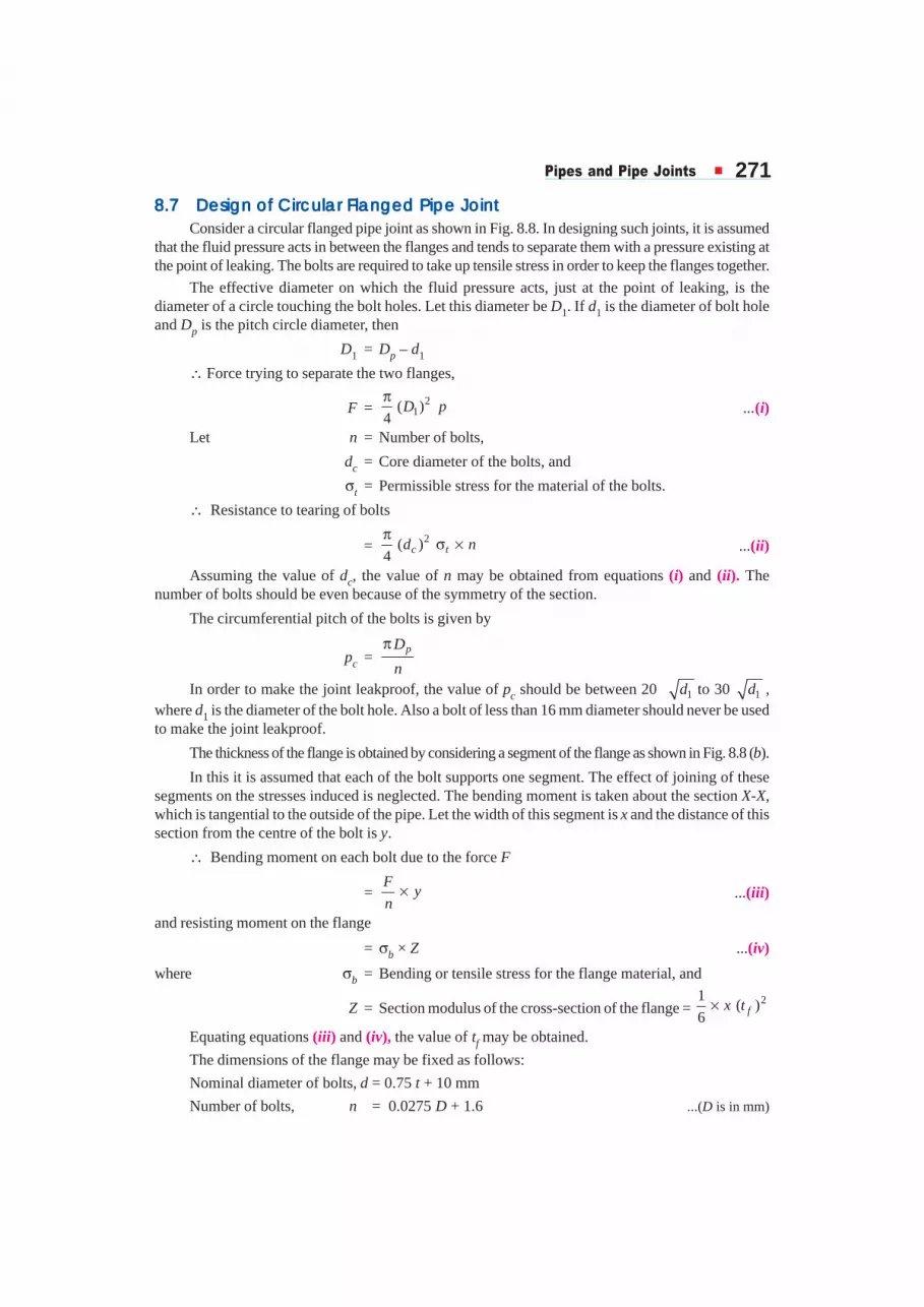
8.78.78.78.78.7 Design of Circular Flanged Pipe JointDesign of Circular Flanged Pipe JointDesign of Circular Flanged Pipe JointDesign of Circular Flanged Pipe JointDesign of Circular Flanged Pipe JointConsider a circular flanged pipe joint as shown in Fig. 8.8. In designing such joints, it is assumed
that the fluid pressure acts in between the flanges and tends to separate them with a pressure existing atthe point of leaking. The bolts are required to take up tensile stress in order to keep the flanges together.
The effective diameter on which the fluid pressure acts, just at the point of leaking, is thediameter of a circle touching the bolt holes. Let this diameter be D1. If d1 is the diameter of bolt holeand Dp is the pitch circle diameter, then
D1 = Dp – d1
∴ Force trying to separate the two flanges,
F = 21( )
4D p
π...(i)
Let n = Number of bolts,
dc = Core diameter of the bolts, and
σt = Permissible stress for the material of the bolts.
∴ Resistance to tearing of bolts
= 2( )4 c td nπ
σ × ...(ii)
Assuming the value of dc, the value of n may be obtained from equations (i) and (ii). Thenumber of bolts should be even because of the symmetry of the section.
The circumferential pitch of the bolts is given by
pc =pD
n
π
In order to make the joint leakproof, the value of pc should be between 20 1d to 30 1d ,where d1 is the diameter of the bolt hole. Also a bolt of less than 16 mm diameter should never be usedto make the joint leakproof.
The thickness of the flange is obtained by considering a segment of the flange as shown in Fig. 8.8 (b).
In this it is assumed that each of the bolt supports one segment. The effect of joining of thesesegments on the stresses induced is neglected. The bending moment is taken about the section X-X,which is tangential to the outside of the pipe. Let the width of this segment is x and the distance of thissection from the centre of the bolt is y.
∴ Bending moment on each bolt due to the force F
=F
yn
× ...(iii)
and resisting moment on the flange
= σb × Z ...(iv)
where σb = Bending or tensile stress for the flange material, and
Z = Section modulus of the cross-section of the flange = 21
( )6 fx t×
Equating equations (iii) and (iv), the value of tf may be obtained.
The dimensions of the flange may be fixed as follows:
Nominal diameter of bolts, d = 0.75 t + 10 mm
Number of bolts, n = 0.0275 D + 1.6 ...(D is in mm)
272 � ����������������������������
Thickness of flange, tf = 1.5 t + 3 mm
Width of flange, B = 2.3 d
Outside diameter of flange,
Do = D + 2t + 2B
Pitch circle diameter of bolts,
Dp = D + 2t + 2d + 12 mm
The pipes may be strengthened by providing greater thickness near the flanges equal to2
ft t+
as shown in Fig. 8.9. The flanges may be strengthened by providing ribs equal to thickness of 2
ft t+ ,
as shown in Fig. 8.10 (a).
Example 8.3. Find out the dimensions of a flanged joint for a cast iron pipe 250 mm diameterto carry a pressure of 0.7 N/mm2.
Solution. Given: D = 250 mm ; p = 0.7 N/mm2
From Table 8.1, we find that for cast iron, allowable tensile stress, σt = 14 N/mm2 and fromTable 8.2, C = 9 mm. Therefore thickness of the pipe,
t =. 0.7 250
9 15.3 say 16 mm2 2 14t
p DC
×+ = + =σ ×
Ans.
Other dimensions of a flanged joint for a cast iron pipe may be fixed as follows:
Nominal diameter of the bolts,
d = 0.75 t + 10 mm = 0.75 × 16 + 10 = 22 mm Ans.Number of bolts, n = 0.0275 D + 1.6 = 0.0275 × 250 + 1.6 = 8.475 say 10 Ans.Thickness of the flanges, tf = 1.5 t + 3 mm = 1.5 × 16 + 3 = 27 mm Ans.Width of the flange, B = 2.3 d = 2.3 × 22 = 50.6 say 52 mm Ans.Outside diameter of the flange,
Do = D + 2t + 2B = 250 + 2 × 16 + 2 × 52 = 386 mm Ans.Pitch circle diameter of the bolts,
Dp = D + 2t + 2d + 12 mm = 250 + 2 × 16 + 2 × 22 + 12 mm= 338 mm Ans.
Circumferential pitch of the bolts,
pc =338
106.2 mm10
pD
n
π × π ×= = Ans.
In order to make the joint leak proof, the value of pc should be between 20 1d to 30 1dwhere d1 is the diameter of bolt hole.
Let us take d1 = d + 3 mm = 22 + 3 = 25 mm
∴ 120 20 25 100 mmd = =
and 130 30 25 150 mmd = =
Since the circumferential pitch as obtained above (i.e. 106.2 mm) is within 1 120 to 30d d ,therefore the design is satisfactory.

������������������� � 273Example 8.4. A flanged pipe with internal diameter as 200 mm is subjected to a fluid pressure
of 0.35 N/mm2. The elevation of the flange is shown in Fig. 8.12. The flange is connected by meansof eight M 16 bolts. The pitch circle diameter of the bolts is 290 mm. If the thickness of the flange is20 mm, find the working stress in the flange.
Solution. Given : D = 200 mm ; p = 0.35 N/mm2 ; n = 8 ;* d = 16 mm ; Dp = 290 mm ; tf = 20 mm
First of all, let us find the thickness of the pipe. Assuming the pipe to be of cast iron, we find fromTable 8.1 that the allowable tensile stress for cast iron, σt = 14 N/mm2 and from Table 8.2, C = 9 mm.
∴ Thickness of the pipe,
t =. 0.35 200
9 11.5 say 12mm2 2 14t
p DC
×+ = + =σ ×
Since the diameter of the bolt holes (d1) is taken larger than the nominal diameter of the bolts(d), therefore let us take diameter of the bolt holes,
d1 = d + 2 mm = 16 + 2 = 18 mm
Fig. 8.12
and diameter of the circle on the inside of the bolt holes,
D1 = Dp – d1 = 290 – 18 = 272 mm
∴ Force trying to separate the flanges i.e. force on 8 bolts,
F = 2 21( ) (272) 0.35 20 340 N
4 4D p
π π= =
Now let us find the bending moment about the section X-X which is tangential to the outside ofthe pipe. The width of the segment is obtained by measuring the distance from the drawing. Onmeasuring, we get
x = 90 mm
and distance of the section X-X from the centre of the bolt,
y =290 200
12 33 mm2 2 2 2
pD Dt
− + = − + = Let σb = Working stress in the flange.
We know that bending moment on each bolt due to force F
=20340
33 83 900 N-mm8
Fy
n× = × = ...(i)
* M16 bolt means that the nominal diameter of the bolt (d) is 16 mm.

274 � ����������������������������
and resisting moment on the flange
=21
( )6b b fZ x tσ × = σ × ×
=21
90 (20) 6000 N-mm6b bσ × × = σ ...(ii)
From equations (i) and (ii), we have
σb = 83 900 / 6000
= 13.98 N/mm2 = 13.98 MPa Ans.
8.88.88.88.88.8 Design of Oval Flanged Pipe JointDesign of Oval Flanged Pipe JointDesign of Oval Flanged Pipe JointDesign of Oval Flanged Pipe JointDesign of Oval Flanged Pipe JointConsider an oval flanged pipe joint as shown
in Fig. 8.11. A spigot and socket is provided forlocating the pipe bore in a straight line. A packing oftrapezoidal section is used to make the joint leakproof. The thickness of the pipe is obtained asdiscussed previously.
The force trying to separate the two flanges hasto be resisted by the stress produced in the bolts. If alength of pipe, having its ends closed somewherealong its length, be considered, then the forceseparating the two flanges due to fluid pressure isgiven by
F1 = 2
4D p
π × ×
where D = Internal diameter of the pipe.The packing has also to be compressed to make the joint leakproof. The intensity of pressure
should be greater than the pressure of the fluid inside the pipe. For the purposes of calculations, it isassumed that the packing material is compressed to the same pressure as that of inside the pipe.Therefore the force tending to separate the flanges due to pressure in the packing is given by
F2 = 2 21( ) ( )
4D D p
π × −
where D1 = Outside diameter of the packing.∴ Total force trying to separate the two flanges,
F = F1 + F2
2 2 2 21 1( ) ( ) ( )
4 4 4D p D D p D p
π π π = × × + − =
Since an oval flange is fastened by means of two bolts, therefore load taken up by each bolt isFb = F /2 . If dc is the core diameter of the bolts, then
Fb = 2( )4 c tbdπ
σ
where σtb is the allowable tensile stress for the bolt material. The value of σtb is usually kept low toallow for initial tightening stress in the bolts. After the core diameter is obtained, then the nominaldiameter of the bolts is chosen from *tables. It may be noted that bolts of less than 12 mm diameter
* In the absence of tables, nominal diameter = Core diameter
0.84
Oval flanged pipe joint.
������������������� � 275should never be used for hydraulic pipes, because very heavy initial tightening stresses may be inducedin smaller bolts. The bolt centres should be as near the centre of the pipe as possible to avoid bendingof the flange. But sufficient clearance between the bolt head and pipe surface must be provided forthe tightening of the bolts without damaging the pipe material.
The thickness of the flange is obtained by considering the flange to be under bending stressesdue to the forces acting in one bolt. The maximum bending stress will be induced at the section X-X.The bending moment at this section is given by
Mxx =2bF
F e e× = ×
and section modulus, Z = 21
( )6 fb t×
where b = Width of the flange at the section X-X, andtf = Thickness of the flange.
Using the bending equation, we have
Mxx = σb.Z
or Fb × e =21
( )6b fb tσ × ×
where σb =Permissible bending stress for the flange material.
From the above expression, the value of tf may be obtained, if b is known. The width of theflange is estimated from the lay out of the flange. The hydraulic joints with oval flanges are known asArmstrong's pipe joints. The various dimensions for a hydraulic joint may be obtained by using thefollowing empirical relations:
Nominal diameter of bolts, d =0.75 t + 10 mm
Thickness of the flange, tf =1.5 t + 3 mm
Outer diameter of the flange,
Do =D + 2t + 4.6 d
Pitch circle diameter, Dp =Do – (3 t + 20 mm)
Example 8.5. Design and draw an oval flanged pipe joint for a pipe having 50 mm bore. It issubjected to an internal fluid pressure of 7 N/mm2. The maximum tensile stress in the pipe material isnot to exceed 20 MPa and in the bolts 60 MPa.
Solution. Given: D = 50 mm or R = 25 mm ; p = 7 N/mm2 ; σt = 20 MPa = 20 N/mm2 ;σtb = 60 MPa = 60 N/mm2
First of all let us find the thickness of the pipe (t). According to Lame's equation, we know thatthickness of the pipe,
t = 20 7
1 25 – 120 7
t
t
pR
p
σ + +− = σ − − = 11.03 say 12 mm Ans.
Assuming the width of packing as 10 mm, therefore outside diameter of the packing,
D1 =D + 2 × Width of packing = 50 + 2 × 10 = 70 mm
∴ Force trying to separate the flanges,
F = 2 21( ) (70) 7 26 943 N
4 4D p
π π= =
Since the flange is secured by means of two bolts, therefore load on each bolt,
Fb =F / 2 = 26 943 /2 = 13 471.5 N
Let dc =Core diameter of bolts.

276 � ����������������������������
We know that load on each bolt (Fb),
13 471.5 = 2 2 2( ) ( ) 60 47.2 ( )4 4c tb c cd d dπ πσ = =
∴ (dc)2 =13 471.5 / 47.2 = 285.4 or dc = 16.9 say 17 mm
and nominal diameter of bolts,
d =17
20.2 say 22 mm0.84 0.84
cd= = Ans.
Outer diameter of the flange,
Do =D + 2t + 4.6 d = 50 + 2 × 12 + 4.6 × 22
=175.2 say 180 mm Ans.and pitch circle diameter of the bolts,
Dp =Do – (3t + 20 mm) = 180 – (3 × 12 + 20) = 124 mm
The elevation of the flange as shown in Fig. 8.13 (which is an ellipse) may now be drawn bytaking major axis as Do (i.e. 180 mm) and minor axis as (Dp – d) i.e. 124 – 22 = 102 mm. In order tofind thickness of the flange (tf), consider the section X-X. By measurement, we find that the width ofthe flange at the section X-X,
b = 89 mm
and the distance of the section X-X from the centre line of the bolt,
e = 33 mm
∴ Bending moment at the section X-X,
Mxx = Fb × e = 13 471.5 × 33 N-mm
= 444 560 N-mm
and section modulus, Z =2 21 1
( ) 89 ( )6 6f fb t t= ×
= 14.83 (tf)2
We know that Mxx = σb × Z
444 560 = 20 × 14.83 (tf)2 = 296.6 ( t f)
2
∴ (tf)2 = 444 560 / 2 96.6 = 1500
or tf = 38.7 say 40 mm Ans.
8.98.98.98.98.9 Design of Square Flanged Pipe JointDesign of Square Flanged Pipe JointDesign of Square Flanged Pipe JointDesign of Square Flanged Pipe JointDesign of Square Flanged Pipe Joint
The design of a square flanged pipe joint, as shown in Fig. 8.14, is similar to that of an ovalflanged pipe joint except that the load has to be divided into four bolts. The thickness of the flangemay be obtained by considering the bending of the flange about one of the sections A-A, B-B, or C-C.
A little consideration will show that the flange is weakest in bending about section A-A.Therefore the thickness of the flange is calculated by considering the bending of the flange, aboutsection A-A.
Fig. 8.13

������������������� � 277
Fig. 8.14. Square flanged pipe joint.
Example 8.6. Design a square flanged pipe joint for pipes of internal diameter 50 mm subjectedto an internal fluid pressure of 7 N/mm2. The maximum tensile stress in the pipe material is not toexceed 21 MPa and in the bolts 28 MPa.
Solution. Given: D = 50 mm or R = 25 mm ; p = 7 N/mm2 ; σt = 21 MPa = 21 N/mm2 ;σtb = 28 MPa = 28 N/mm2
First of all, let us find the thickness of the pipe. According to Lame's equation, we know thatthickness of the pipe,
t =21 7
1 25 1 10.35 say 12 mm21 7
t
t
pR
p
σ + +− = − = σ − − Assuming the width of packing as 10 mm, therefore outside diameter of the packing,
D1 = 50 + 2 × Width of packing = 50 + 2 × 10 = 70 mm∴ Force trying to separate the flanges,
F = 2 21( ) (70) 7 26 943 N
4 4D p
π π= =
Since this force is to be resisted by four bolts, therefore force on each bolt,
Fb = F / 4 = 26 943 / 4 = 6735.8 N
Let dc = Core diameter of the bolts.
We know that force on each bolt (Fb),
6735.8 = 2 2 2( ) ( ) 28 22 ( )4 4c tb c cd d dπ π
σ = =
∴ (dc)2 = 6735.8/22 = 306 or dc = 17.5 mm
and nominal diameter of the bolts,
d =17.5
20.9 say 22 mm0.84 0.84
cd= = Ans.
The axes of the bolts are arranged at the corners of a square of such size that the corners of thenut clear the outside of the pipe.
∴ Minimum length of a diagonal for this square,
L = Outside diameter of pipe + 2 × Dia. of bolt = D + 2t + 2d
= 50 + (2 × 12) + (2 × 22) = 118 mm

278 � ����������������������������
and side of this square,
L1 = 118
83.5 mm2 2
L = =
The sides of the flange must be of sufficient length to accomodate the nuts and bolt headswithout overhang. Therefore the length L2 may be kept as (L1 + 2d ) i.e.
L2 = L1 + 2d = 83.5 + 2 × 22 = 127.5 mm
The elevation of the flange is shown in Fig. 8.15. In order to find the thickness of the flange,consider the bending of the flange about section A-A. The bending about section A-A will take placedue to the force in two bolts.
Fig. 8.15
∴ Bending moment due to the force in two bolts (i.e. due to 2Fb),
M1 = 1 83.52 2 6735.8 562 440 N-mm
2 2bL
F × = × × =
Water pressure acting on half the flange
= 2 Fb = 2 × 6735.8 = 13 472 N
The flanges are screwed with pipe having metric threads of 4.4 threads in 10 mm (i.e. pitch ofthe threads is 10/4.4 = 2.28 mm).
Nominal or major diameter of the threads
= Outside diameter of the pipe = D + 2t = 50 + 2 × 12 = 74 mm
∴ Nominal radius of the threads
= 74 / 2 = 37 mm
Depth of the threads = 0.64 × Pitch of threads = 0.64 × 2.28 = 1.46 mm
∴ Core or minor radius of the threads
= 37 – 1.46 = 35.54 mm
∴ Mean radius of the arc from A-A over which the load due to fluid pressure may be taken tobe concentrated
= 1
2 (37 + 35.54) = 36.27 mm
The centroid of this arc from A-A= 0.6366 × Mean radius = 0.6366 × 36.27 = 23.1 mm
∴ Bending moment due to the water pressure,
M2 = 2 Fb × 23.1 = 2 × 6735.8 × 23.1 = 311 194 N-mm
Square flanged pipe joint.

������������������� � 279Since the bending moments M1 and M2 are in opposite directions, thereforeNet resultant bending moment on the flange about section A-A,
M = M1 – M2 = 562 440 – 311 194 = 251 246 N-mmWidth of the flange at the section A-A,
b = L2 – Outside diameter of pipe = 127.5 – 74 = 53.5 mmLet tf = Thickness of the flange in mm.∴ Section modulus,
Z =2 2 2 21 1
( ) 53.5 ( ) 8.9 ( ) mm6 6f f fb t t t× = × =
We know that net resultant bending moment (M),
251 246 = σb.Z = 21 × 8.9 (tf)2 = 187 (tf)
2
∴ (tf)2 = 251 246 / 187 = 1344 or tf = 36.6 say 38 mm Ans.
EEEEEXEXEXEXEXERRRRRCISECISECISECISECISESSSSS
1. A cast iron pipe of internal diameter 200 mm and thickness 50 mm carries water under a pressure of5 N/mm2. Calculate the tangential and radial stresses at the inner, middle (radius = 125 mm) and outersurfaces. [Ans. 13 MPa, 9.76 MPa, 8 MPa ; – 5 MPa, – 1.76 MPa, 0]
2. A cast iron pipe is to carry 60 m3 of compressed air per minute at a pressure of 1 N/mm2. The velocityof air in the pipe is limited to 10 m/s and the permissible tensile stress for the material of the pipe is14 MPa. Find the diameter of the pipe and its wall thickness. [Ans. 360 mm ; 22 mm]
3. A seamless steel pipe carries 2000 m3 of steam per hour at a pressure of 1.2 N/mm2. The velocity offlow is 28 m/s. Assuming the tensile stress as 40 MPa, find the inside diameter of the pipe and its wallthickness. [Ans. 160 mm ; 5.4 mm]
4. Compute the dimensions of a flanged cast iron pipe 200 mm in diameter to carry a pressure of0.7 N/mm2.
[Ans. t = 20 mm ; d = 16 mm ; n = 8 ; tf = 33 mm ; B = 37 mm ; Do = 314 mm ; Dp = 284 mm]
5. Design an oval flanged pipe joint for pipes of internal diameter 50 mm subjected to a fluid pressure of7 N/mm2. The maximum tensile stress in the pipe material is not to exceed 21 MPa and in the bolts 28MPa. [Ans. t = 12 mm ; d = 30 mm ; tf = 38 mm]
QQQQQUEUEUEUEUESTSTSTSTSTIONSIONSIONSIONSIONS
1. Discuss how the pipes are designed.
2. Describe with sketches, the various types of pipe joints commonly used in engineering practice.
3. Explain the procedure for design of a circular flanged pipe point.
4. Describe the procedure for designing an oval flanged pipe joint.
OBJECTOBJECTOBJECTOBJECTOBJECTIVE IVE IVE IVE IVE TTTTT YPYPYPYPYPE QE QE QE QE QUEUEUEUEUESTSTSTSTSTIONSIONSIONSIONSIONS
1. Cast iron pipes are mainly used
(a) for conveying steam
(b) in water and sewage systems
(c) in pressure lubrication systems on prime movers
(d) all of the above

280 � ����������������������������
2. The diameter of a pipe carrying steam Q m3/min at a velocity v m/min is
(a)Q
v(b)
Q
v
(c)4
π Q
v(d) 1.13
Q
v
3. When the internal diameter of the pipe exceeds twenty times its wall thickness, then .............. cylin-drical shell formula may be applied.
(a) thin (b) thick
4. Which of the following joint is commonly used for joining pipes carrying water at low pressure?
(a) union joint (b) spigot and socket joint
(c) socket or a coupler joint (d) nipple joint
5. The pipes which are burried in the earth should be joined with
(a) union joint (b) spigot and socket joint
(c) coupler joint (d) nipple joint
6. The expansion joint is mostly used for pipes which carry steam at .............. pressures.(a) low (b) high
7. The pipes carrying fluid pressure varying from 5 to 14 N/mm2 should have
(a) square flanged joint (b) circular flanged joint
(c) oval flanged joint (d) spigot and socket joint
8. An oval type flange is fastened by means of
(a) two bolts (b) four bolts
(c) six bolts (d) eight bolts
9. A flanged pipe joint will be a leakproof, if the circumferential pitch of the bolts is
(a) less then 20 d (b) greater than 30 d
(c) between 20 and 30d d (d) equal to one-third of inside diameter of pipe
where d = Diameter of the bolt hole.
10. The flanges in a circular flanged pipe joint are strengthened by providing ribs between the bolt holes.The thickness of such ribs is taken as
(a) t (b) tf
(c)2
− ft t(d)
2
+ ft t
where t =Thickness of pipe, and
tf = Thickness of flange.
ANSWEANSWEANSWEANSWEANSWERRRRRSSSSS
1. (b) 2. (d) 3. (a) 4. (c) 5. (b)
6. (a) 7. (c) 8. (a) 9. (c) 10. (d)