material comparisons: ductile iron pipe vs. hdpe pipe
TRANSCRIPT
Strength and Durability for Life®
MATERIAL COMPARISONS
Ductile Iron Pipe vs. HDPE Pipe
Last Revised: March 2016
1
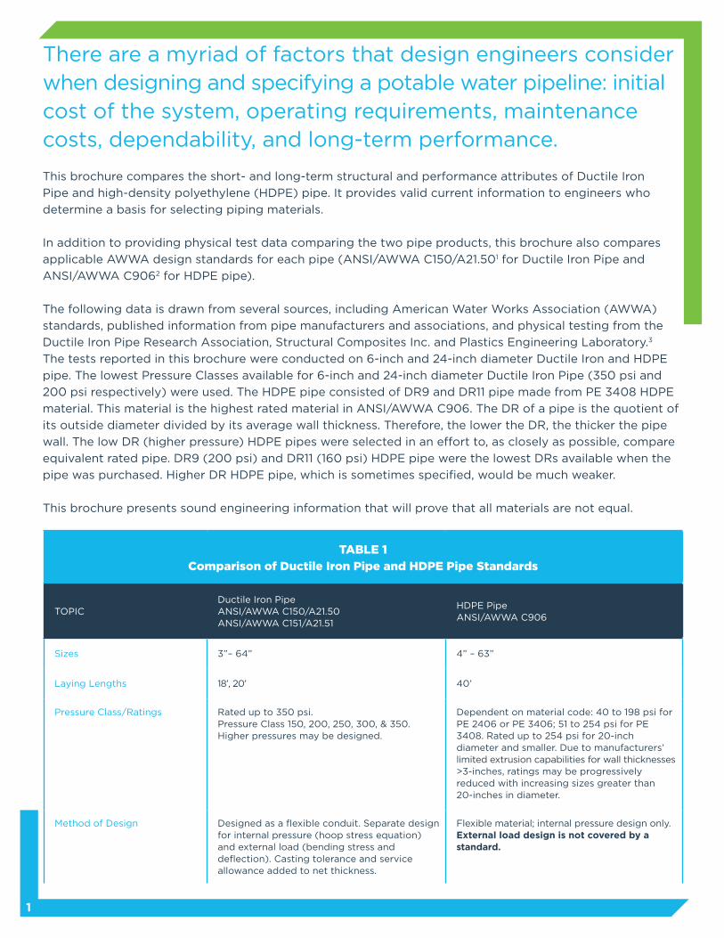
There are a myriad of factors that design engineers consider when designing and specifying a potable water pipeline: initial cost of the system, operating requirements, maintenance costs, dependability, and long-term performance.
This brochure compares the short- and long-term structural and performance attributes of Ductile Iron
Pipe and high-density polyethylene (HDPE) pipe. It provides valid current information to engineers who
determine a basis for selecting piping materials.
In addition to providing physical test data comparing the two pipe products, this brochure also compares
applicable AWWA design standards for each pipe (ANSI/AWWA C150/A21.501 for Ductile Iron Pipe and
ANSI/AWWA C9062 for HDPE pipe).
The following data is drawn from several sources, including American Water Works Association (AWWA)
standards, published information from pipe manufacturers and associations, and physical testing from the
Ductile Iron Pipe Research Association, Structural Composites Inc. and Plastics Engineering Laboratory.3
The tests reported in this brochure were conducted on 6-inch and 24-inch diameter Ductile Iron and HDPE
pipe. The lowest Pressure Classes available for 6-inch and 24-inch diameter Ductile Iron Pipe (350 psi and
200 psi respectively) were used. The HDPE pipe consisted of DR9 and DR11 pipe made from PE 3408 HDPE
material. This material is the highest rated material in ANSI/AWWA C906. The DR of a pipe is the quotient of
its outside diameter divided by its average wall thickness. Therefore, the lower the DR, the thicker the pipe
wall. The low DR (higher pressure) HDPE pipes were selected in an effort to, as closely as possible, compare
equivalent rated pipe. DR9 (200 psi) and DR11 (160 psi) HDPE pipe were the lowest DRs available when the
pipe was purchased. Higher DR HDPE pipe, which is sometimes specified, would be much weaker.
This brochure presents sound engineering information that will prove that all materials are not equal.
TABLE 1
Comparison of Ductile Iron Pipe and HDPE Pipe Standards
TOPICDuctile Iron PipeANSI/AWWA C150/A21.50ANSI/AWWA C151/A21.51
HDPE PipeANSI/AWWA C906
Sizes 3”– 64” 4” – 63”
Laying Lengths 18’, 20’ 40’
Pressure Class/Ratings Rated up to 350 psi.Pressure Class 150, 200, 250, 300, & 350.Higher pressures may be designed.
Dependent on material code: 40 to 198 psi forPE 2406 or PE 3406; 51 to 254 psi for PE 3408. Rated up to 254 psi for 20-inch diameter and smaller. Due to manufacturers’ limited extrusion capabilities for wall thicknesses >3-inches, ratings may be progressively reduced with increasing sizes greater than 20-inches in diameter.
Method of Design Designed as a flexible conduit. Separate design for internal pressure (hoop stress equation) and external load (bending stress and deflection). Casting tolerance and service allowance added to net thickness.
Flexible material; internal pressure design only.External load design is not covered by astandard.
2
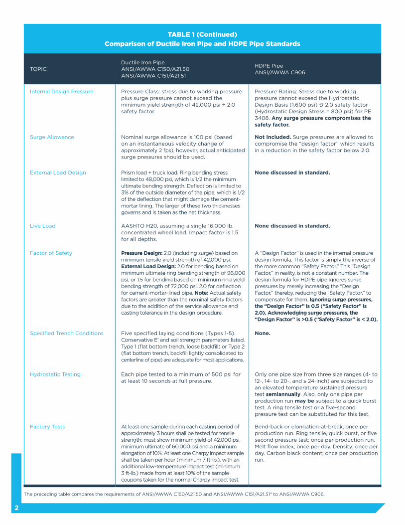
TABLE 1 (Continued)
Comparison of Ductile Iron Pipe and HDPE Pipe Standards
TOPICDuctile Iron PipeANSI/AWWA C150/A21.50ANSI/AWWA C151/A21.51
HDPE PipeANSI/AWWA C906
Internal Design Pressure Pressure Class: stress due to working pressure plus surge pressure cannot exceed the minimum yield strength of 42,000 psi ÷ 2.0 safety factor.
Pressure Rating: Stress due to working pressure cannot exceed the Hydrostatic Design Basis (1,600 psi) ÷ 2.0 safety factor (Hydrostatic Design Stress = 800 psi) for PE 3408. Any surge pressure compromises the safety factor.
Surge Allowance Nominal surge allowance is 100 psi (based on an instantaneous velocity change of approximately 2 fps), however, actual anticipated surge pressures should be used.
Not Included. Surge pressures are allowed tocompromise the “design factor” which results in a reduction in the safety factor below 2.0.
External Load Design Prism load + truck load. Ring bending stress limited to 48,000 psi, which is 1/2 the minimum ultimate bending strength. Deflection is limited to 3% of the outside diameter of the pipe, which is 1/2 of the deflection that might damage the cement-mortar lining. The larger of these two thicknesses governs and is taken as the net thickness.
None discussed in standard.
Live Load AASHTO H20, assuming a single 16,000 lb. concentrated wheel load. Impact factor is 1.5 for all depths.
None discussed in standard.
Factor of Safety Pressure Design: 2.0 (including surge) based on minimum tensile yield strength of 42,000 psi. External Load Design: 2.0 for bending based on minimum ultimate ring bending strength of 96,000 psi, or 1.5 for bending based on minimum ring yield bending strength of 72,000 psi. 2.0 for deflection for cement-mortar-lined pipe. Note: Actual safety factors are greater than the nominal safety factors due to the addition of the service allowance and casting tolerance in the design procedure.
A “Design Factor” is used in the internal pressure design formula. This factor is simply the inverse of the more common “Safety Factor.” This “Design Factor,” in reality, is not a constant number. The design formula for HDPE pipe ignores surge pressures by merely increasing the “Design Factor,” thereby, reducing the “Safety Factor,” to compensate for them. Ignoring surge pressures, the “Design Factor” is 0.5 (“Safety Factor” is 2.0). Acknowledging surge pressures, the “Design Factor” is >0.5 (“Safety Factor” is < 2.0).
Specified Trench Conditions Five specified laying conditions (Types 1-5). Conservative E' and soil strength parameters listed. Type 1 (flat bottom trench, loose backfill) or Type 2 (flat bottom trench, backfill lightly consolidated to centerline of pipe) are adequate for most applications.
None.
Hydrostatic Testing Each pipe tested to a minimum of 500 psi for at least 10 seconds at full pressure.
Only one pipe size from three size ranges (4- to 12-, 14- to 20-, and ≥ 24-inch) are subjected to an elevated temperature sustained pressure test semiannually. Also, only one pipe per production run may be subject to a quick burst test. A ring tensile test or a five-second pressure test can be substituted for this test.
Factory Tests At least one sample during each casting period of approximately 3 hours shall be tested for tensile strength; must show minimum yield of 42,000 psi, minimum ultimate of 60,000 psi and a minimum elongation of 10%. At least one Charpy impact sample shall be taken per hour (minimum 7 ft-lb.), with an additional low-temperature impact test (minimum 3 ft-lb.) made from at least 10% of the sample coupons taken for the normal Charpy impact test.
Bend-back or elongation-at-break; once per production run. Ring tensile, quick burst, or five second pressure test; once per production run. Melt flow index; once per day. Density; once per day. Carbon black content; once per production run.
The preceding table compares the requirements of ANSI/AWWA C150/A21.50 and ANSI/AWWA C151/A21.514 to ANSI/AWWA C906.
3
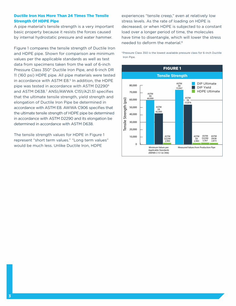
Tensile Strength
Ductile Iron Has More Than 24 Times The Tensile
Strength Of HDPE Pipe
A pipe material’s tensile strength is a very important
basic property because it resists the forces caused
by internal hydrostatic pressure and water hammer.
Figure 1 compares the tensile strength of Ductile Iron
and HDPE pipe. Shown for comparison are minimum
values per the applicable standards as well as test
data from specimens taken from the wall of 6-inch
Pressure Class 350* Ductile Iron Pipe, and 6-inch DR
11 (160 psi) HDPE pipe. All pipe materials were tested
in accordance with ASTM E8.5 In addition, the HDPE
pipe was tested in accordance with ASTM D22906
and ASTM D638.7 ANSI/AWWA C151/A21.51 specifies
that the ultimate tensile strength, yield strength and
elongation of Ductile Iron Pipe be determined in
accordance with ASTM E8. AWWA C906 specifies that
the ultimate tensile strength of HDPE pipe be determined
in accordance with ASTM D2290 and its elongation be
determined in accordance with ASTM D638.
The tensile strength values for HDPE in Figure 1
represent “short term values.” “Long term values”
would be much less. Unlike Ductile Iron, HDPE
experiences “tensile creep,” even at relatively low
stress levels. As the rate of loading on HDPE is
decreased, or when HDPE is subjected to a constant
load over a longer period of time, the molecules
have time to disentangle, which will lower the stress
needed to deform the material.8
* Pressure Class 350 is the lowest available pressure class for 6-inch Ductile
Iron Pipe.
0
10,000
20,000
30,000
40,000
50,000
60,000
70,000
80,000
Minimum Values per Applicable Standards (AWWA C151 & C906)
ASTM E8
60,000
ASTM E8
73,947
ASTM E8
2,983
ASTM D22902,900
ASTM D22903,567
ASTM D6382,873
ASTM E8
53,876
ASTM E8
42,000
Measured Values from Production Pipe
Tens
ile S
tren
gth
(psi
)
DIP UltimateDIP YieldHDPE Ultimate
FIGURE 1
4
Strength Relationship for HDPE
Typical Variations In Operating Or Installation
Temperature Do Not Affect The Strength Of Ductile
Iron Pipe
Since Ductile Iron Pipe has a moderate and
dependable coefficient of thermal expansion,
few problems are created by changes in service
temperatures. Ductile Iron shows no significant
difference in tensile strength in a typical range of
waterworks operating temperatures (32°F to 95°F)
or even a conceivable extreme range of installation
temperatures (-10°F to 140°F).
Because of HDPE pipe’s thermoplastic polymeric
nature, its performance is significantly related to
its operating temperature.9 An indication of this is
that HDPE manufacturers do not recommend their
products for pressure service above 140°F.10
In addition, for service at temperatures greater than
73.4°F, HDPE loses tensile strength, pipe stiffness,
and dimensional stability. The pressure capacity of the
HDPE pipe is reduced, and more care must be taken
during installation to avoid excessive deflection.
Because the thermal expansion coefficient of
HDPE is approximately 18 times that of Ductile
Iron Pipe,11 it is conceivable that, when exposed to
extreme temperature changes, HDPE will experience
undesirable structural movements.
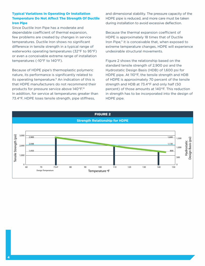
Figure 2 shows the relationship based on the
standard tensile strength of 2,900 psi and the
Hydrostatic Design Basis (HDB) of 1,600 psi for
HDPE pipe. At 110°F, the tensile strength and HDB
of HDPE is approximately 70 percent of the tensile
strength and HDB at 73.4°F and only half (50
percent) of those amounts at 140°F. This reduction
in strength has to be incorporated into the design of
HDPE pipe.
Tens
ile S
tren
gth
(psi
)
Hyd
rost
atic
D
esig
n Ba
sis
(psi
)
Design Temperature Temperature ºF
1,000500
1,000
1,500
07060 73.4º 150120110 1401301009080
0
2,000
3,000
1,450
2,048
2,900
1,130
1,600
800
FIGURE 2
5
Hydrostatic Burst Test
Hydrostatic Burst Test
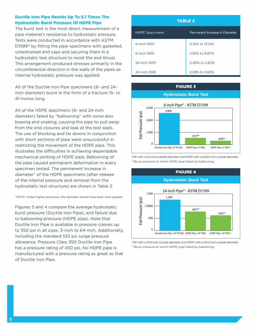
Ductile Iron Pipe Resists Up To 6.1 Times The
Hydrostatic Burst Pressure Of HDPE Pipe
The burst test is the most direct measurement of a
pipe material’s resistance to hydrostatic pressure.
Tests were conducted in accordance with ASTM
D159912 by fitting the pipe specimens with gasketed,
unrestrained end caps and securing them in a
hydrostatic test structure to resist the end thrust.
This arrangement produced stresses primarily in the
circumferential direction in the walls of the pipes as
internal hydrostatic pressure was applied.
All of the Ductile Iron Pipe specimens (6- and 24-
inch diameter) burst in the form of a fracture 15- to
41-inches long.
All of the HDPE specimens (6- and 24-inch
diameter) failed by “ballooning” with some also
bowing and snaking, causing the pipe to pull away
from the end closures and leak at the test seals.
The use of blocking and tie downs in conjunction
with short sections of pipe were unsuccessful in
restricting the movement of the HDPE pipe. This
illustrates the difficulties in achieving dependable
mechanical jointing of HDPE pipe. Ballooning of
the pipe caused permanent deformation in every
specimen tested. The permanent increase in
diameter* of the HDPE specimens (after release
of the internal pressure and removal from the
hydrostatic test structure) are shown in Table 2.
*NOTE: Under higher pressures, the diameter would have been even greater.
Figures 3 and 4 compare the average hydrostatic
burst pressure (Ductile Iron Pipe), and failure due
to ballooning pressure (HDPE pipe). Note that
Ductile Iron Pipe is available in pressure classes up
to 350 psi in all sizes, 3-inch to 64-inch. Additionally,
including the standard 100 psi surge pressure
allowance, Pressure Class 350 Ductile Iron Pipe
has a pressure rating of 450 psi. No HDPE pipe is
manufactured with a pressure rating as great as that
of Ductile Iron Pipe.
* DIP with a 6.9-inch outside diameter and HDPE with a 6.625-inch outside diameter.
**Burst pressure at which HDPE pipe failed by ballooning.
* DIP with a 25.8-inch outside diameter and HDPE with a 24.0-inch outside diameter.
**Burst pressure at which HDPE pipe failed by ballooning.
TABLE 2
HDPE Specimens Permanent Increase in Diameter
6-inch DR11 4.51% to 13.12%
6-inch DR9 1.06% to 8.87%
24-inch DR11 2.46% to 2.63%
24-inch DR9 2.09% to 11.60%
FIGURE 3
FIGURE 4
6-inch Pipe* - ASTM D1599
Fail
Pres
sure
(psi
)
Ductile Iron Pipe 6” PC350 HDPE Pipe 6” DR9
4,500
3,000
3,900
814**
HDPE Pipe 6” DR11
638**
1,500
0
24-inch Pipe* - ASTM D1599
Fail
Pres
sure
(psi
)
Ductile Iron Pipe 24” PC200 HDPE Pipe 24” DR9
1,500
1,0000
1,289
HDPE Pipe 24” DR11
500
0
802**646**
6
The Strength Of Ductile Iron Pipe Is Not
Compromised By Time
There is no measurable relationship between Ductile
Iron’s applied tensile strength and time to failure.
Therefore, the strength for hydrostatic design of
Ductile Iron Pipe is its minimum yield strength in
tension, 42,000 psi.
HDPE responds to tensile stress by failing after a
period of time inversely related to the applied stress.
That means the strength used for hydrostatic design
of HDPE pipe is less than the yield strength of the
material as established in a short time test.13 The
strength value used is called the Hydrostatic Design
Basis (HDB).
The HDB value, which is defined as the stress that
results in failure after 100,000 hours (11.4 years), is
determined according to ASTM standard procedures
by extrapolation from data accumulated from tests
lasting up to 10,000 hours (1.14 years).14 For AWWA
C906 pipe, the HDBs are 1,250 psi (PE 2406 and PE
3406) and 1,600 psi (PE 3408). PE 3408 was used in tests conducted for this brochure. The HDB will be
less than 1,600 psi for HDPE pipe used at temperatures greater than 73.4°F.15
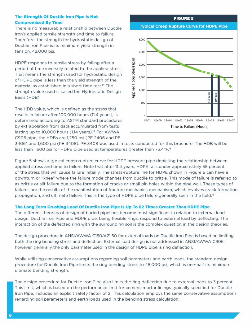
Figure 5 shows a typical creep rupture curve for HDPE pressure pipe depicting the relationship between
applied stress and time to failure. Note that after 11.4 years, HDPE fails under approximately 55 percent
of the stress that will cause failure initially. The stress-rupture line for HDPE shown in Figure 5 can have a
downturn or “knee” where the failure mode changes from ductile to brittle. This mode of failure is referred to
as brittle or slit failure due to the formation of cracks or small pin holes within the pipe wall. These types of
failures are the results of the manifestation of fracture mechanics mechanism, which involves crack formation,
propagation, and ultimate failure. This is the type of HDPE pipe failure generally seen in the field.16
The Long Term Crushing Load Of Ductile Iron Pipe Is Up To 82 Times Greater Than HDPE Pipe
The different theories of design of buried pipelines become most significant in relation to external load
design. Ductile Iron Pipe and HDPE pipe, being flexible rings, respond to external load by deflecting. The
interaction of the deflected ring with the surrounding soil is the complex question in the design theories.
The design procedure in ANSI/AWWA C150/A21.50 for external loads on Ductile Iron Pipe is based on limiting
both the ring bending stress and deflection. External load design is not addressed in ANSI/AWWA C906;
however, generally the only parameter used in the design of HDPE pipe is ring deflection.
While utilizing conservative assumptions regarding soil parameters and earth loads, the standard design
procedure for Ductile Iron Pipe limits the ring bending stress to 48,000 psi, which is one-half its minimum
ultimate bending strength.
The design procedure for Ductile Iron Pipe also limits the ring deflection due to external loads to 3 percent.
This limit, which is based on the performance limit for cement-mortar linings typically specified for Ductile
Iron Pipe, includes an explicit safety factor of 2. This calculation employs the same conservative assumptions
regarding soil parameters and earth loads used in the bending stress calculation.
Typical Creep Rupture Curve for HDPE Pipe
FIGURE 5
0
1.E-01 1.E+00 1.E+01 1.E+02 1.E+03 1.E+04 1.E+05 1.E+071.E+06
500
1,000
1,500
2,000
2,500
3,000
App
lied
Hoo
p St
ress
(psi
)
Time to Failure (Hours)
11.4
Yea
rs
50 Y
ears
7
rigidity are defined by property values that give
consideration to their non-elastic behavior.18
Laboratory ring crush tests of HDPE pipe conducted
with a rapid 0.5 radial inch-per-minute ring loading
rate are meaningless due to its inherent creep. The
material property which ring stiffness is dependent
on is the modulus of elasticity. When HDPE is
stressed, its modulus of elasticity decreases with
time. For example, for a 50-year life expectancy,
the modulus of elasticity of HDPE decreases from
its short-term range of 100,000 — 30,000 psi to
a long-term range of only 20,000 — 30,000 psi.19
Taking this into account, small diameter Pressure
Class 350 Ductile Iron Pipe has approximately 82
times the long term ring stiffness of DR9 HDPE
pipe. Therefore, achieved soil stiffness, bedding
conditions, and on-the-job installation inspection
are obviously much more critical with HDPE pipe
because it has much less long-term pipe stiffness
than Ductile Iron Pipe.
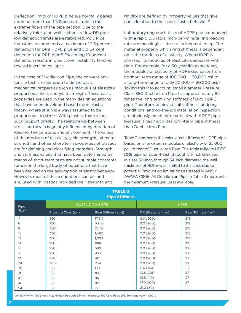
Table 3 compares the calculated stiffness of HDPE pipe,
based on a long-term modulus of elasticity of 25,000
psi, to that of Ductile Iron Pipe. The table reflects HDPE
DR9 pipe for sizes 4-inch through 24-inch diameter.
In sizes 30-inch through 54-inch diameter, the wall
thickness of HDPE was limited to 3 inches due to
potential production limitations as stated in ANSI/
AWWA C906. All Ductile Iron Pipe in Table 3 represents
the minimum Pressure Class available.
Deflection limits of HDPE pipe are normally based
upon no more than 1 1/2 percent strain in the
extreme fibers of the pipe section. Due to the
relatively thick pipe wall sections of low DR pipe,
low deflection limits are established. Poly Pipe
Industries recommends a maximum of 2.5 percent
deflection for DR9 HDPE pipe and 3.0 percent
deflection for DR11 pipe.17 Exceeding 10 percent
deflection results in pipe crown instability tending
toward inversion collapse.
In the case of Ductile Iron Pipe, the conventional
tensile test is relied upon to define basic
mechanical properties such as modulus of elasticity,
proportional limit, and yield strength. These basic
properties are used in the many design equations
that have been developed based upon elastic
theory, where strain is always assumed to be
proportional to stress. With plastics there is no
such proportionality. The relationship between
stress and strain is greatly influenced by duration of
loading, temperature, and environment. The values
of the modulus of elasticity, yield strength, ultimate
strength, and other short-term properties of plastics
are for defining and classifying materials. Strength
and stiffness values that have been determined by
means of short-term tests are not suitable constants
for use in the large body of equations that have
been derived on the assumption of elastic behavior.
However, most of these equations can be, and
are, used with plastics provided their strength and
*ANSI/AWWA C906 only lists 4–inch through 54–inch diameter HDPE with Ductile Iron equivalent O.D.’s
TABLE 3
Pipe Stiffness
Pipe Size*
DUCTILE IRON PIPE HDPE
Pressure Class (psi) Pipe Stiffness (psi) DR (Pressure - psi) Pipe Stiffness (psi)
4 350 17,812 9.0 (200) 218
6 350 5,705 9.0 (200) 218
8 350 2,462 9.0 (200) 218
10 350 1,482 9.0 (200) 218
12 350 1,093 9.0 (200) 218
14 250 696 9.0 (200) 218
16 250 580 9.0 (200) 218
18 250 453 9.0 (200) 218
20 250 401 9.0 (200) 218
24 200 234 9.0 (200) 218
30 150 133 11.0 (160) 112
36 150 108 13.5 (128) 57
42 150 86 15.5 (110) 37
48 150 82 17.0 (100) 27
54 150 77 21.0 (80) 14
8
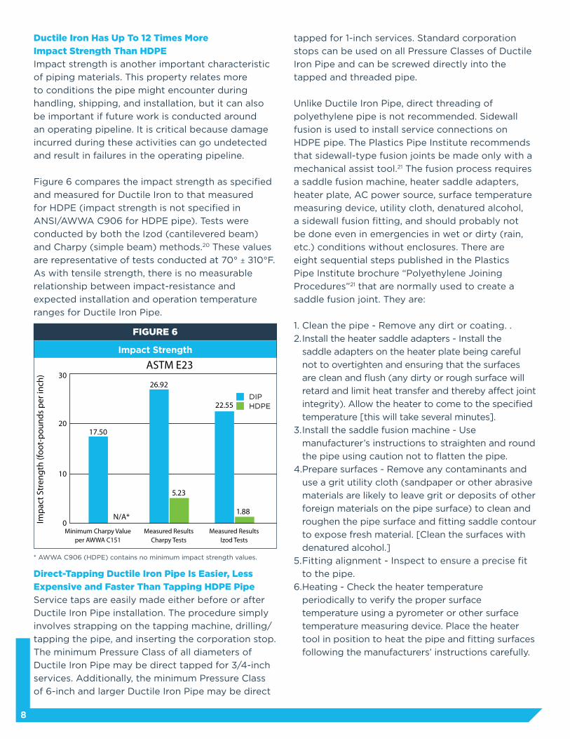
Ductile Iron Has Up To 12 Times More
Impact Strength Than HDPE
Impact strength is another important characteristic
of piping materials. This property relates more
to conditions the pipe might encounter during
handling, shipping, and installation, but it can also
be important if future work is conducted around
an operating pipeline. It is critical because damage
incurred during these activities can go undetected
and result in failures in the operating pipeline.
Figure 6 compares the impact strength as specified
and measured for Ductile Iron to that measured
for HDPE (impact strength is not specified in
ANSI/AWWA C906 for HDPE pipe). Tests were
conducted by both the Izod (cantilevered beam)
and Charpy (simple beam) methods.20 These values
are representative of tests conducted at 70° ± ±10°F.
As with tensile strength, there is no measurable
relationship between impact-resistance and
expected installation and operation temperature
ranges for Ductile Iron Pipe.
Direct-Tapping Ductile Iron Pipe Is Easier, Less
Expensive and Faster Than Tapping HDPE Pipe
Service taps are easily made either before or after
Ductile Iron Pipe installation. The procedure simply
involves strapping on the tapping machine, drilling/
tapping the pipe, and inserting the corporation stop.
The minimum Pressure Class of all diameters of
Ductile Iron Pipe may be direct tapped for 3/4-inch
services. Additionally, the minimum Pressure Class
of 6-inch and larger Ductile Iron Pipe may be direct
tapped for 1-inch services. Standard corporation
stops can be used on all Pressure Classes of Ductile
Iron Pipe and can be screwed directly into the
tapped and threaded pipe.
Unlike Ductile Iron Pipe, direct threading of
polyethylene pipe is not recommended. Sidewall
fusion is used to install service connections on
HDPE pipe. The Plastics Pipe Institute recommends
that sidewall-type fusion joints be made only with a
mechanical assist tool.21 The fusion process requires
a saddle fusion machine, heater saddle adapters,
heater plate, AC power source, surface temperature
measuring device, utility cloth, denatured alcohol,
a sidewall fusion fitting, and should probably not
be done even in emergencies in wet or dirty (rain,
etc.) conditions without enclosures. There are
eight sequential steps published in the Plastics
Pipe Institute brochure “Polyethylene Joining
Procedures”21 that are normally used to create a
saddle fusion joint. They are:
1. Clean the pipe - Remove any dirt or coating. .
2. Install the heater saddle adapters - Install the
saddle adapters on the heater plate being careful
not to overtighten and ensuring that the surfaces
are clean and flush (any dirty or rough surface will
retard and limit heat transfer and thereby affect joint
integrity). Allow the heater to come to the specified
temperature [this will take several minutes].
3. Install the saddle fusion machine - Use
manufacturer’s instructions to straighten and round
the pipe using caution not to flatten the pipe.
4. Prepare surfaces - Remove any contaminants and
use a grit utility cloth (sandpaper or other abrasive
materials are likely to leave grit or deposits of other
foreign materials on the pipe surface) to clean and
roughen the pipe surface and fitting saddle contour
to expose fresh material. [Clean the surfaces with
denatured alcohol.]
5. Fitting alignment - Inspect to ensure a precise fit
to the pipe.
6. Heating - Check the heater temperature
periodically to verify the proper surface
temperature using a pyrometer or other surface
temperature measuring device. Place the heater
tool in position to heat the pipe and fitting surfaces
following the manufacturers’ instructions carefully.
DIPHDPE
Minimum Charpy Valueper AWWA C151
Measured ResultsCharpy Tests
Measured ResultsIzod Tests
17.50
0
10
20
3026.92
22.55
5.23
1.88N/A*Im
pac
t Str
engt
h (fo
ot-p
ound
s p
er in
ch)
ASTM E23
* AWWA C906 (HDPE) contains no minimum impact strength values.
Impact Strength
FIGURE 6
9
7. Fusion - After the prescribed heating requirements
have been met, remove the heater from the heated
pipe and fitting surfaces and quickly inspect the melt
pattern on both the fitting and the pipe. Join the
fitting to the pipe with the prescribed fusion force.
8. Cooling - Continue to hold the force during the
cooling cycle. Allow the joint to cool to ambient
temperature [this may take approximately 30
minutes]. Do not subject the joint to any external
stresses until the fusion joint has cooled. After it
has cooled, cut the service hole in the pipe.
No reference could be found to verify if it is or is
not recommended to install service taps in HDPE
pipe under pressure. Verbal recommendations from
manufacturers and users varied.
Tapping Ductile Iron Pipe is easier, less expensive
and faster than tapping HDPE.
Energy Savings
Ductile Iron Pipe’s larger inside diameter results
in significant energy savings, whether the savings
are based on pumping costs or equivalent pipeline
considerations.22
Utilities save appreciably on power costs and
continue to save money every year for the life of the
pipeline due to Ductile Iron’s larger than nominal
inside diameter and lower pumping costs.
By using equivalent pipeline theories, utilities can
realize immediate savings with Ductile Iron Pipe.
Because of Ductile Iron’s lower head loss, substitute
pipelines with equivalent head loss would require
larger — and more expensive — pipe diameters over
portions of the pipeline.
For example, a 30,000-foot-long, 24-inch Pressure
Class 200* Ductile Iron Pipeline delivering 6,000
gallons per minute has the same total head loss as
1,556 feet of 24-inch DR9 (200 psi), plus 28,444 feet
of 30-inch DR9 (160 psi) HDPE pipe, even when less
proven, more liberal flow coefficients are assumed
for the HDPE pipe.
Conversely, a Ductile Iron Pipeline could be
designed to produce the same head loss as a
substitute pipeline. The Ductile Iron Pipeline,
however, would require smaller — and, thus, less
expensive — pipe diameters over portions of the
pipeline. For the same example above, 30,000 feet
of 24-inch DR9 HDPE pipe would have the same
total head loss as 27,231 feet of 20- inch** Pressure
Class 250* Ductile Iron Pipe plus 2,769 feet of 18-
inch** Pressure Class 250* Ductile Iron Pipe.
OTHER CONSIDERATIONS
Permeation
HDPE is highly permeable and should not be
laid in contaminated land or in land on which
hydrocarbons, including crude and fuel oils,
gasoline, diesel fuel, and kerosene or the
constituents of any of these hydrocarbon mixtures
are used or stored. These chemicals can solvate and
permeate into the walls of polyethylene and other
plastic pipes, potentially swelling and weakening
the pipe and/or adversely affecting the taste and/or
odor of the potable water conveyed.
Unlike HDPE, Ductile Iron Pipe does not
deteriorate and is impermeable when subjected
to hydrocarbons. With Ductile Iron Pipe systems,
only the gasketed joints may be subjected to
permeation. However, due to the gasket’s large mass
and the relatively small contact area between the
gasket and soil, permeation through Ductile Iron
Pipe gasketed joints is not likely to be a significant
source of contamination unless the gasket is
exposed to neat organic chemicals for long periods
of time. This is evidenced in the report titled,
“Permeation of Plastic Pipes by Organic Chemicals,”
by Jenkins of the University of California, Berkeley,
and published in the August 1991 issue of Journal
AWWA under the title “Contamination of Potable
Water by Permeation of Plastic Pipe.”23 The results
of an extensive literature search, together with a
survey of U.S. water utilities, revealed in this report
that plastic pipe was the major piping material
involved in permeation incidents with polybutylene,
polyethylene, and polyvinyl chloride accounting
for 43, 39, and 15 percent respectively of all the
incidents reported. No incident of permeation
of Ductile Iron Pipe and only one incident of
permeation of a gasket (type of pipe was not
disclosed) was reported.
* The minimum pressure class available for that diameter pipe.
** Due to the much smaller than nominal inside diameter of 24–inch HDPE pipe,
the equivalent Ductile Iron Pipeline was constructed of 18– and 20–inch pipe.
10
Some gasket materials resist permeation and
degradation from hydrocarbons better than
others. While tests on other gasket materials
show promise, the results to date indicate that
fluorocarbon rubber gaskets are the most resistant
to permeation. Gaskets of this material are available
for use with Ductile Iron Pipelines installed in areas
contaminated by or susceptible to contamination by
hydrocarbons.
Bedding Requirements
Due to the inherent weaknesses in HDPE pipe,
bedding conditions are much more critical than
with Ductile Iron Pipe. Proper bedding is required
to control deflection, which is the single criterion in
design of HDPE pipe for external loads. Standards
dealing with recommended installation practices for
plastic piping suggest that the pipe be surrounded
by a soil with a minimum particle size, which is
dependent on the pipe diameter, so that the soil
can be sufficiently compacted to develop uniform
lateral passive soil forces.24 The soil also must be
free of organic matter. The trench bottom must be
smooth and free from large stones, large dirt clods,
and any frozen materials, as these objects could
cause a reduction in strength due to scratches or
abrasions.25 Such special bedding requirements are
not practical or actually realized in many areas.
Because of Ductile Iron Pipe’s inherent strength,
Type 1 (flat bottom, loose backfill) or Type 2 (flat
bottom, lightly consolidated backfill) — essentially
native trench conditions in accordance with ANSI/
AWWA C150/A21.50 — are adequate for the vast
majority of applications.
Joining and Joint Deflection
Thermal butt-fusion is the most widely used method
for joining HDPE pipe and requires personnel who
have received training in the use of the fusion
equipment according to the recommendations
of the pipe supplier or the equipment supplier.
This time-consuming method requires expensive
field equipment to hold the pipe and/or fitting in
close alignment, melt the pipe, and join the pipe
with the correct loading. Buttends have to be
faced, cleaned, melted, and fused together, then
cooled under fusion parameters recommended
by the pipe and fusion equipment supplier. The
process also produces a double-roll melt bead on
the inside (restricting flow) and the outside of the
pipe, both of which sometimes may need to be
removed. In situations where different polyethylene
piping materials must be joined, both pipe/fitting
manufacturers should be consulted to determine
the appropriate fusion procedures. The training and
equipment needed to fuse the pipe and service a
system requires a costly expenditure. Even with the
right equipment (fusion machines, generators, repair
components, etc.), variabilities in the weather, or soil
conditions, or even the slightest error in the fusion
procedure can make maintaining a HDPE system
excessively difficult. Expansion and contraction
problems are also common, as are problems created
by the pipe’s dimensional variance and tendency to
“egg.” Fusion equipment is expensive and difficult
to maintain and requires operator competence
that may be difficult to staff and too expensive
to employ for most utilities. Since the butt-fusion
joint is rigid, curves require special fittings or actual
deflection of the pipe itself, which places stress
(perhaps often not appropriately considered in
the design) in the pipe wall. The 40- and 50-foot
lengths of HDPE pipe can create logistical and
equipment challenges in the field. Long exposed
open trenches can also create safety concerns and
business obstructions.
The push-on joint is the most prevalent joining
system for Ductile Iron Pipe systems. It simply
requires lubrication of the joint gasket and
pushing the plain end into the bell end of the pipe.
Ductile Iron Pipe joining has an excellent record
of performance with installation by all kinds of
labor and equipment and in all kinds of conditions,
including dirty and underwater installations. With
Ductile Iron Pipe, no joint or pipe barrel stress is
required to obtain sufficient deflection. Depending
on pipe diameter, push-on joint Ductile Iron Pipe
has a joint deflection of up to 5°.26 Ductile Iron Pipe
fitted with ball and socket joints has a maximum
deflection of up to 15° per joint in sizes up to and
including 24-inch pipe; in sizes 30-inch and larger,
maximum deflection varies from 12.5° to 15°.27
11
Fittings
Ductile Iron Pipe fittings are manufactured in
accordance with ANSI/AWWA C110/A21.10 “Ductile-
Iron and Gray-Iron Fittings 3 In. Through 48 In. For
Water,” and ANSI/AWWA C153/A21.53 “Ductile-Iron
Compact Fittings, For Water Service.” The rated
working pressure (up to 350 psi) of standard fittings
depends on the material (Gray Iron or Ductile
Iron), the fitting size and configuration, and the
wall thickness. The wide range of designs available
in Ductile Iron pressure piping systems results, in
part, from the ready availability of a great variety
of fittings. The ability to go around or bypass
unexpected obstacles encountered in the planned
course of a line by cutting the pipe in the field and
installing the appropriate fittings has long been
recognized as an advantage of iron pipe systems.
The available configurations vary between the two
standards, with bends, tees, crosses, reducers, and
sleeves available from each; while base bends, base
tees, caps, plugs, offsets, connecting pieces, and
tapped tees are covered only by the C110/A21.10
standard. Special fittings such as long radius fittings,
reducing elbows, reducing on-the-run tees, side
outlet fittings, eccentric reducers, wall pipe, welded-
on bosses and outlets, dual purpose and transition
sleeves, and lateral and true wyes are also available
from some manufacturers.
Most fittings for HDPE pipe are fabricated, and
manufacturers typically recommend a derating
factor of 25% for any fabricated fitting which
requires a miter joint (bends and tees). Distributors
may not provide the fully pressure rated fitting
unless the specifications specifically require doing
so. In a DR11 (160 psi working pressure) HDPE pipe
system, DR11 mitered fittings are only rated for
120 psi, and DR9 mitered fittings for only 150 psi.
Therefore, DR7.3 mitered fittings would be required
to assure at least equal pressure rating with the
pipe. This presents a problem. For example: 16-
inch diameter HDPE (DIOD) DR11 and DR7.3 have
average inside diameters of 14.05-inches and
12.35-inches respectively. The effective flow area
of the DR7.3 fitting is 23% less than the DR11 pipe.
Also, there is no agreement between the HDPE
pipe manufacturers that pipe of such different wall
thicknesses may be effectively joined by heat fusion.
There are no universally accepted procedures for
fusing HDPE pipe materials with wall thickness
differentials greater than one SDR grade. The heat
absorption of a DR11 and a DR7.3 are substantially
different and may cause inconsistencies in the
performance of the fused joint.
In the waterworks marketplace, most HDPE fittings
are not made by the same manufacturer as the
pipe. Most fittings are produced by fabrication
shops and independent distributors. This is of
significant concern. Different HDPE pipe and
fitting manufacturers utilize resins from different
sources. Each manufacturer’s very specific and
unique heat fusion procedures are based on their
resin. The parameters and requirements of these
procedures reflect the differences in the behavior
and composition of the resins utilized by each
different manufacturer. Even if the cell class is the
same, resins from different resources may exhibit
different performance properties. Independent
fittings manufacturers may not adhere to the
specific recommended procedures of the pipe
manufacturer. Also, many fitting items are machined
from billet and sheet stock materials from still
other resin resources. Joining of these different
materials together (fittings to pipe or pipe to
pipe) which have different heat fusion procedures
could jeopardize the joint. Consequently, the party
responsible for the quality of the piping system, may
find that it has been clouded and obscured.
Tracer Wires
Because it is a non-metallic substance, buried HDPE
pipe cannot be located using metal detectors. Thus,
tracer wires must be placed in the trench so the
pipe can be located with electronic metal detection
devices. Because Ductile Iron Pipe is metallic, it
requires no tracer wires for location and detection.
Nearby Excavation
Existing HDPE is substantially more vulnerable than
is Ductile Iron Pipe to puncture or damage during
excavation and construction of nearby utilities.
12
Buoyancy
HDPE pipe is buoyant — a concern when installing
the pipe material in areas having a high water
table or when trench flooding is likely to occur. To
prevent loss of completed pipe embedment through
flotation of HDPE pipe, it must be anchored.
Flotation is generally not a concern with normal
installations of Ductile Iron Pipe.
Sun Exposure
Special precautions must be taken when HDPE
pipe is exposed to sunlight for an extended period
of time because, when subjected to long-term
exposure to ultraviolet (UV) radiation from sunlight,
HDPE pipe can suffer surface damage. This effect
is commonly termed ultraviolet (UV) degradation.
According to the ASTM specification, if plastic pipe
is stored outdoors, it may require protection from
weathering in accordance with manufacturers’
recommendations. And in warm climates, the
covering should allow air circulation in and around
the pipe.28 Ductile Iron Pipe is not vulnerable to the
effects of exposure to sunlight or weathering.
Effects Of Scratches
Compared to Ductile Iron Pipe, HDPE is a very soft
material and is consequently much more vulnerable
to abrasions, scratches, and other damage during
shipping and installation. In fact, ANSI/AWWA C906
states that “the walls shall be free from cuts, cracks,
holes, blisters, voids, foreign inclusions, or other
defects that are visible to the naked eye and that
may affect the wall integrity.” This is an arguably
impractical stipulation relative to many rugged
construction sites. Also, the AWWA Committee
Report “Design and Installation of Polyethylene
(PE) Pipe Made in accordance with AWWA C906”29
states that “gouges deeper than 10 percent of the
pipe wall thickness should not be placed in service.
Damage of this magnitude should be corrected
by removing the affected portion of pipe and
subsequently rejoining the remaining pipe ends by
an approved joining method.” Because of Ductile
Iron’s great strength and durability, however, there is
no measurable loss of strength due to scratches and
gouges from normal handling.
Performance History
Man’s ability to cast pipe probably developed from, or
coincidentally with, the manufacture of cannons, which
is reported as early as the year 1313. There is an official
recording of Cast Iron pipe manufactured at Siegerland,
Germany, in 1455 for installation at the Dillenburg Castle.
The earliest record of an AWWA standard for Gray Cast
Iron pipe is contained in the Report of Proceedings
of the Tenth Annual Meeting of the American Water
Works Association (1890). On September 10, 1902,
the New England Water Works Association adopted a
more detailed standard titled “Standard Specifications
for Cast Iron Pipe and Special Castings.”
The advent of Ductile Iron Pipe in 1948 was one of the
most significant developments in the pressure pipe
industry. The first editions of ANSI/AWWA C150/A21.50
(the design standard for Ductile Iron Pipe) and ANSI/
AWWA C151/A21.51 (the manufacturing standard for
Ductile Iron Pipe) were issued in 1965.
The performance of Ductile Iron Pipe extends over 40
years, and because of its close physical resemblance
to Gray Cast Iron pipe, the long-term record of Cast
Iron can be used to predict the life of a Ductile Iron
Pipeline.30 This comparison has been enhanced by
extensive research on the comparative corrosion rates
between Ductile Iron and Gray Cast Iron, which has
shown Ductile Iron to be at least as corrosion-resistant
as Gray Cast Iron.31
Gray and Ductile Iron Pipe have withstood the test of
time. On the other hand, ANSI/AWWA C906 was the
first AWWA standard for HDPE pipe and was only first
issued in 1990.
Conclusion
Ductile Iron Pipe has long been recognized as the
superior pipe material for water and wastewater
applications. Its tremendous strength and durability
allow it to be designed under conservative assumptions
and installed with confidence that the actual service
conditions it experiences will not compromise its ability
to perform.
Regardless of the criteria — strength, durability, tapping,
flow capacity, safety factor, or actual field experience
— it is easy to understand what those who know pipe
have long known. Ductile Iron Pipe is the right decision!
13
1. ANSI/AWWA C150/A21.50 American National
Standard for the Thickness Design of Ductile Iron
Pipe, American Water Works Association, Denver,
Colorado (1996).2. ANSI/AWWA C906 American National Standard
for Polyethylene (PE) Pressure Pipe and Fittings,
4 In. Through 63 In., For Water Distribution,
American Water Works Association, Denver,
Colorado (1999).3. Original tests were conducted by Structural
Composites, Inc., an independent engineering
testing firm, in 1999 in Melbourne, Florida, and
American Cast Iron Pipe Company in Birmingham,
Alabama, in 1999 and witnessed by Professional
Services Industries, an independent consulting
third-party witnessing/testing firm. Supplemental
tests were conducted by Plastics Engineering
Laboratory, an independent testing firm, in 2000
in Lawrenceville, Georgia, and United States
Pipe and Foundry Company in 1999-2000 in
Birmingham, Alabama.4. ANSI/AWWA C151/A21.51 American National
Standard for Ductile-Iron Pipe, Centrifugally Cast,
For Water, American Water Works Association,
Denver, Colorado (1996).5. ASTM E8 Test Methods For Tension Testing of
Metallic Materials.6. ASTM D2290 Apparent Tensile Strength of Ring
or Tubular Plastics and Reinforced Plastics by Split
Disk Method.7. ASTM D638 Tensile Properties of Plastics.8. Engineering Properties of Polyethylene, Plastic
Pipe Institute, p. 3-13.9. Engineering Properties of Polyethylene, Plastic
Pipe Institute, p. 3-36.10. Plexco/Spirolite Engineering Manual, Volume 2:
System Design, p. 3.11. Engineering Properties of Polyethylene, Plastic
Pipe Institute, p. 3-36.12. ASTM D1599 “Test Method for Short-Time
Hydraulic Failure Pressure of Plastic Pipe, Tubing,
and Fittings.”13. Engineering Properties of Polyethylene, Plastic
Pipe Institute, p. 3-19.14. ASTM D2837 “Standard Test Method for Obtaining
Hydrostatic Design Basis for Thermoplastic Pipe
Materials.”15. ANSI/AWWA C906.16. Engineering Properties of Polyethylene, Plastic
Pipe Institute, p. 3-20.
17. Design and Engineering Guide, Poly Pipe
Industries, Inc., p. G1.18. Engineering Properties of Polyethylene, Plastic
Pipe Institute, p. 3-11.19. Engineering Properties of Polyethylene, Plastic
Pipe Institute, p. 3-15.20. ASTM E23 “Notched Bar Impact Testing of Metallic
Materials.”21. Polyethylene Joining Procedures, Plastic Pipe
Institute, p. 6-6.22. “Hydraulic Analysis of Ductile Iron Pipe,” Ductile
Iron Pipe Research Association, Birmingham,
Alabama, 2000.23. D. Jenkins. “Permeation of Plastic Pipes by
Organic Chemicals,” Journal AWWA, August 1991.24. ASTM D2774 Standard Practice for Underground
Installation of Thermoplastic Pressure Piping.25. ASTM D2774.26. AWWA C600, p. 13-14.27. Ductile Iron Pipe Subaqueous Crossings, Ductile
Iron Pipe Research Association, Birmingham,
Alabama.28. ASTM D2774.29. AWWA Committee Report “Design and Installation
of Polyethylene (PE) Pipe Made in Accordance
With AWWA C906,” American Water Works
Association, Denver, Colorado (1998).30. Approximately 550 U.S. and Canadian utilities are
members of the Cast Iron Pipe Century Club for
having Cast Iron pipe in continuous service for
100 years or more. At least 15 utilities have gained
membership in the Cast Iron Pipe Sesquicentury
Club for having Cast Iron pipe in continuous
service for 150 years or more.31. E.C. Sears. “Comparison of the Soil Corrosion
Resistance of Ductile Iron Pipe and Gray
Strength and Durability for Life®
Ductile Iron Pipe Research Association
An association of quality producers dedicated to the highest pipe standards through a program of continuing research and service to water and wastewater professionals.
P.O. Box 190306Birmingham, AL 35219205.402.8700 Telwww.dipra.org
Social Media
Get in the flow with Ductile Iron Pipe by connecting with us on Facebook, Twitter, and LinkedIn.
Visit our website, www.dipra.org/videos, and click on the YouTube icon for informational videos on Ductile Iron Pipe’s ease of use, economic benefits, strength and durability, advantages over PVC, and more.
Copyright © 2016 by Ductile Iron Pipe Research Association
Member Companies
AMERICAN Ductile Iron PipeP.O. Box 2727Birmingham, Alabama 35202-2727
Canada Pipe Company, Ltd.55 Frid St. Unit #1Hamilton, Ontario L8P 4M3 Canada
McWane DuctileP.O. Box 6001Coshocton, Ohio 43812-6001
United States Pipe and Foundry Company Two Chase Corporate DriveSuite 200Birmingham, Alabama 35244
Ductile Iron Pipe is
For more information contact DIPRA or any of its member companies.