aquatherm blue pipe
TRANSCRIPT
aquathermstate of the pipe
aquatherm blue pipePipe system made of polypropylene For heating and cooling and various industrial applications

The application pictures in this catalogue show the aquatherm blue pipe pipes as they were produced until March 2020. With the material change to fusiolen® PP-RCT, the pipes are now single-coloured blue.
NEW SINCE THE LAST VERSION
Page Change
22 Revision Fire Protection
60 Push-fit fitting
89 Planning & design of compressed air applications
102 Explanatory comments on the aquatherm GmbH warranty
from 122 Updated product list
2
33
Service 4
Product overview 6Short cuts & symbols 8
Systems & features
aquatherm polypropylene pipe systems 10aquatherm blue pipe 11aquatherm blue pipe MF (composite technology) 14aquatherm blue pipe ot 15aquatherm blue pipe ti 16UV-resistance 20Integration of other systems or components 20 Permissible working pressure 21 Fire protection 22Connection 26Material: fusiolen® 27aquatherm & ecology 28Environmental Product Declaration and LEED certification 29
Quality assurance Compliance with the system standard/Quality management 30System control/Internal control 31External control 33
Application areas
Heating and air-conditioning 34Building services 35Industrial floor heating 36Ship building 37Under soil heating 38Ice surface cooling 39Compressed air/Swimming pool 40Agriculture/Special applications 41
Fusion: Welding technology
Part A: Tools and accessoires 42Part A: Assembly of welding tools 43Part A: Heating up phase/handling 44
Guidelines Part B: Checking of devices and tools 45
Preparation for the fusion Part B: Heating of pipe and fitting 46
Setting and alignment Part B: Universal peeling tools 47Part C: Weld-in saddles 49Part C: Weld-on saddles: Drilling under pressure 52Part D: Pulling jig (hitch) 53Part E: Welding machines 56Part F: Electrofusion device 57Push-fit fitting 60Flange connections 64Repair options 65Part G: Butt-welding 66Visual inspection of fusion seam 68
Installation principles
Fastening technique/Fixed points/Sliding points 70Installation advice/Linear expansion/Concealed installation 70Installation in ducts 71Open installation/Calculation of the linear expansion 72Linear expansion 73Pipe clamps 75Bending side 76Expansion loop/Pre-stress/Bellow expansion joint 77Length of bending side 78Length of bending side with pre-stress 79Support intervals 80Thermal insulation of hot water pipes 81Insulation thickness 82Pressure test 83Pressure test – test record 85
Planning
Coefficient of loss 87Planning & design of compressed air applications 89
Chemical resistance 90
Warranty 102
References 104
Transport and storage 121
Product list 122
aquatherm blue pipe pipes aquatherm prefabricationFastening materialFittingsWeld-in saddlesWeld-on saddlesFlange adapterThreaded connections & accessoiresTransition pieceScrewed connections & counter partsDistributors Valves & accessoiresCutting tools & welding devicesWelding machines & welding jigButt welding machines & electrofusion devicePeeling toolsSaddle welding toolsDrills & saddle peeling toolHot tapping tool & accessoires
TABLE OF CONTENTS

4
SERVICETECHNICAL HOTLINE+49 2722 950 [email protected] www.aquatherm.de
Headquarters Attendornaquatherm GmbHBiggen 557439 Attendorn GermanyPhone: +49 2722 950 0
Subsidiary Radebergaquatherm GmbHWilhelm-Rönsch-Str. 401454 Radeberg GermanyPhone: +49 3528 4362 0
Trade shows
aquatherm is represented with its own booth at all important sanitary and HVAC trade shows in Germany and abroad. Information on trade fair dates in your area are avail-able at www.aquatherm.de in the „service“ area.
Training
In addition to the proven lectures and counter events in the specia-lized trade and the training at the guild associations, aquatherm regu-larly offers specialist seminars and information events at the training center in Attendorn.
Technical sales
Whether briefing on site, system briefing in your workshop or coun-ter events and tool days at the specialized trade: In addition to the regular training in Attendorn, the aquatherm application engineers are every day and everywhere in Germany on the way.
A list of our partners worldwide can be found on our website www.aquatherm.de in the category „contact“.
55
Subsidiary Radebergaquatherm GmbHWilhelm-Rönsch-Str. 401454 Radeberg GermanyPhone: +49 3528 4362 0
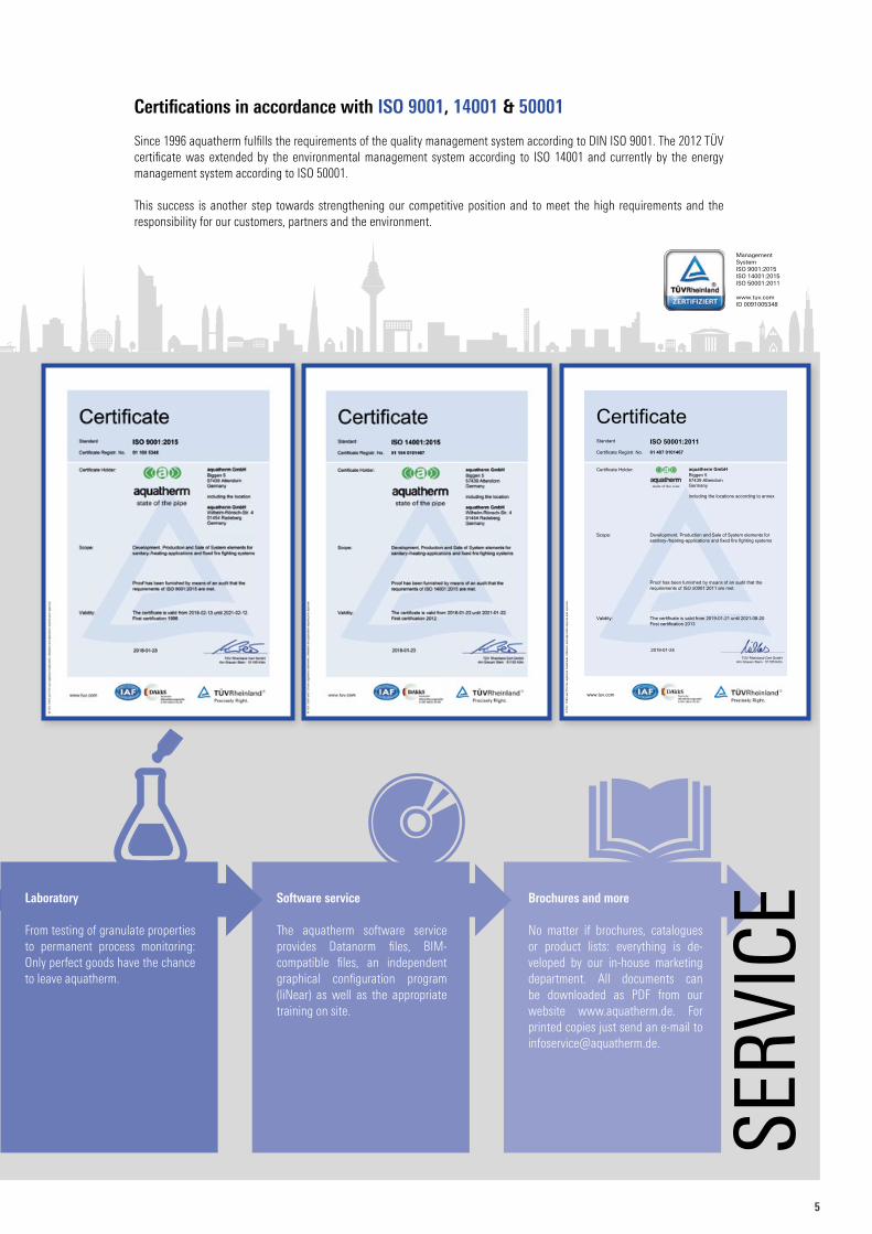
Certifications in accordance with ISO 9001, 14001 & 50001
Since 1996 aquatherm fulfills the requirements of the quality management system according to DIN ISO 9001. The 2012 TÜV certificate was extended by the environmental management system according to ISO 14001 and currently by the energy management system according to ISO 50001.
This success is another step towards strengthening our competitive position and to meet the high requirements and the responsibility for our customers, partners and the environment.
ManagementSystemISO 9001:2015ISO 14001:2015ISO 50001:2011
www.tuv.comID 0091005348
Certificate
Standard ISO 50001:2011
Certificate Registr. No. 01 407 0101467
Certificate Holder:
aquatherm GmbH
Biggen 5 57439 Attendorn Germany including the locations according to annex
Scope: Development, Production and Sale of System elements for sanitary-/heating-applications and fixed fire fighting systems
Proof has been furnished by means of an audit that the requirements of ISO 50001:2011 are met.
Validity: The certificate is valid from 2019-01-21 until 2021-08-20. First certification 2013
2019-01-24
TÜV Rheinland Cert GmbH Am Grauen Stein · 51105 Köln
www.tuv.com
® T
ÜV,
TU
EV a
nd T
UV
are
regi
ster
ed tr
adem
arks
. Util
isat
ion
and
appl
icat
ion
requ
ires
prio
r app
rova
l.
Brochures and more
No matter if brochures, catalogues or product lists: everything is de-veloped by our in-house marketing department. All documents can be downloaded as PDF from our website www.aquatherm.de. For printed copies just send an e-mail to [email protected].
Software service
The aquatherm software service provides Datanorm files, BIM- compatible files, an independent graphical configuration program (liNear) as well as the appropriate training on site.
Laboratory
From testing of granulate properties to permanent process monitoring: Only perfect goods have the chance to leave aquatherm.
SERV
ICE
6
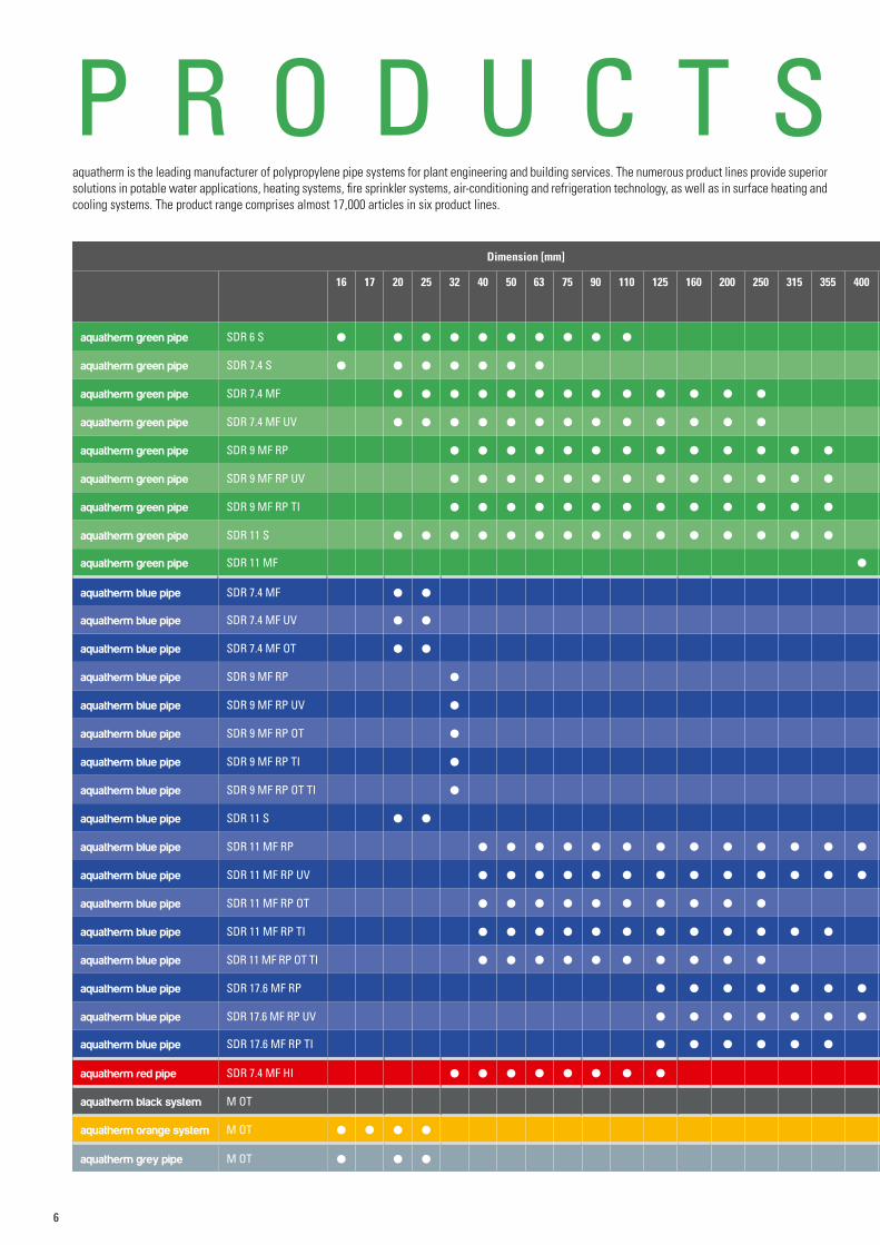
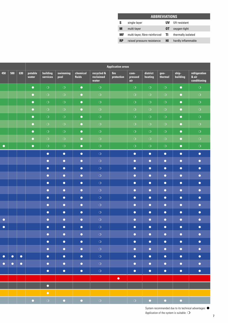
P R O D U C T Saquatherm is the leading manufacturer of polypropylene pipe systems for plant engineering and building services. The numerous product lines provide superior solutions in potable water applications, heating systems, fire sprinkler systems, air-conditioning and refrigeration technology, as well as in surface heating and cooling systems. The product range comprises almost 17,000 articles in six product lines.
Dimension [mm] Application areas
16 17 20 25 32 40 50 63 75 90 110 125 160 200 250 315 355 400 450 500 630 potable water
building services
swimming pool
chemical fluids
recycled & reclaimed water
fire protection
compressed air
district heating
geothermal
shipbuilding
refrigeration & air conditioning
aquatherm green pipe SDR 6 S l l l l l l l l l l l m m l m m m m l m
aquatherm green pipe SDR 7.4 S l l l l l l l l m m l m m m m l m
aquatherm green pipe SDR 7.4 MF l l l l l l l l l l l l l l m m l m m m m l m
aquatherm green pipe SDR 7.4 MF UV l l l l l l l l l l l l l l m m l m m m m l m
aquatherm green pipe SDR 9 MF RP l l l l l l l l l l l l l l m m l m m m m l m
aquatherm green pipe SDR 9 MF RP UV l l l l l l l l l l l l l l m m l m m m m l m
aquatherm green pipe SDR 9 MF RP TI l l l l l l l l l l l l l l m m l m m m m l m
aquatherm green pipe SDR 11 S l l l l l l l l l l l l l l l l m m l m m m m l m
aquatherm green pipe SDR 11 MF l l l m m l m m m m l m
aquatherm blue pipe SDR 7.4 MF l l l l l m l l l l l
aquatherm blue pipe SDR 7.4 MF UV l l l l l m l l l l l
aquatherm blue pipe SDR 7.4 MF OT l l l l l m l l l l l
aquatherm blue pipe SDR 9 MF RP l l l l m l l l l l
aquatherm blue pipe SDR 9 MF RP UV l l l l m l l l l l
aquatherm blue pipe SDR 9 MF RP OT l l l l m l l l l l
aquatherm blue pipe SDR 9 MF RP TI l l l l m l l l l l
aquatherm blue pipe SDR 9 MF RP OT TI l l l l m l l l l l
aquatherm blue pipe SDR 11 S l l l l l m l l l l l
aquatherm blue pipe SDR 11 MF RP l l l l l l l l l l l l l l l l l m l l l l l
aquatherm blue pipe SDR 11 MF RP UV l l l l l l l l l l l l l l l l l m l l l l l
aquatherm blue pipe SDR 11 MF RP OT l l l l l l l l l l l l l m l l l l l
aquatherm blue pipe SDR 11 MF RP TI l l l l l l l l l l l l l l l m l l l l l
aquatherm blue pipe SDR 11 MF RP OT TI l l l l l l l l l l l l l m l l l l l
aquatherm blue pipe SDR 17.6 MF RP l l l l l l l l l l l l l m l l l l l
aquatherm blue pipe SDR 17.6 MF RP UV l l l l l l l l l l l l l m l l l l l
aquatherm blue pipe SDR 17.6 MF RP TI l l l l l l l l l m l l l l l
aquatherm red pipe SDR 7.4 MF HI l l l l l l l l l
aquatherm black system M OT l
aquatherm orange system M OT l l l l l
aquatherm grey pipe M OT l l l l m l l m m l l l
77
ABBREVIATIONS
S single-layer UV UV-resistant
M multi-layer OT oxygen-tight
MF multi-layer, fibre-reinforced TI thermally isolated
RP raised pressure resistance HI hardly inflammable
System recommended due to its technical advantages: lApplication of the system is suitable: m
Dimension [mm] Application areas
16 17 20 25 32 40 50 63 75 90 110 125 160 200 250 315 355 400 450 500 630 potable water
building services
swimming pool
chemical fluids
recycled & reclaimed water
fire protection
compressed air
district heating
geothermal
shipbuilding
refrigeration & air conditioning
aquatherm green pipe SDR 6 S l l l l l l l l l l l m m l m m m m l m
aquatherm green pipe SDR 7.4 S l l l l l l l l m m l m m m m l m
aquatherm green pipe SDR 7.4 MF l l l l l l l l l l l l l l m m l m m m m l m
aquatherm green pipe SDR 7.4 MF UV l l l l l l l l l l l l l l m m l m m m m l m
aquatherm green pipe SDR 9 MF RP l l l l l l l l l l l l l l m m l m m m m l m
aquatherm green pipe SDR 9 MF RP UV l l l l l l l l l l l l l l m m l m m m m l m
aquatherm green pipe SDR 9 MF RP TI l l l l l l l l l l l l l l m m l m m m m l m
aquatherm green pipe SDR 11 S l l l l l l l l l l l l l l l l m m l m m m m l m
aquatherm green pipe SDR 11 MF l l l m m l m m m m l m
aquatherm blue pipe SDR 7.4 MF l l l l l m l l l l l
aquatherm blue pipe SDR 7.4 MF UV l l l l l m l l l l l
aquatherm blue pipe SDR 7.4 MF OT l l l l l m l l l l l
aquatherm blue pipe SDR 9 MF RP l l l l m l l l l l
aquatherm blue pipe SDR 9 MF RP UV l l l l m l l l l l
aquatherm blue pipe SDR 9 MF RP OT l l l l m l l l l l
aquatherm blue pipe SDR 9 MF RP TI l l l l m l l l l l
aquatherm blue pipe SDR 9 MF RP OT TI l l l l m l l l l l
aquatherm blue pipe SDR 11 S l l l l l m l l l l l
aquatherm blue pipe SDR 11 MF RP l l l l l l l l l l l l l l l l l m l l l l l
aquatherm blue pipe SDR 11 MF RP UV l l l l l l l l l l l l l l l l l m l l l l l
aquatherm blue pipe SDR 11 MF RP OT l l l l l l l l l l l l l m l l l l l
aquatherm blue pipe SDR 11 MF RP TI l l l l l l l l l l l l l l l m l l l l l
aquatherm blue pipe SDR 11 MF RP OT TI l l l l l l l l l l l l l m l l l l l
aquatherm blue pipe SDR 17.6 MF RP l l l l l l l l l l l l l m l l l l l
aquatherm blue pipe SDR 17.6 MF RP UV l l l l l l l l l l l l l m l l l l l
aquatherm blue pipe SDR 17.6 MF RP TI l l l l l l l l l m l l l l l
aquatherm red pipe SDR 7.4 MF HI l l l l l l l l l
aquatherm black system M OT l
aquatherm orange system M OT l l l l l
aquatherm grey pipe M OT l l l l m l l m m l l l
8
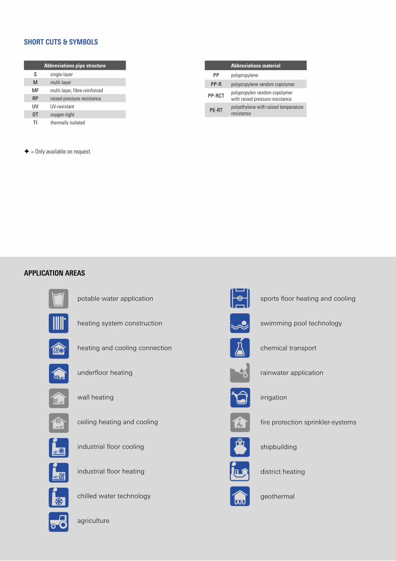
SHORT CUTS & SYMBOLS
APPLICATION AREAS
potable water application
heating system construction
heating and cooling connection
underfloor heating
wall heating
ceiling heating and cooling
industrial floor cooling
industrial floor heating
chilled water technology
agriculture
sports floor heating and cooling
swimming pool technology
chemical transport
rainwater application
irrigation
fire protection sprinkler-systems
shipbuilding
district heating
geothermal
-C°
+C°
+C°
+C°
+/-C°
Abbreviations pipe structure
S single-layer
M multi-layer
MF multi-layer, fibre-reinforced
RP raised pressure resistance
UV UV-resistant
OT oxygen-tight
TI thermally isolated
Abbreviations material
PP polypropylene
PP-R polypropylene random copolymer
PP-RCT polypropylen random copolymer with raised pressure resistance
PE-RT polyethylene with raised temperature resistance
= Only available on request.
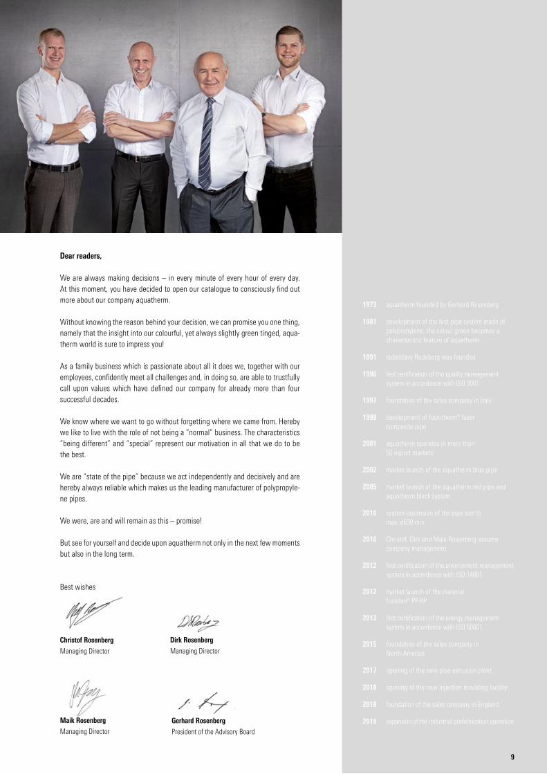
Dirk Rosenberg
Managing Director
Christof Rosenberg
Managing Director
Dear readers,
We are always making decisions – in every minute of every hour of every day. At this moment, you have decided to open our catalogue to consciously find out more about our company aquatherm.
Without knowing the reason behind your decision, we can promise you one thing, namely that the insight into our colourful, yet always slightly green tinged, aqua-therm world is sure to impress you!
As a family business which is passionate about all it does we, together with our employees, confidently meet all challenges and, in doing so, are able to trustfully call upon values which have defined our company for already more than four successful decades.
We know where we want to go without forgetting where we came from. Hereby we like to live with the role of not being a “normal” business. The characteristics “being different” and “special” represent our motivation in all that we do to be the best.
We are “state of the pipe” because we act independently and decisively and are hereby always reliable which makes us the leading manufacturer of polypropyle-ne pipes.
We were, are and will remain as this – promise!
But see for yourself and decide upon aquatherm not only in the next few moments but also in the long term.
Best wishes
Gerhard Rosenberg
President of the Advisory Board
Maik Rosenberg
Managing Director
9
1973 aquatherm founded by Gerhard Rosenberg
1981 development of the first pipe system made of polypropylene; the colour green becomes a characteristic feature of aquatherm
1991 subsidiary Radeberg was founded
1996 first certification of the quality management system in accordance with ISO 9001
1997 foundation of the sales company in Italy
1999 development of fusiotherm® faser composite pipe
2001 aquatherm operates in more than 50 export markets
2002 market launch of the aquatherm blue pipe
2005 market launch of the aquatherm red pipe and aquatherm black system
2010 system expansion of the pipe size to max. ø630 mm
2010 Christof, Dirk and Maik Rosenberg assume company management
2012 first certification of the environment management system in accordance with ISO 14001
2012 market launch of the material fusiolen® PP-RP
2013 first certification of the energy management system in accordance with ISO 50001
2015 foundation of the sales company in North America
2017 opening of the new pipe extrusion plant
2018 opening of the new injection moulding facility
2018 foundation of the sales company in England
2019 expansion of the industrial prefabrication operation
10
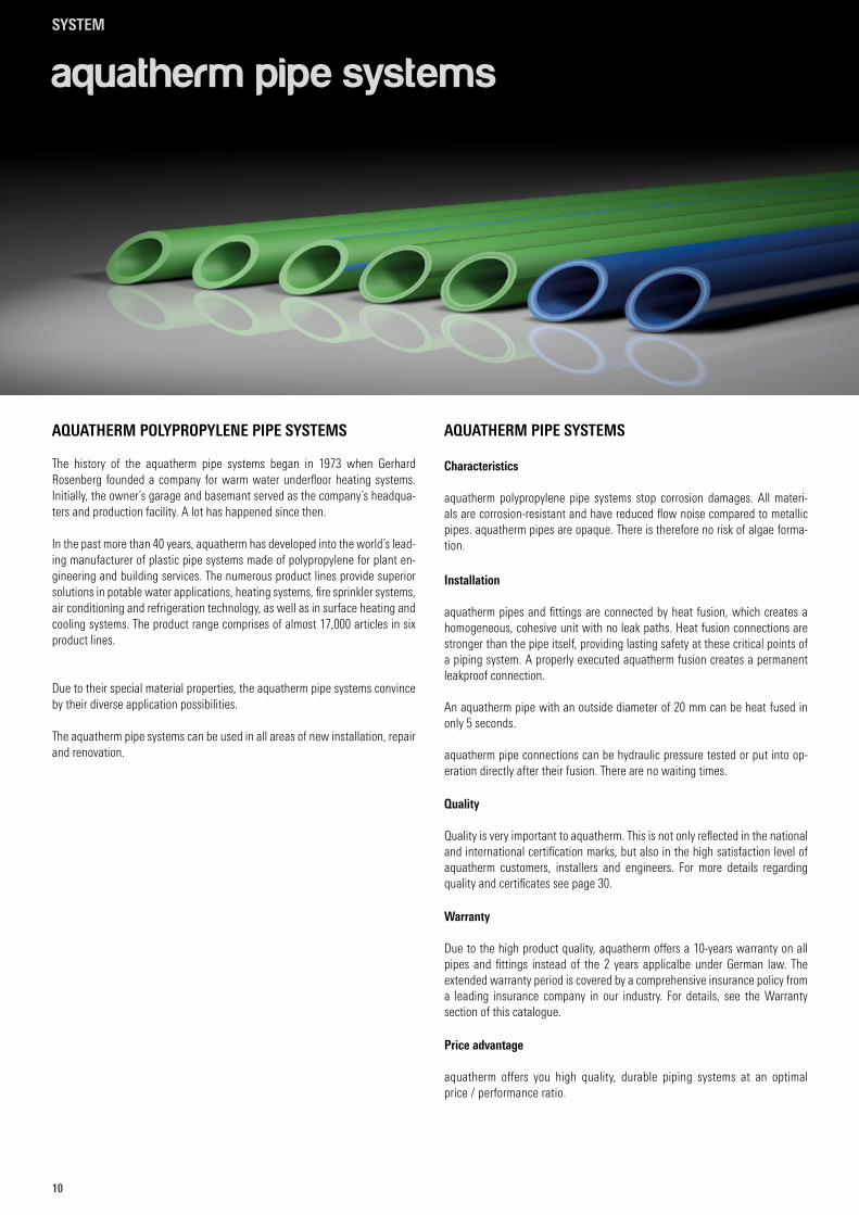
aquatherm pipe systems
AQUATHERM POLYPROPYLENE PIPE SYSTEMS
The history of the aquatherm pipe systems began in 1973 when Gerhard Rosenberg founded a company for warm water underfloor heating systems. Initially, the owner´s garage and basemant served as the company´s headqua-ters and production facility. A lot has happened since then.
In the past more than 40 years, aquatherm has developed into the world´s lead-ing manufacturer of plastic pipe systems made of polypropylene for plant en-gineering and building services. The numerous product lines provide superior solutions in potable water applications, heating systems, fire sprinkler systems, air conditioning and refrigeration technology, as well as in surface heating and cooling systems. The product range comprises of almost 17,000 articles in six product lines.
Due to their special material properties, the aquatherm pipe systems convince by their diverse application possibilities.
The aquatherm pipe systems can be used in all areas of new installation, repair and renovation.
AQUATHERM PIPE SYSTEMS
Characteristics
aquatherm polypropylene pipe systems stop corrosion damages. All materi-als are corrosion-resistant and have reduced flow noise compared to metallic pipes. aquatherm pipes are opaque. There is therefore no risk of algae forma-tion.
Installation
aquatherm pipes and fittings are connected by heat fusion, which creates a homogeneous, cohesive unit with no leak paths. Heat fusion connections are stronger than the pipe itself, providing lasting safety at these critical points of a piping system. A properly executed aquatherm fusion creates a permanent leakproof connection.
An aquatherm pipe with an outside diameter of 20 mm can be heat fused in only 5 seconds.
aquatherm pipe connections can be hydraulic pressure tested or put into op-eration directly after their fusion. There are no waiting times.
Quality
Quality is very important to aquatherm. This is not only reflected in the national and international certification marks, but also in the high satisfaction level of aquatherm customers, installers and engineers. For more details regarding quality and certificates see page 30.
Warranty
Due to the high product quality, aquatherm offers a 10-years warranty on all pipes and fittings instead of the 2 years applicalbe under German law. The extended warranty period is covered by a comprehensive insurance policy from a leading insurance company in our industry. For details, see the Warranty section of this catalogue.
Price advantage
aquatherm offers you high quality, durable piping systems at an optimal price / performance ratio.
SYSTEM
1111
SYSTEM
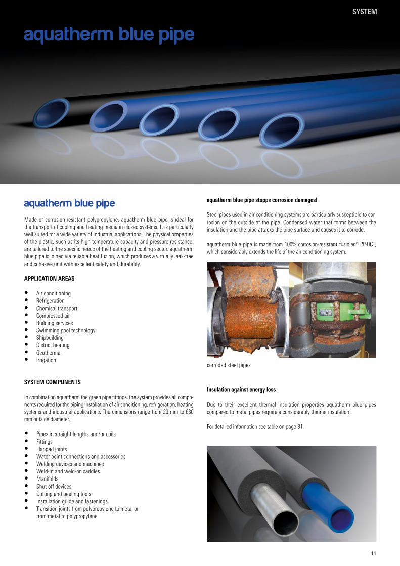
aquatherm blue pipe
aquatherm blue pipe
Made of corrosion-resistant polypropylene, aquatherm blue pipe is ideal for the transport of cooling and heating media in closed systems. It is particularly well suited for a wide variety of industrial applications. The physical properties of the plastic, such as its high temperature capacity and pressure resistance, are tailored to the specific needs of the heating and cooling sector. aquatherm blue pipe is joined via reliable heat fusion, which produces a virtually leak-free and cohesive unit with excellent safety and durability.
APPLICATION AREAS
• Air conditioning• Refrigeration• Chemical transport• Compressed air• Building services• Swimming pool technology• Shipbuilding• District heating• Geothermal• Irrigation
SYSTEM COMPONENTS
In combination aquatherm the green pipe fittings, the system provides all compo-nents required for the piping installation of air conditioning, refrigeration, heating systems and industrial applications. The dimensions range from 20 mm to 630 mm outside diameter.
• Pipes in straight lengths and/or coils• Fittings• Flanged joints• Water point connections and accessories• Welding devices and machines• Weld-in and weld-on saddles• Manifolds• Shut-off devices• Cutting and peeling tools• Installation guide and fastenings• Transition joints from polypropylene to metal or
from metal to polypropylene
aquatherm blue pipe stopps corrosion damages!
Steel pipes used in air conditioning systems are particularly susceptible to cor-rosion on the outside of the pipe. Condensed water that forms between the insulation and the pipe attacks the pipe surface and causes it to corrode.
aquatherm blue pipe is made from 100% corrosion-resistant fusiolen® PP-RCT, which considerably extends the life of the air conditioning system.
Insulation against energy loss
Due to their excellent thermal insulation properties aquatherm blue pipes compared to metal pipes require a considerably thinner insulation.
For detailed information see table on page 81.
corroded steel pipes
SYSTEM
12
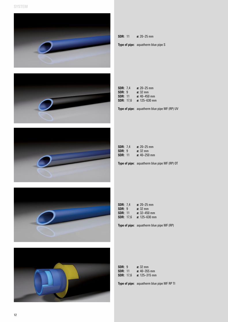
SDR: 11 ø: 20–25 mm
Type of pipe: aquatherm blue pipe S
SDR: 7,4 ø: 20–25 mmSDR: 9 ø: 32 mmSDR: 11 ø: 32–450 mmSDR: 17,6 ø: 125–630 mm
Type of pipe: aquatherm blue pipe MF (RP)
SDR: 7,4 ø: 20–25 mmSDR: 9 ø: 32 mmSDR: 11 ø: 40–250 mm
Type of pipe: aquatherm blue pipe MF (RP) OT
SDR: 7,4 ø: 20–25 mmSDR: 9 ø: 32 mmSDR: 11 ø: 40–450 mmSDR: 17,6 ø: 125–630 mm
Type of pipe: aquatherm blue pipe MF (RP) UV
SDR: 9 ø: 32 mmSDR: 11 ø: 40–355 mmSDR: 17,6 ø: 125–315 mm
Type of pipe: aquatherm blue pipe MF RP TI
SYSTEM
1313
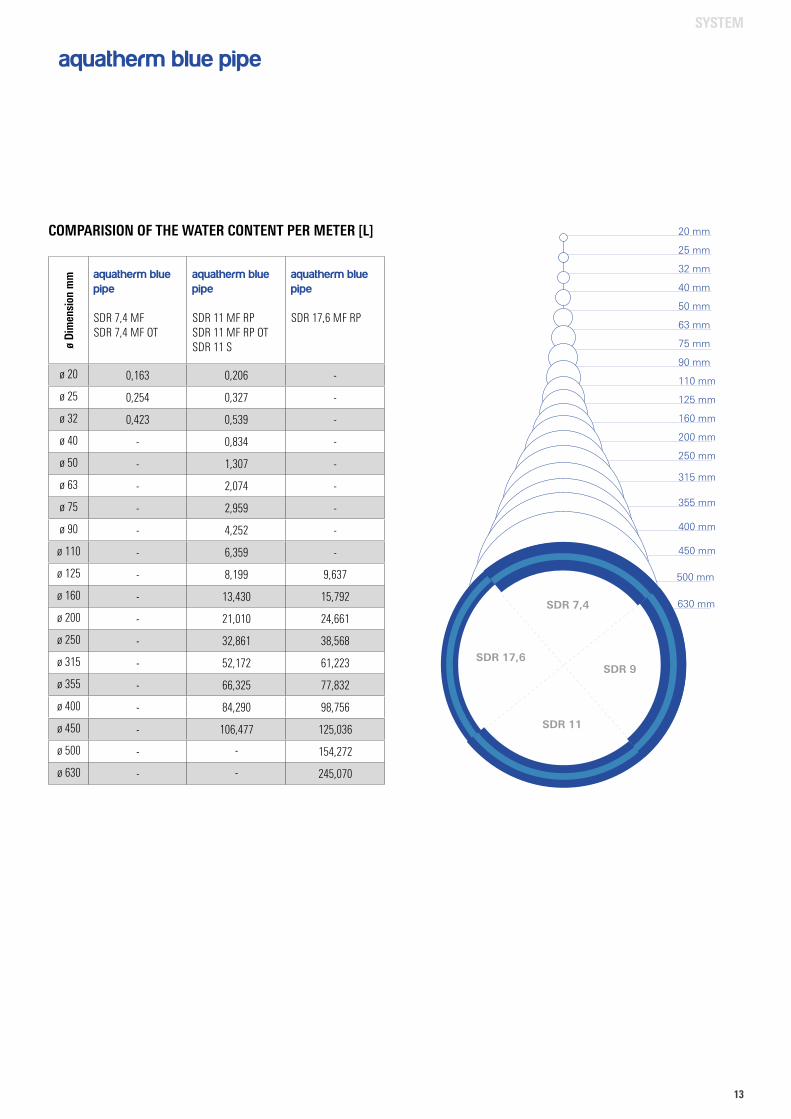
aquatherm blue pipe
COMPARISION OF THE WATER CONTENT PER METER [L]
ø Di
men
sion
mm aquatherm blue
pipe
SDR 7,4 MFSDR 7,4 MF OT
aquatherm blue pipe
SDR 11 MF RPSDR 11 MF RP OT SDR 11 S
aquatherm blue pipe
SDR 17,6 MF RP
ø 20 0,163 0,206 -
ø 25 0,254 0,327 -
ø 32 0,423 0,539 -
ø 40 - 0,834 -
ø 50 - 1,307 -
ø 63 - 2,074 -
ø 75 - 2,959 -
ø 90 - 4,252 -
ø 110 - 6,359 -
ø 125 - 8,199 9,637
ø 160 - 13,430 15,792
ø 200 - 21,010 24,661
ø 250 - 32,861 38,568
ø 315 - 52,172 61,223
ø 355 - 66,325 77,832
ø 400 - 84,290 98,756
ø 450 - 106,477 125,036
ø 500 - - 154,272
ø 630 - - 245,070
20 mm
25 mm
32 mm
40 mm
50 mm
63 mm
75 mm
90 mm
110 mm
125 mm
160 mm
200 mm
250 mm
315 mm
355 mm
400 mm
450 mm
500 mm
630 mmSDR 7,4
SDR 11
SDR 17,6SDR 9
SYSTEM
14
SYSTEM
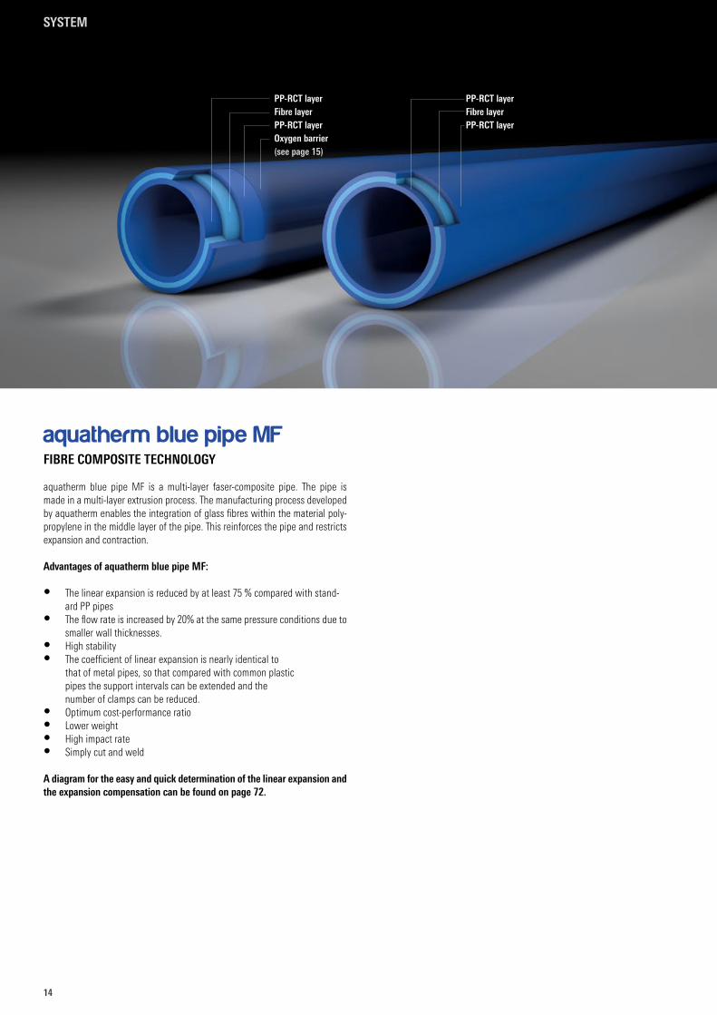
aquatherm blue pipe MF
FIBRE COMPOSITE TECHNOLOGY
aquatherm blue pipe MF is a multi-layer faser-composite pipe. The pipe is made in a multi-layer extrusion process. The manufacturing process developed by aquatherm enables the integration of glass fibres within the material poly-propylene in the middle layer of the pipe. This reinforces the pipe and restricts expansion and contraction.
Advantages of aquatherm blue pipe MF:
• The linear expansion is reduced by at least 75 % compared with stand-ard PP pipes
• The flow rate is increased by 20% at the same pressure conditions due to smaller wall thicknesses.
• High stability• The coefficient of linear expansion is nearly identical to
that of metal pipes, so that compared with common plastic pipes the support intervals can be extended and the number of clamps can be reduced.
• Optimum cost-performance ratio• Lower weight• High impact rate• Simply cut and weld
A diagram for the easy and quick determination of the linear expansion and the expansion compensation can be found on page 72.
PP-RCT layerFibre layerPP-RCT layer
PP-RCT layerFibre layerPP-RCT layerOxygen barrier(see page 15)
1515
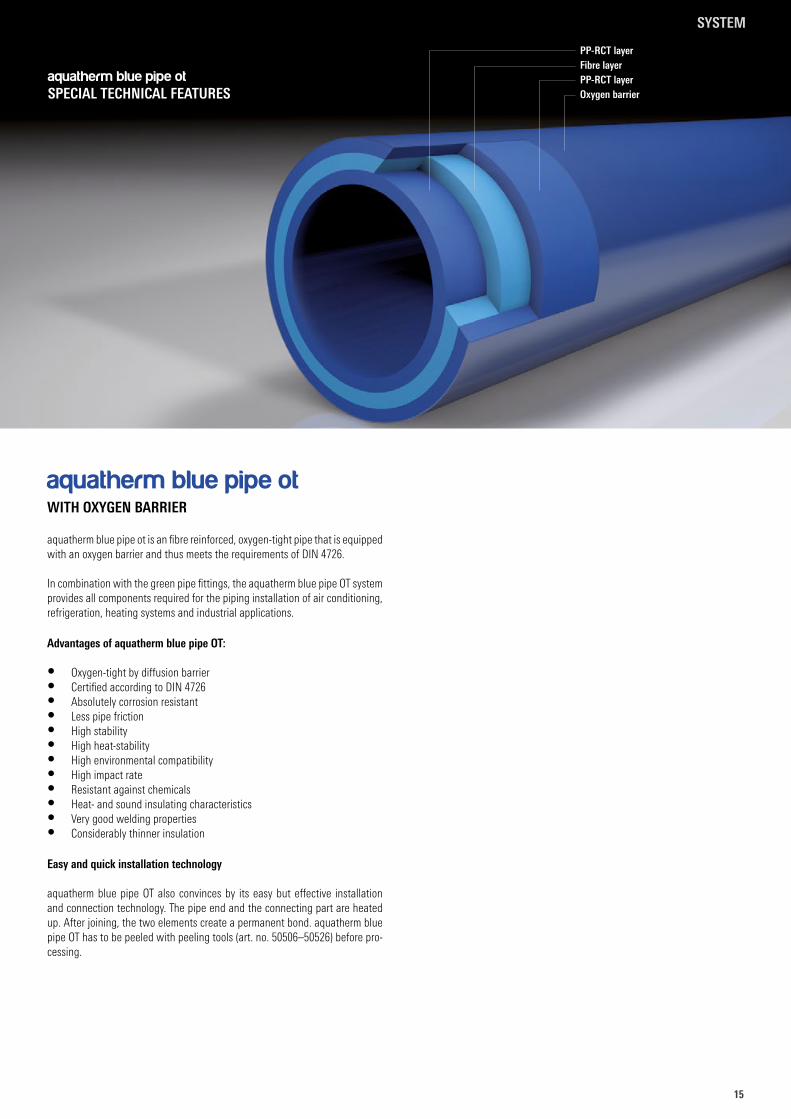
aquatherm blue pipe ot is an fibre reinforced, oxygen-tight pipe that is equipped with an oxygen barrier and thus meets the requirements of DIN 4726.
In combination with the green pipe fittings, the aquatherm blue pipe OT system provides all components required for the piping installation of air conditioning, refrigeration, heating systems and industrial applications.
Advantages of aquatherm blue pipe OT:
• Oxygen-tight by diffusion barrier • Certified according to DIN 4726 • Absolutely corrosion resistant• Less pipe friction• High stability• High heat-stability• High environmental compatibility • High impact rate• Resistant against chemicals• Heat- and sound insulating characteristics• Very good welding properties• Considerably thinner insulation
Easy and quick installation technology
aquatherm blue pipe OT also convinces by its easy but effective installation and connection technology. The pipe end and the connecting part are heated up. After joining, the two elements create a permanent bond. aquatherm blue pipe OT has to be peeled with peeling tools (art. no. 50506–50526) before pro-cessing.
aquatherm blue pipe ot
WITH OXYGEN BARRIER
PP-RCT layerFibre layerPP-RCT layerOxygen barrier
aquatherm blue pipe otSPECIAL TECHNICAL FEATURES
SYSTEM
16
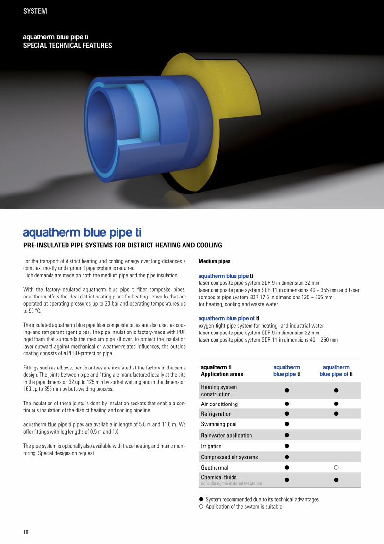
aquatherm blue pipe tiPRE-INSULATED PIPE SYSTEMS FOR DISTRICT HEATING AND COOLING
For the transport of district heating and cooling energy over long distances a complex, mostly underground pipe system is required.High demands are made on both the medium pipe and the pipe insulation.
With the factory-insulated aquatherm blue pipe ti fiber composite pipes, aquatherm offers the ideal district heating pipes for heating networks that are operated at operating pressures up to 20 bar and operating temperatures up to 90 °C.
The insulated aquatherm blue pipe fiber composite pipes are also used as cool-ing- and refrigerant agent pipes. The pipe insulation is factory-made with PUR rigid foam that surrounds the medium pipe all over. To protect the insulation layer outward against mechanical or weather-related influences, the outside coating consists of a PEHD-protection pipe.
Fittings such as elbows, bends or tees are insulated at the factory in the same design. The joints between pipe and fitting are manufactured locally at the site in the pipe dimension 32 up to 125 mm by socket welding and in the dimension 160 up to 355 mm by butt-welding process.
The insulation of these joints is done by insulation sockets that enable a con-tinuous insulation of the district heating and cooling pipeline.
aquatherm blue pipe ti pipes are available in length of 5.8 m and 11.6 m. We offer fittings with leg lengths of 0.5 m and 1.0.
The pipe system is optionally also available with trace heating and mains moni-toring. Special designs on request.
Medium pipes
aquatherm blue pipe tifaser composite pipe system SDR 9 in dimension 32 mmfaser composite pipe system SDR 11 in dimensions 40 – 355 mm and faser composite pipe system SDR 17.6 in dimensions 125 – 355 mm for heating, cooling and waste water
aquatherm blue pipe ot tioxygen-tight pipe system for heating- and industrial water faser composite pipe system SDR 9 in dimension 32 mmfaser composite pipe system SDR 11 in dimensions 40 – 250 mm
aquatherm blue pipe tiSPECIAL TECHNICAL FEATURES
aquatherm ti Application areas
aquatherm blue pipe ti
aquatherm blue pipe ot ti
Heating system construction
Air conditioning
Refrigeration
Swimming pool
Rainwater application
Irrigation
Compressed air systems
Geothermal
Chemical fluids considering the material resistance
System recommended due to its technical advantages Application of the system is suitable
SYSTEM
1717
Low expansion l
Resistance to corrosion l
Very good welding properties l
Less pipe friction l
High impact resistance l
Heat-stability l
Metal deactivation l
Recyclable m
Sound- and heat insulation l
Low weight l
Self-compensating l
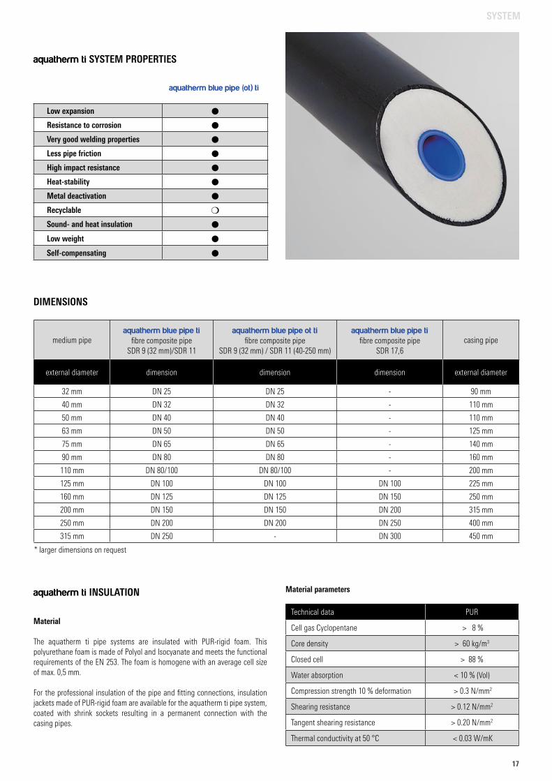
aquatherm blue pipe (ot) ti
aquatherm ti SYSTEM PROPERTIES
medium pipeaquatherm blue pipe ti
fibre composite pipe SDR 9 (32 mm)/SDR 11
aquatherm blue pipe ot tifibre composite pipe
SDR 9 (32 mm) / SDR 11 (40-250 mm)
aquatherm blue pipe tifibre composite pipe
SDR 17,6casing pipe
external diameter dimension dimension dimension external diameter
32 mm DN 25 DN 25 - 90 mm
40 mm DN 32 DN 32 - 110 mm
50 mm DN 40 DN 40 - 110 mm
63 mm DN 50 DN 50 - 125 mm
75 mm DN 65 DN 65 - 140 mm
90 mm DN 80 DN 80 - 160 mm
110 mm DN 80/100 DN 80/100 - 200 mm
125 mm DN 100 DN 100 DN 100 225 mm
160 mm DN 125 DN 125 DN 150 250 mm
200 mm DN 150 DN 150 DN 200 315 mm
250 mm DN 200 DN 200 DN 250 400 mm
315 mm DN 250 - DN 300 450 mm
DIMENSIONS
* larger dimensions on request
Material
The aquatherm ti pipe systems are insulated with PUR-rigid foam. This polyurethane foam is made of Polyol and Isocyanate and meets the functional requirements of the EN 253. The foam is homogene with an average cell size of max. 0,5 mm.
For the professional insulation of the pipe and fitting connections, insulation jackets made of PUR-rigid foam are available for the aquatherm ti pipe system, coated with shrink sockets resulting in a permanent connection with the casing pipes.
aquatherm ti INSULATION Material parameters
Technical data PUR
Cell gas Cyclopentane > 8 %
Core density > 60 kg/m3
Closed cell > 88 %
Water absorption < 10 % (Vol)
Compression strength 10 % deformation > 0.3 N/mm2
Shearing resistance > 0.12 N/mm2
Tangent shearing resistance > 0.20 N/mm2
Thermal conductivity at 50 °C < 0.03 W/mK
SYSTEM
18
F = flow, R = return, AT = am
bient temperature
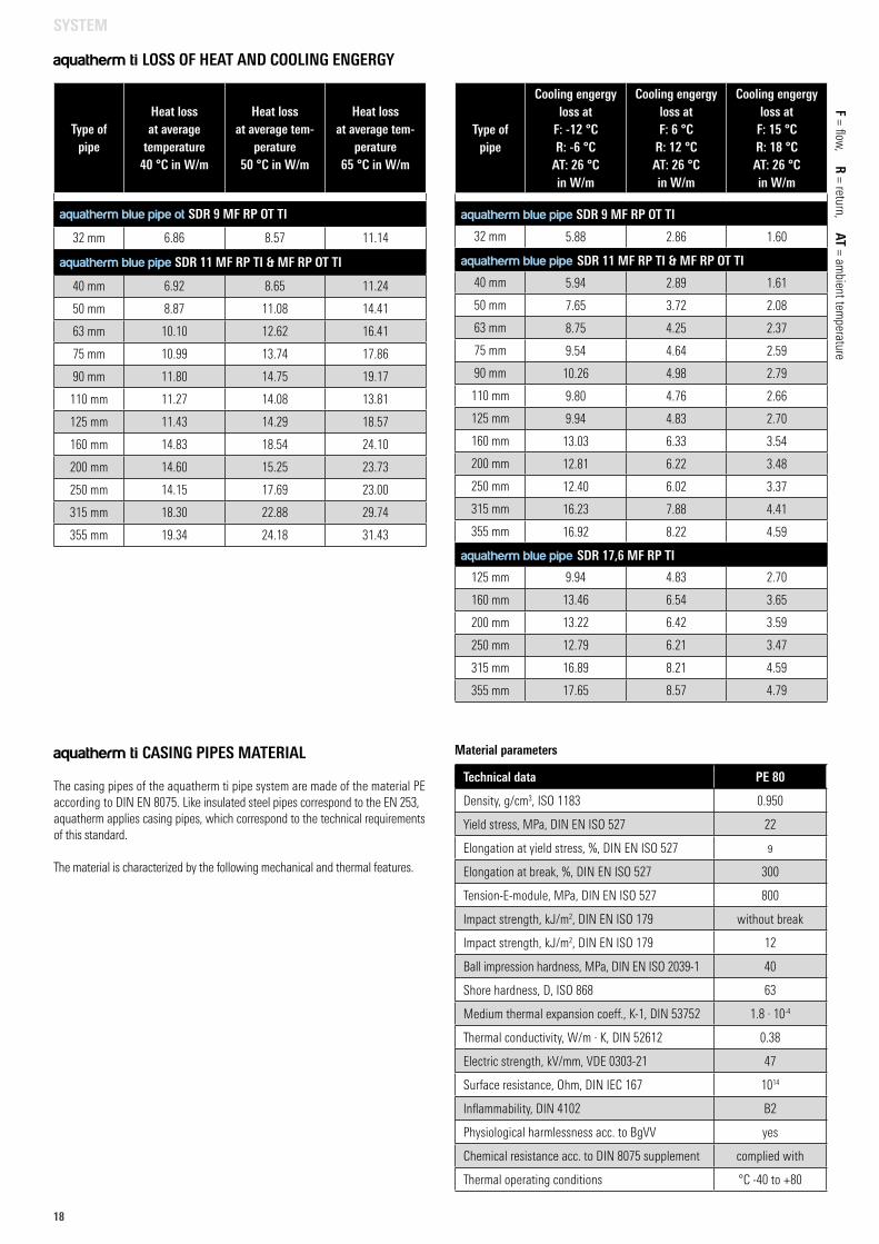
aquatherm ti LOSS OF HEAT AND COOLING ENGERGY
aquatherm ti CASING PIPES MATERIAL
The casing pipes of the aquatherm ti pipe system are made of the material PE according to DIN EN 8075. Like insulated steel pipes correspond to the EN 253, aquatherm applies casing pipes, which correspond to the technical requirements of this standard.
The material is characterized by the following mechanical and thermal features.
Technical data PE 80
Density, g/cm3, ISO 1183 0.950
Yield stress, MPa, DIN EN ISO 527 22
Elongation at yield stress, %, DIN EN ISO 527 9
Elongation at break, %, DIN EN ISO 527 300
Tension-E-module, MPa, DIN EN ISO 527 800
Impact strength, kJ/m2, DIN EN ISO 179 without break
Impact strength, kJ/m2, DIN EN ISO 179 12
Ball impression hardness, MPa, DIN EN ISO 2039-1 40
Shore hardness, D, ISO 868 63
Medium thermal expansion coeff., K-1, DIN 53752 1.8 · 10-4
Thermal conductivity, W/m · K, DIN 52612 0.38
Electric strength, kV/mm, VDE 0303-21 47
Surface resistance, Ohm, DIN IEC 167 1014
Inflammability, DIN 4102 B2
Physiological harmlessness acc. to BgVV yes
Chemical resistance acc. to DIN 8075 supplement complied with
Thermal operating conditions °C -40 to +80
Material parameters
Type of pipe
Heat loss at average
temperature 40 °C in W/m
Heat loss at average tem-
perature 50 °C in W/m
Heat loss at average tem-
perature 65 °C in W/m
aquatherm blue pipe ot SDR 9 MF RP OT TI
32 mm 6.86 8.57 11.14
aquatherm blue pipe SDR 11 MF RP TI & MF RP OT TI
40 mm 6.92 8.65 11.24
50 mm 8.87 11.08 14.41
63 mm 10.10 12.62 16.41
75 mm 10.99 13.74 17.86
90 mm 11.80 14.75 19.17
110 mm 11.27 14.08 13.81
125 mm 11.43 14.29 18.57
160 mm 14.83 18.54 24.10
200 mm 14.60 15.25 23.73
250 mm 14.15 17.69 23.00
315 mm 18.30 22.88 29.74
355 mm 19.34 24.18 31.43
Type of pipe
Cooling engergy loss at
F: -12 °CR: -6 °C
AT: 26 °C in W/m
Cooling engergy loss atF: 6 °C
R: 12 °CAT: 26 °Cin W/m
Cooling engergy loss at
F: 15 °CR: 18 °CAT: 26 °Cin W/m
aquatherm blue pipe SDR 9 MF RP OT TI
32 mm 5.88 2.86 1.60
aquatherm blue pipe SDR 11 MF RP TI & MF RP OT TI
40 mm 5.94 2.89 1.61
50 mm 7.65 3.72 2.08
63 mm 8.75 4.25 2.37
75 mm 9.54 4.64 2.59
90 mm 10.26 4.98 2.79
110 mm 9.80 4.76 2.66
125 mm 9.94 4.83 2.70
160 mm 13.03 6.33 3.54
200 mm 12.81 6.22 3.48
250 mm 12.40 6.02 3.37
315 mm 16.23 7.88 4.41
355 mm 16.92 8.22 4.59
aquatherm blue pipe SDR 17,6 MF RP TI
125 mm 9.94 4.83 2.70
160 mm 13.46 6.54 3.65
200 mm 13.22 6.42 3.59
250 mm 12.79 6.21 3.47
315 mm 16.89 8.21 4.59
355 mm 17.65 8.57 4.79
SYSTEM
1919
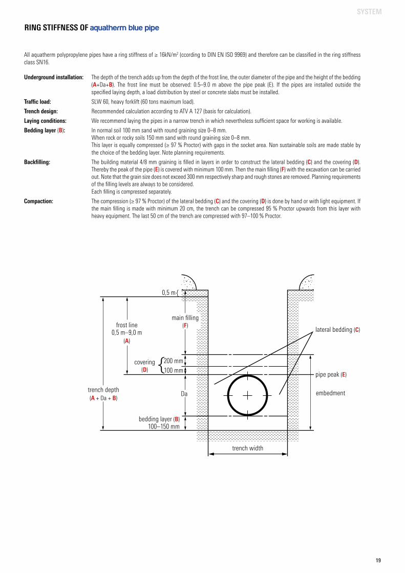
RING STIFFNESS OF aquatherm blue pipe
All aquatherm polypropylene pipes have a ring stiffness of ≥ 16kN/m2 (ccording to DIN EN ISO 9969) and therefore can be classified in the ring stiffness class SN16.
Underground installation: The depth of the trench adds up from the depth of the frost line, the outer diameter of the pipe and the height of the bedding (A+Da+B). The frost line must be observed: 0.5–9.0 m above the pipe peak (E). If the pipes are installed outside the specified laying depth, a load distribution by steel or concrete slabs must be installed.
Traffic load: SLW 60, heavy forklift (60 tons maximum load).
Trench design: Recommended calculation according to ATV A 127 (basis for calculation).
Laying conditions: We recommend laying the pipes in a narrow trench in which nevertheless sufficient space for working is available.
Bedding layer (B): In normal soil 100 mm sand with round graining size 0–8 mm. When rock or rocky soils 150 mm sand with round graining size 0–8 mm. This layer is equally compressed (≥ 97 % Proctor) with gaps in the socket area. Non sustainable soils are made stable by the choice of the bedding layer. Note planning requirements.
Backfilling: The building material 4/8 mm graining is filled in layers in order to construct the lateral bedding (C) and the covering (D). Thereby the peak of the pipe (E) is covered with minimum 100 mm. Then the main filling (F) with the excavation can be carried out. Note that the grain size does not exceed 300 mm respectively sharp and rough stones are removed. Planning requirements of the filling levels are always to be considered. Each filling is compressed separately.
Compaction: The compression (≥ 97 % Proctor) of the lateral bedding (C) and the covering (D) is done by hand or with light equipment. If the main filling is made with minimum 20 cm, the trench can be compressed 95 % Proctor upwards from this layer with heavy equipment. The last 50 cm of the trench are compressed with 97–100 % Proctor.
main filling(F)
0,5 m
frost line0,5 m–9,0 m
(A)
trench depth(A + Da + B)
200 mm100 mm
Da embedment
pipe peak (E)
lateral bedding (C)
covering(D)
bedding layer (B)100–150 mm
trench width
SYSTEM

20
UV-RESISTANCE
Pipes made from fusiolen® polypropylene are normally not exposed to UV-radiation during installation.
To bridge the transport and assembly time, aquatherm polypropylene pipes and fittings are packed in UV-protected packaging. The maximum permissible storage time outdoors is 6 months.
For outdoor pipe laying, aquatherm offers polypropylene composite pipes with a UV protective layer made of polyethylene. The special protection layer prevents damages from sunlight. The pipes are available under the name aquatherm blue pipe MF RP UV.
UV ADHESIVE TAPE
As an alternative to our polyproplylene pipes with UV protection layer, wrapping with UV-resistant adhesive tape is possible, if moulded parts or short pipe sec-tions are to be protected.
For this purpose, the adhesive tape recommended by aquatherm (art. no. 10871) should be selected, which shows good resistance to abrasion, moisture, oils, light acids and alkalis as well as weather influences outdoors.
The tape should always be applied to a dry, clean and grease-free surface. The winding should be done with a slight pull and at least 50% overlap.
Further information on page 119.
INTEGRATION OF OTHER SYSTEMS OR COMPONENTS WITH AQUATHERM PIPING FOR PRESSURE PIPE APPLICATIONS
When integrating aquatherm piping systems with other systems or compo-nents not made of polypropylene (e.g. valves, pumps, other piping, check valves, strainers, etc), care must be taken to ensure the operating parameters for polypropylene won’t damage the other materials or vice versa.
Be aware that even if the aquatherm pipe is compatible with the fluid being transported, other materials in the system may not be. All parts of the system must be verified as compatible with the medium being carried before installing them. And, while aquatherm pipe does not require treatment to protect it from corrosion, metals (ferrous and non-ferrous) in the system may be susceptible to corrosion.
Do not mix aquatherm pipe with other piping systems in conditions that will cause the other system or components to fail.
SYSTEM
2121
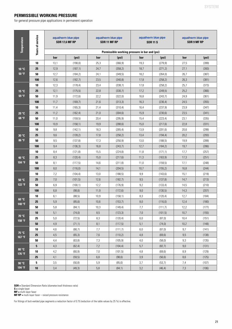
PERMISSIBLE WORKING PRESSUREfor general pressure pipe applications in permanent operation
SDR = Standard Dimension Ratio (diameter/wall thickness ratio) S = single-layer MF = multi-layer faser MF RP = multi-layer faser – raised pressure resistance For fittings of butt-welded pipe segments a reduction factor of 0.75 (reduction of the table values by 25 %) is effective.
Tem
pera
ture
Year
s of
ser
vice aquatherm blue pipe
SDR 17,6 MF RPaquatherm blue pipe
SDR 11 MF RPaquatherm blue pipe
SDR 11 Saquatherm blue pipe
SDR 9 MF RP
Permissible working pressure in bar and (psi)
bar (psi) bar (psi) bar (psi) bar (psi)
10 °C50 °F
10 13,1 (190,0) 25,3 (366,9) 19,3 (279,9) 27,5 (399)
25 12,9 (187,1) 24,7 (358,2) 18,7 (271,2) 27,1 (393)
50 12,7 (184,2) 24,1 (349,5) 18,2 (264,0) 26,7 (387)
100 12,6 (182,7) 23,5 (340,8) 17,8 (258,2) 26,3 (381)
15 °C59 °F
10 12,3 (178,4) 23,4 (338,7) 17,8 (258,2) 25,7 (373)
25 12,1 (175,5) 22,8 (330,7) 17,2 (249,5) 25,2 (366)
50 11,9 (172,6) 22,2 (322,0) 16,8 (243,7) 24,9 (361)
100 11,7 (169,7) 21,6 (313,3) 16,3 (236,4) 24,5 (355)
20 °C68 °F
10 11,4 (165,3) 21,4 (310,4) 16,4 (237,9) 23,9 (347)
25 11,2 (162,4) 21,0 (304,6) 15,9 (230,6) 23,5 (341)
50 11,0 (159,5) 20,4 (295,9) 15,4 (223,4) 23,1 (335)
100 10,9 (158,1) 19,9 (288,6) 15,0 (217,6) 22,8 (331)
30 °C86 °F
10 9,8 (142,1) 18,3 (265,4) 13,9 (201,6) 20,6 (299)
25 9,6 (139,2) 17,8 (258,2) 13,4 (194,4) 20,2 (293)
50 9,5 (137,8) 17,3 (250,9) 13,0 (188,5) 19,9 (289)
100 9,4 (136,3) 16,8 (243,7) 12,7 (184,2) 19,7 (286)
40 °C104 °F
10 8,4 (121,8) 15,5 (224,8) 11,8 (171,1) 17,7 (257)
25 8,3 (120,4) 15,0 (217,6) 11,3 (163,9) 17,3 (251)
50 8,1 (117,5) 14,6 (211,8) 11,0 (159,5) 17,1 (248)
100 8,0 (116,0) 14,1 (204,5) 10,7 (155,2) 16,8 (244)
50 °C122 °F
10 7,2 (104,4) 13,0 (188,5) 9,9 (143,6) 15,1 (219)
25 7,0 (101,5) 12,6 (182,7) 9,5 (137,8) 14,7 (213)
50 6,9 (100,1) 12,2 (176,9) 9,2 (133,4) 14,5 (210)
100 6,8 (98,6) 11,9 (172,6) 9,0 (130,5) 14,3 (207)
60 °C140 °F
10 6,1 (88,5) 10,9 (158,1) 8,3 (120,4) 12,7 (184)
25 5,9 (85,6) 10,6 (153,7) 8,0 (116,0) 12,4 (180)
50 5,8 (84,1) 10,3 (149,4) 7,7 (111,7) 12,2 (177)
70 °C158 °F
10 5,1 (74,0) 8,5 (123,3) 7,0 (101,5) 10,7 (155)
25 5,0 (72,5) 8,3 (120,4) 6,0 (87,0) 10,4 (151)
50 4,9 (71,1) 8,1 (117,5) 5,1 (74,0) 10,2 (148)
75 °C167 °F
10 4,6 (66,7) 7,7 (111,7) 6,0 (87,0) 9,7 (141)
25 4,5 (65,3) 7,6 (110,2) 4,8 (69,6) 9,5 (138)
50 4,4 (63,8) 7,3 (105,9) 4,0 (58,0) 9,3 (135)
80 °C176 °F
5 4,3 (62,4) 7,2 (104,4) 5,7 (82,7) 9,0 (131)
10 4,2 (60,9) 7,0 (101,5) 4,8 (69,6) 8,9 (129)
25 4,1 (59,5) 6,8 (98,6) 3,9 (56,6) 8,6 (125)
90 °C194 °F
5 3,5 (50,8) 5,9 (85,6) 3,7 (53,7) 7,4 (107)
10 3,4 (49,3) 5,8 (84,1) 3,2 (46,4) 7,3 (106)
SYSTEM
22
FIRE PROTECTION
2222
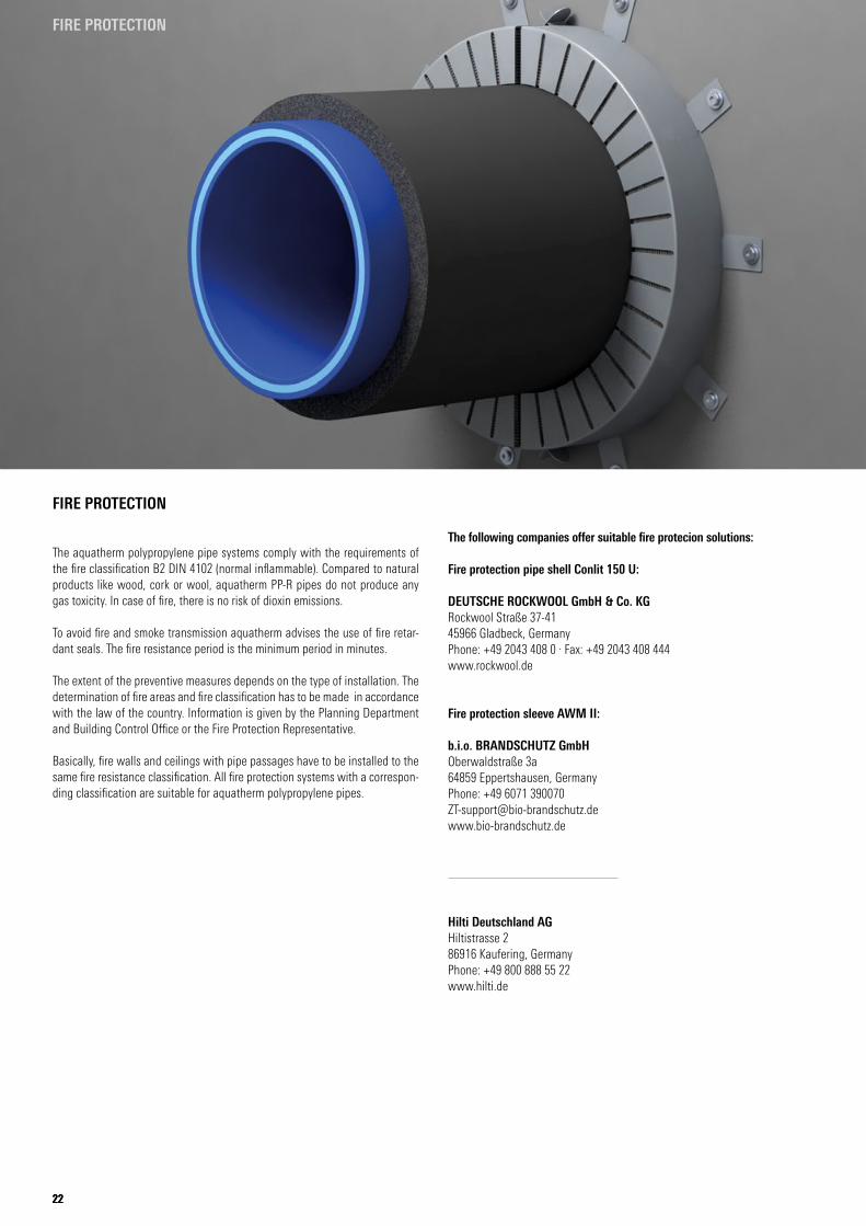
FIRE PROTECTION
The aquatherm polypropylene pipe systems comply with the requirements of the fire classification B2 DIN 4102 (normal inflammable). Compared to natural products like wood, cork or wool, aquatherm PP-R pipes do not produce any gas toxicity. In case of fire, there is no risk of dioxin emissions.
To avoid fire and smoke transmission aquatherm advises the use of fire retar-dant seals. The fire resistance period is the minimum period in minutes.
The extent of the preventive measures depends on the type of installation. The determination of fire areas and fire classification has to be made in accordance with the law of the country. Information is given by the Planning Department and Building Control Office or the Fire Protection Representative.
Basically, fire walls and ceilings with pipe passages have to be installed to the same fire resistance classification. All fire protection systems with a correspon-ding classification are suitable for aquatherm polypropylene pipes.
The following companies offer suitable fire protecion solutions:
Fire protection pipe shell Conlit 150 U:
DEUTSCHE ROCKWOOL GmbH & Co. KG Rockwool Straße 37-41 45966 Gladbeck, Germany Phone: +49 2043 408 0 . Fax: +49 2043 408 444 www.rockwool.de
Fire protection sleeve AWM II:
b.i.o. BRANDSCHUTZ GmbH Oberwaldstraße 3a 64859 Eppertshausen, Germany Phone: +49 6071 [email protected] www.bio-brandschutz.de
Hilti Deutschland AG Hiltistrasse 2 86916 Kaufering, Germany Phone: +49 800 888 55 22 www.hilti.de
2323
FIRE PROTECTION
23
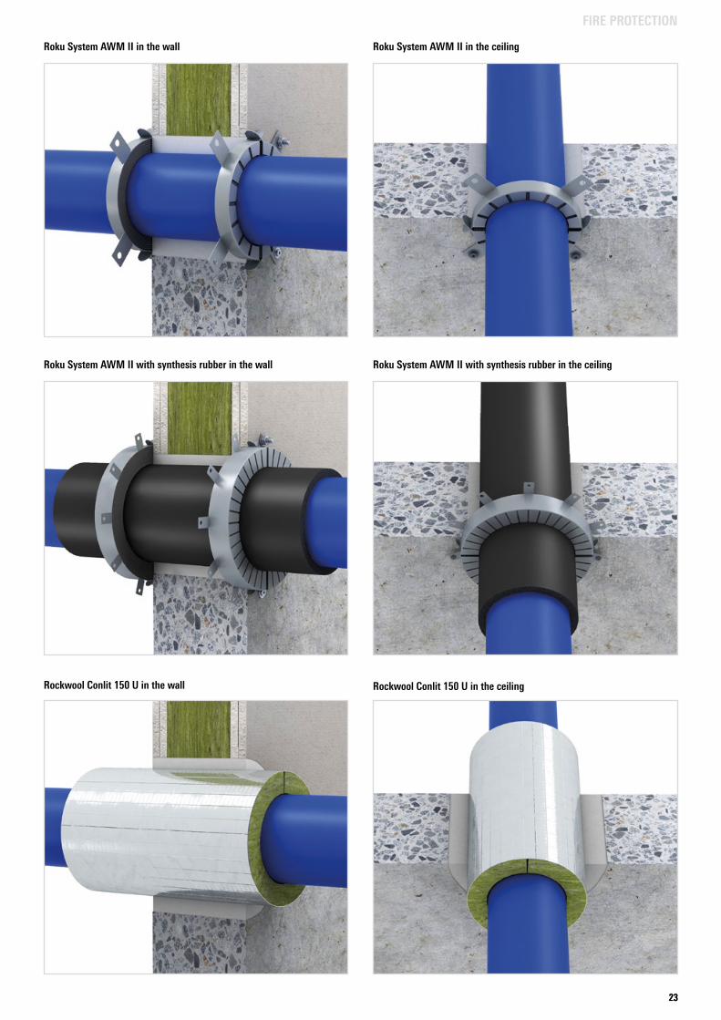
Roku System AWM II in the wall Roku System AWM II in the ceiling
Roku System AWM II with synthesis rubber in the wall Roku System AWM II with synthesis rubber in the ceiling
Rockwool Conlit 150 U in the wall Rockwool Conlit 150 U in the ceiling
24
FIRE PROTECTION
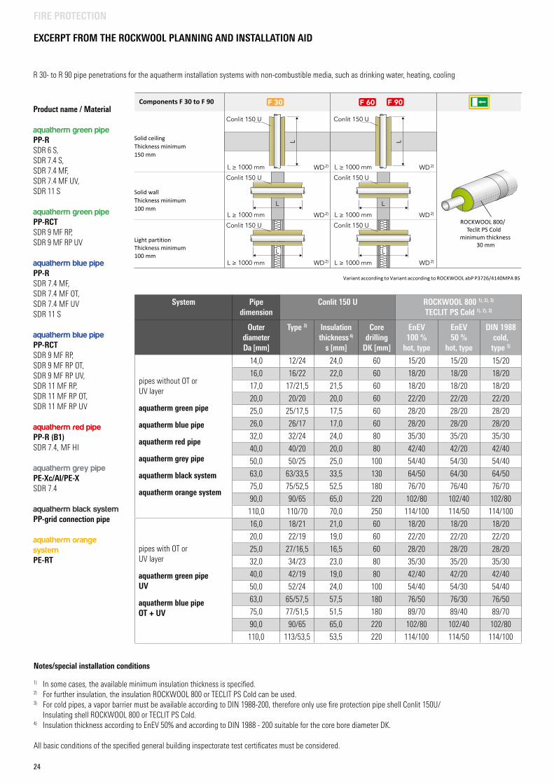
EXCERPT FROM THE ROCKWOOL PLANNING AND INSTALLATION AID
Notes/special installation conditions
1) In some cases, the available minimum insulation thickness is specified.2) For further insulation, the insulation ROCKWOOL 800 or TECLIT PS Cold can be used.3) For cold pipes, a vapor barrier must be available according to DIN 1988-200, therefore only use fire protection pipe shell Conlit 150U/
Insulating shell ROCKWOOL 800 or TECLIT PS Cold.4) Insulation thickness according to EnEV 50% and according to DIN 1988 - 200 suitable for the core bore diameter DK.
All basic conditions of the specified general building inspectorate test certificates must be considered.
R 30- to R 90 pipe penetrations for the aquatherm installation systems with non-combustible media, such as drinking water, heating, cooling
166
Hinweise/besondere Einbaubedingungen1)In einzelnen Fällen ist die lieferbare Mindestdämmdicke angegeben.2)Als weiterführende Dämmung kann die Dämmschale ROCKWOOL 800 bzw. Teclit PS Cold verwendet werden.3)Bei kaltgehenden Leitungen muss nach DIN 1988-200 eine Dampfbremse vorhanden sein, deshalb ausschließlich
Brandschutzrohrschale Conlit 150 U/Dämmschale ROCKWOOL 800 bzw. Teclit PS Cold verwenden.4)Dämmdicke nach EnEV 50 % sowie nach DIN 1988-200 passend zu dem Kernbohrungsdurchmesser DK.
Alle Randbedingungen der angegebenen allgemeinen bauaufsichtlichen Prüfzeugnisse (abP) müssen berücksichtigt werden.
3.4 Kunststoff-/Mehrschichtverbundrohre
Produktname/ Werkstoff:
green pipe, PP-R SDR 6 S,SDR 7,4 S,SDR 7,4 MF,SDR 7,4 MF UV,SDR 11 S
green pipe, PP-RCT SDR 9 MF RP,SDR 9 MF RP UV
blue pipe, PP-R SDR 7,4 MF,SDR 7,4 MF OT,SDR 7,4 MF UVSDR 11 S
blue pipe, PP-RCTSDR 9 MF RP,SDR 9 MF RP OT,SDR 9 MF RP UV,SDR 11 MF RP,SDR 11 MF RP OT,SDR 11 MF RP UV
red pipe, PP-R/B1 SDR 7,4, MF HI
grey pipe PE-Xc/Al/PE-X SDR 7,4
black system/ PP-Registerrohr
orange system , PE-RT
www.aquatherm.de
System Rohrdimension Conlit 150 UROCKWOOL 8001), 2), 3)
Teclit PS Cold1), 2), 3)
Außen-∅Da [mm]
Typ3) Dämmdicke4)
s [mm]Kern-bohrung DK [mm]
EnEV100 %warm, Typ
EnEV50 %warm, Typ
DIN 1988-200kalt, Typ3)
Rohre ohne OT- oder UV-Schicht
green pipe
blue pipe
red pipe
grey pipe
black system
orange system
14,0 12/24 24,0 60 15/20 15/20 15/20
16,0 16/22 22,0 60 18/20 18/20 18/20
17,0 17/21,5 21,5 60 18/20 18/20 18/20
20,0 20/20 20,0 60 22/20 22/20 22/20
25,0 25/17,5 17,5 60 28/20 28/20 28/20
26,0 26/17 17,0 60 28/20 28/20 28/20
32,0 32/24 24,0 80 35/30 35/20 35/30
40,0 40/20 20,0 80 42/40 42/20 42/40
50,0 50/25 25,0 100 54/40 54/30 54/40
63,0 63/33,5 33,5 130 64/50 64/30 64/50
75,0 75/52,5 52,5 180 76/70 76/40 76/70
90,0 90/65 65,0 220 102/80 102/40 102/80
110,0 110/70 70,0 250 114/100 114/50 114/100
Rohre mit OT- oder UV-Schicht green pipe UV
blue pipe OT + UV
16,0 18/21 21,0 60 18/20 18/20 18/20
20,0 22/19 19,0 60 22/20 22/20 22/20
25,0 27/16,5 16,5 60 28/20 28/20 28/20
32,0 34/23 23,0 80 35/30 35/20 35/30
40,0 42/19 19,0 80 42/40 42/20 42/40
50,0 52/24 24,0 100 54/40 54/30 54/40
63,0 65/57,5 57,5 180 76/50 76/30 76/50
75,0 77/51,5 51,5 180 89/70 89/40 89/70
90,0 90/65 65,0 220 102/80 102/40 102/80
110,0 113/53,5 53,5 220 114/100 114/50 114/100
Variant according to Variant according to ROCKWOOL abP P3726/4140MPA BS.
R 30- bis R 90-Rohrdurchführungen für die aquatherm Installationssysteme mit nichtbrennbaren Medien,z. B. Trinkwasser, Heizung, Kälte
ROCKWOOL 800/ Teclit PS Cold
minimum thickness30 mm
Solid ceilingThickness minimum 150 mm
Solid wallThickness minimum 100 mm
Light partitionThickness minimum 100 mm
Components F 30 to F 90Product name / Material
aquatherm green pipe PP-RSDR 6 S,SDR 7.4 S,SDR 7.4 MF,SDR 7.4 MF UV,SDR 11 S
aquatherm green pipe PP-RCTSDR 9 MF RP,SDR 9 MF RP UV
aquatherm blue pipe PP-RSDR 7.4 MF,SDR 7.4 MF OT,SDR 7.4 MF UVSDR 11 S
aquatherm blue pipe PP-RCTSDR 9 MF RP,SDR 9 MF RP OT,SDR 9 MF RP UV,SDR 11 MF RP,SDR 11 MF RP OT,SDR 11 MF RP UV
aquatherm red pipe PP-R (B1)SDR 7.4, MF HI
aquatherm grey pipe PE-Xc/Al/PE-XSDR 7.4
aquatherm black systemPP-grid connection pipe
aquatherm orange systemPE-RT
System Pipe dimension
Conlit 150 U ROCKWOOL 800 1), 2), 3)
TECLIT PS Cold 1), 2), 3)
Outer diameterDa [mm]
Type 3) Insulation thickness 4)
s [mm]
Core drilling
DK [mm]
EnEV 100 %
hot, type
EnEV 50 %
hot, type
DIN 1988cold, type 3)
pipes without OT or UV layer
aquatherm green pipe
aquatherm blue pipe
aquatherm red pipe
aquatherm grey pipe
aquatherm black system
aquatherm orange system
14,0 12/24 24,0 60 15/20 15/20 15/20
16,0 16/22 22,0 60 18/20 18/20 18/20
17,0 17/21,5 21,5 60 18/20 18/20 18/20
20,0 20/20 20,0 60 22/20 22/20 22/20
25,0 25/17,5 17,5 60 28/20 28/20 28/20
26,0 26/17 17,0 60 28/20 28/20 28/20
32,0 32/24 24,0 80 35/30 35/20 35/30
40,0 40/20 20,0 80 42/40 42/20 42/40
50,0 50/25 25,0 100 54/40 54/30 54/40
63,0 63/33,5 33,5 130 64/50 64/30 64/50
75,0 75/52,5 52,5 180 76/70 76/40 76/70
90,0 90/65 65,0 220 102/80 102/40 102/80
110,0 110/70 70,0 250 114/100 114/50 114/100
pipes with OT or UV layer
aquatherm green pipe UV
aquatherm blue pipe OT + UV
16,0 18/21 21,0 60 18/20 18/20 18/20
20,0 22/19 19,0 60 22/20 22/20 22/20
25,0 27/16,5 16,5 60 28/20 28/20 28/20
32,0 34/23 23,0 80 35/30 35/20 35/30
40,0 42/19 19,0 80 42/40 42/20 42/40
50,0 52/24 24,0 100 54/40 54/30 54/40
63,0 65/57,5 57,5 180 76/50 76/30 76/50
75,0 77/51,5 51,5 180 89/70 89/40 89/70
90,0 90/65 65,0 220 102/80 102/40 102/80
110,0 113/53,5 53,5 220 114/100 114/50 114/100
2525
Dimensionmm
aquatherm blue pipe
SDR 7,4 MF/OT
aquatherm blue pipe
SDR 9 MF/OT
aquathermblue pipe
SDR 11 MF/OT
aquathermblue pipe
SDR 17,6 MF
20 1,76 - - -
25 2,74 - - -
32 4,39 3,14 -
40 - - 4,83 -
50 - - 7,48 -
63 - - 11,82 -
75 - - 16,48 -
90 - - 23,86 -
110 - - 35,33 -
125 - - 45,83 30,03
160 - - 74,88 48,53
200 - - 116,64 75,68
250 - - 181,42 117,64
315 - - 285,82 186,32
355 - - 362,93 236,07
400 - - 460,78 299,73
450 - - 583,21 378,64
500 - - - 468,24
630 - - - 740,59
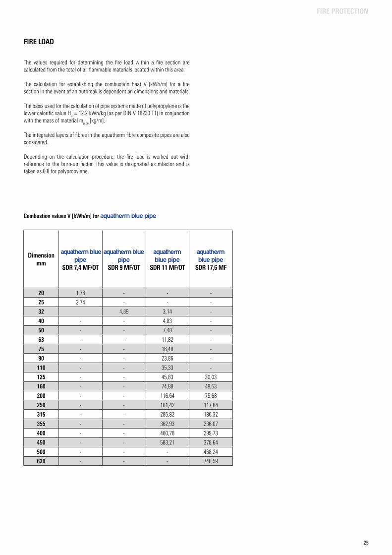
Combustion values V [kWh/m] for aquatherm blue pipe
The values required for determining the fire load within a fire section are calculated from the total of all flammable materials located within this area.
The calculation for establishing the combustion heat V [kWh/m] for a fire section in the event of an outbreak is dependent on dimensions and materials.
The basis used for the calculation of pipe systems made of polypropylene is the lower calorific value H
u = 12.2 kWh/kg (as per DIN V 18230 T1) in conjunction
with the mass of material mpipe
[kg/m].
The integrated layers of fibres in the aquatherm fibre composite pipes are also considered.
Depending on the calculation procedure, the fire load is worked out with reference to the burn-up factor. This value is designated as mfactor and is taken as 0.8 for polypropylene.
FIRE LOAD
FIRE PROTECTION
26
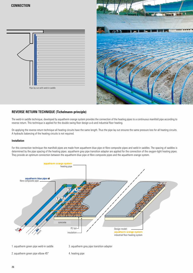
Pipe lay out with weld-in saddle
1. aquatherm green pipe weld-in saddle
2. aquatherm green pipe elbow 45°
3. aquatherm grey pipe transition adapter
4. heating pipe
-
aquatherm orange systemheating pipe
aquatherm blue pipe ot
1 2
3 4
aquatherm orange systemindustrial floor heating system
Design model:
fibre composite pipe
flow
return
concrete
PE foil
insulation
REVERSE RETURN TECHNIQUE (Tichelmann-principle)
The weld-in saddle technique, developed by aquatherm orange system provides the connection of the heating pipes to a continuous manifold pipe according to reverse return. This technique is applied for the double swing floor design a+b and industrial floor heating.
On applying the reverse return technique all heating circuits have the same length. Thus the pipe lay out ensures the same pressure loss for all heating circuits.A hydraulic balancing of the heating circuits is not required.
Installation
For this connection technique the manifold pipes are made from aquatherm blue pipe ot fibre composite pipes and weld-in saddles. The spacing of saddles is determined by the pipe spacing of the heating pipes. aquatherm grey pipe transition adapter are applied for the connection of the oxygen-tight heating pipes. They provide an optimum connection between the aquatherm blue pipe ot fibre composite pipes and the aquatherm orange system.
CONNECTION
2727
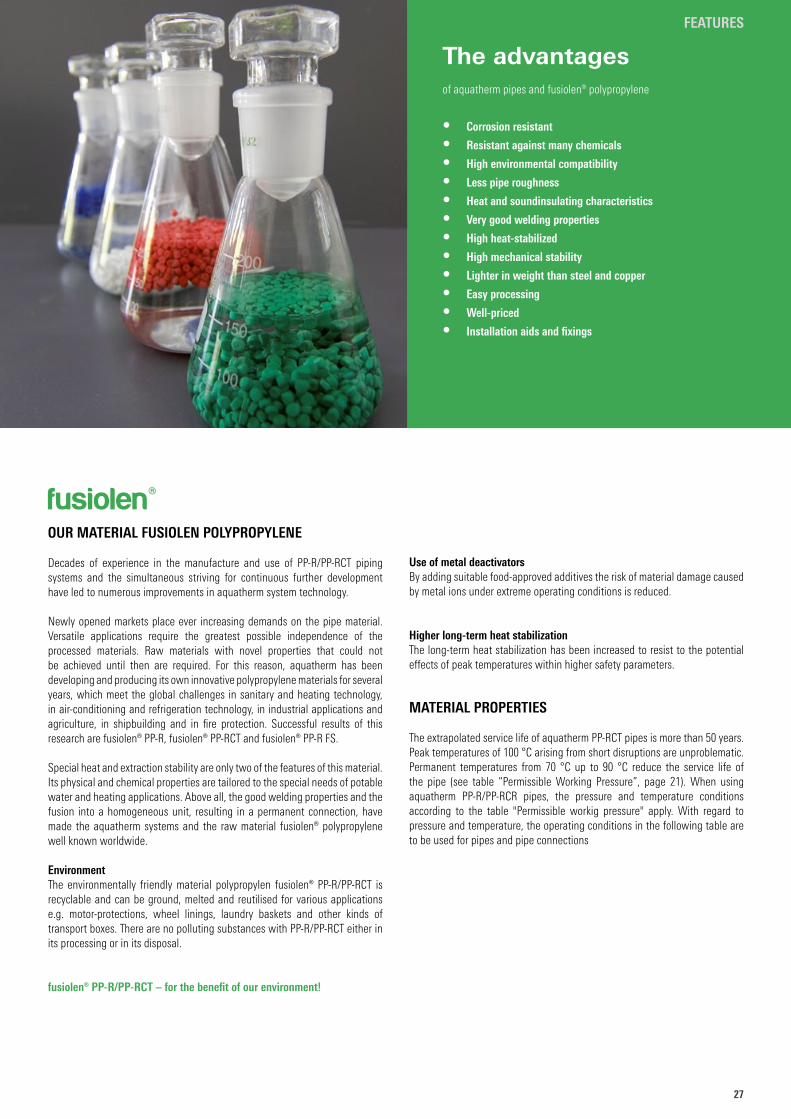
The advantagesof aquatherm pipes and fusiolen® polypropylene
• Corrosion resistant
• Resistant against many chemicals
• High environmental compatibility
• Less pipe roughness
• Heat and soundinsulating characteristics
• Very good welding properties
• High heat-stabilized
• High mechanical stability
• Lighter in weight than steel and copper
• Easy processing
• Well-priced
• Installation aids and fixings
FEATURES
OUR MATERIAL FUSIOLEN POLYPROPYLENE
Decades of experience in the manufacture and use of PP-R/PP-RCT piping systems and the simultaneous striving for continuous further development have led to numerous improvements in aquatherm system technology.
Newly opened markets place ever increasing demands on the pipe material. Versatile applications require the greatest possible independence of the processed materials. Raw materials with novel properties that could not be achieved until then are required. For this reason, aquatherm has been developing and producing its own innovative polypropylene materials for several years, which meet the global challenges in sanitary and heating technology, in air-conditioning and refrigeration technology, in industrial applications and agriculture, in shipbuilding and in fire protection. Successful results of this research are fusiolen® PP-R, fusiolen® PP-RCT and fusiolen® PP-R FS.
Special heat and extraction stability are only two of the features of this material. Its physical and chemical properties are tailored to the special needs of potable water and heating applications. Above all, the good welding properties and the fusion into a homogeneous unit, resulting in a permanent connection, have made the aquatherm systems and the raw material fusiolen® polypropylene well known worldwide.
EnvironmentThe environmentally friendly material polypropylen fusiolen® PP-R/PP-RCT is recyclable and can be ground, melted and reutilised for various applications e.g. motor-protections, wheel linings, laundry baskets and other kinds of transport boxes. There are no polluting substances with PP-R/PP-RCT either in its processing or in its disposal.
fusiolen® PP-R/PP-RCT – for the benefit of our environment!
Use of metal deactivatorsBy adding suitable food-approved additives the risk of material damage caused by metal ions under extreme operating conditions is reduced.
Higher long-term heat stabilizationThe long-term heat stabilization has been increased to resist to the potential effects of peak temperatures within higher safety parameters.
MATERIAL PROPERTIES The extrapolated service life of aquatherm PP-RCT pipes is more than 50 years. Peak temperatures of 100 °C arising from short disruptions are unproblematic. Permanent temperatures from 70 °C up to 90 °C reduce the service life of the pipe (see table “Permissible Working Pressure”, page 21). When using aquatherm PP-R/PP-RCR pipes, the pressure and temperature conditions according to the table "Permissible workig pressure" apply. With regard to pressure and temperature, the operating conditions in the following table are to be used for pipes and pipe connections
fusiolen®
28
FEATURES
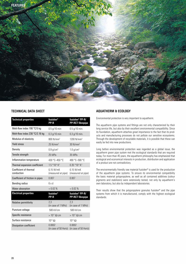
AQUATHERM & ECOLOGY
Environmental protection is very important to aquatherm.
The aquatherm pipe systems and fittings are not only characterized by their long service life, but also by their excellent environmental compatibility. Since its foundation, aquatherm attaches great importance to the fact that its prod-ucts and manufacturing processes do not pollute our sensitive eco systems. Through the development of recyclable materials, it is possible that these can easily be fed into new productions.
Long before environmental protection was regarded as a global issue, the aquatherm green pipe system met the ecological standards that are required today. For more than 45 years, the aquatherm philosophy has emphasized that ecological and economical interests in production, distribution and application of a product are not contradictiory.
The environmentally friendly raw material fusiolen® is used for the production of the aquatherm pipe systems. To ensure its environmental compatibility the basic material polypropylene, as well as all contained additives (colour pigments and stabilizers) were extensively tested, not only by aquatherm’s own laboratory, but also by independent laboratories.
Their results show that the polypropylene granules fusiolen® and the pipe systems from which it is manufactured, comply with the highest ecological standards.
TECHNICAL DATA SHEET
Technical properties fusiolen® PP-R
fusiolen® PP-R/PP-RCT fibrepipe
Melt-flow index 190 °C/5 kg 0.5 g/10 min 0.5 g/10 min.
Melt-flow index 230 °C/2.16 kg 0.3 g/10 min 0.3 g/10 min.
Modulus of elasticity 800 N/mm2 1200 N/mm2
Yield stress 25 N/mm2 30 N/mm2
Density 0.9 g/cm3 1.0 g/cm3
Tensile strength 25 MPa 35 MPa
Inflammation temperature 430 °C–450 °C 490 °C–500 °C
Thermal expansion coefficient 1.5 *10-4 K-1 0.35 *10-4 K-1
Coefficient of thermal conduction
0,15 W/mK (measured at pipe)
0,15 W/mK (measured at pipe)
Coefficient of friction in pipes 0.007 0.007
Bending radius 6 x d
Water absorption < 0.02 % < 0.02 %
Electrical properties fusiolen® PP-R
fusiolen® PP-R/PP-RCT fibrepipe
Relative permittivity 2,3 (in case of 1 MHz)
2,3 (in case of 1 MHz)
Puncture voltage 500 kV/cm 500 kV/cm
Specific resistance > 1017 Ω cm > 1017 Ω cm
Surface resistance 1014 Ω 1014 Ω
Dissipation coefficient 0.0002 (in case of 50 Hertz)
0.0002 (in case of 50 Hertz)
2929
FEATURES
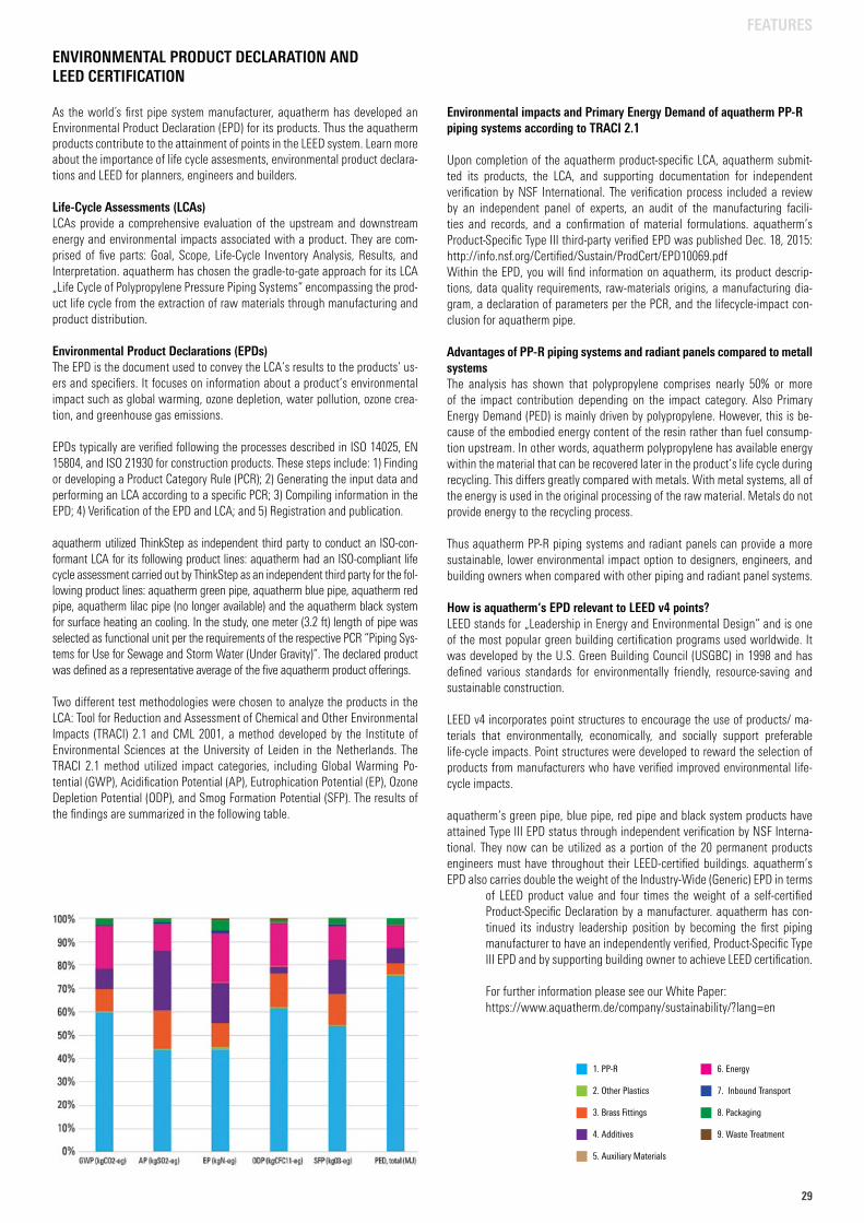
1. PP-R
2. Other Plastics
3. Brass Fittings
4. Additives
5. Auxiliary Materials
6. Energy
7. Inbound Transport
8. Packaging
9. Waste Treatment
Environmental impacts and Primary Energy Demand of aquatherm PP-R piping systems according to TRACI 2.1
Upon completion of the aquatherm product-specific LCA, aquatherm submit-ted its products, the LCA, and supporting documentation for independent verification by NSF International. The verification process included a review by an independent panel of experts, an audit of the manufacturing facili-ties and records, and a confirmation of material formulations. aquatherm’s Product-Specific Type III third-party verified EPD was published Dec. 18, 2015: http://info.nsf.org/Certified/Sustain/ProdCert/EPD10069.pdfWithin the EPD, you will find information on aquatherm, its product descrip-tions, data quality requirements, raw-materials origins, a manufacturing dia-gram, a declaration of parameters per the PCR, and the lifecycle-impact con-clusion for aquatherm pipe.
Advantages of PP-R piping systems and radiant panels compared to metall systemsThe analysis has shown that polypropylene comprises nearly 50% or more of the impact contribution depending on the impact category. Also Primary Energy Demand (PED) is mainly driven by polypropylene. However, this is be-cause of the embodied energy content of the resin rather than fuel consump-tion upstream. In other words, aquatherm polypropylene has available energy within the material that can be recovered later in the product’s life cycle during recycling. This differs greatly compared with metals. With metal systems, all of the energy is used in the original processing of the raw material. Metals do not provide energy to the recycling process.
Thus aquatherm PP-R piping systems and radiant panels can provide a more sustainable, lower environmental impact option to designers, engineers, and building owners when compared with other piping and radiant panel systems.
How is aquatherm‘s EPD relevant to LEED v4 points?LEED stands for „Leadership in Energy and Environmental Design“ and is one of the most popular green building certification programs used worldwide. It was developed by the U.S. Green Building Council (USGBC) in 1998 and has defined various standards for environmentally friendly, resource-saving and sustainable construction.
LEED v4 incorporates point structures to encourage the use of products/ ma-terials that environmentally, economically, and socially support preferable life-cycle impacts. Point structures were developed to reward the selection of products from manufacturers who have verified improved environmental life-cycle impacts.
aquatherm’s green pipe, blue pipe, red pipe and black system products have attained Type III EPD status through independent verification by NSF Interna-tional. They now can be utilized as a portion of the 20 permanent products engineers must have throughout their LEED-certified buildings. aquatherm’s EPD also carries double the weight of the Industry-Wide (Generic) EPD in terms
of LEED product value and four times the weight of a self-certified Product-Specific Declaration by a manufacturer. aquatherm has con-tinued its industry leadership position by becoming the first piping manufacturer to have an independently verified, Product-Specific Type III EPD and by supporting building owner to achieve LEED certification.
For further information please see our White Paper: https://www.aquatherm.de/company/sustainability/?lang=en
ENVIRONMENTAL PRODUCT DECLARATION AND LEED CERTIFICATION
As the world´s first pipe system manufacturer, aquatherm has developed an Environmental Product Declaration (EPD) for its products. Thus the aquatherm products contribute to the attainment of points in the LEED system. Learn more about the importance of life cycle assesments, environmental product declara-tions and LEED for planners, engineers and builders.
Life-Cycle Assessments (LCAs)LCAs provide a comprehensive evaluation of the upstream and downstream energy and environmental impacts associated with a product. They are com-prised of five parts: Goal, Scope, Life-Cycle Inventory Analysis, Results, and Interpretation. aquatherm has chosen the gradle-to-gate approach for its LCA „Life Cycle of Polypropylene Pressure Piping Systems“ encompassing the prod-uct life cycle from the extraction of raw materials through manufacturing and product distribution.
Environmental Product Declarations (EPDs)The EPD is the document used to convey the LCA’s results to the products’ us-ers and specifiers. It focuses on information about a product’s environmental impact such as global warming, ozone depletion, water pollution, ozone crea-tion, and greenhouse gas emissions.
EPDs typically are verified following the processes described in ISO 14025, EN 15804, and ISO 21930 for construction products. These steps include: 1) Finding or developing a Product Category Rule (PCR); 2) Generating the input data and performing an LCA according to a specific PCR; 3) Compiling information in the EPD; 4) Verification of the EPD and LCA; and 5) Registration and publication.
aquatherm utilized ThinkStep as independent third party to conduct an ISO-con-formant LCA for its following product lines: aquatherm had an ISO-compliant life cycle assessment carried out by ThinkStep as an independent third party for the fol-lowing product lines: aquatherm green pipe, aquatherm blue pipe, aquatherm red pipe, aquatherm lilac pipe (no longer available) and the aquatherm black system for surface heating an cooling. In the study, one meter (3.2 ft) length of pipe was selected as functional unit per the requirements of the respective PCR “Piping Sys-tems for Use for Sewage and Storm Water (Under Gravity)”. The declared product was defined as a representative average of the five aquatherm product offerings.
Two different test methodologies were chosen to analyze the products in the LCA: Tool for Reduction and Assessment of Chemical and Other Environmental Impacts (TRACI) 2.1 and CML 2001, a method developed by the Institute of Environmental Sciences at the University of Leiden in the Netherlands. The TRACI 2.1 method utilized impact categories, including Global Warming Po-tential (GWP), Acidification Potential (AP), Eutrophication Potential (EP), Ozone Depletion Potential (ODP), and Smog Formation Potential (SFP). The results of the findings are summarized in the following table.
30
COMPLIANCE WITH THE SYSTEM STANDARD
Various national and international independent authorities and institutions confirm aquatherm’s quality standard. You can see our certificates on our website at www.aquatherm.de/products/certificates
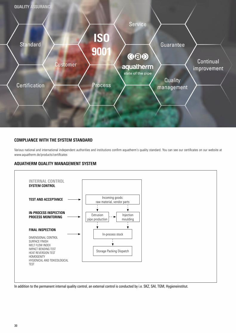
AQUATHERM QUALITY MANAGEMENT SYSTEM
In addition to the permanent internal quality control, an external control is conducted by i.e. SKZ, SAI, TGM, Hygieneinstitut.
INTERNAL CONTROLSYSTEM CONTROL
TEST AND ACCEPTANCE
IN-PROCESS INSPECTIONPROCESS MONITORING
FINAL INSPECTION
DIMENSIONAL CONTROLSURFACE FINISHMELT FLOW INDEXIMPACT BENDING TESTHEAT REVERSION TESTHOMOGENITYHYGIENICAL AND TOXICOLOGICAL TEST
Incoming goods: raw material, vendor parts
In-process stock
Storage Packing Dispatch
Extrusion pipe production
Injectionmoulding
QUALITY ASSURANCE
3131
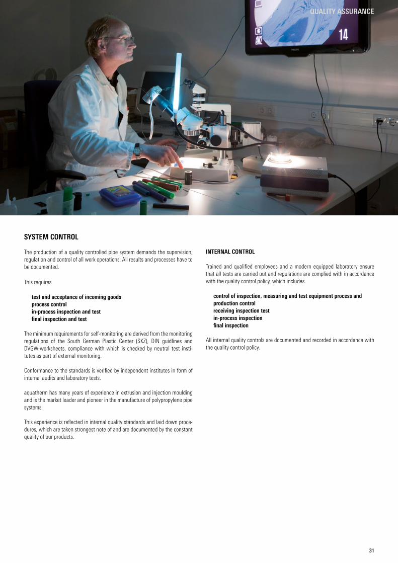
SYSTEM CONTROL
The production of a quality controlled pipe system demands the supervision, regulation and control of all work operations. All results and processes have to be documented.
This requires
test and acceptance of incoming goodsprocess controlin-process inspection and testfinal inspection and test
The minimum requirements for self-monitoring are derived from the monitoring regulations of the South German Plastic Center (SKZ), DIN guidlines and DVGW-worksheets, compliance with which is checked by neutral test insti-tutes as part of external monitoring.
Conformance to the standards is verified by independent institutes in form of internal audits and laboratory tests.
aquatherm has many years of experience in extrusion and injection moulding and is the market leader and pioneer in the manufacture of polypropylene pipe systems.
This experience is reflected in internal quality standards and laid down proce-dures, which are taken strongest note of and are documented by the constant quality of our products.
INTERNAL CONTROL
Trained and qualified employees and a modern equipped laboratory ensure that all tests are carried out and regulations are complied with in accordance with the quality control policy, which includes
control of inspection, measuring and test equipment process and production controlreceiving inspection testin-process inspectionfinal inspection
All internal quality controls are documented and recorded in accordance with the quality control policy.
QUALITY ASSURANCE
32
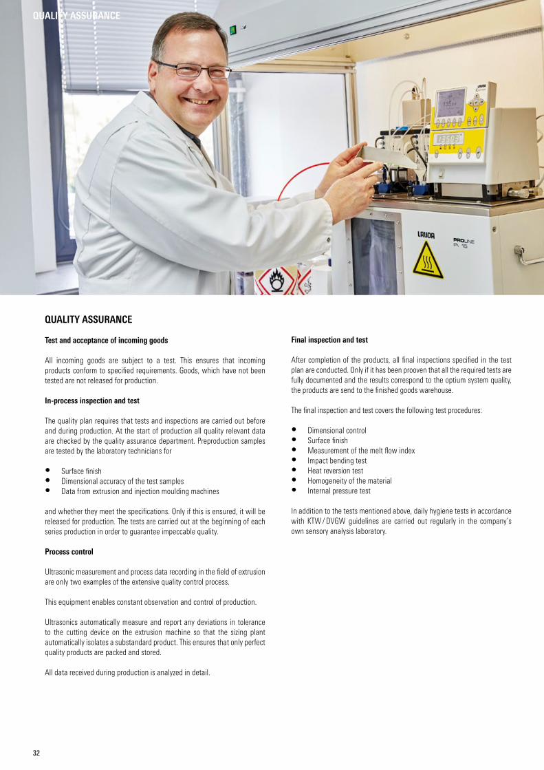
QUALITY ASSURANCE
Test and acceptance of incoming goods
All incoming goods are subject to a test. This ensures that incoming products conform to specified requirements. Goods, which have not been tested are not released for production.
In-process inspection and test
The quality plan requires that tests and inspections are carried out before and during production. At the start of production all quality relevant data are checked by the quality assurance department. Preproduction samples are tested by the laboratory technicians for
• Surface finish • Dimensional accuracy of the test samples • Data from extrusion and injection moulding machines
and whether they meet the specifications. Only if this is ensured, it will be released for production. The tests are carried out at the beginning of each series production in order to guarantee impeccable quality.
Process control
Ultrasonic measurement and process data recording in the field of extrusion are only two examples of the extensive quality control process.
This equipment enables constant observation and control of production.
Ultrasonics automatically measure and report any deviations in tolerance to the cutting device on the extrusion machine so that the sizing plant automatically isolates a substandard product. This ensures that only perfect quality products are packed and stored.
All data received during production is analyzed in detail.
Final inspection and test
After completion of the products, all final inspections specified in the test plan are conducted. Only if it has been prooven that all the required tests are fully documented and the results correspond to the optium system quality, the products are send to the finished goods warehouse.
The final inspection and test covers the following test procedures:
• Dimensional control• Surface finish• Measurement of the melt flow index• Impact bending test• Heat reversion test• Homogeneity of the material• Internal pressure test
In addition to the tests mentioned above, daily hygiene tests in accordance with KTW / DVGW guidelines are carried out regularly in the company’s own sensory analysis laboratory.
QUALITY ASSURANCE
3333
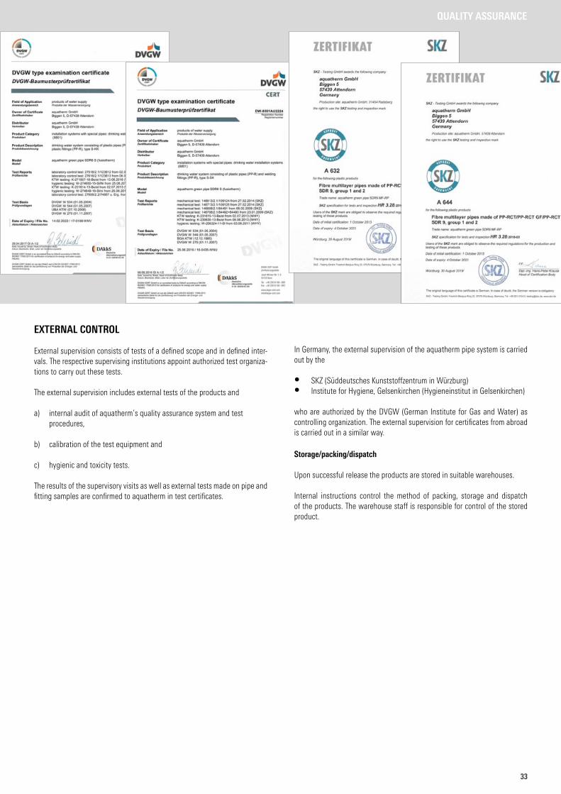
EXTERNAL CONTROL
External supervision consists of tests of a defined scope and in defined inter-vals. The respective supervising institutions appoint authorized test organiza-tions to carry out these tests.
The external supervision includes external tests of the products and
a) internal audit of aquatherm’s quality assurance system and test procedures,
b) calibration of the test equipment and
c) hygienic and toxicity tests.
The results of the supervisory visits as well as external tests made on pipe and fitting samples are confirmed to aquatherm in test certificates.
In Germany, the external supervision of the aquatherm pipe system is carried out by the
• SKZ (Süddeutsches Kunststoffzentrum in Würzburg)• Institute for Hygiene, Gelsenkirchen (Hygieneinstitut in Gelsenkirchen)
who are authorized by the DVGW (German Institute for Gas and Water) as controlling organization. The external supervision for certificates from abroad is carried out in a similar way.
Storage/packing/dispatch
Upon successful release the products are stored in suitable warehouses.
Internal instructions control the method of packing, storage and dispatch of the products. The warehouse staff is responsible for control of the stored product.
QUALITY ASSURANCE
34
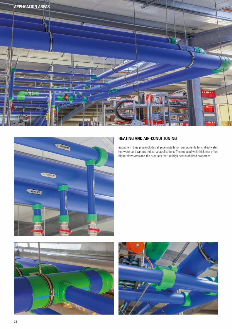
HEATING AND AIR-CONDITIONING
aquatherm blue pipe includes all pipe installation components for chilled water, hot water and various industrial applications. The reduced wall thickness offers higher flow rates and the products feature high heat-stabilized properties.
APPLICATION AREAS
3535
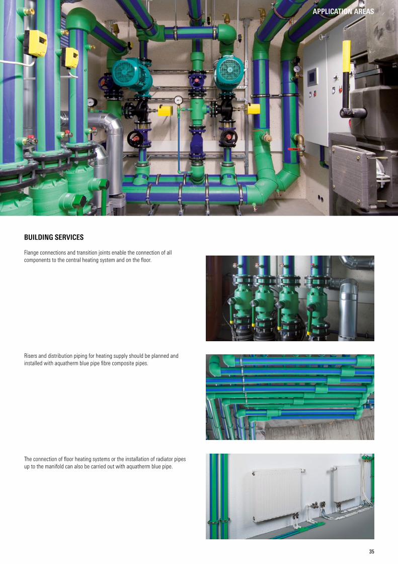
BUILDING SERVICES
Flange connections and transition joints enable the connection of all components to the central heating system and on the floor.
Risers and distribution piping for heating supply should be planned and installed with aquatherm blue pipe fibre composite pipes.
The connection of floor heating systems or the installation of radiator pipes up to the manifold can also be carried out with aquatherm blue pipe.
APPLICATION AREAS
36
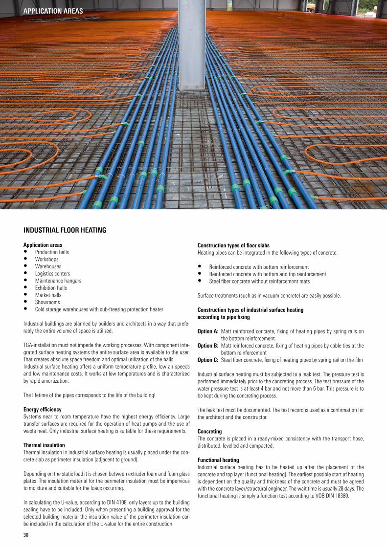
INDUSTRIAL FLOOR HEATING
Application areas• Production halls• Workshops• Warehouses• Logistics centers• Maintenance hangars• Exhibition halls• Market halls• Showrooms• Cold storage warehouses with sub-freezing protection heater
Industrial buildings are planned by builders and architects in a way that prefe-rably the entire volume of space is utilized.
TGA-installation must not impede the working processes. With component inte-grated surface heating systems the entire surface area is available to the user. That creates absolute space freedom and optimal utilization of the halls.Industrial surface heating offers a uniform temperature profile, low air speeds and low maintenance costs. It works at low temperatures and is characterized by rapid amortization.
The lifetime of the pipes corresponds to the life of the building!
Energy efficiencySystems near to room temperature have the highest energy efficiency. Large transfer surfaces are required for the operation of heat pumps and the use of waste heat. Only industrial surface heating is suitable for these requirements.
Thermal insulationThermal insulation in industrial surface heating is usually placed under the con-crete slab as perimeter insulation (adjacent to ground).
Depending on the static load it is chosen between extruder foam and foam glass plates. The insulation material for the perimeter insulation must be impervious to moisture and suitable for the loads occurring.
In calculating the U-value, according to DIN 4108, only layers up to the building sealing have to be included. Only when presenting a building approval for the selected building material the insulation value of the perimeter insulation can be included in the calculation of the U-value for the entire construction.
Construction types of floor slabsHeating pipes can be integrated in the following types of concrete:
• Reinforced concrete with bottom reinforcement• Reinforced concrete with bottom and top reinforcement• Steel fiber concrete without reinforcement mats
Surface treatments (such as in vacuum concrete) are easily possible.
Construction types of industrial surface heatingaccording to pipe fixing
Option A: Matt reinforced concrete, fixing of heating pipes by spring rails on the bottom reinforcement
Option B: Matt reinforced concrete, fixing of heating pipes by cable ties at the bottom reinforcement
Option C: Steel fiber concrete, fixing of heating pipes by spring rail on the film
Industrial surface heating must be subjected to a leak test. The pressure test is performed immediately prior to the concreting process. The test pressure of the water pressure test is at least 4 bar and not more than 6 bar. This pressure is to be kept during the concreting process.
The leak test must be documented. The test record is used as a confirmation for the architect and the constructor.
ConcretingThe concrete is placed in a ready-mixed consistency with the transport hose, distributed, levelled and compacted.
Functional heatingIndustrial surface heating has to be heated up after the placement of the concrete and top layer (functional heating). The earliest possible start of heating is dependent on the quality and thickness of the concrete and must be agreed with the concrete layer/structural engineer. The wait time is usually 28 days. The functional heating is simply a function test according to VOB DIN 18380.
APPLICATION AREAS
3737
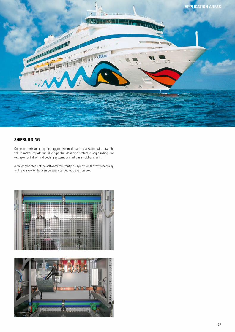
SHIPBUILDING
Corrosion resistance against aggressive media and sea water with low ph-values makes aquatherm blue pipe the ideal pipe system in shipbuilding. For example for ballast and cooling systems or inert gas scrubber drains.
A major advantage of the saltwater resistant pipe systems is the fast processing and repair works that can be easily carried out, even on sea.
APPLICATION AREAS
38
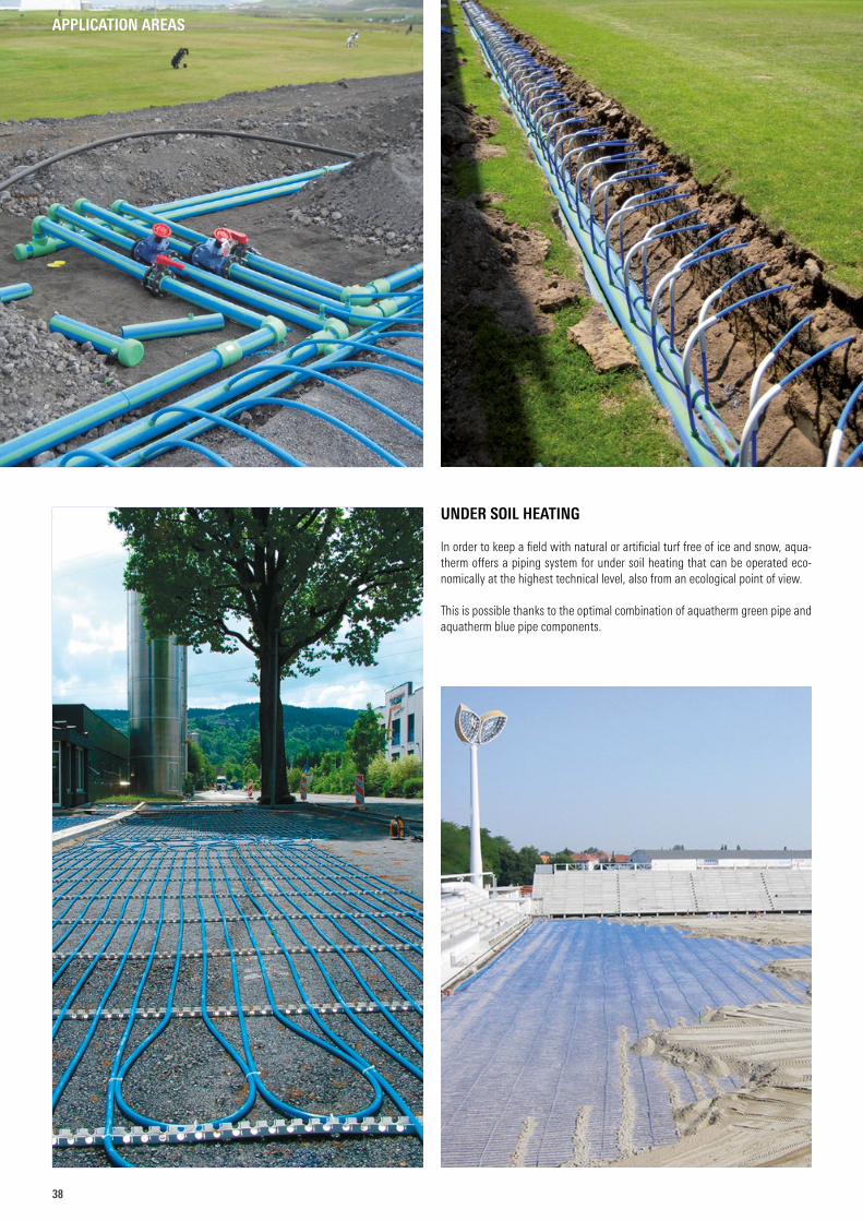
UNDER SOIL HEATING
In order to keep a field with natural or artificial turf free of ice and snow, aqua-therm offers a piping system for under soil heating that can be operated eco-nomically at the highest technical level, also from an ecological point of view.
This is possible thanks to the optimal combination of aquatherm green pipe and aquatherm blue pipe components.
APPLICATION AREAS
3939
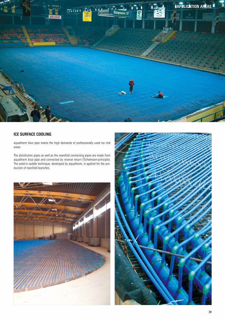
ICE SURFACE COOLING
aquatherm blue pipe meets the high demands of professionally used ice rink areas.
The distribution pipes as well as the manifold connecting pipes are made from aquatherm blue pipe and connected by reverse return (Tichelmann-principle). The weld-in saddle technique, developed by aquatherm, is applied for the pro-duction of manifold branches.
APPLICATION AREAS
40
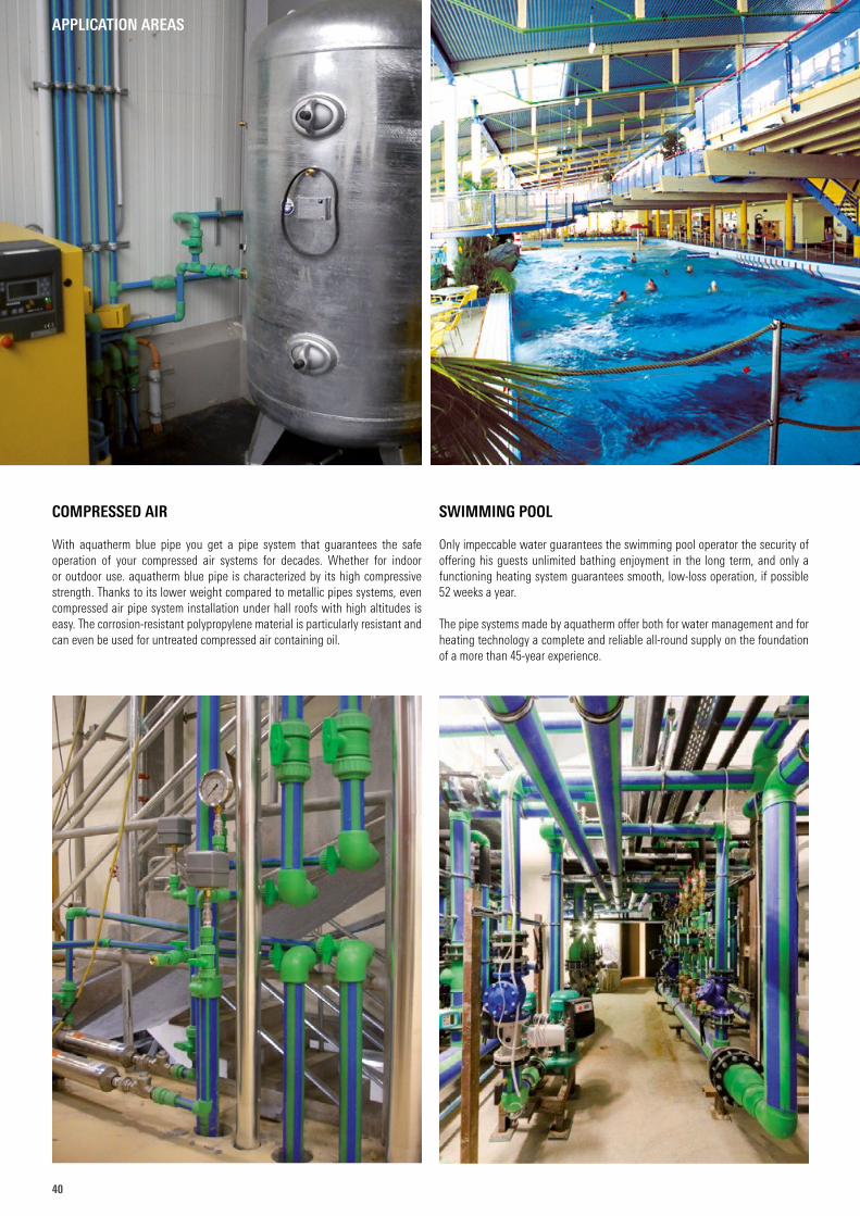
COMPRESSED AIR
With aquatherm blue pipe you get a pipe system that guarantees the safe operation of your compressed air systems for decades. Whether for indoor or outdoor use. aquatherm blue pipe is characterized by its high compressive strength. Thanks to its lower weight compared to metallic pipes systems, even compressed air pipe system installation under hall roofs with high altitudes is easy. The corrosion-resistant polypropylene material is particularly resistant and can even be used for untreated compressed air containing oil.
SWIMMING POOL
Only impeccable water guarantees the swimming pool operator the security of offering his guests unlimited bathing enjoyment in the long term, and only a functioning heating system guarantees smooth, low-loss operation, if possible 52 weeks a year.
The pipe systems made by aquatherm offer both for water management and for heating technology a complete and reliable all-round supply on the foundation of a more than 45-year experience.
APPLICATION AREAS
4141
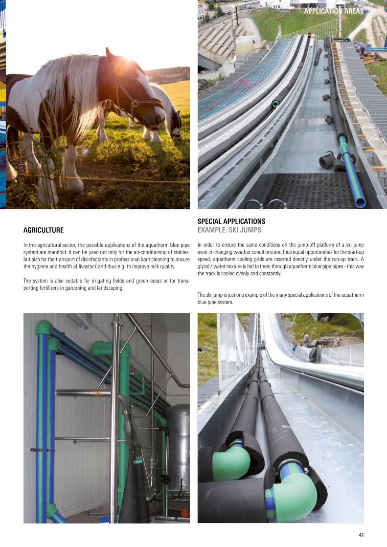
SPECIAL APPLICATIONSEXAMPLE: SKI JUMPS
In order to ensure the same conditions on the jump-off platform of a ski jump even in changing weather conditions and thus equal opportunities for the start-up speed, aquatherm cooling grids are inserted directly under the run-up track. A glycol / water mixture is fed to them through aquatherm blue pipe pipes - this way the track is cooled evenly and constantly.
The ski jump is just one example of the many special applications of the aqua therm blue pipe system.
AGRICULTURE
In the agricultural sector, the possible applications of the aquatherm blue pipe system are manifold. It can be used not only for the air-conditioning of stables, but also for the transport of disinfectants in professional barn cleaning to ensure the hygiene and health of livestock and thus e.g. to improve milk quality.
The system is also suitable for irrigating fields and green areas or for trans-porting fertilizers in gardening and landscaping.
APPLICATION AREAS
42
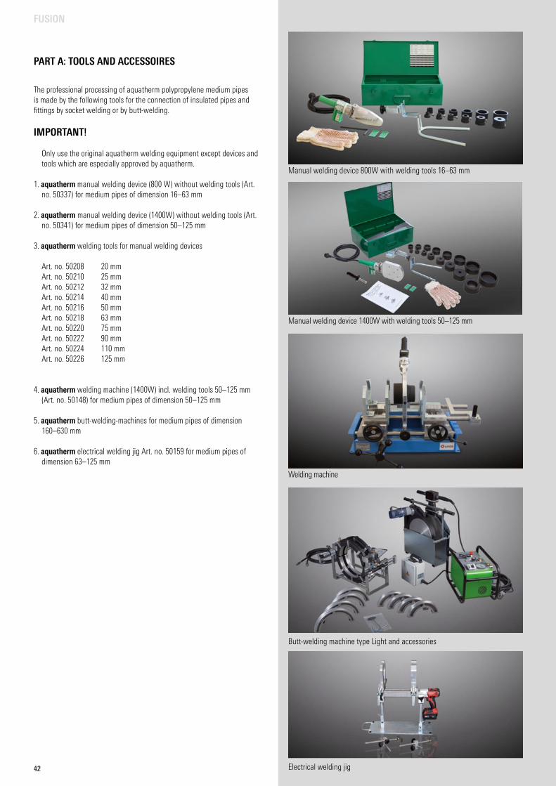
PART A: TOOLS AND ACCESSOIRES
Manual welding device 800W with welding tools 16–63 mm
Manual welding device 1400W with welding tools 50–125 mm
Welding machine
Butt-welding machine type Light and accessories
Electrical welding jig
FUSION
The professional processing of aquatherm polypropylene medium pipes is made by the following tools for the connection of insulated pipes and fittings by socket welding or by butt-welding.
IMPORTANT!
Only use the original aquatherm welding equipment except devices and tools which are especially approved by aquatherm.
1. aquatherm manual welding device (800 W) without welding tools (Art. no. 50337) for medium pipes of dimension 16–63 mm
2. aquatherm manual welding device (1400W) without welding tools (Art. no. 50341) for medium pipes of dimension 50–125 mm
3. aquatherm welding tools for manual welding devices
Art. no. 50208 20 mm Art. no. 50210 25 mm Art. no. 50212 32 mm Art. no. 50214 40 mm Art. no. 50216 50 mm Art. no. 50218 63 mm Art. no. 50220 75 mm Art. no. 50222 90 mm Art. no. 50224 110 mm Art. no. 50226 125 mm
4. aquatherm welding machine (1400W) incl. welding tools 50–125 mm (Art. no. 50148) for medium pipes of dimension 50–125 mm
5. aquatherm butt-welding-machines for medium pipes of dimension 160–630 mm
6. aquatherm electrical welding jig Art. no. 50159 for medium pipes of dimension 63–125 mm
4343
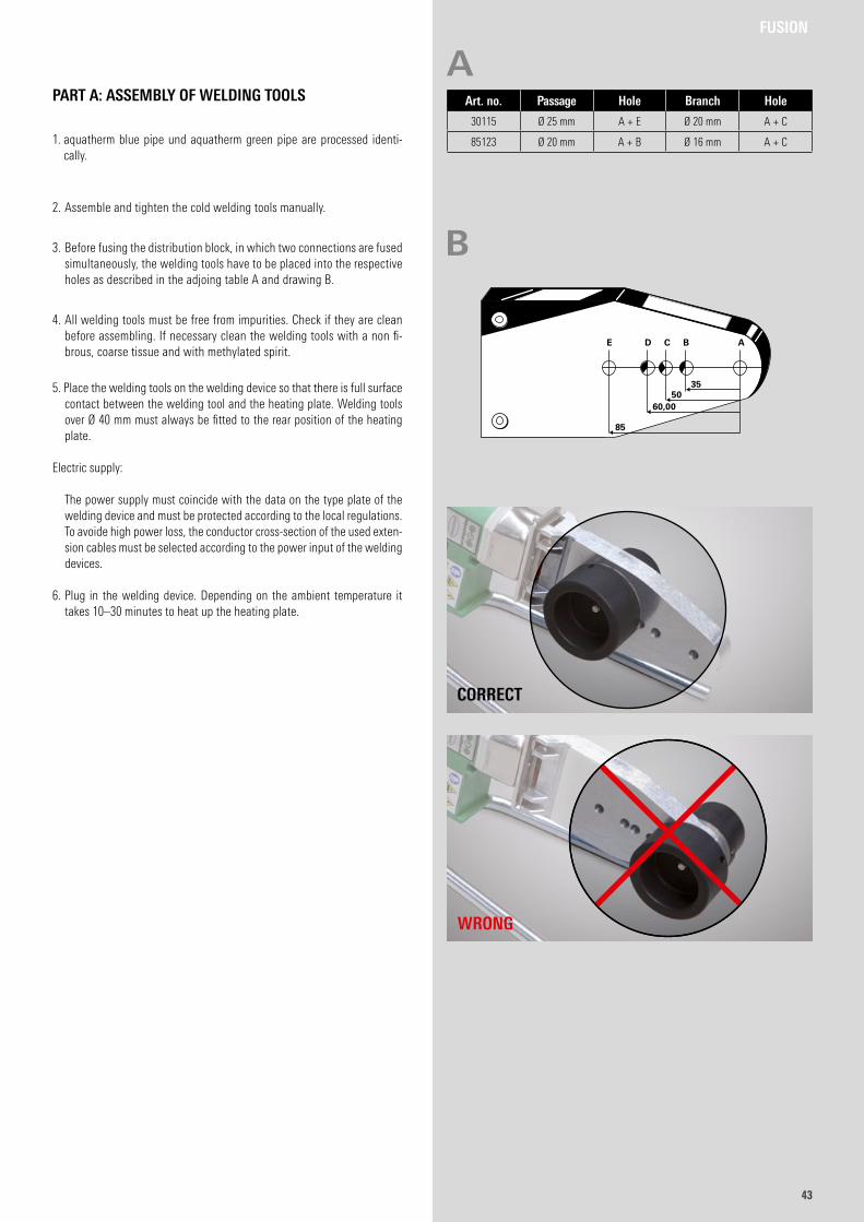
1. aquatherm blue pipe und aquatherm green pipe are processed identi-cally.
2. Assemble and tighten the cold welding tools manually.
3. Before fusing the distribution block, in which two connections are fused simultaneously, the welding tools have to be placed into the respective holes as described in the adjoing table A and drawing B.
4. All welding tools must be free from impurities. Check if they are clean before assembling. If necessary clean the welding tools with a non fi-brous, coarse tissue and with methylated spirit.
5. Place the welding tools on the welding device so that there is full surfacecontact between the welding tool and the heating plate. Welding tools over Ø 40 mm must always be fitted to the rear position of the heating plate.
Electric supply:
The power supply must coincide with the data on the type plate of the welding device and must be protected according to the local regulations. To avoide high power loss, the conductor cross-section of the used exten-sion cables must be selected according to the power input of the welding devices.
6. Plug in the welding device. Depending on the ambient temperature it takes 10–30 minutes to heat up the heating plate.
PART A: ASSEMBLY OF WELDING TOOLS
FUSION
Art. no. Passage Hole Branch Hole
30115 Ø 25 mm A + E Ø 20 mm A + C
85123 Ø 20 mm A + B Ø 16 mm A + C
A
B
WRONG
CORRECT
E D C B A
85
60,0050
35
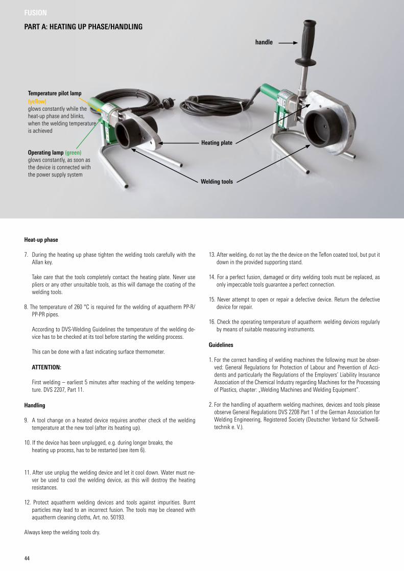
44
Heat-up phase
7. During the heating up phase tighten the welding tools carefully with the Allan key.
Take care that the tools completely contact the heating plate. Never use pliers or any other unsuitable tools, as this will damage the coating of the welding tools.
8. The temperature of 260 °C is required for the welding of aquatherm PP-R/PP-PR pipes.
According to DVS-Welding Guidelines the temperature of the welding de-vice has to be checked at its tool before starting the welding process.
This can be done with a fast indicating surface thermometer.
ATTENTION:
First welding – earliest 5 minutes after reaching of the welding tempera-ture. DVS 2207, Part 11.
Handling
9. A tool change on a heated device requires another check of the welding temperature at the new tool (after its heating up).
10. If the device has been unplugged, e.g. during longer breaks, the heating up process, has to be restarted (see item 6).
11. After use unplug the welding device and let it cool down. Water must ne-ver be used to cool the welding device, as this will destroy the heating resistances.
12. Protect aquatherm welding devices and tools against impurities. Burnt particles may lead to an incorrect fusion. The tools may be cleaned with aquatherm cleaning cloths, Art. no. 50193.
Always keep the welding tools dry.
13. After welding, do not lay the the device on the Teflon coated tool, but put it down in the provided supporting stand.
14. For a perfect fusion, damaged or dirty welding tools must be replaced, as only impeccable tools guarantee a perfect connection.
15. Never attempt to open or repair a defective device. Return the defective device for repair.
16. Check the operating temperature of aquatherm welding devices regularly by means of suitable measuring instruments.
Guidelines
1. For the correct handling of welding machines the following must be obser-ved: General Regulations for Protection of Labour and Prevention of Acci-dents and particularly the Regulations of the Employers’ Liability Insurance Association of the Chemical Industry regarding Machines for the Processing of Plastics, chapter: „Welding Machines and Welding Equipment“.
2. For the handling of aquatherm welding machines, devices and tools please observe General Regulations DVS 2208 Part 1 of the German Association for Welding Engineering, Registered Society (Deutscher Verband für Schweiß-technik e. V.).
FUSION
PART A: HEATING UP PHASE/HANDLING
Welding tools
Heating plate
Temperature pilot lamp (yellow)glows constantly while the heat-up phase and blinks, when the welding temperature is achieved
Operating lamp (green)glows constantly, as soon as the device is connected with the power supply system
handle
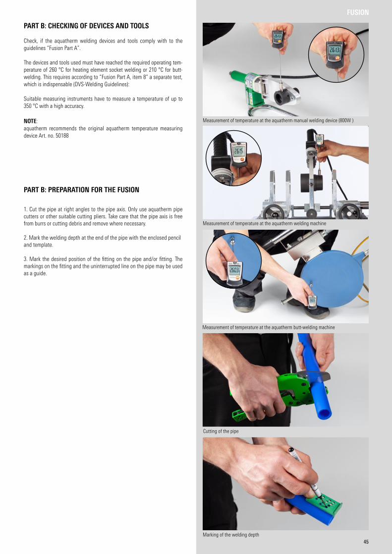
4545
PART B: CHECKING OF DEVICES AND TOOLS
Check, if the aquatherm welding devices and tools comply with to the guidelines “Fusion Part A”.
The devices and tools used must have reached the required operating tem-perature of 260 °C for heating element socket welding or 210 °C for butt-welding. This requires according to “Fusion Part A, item 8” a separate test, which is indispensable (DVS-Welding Guidelines):
Suitable measuring instruments have to measure a temperature of up to 350 °C with a high accuracy.
NOTE:aquatherm recommends the original aquatherm temperature measuring device Art. no. 50188
PART B: PREPARATION FOR THE FUSION
1. Cut the pipe at right angles to the pipe axis. Only use aquatherm pipe cutters or other suitable cutting pliers. Take care that the pipe axis is free from burrs or cutting debris and remove where necessary.
2. Mark the welding depth at the end of the pipe with the enclosed penciland template.
3. Mark the desired position of the fitting on the pipe and/or fitting. The markings on the fitting and the uninterrupted line on the pipe may be used as a guide.
FUSION
Measurement of temperature at the aquatherm butt-welding machine
Measurement of temperature at the aquatherm manual welding device (800W )
Measurement of temperature at the aquatherm welding machine
Cutting of the pipe
Marking of the welding depth
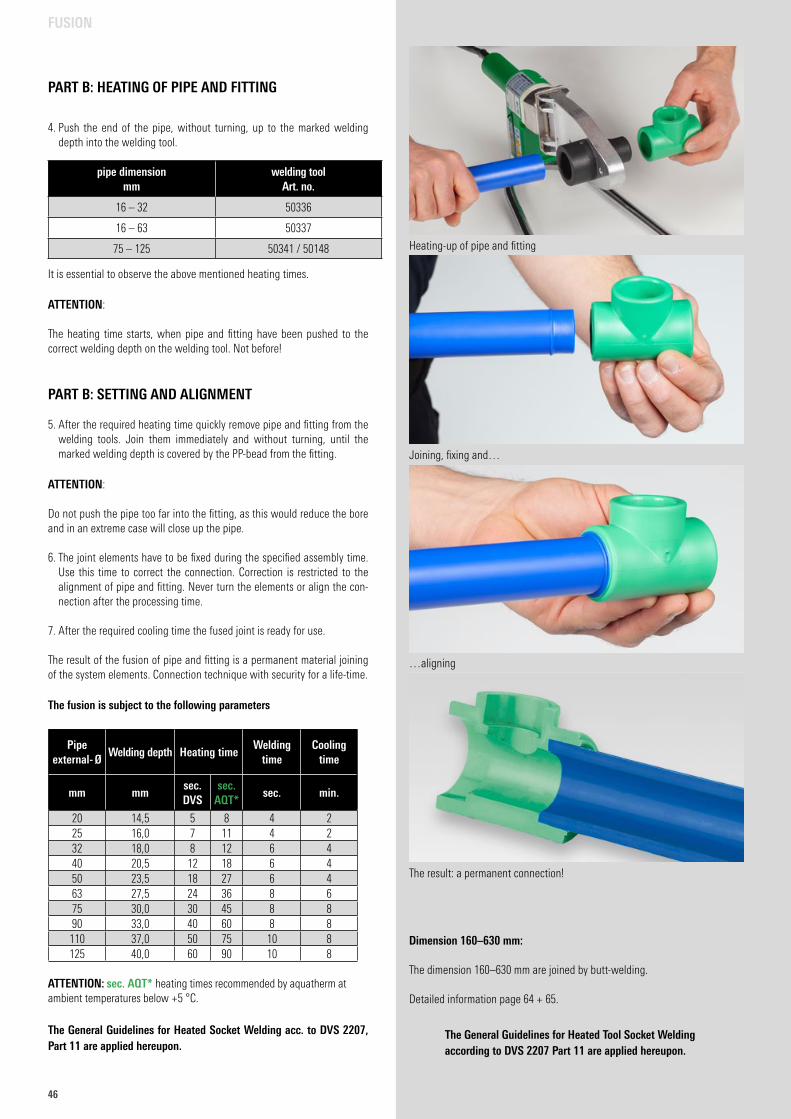
46
PART B: HEATING OF PIPE AND FITTING
Dimension 160–630 mm:
The dimension 160–630 mm are joined by butt-welding.
Detailed information page 64 + 65.
The General Guidelines for Heated Tool Socket Welding according to DVS 2207 Part 11 are applied hereupon.
4. Push the end of the pipe, without turning, up to the marked welding depth into the welding tool.
It is essential to observe the above mentioned heating times.
ATTENTION: The heating time starts, when pipe and fitting have been pushed to the correct welding depth on the welding tool. Not before!
PART B: SETTING AND ALIGNMENT
5. After the required heating time quickly remove pipe and fitting from the welding tools. Join them immediately and without turning, until the marked welding depth is covered by the PP-bead from the fitting.
ATTENTION: Do not push the pipe too far into the fitting, as this would reduce the bore and in an extreme case will close up the pipe.
6. The joint elements have to be fixed during the specified assembly time. Use this time to correct the connection. Correction is restricted to the alignment of pipe and fitting. Never turn the elements or align the con-nection after the processing time.
7. After the required cooling time the fused joint is ready for use. The result of the fusion of pipe and fitting is a permanent material joining of the system elements. Connection technique with security for a life-time.
The fusion is subject to the following parameters
FUSION
Pipe external- Ø
Welding depth Heating timeWelding
timeCooling
time
mm mmsec. DVS
sec. AQT*
sec. min.
20 14,5 5 8 4 225 16,0 7 11 4 232 18,0 8 12 6 440 20,5 12 18 6 450 23,5 18 27 6 463 27,5 24 36 8 675 30,0 30 45 8 890 33,0 40 60 8 8
110 37,0 50 75 10 8125 40,0 60 90 10 8
ATTENTION: sec. AQT* heating times recommended by aquatherm at ambient temperatures below +5 °C.
The General Guidelines for Heated Socket Welding acc. to DVS 2207, Part 11 are applied hereupon.
Joining, fixing and…
…aligning
The result: a permanent connection!
Heating-up of pipe and fitting
pipe dimension mm
welding tool Art. no.
16 – 32 50336
16 – 63 50337
75 – 125 50341 / 50148
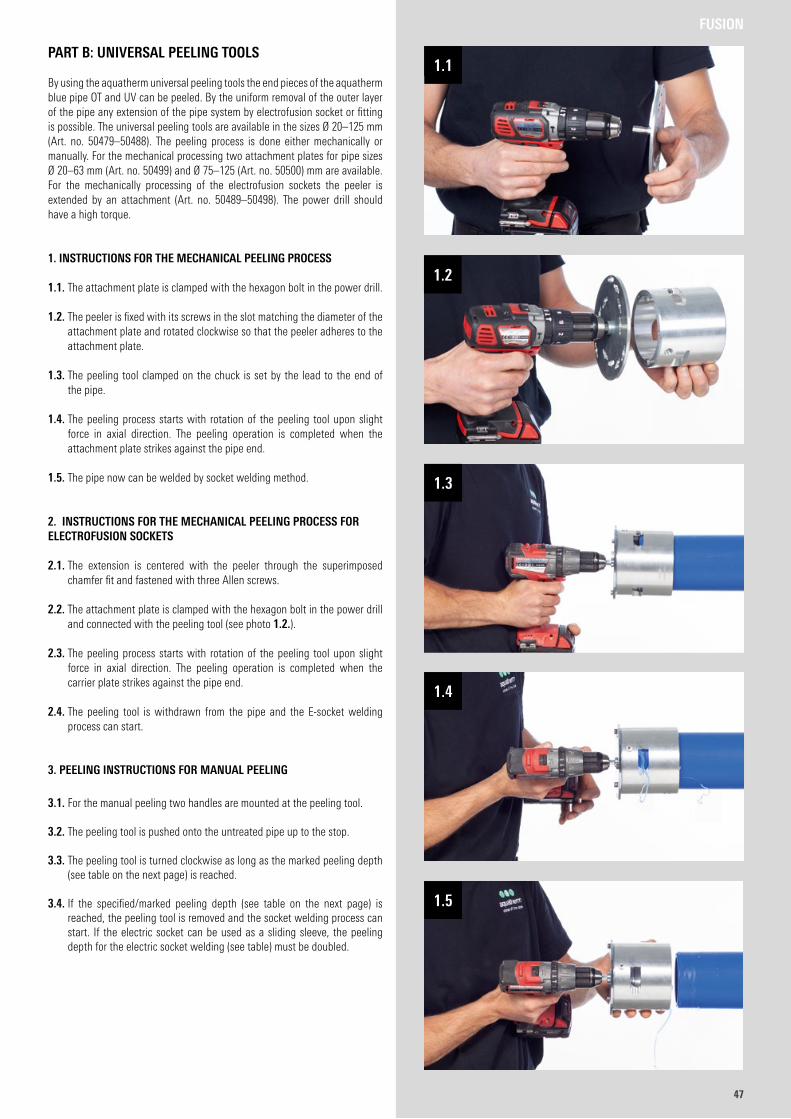
4747
FUSION
PART B: UNIVERSAL PEELING TOOLS
By using the aquatherm universal peeling tools the end pieces of the aquatherm blue pipe OT and UV can be peeled. By the uniform removal of the outer layer of the pipe any extension of the pipe system by electrofusion socket or fitting is possible. The universal peeling tools are available in the sizes Ø 20–125 mm (Art. no. 50479–50488). The peeling process is done either mechanically or manually. For the mechanical processing two attachment plates for pipe sizes Ø 20–63 mm (Art. no. 50499) and Ø 75–125 (Art. no. 50500) mm are available. For the mechanically processing of the electrofusion sockets the peeler is extended by an attachment (Art. no. 50489–50498). The power drill should have a high torque.
1. INSTRUCTIONS FOR THE MECHANICAL PEELING PROCESS
1.1. The attachment plate is clamped with the hexagon bolt in the power drill.
1.2. The peeler is fixed with its screws in the slot matching the diameter of the attachment plate and rotated clockwise so that the peeler adheres to the attachment plate.
1.3. The peeling tool clamped on the chuck is set by the lead to the end of the pipe.
1.4. The peeling process starts with rotation of the peeling tool upon slight force in axial direction. The peeling operation is completed when the attachment plate strikes against the pipe end.
1.5. The pipe now can be welded by socket welding method.
2. INSTRUCTIONS FOR THE MECHANICAL PEELING PROCESS FOR ELECTROFUSION SOCKETS
2.1. The extension is centered with the peeler through the superimposed chamfer fit and fastened with three Allen screws.
2.2. The attachment plate is clamped with the hexagon bolt in the power drill and connected with the peeling tool (see photo 1.2.).
2.3. The peeling process starts with rotation of the peeling tool upon slight force in axial direction. The peeling operation is completed when the carrier plate strikes against the pipe end.
2.4. The peeling tool is withdrawn from the pipe and the E-socket welding process can start.
3. PEELING INSTRUCTIONS FOR MANUAL PEELING
3.1. For the manual peeling two handles are mounted at the peeling tool.
3.2. The peeling tool is pushed onto the untreated pipe up to the stop.
3.3. The peeling tool is turned clockwise as long as the marked peeling depth (see table on the next page) is reached.
3.4. If the specified/marked peeling depth (see table on the next page) is reached, the peeling tool is removed and the socket welding process can start. If the electric socket can be used as a sliding sleeve, the peeling depth for the electric socket welding (see table) must be doubled.
4747
1.1
1.2
1.3
1.4
1.5
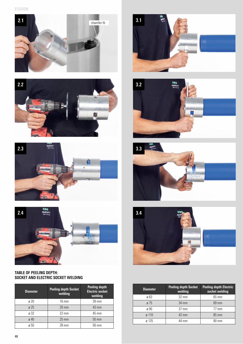
48
chamfer fit
TABLE OF PEELING DEPTH: SOCKET AND ELECTRIC SOCKET WELDING
DiameterPeeling depth Socket
welding
Peeling depth Electric socket
welding
ø 20 16 mm 39 mm
ø 25 20 mm 43 mm
ø 32 22 mm 45 mm
ø 40 25 mm 50 mm
ø 50 28 mm 56 mm
DiameterPeeling depth Socket
weldingPeeling depth Electric
socket welding
ø 63 32 mm 65 mm
ø 75 34 mm 69 mm
ø 90 37 mm 77 mm
ø 110 42 mm 85 mm
ø 125 44 mm 90 mm
FUSION
2.1
2.2
2.3
2.4
3.1
3.2
3.3
3.4
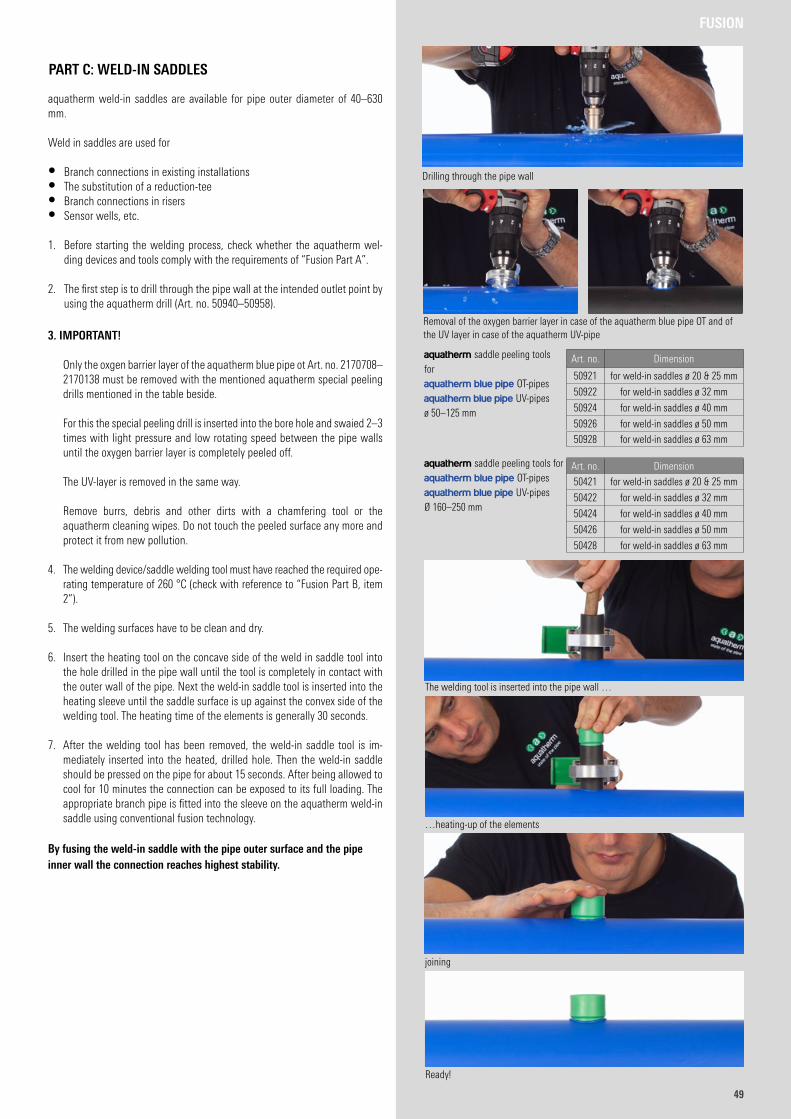
4949
FUSION
PART C: WELD-IN SADDLES
aquatherm weld-in saddles are available for pipe outer diameter of 40–630 mm.
Weld in saddles are used for
• Branch connections in existing installations• The substitution of a reduction-tee• Branch connections in risers• Sensor wells, etc.
1. Before starting the welding process, check whether the aquatherm wel-ding devices and tools comply with the requirements of “Fusion Part A”.
2. The first step is to drill through the pipe wall at the intended outlet point by using the aquatherm drill (Art. no. 50940–50958).
3. IMPORTANT!
Only the oxgen barrier layer of the aquatherm blue pipe ot Art. no. 2170708–2170138 must be removed with the mentioned aquatherm special peeling drills mentioned in the table beside.
For this the special peeling drill is inserted into the bore hole and swaied 2–3 times with light pressure and low rotating speed between the pipe walls until the oxygen barrier layer is completely peeled off.
The UV-layer is removed in the same way. Remove burrs, debris and other dirts with a chamfering tool or the
aquatherm cleaning wipes. Do not touch the peeled surface any more and protect it from new pollution.
4. The welding device/saddle welding tool must have reached the required ope-rating temperature of 260 °C (check with reference to “Fusion Part B, item 2”).
5. The welding surfaces have to be clean and dry.
6. Insert the heating tool on the concave side of the weld in saddle tool into the hole drilled in the pipe wall until the tool is completely in contact with the outer wall of the pipe. Next the weld-in saddle tool is inserted into the heating sleeve until the saddle surface is up against the convex side of the welding tool. The heating time of the elements is generally 30 seconds.
7. After the welding tool has been removed, the weld-in saddle tool is im-mediately inserted into the heated, drilled hole. Then the weld-in saddle should be pressed on the pipe for about 15 seconds. After being allowed to cool for 10 minutes the connection can be exposed to its full loading. The appropriate branch pipe is fitted into the sleeve on the aquatherm weld-in saddle using conventional fusion technology.
By fusing the weld-in saddle with the pipe outer surface and the pipe inner wall the connection reaches highest stability.
Art. no. Dimension
50921 for weld-in saddles ø 20 & 25 mm
50922 for weld-in saddles ø 32 mm
50924 for weld-in saddles ø 40 mm
50926 for weld-in saddles ø 50 mm
50928 for weld-in saddles ø 63 mm
Art. no. Dimension
50421 for weld-in saddles ø 20 & 25 mm
50422 for weld-in saddles ø 32 mm
50424 for weld-in saddles ø 40 mm
50426 for weld-in saddles ø 50 mm
50428 for weld-in saddles ø 63 mm
aquatherm saddle peeling tools for aquatherm blue pipe OT-pipesaquatherm blue pipe UV-pipes ø 50–125 mm
aquatherm saddle peeling tools for aquatherm blue pipe OT-pipesaquatherm blue pipe UV-pipes Ø 160–250 mm
Drilling through the pipe wall
The welding tool is inserted into the pipe wall …
…heating-up of the elements
joining
Ready!
Removal of the oxygen barrier layer in case of the aquatherm blue pipe OT and of the UV layer in case of the aquatherm UV-pipe
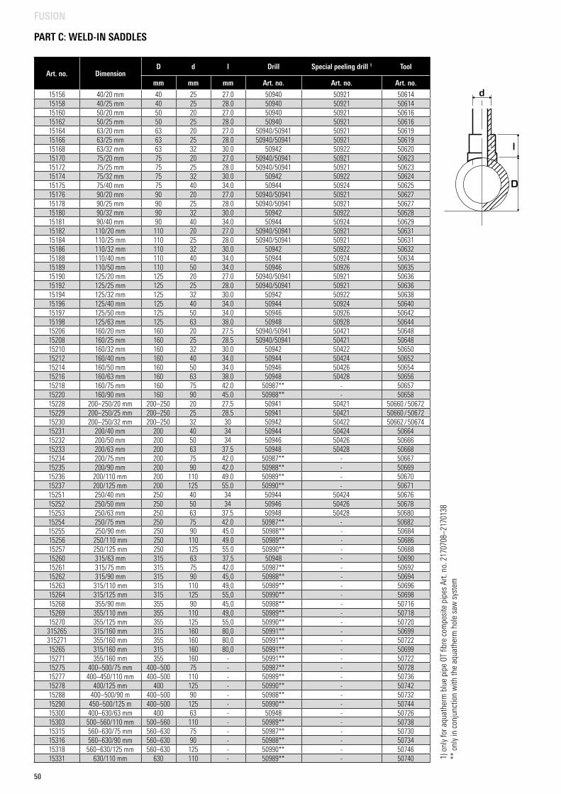
50
PART C: WELD-IN SADDLES
FUSION
1) o
nly
for a
quat
herm
blu
e pi
pe O
T fib
re c
ompo
site
pip
es A
rt. n
o. 2
1707
08–2
1701
38**
onl
y in
con
junc
tion
with
the
aqua
ther
m h
ole
saw
sys
tem
Art. no. DimensionD d l Drill Special peeling drill 1 Tool
mm mm mm Art. no. Art. no. Art. no.
15156 40/20 mm 40 25 27.0 50940 50921 5061415158 40/25 mm 40 25 28.0 50940 50921 5061415160 50/20 mm 50 20 27.0 50940 50921 5061615162 50/25 mm 50 25 28.0 50940 50921 5061615164 63/20 mm 63 20 27.0 50940/50941 50921 5061915166 63/25 mm 63 25 28.0 50940/50941 50921 5061915168 63/32 mm 63 32 30.0 50942 50922 5062015170 75/20 mm 75 20 27.0 50940/50941 50921 5062315172 75/25 mm 75 25 28.0 50940/50941 50921 5062315174 75/32 mm 75 32 30.0 50942 50922 5062415175 75/40 mm 75 40 34.0 50944 50924 5062515176 90/20 mm 90 20 27.0 50940/50941 50921 5062715178 90/25 mm 90 25 28.0 50940/50941 50921 5062715180 90/32 mm 90 32 30.0 50942 50922 5062815181 90/40 mm 90 40 34.0 50944 50924 5062915182 110/20 mm 110 20 27.0 50940/50941 50921 5063115184 110/25 mm 110 25 28.0 50940/50941 50921 5063115186 110/32 mm 110 32 30.0 50942 50922 5063215188 110/40 mm 110 40 34.0 50944 50924 5063415189 110/50 mm 110 50 34.0 50946 50926 5063515190 125/20 mm 125 20 27.0 50940/50941 50921 5063615192 125/25 mm 125 25 28.0 50940/50941 50921 5063615194 125/32 mm 125 32 30.0 50942 50922 5063815196 125/40 mm 125 40 34.0 50944 50924 5064015197 125/50 mm 125 50 34.0 50946 50926 5064215198 125/63 mm 125 63 38.0 50948 50928 5064415206 160/20 mm 160 20 27.5 50940/50941 50421 5064815208 160/25 mm 160 25 28.5 50940/50941 50421 5064815210 160/32 mm 160 32 30.0 50942 50422 5065015212 160/40 mm 160 40 34.0 50944 50424 5065215214 160/50 mm 160 50 34.0 50946 50426 5065415216 160/63 mm 160 63 38.0 50948 50428 5065615218 160/75 mm 160 75 42.0 50987** - 5065715220 160/90 mm 160 90 45.0 50988** - 5065815228 200–250/20 mm 200–250 20 27.5 50941 50421 50660 / 5067215229 200–250/25 mm 200–250 25 28.5 50941 50421 50660 / 5067215230 200–250/32 mm 200–250 32 30 50942 50422 50662 / 5067415231 200/40 mm 200 40 34 50944 50424 5066415232 200/50 mm 200 50 34 50946 50426 5066615233 200/63 mm 200 63 37.5 50948 50428 5066815234 200/75 mm 200 75 42.0 50987** - 5066715235 200/90 mm 200 90 42.0 50988** - 5066915236 200/110 mm 200 110 49.0 50989** - 5067015237 200/125 mm 200 125 55.0 50990** - 5067115251 250/40 mm 250 40 34 50944 50424 5067615252 250/50 mm 250 50 34 50946 50426 5067815253 250/63 mm 250 63 37.5 50948 50428 5068015254 250/75 mm 250 75 42.0 50987** - 5068215255 250/90 mm 250 90 45.0 50988** - 5068415256 250/110 mm 250 110 49.0 50989** - 5068615257 250/125 mm 250 125 55.0 50990** - 5068815260 315/63 mm 315 63 37,5 50948 - 5069015261 315/75 mm 315 75 42,0 50987** - 5069215262 315/90 mm 315 90 45,0 50988** - 5069415263 315/110 mm 315 110 49,0 50989** - 5069615264 315/125 mm 315 125 55,0 50990** - 5069815268 355/90 mm 355 90 45,0 50988** - 5071615269 355/110 mm 355 110 49,0 50989** - 5071815270 355/125 mm 355 125 55,0 50990** - 50720
315265 315/160 mm 315 160 80,0 50991** - 50699315271 355/160 mm 355 160 80,0 50991** - 5072215265 315/160 mm 315 160 80,0 50991** - 5069915271 355/160 mm 355 160 - 50991** - 5072215275 400–500/75 mm 400–500 75 - 50987** - 5072815277 400–450/110 mm 400–500 110 - 50989** - 5073615278 400/125 mm 400 125 - 50990** - 5074215288 400–500/90 m 400–500 90 - 50988** - 5073215290 450–500/125 m 400–500 125 - 50990** - 5074415300 400–630/63 mm 400 63 - 50948 - 5072615303 500–560/110 mm 500–560 110 - 50989** - 5073815315 560–630/75 mm 560–630 75 - 50987** - 5073015316 560–630/90 mm 560–630 90 - 50988** - 5073415318 560–630/125 mm 560–630 125 - 50990** - 5074615331 630/110 mm 630 110 - 50989** - 50740
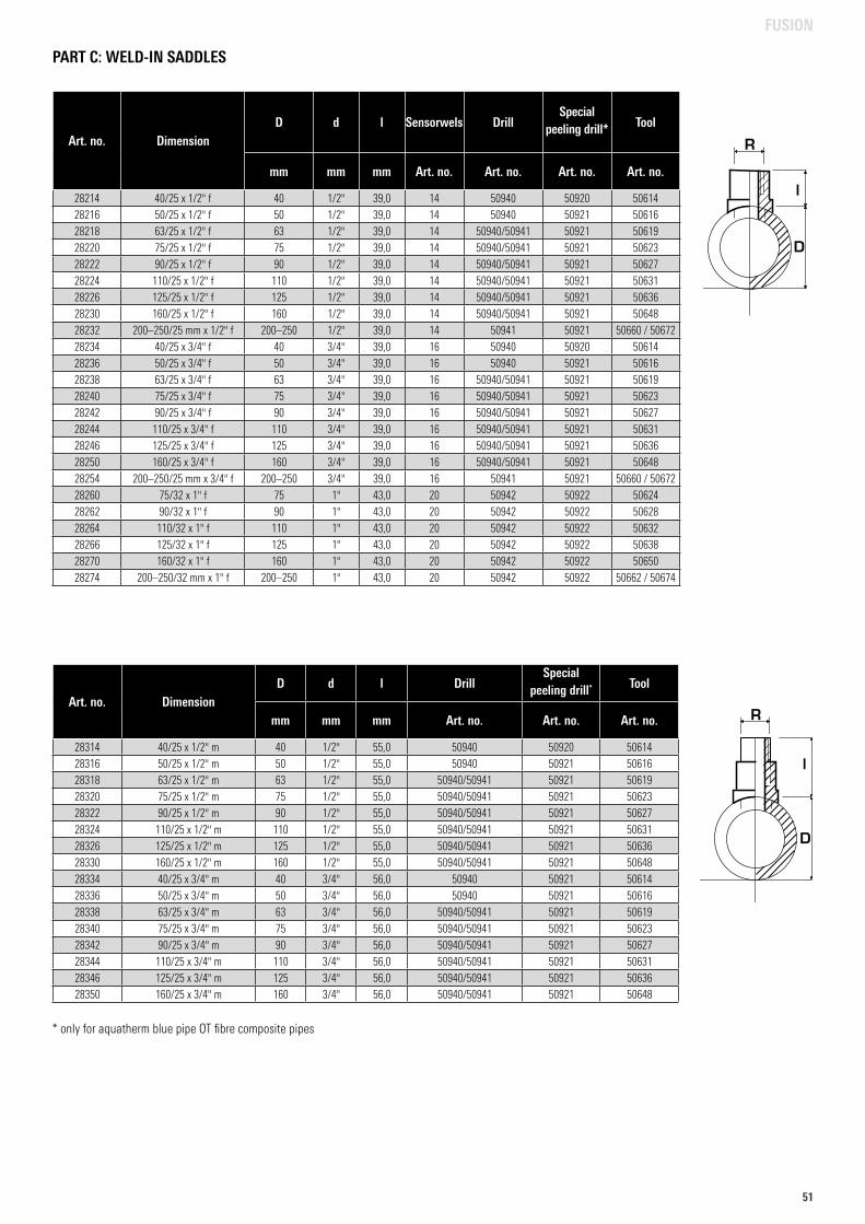
5151
Art. no. DimensionD d l Sensorwels Drill
Special peeling drill* Tool
mm mm mm Art. no. Art. no. Art. no. Art. no.
28214 40/25 x 1/2" f 40 1/2" 39,0 14 50940 50920 5061428216 50/25 x 1/2" f 50 1/2" 39,0 14 50940 50921 5061628218 63/25 x 1/2" f 63 1/2" 39,0 14 50940/50941 50921 5061928220 75/25 x 1/2" f 75 1/2" 39,0 14 50940/50941 50921 5062328222 90/25 x 1/2" f 90 1/2" 39,0 14 50940/50941 50921 5062728224 110/25 x 1/2" f 110 1/2" 39,0 14 50940/50941 50921 5063128226 125/25 x 1/2" f 125 1/2" 39,0 14 50940/50941 50921 5063628230 160/25 x 1/2" f 160 1/2" 39,0 14 50940/50941 50921 5064828232 200–250/25 mm x 1/2" f 200–250 1/2" 39,0 14 50941 50921 50660 / 5067228234 40/25 x 3/4" f 40 3/4" 39,0 16 50940 50920 5061428236 50/25 x 3/4" f 50 3/4" 39,0 16 50940 50921 5061628238 63/25 x 3/4" f 63 3/4" 39,0 16 50940/50941 50921 5061928240 75/25 x 3/4" f 75 3/4" 39,0 16 50940/50941 50921 5062328242 90/25 x 3/4" f 90 3/4" 39,0 16 50940/50941 50921 5062728244 110/25 x 3/4" f 110 3/4" 39,0 16 50940/50941 50921 5063128246 125/25 x 3/4" f 125 3/4" 39,0 16 50940/50941 50921 5063628250 160/25 x 3/4" f 160 3/4" 39,0 16 50940/50941 50921 5064828254 200–250/25 mm x 3/4" f 200–250 3/4" 39,0 16 50941 50921 50660 / 5067228260 75/32 x 1" f 75 1" 43,0 20 50942 50922 5062428262 90/32 x 1" f 90 1" 43,0 20 50942 50922 5062828264 110/32 x 1" f 110 1" 43,0 20 50942 50922 5063228266 125/32 x 1" f 125 1" 43,0 20 50942 50922 5063828270 160/32 x 1" f 160 1" 43,0 20 50942 50922 5065028274 200–250/32 mm x 1" f 200–250 1" 43,0 20 50942 50922 50662 / 50674
PART C: WELD-IN SADDLES
* only for aquatherm blue pipe OT fibre composite pipes
Art. no. DimensionD d l Drill
Special peeling drill* Tool
mm mm mm Art. no. Art. no. Art. no.
28314 40/25 x 1/2" m 40 1/2" 55,0 50940 50920 5061428316 50/25 x 1/2" m 50 1/2" 55,0 50940 50921 5061628318 63/25 x 1/2" m 63 1/2" 55,0 50940/50941 50921 5061928320 75/25 x 1/2" m 75 1/2" 55,0 50940/50941 50921 5062328322 90/25 x 1/2" m 90 1/2" 55,0 50940/50941 50921 5062728324 110/25 x 1/2" m 110 1/2" 55,0 50940/50941 50921 5063128326 125/25 x 1/2" m 125 1/2" 55,0 50940/50941 50921 5063628330 160/25 x 1/2" m 160 1/2" 55,0 50940/50941 50921 5064828334 40/25 x 3/4" m 40 3/4" 56,0 50940 50921 5061428336 50/25 x 3/4" m 50 3/4" 56,0 50940 50921 5061628338 63/25 x 3/4" m 63 3/4" 56,0 50940/50941 50921 5061928340 75/25 x 3/4" m 75 3/4" 56,0 50940/50941 50921 5062328342 90/25 x 3/4" m 90 3/4" 56,0 50940/50941 50921 5062728344 110/25 x 3/4" m 110 3/4" 56,0 50940/50941 50921 5063128346 125/25 x 3/4" m 125 3/4" 56,0 50940/50941 50921 5063628350 160/25 x 3/4" m 160 3/4" 56,0 50940/50941 50921 50648
FUSION
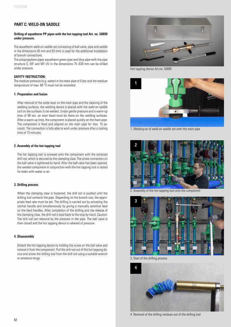
52
PART C: WELD-ON SADDLE
Drilling of aquatherm PP pipes with the hot tapping tool Art. no. 50890 under pressure.
The aquatherm weld-on saddle set (consisting of ball valve, pipe and saddle in the dimensions 40 mm and 63 mm) is used for the additional installation of branch connections. The polypropylene pipes aquatherm green pipe and blue pipe with the pipe structure S, MF and MF UV in the dimensions 75–630 mm can be drilled under pressure.
SAFETY INSTRUCTION:The medium pressure (e.g. water) in the main pipe of 6 bar and the medium temperature of max. 60 °C must not be exceeded.
1. Preparation and fusion
After removal of the oxide layer on the main pipe and the cleaning of the welding surfaces, the welding device is placed with the weld-on saddle tool on the surfaces to be welded. Under gentle pressure and a warm-up time of 90 sec. an even bead must be there on the welding surfaces. After a warm-up time, the component is placed quickly on the main pipe. The component is fixed and aligned on the main pipe for max. 15 se-conds. The connection is fully able to work under pressure after a cooling time of 15 minutes.
2. Assembly of the hot tapping tool
The hot tapping tool is screwed onto the component with the retracted drill rod, which is secured by the clamping claw. The screw connection on the ball valve is tightened by hand. After the ball valve has been opened, the welded component in conjunction with the hot tapping tool is tested for leaks with water or air.
3. Drilling process
When the clamping claw is loosened, the drill rod is pushed until the drilling tool contacts the pipe. Depending on the branch size, the appro-priate feed rate must be set. The drilling is carried out by actuating the ratchet handle and simultaneously by giving a manually sensitive feed on the feed handles. After completion of the drilling and the release of the clamping claw, the drill rod is lead back to the stop by hand. Caution: The drill rod can rebound by the pressure in the pipe. The ball valve is then closed and the hot tapping device is relieved of pressure.
4. Disassembly
Detach the hot tapping device by holding the screw on the ball valve and remove it from the component. Pull the drill rod out of the hot tapping de-vice and screw the drilling tool from the drill rod using a suitable wrench or armature tongs.
Hot tapping device Art.no. 50890
1. Welding-on of weld-on saddle set onto the main pipe
2. Assembly of the hot tapping tool onto the component
3. Start of the drilling process
4. Removal of the drilling residues out of the drilling tool
1
2
3
4
FUSION
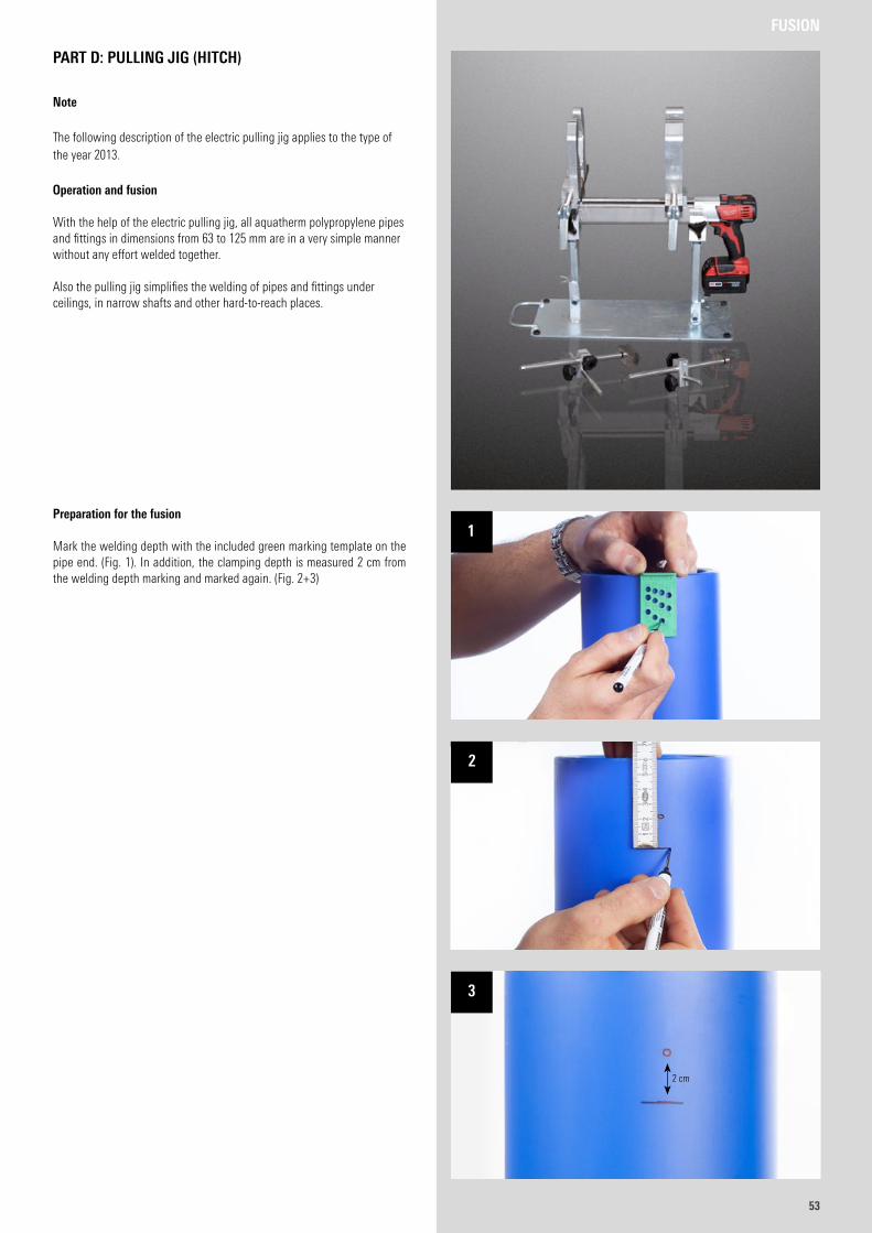
5353
Note
The following description of the electric pulling jig applies to the type of the year 2013.
Operation and fusion
With the help of the electric pulling jig, all aquatherm polypropylene pipes and fittings in dimensions from 63 to 125 mm are in a very simple manner without any effort welded together.
Also the pulling jig simplifies the welding of pipes and fittings under ceilings, in narrow shafts and other hard-to-reach places.
Preparation for the fusion
Mark the welding depth with the included green marking template on the pipe end. (Fig. 1). In addition, the clamping depth is measured 2 cm from the welding depth marking and marked again. (Fig. 2+3)
PART D: PULLING JIG (HITCH)
FUSION
1
2
3
2 cm
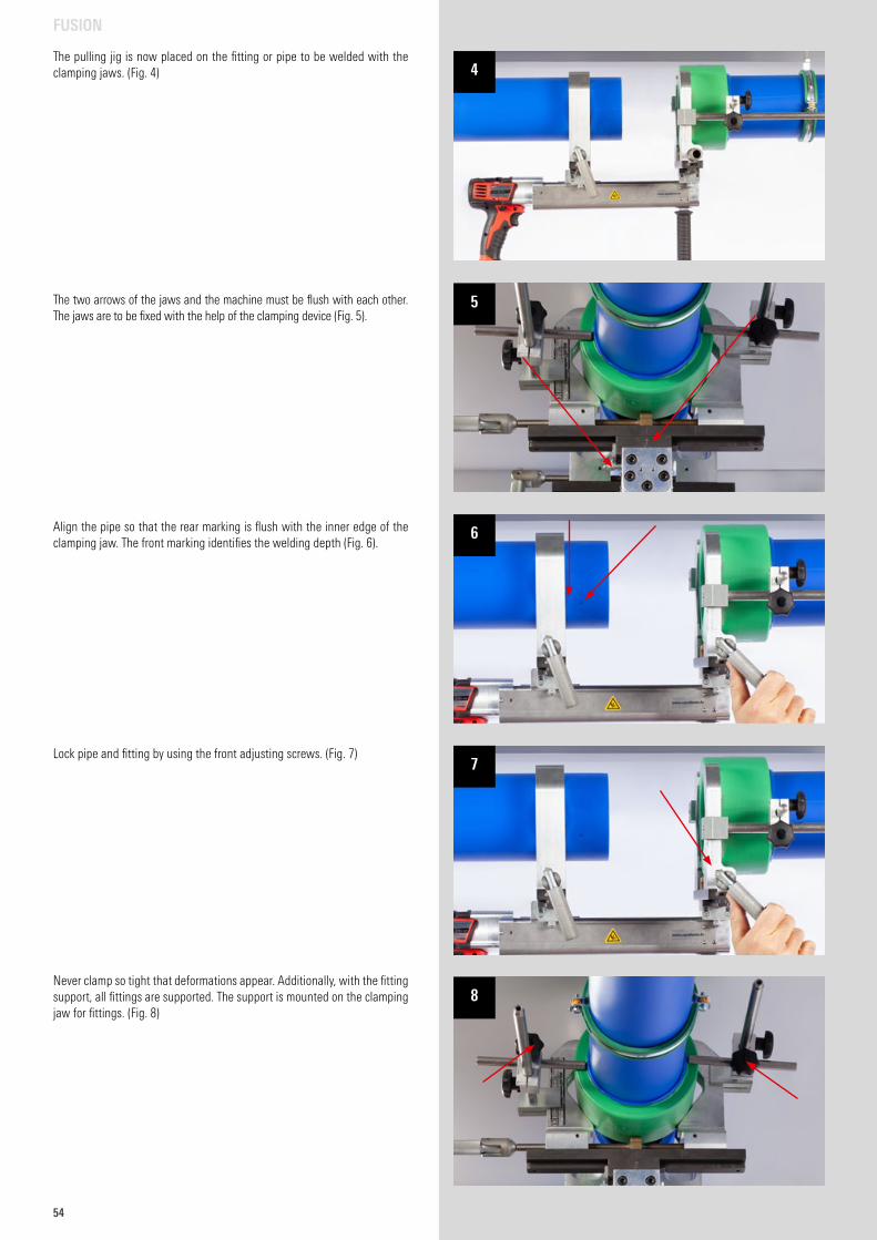
54
The pulling jig is now placed on the fitting or pipe to be welded with the clamping jaws. (Fig. 4)
The two arrows of the jaws and the machine must be flush with each other. The jaws are to be fixed with the help of the clamping device (Fig. 5).
Align the pipe so that the rear marking is flush with the inner edge of the clamping jaw. The front marking identifies the welding depth (Fig. 6).
Lock pipe and fitting by using the front adjusting screws. (Fig. 7)
Never clamp so tight that deformations appear. Additionally, with the fitting support, all fittings are supported. The support is mounted on the clamping jaw for fittings. (Fig. 8)
FUSION
4
5
6
7
8
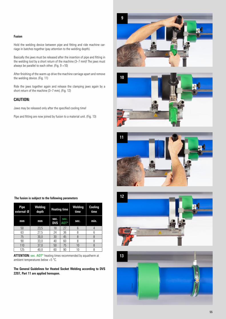
5555
Fusion Hold the welding device between pipe and fitting and ride machine car-riage in batches together (pay attention to the welding depth). Basically the jaws must be released after the insertion of pipe and fitting in the welding tool by a short return of the machine (3–7 mm)! The jaws must always be parallel to each other. (Fig. 9 +10) After finishing of the warm-up drive the machine carriage apart and remove the welding device. (Fig. 11) Ride the jaws together again and release the clamping jaws again by a short return of the machine (3–7 mm). (Fig. 12)
CAUTION: Jaws may be released only after the specified cooling time! Pipe and fitting are now joined by fusion to a material unit. (Fig. 13)
ATTENTION: sec. AQT* heating times recommended by aquatherm at ambient temperatures below +5 °C.
The General Guidelines for Heated Socket Welding according to DVS 2207, Part 11 are applied hereupon.
The fusion is subject to the following parameters
Pipe external- Ø
Welding depth
Heating time Welding
timeCooling
time
mm mmsec. DVS
sec. AQT*
sec. min.
50 23,5 18 27 6 463 27,5 24 36 8 675 30,0 30 45 8 890 33,0 40 60 8 8
110 37,0 50 75 10 8125 40,0 60 90 10 8
9
10
11
12
13
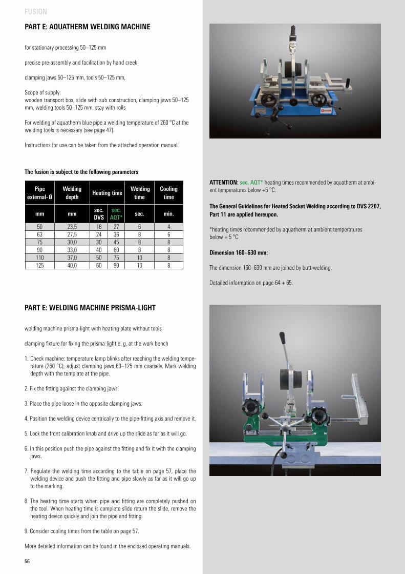
56
PART E: AQUATHERM WELDING MACHINE
for stationary processing 50–125 mm
precise pre-assembly and facilitation by hand creek
clamping jaws 50–125 mm, tools 50–125 mm,
Scope of supply:wooden transport box, slide with sub construction, clamping jaws 50–125 mm, welding tools 50–125 mm, stay with rolls
For welding of aquatherm blue pipe a welding temperature of 260 °C at the welding tools is necessary (see page 47).
Instructions for use can be taken from the attached operation manual.
ATTENTION: sec. AQT* heating times recommended by aquatherm at ambi-ent temperatures below +5 °C.
The General Guidelines for Heated Socket Welding according to DVS 2207, Part 11 are applied hereupon.
*heating times recommended by aquatherm at ambient temperatures below + 5 °C
Dimension 160–630 mm:
The dimension 160–630 mm are joined by butt-welding.
Detailed information on page 64 + 65.
The fusion is subject to the following parameters
Pipe external- Ø
Welding depth
Heating time Welding
timeCooling
time
mm mmsec. DVS
sec. AQT*
sec. min.
50 23,5 18 27 6 463 27,5 24 36 8 675 30,0 30 45 8 890 33,0 40 60 8 8
110 37,0 50 75 10 8125 40,0 60 90 10 8
PART E: WELDING MACHINE PRISMA-LIGHT
welding machine prisma-light with heating plate without tools
clamping fixture for fixing the prisma-light e. g. at the work bench
1. Check machine: temperature lamp blinks after reaching the welding tempe-rature (260 °C), adjust clamping jaws 63–125 mm coarsely. Mark welding depth with the template at the pipe.
2. Fix the fitting against the clamping jaws.
3. Place the pipe loose in the opposite clamping jaws.
4. Position the welding device centrically to the pipe-fitting axis and remove it.
5. Lock the front calibration knob and drive up the slide as far as it will go.
6. In this position push the pipe against the fitting and fix it with the clamping jaws.
7. Regulate the welding time according to the table on page 57, place the welding device and push the fitting and pipe slowly as far as it will go up to the marking.
8. The heating time starts when pipe and fitting are completely pushed on the tool. When heating time is complete slide return the slide, remove the heating device quickly and join the pipe and fitting.
9. Consider cooling times from the table on page 57.
More detailed information can be found in the enclosed operating manuals.
FUSION
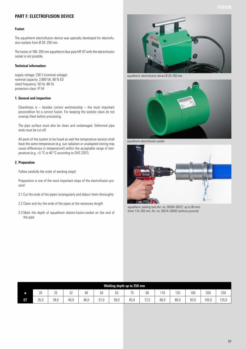
5757
PART F: ELECTROFUSION DEVICE
Fusion
The aquatherm electrofusion device was specially developed for electrofu-sion sockets from Ø 20–250 mm.
The fusion of 160–250 mm aquatherm blue pipe MF OT with the electrofusion socket is not possible.
Technical information:
supply voltage: 230 V (nominal voltage)nominal capacity: 2.800 VA, 80 % EDrated frequency: 50 Hz–60 Hzprotection class: IP 54
1. General and inspection
Cleanliness is – besides correct workmanship – the most important precondition for a correct fusion. For keeping the sockets clean do not unwrap them before processing.
The pipe surface must also be clean and undamaged. Deformed pipe ends must be cut off.
All parts of the system to be fused as well the temperature sensors shall have the same temperature (e.g. sun radiation or unadapted storing may cause differences in temperature!) within the acceptable range of tem-perature (e.g. +5 °C to 40 °C according to DVS 2207).
2. Preparation
Follow carefully the order of working steps!
Preparation is one of the most important steps of the electrofusion pro-cess!
2.1 Cut the ends of the pipes rectangularly and deburr them thoroughly
2.2 Clean and dry the ends of the pipes at the necessary length
2.3 Mark the depth of aquatherm electro-fusion-socket on the end of
the pipe
Welding depth up to 250 mm
ø 20 25 32 40 50 63 75 90 110 125 160 200 250
ET 35,0 39,0 40,0 46,0 51,0 59,0 65,0 72,5 80,0 86,0 93,0 105,0 125,0
aquatherm electrofusion device Ø 20–250 mm
aquatherm electrofusion socket
aquatherm peeling tool (Art. no. 50558–50572, up to 90 mm) (from 110–250 mm: Art. no. 50574–50592 (without picture))
FUSION
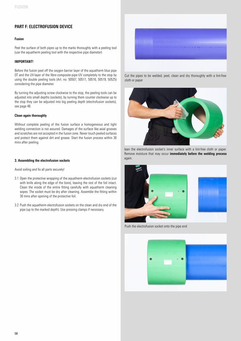
58
Fusion
Peel the surface of both pipes up to the marks thoroughly with a peeling tool (use the aquatherm peeling tool with the respective pipe diameter)
IMPORTANT! Before the fusion peel off the oxygen barrier layer of the aquatherm blue pipe OT and the UV-layer of the fibre-composite-pipe-UV completely to the stop by using the double peeling tools (Art. no. 50507, 50511, 50516, 50519, 50525) considering the pipe diameter. By turning the adjusting screw clockwise to the stop, the peeling tools can be adjusted into small depths (sockets), by turning them counter clockwise up to the stop they can be adjusted into big peeling depth (electrofusion sockets), see page 48.
Clean again thoroughly Without complete peeling of the fusion surface a homogeneous and tight welding connection is not assured. Damages of the surface like axial grooves and scratches are not accepted in the fusion zone. Never touch peeled surfaces and protect them against dirt and grease. Start the fusion process within 30 mins after peeling.
3. Assembling the electrofusion sockets Avoid soiling and fix all parts securely!
3.1 Open the protective wrapping of the aquatherm electrofusion sockets (cut with knife along the edge of the bore), leaving the rest of the foil intact. Clean the inside of the entire fitting carefully with aquatherm cleaning wipes. The socket must be dry after cleaning. Assemble the fitting within 30 mins after opening of the protective foil.
3.2 Push the aquatherm electrofusion sockets on the clean and dry end of the pipe (up to the marked depth). Use pressing clamps if necessary.
PART F: ELECTROFUSION DEVICE
FUSION
Push the electrofusion socket onto the pipe end
Cut the pipes to be welded, peel, clean and dry thoroughly with a lint-free cloth or paper
lean the electrofusion socket´s inner surface with a lint-free cloth or paper. Remove moisture that may occur immediately before the welding process again.
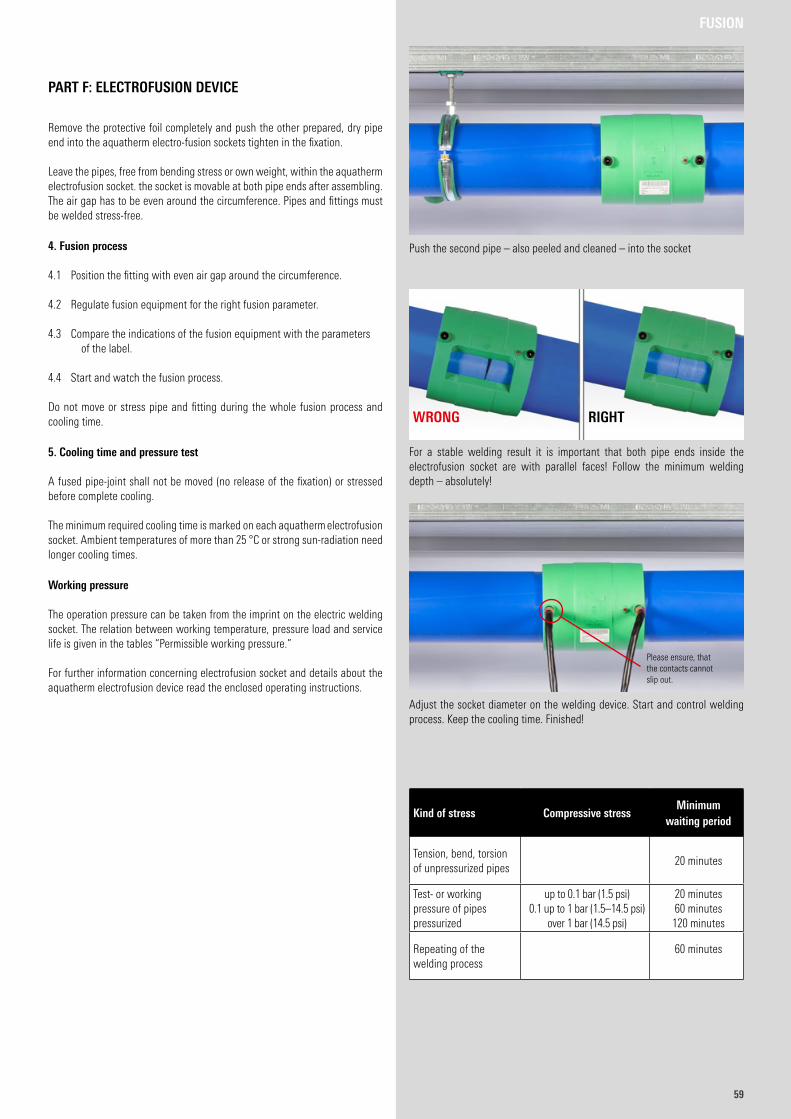
5959
PART F: ELECTROFUSION DEVICE
Remove the protective foil completely and push the other prepared, dry pipe end into the aquatherm electro-fusion sockets tighten in the fixation.
Leave the pipes, free from bending stress or own weight, within the aquatherm electrofusion socket. the socket is movable at both pipe ends after assembling. The air gap has to be even around the circumference. Pipes and fittings must be welded stress-free.
4. Fusion process
4.1 Position the fitting with even air gap around the circumference.
4.2 Regulate fusion equipment for the right fusion parameter.
4.3 Compare the indications of the fusion equipment with the parameters of the label.
4.4 Start and watch the fusion process.
Do not move or stress pipe and fitting during the whole fusion process and cooling time.
5. Cooling time and pressure test
A fused pipe-joint shall not be moved (no release of the fixation) or stressed before complete cooling.
The minimum required cooling time is marked on each aquatherm electrofusion socket. Ambient temperatures of more than 25 °C or strong sun-radiation need longer cooling times.
Working pressure
The operation pressure can be taken from the imprint on the electric welding socket. The relation between working temperature, pressure load and service life is given in the tables “Permissible working pressure.”
For further information concerning electrofusion socket and details about the aquatherm electrofusion device read the enclosed operating instructions.
Kind of stress Compressive stressMinimum
waiting period
Tension, bend, torsion of unpressurized pipes
20 minutes
Test- or working pressure of pipes pressurized
up to 0.1 bar (1.5 psi)0.1 up to 1 bar (1.5–14.5 psi)
over 1 bar (14.5 psi)
20 minutes60 minutes
120 minutes
Repeating of the welding process
60 minutes
FUSION
Push the second pipe – also peeled and cleaned – into the socket
For a stable welding result it is important that both pipe ends inside the electrofusion socket are with parallel faces! Follow the minimum welding depth – absolutely!
WRONG RIGHT
Adjust the socket diameter on the welding device. Start and control welding process. Keep the cooling time. Finished!
Please ensure, that the contacts cannot slip out.
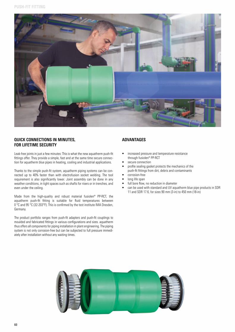
60
QUICK CONNECTIONS IN MINUTES, FOR LIFETIME SECURITY
Leak-free joints in just a few minutes: This is what the new aquatherm push-fit fittings offer. They provide a simple, fast and at the same time secure connec-tion for aquatherm blue pipes in heating, cooling and industrial applications.
Thanks to the simple push-fit system, aquatherm piping systems can be con-nected up to 40% faster than with electrofusion socket welding. The tool requirement is also significantly lower. Joint assembly can be done in any weather conditions, in tight spaces such as shafts for risers or in trenches, and even under the ceiling.
Made from the high-quality and robust material fusiolen® PP-RCT, the aquatherm push-fit fitting is suitable for fluid temperatures between 0 °C and 95 °C (32-203°F). This is confirmed by the test institute IMA Dresden, Germany.
The product portfolio ranges from push-fit adapters and push-fit couplings to moulded and fabricated fittings in various configurations and sizes. aquatherm thus offers all components for piping installation in plant engineering. The piping system is not only corrosion-free but can be subjected to full pressure immedi-ately after installation without any waiting times.
ADVANTAGES
• increased pressure and temperature resistance through fusiolen® PP-RCT
• secure connection• profile sealing gasket protects the mechanics of the
push-fit fittings from dirt, debris and contaminants• corrosion-free• long life span• full bore flow, no reduction in diameter• can be used with standard and UV aquatherm blue pipe products in SDR
11 and SDR 17.6, for sizes 90 mm (3-in) to 450 mm (18-in)
PUSH-FIT FITTING
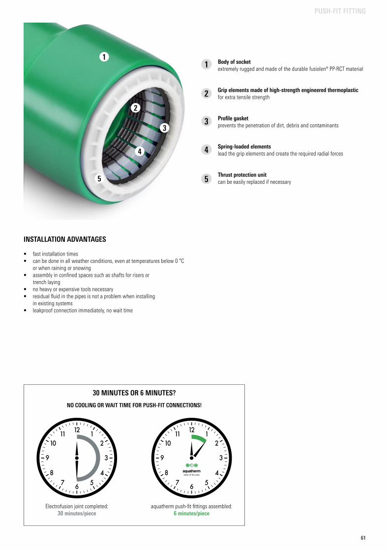
6161
PUSH-FIT FITTING
Body of socketextremely rugged and made of the durable fusiolen® PP-RCT material
Grip elements made of high-strength engineered thermoplasticfor extra tensile strength
Profile gasketprevents the penetration of dirt, debris and contaminants
Spring-loaded elementslead the grip elements and create the required radial forces
Thrust protection unitcan be easily replaced if necessary
1
2
3
4
5
1
2
3
4
5
INSTALLATION ADVANTAGES
• fast installation times• can be done in all weather conditions, even at temperatures below 0 °C
or when raining or snowing• assembly in confined spaces such as shafts for risers or
trench laying• no heavy or expensive tools necessary• residual fluid in the pipes is not a problem when installing
in existing systems• leakproof connection immediately, no wait time
Electrofusion joint completed: 30 minutes/piece
aquatherm push-fit fittings assembled: 6 minutes/piece
30 MINUTES OR 6 MINUTES?
NO COOLING OR WAIT TIME FOR PUSH-FIT CONNECTIONS!
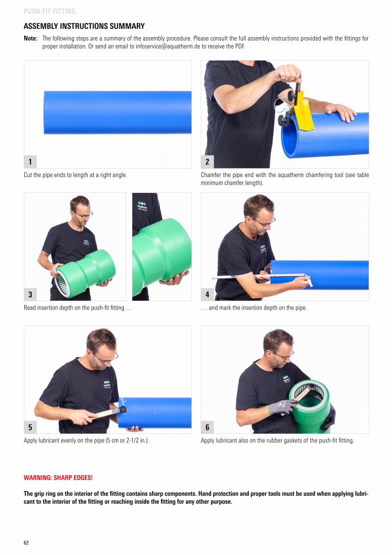
62
PUSH-FIT FITTING
WARNING: SHARP EDGES!
The grip ring on the interior of the fitting contains sharp components. Hand protection and proper tools must be used when applying lubri-cant to the interior of the fitting or reaching inside the fitting for any other purpose.
Apply lubricant also on the rubber gaskets of the push-fit fitting.
6
ASSEMBLY INSTRUCTIONS SUMMARY
Note: The following steps are a summary of the assembly procedure. Please consult the full assembly instructions provided with the fittings for proper installation. Or send an email to [email protected] to receive the PDF.
Cut the pipe ends to length at a right angle.
1
Chamfer the pipe end with the aquatherm chamfering tool (see table minimum chamfer length).
2
Read insertion depth on the push-fit fitting …
3
… and mark the insertion depth on the pipe.
4
Apply lubricant evenly on the pipe (5 cm or 2-1/2 in.).
5
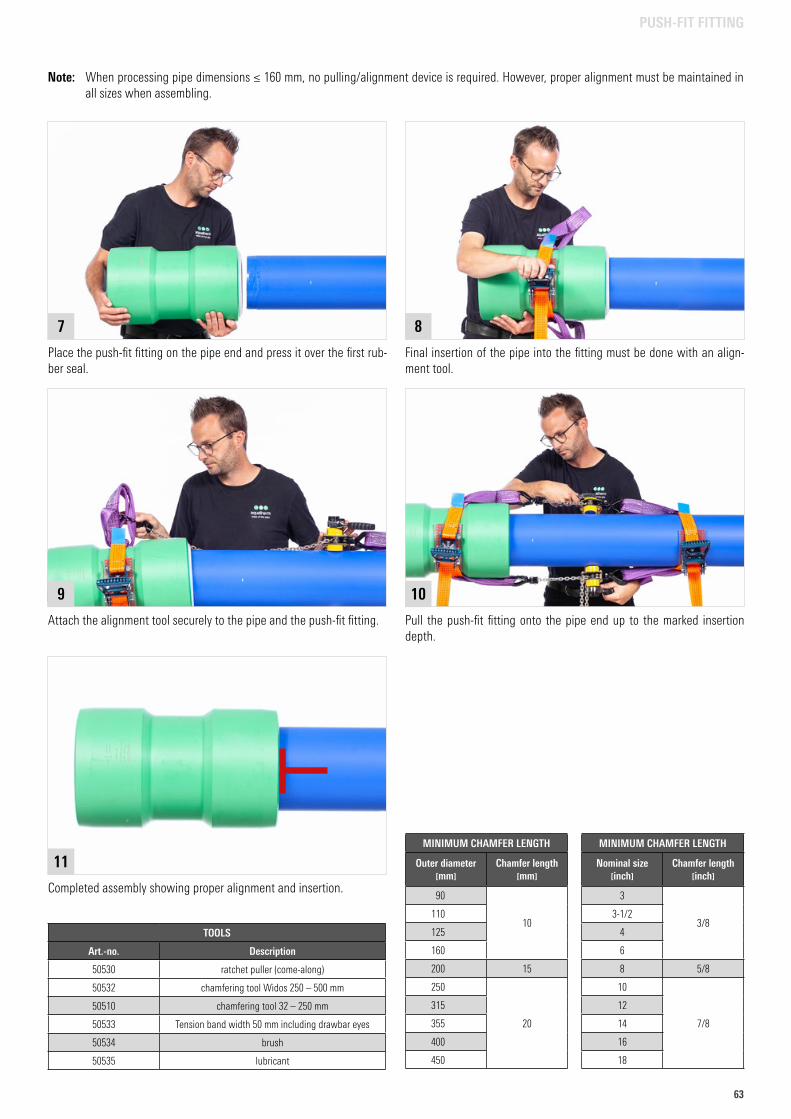
6363
PUSH-FIT FITTING
Place the push-fit fitting on the pipe end and press it over the first rub-ber seal.
7
Final insertion of the pipe into the fitting must be done with an align-ment tool.
8
Pull the push-fit fitting onto the pipe end up to the marked insertion depth.
10
Completed assembly showing proper alignment and insertion.
11
Attach the alignment tool securely to the pipe and the push-fit fitting.
9
MINIMUM CHAMFER LENGTH
Outer diameter mm
Chamfer length mm
90
10110
125
160
200 15
250
20
315
355
400
450
TOOLS
Art.-no. Description
50530 ratchet puller (come-along)
50532 chamfering tool Widos 250 – 500 mm
50510 chamfering tool 32 – 250 mm
50533 Tension band width 50 mm including drawbar eyes
50534 brush
50535 lubricant
MINIMUM CHAMFER LENGTH
Nominal size inch
Chamfer length inch
3
3/83-1/2
4
6
8 5/8
10
7/8
12
14
16
18
Note: When processing pipe dimensions ≤ 160 mm, no pulling/alignment device is required. However, proper alignment must be maintained in all sizes when assembling.
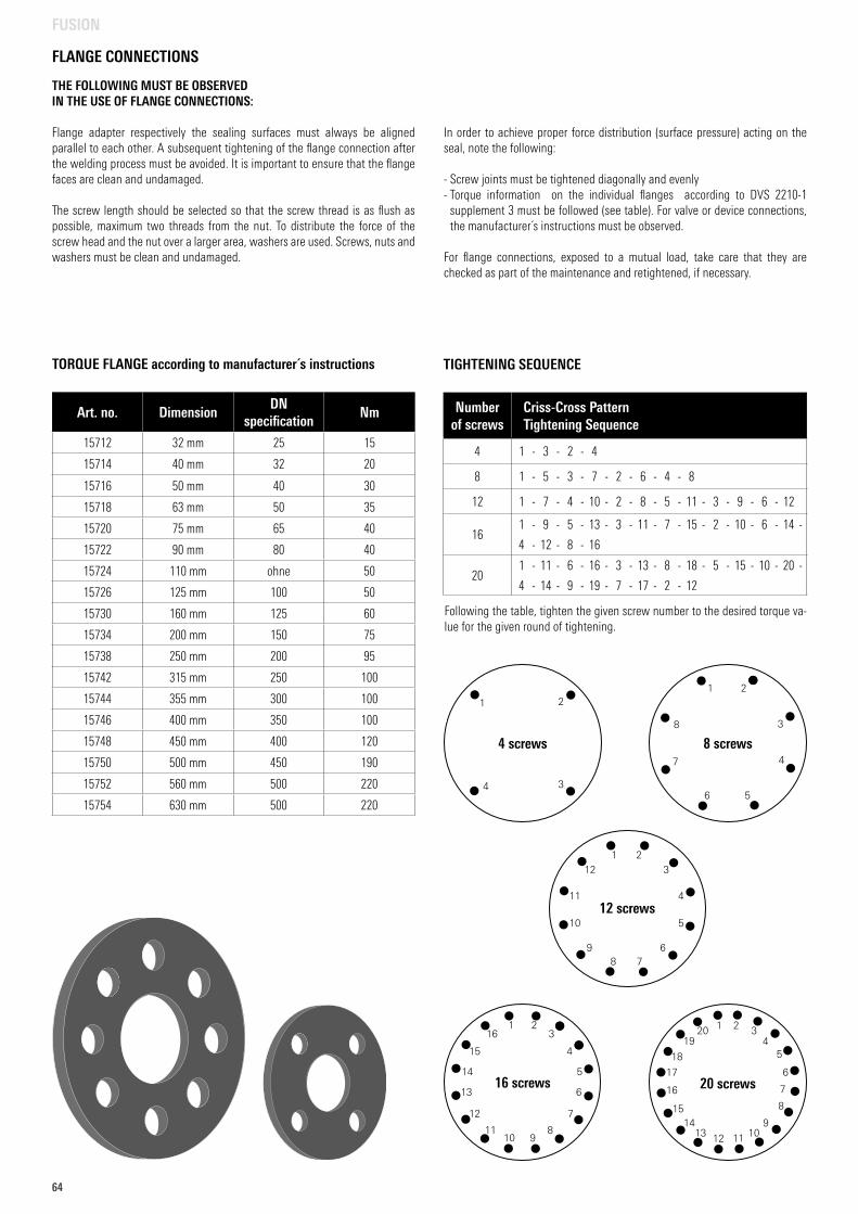
64
THE FOLLOWING MUST BE OBSERVED IN THE USE OF FLANGE CONNECTIONS:
Flange adapter respectively the sealing surfaces must always be aligned parallel to each other. A subsequent tightening of the flange connection after the welding process must be avoided. It is important to ensure that the flange faces are clean and undamaged.
The screw length should be selected so that the screw thread is as flush as possible, maximum two threads from the nut. To distribute the force of the screw head and the nut over a larger area, washers are used. Screws, nuts and washers must be clean and undamaged.
In order to achieve proper force distribution (surface pressure) acting on the seal, note the following:
- Screw joints must be tightened diagonally and evenly- Torque information on the individual flanges according to DVS 2210-1
supplement 3 must be followed (see table). For valve or device connections, the manufacturer´s instructions must be observed.
For flange connections, exposed to a mutual load, take care that they are checked as part of the maintenance and retightened, if necessary.
TORQUE FLANGE according to manufacturer´s instructions
Art. no. DimensionDN
specificationNm
15712 32 mm 25 15
15714 40 mm 32 20
15716 50 mm 40 30
15718 63 mm 50 35
15720 75 mm 65 40
15722 90 mm 80 40
15724 110 mm ohne 50
15726 125 mm 100 50
15730 160 mm 125 60
15734 200 mm 150 75
15738 250 mm 200 95
15742 315 mm 250 100
15744 355 mm 300 100
15746 400 mm 350 100
15748 450 mm 400 120
15750 500 mm 450 190
15752 560 mm 500 220
15754 630 mm 500 220
FLANGE CONNECTIONS
FUSION
Following the table, tighten the given screw number to the desired torque va-lue for the given round of tightening.
TIGHTENING SEQUENCE
Number of screws
Criss-Cross PatternTightening Sequence
4 1 - 3 - 2 - 4
8 1 - 5 - 3 - 7 - 2 - 6 - 4 - 8
12 1 - 7 - 4 - 10 - 2 - 8 - 5 - 11 - 3 - 9 - 6 - 12
161 - 9 - 5 - 13 - 3 - 11 - 7 - 15 - 2 - 10 - 6 - 14 -
4 - 12 - 8 - 16
201 - 11 - 6 - 16 - 3 - 13 - 8 - 18 - 5 - 15 - 10 - 20 -
4 - 14 - 9 - 19 - 7 - 17 - 2 - 12
8 screws
1
8
7
6 5
4
3
2
4 screws
1
4
2
3
12 screws
1
12
11 4
510
9 678
3
2
20 screws
1
11
6
16
3
13
8
18 5
15
10
20 2
12
7
17
4
14 9
19
16 screws
1 23
415
14 5
613
12 7
81110 9
16
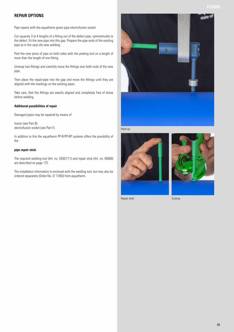
6565
REPAIR OPTIONS
Pipe repairs with the aquatherm green pipe electrofusion socket
Cut squarely 3 to 4 lengths of a fitting out of the defect pipe, symmetrically to the defect. Fit the new pipe into this gap. Prepare the pipe ends of the existing pipe as in the case ofa new welding.
Peel the new piece of pipe on both sides with the peeling tool on a length of more than the length of one fitting.
Unwrap two fittings and carefully move the fittings over both ends of the new pipe.
Then place the repair-pipe into the gap and move the fittings until they are aligned with the markings on the existing pipes.
Take care, that the fittings are exactly aligned and completely free of stress before welding.
Additional possibilities of repair
Damaged pipes may be repaired by means of
fusion (see Part B)electrofusion socket (see Part F).
In addition to this the aquatherm PP-R/PP-RP systems offers the possibility of the
pipe repair stick.
The required welding tool (Art. no. 50307/11) and repair stick (Art. no. 60600) are described on page 175.
The installation information is enclosed with the welding tool, but may also be ordered separately (Order-No. D 11450) from aquatherm.
Heat-up
Repair stick Cutting
FUSION
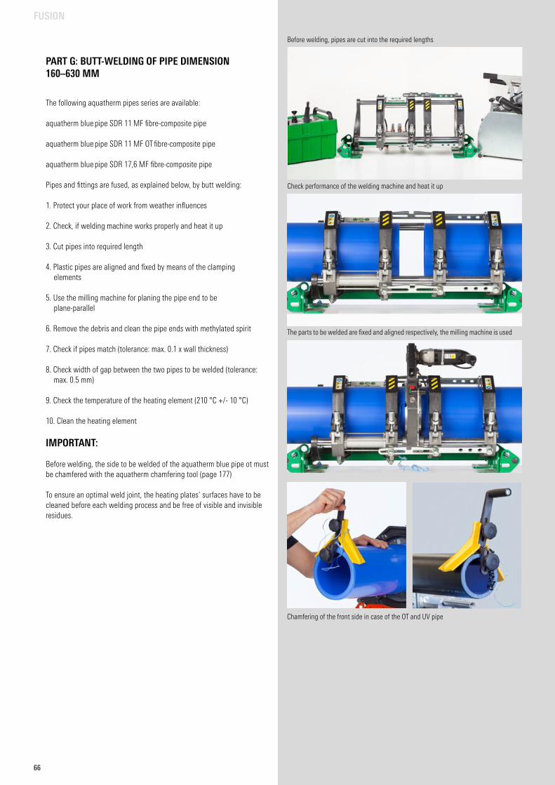
66
PART G: BUTT-WELDING OF PIPE DIMENSION 160–630 MM
The following aquatherm pipes series are available:
aquatherm blue pipe SDR 11 MF fibre-composite pipe
aquatherm blue pipe SDR 11 MF OT fibre-composite pipe
aquatherm blue pipe SDR 17,6 MF fibre-composite pipe
Pipes and fittings are fused, as explained below, by butt welding:
1. Protect your place of work from weather influences
2. Check, if welding machine works properly and heat it up
3. Cut pipes into required length
4. Plastic pipes are aligned and fixed by means of the clamping elements
5. Use the milling machine for planing the pipe end to be plane-parallel
6. Remove the debris and clean the pipe ends with methylated spirit
7. Check if pipes match (tolerance: max. 0.1 x wall thickness)
8. Check width of gap between the two pipes to be welded (tolerance: max. 0.5 mm)
9. Check the temperature of the heating element (210 °C +/- 10 °C)
10. Clean the heating element
IMPORTANT: Before welding, the side to be welded of the aquatherm blue pipe ot must be chamfered with the aquatherm chamfering tool (page 177)
To ensure an optimal weld joint, the heating plates‘ surfaces have to be cleaned before each welding process and be free of visible and invisible residues.
FUSION
Before welding, pipes are cut into the required lengths
Check performance of the welding machine and heat it up
The parts to be welded are fixed and aligned respectively, the milling machine is used
Chamfering of the front side in case of the OT and UV pipe
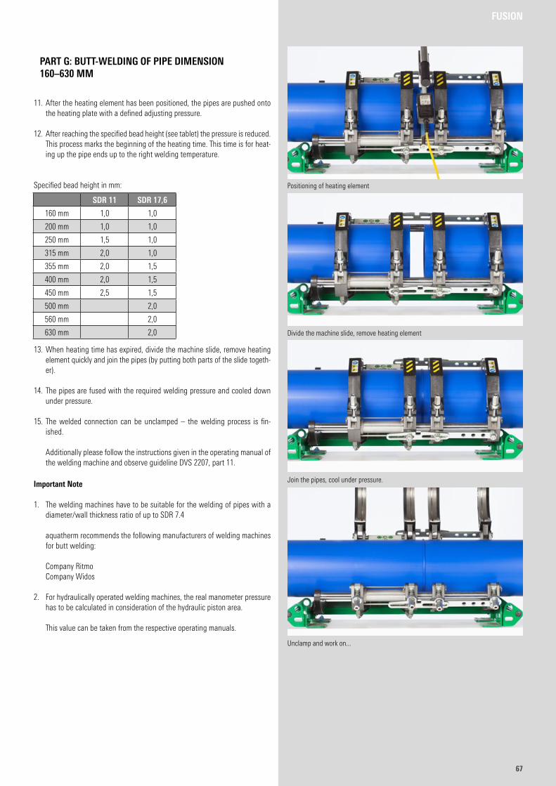
6767
11. After the heating element has been positioned, the pipes are pushed onto the heating plate with a defined adjusting pressure.
12. After reaching the specified bead height (see tablet) the pressure is reduced. This process marks the beginning of the heating time. This time is for heat-ing up the pipe ends up to the right welding temperature.
Specified bead height in mm:
13. When heating time has expired, divide the machine slide, remove heating element quickly and join the pipes (by putting both parts of the slide togeth-er).
14. The pipes are fused with the required welding pressure and cooled down under pressure.
15. The welded connection can be unclamped – the welding process is fin-ished.
Additionally please follow the instructions given in the operating manual of
the welding machine and observe guideline DVS 2207, part 11.
Important Note
1. The welding machines have to be suitable for the welding of pipes with a diameter/wall thickness ratio of up to SDR 7.4
aquatherm recommends the following manufacturers of welding machines for butt welding:
Company Ritmo Company Widos
2. For hydraulically operated welding machines, the real manometer pressure has to be calculated in consideration of the hydraulic piston area.
This value can be taken from the respective operating manuals.
PART G: BUTT-WELDING OF PIPE DIMENSION 160–630 MM
SDR 11 SDR 17,6
160 mm 1,0 1,0
200 mm 1,0 1,0
250 mm 1,5 1,0
315 mm 2,0 1,0
355 mm 2,0 1,5
400 mm 2,0 1,5
450 mm 2,5 1,5
500 mm 2,0
560 mm 2,0
630 mm 2,0
FUSION
Positioning of heating element
Divide the machine slide, remove heating element
Join the pipes, cool under pressure.
Unclamp and work on...
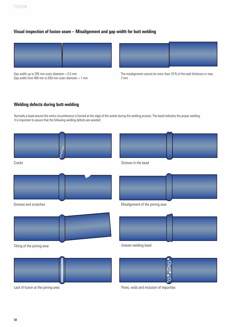
68
Welding defects during butt-welding
Cracks Grooves in the bead
Grooves and scratches
Tilting of the joining area
Misalignment of the joining area
Uneven welding bead
Lack of fusion at the joining area Pores, voids and inclusion of impurities
The misalignment cannot be more than 10 % of the wall thickness or max. 2 mm
Gap width up to 355 mm outer diameter = 0.5 mmGap width from 400 mm to 630 mm outer diameter = 1 mm
Visual inspection of fusion seam – Misalignment and gap width for butt welding
Normally a bead around the entire circumference is formed at the edge of the socket during the welding process. This bead indicates the proper welding. It is important to assure that the following welding defects are avoided:
FUSION
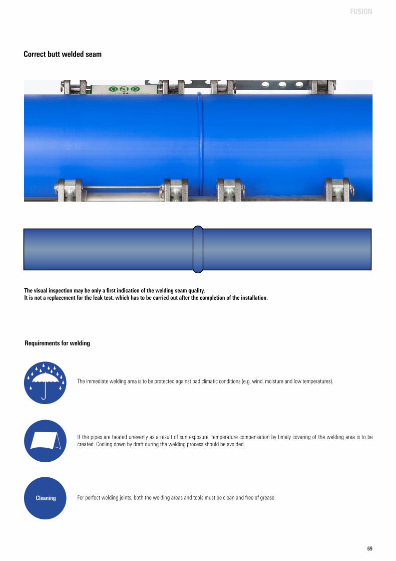
6969
Correct butt welded seam
For perfect welding joints, both the welding areas and tools must be clean and free of grease.
Requirements for welding
The immediate welding area is to be protected against bad climatic conditions (e.g. wind, moisture and low temperatures).
If the pipes are heated unevenly as a result of sun exposure, temperature compensation by timely covering of the welding area is to be created. Cooling down by draft during the welding process should be avoided.
Cleaning
The visual inspection may be only a first indication of the welding seam quality.It is not a replacement for the leak test, which has to be carried out after the completion of the installation.
FUSION
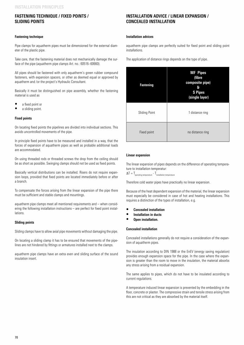
70
Fastening technique Pipe clamps for aquatherm pipes must be dimensioned for the external diam-eter of the plastic pipe.
Take care, that the fastening material does not mechanically damage the sur-face of the pipe (aquatherm pipe clamps Art. no.: 60516–60660).
All pipes should be fastened with only aquatherm’s green rubber compound fasteners, with expansion spacers, or other as deemed equal or approved by aquatherm and /or the project’s Hydraulic Consultant.
Basically it must be distinguished on pipe assembly, whether the fastening material is used as
• a fixed point or• a sliding point.
Fixed points
On locating fixed points the pipelines are divided into individual sections. This avoids uncontrolled movements of the pipe.
In principle fixed points have to be measured and installed in a way, that the forces of expansion of aquatherm pipes as well as probable additional loads are accommodated.
On using threaded rods or threaded screws the drop from the ceiling should be as short as possible. Swinging clamps should not be used as fixed points.
Basically vertical distributions can be installed. Risers do not require expan-sion loops, provided that fixed points are located immediately before or after a branch.
To compensate the forces arising from the linear expansion of the pipe there must be sufficient and stable clamps and mountings.
aquatherm pipe clamps meet all mentioned requirements and – when consid-ering the following installation instructions – are perfect for fixed point instal-lations.
Sliding points
Sliding clamps have to allow axial pipe movements without damaging the pipe.
On locating a sliding clamp it has to be ensured that movements of the pipe-lines are not hindered by fittings or armatures installed next to the clamps.
aquatherm pipe clamps have an extra even and sliding surface of the sound insulation insert.
Installation advices
aquatherm pipe clamps are perfectly suited for fixed point and sliding point installations.
The application of distance rings depends on the type of pipe.
Linear expansion
The linear expansion of pipes depends on the difference of operating tempera-ture to installation temperatur: DT = T
operating temperature - T
installation temperature
Therefore cold water pipes have practically no linear expansion.
Because of the heat dependent expansion of the material, the linear expansion must especially be considered in case of hot and heating installations. This requires a distinction of the types of installation, e.g.
• Concealed installation• Installation in ducts• Open installation.
Concealed installation
Concealed installations generally do not require a consideration of the expan-sion of aquatherm pipes.
The insulation according to DIN 1988 or the EnEV (energy saving regulation) provides enough expansion space for the pipe. In the case where the expan-sion is greater than the room to move in the insulation, the material absorbs any stress arising from a residual expansion.
The same applies to pipes, which do not have to be insulated according to current regulations.
A temperature induced linear expansion is prevented by the embedding in the floor, concrete or plaster. The compressive strain and tensile stress arising from this are not critical as they are absorbed by the material itself.
FASTENING TECHNIQUE / FIXED POINTS / SLIDING POINTS
INSTALLATION ADVICE / LINEAR EXPANSION / CONCEALED INSTALLATION
INSTALLATION PRINCIPLES
Fastening
MF Pipes(fibre
composite pipe)&
S Pipes (single layer)
Sliding Point 1 distance ring
Fixed point no distance ring
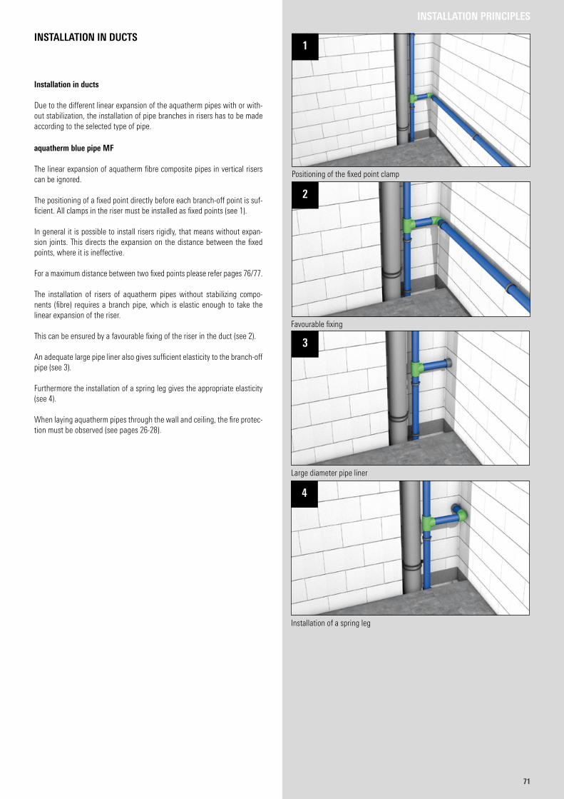
7171
INSTALLATION PRINCIPLES
Installation in ducts
Due to the different linear expansion of the aquatherm pipes with or with-out stabilization, the installation of pipe branches in risers has to be made according to the selected type of pipe.
aquatherm blue pipe MF
The linear expansion of aqua therm fibre composite pipes in vertical risers can be ignored.
The positioning of a fixed point directly before each branch-off point is suf-ficient. All clamps in the riser must be installed as fixed points (see 1).
In general it is possible to install risers rigidly, that means without expan-sion joints. This directs the expansion on the distance between the fixed points, where it is ineffective.
For a maximum distance between two fixed points please refer pages 76/77.
The installation of risers of aquatherm pipes without stabilizing compo-nents (fibre) requires a branch pipe, which is elastic enough to take the linear expansion of the riser.
This can be ensured by a favourable fixing of the riser in the duct (see 2).
An adequate large pipe liner also gives sufficient elasticity to the branch-off pipe (see 3).
Furthermore the installation of a spring leg gives the appropriate elasticity (see 4).
When laying aquatherm pipes through the wall and ceiling, the fire protec-tion must be observed (see pages 26-28).
INSTALLATION IN DUCTS
Favourable fixing
2
Positioning of the fixed point clamp
1
Large diameter pipe liner
3
Installation of a spring leg
4
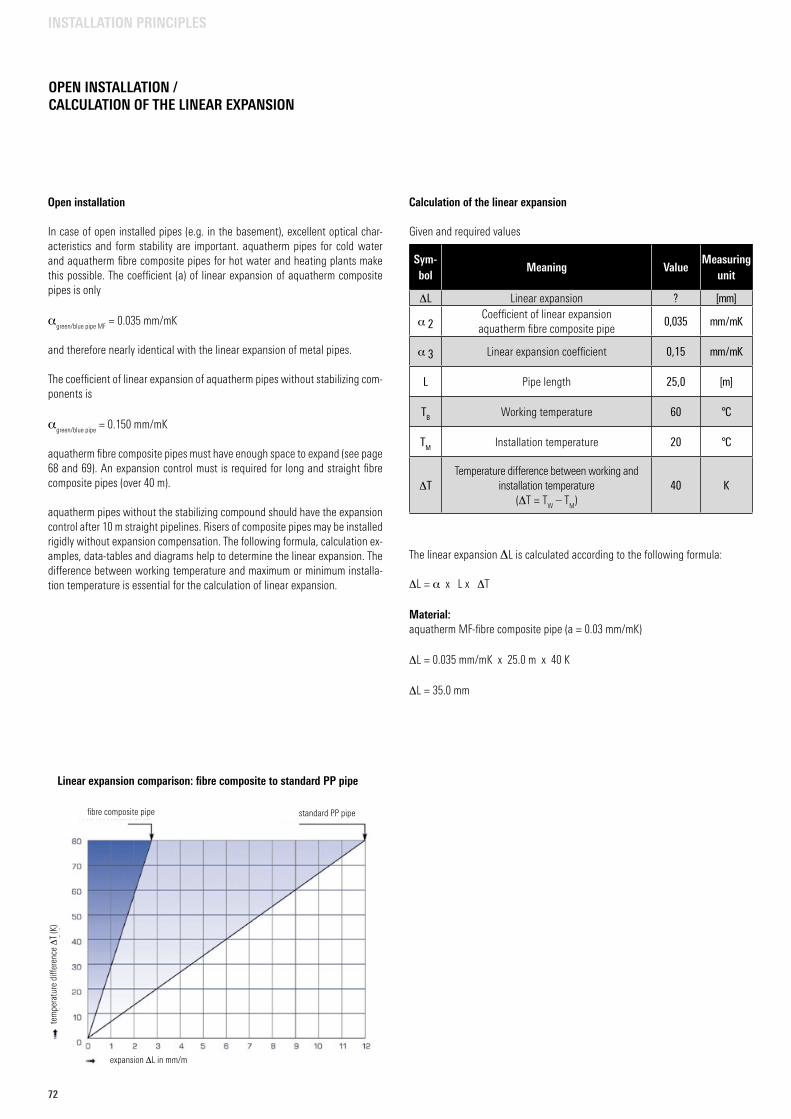
72
OPEN INSTALLATION / CALCULATION OF THE LINEAR EXPANSION
Open installation
In case of open installed pipes (e.g. in the basement), excellent optical char-acteristics and form stability are important. aquatherm pipes for cold water and aquatherm fibre composite pipes for hot water and heating plants make this possible. The coefficient (a) of linear expansion of aquatherm composite pipes is only
agreen/blue pipe MF
= 0.035 mm/mK
and therefore nearly identical with the linear expansion of metal pipes.
The coefficient of linear expansion of aquatherm pipes without stabilizing com-ponents is
agreen/blue pipe
= 0.150 mm/mK
aquatherm fibre composite pipes must have enough space to expand (see page 68 and 69). An expansion control must is required for long and straight fibre composite pipes (over 40 m).
aquatherm pipes without the stabilizing compound should have the expansion control after 10 m straight pipelines. Risers of composite pipes may be installed rigidly without expansion compensation. The following formula, calculation ex-amples, data-tables and diagrams help to determine the linear expansion. The difference between working temperature and maximum or minimum installa-tion temperature is essential for the calculation of linear expansion.
Calculation of the linear expansion
Given and required values
The linear expansion DL is calculated according to the following formula:
DL = a x L x DT
Material:aquatherm MF-fibre composite pipe (a = 0.03 mm/mK)
DL = 0.035 mm/mK x 25.0 m x 40 K
DL = 35.0 mm
Sym-bol
Meaning ValueMeasuring
unit
DL Linear expansion ? [mm]
a 2Coefficient of linear expansion
aquatherm fibre composite pipe0,035 mm / mK
a 3 Linear expansion coefficient 0,15 mm / mK
L Pipe length 25,0 [m]
TB Working temperature 60 °C
TM Installation temperature 20 °C
DTTemperature difference between working and
installation temperature(DT = T
W – T
M)
40 K
INSTALLATION PRINCIPLES
Linear expansion comparison: fibre composite to standard PP pipe
fibre composite pipe standard PP pipe
tem
pera
ture
diff
eren
ce D
T (K
)
expansion DL in mm/m
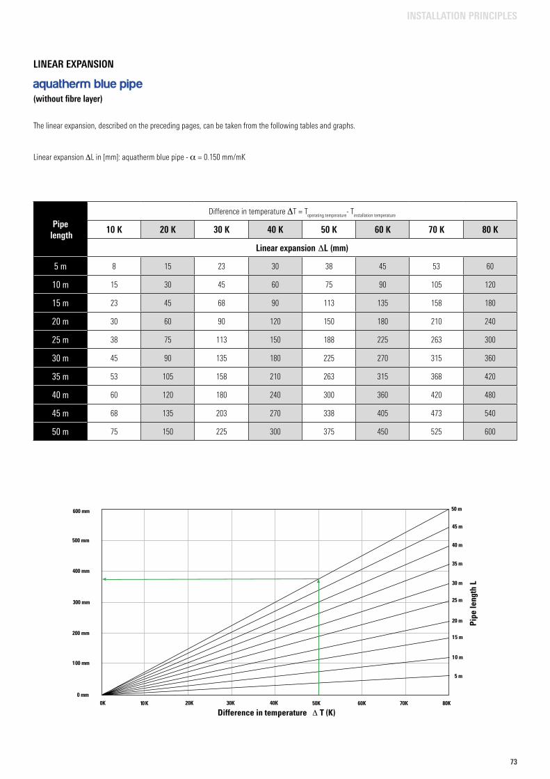
7373
LINEAR EXPANSION
aquatherm blue pipe (without fibre layer)
Pipe length
Difference in temperature DT = Toperating temperature
- Tinstallation temperature
10 K 20 K 30 K 40 K 50 K 60 K 70 K 80 K
Linear expansion DL (mm)
5 m 8 15 23 30 38 45 53 60
10 m 15 30 45 60 75 90 105 120
15 m 23 45 68 90 113 135 158 180
20 m 30 60 90 120 150 180 210 240
25 m 38 75 113 150 188 225 263 300
30 m 45 90 135 180 225 270 315 360
35 m 53 105 158 210 263 315 368 420
40 m 60 120 180 240 300 360 420 480
45 m 68 135 203 270 338 405 473 540
50 m 75 150 225 300 375 450 525 600
The linear expansion, described on the preceding pages, can be taken from the following tables and graphs.
Linear expansion DL in [mm]: aquatherm blue pipe - a = 0.150 mm/mK
25 m
20 m
15 m
10 m
5 m
10K 20K 30K 40K 50K 60K 70K 80K
30 m
35 m
40 m
50 m
45 m
300 mm
400 mm
500 mm
600 mm
200 mm
0 mm
100 mm
0K
Pipe
leng
th L
Difference in temperature Δ T (K)
INSTALLATION PRINCIPLES
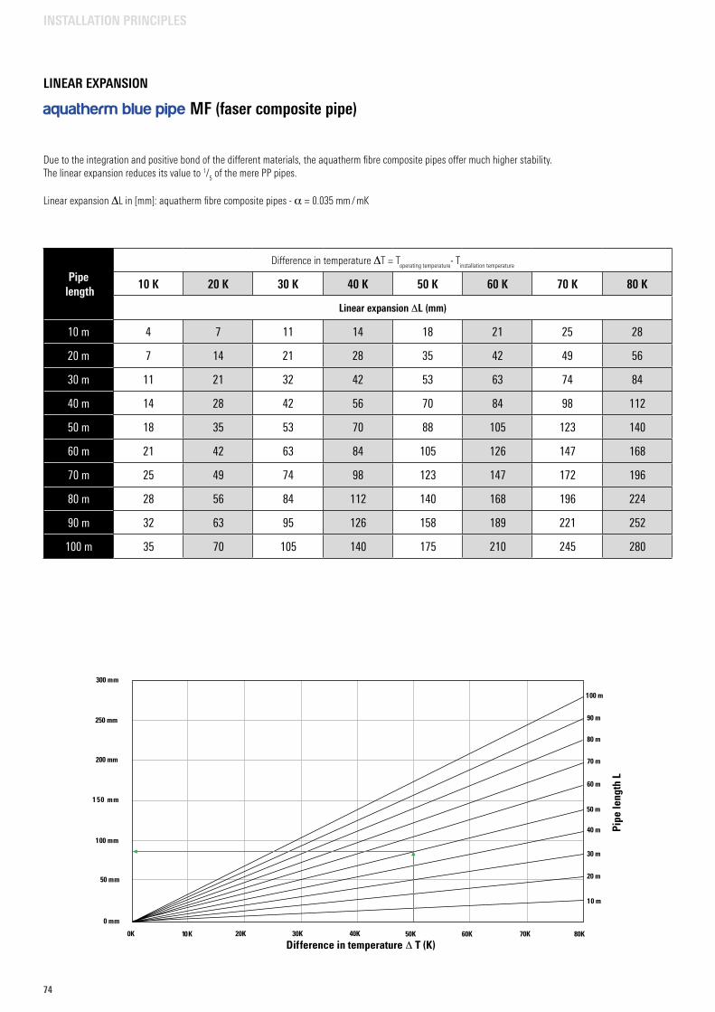
74
Pipe length
Difference in temperature DT = Toperating temperature
- Tinstallation temperature
10 K 20 K 30 K 40 K 50 K 60 K 70 K 80 K
Linear expansion DL (mm)
10 m 4 7 11 14 18 21 25 28
20 m 7 14 21 28 35 42 49 56
30 m 11 21 32 42 53 63 74 84
40 m 14 28 42 56 70 84 98 112
50 m 18 35 53 70 88 105 123 140
60 m 21 42 63 84 105 126 147 168
70 m 25 49 74 98 123 147 172 196
80 m 28 56 84 112 140 168 196 224
90 m 32 63 95 126 158 189 221 252
100 m 35 70 105 140 175 210 245 280
Due to the integration and positive bond of the different materials, the aquatherm fibre composite pipes offer much higher stability.The linear expansion reduces its value to 1/
5 of the mere PP pipes.
Linear expansion DL in [mm]: aquatherm fibre composite pipes - a = 0.035 mm / mK
1 50 mm
200 mm
250 mm
300 mm
100 mm
0 mm
60 m
70 m
80 m
100 m
50 mm
Pipe
leng
th L
90 m
10K 20K 30K 40K 50K 60K 70K 80K0K
50 m
20 m
10 m
30 m
40 m
Difference in temperature Δ T (K)
INSTALLATION PRINCIPLES
LINEAR EXPANSION
aquatherm blue pipe MF (faser composite pipe)
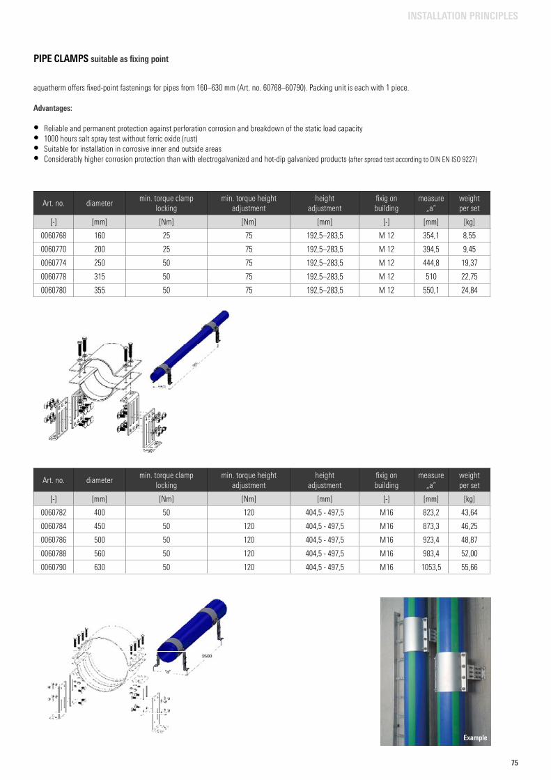
7575
INSTALLATION PRINCIPLES
PIPE CLAMPS suitable as fixing point
Art. no. diametermin. torque clamp
lockingmin. torque height
adjustmentheight
adjustmentfixig on building
measure „a“
weight per set
[-] [mm] [Nm] [Nm] [mm] [-] [mm] [kg]
0060768 160 25 75 192,5–283,5 M 12 354,1 8,55
0060770 200 25 75 192,5–283,5 M 12 394,5 9,45
0060774 250 50 75 192,5–283,5 M 12 444,8 19,37
0060778 315 50 75 192,5–283,5 M 12 510 22,75
0060780 355 50 75 192,5–283,5 M 12 550,1 24,84
aquatherm offers fixed-point fastenings for pipes from 160–630 mm (Art. no. 60768–60790). Packing unit is each with 1 piece.
Advantages:
• Reliable and permanent protection against perforation corrosion and breakdown of the static load capacity• 1000 hours salt spray test without ferric oxide (rust)• Suitable for installation in corrosive inner and outside areas• Considerably higher corrosion protection than with electrogalvanized and hot-dip galvanized products (after spread test according to DIN EN ISO 9227)
Art. no. diametermin. torque clamp
lockingmin. torque height
adjustmentheight
adjustmentfixig on building
measure „a“
weight per set
[-] [mm] [Nm] [Nm] [mm] [-] [mm] [kg]
0060782 400 50 120 404,5 - 497,5 M16 823,2 43,64
0060784 450 50 120 404,5 - 497,5 M16 873,3 46,25
0060786 500 50 120 404,5 - 497,5 M16 923,4 48,87
0060788 560 50 120 404,5 - 497,5 M16 983,4 52,00
0060790 630 50 120 404,5 - 497,5 M16 1053,5 55,66
Example
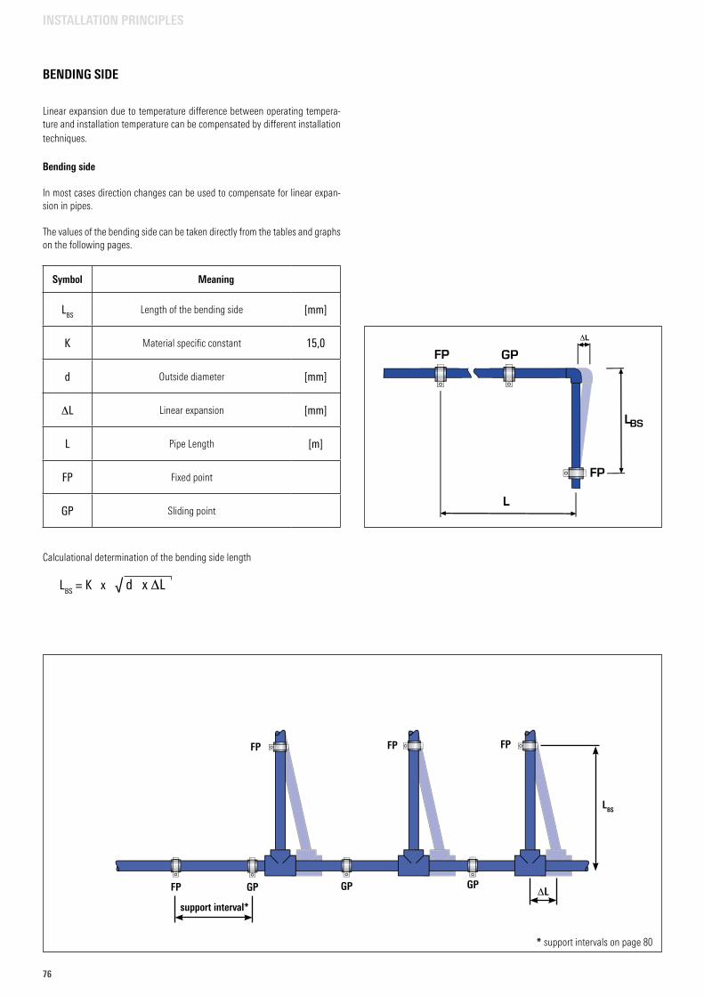
76
INSTALLATION PRINCIPLES
Linear expansion due to temperature difference between operating tempera-ture and installation temperature can be compensated by different installation techniques.
Bending side
In most cases direction changes can be used to compensate for linear expan-sion in pipes.
The values of the bending side can be taken directly from the tables and graphs on the following pages.
Calculational determination of the bending side length
LBS = K x √ d x DL
Symbol Meaning
LBSLength of the bending side [mm]
K Material specific constant 15,0
d Outside diameter [mm]
DL Linear expansion [mm]
L Pipe Length [m]
FP Fixed point
GP Sliding point
BENDING SIDE
FP
FP
LBS
DLsupport interval*
* support intervals on page 80
FP FP
GP GP GP
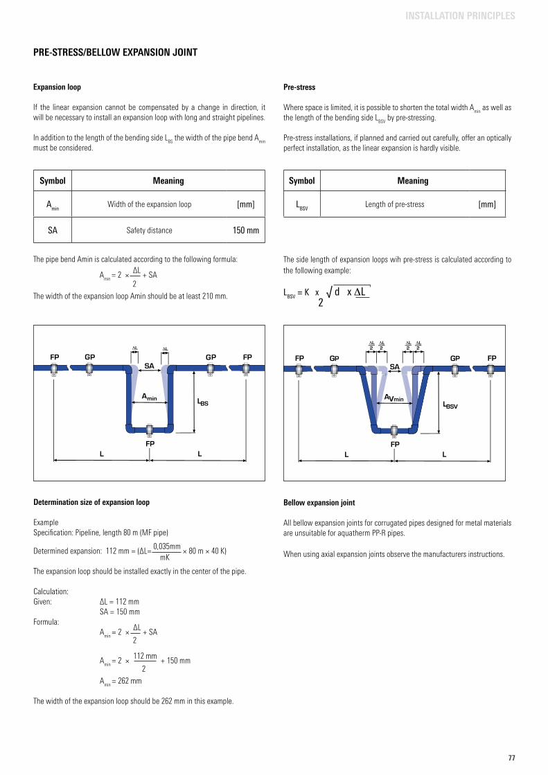
7777
INSTALLATION PRINCIPLES
Pre-stress
Where space is limited, it is possible to shorten the total width Amin
as well as the length of the bending side L
BSV by pre-stressing.
Pre-stress installations, if planned and carried out carefully, offer an optically perfect installation, as the linear expansion is hardly visible.
The side length of expansion loops wih pre-stress is calculated according to the following example:
LBSV = K x √ d x DL 2
Bellow expansion joint
All bellow expansion joints for corrugated pipes designed for metal materials are unsuitable for aquatherm PP-R pipes. When using axial expansion joints observe the manufacturers instructions.
Symbol Meaning
LBSVLength of pre-stress [mm]
Expansion loop
If the linear expansion cannot be compensated by a change in direction, it will be necessary to install an expansion loop with long and straight pipelines.
In addition to the length of the bending side LBS
the width of the pipe bend Amin
must be considered.
The pipe bend Amin is calculated according to the following formula:
Amin
= 2 × ∆L + SA 2 The width of the expansion loop Amin should be at least 210 mm.
Symbol Meaning
AminWidth of the expansion loop [mm]
SA Safety distance 150 mm
PRE-STRESS/BELLOW EXPANSION JOINT
Determination size of expansion loop
ExampleSpecification: Pipeline, length 80 m (MF pipe)
Determined expansion: 112 mm = (∆L= 0,035mm × 80 m × 40 K) mK The expansion loop should be installed exactly in the center of the pipe.
Calculation:Given: ∆L = 112 mm SA = 150 mmFormula: A
min = 2 × ∆L + SA
2
Amin
= 2 × 112 mm + 150 mm 2 A
min = 262 mm
The width of the expansion loop should be 262 mm in this example.
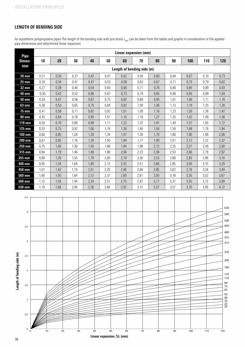
78
LENGTH OF BENDING SIDE
PipeDimen-
sion
Linear expansion (mm)
10 20 30 40 50 60 70 80 90 100 110 120
Length of bending side (m)
20 mm 0,21 0,30 0,37 0,42 0,47 0,52 0,56 0,60 0,64 0,67 0,70 0,73
25 mm 0,24 0,34 0,41 0,47 0,53 0,58 0,63 0,67 0,71 0,75 0,79 0,82
32 mm 0,27 0,38 0,46 0,54 0,60 0,66 0,71 0,76 0,80 0,85 0,89 0,93
40 mm 0,30 0,42 0,52 0,60 0,67 0,73 0,79 0,85 0,90 0,95 0,99 1,04
50 mm 0,34 0,47 0,58 0,67 0,75 0,82 0,89 0,95 1,01 1,06 1,11 1,16
63 mm 0,38 0,53 0,65 0,75 0,84 0,92 1,00 1,06 1,13 1,19 1,25 1,30
75 mm 0,41 0,58 0,71 0,82 0,92 1,01 1,09 1,16 1,23 1,30 1,36 1,42
90 mm 0,45 0,64 0,78 0,90 1,01 1,10 1,19 1,27 1,35 1,42 1,49 1,56
110 mm 0,50 0,70 0,86 0,99 1,11 1,22 1,32 1,41 1,49 1,57 1,65 1,72
125 mm 0,53 0,75 0,92 1,06 1,19 1,30 1,40 1,50 1,59 1,68 1,76 1,84
160 mm 0,60 0,85 1,04 1,20 1,34 1,47 1,59 1,70 1,80 1,90 1,99 2,08
200 mm 0,67 0,95 1,16 1,34 1,50 1,64 1,77 1,90 2,01 2,12 2,22 2,32
250 mm 0,75 1,06 1,30 1,50 1,68 1,84 1,98 2,12 2,25 2,37 2,49 2,60
315 mm 0,84 1,19 1,46 1,68 1,88 2,06 2,23 2,38 2,53 2,66 2,79 2,92
355 mm 0,89 1,26 1,55 1,79 2,00 2,19 2,36 2,53 2,68 2,83 2,96 3,10
400 mm 0,95 1,34 1,64 1,90 2,12 2,32 2,51 2,68 2,85 3,00 3,15 3,29
450 mm 1,01 1,42 1,74 2,01 2,25 2,46 2,66 2,85 3,02 3,18 3,34 3,49
500 mm 1,06 1,50 1,84 2,12 2,37 2,60 2,81 3,00 3,18 3,35 3,52 3,67
560 mm 1,12 1,59 1,94 2,24 2,51 2,75 2,97 3,17 3,37 3,55 3,72 3,89
630 mm 1,19 1,68 2,06 2,38 2,66 2,92 3,15 3,37 3,57 3,76 3,95 4,12
for aquatherm polypropylene pipes The length of the bending side with pre-stress LBSV
can be taken from the tables and graphs in consideration of the applied pipe dimensions and determined linear expansion.
0
0,5
1
1,5
2
2,5
3
3,5
4
4,5
630
560
500
450
355
315
250
200
160
125110
907563
5040322520
400
100 20 30 40 50 60 70 80 90 100 110 120
Leng
th o
f ben
ding
sid
e (m
)
Linear expansion DL (mm)
INSTALLATION PRINCIPLES
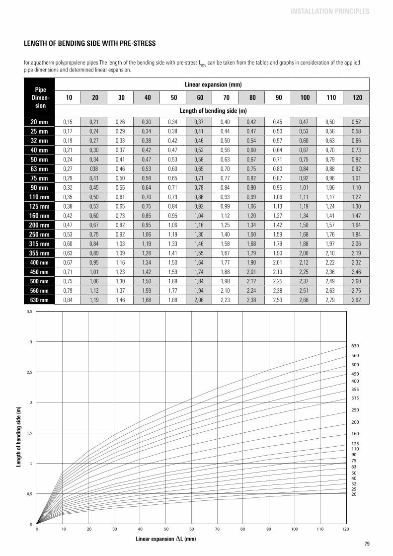
7979
0
0,5
1
1,5
2
2,5
3
3,5
630
560
500
450
355
315
250
200
160
1251109075635040322520
400
LENGTH OF BENDING SIDE WITH PRE-STRESS
PipeDimen-
sion
Linear expansion (mm)
10 20 30 40 50 60 70 80 90 100 110 120
Length of bending side (m)
20 mm 0,15 0,21 0,26 0,30 0,34 0,37 0,40 0,42 0,45 0,47 0,50 0,52
25 mm 0,17 0,24 0,29 0,34 0,38 0,41 0,44 0,47 0,50 0,53 0,56 0,58
32 mm 0,19 0,27 0,33 0,38 0,42 0,46 0,50 0,54 0,57 0,60 0,63 0,66
40 mm 0,21 0,30 0,37 0,42 0,47 0,52 0,56 0,60 0,64 0,67 0,70 0,73
50 mm 0,24 0,34 0,41 0,47 0,53 0,58 0,63 0,67 0,71 0,75 0,79 0,82
63 mm 0,27 038 0,46 0,53 0,60 0,65 0,70 0,75 0,80 0,84 0,88 0,92
75 mm 0,29 0,41 0,50 0,58 0,65 0,71 0,77 0,82 0,87 0,92 0,96 1,01
90 mm 0,32 0,45 0,55 0,64 0,71 0,78 0,84 0,90 0,95 1,01 1,06 1,10
110 mm 0,35 0,50 0,61 0,70 0,79 0,86 0,93 0,99 1,06 1,11 1,17 1,22
125 mm 0,38 0,53 0,65 0,75 0,84 0,92 0,99 1,06 1,13 1,19 1,24 1,30
160 mm 0,42 0,60 0,73 0,85 0,95 1,04 1,12 1,20 1,27 1,34 1,41 1,47
200 mm 0,47 0,67 0,82 0,95 1,06 1,16 1,25 1,34 1,42 1,50 1,57 1,64
250 mm 0,53 0,75 0,92 1,06 1,19 1,30 1,40 1,50 1,59 1,68 1,76 1,84
315 mm 0,60 0,84 1,03 1,19 1,33 1,46 1,58 1,68 1,79 1,88 1,97 2,06
355 mm 0,63 0,89 1,09 1,26 1,41 1,55 1,67 1,79 1,90 2,00 2,10 2,19
400 mm 0,67 0,95 1,16 1,34 1,50 1,64 1,77 1,90 2,01 2,12 2,22 2,32
450 mm 0,71 1,01 1,23 1,42 1,59 1,74 1,88 2,01 2,13 2,25 2,36 2,46
500 mm 0,75 1,06 1,30 1,50 1,68 1,84 1,98 2,12 2,25 2,37 2,49 2,60
560 mm 0,79 1,12 1,37 1,59 1,77 1,94 2,10 2,24 2,38 2,51 2,63 2,75
630 mm 0,84 1,19 1,46 1,68 1,88 2,06 2,23 2,38 2,53 2,66 2,79 2,92
for aquatherm polypropylene pipes The length of the bending side with pre-stress LBSV
can be taken from the tables and graphs in consideration of the applied pipe dimensions and determined linear expansion.
100 20 30 40 50 60 70 80 90 100 110 120
Leng
th o
f ben
ding
sid
e (m
)
Linear expansion DL (mm)
INSTALLATION PRINCIPLES
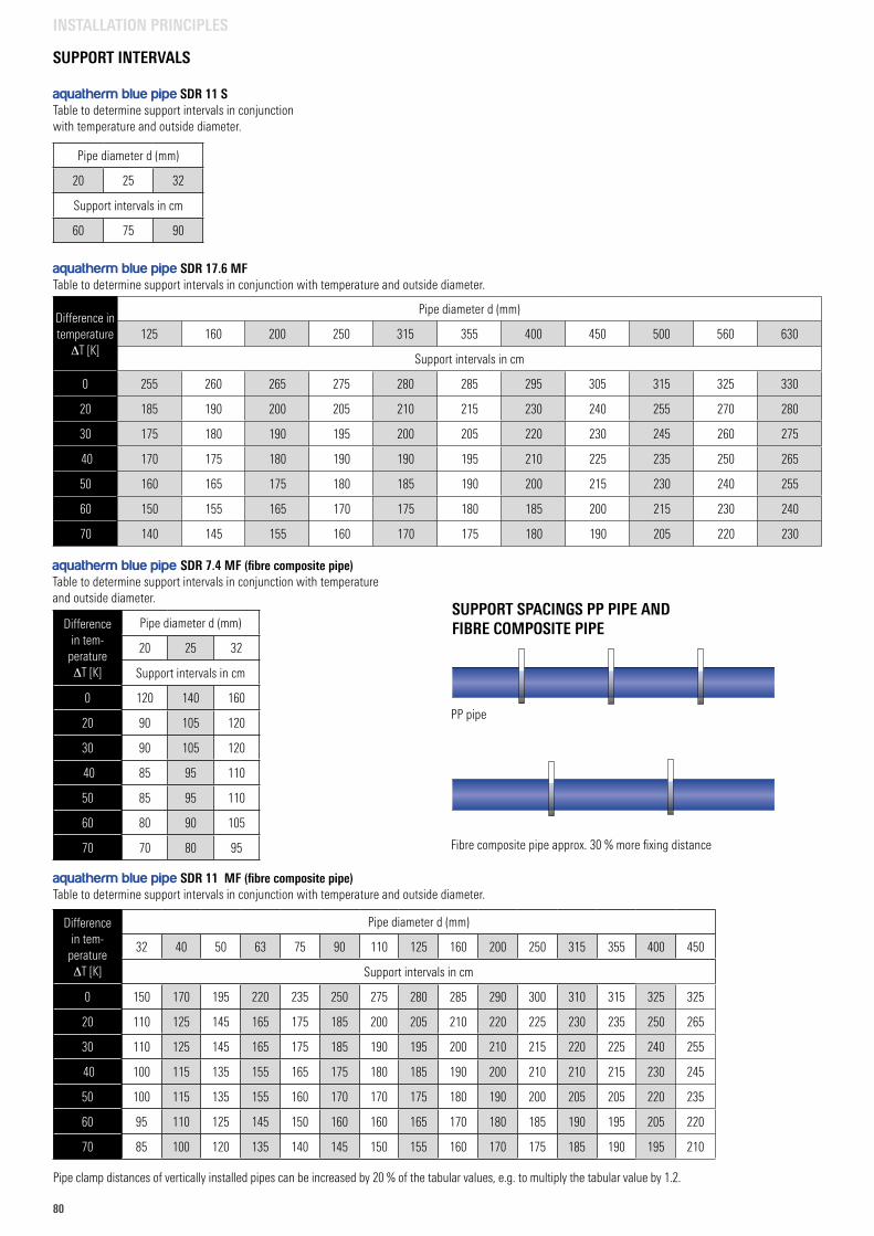
80
SUPPORT INTERVALS
aquatherm blue pipe SDR 17.6 MFTable to determine support intervals in conjunction with temperature and outside diameter.
Difference in temperature
DT [K]
Pipe diameter d (mm)
125 160 200 250 315 355 400 450 500 560 630
Support intervals in cm
0 255 260 265 275 280 285 295 305 315 325 330
20 185 190 200 205 210 215 230 240 255 270 280
30 175 180 190 195 200 205 220 230 245 260 275
40 170 175 180 190 190 195 210 225 235 250 265
50 160 165 175 180 185 190 200 215 230 240 255
60 150 155 165 170 175 180 185 200 215 230 240
70 140 145 155 160 170 175 180 190 205 220 230
aquatherm blue pipe SDR 11 STable to determine support intervals in conjunction with temperature and outside diameter.
Pipe diameter d (mm)
20 25 32
Support intervals in cm
60 75 90
aquatherm blue pipe SDR 7.4 MF (fibre composite pipe)Table to determine support intervals in conjunction with temperature and outside diameter.
Differencein tem-
peratureDT [K]
Pipe diameter d (mm)
20 25 32
Support intervals in cm
0 120 140 160
20 90 105 120
30 90 105 120
40 85 95 110
50 85 95 110
60 80 90 105
70 70 80 95
aquatherm blue pipe SDR 11 MF (fibre composite pipe)Table to determine support intervals in conjunction with temperature and outside diameter.
Pipe clamp distances of vertically installed pipes can be increased by 20 % of the tabular values, e.g. to multiply the tabular value by 1.2.
Differencein tem-
peratureDT [K]
Pipe diameter d (mm)
32 40 50 63 75 90 110 125 160 200 250 315 355 400 450
Support intervals in cm
0 150 170 195 220 235 250 275 280 285 290 300 310 315 325 325
20 110 125 145 165 175 185 200 205 210 220 225 230 235 250 265
30 110 125 145 165 175 185 190 195 200 210 215 220 225 240 255
40 100 115 135 155 165 175 180 185 190 200 210 210 215 230 245
50 100 115 135 155 160 170 170 175 180 190 200 205 205 220 235
60 95 110 125 145 150 160 160 165 170 180 185 190 195 205 220
70 85 100 120 135 140 145 150 155 160 170 175 185 190 195 210
PP pipe
Fibre composite pipe approx. 30 % more fixing distance
SUPPORT SPACINGS PP PIPE AND FIBRE COMPOSITE PIPE
INSTALLATION PRINCIPLES
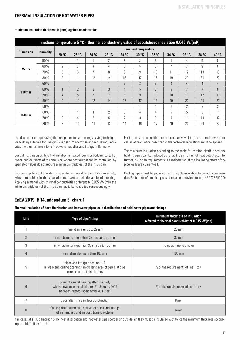
8181
THERMAL INSULATION OF HOT WATER PIPES
The decree for energy saving thermal protection and energy saving technique for buildings Decree for Energy Saving (EnEV energy saving regulation) regu-lates the thermal insulation of hot water supplies and fittings in Germany.
Central heating pipes, line 1–4 installed in heated rooms or building parts be-tween heated rooms of the one user, where heat output can be controlled by open stop valves do not require a minimum thickness of the insulation.
This even applies to hot water pipes up to an inner diameter of 22 mm in flats, which are neither in the circulation nor have an additional electric heating.Applying material with thermal conductivities different to 0.035 W / (mK) the minimum thickness of the insulation has to be converted correspondingly.
For the conversion and the thermal conductivity of the insulation the ways and values of calculation described in the technical regulations must be applied.
The minimum insulation according to the table for heating distributions and heating pipes can be reduced as far as the same limit of heat output even for further insulation requirements in consideration of the insulating effect of the pipe walls are guaranteed.
Cooling pipes must be provided with suitable insulation to prevent condensa-tion. For further information please contact our service hotline +49 2722 950 200
Line Type of pipe/fittingminimum thickness of insulation
referred to thermal conductivity of 0.035 W/(mK)
1 inner diameter up to 22 mm 20 mm
2 inner diameter more than 22 mm up to 35 mm 30 mm
3 inner diameter more than 35 mm up to 100 mm same as inner diameter
4 inner diameter more than 100 mm 100 mm
5pipes and fittings after line 1–4
in wall- and ceiling openings, in crossing area of pipes, at pipe connections, at distributors
1/2 of the requirements of line 1 to 4
6pipes of central heating after line 1–4,
which have been installed after 31. January 2002 between heated rooms of various users
1/2 of the requirements of line 1 to 4
7 pipes after line 6 in floor construction 6 mm
8Cooling distribution and cold water pipes and fittings
of air handling and air conditioning systems6 mm
EnEV 2019, § 14, addendum 5, chart 1
medium temperature 5 °C - thermal conductivity value of caoutchouc insulation 0.040 W/(mK)
Dimension humidityambient temperature
20 °C 22 °C 24 °C 26 °C 28 °C 30 °C 32 °C 34 °C 36 °C 38 °C 40 °C
75mm
50 % 1 1 2 2 3 3 4 4 5 5
60 % 2 3 3 4 5 5 6 7 7 8 8
70 % 5 6 7 8 8 9 10 11 12 13 13
80 % 9 11 12 14 15 17 18 19 20 21 22
110mm
50 % 1 2 2 3 3 4 4 4
60 % 1 2 3 3 4 5 5 6 7 7 8
70 % 4 5 6 7 8 9 10 10 11 12 13
80 % 9 11 12 14 15 17 18 19 20 21 22
160mm
50 % 1 1 2 2 3 3
60 % 1 1 2 3 4 4 5 5 6 7
70 % 3 4 5 6 7 8 9 9 11 11 12
80 % 8 10 11 13 14 16 17 19 20 21 22
minimum insulation thickness in [mm] against condensation
INSTALLATION PRINCIPLES
Thermal insulation of heat distribution and hot water pipes, cold distribution and cold water pipes and fittings
If in cases of § 14, paragraph 5 the heat distribution and hot water pipes border on outside air, they must be insulated with twice the minimum thickness accord-ing to table 1, lines 1 to 4.
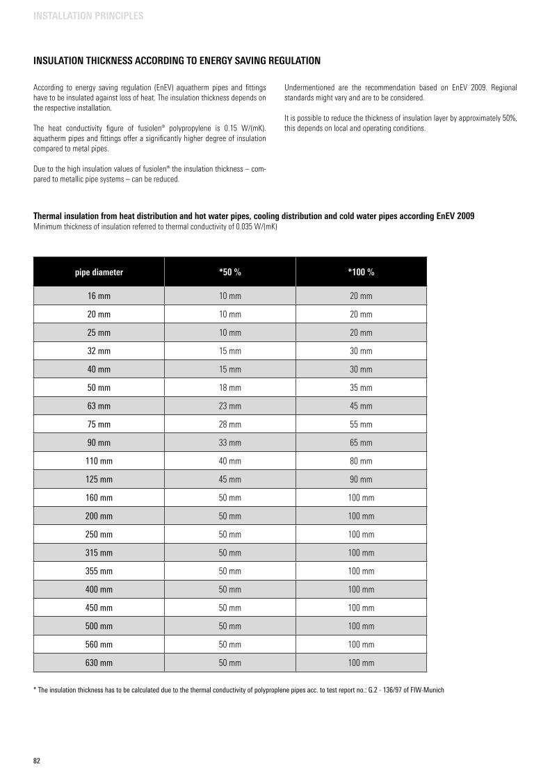
82
INSULATION THICKNESS ACCORDING TO ENERGY SAVING REGULATION
According to energy saving regulation (EnEV) aquatherm pipes and fittings have to be insulated against loss of heat. The insulation thickness depends on the respective installation.
The heat conductivity figure of fusiolen® polypropylene is 0.15 W/(mK). aquatherm pipes and fittings offer a significantly higher degree of insulation compared to metal pipes.
Due to the high insulation values of fusiolen® the insulation thickness – com-pared to metallic pipe systems – can be reduced.
Undermentioned are the recommendation based on EnEV 2009. Regional standards might vary and are to be considered.
It is possible to reduce the thickness of insulation layer by approximately 50%, this depends on local and operating conditions.
* The insulation thickness has to be calculated due to the thermal conductivity of polyproplene pipes acc. to test report no.: G.2 - 136/97 of FIW-Munich
pipe diameter *50 % *100 %
16 mm 10 mm 20 mm
20 mm 10 mm 20 mm
25 mm 10 mm 20 mm
32 mm 15 mm 30 mm
40 mm 15 mm 30 mm
50 mm 18 mm 35 mm
63 mm 23 mm 45 mm
75 mm 28 mm 55 mm
90 mm 33 mm 65 mm
110 mm 40 mm 80 mm
125 mm 45 mm 90 mm
160 mm 50 mm 100 mm
200 mm 50 mm 100 mm
250 mm 50 mm 100 mm
315 mm 50 mm 100 mm
355 mm 50 mm 100 mm
400 mm 50 mm 100 mm
450 mm 50 mm 100 mm
500 mm 50 mm 100 mm
560 mm 50 mm 100 mm
630 mm 50 mm 100 mm
Thermal insulation from heat distribution and hot water pipes, cooling distribution and cold water pipes according EnEV 2009Minimum thickness of insulation referred to thermal conductivity of 0.035 W/(mK)
INSTALLATION PRINCIPLES
8383
Pressure test/Test control
All aquatherm pipe systems shall be subjected to a hydraulical pressure test with a test pressure of 10 bar.
The material properties of the aquatherm pipe systems result in an expansion of the pipes during the pressure test. This affects the test result. Due to the thermal expansion coefficients of the aquatherm pipe systems the results are influenced additionally. The temperature differences between the pipe and the test medium lead to changes in pressure. Hereby a temperature change of 10 K corresponds to a pressure difference of 0.5 up to 1 bar.
Therefore pressure testing of the aquatherm pipe systems should be made with a constant temperature of the test medium. The hydraulic pressure test requires a preliminary, principal and final test.
In the preliminary test a pressure of 18 bar* is applied 3 x 5 minutes for the expansion/release of the pipes. Between the cycles the pipe system must be depressurized.
Immediately after the preliminary test the principal test should be performed. The test duration is 15 min. Here, the test pressure (10 bar) may not fall more than 0.5 bar.
After completion of the preliminary and principle test finally the final test must be performed.
The test duration is 60 minutes. Here, the test pressure – read after the principle test – may not fall more than 0.5 bar.
Measuring of the test pressures
When measuring the system use a pressure measuring device that is able to read a pressure change of 0.1 bar. Place the measuring device at the lowest point (highest static pressure) of the installation.
Test record
A record of the hydraulic pressure test has to be prepared and signed by the client and contractor stating place and date (see page 85).
PRESSURE TEST/TEST CONTROL/ MEASURING OF THE TEST PRESSURES/TEST RECORD
INSTALLATION PRINCIPLES
* Exception: aquatherm blue pipe SDR 17.6: 10 bar
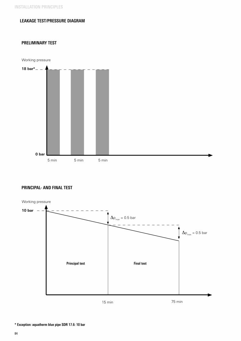
84
LEAKAGE TEST/PRESSURE DIAGRAM
PRINCIPAL- AND FINAL TEST
Principal test Final test
15 min
Dpmax = 0.5 bar
Dpmax = 0.5 bar
Working pressure
10 bar
75 min
PRELIMINARY TEST
Working pressure 18 bar*
0 bar
5 min 5 min 5 min
INSTALLATION PRINCIPLES
* Exception: aquatherm blue pipe SDR 17.6: 10 bar
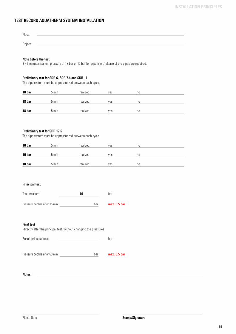
8585
TEST RECORD AQUATHERM SYSTEM INSTALLATION
INSTALLATION PRINCIPLES
Place:
Object:
Note before the test: 3 x 5 minutes system pressure of 18 bar or 10 bar for expansion/release of the pipes are required.
Preliminary test for SDR 6, SDR 7.4 and SDR 11The pipe system must be unpressurized between each cycle.
18 bar 5 min realized: yes no
18 bar 5 min realized: yes no
18 bar 5 min realized: yes no
Preliminary test for SDR 17.6The pipe system must be unpressurized between each cycle.
10 bar 5 min realized: yes no
10 bar 5 min realized: yes no
10 bar 5 min realized: yes no
Principal test
Test pressure: 10 bar
Pressure decline after 15 min: bar max. 0.5 bar
Final test(directly after the principal test, without changing the pressure) Result principal test: bar
Pressure decline after 60 min: bar max. 0.5 bar
Notes:
Place, Date Stamp/Signature
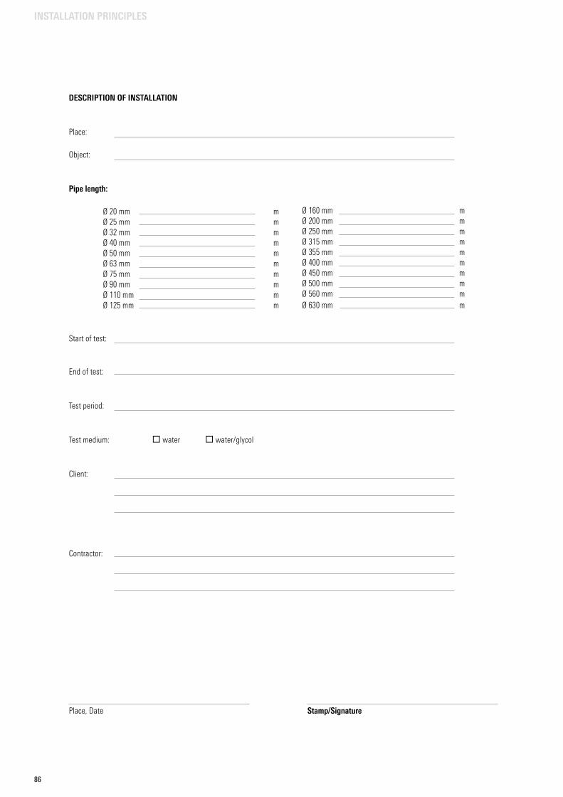
86
DESCRIPTION OF INSTALLATION
Place:
Object:
Pipe length: Ø 20 mm m Ø 25 mm m Ø 32 mm m Ø 40 mm m Ø 50 mm m Ø 63 mm m Ø 75 mm m Ø 90 mm m Ø 110 mm m Ø 125 mm m
Start of test:
End of test:
Test period:
Test medium: water water/glycol Client:
Contractor:
Place, Date Stamp/Signature
INSTALLATION PRINCIPLES
Ø 160 mm m Ø 200 mm m Ø 250 mm m Ø 315 mm m Ø 355 mm m Ø 400 mm m Ø 450 mm m Ø 500 mm m Ø 560 mm m Ø 630 mm m
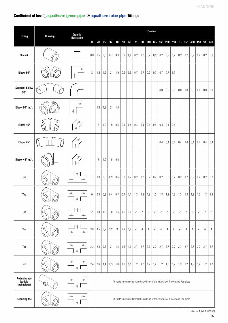
8787
DESCRIPTION OF INSTALLATION
Place:
Object:
Pipe length: Ø 20 mm m Ø 25 mm m Ø 32 mm m Ø 40 mm m Ø 50 mm m Ø 63 mm m Ø 75 mm m Ø 90 mm m Ø 110 mm m Ø 125 mm m
Start of test:
End of test:
Test period:
Test medium: water water/glycol Client:
Contractor:
Place, Date Stamp/Signature
PLANNING
Fitting Drawing Graphic illustration
z-Value
16 20 25 32 40 50 63 75 90 110 125 160 200 250 315 355 400 450 500 630
Socket 0,8 0,5 0,5 0,7 0,9 0,2 0,2 0,2 0,2 0,2 0,2 0,2 0,2 0,2 0,2 0,2 0,2 0,2 0,2 0,2
Elbow 90° 2 1,3 1,2 2 1,9 0,5 0,5 0,7 0,7 0,7 0,7 0,7 0,7 0,7
Segment Elbow
90°0,8 0,8 0,8 0,8 0,8 0,8 0,8 0,8 0,8
Elbow 90° m./f. 1,3 1,2 2 1,9
Elbow 45° 2 1,9 1,9 0,5 0,4 0,4 0,4 0,4 0,4 0,4 0,4 0,4 0,4
Elbow 45° 0,4 0,4 0,4 0,4 0,4 0,4 0,4 0,4 0,4
Elbow 45° m./f. 2 1,9 1,9 0,5
Tee 1,1 0,9 0,9 0,9 0,6 0,2 0,2 0,2 0,2 0,2 0,2 0,2 0,2 0,2 0,2 0,2 0,2 0,2 0,2 0,2
Tee 0 0,3 0,3 0,4 0,7 0,7 1,1 1,3 1,3 1,3 1,3 1,3 1,3 1,3 1,3 1,3 1,3 1,3 1,3 1,3
Tee 2 1,9 1,8 1,8 1,6 1,6 1,6 2 2 2 2 2 2 2 2 2 2 2 2 2
Tee 3,8 3,5 3,2 3,2 3 3,2 3,2 4 4 4 4 4 4 4 4 4 4 4 4 4
Tee 2,2 2,3 2,3 2 1,6 1,9 1,9 2,7 2,7 2,7 2,7 2,7 2,7 2,7 2,7 2,7 2,7 2,7 2,7 2,7
Tee 2,4 2,6 1,4 2,3 1,8 1,2 1,1 1,2 1,2 1,2 1,2 1,2 1,2 1,2 1,2 1,2 1,2 1,2 1,2 1,2
Reducing tee(saddle
technology)The zeta value results from the addition of the zeta values T-piece and Red-piece
Reducing tee The zeta value results from the addition of the zeta values T-piece and Red-piece
Coefficient of loss z aquatherm green pipe- & aquatherm blue pipe-fittings
( = flow direction)
z
dD
Art.N. 11006Artikelliste 2015Seite 18
L
Art.N. 12106Artikelliste 2015Seite 21
dD
zl
Art.N. 12143Artikelliste 2015Seite 22
D
z
Art.N. 12306Artikelliste 2015Seite 23
dD
zl
d
z1l1
Art.N. 12708Artikelliste 2015Seite 23
dD
zl
z1
l1
d
Art.N. 12506Artikelliste 2015Seite 23
dD
zl
Art.N. 13106Artikelliste 2015Seite 24
lz
dD
Lz1z1
Art.N. 13106Artikelliste 2015Seite 24
lz
dD
Lz1z1
Art.N. 13106Artikelliste 2015Seite 24
lz
dD
Lz1z1
Art.N. 13106Artikelliste 2015Seite 24
lz
dD
Lz1z1
Art.N. 13106Artikelliste 2015Seite 24
lz
dD
Lz1z1
Art.N. 13106Artikelliste 2015Seite 24
lz
dD
Lz1z1
Art.N. 13106Artikelliste 2015Seite 24
lz
dD
Lz1z1
Art.N. 12543Artikelliste 2015Seite 24
z
D
Art.N. 13601Artikelliste 2015Seite 27
d1D1
z l
L
D
Spritzgussformteil Segmentgeschweißter Artikel
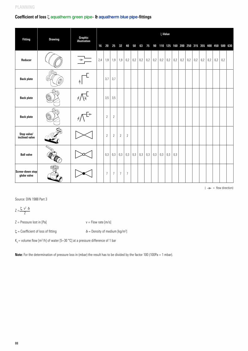
88
PLANNING
Source: DIN 1988 Part 3
Z = z v2 d 2
Z = Pressure lost in [Pa] v = Flow rate [m/s]
z = Coefficient of loss of fitting d = Density of medium [kg/m3]
KV = volume flow [m3 /h] of water [5–30 °C] at a pressure difference of 1 bar
Note: For the determination of pressure loss in (mbar) the result has to be divided by the factor 100 (100Pa = 1 mbar).
Fitting Drawing Graphic illustration
z-Value
16 20 25 32 40 50 63 75 90 110 125 160 200 250 315 355 400 450 500 630
Reducer 2,4 1,9 1,9 1,9 0,2 0,2 0,2 0,2 0,2 0,2 0,2 0,2 0,2 0,2 0,2 0,2 0,2 0,2 0,2
Back plate 3,7 3,7
Back plate 3,5 3,5
Back plate 2 2
Stop valve/ inclined valve 2 2 2 2
Ball valve 0,3 0,3 0,3 0,3 0,3 0,3 0,3 0,3 0,3 0,3 0,3
Screw-down stop globe valve
7 7 7 7
Coefficient of loss z aquatherm green pipe- & aquatherm blue pipe-fittings
( = flow direction)
Art.N. 11114Artikelliste 2015Seite 19
d1D
zl
L
d
Art.N. 20108Artikelliste 2015Seite 40
z2
R D1
z1l1
dD
cz
l
L
Art.N. 20198Artikelliste 2015Seite 39
l3L
z1z
l
cd1
l2
t1
D
Art.N. 20198Artikelliste 2015Seite 39
l3L
z1z
l
cd1
l2
t1
D
41108
Art.N. 41310 Gr. 41308Artikelliste 2015Seite 57
d D
zL
l1
h
40808
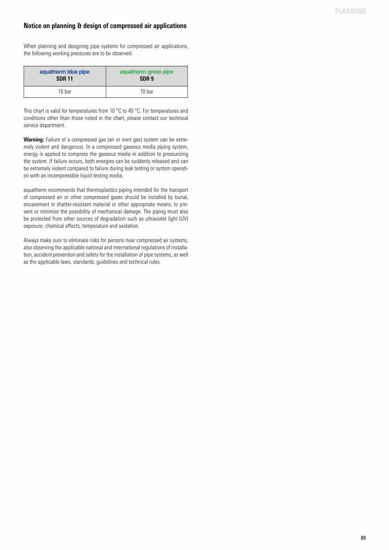
8989
PLANNING
Notice on planning & design of compressed air applications
When planning and designing pipe systems for compressed air applications, the following working pressures are to be observed.
This chart is valid for temperatures from 10 °C to 40 °C. For temperatures and conditions other than those noted in the chart, please contact our technical service department.
Warning: Failure of a compressed gas (air or inert gas) system can be extre-mely violent and dangerous. In a compressed gaseous media piping system, energy is applied to compress the gaseous media in addition to pressurizing the system. If failure occurs, both energies can be suddenly released and can be extremely violent compared to failure during leak testing or system operati-on with an incompressible liquid testing media.
aquatherm recommends that thermoplastics piping intended for the transport of compressed air or other compressed gases should be installed by burial, encasement in shatter-resistant material or other appropriate means, to pre-vent or minimize the possibility of mechanical damage. The piping must also be protected from other sources of degradation such as ultraviolet light (UV) exposure, chemical effects, temperature and oxidation.
Always make sure to eliminate risks for persons near compressed air systems, also observing the applicable national and international regulations of installa-tion, accident prevention and safety for the installation of pipe systems, as well as the applicable laws, standards, guidelines and technical rules.
aquatherm blue pipe SDR 11
aquatherm green pipe SDR 9
10 bar 10 bar
90
The following designations are used for the composition of the flow substances:
a) If the content data is not followed by “(Vol.)”, the data is the weight in % (previously % by weight) . VL: aqueous solution, the weight content of which is ≤ 10 %. L: aqueous solution, the weight content of which is greater than 10 %. GL: saturated (at 20 °C) aqueous solution. TR: flow substance is as least technically pure. H: commercially available composition.
b) Volume content in % (previously % by volume): this is characterized specially by “(Vol)”. The chemical resistance of pipes and pipe fittings is generally not reduced for weight or volume con- tents and temperatures lower than those given in the table.
2) These flow substances and/or chemical resistance data are not contained in ISO/TR 7471.
3) The chemical resistance is evaluated as one group lower in ISO/TR 7471.
4) The chemical resistance is evaluated as one group higher in ISO/TR 7471.
CHEMICAL RESISTANCE OF PIPES AND FITTINGS
The following chemical resistance document can be used as a general guideline, but should not be considered a formal recommendation or approval by aquatherm. The actual behavior of the piping system when exposed to a specific chemical is very dependent on the exposure conditions (temperature, pressure, flow, duration, etc.), the stresses on the piping material and system (mechanical, thermal, cyclic, etc.), and the ancillary materials in the system (o-rings, seals, gaskets, metal components, etc). Due to the comprehensive warranty provided by aquatherm, specific applications must be submitted to aquatherm for review and evaluation using the form in the technical catalogue or the online submittal form. A written response will be provided once the review is completed. The attached guidance document should NOT be used as a definitive reference for determining the chemical compatibility of aquatherm piping in a specific application. This can only be determined by submitting the information to aquatherm for review.
Polypropylene (PP) pipes; chemical resistance of pipes and pipe fittings.
The behavior of pipes and pipe fittings towards flow substances depends on the one hand on the particular nature and type of plastic, the design of the pipe fitting and the manufacturing conditions, and, on the other hand, on the nature of the flow substance. In particular, the duration of the action, temperatures and mechanical stresses acting at the same time and other types of influences which additionally have an effect also determine the behavior. The effects of these influences, which frequently are not clearly foreseeable at the outset, are decisive for the suitability for an application. Furthermore, special requirements on the pipe or pipe fitting (e.g. dimensional stability or mechanical strength) shall be taken into consideration, depending on the application.
For these reasons, the suitability of pipes and pipe fittings for a flow substance can be evaluated only from case to case.
The chemical resistance indicates the gradual behavior of the material of the pipe wall towards the action of the flow substance. It depends in each case on the type of interacting substances, their composition, the temperature and the duration of the action.In an application, the chemical resistance can be influenced by further stresses (e.g. of a mechanical nature).Note: The chemical resistance does not correspond to the term “chemical stability” hitherto used in everyday language, because this contains an evaluation for the particular application.
Data on chemical resistance
Various processes may occur when the flow substances come into contact with the material of the pipe wall, such as absorption of the liquid (swelling), extraction of soluble constituents of the material (shrinkage) and chemical reactions (hydrolysis, oxidation and the like), which in certain circumstances may cause changes in the properties of the pipes and pipe fittings.
The behavior of the pipes and pipe fittings towards the flow substances is classified into the following groups:
: resistant The material of the pipe wall is generally evaluated as suitable.
: conditionally resistant The suitability of the material of the pipe wall for the particular application shall be investigated; if necessary, further experiments shall be carried out.
: not resistant The material of the pipe wall is generally evaluated as unsuitable.
–: No data on the chemical resistance is available
Detailed information regarding the resistance of our pipe systems to the listed fluids can be obtained from the aquatherm laboratory:
Hotline +49 2722 950 0 For inquiries on resistance, medium and operating conditions (operating pressure and temperature) needs to be specified.
1) Table taken from the English translation of DIN 8078 Supplement 1, Feb. 1982, Chemical resistance of (PP-) pipes and pipe fittings.Reproduction with the permission of DIN Deutsches Institut für Normung e. V.. Important: When applying said standard the edition with the most recent
release date should be used (can be purchased at Beuth Verlag GmbH, Burggrafenstrasse 6, 10787 Berlin, Germany).
CHEMICAL RESISTANCE
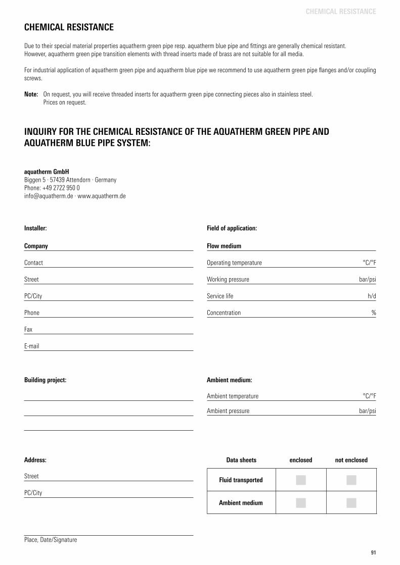
9191
CHEMICAL RESISTANCE
Due to their special material properties aquatherm green pipe resp. aquatherm blue pipe and fittings are generally chemical resistant. However, aquatherm green pipe transition elements with thread inserts made of brass are not suitable for all media.
For industrial application of aquatherm green pipe and aquatherm blue pipe we recommend to use aquatherm green pipe flanges and/or coupling screws.
Note: On request, you will receive threaded inserts for aquatherm green pipe connecting pieces also in stainless steel. Prices on request.
INQUIRY FOR THE CHEMICAL RESISTANCE OF THE AQUATHERM GREEN PIPE AND AQUATHERM BLUE PIPE SYSTEM:
aquatherm GmbHBiggen 5 . 57439 Attendorn . GermanyPhone: +49 2722 950 [email protected] . www.aquatherm.de
Installer:
Company
Contact
Street
PC/City
Phone
Fax
Building project:
Address:
Street
PC/City
Place, Date/Signature
Field of application:
Flow medium
Operating temperature °C/°F
Working pressure bar/psi
Service life h/d
Concentration %
Ambient medium:
Ambient temperature °C/°F
Ambient pressure bar/psi
Data sheets enclosed not enclosed
Fluid transported Ambient medium
CHEMICAL RESISTANCE
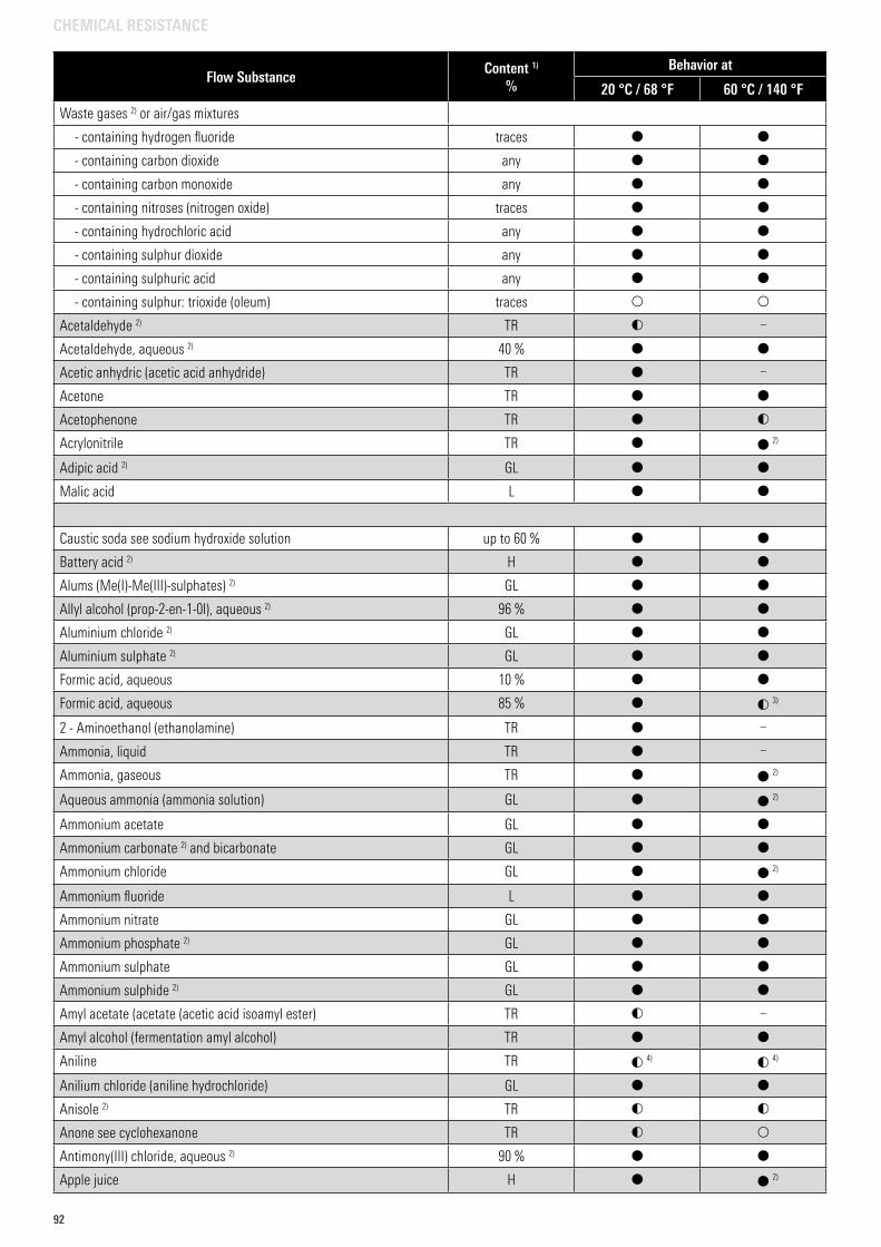
92
Flow SubstanceContent 1)
%Behavior at
20 °C / 68 °F 60 °C / 140 °F
Waste gases 2) or air/gas mixtures
- containing hydrogen fluoride traces
- containing carbon dioxide any
- containing carbon monoxide any
- containing nitroses (nitrogen oxide) traces
- containing hydrochloric acid any
- containing sulphur dioxide any
- containing sulphuric acid any
- containing sulphur: trioxide (oleum) traces
Acetaldehyde 2) TR –
Acetaldehyde, aqueous 2) 40 %
Acetic anhydric (acetic acid anhydride) TR –
Acetone TR
Acetophenone TR
Acrylonitrile TR 2)
Adipic acid 2) GL
Malic acid L
Caustic soda see sodium hydroxide solution up to 60 %
Battery acid 2) H
Alums (Me(I)-Me(III)-sulphates) 2) GL
Allyl alcohol (prop-2-en-1-0l), aqueous 2) 96 %
Aluminium chloride 2) GL
Aluminium sulphate 2) GL
Formic acid, aqueous 10 %
Formic acid, aqueous 85 % 3)
2 - Aminoethanol (ethanolamine) TR –
Ammonia, liquid TR –
Ammonia, gaseous TR 2)
Aqueous ammonia (ammonia solution) GL 2)
Ammonium acetate GL
Ammonium carbonate 2) and bicarbonate GL
Ammonium chloride GL 2)
Ammonium fluoride L
Ammonium nitrate GL
Ammonium phosphate 2) GL
Ammonium sulphate GL
Ammonium sulphide 2) GL
Amyl acetate (acetate (acetic acid isoamyl ester) TR –
Amyl alcohol (fermentation amyl alcohol) TR
Aniline TR 4) 4)
Anilium chloride (aniline hydrochloride) GL
Anisole 2) TR
Anone see cyclohexanone TR
Antimony(III) chloride, aqueous 2) 90 %
Apple juice H 2)
CHEMICAL RESISTANCE
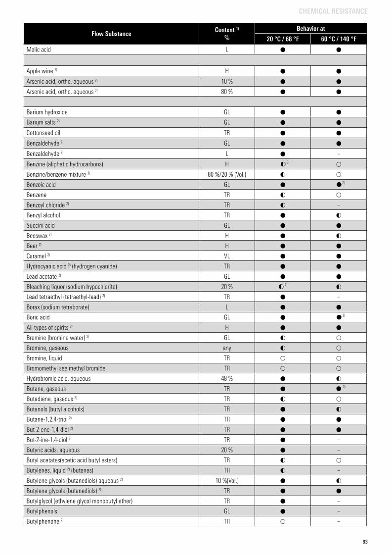
9393
Malic acid L
Apple wine 2) H
Arsenic acid, ortho, aqueous 2) 10 %
Arsenic acid, ortho, aqueous 2) 80 %
Barium hydroxide GL
Barium salts 2) GL
Cottonseed oil TR
Benzaldehyde 2) GL
Benzaldehyde 2) L –
Benzine (aliphatic hydrocarbons) H 3)
Benzine/benzene mixture 2) 80 %/20 % (Vol.)
Benzoic acid GL 2)
Benzene TR
Benzoyl chloride 2) TR –
Benzyl alcohol TR
Succini acid GL
Beeswax 2) H
Beer 2) H
Caramel 2) VL
Hydrocyanic acid 2) (hydrogen cyanide) TR
Lead acetate 2) GL
Bleaching liquor (sodium hypochlorite) 20 % 4)
Lead tetraethyl (tetraethyl-lead) 2) TR –
Borax (sodium tetraborate) L
Boric acid GL 2)
All types of spirits 2) H
Bromine (bromine water) 2) GL
Bromine, gaseous any
Bromine, liquid TR
Bromomethyl see methyl bromide TR
Hydrobromic acid, aqueous 48 %
Butane, gaseous TR 2)
Butadiene, gaseous 2) TR
Butanols (butyl alcohols) TR
Butane-1,2,4-triol 2) TR
But-2-ene-1,4-diol 2) TR
But-2-ine-1,4-diol 2) TR –
Butyric acids, aqueous 20 % –
Butyl acetates(acetic acid butyl esters) TR
Butylenes, liquid 2) (butenes) TR –
Butylene glycols (butanediols) aqueous 2) 10 %(Vol.)
Butylene glycols (butanediols) 2) TR
Butylglycol (ethylene glycol monobutyl ether) TR –
Butylphenols GL –
Butylphenone 2) TR –
Flow SubstanceContent 1)
%Behavior at
20 °C / 68 °F 60 °C / 140 °F
CHEMICAL RESISTANCE
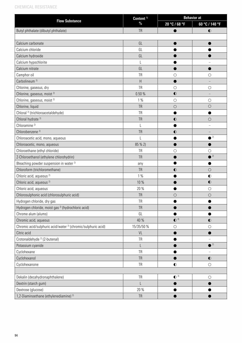
94
Butyl phthalate (dibutyl phthalate) TR
Calcium carbonate GL
Calcium chloride GL
Calcium hydroxide GL
Calcium hypochlorite L –
Calcium nitrate GL
Camphor oil TR
Carbolineum 2) H –
Chlorine, gaseous, dry TR
Chlorine, gaseous, moist 2) 0.50 % –
Chlorine, gaseous, moist 2) 1 %
Chlorine, liquid TR
Chloral 2) (trichloroacetaldehyde) TR
Chloral hydrate 2) TR
Chloramine 2) L –
Chlorobenzene 2) TR –
Chloroacetic acid, mono, aqueous L 2)
Chloroacetic, mono, aqueous 85 % 2)
Chloroethane (ethyl chloride) TR
2-Chloroethanol (ethylene chlorohydrin) TR 2)
Bleaching powder suspension in water 2) any
Chloroform (trichloromethane) TR
Chloric acid, aqueous 2) 1 %
Chloric acid, aqueous 2) 10 %
Chloric acid, aqueous 20 %
Chlorosulphonic acid (chlorosulphuric acid) TR
Hydrogen chloride, dry gas TR
Hydrogen chloride, moist gas 2) (hydrochloric acid) TR
Chrome alum (alums) GL
Chromic acid, aqueous 40 % 4)
Chromic acid/sulphuric acid/water 2) (chromic/sulphuric acid) 15/35/50 %
Citric acid VL
Crotonaldehyde 2) (2-butenal) TR –
Potassium cyanide L 2)
Cyclohexane TR –
Cyclohexanol TR
Cyclohexanone TR
Dekalin (decahydronaphthalene) TR 3)
Dextrin (starch gum) L
Dextrose (glucose) 20 %
1,2-Diaminoethane (ethylenediamine) 2) TR
Flow SubstanceContent 1)
%Behavior at
20 °C / 68 °F 60 °C / 140 °F
CHEMICAL RESISTANCE
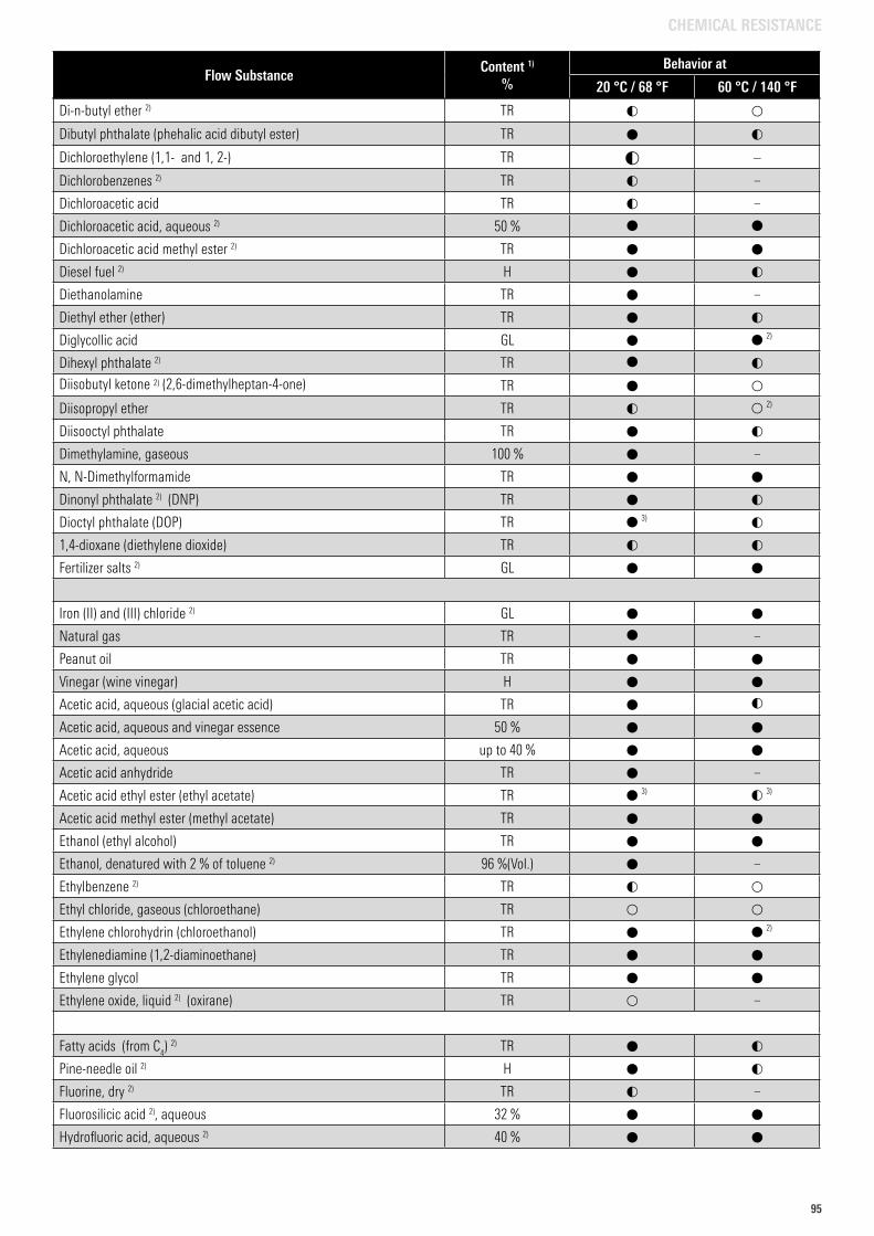
9595
Di-n-butyl ether 2) TR
Dibutyl phthalate (phehalic acid dibutyl ester) TR
Dichloroethylene (1,1- and 1, 2-) TR –
Dichlorobenzenes 2) TR –
Dichloroacetic acid TR –
Dichloroacetic acid, aqueous 2) 50 %
Dichloroacetic acid methyl ester 2) TR
Diesel fuel 2) H
Diethanolamine TR –
Diethyl ether (ether) TR
Diglycollic acid GL 2)
Dihexyl phthalate 2) TR
Diisobutyl ketone 2) (2,6-dimethylheptan-4-one) TR
Diisopropyl ether TR 2)
Diisooctyl phthalate TR
Dimethylamine, gaseous 100 % –
N, N-Dimethylformamide TR
Dinonyl phthalate 2) (DNP) TR
Dioctyl phthalate (DOP) TR 3)
1,4-dioxane (diethylene dioxide) TR
Fertilizer salts 2) GL
Iron (II) and (III) chloride 2) GL
Natural gas TR –
Peanut oil TR
Vinegar (wine vinegar) H
Acetic acid, aqueous (glacial acetic acid) TR
Acetic acid, aqueous and vinegar essence 50 %
Acetic acid, aqueous up to 40 %
Acetic acid anhydride TR –
Acetic acid ethyl ester (ethyl acetate) TR 3) 3)
Acetic acid methyl ester (methyl acetate) TR
Ethanol (ethyl alcohol) TR
Ethanol, denatured with 2 % of toluene 2) 96 %(Vol.) –
Ethylbenzene 2) TR
Ethyl chloride, gaseous (chloroethane) TR
Ethylene chlorohydrin (chloroethanol) TR 2)
Ethylenediamine (1,2-diaminoethane) TR
Ethylene glycol TR
Ethylene oxide, liquid 2) (oxirane) TR –
Fatty acids (from C4) 2) TR
Pine-needle oil 2) H
Fluorine, dry 2) TR –
Fluorosilicic acid 2), aqueous 32 %
Hydrofluoric acid, aqueous 2) 40 %
Flow SubstanceContent 1)
%Behavior at
20 °C / 68 °F 60 °C / 140 °F
CHEMICAL RESISTANCE
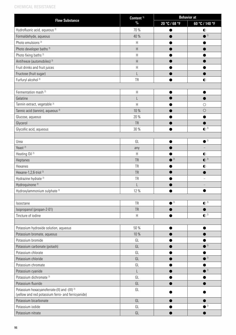
96
Hydrofluoric acid, aqueous 2) 70 %
Formaldehyde, aqueous 40 % 2)
Photo emulsions 2) H
Photo developer baths 2) H
Photo fixing baths 2) H
Antifreeze (automobiles) 2) H
Fruit drinks and fruit juices H
Fructose (fruit sugar) L
Furfuryl alcohol 2) TR
Fermentation mash 2) H
Gelatine L
Tannin extract, vegetable 2) H
Tannic acid (tannin), aqueous 2) 10 %
Glucose, aqueous 20 %
Glycerol TR
Glycollic acid, aqueous 30 % 2)
Urea GL 2)
Yeast 2) any –
Heating Oil 2) H
Heptanes TR 3) 3)
Hexanes TR
Hexane-1,2,6-triol 2) TR
Hydrazine hydrate 2) TR –
Hydroquinone 2) L –
Hydroxylammonium sulphate 2) 12 %
Isooctane TR 3) 3)
Isopropanol (propan-2-01) TR
Tincture of iodine H 2)
Potassium hydroxide solution, aqueous 50 %
Potassium bromate, aqueous 10 %
Potassium bromide GL
Potassium carbonate (potash) GL 2)
Potassium chlorate GL
Potassium chloride GL 2)
Potassium chromate GL
Potassium cyanide L 2)
Potassium dichromate 2) GL
Potassium fluoride GL
Potassium hexacyanoferrate-(II) and -(III) 2)
(yellow and red potassium ferro- and ferricyanide)GL
Potassium bicarbonate GL
Potassium iodide GL 2)
Potassium nitrate GL
Flow SubstanceContent 1)
%Behavior at
20 °C / 68 °F 60 °C / 140 °F
CHEMICAL RESISTANCE
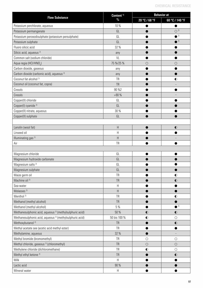
9797
Potassium perchlorate, aqueous 10 %
Potassium permanganate GL 2)
Potassium peroxodisulphate (potassium persulphate) GL 2)
Potassium sulphate GL 2)
Fluoro silicic acid 32 %
Silicic acid, aqueous 2) any
Common salt (sodium chloride) VL
Aqua regia (HCl/HNO3) 75 %/25 %
Carbon dioxide, gaseous any
Carbon dioxide (carbonic acid), aqueous 2) any
Coconut fat alcohol 2) TR
Coconut oil (coconut fat, copra) TR –
Cresols 90 %2
Cresols >90 % –
Copper(II) chloride GL
Copper(I) cyanide 2) GL
Copper(II) nitrate, aqueous 30 %
Copper(II) sulphate GL
Lanolin (wool fat) H
Linseed oil H
Illuminating gas 2) H –
Air TR
Magnesium chloride GL
Magnesium hydroxide carbonate GL
Magnesium salts 2) GL
Magnesium sulphate GL
Maize germ oil TR
Machine oil 2) TR
Sea-water H
Molasses 2) H
Menthol 2) TR
Methanol (methyl alcohol) TR
Methanol (methyl alcohol) 5 % 3)
Methanesulphonic acid, aqueous 2) (methylsulphuric acid) 50 %
Methanesulphonic acid, aqueous 2) (methylsulphuric acid) 50 bis 100 %
Methoxybutanol 2) TR
Methyl acetate see (acetic acid methyl ester) TR
Methylamine, aqueous 32 % –
Methyl bromide (bromomethyl) TR
Methyl chloride, gaseous 2) (chloromethyl) TR
Methylene chloride (dichloromethane) TR
Methyl ethyl ketone 2) TR
Milk H
Lactic acid 90 %
Mineral water H
Flow SubstanceContent 1)
%Behavior at
20 °C / 68 °F 60 °C / 140 °F
CHEMICAL RESISTANCE
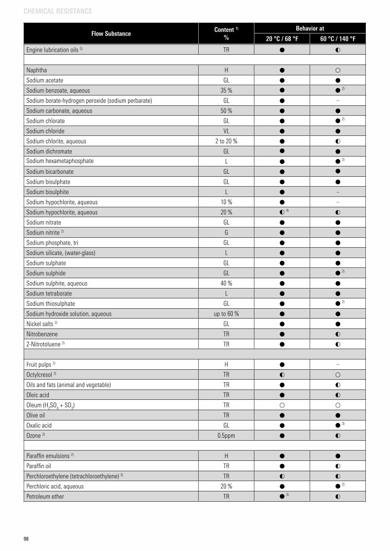
98
Engine lubrication oils 2) TR
Naphtha H
Sodium acetate GL
Sodium benzoate, aqueous 35 % 2)
Sodium borate-hydrogen peroxide (sodium perbarate) GL –
Sodium carbonate, aqueous 50 %
Sodium chlorate GL 2)
Sodium chloride VL
Sodium chlorite, aqueous 2 to 20 %
Sodium dichromate GL
Sodium hexametaphosphate L 2)
Sodium bicarbonate GL
Sodium bisulphate GL
Sodium bisulphite L –
Sodium hypochlorite, aqueous 10 % –
Sodium hypochlorite, aqueous 20 % 4)
Sodium nitrate GL
Sodium nitrite 2) G
Sodium phosphate, tri GL
Sodium silicate, (water-glass) L
Sodium sulphate GL
Sodium sulphide GL 2)
Sodium sulphite, aqueous 40 %
Sodium tetraborate L
Sodium thiosulphate GL 2)
Sodium hydroxide solution, aqueous up to 60 %
Nickel salts 2) GL
Nitrobenzene TR
2-Nitrotoluene 2) TR
Fruit pulps 2) H –
Octylcresol 2) TR
Oils and fats (animal and vegetable) TR
Oleic acid TR
Oleum (H2SO
4 + SO
3) TR
Olive oil TR
Oxalic acid GL 3)
Ozone 2) 0.5ppm
Paraffin emulsions 2) H
Paraffin oil TR
Perchloroethylene (tetrachloroethylene) 2) TR
Perchloric acid, aqueous 20 % 2)
Petroleum ether TR 3)
Flow SubstanceContent 1)
%Behavior at
20 °C / 68 °F 60 °C / 140 °F
CHEMICAL RESISTANCE
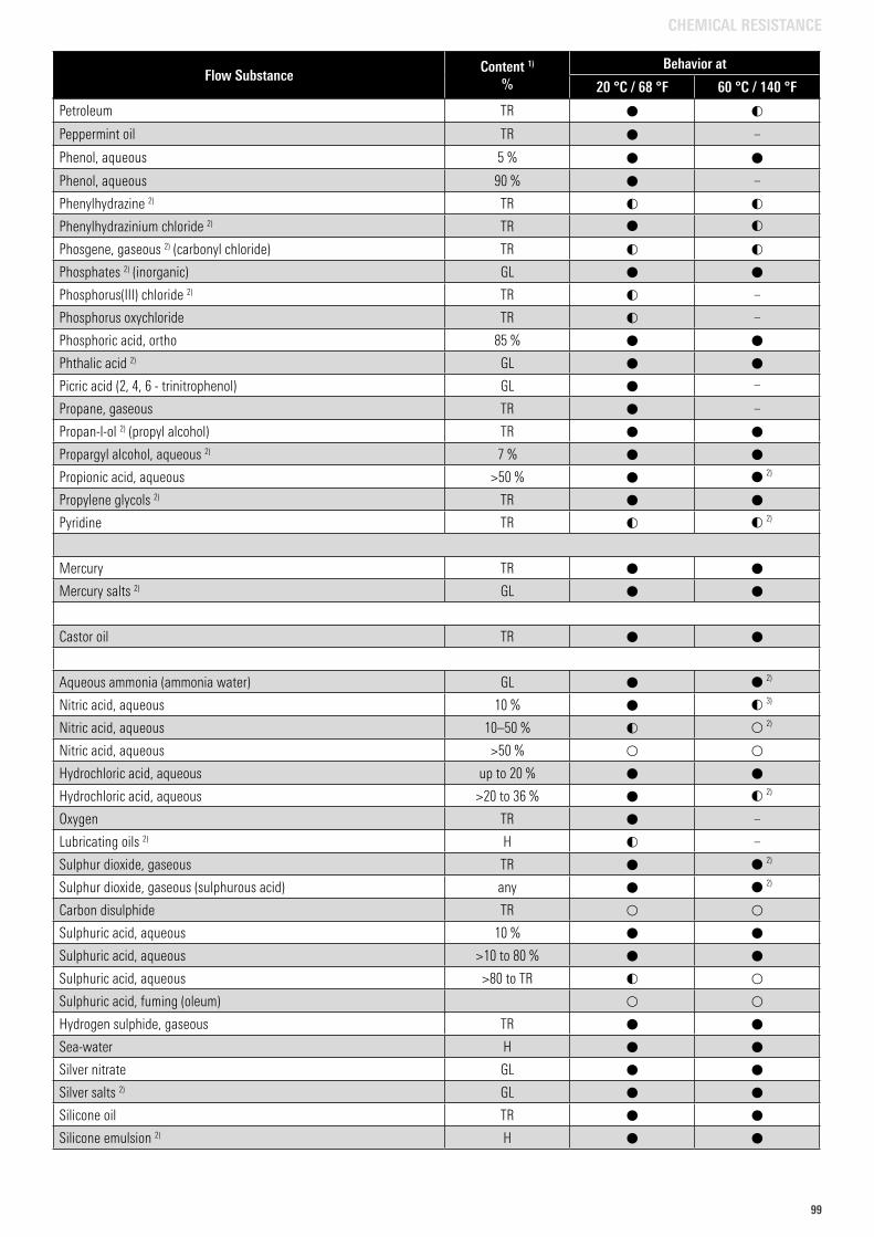
9999
Petroleum TR
Peppermint oil TR –
Phenol, aqueous 5 %
Phenol, aqueous 90 % –
Phenylhydrazine 2) TR
Phenylhydrazinium chloride 2) TR
Phosgene, gaseous 2) (carbonyl chloride) TR
Phosphates 2) (inorganic) GL
Phosphorus(III) chloride 2) TR –
Phosphorus oxychloride TR –
Phosphoric acid, ortho 85 %
Phthalic acid 2) GL
Picric acid (2, 4, 6 - trinitrophenol) GL –
Propane, gaseous TR –
Propan-l-ol 2) (propyl alcohol) TR
Propargyl alcohol, aqueous 2) 7 %
Propionic acid, aqueous >50 % 2)
Propylene glycols 2) TR
Pyridine TR 2)
Mercury TR
Mercury salts 2) GL
Castor oil TR
Aqueous ammonia (ammonia water) GL 2)
Nitric acid, aqueous 10 % 3)
Nitric acid, aqueous 10–50 % 2)
Nitric acid, aqueous >50 %
Hydrochloric acid, aqueous up to 20 %
Hydrochloric acid, aqueous >20 to 36 % 2)
Oxygen TR –
Lubricating oils 2) H –
Sulphur dioxide, gaseous TR 2)
Sulphur dioxide, gaseous (sulphurous acid) any 2)
Carbon disulphide TR
Sulphuric acid, aqueous 10 %
Sulphuric acid, aqueous >10 to 80 %
Sulphuric acid, aqueous >80 to TR
Sulphuric acid, fuming (oleum)
Hydrogen sulphide, gaseous TR
Sea-water H
Silver nitrate GL
Silver salts 2) GL
Silicone oil TR
Silicone emulsion 2) H
Flow SubstanceContent 1)
%Behavior at
20 °C / 68 °F 60 °C / 140 °F
CHEMICAL RESISTANCE
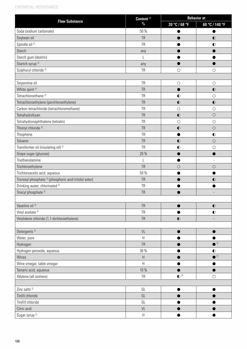
100
Soda (sodium carbonate) 50 %
Soybean oil TR
Spindle oil 2) TR
Starch any
Starch gum (dextrin) L
Startch syrup 2) any
Sulphuryl chloride 2) TR
Terpentine oil TR
White spirit 2) TR
Tetrachloroethane 2) TR
Tetrachloroethylene (perchloroethylene) TR
Carbon tetrachloride (tetrachloromethane) TR
Tetrahydrofuran TR
Tetrahydronaphthalene (tetralin) TR
Thionyl chloride 2) TR
Thiophene TR
Toluene TR
Transformer oil (insulating oil) 2) TR
Grape sugar (glucose) 20 %
Triethanolamine L –
Trichloroethylene TR
Trichloroacetic acid, aqueous 50 %
Tricresyl phosphate 2) (phosphoric acid tritolyl ester) TR
Drinking water, chlorinated 2) TR
Triocyl phosphate 2) TR –
Vaseline oil 2) TR
Vinyl acetate 2) TR
Vinylidene chloride (1,1-dichloroethylene) TR –
Detergents 2) VL
Water, pure H
Hydrogen TR 2)
Hydrogen peroxide, aqueous 30 %
Wines H 2)
Wine vinegar, table vinegar H
Tartaric acid, aqueous 10 %
Xdylene (all isomers) TR 3)
Zinc salts 2) GL
Tin(II) chloride GL
Tin(IV) chloride GL
Citric acid VL
Sugar syrup 2) H
Flow SubstanceContent 1)
%Behavior at
20 °C / 68 °F 60 °C / 140 °F
CHEMICAL RESISTANCE

101101
102
1. Foreword
Thank you very much for making the decision to use a product from aquatherm GmbH, Germany (herein referred to as “aquatherm”). With more than 45 years of experience in the international plastic pipes market, and our trendsetting innovations, we have the expertise needed to offer you engineered piping solutions made in Germany.
The trust placed in the quality of our products has motivated us to offer all pipes and molded, fabricated, machined, and/or assembled parts with a 10-year warranty instead of the standard 2-year warranty required by German law. This extended time covered by warranty is backed by a comprehensive insurance policy from a leading insurance company for our line of business. The warranty period will begin with the date of delivery by aquatherm GmbH, but only comes valid with the successful pressure test, which must be carried out and documented in accordance with the aquatherm specification.
2. Scope of warranty
The aquatherm warranty protects you from financial loss proven to be caused by material defects, manufacturing defects and/or aquatherm’s consulting/engineering services. The warranty coverage shall apply for the following product groups:
• aquatherm green pipe (fusiotherm and aquatherm ISO)• aquatherm blue pipe (climatherm and aquatherm ISO)• aquatherm red pipe (firestop)• aquatherm black system (climasystem)• aquatherm lilac pipe (aquatherm lilac)• aquatherm orange system (aquatherm heating systems)• aquatherm grey pipe (aquatherm SHT system)• assemblies fabricated by aquatherm from these product groups
2.1 What is covered by the aquatherm warranty?
The aquatherm warranty covers three aspects of damages: property damage, financial loss and personal injury.
2.1.1 What is property damage? The damage to or destruction of a tangible item as a result of
a defective product (e.g. classic water damages as a result of a leak). As a result of this, the suitability of the tangible item to fulfill its actual purpose is impaired. The term property damage is used if tangible items are damaged or destroyed. Considerable costs can be incurred as a result of property damage, such as renovation costs, repair costs or replacement costs.
2.1.2 What is meant by financial loss? Financial loss may either be out-of-pocket loss or loss of
business. Out-of-pocket financial loss is for example the costs of removing products and installing replacements after damage. Loss of business is the financial disadvantage suffered by an injured party as a result of a damaging event (e.g. lost income as a result of renovations following property damage).
2.1.3 What is meant by personal injury? If a person suffers physical injury, this is known as personal
injury. For the purposes of this document, the coverage of personal injury means the direct medical costs incurred as a result of the injury.
3. What is not covered?
Costs related to the damages incurred such as a result of:
• Non-compliance with the operating parameters defined and specified by aquatherm as found in aquatherm’s technical documents. In cases of doubt, contact your local aquatherm manufacturer’s rep. Exceptions must be provided for, in writing, by a member of aquatherm’s engineering team.
• Non-compliance with the installation guidelines as set out in the aquatherm Catalogue, with emphasis to the required installation of aquatherm propriety clipping or other compatible with aquatherm piping.
• Non-compliance with respective National Plumbing Standards and Regulations.
• Joints which were not made in accordance with the aquatherm guidelines, including but not limited to: improper fusion technique, use of contaminated materials or tools, use of faulty or unsuitable tools, use of damaged materials or tools, or any connection made by an installer without sound knowlegde of the aquatherm connection techniques and their processes.
• Improperly assembled connections to other pipeline systems and/or components (threads, flanges, stubs, mechanical joints not intended for use with aquatherm PP piping etc.).
• All sealing elements used in the product lines manufactured by aquatherm.
• Tools and accessories sold by aquatherm GmbH are covered for the warranty period by law under the statutory warranty provisions.
• Systems with defective pipeline sections or fittings that were not subjected to the aquatherm pressure test or alternative testing approved by aquatherm prior to start-up.
• Damage to our products caused by incorrect handling after the material has left aquatherm’s possession.
• Damage caused or exacerbated by copper in the water resulting from erosion/corrosion or other degradation of copper components in a domestic hot water recirculating system.
• Time delay, caused by incorrect planning, delivery problems and/or incorrect orders.
• Damage caused by entrained air, cavitation and pressure fluctuations.
Note: This list only includes the most prominent examples. Other circumstances, which compromise the integrity of the products, may also jeopardize the coverage.
EXPLANATORY COMMENTS ON THE AQUATHERM GMBH WARRANTY
WARRANTY
102
103103
1. Foreword
Thank you very much for making the decision to use a product from aquatherm GmbH, Germany (herein referred to as “aquatherm”). With more than 45 years of experience in the international plastic pipes market, and our trendsetting innovations, we have the expertise needed to offer you engineered piping solutions made in Germany.
The trust placed in the quality of our products has motivated us to offer all pipes and molded, fabricated, machined, and/or assembled parts with a 10-year warranty instead of the standard 2-year warranty required by German law. This extended time covered by warranty is backed by a comprehensive insurance policy from a leading insurance company for our line of business. The warranty period will begin with the date of delivery by aquatherm GmbH, but only comes valid with the successful pressure test, which must be carried out and documented in accordance with the aquatherm specification.
2. Scope of warranty
The aquatherm warranty protects you from financial loss proven to be caused by material defects, manufacturing defects and/or aquatherm’s consulting/engineering services. The warranty coverage shall apply for the following product groups:
• aquatherm green pipe (fusiotherm and aquatherm ISO)• aquatherm blue pipe (climatherm and aquatherm ISO)• aquatherm red pipe (firestop)• aquatherm black system (climasystem)• aquatherm lilac pipe (aquatherm lilac)• aquatherm orange system (aquatherm heating systems)• aquatherm grey pipe (aquatherm SHT system)• assemblies fabricated by aquatherm from these product groups
2.1 What is covered by the aquatherm warranty?
The aquatherm warranty covers three aspects of damages: property damage, financial loss and personal injury.
2.1.1 What is property damage? The damage to or destruction of a tangible item as a result of
a defective product (e.g. classic water damages as a result of a leak). As a result of this, the suitability of the tangible item to fulfill its actual purpose is impaired. The term property damage is used if tangible items are damaged or destroyed. Considerable costs can be incurred as a result of property damage, such as renovation costs, repair costs or replacement costs.
2.1.2 What is meant by financial loss? Financial loss may either be out-of-pocket loss or loss of
business. Out-of-pocket financial loss is for example the costs of removing products and installing replacements after damage. Loss of business is the financial disadvantage suffered by an injured party as a result of a damaging event (e.g. lost income as a result of renovations following property damage).
2.1.3 What is meant by personal injury? If a person suffers physical injury, this is known as personal
injury. For the purposes of this document, the coverage of personal injury means the direct medical costs incurred as a result of the injury.
3. What is not covered?
Costs related to the damages incurred such as a result of:
• Non-compliance with the operating parameters defined and specified by aquatherm as found in aquatherm’s technical documents. In cases of doubt, contact your local aquatherm manufacturer’s rep. Exceptions must be provided for, in writing, by a member of aquatherm’s engineering team.
• Non-compliance with the installation guidelines as set out in the aquatherm Catalogue, with emphasis to the required installation of aquatherm propriety clipping or other compatible with aquatherm piping.
• Non-compliance with respective National Plumbing Standards and Regulations.
• Joints which were not made in accordance with the aquatherm guidelines, including but not limited to: improper fusion technique, use of contaminated materials or tools, use of faulty or unsuitable tools, use of damaged materials or tools, or any connection made by an installer without sound knowlegde of the aquatherm connection techniques and their processes.
• Improperly assembled connections to other pipeline systems and/or components (threads, flanges, stubs, mechanical joints not intended for use with aquatherm PP piping etc.).
• All sealing elements used in the product lines manufactured by aquatherm.
• Tools and accessories sold by aquatherm GmbH are covered for the warranty period by law under the statutory warranty provisions.
• Systems with defective pipeline sections or fittings that were not subjected to the aquatherm pressure test or alternative testing approved by aquatherm prior to start-up.
• Damage to our products caused by incorrect handling after the material has left aquatherm’s possession.
• Damage caused or exacerbated by copper in the water resulting from erosion/corrosion or other degradation of copper components in a domestic hot water recirculating system.
• Time delay, caused by incorrect planning, delivery problems and/or incorrect orders.
• Damage caused by entrained air, cavitation and pressure fluctuations.
Note: This list only includes the most prominent examples. Other circumstances, which compromise the integrity of the products, may also jeopardize the coverage.
EXPLANATORY COMMENTS ON THE AQUATHERM GMBH WARRANTY
4. How is the amount of compensation under the aquatherm warranty determined?
In the event of a material failure, samples of the damaged/faulty product are collected by the national aquatherm partner to forward them to aquatherm GmbH for examination and analysis. Working in collaboration with the injured party, aquatherm will identify the cause of the damage, and call in external bodies (test institutes, laboratories, assessors, etc.) as needed. If the damage has been caused by a material and/or manufacturing defect or by aquatherm’s consulting/engineering services, the underwriter shall quantify the compensation claim for damages. All expenditures associated with the damages for this claim must be verified/recorded in detail and in a verifiable format as a required measure.
5. How much is the maximum coverage?
For the first 5 years of the warranty period, property damage, personal injury and financial loss is covered for the sum of €20 million per insurance claim. Total coverage for all claims made in a year is a maximum of €40 million. For years 6-10 of the warranty period, these coverage amounts are €7.5 and €15 million respectively.
6. Why is the coverage stated in Euro?
The insured manufacturer, aquatherm, as well as the insurer, are both based in the EU, so that their agreements are issued in Euros (€). Since exchange rates fluctuate, the exchange rate current on the date of compensation shall apply.
7. What is the channel of communication for notifying claims under warranty and making inquiries about them?
Warranty claims have to be made to aquatherm via the national aquatherm GmbH partners. Information about the progress of the claim will only be released by the aquatherm partner or aquatherm GmbH.
8. Legal note
If a discrepancy or conflict arises between this document and the underlying insurance policy, the latter shall in all cases prevail.
If a discrepancy or conflict arises between this translated document and the German document, the German document shall in all cases prevail.
9. Information about avoiding damage
I) Manufacture under certified quality level As a trusted manufacturer, aquatherm works to a certified
quality standard (ISO 9001); constant internal quality controls are part of the daily routine. In addition to this, all employees are integrated into a quality assurance program. As a result of this, products failing to comply with our high standards are quickly identified and removed from ourproduct range.
II) Preventing damage caused by incorrect handling Our products must be handled conscientiously and carefully
when they are delivered from our production plants. Experience shows that most damage is caused in transit, storage and/or when working on site. At this point we would draw close attention to the fact that correct handling contributes to maintaining the product quality.
III) Work is to be carried out by qualified installers Installation defects are easy to avoid. Our training courses
teach the correct techniques in detail for working with our products. In doing so, particular importance is attached to work being carried out attentively and with care. The work of installers trained by us or our aquatherm partners is much more reliable and carried out much more efficiently.
For a safe connection, we recommend using only aquatherm PP products in a piping system. Mixing with other PP piping systems should be avoided.
June 2020aquatherm GmbH, Biggen 5, 57439 Attendorn, Germany
EXPLANATORY COMMENTS ON THE AQUATHERM GMBH WARRANTY
WARRANTY
103
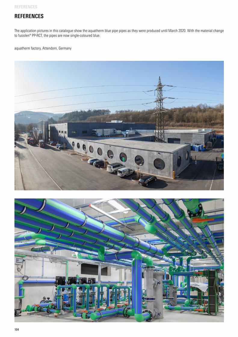
104
REFERENCES
aquatherm factory, Attendorn, Germany
The application pictures in this catalogue show the aquatherm blue pipe pipes as they were produced until March 2020. With the material change to fusiolen® PP-RCT, the pipes are now single-coloured blue.
REFERENCES
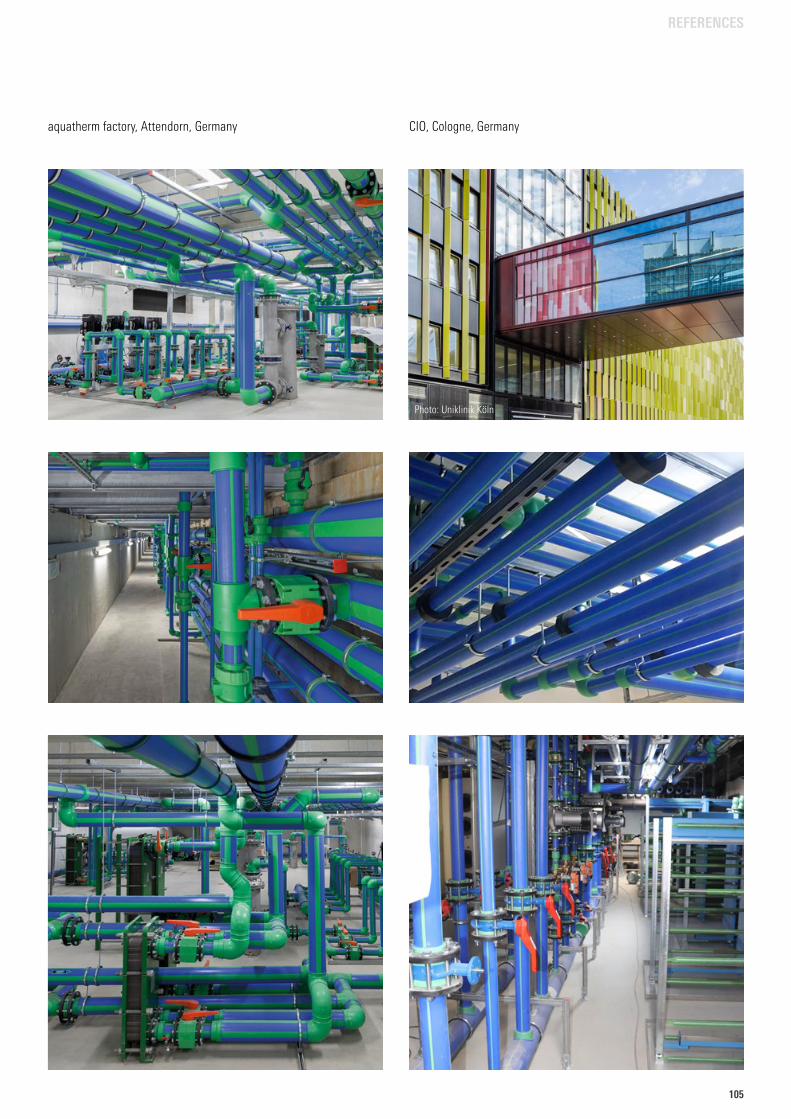
105105
aquatherm factory, Attendorn, Germany CIO, Cologne, Germany
Photo: Uniklinik Köln
REFERENCES
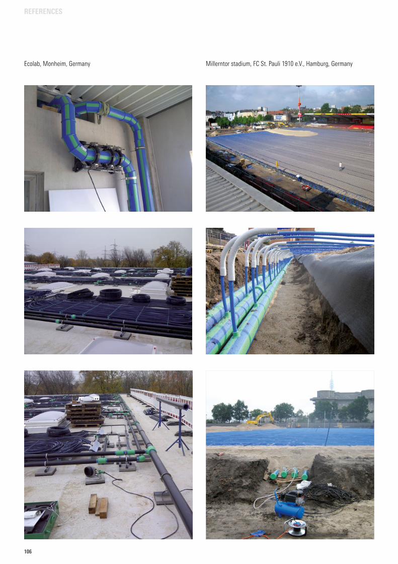
106
Millerntor stadium, FC St. Pauli 1910 e.V., Hamburg, GermanyEcolab, Monheim, Germany
REFERENCES
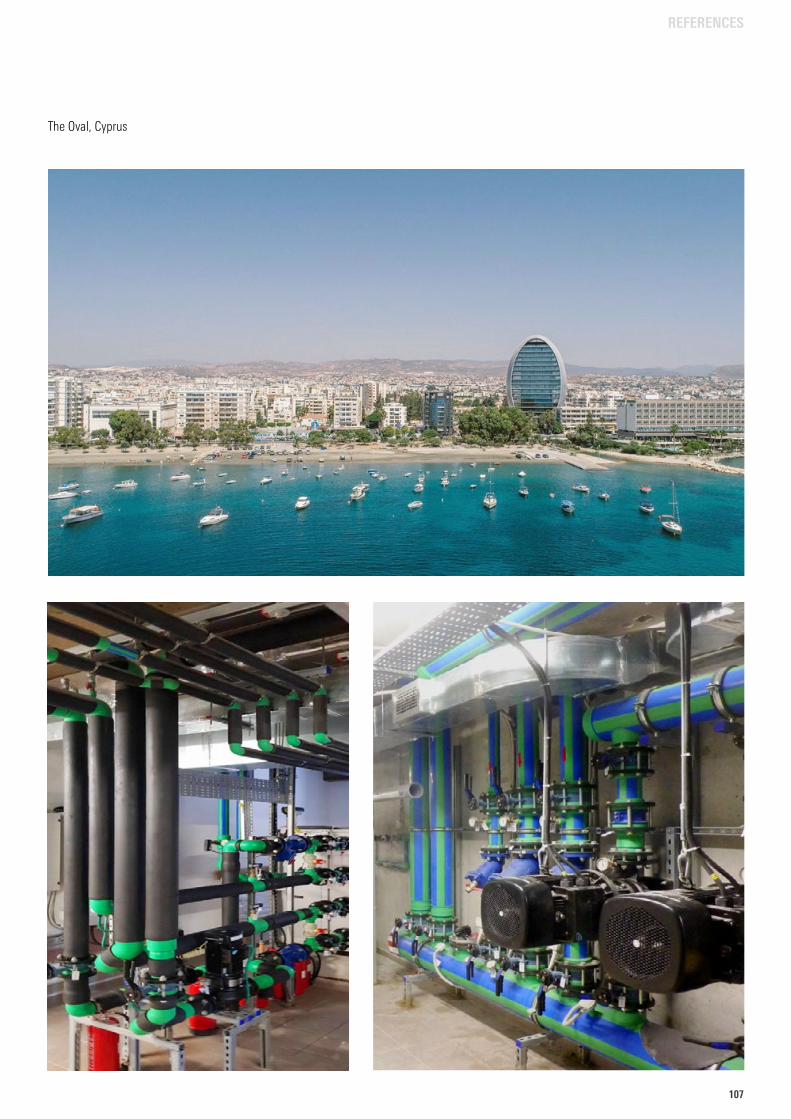
107107
The Oval, Cyprus
REFERENCES
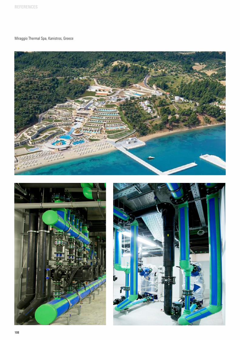
108
Miraggio Thermal Spa, Kanistros, Greece
REFERENCES
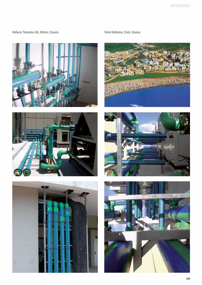
109109
Hellenic Telecoms AG, Athens, Greece Hotel Kalimera, Crete, Greece
REFERENCES
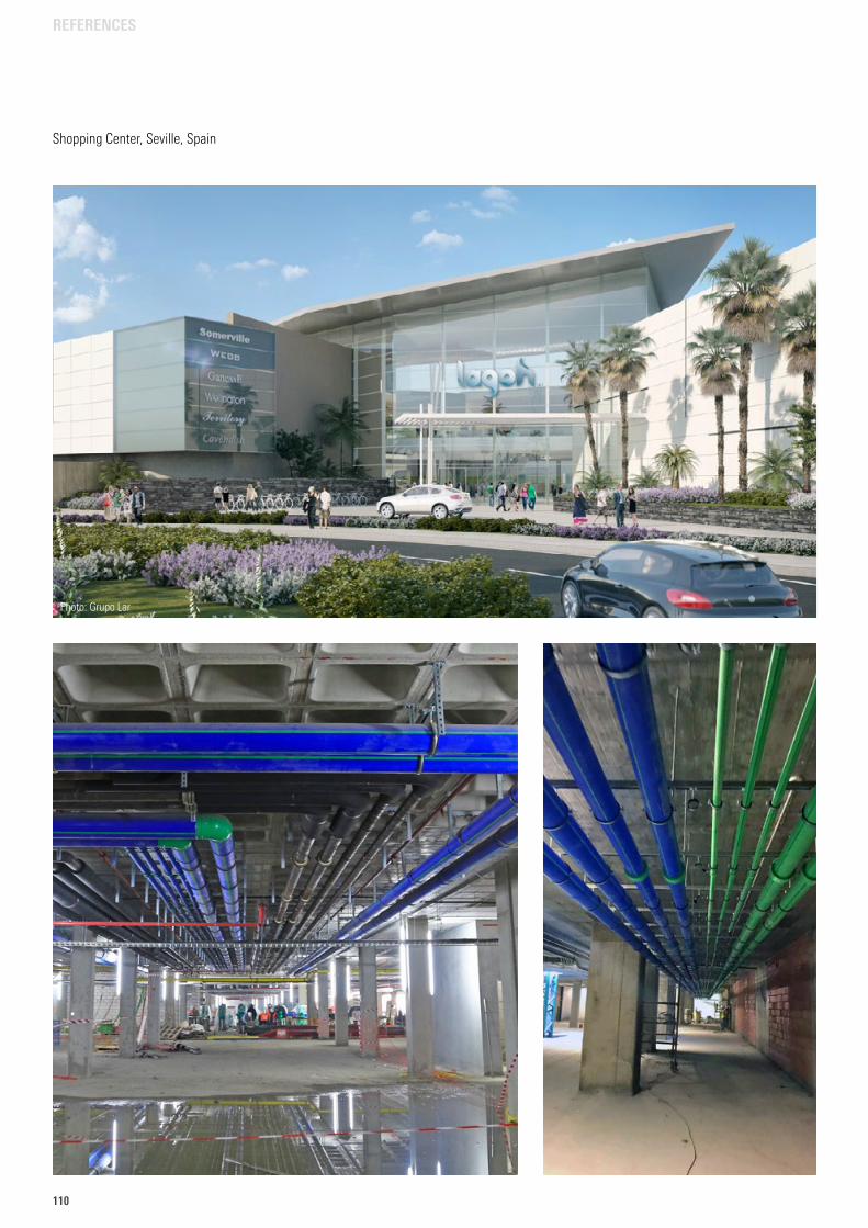
110
Shopping Center, Seville, Spain
Photo: Grupo Lar
REFERENCES
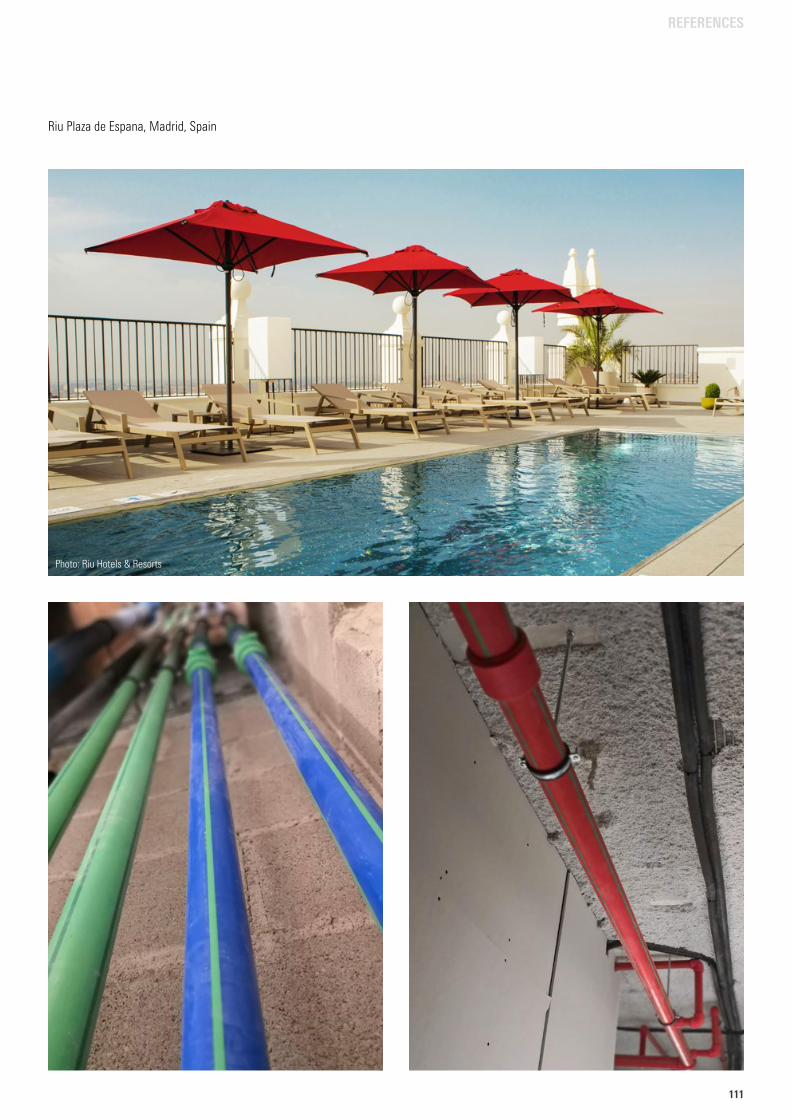
111111
Riu Plaza de Espana, Madrid, Spain
Photo: Riu Hotels & Resorts
REFERENCES
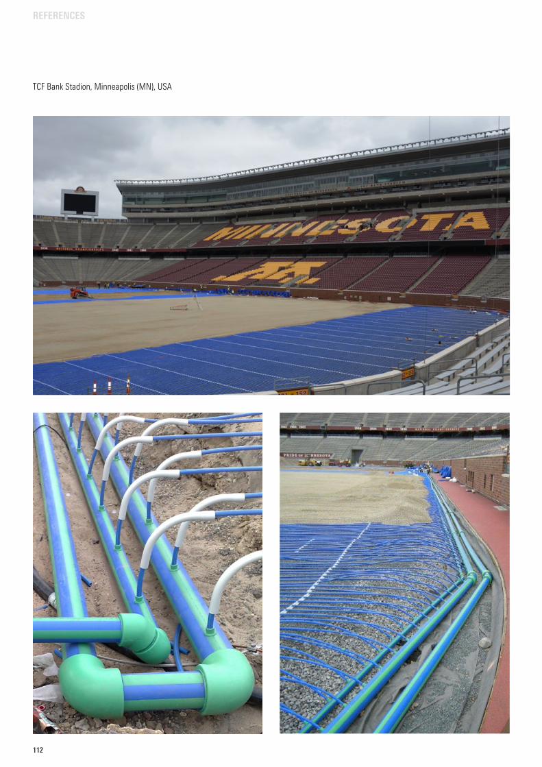
112
TCF Bank Stadion, Minneapolis (MN), USA
REFERENCES
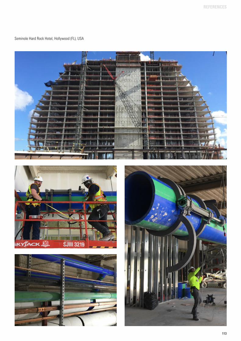
113113
Seminole Hard Rock Hotel, Hollywood (FL), USA
REFERENCES
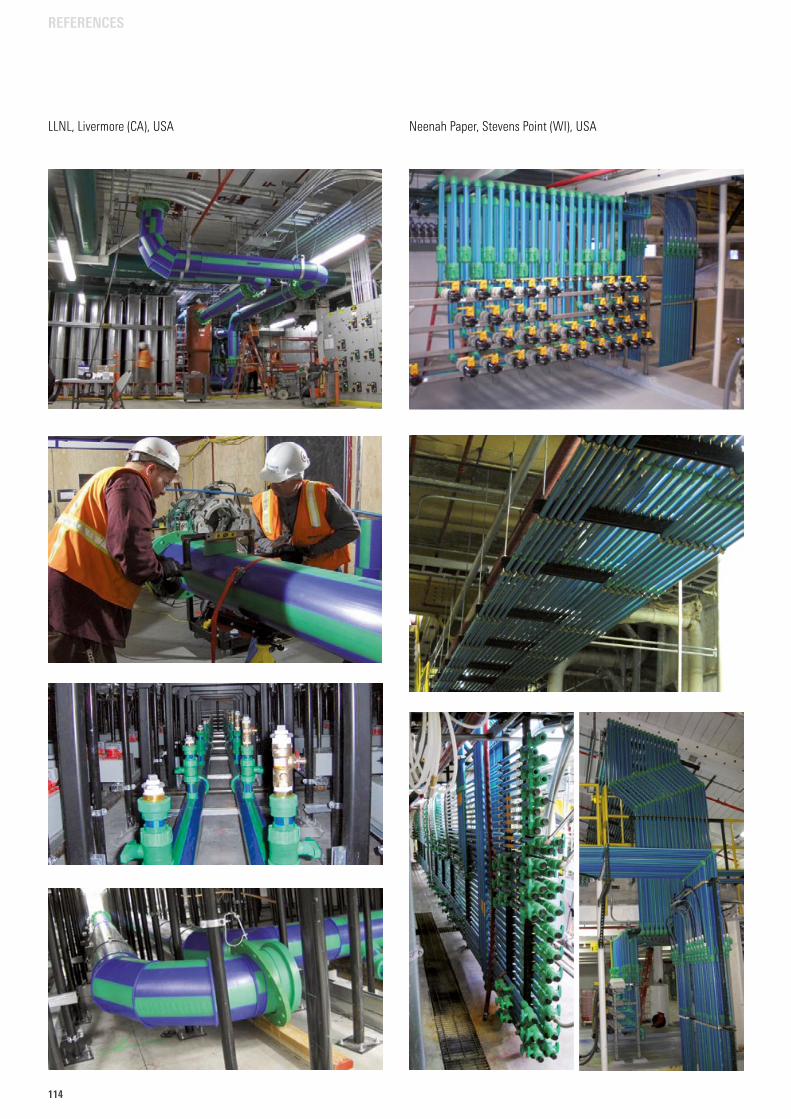
114
LLNL, Livermore (CA), USA Neenah Paper, Stevens Point (WI), USA
REFERENCES
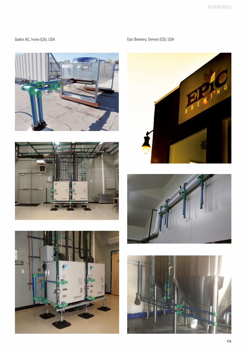
115115
Epic Brewery, Denver (CO), USADaikin AC, Irvine (CA), USA
REFERENCES
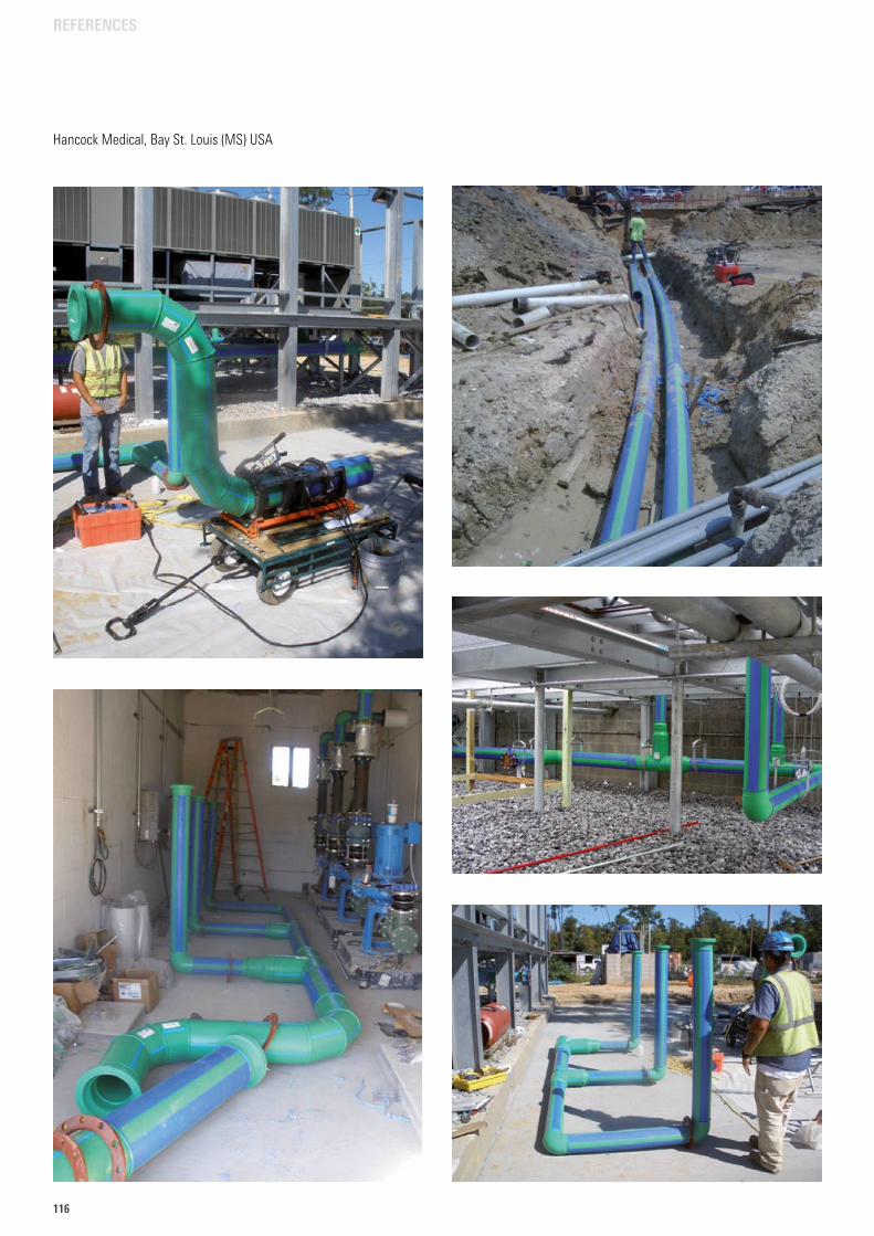
116
Hancock Medical, Bay St. Louis (MS) USA
REFERENCES
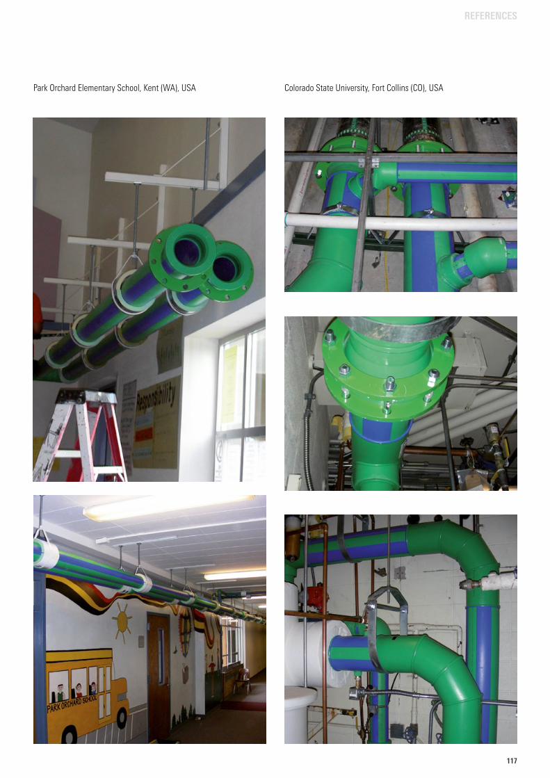
117117
Park Orchard Elementary School, Kent (WA), USA Colorado State University, Fort Collins (CO), USA
REFERENCES
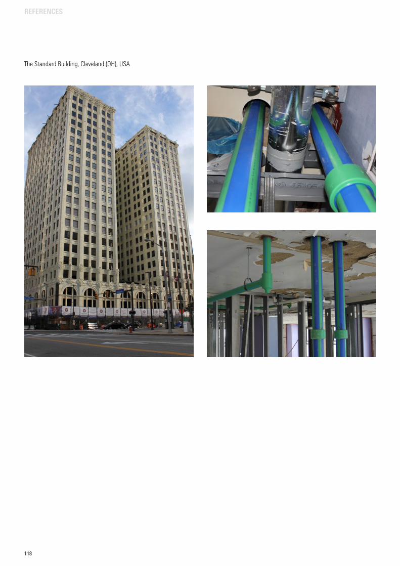
118
REFERENCES
The Standard Building, Cleveland (OH), USA
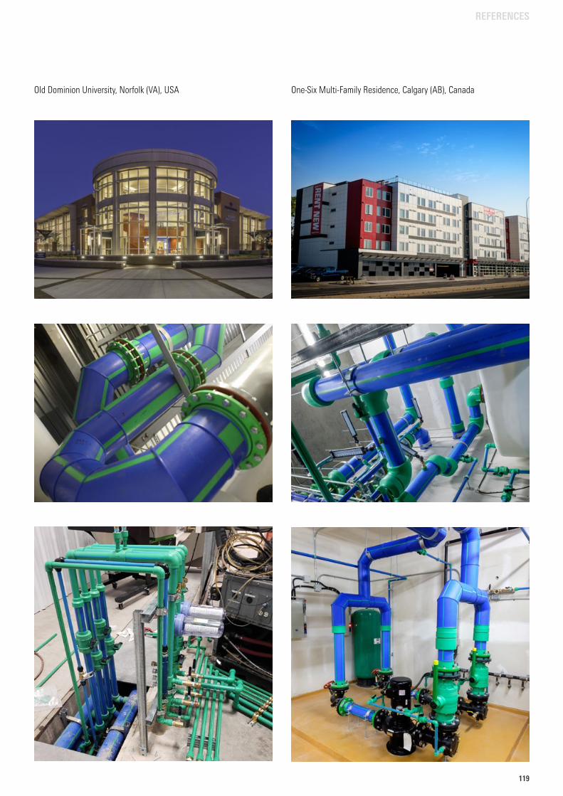
119119
Old Dominion University, Norfolk (VA), USA One-Six Multi-Family Residence, Calgary (AB), Canada
REFERENCES
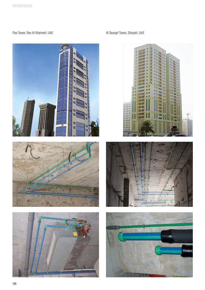
120
REFERENCES
Al Sayegh Tower, Sharjah, UAEFlex Tower, Ras Al Khaimah, UAE

121121
TRANSPORT AND STORAGE
TRANSPORT AND STORAGE
aquatherm polypropylene pipes may be stored outside at any temperature. A solid base for the pipe is very important to avoid a deformation of the pipes while in transport and storage.
At temperatures below 0 °C it is possible to damage the pipes through strong impacts. The material has to be treated with caution at low temperatures.
In spite of its high resistance aquatherm pipes should be treated with care.
UV-radiation has effects on all high polymer plastics. Do not store permanently outdoor.
The maximum permissible storage time outdoors is 6 months.
2623
SDR 6 • 16 x 2,7 mm Art.-No. 0610006 100 m • Made in Germanypacking unit: 30
mm
30 m
m30
mm
90 m
m
90 mm 113 mm 330 mm 161510 16
2623
SDR 6 • 16 x 2,7 mm Art.-No. 0610006 100 m • Made in Germanypacking unit: 30
mm
30 m
m30
mm
90 m
m
90 mm 113 mm 330 mm 161510 16
2623
SDR 6 • 16 x 2,7 mm Art.-No. 0610006 100 m • Made in Germanypacking unit: 30
mm
30 m
m30
mm
90 m
m
90 mm 113 mm 330 mm 161510 16
2623
SDR 6 • 16 x 2,7 mm Art.-No. 0610006 100 m • Made in Germanypacking unit: 30
mm
30 m
m30
mm
90 m
m
90 mm 113 mm 330 mm 161510 16
2623
SDR 6 • 16 x 2,7 mm Art.-No. 0610006 100 m • Made in Germanypacking unit: 30
mm
30 m
m30
mm
90 m
m90 mm 113 mm 330 mm 161510 16

122
aquatherm blue pipe pipes
aquatherm prefabrication
Fastening material
Fittings
Weld-in saddles
Weld-on saddles
Flange adapter
Threaded connections & accessoires
Transition piece
Screwed connections & counter parts
Distributors
Valves & accessoires
Cutting tools & welding devices
Welding machines & welding jig
Butt welding machines & electrofusion device
Peeling tools
Saddle welding tools
Drills & saddle peeling tool
Hot tapping tool & accessoires
TABLE OF CONTENTS
PRODUCT LIST
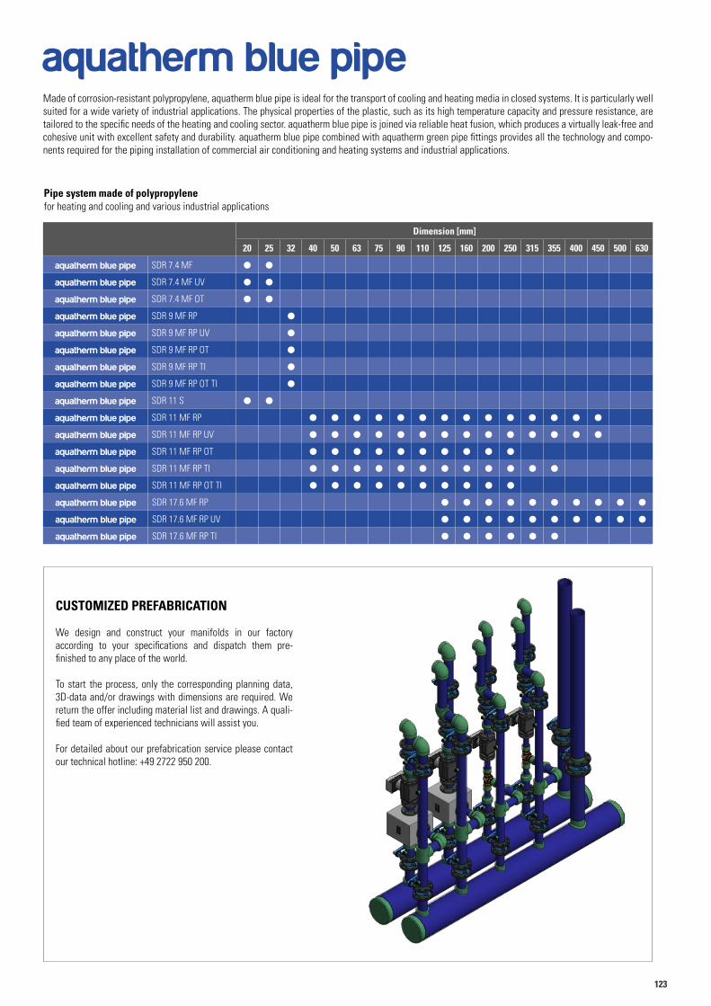
123123
Pipe system made of polypropylene for heating and cooling and various industrial applications
aquatherm blue pipeMade of corrosion-resistant polypropylene, aquatherm blue pipe is ideal for the transport of cooling and heating media in closed systems. It is particularly well suited for a wide variety of industrial applications. The physical properties of the plastic, such as its high temperature capacity and pressure resistance, are tailored to the specific needs of the heating and cooling sector. aquatherm blue pipe is joined via reliable heat fusion, which produces a virtually leak-free and cohesive unit with excellent safety and durability. aquatherm blue pipe combined with aquatherm green pipe fittings provides all the technology and compo-nents required for the piping installation of commercial air conditioning and heating systems and industrial applications.
CUSTOMIZED PREFABRICATION
We design and construct your manifolds in our factory according to your specifications and dispatch them pre- finished to any place of the world.
To start the process, only the corresponding planning data, 3D-data and/or drawings with dimensions are required. We return the offer including material list and drawings. A quali-fied team of experienced technicians will assist you.
For detailed about our prefabrication service please contact our technical hotline: +49 2722 950 200.
Dimension [mm]
20 25 32 40 50 63 75 90 110 125 160 200 250 315 355 400 450 500 630
aquatherm blue pipe SDR 7.4 MF l l
aquatherm blue pipe SDR 7.4 MF UV l l
aquatherm blue pipe SDR 7.4 MF OT l l
aquatherm blue pipe SDR 9 MF RP l
aquatherm blue pipe SDR 9 MF RP UV l
aquatherm blue pipe SDR 9 MF RP OT l
aquatherm blue pipe SDR 9 MF RP TI l
aquatherm blue pipe SDR 9 MF RP OT TI l
aquatherm blue pipe SDR 11 S l l
aquatherm blue pipe SDR 11 MF RP l l l l l l l l l l l l l l
aquatherm blue pipe SDR 11 MF RP UV l l l l l l l l l l l l l l
aquatherm blue pipe SDR 11 MF RP OT l l l l l l l l l l
aquatherm blue pipe SDR 11 MF RP TI l l l l l l l l l l l l
aquatherm blue pipe SDR 11 MF RP OT TI l l l l l l l l l l
aquatherm blue pipe SDR 17.6 MF RP l l l l l l l l l l
aquatherm blue pipe SDR 17.6 MF RP UV l l l l l l l l l l
aquatherm blue pipe SDR 17.6 MF RP TI l l l l l l
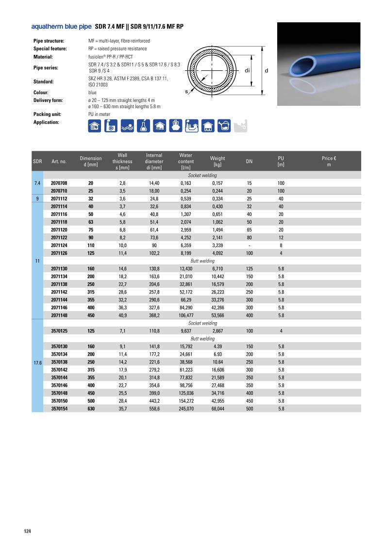
124
s
di d
aquatherm blue pipe SDR 7.4 MF || SDR 9/11/17.6 MF RP
Pipe structure: MF = multi-layer, fibre-reinforced
Special feature: RP = raised pressure resistance
Material: fusiolen® PP-R / PP-RCT
Pipe series: SDR 7.4 / S 3.2 & SDR11 / S 5 & SDR 17.6 / S 8.3 SDR 9 /S 4
Standard: SKZ HR 3.28, ASTM F 2389, CSA B 137.11, ISO 21003
Colour: blue
Delivery form: ø 20 – 125 mm straight lengths 4 mø 160 – 630 mm straight lengths 5.8 m
Packing unit: PU in meter
Application:+C°
SDR Art. no. Dimensiond [mm]
Wall thickness
s [mm]
Internal diameterdi [mm]
Water content
[l/m]
Weight [kg] DN PU
[m]Price €
m
7.4Socket welding
2070708 20 2,8 14,40 0,163 0,157 15 1002070710 25 3,5 18,00 0,254 0,244 20 100
9 2071112 32 3,6 24,8 0,539 0,334 25 40
11
2071114 40 3,7 32,6 0,834 0,430 32 402071116 50 4,6 40,8 1,307 0,651 40 202071118 63 5,8 51,4 2,074 1,062 50 202071120 75 6,8 61,4 2,959 1,494 65 202071122 90 8,2 73,6 4,252 2,141 80 122071124 110 10,0 90 6,359 3,239 - 82071126 125 11,4 102,2 8,199 4,092 100 4
Butt welding
2071130 160 14,6 130,8 13,430 6,710 125 5.82071134 200 18,2 163,6 21,010 10,442 150 5.82071138 250 22,7 204,6 32,861 16,579 200 5.82071142 315 28,6 257,8 52,172 26,223 250 5.82071144 355 32,2 290,6 66,29 33,276 300 5.82071146 400 36,3 327,6 84,290 42,266 300 5.82071148 450 40,9 368,2 106,477 53,566 400 5.8
17.6
Socket welding
3570125 125 7,1 110,8 9,637 2,667 100 4Butt welding
3570130 160 9,1 141,8 15,792 4.39 150 5.83570134 200 11,4 177,2 24,661 6.93 200 5.83570138 250 14,2 221,6 38,568 10.64 250 5.83570142 315 17,9 279,2 61,223 16,606 300 5.83570144 355 20,1 314,8 77,832 21,589 350 5.83570146 400 22,7 354,6 98,756 27,468 350 5.83570148 450 25,5 399,0 125,036 34,716 400 5.83570150 500 28,4 443,2 154,272 42,955 450 5.83570154 630 35,7 558,6 245,070 68,044 500 5.8
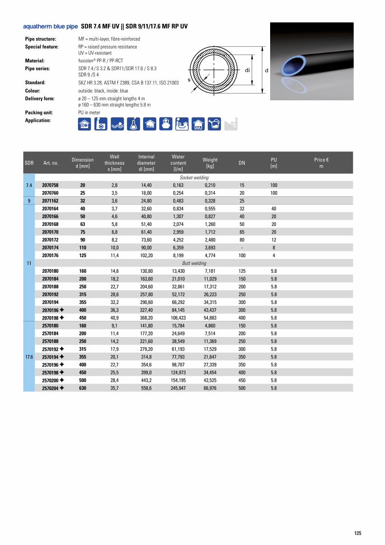
125125
Pipe structure: MF = multi-layer, fibre-reinforced
Special feature: RP = raised pressure resistance UV = UV-resistant
Material: fusiolen® PP-R / PP-RCT
Pipe series: SDR 7.4 / S 3.2 & SDR11/SDR 17.6 / S 8.3 SDR 9 /S 4
Standard: SKZ HR 3.28, ASTM F 2389, CSA B 137.11, ISO 21003
Colour: outside: black, inside: blue
Delivery form: ø 20 – 125 mm straight lengths 4 mø 160 – 630 mm straight lengths 5.8 m
Packing unit: PU in meter
Application:
aquatherm blue pipe SDR 7.4 MF UV || SDR 9/11/17.6 MF RP UV
s
di d
SDR Art. no. Dimensiond [mm]
Wall thickness
s [mm]
Internal diameterdi [mm]
Water content
[l/m]
Weight [kg] DN PU
[m]Price €
m
7.4Socket welding
2070758 20 2,8 14,40 0,163 0,210 15 1002070760 25 3,5 18,00 0,254 0,314 20 100
9 2071162 32 3,6 24,80 0,483 0,328 25
11
2070164 40 3,7 32,60 0,834 0,555 32 402070166 50 4,6 40,80 1,307 0,827 40 202070168 63 5,8 51,40 2,074 1,260 50 202070170 75 6,8 61,40 2,959 1,712 65 202070172 90 8,2 73,60 4,252 2,480 80 122070174 110 10,0 90,00 6,359 3,693 - 82070176 125 11,4 102,20 8,199 4,774 100 4
Butt welding
2070180 160 14,6 130,80 13,430 7,181 125 5.82070184 200 18,2 163,60 21,010 11,029 150 5.82070188 250 22,7 204,60 32,861 17,312 200 5.82070192 315 28,6 257,80 52,172 26,223 250 5.82070194 355 32,2 290,60 66,292 34,315 300 5.8
2070196 400 36,3 327,40 84,145 43,437 300 5.82070198 450 40,9 368,20 106,423 54,883 400 5.8
17.6
2570180 160 9,1 141,80 15,784 4,860 150 5.82570184 200 11,4 177,20 24,649 7,514 200 5.82570188 250 14,2 221,60 38,549 11,369 250 5.8
2570192 315 17,9 279,20 61,193 17,529 300 5.8
2570194 355 20,1 314,8 77,793 21,647 350 5.8
2570196 400 22,7 354,6 98,707 27,339 350 5.8
2570198 450 25,5 399,0 124,973 34,454 400 5.8
2570200 500 28,4 443,2 154,195 42,525 450 5.8
2570204 630 35,7 558,6 245,947 66,976 500 5.8
+C°
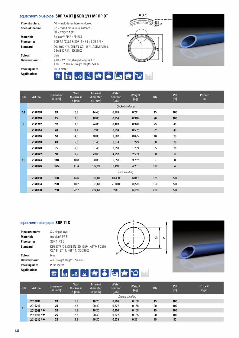
126
Pipe structure: MF = multi-layer, fibre-reinforced
Special feature: RP = raised pressure resistance OT = oxygen-tight
Material: fusiolen® PP-R / PP-RCT
Pipe series: SDR 7.4 / S 3.2 & SDR11 / S 5 / SDR 9 /S 4
Standard: DIN 8077 / 78, DIN EN ISO 15874, ASTM F 2389, CSA B 137.11, ISO 21003
Colour: blue
Delivery form: ø 20 – 125 mm straight lengths 4 mø 160 – 250 mm straight lengths 5,8 m
Packing unit: PU in meter
Application:
Pipe structure: S = single-layer
Material: fusiolen® PP-R
Pipe series: SDR 11/ S 5
Standard: DIN 8077 / 78, DIN EN ISO 15874, ASTM F 2389, CSA B 137.11, NSF 14, ISO 21003
Colour: blue
Delivery form: 4 m straight lengths, *in coils
Packing unit: PU in meter
Application:
aquatherm blue pipe SDR 7.4 OT || SDR 9/11 MF RP OT
SDR Art. no. Dimensiond [mm]
Wall thickness
s [mm]
Internal diameterd1 [mm]
Water content
[l/m]
Weight [kg] DN PU
[m]Price €
m
7.4
Socket welding
2170708 20 2,8 14,40 0,163 0,211 15 100
2170710 25 3,5 18,00 0,254 0,316 20 100
9 2171712 32 3,6 24,80 0,483 0,328 25 40
11
2170114 40 3,7 32,60 0,834 0,562 32 40
2170116 50 4,6 40,80 1,307 0,695 40 20
2170118 63 5,8 51,40 2,074 1,279 50 20
2170120 75 6,8 61,40 2,959 1,739 65 20
2170122 90 8,2 73,60 4,252 2,533 80 12
2170124 110 10,0 90,00 6,359 3,752 - 8
2170126 125 11,4 102,20 8,199 4,201 100 4
Butt welding
2170130 160 14,6 130,80 13,430 6,847 125 5.8
2170134 200 18,2 163,60 21,010 10,520 150 5.8
2170138 250 22,7 204,60 32,861 16,226 200 5.8
+C°
SDR Art. no. Dimensiond [mm]
Wall thickness
s [mm]
Internal diameterdi [mm]
Water content
[l/m]
Weight [kg] DN PU
[m]Price €m/pc
11
Socket welding2010208 20 1,9 16,20 0,206 0,108 15 1002010210 25 2,3 20,40 0,327 0,165 20 1002010308 * 20 1,9 16,20 0,206 0,108 15 1002010310 * 25 2,3 20,40 0,327 0,165 20 1002010312 * 32 2,9 26,20 0,539 0,261 25 50
aquatherm blue pipe SDR 11 S
s
di d
+C°
s
B (2:1)
B
d1 d
OXYGEN-BARRIERPP-R
PP-RPP-R-GF
s
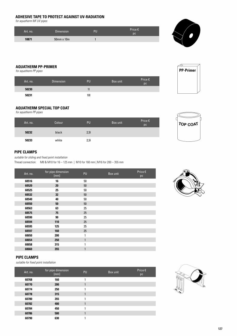
127127
PIPE CLAMPSsuitable for sliding and fixed point installationThread connection: M8 & M10 for 16 – 125 mm | M10 for 160 mm | M16 for 200 – 355 mm
Art. no. for pipe dimension [mm] PU Box unit Price €
pc
60516 16 5060520 20 5060525 25 5060532 32 5060540 40 5060550 50 5060563 63 2560575 75 2560590 90 2560594 110 2560595 125 2560597 160 2560650 200 160654 250 160658 315 160660 355 1
60520
Art. no. for pipe dimension [mm] PU Box unit Price €
pc
60768 160 160770 200 160774 250 160778 315 160780 355 160782 400 160784 450 160786 500 160790 630 1
PIPE CLAMPSsuitable for fixed point installation
AQUATHERM PP-PRIMERfor aquatherm PP pipes
Art. no. Dimension PU Box unit Price €pc
50230 1l
50231 10l
AQUATHERM SPECIAL TOP COAT for aquatherm PP-pipes
Art. no. Colour PU Box unit Price €pc
50232 black 2,5l
50233 white 2,5l
PP-Primer
ADHESIVE TAPE TO PROTECT AGAINST UV-RADIATION for aquatherm MF UV pipes
Art. no. Dimension PU Price €pc
10871 50mm x 10m 1
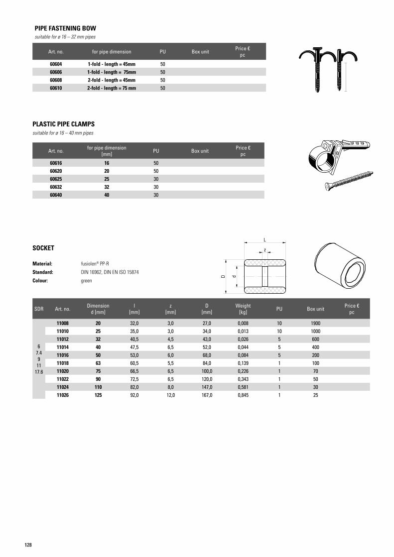
128
Art. no. for pipe dimension PU Box unit Price €pc
60604 1-fold - length = 45mm 5060606 1-fold - length = 75mm 5060608 2-fold - length = 45mm 5060610 2-fold - length = 75 mm 50
PIPE FASTENING BOWsuitable for ø 16 – 32 mm pipes
SDR Art. no. Dimensiond [mm]
l [mm]
z [mm]
D [mm]
Weight [kg] PU Box unit Price €
pc
67.49
1117.6
11008 20 32,0 3,0 27,0 0,008 10 190011010 25 35,0 3,0 34,0 0,013 10 100011012 32 40,5 4,5 43,0 0,026 5 60011014 40 47,5 6,5 52,0 0,044 5 40011016 50 53,0 6,0 68,0 0,084 5 20011018 63 60,5 5,5 84,0 0,139 1 10011020 75 66,5 6,5 100,0 0,226 1 7011022 90 72,5 6,5 120,0 0,343 1 5011024 110 82,0 8,0 147,0 0,581 1 3011026 125 92,0 12,0 167,0 0,845 1 25
SOCKET
Material: fusiolen® PP-R
Standard: DIN 16962, DIN EN ISO 15874
Colour: green
PLASTIC PIPE CLAMPSsuitable for ø 16 – 40 mm pipes
Art. no. for pipe dimension [mm] PU Box unit Price €
pc
60616 16 5060620 20 5060625 25 3060632 32 3060640 40 30
z
dD
Art.N. 11006Artikelliste 2015Seite 18
L
z
dD
Art.N. 11006Artikelliste 2015Seite 18
L
60616
a
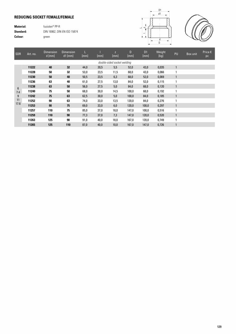
129129
REDUCING SOCKET FEMALE/FEMALE
Material: fusiolen® PP-R
Standard: DIN 16962, DIN EN ISO 15874
Colour: green
SDR Art. no. Dimensiond [mm]
Dimensiond1 [mm]
L [mm]
l [mm]
z [mm]
D [mm]
D1 [mm]
Weight [kg] PU Box unit Price €
pc
double-sided socket welding
67.49
1117.6
11222 40 32 44,0 20,5 5,5 52,0 43,0 0,035 111228 50 32 53,0 23,5 11,5 68,0 43,0 0,066 111230 50 40 50,5 23,5 6,3 68,0 52,0 0,069 111236 63 40 61,0 27,5 13,0 84,0 52,0 0,115 111238 63 50 56,0 27,5 5,0 84,0 68,0 0,120 111240 75 50 68,0 30,0 14,5 100,0 68,0 0,192 111242 75 63 62,5 30,0 5,0 100,0 84,0 0,185 111252 90 63 74,0 33,0 13,5 120,0 84,0 0,276 111253 90 75 69,0 33,0 6,0 120,0 100,0 0,297 111257 110 75 85,0 37,0 18,0 147,0 100,0 0,516 111259 110 90 77,3 37,0 7,3 147,0 120,0 0,520 111263 125 90 91,0 40,0 18,0 167,0 120,0 0,749 111265 125 110 87,0 40,0 10,0 167,0 147,0 0,726 1
Art.N. 11222Artikelliste 2015Seite 18
d1D1
dD
zl
L
Art.N. 11222Artikelliste 2015Seite 18
d1D1
dD
zl
L
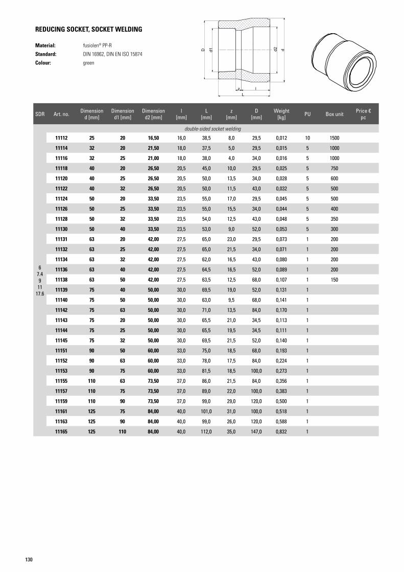
130
REDUCING SOCKET, SOCKET WELDING
Material: fusiolen® PP-R
Standard: DIN 16962, DIN EN ISO 15874
Colour: green
SDR Art. no. Dimensiond [mm]
Dimensiond1 [mm]
Dimensiond2 [mm]
l [mm]
L [mm]
z [mm]
D [mm]
Weight [kg] PU Box unit Price €
pc
67.49
1117.6
double-sided socket welding
11112 25 20 16,50 16,0 38,5 8,0 29,5 0,012 10 1500
11114 32 20 21,50 18,0 37,5 5,0 29,5 0,015 5 1000
11116 32 25 21,00 18,0 38,0 4,0 34,0 0,016 5 1000
11118 40 20 26,50 20,5 45,0 10,0 29,5 0,025 5 750
11120 40 25 26,50 20,5 50,0 13,5 34,0 0,028 5 600
11122 40 32 26,50 20,5 50,0 11,5 43,0 0,032 5 500
11124 50 20 33,50 23,5 55,0 17,0 29,5 0,045 5 500
11126 50 25 33,50 23,5 55,0 15,5 34,0 0,044 5 400
11128 50 32 33,50 23,5 54,0 12,5 43,0 0,048 5 350
11130 50 40 33,50 23,5 53,0 9,0 52,0 0,053 5 300
11131 63 20 42,00 27,5 65,0 23,0 29,5 0,073 1 200
11132 63 25 42,00 27,5 65,0 21,5 34,0 0,071 1 200
11134 63 32 42,00 27,5 62,0 16,5 43,0 0,080 1 200
11136 63 40 42,00 27,5 64,5 16,5 52,0 0,089 1 200
11138 63 50 42,00 27,5 63,5 12,5 68,0 0,107 1 150
11139 75 40 50,00 30,0 69,5 19,0 52,0 0,131 1
11140 75 50 50,00 30,0 63,0 9,5 68,0 0,141 1
11142 75 63 50,00 30,0 71,0 13,5 84,0 0,170 1
11143 75 20 50,00 30,0 65,5 21,0 34,5 0,113 1
11144 75 25 50,00 30,0 65,5 19,5 34,5 0,111 1
11145 75 32 50,00 30,0 69,5 21,5 52,0 0,140 1
11151 90 50 60,00 33,0 75,0 18,5 68,0 0,193 1
11152 90 63 60,00 33,0 78,0 17,5 84,0 0,224 1
11153 90 75 60,00 33,0 81,5 18,5 100,0 0,273 1
11155 110 63 73,50 37,0 86,0 21,5 84,0 0,356 1
11157 110 75 73,50 37,0 89,0 22,0 100,0 0,383 1
11159 110 90 73,50 37,0 99,0 29,0 120,0 0,500 1
11161 125 75 84,00 40,0 101,0 31,0 100,0 0,518 1
11163 125 90 84,00 40,0 99,0 26,0 120,0 0,588 1
11165 125 110 84,00 40,0 112,0 35,0 147,0 0,832 1
Art.N. 11114Artikelliste 2015Seite 19
d1D
zl
L
d
aaqq
uuaatthh
eerrmm
GGmm
bbHH
- B
igg
en 5
- 5
7439
Att
end
orn
Index Änderungen
Freigabe:
Maßstab:Allgemeintol. nach DIN ISO 2768-c
Blatt-Nr.:
Artikelnummer :
Stück (Menge):
Kontrolliert:
Gezeichnet:
Benennung:
Revision:
Datum Name
Weitergabe sowie Vervielfältigung dieses Dokuments,Verwertung und Mitteilung seines Inhalts sind verboten, soweit nicht ausdrücklich gestattet. Zuwiederhand-lungen verpflichten zu Schadenersatz. Alle Rechte für den Fall der Patent-, Ge-brauchsmuster oder Geschmacksmuster vorbehalten.
Position :
Datum: Name:
ab
cd
e
f
gh
Gewicht:
Material (Werkstoff):
01.07.2013
01.07.2013
09.12.2019
Menzebach
Tusche
1 : 1 339,8 g - -
--PP
Red.-Stück
110/75
0011109-0011165W
aaquatherm
state of the pipe
Maß D2 hinzu, 09.12.2019 Hunold
l
d2 d
Lz
D d1
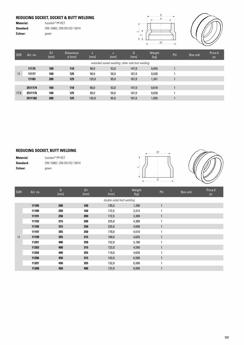
131131
REDUCING SOCKET, SOCKET & BUTT WELDINGMaterial: fusiolen® PP-RCT
Standard: DIN 16962, DIN EN ISO 15874
Colour: green
REDUCING SOCKET, BUTT WELDING
Material: fusiolen® PP-RCT
Standard: DIN 16962, DIN EN ISO 15874
Colour: green
Art.N. 11185Artikelliste 2015Seite 20
D1
D
L
Art.N. 11185Artikelliste 2015Seite 20
D1
D
L
SDR Art. no. D1 [mm]
Dimensiond [mm]
L [mm]
z [mm]
D [mm]
Weight [kg] PU Box unit Price €
pc
onesided socket welding, other side butt welding
11
11175 160 110 90,0 53,0 147,0 0,655 1
11177 160 125 90,0 50,0 167,0 0,636 1
11183 200 125 135,0 95,0 167,0 1,341 1
17.6
2511174 160 110 90,0 53,0 147,0 0,618 1
2511176 160 125 90,0 50,0 167,0 0,628 1
2511182 200 125 135,0 95,0 167,0 1,055 1
SDR Art. no. D [mm]
D1 [mm]
L [mm]
Weight [kg] PU Box unit Price €
pc
double-sided butt welding
11
11185 200 160 135,0 1,206 1
11189 250 160 172,5 2,313 1
11191 250 200 172,5 2,389 1
11193 315 200 225,0 4,389 1
11195 315 250 225,0 4,690 1
11197 355 250 170,0 4,510 1
11199 355 315 160,0 4,635 1
11201 400 250 152,0 5,160 1
11203 400 315 122,0 4,550 1
11204 400 355 110,0 4,620 1
11206 450 315 142,0 6,500 1
11207 450 355 132,0 6,500 1
11208 450 400 122,0 6,000 1
Art.N. 11175Artikelliste 2015Seite 20
zL
dD
D1
Art.N. 11175Artikelliste 2015Seite 20
zL
dD
D1
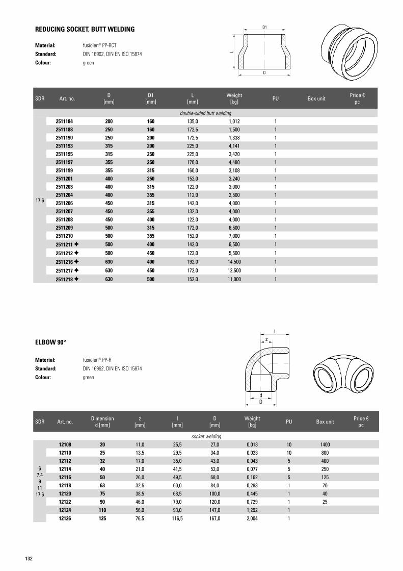
132
REDUCING SOCKET, BUTT WELDING
Material: fusiolen® PP-RCT
Standard: DIN 16962, DIN EN ISO 15874
Colour: green
ELBOW 90°
Material: fusiolen® PP-R
Standard: DIN 16962, DIN EN ISO 15874
Colour: green
Art.N. 12106Artikelliste 2015Seite 21
dD
zl
Art.N. 12106Artikelliste 2015Seite 21
dD
zl
Art.N. 11185Artikelliste 2015Seite 20
D1
D
L
Art.N. 11185Artikelliste 2015Seite 20
D1
D
L
SDR Art. no. D [mm]
D1 [mm]
L [mm]
Weight [kg] PU Box unit Price €
pc
double-sided butt welding
17.6
2511184 200 160 135,0 1,012 12511188 250 160 172,5 1,500 12511190 250 200 172,5 1,338 12511193 315 200 225,0 4,141 12511195 315 250 225,0 3,420 12511197 355 250 170,0 4,480 12511199 355 315 160,0 3,108 12511201 400 250 152,0 3,240 12511203 400 315 122,0 3,000 12511204 400 355 112,0 2,500 12511206 450 315 142,0 4,000 12511207 450 355 132,0 4,000 12511208 450 400 122,0 4,000 12511209 500 315 172,0 6,500 12511210 500 355 152,0 7,000 1
2511211 500 400 142,0 6,500 1
2511212 500 450 122,0 5,500 1
2511216 630 400 192,0 14,500 1
2511217 630 450 172,0 12,500 1
2511218 630 500 152,0 11,000 1
SDR Art. no. Dimensiond [mm]
z [mm]
l [mm]
D [mm]
Weight [kg] PU Box unit Price €
pc
socket welding
67.49
1117.6
12108 20 11,0 25,5 27,0 0,013 10 140012110 25 13,5 29,5 34,0 0,023 10 80012112 32 17,0 35,0 43,0 0,043 5 40012114 40 21,0 41,5 52,0 0,077 5 25012116 50 26,0 49,5 68,0 0,162 5 12512118 63 32,5 60,0 84,0 0,293 1 7012120 75 38,5 68,5 100,0 0,445 1 4012122 90 46,0 79,0 120,0 0,729 1 2512124 110 56,0 93,0 147,0 1,292 112126 125 76,5 116,5 167,0 2,004 1
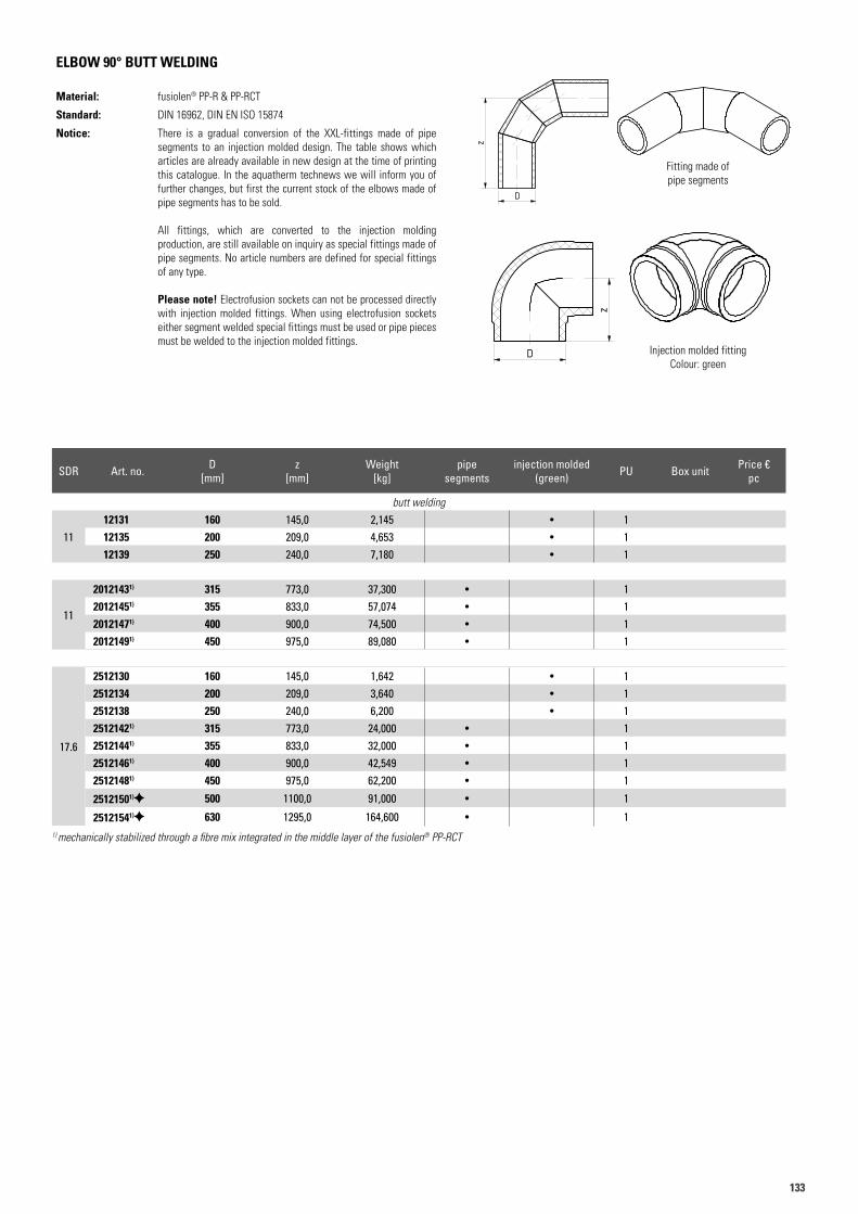
133133
ELBOW 90° BUTT WELDING
Material: fusiolen® PP-R & PP-RCT
Standard: DIN 16962, DIN EN ISO 15874
Notice: There is a gradual conversion of the XXL-fittings made of pipe segments to an injection molded design. The table shows which articles are already available in new design at the time of printing this catalogue. In the aquatherm technews we will inform you of further changes, but first the current stock of the elbows made of pipe segments has to be sold.
All fittings, which are converted to the injection molding production, are still available on inquiry as special fittings made of pipe segments. No article numbers are defined for special fittings of any type.
Please note! Electrofusion sockets can not be processed directly with injection molded fittings. When using electrofusion sockets either segment welded special fittings must be used or pipe pieces must be welded to the injection molded fittings.
Fitting made of pipe segments
Injection molded fittingColour: green
1) mechanically stabilized through a fibre mix integrated in the middle layer of the fusiolen® PP-RCT
Art.N. 12143Artikelliste 2015Seite 22
D
z
Art.N. 12143Artikelliste 2015Seite 22
D
z
Art.N. 12135Artikelliste 2015Seite 22
D
z
Art.N. 12135Artikelliste 2015Seite 22
D
z
SDR Art. no. D [mm]
z [mm]
Weight [kg]
pipesegments
injection molded(green) PU Box unit Price €
pc
butt welding
1112131 160 145,0 2,145 • 112135 200 209,0 4,653 • 112139 250 240,0 7,180 • 1
11
20121431) 315 773,0 37,300 • 120121451) 355 833,0 57,074 • 120121471) 400 900,0 74,500 • 120121491) 450 975,0 89,080 • 1
17.6
2512130 160 145,0 1,642 • 12512134 200 209,0 3,640 • 12512138 250 240,0 6,200 • 125121421) 315 773,0 24,000 • 125121441) 355 833,0 32,000 • 125121461) 400 900,0 42,549 • 125121481) 450 975,0 62,200 • 1
25121501) 500 1100,0 91,000 • 1
25121541) 630 1295,0 164,600 • 1
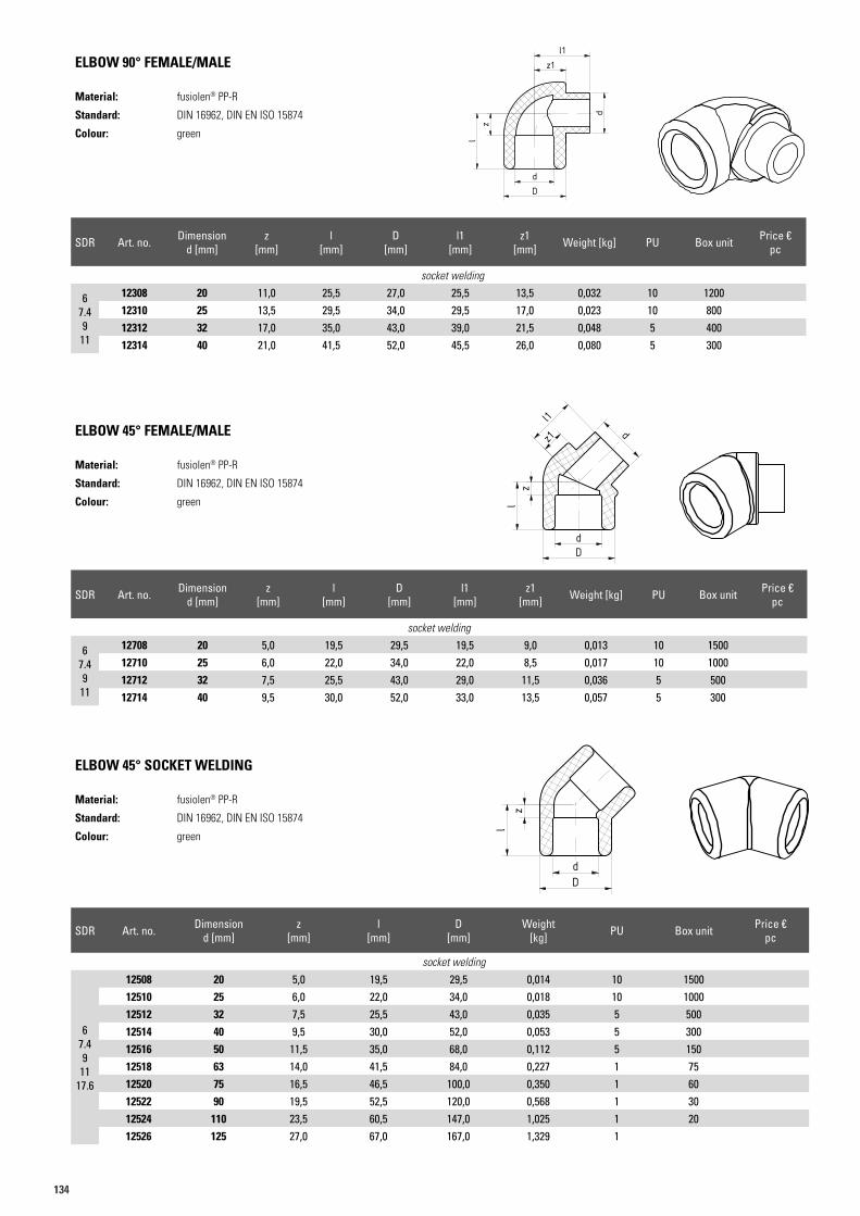
134
SDR Art. no. Dimensiond [mm]
z [mm]
l [mm]
D [mm]
l1 [mm]
z1 [mm] Weight [kg] PU Box unit Price €
pc
socket welding
67.49
11
12308 20 11,0 25,5 27,0 25,5 13,5 0,032 10 120012310 25 13,5 29,5 34,0 29,5 17,0 0,023 10 80012312 32 17,0 35,0 43,0 39,0 21,5 0,048 5 40012314 40 21,0 41,5 52,0 45,5 26,0 0,080 5 300
ELBOW 90° FEMALE/MALE
Material: fusiolen® PP-R
Standard: DIN 16962, DIN EN ISO 15874
Colour: green
SDR Art. no. Dimensiond [mm]
z [mm]
l [mm]
D [mm]
l1 [mm]
z1 [mm] Weight [kg] PU Box unit Price €
pc
socket welding
67.49
11
12708 20 5,0 19,5 29,5 19,5 9,0 0,013 10 150012710 25 6,0 22,0 34,0 22,0 8,5 0,017 10 100012712 32 7,5 25,5 43,0 29,0 11,5 0,036 5 50012714 40 9,5 30,0 52,0 33,0 13,5 0,057 5 300
ELBOW 45° FEMALE/MALE
Material: fusiolen® PP-R
Standard: DIN 16962, DIN EN ISO 15874
Colour: green
SDR Art. no. Dimensiond [mm]
z [mm]
l [mm]
D [mm]
Weight [kg] PU Box unit Price €
pc
socket welding
67.49
1117.6
12508 20 5,0 19,5 29,5 0,014 10 150012510 25 6,0 22,0 34,0 0,018 10 100012512 32 7,5 25,5 43,0 0,035 5 50012514 40 9,5 30,0 52,0 0,053 5 30012516 50 11,5 35,0 68,0 0,112 5 15012518 63 14,0 41,5 84,0 0,227 1 7512520 75 16,5 46,5 100,0 0,350 1 6012522 90 19,5 52,5 120,0 0,568 1 3012524 110 23,5 60,5 147,0 1,025 1 2012526 125 27,0 67,0 167,0 1,329 1
ELBOW 45° SOCKET WELDING
Material: fusiolen® PP-R
Standard: DIN 16962, DIN EN ISO 15874
Colour: green
Art.N. 12306Artikelliste 2015Seite 23
dD
zl
d
z1l1
Art.N. 12306Artikelliste 2015Seite 23
dD
zl
d
z1l1
Art.N. 12708Artikelliste 2015Seite 23
dD
zl
z1
l1
d
Art.N. 12708Artikelliste 2015Seite 23
dD
zl
z1
l1
d
Art.N. 12506Artikelliste 2015Seite 23
dD
zl
Art.N. 12506Artikelliste 2015Seite 23
dD
zl
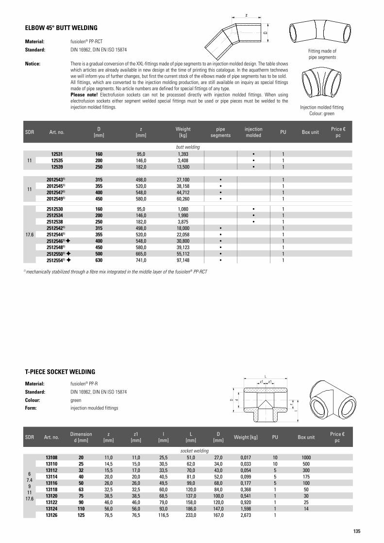
135135
ELBOW 45° BUTT WELDING
Material: fusiolen® PP-RCT
Standard: DIN 16962, DIN EN ISO 15874
Notice: There is a gradual conversion of the XXL-fittings made of pipe segments to an injection molded design. The table shows which articles are already available in new design at the time of printing this catalogue. In the aquatherm technews we will inform you of further changes, but first the current stock of the elbows made of pipe segments has to be sold.All fittings, which are converted to the injection molding production, are still available on inquiry as special fittings made of pipe segments. No article numbers are defined for special fittings of any type. Please note! Electrofusion sockets can not be processed directly with injection molded fittings. When using electrofusion sockets either segment welded special fittings must be used or pipe pieces must be welded to the injection molded fittings.
T-PIECE SOCKET WELDING
Material: fusiolen® PP-R
Standard: DIN 16962, DIN EN ISO 15874
Colour: green
Form: injection moulded fittings
1) mechanically stabilized through a fibre mix integrated in the middle layer of the fusiolen® PP-RCT
Fitting made of pipe segments
Injection molded fittingColour: green
Art.N. 12543Artikelliste 2015Seite 24
z
D
Art.N. 12543Artikelliste 2015Seite 24
z
D
Art.N. 12531Artikelliste 2015Seite 24
z
D
SDR Art. no. D [mm]
z [mm]
Weight [kg]
pipesegments
injection molded PU Box unit Price €
pc
butt welding
1112531 160 95,0 1,393 • 112535 200 146,0 3,408 • 112539 250 182,0 13,500 • 1
11
20125431) 315 498,0 27,100 • 120125451) 355 520,0 38,158 • 120125471) 400 548,0 44,712 • 120125491) 450 580,0 60,260 • 1
17.6
2512530 160 95,0 1,080 • 12512534 200 146,0 1,990 • 12512538 250 182,0 3,875 • 125125421) 315 498,0 18,000 • 125125441) 355 520,0 22,058 • 125125461) 400 548,0 30,800 • 125125481) 450 580,0 39,123 • 125125501) 500 665,0 55,112 • 125125541) 630 741,0 97,148 • 1
SDR Art. no. Dimensiond [mm]
z [mm]
z1 [mm]
l [mm]
L [mm]
D [mm] Weight [kg] PU Box unit Price €
pc
socket welding
67.49
1117.6
13108 20 11,0 11,0 25,5 51,0 27,0 0,017 10 100013110 25 14,5 15,0 30,5 62,0 34,0 0,033 10 50013112 32 15,5 17,0 33,5 70,0 43,0 0,054 5 30013114 40 20,0 20,0 40,5 81,0 52,0 0,099 5 17513116 50 26,0 26,0 49,5 99,0 68,0 0,177 5 10013118 63 32,5 32,5 60,0 120,0 84,0 0,368 1 5013120 75 38,5 38,5 68,5 137,0 100,0 0,541 1 3013122 90 46,0 46,0 79,0 158,0 120,0 0,920 1 2513124 110 56,0 56,0 93,0 186,0 147,0 1,598 1 1413126 125 76,5 76,5 116,5 233,0 167,0 2,673 1
Art.N. 13106Artikelliste 2015Seite 24
lz
dD
Lz1z1
Art.N. 13106Artikelliste 2015Seite 24
lz
dD
Lz1z1
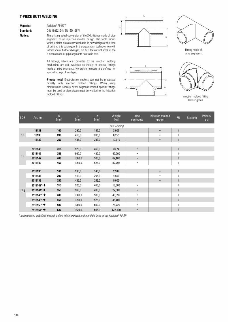
136
T-PIECE BUTT WELDING
Material: fusiolen® PP-RCT
Standard: DIN 16962, DIN EN ISO 15874
Notice: There is a gradual conversion of the XXL-fittings made of pipe segments to an injection molded design. The table shows which articles are already available in new design at the time of printing this catalogue. In the aquatherm technews we will inform you of further changes, but first the current stock of the t-pieces made of pipe segments has to be sold.
All fittings, which are converted to the injection molding production, are still available on inquiry as special fittings made of pipe segments. No article numbers are defined for special fittings of any type.
Please note! Electrofusion sockets can not be processed directly with injection molded fittings. When using electrofusion sockets either segment welded special fittings must be used or pipe pieces must be welded to the injection molded fittings.
Fitting made of pipe segments
Injection molded fittingColour: green
1) mechanically stabilized through a fibre mix integrated in the middle layer of the fusiolen® PP-RP
Art.N. 13145Artikelliste 2015Seite 25
z
D
L
Art.N. 13145Artikelliste 2015Seite 25
z
D
L
Art.N. 13131Artikelliste 2015Seite 25
D
z
L
Art.N. 13131Artikelliste 2015Seite 25
D
z
L
SDR Art. no. D [mm]
L [mm]
z [mm]
Weight [kg]
pipesegments
injection molded(green) PU Box unit Price €
pc
butt welding
1113131 160 290,0 145,0 3,005 • 113135 200 410,0 205,0 6,255 • 113139 250 486,0 243,0 10,710 • 1
11
2013143 315 920,0 460,0 36,74 • 12013145 355 960,0 480,0 40,000 • 12013147 400 1000,0 500,0 62,100 • 12013149 450 1050,0 525,0 82,792 • 1
17.6
2513130 160 290,0 145,0 2,348 • 12513134 200 410,0 205,0 4,500 • 12513138 250 486,0 243,0 9,000 • 1
25131421) 315 920,0 460,0 19,800 • 1
25131441) 355 960,0 480,0 27,500 • 1
25131461) 400 1000,0 500,0 40,395 • 1
25131481) 450 1050,0 525,0 45,400 • 1
25131501) 500 1200,0 600,0 75,726 • 1
25131541) 630 1330,0 665,0 122,500 • 1
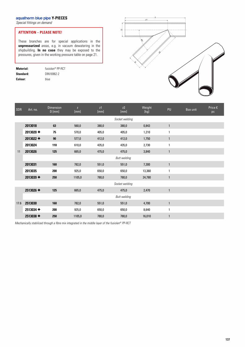
137137
aquatherm blue pipe Y-PIECESSpecial fittings on demand
ATTENTION – PLEASE NOTE!
These branches are for special applications in the unpressurized areas, e.g. in vacuum dewatering in the shipbuilding. In no case they may be exposed to the pressures, given in the working pressure table on page 21.
Material: fusiolen® PP-RCT
Standard: DIN16962-2
Colour: blue
SDR Art. no. DimensionD [mm]
z [mm]
z1 [mm]
z2 [mm]
Weight [kg] PU Box unit Price €
pc
Socket welding
11
2013018 63 560,0 380,0 380,0 0,843 1
2013020 75 570,0 405,0 405,0 1,210 1
2013022 90 577,0 412,0 412,0 1,750 1
2013024 110 610,0 435,0 435,0 2,730 1
2013026 125 665,0 475,0 475,0 3,840 1
Butt welding
2013031 160 782,0 551,0 551,0 7,300 1
2013035 200 925,0 650,0 650,0 13,360 1
2013039 250 1105,0 780,0 780,0 24,780 1
Socket welding
17.6
2513026 125 665,0 475,0 475,0 2,470 1
Butt welding
2513030 160 782,0 551,0 551,0 4,700 1
2513034 200 925,0 650,0 650,0 8,640 1
2513038 250 1105,0 780,0 780,0 16,010 1aaqq
uuaatthh
eerrmm
GGmm
bbHH
- B
igg
en 5
- 5
7439
Att
end
orn
Index Änderungen
Freigabe:
Maßstab:Allgemeintol. nach DIN ISO 2768-c
Blatt-Nr.:
Artikelnummer :
Stück (Menge):
Kontrolliert:
Gezeichnet:
Benennung:
Revision:
Datum Name
Weitergabe sowie Vervielfältigung dieses Dokuments,Verwertung und Mitteilung seines Inhalts sind verboten, soweit nicht ausdrücklich gestattet. Zuwiederhand-lungen verpflichten zu Schadenersatz. Alle Rechte für den Fall der Patent-, Ge-brauchsmuster oder Geschmacksmuster vorbehalten.
Position :
Datum: Name:
a
b
c
d
e
f
gh
Gewicht:
Material (Werkstoff):
27.01.2015
27.01.2015
27.01.2015
Mueller
Tusche
1:5 0.00 - - -
-0PP
Y-Abzweig 45°
2013018-2513038W
D
z2
z1z
D
45°
Mechanically stabilized through a fibre mix integrated in the middle layer of the fusiolen® PP-RCT
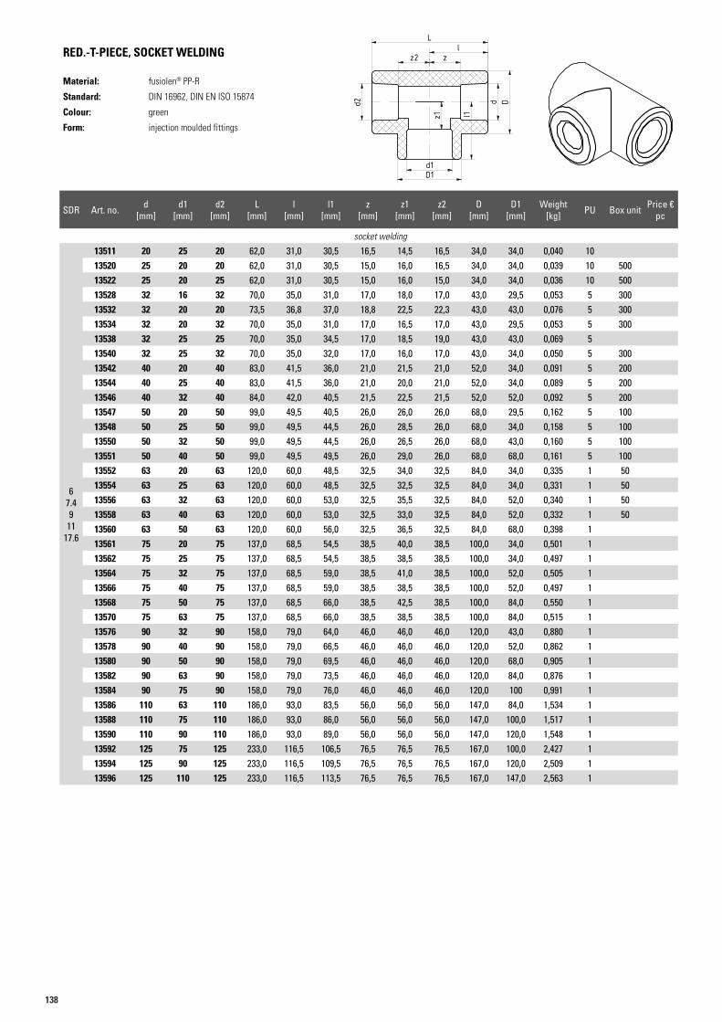
138
RED.-T-PIECE, SOCKET WELDING
Material: fusiolen® PP-R
Standard: DIN 16962, DIN EN ISO 15874
Colour: green
Form: injection moulded fittings
SDR Art. no. d [mm]
d1 [mm]
d2 [mm]
L [mm]
l [mm]
l1 [mm]
z [mm]
z1 [mm]
z2 [mm]
D [mm]
D1 [mm]
Weight [kg] PU Box unit Price €
pc
socket welding
67.49
1117.6
13511 20 25 20 62,0 31,0 30,5 16,5 14,5 16,5 34,0 34,0 0,040 1013520 25 20 20 62,0 31,0 30,5 15,0 16,0 16,5 34,0 34,0 0,039 10 50013522 25 20 25 62,0 31,0 30,5 15,0 16,0 15,0 34,0 34,0 0,036 10 50013528 32 16 32 70,0 35,0 31,0 17,0 18,0 17,0 43,0 29,5 0,053 5 30013532 32 20 20 73,5 36,8 37,0 18,8 22,5 22,3 43,0 43,0 0,076 5 30013534 32 20 32 70,0 35,0 31,0 17,0 16,5 17,0 43,0 29,5 0,053 5 30013538 32 25 25 70,0 35,0 34,5 17,0 18,5 19,0 43,0 43,0 0,069 513540 32 25 32 70,0 35,0 32,0 17,0 16,0 17,0 43,0 34,0 0,050 5 30013542 40 20 40 83,0 41,5 36,0 21,0 21,5 21,0 52,0 34,0 0,091 5 20013544 40 25 40 83,0 41,5 36,0 21,0 20,0 21,0 52,0 34,0 0,089 5 20013546 40 32 40 84,0 42,0 40,5 21,5 22,5 21,5 52,0 52,0 0,092 5 20013547 50 20 50 99,0 49,5 40,5 26,0 26,0 26,0 68,0 29,5 0,162 5 10013548 50 25 50 99,0 49,5 44,5 26,0 28,5 26,0 68,0 34,0 0,158 5 10013550 50 32 50 99,0 49,5 44,5 26,0 26,5 26,0 68,0 43,0 0,160 5 10013551 50 40 50 99,0 49,5 49,5 26,0 29,0 26,0 68,0 68,0 0,161 5 10013552 63 20 63 120,0 60,0 48,5 32,5 34,0 32,5 84,0 34,0 0,335 1 5013554 63 25 63 120,0 60,0 48,5 32,5 32,5 32,5 84,0 34,0 0,331 1 5013556 63 32 63 120,0 60,0 53,0 32,5 35,5 32,5 84,0 52,0 0,340 1 5013558 63 40 63 120,0 60,0 53,0 32,5 33,0 32,5 84,0 52,0 0,332 1 5013560 63 50 63 120,0 60,0 56,0 32,5 36,5 32,5 84,0 68,0 0,398 113561 75 20 75 137,0 68,5 54,5 38,5 40,0 38,5 100,0 34,0 0,501 113562 75 25 75 137,0 68,5 54,5 38,5 38,5 38,5 100,0 34,0 0,497 113564 75 32 75 137,0 68,5 59,0 38,5 41,0 38,5 100,0 52,0 0,505 113566 75 40 75 137,0 68,5 59,0 38,5 38,5 38,5 100,0 52,0 0,497 113568 75 50 75 137,0 68,5 66,0 38,5 42,5 38,5 100,0 84,0 0,550 113570 75 63 75 137,0 68,5 66,0 38,5 38,5 38,5 100,0 84,0 0,515 113576 90 32 90 158,0 79,0 64,0 46,0 46,0 46,0 120,0 43,0 0,880 113578 90 40 90 158,0 79,0 66,5 46,0 46,0 46,0 120,0 52,0 0,862 113580 90 50 90 158,0 79,0 69,5 46,0 46,0 46,0 120,0 68,0 0,905 113582 90 63 90 158,0 79,0 73,5 46,0 46,0 46,0 120,0 84,0 0,876 113584 90 75 90 158,0 79,0 76,0 46,0 46,0 46,0 120,0 100 0,991 113586 110 63 110 186,0 93,0 83,5 56,0 56,0 56,0 147,0 84,0 1,534 113588 110 75 110 186,0 93,0 86,0 56,0 56,0 56,0 147,0 100,0 1,517 113590 110 90 110 186,0 93,0 89,0 56,0 56,0 56,0 147,0 120,0 1,548 113592 125 75 125 233,0 116,5 106,5 76,5 76,5 76,5 167,0 100,0 2,427 113594 125 90 125 233,0 116,5 109,5 76,5 76,5 76,5 167,0 120,0 2,509 113596 125 110 125 233,0 116,5 113,5 76,5 76,5 76,5 167,0 147,0 2,563 1
Art.N. 13511Artikelliste 2015Seite 26
d1D1
z1 l1
d D
zl
z2
L
d2
Art.N. 13511Artikelliste 2015Seite 26
d1D1
z1 l1
d D
zl
z2
L
d2
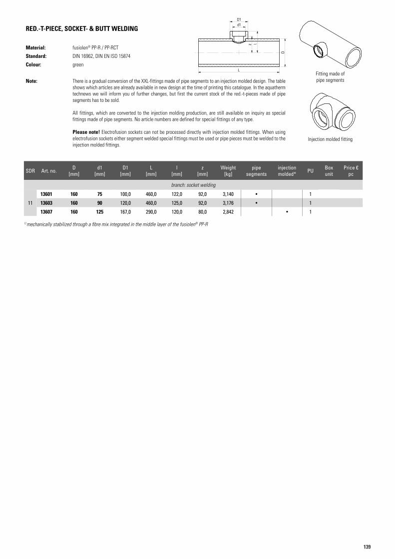
139139
RED.-T-PIECE, SOCKET- & BUTT WELDING
Material: fusiolen® PP-R / PP-RCT
Standard: DIN 16962, DIN EN ISO 15874
Colour: green
Note: There is a gradual conversion of the XXL-fittings made of pipe segments to an injection molded design. The table shows which articles are already available in new design at the time of printing this catalogue. In the aquatherm technews we will inform you of further changes, but first the current stock of the red.-t-pieces made of pipe segments has to be sold.
All fittings, which are converted to the injection molding production, are still available on inquiry as special fittings made of pipe segments. No article numbers are defined for special fittings of any type.
Please note! Electrofusion sockets can not be processed directly with injection molded fittings. When using electrofusion sockets either segment welded special fittings must be used or pipe pieces must be welded to the injection molded fittings.
Fitting made of pipe segments
Injection molded fitting
1) mechanically stabilized through a fibre mix integrated in the middle layer of the fusiolen® PP-R
Art.N. 13601Artikelliste 2015Seite 27
d1D1
z l
L
D
Spritzgussformteil Segmentgeschweißter Artikel
Art.N. 13601Artikelliste 2015Seite 27
d1D1
z l
L
D
Spritzgussformteil Segmentgeschweißter Artikel
Art.N. 13601Artikelliste 2015Seite 27
d1D1
z l
L
D
Spritzgussformteil Segmentgeschweißter Artikel
SDR Art. no. D [mm]
d1 [mm]
D1 [mm]
L [mm]
l [mm]
z [mm]
Weight [kg]
pipesegments
injection molded* PU Box
unitPrice €
pc
branch: socket welding
11
13601 160 75 100,0 460,0 122,0 92,0 3,140 • 1
13603 160 90 120,0 460,0 125,0 92,0 3,176 • 1
13607 160 125 167,0 290,0 120,0 80,0 2,842 • 1
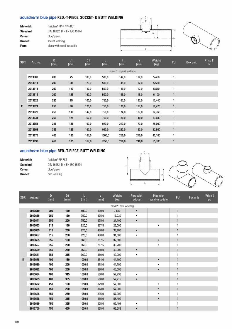
140
aquatherm blue pipe RED.-T-PIECE, SOCKET- & BUTT WELDING
Material: fusiolen® PP-R / PP-RCT
Standard: DIN 16962, DIN EN ISO 15874
Colour: blue/green
Branch: socket welding
Form: pipes with weld-in saddle
aquatherm blue pipe RED.-T-PIECE, BUTT WELDING
Material: fusiolen® PP-RCT
Standard: DIN 16962, DIN EN ISO 15874
Colour: blue/green
Branch: butt welding
Art.N. 2513667 Gr. 2013619Artikelliste 2015Seite 29;31
D
z
L
D1
Art.N. 2013613 (Gruppe 2013609)Artikelliste 2015Seite 29, 30
d1D1
z l
L
D
Segmentgeschweißter Artikel
SDR Art. no. D [mm]
d1 [mm]
D1 [mm]
L [mm]
l [mm]
z [mm]
Weight [kg] PU Box unit Price €
pc
11
branch: socket welding
2013609 200 75 100,0 500,0 142,0 112,0 5,460 1
2013611 200 90 120,0 500,0 145,0 112,0 5,580 1
2013613 200 110 147,0 500,0 149,0 112,0 5,810 1
2013615 200 125 167,0 500,0 155,0 115,0 6,100 1
2013625 250 75 100,0 750,0 167,0 137,0 12,440 1
2013627 250 90 120,0 750,0 170,0 137,0 12,420 1
2013629 250 110 147,0 750,0 174,0 137,0 12,760 1
2013631 250 125 167,0 750,0 180,0 140,0 13,030 1
2013651 315 125 167,0 920,0 213,0 173,0 25,000 1
2013663 355 125 167,0 960,0 233,0 193,0 32,500 1
2013676 400 125 167,0 1000,0 255,0 215,0 42,100 1
2013690 450 125 167,0 1050,0 280,0 240,0 55,700 1
SDR Art. no. D [mm]
D1 [mm]
L [mm]
z [mm]
Weight [kg]
Pipe with reducer
Pipe with weld-in saddle PU Box unit Price €
pc
branch: butt welding
11
2013619 200 160 500,0 300,0 7,650 • 1
2013635 250 160 750,0 375,0 19,030 • 1
2013641 250 200 750,0 375,0 21,100 • 1
2013653 315 160 920,0 237,5 25,000 • 1
2013655 315 200 920,0 460,0 33,200 • 1
2013657 315 250 920,0 460,0 31,500 • 1
2013665 355 160 960,0 257,5 32,500 • 1
2013667 355 200 960,0 267,5 30,200 • 1
2013669 355 250 960,0 480,0 40,000 • 1
2013671 355 315 960,0 480,0 40,000 • 1
2013678 400 160 1000,0 354,0 44,100 • 1
2013680 400 200 1000,0 318,0 44,100 • 1
2013682 400 250 1000,0 280,0 46,000 • 1
2013684 400 315 1000,0 500,0 57,790 • 1
2013685 400 355 1000,0 500,0 52,715 • 1
2013692 450 160 1050,0 379,0 57,900 • 1
2013694 450 200 1050,0 343,0 57,900 • 1
2013696 450 250 1050,0 305,0 57,900 • 1
2013698 450 315 1050,0 315,0 58,400 • 1
2013699 450 355 1050,0 525,0 62,491 • 1
2013700 450 400 1050,0 525,0 62,683 • 1
Art.N. 13601Artikelliste 2015Seite 27
d1D1
z l
L
D
Spritzgussformteil Segmentgeschweißter Artikel
Art.N. 13619 Gr. 13618Artikelliste 2015Seite 28
D
z
L
D1
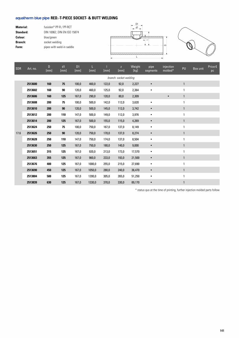
141141
aquatherm blue pipe RED.-T-PIECE SOCKET- & BUTT WELDING
Material: fusiolen® PP-R / PP-RCT
Standard: DIN 16962, DIN EN ISO 15874
Colour: blue/green
Branch: socket welding
Form: pipes with weld-in saddle
SDR Art. no. D [mm]
d1 [mm]
D1 [mm]
L [mm]
l [mm]
z [mm]
Weight [kg]
pipesegments
injection molded* PU Box unit Price €
pc
branch: socket welding
17.6
2513600 160 75 100,0 460,0 122,0 92,0 2,227 • 1
2513602 160 90 120,0 460,0 125,0 92,0 2,364 • 1
2513606 160 125 167,0 290,0 120,0 80,0 2,309 • 1
2513608 200 75 100,0 500,0 142,0 112,0 3,620 • 1
2513610 200 90 120,0 500,0 145,0 112,0 3,742 • 1
2513612 200 110 147,0 500,0 149,0 112,0 3,976 • 1
2513614 200 125 167,0 500,0 155,0 115,0 4,269 • 1
2513624 250 75 100,0 750,0 167,0 137,0 8,149 • 1
2513626 250 90 120,0 750,0 170,0 137,0 8,274 • 1
2513628 250 110 147,0 750,0 174,0 137,0 8,504 • 1
2513630 250 125 167,0 750,0 180,0 140,0 9,000 • 1
2513651 315 125 167,0 920,0 213,0 173,0 17,570 • 1
2513663 355 125 167,0 960,0 233,0 193,0 21,500 • 1
2513676 400 125 167,0 1000,0 255,0 215,0 27,690 • 1
2513690 450 125 167,0 1050,0 280,0 240,0 36,470 • 1
2513804 500 125 167,0 1200,0 305,0 265,0 51,250 • 1
2513839 630 125 167,0 1330,0 370,0 330,0 89,170 • 1
Art.N. 2013613 (Gruppe 2013609)Artikelliste 2015Seite 29, 30
d1D1
z l
L
D
Segmentgeschweißter Artikel
Art.N. 13601Artikelliste 2015Seite 27
d1D1
z l
L
D
Spritzgussformteil Segmentgeschweißter Artikel
* status quo at the time of printing, further injection molded parts follow
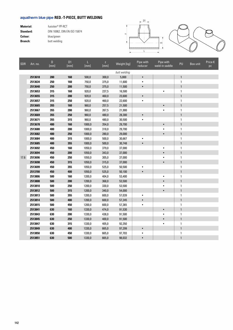
142
aquatherm blue pipe RED.-T-PIECE, BUTT WELDING
Material: fusiolen® PP-RCT
Standard: DIN 16962, DIN EN ISO 15874
Colour: blue/green
Branch: butt welding
Art.N. 2513667 Gr. 2013619Artikelliste 2015Seite 29;31
D
z
L
D1
SDR Art. no. D [mm]
D1 [mm]
L [mm]
z [mm] Weight [kg] Pipe with
reducerPipe with
weld-in saddle PU Box unit Price €pc
butt welding
17.6
2513618 200 160 500,0 300,0 5,000 • 12513634 250 160 750,0 375,0 11,600 • 12513640 250 200 750,0 375,0 11,500 • 12513653 315 160 920,0 237,5 16,500 • 12513655 315 200 920,0 460,0 23,600 • 12513657 315 250 920,0 460,0 22,600 • 12513665 355 160 960,0 257,5 21,500 • 12513667 355 200 960,0 267,5 21,900 • 12513669 355 250 960,0 480,0 28,300 • 12513671 355 315 960,0 480,0 30,500 • 12513678 400 160 1000,0 354,0 29,700 • 12513680 400 200 1000,0 318,0 29,700 • 12513682 400 250 1000,0 280,0 29,000 • 12513684 400 315 1000,0 500,0 30,667 • 12513685 400 355 1000,0 500,0 30,748 • 12513692 450 160 1050,0 379,0 37,000 • 12513694 450 200 1050,0 343,0 37,000 • 12513696 450 250 1050,0 305,0 37,000 • 12513698 450 315 1050,0 315,0 37,000 • 12513699 450 355 1050,0 525,0 50,500 • 12513700 450 400 1050,0 525,0 50,100 • 12513806 500 160 1200,0 404,0 53,400 • 12513808 500 200 1200,0 368,0 53,500 • 12513810 500 250 1200,0 330,0 53,500 • 12513812 500 315 1200,0 340,0 54,000 • 12513813 500 355 1200,0 600,0 57,039 • 12513814 500 400 1200,0 600,0 57,245 • 12513815 500 450 1200,0 600,0 57,365 • 12513841 630 160 1330,0 474,0 91,530 • 12513843 630 200 1330,0 438,0 91,500 • 12513845 630 250 1330,0 400,0 91,500 • 12513847 630 315 1330,0 405,0 92,350 • 12513849 630 400 1330,0 665,0 97,299 • 12513850 630 450 1330,0 665,0 97,703 • 12513851 630 500 1330,0 665,0 98,032 • 1
Art.N. 13619 Gr. 13618Artikelliste 2015Seite 28
D
z
L
D1
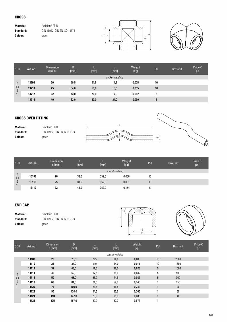
143143
CROSS
Material: fusiolen® PP-R
Standard: DIN 16962, DIN EN ISO 15874
Colour: green
CROSS OVER FITTING
Material: fusiolen® PP-R
Standard: DIN 16962, DIN EN ISO 15874
Colour: green
Art.N. 13710Artikelliste 2015Seite 32
dD
zL
Art.N. 13710Artikelliste 2015Seite 32
dD
zL
Art.N. 16112Artikelliste 2015Seite 32
L
dh
Art.N. 16112Artikelliste 2015Seite 32
L
dh
SDR Art. no. Dimensiond [mm]
D [mm]
L [mm]
z [mm]
Weight [kg] PU Box unit Price €
pc
67.49
11
socket welding
13708 20 29,5 51,5 11,3 0,025 10
13710 25 34,0 59,0 13,5 0,035 10
13712 32 43,0 70,0 17,0 0,062 5
13714 40 52,0 83,0 21,0 0,099 5
SDR Art. no. Dimensiond [mm]
h [mm]
L [mm]
Weight [kg] PU Box unit Price €
pc
67.49
11
socket welding
16108 20 32,0 352,0 0,060 10
16110 25 37,5 352,0 0,091 10
16112 32 48,0 352,0 0,154 5
END CAP
Material: fusiolen® PP-R
Standard: DIN 16962, DIN EN ISO 15874
Colour: green
Art.N. 14110 Gruppe 14106Artikelliste 2015Seite 33
zL
dD
Art.N. 14110 Gruppe 14106Artikelliste 2015Seite 33
zL
dD
SDR Art. no. Dimensiond [mm]
D [mm]
z [mm]
L [mm]
Weight [kg] PU Box unit Price €
pc
socket welding
67.49
11
14108 20 29,5 9,5 24,0 0,009 10 200014110 25 34,0 8,0 24,0 0,011 10 150014112 32 43,0 11,0 29,0 0,023 5 100014114 40 52,0 17,5 38,0 0,042 5 50014116 50 68,0 21,0 44,5 0,082 5 30014118 63 84,0 24,5 52,0 0,146 1 15014120 75 100,0 28,5 58,5 0,243 1 9014122 90 120,0 34,5 67,5 0,365 1 6014124 110 147,0 28,0 65,0 0,635 1 4014126 125 167,0 42,0 82,0 0,872 1
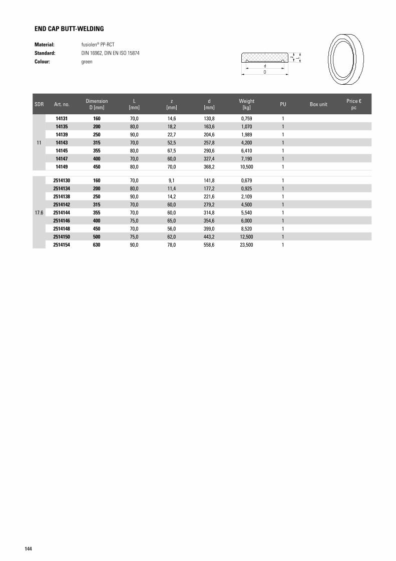
144
END CAP BUTT-WELDING
Material: fusiolen® PP-RCT
Standard: DIN 16962, DIN EN ISO 15874
Colour: green
Art.N. 14147 Gruppe 14130Artikelliste 2015Seite 33
dD
z L
zL
dD
Art.N. 14147 Gruppe 14130Artikelliste 2015Seite 33
dD
z L
zL
dD
SDR Art. no. DimensionD [mm]
L [mm]
z [mm]
d [mm]
Weight [kg] PU Box unit Price €
pc
11
14131 160 70,0 14,6 130,8 0,759 114135 200 80,0 18,2 163,6 1,070 114139 250 90,0 22,7 204,6 1,989 114143 315 70,0 52,5 257,8 4,200 114145 355 80,0 67,5 290,6 6,410 114147 400 70,0 60,0 327,4 7,190 114149 450 80,0 70,0 368,2 10,500 1
17.6
2514130 160 70,0 9,1 141,8 0,679 12514134 200 80,0 11,4 177,2 0,925 12514138 250 90,0 14,2 221,6 2,109 12514142 315 70,0 60,0 279,2 4,500 12514144 355 70,0 60,0 314,8 5,540 12514146 400 75,0 65,0 354,6 6,000 12514148 450 70,0 56,0 399,0 8,520 12514150 500 75,0 62,0 443,2 12,500 12514154 630 90,0 78,0 558,6 23,500 1
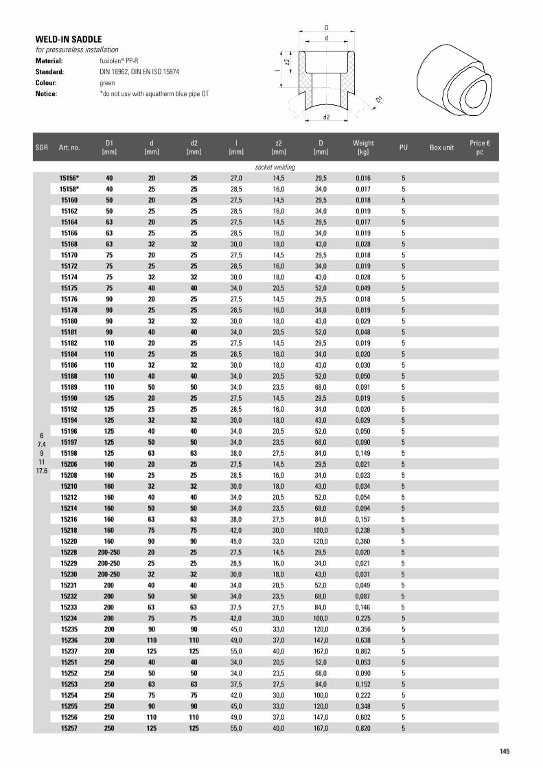
145145
WELD-IN SADDLEfor pressureless installationMaterial: fusiolen® PP-R
Standard: DIN 16962, DIN EN ISO 15874
Colour: green
Notice: *do not use with aquatherm blue pipe OT
SDR Art. no. D1 [mm]
d [mm]
d2 [mm]
l [mm]
z2 [mm]
D [mm]
Weight [kg] PU Box unit Price €
pc
socket welding
67.49
1117.6
15156* 40 20 25 27,0 14,5 29,5 0,016 515158* 40 25 25 28,5 16,0 34,0 0,017 515160 50 20 25 27,5 14,5 29,5 0,018 515162 50 25 25 28,5 16,0 34,0 0,019 515164 63 20 25 27,5 14,5 29,5 0,017 515166 63 25 25 28,5 16,0 34,0 0,019 515168 63 32 32 30,0 18,0 43,0 0,028 515170 75 20 25 27,5 14,5 29,5 0,018 515172 75 25 25 28,5 16,0 34,0 0,019 515174 75 32 32 30,0 18,0 43,0 0,028 515175 75 40 40 34,0 20,5 52,0 0,049 515176 90 20 25 27,5 14,5 29,5 0,018 515178 90 25 25 28,5 16,0 34,0 0,019 515180 90 32 32 30,0 18,0 43,0 0,029 515181 90 40 40 34,0 20,5 52,0 0,048 515182 110 20 25 27,5 14,5 29,5 0,019 515184 110 25 25 28,5 16,0 34,0 0,020 515186 110 32 32 30,0 18,0 43,0 0,030 515188 110 40 40 34,0 20,5 52,0 0,050 515189 110 50 50 34,0 23,5 68,0 0,091 515190 125 20 25 27,5 14,5 29,5 0,019 515192 125 25 25 28,5 16,0 34,0 0,020 515194 125 32 32 30,0 18,0 43,0 0,029 515196 125 40 40 34,0 20,5 52,0 0,050 515197 125 50 50 34,0 23,5 68,0 0,090 515198 125 63 63 38,0 27,5 84,0 0,149 515206 160 20 25 27,5 14,5 29,5 0,021 515208 160 25 25 28,5 16,0 34,0 0,023 515210 160 32 32 30,0 18,0 43,0 0,034 515212 160 40 40 34,0 20,5 52,0 0,054 515214 160 50 50 34,0 23,5 68,0 0,094 515216 160 63 63 38,0 27,5 84,0 0,157 515218 160 75 75 42,0 30,0 100,0 0,238 515220 160 90 90 45,0 33,0 120,0 0,360 515228 200-250 20 25 27,5 14,5 29,5 0,020 515229 200-250 25 25 28,5 16,0 34,0 0,021 515230 200-250 32 32 30,0 18,0 43,0 0,031 515231 200 40 40 34,0 20,5 52,0 0,049 515232 200 50 50 34,0 23,5 68,0 0,087 515233 200 63 63 37,5 27,5 84,0 0,146 515234 200 75 75 42,0 30,0 100,0 0,225 515235 200 90 90 45,0 33,0 120,0 0,356 515236 200 110 110 49,0 37,0 147,0 0,638 515237 200 125 125 55,0 40,0 167,0 0,862 515251 250 40 40 34,0 20,5 52,0 0,053 515252 250 50 50 34,0 23,5 68,0 0,090 515253 250 63 63 37,5 27,5 84,0 0,152 515254 250 75 75 42,0 30,0 100,0 0,222 515255 250 90 90 45,0 33,0 120,0 0,348 515256 250 110 110 49,0 37,0 147,0 0,602 515257 250 125 125 55,0 40,0 167,0 0,820 5
Art.N. 15160Artikelliste 2015Seite 34
dD
z2
D1
d2
l
Art.N. 15160Artikelliste 2015Seite 34
dD
z2
D1
d2
l
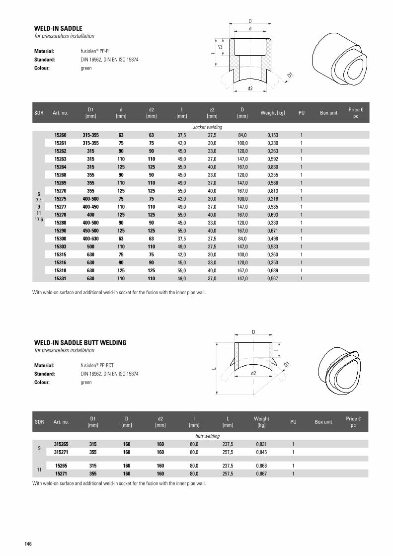
146
WELD-IN SADDLEfor pressureless installation
Material: fusiolen® PP-R
Standard: DIN 16962, DIN EN ISO 15874
Colour: green
WELD-IN SADDLE BUTT WELDINGfor pressureless installation
Material: fusiolen® PP-RCT
Standard: DIN 16962, DIN EN ISO 15874
Colour: green
Art.N. 15265Artikelliste 2015Seite 35
D
l
L D1
d2
Art.N. 15265Artikelliste 2015Seite 35
D
l
L D1
d2
SDR Art. no. D1 [mm]
d [mm]
d2 [mm]
l [mm]
z2 [mm]
D [mm] Weight [kg] PU Box unit Price €
pc
socket welding
67.49
1117.6
15260 315-355 63 63 37,5 27,5 84,0 0,153 115261 315-355 75 75 42,0 30,0 100,0 0,230 115262 315 90 90 45,0 33,0 120,0 0,363 115263 315 110 110 49,0 37,0 147,0 0,592 115264 315 125 125 55,0 40,0 167,0 0,830 115268 355 90 90 45,0 33,0 120,0 0,355 115269 355 110 110 49,0 37,0 147,0 0,586 115270 355 125 125 55,0 40,0 167,0 0,813 115275 400-500 75 75 42,0 30,0 100,0 0,216 115277 400-450 110 110 49,0 37,0 147,0 0,535 115278 400 125 125 55,0 40,0 167,0 0,693 115288 400-500 90 90 45,0 33,0 120,0 0,330 115290 450-500 125 125 55,0 40,0 167,0 0,671 115300 400-630 63 63 37,5 27,5 84,0 0,498 115303 500 110 110 49,0 37,5 147,0 0,533 115315 630 75 75 42,0 30,0 100,0 0,260 115316 630 90 90 45,0 33,0 120,0 0,350 115318 630 125 125 55,0 40,0 167,0 0,689 115331 630 110 110 49,0 37,0 147,0 0,567 1
With weld-on surface and additional weld-in socket for the fusion with the inner pipe wall.
SDR Art. no. D1 [mm]
D [mm]
d2 [mm]
l [mm]
L [mm]
Weight [kg] PU Box unit Price €
pc
butt welding
9315265 315 160 160 80,0 237,5 0,831 1315271 355 160 160 80,0 257,5 0,845 1
1115265 315 160 160 80,0 237,5 0,868 115271 355 160 160 80,0 257,5 0,867 1
With weld-on surface and additional weld-in socket for the fusion with the inner pipe wall.
Art.N. 15160Artikelliste 2015Seite 34
dD
z2
D1
d2
l
Art.N. 15160Artikelliste 2015Seite 34
dD
z2
D1
d2
l
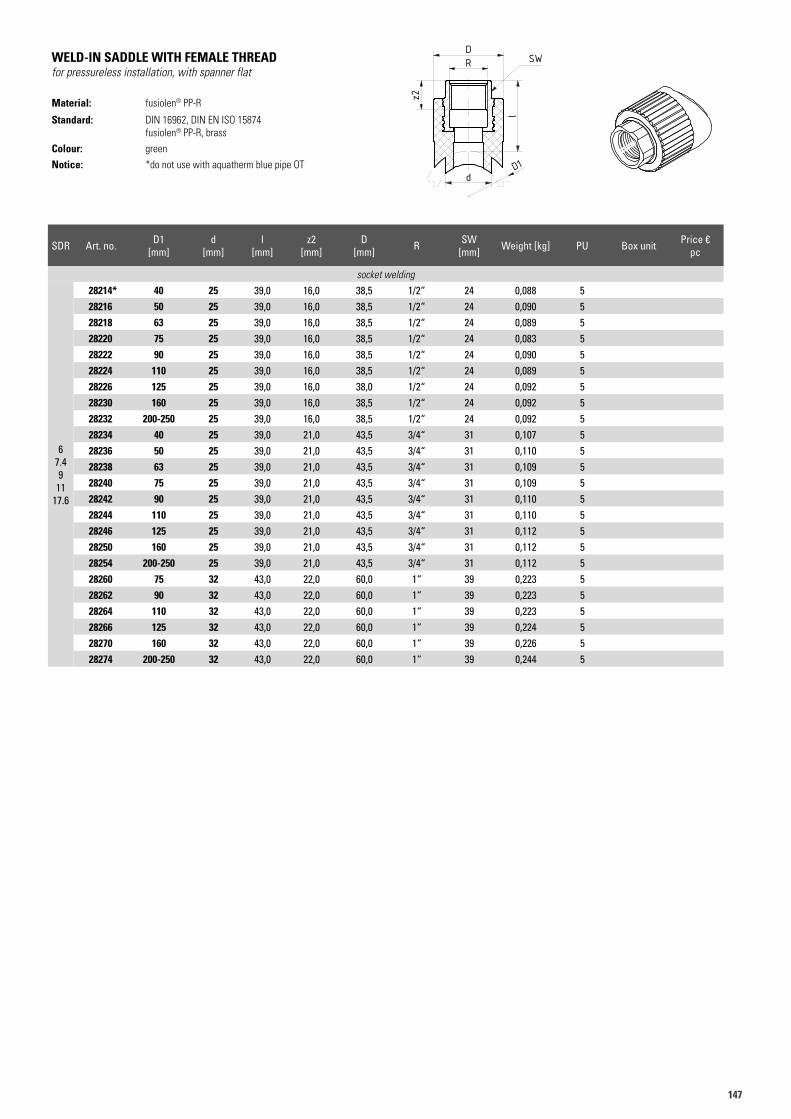
147147
WELD-IN SADDLE WITH FEMALE THREADfor pressureless installation, with spanner flat
Material: fusiolen® PP-R
Standard: DIN 16962, DIN EN ISO 15874fusiolen® PP-R, brass
Colour: green
Notice: *do not use with aquatherm blue pipe OT
Art.N. 28216 Gruppe 28214Artikelliste 2015Seite 36
RD
l
z2
D1d
SW
Art.N. 28216 Gruppe 28214Artikelliste 2015Seite 36
RD
l
z2
D1d
SW
SDR Art. no. D1 [mm]
d [mm]
l [mm]
z2 [mm]
D [mm] R SW
[mm] Weight [kg] PU Box unit Price €pc
socket welding
67.49
1117.6
28214* 40 25 39,0 16,0 38,5 1/2“ 24 0,088 528216 50 25 39,0 16,0 38,5 1/2“ 24 0,090 528218 63 25 39,0 16,0 38,5 1/2“ 24 0,089 528220 75 25 39,0 16,0 38,5 1/2“ 24 0,083 528222 90 25 39,0 16,0 38,5 1/2“ 24 0,090 528224 110 25 39,0 16,0 38,5 1/2“ 24 0,089 528226 125 25 39,0 16,0 38,0 1/2“ 24 0,092 528230 160 25 39,0 16,0 38,5 1/2“ 24 0,092 528232 200-250 25 39,0 16,0 38,5 1/2“ 24 0,092 528234 40 25 39,0 21,0 43,5 3/4“ 31 0,107 528236 50 25 39,0 21,0 43,5 3/4“ 31 0,110 528238 63 25 39,0 21,0 43,5 3/4“ 31 0,109 528240 75 25 39,0 21,0 43,5 3/4“ 31 0,109 528242 90 25 39,0 21,0 43,5 3/4“ 31 0,110 528244 110 25 39,0 21,0 43,5 3/4“ 31 0,110 528246 125 25 39,0 21,0 43,5 3/4“ 31 0,112 528250 160 25 39,0 21,0 43,5 3/4“ 31 0,112 528254 200-250 25 39,0 21,0 43,5 3/4“ 31 0,112 528260 75 32 43,0 22,0 60,0 1“ 39 0,223 528262 90 32 43,0 22,0 60,0 1“ 39 0,223 528264 110 32 43,0 22,0 60,0 1“ 39 0,223 528266 125 32 43,0 22,0 60,0 1“ 39 0,224 528270 160 32 43,0 22,0 60,0 1“ 39 0,226 528274 200-250 32 43,0 22,0 60,0 1“ 39 0,244 5
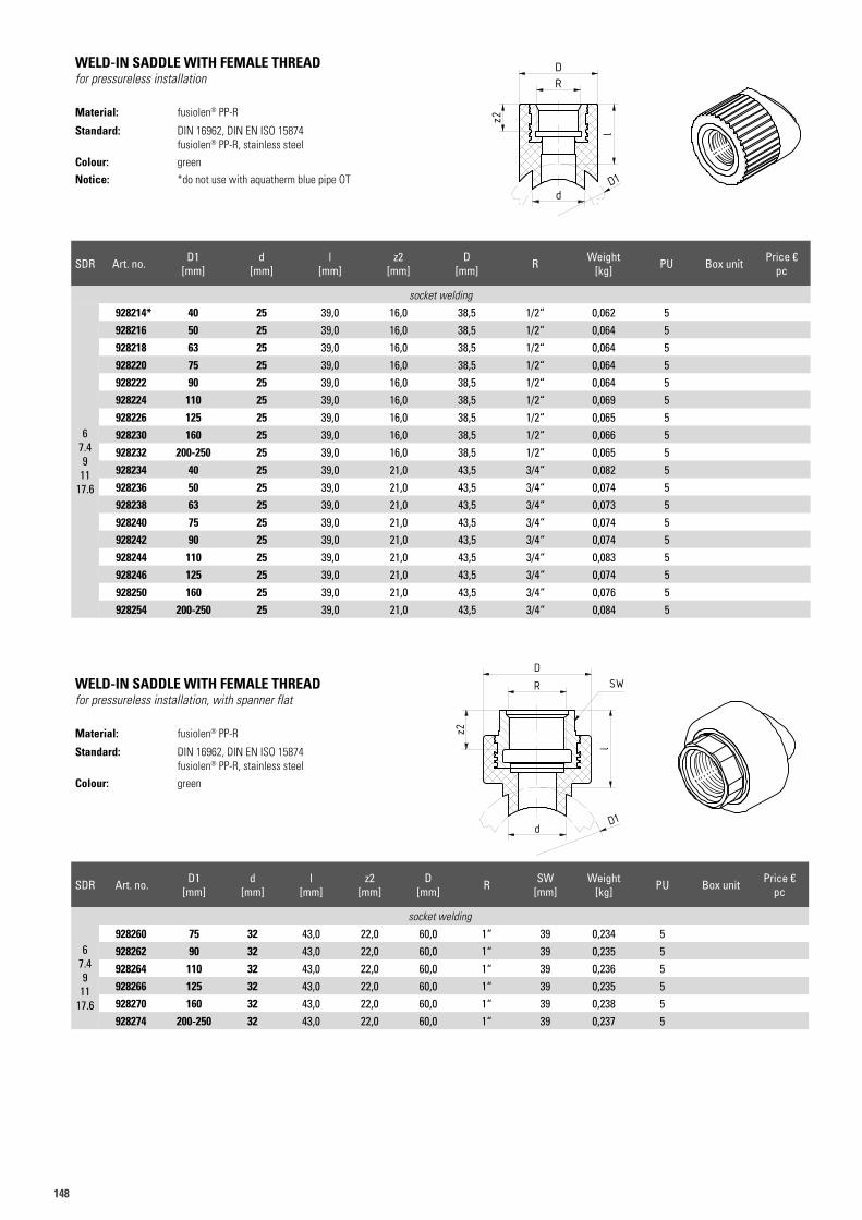
148
WELD-IN SADDLE WITH FEMALE THREADfor pressureless installation
Material: fusiolen® PP-R
Standard: DIN 16962, DIN EN ISO 15874fusiolen® PP-R, stainless steel
Colour: green
Notice: *do not use with aquatherm blue pipe OT
SDR Art. no. D1 [mm]
d [mm]
l [mm]
z2 [mm]
D [mm] R Weight
[kg] PU Box unit Price €pc
socket welding
67.49
1117.6
928214* 40 25 39,0 16,0 38,5 1/2“ 0,062 5928216 50 25 39,0 16,0 38,5 1/2“ 0,064 5928218 63 25 39,0 16,0 38,5 1/2“ 0,064 5928220 75 25 39,0 16,0 38,5 1/2“ 0,064 5928222 90 25 39,0 16,0 38,5 1/2“ 0,064 5928224 110 25 39,0 16,0 38,5 1/2“ 0,069 5928226 125 25 39,0 16,0 38,5 1/2“ 0,065 5928230 160 25 39,0 16,0 38,5 1/2“ 0,066 5928232 200-250 25 39,0 16,0 38,5 1/2“ 0,065 5928234 40 25 39,0 21,0 43,5 3/4“ 0,082 5928236 50 25 39,0 21,0 43,5 3/4“ 0,074 5928238 63 25 39,0 21,0 43,5 3/4“ 0,073 5928240 75 25 39,0 21,0 43,5 3/4“ 0,074 5928242 90 25 39,0 21,0 43,5 3/4“ 0,074 5928244 110 25 39,0 21,0 43,5 3/4“ 0,083 5928246 125 25 39,0 21,0 43,5 3/4“ 0,074 5928250 160 25 39,0 21,0 43,5 3/4“ 0,076 5928254 200-250 25 39,0 21,0 43,5 3/4“ 0,084 5
Art.N. 928216 Gruppe 928214Artikelliste 2018Seite 39
RD
l
z2
D1d
Art.N. 928260 Gruppe 928214Artikelliste 2018Seite 39
RD
l
SW
z2
d D1
Art.N. 928216 Gruppe 928214Artikelliste 2018Seite 39
RD
l
z2
D1d
Art.N. 928260 Gruppe 928214Artikelliste 2018Seite 39
RD
l
SW
z2
d D1
WELD-IN SADDLE WITH FEMALE THREADfor pressureless installation, with spanner flat
Material: fusiolen® PP-R
Standard: DIN 16962, DIN EN ISO 15874fusiolen® PP-R, stainless steel
Colour: green
SDR Art. no. D1 [mm]
d [mm]
l [mm]
z2 [mm]
D [mm] R SW
[mm]Weight
[kg] PU Box unit Price €pc
socket welding
67.49
1117.6
928260 75 32 43,0 22,0 60,0 1“ 39 0,234 5928262 90 32 43,0 22,0 60,0 1“ 39 0,235 5928264 110 32 43,0 22,0 60,0 1“ 39 0,236 5928266 125 32 43,0 22,0 60,0 1“ 39 0,235 5928270 160 32 43,0 22,0 60,0 1“ 39 0,238 5928274 200-250 32 43,0 22,0 60,0 1“ 39 0,237 5
Art.N. 928216 Gruppe 928214Artikelliste 2018Seite 39
RD
l
z2
D1d
Art.N. 928260 Gruppe 928214Artikelliste 2018Seite 39
RD
l
SW
z2
d D1
Art.N. 928216 Gruppe 928214Artikelliste 2018Seite 39
RD
l
z2
D1d
Art.N. 928260 Gruppe 928214Artikelliste 2018Seite 39
RD
l
SW
z2
d D1
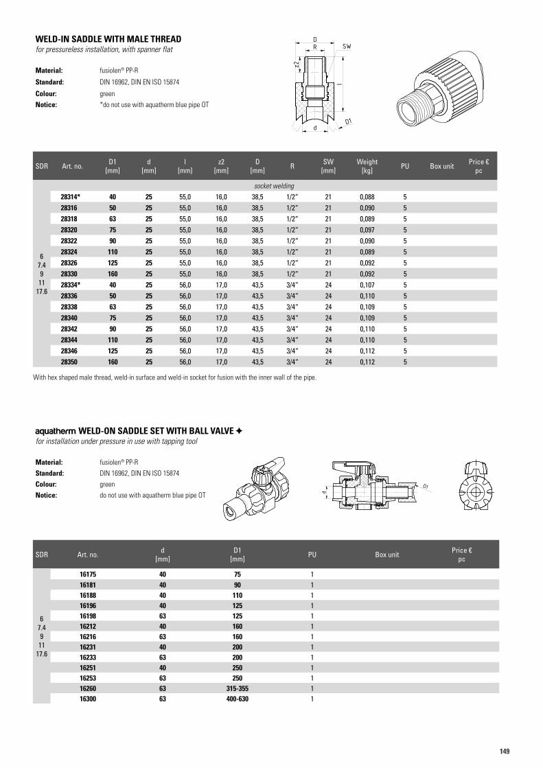
149149
SDR Art. no. D1 [mm]
d [mm]
l [mm]
z2 [mm]
D [mm] R SW
[mm]Weight
[kg] PU Box unit Price €pc
67.49
1117.6
socket welding
28314* 40 25 55,0 16,0 38,5 1/2“ 21 0,088 528316 50 25 55,0 16,0 38,5 1/2“ 21 0,090 528318 63 25 55,0 16,0 38,5 1/2“ 21 0,089 528320 75 25 55,0 16,0 38,5 1/2“ 21 0,097 528322 90 25 55,0 16,0 38,5 1/2“ 21 0,090 528324 110 25 55,0 16,0 38,5 1/2“ 21 0,089 528326 125 25 55,0 16,0 38,5 1/2“ 21 0,092 528330 160 25 55,0 16,0 38,5 1/2“ 21 0,092 528334* 40 25 56,0 17,0 43,5 3/4“ 24 0,107 528336 50 25 56,0 17,0 43,5 3/4“ 24 0,110 528338 63 25 56,0 17,0 43,5 3/4“ 24 0,109 528340 75 25 56,0 17,0 43,5 3/4“ 24 0,109 528342 90 25 56,0 17,0 43,5 3/4“ 24 0,110 528344 110 25 56,0 17,0 43,5 3/4“ 24 0,110 528346 125 25 56,0 17,0 43,5 3/4“ 24 0,112 528350 160 25 56,0 17,0 43,5 3/4“ 24 0,112 5
With hex shaped male thread, weld-in surface and weld-in socket for fusion with the inner wall of the pipe.
WELD-IN SADDLE WITH MALE THREADfor pressureless installation, with spanner flat
Material: fusiolen® PP-R
Standard: DIN 16962, DIN EN ISO 15874
Colour: green
Notice: *do not use with aquatherm blue pipe OT
Art.N. 28316 Gruppe 28314Artikelliste 2015Seite 36
z2
d
RD
l
SW
D1
Art.N. 28316 Gruppe 28314Artikelliste 2015Seite 36
z2
d
RD
l
SW
D1
SDR Art. no. d [mm]
D1 [mm] PU Box unit Price €
pc
67.49
1117.6
16175 40 75 116181 40 90 116188 40 110 116196 40 125 116198 63 125 116212 40 160 116216 63 160 116231 40 200 116233 63 200 116251 40 250 116253 63 250 116260 63 315-355 116300 63 400-630 1
aquatherm WELD-ON SADDLE SET WITH BALL VALVE for installation under pressure in use with tapping tool
Material: fusiolen® PP-R
Standard: DIN 16962, DIN EN ISO 15874
Colour: green
Notice: do not use with aquatherm blue pipe OT
Art.N. 41488+ Aufschweisssattel
d
D1
Art.N. 41488+ Aufschweisssattel
d
D1
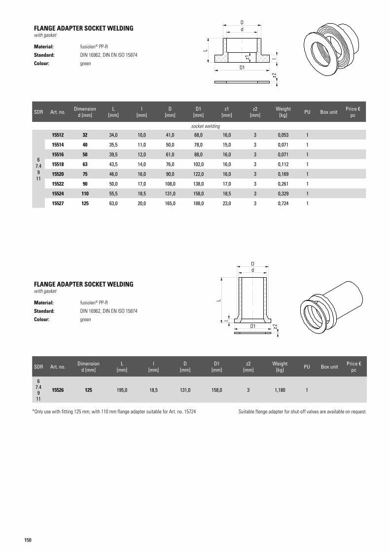
150
FLANGE ADAPTER SOCKET WELDING with gasket
Material: fusiolen® PP-R
Standard: DIN 16962, DIN EN ISO 15874
Colour: green
SDR Art. no. Dimensiond [mm]
L [mm]
l [mm]
D [mm]
D1 [mm]
z2 [mm]
Weight [kg] PU Box unit Price €
pc
67.49
11
15526 125 195,0 18,5 131,0 158,0 3 1,180 1
*Only use with fitting 125 mm; with 110 mm flange adapter suitable for Art. no. 15724 Suitable flange adapter for shut-off valves are available on request.
FLANGE ADAPTER SOCKET WELDING with gasket
Material: fusiolen® PP-R
Standard: DIN 16962, DIN EN ISO 15874
Colour: green
SDR Art. no. Dimensiond [mm]
L [mm]
l [mm]
D [mm]
D1 [mm]
z1 [mm]
z2 [mm]
Weight [kg] PU Box unit Price €
pc
socket welding
67.49
11
15512 32 34,0 10,0 41,0 68,0 16,0 3 0,053 1
15514 40 35,5 11,0 50,0 78,0 15,0 3 0,071 1
15516 50 39,5 12,0 61,0 88,0 16,0 3 0,071 1
15518 63 43,5 14,0 76,0 102,0 16,0 3 0,112 1
15520 75 46,0 16,0 90,0 122,0 16,0 3 0,169 1
15522 90 50,0 17,0 108,0 138,0 17,0 3 0,261 1
15524 110 55,5 18,5 131,0 158,0 18,5 3 0,329 1
15527 125 63,0 20,0 165,0 188,0 23,0 3 0,724 1
Art.N. 15516 Gruppe 15512Artikelliste 2015Seite 37
dD
z1 l
L
z2
D1
dD
Ll
z2
15526
D1
Art.N. 15516 Gruppe 15512Artikelliste 2015Seite 37
dD
z1 l
L
z2
D1
dD
Ll
z2
15526
D1
Art.N. 15516 Gruppe 15512Artikelliste 2015Seite 37
dD
z1 l
L
z2
D1
dD
Ll
z2
15526
D1
Art.N. 15516 Gruppe 15512Artikelliste 2015Seite 37
dD
z1 l
L
z2
D1
dD
Ll
z2
15526
D1
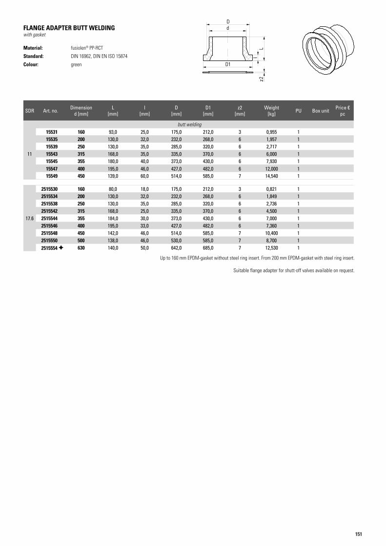
151151
FLANGE ADAPTER BUTT WELDINGwith gasket
Material: fusiolen® PP-RCT
Standard: DIN 16962, DIN EN ISO 15874
Colour: green
SDR Art. no. Dimensiond [mm]
L [mm]
l [mm]
D [mm]
D1 [mm]
z2 [mm]
Weight [kg] PU Box unit Price €
pc
butt welding
11
15531 160 93,0 25,0 175,0 212,0 3 0,955 115535 200 130,0 32,0 232,0 268,0 6 1,957 115539 250 130,0 35,0 285,0 320,0 6 2,717 115543 315 168,0 35,0 335,0 370,0 6 6,000 115545 355 180,0 40,0 373,0 430,0 6 7,930 115547 400 195,0 46,0 427,0 482,0 6 12,000 115549 450 139,0 60,0 514,0 585,0 7 14,540 1
17.6
2515530 160 80,0 18,0 175,0 212,0 3 0,821 12515534 200 130,0 32,0 232,0 268,0 6 1,849 12515538 250 130,0 35,0 285,0 320,0 6 2,736 12515542 315 168,0 25,0 335,0 370,0 6 4,500 12515544 355 184,0 30,0 373,0 430,0 6 7,000 12515546 400 195,0 33,0 427,0 482,0 6 7,360 12515548 450 142,0 46,0 514,0 585,0 7 10,400 12515550 500 138,0 46,0 530,0 585,0 7 8,700 12515554 630 140,0 50,0 642,0 685,0 7 12,530 1
Up to 160 mm EPDM-gasket without steel ring insert. From 200 mm EPDM-gasket with steel ring insert.
Suitable flange adapter for shutt-off valves available on request.
Art.N. 15516Artikelliste 2015Seite 37
dD
D1
z2l
L
Art.N. 15516Artikelliste 2015Seite 37
dD
D1
z2l
L
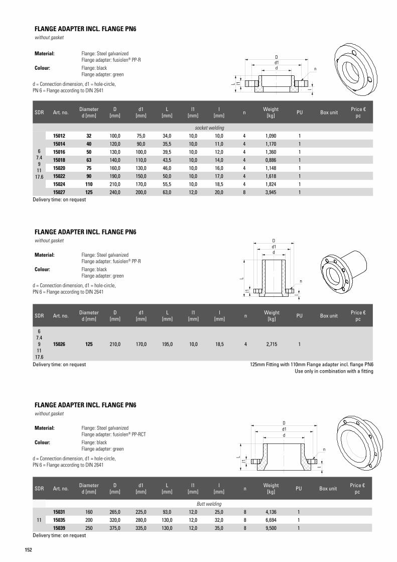
152
SDR Art. no. Diameter d [mm]
D [mm]
d1 [mm]
L [mm]
l1 [mm]
l [mm] n Weight
[kg] PU Box unit Price €pc
socket welding
67.49
1117.6
15012 32 100,0 75,0 34,0 10,0 10,0 4 1,090 115014 40 120,0 90,0 35,5 10,0 11,0 4 1,170 115016 50 130,0 100,0 39,5 10,0 12,0 4 1,360 115018 63 140,0 110,0 43,5 10,0 14,0 4 0,886 115020 75 160,0 130,0 46,0 10,0 16,0 4 1,148 115022 90 190,0 150,0 50,0 10,0 17,0 4 1,618 115024 110 210,0 170,0 55,5 10,0 18,5 4 1,824 115027 125 240,0 200,0 63,0 12,0 20,0 8 3,945 1
Delivery time: on request
FLANGE ADAPTER INCL. FLANGE PN6without gasket
Material: Flange: Steel galvanized Flange adapter: fusiolen® PP-R
Colour: Flange: black Flange adapter: green
d = Connection dimension, d1 = hole-circle, PN 6 = Flange according to DIN 2641
Art.N. 15022,15035 Gruppe 15016Artikelliste 2016Seite ??
L
d
L
d
l
l
d1d1
l1
l1
DD
n
n
Muffenschweißverfahren Stumpfschweißverfahren
ll1L
dd1D
n
Art.N. 15022,15035 Gruppe 15016Artikelliste 2016Seite ??
L
d
L
d
l
l
d1d1
l1
l1
DD
n
n
Muffenschweißverfahren Stumpfschweißverfahren
ll1L
dd1D
n
SDR Art. no. Diameter d [mm]
D [mm]
d1 [mm]
L [mm]
l1 [mm]
l [mm] n Weight
[kg] PU Box unit Price €pc
Butt welding
1115031 160 265,0 225,0 93,0 12,0 25,0 8 4,136 115035 200 320,0 280,0 130,0 12,0 32,0 8 6,694 115039 250 375,0 335,0 130,0 12,0 35,0 8 9,500 1
Delivery time: on request
FLANGE ADAPTER INCL. FLANGE PN6without gasket
Material: Flange: Steel galvanized Flange adapter: fusiolen® PP-RCT
Colour: Flange: black Flange adapter: green
d = Connection dimension, d1 = hole-circle, PN 6 = Flange according to DIN 2641
Art.N. 15022,15035 Gruppe 15016Artikelliste 2016Seite ??
L
d
L
d
l
l
d1d1
l1
l1
DD
n
n
Muffenschweißverfahren Stumpfschweißverfahren
ll1L
dd1D
n
Art.N. 15022,15035 Gruppe 15016Artikelliste 2016Seite ??
L
d
L
d
l
l
d1d1
l1
l1
DD
n
n
Muffenschweißverfahren Stumpfschweißverfahren
ll1L
dd1D
n
SDR Art. no. Diameter d [mm]
D [mm]
d1 [mm]
L [mm]
l1 [mm]
l [mm] n Weight
[kg] PU Box unit Price €pc
67.49
1117.6
15026 125 210,0 170,0 195,0 10,0 18,5 4 2,715 1
Delivery time: on request 125mm Fitting with 110mm Flange adapter incl. flange PN6 Use only in combination with a fitting
FLANGE ADAPTER INCL. FLANGE PN6without gasket
Material: Flange: Steel galvanized Flange adapter: fusiolen® PP-R
Colour: Flange: black Flange adapter: green
d = Connection dimension, d1 = hole-circle, PN 6 = Flange according to DIN 2641
Art.N. 15022,15035 Gruppe 15016Artikelliste 2016Seite ??
L
d
L
d
l
l
d1d1
l1
l1
DD
n
n
Muffenschweißverfahren Stumpfschweißverfahren
ll1L
dd1D
n
Art.N. 15022,15035 Gruppe 15016Artikelliste 2016Seite ??
L
d
L
d
l
l
d1d1
l1
l1
DD
n
n
Muffenschweißverfahren Stumpfschweißverfahren
ll1L
dd1D
n
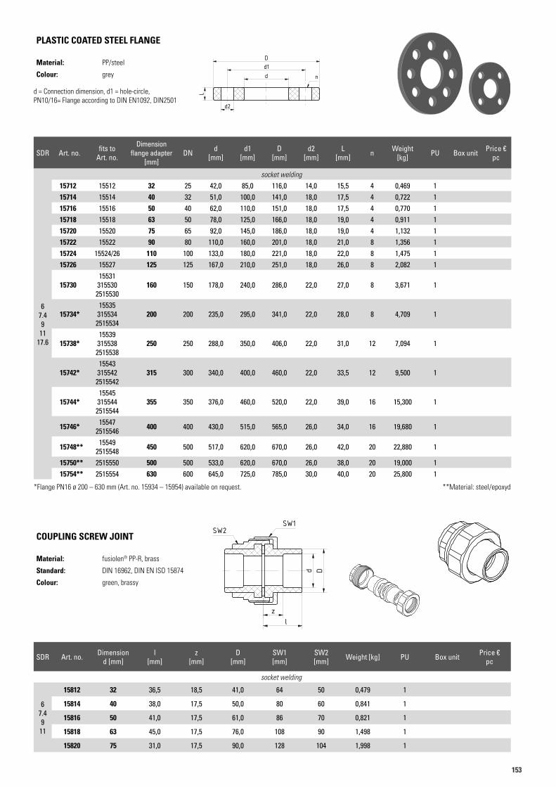
153153
PLASTIC COATED STEEL FLANGE
Material: PP/steel
Colour: grey
d = Connection dimension, d1 = hole-circle, PN10/16= Flange according to DIN EN1092, DIN2501
SDR Art. no. Dimensiond [mm]
l [mm]
z [mm]
D [mm]
SW1 [mm]
SW2 [mm] Weight [kg] PU Box unit Price €
pc
socket welding
67.49
11
15812 32 36,5 18,5 41,0 64 50 0,479 1
15814 40 38,0 17,5 50,0 80 60 0,841 1
15816 50 41,0 17,5 61,0 86 70 0,821 1
15818 63 45,0 17,5 76,0 108 90 1,498 1
15820 75 31,0 17,5 90,0 128 104 1,998 1
COUPLING SCREW JOINT
Material: fusiolen® PP-R, brass
Standard: DIN 16962, DIN EN ISO 15874
Colour: green, brassy
Art.N. 15716Artikelliste 2015Seite 38
d
D
L
d2
d1n
Art.N. 15812Artikelliste 2015Seite 38
d D
zl
SW1SW2
Art.N. 15812Artikelliste 2015Seite 38
d D
zl
SW1SW2
Art.N. 15812Artikelliste 2015Seite 38
d D
zl
SW1SW2
SDR Art. no. fits toArt. no.
Dimen sion flange adapter
[mm]DN d
[mm]d1
[mm]D
[mm]d2
[mm]L
[mm] n Weight [kg] PU Box unit Price €
pc
67.49
1117.6
socket welding
15712 15512 32 25 42,0 85,0 116,0 14,0 15,5 4 0,469 115714 15514 40 32 51,0 100,0 141,0 18,0 17,5 4 0,722 115716 15516 50 40 62,0 110,0 151,0 18,0 17,5 4 0,770 115718 15518 63 50 78,0 125,0 166,0 18,0 19,0 4 0,911 115720 15520 75 65 92,0 145,0 186,0 18,0 19,0 4 1,132 115722 15522 90 80 110,0 160,0 201,0 18,0 21,0 8 1,356 115724 15524/26 110 100 133,0 180,0 221,0 18,0 22,0 8 1,475 115726 15527 125 125 167,0 210,0 251,0 18,0 26,0 8 2,082 1
1573015531
3155302515530
160 150 178,0 240,0 286,0 22,0 27,0 8 3,671 1
15734*15535
3155342515534
200 200 235,0 295,0 341,0 22,0 28,0 8 4,709 1
15738*15539
3155382515538
250 250 288,0 350,0 406,0 22,0 31,0 12 7,094 1
15742*15543
3155422515542
315 300 340,0 400,0 460,0 22,0 33,5 12 9,500 1
15744*15545
3155442515544
355 350 376,0 460,0 520,0 22,0 39,0 16 15,300 1
15746* 155472515546 400 400 430,0 515,0 565,0 26,0 34,0 16 19,680 1
15748** 155492515548 450 500 517,0 620,0 670,0 26,0 42,0 20 22,880 1
15750** 2515550 500 500 533,0 620,0 670,0 26,0 38,0 20 19,000 115754** 2515554 630 600 645,0 725,0 785,0 30,0 40,0 20 25,800 1
*Flange PN16 ø 200 – 630 mm (Art. no. 15934 – 15954) available on request. **Material: steel/epoxyd
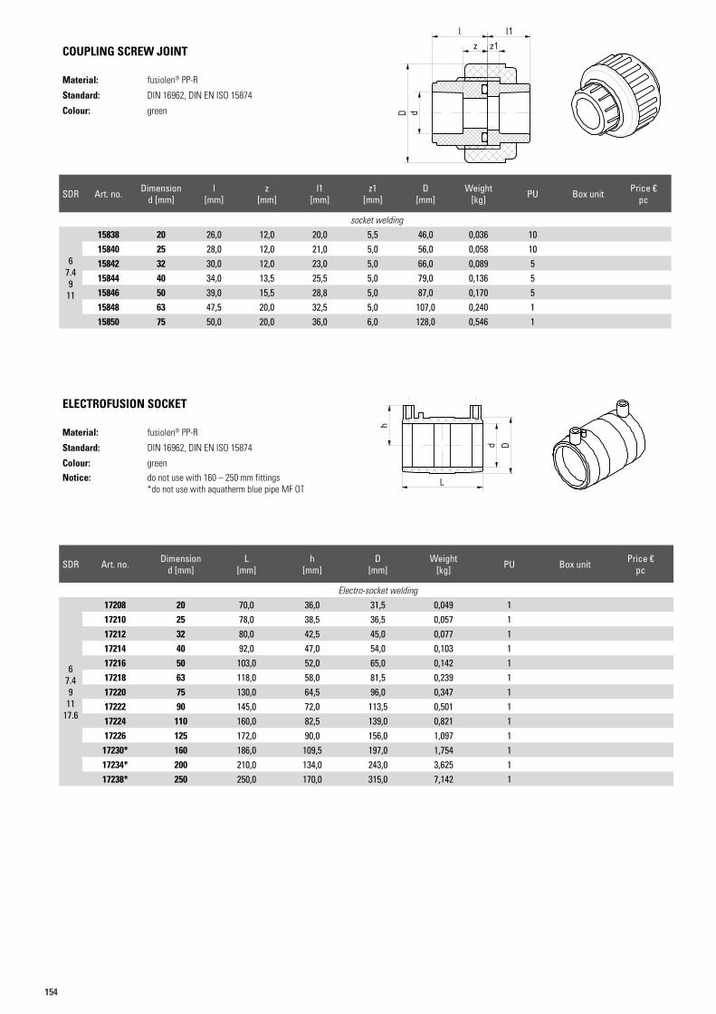
154
SDR Art. no. Dimensiond [mm]
l [mm]
z [mm]
l1 [mm]
z1 [mm]
D [mm]
Weight [kg] PU Box unit Price €
pc
socket welding
67.49
11
15838 20 26,0 12,0 20,0 5,5 46,0 0,036 1015840 25 28,0 12,0 21,0 5,0 56,0 0,058 1015842 32 30,0 12,0 23,0 5,0 66,0 0,089 515844 40 34,0 13,5 25,5 5,0 79,0 0,136 515846 50 39,0 15,5 28,8 5,0 87,0 0,170 515848 63 47,5 20,0 32,5 5,0 107,0 0,240 115850 75 50,0 20,0 36,0 6,0 128,0 0,546 1
COUPLING SCREW JOINT
Material: fusiolen® PP-R
Standard: DIN 16962, DIN EN ISO 15874
Colour: green
Art.N. 15838Artikelliste 2015Seite 39
dD
z z1l l1
Art.N. 15838Artikelliste 2015Seite 39
dD
z z1l l1
ELECTROFUSION SOCKET
Material: fusiolen® PP-R
Standard: DIN 16962, DIN EN ISO 15874
Colour: green
Notice: do not use with 160 – 250 mm fittings*do not use with aquatherm blue pipe MF OT
Art.N. 17218Artikelliste 2015Seite 40
h
Ld D
Art.N. 17218Artikelliste 2015Seite 40
h
L
d D
SDR Art. no. Dimensiond [mm]
L [mm]
h [mm]
D [mm]
Weight [kg] PU Box unit Price €
pc
Electro-socket welding
67.49
1117.6
17208 20 70,0 36,0 31,5 0,049 117210 25 78,0 38,5 36,5 0,057 117212 32 80,0 42,5 45,0 0,077 117214 40 92,0 47,0 54,0 0,103 117216 50 103,0 52,0 65,0 0,142 117218 63 118,0 58,0 81,5 0,239 117220 75 130,0 64,5 96,0 0,347 117222 90 145,0 72,0 113,5 0,501 117224 110 160,0 82,5 139,0 0,821 117226 125 172,0 90,0 156,0 1,097 117230* 160 186,0 109,5 197,0 1,754 117234* 200 210,0 134,0 243,0 3,625 117238* 250 250,0 170,0 315,0 7,142 1
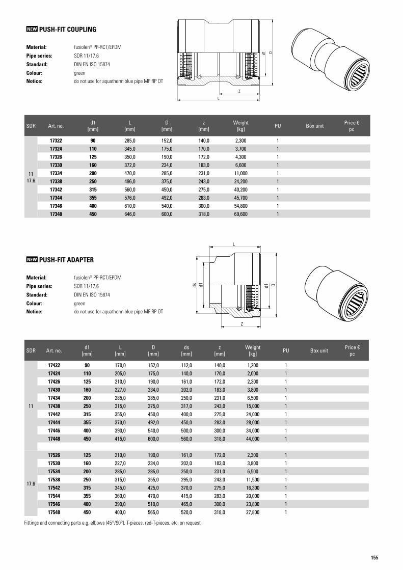
155155
SDR Art. no. d1 [mm]
L [mm]
D [mm]
ds [mm]
z [mm]
Weight [kg] PU Box unit Price €
pc
11
17422 90 170,0 152,0 112,0 140,0 1,200 117424 110 205,0 175,0 140,0 170,0 2,000 117426 125 210,0 190,0 161,0 172,0 2,300 117430 160 227,0 234,0 202,0 183,0 3,800 117434 200 285,0 285,0 250,0 231,0 6,500 117438 250 315,0 375,0 317,0 243,0 15,000 117442 315 355,0 450,0 400,0 275,0 24,000 117444 355 370,0 492,0 450,0 283,0 28,000 117446 400 390,0 540,0 500,0 300,0 34,000 117448 450 415,0 600,0 560,0 318,0 44,000 1
17.6
17526 125 210,0 190,0 161,0 172,0 2,300 117530 160 227,0 234,0 202,0 183,0 3,800 117534 200 285,0 285,0 250,0 231,0 6,500 117538 250 315,0 355,0 295,0 243,0 11,500 117542 315 345,0 425,0 370,0 275,0 16,300 117544 355 360,0 470,0 415,0 283,0 20,000 117546 400 390,0 510,0 465,0 300,0 23,800 117548 450 400,0 565,0 520,0 318,0 27,800 1
Fittings and connecting parts e.g. elbows (45°/90°), T-pieces, red-T-pieces, etc. on request
NEW PUSH-FIT ADAPTER
Material: fusiolen® PP-RCT/EPDM
Pipe series: SDR 11/17.6
Standard: DIN EN ISO 15874
Colour: green
Notice: do not use for aquatherm blue pipe MF RP OT
A A
B B
C C
D D
E E
F F
1
1
2
2
3
3
4
4
1
ReinoGrip XL
1-15-414-1030
#.9 DOS.OO #. #
! "!$" %&& %'(&
Steckkupplung SDR 11 / 17
Reinert-Ritz
)*+,-/0 12345236
78:;< =->?0 * ,/+@ =
Allgemeintoleranzen
ISO 2768m/8074/8077
ReinoGrip XL
1
ABCEFGHBIJ KLM NPNQP N PNRNQ
d1 D
Z
L
d1
SDR 11
d1 L D ds Zp1 Gewicht
250 315 375 317 243 15kg
280 330 410 355 255 19kg
315 355 450 400 275 24kg
355 370 492 450 283 28kg
400 390 540 500 300 34kg
450 415 600 560 318 44kg
ds
SDR 17
d1 L D ds Zp1 Gewicht
250 315 355 295 243 11,5 kg
280 315 385 325 255 12,2 kg
315 345 425 370 275 16,3 kg
355 360 470 415 283 20,0 kg
400 390 510 465 300 23,8 kg
450 400 565 520 318 27,8 kg
SDR Art. no. d1 [mm]
L [mm]
D [mm]
z [mm]
Weight [kg] PU Box unit Price €
pc
11 17.6
17322 90 285,0 152,0 140,0 2,300 117324 110 345,0 175,0 170,0 3,700 117326 125 350,0 190,0 172,0 4,300 117330 160 372,0 234,0 183,0 6,600 117334 200 470,0 285,0 231,0 11,000 117338 250 496,0 375,0 243,0 24,200 117342 315 560,0 450,0 275,0 40,200 117344 355 576,0 492,0 283,0 45,700 117346 400 610,0 540,0 300,0 54,800 117348 450 646,0 600,0 318,0 69,600 1
NEW PUSH-FIT COUPLING
Material: fusiolen® PP-RCT/EPDM
Pipe series: SDR 11/17.6
Standard: DIN EN ISO 15874
Colour: green
Notice: do not use for aquatherm blue pipe MF RP OT
1
1
2
2
3
3
4
4
5
5
6
6
7
7
8
8
A A
B B
C C
D D
E E
F F
3 A3
ReinoGrip XL Stammmaße
1-15-318-01163
Status Änderungen Datum Name
Gezeichnet
Kontrolliert
Norm
Datum Name17.04.2018 I. Kramer
Doppelsteckkupplung
Reinert-RitzD-48531 Nordhorn
Tel.: 05921 - 8347 0
AllgemeintoleranzenISO 2768m/8074/8077
1RevBauteil Nr. 1-15-318-1148
Schutzvermerk nach DIN ISO 16016"Weitergabe sowie Vervielfältigung dieses Dokuments, Verwertung und Mitteilung seines Inhalts sind verboten, soweit nicht ausdrücklich gestattet. Zuwiderhandlungen verpflichten zu Schadenersatz. Alle Rechte für den Fall der Patent-, Gebrauchsmuster- oder Geschmacksmustereintragung vorbehalten." The reproduction, distribution and utilization of this document as well as thecommunication of its contents to others without explicid authorization is prohibited. Offenders will be held liable for the payment of damages. All rights reserved in the event of the grant of a patent, utility model or design.
D
Z
L
d1
ReinoGrip XL Doppelsteckkupplung SDR 11d1 L D ds ZP1 Gewicht250 496 375 317 243 24,2280 520 410 355 255 33,8315 560 450 400 275 40,2355 576 492 450 283 45,7400 610 540 500 300 54,8450 646 600 560 318 69,6
ReinoGrip XL Doppelsteckkupplung SDR 17d1 L D ds ZP1 Gewicht250 496 355 295 243 19,2280 520 385 325 255 26,3315 560 425 370 275 31,2355 576 470 415 283 36,2400 610 510 465 300 39,8450 646 565 520 318 50,6
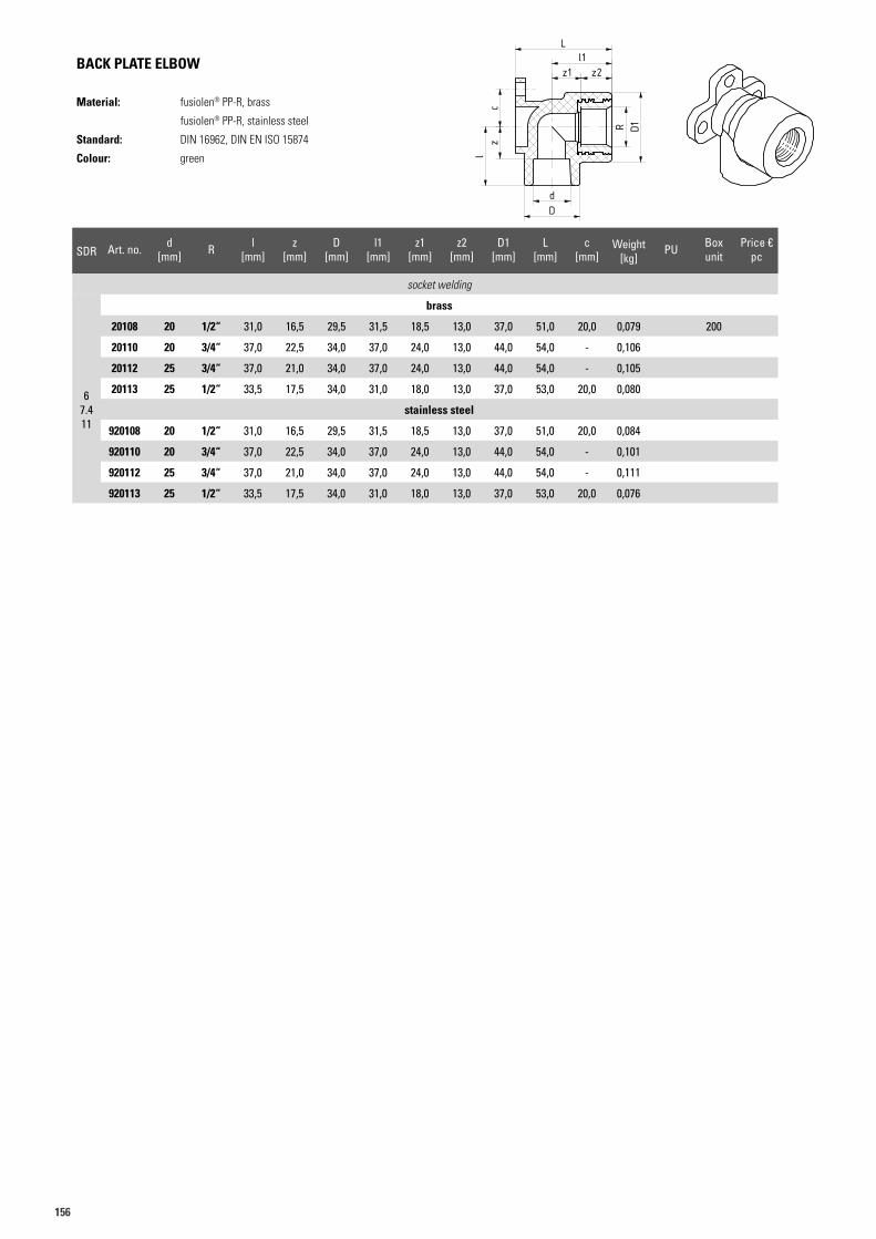
156
SDR Art. no. d [mm] R l
[mm]z
[mm]D
[mm]l1
[mm]z1
[mm]z2
[mm]D1
[mm]L
[mm]c
[mm]Weight
[kg]PU Box
unitPrice €
pc
socket welding
brass
67.411
20108 20 1/2“ 31,0 16,5 29,5 31,5 18,5 13,0 37,0 51,0 20,0 0,079 200
20110 20 3/4“ 37,0 22,5 34,0 37,0 24,0 13,0 44,0 54,0 - 0,106
20112 25 3/4“ 37,0 21,0 34,0 37,0 24,0 13,0 44,0 54,0 - 0,105
20113 25 1/2“ 33,5 17,5 34,0 31,0 18,0 13,0 37,0 53,0 20,0 0,080
stainless steel
920108 20 1/2“ 31,0 16,5 29,5 31,5 18,5 13,0 37,0 51,0 20,0 0,084
920110 20 3/4“ 37,0 22,5 34,0 37,0 24,0 13,0 44,0 54,0 - 0,101
920112 25 3/4“ 37,0 21,0 34,0 37,0 24,0 13,0 44,0 54,0 - 0,111
920113 25 1/2“ 33,5 17,5 34,0 31,0 18,0 13,0 37,0 53,0 20,0 0,076
BACK PLATE ELBOW
Material: fusiolen® PP-R, brass
fusiolen® PP-R, stainless steel
Standard: DIN 16962, DIN EN ISO 15874
Colour: green
Art.N. 20108Artikelliste 2015Seite 40
z2
R D1
z1l1
dD
cz
l
L
Art.N. 20108Artikelliste 2015Seite 40
z2
R D1
z1l1
dD
cz
l
L
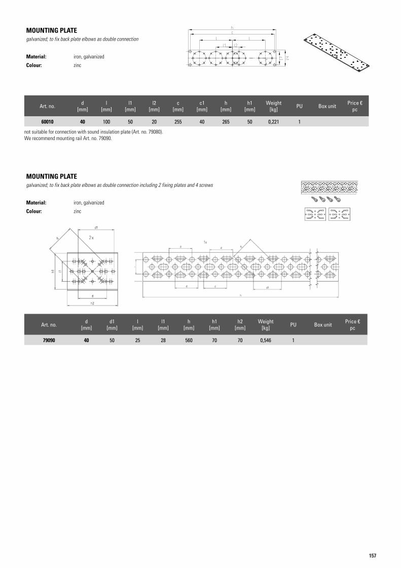
157157
Art. no. d [mm]
l [mm]
l1 [mm]
l2 [mm]
c [mm]
c1 [mm]
h [mm]
h1 [mm]
Weight [kg] PU Box unit Price €
pc
60010 40 100 50 20 255 40 265 50 0,221 1
not suitable for connection with sound insulation plate (Art. no. 79080). We recommend mounting rail Art. no. 79090.
MOUNTING PLATEgalvanized; to fix back plate elbows as double connection
Material: iron, galvanized
Colour: zinc
Art. no. d [mm]
d1 [mm]
l [mm]
l1 [mm]
h [mm]
h1 [mm]
h2 [mm]
Weight [kg] PU Box unit Price €
pc
79090 40 50 25 28 560 70 70 0,546 1
MOUNTING PLATEgalvanized; to fix back plate elbows as double connection including 2 fixing plates and 4 screws
Material: iron, galvanized
Colour: zinc
Art.N. 60010Artikelliste 2016Seite 46
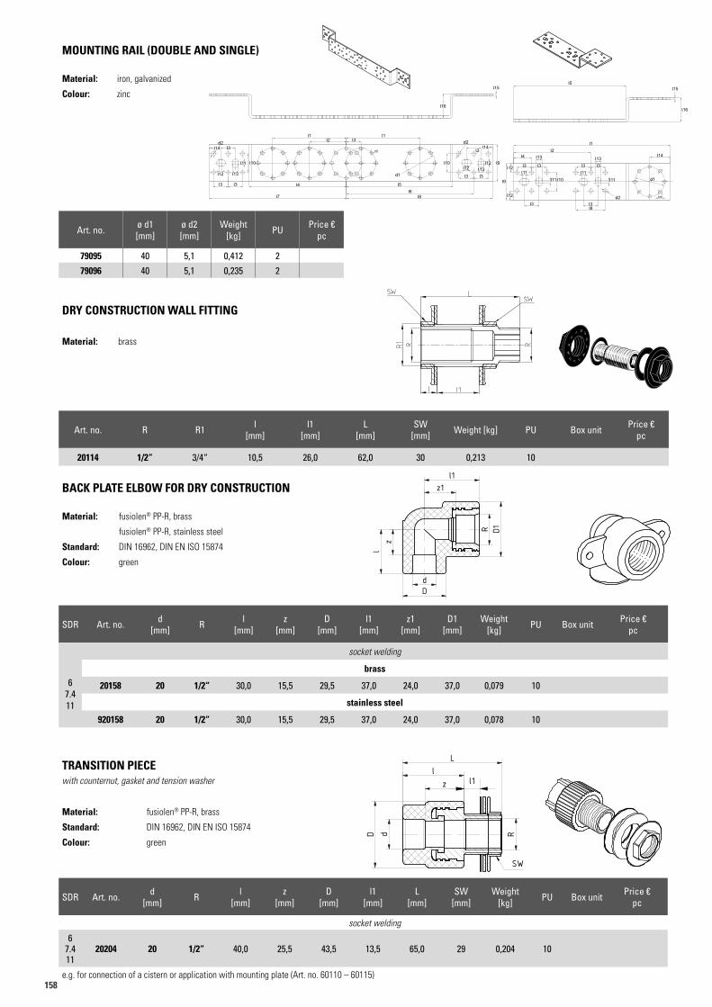
158
DRY CONSTRUCTION WALL FITTING
Material: brass
TRANSITION PIECEwith counternut, gasket and tension washer
Material: fusiolen® PP-R, brass
Standard: DIN 16962, DIN EN ISO 15874
Colour: green
MOUNTING RAIL (DOUBLE AND SINGLE)
Material: iron, galvanized
Colour: zinc
20114
Art.N. 20204Artikelliste 2015Seite 42
dD
zl
R
L
SW
l1
Art.N. 20204Artikelliste 2015Seite 42
dD
zl
R
L
SW
l1
l5l15
l16
l1
l2l4
l3
l3 l3l8
l3 l3
l14
l3
l13 l13
d2
d1l9
l12
l12l11 l11
l11 l11l10
l2l1 l1
l15
l16
l4 l5
l6l7 l8
l12 l13
d2d2
d1
l9l12l10
l14l14
l11
l3
l3
l3
l3
l12 l13
l3 l3
l3
l10
Art. no. R R1 l [mm]
l1 [mm]
L [mm]
SW [mm] Weight [kg] PU Box unit Price €
pc
20114 1/2“ 3/4“ 10,5 26,0 62,0 30 0,213 10
SDR Art. no. d [mm] R l
[mm]z
[mm]D
[mm]l1
[mm]L
[mm]SW
[mm]Weight
[kg] PU Box unit Price €pc
socket welding
67.411
20204 20 1/2“ 40,0 25,5 43,5 13,5 65,0 29 0,204 10
e.g. for connection of a cistern or application with mounting plate (Art. no. 60110 – 60115)
Art. no. ø d1 [mm]
ø d2 [mm]
Weight [kg] PU Price €
pc
79095 40 5,1 0,412 2
79096 40 5,1 0,235 2
Art.N. 79095Artikelliste 2016Seite 47
Art.N. 79096Artikelliste 2016Seite 47
SDR Art. no. d [mm] R l
[mm]z
[mm]D
[mm]l1
[mm]z1
[mm]D1
[mm]Weight
[kg] PU Box unit Price €pc
socket welding
67.411
brass
20158 20 1/2“ 30,0 15,5 29,5 37,0 24,0 37,0 0,079 10
stainless steel
920158 20 1/2“ 30,0 15,5 29,5 37,0 24,0 37,0 0,078 10
BACK PLATE ELBOW FOR DRY CONSTRUCTION
Material: fusiolen® PP-R, brass
fusiolen® PP-R, stainless steel
Standard: DIN 16962, DIN EN ISO 15874
Colour: green
Art.N. 20156Artikelliste 2015Seite 42
c z1
zl
l1
dD
R D1
Art.N. 20156Artikelliste 2015Seite 42
c z1
zl
l1
dD
R D1
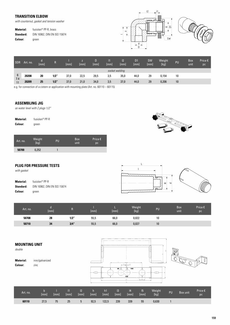
159159
TRANSITION ELBOWwith counternut, gasket and tension washer
Material: fusiolen® PP-R, brass
Standard: DIN 16962, DIN EN ISO 15874
Colour: green
PLUG FOR PRESSURE TESTSwith gasket
Material: fusiolen® PP-R
Standard: DIN 16962, DIN EN ISO 15874
Colour: green
MOUNTING UNITdouble
Material: iron/galvanized
Colour: zinc
Art. no. b [mm]
l [mm]
l1 [mm]
l2 [mm]
h [mm]
h1 [mm]
l3 [mm]
l4 [mm]
l5 [mm]
Weight [kg] PU Box unit Price €
pc
60110 27,5 75 25 5 92,5 122,5 239 339 55 0,630 1
ASSEMBLING JIGas water level with 2 plugs 1/2“
Material: fusiolen® PP-R
Colour: green
Art.N. 20206Artikelliste 2015Seite 43
R D1
SW
dD
zl
l1l2
Art.N. 20206Artikelliste 2015Seite 43
R D1
SW
dD
zl
l1l2
Art.N. 50708Artikelliste 2015Seite 43
R dl
L
Art.N. 50708Artikelliste 2015Seite 43
R d
l
L
60110
80100
150
8 0 1 0 0 1 5 0 2 0 0 2 5 0
aquatherm
2 5 0 2 0 0 1 5 0 1 0 0 8 0
SDR Art. no. d [mm] R l
[mm]z
[mm]D
[mm]l1
[mm]l2
[mm]D1
[mm]SW
[mm]Weight
[kg] PU Box unit
Price €pc
socket welding6
7.411
20208 20 1/2“ 37,0 22,5 29,5 3,5 35,0 44,0 29 0,154 10
20209 25 1/2“ 37,0 21,0 34,0 3,5 37,0 44,0 29 0,206 10
e.g. for connection of a cistern or application with mounting plate (Art. no. 60110 – 60115)
Art. no. d [mm] R l
[mm]L
[mm]Weight
[kg] PU Box unit
Price €pc
50708 28 1/2“ 55,5 66,0 0,022 10
50710 34 3/4“ 55,5 66,0 0,027 10
Art. no. Weight [kg] PU Box
unitPrice €
pc
50700 0,252 1
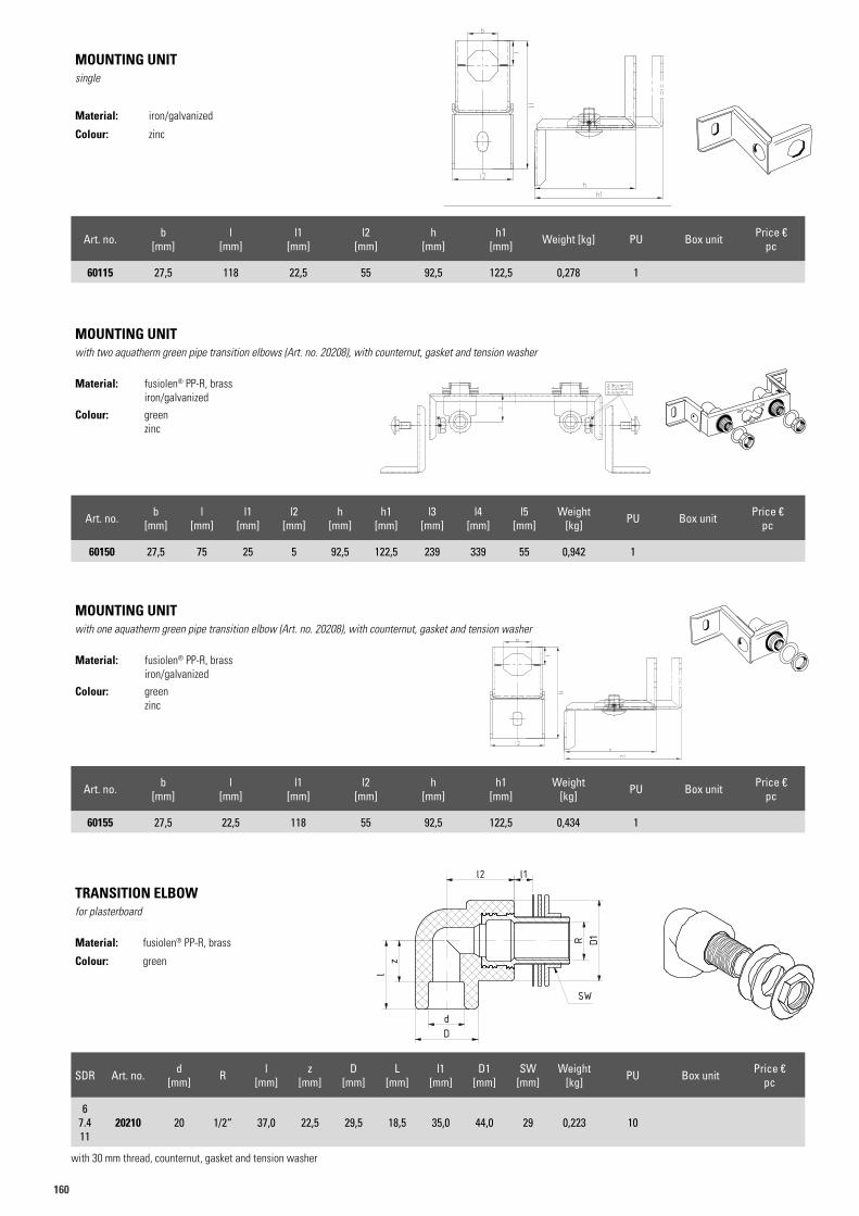
160
MOUNTING UNITsingle
Material: iron/galvanized
Colour: zinc
Art. no. b [mm]
l [mm]
l1 [mm]
l2 [mm]
h [mm]
h1 [mm] Weight [kg] PU Box unit Price €
pc
60115 27,5 118 22,5 55 92,5 122,5 0,278 1
MOUNTING UNITwith two aquatherm green pipe transition elbows (Art. no. 20208), with counternut, gasket and tension washer
Material: fusiolen® PP-R, brass iron/galvanized
Colour: greenzinc
Art. no. b [mm]
l [mm]
l1 [mm]
l2 [mm]
h [mm]
h1 [mm]
l3 [mm]
l4 [mm]
l5 [mm]
Weight [kg] PU Box unit Price €
pc
60150 27,5 75 25 5 92,5 122,5 239 339 55 0,942 1
MOUNTING UNITwith one aquatherm green pipe transition elbow (Art. no. 20208), with counternut, gasket and tension washer
Material: fusiolen® PP-R, brass iron/galvanized
Colour: greenzinc
Art. no. b [mm]
l [mm]
l1 [mm]
l2 [mm]
h [mm]
h1 [mm]
Weight [kg] PU Box unit Price €
pc
60155 27,5 22,5 118 55 92,5 122,5 0,434 1
TRANSITION ELBOWfor plasterboard
Material: fusiolen® PP-R, brass
Colour: green
SDR Art. no. d [mm] R l
[mm]z
[mm]D
[mm]L
[mm]l1
[mm]D1
[mm]SW
[mm]Weight
[kg] PU Box unit Price €pc
67.411
20210 20 1/2“ 37,0 22,5 29,5 18,5 35,0 44,0 29 0,223 10
with 30 mm thread, counternut, gasket and tension washer
60150
80100
150
60155
Art.N. 20210Artikelliste 2015Seite 44
R D1
D
z
l2 l1
SW
l
d
Art.N. 20210Artikelliste 2015Seite 44
R D1
D
z
l2 l1
SW
l
d
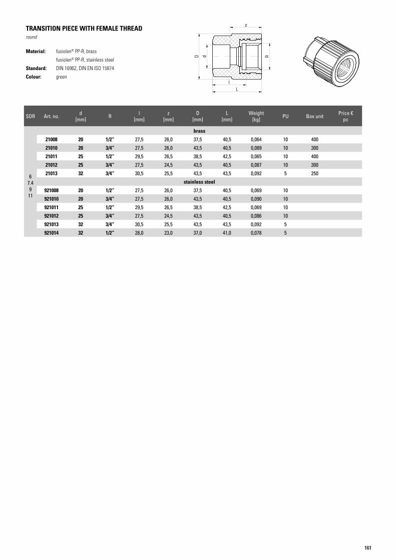
161161
SDR Art. no. d [mm] R l
[mm]z
[mm]D
[mm]L
[mm]Weight
[kg] PU Box unit Price €pc
brass
67.49
11
21008 20 1/2“ 27,5 26,0 37,5 40,5 0,064 10 400
21010 20 3/4“ 27,5 26,0 43,5 40,5 0,089 10 300
21011 25 1/2“ 29,5 26,5 38,5 42,5 0,065 10 400
21012 25 3/4“ 27,5 24,5 43,5 40,5 0,087 10 300
21013 32 3/4“ 30,5 25,5 43,5 43,5 0,092 5 250
stainless steel
921008 20 1/2“ 27,5 26,0 37,5 40,5 0,069 10
921010 20 3/4“ 27,5 26,0 43,5 40,5 0,090 10
921011 25 1/2“ 29,5 26,5 38,5 42,5 0,069 10
921012 25 3/4“ 27,5 24,5 43,5 40,5 0,086 10
921013 32 3/4“ 30,5 25,5 43,5 43,5 0,092 5
921014 32 1/2“ 28,0 23,0 37,0 41,0 0,078 5
TRANSITION PIECE WITH FEMALE THREADround
Material: fusiolen® PP-R, brass
fusiolen® PP-R, stainless steel
Standard: DIN 16962, DIN EN ISO 15874
Colour: green
Art.N. 21008Artikelliste 2015Seite 45
z
lL
dD R
Art.N. 21008Artikelliste 2015Seite 45
z
lL
dD R
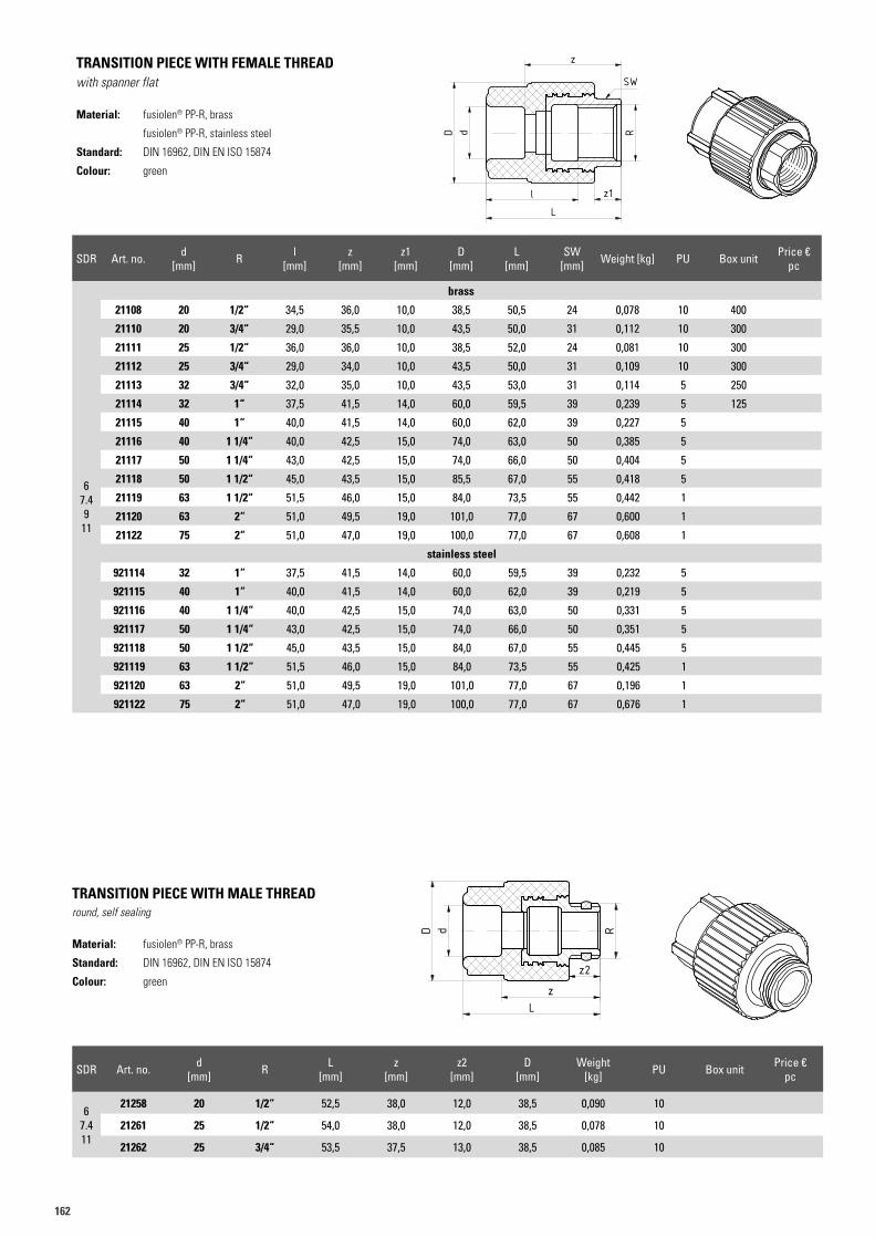
162
TRANSITION PIECE WITH MALE THREADround, self sealing
Material: fusiolen® PP-R, brass
Standard: DIN 16962, DIN EN ISO 15874
Colour: green
Art.N. 21258Artikelliste 2015Seite 45
R
z
z2
L
dD
Art.N. 21258Artikelliste 2015Seite 45
R
z
z2
L
dD
SDR Art. no. d [mm] R L
[mm]z
[mm]z2
[mm]D
[mm]Weight
[kg] PU Box unit Price €pc
67.411
21258 20 1/2“ 52,5 38,0 12,0 38,5 0,090 10
21261 25 1/2“ 54,0 38,0 12,0 38,5 0,078 10
21262 25 3/4“ 53,5 37,5 13,0 38,5 0,085 10
SDR Art. no. d [mm] R l
[mm]z
[mm]z1
[mm]D
[mm]L
[mm]SW
[mm] Weight [kg] PU Box unit Price €pc
brass
67.49
11
21108 20 1/2“ 34,5 36,0 10,0 38,5 50,5 24 0,078 10 400
21110 20 3/4“ 29,0 35,5 10,0 43,5 50,0 31 0,112 10 300
21111 25 1/2“ 36,0 36,0 10,0 38,5 52,0 24 0,081 10 300
21112 25 3/4“ 29,0 34,0 10,0 43,5 50,0 31 0,109 10 300
21113 32 3/4“ 32,0 35,0 10,0 43,5 53,0 31 0,114 5 250
21114 32 1“ 37,5 41,5 14,0 60,0 59,5 39 0,239 5 125
21115 40 1“ 40,0 41,5 14,0 60,0 62,0 39 0,227 5
21116 40 1 1/4“ 40,0 42,5 15,0 74,0 63,0 50 0,385 5
21117 50 1 1/4“ 43,0 42,5 15,0 74,0 66,0 50 0,404 5
21118 50 1 1/2“ 45,0 43,5 15,0 85,5 67,0 55 0,418 5
21119 63 1 1/2“ 51,5 46,0 15,0 84,0 73,5 55 0,442 1
21120 63 2“ 51,0 49,5 19,0 101,0 77,0 67 0,600 1
21122 75 2“ 51,0 47,0 19,0 100,0 77,0 67 0,608 1
stainless steel
921114 32 1“ 37,5 41,5 14,0 60,0 59,5 39 0,232 5
921115 40 1“ 40,0 41,5 14,0 60,0 62,0 39 0,219 5
921116 40 1 1/4“ 40,0 42,5 15,0 74,0 63,0 50 0,331 5
921117 50 1 1/4“ 43,0 42,5 15,0 74,0 66,0 50 0,351 5
921118 50 1 1/2“ 45,0 43,5 15,0 84,0 67,0 55 0,445 5
921119 63 1 1/2“ 51,5 46,0 15,0 84,0 73,5 55 0,425 1
921120 63 2“ 51,0 49,5 19,0 101,0 77,0 67 0,196 1
921122 75 2“ 51,0 47,0 19,0 100,0 77,0 67 0,676 1
TRANSITION PIECE WITH FEMALE THREADwith spanner flat
Material: fusiolen® PP-R, brass
fusiolen® PP-R, stainless steel
Standard: DIN 16962, DIN EN ISO 15874
Colour: green
Art.N. 21108Artikelliste 2015Seite 45
z
lL
dD R
z1
SW
Art.N. 21108Artikelliste 2015Seite 45
z
lL
dD R
z1
SW
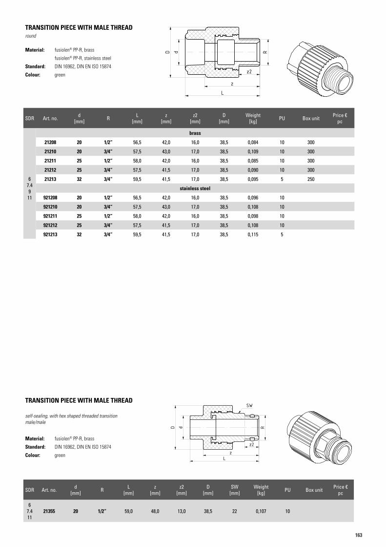
163163
SDR Art. no. d [mm] R L
[mm]z
[mm]z2
[mm]D
[mm]Weight
[kg] PU Box unit Price €pc
brass
67.49
11
21208 20 1/2“ 56,5 42,0 16,0 38,5 0,084 10 300
21210 20 3/4“ 57,5 43,0 17,0 38,5 0,109 10 300
21211 25 1/2“ 58,0 42,0 16,0 38,5 0,085 10 300
21212 25 3/4“ 57,5 41,5 17,0 38,5 0,090 10 300
21213 32 3/4“ 59,5 41,5 17,0 38,5 0,095 5 250
stainless steel
921208 20 1/2“ 56,5 42,0 16,0 38,5 0,096 10
921210 20 3/4“ 57,5 43,0 17,0 38,5 0,108 10
921211 25 1/2“ 58,0 42,0 16,0 38,5 0,098 10
921212 25 3/4“ 57,5 41,5 17,0 38,5 0,108 10
921213 32 3/4“ 59,5 41,5 17,0 38,5 0,115 5
TRANSITION PIECE WITH MALE THREADround
Material: fusiolen® PP-R, brass
fusiolen® PP-R, stainless steel
Standard: DIN 16962, DIN EN ISO 15874
Colour: green
Art.N. 21208Artikelliste 2015Seite 46
R
z2
z
L
dD
Art.N. 21208Artikelliste 2015Seite 46
R
z2
z
L
dD
TRANSITION PIECE WITH MALE THREAD
self-sealing, with hex shaped threaded transitionmale/male
Material: fusiolen® PP-R, brass
Standard: DIN 16962, DIN EN ISO 15874
Colour: green
SDR Art. no. d [mm] R L
[mm]z
[mm]z2
[mm]D
[mm]SW
[mm]Weight
[kg] PU Box unit Price €pc
67.411
21355 20 1/2“ 59,0 48,0 13,0 38,5 22 0,107 10
Art.N. 21355Artikelliste 2015Seite 47
R
z2
zL
dD
SW
Art.N. 21355Artikelliste 2015Seite 47
R
z2
zL
dD
SW
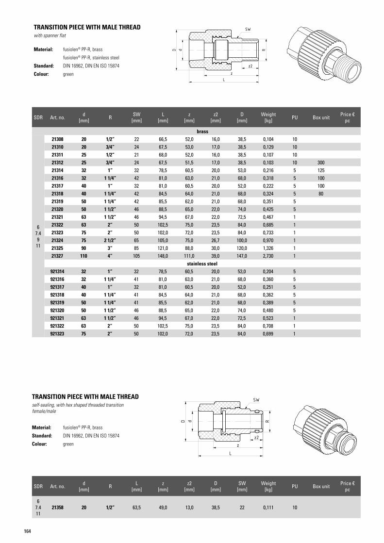
164
SDR Art. no. d [mm] R SW
[mm]L
[mm]z
[mm]z2
[mm]D
[mm]Weight
[kg] PU Box unit Price €pc
brass
67.49
11
21308 20 1/2“ 22 66,5 52,0 16,0 38,5 0,104 1021310 20 3/4“ 24 67,5 53,0 17,0 38,5 0,129 1021311 25 1/2“ 21 68,0 52,0 16,0 38,5 0,107 1021312 25 3/4“ 24 67,5 51,5 17,0 38,5 0,103 10 30021314 32 1“ 32 78,5 60,5 20,0 53,0 0,216 5 12521316 32 1 1/4“ 42 81,0 63,0 21,0 68,0 0,318 5 10021317 40 1“ 32 81,0 60,5 20,0 52,0 0,222 5 10021318 40 1 1/4“ 42 84,5 64,0 21,0 68,0 0,324 5 8021319 50 1 1/4“ 42 85,5 62,0 21,0 68,0 0,351 521320 50 1 1/2“ 46 88,5 65,0 22,0 74,0 0,425 521321 63 1 1/2“ 46 94,5 67,0 22,0 72,5 0,467 121322 63 2“ 50 102,5 75,0 23,5 84,0 0,685 121323 75 2“ 50 102,0 72,0 23,5 84,0 0,733 121324 75 2 1/2“ 65 105,0 75,0 26,7 100,0 0,970 121325 90 3“ 85 121,0 88,0 30,0 120,0 1,326 121327 110 4“ 105 148,0 111,0 39,0 147,0 2,730 1
stainless steel921314 32 1“ 32 78,5 60,5 20,0 53,0 0,204 5921316 32 1 1/4“ 41 81,0 63,0 21,0 68,0 0,360 5921317 40 1“ 32 81,0 60,5 20,0 52,0 0,251 5921318 40 1 1/4“ 41 84,5 64,0 21,0 68,0 0,362 5921319 50 1 1/4“ 41 85,5 62,0 21,0 68,0 0,389 5921320 50 1 1/2“ 46 88,5 65,0 22,0 74,0 0,480 5921321 63 1 1/2“ 46 94,5 67,0 22,0 72,5 0,523 1921322 63 2“ 50 102,5 75,0 23,5 84,0 0,708 1921323 75 2“ 50 102,0 72,0 23,5 84,0 0,699 1
TRANSITION PIECE WITH MALE THREADwith spanner flat
Material: fusiolen® PP-R, brass
fusiolen® PP-R, stainless steel
Standard: DIN 16962, DIN EN ISO 15874
Colour: green
Art.N. 21308Artikelliste 2015Seite 46
z2
zL
RdD
SW
Art.N. 21308Artikelliste 2015Seite 46
z2
zL
RdD
SW
TRANSITION PIECE WITH MALE THREADself-sealing, with hex shaped threaded transitionfemale/male
Material: fusiolen® PP-R, brass
Standard: DIN 16962, DIN EN ISO 15874
Colour: green
SDR Art. no. d [mm] R L
[mm]z
[mm]z2
[mm]D
[mm]SW
[mm]Weight
[kg] PU Box unit Price €pc
67.411
21358 20 1/2“ 63,5 49,0 13,0 38,5 22 0,111 10
Art.N. 21358Artikelliste 2015Seite 47
dD
z2z
L
R
SW
Art.N. 21358Artikelliste 2015Seite 47
dD
z2z
L
R
SW
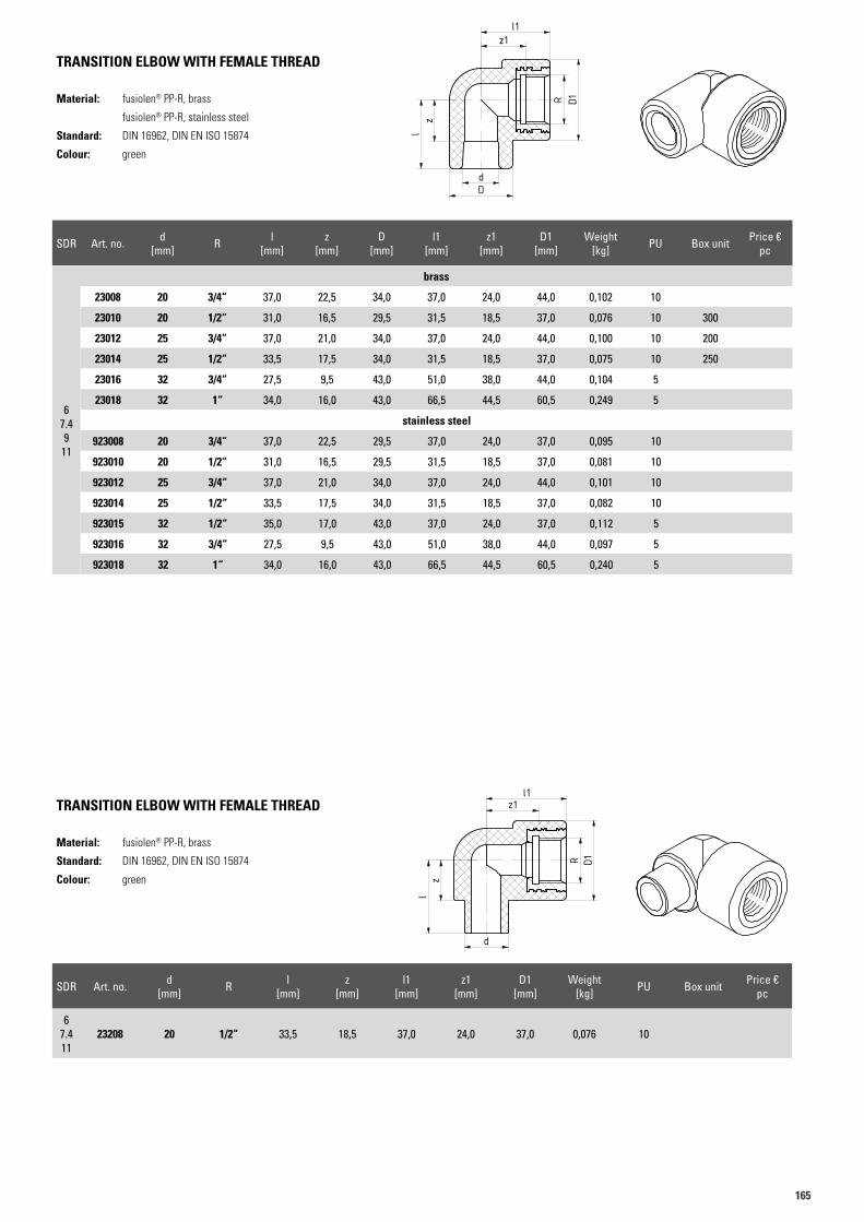
165165
SDR Art. no. d [mm] R l
[mm]z
[mm]D
[mm]l1
[mm]z1
[mm]D1
[mm]Weight
[kg] PU Box unit Price €pc
brass
67.49
11
23008 20 3/4“ 37,0 22,5 34,0 37,0 24,0 44,0 0,102 10
23010 20 1/2“ 31,0 16,5 29,5 31,5 18,5 37,0 0,076 10 300
23012 25 3/4“ 37,0 21,0 34,0 37,0 24,0 44,0 0,100 10 200
23014 25 1/2“ 33,5 17,5 34,0 31,5 18,5 37,0 0,075 10 250
23016 32 3/4“ 27,5 9,5 43,0 51,0 38,0 44,0 0,104 5
23018 32 1“ 34,0 16,0 43,0 66,5 44,5 60,5 0,249 5
stainless steel
923008 20 3/4“ 37,0 22,5 29,5 37,0 24,0 37,0 0,095 10
923010 20 1/2“ 31,0 16,5 29,5 31,5 18,5 37,0 0,081 10
923012 25 3/4“ 37,0 21,0 34,0 37,0 24,0 44,0 0,101 10
923014 25 1/2“ 33,5 17,5 34,0 31,5 18,5 37,0 0,082 10
923015 32 1/2“ 35,0 17,0 43,0 37,0 24,0 37,0 0,112 5
923016 32 3/4“ 27,5 9,5 43,0 51,0 38,0 44,0 0,097 5
923018 32 1“ 34,0 16,0 43,0 66,5 44,5 60,5 0,240 5
TRANSITION ELBOW WITH FEMALE THREAD
Material: fusiolen® PP-R, brass
fusiolen® PP-R, stainless steel
Standard: DIN 16962, DIN EN ISO 15874
Colour: green
Art.N. 23008Artikelliste 2015Seite 47
R D1
z1
dD
zl
l1
Art.N. 23008Artikelliste 2015Seite 47
R D1
z1
dD
zl
l1
TRANSITION ELBOW WITH FEMALE THREAD
Material: fusiolen® PP-R, brass
Standard: DIN 16962, DIN EN ISO 15874
Colour: green
Art.N. 23208Artikelliste 2015Seite 48
R D1
zl
ddD
z1l1
Art.N. 23208Artikelliste 2015Seite 48
R D1
zl
ddD
z1l1
SDR Art. no. d [mm] R l
[mm]z
[mm]l1
[mm]z1
[mm]D1
[mm]Weight
[kg] PU Box unit Price €pc
67.411
23208 20 1/2“ 33,5 18,5 37,0 24,0 37,0 0,076 10
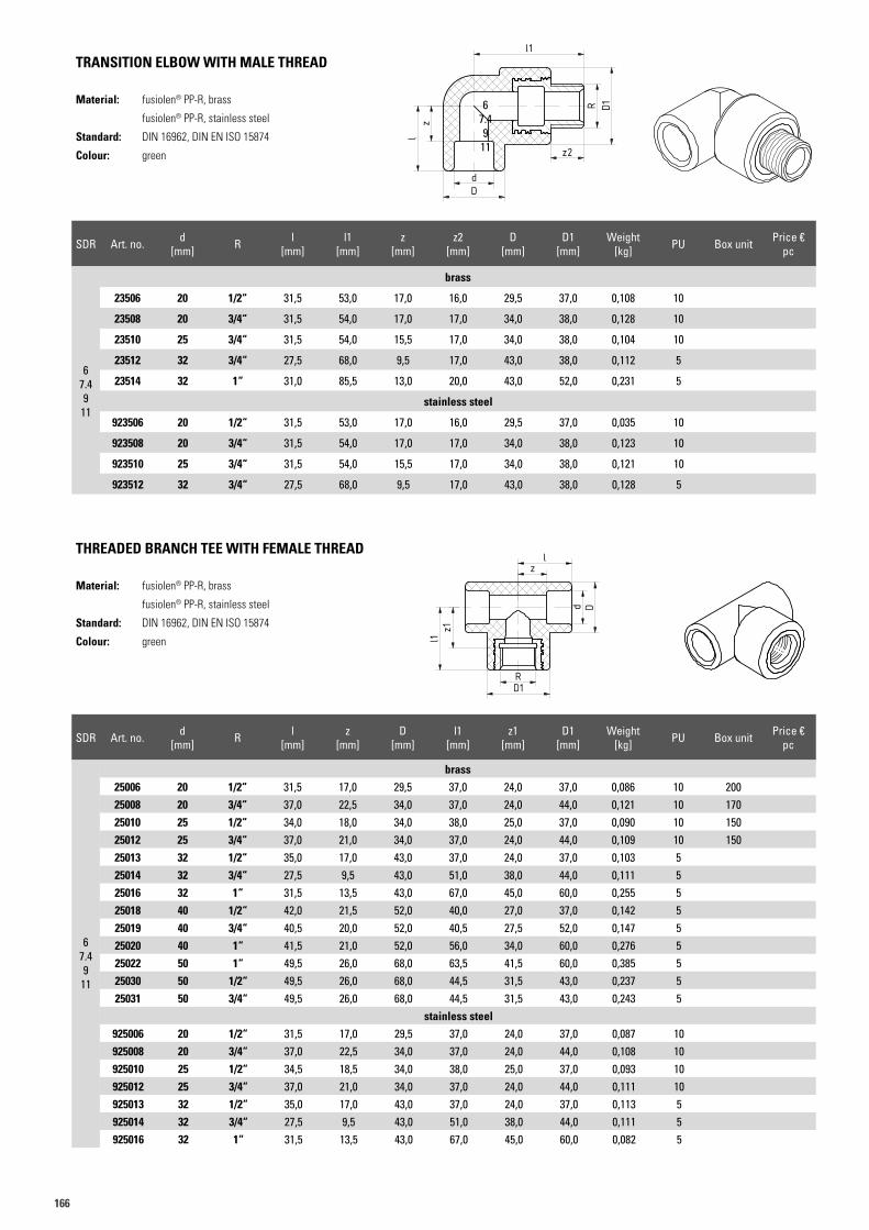
166
SDR Art. no. d [mm] R l
[mm]l1
[mm]z
[mm]z2
[mm]D
[mm]D1
[mm]Weight
[kg] PU Box unit Price €pc
brass
67.49
11
23506 20 1/2“ 31,5 53,0 17,0 16,0 29,5 37,0 0,108 10
23508 20 3/4“ 31,5 54,0 17,0 17,0 34,0 38,0 0,128 10
23510 25 3/4“ 31,5 54,0 15,5 17,0 34,0 38,0 0,104 10
23512 32 3/4“ 27,5 68,0 9,5 17,0 43,0 38,0 0,112 5
23514 32 1“ 31,0 85,5 13,0 20,0 43,0 52,0 0,231 5
stainless steel
923506 20 1/2“ 31,5 53,0 17,0 16,0 29,5 37,0 0,035 10
923508 20 3/4“ 31,5 54,0 17,0 17,0 34,0 38,0 0,123 10
923510 25 3/4“ 31,5 54,0 15,5 17,0 34,0 38,0 0,121 10
923512 32 3/4“ 27,5 68,0 9,5 17,0 43,0 38,0 0,128 5
TRANSITION ELBOW WITH MALE THREAD
Material: fusiolen® PP-R, brass
fusiolen® PP-R, stainless steel
Standard: DIN 16962, DIN EN ISO 15874
Colour: green
Art.N. 23506Artikelliste 2015Seite 48
R D1
l1
zl
dD
z2
Art.N. 23506Artikelliste 2015Seite 48
R D1
l1
zl
dD
z2
SDR Art. no. d [mm] R l
[mm]z
[mm]D
[mm]l1
[mm]z1
[mm]D1
[mm]Weight
[kg] PU Box unit Price €pc
brass
67.49
11
25006 20 1/2“ 31,5 17,0 29,5 37,0 24,0 37,0 0,086 10 20025008 20 3/4“ 37,0 22,5 34,0 37,0 24,0 44,0 0,121 10 17025010 25 1/2“ 34,0 18,0 34,0 38,0 25,0 37,0 0,090 10 15025012 25 3/4“ 37,0 21,0 34,0 37,0 24,0 44,0 0,109 10 15025013 32 1/2“ 35,0 17,0 43,0 37,0 24,0 37,0 0,103 525014 32 3/4“ 27,5 9,5 43,0 51,0 38,0 44,0 0,111 525016 32 1“ 31,5 13,5 43,0 67,0 45,0 60,0 0,255 525018 40 1/2“ 42,0 21,5 52,0 40,0 27,0 37,0 0,142 525019 40 3/4“ 40,5 20,0 52,0 40,5 27,5 52,0 0,147 525020 40 1“ 41,5 21,0 52,0 56,0 34,0 60,0 0,276 525022 50 1“ 49,5 26,0 68,0 63,5 41,5 60,0 0,385 525030 50 1/2“ 49,5 26,0 68,0 44,5 31,5 43,0 0,237 525031 50 3/4“ 49,5 26,0 68,0 44,5 31,5 43,0 0,243 5
stainless steel925006 20 1/2“ 31,5 17,0 29,5 37,0 24,0 37,0 0,087 10925008 20 3/4“ 37,0 22,5 34,0 37,0 24,0 44,0 0,108 10925010 25 1/2“ 34,5 18,5 34,0 38,0 25,0 37,0 0,093 10925012 25 3/4“ 37,0 21,0 34,0 37,0 24,0 44,0 0,111 10925013 32 1/2“ 35,0 17,0 43,0 37,0 24,0 37,0 0,113 5925014 32 3/4“ 27,5 9,5 43,0 51,0 38,0 44,0 0,111 5925016 32 1“ 31,5 13,5 43,0 67,0 45,0 60,0 0,082 5
THREADED BRANCH TEE WITH FEMALE THREAD
Material: fusiolen® PP-R, brass
fusiolen® PP-R, stainless steel
Standard: DIN 16962, DIN EN ISO 15874
Colour: green
Art.N. 25006Artikelliste 2015Seite 48
z1
RD1
d D
lz
l1
Art.N. 25006Artikelliste 2015Seite 48
z1
RD1
d D
lz
l1
67.49
11
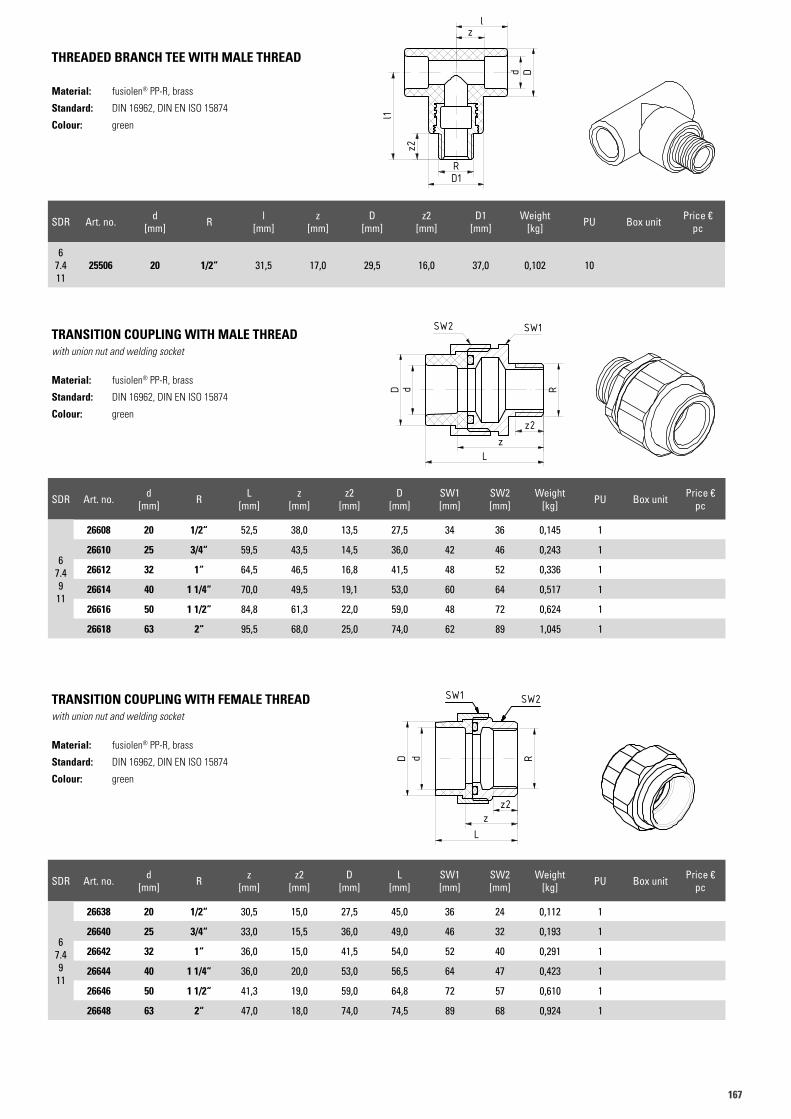
167167
SDR Art. no. d [mm] R l
[mm]z
[mm]D
[mm]z2
[mm]D1
[mm]Weight
[kg] PU Box unit Price €pc
67.411
25506 20 1/2“ 31,5 17,0 29,5 16,0 37,0 0,102 10
THREADED BRANCH TEE WITH MALE THREAD
Material: fusiolen® PP-R, brass
Standard: DIN 16962, DIN EN ISO 15874
Colour: green
TRANSITION COUPLING WITH MALE THREADwith union nut and welding socket
Material: fusiolen® PP-R, brass
Standard: DIN 16962, DIN EN ISO 15874
Colour: green
TRANSITION COUPLING WITH FEMALE THREADwith union nut and welding socket
Material: fusiolen® PP-R, brass
Standard: DIN 16962, DIN EN ISO 15874
Colour: green
Art.N. 25506Artikelliste 2015Seite 48
RD1
z2
l1
zl
d D
Art.N. 25506Artikelliste 2015Seite 48
RD1
z2
l1
zl
d DBN BN
Art.N. 26610Artikelliste 2015Seite 49
z2
R
zL
dD
SW1SW2
BN BN
t.N. 26610tikelliste 2015te 49
BN BN
Art.N. 26610Artikelliste 2015Seite 49
z2
R
zL
dD
SW1SW2
BN BN
t.N. 26610tikelliste 2015te 49
BP
BP
Art.N. 26646Artikelliste 2015Seite 49
RdD
zz2
L
SW2SW1
BP
BP
Art.N. 26646Artikelliste 2015Seite 49
RdD
zz2
L
SW2SW1
SDR Art. no. d [mm] R L
[mm]z
[mm]z2
[mm]D
[mm]SW1 [mm]
SW2 [mm]
Weight [kg] PU Box unit Price €
pc
67.49
11
26608 20 1/2“ 52,5 38,0 13,5 27,5 34 36 0,145 1
26610 25 3/4“ 59,5 43,5 14,5 36,0 42 46 0,243 1
26612 32 1“ 64,5 46,5 16,8 41,5 48 52 0,336 1
26614 40 1 1/4“ 70,0 49,5 19,1 53,0 60 64 0,517 1
26616 50 1 1/2“ 84,8 61,3 22,0 59,0 48 72 0,624 1
26618 63 2“ 95,5 68,0 25,0 74,0 62 89 1,045 1
SDR Art. no. d [mm] R z
[mm]z2
[mm]D
[mm]L
[mm]SW1 [mm]
SW2 [mm]
Weight [kg] PU Box unit Price €
pc
67.49
11
26638 20 1/2“ 30,5 15,0 27,5 45,0 36 24 0,112 1
26640 25 3/4“ 33,0 15,5 36,0 49,0 46 32 0,193 1
26642 32 1“ 36,0 15,0 41,5 54,0 52 40 0,291 1
26644 40 1 1/4“ 36,0 20,0 53,0 56,5 64 47 0,423 1
26646 50 1 1/2“ 41,3 19,0 59,0 64,8 72 57 0,610 1
26648 63 2“ 47,0 18,0 74,0 74,5 89 68 0,924 1
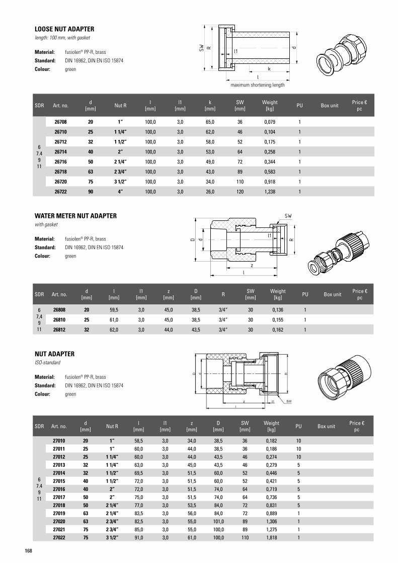
168
LOOSE NUT ADAPTERlength: 100 mm, with gasket
Material: fusiolen® PP-R, brass
Standard: DIN 16962, DIN EN ISO 15874
Colour: green
WATER METER NUT ADAPTERwith gasket
Material: fusiolen® PP-R, brass
Standard: DIN 16962, DIN EN ISO 15874
Colour: green
NUT ADAPTERISO-standard
Material: fusiolen® PP-R, brass
Standard: DIN 16962, DIN EN ISO 15874
Colour: green
Art.N. 26708Artikelliste 2015Seite 49
dRSW
kl
l1
Art.N. 26708Artikelliste 2015Seite 49
dRSW
kl
l1
maximum shortening length
SDR Art. no. d [mm] Nut R l
[mm]l1
[mm]k
[mm]SW
[mm]Weight
[kg] PU Box unit Price €pc
67.49
11
26708 20 1“ 100,0 3,0 65,0 36 0,079 1
26710 25 1 1/4“ 100,0 3,0 62,0 46 0,104 1
26712 32 1 1/2“ 100,0 3,0 58,0 52 0,175 1
26714 40 2“ 100,0 3,0 53,0 64 0,258 1
26716 50 2 1/4“ 100,0 3,0 49,0 72 0,344 1
26718 63 2 3/4“ 100,0 3,0 43,0 89 0,583 1
26720 75 3 1/2“ 100,0 3,0 34,0 110 0,918 1
26722 90 4“ 100,0 3,0 26,0 120 1,238 1
SDR Art. no. d [mm]
l [mm]
l1 [mm]
z [mm]
D [mm] R SW
[mm]Weight
[kg] PU Box unit Price €pc
67,49
11
26808 20 59,5 3,0 45,0 38,5 3/4“ 30 0,136 1
26810 25 61,0 3,0 45,0 38,5 3/4“ 30 0,155 1
26812 32 62,0 3,0 44,0 43,5 3/4“ 30 0,162 1
SDR Art. no. d [mm] Nut R l
[mm]l1
[mm]z
[mm]D
[mm]SW
[mm]Weight
[kg] PU Box unit Price €pc
67.49
11
27010 20 1“ 58,5 3,0 34,0 38,5 36 0,182 1027011 25 1“ 60,0 3,0 44,0 38,5 36 0,186 1027012 25 1 1/4“ 60,0 3,0 44,0 43,5 46 0,274 1027013 32 1 1/4“ 63,0 3,0 45,0 43,5 46 0,279 527014 32 1 1/2“ 69,5 3,0 51,5 60,0 52 0,446 527015 40 1 1/2“ 72,0 3,0 51,5 60,0 52 0,421 527016 40 2“ 72,0 3,0 51,5 74,0 64 0,719 527017 50 2“ 75,0 3,0 51,5 74,0 64 0,736 527018 50 2 1/4“ 77,0 3,0 53,5 84,0 72 0,831 527019 63 2 1/4“ 83,5 3,0 56,0 84,0 72 0,889 127020 63 2 3/4“ 82,5 3,0 55,0 101,0 89 1,306 127021 75 2 3/4“ 85,0 3,0 55,0 100,0 89 1,275 127022 75 3 1/2“ 91,0 3,0 61,0 100,0 110 1,818 1
BP
BP
Art.N. 26808Artikelliste 2015Seite 50
dD
SW
zl
l1
R
BP
BP
Art.N. 26808Artikelliste 2015Seite 50
dD
SW
zl
l1
R
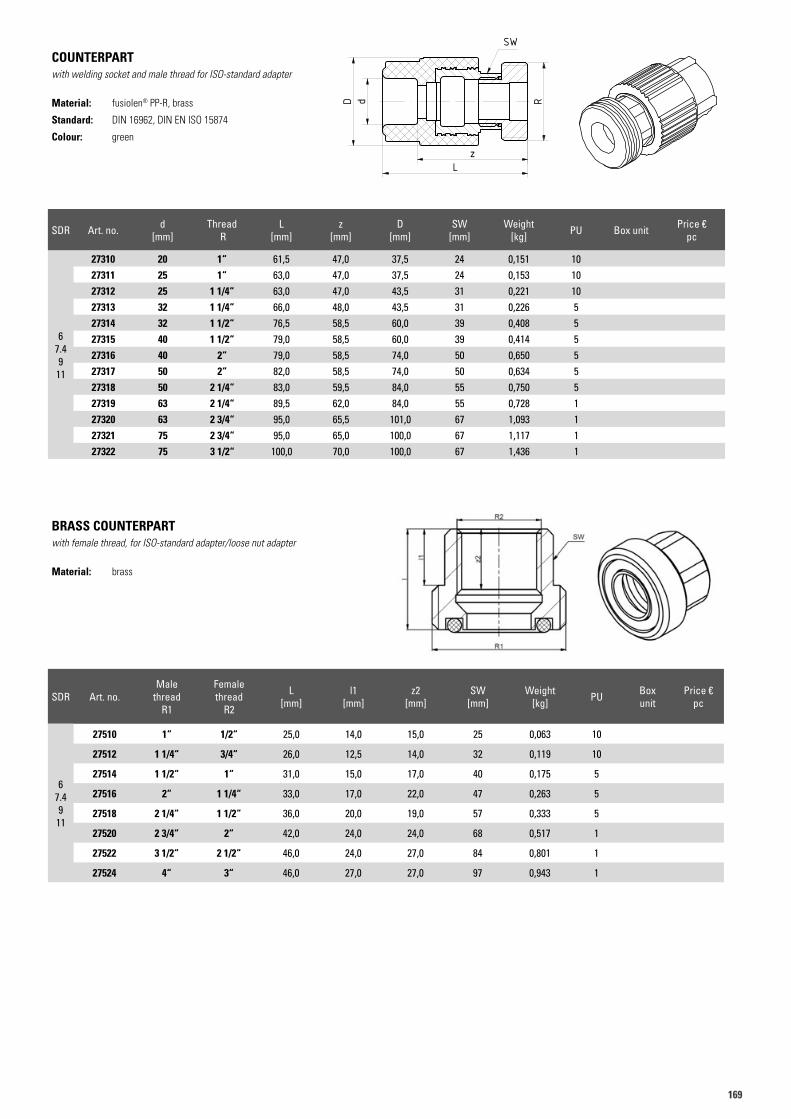
169169
COUNTERPARTwith welding socket and male thread for ISO-standard adapter
Material: fusiolen® PP-R, brass
Standard: DIN 16962, DIN EN ISO 15874
Colour: green
BRASS COUNTERPARTwith female thread, for ISO-standard adapter/loose nut adapter
Material: brass
Art.N. 27310 Artikelliste 2015Seite 51
dD
Lz
R
SW
Art.N. 27310 Artikelliste 2015Seite 51
dD
Lz
R
SW
SDR Art. no. d [mm]
Thread R
L [mm]
z [mm]
D [mm]
SW [mm]
Weight [kg] PU Box unit Price €
pc
67.49
11
27310 20 1“ 61,5 47,0 37,5 24 0,151 1027311 25 1“ 63,0 47,0 37,5 24 0,153 1027312 25 1 1/4“ 63,0 47,0 43,5 31 0,221 1027313 32 1 1/4“ 66,0 48,0 43,5 31 0,226 527314 32 1 1/2“ 76,5 58,5 60,0 39 0,408 527315 40 1 1/2“ 79,0 58,5 60,0 39 0,414 527316 40 2“ 79,0 58,5 74,0 50 0,650 527317 50 2“ 82,0 58,5 74,0 50 0,634 527318 50 2 1/4“ 83,0 59,5 84,0 55 0,750 527319 63 2 1/4“ 89,5 62,0 84,0 55 0,728 127320 63 2 3/4“ 95,0 65,5 101,0 67 1,093 127321 75 2 3/4“ 95,0 65,0 100,0 67 1,117 127322 75 3 1/2“ 100,0 70,0 100,0 67 1,436 1
SDR Art. no. Male
threadR1
Female thread
R2
L [mm]
l1 [mm]
z2 [mm]
SW [mm]
Weight [kg] PU Box
unitPrice €
pc
67.49
11
27510 1“ 1/2“ 25,0 14,0 15,0 25 0,063 10
27512 1 1/4“ 3/4“ 26,0 12,5 14,0 32 0,119 10
27514 1 1/2“ 1“ 31,0 15,0 17,0 40 0,175 5
27516 2“ 1 1/4“ 33,0 17,0 22,0 47 0,263 5
27518 2 1/4“ 1 1/2“ 36,0 20,0 19,0 57 0,333 5
27520 2 3/4“ 2“ 42,0 24,0 24,0 68 0,517 1
27522 3 1/2“ 2 1/2“ 46,0 24,0 27,0 84 0,801 1
27524 4“ 3“ 46,0 27,0 27,0 97 0,943 1
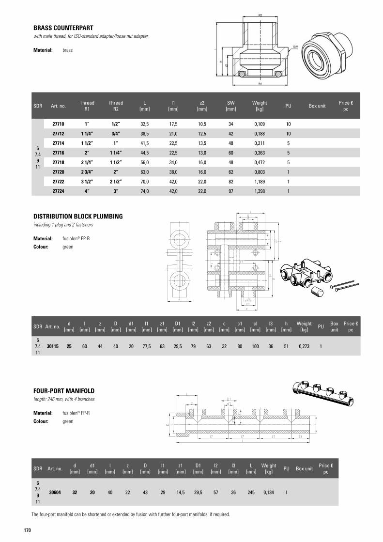
170
BRASS COUNTERPARTwith male thread, for ISO-standard adapter/loose nut adapter
Material: brass
SDR Art. no. d [mm]
l [mm]
z [mm]
D [mm]
d1 [mm]
l1 [mm]
z1 [mm]
D1 [mm]
l2 [mm]
z2 [mm]
c [mm]
c1 [mm]
cl [mm]
l3 [mm]
h [mm]
Weight [kg] PU Box
unit Price €
pc
67.411
30115 25 60 44 40 20 77,5 63 29,5 79 63 32 80 100 36 51 0,273 1
DISTRIBUTION BLOCK PLUMBINGincluding 1 plug and 2 fasteners
Material: fusiolen® PP-R
Colour: green
SDR Art. no. d [mm]
d1 [mm]
l [mm]
z [mm]
D [mm]
l1 [mm]
z1 [mm]
D1 [mm]
l2 [mm]
l3 [mm]
L [mm]
Weight [kg] PU Box unit Price €
pc
67.49
11
30604 32 20 40 22 43 29 14,5 29,5 57 36 245 0,134 1
The four-port manifold can be shortened or extended by fusion with further four-port manifolds, if required.
FOUR-PORT MANIFOLDlength: 246 mm, with 4 branches
Material: fusiolen® PP-R
Colour: green
T-Stück
30602
SDR Art. no. Thread R1
Thread R2
L [mm]
l1 [mm]
z2 [mm]
SW [mm]
Weight [kg] PU Box unit Price €
pc
67.49
11
27710 1“ 1/2“ 32,5 17,5 10,5 34 0,109 10
27712 1 1/4“ 3/4“ 38,5 21,0 12,5 42 0,188 10
27714 1 1/2“ 1“ 41,5 22,5 13,5 48 0,211 5
27716 2“ 1 1/4“ 44,5 22,5 13,0 60 0,363 5
27718 2 1/4“ 1 1/2“ 56,0 34,0 16,0 48 0,472 5
27720 2 3/4“ 2“ 63,0 38,0 16,0 62 0,803 1
27722 3 1/2“ 2 1/2“ 70,0 42,0 22,0 82 1,189 1
27724 4“ 3“ 74,0 42,0 22,0 97 1,398 1
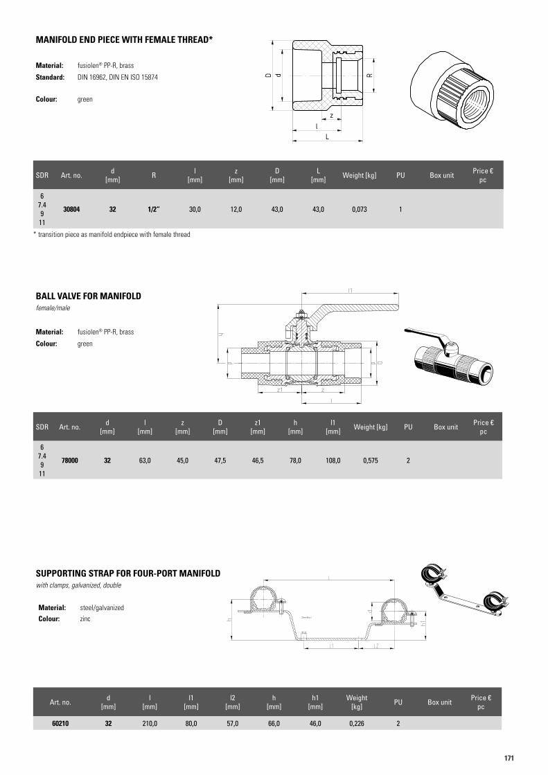
171171
SDR Art. no. d [mm] R l
[mm]z
[mm]D
[mm]L
[mm] Weight [kg] PU Box unit Price €pc
67.49
11
30804 32 1/2“ 30,0 12,0 43,0 43,0 0,073 1
* transition piece as manifold endpiece with female thread
MANIFOLD END PIECE WITH FEMALE THREAD*
Material: fusiolen® PP-R, brass
Standard: DIN 16962, DIN EN ISO 15874
Colour: green
SDR Art. no. d [mm]
l [mm]
z [mm]
D [mm]
z1 [mm]
h [mm]
l1 [mm] Weight [kg] PU Box unit Price €
pc
67.49
11
78000 32 63,0 45,0 47,5 46,5 78,0 108,0 0,575 2
BALL VALVE FOR MANIFOLDfemale/male
Material: fusiolen® PP-R, brass
Colour: green
Art. no. d [mm]
l [mm]
l1 [mm]
l2 [mm]
h [mm]
h1 [mm]
Weight [kg] PU Box unit Price €
pc
60210 32 210,0 80,0 57,0 66,0 46,0 0,226 2
SUPPORTING STRAP FOR FOUR-PORT MANIFOLDwith clamps, galvanized, double
Material: steel/galvanized
Colour: zinc
60210
Art.N. 30804Artikelliste 2015Seite 53
R
zl
L
dD
Art.N. 30804Artikelliste 2015Seite 53
R
zl
L
dD
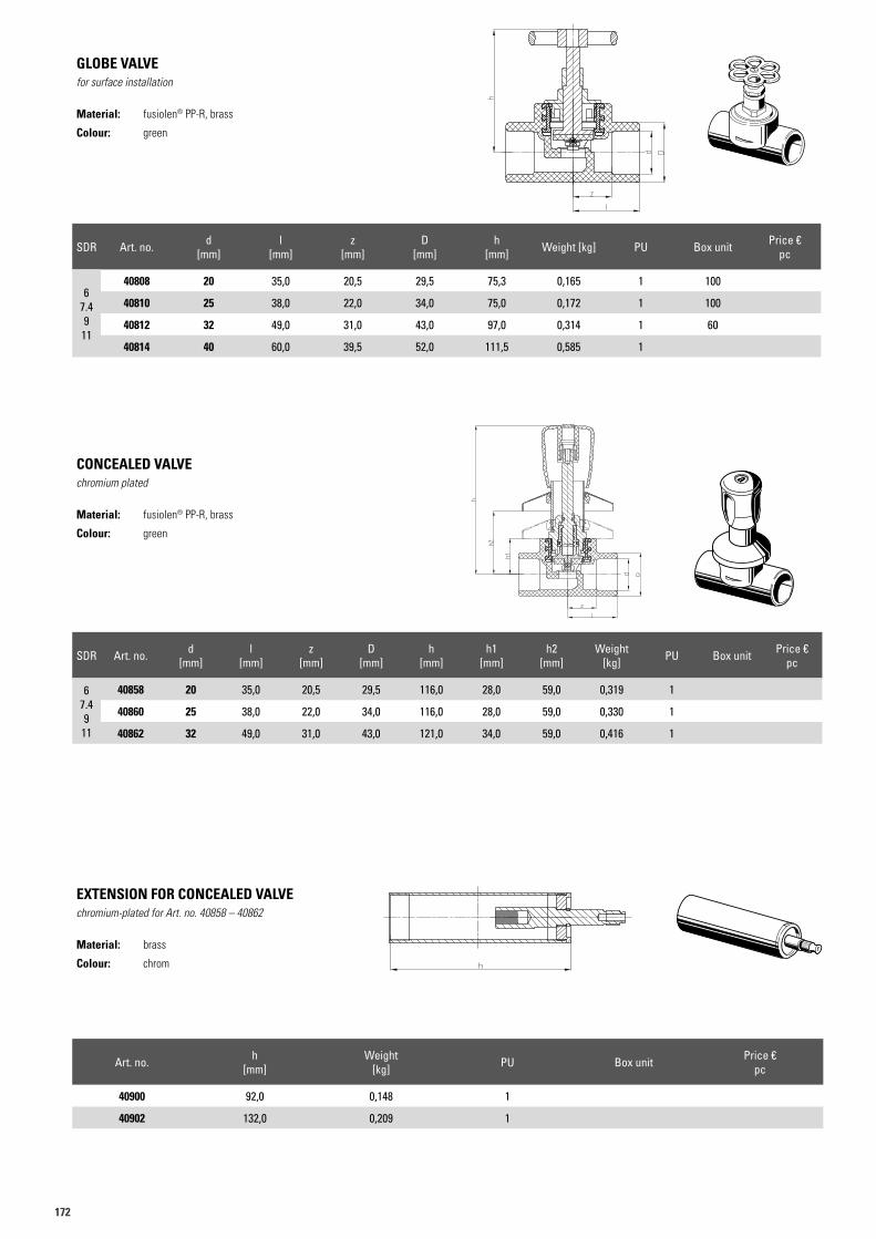
172
SDR Art. no. d [mm]
l [mm]
z [mm]
D [mm]
h [mm] Weight [kg] PU Box unit Price €
pc
67.49
11
40808 20 35,0 20,5 29,5 75,3 0,165 1 100
40810 25 38,0 22,0 34,0 75,0 0,172 1 100
40812 32 49,0 31,0 43,0 97,0 0,314 1 60
40814 40 60,0 39,5 52,0 111,5 0,585 1
GLOBE VALVEfor surface installation
Material: fusiolen® PP-R, brass
Colour: green
SDR Art. no. d [mm]
l [mm]
z [mm]
D [mm]
h [mm]
h1 [mm]
h2 [mm]
Weight [kg] PU Box unit Price €
pc
67.49
11
40858 20 35,0 20,5 29,5 116,0 28,0 59,0 0,319 1
40860 25 38,0 22,0 34,0 116,0 28,0 59,0 0,330 1
40862 32 49,0 31,0 43,0 121,0 34,0 59,0 0,416 1
CONCEALED VALVEchromium plated
Material: fusiolen® PP-R, brass
Colour: green
Art. no. h [mm]
Weight [kg] PU Box unit Price €
pc
40900 92,0 0,148 1
40902 132,0 0,209 1
EXTENSION FOR CONCEALED VALVEchromium-plated for Art. no. 40858 – 40862
Material: brass
Colour: chrom
40808
40858
40900
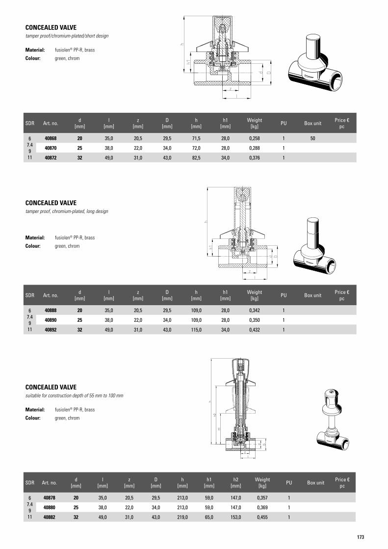
173173
SDR Art. no. d [mm]
l [mm]
z [mm]
D [mm]
h [mm]
h1 [mm]
Weight [kg] PU Box unit Price €
pc
67.49
11
40868 20 35,0 20,5 29,5 71,5 28,0 0,258 1 50
40870 25 38,0 22,0 34,0 72,0 28,0 0,288 1
40872 32 49,0 31,0 43,0 82,5 34,0 0,376 1
CONCEALED VALVEtamper proof/chromium-plated/short design
Material: fusiolen® PP-R, brass
Colour: green, chrom
SDR Art. no. d [mm]
l [mm]
z [mm]
D [mm]
h [mm]
h1 [mm]
h2 [mm]
Weight [kg] PU Box unit Price €
pc
67.49
11
40878 20 35,0 20,5 29,5 213,0 59,0 147,0 0,357 1
40880 25 38,0 22,0 34,0 213,0 59,0 147,0 0,369 1
40882 32 49,0 31,0 43,0 219,0 65,0 153,0 0,455 1
CONCEALED VALVEsuitable for construction depth of 55 mm to 100 mm
Material: fusiolen® PP-R, brass
Colour: green, chrom
SDR Art. no. d [mm]
l [mm]
z [mm]
D [mm]
h [mm]
h1 [mm]
Weight [kg] PU Box unit Price €
pc
67.49
11
40888 20 35,0 20,5 29,5 109,0 28,0 0,342 1
40890 25 38,0 22,0 34,0 109,0 28,0 0,350 1
40892 32 49,0 31,0 43,0 115,0 34,0 0,432 1
CONCEALED VALVEtamper proof, chromium-plated, long design
Material: fusiolen® PP-R, brass
Colour: green, chrom
40878
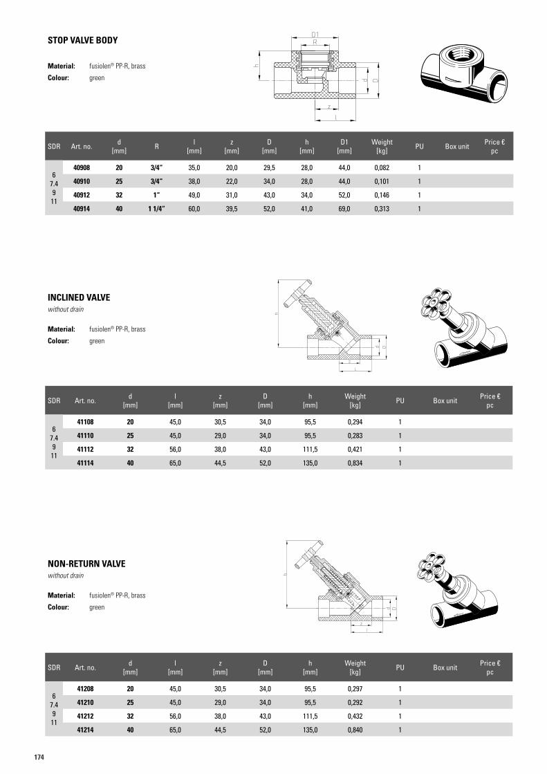
174
SDR Art. no. d [mm] R l
[mm]z
[mm]D
[mm]h
[mm]D1
[mm]Weight
[kg] PU Box unit Price €pc
67.49
11
40908 20 3/4“ 35,0 20,0 29,5 28,0 44,0 0,082 1
40910 25 3/4“ 38,0 22,0 34,0 28,0 44,0 0,101 1
40912 32 1“ 49,0 31,0 43,0 34,0 52,0 0,146 1
40914 40 1 1/4“ 60,0 39,5 52,0 41,0 69,0 0,313 1
STOP VALVE BODY
Material: fusiolen® PP-R, brass
Colour: green
SDR Art. no. d [mm]
l [mm]
z [mm]
D [mm]
h [mm]
Weight [kg] PU Box unit Price €
pc
67.49
11
41108 20 45,0 30,5 34,0 95,5 0,294 1
41110 25 45,0 29,0 34,0 95,5 0,283 1
41112 32 56,0 38,0 43,0 111,5 0,421 1
41114 40 65,0 44,5 52,0 135,0 0,834 1
INCLINED VALVEwithout drain
Material: fusiolen® PP-R, brass
Colour: green
SDR Art. no. d [mm]
l [mm]
z [mm]
D [mm]
h [mm]
Weight [kg] PU Box unit Price €
pc
67.49
11
41208 20 45,0 30,5 34,0 95,5 0,297 1
41210 25 45,0 29,0 34,0 95,5 0,292 1
41212 32 56,0 38,0 43,0 111,5 0,432 1
41214 40 65,0 44,5 52,0 135,0 0,840 1
NON-RETURN VALVEwithout drain
Material: fusiolen® PP-R, brass
Colour: green
40908
41108
41208
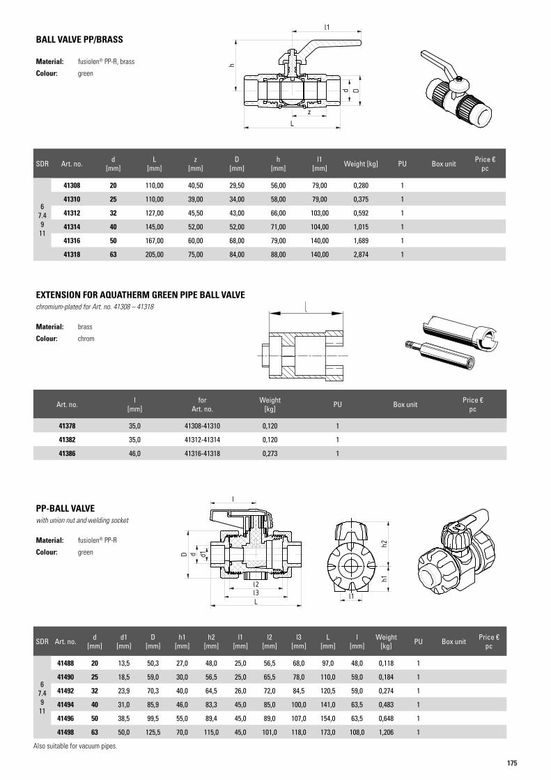
175175
BALL VALVE PP/BRASS
Material: fusiolen® PP-R, brass
Colour: green
Art. no. l [mm]
for Art. no.
Weight [kg] PU Box unit Price €
pc
41378 35,0 41308-41310 0,120 1
41382 35,0 41312-41314 0,120 1
41386 46,0 41316-41318 0,273 1
EXTENSION FOR AQUATHERM GREEN PIPE BALL VALVEchromium-plated for Art. no. 41308 – 41318
Material: brass
Colour: chrom
PP-BALL VALVEwith union nut and welding socket
Material: fusiolen® PP-R
Colour: green
Art.N. 41310 Gr. 41308Artikelliste 2015Seite 57
d D
zL
l1
h
Art.N. 41310 Gr. 41308Artikelliste 2015Seite 57
d D
zL
l1
h
41376
Art.N. 41488Artikelliste 2015Seite 57
l2l3L
dD
l
h1h2
l1
d1
Art.N. 41488Artikelliste 2015Seite 57
l2l3L
dD
l
h1h2
l1
d1
Art.N. 41488Artikelliste 2015Seite 57
l2l3L
dD
l
h1h2
l1
d1
SDR Art. no. d [mm]
L [mm]
z [mm]
D [mm]
h [mm]
l1 [mm] Weight [kg] PU Box unit Price €
pc
67.49
11
41308 20 110,00 40,50 29,50 56,00 79,00 0,280 1
41310 25 110,00 39,00 34,00 58,00 79,00 0,375 1
41312 32 127,00 45,50 43,00 66,00 103,00 0,592 1
41314 40 145,00 52,00 52,00 71,00 104,00 1,015 1
41316 50 167,00 60,00 68,00 79,00 140,00 1,689 1
41318 63 205,00 75,00 84,00 88,00 140,00 2,874 1
SDR Art. no. d [mm]
d1 [mm]
D [mm]
h1 [mm]
h2 [mm]
l1 [mm]
l2 [mm]
l3 [mm]
L [mm]
l [mm]
Weight [kg] PU Box unit Price €
pc
67.49
11
41488 20 13,5 50,3 27,0 48,0 25,0 56,5 68,0 97,0 48,0 0,118 1
41490 25 18,5 59,0 30,0 56,5 25,0 65,5 78,0 110,0 59,0 0,184 1
41492 32 23,9 70,3 40,0 64,5 26,0 72,0 84,5 120,5 59,0 0,274 1
41494 40 31,0 85,9 46,0 83,3 45,0 85,0 100,0 141,0 63,5 0,483 1
41496 50 38,5 99,5 55,0 89,4 45,0 89,0 107,0 154,0 63,5 0,648 1
41498 63 50,0 125,5 70,0 115,0 45,0 101,0 118,0 173,0 108,0 1,206 1
Also suitable for vacuum pipes.
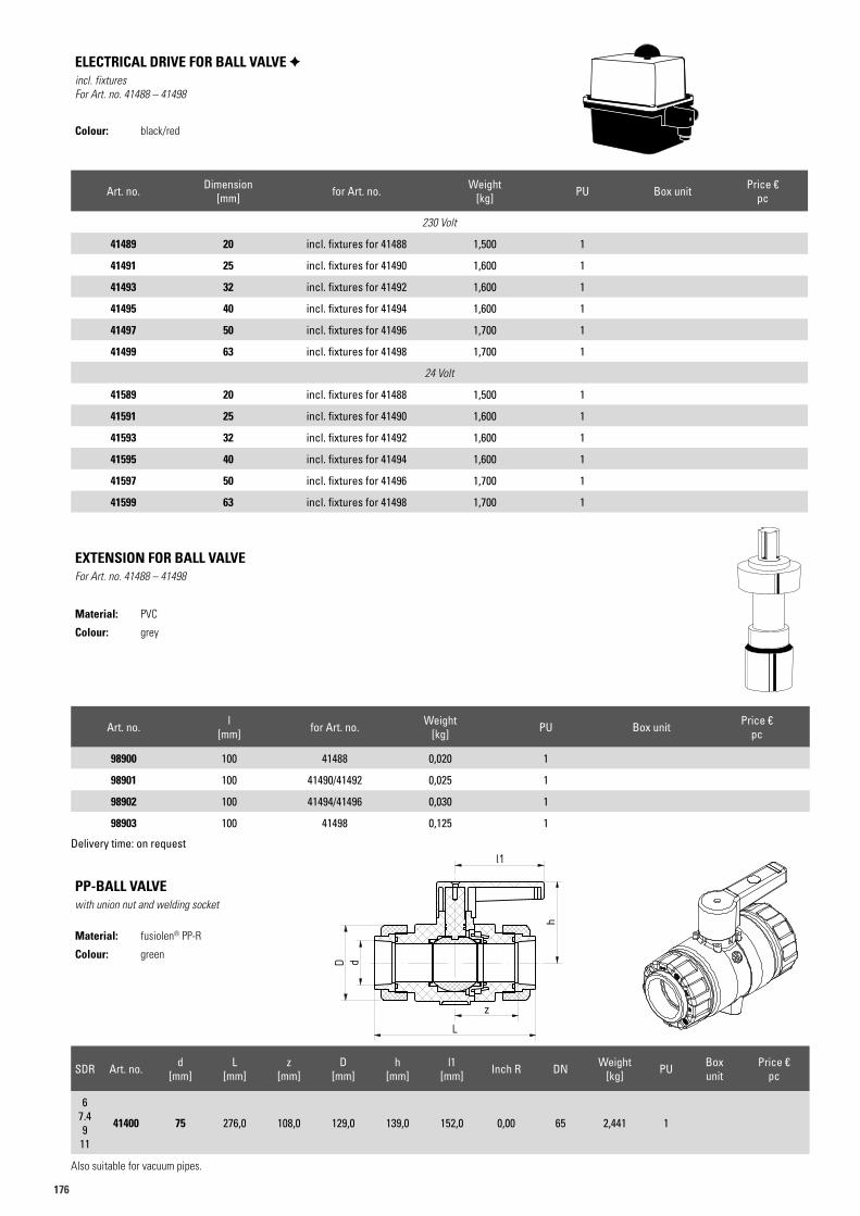
176
SDR Art. no. d [mm]
L [mm]
z [mm]
D [mm]
h [mm]
l1 [mm] Inch R DN Weight
[kg] PU Box unit
Price €pc
67.49
11
41400 75 276,0 108,0 129,0 139,0 152,0 0,00 65 2,441 1
PP-BALL VALVEwith union nut and welding socket
Material: fusiolen® PP-R
Colour: green
Art.N. 41400Artikelliste 2015Seite 58
l1
z
dD
L
h
Art. no. l [mm] for Art. no. Weight
[kg] PU Box unit Price €pc
98900 100 41488 0,020 1
98901 100 41490/41492 0,025 1
98902 100 41494/41496 0,030 1
98903 100 41498 0,125 1
Delivery time: on request
EXTENSION FOR BALL VALVEFor Art. no. 41488 – 41498
Material: PVC
Colour: grey
Art. no. Dimension [mm] for Art. no. Weight
[kg] PU Box unit Price €pc
230 Volt
41489 20 incl. fixtures for 41488 1,500 1
41491 25 incl. fixtures for 41490 1,600 1
41493 32 incl. fixtures for 41492 1,600 1
41495 40 incl. fixtures for 41494 1,600 1
41497 50 incl. fixtures for 41496 1,700 1
41499 63 incl. fixtures for 41498 1,700 1
24 Volt
41589 20 incl. fixtures for 41488 1,500 1
41591 25 incl. fixtures for 41490 1,600 1
41593 32 incl. fixtures for 41492 1,600 1
41595 40 incl. fixtures for 41494 1,600 1
41597 50 incl. fixtures for 41496 1,700 1
41599 63 incl. fixtures for 41498 1,700 1
ELECTRICAL DRIVE FOR BALL VALVE incl. fixturesFor Art. no. 41488 – 41498
Colour: black/red
Also suitable for vacuum pipes.
ind. change / no. datename
external drawing number:
Copyrightreserved
Divergences for dimen-sion without tolerances
DIN ISO 2768-mKDIN 16901
Surface roughnessaccording to
DIN ISO 1302, line 2
material:raw part no.:mould insert:
part name:date: name:
designed:checked:
StübbeGmbH & Co.KGPostfach 1765
D-32591 Vlotho
ident no.: index: format:
weight:
scale:
sheet:
sheets
deduced from:
lename:
Material Id. - No.
This is a drawing derivationof a 3D model. Changes must be
carried out in the 3D model.
Status Serie A. Kran 06.12.19-
138940 - A2
C101 DN65 2½" PN10 1:12
2
06.12.19 A. Kran
138940
PP-PP-EPDM 138940
08.12.08 G. Pohlmeier Aquatherm
Respe
ct pro
tectiv
e note
accor
ding t
o DIN
ISO 16
016
A A
B B
C C
D D
E E
F F
G G
H H
12
12
11
11
10
10
9
9
8
8
7
7
6
6
5
5
4
4
3
3
2
2
1
1
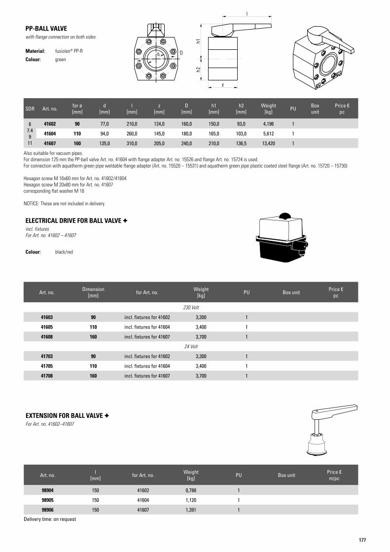
177177
SDR Art. no. for ø [mm]
d [mm]
l [mm]
z [mm]
D [mm]
h1 [mm]
h2 [mm]
Weight [kg] PU Box
unit Price €
pc
67.49
11
41602 90 77,0 210,0 124,0 160,0 150,0 93,0 4,196 1
41604 110 94,0 260,0 145,0 180,0 165,0 103,0 5,612 1
41607 160 135,0 310,0 205,0 240,0 210,0 136,5 13,420 1
Also suitable for vacuum pipes. For dimension 125 mm the PP-ball valve Art. no. 41604 with flange adapter Art. no. 15526 and flange Art. no. 15724 is used.For connection with aquatherm green pipe weldable flange adapter (Art. no. 15520 – 15531) and aquatherm green pipe plastic coated steel flange (Art. no. 15720 – 15730)
Hexagon screw M 16x60 mm for Art. no. 41602/41604Hexagon screw M 20x80 mm for Art. no. 41607corresponding flat washer M 16
NOTICE: These are not included in delivery.
PP-BALL VALVEwith flange connection on both sides
Material: fusiolen® PP-R
Colour: green
Art.N. 41602Artikelliste 2015Seite 58
h2h1
l
z
d D
Art.N. 41602Artikelliste 2015Seite 58
h2h1
l
z
d D
Art.N. 41602Artikelliste 2015Seite 58
h2h1
l
z
d D
Art. no. Dimension [mm] for Art. no. Weight
[kg] PU Box unit Price €pc
230 Volt
41603 90 incl. fixtures for 41602 3,300 1
41605 110 incl. fixtures for 41604 3,400 1
41608 160 incl. fixtures for 41607 3,700 1
24 Volt
41703 90 incl. fixtures for 41602 3,300 1
41705 110 incl. fixtures for 41604 3,400 1
41708 160 incl. fixtures for 41607 3,700 1
ELECTRICAL DRIVE FOR BALL VALVE incl. fixturesFor Art. no. 41602 – 41607
Colour: black/red
Art. no. l [mm] for Art. no. Weight
[kg] PU Box unit Price €m/pc
98904 150 41602 0,788 1
98905 150 41604 1,120 1
98906 150 41607 1,391 1
Delivery time: on request
EXTENSION FOR BALL VALVE For Art. no. 41602–41607
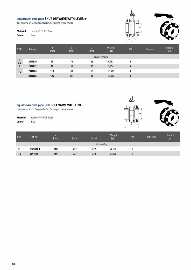
178
SDR Art. no. d [mm]
z [mm]
L [mm]
Weight [kg] PU Box unit Price €
pc
6 7.4 9
11 17.6
socket welding
2041820 75 78 138 6,763 1
2041822 90 80 146 9,134 1
2041824 110 89 163 10,400 1
2041826 125 104 184 15,600 1
aquatherm blue pipe SHUT-OFF VALVE WITH LEVER Set consists of: 2 x flange adapter, 2 x flanges, fixing screws
Material: fusiolen® PP-RCT, Steel
Colour: blue
SDR Art. no. d [mm]
z [mm]
L [mm]
Weight [kg] PU Box unit Price €
pc
Butt welding
11 2041830 160 227 242 22,000 1
17.6 2541830 160 227 242 21,700 1
aquatherm blue pipe SHUT-OFF VALVE WITH LEVERSet consists of: 2 x flange adapter, 2 x flanges, fixing screws
Material: fusiolen® PP-RCT, Steel
Colour: blue
Art.N. 2041926Artikelliste 2016Seite ??
Muffenschweißverfahren
Stumpfschweißverfahren
d
Lz
d
zL
Art.N. 2041926Artikelliste 2016Seite ??
Muffenschweißverfahren
Stumpfschweißverfahren
d
Lz
d
zL
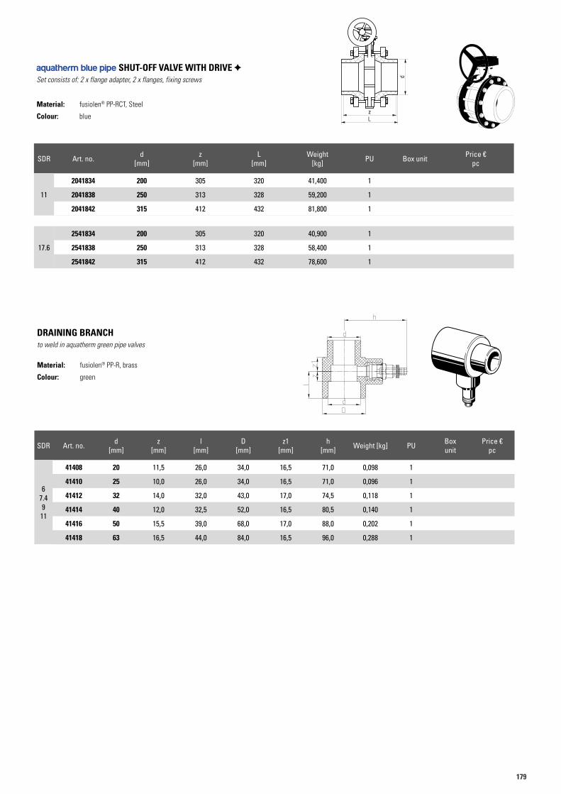
179179
SDR Art. no. d [mm]
z [mm]
L [mm]
Weight [kg] PU Box unit Price €
pc
11
2041834 200 305 320 41,400 1
2041838 250 313 328 59,200 1
2041842 315 412 432 81,800 1
17.6
2541834 200 305 320 40,900 1
2541838 250 313 328 58,400 1
2541842 315 412 432 78,600 1
aquatherm blue pipe SHUT-OFF VALVE WITH DRIVE Set consists of: 2 x flange adapter, 2 x flanges, fixing screws
Material: fusiolen® PP-RCT, Steel
Colour: blue
Art.N. 2041834Artikelliste 2016Seite ??
L
d
z
SDR Art. no. d [mm]
z [mm]
l [mm]
D [mm]
z1 [mm]
h [mm] Weight [kg] PU Box
unit Price €
pc
67.49
11
41408 20 11,5 26,0 34,0 16,5 71,0 0,098 1
41410 25 10,0 26,0 34,0 16,5 71,0 0,096 1
41412 32 14,0 32,0 43,0 17,0 74,5 0,118 1
41414 40 12,0 32,5 52,0 16,5 80,5 0,140 1
41416 50 15,5 39,0 68,0 17,0 88,0 0,202 1
41418 63 16,5 44,0 84,0 16,5 96,0 0,288 1
DRAINING BRANCHto weld in aquatherm green pipe valves
Material: fusiolen® PP-R, brass
Colour: green
41408
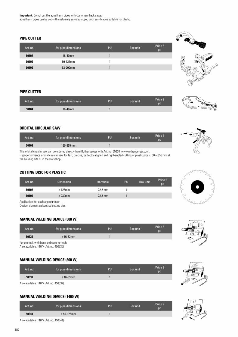
180
PIPE CUTTER
Art. no. for pipe dimensions PU Box unit Price €pc
50102 16-40mm 1
50105 50-125mm 1
50106 63-200mm 1
PIPE CUTTER
Art. no. for pipe dimensions PU Box unit Price €pc
50104 16-40mm 1
MANUAL WELDING DEVICE (500 W)
Art. no. for pipe dimensions PU Box unit Price €pc
50336 ø 16-32mm 1
for one tool, with base and case for toolsAlso available: 110 V (Art. no. 450336)
MANUAL WELDING DEVICE (800 W)
Art. no. for pipe dimensions PU Box unit Price €pc
50337 ø 16-63mm 1
Also available: 110 V (Art. no. 450337)
MANUAL WELDING DEVICE (1400 W)
Art. no. for pipe dimensions PU Box unit Price €pc
50341 ø 50-125mm 1
Also available: 110 V (Art. no. 450341)
Important: Do not cut the aquatherm pipes with customary hack saws.aquatherm pipes can be cut with customary saws equipped with saw blades suitable for plastic.
ORBITAL CIRCULAR SAW
Art. no. for pipe dimensions PU Box unit Price €pc
50108 160-355mm 1
This orbital circular saw can be ordered directly from Rothenberger with Art. no. 55620 (www.rothenberger.com). High-performance orbital circular saw for fast, precise, perfectly aligned and right-angled cutting of plastic pipes 160 – 355 mm at the building site or in the workshop.
CUTTING DISC FOR PLASTIC
Art. no. Dimension borehole PU Box unit Price €pc
50107 ø 125mm 22,2 mm 1
50109 ø 230mm 22,2 mm 1
Application: for each angle grinder Design: diamant galvanized cutting disc
aquatherm
fusiotherm
aquatherm
aquatherm
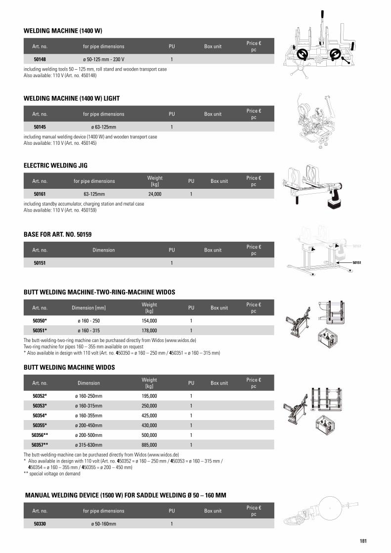
181181
WELDING MACHINE (1400 W)
Art. no. for pipe dimensions PU Box unit Price €pc
50148 ø 50-125 mm - 230 V 1
including welding tools 50 – 125 mm, roll stand and wooden transport caseAlso available: 110 V (Art. no. 450148)
WELDING MACHINE (1400 W) LIGHT
Art. no. for pipe dimensions PU Box unit Price €pc
50145 ø 63-125mm 1
including manual welding device (1400 W) and wooden transport caseAlso available: 110 V (Art. no. 450145)
ELECTRIC WELDING JIG
Art. no. for pipe dimensions Weight [kg] PU Box unit Price €
pc
50161 63-125mm 24,000 1
including standby accumulator, charging station and metal caseAlso available: 110 V (Art. no. 450159)
BASE FOR ART. NO. 50159
Art. no. Dimension PU Box unit Price €pc
50151 1
aquatherm
BUTT WELDING MACHINE-TWO-RING-MACHINE WIDOS
Art. no. Dimension [mm] Weight [kg] PU Box unit Price €
pc
50350* ø 160 - 250 154,000 1
50351* ø 160 - 315 178,000 1
The butt-welding-two-ring machine can be purchased directly from Widos (www.widos.de)Two-ring machine for pipes 160 – 355 mm available on request* Also available in design with 110 volt (Art. no. 450350 = ø 160 – 250 mm / 450351 = ø 160 – 315 mm)
BUTT WELDING MACHINE WIDOS
Art. no. Dimension Weight [kg] PU Box unit Price €
pc
50352* ø 160-250mm 195,000 1
50353* ø 160-315mm 250,000 1
50354* ø 160-355mm 425,000 1
50355* ø 200-450mm 430,000 1
50356** ø 200-500mm 500,000 1
50357** ø 315-630mm 885,000 1
The butt-welding-machine can be purchased directly from Widos (www.widos.de)* Also available in design with 110 volt (Art. no. 450352 = ø 160 – 250 mm / 450353 = ø 160 – 315 mm /
450354 = ø 160 – 355 mm / 450355 = ø 200 – 450 mm)** special voltage on demand
MANUAL WELDING DEVICE (1500 W) FOR SADDLE WELDING Ø 50 – 160 MM
Art. no. for pipe dimensions PU Box unit Price €pc
50330 ø 50-160mm 1
aquatherm
50161
50151
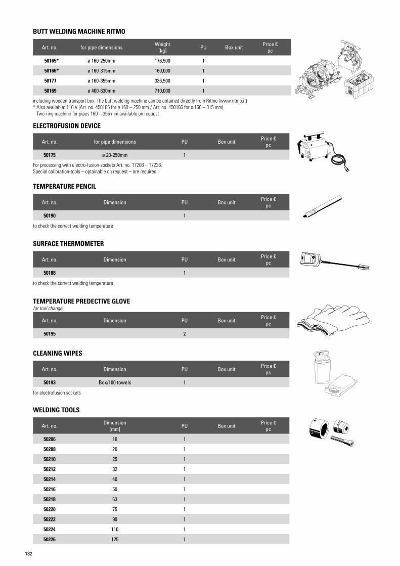
182
TEMPERATURE PENCIL
Art. no. Dimension PU Box unit Price €pc
50190 1
to check the correct welding temperature
TEMPERATURE PREDECTIVE GLOVEfor tool change
Art. no. Dimension PU Box unit Price €pc
50195 2
SURFACE THERMOMETER
Art. no. Dimension PU Box unit Price €pc
50188 1
to check the correct welding temperature
CLEANING WIPES
Art. no. Dimension PU Box unit Price €pc
50193 Box/100 towels 1
for electrofusion sockets
50190
50208
ELECTROFUSION DEVICE
Art. no. for pipe dimensions PU Box unit Price €pc
50175 ø 20-250mm 1
For processing with electro-fusion-sockets Art. no. 17208 – 17238. Special calibration-tools – optainable on request – are required
BUTT WELDING MACHINE RITMO
Art. no. for pipe dimensions Weight [kg] PU Box unit Price €
pc
50165* ø 160-250mm 176,500 1
50166* ø 160-315mm 160,000 1
50177 ø 160-355mm 336,500 1
50169 ø 400-630mm 710,000 1
including wooden transport box. The butt welding machine can be obtained directly from Ritmo (www.ritmo.it)* Also available: 110 V (Art. no. 450165 for ø 160 – 250 mm / Art. no. 450166 for ø 160 – 315 mm)
Two-ring machine for pipes 160 – 355 mm available on request
WELDING TOOLS
Art. no. Dimension [mm] PU Box unit Price €
pc
50206 16 1
50208 20 1
50210 25 1
50212 32 1
50214 40 1
50216 50 1
50218 63 1
50220 75 1
50222 90 1
50224 110 1
50226 125 1
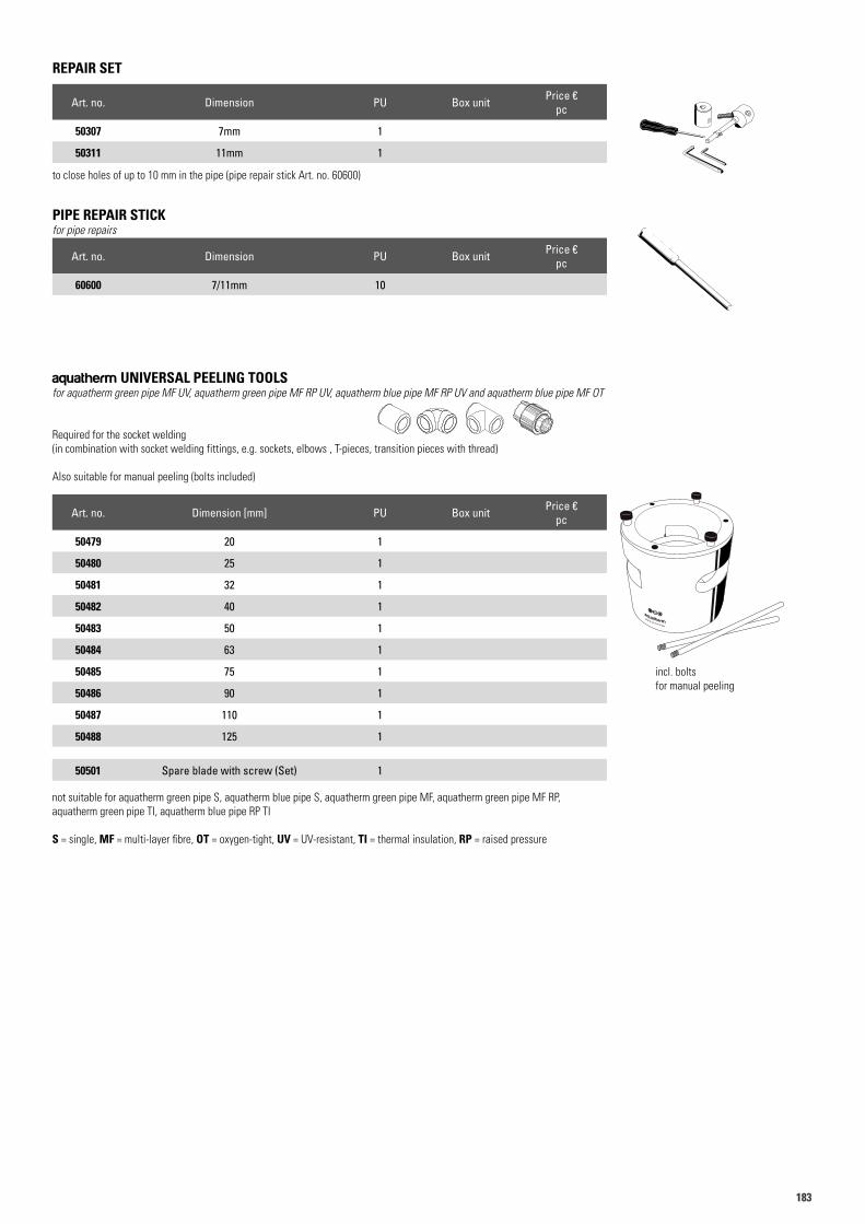
183183
aquatherm UNIVERSAL PEELING TOOLSfor aquatherm green pipe MF UV, aquatherm green pipe MF RP UV, aquatherm blue pipe MF RP UV and aquatherm blue pipe MF OT
Required for the socket welding (in combination with socket welding fittings, e.g. sockets, elbows , T-pieces, transition pieces with thread)
Also suitable for manual peeling (bolts included)
Art. no. Dimension [mm] PU Box unit Price €pc
50479 20 1
50480 25 1
50481 32 1
50482 40 1
50483 50 1
50484 63 1
50485 75 1
50486 90 1
50487 110 1
50488 125 1
50501 Spare blade with screw (Set) 1
not suitable for aquatherm green pipe S, aquatherm blue pipe S, aquatherm green pipe MF, aquatherm green pipe MF RP, aquatherm green pipe TI, aquatherm blue pipe RP TI
S = single, MF = multi-layer fibre, OT = oxygen-tight, UV = UV-resistant, TI = thermal insulation, RP = raised pressure
incl. bolts for manual peeling
REPAIR SET
Art. no. Dimension PU Box unit Price €pc
50307 7mm 1
50311 11mm 1
to close holes of up to 10 mm in the pipe (pipe repair stick Art. no. 60600)
PIPE REPAIR STICKfor pipe repairs
Art. no. Dimension PU Box unit Price €pc
60600 7/11mm 10
z
dD
Art.N. 11006Artikelliste 2015Seite 18
L
Art.N. 12106Artikelliste 2015Seite 21
dD
zl
Art.N. 13106Artikelliste 2015Seite 24
lz
dD
Lz1z1
Art.N. 21108Artikelliste 2015Seite 45
z
lL
dD R
z1
SW
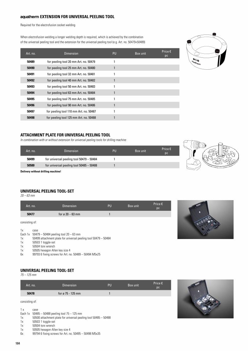
184
UNIVERSAL PEELING TOOL-SET20 – 63 mm
Art. no. Dimension PU Box unit Price €pc
50477 for ø 20 – 63 mm 1
consisting of:
1x caseEach 1x 50479 – 50484 peeling tool 20 – 63 mm1x 50499 attachment plate for universal peeling tool 50479 – 504841x 50503 1 toggle-set1x 50504 torx wrench1x 50505 hexagon Allen key size 46x 99793 6 fixing screws for Art. no. 50489 – 50494 M5x25
UNIVERSAL PEELING TOOL-SET75 – 125 mm
Art. no. Dimension PU Box unit Price €pc
50478 for ø 75 - 125 mm 1
consisting of:
1 x caseEach 1x 50485 – 50488 peeling tool 75 – 125 mm1x 50500 attachment plate for universal peeling tool 50485 – 504881x 50503 1 toggle-set1x 50504 torx wrench1x 50505 hexagon Allen key size 46x 99794 6 fixing screws for Art. no. 50495 – 50498 M5x35
ATTACHMENT PLATE FOR UNIVERSAL PEELING TOOLIn combination with or without extension for universal peeling tools for drilling machine
Art. no. Dimension PU Box unit Price €pc
50499 for universal peeling tool 50479 – 50484 1
50500 for universal peeling tool 50485 – 50488 1
Delivery without drilling machine!
aquatherm EXTENSION FOR UNIVERSAL PEELING TOOL
Required for the electrofusion socket welding
When electrofusion welding a longer welding depth is required, which is achieved by the combination of the universal peeling tool and the extension for the universal peeling tool (e.g. Art. no. 50479+50489)
Art. no. Dimension PU Box unit Price €pc
50489 for peeling tool 20 mm Art. no. 50479 1
50490 for peeling tool 25 mm Art. no. 50480 1
50491 for peeling tool 32 mm Art. no. 50481 1
50492 for peeling tool 40 mm Art. no. 50482 1
50493 for peeling tool 50 mm Art. no. 50483 1
50494 for peeling tool 63 mm Art. no. 50484 1
50495 for peeling tool 75 mm Art. no. 50485 1
50496 for peeling tool 90 mm Art. no. 50486 1
50497 for peeling tool 110 mm Art. no. 50487 1
50498 for peeling tool 125 mm Art. no. 50488 1
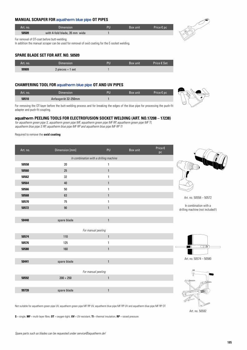
185185
MANUAL SCRAPER FOR aquatherm blue pipe OT PIPES
Art. no. Dimension PU Box unit Price € pc
50509 with 4-fold blade, 35 mm wide 1
SPARE BLADE SET FOR ART. NO. 50509
Art. no. Dimension PU Box unit Price € Set
99909 2 pieces = 1 set 1
CHAMFERING TOOL FOR aquatherm blue pipe OT AND UV PIPES
Art. no. Dimension PU Box unit Price € pc
50510 Anfasgerät 32-250mm 1
For removal of OT-coat before butt-welding.In addition the manual scraper can be used for removal of oxid coating for the E-socket welding.
For removing the OT-layer before the butt-welding process and for breaking the edges of the blue pipe for processing the push-fit adapter and push-fit coupling.
Spare parts such as blades can be requested under [email protected]!
Art. no. 50592
Art. no. 50558 – 50572
In combination with a drilling machine (not included!)
Art. no. 50574 – 50580
aquatherm PEELING TOOLS FOR ELECTROFUSION SOCKET WELDING (ART. NO.17208 – 17238)for aquatherm green pipe S, aquatherm green pipe MF, aquatherm green pipe MF RP, aquatherm green pipe MF TI,aquatherm blue pipe S RP, aquatherm blue pipe MF RP and aquatherm blue pipe MF RP TI
Required to remove the oxid coating
Art. no. Dimension [mm] PU Box unit Price €pc
In combination with a drilling machine
50558 20 1
50560 25 1
50562 32 1
50564 40 1
50566 50 1
50568 63 1
50570 75 1
50572 90 1
50440 spare blade 1
For manual peeling
50574 110 1
50576 125 1
50580 160 1
50441 spare blade 1
For manual peeling
50592 200 + 250 1
99739 spare blade 1
Not suitable for aquatherm green pipe UV, aquatherm green pipe MF RP UV, aquatherm blue pipe MF RP UV and aquatherm blue pipe MF RP OT
S = single, MF = multi-layer fibre, OT = oxygen-tight, UV = UV-resistant, TI = thermal insulation, RP = raised pressure
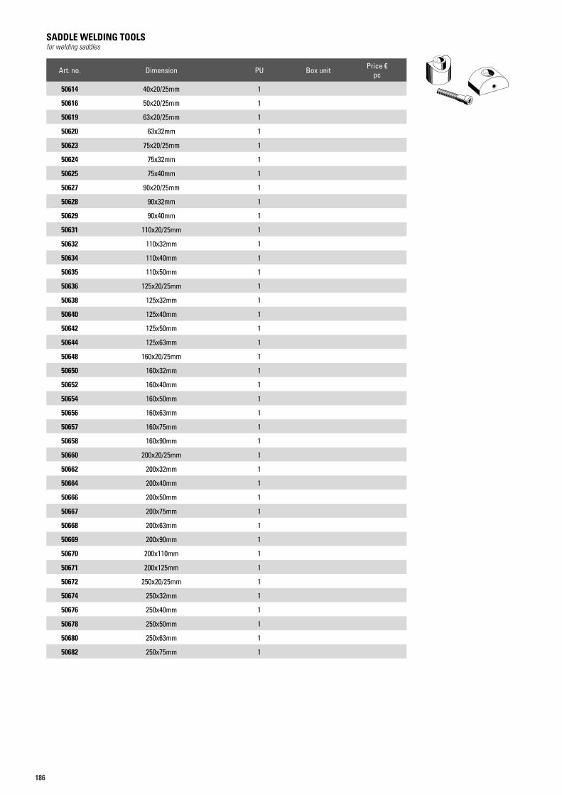
186
SADDLE WELDING TOOLSfor welding saddles
Art. no. Dimension PU Box unit Price €pc
50614 40x20/25mm 1
50616 50x20/25mm 1
50619 63x20/25mm 1
50620 63x32mm 1
50623 75x20/25mm 1
50624 75x32mm 1
50625 75x40mm 1
50627 90x20/25mm 1
50628 90x32mm 1
50629 90x40mm 1
50631 110x20/25mm 1
50632 110x32mm 1
50634 110x40mm 1
50635 110x50mm 1
50636 125x20/25mm 1
50638 125x32mm 1
50640 125x40mm 1
50642 125x50mm 1
50644 125x63mm 1
50648 160x20/25mm 1
50650 160x32mm 1
50652 160x40mm 1
50654 160x50mm 1
50656 160x63mm 1
50657 160x75mm 1
50658 160x90mm 1
50660 200x20/25mm 1
50662 200x32mm 1
50664 200x40mm 1
50666 200x50mm 1
50667 200x75mm 1
50668 200x63mm 1
50669 200x90mm 1
50670 200x110mm 1
50671 200x125mm 1
50672 250x20/25mm 1
50674 250x32mm 1
50676 250x40mm 1
50678 250x50mm 1
50680 250x63mm 1
50682 250x75mm 1
50619
187187
SADDLE WELDING TOOLSfor welding saddles
Art. no. Dimension PU Box unit Price €pc
50684 250x90mm 1
50686 250x110mm 1
50688 250x125mm 1
50690 315x63mm 1
50692 315x75mm 1
50694 315x90mm 1
50696 315x110mm 1
50698 315x125mm 1
50699 315x160mm 1
50712 355x63mm 1
50714 355x75mm 1
50716 355x90mm 1
50718 355x110mm 1
50720 355x125mm 1
50722 355x160mm 1
50726 400-630x63mm 1
50728 400-500x75mm 1
50730 630x75mm 1
50732 400-500x90mm 1
50734 630x90mm 1
50736 400-450x110mm 1
50738 500x110mm 1
50740 630x110mm 1
50742 400x125mm 1
50744 450-500x125mm 1
50746 630x125mm 1
50619
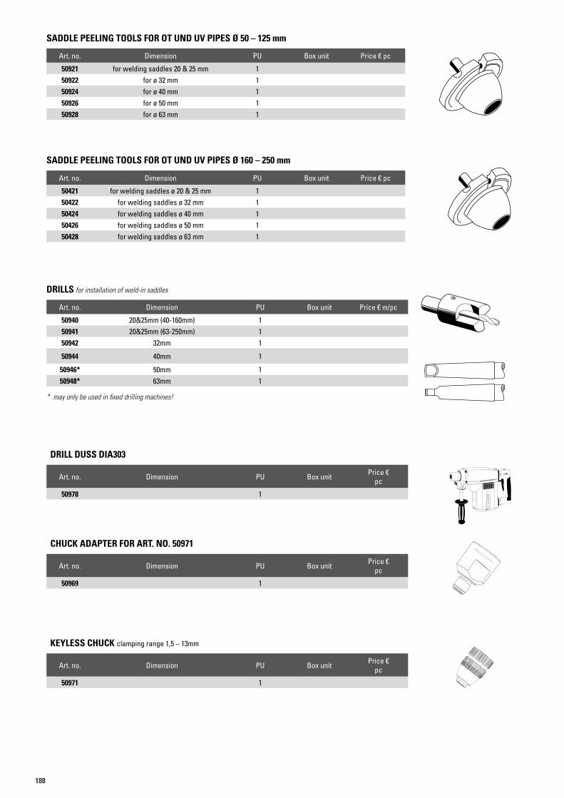
188
SADDLE PEELING TOOLS FOR OT UND UV PIPES Ø 50 – 125 mm
Art. no. Dimension PU Box unit Price € pc
50921 for welding saddles 20 & 25 mm 150922 for ø 32 mm 150924 for ø 40 mm 150926 for ø 50 mm 150928 for ø 63 mm 1
SADDLE PEELING TOOLS FOR OT UND UV PIPES Ø 160 – 250 mm
Art. no. Dimension PU Box unit Price € pc
50421 for welding saddles ø 20 & 25 mm 150422 for welding saddles ø 32 mm 150424 for welding saddles ø 40 mm 150426 for welding saddles ø 50 mm 150428 for welding saddles ø 63 mm 1
DRILL DUSS DIA303
Art. no. Dimension PU Box unit Price €pc
50978 1
CHUCK ADAPTER FOR ART. NO. 50971
Art. no. Dimension PU Box unit Price €pc
50969 1
KEYLESS CHUCK clamping range 1,5 – 13mm
Art. no. Dimension PU Box unit Price €pc
50971 1
DRILLS for installation of weld-in saddles
Art. no. Dimension PU Box unit Price € m/pc
50940 20&25mm (40-160mm) 150941 20&25mm (63-250mm) 150942 32mm 1
50944 40mm 1
50946* 50mm 150948* 63mm 1
* may only be used in fixed drilling machines!
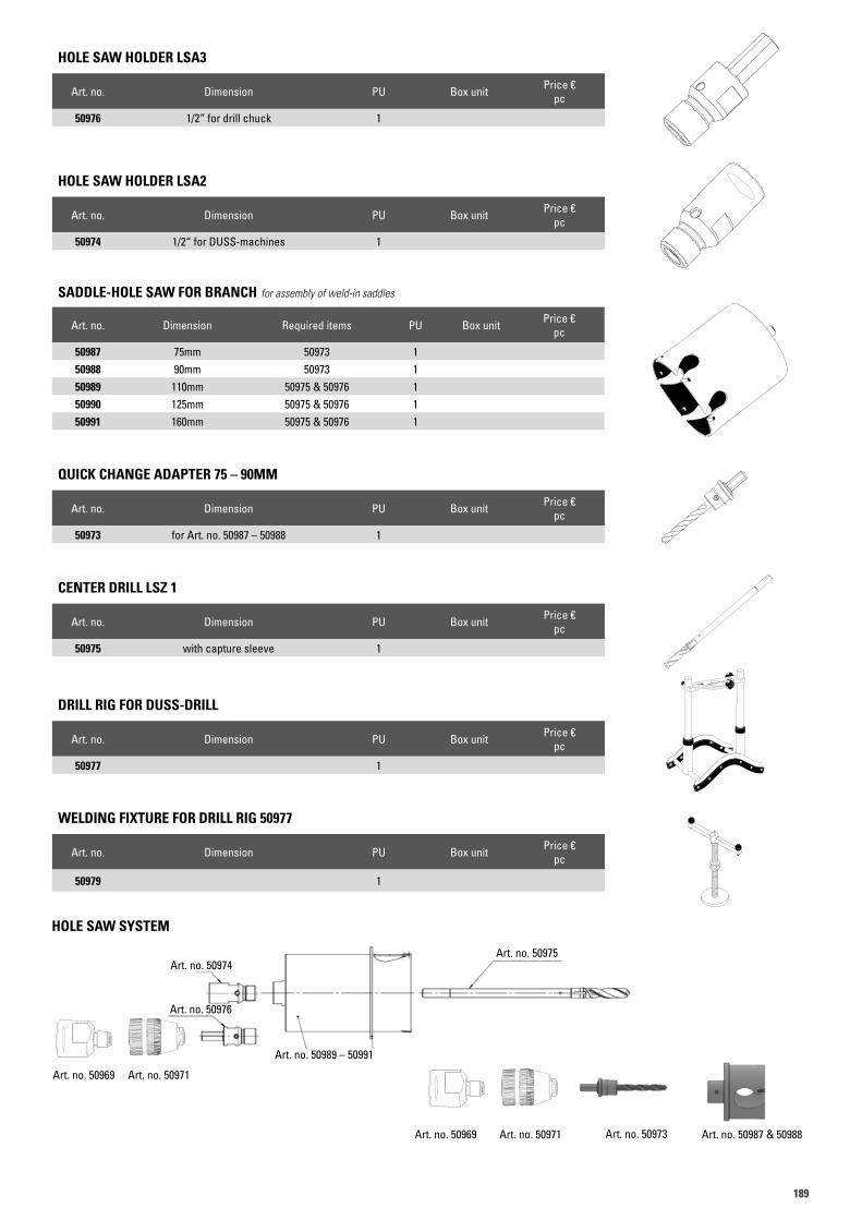
189189
HOLE SAW HOLDER LSA2
Art. no. Dimension PU Box unit Price €pc
50974 1/2“ for DUSS-machines 1
DRILL RIG FOR DUSS-DRILL
Art. no. Dimension PU Box unit Price €pc
50977 1
WELDING FIXTURE FOR DRILL RIG 50977
Art. no. Dimension PU Box unit Price €pc
50979 1
CENTER DRILL LSZ 1
Art. no. Dimension PU Box unit Price €pc
50975 with capture sleeve 1
HOLE SAW HOLDER LSA3
Art. no. Dimension PU Box unit Price €pc
50976 1/2“ for drill chuck 1
HOLE SAW SYSTEM
Art. no. 50974
Art. no. 50989 – 50991
Art. no. 50975
Art. no. 50976
Art. no. 50969
Art. no. 50969
Art. no. 50971
Art. no. 50971 Art. no. 50973 Art. no. 50987 & 50988
SADDLE-HOLE SAW FOR BRANCH for assembly of weld-in saddles
Art. no. Dimension Required items PU Box unit Price €pc
50987 75mm 50973 150988 90mm 50973 150989 110mm 50975 & 50976 150990 125mm 50975 & 50976 150991 160mm 50975 & 50976 1
QUICK CHANGE ADAPTER 75 – 90MM
Art. no. Dimension PU Box unit Price €pc
50973 for Art. no. 50987 – 50988 1
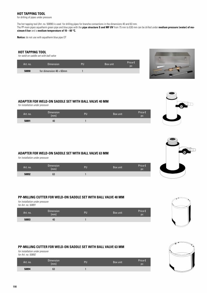
190
Art. no. Dimension PU Box unit Price €m/pc
50893 40 mm 1 3
PP-MILLING CUTTER FOR WELD-ON SADDLE SET WITH BALL VALVE 40 MM for installation under pressurefor Art. no. 50891
Art. no. Dimension [mm] PU Box unit Price €
pc
50894 63 1
PP-MILLING CUTTER FOR WELD-ON SADDLE SET WITH BALL VALVE 63 MM for installation under pressurefor Art. no. 50892
Art. no. Dimension PU Box unit Price €pc
50890 for dimension 40 + 63mm 1
HOT TAPPING TOOLfor weld-on saddle set with ball valve
Art. no. Dimension [mm] PU Box unit Price €
pc
50891 40 1
ADAPTER FOR WELD-ON SADDLE SET WITH BALL VALVE 40 MMfor installation under pressure
Art. no. Dimension [mm] PU Box unit Price €
pc
50892 63 1
ADAPTER FOR WELD-ON SADDLE SET WITH BALL VALVE 63 MM for installation under pressure
Art. no. Dimension [mm] PU Box unit Price €
pc
50893 40 1
HOT TAPPING TOOLfor drilling of pipes under pressure
The hot tapping tool (Art. no. 50890) is used for drilling pipes for branche connections in the dimensions 40 and 63 mm.The PP-main pipes aquatherm green pipe and blue pipe with the pipe structure S and MF UV from 75 mm to 630 mm can be drilled under medium pressure (water) of ma-ximum 6 bar and a medium temperature of 10 – 60 °C.
Notice: do not use with aquatherm blue pipe OT
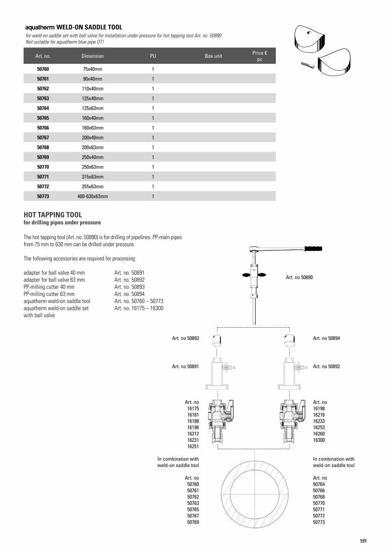
191191
Art. no. Dimension PU Box unit Price €pc
50760 75x40mm 1
50761 90x40mm 1
50762 110x40mm 1
50763 125x40mm 1
50764 125x63mm 1
50765 160x40mm 1
50766 160x63mm 1
50767 200x40mm 1
50768 200x63mm 1
50769 250x40mm 1
50770 250x63mm 1
50771 315x63mm 1
50772 355x63mm 1
50773 400-630x63mm 1
aquatherm WELD-ON SADDLE TOOLfor weld-on saddle set with ball valve for installation under pressure for hot tapping tool Art. no. 50890 Not suitable for aquatherm blue pipe OT!
The hot tapping tool (Art. no. 50890) is for drilling of pipelines. PP-main pipes from 75 mm to 630 mm can be drilled under pressure.
The following accessories are required for processing:
adapter for ball valve 40 mm Art. no. 50891adapter for ball valve 63 mm Art. no. 50892PP-milling cutter 40 mm Art. no. 50893PP-milling cutter 63 mm Art. no. 50894aquatherm weld-on saddle tool Art. no. 50760 – 50773aquatherm weld-on saddle set Art. no. 16175 – 16300with ball valve
HOT TAPPING TOOLfor drilling pipes under pressure
Art. no 16175161811618816196162121623116251
In combination with weld-on saddle tool
Art. no 50760 50761 50762 50763 50765 50767 50769
Art. no 161981621616233162531626016300
In combination with weld-on saddle tool
Art. no 50764 50766 50768 50770 50771 50772 50773
Art. no 50891 Art. no 50892
Art. no 50893 Art. no 50894
Art. no 50890
Art.N. 41488+ Aufschweisssattel
Art.N. 41488+ Aufschweisssattel

192
NOTES

193193
NOTES

194
NOTES

195195
TERMS AND CONDITIONS
Important note regarding our sales, warranty and delivery conditions:
Our sales and delivery conditions (issue: 2014) as well as the contact details of our technical sales department and our representatives can be found on our website www.aquatherm.de.
Errors, misprints and technical modifications reserved. With the appearance of this catalogue all previous issues become void.
aquatherm GmbH, 2020. This technical information is protected by copyright. Reproductions are prosecuted.
ManagementSystemISO 9001:2015ISO 14001:2015ISO 50001:2011
www.tuv.comID 0091005348
Ord
er-N
o.:
E10
050
Ed
itio
n: 0
8.20
20
aqua
ther
m b
lue
pip
e - P
ipe
syst
em F
or h
eatin
g an
d co
olin
g an
d va
rious
indu
stria
l app
licat
ions
aquatherm GmbHBiggen 5 | 57439 Attendorn | Germany | Tel.: +49 2722 950 0 [email protected] | www.aquatherm.de