underwater defect & hazard report
TRANSCRIPT
CONDITION REPORT
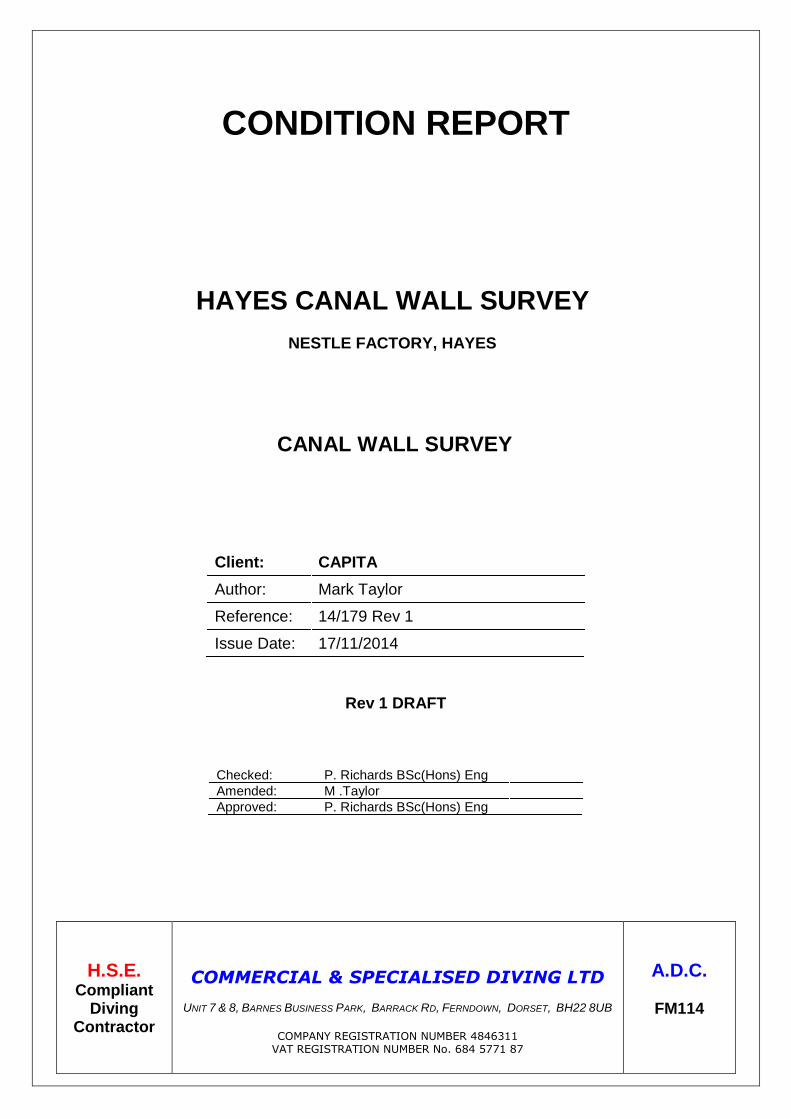
HAYES CANAL WALL SURVEY
NESTLE FACTORY, HAYES
CANAL WALL SURVEY
Client: CAPITA
Author: Mark Taylor
Reference: 14/179 Rev 1
Issue Date: 17/11/2014
Rev 1 DRAFT
Checked: P. Richards BSc(Hons) Eng
Amended: M .Taylor
Approved: P. Richards BSc(Hons) Eng
H.S.E. Compliant
Diving Contractor
COMMERCIAL & SPECIALISED DIVING LTD
UNIT 7 & 8, BARNES BUSINESS PARK, BARRACK RD, FERNDOWN, DORSET, BH22 8UB
COMPANY REGISTRATION NUMBER 4846311
VAT REGISTRATION NUMBER No. 684 5771 87
A.D.C.
FM114
Contents
1.0 INSTRUCTIONS
2.0 GENERAL DESCRIPTION
3.0 INSPECTION AND ACCESS METHODS
4.0 GENERAL OBSERVATIONS
5.0 CONCLUSION
Appendices
Appendix A Pile Thickness Readings
Appendix B Bed Level Readings
Appendix C Chainage Overview
Synopsis The condition survey revealed the sheet pile section of river wall to be in a reasonable condition, although multiple hairline cracks were observed in the concrete capping beam above. These hairline cracks appear to be full penetration cracks and are also visible on the back face of the capping beam adjacent to the Nestle factory roadway. The capping beam also features several areas of spalling above the out pans of the sheet pile wall, probably due to the de-lamination of the steel. From chainage 234m the construction of the wall changes from sheet pile to a brick built wall with concrete coping stones above. The brick built wall features several large areas of missing brick work creating large voids in the wall below the waterline. No scour or undercut was reported at any point along the structure.
Commercial & Specialised Diving - 1 -
1.0 INSTRUCTIONS
1.1 Instructions were received from Paul Edwards of Capita to carry out a condition survey of the retaining
canal wall adjacent to the Nestle factory site in Hayes to establish the following;
Determine the construction of the canal wall. Record canal wall height and water depths.
Provide details, extent and location of any wall defects and features.
A CCTV and photographic survey. Cygnus thickness gauge readings of sheet pile wall. Plan/elevation drawings identifying defect locations to be submitted in CAD format.
2.0 GENERAL DESCRIPTION
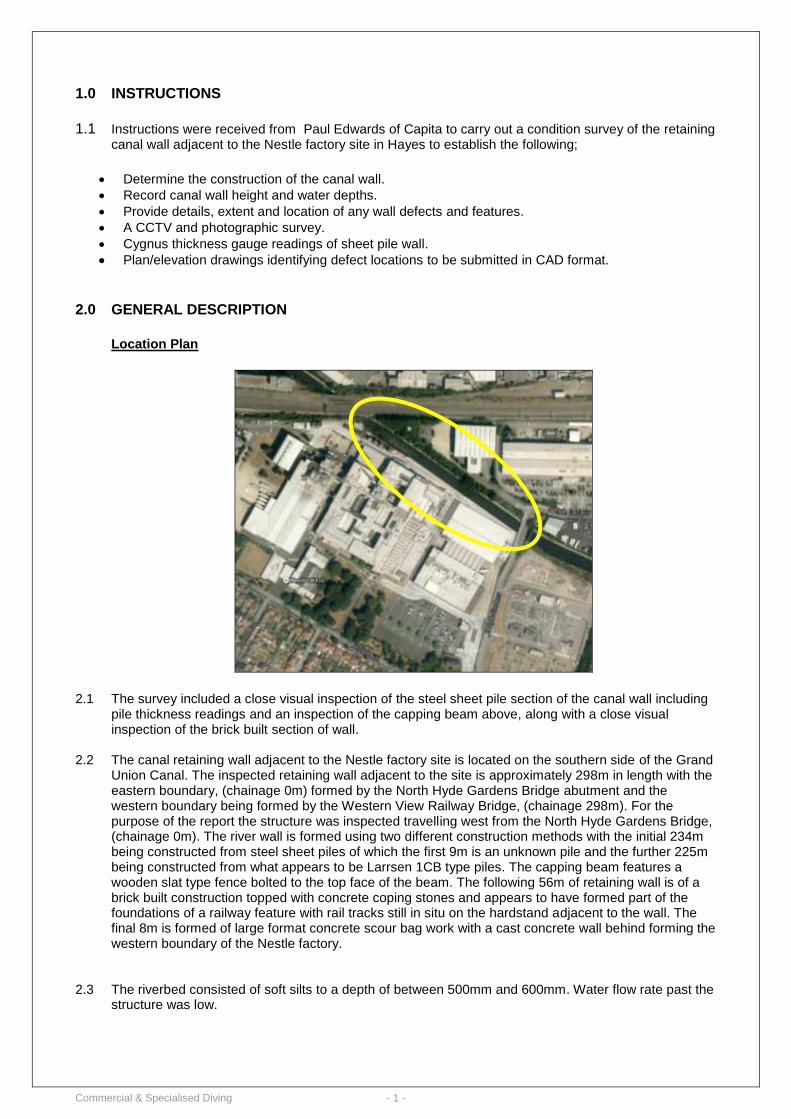
Location Plan
2.1 The survey included a close visual inspection of the steel sheet pile section of the canal wall including
pile thickness readings and an inspection of the capping beam above, along with a close visual inspection of the brick built section of wall.
2.2 The canal retaining wall adjacent to the Nestle factory site is located on the southern side of the Grand
Union Canal. The inspected retaining wall adjacent to the site is approximately 298m in length with the eastern boundary, (chainage 0m) formed by the North Hyde Gardens Bridge abutment and the western boundary being formed by the Western View Railway Bridge, (chainage 298m). For the purpose of the report the structure was inspected travelling west from the North Hyde Gardens Bridge, (chainage 0m). The river wall is formed using two different construction methods with the initial 234m being constructed from steel sheet piles of which the first 9m is an unknown pile and the further 225m being constructed from what appears to be Larrsen 1CB type piles. The capping beam features a wooden slat type fence bolted to the top face of the beam. The following 56m of retaining wall is of a brick built construction topped with concrete coping stones and appears to have formed part of the foundations of a railway feature with rail tracks still in situ on the hardstand adjacent to the wall. The final 8m is formed of large format concrete scour bag work with a cast concrete wall behind forming the western boundary of the Nestle factory.
2.3 The riverbed consisted of soft silts to a depth of between 500mm and 600mm. Water flow rate past the
structure was low.
Commercial & Specialised Diving - 2 -
3.0 INSPECTION AND ACCESS METHODS
Date of inspection: 29th
& 30th October 2014
3.1 The following personnel undertook the inspection works;
Mark Taylor HSE Pt 1, ADC Supervisor Steven Kent HSE Pt 1 Lee Jennings HSE Pt 1 James Johnson HSE Pt 1
3.2 The structure was accessed via the Nestle site. 3.3 Diving operations were conducted from the car park adjacent to the river wall using Surface Demand
Diving Equipment (SDDE) in conjunction with the Commercial Diving Projects Inland/Inshore, Diving at Work Regulations 1997 and under Permit enforced by Canals Rivers Trust.
3.4 Underwater visibility was very poor during the inspection and inhibited the acquisition of underwater
photographic and video footage. A tactile survey of the wall was conducted below the waterline.
3.5 The Grand Union Canal remained open to navigation for the duration of the survey and all relevant
permits were obtained to undertake the works.
Commercial & Specialised Diving - 3 -
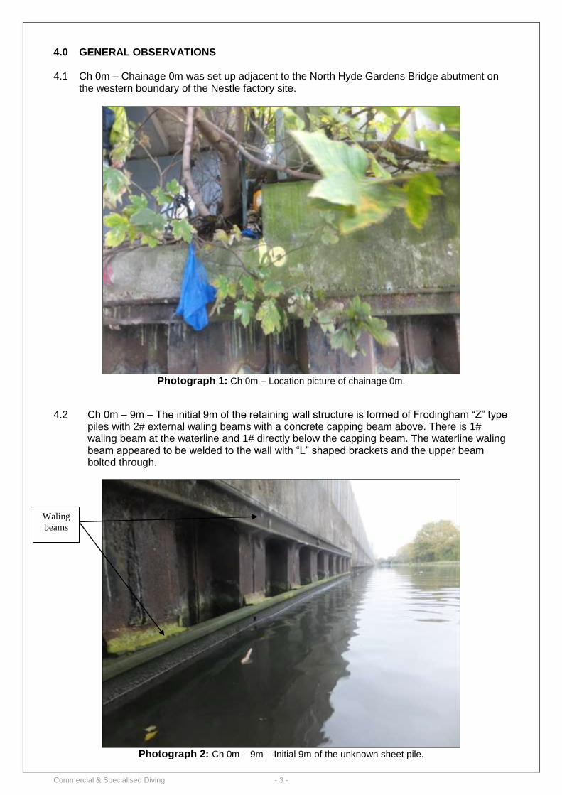
4.0 GENERAL OBSERVATIONS 4.1 Ch 0m – Chainage 0m was set up adjacent to the North Hyde Gardens Bridge abutment on
the western boundary of the Nestle factory site.
Photograph 1: Ch 0m – Location picture of chainage 0m.
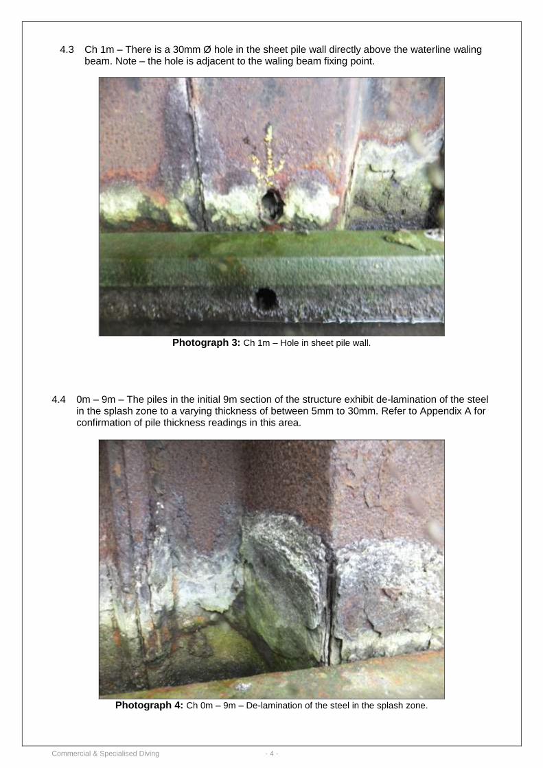
4.2 Ch 0m – 9m – The initial 9m of the retaining wall structure is formed of Frodingham “Z” type piles with 2# external waling beams with a concrete capping beam above. There is 1# waling beam at the waterline and 1# directly below the capping beam. The waterline waling beam appeared to be welded to the wall with “L” shaped brackets and the upper beam bolted through.
Photograph 2: Ch 0m – 9m – Initial 9m of the unknown sheet pile.
Waling
beams
Commercial & Specialised Diving - 4 -
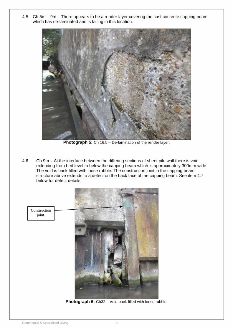
4.3 Ch 1m – There is a 30mm Ø hole in the sheet pile wall directly above the waterline waling beam. Note – the hole is adjacent to the waling beam fixing point.
Photograph 3: Ch 1m – Hole in sheet pile wall.
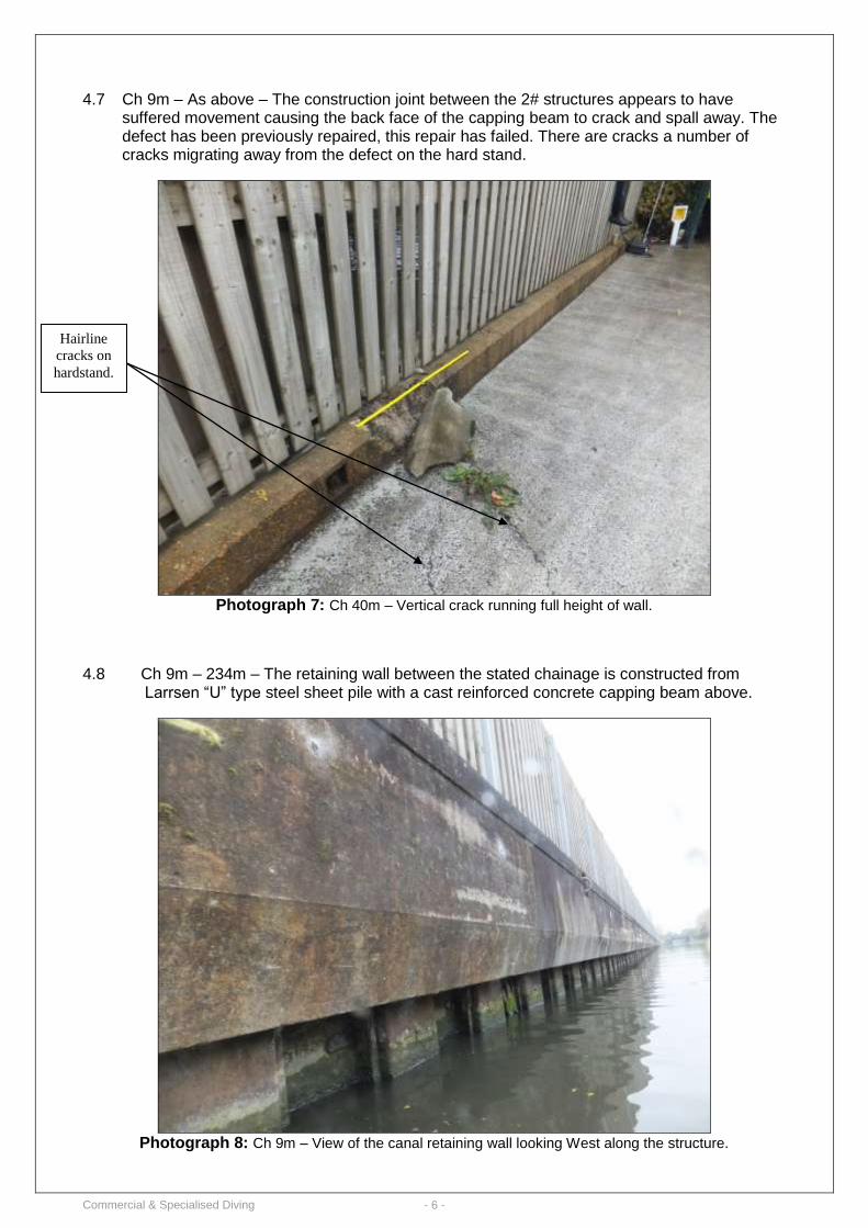
4.4 0m – 9m – The piles in the initial 9m section of the structure exhibit de-lamination of the steel
in the splash zone to a varying thickness of between 5mm to 30mm. Refer to Appendix A for confirmation of pile thickness readings in this area.
Photograph 4: Ch 0m – 9m – De-lamination of the steel in the splash zone.
Commercial & Specialised Diving - 5 -
4.5 Ch 5m – 9m – There appears to be a render layer covering the cast concrete capping beam which has de-laminated and is failing in this location.
Photograph 5: Ch 16.5 – De-lamination of the render layer.
4.6 Ch 9m – At the interface between the differing sections of sheet pile wall there is void extending from bed level to below the capping beam which is approximately 300mm wide. The void is back filled with loose rubble. The construction joint in the capping beam structure above extends to a defect on the back face of the capping beam. See item 4.7 below for defect details.
Photograph 6: Ch32 – Void back filled with loose rubble.
Construction
joint.
Commercial & Specialised Diving - 6 -
4.7 Ch 9m – As above – The construction joint between the 2# structures appears to have
suffered movement causing the back face of the capping beam to crack and spall away. The defect has been previously repaired, this repair has failed. There are cracks a number of cracks migrating away from the defect on the hard stand.
Photograph 7: Ch 40m – Vertical crack running full height of wall.
4.8 Ch 9m – 234m – The retaining wall between the stated chainage is constructed from Larrsen “U” type steel sheet pile with a cast reinforced concrete capping beam above.
Photograph 8: Ch 9m – View of the canal retaining wall looking West along the structure.
Hairline
cracks on
hardstand.
Commercial & Specialised Diving - 7 -
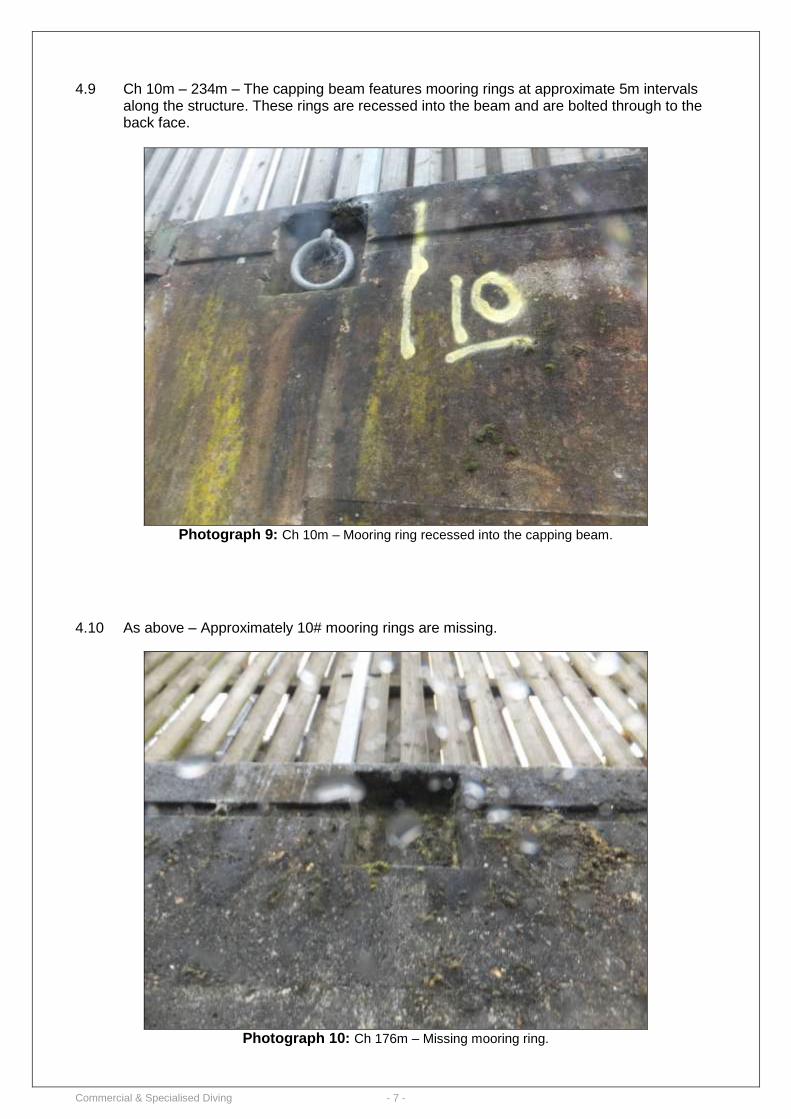
4.9 Ch 10m – 234m – The capping beam features mooring rings at approximate 5m intervals
along the structure. These rings are recessed into the beam and are bolted through to the back face.
Photograph 9: Ch 10m – Mooring ring recessed into the capping beam.
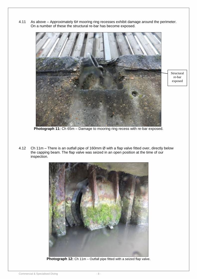
4.10 As above – Approximately 10# mooring rings are missing.
Photograph 10: Ch 176m – Missing mooring ring.
Commercial & Specialised Diving - 8 -
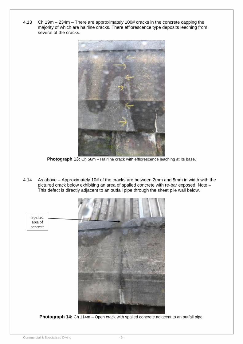
4.11 As above – Approximately 6# mooring ring recesses exhibit damage around the perimeter. On a number of these the structural re-bar has become exposed.
Photograph 11: Ch 65m – Damage to mooring ring recess with re-bar exposed.
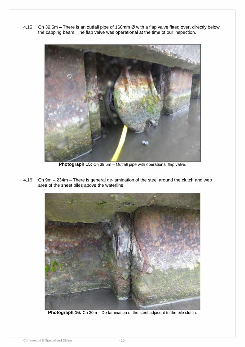
4.12 Ch 11m – There is an outfall pipe of 160mm Ø with a flap valve fitted over, directly below the capping beam. The flap valve was seized in an open position at the time of our inspection.
Photograph 12: Ch 11m – Outfall pipe fitted with a seized flap valve.
Structural
re-bar
exposed
Commercial & Specialised Diving - 9 -
4.13 Ch 19m – 234m – There are approximately 100# cracks in the concrete capping the majority of which are hairline cracks. There efflorescence type deposits leeching from several of the cracks.
Photograph 13: Ch 56m – Hairline crack with efflorescence leaching at its base.
4.14 As above – Approximately 10# of the cracks are between 2mm and 5mm in width with the
pictured crack below exhibiting an area of spalled concrete with re-bar exposed. Note – This defect is directly adjacent to an outfall pipe through the sheet pile wall below.
Photograph 14: Ch 114m – Open crack with spalled concrete adjacent to an outfall pipe.
Spalled
area of
concrete
Commercial & Specialised Diving - 10 -
4.15 Ch 39.5m – There is an outfall pipe of 160mm Ø with a flap valve fitted over, directly below the capping beam. The flap valve was operational at the time of our inspection.
Photograph 15: Ch 39.5m – Outfall pipe with operational flap valve.
4.16 Ch 9m – 234m – There is general de-lamination of the steel around the clutch and web
area of the sheet piles above the waterline.
Photograph 16: Ch 30m – De-lamination of the steel adjacent to the pile clutch.
Commercial & Specialised Diving - 11 -
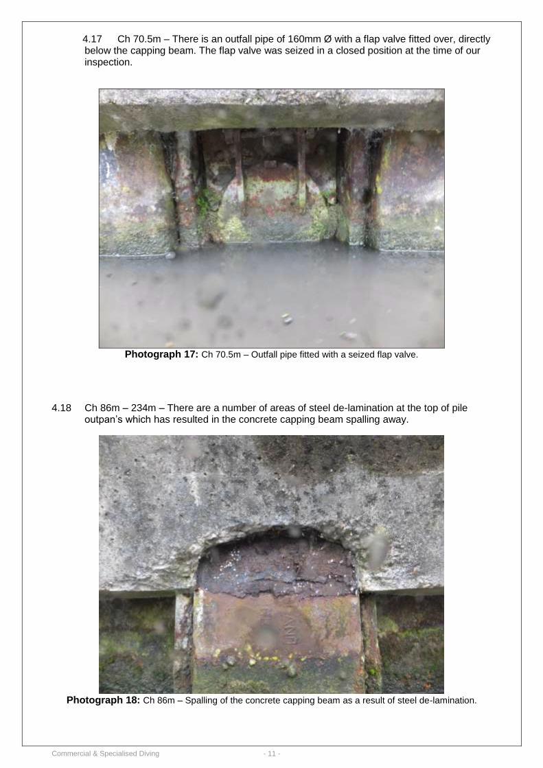
4.17 Ch 70.5m – There is an outfall pipe of 160mm Ø with a flap valve fitted over, directly below the capping beam. The flap valve was seized in a closed position at the time of our inspection.
Photograph 17: Ch 70.5m – Outfall pipe fitted with a seized flap valve.
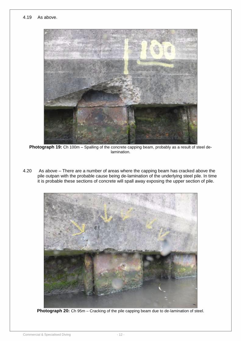
4.18 Ch 86m – 234m – There are a number of areas of steel de-lamination at the top of pile outpan’s which has resulted in the concrete capping beam spalling away.
Photograph 18: Ch 86m – Spalling of the concrete capping beam as a result of steel de-lamination.
Commercial & Specialised Diving - 12 -
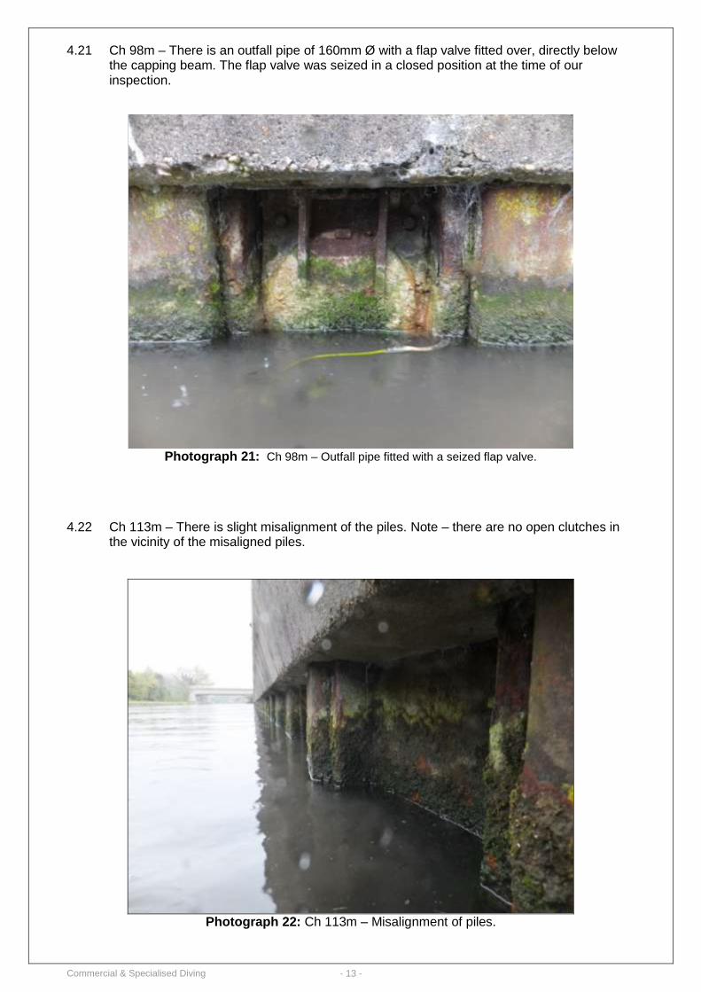
4.19 As above.
Photograph 19: Ch 100m – Spalling of the concrete capping beam, probably as a result of steel de-
lamination.
4.20 As above – There are a number of areas where the capping beam has cracked above the pile outpan with the probable cause being de-lamination of the underlying steel pile. In time it is probable these sections of concrete will spall away exposing the upper section of pile.
Photograph 20: Ch 95m – Cracking of the pile capping beam due to de-lamination of steel.
Commercial & Specialised Diving - 13 -
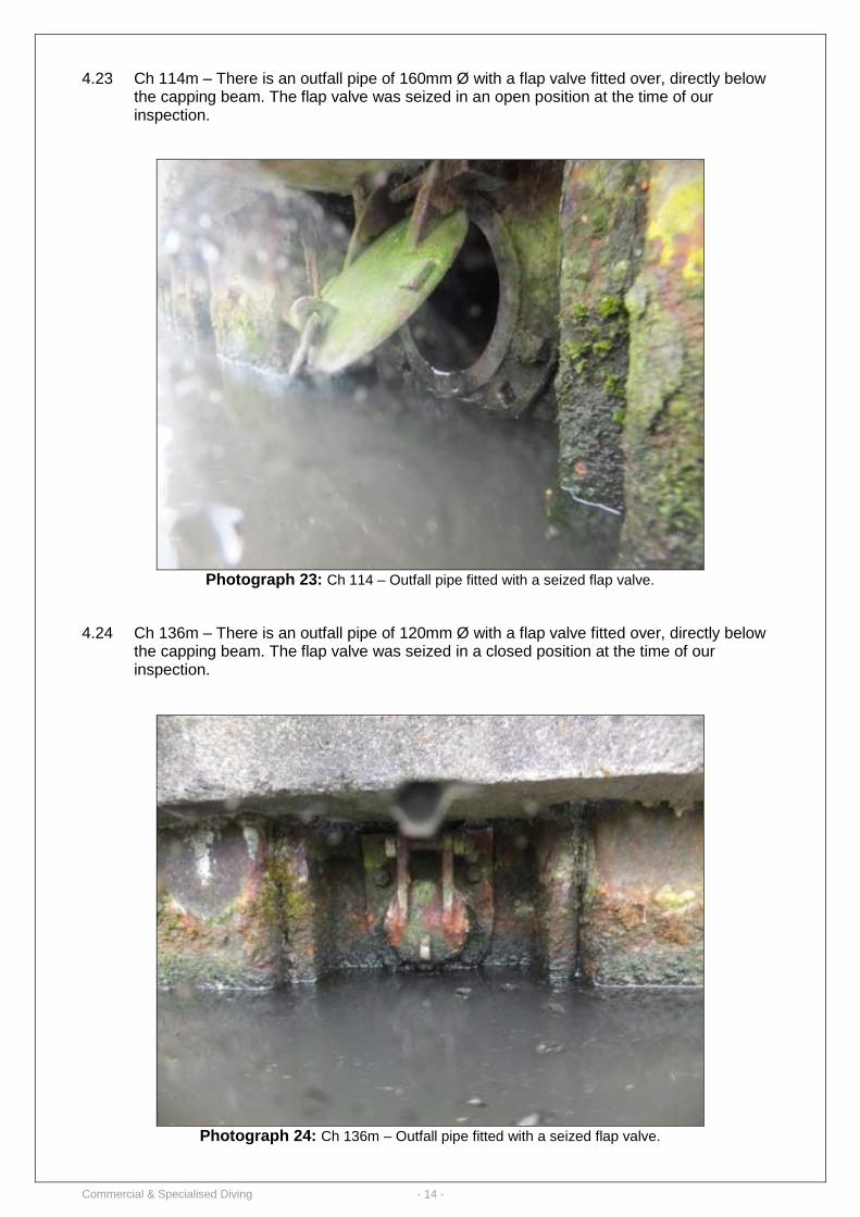
4.21 Ch 98m – There is an outfall pipe of 160mm Ø with a flap valve fitted over, directly below the capping beam. The flap valve was seized in a closed position at the time of our inspection.
Photograph 21: Ch 98m – Outfall pipe fitted with a seized flap valve.
4.22 Ch 113m – There is slight misalignment of the piles. Note – there are no open clutches in
the vicinity of the misaligned piles.
Photograph 22: Ch 113m – Misalignment of piles.
Commercial & Specialised Diving - 14 -
4.23 Ch 114m – There is an outfall pipe of 160mm Ø with a flap valve fitted over, directly below the capping beam. The flap valve was seized in an open position at the time of our inspection.
Photograph 23: Ch 114 – Outfall pipe fitted with a seized flap valve.
4.24 Ch 136m – There is an outfall pipe of 120mm Ø with a flap valve fitted over, directly below
the capping beam. The flap valve was seized in a closed position at the time of our inspection.
Photograph 24: Ch 136m – Outfall pipe fitted with a seized flap valve.
Commercial & Specialised Diving - 15 -
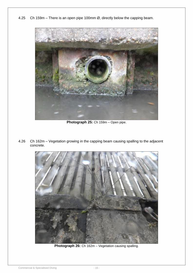
4.25 Ch 159m – There is an open pipe 100mm Ø, directly below the capping beam.
Photograph 25: Ch 159m – Open pipe.
4.26 Ch 162m – Vegetation growing in the capping beam causing spalling to the adjacent concrete.
Photograph 26: Ch 162m – Vegetation causing spalling.
Commercial & Specialised Diving - 16 -
4.27 Ch 175m – There is an outfall pipe of 120mm Ø with a flap valve fitted over, directly below the capping beam. The flap valve was seized in an open position at the time of our inspection.
Photograph 27: Ch 175m – Outfall pipe fitted with a seized flap valve.
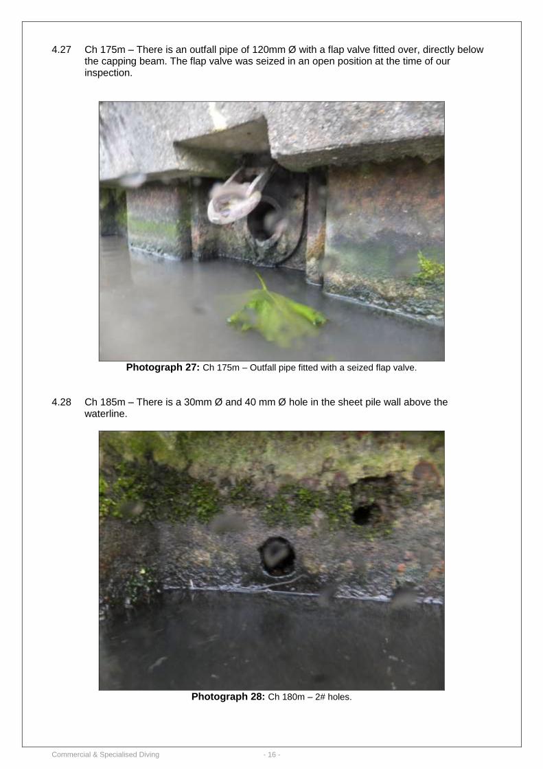
4.28 Ch 185m – There is a 30mm Ø and 40 mm Ø hole in the sheet pile wall above the waterline.
Photograph 28: Ch 180m – 2# holes.
Commercial & Specialised Diving - 17 -
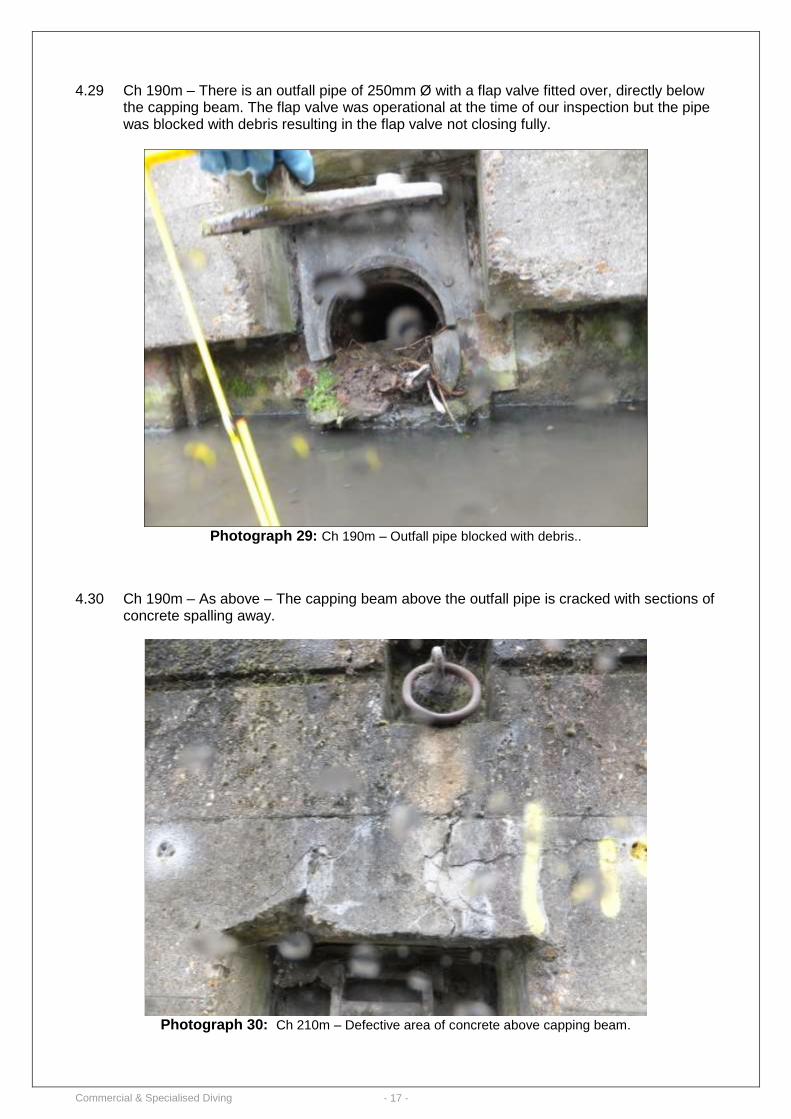
4.29 Ch 190m – There is an outfall pipe of 250mm Ø with a flap valve fitted over, directly below the capping beam. The flap valve was operational at the time of our inspection but the pipe was blocked with debris resulting in the flap valve not closing fully.
Photograph 29: Ch 190m – Outfall pipe blocked with debris..
4.30 Ch 190m – As above – The capping beam above the outfall pipe is cracked with sections of concrete spalling away.
Photograph 30: Ch 210m – Defective area of concrete above capping beam.
Commercial & Specialised Diving - 18 -
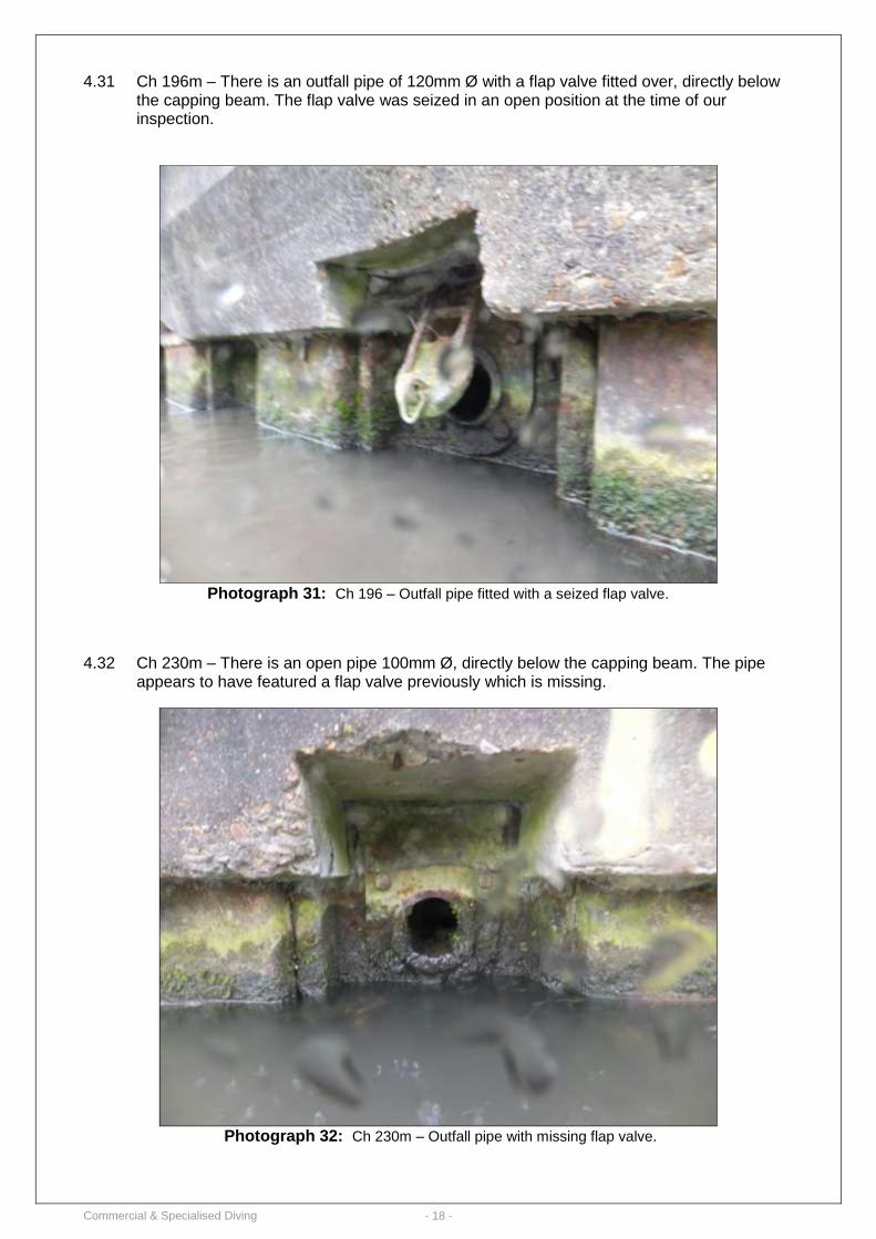
4.31 Ch 196m – There is an outfall pipe of 120mm Ø with a flap valve fitted over, directly below
the capping beam. The flap valve was seized in an open position at the time of our inspection.
Photograph 31: Ch 196 – Outfall pipe fitted with a seized flap valve.
4.32 Ch 230m – There is an open pipe 100mm Ø, directly below the capping beam. The pipe appears to have featured a flap valve previously which is missing.
Photograph 32: Ch 230m – Outfall pipe with missing flap valve.
Commercial & Specialised Diving - 19 -
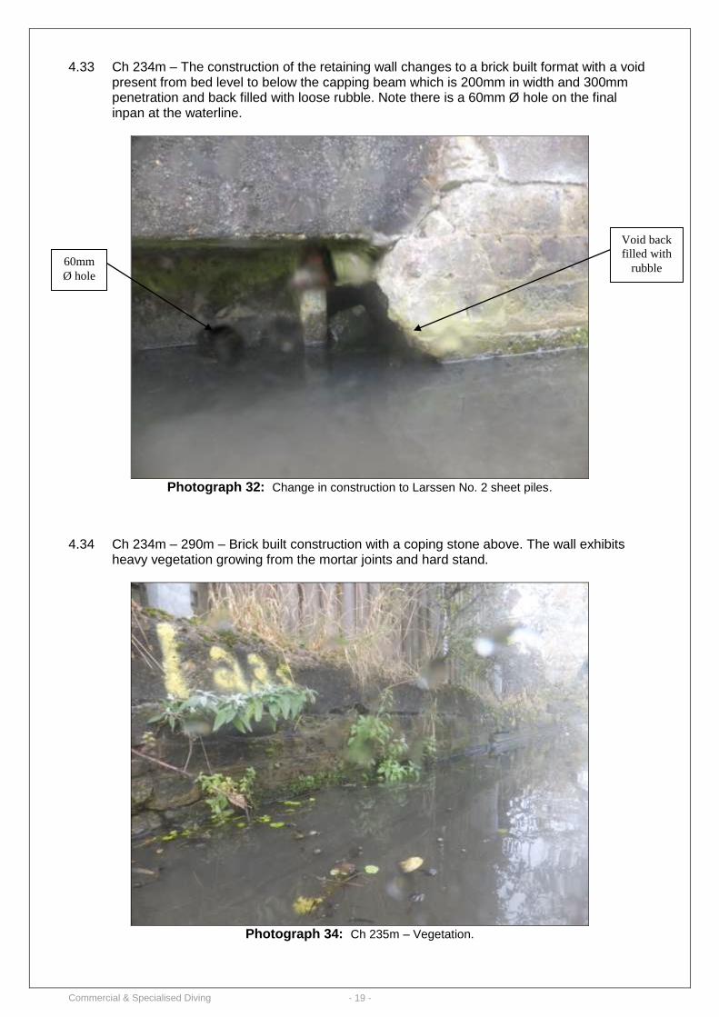
4.33 Ch 234m – The construction of the retaining wall changes to a brick built format with a void
present from bed level to below the capping beam which is 200mm in width and 300mm penetration and back filled with loose rubble. Note there is a 60mm Ø hole on the final inpan at the waterline.
Photograph 32: Change in construction to Larssen No. 2 sheet piles.
4.34 Ch 234m – 290m – Brick built construction with a coping stone above. The wall exhibits heavy vegetation growing from the mortar joints and hard stand.
Photograph 34: Ch 235m – Vegetation.
60mm
Ø hole
Void back
filled with
rubble
Commercial & Specialised Diving - 20 -
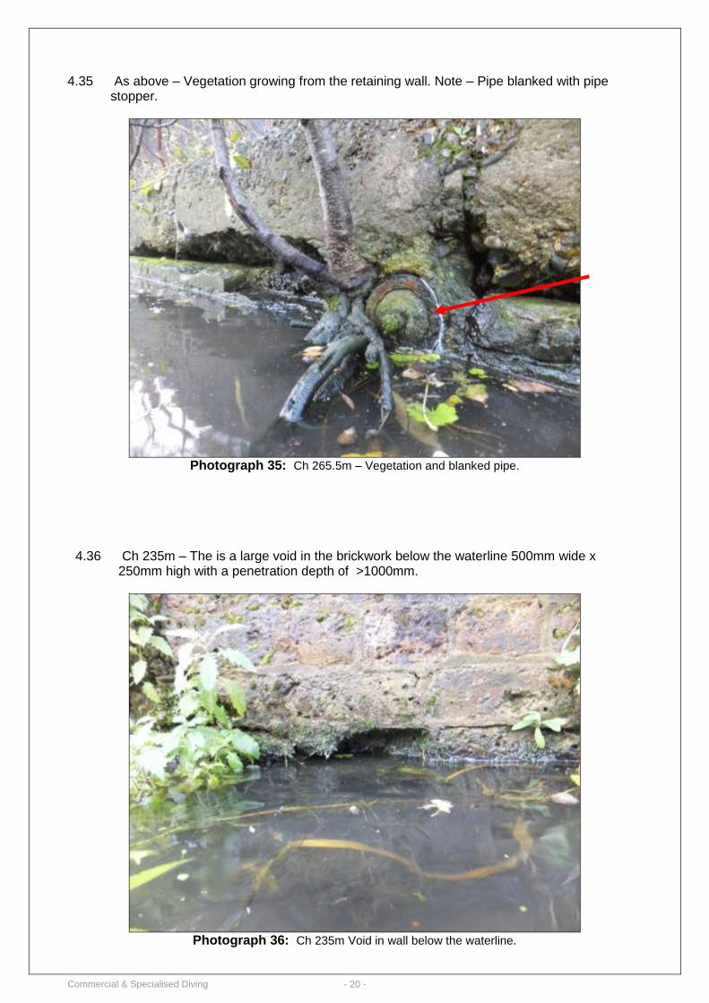
4.35 As above – Vegetation growing from the retaining wall. Note – Pipe blanked with pipe stopper.
Photograph 35: Ch 265.5m – Vegetation and blanked pipe.
4.36 Ch 235m – The is a large void in the brickwork below the waterline 500mm wide x
250mm high with a penetration depth of >1000mm.
Photograph 36: Ch 235m Void in wall below the waterline.
Commercial & Specialised Diving - 21 -
4.37 Ch 234m – 290m – A large proportion of the brickwork mortar joints are missing and
recessed up to 75mm both above and below the waterline. The joint between the top of the brickwork wall and coping stone is also missing and spalled with large voids present.
Photograph 37: Ch 260m – Missing mortar joints.
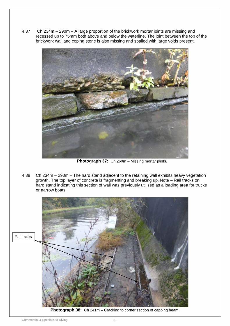
4.38 Ch 234m – 290m – The hard stand adjacent to the retaining wall exhibits heavy vegetation
growth. The top layer of concrete is fragmenting and breaking up. Note – Rail tracks on hard stand indicating this section of wall was previously utilised as a loading area for trucks or narrow boats.
Photograph 38: Ch 241m – Cracking to corner section of capping beam.
Rail tracks
Commercial & Specialised Diving - 22 -
4.39 Ch 240.5m – 100mm Ø open pipe located in the base of the coping stone. There is a similar pile at Ch 257m.
Photograph 38: Ch 240.5m – Open pipe.
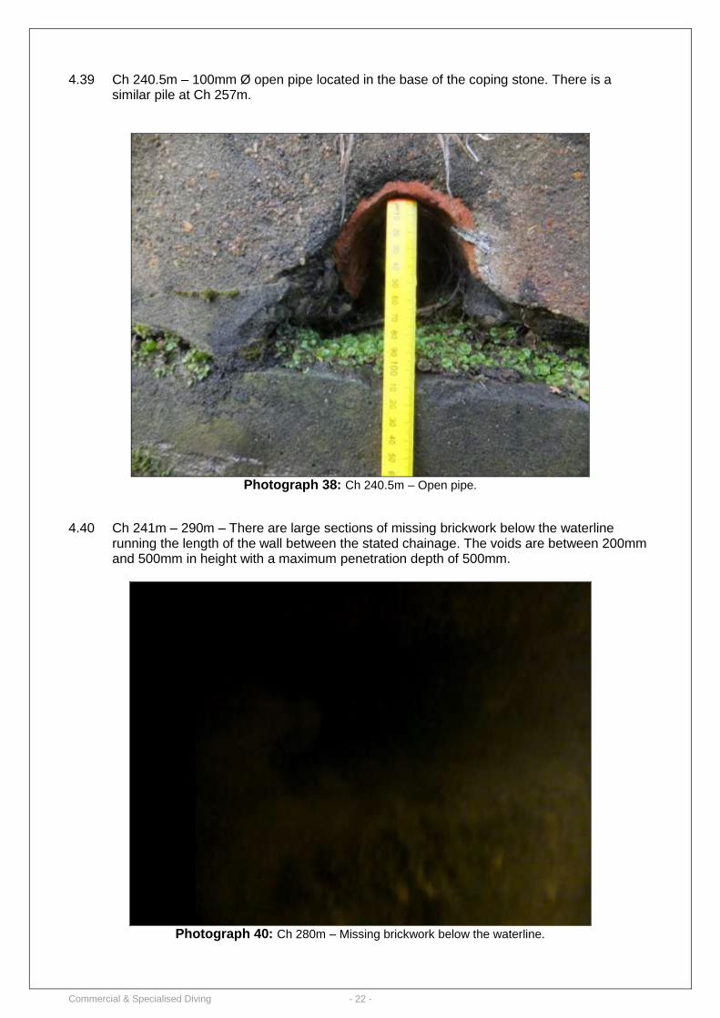
4.40 Ch 241m – 290m – There are large sections of missing brickwork below the waterline running the length of the wall between the stated chainage. The voids are between 200mm and 500mm in height with a maximum penetration depth of 500mm.
Photograph 40: Ch 280m – Missing brickwork below the waterline.
Commercial & Specialised Diving - 23 -
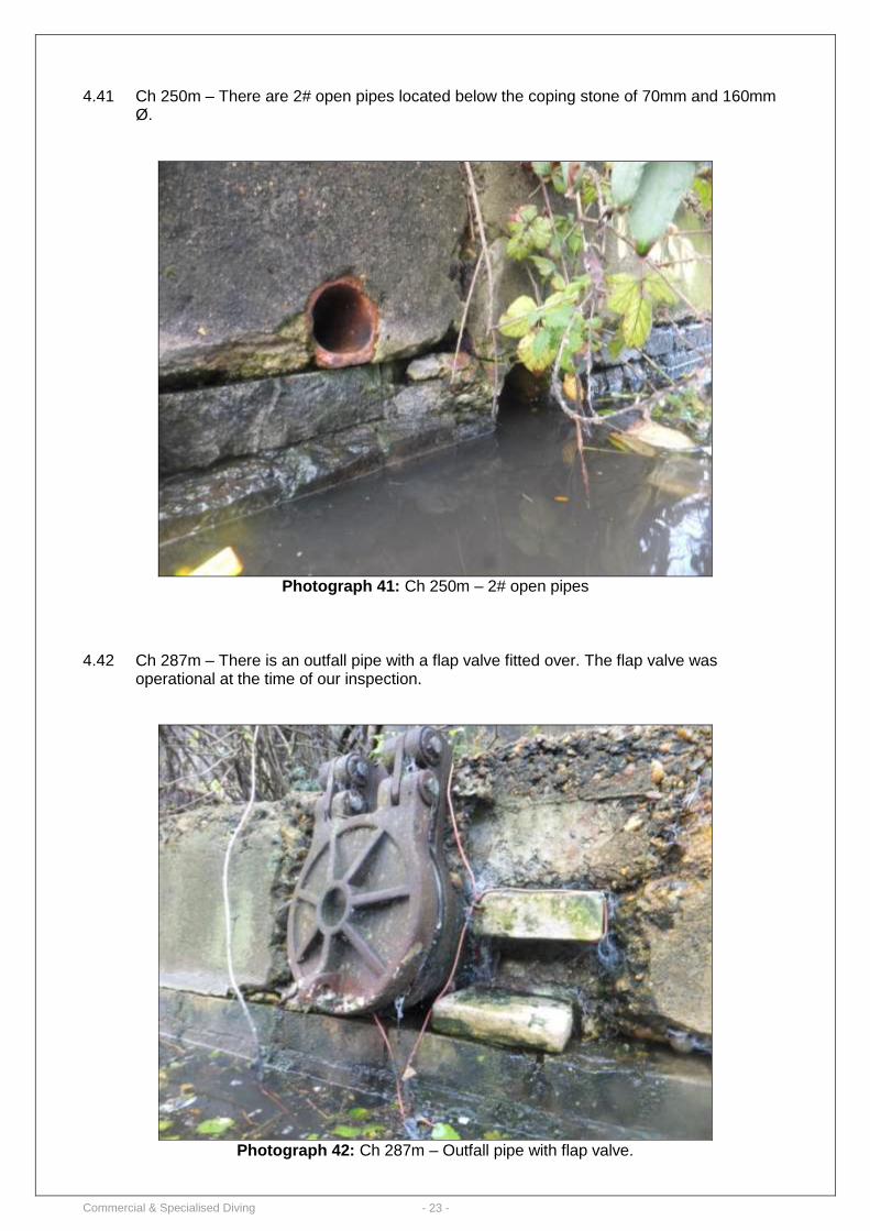
4.41 Ch 250m – There are 2# open pipes located below the coping stone of 70mm and 160mm Ø.
Photograph 41: Ch 250m – 2# open pipes
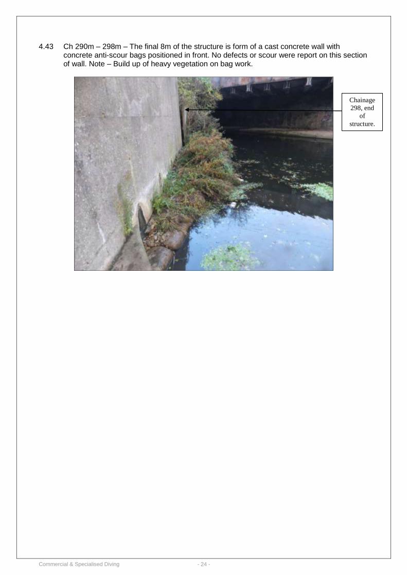
4.42 Ch 287m – There is an outfall pipe with a flap valve fitted over. The flap valve was operational at the time of our inspection.
Photograph 42: Ch 287m – Outfall pipe with flap valve.
Commercial & Specialised Diving - 24 -
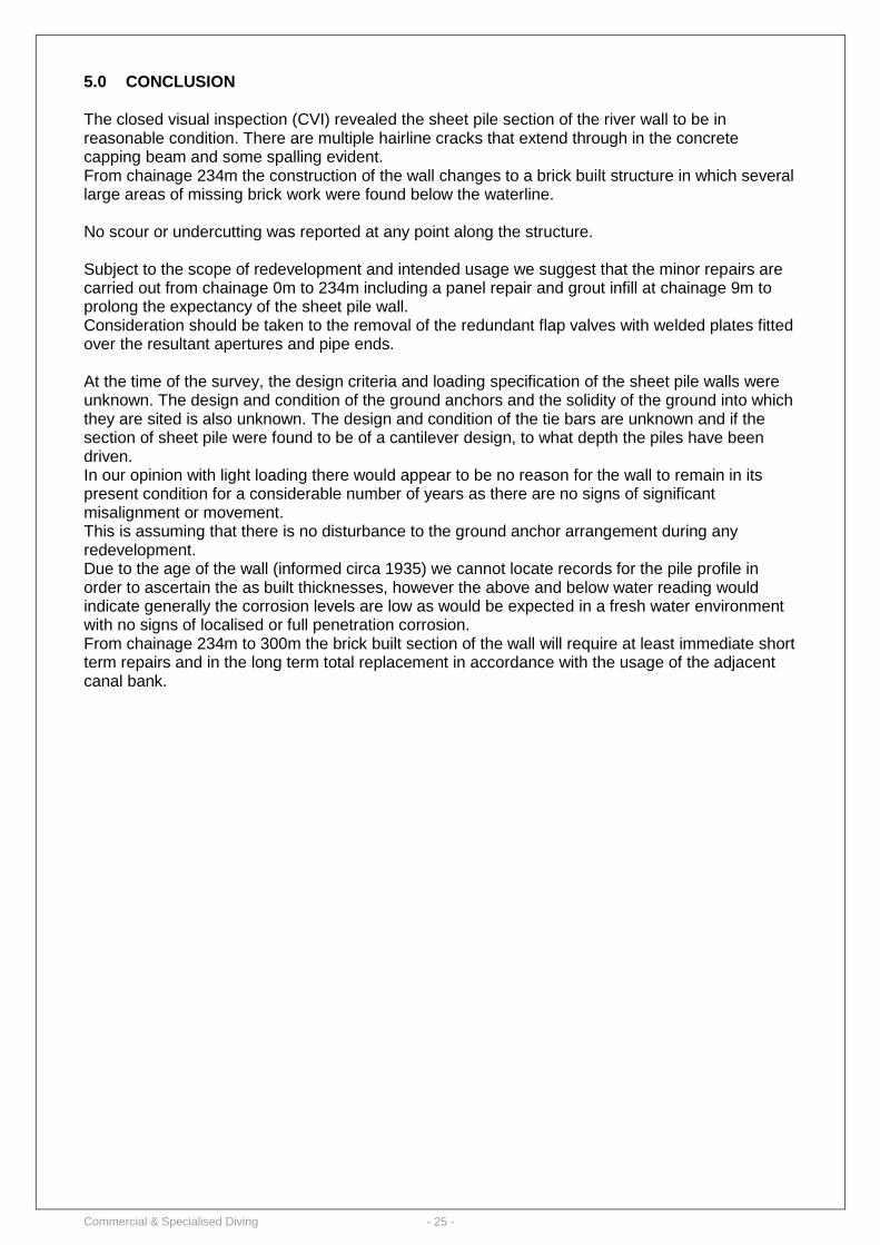
4.43 Ch 290m – 298m – The final 8m of the structure is form of a cast concrete wall with concrete anti-scour bags positioned in front. No defects or scour were report on this section of wall. Note – Build up of heavy vegetation on bag work.
Chainage
298, end
of
structure.
Commercial & Specialised Diving - 25 -
5.0 CONCLUSION
The closed visual inspection (CVI) revealed the sheet pile section of the river wall to be in reasonable condition. There are multiple hairline cracks that extend through in the concrete capping beam and some spalling evident. From chainage 234m the construction of the wall changes to a brick built structure in which several large areas of missing brick work were found below the waterline. No scour or undercutting was reported at any point along the structure. Subject to the scope of redevelopment and intended usage we suggest that the minor repairs are carried out from chainage 0m to 234m including a panel repair and grout infill at chainage 9m to prolong the expectancy of the sheet pile wall. Consideration should be taken to the removal of the redundant flap valves with welded plates fitted over the resultant apertures and pipe ends. At the time of the survey, the design criteria and loading specification of the sheet pile walls were unknown. The design and condition of the ground anchors and the solidity of the ground into which they are sited is also unknown. The design and condition of the tie bars are unknown and if the section of sheet pile were found to be of a cantilever design, to what depth the piles have been driven. In our opinion with light loading there would appear to be no reason for the wall to remain in its present condition for a considerable number of years as there are no signs of significant misalignment or movement. This is assuming that there is no disturbance to the ground anchor arrangement during any redevelopment. Due to the age of the wall (informed circa 1935) we cannot locate records for the pile profile in order to ascertain the as built thicknesses, however the above and below water reading would indicate generally the corrosion levels are low as would be expected in a fresh water environment with no signs of localised or full penetration corrosion. From chainage 234m to 300m the brick built section of the wall will require at least immediate short term repairs and in the long term total replacement in accordance with the usage of the adjacent canal bank.
Commercial & Specialised Diving - 26 -
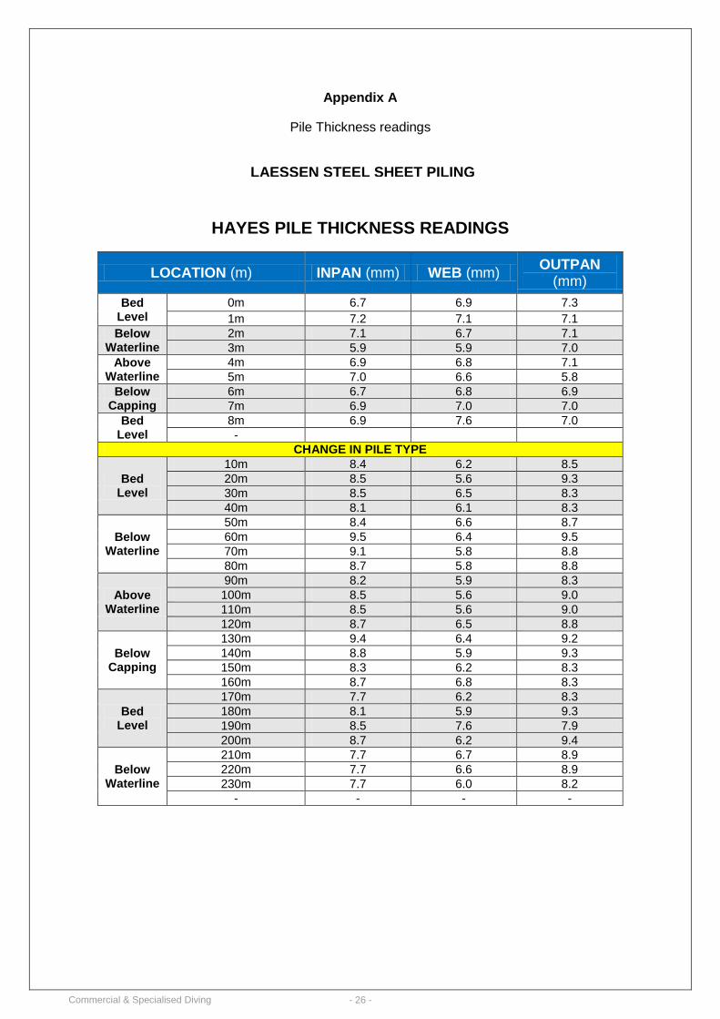
Appendix A
Pile Thickness readings
HAYES PILE THICKNESS READINGS
LOCATION (m) INPAN (mm) WEB (mm) OUTPAN
(mm)
Bed Level
0m 6.7 6.9 7.3
1m 7.2 7.1 7.1
Below Waterline
2m 7.1 6.7 7.1
3m 5.9 5.9 7.0
Above Waterline
4m 6.9 6.8 7.1
5m 7.0 6.6 5.8
Below Capping
6m 6.7 6.8 6.9
7m 6.9 7.0 7.0
Bed Level
8m 6.9 7.6 7.0
-
CHANGE IN PILE TYPE
Bed Level
10m 8.4 6.2 8.5
20m 8.5 5.6 9.3
30m 8.5 6.5 8.3
40m 8.1 6.1 8.3
Below Waterline
50m 8.4 6.6 8.7
60m 9.5 6.4 9.5
70m 9.1 5.8 8.8
80m 8.7 5.8 8.8
Above Waterline
90m 8.2 5.9 8.3
100m 8.5 5.6 9.0
110m 8.5 5.6 9.0
120m 8.7 6.5 8.8
Below Capping
130m 9.4 6.4 9.2
140m 8.8 5.9 9.3
150m 8.3 6.2 8.3
160m 8.7 6.8 8.3
Bed Level
170m 7.7 6.2 8.3
180m 8.1 5.9 9.3
190m 8.5 7.6 7.9
200m 8.7 6.2 9.4
Below Waterline
210m 7.7 6.7 8.9
220m 7.7 6.6 8.9
230m 7.7 6.0 8.2
- - - -
LAESSEN STEEL SHEET PILING
Commercial & Specialised Diving - 27 -
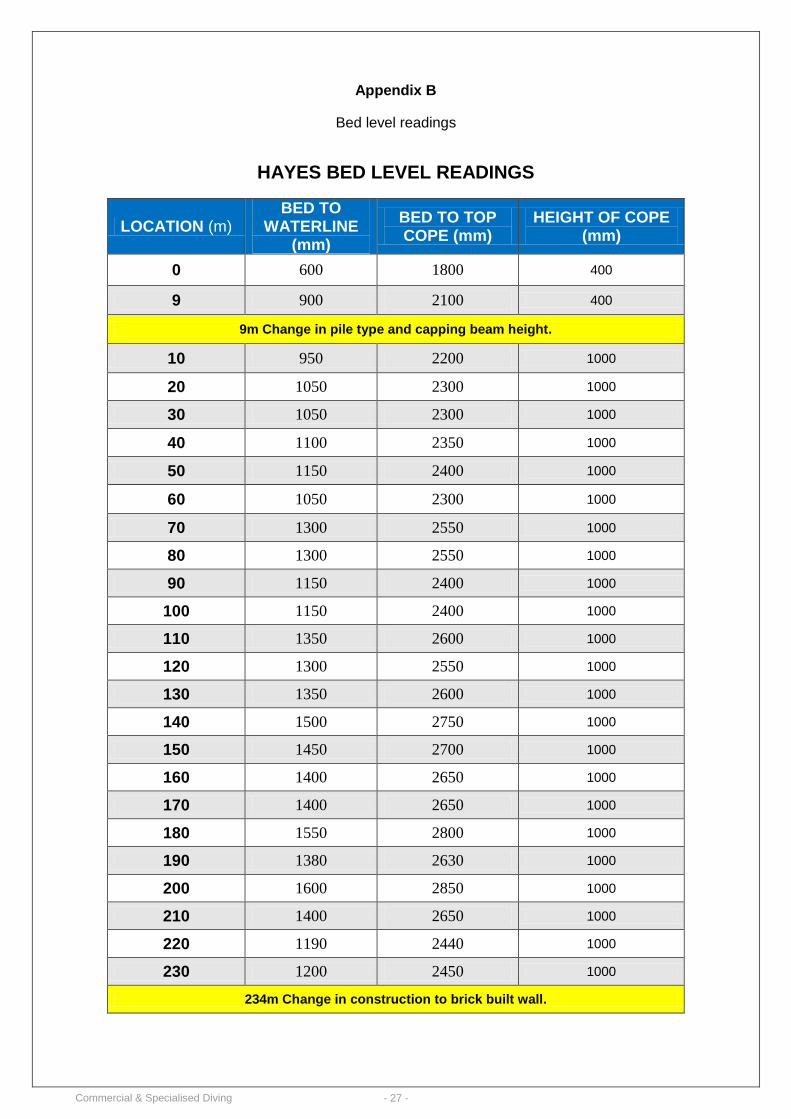
Appendix B
Bed level readings
HAYES BED LEVEL READINGS
LOCATION (m) BED TO
WATERLINE (mm)
BED TO TOP COPE (mm)
HEIGHT OF COPE (mm)
0 600 1800 400
9 900 2100 400
9m Change in pile type and capping beam height.
10 950 2200 1000
20 1050 2300 1000
30 1050 2300 1000
40 1100 2350 1000
50 1150 2400 1000
60 1050 2300 1000
70 1300 2550 1000
80 1300 2550 1000
90 1150 2400 1000
100 1150 2400 1000
110 1350 2600 1000
120 1300 2550 1000
130 1350 2600 1000
140 1500 2750 1000
150 1450 2700 1000
160 1400 2650 1000
170 1400 2650 1000
180 1550 2800 1000
190 1380 2630 1000
200 1600 2850 1000
210 1400 2650 1000
220 1190 2440 1000
230 1200 2450 1000
234m Change in construction to brick built wall.
Commercial & Specialised Diving - 28 -
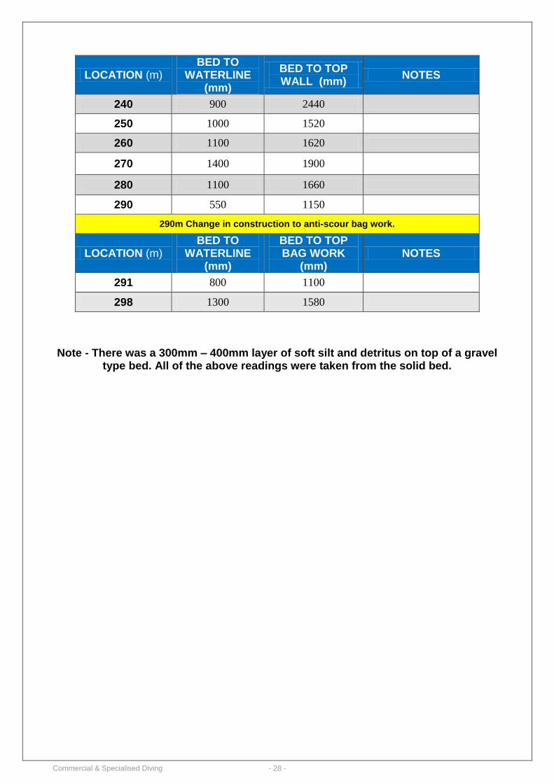
LOCATION (m) BED TO
WATERLINE (mm)
BED TO TOP WALL (mm)
NOTES
240 900 2440
250 1000 1520
260 1100 1620
270 1400 1900
280 1100 1660
290 550 1150
290m Change in construction to anti-scour bag work.
LOCATION (m) BED TO
WATERLINE (mm)
BED TO TOP BAG WORK
(mm) NOTES
291 800 1100
298 1300 1580
Note - There was a 300mm – 400mm layer of soft silt and detritus on top of a gravel
type bed. All of the above readings were taken from the solid bed.
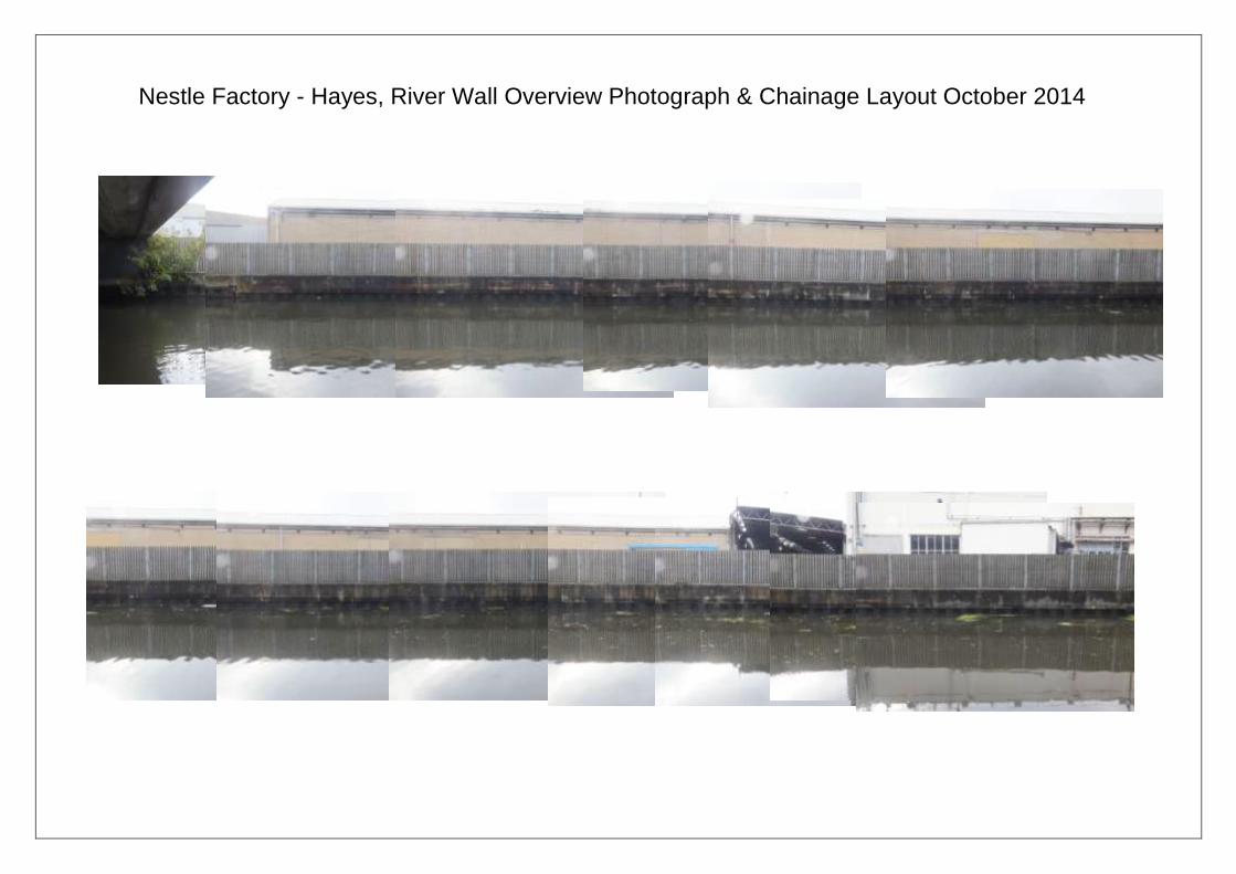
Nestle Factory - Hayes, River Wall Overview Photograph & Chainage Layout October 2014
0m
Nestle Factory - Hayes, River Wall Overview Photograph & Chainage Layout October 2014
Commercial & Specialised Diving - 1 -
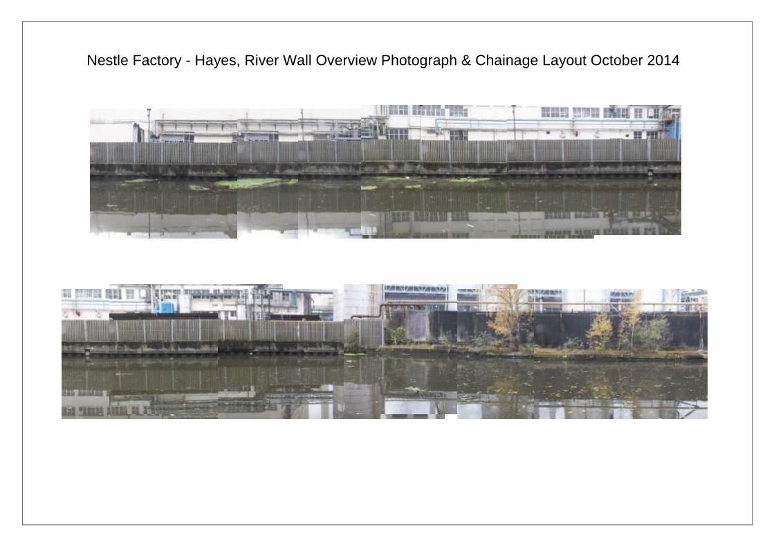
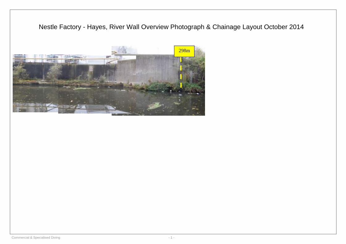
Nestle Factory - Hayes, River Wall Overview Photograph & Chainage Layout October 2014
298m